rotation active sensors based on ultrafast fibre lasers - mdpi
TRANSCRIPT
sensors
Review
Rotation Active Sensors Based on Ultrafast Fibre Lasers
Igor Kudelin 1,* , Srikanth Sugavanam 2 and Maria Chernysheva 3
Citation: Kudelin, I.; Sugavanam, S.;
Chernysheva, M. Rotation Active
Sensors Based on Ultrafast Fibre
Lasers. Sensors 2021, 21, 3530.
https://doi.org/10.3390/s21103530
Academic Editor: Jean-Claude Diels
Received: 1 April 2021
Accepted: 12 May 2021
Published: 19 May 2021
Publisher’s Note: MDPI stays neutral
with regard to jurisdictional claims in
published maps and institutional affil-
iations.
Copyright: © 2021 by the authors.
Licensee MDPI, Basel, Switzerland.
This article is an open access article
distributed under the terms and
conditions of the Creative Commons
Attribution (CC BY) license (https://
creativecommons.org/licenses/by/
4.0/).
1 Aston Institute of Photonic Technologies, Aston University, Birmingham B4 7ET, UK2 School of Computing and Electrical Engineering, IIT Mandi, Kamand, Himachal Pradesh 175075, India;
[email protected] Leibniz Institute of Photonic Technology, Albert-Einstein str. 9, 07745 Jena, Germany;
[email protected]* Correspondence: [email protected]
Abstract: Gyroscopes merit an undeniable role in inertial navigation systems, geodesy and seismol-ogy. By employing the optical Sagnac effect, ring laser gyroscopes provide exceptionally accuratemeasurements of even ultraslow angular velocity with a resolution up to 10−11 rad/s. With therecent advancement of ultrafast fibre lasers and, particularly, enabling effective bidirectional genera-tion, their applications have been expanded to the areas of dual-comb spectroscopy and gyroscopy.Exceptional compactness, maintenance-free operation and rather low cost make ultrafast fibre lasersattractive for sensing applications. Remarkably, laser gyroscope operation in the ultrashort pulsegeneration regime presents a promising approach for eliminating sensing limitations caused by thesynchronisation of counter-propagating channels, the most critical of which is frequency lock-in. Inthis work, we overview the fundamentals of gyroscopic sensing and ultrafast fibre lasers to bridge thegap between tools development and their real-world applications. This article provides a historicaloutline, highlights the most recent advancements and discusses perspectives for the expandingfield of ultrafast fibre laser gyroscopes. We acknowledge the bottlenecks and deficiencies of thepresented ultrafast laser gyroscope concepts due to intrinsic physical effects or currently availablemeasurement methodology. Finally, the current work outlines solutions for further ultrafast lasertechnology development to translate to future commercial gyroscopes.
Keywords: mode-locked laser; fibre gyroscope; Dispersive Fourier Transform; fibre sensors
1. Introduction
The term “gyroscope” was introduced by Léon Foucault in 1852, referring to a devicefor measuring angular rotation. The gyroscope, built by Léon Foucault, helped estimatethe rotation velocity of Earth, which showed the potential for the use of the technology. Atthat time, gyroscopes were entirely mechanical and based on rotating a massive sphere [1]or disk [2]. Later, gyroscopes started utilising electric motors to maintain the rotation of themoving parts of the device. Nowadays, principal types of gyroscopes include mechanical,micro-electro-mechanical system (MEMS), quartz and laser gyroscopes [3]. Mechanicalgyroscopes provide high performance with good stability [3]; however, the presence of amoving part, relatively low start-up time and high cost limit their applications.
In 1963, two years after the laser invention, the first laser gyroscope was demonstratedby Macek and Davis [4]. As the name implies, the laser gyroscope uses a ring laser cavity asa rotation sensing element. The underlying basis of light response to angular movementsrelies on the Sagnac effect or Sagnac interference, originally proposed by Georges Sagnac in1913 [5,6]. According to it, optical waves, counter-propagating inside the cavity, experiencethe difference in optical paths due to the rotation of the gyroscopic platform. Therefore,laser gyroscopes assess the angular velocity by evaluating the time delay between counter-propagated beams, which is also manifested as a shift of the pulse phase or the change ofoscillation frequencies (Section 2). Nowadays, modern laser gyroscopes provide the most
Sensors 2021, 21, 3530. https://doi.org/10.3390/s21103530 https://www.mdpi.com/journal/sensors

Sensors 2021, 21, 3530 2 of 30
accurate rotation measurements and can detect precise rotational motions associated withseismic events [7], Chandler and Annual wobbles [8].
A related device, also operating based on the Sagnac effect, is a fibre optic gyroscope(FOG), as shown in Figure 1a. The first FOG was demonstrated in 1973 [9]. FOG presents apassive interferometer (in other words, one that does not contain active media), where twolaser light fields counter-propagate inside an optical fibre loop. FOG detects a phase shiftbetween the laser beams to define the Sagnac effect. High mechanical flexibility and lowlosses allow coiling of long optical fibres for FOG’s sensitivity enhancement. In such a way,the overall accumulated optical Sagnac effect is multiplied by the number of turns [10].Due to reasonably precise rotational rate information and rigid design [11], FOGs arecurrently widely applied in inertial navigation systems [12,13].
Figure 1. Schematic representation of: (a) passive Sagnac interferometer; and (b) ring laser gyroscope.
The most severe limitation of active laser gyroscopes is a ’lock-in’ effect. This effectoriginates from the interaction of the counter-propagating beams inside a laser cavitydue to back-scattering at reflective surfaces [14] and amplification in active media. Whenthe laser gyroscope rotates, such interaction can cause frequencies synchronisation ofcounter-propagating beams. The range of angular velocities below critical value ΩLcannot be detected and is called a dead-band. Therefore, the lock-in effect is particularlysevere at low rotation velocities. The dead-band can be suppressed, but not completelyeliminated, by coating cavity mirrors with high-reflective dielectrics [15], by applyingexternal dithering [16] or improvement of laser cavity geometry (e.g., developing triangle-shaped cavity) [17]. However, such methods substantially increase the complexity andtotal price of the laser gyroscopes. In these regards, the compact and maintenance-freeall-fibre configuration becomes less advantageous for application in laser gyroscopes dueto inherent Rayleigh scattering [18].
An alternative approach suggested for the lock-in effect mitigation is the exploitationof ultrashort pulses instead of continuous-wave radiation in optical gyroscopes. Ultrashortpulses feature a small spatial length (∼0.3 µm per fs) and, thus, interact shortly only in twopoints in the cavity or fibre loop; therefore, they are less subjected to lock-in synchroni-sation [19]. In ultrafast laser gyroscopes, the low-intensity back-scattered light is furthersuppressed in a saturable absorber used for pulse formation (more details in Section 3.1).The first ultrafast laser gyroscope was realised based on bidirectional ring dye laser in1991 by Dennis et al. [20]. Later in the same year, two groups demonstrated independentstudies of the Sagnac effect in bidirectional mode-locked dye laser [21] and bidirectionalpicosecond diode ring laser [22]. The latest works on gyroscopic measurements in bidirec-tional mode-locked laser showed a sensitivity of 10−8 rad [23,24]. These works confirma significant reduction of the dead-band zone, which induced significant research anddevelopment interest in ultrafast lasers as a platform for gyroscopic measurements.
Sensors 2021, 21, 3530 3 of 30
In 1993, Jeon et al. realised the first fibre-based mode-locked laser gyroscope with anintracavity Sagnac interferometer [25]. Ultrafast fibre lasers have been intensively studiedover the past few decades and proved to be an excellent tool for accurate measurementsin absolute length and frequency metrology [26,27] and spectroscopy [28]. However,today only a few works have been presented related to gyroscopic measurements viamode-locked fibre lasers. Nevertheless, the latest work establishes a novel approach forinterferometric measurements of the Sagnac effect based on time-stretch technique ofultrashort pulses, which allows the achievement of the highest acquisition rates in theMHz range [29]. Generally, ultrashort pulsed fibre laser gyroscopes inherit exceptionalperspectives to become a prominent tool for dead-band-free measurements of angularvelocities.
Previous review papers are focused on laser gyroscopes and their applications [3,17,30].Given recent trends, this Review is dedicated to the development of ultrashort pulsed fibrelaser gyroscopes over the last years to foresee future technological and scientific advance-ment of the field. Portraying the whole process from fabrication and characterisation ofbidirectional mode-locked fibre laser cavities to the optical Sagnac effect evaluation, weprovide insight into the possibilities of such gyroscopic systems, hence, deliver a completeinterdisciplinary package for future research or an introduction to the field. The outline ofthe Review is the following. The first section is focused on the basics of the Sagnac effect,architectures of laser gyroscopes and their limitations with up-to-date performance. In thesecond section, we cover the fundamentals of mode-locking operation, characterisation ofpulsed laser generation, including bidirectional fibre laser setups for potential gyroscopicapplications. The last section encompasses the up-to-date works of gyroscopic measurementsin ultrafast fibre lasers. The Review is concluded with an overview of the current researchdirections and outcomes with future perspectives.
2. Sagnac Effect
As mentioned above, optical gyroscopes are based on the Sagnac effect that relates thedifference in optical paths of counter-propagating beams ∆L to the angular velocity of thegyro platform. If the laser gyroscope platform rotates at an angular velocity ~ω rad/s, thedifference in optical paths between counter-propagating beams could be expressed:
∆L =4~Ac~ω (1)
where ~A is an oriented area of the laser gyroscope and c is the speed of light in media withrefractive index n (n ≈ 1.47 for conventional silica-based fibres). The vector form indicatesthat the laser gyroscopes are sensitive only to the rotation in the laser platform’s plane. Thedifference in optical paths leads to a different time for counter-propagating beams to makea round trip through the laser gyroscope cavity:
∆t =4~Ac2 ~ω (2)
The Sagnac effect can also be expressed as a Sagnac-induced phase shift (φ = 2πcλc· t)
between counter-propagating beams:
∆φ =8π~Aλcc
~ω (3)
where λc is the carrier wavelength of the beams. The presented Sagnac Equations (1)–(3)give a linear relationship between rotation velocity and parameters of the laser beams andcould be applied for arbitrary gyroscope geometry. The fraction which defines the ratiobetween angular velocity and the beam parameter is known as a scale factor. The Sagnaceffect is perfectly explained in the context of general relativity. The complete derivation ofthe Sagnac formula with special-relativistic analysis and corrections can be found in [31,32].
Sensors 2021, 21, 3530 4 of 30
A laser cavity maintains generation only at integer numbers of propagating wave-lengths L = n · λ, which present longitudinal modes. Thus, according to the previousstatement, the difference in the total optical paths ∆L caused by the Sagnac effect can bemanifested through the change of oscillation frequencies ∆ν or beam wavelengths. Theassociated beat-note frequency or ‘Sagnac frequency’ can be derived as:
∆ν
ν=
∆LL
∆ν =∆L · ν
L=
4~ALλc
~ω (4)
where ν is an initial oscillation frequency and L is the cavity perimeter. The equationillustrates that longitudinal frequency modes could be slightly shifted with the rotation ofthe platform. The associated frequency shift can also be interpreted in terms of a Dopplershift, caused by moving the laser platform [23].
The introduced equations for the Sagnac effect establish a basis for angular velocitymeasurements in laser gyroscopes. However, there are several modifications to increasethe response of the laser cavity to the Sagnac effect. For instance, in 1981, A. Kaplan andP. Meystre proposed the implementation of a nonlinearly induced non-reciprocity [33].Other works applied the concept of a ’slow light’ [34] by introducing a giant dispersion toincrease the Sagnac effect [24,35–39].
2.1. Methods for Sagnac Effect Detection
As discussed briefly above, optical interferometers for Sagnac effect measurementsare divided into passive and active. In passive interferometers, an external laser source isneeded (Figure 1a). In contrast, active sensors comprise a laser cavity, i.e., interferometerwith an active media (Figure 1b). The laser gyroscope has to maintain a generation oftwo counter-propagating beams, which are superimposed at the output to retrieve Sagnac-induced relative changes.
Generally, the Sagnac effect can be detected in the temporal domain as a differencebetween arriving time of counter-propagated beams (Equation (2)) , in the frequencydomain as a beat-note (Equation (3)) or as a Sagnac-induced phase shift between counter-propagating beams. However, even the fastest photodetectors have limited rise time in theps range, which also strictly restrain the overall resolution of the gyroscopes in the timedomain.
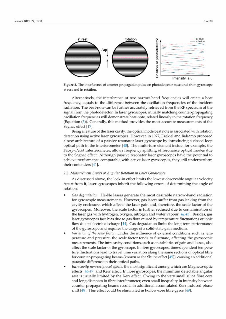
An interferometric pattern of combined counter-propagating beams on the photodetec-tor provides phase-sensitive measurements. During gyroscope platform rotation, counter-propagating beams experience additional Sagnac-induced phases of different signs, dis-placing the interferometric pattern accordingly. The Sagnac-induced phase shift can also betreated as a movement of a standing wave inside the interferometer. Thus, the positionsof nodes and antinodes are fixed if the gyroscope is at rest. When a gyroscope is rotated,the photoreceivers measure the rotation angle by counting the interference fringes runningover them. Figure 2 schematically shows the interferometric patterns when the gyroscopeat rest and during rotation. It is worth noting that the described phase-based detectionof the Sagnac effect is a dominant methodology for passive gyroscopes. In the case ofpassive interferometers, the recorded pattern is sensitive only to a variation of the angularvelocity due to a single traverse in the interferometer by the laser beams. In other words,since the laser beams propagate only once through the interferometer (open-loop), theSagnac-induced phase shift is not accumulated from one roundtrip to another as happensin active gyroscopes. Therefore, passive gyroscopes, generally, provide lower sensitivity.The phase increment of 2π is proportional to the rotation angle of the interferometer. It isusually from 0.1–0.2′ ′ for large perimeters of the order of 4 m to 10–20′ ′ for small perimetersof the order of 4 cm. In Sections 3.3.2 and 4, we discuss and demonstrate a novel approachto record interferograms of ultrashort pulses via time-stretch technique in order to retrievethe relative phase associated with the Sagnac effect.
Sensors 2021, 21, 3530 5 of 30
Figure 2. The interference of counter-propagation pulse on photodetector measured from gyroscopeat rest and in rotation.
Alternatively, the interference of two narrow-band frequencies will create a beatfrequency, equals to the difference between the oscillation frequencies of the incidentradiation. The beat-note can be further accurately retrieved from the RF spectrum of thesignal from the photodetector. In laser gyroscopes, initially matching counter-propagatingoscillation frequencies will demonstrate beat-note, related linearly to the rotation frequency(Equation (3)). Generally, this method provides the most accurate measurements of theSagnac effect [17].
Being a feature of the laser cavity, the optical mode beat note is associated with rotationdetection using active laser gyroscopes. However, in 1977, Ezekiel and Balsamo proposeda new architecture of a passive resonator laser gyroscope by introducing a closed-loopoptical path in the interferometer [40]. The multi-turn element inside, for example, theFabry–Perot interferometer, allows frequency splitting of resonance optical modes dueto the Sagnac effect. Although passive resonator laser gyroscopes have the potential toachieve performance comparable with active laser gyroscopes, they still underperformtheir contenders [41].
2.2. Measurement Errors of Angular Rotation in Laser Gyroscopes
As discussed above, the lock-in effect limits the lowest observable angular velocity.Apart from it, laser gyroscopes inherit the following errors of determining the angle ofrotation:
• Gas degradation. He-Ne lasers generate the most desirable narrow-band radiationfor gyroscopic measurements. However, gas lasers suffer from gas leaking from thecavity enclosure, which affects the laser gain and, therefore, the scale factor of thegyroscopes. Moreover, the scale factor is further reduced due to contamination ofthe laser gas with hydrogen, oxygen, nitrogen and water vapour [42,43]. Besides, gaslaser gyroscopes face bias due to gas flow caused by temperature fluctuations or ionicflow due to electric discharge [44]. Gas degradation limits the long-term performanceof the gyroscope and requires the usage of a solid-state gain medium.
• Variation of the scale factor. Under the influence of external conditions such as tem-perature and pressure, the scale factor tends to fluctuate, affecting the gyroscopicmeasurements. The intracavity conditions, such as instabilities of gain and losses, alsoaffect the scale factor of the gyroscope. In fibre gyroscopes, time-dependent tempera-ture fluctuations lead to travel time variation along the same sections of optical fibrefor counter-propagating beams (known as the Shupe effect [45]), causing an additionalparasitic difference in their optical paths.
• Intracavity non-reciprocal effects, the most significant among which are Magneto-opticeffects [46,47] and Kerr effect. In fibre gyroscopes, the minimum detectable angularrate is usually limited by the Kerr effect. Owing to the very small silica fibre coreand long distances in fibre interferometer, even small inequality in intensity betweencounter-propagating beams results in additional accumulated Kerr-induced phaseshift [48]. This effect could be eliminated in hollow-core fibre gyros [49].
Sensors 2021, 21, 3530 6 of 30
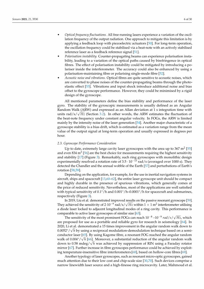
• Optical frequency fluctuations. All free-running lasers experience a variation of the oscil-lation frequency of the output radiation. One approach to mitigate this limitation is byapplying a feedback loop with piezoelectric actuators [50]. For long-term operation,the oscillation frequency could be stabilised via a beat-note with an actively stabilisedreference laser as a feedback reference signal [51].
• Polarisation instability. Counter-propagating beams can experience polarisation insta-bility, leading to a variation of the optical paths caused by birefringence in opticalfibres. The effect of polarisation instability could be mitigated by introducing a po-lariser inside the interferometer. The accuracy could also be enhanced by using apolarisation-maintaining fibre or polarising single-mode fibre [52].
• Acoustic noise and vibrations. Optical fibres are quite sensitive to acoustic noises, whichare converted to phase noises of the counter-propagating beams through the photo-elastic effect [53]. Vibrations and input shock introduce additional noise and biasoffset to the gyroscope performance. However, they could be minimised by a rigiddesign of the gyroscope.
All mentioned parameters define the bias stability and performance of the lasergyro. The stability of the gyroscopic measurements is usually defined as an AngularRandom Walk (ARW) and expressed as an Allan deviation at 1 s integration time withunits rad/s/
√Hz (Section 3.2). In other words, the ARW estimates the fluctuation of
the beat-note frequency under constant angular velocity. In FOGs, the ARW is limitedmainly by the intensity noise of the laser generation [54]. Another major characteristic of agyroscope stability is a bias drift, which is estimated as a variation range from the meanvalue of the output signal at long-term operation and usually expressed in degrees perhour.
2.3. Gyroscope Performance Consideration
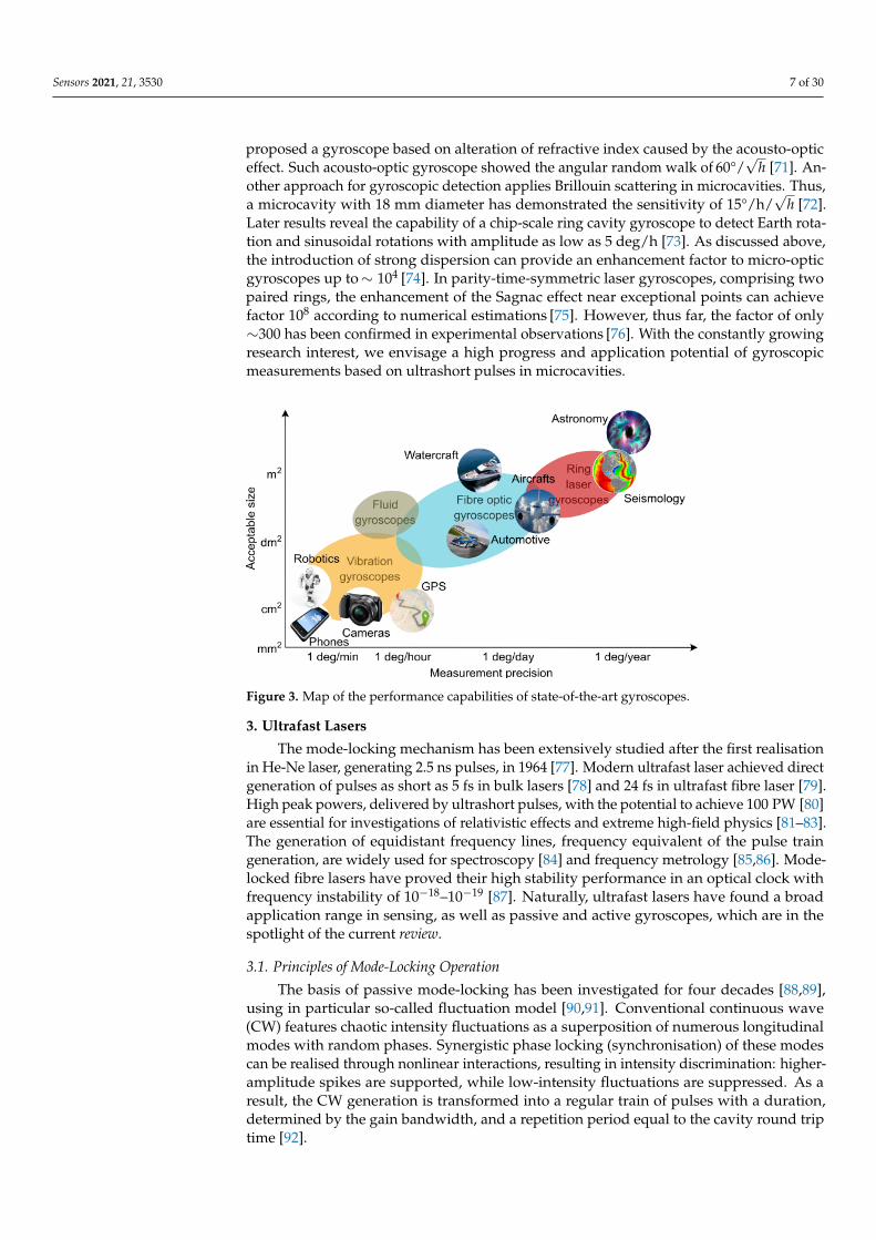
Up to date, extremely large cavity laser gyroscopes with the area up to 367 m2 [55]and even 834 m2 [56] are the best choice for measurements requiring the highest sensitivityand stability [17] (Figure 3). Remarkably, such ring gyroscopes with monolithic designexperimentally resolved a rotation rate of 3.5 · 10−13 rad/s (averaged over 1000 s). Theydetected the Chandler and the annual wobble of the Earth [57] and perturbations of Earth’srotation [58,59].
Depending on the application, for example, for the use in inertial navigation systems inaircraft, ships and spacecraft [13,60–62], the entire laser gyroscope unit should be compactand highly durable in the presence of spurious vibrations, which generally comes atthe price of reduced sensitivity. Nevertheless, most of the applications are well satisfiedwith typical sensitivity of 0.1°/h and 0.001°/h–0.0001°/h for spacecraft and submarines,respectively (Figure 3).
In 2019, Liu et al. demonstrated improved results on the passive resonant gyroscope [59].They achieved the sensitivity of 2·10−9 rad/s/
√Hz within 1 × 1 m2 interferometer utilising
a diode laser locked to adjacent longitudinal modes of a ring cavity. This performance iscomparable to active laser gyroscopes of similar size [63].
The sensitivity of the most prominent FOGs can reach 10−8 –10−9 rad/s/√
Hz, whichare proposed for use as a portable and reliable gyro for research in seismology [64]. In2020, Li et al. demonstrated a 15 times improvement in the angular random walk down to0.0052°/
√h by using a reciprocal modulation-demodulation technique based on a semi-
conductor laser [65]. By using Kagome fibre, a resonant FOG reached the angular randomwalk of 0.004°/
√h [66]. Moreover, a substantial reduction of the angular random walk
down to 0.58 mdeg/√
h was achieved by suppression of RIN using a Faraday rotatormirror [67]. Further increase in fibre gyroscopes performance could be achieved by exploit-ing temperature-insensitive fibre interferometers [68], based on hollow-core fibres [69].
Another typology of laser gyroscopes, such as resonant micro-optic gyroscopes, gainedmuch attention due to their low cost and chip-scale size [30,70]. Such devices comprise anarrow linewidth laser source and a high-finesse ring microcavity. Later, Mahmoud et al.
Sensors 2021, 21, 3530 7 of 30
proposed a gyroscope based on alteration of refractive index caused by the acousto-opticeffect. Such acousto-optic gyroscope showed the angular random walk of 60°/
√h [71]. An-
other approach for gyroscopic detection applies Brillouin scattering in microcavities. Thus,a microcavity with 18 mm diameter has demonstrated the sensitivity of 15°/h/
√h [72].
Later results reveal the capability of a chip-scale ring cavity gyroscope to detect Earth rota-tion and sinusoidal rotations with amplitude as low as 5 deg/h [73]. As discussed above,the introduction of strong dispersion can provide an enhancement factor to micro-opticgyroscopes up to∼ 104 [74]. In parity-time-symmetric laser gyroscopes, comprising twopaired rings, the enhancement of the Sagnac effect near exceptional points can achievefactor 108 according to numerical estimations [75]. However, thus far, the factor of only∼300 has been confirmed in experimental observations [76]. With the constantly growingresearch interest, we envisage a high progress and application potential of gyroscopicmeasurements based on ultrashort pulses in microcavities.
Figure 3. Map of the performance capabilities of state-of-the-art gyroscopes.
3. Ultrafast Lasers
The mode-locking mechanism has been extensively studied after the first realisationin He-Ne laser, generating 2.5 ns pulses, in 1964 [77]. Modern ultrafast laser achieved directgeneration of pulses as short as 5 fs in bulk lasers [78] and 24 fs in ultrafast fibre laser [79].High peak powers, delivered by ultrashort pulses, with the potential to achieve 100 PW [80]are essential for investigations of relativistic effects and extreme high-field physics [81–83].The generation of equidistant frequency lines, frequency equivalent of the pulse traingeneration, are widely used for spectroscopy [84] and frequency metrology [85,86]. Mode-locked fibre lasers have proved their high stability performance in an optical clock withfrequency instability of 10−18–10−19 [87]. Naturally, ultrafast lasers have found a broadapplication range in sensing, as well as passive and active gyroscopes, which are in thespotlight of the current review.
3.1. Principles of Mode-Locking Operation
The basis of passive mode-locking has been investigated for four decades [88,89],using in particular so-called fluctuation model [90,91]. Conventional continuous wave(CW) features chaotic intensity fluctuations as a superposition of numerous longitudinalmodes with random phases. Synergistic phase locking (synchronisation) of these modescan be realised through nonlinear interactions, resulting in intensity discrimination: higher-amplitude spikes are supported, while low-intensity fluctuations are suppressed. As aresult, the CW generation is transformed into a regular train of pulses with a duration,determined by the gain bandwidth, and a repetition period equal to the cavity round triptime [92].
Sensors 2021, 21, 3530 8 of 30
Ultrashort pulse formation, propagation and amplification in fibre laser cavities isgoverned by the modified nonlinear Schrödinger equation for a temporal pulse envelopeA [93]:
δAδz
= − i2
(β2 + i
gΩ2
g
)δ2 Aδt2 + iγ|A|2 A +
12(g− l)A (5)
where g and l are gain and loss of the cavity, z is the propagation distance, Ωg is thebandwidth of the gain, β2 is the second-order dispersion coefficient and γ is a nonlinearcoefficient, determined by operational wavelength λ, effective fibre mode area Ae f f andnonlinear refractive index of the laser media n2, as γ = 2πn2/λAe f f .
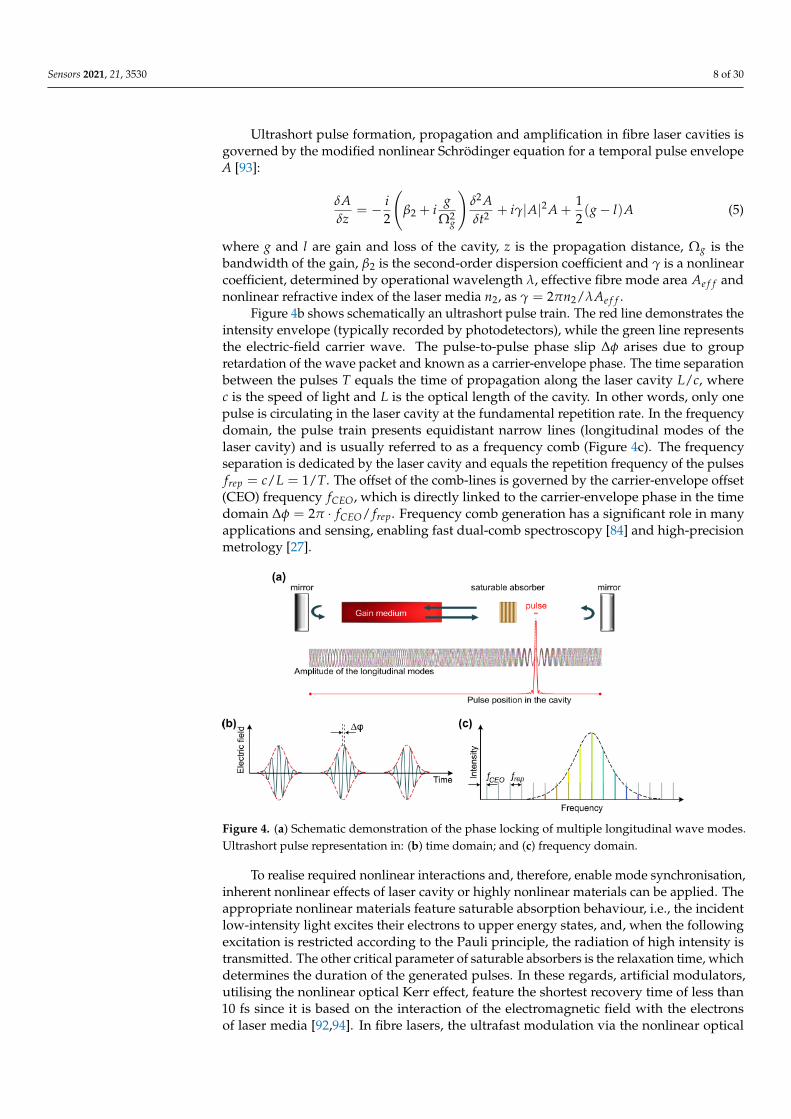
Figure 4b shows schematically an ultrashort pulse train. The red line demonstrates theintensity envelope (typically recorded by photodetectors), while the green line representsthe electric-field carrier wave. The pulse-to-pulse phase slip ∆φ arises due to groupretardation of the wave packet and known as a carrier-envelope phase. The time separationbetween the pulses T equals the time of propagation along the laser cavity L/c, wherec is the speed of light and L is the optical length of the cavity. In other words, only onepulse is circulating in the laser cavity at the fundamental repetition rate. In the frequencydomain, the pulse train presents equidistant narrow lines (longitudinal modes of thelaser cavity) and is usually referred to as a frequency comb (Figure 4c). The frequencyseparation is dedicated by the laser cavity and equals the repetition frequency of the pulsesfrep = c/L = 1/T. The offset of the comb-lines is governed by the carrier-envelope offset(CEO) frequency fCEO, which is directly linked to the carrier-envelope phase in the timedomain ∆φ = 2π · fCEO/ frep. Frequency comb generation has a significant role in manyapplications and sensing, enabling fast dual-comb spectroscopy [84] and high-precisionmetrology [27].
Figure 4. (a) Schematic demonstration of the phase locking of multiple longitudinal wave modes.Ultrashort pulse representation in: (b) time domain; and (c) frequency domain.
To realise required nonlinear interactions and, therefore, enable mode synchronisation,inherent nonlinear effects of laser cavity or highly nonlinear materials can be applied. Theappropriate nonlinear materials feature saturable absorption behaviour, i.e., the incidentlow-intensity light excites their electrons to upper energy states, and, when the followingexcitation is restricted according to the Pauli principle, the radiation of high intensity istransmitted. The other critical parameter of saturable absorbers is the relaxation time, whichdetermines the duration of the generated pulses. In these regards, artificial modulators,utilising the nonlinear optical Kerr effect, feature the shortest recovery time of less than10 fs since it is based on the interaction of the electromagnetic field with the electronsof laser media [92,94]. In fibre lasers, the ultrafast modulation via the nonlinear optical
Sensors 2021, 21, 3530 9 of 30
Kerr effect can be realised by nonlinear polarisation evolution (NPE) [95] or propagatingthrough nonlinear optical and amplifying loop mirrors (NOLM and NALM) [96,97].
Among the first materials exhibiting saturable absorption behaviour are dyes [98,99].Despite the demonstration of sub-100-fs pulse duration, such lasers had low efficiency andelaborate design. Starting from the 1990s, semiconductor saturable absorber mirrors (SESAMs)received widespread development [100]. These III–V group binary and ternary semiconduc-tors with multiple quantum wells structures were grown on a distributed Bragg reflector [100].Shortly after the first demonstration and until now, SESAMs have been widely used in researchand commercial solid-state, semiconductor and fibre laser systems, operating in a broad spec-tral range spanning from visible to short-wave infrared range [101–104]. However, SESAMsfabrication is a sophisticated and expensive process. Therefore, the research communityremains in a continuous search for a cost-effective material featuring high nonlinearity andultrafast relaxation time. During the past decade, numerous new materials, generally nanoma-terials, have emerged, including carbon nanotubes (CNTs) [105], graphene [106,107], transitionmetal dichalcogenides (TMDs) [108,109], MXene [110,111], black phosphorous [112,113] andplasmonic metasurfaces [114]. The key advantage of nanomaterial SAs is the flexibility oftheir implementation into the laser setup. While SESAM is typically operating as a mirrorand, therefore, can be inserted into linear laser configuration or using a circulator, nanoma-terials can operate in transmission. The most common approaches for implementation isby sandwiching the SA composite between fibre ferrules [107], deposition on side-polished(D-shaped) or tapered fibres [115], ink-jet printing [116] or infilling microfluidic channels bySA solution [117].
The advantages of ultrafast fibre lasers are not limited to compactness and robustnessbut also include flexibility of generation regimes and tuneability of output parameters,such as pulse duration and profile, which can be tailored to a particular application. The in-terplay of dispersion and the nonlinearity, gain and losses with the proper selection of fibreparameters can trigger a large variety of operational regimes. The most common operationis the generation of optical solitons [118] when the positive nonlinearity is compensatedby anomalous net cavity group velocity dispersion. With the creation of a dispersion mapin the laser cavity (e.g., by sequencing sections of normal and anomalous dispersion), thegeneration of dispersion-managed solitons [119] can be achieved. Dissipative [120] andself-similar pulses (similaritons) [121] can be formed in all-normal dispersion fibre lasercavities.
By designing the fibre laser cavity so that the normal group-velocity dispersion iscompensated by negative nonlinearity, a conventional soliton cannot be generated. Inducedbroadening and chirping in such cavities give rise to so-called dark solitons, which presenta localised sharp deep in CW background with a constant amplitude [122].
Regarding sensing, particularly of the optical Sagnac effect and following gyroscopeapplications, the influence of nonlinear effects and group velocity dispersion becomes evenmore crucial. Thus, self-phase modulation and self-steepening effect significantly affectthe group and phase velocities of ultrashort pulses and, therefore, determines carrier-to-envelope offset frequency stability [123–125], which in its turn determines the resolution offollowing gyroscopic measurements.
3.2. Characterisation of Output Radiation in Ultrafast Lasers
Any laser source is characterised by a number of parameters. The full energy descrip-tion of the pulsed laser is giving by the next equations:
Pav. = limt→∞
∫ +∞−∞ A2dt
t≈∫ T
0 A2dtT
=Epulse
T[Watt] (6)
Epulse = Pav. · T =Pav.
frep.[Joule] (7)
Sensors 2021, 21, 3530 10 of 30
Ppeak =Epulse
τFWHM
[Watt] (8)
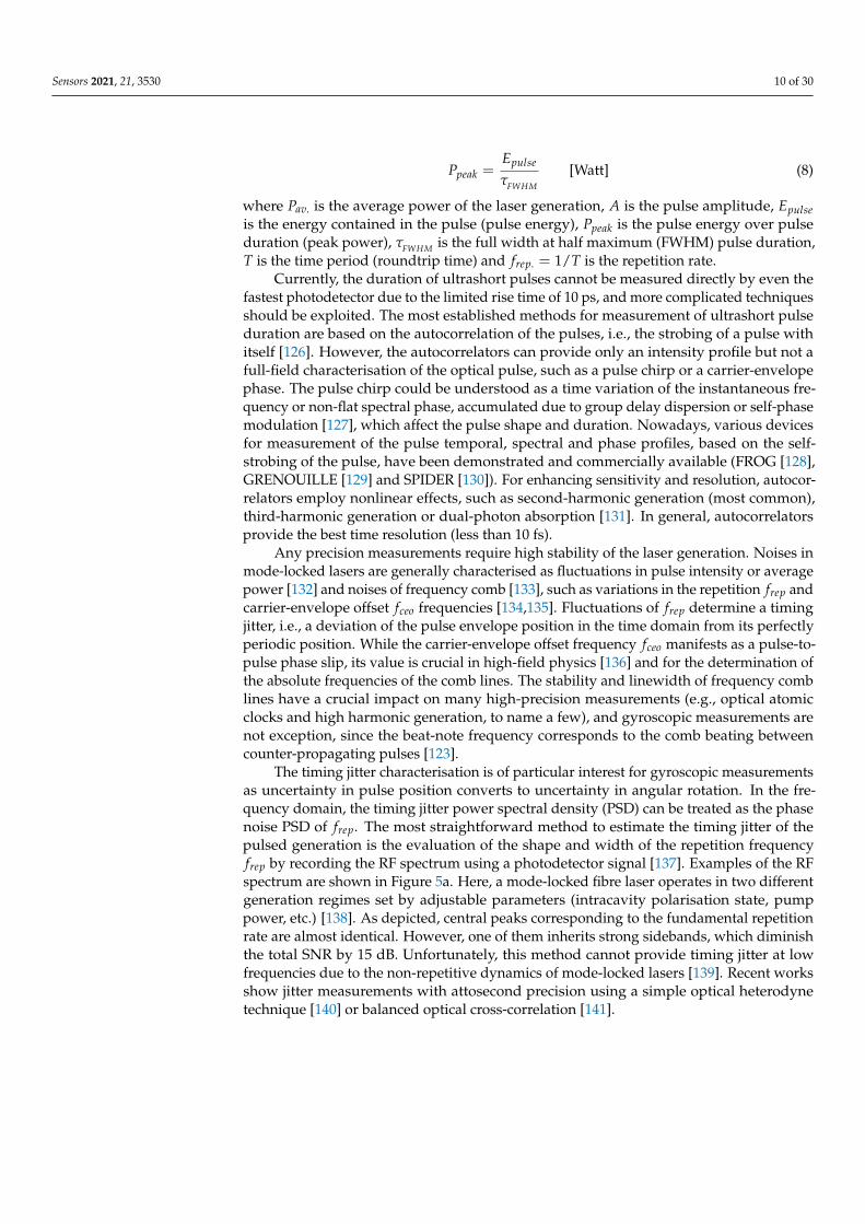
where Pav. is the average power of the laser generation, A is the pulse amplitude, Epulseis the energy contained in the pulse (pulse energy), Ppeak is the pulse energy over pulseduration (peak power), τFWHM is the full width at half maximum (FWHM) pulse duration,T is the time period (roundtrip time) and frep. = 1/T is the repetition rate.
Currently, the duration of ultrashort pulses cannot be measured directly by even thefastest photodetector due to the limited rise time of 10 ps, and more complicated techniquesshould be exploited. The most established methods for measurement of ultrashort pulseduration are based on the autocorrelation of the pulses, i.e., the strobing of a pulse withitself [126]. However, the autocorrelators can provide only an intensity profile but not afull-field characterisation of the optical pulse, such as a pulse chirp or a carrier-envelopephase. The pulse chirp could be understood as a time variation of the instantaneous fre-quency or non-flat spectral phase, accumulated due to group delay dispersion or self-phasemodulation [127], which affect the pulse shape and duration. Nowadays, various devicesfor measurement of the pulse temporal, spectral and phase profiles, based on the self-strobing of the pulse, have been demonstrated and commercially available (FROG [128],GRENOUILLE [129] and SPIDER [130]). For enhancing sensitivity and resolution, autocor-relators employ nonlinear effects, such as second-harmonic generation (most common),third-harmonic generation or dual-photon absorption [131]. In general, autocorrelatorsprovide the best time resolution (less than 10 fs).
Any precision measurements require high stability of the laser generation. Noises inmode-locked lasers are generally characterised as fluctuations in pulse intensity or averagepower [132] and noises of frequency comb [133], such as variations in the repetition frep andcarrier-envelope offset fceo frequencies [134,135]. Fluctuations of frep determine a timingjitter, i.e., a deviation of the pulse envelope position in the time domain from its perfectlyperiodic position. While the carrier-envelope offset frequency fceo manifests as a pulse-to-pulse phase slip, its value is crucial in high-field physics [136] and for the determination ofthe absolute frequencies of the comb lines. The stability and linewidth of frequency comblines have a crucial impact on many high-precision measurements (e.g., optical atomicclocks and high harmonic generation, to name a few), and gyroscopic measurements arenot exception, since the beat-note frequency corresponds to the comb beating betweencounter-propagating pulses [123].
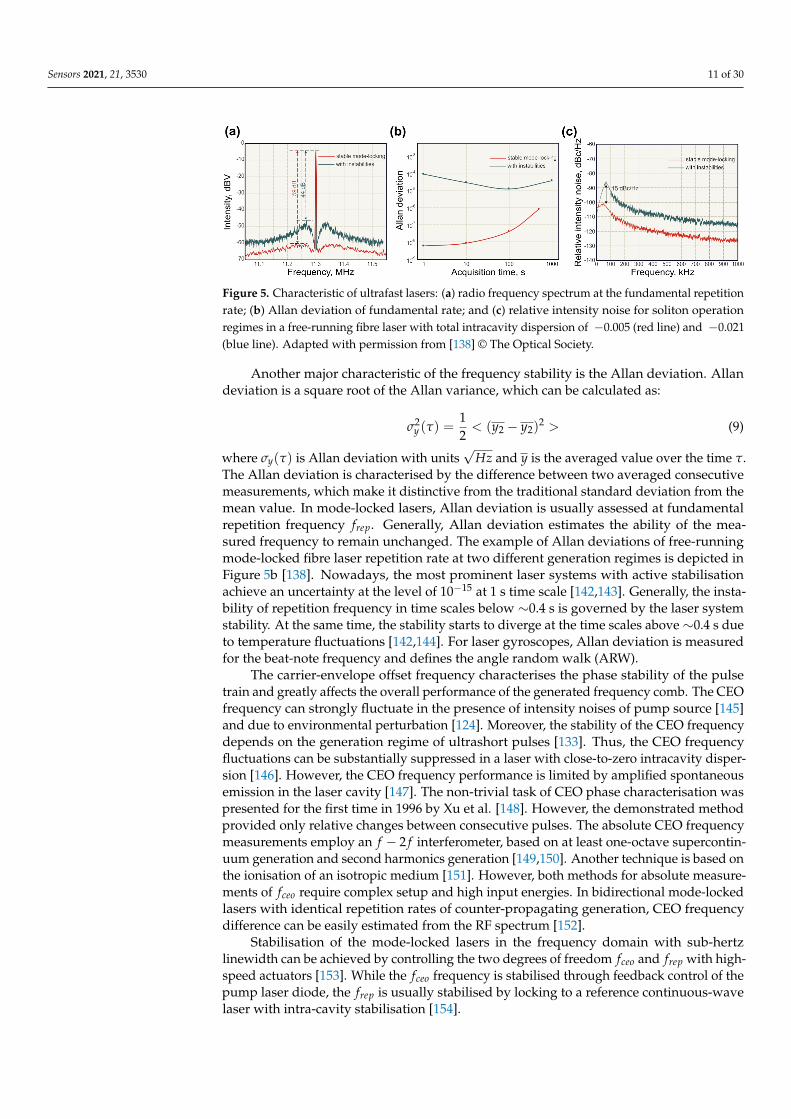
The timing jitter characterisation is of particular interest for gyroscopic measurementsas uncertainty in pulse position converts to uncertainty in angular rotation. In the fre-quency domain, the timing jitter power spectral density (PSD) can be treated as the phasenoise PSD of frep. The most straightforward method to estimate the timing jitter of thepulsed generation is the evaluation of the shape and width of the repetition frequencyfrep by recording the RF spectrum using a photodetector signal [137]. Examples of the RFspectrum are shown in Figure 5a. Here, a mode-locked fibre laser operates in two differentgeneration regimes set by adjustable parameters (intracavity polarisation state, pumppower, etc.) [138]. As depicted, central peaks corresponding to the fundamental repetitionrate are almost identical. However, one of them inherits strong sidebands, which diminishthe total SNR by 15 dB. Unfortunately, this method cannot provide timing jitter at lowfrequencies due to the non-repetitive dynamics of mode-locked lasers [139]. Recent worksshow jitter measurements with attosecond precision using a simple optical heterodynetechnique [140] or balanced optical cross-correlation [141].
Sensors 2021, 21, 3530 11 of 30
Figure 5. Characteristic of ultrafast lasers: (a) radio frequency spectrum at the fundamental repetitionrate; (b) Allan deviation of fundamental rate; and (c) relative intensity noise for soliton operationregimes in a free-running fibre laser with total intracavity dispersion of −0.005 (red line) and −0.021(blue line). Adapted with permission from [138] © The Optical Society.
Another major characteristic of the frequency stability is the Allan deviation. Allandeviation is a square root of the Allan variance, which can be calculated as:
σ2y (τ) =
12< (y2 − y2)
2 > (9)
where σy(τ) is Allan deviation with units√
Hz and y is the averaged value over the time τ.The Allan deviation is characterised by the difference between two averaged consecutivemeasurements, which make it distinctive from the traditional standard deviation from themean value. In mode-locked lasers, Allan deviation is usually assessed at fundamentalrepetition frequency frep. Generally, Allan deviation estimates the ability of the mea-sured frequency to remain unchanged. The example of Allan deviations of free-runningmode-locked fibre laser repetition rate at two different generation regimes is depicted inFigure 5b [138]. Nowadays, the most prominent laser systems with active stabilisationachieve an uncertainty at the level of 10−15 at 1 s time scale [142,143]. Generally, the insta-bility of repetition frequency in time scales below ∼0.4 s is governed by the laser systemstability. At the same time, the stability starts to diverge at the time scales above ∼0.4 s dueto temperature fluctuations [142,144]. For laser gyroscopes, Allan deviation is measuredfor the beat-note frequency and defines the angle random walk (ARW).
The carrier-envelope offset frequency characterises the phase stability of the pulsetrain and greatly affects the overall performance of the generated frequency comb. The CEOfrequency can strongly fluctuate in the presence of intensity noises of pump source [145]and due to environmental perturbation [124]. Moreover, the stability of the CEO frequencydepends on the generation regime of ultrashort pulses [133]. Thus, the CEO frequencyfluctuations can be substantially suppressed in a laser with close-to-zero intracavity disper-sion [146]. However, the CEO frequency performance is limited by amplified spontaneousemission in the laser cavity [147]. The non-trivial task of CEO phase characterisation waspresented for the first time in 1996 by Xu et al. [148]. However, the demonstrated methodprovided only relative changes between consecutive pulses. The absolute CEO frequencymeasurements employ an f − 2 f interferometer, based on at least one-octave supercontin-uum generation and second harmonics generation [149,150]. Another technique is based onthe ionisation of an isotropic medium [151]. However, both methods for absolute measure-ments of fceo require complex setup and high input energies. In bidirectional mode-lockedlasers with identical repetition rates of counter-propagating generation, CEO frequencydifference can be easily estimated from the RF spectrum [152].
Stabilisation of the mode-locked lasers in the frequency domain with sub-hertzlinewidth can be achieved by controlling the two degrees of freedom fceo and frep with high-speed actuators [153]. While the fceo frequency is stabilised through feedback control of thepump laser diode, the frep is usually stabilised by locking to a reference continuous-wavelaser with intra-cavity stabilisation [154].
Sensors 2021, 21, 3530 12 of 30
The intensity noise of both continuous-wave and pulsed generation is characterisedas the relative intensity noise (RIN). Basically, RIN is a ratio of the average mean-squarefluctuation of the optical power 〈δP(t)2〉 to the square of the average optical power 〈P(t)〉2over different acquisition times [137,155,156]. In the Fourier frequency domain, the RINdescribed as:
SRIN( f ) =2
P2
∫ +∞
−∞〈δP(t)δP(t + τ)〉exp(i2π f τ)dτ [Hz−1] (10)
where P is average optical power. The RIN PSD can be derived from the RF spectrumanalyser. Figure 5c demonstrates the RIN PSDs for two operation regimes in a free-running ultrafast fibre laser [138]. Paschotta [157] studied the influence of the intensitynoise on timing jitter and indicated the following coupling mechanisms: slow saturableabsorber, Kramers–Krönig-related phase change, nonlinear Kerr effect and Raman self-frequency shift. The intensity noise of free-running mode-locked fibre lasers is limitedby the RIN of the pump source. Thus, the power fluctuations of the mode-locked laserscould be efficiently stabilised by electronic feedback control of the current of the pumplaser diode [158,159] or with an acousto-optic modulator [160].
3.3. Real-Time Measurements of Ultrashort Pulse Dynamic
The above-described methods are used to measure time-averaged characteristics ofmode-locked lasers and, therefore, are effective when quantifying laser long-term operationstability. However, mode-locked fibre lasers are known for complex nonlinear dynamicsowing to the multidimensional parameter space of their operational regimes [161]. Notably,the typical time scales of nonlinear dynamics are in the cavity round trip time order,which is well beyond the bandwidth of the conventionally used methods described above.Observation of these fast time-scale dynamics becomes crucial if one needs to understandthe ultrafast nonlinear events in these lasers. Therefore, real-time measurements of fibrelaser dynamics have been recently established for observing the nonlinear dynamics atthe high temporal and spectral resolution, preferably over long times scales. In thissection, we highlight two of the commonly used methods of intensity and spectral-domaincharacterisation.
3.3.1. Intensity Domain Methods
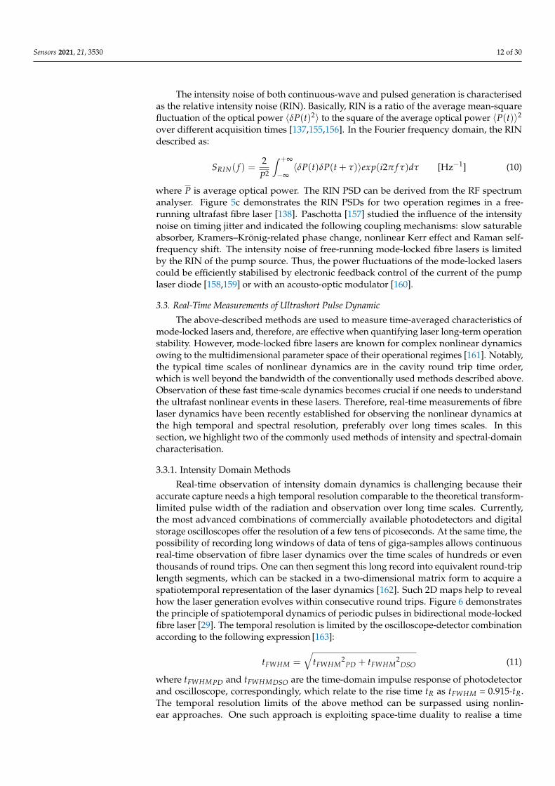
Real-time observation of intensity domain dynamics is challenging because theiraccurate capture needs a high temporal resolution comparable to the theoretical transform-limited pulse width of the radiation and observation over long time scales. Currently,the most advanced combinations of commercially available photodetectors and digitalstorage oscilloscopes offer the resolution of a few tens of picoseconds. At the same time, thepossibility of recording long windows of data of tens of giga-samples allows continuousreal-time observation of fibre laser dynamics over the time scales of hundreds or eventhousands of round trips. One can then segment this long record into equivalent round-triplength segments, which can be stacked in a two-dimensional matrix form to acquire aspatiotemporal representation of the laser dynamics [162]. Such 2D maps help to revealhow the laser generation evolves within consecutive round trips. Figure 6 demonstratesthe principle of spatiotemporal dynamics of periodic pulses in bidirectional mode-lockedfibre laser [29]. The temporal resolution is limited by the oscilloscope-detector combinationaccording to the following expression [163]:
tFWHM =√
tFWHM2
PD + tFWHM2
DSO (11)
where tFWHMPD and tFWHMDSO are the time-domain impulse response of photodetectorand oscilloscope, correspondingly, which relate to the rise time tR as tFWHM = 0.915·tR.The temporal resolution limits of the above method can be surpassed using nonlin-ear approaches. One such approach is exploiting space-time duality to realise a time
Sensors 2021, 21, 3530 13 of 30
lens [164,165], wherein a pulse can be stretched without changing its temporal profile byimprinting a quadratic phase on it.
Figure 6. Principles of real-time measurements of spatiotemporal dynamics: (a) periodic pulsesrecorded by the oscilloscope are converted to 2D evolution of selected pulse pairs separated by theround trip time; and (b) example of spatiotemporal dynamics of two pulses. Adapted from [29] (©CC BY licence).
This effect has been used for real-time full-field characterisation of soliton dynamicswith a temporal magnification of 76.4, which results in 400 fs resolution [166].
The spatiotemporal technique has been effectively used for observing the laminar-turbulent transitions [167], interaction of quasi-stationary localised structures [162] and rogueevents [168]. More recently, the method has been used for capturing the onset dynamics ofpulsed laser generation in Ti:Sapphire lasers [169] and unidirectional [170] and bidirectionalfibre lasers [171,172]. The primary advantage of this method is that it is a linear approach tocapturing fast-evolving dynamics, resulting in a simple measurement configuration.
3.3.2. Spectral Domain Methods
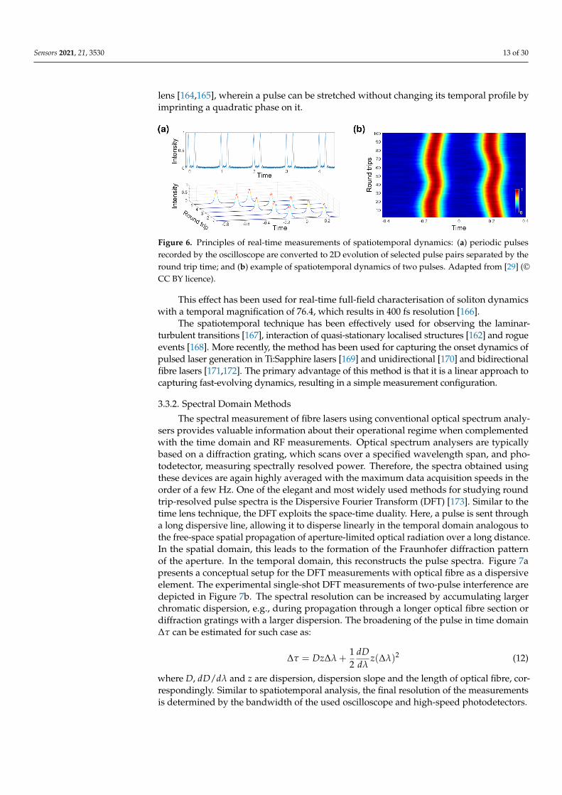
The spectral measurement of fibre lasers using conventional optical spectrum analy-sers provides valuable information about their operational regime when complementedwith the time domain and RF measurements. Optical spectrum analysers are typicallybased on a diffraction grating, which scans over a specified wavelength span, and pho-todetector, measuring spectrally resolved power. Therefore, the spectra obtained usingthese devices are again highly averaged with the maximum data acquisition speeds in theorder of a few Hz. One of the elegant and most widely used methods for studying roundtrip-resolved pulse spectra is the Dispersive Fourier Transform (DFT) [173]. Similar to thetime lens technique, the DFT exploits the space-time duality. Here, a pulse is sent througha long dispersive line, allowing it to disperse linearly in the temporal domain analogous tothe free-space spatial propagation of aperture-limited optical radiation over a long distance.In the spatial domain, this leads to the formation of the Fraunhofer diffraction patternof the aperture. In the temporal domain, this reconstructs the pulse spectra. Figure 7apresents a conceptual setup for the DFT measurements with optical fibre as a dispersiveelement. The experimental single-shot DFT measurements of two-pulse interference aredepicted in Figure 7b. The spectral resolution can be increased by accumulating largerchromatic dispersion, e.g., during propagation through a longer optical fibre section ordiffraction gratings with a larger dispersion. The broadening of the pulse in time domain∆τ can be estimated for such case as:
∆τ = Dz∆λ +12
dDdλ
z(∆λ)2 (12)
where D, dD/dλ and z are dispersion, dispersion slope and the length of optical fibre, cor-respondingly. Similar to spatiotemporal analysis, the final resolution of the measurementsis determined by the bandwidth of the used oscilloscope and high-speed photodetectors.
Sensors 2021, 21, 3530 14 of 30
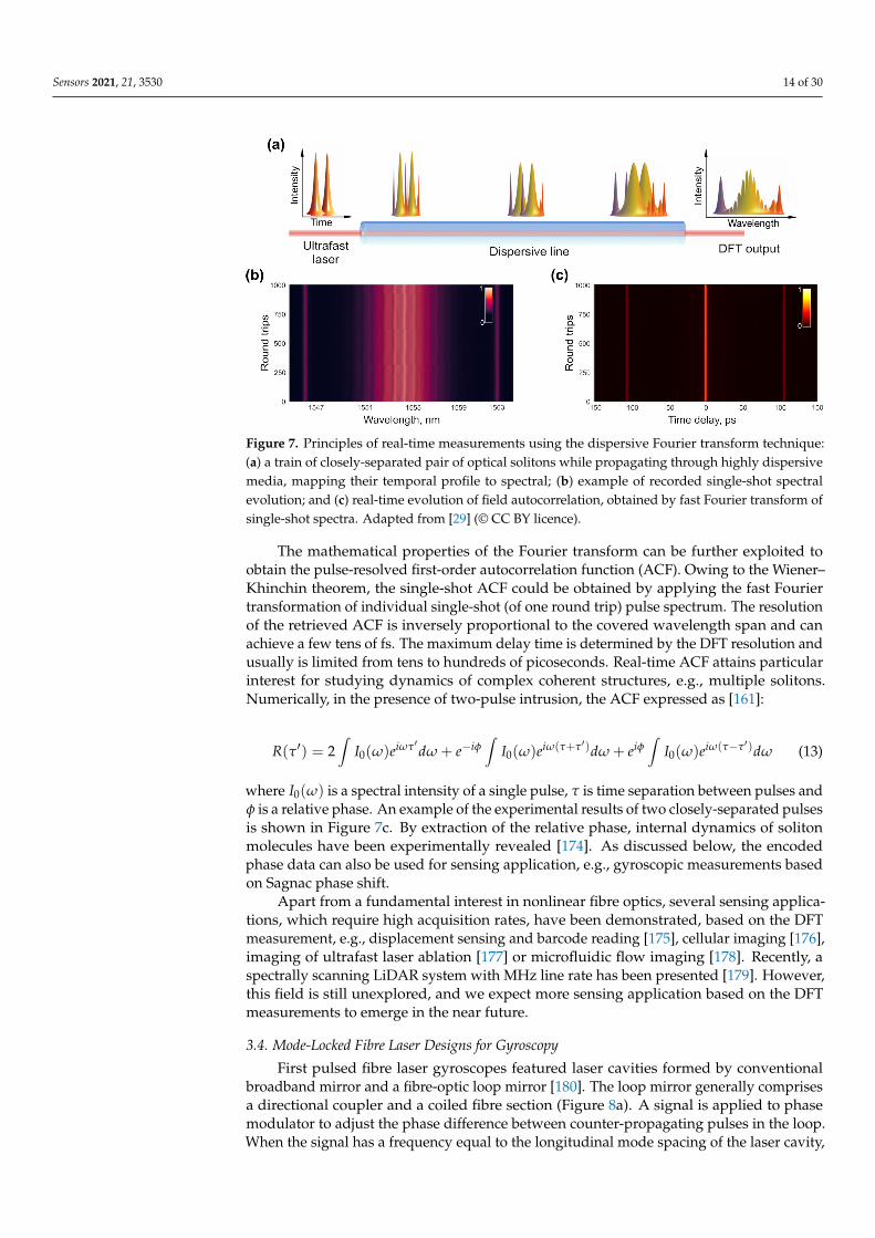
Figure 7. Principles of real-time measurements using the dispersive Fourier transform technique:(a) a train of closely-separated pair of optical solitons while propagating through highly dispersivemedia, mapping their temporal profile to spectral; (b) example of recorded single-shot spectralevolution; and (c) real-time evolution of field autocorrelation, obtained by fast Fourier transform ofsingle-shot spectra. Adapted from [29] (© CC BY licence).
The mathematical properties of the Fourier transform can be further exploited toobtain the pulse-resolved first-order autocorrelation function (ACF). Owing to the Wiener–Khinchin theorem, the single-shot ACF could be obtained by applying the fast Fouriertransformation of individual single-shot (of one round trip) pulse spectrum. The resolutionof the retrieved ACF is inversely proportional to the covered wavelength span and canachieve a few tens of fs. The maximum delay time is determined by the DFT resolution andusually is limited from tens to hundreds of picoseconds. Real-time ACF attains particularinterest for studying dynamics of complex coherent structures, e.g., multiple solitons.Numerically, in the presence of two-pulse intrusion, the ACF expressed as [161]:
R(τ′) = 2∫
I0(ω)eiωτ′dω + e−iφ∫
I0(ω)eiω(τ+τ′)dω + eiφ∫
I0(ω)eiω(τ−τ′)dω (13)
where I0(ω) is a spectral intensity of a single pulse, τ is time separation between pulses andφ is a relative phase. An example of the experimental results of two closely-separated pulsesis shown in Figure 7c. By extraction of the relative phase, internal dynamics of solitonmolecules have been experimentally revealed [174]. As discussed below, the encodedphase data can also be used for sensing application, e.g., gyroscopic measurements basedon Sagnac phase shift.
Apart from a fundamental interest in nonlinear fibre optics, several sensing applica-tions, which require high acquisition rates, have been demonstrated, based on the DFTmeasurement, e.g., displacement sensing and barcode reading [175], cellular imaging [176],imaging of ultrafast laser ablation [177] or microfluidic flow imaging [178]. Recently, aspectrally scanning LiDAR system with MHz line rate has been presented [179]. However,this field is still unexplored, and we expect more sensing application based on the DFTmeasurements to emerge in the near future.
3.4. Mode-Locked Fibre Laser Designs for Gyroscopy
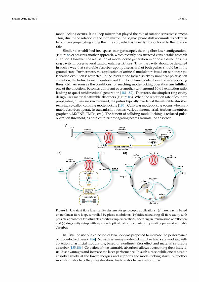
First pulsed fibre laser gyroscopes featured laser cavities formed by conventionalbroadband mirror and a fibre-optic loop mirror [180]. The loop mirror generally comprisesa directional coupler and a coiled fibre section (Figure 8a). A signal is applied to phasemodulator to adjust the phase difference between counter-propagating pulses in the loop.When the signal has a frequency equal to the longitudinal mode spacing of the laser cavity,
Sensors 2021, 21, 3530 15 of 30
mode-locking occurs. It is a loop mirror that played the role of rotation sensitive element.Thus, due to the rotation of the loop mirror, the Sagnac phase shift accumulates betweentwo pulses propagating along the fibre coil, which is linearly proportional to the rotationrate.
Similar to established free-space laser gyroscopes, the ring fibre laser configurations(Figure 8b,c) presents another approach, which recently has attracted considerable researchattention. However, the realisation of mode-locked generation in opposite directions in aring cavity imposes several fundamental restrictions. Thus, the cavity should be designedin such a way that saturable absorber upon pulse arrival of both pulses should be in theground state. Furthermore, the application of artificial modulators based on nonlinear po-larisation evolution is restricted. In the lasers mode-locked solely by nonlinear polarisationevolution, the bidirectional operation could not be obtained only above the mode-lockingthreshold. As soon as the conditions for reaching mode-locking operation are fulfilled,one of the directions becomes dominant over another with around 10-dB extinction ratio,leading to quasi-unidirectional generation [181,182]. Therefore, the simplest ring cavitydesign uses material saturable absorbers (Figure 8b). When the repetition rate of counter-propagating pulses are synchronised, the pulses typically overlap at the saturable absorber,realising so-called colliding mode-locking [183]. Colliding mode-locking occurs when sat-urable absorbers operate in transmission, such as various nanomaterials (carbon nanotubes,graphene, MXENE, TMDs, etc.). The benefit of colliding mode-locking is reduced pulseoperation threshold, as both counter-propagating beams saturate the absorber.
Figure 8. Ultrafast fibre laser cavity designs for gyroscopic applications: (a) laser cavity basedon nonlinear fibre loop, controlled by phase modulator; (b) bidirectional ring all-fibre cavity withpossible approaches for saturable absorbers implementations, operating in transmission or reflection;and (c) ring cavity setup with separated optical paths for counter-propagating pulses at saturableabsorber.
In 1984, the use of a co-action of two SAs was proposed to increase the performanceof mode-locked lasers [184]. Nowadays, many mode-locking fibre lasers are working withco-action of artificial modulators, based on nonlinear Kerr effect and material saturableabsorber [185,186]. Co-action of two saturable absorbers allows overcoming their individ-ual disadvantages and increase the laser performance. In such a case, while one saturableabsorber works at the lower energies and supports the mode-locking start-up, anothermodulator shortens the pulse duration due to a shorter relaxation time.
Sensors 2021, 21, 3530 16 of 30
Nevertheless, nonlinear interaction between counter-propagating pulses in a commonsaturable absorber can cause undesirable instability of the pulses, such as a significantphase noise. Moreover, when the counter-propagating beams share exactly the same opticalpath inside the laser cavity, it restricts the active stabilisation of the output radiation, sincestabilisation in one direction can introduce instability in the counter-propagation beam.One of the ways to overcome this bottleneck is to separate both beams in different fibreand use two different saturable absorbers. Thus, few works suggested the applicationof one or two fibre-based optical circulators to separate counter-propagating pulses andenable two mode-locking mechanisms, typically, using two SESAMs (Figure 8b) [187,188].Such scheme also allows controlling the repetition rate of counter-propagating pulsesindividually by adjusting the length of circulator ports. The obvious drawback of this setupis a higher cost due to the implementation of extra components. Some compromise can beachieved by using laser cavity geometry, as shown in Figure 8c. Here, the setup comprisestwo optical circulators and only one SESAM. However, optical circulators also restrict thelaser performance by limiting operational bandwidth and, together with optical couplersand isolators in the cavity introduce substantial losses, lowering the laser efficiency.
Finally, over the last decade, several works have demonstrated a wide variety of bidirectionallasers operation wavelength, such as at 1.55 and 2 µm in Tm-doped fibre lasers [189–191], andmode-locked pulse generation regimes by varying net cavity dispersion [192–194]. However,according to the Sagnac Equations (3) and (4), the application of shorter operation wavelengths ismore beneficial for increasing the overall sensitivity to rotation.
4. Highlights of Ultrashort Pulsed Fibre Laser Gyroscopes
The first results on gyroscopic measurements in ultrafast fibre lasers were presented in1993 [25]. The gyroscope laser cavity, similar to the one presented in Figure 8a, comprisedNeodymium-doped double-clad fibre pumped via diode array and a Sagnac interferom-eter, based on a fibre loop of 600 m length and coiled in a spool with the radius of 8 cm.The mode-locked generation was achieved via active phase modulation at the frequencycorresponding to the cavity longitudinal modes spacing. The Sagnac effect was evaluatedthrough the temporal shift. The lowest demonstrated measured rotation rate was 5 deg/s.Although no resolution was stated in this first study, this approach showed potential forincreasing acquisition rates for gyroscopic measurements beyond the kHz range. More-over, this work demonstrated that the Sagnac effect could be enhanced by managing theamplitude of the phase modulator.
Further investigations revealed that optical fibre birefringence of both the loop andthe linear part in the gyroscope affects the properties of nonreciprocal pulses and, therefore,output pulse patterns. Nevertheless, nonreciprocal pulses can be controlled by adjustingintracavity polarisation [195]. Thus, in 1997, the sensitivity and angular random walk ofmode-locked fibre laser gyroscope were advanced up to 0.06°/
√h by using a polarisation-
maintaining fibre with intracavity polariser [196].Importantly, Hong et al. [180] demonstrated real-time gyroscopic measurements of
dynamic rotation input. The performance of the time-based measurements of the Sagnaceffect was increased by implementing a lock-in amplifier, which improved the long-termstability of the bias drift down to 20°/h. We want to emphasise that, although the gyroscopewas based on the mode-locked laser, during the measurements, the Sagnac effect was notaccumulated from each round trip, which significantly limited the gyroscope performance.
Later, Braga et al. demonstrated a beat-note response to applied phase modulationof a bidirectional mode-locked fibre laser [197]. Although the beat-note response was notassociated with the Sagnac effect, the phase shift caused by a modulator is similar to theone experienced by laser beams under rotation exposure. Therefore, this result contributesdirectly to the development of the measurement methodology of ultrashort pulsed lasergyroscopes. In this work, the mode-locked generation was achieved via nonlinear polari-sation evolution combined with two amplitude modulators, used to control the crossingpoint of counter-propagating pulses inside the laser cavity. It is worth noting that the con-
Sensors 2021, 21, 3530 17 of 30
trol of the crossing point is essential for further mitigation of the lock-in effect. Moreover,amplitude modulators allowed the repetition rate control with demonstrated uncertainty of±100 Hz. Unfortunately, the implementation of intracavity phase modulators compromisesthe integrity and, therefore, benefits the all-fibre laser gyroscope configuration.
4.1. Beat-Note Measurements of the Optical Sagnac Effect
The first genuinely Sagnac frequency measurements in ultrafast fibre laser were pre-sented by Krylov et al. in 2017, almost 20 years after the first demonstration of mode-lockedlaser gyroscope [123]. The laser gyroscope setup was built in a configuration similar to theone shown in Figure 8b with an Er-doped fibre as a gain media and the net anomalous dis-persion of −0.11 ps2 [198]. The generation of almost bandwidth-limited Gaussian pulses inboth directions was enabled by the above-discussed hybrid mode-locking mechanism, com-bining nonlinear polarisation evolution and carbon nanotubes material saturable absorber.The nonlinear polarisation evolution was realised by implementing coiled polarising fibreand a pair of polarisation controllers. Generally, polarisation selective components in thecavity allow changing the intensity distribution of the field components along the twoprincipal polarisation axes and, therefore, the threshold of intracavity nonlinear effects.Thus, in this work, intracavity polarisation state control and pump power variation allowedfine-tuning of the beat-note frequency, which corresponds to zero rotation [123]. This ‘rest’beat-note (at zero rotation) refers to the beating of CEO frequencies of counter-propagatingpulses [152]. Therefore, the fine-tuning of the ‘rest’ beat-note could be attributed to the CEOfrequencies variation of both counter-propagating pulses. This feature opens a possibilityfor complete elimination of the ‘lock-in’ effect by setting the ‘rest’ beat-note sufficientlyapart. However, the sensitivity to the CEO frequency during gyroscopic measurementshas a deleterious effect on the bias stability, since the CEO frequency experience rapidfluctuations. Nonetheless, the CEO frequency could be independently measured by f − 2 finterferometer and efficiently stabilised. Moreover, as discussed above, the fluctuation ofthe CEO frequency could be minimised by constructing the laser cavity with close-to-zeronet cavity dispersion [133].
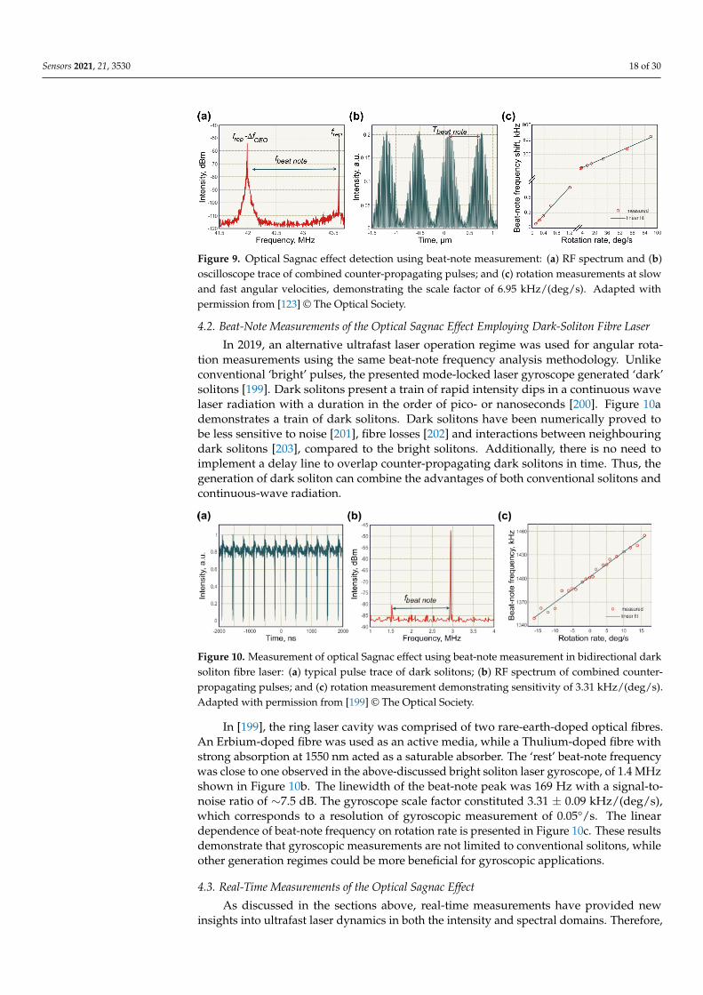
The results of gyroscopic measurements in the above-described mode-locked lasersetup is presented in Figure 9. The ring laser gyroscope presented a single fibre coil witha diameter of ∼1 m and a total area of 0.79 m2. The RF spectrum is shown in Figure 9awith the ‘rest’ beat-note frequency set to 1.61 MHz. The observed beat-note peak hada remarkably high signal-to-noise ratio of ∼30 dB. In the time domain, the pulse trainexhibited a harmonic beat-note pattern with nearly 100% modulation depth, as shown inFigure 9b. The gyroscopic effect manifested through the beat-note frequency shift in regardto the ‘rest’ frequency due to the opposite shifts of CW and CCW combs in the frequencydomain. The angular velocity ranged from 0.12 to 90 deg/s. As expected, the relationbetween the rotation rate and the beat-note frequency shift is almost linear (Figure 9c).The measurement resolution reached 0.01°/s, estimated by the bias frequency drift. Thelimitation of the sensitivity was mostly attributed to the carrier-to-envelope offset frequencystability [124].
Sensors 2021, 21, 3530 18 of 30
Figure 9. Optical Sagnac effect detection using beat-note measurement: (a) RF spectrum and (b)oscilloscope trace of combined counter-propagating pulses; and (c) rotation measurements at slowand fast angular velocities, demonstrating the scale factor of 6.95 kHz/(deg/s). Adapted withpermission from [123] © The Optical Society.
4.2. Beat-Note Measurements of the Optical Sagnac Effect Employing Dark-Soliton Fibre Laser
In 2019, an alternative ultrafast laser operation regime was used for angular rota-tion measurements using the same beat-note frequency analysis methodology. Unlikeconventional ‘bright’ pulses, the presented mode-locked laser gyroscope generated ‘dark’solitons [199]. Dark solitons present a train of rapid intensity dips in a continuous wavelaser radiation with a duration in the order of pico- or nanoseconds [200]. Figure 10ademonstrates a train of dark solitons. Dark solitons have been numerically proved tobe less sensitive to noise [201], fibre losses [202] and interactions between neighbouringdark solitons [203], compared to the bright solitons. Additionally, there is no need toimplement a delay line to overlap counter-propagating dark solitons in time. Thus, thegeneration of dark soliton can combine the advantages of both conventional solitons andcontinuous-wave radiation.
Figure 10. Measurement of optical Sagnac effect using beat-note measurement in bidirectional darksoliton fibre laser: (a) typical pulse trace of dark solitons; (b) RF spectrum of combined counter-propagating pulses; and (c) rotation measurement demonstrating sensitivity of 3.31 kHz/(deg/s).Adapted with permission from [199] © The Optical Society.
In [199], the ring laser cavity was comprised of two rare-earth-doped optical fibres.An Erbium-doped fibre was used as an active media, while a Thulium-doped fibre withstrong absorption at 1550 nm acted as a saturable absorber. The ‘rest’ beat-note frequencywas close to one observed in the above-discussed bright soliton laser gyroscope, of 1.4 MHzshown in Figure 10b. The linewidth of the beat-note peak was 169 Hz with a signal-to-noise ratio of ∼7.5 dB. The gyroscope scale factor constituted 3.31 ± 0.09 kHz/(deg/s),which corresponds to a resolution of gyroscopic measurement of 0.05°/s. The lineardependence of beat-note frequency on rotation rate is presented in Figure 10c. These resultsdemonstrate that gyroscopic measurements are not limited to conventional solitons, whileother generation regimes could be more beneficial for gyroscopic applications.
4.3. Real-Time Measurements of the Optical Sagnac Effect
As discussed in the sections above, real-time measurements have provided newinsights into ultrafast laser dynamics in both the intensity and spectral domains. Therefore,
Sensors 2021, 21, 3530 19 of 30
with the rapid development of these techniques, their applications are were significantlyextended, including gyroscopic measurements [29] capable of interrogating the opticalSagnac effect in real-time. In [29], the laser cavity was similar to one shown by Krylov et al.[123]. A distinctive feature of the laser was a possibility to control generation directivityand repetition rates of counter-propagating pulses by adjusting intracavity polarisationstate [29,204]. Thus, the bidirectional operation regime could be achieved at slightlydifferent repetition rates or synchronisation. The difference in repetition rate could beeasily controlled via polarisation controllers in a region of 50–100 Hz with a central peakat 14.78 MHz and SNR of ∼60 dB. The optical Sagnac effect in laser operating in theseregimes was evaluated using two real-time techniques, spatiotemporal intensity and DFT,correspondingly. The timing jitter, evaluated from the RF spectrum, was assessed to be∼0.87 ps, which guaranteed the stability of the real-time measurements. The gyroscopicmeasurements laser setup was coiled on a rotating platform with a diameter of 0.63 m anda total area of 0.3 m2.
Spatiotemporal Measurements
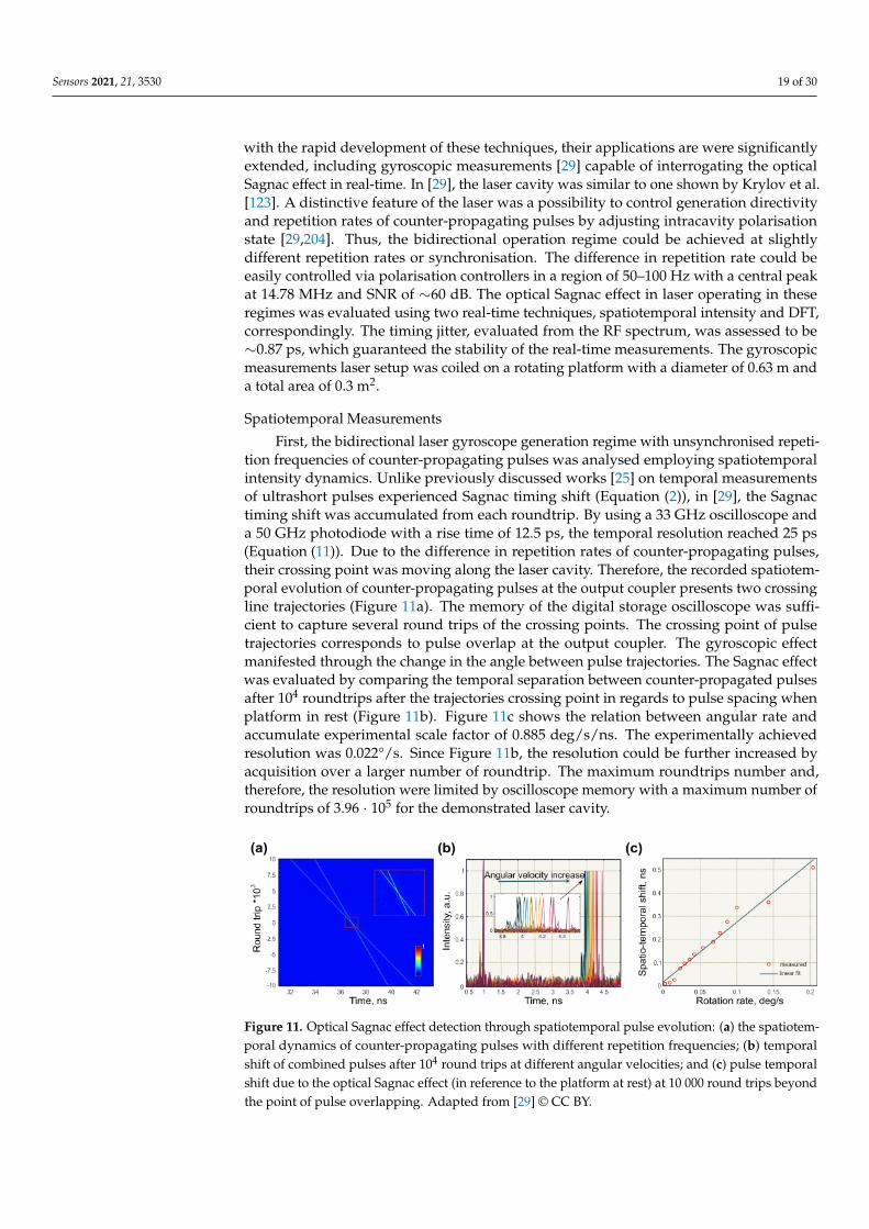
First, the bidirectional laser gyroscope generation regime with unsynchronised repeti-tion frequencies of counter-propagating pulses was analysed employing spatiotemporalintensity dynamics. Unlike previously discussed works [25] on temporal measurementsof ultrashort pulses experienced Sagnac timing shift (Equation (2)), in [29], the Sagnactiming shift was accumulated from each roundtrip. By using a 33 GHz oscilloscope anda 50 GHz photodiode with a rise time of 12.5 ps, the temporal resolution reached 25 ps(Equation (11)). Due to the difference in repetition rates of counter-propagating pulses,their crossing point was moving along the laser cavity. Therefore, the recorded spatiotem-poral evolution of counter-propagating pulses at the output coupler presents two crossingline trajectories (Figure 11a). The memory of the digital storage oscilloscope was suffi-cient to capture several round trips of the crossing points. The crossing point of pulsetrajectories corresponds to pulse overlap at the output coupler. The gyroscopic effectmanifested through the change in the angle between pulse trajectories. The Sagnac effectwas evaluated by comparing the temporal separation between counter-propagated pulsesafter 104 roundtrips after the trajectories crossing point in regards to pulse spacing whenplatform in rest (Figure 11b). Figure 11c shows the relation between angular rate andaccumulate experimental scale factor of 0.885 deg/s/ns. The experimentally achievedresolution was 0.022°/s. Since Figure 11b, the resolution could be further increased byacquisition over a larger number of roundtrip. The maximum roundtrips number and,therefore, the resolution were limited by oscilloscope memory with a maximum number ofroundtrips of 3.96 · 105 for the demonstrated laser cavity.
Figure 11. Optical Sagnac effect detection through spatiotemporal pulse evolution: (a) the spatiotem-poral dynamics of counter-propagating pulses with different repetition frequencies; (b) temporalshift of combined pulses after 104 round trips at different angular velocities; and (c) pulse temporalshift due to the optical Sagnac effect (in reference to the platform at rest) at 10 000 round trips beyondthe point of pulse overlapping. Adapted from [29] © CC BY.
Sensors 2021, 21, 3530 20 of 30
The same technique also demonstrated a high potential to be used for angular veloci-ties monitoring at MHz data acquisition rates, which are equivalent to the round trip timeof the laser. Naturally, an increase of acquisition rate arrives at the expense of the decreasedmeasurement resolution by the same factor. The suitable trade-off could be determinedaccording to the demands of the final application. Thus, for example, a moderate resolutionof the Sagnac effect of 94 mrad/s can be achieve with an acquisition rate as high as 418 kHz.These results surpass current state-of-the-art commercially available modalities by at leasttwo orders of magnitude.
Dispersive Fourier Transform Measurements
The most noticeable results of real-time angular rotation measurements were achievedby using DFT. This approach requires synchronised repetition rates in both directions inorder to record the pulse-to-pulse evolution of the interferometric pattern (Figure 12a).
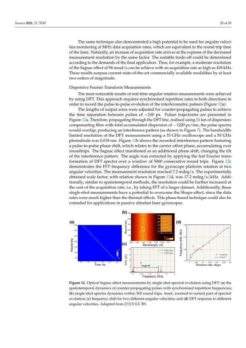
The lengths of output arms were adjusted for counter-propagating pulses to achievethe time separation between pulses of ∼100 ps. Pulses trajectories are presented inFigure 12a. Therefore, propagating through the DFT line, realised using 11 km of dispersion-compensating fibre with total accumulated dispersion of −1200 ps/nm, the pulse spectrawould overlap, producing an interference pattern (as shown in Figure 7). The bandwidth-limited resolution of the DFT measurement using a 33 GHz oscilloscope and a 50 GHzphotodiode was 0.018 nm. Figure 12b shows the recorded interference pattern featuringa pulse-to-pulse phase shift, which relates to the carrier offset phase, accumulating overroundtrips. The Sagnac effect manifested as an additional phase shift, changing the tiltof the interference pattern. The angle was extracted by applying the fast Fourier trans-formation of DFT spectra over a window of 5000 consecutive round trips. Figure 12cdemonstrates the FFT frequency difference for the gyroscope platform rotation at twoangular velocities. The measurement resolution reached 7.2 mdeg/s. The experimentallyobtained scale factor, with relation shown in Figure 12d, was 17.2 mdeg/s/kHz. Addi-tionally, similar to spatiotemporal methods, the resolution could be further increased atthe cost of the acquisition rate, i.e., by taking FFT of a larger dataset. Additionally, thesesingle-shot measurements have a potential to overcome the Shupe effect, since the datarates were much higher than the thermal effects. This phase-based technique could also beextended for applications in passive ultrafast laser gyroscopes.
Figure 12. Optical Sagnac effect measurements by single-shot spectral evolution using DFT: (a) thespatiotemporal dynamics of counter-propagating pulses with synchronised repetition frequencies;(b) single-shot spectra dynamics within 500 round trips. Inset: zoomed-in central part of spectralevolution; (c) frequency shift for two different angular velocities; and (d) DFT response to differentangular velocities. Adapted from [29] © CC BY.
Sensors 2021, 21, 3530 21 of 30
4.4. Rotation Sensing by All-Fibre Bidirectional Optical Parametric Oscillator
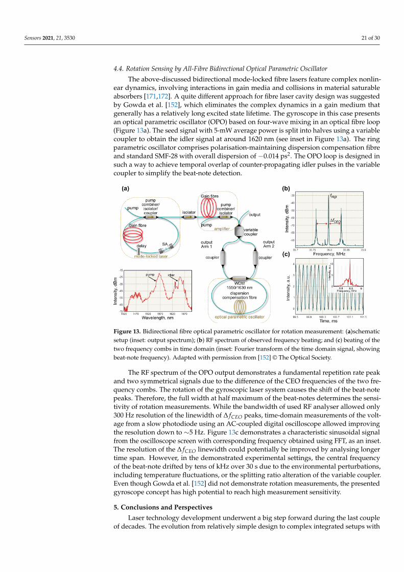
The above-discussed bidirectional mode-locked fibre lasers feature complex nonlin-ear dynamics, involving interactions in gain media and collisions in material saturableabsorbers [171,172]. A quite different approach for fibre laser cavity design was suggestedby Gowda et al. [152], which eliminates the complex dynamics in a gain medium thatgenerally has a relatively long excited state lifetime. The gyroscope in this case presentsan optical parametric oscillator (OPO) based on four-wave mixing in an optical fibre loop(Figure 13a). The seed signal with 5-mW average power is split into halves using a variablecoupler to obtain the idler signal at around 1620 nm (see inset in Figure 13a). The ringparametric oscillator comprises polarisation-maintaining dispersion compensation fibreand standard SMF-28 with overall dispersion of −0.014 ps2. The OPO loop is designed insuch a way to achieve temporal overlap of counter-propagating idler pulses in the variablecoupler to simplify the beat-note detection.
Figure 13. Bidirectional fibre optical parametric oscillator for rotation measurement: (a)schematicsetup (inset: output spectrum); (b) RF spectrum of observed frequency beating; and (c) beating of thetwo frequency combs in time domain (inset: Fourier transform of the time domain signal, showingbeat-note frequency). Adapted with permission from [152] © The Optical Society.
The RF spectrum of the OPO output demonstrates a fundamental repetition rate peakand two symmetrical signals due to the difference of the CEO frequencies of the two fre-quency combs. The rotation of the gyroscopic laser system causes the shift of the beat-notepeaks. Therefore, the full width at half maximum of the beat-notes determines the sensi-tivity of rotation measurements. While the bandwidth of used RF analyser allowed only300 Hz resolution of the linewidth of ∆ fCEO peaks, time-domain measurements of the volt-age from a slow photodiode using an AC-coupled digital oscilloscope allowed improvingthe resolution down to ∼5 Hz. Figure 13c demonstrates a characteristic sinusoidal signalfrom the oscilloscope screen with corresponding frequency obtained using FFT, as an inset.The resolution of the ∆ fCEO linewidth could potentially be improved by analysing longertime span. However, in the demonstrated experimental settings, the central frequencyof the beat-note drifted by tens of kHz over 30 s due to the environmental perturbations,including temperature fluctuations, or the splitting ratio alteration of the variable coupler.Even though Gowda et al. [152] did not demonstrate rotation measurements, the presentedgyroscope concept has high potential to reach high measurement sensitivity.
5. Conclusions and Perspectives
Laser technology development underwent a big step forward during the last coupleof decades. The evolution from relatively simple design to complex integrated setups with
Sensors 2021, 21, 3530 22 of 30
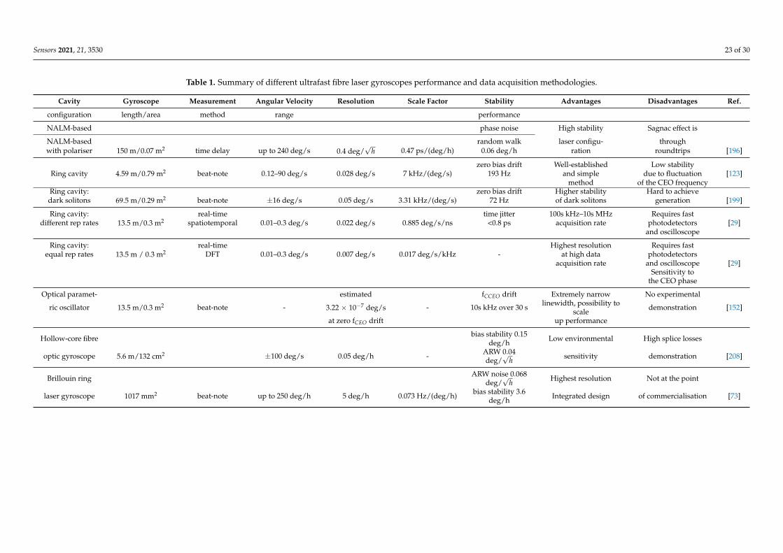
electronics, multiple feedback sensors and machine learning will undoubtedly continue inthe future, accelerated by existing and newly emerging applications. Since ultrafast lasershave been comprehensively investigated, the particular interest moves research forward todevelop new ultrafast applications with a real-time feedback. Thus, most recently, mode-locked fibre lasers have shown themselves as a perspective tool for optical Sagnac effectdetection. Even the first few works have confirmed such advantages of mode-locked fibrelaser gyroscopes over the continuous-wave operation as a much higher data frequencyand the lack of the dead-band. The rising interest in inertial guidance systems has createda demand for reliable and compact gyroscopes with a good correspondence betweentemporal resolution and the accuracy of angular velocity measurements. The bidirectionalregime of operation in mode-locked lasers can occupy a niche of gyroscopic measurementsand satisfy high requirements. Nevertheless, there is still a big room for further ultrafastlaser gyroscope modification, generation regime optimisation and enhancement of angularmeasurement resolution, which motivates both fundamental investigation and industrialdevelopment. In this vein, recently demonstrated novel methods to detect the Sagnaceffect by using spatiotemporal intensity processing and dispersive Fourier transformationprovide a new view on the gyroscopic measurements. We summarise current achievementsin the field in Table 1 underlining benefits and bottlenecks of each of realisations.
We can foresee that future research activities in the field will be focused on accelerat-ing data acquisition rates, e.g., using new real-time measurements and laser generationstabilisation. For the latter, new tailored-made hollow-core optical fibres [49] and novellaser configurations could be of particular interest, such as the application of unidirectionallaser operation [152,205], which is free from complex nonlinear ultrashort pulse interactiondynamics. Application of innovative machine learning approaches could provide stabil-isation of the generation regime by providing controllable feedback [206,207], as well asimproved resolution when applied at the data post-processing stage. Overall, ultrafastfibre laser development offers big room for engineering innovations, providing a widerange of possibilities for significant breakthroughs in rotation sensing.
Sensors 2021, 21, 3530 23 of 30
Table 1. Summary of different ultrafast fibre laser gyroscopes performance and data acquisition methodologies.
Cavity Gyroscope Measurement Angular Velocity Resolution Scale Factor Stability Advantages Disadvantages Ref.
configuration length/area method range performance
NALM-based phase noise High stability Sagnac effect is
NALM-based random walk laser configu- throughwith polariser 150 m/0.07 m2 time delay up to 240 deg/s 0.4 deg/
√h 0.47 ps/(deg/h) 0.06 deg/h ration roundtrips [196]
zero bias drift Well-established Low stabilityRing cavity 4.59 m/0.79 m2 beat-note 0.12–90 deg/s 0.028 deg/s 7 kHz/(deg/s) 193 Hz and simple due to fluctuation [123]
method of the CEO frequencyRing cavity: zero bias drift Higher stability Hard to achievedark solitons 69.5 m/0.29 m2 beat-note ±16 deg/s 0.05 deg/s 3.31 kHz/(deg/s) 72 Hz of dark solitons generation [199]
Ring cavity: real-time time jitter 100s kHz–10s MHz Requires fastdifferent rep rates 13.5 m/0.3 m2 spatiotemporal 0.01–0.3 deg/s 0.022 deg/s 0.885 deg/s/ns <0.8 ps acquisition rate photodetectors [29]
and oscilloscope
Ring cavity: real-time Highest resolution Requires fastequal rep rates 13.5 m / 0.3 m2 DFT 0.01–0.3 deg/s 0.007 deg/s 0.017 deg/s/kHz - at high data photodetectors
acquisition rate and oscilloscope [29]Sensitivity to
the CEO phase
Optical paramet- estimated fCCEO drift Extremely narrow No experimental
ric oscillator 13.5 m/0.3 m2 beat-note - 3.22 × 10⁻⁷ deg/s - 10s kHz over 30 s linewidth, possibility toscale demonstration [152]
at zero fCEO drift up performance
Hollow-core fibre bias stability 0.15deg/h Low environmental High splice losses
optic gyroscope 5.6 m/132 cm2 ±100 deg/s 0.05 deg/h - ARW 0.04deg/
√h sensitivity demonstration [208]
Brillouin ring ARW noise 0.068deg/
√h Highest resolution Not at the point
laser gyroscope 1017 mm2 beat-note up to 250 deg/h 5 deg/h 0.073 Hz/(deg/h) bias stability 3.6deg/h Integrated design of commercialisation [73]
Sensors 2021, 21, 3530 24 of 30
Funding: This research received no external funding.
Conflicts of Interest: The authors declare no conflict of interest.
References1. Scarborough, J.B. The Gyroscope; Interscience Publishers: London, UK, 1958.2. Johnson, W.R. Description of an Apparatus called the Rotascope, for exhibiting several phenomena and illustrating certain laws
of rotary motion. Am. J. Sci. Arts (1820–1879) 1832, 21, 264B.3. Passaro, V.; Cuccovillo, A.; Vaiani, L.; De Carlo, M.; Campanella, C.E. Gyroscope technology and applications: A review in the
industrial perspective. Sensors 2017, 17, 2284. [CrossRef] [PubMed]4. Macek, W.M.; Davis, D.T.M. Rotation rate sensing with traveling-wave ring lasers. Appl. Phys. Lett. 1963, 2, 67–68. [CrossRef]5. Sagnac, G. L’ether lumineux demontre par l’effet du vent relatif d’ether dans un interferometre en rotation uniforme. Comptes
Rendus 1913, 157, 708–710.6. Sagnac, G. Sur la preuve de la realite de l’ether lumineux par l’experience de l’interferographe tournant. C. R. Acad. Sci. 1913,
157, 1410–1413.7. Hadziioannou, C.; Gaebler, P.; Schreiber, U.; Wassermann, J.; Igel, H. Examining ambient noise using colocated measurements of
rotational and translational motion. J. Seismol. 2012, 16, 787–796. [CrossRef]8. Schreiber, K.U.; Klügel, T.; Wells, J.P.R.; Hurst, R.B.; Gebauer, A. How to Detect the Chandler and the Annual Wobble of the Earth
with a Large Ring Laser Gyroscope. Phys. Rev. Lett. 2011, 107, 173904. [CrossRef]9. Vali, V.; Shorthill, R.W. Fiber ring interferometer. Appl. Opt. 1976, 15, 1099–1100. [CrossRef]10. Udd, E.; Watanabe, S.F.; Cahill, R.F. Comparison of Ring Laser and Fiber-Optic Gyro Technology; McDonnell Douglas Astronautics
Company: Berkeley, MO, USA, 1985.11. Napolitano, F. Fiber-Optic Gyroscopes Key Technological Advantages. iXBlue 2010. Available online: https://www.ixblue.com/
m/publication/fog-key-advantages.pdf (accessed on 19 May 2021)12. Korkishko, Y.N.; Fedorov, V.; Prilutskii, V.; Ponomarev, V.; Morev, I.; Skripnikov, S.; Khmelevskaya, M.; Buravlev, A.; Kostritskii,
S.; Fedorov, I.; others. Strapdown inertial navigation systems based on fiber-optic gyroscopes. Gyroscopy Navig. 2014, 5, 195–204.[CrossRef]
13. Paturel, Y.; Honthaas, J.; Lefèvre, H.; Napolitano, F. One nautical mile per month FOG-based strapdown inertial navigationsystem: a dream already within reach? Gyroscopy Navig. 2014, 5, 1–8. [CrossRef]
14. Aronowitz, F.; Collins, R. Mode Coupling due to back-scattering in a He–Ne travelling-wave ring laser. Appl. Phys. Lett. 1966, 9,55–58. [CrossRef]
15. Karwacki, F.A.; Shishkov, M.; Hasan, Z.; Sanzari, M.; Cui, H.-L. Optical biasing of a ring laser gyroscope with a quantum wellmirror. In Proceedings of the IEEE 1998 Position Location and Navigation Symposium (Cat. No.98CH36153), Palm Springs, CA,USA, 20–23 April 1996; pp. 161–168.
16. Geen, J.A. Dithered Ring Laser Gyroscope with Residual Lock-in Error Compensation. US Patent 4,606,637, 19 August 1986.17. Schreiber, K.U.; Wells, J.P.R. Invited review article: Large ring lasers for rotation sensing. Rev. Sci. Instrum. 2013, 84, 041101.
[CrossRef]18. Kanamori, H.; Yokota, H.; Tanaka, G.; Watanabe, M.; Ishiguro, Y.; Yoshida, I.; Kakii, T.; Itoh, S.; Asano, Y.; Tanaka, S. Transmission
characteristics and reliability of pure-silica-core single-mode fibers. J. Light. Technol. 1986, 4, 1144–1150. [CrossRef]19. Chesnoy, J. Picosecond gyrolaser. Opt. Lett. 1989, 14, 990–992. [CrossRef]20. Dennis, M.L.; Diels, J.C.M.; Lai, M. Femtosecond ring dye laser: a potential new laser gyro. Opt. Lett. 1991, 16, 529–531.
[CrossRef]21. Gnass, D.; Ernsting, N.; Schäfer, F. Sagnac effect in the colliding-pulse-mode-locked dye ring laser. Appl. Phys. B 1991, 53, 119–120.
[CrossRef]22. Christian, W.R.; Rosker, M.J. Picosecond pulsed diode ring-laser gyroscope. Opt. Lett. 1991, 16, 1587–1589. [CrossRef]23. Arissian, L.; Diels, J.C. Intracavity phase interferometry: frequency combs sensor inside a laser cavity. Laser Photonics Rev. 2014, 8,
799–826. [CrossRef]24. Hendrie, J.; Lenzner, M.; Afkhamiardakani, H.; Diels, J.C.; Arissian, L. Impact of resonant dispersion on the sensitivity of
intracavity phase interferometry and laser gyros. Opt. Express 2016, 24, 30402–30410. [CrossRef]25. Jeon, M.; Jeong, H.; Kim, B.Y. Mode-locked fiber laser gyroscope. Opt. Lett. 1993, 18, 320–322. [CrossRef]26. Diddams, S.A. The evolving optical frequency comb. J. Opt. Soc. Am. B 2010 27, B51–B62. [CrossRef]27. Lezius, M.; Wilken, T.; Deutsch, C.; Giunta, M.; Mandel, O.; Thaller, A.; Schkolnik, V.; Schiemangk, M.; Dinkelaker, A.; Kohfeldt,
A.; et al. Space-borne frequency comb metrology. Optica 2016 3, 1381–1387. [CrossRef]28. Fermann, M.E.; Hartl, I. Ultrafast fibre lasers. Nat. Photonics 2013, 7, 868–874. [CrossRef]29. Chernysheva, M.; Sugavanam, S.; Turitsyn, S. Real-time observation of the optical Sagnac effect in ultrafast bidirectional fibre
lasers. APL Photonics 2020, 5, 016104. [CrossRef]30. Ciminelli, C.; Dell’Olio, F.; Campanella, C.E.; Armenise, M.N. Photonic technologies for angular velocity sensing. Adv. Opt.
Photonics 2010, 2, 370–404. [CrossRef]31. Tartaglia, A. General relativistic corrections to the Sagnac effect. Phys. Rev. D 1998, 58, 064009. [CrossRef]32. Ori, A.; Avron, J.E. Generalized Sagnac-Wang-Fizeau formula. Phys. Rev. A 2016, 94, 063837. [CrossRef]
Sensors 2021, 21, 3530 25 of 30
33. Kaplan, A.; Meystre, P. Enhancement of the Sagnac effect due to nonlinearly induced nonreciprocity. Opt. Lett. 1981, 6, 590–592.[CrossRef]
34. Hau, L.V.; Harris, S.E.; Dutton, Z.; Behroozi, C.H. Light speed reduction to 17 metres per second in an ultracold atomic gas.Nature 1999, 397, 594–598. [CrossRef]
35. Leonhardt, U.; Piwnicki, P. Ultrahigh sensitivity of slow-light gyroscope. Phys. Rev. A 2000, 62, 055801. [CrossRef]36. Shahriar, M.S.; Pati, G.S.; Tripathi, R.; Gopal, V.; Messall, M.; Salit, K. Ultrahigh enhancement in absolute and relative rotation
sensing using fast and slow light. Phys. Rev. A 2007, 75, 053807. [CrossRef]37. Smith, D.D.; Chang, H.; Arissian, L.; Diels, J.C. Dispersion-enhanced laser gyroscope. Phys. Rev. A 2008, 78, 053824. [CrossRef]38. Eliseev, P. Theory of nonlinear Sagnac effect. Opto-Electron. Rev. 2008, 16, 118–123. [CrossRef]39. Yum, H.N.; Salit, M.; Yablon, J.; Salit, K.; Wang, Y.; Shahriar, M.S. Superluminal ring laser for hypersensitive sensing. Opt. Express
2010, 18, 17658–17665. [CrossRef]40. Ezekiel, S.; Balsamo, S. Passive ring resonator laser gyroscope. Appl. Phys. Lett. 1977, 30, 478–480. [CrossRef]41. Sanders, G.A.; Sanders, S.J.; Strandjord, L.K.; Qiu, T.; Wu, J.; Smiciklas, M.; Mead, D.; Mosor, S.; Arrizon, A.; Ho, W.; et al. Fiber
optic gyro development at Honeywell. In Proceedings of the Fiber Optic Sensors and Applications XIII. International Society forOptics and Photonics, Baltimore, MD, USA, 17–21 April 2016; Volume 9852, p. 985207.
42. Hochuli, U.; Haldemann, P.; Li, H. Factors influencing the relative frequency stabiltiy of He–Ne laser structures. Rev. Sci. Instrum.1974, 45, 1378–1381. [CrossRef]
43. Ahearn, W.E.; Horstmann, R.E. Nondestructive Analysis for He–Ne Lasers. IBM J. Res. Dev. 1979, 23, 128–131. [CrossRef]44. Aronowitz, F. Fundamentals of the ring laser gyro. In Optical Gyros and Their Application; Loukianov, D., Rodloff, R., Sorg, H.,
Stieler, B., Eds.; NATO Research and Technology Organization: Brussels, Belgium 1999; Volume 339, ISBN 92-837-1014-245. Shupe, D.M. Thermally induced nonreciprocity in the fiber-optic interferometer. Appl. Opt. 1980, 19, 654–655. [CrossRef]46. Hotate, K.; Tabe, K. Drift of an optical fiber gyroscope caused by the Faraday effect: influence of the earth’s magnetic field. Appl.
Opt. 1986, 25, 1086–1092. [CrossRef]47. Logozinskii, V. Magnetically induced non-Faraday nonreciprocity in a fiber-optic gyroscope. J. Commun. Technol. Electron. 2006,
51, 836–840. [CrossRef]48. Ezekiel, S.; Davis, J.; Hellwarth, R. Intensity dependent nonreciprocal phase shift in a fiberoptic gyroscope. In Fiber-Optic Rotation
Sensors and Related Technologies; Springer: Berlin/Heidelberg, Germany, 1982; pp. 332–336.49. Kim, H.K.; Digonnet, M.J.F.; Kino, G.S. Air-Core Photonic-Bandgap Fiber-Optic Gyroscope. J. Light. Technol. 2006, 24, 3169.50. Schreiber, U.K.; Rowe, C.H.; Wright, D.N.; Cooper, S.J.; Stedman, G.E. Precision stabilization of the optical frequency in a large
ring laser gyroscope. Appl. Opt. 1998, 37, 8371–8381. [CrossRef] [PubMed]51. Schreiber, K.U.; Gebauer, A.; Wells, J.P.R. Long-term frequency stabilization of a 16 m2 ring laser gyroscope. Opt. Lett. 2012, 37,
1925–1927. [CrossRef]52. Wang, Z.; Yang, Y.; Lu, P.; Luo, R.; Li, Y.; Zhao, D.; Peng, C.; Li, Z. Dual-polarization interferometric fiber-optic gyroscope with an
ultra-simple configuration. Opt. Lett. 2014, 39, 2463–2466. [CrossRef] [PubMed]53. Bucaro, J.A.; Dardy, H.D.; Carome, E.F. Optical fiber acoustic sensor. Appl. Opt. 1977, 16, 1761–1762. [CrossRef]54. Tur, M.; Shafir, E.; Blotekjaer, K. Source-induced noise in optical systems driven by low-coherence sources. J. Light. Technol. 1990,
8, 183–189. [CrossRef]55. Dunn, R.W.; Shabalin, D.E.; Thirkettle, R.J.; MacDonald, G.J.; Stedman, G.E.; Schreiber, K.U. Design and initial operation of a
367-m2 rectangular ring laser. Appl. Opt. 2002, 41, 1685–1688. [CrossRef]56. Hurst, R.B.; Stedman, G.E.; Schreiber, K.U.; Thirkettle, R.J.; Graham, R.D.; Rabeendran, N.; Wells, J.P.R. Experiments with an 834
m2 ring laser interferometer. J. Appl. Phys. 2009, 105, 113115 [CrossRef]57. Schreiber, K.U.; Gebauer, A.; Wells, J.P.R. Closed-loop locking of an optical frequency comb to a large ring laser. Opt. Lett. 2013,
38, 3574–3577. [CrossRef]58. Chao, B.F.; Dehant, V.; Gross, R.S.; Ray, R.D.; Salstein, D.A.; Watkins, M.M.; Wilson, C.R. Space geodesy monitors mass transports
in global geophysical fluids. Trans. Am. Geophys. Union 2000, 81, 247–250. [CrossRef]59. Liu, K.; Zhang, F.L.; Li, Z.Y.; Feng, X.H.; Li, K.; Lu, Z.H.; Schreiber, K.U.; Luo, J.; Zhang, J. Large-scale passive laser gyroscope for
earth rotation sensing. Opt. Lett. 2019, 44, 2732–2735. [CrossRef]60. Kuritsky, M.M.; Goldstein, M.S.; Greenwood, I.; Lerman, H.; McCarthy, J.; Shanahan, T.; Silver, M.; Simpson, J. Inertial navigation.
Proc. IEEE 1983, 71, 1156–1176. [CrossRef]61. Kuznetsov, A.G.; Molchanov, A.V.; Chirkin, M.V.; Izmailov, E.A. Precise laser gyroscope for autonomous inertial navigation.
Quantum Electron. 2015, 45, 78. [CrossRef]62. El-Sheimy, N.; Youssef, A. Inertial sensors technologies for navigation applications: State of the art and future trends. Satell.
Navig. 2020, 1, 1–21. [CrossRef]63. Beghi, A.; Belfi, J.; Beverini, N.; Bouhadef, B.; Cuccato, D.; Virgilio, A.D.; Ortolan, A. Compensation of the laser parameter
fluctuations in large ring-laser gyros: A Kalman filter approach. Appl. Opt. 2012, 51, 7518–7528. [CrossRef] [PubMed]64. Bernauer, F.; Wassermann, J.; Guattari, F.; Frenois, A.; Bigueur, A.; Gaillot, A.; de Toldi, E.; Ponceau, D.; Schreiber, U.; Igel, H. Full
characterization of a 3C broadband rotational seismometer. Seismol. Res. Lett. 2018, 89, 620–629. [CrossRef]65. Li, H.; Lin, Y.; Liu, L.; Ma, H.; Jin, Z. Signal processing improvement of passive resonant fiber optic gyroscope using a reciprocal
modulation-demodulation technique. Opt. Express 2020, 28, 18103–18111. [CrossRef] [PubMed]
Sensors 2021, 21, 3530 26 of 30
66. Ravaille, A.; Feugnet, G.; Debord, B.; Gérôme, F.; Benabid, F.; Bretenaker, F. Rotation measurements using a resonant fiber opticgyroscope based on Kagome fiber. Appl. Opt. 2019, 58, 2198–2204. [CrossRef]
67. Zheng, Y.; Xu, H.; Song, J.; Li, L.; Zhang, C. Excess Relative-Intensity-Noise Reduction in a Fiber Optic Gyroscope Using aFaraday Rotator Mirror. J. Light. Technol. 2020, 38, 6939–6947. [CrossRef]
68. Zhu, W.; Fokoua, E.N.; Chen, Y.; Bradley, T.; Petrovich, M.; Poletti, F.; Zhao, M.; Richardson, D.; Slavík, R. Temperature insensitivefiber interferometry. Opt. Lett. 2019, 44, 2768–2770. [CrossRef]
69. Mutugala, U.S.; Fokoua, E.N.; Chen, Y.; Bradley, T.; Sandoghchi, S.R.; Jasion, G.; Curtis, R.; Petrovich, M.; Poletti, F.; Richardson,D.; et al. Hollow-core fibres for temperature-insensitive fibre optics and its demonstration in an Optoelectronic oscillator. Sci.Rep. 2018, 8, 18015. [CrossRef] [PubMed]
70. Dell’Olio, F.; Tatoli, T.; Ciminelli, C.; Armenise, M. Recent advances in miniaturized optical gyroscopes. J. Eur. Opt. Soc. RapidPubl. 2014, 9, 14013. [CrossRef]
71. Mahmoud, M.; Mahmoud, A.; Cai, L.; Khan, M.; Mukherjee, T.; Bain, J.; Piazza, G. Novel on chip rotation detection based on theacousto-optic effect in surface acoustic wave gyroscopes. Opt. Express 2018, 26, 25060–25075. [CrossRef] [PubMed]
72. Li, J.; Suh, M.G.; Vahala, K. Microresonator Brillouin gyroscope. Optica 2017, 4, 346–348. [CrossRef]73. Lai, Y.H.; Suh, M.G.; Lu, Y.K.; Shen, B.; Yang, Q.F.; Wang, H.; Li, J.; Lee, S.H.; Yang, K.Y.; Vahala, K. Earth rotation measured by a
chip-scale ring laser gyroscope. Nat. Photonic 2020, 14, 345–349. [CrossRef]74. Qin, T.; Yang, J.; Zhang, F.; Chen, Y.; Shen, D.; Liu, W.; Chen, L.; Jiang, X.; Chen, X.; Wan, W. Fast-and slow-light-enhanced light
drag in a moving microcavity. Commun. Phys. 2020, 3, 1–8. [CrossRef]75. Ren, J.; Hodaei, H.; Harari, G.; Hassan, A.U.; Chow, W.; Soltani, M.; Christodoulides, D.; Khajavikhan, M. Ultrasensitive
micro-scale parity-time-symmetric ring laser gyroscope. Opt. Lett. 2017, 42, 1556–1559. [CrossRef]76. Grant, M.J.; Digonnet, M.J.F. Enhanced rotation sensing and exceptional points in a parity–time-symmetric coupled-ring
gyroscope. Opt. Lett. 2020, 45, 6538–6541. [CrossRef]77. Hargrove, L.; Fork, R.L.; Pollack, M. Locking of He–Ne laser modes induced by synchronous intracavity modulation. Appl. Phys.
Lett. 1964, 5, 4–5. [CrossRef]78. Morgner, U.; Kärtner, F.X.; Cho, S.H.; Chen, Y.; Haus, H.A.; Fujimoto, J.G.; Ippen, E.P.; Scheuer, V.; Angelow, G.; Tschudi, T.
Sub-two-cycle pulses from a Kerr-lens mode-locked Ti:sapphire laser. Opt. Lett. 1999, 24, 411–413. [CrossRef] [PubMed]79. Sotor, J.; Sobon, G. 24 fs and 3 nJ pulse generation from a simple, all polarization maintaining Er-doped fiber laser. Laser Phys.
Lett. 2016, 13, 125102. [CrossRef]80. Danson, C.N.; Haefner, C.; Bromage, J.; Butcher, T.; Chanteloup, J.C.F.; Chowdhury, E.A.; Galvanauskas, A.; Gizzi, L.A.; Hein, J.;
Hillier, D.I.; et al. Petawatt and exawatt class lasers worldwide. High Power Laser Sci. Eng. 2019, 7, e54. [CrossRef]81. Brabec, T.; Krausz, F. Intense few-cycle laser fields: Frontiers of nonlinear optics. Rev. Mod. Phys. 2000, 72, 545. [CrossRef]82. Di Piazza, A.; Müller, C.; Hatsagortsyan, K.; Keitel, C.H. Extremely high-intensity laser interactions with fundamental quantum
systems. Rev. Mod. Phys. 2012, 84, 1177. [CrossRef]83. Zhang, P.; Bulanov, S.; Seipt, D.; Arefiev, A.; Thomas, A. Relativistic plasma physics in supercritical fields. Phys. Plasmas 2020, 27,
050601. [CrossRef]84. Coddington, I.; Newbury, N.; Swann, W. Dual-comb spectroscopy. Optica 2016, 3, 414–426. [CrossRef]85. Udem, T.; Holzwarth, R.; Hänsch, T.W. Optical frequency metrology. Nature 2002, 416, 233. [CrossRef]86. Gaal, P.; Raschke, M.B.; Reimann, K.; Woerner, M. Measuring optical frequencies in the 0–40 THz range with non-synchronized
electro–optic sampling. Nat. Photonics 2007. [CrossRef]87. Leopardi, H.; Davila-Rodriguez, J.; Quinlan, F.; Olson, J.; Sherman, J.A.; Diddams, S.A.; Fortier, T.M. Single-branch Er:fiber
frequency comb for precision optical metrology with 10−18 fractional instability. Optica 2017, 4, 879–885. [CrossRef]88. Ippen, E.P. Principles of passive mode locking. Appl. Phys. B 1994, 58, 159–170. [CrossRef]89. Haus, H.A. Mode-locking of lasers. IEEE J. Sel. Top. Quantum Electron. 2000, 6, 1173–1185. [CrossRef]90. Kryukov, P.; Letokhov, V. Fluctuation mechanism of ultrashort pulse generation by laser with saturable absorber. IEEE J. Quantum
Electron. 1972, 8, 766–782. [CrossRef]91. Glenn, W. The fluctuation model of a passively mode-locked laser. IEEE J. Quantum Electron. 1975, 11, 8–17. [CrossRef]92. Agrawal, G.P. Nonlinear fiber optics. In Nonlinear Science at the Dawn of the 21st Century; Springer: Berlin/Heidelberg, Germany,
2000; pp. 195–211.93. Fermann, M.E.; Galvanauskas, A.; Sucha, G. Ultrafast Lasers: Technology and Applications; CRC Press: Boca Raton, FL, USA, 2002;
Volume 80.94. Lariontsev, E.G.; Serkin, V.N. Possibility of using self-focusing for increasing contrast and narrowing of ultrashort light pulses.
Sov. J. Quantum Electron. 1975, 5, 796. [CrossRef]95. Fermann, M.; Andrejco, M.; Silberberg, Y.; Stock, M. Passive mode locking by using nonlinear polarization evolution in a
polarization-maintaining erbium-doped fiber. Opt. Lett. 1993, 18, 894–896. [CrossRef]96. Doran, N.; Wood, D. Nonlinear-optical loop mirror. Opt. Lett. 1988, 13, 56–58. [CrossRef]97. Fermann, M.E.; Haberl, F.; Hofer, M.; Hochreiter, H. Nonlinear amplifying loop mirror. Opt. Lett. 1990, 15, 752–754. [CrossRef]98. Mocker, H.W.; Collins, R. Mode competition and self-locking effects in a Q-switched ruby laser. Appl. Phys. Lett. 1965, 7, 270–273.
[CrossRef]99. Glenn, W.; Brienza, M.; DeMaria, A. Mode locking of an organic dye laser. Appl. Phys. Lett. 1968, 12, 54–56. [CrossRef]
Sensors 2021, 21, 3530 27 of 30
100. Keller, U.; Weingarten, K.J.; Kartner, F.X.; Kopf, D.; Braun, B.; Jung, I.D.; Fluck, R.; Honninger, C.; Matuschek, N.; Aus der Au, J.Semiconductor saturable absorber mirrors (SESAM’s) for femtosecond to nanosecond pulse generation in solid-state lasers. IEEEJ. Sel. Top. Quantum Electron. 1996, 2, 435–453. [CrossRef]
101. Okhotnikov, O.; Grudinin, A.; Pessa, M. Ultra-fast fibre laser systems based on SESAM technology: new horizons and applications.New J. Phys. 2004, 6, 177. [CrossRef]
102. Keller, U. Ultrafast solid-state lasers. Prog. Opt. 2004, 46, 1–116.103. Tilma, B.W.; Mangold, M.; Zaugg, C.A.; Link, S.M.; Waldburger, D.; Klenner, A.; Mayer, A.S.; Gini, E.; Golling, M.; Keller, U.
Recent advances in ultrafast semiconductor disk lasers. Light Sci. Appl. 2015, 4, e310. [CrossRef]104. Gaponenko, M.; Metz, P.W.; Härkönen, A.; Heuer, A.; Leinonen, T.; Guina, M.; Südmeyer, T.; Huber, G.; Kränkel, C. SESAM
mode-locked red praseodymium laser. Opt. Lett. 2014, 39, 6939–6941. [CrossRef] [PubMed]105. Hasan, T.; Sun, Z.; Wang, F.; Bonaccorso, F.; Tan, P.H.; Rozhin, A.G.; Ferrari, A.C. Nanotube–polymer composites for ultrafast
photonics. Adv. Mater. 2009, 21, 3874–3899. [CrossRef]106. Zhang, H.; Tang, D.; Zhao, L.; Bao, Q.; Loh, K. Large energy mode locking of an erbium-doped fiber laser with atomic layer
graphene. Opt. Express 2009, 17, 17630–17635. [CrossRef]107. Martinez, A.; Sun, Z. Nanotube and graphene saturable absorbers for fibre lasers. Nat. Photonics 2013, 7, 842–845. [CrossRef]108. Zhao, G.; Han, S.; Wang, A.; Wu, Y.; Zhao, M.; Wang, Z.; Hao, X. “Chemical Weathering” Exfoliation of Atom-Thick Transition
Metal Dichalcogenides and Their Ultrafast Saturable Absorption Properties. Adv. Funct. Mater. 2015, 25, 5292–5299. [CrossRef]109. Woodward, R.I.; Kelleher, E.J. 2D saturable absorbers for fibre lasers. Appl. Sci. 2015, 5, 1440–1456. [CrossRef]110. Jiang, X.; Liu, S.; Liang, W.; Luo, S.; He, Z.; Ge, Y.; Wang, H.; Cao, R.; Zhang, F.; Wen, Q.; others. Broadband nonlinear photonics
in few-layer MXene Ti3C2Tx (T= F, O, or OH). Laser Photonics Rev. 2018, 12, 1700229. [CrossRef]111. Jhon, Y.I.; Koo, J.; Anasori, B.; Seo, M.; Lee, J.H.; Gogotsi, Y.; Jhon, Y.M. Metallic MXene saturable absorber for femtosecond
mode-locked lasers. Adv. Mater. 2017, 29, 1702496. [CrossRef] [PubMed]112. Chen, Y.; Jiang, G.; Chen, S.; Guo, Z.; Yu, X.; Zhao, C.; Zhang, H.; Bao, Q.; Wen, S.; Tang, D.; et al. Mechanically exfoliated
black phosphorus as a new saturable absorber for both Q-switching and mode-locking laser operation. Optics Express 2015, 23,12823–12833. [CrossRef]
113. Qin, Z.; Xie, G.; Zhao, C.; Wen, S.; Yuan, P.; Qian, L. Mid-infrared mode-locked pulse generation with multilayer black phosphorusas saturable absorber. Opt. Lett. 2016, 41, 56–59. [CrossRef] [PubMed]
114. Wang, J.; Coillet, A.; Demichel, O.; Wang, Z.; Rego, D.; Bouhelier, A.; Grelu, P.; Cluzel, B. Saturable plasmonic metasurfaces forlaser mode locking. Light Sci. Appl. 2020, 9, 1–9. [CrossRef] [PubMed]
115. Kashiwagi, K.; Yamashita, S. Deposition of carbon nanotubes around microfiber via evanascent light. Optics Express 2009, 17,18364–18370. [CrossRef] [PubMed]
116. Hu, G.; Albrow-Owen, T.; Jin, X.; Ali, A.; Hu, Y.; Howe, R.C.; Shehzad, K.; Yang, Z.; Zhu, X.; Woodward, R.I.; et al. Blackphosphorus ink formulation for inkjet printing of optoelectronics and photonics. Nat. Commun. 2017, 8, 1–10. [CrossRef][PubMed]
117. Mou, C.; Rozhin, A.G.; Arif, R.; Zhou, K.; Turitsyn, S. Polarization insensitive in-fiber mode-locker based on carbon nanotubewith N-methyl-2-pryrrolidone solvent filled fiber microchamber. Appl. Phys. Lett. 2012, 100, 101110. [CrossRef]
118. Mollenauer, L.F.; Stolen, R.H.; Gordon, J.P. Experimental observation of picosecond pulse narrowing and solitons in optical fibers.Phys. Rev. Lett. 1980, 45, 1095. [CrossRef]
119. K. Turitsyn, S.; G.Bale, B.; P. Fedoruk, M. Ispersion-managed solitons in fibre systems and lasers. Phys. Rep. 2012, 521, 135–203.[CrossRef]
120. Chong, A.; Buckley, J.; Renninger, W.; Wise, F. All-normal-dispersion femtosecond fiber laser. Opt. Express 2006, emph14,10095–10100. [CrossRef] [PubMed]
121. Oktem, B.; Ülgüdür, C.; Ilday, F.Ö. Soliton–similariton fibre laser. Nat. Photonics 2010, 4, 307–311. [CrossRef]122. Kivshar, Y.S.; Luther-Davies, B. Dark optical solitons: physics and applications. Phys. Rep. 1998, 298, 81–197. [CrossRef]123. Krylov, A.A.; Chernykh, D.S.; Obraztsova, E.D. Gyroscopic effect detection in the colliding-pulse hybridly mode-locked
erbium-doped all-fiber ring soliton laser. Opt. Lett. 2017, 42, 2439–2442. [CrossRef]124. Newbury, N.R.; Swann, W.C. Low-noise fiber-laser frequency combs. JOSA B 2007, 24, 1756–1770. [CrossRef]125. Haus, H.; Ippen, E. Group velocity of solitons. Opt. Lett. 2001, 26, 1654–1656. [CrossRef] [PubMed]126. Sala, K.; Kenney-Wallace, G.; Hall, G. CW autocorrelation measurements of picosecond laser pulses. IEEE J. Quantum Electron.
1980, 16, 990–996. [CrossRef]127. Stolen, R.; Lin, C. Self-phase-modulation in silica optical fibers. Phys. Rev. A 1978, 17, 1448. [CrossRef]128. Kane, D.J.; Trebino, R. Characterization of arbitrary femtosecond pulses using frequency-resolved optical gating. IEEE J. Quantum
Electron.s 1993, 29, 571–579. [CrossRef]129. Akturk, S.; Kimmel, M.; O’Shea, P.; Trebino, R. Measuring pulse-front tilt in ultrashort pulses using GRENOUILLE. Opt. Express
2003, 11, 491–501. [CrossRef] [PubMed]130. Iaconis, C.; Walmsley, I.A. Spectral phase interferometry for direct electric-field reconstruction of ultrashort optical pulses. Opt.
Lett. 1998, 23, 792–794. [CrossRef]131. Trebino, R. Frequency-Resolved Optical Gating: The Measurement of Ultrashort Laser Pulses: The Measurement of Ultrashort Laser Pulses;
Springer Science & Business Media: Berlin/Heidelberg, Germany, 2000.
Sensors 2021, 21, 3530 28 of 30
132. Budunoglu, I.L.; Ülgüdür, C.; Oktem, B.; Ilday, F.Ö. Intensity noise of mode-locked fiber lasers. Optics Lett. 2009, 34, 2516–2518.[CrossRef]
133. Kim, J.; Song, Y. Ultralow-noise mode-locked fiber lasers and frequency combs: principles, status, and applications. Adv. Opt.Photonics 2016, 8, 465–540. [CrossRef]
134. Paschotta, R.; Schlatter, A.; Zeller, S.; Telle, H.; Keller, U. Optical phase noise and carrier-envelope offset noise of mode-lockedlasers. Appl. Phys. B 2006, 82, 265–273. [CrossRef]
135. Jones, D.J.; Diddams, S.A.; Ranka, J.K.; Stentz, A.; Windeler, R.S.; Hall, J.L.; Cundiff, S.T. Carrier-envelope phase control offemtosecond mode-locked lasers and direct optical frequency synthesis. Science 2000, 288, 635–639. [CrossRef] [PubMed]
136. Roudnev, V.; Esry, B. General theory of carrier-envelope phase effects. Phys. Rev. Lett. 2007, 99, 220406. [CrossRef]137. Von der Linde, D. Characterization of the noise in continuously operating mode-locked lasers. Appl. Phys. B 1986, 39, 201–217.
[CrossRef]138. Dvoretskiy, D.A.; Sazonkin, S.G.; Orekhov, I.O.; Kudelin, I.S.; Pnev, A.B.; Karasik, V.E.; Krylov, A.A.; Denisov, L.K. High-energy
ultrashort-pulse all-fiber erbium-doped ring laser with improved free-running performance. JOSA B 2018, 35, 2010–2014.[CrossRef]
139. Haus, H.A.; Mecozzi, A. Noise of mode-locked lasers. IEEE J. Quantum Electron. 1993, 29, 983–996. [CrossRef]140. Hou, D.; Lee, C.C.; Yang, Z.; Schibli, T. Timing jitter characterization of mode-locked lasers with< 1 zs/
√Hz resolution using a
simple optical heterodyne technique. Opt. Lett. 2015, 40, 2985–2988.141. Jung, K.; Kim, J. Characterization of timing jitter spectra in free-running mode-locked lasers with 340 dB dynamic range over 10
decades of Fourier frequency. Opt. Lett. 2015, 40, 316–319. [PubMed]142. Kwon, D.; Jeon, I.; Lee, W.K.; Heo, M.S.; Kim, J. Generation of multiple ultrastable optical frequency combs from an all-fiber
photonic platform. Sci. Adv. 2020, 6, eaax4457. [CrossRef] [PubMed]143. Xie, X.; Bouchand, R.; Nicolodi, D.; Giunta, M.; Hänsel, W.; Lezius, M.; Joshi, A.; Datta, S.; Alexandre, C.; Lours, M.; et al. Photonic
microwave signals with zeptosecond-level absolute timing noise. Nat. Photonics 2017, 11, 44–47. [CrossRef]144. Kwon, D.; Kim, J. All-fiber interferometer-based repetition-rate stabilization of mode-locked lasers to 10−14-level frequency
instability and 1-fs-level jitter over 1 s. Opt. Lett. 2017, 42, 5186–5189. [CrossRef] [PubMed]145. Washburn, B.R.; Swann, W.C.; Newbury, N.R. Response dynamics of the frequency comb output from a femtosecond fiber laser.
Opt. Express 2005, 13, 10622–10633. [CrossRef] [PubMed]146. Nugent-Glandorf, L.; Johnson, T.A.; Kobayashi, Y.; Diddams, S.A. Impact of dispersion on amplitude and frequency noise in a
Yb-fiber laser comb. Opt. Lett. 2011, 36, 1578–1580. [CrossRef]147. Wahlstrand, J.K.; Willits, J.T.; Menyuk, C.R.; Cundiff, S.T. The quantum-limited comb lineshape of a mode-locked laser:
Fundamental limits on frequency uncertainty. Opt. Express 2008, 16, 18624–18630. [CrossRef]148. Xu, L.; Spielmann, C.; Poppe, A.; Brabec, T.; Krausz, F.; Hänsch, T.W. Route to phase control of ultrashort light pulses. Opt. Lett.
1996, 21, 2008–2010. [CrossRef]149. Udem, T.; Reichert, J.; Holzwarth, R.; Hänsch, T.W. Accurate measurement of large optical frequency differences with a
mode-locked laser. Opt. Lett. 1999, 24, 881–883. [CrossRef]150. Hartl, I.; Imeshev, G.; Fermann, M.E.; Langrock, C.; Fejer, M.M. Integrated self-referenced frequency-comb laser based on a
combination of fiber and waveguide technology. Opt. Express 2005, 13, 6490–6496. [CrossRef]151. Wittmann, T.; Horvath, B.; Helml, W.; Schätzel, M.G.; Gu, X.; Cavalieri, A.L.; Paulus, G.; Kienberger, R. Single-shot carrier–
envelope phase measurement of few-cycle laser pulses. Nat. Phys. 2009, 5, 357–362. [CrossRef]152. Gowda, R.; Nguyen, N.; Diels, J.C.; Norwood, R.A.; Peyghambarian, N.; Kieu, K. All-fiber bidirectional optical parametric
oscillator for precision sensing. Opt. Lett. 2015, 40, 2033–2036. [CrossRef] [PubMed]153. Iwakuni, K.; Inaba, H.; Nakajima, Y.; Kobayashi, T.; Hosaka, K.; Onae, A.; Hong, F.L. Narrow linewidth comb realized with a
mode-locked fiber laser using an intra-cavity waveguide electro-optic modulator for high-speed control. Opt. Express 2012, 20,13769–13776. [CrossRef] [PubMed]
154. Benko, C.; Ruehl, A.; Martin, M.; Eikema, K.; Fermann, M.; Hartl, I.; Ye, J. Full phase stabilization of a Yb: fiber femtosecondfrequency comb via high-bandwidth transducers. Opt. Lett. 2012, 37, 2196–2198. [CrossRef] [PubMed]
155. Paschotta, R. Noise in Laser Technology: Part 1: Intensity and Phase Noise. Opt. Photonik 2009, 4, 48–50. [CrossRef]156. McCumber, D.E. Intensity Fluctuations in the Output of cw Laser Oscillators. I. Phys. Rev. 1966, 141, 306–322. [CrossRef]157. Paschotta, R. Noise of mode-locked lasers (Part II): timing jitter and other fluctuations. Appl. Phys. B 2004, 79, 163–173. [CrossRef]158. Kane, T.J. Intensity noise in diode-pumped single-frequency Nd: YAG lasers and its control by electronic feedback. IEEE Photonics
Technol. Lett. 1990, 2, 244–245. [CrossRef]159. Cranch, G. Frequency noise reduction in erbium-doped fiber distributed-feedback lasers by electronic feedback. Opt. Lett. 2002,
27, 1114–1116. [CrossRef]160. Holman, K.W.; Jones, R.J.; Marian, A.; Cundiff, S.T.; Ye, J. Detailed studies and control of intensity-related dynamics of
femtosecond frequency combs from mode-locked Ti: sapphire lasers. IEEE J. Sel. Top. Quantum Electron. 2003, 9, 1018–1024.[CrossRef]
161. Wang, Z.; Nithyanandan, K.; Coillet, A.; Tchofo-Dinda, P.; Grelu, P. Optical soliton molecular complexes in a passively mode-locked fibre laser. Nat. Commun. 2019, 10, 830. [CrossRef] [PubMed]
Sensors 2021, 21, 3530 29 of 30
162. Churkin, D.; Sugavanam, S.; Tarasov, N.; Khorev, S.; Smirnov, S.; Kobtsev, S.; Turitsyn, S. Stochasticity, periodicity and localizedlight structures in partially mode-locked fibre lasers. Nat. Commun. 2015, 6, 7004. [CrossRef] [PubMed]
163. Sugavanam, S.; Tarasov, N.; Churkin, D.V. Real-time intensity domain characterization of fibre lasers using spatio-temporaldynamics. Appl. Sci. 2016, 6, 65. [CrossRef]
164. Kolner, B.H. Space-time duality and the theory of temporal imaging. IEEE J. Quantum Electron. 1994, 30, 1951–1963. [CrossRef]165. Salem, R.; Foster, M.A.; Turner, A.C.; Geraghty, D.F.; Lipson, M.; Gaeta, A.L. Optical time lens based on four-wave mixing on a
silicon chip. Opt. Lett. 2008, 33, 1047–1049. [CrossRef]166. Ryczkowski, P.; Närhi, M.; Billet, C.; Merolla, J.M.; Genty, G.; Dudley, J.M. Real-time full-field characterization of transient
dissipative soliton dynamics in a mode-locked laser. Nat. Photonics 2018, 12, 221. [CrossRef]167. Turitsyna, E.; Smirnov, S.; Sugavanam, S.; Tarasov, N.; Shu, X.; Babin, S.; Podivilov, E.; Churkin, D.; Falkovich, G.; Turitsyn, S. The
laminar–turbulent transition in a fibre laser. Nat. Photonics 2013, 7, 783. [CrossRef]168. Birkholz, S.; Nibbering, E.T.J.; Brée, C.; Skupin, S.; Demircan, A.; Genty, G.; Steinmeyer, G. Spatiotemporal Rogue Events in
Optical Multiple Filamentation. Phys. Rev. Lett. 2013, 111, 243903. [CrossRef]169. Herink, G.; Jalali, B.; Ropers, C.; Solli, D. Resolving the build-up of femtosecond mode-locking with single-shot spectroscopy at
90 MHz frame rate. Nat. Photonics 2016, 10, 321. [CrossRef]170. Peng, J.; Sorokina, M.; Sugavanam, S.; Tarasov, N.; Churkin, D.V.; Turitsyn, S.K.; Zeng, H. Real-time observation of dissipative
soliton formation in nonlinear polarization rotation mode-locked fibre lasers. Commun. Phys. 2018, 1, 20. [CrossRef]171. Kudelin, I.; Sugavanam, S.; Chernysheva, M. Pulse-onset dynamics in a bidirectional mode-locked fibre laser via instabilities.
Commun. Phys. 2020, 3, 1–10. [CrossRef]172. Kudelin, I.; Sugavanam, S.; Chernysheva, M. Build-up dynamics in bidirectional soliton fiber lasers. Photonics Res. 2020, 8,
776–780. [CrossRef]173. Goda, K.; Jalali, B. Dispersive Fourier transformation for fast continuous single-shot measurements. Nat. Photonics 2013, 7, 102.
[CrossRef]174. Herink, G.; Kurtz, F.; Jalali, B.; Solli, D.; Ropers, C. Real-time spectral interferometry probes the internal dynamics of femtosecond
soliton molecules. Science 2017, 356, 50–54. [CrossRef] [PubMed]175. Goda, K.; Tsia, K.K.; Jalali, B. Amplified dispersive Fourier-transform imaging for ultrafast displacement sensing and barcode
reading. Appl. Phys. Lett. 2008, 93, 131109. [CrossRef]176. Wong, T.T.; Lau, A.K.; Wong, K.K.; Tsia, K.K. Optical time-stretch confocal microscopy at 1 µm. Opt. Lett. 2012, 37, 3330–3332.
[CrossRef]177. Goda, K.; Tsia, K.; Jalali, B. Serial time-encoded amplified imaging for real-time observation of fast dynamic phenomena. Nature
2009, 458, 1145–1149. [CrossRef]178. Goda, K.; Ayazi, A.; Gossett, D.R.; Sadasivam, J.; Lonappan, C.K.; Sollier, E.; Fard, A.M.; Hur, S.C.; Adam, J.; Murray, C.; et al.
High-throughput single-microparticle imaging flow analyzer. Proc. Natl. Acad. Sci. USA 2012, 109, 11630–11635. [CrossRef]179. Jiang, Y.; Karpf, S.; Jalali, B. Time-stretch LiDAR as a spectrally scanned time-of-flight ranging camera. Nat. Photonics 2020, 14,
14–18. [CrossRef]180. Hong, J.B.; Yeo, Y.B.; Lee, B.W.; Kim, B.Y. Phase sensitive detection for mode-locked fiber laser gyroscope. IEEE Photonics Technol.
Lett. 1999, 11, 1030–1032. [CrossRef]181. Zhao, L.; Tang, D.; Cheng, T.; Lu, C. Self-started unidirectional operation of a fibre ring soliton laser without an isolator. J. Opt. A
Pure Appl. Opt. 2007, 9, 477. [CrossRef]182. Li, D.; Shen, D.; Li, L.; Chen, H.; Tang, D.; Zhao, L. Unidirectional dissipative soliton operation in an all-normal-dispersion
Yb-doped fiber laser without an isolator. Appl. Opt. 2015, 54, 7912–7916. [CrossRef] [PubMed]183. Fork, R.; Greene, B.; Shank, C.V. Generation of optical pulses shorter than 0.1 psec by colliding pulse mode locking. Appl. Phys.
Lett. 1981, 38, 671–672. [CrossRef]184. Smith, K.; Sibbett, W.; Taylor, J.R. Subpicosecond generation via hybrid mode-locking of styryl 9 in the near infra-red. Opt.
Commun. 1984, 49, 359–361. [CrossRef]185. Kim, S.; Kim, Y.; Park, J.; Han, S.; Park, S.; Kim, Y.J.; Kim, S.W. Hybrid mode-locked Er-doped fiber femtosecond oscillator with
156 mW output powers. Opt. Express 2012, 20, 15054–15060. [CrossRef]186. Dvoretskiy, D.A.; Sazonkin, S.G.; Orekhov, I.O.; Kudelin, I.S.; Pnev, A.B.; Karasik, V.E.; Denisov, L.K.; Lyapin, S.G.; Davydov,
V.A. Hybrid mode-locked erbium-doped all-fiber ring laser with high-density well-aligned single-walled carbon nanotubes. InProceedings of the Progress In Electromagnetics Research Symposium-Spring (PIERS), St. Petersburg, Russia, 22–25 May 2017.
187. Hata, Y.; Nakajima, Y.; Minoshima, K. Bidirectional mode-locked Er-fiber laser with symmetrical cavity configuration. InProceedings of the Conference on Lasers and Electro-Optics/Pacific Rim. Optical Society of America, Hong Kong, China, 29July–3 August 2018; pp. F2E–3.
188. Ouyang, C.; Shum, P.; Wu, K.; Wong, J.H.; Lam, H.Q.; Aditya, S. Bidirectional passively mode-locked soliton fiber laser with afour-port circulator. Opt. Lett. 2011, 36, 2089–2091. [CrossRef]
189. Zhou, Y.; Ren, Y.X.; Shi, J.; Wong, K.K.Y. Breathing dissipative soliton explosions in a bidirectional ultrafast fiber laser. Photon.Res. 2020, 8, 1566–1572. [CrossRef]
190. Li, Y.; Yin, K.; Zhang, X.; Zheng, X.; Cheng, X.; Jiang, T. All-fiber bidirectional mode-locked ultrafast fiber laser at 2 µm. IEEEPhotonics J. 2019, 11, 1–8. [CrossRef]
Sensors 2021, 21, 3530 30 of 30
191. Abdukerim, N.; Kayes, M.I.; Rekik, A.; Rochette, M. Bidirectional mode-locked thulium-doped fiber laser. Appl. Opt. 2018, 57,7198–7202. [CrossRef]
192. Li, B.; Xing, J.; Kwon, D.; Xie, Y.; Prakash, N.; Kim, J.; Huang, S.W. Bidirectional mode-locked all-normal dispersion fiber laser.Optica 2020, 7, 961–964. [CrossRef]
193. Yao, X. Generation of bidirectional stretched pulses in a nanotube-mode-locked fiber laser. Appl. Opt. 2014, 53, 27–31. [CrossRef]194. Yu, Y.; Kong, C.; Li, B.; Kang, J.; Ren, Y.X.; Luo, Z.C.; Wong, K.K. Behavioral similarity of dissipative solitons in an ultrafast fiber
laser. Opt. Lett. 2019, 44, 4813–4816. [CrossRef] [PubMed]195. Jeong, H.J.; Koh, Y.W.; Lee, B.W.; Jeon, M.Y.; Kim, B.Y. Analysis of polarization properties of a mode-locked fiber lasergyroscope.
Appl. Opt. 1996, 35, 2206–2210. [CrossRef] [PubMed]196. Lee, B.W.; Jeong, H.J.; Kim, B.Y. High-sensitivity mode-locked fiber laser gyroscope. Opt. Lett. 1997, 22, 129–131. [CrossRef]197. Braga, A.; Diels, J.C.; Jain, R.; Kay, R.; Wang, L. Bidirectional mode-locked fiber ring laser using self-regenerative, passively
controlled, threshold gating. Opt. Lett. 2010, 35, 2648–2650. [CrossRef] [PubMed]198. Krylov, A.A.; Chernykh, D.S.; Arutyunyan, N.R.; Grebenyukov, V.V.; Pozharov, A.S.; Obraztsova, E.D. Generation regimes of
bidirectional hybridly mode-locked ultrashort pulse erbium-doped all-fiber ring laser with a distributed polarizer. Appl. Opt.2016, 55, 4201–4209. [CrossRef]
199. Zhang, W.; Zhan, L.; Xian, T.; Gao, L. Bidirectional dark-soliton fiber lasers for high-sensitivity gyroscopic application. Opt. Lett.2019, 44, 4008–4011. [CrossRef]
200. Zhang, H.; Tang, D.; Zhao, L.; Wu, X. Dark pulse emission of a fiber laser. Phys. Rev. A 2009, 80, 045803. [CrossRef]201. Zhao, W.; Bourkoff, E. Propagation properties of dark solitons. Opt. Lett. 1989, 14, 703–705. [CrossRef]202. Chen, Y.; Atai, J. Absorption and amplification of dark solitons. Opt. Lett. 1991, 16, 1933–1935. [CrossRef] [PubMed]203. Zhao, W.; Bourkoff, E. Interactions between dark solitons. Opt. Lett. 1989, 14, 1371–1373. [CrossRef]204. Chernysheva, M.; Al Araimi, M.; Kbashi, H.; Arif, R.; Sergeyev, S.V.; Rozhin, A. Isolator-free switchable uni-and bidirectional
hybrid mode-locked erbium-doped fiber laser. Opt. Express 2016, 24, 15721–15729. [CrossRef]205. Kudelin, I.S.; Sugavanam, S.; Chernysheva, M. Ultrafast gyroscopic measurements in passive Mach-Zehnder interferometer via
time-stretch technique. In Proceedings of the The European Conference on Lasers and Electro-Optics. Optical Society of America,Nice, France, 1–3 November 2021.
206. Woodward, R.; Kelleher, E.J. Towards ‘smart lasers’: Self-optimisation of an ultrafast pulse source using a genetic algorithm. Sci.Rep. 2016, 6, 1–9. [CrossRef] [PubMed]
207. Kokhanovskiy, A.; Ivanenko, A.; Kobtsev, S.; Smirnov, S.; Turitsyn, S. Machine learning methods for control of fibre lasers withdouble gain nonlinear loop mirror. Sci. Rep. 2019, 9, 1–7. [CrossRef] [PubMed]
208. Suo, X.; Yu, H.; Li, J.; Wu, X. Transmissive resonant fiber-optic gyroscope employing Kagome hollow-core photonic crystal fiberresonator. Opt. Lett. 2020, 45, 2227–2230. [CrossRef] [PubMed]