rny loud -speaking - manifold
TRANSCRIPT
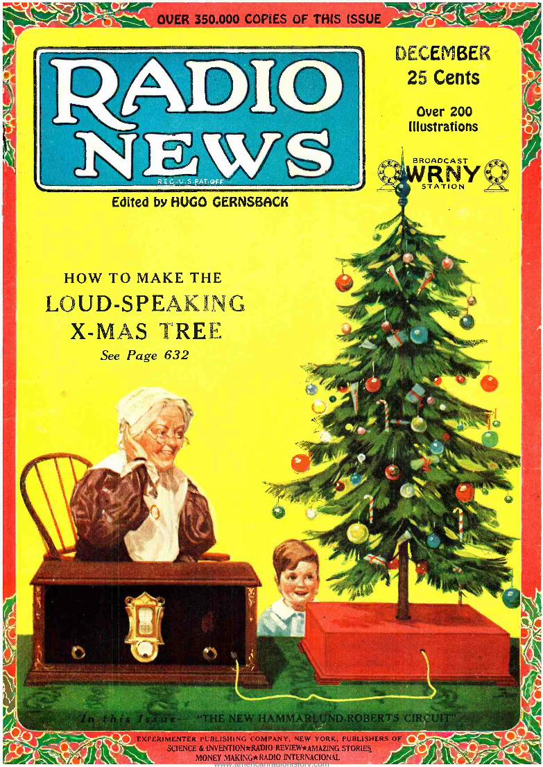
OVER 350.000 COPIES OF THIS ISSUE
DECEMBER 25 Cents
Over 200 Illustrations
BROADCAST
RNY STATION
Edited by HUGO GERNSI3ACK
- r
HOW TO MAKE THE
LOUD -SPEAKING X -MAS TREE
See Page 632
ISHI G MPA' ` ;" °E ` ORK, P ''BUSH - SCIENCE & INVENTIONttRADIO REVIEW*AMAZING STORIES
MONEY MAKING* RAd3IO INTERNACIONAi. www.americanradiohistory.com
V-MV-VAIMVAIMVAIWIWIVAIVAIVAIVAIMM
Since 1915 -Standard for All Sets
Cunningham Radio Tubes
are astoundingly good all the year 'round and at Christmas
time you will receive even a greater appreciation of their quality perfor-
mance because of the attractive Yule- tide programs. These radio programs come in clear and full -toned when your receiving set is Cunningham equipped. Q Every broadcast station splurges a bit at Christmas time and gives you something extra good. Q Entertainers are stimulated to do their best by the knowledge that thousands of new sets are tuned in and that
their already large and enthusiastic audience has swelled to even larger proportions during this Christ-
mas and holiday time. QRadio sets and radio equip- ment in general make immensely popular Christmas
gifts. QWhy not increase someone's pleasure a thousand fold by the gift of a radio set this Christmas? If you want
to make this lucky person's happiness complete, you will make sure that the set has a Cunningham Radio Tube in every socket.
CL To bring increased happiness to someone who now owns a receiver, give him a set. of Cunningham Radio Tubes, known since 1915
as standard for all sets.
vf:f. NEW Y O R K
C H I C A G O SAN FRAN- CISCO VAIVAIMMV IWAIVAIVAIV VAI
www.americanradiohistory.com
Radio Netas for December, 1926
0 e illeíter ín.g tr
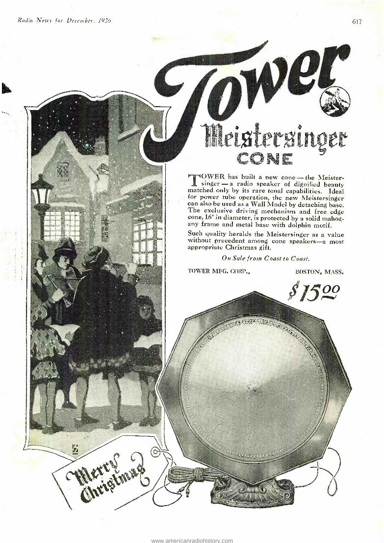
CONE TOWER has built a new cone - the Meister-
singer -a radio speaker of dignified beauty matched only by its rare tonal capabilities. Ideal for power tube operation, the new Meistersinger can also be used as a Wall Model by detaching base. The exclusive driving mechanism and free edge cone, 16" in diameter, is protected by a solid mahog- any frame and metal base with dolphin motif. Such quality heralds the Meistersinger as a value without precedent among cone speakers -a most appropriate Christmas gift.
On Sale from Coast to Coast.
TOWER MFG. CORP., BOSTON, MASS.
154°,
\to
617
www.americanradiohistory.com
618
\ Radio News for December, 1926
YNE WS Published by EXPERIMENTER PUBLISHING COMPANY, Inc., Publishers of "Radio News," "Science and
Invention," "Radio Internacional " "Radio Review," "Money Making" and "Amazing Stories." Editorial and General Offices: 53 Park Pl., New York City
H. GERNSBACK, President. S. GERNSBACK, Treasurer. R. W. DEMOTT, Secretary. Member: Audit Bureau of Circulations Radio Magazine Publishers Association
VOLUME 8 DECEMBER, 1926
Contents of This Issue: Edison and Radio, By Hugo Gernsback 625 New Television Apparatus,
By Lucien Fournier 626 Radio News of the Month 628
List of Broadcast Stations in the United States 629
Electrifying Your Phonograph, By H. B. Whiffen 630
The Loud -Speaking Christmas Tree, By Hugo Gernsback 632
Advancement in Radio, Illustrated 633
The Place of Radio in Home Decoration, By Golda M. Goldman 634
Speaking Over the Radio, By Charles D. Isaacson 636
Radio For All Ages 637
A Christmas Gift of Happiness 638
Recent Topics of Radio Interest Illustrat- ed, By George Wall 639
Radio in the Railroad Yards, By S. R. Winters 640
A 14 -Tube Receiver, By Fred R. Jewell 641
Loud -Speakers and Their Characteristics By M. L. Muhleman 642
What's New in Radio 646
The Neutrodyne and Its Position in Radio By R. M. Klein 650
Constructing the Shielded Hammarlund- Roberts Receiver, By V. T. Baird 652
How to Build the "Pianorad," By Clyde J. Fitch 655
An Infradyne Combination Set, By Clyde J. Fitch 656
An Improved "Bass Note" Circuit, By George V. Rockey 658
Home-Made Coils for the Browning -Drake and Similar Circuits, By C. A. Oldroyd 660
A Versatile Superheterodyne, By Leslie Raymond Jones 662
A Universal All- Circuit Set, By Joseph Riley 664
Establishing Radio Standards of Frequency, By C. B. Jolliffe and Grace Hazen 666
Magnetic Fields in Vacuum Tubes, By Robert Serrell 668
"Design Engineering" in Radio Apparatus, By E. T. Flewelling 669
The Acoustat, By O. C. Roos 670 Progress in Radio 672 Correspondence from Readers 673 Radiotics 674 Radio Wrinkles 675 RADIO NEWS LABORATORIES 676 Short -Wave Receiver Adjustment and -
Operation, -
By A. Binneweg, Jr., 6BX -6XAA 678 I Want to Know, By Joseph Bernsley 679 QRA's 688 What Chemistry Has Given to Radio,
By O. Ivan Lee 700 Wired Radio in England, 722 The Main Problems of Television,
By Dr. Walter Friedel 767 Government and the Radio,
By Bella Webb 770 Radio Reception With Two Grounds,
By H. A. Everest 771
BROADCASTING WEATHER MAPS BY RADIO
By S. R. Winters and B. F. Dashiell The newest use to which Radio is being put
government scientists. by
;In Forthcoming Issues: VISIBLE RADIO WAVES
By Clyde J. Fitch
An interesting suggestion of the possibilities to which radio may be put for aviation, as well as pure research.
A NEW SUPERHETERODYNE, By R. E. Lacault
The inventor of the Ultradyne presents an article which will make easy for RADIO NEWS read- ers the construction of a receiver of great power and fine quality.
RADIO NEWS is published on the 10th of each preceding month. There are 12
numbers per year. Subscription price is 82.50 a year in U. S. and possessions.
Canada and foreign countries, 53.00 n year. U. S. Coin as well as Ti. S. Stamps
accepted shouldbe drawnmtol order of EXPERIMENTER each.
TER PUBLISHING CO., INC.
All communications and contributions to this journal should be addressed to
Editor, RADIO NEWS, 53 Park Place, New York, N. Y. Unaccepted contributions cannot be returned unless full postage has been included. All accepted contributions are paid for on publication. A special rate is paid for novel experiments; good
photocranhs accompanying them are highly desirable. RADIO NEWS. Monthly. Entered as second class matter, July 12. 1924, at the
Post Office at New York, N. Y., under the Act of March 5, 1879. Additional entry
at Long Island City, N Y. and San Francisco. Calif. Title registered II. S.
Patent Office. Copyright. 1926, by The Experimenter Publishing Co., Inc., 53
Park Place, New York. The Contents of this magazine are copyrighted and must not be reproduced without giving full credit to the publication. Copyrighted in Germany. Reproduction of articles in Germany is reserved for Radio, Berlin 42.
RADIO NEWS is for sale at all newsstands in the United States and Canada,
General Advertising Dept., 53
Western Advertising Representatives Finucan & McClure
720 Cass St., Chicano. Ill.
and at Brentano's, Ave de L'Opera, Paris, France. European agents: S. J. Wise Et Cie, 40 Place Verte, Antwerp, Belgium.
HOW TO SUBSCRIBE FOR RADIO NEWS. Send your name, address and remittance to Experimenter Publishing Co., 53 Park Place, New York. Mention the name of the magazine you are ordering. We also publish SCIENCE AND INVEN- TION, RADIO INTERNACIONAL, RADIO REVIEW, MONEY MAKING and AMAZING STORIES. Write clearly.
RATES AND TERMS. The subscription rate for RADIO NEWS is 82.50 per year. (12 numbers). When remitting do so by check, money order, or registered letter if cash is enclosed. Avoid sending cash through the mail if possible. Sub- scriptions for less than one year are not accented. Subscription may be made in combination with SCIENCE & INVENTION, RADIO INTERNACIONAL, RADIO REVIEW, MONEY MAKING and AMAZING STORIES.
POSTAGE. We prepay postage in all parts of the United States, Mexico and island possessions. For foreign or Canadian subscriptions we require 50 cents in addition to the subscription price for additional postage charges.
CHANGE OF ADDRESS. Notify us as far in advance as possible. It requires several weeks to make an address change on our records. Always write clearly.
ON EXPIRATION of your subscription we enclose a renewal blank in our last number to you; we stop our delivery to you on expiration.
Park Place, New York City. Pacifie Coast Advertisinn Representatives
A. I. Norris Hill Co. 5 Third St, San Francisco, Calif.
412 West 6th St., Los Angeles, Calif.
Kansas City Advertising Representatives Davies and Dillon
15 W. Tenth St., Kansas City, Me.
N ̂ w England Advertising Representative Detroit Advertising Representative T. F. Magrane, Park Square Building, Boston. Mass. Roy Buell, Donovan Bldg., Detroit. Mich.
www.americanradiohistory.com
Radio Nezos for December, 1926
CROSLEY RADIO All prices slightly higher west of Rocky Mts.
THB Mr "ST
This little double circuit 1 -tube set has made long dis tance records.
4 tubes. Amazing efficiency, Cres- cendon equipped!
The 4 -29 in port able form.
Five tubes, tuned radio frequency. Two stages non- oscillating radio frequency ampli- fication, Crescen- don, two stages audio frequency amplification.
6 tubes, 1-dial con- trol acuminntors Cres co ndon power tube adapt ability.
6 tubes. True -cas- cade amplifica- ion; non- oscillat- ng and non -radi-
ating.
In a mahogany console. 6 -tube 6 -50 receiver, Crosley Musicone speaker, ample compartment for batteries.
Double drum sta ion selector
Musicone and room for batteries and accessories.
2- inchsize,$12.60 Super Musicone 14.76. Musicone
Deluire,$23.50.Also beautiful Musi- console with room for batteries and accessories, as below.
Cr osley Features
tRESCENDON" -When, on or-
dinaryradios, ears must etraintocatch aatationmiles
away, a turn of the Crescendon on Croaley radios instantly swells reception to room-fill-
619
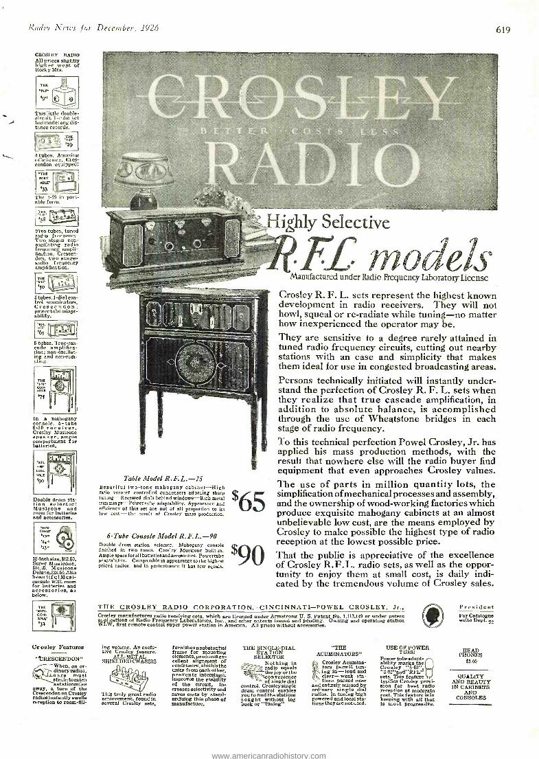
ighly Selective
Table Model R.F.L. -75 Beautiful two-tone mahogany cabinet -High ratio vernier controlled condensers affording sharp tuning -Recessed dials behind windows -Rich racial trimmings -Power tube adaptability. Appearance and efficiency of this set are out of all proportion to its low cost -the result of Crosley mass production.
6 -Tube Console Model R.F.L. -90 Double drum station selector. Mahogany console finished in two tones. Crosley Musicone built -in. Ample space forall batteries and accessories. Powertube adaptability. Comparable in appearance to the highest priced radios, and in performance it has few equals.
models Manufactured under Radio Frequency Laboratory License
Crosley R. F. L. sets represent the highest known development in radio receivers. They will not howl, squeal or re- radiate while tuning -no matter how inexperienced the operator may be. They are sensitive to a degree rarely attained in tuned radio frequency circuits, cutting out nearby stations with an ease and simplicity that makes them ideal for use in congested broadcasting areas. Persons technically initiated will instantly under- stand the perfection of Crosley R. F. L. sets when they realize that true cascade amplification, in addition to absolute balance, is accomplished through the use of Wheatstone bridges in each stage of radio frequency. To this technical perfection Powel Crosley, Jr. has applied his mass production methods, with the result that nowhere else will the radio buyer find equipment that even approaches Crosley values. The use of parts in million quantity lots, the simplification ofmechanical processes and assembly, and the ownership of wood- working factories which produce exquisite mahogany cabinets at an almost unbelievable low cost, are the means employed by Crosley to make possible the highest type of radio reception at the lowest possible price. That the public is appreciative of the excellence of Crosley R.F.L. radio sets, as well as the oppor- tunity to enjoy them at small cost, is daily indi- cated by the tremendous volume of Crosley sales.
THE CROSLEY RADIO CORPORATION, CINCINNATI -POWEL CROSLEY, Jr., Crosley manufactures radio receiving sets, which are licensed under Armstrong U. S. Patent No. 1,113,149 or under patent application of Radio Frequency Laboratories, Inc., and other patents issued and pending. Owning and operating station WLW, first remote control super -power station in America. All prices without accessories.
ing volume. An exclu- sive Crosley feature.
ALL -METAL SHIELDED CHASSIS
This truly great radio achievement, found in several Crosley sets,
furnishes asubstantial frame for mounting elements, produces ex- cellent alignment of condenaers,ahieldsthe units from each other, prevents interstage, improves the stability of the circuit, in- creases selectivity and saves costs by stand- ardizing this phase of manufacture,
THE SINGLE -DIAL STATION
SELECTOR Nothing in
t' i radio equals . ,r- the joy or the
onvemence of single dial
control. Crosley single drum control enables you to find the stations sought without log book or "tuning"
"THE ACUMINATORS"
Croaky Acumina- tors permit tun- ing in -loud and clear -weak sta- tions passed over
and entirely missed by ordinary single dial radios. In tuning high powered and local ata- tionstheyarenotused.
USE OF POWER TUBE
Power tubeadapt- ability marks the Cros ley "5-50",
sets. Thia feature typifies Crosley provi- sion for best radio reception at moderate cost. This feature is in keeping with all that is most progressive.
President For Catalogue write Dept. 22
PHONES $3.00
QUALITY AND BEAUTY IN CABINETS
AND CONSOLES
www.americanradiohistory.com
Radio News for December, 1926
INDEX TO ADVERTISERS Page
A
Acme Apparatus Co. 689 .
Acme Electric & Mfg. Co., The 746
Advance Electric Co. 752
Aero Products, Inc 692
Aerovox Wireless Corp. 710
Alden Mfg. Co. 705, 706, 708, 710, 712
All -American Radio Corp. 699
All Radio Co. 768 Allen- Bradley Co.
690, 720, 747, 750, 756
Ambo Radio Institute 769
American Auto & Radio Mfg. Co., Inc. 712 -762
American Battery Co. 718
American Bosch Magneto Corp. 697 -732
American Electric Co. 700
American Hard Rubber Co. 702, 708 Amplion Corp. of America, The 710 Amrad Corp., The 731
Amsco Products, Inc. 763
AutoStrop Safety Razor Co. 755
E
Baker Yacht Basin, Inc., The 736 Barawik Co., The 730, 740. 742, 744. 746, 748, 752,
761, 763, 764, 769, 779, 773
Belden Mfg. Co. 753 Benjamin Electric Mfg. Co. 749
Birnbach Radio Co. 770
Bodine Electric Co. 694
Bogue, B. N. 712
Bolton Co., Arthur 714
Boudette Mfg. Co. 724
Bradley Institute 716 Brady, John B. 706
Bremer -Tully Mfg. Co 621
Brush Pottery Co. 767
Buckingham Radio Corp. 769
C
C. E. Mfg. Co. 754
Carborundum Co., The 737
Carlton Mills, Inc. 730 Carter Radio Co. 728 Central Radio Labs 692
Chaslyn Co., The 726 Chelsea Radio Co. 756 Chemical Institute of N. Y., Inc 766 Chicago Radio Apparatus 720
Chicago Salvage Stock Stores 690 Chicago Stock Gear Works 763 Clark & Tilson, Inc. 740 Consrad Co., Inc. 764 -775 Cooper Corp., The 707 Cornell Electric Mfg. Corp. 702 Cornish \Vire Co. 742 Coyne Electrical Schools 770 Crescent Radio Supply Co. 763 Crosley Radio Corp., The 619 Culver -Stearns Mfg. Co. ..702, 726 Cunningham, Inc., E. T.
Inside Front Cover Cuno Engineering Corp., The 750
D
Daven Radio Corp. 721 DeForest Boxing Course, Jimmy 768 Deutschman Co., Tobe 694
Page
Dictograph Products Corp. 698
Distantone Radios, Inc. 690
Dodge's Institute 702
Dungan Electric Mfg. Co. 768
Donle- Bristol Corp., The 744
Doolan Mfg. Corp., Jas. F. 754
Dubilier Condenser & Radio Corp. 18
Duro Metal Products Co. 764
E
Easton Coil Co. 748
Electrad, Inc. 741
Electric Specialty Co. 752 Electro- Magnetic Tool 762
English- Whitman Products, Inc. 758
Engineers' Service Co. 764
Erie Fixture Supply Cu. 730
F
Fansteel Products Co., Inc. 683
Fawcett Publications, Inc. 726
Ferbend Electric Co. 745
Ferguson, Inc., J. B. 734
Ferranti, Inc. 691
Fisher, C. C. B. 762
Fishwick Radio Co. 708 Florentine Art Products, Inc 762
Formica Insulation Co., The 743
Freshman Co., Inc., Chas. 775
G
Gardiner & Hepburn, Inc. 770 Cearhart- Schleuter Radio Corp. 688 Gem Tube Co. 712
General Electric Co. 765
General Industries Co., The 760
General Instrument Corp. 704
General Mfg. Co. 767
General Radio Co. 737
George Electric Co. 700 Goodrich Rubber Co., The B. F.
754
Globe Import -Export 765
Gould Storage Battery Co., Inc. The 722
Gray & Danielson Mfg. Co. 723 Grigsby- Grunow -Hinds Co. 728
H
Hammarlund Mfg. Co. 730 Hammarlund- Roberts 725 Hampton -Wright, Inc. 736 Ilawkeye Radio Co. 738 High Frequency Labs. 696 Hommel & Co., Ludwig 744
I
Ideal Products Co. 734 Illinois Stamping & Mfg. Co 714 International Correspondence
Schools 768 International Radio Co. 751
Ivorylite Radio Panel Co. 726
Page
J
J. M. P. Mfg. Co. 736 Jefferson Electric Mfg. Co 700 Jewell Electrical Instrument Co. 748
g
Karas Electric Co. 727 Kelleradio, Inc. 769 Kellogg Switchboard & Supply
Co. 693 Kelsey Co., The 726 Kodel Radio Corp 759,761 Kokomo Electric Co. 740
Lacault Radio Elec. Labs., R. E. 760
Lacey & Lacey 767 Lancaster & Allwine 742 Laurel Motors Corp. 754 Liberty Bell Mfg. Co. 688 Listen -In Co., The 698 Lynch, Inc., Arthur H. 712
M
M. & II. Sporting Goods Co. 770 M -S Syndicate 768 Madison Radio Corp. 686 Magnavox Co., The 719 Martin- Copeland Co. 703
Massachusetts Radio School 752
Metro Electric Co. 681
Midwest Radio Corp. Inside Back Cover
Mogul Electrical Labs. 716 Murray Distributor 696 Muter Co., Leslie F. 746
r1
National Carbon Co. 685
Nr.i?onal Co., Inc. 767
National Radio Institute ..623, 684
National, State & Local Tuberculosis Ass'n of the U. S., The 706
Newark Electric 748 Newark Pen Co. 682 New England Mills Co. 700 Norden- Hauck, Inc 771
o
Omnigraph Mfg. Co., The 722 Ozarka, Inc. 624
p
Pacent Electric Corp. 757 Palmer & Palmer 692 l'arker, C. L. 769 Penn Radio Sales Co. 762 Pilot Electrical Mfg. Co. 735 Polymet Mfg. Corp. 698 Ports Mfg. Co. 746 Potter Mfg. Co. 708
Premier Electric Co. 688, 714 Press Guild, The 775
Prest -O -Lite Co., Inc., The 701
Page
g
Radiali Co. 709 Radio Association of America 771 Radio Corporation of America
Back Cover Radio Foundation, Inc. 720 Radio Institute of America 686 Radio Receptor Co. 711 Radio Specialty Co. 733 Randolph Radio Corp.
696, 708, 714, 718, Raytheon Mfg. Co. Roll-0 Radio Co., The Rono Mfg. Co.
S
Samson Electric Co. Scanlon, Everett Service Battery Co. Seymour Co. Shure Radio Co. Silver -Marshall, Inc. Sonatron Tube Co.
744, 760,
730,
761 715 770 734
696 768 724 762 752 716 714
Southern Toy Co., Inc., The 773 Spartan Electric Corp. 738 Standard Radio Co. 704 Starrett Mfg. Co. 769 Steinite Labs. 752 Sterling Mfg. Co., The ....742, 758 Swift & Anderson 704 Syd Storage "B" Battery Co. 702
T
Teletone Corp. of America 760 Thomas Battery Corp. 750 Thor Radio Mfg. Co. 704 Thordarson Electric Mfg. Co. 713 Tower Mfg. Corp. 617
U
Union Radio Corp. 767
V
Valley Electric Co. 739 Van -Ashe Radio Co. 750 Velvetone Radio Corp. ...... 694
W
\Walker Co., The Geo. W. 740 Wayne- Andrews Co., Inc., The 765 Webster Co.. The 763 Western Radio Mfg. Co. 716 Westingale Elec. Co. 687 Westinghouse Elec. & Mfg. Co 717 Willard Storage Battery Co. 695 Windsor Furniture Co. 729 \Wirthmore Co., The 764 World Battery Co.....760, 764, 770
XYZ
X -L Radio Labs 716 Yale Specialty Supply Co. 756 Yaxley Mfg. Co. 7'8
www.americanradiohistory.com
Radio News for December, 1926 621
THE
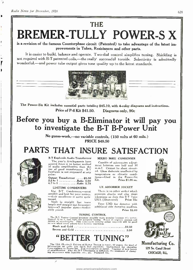
BREMER -TULLY POWER -S X is a revision of the famous Counterphase circuit (Patented) to take advantage of the latest im-
provements in Tubes, Resistances and other parts. It is easier to build, balance and operate. Two -dial control simplifies tuning. Shielding is
not required with B -T patented coils, -the really' successful toroids. Selectivity is admittedly wonderful, -and power tube output gives tone quality up to the latest standards.
The Power -Six Kit includes essential parts totaling $45.10, with 4 -color diagrams and instructions. Price of P -6 Kit $41.50. Diagrams only, 90c
Before you buy a B- Eliminator it will pay you to investigate the B -T B -Power Unit
No guess -work, -no variable controls, (150 volts at 60 mils.) PRICE $49.50
PARTS THAT INSURE SATISFACTION B -T Euphonic Audio Transformer
The year's developments have proved there is no better method of audio amplification than the use of good transformers. B -T Euphonic is not surpassed at any price: Output Transformer . $5.50 2.2 to 1 Ratio 5.00 4.7 to 1 Ratio 5.75
LIFETIME CONDENSERS Use B -T Condensers, -most
sensible and best for your money, -their excellence is never ques- tioned.
Made in straight line wave length and straight line frequency type -all popular sizes- moder- ately priced.
MIKRO MIKE CONDENSER Capable of micrometer adjust-
ment between one half and 30 m.m.f. Cannot be short circuit- ed. Glass dielectric unaffected by temperature or climatic condi- tions -Used in the Power -Six Kit. Price $1.00 ea.
UX ABSORBER SOCKET There is no other socket which
prevents shocks and also stops vibrations as does this B -T Type UXA (Illustrated) Price 75c
Type UXD for detector with additional side damping mufflers.
Price $1.00
TUNING CONTROL The B -T Tuning Control becomes steadily more popular because it's better.
Geared 12 to I, just right for accurate tuning. Reads in degrees, station call letters or wavelengths. Fits condensers turning either way, -It will be good as new when many others have become worthless. Black and Gold .. $2.50 Brown and Gold 3.50
"BETTER TUNING" The 10th (Revised) Edition of Better Tuning is ready, 60 pages, the kind of information on radio you don't find elsewhere. Instructions for changing Counterphase to Power -Six. Full description of latter. Treatise of new forms of amplification. Why the B -T Eliminator is different, the weakness of chang- ing inductance with capacity, etc., etc. Postpaid IOc.
Manufacturing Co. 520 So. Canal Street
CHICAGO, ILL
www.americanradiohistory.com
022 Radio News for December, 1926
RADIO NEWS READERS' BUREAU
Time and Postage Saver IN every issue of RADIO NEWS
you. undoubtedly see numerous articles advertised about which you would like to have further information. 'to sit down and write an individual letter to each of these respective con- cerns, regarding the article on which you desire information, would be quite a task.
As a special service to our readers, we will write the letters for you, thus sav- ing your time and money.
Just write the names of the products about which you want information; and to avoid error the addresses of the manufacturers, on the coupon below and mail it to us.
If the advertiser requires any money or stamps to be sent to pay the mailing charges on his catalogue or descriptive literature, please be sure to enclose the correct amount with the coupon.
We will transmit to the various adver- tisers your request for information on their products. This service will appear regularly every month on this same page in RADIO NEWS. If there is any Manufacturer not ad- vertising in this month's issue of RADIO NEWS, from whom you would like to receive literature, write his name, address and the product in
r the special section of the coupon below.
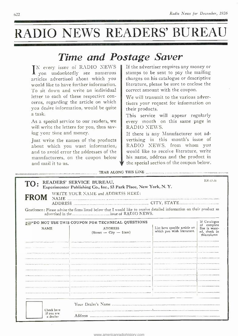
TEAR ALONG THIS LINE
TO READERS' SERVICE BUREAU, Experimenter Publishing Co., Inc., 53 Park Place, New York, N. Y.
FROMWRITE YOUR NAME and ADDRESS HERE:
FROM NAME ADDRESS CITY, STATE
Gentlemen : Please advise the firms listed below that I would like to receive detailed information on their product as
RN-12-26
advertised in the issue of RADIO NEWS.
'DO NOT USE THIS COUPON FOR TECHNICAL QUESTIONS If Catalogue of complete
NAME ADDRESS List here specific article on line is want- (Street - City - State) which you wish literature. ed, check in
this column
Check here if you are a dealer
Your Dealer's Name
Address
www.americanradiohistory.com
Radio News %or December, 1925
Wìll TraînYou At HomeTo Fill a BigPayRadio Job
Igive you all this apparatus so you can learn quickly at home the Practical
Way F
Ms FREE
OF
EXTRA
COST
623
If you're earning a penny less than $50 a week, clip coupon now. Send for AMAZING FREE BOOK, "Rich Rewards in Radio." Why go along at $25 or $35 or $45 a week, when you
could earn $50 to $250 in the same six days, as a Radio Expert? Hundreds of N. R. I. trained men are doing it -why can't you?
Earn $50 to $250 a Week- RADIO EXPERTS IN B!C DEMAND Radio needs trained men. Get into this new live -wire profession
of quick success. It's the trained man, the Radio Expert, who gets the big jobs of this profession -paying $75, $100, $200 a week and up. Every day N. R. I. trained men are taking good places in the Radio field -men just like you -their only advantage is TRAINING. You can prepare just as they did, by new practical methods. Our tested clear training makes it easy for you. Big Free Book contains all the proof.
You Learn Quickly" In Spare Time
So sure am I that I can train you success- fully for a better future in this new Big -Pay
profession, that I guarantee your training with a money -back bond. Lack of ex- perience or education won't hold you
back -common schooling all you need to start. You can stay home, hold your job, and learn quickly and
pleasantly in your spare time. My practical, helpful methods enable
you to start RIGHT AWAY to-. ward one of the bigger Radio
jobs paying $50 to $250 a week. No delay, no losing time
from work - no scrimping or scraping to get your training.
You Get All Of This
All instruments shown here and others sent to all my students free of extra cost under short time special offer Clip coupon now -find out all about this big unequalled offer while you still have time to take advantage of it. This training is intensely practical -these instruments help you do the practical work. You learn workmanship and get
added confidence in your ability.
$70 In One Day For T. M. Wilcox
"I am in businesefor my- self and RECENTLY MADE
an $70 in electrician A of rich experi
e, occupying a pleneid position telephone
intendent wh I enroll- ed with you believing it would open up greater op- portunities- havenot been disappointed. Estimate Radio will be worth tens of thousands of dollars to
In next few years." T. M. Wilcox, Belle Island, Newfoundland.
Operates WMAQ "Accepted a position with
the Chicago Daily News Sta- tion WMAQ. MY INCOME PRACTICALLY DOUBLED, thanks to you. I handle all
eultation, oleo do operat- ing. Your ourse taught e not only the theoretical but aleo the practical knowledge that make y k s, f or me." Keith
w Kimball,
Station WMAQ, Chicago, Ill.
Get This FREE BOOK
World Famous Training That "Pays for Itself"
My Radio course World - Famous as the training that "pays for itself." Make more money QUICK when you take up this practical course. Work on millions of an- tennae, receivin; sets, offers you big chance to make spare time cash while you're learn- ing. I'll show sou how -teach you the latest "dope," furnish you with business cards, show you bow to get Use business and make it pay. My students don', v-ait a yearto increase their income -they report Q -DICK INCREASES as aresult of this course-of ftan two or three weeks after starting.
IIoward Luce, Friedens, Pa. made $320 in 7 weeks during spare tin e. D. II. Suitt Newport, Ark., writes. "While taking the course I earned in spare time work about $900." Esel Wright, Omaha. reports making $400 in a short time while taking course --- working at Radio in spare tinsel Sylvester Senso, Kaukauna. Wis., made S500. These records not unusual -these men a few of hundreds.
Most amazing book on Radio ever written -full of facts and pictures -tells all about
the great new Radio field, how we prepare you and help you start. You can do what others have done -GET THIS BOOK. Send coupon
today -no obligation.
J. E. SMITH, President NATIONAL RADIO INSTITUTE
Dept. PWl, Washington, D. C.
--1
Tour Satisfaction Guaranteed We who know the results this practical tested training gets -
the increased earnings it has brought to men everywhere -stand behind it all the way with a signed guarantee bond that we give you when you enroll. On completion if you're not entirely satisfied' in every way, you get back every cent you've paid us. No strings to this offer -you yourself are the only judge. Get started today! It's your big chance for one of the bigger Itadio jobs -mail coupon NOW for my Big FREE BOOK and proof l No obligation.
EMPLOYMENT SERVICE TO ALL GRADUATES
J. E. SMITH, President NATIONAL RADIO INSTITUTE Dept. PWI, Washington, D. C.
Dear Mr. Smith- Without obligating me in any way, send me your free book, "Rich Rewards in Radio"
and all information about your practical, home -study Radio Course.
Name Age.......
Street Address
Town State
www.americanradiohistory.com
624 Radio News for December, 192d
$13250 F. O. B. Chicago. Ozarka Senior J 5Tube Model complete withLoud Speaker and all accessories.
Also built in a 7 Tube Model
Many Are Being Fooled in Radio By Believing Service Unnecessary
ANY radio, no matter what its price may be, nor who makes it, will only be as
satisfactory as the trained service behind it.
In buying a radio there are a number of important things to consider - APPEARANCE - TONE - VOLUME - DISTANCE - EASE OF TUNING - and last but far the most important - SERVICE.
Tone and Volume can very easily be de- termined by listening. The only real way to prove distance and ease of tuning is by oper- ating the instrument yourself, but the quality of service must be determined only by careful investigation.
Far too often it seems customary to claim that radio service is unnecessary. For four years this company has been building a fac- tory trained service organization until today it consists of 4364 men who know Ozarka instruments in every detail. These men have been trained directly under Ozarka Engineers, the men who originated and developed Ozarka Instruments.
You'll find it well worth your time to in- vestigate this organization before you decide on your radio. A trained Ozarka service man is near you -why not discuss this matter with him?
When anyone tells you that radio service is not necessary, think it over, your own good sense will tell you differently. You have a right to receive from your radio consistent operation, night after night and year after year -the right service by a service man who knows how, will guarantee you that lasting satisfaction you are entitled to.
The claim that service will not be necessary is the poorest type of salesmanship -it only leads to dissatisfaction later -far too often it is used to cover up the fact that the seller is not in a position to deliver service.
In the past, the selling of radio instruments has depended largely on having stock on hand to deliver -in the rush to buy very few paid any attention to what service could be de- livered in case any little trouble came up.
Today, service in radio is not only being recognized and demanded but people who know, go even farther and demand -service by factory trained men.
You would never consider letting any all round mechanic repair your car -then treat your radio in exactly the same manner. Demand not only service but the service of men who know -the day of the radio wizard who knows all radio instruments is gone -the factory trained service man has taken his place.
I N4 CORRORATE 120 W. Austin Avenue A CHICAGO, ILL.
slooF. O. B. Chicago. Ozarka Junior 5 P Tube Model complete with builtia speaker and all accessories.
$.21 5 F. O. B. Chicago. Ozarka Console 5 Tube Model, solid walnut cabinet,
complete with all accessories. Also built in a 7 Tube Model
We have a few Openings for the Right Men WHILE there are today 4364 Ozarka
representatives, some territory is still open. We want men who believe in
the future of radio -men who are tired of working for some one else -men who would like to add to their present income by de- voting their evenings to Ozarka.
At the start you can keep your present position. Later on, after you have proven what you can do, then you will give us all your time because it will pay far more than your present position.
The man we want may not have much money but he is not broke. He has lived in his community for some time -he has a reputation that his word is good. He may not have made any startling success but he has never "put over something' just to make money. He may know nothing about radio or salesmanship but he will be successful if he is willing to study what we are willing to teach him, with- out cost.
The field in radio is wide open for the trained man. The success of the 4364 Ozarka representatives proves what men can do. If you are interested. ask for a copy of the Ozarka Plan. a 100 page book which tells a true story of how big money and a permanent business can be built in radio. It is a story of life; of why some men fail while others succeed. This book has shown many men how to start making extra money immediately and within a very short time establish a business of their own.
www.americanradiohistory.com
'./'°'e/°°X/9 aì°/'f°./V°9/°f'eí°X/24'°9.''/'''°°'°.°'r`
RADIO 'NEI HUGO GERNSBACK,
Editor and Publisher EDITORIAL AND GENERAL OFFICES, 53 PARK PLACE. NEW YORK
1111111111111111111111111111111111111111111111111i11111u IIIIIIIIIII Inn111111111111111n111111n111111111111111111111111MM111 11111111111111111111111111111111I1111111111111111111111111111111111111111111111111111111111111111111111111111 111111111111111111111111 1111111111111111 111111111 Imm1IIMM1111111u11111111111111111111111111111111 111111111111111111111111111111111111111111111111111111111111111111111111111111111111111 , IIIIIIIIIIIIIIII IIII II IIIIIIIIIIIIIIIIt1111111111111111111111111111111111111111111111111t11L
Vol. 8 DECEMBER, 1926 No. 6 111111111111111 1111111 111111111111111111111 11111111 111111111111111111111111111111111111mmI1111111111111111, 111111111111111111111111111111111 ,m1111111111111111111 11 1 111 1111,11111111: IIII: 111111. 11111111111111111111111111111111111 1111111111111111 111111111111 111 11111111111111111111111111111111111111111111111111111111111111111111111111111111111 111111 111111111111111111111111111111111111111111111111111111111111111
11111111111111111111 111111, 1111111111111111111111111111111111111111111111111111111111111111111111111111111111111111111111111111111 ,IUUUUW 11111111111111111NIIIYIII111111111111111111111u111111111111111111111111111111111n11
EDISON AND RADIO By HUGO GERNSBACK
TIIOMAS A. EDISON has recently been quoted in the press as saying that Radio is a dismal failure. The follow- ing remarks on the subject are attributed to Mr. Edison:
"The radio is a commercial failure, and its popularity with the public is waning. Radio is impractical commercially and esthet- ically distorted, and is losing its grip rapidly in the market and in the home. There is not ten per cent. of the interest in radio that there was last year. Radio is a highly complicated machine in the hands of people who know nothing about it. No dealers have made any money out of it. It is not a commercial machine because it is too complicated. Reports from 4,000 Edison dealers who have handled radio sets show that they are rapidly abandoning it, and as for its music -it is awful," continents the Wizard of Menlo Park. "I don't see how they can listen to it.
"Thousands of people have signed a petition asking that sopranos be kept off the air. Of course most of them don't know that the soprano voice distorts the radio. The phonograph is coming into its own because the people want good music. The fact is that radio has never had a high peak of popularity. In towns where 25 or 30 dealers were handling radio sets, only one or two are now handling them. A farmer five miles from town buys a radio, perhaps on the installment plan. A wire becomes loose. The dealer has to ar- range to fix it. This happens time and time again. The business becomes unprofitable for the dealer to engage in. He does not make any money out of it. None of them has. They are giving it up as fast as they can. It is not a commercially successful machine, because it is too complicated."
Turning to the musical side of the question, Mr. Edison chuckled in his characteristic plan- ner, "Static is awful, and the difficulties of tun- ing out -and now they are stealing each other's wavelengths ! It is too bad that the radio has to be so complicated. It was a big and interesting thing and the people responded to it, but they want good music and they have found it is not to be had on the radio. That is why the phonograph is reclaiming its own."
Incidentally, this outburst from the clean of modern electricity was in connection with the announcement of Mr. Edison's latest invention, his 40- minute phonograph record -a great achievement, and one that without doubt will be of much benefit to the phono- graph industry.
Since the publication of this famous interview with Mr. Edison, the press, and particularly the radio press over the entire country, has been more or less agitated. The following comments of mine, most of which were printed in the New York Times of September 26, and the New York Evening Post of the same date, were made by me at the time, and are here somewhat amplified :
I have too high a personal opinion of Thomas A. Edison to wish to say anything of a controversial nature, or anything that would even border on discourtesy to the great inventor, but I do believe that Mr. Edison has not been recently in touch with radio sufficiently to appreciate fully the tremendous advances that have been made. Mr. Edison is a busy man, and a tremendously busy inventor. It would be well -nigh impossible for him to be in touch with all of the various commercial phases of radio all over the country ; and like other executives he obtains his reports from subordinates, and such reports often as not may be highly colorful and even wrong.
Right here I wish to pay a tribute to Mr. Edison that the radio industry so far has been unwilling to accord him. If it were not for Mr. Edison and the "Edison Effect," radio would not he what it is today. It is the Edison Effect that has made possible our present vacuum tubes, now used universally in radio. Radio, therefore, owes a tremendous debt to Thomas Alva Edison; and I recommend to the
radio industry that it acknowledge this debt more frequently in the future.
As to Mr. Edison's remarks, the statements that follow are facts which can be checked up by any one who is unbiased. They are not given with any idea of starting a controversy.
Rather than waning in popularity, it is well known that radio is on the constant increase. Witness, for instance, the recent Third An- oual Radio World's Fair, in New York, where the attendance for ti :e week was 228,000, the greatest on record of any radio show, and a tremendous increase over last year's figures. There certainly was no such interest in the phonograph when the latter was but five years old, which is the age of radio, since radio broadcasting started.
The sales of radio apparatus, for the United States alone, will reach $520,000,000 for 1926. The figures for the former years, com- piled by the Radio Manufacturers' Association, are given here :
1922, $46,500,000 ; 1923, $120,000,000 ; 1924, $350,000,000 ; 1925, $449,000,000. These are not mere estimates, but actual figures. From orders that have been placed, the various radio trade associa- tions know now that the 1926 figure will be exceeded in 1927. The fact is that the popularity of radio is becoming steadily greater
rather than less, and no home today is consid- ered complete without its radio set.
Radio's popularity started with the introduc- tion of broadcasting in 1921. In five short years it has accomplished more than the phonograph did in fifteen years. The modern radio set is uo more complicated than the automobile when it was five years old ; and for best results the radio set should be serviced by radio deal- ers, just as the modern automobile is serviced by its garage. In the last analysis, radio will probably be handled by radio or electrical stores, whose staff understand the mechanism. The phonograph dealer is not always equipped to do servicing, although quite a good many
phonograph stores do so. As for quality, it is the belief of unprejudiced experts that in
many cases the radio, providing it is of a good make, with a good loud- speaker, will deliver quality exceeding that of a phonograph. Neither phonograph nor radio are perfect. The best phonograph is of no avail after a record has been played several dozen times ;
after which, by no stretch of the imagination, can one call the result music. Furthermore, the scratchy sound produced by every phono- graph is highly objectionable and is certainly worse than the few extraneous noises produced in most radio sets today.
The radio and phonograph are two different entities, and should never compete. As a matter of fact, they never do. At the same time, the phonograph has come back only because the popularity of radio caused the phonograph makers to turn out a product such as had never existed before.
The radio dealers are making far more money in radio now than ever before. A great number interviewed, in New York and vicin- ity, claim that their business was never better and is on the increase. There are pretty close to 30,000 radio dealers throughout the country today. It is true that for some time the dealers did not make money, due to the price -cutting evil, but this is rapidly being eradicated.
Some of the best sets of today combine the phonograph and the radio. Each has its particular field. You can not listen to Caruso on the radio, nor can you get the latest presidential address on the phonograph.
The radio industry today is only five years old, and it may safely be predicted that when it becomes as old as the phonograph is today we shall hardly be able to recognize it as the same development. It is admitted that radio is not yet perfect. Neither is the phono- graph, nor the automobile, nor motion pictures, nor electric lights ;
nor, for that matter, a pair of shoes.
1f . . in ud,ich the Editor takes is- sue with Mr. Edison's claim that Ra- dio is a failure; yet it is pointed out that the Radio Industry owes Edison a great debt; wherein facts and fig- ures are given to show that Radio is on a steady increase; granting that neither Radio nor the phonograph is yet perfect; how the interest in Ra- dio is steadily increasing, and radio dealers are now making good money.
Mr. Hugo Gernsback speaks every Monday night at 9 P. M. from Station WRNY on various radio and scientific subjects.
625
www.americanradiohistory.com
626 Radio News for December, 1924
New Television Apparatus Latest Developments by Messrs. Belin and Holweck
By L. FOURNIER
P HIS new apparatus is based on the modulation of a light beam exploring a photographic plate. Let us recall to those of our readers, who have
forgotten that the microphone is an appa- ratus for modulating an electric current, that it transforms the continuous current into a very irregular one. It faithfully obeys the word, that is to say, the fundamental sound. its timbre and its harmonics. Obviously. the microphone is too crude to transform vibra- tions in a light beam into electric current vi- brations. For this work, selenium cells or photo- electric cells are used. These cells take the same place in the transmission of pictures that the microphone takes in the transmission of sounds.
Selenium in this regard was a fine discov- ery, and the discovery of the photo -electric cell has re- awakened old -time hopes, al- though perhaps it is incapable of performing the high- frequency modulations of current required in television. We shall see later why this is the case.
TRANSMISSION The system of transmission is represented
essentially by two little oscillating mirrors (see Fig. 1), one placed above the other. The lower mirror, of very narrow width, os- cillates vertically at a frequency of 500 cycles per second ; the upper mirror, some- what larger, oscillates horizontally at about 10 oscillations per second. The lower mir- ror, receiving the luminous beam, impresses on it as reflected 500 oscillations per second. As this beam is also received by the upper mirror, which oscillates in a line perpen- dicular to that of the lower mirror, the pro-
(Paris Correspondent. RADIO NEWSS
ELECTRIC ARC
DIAPHRAGM
CONDENSERS
OSCILLATING MIRROR
10 PER SEC.
1
----``` OSCILLATING LLATING
OBJECT MIRROR 500 PER SEC.
TRANSPARENCY
FIG. I
PHOTO ELECTRIC CELL
OBJECTIVE AMPLIFIER
Fig. 1. After the light from the arc has been concentrated by the condenser lenses it is caused to pass in a wavy line over the transparency (See Fig. 2) and the variations of the transmitted
light are registered on the cell.
jetted beam will be resolved into two sets of differen- oscillations, each with its own frequency and its own direction.
Suppose now that this beam is received on a screen placed in front of it. Let us follow its course.
The oscillations of the 500 -cycle mirror makes it traverse the screen uninterruptedly from right to left and left to right. but the beam at the sanie time answers to the oscil- lations of the 10 -cycle mirror, which moves in a direction perpendicular to that of the first. It, therefore, is acted upon by two forces. The resultant is traced upon the screen as a luminous line of the form shown in Fig. 2; that is to say, the screen is swept over by the ray alternately from right to left and vice versa and then from above downwards and back again.
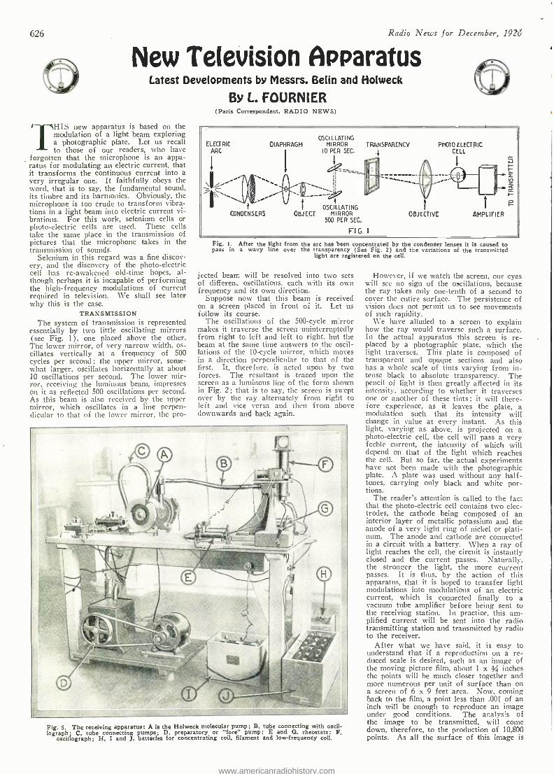
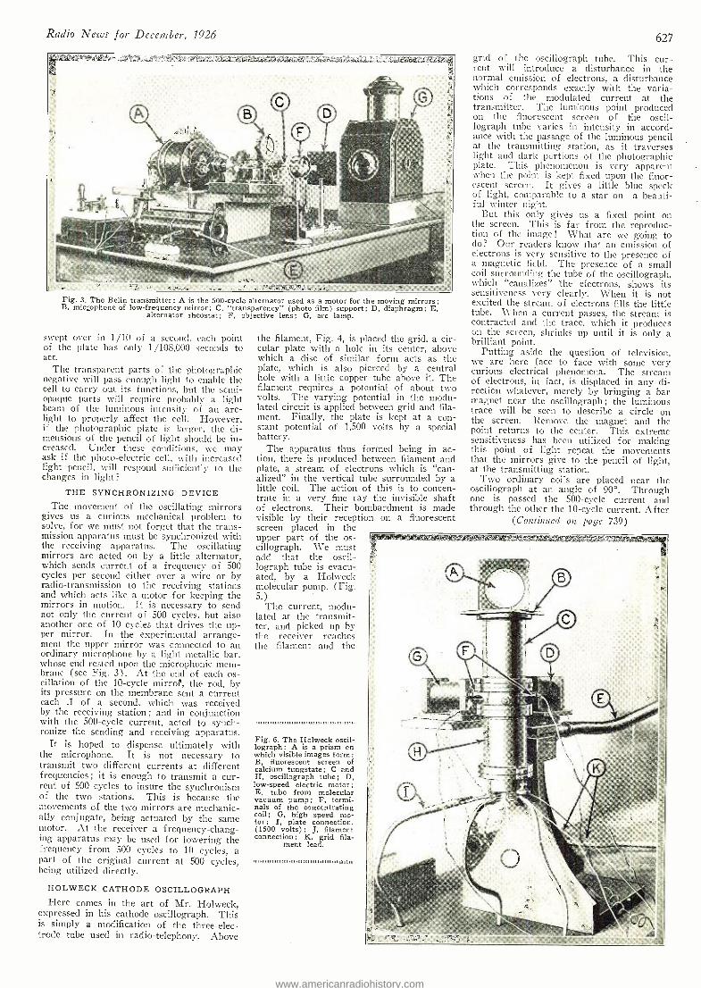
Fig. 5. The receiving apparatus: A is the Holweck molecular pump; B, tube connecting with oscil- lograph ; C, tube connecting pumps; D. preparatory or "fore" pump; E and G. rheostats; F,
oscillograph; H, I and J, batteries for concentrating coil, filament and low- frequency coil.
However, if we watch the screen, our eyes will see no sign of the oscillations, because the ray takes only one -tenth of a second to cover the entire surface. The persistence of vision does not permit us to see movements of such rapidity.
We have alluded to a screen to explain how the ray would traverse such a surface. In the actual apparatus this screen is re- placed by a photographic plate, which the light traverses. This plate is composed of transparent and opaque sections and also has a whole scale of tints varying from in- tense black to absolute transparency. The pencil of light is then greatly affected in its intensity, according to whether it traverses one or another of these tints ; it will there- fore experience, as it leaves the plate, a modulation such that its intensity will change in value at every instant. As this light, varying as above, is projected on a photo- electric cell, the cell will pass a very feeble current, the intensity of which will depend on that of the light which reaches the cell. But so far, the actual experiments have not been made with the photographic plate. A plate was used without any half- tones, carrying only black and white por- tions.
The reader's attention is called to the fact that the photo -electric cell contains two elec- trodes, the cathode being composed of an interior layer of metallic potassium and the anode of a very light ring of nickel or plati- num. The anode and cathode are connected in a circuit with a battery. When a ray of light reaches the cell, the circuit is instantly closed and the current passes. Naturally. the stronger the light, the more current passes. It is thus, by the action of this apparatus, that it is hoped to transfer light modulations into modulations of an electric current, which is connected finally to a vacuum tube amplifier before being sent to the receiving station. In practice, this am- plified current will be sent into the radio transmitting station and transmitted by radio to the receiver.
After what we have said, it is easy to understand that if a reproduction on a re- duced scale is desired, such as an image of the moving picture film, about 1 x 3 inches the points will he much closer together and more numerous per unit of surface than on a screen of 6 x 9 feet area. Now, coming back to the film, a point less than .001 of an inch will be enough to reproduce an image under good conditions. The analysis of the image to be transmitted, will come down, therefore, to the production of 10,800 points. As all the surface of this image is
www.americanradiohistory.com
Radio News for December, 1926 627
Fig. 3. The Belin transmitter: A is the 500 -cycle alternator used as a motor for the moving mirrors; B. microphone of low- frequency mirror; C, "transparency" (photo film) support; D, diaphragm; E,
alternator rheostat; F, objective lens; G, arc lamp.
swept over in 1/10 of a second, each point of the plate has only 1/108,000 seconds to act.
The transparent parts of the photographic negative will pass enough light to enable the cell to carry out its functions, but the semi - opaque parts will require probably a light beam of the luminous intensity of an arc - light to properly affect the cell. However, if the photographic plate is larger, the di- mensions of the pencil of light should be in- creased. Under these conditions, we may ask if the photo- electric cell, with increased light pencil, will respond sufficiently to the changes in light?
THE SYNCHRONIZING DEVICE The movement of the oscillating mirrors
gives us a curious mechanical problem to solve, for we must not forget that the trans- mission apparatus must be synchronized with the receiving apparatus. The oscillating mirrors are acted on by a little alternator, which sends current of a frequency of 500 cycles per second either over a wire or by radio- transmission to the receiving stations and which acts like a motor for keeping the mirrors in motion. It is necessary to send not only the current of 500 cycles, but also another one of 10 cycles that drives the up- per mirror. In the experimental arrange- ment the upper mirror was connected to an ordinary microphone by a light metallic bar, whose end rested upon the microphonic mem- brane (see Fig. 3). At the end of each os- cillation of the 10 -cycle mirrof, the rod, by its pressure on the membrane sent a current each .1 of a second, which was received by the receiving station ; and in conjunction with the 500 -cycle current, acted to synch- ronize the sending and receiving apparatus.
It is hoped to dispense ultimately with the microphone. It is not necessary to transmit two different currents at different frequencies ; it is enough to transmit a cur- rent of 500 cycles to insure the synchronism of the two stations. This is because the movements of the two mirrors are mechanic- ally conjugate, being actuated by the same motor. At the receiver a frequency- chang- ing apparatus may be used for lowering the frequency from 500 cycles to 10 cycles, a part of the original current at 500 cycles, being utilized directly.
HOLWECK CATHODE OSCILLOGRAPH Here comes in the art of Mr. Holweck,
expressed in his cathode oscillograph. This is simply a modification of the three -elec- trode tube used in radio -telephony. Above
the filament, Fig. 4, is placed the grid, a cir- cular plate with a hole in its center, above which a disc of similar form acts as the plate, which is also pierced by a central hole with a little copper tube above it. The filament requires a potential of about two volts. The varying potential in the modu- lated circuit is applied between grid and fila- ment. Finally, the plate is kept at a con- stant potential of 1,500 volts by a special battery.
The apparatus thus formed being in ac- tion, there is produced between filament and plate, a stream of electrons which is "can- alized" in the vertical tube surrounded by a little coil. The action of this is to concen- trate in a very fine ray the invisible shaft of electrons. Their bombardment is made visible by their reception on a fluorescent screen placed in the upper part of the os- cillograph. We must add that the oscil- lograph tube is evacu- ated, by a Holweck molecular pump. (Fig. 5.)
The current, modu- lated at the transmit- ter, and picked up by the receiver reaches the filament and the
Fig. 6. The Holweck oscil- lograph : A is a prism on which visible images form; B, fluorescent screen of calcium tungstate; C and H, oscillograph tube; D, low -speed electric motor; E, tube from molecular vacuum pump; F, termi- nals of the concentrating coil; G, high speed mo- tor; I, plate connection, (1500 volts) ; J, filament connection; K, grid fila-
ment lead.
1,111101111111111111111111111111111111111111111111111111.111111
grid of the oscillograph tube. This cur- rent will introduce a disturbance in the normal emission of electrons, a disturbance which corresponds exactly with the varia- tions of the modulated current at the transmitter. The luminous point produced on the fluorescent screen of the oscil- lograph tube varies in intensity in accord- ance with the passage of the luminous pencil at the transmitting station, as it traverses light and dark portions of the photographic plate. This phenomenon is very apparent when the point is kept fixed upon the fluor- escent screen. It gives a little blue speck of light, comparable to a star on a beauti- ful winter night.
But this only gives us a fixed point on the screen. This is far from the reproduc- tion of the image ! What are we going to do? Our readers know that an emission of electrons is very sensitive to the presence of a magnetic field. The presence of a small coil surrounding- the tube of the oscillograph, which "canalizes" the electrons, shows its sensitiveness very clearly. When it is not excited the stream of electrons fills the little tube. Virhen a current passes, the stream is contracted and the trace, which it produces on the screen, shrinks up until it is only a brilliant point.
Putting aside the question of television, we are here face to face with some very curious electrical phenomena. The stream of electrons, in fact, is displaced in Any di- rection whatever, merely by . bringing a bar magnet near the oscillograph ; the luminous trace will be seen to describe a circle on the screen. Remove the magnet and the point returns to the center. This extreme sensitiveness has been utilized for making this point of light repeat the movements that the mirrors give to the pencil of light, at the transmitting station.
Two ordinary coils are placed near the oscillograph at an angle of 90 °. Through one is passed the 500 -cycle current and through the other the 10 -cycle current. After
(Continued on page 739)
www.americanradiohistory.com
628 Radio News for December, 1926
MEASURING CONTINENTAL MOVEMENTS
THE theory that the continents are not fixed in position, but are very gradu-
ally drifting over the earth's surface, has met with much favor among scientists in late years. The Washington Naval Ob- servatory is co- operating in a series of world -wide measurements which will de- termine more accurately than ever be- fore the exact relative positions of geo- graphical stations. Radio, being almost instantaneous, affords the means of synchronizing the clocks which will de- termine exactly the differences in time, and consequently in longitude.
A GAME BETWEEN ANTIPODES
THE British House of Commons and the Australian Legislature will play a
radio chess match on the occasion of the opening of the new Australian capitol at Canberra next May. For this longest - range match, the Amalgamated Wireless Company of Australia and the British Post Office will transmit the messages without tolls. As Canberra is ten hours ahead of London in time, many moves may be
answered the day before they are made.
POWERFUL NEW NAVAL STATION
ANEWLY installed 80- kilowatt sta- tion at San Diego, Calif., is said to
be the most powerful vacuum -tube trans- mitter owned by the U. S. Navy. It will send code only, and will communicate directly with the Atlantic coast and points all around the Pacific.
BRINGING MUSIC INDOORS
THE usual radio procedure has been re- versed at the Park Avenue Baptist
Church, New York, whose fine peal of bells (carillon) commands much attention. In order that people in the church, as well as those outside, may hear the chimes, there have been installed special microphones which take up the music from the most favorable point and feed it to amplifiers in the auditorium.
GROWTH OF RADIO IN AMERICA
FIGURES compiled by Chairman J. B. Hawley, of the statistical commit-
tee of the Radio Manufacturers' Associa- tion, show that the number of receivers in use in the United States has increased from 37,000 in 1920 to over 5,000,000 at the present time. In 1922 the number jumped from 150,000 to 2,000,000, and lias been increasing at the rate of a mil- lion a year since then. In 1922 parts sales were $40,000,000 and those of com- pleted sets but $5.000,000. For the pres- ent year, it is estimated that the sale of sets amounts to $225,000,000, and acces- sories as much, with but $75,000,000 for separate parts.
NEW FOREIGN RADIO STATIONS
STATION HHK, Port au Prince, Haiti, is heard quite strongly in the South ; it
transmits on 360 meters with a 1- kilowatt set. Sao Paulo, Brazil, with equal power, has the call SQIG, and works on 450 meters. New Zealand has placed in operation a 500 - watt station, IYA, at Auckland, and will have another in a few weeks at Christchurch. Bratislava, Czechoslovakia, uses 500 watts on 300 meters and broadcasts in four languages. A super -power station, with two mountains for aerial supports, 10,000 feet above sea level, is now nearing completion at Herzogstand, in Upper Bavaria (Ger- many) and will, it is said, use 1000 kilo- watts when under full power. China, is
erecting a 50- kilowatt station at Pekin, for trans -Pacific communication. It will have six 1,000 -foot towers.
BROADCASTING AN ARMY
A"MILITARY TATTOO," reproduc- ing the sound of an army in motion,
was a novelty broadcast from 2LO, Lon- don, not long ago. The tramp of march- ers, the rolling of guns and tanks, and the clatterings and rumblings of all the panoply of Mars resounded in the ears of listeners. It was, however, an illusion, and its hearers were left to guess the ingenious methods of producing it.
The readers of RADIO NEWS are invited to co- operate by the contribution of news items which concern novelties in radio or in the uses to which it may be put; especially those in which the element of human interest is found. They should be short; for each one published $1.00 will be paid. Address News Editor. RADIO NEWS, 53 Park Place, New York City.
SUPER BROADCAST PROGRAMS RECENT events of interest have
caused the linking together of more broadcast stations than ever before at- tempted. The Radio Industries' Ban- quet in New York, on the occasion of the Radio World's Fair, mustered no less than 43 of them, and the Dempsey -Tun- ney contest as many as 33. The World's Series baseball games were covered by 22 stations. Per contra, a tendency is shown by individual stations to restrict the length of programs of only local in- terest-as in the case of state political campaigns.
RADIO IN THE SCHOOL
EVERY schoolhouse in the rural regions of Connecticut is to be equipped with a
radio receiving set. While this state will he the first to be thoroughly equipped, the movement is spreading, being encouraged by the development of the U. S. Radio Farm School, recently described in these pages. In Arkansas 112 vocational teachers will di- rect radio programs to farmers in as many rural school houses. Every schoolroom in Atlanta, Ga.. also will have a radio loud- speaker, so it can be seen that the city as well as country educational authorities are awake to the value of radio.
AERIAL RIGHTS AND INTERFERENCE
CHICAGO has brought forth the first
lawsuit between individuals to deter- mine who has the rights to the ether. A radio fan was living happily until an amateur moved into the same apartment house and started up a transmitting set. While it was in operation, the B. C. L. could get nothing else, and therefore ob- jected. The landlord sided with the owner of the transmitter ; so the ag- grieved tenant has brought suit, with the backing of the Broadcast Listeners' As- sociation, to determine what are his rights to uninterrupted reception.
RADIO MUST NOT BE MUSICAL
ANOVEL decision has been given by the legal authorities in New South Wales,
Australia. The law forbids the use of musical instruments in tap- rooms, but some ingenious publicans have run extension cords from their receivers to loud -speakers in the bars, and give their customers the sporting results. This practice has been authorized, providing the speaker is turned off when a musical number is coming over.
THE WIRELESS RADIO DANCE THIS novelty, the practicability of
which was explained in RADIO NEWS for last February, has appealed to oversea lovers of the terpsichorean art. In a Berkhamstead (England) hotel 20 couples danced recently to radio music unheard by the amazed spectators. Each dancer wore inconspicuous headphones through which he or she heard the phan- tom strains from the distant orchestra.
CALL PIGS BY RADIO
OUT in the great West, where even city dwellers do not lose their touch with the
land, one of the big events at the radio show in Omaha was a pig -calling contest by ex- pert swineherds. It is not recorded whether any farmers called in their pet porkers and put the earphones on them, in order that the animals might judge the excellence of the performance.
(Continued on page 763)
RADIO MAKES THE DEAF HEAR
FROM Norway, Maine, comes the re- port of interesting experiments per-
formed by Charles D. Seely, a radio en- thusiast. With the use of a powerful radio set, it was found possible for peo- ple who were born deaf to hear music and the sound of voices from the loud- speaker; though the voices were, of course, unintelligible to those who had never before listened to speech. The music, however, was most pleasing. The success of the experiment presents possi- bilities worthy of the fullest investiga- tion.
www.americanradiohistory.com
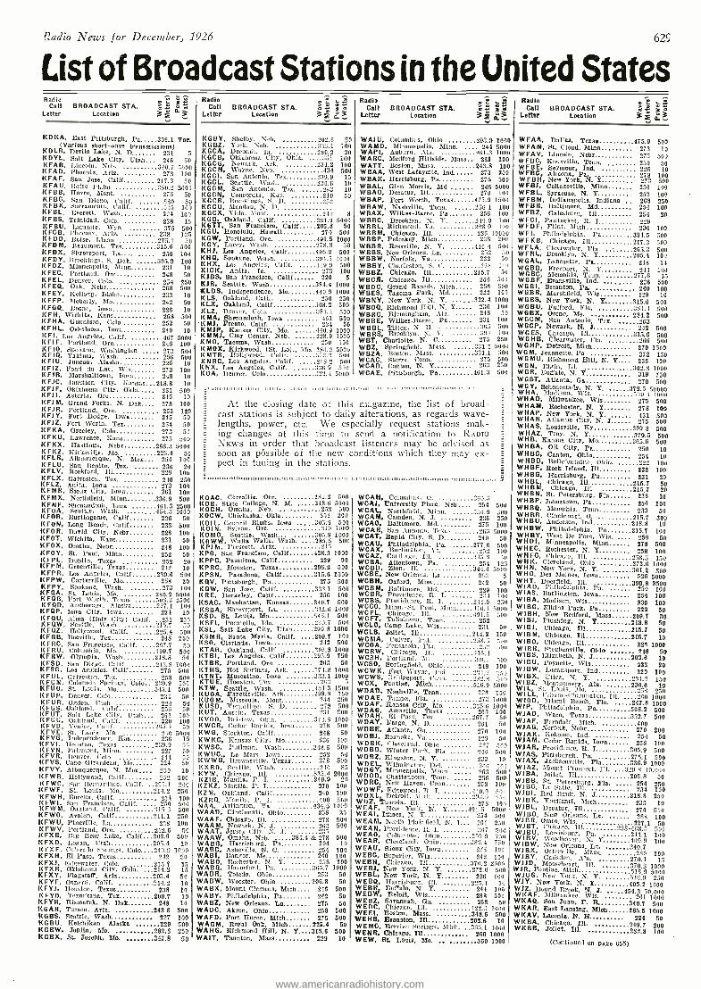
Radio News for December, 1926 629
List of Broadcast Stations in the United States Radio
Call BROADCAST STA. Letter Location 3 a3
KDKA, East Pittsburgh, Pa 309.1 Var. (Various short -wave transmissions) KILR, Devils Lake, N. D 231 5 IDYL, Salt Lake City. Utah 246 50
I( FAB, Lincoln, Neb. 340.7 5000 \( FAD , Phoenix, Ariz. 273 100 I(FAF, San Jose, Calif 217.3 50 K FA U, Moise Plaint 250.2 2000 KFSB, Havre, Mont. 275 50 KFBC, San Diego, Calif. 580 50 K FBK, Sacramento, Calif. 535 100 I(FBL, Everett, Wash 224 100 I(FBS, Trinidad, Colo. 258 15 I< FB U, Laramie, Wyo. 375 500 K FCB, Phoenix, Ariz. 230 125 KFDD, Moise, Idaho 275.1 50 KFDM, Beaumont, Tex 315.6 500 KFDX, Shreveport, Ln 250 100 KFDY, Brookings. S. Dak. 305.9 100 I(FDZ, Minneapolis, Minn 231 10 I(FEC, Portland, Ore 248 50 KFEL, Denver, Colo. 254 250 I(FEQ, Oak, Nebr 268 500 I(FEY, Kellogg, Idaho 233 10 KFFP, Moberly, Mo 242 50 I(FGQ, Boone, Iowa 226 10 I(FH, Wichita, Kano 268 500 I(FHA, Gunnison, Colo 252 50 I(FHL, Oskaloosa, Iowa 240 10 KFI. Los Angeles. Calif. 467 5000 1(FIF, Portland, Ore 218 100 I(FIO, Spokane, Washington 273 500 ((FI0, Yakima, Wash. 256 500 KFIU, Juneau, Alaska 226 10 I( FIZ, Fond du Lac, Wis 273 100 KFIB, Marshalltown, Iowa 248 10 I(FEC, Junction City, Kansas 218.8 10 K FI F, Oklahoma City, Okla 261 500 KFJ I, Astoria, Ore 246 10 I(FIM, Grand Forks, N. Dak 278 100 K FI R, Portland, Ore. 263 120 I(FJY, Fort Dodge, Iowa 246 50 KFJZ, Fort Worth, Tex 254 50 KFKA, Greeley, Colo 273 50 I(FKU, Lawrence, lions 275 500 KFI(X, Hastings, Nebr 288.3 5000 KFKZ, Kirksville, Mo. 225.4 50 I(FLR, Albuquerque, N. Mex 254 100 I(FLU, San Benito, Tex. 236 20 K FLN, Rockford, Ill 229 100 I(FLX, Galveston, Tex 290 250 KFLZ, Anita, Iowa 273 100 KFMR, Sioux City, Iowa 261 100 I(FLX, Northfield, Minn 336.9 500 KFNF, Shenandoah Iowa 461.3 2500 K FOA, Seattle, Wash. 454.3 1000 KFOB, Burlingame, Calif 226 50 KFON, Long Beach, Calif 233 500 KFOR, David City, Nebr 226 100 KFOT, Wichita, Hans 231 50 KFDX, Omaha, Nebr 248 100 KFOY, St. Paul, Minn 252 50 K FP L, Dublin, Texas 252 20 I(FPM, Greenville, Texas 242 10 K FPR, Los Angeles, Calif 230.6 500 KFPW, Carterville, Mo 258 20 I<FPY, Spokane, Wash. 273 100 I(FQA, St. Louis, Mo. 280.2 500(1 KFQB, Fort Worth, Texas 503.2 2100 I(FQD, Anchorage, Alaska 227.1 100 KFQP, Iowa City, Iowa 224 10 I(FQU, Alma (Holy City) Calif. .231 210 KFQW, Seattle, Wash 215.7 50 KFQZ, Hollywood, Calif. 225.4 500 KFRB, Beeville, Tex 248 250 KFRC, San Francisco, Calif. 207.7 50 It FR U. Columbia, Mo. 499.7 500 KFRW, Olympia, Wash 218.8 50 I<FSD, San Diego, Calif. 245.8 1000 I(FSG, Los Angeles, Calif 275 500 I(FUL, Galveston, Tee 258 500 1( F U M, Colorado Springs, Colo. 250.0 11)0 KFUO, St. Lattis, Mo 545.1 500 I(FUP, Denver, Celo 234 50 I(FUR, Ogden, Utah 224 50 K FUS, Oakland. Calif 256 50 I( FUT, Salt Lake City, Utah 261 100 1g F U U, Oakland, Calif. 220 100
-0i. 1 50 n 10 5000 236 15
.210.9 50 227 50 244 50 224 50
KFVY, Albuquerque, N. Mex.... 250 10 «FWB, Hollywood, Calif 252 500 I( F WC, Sao Bernardino, Calif. 291.1 200 KFWF, St. Louis, Mo 214.2 250 KFWH, Eureka, Calif. .. , 254 100 ltFW I, San Francisco. Calif. . 250 500 l(FWM, Oakland. Calif. 313 G 500
KFWO, Avalon, Calif 211.1 250 KFWU, Pineville, La 218 100 I(FW V, Pórtland, Ore. 212.G 50 KFXB, L'ig Bear Lake, Calif 202.6 500 I(FXD, Logan, Utah 205.4 10 I( FX F. Colorado Springs, Colo 219.9 1000 KFXH, El Paso, Texas 242 50 4(FXJ, Edgewater, Colo 215.7 15 KFXR, Oklahoma City, Obis. 214.2 15 KFXY, Flagstaff, Ariz 205.4 50 KFYF, Oxnard, Calif. 214.2 10 RFYJ, Houston. Texas 238 I(FYO, Texarkana, Ter 209.7 I(FYR, Bismarck, N. Dak 298 I(GAR, Tucson. Ariz. 243.8 KGBS, Seattle, Wash 227 KGBU. Ketchikan Alaska 229 K G B W, Joplin, Mo. 282.8 KGBX, SL Joseph, Mo, 347.8
KFVD, Venter, Calif. 1< FVE, St. Louis, Mo. 1( FVG, Independence, Kao I(FVI, Houston, Texas I(FVN, Fairmont, Minn. I(FV R, Denver, Colo. I(FVS, Cape Girardeau, Mo
10 10 10
500 100 500 250
50
Radio Call BROADCAST STA.
Letter Location
L J2 Radio m « Uri Call BROADCAST STA. 3 f 3 Letter Location
KGBY. Shelby, Neb, 20.2.6 KGBZ, York, Neb. 313.1 KGCA, Decorati, Ia. 280.2 \(GCB, Oklahoma City, Okla. .331 KGCG, Newark, Ark, 234.2 KGCH, Wayne, Neb. 434 KGCI, San Antonio, Ter 239.9 KGCL, Seattle, Wash. 230.6 KG CM, San Antonio, Tex. 263 KGCN, Concordia, Kas. 210 I(GCR, Brookings, S. D. -52 KGCU, Mandau, N. D. KGCX, Vida, Mont. 21(1 KGB, Oakland, Calif. 301.2 KGTT, San Francisco, Calif 206.8 KGU, Honolulu, Hawaii 270 KG W, Portland, Ore. 491.5 KGY, Lacey, Wash 178.8 KHJ, Loa Angeles, Calif 405.2 KHQ, Spokane, Wash. ':94.5 KHX, Los Angeles, Calif. 119.9 KICK, Anita, Ia. 273 KJ BS, San Francisco, Calif 220 KiR, Seattle, Wash 384.4 KLDS, Independence, blo 440.9 KLS, Oakland, Calif. 250 KLX, Oakland, Calif 508.2 KLZ, Denver, Colo. 101.1 KMA, Shenandoah. Iowa 461 'Kali, D'resno, Calif. 234 KMJP, Kansas City, Mo. 440.9 KMMJ, Clay Center, Neb. 233.9 KMO, Tacoma, Wash 450 KMOX, Kirkwood, (Si Lo).. Mo 280.2 I( MLR, Hollywood. Calif. 12.2 I<NRC, Los Angeles, Calif. 203.2 KNX, Los Angeles, Calif. 336.9 KOA, Denver, Colo 322.4
50 100
20 100 100 500
15 10 10 50
8 5000
50 500
1000 50
500 1000
500 100
5 1000 1000
250 500 500 500
50 1000 1000 100
5000 500 500
500 5000
° té-sl 3f 0°3
WAIU, Columbus, Ohio 293.9 1000 WAMD, Minneapolis, Minn. ., 244 5000 WAPI, Auburn, Ala. 161.3 1000 WARC, Medford Hillside, Mass 261 100 WATT, Boston, Mass. 243.8 100 WBAA, West Lafayette, Ind WBAK, Harrisburg, Pa WEAL, Glen Morris. Md WBAO, Decatur, Ill W BAP, Fort Worth, Texan WBAW, Nashville, Tents. WBAX, Wilkes- Barre, Pa WBBC, Brooklyn, N. Y. WBBL, Richmond, Va WBBM, Chicago, Ill. WBBP, Petoskey, Mich WBBR, Itossville, N. Y. WEBS, New Orleans. La. WBBW, Norfolk, Va WBBY, Charleston, S. C. WBBZ, Chicago. Ill WBCR, Chicago, Ill WBDC, Grand Rapids, Mich WBES, Takoma Park, Md WBNY, New York. N. Y. WBOQ, Richmond Hill, N. Y WBRC, Birmingham, Ala. WBRE, Wilkes- Barre, Pa WBBL, Tilton, N. I-I. WBRS, Brooklyn, N. Y. W BT, Charlotte, N. C
W BZ, Springfield, Mass. WBZA, Boston, Mass. WCAC, Storrs, Conn. WOAD, Canton, N. Y WCAE, Pittsburgh. Pa
273 250 275 500 246 5000 270 11)11
475.9 1500 2361.1 100
256 100 349.9 100 220.9 100 "26 10000 228 200
416.4 500 252 50 222 50 208 leo
215.7 50 26G 5)10 258 500 222 100
322.4 1000 236 100 248 50 231 100 365 500 391 100 272 250
331.1 5000 331.1 500
275 500 211:1 250
461.3 500
.1.111111.11111111111.111 111.111111,1111111,1111m1: .11111111,111.: .
At the closing date of this magazine, the list of broad- cast stations is subject to daily alterations, as regards wave- lengths, power, etc. We especially request stations mak- ing changes at this time to send a notification to RADIO NEWS in order that broadcast listeners may be advised as soon as pôssible of the new conditions which they may ex- pect in tuning in the stations.
KOAC, Corvallis. Ore. 230.2 500 ROB, State College. N. M. 348.6 5000 KOCH, Omaha, Neb. 258 500 l(OCW, Chickasha, Okla 152 200 KOIL, Council Bluffs, Iowa 305.9 500 K 01 N, Sylvan, Ore. 11.0 1000 KO MO, Seattle, Wash... 305.9 1000 KOW W. Walla Walla, Waah. 285.5 50C KPJ In, Prescott, Aria. 215 1(P0, San Francisco, Calif 428.3 1000 I(PPC, Pasadena, Calif 229 50 I(PRC, Houston, Texas 290.9 500 I(PSN, Pasadena, Calif 315.6 1000 1(0V, Pittsburgh, Pa 275 500 KQW, San Jose, Calif. 333.1 500 K R E, Berkeley, Calif 256 100 I(SAC, Manhattan, Kansas 340.7 500 KSBA, Shreveport, La. 312.0 1000 KSD, St. Louis. Mo 545.1 500 KSEl, Pocatello, Ida. - =10.7 500 l(SL, Salt Lake City. Utah 290.8 1000 KSMR, Santa Maria, Calif. ,, 209.7 100 ESO, Clarinda, Imva STAB, Oakland. Calif. I(TBI, Los Angeles, Calif I(TBR, Portland. Ore KT HS, Hot Springs, Ark. KT NT, Muscatine Iowa I(TUE, Houston,
Muscatine,
KTW. Seattle, Wash. 16 U OA, Fayetteville, Ark I(UOM, Missoula, Mont I(USTI, Vermillion, S. D. I(UT. Austin, Texas KVO0, Bristow, O11a I(WCR, Cedar Rapids, Iowa 1(WG, Stockton, Calif KW 1(C, Kansas City, Mo I(W SC, Pullman, Wash I(W UC Lo Mars, Iowa KWWG, Brownsville, Texas KXRO, Seattle, Wash. I(YW, Chicago, Ill. l<ZI B, Manila, P. I. KzKz, Manila, P. I 1(Z M, Oakland, Calif KZRQ, Manila, P. I. NAA. Arlington, Va. WAAD, Cincinnati, Ohio WAAF, Chicago, Ill. W AA M, Newark, N. T WAAT, Jersey City. N. T ..5
8 WAAW, Omaha, Neb. 384.4 So 27 500 WABB, Harrisburg, Pa 204 10 WABC, Asheville, N. C. 254 100 WABI, Bangor, Sie 240 100 WABO, Rochester. N. Y. 258 100 WABQ, Havolford. Pa '105.7 1000 WABB, Toledo, Ohio 263 50 WABW, Wooster, Ohio 206.8 50 WABX, Mount Clemens, Mich., 246 500 WA BY, Philadelphia, Pa 242 50 WABZ, New Orleans, La 275 50 WADC, Akron, Ohio 258 500 WAFD, Port Huron, Mich 275 500 WAGM, Royal Oak, Mich 226.4 50 WANG, Richmond Hill, N. Y 315.6 500 WAIT, Taunton, Mass 229 10
292 500 302.8 1000 293.9 750
263 50 374.8 1000 333.1 1000
203 , 454.3 1500 299.8 750
..44 250 278 500 2:31 500
371.3 1000 278 500 248 50 2SG 1(l0
398.6 50(1
50 278 500 210 85
515.4 2000 515.4 20
270 100 240 100 400 500
434.5 1000 258 25 278 500 263 500
WCAH, Columbus, O. 2(35.3 WCAJ, University Place, Nob 254 500 WCAL, Northfield, Minn. 336.9 500 WCAM, Camden, N. J. WCAO, Baltimore, Md WCAR, San Antonio, Texas WCAT, Rapid City, S. D WCAU, Philadelphia, Pa. WCAX, Burlington, Vt. WCAZ, Carthage, III. WCBA, Allentown, Pa. WCBD, Zion, Ill WCBE, New Orleans. La WCBH, Oxford, Miss WCBM, Baltimore, Md. WCBR, Providence, R. I. WCBS, Providence, It. I. WCCO, Minn. -St. Paul, Minn WC FL, Chicago, Ill. WCFT, Tullahoma, Tenn. WCLO, Camp Lake, Win WCLS, Joliet, Ill WCMA, Culver, Ind. WCOA, Pensacola, FIs WCRW, Chicago, Ill. WCSH, Portland. Ate. WCSO, Springfield, Ohio WCWK, Fort Wayne, Ltd WOWS, Bridgeport, Coml WCX, Pontiac, Mich WOAD, Nashville, Tenn WDAE, Tampa, Fla. WDAF, Kansas City, Mo. WDAG, Amarillo, Texas W DA H, El Paso, Tex. W DAY, Fargo, N. D WDBE, Atlanta, Oa WDBJ, Roanoke, V. W D BI(, Cleveland, Ohio WD BO, Winter Park, Fla WDBZ, Kingston, N. Y WDEL, Wilminseton, Del. WDGY, Minneapolis, Minn W DOD, Chattanooga, Tenn WDRC, New llanca, Conn W D W F, Edgewood. R. I. WDXL, Detroit, Mich WOZ, Tuscola, Ill. WEAF, New York, N. Y WEAI, Ithaca, N. Y WEAM, North Plainfield, N. J... 261 250 WEAN, Providence, R. I. 167 50( WEAO, Columbus, Ohio 2939 SPI WEAR, Cleveland, Ohio 389.4 750 WEAU, Sioux City, Iowa 275 100 W ERG, Superior, Wis 242 100 WEBH, Chicago, Ill 370.2 2005 WEBJ, New York, N. Y. 272.6 500 WEBL, New York, N. Y 226 100 WEBQ, Harrisburg. Ill. 921.4 10 WEBR. Buffalo, N. Y. 244 100 WEBW, Beloit, Wis 268 500 WEBZ, Savannah, Ga. 263 50 WEDC, Chicago, Ill. 422.3 1000 WEEI, Boston, Mass. 348.6 500 WEHS, Evanston, Ill 202.6 10 WEMC, Berrien Springs, Mich. ,.365.1 4000 W E N R, Chicago, Ill 266 1000 WEW, St. Louis, Mo. 360 1000
50 275 100 263 5000 240 50
277.6 50(1 100
21:5.8 50 254 125
344.6 5000 263 212 50 229 100 234 100
242.5 250 .416.4 5000 491.5 500
252 231 50
214.2 150 258.5 Sou
100 416.4
WI 7 500 248 100
2111.2 250 232..4 500 516.9 5000
226 150 273 1000
365.6 1000 263 100
267.7 50 261 50 270 100 229 50 227 500 240 500 233 10 206 100 263 500 256 500 26s
500
440.9 500 29.1.9 Ils
278 100 491.5 5000
254 500
Radio Call BROADCAST STA.
Letter Location 3 d3
WFAA, Dallas, Texas 475.9 500 W FA M, St. Cloud, Minn 273 10 WFAV, Lincoln, Nebr 275 500 W FBC, Knoxville, Tenn. .. 250 50 WFBE, Seymour, Ind. 216 30 W FRG, Altoona, Pa. 278 100 W FBH, New York. N. Y
278 500
WFBJ, Collegeville, Minn 236 100 WFBL, Syracuse, N. Y 252 100 WFBM, Indianapolis, Indiana 268 250 W FBI/. Baltimore, Md 254 100 W FBZ, Galesburg, Ill 254 20 W FCI, Pawtucket, R. I 129 WFDF, Flint, Mich 234 100 WFI, Philadelphia, I'a 394.5 500 WFKB, Chicago, Ill 217.3 500 WFLA, Clearwater, Fla. 265.3 500 WFRL, Brooklyn, N. Y 205.4 100 WGAL, Lancaster, Pa 248 10 WGBB, Freeport, N. Y 244 100 WGBC, Memphis, Tenn, 277.6 15 WGBF, Evansville, Ind. 236 500 W G B I, Scranton, Pa. 240 100 WGBR, Marshfield, Wis 229 10 WGBS, New York, N. Y 315.6 500 W GB U, Fulford, Fla. as4.4 500 W G BX, Orono, Me. 234.2 500 WGCM, San Antonio, Tex. 263 W6CP, Newark, N. J 252 500 W G ES, Chicago, Ill 31.5.6 500 W G H B, Clearwater, FI'i 266 5110 WGHP, Detroit. Mich 270 1500 WGM, Jeannette, Pa 372 150 WG M U. Richmond Hill, N. Y 236 100 W G N, Elgin, Ill, 102.8 1000 WGR, Buffalo, N. Y 319 750 WGST, Atlanta, Ga 270 500 WGY, Schenectady, N'. Y. 379.5 50000 WHA, Madison, Wis. 530.1 1000 WHAD, Milwaukee, Wis 275 500 WHAM, Rochester, N. Y 278 109 WHAP, New York, N. Y. 431 500 WHAR, Atlantic City, N. J 275 500 WHAS, Louisville, Ky 399.8 500 W HAZ, Troy, N. Y 379.5 500 WHB, Kansas City, Mo 365.6 500 WHBA, Oil City, Pa 250 10 WHBC, Canton, Ohio 254 10 WH BD, Bellefontaine, Ohio. 2,22 100 WHBF, Stock Island, Ill 222 100 WHBG, Harrisburg. Pa 231 20 WHBL, Chicago, Ill 215.7 50 WHBM, Chicago, Ill. 215,7 20 WHEN, St. Petersburg, Fla 238 10 WHBP, Johnstown, Pa 256 100 WHBQ, Memphis, Tenn 233 50 WHBR, Cincinnati, O. 215.7 300 WHBU, Anderson, Ind 218.8 10 WHEW, Philadelphia, Pa 215.7 100 WHEY, West I)e Pero, Wis. .. 250 50 W H D I, Minneapolis, Minn 278 500 WH EC, Rochester, N. Y 258 100 W H FC, Chicago, Ill. 258.5 150 W H K, Cleveland, Ohio 272.6 1000 W H N, Now York, N. Y. 361.2 500 WHO, Des Moines, Iowa 526 5000 WHT, Deerfield Ill. 399.8 3500 WIAD, Philadelphia, Pa. 250 100 WIAS, Burlington, Iowa 254 100 WIBA, Madison, Wis 236 100 W IBO, Elkins Park, Pa 222 50 WIBH, New Bedford, Mass 209.7 30 WIBI, Flushing, N. Y 218.8 50 WIB1, Chicago; Ill 215.7 50 W IBM, Chicago, Ill 215.7 10 W I BO, Chicago, Ill 226 1000 WIBR, Steubenville, Ohio 246 50 W IBS, Elizabeth, N. J 302.6 10 W I B U, Poynette, Wis 222 20 WIBW, Logansport, Ind 220 100 WIBX, Utica, N. Y. 234.2 150 W I BZ, Montgomery, Ala. 230.6 10 W I L, St. Louis, Mo. 953 250 W I L L, l l/ulna -Chanmaign, Ill. 200 1000 W I O D, Miami Beach, Fla. 247.8 1000 WIP, Philadelphia, Pa 508.2 500 WJAD, %Vaco, Texas 352.7 500 WJAF, Ferndale, Mich. 400 WJAG, Norfolk, Nebr 270 200 WJAK, Kokomo, Ind. 254 50 WJAM, Cedar Rapids, Iowa 268 100 WJAR, Providence, K. I 305.9 500 WJAS, Pittsburgh, Pa. 275.1 500 WIAX, Jacksonville, 1175 336.9 1000 WJAZ, Mount Prospect, Ill. ...:329 8 10,000 WJBA, Joliet, Ill 206.8 50 WJBB, St. Petersburg, Fla, 254 250 W1 BC, La Salle, Ill. 234 100 W1B1, Red Bank, N. d 218.8 250 WJBK, Ypsilanti, Mich 233 10 WJBL, Decatur, Ill 270 500 WJBO, New Orleans, La. 268 100 W1 B R, Omro, Wis. 227.1 50 WJBT, Chicago, Ill 233 -468.5 500 WJBU, Lewisburg, Pa. 211.1 100 WJ BV, Woodhaven, N. Y 4(19.9 100 WJBW, New Orleans, La. 340.7 WJBX, Osterville, Mass. 280 100 WIRY. Gadsden. Ala. 270.1 15 WJJD, Mooseheart, Ill, 570.2 10)10 Wirt. Pontiac, Mich 518,9 5000 WJ UG, New York, N. Y. 516.9 250 WJY, New York, N. Y 405.2 1000 WJZ, Bound Brook, N. L 454.3 50,000 W KAF, Milwaukee, Wis. 261 1000 WKAQ, San Juan, P. R 340.7 500
W KAR, East Lansing, Mich 285.5 1000 WKAV, Laconia, N. H. 224 50 W ICBA, Chicago, Ill. - 209.7 200 W K B B, Joliet, Ill. 282.8 100
(Continued on page 655)
www.americanradiohistory.com
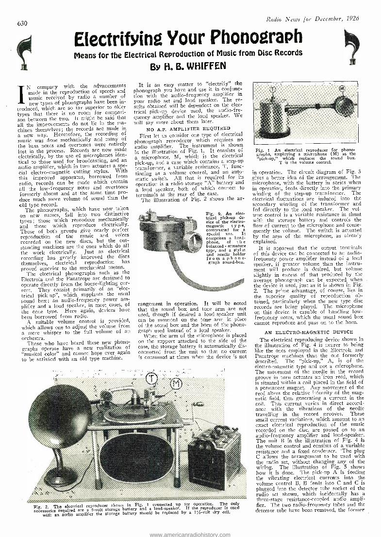
630 Radio News for December, 1926
E(ectrïfin Your Phonograph Means for the Electrical Reproduction of Music from Disc Records
By H. B. WH(FFEN
IN company with the advancements made in the reproduction of speech and music received by radio a number of new types of phonographs have been in-
troduced, which are so far superior to older types that there is no room for compari- son between the two. It might be said that all the improvements do not lie in the ma- chines themselves; the records are made in a new way. Heretofore, the recording of music was done mechanically and many of the bass notes and overtones were entirely lost in the process. Records are now made electrically, by the use of microphones iden- tical to those used for broadcasting, and an audio amplifier, which in turn actuates a spe- cial electro- magnetic cutting stylus. With this improved apparatus, borrowed from radio, records can be made which contain all the low- frequency notes and overtones formerly absent and at the same time pro- duce much more volume of sound than the old type record.
The phonographs, which have now taken on new names, fall into two distinctive types ; those which reproduce mechanically and those which reproduce electrically. Those of both groups give nearly perfect reproduction of the music and voices recorded on the new discs, but the out- standing machines are the ones which do all the work electrically. Just as electrical recording has greatly improved the discs themselves, electrical reproduction has proved superior to the mechanical means.
The electrical phonographs such as the Electrola and the Panatrope are designed to operate directly from the house- lighting cur- rent. They consist primarily of an "elec- trical pick -up ", which supplants the usual sound box; an audio -frequency power am- plifier and a loud speaker, in most cases, of the cone type. Here again, devices have been borrowed from radio.
A suitable volume control is provided, which allows one to adjusf the volume from a mere whisper to the full volume of an orchestra.
Those who have heard these new phono- graphs operate have a new realization of "musical color" and cannot hope ever again to be satisfied with an old type machine.
It is an easy matter to "electrify" the phonograph you have and use it in conjunc- tion with the audio- frequency amplifier in
your radio set and loud speaker. The re- sults obtained will be dependent on the elec- trical pick -up device used, the audio -fre- quency amplifier and the loud speaker. We will say more about them later.
NO A.F. AMPLIFIER REQUIRED
First let us consider one type of electrical phonograph reproducer which requires no audio amplifier. The instrument is shown in the illustration of Fig. 1. It consists of a microphone, M, which is the electrical pick -up, and a case which contains a step -up
transformer, a variable resistance, T, func- tioning as a volume control, and an auto- matic switch. All that is required for its
operation is a radio storage "A" battery and a loud speaker, both of which connect to terminals at the rear of the case.
The illustration of Fig. 2 shows the ar-
Fig. 9. An elec- trical pick -up de- vice of the electro- magnetic t y p e, constructed for a special use. It comprises a head- phone, of t li e balanced - armature type, and a stylus and needle holder from a phono- graph sound -box.
rangement in operation. It will be noted that the sound box and tone arm are not used, though if desired a loud- speaker unit can be mounted on the tone arm in place of the sound box and the horn of the phono- graph used instead of a loud speaker.
When the arm of the microphone is placed on the support attached to the side of the case, the storage battery is automatically dis- connected from the unit so that no current is consumed at times when the device is not
Fig. 2. The electrical reproducer shown in Fig. 1 connected up for operation. The only
accessories required are a 6 -volt storage battery and a loud- speaker. If the reproducer is used
with an audio amplifier the storage battery should be replaced by a 11A-volt dry cell.
Fig. 1 An electrical reproducer for phono- graphs, employing a microphone (M) as the "pick -up," which replaces the sound box.
T is the volume control.
in operation. The circuit diagram of Fig. 3 gives a better idea of the arrangement. The microphone, with the battery in series when in operation, feeds directly into the primary winding of the step -up transformer. The electrical fluctuations are induced into the secondary winding of the transformer and fed directly to the loud speaker. The vol- ume control is a variable resistance in shunt with the storage battery and controls the flow of current to the microphone and conse- quently the volume. The switch is actuated by the arm of the microphone, as already explained.
It is apparent that the output terminals of this device can be connected to an audio - frequency power amplifier instead of a loud speaker, if greater volume than the instru- ment will produce is desired, but volume slightly in excess of that produced by the average phonograph can be expected when the device is used, just as it is shown in Fig. 2. The prime advantage, of course, lies in the superior quality of reproduction ob- tained, particularly when the new type disc records are being played. The microphone on this device is capable of handling low - frequency notes, which the usual sound box cannot reproduce and pass on to the horn.
AN ELECTRO- MAGNETIC DEVICE
The electrical reproducing device shown in the illustration of Fig. 4 is nearer to being like the ones employed in the Electrola and Panatrope machines than the one formerly described. The "pick -up," A, is of the electro- magnetic type and not a microphone. The movement of the needle in the record groove in turn actuates an iron reed, which is situated within a coil placed in the field of a permanent magnet. Any movement of the reed alters the relative intensity of the mag- netic field, thus generating a current in the coil. This current varies in direct accord- ance with the vibrations of the needle travelling in the record grooves. These small current variations, which amount to an exact electrical reproduction of the music recorded on the disc, are passed on to an audio- frequency amplifier and loud- speaker. The unit B in the illustration of Fig. 4 is the volume control and consists of a variable resistance and a fixed condenser. The plug C allows the arrangement to be used with the radio set, without changing any of the wiring. The illustration of Fig. 5 shows how it is done. The pick -up A is feeding the vibrating electrical currents into the volume control B, B feeds into C and C is plugged into the detector tube socket of the radio set shown, which incidentally has a three -stage resistance -coupled audio ampli- fier. The two radio -frequency tubes and the detector tube have been removed, the former
www.americanradiohistory.com
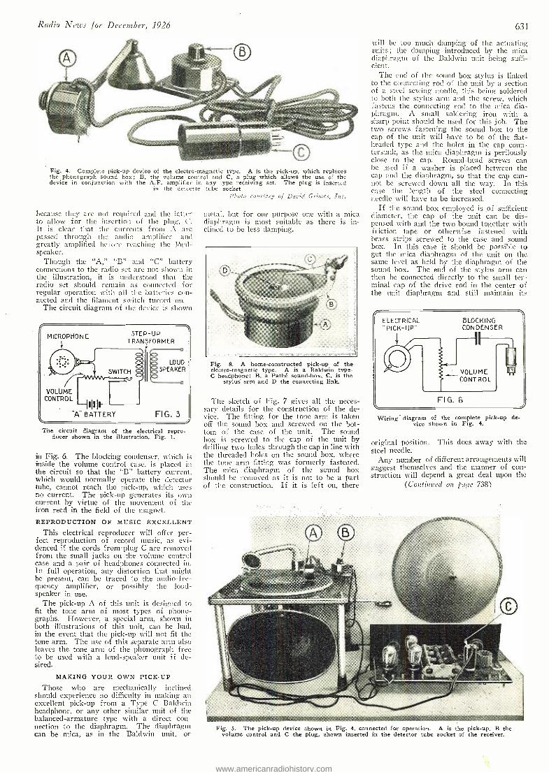
Radio News for December, 1926
Fig. 4. Complete pick -up device of the electro- magnetic type. A is the pick -up, which replaces the phonograph sound box; B, the volume control and C, a plug which allows the use of the device in conjunction with the A.F. amplifier in any type receiving set. The plug is inserted
in the detector tube socket. Photo conrtcsy of David Grintcs, Inc.
because they are not required and the latter to allow for the insertion of the plug, C. It is clear that the currents from A are passed through the audio amplifier and greatly amplified before reaching the 16nd- speaker.
Though the "A," "B" and "C" battery connections to the radio set are not shown in the illustration, it is understood that the radio set should remain as connected for regular operation with all the batteries con- nected and the filament switch turned on.
The circuit diagram of the device is shown
MICROPHONE STEP -UP TRANSFORMER
SWITCH
VOLUME CONTROL
I'll
LOUD SPEAKER
FIG. 3
The circuit diagram of the electrical repro- ducer shown in the illustration, Fig. 1.
in Fig. 6. The blocking condenser, which is inside the volume control case, is placed in the circuit so that the "B" battery current, which would normally operate the detector tube, cannot reach the pick -up, which uses no current. The pick -up generates its own current by virtue of the movement of the iron reed in the field of the magnet.
REPRODUCTION OF MUSIC EXCELLENT This electrical reproducer will offer per-
fect reproduction of record music, as evi- denced if the cords from plug C are removed from the small jacks on the volume control case and a. pair of headphones connected in. In full operation, any distortion that might be present, can be traced to the audio -fre- quency amplifier, or possibly the loud- speaker in use.
The pick -up A of this unit is designed to fit the tone arm of most types of phono- graphs. However, a special arm, shown in both illustrations of this unit, can be hate, in the event that the pick -up will not fit the tone arm. The use of this separate arm also leaves the tone arm of the phonograph free to be used with a loud -speaker unit if de- sired.
MAKING YOUR OWN PICK -UP
Those who are mechanically inclined should experience no difficulty in making an excellent pick -up from a Type C Baldwin headphone, or any other similar unit of the balanced -armature type with a direct con- nection to the diaphragm. The diaphragm can be mica, as in the Baldwin unit, or
metal, but for our purpose one with a mica diaphragm is most suitable as there is in- clined to be less damping.
Fig. 8. A home -constructed pick -up of the electro- magnetic type. A is a Baldwin type - C headphone; B, a Pathé sound -box, C. is the
stylus arm and D the connecting link.
The sketch of Fig. 7 gives all the neces- sary details for the construction of the de- vice. The fitting for the tone arm is taken off the sound box and screwed on the bot- tom of the case of the unit. The sound box is screwed to the cap of the unit by drilling two holes through the cap in line with the threaded holes on the sound box, where the tone aria fitting was formerly fastened. The mica diaphragm of the sound box should be removed as it is not to be a part of the construction. If it is left on, there
631
will be too much damping of the actuating traits ; the clamping introduced by the mica diaphragm of the Baldwin unit being suffi- cient.
The end of the sound box stylus is linked to the connecting rod of the unit by a section of a steel sewing needle, this being soldered to both the stylus arm and the screw, which fastens the connecting rod. to the mica dia- phragm. A small soldering iron with a sharp point should be used for this job. The two screws fastening the sound box to the cap of the unit will have to be of the flat - headed type and the holes in the cap coun- tersunk, as the mica diaphragm is perilously close to the cap. Round -head screws can be used if a washer is placed between the cap and the diaphragm, so that the cap can- not be screwed down all the way. In this case the length of the steel connecting needle will have to be increased.
If the sound box employed is of sufficient diameter, the cap of the unit can be dis- pensed with and the two bound tog-ether with friction tape or otherwise fastened with brass strips screwed to the case and sound box. In this case it should be possible to get the mica diaphragm of the unit on the same level as held by the diaphragm of the sound box. The end of the stylus arm can then be connected directly to the small ter- minal cap of the drive rod in the center of the trait diaphragm and still maintain its
Wiring diagram of the complete pick -up de- vice shown in Fig. 4.
original position. This does away with the steel needle.
Any number of different arrangements will suggest themselves and the manner of con- struction will depend a great deal upon tite
(Continued on Cage 738)
Fig. 5. The pick -up device shown in Fig. 4, connected for operation. A is the pick -up, B the volume control and C the plug, shown inserted in the detector tube socket of the receiver.
www.americanradiohistory.com
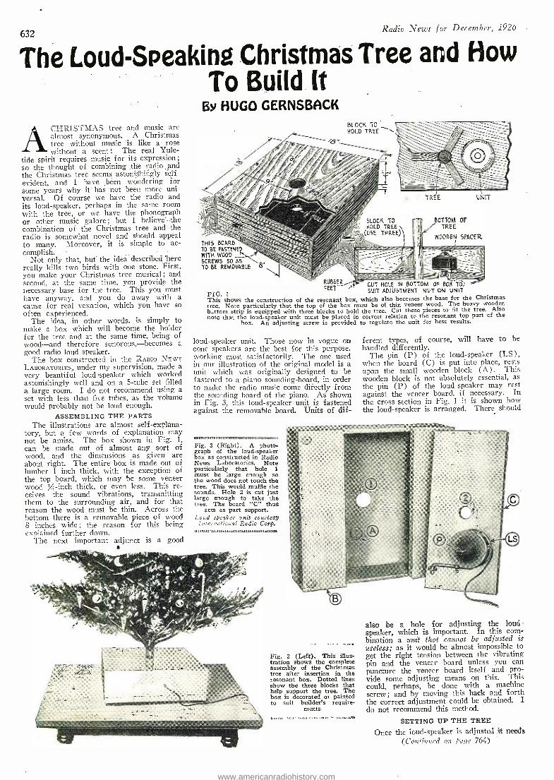
632 Radio News for December, 1920
The Loud -Speaking Christmas Tree and How To Build It
ACHRISTMAS tree and music are almost synonymous. A Christmas tree without music is like a rose without a scent! The real Yule-
tide spirit requires music for its expression; so the thought of combining the radio and the Christmas tree seems astonishingly self evident, and I have been wondering for some years why it has not been more uni- versal. Of course we have the radio and its loud -speaker, perhaps in the same room with the tree, or we have the phonograph or other music galore ; but I believe" the combination of the Christmas tree and the radio is somewhat novel and should appeal to many. Moreover, it is simple to ac- complish.
Not only that, but the idea described here really kills two birds with one stone. First, you make your Christmas tree musical ; and second, at the same time, you provide the necessary base for the tree. This you must have anyway, and you do away with a cause for real vexation, which you have so often experienced.
The idea, in other words, is simply to make a box which will become the holder for the tree and at the same time, being of wood -and therefore sonorous, -becomes a good radio loud speaker.
The box constructed in the RADIO NEWS LABORATORIES, under my supervision, made a very beautiful loudspeaker which worked astonishingly well and on a 5 -tube set filled a large room. I do not recommend using a set with less than five tubes, as the volume would probably not be loud enough.
ASSEMBLING THE PARTS The illustrations are almost self- explana-
tory, but a few words of explanation may not be amiss. The box shown in Fig. 1,
can be made out of almost any sort of wood, and the dimensions as given are
about right. The entire box is made out of lumber 1 inch thick, with the exception of the top board, which may be some veneer wood / -inch thick, or even less. This re- ceives the sound vibrations, transmitting them to the surrounding air, and for that reason the wood must be thin. Across the bottom there is a removable piece of wood 8 inches wide; the reason for this being explained further down.
The next important adjunct is a good
BY HUGO GERNSBACK BLOCK 70 HOLD TREE
THIS BOARD Ç-Z, 10 BE FASTENE1' WITH WOOD II- SCREWS SO AS `; /Ii TO BE REMOVABLE
8.
`Ipin BLOCK TO HOLD TREE \
(USE THREEA
,_y RUBBER, FEET -
FIG. 1
This shows the construction of the resonant box, tree. Note particularly that the top of the box m b_ttom strip is equipped with three blocks to hold note that the loud- speaker unit must be placed in
hox. An adjusting screw is provided
loud- speaker unit. Those now in vogue on cone speakers are the best for this purpose. working most satisfactorily. The one used in our illustration of the original model is a unit which was originally designed to be fastened to a piano sounding - board, in order to malee the radio music come directly from the sounding board of the piano. As shown in Fig. 3, this loud- speaker unit is fastened against the removable board. Units of dif-
IM11},111.1711
Fig. 3 (Right). A photo- graph of the loud- speaker box as constructed in Radio News Laboratories. Note particularly . that hole 1 must be large enough so the wood does not touch the tree. This would muffle the sounds. Hole 2 is cut just large enough to take the tree. The board "C" thus
acts as part support. Loud speaker unit courtesy International Radio Coro.
UNIT
BOTTOM OF TREE
WOODEN SPACER
!;:
CUT HOLE IN BOTTOM OF BOX TÒ; SUIT ADJUSTMENT ON UNIT
which also becomes the base for the Christmas ust be of thin veneer wood. The heavy wooden the tree. Cut these pieces to fit the tree. Also correct relation to the resonant top part of the
to regulate the unit for best results.
ferent types, of course, will have to be handled differently.
The pin (P) of the loud- speaker (LS), when the board (C) is put into place, rests upon the small wooden block (A). This wooden block is not absolutely essential, as the pin (P) of the loud -speaker may rest against the veneer board, if necessary. In the cross -section in Fig. 1 it is shown how the loud- speaker is arranged. There should
Fig. 2 (Left). This illus- tration shows the complete assembly of the Christmas tree after insertion in the resonant box. Dotted lines show the three blocks that help support the tree. The box is decorated or painted to suit builder's require-
ments.
also be a hole for adjusting the loud- speaker, which is important. In this com- bination a knit that cannot be adjusted is useless; as it would be almost impossible to get the right tension between the vibrating pin and the veneer board unless you can puncture the veneer board itself and pro- vide some adjusting means on this. This could, perhaps, be done with a machine screw; and by moving this back and forth the correct adjustment could be obtained. I do not recommend this method.
SETTING UP THE TREE
Once the loud- speaker is adjusted it needs (Continued on page 764)
www.americanradiohistory.com
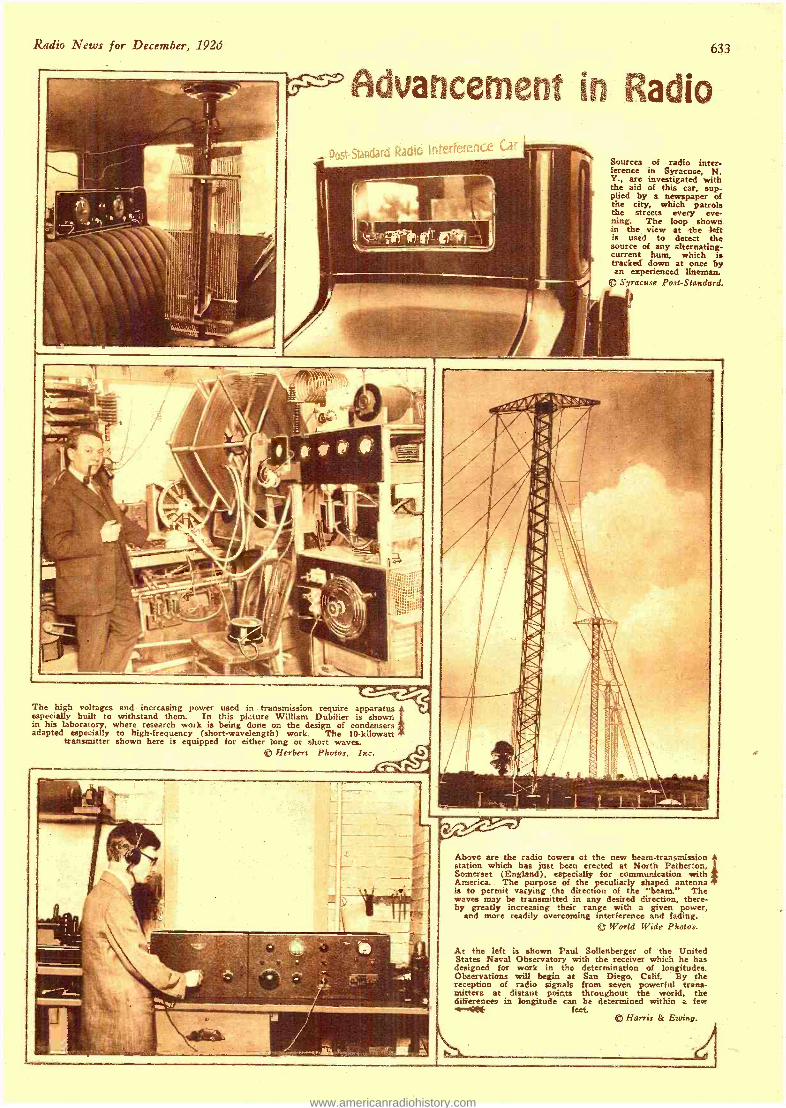
Radio News for December, 192J 633
Advancement in Radio
- Post-Standard Radfo Sources of radio inter- ference in Syracuse, N. Y., are investigated with the aid of this car. sup- plied by a newspaper of the city, which patrols the streets every eve- ning. The loop shown in the view at the left is used to detect the source of any alternating - current hum, which is tracked down at once by an experienced lineman.
© Syracuse Post -Standard.
The high voltages and increasing power used in transmission require apparatus especially built to withstand them. In this picture William Dubilier is shown in his laboratory, where research work is being done on the design of condensers adapted especially to high- frequency (short- wavelength) work. The 10- kilowatt
transmitter shown here is equipped for either long or short waves. ------yyyyyy
© Herbert Photos, Inc. T<
Above are the radio towers of the new beam -transmission station which has just been erected at North Petherton, Somerset (England). especially for communication with America. The purpose of the peculiarly shaped antenna is to permit varying the direction of the "beam." The waves may be transmitted in any desired direction, there- by greatly increasing their range with a given power,
and more readily overcoming interference and fading. Q World Wide Photos.
At the left is shown Paul Sollenberger of the United States Naval Observatory with the receiver which he has designed for work in the determination of longitudes. Observations will begin at San Diego, Calif. By the reception of radio signals from seven powerful trans- mitters at distant points throughout the world, the differences in longitude can be determined within a few 4141E feet.
® Harris & Ewing.
1 d
www.americanradiohistory.com
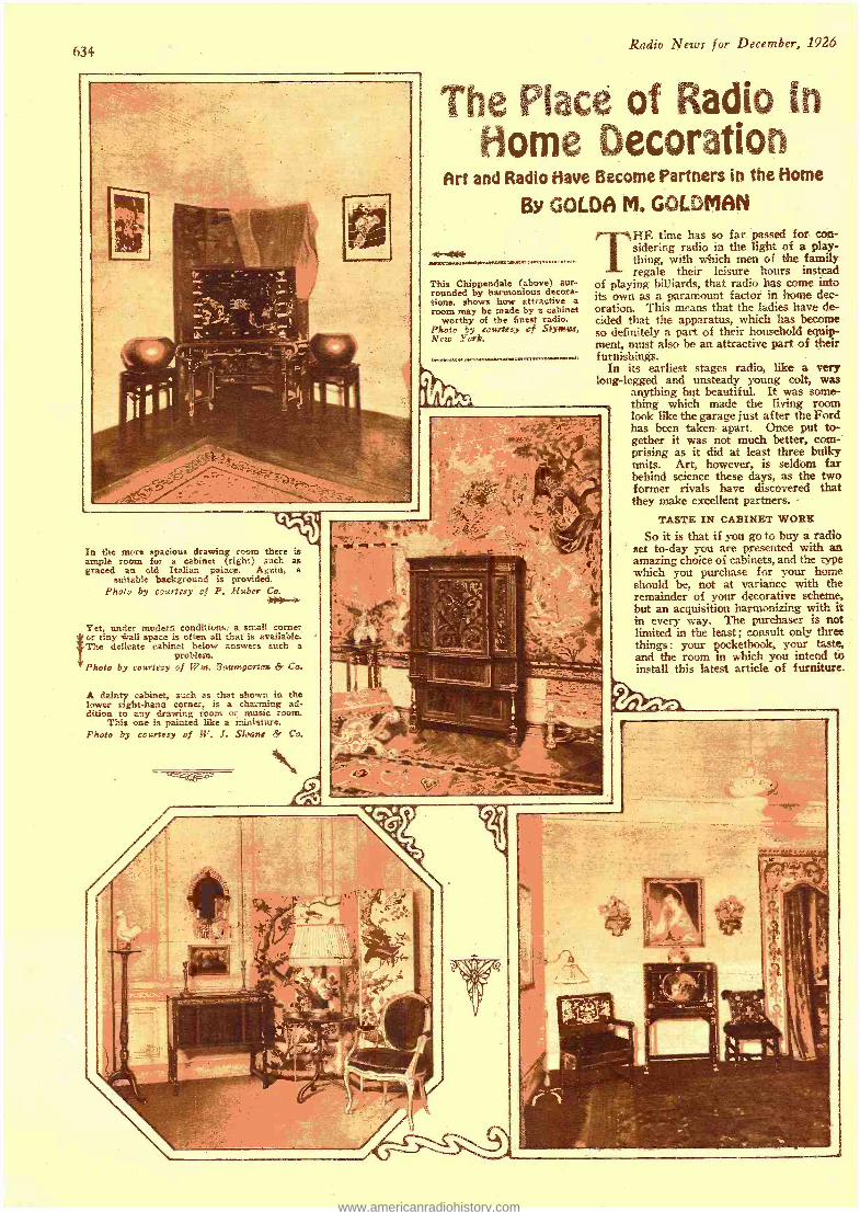
634 Radio News for December, 1926
The Place of Radio to Home Decoration
Art and Radio Have Become Partners in the Home
By GOLDA M. GOLDMAN
This Chippendale (above) sur- rounded by harmonious decora- tions, shows how attractive a room may be made by a cabinet
worthy of the finest radio. Photo by courtesy of Stylvw,t, New York.
OM WWW NW W.14144 aVMWOMMW.17.31,111.1..M,PMMMM.
THE time has so far passed for con- sidering radio in the light of a play- thing, with which men of the family regale their leisure hours instead
of playing billiards, that radio has come into its own as a paramount factor in home dec- oration. This means that the ladies have de- cided that the apparatus, which has become so definitely a part of their household equip- ment, must also be an attractive part of their furnishings.
In its earliest stages radio, Iike a very long- legged and unsteady young colt, was
anything but beautiful. It was some- thing which made the living room look like the garage just after the Ford has been taken apart. Once put to- gether it was not much better, com- prising as it did at least three bulky units. Art, however, is seldom far behind science these days, as the two former rivals have discovered that they make excellent partners.
TASTE IN CABINET WORE
So it is that if you go to buy a radio set to -day you are presented with an amazing choice of cabinets, and the type which you purchase for your home should be, not at variance with the remainder of your decorative scheme, but an acquisition harmonizing with it in every way, The purchaser is not limited in the least ; consult only three things: your pocketbook, your taste, and the room in which you intend to install this latest article of furniture.
In the more spacious drawing room there is ample room for a cabinet (right) such as graced an old Italian palace. Again, a
suitable background is provided. Photo by courtesy of F. Huber Co.
Yet, under modern conditions a small corner Ior tiny wall space is often all that is available. The delicate cabinet below answers such a
problem. Photo by courtesy of Wm. Boumgarfes & Co.
A dainty cabinet, such as that shown in the lower right -hand corner, is a charming ad- dition to any drawing room or music room.
This one is painted like a miniature. Photo óy courtesy of W, J. Sloane & Co.
t
www.americanradiohistory.com
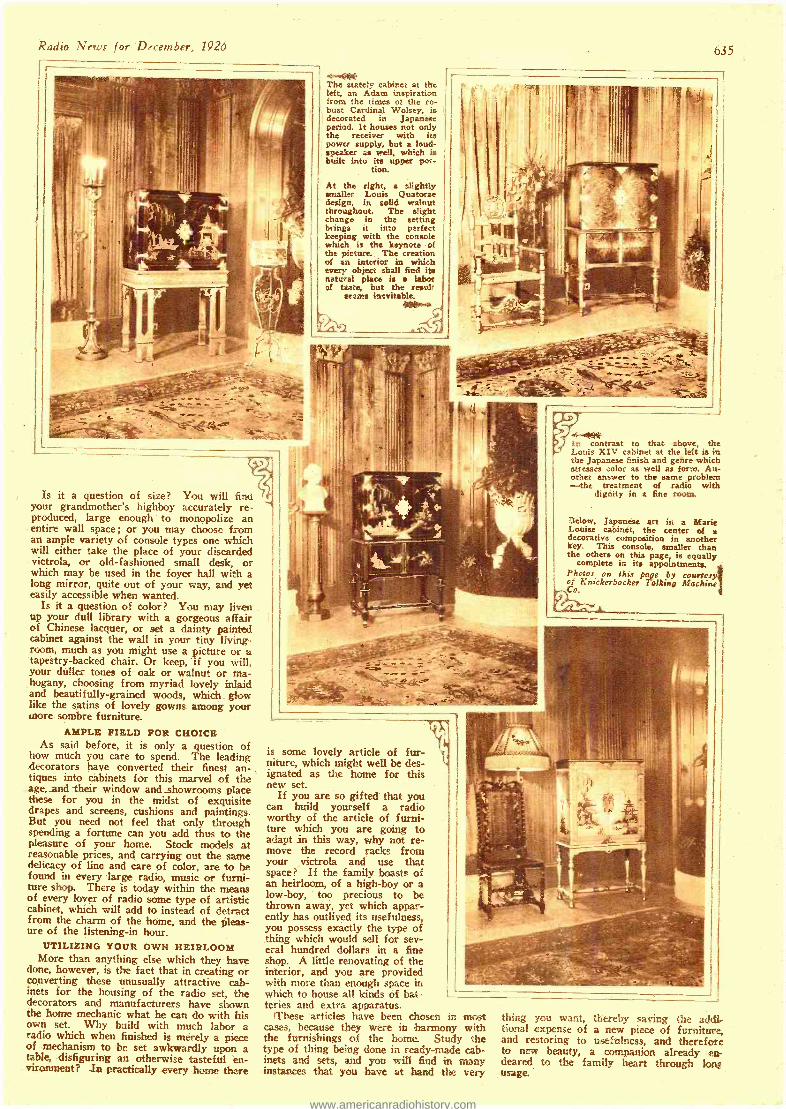
Radio News for December, 1926
The stately cabinet at the left, an Adam inspiration from the times of the ro- bust Cardinal Wolsey, is decorated in Japanese period. It houses not only the receiver with its power supply, but a loud- speaker as well, which is built into its upper por-
tion.
At the right, a slightly smaller Louis Quatorae design, in solid walnut throughout. The slight change in the setting brings it into perfect keeping with the console which is the keynote of the picture. The creation of an interior in which every object shall find its natural place is labor of taste, but the result
seems inevitable.
635
Is it a question of size? You will find your grandmother's highboy accurately re- produced, large enough to monopolize an entire wall space ; or you may choose from an ample variety of console types one which will either take the place of your discarded victrola, or old- fashioned small desk, or which may be used in the foyer hall with a long mirror, quite out of your way, and yet easily accessible when wanted.
Is it a question of color? You may liven up your dull library with a gorgeous affair of Chinese lacquer, or set a dainty painted cabinet against the wall in your tiny living - room, much as you might use a picture or a tapestry -backed chair. Or keep, if you will, your duller tones of oak or walnut or ma- hogany, choosing from myriad lovely inlaid and beautifully- grained woods, which glow like the satins of lovely gowns among your wore sombre furniture.
AMPLE FIELD FOR CHOICE As said before, it is only a question of
how much you care to spend. The leading decorators have converted their finest an- tiques into cabinets for this marvel of the age, and their window and showrooms place these for you in the midst of exquisite drapes and screens, cushions and paintings. But you need not feel that only through spending a fortune can you add thus to the pleasure of your home. Stock models at reasonable prices, and carrying out the same delicacy of line and care of color, are to be found in every large radio, music or furni- ture shop. There is today within the means of every lover of radio some type of artistic cabinet, which will add to instead of detract from the charm of the home, and the pleas- ure of the listening -in hour.
UTILIZING YOUR OWN HEIRLOOM More than anything else which they have
done, however, is the fact that in creating or converting these unusually attractive cab- inets for the housing of the radio set, the decorators and manufacturers have shown the home mechanic what he can do with his own set. Why build with much labor a radio which when finished is merely a piece of mechanism to be set awkwardly upon a table, disfiguring an otherwise tasteful en- vironment? In practically every home there
-i
in contrast to that above, the Louis XIV cabinet at the left is in the Japanese finish and genre which stresses color as well as form. An- other answer to the same problem -the treatment of radio with
dignity in a fine room.
Below, Japanese art in a Marie Louise cabinet, the center of a decorative composition in another key. This console, smaller than the others on this page, is equally
complete in its appointments. Photos on this page by courtesy of Knickerbocker Talking Machine Co.
is some lovely article of fur- niture, which might well be des- ignated as the home for this new set.
If you are so gifted that you can build yourself a radio worthy of the article of furni- ture which you are going to adapt in this way, why not re- move the record racks from your victrola and use that space? If the family boasts of an heirloom, of a high -boy or a low -boy, too precious to be thrown away, yet which appar- ently has outlived its usefulness, you possess exactly the type of thing which would sell for sev- eral hundred dollars in a fine shop. A little renovating of the interior, and you are provided with more than enough space in which to house all kinds of bat- teries and extra apparatus.
These articles have been chosen in most cases, because they were in harmony with the furnishings of the home. Study the type of thing being done in ready -made cab- inets and sets, and you will find in many instances that you have at hand the very
thing you want, thereby saving the addi- tional expense of a new piece of furniture, and restoring to usefulness, and therefore to new beauty, a companion already en- deared to the family heart through lone usage..
www.americanradiohistory.com
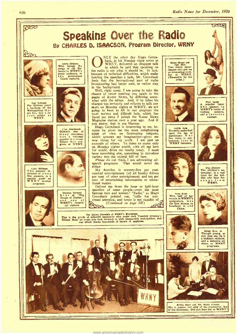
636 Radio News for December, 1926
Speaking Over the Radio By CHARLES D. ISAACS ©N, Program Director, WRNY
!nets Chekeva Who brings the songs of old Bo- hemia to WRNY's great audience, in t h e picturesque
Czech costume.
Carl Schiegel For thirteen years a baritone of the Metropolitan O p - era Co., was a re- c e n t soloist a t
WRNY.
Lina Abarbanell Operatic star of in a n y successes, was a welcome number in a recent Edison Hour pro- gram at WRNY.
Louis Stillman T h e eminent in- structor of many fine pianists, is a regular guest on WRNY musical
programs.
Clarence Derwent Star of "The House of Ussher," and one of WRNY's theatri-
cal visitors.
NLY the other day Hugo Gems- back, in his Monday night series at WRNY, delivered an eloquent talk in which he said that speaking on
the radio is not what it should be. In fact, because of technical difficulties, which make hearing the speeches a task, Mr. Gernsback feels that the instructional part of radio broadcasting had better wait, or rather stay in the background.
Well, right away, I am going to take the chance of never meeting you again in the pages of RADIO NEWS, by differing some- what with the editor. And, if he takes his charges too seriously and refuses to talk any more on Monday nights at WRNY, we are going to have to fill in our program the most serious and difficult hole, which has faced me since I joined the RADIO NEWS Magazine station over a year ago. And if you please, that is not - blarney.
Hugo Gernsback is interesting to me, be- cause he gives me the most enlightening point of view on fascinating subjects, which arouses my imagination -gives me new vision for my work. I am just an example of others. To listen to music only on Monday nights would, with all my love for music. drive me nearly crazy. I must have something else, something to introduce variety into the mental bill of fare.
Please do not think I am advocating all - speech programs. That would never do, either.
My doctrine is seventy -five per cent. musical entertainment (of all kinds) fifteen per cent. of other entertainment, and ten per cent. of entertaining information or educa- tional matter.
Deliver me from the hour or half -hour speeches of some people -even the most famous men and women! "Radio," as Hugo Gernsback pointed out, "calls for non- visual attention, and hence is not capable of
(Continued on page 747)
The Edison Ensemble at WRNY's Microphone
This is the group of splendid musicians who make each Tuesday evening's Edison Hour an event you look forward to with pleasurable anticipation, and
one which draws thousands of letters of applause.
Helen Stryge and Jack Blue
Two clever enter- tainers who put on an interesting num- ber at WRNY. (Ensemble by the
artist.)
Judith Roth Recently embarked upon the sea of matrimony. H e r fine voice is not, however, lost to WRNY listeners.
Paul Lamy A popular tenor w h o appears i n WRNY's roster of visiting soloists, and a favorite
number.
Irene Kuhn Who told of her travels in WRNY's symposium, w a s the first woman to broadcast in o I d
China.
Elm Clement The children's en- tertainer, is a real treat for the kid- dies who hear her songs from
WRNY.
Ralph Rase. Jr. Though young, as you may see, he is a brilliant violinist, and a welcome ad- dition to WRNY
programs.
Birdie Reeve and Her Merle Friends She is master, not only of the typewriter, but of the dictionary. Did you hear her at WRNY?
www.americanradiohistory.com
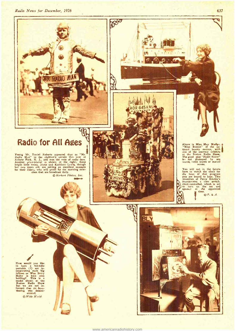
Radio News for December, 1926 637
Radio for AU Ages Young Mr. Daniel Roberts appeared thus as "Mr. Radio Man" in the children's parade this year at Asbury Park, N. J., and won the vote of radio fans. Another prize -winner is shown at the right; these bright little twins. Joyce and Kathleen Lewis, though but two years old, are setting an excellent example for their elders, who will profit by the morning exer-
cises that are broadcast daily. ® Herbert Photos, Inc.
J
Above is Miss May Mudge, "Miss Boston" of the na- tional beauty contest, with one of the amateur exhibits at the Boston Radio Show. The good ship "Radio Rover" is not dismayed by sea waves, radio waves or martel
waves.
You will not in the future have to watch the clock for the hour of that program you are bound to hear. This invention of Percy Emsley's incorporates a time switch. clock -controlled, which is set to turn on the set and speaker at the appointed
time. ® P. & A.
How would you like to have a ten -tube portable ( ?) set in- corporating such big fellows as Miss Betty Haley is here seen holding? This is a model shown at the Boston Radio Show but we are not in- formed that its func- tioning was demon-
strated. t Wide World
www.americanradiohistory.com
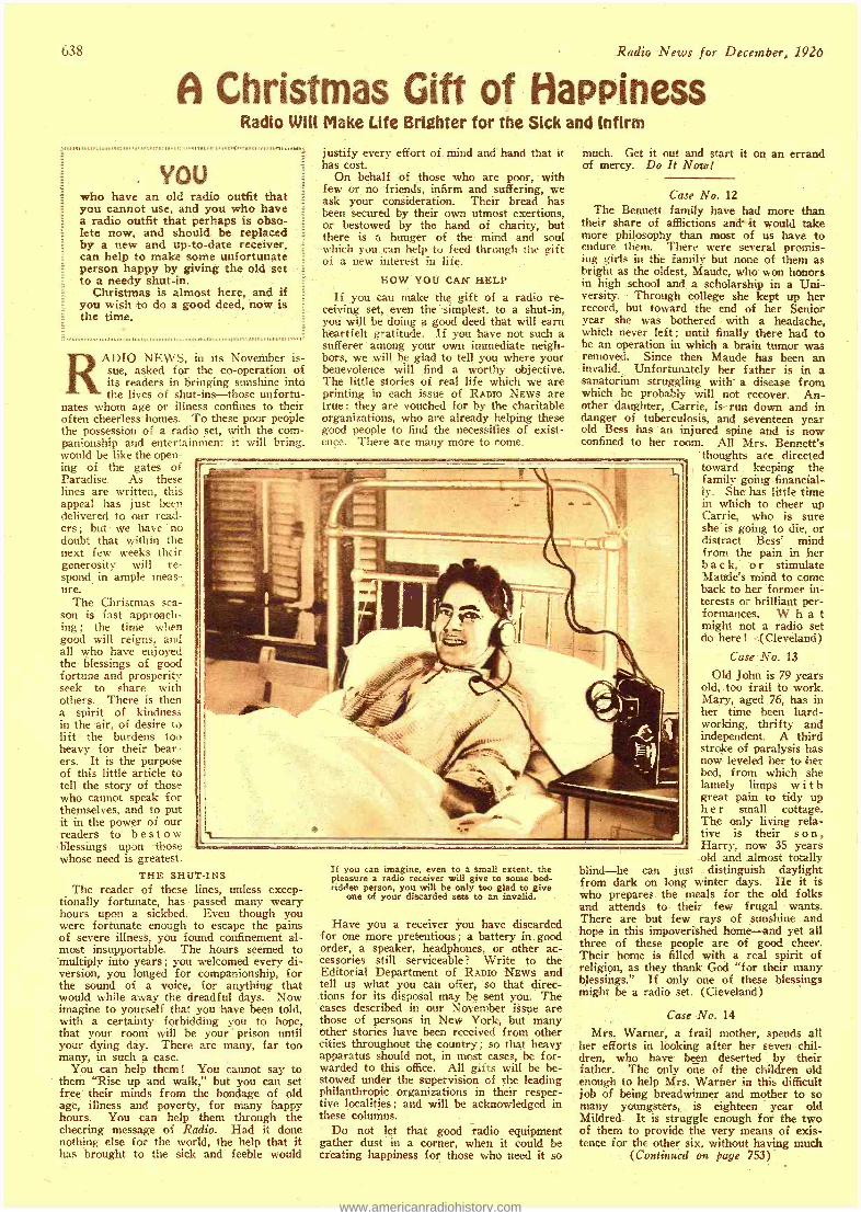
638 Radio News for December, 1926
A Christmas Gift of Happiness
YOU
Radio Will Make Life Brighter for the Sick and Infirm
who have an old radio outfit that you cannot use, and you who have a radio outfit that perhaps is obso- lete now, and should be replaced by a new and up -to -date receiver, can help to make some unfortunate person happy by giving the old set to a needy shut -in.
Christmas is almost here, and if you wish to do a good deed, now is the time.
RADIO NEWS, in its November is- sue, asked for the co- operation of its readers in bringing sunshine into the lives of shut -ins -those unfortu-
nates whom age or illness confines to their often cheerless homes. To these poor people the possession of a radio set, with the com- panionship and entertainment it will bring. would be like the open- ing of the gates of Paradise. As these lines are written, this appeal has just been delivered to our read- ers ; but we have no doubt that within the next few weeks their generosity will re- spond in ample meas- ure.
The Christmas sea- son is fast approach- ing; the time wh n
good will reigns, and all who have enjoyed the blessings of good fortune and prosperity seek to share with others. There is then a spirit of kindness in the -air, of desire to lift the burdens too heavy for their bear - ers. It is the purpose of this little article to tell the story of those who cannot speak for themselves, and to put it in the power of our readers to bestow blessings upon those whose need is greatest.
THE SHUT -INS The reader of these lines, unless excep-
tionally fortunate, has passed many weary hours upon a sickbed. Even though you were fortunate enough to escape the pains of severe illness, you found confinement al- most insupportable. The hours seemed to multiply into years; you welcomed every di- version, you longed for companionship, for the sound of a voice, for anything that would while away the dreadful days. Now imagine to yourself that you have been told, with a certainty forbidding you to hope, that your room will be your prison until your dying day. There are many, far too many, in such a case.
You can help them! You cannot say to them "Rise up and walk," but you can set free their minds from the bondage of old age, illness and poverty, for many happy. hours. You can help them through the cheering message of Radio. Had it done nothing else for the world, the help that it has brought to the sick and feeble would
justify every effort of mind and hand that it has cost.
On behalf of those who are poor, with few or no friends, infirm and suffering, we ask your consideration. Their bread has been secured by their own utmost exertions, or bestowed by the hand of charity, but there is a hunger of the mind and soul which you can help to feed through the gift of a new interest in life,
HOW YOU CAN HELP
If you can make the gift of a radio re- ceiving set, even the simplest, to a shut -in, you will be doing a good deed that will earn heartfelt gratitude. If you have not such a sufferer among your own immediate neigh- bors, we will be glad to tell you where your benevolence will find a worthy objective. The little stories of real life which we are printing in each issue of RADIO NEws are true: they are vouched for by the charitable organizations, who are already helping these good people to find the necessities of exist- ence. There are many more to come.
much. Get it out and start it on an errand of mercy. Do It Now!
Case No. 12 The Bennett family have had more than
their share of afflictions and' -it would take more philosophy than most of us have to endure them. There were several promis- ing girls in the family but none of them as bright as the oldest, Maude, who won honors in high school and a scholarship in a Uni- versity. Through college she kept up her record, but toward the end of her Senior year she was bothered with a headache, which never left; until finally there had to be an operation in which a brain tumor was removed. Since then Maude has been an invalid. Unfortunately her father is in a sanatorium struggling with a disease from which he probably will not recover. An- other daughter, Carrie, is- run down and in danger of tuberculosis, and seventeen year old Bess has an injured spine and is now confined to her room. All Mrs. Bennett's
thoughts are directed toward keeping the family going financial- ly. She has little time in which to cheer up Carrie, who is sure she is going to die, or distract Bess' mind from the pain in her b a c k, o r stimulate Maude's mind to come back to her former in- terests or brilliant per- formances. W h a t might not a radio set do here ! <(Cleveland)
Case No. 13
Old John is 79 years old, too frail to work. Mary, aged 76, has in her time been hard- working, thrifty and independent. A third stroke of paralysis has now leveled her to her bed, from which she lamely limps with great pain to tidy up h e r small cottage. The only living rela- tive is their s o n , Harry, now 35 years old and almost totally
blind -he can just distinguish daylight from dark on long winter days. He it is who prepares the meals for the old folks and attends to their few frugal wants. There are but few rays of sunshine and hope in this impoverished home -and yet all three of these people are of good cheer. Their home is filled with a real spirit of religion, as they thank God "for their many blessings." If only one of these blessings might be a radio set. (Cleveland)
X11
If you can imagine, even to a small extent. the pleasure a radio receiver will give to some bed- ridden person, you will be only too glad to give
one of your discarded sets to an invalid.
Have you a receiver you have discarded for one more pretentious ; a battery in good order, a speaker, headphones. or other ac- cessories still serviceable? Write to the Editorial Department of RADIO NEWS and tell us what you can offer, so that direc- tions for its disposal may be sent you. The cases described in our November issue are those of persons in New York, but many other stories have been received from other cities throughout the country; so that heavy apparatus should not, in most cases, be for- warded to this office. All gifts will be be- stowed under the supervision of the leading philanthropic organizations in their respec- tive localities ; and will be acknowledged in these columns.
Do not let that good radio equipment gather dust in a corner, when it could be creating happiness for those who need it so
Case No. 14
Mrs. Warner, a frail mother, spends all her efforts in looking after her seven chil- dren, who have been deserted by their father. The only one of the children old enough to help Mrs. Warner in this difficult job of being breadwinner and mother to so many youngsters, is eighteen year old Mildred. It is struggle enough for the two of them to provide the very means of exis- tence for the other six, without having much
(Continued on page 753)
www.americanradiohistory.com
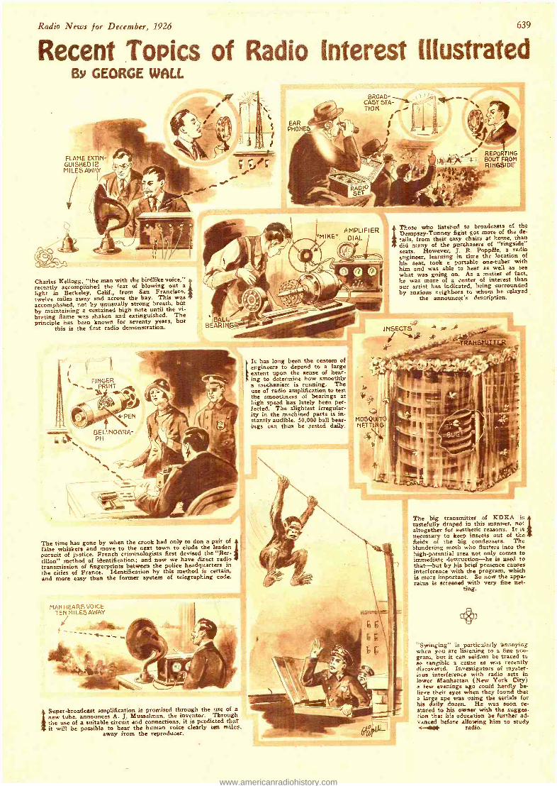
Radio News for December, 1926 639
Recent Topics of Radio Interest Illustrated By GEORGE WALL
EAR PHONEZ
FLAME EXTIN- GUISHEDI2 MILES AWAY
REPORTING BOUT FROM RINGSIDE
AMPLIFIER *MIKE ". DIAL
Charles Kellogg, ''the man with the birdlike voice," recently accomplished the feat of blowing out a light in Berkeley, Calif., from San Francisco, twelve miles away and across the bay. This was accomplished, not by unusually strong breath, belt by maintaining a sustained high note until the vi- brating flame was shaken and extinguished. The principle has been known for seventy years, but
this is the first radio demonstration.
F1 NGER ,e PRINT
Those who listened to broadcasts of the Dempsey- Tunney fight got more of the de- tails, from their easy chairs at home, than did many of the purchasers of "ringside" seats. However, J. R. Poppêle, a radio engineer, learning in time the location of his seat, took a portable one -tuber with him and was able to hear as well as see what was going on. As a matter of fact. he was more of a center of interest than our artist has indicated, being surrounded by anxious neighbors to whom he relayed
the announcer's description.
BALL BEARIN6!x
0
4 4,
eePEN
BELINOGRA PH
'h a,
It has long been the custom of engineers to depend to a large extent upon the sense of hear- ing to determine how smoothly a mechanism is running. The use of radio amplification to test the smoothness of bearings at high speed has lately been per- fected. The slightest irregular- ity in the machined parts is in- stantly audible. 50,000 ball bear- ings can thus be tested daily.
`s.. ., -a
The time has gone by when the crook had only to don a pair of false whiskers and move to the next town to elude the leaden pursuit of justice. French criminologists first devised the "Ber- tillon" method of identification; and now we have direct radio transmission of fingerprints between the police headquarters in the cities of France. Identification by this method is certain. and more easy than the former system of telegraphing code.
MAN HEARS VOICE TEN MI LES AWAY
Super- broadcast amplification is promised through the use of a new tube, announces A. J. Musselman, the inventor. Through the use of a suitable circuit and connections, it is predicted that it will be possible to hear the human voice clearly ten miles.
away from the reproducer.
The big transmitter of KDKA is tastefully draped in this manner, not altogether for aesthetic reasons. It is necessary to keep insects out of the fields of the big condensers. The blundering moth who flutters into the high -potential area not only comes to immediate destruction -he is used to that--but by his brief presence causes interference with the program, which is more important. So now the appa- ratus is screened with very fine net-
ting.
"Syringing" is particularly annoying when you are listening to a fine pro- gram, but it can seldom be traced to so tangible a cause as was recently discovered. investigators of myster- ious interference with radio sets in lower Manhattan (New York City) a few evenings ago could hardly be- lieve their eyes when they found that a large ape was using the aerials for his daily dozen. He was soon re- stored to his owner with the sugges- tion that his education be further ad- vanced before allowing him to study -.- . radio.
www.americanradiohistory.com
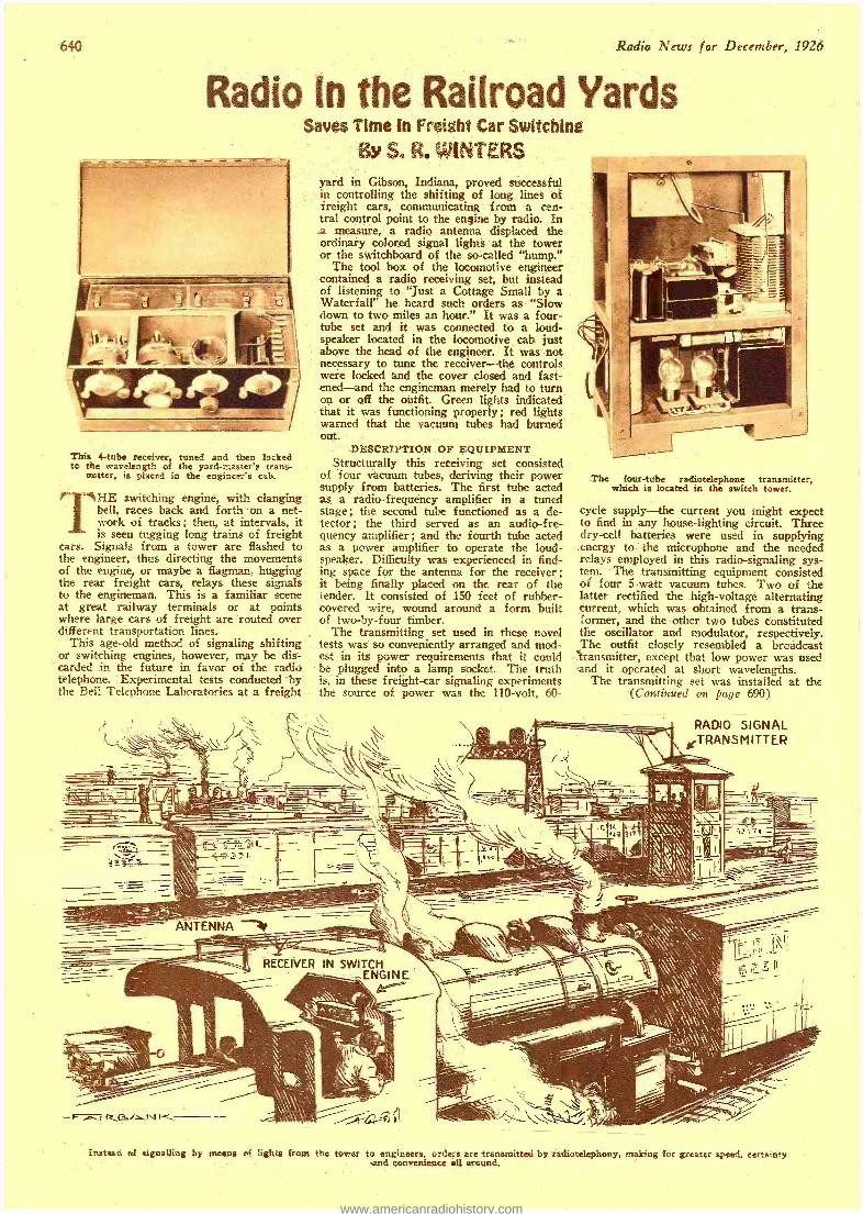
Radio News or December, 1926
Radio In the Railroad Yards
This 4 -tube receiver, tuned and then locked to the wavelength of the yard- master's trans -
mitter, is placed in the engineer's cab.
HE switching engine, with clanging bell, races back and forth on a net - work of tracks; then, at intervals, it is seen tugging long trains of freight
cars. Signals from a tower are flashed to the engineer, thus directing the movements of the engine, or maybe a flagman, hugging the rear freight cars, relays these signals to the engineman. This is a familiar scene at great railway terminals or at points where large cars of freight are routed over different transportation lines.
This age -old method of signaling shifting or switching engines, however, may be dis- carded in the future in favor of the radio telephone. Experimental tests conducted by the Bell Telephone Laboratories at a freight
..
Saves Time to Freight Car Switching By S. R. WINTERS
yard in Gibson, Indiana, proved successful in controlling the shifting of long lines of freight cars, communicating from a cen- tral control point to the engine by radio. In a measure, a radio antenna displaced the ordinary colored signal lights at the tower or the switchboard of the so- called "hump."
The tool box of the locomotive engineer contained a radio receiving set, but instead of listening to "just a Cottage Small by a Waterfall" he heard such orders as "Slow down to two miles an hour." It was a four - tube set and it was connected to a loud- speaker located in the locomotive cab just above the head of the engineer. It was not necessary to tune the receiver -the controls were locked and the cover closed and fast- ened -and the engineman merely had to turn on or off the outfit. Green lights indicated that it was functioning properly; red lights warned that the vacuum tubes had burned out.
DESCRIPTION OF EQUIPMENT Structurally this receiving set consisted
of four vacuum tubes, deriving their power supply from batteries. The first tube acted as a radio- frequency amplifier in a tuned stage; the second tube functioned as a de- tector; the third served as an audio -fre- quency amplifier ; and the fourth tube acted as a power amplifier to operate the loud- speaker. Difficulty was experienced in find- ing space for the antenna for the receiver; it being finally placed on the rear of the tender. It consisted of 150 feet of rubber - covered wire, wound around a form built of two -by -four timber.
The transmitting set used in these novel tests was so conveniently arranged and mod- est in its power requirements that it could be plugged into a lamp socket. The truth is, in these freight -car signaling experiments the source of power was the 110 -volt, 60-
The four -tube radiotelephone transmitter, which is located in the switch tower.
cycle supply-the current you might expect to find in any house- lighting circuit. Three dry -cell batteries were used in supplying energy to the microphone and the needed relays employed in this radio -signaling sys- tem. The transmitting equipment consisted of four 5 -watt vacuum tubes. Two of the latter rectified the high -voltage alternating current, which was obtained from a trans- former, and the other two tubes constituted the oscillator and modulator, respectively. The outfit closely resembled a broadcast
- transmitter, except that low power was used and it operated at short wavelengths.
The transmitting set was installed at the (Continued on page 690)
RADIO SIGNAL TRANSMITTER
r..c .,::. ri_f r - -°- ---
ANTENNA
_\. ; Instead of signalling by means of lights from the tower to engineers, orders are transmitted by radiotelephony,
and convenience all around. ing for greater speed, certainty
www.americanradiohistory.com
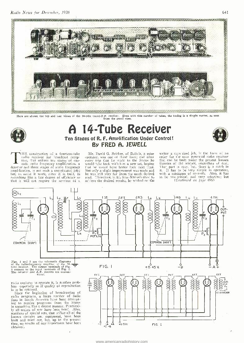
Radio News for December, 1926 641
Here are shown the top and rear views of the 14 -tube tuned -R.F. receiver. Even with this number of tubes, the tuning is a simple matter, as seen from the panel view.
A 14 -Tube Receiver Ten Stages of R. F. Amplification Under Control!
By FRED A. JEWELL
THE construction of a fourteen -tube radio receiver for broadcast recep- tion, that utilizes ten stages 'of cas- cade radio frequency amplification, a
detector and three stages of audio frequency amplification, is not such a complicated job; but, to make it work, after it is built, in something like a fair degree of efficiency so that it will not require the services of a
La
COMMON SHAFT
Figs. I and 2 are the schematic diagrams of the radio -frequency amplifier of the 14- tube receiver. The output terminals of Fig. 1 connect to the input terminals of Fig. 2. The detector and A.F. circuits are conven-
tional.
radio engineer to operate it, is another prob- lem- especially so if quality of reproduction is to be retained.
Since the beginning of broadcasting of radio programs, a large number of radio fans in South America have been attempt- ing to receive programs from the States in something like a decent manner. Practical- ly all makes of sets have been tried. Also, numbers of special sets, that utilize all of the known circuits and equipment, have been built and tried out, hut, up to the present time, no results of any importance have been obtained.
Mr. David G. Bricker, of Bolivia, a mine operator, was one of these fans; and after every trip that he made to the States he would take back with him a new set, hoping that he would have -better luck next time. But only a slight improvement was made and he was still very far from the much desired goal. Therefore, in his firm determination to achieve the desired results, he wished on the
I ST. R.F.T
IN- PUT
FIG. I
L ND.
writer a man -sized job, in the form of an order for the most powerful radio receiver that can be built under the present known theories of the science, regardless of cost. That part is easy, but, there is a catch in.
it. It has to be very simple in operation, with a minimum of controls. Also, it has to be non- critical, and very selective; but
(Continued on page 696)
3RD. L10 Lii 4 TH.
4 45V. -B -A+ R.F. T R.F.
a 9 O C O XX O O 7 O a O
. .
o OUT- PUT o
0 o o 0 -C -A +A +890V.
+C -B FIG. 2
www.americanradiohistory.com
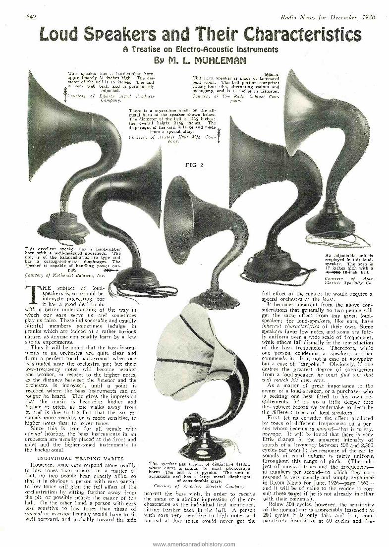
642 Radio News for December, .1926
Loud Speakers and Their Characteristics A Treatise on Electro- Acoustic Instruments
BY M. Lo MUHLEMAN This speaker has a hard- rubber horn, approximately 21 inches high. The dia- meter of the bell is 15 inches. The unit is very well built and is permanently
adjusted.
Courtesy of Liberty dlIetal Products Company.
This -horn speaker is made of laminated bent wood. The bell portion comprises twenty -four ribs, alternating walnut and mahogany, and is 15 inches in diameter. Courtesy of The Radio Cabinet Com-
pany.
There is a crystalline finish on the all - metal horn of the speaker shown below. The diameter of the bell is 14% inches; the overall height 21% inches. The diaphragm of the unit is large and made
from a special alloy. Courtesy of Atwater Kent Mfg. Com-
pany.
FIG. 2
This excellent speaker has a hard -rubber horn with a well- designed gooseneck. The unit is of the balanced- armature type and has a corrugated -metal diaphragm. The speaker is capable of handling power out -
put. -i Courtesy of Nathaniel Baldwin, Inc.
THE subject of loud- speakers is, or should be, intensely interesting, for it has a good deal to do
with a better understanding of the way in which our ears serve us -and sometimes play us false. These indispensable and usually faithful members sometimes indulge in pranks which are indeed of a rather curious nature, as anyone can readily learn by a few simple experiments.
Thus it will be noted that the bass instru- ments in an orchestra are quite clear and form a perfect tonal background when one is situated near the orchestra pit ; but their low -frequency notes will become weaker and weaker, in respect to the higher notes, as the distance between the listener and the orchestra is increased, until a point is reached where the bass instruments can no longer be heard. This gives the impression that the music is becoming higher and higher in pitch, as one walks away from it, and is due to the fact that the ear re- sponds more readily, or is more sensitive, to higher notes than to lower tones.
Since this is true for all people with normal hearing, the bass instruments in an orchestra are usually placed at the front and sides and the higher -toned instruments in the background.
INDIVIDUAL HEARING VARIES However, some ears respond more readily
to low tones than others ; as a matter of fact, no two people hear exactly alike, so that it is obvious a person with ears partial to low tones will gain the full effect of the orchestration by sitting further away from the pit, or possibly nearer the center of the hall. On the other hand, a person with ears less sensitive to low tones than those of normal or average hearing would have to sit well forward, and probably toward the side
This speaker has a horn of distinctive design, whose curve is similar to most phonograph horns. The bell is of pyralin. The unit is adjustable and has a large metal diaphragm
of considerable mass. Courtesy of American Electric Company.
nearest the bass viols, in order to receive the same or a similar impression of the or- chestration as the individual first mentioned, sitting further back in the hall. A person with ears very sensitive to high notes and normal at low tones would never get the
An adjustable unit is employed in this loud- speaker. The horn is 17 inches high with a t- «* 10 -inch bell. Courtesy of Ajax Electric Specialty Co.
full effect of the music ; he would require a special orchestra at the least.
It becomes apparent from the above con- siderations that generally no two people will get the same effect from any given loud- speaker ; for loud- speakers, like ears, have inherent characteristics of their own. Some speakers favor low notes, and some are fair- ly uniform over a wide scale of frequencies, while others fail dismally in the reproduction of the bass frequencies. Therefore, while one person condemns a speaker, another commends it. It is not a case of viewpoint but a case of "earpoint." Obviously, if one desires the greatest degree of satisfaction from a loud -speaker, he must find one that will match his own ears.
As a matter of great importance to the owner of a loud -speaker, or a purchaser who is seeking one best fitted to his own re- quirements, let us go a little deeper into this subject before we undertake to describe the different types of loud -speakers.
First, let us consider the effect produced by tones of different frequencies on a per- son whose hearing is normal -that is to say, average. It will be found that there is very little change in the apparent intensity of sounds of a frequency between 500 and 2,500 cycles per second ; the response of the ear to sounds of equal volume is fairly uniform throughout this range of pitch. (The sub- ject of musical tones and the frequencies - in numbers per second -to which they cor- respond is very clearly and simply explained in RADIO News for June, 1926 -page 1662 - and it will be of value to the reader to con- sult these pages if he is not already familiar with their contents).
Below 500 cycles, however, the sensitivity of the normal ear is appreciably lessened ; at 200 cycles it is only fair, and it is com- paratively insensitive at 60 cycles and fre-
www.americanradiohistory.com
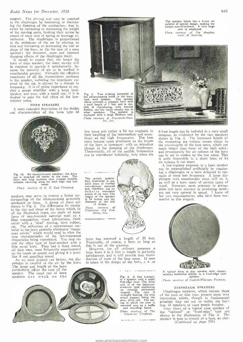
Radio News for December, 1926
magnet. The driving unit may be matched to the diaphragm by increasing or decreas- ing the damping of the mechanism ; that is, either by increasing or decreasing the weight of the moving parts, limiting their action by means of some sort of spring or leverage at- tachment. The diaphragm is proportioned to the resistance of the air by altering its area and increasing or decreasing the size or shape of the horn, or (in the case of a cone speaker) the diameter, mass and inherent damping effects of the diaphragm itself.
It stands to reason that, the larger the horn or cone speaker, the more energy will be required to operate it satisfactorily. be- cause the quantity of air to be worked is considerably greater. Virtually the effective impedance of all the transmission mediums in the speaker, including the impedance ex- erted by the air, is altered by a change in frequency. It is of prime importance to em- ploy a power amplifier with a large loud- speaker, and even with a small one, if it is desired to gain the full effect of the low - register notes.
HORN SPEAKERS A more extended description of the design
and characteristics of the horn type of
Fig. 10. An eccentric -cone speaker; the drive rod is attached off center to the cone. The short and long surfaces thus created provide suitable vibrating areas for both high and low
notes. Photo courtesy of H. G. Saal Company.
speakers may serve to convey a better un- derstanding of the idiosyncrasies generally attributed to them. A group of them are shown in Fig. 2. The differences lie mostly in the size and shape of the horns which, in all the illustrated types, are made of some form of non -resonant material such as a fiber composition, wood fabrications, thick metal with a "dead" coating, hard rubber, etc. The utilization of a non- resonant ma- terial in the horn partially eliminates "reson- ance points," which would tend to alter the true characteristics of the heterogeneous frequencies being reproduced. You may re- call the older type of loud- speaker with a thin metal horn. They had a tinny sound, all their own, most frequently superimposed on the music or speech and giving it a pecu- liar if not appalling sound.
As we have pointed out before, the dia- phragm is coupled to the air by the horn. The shape and length of the horn particularly affect the tone of the speaker. The usual run of horn speakers are weak on the
The speaker below has a 4 -root air column of special design, making the output non -directional. A very large
unit is employed. Photo courtesy of The Amplion
Corp. of America.
645
Fig. 3. Two striking examples of the advancements made in the horn - type loud speaker. The speaker above contains a compact horn with a total length of 7 feet and is cap- able of reproducing, with marked fidelity, the low notes usually lost in other speakers. The speaker is equipped with a large Baldwin unit. Photo coin-tcsy of Newcombe -Haw-
ley, Inc.
low tones and rather a hit too emphatic in their handling of the intermediate and some- times of the high frequencies. The bass notes become more prominent as the length of the horn is increased ; with an attendant change in the damping of the diaphragm. Theoretically, all of the audible frequencies can be reproduced faithfully, only when the
The artistic speaker here illustrated is one solid piece of molded non- resonant material and, therefore, has no definite resonance points of its own. The height of the speaker is 24 inches and the diameter of the bell
12 inches. Photo courtesy of Florentine Art Pro-
ducts, Inc.
ammnmmmmm:mmunm nunina:o
horn has assumed a length of 20 feet. Practically, of course, a horn as long as this is out of the question.
However, for all ordinary purposes a horn from 4 to 6 feet in length is perfectly satisfactory, and it will provide true repro- duction of most of the bass cotes. If care is taken in the design of the horn, a 4- or
Fig. 8. A fine example of a speaker with a small free -edge cone. The drive unit is of the balanced - armature type employing an oversize permanent magnet. The cone is virtually floating. the only actual support being the stou'. drive rod. The cas- ing in which the cone is mounted acts as a baffle
and sounding board. Photo courtesy of The
_lfagnaro.r Company.
6 -foot length can be included in a very small compass, as evidenced by the two speakers shown in Fig. 3. The increased length of the resonating air column comes closer to the wavelengths of the bass notes, which are much longer than those of the high notes; and ccnsequcntly the air column of the horn can be set ill motion by the low notes. This is quite impossible in a short horn as its air column is too short.
A low -register response in a horn speaker can be accomplished artificially by employ- ing a diaphragm or a horn designed to res- onate at some low frequency. A large dia- phragm with considerable mass will do it, as well as a horn made of certain types of wood. However, most attempts to accom- plish this have resulted in producing speak- ers not very natural in sound. I know of but two manufacturers who have been suc- cessful in this respect.
A typical form of disc speaker with charac- teristics somewhat similar to a fixed -edge cone
speaker. Photo courtesy of English- EVhitman Products.
DIAPHRAGM SPEAKERS Diaphragm speakers, which include those
of the cone or disc type, present some very interesting points, though in fundamental principle they are not so unlike the hori type of speakers as most people imagine.
Four views of a typical cone speaker of the "inclosed" or "fixed -edge" type are shown in the illustration of Fig. 4. Thu speaker is seen to consist of a base, an elec-
(Continued on page 750)
www.americanradiohistory.com
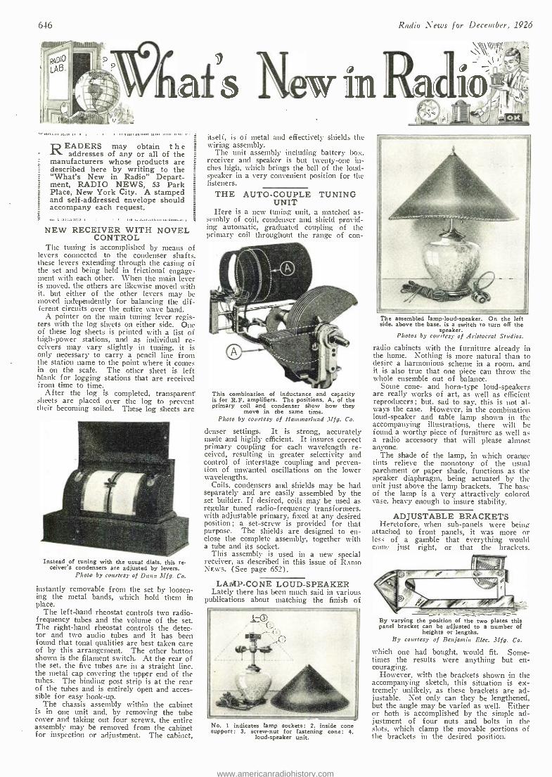
646
IU
t ^ _ i;+
,-.4"- IN -
Radio News for December, 1926
READERS may obtain t h e addresses of any or all of the
manufacturers whose products are described here by writing to the "What's New in Radio" Depart- ment, RADIO NEWS, 53 Park Place, New York City. A stamped and self- addressed envelope should accompany each request.
NEW RECEIVER WITH NOVEL CONTROL
The tuning is accomplished by means of levers connected to the condenser shafts, these levers extending through the casing of the set and being held in frictional engage- ment with each other. When the main lever is moved, the others are likewise moved with it, but either of the other levers may be moved independently for balancing the dif- ferent circuits over the entire wave band.
A pointer on the main tuning lever regis- ters with the log sheets on either side. One of these log sheets is printed with a list of 'high-power stations, and as individual re- ceivers may vary slightly in tuning, it is only necessary to carry a pencil line from the station name to the point where it comes in on the scale. The other sheet is left blank for logging stations that are received from time to time.
After the log is completed, transparent sheets are placed over the log to prevent their becoming soiled. These log sheets are
Instead of tuning with the usual dials, this re- ceiver's condensers are adjusted by levers.
Photo by courtesy of Dunn Mfg. Co.
instantly removable from the set by loosen- ing the metal bands, which hold them in place.
The left -hand rheostat controls two radio - frequency tubes and the volume of the set. The right -hand rheostat controls the detec- tor and two audio tubes and it has been found that tonal qualities are best taken care of by this arrangement. The other button shown is the filament switch. At the rear of the set, the five tubes are in a straight line. the metal cap covering the upper end of the tubes. The binding post strip is at the rear of the tubes and is entirely open and acces- sible for easy hook -up.
The chassis assembly within the cabinet is in one unit and, by removing the tube cover and taking out four screws, the entire assembly may be removed from the cabinet for inspection or adjustment. The cabinet,
itseli, is of metal and effectively shields the wiring assembly.
The unit assembly including battery box. receiver and speaker is but twenty -one in- ches high, which brings the bell of the loud- speaker in a very convenient position for the listeners.
THE AUTO -COUPLE TUNING UNIT
Here is a new tuning unit, a matched as- sembly of coil, condenser and shield provid- ing automatic, graduated coupling of the primary coil throughout the range of con-
This combination of inductance and capacity is for R.F. amplifiers. The positions, A. of the primary coil and condenser show how they
move in the same time. Photo by courtesy of Hauunarluud .11fg. Co.
denser settings. It is strong, accurately made and highly efficient. It insures correct primary coupling for each wavelength re- ceived, resulting in greater selectivity and control of interstage coupling and preven- tion of unwanted oscillations on the lower wavelengths.
Coils, condensers and shields may be had separately and are easily assembled by the set builder. If desired, coils may be used as regular tuned radio- frequency transformers. with adjustable primary, fixed at any desired position; a set -screw is provided for that purpose. The shields are designed to en- close the complete assembly, together with a tube and its socket.
This assembly is used in a new special receiver, as described in this issue of RADIO NEWS. (See page 652).
LAMP -CONE LOUD -SPEAKER Lately there has been much said in various
publications about matching the finish of
No. 1 indicates lamp sockets: 2, inside cone support: 3. screw -nut for fastening cone; 4.
loud- speaker unit.
The assembled lamp -loud- speaker. On the left side. above the base. is a switch to turn off the
speaker. Photos by courtesy of Aristocrat Studios.
radio cabinets with the furniture already in the home. Nothing is more natural than to desire a harmonious scheme in a room, and it is also true that one piece can throw the whole ensemble out of balance.
Some cone- and horn -type loud -speakers are really works of art, as well as efficient reproducers; but, sad to say, this is not al- ways the case. However, in the combination loud -speaker and table lamp shown in the accompanying illustrations, there will be found a worthy piece of furniture as well as a radio accessory that will please almost anyone.
The shade of the lamp, in which orange tints relieve the monotony of the usual parchment or paper shade, functions as the speaker diaphragm, being actuated by the unit just above the lamp brackets. The base of the lamp is a very attractively colored vase, heavy enough to insure stability.
ADJUSTABLE BRACKETS Heretofore, when sub -panels were being
attached to front panels, it was more or less of a gamble that everything would come just right, or that the brackets.
By varying the position of the two plates this panel bracket can be adjusted to a number of
heights or lengths. By courtesy of Benjamin Elec. Mfg. Co.
which one had bought, would fit. Some- times the results were anything but en- couraging.
However, with the brackets shown in the accompanying sketch, this situation is ex- tremely unlikely, as these brackets are ad- justable. Not only can they be lengthened, but the angle may be varied as well. Either or both is accomplished by the simple ad- justment of four nuts and bolts in the slots. which clamp the movable portions of the brackets in the desired position.
www.americanradiohistory.com
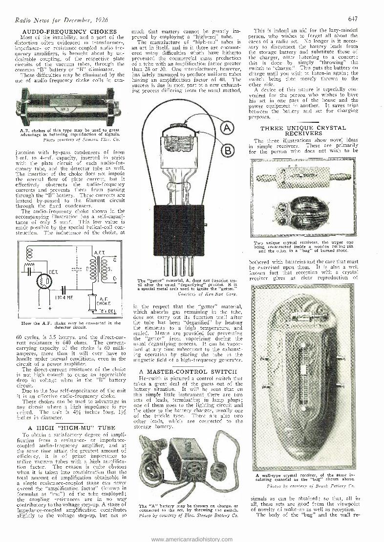
Radio News for December, 1926
AUDIO -FREQUENCY CHOKES Most of the instability, and a part of the
distortion often evidenced in transformer -, impedance- or resistance -coupled audio -fre- quency amplifiers, is brought about by un- desirable coupling, of the respective plate circuits of the vacuum tubes, through the common "B" battery or "B" eliminator.
These difficulties may be eliminated by the use of audio -frequency choke coils in con-
A.F. chokes of this type may be used to great advantage in bettering reproduction of signals.
Photo courtesy of Samson Elec. Co.
junction with by -pass condensers of from 1 -mf. to 4 -mf. capacity, inserted in series with the plate circuit of each audio -fre- quency tube, and the detector tube as well. The insertion of the choke does not impede the normal flow of plate current, but it effectively obstructs the audio- frequency currents and prevents them from passing through the "B" battery. These currents are instead by- passed to the filament circuit through the fixed condensers.
The audio- frequency choke shown in the accompanying illustration has a self- capaci- tance of only 5 mmf. This low value is made possible by the special helical -coil con- struction. The inductance of the choke, at
How the A.F. choke may be connected in the detector circuit.
60 cycles, is 3.5 henrys, and the direct -cur- rent resistance is 640 ohms. The current - carrying capacity of the choice is 60 milli- amperes, more than it will ever have to handle under normal conditions, even in the circuit of a power amplifier.
The direct- current resistance of the choke is not high enough to cause an appreciable drop in voltage when in the "B" battery circuit.
Due to the low self -capacitance of the unit it is an effective radio- frequency choke.
These chokes can be used to advantage in any circuit where a high impedance is re- quired. The unit is 41/4 inches long, 1/ inches in diameter.
A HIGH "HIGH -MU" TUBE To obtain a satisfactory degree of ampli-
fication from a resistance- or impedance - coupled audio- frequency amplifier, and at the same time attain the greatest amount of efficiency, it is of prime importance to utilize vacuum tubes with a high amplifica- tion factor. The reason is quite obvious when it is taken into consideration that the total amount of amplification obtainable in a single resistance -coupled stage can never exceed the "amplification factor" (known in formulas as "mu ") of the tube employed; -the coupling resistances are in no way contributory to the voltage step -up. A stage of impedance -coupled amplification contributes slightly to the voltage step -up, but not so
much that matters cannot be greatly im- proved by employing a "high -mu" tube.
The manufacture of "high -mu" tubes is an art in itself, and in it there are encount- erect many difficulties which have hitherto prevented the commercial mass production of a tube with an amplification factor greater than 28 or 30. One manufacturer, however, has lately managed to produce uniform tubes having an amplification factor of 40. The success is due in most part to a new exhaust- ing process differing from the usual method,
The "getter" material, A, does not function un- til after the usual ` degasifying" process. B is a special metal arch used to ignite the "getter."
Courtesy of Ken -Rad Corp.
in the respect that the "getter" material, which absorbs gas remaining in the tube, does not carry out its function until after the tube has been "degasified" by heating the elements to a high temperature, and sealed. Means are provided for preventing the "getter" from vaporizing during the usual degasifying process. It can be vapor- ized at any time subsequent to the exhaust- ing operation by placing the tube in the magnetic field of a high -frequency generator.
A MASTER -CONTROL SWITCH Herewith is pictured a control switch that
takes a great deal of the guess out of the battery situation. It will be seen that on this simple little instrument there are two sets of leads, terminating in lamp plugs ;
one of them goes to the lighting circuit and the other to the battery charger, usually one of the trickle type. There are also two other leads, which are connected to the storage battery.
The "A" battery may be thrown on charge, or connected to the set, by throwing the switch. Photo by courtesy of Elec. Storage Battery Co.
647
This is indeed an aid for the lazy -minded person, who wishes to forget all about the cares of a radio set. No longer is it neces- sary to disconnect the battery leads from the storage battery and substitute those of the charger, after listening to a concert; this is done by simply "throwing" the switch to "charge." This puts the battery on charge until you wish to listen -in again ; the switch being then merely thrown to the other side.
A device of this nature is especially con- venient for the person who wishes to have his set in one part of the house and the power equipment in another. It saves trips between the battery and set for charging purposes.
THREE UNIQUE CRYSTAL RECEIVERS
The three illustrations show novel ideas in simple receivers. These are primarily for the person who does not wish to be
Two unique crystal receivers, the upper one being constructed inside a wooden roLing -pin
and the other in a "bug" of burned stone.
bothered with batteries and the care that must be exercised upon them. It is also a well known fact that reception with a crystal receiver gives as clear reproduction of
A wall -type crystal receiver, of the same in- sulating material as the "bug" shown above.
Photos by courtesy of Brush Pottery Co.
signals as can be obtained ; so that, all in all, these sets are good from the viewpoint of novelty of make -up as well as reception.
The body of the "bug" and the wall re-
www.americanradiohistory.com
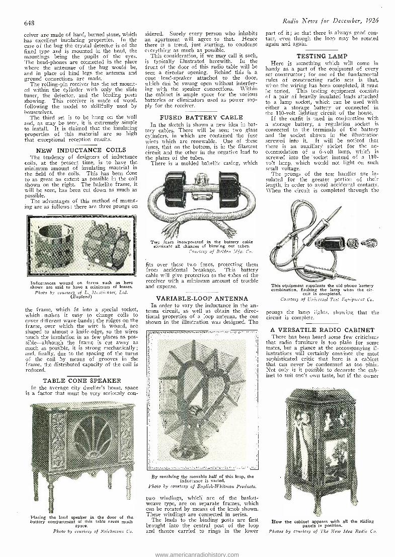
648
ceiver are made of hard, burned stone, which has excellent insulating properties. In the case of the bug the crystal detector is of the fixed type and is mounted in the head, the mountings being the pupils of the eyes. The head- phones are connected in the place where the antennae of the bug would be, and in place of hind legs the antenna and ground connections are made.
The rolling -pin receiver has the set mount- ed within the cylinder with only the slide tuner, the detector, and the binding posts showing. This receiver is made of wood, following the model so skillfully used by housewives.
The third set is to be hung on the wall and, as may be seen, it is extremely simple to install. It is claimed that the insulating properties of this material are so high that exceptional reception results.
NEW INDUCTANCE COILS The tendency of designers of inductance
coils, at the present time, is to have the minimum amount of insulating material in the field of the coils. This has been done to as great an extent as possible in the coil shown on the right. The bakelite frame, it will be seen, has been cut down as much as possible.
The advantages of this method of mount- ing are as follows: there are three prongs on
Inductances wound on forms such as here shown are said to have a minimum of losses.
Photo by courtesy of L. McMichael, Ltd. (England)
the frame, which fit into a special socket, which . makes it easy to change coils to cover different wave -bands ; the ridges on the frame, over which the wire is wound, are shaped to almost a knife -edge, so the wires touch the insulation in as few places as pos- sible- although the frame is cut away as much as possible, it is strong mechanically; and, finally, due to the spacing of the turns of the coil by means of grooves in the frame, the distributed capacity of the coil is reduced.
TABLE CONE SPEAKER In the average city dweller's home, space
is a factor that must be very seriously con-
Placing the loud speaker in the door of the battery compartment of this table saves much
space. Photo by courtesy of Reichmann Co.
sidered. Surely every person who inhabits an apartment will agree to that. Hence there - is a trend, just Starting, to condense everything as much as possible.
This consideration, if we may call it such, is typically illustrated herewith. In the front of the door of this radio table- will be seen a circular opening. Behind this is a cone loud- speaker attached to the door, which can be swung open without interfer- ing with the speaker connections. Within the cabinet is ample space for the various batteries or eliminators used as power sup- ply for the receiver.
FUSED BATTERY CABLE In the sketch is shown a new idea in bat-
tery cables. There will be seen two glass cylinders; in which are contained the fuse wires which are renewable. One of these fuses, that on the bottom, is in the filament circuit and the other in the negative lead to the plates of the tubes.
There is a molded bakelite casing, which
)il 15®;`1..
Two fuses incorporated in the battery cable eliminate all chances of blowing out tubes.
Courtesy of Belden Mfg. Co.
fits over these two fuses, protecting them from accidental breakage. This battery cable will give protection to the tubes of the receiver with a minimum amount of trouble and expense.
VARIABLE -LOOP ANTENNA In order to vary the inductance in the an-
tenna circuit, as well as obtain the direc- tional properties of a loop antenna, the one shown in the illustration was designed. The
By revolving the movable half of this loop, the inductance is varied.
Photo by courtesy of English - Whitman Products.
two windings, which are of the basket - weave type, are on separate frames, which can be rotated by means of the knob shown. These windings are connected in series.
The leads to the binding posts are first brought into the central post of the loop and thence carried to rings in the lower
Radio News for December, 1926
part of it ; so that there is always good con- tact, even though the loop may be rotated again and again.
TESTING LAMP Here is something which will come in
handy as a part of the equipment of every set constructor ; for one of the fundamental rules of constructing radio sets is that, when the wiring has been completed, it must he tested. This testing equipment consists of a pair of heavily insulated leads attached to a lamp socket, which can be used with either a storage battery or connected in the 110 -volt lighting circuit of the house.
If the outfit is used in conjunction with a storage battery, a regulation socket is connected to the terminals of the battery and the socket shown in the illustration screwed into it. It will be noticed that there is an auxiliary sócket for the ac- commodation of a 6 -volt lamp, which is screwed into the 'socket instead of a 110 - volt lamp, which would not light on such small voltage.
The prongs of the test handles are in- sulated for the greater portion of their length, in order to avoid accidental contacts. When the circuit is completed through the
This equipment supplants the old phone battery combination, flashing the lamp when the cir-
cuit is completed. Courtesy of Universal Test Equipment Co.
prongs the lamp lights, showing that the circuit is complete.
A VERSATILE RADIO CABINET There has been heard some few criticisms
that radio furniture is too plain for some tastes, but a glance at the accompanying il- lustrations will certainly convince the most sophisticated critic that here is a cabinet that can never be condemned as too plain. Not only is it possible to decorate the cab- inet to suit one's own taste, but if the owner
How the cabinet appears with all the sliding panels in position.
Photos by courtesy of The New Idea Radio Co.
www.americanradiohistory.com
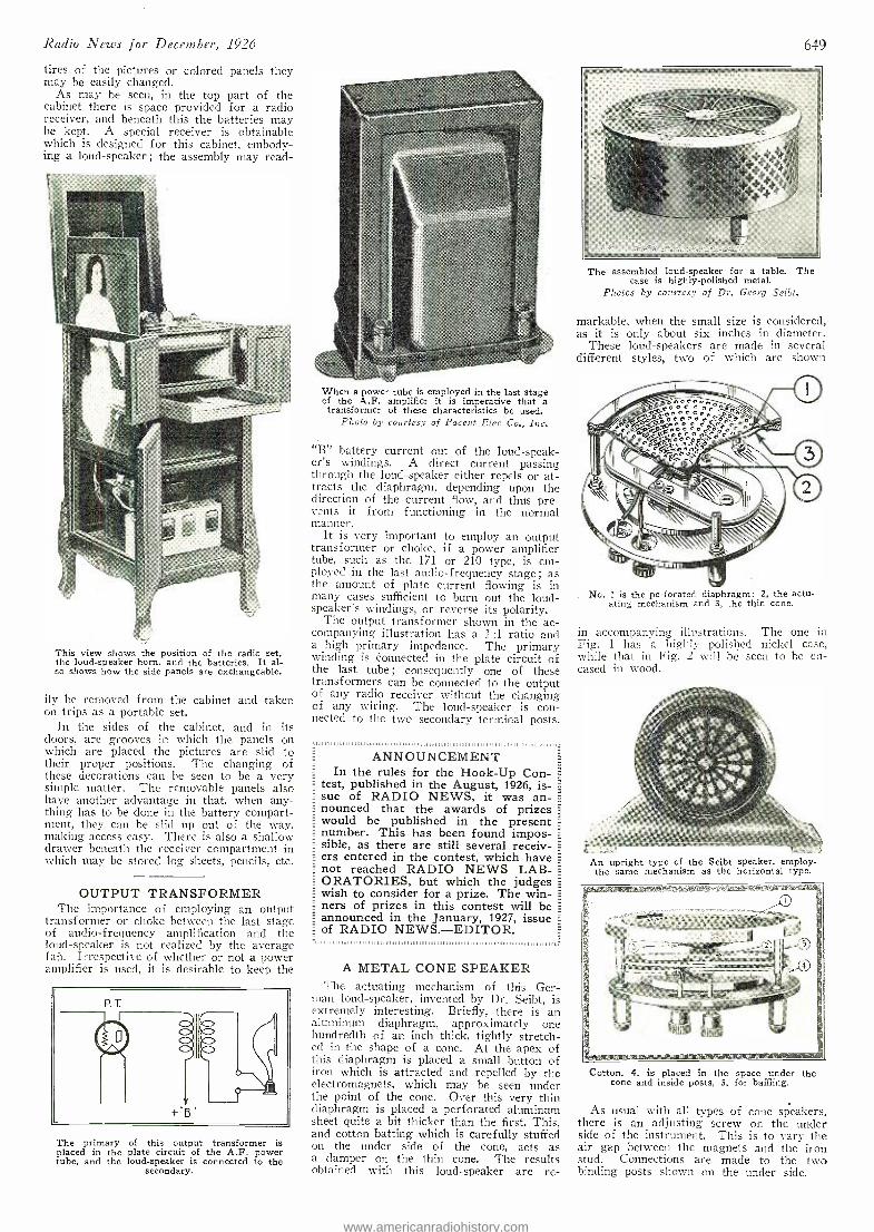
Radio News for December, 1926
tires of the pictures or colored panels they may be easily changed.
As may be seen, in the top part of the cabinet there is space provided for a radio receiver, and beneath this the batteries may be kept. A special receiver is obtainable which is designed for this cabinet, embody- ing a loud -speaker; the assembly may read-
This view shows the position of the radio set, the loud- speaker horn, and the batteries. It al- so shows how the side panels are exchangeable.
ily be removed from the cabinet and taken on trips as a portable set.
In the sides of the cabinet, and in its doors, are grooves in which the panels on which are placed the pictures are slid to their proper positions. The changing of these decorations can be seen to be a very simple matter. The removable panels also have another advantage in that, when any- thing has to be done in the battery compart- ment, they can be slid up out of the way, making access easy. There is also a shallow drawer beneath the receiver compartment in which may be stored log sheets, pencils, etc.
OUTPUT TRANSFORMER The importance of employing an output
transformer or choke between the last stage of audio -frequency amplification and the loud- speaker is not realized by the average fail. Irrespective of whether or not a power amplifier is used, it is desirable to keep the
P. T.
40, 41.
The primary of this output transformer is placed in the plate circuit of the A.F. power tube, and the loud- speaker is connected to the
secondary.
When a power tube is employed in the last stage of the A.F. amplifier it is imperative that a
transformer of these characteristics be used. Photo by courtesy of Pincent Elec Co., Inc.
"B" battery current out of the loud- speak- er's windings. A direct current passing through the loud -speaker either repels or at- tracts the diaphragm, depending upon the direction of the current flow, and thus pre- vents it from functioning in the normal manner.
It is very important to employ an output transformer or choke, if a power amplifier tube, such as the 171 or 210 type, is em- ployed in the last audio- frequency stage ; as the amount of plate current flowing is in many cases sufficient to burn out the loud- speaker's windings, or reverse its polarity.
The output transformer shown in the ac- companying illustration has a 1 :1 ratio and a high primary impedance. The primary winding is Connected in the plate circuit of the last tube ; consequently one of these transformers can be connected to the output of any radio receiver without the changing of any wiring. The loud- speaker is con- nected to the two secondary terminal posts.
1111111111111111111111111
ANNOUNCEMENT In the rules for the Hook -Up Con-
test, published in the August, 1926, is- sue of RADIO NEWS, it was an- nounced that the awards of prizes would be published in the present number. This has been found impos- sible, as there are still several receiv- ers entered in the contest, which have not reached RADIO NEWS LAB- ORATORIES, but which the judges wish to consider for a prize. The win- ners of prizes in this contest will be announced in the January, 1927, issue of RADIO NEWS. -EDITOR.
A METAL CONE SPEAKER The actuating mechanism of this Ger-
man loud- speaker, invented by Dr. Seibt, is extremely interesting. Briefly, there is an aluminum diaphragm, approximately one hundredth of an inch thick, tightly stretch- ed in the shape of a cone. At the apex of this diaphragm is placed a small button of iron which is attracted and repelled by the electromagnets, which may be seen under the point of the cone. Over this very thin diaphragm is placed a perforated aluminum sheet quite a bit thicker than the first. This, and cotton batting which is carefully stuffed on the under side of the cone, acts as a damper on the thin cone. The results obtained with this loud- speaker are re-
64-9
The assembled loud- speaker for a table. case is highly -polished metal.
Photos by courtesy of Dr. Georg Seibt.
The
markable, when the small size is considered, as it is only about six inches in diameter.
These loud- speakers are made in several different styles, two of which are shown
No. 1 is the perforated diaphragm; 2, the actu- ating mechanism and 3, the thin cone.
in accompanying illustrations. The one in Fig. 1 has a highly polished nickel case, while that in Fig. 2 will be seen to he en- cased in wood.
An upright type of the Seibt speaker, employ - the same mechanism as the horizontal type.
Cotton, 4, is placed in the space under the cone and inside posts, 5, for baffling.
As usual with all types of cone speakers, there is an adjusting screw on the under side of the instrument. This is to vary the air gap between the magnets and the iron stud. Connections are made to the two binding posts shown on the under side.
www.americanradiohistory.com
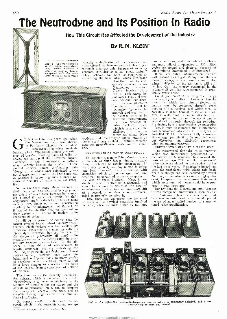
650 Radio News for December, 1926
The Neutrodne and Its Position In Radio How This Circuit Has Affected the Development of the Industry
,n 111mT1,111:11.,:ummmt,,Frralnrrmurrm,
Fig 1 The two controls of this 6 -tube neutrodyne, loop receiver evidence a great advance in design, compared with the same type of set of three years
ago
By R. M. KLEIN*
parently a duplication of the favorable re- sults offered by Neutrodyne, but this dupli- cation is apparent only, because of so many schemes involving so- called "silent tuning." These schemes can only be construed as simulating the basic idea, which Professor
Hazeltine has so ade- quately achieved in his Neutrodyne invention. They involve t h e use of resistances, in- ductances, etc., and pos- sibly combinations there- of in various places in the circuit. It will be recognized by scientific analysis and can readily be demons trated by scientific measurements that these schemes in- volve electrical losses, which in turn impair the efficiency of the re- ceiver equipment. Neu-
trodyne, and Neutrodyne alone, stands as the one and only method of definite capacity coupling neutralization with loss of effici- ency.
GOING back to four years ago, when the Neutrodyne name was applied to Professor Hazeltine's invention of tube -capacity -coupling neutral-
ization, which supplanted almost over -night most of the then existing types of radio re- ceiver, we can recall the extensive flattery evidenced in the innumerable imitations, which shortly flooded the market. These carried various names terminating with "dyne," all of which were calculated to rob the Neutrodyne circuit of its just fame and its position in promoting such a broad ad- vance in the art of radio broadcast recep- tion.
Where are these many "dyne" circuits to-
day? Some of them featured by clever op-
portunists achieved their purpose in promot- ing a good if not ethical profit for their originators, but it is doubtful if any of them in any way, shape or manner contributed anything to the advancement of the art, or if any of the detailed features involved in
their design are featured in modern radio receivers of today.
It will be recognized, of course, that the salient type of tuned radio- frequency trans- former, which perhaps was first evolved by Professor Hazeltine in connection with his Neutrodyne invention, has set the pace for the design of practically all tuned radio transformers even as incorporated in pres- ent -day receiver construction. In the ab- sence of the ability of non- licensees to legally construct receivers embodying the Neutrodyne principle, the designation "tuned radio- frequency receiver" soon came into being, and is applied today to many grades of receivers, which are being manufactured by a large number of concerns, even some of the leaders, from a standpoint of volume of business.
The function of the capacity neutraliza- tion scheme, which is the salient feature of Neutrodyne, is to promote efficiency in the amount of amplification per stage and the Overall amplification on a set, to improve the clarity of reception and tone, and to simplify tuning, together with the elimina- tion of radiation.
Of course, similar results could be se- cured. which to the unsophisticated are ap-
* General Manager, F.A.D. Andrea, Inc.
MINUTENESS OF RADIO QUANTITIES
To say that a man walking slowly travels at the rate of sixty feet a minute, is some- thing which can he readily understood. If we divide by sixty and say a man is going one foot a second, we are dealing with quantities, which to the average mind, are too small to permit of proper conception of the rate of speed involved. Now, if we divide this still further by a. thousand, and state that a man is going at the rate of one -thousandth of a foot in one -thousandth of a second, it requires a semi -technical mind to properly conceive it.
How, then, can we expect the lay mini to conceive the physical quantities involved in radio, when we must divide by millions,
tens of millions, and hundreds of millions, and must talk of frequencies of 300 million cycles per second, and electrical currents of but a minute fraction of a milliampere ?
It has been stated that an efficient receiver will respond to a signal strength on the an- tenna of energy of such small amount, that when multiplied by ten million it will still be less than the energy consumed in the ordinary 25 -watt lamp, encountered in prac- tically every house.
Could you conceive dividing the energy in a lamp by ten million? Consider then the extent to which this minute element of energy must be conserved through every portion of the receiver, and which must be carefully guarded against losses of any na- ture, in order that the signal may be prop- erly amplified to the point, where it can be reproduced as music, through the reproduc- ing device, be it a cone speaker or otherwise.
Yes, it must be conceded that Neutrodyne, and Neutrodyne alone of all the types of so- called T.R.F. receivers, fully conserves this energy, permits it to be amplified with- out distortion, and efficiently reproduces what the antenna receives.
NEUTRODYNE CIRCUIT A BASIC ONE The stereotyped five -tube radio receiver,
which was immediately popularized with the advent of Neutrodyne, has formed the basis of perhaps 95% of the commercial radio receivers placed on the market during the last three years. Remarkable indeed has been the proficiency with which this basic five -tube design has been evolved by several Neutrodyne manufacturers into a highly effi- cient, low -priced instrument -an instrument which no amount of money could have pro- cured a few years ago.
But not here did Neutrodyne stop, because it was recognized immediately upon release of Professor Hazeltine's invention, that here was an instrument, which would permit the use of an unlimited number of stages of tuned radio amplification.
Fig. 4 An eight -tube tuned -radio- frequency receiver which is completely shielded, and is ex- tremely easy to tune and control.
www.americanradiohistory.com
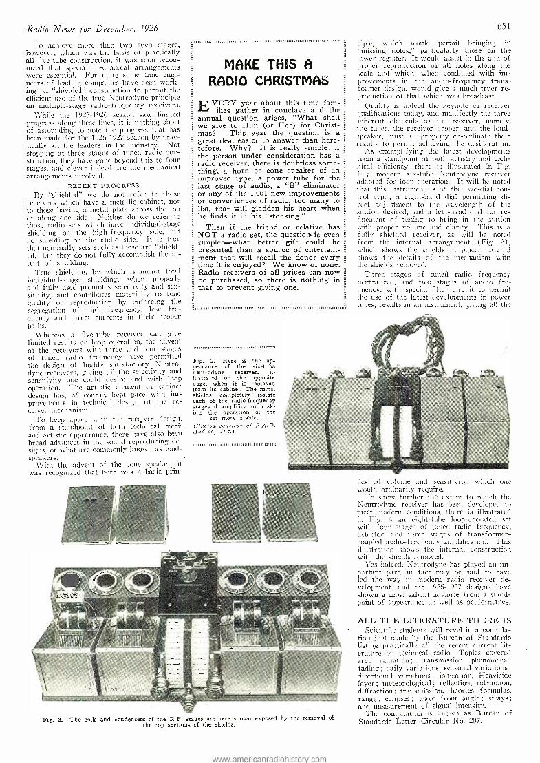
Radio News for December, 1926
To achieve more than two such stages, however, which was the basis of practically all five -tube construction, it was soon recog- nized that special -mechanical arrangements were essential. For quite some time engi- neers of leading companies have been work- ing on "shielded" construction to permit the efficient use of the true Neutrodyne principle on multiple -stage radio- frequency receivers.
While the 1925 -1926 season saw limited progress along these lines, it is nothing short of astounding to note the progress that has been made for the 1926 -1927. season by prac- tically all the leaders in the industry. Not stopping at three stages of tuned radio con- struction, they have gone beyond this to four stages, and clever indeed are the mechanical arrangements involved.
RECENT PROGRESS By 'shielded" we do not refer to those
receivers which have a metallic cabinet, nor to those having a metal plate across the top or along one side. Neither do we refer to those radio sets which have individual -stage shielding on the high -frequency side, but no shielding on the audio side. It is true that nominally sets such as these are "shield- ed," but they do not fully accomplish the in- tent of shielding.
True shielding, by which is meant total individual -stage shielding, when properly and fully used promotes selectivity and sen- sitivity, and contributes materially to tone quality or reproduction by enforcing the segregation of high frequency, low fre- quency and direct currents in their proper paths.
Whereas a five -tube receiver can give limited results on loop operation, the advent of the receivers with three and four stages of tuned radio frequency have permitted the design of highly satisfactory Neutro- dyne receivers, giving all the selectivity and sensitivity one could desire and with loop operation. The artistic element of cabinet design has, of course, kept pace with im- provements in technical design of the re- ceiver mechanism.
To keep apace with the receiver design, from a standpoint of both technical merit and artistic appearance, there have also been broad advances in the sound reproducing de- signs, or what are commonly known as loud- speakers.
With the advent of the cone speaker, it was recognized that here was a basic prin-
MAKE THIS A
RADIO CHRISTMAS
VERY year about this time fam- ilies gather in conclave and the
annual question arises, "What shall we give to Him (or Her) for Christ- mas ?" This year the question is a great deal easier to answer than here-
= tofore. Why? It is really simple: if the person under consideration has a radio receiver, there is doubtless some-
= thing, a horn .or cone speaker of an improved type, a power tube for the last stage of audio, a "B" eliminator or any of the 1,001 new improvements or conveniences of radio, too many to list, that will gladden his heart when he finds it in his "stocking."
Then if the friend or relative has NOT a radio set, the question is even simpler -what better gift could be presented than a source of entertain- _
ment that will recall the donor every time it is enjoyed? We know of none. Radio receivers of all prices can now =
be purchased, so there is nothing in F.
that to prevent giving one.
a 1111. 111, 1111. 11. 1w11111111111.1.11.1.,,L1L.11. 11 1...,11.11111111.1113111111.1.J1
111111111111111111,1,1111111111111111ITTo111111111:11,11,11,11MT.,
Fig. 2. Here is the ap- pearance of the six -tube neutrodyne receiver, il- lustrated on the opposite page, when it is removed from its cabinet. The metal shields completely isolate each of the radio -frequency stages of amplification, mak- ing the operation of the
set more stable. (Photos courtesy of F.A.D. Andrea, Inc.)
651
ciple, which would permit bringing in "missing notes," particularly those on the lower register. It would assist in the aim of proper reproduction of all notes along the scale and which, when combined with im- provements in the audio - frequency trans former design, would give a much truer re- production of that which was broadcast.
Quality is indeed the keynote of receiver qualifications today, and manifestly the three inherent elements of the receiver, namely, the tubes, the receiver proper, and the loud- speaker, must all properly co- ordinate their results to permit achieving the desideratum.
As exemplifying the latest developments from a standpoint of both artistry and tech - nical efficiency, there is illustrated in Fig. 1 a modern six -tube Neutrodyne receiver adapted for loop operation. It will be noted that this instrument is of the two -dial con- trol type ; a right -hand dial permitting di- rect adjustment to the wavelength of the station desired, and a left -hand dial for re- finement of tuning to bring in the station with proper volume and clarity. This is a fully shielded receiver, as will be noted from the internal arrangement (Fig. 2), which shows the shields in place. Fig. 3 shows the details of the mechanism with the shields removed. -
Three stages of tuned radio frequency neutralized, and two stages of audio fre- quency, with special filter circuit to permit the use of the latest developments in power tubes, results in an instrument, giving all the
llllilll(II1II I / Orl!ÌIIl
Fig. 3. The coils and condensers of the R.F. stages are here shown exposed by the removal of the top sections of the shields.
desired volume and sensitivity, which one would ordinarily require.
To show further the extent to which the Neutrodyne receiver has been developed to meet modern conditions, there is illustrated in Fig. 4 an eight -tube loop- operated set with four stages of tuned radio frequency, detector, and three stages of transformer - coupled audio- frequency amplification. This illustration shows the internal construction with the shields removed.
Yes indeed, Neutrodyne has played an im- portant part, in fact may be said to have led the way in modern radio receiver de- velopment, and the 1926 -1927 designs have shown a most salient advance from a stand- point of appearance as well as performance.
ALL THE LITERATURE THERE IS Scientific students will revel in a compila-
tion just made by the Bureau of Standards listing practically all the recent current lit- erature on technical radio. Topics covered are : radiation ; transmission phenomena ;
fading ; daily variations, seasonal variations ;
directional variations ; ionization, Heaviside layer ; meteorological ; reflection, refraction, diffraction ; transmission, theories, formulas, range ; eclipses ; wave front angle ; strays ;
and measurement of signal intensity. The compilation is known as Bureau of
Standards Letter Circular No. 207.
www.americanradiohistory.com
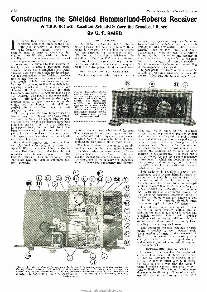
652 Radio News for December, 1926
Constructing the Shielded Hammarlund- Roberts Receiver A T.R.F. Set with Excellent Selectivity Over the Broadcast Range
By V. T. BAIRD IN theory this 5 -tube receiver is com-
paratively simple ; it combines the selec- tivity and sensitivity of two tuned - radio- frequency stages, which have
been designed to insure an extremely high degree of amplification, with the inherent stability and distortionless characteristics of a non -regenerative detector.
To step -up the signals to loud- speaker in- tensity, there is used a two -stage trans- former- coupled audio amplifier ; the. trans- formers used have high primary impedance, and are designed to insure faithful reproduc- tion of the lower -frequency tones of music and speech. Their secondaries are wound by a special process, so that their distributed capacity is reduced to a minimum, and therefore the higher frequencies and their harmonics are passed on without loss to the loud- speaker. The result is the reproduction with full life and brilliance of the higher musical tones of such instruments as the violin, and the absence of the dull and muffled effects so often found in loud- speaker reproduction.
The tuning controls have been reduced to two, although the receiver has three radio - frequency circuits. To effect this, the sec- ond and third variable condensers have been placed on one shaft, and the small difference in capacity found in the third circuit has been compel sated by the introduction, in parallel with its condenser, of a small vari- able capacity which needs no further adjust- ment after being once set.
Exceptionally smooth and gradual volume control, allowing the operator to adjust with equal facility for a powerful local station or a weak distant one, is provided by a rheostat regulating the filament temperatures of the two R.F. tubes. Those in the other three stages are made uniform by automatic fila- ment controls.
THE HOOK -UP Fig. 1 shows the circuit employed. Inter-
action between the fields of the first three stages is prevented by shielding the second R.F. and detector, thus stabilizing the am- plification and increasing its efficiency. No shielding of the first R.F. stage is deemed necessary by the designers ; although the set is so arranged that the constructor may in- clude this extra precaution if he so desires.
DESIGN OF THE R.F. AMPLIFIER The two stages of radio- frequency ampli-
Fig. 2. The tuning of the receiver shown at the right is very simple, as there are only two dials, D, to adjust. The right dial controls two condensers mounted on the same shaft. SW is the antenna cor- rection switch ; RS is a combination filament switch and rheostat, and j is the
loud- speaker jack.
41111111ULLI.1111111 11 1 1 1.,..11:111111.=
increases rapidly as the frequency increases. In other words, the energy transfer is much greater at high frequencies (short wave- lengths) than at low frequencies (long wavelengths) ; while the relative selectivity is less at high frequencies and greater at low frequencies. Conversely, a constant transfer of energy and constant selectivity can be maintained by loosening the coupling as the frequency is increased.
A successful broadcast receiver must be capable of receiving wavelengths from 200 meters (1,500 kc.) up to 545 meters (550
fication present some rather novel features. The design of the antenna coupling coil and the interstage radio - frequency transformers is based on two fundamental laws of radio engineering, that are as old as radio itself.
The first of these is, that up to a certain point an increase in the coupling between two coils affords an increase in energy trans- fer and a decrease in selectivity. The sec- ond law is, that the energy transfer between two coils, such as the primary and secondary of an ordinary radio -frequency transformer,
Fig. 3. In this top view of the assembly, L, Ll are R.F. transformers; C, tuning condensers; Cl, equalizing condensers; C2 and Rl, grid condenser and leak; C3, midget compensating con- denser ; C4, by -pass condenser ; R2 and R3, automatic filament- controls; S, R.F. and detector sockets; Sl, A.F. sockets; T, A.F. transformers; BB, baseboard; SP, sub -panel, and BP,
binding posts.
kc.), the two extremes of the broadcast range. These requirements make it evident that some means of variable coupling must be provided if we are to obtain equal energy transfer and selectivity throughout the broadcast band. Since the trend in modern broadcast receivers is toward simplicity of tuning, the addition of variable coupling controls is not advisable. Therefore there was developed for this set a radio -frequency transformer in which the coupling between the primary and secondary coils is auto- matically varied by the rotation of its asso- ciated tuning condenser.
This variation in coupling is smooth and . continuous and is accomplished by means of a cam on the variable condenser shaft. At the setting of 0 on the condenser dial (which tunes the circuit to a wavelength slightly below 200 meters) the coupling be- tween primary and secondary is minimum. As the tuning dial is advanced toward 100 the coupling increases gradually until it reaches maximum when the condenser dial reads 100, at which time the circuit is tuned to a wavelength of about 560 meters.
The antenna coupler is designed to make use of this same efficient method and, in addition, the antenna coil itself is tapped and a switch provided. This affords a further coupling variation to suit different lengths of antennae and to provide extremely loose coupling in very congested areas.
This automatic variable coupling feature makes it possible to use a comparatively large number of turns in the primaries of the R.F. transformers, which causes greater energy transfer. Increased signal strength and a high degree of selectivity throughout is thus obtained.
EQUALIZING THE CIRCUITS In most of the so- called "self- balanced"
circuits, elimination of the tendency to oscil- late has been attained at the sacrifice of effi- ciency. A method often used is to design the coils in such a way that the losses in them introduce enough resistance to pre- vent oscillation. This method is, of course, detrimental to efficiency. Some others make use of very low plate voltages in the R.F.
www.americanradiohistory.com
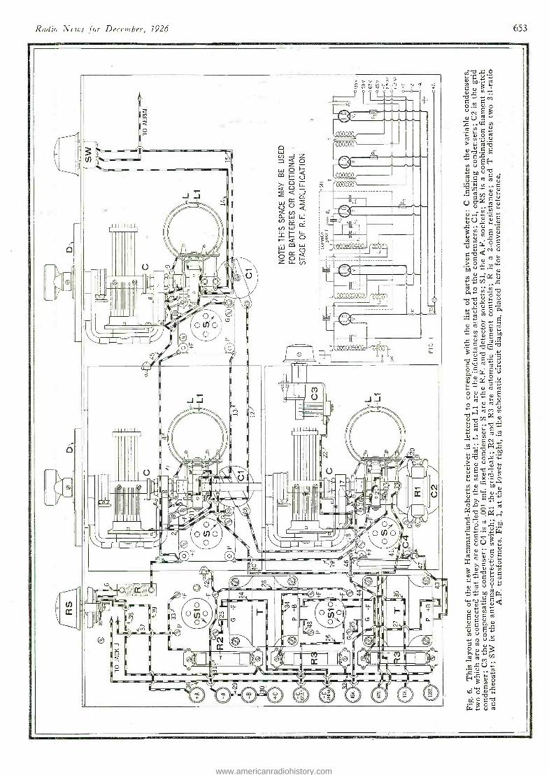
Radio News for December, 1926 653
rpb.a o ... .
-
.._... -
o ^ome >> ua o. a a
u m a -+ , °. o 0 0
loolt a
ÌI' ..
i. [ _0%. 41 da y CÒ m 1.. Qy u ..z w+ b i+
J O ...N+ - O U
M
3 .ñ ._ n o
Ñ ti >0 b
m a, !1; ú- :0.. ^ ÿ E m cOi s.
as ÿ ó N o
agyá > O v. ^ Oy r ÿ í i ä rov áro a+'i ° c°i
0 4 ó ó á ,u á o m ÿ
v `° ; Z7 t
b (b U q , O i E ó ÿa
4L) o o
roN . ~ a td M V g b 8 ~-b-F
a Ñ ro . . °áx
bo-m ? , U , °' v
3 í°'.
; y .c ÿ ó p. y
b ti °: . - ó y...w
v3v ó ó y >1 a u 4, Ñ I.Fi Si
,
% i-+ O U i+ fÒ
Y w ó N u a g m
v R °' c.CiOE .. rn U m
w cOi .
y. Á
á 'rrrr p .
O ,. 000000
w J z O Z O >
I
J J I
wOH 03 0_1= v F09044Q,
}Q 0 l. g¢ J
!;h< ¢
OOH Z L.L. U)
,-
' .> L F I 1 I I 1 I
I
_ I
Q /_ I
oLL or-- .
I lu- lii ï i io:: carol
J I
I
/ e - \1 ,
' U -1t1'I L I ;
l' ìl C C IIII U
' oo : o - 0Q( 0 r' -- OO j"0 ® , OlnO
e OO'} OJ
O
I jo '
/ t->-i: Y'
I
,- IE- _
' ®
lï:v'- n ' I'
^
Io .
J_r _ f
I
!
I
I
1
1á u J J ' I
I ' \
I I
I ¡l'...;
U
a \_ Q,
I°
\ -/i -
IIII v 1
\ `_ /'i7h '' ° ì1I\_,
I
p III
1 I
:
U =a.! / 4 - I`,'
P I\+"I !'
® iìIlII IpIpIlpIpIIpIIpIIpIIpI
11111111
11 t 1
i IIg- Q
1 i1`% ííl ! .. ï 1 ,,1, ( ,-6', I It_
. rr . :-
17 1
iÌi N U
' 1 :_. : . _
= ° , uu i11, -
- - e = . . - ® oo
® O
, ..._._ 1J1, - a _ II; _. - oo V 1 / 0 tt/ L -' + ` j _:C r
Iv ; 1 I ̀ ` 1
N ® , ((¡\\..YJJ
-.. .. e - -
. V }
- _
_. _- ® I 11L
, I :
M V
-
° IIIII' .LL ii
.
(n 1 ,`'
loy
Imo
+
O pNp IN Oy 1
_- __ .
O _ r Ì11._-
.
I 1 ' _
-c ,
I-I I I
4'
1
' 'I ` 11
'IJI I.. IM
, 1 _ OO -v Oy' .a '..- J
1iI ® _
Y U
ó
) I , N. co ¡ j ,ill , . .
CC 1
n_taB I
,
T' - Ì 1Ì I -1I.U 1
4 i,IIL' 1-. ,.,
M v
I - -" , iti , .CU ÿ :~ ° -
' 4+ G. C 3° _ 4J./4J`,
\ f ? M \
O O O O0 O O O O ó
www.americanradiohistory.com
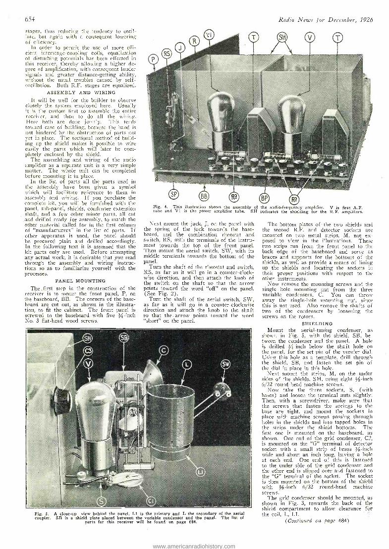
654
stages, thus reducing the tendency to oscil- late, but again with a consequent lowering of efficiency.
In order to permit the use of more effi- cient interstage- coupling coils, equalization of disturbing potentials has been effected in this receiver, thereby allowing a higher de- gree of amplification, with consequent louder signals and greater distance- getting ability, without the usual troubles caused by self - oscillation. Both R.F. stages are equalized.
ASSEMBLY AND WIRING It will be well for the builder to observe
closely the system employed here. Usually it is the custom first to assemble the entire receiver, and then to do all the wiring. Here both are done jointly. This tends toward ease of building, because the hand is not hindered by the obstruction of parts not yet in place. The sectional method of build- ing up the shield makes it possible to wire easily the parts which will later be com- pletely enclosed by the shield.
The assembling and wiring of the audio amplifier as a separate unit is a very simple matter. The whole unit can be completed before mounting it in place.
In the list of parts all the parts used in the assembly have been given a symbol which will facilitate reference to them in assembly and wiring. If you purchase the complete kit, you will be furnished with the panel, sub -panel, shields, condenser -extension shaft, and a few other minor parts, all cut and drilled ready for assembly, to match the other material called for in the first column of "manufacturers" in the list of parts. If other apparatus is used, the panel should be procured plain and drilled accordingly. In the following text it is assumed that the kit parts only are used. Before attempting any actual work, it is desirable that you read through the assembly and wiring instruc- tions so as to familiarize yourself with the processes.
PANEL MOUNTING
The ,first step in the construction of the receiver is to mount the front panel, P, on the baseboard, BB. The corners of the base- board are cut out, as shown in the illustra- tion, to fit the cabinet. The front panel is screwed to the baseboard with five 3/4-inch No. 3 flat -head wood screws.
Radio -News for December, 1926
Fig. 4. This ilustration shows the assembly of the audio -frequency amplifier. V is first A.F. tube and V1 is the power amplifier tube. SH indicates the shielding for the R.F. amplifiers.
Next mount the jack, J, on the panel with the spring of the jack towards the base- board, and the combination rheostat and switch, RS, with the terminals of the instru- ment towards the top of the front panel. Then mount the aerial switch, SW, with its middle terminals towards the bottom of the panel.
Turn the shaft of the rheostat and switch, RS, as far as it will go in a counter- clock- wise direction, and then attach the knob of the switch on the shaft so that the arrow points toward the word "off" on the panel. (See Fig. 2).
Turn the shaft of the aerial switch, SW, as far as it will go in a counter- clockwise direction and attach the knob to the shaft so that the. arrow points toward the word "short" on the panel.
Fig. 5. A close -up view behind the panel, Ll is the primary and L the secondary of the aerial coupler. SB is a shield plate placed between the variable condenser and the panel. The list of
parts for this receiver will be found on page 684.
The bottom plates of the two shields and the second R.F. and detector sockets are mounted on two metal strips, M, not ex- posed to view in the illustrations. These two strips run from the front panel to the back edge of the baseboard and serve as braces and supports for the bottoms of the shields, as well as provide a means of lining up the shields and locating the sockets in their proper positions with respect to the other instruments.
Now remove the mounting screws and the single hole mounting nut from the three variable condensers, C. You can throw away the single -hole mounting nut, since this is not used. Also remove the shafts of two of the condensers by loosening the screws on the rotors.
SHIELDING Mount the aerial- tuning condenser, as
shown in Fig. 5, with the shield, SB, be- tween the condenser and the panel. A hole is drilled / -inch below the shaft hole on the panel, for the set pin of the vernier dial. Using this hole as a template, drill through the shield, SB, and fasten the set pin of the dial in place in this hole.
Next mount the Strips, M, on the under sides of the shields, SH, using eight ,A-inch 6/32 round -head machine screws.
Now take the three sockets, S, (with hases) and loosen the terminal nuts slightly. Then, with a screwdriver, make sure that the screws that fasten the springs to the base are tight, and mount the sockets in place with machine screws passing through holes in the shields and into tapped holes in the strips under the shield bottoms. The first one is mounted on the baseboard, as shown. One end of the grid condenser, C2, is mounted on the "G" terminal of detector socket with a small strip of brass % -inch wide and about an inch long, having a hole at each end. One end of this is fastened to the under side of the grid condenser and the other end is slipped over and fastened to the "G" terminal of the socket. The socket is then mounted on the bottom of the shield with 5A-inch 6/32 round -head machine screws.
The grid condenser should be mounted, as shown in Fig. 3, towards the back of the shield compartment to allow clearance fòr the coil, L, Ll.
(Continued on page 684)
www.americanradiohistory.com
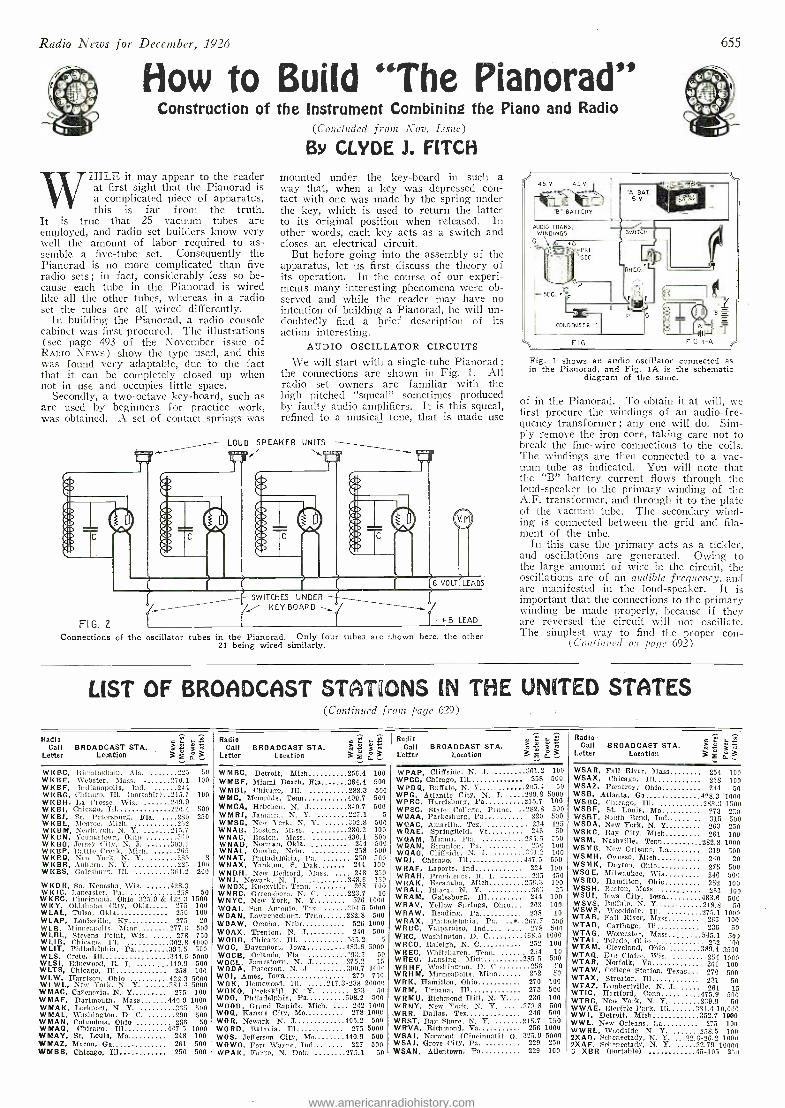
Radio News for December, 1926
flow to Build "The P Construction of the instrument Combining the Piano and Radio
(Concluded front Nov. Issue)
By CLYDE J. FITCH
HILE it may appear to the reader at first sight that the Pianorad is a complicated piece of apparatus, this is far from the truth.
It is true that 25 vacuum tubes are employed, and radio set builders know very well the amount of labor required to as- semble a five -tube set. Consequently the Pianorad is no more complicated than five radio sets ; in fact, considerably less so be- cause each tube in the Pianorad is wired like all the other tubes, wllereas in a radio set the tubes are all wired differently.
In building the Pianorad, a radio console cabinet was first procured. The illustrations (see page 493 of the November issue of RADIO NEws) show the type used, and this was found very adaptable, due to the fact that it can be completely closed up when not in use and occupies little space.
Secondly, a two -octave key- board, such as are used by beginners for practice work, was obtained. A set of contact springs was
mounted under the key -board in such a way that, when a key was depressed con- tact with one was made by the spring under the key, which is used to return the latter to its original position when released. In other words, each key acts as a switch and closes an electrical circuit.
But before going into the assembly of the apparatus, let us first discuss the theory of its operation. In the course of our experi- ments many interesting phenomena were ob- served and while the reader may have no intention of building a Pianorad, he will un- doubtedly find a brief description of its action interesting.
AUDIO OSCILLATOR CIRCUITS
We will start with a single -tube Pianorad ;
the connections are shown in Fig. 1. All radio set owners are familiar with the high pitched "squeal" sometimes produced by faulty audio amplifiers. It is this squeal, refined to a musical tone, that is made use
LOUD SPEAKER UNITS
1 T
FI G.2 I
Connections of the oscillator tubes in the Pianorad. Only four tubes are shown here, the other 21 being wired similarly.
f SWITCHES UNDER -}- /¡ KEYBOARD
655
AUDIO TRANS. W INDINGS
Fig. 1 shows an audio oscillator connected as in the Pianorad, and Fig. lA is the schematic
diagram of the same.
of in the Pianorad. To obtain it at will, we first procure the windings of an audio-f re- quency transformer; any one will do. Sim- ply remove the iron core, taking care not to break the fine -wire connections to the coils. The windings are then connected to a vac- uum tube as indicated. You will note that the "B" battery current flows through the loud- speaker to the primary winding of the A.F. transformer, and through it to the plate of the vacuum tube. The secondary wind- ing is connected between the grid and fila- ment of the tube.
In this case the primary acts as a tickler, and oscillations are generated. Owing to the large amount of wire in the circuit, the oscillations are of an audible frequency, and are manifested in the loud- speaker. It is important that the connections to the primary winding be made properly, because if they are reversed the circuit will not oscillate. The simplest way to find the proper con -
(Continued on page 692)
LIST OF BROADCAST STATIONS IN THE UNITED STATES (Continued front page 629)
Radio E ,, « Call BROADCAST STA. m « j «
Letter Location 3 2 y 3 Radio m C
Call BROADCAST STA. > : i,` Z
Letter Location 3 2' a, 3 Radio m C ,_ ;
Call BROADCAST STA. " Letter Location 3 a 3
Radio - w Call BROADCAST STA. m .°.
á «
Letter Location 3 F o_ 3
WKBC, ]Birmingham, Ala. "25 50 WKBE, Webster, Mass. 2701 100 WI<BF, Indianapolis, Ind. 244 WI(BG, Chicago, Ill. (portable).. 215.7 100 W I(BH, La Crosse, Wis. 249.9 WKB1, Chicago, Ill 220,4 500 WI(BJ, St. Petersburg, Fla. ....280 250 WKBL, Monroe, Mich. 20.0 WKBM, Newburgh, N. Y. 215.7 WI<BN, Youngstown, Ohio 360 WI(BO, Jersey City, N. J. ......309.1 WI(BP, Battle Creek, Itich, 205 WI(BQ, Now York, N. Y. 235 8 W KBR, Auburn, N. Y. 205 100 WKBS, Galesburg, Ill. 361.2 200
WKDR, So, Iiter,sha, Wis. 428.3 WK IC. Lancaster, Pa. 258 50 WKRC, Cincinnati, Ohio 325.9 &422.11500 WI(Y, Oklahoma City, Okla 275 100 WLAL, Tulsa, Okla 250 100 W LAP, Louisville, Ky 275 20 WLB. Minneapolis, Mien 277.6 500 WLBL, Stevens Point, Wis. 278 750 WLIB, Chicago. Ill, 302.8 4000 WLIT, Philadelphia, Pa 394.6 500 W LS, Crete, Ill 394.6 5000 WLSI, Edgewood, R. I. 440.9 500 WLTS, Chicago, Ill 258 100 WLW, Harrison, Ohio 422.3 5000 WLWL, Nor York. N. Y. 387.4 5000 0/MAC, Cazenovia, N. Y 275 100 WMAF, Dartmouth, Mass 440.9 1000 WMAK, I.ceknort, N. Y. 365 500 WMAL. Washington, D. C. 200 500 WMAN, Columbus, Ohio 286 50 WMAQ, Chicago, Ill 9475 1000 NMAY, St. Louis, Mo 298 100 NMAZ, Macon, Ga 261 500 AIMRR_ Oh fo, nn T11 950 5350
WMBC, Detroit, Mich 256.4 100 WMBF, Miami Beach, Fla 384.4 500 WMBI, Chicago, III, 233.3 500 WMC, Memphis, Tenn 499.7 500 WMCA, Hoboken, N. J 340.7 500 WMRJ, Saulaie., N. Y. 227.1 5 WMSG, New York. N. Y. 302.8 500 WNAB, Boston, Mass. , 280.2 100 WNAC, Boston, Mass. 430.1 500 WNAD, Norman, Olcla. , 254 - 500 WNAL, Omaha, Nehr. 258 500 WHAT, Philadelphia, Pa. - 250 500 WNAX, Yankton, S. flak 244 100 WNBH, New Bedford, Mass. 248 250 W NI, Newark, N. J. 348.6 150 WNOX, Knoxville, Tenn. 268 100 WNRC, Greensboro, N. C. 223.7 10 WNYC, New York, N. Y 526 1000 WOAI, fion Antonio. Tex. 391 - 6000 WORN, Lawrenceburg, Tenn 28...5 500 WOAW, Omaha, Nebr 526 1000 WOAX, Trenton, N. J 240 500
- WOBB, Chicago, Ill. 6
WOC. Davenport, Iowa 433.6 5000 WOCB, Orlando. Fla. "937 50 WOOL, Jamestown, N. J 275.2 1.5
WODA, Paterson, N. S. 390 7 1000 W01, Ames, Iowa 270 750 WOK, Hnmemrmd, Ill. 217.3 -233 20000 WOKO, Peekskill, N. 'Y. 233 50 WOO, Philadelphia, Pa- 508.2 500 wHoD, Grand Rapids. Mich. 242 1000 WOQ, Kansas City, Mo 2781000 WOR, Newark, N. J 405.2 500 WORD, Batavia, Ill 275 5000 WOS, Jefferson City, Mo 440.9 500 WOWO, Fort Wayne. Ind 227 500. IL/ oev n.,....., Ti n.,, 995 1 sa
WPAP, Cliffside. N. J. 361.2 100
WPCC, Chicago, Ill 258 500
WPDQ, Buffalo, N. Y 2O5.4 50
WPG, Atlantic City N. J. ., 299.8 5000 WPRC, Harrisburg Pa 215.7 100 WPSC, State College, Penna. ,.282.8 500 WQAA, Parkesburg, Pa 220 500 WQAC, Amarillo, Tex. 234 125 WQAE, Springfield, Vt 246 50 W Qq. M, Miami, Flt 205.5 750 WQAN, Scranton, Pa. 150 100 WQAO, Cliffside, N. J. ^Iï1.2 100 WQJ, Chicago, Ill- 417.5 500 WRAF, Laporte, Ind 224 100 WRAH, agar once, R. I. 235 950 WRAK, Escanaba, Mich 2.56.3 100 WRAL, Ithaca, N. Y. 303 25
WRAM, Galesburg, Ill 244 100 WRAV, Yellow Springs, Ohio 263 100 WRAW, Reading, Pa' 238 10 WRAX, Philadelphia. Pa. 2fí7.7 505 WRBC, Valparaíso, Ind 270 501 WRC, Washington, D. C 463.5 1000 WRCO, Raleigh, N. C 252 100 WREC, \Vhitehaven, Tenn. 254 10 WREO, Lansing, Mich 285.5 500 WRHF, Washington,. D. C 256 : -0
WRHM, Mínnéapolis, Minn 252 50 WRI<, Hamilton, Ohio 270 100 WRM, Urbana, Ill 273 500 WRMU, Richmond Hill. N. Y 236 100 WRNY, New York, N. Y. 375.8 500
._WRR,.. Dallas, Tex . 246 500 WRST, Ray Shore. N. Y. 215.7 150. WRVA, Richmond, Va 256 1000 WSAJ, Norwood (Cincinnati) O. 325.9 5000 WSAJ, Grave City, Pa. 229 250 WSAN_ Allentown. Pa 229 100
WSAR, Fall River, Mass 259 100 WSAX, Chicago, Ill 268. 100 WSAZ, Pomeroy,- Ohio 294 50 WSB, Atlanta, Ga 928.3 -1000 WSBC, Chicago, Ill. 288.1 1500 WSBF, St. Louis, Mo - 273 250 WSBT, South Beird, Ind 015 500 WSDA, New York, N. Y 263 250 WSKC, Ray City, Mich 261 100 WSM, Nashville, Tenn 282.5 1000 WSMB, New Orleans la 314 500 WSMH, Owosso, Mich 240 20 WSMI(, Dayton, Ohio 275 500 WSOE, Milwaukee, Wis 246 500 WSRO, Hamilton, Ohio 252 100 WSSH, Roston, Mass. 261 100 WSU1, Iowa City, Iowa 983.6 500 WSVS, Buffalo, N. Y 218.8 50 WSWS, \VoOddale. III. 275.1 1000 WTAB, Fail River, \lass sos 100 WTA D, Carthage, Ill 236 50 WTAG, Worcester, Mass ..... 545.2 500 WTAL, Toledo, Ohio 252 700 WTAM, Cleveland, Ohio 389.4 3500 WTA Q, Eau Claire. Wis. 259 1000 WTAR, Norfolk, Vs 261 100 WTAW, College Station, Texas.., 270 500 WTAX, Streator, Ill 231 50
WTCZ Lambertville,
47569 5ÓÓ WTRC. New York, N. Y. 239.9 50 WWAE, Clectrie Park, Ill .1.01.410,0M WWJ. Detroit, Mich., 352,7 1000 WWL, New Orleans, La 275 -100 WWRL, Woodside, N. Y. 2i8.5 100 2XAn, Schenectady, N. Y. ...22.6 -26.2 7000 2XAF. Schenectady, N. Y, 32,79 10000 n XRR (nortablel 45_515 950
www.americanradiohistory.com
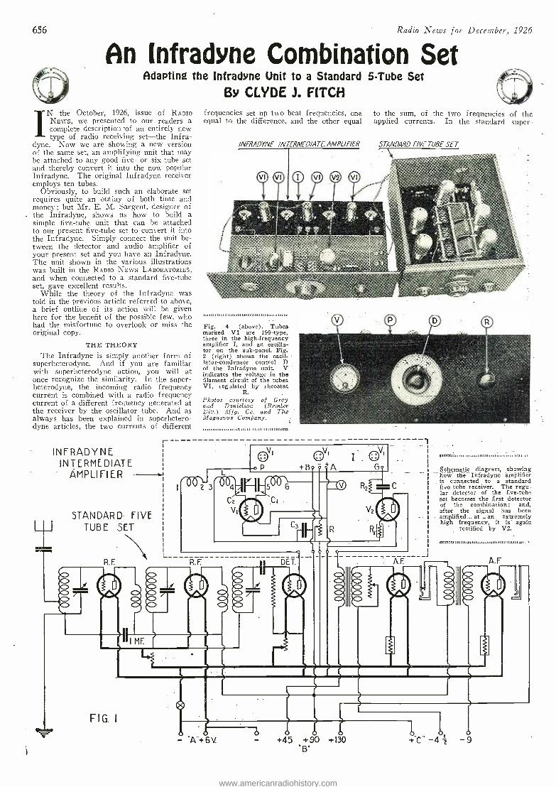
656 Radio News for December, 1926
An (nfradne Combination Set Adapting the Infradyne Unit to a Standard 5 -Tube Set
By CLYDE J. FITCH
IN the October, 1926, issue of RADIO NEWS, we presented to our readers a complete description of an entirely new type of radio receiving set -the Infra-
dyne. Now we are showing a new version of the same set, an amplifying unit that may be attached to any good five- or six -tube set and thereby convert it into the now popular Infradyne. The original Infradyne receiver employs ten tubes.
Obviously, to build such an elaborate set requires quite an outlay of both time and money ; but Mr. E. M. Sargent, designer of the Infradyne, shows us how to build a simple five -tube unit that can be attached to our present five -tube set to convert it into the Infradyne. Simply connect the unit be- tween the detector and audio amplifier of your present set and you have an Infradyne. The unit shown in the various illustrations was built in the RADIO NEWS LABORATORIES, and when connected to a standard five -tube set, gave excellent results.
While the theory of the Infradyne was told in the previous article referred to above, a brief outline of its action will be given here for the benefit of the possible few, who had the misfortune to overlook or miss the original copy.
THE THEORY
The Infradyne is simply another form of superheterodyne. And if you are familiar with superheterodyne action, you will at once recognize the similarity. In the super- heterodyne, the incoming radio frequency current is combined with a radio frequency current of a different frequency generated at the receiver by the oscillator tube. And as always has been explained in superhetero- dyne articles, the two currents of different
INFRADYNE INTERMEDIATE
AMPLIFIER
STANDARD FIVE TUBE SET
INEMINIM
R. F.
-
L_
frequencies set up two beat frequencies, one equal to the difference, and the other equal
INERADYNE INTERMEDIATE AMPLIFIER
to the sum, of the two frequencies of the applied currents. In the standard super-
STANDARD FIVE TUBE SET
Fig. 4 (above). Tubes marked VI are 199 -type, three in the high -frequency amplifier I, and an oscilla- tor on the sub -panel. Fig. 2 (right) shows the oscil- lator- condenser control D of the Infradyne unit. V indicates the voltage in the filament circuit of the tubes VI, regulated by rheostat
R. Photos courtesy of Gray and Danielson (Renfler Div.) ]lIfg. Co. and The Magnavox Company.
1,,,,;;;,;,,,,,,,,;;,;,;,;;;;;;o::::::::: : :::: :: ::::: ::::::::,,.a
G
R. F. DET.
FIG. I
l i
Schematic diagram, showing how- the Infradyne amplifier is connected to a standard five tube receiver. The regu- lar detector of the five -tube set becomes the first detector of the combination; and, after the signal has been amplified at an extremely high frequency, it is again
rectified by V2.
0111r111111111111111:111111 /II
-J
- A+6V. +45 +90 +130 .B.
A.F
www.americanradiohistory.com
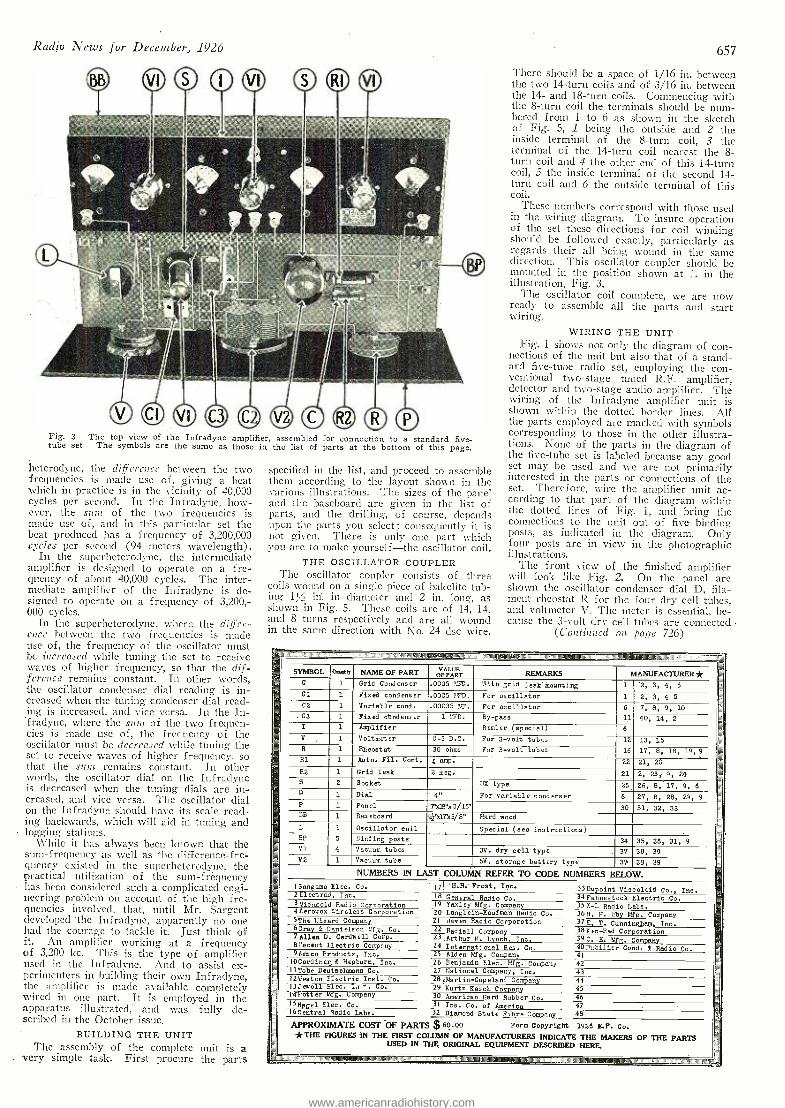
Radio News for December, 1926
Fig. - 3 The top view of the Infradyne amplifier, assembled for connection to a standard five - tube set The symbols are the same as those in the list of parts at the bottom of this page.
heterodyne, the difference between the two frequencies is macle use of, giving a beat which in practice is in the vicinity of 40,000 cycles per second. In the Infradyne, how- ever, the suns of the two frequencies is made use of, and in this particular set the beat produced has a frequency of 3,200,000 cycles per second (94 meters wavelength).
In the superheterodyne, the intermediate amplifier is designed to operate on a fre- quency of about 40,000 cycles. The inter- mediate amplifier of the Infradyne is de- signed to operate on a frequency of 3,200,- 000 cycles.
In the superheterodyne, where the differ- ence between the two frequencies is made use of, the frequency of the oscillator must be increased while tuning the set to receive waves of higher frequency, so that the dif- ference remains constant. In other words, the oscillator condenser dial reading is in- creased when the tuning condenser dial read- ing is increased, and vice versa. In the In- fradyne, where the spin of the two frequen- cies is made use of, the frequency of the oscillator must be decreased while tuning the set to receive waves of higher frequency, so that the soin remains constant. In other words, the oscillator dial on the Infradyne is decreased when the tuning dials are in- creased, and vice versa. The oscillator dial on the Infradyne should have its scale read- ing backwards, which will aid in tuning and
_logging. stations. While it has always been known that the
sum- frequency as well as the difference -fre- quency existed in the superheterodyne, the practical utilization of the sum -frequency has been considered such a complicated engi- neering problem on account of the high fre- quencies involved, that, until Mr. Sargent developed the Infradyne, apparently no one had the courage to tackle it. Just think of it. An amplifier working at a frequency of 3,200 kc. This is the type of amplifier used in the Infradyne. And to assist ex- perimenters in building their own Infradyne, the amplifier is made available completely wired in one part. It is employed in the apparatus illustrated, and was fully de- scribed in the October issue.
BUILDING THE UNIT The assembly of the complete unit is a
very simple task. First procure the parts
specified in the list, and proceed to assemble them according to the layout shown in the various illustrations. The sizes of the panel and the baseboard are given in the list of parts, and the drilling, of course, depends upon the parts you select ; consequently it is not given. There is only one part which you are to make yourself -the oscillator coil.
THE OSCILLATOR COUPLER The oscillator coupler consists of three
coils hound on a single piece of Bakelite tub- ing 1/ in in diameter and 2 in. long, as shown in Fig. 5. These coils are of 14, 14, and 8 turns respectively and are all wound in the sane direction with No. 24 dsc wire.
657
There should be a space of 1/16 in. between the two 14 -turn coils and of 3/16 in. between the 14- and 18 -turn coils. Commencing with the 8 -turn coil the terminals should be num- bered from 1 to 6 as shown in the sketch of Fig. 5, 1 being the outside and 2 the inside terminal of the 8 -turn coil, 3 the terminal of the 14 -turn coil nearest the 8 turn coil and 4 the other end of this 14 -turn coil, .5 the inside terminal of the second 14- turn coil and 6 the outside terminal of this coil.
These numbers correspond with those used in the wiring diagram. To insure operation of the set these directions for coil winding should be followed exactly, particularly as regards their all being wound in the same direction. This oscillator coupler should be mounted in the position shown at L in the illustration, Fig. 3.
The oscillator coil complete, we are now ready to assemble all the parts and start wiring.
WIRING THE UNIT Fig. 1 shows not only the diagram of con-
nections of the unit but also that of a stand- ard five -tube radio set, employing the con- ventional two -stage tuned R.F. amplifier, detector and two -stage audio amplifier. The wiring of the Infradyne amplifier unit is shown within the dotted border lines. All the parts employed are marked with symbols corresponding to those in the other illustra- tions. None of the parts in the diagram of the five -tube set is labeled because any good set may be used and we are not primarily interested in the parts or connections of the set. Therefore, wire the amplifier unit ac- cording to that part of the diagram within the dotted lines of Fig. 1, and bring the connections to the unit out of five binding posts, as indicated in the diagram. Only four posts are in view in the photographic illustrations.
The front view of the finished amplifier will look like Fig. 2. On the panel are shown the oscillator condenser dial D, fila- ment rheostat R for the four dry cell tubes, and voltmeter V. The meter is essential, be- cause the 3 -volt dry cell tubes are connected
(Continued on page 726)
g IIIIWImNIIIIINNIIMINHI11HIIIINIPo MIIIIIMIIIMIIINIIHIIIIM +a ,i. MOM NIIIINtlNIIAIIHAFRS AVIIIlm _
5. SYMBOL Qs..eb NAME OF PART pp pART REMARKS
ea MANUFACTURER ¡ ea
C 1 Grid Condenser .0005 ISFD. With grid leak. Mounting 1 '2, 3, 4, 5 = C. 1 Fixed condenser .0005 ETD. For oscillator 1 2, 3, 4 5
C2 1 Variable cond. .00035 4.T. For oscillator 6 7, 8, 9, 10 - .C3 1 Fixed ctnd enser 1 MT,D. By -pass 11 40, 14, 2
I 1 Amplifier Remler (special) 6
V 1 Voltmeter 0 -5 D.C. For 3 -volt tubes 12 13, 15 R 1 Rheostat 30 ohms For 3 -volt tubes 16 17, 8, 18, 19,9 R1 1 Auto. Fil. Cont. i amp. 22 21, 20 R2 1 Grid leak 2 meg. 21 2, 23, 9, 24 s 2 Socket U/, type 25 26, 8, 17, 9, 6
D 1 Dial 4" For variable condenser 6 27, 8, 28, 29, 9 P 1 Panel 7xl8"x3 /16" 30 31, 32, 33 BB 1 Baseboard 917.17k5/8" Hard wood
L 1 Oscillator coil Special (see instructions) BP 5 Binding posts 34 35, 36, 31, 9
71 4 Vacuum tubes 3V. dry cell type 37 38, 39 Iö V2 1 Vacuum tube 5V. etorage battery type 3 38, 39
NUMBERS IN LAST COLUMN REFER TO CODE NUMBERS BELOW. ISangamo Elec. Co. - ¡ 71'H.H. Frost, Inc. 33Dupoint Viscoloid Co., Inc. 2 Elect rad , Inc. 18 General Radio Co. 34Fahnestock Electric Co.
- 3Micamold Radio Corporation 19 Yaxley Mfg. Company 35 X-L Radio Labs. 4 Aerovox Vireless Corporation 20 Langbein- Kaufman Radio Co. 3614. H. Eby Mfg. Company 5The lizard Company 21 Doyen Radio Corporation 37 E. T. Cunningham, Inc. 60ray & Danielson Mfg. Co. 22 Radial], Company 38Ken -Rad Corporation 7A11en D. Cardwell Corp. 23.Arthur H. Lynch, Inc. 39C. E. Mtg. Company 8Peceut Electric Company 24 International Res. Co. 40Dubilier Cond. & Radio Co.
= 9Ameco Products, Inc. 25 Alden Mfg. Company 41 IOGardiner & Hepburn, Inc. 26 Benjamin Elec. Mfg. Company 42 IlTobe Deutschman Cp. 27 National Company, Inc. 43 12Yieston Electric Inst. Co. 28I14artin- Copeland Company 44 133 *tell Elec. 1,1 '. Co. 29. Kurtz Kasch Company 45 I'4Potter Mfg. Company 30 American Hard Rubber Co. 46 15Nagd Elec. Co. 31 Ins. Co. of America 47 16Central Radio Labs. 32 Diamond State Fibre Company 48
APPROXIMATE COST OF PARTS $ 6ó.0O Form Copyright 1926 H.P. Co. *THE FIGURES IN THE FIRST COLUMN OF MANUFACTURERS INDICATE THE MAKERS OF THE PARTS
USED IN THE ORIGINAL EQUIPMENT DESCRIBED HERE.
l INtl WIIINNINEMEMMIIINUINIIIIIIIINIII n IM Oil WMCmHOUHN !aRmim ¡Ma.-
www.americanradiohistory.com
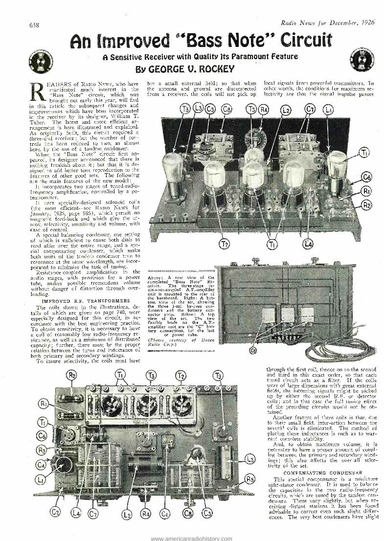
658 Radio News for December, 1926
An Improved "Bass Note" Circuit A Sensitive Receiver with Quality Its Paramount Feature
By GEORGE V. ROCKEY
READERS of RADIO NEws, who have manifested much interest in the "Bass Note" circuit, which was brought out early this year, will find
in this article the subsequent changes and improvements which have been incorporated in the receiver by its designer, William T. Taber. The latest and more efficient ar- rangement is here illustrated and explained. As originally built, this circuit required a three -dial receiver ; but the number of con-. trois has been reduced to two, as shown here, by the use of a tandem condenser.
When the "Bass Note" circuit first ap- peared, its designer announced that there is nothing freakish about it ; but that it is de- signed to add better tone reproduction to the features of other good sets. The following are the -main features of the new model:
It incorporates two stages of tuned- radio- frequency amplification, controlled by a po- tentiometer.
It uses specially- designed solenoid coils (the most efficient -see RADIO NEWS for January, 1926, page 986), which permit no magnetic feed -back and which give the ut- most selectivity, sensitivity and volume, with ease of control.
A special balancing condenser, one setting of which is sufficient to cause both dials to read alike over the entire range, and a spe- cial compensating condenser, which make both units of the tandem condenser tune to resonance at the same wavelength, are incor- porated to minimize the task of tuning.
Resistance -coupled amplification in the audio stages, with provision for a power tube, makes possible tremendous volume without danger of distortion through over- loading.
IMPROVED R.F. TRANSFORMERS The coils shown in the illustrations, de-
tails of which are given on page 740, were especially designed for this circuit, in ac- cordance with the best engineering practice. To obtain sensitivity, it is necessary to have a coil of reasonably low radio -frequency re- sistance, as well as a minimum of distributed capacity; further, there must be the proper relation between the turns and inductance of both primary and secondary windings.
To insure selectivity, the coils must have
but a small external field ; so that when the antenna and ground are disconnected from a receiver, the coils will not pick up
local signals from powerful transmitters. In. other words, the conditions for maximum se- lectivity are that the signal impulse passes.
on i nmi mmm71mnmm11nmrn1mnm1mmmim, 11111 M17=1.2
Above : A rear view of the completed "Bass Note" Re- ceiver. The three -stage re- sistance- coupled A.F.- amplifier unit is mounted to the rear of the baseboard. Right: A bot- tom view of the set, showing the three 1 -mf. by -pass con- densers and the battery con- nector strip. Below: A top view of the set. The two flexible leads on the A.F.- amplifier unit are the "C" bat- tery connections, for the last
or power tube. (Photos courtesy of Doyen Radio Corp.)
through the first coil, thence on to the second and third in this exact order, so that each . tuned circuit acts as a filter. If the coils -
were of large dimensions with great external fields, the incoming signals might be picked up by either the second R.F. or detector coils ; and in that case the full tuning effect .
of the preceding circuits would not be ob- tained.
Another feature of these coils is that, due to their small field, inter -action between the several coils is eliminated. The method of placing these inductances is such as to war- rant complete stability.
And, to obtain maximum volume, it is. necessary to have a proper amount of coupl- ing between the primary and secondary wind- ings ; this also affects the over -all selec- tivity of the set.
COMPENSATING CONDENSER This special compensator is a miniature -
split- stator condenser. It is used to balance the capacities in the two radio - frequency circuits, which are tuned by the tandem con- densers. These vary slightly, but when re- ceiving distant stations it has been found' advisable to correct even such slight differ- ences. The very best condensers have slight.
www.americanradiohistory.com
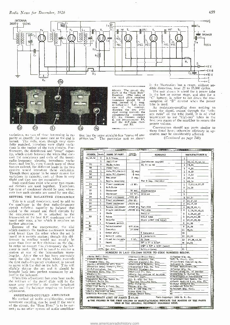
Radio News for December, 1926
ANTENNA SHORT 9 9LONG
variations, no two of them increasing in ca- pacity at exactly the same rate as the dial is turned. The coils, also, though very care- fully matched, introduce very slight varia- tions in the tuning of the two circuits. Fur- thermore, the distributed and "stray" capac- ity, which exists between the wires that con- nect the condensers and coils of the .tuned- radio-frequency circuits, introduces varia- tions ; and finally, even though none of these factors existed, the different loads in the two circuits would introduce these variations. Though there appear to be many causes for variations in capacity, each of them is very slight and they are not cumulative.
Such conditions exist whenever two reson- ant circuits are used together. Therefore, this type of condenser should be used when- ever two such circuits are tuned by one dial. SETTING THE BALANCING CONDENSER
This is a small condenser, used to add to the condenser in the first radio -frequency circuit sufficient capacity to balance that
- added to the second and third circuits by the compensator. It is attached to the framework of the first R.F. condenser and is tuned only once, after which it requires no further attention.
Because of the compensator, the dial which controls the tandem condensers would read lower than the other when the set is tuned to a certain station ; though this dif- ference in reading would not usually be more than four or five divisions on the dial. In order to correct this discrepancy the bal- ancer is used. The set is tuned to receive a ,station at one of the intermediate wave- lengths. After the set has been accurately tuned the dial on the right, which controls the first radio -frequency condenser, is turned to agree with the dial on the left. This will slightly detune the set and it should be brought back into perfect resonance by ad- justing the balancer.
When this adjustment has once been made, the settings of the panel dials will be the same over practically the entire broadcast range, and the balancer requires no further adj ustment.
RESISTANCE- COUPLED AMPLIFIER No method of audio amplification, except
resistance coupling, can be used if the name of the circuit, the `Bass Note," is to be cor- rect ; as no other system of audio amplifica-
u mmunnnm,r.11,,1 mmmo Above: The circuit dia- gram of the "Bass Note" Receiver. (The value of the third plate coupling resistance should be .1 meg. instead of 1. meg. as indicated.) Left, front view of the receiver, showing the two prin- cipal tuning controls, the compensating condenser C2, the filament switch S, the potentiometer R4, and the R.F. -tube rheo-
stat RS.
tion has the same straight -line "curve of am- plification." The particular unit as . shown
R,
659
4 671
T5
SPEAKER
9 135 V.
+6 V.
0 -6V -8 0 +90 V.
o C
o+ C
in the illustration has a range, without au- dible distortion, from 25 to 15,000 cycles.
The unit shown is wired for a power tube in the last or output stage, and also for a "C" battery, in order to cut down the con- sumption of "B" current when the power tube is used.
As resistance -coupling does nothing to boost the signal, except through the "volt- age ratio" of the tube itself, it is of vital importance to use "high -mu" tubes in the first two stages of the amplifier to secure the proper volume.
Constructors should use parts similar to those listed here; otherwise efficiency in op- eration may be considerably affected.
(Continued on. page 740)
n MIUMNIMMEMMUMFMMINMEll i
SYMBOL Q"..ew NAME OF PART =War v T AR REMARKS MANUFACTURER *
L1,L2,L3 3 R.F.Trane. 1
1 Amplifier Resistance coupled 1 1
43,44,45,46,16 25,26 T1 3 Hi-Mu tubes Mu 20 to 40 1
T2 - 1 Power tube 1 6,24 R1 1 Auto.Fil.Control 1} amp, 1 8,10
m R2 1 Auto,Fil.Control ¡ amp, 1 8,10'
R3 1 Resistor 2 meg. 1 42,16
1 Reais. mounting For 2 meg. resistor 1 42,16 Cl 1 Fixed Condenser .1 MI. 1 3,13,16,17,37 = L4 1 R.F.Choke 2 14,15 =_
C2 - 1 Condenser 35 Mmf. Compensating 1
C3 1 Condenser 25 Mmf. Bala rce 1
C4 1 Fixed condenser .0005 Mf. 3. 16,17 C5 1 Fixed condeneer .006 Mf. 3 16,17,13
16,17,13 C6 1 Fixed condenser .00025 Mf. 3
CT 1 Tandem condenser .0_+035 Mf. Variable 4 18,19,20,21
www.americanradiohistory.com
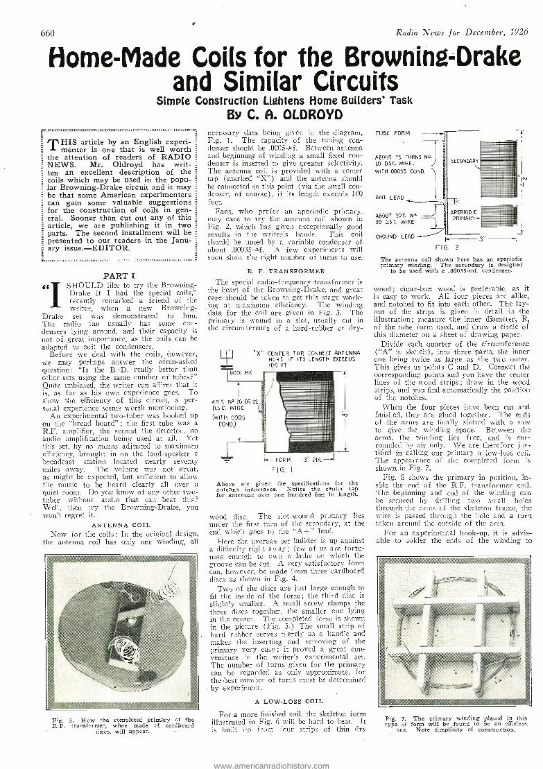
660
É
Radio News for December, 1926
Home -Made Coils for the Browning -Drake and Similar Circuits
Simple Construction Lightens Home Builders' Task By C. A. OLDROYD
THIS article by an English experi- menter is one that is well worth
the attention of readers of RADIO NEWS. Mr. Oldroyd has writ- _
ten an excellent description of the =
coils which may be used in the popu- lar Browning -Drake circuit and it may be that some American experimenters can gain some valuable suggestions for the construction of coils in gen- eral. Sooner than cut out any of this article, we are publishing it in two parts. The second installment will be presented to our readers in the Janu- ary issue. -EDITOR.
PART I
« SHOULD like to try the Browning - Drake if I had the special coils," recently remarked a friend of the writer, when a new Browning-
Drake set was demonstrated to him. The radio fan usually has some con- densers lying around, and their capacity is not of great importance, as the coils can be adapted to suit the condensers.
Before we deal with the coils, however, we may perhaps answer the often -asked question: Is the B. -D. really better than other sets using the same number of tubes ?" Quite unbiased, the writer can affirm that it is, as far as his own experience goes. To show the efficiency of this circuit, a per- sonal experience seems worth mentioning.
An experimental two -tuber was hooked up on the "bread board" ; the first tube was a R.F. amplifier, the second the detector, no audio amplification being used at all. Yet this set, by no means adjusted to maximum efficiency, brought in on the loud- speaker a broadcast station located nearly seventy miles away. The volume was not great, as might be expected, but sufficient to allow the music to be heard clearly all over a quiet room. Do you know of any other two - tuber without audio that can beat this? Well, then try the Browning- Drake, you won't regret it.
ANTENNA COIL Now for the coils: In the original design,
the antenna coil has only one winding, all
Fig. 5. How the completed primary of the R.F. transformer, when made of cardboard
discs, will appear. - --
necessary data being given in the diagram, Fig. 1. The capacity of the tuning con- denser should be .0005 -cf. Between antenna and beginning of winding a small fixed con- denser is inserted to give greater selectivity. The antenna coil is provided with a center WITH .00035 COND.
tap (marked "X ") and the antenna should be connected to this point (via the small con- denser, of course), if its length exceeds 100 feet.
Fans, who prefer an aperiodic primary, may care to try the antenna coil shown in Fig. 2, which has given exceptionally good results in the writer's hands. This coil should be tuned by a variable condenser of about .00035 -µf. A few experiments will soon show the right number of turns to use.
TUBE FORM
ABOUT 75 TURNS Na 20 D.SC. WIRE.
R. F. TRANSFORMER
The special radio- frequency transformer is the heart of the Browning- Drake, and great care should be taken to get this stage work- ing at maximum efficiency. The winding data for the coil are given in Fig. 3. The primary is wound in a slot, usually cut in the circumference of a hard- rubber or dry-
0001 MF.
"X-- CENTER TAP. CONNECT ANTENNA HERE IF ITS LENGTH EXCEEDS 100 FT
45 T. N5 20 OR 22 D.S.C. WIRE
(WITH .0005 COND.)
k- FORM -3" DIA.-1
FIG. I
Above are given the specifications for the antenna inductance. Notice the center tap for antennae over one hundred feet in length.
wood disc. The slot -wound primary lies under the first turn of the secondary, at the end which goes to the "A+" lead.
Here the average set builder is up against a difficulty right away ; few of us are fortu- nate enough to own a lathe on which the groove can be cut. A very satisfactory form can, however, be made from three cardboard discs as shown in Fig. 4.
Two of the discs are just large enough to fit the inside of the form; the third disc is slightly smaller. A small screw clamps the three discs together, the smaller one lying in the center. The, completed form is shown in the picture (Fig. 5.) The small strip of hard rubber serves merely as a handle and makes the inserting and removing of the primary very easy ; it proved a great con- venience in the writer's experimental set. The number of turns given for the primary can be regarded as only approximate, for the best number of turns must be determined by experiment.
A LOW -LOSS COIL
For a more finished coil, the skeleton form illustrated in Fig. 6 will be hard to beat. It is built up from four strips of thin dry
ANT LEAD
ABOUT 20T N° 30 D.S.C. WIRE
GROUND LEAD
APERIODIC PRIMARY+
FIG. 2
The antenna coil shown here has an aperiodic primary winding. The secondary is designed
to be used with a .00035 -mf. condenser.
wood; cigar-box wood is preferable, as it is easy to work. All four pieces are alike, and notched to fit into each other. The lay- out of the strips is given in detail in the illustration ; measure the inner diameter, R, of the tube form used, and draw a circle of this diameter on a sheet of drawing paper.
Divide each quarter of the circumference ( "A" in sketch), into three parts, the inner one being twice as large as the two outer. This gives us points C and D. Connect the corresponding points and you have the center lines of the wood strips ; draw in the wood strips, and you find automatically the position of the notches.
When the four pieces have been cut and finished, they are glued together. The ends of the arms are finally slotted with a saw to give the winding space. Between the arms, the winding lies free, and is sur- rounded by air only. We are therefore jus- tified in calling our primary a low -loss coil. The appearance of the completed form is shown in Fig. 7.
Fig. 8 shows the primary in position, in- side the end of the R.F. transformer coil. The -beginning and end of the winding can be secured by drilling two small holes through the arms of the skeleton frame, the wire is passed through the hole and a turn taken around the outside of the arm.
For an experimental hook -up, it is advis- able to solder the ends of the winding to
Fig. 7. The primary winding placed in this type of form will be found to be an efficient
one. Note simplicity of construction.
www.americanradiohistory.com
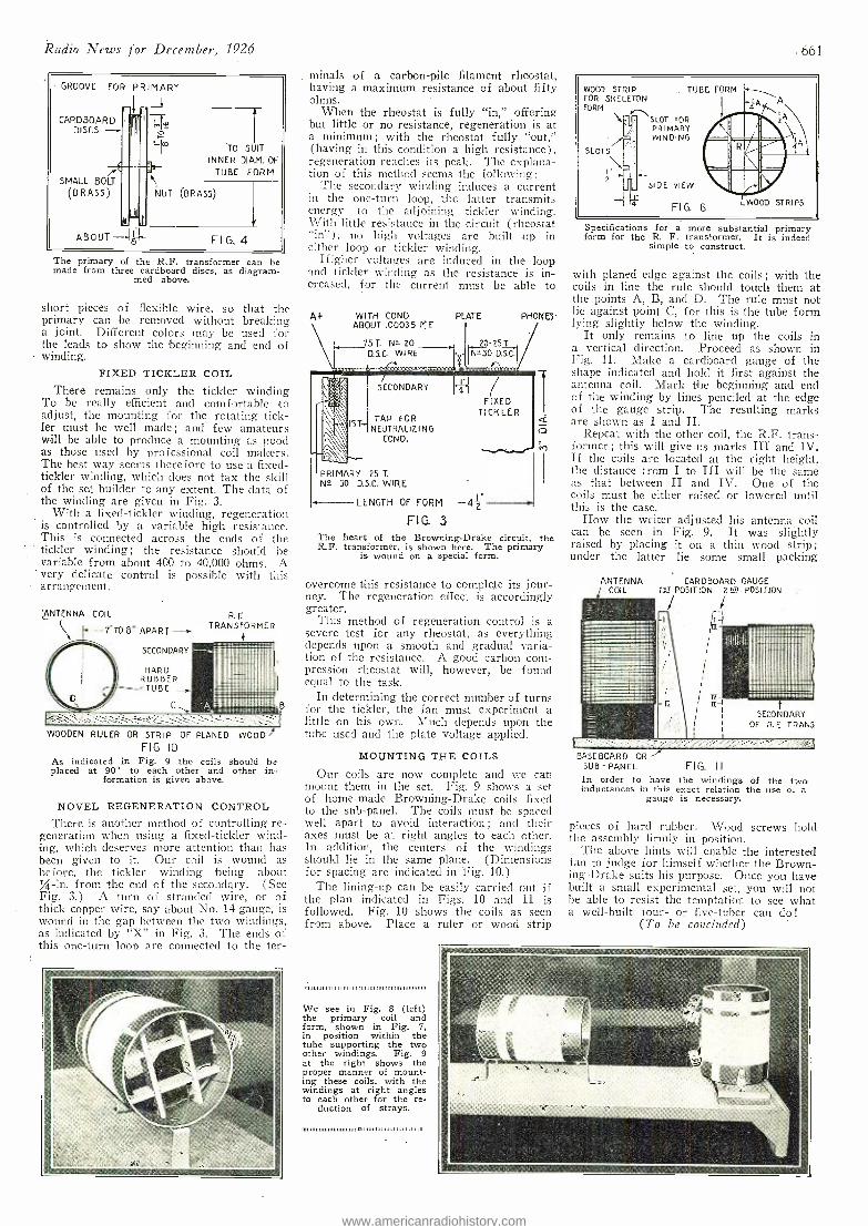
Radio News for December, 1926
GROOVE FOR PRIMARY
CARDBOARD DISCS -
SMALL BOLT
(BRASS)
f l
ABOUT
*TO SUIT
INNER DIAM. OF
TUBE FORM
NUT (BRASS)
t Fl G. 4
The primary o the R.F. transformer can be made from three cardboard discs, as diagram-
med above.
short pieces of flexible wire, so that the primary can be removed without breaking a joint. Different colors may be used for the leads to show the beginning and end of winding.
FIXED TICKLER COIL There remains only the tickler winding
To be really efficient and comfortable to adjust, the mounting for the rotating tick- ler must be well macle; and few amateurs will be able to produce a mounting as good as those used by professional coil makers. The best way seems therefore to use a fixed - tickler winding, which does not tax the skill of the set builder to any extent. The data of the winding are given in Fig. 3.
With a fixed -tickler winding, regeneration is controlled by a variable high resistance. This is connected across the ends of the tickler winding; the resistance should he variable from about 400 to 40,000 ohms. A very delicate control is possible with this arrangement.
(ANTENNA COIL
7"TO8" APART- --sl
SECONDARY
HARD RUBBER
TUBE
C
R. E TRANSFORMER
WOODEN RULER OR STRIP OF PLANED WOOD1 FIG. IO
As indicated in Fig. 9 the coils should be placed at 90° to each other and other in-
formation is given above.
NOVEL REGENERATION CONTROL
There is another method of controlling re- generation when using a fixed- tickler wind- ing, which deserves more attention than has been given to it. Our coil is wound as before, the tickler winding being about
-in. from the end of the secondary. (See Fig. 3.) A turn of stranded wire, or of thick copper wire, say about No. 14 gauge, is wound in the gap between the two windings, as indicated by "X" in Fig. 3. The ends of this one -turn loop are connected to the ter-
minais of a carbon -pile filament rheostat, having a:maximum resistance of about fifty. ohms. '
When the rheostat is fully "in," offering but little or no resistance, regeneration is at a minimum; with the rheostat fully "out," (having in this condition a high resistance), regeneration reaches its peak. The explana- tion of this method seems the following:
The secondary winding induces a current ill the one -turn loop, the latter transmits energy to the adjoining tickler winding. With little resistance in the circuit (rheostat "in "), no high voltages are built up in either loop or tickler winding.
Higher voltages are induced in the loop and tickler winding as the resistance is in- creased, for the current must be able to
WITH COND. ABOUT .00055 ME
75 T. N° 20 DIG. WIRE
PLATE PHONES'
2025T. N.130 D.S.C.
SECONDARY
TAP FOR IST-' NEUTRALIZING
COND.
PRIMARY 25 T.
N° 30 D.S.C. WIRE
LENGTH OF FORM
FIG. 3 The heart of the Browning -Drake circuit, the R.F. transformer, is shown here. The primary
is wound on a special form.
FIXED TICKLER
overcome this resistance to complete its jour- ney. The regeneration effect is accordingly greater.
This method of regeneration control is a severe test for any rheostat, as everything depends upon a smooth and gradual varia- tion of the resistance. A good carbon com- pression rheostat will, however, be found equal to the task.
In determining the correct number of turns for the tickler, the fan must experiment a little on his own. Much depends upon the tube used and the plate voltage applied.
MOUNTING THE COILS
Our coils are now complete and we can mount them in the set. Fig. 9 shows a set of home -made Browning -Drake coils fixed to the sub -panel. The coils must be spaced well apart to avoid interaction ; and their axes must be at right angles to each other. In addition, the centers of the windings should lie in the same plane. (Dimensions for spacing are indicated in Fig. 10.)
The lining -up can be easily carried out if the plan indicated in Figs. 10 and 11 is followed. Fig. 10 shows the coils as seen from above. Place a ruler or wood strip
,a111,,,,111 ,11 111111 11111,1,1111111111101,,,,,,,,,,,,,
We see in Fig. 8 (left) the primary coil and form, shown in Fig. 7, in position within the tube supporting the two other windings. Fig. 9 at the right shows the proper manner of mount- ing these coils, with the windings at right angles to each other for the re-
duction of strays.
1,111111111111111111111111111111o111111111111111111111111111111,
661
WOOD STRIP FOR SKELETON FORM
. TUBE FORM
(ÌISLOT FOR I PRIMARY
WINDING
SLOTS
I" ~
4
SIDE VIEW
A A
FIG. 6 WOOD STRIPS
Specifications for a more substantial primary form for the R. F. transformer. It is indeed
simple to construct.
with planed edge against the coils ; with the coils in line the rule should touch them at the points A, B, and D. The rule must not lie against point C, for this is the tube form lying slightly below the winding.
It only remains to line up the coils in a vertical direction. Proceed as shown in Fig. 11. Make a cardboard gauge of the shape indicated and hold it first against the antenna coil. Mark the beginning and end of the winding by lines penciled at the edge of the gauge strip. The resulting marks are shown as I and II.
Repeat with the other coil, the R.F. trans- former ; this will give us marks III and IV. If the coils are located at the right height, the distance from I to III will be the same as that between II and IV. One of the coils must be either raised or lowered until this is the case.
How the writer adjusted his antenna coil can be seen in Fig. 9. It was slightly raised by placing it on a thin wood strip; under the latter lie some small packing
CARDBOARD GAUGE 151 POSITION las POSITION
rl
Ìj
SECONDARY OF R.E TRANS.
BASEBOARD OR -' SUB - PANEL FIG. II
In order to have the windings of the two inductances in this exact relation the use o: a
gauge is necessary.
pieces of hard rubber. Wood screws hold the assembly firmly in position.
The above hints will enable the interested fan to judge for himself whether the Brown- ing -Drake suits his purpose. Once you have built a small experimental set, you will not be able to resist the temptation to see what a well -built four- or five -tuber can do!
(To be concluded)
www.americanradiohistory.com
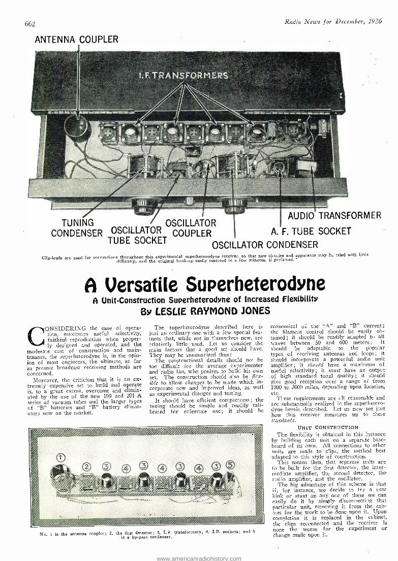
662
ANTENNA COUPLER
Radio News for December., 1926
TUNING OSCILLATOR AUDIO TRANSFORMER
CONDENSER OSCILLATOR COUPLER A. F. TUBE SOCKET TUBE SOCKET
OSCILLATOR CONDENSER Clip -leads are used for connections throughout this experimental superheterodyne receiver, so that new circuits and apparatus may b._ tried with little
difficulty, and the original hook -up easily restored in a few minutes, if preferred. -
A Versatile Superheterodyne A Unit -Construction Superheterodyne of Increased Flexibility
By LESLIE RAYMOND JONES
CONSIDERING the ease of opera- tion, maximum useful selectivity, faithful reproduction when proper- ly designed and operated, and the
moderate cost of construction and main- tenance, the superheterodyne is, in the opin- ion of most engineers, the ultimate, as far as present broadcast receiving methods are concerned.
Moreover, the criticism that it is an ex- tremely expensive set to build and operate is, to a great extent, overcome and elimin- ated by the use of the new 199 and 201 -A series of vacuum tubes and the larger types of "B" batteries and "B" battery elimin- ators now on the market.
The superheterodyne described here is just an ordinary one with a few special fea- tures that, while not in themselves new, are relatively little used. Let us consider the main factors that a good set should have. They may be summarized thus :
The constructional details should not be too difficult for the average experimenter and radio fan, who prefers to build his own set. The construction should also be flex- ible to allow changes to be made which in- corporate new and improved ideas, as well as experimental changes and testing.
It should have efficient compactness ; the tuning should be simple and readily cali- brated for reference use; it should be
No. I is the antenna coupler; 2, the first detector; 3, I.F. transformers; 4, I.F. sockets; and 5
is a by -pass condenser.
economical of the "A" and "B" current; the filament control should be easily ob- tained; it should be readily adapted to all waves between 50 and 600 meters : It should be adaptable to the popular types of receiving antennas and loops ; it should incorporate a powerful audio unit amplifier ; it should have a maximum of useful selectivity ; it must have an output of high standard tonal quality ; it should give good reception over a range of from 1000 to 3000 miles, depending upon location, etc.
These requirements are all reasonable and are substantially realized in the superhetero- dyne herein described. Let us now see just how this receiver measures up to these standards.
UNIT CONSTRUCTION The flexibility is obtained in this instance
by building each unit on a separate base- board of its own. All connections to other units are made to clips, the method best adapted to this style of construction.
This means then, that separate units are to be built for the first detector, the inter - mediate amplifier, the second detector, the audio amplifier, and the oscillator.
The big advantage of this scheme is that if, for instance, we decide to try a new kink or stunt on any one of these we can easily do it by simply disconnecting that particular unit, removing it from the cab- inet for the work to be done upon it. Upon completion it is replaced in the cabinet, the clips reconnected and the receiver is none the worse for the experiment or change made upon it.
www.americanradiohistory.com
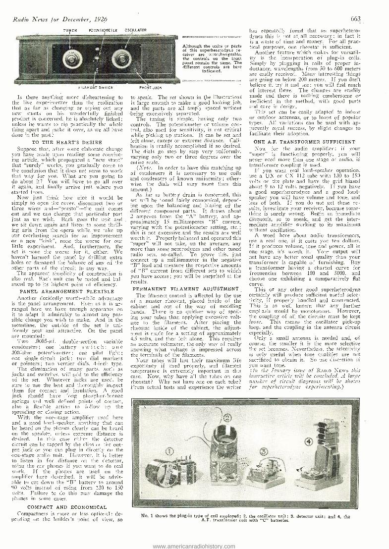
Radio News for December, 1926
POTENTIOMETER OSCILLATOR
FILAMENT SWITCH
Is there anything more disheartening to the live experimenter than the realization that as far as changing or trying out any new stunts on his wonderfully finished product is concerned, he is absolutely licked; unless he wants to rip practically the whole thing apart and make it over, as we all have clone in the past?
TO THE HEART'S DESIRE Suppose that, a (ter some elaborate change
you have made upon reading some convinc- ing article, which propagated a "new stunt" that "surely" works, you gradually come to the conclusion that it sloes not seem to work that way for you. What are you going to do about it? You will have to go all over it again, and finally arrive just where you started from.
Now just think how nice it would be simply to open the cover, disconnect two or three wires and -"presto" -the unit comes out and we can change that particular part just as we wish. Back goes the unit and we sit down again and listen to some thrill- ing aria from the opera while we take up our everlasting search for an improvement or a new "kink ", none the worse for our little experiment. And, furthermore, the set is none the worse for it, either. We haven't harmed the panel by drilling extra holes or damaged the balance of any of the other parts of the circuit in any way.
The apparent simplicity of construction is also real. Each unit can he tested and bal- anced up to its highest point of efficiency.
PANEL ARRANGEMENT FLEXIBLE Another decidedly' worth -while advantage
is the panel arrangement. Even as it is ar- ranged here we have enough apparatus on it to adapt it admirably to almost any pos- sible change you wish to make. And in the meantime, the outside of the set is uni- formly neat' and attractive. On the panel are mounted :
Two .0005 -µf. double- section variable condensers ; one battery s w i t c h; o n e 300 -ohm potentiometer ; one pilot light; one single- circuit jack ; two dial markers or pointers ; two vernier dials, 4 -inch type.
The elimination of many parts, such as jacks and switches, Will add to the efficiency of the set. Whatever jacks are used, be sure to use the best and thoroughly inspect them for contact and insulation. A good jack should have long phosphor -bronze springs and well defined points of contact, also a flexible action to follow up the spreading or closing action.
With the one -stage amplifier used here and a good loud- speaker, anything that can be-heard on the phones clearly can be heard on the speaker, unless extreme distance is desired. In this case either the detector circuit can he tapped by the clips on the out- put jack or you can plug in directly on the one -stage audio unit. However, it is better -to listen in for distance on the detector, using the ear phones if you want to do real work. If the phones are used on the amplifier 'here described, it will be advis- able to cut down the "B" battery to around 90 volts instead of using from 130 to 150 volts. Failure to do this may damage the phones in some cases.
COMPACT AND ECONOMICAL Compactness is more or less optional ; de-
pending on the builder's point of view, so
PHONE. JACK
0911.,1111111111111111111111111111I11 1111:11111,11111111111111Ir
Although the units or parts of this superheterodyne re- ceiver are interchangeable, the controls on the front panel remain the same. The different controls are here
indicated.
to speak. The set shown in the illustrations is large enough to make a good looking job, and the parts are all amply Spaced without .being excessively separated.
The tuning is simple, having only two controls. The potentiometer or volume con- trol, also used for sensitivity, is not critical while picking up stations. It can be set and left alone, except on extreme distance. Cali- bration is readily accomplished if so desired. The dials go step by step very uniformly, varying only two or three degrees over the entire scale.
(Note. In order to have this matching up of condensers it is necessary to use coils and condensers of known uniformity ; other- wise, the dials will vary more than this amount.)
As far as battery drain is concerned, this set will be found fairly economical, depend- ing upon the balancing and biasing of the different component parts. It draws about 2 amperes from the "A" battery, and ap- proximately 15 milliamperes "B" current, varying with the potentiometer setting, etc.; this is not excessive and the results are well worth it. Properly balanced and operated this "super" will not take, on the average, any more than some neutrodynes and other tuned radio sets, so- called. To prove this, just connect up a milliammeter in the negative "B" lead and measure the respective amounts of `B" current from different sets to which you have access ; you will be surprised at the results. PERMANENT FILAMENT ADJUSTMENT The filament control is affected by the use
of a master rheostat, placed inside of the cabinet and out of the way of meddling hands. There is no quicker way of spoil- ing your tubes than applying excessive volt- age to the filaments. After placing the rheostat inside of the cabinet, the adjust- ment is made for a setting of approximately 4.5 volts, and then left alone. This requires an accurate voltmeter, the only way of really knowing what voltage is impressed across the terminals of the filaments.
Your tubes will last their maximum life expectancy if used properly, and filament temperature is extremely important in this case. Now, why have all the tubes on one rheostat? Why not have one on each tube? From actual tests and experience the writer
663
has repeatedly found that on superhetero- dynes this is not at. all necessary ; in fact it is a waste of time and money. For all prac- tical purposes, one rheostat is sufficient.
Another feature which makes for versatil- ity is the incorporation of plug -in coils. Simply by plugging in coils of proper in- ductance, wavelengths from 50 to 600 meters are easily received. Many interesting things are going on below 200 meters. If you don't believe it, try it and see ; you will find much of interest there. The changes are readily macle and there is nothing cumbersome or inefficient in the method, with good parts and care in design.
This set can be easily adapted to indoor or outdoor antennas, or to loops of popular types. All variations can be used with ap- parently equal success, by slight changes to facilitate their adoption.
ONE A.F. TRANSFORMER SUFFICIENT Now for the audio amplifier : if your
"super" is functioning properly, you will never need more than one stage of audio, if transformer coupling is used.
If you want real loud -speaker operation, use a UX or CX 112 tube with 130 to 15(1 volts on the plate and have the grid biased about 9 to 12 volts negatively. If you have a good superheterodyne and a good loud- speaker you will have volume and tone, and lots of both. If you do not get these re- sults, investigate your receiver, because some- thing is surely wrong. Begin an immediate diagnosis, so to speak, and get the inter- mediate amplifier working to its maximum without oscillation.
A word here about audio transformers, use a real one, if it costs you ten dollars. If it produces volume, tone and power, all in one stage, it's worth it. Your output will not have any better tonal quality than your transformer is capable of furnishing. Buy a transformer having a charted curve for frequencies between 100 and 5000, and choose one exhibiting a comparatively flat curve.
This or any other good superheterodyne certainly will produce sufficient useful selec- tivity, if properly handled and constructed. This is so well known that any further emphasis would be monotonous. However, the coupling of all the circuits must be kept loose. This means the oscillator pick -up loop, and the coupling in the antenna circuit especially.
Only a small antenna is needed and, of course, the smaller it is the more selective the set becomes. Nevertheless, the selectivity is only useful when tone qualities are not sacrificed to obtain it. So use discretion i f
you want tone. (In the January issue of RADIO NEWS this instructive article will be concluded. A large number of circuit diagrams. will be show for superheterodyne experimenting.)
No. 1 shows the plug -in type of coil employed; 2, the oscillator unit; 3, detector unit; and 4, the A.F. transformer unit with "C" batteries.
www.americanradiohistory.com
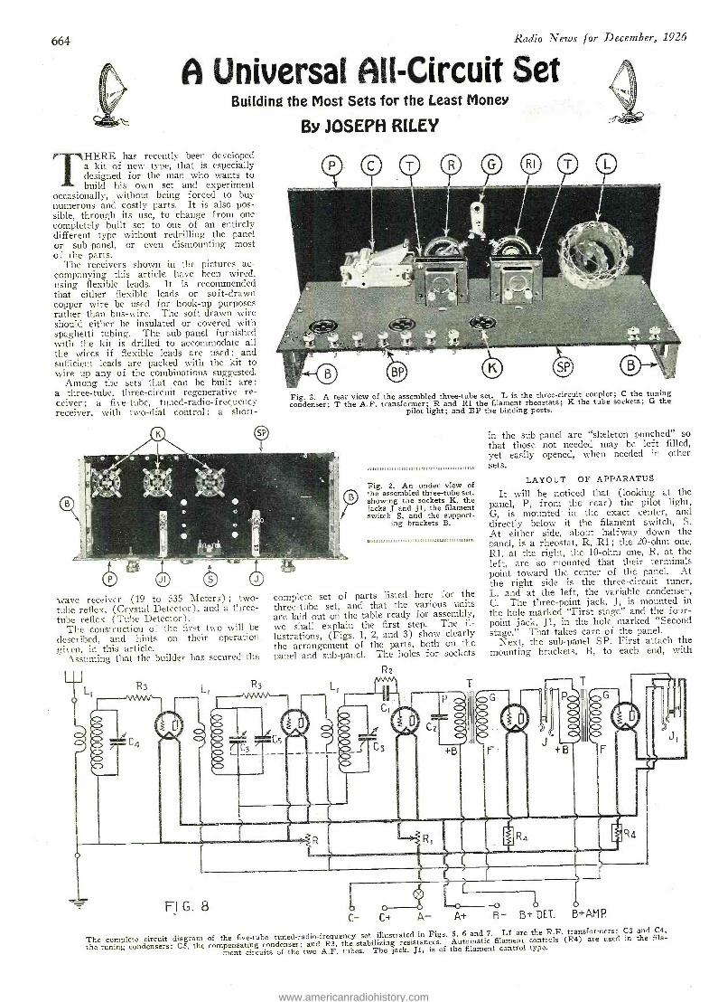
664 Radio News for December, 1926
A Universal All- Circuit Set Building the Most Sets for the Least Money
BY JOSEPH RILEY
THERE has recently been developed a kit of new type, that is especially designed for the man who wants to build his own set and experiment
occasionally, without being forced to buy numerous and costly parts. It is also pos- sible, through its use, to change from one completely built set to one of an entirely different type without redrilling the panel or sub - panel, or even dismounting most of the parts.
The receivers shown in the pictures ac- companying this article have been wired, using flexible leads. It is recommended that either flexible leads or soft -drawn copper wire be used for hook -up purposes rather than bus -wire. The soft -drawn wire should either he insulated or covered with spaghetti tubing. The sub -panel furnished with the kit is drilled to accommodate all the wires if flexible leads are used; and sufficient leads are packed with the kit to wire up any of the combinations suggested.
Among the sets that can be built are :
a three -tube, three- circuit regenerative re- ceiver; a five -tube, tuned- radio -frequency receiver, with twoLdial control ; a short-
4 4.
Fig. 3. A rear view of the assembled three -tube set. L is the three -circuit coupler; C the tuning condenser; T the A.F. transformer; R and Rl the filament rheostats; K the tube sockets; G the
pilot light; and BP the binding posts.
wave receiver (19 to 535 Meters) ; two - tube reflex. (Crystal Detector), and a three - tube reflex (Tube Detector).
The construction of the first two will be described, and hints on their operation given, in this article.
Assuming that the builder has secured the
Fig. 2. An under view of the assembled three -tube set, showing the sockets K, the jacks J and Jl, the filament switch S, and the support-
ing brackets B.
complete set of parts listed here for the three -tube set, and that the various units are laid out on the table ready for assembly, we shall explain the first step. The il- lustrations, (Figs. 1, 2, and 3) show clearly the arrangement of the parts, both on the panel and sub -panel. The holes for sockets
Rz
in the sub -panel are "skeleton punched" so that those not needed may be left filled, yet easily opened, when needed in other sets.
LAYOUT OF APPARATUS
It will be noticed that (looking at the panel, P, from the rear) the pilot light, G, is mounted in the exact center, and directly below it the filament switch, S. At either side, about halfway down the panel, is a rheostat, R, .Rl ; the 20 -ohm one, Rl, at the right, the 10 -ohm one, R, at the left, are so mounted that their terminals point toward the center of the panel. At the right side is the three -circuit tuner, L, and at the left, the variable condenser, C. The three -point jack, J, is mounted in the hole marked "First stage" and the f our- point jack, Ji, in the hole marked "Second stage." That takes care of the panel.
Next, the sub -panel SP. First attach the mounting brackets, B, to each end, with
C
FI G. 8
The complete circuit diagram of the five -tube tuned -radio -frequency set illustrated in Figs. 5, 6 and 7. Ll are the R.F. transformers; C3 and C4,
the tuning condensers; C5, the compensating condenser; and R3, the stabilizing resistances. Automatic filament controls (R4) are used in the fila-
ment circuits of the two A.F. tubes. The jack, Ji, is of the filament control type.
www.americanradiohistory.com
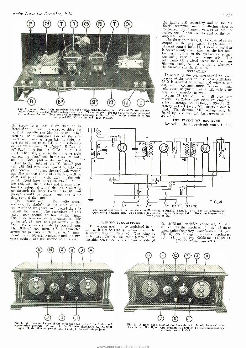
Radio News for December, 1926 665
Fig. 6. A rear view of the assembled five -tube tuned -radio -frequency set. C3 and C4 are the tun- . ing condensers; C5, the compensating condenser. The other parts are the same as those employed in the three -tube set. Note the grid condenser and leak at the left and on the underside of the sub -panel SP, K1 are the R.F. tube sockets.
the scréw holes that allow them to be fastened to the panel at the proper side ; that is, that opposite the binding' posts. Then turn to the binding -post side of the sub - panel and, working from left to right, in- sert the binding posts, BP, in the following order : "B amp+" ; "B Det+" B Bat -; A" Bat+ ;" "A Bat -" ; "C Bat +" "C Bat
Then skip over to the extreme right and put the "Ant." post in the farthest hole, and the "Gnd." post in the next one.
Just to the right of the "C Bat -" post you will find two holes spaced to take the grid condenser, Cl, and the grid leak mount- ing clips so that the grid leak, R2, will he close and parallel to the back of the sub - panel. Next insert three sockets, K, at the left end, with their bodies and terminals be- low the sub -panel and their tops projecting up through the large holes. The filament prongs should be toward you, the white dots toward the panel.
Then mount one of the audio trans- formers, T, slightly to the right of the center of the sub -panel, and toward the side nearest the panel. The secondary of this transformer should be toward the right. The other transformer is mounted a little to the left of -best, at right angles to-the first. Its secondary will be toward you. The .002 -mf. condenser, C2, is connected across the primary of the first A.F. trans- former; the .006 -mf. condenser and the two extra sockets are not needed in this set.
L
the tuning coil secondary and to the "A Bat +" terminal ; use the 20 -ohm rheostat to control the filament voltage of the de- tector, the 10 -ohm one to control the two amplifier tubes.
The three -point jack, J, is connected in the output of the first audio stage, and the filament -control jack, JI, is so arranged that it controls only the filament of the last tube, turning it off when the speaker or phones are being used on one stage only. The pilot lamp, G, is wired across the two main filament leads, so that it lights whenever the filament switch, S, is on.
OPERATION In operating this set, care should be taken
to prevent the detector tube from oscillating. If it is allowed to squeal and whistle, not only will it consume more "B" current and ruin your enjoyment, but it will ruin your neighbor's reception as well.
About 75 feet of aerial will give best results. If 201 -A type tubes are employed a 6 -volt storage "A" battery, a 90 -volt "B" battery and a 4% -volt "C" battery should be used. The detector "B" voltage may be found by trial and will be between 16 and 45 volts.
THE FIVE -TUBE RECEIVER Instead of the three -circuit tuner, L, and
+B
b
A- A+
G
Cr C7
O O B- B*DET. B+AMP
FIG..4
The circuit diagram of the three -tube set illustrated in Figs. 1, 2 and 3. This is of the regenerative type, using a tickler coil. The primary coil of the coupler L is aperiodic. Note the by -pass con- denser, C6 or C7.
WIRING SUGGESTIONS The wiring need not be explained in de-
tail, as it can be readily followed from the schematic diagram (Fig. 4). The points to watch are : Connect the rotor plates of the variable condenser to the filament side of
Fig. 1. A front -panel view of the three -tube set. D are the tuning and regeneration controls; R and R1, the filament rheostats; G, the pilot light; S, the filament switch, and J and J1 the audio -stage jacks.
the .0005 -mf. variable condenser, C, this set requires the purchase of a set of three tuned -radio -frequency transformers, Ll, (see Fig. 6) one two -gang variable condenser, C3, made up of two .00038 -mf. (17- plate)
(Continued on page 682)
Fig. 5. A front panel view of the five -tube set. It will be noted that there is no pilot light; this position is occupied by the compensating - condenser control, C -5.
www.americanradiohistory.com
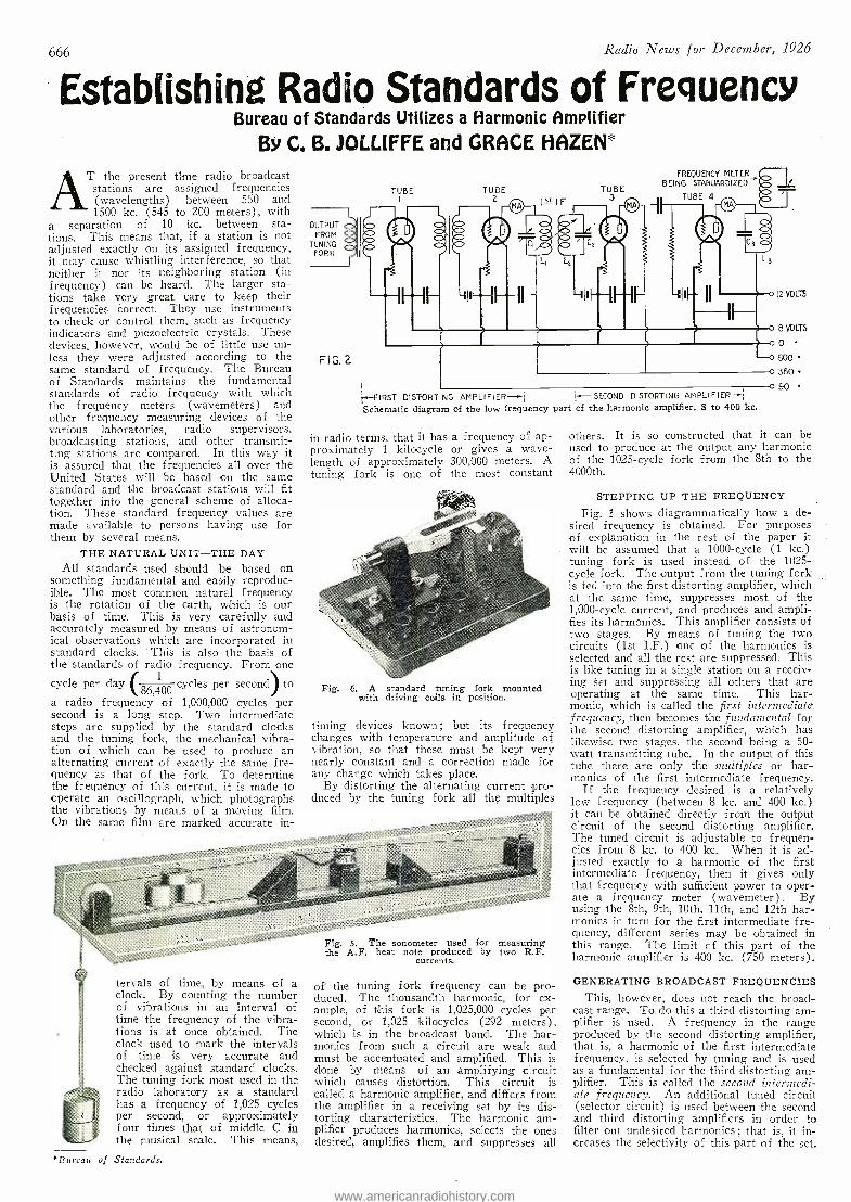
666 Radio News for December, 1926
Establishing Radio Standards of Frequency Bureau of Standards Utilizes a Harmonic Amplifier
BY C. B. JOLL[FFE and GRACE HAZEN*
T the present time radio broadcast stations are assigned frequencies (wavelengths) between 550 and 1500 kc. (545 to 200 meters), with
a separation of 10 kc. between sta- tions. This means that, if a station is not adjusted exactly on its assigned frequency, it may cause whistling interference, so that neither it nor its neighboring station (in frequency) can be heard. The larger sta- tions take very great care to keep their frequencies correct. They use instruments to check or control them, such as frequency indicators and piezoelectric crystals. These devices, however, would be of little use un- less they were adjusted according to the same standard of frequency. The Bureau of Standards maintains the fundamental standards of radio frequency with which the frequency meters (wavemeters) and other frequency measuring devices of the various laboratories, radio supervisors, broadcasting stations, and other transmit- ting stations are compared. In this way it is assured that the frequencies all over the United States will be based on the same standard and the broadcast stations will fit together into the general scheme of alloca- tion. These standard frequency values are made available to persons having use for them by several means.
THE NATURAL UNIT -THE DAY
All standards used should be based on something fundamental and easily reproduc- ible. The most common natural frequency is the rotation of the earth, which is our basis of time. This is very carefully and accurately measured by means of astronom- ical observations which are incorporated in standard clocks. This is also the basis of the standards of radio frequency. From one
cycle per day (86,L1100
cycles per second) to
a radio frequency of 1,000,000 cycles per second is a long step. Two intermediate steps are supplied by the standard clocks and the tuning fork, the mechanical vibra- tion of which can be used to produce an alternating current of exactly the same fre- quency as that of the fork. To determine the frequency of this current, it is made to operate an oscillograph, which photographs the vibrations by means of a moving film. On the same film are marked accurate in-
OUTPUT FROM
TUNING FORK
FiG. 2
TUBE
FREQUENCY METERy(,.. BEING STANDARDIZED
TUBE 4
C3
o 8 VOLTS
00 eco
o360 0 90
j-FIRST DISTORTI NG AMP LIFIER1 H- SECOND DISTORTING AMPLIFIER -r;
Schematic diagram of the low frequency part of the harmonic amplifier, 8 to 400 kc.
in radio terms, that it has a frequency of ap- proximately 1 kilocycle or gives a wave- length of approximately 300,000 meters. A tuning fork is one of the most constant
Fig. 6. A standard tuning fork mounted with driving coils in position.
timing devices known; but its frequency changes with temperature and amplitude of vibration, so that these must be kept very nearly constant and a correction made for any change which takes place.
By distorting the alternating current pro- duced by the tuning fork all the multiples
tervals of time, by means of a clock. By counting the number of vibrations in an interval of time the frequency of the vibra- tions is at once obtained. The clock used to mark the intervals of time is very accurate and checked against standard clocks. The tuning fork most used in the radio laboratory as a standard has a frequency of 1,025 cycles per second, or approximately four times that of middle C in the musical scale. This means,
*Bureau of Standards.
Fig. 5. The sonometer used for measuring the A.F. beat note produced by two R.F.
currents.
of the tuning fork frequency can be pro- duced. The thousandth harmonic, for ex- ample, of this fork is 1,025,000 cycles per second, or 1,025 kilocycles (292 meters), which is in the broadcast band. The har- monics from such a circuit are weak and must be accentuated and amplified. This is done by means of an amplifying circuit which causes distortion. This circuit is called a harmonic amplifier, and differs from the amplifier in a receiving set by its dis- torting characteristics. The harmonic am- plifier produces harmonics, selects the ones desired, amplifies them, and suppresses all
others. It is so constructed that it can be used to produce at the output any harmonic of the 1025 -cycle fork from the 8th to the 4000th.
STEPPING UP THE FREQUENCY
Fig. 1 shows diagrammatically how a de- sired frequency is obtained. For purposes of explanation in the rest of the paper it will be assumed that a 1000 -cycle (1 kc.) tuning fork is used instead of the 1025 - cycle fork. The output from the tuning fork is fed into the first distorting amplifier, which at the same time, suppresses most of the 1,000 -cycle current, and produces and ampli- fies its harmonics. This amplifier consists of two stages. By means of tuning the two circuits (1st I.F.) one of the harmonics is selected and all the rest are suppressed. This is like tuning in a single station on a receiv- ing Set and suppressing all others that are operating at the same time. This har- monic, which is called the first intermediate . frequency, then becomes the fundamental for the second distorting amplifier, which has likewise two stages, the second being a 50- watt transmitting tube. In the output of this tube there are only the multiples or har- monics of the first intermediate frequency.
If the frequency desired is a relatively low frequency (between 8 kc. and 400 kc.) it can be obtained directly from the output circuit of the second distorting amplifier. The tuned circuit is adjustable to f requen- cies from -8 kc. to 400 kc. When it is ad- justed exactly to a harmonic of the first intermediate frequency, then it gives only that frequency with sufficient power to oper- ate a frequency meter (wavemeter). By using the 8th, 9th, 10th, 11th, and 12th har- monics in turn for the first intermediate fre- quency, different series may be obtained in this range. The limit of this part of the harmonic amplifier is 400 kc. (750 meters).
GENERATING BROADCAST FREQUENCIES This, however, does not reach the broad-
cast range. To do this a third distorting am- plifier is used. A frequency in the range produced by the second distorting amplifier, that is, a harmonic of the first intermediate frequency, is selected by tuning and is used as a fundamental for the third distorting am- plifier. This is called the second intermedi- ate frequency. An additional tuned circuit (selector circuit) is used between the second and third distorting amplifiers in order to filter out undesired harmonics ; that is, it in- creases the selectivity of this part of the set.
www.americanradiohistory.com
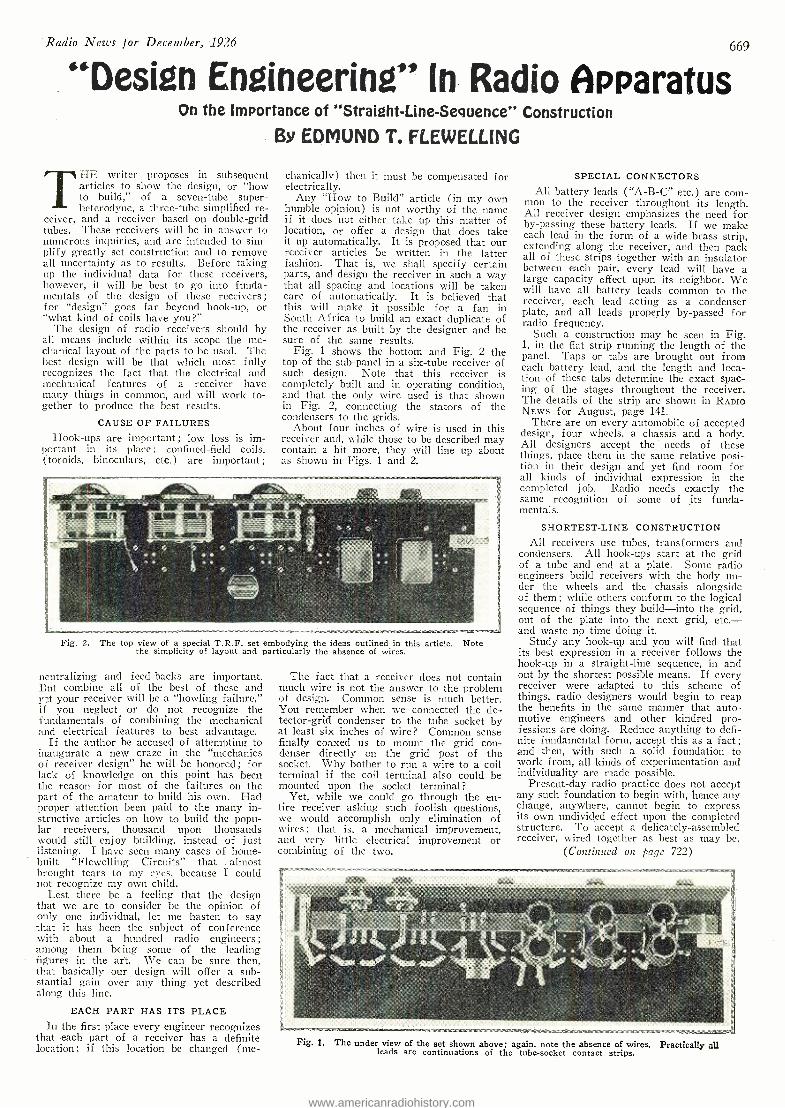
'Radio News for December, 1926 669
"Design Engineering" In Radio Apparatus On the Importance of "Straight- Line -Sequence" Construction
By EDMUND T. FLEWELL[NG
THE writer proposes in subsequent articles to show the design, or "how to build," of a seven -tube super- heterodyne, a three -tube simplified re-
ceiver, and a receiver based on double -grid tubes. These receivers will be in answer to numerous inquiries, and are intended to sim- plify greatly set construction and to remove all uncertainty as to results. Before taking up the individual data for these receivers, however, it will be best to go into funda- mentals of the design of these receivers; for "design" goes far beyond hook -up, or "what kind of coils have you ?"
The design of radio receivers should by all means include within its scope the me- chanical layout of the parts to be used. The best design will be that which most fully recognizes the fact that the electrical and mechanical features of a receiver have many things in common, and will work to- gether to produce the best results.
CAUSE OF FAILURES Hook -ups are important ; low loss is im-
portant in its place ; confined -field coils, (toroids, binoculars, etc.) are important;
chanically) then it must be compensated for electrically.
Any "How to Build" article (in my own humble opinion) is not worthy of the name if it does not either take up this matter of location, or offer a design that does take it up automatically. It is proposed that our receiver articles be written in the latter fashion. That is, we shall specify certain parts, and design the receiver in such a way that all spacing and locations will be taken care of automatically. It is believed that this will make it possible for a fan in South Africa to build an exact duplicate of the receiver as built by the designer and be sure of the same results.
Fig. 1 shows the bottom and Fig. 2 the top of the sub -panel in a six -tube receiver of such design. Note that this receiver is completely built and in operating condition, and that the only wire used is that shown in Fig. 2, connecting the stators of the condensers to the grids.
About four inches of wire is used in this receiver and, while those to be described may contain a bit more, they will line up about as shown in Figs. 1 and 2.
Fig. 2. The top view of a special T.R.F. set embodying the ideas outlined in this article. Note the simplicity of layout and particularly the absence of wires.
neutralizing and feed -backs are important. But combine all of the best of these and yet your receiver will be a "howling failure," if you neglect or do not recognize the fundamentals of combining the mechanical and electrical features to best advantage.
If the author be accused of attempting to inaugurate a new craze in the "mechanics of receiver design" he will be honored; for lack of knowledge on this point has been the reason for most of the failures on the part of the amateur to build his own. Had proper attention been paid to the many in- structive articles on how to build the popu- lar receivers, thousand upon thousands would still enjoy building, instead of just listening. I have seen many cases of home - built "Flewelling Circuits" that . almost brought tears to my eyes, because I could not recognize my own child.
Lest there be a feeling that the design that we are to consider be the opinion of only one individual, let me hasten to say that it has been the subject of conference with about a hundred radio engineers ;
among them being some of the leading figures in the art. We can be sure then, that basically our design will offer a sub- stantial gain over any thing yet described along this line.
EACH PART HAS ITS PLACE
In the first place every engineer recognizes that each part of a receiver has a definite location ; if this location be changed (me-
The fact that a receiver does not contain much wire is not the answer to the problem of design. Common sense is much better. You remember when we connected the de- tector -grid condenser to the tube socket by at least six inches of wire? Common sense finally coaxed us to mount the grid con- denser directly on the grid post of the socket. Why bother to run a wire to a coil terminal if the coil terminal also could be mounted upon the socket terminal?
Yet, while we could go through the en- tire receiver asking such foolish questions, we would accomplish only elimination of wires ; that is, a mechanical improvement, and very little electrical improvement or combining of the two.
SPECIAL CONNECTORS All battery leads ( "A -B -C" etc.) are corn -
mon to the receiver throughout its length. All receiver design emphasizes the need for by- passing these battery leads. If we make each lead in the form of a wide brass strip, extending along the receiver, and then pack all of these strips together with an insulator between each pair, every lead will have a large capacity effect upon its neighbor. We will have all battery leads common to the receiver, each lead acting as a condenser plate, and all leads properly by- passed for radio frequency.
Such a construction may be seen in Fig. 1, in the flat strip running the length of the panel. Taps or tabs are brought out from each battery lead, and the length and loca- tion of these tabs determine the exact spac- ing of the stages throughout the receiver. The details of the strip are shown in RADIO NEWS for August, page 141.
There are on every automobile of accepted design, four wheels, a chassis and a body. All designers accept the needs of these things, place then in the same relative posi- tion in their design and yet find room for all kinds of individual expression in the completed job. Radio needs exactly the same recognition of some of its funda- mentals.
SHORTEST -LINE CONSTRUCTION
All receivers use tubes, transformers and condensers. All hook -ups start at the grid of a tube and end at a plate. Some radio engineers build receivers with the body un- der the wheels and the chassis alongside of them ; while others conform to the logical sequence of things they build -into the grid, out of the plate into the next grid, etc. - and waste no time doing it.
Study any hook -up and you will find that its best expression in a receiver follows the hook -up in a straight -line sequence, in and out by the shortest possible means. If every receiver were adapted to this scheme of things, radio designers would begin to reap the benefits in the same manner that auto- motive engineers and other kindred pro- fessions are doing. Reduce anything to defi- nite fundamental form, accept this as a fact; and then, with such a solid foundation to work from, all kinds of experimentation and individuality are made possible.
Present -day radio practice does not accept any such foundation to begin with, hence any change, anywhere, cannot begin to express its own undivided effect upon the completed structure. To accept a delicately -assembled receiver, wired together as best as may be,
(Continued on page 722)
Fig. I. The under view of the set shown above; again, note the absence of wires. Practically all leads are continuations of the tube -socket contact strips.
www.americanradiohistory.com
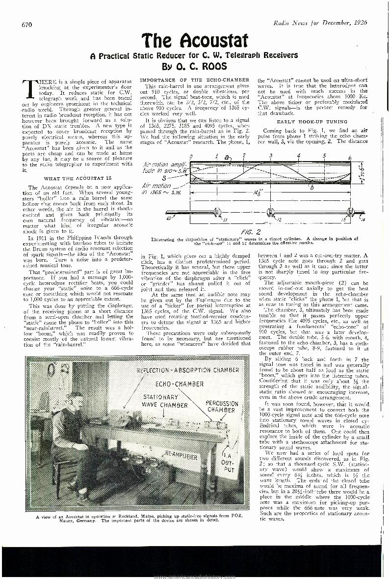
670 Radio News for December, 1926
The Acoustat A Practical Static Reducer for C. W. Telegraph Receivers
BY O. C. ROOS
THERE is a simple piece of apparatus knocking at the experimenter's door today. It reduces static for C.W. telegraph work and has been tested
out by engineers prominent in the technical -radio world. Through greater general in- terest in radio broadcast reception, it has not however been brought forward as a solu- tion of DX static troubles. A new type is expected to cover broadcast reception by purely electrical means, whereas this ap- paratus is purely acoustic. The name "Acoustat" has been given to it and as the parts are cheap and can be made at home by any fan, it may be a source of pleasure to the radio telegrapher to experiment with it.
WHAT THE ACOUSTAT IS
The Acoustat depends on a new applica- tion of an old fact. When several young- sters "holler" into a rain barrel the same hollow ring comes back from each shout. In ether words, the air in the barrel is shock - excited and gives back principally its own natural frequency of vibration -no matter what kind of irregular acoustic shock is given to it.
In 1911 in the Philippine Islands through experimenting with bamboo tubes to imitate the Braun system of audio resonant selection of spark signals -the idea of the "Acoustat" was born. Turn a noise into a predeter- mined musical tone.
That "predetermined" part is of great im- portance. If you had a message by 1,000 - cycle heterodyne rectifier beats, you could change your "static" noise to a 666 -cycle note or something which would not resonate to 1,000 cycles to an appreciable extent.
This was clone by putting the diaphragm of the receiving phone at a short distance from a semi -open chamber and letting the "static" cause the phone to "holler" into this "near -rainbarrel." The result was a hol- low "boom," which was readily proven to consist mostly of the natural lowest vibra- tion of the "rain- barrel."
IMPORTANCE OF THE ECHO -CHAMBER This rain -barrel in one arrangement gives
out 910 cycles, or double vibrations, per second. The signal beat -tone, which is used therewith, can be 3/2, 5/2, 7/2, etc., of the above 910 cycles. A frequency "of 1365 cy- cles worked very well.
It is obvious that we can listen to a signal of 1365, 2275, 3185 and 4095 cycles, when passed through the rain -barrel as in Fig. 2. \Ve had the following situation in the early stages of "Acoustat" research. The phone, 1,
Air motion ampli- tude in
s Air mo/ior/
/365
the "Acoustat" cannot be used on ultra -short waves. It is true that the heterodyne can not be used with much success in the "Acoustat" at frequencies above 1000 Kc. The above ticker or preferably modulated C.W. signals -is the perfect remedy for that drawback.
EARLY HOOK -UP TUNING
Coming back to Fig. 1, we find an air pulse from phone 1 striking the echo cham- ber wall, 3, via the opening, 2. The distance
4
d
i1
/41
/2 /3
FIG. 2 Illustrating the disposition of "stationary" waves in a closed cylinder. A change in position of
the "nick -ups" 11 and 12 determines the effective results.
in Fig. 1, which gives out a highly damped click, has a distinct predetermined period. Theoretically it has several, but these upper frequencies are not appreciable in the free vibration of the diaphragm after a "click" or "grinder" has almost pulled it out of joint and then released it.
At the same time an audible note may be given out by the diaphragm due to the use of a "ticker" for partial interruption at 1365 cycles, of the C.W. signal. We also have used rotating toothed -vernier condens- ers to detune the signal at 1365 and higher frequencies.
These precautions were only subsequently found to be necessary, but are mentioned here, as some "wiseacres" have decided that
ECHO CHAMBER
PERCUSSION CHAMBER
A view of an Acoustat in operation at Rockland, Maine, picking up static -free signals from POZ, Nauen, Germany. The important parts of the device are shown in detail.
between 1 and 2 was a cut -ana -try matter. A 1365 cycle note goes through 2 and gets through 3 as well as it can ; since the latter is not sharply tuned to any particular fre- quency.
The adjustable mouth -piece (2) can be moved in -and -out axially to get the best sound development in the echo -chamber when static "clicks" the phone 1, but that is as near to tuning as this arrangement came.
The chamber, 3, ultimately has been made tunable so that it passes perfectly upper frequencies like 4095 cycles, etc., as well as generating a fundamental "echo- tone" of 910 cycles, but that was a later develop- ment. The double tube, 5 -6, with mouth, 4, fastened to the echo -chamber, 3, has a steth- oscope rubber tube, 8 -9, fastened to it at the outer end, 7.
By sliding 6 back and forth in 7 the signal tone was tuned in and was generally found to be about half as loud as the static "boom," which gets into the listening tubes. Considering that it was only about / the strength of the static audibility, the signal - static ratio showed an encouraging increase, even in the above crude arrangement.
It was soon found, however, that it would be a vast improvement to convert both the 1000 -cycle signal note and the 666 -cycle note into stationary sound waves in closed cy- lindrical tubes, which were in acoustic resonance to both of them. One could then explore the inside of the cylinder by a small tube with a stethoscope attachment for sta- tionary sound waves.
We now had a series of loud spots .for two different sounds discovered, as in Fig. 2; so that a thousand -cycle S.W. (station- ary wave) would show a maximum of sound every 6Y1. inches, which is / the wave length. The . ends of the closed tube would be maxima of sound for all frequen- cies, but in a 20 % -inch tube there would be a place in the middle where the 1000 -cycle note was a maximum for picking -up pur- poses while the 666 -note was very weak. Such are the properties of stationary acous- tic waves.
www.americanradiohistory.com
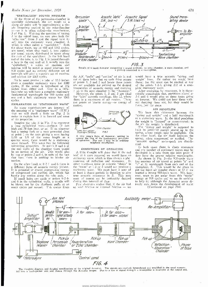
Radio News for December, 1926
"SPATIALIZER" SOLVES PROBLEM If the shape of the percussion- chamber is
carefully determined, the net result of a sharp air pulse will be approximately a sin- gle frequency excited in the echo -chamber or -as it is often called -the reverberator, 3 of Fig. 1. Waiving the question of tuning 3 to the signal tone, we now pass both the "echo -tone" from 3 and the signal tone it- self into the stationary wave chamber, 5, which is often called a "spatializer." Both the above tones, say of 910 and 1365 cycles, are tuned, when they reach 5, into station- ary sound waves, distributed in space along the axis of the spatializer. If the left hand end of the tube, 6, in Fig. 1 is passed through a hole in the end wall of 5, axially into the " spatializer," a series of maxima and minima will be noted at equal intervals for 910 cycles and an entirely different set of intervals will give a separate set of maxima and minima for 1365 cycles.
To be more precise ; a tube of 13.5 inches gives a complete stationary wave for 1000 cycles, if the sound is introduced at 3/ inches from either end. Now in a 14%- inch tube we will have a complete stationary fundamental wavelength for 910 cycles and one and a half stationary waves for 1365 cycles. EXPLANATION OF "STATIONARY WAVE"
So many experimenters are ignorant of the meaning of a "stationary wave" (S.W.) that we will dwell a little on Fig. 2 in order to explain how it is formed and some of its properties.
Imagine the tube S in Fig. 2 to represent a long cylindrical room -perhaps 12 feet high and 70 feet long, or so. If an observer had a tuning fork or a very powerful siren at point 1 on the axis giving a note having 1 /10 or 1/6 of the room length as a quarter wave, there would be a stationary wave formed. This wave has the following interesting properties. At points 0 and 6 at the end walls of the chamber there would be no motion of the air. This would also be true at points 2 and 4, in spite of the fact that here there is nothing to hinder air motion.
On the other hand, at 0 -2 -4- and 6 there is a different form of acoustic energy present. It is potential or stored energy -the energy of compressed and rarified air, which has hardly any motion along the tube axis.
If small holes are made at points 0-2-4- and 6 in the cylindrical walls, a candle will he blown out by the rhythmic puffs at so many cycles per second. This comes from
"InMeil " Amp /ifiér
Aux. test phones
Percussion Acoustic static" Acoustic Signa/ space", S.i1 (9io tii /S.W. 0365,)
To initia/ \`\ 16 - 5 amp / /TPr \ r
91 /0 g -
S 7 7
; 12
,ff-Pick- Up
Sound trans - /ating device
/
/ /B
671
To Re- Amp/ifiér
/4 -17
Sound / / producer
Reverberator_J orfcho chamber
_35.. 8 I
5" /¢8 Spatia/izing
4,i0365) - 4(ags) > --Nave chamber
F/6.3 Details of a small Acoustat comprising a sound producer, an echo chamber, a wave chamber, and
a pick -up connected to a re- amplifier.
the A.F. "puffs" and "suction" of air in and out of these holes, but no such thing occurs at points 1, 3 and 5 and hence these points are not available for picking up the desired frequencies of acoustic energy and carrying it on to the next chamber in the "Acoustat."
However, the points 1, 3 and 5 are ideal for "inlet" acoustic couplings, like 12, where there is a maximum of air motion. These are points of kinetic energy -or energy of motion.
Stethoscope,. far tubes'
7
fcha Chamber Tuned loud speader
FIG./ Diaphragm (damped)
A very -simple form of Acoustat, serving to convey the idea of the fundamental principles of operation. The unit 2 may be an ordinary
telephone mouthpiece.
CONDITIONS OF OPERATION A little thought will show that if the end
wall at 6 were removed we would have no stationary wave, which is thus always a phe- nomenon of reflection and resonance. In other words -a noise or acoustic "shock" in the "room" at 1 -3 or 5 would not produce a stationary wave. We must have a note of at least a dozen periods in duration to give true acoustic resonance in S. This note must of course not be noticeably clamped during this interval of time.
Few observers realize that, if the air had no wall friction or internal friction - we
6 E- 3 >< /32'" A
Y for moo- A for /000,s- s9na/acfoa//y
2000?,
would have a true acoustic "spring and weight" here. Or rather we would have three; for the wave can be excited at any of the points 1 -3 -5, giving 3/2 of a com- plete stationary wave.
After excitation by resonance, it is theor- etically conceivable that, partitions placed at 2 -4 and 6 would give us three tones going on forever. We could not hear them with - out damping them out, but they would be there, just the same.
AIR PENDULUM We have this difference between the
"spring and weight" and a half wavelength of a stationary wave. In the ideal pendulum the weight is "lumped" or concentrated; in the air the weight is distributed.
The "spring and weight" is supposed to have its potential energy stored up in the spring, whose weight may be negligible. On the other hand, the air itself becomes the spring, when compressed or rarified. The "acoustic springs" so -to -speak are distrib- uted.
In both cases there is sharp resonance and any number of stationary waves may be developed in a tube from one inlet point if they have the proper relative wavelengths.
As shown in Fig. 2 -the 910 -cycle wave has maxima of air travel at points "a" and "b" at / wavelength from each end of the spatializer, S. This would be the place to put the input air coupler shown at 12 if we wanted a strong 910 -cycle wave. We, how- ever, want to get away from this "static" energy at 910 cycles and so we do nothing to help it ; although the Acoustat never di- rectly cuts down the development of static
(Continued Oli page 714)
Audibi /ity meter --.- "
A
/32
for i000 - 22 for moo- s/Qna/
Pic/%úp / Pichup Telephone iPercussion (Reverberrzt /on receiver chamber or fcho "chamber
Heterodyne
Re- Amp /ifierJi_
fiai -up /rave'Chamber
Con/ro/ can,'
F/G. 4
Ref /ection- Absorp/ /an " Chamber
\ / / A
Phone at focus
The complete diagram and detailed specifications of the original Acoustat. The signals are received, heterodyned and amplified in the usual manner,
fed into a loud- speaker unit and thence through the Acoustat proper. Due to a loss of signal strength a re- amplifier is employed at the output end.
www.americanradiohistory.com
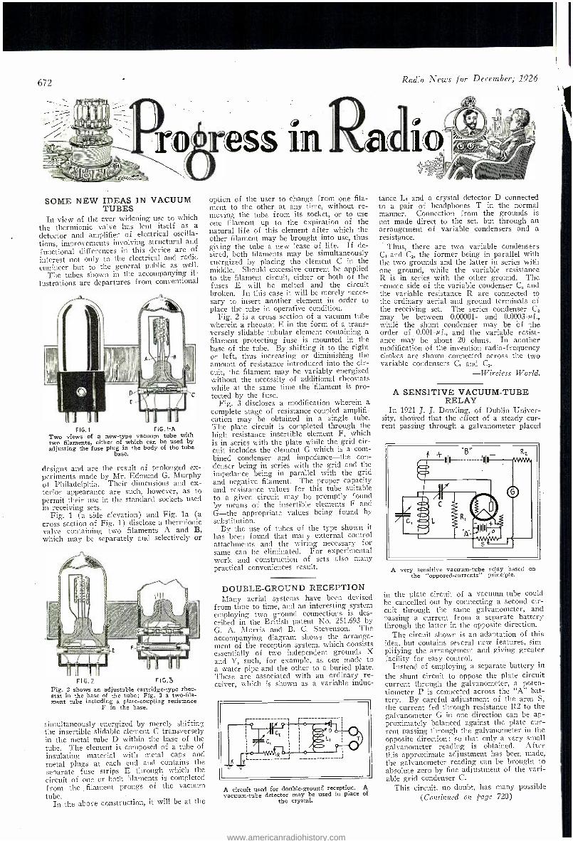
672 Radio News for December; 1926
ress in Ralo SOME NEW IDEAS IN VACUUM
TUBES In view of the ever widening use to which
the thermionic valve has lent itself as a detector and amplifier of electrical oscilla- tions, improvements involving structural and functional differences in this device are of interest not only to the electrical and radic engineer but to the general public as well.
The tubes shown in the accompanying il-
lustrations are departures from conventional
FIG I FIG. 1 -A Two views of a new -type vacuum tube with two filaments, either of which can be used by adjusting the fuse plug in the body of the tube
base.
designs and are the result of prolonged ex- periments made by Mr. Edmund G. Murphy of Philadelphia. Their dimensions and ex- terior appearance are such, however, as to permit their use in the standard sockets used in receiving sets.
Fig. 1 (a side elevation) and Fig. la (a cross section of Fig. 1) disclose a thermionic valve containing two filaments A and B, which may be separately and selectively or
FI G.2 FIG.5 Fig. 2 shows an adjustable cartridge -type rheo- stat in the base of the tube; Fig. 3 a two -fila- ment tube including a plate- coupling resistance
F in the base.
simultaneously energized by merely shiftin ; the insertible slidable element C transversely in the metal tube D within the base of the tube. The element is composed of a tube of insulating material with metal caps and metal plugs at each end and contains the separate fuse strips E through which the circuit of one or both filaments is completed from the filament prongs of the vacuum tubé.
In the above construction, it will be at the
option of the user to change from one fila- ment to the other at any time, without re- moving the tube from its socket, or to use one filament up to the expiration of the natural life of this element after which the other filament may be brought into use, thus giving the tube a new lease of life. If de- sired, both filaments may be simultaneously energized by placing the element C in the middle. Should excessive current be applied to the filament circuit, either or both of the fuses E will be melted and the circuit broken. In this case it will be merely neces- sary to insert another element in order to place the tube in operative condition.
Fig. 2 is a cross section of a vacuum tube wherein a rheostat E in the form of a trans- versely slidable tubular element containing a filament protecting fuse is mounted in the base of the tube. By shifting it to the right or left, thus increasing or diminishing the amount of resistance introduced into the cir- cuit, the filament may be variably energized without the necessity of additional rheostats while at the same time the filament is pro- tected by the fuse.
Fig. 3 discloses a modification wherein a complete stage of resistance -coupled amplifi- cation may be obtained in a single tube. The plate circuit is completed through the high resistance insertible element F, which is in series with the plate while the grid cir- cuit includes the element G which is a com- bined condenser and impedance -the con- denser being in series with the grid and the impedance being in parallel with the grid and negative filament. The proper capacity and resistance values for this tube suitable to a given circuit may be promptly found by means of the insertible elements F and G -the appropriate values being found by substitution.
By the use of tubes of the type shown it has been found that many external control attachments and the wiring necessary for same can be eliminated. For experimental work and construction of sets also many practical conveniences result.
DOUBLE -GROUND RECEPTION Many aerial systems have been devised
from time to time, and an interesting system employing two ground connections is des- cribed in the British patent No. 251,693 by G. A. Morris and B. C. Stevenson. The accompanying diagram shows the arrange- ment of the reception system, which consists essentially of two independent grounds X and Y, such, for example, as one made to a water pipe and the other to a buried plate. These are associated with an ordinary re- ceiver, Which is shown as a variable induc-
A circuit used for double -ground reception. A vacuum -tube detector may be used in place of
the crystal.
tance L, and a crystal detector D connected to a pair of headphones T in the normal manner. Connection from the grounds is not made direct to the set, but through an arrangement of variable condensers and a resistance.
Thus, there are two variable condensers C, and C2, the former being in parallel with the two grounds and the latter in series with one ground, while the variable resistance R is in series with the other ground. The remote side of the variable condenser C, and the variable resistance R are connected to the ordinary aerial and ground terminals of the receiving set. The series condenser C, may be between 0.00001- and 0.0003 -µf., whilé the shunt condenser may be of -the order of 0.001 -cf., and the variable resist- ance may be about 20 ohms. In another modification of the invention radio -frequency chokes are shown connected across the two variable condensers C, and C2.
-Wireless World.
A SENSITIVE VACUUM -TUBE RELAY
In 1921 J. J. Dowling, of Dublin Univer- sity, showed that the effect of a steady cur- rent passing through a galvanometer placed
A very sensitive vacuum -tube relay based on the "opposed- currents" principle.
in the plate circuit of a vacuum -tube could be cancelled out by connecting a second cir- cuit through the same galvanometer, and passing a current from a separate battery through the latter in the opposite direction.
The circuit shown is an adaptation of this idea, but contains several new features, sim- plifying the arrangement and giving greater facility for easy control.
Instead of employing a separate battery in the shunt circuit to oppose the plate circuit current through the galvanometer, a poten- tiometer P is connected across the "A" bat- tery. By careful adjustment of the arm S, the current fed through resistance R2 to the galvanometer G in one direction can be ap- proximately balanced against the plate cur- rent passing through the galvanometer in the opposite direction; so that only a very small galvanometer reading is obtained. After this approximate adjustment has been made, the galvanometer reading can be brought to absolute zero by fine adjustment of the vari- able grid condenser C.
This circuit, no doubt, has many possible (Continued on page 720)
www.americanradiohistory.com
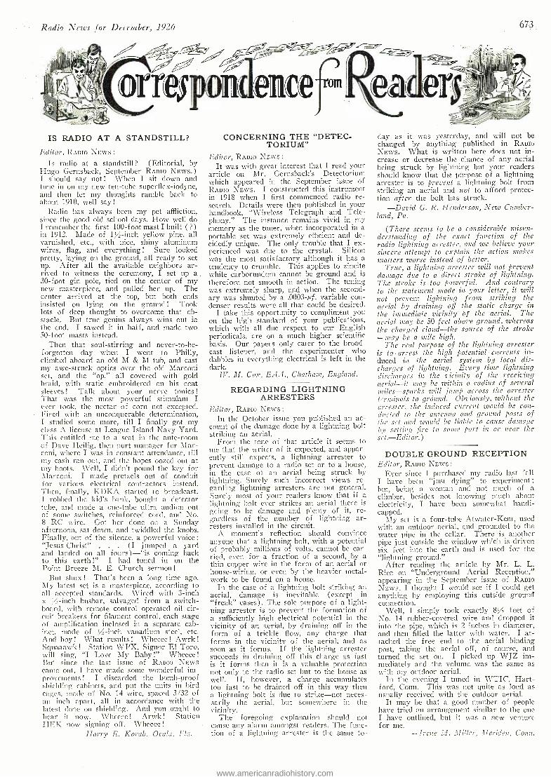
Radio News for December, 1926 673,
IS RADIO AT A STANDSTILL?
Editor, RADIO NEws :
Is radio at a standstill ? (Editorial, by Hugo Gernsback, September RADIo NEWS.) I should say not ! When I sit down and tune in on my new ten -tube superflex- iodyne, and then let my thoughts ramble back to about 1910, well say!
Radio has always been my pet affliction, since the good old school days. How well do I remember the first 100 -foot mast I built ( ?) in 1912. Made of 1% -inch yellow pine, all varnished, etc., with nice, shiny aluminum wires, flag, and everything! Sure looked pretty, laying on the ground, all ready to set up. After all the available neighbors ar- rived to witness the ceremony, I set up a 30 -foot gin pole, tied on the center of my new masterpiece, and pulled her up. The center arrived at the top, but both ends insisted on lying on the ground ! Took lots of deep thought to overcome that ob- stacle. But true genius always wins out in the end. I sawed it in half, and made two 50 -foot masts instead.
Then that soul -stirring and never- to -be- forgotten day when I went to Philly, climbed aboard an old M & M tub, and cast my awe- struck optics over the old Marconi set, and the "op." all covered with gold braid, with static embroidered on his coat sleeves ! Talk about your nerve tonics !
That was the most powerful stimulant I ever took, the nectar of corn not excepted. Fired with an unconquerable determination, I studied some more, till I finally got my class A license at League Island Navy Yard. This entitled me to a seat in the ante -room of Dave Heilig, then port manager for Mar- coni, where I was in constant attendance, till my cash ran out, and the hopes oozed out at my hoots. Well, I didn't pound the key for Marconi. I made pretzels out of conduit for various electrical contractors instead. Then, finally, KDKA started to broadcast. I robbed the kid's bank, bought a detector tube, and macle a one -tube ultra auction out of some switches, reinforced cord, and No. 8 RC wire. Got her done on a Sunday afternoon, sat down, and twiddled the knobs. Finally, out of the silence, a powerful voice: "Jesus Christ" . (I jumped a yard and landed on all fours) -"is coming back to this earth !" I had tuned in on the Point Breeze M. E. Church sermon!
But shux! That's been a long time ago. My latest set is a masterpiece, according to all accepted standards. Wired with 3 -inch x V,-inch busbar, salvaged from a switch- board. with remote control operated oil cir- cuit breakers for filament control, each stage of amplification inclosed in a separate cab- inet. macle of / -inch vanadium steel, etc. And hoy ! What results ! Wheeee ! Awrk !
Squaaawk ! Station WPX, Signor El Toro, will sing, "I Love My Baby !" Wheeee !
But since the last issue of RADIO NEWS came out, I have made some wonderful im- provements ! I discarded the bomb -proof shielding cabinets, and put the units in bird cages, made of No. 14 wire, spaced 3/32 of an inch apart, all in accordance with the latest elope on shielding. And you ought to hear it now. Wheeee ! Arwk ! Station HEK now signing off. Wheeee !
Harry E. Korab, Ocala, F.ea.
CONCERNING THE "DET'EC- TORIUIti"
Editor, RADIO NEWS :
It was with great interest that I read your article on Mr. Gernsback's Detectorium which appeared in the September issue of RADIO NEws. I constructed this instrument ill 1918 when I first commenced radio re- search. Details were then published in your handbook, "Wireless Telegraph and Tele- phony." The instance remains vivid in my memory as the tuner, when incorporated in a portable set was extremely efficient and de- cidedly unique. The only trouble that I ex- perienced was due to the crystal. Silicon was the most satisfactory although it has a tendency to crumble. This applies to zincite while carborundum cannot be ground and is therefore not smooth in action. The tuning was extremely sharp, and when the second- ary was shunted by a .0003 -nf. variable con- denser results were all that could be desired.
I take this opportunity to compliment you on the high standard of your publications, which with all due respect to our English periodicals, are on a much higher scientific basis. Our papers only cater to the broad- cast listener, and the experimenter who dabbles in everything electrical is left in the dark.
W. M. Cos, EAA., Chatham, England.
REGARDING LIGHTNING ARRESTERS
Editor, RADIO NEWS :
In the October issue you published an ac- count of the damage done by a lightning bolt striking an aerial.
From the tone of that article it seems to me that the writer of it expected, and appar- ently still expects, a lightning arrester to prevent damage to a radio set or to a house, in the case of an aerial being struck by lightning. Surely such incorrect views re- garding lightning arresters are not general. Surely most of your readers know that if a lightning bolt ever strikes an aerial there is going to be damage and plenty of it, re- gardless of the number of lightning ar- resters installed in the circuit.
A moment's reflection should convince anyone that a lightning bolt, with a potential of probably millions of volts, cannot be car- ried, even for a fraction of a second, by a thin copper wire in the form of an aerial or house- wiring, or even by the heavier metal- work to be found on a house.
In the case of a lightning holt striking an aerial, damage is inevitable (except in "freak" cases). The sole purpose of a light- ning arrester is to prevent the formation of a sufficiently high electrical potential in the vicinity of an aerial, by draining off in the form of a trickle flow, any charge that forms in the vicinity of the aerial, and as soon as it forms. If the lightning arrester succeeds in draining off this charge as fast is it forms then it is a valuable protection not only to the radio set but to the house as well. If, however, a charge accumulates too fast to be drained off in this way then a lightning bolt is due to strike -not neces- sarily the aerial, but somewhere in the vicinity.
The foregoing explanation should not cause any alarm amongst readers. The func- tion of a lightning arrester is the same to-
day as it was yesterday, and will not be changed by anything published in RADIO NEWS. What is written here does not in- crease or decrease the chance of any aerial being struck by lightning but your readers should know that the purpose of a lightning arrester is to prevent a lightning bolt from striking an aerial and not to afford protec- tion after the bolt has struck.
-David G. R. Henderson, New Cumber- land, Pa.
(There seems to be a considerable misun- derstanding of the exact function of the radio lightening arrester, and we believe your sincere attempt to explain the action makes matters worse instead of better.
True, a lightning arrester will not prevent damage due to a direct stroke of lightning. The stroke is too powerful. And contrary to the statement made in your letter, it will not prevent lightning front striking the aerial by draining off the static charge in the immediate vicinity bf the aerial. The aerial may be_50 feet above ground, whereas the charged cloud -the source of the stroke -may be a mile high.
The real purpose of the lightning arrester is toarrest the high potential currents in- duced in the aerial system by local dis- charges of lightning. Every time lightning discharges in the vicinity of the receiving aerial -it may be within a radius of several miles- sparks will jump across the arrester terminals to grOlmd. Obviously, zuithout the arrester, the induced current would be con- ducted to the antenna and ground posts of the set and would be liable to cause damage by setting fire to some part ist or near the set. Editor.)
DOUBLE -GROUND RECEPTION Editor, RADIO NEWS :
Ever since I purchased my radio last fall I have been "just dying" to experiment; but, being a woman and not much of a climber, besides not knowing much about electricity, I have been somewhat handi- capped.
My set is a four -tube Atwater -Kent, used with an outdoor aerial, and grounded to the water pipe in the cellar. There is another pipe just outside the window which is driven six feet into the earth and is used for the "lightning ground."
After reading the article by Mr. L. L. Rice on "Underground Aerial Reception," appearing in the September issue of RADIO NEWS, I thought I would see if I could get anything by employing this outside ground connection.
Well, I simply took exactly 8% feet of No. 14 rubber -covered wire and dropped it into the pipe, which is 2 inches in diameter, and then filled the latter with water. I at- tached the free end to the aerial binding post, taking the aerial off, of course, and turned the set on. I picked up WJZ im- mediately and the volume was the same as with my outdoor aerial.
In the evening I tuned in WTIC, Hart- ford, Conn. This was not quite as loud as usually received with the outdoor aerial.
It may be that a good number of people have tried an arrangement similar to the one I have outlined, but it was a new venture for me.
--Irene M. Miller, ?Meriden, Conn.
www.americanradiohistory.com
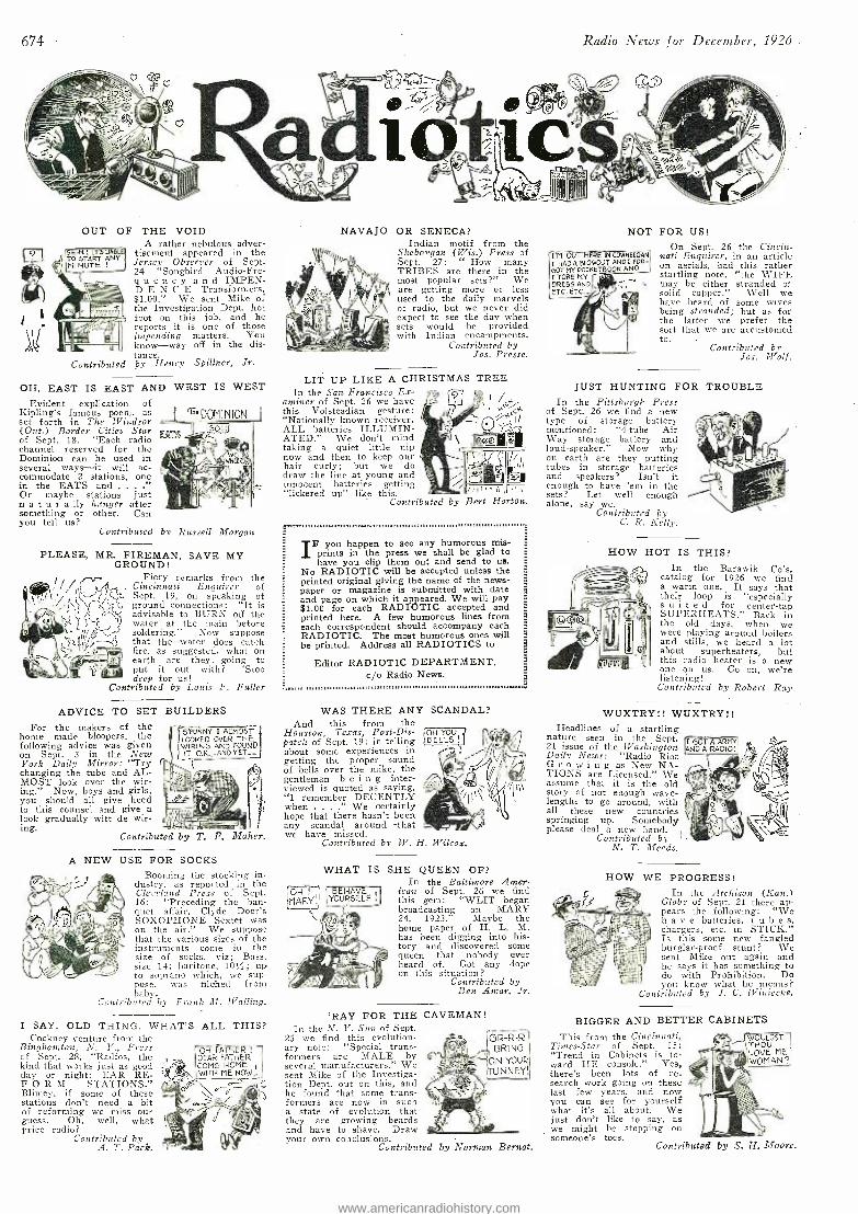
674 Radio News for December, 1926
OUT OF THE VOID A rather nebulous adver-
tisement appeared in the Jersey Observer of Sept. 24 `Songbird Audio -Fre- queney and IMPEN- D E N C E Transformers, $1.00." We sent Mike of the Investigation Dept. hot foot on this job, and he reports it is one of those impending matters. You know -way off in the dis- tance.
Contributed by Henry Spillner, Jr.
OH, EAST IS EAST AND WEST IS WEST Evident explication of
Kipling's famous poem, as set forth in The Windsor (Ont.) Border Cities Star of Sept. 18. "Each radio channel reserved for the Dominion can be used in several ways -it will ac- commodate 2 stations, one in the EATS and .
Or maybe stations just naturally hunger after something or other. Can you tell us?
Contributed by Russell Morgan
PLEASE, MR. FIREMAN, SAVE MY GROUND!
Fiery remarks from the Cincinnati Enquirer of Sept. 19, on speaking of ground connections: "It is advisable to BURN off the water at the main before soldering." Now suppose that the water does catch fire, as suggested, what on earth are they going to
put it out with? `S too deep for us!
Contributed by Louis F. Fuller
ADVICE TO SET For the makers of the
home made bloopers, the following advice was given on Sept. 3 in the New York Daily Mirror: "Try changing the tube and AL- MOST look over the wir- ing." Now, boys and girls, you should all give heed to this counsel and give a look gradually witt de wir- ing.
A NEW
BUILDERS
S'FUNNY I ALMOST LOOKED OVER THE WIRING AND FOUND IT O.K.. -ANO YET__
Contributed
USE FOR
by T. F.
SOCKS Booming the stocking in-
dustry, as reported in the Cleveland Press of Sept. 16: "Preceding the ban- quet affair, Clyde - Doer's SOXOPIIONE Sextet was on the air." We suppose that the various sizes of the instruments come in the size of socks, viz; Bass, size 14; baritone, 10 %; up to soprano which, we sup- pose, was filched from baby.
Contributed by Frank M. Walling.
I SAY, OLD THING. WHAT'S ALL Cockney venture from the
Binghamton, N. Y., Press of Sept. 28, "Radios, the kind that works just as good day or night; EAR RE- FORM STATIONS." Blimey, if some of these stations don't need a bit of reforming we miss our guess. Oh, well, what price radio?
Contributed by A. T. Pack.
THIS?
OH FATHER DEAR FATHER COME HOME !
WITH ME NOW.. )
NAVAJO OR SENECA? Indian motif from the
Sheboygan (Wis.) Press of Sept. 27: " How many TRIBES are there in the most popular sets ?" We are getting more or less used to the daily marvels of radio, but we never did expect to see the day when sets would be provided with Indian encampments.
Contributed by Jos. Presse.
LIT UP LIKE A CHRISTMAS TREE In the San Francisco Ex-
aminer of Sept. 26 we have this Volsteadian gesture: "Nationally known receiver, ALL batteries ILLUMIN- ATED." We don't mind taking a quiet little nip now and then to keep our hair curly; but we do draw the line at young and innocent batteries getting "lickered up" like this.
Contributed by
l /
,'Ii Il 'Ili Bert Horton.
F you happen to see any humorous mis- prints in the press we shall be glad to have you clip them out and send to us.
No RADIOTIC will be accepted unless the printed original giving the name of the news- paper or magazine is submitted with date and page on which it appeared. We will pay $1.00 for each RADIOTIC accepted and printed here. A few humorous lines from each correspondent should accompany each RADIOTIC. The most humorous ones will be printed. Address all RADIOTICS to
Editor RADIOTIC DEPARTMENT, c/o Radio News..
WAS THERE ANY SCANDAL? And this from the
Houston, Texas, Post -Dis- patch of Sept. 19: in telling about some experiences in getting the proper sound of bells over the mike, the gentleman b e i n g inter- viewed is quoted as saying, "I remember DECENTLY when " We certainly hope that there hasn't been any scandal around -that we have missed.
Contributed by W. H. Wilcox.
OH! MARY.
OH YOU BELLS
WHAT IS SHE QUEEN OF? In the Baltimore Amer -
BEHAVE I icon of Sept. 26 we find YOURSELF . this gem: "WLIT began -Y broadcasting on MARY
24, - 1923." Maybe the home paper of H. L. M. has been digging into his- tory and discovered some queen that nobody ever heard of. Got any dope on this situation?
Contributed by Ben Amer, Jr.
'RAY FOR THE CAVEMAN! In the N. Y. Sun of Sept.
25 we find this evolution- ary note: "Special trans- formers are MALE by several manufacturers." We sent Mike of the Investiga- tion Dept. out on this, and he found that some trans- formers are now in such a state of evolution that they are growing beards and have to shave. Draw your own conclusions.
Contributed by Norman Bernat.
NOT FOR US! On Sept. 26 the Cincin-
nati Enquirer, in an article on aerials, had this rather startling note, "the WIFE may be either stranded or solid copper." Well we have heard of some wives being stranded; but as for the latter we prefer the sort that we are accustomed to.
I'M OUT HERE INCOWHEEGANi AND
GOT MY RoCKEETTUBOOK AND R-
L TORE MY DRESS AND ETC. ETC.-
Contributed by Jos. Wolf.
JUST HUNTING FOR TROUBLE In the Pittsburgh Press
of Sept. 26 we find a new type of storage battery mentioned: "4 -tube Air Way storage battery and loud -speaker." Now why on earth are they putting tubes in storage batteries and speakers? Isn't it enough to have 'ens in the sets? Let well enough alone, say we.
Contributed by C. R. Kelly.
HOW HOT IS THIS? In the Barawik Co's.
catalog for 1926 we find a warns one. It says that their loop is "especially suit e d for center -tap SUPERHEATS." Back in the old days, when we were playing around boilers and stills, we heard a lot about superheaters, but this radio heater is a new one on us. Go on, we're listening!
Contributed by Robert Ray
WUXTRY!! WUXTRY!! Headlines of a startling
nature seen in the Sept. 21 issue of the Washington Daily News: "Radio Riot Growing as New NA- TIONS are Licensed." We assume that it is the old story of not enough wave- lengths to go around, with all these new countries springing up. Somebody please deal a new hand.
Contributed by N. T. Meeds.
I GOT A ARMY ANDA -RADIO! )9t,
HOW WE PROGRESS! In the Atchison (Kan.)
Globe of Sept. 21 there ap- pears the following: "%Ve h a v e batteries, t u b e s, chargers, etc. in 'STICK." Is this sonie new fangled burglar -proof stunt? We sent Mike out again and he says it has something to do with Prohibition. Do you know what he means?
Contributed by J. C. f Viniecke.
BIGGER AND BETTER CABINETS
This from the Cincinnati, WOULOST Times -Star of Sept. 15: THOU "Trend in Cabinets is to- 1lTz LOVE ME
ward HE console." Yes, there's been lots of re- search work going on these last few years, and now you can see for yourself what it's all about. We just don't like to say, as we might be stepping on someone's toes.
Contributed by S. H. Moore.
WOMAN2
www.americanradiohistory.com
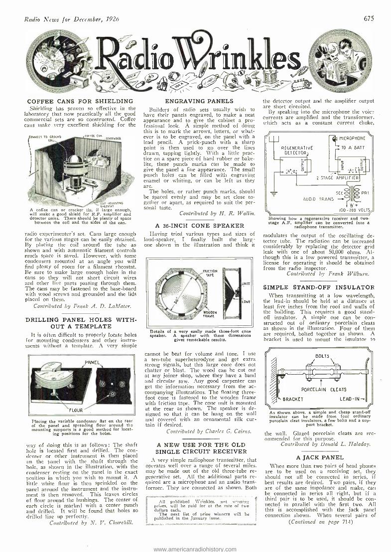
Radio News for December, 1926 675
COFFEE CANS FOR SHIELDING Shielding has proven so effective in the
laboratory that now practically all the good commercial sets are so constructed. Coffee cans make very excellent shielding for the
'CONNECT 70 GROUND COI
SW ADJUSTING ANFOSTAT
A coffee can or cracker tin, if large enough, will make a good shield for R.F. amplifier and detector units. There should be plenty of space
between the coil and the sides of the can.
radio experimenter's set. Cans large enough for the various stages can be easily obtained. By placing the coil around the tube as shown and with automatic filament controls much space is saved. However, with some condensers mounted at an angle you will find plenty of room for a filament rheostat. Be sure to make large enough holes in the cans so they will not short circuit wires and other live parts passing through them. The cans may be fastened to the base -board with wood screws and grounded and the lids placed on them.
Contributed by Frank A. D. Laifater.
DRILLING PANEL HOLES WITH- OUT A TEMPLATE
It is often difficult to properly locate holes for mounting condensers and other instru- ments without a template. A very simple
Placing the variable condenser flat on the rear of the panel and spreading flour around the mounting supports is a good method for locat-
ing positions for the holes.
way of doing this is as follows: The shaft hole is located first and drilled. The con- denser or other instrument is then placed on the panel with the shaft through the hole, as shown in the illustration, with the condenser resting on the panel in the exact position in which you wish to mount it. A little white flour is then sprinkled on the panel around the instrument and the instru- ment is then removed. This leaves circles of flour around the bushings. The center of each circle is marked with a center punch and drilled. It will be found that holes so drilled line up perfectly.
Contributed by N. V. Churchill.
ENGRAVING PANELS Builders of radio sets usually wish to
have their panels engraved, to make a neat appearance and to give the cabinet a pro- fessional look. A simple method of doing this is to mark the arrows, letters, or what- ever is to be engraved, on the panel with a lead pencil. A prick -punch with a sharp point is then used to go over the lines drawn, tapping lightly. With a little prac- tice on a spare piece of hard rubber or Bake- lite, these punch marks can be made to give the panel a fine appearance. The small punch holes can be filled with engraving enamel or whiting, or can be left as they are.
The holes, or rather punch marks, should be spaced evenly and may be set close to- gether or apart, as required to suit the per- sonal taste.
Contributed by H. R. Wallin.
A 36 -INCH CONE SPEAKER Having tried various types and sizes of
loud- speaker, I finally built the larg' one shown in the illustration and think it
FRICTION TAPE
WOODEN FRAME
Details of a very easily made three -foot cone speaker. A speaker with these dimensions
gives remarkable results.
cannot be beat for volume and tone. I use a ten -tube superheterodyne and get extra strong signals, but this large cone does not chatter or blast. The wood can be cut out at any joiner shop, where they have a band and circular saw. Any good carpenter can get the information necessary from the ac- companying illustrations. The floating three - foot cone is fastened to the wooden frame with friction tape. The cone unit is mounted at the rear as shown. The speaker is de- signed so that it can be hung on the wall and covered with an ornamental silk cur- tain if desired.
Contributed by Charles G. Cairns.
A NEW USE FOR THE OLD SINGLE CIRCUIT RECEIVER
A very simple radiophone transmitter, that operates well over a range of several miles. may be made out of the old three -tube re- generative set. All the additional parts re- quired are a microphone and an audio trans- former. They are connected as shown. Both
,''''
-" prizes, will paid for at the All puhlished Wrinkles. not winning,
E rate of two
E dollars each. p
The next list of prize winners will be published in the January issue.
the detector output are short circuited.
By speaking into the microphone the voie_ currents are amplified and the transformer, which acts as a constant current choke,
and the amplifier output
lr MICROPHONE
TO A BATT REGENERAT VE DETECTOR
2 STAGE AMPLIFIER
AUDIO TRANS
SEC PRI.
100 -200 VOLTS
Showing how a regenerative receiver and two - stage A.F. amplifier can be converted into a
radiophone transmitter.
modulates the output of the oscillating de- tector tube. The radiation can be increased considerably by replacing the detector grid leak with one of about 50,000 ohms. Al- though this is a low powered transmitter, a license for operating it should be obtained from the radio inspector.
Contributed by Frank Wilburn.
SIMPLE STAND -OFF INSULATOR When transmitting at a low wavelength,
the lead -in should be held at a distance at least five inches from the roof and walls of the building. This requires a good stand- off insulator. A simple one can be con- structed out of ordinary porcelain cleats as shown in the illustration. Four of them are required, bolted together as shown. A bracket is used to mount the insulator to
BOLTS
ITOONIMal dffilIEN bM PORCELAIN CLEATS
BRACKET LEAD -IN
As shown above, a simple and cheap stand -off insulator can be made from four ordinary porcelain cleat insulators, a few bolts and a sup-
port bracket.
the wall. Glazed porcelain cleats are rec- ommended for this purpose.
Contributed by Donald L. Halada)'.
A JACK PANEL When more than two pairs of head phones
are to be used on a receiving set, they should not all be connected in series, if best results are desired. Two pairs, if they are of the same impedance and make, can be connected in series all right, but if a third pair is to be used, it should be con- nected in parallel with the first two. All this is accomplished with the jack panel connection shown. When several pairs of
(Continued on page 714)
www.americanradiohistory.com
676 Radio News for December, ,1926
RADIO manufacturers are invited to send to RADIO NEWS LABORATORIES, samples of their products for test. It does not matter whether or not they advertise in RADIO NEWS, the RADIO NEWS LABORATORIES being an independent organization, with the improvement of radio appar- atus as its aim. If, after being tested, the instruments submitted prove to be built according to modern radio engineering practice, they will each be
awarded a certificate of merit, and a "write -up" such as those given below will appear in this department of RADIO NEWS. If the apparatus does not pass the Laboratory tests, it will be returned to the manufacturer with suggestions for improvements. No "write -ups" sent by manufacturers are published on these pages, and only apparatus which has been tested by the Laboratories and found to be of good mechanical and electrical construction is described. Inasmuch as the service of the RADIO NEWS LABORATORIES is free to all manufacturers whether they are advertisers or not, it is necessary that all goods to be tested be forwarded prepaid, otherwise they cannot be accepted by the Laboratories. Apparatus ready for the market or already on the market will be tested for manufacturers, as heretofore, free of charge. Apparatus in process of development will be tested at a charge of $2.00 per hour required to do the work. Address all communications and all parcels to RADIO NEWS LABORATORIES, 53 Park Place, New York City.
PUSH POST The Binding Post shown here-
with was submitted by the X -L Radio Labs., 2424 Lincoln Ave., Chicago, Ill. The connection is made by pushing down on the post,
inserting the wire and releasing the post; the spring inside grips the wire securely.
AWARDED THE RADIO NEWS LABORATORIES CER- TIFICATE OF MERIT NO. 1197.
RADIO -FREQUENCY' TRANS- FORMER
The "Proudfoot" Radio Frequency Transformer shown was submitted by the Cruver Mfg. Co., 2456 West Jackson Blvd., Chicago, Ill. With the ever -increasing number of broad- casting stations, selectivity is of
prime importance in receiving sets. The instrument illustrated is scienti- fically designed, and covers the broadcast band when connected to a .00035 -mf. variable condenser.
AWARDED THE RADIO NEWS LABORATORIES CER- TIFICATE OF MERIT NO. 1314.
TOGGLE SWITCH The Toggle Switch shown, sub-
mitted by the Saturn Mfg. & Sales Co., 48 Beekman St., New York City, may be used in the filament
OFF circuit to turn the radio set on and off. The "on.. and off" name plate furnished shows at a glance whether the circuit is closed or not.
AWARDED THE RADIO NEWS. LABORATORIES CER- TIFICATE OF MERIT NO. 1348.
BATTERY CABLE The Battery Cable shown, sub-
mitted by the Birnbach Radio Co., 370 Seventh Ave., New York City, employs five wires with different-
colored insulation, insuring ac- curacy and neatness in the battery connections.
AWARDED THE RADIO NEWS LABORATORIES CER- TIFICATE OF MERIT NO. 1447.
PHONOGRAPH ATTACHMENT The "Operola" Phonograph At-
tachment shown submitted by the Zisch Engineering Corp., 39 -43 Ave-
nue L, Newark, N. J., has an ad- justable unit and is well adapted for the phonograph tone -arm. The quality of reproduction is unusually good.
AWARDED THE RADIO NEWS LABORATORIES CER- TIFICATE OF MERIT NO. 1558.
VACUUM TUBES The "Armor" Tube shown,
submitted by the Armstrong Electric & Mfg. Co., 351 Halsey St., New- ark, N. J., is a detector- amplifier, type C.F. 500, and employs the modern UX socket with bakelite base. It has the usual characteristics found in the 201A -type tubes.
AWARDED THE RADIO NEWS LABORATORIES CER- TIFICATE OF MERIT NO. 1566.
COMBINATION SWITCH AND RHEOSTAT
The Midget Rheostat with Fila- ment Switch shown, was submitted by the Carter Radio Co., 300 South Racine Ave., Chicago, Ill. While the ordinary filament rheostat may be used also as a switch to close the circuit of the tubes which it controls, it can not be used to turn on the other tubes in the set.
The combination switch and rheostat illustrated is designed for this pur- pose. Turning the knob to the right automatically closes the switch.
AWARDED THE RADIO NEWS LABORATORIES CER- TIFICATE OF MERIT NO. 1580.
TEST HANDLES The "Universal" Trouble Shooter
shown were submitted by the Uni-
versal Test Equipment Co., 2939 -41 No. Oakley Ave. Chicago, Ill. On screwing the plug of these in- struments into a lamp socket, and
touching the two handle- electrodes to the device under test, the lamp will light if the circuit is con- tinuous. - Flexible rubber- covered cable is employed. Either a 6- volt or 110 -volt lamp may be used.
AWARDED THE RADIO NEWS LABORATORIES CER- TIFICATE OF MERIT NO. 1583.
VARIOMETER -TUNED RECEIVER
The "Rótofor" Radio Receiver shown, submitted by the Inter- national Radio Corp., Johnston and
Alhambra Ave., Los Angeles, Calif., employs, instead of the usual meth- od of tuning with variable conden- sers, three variable inductances of the variometer type, geared to one control knob. It contains five tubes and is built into a drawer which may be removed from the cabinet.
AWARDED THE RADIO NEWS LABORATORIES CER- TIFICATE OF MERIT NO. 1589.
SIX -TUBE RECEIVER KIT The "Somerlog Dymac -Kit"
shown, submitting by the Electrical Products Mfg. Co., 619 Sprague St., Providence, R. I., contains three "figure- eight" coils, three fixed
balancers, one by -pass condenser and one set of constructional drawings, showing how to build a six -tube set. The parts are well made, and when they are used in the circuit designed for them, very good re- sults are obtained.
AWARDED THE RADIO NEWS LABORATORIES CER- TIFICATE OF MERIT NO. 1590.
"B" ELIMINATOR The "Kingston" "B" Eliminator
shown, submitted by the Kokomo Electric Co., Kokomo, Ind., is of excellent construction, both elec- trically and mechanically. It is de-
signed for use with the double -wave Raytheon tube, and delivers "B" cur- rent at voltages up to 150.
/III ,,
:
AWARDED THE RADIO NEWS -- LABORATORIES CER- TIFICATE OF MERIT NO. 1596.
SEVEN -TUBE RADIO RE- CEIVER
The Radio Receiver - shown, sub- mitted by the Alden Manufacturing Co., Springfield, Mass. employs a three -stage R.F. amplifier tuned with the "Na -Ald Localized Con- trol" variable condensers, a detec- tor, and a three -stage Donle imped- ance- coupled audio amplifier. The units are well shielded, and the set responds with good quality and volume throughout the entire broad- cast range.
AWARDED . THE RADIO NEWS LABORATORIES CER- TIFICATE OF MERIT NO. 1598.
SINGLE- CONTROL RADIO RECEIVER
The "Apex" . Radio Receiver shown was submitted by the Apex Electric Mfg. Co., 1410 West 59th St., Chicago, Ill. Six tubes are used in this set ; the two -stage R.F. Amplifier employs "figure- eight" coils, with the three tuning conden- sers - geared together. The audio
amplifier is of the three -stage im- pedance- coupled type. The front of the cabinet may be closed when the set is not in use.
AWARDED THE RADIO NEWS LABORATORIES CER- TIFICATE OF MERIT NO. 1605.
ANTENNA PLUG The Antenna Plug shown, sub-
mitted by Leslie F. Muter Co., 76th St. & Greenwood Ave., Chi- cago, Ill., is one of the simplest manufactured. It consists of a standard lamp- socket plug receptacle into which is placed a one -note plug connected to one terminal of a fixed.
www.americanradiohistory.com
Radio News for December, 1926
condenser. The other terminal is connected to the binding post shown. The plug may be removed and re- versed.
AWARDED THE RADIO NEWS LABORATORIES CER- TIFICATE OF MERIT NO. 1609.
SUB -PANEL BRACKET The Sub -Panel Bracket shown,
submitted by the American Radio Hardware Co., 203 Lafayette St., New York City, is stamped out of one piece of sheet aluminum. The
shape is such that it is unusually strong. It is 244 inches high.
AWARDED THE RADIO NEWS LABORATORIES CER- TIFICATE OF MERIT NO. 1610.
LOUD -SPEAKER The "Dictogrand" Loud - Speaker
shown was submitted by the Dicto- graph Products Corp., 220 \Vest 42nd St., New York City. The
vibrating unit, or reproducing mem- ber, of this speaker is in the shape of two semi -cylindrical rolls of ma- terial, such as is used in cove - speakers. One roll, being larger than the other, covers a different frequency -range; and the combina- tion of the two gives the instru- ment good characteristics. The driving unit is in the center.
AWARDED THE RADIO NEWS LABORATORIES CER- TIFICATE OF MERIT NO. 1612.
CRACKLE -SURFACE PANEL The Crackle- Surface Panel shown,
submitted by the American Ilard Rubber Co., 11 Mercer Sreet, New
York City, is of tb, ,cone high grade rubber used in Radios panels. The crackle surface removes the glossy effect and gives the panel a more finished appearance.
AWARDED THE RADIO NEWS LABORATORIES CER- TIFICATE OF MERIT NO. 1614.
RADIO CEMENT This "Brevolite" Radio cement,
submitted for test by the Waukegan Chemical Co., Waukegan, III., is furnished usually with the Brevoline
Thinning Solvent. It will be found useful in the construction of radio parts, such as inductance coils.
AWARDED TiiE RADIO NEWS LABORATORIES CER- TIFICATE OF MERiT NO. 1615.
SPAGHETTI The Spaghetti shown, submitted
by William Brand & Co.. 27 East 22nd St., New York City, is finished
in red and black and is very flexible. AWARDED THE RADIO
NEWS LABORATORIES CER TIFICATE OF MERIT NO. 1616.
RUBBER COVERED BRAID The Rubber Covered Braid shown,
submitted by the Belden Mfg. Co., 2300 S. Western Ave., Chicago, Ill., has five stranded cables, each separately insulated with different
colored insulating material, and bound together into one cable. It is designed for radio -battery con- nection leads.
AWARDED THE RADIO NEWS LABORATORIES CER- TIFICATE OF MERIT NO. 1617.
FUSED BATTERY CORD The Fused Radio Battery Cord
shown, submitted by the Belden Mfg. Co., 2300 S. Western Ave.,
Chicago, Ill.. is provided with fuses for both "A" and "B" battery cir- cuits, thereby protecting tubes against overloads. The hakelite case is easily opened for replacing fuses.
AWARDED THE RADIO NEWS LABORATORIES CER- TIFICATE OF MERIT NO. 1618.
LIGHTNING ARRESTER The "Safe Guard" Lightning
Arrester shown was submitted by Swan- Haverstick, Inc., Trenton, N.
J. As a protection against high - voltage induction in the aerial sys- tem, as a result of local lightning discharges, a lightning arrester is essential. This one complies fully with the underwriters' require- ments.
AWARDED THE RADIO NEWS LABORATORIES CER- TIFICATE OF MERIT NO. 1620.
RADIO -FREQUENCY COIL The plug -in Radio -Frequency Coil
shown, submitted by the Thor Radio Mfg. Co., 35 So. Dearborn St., Chicago, Ill., has a rotor inside and two windings on the outer tube. It
Jim may he used for the oscillator dir cuit of a Superheterodyne or for other purposes. The plug -in feature is well made, and by its use a wider wavelength range may he obtained with different sizes of coils.
AWARDED THE RADIO NEWS LABORATORY CERTI- FICATE OF MERIT NO. 1623.
SHORT -WAVE. RECEPTION ATTACHMENT
The "Submariner" shown, sub- mitted by the J-M -P Mfg. Co., 172 Seventh St., Milwaukee, \Vis., tunes down to the short waves, which are fed into the audio amplifier of the ordinary broadcast receiver, by in-
serting its plug into the detector socket of the set. A socket is pro- vided on the top of this instrument for the short -wave detector babe.
AWARDED THE RADIO NEWS LABORATORY CERTI- FICATE OF MERIT NO. 1624.
VACUUM TUBE The "Ureco" Vacuum Tube
shown, submitted by the United Radio & Electric Corp., Newark, N. J., employs the modern UX
type socket with hakelite base. It has the usual characteristics found in the 201 -A -type tubes.
AWARDED THE R A D I O NE \VS LABORATORY CERTI- FICATE OF MERIT NO. 1625.
LONG -WAVE TRANSFORMER The "Selectone" Long -Wave
Transformer shown, submitted by the Scott Radio Laboratories, 34 South Dearborn St., Chicago, Ill., may be used with an intermediate amplifier in superheterodynes or any other circuits where a long -wave transformer is specified. The trans- former is enclosed in a molded
case, with the primary and secondary terminals at the top. There are two types. 400 and 410; one is more sharply tufted than the other, cover- ing a range of 6,000 to 8,000 meters.
AWARDED TIIE RA RADIO NE \VS LABORATORY CERTI- FICATE OF MERIT NO. 1627.
SPRING -CUSHION SOCKETS The "Na -Ald" Spring- Cushion
Socket shown, submitted by the Alden Mfg. Co., 54 Willow St., Springfield, Mass. The phosphor - bronze spring contact strips of this socket also support the central por-
tion, and thereby reduce vibration of the tubes. It is of the UN type.
AWARDED TiTS RADIO NEWS LABORATORY CERTI- FICATE OF MERIT NO. 1628.
677
CRYSTAL RECEIVER The "Pal" Crystal Radio Receiver
shown, submitted by the Pal Radio Co., 1204 Summit Ave., Jersey City,
N. J., works very well when used with an efficient aerial. It covers the broadcast range, and occupies small space.
AWARDED THE RA DI O NEWS LABORATORY CERTI- FICATE OF MERIT NO. 1629.
TUNED -R.F. RECEIVER The "BST -5" Radio Receiver
shown, submitted by the Guaranty Radio Goods Co., 145 West 45th St., New York City, is of the 5- tube-R.F. variety, employing "spider
web" R.F. coils and a transformer - coupled audio amplifier. The set is well built and gives very good re. ception.
AWARDED THE RADIO NEWS LABORATORY CERTI- FICATE OF MERIT NO. 1630.
CRYSTAL RECEIVER The Crystal Receiver shown. sub-
mitted by the Steinite Laboratories, Radio Bldg., Atchison, Kans., gives unusually good results on local re-
ception; and with a good aerial in- stallation and sensitive headset, distance reception is possible.
AWARDED THE R A D I O NEWS LABORATORY CERTI- FICATE OF MERIT NO. 163L
CONSOLE RADIO RECEIVER The "Crosley" Radio Receiver,
"Model 5 -75," shown. submitted by the Crosley Radio Corp., 1132 Alfred St.. Cincinnati, Ohio, is of the console type. with the Crosley "Musicone" mounted in the louver
section, and employs five tubes. The three tuning condensers are mounted on one shaft and controlled by the drum -type dial. The set is neat in appearance and performance and fills the average broadcast receiving requirements.
.A\VARDF.11 THE RADIO NEWS LABORATORY CERTI- FICATE OF MERIT NO. 1632.
(Confirmed on rage 757)
www.americanradiohistory.com
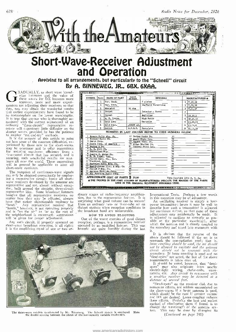
678 Radio News for December, 1926
Short- Wave -Receiver Adjustment and Operation
Applying to all arrangements, but particularly to the "Schnell" circuit By A. B(NNEWEG, JR., 6BX, 6XAA.
GRADUALLY, as short wave knowl- edge increases and the value of these waves for DX becomes more apparent, more and more experi-
menters are adjusting their receivers so that they, too, may obtain the wonderful results that earlier experimenters have found to be so commonplace on the lower wavelengths. It is true that anyone who is thoroughly ac- quainted with the correct adjustment of an ordinary "three- circuit" regenerative re- ceiver will experience little difficulty on the shorter waves, provided he has the patience to employ "cut- and -try" methods.
It is the purpose of this article to point out how some of the common difficulties, ex- perienced by those new to the short- waves, may be overcome and to offer suggestions for securing maximum efficiency from a time- tested circuit that has secured, and is securing, such wonderful results for ama- teurs.all over the world. These suggestions will in general be applicable to most all short -wave receivers.
The reception of continuous -wave signals can only be obtained conveniently by employ- Mg a regenerative circuit ; hence all short- wave receivers developed by the amateur are regenerative and are, almost without excep- tion; built around the straight, three -circuit regenerative idea. Some broadcast listeners imagine that all regenerative receivers, no matter how they may be adjusted, always have that rather objectionable tendency to "howl." Any regenerative receiver that "howls," however, is not operating properly and is "on the air" as far as the rest of the neighborhood is concerned ; suggestions will be given for proper adjustment.
Any such circuit, if properly operated on short -wave broadcast reception, is all right; it is the amplifying equal of one or two or-
A
SYMBOL Qwmb NAME OF PART OFpM REMARKS MANUFACTURER * 1 Var. Cond. 7 platee 1 7,10,18
1 Var. Cond. 10-Plate Throttling 1 7,10,18 1 Rheostat 30 ohm 2 9,11,17 N
1 Socket Detector - Pyrex 3 -_
1 Socket Amplifier 3 10,18,1 1 A, Y. Trans, High Ratio 4 10,16,19 1 Grid Leak Variable 5 11,20,21 1 Grid Cond. .00025 mf. 6 15,11,8
-1 Switch S.P. D. T. Porcelain 8 12,13,14 NUMBERS IN LAST- COLUMN REFER TO CODE NUMBERS BELOW.
I Bremor -Tully Mfg. Co. 17 Carter Radio Co. 33 __
2 Kloener Radio Co. 18 Ameco Prod. Inc. 34 3 Gerod Corp. 19 Samson Elec. Co. 35 4 Radio Corp. of America 20 Allen Bradley Co. 36 5 Durham It Co. 21 Central Radio Lab. 37-
6 N, Y. Coil Co. 22 38 7 Hemmarlund Mfg. 23. - 39 8 Leslie F. Muter Co. 24 40 9 E, H. Frost, Inc. 25 41
10 Pacent Elec. Co., Inc. 26 42 II Electrad, Inc. 27 43 12 Berkelew Elec. Mfg. Co. 28 44 13 Westiàghouee Elec. & Mfg. co, 29 45 14 Circle F Mfg. Co. 30 46 15 Aerovox Fireless Corp. 31 47 16 All American Radio Corp. T2 48
APPROXIMATE COST OF PARTS $ 18.00 Form Copright 1926 E. P. Co. -
*THE FIGURES IN THE FIRST COLUMN OF MANUFACTURERS INDICATE THE MAKERS' OF THE PARTS _- USED IN THE ORIGINAL EQUIPMENT DESCRIBED HERE.
maarammaimmorol,1111111
d nary stages of radio -frequency amplifica- t'on, due to the regenerative feature. It is surprising what good volume can be secured from an ordinary two- or three -tube set on distant stations when reception conditions in the broadcast band are unfavorable.
HOW TO AVOID BLOOPING One of the worst enemies of good distant
reception, perhaps, is a regenerative receiver operated by an unskilled listener. This was brought out quite forcibly during the last
The short -wave receiver constructed by Mr. Binneweg. The Schnell circuit is employed. Note the double spacing between the plates of the low- capacity variable condensers.
International Tests. Perhaps a few words in this collection may be of advantage.
An oscillating receiver is simply a low =.
power transmitter ; hence it may be well to describe how such a transmitter is adjusted for uzaxununc output, so that none of these adjustments may accidentally be made. It is adjusted to oscillate as strongly as pos- sible at the particular wavelength, after which the antenna coil is closely coupled to the secondary and tuned into resonance with it.
It is obvious that the reverse of the above should be followed if the set is to approach the non- radiation goal; that is, loose coupling should be used, the set should not be allowed to oscillate and the antenna circuit should not be resonant with the secondary. If loose coupling is used and no "dead- spots" are noted, the last of the above requirements is taken care of.
It should be noted, however, that "dead - spots" may also originate from nearby electric -light wiring, choke -coils, wave - meters, .etc. Any circuit in resonance with a sensitive receiver play be detected at a distance of several feet.
"Dead- spots" on the receiver dial, due to resonance effects, are seldom encountered on the short -waves if a large antenna is used, which should be the case if greater volume and DX are desired. Loose -coupling reduces these effects. Probably the best and easiest method of eliminating them if found, is to change the wavelength of the antenna sys- tem. This may be done by changing its
(Continued on page 741)
www.americanradiohistory.com
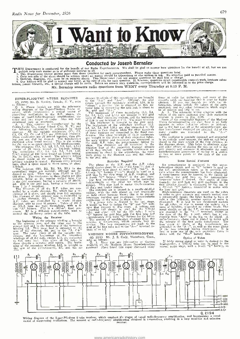
Radio News for December, 1926 679
Conducted by Joseph Bernsley THIS Department is conducted for the benefit of our Radio Experimenters. We shall be glad to answer here questions for the benefit of all, but we can
publish only such matter as is of sufficient interest to all. 1. This Department cannot answer more than three questions for each correspondent. Please make these questions brief. 2. Only one side of the sheet should be written upon; all matter should be typewritten or else written in ink. No attention paid to penciled matter. 3. Sketches, diagrams, etc., must be on separate sheets. This Department does not answer questions by mail free of charge. 4. Our Editors -will be glad to answer any letter, at the rate of 25c. for each question. If, however, questions entail considerable research work, intricate calcu-
lations, patent research, etc., a special charge will be made. Before we answer such questions, correspondents will be informed as to the price charge.
Mr. Bernsley answers radio questions from WRNY every Thursday at 8:15 P. M.
SUPER -PLIODYNE 9 -TUBE RECEIVER (Q. 2194) Mr. D. Stanley, Tuxedo, N. Y., asks
as follows: Q. 1. Please furnish me with the schematic
wiring diagram of the Super -Pliodyne 9 -tube re- ceiver, which incorporates a special means of controlling oscillations in the R.F. stages, she stages of tuned -radio -frequency amplification, de- tector and two stages of audio. Also any con- structional data or constants.
A. 1. This receiver is manufactured by the Golden -Leutz Co., Long Island City, N. Y., and the following information is published by their courtesy. All the variable condensers (Cl, C2, C3, C4, C5, CO and C7,) are 0005 -mfd. capacity. These condensers are all geared together, thus giv- ing you one dial for control. The transformers employed allow broad tuning. This is the reason for the use of so many stages tuned simultaneously.
The primaries (LI, L3, L5, L7, L9, L11, L13,) consist of 25 turns, wound on 134-inch tubing. The secondaries (LI, L4, Lt. L8, LI O, L12, L14,) consist of 100 turns wound on 2 -inch tubing. No. 26 D.C.C. wire is used. The primary tubing is placed inside of the secondary tubing. The primary winding is spaced. Between every primary turn, allow a space equal to three turns, or about 1/8-inch.
The resistors (RI, R2, R3, R4, R5,) in the neutralized stages are variable, although not in- dicated as such. They vary from 20,000 to 120,- 000 ohms. The condensers in these stages are also variable, being of the regular midget type. C14 is the grid condenser, having a capacity of .00025- mí. R10 is the grid leak, having a resistance of from 1 to 3 megohms.
The filaments of all the R.F. tubes are con- trolled by a single rheostat, R6, which has a re- sistance of 6 ohms, and should pass 1¡z amperes. The filament of the detector tube is controlled by a 20 -ohm rheostat, R8. The filaments of the A.F. tubes are controlled by a single 10 -ohm rheostat, able to pass %- ampere. Tubes of 201 -A or 301 -A type are used throughout, with a 6- volt "A" battery. C13 is a .003 -mf. fixed con- denser. R7 is a 400 -ohm potentiometer, used to control the oscillatory action of the tube.
Wiring the Receiver The beginning of the primary winding is brought
to the antenna post. and the other end to the ground post and to the beginning of the secondary winding L2. This same lead is extended to the arm of the rheostat, R6, and to the "A -C +" post. The rotor plates of all the variable con- densers and the beginnings of the secondary windings of all the coils, except L12, are connected to this same lead. This gives all the tubes in these circuits a negative grid return. The begin- ning of the secondary winding, L12, is brought to the arm of the potentiometer, R7, and the re.
Rz C9
O O ó L
sistance terminals of this potentiometer are brought to the "A +" and "A -". Although the grid return through the secondary winding, L14, is to "minus," a positive bias is obtained on this de- tector tube by connecting the grid leak in shunt to the grid and "A+."
The beginnings of these secondaries (L2, IA, L6, L8, L10, and L12,) are brought to the grid posts of their respective sockets, and the beginning of L14 to one terminal of C14. The other terminal of this condenser is brought to the grid post. The beginnings of the secondary windings (L2, L4, L6, L8, and L10,) are also connected to the resistors in their stages, while the other terminals of these resistors are connected to the fixed con- densers. The other terminals of these condensers are brought to the plates of their respective tubes. No such resistor and condenser are connected to the sixth R.F. tube, the potentiometer taking its place. The rheostats are all connected in the negative legs of the respective filament circuits which they control. The variable condensers are connected in shunt to the secondaries, the rotor leads going to the filament side and the stators to the grid side.
Batteries Required The plates of the R.F. and the A.F. tubes
should receive about 90 volts ( "B+Amp. ") ; that of the detector tube about 45 volts ( "B +Det. "). A 4.5 -volt "C" battery ( "low ") should be used as a grid bias in the first stage of A.F. coupling, and a 9 -volt "C" battery "High" in the last stage.
The first variable condenser can be controlled independently of the other six which may be ganged. This may lead to easier synchronization of dials and louder signals.
The complete set is housed in a totally -shielded cabinet, with the coils placed so that practically no field exists between them; this is to prevent interstage coupling and consequent uncontrollable oscillations of the tubes in these circuits.
If a power tube is desired in the last stage, it would be best to isolate the "B" and "C" volt- ages that connect to this stage. A voltage not exceeding 135 should be used for the UX112 tube, and about 175 for the 171 tube; 9 volts "C" battery for grid bias with the first tube and approximately 22% volts "C" battery for the latter.
The amount of amplification obtained from this receiver is tremendous, which permits loop re- ception. The loop connections are made to the grid of the first tube and to the "A -" terminal in- stead of to L2.
MADISON MOORE SUPERHETERODYNE (Q. 2195) Mr. J. S. Cody, Waterbury, Conn.,
asks as follows: Q. 1. Have you any information or diagram
available on the Madison Moore Superheterodyne receiver? Have heard this super discussed many
c,. Rs 11Çit
times at radio fan gatherings, and some of the -
remarks made me conclude that it must be highly efficient. If you can furnish me with the in- formation, please include the values of the parts employed, and any other information which might be of interest and help to me.
A. I. The schematic wiring diagram with the values of the parts indicated over their respective symbols is shown in Fig. 2195.
Some of the remarkable features of the Madisort Moore Superheterodyne are that there is no body capacity or other inductive effects or pick -up; due to the fact that all of the accurately -tuned air - core transformers employed are shielded. All of the metal shields are grounded to the "A -" terminal.
The oscillator is specially designed and connected in an entirely novel manner, the pick -up coil being placed in the plate circuit of the first detector, as the diagram shows. This helps to eliminate noise and other effects of placing the pick -up coil in the grid circuit; and moreover it eliminates the usual superheterodyne annoyance of tuning in a station at two or more points on the dials of the con- densers.
Some Special Features No potentiometer is employed in this super-
' heterodyne circuit, and no "C" battery is used on the I.F. amplification tubes, as in previous cir- cuits where the potentiometer has been eliminated. A potentiometer may be inserted in the circuit for controlling the grid bias on the intermediate - frequency tubes if desired. One source of noise (namely, the grid leak and grid condenser in the first detector circuit) is eliminated by the use of a 4% -volt "C" battery, connected in series with the loop and grid.
High -resistance rheostats are used on the tubes in order to give accurate and smooth control over a considerable range; the tubes having to burn at only a dim brilliancy, another source of noise is eliminated. It is best to use shockproof sockets for all tubes, or else to mount the sockets on a piece of bakelite, suspended on rubber bauds. The metal shields on all the I.F. air -core transformers are grounded to the "A-" terminal; except in the case of the No. 5 unit, which has a wire running from "A -" to the lug on the shield. A radio -frequency choke coil is placed in series with the primary of the first audio transformer. The iron cores or shells of the transformers are grounded to the "A -", as well as the rotor plates of the two principal tuning condensers. It is best to place one of the new protective fuses in series with the "B -" battery line.
Option of Tubes If fairly strong signal or voice is desired on the
loud -speaker, a UXI12 tube can be used in the second audio stage, with a 9- volt "C" battery, as
,,Cw
C b_ L4
Ó Lu L.14 Rio
Re 9
Wiring diagram of the Super -Pliodvne means of suppressing oscillations. The
C-HIGH
C- LOW
B+OLT.
B+AMP.
P,+B- A C+
Q. 2194 9 -tube receiver, which employs six stages of tuned radio -frequency amplification, and incorporates a novel
amount of radio- frequency amplification obtained is tremendous, resulting in a very sensitive and selective receiver.
www.americanradiohistory.com
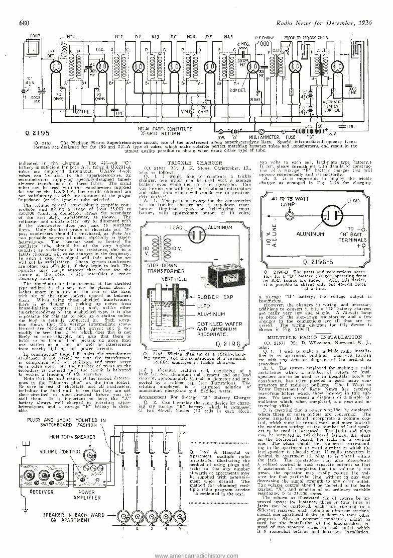
680
N=3 Rf N44
L
Q. 2195
O Ó
L
V M.
R.E 1,12: 5
2,MEG
RF CHOKE
Radio News for December, 1926
25,000 TO 250,000 OHMS
P A.F.T.
A- B
O O O O O
20 OHMS
METAL CASES CONSTITUTE A-GRID RETURN
005 MF,
AUTOMATIC
FILAMENT CONTROL
445 90
-1:11111 + aT. - IIIIII11lIl1I111I1I1 ±31 MF.
SW. A MILLI- AMMETER. FUSE "B" Q. 2195. The Madison Moore Superheterodyne circuit, one of the mostrecent along superheterodyne lines. Special intermediate- frequency trans- formers are designed for the 199 and 201 -A type of tubes, which make possible perfect matching between tubes and transformers, and result in the
utmost quality possible to obtain when using either type of tube.
indicated ' in the diagram. The 4% -volt "C" battery is sufficient for both A.F. tubes if UX201 -A tubes are employed throughout. UX199 3 -volt tubes can be used in this superheterodyne, its manufacturers supplying specially -designed tuned - air -core - transformers for these tubes. The small tubes can be used with thé- transformers supplied for use on the UX201 -A, but results obtained are not satisfactory as with transformers of the proper impedance for the type of tube selected.
The volume control, comprising a graphite com- pression unit giving a range of from 25,000 to 250,000 ohms, is connected across the secondary of the first A.F. transformer, as shown. The voltmeter and milliammeter may be dispensed with if the constructor does not care to purchase them. Only the best grade of rheostats and by- pass condensers should he purchased, as these are two probable sources of noise, especially in super - heterodynes. The rheostat used to control the oscillator tube should be of the very highest quality; as variations in the resistance, due to a faulty rheostat, will cause changes in the frequency. In such a case the signal will fade and the set will not be satisfactory. Cheap by -pass condensers are other bad offenders, if they begin to leak. The operator may never suspect that these are the source of the noise, which resembles a steady steaming sound.
The tuned- air -core transformers, of the shielded type utilized in this set, may be placed about 3
inches apart in a row at the rear of the base, with six of the tube sockets spaced in between them. When using these shielded transformers, there is no danger of picking up noises from house -lighting circuits, etc.-; and, unlske other superheterodynes of the unshielded type, it is also impossible for this set to pick up a station unless the loop is actually connected in. Such recep- tion shows that the various intermediate trans- formers are picking up radio waves ; and it can readily be seen that a set which does this is not likely to tune sharply, and also that there is liable to he trouble from picking up more than one station at a time, as well as interference from nearby lighting and power circuits.
In constructing these I.F. units, the transformer condenser is not varied to tune the transformer, in connection with an oscillator and wave meter as is often done; but the number of turns on the secondary is changed until the circuit is balanced to within a fraction of 1% accuracy.
Note that the grid return of the second detector goes to the "filament plus" on the tube socket. Be sure to test all rheostats, and all condensers, including the fixed unit, to see that they are not short -circuited or open -circuited before you in- stall them. It is important to keep the "A" battery always well charged in operating super - heterodynes, and a storage "B" battery is desir- able.
PLUGS AND JACKS MOUNTED IN SWITCHBOARD FASHION
MONITOR SPEAKER
VOLUME CONTROL
TRICKLE CHARGER (Q. 2196) Mr. J. K. Stone, Christopher,
asks as follows: Q. 1. I would like to construct a trickle
charger, enie which can be used with a storage battery even while the set is in operation. Can you furnish me with any constructional information and other data which will enable me to construct this device?
A. I. The parts necessary for the construction of the trickier charger are a step -down trans- former (toy -train type, or bell- ringing trans- former, with approximate output of 10 volts)
110
V.
LEAD
IMO
10 V.
ALUMINUM
STEP DOWN TRANSFORMER
VENT HOLE
t
RUBBER CAP
LEAD
ALUMINUM
DISTILLED WATER AND AMMONIUM PHOSPHATE.
Q. 2I 96 Q. 2196 Wiring diagram of a trickle- charg-
system, and the construction of a chemical rectifier employed in trickle chargers.
and a chemical rectifier cell, consisting of a fruit jar, one aluminum rod element and one lead clement, approximately % -inch in diameter and sup- ported by a rubber cap (see illustration). The solution employed is a saturated solution of ammonium phosphate and distilled water. Arrangement For Storage "s" Battery Charger
Q. 2. Can I employ the same device for charg- ing my storage "B" battery, which is composed of two 46 -volt blocks (23 cells in each block,
i¡ò 0
"`"''. ®~J® "t, RECEIVER POWER
AMPLIFI ER
-4PEAKER IN EACH WARD OR APART MENT
Q. 2197 A Hospital or Apartment multiple radio installation, illustrating the method of using plugs and jacks so that any nuinbe- of wards or apartments may be supplied with entertain- ment when desired. The method for obtaining mul- tiple radio program service
is explained in the text.
two volts to each cell, lead -plate type battery.) If not, please furnish ine with details of construc- tion of a storage "B" battery charger that will operate economically and satisfactorily.
A. 2. It is impossible to employ the trickle charger as arranged in Fig. 2196 for charging
Q. 2196 -B The parts and connections neces- sary for a "B" battery charger, operating from an A.C. source are shown. With this device, it is possible to charge only one 45 -volt block
at a time.
a storage "B" battery; the voltage output is insufficient.
However, the changes in wiring, and necessary additions to convert it into a `B" battery charger, are really very few and simple. A 75 -watt lamp in place of the step -down transformer and a few changes in the connections are all that are re- quired. The wiring diagram for this device is shown in Fig. 2196 -B.
MULTIPLE RADIO INSTALLATION (Q. 2197) Mr. D. Wilkerson, Norwood, N. J.,
asks: Q. 1. I wish to make a multiple radio installa-
tion in an apartment building. Can you furnish me with any data or diagram of the method of procedure?
A. 1. The system employed for making a radio installation where a number of outlets or loud- speakers are to be used, as in hospitals, hotels or apartments, has often puzzled a good ' many con- structors and radio -set builders. The I Want to Know Department of RADIO NEWS has received numerous letters which show interest in this sub- ject. We here present a diagram of a simple in- stallation which, when completed, is a neat and in- teresting affair.
It is essential that a power amplifier be employed where three or more outlets are concerned. The power amplifier should incorporate a volume con- trol, which must be turned more and more towards the maximum setting, as the number of loud- speak- ers to be used is increased. The jacks and plugs may be mounted in switchboard fashion, the plugs on the horizontal board, the jacks on a vertical one. The plugs should be numbered correspond- ing to the apartment or ward number in which the loud- speaker is placed; thus, if radio reception is desired in apartment 13, plug 13 is placed within the jack. The constructor may also incorporate a volume control in each separate output; so that if apartment 13 complains that the volume is too great, the operator may easily reduce the vol- time for that particular line, without in any way decreasing the signal strength to any other outlet. The volume control should be conected to the leads marked "X ", and consists of an ordinary variable resistance, 0 to 25.000 ohms.
The scheme as illustrated can of course be im- proved upon; for instance, three or four lines of jacks can be employed, each line running to a different receiver, each obtaining different stations, should one apartment desire to listen to some other program. Also, a common connection might be used for the installation of the loud- speaker, in- stead of two separate wires for each outlet, which is a somewhat tedious and laborious installation.
www.americanradiohistory.com
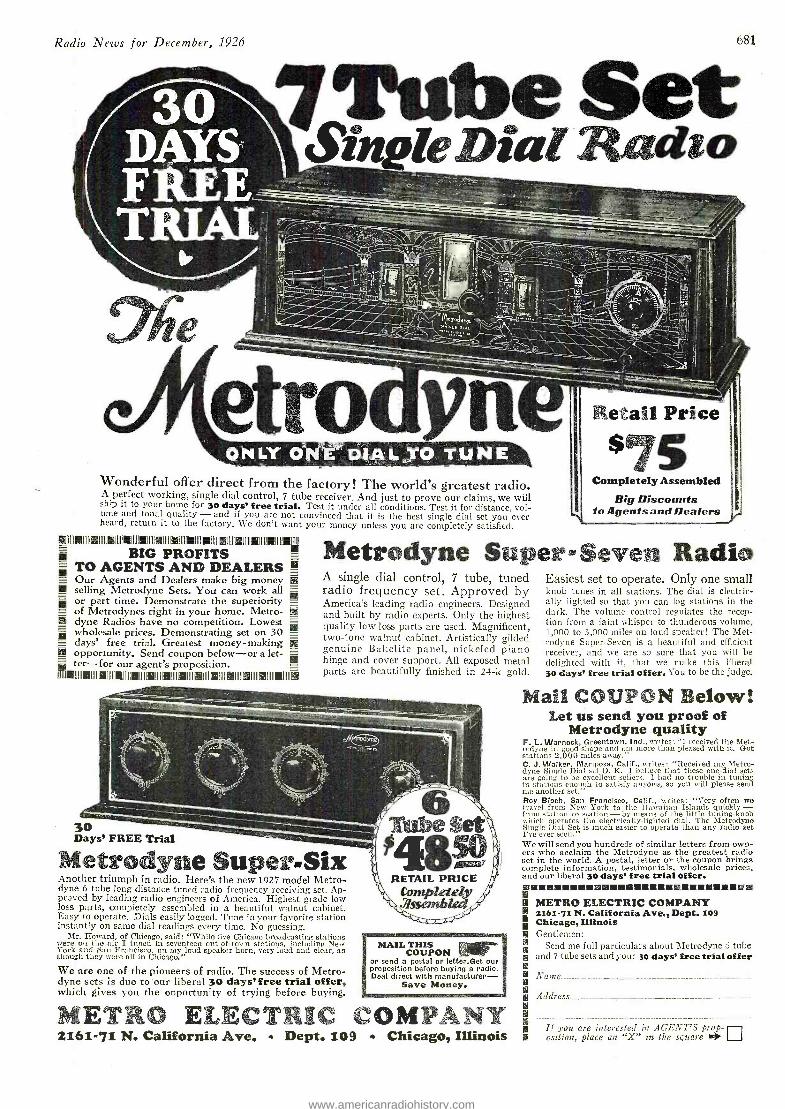
O 1IIII01IIil IIIIl 111110IIIII0111II01IIIIIIIIII IIIIIIIiII iiIfIII1101111I01111I0 Iw
TO AGENTS AND DEALERS ó Our Agents and Dealers make big money selling Metrodyne Sets. You can work all or part time. Demonstrate the superiority = of Metrodynes right in your home. Metro- U dyne Radios have no competition. Lowest wholesale prices. Demonstrating set on 30 T.
days' free trial. Greatest money - making U p opportunity. Send coupon below -or a let- -a ter --for our agent's proposition. Y
r01111101111I01111i011111 011111 111110 111110 IIIII0111II01111101111101111011111 11111
BIG PROFITS
Radio News for December, 1926 681
7Tube Set Sinpie Dial Radio
Wonderful offer direct from the factory! The world's greatest radio. A perfect working, single dial control, 7 tube receiver. And just to prove our claims, we will ship it to your home for 30 days' free trial. Test it under all conditions. Test it for distance, vol- ume and tonal quality - and if you are not convinced that it is the best single dial set you ever heard, return it to the factory. We don't want your money unless you are completely satisfied.
Retail Price
$75 Completely Assembled
Big Discounts to agents and Dealers l
Metrodyne Super-Seven Radio A single dial control, 7 tube, tuned radio frequency set. Approved by America's leading radio engineers. Designed and built by radio experts. Only the highest quality low loss parts are used. Magnificent, two -tone walnut cabinet. Artistically gilded genuine Bakelite panel, nickeled piano hinge and cover support. All exposed metal parts are beautifully finished in 24 -k gold.
30 Days' FREE Trial
Metrodyne Super -Six Another triumph in radio. Here's the new 1927 model Metro - dyne 6 tube long distance tuned radio frequency receiving set. Ap- proved by leading radio engineers of America. Highest grade low loss parts, completely assembled in a beautiful walnut cabinet. Easy to operate. Dials easily logged. Tune in your favorite station instantly on sane dial readings every time. No guessing.
Mr. IIoward, of Chicago, said: "While five Chicago broadcasting stations were on the air I tuned in seventeen out -of -town stations, including New York and San Francisco, on my loud speaker horn, very loud and clear, as though they were all in Chicago."
We are one of the pioneers of radio. The success of Metro - dyne sets is due to our liberal 30 days' free trial offer, which gives you the opportunity of trying before buying.
MAIL THIS COUPON Ellir
or send a postal or Ietter.Get our proposition before buying a radio. Deal direct with manufacturer -
Save Money.
METRO ELECTRIC COMPANY 2161 -71 N. California Ave. 4 Dept. 109 Chicago, Illinois
Easiest set to operate. Only one small knob tunes in all stations. The dial is electric- ally lighted so that you can log stations in the dark. The volume control regulates the recep- tion from a faint whisper to thunderous volume, 1,000 to 3,000 miles on loud speaker! The Met - rodyne Super -Seven is a beautiful and efficient receiver, and we are so sure that you will be delighted with it, that we make this liberal 30 days' free trial offer. You to be the judge.
Mail COUPON Below! Let us send you proof of
Metrodyne quality F. L.. Warnock, Greentown, Ind., writes: "I received the Met - rodyne in good shape and am more than pleased with it. Got stations 2,000 miles away." C. J. Walker, Mariposa, Calif., writes: "Received my Metro - dyne Single Dial set O. K. I believe that these one -dial sets are going to be excellent sellers. I had no trouble in tuning in stations h mooc to satisfy anyone, so you will please send me another set." Roy Bloch, San Francisco, Calif., writes: "Very often we travel from New York to the Hawaiian Islands quickly - from station to station -by means of the little tuning -knob which operates the electrically -lighted dial. The Metrodyne Single Dial Set is much easier to operate than any radio set I've ever seen." We will send you hundreds of similar letters from own- ers who acclaim the Metrodyne as the greatest radio set in the world. A postal, letter or the coupon brings complete information, testimonials, wholesale prices, and our liberal 30 days' free trial Offer. 11111111111111sI6 eoHHMINYIIM00HHtIIMIN
METRO ELECTRIC COMPANY 2561-71N. California Ave., Dept. 109 Chicago, Illinois Gentlemen:
Send nie full particulars about Mctrodyne 6 tube and 7 tube sets and your 3o days' free trial offer
Name
Address
If you are interested in AGENT'S prop- osition, place an "X" in the square y
www.americanradiohistory.com
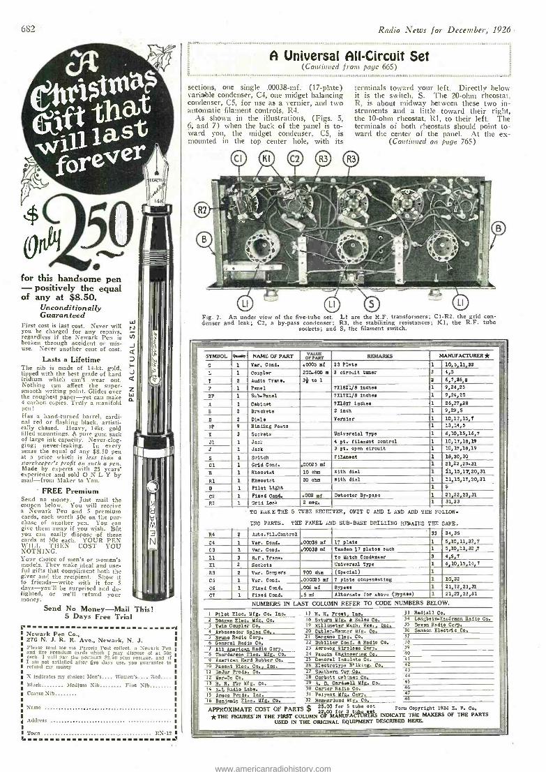
682
for this handsome pen - positively the equal of any at $8.50.
Unconditionally Guaran teed
First cost is last cost. Never will you be charged for any repairs, regardless if the Newark Pen is broken through accident or mis- use. Never another cent of cost.
Lasts a Lifetime The nib is made of I4 -kt. gild, tipped with the best grade of hard iridium which can't . wear out. Nothing can affect the super - smooth writing point. Glides over the roughest paper -yet can make 4 carbon copies. Truly a manifold pen! Has a hand- turned barrel, cardi- nal red or flashing black, artisti- cally chased. Heavy, 14kt. gold filled mountings. A pure guns sack of large ink capacity. Never -clog- ging; never -leaking. In every sense the equal of any $3.50 pen at a price which is less than a storekeeper's profit on such a pen. Made by experts with 25 years' experience and sold ONLY by mail -from Maker to You.
FREE Premium Send no money. Just nail the coupcn below. You will receive a Newark Pen and 5 premium cards, each worth 50c on the pur- chase of another pen. You can give them away if you wish. But you can easily dispose -of these cards at 50c each. YOUR PEN w-li_l. THEN COST YOU NOTHING. Your choice of men's or women's models. They make ideal and use- ful gifts that compliment both the giver and the recipient. Show it to friends -write with it for 5 days-you'll be surprised and de- lighted, or well refund your money.
P
Send No Money -Mail This! 5 Days Free Trial
Newark Pen Co., 276 N. J. R. R. Ave., Newark, N. J. Please send me ria Parcels Post collect. a Newark Pen and five premium cards which I may dispose of at 50e
ach. I will pap- the postman $5.50 plus Postage, and if I am not satisfied after five days use, you guarantee to refund my money
X indicates my choice: \fen's.... Women's.... Red.... ]clack Medium Nib Fine Nlb Coarse Nib
Name
Address
Town RN -1^-
J
Radio News for December, 1926
M. MDMIIM
A Universal All- Circuit Set ( Continued frota page 665)
sections, one single .00038 -mf. (17- plate) variable condenser, C4, one midget balancing condenser, C5, for use as a vernier, and two automatic filament controls, R4.
As shown in the illustrations, (Figs. 5, 6, and 7) when the back of the panel is to- ward you, the midget condenser, C5, is mounted in the top center hole, with its
terminals toward your left. Directly below it is the switch, S. The 20 -ohm rheostat, R, is about midway between these two in- struments and a little toward their right. the 10 -ohm rheostat, Rl, to their left. The terminals of both rheostats should point to- ward the center of the panel. At the ex-
(Continued on page 765)
Fig. 7. An under view of the five -tube set. Ll are the R.F. transformers; C1 -R2. the grid con- denser and leak; C2, a by -pass condenser; R3, the stabilizing resistances; K1, the R.F. tube
sockets; and S, the filament switch.
0... so NAME OF PART MANUFACTURER* E
SYMBOL pr p REMARKS
C 1 Var. Cond. .0005 mf 23 Plate 1 10,5,11,33 L 1 Coupler 200.600 at 3 circuit tuner 3 4,5
T 2 Audio Trans. 3* to 1 2 6,7,36,8 P 1 Panel 711811/8 inches 1 9,24,25
BP 1 Sub -Panel 711711/8 inches 1 9,24,25
A 1 Cabinet 7II8i7 Saches 1 26,27,38 B 3 Brackets 2 inch 1 9,29,5 D 2 Dials vernier 1 10,12,15,7
_ BP 9 Binding Poets 1 13,14,5
C 3 Sockets Oniverslel type 1 6,10,15,16,7 J1 1 Jack 4 pt.tilament control 1 10,17,18,19 J 1 Jack 3 pt. open circuit 1 10,17,18,19
S 1 Seit eh Filament 1 18,30,30 B
Cl 1 Grid Coni. ,00025 mf 1 21,22,29.31 R 1 Rheostat 10 ohm With dial 1 11,15,19,20,31
R1 1 Rheostat 20 ohm With dial 1 11,15,17,20,31 G 1 Pilot Light 1 5
CD 1 Fixed Cond. .002 mf Detector By -pass 1 21,22,23,31
X-1 R2 1 Grid Leak 2 meg. 1 31,23
la TO LAKE THE 5 TUBE RECEIVER, OMIT C AND L AND ADD THE FOLLOR-
ö INC PARTS. THE PANEL AND SUB -BASE DRILLING RFMAII]S THE SAME. E
R4 2 Auto.Fil.Control 33 34,35 F.
C4 1 Var. Cond. ,.00338 mf 17 plate 1. 5,10,11,32,7 03 1 Var. Cond. .00038 mf Tandem 17 plates each 1 5,10,11,32 ,7
L1 3 R.F. Trans. To Match Condenser 3 4,5,7 El 2 Sockets Universal Type 1 6,10,15,16,7
° R3 2 Ver. Dampers 700 ohm (Special) 1
-- 05 1 Var. Cond. .000025 mf 7 plate compensating 1 10,32
C6 1 Pined Cond. .006 of Bypass 1 21,22,23,31 =_
C7 1 Fixed Cond. .5 ad Alternate for above (Bypass) 1 21,22,23,31
NUMBERS IN LAST COLUMN REFER TO CODE NUMBERS BELOW.
I Pilot Elea. Mfg. Co. Inc. 17 H. H. Frost, Inc. 33 Radiali Co.
2 Donlan Elea, Mfg. Co. 18 Satura Mfg. d Sales Co. 34 Langbein.Eaufmaen Radio Co. 3 Twin Coupler Co. 19 Millimeter Mach. Wks., Inc. 35 Doyen Radio Corp. _
4 Ambassador gales Co. 20 Cutler -Huer Mfg. Co. 36 Samson Electric Co. ,
5 Bruno Radio Corp. 21 Sangemo Else. Co. 37
= 6 General Radio Co. 22 Dabilier Cond. d Radio Co. 38
7 All American Radio Corp, 23 Aerovox Wireless Corp. 39 _.
= 8 Thordarson Elec. Mfg. Co. 24 Pausin Engineering Co. 40
9 American Hard Rubber Co. 25 General Insulate Co. 41
Io Paeent Elec. Co., Inc. 26 Electrotype Bilking. Co. 42
11 DeJur Prods. CO. 27 Southern Toy Co. 43
12 Mar.Co Co. 28 Corbett cabinet Co. 44
13 H. H. by Mfg. Co. 29 A. D. Cardwell Mfg. Co. 4S
14 r Radio Labs. 30 Carter Radio Co. 46 -L 15 Armco Prods. Inc. 31 Pointes Mfg. Corp. _47
16 Benjamin Elec. Mfg. Co. 32 Hanrarluad Mfg. Co. 48
APPROXIMATE COST OF PARTS $ 25.00 for 5 tube set Form Copyright 1926 E. P. Co. = 23.00 for 3 tubs set
*THE FIGURES'IN THE FIRST COLUMN OF MANUFACTURERS INDICATE THE MAKERS OF THE PARTS
USED IN THE ORIGINAL EQUIPMENT DESCRIBED HERE. - - _=-
www.americanradiohistory.com
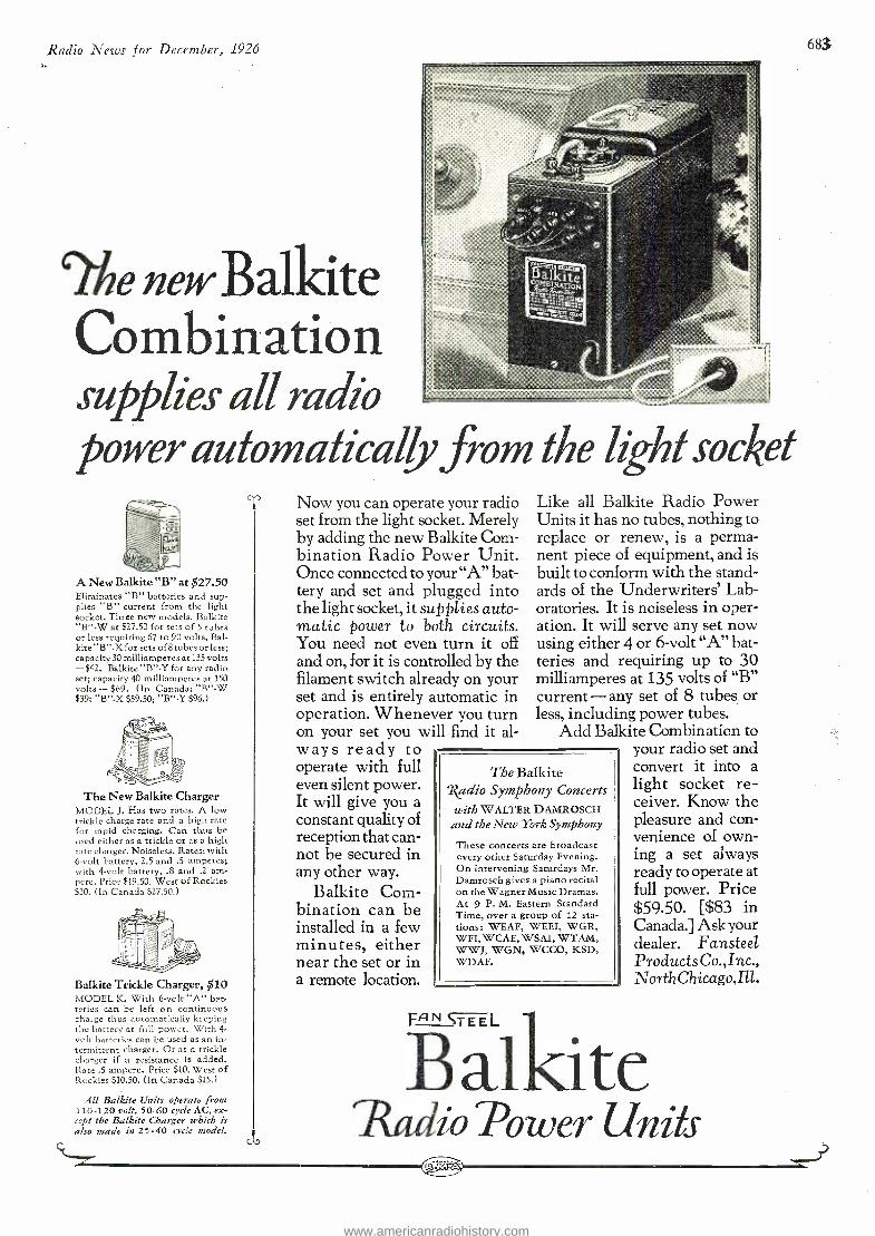
Radio News for December, 1926 083
`?fie new Balkite Combination supplies all radio L
power aufomatically from the lzh1 socket
-- A New Balkite "B" at $27.50 Eliminates "B" batteries and sup- plies "B" current from the light socket. Three new models. Balkite "B " -W at $27.50 for sets of 5 tubes or less requiring 67 to 90 volts. Bal - kite "B " -X for sets of tubes or less; capacity 30 milliamperes at 135 volts -$42. Balkite "B " -Y for any radio set; capacity 40 milliamperes at 150 volts - $i'9. (In Canada: ' B " -W $39; "B " -X $59.50; "B " -Y $96.)
The New Balkite Charger MODEL J. Has two rates. A low trickle charge rate and a high rate for rapid charging. Can thus be used either as a trickle or as a high rate charger. Noiseless. Rates: with 6 -volt battery, 2.5 and .5 amperes; with 4 -volt battery, .8 and .2 am- pere. Price $19.50. West of Rockies $20. (In Canada $27.50.)
Balkite Trickle Charger, $10 MODEL K. With 6 -volt "A" bat- teries can be left on continuous charge thus automatically keeping the battery at full power. With 4- volt batteries can be used as an in- termittent charger. Or as a trickle charger if a resistance is added. Rate .5 ampere. Price $10. West of Rockies $10.50. (In Canada $15.)
All Balkite Units operate from 110 -120 volt, 50 -60 cycle AC, ex-
cept' the Balkite Charger which is also made in 25 -40 cycle model.
Now you can operate your radio set from the light socket. Merely by adding the new Balkite Com- bination Radio Power Unit. Once connected to your "A" bat- tery and set and plugged into the light socket, it supplies auto- matic power to both circuits. You need not even turn it off and on, for it is controlled by the filament switch already on your set and is entirely automatic in operation. Whenever you turn on your set you will find it al- ways ready to operate with full even silent power. It will give you a constant quality of reception that can- not be secured in any other way.
Balkite Com- bination can be installed in a few minutes, either near the set or in a remote location.
The Balkite Xadio Symphony Concerts with WALTER DAMROSCH and the New York Symphony
These concerts are broadcast every other Saturday Evening. On intervening Saturdays Mr. Damrosch gives a piano recital on the Wagner Music Dramas. At 9 P. M. Eastern Standard Time, over a group of 12 sta- tions: WEAF, WEEI, WGR, WFI, WCAE, WSAI, WTAM, WWJ, WGN, WCCO, KSD, WDAF.
FsE L
Like all Balkite Radio Power Units it has no tubes, nothing to replace or renew, is a perma- nent piece of equipment, and is built to conform with the stand- ards of the Underwriters' Lab- oratories. It is noiseless in oper- ation. It will serve any set now using either 4 or 6 -volt "A" bat- teries and requiring up to 30 milliamperes at 135 volts of "B" current - any set of 8 tubes or less, including power tubes.
Add Balkite Combination to your radio set and convert it into a
light socket re- ceiver. Know the pleasure and con- venience of own- ing a set always ready to operate at full power. Price $59.50. [$83 in Canada.] Ask your dealer. Fansteel Products Co., Inc., North Chicago,Ill.
B alkite Radio Power Units
www.americanradiohistory.com
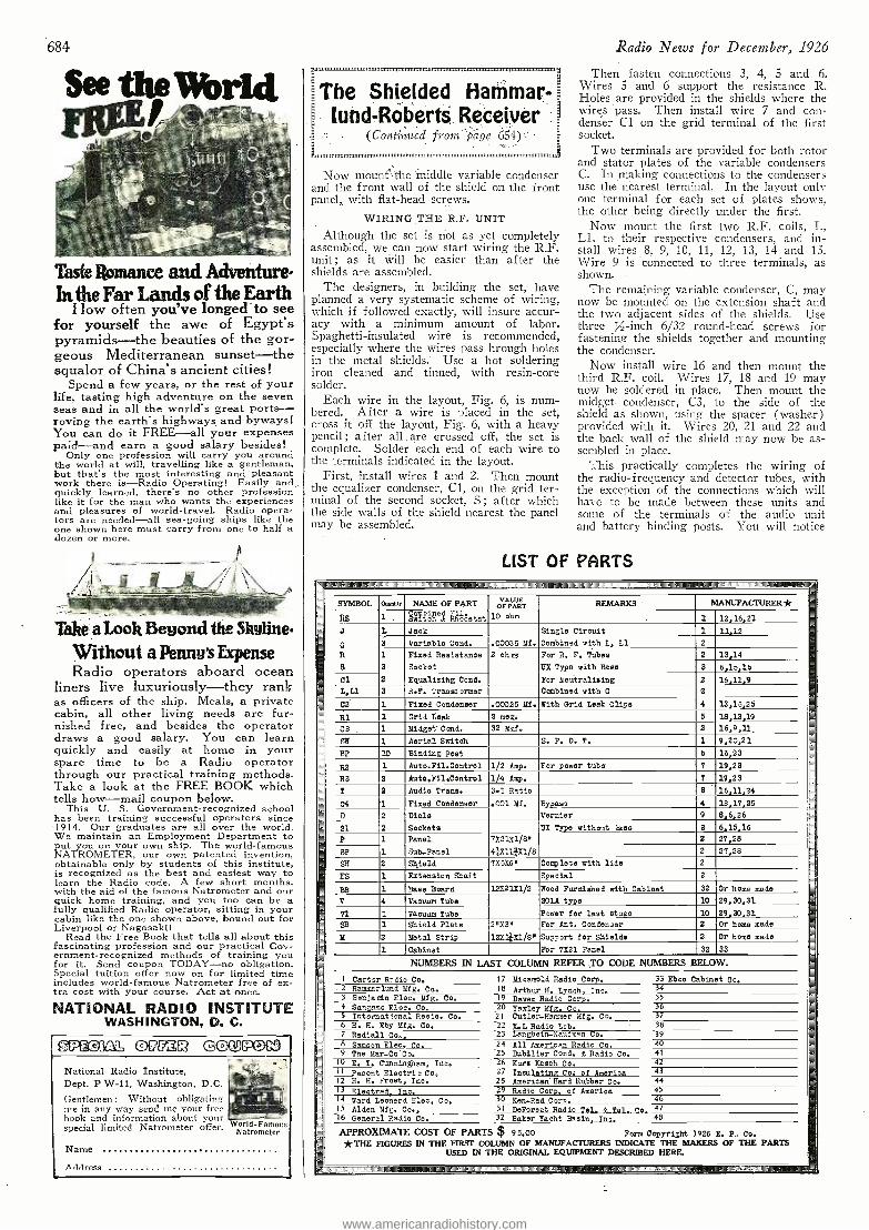
684
See the World
Taste Romance and Adventure' Inthe Far Lands of the Earth
How often you've longed to see for yourself the awe of Egypt's pyramids -the beauties of the gor- geous Mediterranean sunset -the squalor of China's ancient cities!
Spend a few years, or the rest of your life, tasting high adventure on the seven seas and in all the world's great ports - roving the earth's highways and byways! You can do it FREE -all your expenses pa;d -and earn a good salary besides!
Only one profession will carry you around the world at will, travelling like a gentleman, but that's the most interesting and pleasant work there is -Radio Operating! Easily and quickly learned, there's no other profession like it for the man who wants the experiences and pleasures of world - travel. Radio opera- tors are needed -all sea -going ships like the one shown here must carry from one to half a dozen or more.
Take a Look Beyond the Skyline.
Without a Penny's Expense Radio operators aboard ocean
liners live luxuriously -they rank as officers of the ship. Meals, a private cabin, all other living needs are fur- nished free, and besides the operator draws a good salary. You can learn quickly and easily at home in your spare time to be a Radio operator through our practical training methods. Take a look at the FREE BOOK which tells how -mail coupon below.
This U. S. Government -recognized school has been training successful operators since -1914. Our graduates are all over the world. We maintain an Employment Department to put you on your own ship. The world- famous NATROMETER, our own patented invention, obtainable only by students of this institute, is recognized as the best and easiest way to learn the Radio code. A few short months, with the aid of the famous Natrometer and our quick home training, and you too can be a fully qualified Radio operator, sitting in your cabin like the one shown above, bound out for Liverpool or Nagasaki!
Read the Free Book that tells all about this fascinating profession and our practical Gov- ernment- recognized methods of training you for it. Send coupon TODAY -no obligation. Special tuition offer now on for limited time includes world- famous Natrometer free of ex- tra cost with your course. Act at once.
NATIONAL RADIO INSTITUTE WASHINGTON, D. C.
0177L3Q GOO PON
National Radio Institute, Dept. P W -11, Washington, D.C.
Gentlemen: Without obligating me in any way send me your free book and information about your special limited Natrometer offer.
Name
World- Famous Natrometer
Address
The Shielded Hammar- [und- Roberts Receiver
(Continued front page 654) =
Rumil,tim,,,,,,,,munn,,,,,,,,,1111111111111.1,,,1333.31.m,ummum
Now mount the middle variable condenser and the front wall of the shield on the front panel, with flat -head screws.
WIRING THE R.F. UNIT
Although the set is not as yet completely assembled, we can now start wiring the R.F. unit ; as it will be easier than after the shields are assembled.
The designers, in building the set, have planned a very systematic scheme of wiring, which if followed exactly, will insure accur- acy " with a minimum amount of labor. Spaghetti- insulated wire is recommended, especially where the wires pass hrough holes in the metal shields.' Use a hot soldering iron cleaned and tinned, with resin -core solder.
Each wire in the layout, Fig. 6, is num- bered. After a wire is placed in the set, cross it off the layout, Fig. 6, with a heavy pencil ; after all : are crossed off, the set is complete. Solder each end of each wire to the terminals indicated in the layout.
First, install wires 1 and 2. Then mount the equalizer condenser, Cl, on the grid ter- minal of the second socket, S ; after which the side walls of the shield nearest the panel may be assembled.
Radio News for December, 1926
Then fasten connections 3, 4, 5 and 6. Wires 5 and 6 support the resistance R. Holes are provided in the shields where the wires pass. Then install wire 7 and con- denser Cl on the grid terminal of the first socket.
Two terminals are provided for both rotor and stator plates of the variable condensers C. In making connections to the condensers use the nearest terminal. In the layout only one terminal for each set of plates shows, the other being directly under the first.
Now mount the first two R.F. coils, L, Ll, to their respective condensers, and in- stall wires 8, 9, 10, 11, 12, 13, 14 and 15. Wire 9 is connected to three terminals, as shown.
The remaining variable condenser, C, may now be mounted on the extension shaft and the two adjacent sides of the shields. Use three / -inch 6/32 round -head screws for fastening the shields together and mounting the condenser. -
Now install wire 16 and then mount the third R.F. coil. Wires 17, 18 and 19 may now be soldered in place. Then mount the midget condenser, C3, to the side of the shield as shown, using the spacer (washer) provided with it. Wires 20, 21 and 22 and the back wall of the shield may now be as- sembled in place.
This practically completes the wiring of the radio - frequency and detector tubes, with the exception of the connections which will have to be made between these units and some of the terminals of the audio unit and battery binding posts. You will notice
LIST OF PARTS a UIIIIMmIIOm Mani iülmMMUI EMEND MMIUIIIIUMIIMIIUIIIIMIIIIIIIIIIMIII M UMM UImIIIIIIIIImIIIMIIIINIMIIIIIIIIIIIIIIIIINIIMIIIIUIIImIIIIIe mIIII1IIIIIIIIIImImIIIUIIImIIIIMMIIIMIIIUIIIIIUIIIIMIImlllllllnmmlllNminIUuIWIUmII u mm mom116YIIImIIIAUIOmIImIIWII
- SYMBOL Q..enh NAME OF PART VAL OF PARUE T REMARKS' MANUFACTURER*
www.americanradiohistory.com
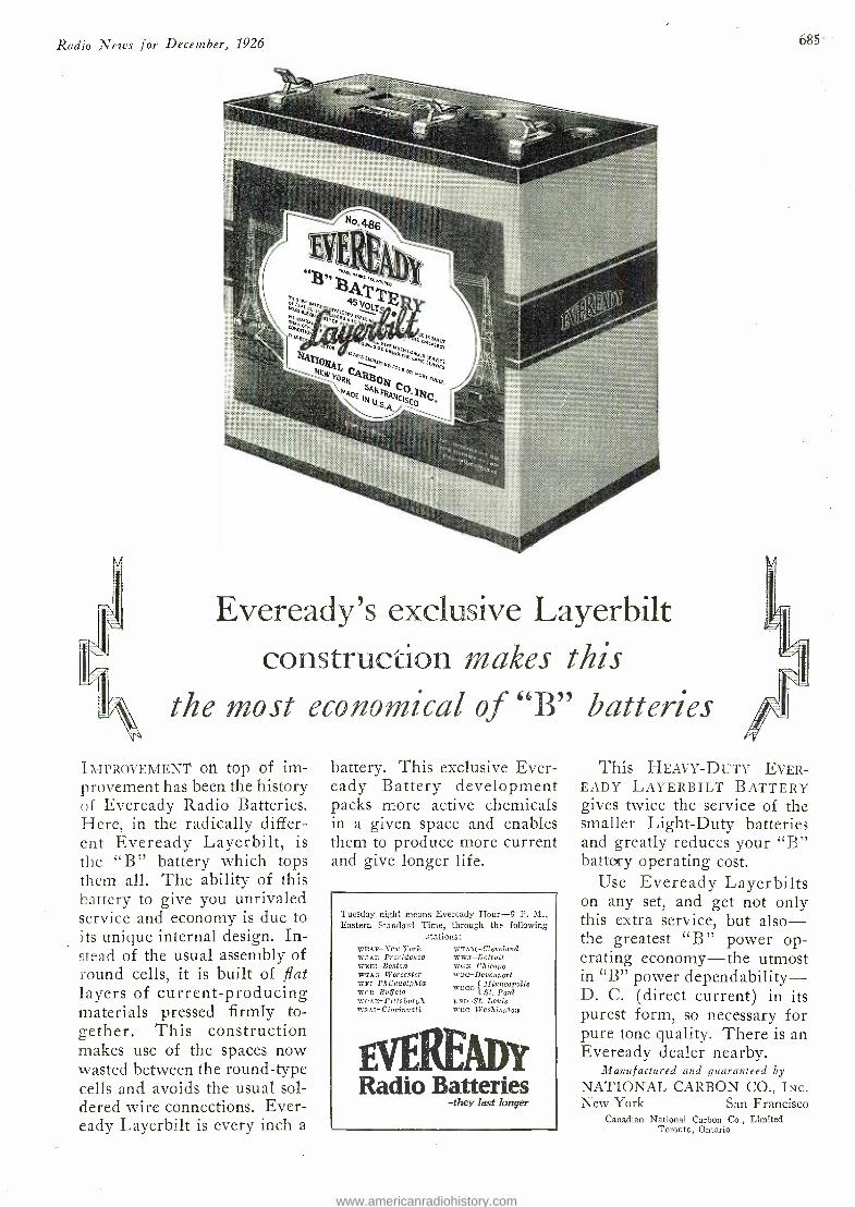
Radio News for December, 1926
Eveready's exclusive Layerbilt construction makes this
the most economical of "B" batteries
IMPROVEMENT On top of im- provement has been the history of Eveready Radio Batteries. Here, in the radically differ- ent Eveready Layerbilt, is the "B" battery which tops them all. The ability of this battery to give you unrivaled service and economy is due to its unique internal design. In- stead of the usual assembly of round cells, it is built of flat layers of current- producing materials pressed firmly to- gether. This construction makes use of the spaces now wasted between the round -type cells and avoids the usual sol- dered wire connections. Ever- eady Layerbilt is every inch a
battery. This exclusive Ever- eady Battery development packs more active chemicals in a given space and enables them to produce more current and give longer life.
Tuesday night means Eveready Hour -9 P. M., Eastern Standard Time, through the following
stations: WEAP-Sevo York waar.-Prouidcnce WEEI-BOStan wxeG-Worcester wsI-Philadelphia weit-Buff alo wCLE-Pittsburgh. wsal-Cincinnati
WTAM- Cleveiand wwa- Detroit WGN- Chicago Woe- Davenport
wee. Minneapolis St. Paul
nsn -St. Louis wcc- Washington
EvEREAADf Radio Batteries
-they last longer
685
This HEAVY -DUTY EVER - EADY LAYERBILT BATTERY gives twice the service of the smaller Light -Duty batteries and greatly reduces your "B" battery operating cost.
Use Eveready Layerbilts on any set, and get not only this extra service, but also - the greatest "B" power op- erating economy -the utmost in "B" power dependability - D. C. (direct current) in its purest form, so necessary for pure tone quality. There is an Eveready dealer nearby.
Manufactured and guaranteed by
NATIONAL CARBON CO., INc. New York San Francisco
Canadian National Carbon Co., Limited Toronto, Ontario
www.americanradiohistory.com
686
SAIL AWAY AS A
RADIO OPERATOR
RAVEL to foreign shores as a radio operator and draw good pay while you see the world.
Radio operating is fascinating work. Excellent quarters and board, the ranking of a ship's officer, and shore leave in foreign ports are among the privileges accorded to the "op ". The prom- inent radio positions held by our 8,000 graduates show the won- derful opportunities for advance- ment.
RIA conducted by RCA Radio Institute of America instruc- tion is not surpassed anywhere. The Institute is conducted by RCA and, in addition to enjoying every advantage of the world's greatest radio organization, it has seven- teen years' experience back of it.
Study at home A few months of study at home will qualify you to pass the U. S. Government Commercial Ama- teur or Broadcast License Exami- nation and start on a successful radio career.
Send in the coupon. It will bring you abooklet filledwith interesting information on license require- ments and opportunities in the radio field. It outlines our courses in detail.
Radio Institute conducts a spe- cial technicians' course for ra- dio dealers, jobbers and service men. Write for information.
Send this in -1 Radio Institute of America 324 Broadway, New York City
Please send me your free booklet. I am interested in the radio course which prepares for the Govt. Commercial, Broad- cast or Amateur License. I am interested in the technicians' course for jobbers, dealers and service men.
Name
Address .
Radio Institute of America 324 Broadway - New York City
that there are very few connections ; this is due to the fact that many are automatically made when the parts are mounted on the shield.
WIRING THE AUDIO UNIT You can now proceed to assemble and
wire the audio unit. A very good view of the bottom of the audio unit is given in Fig. 4, which shows the location and placing of soldering lugs to which connections are made.
Next mount the two sockets, Sl, placing the springs on the bottom side of the sub- panel and the tube supports on the top side of the sub- panel. The two portions of the socket are disassembled by . unscrewing the screw at the center. Be sure that the springs are . not bent, or twisted ; and in mounting the sockets be careful to assemble them so that the two halves fit together properly. As an additional check on the po- sitions of the terminals, make sure that the arrow on the socket is in the same position as shown in Fig. 6.
Next mount the two audio transformers, T,T, with their terminals in the positions as shown in Fig. 6. The location of the terminals is very important. In mounting the transformers use four % -inch 6/32 round -head machine screws, two for each instrument. The other mounting holes will be used later for mounting the unit on the baseboard.
A simple way to mount the automatic filament controls, R2, R3, so that the term- inals will be on the under side of the sub - panel, is to disassemble the clips and then use % -inch 4/36 round -head machine screws to fasten the mountings to the sub - panel, with the screws projecting on its bot- tom side. Soldering lugs can be fastened in place on the under side of the sub -panel, making the connection with the terminals of R2, R3.
Next mount the binding posts in the order shown in Figs. 1 and 6. The soldering lugs should be placed on the bottom side of the sub -panel, except for that on the "A Bat. +" binding post, which should be placed on the top side instead.
Although all the connections are shown in the same style in the layout, you will note from the photographic illustrations that practically all the wiring of the audio unit is placed underneath the sub -panel. There- fore this unit is almost completely wired by itself before installing in the set.
Begin by soldering in place wires 23, 24, 25, 26, 27 and 48. Be sure that none of the connections on the underside of the sub panel is close enough to interfere with the action of the spring sockets. Where it is necessary to cross over the sockets the wires should be carried at least a quarter of an inch away from the socket springs.
Now connect in turn wires 28, 29, 30, 31, 32, 33, 34 and 35. This completes the pre- liminary wiring of the audio unit.
You can now mount the audio unit on the baseboard as shown in Fig. 3 and make the final connections between the audio term- inals and the rest of the receiver.
In mounting the unit, use the remaining holes in the transformers, through which should be threaded 1% -inch No. 6 ;round- head wood screws. The unit should be mounted as shown, with a space of % -inch between the edge of the unit sub -panel and the shields on the one side, and 1% inches between the front edge of the sub -panel and the front panel of the receiver.
Now connect in turn wires 36, 37, 38, 39, 40, 41, 42, 43 and 44. The by -pass con- denser, C4, may now be connected to the socket terminals with wires 46 and 47. One more wire, 45, which connects the frame of the first variable condenser with the shield, completes the wiring.
PLACING THE SET IN OPERATION If you have followed the wiring instruc-
Radio News for December, 1926
omplete Parts
for the
ULTPWP e The Ultradyne is the only receiver that incorporates the "Modulation System" of radio reception. The most selective set known- capable of detecting the faintest broadcast signals, making them audible on the loud speaker. A real distance getter. Fully described in our free circular.
3-YâRm e ìrlund H1'Q
The easiest receiver on the market to as- semble. Designed and backed by the leading radio manufacturers. Every part synchronizes the most efficient
5 -tube receiver.
LC -27 Such a demand is expected for parts to build the LC -27 that we have made special arrangements to stock these com- plete parts in large quantities. Immedi- ate shipment is assured if you.order from us.
Madison Guarantee Madison offers the most unusual guarantee of any house in the radio industry. If com- plete parts to build receivers shown in our circular are ordered from us, we guarantee the receiver after you assemble it, to function as we claim. If not, we make it do so at no cost to you.
Dealers Send for Circular
Send for free circular. Shows the most complete line of nationally known radio parts and accessories.
I Madison Radio Corporation, 114 -C East 28th St., New York City.
I Please send me immediately a copy of your free I circular showing how I can save money on
standard radio parts.
! Name 1
1 Address 1
1
1
www.americanradiohistory.com
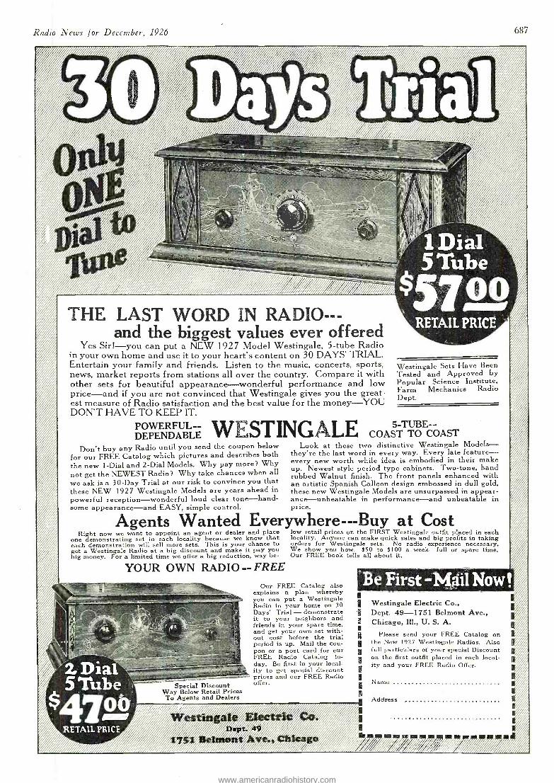
Radio News fo December, 1926 687
r.
and the biggest values ever offered Yes Sir! -you can put a NEW 1927 Model Westingale, 5 -tube Radio
in your own home and use it to your heart's content on 30 DAYS' TRIAL. Entertain your family and friends. Listen to the music, concerts, sports, news, market reports from stations all over the country. Compare it with other sets for beautiful appearance -wonderful performance and low price -and if you are not convinced that Westingale gives you the great- est measure of Radio satisfaction and the best value for the money -YOU DON'T HAVE TO KEEP IT.
1Dia1 5 Tube
5T_. RETAIL PRICE
Westingale Sets Have Been Tested and Approved by Popular Science Institute, Farm Mechanics Radio Dept.
POWERFUL -- WESTINGALE COAST TO COAST DEPENDABLE Don't buy any Radio until you send the coupon below Look at these two distinctive Westingale Models -
for our FREE Catalog which pictures and describes both they're the last word in every way. Every late feature - the new 1-Dial and 2 -Dial Models. Why pay more? Why every new worth while idea is embodied in their make
not get the NEWEST Radio? Why take chances when all up. Newest style period type cabinets. Two -tone, hand rubbed Walnut finish. The front panels enhanced with
we ask is a 30 -Day Trial at our risk to convince you that an artistic Spanish Galleon design embossed in dull gold, these NEW 1927 Westingale Models are years ahead in these new Westingale Models are unsurpassed in appear - powerful reception- wonderful loud clear tone -hand- ance- unbeatable in performance -and unbeatable in some appearance -and EASY, simple control. price.
Agents Wanted Everywhere - --Buy at Cost and place low retail prices on the FIRST Westingale ut Right now we want to appoint an agent or dealer an p p o e outfit placed in each
one demonstrating set in each locality because we know that locality. Anyone can make quick sales and big profits in taking each demonstration will sell more sets. This is your chance to orders for Westingale sets. No radio experience necessary. get a Westingale Radio at a big discount and make it pay you We show you how. $50 to $100 a week -full or spare time. big money. For a limited time we offer a big reduction, way be- Our FREE book tells all about it.
YOUR OWN RADIO -- FREE
2 Dia 5 1ube
S rRETAiL PRICE
Our FREE Catalog also explains a plan whereby you can put a Westingale Radio in your home on 30 Days' Trial - demonstrate it to your neighbors and friends in your spare time, and get your own set with- out cost before the trial period is up. Mail the cou- pon or a post card for our FREE Radio Catalog to- day. Be first in your local- ity to get special discount prices and our FREE Radio
Special Discount offer. Way Below Retail Prices
To Agents and Dealers
. / ,/ i,3 ; o/ as_: . r : // ' " i i iíA Dept.
Be First -Mail Now Westingale Electric Co., Dept. 49 -1751 Belmont Ave., Chicago, Ill., U. S. A.
Please send your FREE Catalog on the New 1927 Westingale Radios. Also full particulars of your special Discount on the first outfit placed in each local- ity and your FREE Radio Offer.
Address
iG/í%iíüiii/D/
www.americanradiohistory.com
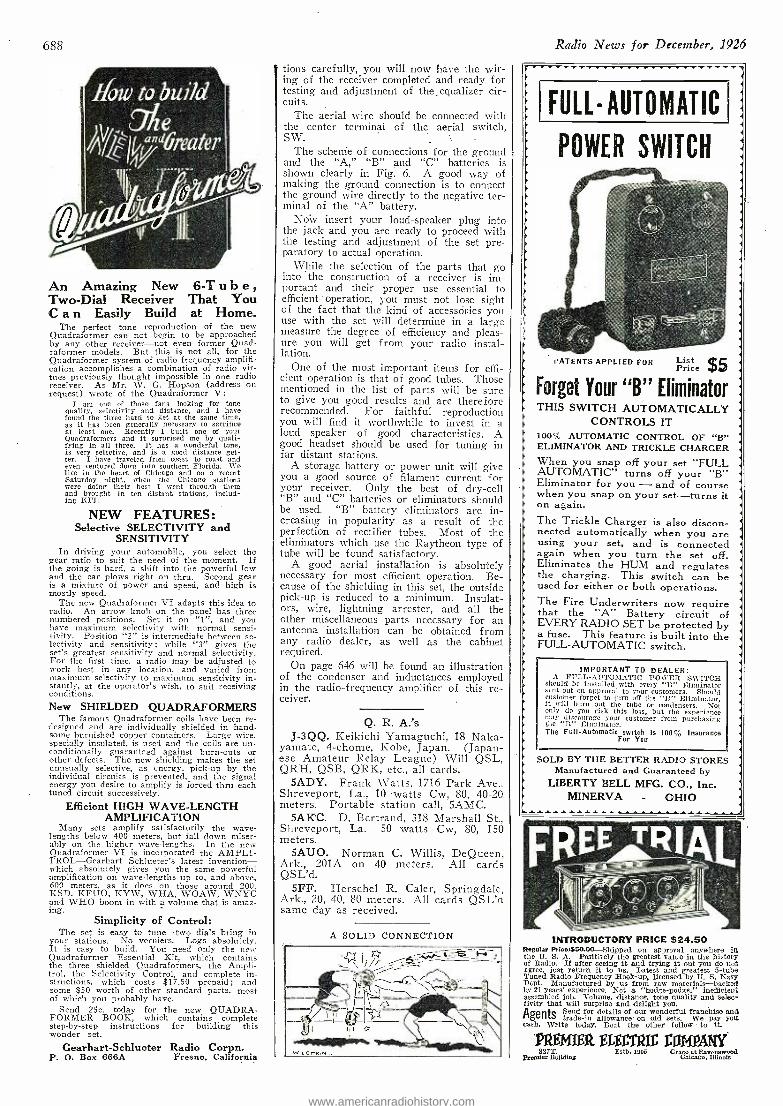
688
An Amazing New 6 -T u b e ,
Two -Dial Receiver That You C a n Easily Build at Home.
The perfect tone reproduction of the new Quadraformer can not begin to be approached by any other receiver -not even former Quad- raformer models. But this is not all, for the Quadraformer system of radio frequency amplifi- cation accomplishes a combination of radio vir- tues previously thought impossible in one radio receiver. As Mr. W. G. Hopson (address on request) wrote of the Quadraformer V:
I am one of those fans looking for tone quality, selectivity and distance, and I have found the three hard to get at the saine time, as it has been generally necessary to sacrifice at least one. Recently I built one of your Quadraformers and it surprised me by quali- fying in all three. It has a wonderful tone, is very selective, and is a good distance get- ter. I have traveled from coast to coast and even ventured down into southern Florida. We live in the heart of Chicago and on a recent Saturday night, when the Chicago stations were doing their best I went through them and brought in ten distant stations, includ- ing KFI!
NEW FEATURES: Selective SELECTIVITY and
SENSITIVITY In driving your automobile, you select the
gear ratio to suit the need of the moment. If the going is hard, a shift into the powerful low and the car plows right on thru. Second gear is a mixture of power and speed, and high is mostly speed.
The new Quadraformer VI adapts this idea to radio. An arrow knob on the panel has three numbered positions. Set it on "1 ", and you have maximum selectivity with normal sensi- tivity. Position "2" is intermediate between se- lectivity and sensitivity; while "3" gives the set's greatest sensitivity and normal selectivity. For the first time, a radio may be adjusted to work best in any location, and varied from maximum selectivity to maximum sensitivity in- stantly, at the operator's wish, to suit receiving conditions. New SHIELDED QUADRAFORMERS
The famous Quadraformer coils have been re- designed and are individually shielded in hand- some burnished copper containers. Large wire, specially insulated, is used and the coils are un- conditionally guaranteed against burn -outs or other defects. The new shielding makes the set unusually selective, as energy, pick -up by the individual circuits is prevented, and the signal energy you desire to amplify is forced thru each tuned circuit successively.
Efficient HIGH WAVE -LENGTH AMPLIFICATION
Many sets amplify satisfactorily the wave- lengths below 400 meters, but fall down miser- ably on the higher wave- lengths. In the new Quadraformer VI is incorporated the AMPLI- TROL- Gearhart Schlueter's latest invention - which absolutely gives you the same powerful amplification on wave- lengths up to, and above, 600 meters, as it does on those around 200. KSD. KFUO, KYW, WHA, WOAW, WNYC and WHO boom in with a volume that is amaz- ing.
Simplicity of Control: The set is easy to tune -two dials bring in
your stations. No verniers. Logs absolutely. It is easy to build. You need only the new Quadraformer Essential Kit, which contains the three shielded Quadraformers, the Ampli- trol, the Selectivity Control, and complete in- structions, which costs $17.50 prepaid; and some $50 worth of other standard parts, most of which you probably have.
Send 25c. today for the new QUADRA- FORMER BOOK, which contains complete step -by -step instructions for building this wonder set.
Gearhart -Schlueter Radio Corpn. P. O. Box 666A Fresno, California
tions carefully, you will now have the wir- ing of the receiver completed and ready for testing and adjustment of the, equalizer cir- cuits.
The aerial wire should be connected with the center terminal of the aerial switch, SW.
The schenie of connections for the ground and the "A," "B" and "C" batteries is shown clearly in Fig. 6. A good way of making the ground connection is to connect the ground wire directly to the negative ter- minal of the "A" battery.
Now insert your loud -speaker plug into the jack and you are ready to proceed with the testing and adjustment of the set pre- paratory to actual operation.
While the selection of the parts that go into the construction of a receiver is im- portant and their proper use essential to efficient operation, you must not lose sight of the fact that the kind of accessóries you use with the set will determine in a large measure the degree of efficiency and pleas- ure you will get from your radio instal- lation.
One of the most important items for effi- cient operation is that of good tubes. Those mentioned in the list of parts will be sure to give you good results and are therefore recommended. For faithful reproduction you will find it worthwhile to invest in a loud speaker of good characteristics. A good headset should be used for tuning in far distant stations.
A storage battery or power unit will give you a good source of filament current for your receiver. Only the best of dry -cell "B" and "C" batteries or eliminators should be used. "B" battery eliminators are in- creasing in popularity as a result of the perfection of rectifier tubes. Most of the eliminators which use the Raytheon type of tube will be found satisfactory.
A good aerial installation is absolutely necessary for most efficient operation. Be- cause of the shielding in this set, the outside pick -up is reduced to a minimum. Insulat- ors, wire, lightning arrester, and all the other miscellaneous parts necessary for an antenna installation can be obtained from any radio dealer, as well as the cabinet required.
On page 646 will be found an illustration of the condenser' and inductances employed in the radio -frequency amplifier of this re- ceiver.
Q. R. A.'s J -3QQ. Keikichi Yamaguchi, 18 Naka-
yamate, 4- chome, Kobe, Japan. (Japan- ese Amateur Relay League) Will QSL, QRH, QSB, QRK, etc., all cards.
SADY. Frank Watts, 1716 Park Ave., Shreveport, La., 10 -watts Cw, 80, 40 -20 meters. Portable station call, SAMC.
5AK'C. D. Bertrand, 318 Marshall St., Shreveport, La. - 50 watts Cw, 80, 150 meters.
5AUO. Norman C. Willis, DeQueen, Ark., 201A on 40 meters. All cards QSL'd.
5FF. Herschel R. Caler, Springdale, Ark., 20, 40, 80 meters. All cards QSL'd same day as received.
A SOLID CONNECTION
Radio News for December, 1926
FULL AUTOMATIC
POWER SWITCH
PATENTS APPLIED FOR List 5 $ Price $5 Forget Your "B" Eliminator THIS SWITCH AUTOMATICALLY
CONTROLS IT 100% AUTOMATIC CONTROL OF "B" ELIMINATOR AND TRICKLE CHARGER When you snap off your set "FULL AUTOMATIC" turns off your "B" Eliminator for you - and of course when you snap on your set -turns it on again. The Trickle Charger is also discon- nected automatically when you are using your set, and is connected again when you turn the set off. Eliminates the HUM and regulates the charging. This switch can be used for either or both operations. The Fire Underwriters now require that the "A" Battery circuit of EVERY RADIO SET be protected by a fuse. This feature is built into the FULL -AUTOMATIC switch.
IMPORTANT TO DEALER: A FULL- AUTOMIATIC POWER SWITCH
should be installed with every `13" Eliminator sent out on approval to your customers. Should customer forget to turn off the "B" Eliminator, it will burn out the tube or condensers. Not only do you risk this loss, but the experience may discourage your customer from purchasing the "B" Eliminator. The Full- Automatic switch is 100% Insurance
For You
SOLD BY THE BETTER RADIO STORES Manufactured and Guaranteed by
LIBERTY BELL MFG. CO., Inc. MINERVA - OHIO
NIL INTRODUCTORY PRICE $24.50
Regular Price,$50.00-Shipped on approval anywhere in the U. S. A. Positively the greatest value in the history of Radio. If after seeing it and trying it out you do not agree, just return it to vs. Latest and greatest 5 -tube Timed Radio Frequency Hook -up, licensed by U. S. Navy Dept, Manufactured by us from raw materials -backed by 21 years' experience. Not a "hodge- podge," inefficient assembled job. Volume, distance, tone quality and selec- tivity that will surprise and delight you.
Agents
Send for details of our wonderful franchise and trade -in allowance on old sets. We pay you
cash. Write today. Beat the other fellow to it.
'PREMIER ELE IE MOAN,/ 7T. Estb. 1905 Gr
Cincago lio s 8-'ng
www.americanradiohistory.com
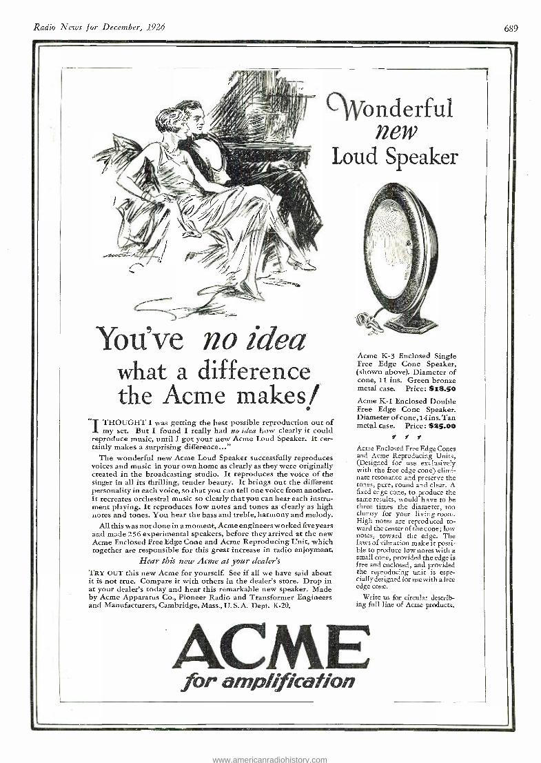
Radio News for December, 1926 6S9
You've no idea what a difference the Acme makes/
ónderful new
Loud Speaker
"T THOUGHT I was getting the best possible reproduction out of I my set. But I found I really had no idea how clearly it could reproduce music, until I got your new. Acme Loud Speaker. It cer- tainly makes a surprising difference..."
The wonderful new Acme Loud Speaker successfully reproduces voices and music in your own home as clearly as they were originally created in the broadcasting studio. It reproduces the voice of the singer in all its thrilling, tender beauty. It brings out the different personality in each voice, so that you can tell one voice from another. It recreates orchestral music so clearly that you can hear each instru- ment playing. It reproduces low notes and tones as clearly as high notes and tones. You hear the bass and treble, harmony and melody.
All this was not done in a moment, Acme engineers worked five years and made 256 experimental speakers, before they arrived at the new Acme Enclosed Free Edge Cone and Acme Reproducing Unit, which together are responsible for this great increase in radio enjoyment.
Hear this new Acme at your dealer's TRY OUT this new Acme for yourself. See if all we have said about it is not true. Compare it with others in the dealer's store. Drop in at your dealer's today and hear this remarkable new speaker. Made by Acme Apparatus Co., Pioneer Radio and Transformer Engineers and Manufacturers, Cambridge, Mass., U. S.A. Dept. K -20.
Acme K -3 Enclosed Single Free Edge Cone Speaker, (shown above). Diameter of cone, 11 ins. Green bronze metal case. Price : $18.50 Acme K -1 Enclosed Double Free Edge Cone Speaker. Diameter ofcone, l4ins. Tan metal case. Price: $25.00
V f s
Acme Enclosed Free Edge Cones and Acme Reproducing Units, (Designed for use exclusively with the free edge cone) elimi- nate resonance and preserve the tones, pure, round and clear. A fixed edge cone, to produce the same results, would have to be three times the diameter, too clumsy for your living -room. High notes are reproduced to- ward the center of the cone ; low notes, toward the edge. The laws of vibration make it possi- ble to produce low notes with a small cone, provided the edge is free and enclosed, and provided the reproducing unit is espe- cially designed for usewith a free edge cone.
Write us for circular describ- ing full line of Acme products.
ACME for amplification
www.americanradiohistory.com
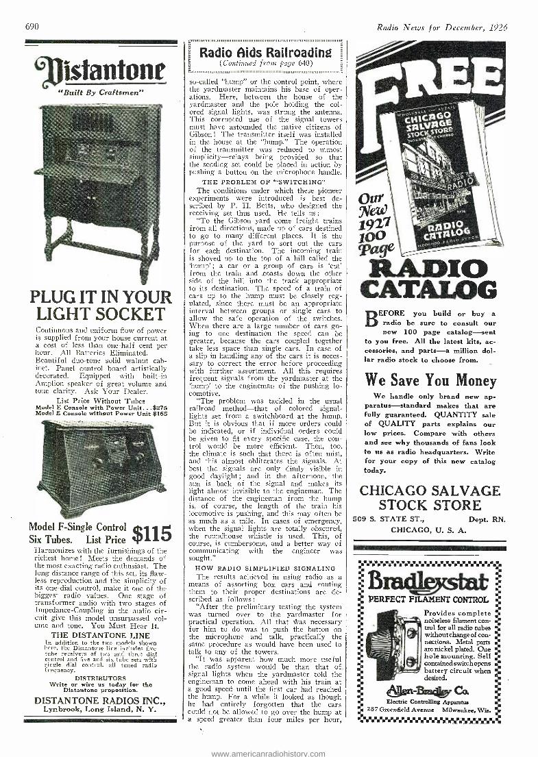
690
Iixtantone "Built By Craftsmen"
PLUG IT IN YOUR LIGHT SOCKET Continuous and uniform flow of power is supplied from your house current at a cost of less than one -half cent per hour. All Batteries Eliminated. Beautiful duo -tone solid walnut cab- inet. Panel control board artistically decorated. Equipped with built -in Amplion speaker of great volume and tone clarity. Ask Your Dealer.
List Price Without Tubes Model E Console with Power Unit...$275 Model E Console without Power Unit $165
Model F- Single Control $115 Six Tubes. List Price Harmonizes with the furnishings of the richest home ! Meets the demands of the most exacting radio enthusiast. The long distance range of this set, its flaw- less reproduction and the simplicity of its one -dial control, make it one of the biggest radio values. One stage of transformer audio with two stages of Impedance -Coupling in the audio cir- cuit give this model unsurpassed vol- ume and tone. You Must Hear It.
THE DISTANTONE LINE In addition to the two models shown here, the Distantone line includes five tube receivers of two and three dial control and five and six tube sets with single dial control, all tuned radio frequency.
DISTRIBUTORS Write or wire us today for the
Distantone proposition.
DISTANTONE RADIOS INC., Lynbrook, Long Island, N. Y.
Radio Aids Railroading (Continued from page 640)
so- called "hump" or the control point, where the yardmaster maintains his base of oper- ations. Here, between the house of the yardmaster and the pole holding the col- ored signal lights, was strung the antenna. This corrupted use of the signal towers must have astounded the native citizens of Gibson ! The transmitter itself was installed in the house at the "hump." The operation of the transmitter was reduced to utmost simplicity- relays being provided so that the sending set could be placed in action by pushing a button on the microphone handle.
THE PROBLEM OF "`SWITCHING" The conditions under which these pioneer
experiments were introduced is best de- scribed by P. H. Betts, who designed the receiving set thus used. He tells us :
"To the Gibson yard come freight trains from all directions, made up of cars destined to go to many different places. It is the purpose of the yard to sort out the cars for each destination. The incoming train is shoved up to the top of a hill called the `hump' ; a car or a group of cars is `cut' from the train and .coasts down the other side of the hill into the track appropriate to its destination. The speed of a train of cars up to the hump must be closely reg- ulated, since there must be an appropriate interval between groups or single cars to allow the safe operation of the switches. When there are a large number of cars go- ing to one destination the speed can be greater, because the cars coupled together take less space than single cars. In case of a slip in handling any of the cars it is neces- sary to correct the error before proceeding with further assortment. All this requires frequent signals from the yardmaster at the 'hump' to the engineman of the pushing lo- comotive.
"The problem was tackled in the usual railroad method -that of colored signal - lights set from a switchboard at the hump. But it is obvious that if more orders could be indicated, or if individual orders could be given to fit every specific case, the con- trol would be more efficient. Then, too, the climate is such that there is often mist, and this almost obliterates the signals. At best the signals are only dimly visible in good daylight; and in the afternoon, - the sun is back of the signal and makes its light almost invisible to the engineman. The distance of the engineman from the hump is, of course, the length of the train his locomotive is pushing, and this may often be as much as a mile. In cases of emergency, when the signal lights are totally obscured, the roundhouse whistle is used. This, of course, is cumbersome, and a better way of communicating with the engineer was sought."
HOW RADIO SIMPLIFIED SIGNALING The results achieved in using radio as a
means of assorting box cars and routing them to their proper destinations are de- scribed as follows:
"After the preliminary testing the system was turned over to the yardmaster for practical operation. All that *as necessary for him to do was to push the button on the microphone and talk, practically the same procedure as would have been used to talk to any of the towers.
"It was apparent how much more useful the radio system would be than that of_ signal lights when the yardmaster told the engineman to come ahead with his train at a good speed until the first car had reached the hump. For a while it looked as though he had entirely forgotten that the cars could not be allowed to go over the hump at a speed greater than four miles per hour,
Radio - News for December, 1926
RADIO CATALOG
BEFORE you build or buy a radio be sure to consult our new 100 page catalog -sent
to you free. All the latest kits, ac- cessories, and parts -a million dol- lar radio stock to choose from.
We Save You Money We handle only brand new ap-
paratus- standard makes that are fully guaranteed. QUANTITY sale of QUALITY parts explains our low prices. Compare with others and see why thousands of fans look to us as radio headquarters. Write for your copy of this new catalog today.
CHICAGO SALVAGE STOCK STORE
509 S. STATE ST., Dept. RN. CHICAGO, U. S. A.
%%%%%%%%%%%%%%%%%%%%%%%%%%
-a
ti 61krrilealt9r Ca Electric Controlling Apparatus
as 287 Greenfield Avenue Milwaukee, Wis.
ti PERFECT FILAMENT CONTROL
Provides complete % noiseless filament con - T trol for all radio tubes ". withoutchangeof con- ti nections. Metal parts T are nickel plated. One ti hole mounting. Self ¡a contained switch opens a. battery circuit when . desired.
www.americanradiohistory.com
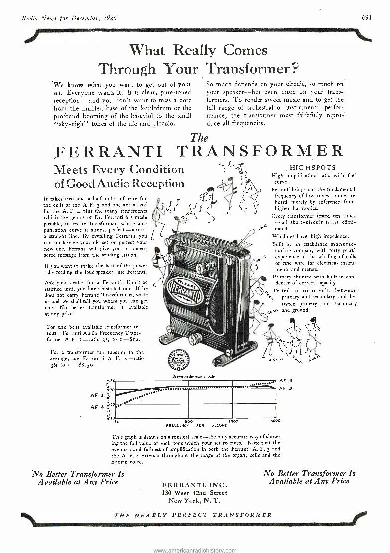
HIGHS POTS High amplification ratio with flat
curve. Ferranti brings out the fundamental
frequency of low tones -none are heard merely by inference from higher harmonics.
Every transformer tested ten times - all short -circuit turns elimi- nated.
Windings have high impedence.
Built by an established manufac- turing company with forty years' experience in the winding of coils of fine wire for electrical instru- ments and meters.
Primary shunted with built -in con- denser of correct capacity
Tested to too() volts between o primary and secondary and be-
tween primary and secondary and ground,
Drawn on the musical scale
4 20
Radio News for December, 1926 691
limmaimmemePwr
What Really Comes Through Your Transformer?
We know what you want to get out of your set. Everyone wants it. It is clear, pure -toned reception -and you don't want to miss a note from the muffled base of the kettledrum or the profound booming of the baseviol to the shrill "sky- high" tones of the fife and piccolo.
So much depends on your circuit, so much on your speaker -but even more on your trans- formers. To render sweet music and to get the full range of orchestral or instrumental perfor- mance, the transformer must faithfully repro- duce all frequencies.
The
FERRANTI TRANSFORMER Meets Every Condition of Good Audio Reception
It takes two and a half miles of wire for the coils of the A. F. 3 and one and a half for the A. F. 4 plus the many refinements which the genius of Dr. Ferranti has made possible, to create transformers whose am- plification curve is almost perfect - almost a straight line. By installing Ferrantis you can modernize your old set or perfect your new one. Ferranti will give you an uncen- sored message from the sending station.
If you want to make the best of the power tube feeding the loud speaker, use Ferranti.
Ask your dealer for a Ferranti. Don't be
satisfied until you have installed one. If he does not carry Ferranti Transformers, write us and we shall tell you where you can get one. No better transformer is available at any price.
For the best available transformer re- sults- Ferranti Audio Frequency Trans- former A.F. 3 -ratio 3% to I -$I2.
For a transformer far superior to the average, use Ferranti A. F. 4 -ratio 3% to I- $8.5o.
03E
0:30 AF 3 ó
AF rr0 1*
Y.
r
,.....Y.YY
.
........ t ...
l0 50 500 2000
FREQUENCY PER SECOND
AF 4
AF 3
a000
This graph is drawn on a musical scale -the only accurate way of show- ing the full value of each tone which your set receives. Note that the evenness and fullness of amplification in both the Ferranti A. F. 3 and the A. F. 4 extends throughout the range of the organ, cello and the human voice.
No Better Transformer Is Available at Any Price FERRANTI, INC.
130 West 42nd Street New York, N. Y.
No Better Transformer Is Available at Any Price
THE NEARLY PERFECT TRANSFORMER
www.americanradiohistory.com
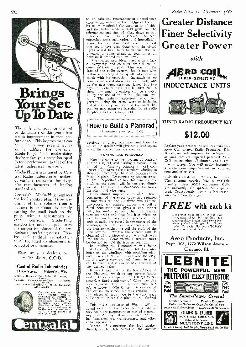
692
Briiuis Your UpTo Date The only real advance claimed by the makers of this year's best sets is improvement in tone per- formance. This improvement can be made in your present set by simply adding the Centralab Modu -Plug. This modernizing device makes your reception equal in tone performance to that of the latest high -priced receivers.
Modu -Plug is warranted by Cen- tral Radio Laboratories, makers of variable resistances for sixty - nine manufacturers of leading standard sets.
Centralab Modu -Plug replaces the loud speaker plug. Gives any degree of tone volume from a whisper to maximum by simply turning the small knob on the plug, without adjustments of other controls. Modu -Plug matches the speaker impedance to the output impedance of the set. Reduces interfering noises. Clar- ity and faithful reproduction equal the latest developments in perfected performance.
$2.50 at your dealer's, or mailed direct, C.O.D.
Central Radio Laboratories 19 Keefe Ave., Milwau:tee, Wis.
Canadian Representative- Irving W. Levine, Montreal.
Australian Representative- United Distributors, Ltd., Sydney.
Great Britain Representative -R. A. Rothermel, Ltd., London.
Centralab Radiohm permits clear, true -tone reception by holding the sensitive re- generative position whirls immediately precedes the oscillation point, without distortion or loss of selec- tivity. A standard unit on leading sets. Retail price, $2.00, at your dealer's or from us C.O.D.
as the train was approaching at a speed very close to ten miles per hour. One of the car inspectors reminded the yardmaster of this, and the latter made a wild grab for the microphone and shouted `Slow down to two miles an hour.' The enginemán had been expecting some such order, and immediately slowed the train down as directed. The best that could have been done with the signal lights would have been to instruct the en- gineman to come ahead at four miles an hour until ordered to slow down.
"Very often new ideas meet with a lack of sympathy, and consequently fail to ac- complish' their purpose. This was not the fate of the radio system, for it met with enthusiastic recognition by all, who were in touch with its operation. Inasmuch as no commercial installation has been made, and as the first demonstrations lasted but two days, no definite data can be advanced to show how much operation can be speeded up by the use of the radio telephone sys- tem. The railway engineers, who were present during the tests, were enthusiastic, and it may very well be that this small be- ginning may mean the introduction of radio telephony to the railway field."
:,,,,llit,m,,,I,,,,,11.111111111111111111111111111111,1111111111111,1,1111,,,,1,11,,,1,,,,,1,1111,11111111,11. 1.11,101
How to Build a Pianorad (Continued from page 655)
V. [,u,ui,il,,,,, ,, , 11 1,11111111111111111111101,111
nections is to try one way and then the other ; the speaker will give out a loud squeal when the connections are correct.
TUNING THE PIANORAD
Now we come to the problem of control- ling this squeal, and making a musical tone out of it. First we connect a fixed con- denser (C)) across the secondary winding as shown ; immediately the squeal becomes much lower in pitch. By connecting condensers of different capacities across this winding; the pitch of the squeal will be correspondingly varied. The larger the condenser, the lower the pitch, and vice versa.
It is almost impossible to obtain fixed condensers of the exact capacities required to tune the circuit to a definite musical tone. Therefore, we connect across the coil a fixed condenser that gives a note rather near, but higher in pitch than the musical tone required ; and then fine iron wires, or for that matter any small pieces of iron such as nails, are placed in the center of the windings, where the core was originally. As the iron approaches the coil the pitch of the tone lowers. Perhaps the correct note is obtained with a piece of iron wire half way into the coil. Some means, therefore, must be devised to hold the iron in position.
In building the Pianorad it was found that the simplest method is to fill the center holes of the windings with modeling clay, and then stick the iron wires into the clay. In this way a very gradual change in pitch can be made and it can be held constant at any desired value.
It was found that for the lowest' tone of the Pianorad, which is one octave below middle C, or a frequency of 128 cycles per second, a fixed condenser of .02 -of. capacity was - required. For the highest note, one octave above middle C, or a frequency of 512 cycles, no condenser was required. A few pieces of iron wire in the core were sufficient to lower the pitch to the desired value.
This audio oscillator of Fig. 1 will be found useful in the experimenter's labora- tory for other purposes than that of generat- ing musical tones. It may be used for test- ing loud -speakers, transformers, and other radio apparatus.
Instead of connecting the loud- speaker directly in the plate circuit of the vacuum
Radio News for December, 1926
Greater Distance Finer Selectivity Greater Power
with
gUPENg1TO!1111.1411
INDUCTANCE UNITS
TUNED RADIO FREQUENCY KIT
$12.00 Replace your present inductances with this Aero Coil Tuned Radio Frequency Kit. It will positively improve the performance of your receiver. Special patented Aero Coil construction eliminates radio fre- quency losses. You will notice instantly, a tremendous improvement in volume, tone and selectivity.
This kit consists of three matched units. The antenna coupler has a variable primary. Uses .00035 condenser. Coils are uniformly air spaced. No dope is used. Consequently they tune into reson- ance on a "knife's edge."
FREE with each kit Eight page color circuit, layout and instruction sheet for building the super- sensitive 5 tube Aero -Dyne Re- ceiver packed with each kit. Extra copies, 75c each. Get yours TODAY from your nearest dealer.
Aero Products, Inc. Dept. 105, 1772 Wilson Avenue
Chicago, Ill.
LEBN ITE THE POWERFUL NEW
MULTIPOINT FIXT DETECTOR 75c - 75c Post 1
QIt+T ` ¡ 11 Post Ix J" Paid = Paid
The Super -Power Crystal Double Volume Double Distance Perfect for Reflex - Great for Crystal Sets
From your dealer or direct. Dealers write for discounts
PALMER 86 PALMER 404 W. Utica St. Buffalo, N. Y.
Makers of the Famous
MULTIPOINT LINE Kennedy & Kennedy, 1442 YonneSt., Toronto, Ont., Enclo. Can. Disto.
V ï www.americanradiohistory.com
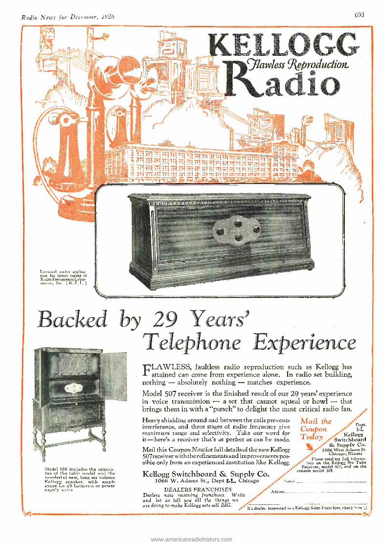
Radio News for Decenwer, 1926 693
_
,-r'54-ret
Licensed under applica- tion for letters patent of Radio Frenquency Labor- atories, Inc. [ R. F. L.
KELLOGG glawless Reproduction.,
1 f adio -
kl)V-944.itQ
,r71311 7;i3U
ft r41114_11117141177 1711117179 .-1-T111111117111 .711Zi T413 'PI, ri 111 ir 4171143111i izi:11111-1` lZi pri.9 - 11,7 _
- - - ;1% 111 '4'4it 141774 3;1771M 7133,77.!:;1 tra,114,13, 1T4N Tr, 211111 :r1 171 7,13 VI 13I :17 .11 i3 1a MITI VA
ZU E.7.0-
iijOilf17.1i,f11,4,1tioekt4A,S,til t4t4i1 " ' o ait iiq,,tliii
Backed by 29 Years' Telephone Experience
Model 508 includes the appara- tus of the table model and the wonderful new, long air column Kellogg speaker, with ample space for all batteries or power supply units.
sr-
"CLAWLESS, faultless radio reproduction such as Kellogg has I. attained can come from experience alone. In radio set building, nothing - absolutely nothing - matches experience.
Model 507 receiver is the finished result of our 29 years' experience in voice transmission - a set that cannot squeal or howl - that brings them in with a "punch" to delight the most critical radio fan.
Heavy shielding around and between the coils prevents Mai/ the interference, and three stages of radio frequency give Coupon . rat- maximum range and selectivity. Take our word for it - here's a receiver that's as perfect as can be made.
, Kellogg T
Mail this Coupon Now for full details of the new Kellogg da"
y.....06L.'S swuiptcphlbyocarod.
7. 1066 West Adams St.
ease send me full informa- 507receiver with the refinements and improvements pos- *
.... Chicago, Illinois
informa- sible only from an experienced institution like K ellogg. ...` tien on the Kellogg Six Tube
. Pl
.... Receiver, model 507, and on the ...
Kellogg Switchboard & Supply Co. console model 508.
..... 1066 W. Adams St., Dept 1.1, Chicago * Name
DEALERS FRANCHISES ...**
Dealers now receiving franchises. Write .0! ' Address
and let us tell you all the things we .., are doing to make Kellogg sets sell BIG.
0****If a dealer, interested in a Kellogg Sales Franchise, check here
www.americanradiohistory.com
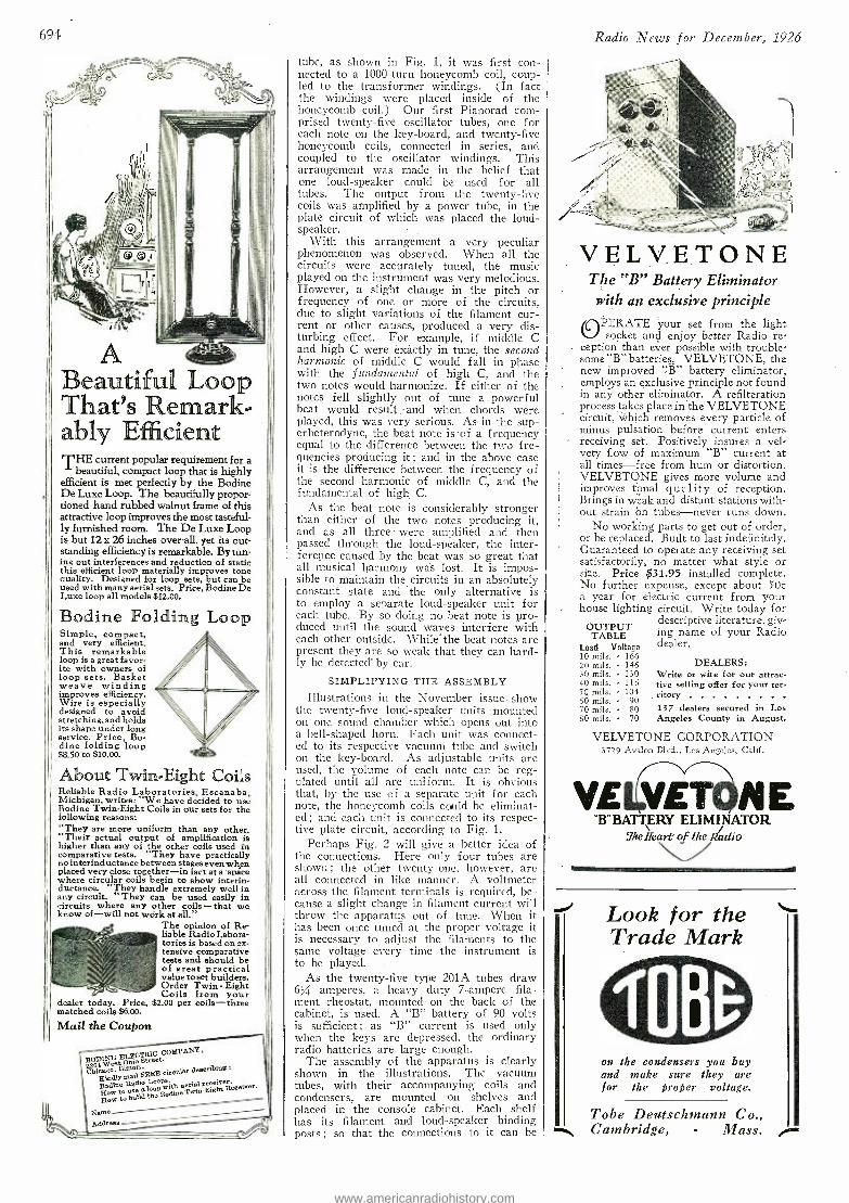
694
A eautiful Loop
That's Remark. ably Efficient THE current popular requirement for a
beautiful, compact loop that is highly efficient is met perfectly by the Bodine De Luxe Loop. The beautifully propor- tioned hand rubbed walnut frame of this attractive loop improves the most tasteful- ly furnished room. The De Luxe Loop is but 12 x 26 inches over -all, yet its out- standing efficiency is remarkable. By tun- ing out interferences and reduction of static this efficient loop materially improves tone quality. Designed for loop sets, but can be used with many aerial sets. Price, Bodine De Luxe loop all models $12,00.
Bodine Folding Loop Simple, Compact, and very efficient. This remarkable loop is a great favor- ite with owners of loop sets. Basket weave winding improves efficiency. Wire is especially designed to avoid stretching, and holds its shape under long service. Price, Bo- dine folding loop $8.50 to $10.00.
About Twin-Eight Coi;.s Reliable Radio Laboratories, Escanaba, Michigan, writes:' We have decided to use Bodine Twin -Eight Coils in our sets for the following reasons: "They are more uniform than any other. "Their actual output of amplification is higher than any of the other coils used in comparative tests. They have practically no interinductance between stages even when placed very close together -in fact at a'spice where circular coils begin to show interin- ductance. They handle extremely well in any circuit. They can be used easily in circuits where any other coils -that we know of -will not wórk at all."
The opinion of Re- liable Radio Labora- tories is based on ex- tensive comparative tests and should be of great practical value to set builders. Order Twin - Eight Coils from your
dealer today. Price, $2.00 per coils -three matched coils $6.00.
Mail the Coupon
EDNEOET C e tC.
OMAY
Chicago. Illinois. FREE circular describing:
xk,dlr mai Bodine
use L000ps.
Bow to aerial receiver.
flow build s
ow to d the Bodine Twin- Bight
Name Address
tube, as shown in Fig. 1, it was first con- nected to a 1000 -turn honeycomb coil, coup- led to the transformer windings. (In fact the windings were placed inside of the honeycomb coil.) Our first Pianorad com- prised twenty -five oscillator tubes, one for each note on the key -board, and twenty -five honeycomb coils, connected in series, and coupled to the oscillator windings. This arrangement was macle in the belief that one loud- speaker could be used for all tubes. The output from the twenty -five coils was amplified by a power tube, in the plate circuit of which was placed the loud- speaker.
With this arrangement a very peculiar phenomenon was observed. When all the circuits were accurately tuned, the music played on the instrument was very melodious. However, a slight chänge in the pitch or frequency of one or more of the circuits, due to slight variations of the filament cur- rent or other causes, produced a very dis- turbing effect. For example, if middle C and high C were exactly in tune, the second harmonic of middle C would fall in phase with the fundamental of" high C, and the two notes would harmonize. If either of the notes fell slightly out of tune a powerful beat would result and when chords were played, this was very serious. As in the sup- erheterodyne, the beat note is of a frequency equal to the difference between the two fre- quencies producing it ; and in the above case it is the difference between the frequency of the second harmonic of middle C, and the fundamental of high C.
As the beat note is considerably stronger than either of the two notes producing it, and as all three were amplified and then passed through the loud -speaker, the inter- ference caused by the beat was so great that all musical harmony was lost. It is impos- sible to maintain the circuits in an absolutely constant state and the only alternative is to employ a separate loud- speaker unit for each tube. By so doing no beat note` is pro- duced until the sound waves interfere with each other outside. While the beat notes are present they are so weak that they can hard- ly be detected' by ear.
SIMPLIFYING THE ASSEMBLY
Illustrations in the November issue show the twenty -five loud- speaker units mounted on one sound chamber which opens out into a bell - shaped horn. Each unit was connect- ed to its respective vacuum tube and switch on the key- board. As adjustable units are used, the volume of each note can be reg- ulated until all are uniform. It is obvious that, by the use of a separate unit for each note, the honeycomb coils could be eliminat- ed ; and each unit is connected to its respec- tive plate circuit, according to Fig. 1.
Perhaps Fig. 2 will give a better idea of the connections. Here only four tubes are shown ; the other twenty -one, however, are all connected in like manner. A voltmeter across the filament terminals is required, be- cause a slight change in filament current will throw the apparatus out of tune. When it has been once tuned at the proper voltage it is necessary to adjust the filaments to the same voltage every time the instrument is to be played.
As the twenty -five type 201A tubes draw 6% amperes, a heavy duty 7- ampere fila- ment rheostat, mounted on the back of the cabinet, is used. A "B" battery of 90 volts is sufficient ; as "B" current is used only when the keys are depressed, the ordinary radio batteries are large enough.
The assembly of the apparatus is clearly shown in the illustrations. The vacuum tubes, with their accompanying coils and condensers, are mounted on shelves and placed in the console cabinet. Each shelf has its filament and loud- speaker binding posts ; so that the connections to it can be
Radio News for December, 1926
VELV_ETONE The "B" Battery Eliminator with an exclusive principle OPERATE 'your set from the light
socket and enjoy better Radio re- ception than ever possible with trouble- some "B" batteries. VELVETONE, the new improved "B" battery eliminator, employs an exclusive principle not found in any other eliminator. A refilteration process takes place in the VELVETONE circuit, which removes every particle of minus pulsation before current enters receiving set. Positively insures a vel- vety flow of maximum "B" current at all times -free from hum or distortion. VELVETONE gives more volume and improves tonal quality of reception. Brings in wëak and distant stations with- out strain bn tubes -never runs down.
No working parts to get out of order, or be replaced. Built to last indefinitely. Guaranteed to operate any receiving set satisfactorily, no matter what style or size. Price $31.95 installed complete. No further expense, except about 50c a year for electric current from your house lighting circuit. Write today for
descriptive literature, giv- ing name of your Radio dealer.
OUTPUT TABLE
Load Voltage 10 mils. 166 20 mils. 146 30 mils. 130 40 mils. 116 50 mils. 104 60 mils. 90 70 mils. 80 137 dealers secured in Los 80 mils. 70 Angeles County in August.
DEALERS: Write or wire for our attrac- tive selling offer for your ter-
. ritory
VELVETONE CORPORATION 3729 Avalon Blvd., Los Angeles, Calif.
VELIVETOII E "BBATTpRY ELIMINATOR
YIæHeart o f the Radio
NUNN
Look for the Trade Mark
on the condensers you buy and make sure they are for the proper voltage.
Tobe Deutschmann Co., Cambridge, - Mass.
www.americanradiohistory.com
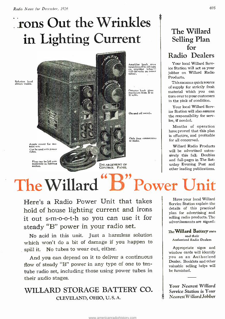
Radio News for December, 1926 695
Irons Out the Wrinkles in Lighting Current
Solution level always visible.
Ample power for ten - tube sets. Can be used with power tubes.
Plug can be left per- manently in lighting socket. ENLARGEMENT OF
CONTROL PANEL
Amplifier knob gives range from 65 to 115 volts on amplifier tubes - (120.160 volts on power tubes).
Detector knob gives regulation from 10 to 70 volts.
On and off switch.
Only four connections to make.
The Willard Selling Plan
for Radio Dealers
Your local Willard Serv- ice Station will act as your jobber on Willard Radio Products.
This means a quick source of supply for strictly fresh material which you can turn over to your customers in the pink of condition.
Your local Willard Serv- ice Station will also assume the responsibility for serv- ice, if needed.
Months of operation have proved that this plan is effective, and profitable for all concerned.
Willard Radio Products will be advertised exten- sively this fall. Doubles and full -pages in The Sat- urday Evening Post and other leading publications.
The Willard D Power Unit Here's a Radio Power Unit that takes hold of house lighting current and irons it out s- m- o -o -t -h so you can use it for steady "B" power in your radio set.
No acid in this unit. Just a harmless solution which won't do a bit of damage if you happen to
spill it. No tubes to wear out, either.
And you can depend on it to deliver a continuous flow of steady "B" power in any type of one to ten - tube radio set, including those using power tubes in
their audio stages.
WILLARD STORAGE BATTERY CO. CLEVELAND, OHIO, U. S. A.
Have your local Willard Service Station explain the details of this practical plan for advertising and selling radio products. The advertisements are signed:
TheWillard Battery men and their
Authorized Radio Dealers
Appropriate signs and window cards will identify you as an Authorized Dealer. Booklets and other valuable selling helps will be furnished.
Your Nearest Willard Service Station is Your NearestWillard Jobber
www.americanradiohistory.com
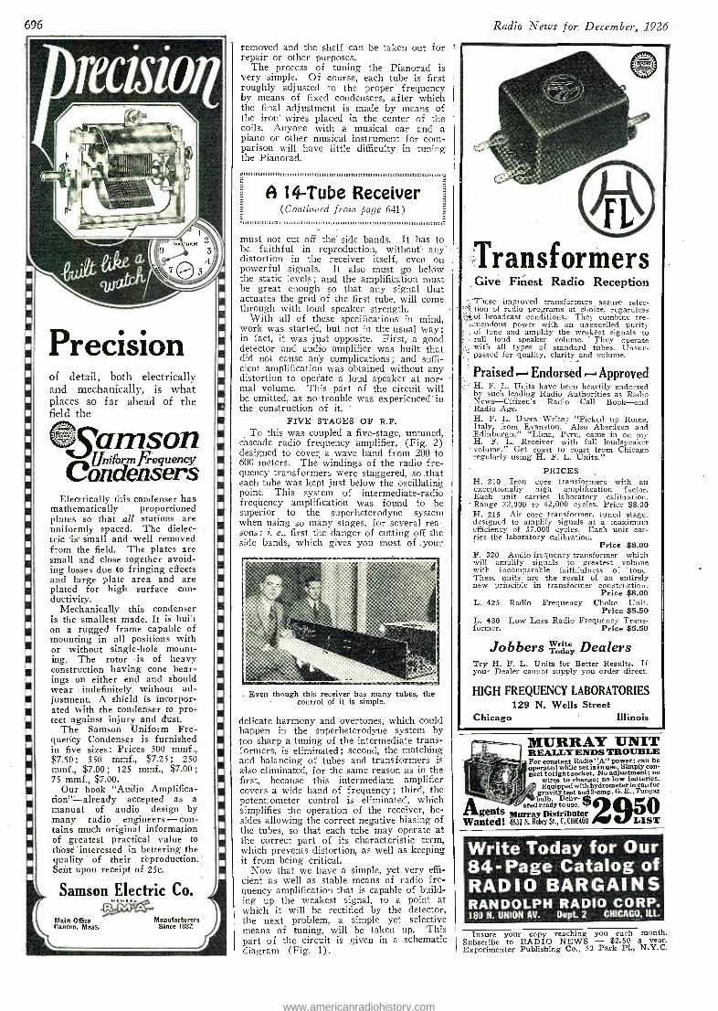
696
J1,1)11111111111 111,011
Precision of detail, both electrically and mechanically, is what places so far ahead of the field the
@Samson Uni %rmFequeney
Condensers Electrically this condenser has
mathematically proportioned plates so that all stations - are uniformly spaced. The dielec- tric is small and well removed from the field. The plates are small and close together avoid- ing losses due to fringing effects and large plate area and are plated for high surface con- ductivity.
Mechanically this condenser is the smallest made. It is built on a rugged frame capable of mounting in all positions with or without single -hole mount- ing. The rotor is of heavy construction having cone bear- ings on either end and should wear .: indefinitely; without ad- justment. A shield is incorpor- ated with the condenser to pro- tect against injury and dust.
The Samson Uniform Fre- quency Condenser is furnished in five sizes: Prices 500 mmf., $7.50 ; : 350 mmf., $7.25 250 mmf., $7.00 ; 125 mmf., $7.00; 75 mmf., $7.00.
Our book "Audio Amplifica- tion"= already accepted as a manual of audio design by many radio engineers - con- tains much original information of greatest practical value to those - interested in bettering the quality of their reproduction. Sent upon receipt of 25e.
Samson Electric El}eccttric Co.
Main Office Manufacturers Canton, Mass. Since 1882
removed and the shelf can be taken out for repair or other purposes.
The process of tuning the Pianorad is very simple. Of course, each tube is first roughly adjusted to the proper frequency by means of fixed condensers, after which the final adjustment is made by means of the iron wires placed in the center of the coils. Anyone with a musical ear and a piano or other musical instrument for com- parison will have little difficulty in tuning the Pianorad. Ein 1w.nnuniiiiiiinniuumuiniimn.m1.nmmIImmvrtnnmm.mo. nmumirtnmvin.ii
A 14 -Tube Receiver (Continued frost page 641) i
must not cut off the side bands. It has to be faithful in reproduction, without any' distortion in the receiver itself; even on powerful signals. It also must go below the static levels ; and the amplification must be great enough so that any signal that actuates the grid of the first tube, will come through with loud speaker strength.
With all of these specifications in mind, work was started, but not in the usual way; in fact, it was just opposite. First, a good detector and audio amplifier was built that did not cause any complications ; and suffi- cient amplification was obtained without any distortion to operate a loud speaker at nor - -
mal volume. This part of the circuit will be omitted, as no trouble was experienced in the construction of it.
FIVE STAGES OF R.F. To this was coupled 'a five -stage, untuned,
cascade radio frequency amplifier, (Fig. 2) designed to cover a wave band from 200 to 600 meters. The windings of the radio fre- quency transformers were staggered, so ,that each tube was kept just below the oscillating point. This system of intermediate -radio frequency amplification was found to be superior to the superheterodyne system when using so many stages, for several rea- sons : i. e., first the danger of cutting off the side bands, which gives you most of your
Even though this receiver has many tubes, the control of it is simple.
delicate harmony and overtones, which could happen in the superheterodyne system by too sharp a tuning of the intermediate trans- formers, is eliminated ; second, the matching and balancing of tubes and transformers is also eliminated, for the same reason as in the first, because this intermediate amplifier covers a wide band of frequency; third, the potentiometer control is eliminated, which simplifies the operation of the receiver, be- sides allowing the correct negative biasing of the tubes, so that each tube may operate at the correct part of its characteristic term, which prevents distortion, as well as keeping it from being critical.
Now that we have a simple, yet very effi- cient as well as stable means of radio fre- quency amplification that is capable of build- ing up the weakest signal, to a point at which it will he rectified by the detector, the next problem, a simple yet selective means of tuning, will be taken up. This part of the circuit is given in a schematic diagram (Fig. 1).
Radio News or December, 1926
Transformers Give Finest Radio Reception These improved transformers assure selec- tion of radio programs at choice, regardless of broadcast conditions. They combine tre- mendous power with an unexcelled purity of tone and amplify the weakest signals to full loud speaker volume. They operate with all types of standard tubes. Unsur- passed for quality, clarity and volume.
Praised -.Endorsed --Approved H. F. L. Units have been heartily endorsed by such leading Radio Authorities as Radio News- Citizen's Radio Call Book -and Radio Age. H. F. L. Users Write: "Picked up Rome, Italy, from Evanston. " Also Aberdeen and Edinburgh." "Lima, Peru, came in on my H. F. L. Receiver with full loudspeaker volume." Get coast to coast from Chicago regularly using H. F. L. Units."
PRICES H. 210 Iron core transformers - -with an exceptionally high amplification factor. Each unit carries laboratory calibration. Range 32,000 to 42,000 cycles. Price $8.00 H. 215 Air core transformer, tuned stage, designed to amplify signals at a maximum efficiency of 37,000 cycles. Each unit car- ries the laboratory calibration.
Price $8.00 F. 320 Audio frequency transformer which will amplify signals to greatest volume with incomparable faithfulness of tone. These units are the result of an entirely new principle in transformer construction.
Price $8.00 L. 425 Radio Frequency Choke Unit.
Price $5.50 L. 430 Low Loss Radio Frequency Trans- former. Price $5.50
Jobbers Write Dealers Today
Try H. F. L. Units for Better Results. If your Dealer cannot supply you order direct.
HIGH FREQUENCY LABORATORIES 129 N. Wells Street
Chicago Illinois
MURRAY UNIT REALLY ENDS TROUBLE For constant Radio "A" power; can be operated while set is in use. Simply con- nect tolight socket. No adjustment; no
wires to change; no low batteries. Equipped with hydrometer in cap for
gravity test and 2 -amp. G. E.. Tungar .
bulb. Deliv- ered ready to use. P
Agents Murray Distributor Wanted: 4837 N. Robe SL, f, CHICAGO /11 V LIST
50
Write Today for Our 84-Page Catalog of RADIO BARGAINS RANDOLPH RADIO CORP. 180 N. UNION AV. Dept. 2 CHICAGO, ILL.
Insure your copy reaching you each month. Subscribe to RADIO NEWS - $2.50 a year. Experimenter Publishing Co., 53 Park Pl., N.Y.C.
www.americanradiohistory.com
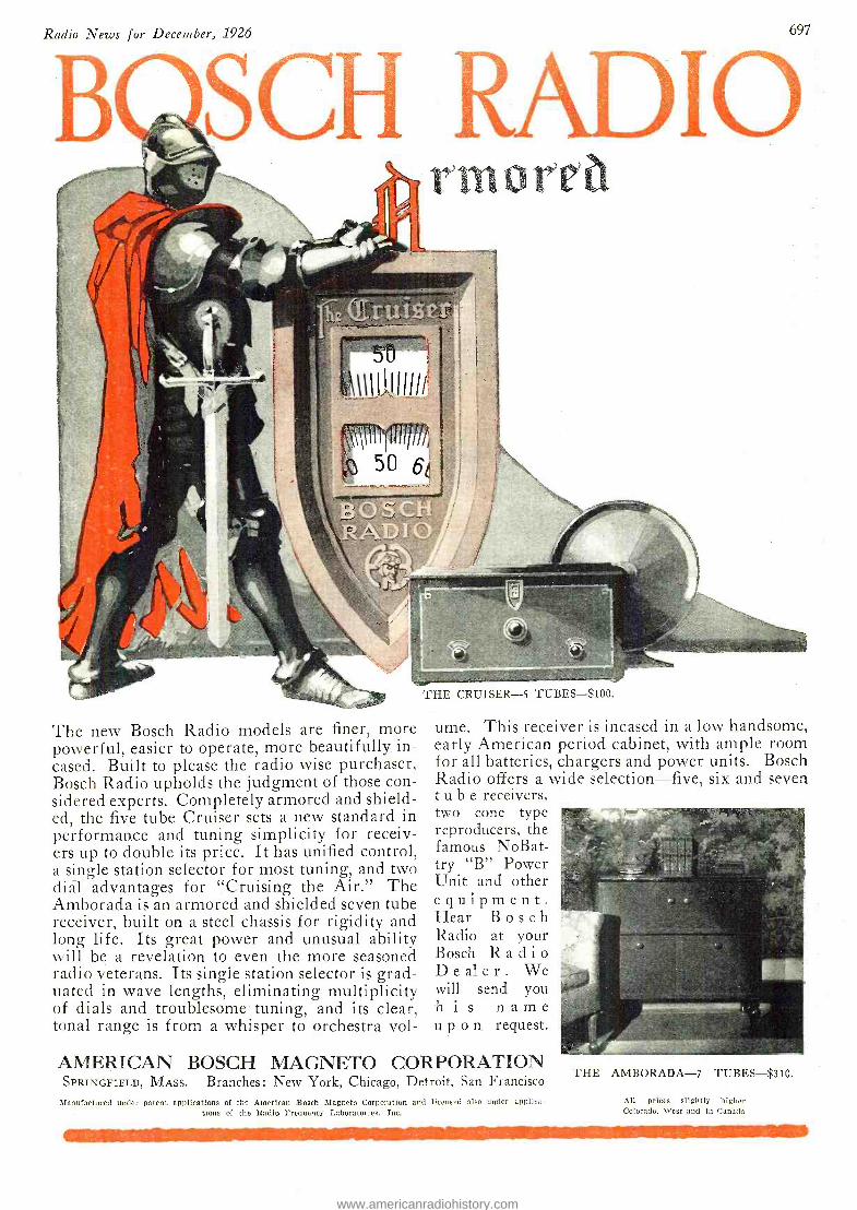
Radio News for December, 1926
E
697
SCh ADIC rmorea
The new Bosch Radio models are finer, more powerful, easier to operate, more beautifully. in- cased. Built to please the radio wise purchaser, Bosch Radio upholds the judgment of those con- sidered experts. Completely armored and shield- ed, the five tube Cruiser sets a new standard in performance and tuning simplicity for receiv- ers up to double its price. It has unified control, a single station selector for most tuning, and two dial advantages for "Cruising the Air." The Amborada is an armored and shielded seven tube receiver, built on a steel chassis for rigidity and long life. Its great power and unusual ability will be a revelation to even the more seasoned radio veterans. Its single station selector is grad- uated in wave lengths, eliminating multiplicity of dials and troublesome tuning, and its clear, tonal range is from a whisper to orchestra vol-
THE CRUISER -5 TUBES -$100.
urne. This receiver is incased in a low handsome, early American period cabinet, with ample room for all batteries, chargers and power units. Bosch Radio offers a wide selection -five, six and seven tube receivers, two cone type reproducers, the famous NoBat- try "B" Power Unit and other equipment. Hear Bosch Radio at your Bosch Radio Dealer. We will send you his name upon request.
AMERICAN BOSCH MAGNETO CORPORATION SPRINGFIELD, MASS. Branches: New York, Chicago, Detroit, San Francisco
Manufactured under patent applications of the American :Bosch Magneto Corporation and licensed also under apolica- tions of the Radio Frequency Laboratories, Inc.
THE AMBORADA -7 TUBES -$310.
All prices slightly higher Colorado, West and in Canada
www.americanradiohistory.com
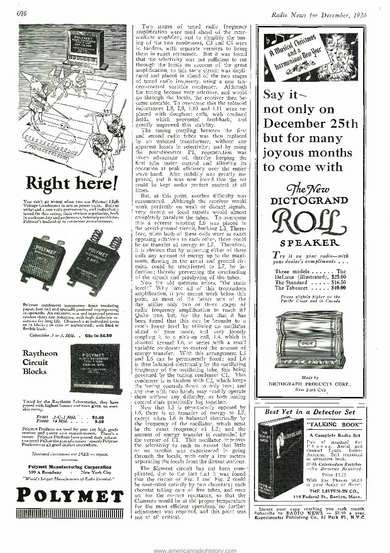
698
Right here( You can't go wrong when you use Polymet High Voltage Condensers in sets or power units. Built to withstand x,000 volts permanently, and individually tested for this rating, their obvious superiority, both in workmanship and performance, definitely establishes Polymet's leadership as condenser manufacturers.
Polymet condensers incorporate finest insulating paper, best foil and specially prepared impregnating compounds. An exclusive, new and improved process renders them non -inductive, with high dielectric re- sistance for long life. Obtainable as individual units or in blocks; in cans or unmounted; with fixed or flexible leads.
Capacities .1 to 5. Mfd. . 60c to $4.50
Raytheon Circuit Blocks
POLYMET 10CK CONDENSER
TYPE F1000 CAP.-14. MEO
Tested by the Raytheon Laboratories, they have passed with highest honors and been given an envi- able rating.
F1 001 .1 -C -.1 Mfd. . . $2.00 F1000 14 Mfd. 9.50
Polymer Products are used by over 025 high grade receiver and power unit manufacturers. There's a reason -Polymer Products have passed their exhaus- tive tests! Follow the manufacturers -specify Polymer Products -at all good dealers everywhere.
Illustrated ¿escriptions sent FREE on request.
Polymet Manufacturing Corporation 599 A Broadway - New York City
"World's Largest Manufacturers of Radio Essentials"
POLYMET miiummiumiuiimuummmmmmiuiii
Two stages of tuned radio frequency amplification were used ahead of the inter-
'mediate amplifier; and to simplify the tun- ing of the two condensers, C3 and C4 were it tandem, with separate verniers to bring them in exact resonance. But it was found that the selectivity was not sufficient to cut through the locals on account of the great amplification, so this same circuit was dupli- cated and placed in ahead of the two stages of tuned radio frequency, using a new tan- dem- control variable condenser. Although the tuning became very selective, and would go through the locals, the receiver then be- came unstable. To overcome this the solenoid inductances L8, L9, L10 and L11 were re- placed with doughnut coils, with confined fields, which prevented feed -back, and greatly improved this stability.
The tuning coupling between the first and second radio tubes was then replaced by an untuned transformer, without any apparent losses in selectivity; and by using the potentiometer Pl, regeneration was taken advantage of, thereby keeping the first tube under control and allowing its operation at peak efficiency over the entire wave band. Also stability was greatly im- proved, and it was now found that the set could be kept under perfect control at all times.
But, at this point, another difficulty was encountered. Although the receiver would work perfectly on weak or distant signals, very strong or local signals would almost completely paralyze the tubes. To overcome this a reverse winding L6 was placed in the aerial- ground circuit, bucking L5. There- fore, when both of these coils were in exact opposing relations to each other, there could be no transfer of energy to L7. Therefore, it is obvious that by adjusting either of these coils any amount of energy up to the maxi- mum, flowing in the aerial and ground cir- cuits, could be transferred to L7, by in- duction; thereby preventing the overloading of the circuit and paralyzing of the tubes.
Now the old question arises, "the static level ?" Why have all of this tremendous amplification, if you cannot work below this point, as most of the better sets of the day utilize only two or three stages of radio frequency amplification to reach it? Quite true, but, for the fact that it has been found that this can be brought to a much lower level by utilizing an oscillator ahead of your tuner, and very loosely coupling it to a pick -up coil, L4, which is shunted around L6, in series with a small variable condenser to control the amount of energy transfer. With this arrangement L5 and L6 can be permanently fixed ; and 1.6 is then balanced electrically by the oscillating frequency of the oscillating tube, this being governed by the tuning condenser Cl. This condenser is in tandem with C2, which keeps the tuning controls down to only two ; and any one with two hands may readily operate them without any difficulty, as both tuning control dials practically log together.
Now that L5 is permanently opposed by L6, there is no transfer of energy to L7, except when L6 is balanced electrically by the frequency of the oscillator, which must be the exact frequency of L2 ; and the amount of energy transfer is controlled by the vernier of Cl. This oscillator improves the selectivity to such an extent that little or no trouble was experienced in going through the locals, with only a few meters separating the locals from the distant stations.
The filament circuit has not been corn- -
plicated, due to the fact that it was found that the circuit of Fig. 1 and Fig. 2 could be controlled entirely by two rheostats ; each rheostat taking care of five tubes, and once set for the correct resistance, so that the filaments would be at the proper temperature for the most efficient operation, -no further adjustment was required, and this point was not at all critical.
Radio News for December, 1926
Say it not only on December 25th but for many joyous months to come with
Gf 'hie ezv DICTO GRAND
S P E AKE R Try it on your radio -with your dealer's compliments . . .
Three models The DeLuxe (illustrated), $25.00 The Standard $16.50 The Tabouret $40.00
Prices slightly higher on the Pacific Coast and in Canada
i1sC.$I(ir(a)>iliiti
Made by
DICTOGRAPH PRODUCTS CORP., New York City
Best Yet in a Detector Set
"TALKING BOOK"
A Complete Radio Set Pair of standard Ear Phones, Aerial and Ground Leads, Indoor Antenna. Self contained in attractive book. With Celerundu,n Rectifier -No Batteries Required.
Price $3.50 With Ear Phones $6.00 at your dealer or direct.
THE LISTEN -IN CO., 115 Federal St., Boston, Mass.
Insure your copy reaching you each month. Subscribe to RADIO NEWS - $2.50 a year. Experimenter Publishing Co., 53 Park PI., N.Y.C.
www.americanradiohistory.com
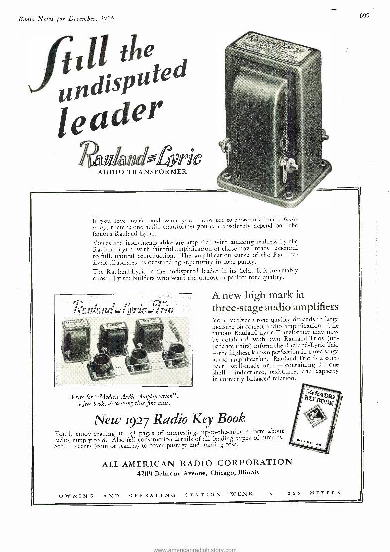
Radio Neees for December, 1926
till she andisjJ" leader
41,1,1( o
DIOTRANsFoiee
., If you love music, and want your radio set to reproduce tones fault - lessly, there is one audio transformer you can absolutely depend on -the famous Rauland- Lyric.
Voices and instruments alike are amplified with amazing realness by the Rauland- Lyric; with faithful amplification of those "overtones" essential to full, natural reproduction. _The amplification curve of the Rauland- Lyric illustrates its outstanding superiority in tone purity.
The Rauland -Lyric is the undisputed leader in its field. It is invariably chosen by set builders who want the utmost in perfect tone quality.
Write for "Modern Audio Amplification ", a free book, describing this fine unit.
699
A new high mark in three -stage audio amplifiers Your receiver's tone quality depends in large measure on correct audio amplification. The famous Rauland -Lyric Transformer may now be combined with two Rauland -Trios (im- pedance units) to form the Rauland- Lyric -Trio --the highest known perfection in three -stage audio amplification. Rauland -Trio is a com- pact, well -made unit - containing in one shell - inductance, resistance, and capacity in correctly balanced relation.
New 1927 Radio Key Book You'll enjoy reading it -48 pages of interesting, up -to -the- minute facts about radio, simply told. Also full construction details of all leading types of circuits. Send Io cents (coin or stamps) to cover postage and mailing cost.
ALL- AMERICAN RADIO CORPORATION 4209 Belmont Avenue, Chicago, Illinois
OWNING AND OPERATING STATION WENR 266 METERS
www.americanradiohistory.com
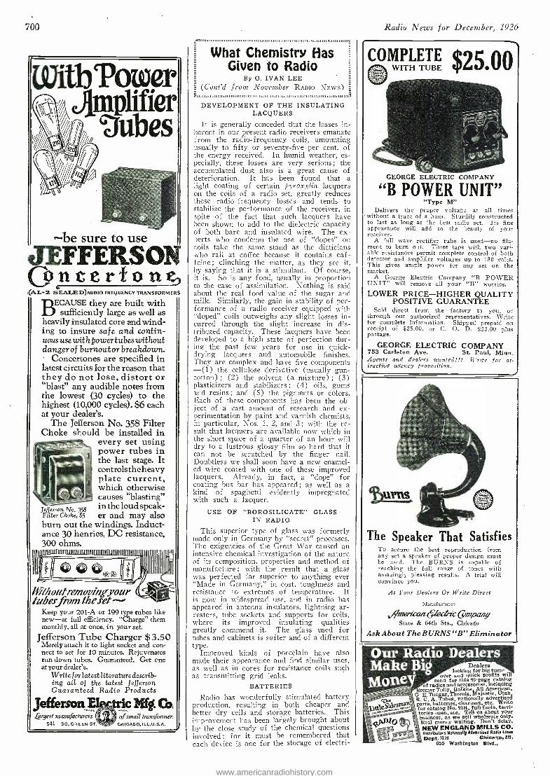
loo
i WitbPower JJnp1ifier , Gaubes
be sure to use - ÌI
LEFFERSON óntorfon (AL -2 SEALED)AUDIO FREQUENCY TRANSFORMERS
BECAUSE they are built with sufficiently large as well as
heavily insulated core and wind- ing to insure safe and contin- uous usewithfower tubes without danger of burnout or breakdown.
Concertones are specified in latest circuits for the reason that they do not lose, distort or "blast" any audible notes from the lowest (30 cycles) to the highest (10,000 cycles). $6 each at your dealer's.
The Jefferson No. 358 Filter Choke should be installed in
every set using power tubes in the last stage. It controls the heavy plate current, which otherwise causes "blasting"
Jefferson No. 35$ intheloudspeak- Filter Choke, $5 er and may also burn out the windings. Induct- ance 30 henries, DC resistance, 300 ohms.
-- _ ÌBIIIIIÌVIIIQII1III
ithoutremoving'your hrberfrom the.ret^-
Keep your 201 -A or 199 type tubes like new -at full efficiency. "Charge" them monthly, all at once, in your set.
Jefferson Tube Charger $ 3.50 Merely attach it to light socket and con- nect to set for 10 minutes. Rejuvenates run -down tubes. Guaranteed. Get one at your dealer's.
Write for latest literaturedescrib- ing all of the latest Jefferson Guaranteed Radio Products
Jefferson_a tric lrif f. Cot L rgest manufacturers of small transformen
541 SO. GREEN ST. CHICAGO, ILL-U.S.A. -
What Chemistry Has Given to Radio
By O. IVAN LEE (Cont'd from November RADIO NEWS)
DEVELOPMENT OF THE INSULATING LACQUERS
It is generally conceded that the losses in- herent in our present radio receivers emanate from the radio -frequency coils, amounting usually to fifty or seventy -five per cent. of the energy received. In humid weather, es- pecially, these losses are very serious; the accumulated dust also is a great cause of deterioration. It has been found that a light coating of certain pyroxylin lacquers on the coils of a radio set, greatly reduces these radio - frequency losses and tends to stabilize the performance of the receiver, in spite of the fact that such lacquers have been shown to add to the dielectric capacity of both bare and insulated wire. The ex- perts who condemn the use of "dopes" on coils take the same stand as the dieticians who rail at coffee because it contains caf- feine ; clinching the matter, as they see it, by saying that it is a -stimulant. Of course, it is. So is any food, usually in proportion to the ease of assimilation. Nothing is said about the real food value of the sugar and milk. Similarly, the gain in stability of per- formance of a radio receiver equipped with "doped" coils outweighs any slight losses in- curred through the slight increase in dis- tributed capacity. These lacquers have been developed to a high state of perfection dur- ing the past few years for use in quick - drying lacquers and automobile finishes. They are complex and have five components -(1) the cellulose derivative (usually gun- cotton) ; (2) the solvent (a mixture) ; (3) plasticizers and stabilizers ; (4) oils, gums and resins ; and (5) the pigments or colors. Each of these components has been the ob- ject of a vast amount of research and ex- perimentation by paint and varnish chemists, in particular, Nos. 1, 2, and 3 ; with the re- sult that lacquers are available now which in the short space of a quarter of an hour will dry to a lustrous glossy film so hard that it can not be scratched by the finger nail. Doubtless we shall soon have a new enamel- ed wire coated with one of these improved lacquers. Already, in fact, a "dope" for coating bus bar has appeared; as well as a kind of spaghetti evidently impregnated with such a lacquer.
USE OF "BOROSILICATE" GLASS IN RADIO
This superior type of glass was formerly made only in Germany by "secret" processes. The exigencies of the Great War caused an intensive chemical investigation of the nature of its composition, properties and method of manufacture ; with the result that a glass was perfected far superior to anything ever "Made in Germany," in cost, toughness and resistance to extremes of temperature. It is now in widespread use, and in radio has appeared in antenna insulators, lightning ar- resters, tube sockets and supports for coils, where its - improved insulating qualities greatly commend it. The glass used for tubes and cabinets is softer and of a different type.
Improved kinds of porcelain have also made their appearance and find similar uses, as well as in cores for resistance coils such as transmitting grid leaks.
BATTERIES
Radio has wonderfully stimulated battery production, resulting in both cheaper and
better dry cells and storage batteries. This improvement has been largely brought about by the close study of the chemical questions involved ; for it must be remembered that each device is one for the storage of electri-
Radio News for December, 1926
COMPLETE $25 .00 WITH TUBE
GEORGE ELECTRIC COMPANY
"B POWER UNIT 99
"Type M" Delivers the proper voltage at all times
without a trace of a hum. Sturdily constructed to last as long as the best radio set. Its fine appearance will add to the beauty of your receiver.
A full wave rectifier tube is used -no fila- ment to burn out. Three taps with two vari- able resistances permit complete control of both detector and amplifier voltages up to 180 volts. This gives ample power for any set on the market.
A George Electric Company "B POWER UNIT" will remove all your "B" worries.
LOWER PRICE -HIGHER QUALITY POSITIVE GUARANTEE
Sold direct from the factory to you, or through our authorized representatives. Write for complete information. Shipped prepaid on receipt of $25.00, or C. O. D. $25.00 plus postage.
GEORGE ELECTRIC COMPANY 753 Carleton Ave. St. Paul, Minn. Agents and dealers wanted!!! Write for at- tractive agency j,robositio,,.
The Speaker That Satisfies To secure the best reproduction from any set a speaker of proper design must be used. The BURNS is capable of reaching the full range of tones with amazingly pleasing results. A trial will convince you.
At Your Dealers Or Write Direct
Manufacturer
ivm er & azz 6/e a * Cç nir o air y State & 64th Sts., Chicago
Ask About The BURNS "B" Eliminator
Dealers looking for big turn-
over and quick profits will send for this 96 -page catalog
of radios and accessories, including Bremer Tully, Balkite, All American,
G. E.Tungar,Thorola, Majestic, Utah R. C. A. Tubes, nationally advertised parts, batteries, chargers, etc. Write for catalog No. 9113, full facts, terri- tories open, etc. Tell us about your business, as we sell wholesale only. Real money waiting. Don't delay. NEW ENGLAND MILLS CO. Distributors Natianall) Advertised Radio Lines
Dept. 91H - Chicago, Ill. 855 Washington Blvd.,
www.americanradiohistory.com
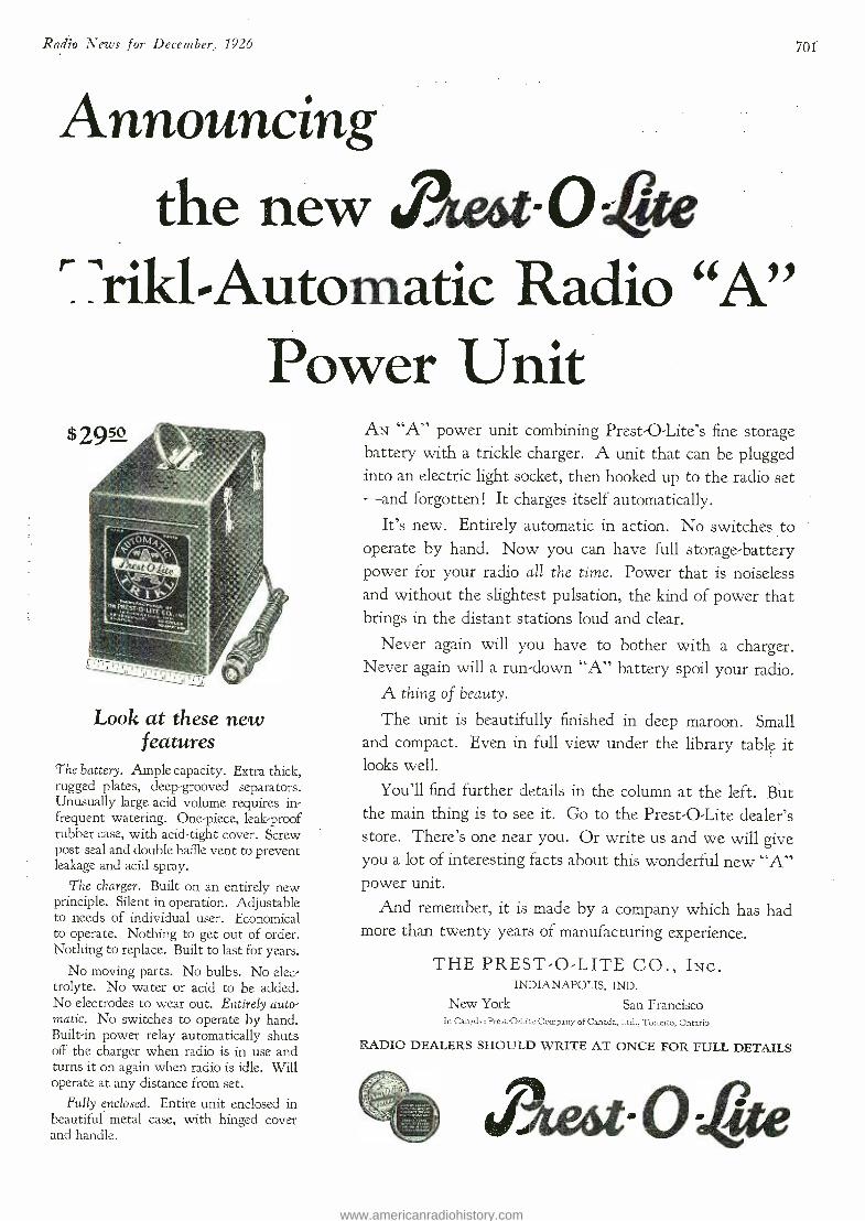
Radio News for December, 1926
Announcing the new J3eot-O4te
T 'riki-Automatic Radio "A" Power Unit
Look at these new features
The battery. Ample capacity. Extra thick, rugged plates, deep -grooved separators. Unusually large acid volume requires in- frequent watering. One -piece, leak -proof rubber case, with acid -tight cover. Screw post seal and double baffle vent to prevent leakage and acid spray.
The charger. Built on an entirely new principle. Silent in operation. Adjustable to needs of individual user. Economical to operate. Nothing to get out of order. Nothing to replace. Built to last for years.
No moving parts. No bulbs. No elec- trolyte. No water or acid to be added. No electrodes to wear out. Entirely auto- matic. No switches to operate by hand. Built -in power relay automatically shuts off the charger when radio is in use and turns it on again when radio is idle. Will operate at any distance from set.
Fully enclosed. Entire unit enclosed in beautiful metal case, with hinged cover and handle.
AN "A" power unit combining Prest -O- Lite's fine storage battery with a trickle charger. A unit that can be plugged into an electric light socket, then hooked up to the radio set -and forgotten ! It charges itself automatically.
It's new. Entirely automatic in action. No switches to operate by hand. Now you can have full storage -battery power for your radio all the time. Power that is noiseless and without the slightest pulsation, the kind of power that brings in the distant stations loud and clear.
Never again will you have to bother with a charger. Never again will a run -down "A" battery spoil your radio.
A thing of beauty.
The unit is beautifully finished in deep maroon. Small and compact. Even in full view under the library table it looks well.
You'll find further details in the column at the left. But the main thing is to see it. Go to the Prest -O -Lite dealer's store. There's one near you. Or write us and we will give you a lot of interesting facts about this wonderful new "A" power unit.
And remember, it is made by a company which has had more than twenty years of manufacturing experience.
THE PREST -O -LITE CO., INC. INDIANAPOLIS, IND.
New York San Francisco In Canada: Prest- O -Lite Company of Canada, Ltd., Toronto, Ontario
RADIO DEALERS SHOULD WRITE AT ONCE FOR FULL DETAILS
,pAe6t-Otite
701
www.americanradiohistory.com
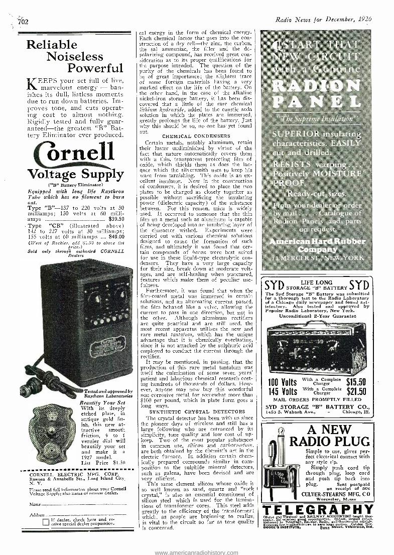
702
Reliable Noiseless
Powerful KEEPS your set full of live,
marvelous energy - ban- ishes its dull, listless moments clue to run down batteries. Im- proves tone, and cuts operat- ing cost to almost nothing. Rigidly tested and fully guar- anteed-the greatest "B" Bat- tery Eliminator ever produced.
órnell Voltage Supply
( "B" Battery Eliminator) Equipped with long life Raytheon Tube which has no filament to burn out. Type "B" -137 to 220 volts at 30 milliamps; 150 volts at 60 milli - amps $39.50 Type "CB "- (illustrated above) 142 to 227 volts at 30 milliamps; 155 volts at 60 milliamps .___ $49.00 (West of Rockies, add $1.90 to above list
prices) Sold only through authoried CORNELL
Dealers
Tested and approved by Raytheon Laboratories
Beautify Your Set With its deeply etched plate, in antique gold fin- ish, this new at- tractive smooth friction, 9 to 1
vernier dial will beautify your set and make it a 1927 model. List Price $1.50
CORNELL ELECTRIC MFG. CORP. Rawson & Annabelle Sts., Long Island City, N. Y.
Please send full information about your Cornell Voltage Supply; also name of nearest dealer.
Address
UIf dealer, check here and re- ceive special dealer proposition.
cal energy in the form of chemical energy. Each chemical factor that goes into the con- struction of a dry cell -the zinc, the carbon, the sal ammoniac, the filler and the de- polarizing compound, has received great con- sideration as to its proper qualifications for the purpose intended. The question of the purity of the chemicals has been found to be of great importance ; the slightest trace of some foreign materials having a very marked- effect on the life of the battery. On the other hand, in the case of the alkaline nickel -iron storage battery, it has been dis- covered that a little of the rare chemical lithium hydroxide, added to the caustic soda solution in which the plates are immersed, greatly prolongs the life of the battery. Just why this should be so, no one has. yet found out.
CHEMICAL CONDENSERS Certain metals, notably aluminum, retain
their luster undiminished by virtue of the fact that nature automatically covers them with a thin, transparent protecting film of oxide, which shields them as does the lac- quer which the silversmith uses to keep his ware from tarnishing. This oxide is an ex- cellent insulator. Now in the construction of condensers, it is desired to place the two plates to be charged as closely together as possible without sacrificing the insulating power (dielectric capacity) of the substance between. For this reason, mica is widely used. It occurred to someone that the thin film on a metal such as aluminum is capable of being developed into an insulating layer of the character wished. Experiments were carried out with various chemical solutions designed to cause the formation of such films, and ultimately it was found that cer- tain compounds of boron were best suited for use in these liquid -type electrolytic con- densers. They have a very large capacity for their size, break clown at moderate volt- ages, and are self -healing when punctured, features which make them of peculiar use- fulness.
Furthermore, it was found that when the film- coated metal was immersed in certain solutions, and an alternating current passed, the film behaved like a valve, allowing the current to pass in one direction, but not in the other. Although aluminum rectifiers are quite practical and are still used, the most recent apparatus utilizes the new and rare metal tantalum, which has the unique advantage that it is chemically everlasting, since it is not attacked by the sulphuric acid employed to conduct the current through the rectifier.
It may be mentioned, in passing, that the production of this rare metal tantalum was itself the culmination of some seven years' patient and laborious chemical research cost- ing hundreds of thousands of dollars. How- ever, anyone may now buy this wonderful non -corrosive metal for somewhat more than $100 per pound, which in plate form goes a long ways.
SYNTHETIC CRYSTAL DETECTORS The crystal detector has been with us since
the pioneer days of wireless and still has a large following who are entranced by its simplicity, tone quality and low cost of up- keep. Two of the most popular substances in common use, silicon and carborundum, are both obtained by the chemist's art in the electric furnace. In addition certain chem- ically prepared compounds similar in com- position to the sulphide mineral detectors, such as galena, have been devised and are very efficient.
This same element silicon whose oxide is so well known as sand, quartz and "rock crystal," is also an essential constituent of silicon steel which is used for the lamina- tions of transformer cores. This steel adds greatly to the efficiency of the transformer ;
which, as people are beginning to realize, is vital to the circuit so far as tone quality is concerned.
Radio News for December, 1926
CSTART THAT NEW CIRCUIT with a Genuine
RADION PANEL
'The Supreme Insulation'
SUPERIOR. insulating characteristics. EASILY cut and drilled. RESISTS warping.... Positively MOISTURE PROOF.
Ready -cut sizes.
From your dealer or order by mail Catalogue of Radion Panels and parts
on request.
American Hard Rubber Company
11 MERCER ST., NEW YORK
SYDLONG C V D STORAGE
LIFE " SYD BATTERY 1
The Syd Storage "B" Battery was submitted for a thorough test to the Radio Laboratory of a Chicago daily newspaper and found sat- isfactory. Also tested and approved by Popular Radio Laboratory, New York.
Unconditional 2 -Year Guarantee
MO Volts WithChaCgmplete $15.50 145 Volts
WithChargemplete $21.50
MAIL ORDERS PROMPTLY FILLED
SYD STORAGE "B" BATTERY CO., 1453 S. Wabash Ave., - Chicago, Ill.
A NEW RADIO PLUG
Simple to use, gives per- fect electrical contact with any style tip.
Simply push cord tip through plug, loop cord and push tip back into plug. Sent postpaid
on receipt of 50e CULVER -STEARNS MFG. C 0
Worcester, M.sas
TELEGRAPHY (Morse end Wireless) and RAILWAY ACCOUNTING taught thor- oughly. Big salaries; great opportunities. Oldest, largest school.
ndorsed by Telegraph, Railway, Radio. and Government officials. Expense, low -o rtamtiev to earn large portion. Catalog free. OODGE's INSTITUTE, Swan Street, Valparaiso. Intl.
www.americanradiohistory.com
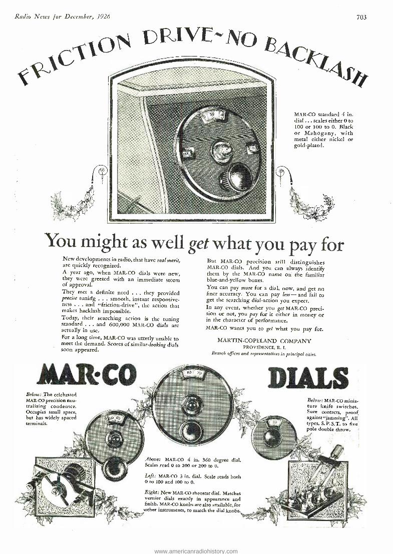
Radio News for December, 1926
MAR -CO standard 4 in. dial ... scales either 0 to 100 or 100 to O. Black or Mahogany, with metal either nickel or gold- plated.
You might as well get what you pay for New developments in radio, that have real merit, are quickly recognized. A year ago, when MAR -CO dials were new, they were greeted with an immediate storm of approval. They met a definite need ... they provided precise tuning ... smooth, instant responsive- ness ... and "friction- drive ", the action that makes backlash impossible. Today, their searching action is the tuning standard ... and 600,000 MAR -CO dials are actually in use. For a long time, MAR -CO was utterly unable to meet the demand. Scores of similar- looking dials soon appeared.
M&R?CO Below: The celebrated MAR -CO precision neu- tralizing condenser. Occupies small space, but has widely spaced terminals.
But MAR -CO precision still distinguishes MAR -CO dials. And you can always identify them by the MAR -CO name on the familiar blue- and -yellow boxes. You can pay more for a dial, now, and get no finer accuracy. You can pay less -and fail to get the searching dial- action you expect. In any event, whether you get MAR -CO preci- sion or not, you pay for it either in money or in the character of performance. MAR -CO wants you to get what you pay for.
MARTIN -COPELAND COMPANY PROVIDENCE, R. I.
Branch offices and representatives in principal cities.
703
Below: MAR -CO minia- ture knife switches. Sure contacts, proof against "jamming ". All types, S. P.S.T. to five; pole double throw.
Above: MAR -CO 4 in. 360 degree . dial. Scales read 0 to 200 or 200 to 0.
Left: MAR -CO 3 in. dial. Scale reads both 0 to 100 and 100 to 0.
Right: New MAR -CO rheostat dial. Matches vernier dials exactly in appearance and finish. MAR -CO knobs are also available, for pother instruments, to match the dial knobs.
.
r
www.americanradiohistory.com
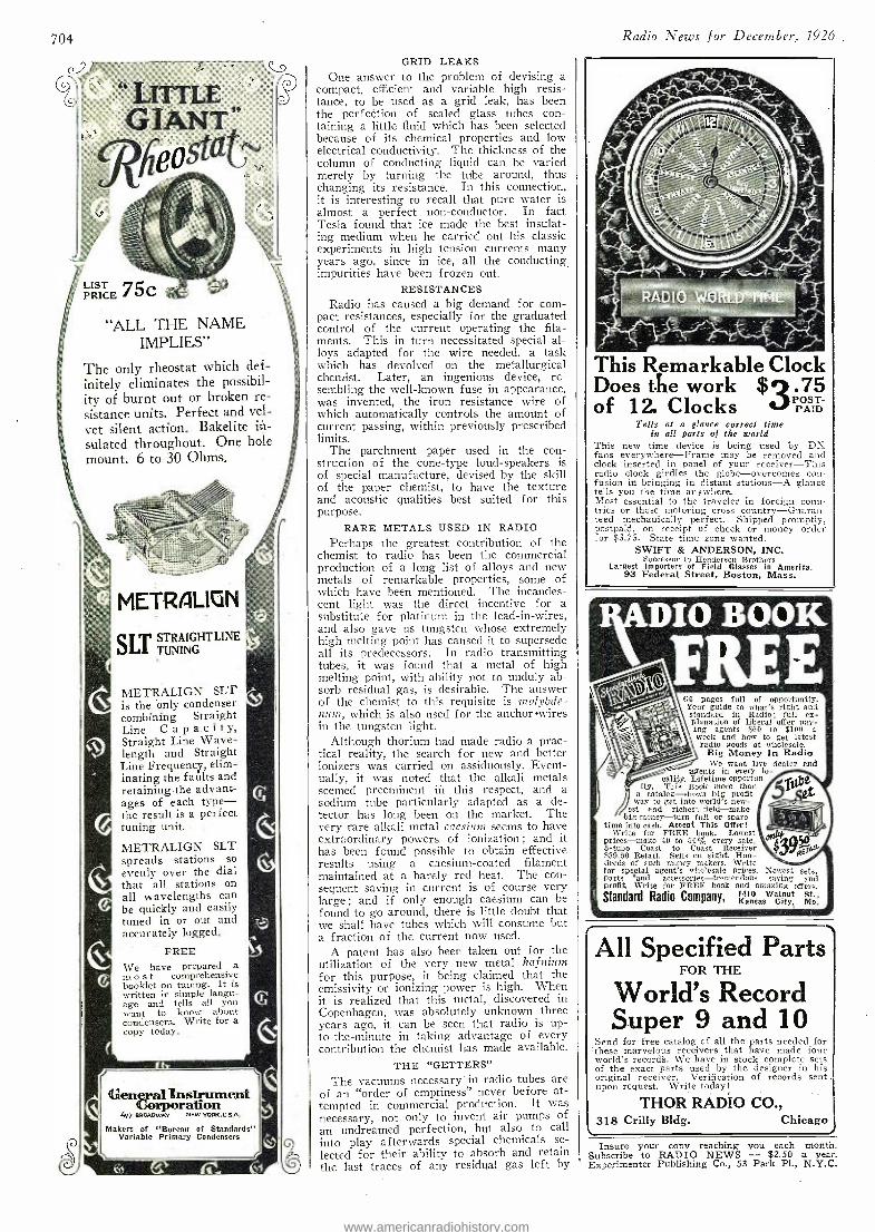
704
LITTLE GIANT
Osta
LIS PRIT CE c
"ALL THE NAME IMPLIES"
The only rheostat which def- initely eliminates the possibil- ity of burnt out or broken re-
sistance units. Perfect and vel- vet silent action. Bakelite in- sulated throughout. One hole mount. 6 to 30 Ohms.
METRALIGN
SLTi STRAIGHT LINE TUNING
METRALIGN SLT is the only condenser combining Straight Line C a p a.c i t y,
Straight Line Wave- length and. Straight Line Frequency, elim- inating the faults and retaining the advant- ages of each type - the result is a perfect tuning unit.
METRALIGN SLT spreads stations so evenly over the dial that all stations on all wavelengths can be quickly and easily tuned in or out and accurately logged.
FREE We have prepared a in o s t comprehensive booklet on tuning. It is written in simple langu- age and tells all you want to know about condensers. Write for a copy today.
General lLusirament Corporation
477 BROADWAY NEW YORK.U.S.A.
Makers of "Bureau of Standards" Variable Primary Condensers
i
GRID LEAKS One answer to the problem of devising a
compact, efficient and variable high resis- tance, to be used as a grid leak, has been the perfection of sealed glass tubes con- taining a little fluid which has been selected because of its chemical properties and low electrical conductivity. The thickness of the column of conducting liquid can be varied merely by turning the tube around, thus changing its resistance. In this connection, it is interesting to recall that pure water is almost a perfect non -conductor. In fact Tesla found that ice made the best insulat- ing medium when he carried out his classic experiments in high tension currents many years ago, since in ice, all the conducting impurities have been frozen out.
RESISTANCES Radio has caused a big demand for corn -
pact resistances, especially for the graduated control of the current operating the fila- ments. This in turn necessitated special al- loys adapted for the wire needed, a task which has devolved on the metallurgical chemist. Later, an ingenious device, re- sembling the well -known fuse in appearance, was invented, the iron resistance wire of which automatically controls the amount of current passing, within previously prescribed limits.
The parchment paper used in the con- struction of the cone -type loud- speakers is of special manufacture, devised by the skill of the paper chemist, to have the texture and acoustic qualities best suited for this purpose.
RARE METALS USED IN RADIO
Perhaps the greatest contribution of the chemist to radio has been the commercial production of a long list of alloys and new metals of remarkable properties, some of which have been mentioned. The incandes- cent light was the direct incentive for a substitute for platinum in the lead -in- wires, and also gave us tungsten whose extremely high melting point has caused it to supersede all its predecessors. In radio transmitting tubes, it was found that a metal of high melting point, with ability not to unduly ab- sorb residual gas, is desirable. The answer of the chemist to this requisite is lnolybde- flilnl, which is also used for the anchor 'wires in the tungsten light.
Although thorium had made radio a prac- tical reality, the search for new and better ionizers was carried on assiduously. Event- ually, it was noted that the alkali metals seemed preeminent inn this respect, and a sodium tube particularly adapted as a de- tector has long been on the market. The very rare alkali metal caesium seems to have extraordinary powers of ionization; and it has been found possible to obtain effective results using a caesium- coated filament maintained at a barely red heat. The con- sequent saving in current is of course very large ; and if only enough caesium can be found to go around, there is little doubt that we shall have tubes which will consume but a fraction of the current now used.
A patent has also been taken out for the utilization of the very new metal hafnium for this purpose, it being claimed that the emissivity or ionizing power is high. When it is realized that this metal, discovered in Copenhagen, was absolutely unknown three years ago, it can be seen that radio is up- to- the -minute in taking advantage of every contribution the chemist has made available.
THE' "GETTERS" The vacuums necessary- in radio tubes are
of an "order of emptiness" never before at- tempted in commercial production. It was necessary, not only to invent air pumps of an undreamed perfection, but also to call into play afterwards special chemicals se- lected for their ability to absorb and retain the last traces of any residual gas left by
Radio News for December, 1926
This Remarkable Clock Does the work $3.75 of 12. Clocks POST-
PAID Tells at a glance correct time
in all parts of the world This new time device is being used by DX fans everywhere -Frame may be removed and clock inserted in panel of your receiver-This radio clock girdles the globe -overcomes con- fusion in bringing in distant stations -A glance tells you the time any where. Most essential to the traveler in foreign coun- tries or those motoring cross country- Guaran- teed mechanically perfect. Shipped promptly, postpaid, on receipt of check or money order for $3.75. State time zone wanted.
SWIFT & ANDERSON; INC. Successor to Henderson Brothers
Largest Importers of Field Glasses in America. 93 Federal Street, Boston, Mass.
64 pages full of opportunity. Your guide to what's right and standard in Radio; fill ex- planation of liberal offer pay- ing agents $60 to $100 a week and how to get latest radio goods at wholesale. .... i,.,..- Big Money In Radio
We want live dealer and agents in every lo-
cality. Lifetime opportun- ity. This Rook more than
a catalog -shows big profit way to get into world's new-
est and richest field -make big money -turn full or spare
time into cash. Accept This Offer! Write for FREE book. Lowest
prices -make 40 to 60% every sale. 5 -tube Coast to Coast Receiver $39.50 Retail. Sells on sight. Hun- dreds of such money makers. Write for special agent's wholesale prices. Newest sets. parts 'and accessories--tremendous saving and profit Write for FREE book and amazing offers.
Standard Radio Company, 1410 Walnut St., Kansas City, Mo.
r All Specified Parts
FOR THE
World's Record Super 9 and 10
Send for free catalog of all the parts needed for these marvelous receivers that have made four world's record's. We have in stock complete sets of the exact parts used by the designer in his original receiver. Verification of records sent upon request. Write today!
THOR RADIO CO., 318 Crilly BIdg. Chicago
Insure your copy reaching you each Subscribe to RADIO NEWS - $2.50 Experimenter Publishing Co., 53 Park PL,
month. a year. N.Y.C.
www.americanradiohistory.com
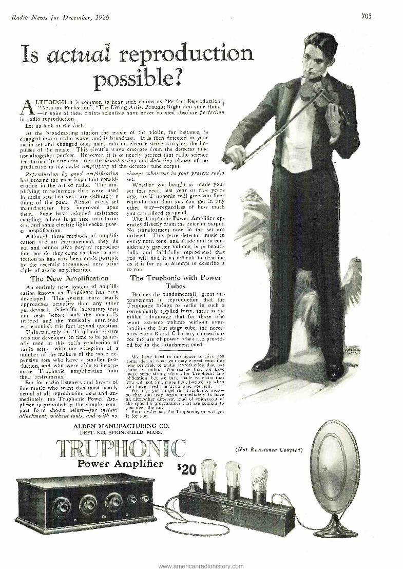
Radio News for December, 1926
Is actual reproduction possible?
ALTHOUGH it is common to hear such claims as "Perfect Reproduction ", "Absolute Perfection ", "The Living Artist Brought Right into your Home" -in spite of these claims scientists have never boasted absolute perfection
in radio reproduction. Let us look at the facts. At the broadcasting station the music of the violin, for instance, is
changed into a radio wave, and is broadcast. It is then detected in your radio set and changed once more into an electric wave carrying the im- pulses of the music. This electric wave emerges from the detector tube not altogether perfect. However, it is so nearly perfect that radio science has turned its attention from the broadcasting and detecting phases of re- production to the audio amplifying of the detector tube output.
Reproduction by good amplification has become the most important consid- eration in the art of radio. The am- plifying transformers that were used in radio sets last year are definitely a
thing of the past. Almost every set manufacturer has improved upon them. Some have adopted resistance coupling, others large size transform- ers, and some electric light socket pow- er amplification.
Although these methods of amplifi- cation are an improvement, they do not and cannot give perfect reproduc- tion, nor do they come as close to per- fection as has now been made possible by the recently announced new prin- ciple of audio amplification.
The New Amplification An entirely new system of amplifi-
cation known as Truphonic has been developed. This system more nearly approaches actuality than any other yet devised. Scientific laboratory tests and tests before both the musically trained and the musically untrained ear establish this fact beyond question.
Unfortunately the Truphonic system was not developed in time to be gener- ally used in this fall's production of radio sets - with the exception of a number of the makers of the more ex- pensive sets who have a smaller pro- duction, and who were able to incorp- orate Truphonic amplification into their instruments.
But for radio listeners and lovers of fine music who want this most nearly actual of all reproduction now and im- mediately, the Truphonic Power Am- plifier is provided in the simple, com- pact form shown below -for instant attachment, without tools, and with no
705
change whatever in your present radio set.
Whether you bought or made your set this year, last year or five years ago, the Truphonic will give you finer reproduction than you can get in any other way -regardless of how much you can afford to spend.
The Truphonic Power Amplifier op- erates directly from the detector output. No transformers now in the set are utilized. This pure detector music in every note, tone, and shade and in con- siderably greater volume, is so beauti- fully and faithfully reproduced that you will find it as difficult to describe as it is for us to attempt to describe it to you.
The Truphonic with Power Tubes
Besides the fundamentally great im- provement in reproduction that the Truphonic brings to radio in such a conveniently applied form, there is the added advantage that for those who want extreme volume without over- loading the last stage tube, the neces- sary extra B and C battery connections for the use of power tubes are provid- ed for in the attachment cord.
We have tried in this space to give you some idea of what you may expect from this new principle of audio reproduction that has come to radio. We realize that we have made some strong claims for Truphonic am- plification, but we have made no claim that you will not find more than backed up when you have tried the Truphonic yourself.
We urge you to get the Truphonic now- - so that you may begin immediately to have an altogether different kind of enjoyment of the splendid programmes that are coming to you over the air.
Your dealer has the Truphonic, or will get it for you.
ALDEN MANUFACTURING CO. DEPT. K23, SPRINGFIELD, MASS.
(Not Resistance Coupled)
Power Amplifier
www.americanradiohistory.com
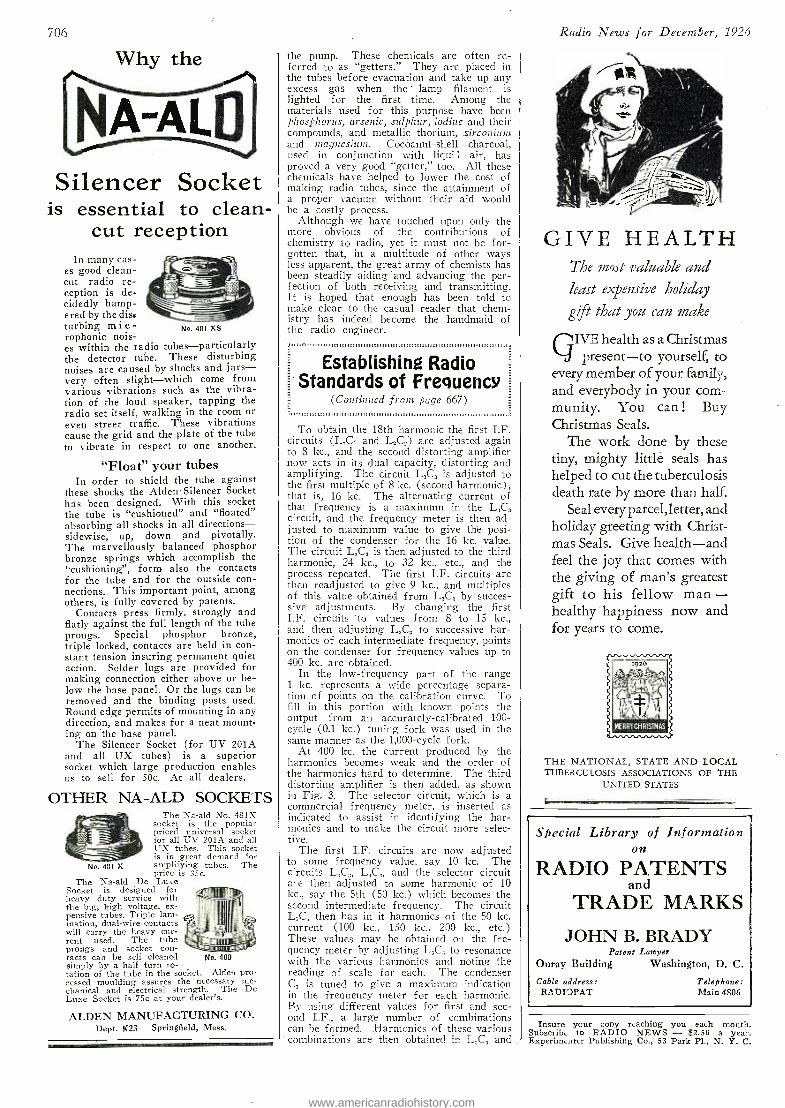
706
Why the
Silencer Socket is essential to clean -
cut reception In many cas-
es good clean - cut radio re- ception is de- cidedly hamp- ered by the dis, turbing m i e - No 481 XS rophonic nois- es within the radio tubes -particularly the detector tube. These disturbing noises are caused by shocks and jars - very often slight -which come from various vibrations such as the vibra- tion of the loud speaker, tapping the radio set itself, walking in the room or even street traffic. These vibrations cause the grid and the plate of the tube to vibrate in respect to one another.
"Float" your tubes In order to shield the tube against
these shocks the Alden Silencer Socket has been designed. With this socket the tube is "cushioned" and "floated" absorbing all shocks in all directions - sidewise, up, down and pivotally. The marvellously balanced phosphor bronze springs which accomplish the "cushioning ", form also the contacts for the tube and for the outside con- nections. This important point, among others, is fully covered by patents.
Contacts press firmly, strongly and flatly against the full length of the tube prongs. Special phosphor bronze, triple locked, contacts are held in con- stant tension insuring permanent quiet action. Solder lugs are provided for making connection either above or be- low the base panel. Or the lugs can be removed and the binding posts used. Round edge permits of mounting in any direction, and makes for a neat mount- ing on the base panel.
The Silencer Socket (for UV 201A and all UX tubes) is a superior socket which large production enables us to sell for 50e. At all dealers.
OTHER NA -ALD SOCKETS The Na -ald No. 481X
socket is the popular priced universal socket for all UV 201A and all UX tubes. This socket is in great demand for
No. 481 X amplifying tubes. The price is 35c.
The Na -ald De Luxe Socket is designed for heavy duty service with the big, high voltage, ex- pensive tubes. Triple lam- ination, dual -wire contacts will carry the heavy cur- rent used. The tube prongs and socket con- tacts can be self cleaned simply by a half turn ro- tation of the tube in the socket. Alden pro- cessed moulding assures the necessary me- chanical and electrical strength. The De Luxe Socket is 75c at your dealer's.
Joni
No. 400
ALDEN MANUFACTURING CO. Dept. K23 Springfield, Mass.
the pump. These chemicals are often re- ferred to as "getters." They are placed in the tubes before evacuation and take up any excess gas when the - lamp filament is lighted for the first time. Among the materials used for this purpose have been phosphorus, arsenic, sulphur, iodine and their compounds, and metallic thorium, zirconium and magnesium. Cocoanut -shell charcoal, used in conjunction with liqui i air, has proved a very good "getter," too. All these chemicals have helped to lower the cost of making radio tubes, since the attainment of a proper vacuum without their aid would he a costly process.
Although we have touched upon only the more obvious of the contributions of chemistry to radio, yet it must not be for- gotten that, in a multitude of other ways less apparent, the great army of chemists has been steadily aiding and advancing the per- fection of both receiving and transmitting. It is hoped that enough has been told to make clear to the casual reader that chem- istry has indeed become the handmaid of the radio engineer.
Establishing Radio Standards of Frequency
(Continued from page 667) -
To obtain the 18th harmonic the first I.F. circuits (L,C, and L,C,) are adjusted again to 8 kc., and the second distorting amplifier now acts in its dual capacity, distorting and amplifying. The circuit L,C, is adjusted to the first multiple of 81 kc. (second harmonic), that is, 16 kc. The alternating current of that frequency is a maximum in the L,C, circuit, and the frequency meter is then ad- justed to maximum value to give the posi- tion of the condenser for the 16 kc. value. The circuit L,C, is then adjusted to the third harmonic, 24 kc., to 32 kc., etc., and the process repeated. The first I.F. circuits are then readjusted to give 9 kc., and multiples of this value obtained from L,C, by succes- sive adjustments. By changing the first I.F. circuits to values from 8 to 15 kc., and then adjusting L,C, to successive har- monics of each intermediate frequency, points on the condenser for frequency values up to 400 kc. are obtained.
In the low- frequency part of the range 1 kc. represents a wide percentage separa- tion of points on the calibration curve. To fill in this portion with known points the output from an accurately -calibrated 100 - cycle (0.1 kc.) tuning fork was used in the same manner as the 1,000 -cycle fork.
At 400 kc. the current produced by the harmonics becomes weak and the order of the harmonics hard to determine. The third distorting amplifier is then added, as shown in Fig. 3. The selector circuit, which is a commercial frequency meter, is inserted as indicated to assist in identifying the har- monics and to make the circuit more selec- tive.
The first I.F. circuits are now adjusted to some frequency value, say 10 kc. The circuits L,C LAC and the selector circuit a -e then adjusted to some harmonic of 10 kc., say the 5th (50 kc.) which becomes the second intermediate frequency. The circuit LX, then has in it harmonics of the 50 kc. current (100 kc., 150 kc.. 200 kc., etc.) These values may be obtained on the fre- quency meter by adjusting L,C to resonance with the various harmonics and noting the reading of scale for each. The condenser C, is tuned to give a maximum indication in the frequency meter for each harmonic. By using different values for first and sec- ond I.F., a large number of combinations can be formed. Harmonics of these various combinations are then obtained in L,C, and
Radio News for Decetrsber, 1926
GIVE HEALTH The most valuable and least expensive holiday
gift that you can make
QIVE health as a Christmas present -to yourself, to
every member of your family, and everybody in your com- munity. You can ! Buy Christmas Seals.
The work done by these tiny, mighty little seals has helped to cut the tuberculosis death rate by more than half.
Seal everyparcel,letter, and holiday greeting with Christ- mas Seals. Give health -and feel the joy that comes with the giving of man's greatest gift to his fellow man - healthy happiness now and for years to come.
r
ERRYCHRISTMAS
THE NATIONAL, STATE AND LOCAL TUBERCULOSIS ASSOCIATIONS OF THE
UNITED STATES
Special Library of Information on
RADIO PATENTS and
TRADE MARKS
JOHN B. BRADY Patent Lawyer
Ouray Building Washington, D. C.
Cable address: RA DIOPAT
Telephone: Main 4806
Insure your copy reaching you each month. Subscribe to RADIO NEWS - $2.50 a year. Experimenter Publishing Co., 53 Park Pl., N. Y. C.
www.americanradiohistory.com
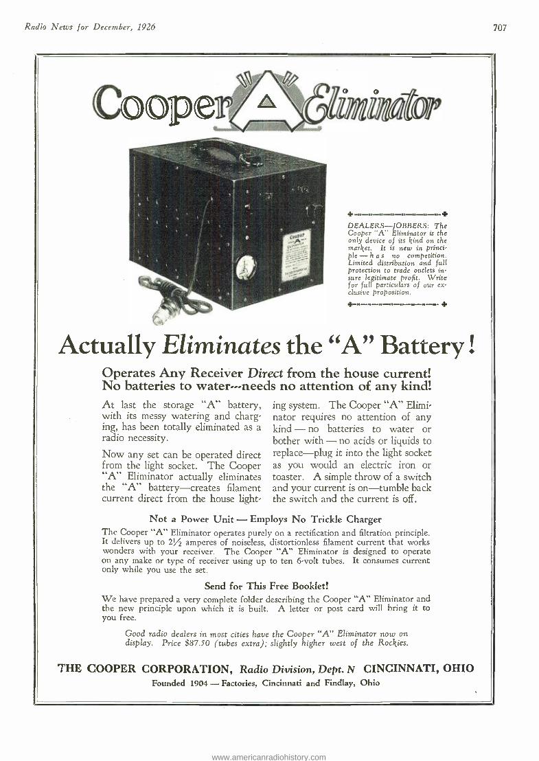
Radio News for December, 1926 707
DEALERS -JOBBERS: The Cooper "A" Eliminator is the only device of its kind on the market. It is new in princi- ple -h a s no competition. Limited distribution and full protection to trade outlets in- sure legitimate profit. Write for full particulars of our ex- clusive proposition.
4.
Actually Eliminates the "A" Battery ! Operates Any Receiver Direct from the house current! No batteries to water -- -needs no attention of any kind! At last the storage "A" battery, with its messy watering and charg- ing, has been totally eliminated as a radio necessity.
Now any set can be operated direct from the light socket. The Cooper "A" Eliminator actually eliminates the "A" battery- creates filament current direct from the house light-
ing system. The Cooper "A" Elimi- nator requires no attention of any kind - no batteries to water or bother with - no acids or liquids to replace -plug it into the light socket as you would an electric iron or toaster. A simple throw of a switch and your current is on- tumble back the switch and the current is off.
Not a Power Unit - Employs No Trickle Charger The Cooper "A" Eliminator operates purely on a rectification and filtration principle. It delivers up to 2%2 amperes of noiseless, distortionless filament current that works wonders with your receiver. The Cooper "A" Eliminator is designed to operate on any make or type of receiver using up to ten 6 -volt tubes. It consumes current only while you use the set.
Send for This Free Booklet! We have prepared a very complete folder describing the Cooper "A" Eliminator and the new principle upon which it is built. A letter or post card will bring it to you free.
Good radio dealers in most cities have the Cooper "A" Eliminator now on display. Price $87.50 (tubes extra); slightly higher west of the Rockies.
THE COOPER CORPORATION, Radio Division, Dept. N CINCINNATI, OHIO Founded 1904 - Factories, Cincinnati and Findlay, Ohio
www.americanradiohistory.com
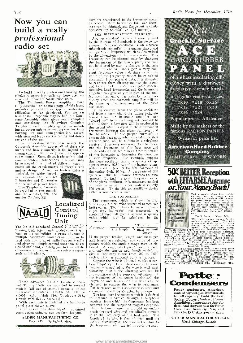
708
Now you can build a really professional radio set
,
To build a really professional looking and efficiently operating_ radio set here are tw_o- new and important construction units.
The Truphonic Power Amplifier, more fully described on another page of this issue, provides by far the finest type of audio am- plification so far developed. For the set builder the Truphonic may be had in a Cata- comb Assembly which gives you a complete unit containing the following: Complete Truphonic audio amplifying system includ- ing an output unit to protect the speaker from burning out and demagnetization, sockets with attached leads for the tuning and detec- tor end of the set.
The illustration shows how neatly this Catacomb Assembly houses all of these ele- ments and how compactly it fits behind the tuning control. No holes to drill, no appara- tus to mount. Short, direct leads with a mini- mum of soldered connections. This unit may be arranged in a hundred different ways to match all the requirements of every circuit and set design. A six foot battery cable is included, in which provi- sion is made for the extra B batteries and C batteries for the use of power tubes.
The Truphonic Assembly is provided in two models, one for 6 tubes, $20, and one for 7 tubes, $22.
Localized ~ f Control NA -A`LD Tuning
Unit The Na -Ald Localized Control i?ru1em ik pig. Tuning Unit (Quadruple model shown) is a boon to the set builder -a great advance in multiple condenser construction. It can be used with any form of radio frequency coils, nd gives you simple control under the finger
tips of one hand, enabling you to tune all the condensers at once, or to tune each one separ- ately and distinctly.
These advanced Na -Ald Localized Con- trol Tuning Units are provided in several models (all are of .000375 capacity unless otherwise indicated). Double $8., Double (.0005) $10., Triple $10., Quadruple $15., Double with tickler control $10.
With each unit is included the handsome panel plate shown above.
Your dealer has these Na -Ald advanced construction units, or can get them for you.
ALDEN MANUFACTURING CO. Dept. K23 Springfield_ Mass.
they are transferred to the frequency meter as before. More harmonics than are neces- sary can be obtained, and the circuit is easily operative up to 4,000 kc. (75 meters).
THE PIEZO- ELECTRIC STANDARD Another standard of radio frequency used
by the Bureau of Standards is the piezo os- cillator. A piezo oscillator is an electron tube circuit controlled by a quartz plate; and will give one frequency which is determined by the dimensions of the quartz plate. This frequency can be changed only by changing the dimensions of the quartz plate, and can- not be altered by making changes in the tube circuit. These oscillators give a very con- stant frequency value and, since as yet the value of the frequency cannot be calculated accurately from physical data, it is desirable to calibrate them directly against the stand- ard tuning fork. Since these piezo oscilla- tors give fixed frequencies and the harmonic amplifier can give only multiples of the tun- ing, fork frequency, it is unlikely that a fre- quency from the harmonic amplifier will be the same as the frequency of the piezo oscillator.
If the current from the piezo oscillator and from a harmonic of the tuning fork, ob- tained from the harmonic amplifier, are "picked up" in a receiving set coupled to ,both of them, a beat note will be produced in this circuit which is equal to the difference in frequency between the piezo oscillator and the harmonic. If the proper harmonic is chosen this beat note, when carried through a detector tube, will be audible in a telephone receiver. It is only necessary then to meas- ure the frequency of this beat note and either add or subtract it to or from the value of the harmonic to determine the piezo os- cillator frequency. For example, suppose the piezo oscillator has a frequency of ap- approximately 80.5 kc., and the harmonic am- plifier is set to produce the 80th harmonic of the tuning fork, 80 kc. A beat note of 500 cycles will then be obtained between the two sources. To find the exact frequency value of the piezo oscillator, it is necessary to find out whether or not this beat note is exactly 500 cycles. To do this an auxiliary device called a sonometer is used.
THE SONOIVIETER The sonometer, which is shown in Fig.
5, is simply a steel wire stretched across two knife edges. The distance between the knife edges may be varied and measured. A stretched wire will give a natural frequency value which may be calculated by the formula
Frequency - 1 Tension 2 x length NI mass per unit
length If the proper tension, length, and mass per unit length are selected, any value of fre- quency within the audible range may be ob- tained. A single steel piano wire is used, and only the tension and length varied, to give a frequency range from 100 to 3,000 cycles, which is sufficient for the purpose.
Suppose the wire is adjusted to give a cer- tain frequency. If a vibration of the same frequency is applied to the wire it will start vibrating; that is the vibrating wire will be in resonance with the source of vibration. If the frequency of the source is changed, the length of and tension on the wire can be changed to restore the wire to resonance. The wire used in this sonometer is steel and consequently will be attracted by a magnet.
The beat note frequency which it is desired to measure is carried through a telephone receiver, from which the diaphragm has been removed and the telephone magnets exposed. This telephone magnet is brought up under- neath the steel wire and periodically attracts it at the frequency of the beat note. The length of the wire is then adjusted until the natural frequency of the wire is the same as the frequency being carried through the mag-
Radio News for December, 1926
ew! Crackle Surface i ACE HARD RUBBER PANEL of highest insulating effi- ciency with a distinctly attractive surface finish.
Ind regular ready -cut sizes: 7x10. 7x18" 6x26 7x12 7x21 7x30 7x14 7x24
Popular prices. All dealers.
Made by the makers of the famous RADION PANELS.
Write for price list.
American Hard Rubber Company
11 MERCER ST., NEW YORK
50Z NITER ' : lion with F.TFARSFEAutenAae OryOuZ'.liQ1l8yliQdd
That guarantee shows how certain we are that the wonderful new EFFARSEE Antennae will increase the power, range and selectivity of your -set. The scientific design of this marvelous device, built on an entirely new principle with two specially made condensers, practic- ally eliminates static and interfer- ence.
Don't Imperil Your Life why clutter up your home with ugly outside wires or masts? Why take a chance of death by a fall when erecting or repairing an outside aerial? Why deliberately attract
the deadly lightning that may kill your whole family and burn your borne? Just buy your EFFARSEE Antennae, shove it under a rug or put it in the attic, and enjoy perfect safety and get 50% better reception. No trouble -installed in 30 seconds -lasts forever. Radio manufac- turers find it ideal for testing sets. Approved by Radio News, Popular Science, Popular Radio mid other prominent Radio Magazines. Thousands of enthusiastic users.
Send No Money Order your EFFARSEE Antennae today, at the special price of $4.00. If it does not improve the performance of your set at least 50 %, return it and ive will refund your pay- ment in full. Send no money -lust your name and ad- dress. We'll send your EFFARSEE Antennae at once, and You can pay $4.00 to the Postman on delivery. Re- member. you take ABSOLUTELY NO RISK. Dept. 25 FISHWICK RADIO CO., Cincinnati, Ohio
Pofte: Conc'-ensers
Potter condensers, American made of highest quality materials to full capacity, build the best Socket Power Devices, Power Amplifiers, Impedance Ampli- fiers. And they are best for Filter Uses, Rectifiers, By Pass, and Blocking D.C. All types and sizes.
POTTER MANUFACTURING CO. North Chicago, Illinois
www.americanradiohistory.com
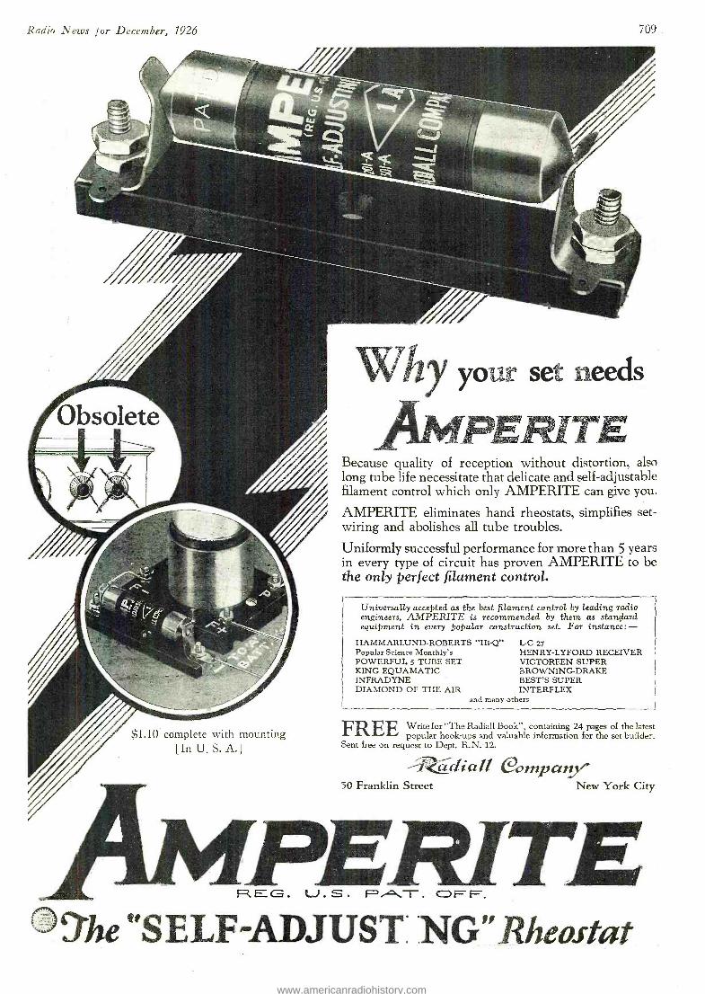
Radio News for December, 1926 709
$1.10 complete with mounting [In U. S. A.]
w hy your set needs
PERITE Because quality of reception without distortion, also long tube life necessitate that delicate and self -adjustable filament control which only AMPERITE can give you.
AMPERITE eliminates hand rheostats, simplifies set - wiring and abolishes all tube troubles.
Uniformly successful performance for more than 5 years in every type of circuit has proven AMPERITE to be the only perfect filament control.
Universally accepted as the best filament control by leading radio engineers, AMPERITE is recommended by them as standard equipment in every popular construction set. For instance:-
HAMMARLUND- ROBERTS "Hi -Q" Popular Science Monthly's POWERFUL 5 TUBE SET KING EQUAMATIC INFRADYNE DIAMOND OF THE AIR
FREE
L -C 27 HENRY -LYFORD RECEIVER VICTOREEN SUPER BROWNING -DRAKE BEST'S SUPER INTERFLEX
and many others
Write for The Radiali Book ", containing 24 pages of the latest popular hook -ups and valuable information for the set -builder.
Sent free on request to Dept. R.N. -12.
-1tdiall Company - 50 Franklin Street New York City
PERITE fEG. . S . PAT. OFF.
tìhe" S E LF ADJUST NG " Rheostat www.americanradiohistory.com
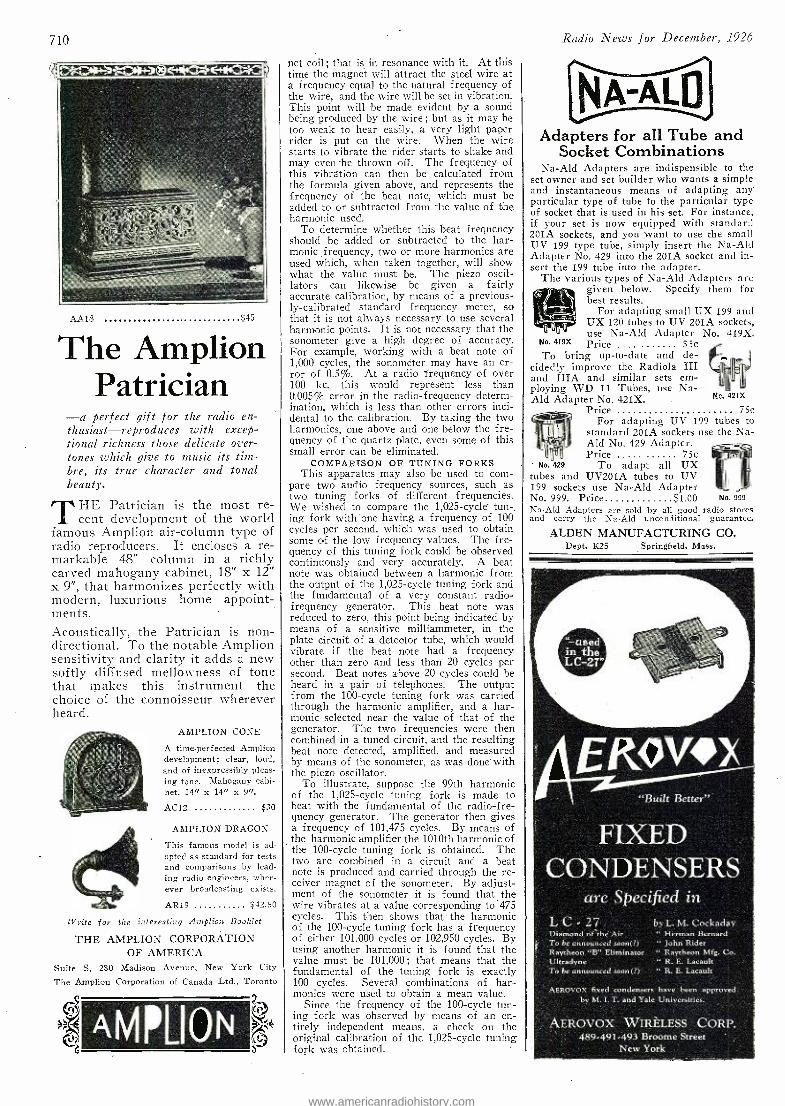
710
AA 18 $45
The Amplion Patrician
-a perfect gift for the radio en- thusiast- reproduces with excep- tional richness those delicate over- tones which give to music its tinz- bre, its true character and tonal beauty.
THE Patrician is the most re- cent development of the world
famous Amplion air -column type of radio reproducers. It encloses a re- markable 48" column in a richly carved mahogany cabinet, 18" x 12" x 9 ", that harmonizes perfectly with modern, luxurious home appoint- ments. Acoustically, the Patrician is non - directional. To the notable Amplion sensitivity and clarity it adds a new softly diffused mellowness of tone that makes this instrument the choice of the connoisseur wherever heard.
AMPLION CONE
A time -perfected Amplion development; clear, loud, and of inexpressibly pleas- ing tone. Mahogany cabi- net, 14" x 14" x 9 ".
AC12 $30
AMPLION DRAGON
This famous model is ad- opted as standard for tests and comparisons by lead- ing radio engineers, wher- ever broadcasting exists.
ÁR19 $42.50
IV rite for the interesting Amplion Booklet
THE AMPLION CORPORATION OF AMERICA
Suite S, 2S0 Madison Avenue, New York City
The Amplion Corporation of Canada Ltd., Toronto
AMPLION .
net coil ; that is in resonance with it. At this time the magnet will attract the steel wire at a frequency equal to the natural frequency of the wire, and the wire will be set in vibration. This point will be made evident by a sound being produced by the wire ; but as it may be too weak to hear easily, a very light paper rider is put on the wire. When the wire starts to vibrate the rider starts to shake and may even-be thrown off. The frequency of this vibration can then be calculated from the formula given above, and represents the frequency of the beat note, which must be added to or subtracted from the value of the harmonic used.
To determine whether this beat frequency should be added or subtracted to the har- monic, frequency, two or more harmonics are used which, when taken together, will show what the value must be. The piezo oscil- lators can likewise be given a fairly accurate calibration, by means of a previous- ly- calibrated standard frequency meter, so that it is not always necessary to use several harmonic points. It is not necessary that the sonometer give a high degree of accuracy. For example, working with a beat note of 1,000 cycles, the sonometer may have an er- ror of 0.5%. At a radio frequency of over 100 kc. this would represent less than 0.005% error in the radio- frequency determ- ination, which is less than other errors inci- dental to the calibration. By taking the two harmonics, one above and one below the fre- quency of the quartz plate, even some of this small error can be eliminated.
COMPARISON OF TUNING FORKS This apparatus may also be used to corn -
pare two audio frequency sources, such as two tuning forks of different frequencies. We wished to compare the 1,025 -cycle tun -. ing fork with one having a frequency of 100 cycles per second, which was used to obtain some of the low frequency values. The fre- quency of this tuning fork could be observed continuously and very accurately. A beat note was obtained between a harmonic from the output of the 1,025 -cycle tuning fork and the fundamental of a very constant radio - frequency generator. This beat note was reduced to zero, this point being indicated by means of a sensitive milliammeter, in the plate circuit of a deteotor tube, which would vibrate if the beat note had a frequency other than zero and less than 20 cycles per second. Beat notes above 20 cycles could be heard in a pair of telephones. The output from the 100 -cycle tuning fork was carried through the harmonic amplifier, and a har- monic selected near the value of that of the generator. The two frequencies were then combined in a tuned circuit, and the resulting beat note detected, amplified, and measured by means of the sonometer, as was done with the piezo oscillator.
To illustrate, suppose the 99th harmonic of the 1,025 -cycle tuning fork is made to beat with the fundamental of the radio -fre- quency generator. The generator then gives a frequency of 101.475 cycles. By means of the harmonic amplifier the 1010th harmonic of the 100 -cycle tuning fork is obtained. The two are combined in a circuit and a beat note is produced and carried through the re- ceiver magnet of the sonometer. By adjust- ment of the sonometer it is found that the wire vibrates at a value corresponding to 475 cycles. This then shows that the harmonic of the 100 -cycle tuning fork has a frequency of either 101,000 cycles or 102,950 cycles. By using another harmonic it is found that the value must be 101,000 ; that means that the fundamental of the tuning fork is exactly 100 cycles. Several combinations of har- monics were used to obtain a mean value.
Since the frequency of the 100 -cycle tun - ing fork was observed by means of an en- tirely independent means, a check on the original calibration of the 1,025 -cycle tuning fork was obtained.
Radio News for December, 1926
NA-ALU Adapters for all Tube and
Socket Combinations Na -Ald Adapters are indispensible to the
set owner and set builder who wants a simple and instantaneous means of adapting any' particular type of tube to the particular type of socket that is used in his set. For instance, if your set is now equipped with standard 201A sockets, and you want to use the small U V 199 type tube, simply insert the Na -Ald Adapter No. 429 into the 201A socket and in- sert the 199 tube into the adapter.
The various types of Na -Aid Adapters are given below. Specify them for best results.
For adapting small UX 199 and UX 120 tubes to UY 201A sockets, use Na -Ald Adapter No. 419X.
No. 419X Price .... 35c To bring up -to -date and de-
cidedly improve the Radiola III and IIIA and similar sets em- ploying WD 11 Tubes, use Na- Ald Adapter No. 421X.
Price - 75c
For adapting UV 199 tubes to standard 201A sockets use the Na- Ald No. 429 Adapter. Price - 75e
No. 429 To adapt all UX tubes and UV201A tubes to UV 199 sockets use Na -Ald Adapter No. 999. Price $1.00 No. 999
Na -Ald Adapters are sold by all good radio stores and carry the Na -Ald unconditional guarantee.
ALDEN MANUFACTURING CO. Dept. K25 Springfield, Mass.
"Built Better"
FIXED CONDENSERS
are Specified in L C - 27 Diamond of-the Air To be announced soon(?) Raytheon "B" Eliminator Ultradyne To be announced soon(?)
by L. M. Cockaday " Berman Bernard " John Rider " Raytheon Mfg. Co. " R. E. Lacault .. -
" R. E. Lacault
" AEROVOX fixed condensers have been approved by M. I. T. and Yale Universities.
AEROVOX WIRELESS CORP. 489- 491 -493 Broome Street
New York
www.americanradiohistory.com
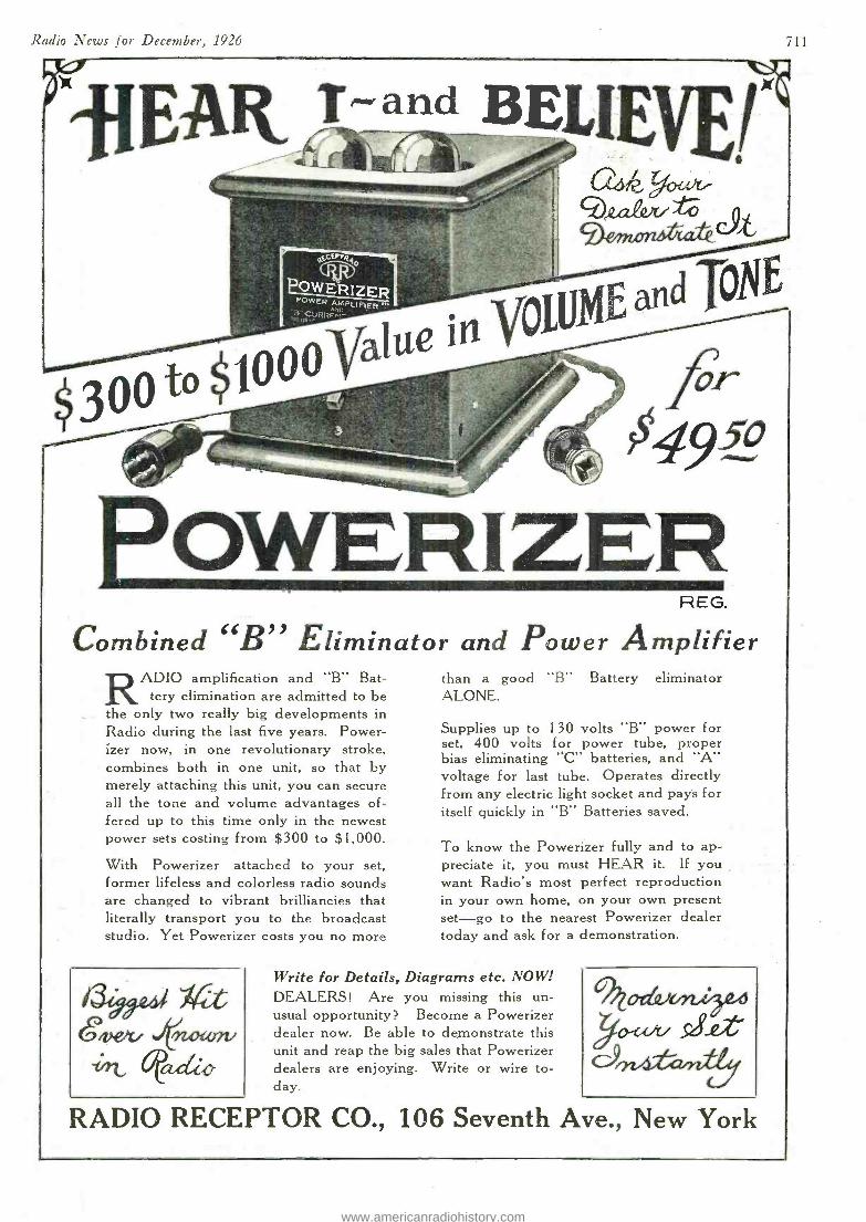
Radio News for December, 1926
rvilEAR T,.-v
-BEL[EvE¡ eo.t.a4ut
cpix)r-
ar
04wp,
OWERI ZER REG.
Combined "B" Eliminator and Power Amplifier RADIO amplification and "B" Bat-
tery elimination are admitted to be the only two really big developments in Radio during the last five years. Power - izer now, in one revolutionary stroke, combines both in one unit, so that by merely attaching this unit, you can secure all the tone and volume advantages of- fered up to this time only in the newest power sets costing from $300 to $1,000.
With Powerizer attached to your set, former lifeless and colorless radio sounds are changed to vibrant brilliancies that literally transport you to the broadcast studio. Yet Powerizer costs you no more
.vew mown. -Nt, aciio
than a good "B" Battery eliminator ALONE.
Supplies up to 130 volts "B" power for set, 400 volts for power tube, proper bias eliminating "C" batteries, and "A'S voltage for last tube. Operates directly from any electric light socket and pays for itself quickly in "B" Batteries saved.
To know the Powerizer fully and to ap- preciate it, you must HEAR it. If you want Radio's most perfect reproduction in your own home, on your own present set -go to the nearest Powerizer dealer today and ask for a demonstration.
Write for Details, Diagrams etc. NOW! DEALERS! Are you missing this un- usual opportunity? Become a Powerizer dealer now. Be able to demonstrate this unit and reap the big sales that Powerizer dealers are enjoying. Write or wire to- day.
C)024f/a/rdb
RADIO RECEPTOR CO., 106 Seventh Ave., New York
www.americanradiohistory.com
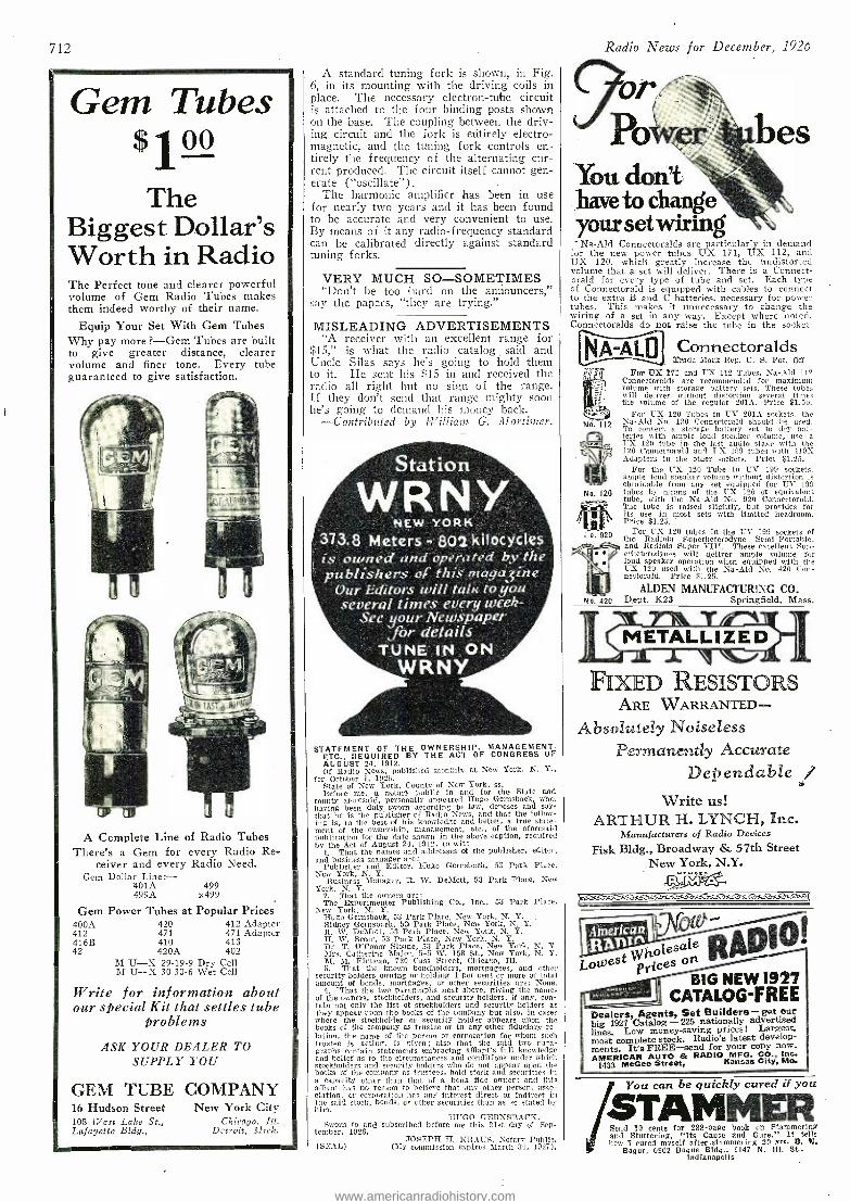
712
Gem Tubes $100
The Biggest Dollar's Worth in Radio The Perfect tone and clearer powerful volume of Gem Radio Tubes makes them indeed worthy cf their name.
Equip Your Set With Gem Tubes Why pay more ?-Gem Tubes are built to give greater distance, clearer volume and finer tone. Every tube guaranteed to give satisfaction.
A Complete Line of Radio Tubes There's a Gem for every Radio Re-
ceiver and every Radio Need. Gem Dollar Line: -
401A 499 499A x499
Gem Power Tubes at Popular Prices 400A 420 412 Adapter 412 471 471 Adapter 416B 410 413 42 420A 402
M U -X 29 -19 -9 Dry Cell M U -X 30 -30 -6 Wet Cell
Write for information about our special Kit that settles tube
problems
ASK YOUR DEALER TO SUPPLY YOU
GEM TUBE COMPANY 16 Hudson Street New York City 108 West Lake St., Chicago. Ill.. Lafayette Bldg., Detroit, 111ich.
A standard tuning fork is shown, in Fig. 6, in its mounting with the driving coils in place. The necessary electron -tube circuit is attached to the four binding posts shown on the base. The coupling between the driv- ing circuit and the fork is entirely electro- magnetic, and the tuning fork controls en- tirely the frequency of the alternating cur- rent produced. The circuit itself cannot gen- erate ( "oscillate ").
The harmonic amplifier has been in use for nearly two years and it has been found to be accurate and very convenient to use. By means of it any radio- frequency standard can be calibrated directly against standard tuning forks.
VERY MUCH SO- SOMETIMES "Don't be too hard on the announcers,"
say the papers, "they are trying."
MISLEADING ADVERTISEMENTS "A receiver with an excellent range for
$15," is what the radio catalog. said and Uncle Silas says he's going to hold them to it. He sent his $15 in and received the radio all right but no sign of the range. If they don't send that range mighty sóou he's going to demand his money back.
-Contributed by William G. Mortimer.
NEW YORK 373.8 Meters - 802 kilocÿcles is owned and operated by the publishers of this nraga3ine
Our Editors will talK7o you several times every week-
See your Newspaper for details
TUNE IN ON WRtVY
STATEMENT REQUIRED
THE BY THEOWNERSHIP. ACT OF CONGRESS OF
AUGUST 24, 1912. Of Radio News, published monthly at New York, N. Y.,
for October 1, 1926. State of New Tork, County of New York, ss. Before me, a notary public in and for the State and
county aforesaid, personally appeared Hugo Gernsback, who, having been duly sworn according to law, deposes and says that he is the publisher of Radio News, and that the follow- ing is, to the best of his knowledge and belief, a true state- ment of the ownership, management, etc., of the aforesaid publication for the date shown in the above caption, required by the Act of August 21, 1912, to wit:
1. That the names and addresses of the publisher, editor, and business manager are:
Publisher and Editor, Hugo Gernsback, 53 Park Place. New York, N. Y.
Business Manager, It. W. DeMott, 53 Park Place, New York, N. Y.
2. That the owners are: The Experimenter Publishing Co., Inc., 53 Park Place,
New York, N. Y. Hugo Gernsback, 53 Park Place, New York, N. Y. Sidney Gernsback, 53' Park Place, New York, N. Y. R. W. DeMott, 53 Parle Place, New York, N. Y. H. W. Secor, 53 Park Place, Nev York, N. Y. Dr. T. O'Conor Sloane, 53 Park Place, New York, N. Y. Mrs. Catherine Mailer, 545 W. 158 St., New York, N. Y. M. M. Finucan, 720 Cass Street, Chicago, Ill. S. That the known bondholders, mortgagees, and other
security holders owning or bolding 1 per cent or more of total amount of bonds, mortgages, or other securities are: None.
4. That the two paragraphs next above, giving the names of the owners, stockholders, and security holders, if any, con- tain not only the list of stockholders and security holders as they appear upon the books of the company but also, in eases where the stockholder or security holder appears upon the books of the company as trustee or in any other fiduciary re- lation, the name of the persan or corporation for whom such trustee is acting, is given; also that the said two para- graphs contain statements embracing afHant's full knowledge and belief as to the circumstances and conditions under which stockholders and security holders who do not appear upon the books of the company as trustees, hold stock and securities in a capacity other than that of a bona fide owner; and this argent has no reason to believe that any other person. asso- ciation, or corporation has any interest direct or indirect in the said stock, bonds, or other securities than as so stated by him.
m'GO GERNSBACK, Sworn to and subscribed before me this 21st day of Sep-
tember, 1926. TOSEPH 11. KRAUS. Notary Public.
(SEAL) (My commission expires March 30. 1927).
Radio News for December, 1926
961' Po bes
You don't have to change your set wiring Na -Ald Connectoralds are particularly in demand
for the new power tubes UX 171, UX 112, and UX 120, which greatly increase the undistorted volume that a set will deliver. There is a Connect- oraid for every type of tube and set. Each type of Connectorald is equipped with cables to connect to the extra B and C batteries, necessary for power tubes. This makes it unnecessary to change the wiring of a set in any way. Except where noted, Connectoralds do not raise the tube in the socket
No. 120
Connectoralds Trade Mark Reg. U. S. Pat. Off
For DX 171 and 'UN 112 Tubes, Na -Ald 112 Connectoralds are recommended for maximum volume with storage battery sets. These tubes will deliver without distortion several times the volume of the regular 201A. Price $1.50.
For UN 120 Tubes in UV 201A sockets, the Na -Ald No. 120 Connectorald should be used. To convert a storage battery set to dry bat- teries with ample loud speaker volume, use a I -X. 120 tube in- the last audio stage with the 120 Connectorald and UX 109 tubes with 419X Adapters in the other sockets. Price $1.25.
For the UX 120 Tube in UV 199 sockets. ample loud speaker volume without distortion is obtainable from any set equipped for UV 199 tubes by means of the UX 120 or equivalent tube, with the Na -Ald No. 920 Connectorald. The tube is raised slightly, but provides for its use in most sets with limited headroom. Price $1.25.
For UX 120 tubes in the LW 199 sockets of the Radiola Superheterodyne Semi -Portable, and Radiola Super VIII. These excellent Sup eheteroclynes will deliver ample volume for loud speaker operation when equipped with the UX 120 used with the Na -Ald No. 420 Con- nectorald. Price $1.25.
ALDEN MANUFACTURING CO. Dept. 1(23 - Springfield, Mass.
7114k T"'4% METALLIZED
L L
FIXED RESISTORS ARE WARRANTED- -
Absolutely Noiseless Permanently Accurate
Dependable / Write us!
ARTHUR H. LYNCH, Inc. Manufacturers of Radio Devices
Fisk Bldg., Broadway St. 57th Street New York, N.Y.
_ r..
American I
fRAn W oles vn Lowest price
RAD10!
BIG NEW 1927 CATALOG-FREE
Dealers, Agents, Set Builders -get our big 1927 Catalog - 225 nationally advertised lines. Low money -saving prices I Largest. most complete stock. Radio's latest develop- ments. It's FREE -send for your copy now. AM3 RIMCGCO
SCAN t eel RADIO Ka Kansas Ciitty, Mc.
You can be quickly cured if you
/STAMMER Send 10 cents for 288 -page book on Stammering and Stuttering, "Its Cause and Cure." It tells how I cured myself after stammering 20 yea. B. N.
Bogue, 6962 Bogue Bldg., 1147 N. III. St., Indianapolis
www.americanradiohistory.com
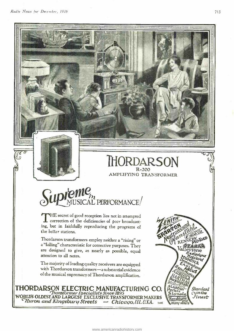
Radio Nrì.'s l or D ere ruGrr. 1(.426
uummm11uumuuummxwwunmummnnnmmnom1mnonnmunmmnmmMwmuumMllwmmmoNUUUwuxx1
THORDARS ON R -200
AMPLIFYING TRANSFORMER
fvsv 7Zj MUSICAL PERFORMANCE/
THE secret of good reception lies not in attempted correction of the deficiencies of boor broadcast-
ing, but in faithfully reproducing the programs of the better stations.
Thordarson transformers employ neither a "rising" or a "falling" characteristic for corrective purposes. They are designed to give, as nearly as possible, equal attention to all notes.
The majority of leading quality receivers are equipped with Thordarson transformers -a substantial evidence of the musical supremacy of Thordarson amplification.
THORDARSON ELECTRIC MANUFACTURING CO. `Transformer Specialists Since 189.5
WORLDS OLDEST AND LARGEST EXCLUSIVE TRANSFORMER MAKERS `?iuron and Kingsbury Streets Chicaco.Ill. U.S.A. 3445
ACq" PerielPv
fs_ tried
many others
Standard fon the inest'
713
www.americanradiohistory.com
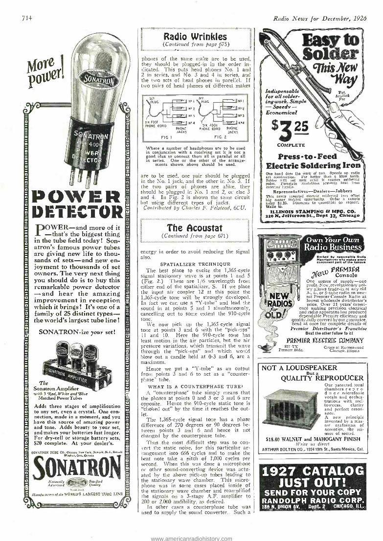
The Acoustat (Continued from page 671)
1,,,,,,,,,,,,1,,,,,a,,,.,n,,,,,,,,,,,,11,1,1,1,,,,,,,,,,,,,,,,,,,,,,,,,,,,,1,n,,,,,,,,,,,1n1,,,,,nmnm,,,,,,,,,:
714
POWER DETECTOR
OWER -and more of it - that's the biggest thing in the tube field today! Son - atron's famous power tubes are giving new life to thou- sands of sets -and new en- joyment to thousands of set owners. The very next thing you should do is to buy this remarkable power detector -and hear the amazing improvement in reception which it brings! It's one of a family of 25 distinct types - the world's largest tube line !
SONATRON -ize your set!
The Sonatron Amplifier with 3 'Red, White and 'Blue
Matched Power Tubes
Adds three stages of amplification to any set, even a crystal. One con- nection, made in a moment, and you have this source of amazing power and tone. Adds beauty to your set, and makes your batteries last longer. For dry -cell or storage battery sets, $20 complete. At your dealer's.
60NATRON TUBE CO.. Chicano. New York, N. ..k. N. J. Detroit Windsor, ana Canada
ONATRO Nationally ONarRON Standard eldvertised ,¢ Quality
Ttal Al.;
Afanl,tartarers of the WORLD'S LARGESTTVBE LINE
k.ummmMautmnm,,.. .dd.!'
Radio Wrinkles (Continued front page 675)
phones of the same make are to be used. they should be plugged -in in the order in- dicated. This pats head phones No. 1 and 2 in series, and No. 3 and 4 in series, and the two sets of head phones in parellel. If two pairs of head phones of different makes
5E7 PLUG
SIX FOOT
PHONE CORD
FIG. I
PHONE JACKS
5E7 N' I PLUG
N'2
N' 3
N' 4 SIX FOOT
PHONE CORD
N'I
N'2
N' 3
N94
PHONE JACKS
FIG. 2
Where a number of headphones are to be used in conjunction with a receiving set it is not a good idea to connect them all in parallel or all in series. One or the other of the arrange-
ments shown above should be used.
are to be used, one pair should be plugged in the No. 1 jack, and the other in No. 3. If the two pairs of phones are alike, they should be plugged in No. 1 and 2. or else 3 and 4. In Fig. 2 is shown the saine circuit but using different types of jacks.
Contributed by Charles F. Felstead, 6CU.
energy in order to avoid reducing the signal also.
SPATIALIZER TECHNIQUE The best place to excite the 1,365 -cycle
signal stationary wave is at points 1 and 5 (Fig. 2.) These are 1/6 wavelength from either end of the spatializer, S. If we place the input air coupler 12 at this point the 1,365 -cycle tone will be strongly developed. In fact we can use a "Y- tube" and lead the sound in at points 5 and 1 simultaneously, cancelling out to some extent the 910 -cycle tone.
We now pick up the 1,365 -cycle signal tone at points 3 and 6 with the "pick -ups" 11 and 10. Here the 910 -cycle tone has least motion in the air particles, but the air pressure variations, which transmit the wave through the "pick -ups" and which would blow out a candle held at 0 -3 and 6, are a maximum.
Hence we put a "Y -tube" as an output from points 3 and 6 to act as a "counter - phase" tube.
WHAT IS A COUNTERPHASE TUBE? A "counterphase" tube simply means that
the phases at points 0 and 3 or 3 and 6 are opposite. Hence the 910 -cycle static tone is "choked out" by the time it reaches the out- let.
The 1,365 -cycle signal tone has a phase difference of 270 degrees or 90 degrees be- tween points 3 and 6 and hence is not changed by the counterphase tube.
Thus the most difficult step was to con - vert the static noise, for this particular ar- rangement into 666 cycles and to make the beat note take a pitch of 1'.000 cycles per second. When this was done a microphone or other sound -converting device was actu- ated by the above pick -up tubes leading to the stationary wave chamber. This micro- phone was in some cases placed inside of the stationary wave chamber and reamplified the signals on a 3 -stage A.F. amplifier to 200 or 2,000 audibility, as desired.
In other cases a counterphase tube was used to supply the sound converter. Such a
Radio t \rezos for December, .1926
Indispensable for all solder - ing work. Simple - Speedy - Economical
$3 25 COMPLETE
Press-to-Feed Electric Soldering Iron One hand does the work of two. Speeds up radio set construction. Far better than a blow torch. Solder will not melt until it reaches soldering point. Porcelain insulations Prevents heat from entering handle.
Representatives -Dealers -- Jobbers This newly invented electric soldering iron offers big money making opportunity. Order a sample today $3.25. Discounts in quantities on request. Write Co.
ILLINOIS STAMPING E.4 MFG. CO. 220 N. JeffersonSt., Dept 13, Chicago
Backed by responsible Radio Manufacturer who makes every component part of the famous
an Console
One source of supply -one profit. N ew, revolutionary pol- icy allows trade -in of any old 3 -, 4-, or 5 -tube radio on new- est Premier Console Radio at
RADIOS
R. DjS) ' lowest wholesale distributor's J price. Over 21 years' experi- for ence making precision electrical
OLD!' and radio apparatus has produced dependable Premier efficiency and
quality,f ully covered byour guarantee. Send at once for complete details of Premier Distributor's Franchise
Beat the other fellow to HI
PREMIER ELEl TRIE EIIMPAMY 8227-Tx Grace at Ravenswood
Premier Bldg. Chicago, Illinois
NOT A LOUDSPEAKER But a
QUALITY REPRODUCER Our patented tonal chambers rep r o- d u c e microfonic vocals and orches- trations with mel- lowness, clarity and perfect reson- ance. A new principle invented by a mas- ter craftsman of acoustics, the sci- ence of sound.
$18.00 WALNUT and MAHOGANY FINISH Write us direct
ARTHUR BOLTEN CO., 192419th St., Santa Monica, Cal.
1927 CATALOG JUST OUT!
SEND FOR YOUR COPY RANDOLPH RADIO CORP. 180 N. UNION AV. Dept. 2 CHICAGO, ILL.
www.americanradiohistory.com
Radio News for December, 1926
2O,OOO,OOO I
"Approved by Raytheon"
Manufacturers of Complete B -Power Units, Raytheon -equipped:
Acme Apparatus Co., Cambridge, Mass. All- American Radio Corp., Chicago, Ill. American Electric Co., Chicago, Ill. Apco Mfg. Co., Providence, R. I. Cornell Elec. Mfg. Co., L. I. City, N.Y. Electrical Research Labs., Inc., Chicago General Radio Co., Cambridge, Mass. Grigsby -Grunow -Hinds Co.,Chicago,Ill. King Elec. Mfg. Co., Buffalo, N. Y. Kokomo Electric Co., Kokomo, Indiana Mayolian Radio Corp., Bronx, N. Y. The Modern Elec. Mfg. Co., Toledo, O. Pathe Phonograph Co., Brooklyn, N. Y. Sparks -Withington Co., Jackson, Mich. The Sterling Mfg. Co., Cleveland, Ohio Storad Mfg. Co., Cleveland, Ohio J. S. Timmons, Inc., Germantown, Phila. Valley Electric Co., St. Louis, Mo. The Webster Co., Chicago, Ill. Zenith Radio Corp.. Chicago, Ill.
r FEN YEARS ago Charles Grover Smith began .11 the intensive study of the possibilities of
handling electrical power by gaseous conduc- tion. With the resources of the Raytheon Re- search Organization behind him, he produced the Raytheon Rectifier, giving for the first time full wave rectification with simplicity, long life, and absolute reliability, and making possible in the one year since its introduction, a business in Raytheon -equipped B -Power units of approxi- mately $20,000,000.
Raytheon has many ideas. For their development Raytheon maintains a Research Organization housed in a separate building, and with a staff headed by such men as Mr. Smith, Dr. Vannevar Bush of M. I. T., Monsieur Andre of the La Radio Technique of Paris, Mr. J. A. Spencer, in- ventor of the Million Dollar Thermostat, and many others. The equipment at their disposal cannot be duplicated anywhere. It is little wonder that those close to radio power prob- lems look to Raytheon for their most effective solution.
RAYTHEON MANUFACTURING COMPANY CAMBRIDGE, MASSACHUSETTS
EA
The Romance of Raytheon
'By DONALD WILHELM
ETWEEN the time Mr. Smith set to work on his research, and the
time that the Raytheon Rectifier was produced there were many hours, days, and months of dreams, discour- agement, thrilling discovery, and pa- tience. It makes good reading. For example, we think of copper as being an excellent conductor, yet Mr. Smith found that he could pass seventy times as much current through a column of gas as through a copper wire of the same diameter. If you are interested to know more about the years of research resulting in the development of the Raytheon Rectifier, we shall be glad to mail you a leaflet telling the story in the words of Mr. Donald Wilhelm, author of " The Story of Steel," " The Story. of Wrought Iron," and many other pub- lications. Drop us a line.
715
-~ RAYTI EON f rectifier
4*1-.
www.americanradiohistory.com
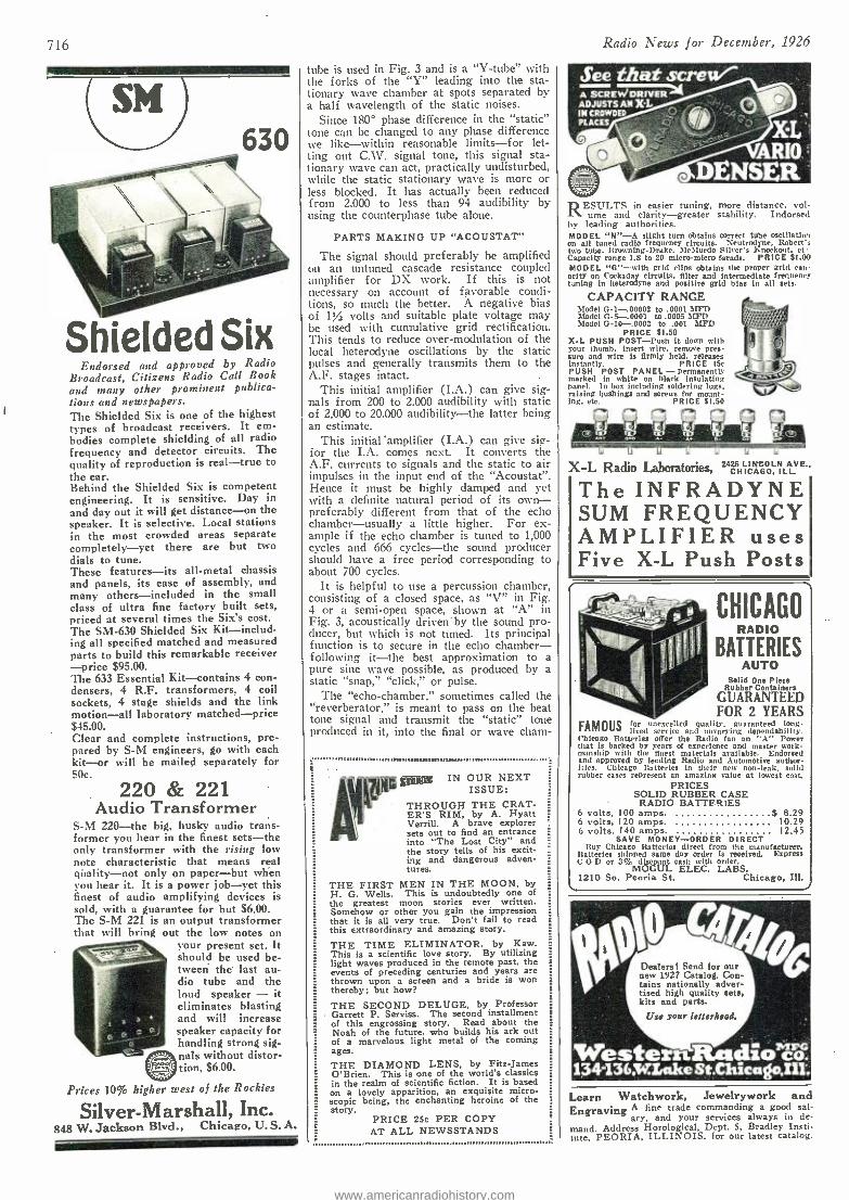
716
SM 630
Shielded Six Endorsed and approved by Radio
Broadcast, Citizens Radio Call Book and many other prominent publica- tions and newspapers. The Shielded Six is one of the highest types of broadcast receivers. It em- bodies complete shielding of all radio frequency and detector circuits. The quality of reproduction is real -true to the ear. Behind the Shielded Six is competent engineering. It is sensitive. Day in and day out it will get distance -on the speaker. It is selective. Local stations in the most crowded areas separate completely -yet there are but two dials to tune. These features -its all -metal chassis and panels, its ease of assembly, and many others -included in the small class of ultra fine factory built sets, priced at several times the Six's cost. The SM -630 Shielded Six Kit- includ- ing all specified matched and measured parts to build this remarkable receiver -price $95.00. The 633 Essential Kit -contains 4 con- densers, 4 R.F. transformers, 4 coil sockets, 4 stage shields and the link motion -all laboratory matched -price $45.00. Clear and complete instructions, pre- pared by S -M engineers, go with each kit-or will be mailed separately for SOc.
220 & 221 Audio Transformer
S -M 220 -the big, husky audio trans- former you hear in the finest sets -the only transformer with the rising low note characteristic that means real quality -not only on paper -but when you hear it. It is a power job -yet this finest of audio amplifying devices is sold, with a guarantee for but $6.00. The S -M 221 is an output transformer that will bring out the low notes on
your present set. It should be used be- tween the last au- dio tube and the loud speaker - it eliminates blasting and will increase speaker capacity for handling strong sig-
0nals without distor- tion, $6.00.
Prices 10% higher west of the Rockies
Silver -Marshall, Inc. 848 W. Jackson Blvd., Chicago, U.S. A.
tube is used in Fig. 3 and is a "Y- tube" with the forks of the "Y" leading into the sta- tionary wave chamber at spots separated by a half wavelength of the static noises.
Since 180° phase difference in the "static" tone can be changed to any phase difference we like- within reasonable limits -for let- ting out C.V. signal tone, this signal sta- tionary wave can act, practically undisturbed, while the static stationary wave is more or less blocked. It has actually been reduced from 2,000 to less than 94 audibility by using the counterphase tube alone.
PARTS MAKING UP "ACOUSTAT"
The signal should preferably be amplified on an untuned cascade resistance coupled amplifier for DX work. If this is not necessary on account of favorable condi- tions, so much the better. A negative bias of 1% volts and suitable plate voltage may be used with cumulative grid rectification. This tends to reduce over- modulation of the local heterodyne oscillations by the static pulses and generally transmits them to the A.F. stages intact.
This initial amplifier (I.A.) can give sig- nals from 200 to 2.000 audibility with static of 2,000 to 20,000 audibility -the latter being an estimate.
This initial 'amplifier (I.A.) can give sie- for the I.A. comes next. It converts the A.F. currents to signals and the static to air impulses in the input end of the "Acoustat ". Hence it must be highly damped and yet with a definite natural period of its own - preferably different from that of the echo chamber- usually a little higher. For ex- ample if the echo chamber is tuned to 1,000 cycles and 666 cycles -the sound producer should have a free period corresponding to about 700 cycles.
It is helpful to use a percussion chamber, consisting of a closed space, as "V" in Fig. 4 or a semi -open space, shown at "A" in Fig. 3, acoustically driven by the sound pro- ducer, but which is not tuned. Its principal function is to secure in the echo chamber - following it -the best approximation to a pure sine wave possible, as produced by a static "snap," "click," or pulse.
The "echo- chamber," sometimes called the "reverberator," is meant to pass on the beat tone signal and transmit the "static" tone produced in it, into the final or wave cham-
,tIttlm..n$11omnunna.m.mn,mnnnmmmrm:1mwumw.,a.1o1.m.1i.im,i0ou..,.1...,.,.1.
pone IN OUR NEXT ISSUE:
THROUGH THE CRAT- ER'S RIM, by A. Hyatt Verrill. A brave explorer sets out to find an entrance into "The Lost City" and the story tells of his excit- ing and dangerous adven- tures.
THE FIRST MEN IN THE MOON, by H. G. Wells. This is undoubtedly one of the greatest moon stories ever written. Somehow or other you gain the impression that it is all very true. Don't fail to read this extraordinary and amazing story.
THE TIME ELIMINATOR. by Kaw. This is a scientific love story. By utilizing light waves produced in the remote past, the events of preceding centuries and years are thrown upon a screen and a bride is won thereby; but how?
THE SECOND DELUGE, by Professor Garrett P. Serviss. The second installment of this engrossing story. Read about the Noah of the future, who builds his ark out of a marvelous light metal of the coming ages.
THE DIAMOND LENS. by Fitz -James O'Brien. This is one of the world's classics in the realm of scientific fiction. It is based on a lovely apparition, an exquisite micro-
'_- scopic being, the enchanting heroine of the story.
PRICE 25c PER COPY AT ALL NEWSSTANDS
Radio News for December, 1926
See that screW/- A SCREN,IMI. R ADJUSTS AN X-L IN CROWDED PLACES
X**L nn ,
L'llu DENSER
RESULTS in easier tuning, more distance, vol- ume and clarity -greater stability. Indorsed
by leading authorities. MODEL "N " -A slight turn obtains correct tube oselllatint on all tuned radio frequency circuits. Neutrodyne, Robert's two tube, Browning-Drake, McMurdo Silver's Knockout. et Capacity range 1.8 to 20 micro-micro farads. PRICE $1.00 MODEL "G" -with grid clips obtains the proper grid cap- acity on Cockaday circuits, filter and intermediate frequency tuning in heterodyne and positive grid bins in all sets.
CAPACITY RANGE ,0,-
Model G -1- .00002 to .0001 ár177 ;, , -
Dfodel G -5 -.0001 to .0005 MFD ' iii Model O -10 -.0003 to 001 MJ'D ' '- " "'`
PRICE $1.50 X -L PUSH POST -Push it down with your thumb, insert wire, remove pres- sure and wire is firmly held. releases instantly. PRICE l5e PUSH POST PANEL - permanently marked to white on black insulating panel. In box including soldering lugs, raising bushings :old screws for mount- ing. etc. PRICE SI.50
r f rl rí r-Aarl T..essasemanamamosameau
1,
X -I, Radio laboratories 2 LION .
f 32
C0 HICNCAGOL. ILL AVR.
The INFRADYNE SUM FREQUENCY AMPLIFIER uses Five X -L Push Posts
CHICAGO RADIO
IES BATTER AUTO
Solid One Piece Rubber Containers
GUARANTEED FOR 2 YEARS
FAMOUSfar unexcelled quality. guaranteed long - lived service and unvarying dependability.
Chicago Batteries offer the Radio fan an A" Power that is backed by years of experience and master wamk- manship with the finest materials available. Endorsed and approved by leading Radio and Automotive author- ities. Chicago Batteries in their new non -leak, solid tubber cases represent an amazing value at burst cost.
PRICES SOLID RUBBER CASE RADIO BATTERIES
6 volts, 100 amps. $ 8.29 6 volts, 120 amps. 10.29 6 volts, 140 amps. 12.45
SAVE MONEY -ORDER DIRECT Buy Chicago Batteries direct from the manufacturer.
Batteries shipped same day order is received. Express C O D or 3% discount cash with order.
MOGUL ELEC. LABS. 1210 So. Peoria St. Chicago, Ill.
Dealers! Send for our new 1927 Catalog. Con- tains nationally adver- tised high quality sets, kits and parts.
Use your letterhead.
WesterslRadio có 134r1363nake St.Çkicago;,Iil;
Learn Watchwork, Jewelrywork and Engraving A tine trade commanding a good sal-
ary, and your services always in de- mand. Address Horological, Dept. 5, Bradley Insti- tute, PEORIA, ILLINOIS. for our latest catalog.
www.americanradiohistory.com
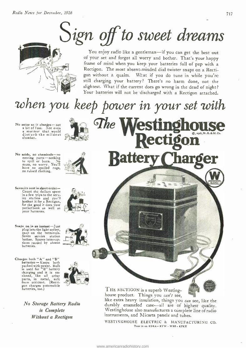
Radio News for December, 1926
Sign of to sweet dreams You enjoy radio like a gentleman -if you can get the best out
of your set and forget all worry and bother. That's your happy frame of mind when you keep your batteries full of pep with a Rectigon. The most absent -minded dial twister snaps on a Recti- gon without a qualm. WIat if you do tune in while you're still charging your battery? There's no harm done, not the slightest. What if the current does go wrong in the dead of night? Your batteries will not be discharged with a Rectigon attached.
when you keep power in your set with No noise as it charges -not
a bit of fuss. Not even a murmur that would disturb the mildest sl um ber.
No acids, no chemicals -no moving parts- nothing to spill or burn. No muss, no worry. You'll ,
have no spoiled rugs, no ruined clothing.
Saves its cost in short order - Count the dollars spent in a few trips to the serv- ice sta tion and you'll hotfoot it for a Rectigon, for the good it does your pocketbook as well as your batteries.
Snaps on in an instant -Just plug into the light socket, snap on the terminals. Saves service station bother. Spares interrup- tions caused by absent batteries.
6-The Westinghouse Rectigon
Batter karger
Charges both "A" and "B" batteries- Keeps both packed with power. Bulb is used for "B" battery charging and it is en- closed, like all other parts, in metal, safe from accident. (Recti- gon charges automobile batteries, too.)
No Storage Battery Radio is Complete
Without a Rectigon
THE RECT1GON is a superb Westing- house product. Things you can't see, like extra heavy insulation, things you can see, like the durably enameled case -all are of highest quality. Westinghouse also manufactures a complete line of radio instruments, and Micarta panels and tubes. WESTINGHOUSE ELECTRIC & MANUFACTURING CO.
Tune in on KDKA- KYW - WBZ. KFKX
717
www.americanradiohistory.com
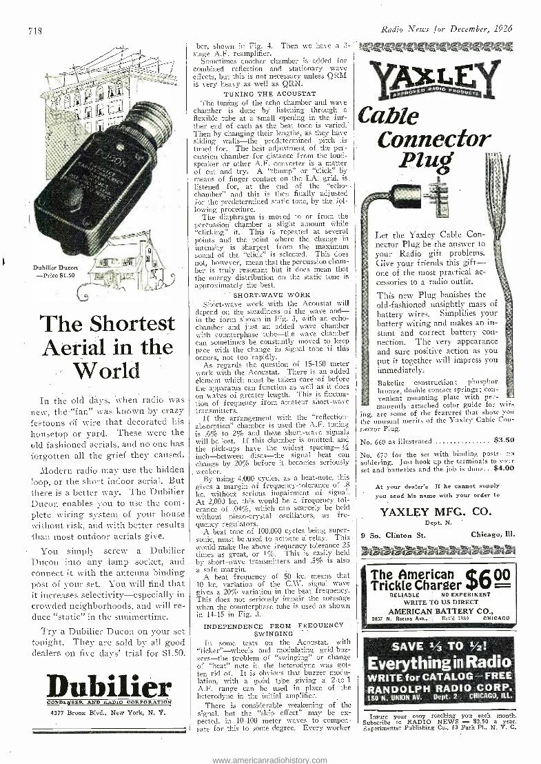
718
Dubilier Ducon -Price $1.50
The Shortest Aerial in the
World In the old days, when radio was
neW, the "fan" was known by crazy festoons Of wire that decorated his housetop or yard. These were the old fashioned aerials, and no one has forgotten all the grief they caused.
Modern radio may use the hidden loop, or the short indoor aerial. But there is a better way. The Dubilier Ducon enables you to use the coin - plete wiring system of your house without risk, and with better results than most outdoor aerials give.
You simply screw a Dubilier Ducon into any lamp socket, and connect it with the antenna binding post of your set. You will find that it increases selectivity- especially in crowded neighborhoods, and will re- duce "static" in the summertime.
Try a Dubilier Ducon on your set tonight. They are sold by all good dealers on five days' trial for $1.50.
Dubilier CONDEArSER AND RADIO CORPORATION
4377 Bronx Blvd., New York, N. Y.
ber, shown in Fig. 4. Then we have a 3- stage A.F. reamplifier.
Sometimes another chamber is added for combined reflection and stationary wave effects, but this is not necessary unless QRM is very heavy as well as QRN.
TUNING THE ACOUSTAT The tuning of the echo chamber and wave
chamber is done by listening through a flexible tube at a 'small opening in the furs- ther end of eäch as the -beat tone is varied.- Then by changing their lengths, as they have sliding walls -the predeteriniried pitch is tuned for. The best adjustment of the per- cussion chamber for distance from the loud- speaker or other A.F. converter is a matter of cut and try. A "thump" or "click". by means of finger contact on the I.A grid, is listened for, at the end of the "echo- -
chamber" and this is then finally adjusted for the predetermined static tone, by the fol- lowing procedure.
The diaphragm is moved to or from the percussion chamber a slight amount while "clicking" it. This is repeated at several points and the point where the change in intensity is sharpest from the maximum sound of the "click" is selected. This does not, however, mean that the percussion cham- ber is truly resonant but it does mean that the energy distribution on the static tone is approximately the best.
SHORT -WAVE WORK Shòrt -wave work with the Acoustat will
depend on the steadiness of the wave and- in the form shown in Fig. 3, with an echo - chamber and just an added wave chamber with counterphase tube -the wave chamber can sometimes be constantly moved to keep pace with the change in signal tone if this occurs, not too 'rapidly.
As regards the question of 15 -150 meter work with the Acoustat. There is an added element which must be taken care -of before the apparatus can function as well as it does on waves of greater length. This is fluctua- tion of frequency from amateur short -wave transmitters.
If the arrangement with the "reflection- absorption" chamber is used the A.F. tuning is .6% to 2% and these short -wave signals will be lost. If this chamber is omitted, and the pick -ups have the widest spacing -/ inch -between discs -the signal beat can change by 20% before it beconies seriously
. weaker. By using 4,000 cycles, as a beat -note, this
gives a margin of frequency -tolerance of .8
kc. without serious impairment of signal' At 2,000 kc. this would be a frequency tol- erance of .04 %, which can scarcely be held without piezo- crystal oscillators, as fre- quency regulators.
A beat tone of 100,000 cycles being super- sonic, must - be .used to actuate a relay. This would make the above frequency tolerance 25
times as great, or 1%. This is easily held by short -wave transmitters and .5% is also a safe margin.
A beat frequency of 50 kc. means that 10 kc. variation of the C.V. signal wave gives a 20% variation in the beat frequency. This does not seriously impair the message when the counterphase tube is used as shown in 14 -15 in Fig. 3.
INDEPENDENCE FROM FREQUENCY SWINGING
In some tests on the Acoustat, with "ticker " -wheels and modulating grid -buz- zers -the problem of "swinging" or change of "beat" note in the heterodyne was got- ten rid of. It is obvious that buzzer modu- lation, with a good type giving a 2 -to -1 A.F. range can be used in place of the heterodyne in the initial amplifier.
There is considerable weakening of the signal, but the "skip effect" may be ex- pected, in 10 -100 meter waves to compen- sate for this to some degree. Every worker
Radio News for December, 1926 . y1i Xi yi Wi ri r i;r ) ) ;ri;x t4, .k ^ ,S.: .. k K. -F ik .S. -4 -k ik Yn
Aluzy Cable
Connector Plug 1! T%`
Let the Yaxley Cable Con- nector Plug be the answer to your Radio gift problems. Give your friends this gift - one of the most practical ac- cessories to a radio outfit.
This new Plug banishes the old -fashioned unsightly mass of
battery wires. Simplifies your battery wiring and makes an in- stant and correct battery con- nection. The very appearance and sure positive action as you put it together will impress you immediately.
Bakelite construction; phosphor bronze, double contact springs; con- venient mounting plate with per - manently attachéd color guide for wir-
ing, are some of the features that show you the unusual merits of the Yaxley Cable Con- nector Plug.
No. 660 as illustrated $3.50
No. 670 for the set with binding posts --no soldering. Just hook up the terminals to your set and batteries and the job is done $4.00
At your dealer's If he cannot supply you send his name with your order to
YAXLEY MFG. CO. Dept. N.
9 So. Clinton St.
I ,';..
Chicago, Ili.
The American C6 00 Trickle Charger
RELIABLE NO EXPERIMENT WRITE TO US DIRECT
AMERICAN BATTERY CO., 2057 N. Racine Ave., st'd 1559 CHICAGO
SAVE 1/3 TO 1/2:
Everything in Radio WRITE for CATALOG -FREE RANDOLPH RADIO CORP. 180 N. UNION AV. Dept. 2 CHICAGO, ILL.
Insure your cony reaching you each month. Subscribe to RADIO NEWS - $2.50 a year. Experimenter Publishing Co., 53 Park Pl., N. Y. C.
www.americanradiohistory.com
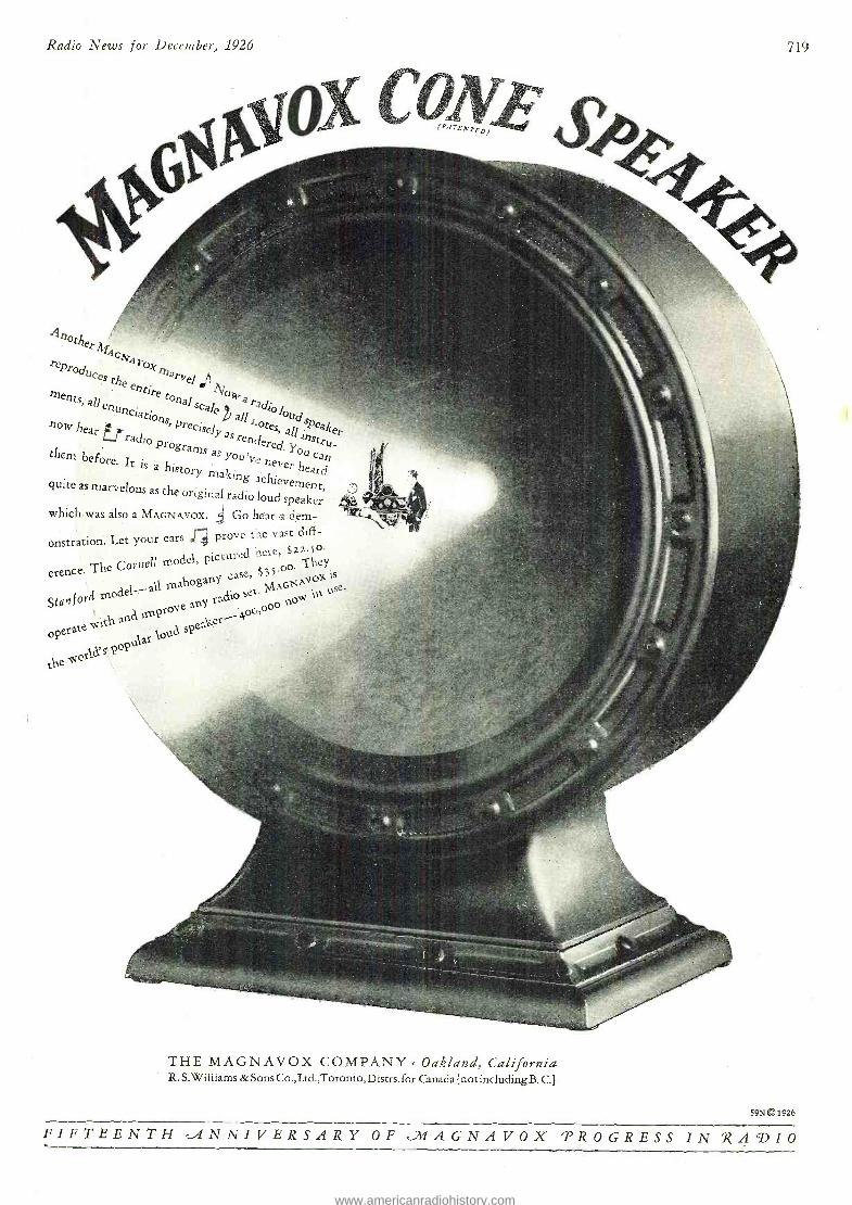
Radio News for December, 1926
oNzi (P.iTENTf p
719
4120th
reproduces r
ox marvel
J' he en ti Inents,all s °wara ecise! a,l
alSPr`e1 nog. hear Y as
them Programs as You'vd hed. y ° á before. It is a histor er
Y makin heard.
quite as marvelous as the original g achievement
o nal radioloud speaker ,
which was álso a MAGNAVOX. 4 Go hear a dem-
onstration. Let your ears ,r; prove tie vast diff-
erence. The Connell model, picture -fh.ey
lhoganY case, ß5'p °rivo %.ls
moat! -all m< set M C Usé.
Stan f orti n radi° lo and ,mptOVe
a Y °< '
overate
s 4 °pt,kaz ko, speaker
LN,e It °zld
d rere $zz.5o
THE MAGNAVOX COMPANY . Oakland, California R. S. Williams & Sons Co., Ltd.,Toronto, Distrs. for Canada {not including B. C.}
59N0 1926
FIFTEENTH cA4NNIVERSARY OF tíl1AGNAVOX PROGRESS IN YZAGDIO
www.americanradiohistory.com
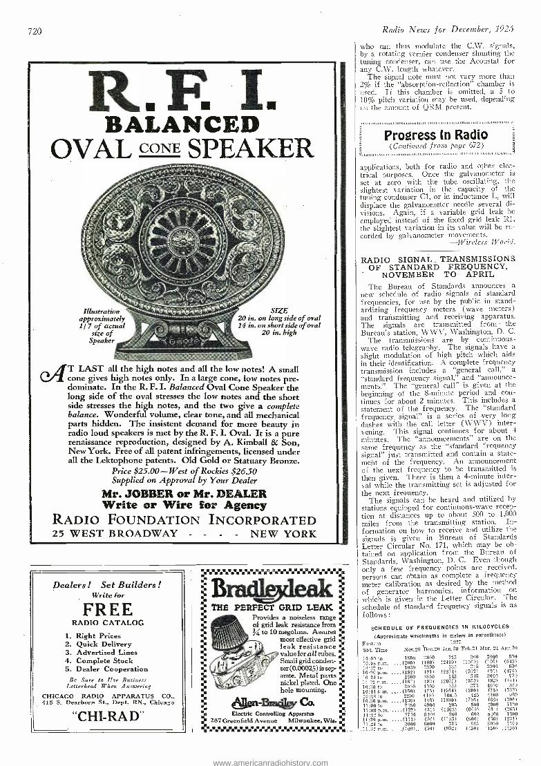
720
R.F. I. BALANCED
OVAL CONE SPEAKER
Illustration approximately 1/7 of actual
size of Speaker
SIZE 20 in. on long side of oval 14 in. on short side of oval
20 in. high
TT LAST all the high notes and all the low notes! A small ( cone gives high notes only. In a large cone, low notes pre- dominate. In the R. F. I. Balanced Oval Cone Speaker the long side of the oval stresses the low notes and the short side stresses the high notes, and the two give a complete balance. Wonderful volume, clear tone, and all mechanical parts hidden. The insistent demand for more beauty in radio loud speakers is met by the R. F. I. Oval. It is a pure renaissance reproduction, designed by A. Kimball & Son, New York. Free of all patent infringements, licensed under all the Lektophone patents. Old Gold or Statuary Bronze.
Price $25.00 -West of Rockies $26.50 Supplied on Approval by Your Dealer
Mr. JOBBER or Mr. DEALER Write or Wire for Agency
RADIO FOUNDATION INCORPORATED 25 WEST BROADWAY - - - - NEW YORK
Dealers ! Set Builders ! Write for
FREE RADIO CATALOG
I. Right Prices 2. Quick Delivery 3. Advertised Lines 4. Complete Stock 5. Dealer Cooperation
Be Sure to Use Business Letterhead When Answering
CHICAGO RADIO APPARATUS CO., 415 S. Dearborn St., Dept. RN., Chicago
"CHI-RA D"
}inni a.ìi .u áa'ra°fi i . Bracbdeak.
ti THE PERFECT GRID LEAK ti ti ti ti
ti
ti ti .
i
Provides a noiseless range eL of grid leak resistance from
to IO megohms. Assures L most effective grid k leak resistance % value for all tubes. ".. Small grid conden- ser(0.00025) is sep- .s arate. Metal parts a nickel plated. One eé hole mounting. .
611011-SagitY CC" . Electric Controlling Apparatus é le 287 Greenfield Avenue Milwaukee. Wie.
Radio News for December, 1925
who can thus modulate the C.W. signals, by a rotating vernier condenser shunting the tuning condenser, can use the Acoustat for any C.W. length whatever.
The signal note must not vary more than 2% if the "absorption- reflection" chamber is used. If this chamber is omitted, a 5 to 10% pitch variation may be used, depending (n the amount of ORM present.
Progress In Radio (Continued front page 672)
P..00,s00,88sss.smss0ss.s.00...00ssmsLst 11111,...,1 .1.111 111111.11.11,11r1.111111
a e 672
applications, both for radio and other elec- trical purposes. Once the galvanometer is set at zero with, the tube oscillating, the slightest variation in the capacity of the tuning condenser Cl, or in inductance L, will displace the galvanometer needle several di- visions. Again, if a variable grid leak be employed instead of the fixed grid leak Rl, the slightest variation in its value will be re- corded by galvanometer movements.
-Wireless World.
RADIO SIGNAL TRANSMISSIONS OF STANDARD FREQUENCY,
NOVEMBER TO APRIL The Bureau of Standards announces a
new schedule of radio signals of standard frequencies, for use by the public in stand- ardizing frequency meters (wave meters) and transmitting and receiving apparatus. The signals are transmitted from the Bureau's station, WWV, Washington, D. C.
The transmissions are by continuous - wave radio telegraphy. The signals have a slight modulation of high pitch which aids in their identification. A complete frequency transmission includes a "general call," a "standard frequency signal," and "announce- ments." The "general call" is given at the beginning of the 8- minute period and con- tinues for about 2 minutes. This includes a statement of the frequency. The "standard frequency, signal" is a series of very long dashes with the call letter (WWV) inter- vening. This signal continues for about 4 minutes. The "announcements" are on the same frequency as the "sfandard frequency signal" just transmitted and contain a state- ment of the frequency. An announcement of the next frequency to be transmitted is
then given. There is then a 4- minute inter- val while the transmitting set is adjusted for the next frequency.
The signals can be heard and utilized by stations equipped for continuous -wave recep- tion at distances up to about 500 to 1,000 miles from the transmitting station. In- formation on how to receive and utilize the signals is given in Bureau of Standards Letter Circular No. 171, which may be ob- tained on application from the Bureau of Standards, Washington, D. C. Even though only a few frequency points are received, persons can obtain as complete a frequency meter calibration as desired by the method of generator harmonics, information on which is given in the Letter Circular. The schedule of standard frequency signals is as follows :
SCHEDULE OF FREQUENCIES IN KILOCYCLES
(Approximate wavelengths in meters in parentheses)
Eastern Std. Time
1927
Nov.20 Dec.20 Jan.20 Feb.21 D4ar. 21 Apr.20
10:00 to 1500 3000 125 200 3000 550 10:08 p.m. ..(200) (100) (2400) (1000) (100) (545) 10:12 to 1050 3300 133 30.5 3300 630 10:20 p.m. . ..(182) (91) (2254) (952) (91) (476) 10:24 ta 1800 3600 143 345 3600 730
10:22 p.m. . ..(167.1 (83) (2097) (S69) (83) (4í1't
10:36 to 2000 4000 155 375 4000 450 10:44 p.m. . ..(150) (75) (1934) (800) (75) (353) 10:48 to 2200 4400 160.5 425 4400 980 10:56 p.m. . ..(126) (68) (1800) (705) (68) (306) 11:00 to 2450 4900 205 500 4900 1130 11:08 p.m. . ..(122) (61) (1463) (600) (61) (2fi.5) 11:12 to 2700 5400 260 -600 5400 1300 11:20 D.m. . (111) (56) (1153) (500) (50) (231) 11 1to 3000 5000 315 666 6000 1500 11.3 t.m. ...__(100.)..- (5.0) (9.521 (150) (50) ..(200)
www.americanradiohistory.com
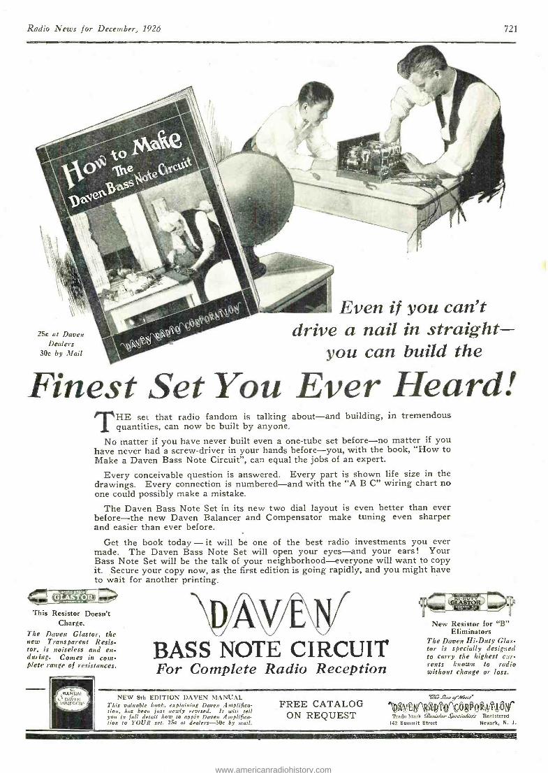
Radio News for December, 1926 721
25c at Doyen Dealers
30c by Mail
Even if you can't drive a nail in straight -
you can build the
Finest Set You Ever Heard! THE set that radio fandotn is talking about -and building, in tremendous
quantities, can now be built by anyone.
No matter if you have never built even a one -tube set before -no matter if you have never had a screw- driver in your hands before -you, with the book, "How to Make a Daven Bass Note Circuit ", can equal the jobs of an expert.
Every conceivable question is answered. Every part is shown life size in the drawings. Every connection is numbered -and with the "A B C" wiring chart no one could possibly make a mistake.
The Daven Bass Note Set in its new two dial layout is even better than ever before -the new Daven Balancer and Compensator make tuning even sharper and easier than ever before.
Get the book today - it will be one of the best radio investments you ever made. The Daven Bass Note Set will open your eyes -and your ears! Your Bass Note Set will be the talk of your neighborhood- everyone will want to copy it. Secure your copy now, as the first edition is going rapidly, and you might have to wait for another printing.
4101EIPV511
This Resistor Doesn't Charge.
The Doyen Glastor, the new Transparent Resis- tor, is noiseless and en- during. Connes in com- plete range of resistances.
,IIANUAI nn'vu
VIvurIC+110)
DAVEN BASS NOTE CIRCUIT For Complete Radio Reception
i4R' New Resistor for "B"
Eliminators The Doyen Hi -Duty Glas- tor is specially designed to carry the highest c::r- rents known to radio without change or loss.
NEW 8th EDITION DAVEN MANCAI. This valuable book, explaining Daven Amplifica- tion, has been just newly revised. It will tell you in full detail how to apply Daven Amplifica- tion to YOUR set. 25c at dealers -30c by nail.
FREE CATALOG ON REQUEST
A
T JI n p¡ne;ete'
, :Alit Atosr Trade Mark úr/ eJ ,cia(;rfs Begtsterni
142 Summit Street Newark, N. .I.
www.americanradiohistory.com
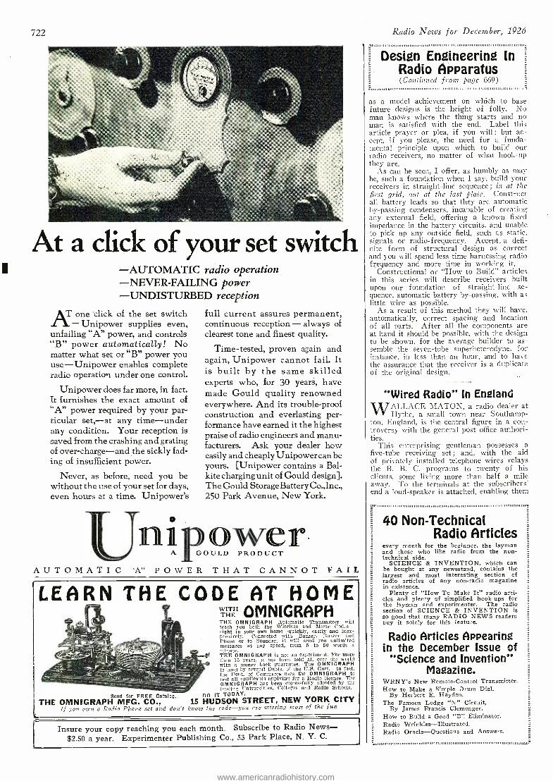
722
At a click of your set switch -AUTOMATIC radio operation -NEVER- FAILING power -UNDISTURBED reception
AT one click of the set switch - Unipower supplies even,
unfailing "A" power, and controls "B" power automatically! No matter what set or "B" power you use - Unipower enables complete radio operation under one control.
Unipower does far more, in fact. It furnishes the exact amount of "A" power required by your par- ticular set, -at any time -under any condition. Your reception is saved from the crashing and grating of over -charge -and the sickly fad- ing of insufficient power.
Never, as before, need you be without the use of your set for days, even hours at a time. Unipower's
A U T O M A T I C
full current assures permanent, continuous reception - always of clearest tone and finest quality.
Time - tested, proven again and again, Unipower cannot fail. It is built by the same skilled experts who, for 30 years, have made Gould quality renowned everywhere. And its trouble -proof construction and everlasting per- formance have earned it the highest praise of radio engineers and manu- facturers. Ask your dealer how easily and cheaply Unipower can be yours. [Unipower contains a Bal- kite charging unit of Gould design]. The Gould Storage Battery Co., Inc., 250 Park Avenue, New York.
nipor ' A GOULD PRODUCT
"A" POWER THAT CANNOT FAIL
LEARN THE CODE AT HOME THE OMNIGRAPH THE OMNIGRAPH Automatic Transmitter will teach you both the Wireless and Morse Codes - right in your own home -quickly, easily and inex- pensively. Connected with Buzzer, Buzzer and Phone or to Sounder, it will send you unlimited messages at any speed, from 5 to 50 words a
-0 minute. THE OMNIGRAPH is not an experiment. For more than 15 years, it has been sold all over the world with a money back guarantee. The OMNIGRAPH is used by several Depts.- of the D.S. Govt. -in fact, the Dept. of Commerce uses the OMNIGRAPH to test all applicants applying for a Radio license. The OMNIGRAPH has been successfully adopted by the leading Universities, Colleges and Radio Schools.
Send for FREE Catalog. THE OMNIGRAPH MFG. CO., 15 HUDSON
Do IT TODAY. STREET, NEW YORK CITY
If you own a Radio Phone set and don't know the code-you ere missing most of the fun I
Insure your copy reaching you each month. Subscribe to Radio News - $2.50 a year. Experimenter Publishing Co., 53 Park Place, N. Y. C.
Radio News for December, 1926
Design Engineering in Radio Apparatus (Continued front page 669)
,,,,,,,,,,,,,,,,,,,.,,,,,,,,,,,,,,,, ,,,..,,..,..,,.,,, , ,,.,..,,,,,,,,,,,.,..,. ,,,,,
as a model achievement on which to base future designs is the height of folly. No man knows where the thing starts and no man is satisfied with the end. Label this article prayer or plea, if you will ; but ac- cept, if you please, the need for a funda- mental principle upon which to build our radio receivers, no matter of what hook -up they are.
As can be seen, I offer, as humbly as may be, such a foundation when I say, build your receivers in straight -line sequence ; in at the first grid, out at the last plate. Construct all battery leads so that they are automatic by- passing condensers, incapable of creating any external field, offering a known fixed impedance in the battery circuits, and unable to pick up any outside field, such as static. signals or radio- frequency. Accept- a defi- nite form of structural design as correct and you will spend less time harnessing radio frequency and more time in working it.
Constructional or "How to Build" articles in this series will describe receivers built upon our foundation of straight -line se- quence, automatic battery by- passing, with as little wire as possible.
As a result of this method they will have, automatically, correct spacing and location of all parts. After all the components are at hand it should be possible, with the design to be shown, for the average builder to as- semble the seven -tube superheterodyne, for instance, in less than an hour, and to have the assurance that the receiver is a duplicate of the original design.
"Wired Radio" In England
WALLACE MATON, a radio dealer at Hythe, á small town near Southamp-
ton, England, is the central figure in a con- troversy with the general post office authori- ties.
This enterprising gentleman possesses a five -tube receiving set ; and, with the aid of privately installed telephone wires relays the B. B. C. programs to twenty of his clients, some living more than half a mile away. To the terminals at the subscribers' end a loud -speaker is attached, enabling them
40 Non -Technical Radio Articles
every month for the beginner, the layman and those who like radio from the non- technical side.
SCIENCE & INVENTION, which can be bought at any newsstand, contains the largest and most interesting section of radio articles of any non -radio magazine in existence.
Plenty of "How To Make It" radio arti- cles and plenty of simplified hook -ups for the layman and experimenter. The radio section of SCIENCE & INVENTION is so good that many RADIO NEWS readers buy it solely for this feature.
Radio Articles Appearing in the December Issue of
"Science and Invention's Magazine.
WRNY's New Remote -Control Transmitter. How to Make a Simple Drum Dial,
By Herbert E. Hayden. The Famous Lodge "N" Circuit,
By James Francis Clemenger. How to Build a Good "B ". Eliminator. Radio Wrinkles -Illustrated. Radio Oracle- Questions and Answers.
www.americanradiohistory.com
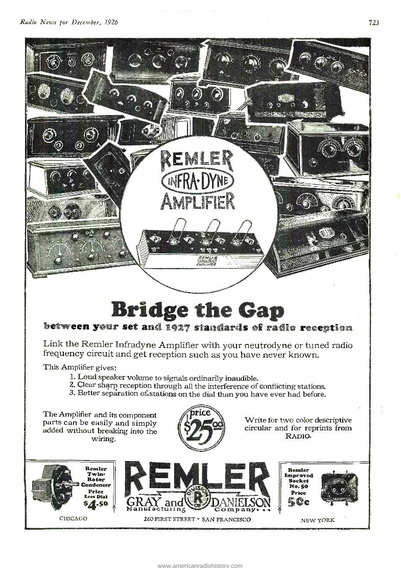
Radio News for December, 1926
7=77----
723
met.-__
ll id,. ',;,, ':s;- % _ -
Bridge the Gap between your set and 1927 standards of radio reception Link the Remler Infradyne Amplifier with your neutrodyne or tuned radio frequency circuit and get reception such as you have never known. This Amplifier gives:
1. Loud speaker volume to signals ordinarily inaudible. 2. Clear sharp reception through all the interference of conflicting stations. 3. Better separation of.stations on the dial than you have ever had before.
The Amplifier and its component parts can be easily and simply added without breaking into the
wiring.
Remler Twin - Rotor
Condenser Price
Le4so GRAY and DAMELSON Manufacturing Comp any. .4. 260 FIRST STREET - SAN FRANCISCO
Write for two color descriptive circular and for reprints from
RADIO.
CHICAGO
Remler Improved
Socket No. SO Price
50c NEW YORK
www.americanradiohistory.com
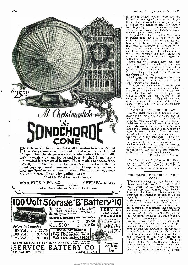
724
BY those who have tried them all Sonochorde is recognized as the premiere achievement in radio acoustics. Instead
of paper, Sonochorde presents a rich wine -colored front of silk with unbreakable metal frame and base, finished in mahogany -a musical instrument of beauty. Three models to choose from -Wall, Floor Standard and Table, each equipped with the or- iginal super -powered Sonochorde unit. Compare Sonochorde with any Speaker regardless of price. Then buy as your eyes and ears direct. On sale by leading dealers.
Send for the Sonochorde Story.
BOUDETTE MFG. CO. CHELSEA, MASS. Factory Sales Agents
Hastings Electric Sales Co., 42 Binford St., S. Boston
100 Volt Storage"B"BatterY$10
Prices in Canada: 50 Volt . . $7.75
100 Volt . . $14.50 125 Volt . . $17.00
Everybody can now enjoy the benefits of Storage "B" Batteries -more power, quieter reception. greater economy. Rubber case prevents leakage or shorting. Easy to recharge. Will last for years with ordinary care.
SERVICE Rechargeable "B" Batteries 50 $5.50 VOLT 125 $12.50 VOLT
in all- rubber cases
VOLTS p°
VOLTS
SERVICE "A" Batteries Indestructible rubber case. 2 year guarantee. 6Volt.100amp.hr. $14.00 6Volt.120amp.hr. $16.00
SERVICE BATTERY CO. of Canada ,'T rent , Ontario
SERVICE Double -Duty
CHARGER Charges 6 -volt "A" or Auto Batteries or up to 125 volts of "B" Battery IN SERIES. Noiseless in operation. Ex- tremely economical. The height of con-
venience.
SERVICE BATTERY CO. 1704 East 102nd Street Cleveland, Ohio
Complete with Bulb
'14.5°
Radio News for December, 1926
to listen in without having a radio receiver, in the true meaning of the word, at all ; ,al- though `they- individually enjoy the benefits of a bona -fide license holder. The charge for this privilege is one shilling and six pence (36 cents) per week, the subscribers buying the loud- speakers themselves.
The Pöst Office officials say that Mr. Maton is transgressing the first condition of his radio license, which stipulates that the sta- tion must not be used for any purpose other than receiving messages in the premises oc- cupied by the holder. The matter does not end here, apparently. The subscribers to this private exchange are liable themselves to proceedings for using radio apparatus without a license.
After the radio officials have had their say the telegraph acts will then be con- sidered ; these make it illegal to institute a system of public telephonic communication in any exchange area without the license of the postmaster general.
So it seems that Mr. Maton will be in hot water all round, for an idea that was at once ingenious and original.
This case attracted the notice of the post office on August 6 anti -it is taking immediate steps to get "à high court ruling on the mat- ter. Doubtless, when the full glare of public attention bus been focused on the case, the radio laws of England will have to undergo a searching test ; and definite laws made to cope with this and other problems relating to radio.
NO "SEARCH AND SEIZURE" LAW Only a short time ago a London house-
holder had refused admission to the post of- fice authorities, who wished to search his house for radio apparatus, because he had an aerial erected but was without a license. Act- ing on the assumption that "an Englishman's house is his castle," he defied them from an tipper bedroom window. With all doors locked and a large Union Jack hanging over the front door, this gentleman held out un- til it was realized that without a warrant the door could not be smashed in. No magistrate could grant a warrant ; for the law as it stands has made no provision for this exigency. Mr. Maton is less fortunate, as he has transgressed existing laws.
-Reported by A. L: Wells
The "wired radio" system of Mr. Maton lias since been authorized by the post of- fice authorities, on conditions that all his subscribers have receiving licenses. -Editor
TROUBLES OF FOREIGN RADIO FANS
THREE- FIFTHS of the broadcasting stations of the world are in the United
States, which has five times more receiving sets than the next country, Great Britain. This is not due, however, entirely to superior enterprise of Americans or greater Yankee ingenuity. This is the only large country where anyone is free to transmit, or even to listen. In Greece only a Greek can own a receiver ; in other European countries there are national discriminations, and regulations are everywhere numerous. Great Britain charges $2.44 a license -Peru, $4.00. In Japan the government license costs 1 yen (50 cents) a year and a subscription fee to the local broadcaster from one to two yen per month. Transmitters are taxed. In Bulgaria, no pri- vate individuals may transmit anything but news or talks on agriculture. In Greece it is unlawful to own a receiver which can be tuned to more than 2,000 meters wavelength and possessors of long -wave sets had to turn them in for adjustment. In Hungary there is a fine for unauthorized listening - in of three millions of kronen, which, how- ever, is but $43. In parts of China the im- portation of radio is forbidden, as contra- band of war.
www.americanradiohistory.com
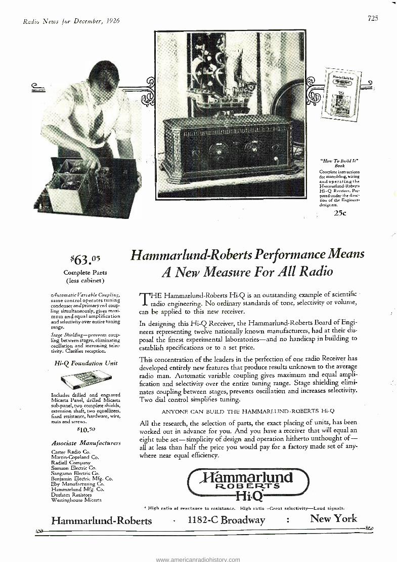
Radio News for December, 1926 725
(a l r1t °i.jIit.
du
$63.05 Complete Parts (less cabinet)
c/futomaticVariable Coupling, same control operates tuning condenser and primary coil coup- ling simultaneously, gives maxi- mum and equal amplification and selectivity over entire tuning range.
Stage Shielding - prevents coup- ling between stages, eliminating oscillation and increasing selec- tivity. Clarifies reception.
Hi -Q Foundation Unit
Includes drilled and engraved Micarta Panel, drilled Micarta sub- panel, two complete shields, extension shaft, two equallizers, fixed resistance, hardware, wire, nuts and screws.
$10.5°
Associate Manufacturers Carter Radio Co. Martin -Copeland Co. Radials Company Samson Electric Co. Sangamo Electric Co. Benjamin Electric Mfg. Co. Eby Manufacturing Co. Hammarlund Mfg. Co. Durham Resistors Westinghouse Micarta
"How To Build It" Book
Complete instructions for assembling, wiring andoperating the Hammarlund- Roberts Hi - Q Receiver. Pre- pared under the direc- tion of the Engineer - designers.
25c
Hammarlund - Roberts Performance Means A New Measure For All Radio
THE Hammarlund- Roberts Hi -Q is an outstanding example of scientific
radio engineering. No ordinary standards of tone, selectivity or volume,
can be applied to this new receiver.
In designing this Hi -Q Receiver, the Hammarlund -Roberts Board of Engi-
neers representing twelve nationally known manufacturers, had at their dis-
posal the finest experimental laboratories -and no handicap in building to
establish specifications or to a set price.
This concentration of the leaders in the perfection of one radio Receiver has
developed entirely new features that produce results unknown to the average
radio man. Automatic variable coupling gives maximum and equal ampli- fication and selectivity over the entire tuning range. Stage shielding elimi-
nates coupling between stages, prevents oscillation and increases selectivity. Two dial control simplifies tuning.
ANYONE CAN BUILD THE HAMMARLUND - ROBERTS Hi -Q
All the research, the selection of parts, the exact placing of units, has been worked out in advance for you. And you have a receiver that will equal an eight tube set - simplicity of design and operation hitherto unthought of- all at less than half the price you would pay for a factory made set of any-
where near equal efficiency.
(J-Iâmmarlund RO B ER.TS *
H lsQ * High ratio of reactance to resistance. High ratio -Great selectivity -Loud signals.
Hammarlund- Roberts 1182 -C Broadway : New York
www.americanradiohistory.com
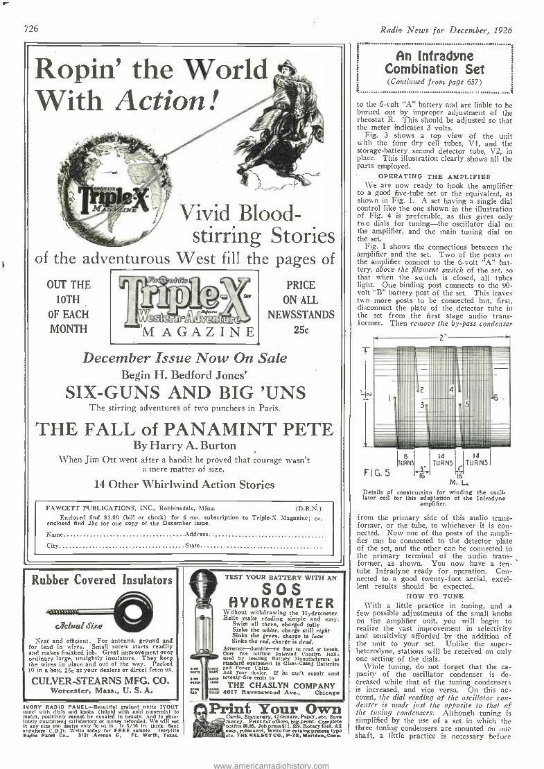
726
Ropin' the World With Action
Vivid Blood- stirring Stories
of the adventurous West fill the pages of
OUT THE
10TH
OF EACH
MONTH MAGAZINE
PRICE
ON ALL
NEWSSTANDS
25c
December Issue Now On Sale Begin H. Bedford Jones'
SIX -GUNS AND BIG 'UNS The stirring adventures of two punchers in Paris.
THE FALL of PANAMINT PETE By Harry A. Burton
When Jim Ott went after a bandit he proved that courage wasn't a mere matter of size.
14 Other Whirlwind Action Stories
FAWCETT PUBLICATIONS, INC., Robbinsdale, Mina. (D.R.N.) Enclosed find $1.00 (bill or check) for 6 mo. subscription to Triple.X Magazine; or.
enclosed find 25c for one copy of the December issue.
Name Address
City State
Rubber Covered Insulators
actual Size
Neat and efficient. For antenna. ground and for lead in wires. Small screw starts readily and makes finished job. Great improvement over ordinary large, unsightly insulators. They keep the wires in place and out of the way. Packed 10 in a box, 25c at your dealers or direct from us.
CULVER -STEARNS MFG. CO. Worcester, Mass., U. S. A.
IVORY RADIO PANEL -Beautiful grained white IVORY panel with dials and knobs (inlaid with gold numerals) to match, positively cannot be equaled in beauty. And is abso- lutely guaranteed satisfactory or money refunded. We will cut it any size you desire only 3c sq.in.. is 3/16 in. thick. Sent anywhere C.O.P. Write today for FREE sample. Ivorylite Radio Panel Co., 3121 Avenue G, Ft Worth, Texaa
ew'nii
SSF[a
wa[[ ai[aT
TEST YOUR BATTERY WITH AN
SOS HYDROMETER
Without withdrawing the Hydrometer. Balls make reading simple and easy.
Swim all three, charged fully Sinks the white, charge still right Sinks the green, charge is lean Sinks the red, charge is dead.
Accurate --- durable -no float to read or break. Over five million patented Chaslyn halls used by leading Battery Manufacturers as standard equipment In Glass -Cased Batteries and Power Units. Ask your dealer. If he can't supply send seventy -five cents to
THE CHASLYN COMPANY am % 4617 Ravenswood Ave., Chicago SINN
Print Your Own Cards, Stationery, Circulars, Paper, etc. Save money. Print for others. big profit. Complete outfits $8.F5. Job press $11. $29. Rotary $149. All easy. rules sent. Write for catalog presses type etc. THE KELSEY CO., P -72. Meriden, Conn.
Radio News for December, 1926
An Infradyne Combination Set (Continued front page 657)
to tige 6 -volt "A" battery and are liable to be burned out by improper adjustment of the rheostat R. This should be adjusted so that the meter indicates 3 volts.
Fig. 3 shows a top view of the unit with the four dry cell tubes, V1, and the storage- battery second detector tube, V2, in place. This illustration clearly shows all the parts employed.
OPERATING THE AMPLIFIER \\-e are now ready to hook the amplifier
to a good five -tube set or the equivalent, as shown in Fig. 1. A set having a single dial control like the one shown in the illustration of Fig. 4 is preferable, as this gives only two dials for tuning -the oscillator dial on the amplifier, and the main tuning dial on the set.
Fig. 1 shows the connections between the amplifier and the set. Two of the posts on the amplifier connect to the 6 -volt "A" bat- tery, above the filament switch of the set, so that when the switch is closed, all tubes light. One binding post connects to the 90- volt "B" battery post of the set. This leaves two more posts to be connected but, first, disconnect the plate of the detector tube in the set from the first stage audio trans- former. Then remove the by -pass condenser
a"
IT8
URNS
14 TURNS
1- F I G. 5 '-16 16
M.. l,. Details of construction for winding the oscil- lator coil for this adaptation of the Infradyne
amplifier.
from the primary side of this audio trans- former, or the tube, to whichever it is con- nected. Now one of the posts of the ampli- fier can be connected to the detector plate of the set, and the other can be connected to the primary terminal of the audio trans- former, as shown. You now have a ten - tube Infradyne ready for operation. Con- nected to a good twenty -foot aerial, excel- lent results should be expected.
HOW TO TUNE With a little practice in tuning, and a
few possible adjustments of the small knobs on the amplifier unit, you will begin to realize the vast improvement in selectivity and sensitivity afforded by the addition of the unit to your set. Unlike the super- heterodyne, stations will be received on only one setting of the dials.
While tuning, do not forget that the ca- pacity of the oscillator condenser is de- creased while that of the tuning condensers is increased, and vice versa. On this ac- count, the dial reading of the oscillator con- denser is made just the opposite to that of the doling condensers. Although tuning is simplified by the use of a set in which the three tuning condensers are mounted on one shaft, a little practice is necessary before
TURNS 14
www.americanradiohistory.com
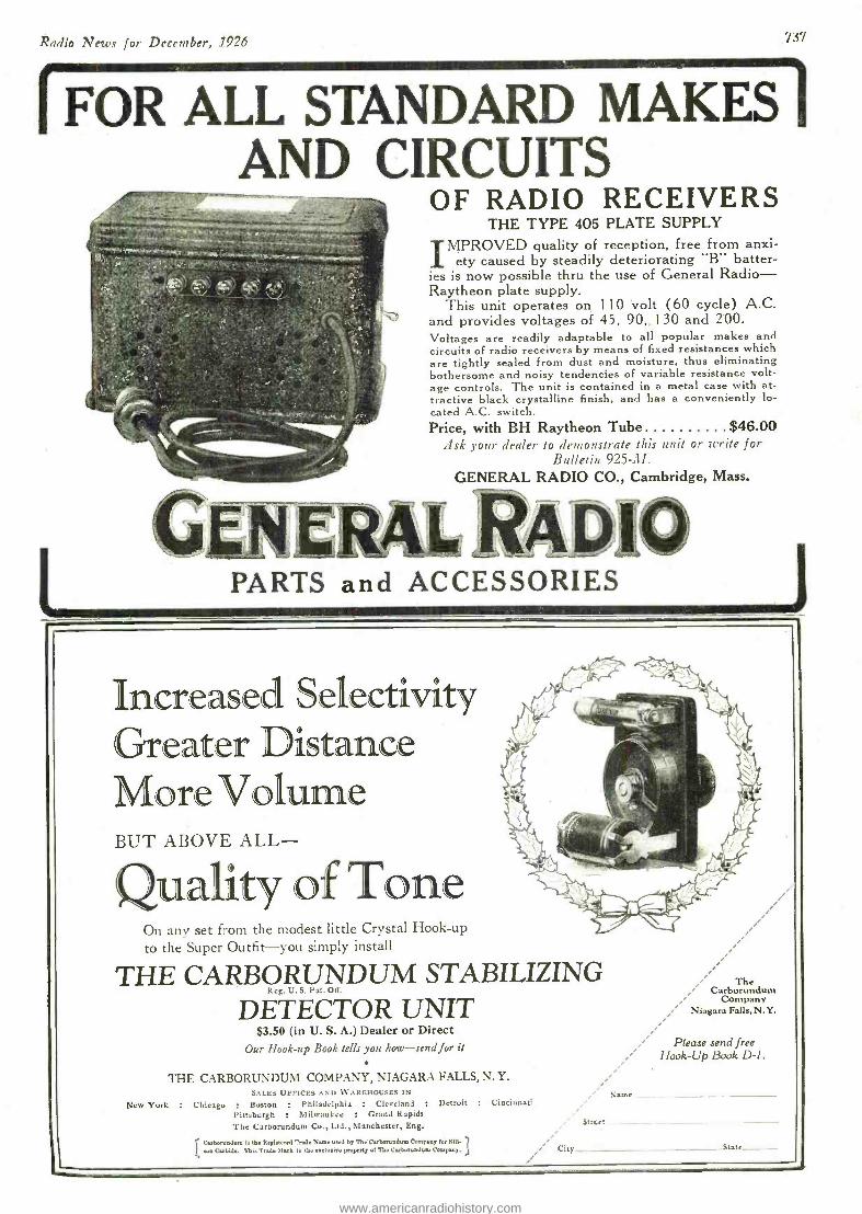
Radio News for December, 1926 737
FOR ALL STAN DARDIXKES AND CIRCUITS
OF RADIO RECEIVERS THE TYPE 405 PLATE SUPPLY
IMPROVED quality of reception, free from anxi- ety caused by steadily deteriorating "B" batter-
ies is now possible thru the use of General Radio - Raytheon plate supply.
This unit operates on 110 volt (60 cycle) A.C. and provides voltages of 45, 90,. 1 30 and 200. Voltages are readily adaptable to all popular makes and circuits of radio receivers by means of fixed resistances which are tightly sealed from dust and moisture, thus eliminating bothersome and noisy tendencies of variable resistance volt- age controls. The unit is contained in a metal case with at- tractive black crystalline finish, and has a conveniently lo- cated A.C. switch. Price, with BH Raytheon Tube $46.00
.ask your dealer to demonstrate this unit or write for Bulletin 925 -.1 /.
GENERAL RADIO CO., Cambridge, Mass.
PARTS and ACCESSORIES
Increased Selectivity Greater Distance More Volume BUT ABOVE ALL-
On any set from the modest little Crystal Hook -up
to the Super Outfit -you simply install
THE CARBORUNDUM STABILIZING Reg. U. S. Pat. Off.
DETECTOR UNIT
-**-trAe
$3.50 (in U. S. A.) Dealer or Direct Our Hook -up Book tells you how -send for it
THE CARBORUNDUM COMPANY, NIAGARA FALLS, N. Y. SALES OFFICES AND WAREHOUSES IN
New York : Chicago Boston : Philadelphia : Cleveland Pittsburgh . Milwaukee : Grand Rapids
The Carborundum Co., Ltd., Manchester, Eng.
Carborundum I. the Itegi.t.red Trade Name need M The Carborundum Comps., for SN. eue Carbide. This Trade Mark Is the exclusive property of The Carwruadmu Company.
The Carborundum
Company Niagara Falls, N.Y.
Please send free Hook -Up Book D -1.
Name Detroit : Cincinnati
atmet
i ' City _ State__ .
www.americanradiohistory.com
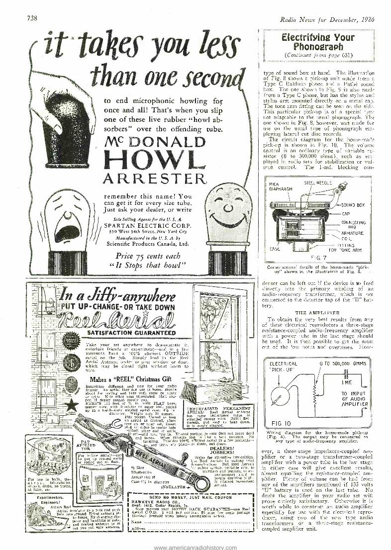
0411110 Ii I @d9,,N.
For use in halls, the- atres. laboratories. schools, clubs, on trains, at fairs, etc.
738
1t2 taîjes you lecs than one seco
1l
to end microphonic howling for once and all! That's when you slip one of these live rubber "howl ab- sorbers" over the offending tube.
MC DONALD HOWL ARRESTER, remember this name! You can get it for every size tube. Just ask your dealer, or write
Sole Selling Agents for the U. S. A.
SPARTAN ELECTRIC CORP. 350 West 34th Street, New York City
Manufactured in the U. S, A. by
Scientific Products Canada, Ltd.
Price 75 cents each « It Stops that howl"
n a Jig; -anywhere PUT UP- CHANGE -OR TAKE DOWN
SATISFACTION GUARANTEED
Take your set anywhere -to demonstrate it, entertain friends or experiment -and in a few moments have a 100% efficient OUTSIDE aerial on the job. Simply lead in the Reel Aerial Antenna under or over window or door, which thay be closed tight without harm to wire.
Makes a "REEL" Christmas Gift Something different and new for your radio friends. An aerial they can use at home, change about for testing and take with them on visits or trips. Nate other uses illustrated. Mail cou- pon if dealer cannot supply you. HERE'S 100 feet of Y. in. wide FLAT bare, copper wire. with insulator on outer end, reeled up in a handsomely nickled metal case, 41 in.
diameter. Weighs only 21 ounces. Fits pocket. Unreel as long an aerial as desired, place case on or near set, insert plug on cable in center hole -attach other end of cable
o set -and tune 'em in. Unused portion in case does not cause dead end losses. When through reel in like a tape measure. No
tangling. Provides 100% efficient aerial in a few moments - any time, any place -in doors. out doom.
Experimenters, Engineers!
Attach Reel Aerial insulator to a pole and push its Aerial pole into ground. Bring antenna ix-
to house. By changing dis- tance and locations of pole,
, and reeling antenna in or w' out you can vary antenna.
UNSURPASSED PERMANENT AERIAL! Reel Aerial antenna has same inductance value as stranded copper wire. Being flat, smooth, and easy to take down, it is easily cleaned.
PAT. APPLIED
FOR
For indoor aerials -can be put up around walls or reeled out on floor.
1/z Size Illustration Actual size of Case 45 in. diameter
INSULATOR .3r
DEALERS! JOBBERS!
Write for attractive proposition. Use Reel Aerials in making trial demonstrations. Sell Reel Aerials `or indoor aerials, portable sets, to
travelers and tourists, to ex- perimenters a n d to people desiring high- ly efficient permanent aerials.
WWI 11 SEND NO MON
I VV MAIL COUPON
HAWKEYE RADIO CO., I Dept. 1412, Cedar Rapids, la. I Ship me-on your MONEY BACK GUARANTEE -one Reel I
Aerial C.O.D. I will pay postman $5 plus few cents postage I (postage prepaid when money accompanies order).
Name
Address ..p omm. ------------ .... -oo -o 1
Radio News for December, I926 _
Electrifying Your Phonograph
(Continued frort page 631)
type of sound box at hand. The illustration of Fig. 8 shows a pick -up unit made from a Type C Baldwin phone and a Pathé sound box. The one shown in Fig. 9 is also made from a Type C phone, but has the stylus and stylus arm mounted directly on a metal cap. The tone arm fitting can be seen on the side. This particular pick -up is of a special type not adaptable to the usual phonograph. The one shown in Fig. 8, however, was made for use on the usual type of phonograph em- ploying lateral cut disc records.
The circuit diagram for the home -made pick -up is shown in Fig, 10. The volume control is an ordinary type of variable rë- sistor (0 to 500,000 ohms), such as em- ployed in radio sets for stabilization or vol- ume control, The 1 -mf. blocking con-
MICA
DIAPHRAGM
STEEL NEEDLE
IiliiimmuíiillmllTilu íi ITrunnumnammü
CASE
FIG. 7
SOUND BOX
CAP
CONNECTING ROD
ARMATURE
COIL
FITTING FOR TONE ARM
Constructional details of the home -made "pick- up" shown in the illustration of Fig. 8.
denser can be left out if the device is áo feed directly into the primary winding of an audio- frequency transformer, which is not connected to the detector tap of the "B" bat- tery.
THE AMPLIFIER To obtain the very best results from any
of these electrical reproducers a three -stage resistance -coupled audio- frequency amplifier with a power tube in the last stage should be used. It is then possible to get the most out of the low notes and overtones. How-
1 M
TO INPUT OF AUDIO AMPLIFIER
Wiring diagram for the home -made pick -up (Fig. 8). The output may be connected to
any type of audio -frequency amplifier.
ever, a three -stage impedance- coupled am- plifier or a two -stage transformer -coupled amplifier with a power tube in the last stage in either case will give excellent results, almost equalling the resistance- coupled am- plifier. Plenty of volume can be had from any of the amplifiers mentioned if 135 volts "B" battery is used on the last tube. No doubt the amplifier in your radio set will prove entirely satisfactory. Otherwise it is worth while to construct an audio amplifier especially for use with the electrical repro- ducer, using two of the new type audio transformers or a three -stage resistance- coupled amplifier unit.
www.americanradiohistory.com
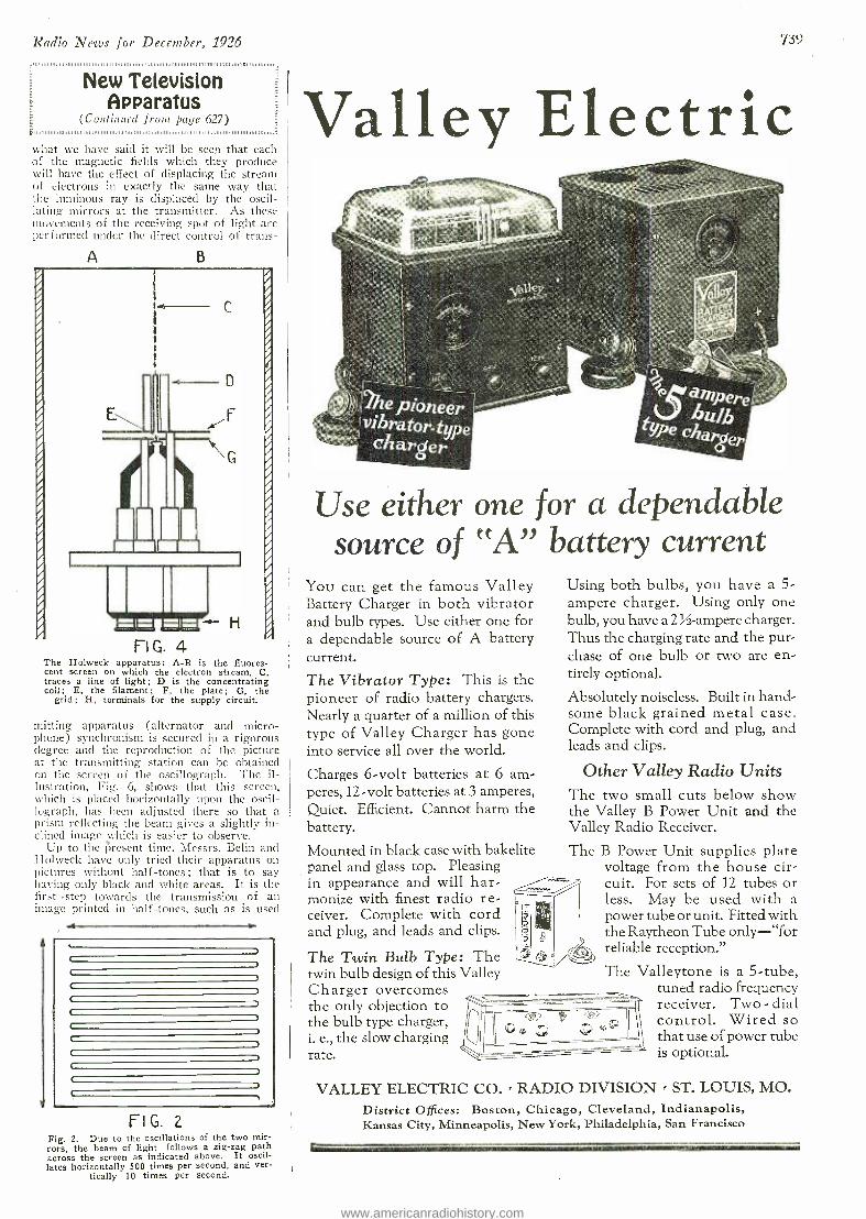
Radio News for December, 1926
New Television Apparatus
(Continued from page 6V) ,,
what we have said it will be seen that each of the magnetic fields which they produce will have the effect of displacing the stream of electrons in exactly the same way that the luminous ray is displaced by the oscil- lating mirrors at the transmitter. As these movements of the receiving spot of light are performed under the direct control of trans-
A B
The Holweck apparatus: A -B is the fluores- cent screen on which the electron stream, C, traces a line of light; D is the concentrating coil; E, the filament; F, the plate; G, the
grid; H, terminals for the supply circuit.
mitting apparatus (alternator and micro- phone) synchronism is secured in a rigorous degree and the reproduction of the picture at the transmitting station can be obtained on the screen of the oscillograph. The il- lustration, Fig. 6, shows that this screen, which is placed horizontally upon the oscil- lograph, has been adjusted there so that a prism reflecting the beam gives a slightly in- clined image which is easier to observe.
Up to the ?;resent time, Messrs. Belin and Holweck have only tried their apparatus on pictures without half -tones ; that is to say having only black and white areas. It is the first step towards the transmission of an image printed in half -tones, such as is used
.-
FIG. 2 Fig. 2. Due to the oscillations of the two mir- rors, the beam of light follows a zig -zag path across the screen as indicated above. It oscil- lates horizontally 500 times per second, and ver-
tically 10 times per second.
739%
Valley Electric
Use either one for a dependable source of "A battery current
You can get the famous Valley Battery Charger in both vibrator and bulb types. Use either one for a dependable source of A battery current.
The Vibrator Type: This is the pioneer of radio battery chargers. Nearly a quarter of a million of this type of Valley Charger has gone into service all over the world.
Charges 6 -volt batteries at 6 am- peres, 12 -volt batteries at 3 amperes, Quiet. Efficient. Cannot harm the battery.
Mounted in black case with bakelite panel and glass top. Pleasing in appearance and will har- monize with finest radio re- ceiver. Complete with cord and plug, and leads and clips.
The Twin Bulb Type: The twin bulb design of this Valley Charger overcomes the only objection to the bulb type charger, i. e., the slow charging rate.
Using both bulbs, you have a 5- ampere charger. Using only one bulb, you have a 2 %- ampere charger. Thus the charging rate and the pur- chase of one bulb or two are en- tirely optional.
Absolutely noiseless. Built in hand- some black grained metal case. Complete with cord and plug, and leads and clips.
Other Valley Radio Units The two small cuts below show the Valley B Power Unit and the Valley Radio Receiver.
The B Power Unit supplies plate voltage from the house cir- cuit. For sets of 12 tubes or less. May be used with a power tube or unit. Fitted with the Raytheon Tube only - "for reliable reception."
The Valleytone is a 5 -tube, tuned radio frequency receiver. Two - dial control. Wired so that use of power tube is optional.
VALLEY ELECTRIC CO. > RADIO DIVISION > ST. LOUIS, MO. District Offices: Boston, Chicago, Cleveland, Indianapolis, Kansas City, Minneapolis, New York, Philadelphia, San Francisco
r
www.americanradiohistory.com
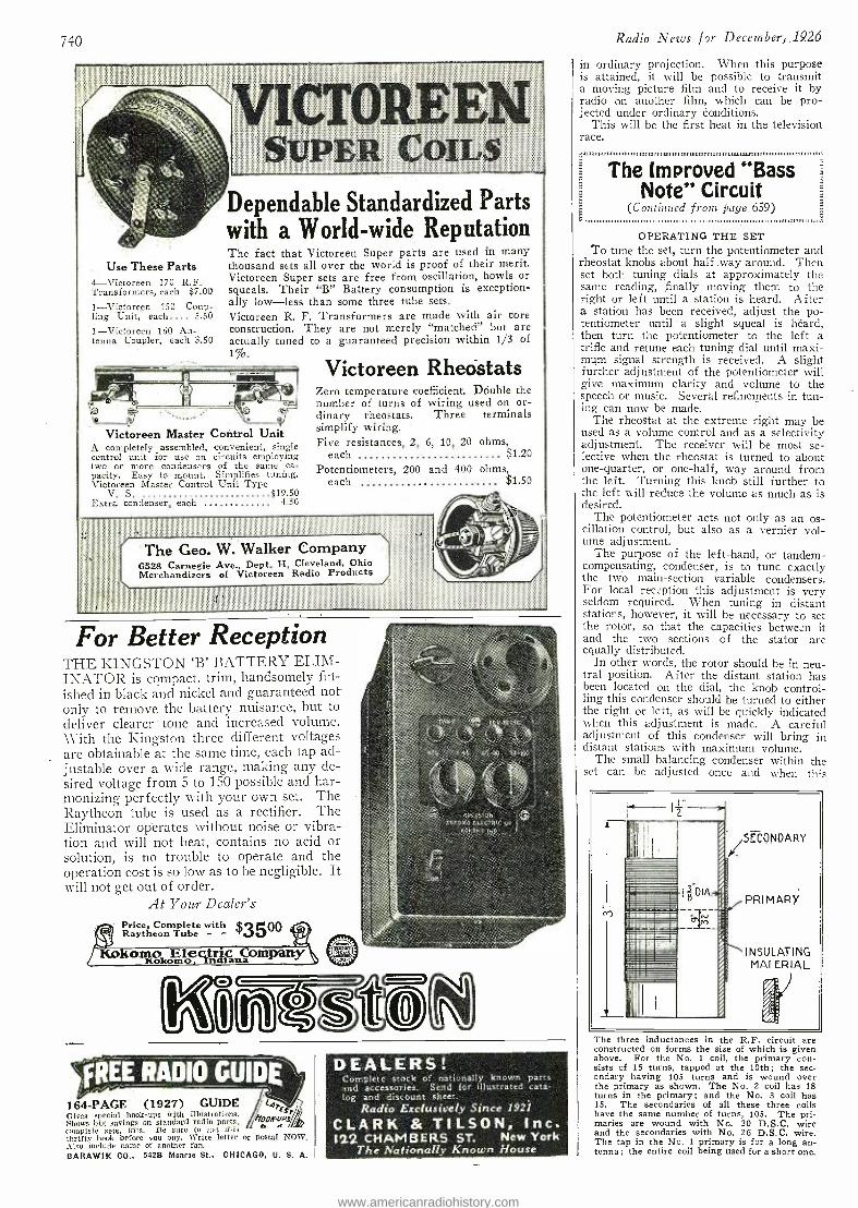
740
ICTOREE:
Use These Parts 4- Victoreen 170 R.F. Transformers, each $7.00
1- Victoreen 150 Coup- ling Unit, each.... 5.50
1- Victoreen 160 An- tenna Coupler, each 3.50
Dependable Standardized Parts with a World -wide Reputation The fact that Victoreen Super parts are used in many thousand sets all over the world is proof of their merit. Victoreen Super sets are free from oscillation, howls or squeals. Their "B" Battery consumption is exception- ally low -less than some three tube sets. Victoreen R. F. Transformers are made with air core construction. They are not merely "matched" but are actually tuned to a guaranteed precision within 1/3 of 1%.
Victoreen Master Control Unit A completely assembled, convenient, single control unit for use on circuits employing two or more condensers of the same ca- pacity. Easy to mount. Simplifies tuning. Victoreen Master Control Unit Type
V. S. $19.50 Extra condenser, each 4.50
Victoreen Rheostats Zero temperature coefficient. Double the number of turns of wiring used on or- dinary rheostats. Three terminals simplify wiring. Five resistances, 2, 6, 10, 20 ohms,
each Potentiometers, 200 and 400 ohms,
each
$1.20
The Geo. W. Walker Company 6528 Carnegie Ave., Dept. H, Cleveland, Ohio Merchandizers of Victoreen Radio Products
$1.50
For Better Reception THE KINGSTON `B' BATTERY ELIM- INATOR is compact, trim, handsomely firi- ished in black and nickel and guaranteed not only to remove the battery nuisance, but to deliver clearer tone and increased volume. With the Kingston three different voltages are obtainable at the saine time, each tap ad- justable over a wide range, making any de- sired voltage from 5 to 150 possible and har- monizing perfectly with your own set. The Raytheon tube is used as a rectifier. The Eliminator operates without noise or vibra- tion and will not heat, contains no acid or solution, is no trouble to operate and the operation cost is so low as to be negligible. It will not get out of order.
At Your Dealer's Price, Complete with _Ç,3 + 00 Raytheon Tube - w a7
r;tHcì:TUM1 .: lár, L"cC(ü > <. KOKON,
Revs comló cftfñaiánmpy
REE RADIO GUIDES -) 164 -PAGE (1927) GUIDE l4T
E Cites sal hook-ups n illustrations. Shows savings standard raio Parts,
iYaroOS
complets sets. kits. Be sure to get this thrifty hook before you buy. write letter or postal NOW. Also include name of another fan.
BARAWIK CO., -5428 Monroe St., CHICAGO, U. S. A.
DEALERS! Complete stock of nationally known parts and accessories. Send for illustrated cata- log and discount sheet.
Radio Exclusively Since 1921
CLARK & TILSON, Inc. 122 CHAMBERS ST. New York
The Nationally Known House
Radio News for December; 1926
in ordinary projection. When this purpose is attained, it will be possible to transmit a moving picture film and to receive it by radio on another film, which can be pro- jected under ordinary conditions.
This will be the first heat in the television race.
The Improved "Bass Note" Circuit
(Continued from page 659) .,11111111111111,11 ,111111110II,II.,,11,1,1101,,,1,,,1M,,1,,.,11.1,1111,111111,1,111,,,,11,,,,,aa.a,a.1111,,,,,5
OPERATING THE SET To tune the set, turn the potentiometer and
rheostat knobs about half way around. Then set both tuning dials at approximately the same reading, finally moving them to the right or left until a station is heard. After a station has been received, adjust the po- tentiometer until a slight squeal is heard, then turn the potentiometer to the left a trifle and retune each tuning dial until maxi - mum signal strength is received. A slight further adjustment of the potentiometer will give maximum clarity and volume to the speech or music. Several refinements in tun- ing can now be made.
The rheostat at the extreme right may be used as a volume control and as a selectivity adjustment. The receiver will be most se- lective when the rheostat is turned to about one -quarter, or one -half, way around from the left. Turning this knob still further to the left will reduce the volume as much as is desired.
The potentiometer acts not only as an os- cillation control, but also as a vernier vol- ume adjustment.
The purpose of the left -hand, or tandem - compensating, condenser, is to tune exactly the two main- section variable condensers. For local reception this adjustment is very seldom required. When tuning in distant stations, however, it will be necessary to set the rotor, so that the capacities between it and the two sections of the stator are equally distributed.
In other words, the rotor should be in neu- tral position. After the distant station has been located on the dial, the knob control- ling this condenser should be turned to either the right or left, as will be quickly indicated when this adjustment is made. A careful adjustment of this condenser will bring in distant stations with maximum volume.
The small balancing condenser within the set can be adjusted once and when this
The three inductances in the R.F. c'rcuit are constructed on forms the size of which is given above. For the No. 1 coil, the primary con- sists of 15 turns, tapped at the 10th ; the sec- ondary having 105 turns and is wound over the primary as shown. The No. 2 coil has 18 turns in the primary; and the No. 3 coil has 15. The secondaries of all these three coils have the same number of turns, 105. The pri- maries are wound with No. 30 D.S.C. wire and the secondaries with No. 26 D.S.C. wire. The tap in the No. 1 primary is for a long an- tenna ; the entire coil being used for a short one.
www.americanradiohistory.com
Radio News for December, 1926
adjustment is made, need not be touched again. The adjustment should be made when receiving a station that tunes in at about 50 on the dials. If the dial settings are not identical, the right -hand one will he high. Turn the right -hand condenser so that the dial readings agree with the dial readings of the left -hand condenser; and then adjust the small balancing condenser until the station comes in again with maxi- mum volume. This setting of the condenser will be satisfactory for all points on the dial.
.11111,.,,,,,,,,,,,,,,,,,,,,11,,,,,I,,,IMIMImB,,.,,,,,,,,,,,,,,1,,,,1,1111,IIIIIII,11111111,,,,,,1,,,,0,,,,,m,uM,; _ ' E
i
Short -Wave Receiver Operation
(Continued from page 678)
length or using a small series condenser. In the case of the amateur who employs the same antenna for both transmitting and re- ceiving, this cannot be done, but a separate antenna for receiving always gives better results anyway.
THE SCHNELL CIRCUIT The three -coil circuit employing the awk-
ward, moving tickler coil has been al- most entirely done away with of late and the "Schnell" circuit substituted. This cir- cuit employs a variable by -pass condenser or throttling condenser, in conjunction with a fixed tickler coil for regeneration control. This circuit is shown in Fig. 1 and Fig. 2.
Fig. 2 shows how the primary may be re- placed by a small series condenser of the proper value. This capacity, if used, should be two small plates of brass or copper, to allow soldering, about / -inch square, mounted on binding -posts about an inch apart. A wire soldered to one of the plates and passing through the hole in one of the screws serves as the variable capacity ad- justment and the correct distance is about half an inch. This capacity must be read- justed and its setting is dependent upon the antenna used. For the experimenter this is sometimes objectionable. A primary coil of about 3 turns gives the same results, and practically all short -wave receivers employ one.
SEC.
PHONES OR
AMP - LIFIER
FIG. I
The Schnell circuit, which employs a fixed tickler coil and a variable by -pass condenser.
The process of assembling a receiver is not difficult but making it function on the proper wave is another matter. Perhaps it may be to advantage to outline this procedure in the following paragraphs.
The selection of the proper inductance for the particular wave -band is perhaps the first consideration. This should not be an ordin- ary "vario- coupler," "honey- comb," or any of the favorite coils ordinarily in use on the longer waves ; but preferably a space -wound coif of say 23/4 or 3 inches in diameter and macle of about No. 20 wire. Smaller wire may be used, perhaps, but No. 20 will serve and furnish the proper rigidity. The familiar "collodion- celluloid" space -wound coils, now very popular with short -wave enthusiasts, are excellent for this purpose and are quite readily constructed.
741
E LECT-RA1 Listed by Under- writers' Laboratories. All genuine Bakelite.
No trouble putting up an aerial. Just plug in on any electric light socket. No incon- venience or interference from neighbors' sets and aerials. Also smothers static and helps get distance. Uses no current. Perfectly safe to use. Tested an5i certified electrically. The simplest, neatest and most efficient on the market. At all good radio stores, or they Price U. S. 75c, Canada $1.10.
SAFE Just Plug In -- That's All, No Trouble with
This Antenna
% _,
,14' *.\ 'I011li'.6
: - . can easily get it for you.
The ELECTRAD
Royalty Variable High Resistances Leading radio authorities endorse and re- commend these improved high resistances - 11 types -a range for every purpose. All ranges dissipate 3 watts. Note these im- portant features. Resistance element not exposed to any me- chanical operation. Metallic arm on wire -wound strip insures positive electrical contact. Same resistance always obtained at same Resistance value under control in process remains constant in use. Shaft is turned smoothly over entire range less than a single turn of the knob. Type E- $2.00; all other types, $1.50. -T7
Licensed by Technidyne Cor- poration under U. S. Pat. No. 1593685, July 27, 1926.
point. of manufacture-
of resistance with
If you have an Out- door Aerial demand the Genuine Electrad Lead -In Copied and imitated, but the quality never approached. Triple -ply insulation -full 10 in- ches long. Fahnestock clips, all connections riveted and soldered. Fits under locked windows and doors. Bends to any shape. Saves walls, windows and door trim. Price, U. S., 40c. Canada, 60c. at all good radio stores.
ELECTRA Inc
www.americanradiohistory.com
orqet yourbaftery charging problems I
YOUR storage "A" Battery need never be low if you leave it to the Sterling Trickle Charger to keep it everlastingly charged. When
you're using your set this charger takes a rest, but the moment you "turn off" the radio the charger starts to charge. It charges at the steady 2/3 ampere rate for 6 -volt A or % ampere for 4 -volt, a safe slow rate with automatic cut -off. It is the quiet and efficient bulb type. Sterling, meter -equipped, Price, $14.00.
THE STERLING MFG. CO., Cleveland, Ohio
Rerlirt Trick le Charger
g
ov°{he isit.. ee
1t ¢oatla>>y,s o 4üto the
No. R -102 Bulb Type
Trickle Charger Show this ad to your dealer. If
he hasn't the Sterling Trickle Charger in stock he can get it for you.
Ask for our 32 -page booklet on care and upkeep of radio - it's freeI
oRWico; _ RADIO'S BEST WIRE
"From the Ground Up" Every spool or coil of Corwico Wire is
Corwico Products guaranteed full weight, full length, full
Antenna Wire Annunciator Wire gauge best grade of copper, insulated
( diid, Stranded Flexible Wire with the best materials obtainable, free and Braided Lead -in Wire from all defects and up to the highest
Magnet Wire Litz Wire specifications in every respect. Bus Bar Wire Loop Aerial Wire Hook -Up Wire Battery Cable Ask Your Dealer
for Corwico Wire
FR EE Write for interesting booklet, telling all about the vari- Gus kinds of radio wire and their uses.
Dealers and Jobbers -Write for the "Corwico" wire proposition.
CORNISH WIRE COMPANY 30 Church Street New York City
FREE RADIO GUIDE
`4TF t hobR uvs, n e
164 -PAGE (1927) GUIDE Owes special hook -ups with illustrations. Shows big savings on standard radio parts, complete sets, kits. Be sure to get this thrifty book before you buy. Write letter or postal NOW: Also include naine of another fan.
BARAWIK CO., 542B Monroe St., CHICAGO, U. S. d
DON'T LOSE YOUR RIGHTS Before disclosing your invention to anyone send for free blank form
EVIDENCE OF CONCEPTION" to be signed and witnessed.
LANCASTER & ALLWINE Reg. Pat. Attys. in U. S. and Canada 270 Ouray Bldg., Washington D. C. Originators of the form 'Evidence
of Conception"
Radio News for December, 1926
The secondary shunt variable condenser, as usual, should be the best obtainable and ought to be of the SLF type ; a 7 -plate serves well on the ranges down to about 60 meters ; below this a 5 -plate should be em- ployed. Even with these comparatively small capacities tuning is often close ; hence it is quite an advantage to have a good vernier attachment for best results.
Hand -capacity becomes especially Notice- able at the higher frequencies ; in this con- nection, it is often necessary to employ a 10- inch extension handle to overcome this effect, on a wavelength of 5 meters ! The selec- tion of properly- constructed condensers does away with this objection to some extent if the rotary plates are connected to the fila- ment side of the inductance and not to the grid -end ; this point is often overlooked.
ADJUSTMENT FOR LOWER WAVES As the number of turns in the secondary
inductance is reduced, the wavelength of the receiver is reduced and less turns are neces- sary in the fixed tickler for proper regenera- tion. Perhaps the best procedure in adjust- ing for the lower waves is a gradual re- duction from some wavelength at which the operation of the receiver is understood. Choose a certain size of inductance that will allow tuning -in on this particular, familiar wave -band ; and gradually reduce the num- ber of turns in the secondary, say 5 or 6
turns at a time. For each reduction' in the inductance it will be necessary to readjust the tickler coil, that is, to reduce its number of turns somewhat.
If the set will not regenerate on the lower settings of the secondary condenser, the number of turns in the tickler coil is too high or they may be too close. Usually,
I I I`SERIES ANTENNA CONDENSER
ANT. COIL
UII _ B +
TICKLER
FIG. 2 A modification of the Schnell circuit wherein the primary inductance is eliminated through the use of a fixed series antenna condenser.
PHONES
OR
AMP- LIFIER
however, the number of turns determines the range of regeneration control and proper spacing improves matters by not allowing such violent regeneration or oscillations and promoting more critical control by the by- pass condenser. In general, the lower the wavelength, the less the turns necessary in the tickler and with a given tickler, the less the capacity necessary in this condenser. More turns may then be removed and the adjustments made again, until the desired wavelength is reached.
But take it easy. If you are not well ac- quainted with short -wave pecularities you may get lost, especially if a wavemeter is not available ; but a rough check may be se- cured by listening for the amateur bands. A telegraph and telephone band exists around 80 meters, another at about 40 meters and yet another at 20 meters. Hence if one ex- pects to operate his receiver at 65 meters, say, and can tune -in code and amateur phone with a certain value of inductance, etc., 65 meters is not very far below, and so on. Yet another method is to construct a receiver exactly to specifications given, for coil sizes and the like. This is usually objectionable, however, and sometimes difficult to do. Vf'itll a little experimentation, the operation of determining one's wavelength is not difficult.
The oscillation control, in this case a
www.americanradiohistory.com
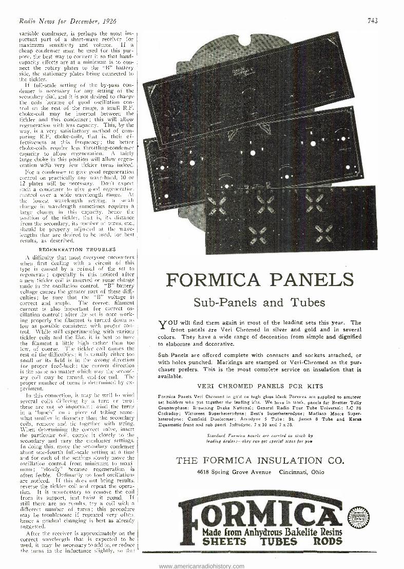
Radio News for December, 1926
variable condenser, is perhaps the most im- portant part of a short -wave receiver for maximum sensitivity and volume. If a cheap condenser must be used for this pur- pose, the best way to connect it so that hand - capacity effects are at a minimum is to con- nect the rotary plates to the `B" battery side, the stationary plates being connected to the tickler.
If full -scale setting of the by -pass con- denser is necessary for any setting of the secondary dial, and it is not desired to change the coils because of good oscillation con- trol on the rest of the range, a small R.F. choke -coil may be inserted between the tickler and this condenser ; this will allow regeneration with less capacity. This, by the way, is a very satisfactory method of com- paring R.F. choke- coils, that is, their ef- fectiveness at this frequency ; the better choke -coils require less throttling -condenser capacity to allow regeneration. A fairly large choke in this position will allow regen- eration with very few tickler turns indeed.
For a condenser to give good regeneration control on practically any wave -band, 10 or 12 plates will be necessary. Don't expect such a condenser to give god regeneration control over a wide wavelength range. At the lowest wavelength setting, a small change in wavelength sometimes requires a large change in this capacity, hence the position of the tickler, that is, its distance from the secondary, its number of turns, etc., should be properly adjusted at the wave- lengths that are desired to be used, for best results, as described.
REGENERATION TROUBLES
A difficulty that most everyone encounters when first dealing' with a circuit of this type is caused by a refusal of the set to regenerate ; especially is this noticed after a new tickler coil is inserted or some change made in the oscillation control. "B" battery voltage causes the greater part of these diffi- culties ; be sure that the "B" voltage is correct and ample. The correct filament current is also important for correct os- cillation control ; after the set is once work- ing properly the filament is turned down as low as possible consistent with proper con- trol. While still experimenting with various tickler coils and the like, it is best to have the filament a little high rather than too low, of course. The tickler coil causes the rest of the difficulties ; it is usually either too small or its field is in the wrong direction for proper feed-back ; the correct direction is the same no matter which way the second- ary coil may be turned, end- for -encl. The proper number of turns is determined by ex- periment.
In this connection, it may be well to wind several coils differing by a turn or two; these are not so important ; wind the turns in a "bunch" on a piece of tubing some- what smaller in diameter than the secondary coils, remove and tie together with string. When determining the correct value, insert the particular coil, couple it closely to the secondary and vary the condenser settings. In doing this, move the secondary condenser about one- fourth full -scale setting at a time and for each of the settings slowly move the oscillation control from minimum to maxi - mum ; "slowly" because regeneration is often feeble. Ordinarily no loud oscillations are noticed. If this does not bring results, reverse the tickler coil and repeat the opera- tion. It is unnecessary to remove the coil from its support, just twist it round. If still there are no results, try a coil with a different number of turns ; this procedure may be troublesome if repeated very often. hence a gradual changing is best as already suggested.
After the receiver is approximately on the correct wavelength that is expected to be used, it may be necessary to add to, or reduce the turns in the inductance slightly, so that
743
FORMICA PANELS Sub -Panels and Tubes
YOU will find them again in most of the leading sets this year. The front panels are Veri Chromed in silver and gold and in several
colors. They have a wide range of decoration from simple and dignified to elaborate and decorative.
Sub -Panels are offered complete with contacts and sockets attached, or with holes punched. Markings are stamped or Veri- Chromed as the pur- chaser prefers. This is the most complete service on insulation that is available.
VERI CHROMED PANELS FOR KITS
Formica Panels Veri Chromed in gold on high gloss black Formica are supplied to amateur set builders who put together the leading kits. We have in stock, panels for Bremer. Tully Counterphase; Browning Drake National; General Radio Four Tube Universal; LC 26 Cockaday; Victoreen Superheterodyne; Best's Superheterodyne; Madison Moore Super- heterodyne; Camfield Duoformer; Aerodyne 5 Tube; St. James 8 Tube and Kara* Equamatic front and sub panel. Infradyne, 7 x 30 and 7 x 28.
Standard Formica panels are carried in stock by leading dealers -they can get special sizes for you
THE FORMICA INSULATION CO. 4618 Spring Grove Avenue Cincinnati, Ohio
ÓRMICA. Made from Anhydrous Bakelite Resins SHEETS TUBES RODS ......a
www.americanradiohistory.com
744
Heir: the .drawer
WHOLESALE
929 PENN AVENUE
rHE "I Want to Know" Booklet issued by Hommel is now
ready for distribution to every radio dealer w h o
wants to put his customers on a familiar footing with every -day radio problems.
It's the alpha and omega of useful radio information -the question and answer of many common radio queries -a booklet that every radio customer will be pleased to get.
Every dealer will profit by their distribution, be- cause these booklets contain not only interesting informa- tion that customers want, but also will incidentally serve to stimulate every dealer's radio sales.
Write to -day -the supply is limited.
EXCLUSIVELY Lcit*, PITTSBURGH, PA.
B-6 TUBE
$5
Announcing BECAUSE of the ready acceptance of
the B -6 Tube and the circuit we have developed for it, and to comply with general request, we announce a kit in two forms and a complete set built to the specifications of this cir- cuit. Send for literature.
THE DONLE - BRISTOL CORP.
MERIDEN - - CONNECTICUT
ifREE RADIO GUIDE j 164 -PAGE (1927) GUIDE (Q,,esr
tioarePS Gives special hook -ups with illustrations. Shows big savings on standard radio parts. complete sets, kits. Be sure to get this thrifty book before you huy. Write letter or postal NOW.
Also include name of another fan.
BARAWIK CO., 542B Monroe St., CHICAGO, U. S. A.
e. R
84 Illustrated Pages of Radio Bargains! Write for Catalog Today RANDOLPH RADIO CORP. 180 N. UNION AV. Dept. 2 CHICAGO, ILL.
Radio News for December,'1926
tuning may be done at the correct position on the wavelength dial. A tickler coil should be selected of the correct value and properly spaced from the secondary so that the set may be made to regenerate at about the center of the by -pass condenser scale when it is properly tuned. Regeneration should not start with a click but quietly and with a gentle "hiss." Since a click is a sud- den beginning of regeneration, it may be readily seen that the most sensitive spot of the whole receiver, just at the point of re- generation, is lost. This may usually be remedied by adjusting the distance of the fixed tickler from the secondary and some- times by reducing the plate voltage. Close coupling of the antenna coil may also cause clicks or violent regeneration. Other causes are poor - tubes, grid . condensers and grid leaks, especially the variable. ones.
Another very common difficulty is caused by very close coupling of the primary and secondary coils. This, will not work on the short waves,. usually. The -usual high- resis- tance antenna closely coupled to the second- ary prevents the tube from oscillating f ree- ly. Use enough coupling to allow the proper regeneration and selectivity.
TUBE SELECTION
The detector tube is of great importance if sensitivity, proper regeneration and a minimum of unnecessary noise, are desired. Some tubes regenerate with a hum, others with a click and still others with a gentle "hiss." The grid -leak may influence this to some extent ; but in general only the third type of tube should be employed where quiet, sensitive reception is desired. A good tube with a socket that will not . allow "ringing" (which is especially noticeable at the higher frequencies in sets subject to vi- bration) is certainly a big step toward prop- er receiver operation. Flexible leads, such as thin foil, near the socket terminals pre- vent vibrations reaching the tube through the wiring.
The grid -leak, besides being sometimes the cause of unnecessary noises, is often not of the proper value. A variable grid -leak for securing the proper grid resistance is an advantage, especially where a variety of different wavelengths may be used. It has been found that the grid -leak gives roper
II.
SEC.
TICKLER
- e - + i'
FIG. 3 A three -circuit tuner with a variable tickler coil, formerly employed for short -wave recep-
tion.
111111111-
PHONES
OR
AM P
oscillation control under most circumstances. This is hardly noticeable on the higher wavelengths ; but almost all short -wave cir- cuits give better results if a proper value of resistance is employed. In general the prop- er resistance for short -wave receivers is higher ; sometimes very much higher. The selection of the proper resistance is import- ant where short -wave broadcast receiving is to be done. After the proper value for the particular wave -band is known, a fixed leak may be used.
For efficiency, of course, all parts should be as low -loss as possible and the wiring be well- spaced. It is difficult to conceive how any cramped, panel- mounted short -wave re- ceiver can compete with one neatly laid -out. all parts given the proper spacing and the amplifier placed off by itself. Since those interested in short -wave receiving are most-
www.americanradiohistory.com
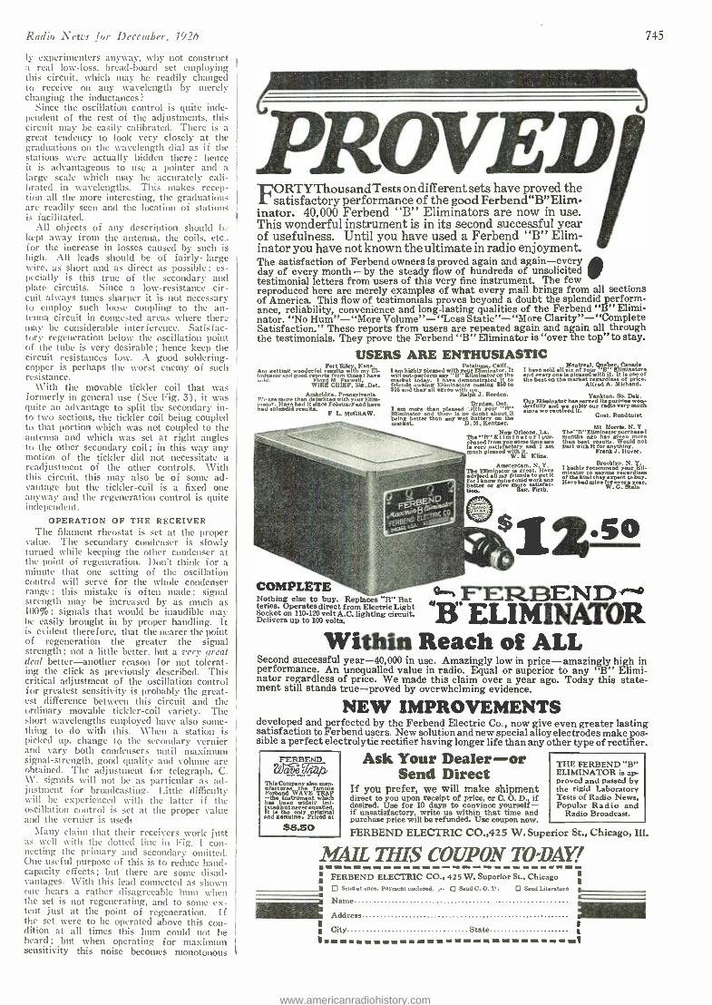
Radio News for December, 1926
ly experimenters anyway, why not construct :t real low -loss, bread -board set employing this circuit, which may be readily changed to receive on any wavelength by merely changing the inductances?
Since the oscillation control is quite inde- pendent of the rest of the adjustments, this circuit may be easily calibrated. There is a great tendency to look very closely at the graduations on the wavelength dial as if the stations were actually hidden there; hence it is advantageous to use a pointer and a large scale which may be accurately cali- brated in wavelengths. This makes recep- tion all the more interesting, the graduations are readily seen and the location of stations is facilitated.
All objects of any description should L: kept away from the antenna, the coils, etc.. for the increase in losses caused by such is high. All leads should be of fairly- large wire, as short and as direct as possible ; es- pecially is this true of the secondary awl plate circuits. Since a low- resistance cir- cuit always tunes sharper it is not necessary to employ such loose coupling to the an- tenna circuit in congested areas where there may be considerable interference. Satisfac- tory regeneration below the oscillation point of the tube is very desirable ; hence keep the circuit resistances low. A good soldering - copper is perhaps the worst enemy of such resistance.
With the movable tickler coil that was formerly in general use (See Fig. 3), it was quite an advantage to split the secondary in- to two sections, the tickler coil being coupled to that portion which was not coupled to the antenna and which was set at right angles to the other secondary coil ; in this way any motion of the tickler did not necessitate a readjustment of the other controls. With this circuit, this may also be of some ad- vantage but the tickler -coil is a fixed one anyway and the regeneration control is quite independent.
OPERATION OF THE RECEIVER The filament rheostat is set at the proper
value. The secondary condenser is slowly turned while keeping the other condenser at the point of regeneration. Don't think for a minute that one setting of the oscillation control will serve for the whole condenser range : this mistake is often made ; signal strength may be increased by as much as 100% ; signals that would be inaudible may be easily brought in by proper handling. It is evident therefore, that the nearer the point of regeneration the greater the signal strength ; not a little better, but a very great deal better- another reason for not tolerat- ing the click as previously described. This critical adjustment of the oscillation control for greatest sensitivity is probably the great- est difference between this circuit and the ordinary movable tickler -coil variety. The short wavelengths employed have also some- thing to do with this. When a station is picked up, change to the secondary vernier and vary both condensers until maximum signal -strength, good quality and volume are obtained. The adjustment for telegraph, C. W. signals will not be as particular as ad- justment for broadcasting. Little difficulty will be experienced with the latter if the oscillation control is set at the proper value and the vernier is used,
Many claim that their receivers work just as well with the dotted line in Fig. I con- necting the primary and secondary omitted. One useful purpose of this is to reduce hand - capacity effects ; but there are sonic disad- vantages. With this lead connected as shown one hears a rather disagreeable hunt when the set is not regenerating, and to some ex- tent just at the point of regeneration. If the set were to be operated above this con- dition at all times this hum could not he heard; but when operating for maximum sensitivity this noise becomes monotonous
745
FORTY Thou sand Tests on different sets have proved the satisfactory performance of the good Ferbend "B "Elime
inator. 40,000 Ferbend "B" Eliminators are now in use. This wonderful instrument is in its second successful year of usefulness. Until you have used a Ferbend "B" Elim- inator you have not known the ultimate in radio enjoyment. The satisfaction of Ferbend owners is proved again and again -every day of every month - by the steady flow of hundreds of unsolicited testimonial letters from users of this very fine instrument. The few reproduced here are merely examples of what every mail brings from all sections of America. This flow of testimonials proves beyond a doubt the splendid perform- ance, reliability, convenience and long-lasting qualities of the Ferbend "B" Elimi- nator. "No Hum " - "More Volume"- "Less Static"- "More Clarity " - "Complete Satisfaction." These reports from users are repeated again and again all through the testimonials. They prove the Ferbend "B" Eliminator is "over the top" to stay.
USERS ARE ENTHUSIASTIC
..Id.
Fort Ri ' Am getting wonderful with I El- iminator and good reports from those have
Flu dM. Farwell. WIRE CHIEF. Sig. Det.
Wt. are more than delirghted with your Elim- inator. Have had it since February and have ad splendid results.
F L. McGRAW.
Petaloma, Calif. l em highly pleased with your Eliminator. It will out -perform any "B" Eliminator on the
friends today.
g Elimindemonstrated tars costing 550 to $75 and they all agree with me.
Ralph J. Rorden.
Dryden, Ont. I am more than pleased ith your "B' Eliminator and there is no doubt about it being better than any wet battery on the market. D. M. Keatner.
I have sold all six of
your Kllimtnatore
thand every one is please with it. It Is one of
e beat on the market regardless of pile.. Alfred A. Michnnd.
Our Eliminator tae served itsnparposewon- derfully and we enjoy our radio very much since we received It.
Gent. Rundqulet
Ney Orleans, La.
hed v ulntacasfr m some time go Is very satisfactory and 1 am much pleased with it,
W. M Kline,
Amsterdam, N. Y. The all mrrfriends to ft et
Have
for I know none could work soy better or give more satisfac- tion. Reg. Firth.
COMPLETE Nothing else to buy. Replaces "B" Bat teries. Operates direct from Electric Light Socket on 110 -120 volt A.C. lighting circuit, Delivers up to 100 volts.
Mt Morrie, N. Y The 'B "Eliminator purchased months ago has given han bona ups. Would not
Dort with it for anything. Frank J. Hover.
Brooklyn. N. Y. I Eli- minator
recommend regardless l-
the kind they expect to buy. of ave had mine for over year,
W. G. Stein
i2so 'EN B ELIMINATOR
Within Reach of ALL Second successful year- 40,000 in use. Amazingly low in price - amazingly high in performance. An unequalled value in radio. Equal or superior to any "B" Elimi- nator regardless of price. We made this claim over a year ago. Today this state- ment still stands true - proved by overwhelming evidence.
NEW IMPROVEMENTS developed and perfected by the Ferbend Electric Co., now give even greater lasting satisfaction to Ferbend users. New solution and new special alloy electrodes make pos- sible a perfect electrolytic rectifier having longer life than any other type of rectifier.
?kg-4)40A WO/OÇ ü/'cQa This man- ufactures the famous Korbond WAVE TRAP -the enw ie1he. instrument evdly which
, ted but never equalled. It 'e the only original and genuine. Priced at
$8.50
Ask Your Dealer -or Send Direct
If you prefer, we will make shipment direct to you upon receipt of price. or C. O. D., if desired. Use for 10 days to convince yourself - if unsatisfactory, write us within that time and purchase price will be refunded. Use coupon now
FERBEND ELECTRIC CO.,425 W. Superior St., Chicago, Ill.
THE FERBEND "B" ELIMINATOR is ap proved and passed by the rigid Laboratory Tests of Radio News, Popular Radio and
Radio Broadcast.
MAIL THIS COUPON TO -DAY! FERBEND ELECTRIC CO., 425 W. Superior St., Chicago
Send at once. Payment enclosed. ,. Send C. O. D. D Send Literature
Name
Address
City .
1 1 r
311111M1 State l . =I
www.americanradiohistory.com
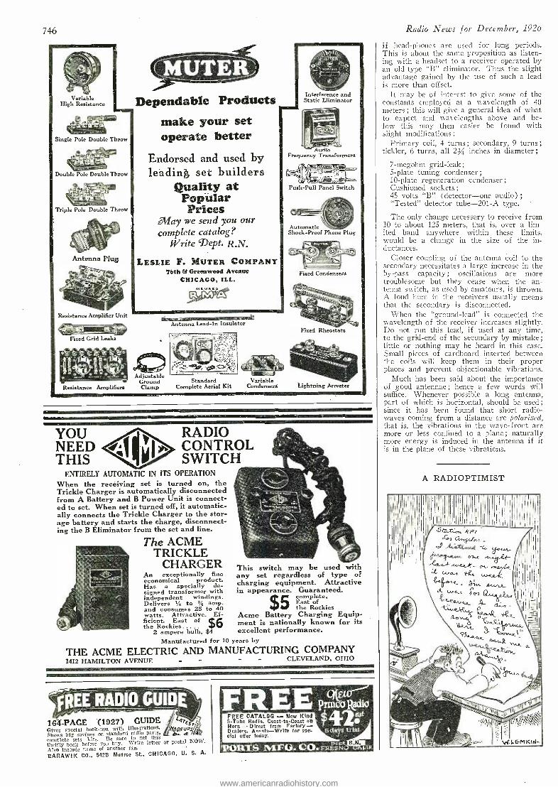
746
I - °...° °- >s'o Adjustable
Ground Resistance Amplifiers Clamp
Variable High Resistance
Single Pole Double Throw
Double Pole Double Throw
Triple Pole Double Throw
Antenna Plug
Resistance Amplifier Unit
Fixed Grid Leaks
Dependable Products make your set operate better
Endorsed and used by leading set builders
Quality at Popular Prices
May we send you our complete catalog?
Write 'Dept. R.N.
LESLIE F. MUTER COMPANY 76th & Greenwood Avenue
CHICAGO, ILL.
smolitimmaaro, Antenna Lead -In Insulator
Interference and Static Eliminator
Audio Frequency Transformers
Push -Pull Panel Switch
Automatic Shock -Proof Phone Plug
Fixed Condensers
Fixed Rheostats
Standard Complete Aerial Kit
Variable Condensers Lightning Arrester
You NEED THIS
RADIO CONTROL SWITCH
ENTIRELY AUTOMATIC IN ITS OPERATION
When the receiving set is turned on, the Trickle Charger is automatically disconnected from A Battery and B Power Unit is connect- ed to set. When set is turned off, it automatic- ally connects the Trickle Charger to the stor- age battery and starts the charge, disconnect- ing the B Eliminator from the set and line.
The ACME TRICKLE
CHARGER An exceptionally fine economical product. Has a specially de- signed transformer with independent windings. Delivers r/z to a/ amp. and consumes 25 to 40 watts. Attractive. Ef- ficient. East of $6 the Rockies
2 ampere bulb, $4
This switch may be used with any set regardless of type of charging equipment. Attractive in appearance. Guaranteed.
5 complete, East of the Rockies
Acme Battery Charging Equip- ment is nationally known for its excellent performance.
Manufactured for 10 years by
THE ACME ELECTRIC AND MANUFACTURING COMPANY 14I2 HAMILTON AVENUE - - CLEVELAND, OHIO
ÇR1ERADIO GUIDE
164 -PAGE "(1927) GUIDE 4ff Gives special hook -ups with illustrations. pps Shows big savings on standard radio parts, .P7 a / complete sets kits. Be sure to get this thrifty book before you buy. Write letter or postal NOW. Also include name of another fan.
BARAWII( CO., 542B Monroe St., CHICAGO, U. S. A.
FREE Pnlitadia 4Z: FREE CATALOG - New Kind
5 -Tube Radio. Coast -to -Coast on Horn - Direct from Factory - Dealers, Asents -Write for spe. dal offer today.
5 days triar.
'PORTS MF(i.. CO. FRE SN LIF
Radio News for December, 1926
if head -phones are used for long periods. This is about the same proposition as listen- ing with a headset to a receiver operated by an old -type "B" eliminator. Thus the slight advantage gained by the use of such a lead is more than offset.
It may be of interest to give some of the constants employed at a wavelength of 40 meters ; this will give a general idea of what to expect and wavelengths above and be- low this may then easier be found with slight modifications :
Primary coil, 4 turns ; secondary, 9 turns ;
tickler, 6 turns, all 2/ inches in diameter;
7- megohm grid -leak ;
5 -plate tuning condenser ; 10 -plate regeneration condenser; Cushioned sockets; 45 volts `B" (detector -one audio) ;
"Tested" detector tube -201 -A type.
The only change necessary to receive from 10 to about 125 meters, that is, over a lim- ited band anywhere within these limits, would be a change in the size of the in- ductances.
Closer coupling of the antenna coil to the secondary necessitates a large increase in the by -pass capacity ; oscillations are more troublesome but they cease when the an- tenna switch, as used by amateurs, is thrown. A loud hum in the receivers usually means that the secondary is disconnected.
When the "ground- lead" is connected the wavelength of the receiver increases slightly. Do not run this lead, if used at any time, to the grid -end of the secondary by mistake; little or nothing may be heard in this case. Small pieces of cardboard inserted between the coils will keep them in their proper places and prevent objectionable vibrations.
Much has been said about the importance of good antennae ; hence a few words will suffice. Whenever possible a long antenna, part of which is horizontal, should be used; since it has been found that short radio - waves coming from a distance are polarized, that is, the vibrations in the wave -front are more or less confined to a plane ; naturally more energy is induced in the antenna if it is in the plane of these vibrations.
A RADIOPTIMIST
www.americanradiohistory.com
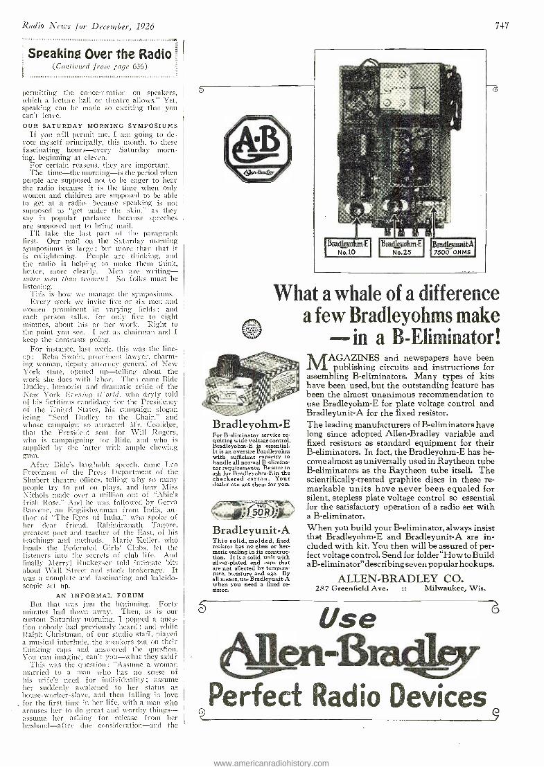
Radio News for December, 1926 747
Speaking Over the Radio (Continued f rom page 636)
fl 111111111111111111:1111111111111111111111111:11111111111111111I111111,1111,:1111.1.111.1111,1.
permitting the concentration on speakers, which a lecture hall or theatre allows." Yet, speaking can he made so exciting that you can't leave. OUR SATURDAY MORNING SYMPOSIUMS
If you will permit nie, I am going to de- vote myself principally, this month, to these fascinating hours -every Saturday morn- ing, beginning at eleven.
For certain reasons, they are important. The time -the morning -is the period when
people are supposed not to be eager to hear the radio because it is the time when only women and children are supposed to be able to get at a radio -because speaking is not supposed to "get under the skin," as they say in popular parlance- because speeches are supposed not to bring mail.
I'll take the last part of the paragraph first. Our nail on the Saturday morning symposiums is large ; but more than that it is enlightening. People are thinking, and the radio is helping to make them think, better, more clearly. Men are writing - more amen than euonncn! So folks must be listening.
This is how we manage the symposiums. Every week we invite five or six men and
women prominent in varying fields ; and each person talks, for only five to eight minutes, about his or her work. Right to the point you see. I act as chairman and I keep the contrasts going.
For instance, last week, this was the line- up : Reba Swain, prominent lawyer, charm- ing woman, deputy attorney general of New York state, opened up- telling about the work she does with labor. Then came Bide Dudley, humorist and dramatic critic of the New York Evening ii-orld, who dryly told of his fictitious candidacy for the Presidency of the United States, his campaign slogan being "Send Dudley to the Chair," and whose campaign so attracted Mr. Coolidge, that the President sent for Will Rogers, who is campaigning for Bide, and who is supplied by the latter with ample chewing gum.
After Bide's laughable speech, came Leo Freedman of the Press Department of the Shubert theatre offices, telling why so many people try to put on plays, and how Miss Nichols macle over a million out of "Abie's Trish Rose." And he was followed by Gerva Baronte, an Englishwoman from India. au- thor of "The Eyes of India," wito spoke of her clear friend, Rabindranath Tagore, greatest poet and teacher of the East, of his teachings and methods. Marie Keller, who heads the Federated Girls' Clubs, let the listeners into the secrets of club life. And finally Merryl Ruckeyser told intimate bits about Wall Street and stock brokerage. It was a complete and fascinating and kaleido- scopic set up.
AN INFORMAL FORUM But that was just the beginning. Forty
minutes bad flown away. Then, as is our custom Saturday morning, I popped a ques- tion nobody had previously heard ; and while Ralph Christman, of our studio staff, played a musical interlude, the speakers put on their thinking caps and answered the question. You can imagine, can't you -what they said?
This was the question : "Assume a woman married to a man who has no sense of his wife's need for individuality ; assume iter suddenly awakened to her status as house- worker- slave, and then falling in love for the first time in her life, with a man who arouses her to do great and worthy things - assume her asking for release from her husband -after clue consideration -and the
Brad zunit.A 7500 OHMS
d
What a whale of a difference a few Bradleyohms make
-in a B- Eliminator!
Bradleyohm-E For B- eliminator service re- quiring wide voltage control, Bradleyohm -E is essential. It is an oversize Bradleyohm with sufficient capacity to handle all normal B- elimina- tor requirements. Be sure to ask for Bradleyohm -E in the checkered carton. Your dealer can get them for you.
Bradleyunit-A This solid, molded, fixed resistor has no glass or her- metic sealing in its construc- tion. It is a solid unit with silver -plated end caps that are not affected by tempera- ture, moisture and age. By all means, use Bradleyunit -A when you need a fixed re- sistor.
MAGAZINES and newspapers have been publishing circuits and instructions for
assembling B- eliminators. Many types of kits have been used, but the outstanding feature has been the almost unanimous recommendation to use Bradleyohm -E for plate voltage control and Bradleyunit -A for the fixed resistor. The leading manufacturers of B- eliminators have long since adopted Allen- Bradley variable and fixed resistors as standard equipment for their B- eliminators. In fact, the Bradleyohm -E has be- come almost as universally used in Raytheon tube B- eliminators as the Raytheon tube itself. The scientifically- treated graphite discs in these re- markable units have never been equaled for silent, stepless plate voltage control so essential for the satisfactory operation of a radio set with a B- eliminator. When you build your B- eliminator, always insist that Bradleyohm -E and Bradleyunit -A are in- cluded with kit. You then will be assured of per- fect voltage control. Send for folder "How to Build a &eliminator "describing seven popular hookups.
ALLEN- BRADLEY CO. 287 Greenfield Ave. :: Milwaukee,, Wis.
Use nß Perfect Radio Devices
9
www.americanradiohistory.com
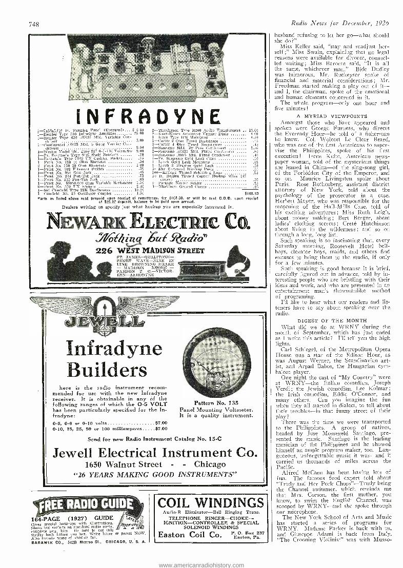
748
INFRADYNE 1- 7x2Sx3/16 in. Formica Panel (Engraved) $ 6.85 1- Remler Type 700 Infradyne Amplifier 25.00 1- Remler Type 630 .00035 Affd. Variable Con -
d[nser 5.00 1- Continental .00035 MId. 3 Geng Vernier Con-
densers 9.50 1- Weston Model -506; Type 217 0 -7 -140 Voltmeter 9.00 1 -Pr. Benjamin Type 8629 Shelf Brackets .70 1- Benjamin Type 9040 UX Cushion Socket - 1 -Frost No. 710 10 Ohm Rheostat 2-Frost No. 730 30 Ohm Rheostats 1 -Frost No. 608 Filament Switch 1 -Frost No. 954 Gem -.Tack 1 -Frost No. 234 Pan -Tab Jack
2- Thordarson Type 8200 Audio Transformers 16.00 -Kurz -Basch Aristocrat Vender Dials 4.00 4.50
.15
.45 2.:70
.80
.40
.10
i0
l -Jones Type 10M Multiples 1- Carter 2 Ohm Fixed Resistance 3-Carter 4 Ohm Fixed Resistances -Sangamo Alfd. By -Pass Condensers -Sangamo .00025 Alfd. Fixed Condensers 1- Sangamo .0005 Slfd, Fixed Condenser
1 -Pr. Sangamo Grid Leak Clips .50 1 -Lynch Grid Leak Mounting
1.00 1 -Lynch 2 Megohnt Grid Leak .30 5 -Eby Engraved Binding Posts .45 100 -Kellogg Tinned Soldering Lugs .73 .75 50 ft. Belden Tinned Copper Hookup Wire (12
1 -Frost No. 235 Pan -Tab Jack .85 gauge) .50 I -Frost No. 88050.000 Ohm Variable Resistance 1.50 I- Package Rester Solder 6 -Frost No. 5a0 1Ix Sockets 2.40 1- Blackburn Ground Clamp .25 1 --Set Caulfield Type 22K Duofor:nets 10.00 1- Caulfield No. 23 Oscillator Coupler 1.50 $108.30 °arts as listed above sent prepaid open receipt of remittance, fer $118.30, or will be sent C.O.D. upon receipt
of $25.00 deposit, balance to be paid upon arrival. Dealers writing us specify just what hookup you are especially interested in.
NEwA ELECT C CO. " othiog Zité Radz®" 226 WEST MADISON STREET
ST. JAMES-QUALITONE- SHORT WAVE, NINE IN LINE- BROAFNING DRAKE - MADISON MOORE - SAMSON T. C.- VICTOR- REN- AERODYNE
cJ EWELL, . Infradyne Builders
here is the radio instrument recom- mended for use with the new Infradyne receiver. It is obtainable in any of the following ranges of which the O -5 VOLT has been particularly specified for the In- fradyne: o -5, o -& or 0 -10 volts $7.00 0 -10, 15, 25, 50 or 100 milliamperes $7.00
Pattern No. 135 Panel Mounting Voltmeter. It is a quality instrument.
Send for new Radio Instrument Catalog No. 15 -C
Jewell Electrical Instrument Co. 1650 Walnut Street - - Chicago
"26 YEARS MAKING GOOD INSTRUMENTS"
164 -PAGE (1927) GUIDE i, re, c
Gives special hook -ups with illustrations. '%/OoONQ!_r
Shows big savings on standard radio parts. q complete sets, kits Be sure to get this thrifty book before you boy. Write letter or postal NOW. Also include name of another fan. BARAWIK CO., 542B Monroe St., CHICAGO, U. S. A.
COIL. WINDINGS Audio -B Eliminator -Bell Ringing Trans.
TELEPHONE RINGER- CHOKE- IGNITION -CONTROLLED & SPECIAL
SOLENOID WINDINGS
Easton Coil Co. P. O. Box 237 Easton, Pa.
Radio News for December, 1926
husband refusing to let her go -what should she do ?"
Miss Keller said, "stay and readjust her- self ;" Miss Swain, explaining that no legal reasons were available for divorce, counsel- led waiting; Miss Baronte said, "It is all the same, whichever man." Bide Dudley was humorous, Mr. Ruckeyser spoke of financial and material considerations ; Mr. Freedman started making a play out cf it- and I, the chairman, spoke of the emotional and human elements concerned in it.
The whole program -only one hour and five minutes!
A MYRIAD VIEWPOINTS Amongst those who have appeared and
spoken were George Furness, who directs the Eveready Hour -he told of a fisherman he knew. Col. Wolcott Le Clear Beard, who was one of the first Americans to super- vise the Philippines, spoke of his first execution ! Irene- Kuhn, American news- paper woman, told of the mysterious things she leaned in China -of the sing -song girl, of the Forbiddeil City of the Emperor, and so on. Maurice Livingston spoke about Paris. Rose Rothenberg, assistant district attorney of New York, told about the psychology of the prosecutor in a case. Herbert Mayer, who was responsible for the reopening of the Hall -Mills Case, told of his exciting adventures ; Miss Ruth Leigh, about money making; Bert Berger, about ladies' clothing secrets ; Creté Hutchinson about living in the wilderness ; and so on through a long, long list.
Such speaking is so fascinating that, every Saturday morning, Roosevelt Hotel bell- boys, elevator boys, maids, and others find excuses to bring them to the studio, if only for a few minutes.
Such speaking is good because it is brief, carefully figured out in advance, told by in- teresting people who are bristling with their ideas and work, and who are presented in an entertainment man's showmanlike method of programing.
I'd like to hear what our readers and lis- teners have to say about speaking over the radio.
DIGEST OF THE MONTH What did we do at WRNY during the
month of September, which has just ended as I write this article? I'll tell you the high lights.
Carl Schlegel, of the Metropolitan Opera House was a star of the Edison Hour, as was August Werner, the Scandinavian art- ist, and Arpad Babos, the Hungarian cym- balom player.
One night the cast of "My Country" were at WRNY -the Italian comedian, Joseph Verdi ; the Jewish comedian, Lee Kolmar ;
the Irish comedian, Eddie O'Connor, and many others. Can you imagine the fun when they all started in dialect, to tell about their troubles -in that funny street of their play?
There was the time we were transported to the Philippines. A group of natives, headed by Jose Mossegeld Santiago, pre- sented the music. Santiago is the leading musician of the Philippines and he showed himself an ample program maker, too. Lan- guorous, unforgettable music it was -and it carried us thousands of miles across the Pacific.
Alfred McCann has been having lots of fun. The famous food expert told about "Trudy and Her Pork Chops" -Trudy being the Channel swimmer, which reminds me that Mrs. Corson, the first mother, you know, to swim the English Channel, was scooped by WRNY -and sise spoke through our microphone.
The New York School of Arts and Music has started a series of programs for WRNY. Madame Parker is back with us, and Giuseppe Adami is back from Italy. "The Crooning Violinist" was with Musso-
www.americanradiohistory.com
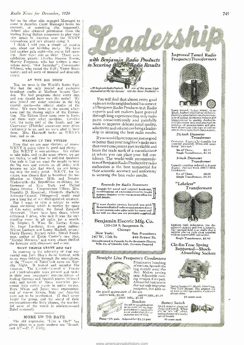
Radio News for December, 1926
lini on the other side, engaged Mascagni to .come to America (later Mascagni broke his contract, or something else happened). Adami also obtained permission from the leading living Italian composers to play their new music in America over the WRNY microphone and he's already doing it.
I think I told you, a couple of months ago, about our birthday party. We have had another gala night -the grand fall open- ing. Now there was an idea! There were celebrities galore : Charles Hanson Towne, Harvey Ferguson, who has written a mar- velous novel, "Hot Saturday" ; Commander Ellsberg, who raised the S-51; Victor Rose - water ; and all sorts of musical and dramatic treats.
AT THE BIG SHOW
Yes, we were in the World's Radio Fair. We had the only special and exclusive broadcast studio at Madison Square Gar- den. We had programs there every clay, and you should have seen the mobs ! We also joined our sister stations in the big crystal studio -the official studio of the show. We were hosts on the second after- noon and the closing nights of the Exposi- tion. The Edison Hour came over in force, and there were other novelties. Caroline Lee, the radio girl of the South, and her Clearwater (Florida) announcer were given exclusively to us, and we were glad to have them. Mrs. I- Iarrauff spoke on WRNY's time, and so on.
WAKING UP THE VOTERS Now that we are near election, of course
WRNY is going after it, good and plenty. But WRNY is non -partisan. We refuse
to take sides, and unlike some others, we are not trying to sell time to political speakers. Our rule is that we want the people to hear the big men and women on all sides ; and, because we take that stand, we are bring- ing only the really great. WRNY, for in- stance, was chosen first to broadcast the no- tification to Ogden Mills and Senator Wadsworth -the Republican candidates for Governor of New York and United States Senator. Congressman Tillson, Mrs. Franklin D. Roosevelt, Elizabeth Marbury, Attorney - General Ottinger -I could read you a long list of our distinguished speakers.
But I want to take a minute to write about something which is worthy the space of this entire article, the Israel Zangwill Memorial. There have been those, whose criticisms I prize, who said it was the out- standing event in all radio for a month. Dr. Stephen S. Wise, Dr. Nathan Krass, Dr. Isaac Landman, three great rabbis ;
Wilton Lackaye and Loney Haskell, actors ;
Harry Hansen, literary critic ; David Freed- man, author of Eddie Cantor's new play, "Mendel Marantz," and many others thrilled the listeners with eloquence and music.
MANY THINGS GRAVE AND GAY
In contrast to the solemnity of that me- morial was Jack Blue's dance festival, with Glance steps tickling through the microphone, or the "Tower of Babel " -it came on Nov- elty Night. It looked and sounded like Locarno. The Consuls- General of France and Czechoslovakia were present and spoke in their own languages ; representatives of leading German and Spanish papers followed suit ; and artists of these countries pre- sented their native music in native tongue. Even Wales and Japan were represented, and of course Russia, Italy and America were not to be overlooked. (I shall never forget the group, and the sound of their conversations -the little cliques, the wonder- ful sense of the world in miniature -and Babel restored).
MORE UP TO DATE The old expression "Hire a Hall" has
given place to a more modern one "Broad- cast it! " -D. F. Kirby.
749
with Bea jaa n Radio Products in Securing s eJ3est -Radio Results
411BerjaminRadioProducts g are of the same high Cle Ra Tone Sockets- standard as the far -famed
You will find that almost every good radio set in the neighborhood has some or all Benjamin Radio Products in it. Radio experts and set makers have proved through long experience that only radio parts conscientiously and painfully made to improve delicate tonal quality, selectivity and volume can bring a leader- ship in securing the best radio results.
If you would have your set just as good or better than your neighbor's make sure that every component part is reliable and bears the trade mark of a manufacturer in whom you can place your full con- fidence. The world -wide recommenda- tion of Benjamin Radio Products by radio authorities is the best testimonial for *heir scientific accuracy and uniformity in securing the best radio results.
Rewards for Radio Reasoners .I[Awards for novel and original hook.ups, modifications of existing circuits; trade names; slogans; write our nearest office for full details.
¡'If your dealer cannot furnish you BenjaminRadio Products send amount direct to our. nearest sales office with his name and we will see that you are promptly supplied.
Benjamin Electric Mfg. Co. 120.128 S. Sangamon St.
Chicago New York: San Francisco:
247 W. 17th St. 448 Bryant St. Manufactured in Canada by the Benjamin Electric
Mfg. Co. of Canada, Ltd., Toronto, Ontario
//imo /; ,/0 Gd////.///i /// remit i Straight Line Frequency Condensers
Eliminates bunching of stations. Spreads the log evenly over the dial. Makes tuning easy. Adjustable turn - ing tension. Compact. A beautiful instrument that not only improves reception, but adds to
the good appearance of the set. .00025 Mfd., $5.00 .00035 Mfd., $5.25
.0005 Mfd., $5.50 Brackets
An aid to simplification in set construction. Sup- ports the sub -panel,with room underneath for ac- cessories and wiring.
Plain -70c pair. Adjustable -$1.25 pair
Improved Tuned Radio FrequencyTrans f ormers
Space wound; basket weave; cylin- drical; highest practical air dielectric. Proved togivethebest results in sharp- ness of tuning, increase in volume and improvement in quality. Authorita- tive laboratory tests and practical ex- perience of manufacturers and ama- teurs shows that this type of coil ex- cels in every important characteristic.
21/4-inch Diameter .Transformer
Compact. Especially desirable for crowded assembly. Eliminates inter- fering "pick- ups."
Set of Three, $5.75 Single Transformer, $2.10
3 -inch Diameter Transformer
Capacity coupling reduced to lowest degree. For use with .00035 Mfd. Condensers.
Set of Three, $6.00 Single Transformer, $2.25
"Lekeless" Transformers
Uniform high inductance, low dis- tributed capacity and low resistance. The external field is so slight that it permits placing coils close together without appreciable interaction.
Single Transformer, $2.50
Cle -Ra -Tone Spring Supported -S hock -
Absorbing Sockets
Spring Supported, Shock -Absorbing. Stop Tube Noises. The greatest aid to non -noisy operation. Contacts always clean.
75 cents each
Battery Switch Quick, positive, clean -cut make and break. When its `in" it's "off ",elimi - nating danger of wasteful use of battery.
30 cents each
;/! l`ii'/'/%D%/i%6i/
www.americanradiohistory.com
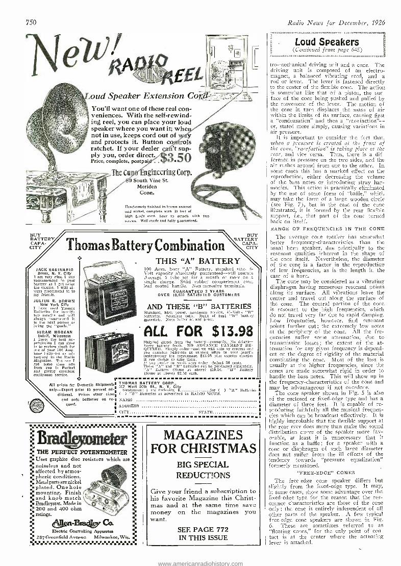
:Bm4kro'ne'e'1:
,} THE PERFECT POTENTIOMETER ti;
% Uses graphite disc resistors which are
% noiseless and not
.. affected by atmos- pheric conditions.
0¡ Metal parts are nickel %plated. One hole
mounting. Finish and knob match Bradleystat. Made in E 200 and 400 ohm
~ei
ratings. °
®
ti ti _
' Electric Controlling Apparatus ti287 Greenfield Avenue Milwaukee, Wis. %
750
EEL oud Speaker Extension Cord.°- You'll want one of these real con- veniences. With the self- rewind- ing reel, you can place your loud speaker where you want it; whe not in use, keeps cord out of . y and protects it. Button co ols ratchet. If your dealer 't sup- ply you, order direct. IIzQ
c, Price, complete, postpai, . . '
The Cu ngineering Corp. 0 South Vine St.
Meriden Conn.
Handsomely finished in brown enamel and nickel, complete with 25 feet of high grade cord. Easy to attach with two screws. Well made and fully guaranteed.
BUY BATTERY CAPA-
CITY Thomas Battery Combination
JACK SAGINARIO Bronx, N. Y. City
I am very glad I was recommended to your battery as I get twice the volume. I will al- clays recommend it to my friends.
JULIUS R. BROWN New York City
I have used Thomas Batteries for twenty - two months and will always recommend it to the next person as being the "goods."
HIRAM MORGAN Beloit, Wisconsin
I guess the best ap- preciation I earl show is to enclose cheep for one of your 100 Amp. hour batteries as ad- vertised in the Badio Magazine. The one I got some time ago from you is Perfect and giving excellent continuous service.
t!_.:.:._:':..._... .._.....::'
tN
All prices for Domestic Shipments only -Export price 15 percent ad-
ditional. Prices other sizes and auto batteries on, re-
quest.
r
BUY BATTERY
CAPA- CITY
THIS "A" BATTERY 100 Amp. hour "A" Battery, standard rate. 6- Volt capacity absolutely guaranteed -will operate Average 5 tube set for a month or more on a single charge. Solid rubber compartment case, lead coated handle. Non- corrosive terminals.
GUARANTEED 2 YEARS OVER 18,000 SATISFIED CUSTOMERS
AND THESE "B" BATTERIES Standard, high power, maximum service, 15-Volt . "B" batteries. Seamless cells. Built of best "B" battery materials. None better at any price.
ALL FOR $13.98 Shipped direct from the factory- promptly, No delays - Every battery fresh. NO ADVANCE PAYMENT RE- QUIRED. Simply order -and we will ship by express and you examine batteries at express office to your heart's content -pay the expressman $13.98 plus express charges if you decide to take them. If you prefer to remit with order -deduct 50 cents. These "A" and "B" batteries can be purchased separately. "A" Battery (Same as above) $10.50. "B" Battery (Same as above) $1.50 each.
THOMAS BATTERY CORP., 507 West 50th St., N. Y. City
Gentlemen: I am enclosing $ for ( ) "A" Batteries ( ) "B" Batteries as advertised in RADIO NEWS. NAME
ADDRESS CITY STATE
MAGAZINES FOR CHRISTMAS
BIO SPECIAL REDUCTIONS
Give your friend a subscription to his favorite Magazine this Christ- mas and at the same time save money on the magazines you want.
SEE PAGE 772 IN THIS ISSUE
Radio News for December, 1926
Loud Speakers (Continued front page 645)
tro- mechanical driving unit and a cone. The driving unit is composed of an electro- magnet, a balanced vibrating reed, and a rod or lever. The lever is fastened directly to the center of the flexible cone. The action is somewhat like that of a piston, the sur- face of the cone being pushed and pulled by the movement of the lever. The motion of the cone in turn displaces the mass of air within the limits of its surface, causing first a "condensation" and then a "rarefaction" - or, stated more simply, causing variations in air pressure.
It is important to consider the fact that, when a pressure is created at the front of the cone, "rarefaction" is taking place at the rear, and vice versa. Thus, there is a dif- ference in pressure on the two sides, and the air rushes around from one to the other. In some cases this has a marked effect on the reproduction, either decreasing the volume of the bass notes or introducing stray har- monics. This action is practically eliminated by the use of some form of "baffle," which may take the form of a large wooden circle (see Fig. 7), but in the case of the cone illustrated, it is formed by the rear flexible support, i.e., that part of the cone turned back on itself. RANGE OF FREQUENCIES IN THE CONE
The average cone speaker has somewhat better frequency- characteristics than the usual horn speaker, due principally to the resonant qualities inherent in the shape of the cone itself. Nevertheless, the diameter of the cone is a factor in the reproduction of low frequencies, as is the length in the case of a horn.
The cone may be considered as a vibrating diaphragm having numerous resonant points along its surface. All vibrations leave the center and travel out along the surface of the cone. The central portion of the cone is resonant to the high frequencies, which do not travel very far due to rapid damping. Low frequencies, however, find resonant points further out ; the extremely low notes at the periphery of the cone. All the fre- quencies suffer some attenuation, due to transmission losses ; the extent of the at- tenuation for any given frequency is depend- ent on the degree of rigidity of the material constituting the cone. Most of the loss is usually at the higher frequencies, since the cones are made somewhat rigid in order to handle the bass notes. This will show up in the frequency- characteristics of the cone and may be advantageous if not overdone.
The cone speaker shown in Fig. 5 is also of the enclosed or fixed -edge type and has a diameter of three feet. It is capable of re- producing faithfully all the musical frequen- cies which can be broadcast effectively. It is highly improbable that the flexible support at the rear ever does more than make the sound distribution curve of the speaker more fav- orable, at least it is unnecessary that it function as a baffle ; for a speaker with a cone or diaphragm of such large diameter does not suffer from the ill effects of the tendency towards "pressure equalization" formerly mentioned.
"FREE- EDGE" CONES
The free -edge cone speaker differs but slightly from the fixed -edge type. It may, in some cases, show some advantage over the fixed -edge type for the reason that the res- onance characteristics are those of the cone only ; the cone is entirely independent of all other parts of the speaker. A few typical free -edge cone speakers are shown in Fig. 6. These are sometimes referred to as "floating cones," for the only point of con- tact is at the center where the actuating lever is attached.
www.americanradiohistory.com
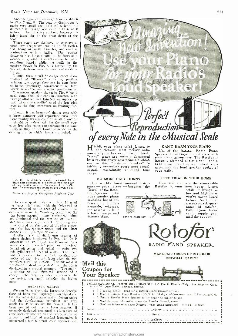
Radio News for December, 1926
Another type of free -edge cone is shown in Figs. 7 and 8. The cone or diaphragm is made very small and light of weight ; the diameter is usually not more than 6 or 8 inches. The effective surface, however, is fairly large, due to the great depth of the cone.
These cones are designed to resonate at some low frequency, say 40 to 60 cycles, and, being of small diameter, are used in conjunction with a baffle. The speaker shown in Fig. 7 has a baffle in the form of a wooden ring, which also acts somewhat as a sounding board ; while the baffle in the speaker shown in Fig. 8 is formed by the cabinet which encloses the cone and its driv- ing unit.
Though these small free -edge cones show evidence of "flexural" vibration, particu- larly on low power, they can be considered as being practically non -resonant on high power, when the piston action predominates.
The power speaker shown in Fig. 9 has a small cone, about 6 inches in diameter, with its edge attached to a thin leather supporting ring. It can be classified as of the free -edge type, as the ring introduces no limiting fac- tors.
Though it has been said that a cone with a large diameter will reproduce bass notes more readily than a cone of small diameter, it should be understood that the small con- cave f ree -edge cones can accomplish the same thing, as they do not limit the action of the driving unit to which they are attached.
Fig. Il. A roll -type speaker, actuated by a drive unit attached to the central meeting point of two flexible rolls in the shape of half- cylin- ders. In operation the cylinders are given a roll-
ing motion. Photo courtesy of Dictograph Products Corp.
The cone speaker shown in Fig. 10 is of the "eccentric" type, with the drive -rod or lever attached to the cone off center. The distances from the "working center" to the rim being unequal, many resonance points are eliminated and the creation of undesir- able harmonics is prevented. The long sec- tions caused by the unequal division repro- duce the low -register notes, and the short sections the high- register notes.
Another type of diaphragm speaker of unique design is shown in Fig. 11. It is known as the "roll" type, and is formed by a single sheet of special paper or "fonotex" folded off -center and rolled to make two hal f-cylinders of unequal width. The drive unit is fastened to the fold, so that any motion of the drive unit lever gives the two cylinders a rolling motion. The air mass is "swished" instead of pushed ; yet the air is displaced in a normal manner. (The action is similar to the "flexural" motion of a cone). The large cylinder reproduces the low notes, the small cylinder the higher ones.
RELATIVE MERITS We can learn, from the foregoing descrip-
tions of horn and diaphragm loud- speakers, shat the main differences rest in design only; that the fundamental principles are very much the same, as are the results. It has been pointed out that a horn speaker, if properly designed, can equal a given type of cone speaker insofar as the reproduction of a very broad band of musical frequencies is concerned ; but a small cone speaker will
75I
producfinn ofeveryNote in the Musical scale
HEAR your piano talk! Listen to the clearest, most mellow radio
music anyone has ever heard. Harsh, "tinny" tones are entirely eliminated by a revolutionary new principle which enables this "Invisible Speaker" to faithfully reproduce every note broad- casted. Asbsolutely unlimited tone range.
NO MORE UGLY HORNS The world's finest musical instru-
ment - your piano - becomes the "horn" of the Roto - for Speaker. The huge wooden piano sounding board dif- fuses the notes properly, whereas, the narrow neck of a horn cramps and distorts them.
SPX/ r--ii.osu: feed ...1111
CAN'T HARM YOUR PIANO Use of the Rotofor Radio Piano
Speaker doesn't injure or interfere with your piano in any way. The Rotofor is instantly clamped out of sight, -and a hidden wire, as long as desired, con- nects with the loud speaker socket of your radio.
FREE TRIAL IN YOUR HOME Hear
Rotofor and compare the remarkable in your own house. Listen
while it brings in low and high notes you've never heard before. Sold under a money -back guar- antee of satisfac- tion. If your dealer can't supply you, mail the coupon.
RADIO PIANO SPEAKER,
MANUFACTURERS OF ROTOFOR ONE -DIAL RADIOS
Mail this Coupon for Your Speaker
INTERNATIONAL RADIO CORPORATION, 145 Pacific Electric Bldg., Los Angeles, Calif. or 225 W. Ohio Street, Chicago, Illinois.
( ) I enclose $28.00. Send me a Rotofor Piano Speaker prepaid. ( ) Send a Rotofor Piano Speaker C.O.D. for 10 clays' trial -money back if I'm dissatisfied. ( ) Send a Rotofor Piano Speaker to my dealer to deliver to me. ( ) Send me more information about the Rotofor Piano Speaker. ( ) Send me information about Rotofor -"The Radio Simplified" -one dial -5 tubes.
Name Address
City State
Dealer's Name Address
www.americanradiohistory.com
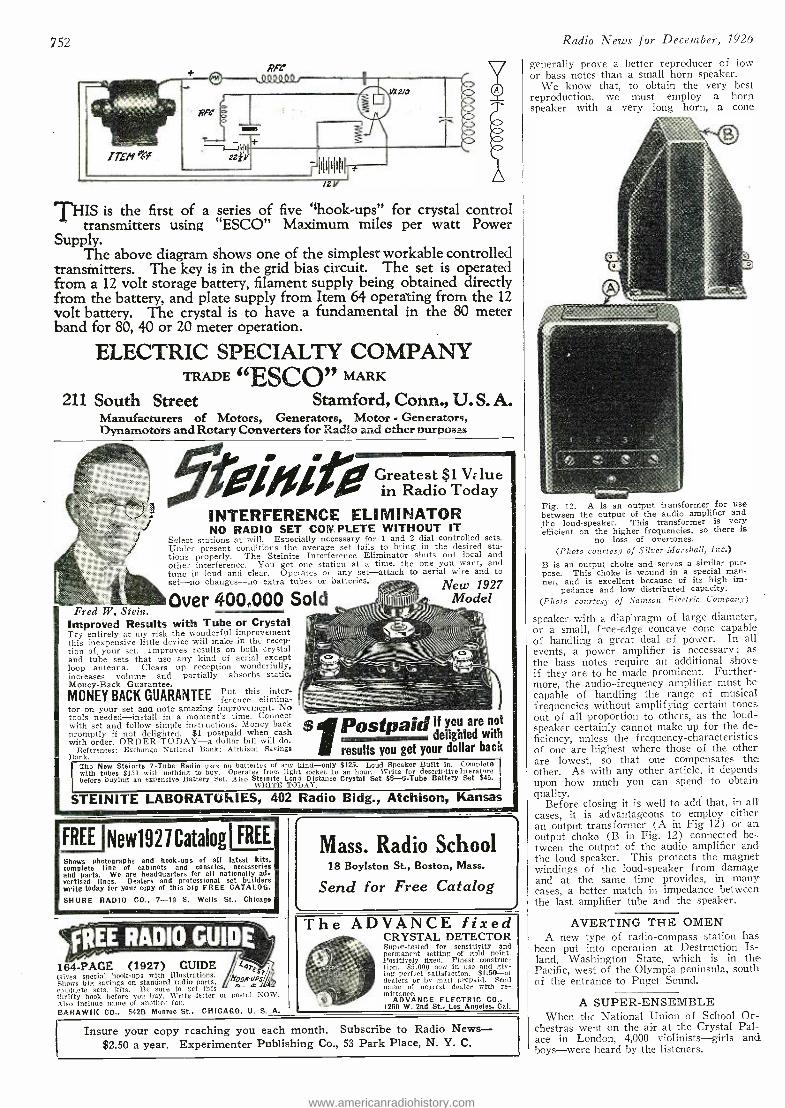
752
vxz/0
-hI1111l0l1 f /2V
'FHIS is the first of a series of five `shook -ups" for crystal control transmitters using "ESCO" Maximum miles per watt Power
Supply. The above diagram shows one of the simplest workable controlled
transmitters. The key is in the grid bias circuit. The set is operated from a 12 volt storage battery, filament supply being obtained directly from the battery, and plate supply from Item 64 operating from the 12 volt battery. The crystal is to have a fundamental in the 80 meter band for 80, 40 or 20 meter operation.
ELECTRIC SPECIALTY COMPANY TRADE 66ESCO" MARK
211 South Street Stamford, Conn., U. S. A. Manufacturers of Motors, Generators, Motor . Generators, Dynamotors and Rotary Converters for Radio aad other purposes
Greatest $1 Vz lue in Radio Today
INTERFERENCE ELIMINATOR NO RADIO SET COPO PLETE WITHOUT IT
Select stations at will. Especially necessary for 1 and 2 dial controlled sets. Under present conditions the average set fails to bring in the desired sta- tions properly. The Steinite Interference Eliminator shuts out local and other interference. You get one station at a time, the one you want, and tune in loud and clear. Operates on any set -attach to aerial wire and to set -no changes -no extra tubes or batteries.
Fred W. Stein. Over 400000 S
Improved Results with Tube or Crystal Try entirely at niy risk the wonderful improvement this inexpensive little device will make in the recep- tion of your set. Improves results on both crystal and tube sets that use any kind of aerial except loop antenna. Clears up reception wonderfully, increases volume and partially absorbs static. Money -Back Guarantee. MONEY BACK GUARANTEE erence t elimina- tor on your set and note amazing improvement. No tools needed -install in a moment's time. Connect with set and follow simple instructions. Money hack promptly if not delighted. $1 postpaid when cash with order. ORDER TODAY -a dollar bill will do.
References: Exchange National Bank; Atchison Savings Bank
New 1927
$ Postpaid If you are not delighted with
results you get your dollar back The New Steinite 7 -Tube Radio uses no batteries of any kind -only $125. Loud Speaker Built in. Complete
1 with tubes $151 with nothing to buy. Operates from light socket lc an hour. Write for descriptive literature before buying an expensive Battery Set. Also Steinite Long Distance Crystal Set $6r- 6-Tube Battery Set $45.
WRITE TODAY.
STEINITE LABORATUlir1ES, 402 Radio Bldg., Atchison, Kansas
FREE INew1927Catalogi FREE
Shows photographs and hook -ups of all latest kits. complete line of cabinets and consoles, accessories and parts. We are headquarters for all nationally ad- vertised lines. Dealers and professional set builders write today for your copy of this big FREE CATALOG.
SHURE RADIO CO., 7 -10 S. Wells St., Chicago
4REE RADIO GUIDE 164 -PAGE (1927) GUIDE
orES Gives special hook -ups with illustrations. fitorooSr Shows big savings on standard radio parts, et m n complete sets, kits. Be sure to get this thrifty book before sou buy. Write letter or postal NOW. Also include name of another fan. BARAWIK CO., 542B Monroe St., CHICAGO, U. S. A.
Mass. Radio School 18 Boylston St., Boston, Mass.
Send for Free Catalog
The ADVANCE fixed CRYSTAL DETECTOR Super- tested for sensitivity and permanent setting of gold point. Positively fixed. Finest construc- tion. 85,00.0 now in use and giv- ing perfect satisfaction. 51.50 -at dealers or by mail prepaid. Send name of nearest dealer with re- mittance.
ADVANCE ELECTRIC CO., 1260 W. 2nd St., Los Angeles, Cal.
Insure your copy reaching you each month. Subscribe to Radio News - $2.50 a year. Experimenter Publishing Co., 53 Park Place, N. Y. C.
Radio News for December, 1926
generally prove a better reproducer of low or bass notes than a small horn speaker.
We know that, to obtain the very best reproduction, we must employ a horn speaker with a very long horn, a cone
Fig. 12. A is an output transformer for use between the output of the audio amplifier and the loud- speaker. This transformer is very efficient on the higher frequencies, so there is
no loss of overtones. (Photo courtesy of Silver -Marshall, Inc.)
B is an output choke and serves a similar pur- pose. This choke is wound in a special man- ner, and is excellent because of its high im-
pedance and low distributed capacity. (Photo courtesy of Samson Electric Company)
speaker with a diaphragm of large diameter, or a small, free -edge concave cone capable of handling a great deal of power. In all events, a power amplifier is necessary ; as the bass notes require an additional shove if they are to be made prominent. Further- more, the audio -frequency amplifier must be capable of handling the range of musical frequencies without amplifying certain tones out of all proportion to others, as the loud- speaker certainly cannot make up for the de- ficiency, unless the frequency- characteristics of one are highest where those of the other are lowest, so that one compensates the other. As with any other article, it depends upon how much you can spend to obtain quality.
Before closing it is well to add that, in all cases, it is advantageous to employ either an output transformer (A in Fig 12) or an output choke (B in Fig. 12) connected be- tween the output of the audio amplifier and the loud- speaker. This protects the magnet windings of the loud -speaker from damage and at the same time provides, in many cases, a better match in impedance between the last amplifier tube and the speaker.
AVERTING THE OMEN A new type of radio- compass station has
been put into operation at Destruction Is- land, Washington State, which is in the Pacific, west of the Olympia peninsula, south of the entrance to Puget Sound.
A SUPER -ENSEMBLE When the National Union of School Or-
chestras went on the air at the Crystal Pal- ace in London, 4,000 violinists -girls and boys -were heard by the listeners.
www.americanradiohistory.com
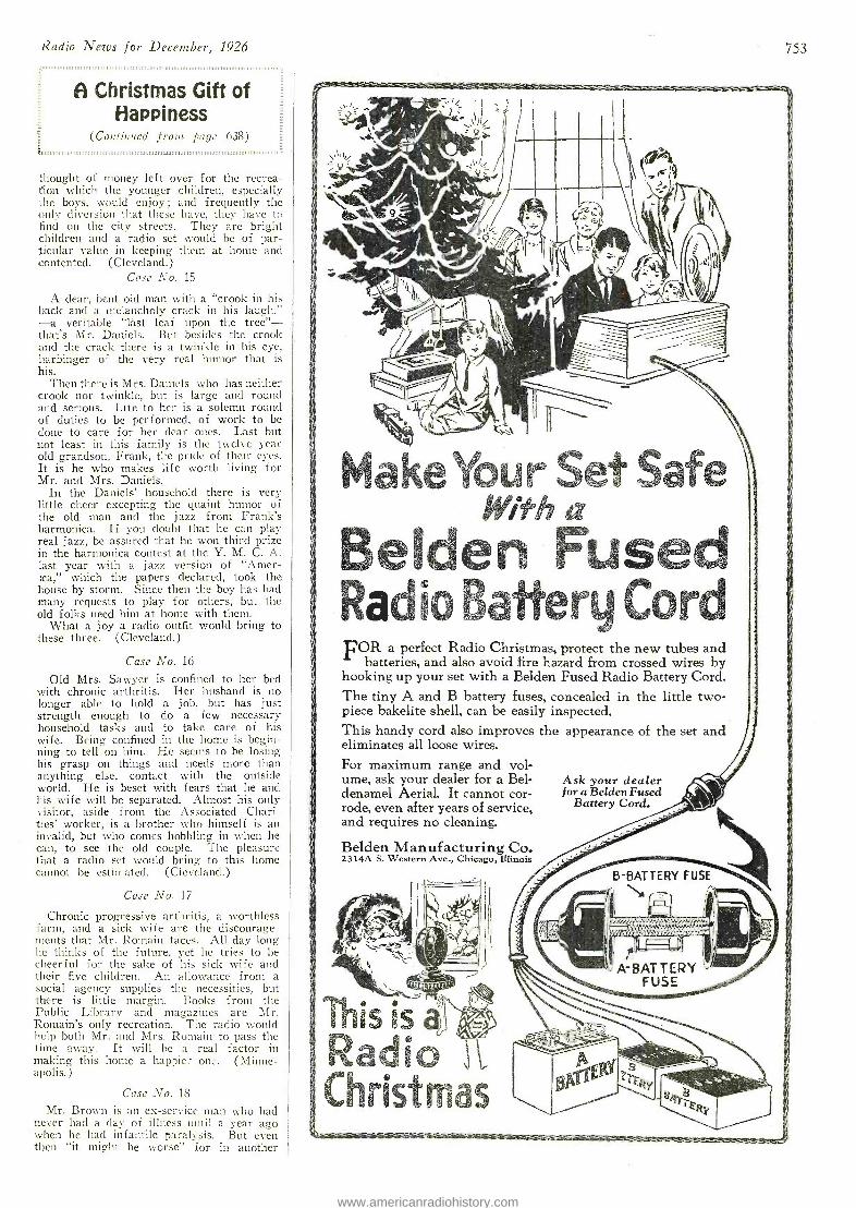
Radio News for December, 1926
A Christmas Gift of Happiness
(Continued front pnric 638) 1.1111,111111,1111111:11111111311111:1:111::11111111,.111u.,1111. 1111M111::::: :, -.::.
thought of money left over for the recrea- tion which the younger children, especially the boys, would enjoy; and frequently the only diversion that these have, they have to find on the city streets. They are bright children and a radio set would be of par- ticular value in keeping them at home and contented. (Cleveland.)
Case No. 15
A dear, bent old man with a "crook in his back and a melancholy crack in his laugh," -a veritable "last leaf upon the tree" - that's Mr. Daniels. But besides the crook and the crack there is a twinkle in his eye, harbinger of the very real humor that is his.
Then there is Mrs. Daniels who has neither crook nor twinkle, but is large and round and serious. Life to her is a solemn round of duties to be performed, of work to be done to care for her dear ones. Last but not least in this family is the twelve year old grandson, Frank, the pride of their eyes. It is he who makes life worth living for Mr. and Mrs. Daniels.
In the Daniels' household there is very little cheer excepting the quaint humor of the old man and the jazz from Frank's harmonica. If you doubt that he can play real jazz, be assured that he won third prize in the harmonica contest at the Y. M. C. A. last year with a jazz version of "Amer- ica," which the papers declared, took the house by storm. Since then the boy has had many requests to play for others, but the old folks need him at home with them.
What a joy a radio outfit would bring to these three. (Cleveland.)
Case No. 16
Old Mrs. Sawyer is confined to her bed with chronic arthritis. Her husband is no longer able to hold a job, but has just strength enough to do a few necessary household tasks and to take care of his wife. Being confined in the home is begin- ning to tell on him. He seems to be losing his grasp on things and needs more than anything else, contact with the outside world. He is beset with fears that he and his wife will be separated. Almost his only visitor, aside from the Associated Chari- ties' worker, is a brother who himself is an invalid, but who comes hobbling in when he can, to see the old couple. The pleasure that a radio set would bring to this home cannot be estimated. (Cleveland.)
Case No. 17
Chronic progressive arthritis, a worthless farm, and a sick wife are the discourage - ments that Mr. Romain faces. All day long he thinks of the future, yet he tries to be cheerful for the sake of his sick wife and their five children. An allowance from a social agency supplies the necessities, but there is little margin. Books from the Public Library and magazines are Mr. Romain's only recreation. The radio would help both Mr. and Mrs. Romain to pass the time away. It will be a real factor in making this home a happier one. (Minne- apolis.)
Case No. 18
Mr. Brown is an ex- service man who had never had a clay of illness until a year ago when he had infantile paralysis. But even then "it might be worse" for in another
753
Make Your Set Safe With a
Belden Fused Radio Battery Cord FOR a perfect Radio Christmas, protect the new tubes and
batteries, and also avoid fire hazard from crossed wires by hooking up your set with a Belden Fused Radio Battery Cord. The tiny A and B battery fuses, concealed in the little two-
/ piece bakelite shell, can be easily inspected. This handy cord also improves the appearance of the set and eliminates all loose wires.
For maximum range and vol- ume, ask your dealer for a Bel- Ask your dealer denamel Aerial. It cannot cor- for a Belden Fused rode, even after years of service, Battery Cord. and requires no cleaning.
Belden Manufacturing Co. 2314A S. Western Ave., Chicago, Illinois
I N, YY /Y/YY YIv à/llekptlPCd wdiM"h
ma#?''aatiattomec.
..,k -1
This is Radio Christmas
www.americanradiohistory.com
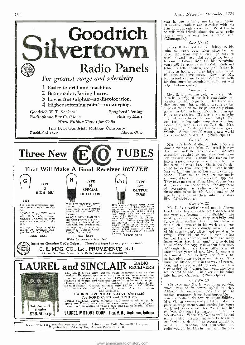
754
Silvertoodrich Radio Panels
For greatest range and selectivity
1 Easier to drill and machine. 2 Better color, lasting lustre. 3 Lower free sulphur -no discoloration. 4 Higher softening point -no warping.
Goodrich V. T. Sockets Spaghetti Tubing Radiophone Ear Cushions Battery Mats
Hard Rubber Tubes for Coils
The B. F. Goodrich Rubber Company Established 1870 Akron, Ohio
Three New o . TUBES That Will Make A Good Receiver BETTER
n UdU
TYPE G
HIGH MU
For use in impedance and resistance coupled receiv- ers. "CeCo" Type "G" tube will carry more power without overloading than any other available High - Mu. Average voltage amplifi- cation 20- Average Out- put Impedance 25,000.
PRICE $2.50
TYPE H
SPECIAL DETECTOR
Will give improved repro- duction and avoid the usual rushing and hissing sounds of the "soft" de- tectors. Using a higher plate volt- age than previous types, it will handle powerful sig- nals with less overloading. Average mutual conduct- ance 940. Voltage Ampli- fication factor 14.4.
PRICE $2.50 Write for complete data sheet.
J71 TYPE J -71
OUTPUT TUBE
Will candle sufficient power to op- crate the largest loud speakers at full volume. Does not require high voltage plate supply. At 90 v. it will give twelve times the undistorted Power of the ordinary "A" type. To be used in receivers where a sep- arate "C" Battery connection for the last tube is furnished. Can be used on voltages up to 180 with en- ormous volume output, provided a
special output circuit is used to protect the loud speaker. Filament 5 v.-% PRICE $6.00
Insist on Genuine CeCo Tubes. There's a type for every radio need.
C. E. MFG. CO., Inc., PROVIDENCE, R. I. The Largest Plant in the World Making Radio Tubes Exclusively
LAUREL and SINCLAIR RECEIVERS
5-tube and 6-tube
$29.50 up
The lowest -priced high quality radio receiving sets on the market. Extraordinary selectivity, coast to coast reception. Five -tube and six -tube sets from $29.50 up. Many superior features of design and construction to bring better, stronger, clearer reception. Beautifully finished console cabinet de- signs if desired. Console cabinets only, $17.50 to $35. Write for free booklet and confidential discount sheet for dealers
and salesmen. LAUREL OVERHEAD VALVE SYSTEMS
For FORD CARS and TRUCKS Laurel overhead valve, cylinder -head permits 65 m. p. h. speed for Fords, save gas, increase power. Low cost, easy terms. We specialize in racing cars and racing heads. Write
for circular.
LAUREL MOTORS CORP., Dep. V. R., Anderson, Indiana J
Insure your copy reaching you each month. Subscribe to Radio News -$2.50 a year Experimenter Publishing Co., 53 Park Place, N. Y. C.
Radio News for December, 1926
year be can probably use his arm again. Meanwhile reading and chatting with his friends is his only recreation. What fun to to talk with friends about the latest radio program, -if he only had a radio set !
(Minneapolis. ) Case No. 19
James Rutherford had an injury to his spine ten years ago. Ever since he has hoped that some day he could go back to work -a well man. But now he no longer hopes -he knows that all his remaining years will be spent as an invalid. Ruth and John, his little children, are glad father is to stay at home, but they little know what his days at home mean. Now that Mr. Rutherford can no longer hope to be well, his time must be occupied -a radio set will help. (Minneapolis.)
Case No. 20
Mrs. B. is a woman well past sixty. She is so badly crippled that it is practically im- possible for her to go out. Her home is a tiny two -room house which, in spite of her crippled condition she keeps spotlessly clean. An unmarried brother of about her own age is her only relative. He works in a near -by city and comes to visit her on Sundays. Ex- cept for him her only companion is a tiny Polish girl, who speaks no English. Mrs. B. speaks no Polish, but the two are great friends. A radio would mean a new world and a new life to Mrs. B. (Philadelphia)
Case No. 21
Mrs. F.'s husband died of tuberculosis a short time ago and Mrs. F. herself is now threatened with the same disease. She was unusually attached to and dependent upon her husband, and his death has thrown her into a state of depression from which noth- ing seems to rouse her. She is deeply de- voted to her two little girls and can hardly bear to let them out of her sight, even for school. Thus the children are constantly surrounded by an atmosphere of unhappiness. They have no fun at all, as Mrs. F. considers it impossible for her to go out for any form of recreation. A radio would have a therapeutic value in this family and would also bring a hit of cheer into their drab life. (Philadelphia.)
Case No. 22
Mr. L. is a well- educated and intelligent Greek, who has incurable heart disease and one year ago became totally disabled. He must govern his clays very carefully and follow strict routine. Prior to his illness he was much interested in his work as an en- graver and was exceedingly active in all of his countrymen's affairs and social gath- erings. Since his enforced idleness he has lost heart and courage, and there are many hours when there is not much else to do but think of the far happier days that have past. Although there are three little ones all under three years of age, Mrs. L. makes a determined effort to keep her family to- gether, plying her trade as seamstress. This home has little to offer in the way of recrea- tion, and a radio would not only give them a great deal of pleasure, but would also be a real benefit to Mr. L. in diverting his mind into happier channels. (Philadelphia)
Case No. 23
Six years ago Mr. G. was in an accident which resulted in severe spinal injuries. Although he underwent long and painful medical treatment, it has been impossible for him to resume his former responsibilities. Mrs. G. has courageously tried to take his place as wage earner, and besides her house work and personal care for Mr. G. and her children, she sews for various tailoring es- tablishments. When Mr. G. was well he had many outside interests ; but since he has been confined to a chair it has become a fight to ward off melancholy and depression. A radio would bring him in touch with the out-
www.americanradiohistory.com
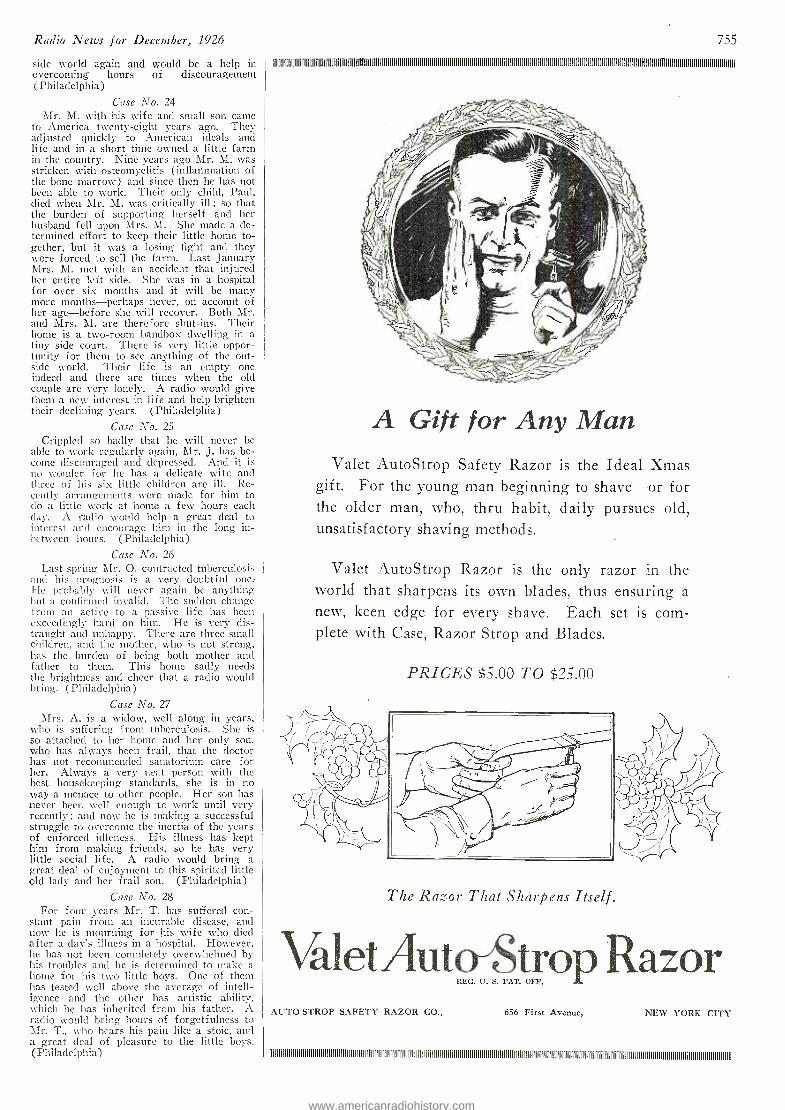
Radio News for December, 1926
side world again and would be a help in overcoming hours of discouragement (Philadelphia)
Case No. 24 Mr. M. with his wife and small son carne
to America twenty -eight years ago. They adjusted quickly to American ideals and life and in a short time owned a little farm in the country. Nine years ago Mr. M. was stricken with osteomyelitis (inflammation of the bone marrow) and since then he has not been able to work. Their only child, Paul, died when Mr. M. was critically ill ; so that the burden of supporting herself and her husband fell upon Mrs. M. She made a de- termined effort to keep their little home to- gether, but it was a losing fight and they were forced to sell the farm. Last January Mrs. M. met with an accident that injured her entire left side. She was in a hospital for over six months and it will be many more months -perhaps never, on account of her age- before she will recover. Both Mr. and Mrs. M. are therefore shut -ins. Their home is a two -room bandbox dwelling in a tiny side court. There is very little oppor- tunity for them to see anything of the out- side world. Their life is an empty one indeed and there are times when the old couple are very lonely. A radio would give them a new interest in life and help brighten their declining years. (Philadelphia)
Case No. 25
Crippled so badly that he will never be able to work regularly again, Mr. J. has .be- come discouraged and depressed. And it is no woodier for he has a delicate wife and three of his six little children are ill. Re- cently arrangements were made for him to do a little work at home a few hours each day. A radio would help a great deal to interest and encourage hint in the long in- between hours. (Philadelphia)
Case No. 26 Last spring Mr. O. contracted tuberculosis
and his prognosis is a very doubtful one He probably will never again be anything but a confirmed invalid. The sudden change from an active to a passive life has been exceedingly hard on him. He is very dis- traught and unhappy. There are three small children, and the mother, who is not strong, has the burden of being both mother and father to them. This home sadly needs the brightness and cheer that a radio would bring. (Philadelphia)
Case No. 27 Mrs. A. is a widow, well along in years,
who is suffering from tuberculosis. She is so attached to her home and her only son, who has always been frail, that the doctor has not recommended sanatorium care for her. Always a very neat person with the best housekeeping standards, she is in no way a menace to other people. Her son has never been well enough to worle until very recently ; and now he is making a successful struggle to overcome the inertia of the years of enforced idleness. His illness has kept him from making friends, so he has very little social life. A radio would bring a great deal of enjoyment to this spirited little old lady and her frail son. (Philadelphia)
Case No. 28 For four years Mr. T. has suffered con-
stant pain from an incurable disease, and now he is mourning for his wife who died after a clay's illness in a hospital. However, he has not been completely overwhelmed by his troubles and he is determined to make a home for his two little boys. One of them has tested well above the average of intell- igence and the other has artistic ability, which he has inherited from his father. A radio would bring hours of forgetfulness to Mr. T., who bears his pain like a stoic, and a great deal of pleasure to the little boys. (Philadelphia)
755
A Gift for Any Man Valet AutoStrop Safety Razor is the Ideal Xmas
gift. For the young man beginning to shave -or for the older man, who, thru habit, daily pursues old, unsatisfactory shaving methods.
Valet AutoStrop Razor is the only razor in the world that sharpens its own blades, thus ensuring a
new, keen edge for every shave. Each set is com- plete with Case, Razor Strop and Blades.
PRICES $5.00 TO $25.00
The Razor That Sharpens Itself.
Valet Aut REG. U. S. PAT. OFF.
AUTO STROP SAFETY RAZOR CO., 656 First Avenue, NEW YORK CITY
i l l l i l i
www.americanradiohistory.com
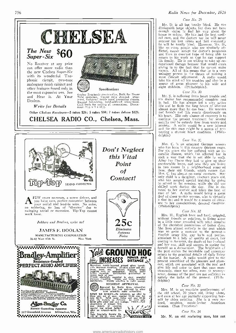
756
CHELSEA The New $6® Super -Six No Receiver at any price, can offer more radio than1'; the new Chelsea Super -Six , with its wonderful Tru- phonic circuit, two -tone _ mahogany finish cabinet and "°°°°"° RAUIOI- ! other features found only in Specifications the most expensive sets. See
6 -tubes Truphonic construction, Built for Power and Hear it. At Your Tube operation. Circuit fully shielded. Dust -
Dealers. proof, fool -proof inside panel protecting chassis. Rugged bus -wiring, hand -soldered connections. Cord leads for making all connections. Dimen- Write for Details sions 21/ x 9 x 11%.
Other Chelsea Receivers -3 tubes $26; 5 tubes $50; 7 tubes deluxe $125.
CHELSEA RADIO CO., Chelsea, Mass.
r
` agmilou 011a
LEAD -IN CONNECTOR
AFEW spare moments, a screw driver, and
you have sure, perfect connection between your aerial and lead -in wire. No noise,
no soldering, no loss of "distance" due to swinging aerial or corrosion. Tip -Top cannot work loose.
Jobbers and Dealers, write us!
JAMES F. DOOLAN MANUFACTURING CORPORATION
36 -42 West 47th St. New York
Don't Neglect this Vital
Point of
Contact!
fr
25c Eliminates Antenna
Noise
. hS.UY..Yr...Ytr..%%'h: 'te
. }}-- Resistance-Coupled PERFECT AUDIO AMPLIFIER%
. Provides audio amplification - . with minimum distortion. BradieyimIt --
dold d resistors used ln the Bradley- Amplifier
o t vnry wità ssa and are not affected by atmospheric % conditio C be sed ro replace transformer amplifiera . in etaadardradio sets wit: decided intoaeauatity.
CI % Electric Controlling Apparatus , . 287 Greenfield Avenue Milwaukee, Wis.
y GROUND HOG INCREASES DiPSTÁÑCÉ
Marvelous newly -invented ground glees incred- ably improved reception. Doubles power and dis- / tance users say. Reduces leakage. Stops i jangling even in midsummer. Results never before equalled. Satisfaction guaranteed or money bark at once. Proven absolutely essential to clear. powerful distance r ̂ ceptinn. Draws and holds moisture indefinitely. H ighly sensitive to radio energy.
HIGHEST APPROVAL Approved by Radio News exhaustive laboratory test and endorsed by other
high scientific radio authorities. SEND NO MONEY -To introduce. we offer to those who net at once. regular $5.00 size for only 52.00. Send name today and pay $2.00 Pius 17e postage on delivery. Or send only $2.00 with order and save postage. FREE -Full description of Ground Hog and details of amazing special low priced battery offer on request -write to- day.
. =ACA tE Yale Specialty Supply Co. 125 W. 5th St.. Kan. City -.-
y
-GROUND HOG
Radio News for December, 1926
Case No. 29
Mr. D. is all but totally blind. He can distinguish large objects, but does not have enough vision to find his way about the house in safety. He has had the best medi- cal care, and the doctors say he will never recover his lost vision and that eventually he will be totally blind. However, Mr. D., like so many people who are similarly af- flicted, cannot accept the doctor's prognosis and lives in constant hope of being able to return to his work so that he can support his family. He is not willing to take up oc- cupational therapy because that would mean giving in to the fact that he cannot make money. All of this means that he is a very unhappy person in the throes of making a most difficult adjustment. A radio would take his mind off his troubles and also be a source of great pleasure to his wife and eight children. (Philadelphia).
Case No. 30 Mr. S. is suffering from heart trouble and
his doctor has recommended complete rest in bed. He has always led a very active life and he finds the long hours of idleness almost more than he can bear. He worries and broods and this reacts disastrously on his heart. His only chance of recovery is to continue the present treatment for several months and be entirely free from worry and anxiety. A radio would be a new interest and for this man might be a means of pre- venting a chronic heart condition. (Phila- delphia)
Case No. 31 Mrs. C. is an educated German woman
who has been in this country thirteen years. For six years she has suffered with an in- curable disease, which has affected her in such a way that she is not able to walk. After her illness they had to give up their comfortable home, and now they are living in two rooms in a neighborhood remo- ed from their old friends, which means that Mrs. C. has almcst no social contacts. Her only child is a daughter, nineteen years old, who has secured special training by going to school in the evening. while she did un- skilled work during the day. She is de- voted to her mother and takes the best of care of her. A radio would bring a great deal of cheer to this woman, who is virtually a shut -in ; and it would be a source of pleas- ure to her conscientious, devoted daughter. (Philadelphia)
Case No. 32 Mrs. H., English born and bred, crippled,
without friends or relatives, is living alone in a little room crowded with what remains of the cherished possessions of better days_ She lives almost entirely in the past which was so great a contrast to the present - English army life, gay balls and parties, attendant to a lady of quality at court, her coming to America, the death of her husband and her own skill and success in caring for herself as a dressmaker. The brightness of the past makes the inevitable and necessary return to the practical details of daily living all the harder. A radio would give to the present something of the pleasure and glam- our, which are associated with the past and give life and color to days that pass mon- otonously, since too often, even to seventy - seven, dreams of the past are not sufficient to satisfy the lacks of the present. (Phila- delphia)
Case No. 33 Mrs. M. is an exquisite gentlewoman of
the old school, 70 years old, living alone, and even at her age partially supporting her- self by china painting. She is a very re- fined, sensitive, music -loving American woman. (San Francisco)
Case No. 34
Mr. N. an old seafaring man, has not
www.americanradiohistory.com
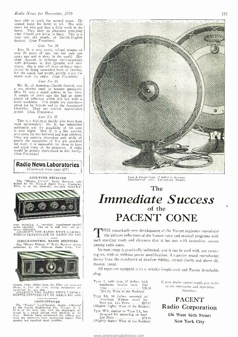
Radio News for December, 1926
been able to work for several years. He cannot leave his home at all. His wife cares for him and does a little work in the home. They have no pleasures excepting what friends can bring to them. This is a very nice old couple, of Danish- English descent. (San Francisco)
Case No. 35 Mrs. H. a very sweet, refined woman of
over 70 years of age, lost her only son years ago and is alone in the world. Her chief pleasure is religious correspondence with prisoners in San Quentin and else- where. She is shut off from ordinary inter- course by being somewhat hard of hearing, but she could, and would, greatly enjoy the music over the radio. (San Francisco)
Case No. 36 Mr. H., of American -Danish descent, was
a sea captain until he became paralyzed. Mrs. H. was a noted actress in her time. A couple of years ago she had an acute attack of influenza which left her with a heart weakness. This couple are shut-ins - cared for by friends and by the Associated Charities. They are refined, appreciative people. (San Francisco)
Case No. 37 This is a high -type family who have been
most unfortunate.. Mr. E. has tubercular peritonitis and the possibility of his cure is very slight. Mrs. E. is a fine woman, who cares for her husband and four children. They are entirely dependent and, while of course the necessities of life are provided for them, it is impossible for them to have and enjoy many of the pleasures. A radio would be greatly appreciated in this family. (San Francisco)
111Radio News Laboratories 1_
n"""""(Çotct'iuued from page 677)
FIVE -TUBE RECEIVER The " Miraco Ultra -5" Radio Receiver, sub-
mitted by the Midwest Radio Corp., Cincinnati, Ohio, is of the three -dial five -tube tuned -R.F.
type including a two -stage transformer- coupled audio amplifier. The set is well built and per- forms admirably.
AWARDED THE RADIO NEWS LABORA- TORIES CERTIFICATE OF MERIT NO. 1603.
SINGLE -CONTROL RADIO RECEIVER The "Miraco Unitone 5" Radio Receiver shown,
submitted by the Midwest Radio Corp., Cin-
cinnati, Ohio, differs from the Ultra set described above, in that the three tuning condensers are controlled by one dial.
. AWARDED THE RADIO NEWS LABORA- TORIES CERTIFICATE OF MERIT NO. 1604.
LOUD -SPEAKER The "Pausin" Loud -Speaker shown, submitted
by the Pausin Engineering Co., Newark, N. J. It is of the cone type, with the diaphragm en- closed in a metal cabinet with openings in the front. Besides being ornamental the cabinet pro- tects the apparatus from mechanical injury. This speaker has excellent tonal qualities.
757
Type A Pacent Cone, 17 inches in diameter. Manufactured under Lektophone Patents.
The
Immediate Success of the
PACENT CONE THIS remarkable new development of the Pacent engineers reproduces
the delicate inflections of the human voice and musical programs with such startling truth and clearness that it has met with immediate success among radio users.
Its tone range is practically unlimited, and it can be used with any receiv- ing set, with or without power amplification. A superior sound reproducing device from the standpoint of absolute fidelity, crystal clarity and above all, musical range.
All types are equipped with a suitable length cord and Pacent detachable plug.
Type A, table type, 17 inches, with handsome bronze base. List price $28.50 ($31.50, West of the Rockies)
Type SA, 36 inches, mounted on American Walnut stand for floor use. List Price $89.50
(Slightly higher West of the Rockies) Type WA, similar to Type SA, but
designed for mounting on wall. List Price $78.50
(Slightly higher West of the Rockies)
If your dealer cannot supply you, cmrite us for interesting and informing
literature.
PACENT Radio Corporation
156 West 16th Street New York City
www.americanradiohistory.com
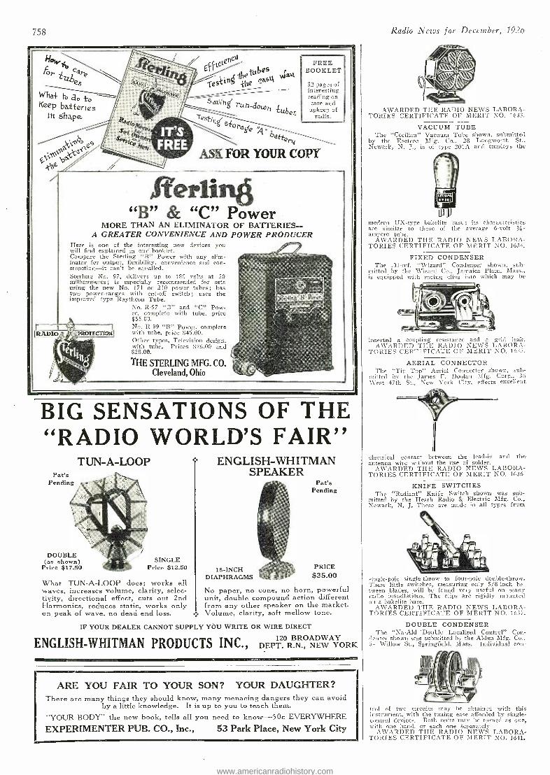
758
Hoh,..1 C T / El tCtQBCU .
D es For are \ IS -tile dub watI e / A .? ? siin e ease S ° TQ {¡I
, - Wha+ to a mO "`
° to `t sdllih Keep batteries run -down -Lubec 111 Shape. - Test,
n
FREE BOOKLET
32 3 pages of interesting reading on care and
upkeep of radio.
SiordJ s IT'S \ e q° 6° Sei
k Jo..., ...,,,-- '"ceAfelt FREE
d r 4
OPY tibe 0i^MaG ASK FOR YOUR C h6
Ier1insj "B" & "C" Power
MORE THAN AN ELIMINATOR OF BATTERIES- - A GREATER CONVENIENCE AND POWER PRODUCER
Here is one of the interesting new devices you will find explained in our booklet. ./J Compare the Sterling "B" Power with any elim- - inator for output, flexibility, convenience and con- struction---it can't be equalled. -
Sterling No. 97, delivers up to ISO volts at 50 milliamperes ; is especially recommended for sets a
using the new No. 171 or 210 power tubés; has two power- ranges with cut -off switch; uses the t¢rlin$BPower improved type Raytheon Tube. x`
us LT --,' No. R -97 "B" and "C" Pow-
''"*".4`_` er, complete with tube, price - $55.00. No. R -99 "B" Power, complete
RADIO IQ:T*10X *WI with tube, price $45.00. -
°it, ,
.`'
Other types, Television design, with tube. Prices $26.00 and $28.00.
THE STERLING MFG. CO. Cleveland, Ohio
BIG SENSATIONS OF THE "RADIO WORLD'S FAIR"
TUN -A -LOOP
DOUBLE (as shown)
Price $17.50 SINGLE
Price $12.50
What TUN -A -LOOP does; works all waves, increases volume, clarity, selec- tivity, directional effect, cuts out 2nd Harmonics, reduces static, works only on peak of wave, no dead end loss.
ENGLISH -WHITMAN SPEAKER
Pat's Pending
18 -INCH DIAPHRAGMS
PRICE $35.00
No paper, no cone, no horn, powerful unit, double compound action different from any other speaker on the market. Volume, clarity, soft mellow tone.
IF YOUR DEALER CANNOT SUPPLY YOU WRITE OR WIRE DIRECT
ENGLISH -WHITMAN PRODUCTS INC., DEPT R.N., NEW YORK ORK
ARE YOU FAIR TO YOUR SON? YOUR DAUGHTER? There are many things they should know, many menacing dangers they can avoid
by a little knowledge. It is up to you to teach them.
"YOUR BODY" the new book, tells all you need to know -50c EVERYWHERE
EXPERIMENTER PUB. CO., Inc., 53 Park Place, New York City
Radio News for December, 192o
AWARDED THE RADIO NEWS LABORA- TORIES CERTIFICATE OF MERIT NO. 1633,
VACUUM TUBE The "Cecilian" Vacuum Tube shown, submitted
by the Esetroc Mfg. Co.. 28 Longworth St., Newark, N. J., is of type 201A and employs the
Ui Ui
modern UX -type bakelite base ; its characteristics are similar to those of the average 6 -volt V.4.-
ampere tube. AWARDED THE RADIO NEWS LABORA-
TORIES CERTIFICATE OF MERIT NO. 1634.
FIXED CONDENSER The .0I -mf. "Wizard" Condenser shown, sub-
mitted by the Wizard Co., Jamaica Plain; Mass., is equipped with spring clips into which may be
inserted a coupling resistance and a grid leak. AWARDED THE RADIO NEWS LABORA-
TORIES CERTIFICATE OF MERIT NO. 1635.
AERIAL CONNECTOR The "Tip Top" Aerial Connector shown, sub-
mitted by the James F. Doolan Mfg. Corp., 36 \Vest 47th St., New York City, effects excellent
electrical contact between the lead -in and the antenna wire without the use of solder.
AWARDED THE RADIO NEWS LABORA- TORIES CERTIFICATE OF MERIT NO. 1636
KNIFE SWITCHES The "Radiant" Knife Switch shown was sub-
mitted by the Heath Radio & Electric Mfg. Co., Newark, N. J. These are made in all types from
single -pole single -throw to four -pole double -throw. These little switches, measuring only 5/8 -inch be- tween blades, will be found very useful on many radio installations. The clips are rigidly mounted on a bakelite hase.
AWARDED THE RADIO NEWS LABORA- TORIES CERTIFICATE OF MERIT NO. 1637.
DOUBLE CONDENSER The "Na -Aid 'Double Localized Control" Con-
denser shown was submitted by the Alden Mfg. Co.. 54 Willow St., Springfield, Mass. Individual con-
trol of two circuits may he obtained with this instrument, with the tuning ease afforded by single - control devices. Both units may be turned as one, with one hand, or each one separately
AWARDED THE RADIO NEWS LABORA- TORIES CERTIFICATE OF MERIT NO. 1641.
www.americanradiohistory.com
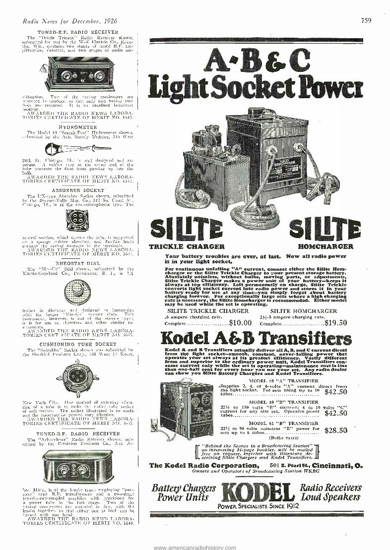
Radio News for December, 1926
TUNED -R.F. RADIO RECEIVER The "Oriole Trinum" Radio Receiver shown,
submitted for test by the W -K Electric Co., Keno- sha, Wis., contains two stages of tuned R.F. am- plification, detector, and two stages of audio am-
plification. Two of the tuning condensers are mounted in tandem, so that only two tuning con- trols are required. It is an excellent broadcast receiver.
AWARDED THE RADIO NEWS LABORA- TORIES CERTIFICATE OF MERIT NO. 1642.
HYDROMETER The Model 10 "Smash Pruf" Hydrometer shown,
:.rl mitted by the Acid Supply Utilities, 316 West
24th St., Chicago, Ill., is well designed and ac- curate. A rubber stop at the upper end of the tube prevents the float from passing up into the bulb.
AWARDED THE RADIO NEWS LABORA- TORIES CERTIFICATE OF MERIT NO. 1643.
ABSORBER SOCKET The L'S -type Absorber Socket shown, submitted
by the Bremer -Tully Mfg. Co., 532 So. Canal St., Chicago, Ill., is of the non -microphonic type. The
central portion, which carries the tube, is supported on a sponge rubber absorber, and flexible leads connect the spring contacts to the terminals.
AWARDED THE RADIO NE \VS LABORA- TORIES CERTIFICATE OF MERIT NO. 1644.
RHEOSTAT DIAL The "Mar -Co" Dial shown, submitted by the
Martin- Copeland Co., Providence, R. I., is 2y1
inches in diameter and designed to harmonize with the larger "Mar-Co" vernier dials. This instrument, however, is not of the vernier type; it is for use on rheostats and other similar in- struments.
AWARDED THE RADIO NEWS LABORA- TORIES CERTIFICATE OF MERIT NO. 1645.
CUSHIONING TUBE SOCKET The "Sofrubba" Socket shown was submitted by
the Moulded Products Corp., 549 West 52 Street,
New Fork City. One method of reducing vibra- tion of a tube is to make the entire tube socket of soft rubber. The socket illustrated is so made and the construction proved very effective.
A\VARDEI) THE RADIO NEWS LABORA- TORIES CERTIFICATE OF MERIT NO. 1643.
TUNED -R.F. RADIO RECEIVER The "Arborphone" Radio Receiver shown, sub -
mitted by the Precision Products Co., Ann Ar-
bor, Mich., s of the 5 -tube type; employing "pan- cake" type R.F. transformers and a two -stage transformer- coupled amplifier with provisions for a power tube in the last stage. Two of the tuning condensers are mounted in line, with the knobs together, so that either one or both can be turned with one hand.
AWARDED THE RADIO NEWS LABORA- TORIES CERTIFICATE OF MERIT NO. 1649.
759
AD&C Ligia Socket Power
-lilll I 111111 111111
=111III 1
TRICKLE CHARGER sILTe
HOMCHARGER Tour battery troubles are over, at last. Now all radio power is in your light socket. For continuous unfailing "An current, connect either the Silite Kona- charger or the Silite Trickle Charger to your present storage battery. Absolutely noiseless, without bulbs, moving parts, or adjustments, Silite Trickle Charger makes a power unit of your battery -keeps it always at top efficiency. Left permanently on charge, Silite Trickle converts light socket current into radio power and stores it in your battery ready for use at any time -you simply forget about battery charging forever. For exceptionally large sets where a high charging rate is necessary, the Silite Homcharger is recommended. Either model may be used while the set is operating. SILITE TRICKLE CHARGER
.6 ampere charging rate. Complete $10.00
SILITE HOMCHARGER 2M -3 ampere charging rate. Complete $19.50
Kodel A&B Transifiers Kodel A and B Transifiers actually deliver all A, B, and C current direct from the light socket -smooth, constant, never failing power that operates your set always at its greatest efficiency. Vastly different from and superior to the ordinary power unit, Kodel Transifiers con. sume current only while the set is operating- maintenance cost is less than one -half cent for every hour you use your set. Any radio dealer can show you Silite Battery Chargers and Kodel Transifiers.
MODEL 10 "A" TRANSIFIER .Supplies 2, 4, or 6 -volts "A" current direct from the light socket. For sets using up to 10 $42.50 tubes W
II!pllÌllll 'No
MODEL 10 "B" TRANSIFIER 22% to 150 volts "B" current; 4 to 10 volts "C" current for any size set. Operates power
45 Y42 20
tubes $
$28.50 MODEL 61 "B" TRANSIFIFR
223,6 to 90 volts noiseless "B" power for sets up to 6 tubes
(Bulbs extra)
"Behind the Scenes in a Broadcasting Station" an interesting 24 -page booklet, will be mailed free on request, together with literature de- scribing Silite Chargers and Kodel Transifiers.
The Kodel Radio Corporation, 501 E. PeariSt., Cincinnati, O. Owners and Operators of Broadcasting Station WKRC
Battery Chargers Power Units
POWER SPECIALISTS SINCE 1912
Radio Receivers Loud Speakers
www.americanradiohistory.com
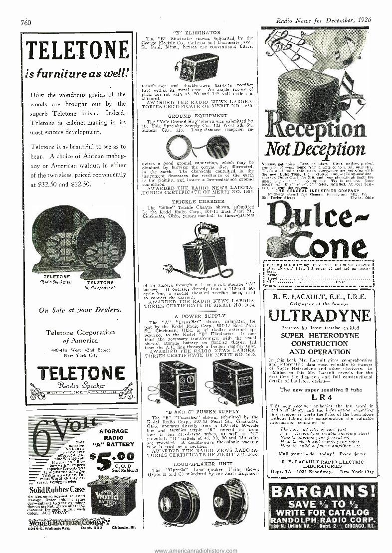
BARGAINS! SAVE i/3TO1/2
I WRITE FO13. CATALOG
RANDOLPH. RADIO CORP.: 180 N. UNION AV. Dept. 2 CHICAGO, ILL.
760
TELETONE is furniture as Well!
How the wondrous grains of the
woods are brought out by the
superb Teletone finish ! Indeed,
Teletone is cabinet -making in its
most sincere development.
Teletone is as beautiful to see as to
hear. A choice of African mahog-
any or American walnut, in either
of the two sizes, priced conveniently
at $32.50 and $22:50.
TELETONE 'Radio Speaker 60 TELETONE
Radio Speaker 62
On Sale at your Dealers.
Teletone Corporation of America
449 -453 West 42nd Street New York City
TELETONE Radzo epeakter
B LIILT LIKE A VIOLIN
Most amazing battery
value ever offered! A gen-
uine World 6 -volt Radio "A" Bat-
tery with 25 ampere capacity for only $5. _- It is just the thing for
Trickle char ger. Fa- mous World Quality as-
sured. Equipped with
SolidRubberCase An assurance against acid and leakage. Order shipped same day- subject to your examina- tion on arrival. Extra offer: 5% discount for cash in full with order. ACT TODAY!
STORAGE RADIO
"A" BATTERY
S 00 C. O. D
Send No Money
O+V rle BAT
t1219 S. Wabash Ave. Dept. 110 Chicago. ill.
"B ". ELIMINATOR The "B" EIiminator shown, submitted by the
George Electric Co., Carleton and University Ave., St. Paul, Minn., houses the conventional filters,
transformer and double -wave gas -type rectifier tube within its metal case. An ample supply of plate curi ant with 45, 90 and 145 volt outlets is obtained.
AWARDED THE RADIO NEWS LABORA- TORIES CERTIFICATE OF MERIT NO. 1650.
GROUND EQUIPMENT The "Yale Ground Hog" shown was submitted by
the Yale Specialty Supply Co., 123 West 5th St., Kansas City, Mo. Long- distance reception re-
,A11: Hie
quires a good ground connection, which may be obtained by burying the copper disc, illustrated, in the earth. The chemicals contained in the instrument decreases the resistance of the earth in the vicinity, and insure a low- resistance ground connection.
AWARDED THE RADIO NEWS LABORA TORIES CERTIFICATE OF MERIT NO. 1653.
TRICKLE CHARGER The "Silite" Trickle Charger shown, submitted
by the Kodel Radio Corp., 507 -13 East Pearl St., Cincinnati, Ohio, passes one -half to three- quarters
of an ampere through a 4- or 6 -volt storage "A" battery. It operates directly from a 110 -volt 60- cycle line, a special chemical rectifier being used to convert the current.
AWARDED THE RADIO NEWS LABORA- TORIES CERTIFICATE OF MERIT NO. 1654.
A POWER SUPPLY The "A" "Transifier" shown, submitted for
test by the Kodel Radio Corp., 507 -13 East Pearl St., Cincinnati, Ohio, is of similar external ap- pearance to the Kodel "B" Eliminator. It con- tains the necessary transformers, with the usual six -volt storage battery on floating charge, fed from the A.C. line through a Tungar rectifier tube.
AWARDED THE RADIO NEWS LABORA- TORIES CERTIFICATE OF MERIT NO. 1655.
"B AND C" POWER SUPPLY The "B" "Transifier" shown, submitted by the
Kodel Radio Corp., 507 -13 Pearl St., Cincinnati, Ohio, operates directly from a 110 -volt, 60 -cycle line and supplies ample "B" current for from four to ten 201 -A -type tubes, as well as "C" potential; "B" outlets of 45, 70, 90 and 150 volts are provided. A double -wave thermionic vacuum tube is used as a rectifier.
AWARDED THE RADIO NEWS LABORA- TORIES CERTIFICATE OF MERIT NO. 1656.
LOUD -SPEAKER UNIT The "Operola" Loud -Speaker Units shown
(types B and C) submitted by the Zisch Engineer-
Radio News for December, 1926
eiption lsrotDeeetíon
Volume, not noise. Tone, not blare. Clear, mellow, pitted reception of every sound from a whisper to a full orchestra. That's what radio enthusiasts everywhere are enjoying with the new Dulce -Tone, the perfected radio- talking -machine- speaker. Dulce -Tone, for $10, and your phonograph make the finest loud speaker money can buy. Try it and see. Your money back if you're not completely satisfied. At your deal- er's, or send the roupon.
THE GENERAL INDUSTRIES COMPANY Formerly named The General Phonograph MIe Co.
251 Taylor Street Elyria, Ohio
ice- one
-a Enclosed is $10 for my Dulce -Tone. If I'm not satisfied I after 10 days' trial, I'll return it and get my money I.
I Name Street City State
in! INIMIONMINII.-11===1.11111111119=d1471.13011,112
R. E. LACAULT, E.E., I.R.E. Originator of the famous
V LTRAIYNfE Presents his latest treatise entitled
SUPER HETERODYNE CONSTRUCTION
AND OPERATION In this book Mr. Lacault gives comprehensive and informative data most valuable to owners of Super Heterodyne and other receivers. In addition to this Mr. Lacault reveals for the first time the diagrams and full constructional details of his latest design-
The new super sensitive 9 tube LR4
This new receiver embodies the last word in Radio efficiency and the information regarding titis receiver is worth the price of the book alone without taking into consideration the valuable information contained on
The how and why of each part Super Heterodyne trouble shooting chart How to improve Zone present .set How to check and match your tubes How to build a power amplifier, etc.
Mail your order today! Price $1.97
R. E. LACAULT RADIO ELECTRIC LABORATORIES
Dept. 1A -1931 Broadway, New York City
www.americanradiohistory.com
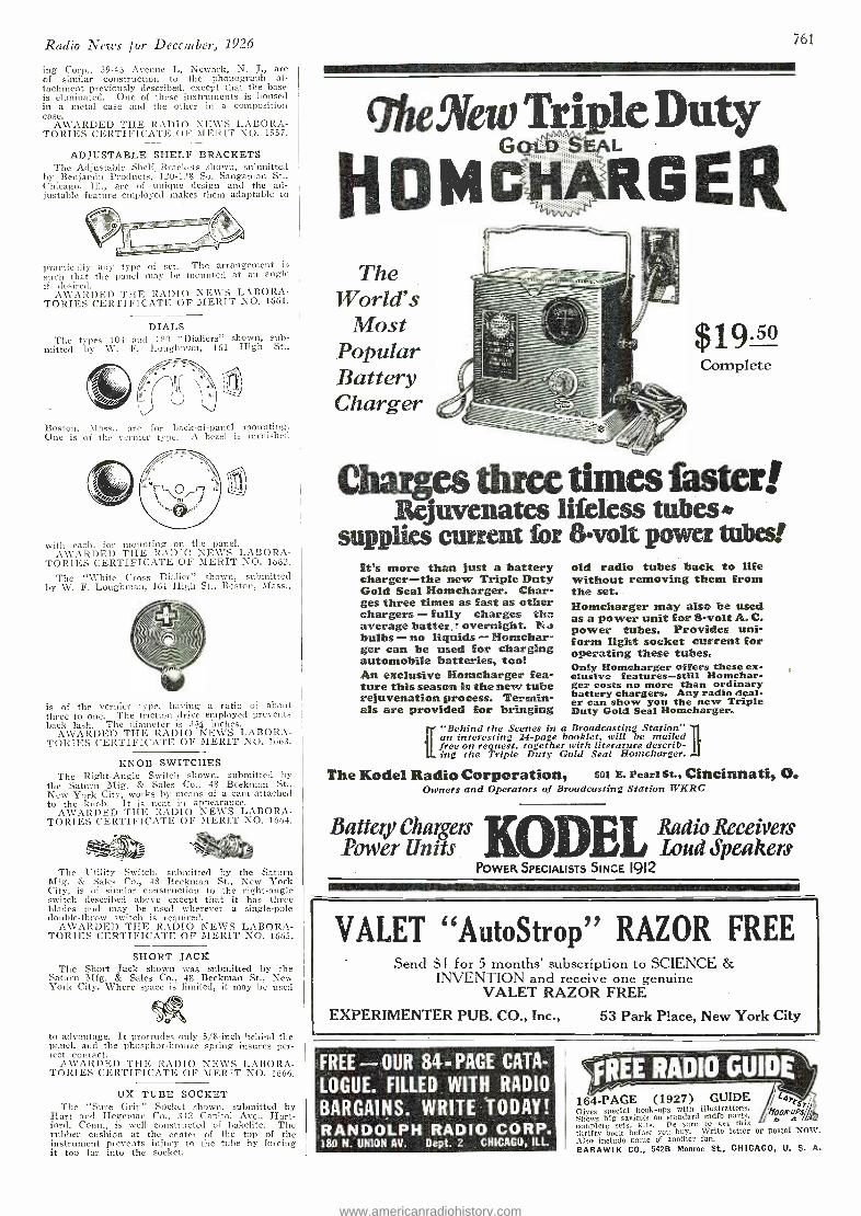
Radio News for December, 1926
ing Corp., 39 -43 Avenue L, Newark, N. 3., are of similar construction to the phonograph at- tachment previously described, except that the base is eliminated. One of these instruments is housed in a metal case and the other in a composition case.
AWARDED THE RADTO NEWS LABORA- TORIES CERTIFICATE OF MERIT NO. 1557.
ADJUSTABLE SHELF BRACKETS The Adjustable Shelf. Brackets shown, submitted
by Benjamin Products, 120 -128 So. Sangamon St., Chicago, IIL,- are of unique design and the ad- justable feature employed makes them adaptable to
practically any type of set. The arrangement is such that the panel may he mounted at an angle if desired.
AWARDED THE RADIO NEWS LABORA- TORIES CERTIFICATE OF MERIT NO. 1661.
DIALS The types 104 and 180 "Dialiers" shown, sub-
mitted by W. F. Loughran, 161 High St.,
Boston, Mass., are for back -of -panel mounting,. One is of the vernier type. A bezel is furnished
with each, for mounting on the panel. AWARDED THE RADIO NEWS LABORA-
TORIES CERTIFICATE OF MERIT NO. 1662.
The "White Cross Dialler" shown, submitted by W. F. Loughman, 161 High St., Boston, Mass.,
is of the vernier type, having a ratio of about three to one. The friction drive employed prevents back lash. The diameter is 344 inches.
AWARDED THE RADIO NEWS LABORA- TORIES CERTIFICATE OF MERIT NO. 1663.
KNOB SWITCHES The Right -Angle Switch shown, submitted by
the Saturn Mfg. & Sales Co., 48 Beekman St., New York City, works by means of a cani attached to the knob. It is neat in appearance.
AWARDED THE RADIO NEWS LABORA- TORIES CERTIFICATE OF MERIT NO. 1664.
JI The utility, Switch, submitted by the Saturn
Mfg. & Sales Co., 48 Beekman St., New York City, is of similar construction to the right -angle switch described above except that it has three blades and may be used wherever a single -pole doable -throw switch is required.
AWARDED THE RADIO NEWS LABORA- TORIES CERTIFICATE OF MERIT NO. 1665.
SHORT JACK The Short Jack shown was submitted by the
Saturn Mfg. & Sales Co., 48 Beekman St., New York City. Where space is limited, it may be used
to advantage. It protrudes only 5/8 -inch behind the panel, and the phosphor -bronze spring insures per- fect contact.
AWARDED THE RADIO NEWS LABORA- TORIES CERTIFICATE OF MERIT NO. 1666.
UX TUBE SOCKET The "Sure Grip" Socket shown, submitted by
Hart and Hegemau Co., 342 Capitol Ave., Hart- ford, Conn., is well constructed of hakelite. The rubber cushion at the center of the top of the instrument prevents injury to the tube by forcing it too far into the socket.
761
que Yet1 1$'.!e Duty
The World's
Most Popular Battery Charger
$19.50 Complete
es three times faster! Rejuvenates lifeless tubes*
supplies current for &volt power tubes! Ws more than just a battery charger -the new Triple Duty Gold Seal Homcharger. Char- ges three times as fast as other chargers - fully charges th° average batter overnight. No bulbs - no liquids - Homchar- ger can be used for charging automobile batteries, too! An exclusive Homcharger fea- ture this season is the new tube rejuvenation process. Termin- als are provided for bringing
old radio tubes back to life without removing them from the set. Homcharger may also be used as a power unit ford-volt A. C. power tubes. Provides uni- form light socket current for operating these tubes. Only Homcharger offers these ex- clusive features -still Homchar- ger costs no more than ordinary battery chargers. Any radio deal- er can show you the new Triple Duty Gold Seal Homcharger.
11Behind the Scenes in a Broadcasting Station" an interesting 24 -page booklet, will be mailed free on request, together with literature describ- ing the Triple Duty Gold Seal Homcharger.
The Kodel Radio Corporation, 501 E. Pearl St., Cincinnati, O. Owners and Operators of Broadcasting Station WKRC
Battery Chargers KODEL Radio Receivers Power Units . Loud Speakers
POWER SPECIALISTS SINCE 1912
VALET "AutoStrop" RAZOR FREE Send $ Í for 5 months' subscription to SCIENCE &
INVENTION and receive one genuine VALET RAZOR FREE
EXPERIMENTER PUB. CO., Inc., 53 Park Place, New York City
FREE-OUR 84-PAGE CATA-
LOGUE. FILLED. WITH RADIO
BARGAINS. WRITE TODAY! RANDOLPH RADIO CORP. 18.0 N. UNION AV. Dept. 2 CHICAGO, ILL.
SEE RADIO GUIDE 164 -PAGE (1927) GUIDE l4Tesr
Gives special hook -ups with illustrations. h,00wlr Shows big savings on standard radio parts, o. complete sets, kits. Tie sure to get this thrifty book before you buy. Write letter or postal NOW. Also include name of another fan. BARAWIK CO., 542B Monroe St,, CHICAGO, U. S. A.
www.americanradiohistory.com
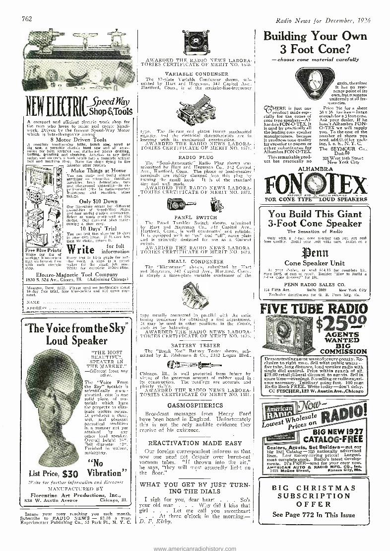
762
XNfLKTRICs o91T s A compact and efficient electric work shop for the man who loves to make and create handi- work. Driven by the famous Speed -Way Motor which is interchangeable among
8 Motor Driven Tools A complete woodturniug lathe, bench saw, scroll or jig saw. a portable electric hand saw and all acces- sories for both portable and stationary power drilling, buffing, grinding and cleaning. Attaches to any light socket and converts a work bench into a complete private tool and machine shop. Have the chips flying in five
minutes after receipt.
- Make Things at Home You can make and build almost anything - attractive furniture novelties, lawn decorations, toys and playground apparatus -do ex- perimental jobs in radio- perfect inventions and countless other things.
Free Blue Prints Write for list of working blue- prints that wo furnish free with each electric sboP.
Only $10 Down Our literature covers ten different assemblies of Speed -Way Shops and toter useful electric accessories. Select as much equipment as you desire. Our payment plan makes owning a shop easy.
10 Days' Trial You can test this shop for 10 clays in your own home. If it does less than we claim, return it.
Writefor full information
Every tool is high grade for reg- ular work. A chop is a money maker for the small job man. Write for complete information.
Electro- Magnetic Tool Company 1830 S. 52d Av., Cicero, Ill. (Adjoining Chicago)
Manager, Dept. 2212. Please send me particulars about 10 -day free trial, free blue -prints and 010 down pay- ment.
NAME
ADDRESS -
"The Voice from the Sky" Loud Speaker
"THE MOST BEAUTIFUL SPEAKER IN
THE MARKET." -different from any
other.
The "Voice From the Sky" speaker is scientifically c o n -
structed, cast in one solid piece, of ma- terials which have the property to elim- inate useless noises. It produces a clear, soft, and pleasant acoustical rendition in a manner not yet attained by any other loud speaker. Overall height 24 ". Bell diameter 12 ". Finished in walnut. mahogany.
g No
List Price, $30 Vibration" If'rtite for further information and discounts
MANUFACTURED BY Florentine Art Productions, Inc.,
838 W. Austin Avenue Chicago, Ill.
Insure your copy reaching you each month. Subscribe to RADIO NEWS - $2.50 a year. Experimenter Publishing Co., 53 Park Pl., N. Y. C.
AWARDED THE RADIO NEWS LABORA- TORIES CERTIFICATE OF MERIT NO. 1668.
VARIABLE CONDENSER The 17 -plate Variable Condenser shown, sub-
mitted by Hart and Hegeman, 342 Capitol Ave., Hartford, Conn., is of the straight- line -frequency
type. The die-cast end plates insure mechanical rigidity, and the electrical characteristics are in keeping with its mechanical construction.
AWARDED THE RADIO NEWS LABORA- TORIES CERTIFICATE OF MERIT NO. 1671.
RADIO PLUG The "Semi- Automatic" Radio Plug shown was
submitted by Hart and Hegeman Co., 342 Capitol Ave., Hartford, Conn. The phone or loud- speaker terminals are rigidly clamped into this plug by turning the small knob It is of the standard size and well made.
AWARDED THE RADIO NEWS LABORA- TORIES CERTIFICATE OF MERIT NO. 1672.
PANEL SWITCH The Panel Tumbler Switch shown, submitted
by Hart and Hegeman Co., 342 Capitol Ave., Hartford, Conn., is well constructed and reliable. It is equipped with an "on" and "off ". name plate and is primarily designed for use as a filament switch.
AWARDED THE RADIO NEWS LABORA- TORIES CERTIFICATE OF MERIT NO. 1673.
SMALL CONDENSER The "Microtuner" shown, submitted by Hart
and Hegeman, 342 Capitol Ave., Hartford, Conn., is simply a three -plate variable condenser of the
type usually connected i parallel wills the main tuning condenser for obtaining a fine adjustment. It may be used in other positions in the circuit, such as for balancing.
AWARDED THE RADIO NEWS LABORA- TORIES CERTIFICATE OF MERIT NO. 1675.
BATTERY TESTER The "Break Not" Battery Tester shown, sub-
mitted by E. Ed elmann & Co., 2362 Logan Blvd.,
mm
^
Chicago, Ill., is well protected from injury by virtue of the generous amount of rubber used in its construction. The readings are accurate and plainly visible.
AWARDED THE RADIO NEWS LABORA- TORIES CERTIFICATE OF MERIT NO. 1681.
GASMOSPHERICS Broadcast messages from Henry Force
have been heard in England. Unfortunately this is not the only audible evidence they receive of his existence.
REACTIVATION MADE EASY Our foreign correspondent informs us that
now one need not despair over burnt -out vacuum tubes. "If thrown into the air," Ile says, "they will most assuredly light on the floor."
WHAT YOU GET BY JUST TURN- ING THE DIALS
I sigh for you, dear heart . So's your old man . . . Why did I kiss that girl . Let me call you sweetheart
At three o'clock in the morning. - D. F. Kirby.
Radio News for December, 1926
Building Your Own 3 Foot Cone?
- choose cone material carefully
grain; therefore it has no reso- ave point of its
wn, but resonates iformly at all fre-
quencies. c FIERE is just one
product made espe- cially for the cones of cone type speakers -Al- hambra FON- O -TEX. It is used by practically all the leading cone speaker manufacturers, because it produces tone quality far superior to papers or other substitutes for Alhambra FON- O -TEX.
This remarkable prod- uct has practically no
Price 75c for a sheet 38 x 38 inches -large enough for a 3 foot cone. Ask your dealer. If he hasn't Alhambra FON- 0-TEX we will supply you. To the cost of the number of sheets you need add Moo for pack- ing, f. o. b., N. Y. C. The SEYMOUR Co.,
Desk50 325 West 16th Street
New York City
ALHAMBRA
N oucr
FOR CONE TYPE
You Build This Giant 3 -Foot Cone Speaker
The Sensation of Radio Only with a 3 -foot cone speaker can you get real
tone quality. Build your unit with care. Insist on a
I. tint Cone Speaker Unit
At your dealer, or send $11.15 for complete kit. Save 80% of cost at retail. Booklet "How to Build a 3 -foot Cone Speaker" for 10e.
PENN RADIO SALES CO. IC4 Fifth Ave. Suite 2009 New York City
Exclusive distributors for G. R. Penn Mfg. Co.
FIVE TUBE RADIO $2529 AGENTS WANTED
BIG COMMISSION
Demonstrating agent wanted every county. Ex- clusive to right man. Sell what public wants - five tube, long distance, loud speaker radio with single dial control. Price within reach of all, $25,00 retail ;liberal discount to agents. Sell in spare time -evenings. No selling or radio experi- ence necessary. Territory going fast. 100 page Radio Book FREE. Write today -don't delay.
CC FISCHER,322 W. Austin Ave.,Chicago
FOntil P Lowest
rjces On
BIG NEW 1927 CATALOG-FREE
Dealers, Agents, Set Builders -get our big 1927 Catalog-225 nationally advertised lines. Low money -saving prices! Largest. most complete stock. Radio's latest develop- ments. It's FREE -send for your copy now. Ae"QRICAN AUTO & RADIO MFG. CO., Inc.
1433 McGee Street, Kansas City, Mo.
BIG CHRISTMAS SUBSCRIPTION
OFFER See Page 772 In This Issue
www.americanradiohistory.com
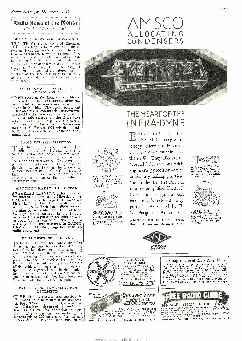
Radio News for December, 1926
ra11ars111,1.,,,,I,,,,,.,,1.1111,111111111.,,,1,11,, 1,. ,,,,, 1 i1,1,11111,111,,,,1111, ,1,1,111111,1,
Radio News of the Month (Continued from page 628)
_ F1i1.aaiwiiiiiuivuauiiiui.ii,iiiia1,1..11i11i,i ,i11i1111i,.mv..i ..ii.,.. IiiiiiiiiuuniiiiuIiiiiiiiniiivaani.-
AUTOMATIC BROADCAST INDICATORS
Wj ITH the readjustment of European y wavelengths to relieve the conges-
tion of broadcast stations under the new Geneva agreement, about to go into effect, it is announced that all transmitters will be equipped with calibrated indicators which will automatically give a luminous signal if they vary from the assigned fundamental wave. Much interest in the working of the scheme is expressed abroad, as the waves of some stations have been very broad.
RADIO AMATEURS IN THE STORM BELT
THE story of the Lion and the Mouse found another application after the
terrific Gulf storm which worked so much havoc in Florida. The aerial equipment of broadcast and commercial stations was wrecked by the unprecedented fury of the gale. In this emergency, the short -wave sets of local amateurs proved life- savers. The first station heard out of Miami was that of J. Y. Heisch, 4KJ, which "raised" 4HZ of Jacksonville and restored com- munication.
RADIO FOR SHIP DIRECTION
TI -IE liner "Carnarvon Castle," just built at Belfast, Ireland, carries a
complete radio loud- speaker system which will reproduce broadcast programs on her decks for the passengers. The same am- plifiers will also be used in the operation o
the ship, particularly when she is docking. Microphones are mounted on the bridge, so that the captain can issue orders to his crew without relying on the old fashioned speaking -trumpet.
ANOTHER RADIO GOLD STAR CHARLES CLAVIER, radio operator,
died at his post in the Sikorsky plane S -35, which was destroyed at Roosevelt Field, L. I., during the take -off for the attempted New York -Paris flight on the morning of September 21. He had been for eight years engaged in flight radio work, and his reputation for skill as well as good fortune was high. The ill -star- red expedition was pictured in RADIO NEWS for October, together with its radio equipment.
NO LICENSES, NO PROGRAMS
IN the United States, fortunately, there has yet been no need to pass the hat among
radio fans, but elsewhere it is different. In New Zealand, for instance, "radio pirates" who are targets for numerous brickbats are people who are not paying for receiving licenses. At a recent meeting a government official criticised them' sharply, saying that the postmaster -general, who is the regulat- ing authority, cannot insist on stations be- ginning programs until fees have been col- lected to make the effort worth while.
TELEVISION TRANSMISSION LICENSED
THE first television transmission li- censes have been issued by the Brit-
ish Post Office to J. L. Baird, inventor of the Televisor, described recently in RADIO NEWS, for operation in Lon- don. The apparatus transmits on a wavelength of 200 meters, under the call letters 2LV. Listeners who tune in to
763
ATM SCO ALLOCATI NG CONDENSERS
AMSCO FLOATING SOCKETS eliminate noises, mechanical feed -back and audio vibration. Approved by E. M. Sargent.
AMSCO ALLOCATING CONDENSERS.You'll need one of these single .00035 mfd. Allocators for your Infra -Dyne. Approved by E. M. Sargent.
THE H EART OF THE
INFRA +DYNE EACH unit of this
AMSCO triple is
.0003 5 micro-farads capa-
city, matched within less
than I %. They allocate or
"spread" the stations with engineering precision -their uniformity making practical the hitherto theoretical ideal of Simplified Control. Construction guaranteed mechanicallyand electrically perfect. Approved by E.
M. Sargent. At dealers.
AMSCO PRODUCTS,INC. Broome & Lafayette Streets, N. Y. C.
ÁtisLD lh
AMSCO METALOID GRID GATES. Approved by Sargent. Uniquely silent, due to new colloidal Metal oid resistance element.
AMSCO TOM THUMB RHEOSTATS save space front and back of the panel. Order a 10 ohm and two 30 ohm Tom Thumps for your Infra-Dyne.
:ài111 P")'y GEARS
All Kinds -Small The most accurate made and t prices reasonable. We carry a complete line of gears in stock for immediate shipment. Can also quote on special gears cf
c all kinds. Send usyourinquiries. Write for Catalogue 40
Chicago Stock Gear Works 105 South Jefferson St., Chicago
fLabora 'orf Product CE3; NT L
y°3 Es `T,/Ngms For Distertionless Amplification
Used on the U. S. A. Dirigibles. Made all capacities 12,000 ohms and un. List price $1.50.
Special sizes to order. Write today. Discounts tc dealers.
Crescent Radio Supply Co., I -5 Liberty St., Jamaica, N. Y.
A Complete Line of Radio Power Units From the Webster line of poker supply units everyone may find the right type for his set at a price he can af- ford. "Little Giant B C" at $50.00 has five variable voltages one for C power. "Super 11" has three volt- ages with variable control price $39.00. "Popular B" is open type- $35.00 -all equipped with Webster Duo Choke (pat. pending) and Raytheon tube. Write for complete description in folder "Improving Your Radio." THE WEBSTER CO., 3516 West Lake St., Chicago
FREE RADIO GUIDE 164 -PAGE (1927) GUIDE
fri i4 oopod Gives special book -ups with illustrations. Shows big savines on standard radio parts, ccmpleto sets, kits. Be sure to get this thrifty book before you boy. Write letter or postal NOW.
Also fnclado name of another fan.
BARAWIK CO., 542B Monroe St., CHICAGO, U. S. A.
www.americanradiohistory.com
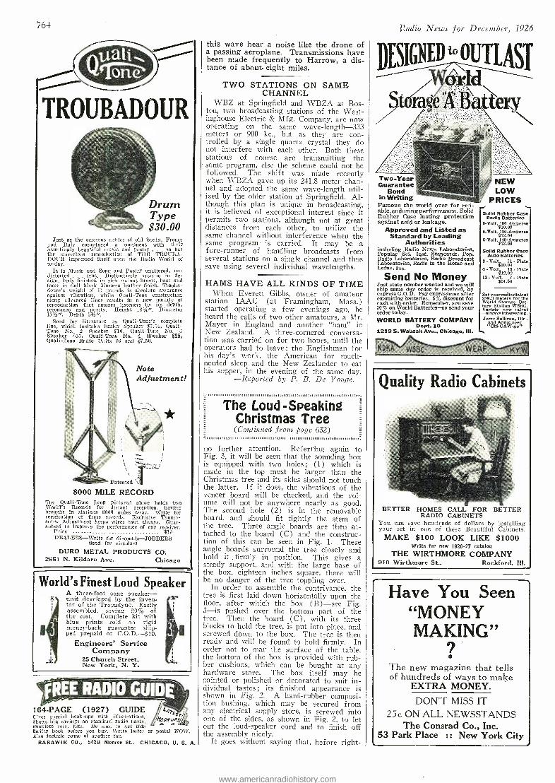
764 Radio News for December, 1926
TROUBADOUR
Just as the amorous nobles of old Spain, France and Italy enraptured a continent with their hauntingly beautiful music and poetry . . . so has the marvelous reproduction of THE OUBA- DOUR impressed itself upon the Radio World of to -day.
It is Music and Song and Poetry unaltered, un- distorted . . true. Distinctively artistic in de- sign, body finished in rich walnut brown, base and faces in dull black Morocco leather finish. Trouba- doure's weight of 11 pounds is absolute assurance against vibration, while Quali -Tone construction along advanced lines results in a new quality of reproduction that amazes listeners by its depth, resonance and purity. Height 161/20. Diameter 131/20. Depth 51/20.
Send for literature on Quali- Tone's complete line, which includes Junior Speaker $7.50, Qualf- Tone No. '2 Speaker $10, Quali -Tone No. 3 Speaker $15, Quali -Tone No. 4 Speaker $25, Quali -Tone Radio Units $6 and $7.50.
Note Adjustment!
Patented .T 8000 MILE RECORD
The Quali -Tone Loop pictured above holds two World's Records for distant reception, having brought in stations 8000 miles away. Write for verification of these records. Exclusive Thumb- screw Adjustment keeps wires taut always. Guar- anteed to improve the performance of any receiver.
Price $10 DEALERS -Write for discounts- JOBBERS
Send for circulars DURO METAL PRODUCTS CO.
2651 N. Kildare Ave. Chicago
World's Finest Loud Speaker A three -foot cone speaker -
-'A unit developed by the inven- tor of the Tropadyne. Easily assembled, saving 80°ío of the cost. Complete kit with blue prints sold on rigid money-back guarantee -ship- ped prepaid or C.O.D. -$10.
Engineers' Service Company
ÿ 25 Church Street, New York, N. Y.
7C-
164 -PAGE (1927) GUIDE (lives special hook -ups with illustrations. A, pS lthosys big savings on standard radio parts. 2 complete sets, kits. Be sure to get this thrifty book before you buy. Write letter or postal NOW. Also include name of another fan.
BARAWIK CO., 542B Monroe St., CHICAGO, U. S. A.
this wave hear a noise like the drone of a passing aeroplane. Transmissions have been made frequently to Harrow, a dis- tance of about. eight miles.
TWO STATIONS ON SAME CHANNEL
WBZ at Springfield and WBZA at Bos- ton, two broadcasting stations of the West- inghouse Electric & Mfg. Company, are now operating on the same wave- length -333 meters or 900 kc., but as they are con- trolled by a single quartz crystal they do not interfere with each other. Both these stations of course are transmitting the
- same program, else the scheme could not be followed. The shift was made recently when WBZA gave up its 241.8 meter chan- nel and adopted the same wave- length util- ized by the older station at Springfield. Al- though this plan is unique in broadcasting, it is believed of exceptional interest since it permits two stations, although not at great distances from each other, to utilize the same channel without interference when the same program is carried. It may be a fore -runner of handling broadcasts from several stations on a single channel and thus save using several individual wavelengths.
HAMS HAVE ALL KINDS OF TIME When Everett Gibbs, owner of amateur
station 1AAC (at Framingham, Mass.) started operating a few evenings ago, he heard the calls of two other amateurs, a Mr. Mayer in England and another "ham" in New Zealand. A three -cornered conversa- tion was carried on for two hours, until the operators had to leave: the Englishman for his day's work, the American for much - needed sleep and the New Zealander to eat his supper, in the evening of the same day.
-Reported by P. B. De Yonge.
The Loud - Speaking Christmas Tree (Continued front page 632)
no further attention. Referring again to Fig. 3, it will be seen that the sounding box is equipped with two holes; (1) which is made in the top must be larger than the Christmas tree and its sides should not touch the latter. If it does, the vibrations of the veneer board will be checked, and the vol- ume will not be anywhere nearly as good. The second hole (2) is in the removable board, and should fit tightly the stem of the tree. Three angle boards are then at- tached to the board (C) and the construc- tion of this can be seen in Fig. 1. These angle boards surround the tree closely and hold it . firmly in position. This gives a steady support, and with the large base of the box, eighteen inches square, there will be no danger of the tree toppling over.
In order to assemble the contrivance, the tree is first laid down horizontally upon the floor, after which the box (B) -see Fig. 3 -is pushed over the bottom part of the tree. Then the board (C), with its three blocks to hold the tree, is put into place, and screwed down to the box. The tree is then ready and will he found to hold firmly. In order not to mar the surface of the table, the bottom of the box is provided with rub- ber cushions, which can be bought at any hardware store. The box itself may be painted or polished or decorated to suit in- dividual tastes; its finished appearance is shown in :Fig. 2. A hard- rubber composi- tion bushing, which may be secured from any electrical supply store, is screwed into one of the sides, as shown in Fig. 2, to let out the loud- speaker cord and to finish off the assembly nicely.
It goes without saying that, before right -
Two -Year Guarantee
Bond in Writing
Famous the world over for reli- able,enduringperformance. Solid Rubber Case lasting protection against acid or leakage.
Approved and Listed as Standard by Leading
Authorities including Radio News Laboratories, Popular Sci. Inst. Standards, Pop. Radio Laboratories, Radio Broadcast Laboratories, Radio in the Home and Lefax, Inc.
Send No Money Just state number wanted and we will ship same day order is received, by express C.O.D. Pay expressman after examining batteries. 5% discount for cash with order. Remember, you save 50% on World Batteries -so send your order today. WORLD BATTERY COMPANY
Dept. 10 1219 S. Wabash Ave., Chicago, Ill.
NEW LOW
PRICES
Solid Rubber Case Radio Batteries
6 -Volt, 100 - Ampere. $10.00
6 -Volt, 120 -Amperes $12.00
6 -Volt, 140 - Amperes $13.00
Solid Rubber Case Auto Batteries
6 -Volt 11- Plate $10.00
6 -Volt 13 -Plate $12.00
12 - Volt, 7 - Plate $14.50
Variety-new
Set yourrodiodfaloot World Store
for
tyá new
Storage
-always interesting. Jerry Sullivan, Dir.
and Announcer
Quality Radio Cabinets
BETTER HOMES CALL FOR BETTER RADIO CABINETS
You can save hundreds of dollars by installing your set in one of these Beautiful Cabinets.
MAKE $100 LOOK LIKE $1000 Write for new 1926.27 catalog
THE WIRTHMORE COMPANY 910 Wirthmore St., Rockford, Ill.
Have You Seen "MONEY MAKING"
e
The new magazine that tells of hundreds of ways to make
EXTRA MONEY.
DON'T MISS IT 25c ON ALL NEWSSTANDS
The Consrad Co., Inc. 53 Park Place :: New York City
www.americanradiohistory.com
Radio News for December, 1926
ing the tree, the loud- speaker unit should be tried to see if it gives the full sound; and after the speaker is once adjusted it can be left in this position. After the whole has been assembled and the tree placed on the table or floor, the radio set can then be turned on. The effect is very mysterious, particularly if the connecting cord is hidden. It will then seem as if the music comes di- rectly from the tree. I shall be glad to hear from those who have constructed the In ul- pcakinn Christmas tree.
A Universal A((- Circuit Set
(Continued froul page 682) F "" iii. ii.iii.i..iiiiiiiiiiiiiiiiii'"" iii....
.". , 3
trente left, mount the two -gang condenser, C3, and at the other end of the panel, the single condenser, C4. On both sides of the switch are holes for mounting the jacks. The three -point jack, J, is fastened through the hole at the right, and the filament con- trol jack, J1, through the other.
Then place the sub -panel with the edge that goes toward the panel furthest from you. Put on the binding posts, beginning at the left hand end, in the following order: "B Amp +" ; B Det +"; "B Bat-"; "A Bat +" ; "A Bat-' ; `'C Bat +" ; "C Bat -." The next two holes carry the grid con- denser below the sub-panel and the grid leak mounting clips above it. At the right are two more holes ; the further takes the "Ant." binding post, and the one next to it, the "Gil." post. Then mount the five sockets under the sub- panel, with their tops coming through the holes provided, and the white clots toward the panel.
Holes for mounting the audio trans- forms, T, behind the rheostats must next be located, and one transformer mounted with its secondary toward the right hand side of the sub -panel. The other is best mounted at right angles to it, with its sec- ondary towards the panel. Holes are drilled in the sub -panel, one directly tinder the shaft of the two -gang condenser, one between the two audio transformers and one just be- hind the shaft of the single condenser, so that the radio- frequency transformers, Ll, may be mounted under the sub -panel.
RECOMMENDATIONS In following the wiring diagram, (Fig. 8),
it will be noticed that all the filament leads on the radio -frequency coils, L1, are run to the negative side of the "A" battery. There- fore the grid leak is connected to the positive filament lead, instead of across the grid condenser as is customary. The pilot light is generally omitted in this hook -up, so the midget condenser may he mounted in the hole; but by drilling a-n additional hole 2 5/16 inches below the first hole, this light may be used. The midget condenser is connected across either segment of the two -gang condenser ; the one to which it is attached should be adjusted so that when the blades of the other are completely in mesh, its blades are about 1/32 -inch out.
A separate condenser must be used to time the first coil, as various lengths of aerial change the setting of this dial to quite an extent. If you are using an exceptionally long antenna, and find that the set tunes broadly, connect a .00025 -mf. fixed con- denser between the aerial binding post and the aerial lead -in wire. This will afford greater selectivity. The 700 -ohm resistances, R3, need be added only if the set shows un- clue tendencies to oscillate. In that case they should he connected in the grid leads of the second and third tubes from the left, the two radio amplifiers, as shown in the wiring diagram (Fig. 8). The filaments of these tubes are controlled by the 10 -ohm rheostat, the detector by the 20 -ohm one, and the
765
Send your good wishes and a Tungar, too
East of the Rockies 2 ampere Tungar, $18 5 ampere Tungar, $28 Trickle Charger, $12 (60 cycles -110 volis)
Merchandise Department General Electric Company
Bridgeport, Connecticut
If he enjoys the radio- surprise him with a G -E Tungar. It wi:l keep batteries fully charged; help him to obtain bet- ter reception. Through the years, its helpfulness will be a
constant reminder of your greetings.
Five ampere, two ampere, or Trickle Charger -your dealer will show you the correct type for any service. They are all made by General Electric -they all can be permanently installed, and they all say" good -by battery charging problem."
P. S. Treat yourself to one, too.
Two ampere -charges all 2, 4 or l volt -A,' and 24 to 96 volt "B.' batteries in series -and auto batteries, too. Trickle - charges 4 or 6
volt radio "A" storage bat- teries: four charging rates up to one -half ampere. Five ampere -same range as two ampere but charges faster.
2 ampere Tungar
Tungar -a registered trademark -is found only on the genuine. Look for it on the name plate.
1LECT Send For Your Copy Of Andrew's Radio Directory and Log
Gives new stations
and latest changes. Helps tune in stations
never before heard. Helps locate nnloggedstations on your dials.
Shows broadcast and time division map. Gives trouble information and remedies. Lists stations in U. S., Can., Mex., Cuba. Stations listed three different ways, by meters and kilocycles, by call -letters, by location. Eachlist cross- indexed (copyrighted) with other two. 28 pages, well printed, heavy white paper. If not sold by your local radio or news dealer, copy mailed postpaid for 25c each, coin or stamps.
THE WAYNE- ANDREWS CO., INC., 1203 Central Bldg. Ft. Wayne, Ind.
LOETAN QUICK LIQUID SOLDER Requires no flux or excessive heat. Can
be used with or without soldering iron. Marvelous new German Invention. Solders
metals of all kinds including iron, steel and precious metals. Indispensable for the set builder.
On sale at all radio stores or send $1.00 for special introductory offer of 3 cans.
Dealers Write for Discounts.
GLOBE IMPORT- EXPORT CO. Dept. RN -5465 Everett Avenue
Fairfax 6713 Chicago,
Insure your copy reaching you each month. Subscribe to Radio News - $2.50 a year. Experimenter Publishing Co., 53 Park Place, N. Y. C.
www.americanradiohistory.com
766 Radio News for December, 1926
Chemistry to success Some people measure success in
terms of money and others in degree of knowledge and culture. Chemistry is the one uncrowded profession today that offers both. America, always a land of amazing opportunities, is especially so now in the field of applied Chemistry. In- dustries have developed within eight years more rapidly than the output of trained men to conduct them. Every big industry needs chemists and there is a real demand for them immediately.
Earn a Bigger Salary fron now on I'd Good Chemists Command High Salaries; you can make yourself independent for life by unearthing
one of Chemistry's undiscovered secrets! Do you remember how the tales of pirate gold used to fire your imagina- tion and make you want to sail the uncharted seas in search of treasure and adventure ? And then you would regret that such things were no longer done. But that is a mistake. They are done -today and every day -not on desert islands, but in the chemical laboratories throughout your own coun- try. Quietly, systematically, the chemist works. His work is difficult, but more adventurous than the blood -curdling deeds of the Spanish Main. In- stead of meeting an early and violent death on some forgotten shore, he gathers wealth and honor through his invaluable contributions to human ity. Alfred Nobel, the Swedish chemist who invented dynamite, made so many millions that the income alone from his bequests provides five $40,000 prizes every year for the advancement of science and peace. Herman Frasch, who showed how to extract sulphur built up a huge fortune. C. M. Hall, the chemist who discovered how to manufacture aluminum made millions through this discovery. F. G. Cottrell, who devised a valuable process for recovering the waste from the flue gases, James Gayley, who showed how to save enormous losses in steel manufacture, L. H. Baeke- land, who invented Bakelite -these are only a few of the men to whom fortunes have come through their chemical achievements.
NOW IS THE TIME TO STUDY CHEMISRTY Not only are there boundless opportunities for amassing wealth in Chemistry, but the profession affords congenial employment at good salaries to hundreds of thousands who merely follow out its present applications. These applications are innumerable, touching intimately every business and every product in the world. The work of the chemist can hardly be called work at all. It is the keenest and most enjoyable kind of pleasure. The days in a chemical laboratory are filled with thrilling and delightful experimentation, with the alluring prospect of a discovery that may spell Fortune always at hand to spur your enthusiasm.
YOU CAN LEARN AT HOME To qualify for this remarkable calling requires elaborate specialized training. Former- ly it was necessary to attend a university for several years to acquire that training, but thanks to our highly perfected and thorough system of instruction, you can now stay at home, keep your position, and let us educate you in Chemistry during your spare time. Even with only common schooling you can take our course and equip yourself for immediate practical work in a chemical laboratory.
EASY MONTHLY PAYMENTS You don't have to have even the small price of the course to start. You can pay for it in small monthly amounts -so small that you won't feel them. The cost of our course is very low, and includes everything, even the chemistry outfit -there are no extras to buy with our course. Our plan of monthly payments places a chemical education within the reach of everyone.
SPECIAL 30 DAY OFFER Besicles furnishing the student with his Experimental Equipment, we are making an additional special offer for a short while only. You owe it to yourself to find out about it. Write today for full information and free book "Opportunities for Chem- ists." Send the coupon right now while it is fresh in your mind. Or just write your name and address on a postal and mail it to us. But whatever you do, act today before this offer is withdrawn.
DON'T WAIT -MAIL COUPON NOW!
CHEMICAL INSTITUTE OF NEW YORK, Inc. Home Extension Division 12
66 -R West Broadway New York City
LETTERS From Students Who Have
Taken This Course You will probably be pleased to learn one of the lessons gave me an idea to turn my chemical knowledge to profitable account. I am now making a varnish and paint which undersells the other type products by $2.60 a gallon, in some cases more. Have been receiving gallon orders from paint- ers clueing past week which has netted nie a profit of $12.50 for nay "spare -time chemical indus- try." Many thanks for your training thus far.
J. J. KELLY. I am but half way through your course and am certain that I have saved my Company many times the cost of the course and raised my- self in the Share Holders estima- tion. The knowledge obtained has its immediate practical application and I do not hesitate in saying your course and the personal at- tention you give is invaluable to the practical man in any business where chemistry plays a Part. You may use this letter and my name and address to the furtherance of your good work.
JOHN WALTER. I have not written since I re- ceived the big set. I can still say that it for exceeded my anticipa- tions. Since I have been studying with your school I have been ap- pointed chemist for the Scranton Coal Co., testing all the coal and. ash by proximate analysis. The lessons are helping me wonder- fully, and the interesting way in which they are written makes me wait patiently for each lesson.
MORLAIS COUZENS.
T. O'CONOR SLOANE, A. B., A. M., LL. D., Ph. D.
Noted Instructor, Lectur- er and Author. Form- erly Treasurer Ameri- can Chemical Society and a practical chemist with many well known achievements to his credit. Not only has Dr. Sloane taught chem- istry for years but he was for many years en- gaged in commercial chemistry work.
EXPERIMENTAL EQUIPMENT FURNISHED TO EVERY STUDENT
We give to every student without additional charge this chem- ical equipment, including forty -nine pieces of laboratory ap- paratus and supplies, and forty different chemicals and reagents. These comprise the apparatus and chemicals used for the ex- perimental work of the course. The fitted heavy wooden box serves not only as a case for the outfit but also as a usefu, laboratory accessory for performing countless experiments.
CHEMICAL INSTITUTE OF NEW YORK, INC. Home Extension Division 12
66 -R -West Broadway, New York City Please send me at once, without any obligation on my
part, your free Book "Opportunities for Chemists," and full particulars about the Experimental Equipment given to every student. Also please tell me about your plan of payment and your special 30 day offer. NAME ADDRESS CITY STATE
11 Tloe 19?fi_
www.americanradiohistory.com
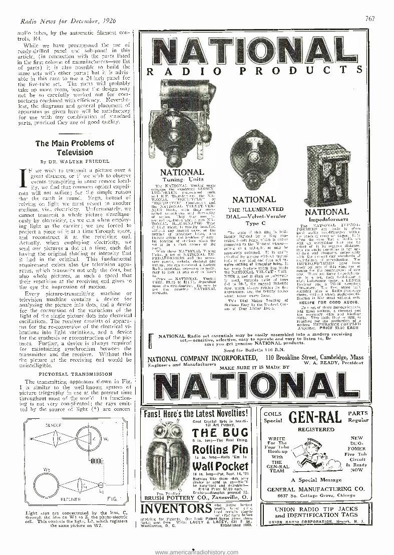
COILS (1 N- A i PARTS Special u 1, a(']L Regular
WRITE For The
Four Tube Hook -up
With THE
GEN -RAL TEAM
REGISTERED NEW DUO -
FOMER Five Tub
Circuit ( D Is Ready ' NOW
A Special Message
GENERAL MANUFACTURING CO. 6637 So. Cottage Grove, Chicago
Radio News for December, 1926
audio tubes, by the automatic filament con - trois, R4.
While we have presupposed the use of ready -drilled panel and sub -panel in this article, (in connection with the parts listed in the first column of manufacturers -see list of parts) it is also possible to build the same sets with other parts ; but it is advis- able in this case to use a 24 -inch panel for the five -tube set. The parts will probably take up more room, because the design may not be so carefully worked out for corn - pactness combined with efficiency. Neverthe- less, the diagrams and general placement of apparatus as given here will be satisfactory for use with any combination of standard parts, provided they are of good quality.
The Main Problems of Television
By DR. WALTER FRIEDEL
IF we wish to transmit a picture over a great distance, or if we wish to observe events transpiring in some remote local- ity, we find that common optical expedi-
ents will not suffice; for the simple reason that the earth is round. Ergo, instead of relying on light we must resort to another medium, viz., electricity. Unfortunately, we cannot transmit a whole picture simultane- ously by electricity, as we can when employ- ing light as the carrier ; we are forced to project a piece of it at a time through space, and reconstruct it at the receiving end. Actually, when employing electricity, we send our pictures a dot at a time, each dot having the original shading or intensity that it had in the original. This fundamental requirement exists also for television appa- ratus, which transmits not only the dots, but also whole pictures, at such a speed that their repetition at the receiving end gives to the eye the impression of motion.
Every picture- transmitting machine or television machine contains a device for analyzing the picture into clots, and a device for the conversion of the variations of the light of the single picture -clots into electrical oscillations. The receiver consists of appara- tus for the re- conversion of the electrical vi- brations into light variations, and a device for the synthesis or reconstruction of the pic- tures. Further, a device is always required for maintaining synchronism between the transmitter and the receiver. Without this the picture at the receiving end would be unintelligible.
PICTORIAL TRANSMISSION
The transmitting apparatus shown in Fig. 1 is similar to the well -known system of picture telegraphy in use at the present time throughout most of the world. Its function- ing is not very complicated ; the rays emit- ted by the source of light ( *) are concen
SENDER
,*La RECEIVER FIG. I
Light rays are concentrated by the lens, C, through the film on W1 to Z, the photo -electric cell. This controls the light, L2, which registers
the same picture on W2.
N1ÀTIkN/L R A D I O P R O D U C T S
NATIONAL Tuning-Units
The NATIONAL Tuning units combine the wonderful BROIhN- ING- DIIAKE spaeewound coils and RP. Transformers, the NA- TIONAL " I.IUICYS'LE" or " lsq]'I'METlit" Condensers and the NATIONAL VELVET -VF.R- NIElt Dials. with their unex- celled smoothness and durability of action. They nosy now lie secured equippod with a new NA- TIONAI, ILL.MUNAT13D Type i' Dial which is readily installed without any special tools, or the cutting of irregular holes, and forever solves the problem of care- ful logging of stations when the set is in a dark corner of the reran.
With these NATIONAL Tuning Units. a set of NATIONAL I i- PEDAFOIuIERS and the neces- sary panels, sockets, rheostat and wiring, you can construct a modern Radio receiving set-easy to make, easy to leek at and easy to listen to.
Price - NATION.AL 'Tuning Units, $9.75 to $11.75, dependent upon the combination. Ile sure to Pct the genuine NATIONAL products.
Q
NATIONAL THE ILLUMINATED
DIAL -Velvet- Vernier Type C
The scale of this dial is bril- liantly lighted by a tiny con- cealed 6 -volt lamp. which is either connected to the filament wirinri acting as a tell -tale, or may be
separately switched. It is easily attached by anyone without :.peci al tools of any hind and does not re- quire cutting of irregular holes. It has every feature which has mode the NATIONAL VELVET - VER- NIER A and B dials so universal- ly used, variable ratio of from 6 -1 to 25 -1, the rugged Bakelite case, which always retains its fine appearance, and the velvety action which never wears loose.
This Dial Stakes Logging of Stations Easy In the Darkest Cor- ner of Your Living Rosin.
NATIONAL Impedaformers
The NATIONAL I\IPEDA- FOliylE]LS are made to place good audio amplification within the reach of every set owner. It is often the case that a Radio set will do everything that can be unshed of it as regards distance. L'ut its audio amplifier is not up- to -date and compares unfavorably with the present-day standards of truthfulness of reproduction. 'Tho 12II'EDAFOR\MERS have been made for sets of this kind and of course for the construction of new sets. There are three Impcdaform- crs to a set, each containing a
high inductance choice, a LYNCH Resistor and a TORE Coupling Condenser. The first stage unit contains also o Radio -frequency choke, without which audio- ampli- fication is like meat without sail..
RECIPE FOR GOOD AUDIO. To a set of three Impedaformers,
add three sockets, a rheostat and the necessary wire and binding posts. Very little time or skill is required for the production of a modern IMPEDANCE- COUPLED Amplifier. PRICE $5.50 EACH
NATIONAL Radio set essentials may be easily assembled into a modern receiving set, -sensitive, selective, easy to operate and easy to listen to. Be
sure you get genuine NATIONAL products. Send for Bulletin 116 R.N.
NATIONAL COMPANY INCORPORATED, 110 Brookline Street, Cambridge, Mass Engineers and Manufacturers W. A. READY, President
MAKE SURE IT IS MADE BY
L
767
Fans! Here's the Latest Novelties! Good Crystal Sets in beauti-
ful Art Pottery.
THE BUG 9 in. long -The Real Thing.
Rolling Pin 15 in. long -Rolls 'Em In
Wall Pocket II in. long -Pat. Sept. 14, '26 Nothing like them -Ask your dealer or send to us- You'll be surprised and delighted -
R ^tail Price $7.50 each.
Pat. Pending Dealers -Samples prepaid $5.
BRUSH POTTERY CO., Zanesville, O.
INVENTORS who derive larges profits know a n d heed certain simpl but vital facts befor
applying for Patents. Our book Patent -Sense gives thon farts; sent free. write LACEY & LACEY, 631 F SI., Washington, D. C. Established 1869.
UNION RADIO TIP JACKS and IDENTIFICATION TAGS
UNION RAn'O CORPORATION. Newark. N. i.
www.americanradiohistory.com
768
Blue Prints FREEWrite
for a complete description of the Peer of all receivers -the
World's Record Super 9 -the wonder receiver that holds 4 fully verified World's Records for distance. The World's Record Super 9 is one of the few receivers to bring London into Chicago during the last two International Contests. Thousands of testimonials hail the World's Rec- ord Super 9 as the marvel of Radio. Write for free list of records and testimonials today!
Easy to Build You can build an exact duplicate of the original World's Record Super 9 by following our Blue Prints. Building instructions complete in every detail with each set of Blue Prints make it easy for anyone to build this remarkable receiver with perfect success. Complete Building in- structions and Blue Prints $5.00. Remit with order or we will send C. O. D.
Mail the Coupon Today!
M -S SYNDICATE Box 2131 Cleveland, Ohio
M -S SYNDICATE, Box 2131, Cleveland, Ohio
Please send me free literature and verifica- tions of the records made by the World's Record Super 9.
Am enc.osing $5 for Blue Prints, etc. Send me Blue Prints. etc., C.O.D.
NAME
ADDRESS
r-
Every Radio Fan should have this book
JUST OUT -514 PAGES Compiled by
HARRY F. DART, E.E. Formerly with the Western Electric Co., and U. S. Army Instructor of Radio.
Technically edited by F. H. Doane
NO MORE need you turn from book to book,
hoping to find what you want. It is all here, in 514 pages crammed full of every possible radio de- tail. Written in plain language, by engineers for laymen. 100,000 sold.
IT EXPLAINS: Electrical terms and circuits, antennas, batteries, generators and motors, electron (vacuum) tubes, many receiving book -ups, radio and audio frequency am- plification, broadcast and commercial transmitters and receivers, super -regeneration, codes, etc.
Send $1 today and get this 514 -page I. C. S. Radio Handbook -the biggest value in radio today.
r- International Correspondence Schools
Box 8Y81 -H Scranton, Penna. I enclose One Dollar. Please send me- post -paid= the 519 -page I. C. S. Radio Handbook. It is understood that if I am not entirely satisfied I may return this book within five days and you will refund my money.
Name
Address ('p 1 eek Here and enclose $1.00 if you wish the I
edition bound in Leatheroid.
EVERYTHING IN RADIO AT ATTRACTIVE PRICES. SETS OR PARTS. Prompt and Honest Service. Write for Prices.
Mail Order Only. AU. RADIO COMPANY, 417 North Clark St., Chicago
trated on a small dot of a photographic film, stretched on a glass cylinder WI, by- passing them through the lens C. The light rays will be diminished in direct proportion to the shading of the spot on the film, and so shine on the selenium or photo- electric cell, Z, with varying intensity as the glass cylinder is rotated. This light- sensitive -cell,
Z, is connected into a battery circuit and ac- cordingly controls the flow of current to the light, L -2, at the receiving end, in the same degree that it is acted upon by the light ray at the transmitter. The light fluctuations of the lamp, L -2, are concentrated by the lens, C -1, and directed upon an undeveloped pho- tograph film stretched upon the cylinder, W -2. The cylinders, W -1 and W -2, rotate in synchronism and thus displace themselves at the same time in the direction of their axis of revolution. It is clear that all the dots composing the original picture will be successively transmitted and finally regis- tered on the sensitized film at the receiver end.
It is not possible to depart from the basic principle outlined ; it is necessary to break up the picture to be transmitted into a great number of dots and reconstruct it into a vir- tual mosaic at the receiving end. However, there are two ways in which this can be ac- complished; either by the use of a great number of light- sensitive cells in the trans- mitter and likewise a great number of tele- graphic lines, or by a single line and one light- sensitive cell, as commonly employed, upon which all the parts of the picture are successively projected. By the first method all the dots of the picture are transmitted at the same time ; in the second they are transmitted, one after the other, at such a great spéed, that the eye receives the im- pression that the actions are simultaneous.
Upon first thought it might seem that the "many -cell method" would be the most satis- factory, but it is very difficult to carry into practice. To produce a simple picture, at least 10,000 dots must be transmitted ; while more complicated pictures, such as groups of people or a landscape, demand the trans- mission of from 60,000 to 80,000 dots. Imagine that many light- sensitive cells ! An- other fact that makes the many -celled method impractical is the requirement of multiple lines or, if we are to substitute radio, mul- tiple wavelengths.
It is obvious then, that the one -cell method is the most practical. This system, as de- veloped by Denes von Mihaly, is illustrated in Fig. 2. The original picture to be trans- mitted is projected 'by the objective, O, on the condenser lens, C. This lens concen- trates the beams of light on a small oscillat- ing mirror, Sn, which in turn throws them on the screen, S. This screen has a small opening, B, behind which is mounted a light - sensitive cell, Se. The mirror, Sn, actually consists of a series of small reflectors mount- ed on the rim of a wheel, which oscillates rapidly in one direction, and at the same time, slowly on an axis at right angles to the first. In this manner each successive dot is projected across the surface of the light - sensitive cell.
SUFFICIENCY OF ILLUMINATION The one -cell method of television is, of
course, considerably cheaper than the multi - cell arrangement and has proven itself more adaptable to conditions. However, there is one great disadvantage which, in the opin- ion of the writer, has up until now hindered the progress in television. This disadvan- tage lies in the fact that the amount of light falling on a single dot is insufficient for really satisfactory operation of the arrange- ment. As an example ; the objective of the television apparatus may be a photographic lens projecting images of great intensity of light. say four inches square. If we are satisfied with an area 1/25 -inch square for
Radio News for December, 1926
/W M% ,QUALITY" PRODUCTS
Transformers and Chokes used in
Lynch Power Amplifier with the
Browning -Drake Receiver consists of
1 -No. 2561 Transformer list $8.00 2 -No. 1591 Chokes list $6.00 Dongan Parts are an important factor in the marvelous performance of the Lynch Power Am- plifier. Like all Dongan products these power units are sturdy and dependable and are guar- anteed to give satisfaction. No. 2568, a com- bination of No. 2561 and No. 1591, also is ideal in the construction of A B C Eliminators using the Raytheon B H tube.
Regardless of what type of eliminator or power ampli- fier you build you will get certain success with the propel Dorgan Parts. Toro popular types are No. 2505 and No. 2569 transformers for RCA No. 213 and No. 210 0 tubes used in connection with A R C and Power Amplifier circuit.
Send for complete information on types you are interested in.
Dongan Electric Manufacturing Co. 2977 -3001 Franklin St., Detroit
RADIO DEALERS= Get the New 1926 -27 Van -Ache Catalogue - Shows all the newest parts, circuits and kits -all the hard -to -get items that set- builders demand. 12 -hour ship-
ments - extra -good discounts. Mail the coupon. ;
:Pan-AsheRadio Co
Send catalogue.
Name Address
In 20 Wield, the System of Jimmy DeFor est World's Greatest Trainer and Maker of Champions, teaches you all there is to learn about boxing. Every 6 months 30 are selected from all classes and recommended to leading promoters for engagements. Send fer famous bock, "The Golden Age of Box- ing," full of valuable information, photos of great fighters and pupils who became successes overnight. Enclose 10c to cover cost of mailing, etc.
JIMMY DeFOREST BOXING COURSE 347 Madison Avenue, Box 3912, New York City
CHIMNEY AERIAL. 100 -ft. cage coil, heavy gauge and special fire resisting, very sensitive in conjunction wills smoke column and cage construction, most selective, low atmospherics. Price, $3.50 (putee., 6 lbs.)
BALLOON AERIAL. Initial pick -up extremely strong, suitable for week -end tryouts, $5.00 (pstge, 5 lbs.), extras.
GRAVITY BATTERIES. Gallon size, $1.25. Runs li. amp. tube 1500 -2400 hrs. RIBBON WIRE. For honeycomb, pancake or other in- ductances. Equivalent to No. 24 round wire. write for literature, samples; 14 lb., $2.00; $5 lb., $3.50. EVERETT SCANLON, Radio Specialties, Lakewood, R. 1.
www.americanradiohistory.com
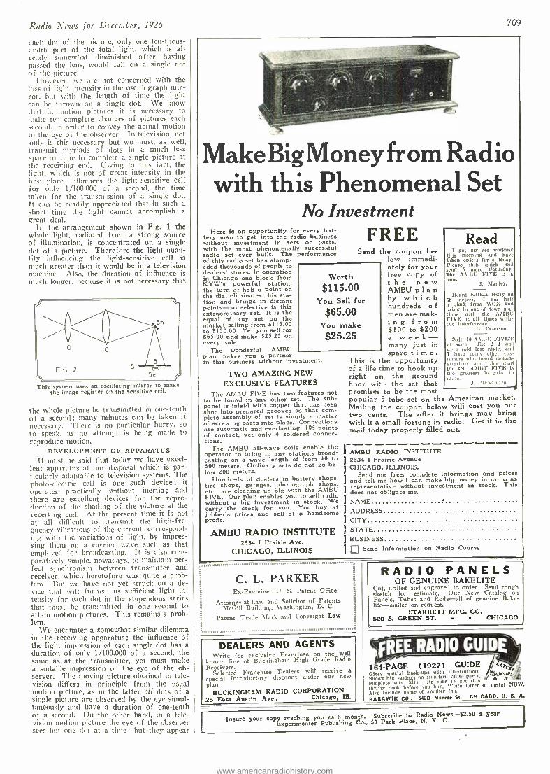
Radio News for December, 1926
each clot of the picture, only one ten- thous- andth part of the total light, which is al- ready somewhat diminished after having passed the lens, would fall on a single dot of the picture.
However, we are not concerned with the loss of light intensity in the oscillograph mir- ror. but with the length of time the light can be thrown on a single dot. We know that in motion pictures it is necessary to make ten complete changes of pictures each second, in order to convey the actual motion to the eye of the observer. In television, not only is this necessary but we must, as well, transmit myriads of clots in a much less space of time to complete a single picture at the receiving end. Owing to this fact, the light. which is not of great intensity in the first place. influences the light- sensitive cell for only 1 /100.000 of a second, the time taken for the transmission of a single dot. It can he readily appreciated that in such a short time the light cannot accomplish a great deal.
In the arrangement shown in Fig. 1 the whole light, radiated from a strong source of illumination, is concentrated on a single dot of a picture. Therefore the light quan- tity influencing the light- sensitive cell is much greater than it would be in a television machine. Also, the duration of influence is much longer, because it is not necessary that
Fil,. 2
^-\\ 5e
This system uses an oscillating mirror to maze the image register on the sensitive cell.
the whole picture be transmitted in one -tenth of a second; many minutes can be taken if necessary. There is no particular hurry. so to speak, as no attempt is being made to reproduce motion.
DEVELOPMENT OF APPARATUS It must be said that today we have excel-
lent apparatus at our disposal which is par- ticularly adaptable to television systems. The photo- electric cell is one such device; it operates practically without inertia ; and there are excellent devices for the repro- duction of the shading of the picture at the receiving end. At the present time it is not at all diilìcult to transmit the high -fre- quency vibrations of the current, correspond- ing with the variations of light, by impres- sing them on a carrier wave such as that employed for broadcasting. It is also com- paratively simple, nowadays, to maintain per- fect synchronism between transmitter and receiver, which heretofore was quite a prob- lem. But we have not yet struck on a de- vice that will furnish us sufficient light in- tensity for each clot in the stupendous series that must be transmitted in one second to attain motion pictures. This remains a prob- lem.
We encounter a somewhat similar dilemma in the receiving apparatus; the influence of the light impression of each single dot has a duration of only 1 /100,000 of a second, the sane as at the transmitter, yet must make a suitable impression on the eye of the ob- server. The moving picture obtained in tele- vision differs in principle from the usual motion picture, as in the latter all dots of a single picture are observed by the eye simul- taneously and have a duration of one -tenth of a second. On the other hand, in a tele- vision motion picture the eye of the observer secs but one dot at a time but they appear
769
MakeBigMoney from Radio with this Phenomenal Set
No Investment Here is an opportunity for every bat-
tery man to get into the radio business without investment in sets or parts, with the most phenomenally successful radio set ever built. The performance of this radio set has stamp- eded thousands of people to dealers' stores. In operation in Chicago one block from KYW's powerful station, the turn of half a point on the dial eliminates this sta- tion and brings in distant points -so selective is this extraordinary set. It is the equal of any set on the market selling from $115.00 to $ 150.00. Yet you sell for $65.00 and make $25.25 on every sale.
The wonderful AMBU plan makes you a partner in this business without investment.
TWO AMAZING NEW EXCLUSIVE FEATURES
The AMBU FIVE has two features not to be found in any other set. The sub - panel is inlaid with copper that has been shot into prepared grooves so that com- plete assembly of set is simply a matter of screwing parts into place. Connections are automatic and everlasting. 105 points of contact. yet only 4 soldered connec- tions.
The AMBU all -wave coils enable the operator to bring in any stations broad- casting on a wave length of from 40 to 600 meters. Ordinary sets do not go be- low 200 meters.
Hundreds of dealers in battery shops, tire shops, garages, phonograph shops. etc., are cleaning up big with the AMBU FIVE. Our plan enables you to sell radio without a big investment in stock. We carry the stock for you. You buy at jobbers prices and sell at a handsome profit.
AMBU RADIO INSTITUTE 2634 I Prairie Ave.
CHICAGO, ILLINOIS
FREE Send the coupon be-
low immedi- ately for your free copy of the new AMBU p 1 a n by which hundreds o f
men are mak- ing from $100 to $200 a week - many just in spare time.
This is he opportunity of a life ime to hook up right on the ground floor wit' the set that promises to be the most popular 5 -tube set on the American market. Mailing the coupon below will cost you but two cents. The offer it brings may bring with it a small fortune in radio. Get it in the mail today properly filled out.
Wo
$11 rth 5.00
You S
$65 You
ell for .00 make
$25 .25
Read I got my set working
this morning and hart taken orders for 5 today. Please ship quick and scud 5 more Saturday. The AMItU FIVE is a wow.
J. Manley.
Heard finl(A today on is meters. I am half a block from WEN and bring in out of town sta- tiuns with the AMIll FIVE at all tines with- out interference:
IL Peterson.
Ship 10 AMBIT FIVE'S at once. The 2 I had were sold last night and I have ninny other eus- bnners who heard demon- strations and who want the set. AMIIU FIVE is the greatest bargain in r. .
I AMBU RADIO INSTITUTE 2634 I Prairie Avenue CHICAGO, ILLINOIS.
Send me free, complete information and prices J and tell me how I can make big money in radio as
Irepresentative without investment in stock. This
does not obligate me.
I NAME
I ADDRESS
I CITY
I STATE I BUSINESS
1 Send Information on Radio Course
C. L. PARKER Ex- Examiner U. S. Patent Office
Attorney -at -Law and Solicitor of Patents McGill Building, Washington, D. C.
Patent, Trade Mark and Copyright Law
RADIO PANELS OF GENUINE BAKELITE
Cut, drilled and engraved to order. Send rough sketch for estimate. Our New Catalog on Panels, Tubes and Rods -all of genuine Bake- lite- mailed on request.
STARRETT MFG. CO. 520 S. GREEN ST. - - CHICAGO
DEALERS AND AGENTS Write for exclusive Franchise on the well
known line of Buckingham High Grade Radio Receivers.
Selected Franchise Dealers will receive a
special introductory discount under our new plan.
BUCKINGHAM RADIO CORPORATION 25 East Austin Ave., Chicago, III.
FREE RADIO GUIDE csr /r / /conics / o s
164 -PAGE (1927) GUIDE Gives special book -ups with illusti niions. Shows big savings on standard radio parts, cmmnlete sri, kits 11e sure to get this thrifty book before sou buy, Write letter or postal NOW. Also Include naine of another fan.
BARAWIK CO.. 5428 Monroe St.. CHICAGO, U. S. A.
Insure your coPExperimenteroPublishing month. Co.,
Subscribe to Radio s -$2.50 a year Place, N. Y. C.
www.americanradiohistory.com
770
tOUÑDED 1899
Earn $60 to $200 a Week! FREE Railroad Fare ! Why work for $25.00 or $30.00 or even $40.00 a week when as a Coyne Trained Expert you con make $60.00 to $200.00 a week. Coy Trains You 0e Actual Electrical Machinery. No books or lessons, all practical experience. You don't need education or experience. We Will Assist You To Part Time Job While Learning And Free Employment Service For Life After Graduation. Free courses In Radio and Auto Electricity and I'll pay your railroad fare. Write Now for Free Book.
COYNE 1300 -1910 West Harrison St.
ELECTRICAL SCHOOL e Dept 96 87
H. C. Lewis, Pres. Coyne Electrical School, Dept. 96-87
13004310 W, Harrison St., Chicago Dear H. C.: Please send me free your big cata- log and full particulars of your special offer.
Name
Address
2bson State e ®
World Radio Storage "B" Battery
12 Cell -24 Volt Proved value. Thousands of users find reception almost magical. Clear, true power -instantly and unenuingly. Wise economy. Sturdy construction -Solid Rubber Case protec- tion. Recharged for almost nothing. Endorsed and listed as standard by famous Radio institutions including Pop. Radio Laboratories, Pop. Sci. Inst. Standards, Red*. News Lab., Lefax, Ine., and other Radio authorities. What more need be said? Extra Offer: .5 Batteries in series (96 volts) $10.50.
Send No Money Juet state numberwanted and we w:II get C. O. D. Pay expressman after examiñ examining batteries. 05, discount for cash with order. Remember -you save 507, on World Batteries.
jAWA W:4 1219 So. Wabash Ave. Dept. 75 Chicago, Ill.
Makers ethe Famous World Radio "A" Storage Battery Priem 6 -volt, 100 Amp. $10.00; 120 Amp. S12.00: 140 Amp. $15.00. All equipped with Solid Rubber Case. cc>3Set your radio dials at 288.3 meters for theWorld Storage Bat- (( tery ntatlon WSBC. Va lety- NewTalent- Always Interesting. yip JERRY SOLL[VAN- Director and Announcer -"Chi- CAW -go" 5599
cßrotect C//our Set BIRNBACH BATTERY CABLE
SIMPLIFIES THE CONNECTING OF RADIO BATTERIES SEPARATE COLORED WIRES
5 Conductor Cable I `Soldered Terminals. ALSO MADE IN -6 -7 -B -WIRE CABLES
^IDGc i
5mproüe g/ourfeceptio,v BY PLACING YOUR LOUD SPEAKER ANY
DISTANCE FROM YOUR RECEIVED. 20ft. Extension Cord with Connector
AND-30-40 -50-100-FOOT UNITS SEND FOR FREE LITERATURE
BU N i ACH RADIO CO. 370-SEVENTH AVE. ^- NEW YORK CITY
¶REE RADIO GUIDE' 164 -PAGE (1927) GUIDE t Cives special hook -ups with illustrations. Espi Shows big savings on standard radio parts, 1tOOKU a- "'
S/% complete sets. kits. Be sure to Oct this thrifty book before YOU buy. Write letter or postal NOW. Also include name of another fan. BARAWIK CO.. 5426 Monroe St., CHICAGO, U. S. A.
in such rapid succession that the impression is that of a complete picture. Korn has already called our attention to the fact that there is a limit to the frequency of impres- sions on the eye that can be registered satis- factorily, and for this reason believes that the one -cell method of television will never prove practical. However, it is possible to lengthen the duration of a single impres- sion of light by using - a projection screen having a phosphorescent light -receiving sur- face. But this by no means would solve the problem of obtaining sufficient light inten- sity for each dot transmitted.
All these observations go to show that objectives yielding an extremely large aper- ture must be employed in both the trans- mitter and receiver. If all dimensions are increased in proportion, the amount of light falling on a single dot will be increased. If the linear dimensions of the camera were to be increased tenfold, the light falling on a single dot of a picture would be 100 times greater. It is hard to say whether this would completely solve the problem, but there is little doubt that it would increase the effec- tiveness of operation.
GOVERNMENT AND THE RADIO
By BELLA WEBB
T RING the recent strike the radio won its way into the everyday life of the English people, as it could never
do before. The service rendered by the government broadcast stations, in supplying hour -by -hour news of the historic event as it developed, convinced the entire British public of the value of radio in every- home.
Ill reviewing the . strike, one observer said: "Radio killed rumors, broke down the isolation threatened by restricted transport, arid - kept every .listener in close touch with the steps that were being taken to maintain order and facilitate the distribution of sup- plies. That service has secured indirectly a two -fold reward: it has broken down permanently the prejudice against radio which many people hitherto displayed, and it has increased the business of the radio in- dustry as a whole. Circumstances more favorable to a demonstration of the capabil- ities of radio could hardly be imagined."
In every national crisis there are thou- sands of people, who wonder if the news be- ing given them has not been at least partly manufactured to meet the designs of inter- ested parties. They cite means whereby events and the opinions of leaders could very easily be misstated. They are the pessi- mists found in every situation, and because there are always others over whom they have influence, their words have often post- poned the successful close of many a worthy issue.
\Pith the common use -of the radio, how- ever, the wind is quite taken from the sails of all such people. We get statements directly from the leaders themselves, as directly as if they were face to face with us. Important news comes from govern- ment officials, as personally as if they had come to call on us alone. There is mi chance of any intermediary between them and us.
Much has been said about the influence the radio is having upon international rela- tions today, but little has been made of the fact that it is one of the greatest factors in strengthening the faith of a people in their own particular government. As the sincerity of their officials penetrates an increasingly larger number of homes, there is bound to be less political unrest and criticism. And all these things are going to have a tremendous influence on the prosperity and happiness to be found in every civilized community.
Radio News for December, 1926
ESTABLISHED 30 YEARS RADIO'S LARGEST KIT
SUPPLY HOUSE
SPECIAL
Kit Complete Parts Famous Daven -Bass Note Receiver er
Parts as ¡ Described $ and Used By Author
All Shipping Charges Prepaid. The set that produces all the finest
notes, low tones especially. Six tubes in- cluding resistance coupled amplification. D R F Coils. Wonderful Selectivity, Volume and Distance. Tubes, of course not included.
Make Your 5 -Tube $4485 Set an INFRADYNE
COMPLETE PARTS FOR CHANGING
be Will Our Circular ready soon. It will pay Set Builders to send for it.
M. &H.SPORTING GOODS CO. 512 Market St., Phila.
BATTERY ELIMINATOR
$95 MONEY -BACK GUARANTEE
No more worry with "B" Batteries! Hook up a Boll -O "B" Battery Eliminator and forget bat- tery, troubles forever. This wonderful new inven- tion means better reception, sharper tuning. Gives you more real pleasure from your set.
Completely Equipped -No "Extras" to Buy ' Operates perfectly on direct or alternating cur-
rent, giving up to 90 volts current, and using the full wave of the power supply. Simple directions enclosed- anyone can plug it in to any kind of set
up to six tubes. Constant voltage gives set more power. Costs no more than set of good "B" Batteries. Sol- idly built in beautifully finished metal case, with genuine Bakelite top.
SEND YOUR ORDER NOW Don't blame your set because run down "B"
Batteries won't let it work right. Order your Eliminator NOW. Write name and address on a piece of paper, pin a dallar bill to it. and mail it TODAY. Pay postman balance ($6.95 plus a few cents postage) when he delivers your Elimi- nator. Use it ten days. If not more than satis-
fied, return it and get your money back. THE ROLL -O RADIO CO.
Dept. 05' '3d & Sycamore. Cincinnati. 0.
Capacity
.00035 PRICE
$250
CONTINENTAL Lo Loss CONDENSERS
The low dielectric losses, exact capacities and mechani- cal perfection of Continental condensers make them the logical choice where fine reception is appreciated. Continental (Single) .00035 $2.50
Continental (Double) .00035 $5.00 (Specified in the Doyen Bass Note Receiver)
If not at your dealer's, write Condenser Headquarters GARDINER & HEPBURN, Inc.
611 Widener Bldg., Philadelphia
www.americanradiohistory.com
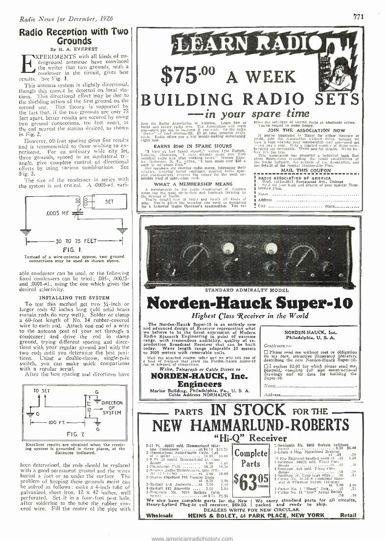
Radio News for December, 1926
Radio Reception with Two Grounds
By H. A. EVEREST
with all kinds of un- derground antennae have convinced
he writer that two grounds, with a condenser in the circuit, gives best
results. See Fig. 1.
This antenna system is slightly directional, though this cannot be detected on local sta- tions. This directional effect may be due to the shielding action of the first ground on the second one. This theory is supported by the fact that, if the two grounds are over 75
feet apart, better results are secured by using two ground connections, ten feet apart, at the end nearest the station desired, as shown in Fig. 2.
However, 60 -foot spacing gives fine results and is recommended to those wishing to ex- periment. For an ordinary wide city lot, three grounds, spaced in an equilateral tri- angle, give complete control of directional effects by using various combinations. See Fig. 3.
The size of the condenser in series with the system is not critical. A .0005 -µf. vari-
.0005 MF
30 TO 75 FEET - FIG. I,
Instead of a wire- antenna system, two ground connections may be used as shown above.
able condenser can be used, or the following fixed condensers can be tried ; .005 -, .00025 - and .0001 -sf., using the one which gives the desired selectivity.
INSTALLING THE SYSTEM To test this method get two % -inch or
larger rods 42 inches long (old solid brass curtain rods do very well). Solder or clamp a 60 -foot length of No. 14 rubber -covered wire to each rod. Attach one end of a wire to the antenna post of your set through a condenser; and drive the rod in clamp ground, trying different spacing and direc- tions with your regular ground and with the two rods until you determine the best posi- tions. Using a double -throw, single -pole switch, you can make quick comparisons with a regular aerial.
After the best spacing and directions have
TO SET
r11 G
I+-- 100 FT
G rL DIRECTION
FIG. 2
o OF T SYSTEM
G
J-
Excellent results are obtained when the receiv- ing system is grounded in three places, at the
distances indicated.
been determined, the rods should be replaced with a good permanent ground and the wires buried a foot or so under the surface. The problem of keeping these grounds moist can be solved as follows: make a 4 -inch tube of galvanized sheet iron, 12 x 42 inches, well perforated. Set it in a four -foot post hole, after soldering to the tube the rubber cov- ered wire. Fill the center of the pipe with
771
$75.0o A WEEK BUILDING RADIO SETS -in your spare time Join the Radio Association of America. Learn how to build and repair radio sets. The Association will train You -start you out in business it you wish. Be the radio "doctor" of your community. $3 an hour upwards easily made. Radio otters you a big money -making opportunity right nine.
EARNS $500 IN SPARE HOURS "I bave at last found myself," writes Lyle Follick,
Lansing, Michigan, "1 have already node over 5500 building radio sets after working hours." Werner Eich- ler. Rochester, N. Y., writes, "I have made over $50 a week in my spare time."
Our members are starting radio stores, increasing their salaries, securtng better positions, passing radio oper- ator examinations. earning big money for the most en- joyable kind of spare -time work.
WHAT A MEMBERSHIP MEANS A membership in the radio Association of America
gives you the most up-to -date and thorough training in the Science of Radio.
You're taught how to build and repair all kinds ct sets. You're Orin the training you need in preparing for a Licensed Radio Operator's examination. You re-
ccive the privilege of buying parts at wholesale prices. 1 ou're helped to make money.
JOIN THE ASSOCIATION NOW If you're interested in Radio for either pleasure or
Profit, loin the Association without delay, because tee have a plan whereby your membership may not -need not -cost you a rent. Only a limited number of these mem- berships are acceptable. Write now for details. Write be- fore it's too late.
This Association has prepared a beautiful book that gives figure -facts regarding the profit possibilities of the Radio Industry, the purpose of the Association, and the details of the Special Membership flan.
MAIL THIS COUPON
RADIO ASSOCIATION OF AMERICA Dept. 1512 -4513 Ravenswood Ave., Chicago Seed mc your book and details of your Special Mem-
bership Plan. Name
Address
City State
STANDARD ADMIRALTY MODEL
NordeuHauck Supers i o Highest Class `Receiver in the World
The Norden -Hauck Super -10 is an entirely new and advanced design of Receiver representing what we believe to be the finest expression of Modern Radio Research Engineering in point of extreme range, with tremendous audibility, quality of re- production Broadcast Receiver that can be built today. Wave length range adaptable 35 meters to 3600 meters with removable coils.
Mail the attached coupon today and we will tell you of a host of features that place the Norden- llauck Super -10 far in advance of competition.
Write, Telegraph or Cable Direct to
NORDEN.HAUCK, Inc. Engineers
Marine Building, Philadelphia, Pa., U. S. A. Cable Address NORHAUCK
NORDEN- HAUCK, Inc. Philadelphia, U. S. A.
Gentlemen: Please send me without cost or obligation
on my part, attractive illustrated literature describing the new Norden -Hauck Super -10.
I enclose $2.00 for which please send me. postpaid, complete full size constructional drawings and all data for building the Super -10.
Name_.-- -. - - - -- Address_.
PARTS IN STOCK FOR THE
NEW HAMMARLUND- ROBERTS "Hi -Q" Receiver
3 -17 Pl. .00035 ofd. Ilammarlund Wi- nne Condensers at $4.75 S11.23
3 lfammarlund Auto-Couple Coils. (set of coils) 10.00 10.00
1 -9 l'l. 32 mmfd. Ilammarlund Jr. Con- denser 1.50 1.00
1- Foundation Unit 10.50 10.511 2- Santsrcn Audio Transfo, mers. type IIW-
,1t1 (3 -1 ratio) at 5.00 10.00 2- Martin Copeland 192 Vernier Dials
at 2.50 5.00 2- Radial) 1 -A Amperite at LIS 22.20 1- Radial) 112 Amperito 1.10 1.10 3 -R, njamin No. 9040 Sockets (with
basest at $.73 52.25
Complete Parts
$63°5
2- 13eniamin No. 9049 Sockets (without bases) 5.50 $1.00
1 -Lynch 2 Meg. Metallized Resistor at .50
le Eby Engraved binding posts at .15 1 Simgamo .00025 mfd. Fixed Cot -
denser at .90 1 Sangamo .001 mfd. Fixed Con-
denser .50 1 Sangamo pr. Grid -Lack clips .10 1 Carter No. M -10 -S Combined Rheo-
stat & Filament Switch (10 ohm) at 1.00
1 Carter No. 1 "Short" Tack 25 1 Carter No. 12 "Imp" Aerial Switch
.70 .70
.50 1.30
.40
.5n
.10
1:Oó
We also have complete parts for the New We carry standard parts for alt circuits, Henry -Lyford Plug -in coil receiver, $69.50. I packed and ready to ship.
DEALERS WRITE FOR NEW CIRCULAR. Wholesale HEINS & BOLET, 44 PARK PLACE, NEW YORK Retail
www.americanradiohistory.com
772 Radio News for December, 1926
Curls was gift that l rou' A-4 the whole year,
Choose from this list. Use coupon below II' I VIII III I lIII1
I I LIrI / 1 I L ww and order by Group Number. Subscriptions
Ir
' III
sold only in groups shown.
A 1 Money Making 2 Radio News
B 1 Science & Invention 2 Boy's Life
C 1 Amaging Stories 2 Science & Invention
D 1 Radio News 2 Collier's Weekly
E 1 Science & Invention 2 World's Work
F 1 Amazing Stories 2 American Magazine 3 Woman's Home Com-
panion G
1 Money Making 2 Pathfinder
H 1 Radio News 2 Pathfinder
I 1 McCalls 2 Science & Invention
or 3 Money Making
J 1 Radio News 2 Science & Invention 3 Amazing Stories
K 1 Amazing Stories 2 Money Making
L 1 Cosmopolitan 2 Good Housekeeping 3 Radio News
or 4 Science & Invention
M 1 Pictorial Review 2 McCalls 3 Money Making
or 4 Amazing Stories
N 1 Radio News 2 Science & Invention 3 Amazing Stories 4 Money Making
o 1 Radio News 2 Radio Review
(quarterly)
} $4.25
} 3.75
} 4.25
} 3.75
5.50
i
5.00
2.75
2.75
3.00
6.00
4.25
6.25
4.00
8.00
3.50 -SPECIAL-
Your own subscription to either Science & Inven- tion, Amazing Stories, Radio News or Money Making and a year for your friend of either of these magazines with a Christmas card to reach him on Christmas Day all for $4.00.
and ít inexpensive tool Here's a happy solution to your gift problem. Use the coupon below. We take care of the rest.
Not every day in the year can you offer such a genuine, agreeable surprise to your friend or friends. As a special Christmas opportunity you can obtain a 12 months' sub- scription to any of the magazines shown on this page at greatly re- duced rates. In order to make possible this reduction it has been necessary to corn bine these magazines into groups of 2 or more. If you prefer, we will send one to you, the other to your friend, together with Christ -. mas card to reach him on Christmas morning. Just fill out the coupon -we take care of the rest.
EXPERIMENTER PUBLISHING CO., Inc. 53 PARK PLACE, NEW YORK, N. Y.
w EXPERIMENTER PUBLISHING CO., Inc., 53 Park Place, N. Y.
Gentlemen :-I enclose $ for 12 months' subscription to magazines in Group Kindly send magazine Number in this group to my friend and magazine Number to myself.
Your Friend's Name Your Name
Address Address
City, State City, State
NOTICE -Be sure to mention group letter, and the number of each magazine desired. Enclose full amount. Do not forget to write your friend's name and address.
www.americanradiohistory.com
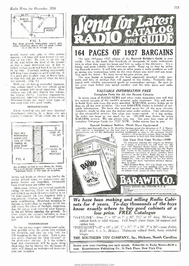
Radio News for December, 1926
60 FT.
\ BURIED
\
G WIRE-
60
<
G
HOUSE)
FIG. 3 The three g rounds triangularly spaced give better directional effects, and are easily located
on a city lot of average size.
gravel, coarse sand, coke or other porous material, and tamp stiff mud around the out- side of the tube. Be sure to set the top of the tube below the level of the ground so that a small depression can be left to collect surface water and lead it to the center of the tube. Thorough soaking occasionally will keep these grounds in good condition. It is a good plan to place them in flower beds, so that they will get watered when the beds are watered. (Fig. 4.)
With any set having controlled regenera- tion, volume equal to the best outside aerial can be secured with equal selectivity. Neu - trodyne sets will give slightly less volume, but greater clarity. Low -loss regenerative, regenerative superheterodynes, counterphase, Browning -Drake and many other types of sets were tried with good results.
INTERFERENCE
Static, squealing sets and most electrical disturbances existing in a large city are greatly diminished. While noises due to de-
FOUR INCH ' `''` a LEAD IN
PERFORATED /.;;ìa.:: TO SET
GALVANIZED '' TUBE 42' LONG ".. TAMPED IN
'.' .
s WITH DAMP EARTH
i POROUS ,.:< FILLING TO
i a HOLD a'' MOISTURE
FIG. 4
An excellent method is here shown for obtain- ing a good ground connection; which is a most
important factor in this type of reception.
fective rail bonds on electric car tracks, de- fective ground wires on transformers and power houses are magnified, fortunately these disturbances are rather rare.
Short -wave stations are received regularly during the daytime, 2XAF on 32.79 meters and KDKA on about 63 meters coming in on the loud- speaker (in Los Angeles) with a regenerative detector and two stages of audio amplification. Broadcast reception in daytime is better than by regular aerial, but still shows the effect of daylight, suggesting that the waves must traverse some distance in the air before entering the ground. In other words, the station's radiation is from the aerial and not from the ground connec- tion.
TRANSMISSION
In time we may expect underground radia- tion, possibly using the system just outlined for reception, and then we may look for DX reception by clay or night. Such a sys- tem might eliminate the "skip distance" of the short -wave stations. It is the writer's hope that experiments will be made along these lines, for he believes that the future of radio will depend tan underground transmis- sion and reception
773
_>;::.:..:.,. ::.!:we;T ,..;: ,..,.. .t..t":"- ?.k`.`.,'.+.
..;;1L.r.;:. :¿=.r: .Yt. .:F:tF :''4:.:,7:i :.¿ .ilv,. ... :.T'. . ... . . :::.. ... .. . ..:. .
. . ... ñ: }.. . . .... .. ...r:.. .t . . ........... . . M1 . .
: . , ~ ̀ ïï:'A'ili'iÍi
. ;:,..,'it;;s?I3::;j ;6!!:.1;:r;Y':" ̀á>: tís:..+ :s:ë: t'..,:..:: a... .::.... .....:. .....::.; ,:,.. ..V.. .Y.:: n.: ;t+Tv......:.i`:...... ....'..St`;ì.c.._..,: .... .. . .... .. . .. .: ...
164 PAGES OF 1927 BARGAINS The new I64 -page 1927 edition of the Barawik Builder's Guide is now
ready. This is the book that hundreds of thousands of radio enthusiasts turn to when they want the latest and best in radio at big discounts. It's a handy and most reliable radio reference guide. Keep up to date by utiliz- ing Barawik service. It will help you to solve many a radio problem as well as saving you tremendous sums on the very things you need and use most. You want the latest -We have it -at bargain prices, too.
The new Guide is brimful of the best approved standard radio sets. parts and kits, at savings that will appeal to the thrifty. Profusely illus- trated with reliable guaranteed goods at tremendous savings. Be sure to get your copy before you spend another cent for sets, parts and radio supplies.
VALUABLE INFORMATION FREE Complete Parts for All the Newest Circuits
In every issue of RADIO NEWS and other radio magazines you will find the newest circuits of the world's greatest radio engineers. You will want to build these sets from the parts specified. BARAWIK service keeps up to date on all the new wrinkles. The new BARAWIK Guide is brimful of val- uable information. We have the specified parts for all the new circuits, complete, ready to ship you the instant your order arrives. Take advantage of this unequalled service. Get what you want- quick -at a big saving. No order too large or too small for us. 300,000 fans thrive by using BARAWIK service. We can please you, too. Get your free copy of the complete I 64-page Guide for 1927 NOW. Delay means loss to you.
Special Amateur Section -Short Wave Equipment Another new Barawik idea is the Amateur Section under the direction of F. J. Marco,
9ZA, wherein is presented for the first time a complete line of short wave receivers, transmitters and all the necessary amateur equipment so dear to the amateur experi-
menter -all at bargain prices. Don't miss the opportunity to look into this inviting field.
Get Your Free Copy Tc- day -NOW To everyone mailing the coupon or writing
us a letter or postcard we will mail free the new 1927 Barawik Radio Guide, with its 164 pages of everything interesting for the Radio fan. Never in the history of radio has such a tremendous collection of radio supplies been presented to the public. Build the set of your dreams now. Get the things you have always longed for. You can do it, for our low prices will make the most expensive articles reason- able in price.
Mail Coupon Now. Get this Guide into your hands before you buy another part. It will mean money in your pocket. Write today; al- so please send names of other radio fans.
an
'-'`F Ë 3i:`.i:'..; iF; ;',:E' :-.: : :dik'
540 -552A 1MONROE ST.. CHICAGO, U. S. A. NAME ADDRESS FRIEND
1
We have been making and selling Radio Cabi- nets for 4 years. To -day thousands of the boys know exactly where to buy good cabinets at a
low price. FREE Catalogue "IVEYLINE" -Sizes 7" x 18" to 7" x 30 ", 7/" or 10" deep. Mahogan--
rubbed finish or solid walnut. Full length piano hinge, lid support and rubber feet.
"PIEDMONT " -7" x 18" x 10 ", 7" x 21 ", 7" x 24", 7" x 26" -your choice, $2.65 each, f. o. b., Hickory. Mahogany rubbed finish, fancy nickeled. hinges.
THE SOUTHERN TOY COMPANY, Inc., Hickory, North Carolina
Insure your copy reaching you each month. Subscribe to Radio News -$2.50 a
year. Experimenter Publishing Co., 53 Park Place, New York 'City.
www.americanradiohistory.com
774 Radio News for December, 1926
1,vr vItun II l IM . 141,,1DIA M Ikly. uai Ortgv)taA vltvr ult tvnu ,, tunv tvat]nvnvt itutwnv,,,.. ,,vat]acva...A . vltv,lvtvi , OPPORTUNITY AD -LETS
Follow these advertisements every month. Reliable advertisers from all over the country offer their most attractive specials in these columns.
Classified advertising rate twenty -two cents a word for each insertion. Ten per cent discount for 6 issues, 20 per cent discount for 12 issues. Name and address must be included at the above rate. Cash should accompany all classified advertisements unless placed by an accredited advertising agency. No advertisement for less than 10 words accepted.
Objectionable or misleading advertisements not accepted. Advertisements for the February issue must reach us not later than Decem- ber 1st.
CIRCULATION LARGER THAN THAT OF ANY OTHER RADIO PUBLICATION EXPERIMENTER PUBLISHING CO., INC., 53 Park Place, New York, N. Y.
- tY\fit11/a rrevllY Y11 14110k11YíY1fYlRNM I/ tYí rilltYí VIVA f í fit g11 11A1t/ Ii VAX/ í 1fí 1rriYitYí IIYí Y1t ífIIYIIYícilmitratarA1Mrivilml.
Agents Wanted
Big Money and fast sales. Every owner buys gold initials for his auto. You charge $1.50; make $1.35. Ten orders daily easy. Write for particulars and free samples. American Monogram Co., Dept. 133, East Orange, N. J.
We Start You In Business, Furnishing everything. Men and Women, opportunity to earn $40.00 to $100.00 weekly operating Ragsdale s original "Neuv System Specialty Candy Factories" anywhere; wholesale or retail. Valuable commercial candy book free. W. Hillyer Ragsdale, Draw- er 210, East Orange, N. J.
Representatives wanted to sell guaranteed 180 volt "B POWER UNIT" for $25.00. Liberal Commissions. Excep- tionally attractive agency preposition. George Electric Com- pany, 75.4 Carlton Ave., St. Paul, Minn.
A permanent Position and Good Income is open to mats or woman handling our goods in your locality. Established 33 years. No experience or capital. Full or part time. Dignified work. Write Employment Dept., Winter Com- pany, 18 Winter Bldg., Washington, D. C.
Sure Seller to every merchant -no gamble -big profits- steady repeater -free sample anti exclusive territory. Em- bossed Show Card Co., 1100 Euclid, Cleveland, Ohio.
Easy Sales -Quick Profits- dilute our concentrated ma- terials for making high quality foods, beverages, extracts, toilet and auto specialties. Market under your brand or ours. Labels and containers furnished. Permanent, profit- able, exclusive. D -B Concentrating Co., Station E -24, Kansas City, Mo.
Agents -Snappiest household line on earth. Red hot sellers, steady repeaters-100% profit. 350 light weight, fast selling, popular priced necessities. Selling outfit free. (let busy quick -Write today; postal will do. Ameri- can Products Co., 6329 Monmouth, Cincinnati, O.
e m 1 m 1 m 11 1 m 11 n n 1 m mmnml,mm m m1 m 11111111111111 m m n 1,1 1111,1111111 11 1111111, n n,n 1 111 m
Business Opportunities_
Free Book. Start little Mail Order Business, Pier Com- pany, 72AF Cortland Street. N. Y.
Stocks -Bonds, Domestic- Foreign, bought -sold. Deal- ers in all marketable securities. Frank Y. Everett & Co.. 20 Broad St., New York.
Manufacture Crystals-Big profits, particulars Free. Box 313, Wichita, Kansas.
Establish Your Own Industry. Start small, in spite of your handioaps, and grow successful. How? By becoming a co- operative EIA member. Prospectus and catalogues 25c. Equit- able Industries Association, 151 -It Nassau Street, New York.
Manufacture New Fast Selling Novelties, Toys, Prepara- tions, Agent's Gocds. Free list reliable plans, patterns, processes, commercial information. Manufacturer's Bureau, 11291' East 31st, Kansas City, Mo.
Publish a magazine of your own and start a mail order business on $1.00 capital. Sample magazine and details 25 cts. (coin). E. D. Tupper, P. O. Box 184, Los Gatos, Calif.
.m m 1 m. muunmmu ulmumrmaammnnuu 11 m 111uu 1111111mn1immmmmismmmnlmmmm,
Chemistry
Learn Chemistry at Home. Dr. T. O'Conor Sloane, noted educator and scientific authority, will teach you. Our home study correspondence course fits you to take a position as chemist. See our full page ad on page 766 of this issue. Chemical Institute of New York, 66 W. Broadway, New York City.
Correspondence Courses
Used correspondence school nurses. All kinds. Sold on repurchase basis. Big saving. .Money back guarantee. Lists free. (Courses bought). Lee Mountain, Pisgah, Ala- bama.
Farms, Land, Etc.
Land Free if planted to bananas. Bananas bear a full crop the second year. $5.00 monthly will plant five acres, which should pay $1,500 profit annually. Reliable Companies will cultivate and market your bananas for 1/3. Bananas ripen exery day and you get your check every 90 days. For par- ticulars address National Development Co.. Empire Build- ing, Block 135, Pittsburgh, l'a.
For Advertisers
Advertisers International Manual, new edition. Inside information for advertisers and Publishers' Rates. 50e post- paid. Economies Publishing Co., Dept. 56, 1475 Broadway. New York.
Help Wanted
Detectives Needed Everywhere. Travel. Experience un- necessary. Write, George Wagner, former Government De- tective, 1968 Broadway, N. Y.
Earn $25 weekly, spare time. writing for newspapers, magazines. Experience unnecessary. Details FREE. Press Syndicate, 973, St. Louis, Mo.
All me- women, 18 -60, wanting to qualify for Perma- nent Government Positions, $140 -$300 month, home or else- where. Write, Mr. Ozment, 251, St. Louie, Mo.
nu 111111/111 u 1 n 111nu1m 111 n 1111111111u:u11.uu 111111 u 1111111 u u 11u nrum111111.11u11unnun.0 uu.11q
Home Study Courses
Used Correspondence School Courses and Educational Books. bought, sold, exchanged; Bargain Catalogue FREE. Hanfling, R -799 Broadway, New York.
11.1.1111111111111111 lllll
Incorporations
Patent Attorneys (Continued)
Patents -Send for form "Evidence of Conception to be signed and witnessed. Form, fee schedule, information free. Lancaster and Aliwine. Registered Patent Attorneys in United States and Canada, 269 Ouray Bldg., Washington, D. C.
Patents. Send drawing or model for examination and re- port as to patentability. Advice and booklet free. Highest references, Best results. Promptness assured. Watson E. Coleman, Patent Lawyer, 644 G Street, N.W., Washington, D. C.
.111111un 11111nm.m.mmmmm 1.11111n11u 1.1.11111uu u u 11 n.u1111111111uuuuum...1u 111u 1m.mso
Patents
Inventions Commercialized. Patented or unpatented. Write Adam Fisher Mfg. Co., 278 Enright. St. Louis. Mo.
Patent Sense valuable book free. See Lacey's ad page 767 Lacey & Lacey, 631 F St., N.W., Washington, D. C.
Postage Stamps Stamp Collectors- Phillips Monthly Bulletin (illustrated)
offers over 2000 special bargains, sets, packets, single stamps ate., each issue. Free. Phillips, Box 1012, Hartford, Conn. ,,.....11111.1.1.111.1111111111..11..1111,11.1111.11111111111111.11111111111.,1111111111111111111111.1 1.11111.111..111
Radio
Borst Don't Overlook This. The "Rasco" Baby Detector. Delaware Incorporator, Charters; Fees Small; forme. Chee.
Greatest detector ever brought out with molded base. Q. Guyer, 901 Orange St., Wilmington, Del. Fully adjustable. See former advertisements Cr this pub -
tfon, or our catalog. Detector with Crystal. com- plete SOS the
yours detector with ßndiocite Crystal,
,11,11 .......1....1.....111.1.... 111111111. 111111111111111111 ,11,,,,,,,,11..11.,. 11111111111111111 ,1111111111 1,1,1,111,,, paid. Send for Yours today Radio Specialty Company, 06 -98 Park Place, New York City. Instruction
Learn Chemistry at Home. Dr. T. O'Conor Sloane noted educator and scientific authority, will teach you. Our home study correspondence course fits you to take a position as chemist. See our full page ad on page 766 of this issue. Chemical Institute of Nose York, 66 W. Broadway, New York
1.1....1...1... . 1 111 1... 1,1111111111111111. 1.111111111111111111 ,1111111,1111,1 1 Miscellaneous
Multlgraph typewritten letters sell anything. Two dol- lars thousand. Meyer Rey Corporation, Monmouth, Illinois.
W G Y's Home City; Twelve dandy views- Schenectady, N. Y., Post -paid 25 cents (coin). Patrick -Mahoney Co., P. O. Box 931, Schenectady, N. Y.
Grandfather clock works $5.00. Build your own 'case. instructions free; make good profits selling your friends. Clock works with chimes for old or new cases, Write for full particulars. Clock Co., Nicetofn, Phila.
Lightning Electrolyte. Charges storage batteries in- stantly. Gallon costs 50e, sells $10.00. Make it your- self. Guaranteed formula $5.00. Write for free circulare. Murphy, Chemist, Tujunga. Calif. Box -D.
11..11..11.1...1..........11.11...1..11...1........1.1....1...1.1...11...11.111111111111.1.1.111.011111111....1....11
Motorcycles, Bicycles
Don't Buy a Bicycle Motor Attachment until you get our catalog and prices. Shaw Mfg. Co., Dept, 6. Galesburg, Kansas.
n..1 1..11.m11m111u.11u11111m1n11111.1111111:1m11111:.11111uu1nnuuumnnunnnu11mununu.11lmumu:l11
Old Coins
German Gov't Bond 5,000,000 Mk. 1924, $1.50. 2,000,000 Mk Bond 1923, $5.00. 500,000 Mk, Bill and Catalogue, 10c. Norman Shultz, Box 746. Salt Lake City, Utah.
iiiii
Old Money Wanted
$2 to $500 each paid for hundreds of Old or Odd Coins. Keep all old money, it may be very valuable. Send 10e far New, Illustrated Coin Value Book, 4x6, Guaranteed prices. Get posted. We pay Cash. Clarke Coin Company, 14 Street, LeRoy, N. Y.
m m11 m n m m.1 n m mm n n mm m..0 l m l u m 111,.1.1.,.
Patent Attorneys
Inventors -Should write for our Free Guide Books and "Record of Invention Blank before disclosing inventions. Send model or sketch of your invention for our Free Inspec- tion and Instructions. Radio, Electrical, Chemical, Me- chanical and Trademark experts. Terms reasonable- Victor J. Evans. & Co., 922 Ninth, Washington, D. C.
Attention t -50 Vacuum tube hook -ups. The greatest col - ection of vacuum tube circuits ever brought under two
covers at such insignificant cost. These diagrams will be found in the great Rasco catalog, which contains raw ma- terials and parts in a greater profusion than any other catalog. 15e in stamps, or coin, will bring the catalog to psis. Radio Specialty Co., 96 -98 l'ark Place. New York City.
Play your Phonograph thre your Radio. Results equal to New Electric Phonographs. Inexpensive hook -up. Com- plete plans $1.00. Complete apparatus ready for use $11..50. Mogle .d: McClelland, Dept. 1l, Winfield, Kansas.
Radio trouble finder, log and dictionary. A new book just off the press. Send for free circular. Patrick - Mahoney Co., P. O. Box 951, Schenectady, N. Y.
Chokes. 50H, SOMA Filter or speaker bypass, $2.00 - 30H, 5031A, Raytheon Filer. $1.75 -20H, 25PIA $1.00, unmounted, Prepaid. Write for list of transformers, etc. Radio Parts Sales Co., Bos 24, Orange, N. J.
Send 4 cents Stamps for Bargain Radio Catalog. Perryman 201A Guaranteed Tubes $1.60. Radio Specialty Shop, 525 Park Ave., Kent, Ohio.
Selenium- or Photo - Electric Cells, For all purposes, very sensitive, quick, and permanent in action. Three years guarantee. Send 10c stamps for catalog. Selenium Laboratories, Hampton Bays, Long Island, N. Y.
Build a Lifetime "B Battery from my better Edi- son Elements. With Welded connections 7c pair. Sample cell 1Oc. Paul Mills, 'Woodburn, Oregon.
Single control Magnavox Radio $70. It. Schlegel, 1113 N. Negley, Pittsburgh, Pa. limm1 .1m1mm1..m.mlm11nn111.m..11111
Salesmen Wanted
A Salesman wanted in every town or city within 25 miles of a broadcasting station to sell Radiogem, the complete radio receiving set that retails for $2.10. With Radiogem there is nothing else to buy -the outfit includes the Radio - gem receiving apparatus, 1,000 ohm-phone, and aerial outfit. The cheapest radio outfit on the 'market-yet as practical as the most expensive. Big money to the right men. Send $2.00 for sample outfit. Tile Radiogem Corp., 66 -R D'est Broadway, New York City.
Make $100 Weekly in spare time. Sell what the public wants -long distance radio receiving sets. Two sales week- ly pays $100 profit. No big investment, no canvassing. Sharpe of Colorado made $955 in one month. Representa- tives wanted at once. This plan is sweeping the country- write today before your county is gone- OZARKA, INC., 431 N. LaSalle, Ave, K, Chicago. .u111»>s;»»msn 111111 .111111um111m11mu.1lm.mnmmmm1111171,®111
u 11111111 n 11111
Scenery for Rent
World's Most Beautiful Settings fer operas, plays, min- strels. Amelia Grain, Philadelphia.
www.americanradiohistory.com
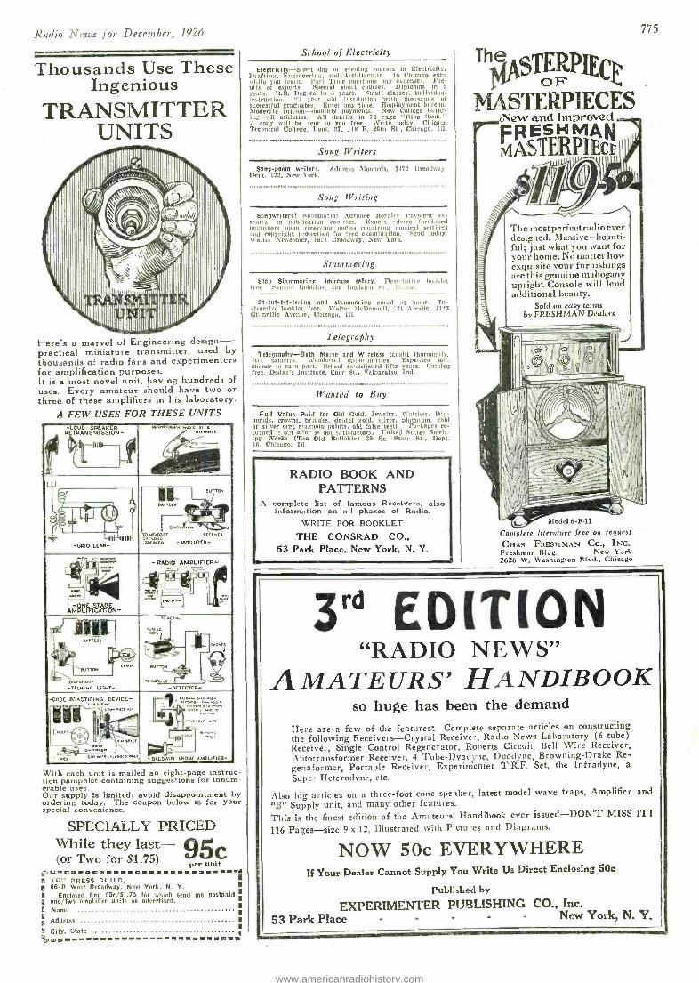
Rnlro A.I S for DeccmGer, 1926
Thousands Use These Ingenious
TRANSMITTER UNITS
1111111111 '11111111011iliiiii,
Here's a marvel of Engineering design -- practical miniature transmitter, used by thousands of radio fans and experimenters for amplification purposes. It is a most novel unit, having hundreds of uses. Every amateur should have two or three of these amplifiers in his laboratory.
A FEW USES FOR THESE UNITS
)
-LOUD RETRANSMISSION-
SPEAKER
MI! ' (. IILAV7
wONOG+A. y / 1 tr
11
euTTO.4
- / eATTro
. TO
",!.oscT 5PEAKCn
tF'1 0. ..w1 4 0
uccuvco
-AMPLIFIER- II YYY
-GRID LEAK-
;; `
-ONE AMPLIFICATION-
STAGE
-RADIO AMPLIFIER-
. rrr -i L I
1_ : ....
a_
AI
'j1
BATTCRY
!re BuTTON
AA,
TO
cO
...r - --
BuTTD
" V.J TO LBP1..,
o-DRCCfOR-
Cs
! :; "
- é.nl.c.wA -TALK ING LIGHT
-CDOE PRACTICING
3 , , »« ` ,oer . SPACE
I, L1,, Am0
o-
I IA( .. imet
.., .
PHONE A.MPLIFIER- \,aAt twtT cA.wnlr
With each unit is mailed an eight -page instruc- tion pamphlet containing suggestions for innum- erable uses. Our supply is limited; avoid disappointment by ordering today. The coupon below is for your special convenience.
SPECIALLY PRICED While they last --- 9ge (or Two for S1.75) per unit
i; f PRESS GUILD, l! 66 -R West Broadway, Nevi York, N. Y. A Enclosed find 95e/Sl.75 for which send me postpaid is one /two amplifier units as advertised. L Norm
Ft; Address
fi City. State R.nwówmmmmmmmm------ .mimmmwmwsta
School of Electricity
Electricity -Short day or evening courses in Electricity. Drafting, Engineering. and .architecture. In Chicago earn widlo you learn. l'art Time positions pay expenses. Fac- ulty of experts. Special short courses. Diplomas in 2
years. B.S. Degree in t years. Small classes. individual instruction. 2 :: year old Instituttrm with thousands of successful graduates. Enter any time. Employment bureau. Moderate tuition- monthly payments. New College build- ing -all athletics. All details in 72 rage 'Blue nook." A ropy will be sent to you free. Write today. Chicago Ttchnical College. Dept. 27, 118 E. 2Gth St , Chicago. Ill.
.Song Writers
Song -poem writers. Address Monarch, 1172 Ilmadway Dept. 122, New
York1,,,,..,
Song Writing
£-nnwrlters! Substantial .advance Royally' Payment vs- M'lilld to publication contract. Expert advice furnished beginners upon receiving poems requiring musical settings and eopyright protection for free examination. Send today. lcaltu' Newcomer, 1671 Broadway, New York.
.,,,,,,,,,,,111111111,1,,,11,111111,,,,,B,P1H81,,,11,n1,11111111111111111111111I,,,,,,,,,,,,,11111n , i Stammering
Step Stammering. increase salary. Deseriplive booklet tree. Samuel Robbins. ::Ill Ilryl al:l "I., i; .l,nl.
St- tut -t -t- tering and stammering cured at home. In- structive booklet free. Walter McDonnell, 121 Arcade, 1126 Granville Avenue, Chicago, III.
,111w11,11111111111w11.,1fw.w',...,,,..,1..wo1,1,,1e,1..",.11,1"11,,,.,
Telegraphy
Telegraphy -Both Morse and Wireless taught thoroughly. I:ig sa lari, s. \ \'ouderfnl uppot[unities. Expenses low, chance to earn part. School established fifty yea's. Catalog free. Dodge's Institute, Cour St., Valparaiso, Ind.
0,111111,1, ili11ii11l 1l1p11 11111111111111,1111.,11111111111111111111,1111111111111111,,,,O1im, i,,, iiiii
Wanted to Buy
Full Value Paid for Old Gold. Jewelry, Watches. Dia- monds, crowns, bridges, dental gold, silver, platinum. gold or silver ore; magneto points. old false teeth. Packages re- turned if our offer is not satisfactory. United States Smelt- ing Works (The Old Reliable) 39 So. State St., Dept. 16. Chicago, Ill.
RADIO BOOK AND PATTERNS
A complete list of famous Receivers, also information on all phases of Radio.
WRITE FOR BOOKLET
THE CONSRAD CO., 53 Park Place, New York, N. Y.
The sT PPCta
®F L MASTERPIECES
2New and Improved FRESHMAN N1 ASTERPIEC
The mostperfectradio ever designed. Massive- beauti- ful; just what you want for your home. No matter how exquisite your furnishings are this genuine mahogany upright Console will lend additional beauty.
Sold on easy te: ms by FRESHMAN Dealers
775
\lodcl b -F -11
Complete literature free on request
CHAS. FRESHMAN CO., INC. Freshman Bldg. New Y..rk 2626 W. Washington Blvd., Chicago
3'° EDITION "RADIO NEWS"
AMATEURS' HA NDIB OOK so huge has been the demand
Here are a few of the features` Complete separate articles on constructing the following Receivers -Crystal Receiver, Radio News Laboratory (6 tube) Receiver, Single Control Regenerator, Roberts Circuit, Bell Wire Receiver, Autotransformer Receiver, 4 Tube- Dyadne, Duodyne, Browning -Drake Re- genaformer, Portable Receiver, Experimenter T.R.F. Set, the Infradyne, a
Super Heterodyne, etc.
Also big articles on a three -foot cone speaker, latest model wave traps, Amplifier and "B" Supply unit, and many other features. This is the finest edition of the Amateurs' Handibook ever issued -DON'T MISS IT!
116 Pages -size 9 x 12, Illustrated with Pictures and Diagrams.
NOW 50c EVERYWHERE If Your Dealer Cannot Supply You Write Us Direct Enclosing 50e
Published by
EXPERIMENTER PUBLISHING CO., Inc. 53 Park Place - - - - - New York, N. Y.
www.americanradiohistory.com

776 Radio Netos for December, 1926
'Th1s 84 Page Wonder Book of RADIO B
Send for this guide to Radio prices and Radio quality. All of our vast resources and radio experience have been utilized to assemble for you in one gigan- tic institution, the best and newest things in radio. The Randolph catalog is indeed the radio market place of the world -a masterpiece of merchandising that befits our house -the largest exclusive radio mail order house in the world.
What Our Catalog Contains Over 2,000 items -from the most beautiful, fully equipped console model radio set, down to the smallest part or tool for the set builder -kits, parts, and supplies of every conceivable type and style. All beautifully illustrated and interestingly described. And to give this book added value, we have included radio data that makes it an invaluable text book for every lover of today's most fascinating and most wonderful achievement- RADIO.
Radio Sets Radio Parts and In this great radio market place you will find table model sets and console types with built -in loud speakers; the newest ampliphonic console sets; new Spanish period consoles; five, Six, seven, and eight tube sets. with three dial, two dial, and the newest and most popular sin- gle simplified control. All sets are assembled in beautiful, genuine mahogany and walnut cabi- nets in a choice of latest types and designs.
5 Tube sets as low as $24.90 Latest 1927 Models
All Randolph sets are sold at amazingly low prices. No matter what kind of set you want - no matter how little you want to pay -you can select YOUR SET AT YOUR PRICE from the Randolph catalog.
Radio Kits The radio kits we offer for sale are approved by the world's foremost radio engineers. Wonderful values 'n the latest kits, including all classes of radio frequency, super-hetero- dynes and every other approved popular and advertised circuit. There is nothing in the line of radio kits and parts of any value and which are in demand which we do not carry.
Supplies
Over 2000 ITEMS
Everything in RADIO
The Randolph catalog also contains a most complete line of "B" Battery Eliminators. in.. eluding the famous Raytheon Eliminators; the latest type of Loud Speakers, Cone Speakers, a complete line of quality "A" power units - in fact, you will find listed in this wonder book every part that goes into the construction of a radio set, or any accessories you desire, at prices that mean a substantial saving to you.
Free Radio Service Everyone has need for radio service. The average man has no time to keep up with the rapid developments of radio. We employ Radio Engineers who have made radio their life work. Their expert advice and helpful suggestions solve every radio problem of our customers.
Our Guarantee Every article in our catalog is based on careful iaboratory analyses and tests. We guarantee to back up every item in our catalog with our own as well as manufac- turer's assurance of quality.
YOU MUST VE IS BOOK Space limitations here prevent oui telling you more about the Randolph Catalog. Simply fill out and mail the coupon -or you may send a postal or letter -and this truly remarkable Radio hook will come to you ABSOLUTELY FREE. MAIL THE COUPON NOW.
Randolph Radio Corporation %90 North Union Avenue 4 Dept. 181 4 Chicago, Ill.
9Phy7i'eSaveiu.Noneey Because we handle radio exclusively and sell a tremendous volume of everything in Radio, we can concen- trate our buying power for the ben- efit of our customers.
Volume purchases regulate prices. We command rock bottom prices from manufacturers, and in many cases we con- tract for entire factory output of exclu- sive products. You will benefit by our great volume of purchases and sales, by securing anything you may want in radio at a substantial saving.
This Coupon Brings:: the , l
Great RADIO Book FREE RANDOLPH RADIO CORPORATION 180 N. Union Ave., Dept: I8 Chicago, Illinois
Send me- free -your 84 -page, 1927 Radio Book.
Name
Street and No.__ -_ - -- _-- __--- ---- _ --- -° R. F. D - _____- __-Box
City-- ____ - -- - -_ -- -State
®a®eamamum®.n.m I'RINTED BY GII.ES PRINTING CO., LONG ISLAND CITY
www.americanradiohistory.com
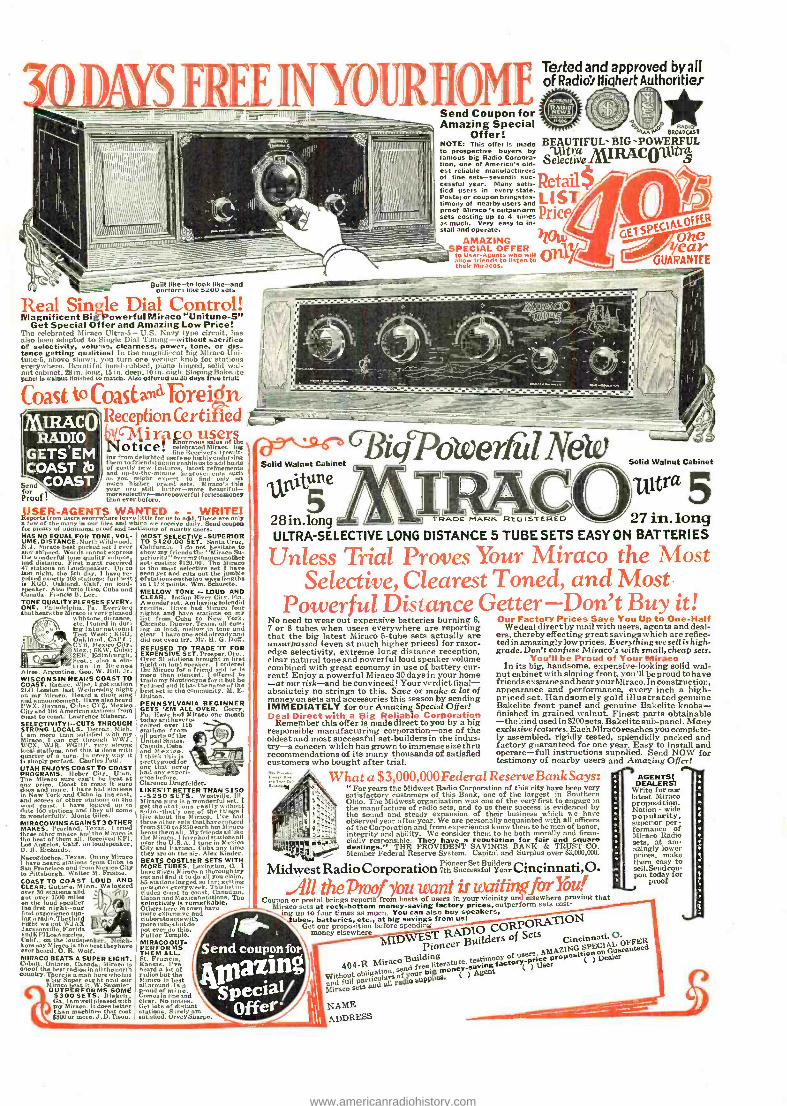
s FREE INYO1IRIIOME ;_ Send Coupon for
Amazing Special Offer!
NOTE: This otter is made to prospective buyers by famous big Radio Corpora- tion, one of America's old- est reliable manufacturers of fine sets -seventh suc- cessful year. Many satin tied users in every state. Postal or couponbringstes- timony of nearby users and proof Miraco 's outper,orm sets costing up to 4 times as much. Very easy to in- stall and operate.
1111111111111111nllnlllllnannan 111111111n
Tested and approved by all of Radio's Highest Authorities'
is l I o Mò i'laneR mouse
BEAUTIFUL-BIG-POWERFUL
$eleetiVeMRACQu 3 Retail LIST Price
n 'k.. AMAZI NG lltilsssyt
SPECIAL OFFER to User -Agents who will allow Mends to listen to
.or Miracos.
fER
oe Bear
GUARANTEE
Built erform like $200 like-and
$200 sets
_ -------
Real Sinle Dial Control! Magnificent Big-Powerful Miraco "Unitune -S"
Get Special Offer and Amazing Low Price! The celebrated Miraco Ultra -5- U.S. Navy type circuit, has also been adapted to Single Dial Tuning- without sacrifice of selectivity, volume, clearness, power, tone, or dis- tance getting qualities! In the magnificent big Miraco Uni- tune -5. shove shown, you turn one vernier knob for stations everywhere. Beautiful hand- rubbed, piano hinged, solid wal- nut cabinet, 28 in. long, 15 in. deep, 10 in. high. Sloping Bakelite pf eel ie walnut finished to match. Also offered on 80 days free Irian
Coast to MillAC( 'Reception Cel'tiIled
li it tpo uses'' otice aria
" ° " "'ea "" fine Receivers )restio., ing from delighted user. en highly endorsing them to friends) "gain enable us to addhoste
ofd up -to- the- mrinueenI latest
Improvements such
year
provemenn - / Il you might a ,t to find my °Co Send\ much higher tiri, rod seta. Maraca's this for liras nveeer Live morepowerful
better-more P[OOC Chun ever before.
11SE/1- AGENTS WANTED WRITE! font f the many iinO or m ., and
leave little us pdaiie hSend coupoñ
for plenty of additional proof and testimony of nearby seer.. HAS NO EQUAL FOR TONE. VOL- UME, OISTANCE.North Wildwo,d, N.J. huraro beet parked net I ever
the.hirted. Words cannot perta wonderful tune quality volume rad rietonce. First night received
4V mutina. on lauds aker. Up to last night, the 6th dpr. I have re-
d exactly 103 stations: farthest isKGO, Oakland. Calif. loud-
C)
w aker. Also Porto Rico, Cubs and
anada. Francis B. Lee. TONE QUALITY PLEASES EVERY - ONEQyiehia, Pa. Everyone that bears is very pleased
X thtene,dietane, ',t\1,'` iré internati
dur- ing Tent Week EGO, Oakland. Calif.: CYIR. Mexico City. Mee.; fiK W Cuba; 2$ :H. Edinburgh. Scot.: also a eta - tion in Buenas
Aires. Argentine. Geo. W. Hill. Jr. WISCONSIN HEARS COAST TO COAST. Racine. W isc. I got station niy°rent nit my
Wednesday choir tong
and announcement. Have also heard l'W X. Havana. Cuba; CYZ, Mexico City and 1114 American Illations from court to court. Lawrence Eisberg. SELECTIVITY!- -CUTS THROUGH STRONG LOCALS. Detroit, Mich.
Mimeomore can scut satisfied with
\V SW, WCX, wig. WGIi1', strop local Motions, and title is
very strong with
q uarter simply of
Chnarles l'aui Y it
UTAH ENJOYS COAST TO COAST PROGRAMS. Heber City. Utah. Tne Miraco sure can't be beet at
áray .rice. Coast toc tit uro
, nd more. 1 Caer hnd d ations in New York and Cuita in the earn, and acores of other Bunions on the
rat coast. I have logged up to date
wonderfully. Monte Giles.n come
MIRACOWINS AGAINST 3 OTHER MAKES. Poarlond. Texas. 1 tried three other waken and the Miraco is the best of them all. Received K F1, Loco Angeles. Calif. on louseaker, O. 11. Richarde. Nacosdochee. Texas. Onny Miraco
1 have heard stations from Cuba to San Francisco and from Mexico City to Pittsburgh. Walter M. Friable. COAST TO COAST LOUD AND CLEAR. Guthrie. Minn. We logged
r 30 rtatio and got 1500 ilea l W
the over
speaker the Sent night-our - ' %'I lint experience tun- ing arodio.Thethird right we got WJA Jacksonville, Florida
rad KFl Los noel.. Calif_ on the loudspeaker. igh- bore nay Miraco is the beet theyhave ever heard. O. R. Wolf. MIRACO BEATS A SUPER EIGHT. Cobalt. Ontario, Canada. Stiraro is
coroof the beet radios in all the north
uatry.There is a man here whohaa able Super eight and our Miraeo beat it. W S"umier OUTPERFORMS SOMi
$300 SETS. Blake'', Ga. I am well pleased with my Miraco. I t dure better than machines that cost $BOO or more. J. D. Tison.
MOST SELECTIVE -SUPERIOR TO $120.00 SET. Sant., Cruz, C liforria. I do not hesitate to show my friends the 'M intro Su- periority my (namesanother cet costing $120.10. The Mimeo is the most °elective t 1 have sfaatnoon etas jumble
in L 1/2 pointa. Wm. Schuette. MELLOW TONE -. LOUD AND CLEAR. Indian River City. Fla. A wonder set. Am having splendid results. Have had )timers four nights and have stations on my list from Cuba to New York. Chicago, Denver. Tex., all com- ing in loud. mollo,' in tone and clear. I have fine sold already and did not even try. Mr. U. G. Daä. REFUSED TO TRADE "IT FOR EXPENSIVE SET.Pron r.Ore., Over 31 talions brought in first thehMiiraco for a friend and
ordered Ix
than pleased. I offered to trade my Nmnrodyne for it but he refused end it has the name of the beet set in the community. M. E. Halton. PENNSYLVANIA BEGINNER GETS 'EM ALL OVER. Corry, Pa. Have had Miraco one month today and havero.
ntati, nn from 6
United States, Canada. Cuba
I think ix prettyrood for had any exneri-
ce before. Clarence Drugfelder. LIKES -IT BETTER THANj$150 --$250 SETS.
onderful set.lt g et
that's one of thé thing. like three otherrseets that hsvcranggod from f C.S to $^-60 each but M iraco
themihemall. Myfriendn°Illike
the mint I hava had etationx all
Citover the U.S.A. I tune in Mexico
y and Havana. a. Cabe any time they are on the air. Alex Kinder. BEATS COSTLIER SETS WITH MORE TUBES. Lexington, O. 1
have given Mimen a thorough try t and find it to do all you claim.
86 Motions lugged so far: getting ryweek. TCi:, list in-
iudes coast to coast. Canadian, Cuban and Mexican stations. The selectivity is remarkable. Others here In town have
expensive and morn iatoaetawith m ro tubes htrid° i ever do this. Fuller Temple. MIRACO OUT. PERFORMS THEM
Franc n, Kansas. I've beard a lot of radios but the
altcrounñ b m proud of mine.
fine and
Get lots of dvaaut stations. Surely am satisfied. Oeoey Shaepo.
.- Solid Walnut Cabinet
gYoeriu Solid Walnut Cabinet
iritune /A \ i i ultra 5 5
28 in.lon ULTRA -SELECTIVE LONG DISTANCE 5 TUBE SETS EASY ON BATTERIES
Unless Trial Proves Your Miraco the Most Selective, Clearest Toned, and Most.
Powerful Distance Getter -Don't Buy it! Our Factory Prices Save You Up to One -Half
Wedeal direct by mail with users, agents and deal- ers, thereby effecting great savings which are reflec- ted in amazingly low prices. Everything we sell is high - grade. Don't confuse Miraco's with small, cheap sets.
You'll be Proud of Your Mimeo In its big, handsome, expensive- looking solid wal-
nut cabinet with sloping front, you'll be proud to have friends examine and hear yourMiraco. In construction. appearance and performance, every inch a high - priced set. Handsomely gold illustrated genuine Bakelite front panel and genuine Bakelite knobs - finished in grained walnut. Finest parts obtainable -the kind used in $200 sets. Bakelite sub-panel. Many exclusive features. Each Miraco reach es you complete- ly assembled, rigidly tested, splendidly packed and factory guaranteed for one year. Easy to install and operate -full instructions supplied. Send NOW for testimony of nearby users and Amazing Offer!
No need to wear out expensive batteries burning 6, 7 or 6 tubes when users everywhere are reporting that the big latest Miraco 6 -tube sets actually are unsurpassed (even at much higher prices) for razor - edge selectivity, extreme long distance reception, clear natural tone and powerful loud speaker volume combined with great economy in use of battery cur- rent! Enjoy a powerful Miraco 30 days in your home -at our risk -and be convinced! Your verdict final - absolutely no strings to this. Save or snake a lot of money on sets and accessories this season by sending IMMEDIATELY for our Amazing Special Offer! Deal Direct with a Big Reliable Corporation
Remember this offer is made direct to you by a big responsible manufacturing corporation -one of the oldest and most successful set -builders in the indus- try-a concern which has grown to immense size thru recommendations of its many thousands of satisfied customers who bought after trial.
What a $3,000,000Federal ReserveBankSays: rr For years the Midwest Radio Corporation of this city have been very satisfactory customers of this Bank, one of the largest in Southern Ohio. The Midwest organization was one of the very first to engage in the manufacture of radio sets, and to us their success is evidenced by the sound and steady expansion of their business which we have observed year after year. We are personally acquainted with all officers of the Corporation and from experiences know them to be men of honor, integrity and ability. We consider them to he both morally and finan- cially responsible. They have a re putation for fair and square dealings." THE PROVIDENT SAVINGS BANK & TRUST CO. Member Federal Reserve System. Capital and Surplus over $3,000,000.
Pioneer Set Builders Midwest Radio Corporation 7tb sneeesaful Year O.
Ali theTvof you wcmt tr uaaittin .forMit! COOpon or postal brings report's from hosts of users in your vicinity an elsewhere proving that
Miraco sets at rock -bottom money- saving factory prices, outperform seta cost- ing up to fJur times as mai. You can also buy speakers,
ubes, batteries, etc., at big savings from usi ON Get our proposition before spending CpRPO
money elsewhere RADIO Dw pioneer Buidas of Sell Cincinnati. O.
testimony of users AMAZING SPECIAL OFFER
$gilding proING S ) et el Guarantee.
404.8 MiTgpO free literature, vinB factor ('P U
Without send gg money-' neat
and full paw cwiraa=0 50P$lIC5 ( )
Mitaco sets lw
NAME ADDRESS
AGENTS) DEALER
Write for our latest Miraco proposition. Nation - wide popularity.
1perior per- formance of Mimeo Radio sets, at am- azingly lower prices, make them easy to sell. Send cou- pon today for
proof
www.americanradiohistory.com
tune s ettex than im1Q
ITH four times less drain ö your "A" batteries than the
storage battery tube of five years ago, the filament of a Radiotron UX -201 -A throws across to the plate five times as many electrons - -a steady stream of tiny electrical charges that carry the song and speech. This is a big increase in efficiency!
And the Radiotron UX -201 -A does not burn out - unless you apply a huge, excessive voltage. It does not die gradually, but keeps its efficiency almost to the very end of its life. to get xnore
power -put an RCA power Radio - tron UX -120, UX -171 or UX -210 in the last audio stage of your set.
-to get more- d is tame
(on a stooge battery Jet)
-put the new special detector Radiotron UX -200 -A in the detector socket.
RCA is not only making Ra- diotrons steadily better -but is further improving recep- tion with these new special Radiotrons. Keep your set up to date.
These are but a few of the advances in vacuum tube making that have come from the laboratories of RCA and its associates -General Electric and Westinghouse. Un- ceasing research brings continual improvement in RCA Radiotrons, making possible ever better re- ception-at lowered cost.
RADIO CORPORATION OF AMERICA
New York Chicago San Francisco
KCA1kud lotron MADE,.B. Lìr.A,-_.RS HE IO
www.americanradiohistory.com