rkc instrument inc.: temperature controller
TRANSCRIPT
1
RKC INSTRUMENT INC.
Temperature Controller Driver
1 System Configuration....................................................................................................... 3
2 Selection of External Device .......................................................................................... 12
3 Example of Communication Setting ............................................................................... 13
4 Setup Items .................................................................................................................. 105
5 Cable Diagram ............................................................................................................. 110
6 Supported Device......................................................................................................... 226
7 Device Code and Address Code.................................................................................. 301
8 Error Messages............................................................................................................ 307
Temperature Controller Driver
GP-Pro EX Device/PLC Connection Manual 2
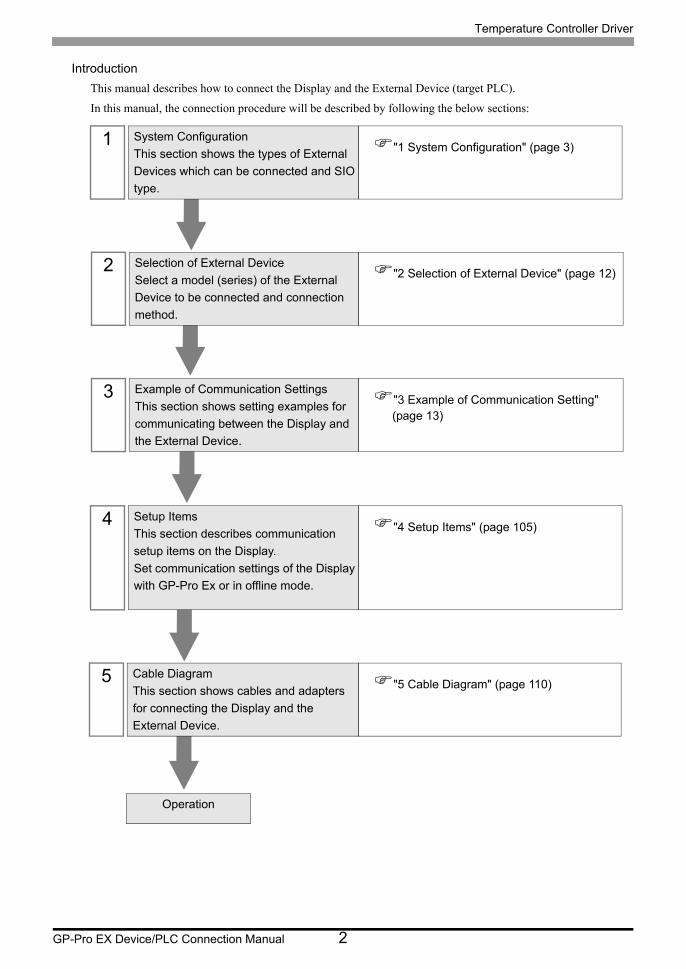
Introduction
This manual describes how to connect the Display and the External Device (target PLC).
In this manual, the connection procedure will be described by following the below sections:
1 System Configuration
This section shows the types of External
Devices which can be connected and SIO
type.
"1 System Configuration" (page 3)
2 Selection of External Device
Select a model (series) of the External
Device to be connected and connection
method.
"2 Selection of External Device" (page 12)
3 Example of Communication Settings
This section shows setting examples for
communicating between the Display and
the External Device.
"3 Example of Communication Setting" (page 13)
4 Setup Items
This section describes communication
setup items on the Display.
Set communication settings of the Display
with GP-Pro Ex or in offline mode.
"4 Setup Items" (page 105)
5 Cable Diagram
This section shows cables and adapters
for connecting the Display and the
External Device.
"5 Cable Diagram" (page 110)
Operation
Temperature Controller Driver
GP-Pro EX Device/PLC Connection Manual 3
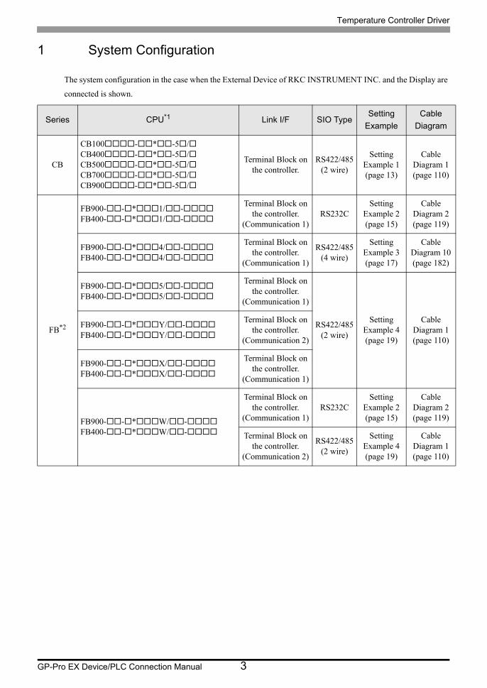
1 System Configuration
The system configuration in the case when the External Device of RKC INSTRUMENT INC. and the Display are
connected is shown.
Series CPU*1 Link I/F SIO TypeSetting
Example
Cable
Diagram
CB
CB100-*-5/CB400-*-5/CB500-*-5/CB700-*-5/CB900-*-5/
Terminal Block on the controller.
RS422/485(2 wire)
Setting Example 1 (page 13)
Cable Diagram 1 (page 110)
FB*2
FB900--*1/-FB400--*1/-
Terminal Block on the controller.
(Communication 1)RS232C
Setting Example 2 (page 15)
Cable Diagram 2 (page 119)
FB900--*4/-FB400--*4/-
Terminal Block on the controller.
(Communication 1)
RS422/485(4 wire)
Setting Example 3 (page 17)
Cable Diagram 10 (page 182)
FB900--*5/-FB400--*5/-
Terminal Block on the controller.
(Communication 1)
RS422/485(2 wire)
Setting Example 4 (page 19)
Cable Diagram 1 (page 110)
FB900--*Y/-FB400--*Y/-
Terminal Block on the controller.
(Communication 2)
FB900--*X/-FB400--*X/-
Terminal Block on the controller.
(Communication 1)
FB900--*W/-FB400--*W/-
Terminal Block on the controller.
(Communication 1)RS232C
Setting Example 2 (page 15)
Cable Diagram 2 (page 119)
Terminal Block on the controller.
(Communication 2)
RS422/485(2 wire)
Setting Example 4 (page 19)
Cable Diagram 1 (page 110)
Temperature Controller Driver
GP-Pro EX Device/PLC Connection Manual 4
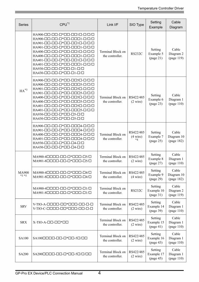
HA*3
HA900---*-1-//HA900---*-1-//HA901---*-1-//HA901---*-1-//HA400---*-1-//HA400---*-1-//HA401---*-1-//HA401---*-1-//HA930---*-1-/HA430---*-1-/
Terminal Block on the controller.
RS232CSetting
Example 5 (page 21)
Cable Diagram 2 (page 119)
HA900---*-5-//HA900---*-5-//HA901---*-5-//HA901---*-5-//HA400---*-5-//HA400---*-5-//HA401---*-5-//HA401---*-5-//HA930---*-5-/HA430---*-5-/
Terminal Block on the controller.
RS422/485(2 wire)
Setting Example 6 (page 23)
Cable Diagram 1 (page 110)
HA900---*-4-//HA901---*-4-//HA400---*-4-//HA401---*-4-//HA930---*-4-/HA430---*-4-/
Terminal Block on the controller.
RS422/485(4 wire)
*4
Setting Example 7 (page 25)
Cable Diagram 10 (page 182)
MA900*3 *5
MA900-4--*-5/MA901-8--*-5/
Terminal Block on the controller.
RS422/485(2 wire)
Setting Example 8 (page 27)
Cable Diagram 1 (page 110)
MA900-4--*-4/MA901-8--*-4/
Terminal Block on the controller.
RS422/485(4 wire)
Setting Example 9 (page 29)
Cable Diagram 10 (page 182)
MA900-4--*-1/MA901-8--*-1/
Terminal Block on the controller.
RS232CSetting
Example 10 (page 31)
Cable Diagram 2 (page 119)
SRVV-TIO-A--*---V-TIO-C--*---
Terminal Block on the controller.
RS422/485(2 wire)
Setting Example 14 (page 39)
Cable Diagram 1 (page 110)
SRX X-TIO-A--*Terminal Block on
the controller.RS422/485
(2 wire)
Setting Example 15 (page 41)
Cable Diagram 1 (page 110)
SA100 SA100--*-5/Terminal Block on
the controller.RS422/485
(2 wire)
Setting Example 16 (page 43)
Cable Diagram 1 (page 110)
SA200 SA200--*-5//Terminal Block on
the controller.RS422/485
(2 wire)
Setting Example 17 (page 45)
Cable Diagram 1 (page 110)
Series CPU*1 Link I/F SIO TypeSetting
Example
Cable
Diagram
Temperature Controller Driver
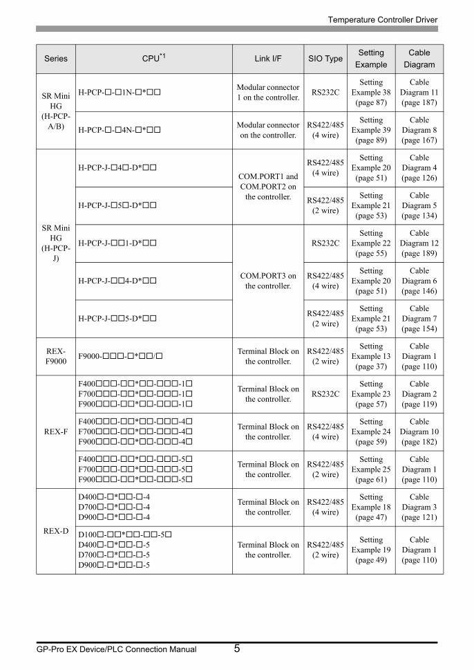
GP-Pro EX Device/PLC Connection Manual 5
SR Mini HG
(H-PCP-A/B)
H-PCP--1N-*Modular connector 1 on the controller.
RS232CSetting
Example 38 (page 87)
Cable Diagram 11 (page 187)
H-PCP--4N-*Modular connector on the controller.
RS422/485(4 wire)
Setting Example 39 (page 89)
Cable Diagram 8 (page 167)
SR Mini HG
(H-PCP-J)
H-PCP-J-4-D*COM.PORT1 and COM.PORT2 on
the controller.
RS422/485(4 wire)
Setting Example 20 (page 51)
Cable Diagram 4 (page 126)
H-PCP-J-5-D*RS422/485
(2 wire)
Setting Example 21 (page 53)
Cable Diagram 5 (page 134)
H-PCP-J-1-D*
COM.PORT3 on the controller.
RS232CSetting
Example 22 (page 55)
Cable Diagram 12 (page 189)
H-PCP-J-4-D*RS422/485
(4 wire)
Setting Example 20 (page 51)
Cable Diagram 6 (page 146)
H-PCP-J-5-D*RS422/485
(2 wire)
Setting Example 21 (page 53)
Cable Diagram 7 (page 154)
REX-F9000
F9000--*/Terminal Block on
the controller.RS422/485
(2 wire)
Setting Example 13 (page 37)
Cable Diagram 1 (page 110)
REX-F
F400-*--1F700-*--1F900-*--1
Terminal Block on the controller.
RS232CSetting
Example 23 (page 57)
Cable Diagram 2 (page 119)
F400-*--4F700-*--4F900-*--4
Terminal Block on the controller.
RS422/485(4 wire)
Setting Example 24 (page 59)
Cable Diagram 10 (page 182)
F400-*--5F700-*--5F900-*--5
Terminal Block on the controller.
RS422/485(2 wire)
Setting Example 25 (page 61)
Cable Diagram 1 (page 110)
REX-D
D400-*--4D700-*--4D900-*--4
Terminal Block on the controller.
RS422/485(4 wire)
Setting Example 18 (page 47)
Cable Diagram 3 (page 121)
D100-*--5D400-*--5D700-*--5D900-*--5
Terminal Block on the controller.
RS422/485(2 wire)
Setting Example 19 (page 49)
Cable Diagram 1 (page 110)
Series CPU*1 Link I/F SIO TypeSetting
Example
Cable
Diagram

Temperature Controller Driver
GP-Pro EX Device/PLC Connection Manual 6
REX-G9
G9-*--1/ATerminal Block on
the controller.RS232C
Setting Example 26 (page 63)
Cable Diagram 2 (page 119)
G9-*--4/ATerminal Block on
the controller.RS422/485
(4 wire)
Setting Example 27 (page 65)
Cable Diagram 10 (page 182)
G9-*--2/ATerminal Block on
the controller.RS422/485
(2 wire)
Setting Example 28 (page 67)
Cable Diagram 9 (page 172)
REX-P300
P300--*D--1Terminal Block on
the controller.RS232C
Setting Example 29 (page 69)
Cable Diagram 2 (page 119)
P300--*D--4Terminal Block on
the controller.RS422/485
(4 wire)
Setting Example 30 (page 71)
Cable Diagram 3 (page 121)
P300--*D--5Terminal Block on
the controller.RS422/485
(2 wire)
Setting Example 31 (page 73)
Cable Diagram 1 (page 110)
REX-P250
P250-*--1Terminal Block on
the controller.RS232C
Setting Example 32 (page 75)
Cable Diagram 2 (page 119)
P250-*--2Terminal Block on
the controller.RS422/485
(2 wire)
Setting Example 33 (page 77)
Cable Diagram 9 (page 172)
REX-AD
AD410-*---4/CETerminal Block on
the controller.RS422/485
(4 wire)
Setting Example 34 (page 79)
Cable Diagram 3 (page 121)
AD410-*---5/CETerminal Block on
the controller.RS422/485
(2 wire)
Setting Example 35 (page 81)
Cable Diagram 1 (page 110)
REX-PG
PG410*-4Terminal Block on
the controller.RS422/485
(4 wire)
Setting Example 36 (page 83)
Cable Diagram 3 (page 121)
PG410*-5Terminal Block on
the controller.RS422/485
(2 wire)
Setting Example 37 (page 85)
Cable Diagram 1 (page 110)
AE500 AE500-*-5/Terminal Block on
the controller.RS422/485
(2 wire)
Setting Example 11 (page 33)
Cable Diagram 1 (page 110)
LE100 LE100-*5-Terminal Block on
the controller.RS422/485
(2 wire)
Setting Example 12 (page 35)
Cable Diagram 1 (page 110)
Series CPU*1 Link I/F SIO TypeSetting
Example
Cable
Diagram
Temperature Controller Driver
GP-Pro EX Device/PLC Connection Manual 7
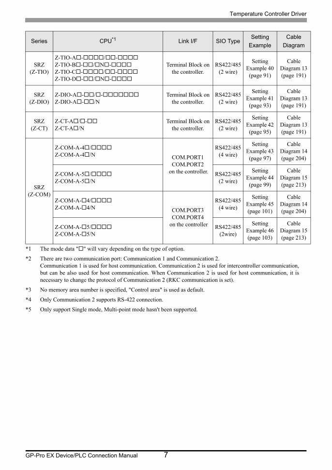
SRZ(Z-TIO)
Z-TIO-A-/-Z-TIO-B-/N-Z-TIO-C-/-Z-TIO-D-/N-
Terminal Block on the controller.
RS422/485(2 wire)
Setting Example 40 (page 91)
Cable Diagram 13 (page 191)
SRZ(Z-DIO)
Z-DIO-A-/-Z-DIO-A-/N
Terminal Block on the controller.
RS422/485(2 wire)
Setting Example 41 (page 93)
Cable Diagram 13 (page 191)
SRZ(Z-CT)
Z-CT-A/-Z-CT-A/N
Terminal Block on the controller.
RS422/485(2 wire)
Setting Example 42 (page 95)
Cable Diagram 13 (page 191)
SRZ(Z-COM)
Z-COM-A-4/Z-COM-A-4/N COM.PORT1
COM.PORT2 on the controller.
RS422/485(4 wire)
Setting Example 43 (page 97)
Cable Diagram 14 (page 204)
Z-COM-A-5/Z-COM-A-5/N
RS422/485(2 wire)
Setting Example 44 (page 99)
Cable Diagram 15 (page 213)
Z-COM-A-4/Z-COM-A-4/N COM.PORT3
COM.PORT4 on the controller
RS422/485(4 wire)
Setting Example 45 (page 101)
Cable Diagram 14 (page 204)
Z-COM-A-5/Z-COM-A-5/N
RS422/485(2wire)
Setting Example 46 (page 103)
Cable Diagram 15 (page 213)
*1 The mode data "" will vary depending on the type of option.
*2 There are two communication port: Communication 1 and Communication 2. Communication 1 is used for host communication. Communication 2 is used for intercontroller communication, but can be also used for host communication. When Communication 2 is used for host communication, it is necessary to change the protocol of Communication 2 (RKC communication is set).
*3 No memory area number is specified, "Control area" is used as default.
*4 Only Communication 2 supports RS-422 connection.
*5 Only support Single mode, Multi-point mode hasn't been supported.
Series CPU*1 Link I/F SIO TypeSetting
Example
Cable
Diagram
Temperature Controller Driver
GP-Pro EX Device/PLC Connection Manual 8
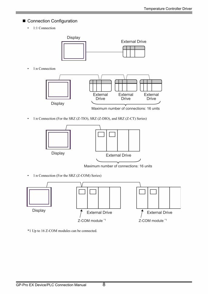
Connection Configuration
• 1:1 Connection
• 1:n Connection
• 1:n Connection (For the SRZ (Z-TIO), SRZ (Z-DIO), and SRZ (Z-CT) Series)
• 1:n Connection (For the SRZ (Z-COM) Series)
*1 Up to 16 Z-COM modules can be connected.
DisplayExternal Drive
Display
ExternalDrive
ExternalDrive
ExternalDrive
Maximum number of connections: 16 units
DisplayExternal Drive
Maximum number of connections: 16 units
DisplayExternal Drive
Z-COM module *1
External Drive
Z-COM module *1
Temperature Controller Driver
GP-Pro EX Device/PLC Connection Manual 9
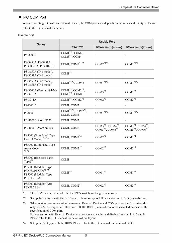
IPC COM Port
When connecting IPC with an External Device, the COM port used depends on the series and SIO type. Please
refer to the IPC manual for details.
Usable port
SeriesUsable Port
RS-232C RS-422/485(4 wire) RS-422/485(2 wire)
PS-2000BCOM1*1 , COM2, COM3*1, COM4
*1 The RI/5V can be switched. Use the IPC’s switch to change if necessary.
- -
PS-3450A, PS-3451A,PS3000-BA, PS3001-BD
COM1, COM2*1*2 COM2*1*2 COM2*1*2
PS-3650A (T41 model),PS-3651A (T41 model)
COM1*1 - -
PS-3650A (T42 model),PS-3651A (T42 model)
COM1*1*2, COM2 COM1*1*2 COM1*1*2
PS-3700A (Pentium®4-M)PS-3710A
COM1*1, COM2*1, COM3*2 , COM4
*2 Set up the SIO type with the DIP Switch. Please set up as follows according to SIO type to be used.
COM3*2 COM3*2
PS-3711A COM1*1, COM2*2 COM2*2 COM2*2
PS4000*3
*3 When making communication between an External Device and COM port on the Expansion slot, only RS-232C is supported. However, ER (DTR/CTS) control cannot be executed because of the specification of COM port.For connection with External Device, use user-created cables and disable Pin Nos. 1, 4, 6 and 9.Please refer to the IPC manual for details of pin layout.
COM1, COM2 - -
PL3000COM1*1*2, COM2*1, COM3, COM4
COM1*1*2 COM1*1*2
PE-4000B Atom N270 COM1, COM2 - -
PE-4000B Atom N2600 COM1, COM2COM3*4 , COM4*4, COM5*4, COM6*4
*4 Set up the SIO type with the BIOS. Please refer to the IPC manual for details of BIOS.
COM3*4, COM4*4, COM5*4, COM6*4
PS5000 (Slim Panel Type Core i3 Model) *5 *6 COM1, COM2*4 COM2*4 COM2*4
PS5000 (Slim Panel Type Atom Model) *5 *6
COM1, COM2*7 COM2*7 COM2*7
PS5000 (Enclosed Panel Type)*8 COM1 - -
PS5000 (Modular Type PFXPU/PFXPP)*5 *6
PS5000 (Modular Type PFXPL2B5-6)
COM1*7 COM1*7 COM1*7
PS5000 (Modular Type PFXPL2B1-4)
COM1, COM2*7 COM2*7 COM2*7
Temperature Controller Driver
GP-Pro EX Device/PLC Connection Manual 10
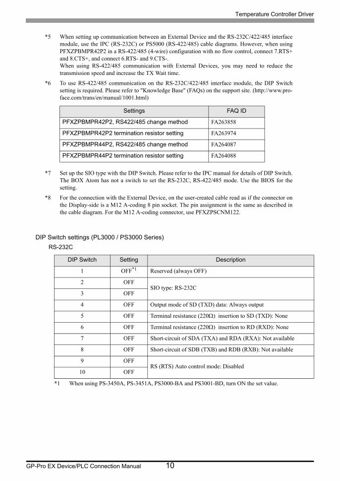
DIP Switch settings (PL3000 / PS3000 Series)
RS-232C
*5 When setting up communication between an External Device and the RS-232C/422/485 interface module, use the IPC (RS-232C) or PS5000 (RS-422/485) cable diagrams. However, when using PFXZPBMPR42P2 in a RS-422/485 (4-wire) configuration with no flow control, connect 7.RTS+ and 8.CTS+, and connect 6.RTS- and 9.CTS-.When using RS-422/485 communication with External Devices, you may need to reduce the transmission speed and increase the TX Wait time.
*6 To use RS-422/485 communication on the RS-232C/422/485 interface module, the DIP Switch setting is required. Please refer to "Knowledge Base" (FAQs) on the support site. (http://www.pro- face.com/trans/en/manual/1001.html)
*7 Set up the SIO type with the DIP Switch. Please refer to the IPC manual for details of DIP Switch.The BOX Atom has not a switch to set the RS-232C, RS-422/485 mode. Use the BIOS for the setting.
*8 For the connection with the External Device, on the user-created cable read as if the connector on the Display-side is a M12 A-coding 8 pin socket. The pin assignment is the same as described in the cable diagram. For the M12 A-coding connector, use PFXZPSCNM122.
DIP Switch Setting Description
1 OFF*1
*1 When using PS-3450A, PS-3451A, PS3000-BA and PS3001-BD, turn ON the set value.
Reserved (always OFF)
2 OFFSIO type: RS-232C
3 OFF
4 OFF Output mode of SD (TXD) data: Always output
5 OFF Terminal resistance (220) insertion to SD (TXD): None
6 OFF Terminal resistance (220) insertion to RD (RXD): None
7 OFF Short-circuit of SDA (TXA) and RDA (RXA): Not available
8 OFF Short-circuit of SDB (TXB) and RDB (RXB): Not available
9 OFFRS (RTS) Auto control mode: Disabled
10 OFF
Settings FAQ ID
PFXZPBMPR42P2, RS422/485 change method FA263858
PFXZPBMPR42P2 termination resistor setting FA263974
PFXZPBMPR44P2, RS422/485 change method FA264087
PFXZPBMPR44P2 termination resistor setting FA264088
Temperature Controller Driver
GP-Pro EX Device/PLC Connection Manual 11
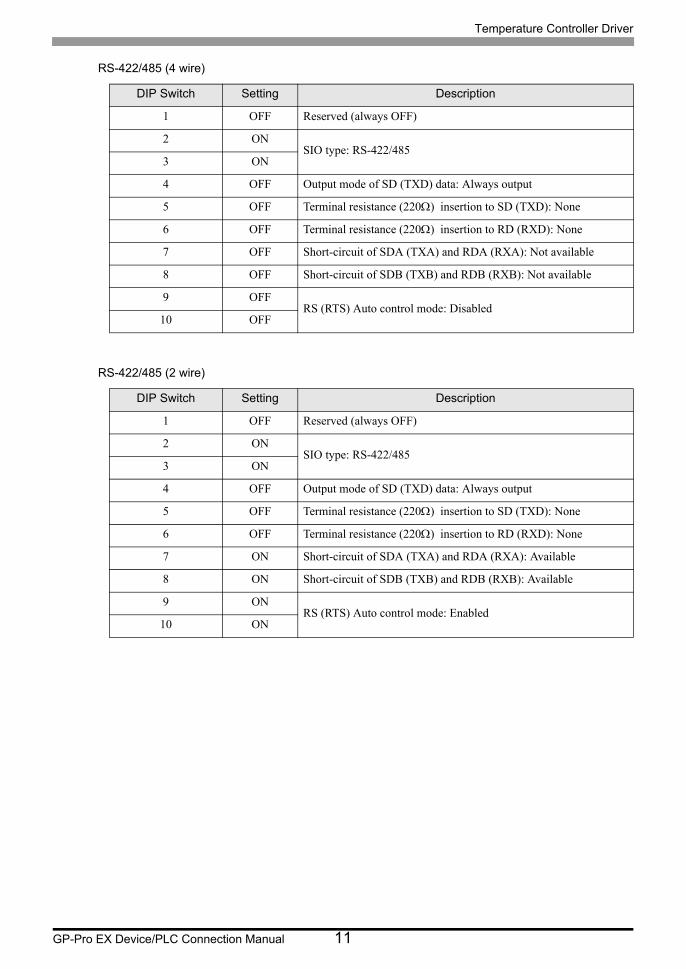
RS-422/485 (4 wire)
RS-422/485 (2 wire)
DIP Switch Setting Description
1 OFF Reserved (always OFF)
2 ONSIO type: RS-422/485
3 ON
4 OFF Output mode of SD (TXD) data: Always output
5 OFF Terminal resistance (220) insertion to SD (TXD): None
6 OFF Terminal resistance (220) insertion to RD (RXD): None
7 OFF Short-circuit of SDA (TXA) and RDA (RXA): Not available
8 OFF Short-circuit of SDB (TXB) and RDB (RXB): Not available
9 OFFRS (RTS) Auto control mode: Disabled
10 OFF
DIP Switch Setting Description
1 OFF Reserved (always OFF)
2 ONSIO type: RS-422/485
3 ON
4 OFF Output mode of SD (TXD) data: Always output
5 OFF Terminal resistance (220) insertion to SD (TXD): None
6 OFF Terminal resistance (220) insertion to RD (RXD): None
7 ON Short-circuit of SDA (TXA) and RDA (RXA): Available
8 ON Short-circuit of SDB (TXB) and RDB (RXB): Available
9 ONRS (RTS) Auto control mode: Enabled
10 ON
Temperature Controller Driver
GP-Pro EX Device/PLC Connection Manual 12
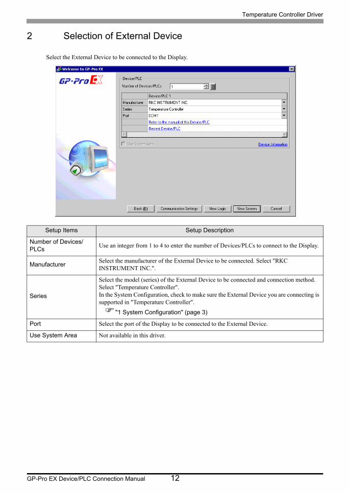
2 Selection of External Device
Select the External Device to be connected to the Display.
Setup Items Setup Description
Number of Devices/PLCs
Use an integer from 1 to 4 to enter the number of Devices/PLCs to connect to the Display.
ManufacturerSelect the manufacturer of the External Device to be connected. Select "RKC INSTRUMENT INC.".
Series
Select the model (series) of the External Device to be connected and connection method. Select "Temperature Controller".In the System Configuration, check to make sure the External Device you are connecting is supported in "Temperature Controller".
"1 System Configuration" (page 3)
Port Select the port of the Display to be connected to the External Device.
Use System Area Not available in this driver.
Temperature Controller Driver
GP-Pro EX Device/PLC Connection Manual 13
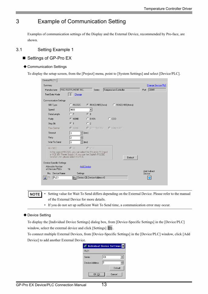
3 Example of Communication Setting
Examples of communication settings of the Display and the External Device, recommended by Pro-face, are
shown.
3.1 Setting Example 1
Settings of GP-Pro EX
Communication Settings
To display the setup screen, from the [Project] menu, point to [System Settings] and select [Device/PLC].
Device Setting
To display the [Individual Device Settings] dialog box, from [Device-Specific Settings] in the [Device/PLC]
window, select the external device and click [Settings] .
To connect multiple External Devices, from [Device-Specific Settings] in the [Device/PLC] window, click [Add
Device] to add another External Device.
• Setting value for Wait To Send differs depending on the External Device. Please refer to the manual
of the External Device for more details.
• If you do not set up sufficient Wait To Send time, a communication error may occur.

Temperature Controller Driver
GP-Pro EX Device/PLC Connection Manual 14
Settings of External Device
Communication setting of the external device is set with the SET, Shift, UP and Down keys located on the front
face of the temperature controller.
Please refer to the temperature controller manual for details.
Procedure
1. While depressing the SET key, press the Shift key to change from PV/SV display mode to communication
setting mode.
2. Press the SET key and select parameters.
3. Press UP/Down keys to change the setting.
4. While depressing the SET key, press Shift key to change from communication setting mode to PV/SV display
mode.
5. Turn off power to the temperature controller and turn on again to set the setting.
Setting value
Add 0
bPS 2
bIT 0
• Parameters to be set differ per temperature controller. Please refer to the temperature controller
manual for details.

Temperature Controller Driver
GP-Pro EX Device/PLC Connection Manual 15
3.2 Setting Example 2
Settings of GP-Pro EX
Communication Settings
To display the setup screen, from the [Project] menu, point to [System Settings] and select [Device/PLC].
Device Setting
To display the [Individual Device Settings] dialog box, from [Device-Specific Settings] in the [Device/PLC]
window, select the external device and click [Settings] .
To connect multiple External Devices, from [Device-Specific Settings] in the [Device/PLC] window, click [Add
Device] to add another External Device.
• Setting value for Wait To Send differs depending on the External Device. Please refer to the manual
of the External Device for more details.
• If you do not set up sufficient Wait To Send time, a communication error may occur.
Temperature Controller Driver
GP-Pro EX Device/PLC Connection Manual 16
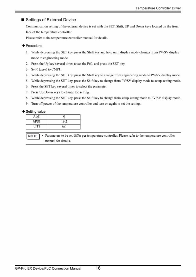
Settings of External Device
Communication setting of the external device is set with the SET, Shift, UP and Down keys located on the front
face of the temperature controller.
Please refer to the temperature controller manual for details.
Procedure
1. While depressing the SET key, press the Shift key and hold until display mode changes from PV/SV display
mode to engineering mode.
2. Press the Up key several times to set the F60, and press the SET key.
3. Set 0 (zero) to CMP1.
4. While depressing the SET key, press the Shift key to change from engineering mode to PV/SV display mode.
5. While depressing the SET key, press the Shift key to change from PV/SV display mode to setup setting mode.
6. Press the SET key several times to select the parameter.
7. Press Up/Down keys to change the setting.
8. While depressing the SET key, press the Shift key to change from setup setting mode to PV/SV display mode.
9. Turn off power of the temperature controller and turn on again to set the setting.
Setting value
Add1 0
bPS1 19.2
bIT1 8n1
• Parameters to be set differ per temperature controller. Please refer to the temperature controller
manual for details.

Temperature Controller Driver
GP-Pro EX Device/PLC Connection Manual 17
3.3 Setting Example 3
Settings of GP-Pro EX
Communication Settings
To display the setup screen, from the [Project] menu, point to [System Settings] and select [Device/PLC].
Device Setting
To display the [Individual Device Settings] dialog box, from [Device-Specific Settings] in the [Device/PLC]
window, select the external device and click [Settings] .
To connect multiple External Devices, from [Device-Specific Settings] in the [Device/PLC] window, click [Add
Device] to add another External Device.
• Setting value for Wait To Send differs depending on the External Device. Please refer to the manual
of the External Device for more details.
• If you do not set up sufficient Wait To Send time, a communication error may occur.

Temperature Controller Driver
GP-Pro EX Device/PLC Connection Manual 18
Settings of External Device
Communication setting of the external device is set with the SET, Shift, UP and Down keys located on the front
face of the temperature controller.
Please refer to the temperature controller manual for details.
Procedure
1. While depressing the SET key, press the Shift key and hold until display mode changes from PV/SV display
mode to engineering mode.
2. Press the Up key several times to set the F60, and press the SET key.
3. Set 0 (zero) to CMP1.
4. While depressing the SET key, press the Shift key to change from engineering mode to PV/SV display mode.
5. While depressing the SET key, press the Shift key to change from PV/SV display mode to setup setting mode.
6. Press the SET key several times to select the parameter.
7. Press Up/Down keys to change the setting.
8. While depressing the SET key, press the Shift key to change from setup setting mode to PV/SV display mode.
9. Turn off power of the temperature controller and turn on again to set the setting.
Setting value
Add1 0
bPS1 19.2
bIT1 8n1
• Parameters to be set differ per temperature controller. Please refer to the temperature controller
manual for details.

Temperature Controller Driver
GP-Pro EX Device/PLC Connection Manual 19
3.4 Setting Example 4
Settings of GP-Pro EX
Communication Settings
To display the setup screen, from the [Project] menu, point to [System Settings] and select [Device/PLC].
Device Setting
To display the [Individual Device Settings] dialog box, from [Device-Specific Settings] in the [Device/PLC]
window, select the external device and click [Settings] .
To connect multiple External Devices, from [Device-Specific Settings] in the [Device/PLC] window, click [Add
Device] to add another External Device.
• Setting value for Wait To Send differs depending on the External Device. Please refer to the manual
of the External Device for more details.
• If you do not set up sufficient Wait To Send time, a communication error may occur.
Temperature Controller Driver
GP-Pro EX Device/PLC Connection Manual 20
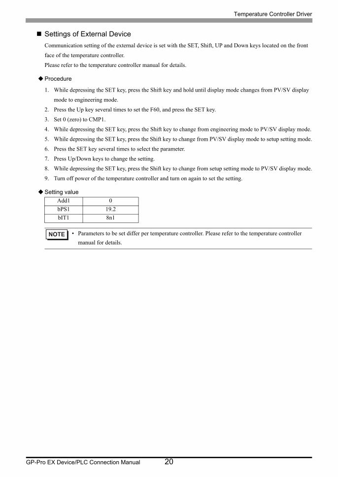
Settings of External Device
Communication setting of the external device is set with the SET, Shift, UP and Down keys located on the front
face of the temperature controller.
Please refer to the temperature controller manual for details.
Procedure
1. While depressing the SET key, press the Shift key and hold until display mode changes from PV/SV display
mode to engineering mode.
2. Press the Up key several times to set the F60, and press the SET key.
3. Set 0 (zero) to CMP1.
4. While depressing the SET key, press the Shift key to change from engineering mode to PV/SV display mode.
5. While depressing the SET key, press the Shift key to change from PV/SV display mode to setup setting mode.
6. Press the SET key several times to select the parameter.
7. Press Up/Down keys to change the setting.
8. While depressing the SET key, press the Shift key to change from setup setting mode to PV/SV display mode.
9. Turn off power of the temperature controller and turn on again to set the setting.
Setting value
Add1 0
bPS1 19.2
bIT1 8n1
• Parameters to be set differ per temperature controller. Please refer to the temperature controller
manual for details.
Temperature Controller Driver
GP-Pro EX Device/PLC Connection Manual 21
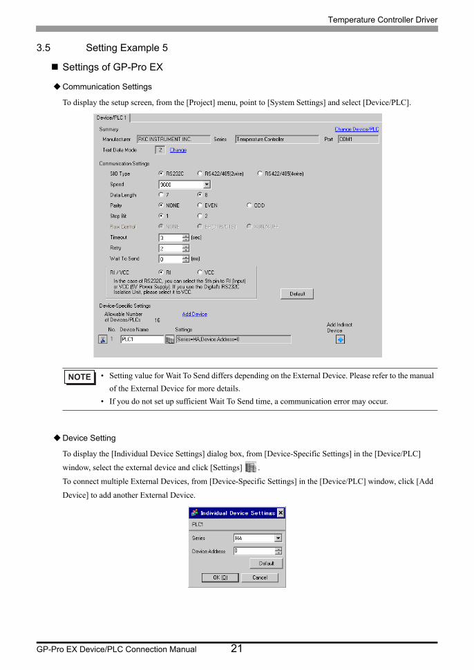
3.5 Setting Example 5
Settings of GP-Pro EX
Communication Settings
To display the setup screen, from the [Project] menu, point to [System Settings] and select [Device/PLC].
Device Setting
To display the [Individual Device Settings] dialog box, from [Device-Specific Settings] in the [Device/PLC]
window, select the external device and click [Settings] .
To connect multiple External Devices, from [Device-Specific Settings] in the [Device/PLC] window, click [Add
Device] to add another External Device.
• Setting value for Wait To Send differs depending on the External Device. Please refer to the manual
of the External Device for more details.
• If you do not set up sufficient Wait To Send time, a communication error may occur.

Temperature Controller Driver
GP-Pro EX Device/PLC Connection Manual 22
Settings of External Device
Communication setting of the external device is set with the SET, Shift, UP and Down keys located on the front
face of the temperature controller.
Please refer to the temperature controller manual for details.
Procedure
1. While depressing the SET key, press the Shift key to change from SV setting & monitor mode to setup setting
mode.
2. Press the SET key and select parameters.
3. Press UP/Down keys to change the setting.
4. While depressing the SET key, press Shift key to change from setup setting mode to SV setting & monitor
mode.
5. Turn off power to the temperature controller and turn on again to set the setting.
Setting value
Add1 0
bPS1 9.6
bIT1 8n1
• Parameters to be set differ per temperature controller. Please refer to the temperature controller
manual for details.

Temperature Controller Driver
GP-Pro EX Device/PLC Connection Manual 23
3.6 Setting Example 6
Settings of GP-Pro EX
Communication Settings
To display the setup screen, from the [Project] menu, point to [System Settings] and select [Device/PLC].
Device Setting
To display the [Individual Device Settings] dialog box, from [Device-Specific Settings] in the [Device/PLC]
window, select the external device and click [Settings] .
To connect multiple External Devices, from [Device-Specific Settings] in the [Device/PLC] window, click [Add
Device] to add another External Device.
• Setting value for Wait To Send differs depending on the External Device. Please refer to the manual
of the External Device for more details.
• If you do not set up sufficient Wait To Send time, a communication error may occur.

Temperature Controller Driver
GP-Pro EX Device/PLC Connection Manual 24
Settings of External Device
Communication setting of the external device is set with the SET, Shift, UP and Down keys located on the front
face of the temperature controller.
Please refer to the temperature controller manual for details.
Procedure
1. While depressing the SET key, press the Shift key to change from SV setting & monitor mode to setup setting
mode.
2. Press the SET key and select parameters.
3. Press UP/Down keys to change the setting.
4. While depressing the SET key, press Shift key to change from setup setting mode to SV setting & monitor
mode.
5. Turn off power to the temperature controller and turn on again to set the setting.
Setting value
Add1 0
bPS1 9.6
bIT1 8n1
• Parameters to be set differ per temperature controller. Please refer to the temperature controller
manual for details.

Temperature Controller Driver
GP-Pro EX Device/PLC Connection Manual 25
3.7 Setting Example 7
Settings of GP-Pro EX
Communication Settings
To display the setup screen, from the [Project] menu, point to [System Settings] and select [Device/PLC].
Device Setting
To display the [Individual Device Settings] dialog box, from [Device-Specific Settings] in the [Device/PLC]
window, select the external device and click [Settings] .
To connect multiple External Devices, from [Device-Specific Settings] in the [Device/PLC] window, click [Add
Device] to add another External Device.
• Setting value for Wait To Send differs depending on the External Device. Please refer to the manual
of the External Device for more details.
• If you do not set up sufficient Wait To Send time, a communication error may occur.
Temperature Controller Driver
GP-Pro EX Device/PLC Connection Manual 26
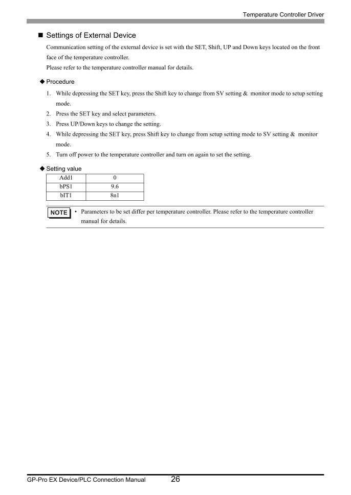
Settings of External Device
Communication setting of the external device is set with the SET, Shift, UP and Down keys located on the front
face of the temperature controller.
Please refer to the temperature controller manual for details.
Procedure
1. While depressing the SET key, press the Shift key to change from SV setting & monitor mode to setup setting
mode.
2. Press the SET key and select parameters.
3. Press UP/Down keys to change the setting.
4. While depressing the SET key, press Shift key to change from setup setting mode to SV setting & monitor
mode.
5. Turn off power to the temperature controller and turn on again to set the setting.
Setting value
Add1 0
bPS1 9.6
bIT1 8n1
• Parameters to be set differ per temperature controller. Please refer to the temperature controller
manual for details.
Temperature Controller Driver
GP-Pro EX Device/PLC Connection Manual 27
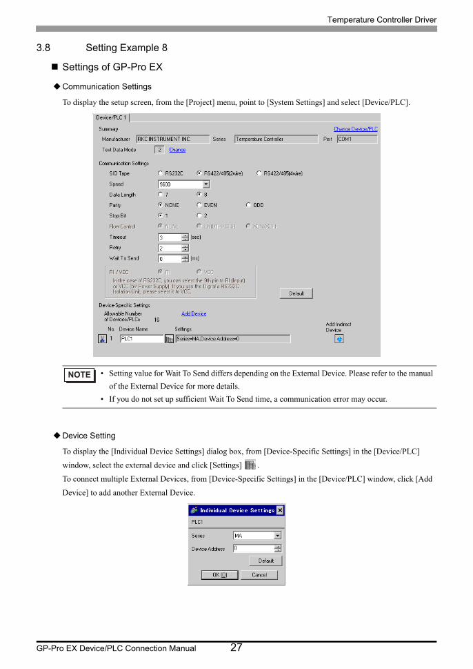
3.8 Setting Example 8
Settings of GP-Pro EX
Communication Settings
To display the setup screen, from the [Project] menu, point to [System Settings] and select [Device/PLC].
Device Setting
To display the [Individual Device Settings] dialog box, from [Device-Specific Settings] in the [Device/PLC]
window, select the external device and click [Settings] .
To connect multiple External Devices, from [Device-Specific Settings] in the [Device/PLC] window, click [Add
Device] to add another External Device.
• Setting value for Wait To Send differs depending on the External Device. Please refer to the manual
of the External Device for more details.
• If you do not set up sufficient Wait To Send time, a communication error may occur.

Temperature Controller Driver
GP-Pro EX Device/PLC Connection Manual 28
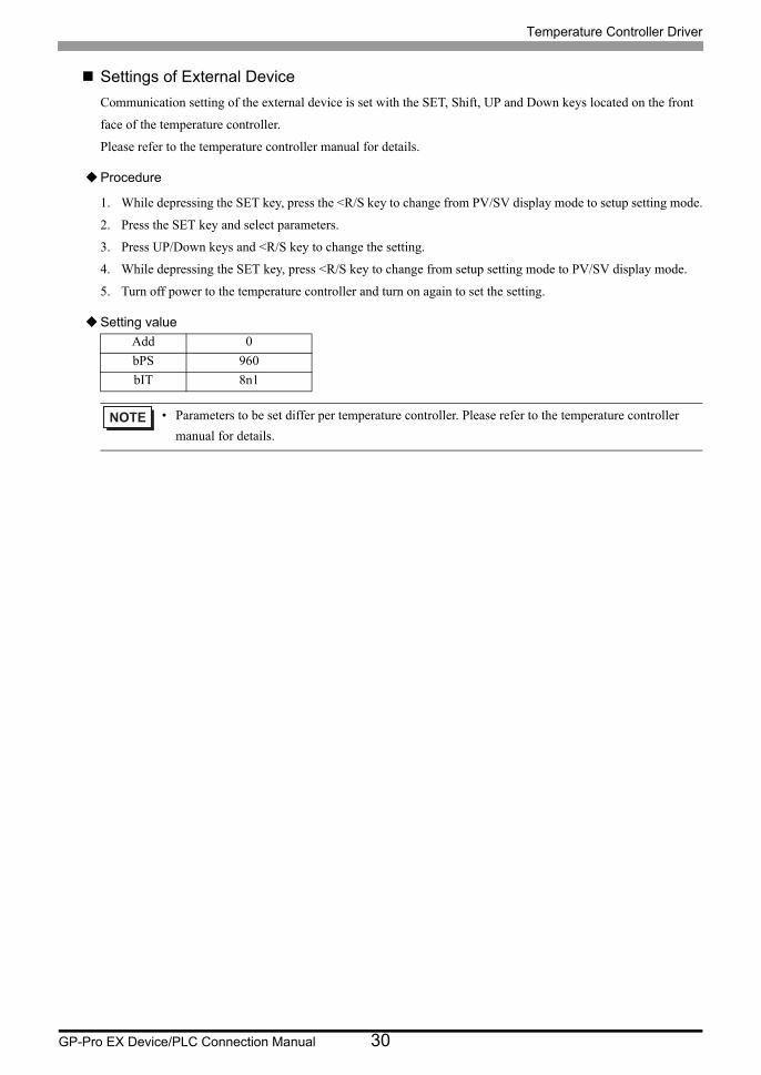
Settings of External Device
Communication setting of the external device is set with the SET, Shift, UP and Down keys located on the front
face of the temperature controller.
Please refer to the temperature controller manual for details.
Procedure
1. While depressing the SET key, press the <R/S key to change from PV/SV display mode to setup setting mode.
2. Press the SET key and select parameters.
3. Press UP/Down keys and <R/S key to change the setting.
4. While depressing the SET key, press <R/S key to change from setup setting mode to PV/SV display mode.
5. Turn off power to the temperature controller and turn on again to set the setting.
Setting value
Add 0
bPS 960
bIT 8n1
• Parameters to be set differ per temperature controller. Please refer to the temperature controller
manual for details.

Temperature Controller Driver
GP-Pro EX Device/PLC Connection Manual 29
3.9 Setting Example 9
Settings of GP-Pro EX
Communication Settings
To display the setup screen, from the [Project] menu, point to [System Settings] and select [Device/PLC].
Device Setting
To display the [Individual Device Settings] dialog box, from [Device-Specific Settings] in the [Device/PLC]
window, select the external device and click [Settings] .
To connect multiple External Devices, from [Device-Specific Settings] in the [Device/PLC] window, click [Add
Device] to add another External Device.
• Setting value for Wait To Send differs depending on the External Device. Please refer to the manual
of the External Device for more details.
• If you do not set up sufficient Wait To Send time, a communication error may occur.
Temperature Controller Driver
GP-Pro EX Device/PLC Connection Manual 30
Settings of External Device
Communication setting of the external device is set with the SET, Shift, UP and Down keys located on the front
face of the temperature controller.
Please refer to the temperature controller manual for details.
Procedure
1. While depressing the SET key, press the <R/S key to change from PV/SV display mode to setup setting mode.
2. Press the SET key and select parameters.
3. Press UP/Down keys and <R/S key to change the setting.
4. While depressing the SET key, press <R/S key to change from setup setting mode to PV/SV display mode.
5. Turn off power to the temperature controller and turn on again to set the setting.
Setting value
Add 0
bPS 960
bIT 8n1
• Parameters to be set differ per temperature controller. Please refer to the temperature controller
manual for details.

Temperature Controller Driver
GP-Pro EX Device/PLC Connection Manual 31
3.10 Setting Example 10
Settings of GP-Pro EX
Communication Settings
To display the setup screen, from the [Project] menu, point to [System Settings] and select [Device/PLC].
Device Setting
To display the [Individual Device Settings] dialog box, from [Device-Specific Settings] in the [Device/PLC]
window, select the external device and click [Settings] .
To connect multiple External Devices, from [Device-Specific Settings] in the [Device/PLC] window, click [Add
Device] to add another External Device.
• Setting value for Wait To Send differs depending on the External Device. Please refer to the manual
of the External Device for more details.
• If you do not set up sufficient Wait To Send time, a communication error may occur.

Temperature Controller Driver
GP-Pro EX Device/PLC Connection Manual 32
Settings of External Device
Communication setting of the external device is set with the SET, Shift, UP and Down keys located on the front
face of the temperature controller.
Please refer to the temperature controller manual for details.
Procedure
1. While depressing the SET key, press the <R/S key to change from PV/SV display mode to setup setting mode.
2. Press the SET key and select parameters.
3. Press UP/Down keys and <R/S key to change the setting.
4. While depressing the SET key, press <R/S key to change from setup setting mode to PV/SV display mode.
5. Turn off power to the temperature controller and turn on again to set the setting.
Setting value
Add 0
bPS 960
bIT 8n1
• Parameters to be set differ per temperature controller. Please refer to the temperature controller
manual for details.
Temperature Controller Driver
GP-Pro EX Device/PLC Connection Manual 33
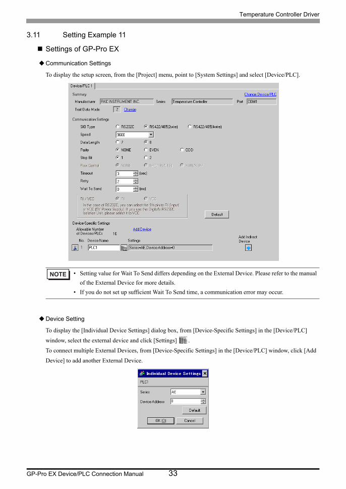
3.11 Setting Example 11
Settings of GP-Pro EX
Communication Settings
To display the setup screen, from the [Project] menu, point to [System Settings] and select [Device/PLC].
Device Setting
To display the [Individual Device Settings] dialog box, from [Device-Specific Settings] in the [Device/PLC]
window, select the external device and click [Settings] .
To connect multiple External Devices, from [Device-Specific Settings] in the [Device/PLC] window, click [Add
Device] to add another External Device.
• Setting value for Wait To Send differs depending on the External Device. Please refer to the manual
of the External Device for more details.
• If you do not set up sufficient Wait To Send time, a communication error may occur.
Temperature Controller Driver
GP-Pro EX Device/PLC Connection Manual 34
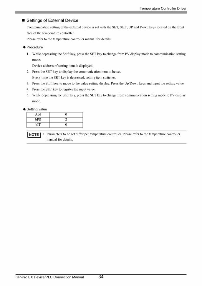
Settings of External Device
Communication setting of the external device is set with the SET, Shift, UP and Down keys located on the front
face of the temperature controller.
Please refer to the temperature controller manual for details.
Procedure
1. While depressing the Shift key, press the SET key to change from PV display mode to communication setting
mode.
Device address of setting item is displayed.
2. Press the SET key to display the communication item to be set.
Every time the SET key is depressed, setting item switches.
3. Press the Shift key to move to the value setting display. Press the Up/Down keys and input the setting value.
4. Press the SET key to register the input value.
5. While depressing the Shift key, press the SET key to change from communication setting mode to PV display
mode.
Setting value
Add 0
bPS 2
bIT 0
• Parameters to be set differ per temperature controller. Please refer to the temperature controller
manual for details.
Temperature Controller Driver
GP-Pro EX Device/PLC Connection Manual 35
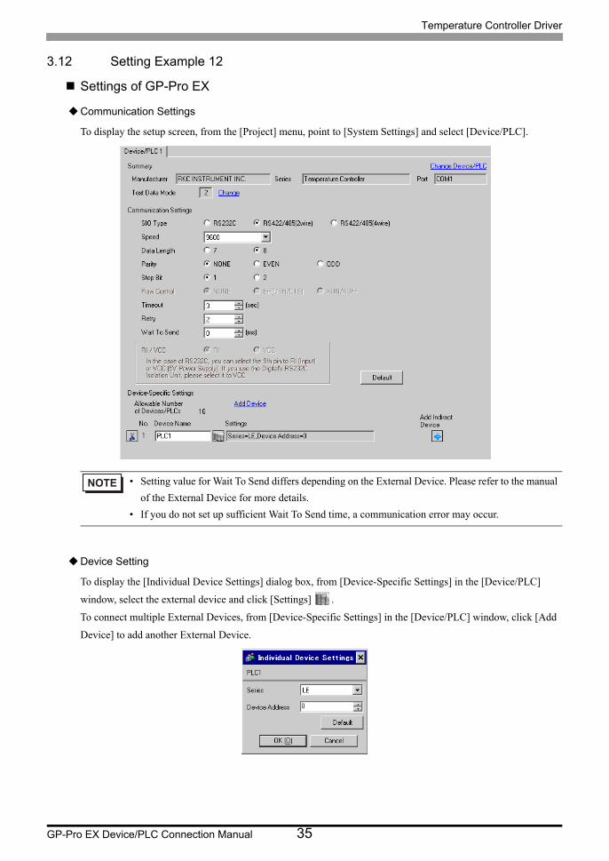
3.12 Setting Example 12
Settings of GP-Pro EX
Communication Settings
To display the setup screen, from the [Project] menu, point to [System Settings] and select [Device/PLC].
Device Setting
To display the [Individual Device Settings] dialog box, from [Device-Specific Settings] in the [Device/PLC]
window, select the external device and click [Settings] .
To connect multiple External Devices, from [Device-Specific Settings] in the [Device/PLC] window, click [Add
Device] to add another External Device.
• Setting value for Wait To Send differs depending on the External Device. Please refer to the manual
of the External Device for more details.
• If you do not set up sufficient Wait To Send time, a communication error may occur.
Temperature Controller Driver
GP-Pro EX Device/PLC Connection Manual 36
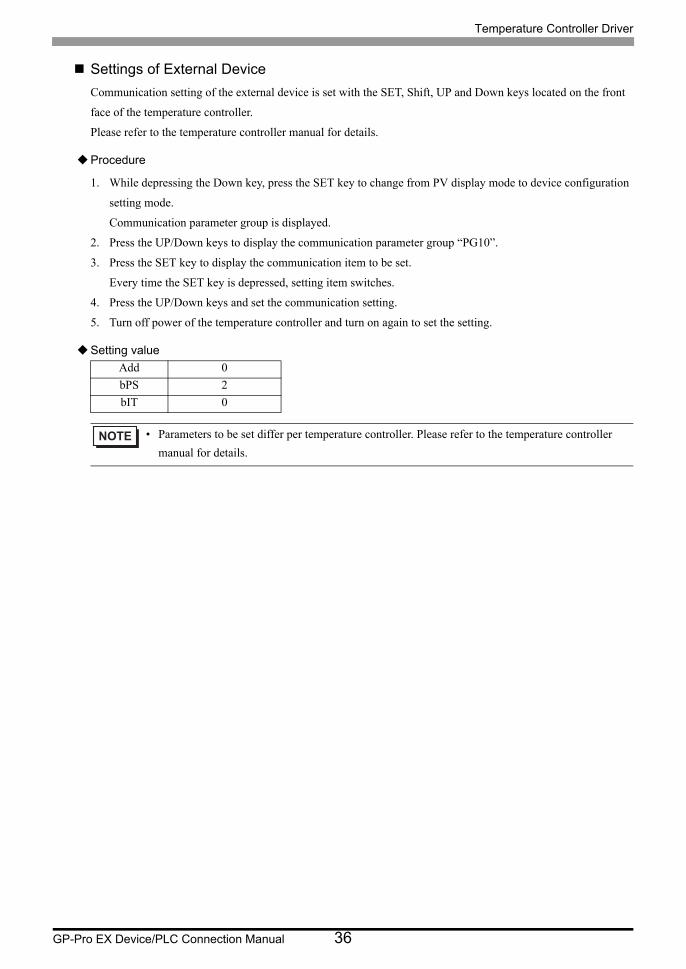
Settings of External Device
Communication setting of the external device is set with the SET, Shift, UP and Down keys located on the front
face of the temperature controller.
Please refer to the temperature controller manual for details.
Procedure
1. While depressing the Down key, press the SET key to change from PV display mode to device configuration
setting mode.
Communication parameter group is displayed.
2. Press the UP/Down keys to display the communication parameter group “PG10”.
3. Press the SET key to display the communication item to be set.
Every time the SET key is depressed, setting item switches.
4. Press the UP/Down keys and set the communication setting.
5. Turn off power of the temperature controller and turn on again to set the setting.
Setting value
Add 0
bPS 2
bIT 0
• Parameters to be set differ per temperature controller. Please refer to the temperature controller
manual for details.

Temperature Controller Driver
GP-Pro EX Device/PLC Connection Manual 37
3.13 Setting Example 13
Settings of GP-Pro EX
Communication Settings
To display the setup screen, from the [Project] menu, point to [System Settings] and select [Device/PLC].
Device Setting
To display the [Individual Device Settings] dialog box, from [Device-Specific Settings] in the [Device/PLC]
window, select the external device and click [Settings] .
To connect multiple External Devices, from [Device-Specific Settings] in the [Device/PLC] window, click [Add
Device] to add another External Device.
• Setting value for Wait To Send differs depending on the External Device. Please refer to the manual
of the External Device for more details.
• If you do not set up sufficient Wait To Send time, a communication error may occur.
Temperature Controller Driver
GP-Pro EX Device/PLC Connection Manual 38
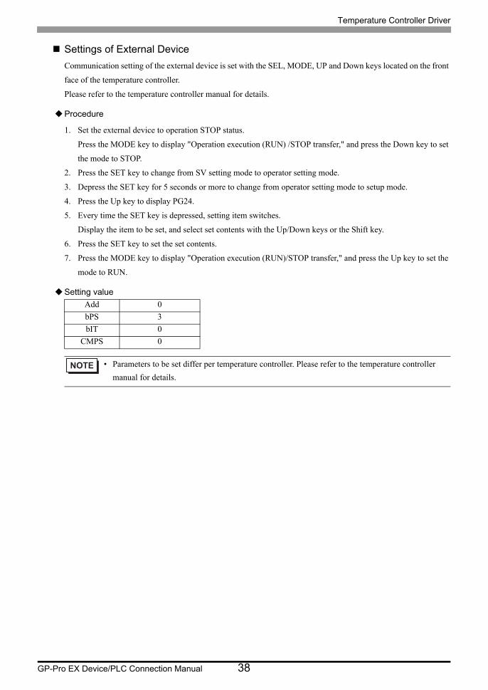
Settings of External Device
Communication setting of the external device is set with the SEL, MODE, UP and Down keys located on the front
face of the temperature controller.
Please refer to the temperature controller manual for details.
Procedure
1. Set the external device to operation STOP status.
Press the MODE key to display "Operation execution (RUN) /STOP transfer," and press the Down key to set
the mode to STOP.
2. Press the SET key to change from SV setting mode to operator setting mode.
3. Depress the SET key for 5 seconds or more to change from operator setting mode to setup mode.
4. Press the Up key to display PG24.
5. Every time the SET key is depressed, setting item switches.
Display the item to be set, and select set contents with the Up/Down keys or the Shift key.
6. Press the SET key to set the set contents.
7. Press the MODE key to display "Operation execution (RUN)/STOP transfer," and press the Up key to set the
mode to RUN.
Setting value
Add 0
bPS 3
bIT 0
CMPS 0
• Parameters to be set differ per temperature controller. Please refer to the temperature controller
manual for details.
Temperature Controller Driver
GP-Pro EX Device/PLC Connection Manual 39
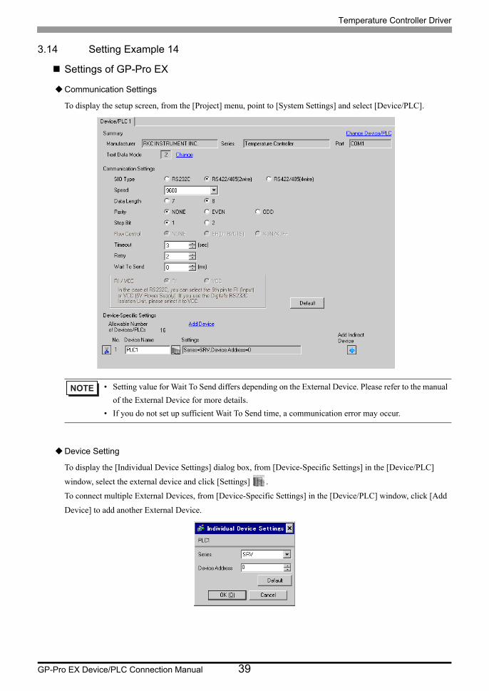
3.14 Setting Example 14
Settings of GP-Pro EX
Communication Settings
To display the setup screen, from the [Project] menu, point to [System Settings] and select [Device/PLC].
Device Setting
To display the [Individual Device Settings] dialog box, from [Device-Specific Settings] in the [Device/PLC]
window, select the external device and click [Settings] .
To connect multiple External Devices, from [Device-Specific Settings] in the [Device/PLC] window, click [Add
Device] to add another External Device.
• Setting value for Wait To Send differs depending on the External Device. Please refer to the manual
of the External Device for more details.
• If you do not set up sufficient Wait To Send time, a communication error may occur.
Temperature Controller Driver
GP-Pro EX Device/PLC Connection Manual 40
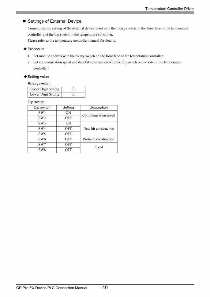
Settings of External Device
Communication setting of the external device is set with the rotary switch on the front face of the temperature
controller and the dip switch in the temperature controller.
Please refer to the temperature controller manual for details.
Procedure
1. Set module address with the rotary switch on the front face of the temperature controller.
2. Set communication speed and data bit construction with the dip switch on the side of the temperature
controller.
Setting value
Rotary switch
Dip switch
Upper Digit Setting 0
Lower Digit Setting 0
Dip switch Setting Description
SW1 ONCommunication speed
SW2 OFF
SW3 ON
Data bit constructionSW4 OFF
SW5 OFF
SW6 OFF Protocol construction
SW7 OFFFixed
SW8 OFF

Temperature Controller Driver
GP-Pro EX Device/PLC Connection Manual 41
3.15 Setting Example 15
Settings of GP-Pro EX
Communication Settings
To display the setup screen, from the [Project] menu, point to [System Settings] and select [Device/PLC].
Device Setting
To display the [Individual Device Settings] dialog box, from [Device-Specific Settings] in the [Device/PLC]
window, select the external device and click [Settings] .
To connect multiple External Devices, from [Device-Specific Settings] in the [Device/PLC] window, click [Add
Device] to add another External Device.
• Setting value for Wait To Send differs depending on the External Device. Please refer to the manual
of the External Device for more details.
• If you do not set up sufficient Wait To Send time, a communication error may occur.

Temperature Controller Driver
GP-Pro EX Device/PLC Connection Manual 42
Settings of External Device
Communication setting of the external device is set with the rotary switch on the front face of the temperature
controller and the dip switch in the temperature controller.
Please refer to the temperature controller manual for details.
Procedure
1. Set module address with the rotary switch on the front face of the temperature controller.
2. Set communication speed and data bit construction with the dip switch on the side of the temperature
controller.
Setting value
Rotary switch
Dip switch
Upper Digit Setting 0
Lower Digit Setting 0
Dip switch Setting Description
SW1 ONCommunication speed
SW2 OFF
SW3 ON
Data bit constructionSW4 OFF
SW5 OFF
SW6 OFF Protocol construction
SW7 OFFFixed
SW8 OFF
Temperature Controller Driver
GP-Pro EX Device/PLC Connection Manual 43
3.16 Setting Example 16
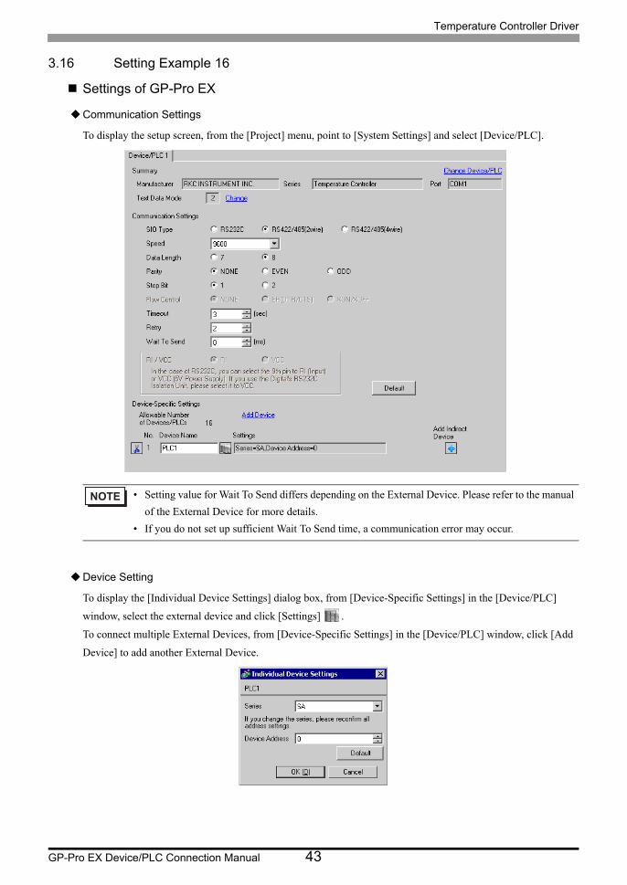
Settings of GP-Pro EX
Communication Settings
To display the setup screen, from the [Project] menu, point to [System Settings] and select [Device/PLC].
Device Setting
To display the [Individual Device Settings] dialog box, from [Device-Specific Settings] in the [Device/PLC]
window, select the external device and click [Settings] .
To connect multiple External Devices, from [Device-Specific Settings] in the [Device/PLC] window, click [Add
Device] to add another External Device.
• Setting value for Wait To Send differs depending on the External Device. Please refer to the manual
of the External Device for more details.
• If you do not set up sufficient Wait To Send time, a communication error may occur.

Temperature Controller Driver
GP-Pro EX Device/PLC Connection Manual 44
Settings of External Device
Communication setting of the external device is set with the SET, Shift, UP and Down keys located on the front
face of the temperature controller.
Please refer to the temperature controller manual for details.
Procedure
1. While depressing the SET key, press the Shift key to change from PV/SV display mode to communication
setting mode.
2. Press the SET key and select parameters.
3. Press UP/Down keys to change the setting.
4. While depressing the SET key, press Shift key to change from communication setting mode to PV/SV display
mode.
5. Turn off power to the temperature controller and turn on again to set the setting.
Setting value
Add 0
bPS 960
bIT 8n1
• Parameters to be set differ per temperature controller. Please refer to the temperature controller
manual for details.
Temperature Controller Driver
GP-Pro EX Device/PLC Connection Manual 45
3.17 Setting Example 17
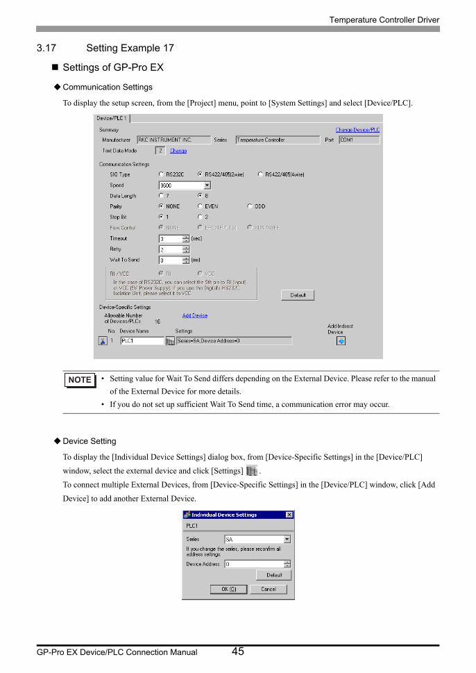
Settings of GP-Pro EX
Communication Settings
To display the setup screen, from the [Project] menu, point to [System Settings] and select [Device/PLC].
Device Setting
To display the [Individual Device Settings] dialog box, from [Device-Specific Settings] in the [Device/PLC]
window, select the external device and click [Settings] .
To connect multiple External Devices, from [Device-Specific Settings] in the [Device/PLC] window, click [Add
Device] to add another External Device.
• Setting value for Wait To Send differs depending on the External Device. Please refer to the manual
of the External Device for more details.
• If you do not set up sufficient Wait To Send time, a communication error may occur.
Temperature Controller Driver
GP-Pro EX Device/PLC Connection Manual 46
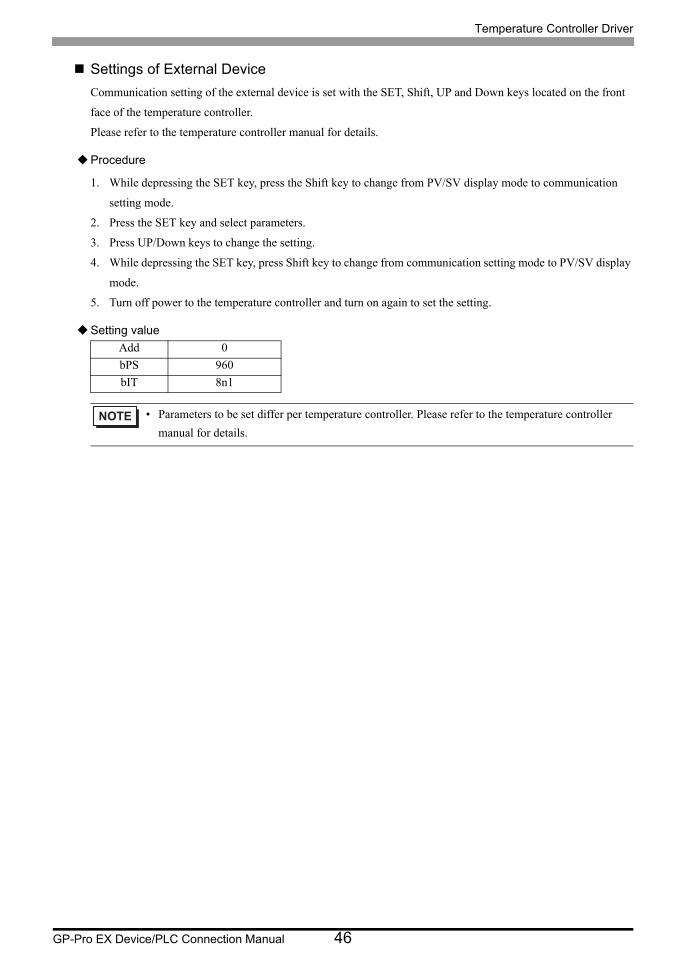
Settings of External Device
Communication setting of the external device is set with the SET, Shift, UP and Down keys located on the front
face of the temperature controller.
Please refer to the temperature controller manual for details.
Procedure
1. While depressing the SET key, press the Shift key to change from PV/SV display mode to communication
setting mode.
2. Press the SET key and select parameters.
3. Press UP/Down keys to change the setting.
4. While depressing the SET key, press Shift key to change from communication setting mode to PV/SV display
mode.
5. Turn off power to the temperature controller and turn on again to set the setting.
Setting value
Add 0
bPS 960
bIT 8n1
• Parameters to be set differ per temperature controller. Please refer to the temperature controller
manual for details.

Temperature Controller Driver
GP-Pro EX Device/PLC Connection Manual 47
3.18 Setting Example 18
Settings of GP-Pro EX
Communication Settings
To display the setup screen, from the [Project] menu, point to [System Settings] and select [Device/PLC].
Device Setting
To display the [Individual Device Settings] dialog box, from [Device-Specific Settings] in the [Device/PLC]
window, select the external device and click [Settings] .
To connect multiple External Devices, from [Device-Specific Settings] in the [Device/PLC] window, click [Add
Device] to add another External Device.
• Setting value for Wait To Send differs depending on the External Device. Please refer to the manual
of the External Device for more details.
• If you do not set up sufficient Wait To Send time, a communication error may occur.
Temperature Controller Driver
GP-Pro EX Device/PLC Connection Manual 48
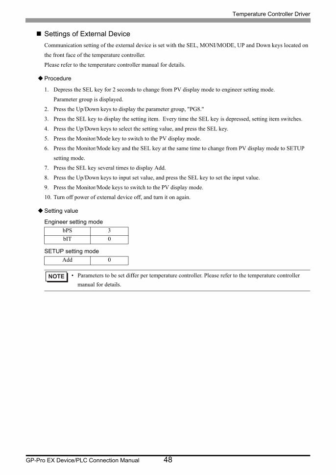
Settings of External Device
Communication setting of the external device is set with the SEL, MONI/MODE, UP and Down keys located on
the front face of the temperature controller.
Please refer to the temperature controller manual for details.
Procedure
1. Depress the SEL key for 2 seconds to change from PV display mode to engineer setting mode.
Parameter group is displayed.
2. Press the Up/Down keys to display the parameter group, "PG8."
3. Press the SEL key to display the setting item. Every time the SEL key is depressed, setting item switches.
4. Press the Up/Down keys to select the setting value, and press the SEL key.
5. Press the Monitor/Mode key to switch to the PV display mode.
6. Press the Monitor/Mode key and the SEL key at the same time to change from PV display mode to SETUP
setting mode.
7. Press the SEL key several times to display Add.
8. Press the Up/Down keys to input set value, and press the SEL key to set the input value.
9. Press the Monitor/Mode keys to switch to the PV display mode.
10. Turn off power of external device off, and turn it on again.
Setting value
Engineer setting mode
SETUP setting mode
bPS 3
bIT 0
Add 0
• Parameters to be set differ per temperature controller. Please refer to the temperature controller
manual for details.
Temperature Controller Driver
GP-Pro EX Device/PLC Connection Manual 49
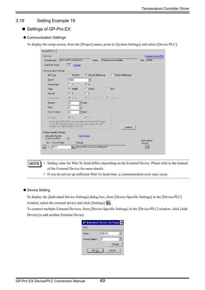
3.19 Setting Example 19
Settings of GP-Pro EX
Communication Settings
To display the setup screen, from the [Project] menu, point to [System Settings] and select [Device/PLC].
Device Setting
To display the [Individual Device Settings] dialog box, from [Device-Specific Settings] in the [Device/PLC]
window, select the external device and click [Settings] .
To connect multiple External Devices, from [Device-Specific Settings] in the [Device/PLC] window, click [Add
Device] to add another External Device.
• Setting value for Wait To Send differs depending on the External Device. Please refer to the manual
of the External Device for more details.
• If you do not set up sufficient Wait To Send time, a communication error may occur.

Temperature Controller Driver
GP-Pro EX Device/PLC Connection Manual 50
Settings of External Device
Communication setting of the external device is set with the SEL, MONI/MODE, UP and Down keys located on
the front face of the temperature controller.
Please refer to the temperature controller manual for details.
Procedure
1. Depress the SEL key for 2 seconds to change from PV display mode to engineer setting mode.
Parameter group is displayed.
2. Press the Up/Down keys to display the parameter group, "PG8."
3. Press the SEL key to display the setting item. Every time the SEL key is depressed, setting item switches.
4. Press the Up/Down keys to select the setting value, and press the SEL key.
5. Press the Monitor/Mode key to switch to the PV display mode.
6. Press the Monitor/Mode key and the SEL key at the same time to change from PV display mode to SETUP
setting mode.
7. Press the SEL key several times to display Add.
8. Press the Up/Down keys to input set value, and press the SEL key to set the input value.
9. Press the Monitor/Mode keys to switch to the PV display mode.
10. Turn off power of external device off, and turn it on again.
Setting value
Engineer setting mode
SETUP setting mode
bPS 3
bIT 0
Add 0
• Parameters to be set differ per temperature controller. Please refer to the temperature controller
manual for details.
Temperature Controller Driver
GP-Pro EX Device/PLC Connection Manual 51
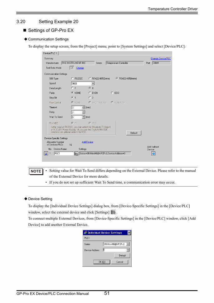
3.20 Setting Example 20
Settings of GP-Pro EX
Communication Settings
To display the setup screen, from the [Project] menu, point to [System Settings] and select [Device/PLC].
Device Setting
To display the [Individual Device Settings] dialog box, from [Device-Specific Settings] in the [Device/PLC]
window, select the external device and click [Settings] .
To connect multiple External Devices, from [Device-Specific Settings] in the [Device/PLC] window, click [Add
Device] to add another External Device.
• Setting value for Wait To Send differs depending on the External Device. Please refer to the manual
of the External Device for more details.
• If you do not set up sufficient Wait To Send time, a communication error may occur.
Temperature Controller Driver
GP-Pro EX Device/PLC Connection Manual 52
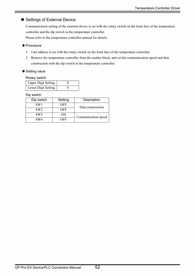
Settings of External Device
Communication setting of the external device is set with the rotary switch on the front face of the temperature
controller and the dip switch in the temperature controller.
Please refer to the temperature controller manual for details.
Procedure
1. Unit address is set with the rotary switch on the front face of the temperature controller.
2. Remove the temperature controller from the mother block, and set the communication speed and data
construction with the dip switch in the temperature controller.
Setting value
Rotary switch
Dip switch
Upper Digit Setting 0
Lower Digit Setting 0
Dip switch Setting Description
SW1 OFFData construction
SW2 OFF
SW3 ONCommunication speed
SW4 OFF
Temperature Controller Driver
GP-Pro EX Device/PLC Connection Manual 53
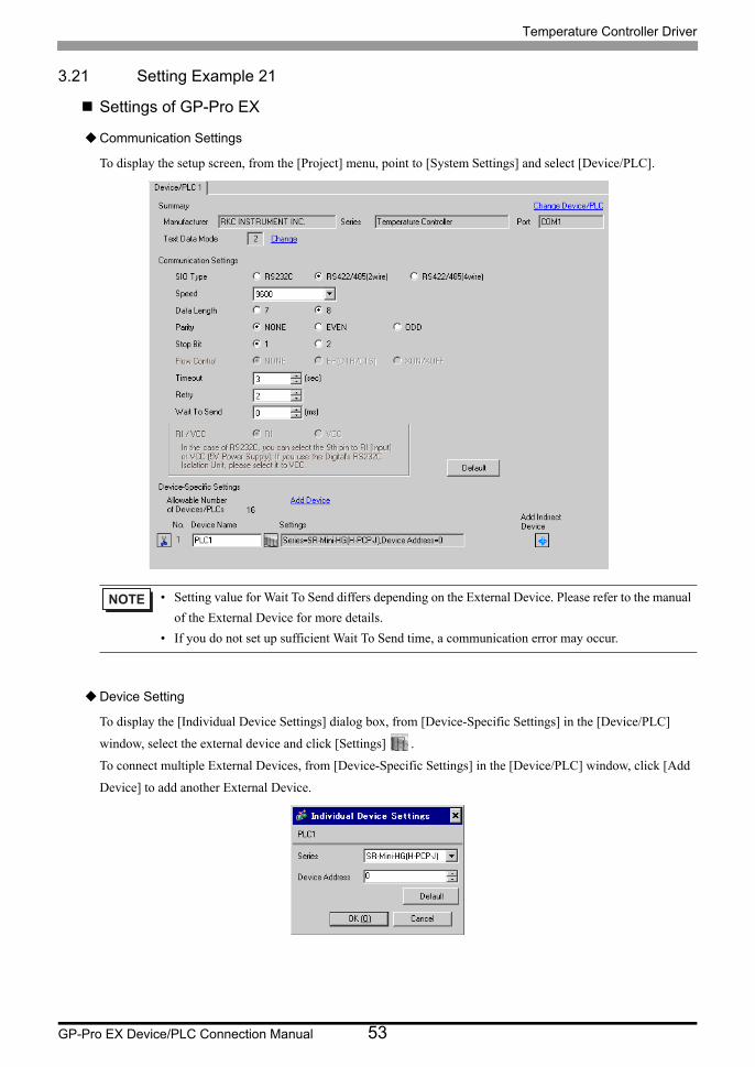
3.21 Setting Example 21
Settings of GP-Pro EX
Communication Settings
To display the setup screen, from the [Project] menu, point to [System Settings] and select [Device/PLC].
Device Setting
To display the [Individual Device Settings] dialog box, from [Device-Specific Settings] in the [Device/PLC]
window, select the external device and click [Settings] .
To connect multiple External Devices, from [Device-Specific Settings] in the [Device/PLC] window, click [Add
Device] to add another External Device.
• Setting value for Wait To Send differs depending on the External Device. Please refer to the manual
of the External Device for more details.
• If you do not set up sufficient Wait To Send time, a communication error may occur.

Temperature Controller Driver
GP-Pro EX Device/PLC Connection Manual 54
Settings of External Device
Communication setting of the external device is set with the rotary switch on the front face of the temperature
controller and the dip switch in the temperature controller.
Please refer to the temperature controller manual for details.
Procedure
1. Unit address is set with the rotary switch on the front face of the temperature controller.
2. Remove the temperature controller from the mother block, and set the communication speed and data
construction with the dip switch in the temperature controller.
Setting value
Rotary switch
Dip switch
Upper Digit Setting 0
Lower Digit Setting 0
Dip switch Setting Description
SW1 OFFData construction
SW2 OFF
SW3 ONCommunication speed
SW4 OFF
Temperature Controller Driver
GP-Pro EX Device/PLC Connection Manual 55
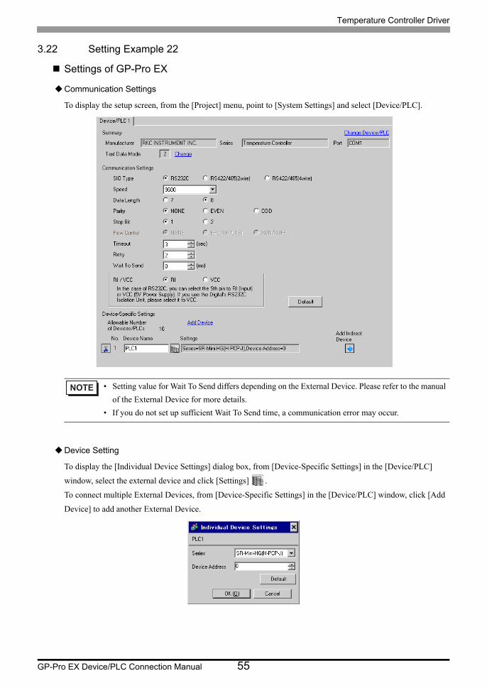
3.22 Setting Example 22
Settings of GP-Pro EX
Communication Settings
To display the setup screen, from the [Project] menu, point to [System Settings] and select [Device/PLC].
Device Setting
To display the [Individual Device Settings] dialog box, from [Device-Specific Settings] in the [Device/PLC]
window, select the external device and click [Settings] .
To connect multiple External Devices, from [Device-Specific Settings] in the [Device/PLC] window, click [Add
Device] to add another External Device.
• Setting value for Wait To Send differs depending on the External Device. Please refer to the manual
of the External Device for more details.
• If you do not set up sufficient Wait To Send time, a communication error may occur.
Temperature Controller Driver
GP-Pro EX Device/PLC Connection Manual 56
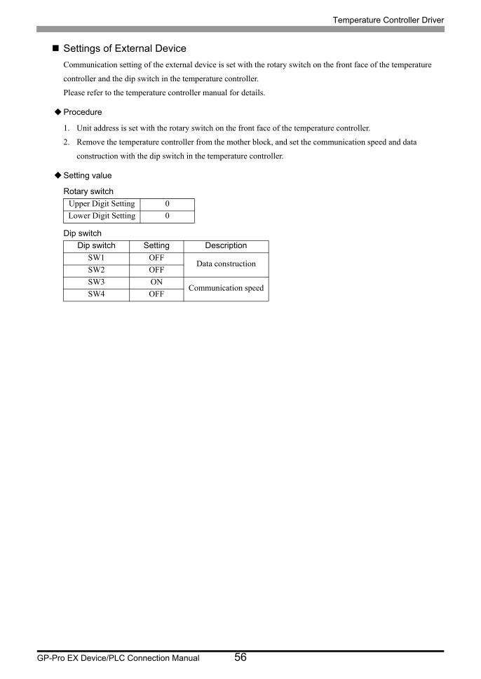
Settings of External Device
Communication setting of the external device is set with the rotary switch on the front face of the temperature
controller and the dip switch in the temperature controller.
Please refer to the temperature controller manual for details.
Procedure
1. Unit address is set with the rotary switch on the front face of the temperature controller.
2. Remove the temperature controller from the mother block, and set the communication speed and data
construction with the dip switch in the temperature controller.
Setting value
Rotary switch
Dip switch
Upper Digit Setting 0
Lower Digit Setting 0
Dip switch Setting Description
SW1 OFFData construction
SW2 OFF
SW3 ONCommunication speed
SW4 OFF
Temperature Controller Driver
GP-Pro EX Device/PLC Connection Manual 57
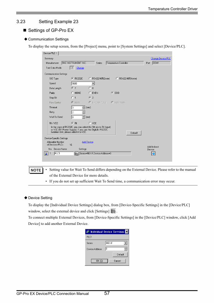
3.23 Setting Example 23
Settings of GP-Pro EX
Communication Settings
To display the setup screen, from the [Project] menu, point to [System Settings] and select [Device/PLC].
Device Setting
To display the [Individual Device Settings] dialog box, from [Device-Specific Settings] in the [Device/PLC]
window, select the external device and click [Settings] .
To connect multiple External Devices, from [Device-Specific Settings] in the [Device/PLC] window, click [Add
Device] to add another External Device.
• Setting value for Wait To Send differs depending on the External Device. Please refer to the manual
of the External Device for more details.
• If you do not set up sufficient Wait To Send time, a communication error may occur.
Temperature Controller Driver
GP-Pro EX Device/PLC Connection Manual 58
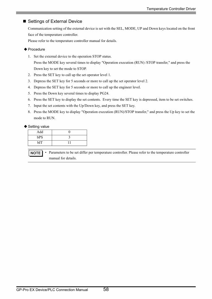
Settings of External Device
Communication setting of the external device is set with the SEL, MODE, UP and Down keys located on the front
face of the temperature controller.
Please refer to the temperature controller manual for details.
Procedure
1. Set the external device to the operation STOP status.
Press the MODE key several times to display "Operation execution (RUN) /STOP transfer," and press the
Down key to set the mode to STOP.
2. Press the SET key to call up the set operator level 1.
3. Depress the SET key for 5 seconds or more to call up the set operator level 2.
4. Depress the SET key for 5 seconds or more to call up the engineer level.
5. Press the Down key several times to display PG24.
6. Press the SET key to display the set contents. Every time the SET key is depressed, item to be set switches.
7. Input the set contents with the Up/Down key, and press the SET key.
8. Press the MODE key to display "Operation execution (RUN)/STOP transfer," and press the Up key to set the
mode to RUN.
Setting value
Add 0
bPS 3
bIT 11
• Parameters to be set differ per temperature controller. Please refer to the temperature controller
manual for details.
Temperature Controller Driver
GP-Pro EX Device/PLC Connection Manual 59
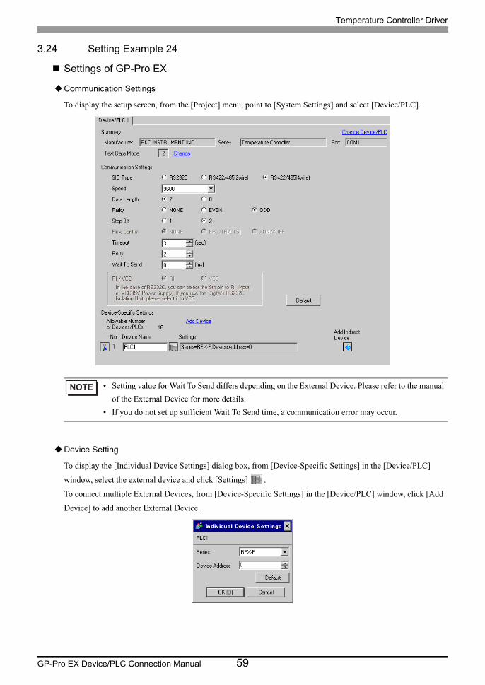
3.24 Setting Example 24
Settings of GP-Pro EX
Communication Settings
To display the setup screen, from the [Project] menu, point to [System Settings] and select [Device/PLC].
Device Setting
To display the [Individual Device Settings] dialog box, from [Device-Specific Settings] in the [Device/PLC]
window, select the external device and click [Settings] .
To connect multiple External Devices, from [Device-Specific Settings] in the [Device/PLC] window, click [Add
Device] to add another External Device.
• Setting value for Wait To Send differs depending on the External Device. Please refer to the manual
of the External Device for more details.
• If you do not set up sufficient Wait To Send time, a communication error may occur.

Temperature Controller Driver
GP-Pro EX Device/PLC Connection Manual 60
Settings of External Device
Communication setting of the external device is set with the SEL, MODE, UP and Down keys located on the front
face of the temperature controller.
Please refer to the temperature controller manual for details.
Procedure
1. Set the external device to the operation STOP status.
Press the MODE key several times to display "Operation execution (RUN) /STOP transfer," and press the
Down key to set the mode to STOP.
2. Press the SET key to call up the set operator level 1.
3. Depress the SET key for 5 seconds or more to call up the set operator level 2.
4. Depress the SET key for 5 seconds or more to call up the engineer level.
5. Press the Down key several times to display PG24.
6. Press the SET key to display the set contents. Every time the SET key is depressed, item to be set switches.
7. Input the set contents with the Up/Down key, and press the SET key.
8. Press the MODE key to display "Operation execution (RUN)/STOP transfer," and press the Up key to set the
mode to RUN.
Setting value
Add 0
bPS 3
bIT 11
• Parameters to be set differ per temperature controller. Please refer to the temperature controller
manual for details.
Temperature Controller Driver
GP-Pro EX Device/PLC Connection Manual 61
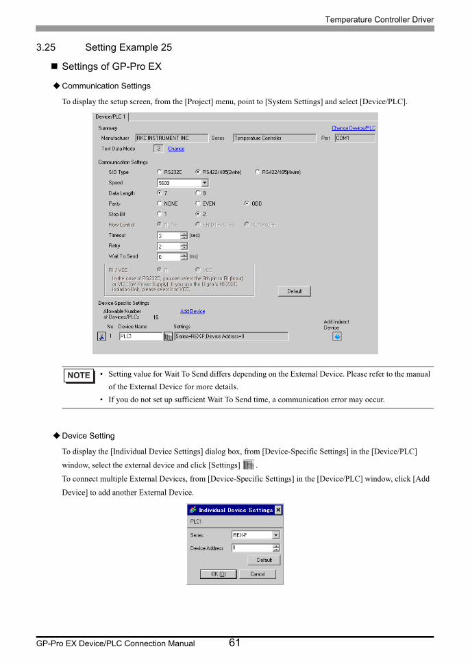
3.25 Setting Example 25
Settings of GP-Pro EX
Communication Settings
To display the setup screen, from the [Project] menu, point to [System Settings] and select [Device/PLC].
Device Setting
To display the [Individual Device Settings] dialog box, from [Device-Specific Settings] in the [Device/PLC]
window, select the external device and click [Settings] .
To connect multiple External Devices, from [Device-Specific Settings] in the [Device/PLC] window, click [Add
Device] to add another External Device.
• Setting value for Wait To Send differs depending on the External Device. Please refer to the manual
of the External Device for more details.
• If you do not set up sufficient Wait To Send time, a communication error may occur.

Temperature Controller Driver
GP-Pro EX Device/PLC Connection Manual 62
Settings of External Device
Communication setting of the external device is set with the SEL, MODE, UP and Down keys located on the front
face of the temperature controller.
Please refer to the temperature controller manual for details.
Procedure
1. Set the external device to the operation STOP status.
Press the MODE key several times to display "Operation execution (RUN) /STOP transfer," and press the
Down key to set the mode to STOP.
2. Press the SET key to call up the set operator level 1.
3. Depress the SET key for 5 seconds or more to call up the set operator level 2.
4. Depress the SET key for 5 seconds or more to call up the engineer level.
5. Press the Down key several times to display PG24.
6. Press the SET key to display the set contents. Every time the SET key is depressed, item to be set switches.
7. Input the set contents with the Up/Down key, and press the SET key.
8. Press the MODE key to display "Operation execution (RUN)/STOP transfer," and press the Up key to set the
mode to RUN.
Setting value
Add 0
bPS 3
bIT 11
• Parameters to be set differ per temperature controller. Please refer to the temperature controller
manual for details.
Temperature Controller Driver
GP-Pro EX Device/PLC Connection Manual 63
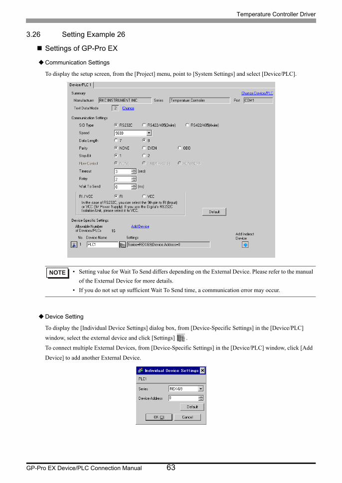
3.26 Setting Example 26
Settings of GP-Pro EX
Communication Settings
To display the setup screen, from the [Project] menu, point to [System Settings] and select [Device/PLC].
Device Setting
To display the [Individual Device Settings] dialog box, from [Device-Specific Settings] in the [Device/PLC]
window, select the external device and click [Settings] .
To connect multiple External Devices, from [Device-Specific Settings] in the [Device/PLC] window, click [Add
Device] to add another External Device.
• Setting value for Wait To Send differs depending on the External Device. Please refer to the manual
of the External Device for more details.
• If you do not set up sufficient Wait To Send time, a communication error may occur.

Temperature Controller Driver
GP-Pro EX Device/PLC Connection Manual 64
Settings of External Device
Communication setting of the external device is set with the MODE, PARA, >>>, UP and Down keys located on
the front face of the temperature controller.
Please refer to the temperature controller manual for details.
Procedure
1. Press the MODE key to display "Operation execution (RUN)/STOP transfer."
Press the >>> key to stop operation.
2. Press PARA key to display "Setting (PARA) screen."
Press the Up/Down keys, select PARA GROUP 24, and press the PARA key.
3. Every time the PARA Key is depressed, setting item switches.
Display the item to be set, and select the set contents with the Up/Down keys.
4. After setting, press the MODE key to display "Operation execution (RUN)/STOP screen."
Press the >>> key to put the operation into action.
Setting value
Bit FormatP (Parity): nDT (Data Bit): 8SP (Stop bit): 1
Device Address 0
Speed 9600
• Parameters to be set differ per temperature controller. Please refer to the temperature controller
manual for details.

Temperature Controller Driver
GP-Pro EX Device/PLC Connection Manual 65
3.27 Setting Example 27
Settings of GP-Pro EX
Communication Settings
To display the setup screen, from the [Project] menu, point to [System Settings] and select [Device/PLC].
Device Setting
To display the [Individual Device Settings] dialog box, from [Device-Specific Settings] in the [Device/PLC]
window, select the external device and click [Settings] .
To connect multiple External Devices, from [Device-Specific Settings] in the [Device/PLC] window, click [Add
Device] to add another External Device.
• Setting value for Wait To Send differs depending on the External Device. Please refer to the manual
of the External Device for more details.
• If you do not set up sufficient Wait To Send time, a communication error may occur.
Temperature Controller Driver
GP-Pro EX Device/PLC Connection Manual 66
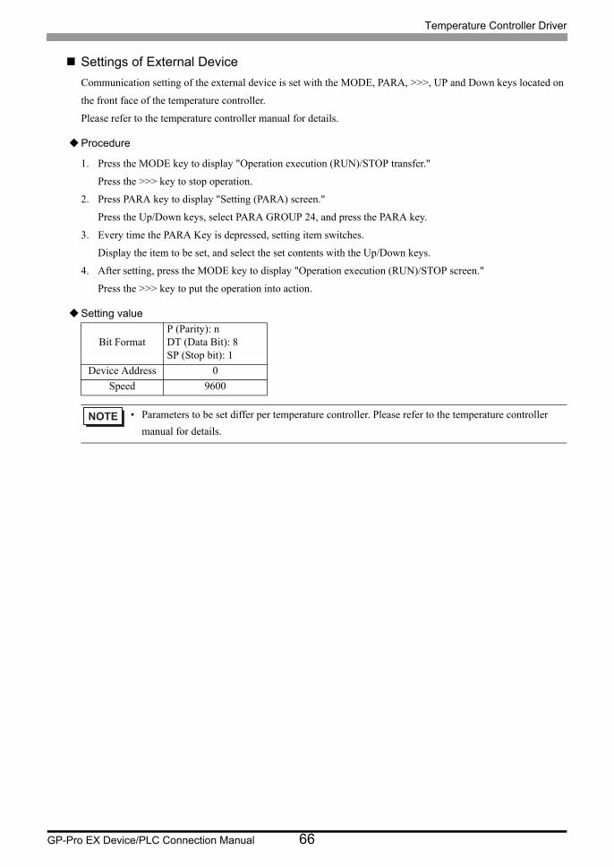
Settings of External Device
Communication setting of the external device is set with the MODE, PARA, >>>, UP and Down keys located on
the front face of the temperature controller.
Please refer to the temperature controller manual for details.
Procedure
1. Press the MODE key to display "Operation execution (RUN)/STOP transfer."
Press the >>> key to stop operation.
2. Press PARA key to display "Setting (PARA) screen."
Press the Up/Down keys, select PARA GROUP 24, and press the PARA key.
3. Every time the PARA Key is depressed, setting item switches.
Display the item to be set, and select the set contents with the Up/Down keys.
4. After setting, press the MODE key to display "Operation execution (RUN)/STOP screen."
Press the >>> key to put the operation into action.
Setting value
Bit FormatP (Parity): nDT (Data Bit): 8SP (Stop bit): 1
Device Address 0
Speed 9600
• Parameters to be set differ per temperature controller. Please refer to the temperature controller
manual for details.

Temperature Controller Driver
GP-Pro EX Device/PLC Connection Manual 67
3.28 Setting Example 28
Settings of GP-Pro EX
Communication Settings
To display the setup screen, from the [Project] menu, point to [System Settings] and select [Device/PLC].
Device Setting
To display the [Individual Device Settings] dialog box, from [Device-Specific Settings] in the [Device/PLC]
window, select the external device and click [Settings] .
To connect multiple External Devices, from [Device-Specific Settings] in the [Device/PLC] window, click [Add
Device] to add another External Device.
• Setting value for Wait To Send differs depending on the External Device. Please refer to the manual
of the External Device for more details.
• If you do not set up sufficient Wait To Send time, a communication error may occur.

Temperature Controller Driver
GP-Pro EX Device/PLC Connection Manual 68
Settings of External Device
Communication setting of the external device is set with the MODE, PARA, >>>, UP and Down keys located on
the front face of the temperature controller.
Please refer to the temperature controller manual for details.
Procedure
1. Press the MODE key to display "Operation execution (RUN)/STOP transfer."
Press the >>> key to stop operation.
2. Press PARA key to display "Setting (PARA) screen."
Press the Up/Down keys, select PARA GROUP 24, and press the PARA key.
3. Every time the PARA Key is depressed, setting item switches.
Display the item to be set, and select the set contents with the Up/Down keys.
4. After setting, press the MODE key to display "Operation execution (RUN)/STOP screen."
Press the >>> key to put the operation into action.
Setting value
Bit FormatP (Parity): nDT (Data Bit): 8SP (Stop bit): 1
Device Address 0
Speed 9600
• Parameters to be set differ per temperature controller. Please refer to the temperature controller
manual for details.

Temperature Controller Driver
GP-Pro EX Device/PLC Connection Manual 69
3.29 Setting Example 29
Settings of GP-Pro EX
Communication Settings
To display the setup screen, from the [Project] menu, point to [System Settings] and select [Device/PLC].
Device Setting
To display the [Individual Device Settings] dialog box, from [Device-Specific Settings] in the [Device/PLC]
window, select the external device and click [Settings] .
To connect multiple External Devices, from [Device-Specific Settings] in the [Device/PLC] window, click [Add
Device] to add another External Device.
• Setting value for Wait To Send differs depending on the External Device. Please refer to the manual
of the External Device for more details.
• If you do not set up sufficient Wait To Send time, a communication error may occur.

Temperature Controller Driver
GP-Pro EX Device/PLC Connection Manual 70
Settings of External Device
Communication setting of the external device is set with the SET, MODE, UP and Down keys located on the front
face of the temperature controller.
Please refer to the temperature controller manual for details.
Procedure
1. Press the SET key for 2 seconds to change from PV display mode to engineer setting mode.
Parameter group is displayed.
2. Press the Up/Down keys to display the parameter group, "PG60."
3. Press the SET Key to display setting item. Every time the SET Key is depressed, item to be set switches.
4. Press the Up/Down keys to select set value, and press the SET Key.
5. Press the Reset key to reset the external device.
6. Press the Monitor/Mode key and the SET key at the same time to move to SETUP setting mode.
7. Press the SET key several times to display Add.
8. Press the Up/Down keys to select set value, and press the SET key.
9. Press the RUN/HOLD key to move to operation monitor mode.
Setting value
Engineer setting mode
SETUP setting mode
bPS 2
bIT 0
Add 0
• Parameters to be set differ per temperature controller. Please refer to the temperature controller
manual for details.

Temperature Controller Driver
GP-Pro EX Device/PLC Connection Manual 71
3.30 Setting Example 30
Settings of GP-Pro EX
Communication Settings
To display the setup screen, from the [Project] menu, point to [System Settings] and select [Device/PLC].
Device Setting
To display the [Individual Device Settings] dialog box, from [Device-Specific Settings] in the [Device/PLC]
window, select the external device and click [Settings] .
To connect multiple External Devices, from [Device-Specific Settings] in the [Device/PLC] window, click [Add
Device] to add another External Device.
• Setting value for Wait To Send differs depending on the External Device. Please refer to the manual
of the External Device for more details.
• If you do not set up sufficient Wait To Send time, a communication error may occur.

Temperature Controller Driver
GP-Pro EX Device/PLC Connection Manual 72
Settings of External Device
Communication setting of the external device is set with the SET, MODE, UP and Down keys located on the front
face of the temperature controller.
Please refer to the temperature controller manual for details.
Procedure
1. Press the SET key for 2 seconds to change from PV display mode to engineer setting mode.
Parameter group is displayed.
2. Press the Up/Down keys to display the parameter group, "PG60."
3. Press the SET Key to display setting item. Every time the SET Key is depressed, item to be set switches.
4. Press the Up/Down keys to select set value, and press the SET Key.
5. Press the Reset key to reset the external device.
6. Press the Monitor/Mode key and the SET key at the same time to move to SETUP setting mode.
7. Press the SET key several times to display Add.
8. Press the Up/Down keys to select set value, and press the SET key.
9. Press the RUN/HOLD key to move to operation monitor mode.
Setting value
Engineer setting mode
SETUP setting mode
bPS 2
bIT 0
Add 0
• Parameters to be set differ per temperature controller. Please refer to the temperature controller
manual for details.

Temperature Controller Driver
GP-Pro EX Device/PLC Connection Manual 73
3.31 Setting Example 31
Settings of GP-Pro EX
Communication Settings
To display the setup screen, from the [Project] menu, point to [System Settings] and select [Device/PLC].
Device Setting
To display the [Individual Device Settings] dialog box, from [Device-Specific Settings] in the [Device/PLC]
window, select the external device and click [Settings] .
To connect multiple External Devices, from [Device-Specific Settings] in the [Device/PLC] window, click [Add
Device] to add another External Device.
• Setting value for Wait To Send differs depending on the External Device. Please refer to the manual
of the External Device for more details.
• If you do not set up sufficient Wait To Send time, a communication error may occur.
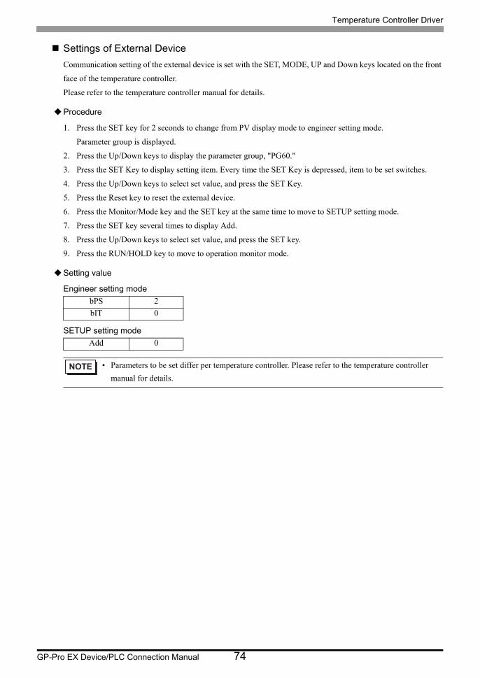
Temperature Controller Driver
GP-Pro EX Device/PLC Connection Manual 74
Settings of External Device
Communication setting of the external device is set with the SET, MODE, UP and Down keys located on the front
face of the temperature controller.
Please refer to the temperature controller manual for details.
Procedure
1. Press the SET key for 2 seconds to change from PV display mode to engineer setting mode.
Parameter group is displayed.
2. Press the Up/Down keys to display the parameter group, "PG60."
3. Press the SET Key to display setting item. Every time the SET Key is depressed, item to be set switches.
4. Press the Up/Down keys to select set value, and press the SET Key.
5. Press the Reset key to reset the external device.
6. Press the Monitor/Mode key and the SET key at the same time to move to SETUP setting mode.
7. Press the SET key several times to display Add.
8. Press the Up/Down keys to select set value, and press the SET key.
9. Press the RUN/HOLD key to move to operation monitor mode.
Setting value
Engineer setting mode
SETUP setting mode
bPS 2
bIT 0
Add 0
• Parameters to be set differ per temperature controller. Please refer to the temperature controller
manual for details.
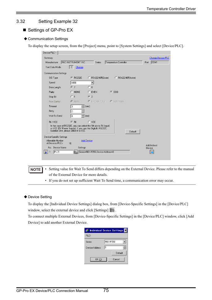
Temperature Controller Driver
GP-Pro EX Device/PLC Connection Manual 75
3.32 Setting Example 32
Settings of GP-Pro EX
Communication Settings
To display the setup screen, from the [Project] menu, point to [System Settings] and select [Device/PLC].
Device Setting
To display the [Individual Device Settings] dialog box, from [Device-Specific Settings] in the [Device/PLC]
window, select the external device and click [Settings] .
To connect multiple External Devices, from [Device-Specific Settings] in the [Device/PLC] window, click [Add
Device] to add another External Device.
• Setting value for Wait To Send differs depending on the External Device. Please refer to the manual
of the External Device for more details.
• If you do not set up sufficient Wait To Send time, a communication error may occur.

Temperature Controller Driver
GP-Pro EX Device/PLC Connection Manual 76
Settings of External Device
Communication setting of the external device is set with the SET, UP and Down keys located on the front face of
the temperature controller.
Please refer to the temperature controller manual for details.
Procedure
1. While lifting up the stopper located at the lower section of the external device with a finger, pull and remove
it from the case.
2. Turn on the internal switch A at upper external device and put it back in the case.
3. Press the SET key to display the item to be set, and select the set contents with the Up/Down keys. Stop bit,
data bit, and parity bit are displayed in a 3 digit character string at the setting item, bIT, so touch each one's
digit, ten's digit, and hundred's digit on the SV indicator, and select the set contents with the Up/Down keys.
4. Press the SET key to set the set contents.
5. Remove the external device form the case, turn OFF the internal switch A mentioned in 2 above, and return it
to the case.
Setting value
bPS 4800
bIT o72
Add 0
• Parameters to be set differ per temperature controller. Please refer to the temperature controller
manual for details.

Temperature Controller Driver
GP-Pro EX Device/PLC Connection Manual 77
3.33 Setting Example 33
Settings of GP-Pro EX
Communication Settings
To display the setup screen, from the [Project] menu, point to [System Settings] and select [Device/PLC].
Device Setting
To display the [Individual Device Settings] dialog box, from [Device-Specific Settings] in the [Device/PLC]
window, select the external device and click [Settings] .
To connect multiple External Devices, from [Device-Specific Settings] in the [Device/PLC] window, click [Add
Device] to add another External Device.
• Setting value for Wait To Send differs depending on the External Device. Please refer to the manual
of the External Device for more details.
• If you do not set up sufficient Wait To Send time, a communication error may occur.
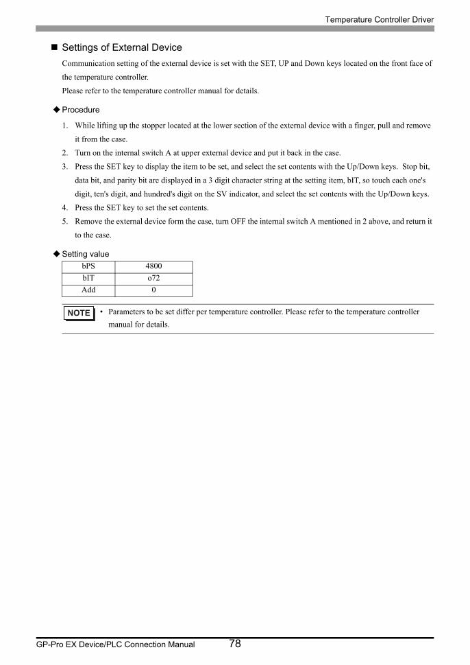
Temperature Controller Driver
GP-Pro EX Device/PLC Connection Manual 78
Settings of External Device
Communication setting of the external device is set with the SET, UP and Down keys located on the front face of
the temperature controller.
Please refer to the temperature controller manual for details.
Procedure
1. While lifting up the stopper located at the lower section of the external device with a finger, pull and remove
it from the case.
2. Turn on the internal switch A at upper external device and put it back in the case.
3. Press the SET key to display the item to be set, and select the set contents with the Up/Down keys. Stop bit,
data bit, and parity bit are displayed in a 3 digit character string at the setting item, bIT, so touch each one's
digit, ten's digit, and hundred's digit on the SV indicator, and select the set contents with the Up/Down keys.
4. Press the SET key to set the set contents.
5. Remove the external device form the case, turn OFF the internal switch A mentioned in 2 above, and return it
to the case.
Setting value
bPS 4800
bIT o72
Add 0
• Parameters to be set differ per temperature controller. Please refer to the temperature controller
manual for details.
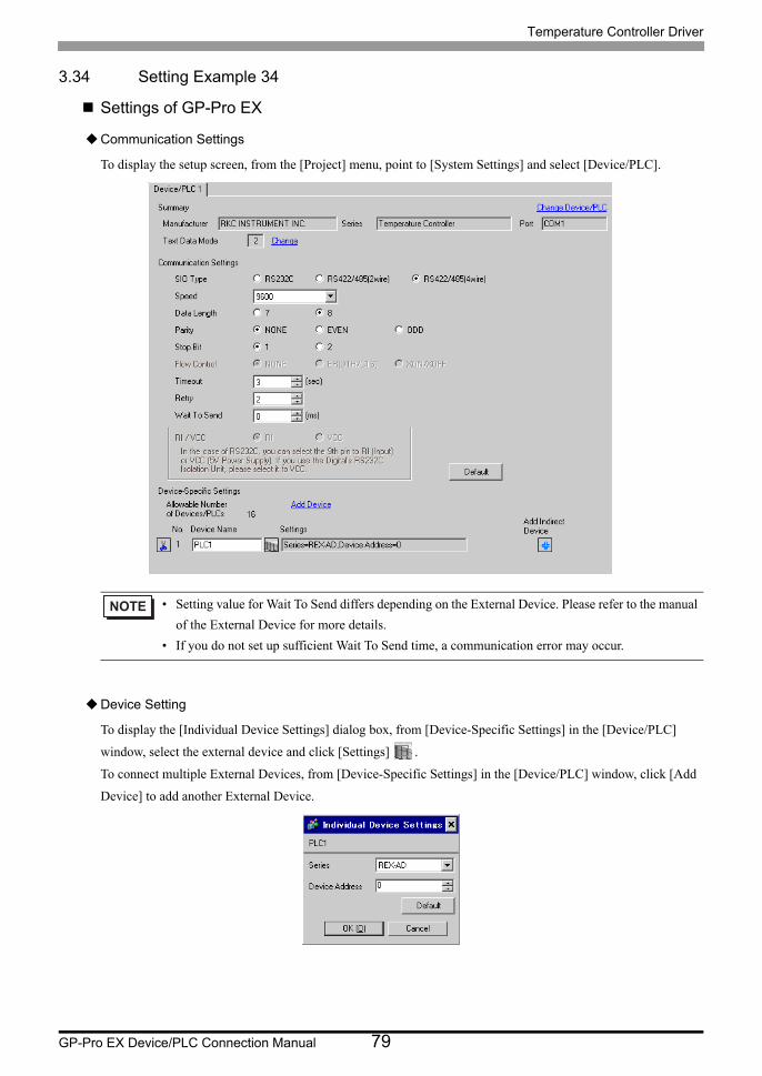
Temperature Controller Driver
GP-Pro EX Device/PLC Connection Manual 79
3.34 Setting Example 34
Settings of GP-Pro EX
Communication Settings
To display the setup screen, from the [Project] menu, point to [System Settings] and select [Device/PLC].
Device Setting
To display the [Individual Device Settings] dialog box, from [Device-Specific Settings] in the [Device/PLC]
window, select the external device and click [Settings] .
To connect multiple External Devices, from [Device-Specific Settings] in the [Device/PLC] window, click [Add
Device] to add another External Device.
• Setting value for Wait To Send differs depending on the External Device. Please refer to the manual
of the External Device for more details.
• If you do not set up sufficient Wait To Send time, a communication error may occur.

Temperature Controller Driver
GP-Pro EX Device/PLC Connection Manual 80
Settings of External Device
Communication setting of the external device is set with the SEL, MODE, UP and Down keys located on the front
face of the temperature controller.
Please refer to the temperature controller manual for details.
Procedure
1. Depress the SEL key for 2 seconds to change from PV display mode to engineer setting mode.
Parameter group is displayed.
2. Press the Up/Down keys to display the parameter group, "PG9."
3. Press the SEL key to display the setting item. Every time the SEL key is depressed, setting item switches.
4. Press the Up/Down keys to display the setting value.
5. Press the Up/Down keys to select the setting value, and press the SEL key.
6. Press the Monitor/Mode key to switch to the PV display mode.
7. Press the Monitor/Mode key and the SEL key at the same time to change from PV display mode to SETUP
setting mode.
8. Press the SEL key several times to display Add.
9. Press the Up/Down keys to display the setting value.
10. Press the Up/Down keys to display the setting value.
11. Press the Monitor/Mode keys to switch to the PV display mode.
Setting value
Engineer setting mode
SETUP setting mode
bPS 3
bIT 0
Add 0
• Parameters to be set differ per temperature controller. Please refer to the temperature controller
manual for details.

Temperature Controller Driver
GP-Pro EX Device/PLC Connection Manual 81
3.35 Setting Example 35
Settings of GP-Pro EX
Communication Settings
To display the setup screen, from the [Project] menu, point to [System Settings] and select [Device/PLC].
Device Setting
To display the [Individual Device Settings] dialog box, from [Device-Specific Settings] in the [Device/PLC]
window, select the external device and click [Settings] .
To connect multiple External Devices, from [Device-Specific Settings] in the [Device/PLC] window, click [Add
Device] to add another External Device.
• Setting value for Wait To Send differs depending on the External Device. Please refer to the manual
of the External Device for more details.
• If you do not set up sufficient Wait To Send time, a communication error may occur.

Temperature Controller Driver
GP-Pro EX Device/PLC Connection Manual 82
Settings of External Device
Communication setting of the external device is set with the SEL, MODE, UP and Down keys located on the front
face of the temperature controller.
Please refer to the temperature controller manual for details.
Procedure
1. Depress the SEL key for 2 seconds to change from PV display mode to engineer setting mode.
Parameter group is displayed.
2. Press the Up/Down keys to display the parameter group, "PG9."
3. Press the SEL key to display the setting item. Every time the SEL key is depressed, setting item switches.
4. Press the Up/Down keys to display the setting value.
5. Press the Up/Down keys to select the setting value, and press the SEL key.
6. Press the Monitor/Mode key to switch to the PV display mode.
7. Press the Monitor/Mode key and the SEL key at the same time to change from PV display mode to SETUP
setting mode.
8. Press the SEL key several times to display Add.
9. Press the Up/Down keys to display the setting value.
10. Press the Up/Down keys to display the setting value.
11. Press the Monitor/Mode keys to switch to the PV display mode.
Setting value
Engineer setting mode
SETUP setting mode
bPS 3
bIT 0
Add 0
• Parameters to be set differ per temperature controller. Please refer to the temperature controller
manual for details.
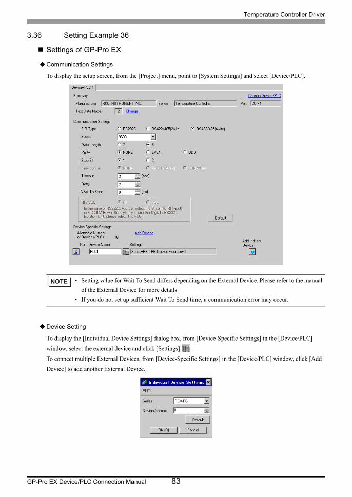
Temperature Controller Driver
GP-Pro EX Device/PLC Connection Manual 83
3.36 Setting Example 36
Settings of GP-Pro EX
Communication Settings
To display the setup screen, from the [Project] menu, point to [System Settings] and select [Device/PLC].
Device Setting
To display the [Individual Device Settings] dialog box, from [Device-Specific Settings] in the [Device/PLC]
window, select the external device and click [Settings] .
To connect multiple External Devices, from [Device-Specific Settings] in the [Device/PLC] window, click [Add
Device] to add another External Device.
• Setting value for Wait To Send differs depending on the External Device. Please refer to the manual
of the External Device for more details.
• If you do not set up sufficient Wait To Send time, a communication error may occur.
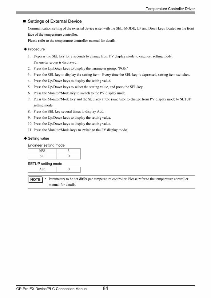
Temperature Controller Driver
GP-Pro EX Device/PLC Connection Manual 84
Settings of External Device
Communication setting of the external device is set with the SEL, MODE, UP and Down keys located on the front
face of the temperature controller.
Please refer to the temperature controller manual for details.
Procedure
1. Depress the SEL key for 2 seconds to change from PV display mode to engineer setting mode.
Parameter group is displayed.
2. Press the Up/Down keys to display the parameter group, "PG6."
3. Press the SEL key to display the setting item. Every time the SEL key is depressed, setting item switches.
4. Press the Up/Down keys to display the setting value.
5. Press the Up/Down keys to select the setting value, and press the SEL key.
6. Press the Monitor/Mode key to switch to the PV display mode.
7. Press the Monitor/Mode key and the SEL key at the same time to change from PV display mode to SETUP
setting mode.
8. Press the SEL key several times to display Add.
9. Press the Up/Down keys to display the setting value.
10. Press the Up/Down keys to display the setting value.
11. Press the Monitor/Mode keys to switch to the PV display mode.
Setting value
Engineer setting mode
SETUP setting mode
bPS 3
bIT 0
Add 0
• Parameters to be set differ per temperature controller. Please refer to the temperature controller
manual for details.

Temperature Controller Driver
GP-Pro EX Device/PLC Connection Manual 85
3.37 Setting Example 37
Settings of GP-Pro EX
Communication Settings
To display the setup screen, from the [Project] menu, point to [System Settings] and select [Device/PLC].
Device Setting
To display the [Individual Device Settings] dialog box, from [Device-Specific Settings] in the [Device/PLC]
window, select the external device and click [Settings] .
To connect multiple External Devices, from [Device-Specific Settings] in the [Device/PLC] window, click [Add
Device] to add another External Device.
• Setting value for Wait To Send differs depending on the External Device. Please refer to the manual
of the External Device for more details.
• If you do not set up sufficient Wait To Send time, a communication error may occur.

Temperature Controller Driver
GP-Pro EX Device/PLC Connection Manual 86
Settings of External Device
Communication setting of the external device is set with the SEL, MODE, UP and Down keys located on the front
face of the temperature controller.
Please refer to the temperature controller manual for details.
Procedure
1. Depress the SEL key for 2 seconds to change from PV display mode to engineer setting mode.
Parameter group is displayed.
2. Press the Up/Down keys to display the parameter group, "PG9."
3. Press the SEL key to display the setting item. Every time the SEL key is depressed, setting item switches.
4. Press the Up/Down keys to display the setting value.
5. Press the Up/Down keys to select the setting value, and press the SEL key.
6. Press the Monitor/Mode key to switch to the PV display mode.
7. Press the Monitor/Mode key and the SEL key at the same time to change from PV display mode to SETUP
setting mode.
8. Press the SEL key several times to display Add.
9. Press the Up/Down keys to display the setting value.
10. Press the Up/Down keys to display the setting value.
11. Press the Monitor/Mode keys to switch to the PV display mode.
Setting value
Engineer setting mode
SETUP setting mode
bPS 3
bIT 0
Add 0
• Parameters to be set differ per temperature controller. Please refer to the temperature controller
manual for details.
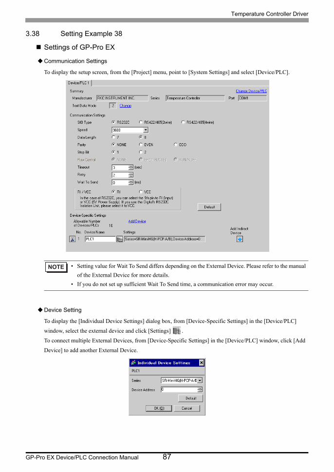
Temperature Controller Driver
GP-Pro EX Device/PLC Connection Manual 87
3.38 Setting Example 38
Settings of GP-Pro EX
Communication Settings
To display the setup screen, from the [Project] menu, point to [System Settings] and select [Device/PLC].
Device Setting
To display the [Individual Device Settings] dialog box, from [Device-Specific Settings] in the [Device/PLC]
window, select the external device and click [Settings] .
To connect multiple External Devices, from [Device-Specific Settings] in the [Device/PLC] window, click [Add
Device] to add another External Device.
• Setting value for Wait To Send differs depending on the External Device. Please refer to the manual
of the External Device for more details.
• If you do not set up sufficient Wait To Send time, a communication error may occur.
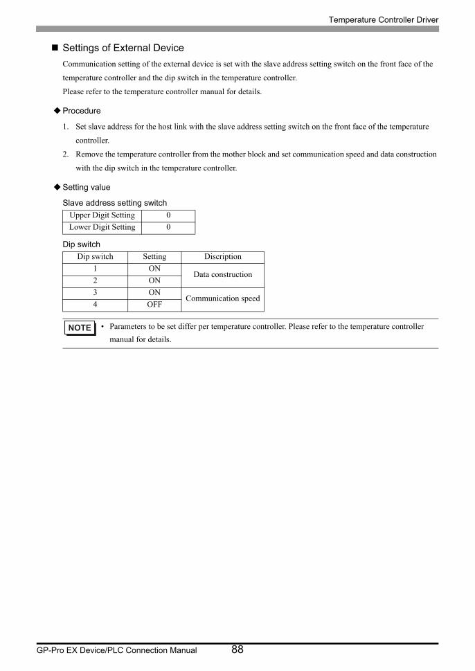
Temperature Controller Driver
GP-Pro EX Device/PLC Connection Manual 88
Settings of External Device
Communication setting of the external device is set with the slave address setting switch on the front face of the
temperature controller and the dip switch in the temperature controller.
Please refer to the temperature controller manual for details.
Procedure
1. Set slave address for the host link with the slave address setting switch on the front face of the temperature
controller.
2. Remove the temperature controller from the mother block and set communication speed and data construction
with the dip switch in the temperature controller.
Setting value
Slave address setting switch
Dip switch
Upper Digit Setting 0
Lower Digit Setting 0
Dip switch Setting Discription
1 ONData construction
2 ON
3 ONCommunication speed
4 OFF
• Parameters to be set differ per temperature controller. Please refer to the temperature controller
manual for details.
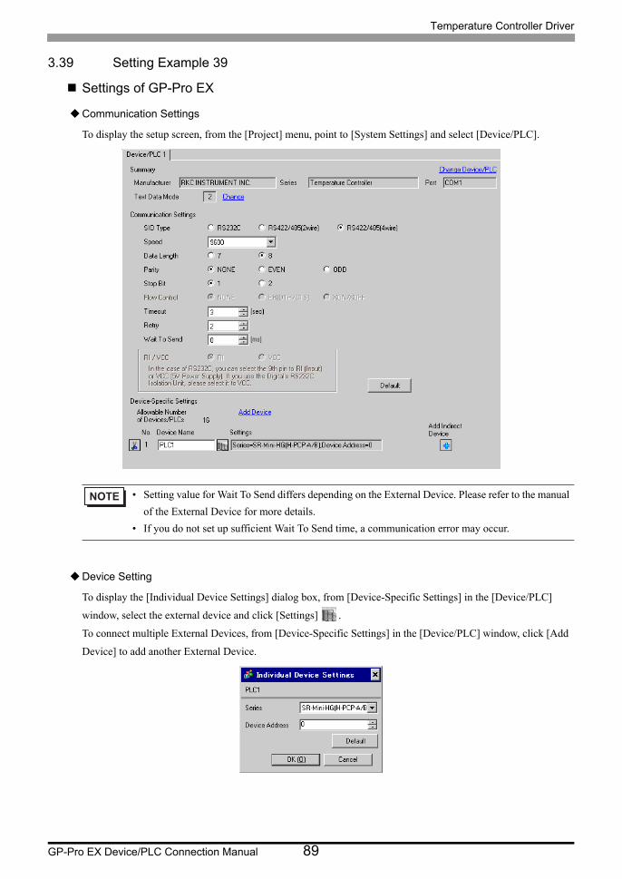
Temperature Controller Driver
GP-Pro EX Device/PLC Connection Manual 89
3.39 Setting Example 39
Settings of GP-Pro EX
Communication Settings
To display the setup screen, from the [Project] menu, point to [System Settings] and select [Device/PLC].
Device Setting
To display the [Individual Device Settings] dialog box, from [Device-Specific Settings] in the [Device/PLC]
window, select the external device and click [Settings] .
To connect multiple External Devices, from [Device-Specific Settings] in the [Device/PLC] window, click [Add
Device] to add another External Device.
• Setting value for Wait To Send differs depending on the External Device. Please refer to the manual
of the External Device for more details.
• If you do not set up sufficient Wait To Send time, a communication error may occur.
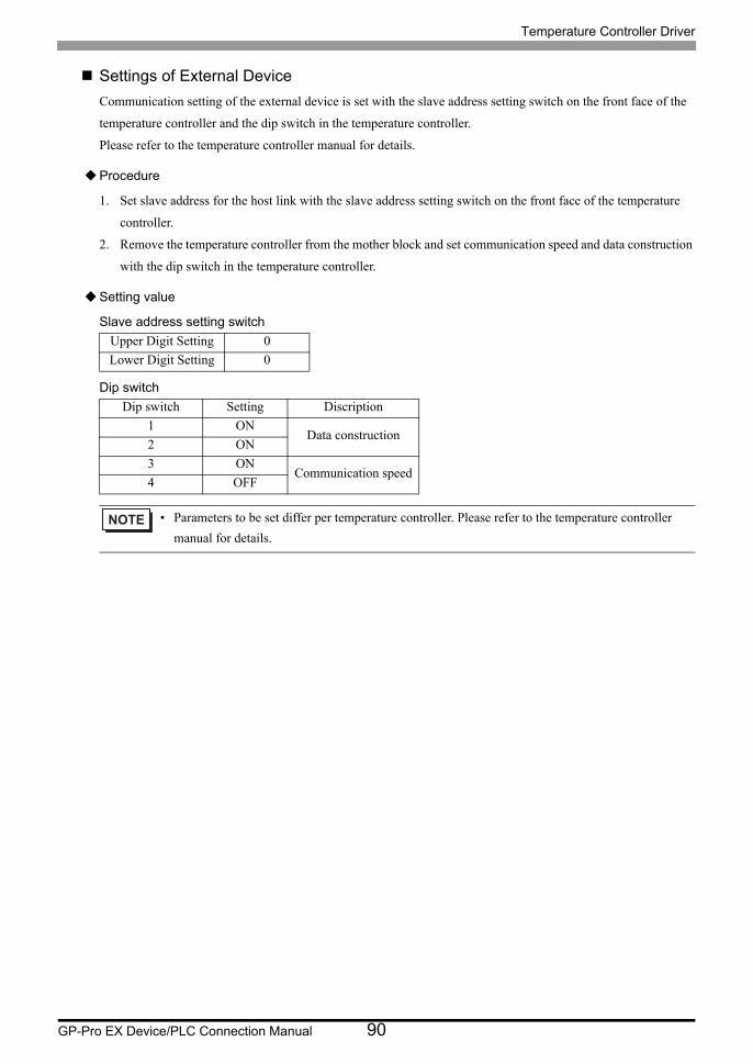
Temperature Controller Driver
GP-Pro EX Device/PLC Connection Manual 90
Settings of External Device
Communication setting of the external device is set with the slave address setting switch on the front face of the
temperature controller and the dip switch in the temperature controller.
Please refer to the temperature controller manual for details.
Procedure
1. Set slave address for the host link with the slave address setting switch on the front face of the temperature
controller.
2. Remove the temperature controller from the mother block and set communication speed and data construction
with the dip switch in the temperature controller.
Setting value
Slave address setting switch
Dip switch
Upper Digit Setting 0
Lower Digit Setting 0
Dip switch Setting Discription
1 ONData construction
2 ON
3 ONCommunication speed
4 OFF
• Parameters to be set differ per temperature controller. Please refer to the temperature controller
manual for details.
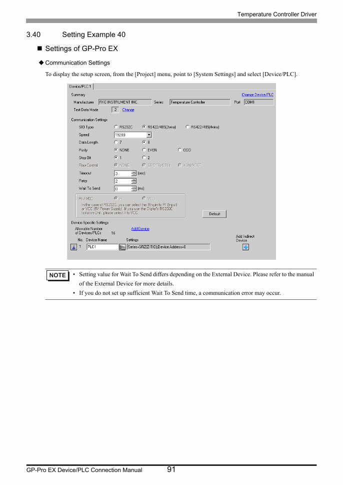
Temperature Controller Driver
GP-Pro EX Device/PLC Connection Manual 91
3.40 Setting Example 40
Settings of GP-Pro EX
Communication Settings
To display the setup screen, from the [Project] menu, point to [System Settings] and select [Device/PLC].
• Setting value for Wait To Send differs depending on the External Device. Please refer to the manual
of the External Device for more details.
• If you do not set up sufficient Wait To Send time, a communication error may occur.

Temperature Controller Driver
GP-Pro EX Device/PLC Connection Manual 92
Device Setting
To display the [Individual Device Settings] dialog box, from [Device-Specific Settings] in the [Device/PLC]
window, select the external device and click [Settings] .
To connect multiple External Devices, from [Device-Specific Settings] in the [Device/PLC] window, click [Add
Device] to add another External Device.
Settings of External Device
Use the unit address setting switch on the front of the Temperature Controller and the DIP switch on the side of
the Temperature Controller for communication settings of the External Device.
Please refer to the manual of the Temperature Controller for more details.
Procedure
1. Use the unit address setting switch on the front of the Temperature Controller to set the slave address.
2. Use the DIP switch on the side of the Temperature Controller to set the speed, data bit configuration, and
communication protocol.
3. After completing the settings, turn ON the Temperature Controller again.
Setting Value
Unit address setting switch
DIP Switch
Slave address setting 0
SW Settings Description
1 OFFSpeed: 19200 bps
2 ON
3 OFFData bit configuration:
Data length 8 bits, no parity, stop 1 bit4 OFF
5 ON
6 OFFCommunication protocol:
RKC communication
7 OFF Fixed
8 OFF Fixed
• Parameters to be set vary depending on the Temperature Controller. Please refer to the manual of
the Temperature Controller for more details.
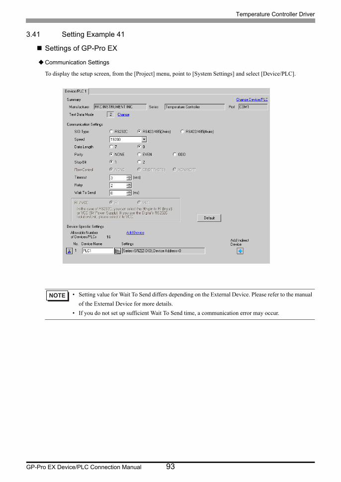
Temperature Controller Driver
GP-Pro EX Device/PLC Connection Manual 93
3.41 Setting Example 41
Settings of GP-Pro EX
Communication Settings
To display the setup screen, from the [Project] menu, point to [System Settings] and select [Device/PLC].
• Setting value for Wait To Send differs depending on the External Device. Please refer to the manual
of the External Device for more details.
• If you do not set up sufficient Wait To Send time, a communication error may occur.
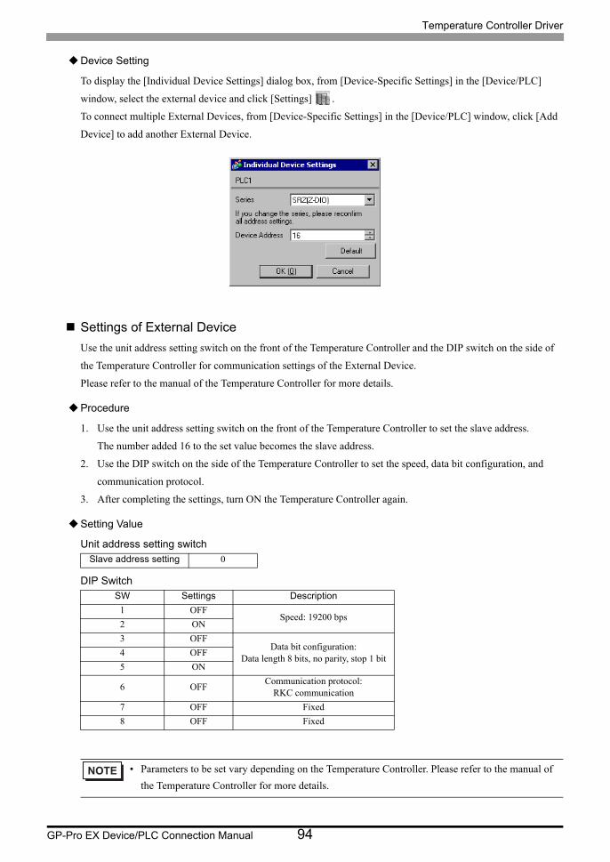
Temperature Controller Driver
GP-Pro EX Device/PLC Connection Manual 94
Device Setting
To display the [Individual Device Settings] dialog box, from [Device-Specific Settings] in the [Device/PLC]
window, select the external device and click [Settings] .
To connect multiple External Devices, from [Device-Specific Settings] in the [Device/PLC] window, click [Add
Device] to add another External Device.
Settings of External Device
Use the unit address setting switch on the front of the Temperature Controller and the DIP switch on the side of
the Temperature Controller for communication settings of the External Device.
Please refer to the manual of the Temperature Controller for more details.
Procedure
1. Use the unit address setting switch on the front of the Temperature Controller to set the slave address.
The number added 16 to the set value becomes the slave address.
2. Use the DIP switch on the side of the Temperature Controller to set the speed, data bit configuration, and
communication protocol.
3. After completing the settings, turn ON the Temperature Controller again.
Setting Value
Unit address setting switch
DIP Switch
Slave address setting 0
SW Settings Description
1 OFFSpeed: 19200 bps
2 ON
3 OFFData bit configuration:
Data length 8 bits, no parity, stop 1 bit4 OFF
5 ON
6 OFFCommunication protocol:
RKC communication
7 OFF Fixed
8 OFF Fixed
• Parameters to be set vary depending on the Temperature Controller. Please refer to the manual of
the Temperature Controller for more details.

Temperature Controller Driver
GP-Pro EX Device/PLC Connection Manual 95
3.42 Setting Example 42
Settings of GP-Pro EX
Communication Settings
To display the setup screen, from the [Project] menu, point to [System Settings] and select [Device/PLC].
• Setting value for Wait To Send differs depending on the External Device. Please refer to the manual
of the External Device for more details.
• If you do not set up sufficient Wait To Send time, a communication error may occur.
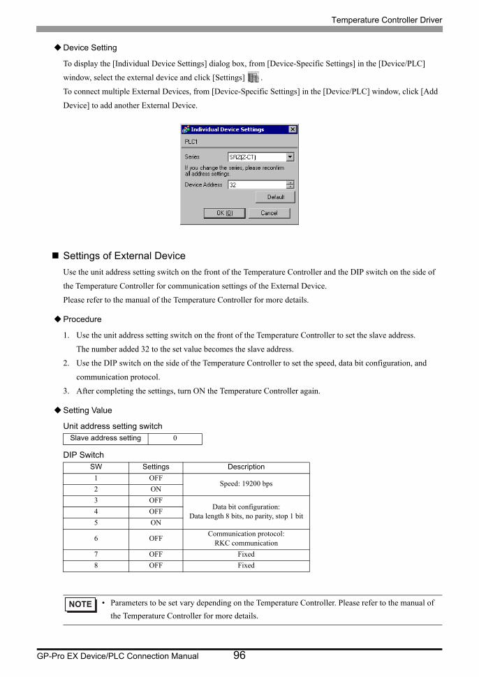
Temperature Controller Driver
GP-Pro EX Device/PLC Connection Manual 96
Device Setting
To display the [Individual Device Settings] dialog box, from [Device-Specific Settings] in the [Device/PLC]
window, select the external device and click [Settings] .
To connect multiple External Devices, from [Device-Specific Settings] in the [Device/PLC] window, click [Add
Device] to add another External Device.
Settings of External Device
Use the unit address setting switch on the front of the Temperature Controller and the DIP switch on the side of
the Temperature Controller for communication settings of the External Device.
Please refer to the manual of the Temperature Controller for more details.
Procedure
1. Use the unit address setting switch on the front of the Temperature Controller to set the slave address.
The number added 32 to the set value becomes the slave address.
2. Use the DIP switch on the side of the Temperature Controller to set the speed, data bit configuration, and
communication protocol.
3. After completing the settings, turn ON the Temperature Controller again.
Setting Value
Unit address setting switch
DIP Switch
Slave address setting 0
SW Settings Description
1 OFFSpeed: 19200 bps
2 ON
3 OFFData bit configuration:
Data length 8 bits, no parity, stop 1 bit4 OFF
5 ON
6 OFFCommunication protocol:
RKC communication
7 OFF Fixed
8 OFF Fixed
• Parameters to be set vary depending on the Temperature Controller. Please refer to the manual of
the Temperature Controller for more details.
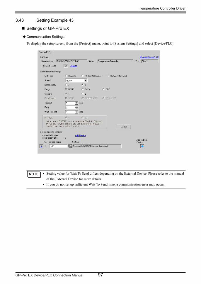
Temperature Controller Driver
GP-Pro EX Device/PLC Connection Manual 97
3.43 Setting Example 43
Settings of GP-Pro EX
Communication Settings
To display the setup screen, from the [Project] menu, point to [System Settings] and select [Device/PLC].
• Setting value for Wait To Send differs depending on the External Device. Please refer to the manual
of the External Device for more details.
• If you do not set up sufficient Wait To Send time, a communication error may occur.
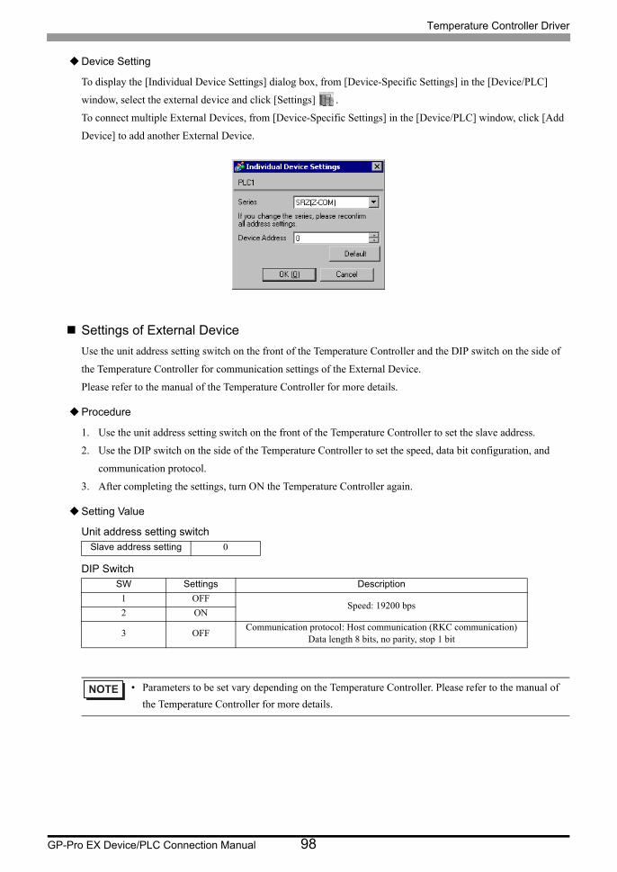
Temperature Controller Driver
GP-Pro EX Device/PLC Connection Manual 98
Device Setting
To display the [Individual Device Settings] dialog box, from [Device-Specific Settings] in the [Device/PLC]
window, select the external device and click [Settings] .
To connect multiple External Devices, from [Device-Specific Settings] in the [Device/PLC] window, click [Add
Device] to add another External Device.
Settings of External Device
Use the unit address setting switch on the front of the Temperature Controller and the DIP switch on the side of
the Temperature Controller for communication settings of the External Device.
Please refer to the manual of the Temperature Controller for more details.
Procedure
1. Use the unit address setting switch on the front of the Temperature Controller to set the slave address.
2. Use the DIP switch on the side of the Temperature Controller to set the speed, data bit configuration, and
communication protocol.
3. After completing the settings, turn ON the Temperature Controller again.
Setting Value
Unit address setting switch
DIP Switch
Slave address setting 0
SW Settings Description
1 OFFSpeed: 19200 bps
2 ON
3 OFFCommunication protocol: Host communication (RKC communication)
Data length 8 bits, no parity, stop 1 bit
• Parameters to be set vary depending on the Temperature Controller. Please refer to the manual of
the Temperature Controller for more details.

Temperature Controller Driver
GP-Pro EX Device/PLC Connection Manual 99
3.44 Setting Example 44
Settings of GP-Pro EX
Communication Settings
To display the setup screen, from the [Project] menu, point to [System Settings] and select [Device/PLC].
• Setting value for Wait To Send differs depending on the External Device. Please refer to the manual
of the External Device for more details.
• If you do not set up sufficient Wait To Send time, a communication error may occur.
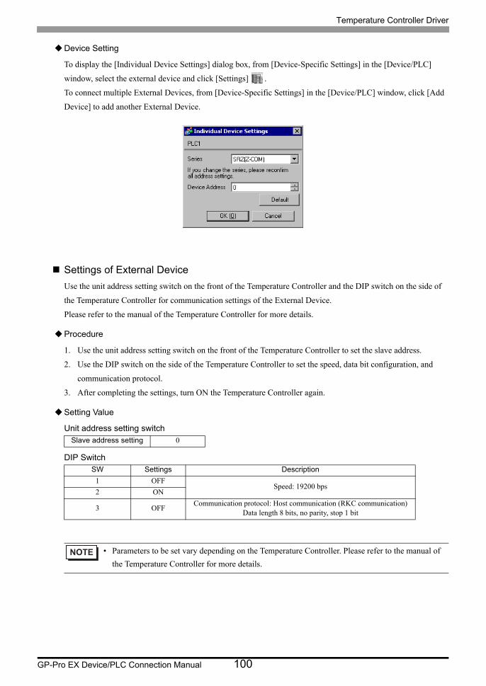
Temperature Controller Driver
GP-Pro EX Device/PLC Connection Manual 100
Device Setting
To display the [Individual Device Settings] dialog box, from [Device-Specific Settings] in the [Device/PLC]
window, select the external device and click [Settings] .
To connect multiple External Devices, from [Device-Specific Settings] in the [Device/PLC] window, click [Add
Device] to add another External Device.
Settings of External Device
Use the unit address setting switch on the front of the Temperature Controller and the DIP switch on the side of
the Temperature Controller for communication settings of the External Device.
Please refer to the manual of the Temperature Controller for more details.
Procedure
1. Use the unit address setting switch on the front of the Temperature Controller to set the slave address.
2. Use the DIP switch on the side of the Temperature Controller to set the speed, data bit configuration, and
communication protocol.
3. After completing the settings, turn ON the Temperature Controller again.
Setting Value
Unit address setting switch
DIP Switch
Slave address setting 0
SW Settings Description
1 OFFSpeed: 19200 bps
2 ON
3 OFFCommunication protocol: Host communication (RKC communication)
Data length 8 bits, no parity, stop 1 bit
• Parameters to be set vary depending on the Temperature Controller. Please refer to the manual of
the Temperature Controller for more details.

Temperature Controller Driver
GP-Pro EX Device/PLC Connection Manual 101
3.45 Setting Example 45
Settings of GP-Pro EX
Communication Settings
To display the setup screen, from the [Project] menu, point to [System Settings] and select [Device/PLC].
• Setting value for Wait To Send differs depending on the External Device. Please refer to the manual
of the External Device for more details.
• If you do not set up sufficient Wait To Send time, a communication error may occur.

Temperature Controller Driver
GP-Pro EX Device/PLC Connection Manual 102
Device Setting
To display the [Individual Device Settings] dialog box, from [Device-Specific Settings] in the [Device/PLC]
window, select the external device and click [Settings] .
To connect multiple External Devices, from [Device-Specific Settings] in the [Device/PLC] window, click [Add
Device] to add another External Device.
Settings of External Device
Use the unit address setting switch on the front of the Temperature Controller and the DIP switch on the side of
the Temperature Controller for communication settings of the External Device.
Please refer to the manual of the Temperature Controller for more details.
Procedure
1. Use the unit address setting switch on the front of the Temperature Controller to set the slave address.
2. Use the DIP switch on the side of the Temperature Controller to set the speed, data bit configuration, and
communication protocol.
3. After completing the settings, turn ON the Temperature Controller again.
Setting Value
Unit address setting switch
DIP Switch
Slave address setting 0
SW Settings Description
4 ON Speed: 19200 bps
5 OFFCommunication protocol: Host communication (RKC communication)
Data length 8 bits, no parity, stop 1 bit6 OFF
7 OFF
8 OFF DIP switch setting: Enabled
• Parameters to be set vary depending on the Temperature Controller. Please refer to the manual of
the Temperature Controller for more details.
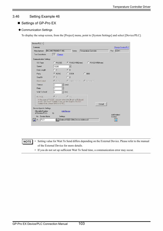
Temperature Controller Driver
GP-Pro EX Device/PLC Connection Manual 103
3.46 Setting Example 46
Settings of GP-Pro EX
Communication Settings
To display the setup screen, from the [Project] menu, point to [System Settings] and select [Device/PLC].
• Setting value for Wait To Send differs depending on the External Device. Please refer to the manual
of the External Device for more details.
• If you do not set up sufficient Wait To Send time, a communication error may occur.
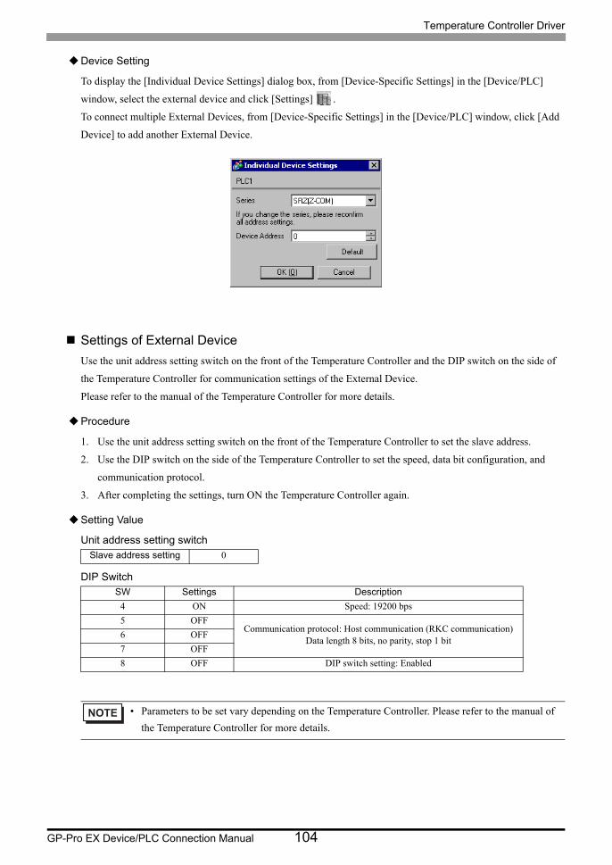
Temperature Controller Driver
GP-Pro EX Device/PLC Connection Manual 104
Device Setting
To display the [Individual Device Settings] dialog box, from [Device-Specific Settings] in the [Device/PLC]
window, select the external device and click [Settings] .
To connect multiple External Devices, from [Device-Specific Settings] in the [Device/PLC] window, click [Add
Device] to add another External Device.
Settings of External Device
Use the unit address setting switch on the front of the Temperature Controller and the DIP switch on the side of
the Temperature Controller for communication settings of the External Device.
Please refer to the manual of the Temperature Controller for more details.
Procedure
1. Use the unit address setting switch on the front of the Temperature Controller to set the slave address.
2. Use the DIP switch on the side of the Temperature Controller to set the speed, data bit configuration, and
communication protocol.
3. After completing the settings, turn ON the Temperature Controller again.
Setting Value
Unit address setting switch
DIP Switch
Slave address setting 0
SW Settings Description
4 ON Speed: 19200 bps
5 OFFCommunication protocol: Host communication (RKC communication)
Data length 8 bits, no parity, stop 1 bit6 OFF
7 OFF
8 OFF DIP switch setting: Enabled
• Parameters to be set vary depending on the Temperature Controller. Please refer to the manual of
the Temperature Controller for more details.

Temperature Controller Driver
GP-Pro EX Device/PLC Connection Manual 105
4 Setup Items
Set communication settings of the Display with GP-Pro EX or in offline mode of the Display.
The setting of each parameter must be identical to that of External Device.
"3 Example of Communication Setting" (page 13)
4.1 Setup Items in GP-Pro EX
Communication Settings
To display the setup screen, from the [Project] menu, point to [System Settings] and select [Device/PLC].
Setup Items Setup Description
SIO Type Select the SIO type to communicate with the External Device.
Speed Select speed between the External Device and the Display.
Data Length Select data length.
Parity Select how to check parity.
Stop Bit Select stop bit length.
Flow ControlDisplay the communication control method to prevent overflow of transmission and reception data.
TimeoutUse an integer from 1 to 127 to enter the time (s) for which the Display waits for the response from the External Device.
RetryIn case of no response from the External Device, use an integer from 0 to 255 to enter how many times the Display retransmits the command.
Wait To SendUse an integer from 0 to 255 to enter standby time (ms) for the Display from receiving packets to transmitting next commands.

Temperature Controller Driver
GP-Pro EX Device/PLC Connection Manual 106
Device Setting
To display the [Individual Device Settings] dialog box, from [Device-Specific Settings] in the [Device/PLC]
window, select the external device and click [Settings] .
To connect multiple External Devices, from [Device-Specific Settings] in the [Device/PLC] window, click [Add
Device] to add another External Device.
RI/VCCYou can switch RI/VCC of the 9th pin when you select RS232C for SIO type.It is necessary to change RI/5V by changeover switch of IPC when connect with IPC. Please refer to the manual of the IPC for more detail.
• Refer to the GP-Pro EX Reference Manual for Indirect Device.
Cf. GP-Pro EX Reference Manual "Changing the Device/PLC at Runtime (Indirect Device)"
Setup Items Setup Description
Series Select the External Device series.
Device Address Enter the address of the External Device, using 0 to 99.
Setup Items Setup Description
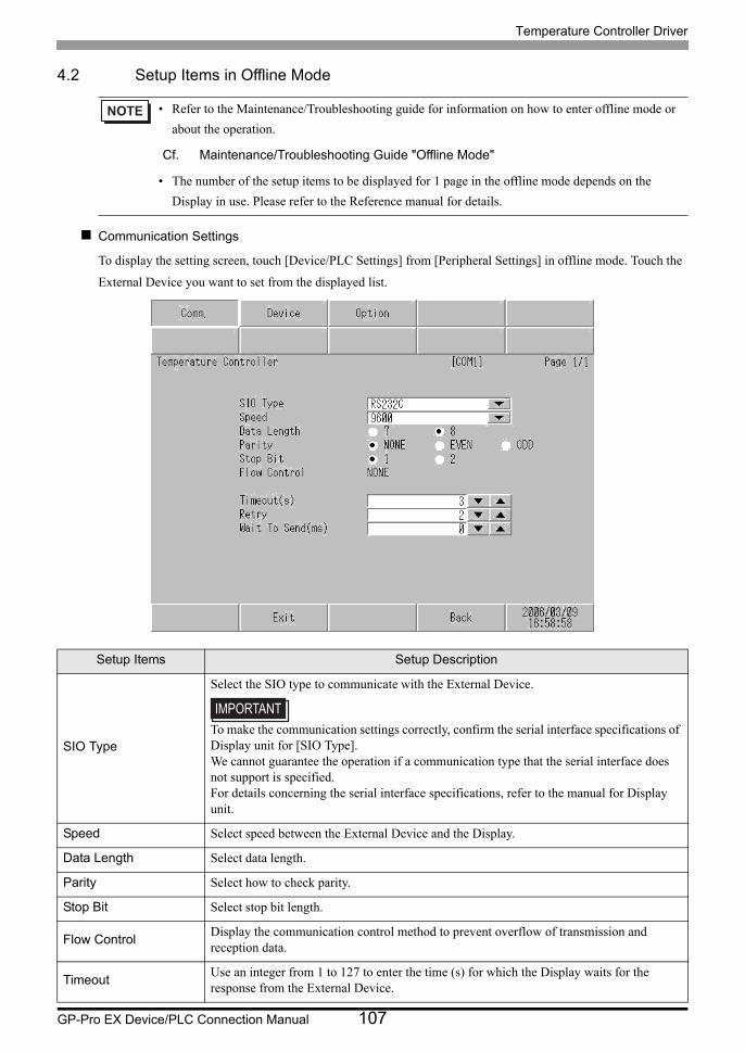
Temperature Controller Driver
GP-Pro EX Device/PLC Connection Manual 107
4.2 Setup Items in Offline Mode
Communication Settings
To display the setting screen, touch [Device/PLC Settings] from [Peripheral Settings] in offline mode. Touch the
External Device you want to set from the displayed list.
• Refer to the Maintenance/Troubleshooting guide for information on how to enter offline mode or
about the operation.
Cf. Maintenance/Troubleshooting Guide "Offline Mode"
• The number of the setup items to be displayed for 1 page in the offline mode depends on the
Display in use. Please refer to the Reference manual for details.
Setup Items Setup Description
SIO Type
Select the SIO type to communicate with the External Device.
To make the communication settings correctly, confirm the serial interface specifications of Display unit for [SIO Type].We cannot guarantee the operation if a communication type that the serial interface does not support is specified.For details concerning the serial interface specifications, refer to the manual for Display unit.
Speed Select speed between the External Device and the Display.
Data Length Select data length.
Parity Select how to check parity.
Stop Bit Select stop bit length.
Flow ControlDisplay the communication control method to prevent overflow of transmission and reception data.
TimeoutUse an integer from 1 to 127 to enter the time (s) for which the Display waits for the response from the External Device.
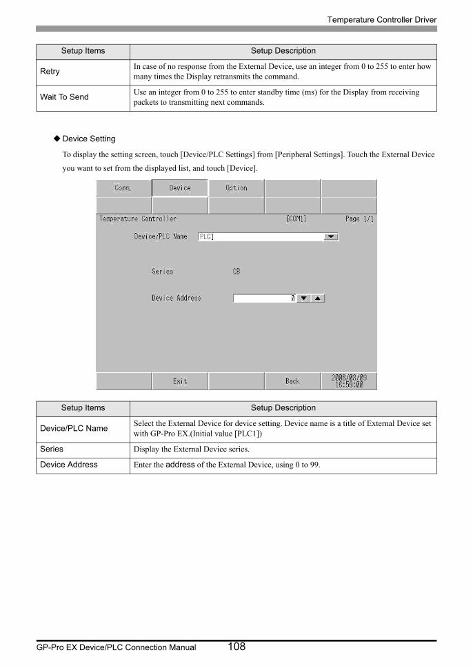
Temperature Controller Driver
GP-Pro EX Device/PLC Connection Manual 108
Device Setting
To display the setting screen, touch [Device/PLC Settings] from [Peripheral Settings]. Touch the External Device
you want to set from the displayed list, and touch [Device].
RetryIn case of no response from the External Device, use an integer from 0 to 255 to enter how many times the Display retransmits the command.
Wait To SendUse an integer from 0 to 255 to enter standby time (ms) for the Display from receiving packets to transmitting next commands.
Setup Items Setup Description
Device/PLC NameSelect the External Device for device setting. Device name is a title of External Device set with GP-Pro EX.(Initial value [PLC1])
Series Display the External Device series.
Device Address Enter the address of the External Device, using 0 to 99.
Setup Items Setup Description
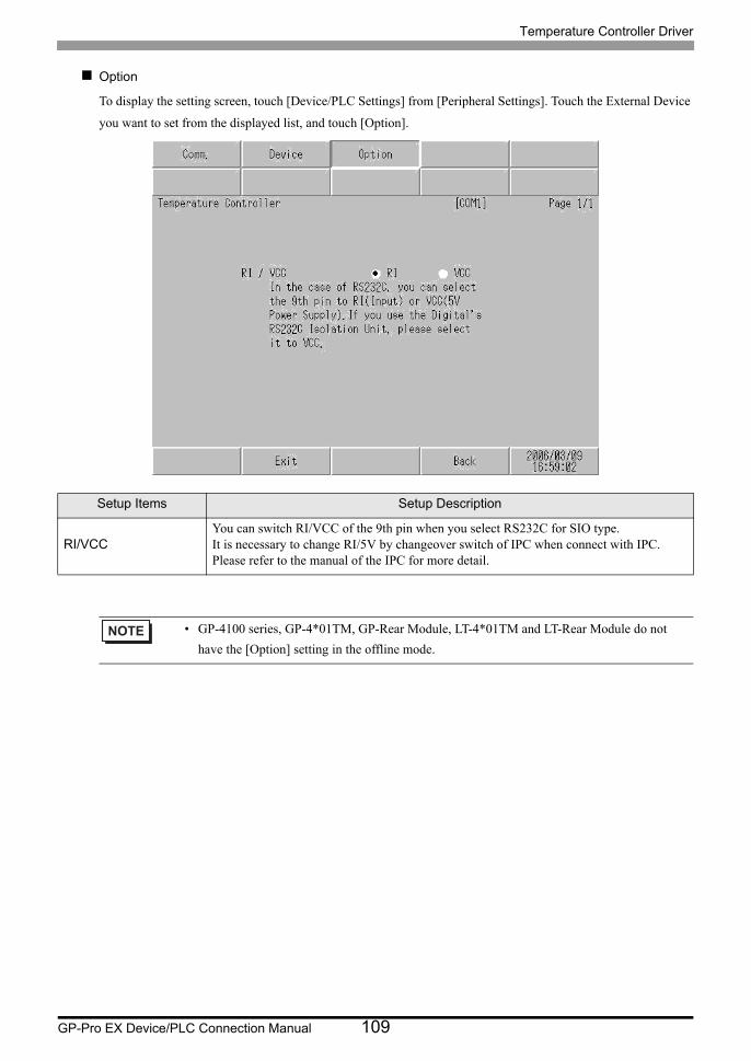
Temperature Controller Driver
GP-Pro EX Device/PLC Connection Manual 109
Option
To display the setting screen, touch [Device/PLC Settings] from [Peripheral Settings]. Touch the External Device
you want to set from the displayed list, and touch [Option].
Setup Items Setup Description
RI/VCCYou can switch RI/VCC of the 9th pin when you select RS232C for SIO type.It is necessary to change RI/5V by changeover switch of IPC when connect with IPC. Please refer to the manual of the IPC for more detail.
• GP-4100 series, GP-4*01TM, GP-Rear Module, LT-4*01TM and LT-Rear Module do not
have the [Option] setting in the offline mode.
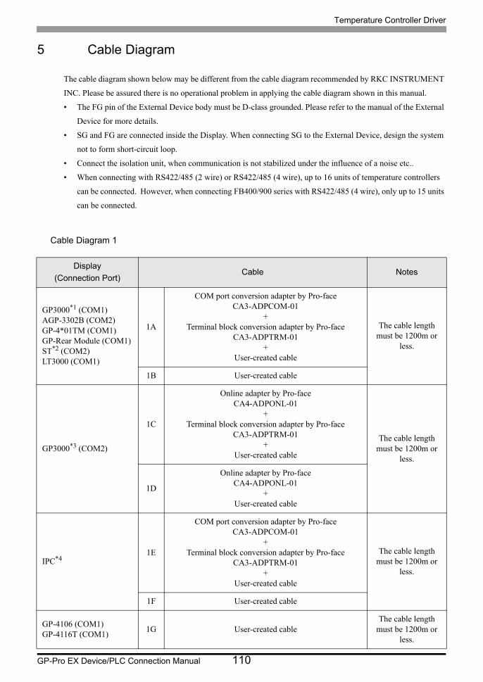
Temperature Controller Driver
GP-Pro EX Device/PLC Connection Manual 110
5 Cable Diagram
The cable diagram shown below may be different from the cable diagram recommended by RKC INSTRUMENT
INC. Please be assured there is no operational problem in applying the cable diagram shown in this manual.
• The FG pin of the External Device body must be D-class grounded. Please refer to the manual of the External
Device for more details.
• SG and FG are connected inside the Display. When connecting SG to the External Device, design the system
not to form short-circuit loop.
• Connect the isolation unit, when communication is not stabilized under the influence of a noise etc..
• When connecting with RS422/485 (2 wire) or RS422/485 (4 wire), up to 16 units of temperature controllers
can be connected. However, when connecting FB400/900 series with RS422/485 (4 wire), only up to 15 units
can be connected.
Cable Diagram 1
Display
(Connection Port)Cable Notes
GP3000*1 (COM1)AGP-3302B (COM2)GP-4*01TM (COM1)GP-Rear Module (COM1)ST*2 (COM2)LT3000 (COM1)
1A
COM port conversion adapter by Pro-faceCA3-ADPCOM-01
+Terminal block conversion adapter by Pro-face
CA3-ADPTRM-01+
User-created cable
The cable length must be 1200m or
less.
1B User-created cable
GP3000*3 (COM2)
1C
Online adapter by Pro-faceCA4-ADPONL-01
+Terminal block conversion adapter by Pro-face
CA3-ADPTRM-01+
User-created cable
The cable length must be 1200m or
less.
1D
Online adapter by Pro-faceCA4-ADPONL-01
+User-created cable
IPC*41E
COM port conversion adapter by Pro-faceCA3-ADPCOM-01
+Terminal block conversion adapter by Pro-face
CA3-ADPTRM-01+
User-created cable
The cable length must be 1200m or
less.
1F User-created cable
GP-4106 (COM1)GP-4116T (COM1)
1G User-created cableThe cable length
must be 1200m or less.

Temperature Controller Driver
GP-Pro EX Device/PLC Connection Manual 111
GP-4107 (COM1)GP-4*03T*5 (COM2)GP-4203T (COM1)
1H User-created cableThe cable length
must be 1200m or less.
GP4000*6 (COM2)GP-4201T (COM1)SP5000*7 (COM1/2)SP-5B00 (COM2)
1I
RS-422 terminal block conversion adapter by Pro-facePFXZCBADTM1*8
+User-created cable
The cable length must be 1200m or
less.
1B User-created cable
LT-4*01TM (COM1)LT-Rear Module (COM1) 1J
RJ45 RS-485 Cable (5m) by Pro-facePFXZLMCBRJR81
The cable length must be 200m or
less.
PE-4000B*9
PS5000*9 1K User-created cableThe cable length
must be 1200m or less.
*1 All GP3000 models except AGP-3302B
*2 All ST models except AST-3211A and AST-3302B
*3 All GP3000 models except GP-3200 series and AGP-3302B
*4 Only the COM port which can communicate by RS-422/485 (2 wire) can be used. (Except PE-4000B, PS5000)
IPC COM Port (page 9)
*5 Except GP-4203T
*6 All GP4000 models except GP-4100 series, GP-4*01TM, GP-Rear Module, GP-4201T and GP-4*03T
*7 Except SP-5B00
*8 When using a Terminal Block Conversion Adapter (CA3-ADPTRM-01) instead of the RS-422 Terminal Block Conversion Adapter, refer to Cable Diagram 1A.
*9 Only the COM port which can communicate by RS-422/485 (2 wire) can be used.
IPC COM Port (page 9)
Display
(Connection Port)Cable Notes
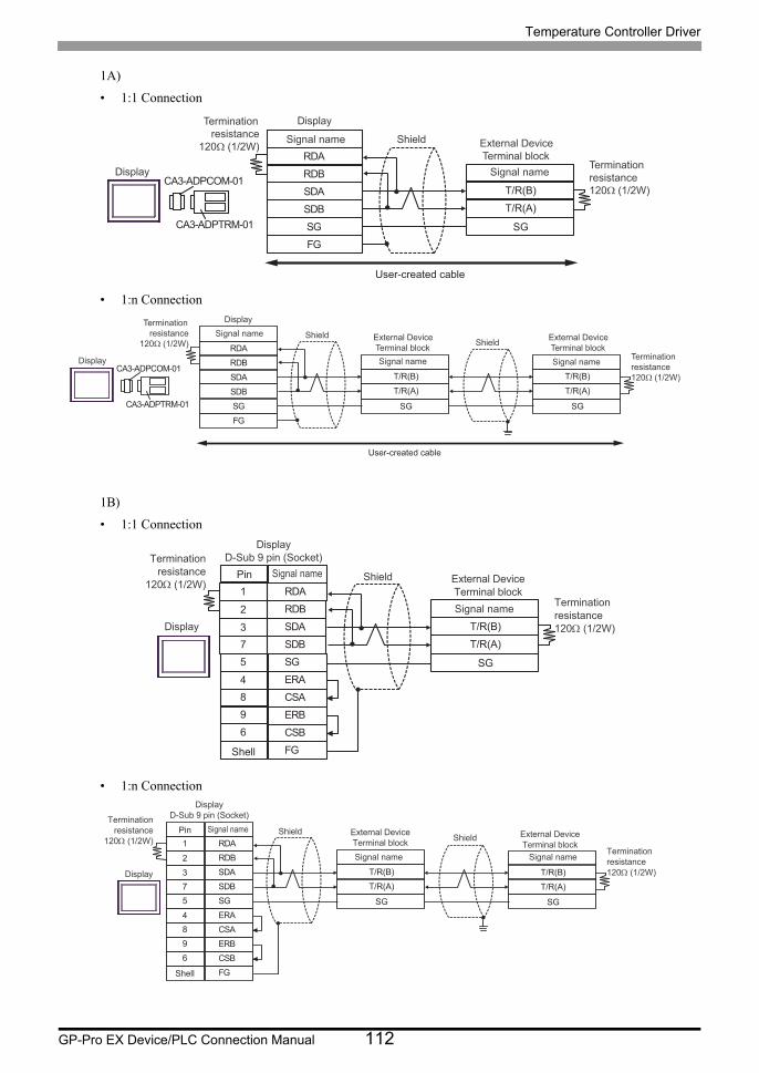
Temperature Controller Driver
GP-Pro EX Device/PLC Connection Manual 112
1A)
• 1:1 Connection
• 1:n Connection
1B)
• 1:1 Connection
• 1:n Connection
RDB
SDBSGFG
CA3-ADPCOM-01
CA3-ADPTRM-01
RDA
SDA T/R(B)
T/R(A)
SG
Terminationresistance
120Ω (1/2W)
Terminationresistance120Ω (1/2W)
Display
Display
External DeviceTerminal block
ShieldSignal name
Signal name
User-created cable
RDB
SDBSGFG
CA3-ADPCOM-01
CA3-ADPTRM-01
RDA
SDA T/R(B)
T/R(A)
SG
T/R(B)
T/R(A)
SG
Terminationresistance
120Ω (1/2W)Terminationresistance120Ω (1/2W)
Display
Display
External DeviceTerminal block
External DeviceTerminal block
ShieldShield
Signal name Signal name
Signal name
User-created cable
SDA3
RDB2
SG5
4 ERA
SDB
ERB
7
9
CSB6
Shell FG
RDA1
Pin
CSA8
T/R(B)
T/R(A)
SG
Terminationresistance
120 (1/2W)
Terminationresistance120 (1/2W)
DisplayD-Sub 9 pin (Socket)
External DeviceTerminal block
Shield
Signal name
Signal name
Display
Shell
SDA3
RDB2
SG5
4 ERA
SDB
ERB
7
9
CSB6
FG
RDA1
CSA8
T/R(B)
T/R(A)
SG
T/R(B)
T/R(A)
SG
Terminationresistance
120 (1/2W)Terminationresistance120 (1/2W)
DisplayD-Sub 9 pin (Socket)
External DeviceTerminal block
External DeviceTerminal block
ShieldShield
Signal name Signal name
Pin Signal name
Display
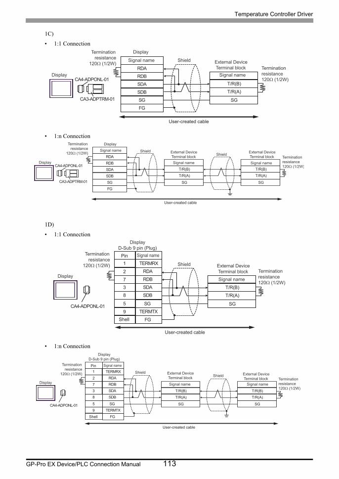
Temperature Controller Driver
GP-Pro EX Device/PLC Connection Manual 113
1C)
• 1:1 Connection
• 1:n Connection
1D)
• 1:1 Connection
• 1:n Connection
RDB
SDBSGFG
CA4-ADPONL-01
CA3-ADPTRM-01
RDA
SDA T/R(B)
T/R(A)
SG
Terminationresistance
120Ω (1/2W)Terminationresistance120Ω (1/2W)
Display
Display
External DeviceTerminal block
ShieldSignal name
Signal name
User-created cable
RDB
SDBSGFG
CA4-ADPONL-01
CA3-ADPTRM-01
RDA
SDA T/R(B)
T/R(A)
SG
T/R(B)
T/R(A)
SG
Terminationresistance
120Ω (1/2W)Terminationresistance120Ω (1/2W)
Display
Display
External DeviceTerminal block
External DeviceTerminal block
ShieldShield
Signal name Signal name
Signal name
User-created cable
CA4-ADPONL-01
RDB7
RDA2
SDB8
9 TERMTX
SDA
FG
3
TERMRX1
SG5
T/R(B)
T/R(A)
SG
Shell
PinTerminationresistance
120Ω (1/2W)Terminationresistance120Ω (1/2W)
DisplayD-Sub 9 pin (Plug)
External DeviceTerminal block
Shield
Signal name
Signal name
Display
User-created cable
CA4-ADPONL-01
RDB7
RDA2
SDB8
9 TERMTX
SDA
FG
3
TERMRX1
SG5
T/R(B)
T/R(A)
SG
T/R(B)
T/R(A)
SG
Shell
Terminationresistance
120Ω (1/2W)Terminationresistance120Ω (1/2W)
DisplayD-Sub 9 pin (Plug)
External DeviceTerminal block
External DeviceTerminal block
ShieldShield
Signal name Signal name
Pin Signal name
Display
User-created cable
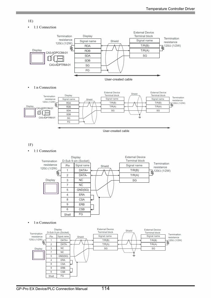
Temperature Controller Driver
GP-Pro EX Device/PLC Connection Manual 114
1E)
• 1:1 Connection
• 1:n Connection
1F)
• 1:1 Connection
• 1:n Connection
RDB
SDBSGFG
CA3-ADPCOM-01
CA3-ADPTRM-01
RDA
SDA
T/R(B)
T/R(A)
SG
Terminationresistance
120Ω (1/2W)Terminationresistance120Ω (1/2W)
Display
Display
External DeviceTerminal block
ShieldSignal name Signal name
User-created cable
RDB
SDBSGFG
CA3-ADPCOM-01
CA3-ADPTRM-01
RDA
SDA
T/R(B)
T/R(A)
SG
T/R(B)
T/R(A)
SG
Terminationresistance
120Ω (1/2W)
Terminationresistance120Ω (1/2W)
Display
Display
External DeviceTerminal block
External DeviceTerminal block
Shield
Shield
Signal name Signal nameSignal name
User-created cable
NC3
DATA-2
GND(SG)5
4 ERA
NC
ERB
7
9
CSB6
Shell FG
DATA+1
Pin
CSA8
T/R(B)
T/R(A)
SG
Termination
resistance
120Ω (1/2W)
Termination
resistance
120Ω (1/2W)
Display
D-Sub 9 pin (Socket)
External Device
Terminal block
Shield Signal nameSignal name
Display
Shell
NC3
DATA-2
GND(SG)5
4 ERA
NC
ERB
7
9
CSB6
FG
DATA+1
CSA8
T/R(B)
T/R(A)
SG
T/R(B)
T/R(A)
SG
Termination
resistance
120Ω (1/2W)
Termination
resistance
120Ω (1/2W)
Display
D-Sub 9 pin (Socket)
External Device
Terminal blockExternal Device
Terminal block
Shield
Shield
Signal name Signal namePin Signal name
Display

Temperature Controller Driver
GP-Pro EX Device/PLC Connection Manual 115
1G)
• 1:1 Connection
• 1:n Connection
*1 The resistance in the Display is used as the termination resistance. Set the value of the DIP Switch on the rear of the Display as shown in the table below.
DIP Switch No. Set Value
1 OFF
2 OFF
3 ON
4 ON
SDARDB
SGERA
SDB
ERBCSB
RDA
CSA
T/R(B)
T/R(A)
SG
Terminationresistance*1
Terminationresistance120Ω (1/2W)
External DeviceTerminal block
Shield
Signal name
Signal name
Display
Display side Terminal block
SDARDB
SGERA
SDB
ERBCSB
RDA
CSA
T/R(B)
T/R(A)
SG
T/R(B)
T/R(A)
SG
Terminationresistance*1
Terminationresistance120Ω (1/2W)
External DeviceTerminal block
External DeviceTerminal block
ShieldShield
Signal name Signal name
Signal name
Display
Display side Terminal block
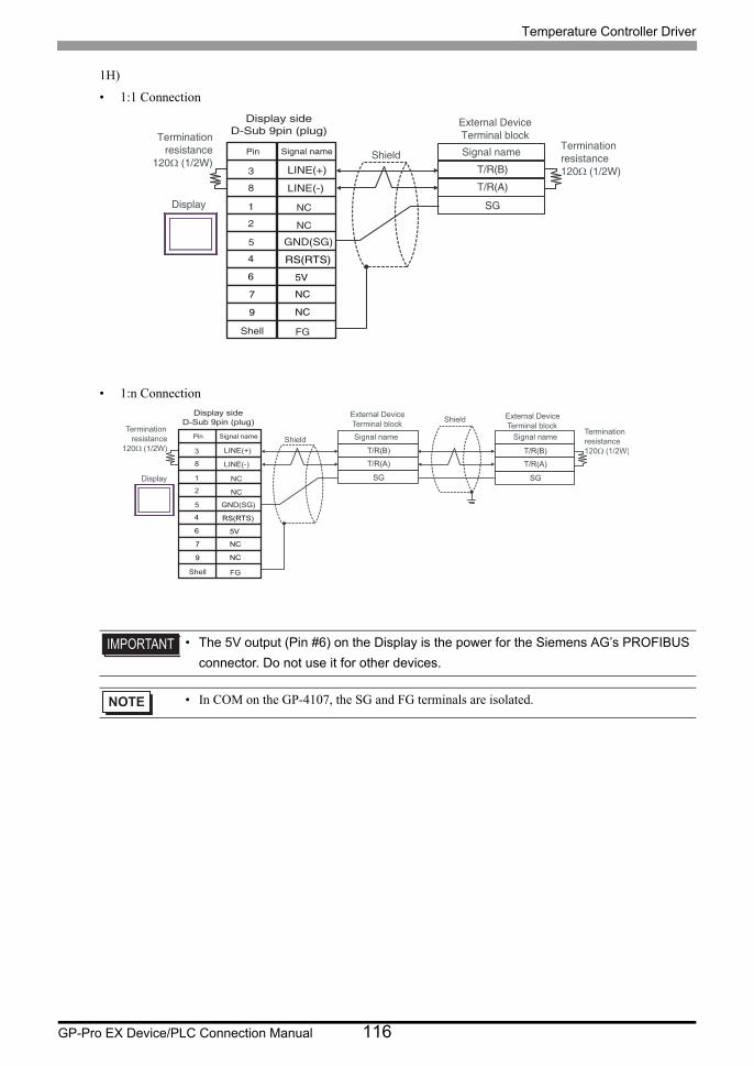
Temperature Controller Driver
GP-Pro EX Device/PLC Connection Manual 116
1H)
• 1:1 Connection
• 1:n Connection
• The 5V output (Pin #6) on the Display is the power for the Siemens AG’s PROFIBUS
connector. Do not use it for other devices.
• In COM on the GP-4107, the SG and FG terminals are isolated.
T/R(B)
T/R(A)
SG
Terminationresistance
120Ω (1/2W)Terminationresistance120Ω (1/2W)
External DeviceTerminal block
Shield Signal name
Display
Pin Signal name
NC
NC
GND(SG)
RS(RTS)
5V
NC
NC
FG
LINE(+)
LINE(-)
3
8
1
2
5
4
6
7
9
Shell
Display sideD-Sub 9pin (plug)
T/R(B)
T/R(A)
SG
T/R(B)
T/R(A)
SG
Terminationresistance
120Ω (1/2W)
Terminationresistance120Ω (1/2W)
External DeviceTerminal block
External DeviceTerminal block
Shield
Shield
Signal name Signal name
Display
Pin Signal name
NC
NC
GND(SG)
RS(RTS)
5V
NC
NC
FG
LINE(+)
LINE(-)
3
8
1
2
5
4
6
7
9
Shell
Display sideD-Sub 9pin (plug)
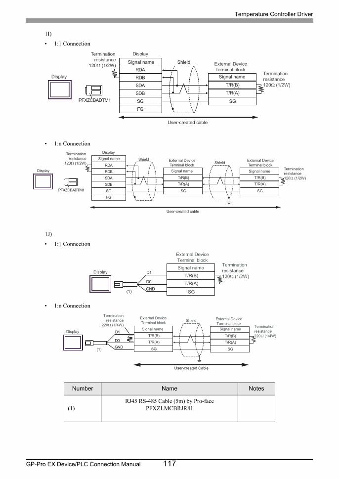
Temperature Controller Driver
GP-Pro EX Device/PLC Connection Manual 117
1I)
• 1:1 Connection
• 1:n Connection
1J)
• 1:1 Connection
• 1:n Connection
Number Name Notes
(1)RJ45 RS-485 Cable (5m) by Pro-face
PFXZLMCBRJR81
RDB
SDB SG FG
PFXZCBADTM1
RDA
SDA T/R(B)
T/R(A)
SG
Termination resistance
120Ω (1/2W)
Termination resistance 120Ω (1/2W)
Display
Display
External Device Terminal block
Shield Signal name
Signal name
User-created cable
RDB
SDB SG FG
PFXZCBADTM1
RDA
SDA T/R(B)
T/R(A)
SG
T/R(B)
T/R(A)
SG
Termination resistance
120Ω (1/2W) Termination resistance 120Ω (1/2W)
Display
Display
External Device Terminal block
External Device Terminal block
Shield Shield
Signal name Signal name
Signal name
User-created cable
T/R(B)
T/R(A)
SG
Terminationresistance120Ω (1/2W)
External DeviceTerminal blockSignal name
Display
GNDD0
D1
(1)
T/R(B)
T/R(A)
SG
T/R(B)
T/R(A)
SG
Terminationresistance
220Ω (1/4W) Terminationresistance220Ω (1/4W)
External DeviceTerminal block
External DeviceTerminal block
Shield
Signal name Signal nameDisplay
GNDD0
D1
(1)
User-created Cable

Temperature Controller Driver
GP-Pro EX Device/PLC Connection Manual 118
1K)
• 1:1 Connection
• 1:n Connection
NC3
DATA-1
GND5
4
NC
NCNCNCNC
7
96
Shell FG
DATA+2Pin
8
T/R(B)
T/R(A)
SG
Terminationresistance
120Ω (1/2W)Terminationresistance120Ω (1/2W)
DisplayD-Sub 9 pin (Socket)
External DeviceTerminal block
Shield Signal nameSignal name
Display
Shell
NC3
DATA-1
GND5
4
NC
NCNC
NCNC
7
96
FG
DATA+2
8
T/R(B)
T/R(A)
SG
T/R(B)
T/R(A)
SG
Terminationresistance
120Ω (1/2W)
Terminationresistance120Ω (1/2W)
DisplayD-Sub 9 pin (Socket)
External DeviceTerminal block
External DeviceTerminal block
Shield
Shield
Signal name Signal namePin Signal name
Display
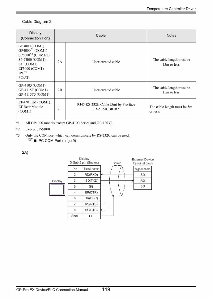
Temperature Controller Driver
GP-Pro EX Device/PLC Connection Manual 119
Cable Diagram 2
2A)
Display
(Connection Port)Cable Notes
GP3000 (COM1)GP4000*1 (COM1)SP5000*2 (COM1/2)SP-5B00 (COM1)ST (COM1)LT3000 (COM1)IPC*3
PC/AT
*1 All GP4000 models except GP-4100 Series and GP-4203T
*2 Except SP-5B00
*3 Only the COM port which can communicate by RS-232C can be used.
IPC COM Port (page 9)
2A User-created cableThe cable length must be
15m or less.
GP-4105 (COM1)GP-4115T (COM1)GP-4115T3 (COM1)
2B User-created cableThe cable length must be
15m or less.
LT-4*01TM (COM1)LT-Rear Module (COM1)
2CRJ45 RS-232C Cable (5m) by Pro-face
PFXZLMCBRJR21The cable length must be 5m or less.
SD(TXD)3
RD(RXD)2
SG5
SD
RD
4 ER(DTR)
SG
RS(RTS)
CS(CTS)
7
8
DR(DSR)6
FGShell
DisplayD-Sub 9 pin (Socket)
External DeviceTerminal blockShield
Display
Pin Signal nameSignal name
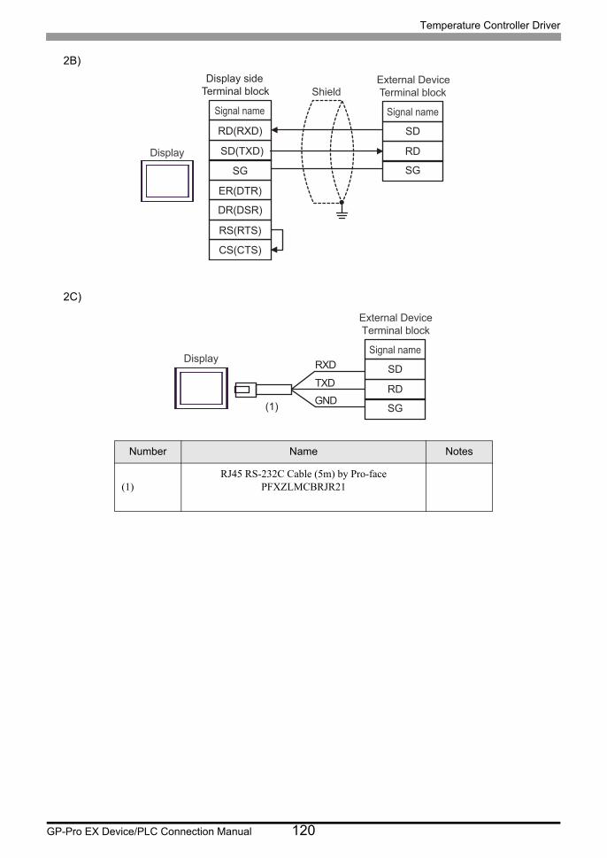
Temperature Controller Driver
GP-Pro EX Device/PLC Connection Manual 120
2B)
2C)
Number Name Notes
(1)RJ45 RS-232C Cable (5m) by Pro-face
PFXZLMCBRJR21
SD(TXD)
RD(RXD)
SG
SD
RD
ER(DTR)
SG
RS(RTS)
CS(CTS)
DR(DSR)
External DeviceTerminal blockShield
Display
Signal nameSignal name
Display side Terminal block
SD
RD
SG
External DeviceTerminal block
Signal nameDisplay
GNDTXD
RXD
(1)

Temperature Controller Driver
GP-Pro EX Device/PLC Connection Manual 121
Cable Diagram 3
Display
(Connection Port)Cable Notes
GP3000*1 (COM1)AGP-3302B (COM2)GP-4*01TM (COM1)GP-Rear Module (COM1)ST*2 (COM2)LT3000 (COM1)IPC*3
*1 All GP3000 models except AGP-3302B
*2 All ST models except AST-3211A and AST-3302B
*3 Only the COM port which can communicate by RS-422/485 (4 wire) can be used. (Except PE-4000B, PS5000)
IPC COM Port (page 9)
3A
COM port conversion adapter by Pro-faceCA3-ADPCOM-01
+Terminal block conversion adapter by Pro-face
CA3-ADPTRM-01+
User-created cable
The cable length must be 1200m or
less.
3B User-created cable
GP3000*4 (COM2)
*4 All GP3000 models except GP-3200 series and AGP-3302B
3C
Online adapter by Pro-faceCA4-ADPONL-01
+Terminal block conversion adapter by Pro-face
CA3-ADPTRM-01+
User-created cable
The cable length must be 1200m or
less.
3D
Online adapter by Pro-faceCA4-ADPONL-01
+User-created cable
GP-4106 (COM1)GP-4116T (COM1)
3E User-created cableThe cable length
must be 1200m or less.
GP4000*5 (COM2)GP-4201T (COM1)SP5000*6 (COM1/2)SP-5B00 (COM2)
*5 All GP4000 models except GP-4100 series, GP-4*01TM, GP-Rear Module, GP-4201T and GP-4*03T
*6 Except SP-5B00
3F
RS-422 terminal block conversion adapter by Pro-facePFXZCBADTM1*7
+User-created cable
*7 When using a Terminal Block Conversion Adapter (CA3-ADPTRM-01) instead of the RS-422 Terminal Block Conversion Adapter, refer to Cable Diagram 3A.
The cable length must be 1200m or
less.
3B User-created cable
PE-4000B*8
PS5000*8
*8 Only the COM port which can communicate by RS-422/485 (4 wire) can be used.
IPC COM Port (page 9)
3G User-created cableThe cable length
must be 1200m or less.
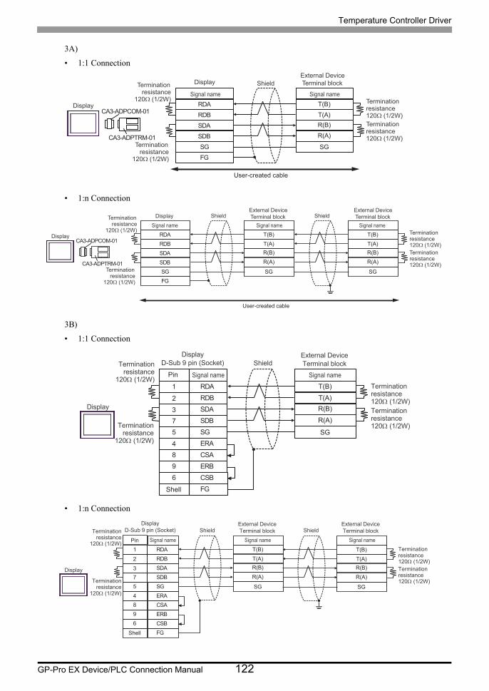
Temperature Controller Driver
GP-Pro EX Device/PLC Connection Manual 122
3A)
• 1:1 Connection
• 1:n Connection
3B)
• 1:1 Connection
• 1:n Connection
RDB
SDBSGFG
CA3-ADPCOM-01
CA3-ADPTRM-01
RDA
SDA
T(B)
T(A)R(B)
R(A)
SG
External DeviceTerminal blockShield
Display
Signal name Signal nameTermination
resistance120Ω (1/2W) Termination
resistance120Ω (1/2W)Terminationresistance120Ω (1/2W)
Terminationresistance
120Ω (1/2W)
Display
User-created cable
RDB
SDBSGFG
CA3-ADPCOM-01
CA3-ADPTRM-01
RDA
SDA
T(B)
T(A)R(B)
R(A)
SG
T(B)
T(A)R(B)
R(A)
SG
External DeviceTerminal block
External DeviceTerminal blockShield Shield
Display
Signal name Signal name Signal nameTerminationresistance120Ω (1/2W)Terminationresistance120Ω (1/2W)
Terminationresistance
120Ω (1/2W)
Terminationresistance
120Ω (1/2W)
Display
User-created cable
SDA3
RDB2
SG5
4 ERA
SDB
ERB
7
9
CSB6
FG
RDA1
CSA8
T(B)
T(A)
R(B)
R(A)
SG
Shell
DisplayD-Sub 9 pin (Socket)
External DeviceTerminal blockShield
Display
Pin Signal nameSignal name
Terminationresistance120 (1/2W)Terminationresistance120 (1/2W)
Terminationresistance
120 (1/2W)
Terminationresistance
120 (1/2W)
SDA3
RDB2
SG5
4 ERA
SDB
ERB
7
9
CSB6
FG
RDA1
CSA8
T(B)
T(A)
R(B)
R(A)
SG
T(B)
T(A)
R(B)
R(A)
SG
Shell
DisplayD-Sub 9 pin (Socket)
External DeviceTerminal block
External DeviceTerminal blockShield Shield
Display
Pin Signal name Signal nameSignal name
Terminationresistance120 (1/2W)Terminationresistance120 (1/2W)
Terminationresistance
120 (1/2W)
Terminationresistance
120 (1/2W)
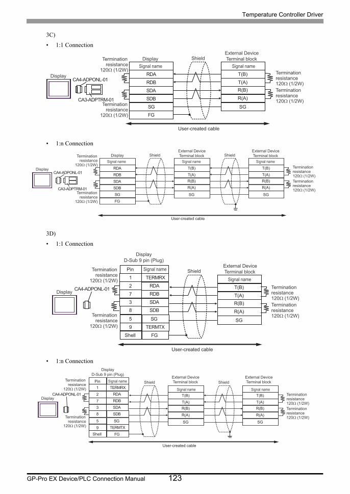
Temperature Controller Driver
GP-Pro EX Device/PLC Connection Manual 123
3C)
• 1:1 Connection
• 1:n Connection
3D)
• 1:1 Connection
• 1:n Connection
RDB
SDBSGFG
CA4-ADPONL-01
CA3-ADPTRM-01
RDA
SDA
T(B)
T(A)R(B)
R(A)
SG
External DeviceTerminal blockShield
Display
DisplaySignal name Signal name
Terminationresistance120Ω (1/2W)Terminationresistance120Ω (1/2W)
Terminationresistance
120Ω (1/2W)
Terminationresistance
120Ω (1/2W)
User-created cable
RDB
SDBSGFG
CA4-ADPONL-01
CA3-ADPTRM-01
RDA
SDA
T(B)
T(A)R(B)
R(A)
SG
T(B)
T(A)R(B)
R(A)
SG
External DeviceTerminal block
External DeviceTerminal blockShield ShieldDisplay
Display
Signal name Signal name Signal nameTerminationresistance120Ω (1/2W)Terminationresistance120Ω (1/2W)
Terminationresistance
120Ω (1/2W)
Terminationresistance
120Ω (1/2W)
User-created cable
CA4-ADPONL-01RDB7
RDA2
SDB8
9 TERMTX
SDA
FG
3
TERMRX1
SG5
T(B)
T(A)R(B)
R(A)
SG
External DeviceTerminal blockShield
Display
Signal nameTerminationresistance120Ω (1/2W)Terminationresistance120Ω (1/2W)
Terminationresistance
120Ω (1/2W)
Terminationresistance
120Ω (1/2W)
Shell
DisplayD-Sub 9 pin (Plug)
Pin Signal name
User-created cable
CA4-ADPONL-01RDB7
RDA2
SDB8
9 TERMTX
SDA
FG
3
TERMRX1
SG5
T(B)
T(A)R(B)
R(A)
SG
T(B)
T(A)R(B)
R(A)
SG
External DeviceTerminal block
External DeviceTerminal blockShield Shield
DisplayTerminationresistance120Ω (1/2W)Terminationresistance120Ω (1/2W)
Terminationresistance
120Ω (1/2W)
Terminationresistance
120Ω (1/2W)
Shell
DisplayD-Sub 9 pin (Plug)
Signal name Signal name
Pin Signal name
User-created cable
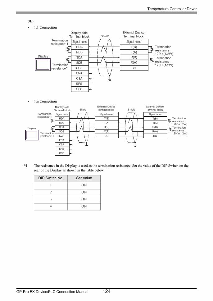
Temperature Controller Driver
GP-Pro EX Device/PLC Connection Manual 124
3E)
• 1:1 Connection
• 1:n Connection
*1 The resistance in the Display is used as the termination resistance. Set the value of the DIP Switch on the rear of the Display as shown in the table below.
DIP Switch No. Set Value
1 ON
2 ON
3 ON
4 ON
SDARDB
SGERA
SDB
ERBCSB
RDA
CSA
T(B)
T(A)R(B)
R(A)
SG
External DeviceTerminal blockShield
Display
Signal nameSignal nameTerminationresistance120Ω (1/2W)Terminationresistance120Ω (1/2W)
Terminationresistance*1
Terminationresistance*1
Display side Terminal block
SDARDB
SGERA
SDB
ERBCSB
RDA
CSA
T(B)
T(A)R(B)
R(A)
SG
T(B)
T(A)R(B)
R(A)
SG
External DeviceTerminal block
External DeviceTerminal blockShield Shield
Display
Signal name Signal nameSignal nameTerminationresistance120Ω (1/2W)Terminationresistance120Ω (1/2W)
Terminationresistance*1
Terminationresistance*1
Display side Terminal block
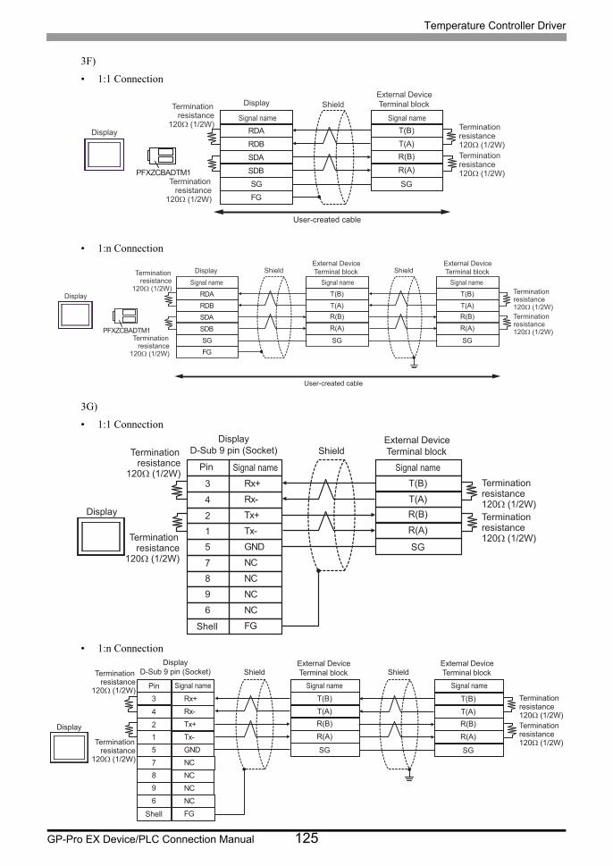
Temperature Controller Driver
GP-Pro EX Device/PLC Connection Manual 125
3F)
• 1:1 Connection
• 1:n Connection
3G)
• 1:1 Connection
• 1:n Connection
RDB
SDB SG FG
PFXZCBADTM1
RDA
SDA
T(B)
T(A) R(B)
R(A)
SG
External Device Terminal block Shield
Display
Signal name Signal name Termination
resistance 120Ω (1/2W) Termination
resistance 120Ω (1/2W)Termination resistance 120Ω (1/2W)
Termination resistance
120Ω (1/2W)
Display
User-created cable
RDB
SDB SG FG
PFXZCBADTM1
RDA
SDA
T(B)
T(A) R(B)
R(A)
SG
T(B)
T(A) R(B)
R(A)
SG
External Device Terminal block
External Device Terminal block Shield Shield
Display
Signal name Signal name Signal name Termination resistance 120Ω (1/2W)Termination resistance 120Ω (1/2W)
Termination resistance
120Ω (1/2W)
Termination resistance
120Ω (1/2W)
Display
User-created cable
Tx+2
Rx-4
GND5
7 NC
Tx-
NC
1
9
NC6FG
Rx+3
NC8
T(B)
T(A)R(B)
R(A)
SG
Shell
DisplayD-Sub 9 pin (Socket)
External DeviceTerminal blockShield
Display
Pin Signal nameSignal nameTerminationresistance120Ω (1/2W)Terminationresistance120Ω (1/2W)
Terminationresistance
120Ω (1/2W)
Terminationresistance
120Ω (1/2W)
Tx+2
Rx-4
GND5
7 NC
Tx-
NC
1
9
NC6
FG
Rx+3
NC8
T(B)
T(A)R(B)
R(A)
SG
T(B)
T(A)R(B)
R(A)
SG
Shell
DisplayD-Sub 9 pin (Socket)
External DeviceTerminal block
External DeviceTerminal blockShield Shield
Display
Pin Signal name Signal nameSignal nameTerminationresistance120Ω (1/2W)Terminationresistance120Ω (1/2W)
Terminationresistance
120Ω (1/2W)
Terminationresistance
120Ω (1/2W)

Temperature Controller Driver
GP-Pro EX Device/PLC Connection Manual 126
Cable Diagram 4
Display
(Connection Port)Cable Notes
GP3000*1 (COM1)AGP-3302B (COM2)GP-4*01TM (COM1)GP-Rear Module (COM1)ST*2 (COM2)LT3000 (COM1)IPC*3
*1 All GP3000 models except AGP-3302B
*2 All ST models except AST-3211A and AST-3302B
*3 Only the COM port which can communicate by RS-422/485 (4 wire) can be used. (Except PE-4000B, PS5000)
IPC COM Port (page 9)
4A
COM port conversion adapter by Pro-faceCA3-ADPCOM-01
+Terminal block conversion adapter by Pro-face
CA3-ADPTRM-01+
User-created cable
The cable length must be 1200m or
less.
4B User-created cable
GP3000*4 (COM2)
*4 All GP3000 models except GP-3200 series and AGP-3302B
4C
Online adapter by Pro-faceCA4-ADPONL-01
+Terminal block conversion adapter by Pro-face
CA3-ADPTRM-01+
User-created cable
The cable length must be 1200m or
less.
4D
Online adapter by Pro-faceCA4-ADPONL-01
+User-created cable
GP-4106 (COM1)GP-4116T (COM1)
4E User-created cableThe cable length
must be 1200m or less.
GP4000*5 (COM2)GP-4201T (COM1)SP5000*6 (COM1/2)SP-5B00 (COM2)
*5 All GP4000 models except GP-4100 series, GP-4*01TM, GP-Rear Module, GP-4201T and GP-4*03T
*6 Except SP-5B00
4F
RS-422 terminal block conversion adapter by Pro-facePFXZCBADTM1*7
+User-created cable
*7 When using a Terminal Block Conversion Adapter (CA3-ADPTRM-01) instead of the RS-422 Terminal Block Conversion Adapter, refer to Cable Diagram 4A.
The cable length must be 1200m or
less.
4B User-created cable
PE-4000B*8
PS5000*8
*8 Only the COM port which can communicate by RS-422/485 (4 wire) can be used.
IPC COM Port (page 9)
4G User-created cableThe cable length
must be 1200m or less.

Temperature Controller Driver
GP-Pro EX Device/PLC Connection Manual 127
4A)
• 1:1 Connection
• 1:n Connection
• Terminal resistance is not required.
RDB
SDBSGFG
CA3-ADPCOM-01
CA3-ADPTRM-01
RDA
SDA
4
52
T(B)
T(A)R(B)
1 R(A)
3 SG6
External DeviceCOM.PORT 1Modular 6 pinShield
Shield
Display
DisplaySignal name Pin Signal name
User-created cable
3 SG 3 SG 3 SG 3 SG
RDB
SDBSGFG
CA3-ADPCOM-01
CA3-ADPTRM-01
RDA
SDA
4
52
T(B)
T(A)R(B)
1 R(A)
6
4
52
T(B)
T(A)R(B)
1 R(A)
6
4
52
T(B)
T(A)R(B)
1 R(A)
6
4
52
T(B)
T(A)R(B)
1 R(A)
6
External DeviceCOM.PORT 1Modular 6 pin
External DeviceCOM.PORT 2Modular 6 pin
External DeviceCOM.PORT 1Modular 6 pin
External DeviceCOM.PORT 2Modular 6 pinShield Shield
Shield Shield Shield Shield
Display
Display
Signal name Pin Signal name Pin Signal name Pin Signal name Pin Signal name
User-created cable
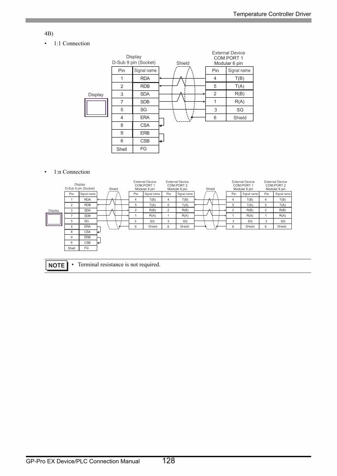
Temperature Controller Driver
GP-Pro EX Device/PLC Connection Manual 128
4B)
• 1:1 Connection
• 1:n Connection
• Terminal resistance is not required.
3 SG
4
5
2
T(B)
T(A)
R(B)
1 R(A)
6
SDA3
RDB2
SG5
4 ERA
SDB
ERB
7
9
CSB6
FG
RDA1
CSA8
External DeviceCOM.PORT 1Modular 6 pinShield
Shield
Display
Shell
DisplayD-Sub 9 pin (Socket)
Pin Signal name Pin Signal name
4
5
2
T(B)
T(A)
R(B)
1 R(A)
6
SDA3
RDB2
SG5
4 ERA
SDB
ERB
7
9
CSB6
FG
RDA1
CSA8
4
5
2
T(B)
T(A)
R(B)
1 R(A)
6
4
5
2
T(B)
T(A)
R(B)
1 R(A)
6
4
5
2
T(B)
T(A)
R(B)
1 R(A)
6
3 SG3 SG 3 SG3 SG
External DeviceCOM.PORT 1Modular 6 pin
External DeviceCOM.PORT 2Modular 6 pin
External DeviceCOM.PORT 1Modular 6 pin
External DeviceCOM.PORT 2Modular 6 pinShield Shield
Shield Shield Shield Shield
Display
Shell
DisplayD-Sub 9 pin (Socket)
Pin Signal name Pin Signal name Pin Signal name Pin Signal name Pin Signal name

Temperature Controller Driver
GP-Pro EX Device/PLC Connection Manual 129
4C)
• 1:1 Connection
• 1:n Connection
• Terminal resistance is not required.
RDB
SDBSGFG
CA4-ADPONL-01
CA3-ADPTRM-01
RDA
SDA
4
52
T(B)
T(A)R(B)
1 R(A)
63 SG
Shield
Display
Display
Signal name
External DeviceCOM.PORT 1Modular 6 pin
Shield
Pin Signal name
User-created cable
RDB
SDBSGFG
CA4-ADPONL-01
CA3-ADPTRM-01
RDA
SDA
4
52
T(B)
T(A)R(B)
1 R(A)
6
4
52
T(B)
T(A)R(B)
1 R(A)
6
4
52
T(B)
T(A)R(B)
1 R(A)
6
4
52
T(B)
T(A)R(B)
1 R(A)
63 SG3 SG3 SG3 SG
Shield Shield
Display
Display
Signal name
External DeviceCOM.PORT 1Modular 6 pin
External DeviceCOM.PORT 2Modular 6 pin
Shield Shield
Pin Signal name Pin Signal name
External DeviceCOM.PORT 1Modular 6 pin
External DeviceCOM.PORT 2Modular 6 pin
Shield Shield
Pin Signal name Pin Signal name
User-created cable
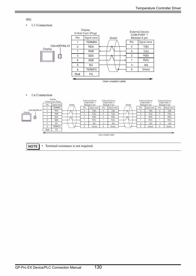
Temperature Controller Driver
GP-Pro EX Device/PLC Connection Manual 130
4D)
• 1:1 Connection
• 1:n Connection
• Terminal resistance is not required.
CA4-ADPONL-01 4
52
T(B)
T(A)R(B)
1 R(A)
6
RDB7
RDA2
SDB8
9 TERMTX
SDA
FGShell
3
TERMRX1
SG5 3 SG
Shield
Display
DisplayD-Sub 9 pin (Plug)
Pin Signal name
External DeviceCOM.PORT 1Modular 6 pin
Shield
Pin Signal name
User-created cable
CA4-ADPONL-01 4
52
T(B)
T(A)R(B)
1 R(A)
6
RDB7
RDA2
SDB8
9 TERMTX
SDA
FG
3
TERMRX1
SG5
4
52
T(B)
T(A)R(B)
1 R(A)
6
4
52
T(B)
T(A)R(B)
1 R(A)
6
4
52
T(B)
T(A)R(B)
1 R(A)
63 SG3 SG 3 SG3 SG
Shield Shield
Shell
Display
DisplayD-Sub 9 pin (Plug)
Pin Signal name
External DeviceCOM.PORT 1Modular 6 pin
External DeviceCOM.PORT 2Modular 6 pin
Shield Shield
Pin Signal name Pin Signal name
External DeviceCOM.PORT 1Modular 6 pin
External DeviceCOM.PORT 2Modular 6 pin
Shield Shield
Pin Signal name Pin Signal name
User-created cable

Temperature Controller Driver
GP-Pro EX Device/PLC Connection Manual 131
4E)
• 1:1 Connection
• 1:n Connection
• Terminal resistance is not required.
3 SG
4
52
T(B)
T(A)R(B)
1 R(A)
6
SDARDB
SGERA
SDB
ERBCSB
RDA
CSA
External DeviceCOM.PORT 1Modular 6 pinShield
Shield
Display
Signal name Pin Signal name
Display side Terminal block
4
52
T(B)
T(A)R(B)
1 R(A)
6
SDARDB
SGERA
SDB
ERBCSB
RDA
CSA
4
52
T(B)
T(A)R(B)
1 R(A)
6
4
52
T(B)
T(A)R(B)
1 R(A)
6
4
52
T(B)
T(A)R(B)
1 R(A)
63 SG3 SG 3 SG3 SG
External DeviceCOM.PORT 1Modular 6 pin
External DeviceCOM.PORT 2Modular 6 pin
External DeviceCOM.PORT 1Modular 6 pin
External DeviceCOM.PORT 2Modular 6 pinShield Shield
Shield Shield Shield Shield
Display
Signal name Pin Signal name Pin Signal name Pin Signal name Pin Signal name
Display side Terminal block
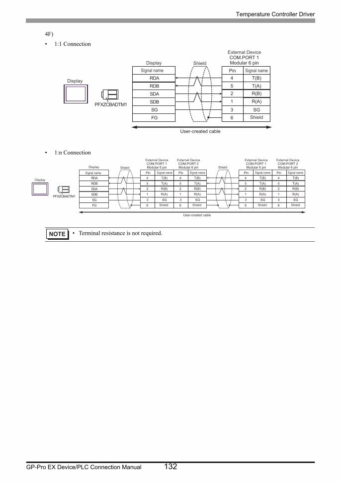
Temperature Controller Driver
GP-Pro EX Device/PLC Connection Manual 132
4F)
• 1:1 Connection
• 1:n Connection
• Terminal resistance is not required.
RDB
SDB SG FG
PFXZCBADTM1
RDA
SDA
4
5 2
T(B)
T(A) R(B)
1 R(A)
3 SG 6
External Device COM.PORT 1 Modular 6 pin Shield
Shield
Display
Display Signal name Pin Signal name
User-created cable
3 SG 3 SG 3 SG 3 SG
RDB
SDB SG FG
PFXZCBADTM1
RDA
SDA
4
5 2
T(B)
T(A) R(B)
1 R(A)
6
4
5 2
T(B)
T(A) R(B)
1 R(A)
6
4
5 2
T(B)
T(A) R(B)
1 R(A)
6
4
5 2
T(B)
T(A) R(B)
1 R(A)
6
External Device COM.PORT 1 Modular 6 pin
External Device COM.PORT 2 Modular 6 pin
External Device COM.PORT 1 Modular 6 pin
External Device COM.PORT 2 Modular 6 pin Shield Shield
Shield Shield Shield Shield
Display
Display
Signal name Pin Signal name Pin Signal name Pin Signal name Pin Signal name
User-created cable
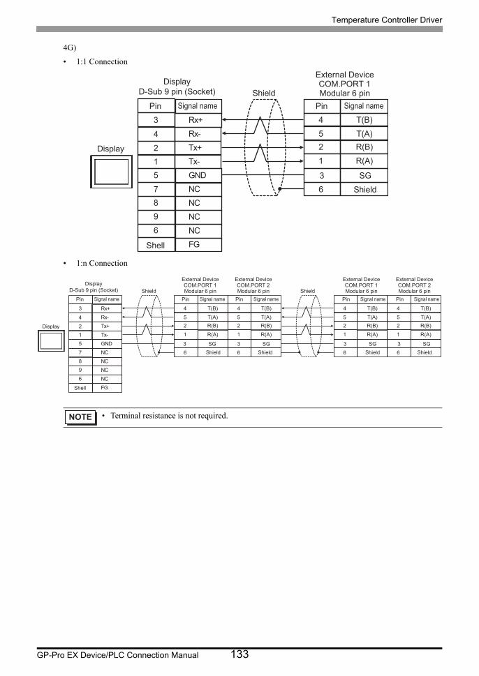
Temperature Controller Driver
GP-Pro EX Device/PLC Connection Manual 133
4G)
• 1:1 Connection
• 1:n Connection
• Terminal resistance is not required.
3 SG
4
52
T(B)
T(A)R(B)
1 R(A)
6
Tx+2
Rx-4
GND5
7 NC
Tx-
NC
1
9
NC6
FG
Rx+3
NC8
External DeviceCOM.PORT 1Modular 6 pinShield
Shield
Display
Shell
DisplayD-Sub 9 pin (Socket)
Pin Signal name Pin Signal name
4
52
T(B)
T(A)R(B)
1 R(A)
6
Tx+2
Rx-4
GND5
7 NC
Tx-
NC
1
9
NC6
FG
Rx+3
NC8
4
52
T(B)
T(A)R(B)
1 R(A)
6
4
52
T(B)
T(A)R(B)
1 R(A)
6
4
52
T(B)
T(A)R(B)
1 R(A)
63 SG3 SG 3 SG3 SG
External DeviceCOM.PORT 1Modular 6 pin
External DeviceCOM.PORT 2Modular 6 pin
External DeviceCOM.PORT 1Modular 6 pin
External DeviceCOM.PORT 2Modular 6 pinShield Shield
Shield Shield Shield Shield
Display
Shell
DisplayD-Sub 9 pin (Socket)
Pin Signal name Pin Signal name Pin Signal name Pin Signal name Pin Signal name
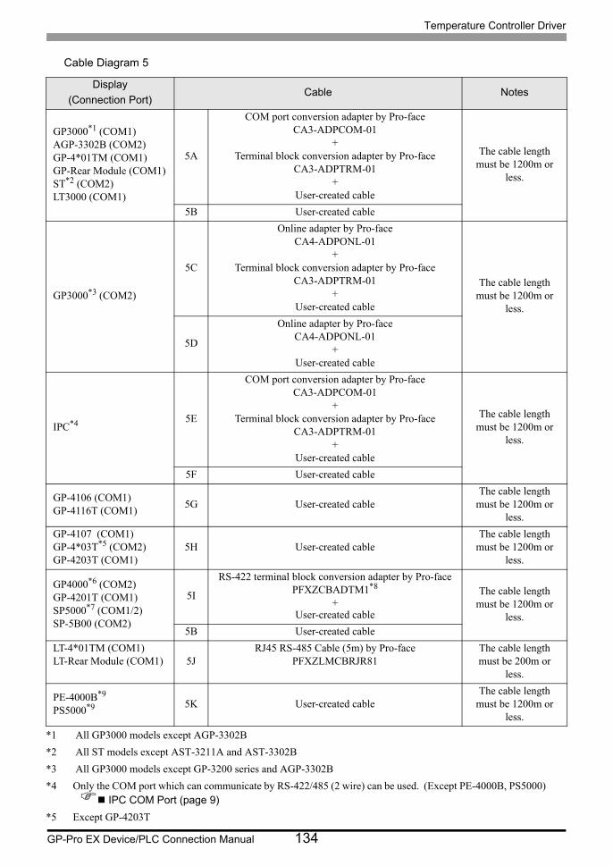
Temperature Controller Driver
GP-Pro EX Device/PLC Connection Manual 134
Cable Diagram 5
Display
(Connection Port)Cable Notes
GP3000*1 (COM1)AGP-3302B (COM2)GP-4*01TM (COM1)GP-Rear Module (COM1)ST*2 (COM2)LT3000 (COM1)
*1 All GP3000 models except AGP-3302B
*2 All ST models except AST-3211A and AST-3302B
5A
COM port conversion adapter by Pro-faceCA3-ADPCOM-01
+Terminal block conversion adapter by Pro-face
CA3-ADPTRM-01+
User-created cable
The cable length must be 1200m or
less.
5B User-created cable
GP3000*3 (COM2)
*3 All GP3000 models except GP-3200 series and AGP-3302B
5C
Online adapter by Pro-faceCA4-ADPONL-01
+Terminal block conversion adapter by Pro-face
CA3-ADPTRM-01+
User-created cable
The cable length must be 1200m or
less.
5D
Online adapter by Pro-faceCA4-ADPONL-01
+User-created cable
IPC*4
*4 Only the COM port which can communicate by RS-422/485 (2 wire) can be used. (Except PE-4000B, PS5000) IPC COM Port (page 9)
5E
COM port conversion adapter by Pro-faceCA3-ADPCOM-01
+Terminal block conversion adapter by Pro-face
CA3-ADPTRM-01+
User-created cable
The cable length must be 1200m or
less.
5F User-created cable
GP-4106 (COM1)GP-4116T (COM1)
5G User-created cableThe cable length
must be 1200m or less.
GP-4107 (COM1)GP-4*03T*5 (COM2)GP-4203T (COM1)
*5 Except GP-4203T
5H User-created cableThe cable length
must be 1200m or less.
GP4000*6 (COM2)GP-4201T (COM1)SP5000*7 (COM1/2)SP-5B00 (COM2)
5I
RS-422 terminal block conversion adapter by Pro-facePFXZCBADTM1*8
+User-created cable
The cable length must be 1200m or
less.5B User-created cable
LT-4*01TM (COM1)LT-Rear Module (COM1) 5J
RJ45 RS-485 Cable (5m) by Pro-facePFXZLMCBRJR81
The cable length must be 200m or
less.
PE-4000B*9
PS5000*9 5K User-created cableThe cable length
must be 1200m or less.
Temperature Controller Driver
GP-Pro EX Device/PLC Connection Manual 135
*6 All GP4000 models except GP-4100 series, GP-4*01TM, GP-Rear Module, GP-4201T and GP-4*03T
*7 Except SP-5B00
*8 When using a Terminal Block Conversion Adapter (CA3-ADPTRM-01) instead of the RS-422 Terminal Block Conversion Adapter, refer to Cable Diagram 5A.
*9 Only the COM port which can communicate by RS-422/485 (2 wire) can be used. IPC COM Port (page 9)
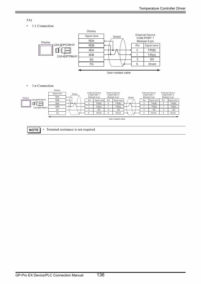
Temperature Controller Driver
GP-Pro EX Device/PLC Connection Manual 136
5A)
• 1:1 Connection
• 1:n Connection
• Terminal resistance is not required.
RDB
SDBSGFG
CA3-ADPCOM-01
CA3-ADPTRM-01
RDA
SDA 2
1
T/R(B)
T/R(A)
63 SG
Shield
Display
Display
Signal name External DeviceCOM.PORT 1Modular 6 pin
Shield
Pin Signal name
User-created cable
RDB
SDBSGFG
CA3-ADPCOM-01
CA3-ADPTRM-01
RDA
SDA 2
1
T/R(B)
T/R(A)
6
2
1
T/R(B)
T/R(A)
6
2
1
T/R(B)
T/R(A)
6
2
1
T/R(B)
T/R(A)
63 SG 3 SG 3 SG 3 SG
Shield
ShieldDisplay
Display
Signal name External DeviceCOM.PORT 1Modular 6 pin
Shield Shield
Pin Signal name
External DeviceCOM.PORT 2Modular 6 pinPin Signal name
External DeviceCOM.PORT 1Modular 6 pin
Shield Shield
Pin Signal name
External DeviceCOM.PORT 2Modular 6 pinPin Signal name
User-created cable
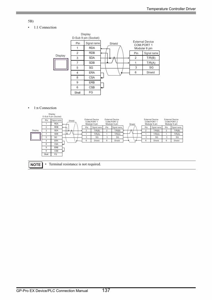
Temperature Controller Driver
GP-Pro EX Device/PLC Connection Manual 137
5B)
• 1:1 Connection
• 1:n Connection
• Terminal resistance is not required.
SDA3
RDB2
SG5
4 ERA
SDB
ERB
7
9
CSB6
FGShell
RDA1
CSA8
2
1
T/R(B)
T/R(A)
6
3 SG
Shield
Display
External DeviceCOM.PORT 1Modular 6 pin
Shield
Pin Signal name
Pin Signal name
DisplayD-Sub 9 pin (Socket)
SDA3
RDB2
SG5
4 ERA
SDB
ERB
7
9
CSB6
FG
RDA1
CSA8
2
1
T/R(B)
T/R(A)
6
2
1
T/R(B)
T/R(A)
6
2
1
T/R(B)
T/R(A)
6
2
1
T/R(B)
T/R(A)
6
3 SG 3 SG 3 SG 3 SG
Shield
Shield
External DeviceCOM.PORT 1Modular 6 pin
Shield Shield
Pin Signal name
External DeviceCOM.PORT 2Modular 6 pin
Pin Signal name
External DeviceCOM.PORT 1Modular 6 pin
Shield Shield
Pin Signal name
External DeviceCOM.PORT 2Modular 6 pin
Pin Signal name
Shell
Display
Pin Signal name
DisplayD-Sub 9 pin (Socket)

Temperature Controller Driver
GP-Pro EX Device/PLC Connection Manual 138
5C)
• 1:1 Connection
• 1:n Connection
• Terminal resistance is not required.
RDB
SDBSGFG
CA4-ADPONL-01
CA3-ADPTRM-01
RDA
SDA 2
1
T/R(B)
T/R(A)
63 SG
Shield
Display
Display
Signal name External DeviceCOM.PORT 1Modular 6 pin
Shield
Pin Signal name
User-created cable
RDB
SDBSGFG
CA4-ADPONL-01
CA3-ADPTRM-01
RDA
SDA 2
1
T/R(B)
T/R(A)
6
2
1
T/R(B)
T/R(A)
6
2
1
T/R(B)
T/R(A)
6
2
1
T/R(B)
T/R(A)
63 SG 3 SG 3 SG 3 SG
Shield
ShieldDisplay
Display
Signal name External DeviceCOM.PORT 1Modular 6 pin
Shield Shield
Pin Signal name
External DeviceCOM.PORT 2Modular 6 pinPin Signal name
External DeviceCOM.PORT 1Modular 6 pin
Shield Shield
Pin Signal name
External DeviceCOM.PORT 2Modular 6 pin
Pin Signal name
User-created cable
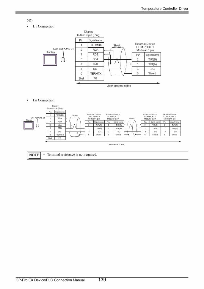
Temperature Controller Driver
GP-Pro EX Device/PLC Connection Manual 139
5D)
• 1:1 Connection
• 1:n Connection
• Terminal resistance is not required.
CA4-ADPONL-01
RDB7
RDA2
SDB8
9 TERMTX
SDA
FG
3
TERMRX1
SG5
2
1
T/R(B)
T/R(A)
63 SG
Shell
Shield
Display
External DeviceCOM.PORT 1Modular 6 pin
Shield
Pin Signal name
Pin Signal name
DisplayD-Sub 9 pin (Plug)
User-created cable
CA4-ADPONL-01
RDB7
RDA2
SDB8
9 TERMTX
SDA
FG
3
TERMRX1
SG5
2
1
T/R(B)
T/R(A)
6
2
1
T/R(B)
T/R(A)
6
2
1
T/R(B)
T/R(A)
6
2
1
T/R(B)
T/R(A)
63 SG 3 SG 3 SG 3 SG
External DeviceCOM.PORT 1Modular 6 pin
Shield Shield
Pin Signal name
External DeviceCOM.PORT 2Modular 6 pinPin Signal name
External DeviceCOM.PORT 1Modular 6 pin
Shield Shield
Pin Signal name
External DeviceCOM.PORT 2Modular 6 pinPin Signal name
Shield
Shell
Shield
Display
Pin Signal name
DisplayD-Sub 9 pin (Plug)
User-created cable
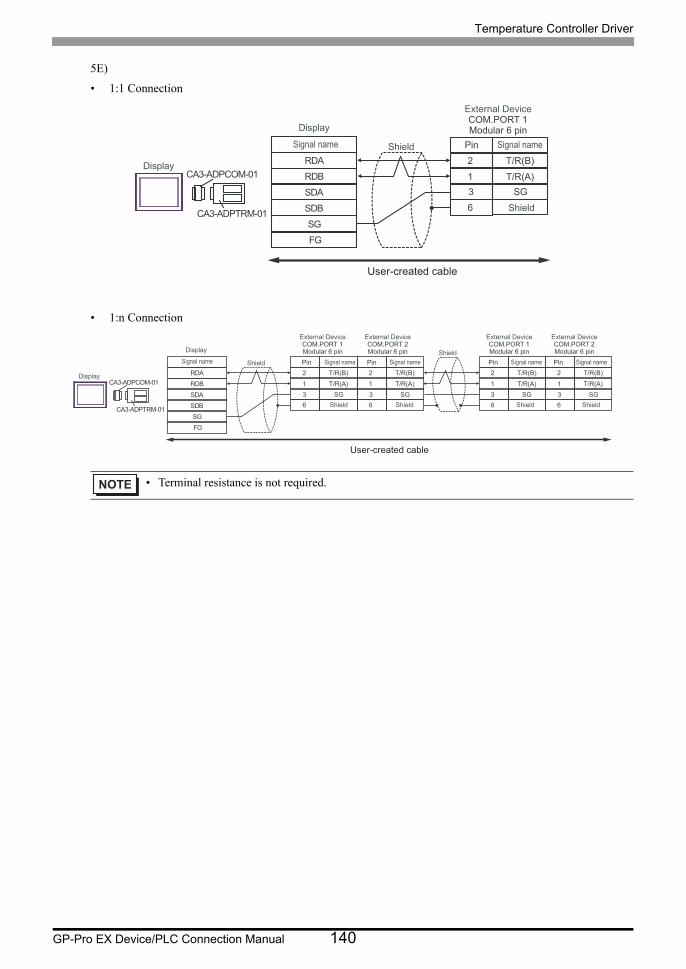
Temperature Controller Driver
GP-Pro EX Device/PLC Connection Manual 140
5E)
• 1:1 Connection
• 1:n Connection
• Terminal resistance is not required.
RDB
SDBSGFG
CA3-ADPCOM-01
CA3-ADPTRM-01
RDA
SDA
2
1
T/R(B)
T/R(A)
63 SG
Shield
Display
Display
Signal name
External DeviceCOM.PORT 1Modular 6 pin
Shield
Pin Signal name
User-created cable
RDB
SDBSGFG
CA3-ADPCOM-01
CA3-ADPTRM-01
RDA
SDA
2
1
T/R(B)
T/R(A)
6
2
1
T/R(B)
T/R(A)
6
2
1
T/R(B)
T/R(A)
6
2
1
T/R(B)
T/R(A)
63 SG3 SG3 SG3 SG
ShieldShield
Display
Display
Signal name
External DeviceCOM.PORT 1Modular 6 pin
Shield Shield
Pin Signal name
External DeviceCOM.PORT 2Modular 6 pinPin Signal name
External DeviceCOM.PORT 1Modular 6 pin
Shield Shield
Pin Signal name
External DeviceCOM.PORT 2Modular 6 pinPin Signal name
User-created cable
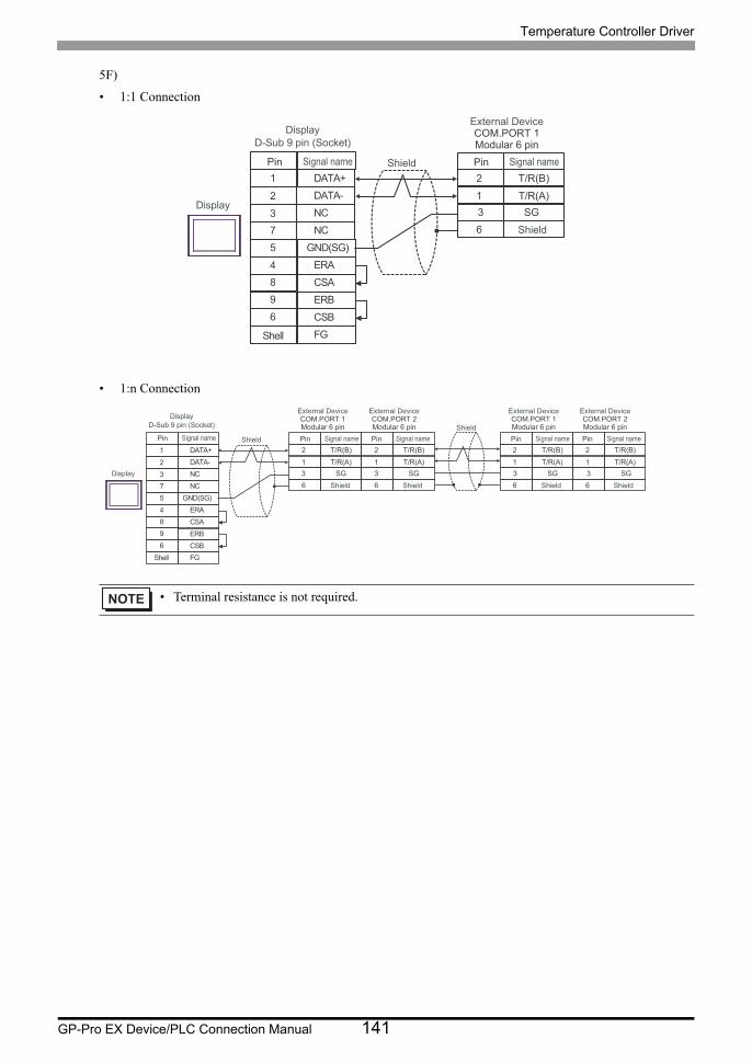
Temperature Controller Driver
GP-Pro EX Device/PLC Connection Manual 141
5F)
• 1:1 Connection
• 1:n Connection
• Terminal resistance is not required.
NC3
DATA-2
GND(SG)5
4 ERA
NC
ERB
7
9
CSB6
FGShell
DATA+1
CSA8
2
1
T/R(B)
T/R(A)
6
3 SG
Shield
Display
External DeviceCOM.PORT 1Modular 6 pin
Shield
Pin Signal namePin Signal name
Display
D-Sub 9 pin (Socket)
NC3
DATA-2
GND(SG)5
4 ERA
NC
ERB
7
9
CSB6
FG
DATA+1
CSA8
2
1
T/R(B)
T/R(A)
6
2
1
T/R(B)
T/R(A)
6
2
1
T/R(B)
T/R(A)
6
2
1
T/R(B)
T/R(A)
6
3 SG3 SG3 SG3 SG
Shield
Shield
External DeviceCOM.PORT 1Modular 6 pin
Shield Shield
Pin Signal name
External DeviceCOM.PORT 2Modular 6 pin
Pin Signal name
External DeviceCOM.PORT 1Modular 6 pin
Shield Shield
Pin Signal name
External DeviceCOM.PORT 2Modular 6 pin
Pin Signal name
Shell
Display
Pin Signal name
Display
D-Sub 9 pin (Socket)
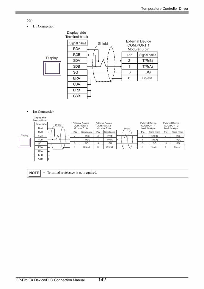
Temperature Controller Driver
GP-Pro EX Device/PLC Connection Manual 142
5G)
• 1:1 Connection
• 1:n Connection
• Terminal resistance is not required.
SDARDB
SGERA
SDB
ERBCSB
RDA
CSA
2
1
T/R(B)
T/R(A)
63 SG
Shield
Display
External DeviceCOM.PORT 1Modular 6 pin
Shield
Pin Signal name
Signal name
Display side Terminal block
SDARDB
SGERA
SDB
ERBCSB
RDA
CSA
2
1
T/R(B)
T/R(A)
6
2
1
T/R(B)
T/R(A)
6
2
1
T/R(B)
T/R(A)
6
2
1
T/R(B)
T/R(A)
63 SG 3 SG 3 SG 3 SG
Shield
Shield
External DeviceCOM.PORT 1Modular 6 pin
Shield Shield
Pin Signal name
External DeviceCOM.PORT 2Modular 6 pinPin Signal name
External DeviceCOM.PORT 1Modular 6 pin
Shield Shield
Pin Signal name
External DeviceCOM.PORT 2Modular 6 pinPin Signal name
Display
Signal name
Display side Terminal block
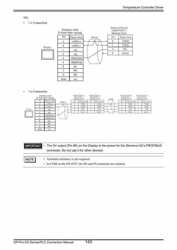
Temperature Controller Driver
GP-Pro EX Device/PLC Connection Manual 143
5H)
• 1:1 Connection
• 1:n Connection
• The 5V output (Pin #6) on the Display is the power for the Siemens AG’s PROFIBUS
connector. Do not use it for other devices.
• Terminal resistance is not required.
• In COM on the GP-4107, the SG and FG terminals are isolated.
2
1
T/R(B)
T/R(A)
63 SG
Shield
Display
External DeviceCOM.PORT 1Modular 6 pin
Shield
Pin Signal namePin Signal name
NC
NC
GND(SG)
RS(RTS)
5V
NC
NC
FG
LINE(+)
LINE(-)
3
8
1
2
5
4
6
7
9
Shell
Display sideD-Sub 9pin (plug)
2
1
T/R(B)
T/R(A)
6
2
1
T/R(B)
T/R(A)
6
2
1
T/R(B)
T/R(A)
6
2
1
T/R(B)
T/R(A)
63 SG3 SG3 SG3 SG
Shield
Shield
External DeviceCOM.PORT 1Modular 6 pin
Shield Shield
Pin Signal name
External DeviceCOM.PORT 2Modular 6 pinPin Signal name
External DeviceCOM.PORT 1Modular 6 pin
Shield Shield
Pin Signal name
External DeviceCOM.PORT 2Modular 6 pinPin Signal name
Display
Pin Signal name
NC
NC
GND(SG)
RS(RTS)
5V
NC
NC
FG
LINE(+)
LINE(-)
3
8
1
2
5
4
6
7
9
Shell
Display sideD-Sub 9pin (plug)

Temperature Controller Driver
GP-Pro EX Device/PLC Connection Manual 144
5I)
• 1:1 Connection
• 1:n Connection
5J)
• 1:1 Connection
• 1:n Connection
• Terminal resistance is not required.
• Terminal resistance is not required.
Number Name Notes
(1)RJ45 RS-485 Cable (5m) by Pro-face
PFXZLMCBRJR81
RDB
SDB SG FG
PFXZCBADTM1
RDA
SDA 2
1
T/R(B)
T/R(A)
6 3 SG
Shield
Display
Display
Signal name External Device COM.PORT 1 Modular 6 pin
Shield
Pin Signal name
User-created cable
RDB
SDB SG FG
PFXZCBADTM1
RDA
SDA 2
1
T/R(B)
T/R(A)
6
2
1
T/R(B)
T/R(A)
6
2
1
T/R(B)
T/R(A)
6
2
1
T/R(B)
T/R(A)
6 3 SG 3 SG 3 SG 3 SG
Shield
Shield Display
Display
Signal name External Device COM.PORT 1 Modular 6 pin
Shield Shield
Pin Signal name
External Device COM.PORT 2 Modular 6 pin Pin Signal name
External Device COM.PORT 1 Modular 6 pin
Shield Shield
Pin Signal name
External Device COM.PORT 2 Modular 6 pin Pin Signal name
User-created cable
2
1
T/R(B)
T/R(A)
63 SG
External DeviceCOM.PORT 1Modular 6 pin
Shield
Pin Signal nameDisplay
GNDD0
D1
(1)
2
1
T/R(B)
T/R(A)
6
2
1
T/R(B)
T/R(A)
6
2
1
T/R(B)
T/R(A)
6
2
1
T/R(B)
T/R(A)
63 SG3 SG3 SG3 SG
Shield
External DeviceCOM.PORT 1Modular 6 pin
Shield Shield
Pin Signal name
External DeviceCOM.PORT 2Modular 6 pinPin Signal name
External DeviceCOM.PORT 1Modular 6 pin
Shield Shield
Pin Signal name
External DeviceCOM.PORT 2Modular 6 pinPin Signal nameDisplay
GNDD0D1
(1)
User-created Cable
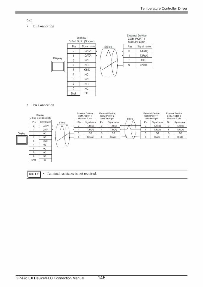
Temperature Controller Driver
GP-Pro EX Device/PLC Connection Manual 145
5K)
• 1:1 Connection
• 1:n Connection
• Terminal resistance is not required.
NC3
DATA-1
GND5
4
NC
NCNC
NCNC
7
96
FGShell
DATA+2
8
2
1
T/R(B)
T/R(A)
63 SG
Shield
Display
External DeviceCOM.PORT 1Modular 6 pin
Shield
Pin Signal namePin Signal name
DisplayD-Sub 9 pin (Socket)
NC3
DATA-1
GND5
4
NC
NCNCNCNC
7
96
FG
DATA+2
8
2
1
T/R(B)
T/R(A)
6
2
1
T/R(B)
T/R(A)
6
2
1
T/R(B)
T/R(A)
6
2
1
T/R(B)
T/R(A)
63 SG3 SG3 SG3 SG
Shield
Shield
External DeviceCOM.PORT 1Modular 6 pin
Shield Shield
Pin Signal name
External DeviceCOM.PORT 2Modular 6 pinPin Signal name
External DeviceCOM.PORT 1Modular 6 pin
Shield Shield
Pin Signal name
External DeviceCOM.PORT 2Modular 6 pinPin Signal name
Shell
Display
Pin Signal name
DisplayD-Sub 9 pin (Socket)

Temperature Controller Driver
GP-Pro EX Device/PLC Connection Manual 146
Cable Diagram 6
Display
(Connection Port)Cable Notes
GP3000*1 (COM1)AGP-3302B (COM2)GP-4*01TM (COM1)GP-Rear Module (COM1)ST*2 (COM2)LT3000 (COM1)IPC*3
*1 All GP3000 models except AGP-3302B
*2 All ST models except AST-3211A and AST-3302B
*3 Only the COM port which can communicate by RS-422/485 (4 wire) can be used. (Except PE-4000B, PS5000)
IPC COM Port (page 9)
6A
COM port conversion adapter by Pro-faceCA3-ADPCOM-01
+Terminal block conversion adapter by Pro-face
CA3-ADPTRM-01+
User-created cable
The cable length must be 1200m or
less.
6B User-created cable
GP3000*4 (COM2)
*4 All GP3000 models except GP-3200 series and AGP-3302B
6C
Online adapter by Pro-faceCA4-ADPONL-01
+Terminal block conversion adapter by Pro-face
CA3-ADPTRM-01+
User-created cable
The cable length must be 1200m or
less.
6D
Online adapter by Pro-faceCA4-ADPONL-01
+User-created cable
GP-4106 (COM1)GP-4116T (COM1)
6E User-created cableThe cable length
must be 1200m or less.
GP4000*5 (COM2)GP-4201T (COM1)SP5000*6 (COM1/2)SP-5B00 (COM2)
*5 All GP4000 models except GP-4100 series, GP-4*01TM, GP-Rear Module, GP-4201T and GP-4*03T
*6 Except SP-5B00
6F
RS-422 terminal block conversion adapter by Pro-facePFXZCBADTM1*7
+User-created cable
*7 When using a Terminal Block Conversion Adapter (CA3-ADPTRM-01) instead of the RS-422 Terminal Block Conversion Adapter, refer to Cable Diagram 6A.
The cable length must be 1200m or
less.
6B User-created cable
PE-4000B*8
PS5000*8
*8 Only the COM port which can communicate by RS-422/485 (4 wire) can be used.
IPC COM Port (page 9)
6G User-created cableThe cable length
must be 1200m or less.
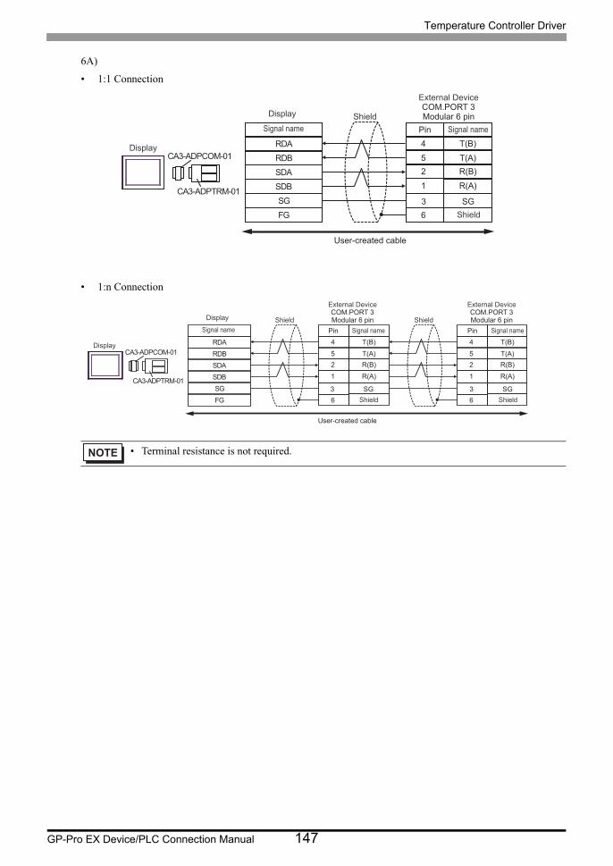
Temperature Controller Driver
GP-Pro EX Device/PLC Connection Manual 147
6A)
• 1:1 Connection
• 1:n Connection
• Terminal resistance is not required.
RDB
SDBSGFG
CA3-ADPCOM-01
CA3-ADPTRM-01
RDA
SDA
4
52
T(B)
T(A)R(B)
1 R(A)
63 SG
Shield
Display
Display
Signal name
External DeviceCOM.PORT 3Modular 6 pin
Shield
Pin Signal name
User-created cable
RDB
SDBSGFG
CA3-ADPCOM-01
CA3-ADPTRM-01
RDA
SDA
4
52
T(B)
T(A)R(B)
1 R(A)
6
4
52
T(B)
T(A)R(B)
1 R(A)
63 SG
Shield
Display
Display
Signal name
External DeviceCOM.PORT 3Modular 6 pin
Shield
Pin Signal name
3 SG
Shield
External DeviceCOM.PORT 3Modular 6 pin
Shield
Pin Signal name
User-created cable
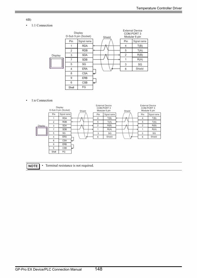
Temperature Controller Driver
GP-Pro EX Device/PLC Connection Manual 148
6B)
• 1:1 Connection
• 1:n Connection
• Terminal resistance is not required.
4
5
2
T(B)
T(A)
R(B)
1 R(A)
6
SDA3
RDB2
SG5
4 ERA
SDB
ERB
7
9
CSB6
FG
RDA1
CSA8
3 SG
Shell
Shield
Display
External DeviceCOM.PORT 3Modular 6 pin
Shield
Pin Signal namePin Signal name
DisplayD-Sub 9 pin (Socket)
4
5
2
T(B)
T(A)
R(B)
1 R(A)
6
SDA3
RDB2
SG5
4 ERA
SDB
ERB
7
9
CSB6
FG
RDA1
CSA8
4
5
2
T(B)
T(A)
R(B)
1 R(A)
6
3 SG
Shell
Shield
Display
External DeviceCOM.PORT 3Modular 6 pin
Shield
Pin Signal name
3 SG
Shield
External DeviceCOM.PORT 3Modular 6 pin
Shield
Pin Signal namePin Signal name
DisplayD-Sub 9 pin (Socket)
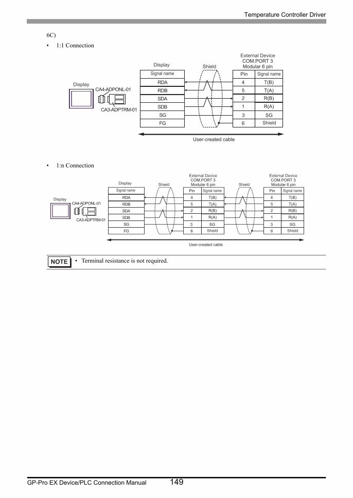
Temperature Controller Driver
GP-Pro EX Device/PLC Connection Manual 149
6C)
• 1:1 Connection
• 1:n Connection
• Terminal resistance is not required.
RDB
SDBSGFG
CA4-ADPONL-01
CA3-ADPTRM-01
RDA
SDA
4
52
T(B)
T(A)R(B)
1 R(A)
63 SG
Shield
Display
Display
Signal name
External DeviceCOM.PORT 3Modular 6 pin
Shield
Pin Signal name
User-created cable
RDB
SDBSGFG
CA4-ADPONL-01
CA3-ADPTRM-01
RDA
SDA
4
52
T(B)
T(A)R(B)
1 R(A)
6
4
52
T(B)
T(A)R(B)
1 R(A)
63 SG
Shield
Display
Display
Signal name
External DeviceCOM.PORT 3Modular 6 pin
Shield
Pin Signal name
3 SG
Shield
External DeviceCOM.PORT 3Modular 6 pin
Shield
Pin Signal name
User-created cable
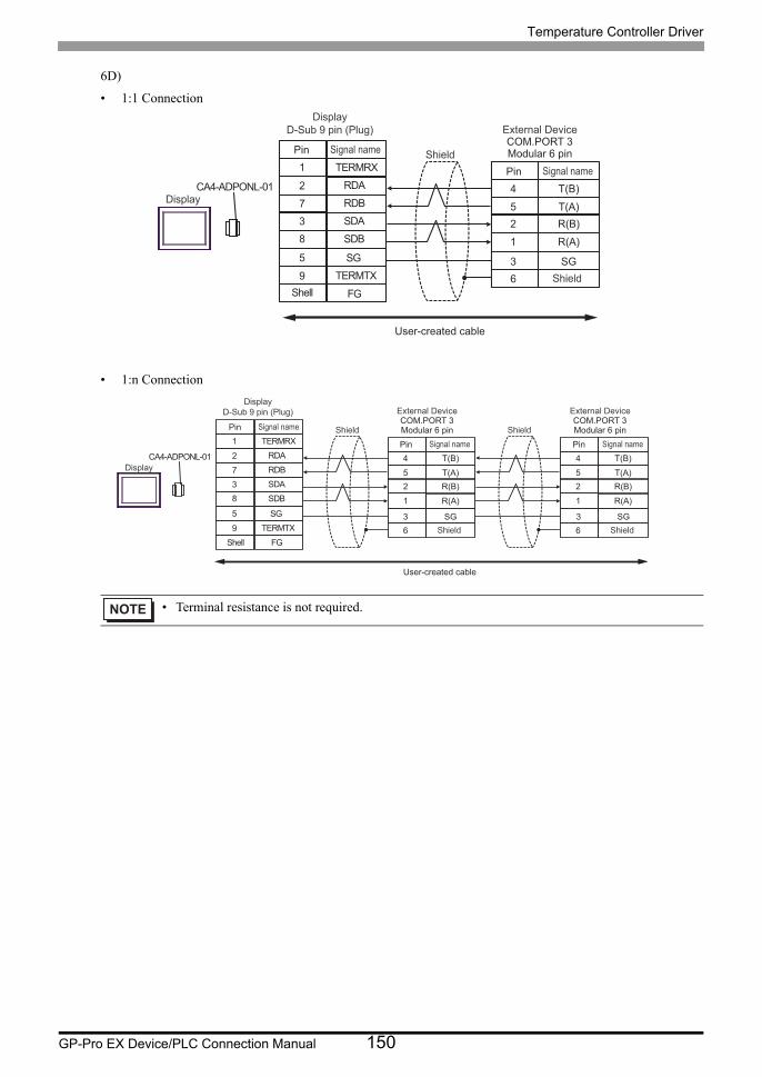
Temperature Controller Driver
GP-Pro EX Device/PLC Connection Manual 150
6D)
• 1:1 Connection
• 1:n Connection
• Terminal resistance is not required.
CA4-ADPONL-01RDB7
RDA2
SDB8
9 TERMTX
SDA
FG
3
TERMRX1
SG5
4
52
T(B)
T(A)R(B)
1 R(A)
63 SG
Shell
Shield
Display
External DeviceCOM.PORT 3Modular 6 pin
Shield
Pin Signal name
Pin Signal name
DisplayD-Sub 9 pin (Plug)
User-created cable
CA4-ADPONL-01RDB7
RDA2
SDB8
9 TERMTX
SDA
FG
3
TERMRX1
SG5
4
52
T(B)
T(A)R(B)
1 R(A)
6
4
52
T(B)
T(A)R(B)
1 R(A)
6
Shield Shield
3 SG
External DeviceCOM.PORT 3Modular 6 pin
Shield
Pin Signal name
3 SG
External DeviceCOM.PORT 3Modular 6 pin
Shield
Pin Signal name
Shell
Display
Pin Signal name
DisplayD-Sub 9 pin (Plug)
User-created cable
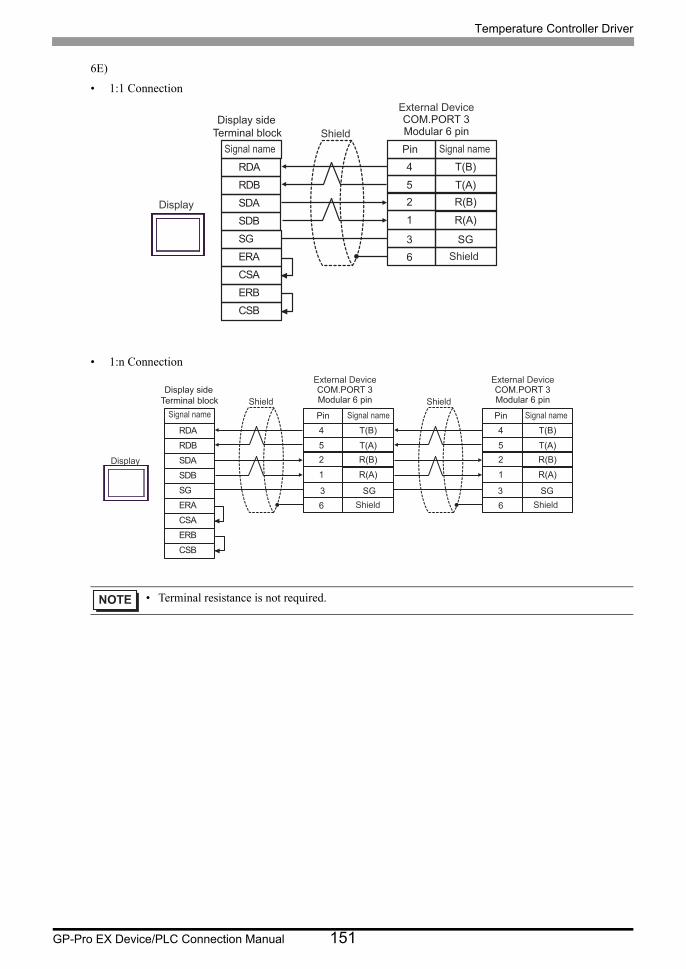
Temperature Controller Driver
GP-Pro EX Device/PLC Connection Manual 151
6E)
• 1:1 Connection
• 1:n Connection
• Terminal resistance is not required.
4
52
T(B)
T(A)R(B)
1 R(A)
6
SDARDB
SGERA
SDB
ERBCSB
RDA
CSA
3 SG
Shield
Display
External DeviceCOM.PORT 3Modular 6 pin
Shield
Pin Signal nameSignal name
Display side Terminal block
4
52
T(B)
T(A)R(B)
1 R(A)
6
SDARDB
SGERA
SDB
ERBCSB
RDA
CSA
4
52
T(B)
T(A)R(B)
1 R(A)
63 SG
Shield
Display
External DeviceCOM.PORT 3Modular 6 pin
Shield
Pin Signal name
3 SG
Shield
External DeviceCOM.PORT 3Modular 6 pin
Shield
Pin Signal nameSignal name
Display side Terminal block

Temperature Controller Driver
GP-Pro EX Device/PLC Connection Manual 152
6F)
• 1:1 Connection
• 1:n Connection
• Terminal resistance is not required.
RDB
SDB SG FG
PFXZCBADTM1
RDA
SDA
4
5 2
T(B)
T(A) R(B)
1 R(A)
6 3 SG
Shield
Display
Display
Signal name
External Device COM.PORT 3 Modular 6 pin
Shield
Pin Signal name
User-created cable
RDB
SDB SG FG
PFXZCBADTM1
RDA
SDA
4
5 2
T(B)
T(A) R(B)
1 R(A)
6
4
5 2
T(B)
T(A) R(B)
1 R(A)
6 3 SG
Shield
Display
Display
Signal name
External Device COM.PORT 3 Modular 6 pin
Shield
Pin Signal name
3 SG
Shield
External Device COM.PORT 3 Modular 6 pin
Shield
Pin Signal name
User-created cable
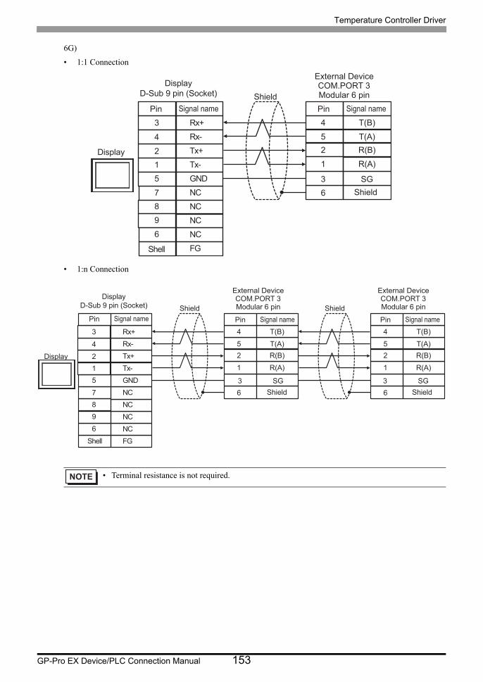
Temperature Controller Driver
GP-Pro EX Device/PLC Connection Manual 153
6G)
• 1:1 Connection
• 1:n Connection
• Terminal resistance is not required.
4
52
T(B)
T(A)R(B)
1 R(A)
6
Tx+2
Rx-4
GND5
7 NC
Tx-
NC
1
9
NC6
FG
Rx+3
NC8
3 SG
Shell
Shield
Display
External DeviceCOM.PORT 3Modular 6 pin
Shield
Pin Signal namePin Signal name
DisplayD-Sub 9 pin (Socket)
4
52
T(B)
T(A)R(B)
1 R(A)
6
Tx+2
Rx-4
GND5
7 NC
Tx-
NC
1
9
NC6
FG
Rx+3
NC8
4
52
T(B)
T(A)R(B)
1 R(A)
63 SG
Shell
Shield
Display
External DeviceCOM.PORT 3Modular 6 pin
Shield
Pin Signal name
3 SG
Shield
External DeviceCOM.PORT 3Modular 6 pin
Shield
Pin Signal namePin Signal name
DisplayD-Sub 9 pin (Socket)

Temperature Controller Driver
GP-Pro EX Device/PLC Connection Manual 154
Cable Diagram 7
Display
(Connection Port)Cable Notes
GP3000*1 (COM1)AGP-3302B (COM2)GP-4*01TM (COM1)GP-Rear Module (COM1)ST*2 (COM2)LT3000 (COM1)
*1 All GP3000 models except AGP-3302B
*2 All ST models except AST-3211A and AST-3302B
7A
COM port conversion adapter by Pro-faceCA3-ADPCOM-01
+Terminal block conversion adapter by Pro-face
CA3-ADPTRM-01+
User-created cable
The cable length must be 1200m or less.
7B User-created cable
GP3000*3 (COM2)
*3 All GP3000 models except GP-3200 series and AGP-3302B
7C
Online adapter by Pro-faceCA4-ADPONL-01
+Terminal block conversion adapter by Pro-face
CA3-ADPTRM-01+
User-created cable
The cable length must be 1200m or less.
7D
Online adapter by Pro-faceCA4-ADPONL-01
+User-created cable
IPC*4
*4 Only the COM port which can communicate by RS-422/485 (2 wire) can be used. (Except PE-4000B, PS5000) IPC COM Port (page 9)
7E
COM port conversion adapter by Pro-faceCA3-ADPCOM-01
+Terminal block conversion adapter by Pro-face
CA3-ADPTRM-01+
User-created cable
The cable length must be 1200m or less.
7F User-created cable
GP-4106 (COM1)GP-4116T (COM1)
7G User-created cableThe cable length must
be 1200m or less.
GP-4107 (COM1)GP-4*03T*5 (COM2)GP-4203T (COM1)
*5 Except GP-4203T
7H User-created cableThe cable length must
be 1200m or less.
GP4000*6 (COM2)GP-4201T (COM1)SP5000*7 (COM1/2)SP-5B00 (COM2)
*6 All GP4000 models except GP-4100 series, GP-4*01TM, GP-Rear Module, GP-4201T and GP-4*03T
7I
RS-422 terminal block conversion adapter by Pro-facePFXZCBADTM1*8
+User-created cable
The cable length must be 1200m or less.
7B User-created cable
LT-4*01TM (COM1)LT-Rear Module (COM1) 7J
RJ45 RS-485 Cable (5m) by Pro-facePFXZLMCBRJR81
The cable length must be 200m or less.
PE-4000B*9
PS5000*9 7K User-created cableThe cable length must
be 1200m or less.
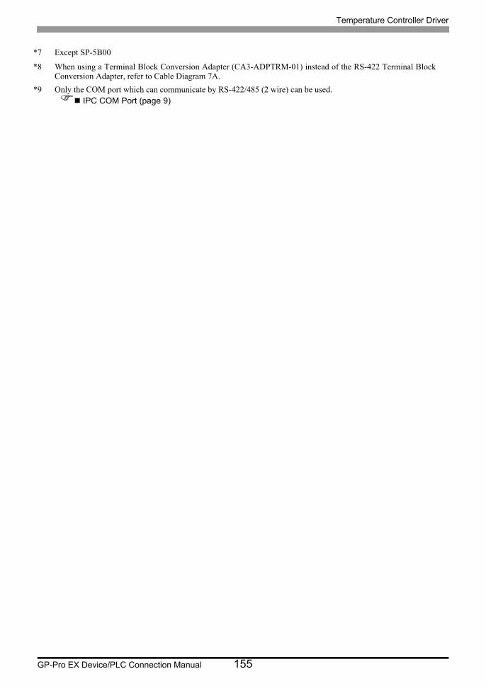
Temperature Controller Driver
GP-Pro EX Device/PLC Connection Manual 155
*7 Except SP-5B00
*8 When using a Terminal Block Conversion Adapter (CA3-ADPTRM-01) instead of the RS-422 Terminal Block Conversion Adapter, refer to Cable Diagram 7A.
*9 Only the COM port which can communicate by RS-422/485 (2 wire) can be used. IPC COM Port (page 9)

Temperature Controller Driver
GP-Pro EX Device/PLC Connection Manual 156
7A)
• 1:1 Connection
• 1:n Connection
• Terminal resistance is not required.
RDB
SDBSGFG
CA3-ADPCOM-01
CA3-ADPTRM-01
RDA
SDA 2
1
T/R(B)
T/R(A)
63 SG
Shield
Display
DisplaySignal name External Device
COM.PORT 3Modular 6 pin
Shield
Pin Signal name
User-created cable
RDB
SDBSGFG
CA3-ADPCOM-01
CA3-ADPTRM-01
RDA
SDA 2
1
T/R(B)
T/R(A)
6
2
1
T/R(B)
T/R(A)
6
Shield
Display
DisplaySignal name
3 SG
External DeviceCOM.PORT 3Modular 6 pin
Shield
Pin Signal name
3 SG
External DeviceCOM.PORT 3Modular 6 pin
Shield
Pin Signal name
Shield
User-created cable

Temperature Controller Driver
GP-Pro EX Device/PLC Connection Manual 157
7B)
• 1:1 Connection
• 1:n Connection
• Terminal resistance is not required.
SDA3
RDB2
SG5
4 ERA
SDB
ERB
7
9
CSB6
FG
RDA1
CSA8
2
1
T/R(B)
T/R(A)
6
3 SG
Shell
Shield
Display
External DeviceCOM.PORT 3Modular 6 pin
Shield
Pin Signal name
Pin Signal name
DisplayD-Sub 9 pin (Socket)
SDA3
RDB2
SG5
4 ERA
SDB
ERB
7
9
CSB6
FG
RDA1
CSA8
2
1
T/R(B)
T/R(A)
6
2
1
T/R(B)
T/R(A)
6
Display
3 SG
External DeviceCOM.PORT 3Modular 6 pin
Shield
Pin Signal name
3 SG
External DeviceCOM.PORT 3Modular 6 pin
Shield
Pin Signal name
Shell
ShieldPin Signal name
DisplayD-Sub 9 pin (Socket)
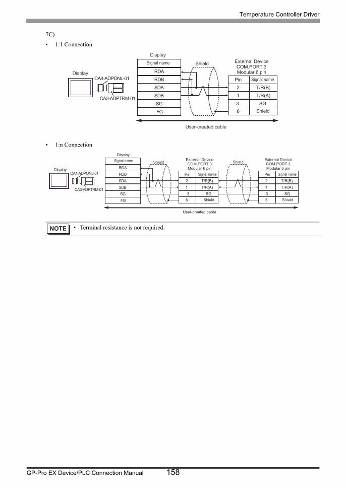
Temperature Controller Driver
GP-Pro EX Device/PLC Connection Manual 158
7C)
• 1:1 Connection
• 1:n Connection
• Terminal resistance is not required.
RDB
SDBSGFG
CA4-ADPONL-01
CA3-ADPTRM-01
RDA
SDA 2
1
T/R(B)
T/R(A)
63 SG
Shield
Display
DisplaySignal name External Device
COM.PORT 3Modular 6 pin
Shield
Pin Signal name
User-created cable
RDB
SDBSGFG
CA4-ADPONL-01
CA3-ADPTRM-01
RDA
SDA 2
1
T/R(B)
T/R(A)
6
2
1
T/R(B)
T/R(A)
6
Shield
Display
DisplaySignal name
3 SG
External DeviceCOM.PORT 3Modular 6 pin
Shield
Pin Signal name
3 SG
External DeviceCOM.PORT 3Modular 6 pin
Shield
Pin Signal name
Shield
User-created cable
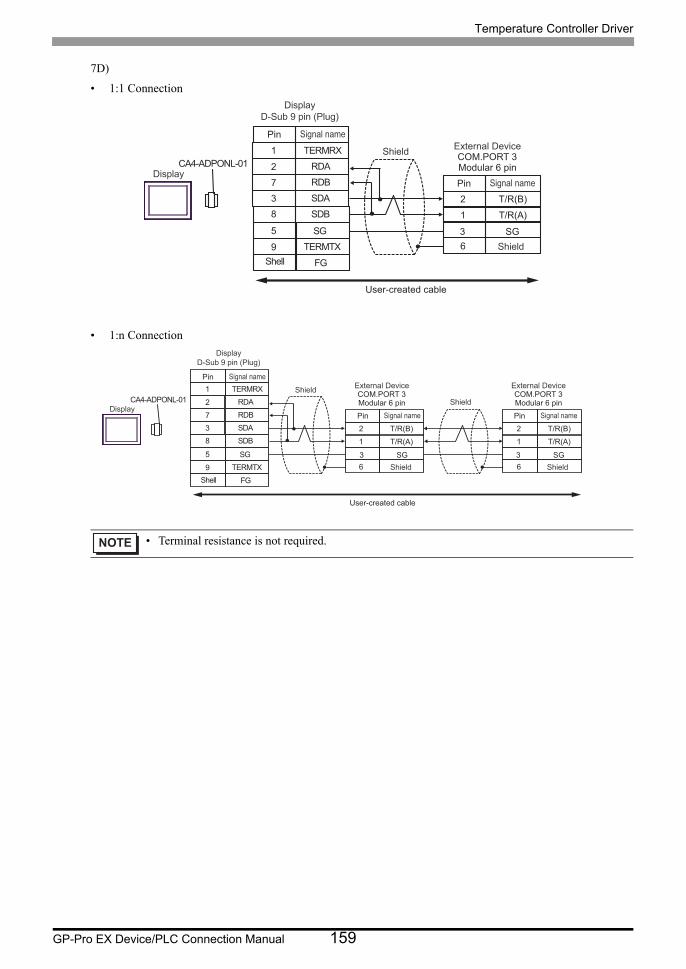
Temperature Controller Driver
GP-Pro EX Device/PLC Connection Manual 159
7D)
• 1:1 Connection
• 1:n Connection
• Terminal resistance is not required.
CA4-ADPONL-01
RDB7
RDA2
SDB8
9 TERMTX
SDA
FG
3
TERMRX1
SG5
2
1
T/R(B)
T/R(A)
63 SG
Shell
Shield
Display
External DeviceCOM.PORT 3Modular 6 pin
Shield
Pin Signal name
Pin Signal name
DisplayD-Sub 9 pin (Plug)
User-created cable
CA4-ADPONL-01
RDB7
RDA2
SDB8
9 TERMTX
SDA
FG
3
TERMRX1
SG5
2
1
T/R(B)
T/R(A)
6
2
1
T/R(B)
T/R(A)
6
ShieldShield
3 SG
External DeviceCOM.PORT 3Modular 6 pin
Shield
Pin Signal name
3 SG
External DeviceCOM.PORT 3Modular 6 pin
Shield
Pin Signal name
Shell
Display
Pin Signal name
DisplayD-Sub 9 pin (Plug)
User-created cable
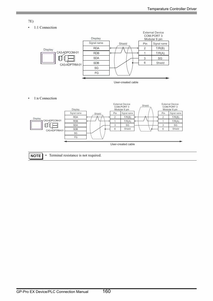
Temperature Controller Driver
GP-Pro EX Device/PLC Connection Manual 160
7E)
• 1:1 Connection
• 1:n Connection
• Terminal resistance is not required.
RDB
SDBSGFG
CA3-ADPCOM-01
CA3-ADPTRM-01
RDA
SDA
2
1
T/R(B)
T/R(A)
63 SG
Shield
Display
DisplaySignal name
External DeviceCOM.PORT 3Modular 6 pin
Shield
Pin Signal name
User-created cable
RDB
SDBSGFG
CA3-ADPCOM-01
CA3-ADPTRM-01
RDA
SDA
2
1
T/R(B)
T/R(A)
6
2
1
T/R(B)
T/R(A)
6
Shield
Display
DisplaySignal name
3 SG3 SG
External DeviceCOM.PORT 3Modular 6 pin
Shield
Pin Signal name
External DeviceCOM.PORT 3Modular 6 pin
Shield
Pin Signal name
Shield
User-created cable
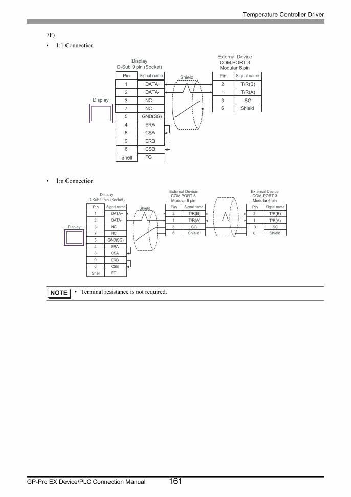
Temperature Controller Driver
GP-Pro EX Device/PLC Connection Manual 161
7F)
• 1:1 Connection
• 1:n Connection
• Terminal resistance is not required.
NC3
DATA-2
GND(SG)5
4 ERA
NC
ERB
7
9
CSB6
FG
DATA+1
CSA8
2
1
T/R(B)
T/R(A)
6
3 SG
Shell
Shield
Display
External DeviceCOM.PORT 3Modular 6 pin
Shield
Pin Signal namePin Signal name
Display
D-Sub 9 pin (Socket)
NC3
DATA-2
GND(SG)5
4 ERA
NC
ERB
7
9
CSB6
FG
DATA+1
CSA8
2
1
T/R(B)
T/R(A)
6
2
1
T/R(B)
T/R(A)
6
Display 3 SG
External DeviceCOM.PORT 3Modular 6 pin
Shield
Pin Signal name
3 SG
External DeviceCOM.PORT 3Modular 6 pin
Shield
Pin Signal name
Shell
ShieldPin Signal name
Display
D-Sub 9 pin (Socket)
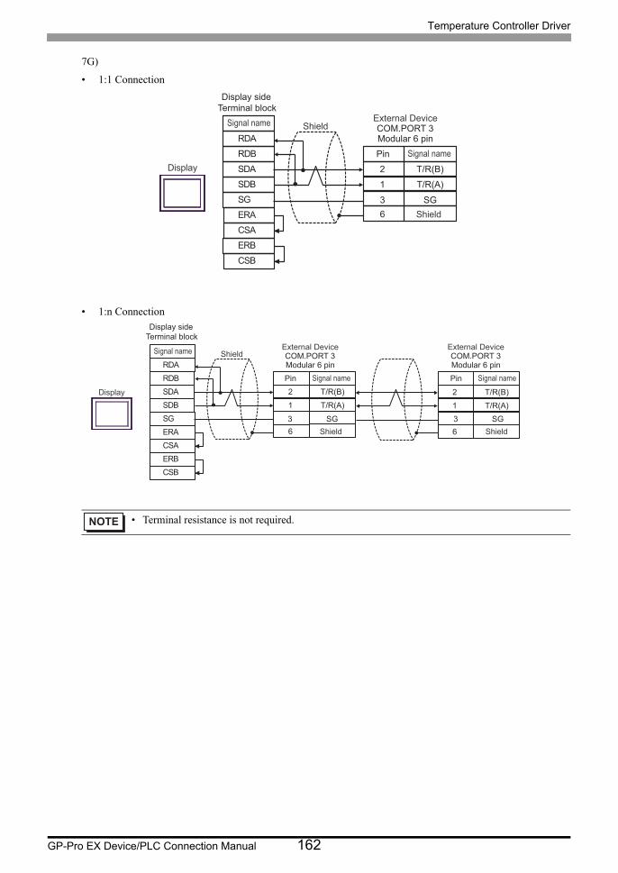
Temperature Controller Driver
GP-Pro EX Device/PLC Connection Manual 162
7G)
• 1:1 Connection
• 1:n Connection
• Terminal resistance is not required.
SDARDB
SGERA
SDB
ERBCSB
RDA
CSA
2
1
T/R(B)
T/R(A)
63 SG
Shield
Display
External DeviceCOM.PORT 3Modular 6 pin
Shield
Pin Signal name
Signal name
Display side Terminal block
SDARDB
SGERA
SDB
ERBCSB
RDA
CSA
2
1
T/R(B)
T/R(A)
6
2
1
T/R(B)
T/R(A)
6
Display
3 SG
External DeviceCOM.PORT 3Modular 6 pin
Shield
Pin Signal name
3 SG
External DeviceCOM.PORT 3Modular 6 pin
Shield
Pin Signal name
ShieldSignal name
Display side Terminal block
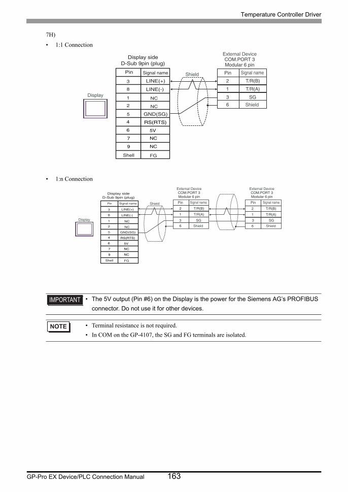
Temperature Controller Driver
GP-Pro EX Device/PLC Connection Manual 163
7H)
• 1:1 Connection
• 1:n Connection
• The 5V output (Pin #6) on the Display is the power for the Siemens AG’s PROFIBUS
connector. Do not use it for other devices.
• Terminal resistance is not required.
• In COM on the GP-4107, the SG and FG terminals are isolated.
2
1
T/R(B)
T/R(A)
63 SG
Shield
Display
External DeviceCOM.PORT 3Modular 6 pin
Shield
Pin Signal namePin Signal name
NC
NC
GND(SG)
RS(RTS)
5V
NC
NC
FG
LINE(+)
LINE(-)
3
8
1
2
5
4
6
7
9
Shell
Display sideD-Sub 9pin (plug)
2
1
T/R(B)
T/R(A)
6
2
1
T/R(B)
T/R(A)
6
Display 3 SG
External DeviceCOM.PORT 3Modular 6 pin
Shield
Pin Signal name
3 SG
External DeviceCOM.PORT 3Modular 6 pin
Shield
Pin Signal nameShieldPin Signal name
NC
NC
GND(SG)
RS(RTS)
5V
NC
NC
FG
LINE(+)
LINE(-)
3
8
1
2
5
4
6
7
9
Shell
Display sideD-Sub 9pin (plug)
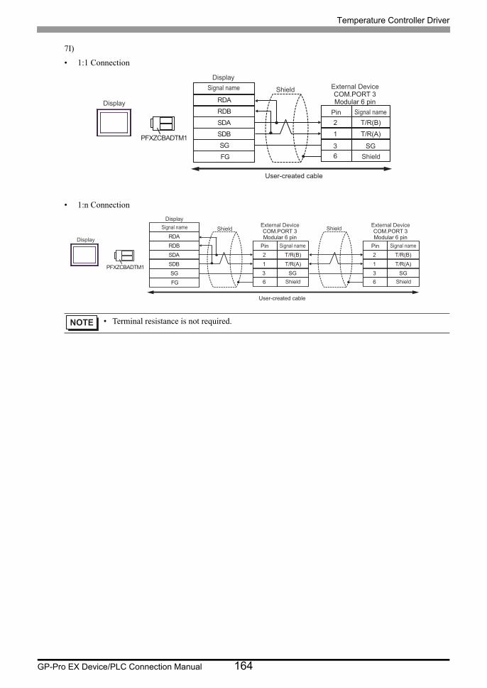
Temperature Controller Driver
GP-Pro EX Device/PLC Connection Manual 164
7I)
• 1:1 Connection
• 1:n Connection
• Terminal resistance is not required.
RDB
SDB SG FG
PFXZCBADTM1
RDA
SDA 2
1
T/R(B)
T/R(A)
6 3 SG
Shield
Display
Display Signal name External Device
COM.PORT 3 Modular 6 pin
Shield
Pin Signal name
User-created cable
RDB
SDB SG FG
PFXZCBADTM1
RDA
SDA 2
1
T/R(B)
T/R(A)
6
2
1
T/R(B)
T/R(A)
6
Shield
Display
Display Signal name
3 SG
External Device COM.PORT 3 Modular 6 pin
Shield
Pin Signal name
3 SG
External Device COM.PORT 3 Modular 6 pin
Shield
Pin Signal name
Shield
User-created cable
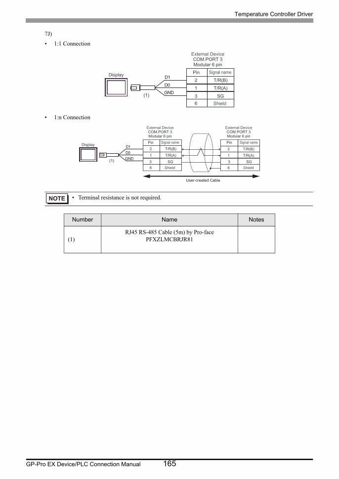
Temperature Controller Driver
GP-Pro EX Device/PLC Connection Manual 165
7J)
• 1:1 Connection
• 1:n Connection
• Terminal resistance is not required.
Number Name Notes
(1)RJ45 RS-485 Cable (5m) by Pro-face
PFXZLMCBRJR81
2
1
T/R(B)
T/R(A)
63 SG
External DeviceCOM.PORT 3Modular 6 pin
Shield
Pin Signal nameDisplay
GNDD0
D1
(1)
2
1
T/R(B)
T/R(A)
6
2
1
T/R(B)
T/R(A)
63 SG
External DeviceCOM.PORT 3Modular 6 pin
Shield
Pin Signal name
3 SG
External DeviceCOM.PORT 3Modular 6 pin
Shield
Pin Signal nameDisplay
GNDD0D1
(1)
User-created Cable
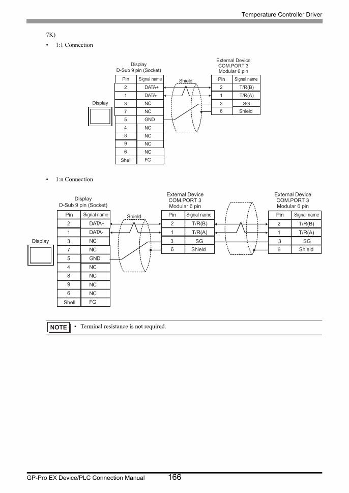
Temperature Controller Driver
GP-Pro EX Device/PLC Connection Manual 166
7K)
• 1:1 Connection
• 1:n Connection
• Terminal resistance is not required.
NC3
DATA-1
GND5
4
NC
NCNCNCNC
7
96
FG
DATA+2
8
2
1
T/R(B)
T/R(A)
63 SG
Shell
Shield
Display
External DeviceCOM.PORT 3Modular 6 pin
Shield
Pin Signal namePin Signal name
DisplayD-Sub 9 pin (Socket)
NC3
DATA-1
GND5
4
NC
NCNC
NCNC
7
96
FG
DATA+2
8
2
1
T/R(B)
T/R(A)
6
2
1
T/R(B)
T/R(A)
6Display 3 SG
External DeviceCOM.PORT 3Modular 6 pin
Shield
Pin Signal name
3 SG
External DeviceCOM.PORT 3Modular 6 pin
Shield
Pin Signal name
Shell
ShieldPin Signal name
DisplayD-Sub 9 pin (Socket)
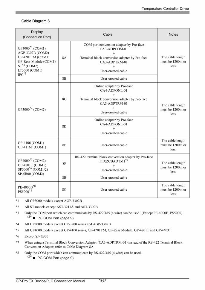
Temperature Controller Driver
GP-Pro EX Device/PLC Connection Manual 167
Cable Diagram 8
Display
(Connection Port)Cable Notes
GP3000*1 (COM1)AGP-3302B (COM2)GP-4*01TM (COM1)GP-Rear Module (COM1)ST*2 (COM2)LT3000 (COM1)IPC*3
*1 All GP3000 models except AGP-3302B
*2 All ST models except AST-3211A and AST-3302B
*3 Only the COM port which can communicate by RS-422/485 (4 wire) can be used. (Except PE-4000B, PS5000)
IPC COM Port (page 9)
8A
COM port conversion adapter by Pro-faceCA3-ADPCOM-01
+Terminal block conversion adapter by Pro-face
CA3-ADPTRM-01+
User-created cable
The cable length must be 1200m or
less.
8B User-created cable
GP3000*4 (COM2)
*4 All GP3000 models except GP-3200 series and AGP-3302B
8C
Online adapter by Pro-faceCA4-ADPONL-01
+Terminal block conversion adapter by Pro-face
CA3-ADPTRM-01+
User-created cable
The cable length must be 1200m or
less.
8D
Online adapter by Pro-faceCA4-ADPONL-01
+User-created cable
GP-4106 (COM1)GP-4116T (COM1)
8E User-created cableThe cable length
must be 1200m or less.
GP4000*5 (COM2)GP-4201T (COM1)SP5000*6 (COM1/2)SP-5B00 (COM2)
*5 All GP4000 models except GP-4100 series, GP-4*01TM, GP-Rear Module, GP-4201T and GP-4*03T
*6 Except SP-5B00
8F
RS-422 terminal block conversion adapter by Pro-facePFXZCBADTM1*7
+User-created cable
*7 When using a Terminal Block Conversion Adapter (CA3-ADPTRM-01) instead of the RS-422 Terminal Block Conversion Adapter, refer to Cable Diagram 8A.
The cable length must be 1200m or
less.
8B User-created cable
PE-4000B*8
PS5000*8
*8 Only the COM port which can communicate by RS-422/485 (4 wire) can be used.
IPC COM Port (page 9)
8G User-created cableThe cable length
must be 1200m or less.
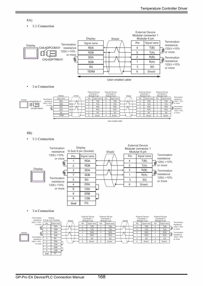
Temperature Controller Driver
GP-Pro EX Device/PLC Connection Manual 168
8A)
• 1:1 Connection
• 1:n Connection
8B)
• 1:1 Connection
• 1:n Connection
RDB
SDBSG
TERM
CA4-ADPCOM-01
CA3-ADPTRM-01
RDA
SDA
4
52
T(B)
T(A)R(B)
1 R(A)
6
3 SG
Shield
Display
DisplaySignal name
External DeviceModular connector 1
Modular 6 pin
Shield
Pin Signal nameTerminationresistance
120Ω +10% or more
Terminationresistance120Ω +10% or more
Terminationresistance120Ω +10% or more
User-created cable
RDB
SDBSG
TERM
CA4-ADPONL-01
CA3-ADPTRM-01
RDA
SDA
4
52
T(B)
T(A)R(B)
1 R(A)
3 SG6
4
52
T(B)
T(A)R(B)
1 R(A)
3 SG6
4
52
T(B)
T(A)R(B)
1 R(A)
3 SG 3 SG6
4
52
T(B)
T(A)R(B)
1 R(A)
6
ShieldShield
External DeviceConnector 1
Modular 6 pin
Shield
Pin Signal name
External DeviceConnector 2
Modular 6 pin
Shield
Pin Signal name
External DeviceConnector 1
Modular 6 pin
Shield
Pin Signal name
External DeviceConnector 2
Modular 6 pin
Shield
Pin Signal nameTerminationresistance120Ω +10% or more
Display
DisplaySignal nameTermination
resistance120Ω +10%
or moreTerminationresistance120Ω +10% or more
User-created cable
4
5
2
T(B)
T(A)
R(B)
1 R(A)
6
SDA3
RDB2
SG5
4 ERA
SDB
ERB
7
9
CSB6
FG
RDA1
CSA8
Terminationresistance
120+10% or more
Terminationresistance
120+10% or more
3 SG
External DeviceModular connector 1
Modular 6 pin
Shield
Pin Signal name Terminationresistance120+10% or more
Terminationresistance120+10% or more
Shell
Shield
Display
Pin Signal name
DisplayD-Sub 9 pin (Socket)
4
5
2
T(B)
T(A)
R(B)
1 R(A)
3 SG
6
SDA3
RDB2
SG5
4 ERA
SDB
ERB
7
9
CSB6
FG
RDA1
CSA8
4
5
2
T(B)
T(A)
R(B)
1 R(A)
3 SG
6
4
5
2
T(B)
T(A)
R(B)
1 R(A)
3 SG 3 SG
6
4
5
2
T(B)
T(A)
R(B)
1 R(A)
6
External DeviceConnector 1
Modular 6 pin
Shield
Pin Signal name
External DeviceConnector 2
Modular 6 pin
Shield
Pin Signal name
External DeviceConnector 1
Modular 6 pin
Shield
Pin Signal name
External DeviceConnector 2
Modular 6 pin
Shield
Pin Signal name
Terminationresistance
120+10% or more
Terminationresistance
120+10% or more
Terminationresistance120+10% or more
Terminationresistance120+10% or more
Shield Shield
Display
Shell
Pin Signal name
DisplayD-Sub 9 pin (Socket)
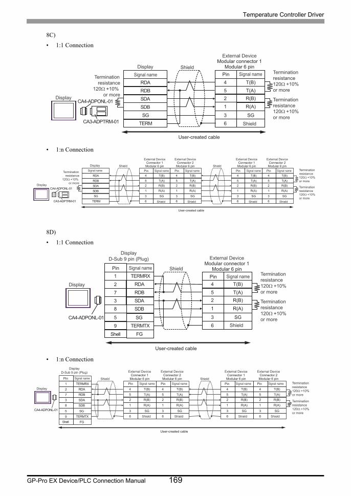
Temperature Controller Driver
GP-Pro EX Device/PLC Connection Manual 169
8C)
• 1:1 Connection
• 1:n Connection
8D)
• 1:1 Connection
• 1:n Connection
RDB
SDBSG
TERM
CA4-ADPONL-01
CA3-ADPTRM-01
RDA
SDA
4
52
T(B)
T(A)R(B)
1 R(A)
3 SG6
Shield
Display
DisplaySignal name
External DeviceModular connector 1
Modular 6 pin
Shield
Pin Signal nameTerminationresistance
120Ω +10% or more
Terminationresistance120Ω +10% or more
Terminationresistance120Ω +10% or more
User-created cable
RDB
SDBSG
TERM
CA4-ADPONL-01
CA3-ADPTRM-01
RDA
SDA
4
52
T(B)
T(A)R(B)
1 R(A)
3 SG6
4
52
T(B)
T(A)R(B)
1 R(A)
3 SG6
4
52
T(B)
T(A)R(B)
1 R(A)
3 SG6
4
52
T(B)
T(A)R(B)
1 R(A)
3 SG6
Display
DisplaySignal nameTermination
resistance120Ω +10%
or more
Terminationresistance120Ω +10% or more
Terminationresistance120Ω +10% or more
Shield
External DeviceConnector 1
Modular 6 pin
Shield
Pin Signal name
External DeviceConnector 2
Modular 6 pin
Shield
Pin Signal nameShield
External DeviceConnector 1
Modular 6 pin
Shield
Pin Signal name
External DeviceConnector 2
Modular 6 pin
Shield
Pin Signal name
User-created cable
CA4-ADPONL-01
4
52
T(B)
T(A)R(B)
1 R(A)
3 SG6
RDB7
RDA2
SDB8
9 TERMTX
SDA
FG
3
TERMRX1
SG5
External DeviceModular connector 1
Modular 6 pin
Shield
Pin Signal name Terminationresistance120Ω +10% or more
Terminationresistance120Ω +10% or more
Shell
Shield
Display
Pin Signal name
DisplayD-Sub 9 pin (Plug)
User-created cable
4
52
T(B)
T(A)R(B)
1 R(A)
3 SG6
RDB7
RDA2
SDB8
9 TERMTX
SDA
FG
3
TERMRX1
SG5
4
52
T(B)
T(A)R(B)
1 R(A)
3 SG6
4
52
T(B)
T(A)R(B)
1 R(A)
3 SG6
4
52
T(B)
T(A)R(B)
1 R(A)
3 SG6
CA4-ADPONL-01
External DeviceConnector 1
Modular 6 pin
Shield
Pin Signal name
External DeviceConnector 2
Modular 6 pin
Shield
Pin Signal name
External DeviceConnector 1
Modular 6 pin
Shield
Pin Signal name
External DeviceConnector 2
Modular 6 pin
Shield
Pin Signal name Terminationresistance120Ω +10% or more
Terminationresistance120Ω +10% or more
Shield Shield
Shell
Display
Pin Signal name
DisplayD-Sub 9 pin (Plug)
User-created cable
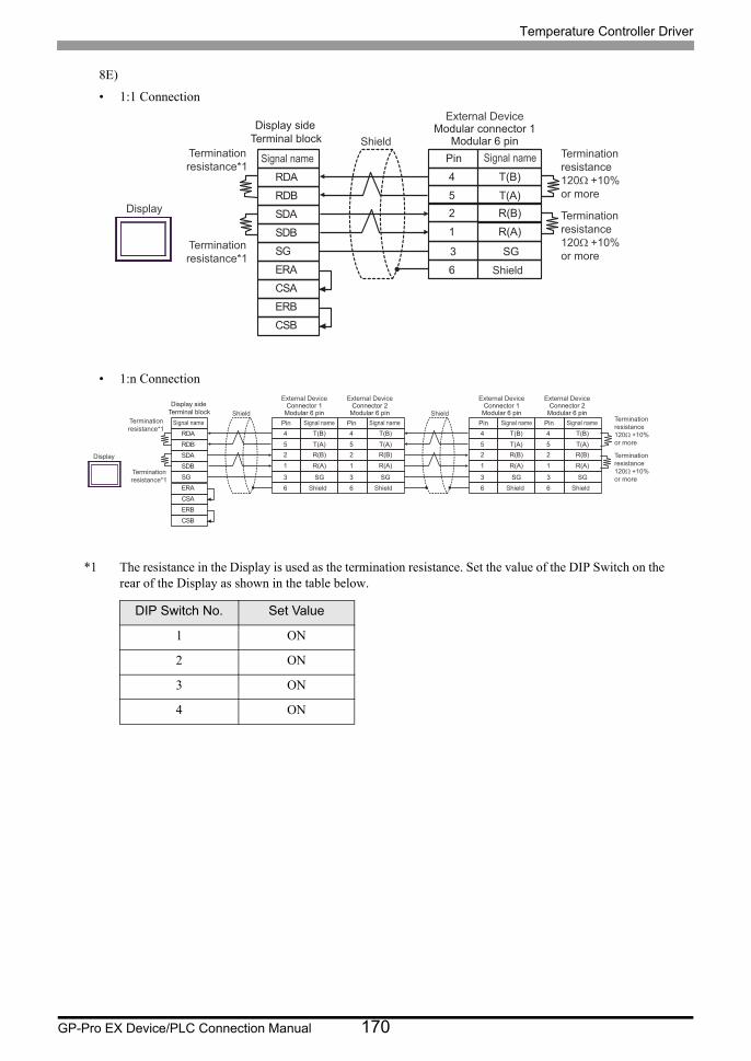
Temperature Controller Driver
GP-Pro EX Device/PLC Connection Manual 170
8E)
• 1:1 Connection
• 1:n Connection
*1 The resistance in the Display is used as the termination resistance. Set the value of the DIP Switch on the rear of the Display as shown in the table below.
DIP Switch No. Set Value
1 ON
2 ON
3 ON
4 ON
4
52
T(B)
T(A)R(B)
1 R(A)
6
SDARDB
SGERA
SDB
ERBCSB
RDA
CSA
Terminationresistance*1
Terminationresistance*1 3 SG
External DeviceModular connector 1
Modular 6 pin
Shield
Pin Signal name Terminationresistance120Ω +10% or more
Terminationresistance120Ω +10% or more
Shield
Display
Signal name
Display side Terminal block
4
52
T(B)
T(A)R(B)
1 R(A)
3 SG6
SDARDB
SGERA
SDB
ERBCSB
RDA
CSA
4
52
T(B)
T(A)R(B)
1 R(A)
3 SG6
4
52
T(B)
T(A)R(B)
1 R(A)
3 SG 3 SG6
4
52
T(B)
T(A)R(B)
1 R(A)
6
External DeviceConnector 1
Modular 6 pin
Shield
Pin Signal name
External DeviceConnector 2
Modular 6 pin
Shield
Pin Signal name
External DeviceConnector 1
Modular 6 pin
Shield
Pin Signal name
External DeviceConnector 2
Modular 6 pin
Shield
Pin Signal nameTerminationresistance*1
Terminationresistance*1
Terminationresistance120Ω +10% or more
Terminationresistance120Ω +10% or more
Shield Shield
Display
Signal name
Display side Terminal block
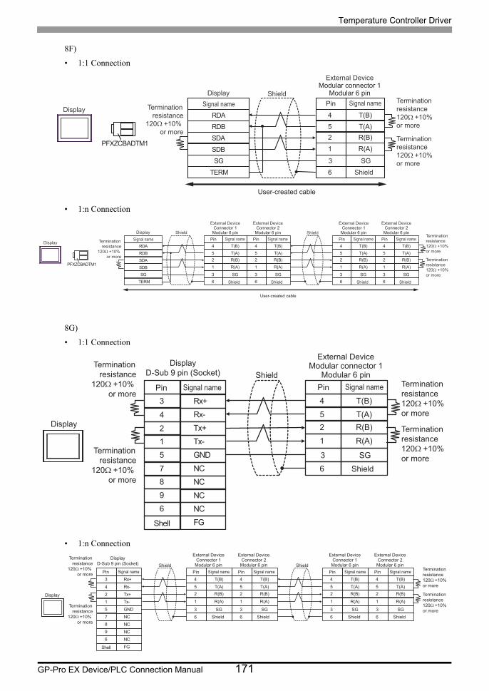
Temperature Controller Driver
GP-Pro EX Device/PLC Connection Manual 171
8F)
• 1:1 Connection
• 1:n Connection
8G)
• 1:1 Connection
• 1:n Connection
RDB
SDB SG
TERM
PFXZCBADTM1
RDA
SDA
4
5 2
T(B)
T(A) R(B)
1 R(A)
6
3 S G
Shield
Display
Display Signal name
External Device Modular connector 1
Modular 6 pin
Shield
Pin Signal name Termination resistance
120Ω +10% or more
Termination resistance 120Ω +10% or more
Termination resistance 120Ω +10% or more
User-created cable
RDB
SDB SG
TERM
PFXZCBADTM1
RDA
SDA
4
5 2
T(B)
T(A) R(B)
1 R(A)
3 S G 6
4
5 2
T(B)
T(A) R(B)
1 R(A)
3 S G 6
4
5 2
T(B)
T(A) R(B)
1 R(A)
3 S G 3 S G 6
4
5 2
T(B)
T(A) R(B)
1 R(A)
6
Shield Shield
External Device Connector 1
Modular 6 pin
Shield
Pin Signal name
External Device Connector 2
Modular 6 pin
Shield
Pin Signal name
External Device Connector 1
Modular 6 pin
Shield
Pin Signal name
External Device Connector 2
Modular 6 pin
Shield
Pin Signal name Termination resistance 120Ω +10% or more
Display
Display Signal name Termination
resistance 120Ω +10%
or more Termination resistance 120Ω +10% or more
User-created cable
4
52
T(B)
T(A)R(B)
1 R(A)
6
Tx+2
Rx-4
GND5
7 NC
Tx-
NC
1
9
NC6
FG
Rx+3
NC8
Terminationresistance
120Ω +10% or more
Terminationresistance
120Ω +10% or more
3 SG
External DeviceModular connector 1
Modular 6 pin
Shield
Pin Signal name Terminationresistance120Ω +10% or more
Terminationresistance120Ω +10% or more
Shell
Shield
Display
Pin Signal name
DisplayD-Sub 9 pin (Socket)
4
52
T(B)
T(A)R(B)
1 R(A)
3 SG6
Tx+2
Rx-4
GND5
7 NC
Tx-
NC
1
9
NC6
FG
Rx+3
NC8
4
52
T(B)
T(A)R(B)
1 R(A)
3 SG6
4
52
T(B)
T(A)R(B)
1 R(A)
3 SG 3 SG6
4
52
T(B)
T(A)R(B)
1 R(A)
6
External DeviceConnector 1
Modular 6 pin
Shield
Pin Signal name
External DeviceConnector 2
Modular 6 pin
Shield
Pin Signal name
External DeviceConnector 1
Modular 6 pin
Shield
Pin Signal name
External DeviceConnector 2
Modular 6 pin
Shield
Pin Signal name
Terminationresistance
120Ω +10% or more
Terminationresistance
120Ω +10% or more
Terminationresistance120Ω +10% or more
Terminationresistance120Ω +10% or more
Shield Shield
Display
Shell
Pin Signal name
DisplayD-Sub 9 pin (Socket)
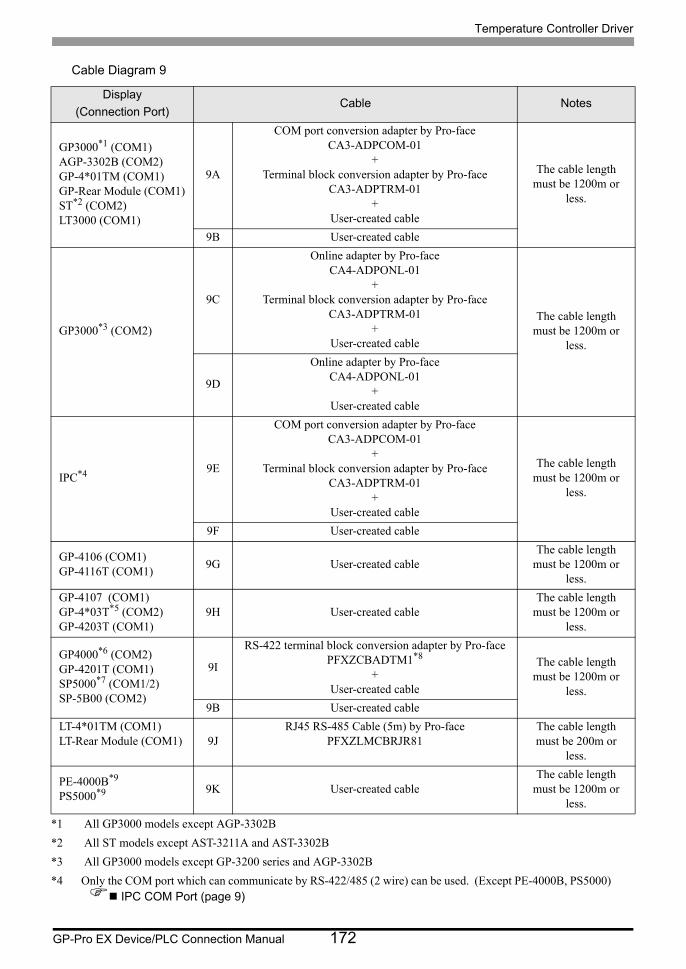
Temperature Controller Driver
GP-Pro EX Device/PLC Connection Manual 172
Cable Diagram 9
Display
(Connection Port)Cable Notes
GP3000*1 (COM1)AGP-3302B (COM2)GP-4*01TM (COM1)GP-Rear Module (COM1)ST*2 (COM2)LT3000 (COM1)
*1 All GP3000 models except AGP-3302B
*2 All ST models except AST-3211A and AST-3302B
9A
COM port conversion adapter by Pro-faceCA3-ADPCOM-01
+Terminal block conversion adapter by Pro-face
CA3-ADPTRM-01+
User-created cable
The cable length must be 1200m or
less.
9B User-created cable
GP3000*3 (COM2)
*3 All GP3000 models except GP-3200 series and AGP-3302B
9C
Online adapter by Pro-faceCA4-ADPONL-01
+Terminal block conversion adapter by Pro-face
CA3-ADPTRM-01+
User-created cable
The cable length must be 1200m or
less.
9D
Online adapter by Pro-faceCA4-ADPONL-01
+User-created cable
IPC*4
*4 Only the COM port which can communicate by RS-422/485 (2 wire) can be used. (Except PE-4000B, PS5000) IPC COM Port (page 9)
9E
COM port conversion adapter by Pro-faceCA3-ADPCOM-01
+Terminal block conversion adapter by Pro-face
CA3-ADPTRM-01+
User-created cable
The cable length must be 1200m or
less.
9F User-created cable
GP-4106 (COM1)GP-4116T (COM1)
9G User-created cableThe cable length
must be 1200m or less.
GP-4107 (COM1)GP-4*03T*5 (COM2)GP-4203T (COM1)
9H User-created cableThe cable length
must be 1200m or less.
GP4000*6 (COM2)GP-4201T (COM1)SP5000*7 (COM1/2)SP-5B00 (COM2)
9I
RS-422 terminal block conversion adapter by Pro-facePFXZCBADTM1*8
+User-created cable
The cable length must be 1200m or
less.
9B User-created cable
LT-4*01TM (COM1)LT-Rear Module (COM1) 9J
RJ45 RS-485 Cable (5m) by Pro-facePFXZLMCBRJR81
The cable length must be 200m or
less.
PE-4000B*9
PS5000*9 9K User-created cableThe cable length
must be 1200m or less.
Temperature Controller Driver
GP-Pro EX Device/PLC Connection Manual 173
*5 Except GP-4203T
*6 All GP4000 models except GP-4100 series, GP-4*01TM, GP-Rear Module, GP-4201T and GP-4*03T
*7 Except SP-5B00
*8 When using a Terminal Block Conversion Adapter (CA3-ADPTRM-01) instead of the RS-422 Terminal Block Conversion Adapter, refer to Cable Diagram 9A.
*9 Only the COM port which can communicate by RS-422/485 (2 wire) can be used. IPC COM Port (page 9)
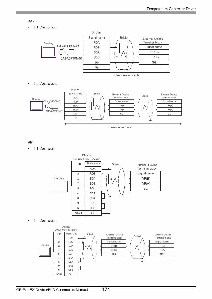
Temperature Controller Driver
GP-Pro EX Device/PLC Connection Manual 174
9A)
• 1:1 Connection
• 1:n Connection
9B)
• 1:1 Connection
• 1:n Connection
RDB
SDBSGFG
CA3-ADPCOM-01
CA3-ADPTRM-01
RDA
SDA T/R(B)
T/R(A)
SG
Display
DisplayExternal DeviceTerminal block
ShieldSignal name
Signal name
User-created cable
RDB
SDBSGFG
CA3-ADPCOM-01
CA3-ADPTRM-01
RDA
SDA T/R(B)
T/R(A)
SG
T/R(B)
T/R(A)
SG
Display
Display
External DeviceTerminal block
ShieldSignal name
Signal name
External DeviceTerminal block
Shield
Signal name
User-created cable
SDA3
RDB2
SG5
4 ERA
SDB
ERB
7
9
CSB6
FG
RDA1
CSA8
T/R(B)
T/R(A)
SG
Shell
Pin
DisplayD-Sub 9 pin (Socket)
External Device�Terminal block
Shield
Signal name
Signal name
Display
SDA3
RDB2
SG5
4 ERA
SDB
ERB
7
9
CSB6
FG
RDA1
CSA8
T/R(B)
T/R(A)
SG
T/R(B)
T/R(A)
SG
Shell
Pin
DisplayD-Sub 9 pin (Socket)
External Device�Terminal block
ShieldShield
Signal name
External Device�Terminal block
Signal name
Signal name
Display
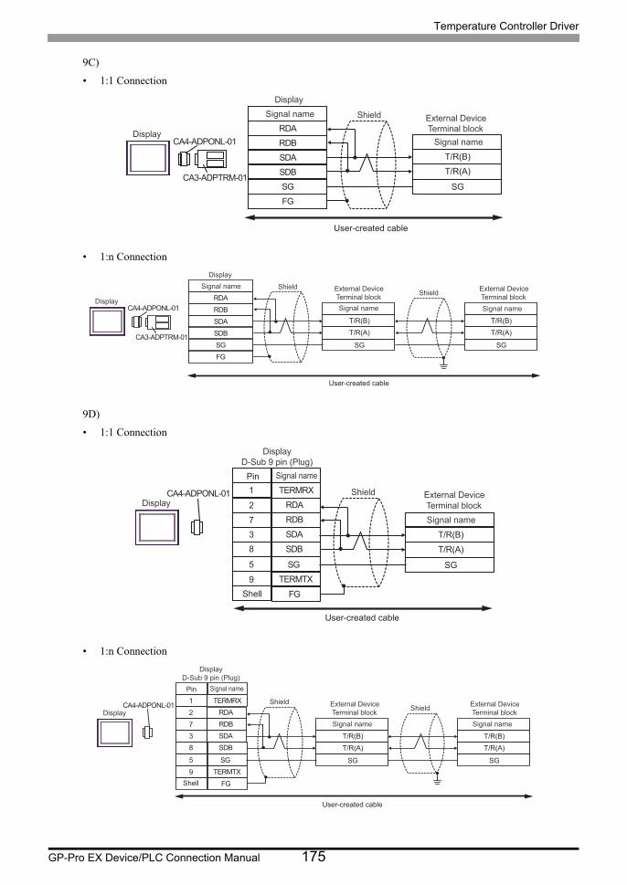
Temperature Controller Driver
GP-Pro EX Device/PLC Connection Manual 175
9C)
• 1:1 Connection
• 1:n Connection
9D)
• 1:1 Connection
• 1:n Connection
RDB
SDBSGFG
CA4-ADPONL-01
CA3-ADPTRM-01
RDA
SDA T/R(B)
T/R(A)
SG
Display
Display
External DeviceTerminal block
ShieldSignal name
Signal name
User-created cable
RDB
SDBSGFG
CA4-ADPONL-01
CA3-ADPTRM-01
RDA
SDA T/R(B)
T/R(A)
SG
T/R(B)
T/R(A)
SG
Display
Display
External DeviceTerminal block
External DeviceTerminal block
ShieldShield
Signal name Signal name
Signal name
User-created cable
CA4-ADPONL-01
RDB7
RDA2
SDB8
9 TERMTX
SDA
FG
3
TERMRX1
SG5
T/R(B)
T/R(A)
SG
Shell
Pin
DisplayD-Sub 9 pin (Plug)
External DeviceTerminal block
Shield
Signal name
Signal name
Display
User-created cable
CA4-ADPONL-01
RDB7
RDA2
SDB8
9 TERMTX
SDA
FG
3
TERMRX1
SG5
T/R(B)
T/R(A)
SG
T/R(B)
T/R(A)
SG
ShieldShieldExternal Device
Terminal blockSignal name
External DeviceTerminal blockSignal name
Shell
Pin
DisplayD-Sub 9 pin (Plug)
Signal name
Display
User-created cable
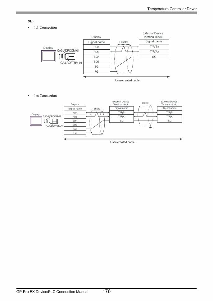
Temperature Controller Driver
GP-Pro EX Device/PLC Connection Manual 176
9E)
• 1:1 Connection
• 1:n Connection
RDB
SDBSGFG
CA3-ADPCOM-01
CA3-ADPTRM-01
RDA
SDA
T/R(B)
T/R(A)
SG
Display
Display
External DeviceTerminal block
ShieldSignal name Signal name
User-created cable
RDB
SDBSGFG
CA3-ADPCOM-01
CA3-ADPTRM-01
RDA
SDA
T/R(B)
T/R(A)
SG
T/R(B)
T/R(A)
SG
Display
DisplayExternal DeviceTerminal block
ShieldSignal name Signal name
External DeviceTerminal block
Shield
Signal name
User-created cable
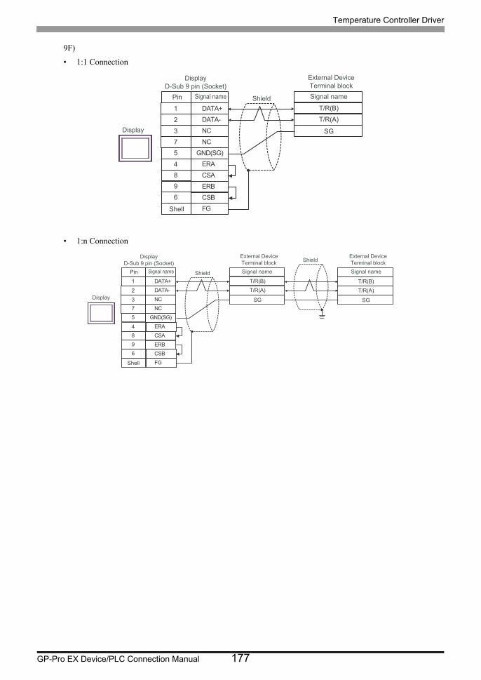
Temperature Controller Driver
GP-Pro EX Device/PLC Connection Manual 177
9F)
• 1:1 Connection
• 1:n Connection
NC3
DATA-2
GND(SG)5
4 ERA
NC
ERB
7
9
CSB6
FG
DATA+1
CSA8
T/R(B)
T/R(A)
SG
Shell
Pin
Display
D-Sub 9 pin (Socket)
External Device
Terminal block
Shield Signal nameSignal name
Display
NC3
DATA-2
GND(SG)5
4 ERA
NC
ERB
7
9
CSB6
FG
DATA+1
CSA8
T/R(B)
T/R(A)
SG
T/R(B)
T/R(A)
SG
Shell
Pin
Display
D-Sub 9 pin (Socket)
External Device
Terminal block
Shield
Shield
Signal name
External Device
Terminal block
Signal nameSignal name
Display
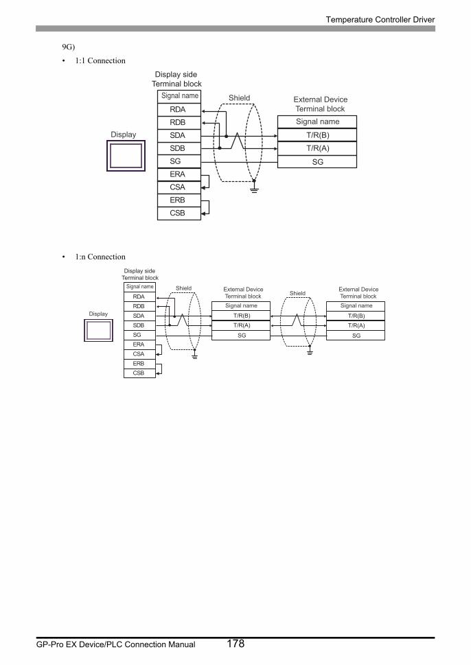
Temperature Controller Driver
GP-Pro EX Device/PLC Connection Manual 178
9G)
• 1:1 Connection
• 1:n Connection
SDARDB
SGERA
SDB
ERBCSB
RDA
CSA
T/R(B)
T/R(A)
SG
External DeviceTerminal block
Shield
Signal name
Signal name
Display
Display side Terminal block
SDARDB
SGERA
SDB
ERBCSB
RDA
CSA
T/R(B)
T/R(A)
SG
T/R(B)
T/R(A)
SG
External DeviceTerminal block
ShieldShield
Signal name
External DeviceTerminal blockSignal name
Signal name
Display
Display side Terminal block
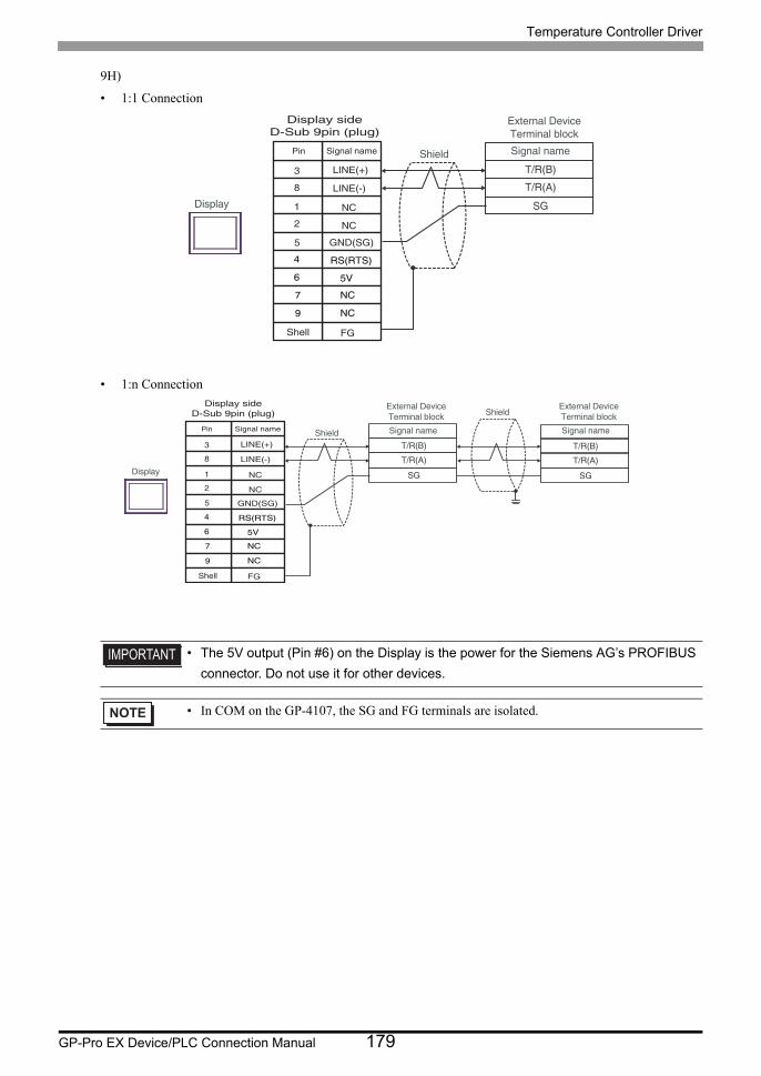
Temperature Controller Driver
GP-Pro EX Device/PLC Connection Manual 179
9H)
• 1:1 Connection
• 1:n Connection
• The 5V output (Pin #6) on the Display is the power for the Siemens AG’s PROFIBUS
connector. Do not use it for other devices.
• In COM on the GP-4107, the SG and FG terminals are isolated.
T/R(B)
T/R(A)
SG
External DeviceTerminal block
Shield Signal name
Display
Pin Signal name
NC
NC
GND(SG)
RS(RTS)
5V
NC
NC
FG
LINE(+)
LINE(-)
3
8
1
2
5
4
6
7
9
Shell
Display sideD-Sub 9pin (plug)
T/R(B)
T/R(A)
SG
T/R(B)
T/R(A)
SG
External DeviceTerminal block
Shield
Shield
Signal name
External DeviceTerminal blockSignal name
Display
Pin Signal name
NC
NC
GND(SG)
RS(RTS)
5V
NC
NC
FG
LINE(+)
LINE(-)
3
8
1
2
5
4
6
7
9
Shell
Display sideD-Sub 9pin (plug)
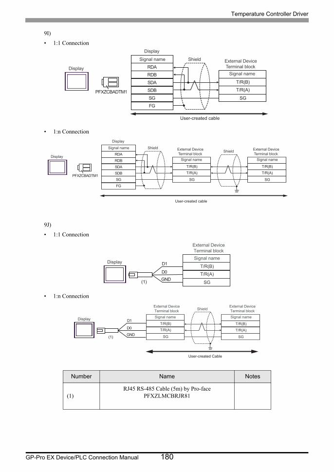
Temperature Controller Driver
GP-Pro EX Device/PLC Connection Manual 180
9I)
• 1:1 Connection
• 1:n Connection
9J)
• 1:1 Connection
• 1:n Connection
Number Name Notes
(1)RJ45 RS-485 Cable (5m) by Pro-face
PFXZLMCBRJR81
RDB
SDB SG FG
PFXZCBADTM1
RDA
SDA T/R(B)
T/R(A)
SG
Display
Display External Device Terminal block
Shield Signal name
Signal name
User-created cable
RDB
SDB SG FG
PFXZCBADTM1
RDA
SDA T/R(B)
T/R(A)
SG
T/R(B)
T/R(A)
SG
Display
Display
External Device Terminal block
Shield Signal name
Signal name
External Device Terminal block
Shield
Signal name
User-created cable
T/R(B)
T/R(A)
SG
External DeviceTerminal blockSignal name
Display
GNDD0
D1
(1)
T/R(B)
T/R(A)
SG
T/R(B)
T/R(A)
SG
External DeviceTerminal block Shield
Signal name
External DeviceTerminal blockSignal nameDisplay
GND
D0
D1
(1)
User-created Cable
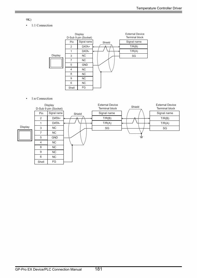
Temperature Controller Driver
GP-Pro EX Device/PLC Connection Manual 181
9K)
• 1:1 Connection
• 1:n Connection
NC3
DATA-1
GND5
4
NC
NCNCNCNC
7
96
FG
DATA+2
8
T/R(B)
T/R(A)
SG
Shell
Pin
DisplayD-Sub 9 pin (Socket)
External DeviceTerminal block
Shield Signal nameSignal name
Display
NC3
DATA-1
GND5
4
NC
NCNC
NCNC
7
96
FG
DATA+2
8
T/R(B)
T/R(A)
SG
T/R(B)
T/R(A)
SG
Shell
Pin
DisplayD-Sub 9 pin (Socket)
External DeviceTerminal block
Shield
Shield
Signal name
External DeviceTerminal blockSignal nameSignal name
Display
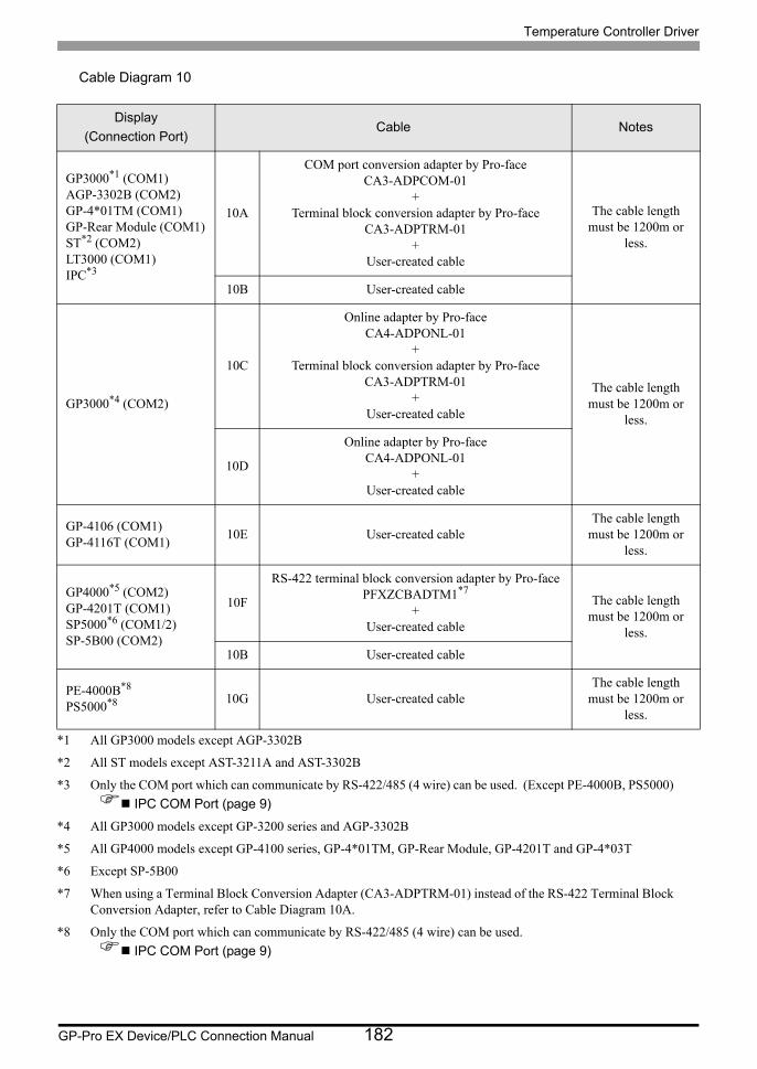
Temperature Controller Driver
GP-Pro EX Device/PLC Connection Manual 182
Cable Diagram 10
Display
(Connection Port)Cable Notes
GP3000*1 (COM1)AGP-3302B (COM2)GP-4*01TM (COM1)GP-Rear Module (COM1)ST*2 (COM2)LT3000 (COM1)IPC*3
*1 All GP3000 models except AGP-3302B
*2 All ST models except AST-3211A and AST-3302B
*3 Only the COM port which can communicate by RS-422/485 (4 wire) can be used. (Except PE-4000B, PS5000)
IPC COM Port (page 9)
10A
COM port conversion adapter by Pro-faceCA3-ADPCOM-01
+Terminal block conversion adapter by Pro-face
CA3-ADPTRM-01+
User-created cable
The cable length must be 1200m or
less.
10B User-created cable
GP3000*4 (COM2)
*4 All GP3000 models except GP-3200 series and AGP-3302B
10C
Online adapter by Pro-faceCA4-ADPONL-01
+Terminal block conversion adapter by Pro-face
CA3-ADPTRM-01+
User-created cable
The cable length must be 1200m or
less.
10D
Online adapter by Pro-faceCA4-ADPONL-01
+User-created cable
GP-4106 (COM1)GP-4116T (COM1)
10E User-created cableThe cable length
must be 1200m or less.
GP4000*5 (COM2)GP-4201T (COM1)SP5000*6 (COM1/2)SP-5B00 (COM2)
*5 All GP4000 models except GP-4100 series, GP-4*01TM, GP-Rear Module, GP-4201T and GP-4*03T
*6 Except SP-5B00
10F
RS-422 terminal block conversion adapter by Pro-facePFXZCBADTM1*7
+User-created cable
*7 When using a Terminal Block Conversion Adapter (CA3-ADPTRM-01) instead of the RS-422 Terminal Block Conversion Adapter, refer to Cable Diagram 10A.
The cable length must be 1200m or
less.
10B User-created cable
PE-4000B*8
PS5000*8
*8 Only the COM port which can communicate by RS-422/485 (4 wire) can be used.
IPC COM Port (page 9)
10G User-created cableThe cable length
must be 1200m or less.
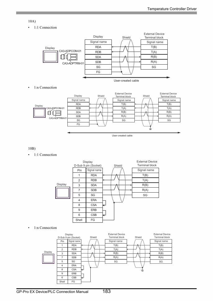
Temperature Controller Driver
GP-Pro EX Device/PLC Connection Manual 183
10A)
• 1:1 Connection
• 1:n Connection
10B)
• 1:1 Connection
• 1:n Connection
RDB
SDBSGFG
CA3-ADPCOM-01
CA3-ADPTRM-01
RDA
SDA
T(B)
T(A)R(B)
R(A)
SG
Display
Display
External DeviceTerminal blockShield
Signal name Signal name
User-created cable
RDB
SDBSGFG
CA3-ADPCOM-01
CA3-ADPTRM-01
RDA
SDA
T(B)
T(A)R(B)
R(A)
SG
T(B)
T(A)R(B)
R(A)
SG
Display
Shield ShieldDisplay
Signal name
External DeviceTerminal block
Signal name
External DeviceTerminal block
Signal name
User-created cable
SDA3
RDB2
SG5
4 ERA
SDB
ERB
7
9
CSB6
FG
RDA1
CSA8
T(B)
T(A)
R(B)
R(A)
SG
Shell
Pin
DisplayD-Sub 9 pin (Socket)
External Device�Terminal blockShield
Signal nameSignal name
Display
SDA3
RDB2
SG5
4 ERA
SDB
ERB
7
9
CSB6
FG
RDA1
CSA8
T(B)
T(A)
R(B)
R(A)
SG
T(B)
T(A)
R(B)
R(A)
SG
Shell
Shield ShieldExternal Device�Terminal block
Signal name
External Device�Terminal block
Signal namePin
DisplayD-Sub 9 pin (Socket)
Signal name
Display
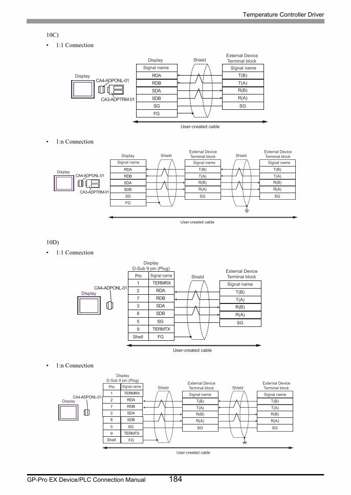
Temperature Controller Driver
GP-Pro EX Device/PLC Connection Manual 184
10C)
• 1:1 Connection
• 1:n Connection
10D)
• 1:1 Connection
• 1:n Connection
RDB
SDBSGFG
CA4-ADPONL-01
CA3-ADPTRM-01
RDA
SDA
T(B)
T(A)R(B)
R(A)
SG
Display
Display
External DeviceTerminal blockShield
Signal name Signal name
User-created cable
RDB
SDBSGFG
CA4-ADPONL-01
CA3-ADPTRM-01
RDA
SDA
T(B)
T(A)R(B)
R(A)
SG
T(B)
T(A)R(B)
R(A)
SG
Display
DisplayExternal DeviceTerminal blockShield
Signal name Signal name
External DeviceTerminal blockShield
Signal name
User-created cable
CA4-ADPONL-01
RDB7
RDA2
SDB8
9 TERMTX
SDA
FG
3
TERMRX1
SG5
T(B)
T(A)R(B)
R(A)
SG
Shell
Pin
DisplayD-Sub 9 pin (Plug) External Device
Terminal blockShieldSignal name
Signal name
Display
User-created cable
CA4-ADPONL-01
RDB7
RDA2
SDB8
9 TERMTX
SDA
FG
3
TERMRX1
SG5
T(B)
T(A)R(B)
R(A)
SG
T(B)
T(A)R(B)
R(A)
SG
ShieldShieldExternal DeviceTerminal blockSignal name
External DeviceTerminal blockSignal name
Shell
Pin
DisplayD-Sub 9 pin (Plug)
Signal name
Display
User-created cable
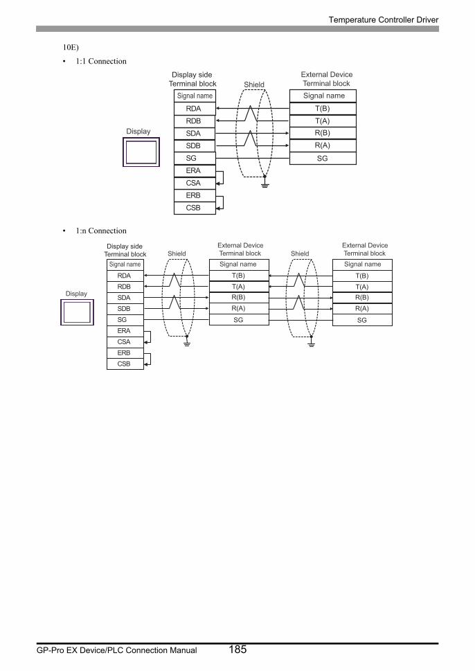
Temperature Controller Driver
GP-Pro EX Device/PLC Connection Manual 185
10E)
• 1:1 Connection
• 1:n Connection
SDARDB
SGERA
SDB
ERBCSB
RDA
CSA
T(B)
T(A)R(B)
R(A)
SG
External DeviceTerminal blockShieldSignal nameSignal name
Display
Display side Terminal block
SDARDB
SGERA
SDB
ERBCSB
RDA
CSA
T(B)
T(A)R(B)
R(A)
SG
T(B)
T(A)R(B)
R(A)
SG
Shield ShieldExternal DeviceTerminal blockSignal name
External DeviceTerminal blockSignal nameSignal name
Display
Display side Terminal block
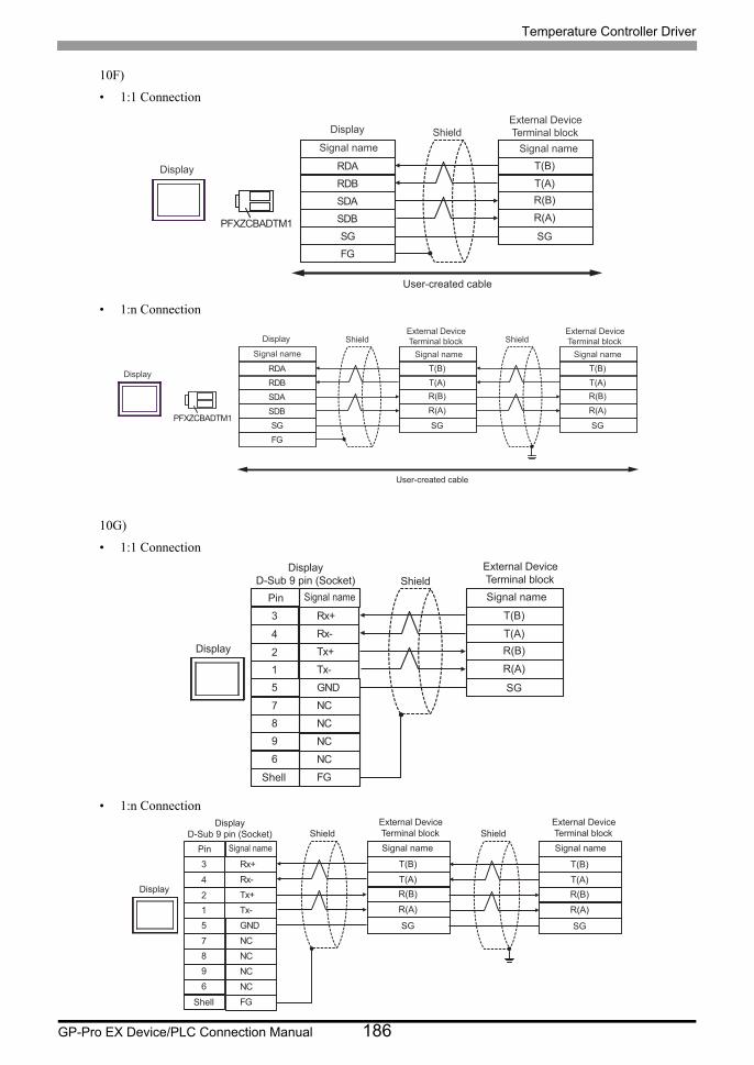
Temperature Controller Driver
GP-Pro EX Device/PLC Connection Manual 186
10F)
• 1:1 Connection
• 1:n Connection
10G)
• 1:1 Connection
• 1:n Connection
RDB
SDB SG FG
PFXZCBADTM1
RDA
SDA
T(B)
T(A) R(B)
R(A)
SG
Display
Display
External Device Terminal block Shield
Signal name Signal name
User-created cable
RDB
SDB SG FG
PFXZCBADTM1
RDA
SDA
T(B)
T(A) R(B)
R(A)
SG
T(B)
T(A) R(B)
R(A)
SG
Display
Shield Shield Display
Signal name
External Device Terminal block
Signal name
External Device Terminal block
Signal name
User-created cable
Tx+2
Rx-4
GND5
7 NC
Tx-
NC
1
9
NC6
FG
Rx+3
NC8
T(B)
T(A)R(B)
R(A)
SG
Shell
Pin
DisplayD-Sub 9 pin (Socket)
External DeviceTerminal blockShieldSignal nameSignal name
Display
Tx+2
Rx-4
GND5
7 NC
Tx-
NC
1
9
NC6
FG
Rx+3
NC8
T(B)
T(A)R(B)
R(A)
SG
T(B)
T(A)R(B)
R(A)
SG
Shell
Shield ShieldExternal DeviceTerminal blockSignal name
External DeviceTerminal blockSignal namePin
DisplayD-Sub 9 pin (Socket)
Signal name
Display
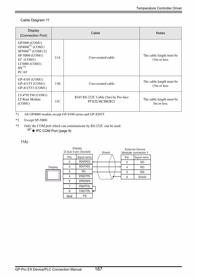
Temperature Controller Driver
GP-Pro EX Device/PLC Connection Manual 187
Cable Diagram 11
11A)
Display
(Connection Port)Cable Notes
GP3000 (COM1)GP4000*1 (COM1)SP5000*2 (COM1/2)SP-5B00 (COM1)ST (COM1)LT3000 (COM1)IPC*3
PC/AT
*1 All GP4000 models except GP-4100 series and GP-4203T
*2 Except SP-5B00
*3 Only the COM port which can communicate by RS-232C can be used.
IPC COM Port (page 9)
11A User-created cableThe cable length must be
15m or less.
GP-4105 (COM1)GP-4115T (COM1)GP-4115T3 (COM1)
11B User-created cableThe cable length must be
15m or less.
LT-4*01TM (COM1)LT-Rear Module (COM1)
11CRJ45 RS-232C Cable (5m) by Pro-face
PFXZLMCBRJR21The cable length must be
5m or less.
SG5
SD(TXD)3
DR(DSR)6
8 CS(CTS)
ER(DTR)
FG
4
RD(RXD)2
RS(RTS)7
2
4
SD
RD3 SG
6
External DeviceModular connector 1
Shield
Pin Signal name
Shell
Shield
Display
Pin Signal name
DisplayD-Sub 9 pin (Socket)
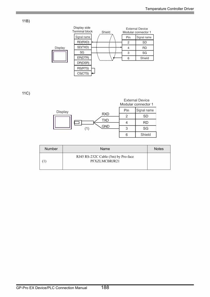
Temperature Controller Driver
GP-Pro EX Device/PLC Connection Manual 188
11B)
11C)
Number Name Notes
(1)RJ45 RS-232C Cable (5m) by Pro-face
PFXZLMCBRJR21
2
4
SD
RD3 SG
6
External DeviceModular connector 1
Shield
Pin Signal nameShield
Display
Signal name
Display side Terminal block
SGSD(TXD)
DR(DSR)
CS(CTS)
ER(DTR)
RD(RXD)
RS(RTS)
2
4
SD
RD3 SG
6
External DeviceModular connector 1
Shield
Pin Signal nameDisplay
GNDTXD
RXD
(1)
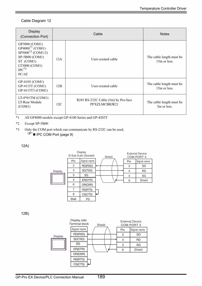
Temperature Controller Driver
GP-Pro EX Device/PLC Connection Manual 189
Cable Diagram 12
12A)
12B)
Display
(Connection Port)Cable Notes
GP3000 (COM1)GP4000*1 (COM1)SP5000*2 (COM1/2)SP-5B00 (COM1)ST (COM1)LT3000 (COM1)IPC*3
PC/AT
*1 All GP4000 models except GP-4100 Series and GP-4203T
*2 Except SP-5B00
*3 Only the COM port which can communicate by RS-232C can be used.
IPC COM Port (page 9)
12A User-created cableThe cable length must be
15m or less.
GP-4105 (COM1)GP-4115T (COM1)GP-4115T3 (COM1)
12B User-created cableThe cable length must be
15m or less.
LT-4*01TM (COM1)LT-Rear Module (COM1)
12CRJ45 RS-232C Cable (5m) by Pro-face
PFXZLMCBRJR21The cable length must be
5m or less.
5
3
6
8
4
2
7
2
4
SD
RD
3 SG6
External DeviceCOM.PORT 3
Shield
Pin Signal nameShield
Display
Shell
Pin Signal name
DisplayD-Sub 9 pin (Socket)
SGSD(TXD)
DR(DSR)
CS(CTS)
ER(DTR)
FG
RD(RXD)
RS(RTS)
2
4
SD
RD
3 SG6
External DeviceCOM.PORT 3
Shield
Pin Signal nameShield
Display
Signal name
Display side Terminal block
SGSD(TXD)
DR(DSR)
CS(CTS)
ER(DTR)
RD(RXD)
RS(RTS)

Temperature Controller Driver
GP-Pro EX Device/PLC Connection Manual 190
12C)
Number Name Notes
(1)RJ45 RS-232C Cable (5m) by Pro-face
PFXZLMCBRJR21
2
4
SD
RD
3 SG6
External DeviceCOM.PORT 3
Shield
Pin Signal nameDisplay
GNDTXD
RXD
(1)
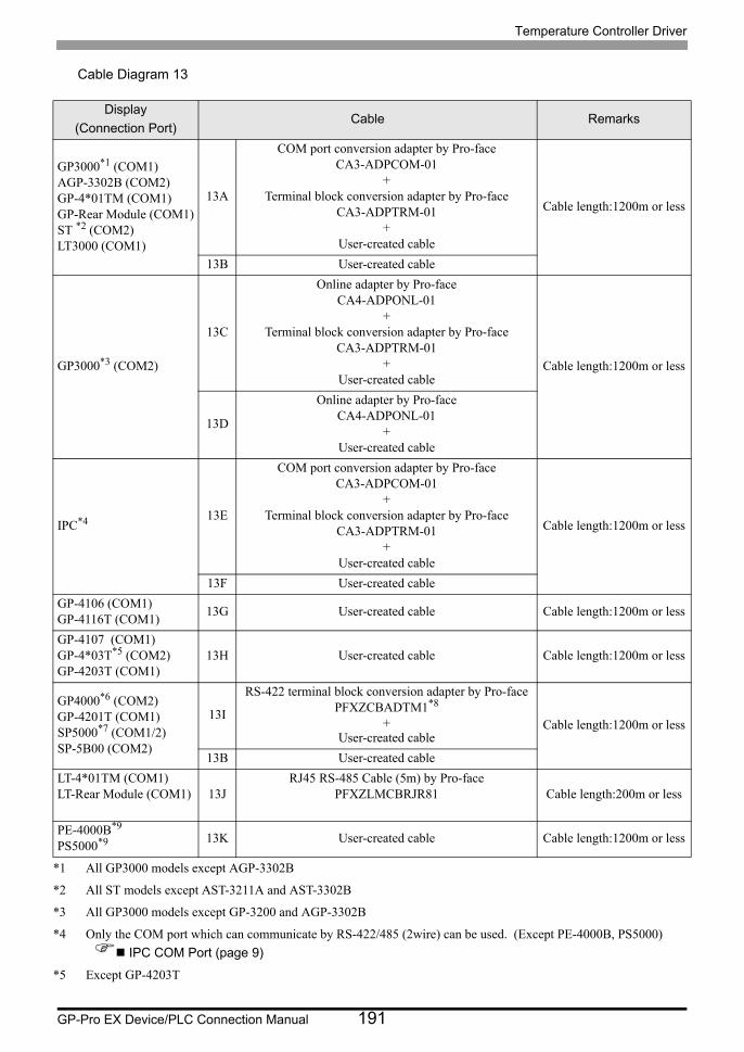
Temperature Controller Driver
GP-Pro EX Device/PLC Connection Manual 191
Cable Diagram 13
Display
(Connection Port)Cable Remarks
GP3000*1 (COM1)AGP-3302B (COM2)GP-4*01TM (COM1)GP-Rear Module (COM1)ST *2 (COM2)LT3000 (COM1)
*1 All GP3000 models except AGP-3302B
*2 All ST models except AST-3211A and AST-3302B
13A
COM port conversion adapter by Pro-faceCA3-ADPCOM-01
+Terminal block conversion adapter by Pro-face
CA3-ADPTRM-01+
User-created cable
Cable length:1200m or less
13B User-created cable
GP3000*3 (COM2)
*3 All GP3000 models except GP-3200 and AGP-3302B
13C
Online adapter by Pro-faceCA4-ADPONL-01
+Terminal block conversion adapter by Pro-face
CA3-ADPTRM-01+
User-created cableCable length:1200m or less
13D
Online adapter by Pro-faceCA4-ADPONL-01
+User-created cable
IPC*4
*4 Only the COM port which can communicate by RS-422/485 (2wire) can be used. (Except PE-4000B, PS5000)
IPC COM Port (page 9)
13E
COM port conversion adapter by Pro-faceCA3-ADPCOM-01
+Terminal block conversion adapter by Pro-face
CA3-ADPTRM-01+
User-created cable
Cable length:1200m or less
13F User-created cable
GP-4106 (COM1)GP-4116T (COM1)
13G User-created cable Cable length:1200m or less
GP-4107 (COM1)GP-4*03T*5 (COM2)GP-4203T (COM1)
*5 Except GP-4203T
13H User-created cable Cable length:1200m or less
GP4000*6 (COM2)GP-4201T (COM1)SP5000*7 (COM1/2)SP-5B00 (COM2)
13I
RS-422 terminal block conversion adapter by Pro-facePFXZCBADTM1*8
+User-created cable
Cable length:1200m or less
13B User-created cable
LT-4*01TM (COM1)LT-Rear Module (COM1) 13J
RJ45 RS-485 Cable (5m) by Pro-facePFXZLMCBRJR81 Cable length:200m or less
PE-4000B*9
PS5000*9 13K User-created cable Cable length:1200m or less

Temperature Controller Driver
GP-Pro EX Device/PLC Connection Manual 192
*6 All GP4000 models except GP-4100 series, GP-4*01TM, GP-Rear Module, GP-4201T and GP-4*03T
*7 Except SP-5B00
*8 When using a Terminal Block Conversion Adapter (CA3-ADPTRM-01) instead of the RS-422 Terminal Block Conversion Adapter, refer to Cable Diagram 13A.
*9 Only the COM port which can communicate by RS-422/485 (2wire) can be used.
IPC COM Port (page 9)
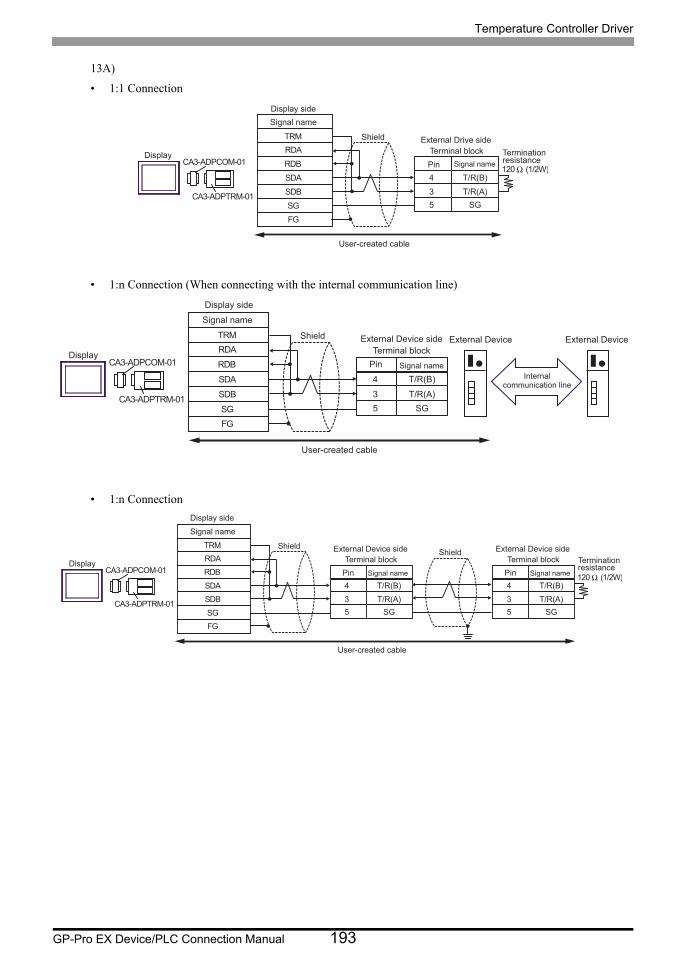
Temperature Controller Driver
GP-Pro EX Device/PLC Connection Manual 193
13A)
• 1:1 Connection
• 1:n Connection (When connecting with the internal communication line)
• 1:n Connection
Signal name
RDB
SDB
SG
FG
CA3-ADPCOM-01
CA3-ADPTRM-01
Display
Shield
RDA
SDA
Terminal blockExternal Drive side
4
3
Signal name
T/R(B)
T/R(A)
Pin
5 SG
User-created cable
TRM
120 Ω (1/2W)
Terminationresistance
Display side
Signal name
RDB
SDBSGFG
CA3-ADPCOM-01
CA3-ADPTRM-01
Display
ShieldRDA
SDA
Terminal blockExternal Device side
4
3
Signal name
T/R(B)
T/R(A)
Pin
5 SG
User-created cable
TRM
Display side
External Device External Device
Internalcommunication line
Signal name
RDB
SDB
SG
FG
CA3-ADPCOM-01
CA3-ADPTRM-01
Display
Shield
RDA
SDA
Terminal block
External Device side
4
3
Signal name
T/R(B)
T/R(A)
Pin
5 SG
User-created cable
TRM
Terminal block
External Device side
4
3
Signal name
T/R(B)
T/R(A)
Pin
5 SG
120 Ω (1/2W)
Terminationresistance
Shield
Display side
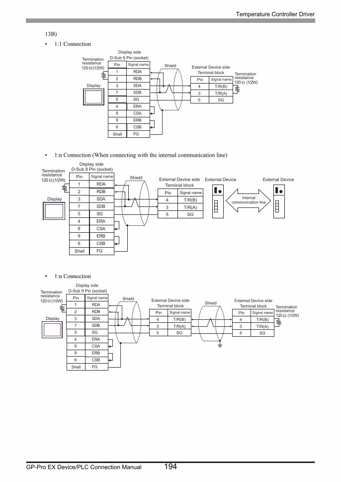
Temperature Controller Driver
GP-Pro EX Device/PLC Connection Manual 194
13B)
• 1:1 Connection
• 1:n Connection (When connecting with the internal communication line)
• 1:n Connection
120 Ω (1/2W)
SDA3
RDB2
SG5
4 ERA
SDB
ERB
7
9
CSB6
FG
RDA1
CSA8
D-Sub 9 Pin (socket)Terminationresistance
Shell
Shield
Display 4
3
T/R(B)
T/R(A)5 SG
120 Ω (1/2W)
Signal namePin
Signal namePin
Terminal blockExternal Device side
Terminationresistance
Display side
120 Ω (1/2W)
SDA3
RDB2
SG5
4 ERA
SDB
ERB
7
9
CSB6
FG
RDA1
CSA8
D-Sub 9 Pin (socket)Terminationresistance
Shell
Shield
Display 4
3
T/R(B)
T/R(A)5 SG
Signal namePin
Signal namePin
Terminal blockExternal Device side
Display side
External Device External Device
Internalcommunication line
120 Ω (1/2W)
SDA3
RDB2
SG5
4 ERA
SDB
ERB
7
9
CSB6
FG
RDA1
CSA8
D-Sub 9 Pin (socket)
Shell
Shield
Display 4
3
T/R(B)
T/R(A)5 SG
4
3
T/R(B)
T/R(A)5 SG
120 Ω (1/2W)
Shield
Terminationresistance Signal namePin
Terminal blockExternal Device side
Signal namePinTerminal block
External Device side
Signal namePinTerminationresistance
Display side
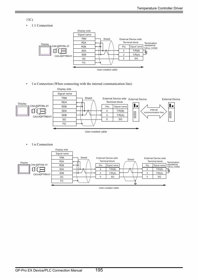
Temperature Controller Driver
GP-Pro EX Device/PLC Connection Manual 195
13C)
• 1:1 Connection
• 1:n Connection (When connecting with the internal communication line)
• 1:n Connection
RDB
SDB
SG
FG
CA4-ADPONL-01
CA3-ADPTRM-01
Display
Shield
RDA
SDA 4
3
T/R(B)
T/R(A)
5 SG
User-created cable
TRM
120 Ω (1/2W)
Signal name
Terminal block
External Device side
Signal namePin
Terminationresistance
Display side
RDB
SDBSGFG
CA4-ADPONL-01
CA3-ADPTRM-01
RDA
SDA 4
3
T/R(B)
T/R(A)5 SG
TRM
Display
Shield
User-created cable
Signal name
Terminal blockExternal Device side
Signal namePin
Display side
External Device External Device
Internalcommunication line
RDB
SDB
SG
FG
CA4-ADPONL-01
CA3-ADPTRM-01
RDA
SDA 4
3
T/R(B)
T/R(A)
5 SG
TRM
4
3
T/R(B)
T/R(A)
5 SG
120 Ω (1/2W)
Display
Shield
Signal name
Terminal block
External Device side
Signal namePin
Shield
User-created cable
Terminationresistance
Terminal block
External Device side
Signal namePin
Display side
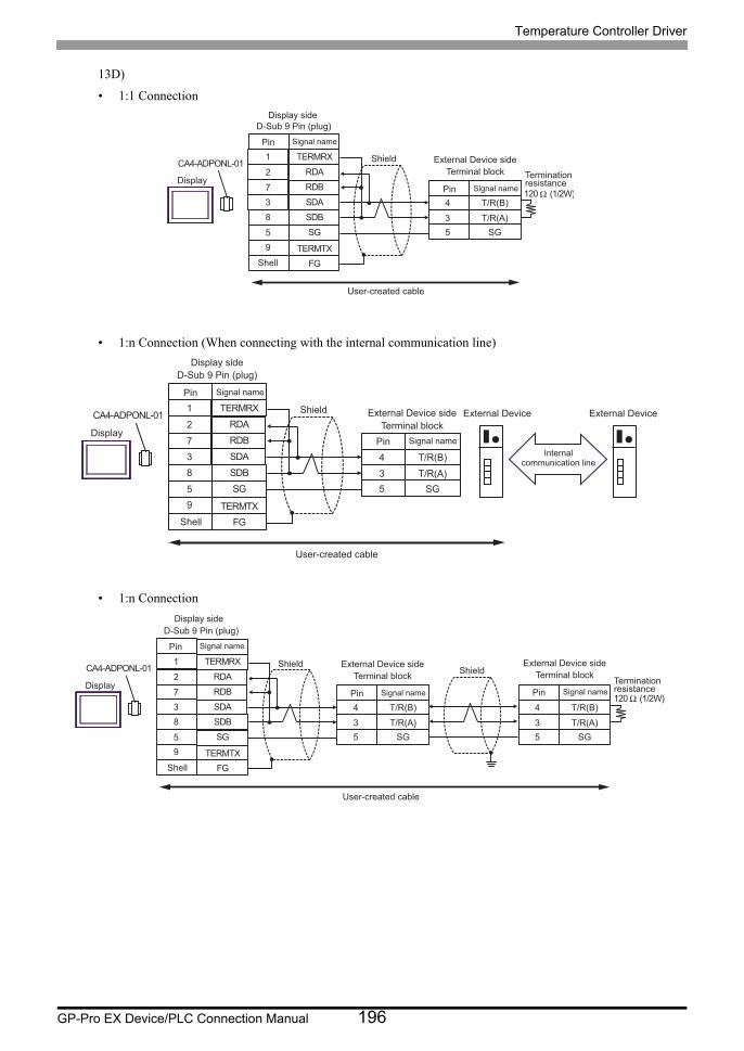
Temperature Controller Driver
GP-Pro EX Device/PLC Connection Manual 196
13D)
• 1:1 Connection
• 1:n Connection (When connecting with the internal communication line)
• 1:n Connection
CA4-ADPONL-01
4
3
T/R(B)
T/R(A)5 SG
120 Ω (1/2W)SDA
7 RDB2
SG8
5
SDB3
FG
RDA1
9
ShellTERMTX
TERMRX
Display
ShieldTerminal block
External Device side
Signal namePin
User-created cable
Terminationresistance
D-Sub 9 Pin (plug)Signal namePin
Display side
CA4-ADPONL-01
4
3
T/R(B)
T/R(A)5 SG
SDA7 RDB2
SG8
5
SDB3
FG
RDA1
9 TERMTX
TERMRX
Shell
Display
ShieldTerminal block
External Device side
Signal namePin
User-created cable
D-Sub 9 Pin (plug)
Signal namePin
Display side
External Device External Device
Internalcommunication line
CA4-ADPONL-01
4
3
T/R(B)
T/R(A)5 SG
SDA7 RDB2
SG8
5
SDB3
FG
RDA1
9 TERMTX
TERMRX
4
3
T/R(B)
T/R(A)5 SG
120 Ω (1/2W)
Shell
Display
ShieldTerminal block
External Device side
Signal namePin
User-created cable
Terminationresistance
D-Sub 9 Pin (plug)Signal namePin
Shield Terminal blockExternal Device side
Signal namePin
Display side
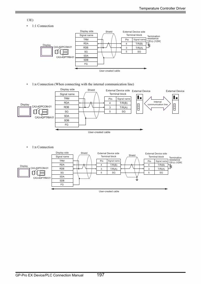
Temperature Controller Driver
GP-Pro EX Device/PLC Connection Manual 197
13E)
• 1:1 Connection
• 1:n Connection (When connecting with the internal communication line)
• 1:n Connection
RDB
SDB
SG
FG
CA3-ADPCOM-01
CA3-ADPTRM-01
RDA
SDA
4
3
T/R(B)
T/R(A)
5 SG
TRM120 Ω (1/2W)
Display
Shield
Terminal block
External Device side
Signal namePin
User-created cable
Terminationresistance
Signal name
Display side
RDB
SDB
SG
FG
CA3-ADPCOM-01
CA3-ADPTRM-01
RDA
SDA
4
3
T/R(B)
T/R(A)5 SG
TRM
Display
ShieldTerminal block
External Device side
Signal namePin
User-created cable
Signal name
Display side External Device External Device
Internalcommunication line
RDB
SDB
SG
FG
CA3-ADPCOM-01
CA3-ADPTRM-01
RDA
SDA
4
3
T/R(B)
T/R(A)
5 SG
TRM
4
3
T/R(B)
T/R(A)
5 SG
120 Ω (1/2W)
Display
Shield
Terminal block
External Device side
Signal namePin
User-created cable
Terminationresistance
Signal nameShield
Terminal block
External Device side
Signal namePin
Display side
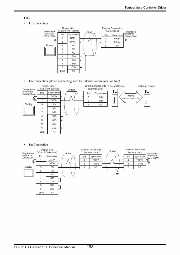
Temperature Controller Driver
GP-Pro EX Device/PLC Connection Manual 198
13F)
• 1:1 Connection
• 1:n Connection (When connecting with the internal communication line)
• 1:n Connection
120 Ω (1/2W)
NC3
DATA -2
SG5
4 ERANC
ERB
7
9
CSB6
FG
DATA+1
CSA8
4
3
T/R(B)
T/R(A)5 SG
120 Ω (1/2W)
Shell
Display
Shield Terminal blockExternal Device side
Signal namePin
D-Sub 9 Pin (socket)Signal namePin
Terminationresistance
Terminationresistance
Display side
120 Ω (1/2W)
NC3
DATA -2
SG5
4 ERANC
ERB
7
9
CSB6
FG
DATA+1
CSA8
4
3
T/R(B)
T/R(A)5 SG
Shell
Display
Shield Terminal blockExternal Device side
Signal namePin
D-Sub 9 Pin (socket)Signal namePin
Terminationresistance
Display side External Device External Device
Internalcommunication line
120 Ω (1/2W)
NC3
DATA -2
SG5
4 ERANC
ERB
7
9
CSB6
FG
DATA+1
CSA8
4
3
T/R(B)
T/R(A)5 SG
4
3
T/R(B)
T/R(A)5 SG
120 Ω (1/2W)
Shell
Display
Shield Terminal blockExternal Device side
Signal namePin
D-Sub 9 Pin (socket)Signal namePin
Shield Terminal blockExternal Device side
Signal namePinTerminationresistance
Terminationresistance
Display side
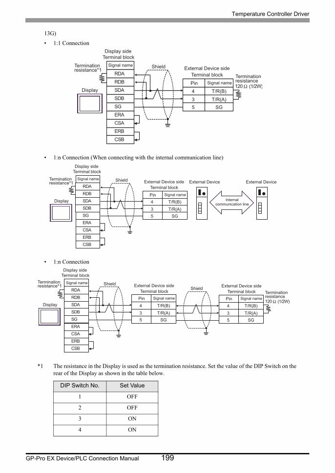
Temperature Controller Driver
GP-Pro EX Device/PLC Connection Manual 199
13G)
• 1:1 Connection
• 1:n Connection (When connecting with the internal communication line)
• 1:n Connection
*1 The resistance in the Display is used as the termination resistance. Set the value of the DIP Switch on the rear of the Display as shown in the table below.
DIP Switch No. Set Value
1 OFF
2 OFF
3 ON
4 ON
SDARDB
SGERA
SDB
ERBCSB
RDA
CSA
Terminationresistance*1
Shield
Display 4
3
T/R(B)
T/R(A)5 SG
120Ω (1/2W)
Signal name
Signal namePin
Terminal blockExternal Device side
Terminationresistance
Display side Terminal block
SDARDB
SGERA
SDB
ERBCSB
RDA
CSA
Terminationresistance*1
Shield
Display 4
3
T/R(B)
T/R(A)5 SG
Signal name
Signal namePin
Terminal blockExternal Device side External Device External Device
Internalcommunication line
Display side Terminal block
SDARDB
SGERA
SDB
ERBCSB
RDA
CSA
Shield
Display 4
3
T/R(B)
T/R(A)5 SG
4
3
T/R(B)
T/R(A)5 SG
120Ω (1/2W)
ShieldTerminationresistance*1
Signal name
Terminal blockExternal Device side
Signal namePinTerminal block
External Device side
Signal namePinTerminationresistance
Display side Terminal block
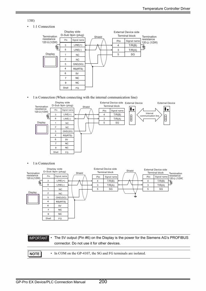
Temperature Controller Driver
GP-Pro EX Device/PLC Connection Manual 200
13H)
• 1:1 Connection
• 1:n Connection (When connecting with the internal communication line)
• 1:n Connection
• The 5V output (Pin #6) on the Display is the power for the Siemens AG’s PROFIBUS
connector. Do not use it for other devices.
• In COM on the GP-4107, the SG and FG terminals are isolated.
120Ω (1/2W)
4
3
T/R(B)
T/R(A)5 SG
120Ω (1/2W)
Display
Shield Terminal blockExternal Device side
Signal namePinTerminationresistance
TerminationresistancePin Signal name
NC
NC
GND(SG)
RS(RTS)
5V
NC
NC
FG
LINE(+)
LINE(-)
3
8
1
2
5
4
6
7
9
Shell
Display sideD-Sub 9pin (plug)
120Ω (1/2W)
4
3
T/R(B)
T/R(A)5 SGDisplay
Shield Terminal blockExternal Device side
Signal namePinTerminationresistance
External Device External Device
Internalcommunication line
Pin Signal name
NC
NC
GND(SG)
RS(RTS)
5V
NC
NC
FG
LINE(+)
LINE(-)
3
8
1
2
5
4
6
7
9
Shell
Display sideD-Sub 9pin (plug)
120Ω (1/2W)4
3
T/R(B)
T/R(A)5 SG
4
3
T/R(B)
T/R(A)5 SG
120Ω (1/2W)
Shield Terminal blockExternal Device side
Signal namePin
ShieldTerminal block
External Device side
Signal namePinTerminationresistance
Terminationresistance Pin Signal name
NC
NC
GND(SG)
RS(RTS)
5V
NC
NC
FG
LINE(+)
LINE(-)
3
8
1
2
5
4
6
7
9
Shell
Display sideD-Sub 9pin (plug)
Display
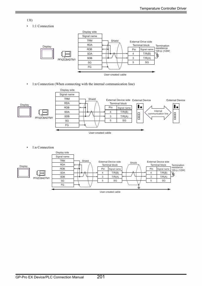
Temperature Controller Driver
GP-Pro EX Device/PLC Connection Manual 201
13I)
• 1:1 Connection
• 1:n Connection (When connecting with the internal communication line)
• 1:n Connection
Signal name
RDB
SDB
SG
FG
PFXZCBADTM1
Display
Shield
RDA
SDA
Terminal blockExternal Drive side
4
3
Signal name
T/R(B)
T/R(A)
Pin
5 SG
User-created cable
TRM
120 Ω (1/2W)
Terminationresistance
Display side
Signal name
RDB
SDB SG FG
PFXZCBADTM1
Display
Shield RDA
SDA
Terminal block External Device side
4
3
Signal name
T/R(B)
T/R(A)
Pin
5 SG
User-created cable
TRM
Display side
External Device External Device
Internal communication line
Signal name
RDB
SDBSGFG
PFXZCBADTM1
Display
ShieldRDA
SDA
Terminal blockExternal Device side
4
3
Signal name
T/R(B)
T/R(A)
Pin
5 SG
User-created cable
TRM
Terminal blockExternal Device side
4
3
Signal name
T/R(B)
T/R(A)
Pin
5 SG
120 Ω (1/2W)
Terminationresistance
Shield
Display side
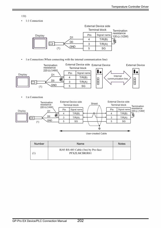
Temperature Controller Driver
GP-Pro EX Device/PLC Connection Manual 202
13J)
• 1:1 Connection
• 1:n Connection (When connecting with the internal communication line)
• 1:n Connection
Number Name Notes
(1)RJ45 RS-485 Cable (5m) by Pro-face
PFXZLMCBRJR81
4
3
T/R(B)
T/R(A) 5 SG
120 Ω (1/2W)
Terminal block External Device side
Signal name Pin Termination resistance
Display
GNDD0D1
(1)
External Device External Device
Internal communication line
220 Ω (1/4W)
4
3
T/R(B)
T/R(A)5 SG
Terminal blockExternal Device side
Signal namePin
Terminationresistance
Display
GNDD0
D1
(1)
220 Ω (1/4W)
4
3
T/R(B)
T/R(A) 5 SG
4
3
T/R(B)
T/R(A) 5 SG
220 Ω (1/4W)
Terminal block External Device side
Signal name Pin
Shield Terminal block External Device side
Signal name Pin Termination resistance
Terminationresistance
Display
GNDD0
D1
(1)
User-created Cable
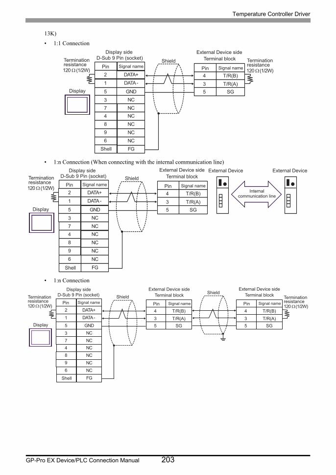
Temperature Controller Driver
GP-Pro EX Device/PLC Connection Manual 203
13K)
• 1:1 Connection
• 1:n Connection (When connecting with the internal communication line)
• 1:n Connection
120 Ω (1/2W)
NC3
DATA -1
GND5
4 NCNC
NC
7
9
NC6
FG
DATA+2
NC8
4
3
T/R(B)
T/R(A)5 SG
120 Ω (1/2W)
Shell
Display
Shield Terminal blockExternal Device side
Signal namePin
D-Sub 9 Pin (socket)Signal namePin
Terminationresistance
Terminationresistance
Display side
120 Ω (1/2W)
NC3
DATA - 1
GND5
4 NCNC
NC
7
9
NC6
FG
DATA+ 2
NC8
4
3
T/R(B)
T/R(A) 5 SG
Shell
Display
Shield Terminal block External Device side
Signal name Pin
D-Sub 9 Pin (socket) Signal name Pin
Termination resistance
Display side External Device External Device
Internal communication line
120 Ω (1/2W)
NC 3
DATA - 1
GND5
4 NCNC
NC
7
9
NC6
FG
DATA+ 2
NC8
4
3
T/R(B)
T/R(A) 5 SG
4
3
T/R(B)
T/R(A) 5 SG
120 Ω (1/2W)
Shell
Display
Shield Terminal block External Device side
Signal name Pin
D-Sub 9 Pin (socket) Signal name Pin
Shield Terminal block External Device side
Signal name Pin Termination resistance
Termination resistance
Display side

Temperature Controller Driver
GP-Pro EX Device/PLC Connection Manual 204
Cable Diagram 14
Display
(Connection Port)Cable Remarks
GP3000*1 (COM1)AGP-3302B (COM2)GP-4*01TM (COM1)GP-Rear Module (COM1)ST*2 (COM2)LT3000 (COM1)IPC*3
14A
COM port conversion adapter by Pro-faceCA3-ADPCOM-01
+Terminal block conversion adapter by Pro-face
CA3-ADPTRM-01+
User-created cable+
Connection cable from RKC INSTRUMENT INC.*5
W-BF-02
Cable length:1200m or less
14B
User-created cable+
Connection cable from RKC INSTRUMENT INC.*5
W-BF-02
GP3000*4 (COM2)
14C
Online adapter by Pro-faceCA4-ADPONL-01
+Terminal block conversion adapter by Pro-face
CA3-ADPTRM-01+
User-created cable+
Connection cable from RKC INSTRUMENT INC.*5
W-BF-02
Cable length:1200m or less
14D
Online adapter by Pro-faceCA4-ADPONL-01
+User-created cable
+Connection cable from RKC INSTRUMENT INC.*5
W-BF-02
GP-4106 (COM1)GP-4116T (COM1)
14E
User-created cable+
Connection cable from RKC INSTRUMENT INC.*5
W-BF-02
Cable length:1200m or less
GP4000*6 (COM2)GP-4201T (COM1)SP5000*7 (COM1/2)SP-5B00 (COM2)
14F
RS-422 terminal block conversion adapter by Pro-facePFXZCBADTM1*8
+User-created cable
+Connection cable from RKC INSTRUMENT INC.*5
W-BF-02
Cable length:1200m or less
14B
User-created cable+
Connection cable from RKC INSTRUMENT INC.*5
W-BF-02
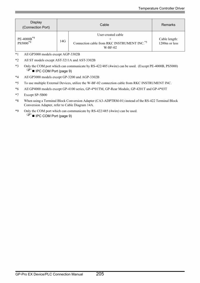
Temperature Controller Driver
GP-Pro EX Device/PLC Connection Manual 205
PE-4000B*9
PS5000*9 14G
User-created cable+
Connection cable from RKC INSTRUMENT INC.*5
W-BF-02
Cable length:1200m or less
*1 All GP3000 models except AGP-3302B
*2 All ST models except AST-3211A and AST-3302B
*3 Only the COM port which can communicate by RS-422/485 (4wire) can be used. (Except PE-4000B, PS5000)
IPC COM Port (page 9)
*4 All GP3000 models except GP-3200 and AGP-3302B
*5 To use multiple External Devices, utilize the W-BF-02 connection cable from RKC INSTRUMENT INC.
*6 All GP4000 models except GP-4100 series, GP-4*01TM, GP-Rear Module, GP-4201T and GP-4*03T
*7 Except SP-5B00
*8 When using a Terminal Block Conversion Adapter (CA3-ADPTRM-01) instead of the RS-422 Terminal Block Conversion Adapter, refer to Cable Diagram 14A.
*9 Only the COM port which can communicate by RS-422/485 (4wire) can be used.
IPC COM Port (page 9)
Display
(Connection Port)Cable Remarks
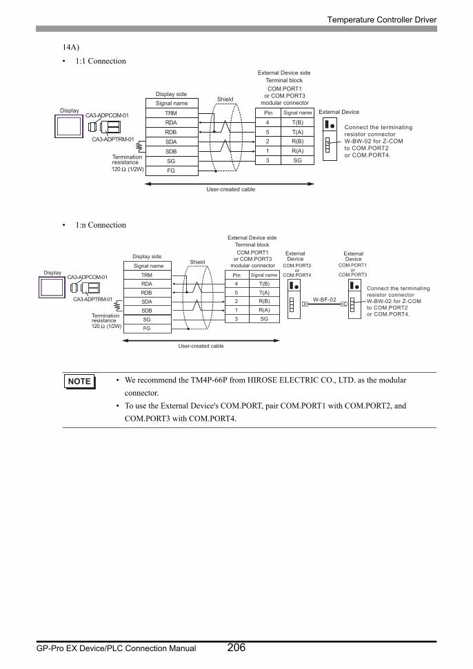
Temperature Controller Driver
GP-Pro EX Device/PLC Connection Manual 206
14A)
• 1:1 Connection
• 1:n Connection
• We recommend the TM4P-66P from HIROSE ELECTRIC CO., LTD. as the modular
connector.
• To use the External Device's COM.PORT, pair COM.PORT1 with COM.PORT2, and
COM.PORT3 with COM.PORT4.
RDB
SDBSGFG
CA3-ADPCOM-01
CA3-ADPTRM-01
RDA
SDA
COM.PORT1or COM.PORT3
modular connector
4
5
T(B)
T(A)2 R(B)
TRM
120 Ω (1/2W)
1 R(A)3 SG
Connect the terminating resistor connector W-BW-02 for Z-COM to COM.PORT2 or COM.PORT4.
Display
Shield
Terminal blockExternal Device side
Signal namePin
Signal nameExternal Device
Terminationresistance
User-created cable
Display side
RDB
SDBSGFG
CA3-ADPCOM-01
CA3-ADPTRM-01
RDA
SDA
4
5
T(B)
T(A)2 R(B)
TRM
120 Ω (1/2W)
1 R(A)3 SG
W-BF-02
COM.PORT2or
COM.PORT4
COM.PORT1or
COM.PORT3
COM.PORT1or COM.PORT3
modular connectorDisplay
Shield
Terminal blockExternal Device side
Signal namePin
Signal name
ExternalDevice
Terminationresistance
User-created cable
ExternalDevice
Connect the terminating resistor connector W-BW-02 for Z-COM to COM.PORT2 or COM.PORT4.
Display side
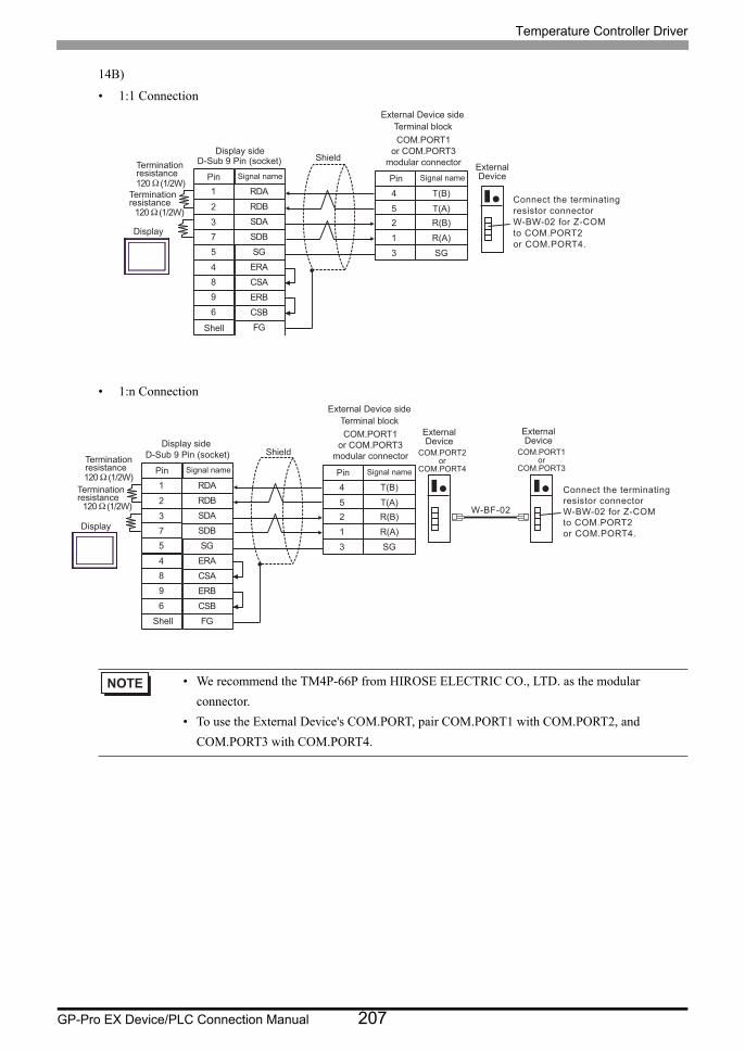
Temperature Controller Driver
GP-Pro EX Device/PLC Connection Manual 207
14B)
• 1:1 Connection
• 1:n Connection
• We recommend the TM4P-66P from HIROSE ELECTRIC CO., LTD. as the modular
connector.
• To use the External Device's COM.PORT, pair COM.PORT1 with COM.PORT2, and
COM.PORT3 with COM.PORT4.
4
5
T(B)
T(A)
2 R(B)
1 R(A)
3 SG
120 Ω (1/2W)
SDA3
RDB2
SG5
4 ERA
SDB
ERB
7
9
CSB6
FG
RDA1
CSA8
120 Ω (1/2W)
Shell
Display
ShieldTerminationresistance
D-Sub 9 Pin (socket)
Signal namePin
Terminationresistance
COM.PORT1
or COM.PORT3
modular connector
Terminal block
External Device side
Signal namePin
ExternalDevice
Connect the terminating
resistor connector
W-BW-02 for Z-COM
to COM.PORT2
or COM.PORT4.
Display side
4
5
T(B)
T(A)2 R(B)1 R(A)3 SG
120 Ω (1/2W)
SDA3
RDB2
SG5
4 ERA
SDB
ERB
7
9
CSB6
FG
RDA1
CSA8
120 Ω (1/2W) W-BF-02
Shell
Display
ShieldTerminationresistance
D-Sub 9 Pin (socket)Signal namePin
Terminationresistance
COM.PORT1or COM.PORT3
modular connector
Terminal blockExternal Device side
Signal namePin
COM.PORT2or
COM.PORT4
ExternalDevice
COM.PORT1or
COM.PORT3
ExternalDevice
Connect the terminating resistor connector W-BW-02 for Z-COM to COM.PORT2 or COM.PORT4.
Display side

Temperature Controller Driver
GP-Pro EX Device/PLC Connection Manual 208
14C)
• 1:1 Connection
• 1:n Connection
• We recommend the TM4P-66P from HIROSE ELECTRIC CO., LTD. as the modular
connector.
• To use the External Device's COM.PORT, pair COM.PORT1 with COM.PORT2, and
COM.PORT3 with COM.PORT4.
RDB
SDB
SG
FG
CA4-ADPONL-01
CA3-ADPTRM-01
RDA
SDA
4
5
T(B)
T(A)
2 R(B)
TRM
120 Ω (1/2W)
1 R(A)
3 SG
COM.PORT1
or COM.PORT3
modular connectorDisplay
Shield
Terminal block
External Device side
Signal namePin
Signal nameExternalDevice
Terminationresistance
User-created cable
Connect the terminating
resistor connector
W-BW-02 for Z-COM
to COM.PORT2
or COM.PORT4.
Display side
RDB
SDBSGFG
CA4-ADPONL-01
CA3-ADPTRM-01
RDA
SDA
4
5
T(B)
T(A)2 R(B)
TRM
120 Ω (1/2W)1 R(A)3 SG
W-BF-02
COM.PORT1or COM.PORT3
modular connectorDisplay
Shield
Terminal blockExternal Device side
Signal namePin
Signal name
Terminationresistance
User-created cable
COM.PORT2or
COM.PORT4
ExternalDevice
COM.PORT1or
COM.PORT3
ExternalDevice
Connect the terminating resistor connector W-BW-02 for Z-COM to COM.PORT2 or COM.PORT4.
Display side
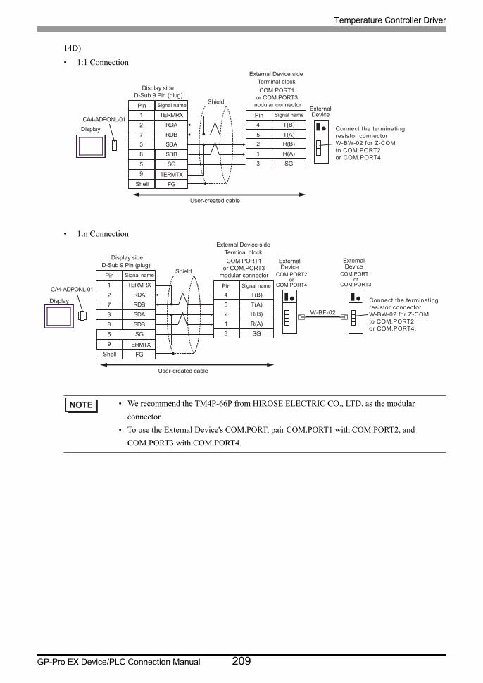
Temperature Controller Driver
GP-Pro EX Device/PLC Connection Manual 209
14D)
• 1:1 Connection
• 1:n Connection
• We recommend the TM4P-66P from HIROSE ELECTRIC CO., LTD. as the modular
connector.
• To use the External Device's COM.PORT, pair COM.PORT1 with COM.PORT2, and
COM.PORT3 with COM.PORT4.
4
5
T(B)
T(A)
2 R(B)
1 R(A)
3 SG
CA4-ADPONL-01
SDA
7 RDB
2
SG
8
5
SDB
3
FG
RDA
1
9 TERMTX
TERMRX
Shell
Display
ShieldD-Sub 9 Pin (plug)
Signal namePin
COM.PORT1
or COM.PORT3
modular connector
Terminal block
External Device side
Signal namePinExternalDevice
User-created cable
Connect the terminating
resistor connector
W-BW-02 for Z-COM
to COM.PORT2
or COM.PORT4.
Display side
4
5
T(B)
T(A)2 R(B)1 R(A)3 SG
W-BF-02
CA4-ADPONL-01
SDA7 RDB2
SG8
5
SDB3
FG
RDA1
9 TERMTX
TERMRX
Shell
Display
ShieldD-Sub 9 Pin (plug)
Signal namePin
COM.PORT1or COM.PORT3
modular connector
Terminal blockExternal Device side
Signal namePin
User-created cable
COM.PORT2or
COM.PORT4
ExternalDevice
COM.PORT1or
COM.PORT3
ExternalDevice
Connect the terminating resistor connector W-BW-02 for Z-COM to COM.PORT2 or COM.PORT4.
Display side
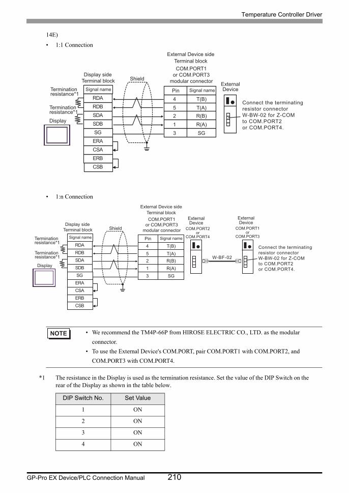
Temperature Controller Driver
GP-Pro EX Device/PLC Connection Manual 210
14E)
• 1:1 Connection
• 1:n Connection
*1 The resistance in the Display is used as the termination resistance. Set the value of the DIP Switch on the rear of the Display as shown in the table below.
• We recommend the TM4P-66P from HIROSE ELECTRIC CO., LTD. as the modular
connector.
• To use the External Device's COM.PORT, pair COM.PORT1 with COM.PORT2, and
COM.PORT3 with COM.PORT4.
DIP Switch No. Set Value
1 ON
2 ON
3 ON
4 ON
4
5
T(B)
T(A)2 R(B)1 R(A)3 SG
SDARDB
SGERA
SDB
ERBCSB
RDA
CSA
Display
Shield
Terminationresistance*1
Signal name
Terminationresistance*1
COM.PORT1or COM.PORT3
modular connector
Terminal blockExternal Device side
Signal namePinExternalDevice
Connect the terminating resistor connector W-BW-02 for Z-COM to COM.PORT2 or COM.PORT4.
Display side Terminal block
4
5
T(B)
T(A)2 R(B)1 R(A)3 SG
SDARDB
SGERA
SDB
ERBCSB
RDA
CSA
W-BF-02
Display
Shield
Terminationresistance*1
Signal name
Terminationresistance*1
COM.PORT1or COM.PORT3
modular connector
Terminal blockExternal Device side
Signal namePin
COM.PORT2or
COM.PORT4
ExternalDevice
COM.PORT1or
COM.PORT3
ExternalDevice
Connect the terminating resistor connector W-BW-02 for Z-COM to COM.PORT2 or COM.PORT4.
Display side Terminal block
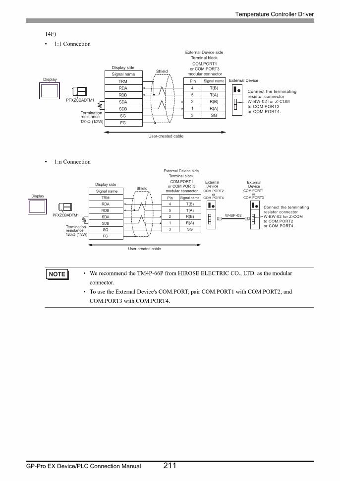
Temperature Controller Driver
GP-Pro EX Device/PLC Connection Manual 211
14F)
• 1:1 Connection
• 1:n Connection
• We recommend the TM4P-66P from HIROSE ELECTRIC CO., LTD. as the modular
connector.
• To use the External Device's COM.PORT, pair COM.PORT1 with COM.PORT2, and
COM.PORT3 with COM.PORT4.
RDB
SDB SG FG
PFXZCBADTM1
RDA
SDA
COM.PORT1 or COM.PORT3
modular connector
4
5
T(B)
T(A) 2 R(B)
TRM
120 Ω (1/2W)
1 R(A) 3 SG
Connect the terminating resistor connector W-BW-02 for Z-COM to COM.PORT2 or COM.PORT4.
Display
Shield
Terminal block External Device side
Signal name Pin
Signal name External Device
Termination resistance
User-created cable
Display side
RDB
SDB SG FG
PFXZCBADTM1
RDA
SDA
4
5
T(B)
T(A) 2 R(B)
TRM
120 Ω (1/2W)
1 R(A) 3 SG
W-BF-02
COM.PORT2 or
COM.PORT4
COM.PORT1 or
COM.PORT3
COM.PORT1 or COM.PORT3
modular connector Display
Shield
Terminal block External Device side
Signal name Pin
Signal name
External Device
Termination resistance
User-created cable
External Device
Connect the terminating resistor connector W-BW-02 for Z-COM to COM.PORT2 or COM.PORT4.
Display side
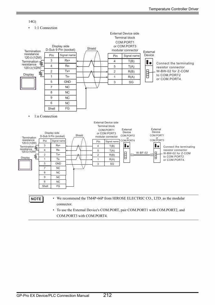
Temperature Controller Driver
GP-Pro EX Device/PLC Connection Manual 212
14G)
• 1:1 Connection
• 1:n Connection
• We recommend the TM4P-66P from HIROSE ELECTRIC CO., LTD. as the modular
connector.
• To use the External Device's COM.PORT, pair COM.PORT1 with COM.PORT2, and
COM.PORT3 with COM.PORT4.
4
5
T(B)
T(A)2 R(B)1 R(A)3 SG
120 Ω (1/2W)
Tx+2
Rx-4
GND5
7 NC
Tx-1
96
FG
Rx+3
NC
NCNC
8
120 Ω (1/2W)
Shell
Display
ShieldTerminationresistance
D-Sub 9 Pin (socket)Signal namePin
Terminationresistance
COM.PORT1or COM.PORT3
modular connector
Terminal blockExternal Device side
Signal namePinExternalDevice
Connect the terminating resistor connector W-BW-02 for Z-COM to COM.PORT2or COM.PORT4.
Display side
4
5
T(B)
T(A) 2 R(B) 1 R(A) 3 SG
120 Ω (1/2W)
Tx+2
Rx-4
GND5
7 NC
Tx-1
9 6
FG
Rx+3
NC
NCNC
8
120 Ω (1/2W) W-BF-02
Shell
Display
Shield Termination resistance
D-Sub 9 Pin (socket) Signal name Pin
Termination resistance
COM.PORT1 or COM.PORT3
modular connector
Terminal block External Device side
Signal name Pin
COM.PORT2 or
COM.PORT4
External Device
COM.PORT1 or
COM.PORT3
External Device
Connect the terminating resistor connector W-BW-02 for Z-COM to COM.PORT2 or COM.PORT4.
Display side
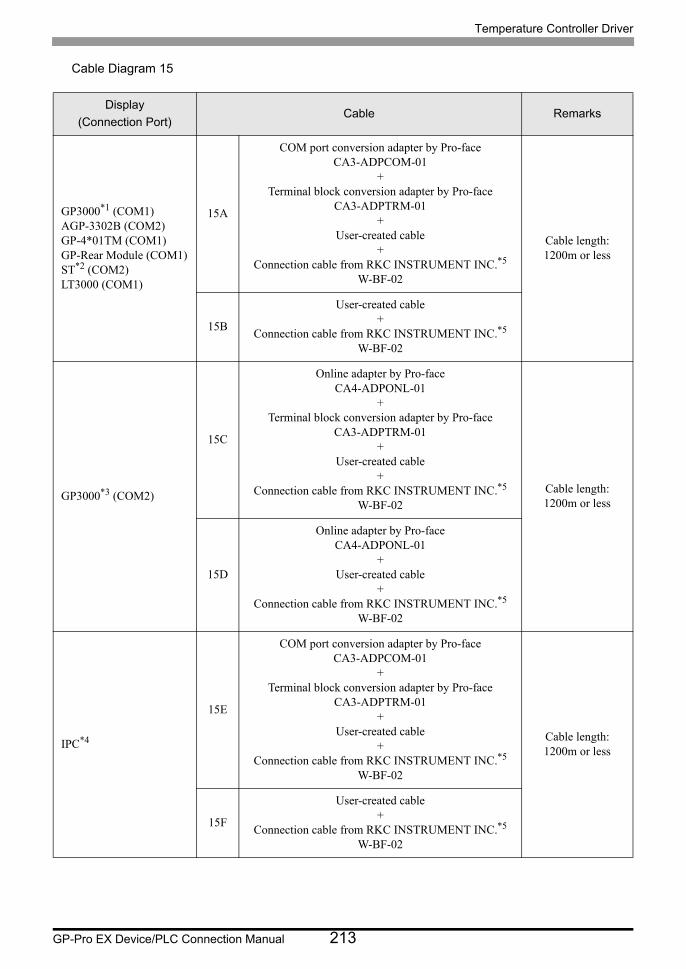
Temperature Controller Driver
GP-Pro EX Device/PLC Connection Manual 213
Cable Diagram 15
Display
(Connection Port)Cable Remarks
GP3000*1 (COM1)AGP-3302B (COM2)GP-4*01TM (COM1)GP-Rear Module (COM1)ST*2 (COM2)LT3000 (COM1)
15A
COM port conversion adapter by Pro-faceCA3-ADPCOM-01
+Terminal block conversion adapter by Pro-face
CA3-ADPTRM-01+
User-created cable+
Connection cable from RKC INSTRUMENT INC.*5
W-BF-02
Cable length:1200m or less
15B
User-created cable+
Connection cable from RKC INSTRUMENT INC.*5
W-BF-02
GP3000*3 (COM2)
15C
Online adapter by Pro-faceCA4-ADPONL-01
+Terminal block conversion adapter by Pro-face
CA3-ADPTRM-01+
User-created cable+
Connection cable from RKC INSTRUMENT INC.*5
W-BF-02
Cable length:1200m or less
15D
Online adapter by Pro-faceCA4-ADPONL-01
+User-created cable
+Connection cable from RKC INSTRUMENT INC.*5
W-BF-02
IPC*4
15E
COM port conversion adapter by Pro-faceCA3-ADPCOM-01
+Terminal block conversion adapter by Pro-face
CA3-ADPTRM-01+
User-created cable+
Connection cable from RKC INSTRUMENT INC.*5
W-BF-02
Cable length:1200m or less
15F
User-created cable+
Connection cable from RKC INSTRUMENT INC.*5
W-BF-02
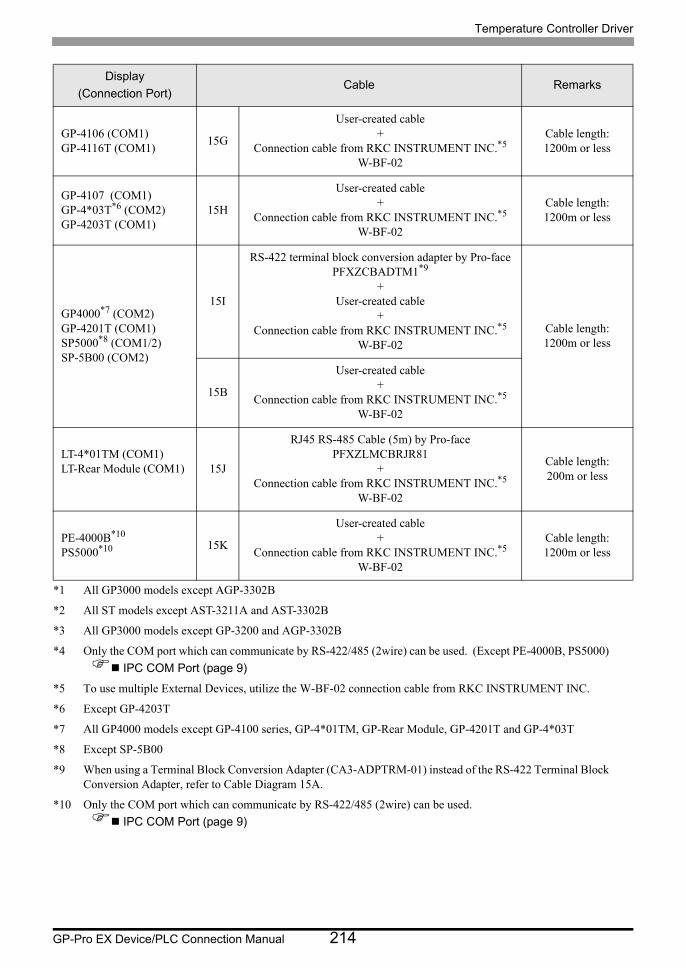
Temperature Controller Driver
GP-Pro EX Device/PLC Connection Manual 214
GP-4106 (COM1)GP-4116T (COM1)
15G
User-created cable+
Connection cable from RKC INSTRUMENT INC.*5
W-BF-02
Cable length:1200m or less
GP-4107 (COM1)GP-4*03T*6 (COM2)GP-4203T (COM1)
15H
User-created cable+
Connection cable from RKC INSTRUMENT INC.*5
W-BF-02
Cable length:1200m or less
GP4000*7 (COM2)GP-4201T (COM1)SP5000*8 (COM1/2)SP-5B00 (COM2)
15I
RS-422 terminal block conversion adapter by Pro-facePFXZCBADTM1*9
+User-created cable
+Connection cable from RKC INSTRUMENT INC.*5
W-BF-02
Cable length:1200m or less
15B
User-created cable+
Connection cable from RKC INSTRUMENT INC.*5
W-BF-02
LT-4*01TM (COM1)LT-Rear Module (COM1) 15J
RJ45 RS-485 Cable (5m) by Pro-facePFXZLMCBRJR81
+Connection cable from RKC INSTRUMENT INC.*5
W-BF-02
Cable length:200m or less
PE-4000B*10
PS5000*10 15K
User-created cable+
Connection cable from RKC INSTRUMENT INC.*5
W-BF-02
Cable length:1200m or less
*1 All GP3000 models except AGP-3302B
*2 All ST models except AST-3211A and AST-3302B
*3 All GP3000 models except GP-3200 and AGP-3302B
*4 Only the COM port which can communicate by RS-422/485 (2wire) can be used. (Except PE-4000B, PS5000)
IPC COM Port (page 9)
*5 To use multiple External Devices, utilize the W-BF-02 connection cable from RKC INSTRUMENT INC.
*6 Except GP-4203T
*7 All GP4000 models except GP-4100 series, GP-4*01TM, GP-Rear Module, GP-4201T and GP-4*03T
*8 Except SP-5B00
*9 When using a Terminal Block Conversion Adapter (CA3-ADPTRM-01) instead of the RS-422 Terminal Block Conversion Adapter, refer to Cable Diagram 15A.
*10 Only the COM port which can communicate by RS-422/485 (2wire) can be used.
IPC COM Port (page 9)
Display
(Connection Port)Cable Remarks
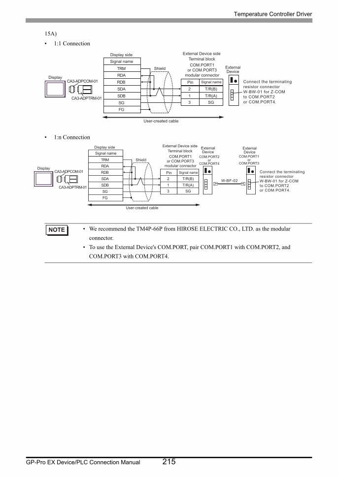
Temperature Controller Driver
GP-Pro EX Device/PLC Connection Manual 215
15A)
• 1:1 Connection
• 1:n Connection
• We recommend the TM4P-66P from HIROSE ELECTRIC CO., LTD. as the modular
connector.
• To use the External Device's COM.PORT, pair COM.PORT1 with COM.PORT2, and
COM.PORT3 with COM.PORT4.
RDB
SDB
SG
FG
CA3-ADPCOM-01
CA3-ADPTRM-01
RDA
SDA 2
1
T/R(B)
T/R(A)
3 SG
TRMCOM.PORT1
or COM.PORT3
modular connectorDisplay
Shield
Terminal block
External Device side
Signal namePin
Signal name
ExternalDevice
User-created cable
Connect the terminating
resistor connector
W-BW-01 for Z-COM
to COM.PORT2
or COM.PORT4.
Display side
RDB
SDBSGFG
CA3-ADPCOM-01
CA3-ADPTRM-01
RDA
SDA 2
1
T/R(B)
T/R(A)3 SG
TRM
W-BF-02
COM.PORT2or
COM.PORT4
COM.PORT1or
COM.PORT3
COM.PORT1or COM.PORT3
modular connectorDisplay
Shield
Terminal blockExternal Device side
Signal namePin
Signal nameExternalDevice
User-created cable
ExternalDevice
Connect the terminating resistor connector W-BW-01 for Z-COM to COM.PORT2 or COM.PORT4.
Display side
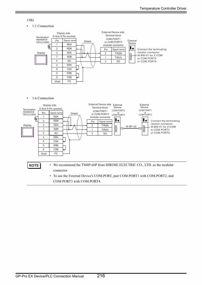
Temperature Controller Driver
GP-Pro EX Device/PLC Connection Manual 216
15B)
• 1:1 Connection
• 1:n Connection
• We recommend the TM4P-66P from HIROSE ELECTRIC CO., LTD. as the modular
connector.
• To use the External Device's COM.PORT, pair COM.PORT1 with COM.PORT2, and
COM.PORT3 with COM.PORT4.
2
1
T/R(B)
T/R(A)
3 SG
120 Ω (1/2W)
SDA3
RDB2
SG5
4 ERA
SDB
ERB
7
9
CSB6
FG
RDA1
CSA8
Shell
Display
Shield
D-Sub 9 Pin (socket)
Signal namePin
Terminationresistance COM.PORT1
or COM.PORT3
modular connector
Terminal block
External Device side
Signal namePin
ExternalDevice
Connect the terminating
resistor connector
W-BW-01 for Z-COM
to COM.PORT2
or COM.PORT4.
Display side
2
1
T/R(B)
T/R(A)3 SG
120 Ω (1/2W)
SDA3
RDB2
SG5
4 ERA
SDB
ERB
7
9
CSB6
FG
RDA1
CSA8
W-BF-02
Shell
Display
ShieldTerminationresistance
D-Sub 9 Pin (socket)Signal namePin
COM.PORT1or COM.PORT3
modular connector
Terminal blockExternal Device side
Signal namePin
COM.PORT2or
COM.PORT4
ExternalDevice
COM.PORT1or
COM.PORT3
ExternalDevice
Connect the terminating resistor connector W-BW-01 for Z-COM to COM.PORT2 or COM.PORT4.
Display side
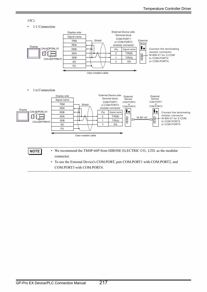
Temperature Controller Driver
GP-Pro EX Device/PLC Connection Manual 217
15C)
• 1:1 Connection
• 1:n Connection
• We recommend the TM4P-66P from HIROSE ELECTRIC CO., LTD. as the modular
connector.
• To use the External Device's COM.PORT, pair COM.PORT1 with COM.PORT2, and
COM.PORT3 with COM.PORT4.
RDB
SDB
SG
FG
CA4-ADPONL-01
CA3-ADPTRM-01
RDA
SDA 2
1
T/R(B)
T/R(A)
3 SG
TRMCOM.PORT1
or COM.PORT3
modular connectorDisplay
Shield
Terminal block
External Device side
Signal namePin
Signal name
ExternalDevice
User-created cable
Connect the terminating
resistor connector
W-BW-01 for Z-COM
to COM.PORT2
or COM.PORT4.
Display side
RDB
SDBSGFG
CA4-ADPONL-01
CA3-ADPTRM-01
RDA
SDA 2
1
T/R(B)
T/R(A)3 SG
TRM
W-BF-02
COM.PORT1or COM.PORT3
modular connectorDisplay
Shield
Terminal blockExternal Device side
Signal namePin
Signal name
User-created cable
COM.PORT2or
COM.PORT4
ExternalDevice
COM.PORT1or
COM.PORT3
ExternalDevice
Connect the terminating resistor connector W-BW-01 for Z-COM to COM.PORT2 or COM.PORT4.
Display side
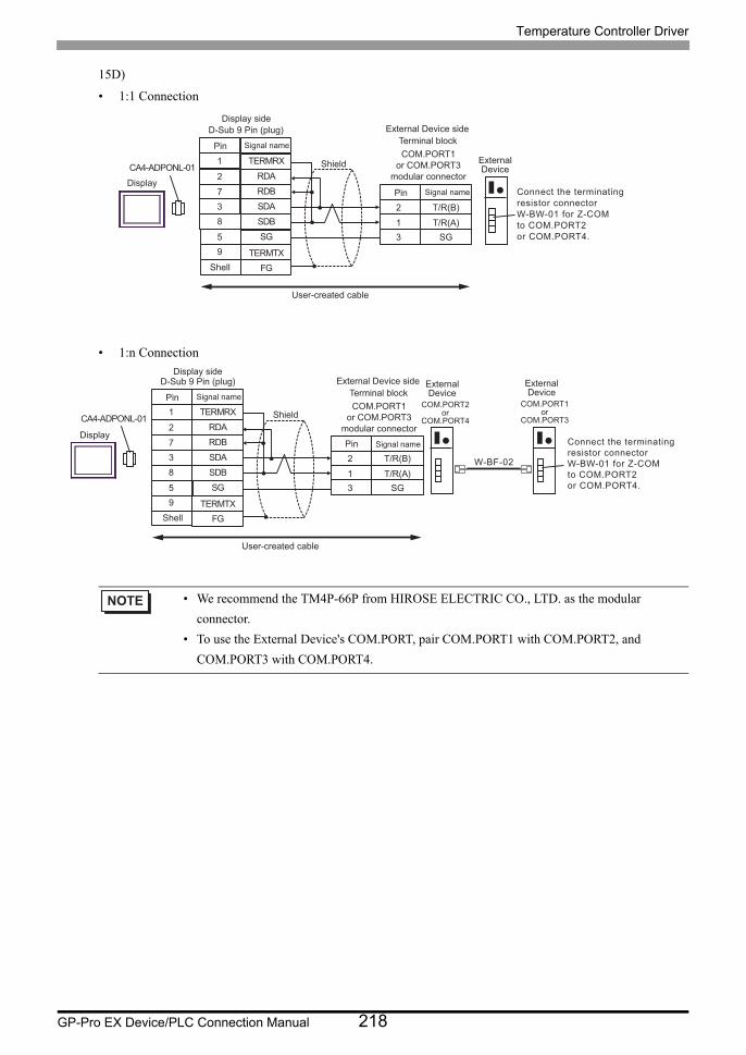
Temperature Controller Driver
GP-Pro EX Device/PLC Connection Manual 218
15D)
• 1:1 Connection
• 1:n Connection
• We recommend the TM4P-66P from HIROSE ELECTRIC CO., LTD. as the modular
connector.
• To use the External Device's COM.PORT, pair COM.PORT1 with COM.PORT2, and
COM.PORT3 with COM.PORT4.
2
1
T/R(B)
T/R(A)
3 SG
CA4-ADPONL-01
SDA
7 RDB
2
SG
8
5
SDB
3
FG
RDA
1
9 TERMTX
TERMRX
Shell
Display
Shield
D-Sub 9 Pin (plug)
Signal namePinCOM.PORT1
or COM.PORT3
modular connector
Terminal block
External Device side
Signal namePin
ExternalDevice
User-created cable
Connect the terminating
resistor connector
W-BW-01 for Z-COM
to COM.PORT2
or COM.PORT4.
Display side
2
1
T/R(B)
T/R(A)
3 SG
CA4-ADPONL-01
SDA
7 RDB
2
SG
8
5
SDB
3
FG
RDA
1
9 TERMTX
TERMRX
W-BF-02
Shell
Display
Shield
D-Sub 9 Pin (plug)
Signal namePinCOM.PORT1
or COM.PORT3
modular connector
Terminal block
External Device side
Signal namePin
User-created cable
COM.PORT2or
COM.PORT4
ExternalDevice
COM.PORT1or
COM.PORT3
ExternalDevice
Connect the terminating resistor connector W-BW-01 for Z-COM to COM.PORT2 or COM.PORT4.
Display side
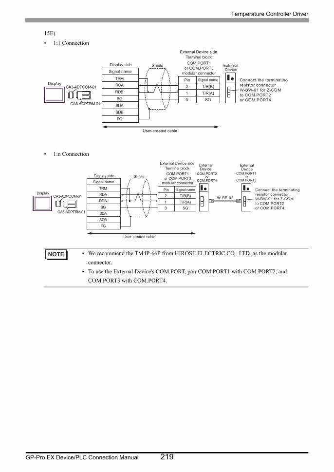
Temperature Controller Driver
GP-Pro EX Device/PLC Connection Manual 219
15E)
• 1:1 Connection
• 1:n Connection
• We recommend the TM4P-66P from HIROSE ELECTRIC CO., LTD. as the modular
connector.
• To use the External Device's COM.PORT, pair COM.PORT1 with COM.PORT2, and
COM.PORT3 with COM.PORT4.
2
1
T/R(B)
T/R(A)
3 SG
RDB
SDB
SG
FG
RDA
SDA
TRM
CA3-ADPCOM-01
CA3-ADPTRM-01
COM.PORT1
or COM.PORT3
modular connector
Display
Shield
Terminal block
External Device side
Signal namePin
Signal name
ExternalDevice
User-created cable
Connect the terminating
resistor connector
W-BW-01 for Z-COM
to COM.PORT2
or COM.PORT4.
Display side
2
1
T/R(B)
T/R(A)3 SG
RDB
SDB
SG
FG
RDA
SDA
TRM
CA3-ADPCOM-01
CA3-ADPTRM-01
W-BF-02
COM.PORT2or
COM.PORT4
COM.PORT1or
COM.PORT3
COM.PORT1or COM.PORT3
modular connector
Display
Shield
Terminal blockExternal Device side
Signal namePin
Signal name
ExternalDevice
User-created cable
ExternalDevice
Connect the terminating resistor connector W-BW-01 for Z-COM to COM.PORT2 or COM.PORT4.
Display side
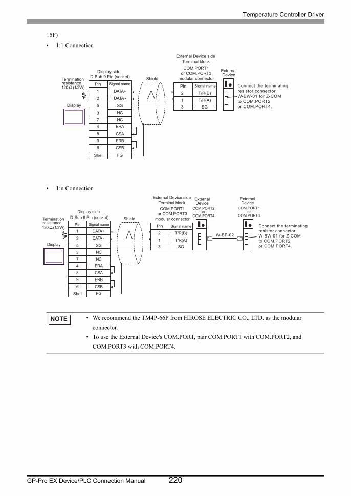
Temperature Controller Driver
GP-Pro EX Device/PLC Connection Manual 220
15F)
• 1:1 Connection
• 1:n Connection
• We recommend the TM4P-66P from HIROSE ELECTRIC CO., LTD. as the modular
connector.
• To use the External Device's COM.PORT, pair COM.PORT1 with COM.PORT2, and
COM.PORT3 with COM.PORT4.
2
1
T/R(B)
T/R(A)
3 SG
120 Ω (1/2W)
NC3
DATA -2
SG5
4 ERA
NC
ERB
7
9
CSB6
FG
DATA+1
CSA8
Shell
Display
ShieldD-Sub 9 Pin (socket)
Signal namePin
COM.PORT1
or COM.PORT3
modular connector
Terminal block
External Device side
Signal namePin
ExternalDevice
Terminationresistance
Connect the terminating
resistor connector
W-BW-01 for Z-COM
to COM.PORT2
or COM.PORT4.
Display side
2
1
T/R(B)
T/R(A)3 SG
120 Ω (1/2W)
NC3
DATA -2
SG5
4 ERANC
ERB
7
9
CSB6
FG
DATA+1
CSA8
W-BF-02
Shell
Display
ShieldD-Sub 9 Pin (socket)Signal namePin
COM.PORT1or COM.PORT3
modular connector
Terminal blockExternal Device side
Signal namePin
COM.PORT2or
COM.PORT4
ExternalDevice
COM.PORT1or
COM.PORT3
ExternalDevice
Terminationresistance
Connect the terminating resistor connector W-BW-01 for Z-COM to COM.PORT2 or COM.PORT4.
Display side

Temperature Controller Driver
GP-Pro EX Device/PLC Connection Manual 221
15G)
• 1:1 Connection
• 1:n Connection
*1 The resistance in the Display is used as the termination resistance. Set the value of the DIP Switch on the rear of the Display as shown in the table below.
• We recommend the TM4P-66P from HIROSE ELECTRIC CO., LTD. as the modular
connector.
• To use the External Device's COM.PORT, pair COM.PORT1 with COM.PORT2, and
COM.PORT3 with COM.PORT4.
DIP Switch No. Set Value
1 OFF
2 OFF
3 ON
4 ON
2
1
T/R(B)
T/R(A)3 SG
SDARDB
SGERA
SDB
ERBCSB
RDA
CSA
Display
ShieldSignal nameTerminationresistance*1
COM.PORT1or COM.PORT3
modular connector
Terminal blockExternal Device side
Signal namePin
ExternalDevice
Connect the terminating resistor connector W-BW-01 for Z-COM to COM.PORT2 or COM.PORT4.
Display side Terminal block
2
1
T/R(B)
T/R(A)3 SG
SDARDB
SGERA
SDB
ERBCSB
RDA
CSA
W-BF-02Display
ShieldTerminationresistance*1
Signal nameCOM.PORT1
or COM.PORT3modular connector
Terminal blockExternal Device side
Signal namePin
COM.PORT2or
COM.PORT4
ExternalDevice
COM.PORT1or
COM.PORT3
ExternalDevice
Connect the terminating resistor connector W-BW-01 for Z-COM to COM.PORT2 or COM.PORT4.
Display side Terminal block
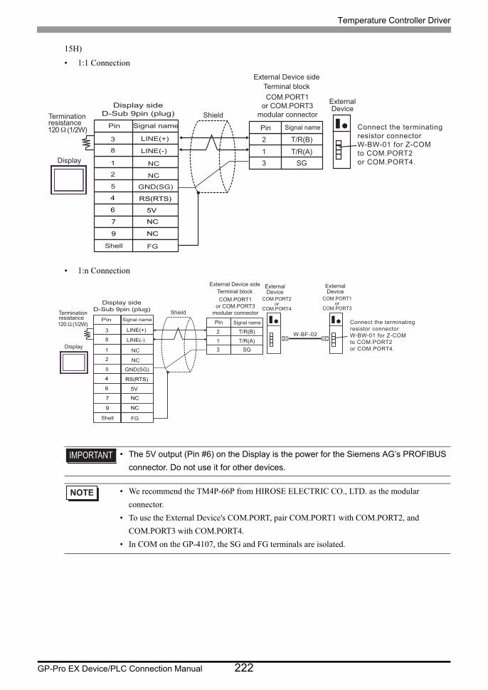
Temperature Controller Driver
GP-Pro EX Device/PLC Connection Manual 222
15H)
• 1:1 Connection
• 1:n Connection
• The 5V output (Pin #6) on the Display is the power for the Siemens AG’s PROFIBUS
connector. Do not use it for other devices.
• We recommend the TM4P-66P from HIROSE ELECTRIC CO., LTD. as the modular
connector.
• To use the External Device's COM.PORT, pair COM.PORT1 with COM.PORT2, and
COM.PORT3 with COM.PORT4.
• In COM on the GP-4107, the SG and FG terminals are isolated.
2
1
T/R(B)
T/R(A)3 SG
120Ω (1/2W)
Display
Shield
COM.PORT1or COM.PORT3
modular connector
Terminal blockExternal Device side
Signal namePin
ExternalDevice
Terminationresistance Connect the terminating
resistor connector W-BW-01 for Z-COM to COM.PORT2 or COM.PORT4.
Pin Signal name
NC
NC
GND(SG)
RS(RTS)
5V
NC
NC
FG
LINE(+)
LINE(-)
3
8
1
2
5
4
6
7
9
Shell
Display sideD-Sub 9pin (plug)
2
1
T/R(B)
T/R(A)3 SG
120Ω (1/2W)
W-BF-02
Display
Shield
COM.PORT1or COM.PORT3
modular connector
Terminal blockExternal Device side
Signal namePin
COM.PORT2or
COM.PORT4
ExternalDevice
COM.PORT1or
COM.PORT3
ExternalDevice
Terminationresistance
Connect the terminating resistor connector W-BW-01 for Z-COM to COM.PORT2 or COM.PORT4.
Pin Signal name
NC
NC
GND(SG)
RS(RTS)
5V
NC
NC
FG
LINE(+)
LINE(-)
3
8
1
2
5
4
6
7
9
Shell
Display sideD-Sub 9pin (plug)
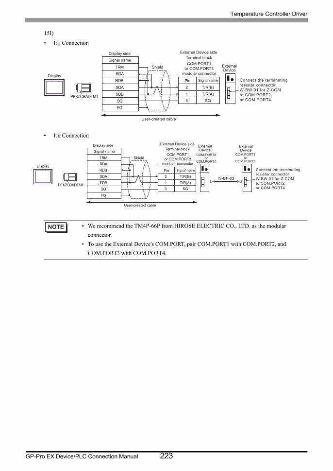
Temperature Controller Driver
GP-Pro EX Device/PLC Connection Manual 223
15I)
• 1:1 Connection
• 1:n Connection
• We recommend the TM4P-66P from HIROSE ELECTRIC CO., LTD. as the modular
connector.
• To use the External Device's COM.PORT, pair COM.PORT1 with COM.PORT2, and
COM.PORT3 with COM.PORT4.
RDB
SDBSGFG
PFXZCBADTM1
RDA
SDA 2
1
T/R(B)
T/R(A)3 SG
TRMCOM.PORT1
or COM.PORT3modular connectorDisplay
Shield
Terminal blockExternal Device side
Signal namePin
Signal nameExternalDevice
User-created cable
Connect the terminating resistor connector W-BW-01 for Z-COM to COM.PORT2 or COM.PORT4.
Display side
RDB
SDB SG FG
PFXZCBADTM1
RDA
SDA 2
1
T/R(B)
T/R(A) 3 SG
TRM
W-BF-02
COM.PORT2 or
COM.PORT4
COM.PORT1 or
COM.PORT3
COM.PORT1 or COM.PORT3
modular connector Display
Shield
Terminal block External Device side
Signal name Pin
Signal name External Device
User-created cable
External Device
Connect the terminating resistor connector W-BW-01 for Z-COM to COM.PORT2 or COM.PORT4.
Display side
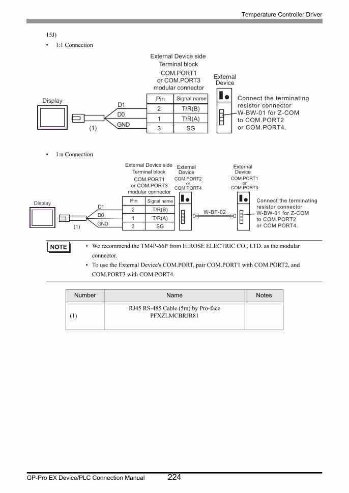
Temperature Controller Driver
GP-Pro EX Device/PLC Connection Manual 224
15J)
• 1:1 Connection
• 1:n Connection
• We recommend the TM4P-66P from HIROSE ELECTRIC CO., LTD. as the modular
connector.
• To use the External Device's COM.PORT, pair COM.PORT1 with COM.PORT2, and
COM.PORT3 with COM.PORT4.
Number Name Notes
(1)RJ45 RS-485 Cable (5m) by Pro-face
PFXZLMCBRJR81
2
1
T/R(B)
T/R(A)3 SG
COM.PORT1or COM.PORT3
modular connector
Terminal blockExternal Device side
Signal namePin
ExternalDevice
Connect the terminating resistor connector W-BW-01 for Z-COM to COM.PORT2 or COM.PORT4.
Display
GNDD0D1
(1)
2
1
T/R(B)
T/R(A) 3 SG
W-BF-02
COM.PORT1 or COM.PORT3
modular connector
Terminal block External Device side
Signal name Pin
COM.PORT2 or
COM.PORT4
External Device
COM.PORT1 or
COM.PORT3
External Device
Connect the terminating resistor connector W-BW-01 for Z-COM to COM.PORT2 or COM.PORT4.
Display
GNDD0D1
(1)
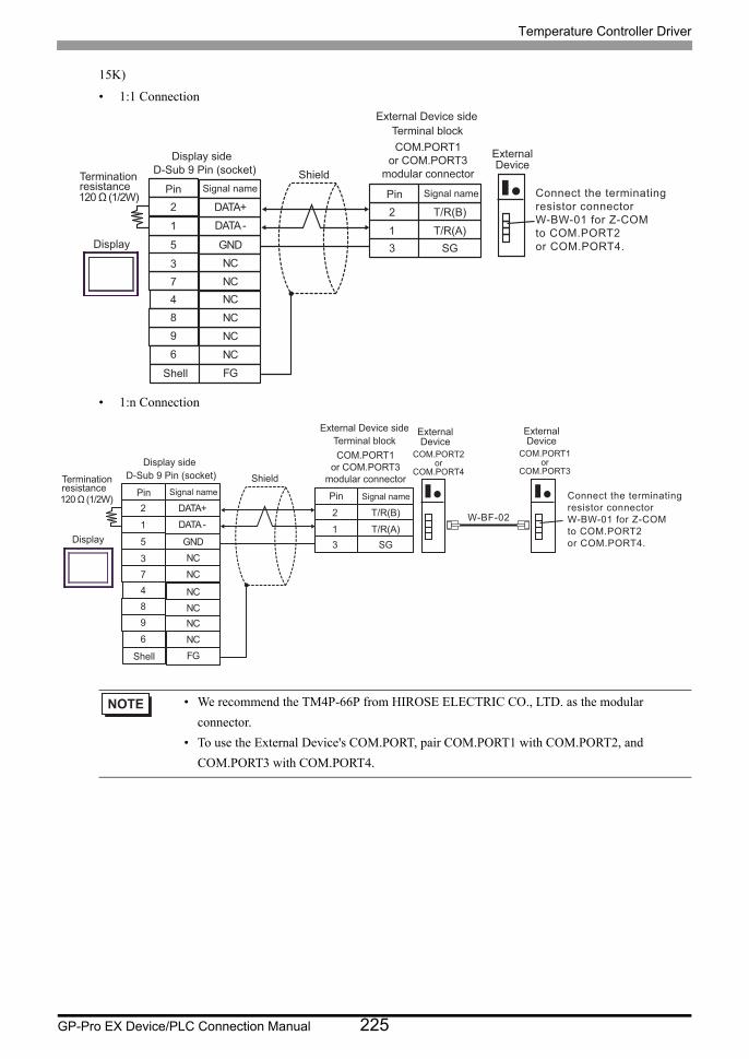
Temperature Controller Driver
GP-Pro EX Device/PLC Connection Manual 225
15K)
• 1:1 Connection
• 1:n Connection
• We recommend the TM4P-66P from HIROSE ELECTRIC CO., LTD. as the modular
connector.
• To use the External Device's COM.PORT, pair COM.PORT1 with COM.PORT2, and
COM.PORT3 with COM.PORT4.
2
1
T/R(B)
T/R(A)3 SG
120 Ω (1/2W)
NC3
DATA -1
GND5
4 NCNC
NC
7
9
NC6
FG
DATA+2
NC8
Shell
Display
ShieldD-Sub 9 Pin (socket)Signal namePin
COM.PORT1or COM.PORT3
modular connector
Terminal blockExternal Device side
Signal namePin
ExternalDevice
Terminationresistance Connect the terminating
resistor connector W-BW-01 for Z-COM to COM.PORT2 or COM.PORT4.
Display side
2
1
T/R(B)
T/R(A) 3 SG
120 Ω (1/2W)
NC 3
DATA - 1
GND5
4 NC
NCNC
NCNC
7
9 6
FG
DATA+ 2
8
W-BF-02
Shell
Display
Shield D-Sub 9 Pin (socket) Signal name Pin
COM.PORT1 or COM.PORT3
modular connector
Terminal block External Device side
Signal name Pin
COM.PORT2 or
COM.PORT4
External Device
COM.PORT1 or
COM.PORT3
External Device
Termination resistance
Connect the terminating resistor connector W-BW-01 for Z-COM to COM.PORT2 or COM.PORT4.
Display side
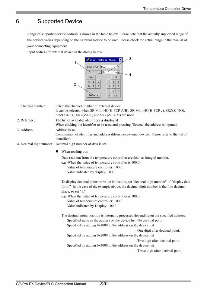
Temperature Controller Driver
GP-Pro EX Device/PLC Connection Manual 226
6 Supported Device
Range of supported device address is shown in the table below. Please note that the actually supported range of
the devices varies depending on the External Device to be used. Please check the actual range in the manual of
your connecting equipment.
Input address of external device in the dialog below.
When reading out:
Data read out from the temperature controller are dealt as integral number.e.g. When the value of temperature controller is 100.0;
Value of temperature controller: 100.0Value indicated by display: 1000
To display decimal points in value indication, set "decimal digit number" of "display data form." In the case of the example above, the decimal digit number is the first decimal place, so set "1."e.g. When the value of temperature controller is 100.0;
Value of temperature controller: 100.0Value indicated by Diaplay: 100.0
The decimal point position is internally processed depending on the specified address.Specified same as the address on the device list: No decimal pointSpecified by adding 0x1000 to the address on the device list
: One digit after decimal point.Specified by adding 0x2000 to the address on the device list
: Two digit after decimal point.Specified by adding 0x3000 to the address on the device list
: Three digit after decimal point.
1. Channel number Select the channel number of external device.It can be selected when SR Mini HG(H-PCP-A/B), SR Mini HG(H-PCP-J), SRZ(Z-TIO), SRZ(Z-DIO), SRZ(Z-CT) and SRZ(Z-COM) are used.
2. Reference The list of available identifiers is displayed.When clicking the identifier to be used and pressing "Select," the address is inputted.
3. Address Address is set.Combination of identifier and address differs per external device. Please refer to the list of identifiers.
4. Decimal digit number Decimal digit number of data is set.
1
2
3
4
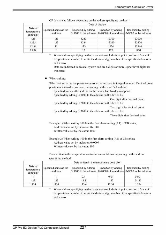
Temperature Controller Driver
GP-Pro EX Device/PLC Connection Manual 227
GP data are as follows depending on the address specifying method.
* When address specifying method does not match decimal point position of data of temperature controller, truncate the decimal digit number of the specified address or add a zero.Data are indicated in decadal system and are 6 digits or more, upper level digits are truncated.
When writing:
When writing in the temperature controller, value is set in integral number. Decimal point position is internally processed depending on the specified address.
Specified same as the address on the device list: No decimal pointSpecified by adding 0x1000 to the address on the device list
: One digit after decimal point.Specified by adding 0x2000 to the address on the device list
: Two digit after decimal point.Specified by adding 0x3000 to the address on the device list
: Three digit after decimal point.
Example 1) When writing 100.0 in the first alarm setting (A1) of CB series;Address value set by indicator: 0x1007Written value set by indicator: 1000
Example 2) When writing 100 in the first alarm setting (A1) of CB series;Address value set by indicator: 0x0007Written value set by indicator: 100
Data written in the temperature controller are as follows depending on the address
specifying method.
* When address specifying method does not match decimal point position of data of temperature controller, truncate the decimal digit number of the specified address or add a zero.
Data of display
Data of temperature
controller
Specified same as the address
Specified by adding 0x1000 to the address
Specified by adding 0x2000 to the address
Specified by adding 0x3000 to the address
123 123 1230 12300 23000
123.4 123 1234 12340 23400
12.34 12 123 1234 12340
1.234 1 12 123 1234
Data written in the temperature controller
Data of temperature
controller
Specified same as the address
Specified by adding 0x1000 to the address
Specified by adding 0x2000 to the address
Specified by adding 0x3000 to the address
1 1 0.1 0.01 0.001
123 123 12.3 1.23 0.123
1234 1234 123.4 12.34 1.234
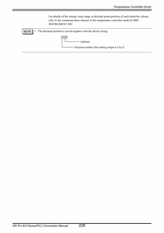
Temperature Controller Driver
GP-Pro EX Device/PLC Connection Manual 228
For details of the setting value range or decimal point position of each identifier, please refer to the communication manual of the temperature controller made by RKC INSTRUMENT INC.
• The decimal position is saved together with the device string.
0000
Decimal position (the setting range is 0 to 3)
Address
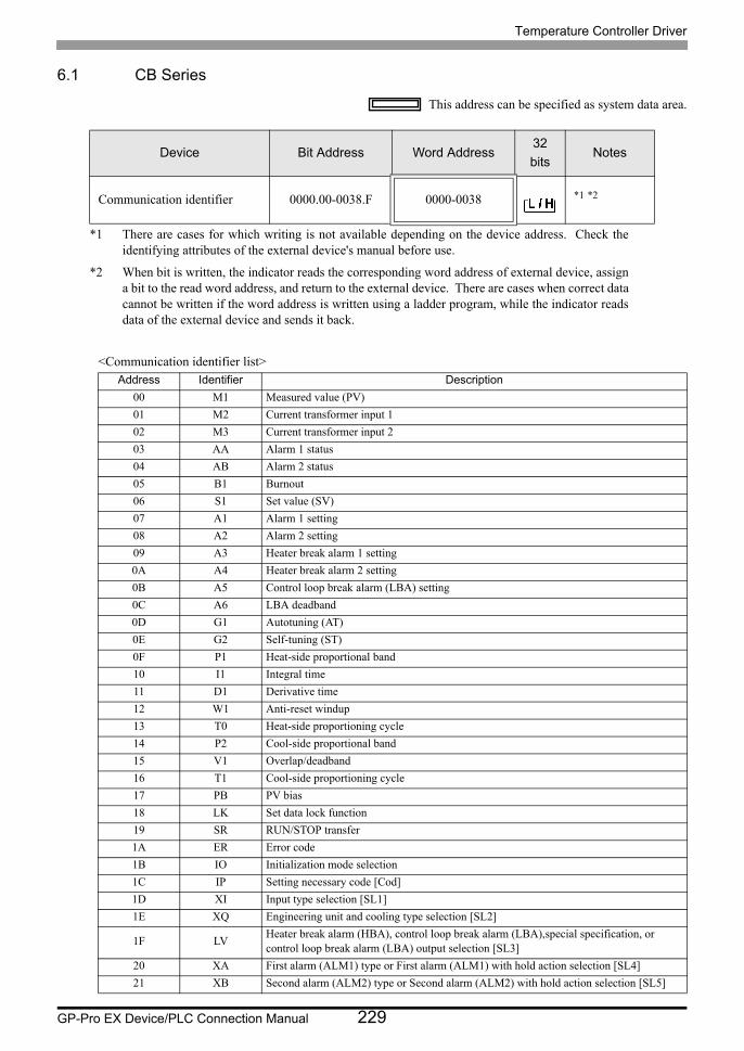
Temperature Controller Driver
GP-Pro EX Device/PLC Connection Manual 229
6.1 CB Series
This address can be specified as system data area.
<Communication identifier list>
Device Bit Address Word Address32
bitsNotes
Communication identifier 0000.00-0038.F 0000-0038 *1 *2
*1 There are cases for which writing is not available depending on the device address. Check the identifying attributes of the external device's manual before use.
*2 When bit is written, the indicator reads the corresponding word address of external device, assign a bit to the read word address, and return to the external device. There are cases when correct data cannot be written if the word address is written using a ladder program, while the indicator reads data of the external device and sends it back.
Address Identifier Description
00 M1 Measured value (PV)
01 M2 Current transformer input 1
02 M3 Current transformer input 2
03 AA Alarm 1 status
04 AB Alarm 2 status
05 B1 Burnout
06 S1 Set value (SV)
07 A1 Alarm 1 setting
08 A2 Alarm 2 setting
09 A3 Heater break alarm 1 setting
0A A4 Heater break alarm 2 setting
0B A5 Control loop break alarm (LBA) setting
0C A6 LBA deadband
0D G1 Autotuning (AT)
0E G2 Self-tuning (ST)
0F P1 Heat-side proportional band
10 I1 Integral time
11 D1 Derivative time
12 W1 Anti-reset windup
13 T0 Heat-side proportioning cycle
14 P2 Cool-side proportional band
15 V1 Overlap/deadband
16 T1 Cool-side proportioning cycle
17 PB PV bias
18 LK Set data lock function
19 SR RUN/STOP transfer
1A ER Error code
1B IO Initialization mode selection
1C IP Setting necessary code [Cod]
1D XI Input type selection [SL1]
1E XQ Engineering unit and cooling type selection [SL2]
1F LVHeater break alarm (HBA), control loop break alarm (LBA),special specification, or control loop break alarm (LBA) output selection [SL3]
20 XA First alarm (ALM1) type or First alarm (ALM1) with hold action selection [SL4]
21 XB Second alarm (ALM2) type or Second alarm (ALM2) with hold action selection [SL5]

Temperature Controller Driver
GP-Pro EX Device/PLC Connection Manual 230
22 CA Control action type selection [SL6]
23 Z1 Energized/de-energized alarm selection, special specification selection 1 [SL7]
24 Z2 Special specification selection 2 [SL8]
25 Z3 Special specification selection 3 [SL9]
26 DH Option selection [SL10]
27 XC SV alarm type selection [SL11]
28 XV Setting limiter (high limit) [SLH]
29 XW Setting limiter (low limit) [SLL]
2A XU Setting the position of decimal point [PGdP]
2B MH Differential gap setting of ON/OFF action [oH]
2C HA Differential gap setting of first alarm (ALM1) [AH1]
2D HB Differential gap setting of second alarm (ALM2) [AH2]
2E XR CT ratio setting [CTr]
2F F1 Digital filter setting [dF]
30 GH Time factor assumed to be safe [STTM]
31 PU Factor to calculate proportional band [STPK]
32 IU Factor to calculate integral time [STIK]
33 IL Integral time limiter [ILIM]
34 HP Holding peak ambient temperature [TCJ]
35 UT Operating time display unit (Upper digits) [WTH]
36 UU Operating time display unit (Lower digits) [WTL]
37 EB EEPROM storage mode
38 EM EEPROM storage state
• Setting "Use system data area" to GP-Pro EX system area result in improper operation. Do not set "Use system data area."
• System area setting that can be used for the temperature controller is reading area size only. Please
refer to the GP-Pro EX Reference Manual for system data area.
Cf. GP-Pro EX Reference Manual "LS Area (Direct Access Method Area)"• Please refer to the precautions on manual notation for icons in the table.
"Manual Symbols and Terminology"
• Even if non-existing address is used, there are cases when read error is not indicated. In this case,
zero (0) is kept for read out data. On the other hand, writing error is indicated.
Address Identifier Description
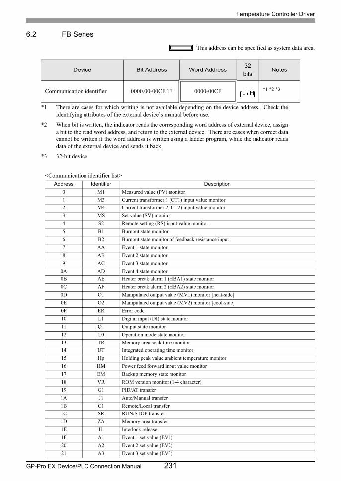
Temperature Controller Driver
GP-Pro EX Device/PLC Connection Manual 231
6.2 FB Series
This address can be specified as system data area.
<Communication identifier list>
Device Bit Address Word Address32
bitsNotes
Communication identifier 0000.00-00CF.1F 0000-00CF *1 *2 *3
*1 There are cases for which writing is not available depending on the device address. Check the identifying attributes of the external device’s manual before use.
*2 When bit is written, the indicator reads the corresponding word address of external device, assign a bit to the read word address, and return to the external device. There are cases when correct data cannot be written if the word address is written using a ladder program, while the indicator reads data of the external device and sends it back.
*3 32-bit device
Address Identifier Description
0 M1 Measured value (PV) monitor
1 M3 Current transformer 1 (CT1) input value monitor
2 M4 Current transformer 2 (CT2) input value monitor
3 MS Set value (SV) monitor
4 S2 Remote setting (RS) input value monitor
5 B1 Burnout state monitor
6 B2 Burnout state monitor of feedback resistance input
7 AA Event 1 state monitor
8 AB Event 2 state monitor
9 AC Event 3 state monitor
0A AD Event 4 state monitor
0B AE Heater break alarm 1 (HBA1) state monitor
0C AF Heater break alarm 2 (HBA2) state monitor
0D O1 Manipulated output value (MV1) monitor [heat-side]
0E O2 Manipulated output value (MV2) monitor [cool-side]
0F ER Error code
10 L1 Digital input (DI) state monitor
11 Q1 Output state monitor
12 L0 Operation mode state monitor
13 TR Memory area soak time monitor
14 UT Integrated operating time monitor
15 Hp Holding peak value ambient temperature monitor
16 HM Power feed forward input value monitor
17 EM Backup memory state monitor
18 VR ROM version monitor (1-4 character)
19 G1 PID/AT transfer
1A J1 Auto/Manual transfer
1B C1 Remote/Local transfer
1C SR RUN/STOP transfer
1D ZA Memory area transfer
1E IL Interlock release
1F A1 Event 1 set value (EV1)
20 A2 Event 2 set value (EV2)
21 A3 Event 3 set value (EV3)

Temperature Controller Driver
GP-Pro EX Device/PLC Connection Manual 232
22 A4 Event 4 set value (EV4)
23 A5 Control loop break alarm (LBA) time
24 N1 LBA deadband
25 S1 Set value (SV)
26 P1 Proportional band [heat-side]
27 I1 Integral time [heat-side]
28 D1 Derivative time [heat-side]
29 CA Control response parameter
2A P2 Proportional band [cool-side]
2B I2 Integral time [cool-side]
2C D2 Derivative time [cool-side]
2D V1 Overlap/Deadband
2E MR Manual reset
2F HH Setting change rate limiter (up)
30 HL Setting change rate limiter (down)
31 TM Area soak time
32 LP Link area number
33 A7 Heater break alarm 1 (HBA1) set value
34 NE Heater break determination point 1
35 NF Heater melting determination point 1
36 A8 Heater break alarm 2 (HBA2) set value
37 NH Heater break determination point 2
38 NI Heater melting determination point 2
39 PB PV bias
3A F1 PV digital filter
3B PR PV ratio
3C DP PV low input cut-off
3D RB RS bias
3E F2 RS digital filter
3F PR RS ratio
40 T0 Proportional cycle time [heat-side]
41 T1 Proportional cycle time [cool-side]
42 ON Manual manipulated output value
43 LK Set lock level
44 DX STOP display
45 DA Bar graph display
46 DE Bar graph display resolution
47 DK Direct key 1
48 DL Direct key 2
49 DM Direct key 3
4A DN Direct key type
4B XI Input type
4C PU Display unit
4D XU Decimal point position
4E XV Input scale high
4F XW Input scale low
50 AV Input error determination point (high)
51 AW Input error determination point (low)
52 BS TC input burnout direction
53 XH Square root extraction
54 JT Power supply frequency
55 TZ Sampling cycle
Address Identifier Description
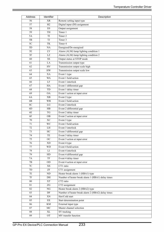
Temperature Controller Driver
GP-Pro EX Device/PLC Connection Manual 233
56 XR Remote setting input type
57 H2 Digital input (DI) assignment
58 E0 Output assignment
59 TH Timer 1
5A TI Timer 2
5B TJ Timer 3
5C TK Timer 4
5D NA Energized/De-energized
5E LY Alarm (ALM) lamp lighting condition 1
5F LZ Alarm (ALM) lamp lighting condition 2
60 SS Output status at STOP mode
61 LA Transmission output type
62 HV Transmission output scale high
63 HW Transmission output scale low
64 XA Event 1 type
65 WA Event 1 hold action
66 LF Event 1 interlock
67 HA Event 1 differential gap
68 TD Event 1 delay timer
69 OA Event 1 action at input error
6A XB Event 2 type
6B WB Event 2 hold action
6C LG Event 2 interlock
6D HB Event 2 differential gap
6E TG Event 2 delay timer
6F OB Event 2 action at input error
70 XC Event 3 type
71 WC Event 3 hold action
72 LH Event 3 interlock
73 HC Event 3 differential gap
74 TE Event 3 delay timer
75 OC Event 3 action at input error
76 XD Event 4 type
77 WD Event 4 hold action
78 LI Event 4 interlock
79 HD Event 4 differential gap
7A TF Event 4 delay timer
7B OD Event 4 action at input error
7C XS CT1 ratio
7D ZF CT1 assignment
7E ND Heater break alarm 1 (HBA1) type
7F DH Number of heater break alarm 1 (HBA1) delay times
80 XT CT2 ratio
81 ZG CT2 assignment
82 NG Heater break alarm 2 (HBA2) type
83 DF Number of heater break alarm 2 (HBA2) delay times
84 XN Hot/Cold start
85 SX Start determination point
86 KM External input type
87 MC Master channel selection
88 XL SV tracking
89 OT MV transfer function
Address Identifier Description

Temperature Controller Driver
GP-Pro EX Device/PLC Connection Manual 234
8A XE Control action
8B PK Integral/derivative time decimal point position
8C KA Derivative term operating factor
8D KB Undershoot suppression factor
8E DG Derivative gain
8F IV ON/OFF action differential gap (upper)
90 IW ON/OFF action differential gap (lower)
91 WH Action (high) at input error
92 WL Action (low) at input error
93 OE Manipulated output value at input error
94 OF Manipulated output value (MV1) at STOP mode
95 OG Manipulated output value (MV2) at STOP mode
96 PH Output change rate limiter (up) [MV1]
97 PL Output change rate limiter (down) [MV1]
98 OH Output limiter (high) [MV1]
99 OL Output limiter (low) [MV1]
9A PX Output change rate limiter (up) [MV2]
9B PY Output change rate limiter (down) [MV2]
9C OX Output limiter (high) [MV2]
9D OY Output limiter (low) [MV2]
9E PF Power feed forward selection
9F PZ Power feed forward gain
A0 GB AT bias
A1 G3 AT cycles
A2 OP Output value with AT turned on
A3 OQ Output value with AT turned off
A4 GH AT differential gap time
A5 KC Proportional band adjusting factor [heat-side]
A6 KD Integral time adjusting factor [heat-side]
A7 KE Derivative time adjusting factor [heat-side]
A8 KF Proportional band adjusting factor [cool-side]
A9 KG Integral time adjusting factor [cool-side]
AA KH Derivative time adjusting factor [cool-side]
AB P6 Proportional band limiter (high) [heat-side]
AC P7 Proportional band limiter (low) [heat-side]
AD I6 Integral time limiter (high) [heat-side]
AE I7 Integral time limiter (low) [heat-side]
AF D6 Derivative time limiter (high) [heat-side]
B0 D7 Derivative time limiter (low) [heat-side]
B1 P8 Proportional band limiter (high) [cool-side]
B2 P9 Proportional band limiter (low) [cool-side]
B3 I8 Integral time limiter (high) [cool-side]
B4 I9 Integral time limiter (low) [cool-side]
B5 D8 Derivative time limiter (high) [cool-side]
B6 D9 Derivative time limiter (low) [cool-side]
B7 V2 Open/Close output neutral zone
B8 VH Open/Close output differential gap
B9 SY Action at feedback resistance (FBR) input error
BA FV Feedback adjustment
BB TN Control motor time
BC OI Integrated output limiter
BD VS Valve action at STOP
Address Identifier Description
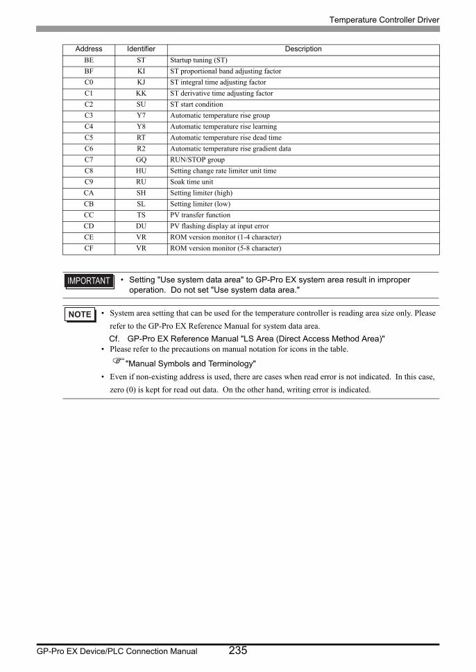
Temperature Controller Driver
GP-Pro EX Device/PLC Connection Manual 235
BE ST Startup tuning (ST)
BF KI ST proportional band adjusting factor
C0 KJ ST integral time adjusting factor
C1 KK ST derivative time adjusting factor
C2 SU ST start condition
C3 Y7 Automatic temperature rise group
C4 Y8 Automatic temperature rise learning
C5 RT Automatic temperature rise dead time
C6 R2 Automatic temperature rise gradient data
C7 GQ RUN/STOP group
C8 HU Setting change rate limiter unit time
C9 RU Soak time unit
CA SH Setting limiter (high)
CB SL Setting limiter (low)
CC TS PV transfer function
CD DU PV flashing display at input error
CE VR ROM version monitor (1-4 character)
CF VR ROM version monitor (5-8 character)
• Setting "Use system data area" to GP-Pro EX system area result in improper operation. Do not set "Use system data area."
• System area setting that can be used for the temperature controller is reading area size only. Please
refer to the GP-Pro EX Reference Manual for system data area.
Cf. GP-Pro EX Reference Manual "LS Area (Direct Access Method Area)"• Please refer to the precautions on manual notation for icons in the table.
"Manual Symbols and Terminology"
• Even if non-existing address is used, there are cases when read error is not indicated. In this case,
zero (0) is kept for read out data. On the other hand, writing error is indicated.
Address Identifier Description
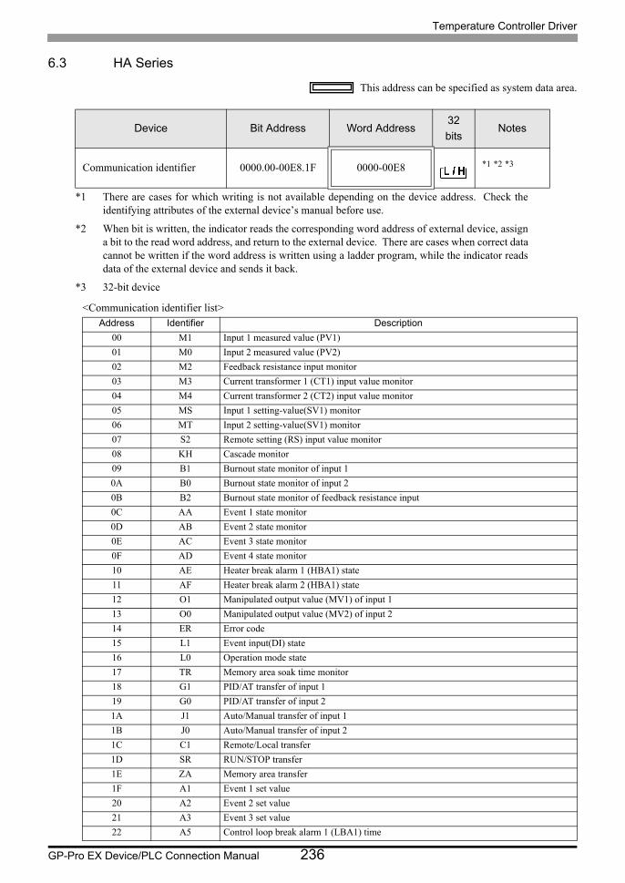
Temperature Controller Driver
GP-Pro EX Device/PLC Connection Manual 236
6.3 HA Series
This address can be specified as system data area.
<Communication identifier list>
Device Bit Address Word Address32
bitsNotes
Communication identifier 0000.00-00E8.1F 0000-00E8 *1 *2 *3
*1 There are cases for which writing is not available depending on the device address. Check the identifying attributes of the external device’s manual before use.
*2 When bit is written, the indicator reads the corresponding word address of external device, assign a bit to the read word address, and return to the external device. There are cases when correct data cannot be written if the word address is written using a ladder program, while the indicator reads data of the external device and sends it back.
*3 32-bit device
Address Identifier Description
00 M1 Input 1 measured value (PV1)
01 M0 Input 2 measured value (PV2)
02 M2 Feedback resistance input monitor
03 M3 Current transformer 1 (CT1) input value monitor
04 M4 Current transformer 2 (CT2) input value monitor
05 MS Input 1 setting-value(SV1) monitor
06 MT Input 2 setting-value(SV1) monitor
07 S2 Remote setting (RS) input value monitor
08 KH Cascade monitor
09 B1 Burnout state monitor of input 1
0A B0 Burnout state monitor of input 2
0B B2 Burnout state monitor of feedback resistance input
0C AA Event 1 state monitor
0D AB Event 2 state monitor
0E AC Event 3 state monitor
0F AD Event 4 state monitor
10 AE Heater break alarm 1 (HBA1) state
11 AF Heater break alarm 2 (HBA1) state
12 O1 Manipulated output value (MV1) of input 1
13 O0 Manipulated output value (MV2) of input 2
14 ER Error code
15 L1 Event input(DI) state
16 L0 Operation mode state
17 TR Memory area soak time monitor
18 G1 PID/AT transfer of input 1
19 G0 PID/AT transfer of input 2
1A J1 Auto/Manual transfer of input 1
1B J0 Auto/Manual transfer of input 2
1C C1 Remote/Local transfer
1D SR RUN/STOP transfer
1E ZA Memory area transfer
1F A1 Event 1 set value
20 A2 Event 2 set value
21 A3 Event 3 set value
22 A5 Control loop break alarm 1 (LBA1) time

Temperature Controller Driver
GP-Pro EX Device/PLC Connection Manual 237
23 N1 LBA1 deadband
24 A4 Event 4 set value
25 A6 Control loop break alarm 2 (LBA2) time
26 N2 LBA2 deadband
27 S1 Set value (SV1) of input 1
28 P1 Proportional band of input 1
29 I1 Integral time of input 1
2A D1 Derivative time of input 1
2B CA Control response parameter of input 1
2C S0 Set value (SV2) of input 2
2D P0 Proportional band of input 2
2E I0 Integral time of input 2
2F D0 Derivative time of input 2
30 C9 Control response parameter of input 2
31 HH Setting change rate limiter (up) of input 1
32 HL Setting change rate limiter (down) of input 1
33 HX Setting change rate limiter (up) of input 2
34 HY Setting change rate limiter (down) of input 2
35 TM Area soak time
36 LP Link area number
37 A7 Heater break alarm 1 (HBA1) set value
38 A8 Heater break alarm 2 (HBA2) set value
39 PB PV bias of input 1
3A F1 PV digital filter of input 1
3B PR PV ratio of input 1
3C DP PV low input cut-off of input 1
3D T0 Proportional cycle of input 1
3E ON Manual output value of input 1
3F PA PV bias of input 2
40 F0 PV digital filter of input 2
41 PQ PV ratio of input 2
42 DO PV low input cut-off of input 2
43 T2 Proportional cycle of input 2
44 OM Manual output value of input 2
45 LK Set lock level
46 EM EEPROM status
47 EB EEPROM mode
48 NE Heater break determination point 1
49 NF Heater melting determination point 1
4A NH Heater break determination point 2
4B NI Heater melting determination point 2
4C HP Not used
4D HQ Not used
4E HR Not used
4F FP Not used
50 FQ Not used
51 FR Not used
52 IL Not used
53 AZ Not used
54 FS Not used
55 DX STOP display selection
56 DA Bar graph display selection
Address Identifier Description
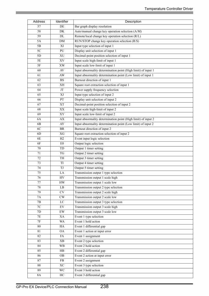
Temperature Controller Driver
GP-Pro EX Device/PLC Connection Manual 238
57 DE Bar graph display resolution
58 DK Auto/manual change key operation selection (A/M)
59 DL Remote/local change key operation selection (R/L)
5A DM RUN/STOP change key operation selection (R/S)
5B XI Input type selection of input 1
5C PU Display unit selection of input 1
5D XU Decimal-point position selection of input 1
5E XV Input scale high-limit of input 1
5F XW Input scale low-limit of input 1
60 AV Input abnormality determination point (High limit) of input 1
61 AW Input abnormality determination point (Low limit) of input 1
62 BS Burnout direction of input 1
63 XH Square root extraction selection of input 1
64 JT Power supply frequency selection
65 XJ Input type selection of input 2
66 PT Display unit selection of input 2
67 XT Decimal-point position selection of input 2
68 XX Input scale high-limit of input 2
69 XY Input scale low-limit of input 2
6A AX Input abnormality determination point (High limit) of input 2
6B AY Input abnormality determination point (Low limit) of input 2
6C BR Burnout direction of input 2
6D XG Square root extraction selection of input 2
6E H2 Event input logic selection
6F E0 Output logic selection
70 TD Output 1 timer setting
71 TG Output 2 timer setting
72 TH Output 3 timer setting
73 TI Output 4 timer setting
74 TJ Output 5 timer setting
75 LA Transmission output 1 type selection
76 HV Transmission output 1 scale high
77 HW Transmission output 1 scale low
78 LB Transmission output 2 type selection
79 CV Transmission output 2 scale high
7A CW Transmission output 2 scale low
7B LC Transmission output 3 type selection
7C EV Transmission output 3 scale high
7D EW Transmission output 3 scale low
7E XA Event 1 type selection
7F WA Event 1 hold action
80 HA Event 1 differential gap
81 OA Event 1 action at input error
82 FA Event 1 assignment
83 XB Event 2 type selection
84 WB Event 2 hold action
85 HB Event 2 differential gap
86 OB Event 2 action at input error
87 FB Event 2 assignment
88 XC Event 3 type selection
89 WC Event 3 hold action
8A HC Event 3 differential gap
Address Identifier Description
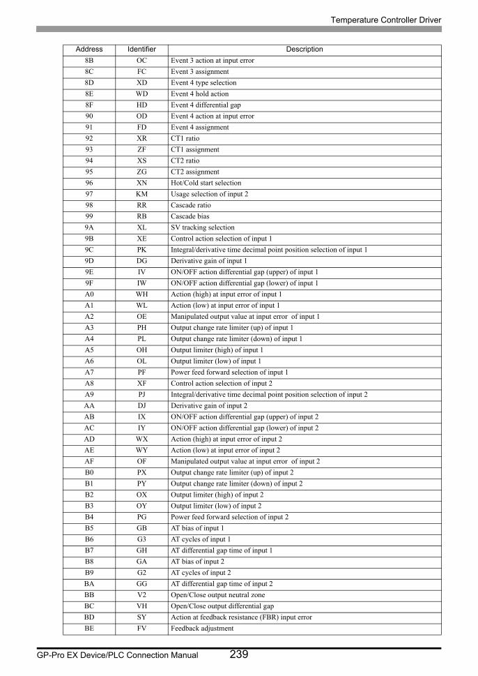
Temperature Controller Driver
GP-Pro EX Device/PLC Connection Manual 239
8B OC Event 3 action at input error
8C FC Event 3 assignment
8D XD Event 4 type selection
8E WD Event 4 hold action
8F HD Event 4 differential gap
90 OD Event 4 action at input error
91 FD Event 4 assignment
92 XR CT1 ratio
93 ZF CT1 assignment
94 XS CT2 ratio
95 ZG CT2 assignment
96 XN Hot/Cold start selection
97 KM Usage selection of input 2
98 RR Cascade ratio
99 RB Cascade bias
9A XL SV tracking selection
9B XE Control action selection of input 1
9C PK Integral/derivative time decimal point position selection of input 1
9D DG Derivative gain of input 1
9E IV ON/OFF action differential gap (upper) of input 1
9F IW ON/OFF action differential gap (lower) of input 1
A0 WH Action (high) at input error of input 1
A1 WL Action (low) at input error of input 1
A2 OE Manipulated output value at input error of input 1
A3 PH Output change rate limiter (up) of input 1
A4 PL Output change rate limiter (down) of input 1
A5 OH Output limiter (high) of input 1
A6 OL Output limiter (low) of input 1
A7 PF Power feed forward selection of input 1
A8 XF Control action selection of input 2
A9 PJ Integral/derivative time decimal point position selection of input 2
AA DJ Derivative gain of input 2
AB IX ON/OFF action differential gap (upper) of input 2
AC IY ON/OFF action differential gap (lower) of input 2
AD WX Action (high) at input error of input 2
AE WY Action (low) at input error of input 2
AF OF Manipulated output value at input error of input 2
B0 PX Output change rate limiter (up) of input 2
B1 PY Output change rate limiter (down) of input 2
B2 OX Output limiter (high) of input 2
B3 OY Output limiter (low) of input 2
B4 PG Power feed forward selection of input 2
B5 GB AT bias of input 1
B6 G3 AT cycles of input 1
B7 GH AT differential gap time of input 1
B8 GA AT bias of input 2
B9 G2 AT cycles of input 2
BA GG AT differential gap time of input 2
BB V2 Open/Close output neutral zone
BC VH Open/Close output differential gap
BD SY Action at feedback resistance (FBR) input error
BE FV Feedback adjustment
Address Identifier Description
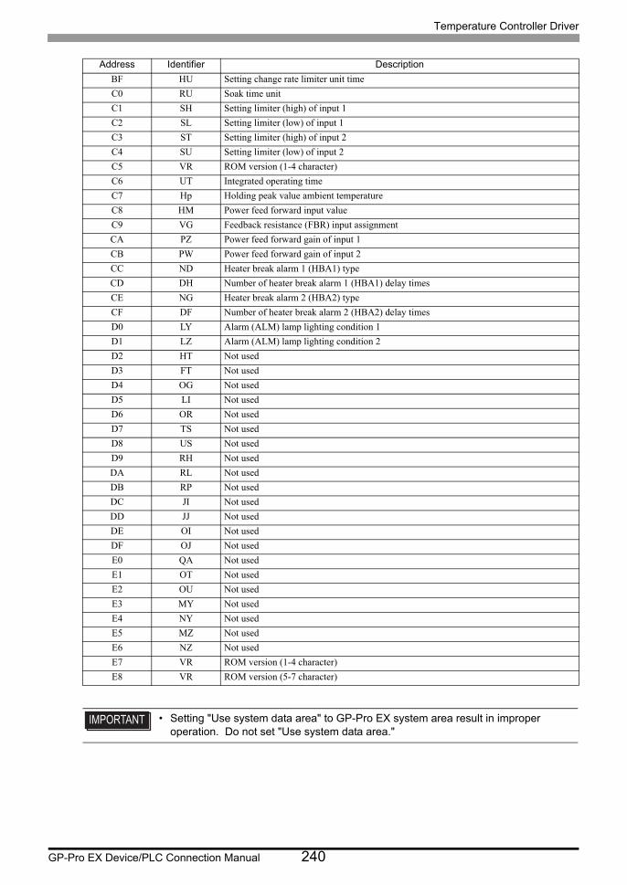
Temperature Controller Driver
GP-Pro EX Device/PLC Connection Manual 240
BF HU Setting change rate limiter unit time
C0 RU Soak time unit
C1 SH Setting limiter (high) of input 1
C2 SL Setting limiter (low) of input 1
C3 ST Setting limiter (high) of input 2
C4 SU Setting limiter (low) of input 2
C5 VR ROM version (1-4 character)
C6 UT Integrated operating time
C7 Hp Holding peak value ambient temperature
C8 HM Power feed forward input value
C9 VG Feedback resistance (FBR) input assignment
CA PZ Power feed forward gain of input 1
CB PW Power feed forward gain of input 2
CC ND Heater break alarm 1 (HBA1) type
CD DH Number of heater break alarm 1 (HBA1) delay times
CE NG Heater break alarm 2 (HBA2) type
CF DF Number of heater break alarm 2 (HBA2) delay times
D0 LY Alarm (ALM) lamp lighting condition 1
D1 LZ Alarm (ALM) lamp lighting condition 2
D2 HT Not used
D3 FT Not used
D4 OG Not used
D5 LI Not used
D6 OR Not used
D7 TS Not used
D8 US Not used
D9 RH Not used
DA RL Not used
DB RP Not used
DC JI Not used
DD JJ Not used
DE OI Not used
DF OJ Not used
E0 QA Not used
E1 OT Not used
E2 OU Not used
E3 MY Not used
E4 NY Not used
E5 MZ Not used
E6 NZ Not used
E7 VR ROM version (1-4 character)
E8 VR ROM version (5-7 character)
• Setting "Use system data area" to GP-Pro EX system area result in improper operation. Do not set "Use system data area."
Address Identifier Description
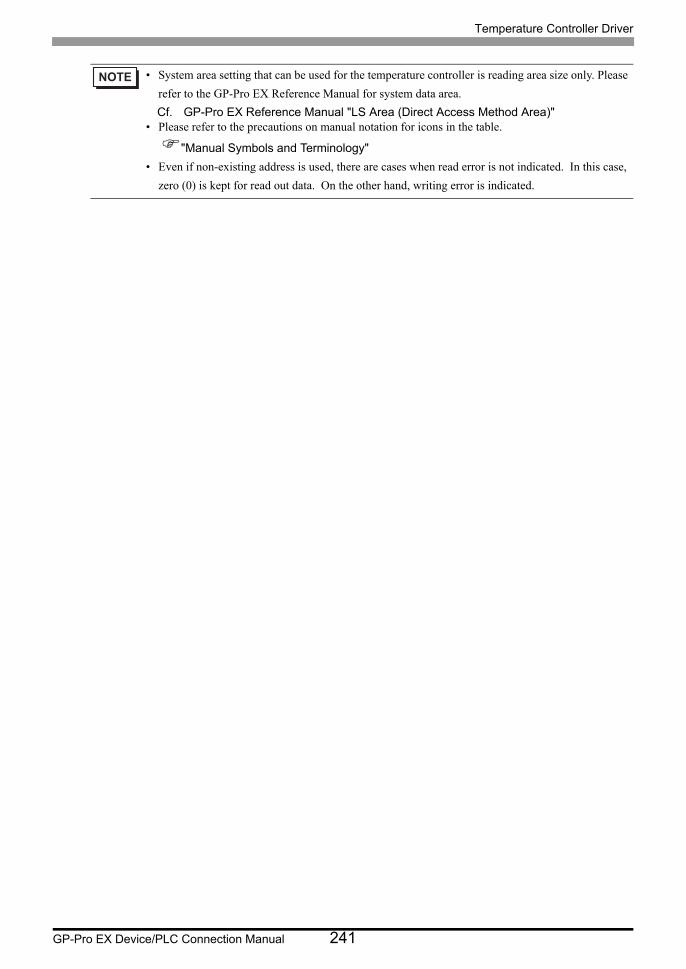
Temperature Controller Driver
GP-Pro EX Device/PLC Connection Manual 241
• System area setting that can be used for the temperature controller is reading area size only. Please
refer to the GP-Pro EX Reference Manual for system data area.
Cf. GP-Pro EX Reference Manual "LS Area (Direct Access Method Area)"• Please refer to the precautions on manual notation for icons in the table.
"Manual Symbols and Terminology"
• Even if non-existing address is used, there are cases when read error is not indicated. In this case,
zero (0) is kept for read out data. On the other hand, writing error is indicated.
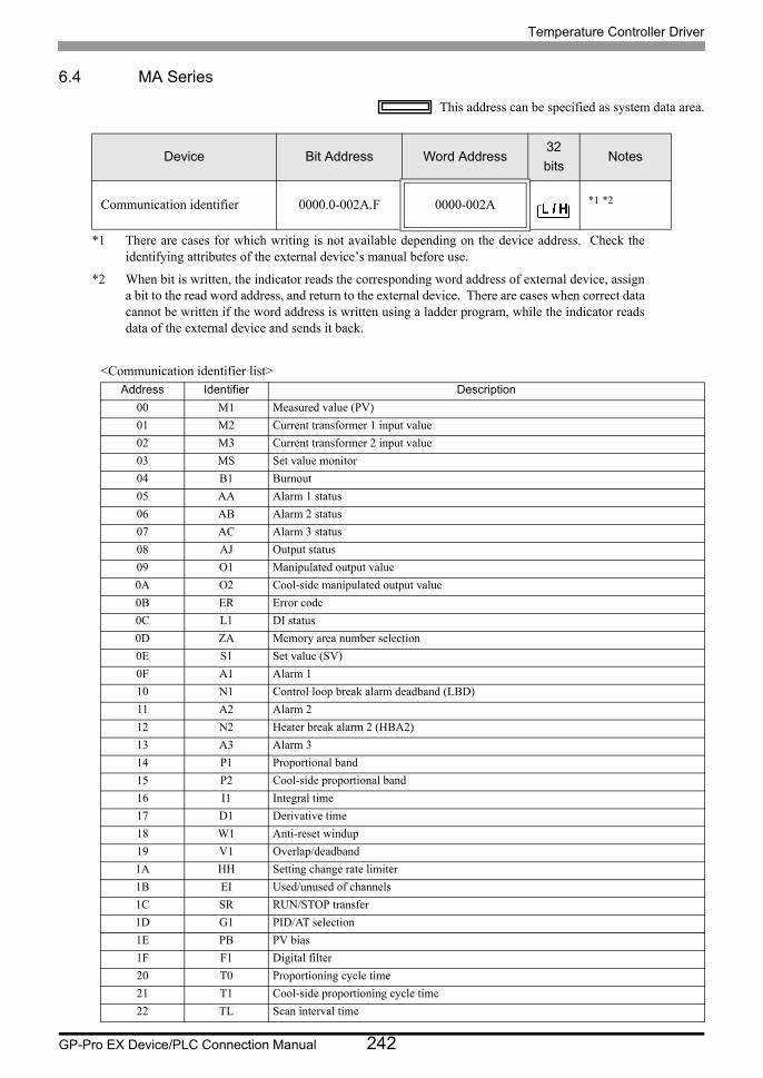
Temperature Controller Driver
GP-Pro EX Device/PLC Connection Manual 242
6.4 MA Series
This address can be specified as system data area.
<Communication identifier list>
Device Bit Address Word Address32
bitsNotes
Communication identifier 0000.0-002A.F 0000-002A *1 *2
*1 There are cases for which writing is not available depending on the device address. Check the identifying attributes of the external device’s manual before use.
*2 When bit is written, the indicator reads the corresponding word address of external device, assign a bit to the read word address, and return to the external device. There are cases when correct data cannot be written if the word address is written using a ladder program, while the indicator reads data of the external device and sends it back.
Address Identifier Description
00 M1 Measured value (PV)
01 M2 Current transformer 1 input value
02 M3 Current transformer 2 input value
03 MS Set value monitor
04 B1 Burnout
05 AA Alarm 1 status
06 AB Alarm 2 status
07 AC Alarm 3 status
08 AJ Output status
09 O1 Manipulated output value
0A O2 Cool-side manipulated output value
0B ER Error code
0C L1 DI status
0D ZA Memory area number selection
0E S1 Set value (SV)
0F A1 Alarm 1
10 N1 Control loop break alarm deadband (LBD)
11 A2 Alarm 2
12 N2 Heater break alarm 2 (HBA2)
13 A3 Alarm 3
14 P1 Proportional band
15 P2 Cool-side proportional band
16 I1 Integral time
17 D1 Derivative time
18 W1 Anti-reset windup
19 V1 Overlap/deadband
1A HH Setting change rate limiter
1B EI Used/unused of channels
1C SR RUN/STOP transfer
1D G1 PID/AT selection
1E PB PV bias
1F F1 Digital filter
20 T0 Proportioning cycle time
21 T1 Cool-side proportioning cycle time
22 TL Scan interval time
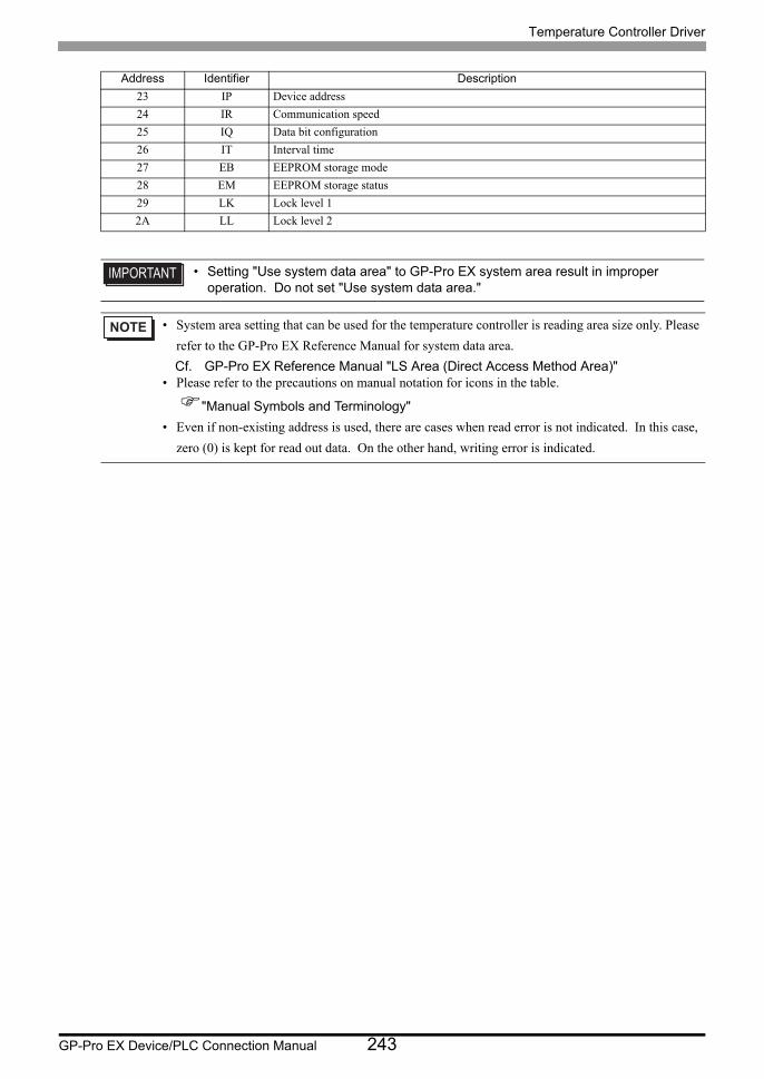
Temperature Controller Driver
GP-Pro EX Device/PLC Connection Manual 243
23 IP Device address
24 IR Communication speed
25 IQ Data bit configuration
26 IT Interval time
27 EB EEPROM storage mode
28 EM EEPROM storage status
29 LK Lock level 1
2A LL Lock level 2
• Setting "Use system data area" to GP-Pro EX system area result in improper operation. Do not set "Use system data area."
• System area setting that can be used for the temperature controller is reading area size only. Please
refer to the GP-Pro EX Reference Manual for system data area.
Cf. GP-Pro EX Reference Manual "LS Area (Direct Access Method Area)"• Please refer to the precautions on manual notation for icons in the table.
"Manual Symbols and Terminology"
• Even if non-existing address is used, there are cases when read error is not indicated. In this case,
zero (0) is kept for read out data. On the other hand, writing error is indicated.
Address Identifier Description

Temperature Controller Driver
GP-Pro EX Device/PLC Connection Manual 244
6.5 SRV Series
This address can be specified as system data area.
<Communication identifier list>
Device Bit Address Word Address32
bitsNotes
Communication identifier 0000.0-0085.1F 0000-0085 *1 *2 *3
*1 There are cases for which writing is not available depending on the device address. Check the identifying attributes of the external device’s manual before use.
*2 When bit is written, the indicator reads the corresponding word address of external device, assign a bit to the read word address, and return to the external device. There are cases when correct data cannot be written if the word address is written using a ladder program, while the indicator reads data of the external device and sends it back.
*3 32-bit device
Address Identifier Description
00 M1(ch1) CH1 Measured-value (PV)
01 M1(ch2) CH2 Measured-value (PV)
02 AJ(ch1) CH1 Overall event status
03 AJ(ch2) CH2 Overall event status
04 B1(ch1) CH1 Burnout state
05 B1(ch2) CH2 Burnout state
06 AA(ch1) CH1 Event 1 state
07 AA(ch2) CH2 Event 1 state
08 AB(ch1) CH1 Event 2 state
09 AB(ch2) CH2 Event 2 state
0A AC(ch1) CH1 Heater break alarm (HBA) state
0B AC(ch2) CH2 Heater break alarm (HBA) state
0C AP(ch1) CH1 Control loop break alarm (LBA) state
0D AP(ch2) CH2 Control loop break alarm (LBA) state
0E O1(ch1) CH1 Manipulated output value[heat-side]
0F O1(ch2) CH2 Manipulated output value[heat-side]
10 O2(ch1) CH1 Manipulated output value[cool-side]
11 O2(ch2) CH2 Manipulated output value[cool-side]
12 M3(ch1) CH1 CT input measured value
13 M3(ch2) CH2 CT input measured value
14 MS(ch1) CH1 Set-value monitoring
15 MS(ch2) CH2 Set-value monitoring
16 ER Error code
17 HE(ch1) CH1 Temperature rise completion status
18 HE(ch2) CH2 Temperature rise completion status
19 S1(ch1) CH1 Set value (SV)
1A S1(ch2) CH2 Set value (SV)
1B P1(ch1) CH1 Proportional band [heat-side]
1C P1(ch2) CH2 Proportional band [heat-side]
1D P2(ch1) CH1 Proportional band [cool-side]
1E P2(ch2) CH2 Proportional band [cool-side]
1F I1(ch1) CH1 Integral time
20 I1(ch2) CH2 Integral time
21 D1(ch1) CH1 Derivative time
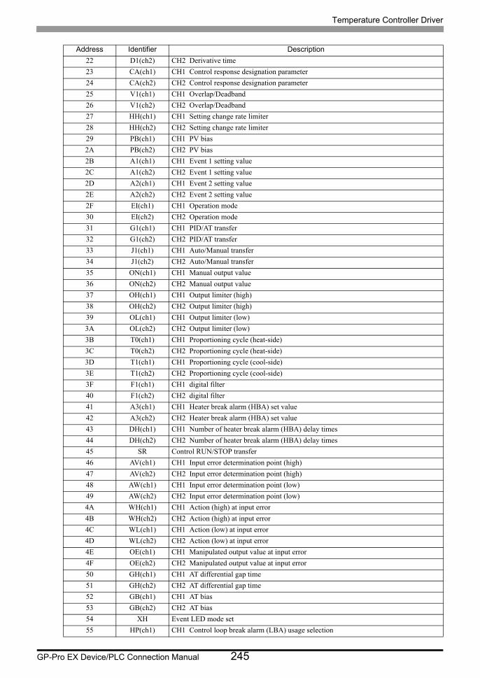
Temperature Controller Driver
GP-Pro EX Device/PLC Connection Manual 245
22 D1(ch2) CH2 Derivative time
23 CA(ch1) CH1 Control response designation parameter
24 CA(ch2) CH2 Control response designation parameter
25 V1(ch1) CH1 Overlap/Deadband
26 V1(ch2) CH2 Overlap/Deadband
27 HH(ch1) CH1 Setting change rate limiter
28 HH(ch2) CH2 Setting change rate limiter
29 PB(ch1) CH1 PV bias
2A PB(ch2) CH2 PV bias
2B A1(ch1) CH1 Event 1 setting value
2C A1(ch2) CH2 Event 1 setting value
2D A2(ch1) CH1 Event 2 setting value
2E A2(ch2) CH2 Event 2 setting value
2F EI(ch1) CH1 Operation mode
30 EI(ch2) CH2 Operation mode
31 G1(ch1) CH1 PID/AT transfer
32 G1(ch2) CH2 PID/AT transfer
33 J1(ch1) CH1 Auto/Manual transfer
34 J1(ch2) CH2 Auto/Manual transfer
35 ON(ch1) CH1 Manual output value
36 ON(ch2) CH2 Manual output value
37 OH(ch1) CH1 Output limiter (high)
38 OH(ch2) CH2 Output limiter (high)
39 OL(ch1) CH1 Output limiter (low)
3A OL(ch2) CH2 Output limiter (low)
3B T0(ch1) CH1 Proportioning cycle (heat-side)
3C T0(ch2) CH2 Proportioning cycle (heat-side)
3D T1(ch1) CH1 Proportioning cycle (cool-side)
3E T1(ch2) CH2 Proportioning cycle (cool-side)
3F F1(ch1) CH1 digital filter
40 F1(ch2) CH2 digital filter
41 A3(ch1) CH1 Heater break alarm (HBA) set value
42 A3(ch2) CH2 Heater break alarm (HBA) set value
43 DH(ch1) CH1 Number of heater break alarm (HBA) delay times
44 DH(ch2) CH2 Number of heater break alarm (HBA) delay times
45 SR Control RUN/STOP transfer
46 AV(ch1) CH1 Input error determination point (high)
47 AV(ch2) CH2 Input error determination point (high)
48 AW(ch1) CH1 Input error determination point (low)
49 AW(ch2) CH2 Input error determination point (low)
4A WH(ch1) CH1 Action (high) at input error
4B WH(ch2) CH2 Action (high) at input error
4C WL(ch1) CH1 Action (low) at input error
4D WL(ch2) CH2 Action (low) at input error
4E OE(ch1) CH1 Manipulated output value at input error
4F OE(ch2) CH2 Manipulated output value at input error
50 GH(ch1) CH1 AT differential gap time
51 GH(ch2) CH2 AT differential gap time
52 GB(ch1) CH1 AT bias
53 GB(ch2) CH2 AT bias
54 XH Event LED mode set
55 HP(ch1) CH1 Control loop break alarm (LBA) usage selection
Address Identifier Description
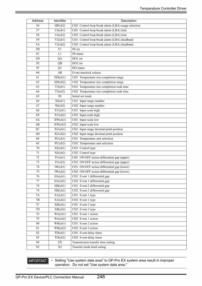
Temperature Controller Driver
GP-Pro EX Device/PLC Connection Manual 246
56 HP(ch2) CH2 Control loop break alarm (LBA) usage selection
57 C6(ch1) CH1 Control loop break alarm (LBA) time
58 C6(ch2) CH2 Control loop break alarm (LBA) time
59 V2(ch1) CH1 Control loop break alarm (LBA) deadband
5A V2(ch2) CH2 Control loop break alarm (LBA) deadband
5B E1 DI set
5C L1 DI status
5D QA DO1 set
5E QB DO2 set
5F Q1 DO status
60 AR Event interlock release
61 HD(ch1) CH1 Temperature rise completion range
62 HD(ch2) CH2 Temperature rise completion range
63 T3(ch1) CH1 Temperature rise completion soak time
64 T3(ch2) CH2 Temperature rise completion soak time
65 IN Initial set mode
66 XI(ch1) CH1 Input range number
67 XI(ch2) CH2 Input range number
68 XV(ch1) CH1 Input scale high
69 XV(ch2) CH2 Input scale high
6A XW(ch1) CH1 Input scale low
6B XW(ch2) CH2 Input scale low
6C XU(ch1) CH1 Input range decimal point position
6D XU(ch2) CH2 Input range decimal point position
6E PU(ch1) CH1 Temperature unit selection
6F PU(ch2) CH2 Temperature unit selection
70 XE(ch1) CH1 Control type
71 XE(ch2) CH2 Control type
72 IV(ch1) CH1 ON/OFF action differential gap (upper)
73 IV(ch2) CH2 ON/OFF action differential gap (upper)
74 IW(ch1) CH1 ON/OFF action differential gap (lower)
75 IW(ch2) CH2 ON/OFF action differential gap (lower)
76 HA(ch1) CH1 Event 1 differential gap
77 HA(ch2) CH2 Event 1 differential gap
78 HB(ch1) CH1 Event 2 differential gap
79 HB(ch2) CH2 Event 2 differential gap
7A XA(ch1) CH1 Event 1 type
7B XA(ch2) CH2 Event 1 type
7C XB(ch1) CH1 Event 2 type
7D XB(ch2) CH2 Event 2 type
7E WA(ch1) CH1 Event 1 action
7F WA(ch2) CH2 Event 1 action
80 WB(ch1) CH1 Event 2 action
81 WB(ch2) CH2 Event 2 action
82 TD(ch1) CH1 Event delay timer
83 TD(ch2) CH2 Event delay timer
84 ZX Transmission transfer time setting
85 X2 Transfer mode hold setting
• Setting "Use system data area" to GP-Pro EX system area result in improper operation. Do not set "Use system data area."
Address Identifier Description

Temperature Controller Driver
GP-Pro EX Device/PLC Connection Manual 247
• System area setting that can be used for the temperature controller is reading area size only. Please
refer to the GP-Pro EX Reference Manual for system data area.
Cf. GP-Pro EX Reference Manual "LS Area (Direct Access Method Area)"• Please refer to the precautions on manual notation for icons in the table.
"Manual Symbols and Terminology"
• Even if non-existing address is used, there are cases when read error is not indicated. In this case,
zero (0) is kept for read out data. On the other hand, writing error is indicated.
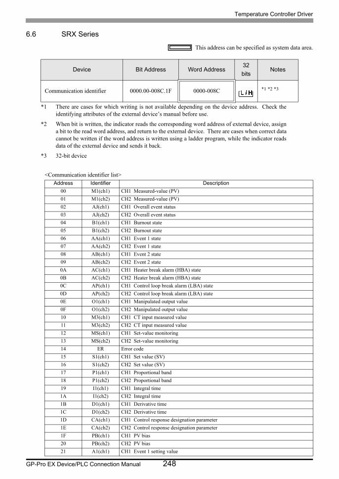
Temperature Controller Driver
GP-Pro EX Device/PLC Connection Manual 248
6.6 SRX Series
This address can be specified as system data area.
<Communication identifier list>
Device Bit Address Word Address32
bitsNotes
Communication identifier 0000.00-008C.1F 0000-008C *1 *2 *3
*1 There are cases for which writing is not available depending on the device address. Check the identifying attributes of the external device’s manual before use.
*2 When bit is written, the indicator reads the corresponding word address of external device, assign a bit to the read word address, and return to the external device. There are cases when correct data cannot be written if the word address is written using a ladder program, while the indicator reads data of the external device and sends it back.
*3 32-bit device
Address Identifier Description
00 M1(ch1) CH1 Measured-value (PV)
01 M1(ch2) CH2 Measured-value (PV)
02 AJ(ch1) CH1 Overall event status
03 AJ(ch2) CH2 Overall event status
04 B1(ch1) CH1 Burnout state
05 B1(ch2) CH2 Burnout state
06 AA(ch1) CH1 Event 1 state
07 AA(ch2) CH2 Event 1 state
08 AB(ch1) CH1 Event 2 state
09 AB(ch2) CH2 Event 2 state
0A AC(ch1) CH1 Heater break alarm (HBA) state
0B AC(ch2) CH2 Heater break alarm (HBA) state
0C AP(ch1) CH1 Control loop break alarm (LBA) state
0D AP(ch2) CH2 Control loop break alarm (LBA) state
0E O1(ch1) CH1 Manipulated output value
0F O1(ch2) CH2 Manipulated output value
10 M3(ch1) CH1 CT input measured value
11 M3(ch2) CH2 CT input measured value
12 MS(ch1) CH1 Set-value monitoring
13 MS(ch2) CH2 Set-value monitoring
14 ER Error code
15 S1(ch1) CH1 Set value (SV)
16 S1(ch2) CH2 Set value (SV)
17 P1(ch1) CH1 Proportional band
18 P1(ch2) CH2 Proportional band
19 I1(ch1) CH1 Integral time
1A I1(ch2) CH2 Integral time
1B D1(ch1) CH1 Derivative time
1C D1(ch2) CH2 Derivative time
1D CA(ch1) CH1 Control response designation parameter
1E CA(ch2) CH2 Control response designation parameter
1F PB(ch1) CH1 PV bias
20 PB(ch2) CH2 PV bias
21 A1(ch1) CH1 Event 1 setting value

Temperature Controller Driver
GP-Pro EX Device/PLC Connection Manual 249
22 A1(ch2) CH2 Event 1 setting value
23 A2(ch1) CH1 Event 2 setting value
24 A2(ch2) CH2 Event 2 setting value
25 EI(ch1) CH1 Operation mode
26 EI(ch2) CH2 Operation mode
27 G1(ch1) CH1 PID/AT transfer
28 G1(ch2) CH2 PID/AT transfer
29 J1(ch1) CH1 Auto/Manual transfer
2A J1(ch2) CH2 Auto/Manual transfer
2B ON(ch1) CH1 Manual output value
2C ON(ch2) CH2 Manual output value
2D OH(ch1) CH1 Output limiter (high)
2E OH(ch2) CH2 Output limiter (high)
2F OL(ch1) CH1 Output limiter (low)
30 OL(ch2) CH2 Output limiter (low)
31 T0(ch1) CH1 Proportioning cycle
32 T0(ch2) CH2 Proportioning cycle
33 F1(ch1) CH1 digital filter
34 F1(ch2) CH2 digital filter
35 A3(ch1) CH1 Heater break alarm (HBA) set value
36 A3(ch2) CH2 Heater break alarm (HBA) set value
37 DH(ch1) CH1 Number of heater break alarm (HBA) delay times
38 DH(ch2) CH2 Number of heater break alarm (HBA) delay times
39 XN(ch1) CH1 Hot/Cold start selection
3A XN(ch2) CH2 Hot/Cold start selection
3B SX(ch1) CH1 Start determination point
3C SX(ch2) CH2 Start determination point
3D SR Control RUN/STOP transfer
3E AV(ch1) CH1 Input error determination point (high)
3F AV(ch2) CH2 Input error determination point (high)
40 AW(ch1) CH1 Input error determination point (low)
41 AW(ch2) CH2 Input error determination point (low)
42 WH(ch1) CH1 Action (high) at input error
43 WH(ch2) CH2 Action (high) at input error
44 WL(ch1) CH1 Action (low) at input error
45 WL(ch2) CH2 Action (low) at input error
46 OE(ch1) CH1 Manipulated output value at input error
47 OE(ch2) CH2 Manipulated output value at input error
48 GH(ch1) CH1 AT differential gap time
49 GH(ch2) CH2 AT differential gap time
4A GB(ch1) CH1 AT bias
4B GB(ch2) CH2 AT bias
4C C1 Remote/Local transfer
4D XH Event LED mode set
4E E1(ch1) CH1 Digital input setting 1 (RESET)
4F E1(ch2) CH2 Digital input setting 1 (RESET)
50 E2(ch1) CH1 Digital input setting 2 (RUN)
51 E2(ch2) CH2 Digital input setting 2 (RUN)
52 E3(ch1) CH1 Digital input setting 3 (FIX)
53 E3(ch2) CH2 Digital input setting 3 (FIX)
54 E4(ch1) CH1 Digital input setting 4 (MAN)
55 E4(ch2) CH2 Digital input setting 4 (MAN)
Address Identifier Description
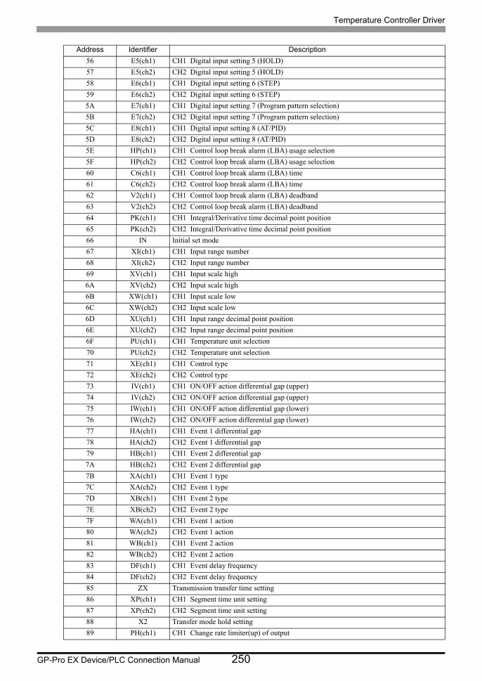
Temperature Controller Driver
GP-Pro EX Device/PLC Connection Manual 250
56 E5(ch1) CH1 Digital input setting 5 (HOLD)
57 E5(ch2) CH2 Digital input setting 5 (HOLD)
58 E6(ch1) CH1 Digital input setting 6 (STEP)
59 E6(ch2) CH2 Digital input setting 6 (STEP)
5A E7(ch1) CH1 Digital input setting 7 (Program pattern selection)
5B E7(ch2) CH2 Digital input setting 7 (Program pattern selection)
5C E8(ch1) CH1 Digital input setting 8 (AT/PID)
5D E8(ch2) CH2 Digital input setting 8 (AT/PID)
5E HP(ch1) CH1 Control loop break alarm (LBA) usage selection
5F HP(ch2) CH2 Control loop break alarm (LBA) usage selection
60 C6(ch1) CH1 Control loop break alarm (LBA) time
61 C6(ch2) CH2 Control loop break alarm (LBA) time
62 V2(ch1) CH1 Control loop break alarm (LBA) deadband
63 V2(ch2) CH2 Control loop break alarm (LBA) deadband
64 PK(ch1) CH1 Integral/Derivative time decimal point position
65 PK(ch2) CH2 Integral/Derivative time decimal point position
66 IN Initial set mode
67 XI(ch1) CH1 Input range number
68 XI(ch2) CH2 Input range number
69 XV(ch1) CH1 Input scale high
6A XV(ch2) CH2 Input scale high
6B XW(ch1) CH1 Input scale low
6C XW(ch2) CH2 Input scale low
6D XU(ch1) CH1 Input range decimal point position
6E XU(ch2) CH2 Input range decimal point position
6F PU(ch1) CH1 Temperature unit selection
70 PU(ch2) CH2 Temperature unit selection
71 XE(ch1) CH1 Control type
72 XE(ch2) CH2 Control type
73 IV(ch1) CH1 ON/OFF action differential gap (upper)
74 IV(ch2) CH2 ON/OFF action differential gap (upper)
75 IW(ch1) CH1 ON/OFF action differential gap (lower)
76 IW(ch2) CH2 ON/OFF action differential gap (lower)
77 HA(ch1) CH1 Event 1 differential gap
78 HA(ch2) CH2 Event 1 differential gap
79 HB(ch1) CH1 Event 2 differential gap
7A HB(ch2) CH2 Event 2 differential gap
7B XA(ch1) CH1 Event 1 type
7C XA(ch2) CH2 Event 1 type
7D XB(ch1) CH1 Event 2 type
7E XB(ch2) CH2 Event 2 type
7F WA(ch1) CH1 Event 1 action
80 WA(ch2) CH2 Event 1 action
81 WB(ch1) CH1 Event 2 action
82 WB(ch2) CH2 Event 2 action
83 DF(ch1) CH1 Event delay frequency
84 DF(ch2) CH2 Event delay frequency
85 ZX Transmission transfer time setting
86 XP(ch1) CH1 Segment time unit setting
87 XP(ch2) CH2 Segment time unit setting
88 X2 Transfer mode hold setting
89 PH(ch1) CH1 Change rate limiter(up) of output
Address Identifier Description
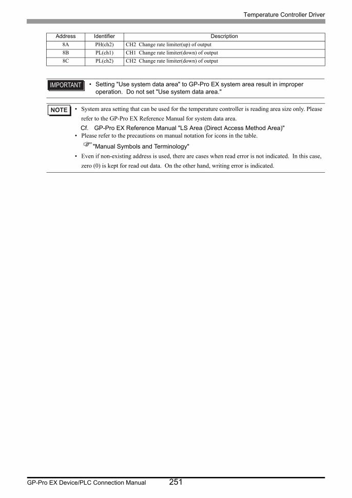
Temperature Controller Driver
GP-Pro EX Device/PLC Connection Manual 251
8A PH(ch2) CH2 Change rate limiter(up) of output
8B PL(ch1) CH1 Change rate limiter(down) of output
8C PL(ch2) CH2 Change rate limiter(down) of output
• Setting "Use system data area" to GP-Pro EX system area result in improper operation. Do not set "Use system data area."
• System area setting that can be used for the temperature controller is reading area size only. Please
refer to the GP-Pro EX Reference Manual for system data area.
Cf. GP-Pro EX Reference Manual "LS Area (Direct Access Method Area)"• Please refer to the precautions on manual notation for icons in the table.
"Manual Symbols and Terminology"
• Even if non-existing address is used, there are cases when read error is not indicated. In this case,
zero (0) is kept for read out data. On the other hand, writing error is indicated.
Address Identifier Description
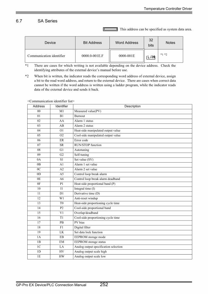
Temperature Controller Driver
GP-Pro EX Device/PLC Connection Manual 252
6.7 SA Series
This address can be specified as system data area.
<Communication identifier list>
Device Bit Address Word Address32
bitsNotes
Communication identifier 0000.0-001E.F 0000-001E *1 *2
*1 There are cases for which writing is not available depending on the device address. Check the identifying attributes of the external device’s manual before use.
*2 When bit is written, the indicator reads the corresponding word address of external device, assign a bit to the read word address, and return to the external device. There are cases when correct data cannot be written if the word address is written using a ladder program, while the indicator reads data of the external device and sends it back.
Address Identifier Description
00 M1 Measured value(PV)
01 B1 Burnout
02 AA Alarm 1 status
03 AB Alarm 2 status
04 O1 Heat-side manipulated output value
05 O2 Cool-side manipulated output value
06 ER Error code
07 SR RUN/STOP function
08 G1 Autotuning
09 G2 Self-tuning
0A S1 Set value (SV)
0B A1 Alarm 1 set value
0C A2 Alarm 2 set value
0D A5 Control loop break alarm
0E A6 Control loop break alarm deadband
0F P1 Heat-side proportional band (P)
10 I1 Integral time (I)
11 D1 Derivative time (D)
12 W1 Anti-reset windup
13 T0 Heat-side proportioning cycle time
14 P2 Cool-side proportional band
15 V1 Overlap/deadband
16 T1 Cool-side proportioning cycle time
17 PB PV bias
18 F1 Digital filter
19 LK Set data lock function
1A EB EEPROM storage mode
1B EM EEPROM storage status
1C LA Analog output specification selection
1D HV Analog output scale high
1E HW Analog output scale low

Temperature Controller Driver
GP-Pro EX Device/PLC Connection Manual 253
• Setting "Use system data area" to GP-Pro EX system area result in improper operation. Do not set "Use system data area."
• System area setting that can be used for the temperature controller is reading area size only. Please
refer to the GP-Pro EX Reference Manual for system data area.
Cf. GP-Pro EX Reference Manual "LS Area (Direct Access Method Area)"• Please refer to the precautions on manual notation for icons in the table.
"Manual Symbols and Terminology"
• Even if non-existing address is used, there are cases when read error is not indicated. In this case,
zero (0) is kept for read out data. On the other hand, writing error is indicated.
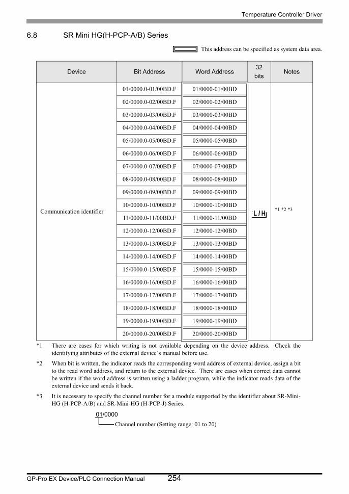
Temperature Controller Driver
GP-Pro EX Device/PLC Connection Manual 254
6.8 SR Mini HG(H-PCP-A/B) Series
This address can be specified as system data area.
Device Bit Address Word Address32
bitsNotes
Communication identifier
01/0000.0-01/00BD.F 01/0000-01/00BD
*1 *2 *3
*1 There are cases for which writing is not available depending on the device address. Check the identifying attributes of the external device’s manual before use.
*2 When bit is written, the indicator reads the corresponding word address of external device, assign a bit to the read word address, and return to the external device. There are cases when correct data cannot be written if the word address is written using a ladder program, while the indicator reads data of the external device and sends it back.
*3 It is necessary to specify the channel number for a module supported by the identifier about SR-Mini- HG (H-PCP-A/B) and SR-Mini-HG (H-PCP-J) Series.
02/0000.0-02/00BD.F 02/0000-02/00BD
03/0000.0-03/00BD.F 03/0000-03/00BD
04/0000.0-04/00BD.F 04/0000-04/00BD
05/0000.0-05/00BD.F 05/0000-05/00BD
06/0000.0-06/00BD.F 06/0000-06/00BD
07/0000.0-07/00BD.F 07/0000-07/00BD
08/0000.0-08/00BD.F 08/0000-08/00BD
09/0000.0-09/00BD.F 09/0000-09/00BD
10/0000.0-10/00BD.F 10/0000-10/00BD
11/0000.0-11/00BD.F 11/0000-11/00BD
12/0000.0-12/00BD.F 12/0000-12/00BD
13/0000.0-13/00BD.F 13/0000-13/00BD
14/0000.0-14/00BD.F 14/0000-14/00BD
15/0000.0-15/00BD.F 15/0000-15/00BD
16/0000.0-16/00BD.F 16/0000-16/00BD
17/0000.0-17/00BD.F 17/0000-17/00BD
18/0000.0-18/00BD.F 18/0000-18/00BD
19/0000.0-19/00BD.F 19/0000-19/00BD
20/0000.0-20/00BD.F 20/0000-20/00BD
01/0000
Channel number (Setting range: 01 to 20)
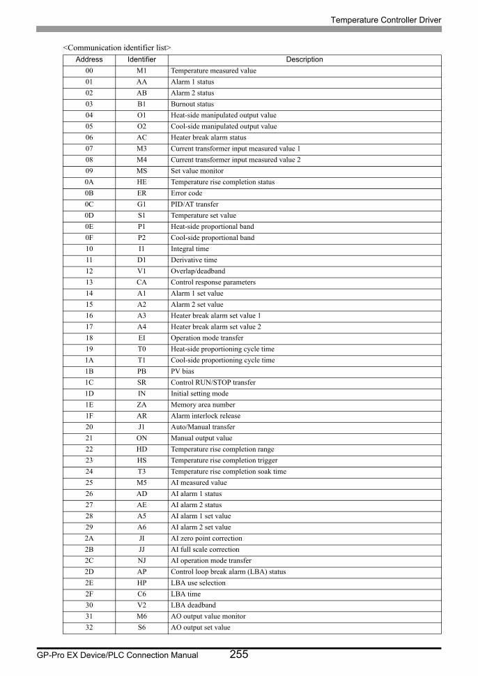
Temperature Controller Driver
GP-Pro EX Device/PLC Connection Manual 255
<Communication identifier list>Address Identifier Description
00 M1 Temperature measured value
01 AA Alarm 1 status
02 AB Alarm 2 status
03 B1 Burnout status
04 O1 Heat-side manipulated output value
05 O2 Cool-side manipulated output value
06 AC Heater break alarm status
07 M3 Current transformer input measured value 1
08 M4 Current transformer input measured value 2
09 MS Set value monitor
0A HE Temperature rise completion status
0B ER Error code
0C G1 PID/AT transfer
0D S1 Temperature set value
0E P1 Heat-side proportional band
0F P2 Cool-side proportional band
10 I1 Integral time
11 D1 Derivative time
12 V1 Overlap/deadband
13 CA Control response parameters
14 A1 Alarm 1 set value
15 A2 Alarm 2 set value
16 A3 Heater break alarm set value 1
17 A4 Heater break alarm set value 2
18 EI Operation mode transfer
19 T0 Heat-side proportioning cycle time
1A T1 Cool-side proportioning cycle time
1B PB PV bias
1C SR Control RUN/STOP transfer
1D IN Initial setting mode
1E ZA Memory area number
1F AR Alarm interlock release
20 J1 Auto/Manual transfer
21 ON Manual output value
22 HD Temperature rise completion range
23 HS Temperature rise completion trigger
24 T3 Temperature rise completion soak time
25 M5 AI measured value
26 AD AI alarm 1 status
27 AE AI alarm 2 status
28 A5 AI alarm 1 set value
29 A6 AI alarm 2 set value
2A JI AI zero point correction
2B JJ AI full scale correction
2C NJ AI operation mode transfer
2D AP Control loop break alarm (LBA) status
2E HP LBA use selection
2F C6 LBA time
30 V2 LBA deadband
31 M6 AO output value monitor
32 S6 AO output set value
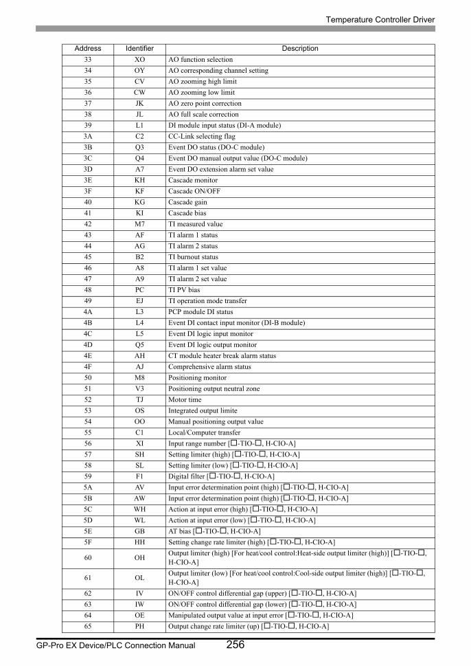
Temperature Controller Driver
GP-Pro EX Device/PLC Connection Manual 256
33 XO AO function selection
34 OY AO corresponding channel setting
35 CV AO zooming high limit
36 CW AO zooming low limit
37 JK AO zero point correction
38 JL AO full scale correction
39 L1 DI module input status (DI-A module)
3A C2 CC-Link selecting flag
3B Q3 Event DO status (DO-C module)
3C Q4 Event DO manual output value (DO-C module)
3D A7 Event DO extension alarm set value
3E KH Cascade monitor
3F KF Cascade ON/OFF
40 KG Cascade gain
41 KI Cascade bias
42 M7 TI measured value
43 AF TI alarm 1 status
44 AG TI alarm 2 status
45 B2 TI burnout status
46 A8 TI alarm 1 set value
47 A9 TI alarm 2 set value
48 PC TI PV bias
49 EJ TI operation mode transfer
4A L3 PCP module DI status
4B L4 Event DI contact input monitor (DI-B module)
4C L5 Event DI logic input monitor
4D Q5 Event DI logic output monitor
4E AH CT module heater break alarm status
4F AJ Comprehensive alarm status
50 M8 Positioning monitor
51 V3 Positioning output neutral zone
52 TJ Motor time
53 OS Integrated output limite
54 OO Manual positioning output value
55 C1 Local/Computer transfer
56 XI Input range number [-TIO-, H-CIO-A]
57 SH Setting limiter (high) [-TIO-, H-CIO-A]
58 SL Setting limiter (low) [-TIO-, H-CIO-A]
59 F1 Digital filter [-TIO-, H-CIO-A]
5A AV Input error determination point (high) [-TIO-, H-CIO-A]
5B AW Input error determination point (high) [-TIO-, H-CIO-A]
5C WH Action at input error (high) [-TIO-, H-CIO-A]
5D WL Action at input error (low) [-TIO-, H-CIO-A]
5E GB AT bias [-TIO-, H-CIO-A]
5F HH Setting change rate limiter (high) [-TIO-, H-CIO-A]
60 OHOutput limiter (high) [For heat/cool control:Heat-side output limiter (high)] [-TIO-, H-CIO-A]
61 OLOutput limiter (low) [For heat/cool control:Cool-side output limiter (high)] [-TIO-, H-CIO-A]
62 IV ON/OFF control differential gap (upper) [-TIO-, H-CIO-A]
63 IW ON/OFF control differential gap (lower) [-TIO-, H-CIO-A]
64 OE Manipulated output value at input error [-TIO-, H-CIO-A]
65 PH Output change rate limiter (up) [-TIO-, H-CIO-A]
Address Identifier Description
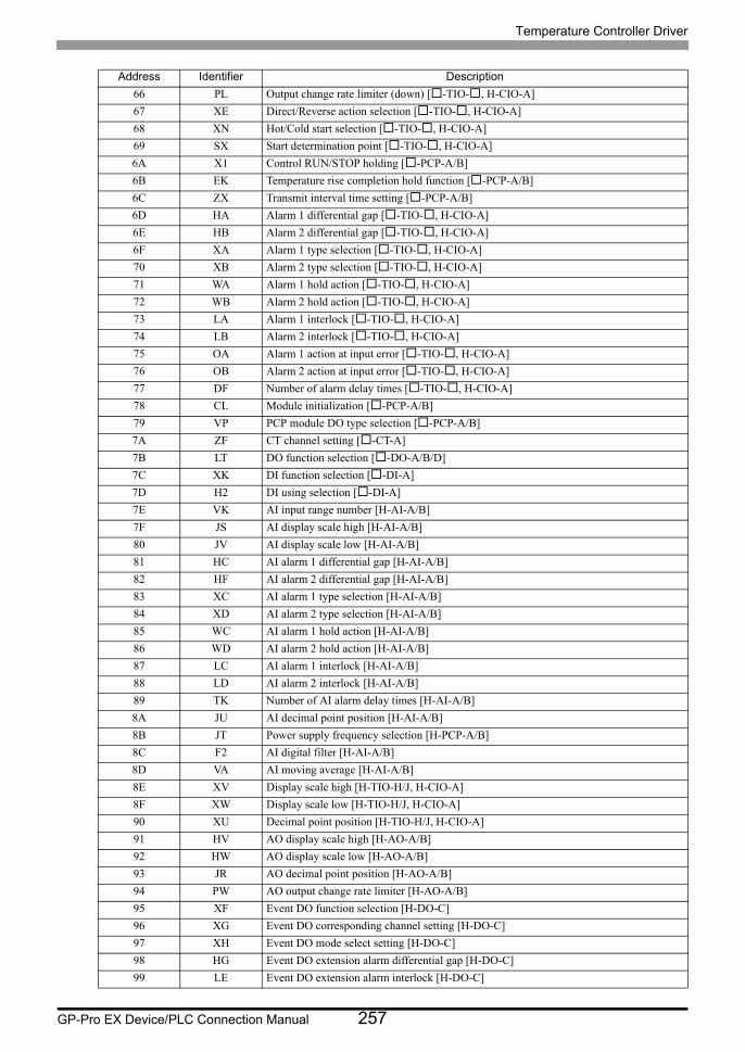
Temperature Controller Driver
GP-Pro EX Device/PLC Connection Manual 257
66 PL Output change rate limiter (down) [-TIO-, H-CIO-A]
67 XE Direct/Reverse action selection [-TIO-, H-CIO-A]
68 XN Hot/Cold start selection [-TIO-, H-CIO-A]
69 SX Start determination point [-TIO-, H-CIO-A]
6A X1 Control RUN/STOP holding [-PCP-A/B]
6B EK Temperature rise completion hold function [-PCP-A/B]
6C ZX Transmit interval time setting [-PCP-A/B]
6D HA Alarm 1 differential gap [-TIO-, H-CIO-A]
6E HB Alarm 2 differential gap [-TIO-, H-CIO-A]
6F XA Alarm 1 type selection [-TIO-, H-CIO-A]
70 XB Alarm 2 type selection [-TIO-, H-CIO-A]
71 WA Alarm 1 hold action [-TIO-, H-CIO-A]
72 WB Alarm 2 hold action [-TIO-, H-CIO-A]
73 LA Alarm 1 interlock [-TIO-, H-CIO-A]
74 LB Alarm 2 interlock [-TIO-, H-CIO-A]
75 OA Alarm 1 action at input error [-TIO-, H-CIO-A]
76 OB Alarm 2 action at input error [-TIO-, H-CIO-A]
77 DF Number of alarm delay times [-TIO-, H-CIO-A]
78 CL Module initialization [-PCP-A/B]
79 VP PCP module DO type selection [-PCP-A/B]
7A ZF CT channel setting [-CT-A]
7B LT DO function selection [-DO-A/B/D]
7C XK DI function selection [-DI-A]
7D H2 DI using selection [-DI-A]
7E VK AI input range number [H-AI-A/B]
7F JS AI display scale high [H-AI-A/B]
80 JV AI display scale low [H-AI-A/B]
81 HC AI alarm 1 differential gap [H-AI-A/B]
82 HF AI alarm 2 differential gap [H-AI-A/B]
83 XC AI alarm 1 type selection [H-AI-A/B]
84 XD AI alarm 2 type selection [H-AI-A/B]
85 WC AI alarm 1 hold action [H-AI-A/B]
86 WD AI alarm 2 hold action [H-AI-A/B]
87 LC AI alarm 1 interlock [H-AI-A/B]
88 LD AI alarm 2 interlock [H-AI-A/B]
89 TK Number of AI alarm delay times [H-AI-A/B]
8A JU AI decimal point position [H-AI-A/B]
8B JT Power supply frequency selection [H-PCP-A/B]
8C F2 AI digital filter [H-AI-A/B]
8D VA AI moving average [H-AI-A/B]
8E XV Display scale high [H-TIO-H/J, H-CIO-A]
8F XW Display scale low [H-TIO-H/J, H-CIO-A]
90 XU Decimal point position [H-TIO-H/J, H-CIO-A]
91 HV AO display scale high [H-AO-A/B]
92 HW AO display scale low [H-AO-A/B]
93 JR AO decimal point position [H-AO-A/B]
94 PW AO output change rate limiter [H-AO-A/B]
95 XF Event DO function selection [H-DO-C]
96 XG Event DO corresponding channel setting [H-DO-C]
97 XH Event DO mode select setting [H-DO-C]
98 HG Event DO extension alarm differential gap [H-DO-C]
99 LE Event DO extension alarm interlock [H-DO-C]
Address Identifier Description
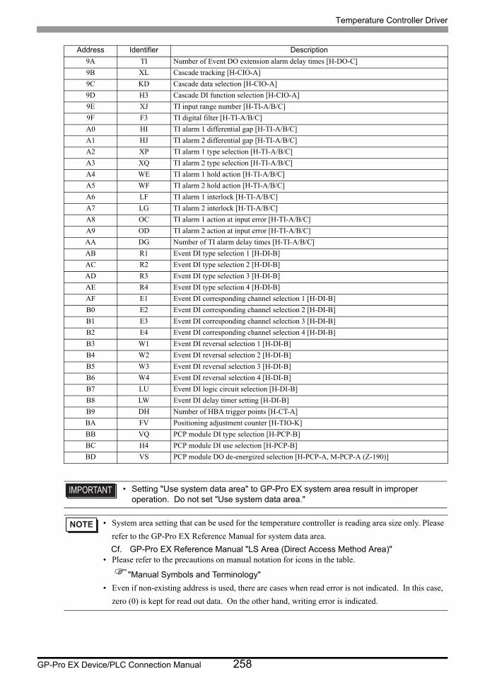
Temperature Controller Driver
GP-Pro EX Device/PLC Connection Manual 258
9A TI Number of Event DO extension alarm delay times [H-DO-C]
9B XL Cascade tracking [H-CIO-A]
9C KD Cascade data selection [H-CIO-A]
9D H3 Cascade DI function selection [H-CIO-A]
9E XJ TI input range number [H-TI-A/B/C]
9F F3 TI digital filter [H-TI-A/B/C]
A0 HI TI alarm 1 differential gap [H-TI-A/B/C]
A1 HJ TI alarm 2 differential gap [H-TI-A/B/C]
A2 XP TI alarm 1 type selection [H-TI-A/B/C]
A3 XQ TI alarm 2 type selection [H-TI-A/B/C]
A4 WE TI alarm 1 hold action [H-TI-A/B/C]
A5 WF TI alarm 2 hold action [H-TI-A/B/C]
A6 LF TI alarm 1 interlock [H-TI-A/B/C]
A7 LG TI alarm 2 interlock [H-TI-A/B/C]
A8 OC TI alarm 1 action at input error [H-TI-A/B/C]
A9 OD TI alarm 2 action at input error [H-TI-A/B/C]
AA DG Number of TI alarm delay times [H-TI-A/B/C]
AB R1 Event DI type selection 1 [H-DI-B]
AC R2 Event DI type selection 2 [H-DI-B]
AD R3 Event DI type selection 3 [H-DI-B]
AE R4 Event DI type selection 4 [H-DI-B]
AF E1 Event DI corresponding channel selection 1 [H-DI-B]
B0 E2 Event DI corresponding channel selection 2 [H-DI-B]
B1 E3 Event DI corresponding channel selection 3 [H-DI-B]
B2 E4 Event DI corresponding channel selection 4 [H-DI-B]
B3 W1 Event DI reversal selection 1 [H-DI-B]
B4 W2 Event DI reversal selection 2 [H-DI-B]
B5 W3 Event DI reversal selection 3 [H-DI-B]
B6 W4 Event DI reversal selection 4 [H-DI-B]
B7 LU Event DI logic circuit selection [H-DI-B]
B8 LW Event DI delay timer setting [H-DI-B]
B9 DH Number of HBA trigger points [H-CT-A]
BA FV Positioning adjustment counter [H-TIO-K]
BB VQ PCP module DI type selection [H-PCP-B]
BC H4 PCP module DI use selection [H-PCP-B]
BD VS PCP module DO de-energized selection [H-PCP-A, M-PCP-A (Z-190)]
• Setting "Use system data area" to GP-Pro EX system area result in improper operation. Do not set "Use system data area."
• System area setting that can be used for the temperature controller is reading area size only. Please
refer to the GP-Pro EX Reference Manual for system data area.
Cf. GP-Pro EX Reference Manual "LS Area (Direct Access Method Area)"• Please refer to the precautions on manual notation for icons in the table.
"Manual Symbols and Terminology"
• Even if non-existing address is used, there are cases when read error is not indicated. In this case,
zero (0) is kept for read out data. On the other hand, writing error is indicated.
Address Identifier Description
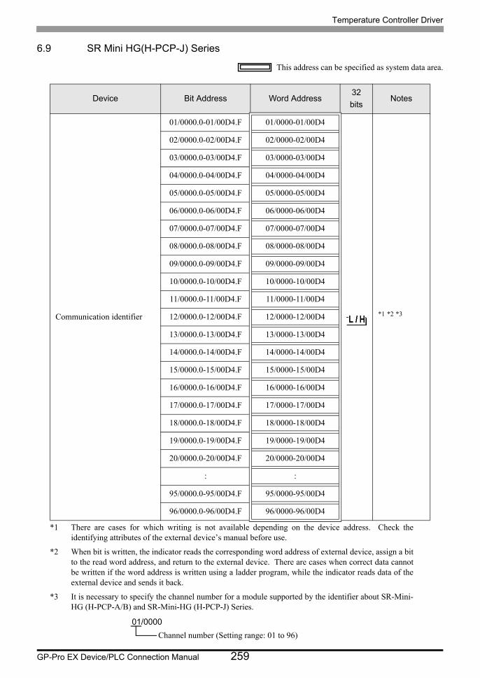
Temperature Controller Driver
GP-Pro EX Device/PLC Connection Manual 259
6.9 SR Mini HG(H-PCP-J) Series
This address can be specified as system data area.
Device Bit Address Word Address32
bitsNotes
Communication identifier
01/0000.0-01/00D4.F 01/0000-01/00D4
*1 *2 *3
*1 There are cases for which writing is not available depending on the device address. Check the identifying attributes of the external device’s manual before use.
*2 When bit is written, the indicator reads the corresponding word address of external device, assign a bit to the read word address, and return to the external device. There are cases when correct data cannot be written if the word address is written using a ladder program, while the indicator reads data of the external device and sends it back.
*3 It is necessary to specify the channel number for a module supported by the identifier about SR-Mini- HG (H-PCP-A/B) and SR-Mini-HG (H-PCP-J) Series.
02/0000.0-02/00D4.F 02/0000-02/00D4
03/0000.0-03/00D4.F 03/0000-03/00D4
04/0000.0-04/00D4.F 04/0000-04/00D4
05/0000.0-05/00D4.F 05/0000-05/00D4
06/0000.0-06/00D4.F 06/0000-06/00D4
07/0000.0-07/00D4.F 07/0000-07/00D4
08/0000.0-08/00D4.F 08/0000-08/00D4
09/0000.0-09/00D4.F 09/0000-09/00D4
10/0000.0-10/00D4.F 10/0000-10/00D4
11/0000.0-11/00D4.F 11/0000-11/00D4
12/0000.0-12/00D4.F 12/0000-12/00D4
13/0000.0-13/00D4.F 13/0000-13/00D4
14/0000.0-14/00D4.F 14/0000-14/00D4
15/0000.0-15/00D4.F 15/0000-15/00D4
16/0000.0-16/00D4.F 16/0000-16/00D4
17/0000.0-17/00D4.F 17/0000-17/00D4
18/0000.0-18/00D4.F 18/0000-18/00D4
19/0000.0-19/00D4.F 19/0000-19/00D4
20/0000.0-20/00D4.F 20/0000-20/00D4
: :
95/0000.0-95/00D4.F 95/0000-95/00D4
96/0000.0-96/00D4.F 96/0000-96/00D4
01/0000
Channel number (Setting range: 01 to 96)

Temperature Controller Driver
GP-Pro EX Device/PLC Connection Manual 260
<Communication identifier list>Address Identifier Description
00 M1Temperature measured value (PV) [H-TIO-, H-CIO-A] / Motor speed measured value [H-SIO-A]
01 AA Alarm 1 status [H-TIO-, H-CIO-A, H-SIO-A]
02 AB Alarm 2 status [H-TIO-, H-CIO-A, H-SIO-A]
03 B1 Burnout status [H-TIO-, H-CIO-A, H-SIO-A]
04 O1 Heat-side manipulated output value [H-TIO-, H-CIO-A]
05 O2 Cool-side manipulated output value [H-TIO-, H-CIO-A]
06 AC Heater break alarm status [H-TIO-A/C/D, H-CIO-A]
07 M3 Current transformer input measured value 1 [H-TIO-A/C/D]
08 M4 Current transformer input measured value 2 [H-CT-A]
09 MS Set value monitor [H-TIO-, H-CIO-A, H-SIO-A]
0A HE Temperature rise completion status [H-TIO-, H-CIO-A]
0B ER Error code [H-PCP-J]
0C G1 PID/AT transfer [H-TIO-, H-CIO-A, H-SIO-A]
0D S1 Temperature set value (SV) [H-TIO-, H-CIO-A] / Motor speed set value [H-SIO-A]
0E P1 Heat-side proportional band [H-TIO-, H-CIO-A, H-SIO-A]
0F P2 Cool-side proportional band [H-TIO-, H-CIO-A]
10 I1 Integral time [H-TIO-, H-CIO-A, H-SIO-A]
11 D1 Derivative time [H-TIO-, H-CIO-A, H-SIO-A]
12 V1 Overlap/deadband [H-TIO-, H-CIO-A]
13 CA Control response parameters [H-TIO-, H-CIO-A, H-SIO-A]
14 A1 Alarm 1 set value [H-TIO-, H-CIO-A, H-SIO-A]
15 A2 Alarm 2 set value [H-TIO-, H-CIO-A, H-SIO-A]
16 A3 Heater break alarm set value 1 [H-TIO-A/C/D]
17 A4 Heater break alarm set value 2 [H-CT-A]
18 EI Operation mode transfer [H-TIO-, H-CIO-A, H-SIO-A]
19 T0 Heat-side proportioning cycle time [H-TIO-, H-CIO-A]
1A T1 Cool-side proportioning cycle time [H-TIO-, H-CIO-A]
1B PB PV bias [H-TIO-, H-CIO-A, H-SIO-A]
1C SR Control RUN/STOP transfer [H-PCP-J]
1D IN Initial setting mode [H-PCP-J]
1E ZA Memory area number [H-TIO-, H-CIO-A, H-SIO-A]
1F AR Alarm interlock release [H-TIO-, H-CIO-A, H-TI-, H-AI-]
20 J1 Auto/Manual transfer [H-TIO-, H-CIO-A]
21 ON Manual output value [H-TIO-, H-CIO-A]
22 HD Temperature rise completion range [H-TIO-, H-CIO-A]
23 HS Temperature rise completion trigger [H-TIO-, H-CIO-A]
24 T3 Temperature rise completion soak time [H-TIO-, H-CIO-A]
25 M5 AI measured value [H-AI-A/B]
26 AD AI alarm 1 status [H-AI-A/B]
27 AE AI alarm 2 status [H-AI-A/B]
28 A5 AI alarm 1 set value [H-AI-A/B]
29 A6 AI alarm 2 set value [H-AI-A/B]
2A JI AI zero point correction [H-AI-A/B]
2B JJ AI full scale correction [H-AI-A/B]
2C NJ AI operation mode transfer [H-AI-A/B]
2D AP Control loop break alarm (LBA) status [H-TIO-, H-CIO-A]
2E HP LBA use selection [H-TIO-, H-CIO-A]
2F C6 LBA time [H-TIO-, H-CIO-A]
30 V2 LBA deadband [H-TIO-, H-CIO-A]
31 M6 AO output value monitor [H-AO-A/B]
32 S6 AO output set value [H-AO-A/B]
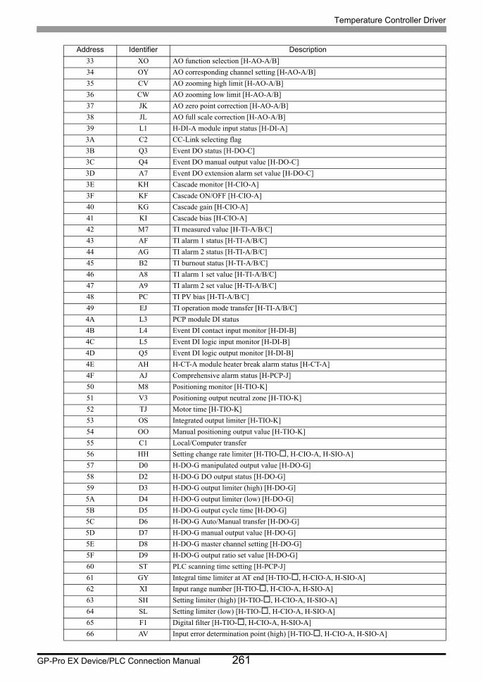
Temperature Controller Driver
GP-Pro EX Device/PLC Connection Manual 261
33 XO AO function selection [H-AO-A/B]
34 OY AO corresponding channel setting [H-AO-A/B]
35 CV AO zooming high limit [H-AO-A/B]
36 CW AO zooming low limit [H-AO-A/B]
37 JK AO zero point correction [H-AO-A/B]
38 JL AO full scale correction [H-AO-A/B]
39 L1 H-DI-A module input status [H-DI-A]
3A C2 CC-Link selecting flag
3B Q3 Event DO status [H-DO-C]
3C Q4 Event DO manual output value [H-DO-C]
3D A7 Event DO extension alarm set value [H-DO-C]
3E KH Cascade monitor [H-CIO-A]
3F KF Cascade ON/OFF [H-CIO-A]
40 KG Cascade gain [H-CIO-A]
41 KI Cascade bias [H-CIO-A]
42 M7 TI measured value [H-TI-A/B/C]
43 AF TI alarm 1 status [H-TI-A/B/C]
44 AG TI alarm 2 status [H-TI-A/B/C]
45 B2 TI burnout status [H-TI-A/B/C]
46 A8 TI alarm 1 set value [H-TI-A/B/C]
47 A9 TI alarm 2 set value [H-TI-A/B/C]
48 PC TI PV bias [H-TI-A/B/C]
49 EJ TI operation mode transfer [H-TI-A/B/C]
4A L3 PCP module DI status
4B L4 Event DI contact input monitor [H-DI-B]
4C L5 Event DI logic input monitor [H-DI-B]
4D Q5 Event DI logic output monitor [H-DI-B]
4E AH H-CT-A module heater break alarm status [H-CT-A]
4F AJ Comprehensive alarm status [H-PCP-J]
50 M8 Positioning monitor [H-TIO-K]
51 V3 Positioning output neutral zone [H-TIO-K]
52 TJ Motor time [H-TIO-K]
53 OS Integrated output limiter [H-TIO-K]
54 OO Manual positioning output value [H-TIO-K]
55 C1 Local/Computer transfer
56 HH Setting change rate limiter [H-TIO-, H-CIO-A, H-SIO-A]
57 D0 H-DO-G manipulated output value [H-DO-G]
58 D2 H-DO-G DO output status [H-DO-G]
59 D3 H-DO-G output limiter (high) [H-DO-G]
5A D4 H-DO-G output limiter (low) [H-DO-G]
5B D5 H-DO-G output cycle time [H-DO-G]
5C D6 H-DO-G Auto/Manual transfer [H-DO-G]
5D D7 H-DO-G manual output value [H-DO-G]
5E D8 H-DO-G master channel setting [H-DO-G]
5F D9 H-DO-G output ratio set value [H-DO-G]
60 ST PLC scanning time setting [H-PCP-J]
61 GY Integral time limiter at AT end [H-TIO-, H-CIO-A, H-SIO-A]
62 XI Input range number [H-TIO-, H-CIO-A, H-SIO-A]
63 SH Setting limiter (high) [H-TIO-, H-CIO-A, H-SIO-A]
64 SL Setting limiter (low) [H-TIO-, H-CIO-A, H-SIO-A]
65 F1 Digital filter [H-TIO-, H-CIO-A, H-SIO-A]
66 AV Input error determination point (high) [H-TIO-, H-CIO-A, H-SIO-A]
Address Identifier Description

Temperature Controller Driver
GP-Pro EX Device/PLC Connection Manual 262
67 AW Input error determination point (low) [H-TIO-, H-CIO-A, H-SIO-A]
68 WH Action at input error (high) [H-TIO-, H-CIO-A, H-SIO-A]
69 WL Action at input error (low) [H-TIO-, H-CIO-A, H-SIO-A]
6A GB AT bias [H-TIO-, H-CIO-A, H-SIO-A]
6B OHOutput limiter (high) [For heat/cool control:Heat-side output limiter (high)] [H-TIO-, H-CIO-A, H-SIO-A]
6C OLOutput limiter (low) [For heat/cool control:Cool-side output limiter (high)] [H-TIO-, H-CIO-A, H-SIO-A]
6D IV ON/OFF control differential gap (upper) [H-TIO-, H-CIO-A, H-SIO-A]
6E IW ON/OFF control differential gap (lower) [H-TIO-, H-CIO-A, H-SIO-A]
6F OE Manipulated output value at input error [H-TIO-, H-CIO-A, H-SIO-A]
70 PH Output change rate limiter (up) [H-TIO-, H-CIO-A, H-SIO-A]
71 PL Output change rate limiter (down) [H-TIO-, H-CIO-A, H-SIO-A]
72 XE Direct/Reverse action selection [H-TIO-, H-CIO-A, H-SIO-A]
73 XN Hot/Cold start selection [H-TIO-, H-CIO-A, H-SIO-A]
74 SX Start determination point [H-TIO-, H-CIO-A]
75 X1 Control RUN/STOP holding [H-PCP-J]
76 EK Temperature rise completion hold function [H-PCP-J]
77 ZX Interval time setting COM.PORT1/COM.PORT2 [H-PCP-J]
78 ZY Interval time setting COM.PORT3 [H-PCP-J]
79 HA Alarm 1 differential gap [H-TIO-, H-CIO-A, H-SIO-A]
7A HB Alarm 2 differential gap [H-TIO-, H-CIO-A, H-SIO-A]
7B XA Alarm 1 type selection [H-TIO-, H-CIO-A, H-SIO-A]
7C XB Alarm 2 type selection [H-TIO-, H-CIO-A, H-SIO-A]
7D WA Alarm 1 hold action [H-TIO-, H-CIO-A, H-SIO-A]
7E WB Alarm 2 hold action [H-TIO-, H-CIO-A, H-SIO-A]
7F LA Alarm 1 interlock [H-TIO-, H-CIO-A, H-SIO-A]
80 LB Alarm 2 interlock [H-TIO-, H-CIO-A, H-SIO-A]
81 OA Alarm 1 action at input error [H-TIO-, H-CIO-A, H-SIO-A]
82 OB Alarm 2 action at input error [H-TIO-, H-CIO-A, H-SIO-A]
83 DF Number of alarm delay times [H-TIO-, H-CIO-A, H-SIO-A]
84 CL Module initialization [H-PCP-J]
85 ZF CT channel setting [H-CT-A]
86 LT DO function selection [H-DO-A/B/D]
87 XK DI function selection [H-DI-A]
88 H2 DI using selection [H-DI-A]
89 VK AI input range number [H-AI-A/B]
8A JS AI display scale high [H-AI-A/B]
8B JV AI display scale low [H-AI-A/B]
8C HC AI alarm 1 differential gap [H-AI-A/B]
8D HF AI alarm 2 differential gap [H-AI-A/B]
8E XC AI alarm 1 type selection [H-AI-A/B]
8F XD AI alarm 2 type selection [H-AI-A/B]
90 WC AI alarm 1 hold action [H-AI-A/B]
91 WD AI alarm 2 hold action [H-AI-A/B]
92 LC AI alarm 1 interlock [H-AI-A/B]
93 LD AI alarm 2 interlock [H-AI-A/B]
94 TK Number of AI alarm delay times [H-AI-A/B]
95 JU AI decimal point position [H-AI-A/B]
96 JT Power supply frequency selection [H-PCP-J]
97 F2 AI digital filter [H-AI-A/B]
98 VA AI moving average [H-AI-A/B]
99 XV Display scale high [H-TIO-H/J,H-CIO-A,H-SIO-A]
Address Identifier Description
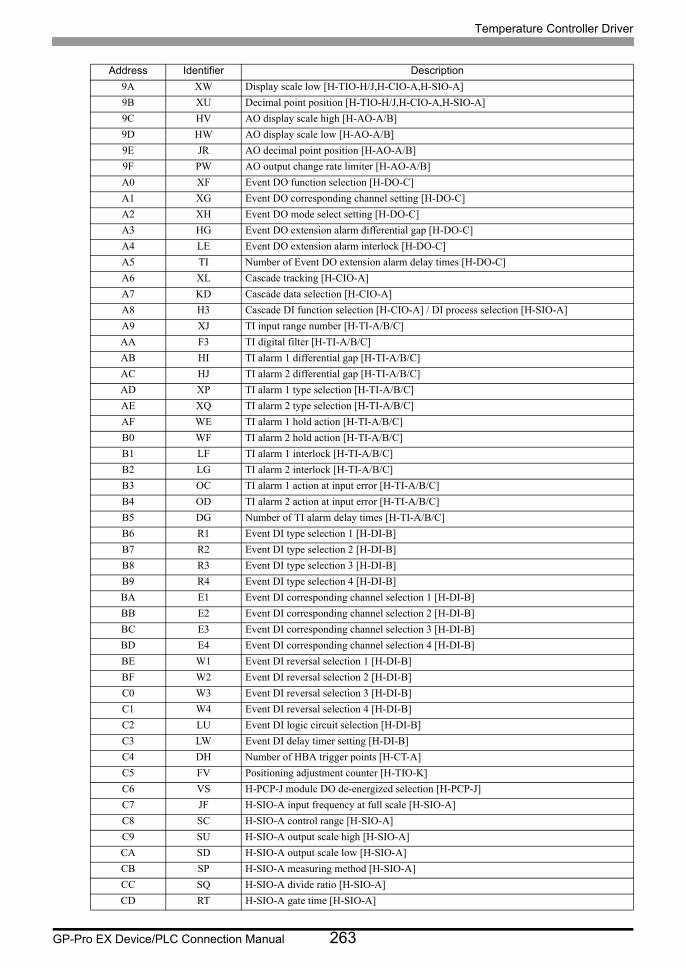
Temperature Controller Driver
GP-Pro EX Device/PLC Connection Manual 263
9A XW Display scale low [H-TIO-H/J,H-CIO-A,H-SIO-A]
9B XU Decimal point position [H-TIO-H/J,H-CIO-A,H-SIO-A]
9C HV AO display scale high [H-AO-A/B]
9D HW AO display scale low [H-AO-A/B]
9E JR AO decimal point position [H-AO-A/B]
9F PW AO output change rate limiter [H-AO-A/B]
A0 XF Event DO function selection [H-DO-C]
A1 XG Event DO corresponding channel setting [H-DO-C]
A2 XH Event DO mode select setting [H-DO-C]
A3 HG Event DO extension alarm differential gap [H-DO-C]
A4 LE Event DO extension alarm interlock [H-DO-C]
A5 TI Number of Event DO extension alarm delay times [H-DO-C]
A6 XL Cascade tracking [H-CIO-A]
A7 KD Cascade data selection [H-CIO-A]
A8 H3 Cascade DI function selection [H-CIO-A] / DI process selection [H-SIO-A]
A9 XJ TI input range number [H-TI-A/B/C]
AA F3 TI digital filter [H-TI-A/B/C]
AB HI TI alarm 1 differential gap [H-TI-A/B/C]
AC HJ TI alarm 2 differential gap [H-TI-A/B/C]
AD XP TI alarm 1 type selection [H-TI-A/B/C]
AE XQ TI alarm 2 type selection [H-TI-A/B/C]
AF WE TI alarm 1 hold action [H-TI-A/B/C]
B0 WF TI alarm 2 hold action [H-TI-A/B/C]
B1 LF TI alarm 1 interlock [H-TI-A/B/C]
B2 LG TI alarm 2 interlock [H-TI-A/B/C]
B3 OC TI alarm 1 action at input error [H-TI-A/B/C]
B4 OD TI alarm 2 action at input error [H-TI-A/B/C]
B5 DG Number of TI alarm delay times [H-TI-A/B/C]
B6 R1 Event DI type selection 1 [H-DI-B]
B7 R2 Event DI type selection 2 [H-DI-B]
B8 R3 Event DI type selection 3 [H-DI-B]
B9 R4 Event DI type selection 4 [H-DI-B]
BA E1 Event DI corresponding channel selection 1 [H-DI-B]
BB E2 Event DI corresponding channel selection 2 [H-DI-B]
BC E3 Event DI corresponding channel selection 3 [H-DI-B]
BD E4 Event DI corresponding channel selection 4 [H-DI-B]
BE W1 Event DI reversal selection 1 [H-DI-B]
BF W2 Event DI reversal selection 2 [H-DI-B]
C0 W3 Event DI reversal selection 3 [H-DI-B]
C1 W4 Event DI reversal selection 4 [H-DI-B]
C2 LU Event DI logic circuit selection [H-DI-B]
C3 LW Event DI delay timer setting [H-DI-B]
C4 DH Number of HBA trigger points [H-CT-A]
C5 FV Positioning adjustment counter [H-TIO-K]
C6 VS H-PCP-J module DO de-energized selection [H-PCP-J]
C7 JF H-SIO-A input frequency at full scale [H-SIO-A]
C8 SC H-SIO-A control range [H-SIO-A]
C9 SU H-SIO-A output scale high [H-SIO-A]
CA SD H-SIO-A output scale low [H-SIO-A]
CB SP H-SIO-A measuring method [H-SIO-A]
CC SQ H-SIO-A divide ratio [H-SIO-A]
CD RT H-SIO-A gate time [H-SIO-A]
Address Identifier Description
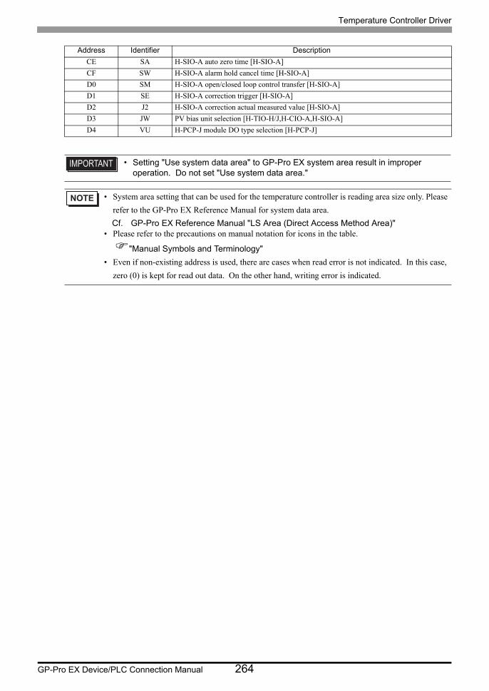
Temperature Controller Driver
GP-Pro EX Device/PLC Connection Manual 264
CE SA H-SIO-A auto zero time [H-SIO-A]
CF SW H-SIO-A alarm hold cancel time [H-SIO-A]
D0 SM H-SIO-A open/closed loop control transfer [H-SIO-A]
D1 SE H-SIO-A correction trigger [H-SIO-A]
D2 J2 H-SIO-A correction actual measured value [H-SIO-A]
D3 JW PV bias unit selection [H-TIO-H/J,H-CIO-A,H-SIO-A]
D4 VU H-PCP-J module DO type selection [H-PCP-J]
• Setting "Use system data area" to GP-Pro EX system area result in improper operation. Do not set "Use system data area."
• System area setting that can be used for the temperature controller is reading area size only. Please
refer to the GP-Pro EX Reference Manual for system data area.
Cf. GP-Pro EX Reference Manual "LS Area (Direct Access Method Area)"• Please refer to the precautions on manual notation for icons in the table.
"Manual Symbols and Terminology"
• Even if non-existing address is used, there are cases when read error is not indicated. In this case,
zero (0) is kept for read out data. On the other hand, writing error is indicated.
Address Identifier Description
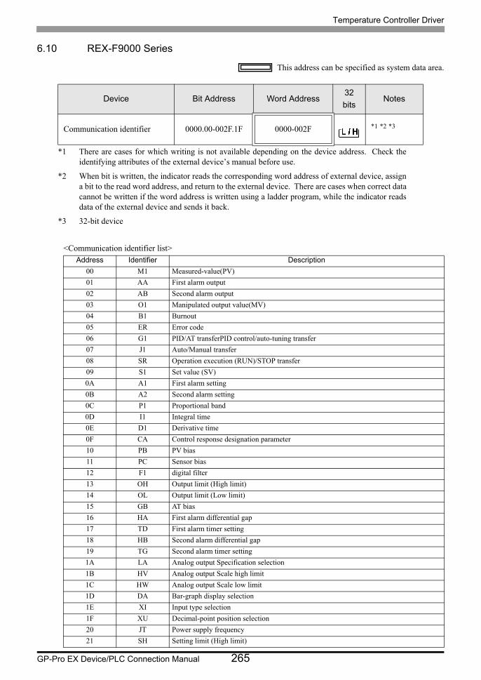
Temperature Controller Driver
GP-Pro EX Device/PLC Connection Manual 265
6.10 REX-F9000 Series
This address can be specified as system data area.
<Communication identifier list>
Device Bit Address Word Address32
bitsNotes
Communication identifier 0000.00-002F.1F 0000-002F *1 *2 *3
*1 There are cases for which writing is not available depending on the device address. Check the identifying attributes of the external device’s manual before use.
*2 When bit is written, the indicator reads the corresponding word address of external device, assign a bit to the read word address, and return to the external device. There are cases when correct data cannot be written if the word address is written using a ladder program, while the indicator reads data of the external device and sends it back.
*3 32-bit device
Address Identifier Description
00 M1 Measured-value(PV)
01 AA First alarm output
02 AB Second alarm output
03 O1 Manipulated output value(MV)
04 B1 Burnout
05 ER Error code
06 G1 PID/AT transferPID control/auto-tuning transfer
07 J1 Auto/Manual transfer
08 SR Operation execution (RUN)/STOP transfer
09 S1 Set value (SV)
0A A1 First alarm setting
0B A2 Second alarm setting
0C P1 Proportional band
0D I1 Integral time
0E D1 Derivative time
0F CA Control response designation parameter
10 PB PV bias
11 PC Sensor bias
12 F1 digital filter
13 OH Output limit (High limit)
14 OL Output limit (Low limit)
15 GB AT bias
16 HA First alarm differential gap
17 TD First alarm timer setting
18 HB Second alarm differential gap
19 TG Second alarm timer setting
1A LA Analog output Specification selection
1B HV Analog output Scale high limit
1C HW Analog output Scale low limit
1D DA Bar-graph display selection
1E XI Input type selection
1F XU Decimal-point position selection
20 JT Power supply frequency
21 SH Setting limit (High limit)
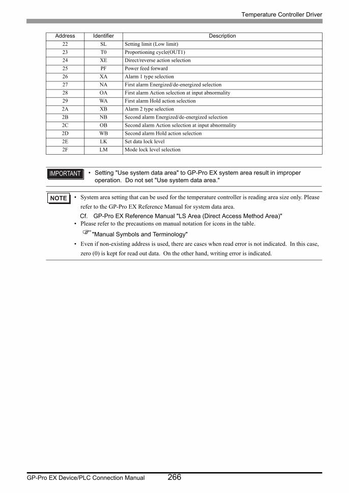
Temperature Controller Driver
GP-Pro EX Device/PLC Connection Manual 266
22 SL Setting limit (Low limit)
23 T0 Proportioning cycle(OUT1)
24 XE Direct/reverse action selection
25 PF Power feed forward
26 XA Alarm 1 type selection
27 NA First alarm Energized/de-energized selection
28 OA First alarm Action selection at input abnormality
29 WA First alarm Hold action selection
2A XB Alarm 2 type selection
2B NB Second alarm Energized/de-energized selection
2C OB Second alarm Action selection at input abnormality
2D WB Second alarm Hold action selection
2E LK Set data lock level
2F LM Mode lock level selection
• Setting "Use system data area" to GP-Pro EX system area result in improper operation. Do not set "Use system data area."
• System area setting that can be used for the temperature controller is reading area size only. Please
refer to the GP-Pro EX Reference Manual for system data area.
Cf. GP-Pro EX Reference Manual "LS Area (Direct Access Method Area)"• Please refer to the precautions on manual notation for icons in the table.
"Manual Symbols and Terminology"
• Even if non-existing address is used, there are cases when read error is not indicated. In this case,
zero (0) is kept for read out data. On the other hand, writing error is indicated.
Address Identifier Description
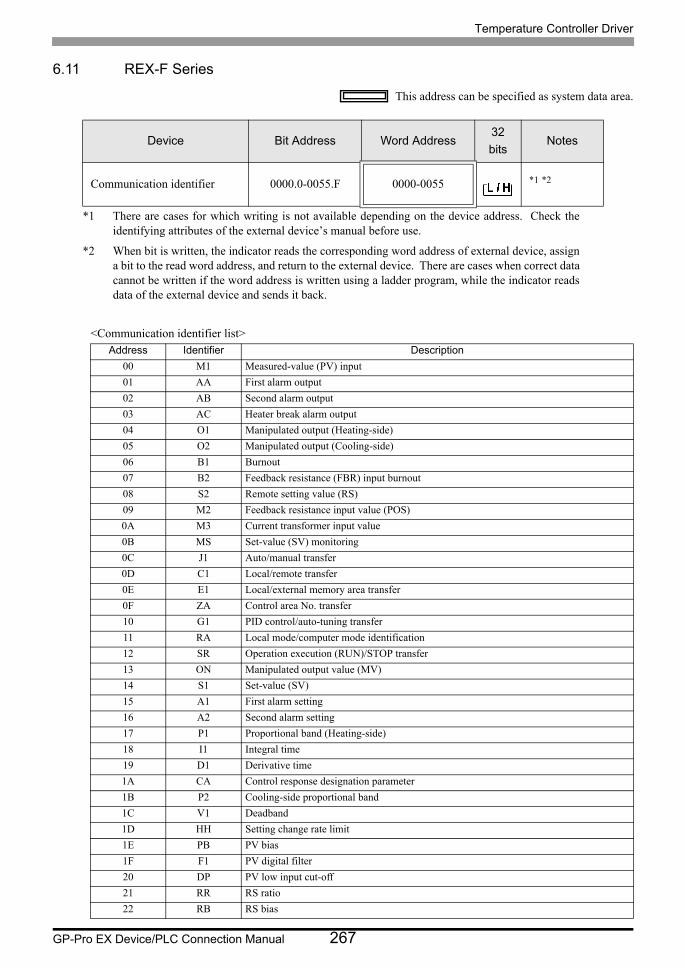
Temperature Controller Driver
GP-Pro EX Device/PLC Connection Manual 267
6.11 REX-F Series
This address can be specified as system data area.
<Communication identifier list>
Device Bit Address Word Address32
bitsNotes
Communication identifier 0000.0-0055.F 0000-0055 *1 *2
*1 There are cases for which writing is not available depending on the device address. Check the identifying attributes of the external device’s manual before use.
*2 When bit is written, the indicator reads the corresponding word address of external device, assign a bit to the read word address, and return to the external device. There are cases when correct data cannot be written if the word address is written using a ladder program, while the indicator reads data of the external device and sends it back.
Address Identifier Description
00 M1 Measured-value (PV) input
01 AA First alarm output
02 AB Second alarm output
03 AC Heater break alarm output
04 O1 Manipulated output (Heating-side)
05 O2 Manipulated output (Cooling-side)
06 B1 Burnout
07 B2 Feedback resistance (FBR) input burnout
08 S2 Remote setting value (RS)
09 M2 Feedback resistance input value (POS)
0A M3 Current transformer input value
0B MS Set-value (SV) monitoring
0C J1 Auto/manual transfer
0D C1 Local/remote transfer
0E E1 Local/external memory area transfer
0F ZA Control area No. transfer
10 G1 PID control/auto-tuning transfer
11 RA Local mode/computer mode identification
12 SR Operation execution (RUN)/STOP transfer
13 ON Manipulated output value (MV)
14 S1 Set-value (SV)
15 A1 First alarm setting
16 A2 Second alarm setting
17 P1 Proportional band (Heating-side)
18 I1 Integral time
19 D1 Derivative time
1A CA Control response designation parameter
1B P2 Cooling-side proportional band
1C V1 Deadband
1D HH Setting change rate limit
1E PB PV bias
1F F1 PV digital filter
20 DP PV low input cut-off
21 RR RS ratio
22 RB RS bias
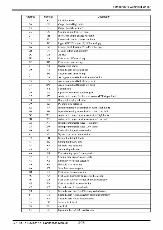
Temperature Controller Driver
GP-Pro EX Device/PLC Connection Manual 268
23 F2 RS digital filter
24 OH Output limit (High limit)
25 OL Output limit (Low limit)
26 OQ Cooling output Min. ON time
27 PH Increase in output change rate limit
28 PL Decrease in output change rate limit
29 IV Upper ON/OFF action (A) differential gap
2A IW Lower ON/OFF action (A) differential gap
2B OE Manual output at abnormality
2C GB AT bias
2D HA First alarm differential gap
2E TD First alarm timer setting
2F A3 Heater break alarm
30 HB Second alarm differential gap
31 TG Second alarm timer setting
32 LA Analog output (AO) Specification selection
33 HV Analog output (AO) Scale high limit
34 HW Analog output (AO) Scale low limit
35 V2 Neutral zone
36 VH Open/close output differential gap
37 SY Action selection at feedback resistance (FBR) input break
38 DA Bar-graph display selection
39 XI PV input type selection
3A AV Input abnormality determination point (High limit)
3B AW Input abnormality determination point (Low limit)
3C WH Action selection at input abnormality (High limit)
3D WL Action selection at input abnormality (Low limit)
3E XV Input programmable range (High limit)
3F XW Input programmable range (Low limit)
40 XU Decimal-point position selection
41 XH Square root extraction selection
42 SH Setting limit (High limit)
43 SL Setting limit (Low limit)
44 XR RS input type selection
45 XL SV tracking selection
46 T0 Proportioning cycle (Heating-side)
47 T1 Cooling-side proportioning cycle
48 XE Direct/reverse action selection
49 XN Hot/cold start selection
4A SX Start determination point
4B XA First alarm Action selection
4C NA First alarm Energized/de-energized selection
4D OA First alarm Action selection at input abnormality
4E WA First alarm Hold action selection
4F XB Second alarm Action selection
50 NB Second alarm Energized/de-energized selection
51 OB Second alarm Action selection at input abnormality
52 WB Second alarm Hold action selection
53 LK Set data lock level
54 LL area lock
55 DH Operation RUN/STOP display lock
Address Identifier Description

Temperature Controller Driver
GP-Pro EX Device/PLC Connection Manual 269
• Setting "Use system data area" to GP-Pro EX system area result in improper operation. Do not set "Use system data area."
• System area setting that can be used for the temperature controller is reading area size only. Please
refer to the GP-Pro EX Reference Manual for system data area.
Cf. GP-Pro EX Reference Manual "LS Area (Direct Access Method Area)"• Please refer to the precautions on manual notation for icons in the table.
"Manual Symbols and Terminology"
• Even if non-existing address is used, there are cases when read error is not indicated. In this case,
zero (0) is kept for read out data. On the other hand, writing error is indicated.
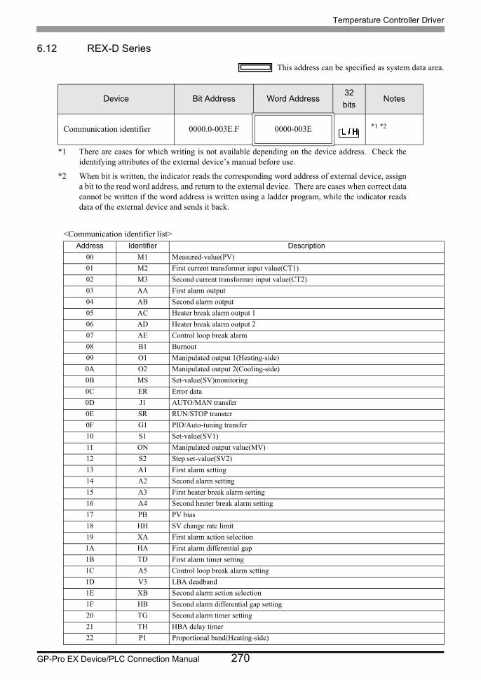
Temperature Controller Driver
GP-Pro EX Device/PLC Connection Manual 270
6.12 REX-D Series
This address can be specified as system data area.
<Communication identifier list>
Device Bit Address Word Address32
bitsNotes
Communication identifier 0000.0-003E.F 0000-003E *1 *2
*1 There are cases for which writing is not available depending on the device address. Check the identifying attributes of the external device’s manual before use.
*2 When bit is written, the indicator reads the corresponding word address of external device, assign a bit to the read word address, and return to the external device. There are cases when correct data cannot be written if the word address is written using a ladder program, while the indicator reads data of the external device and sends it back.
Address Identifier Description
00 M1 Measured-value(PV)
01 M2 First current transformer input value(CT1)
02 M3 Second current transformer input value(CT2)
03 AA First alarm output
04 AB Second alarm output
05 AC Heater break alarm output 1
06 AD Heater break alarm output 2
07 AE Control loop break alarm
08 B1 Burnout
09 O1 Manipulated output 1(Heating-side)
0A O2 Manipulated output 2(Cooling-side)
0B MS Set-value(SV)monitoring
0C ER Error data
0D J1 AUTO/MAN transfer
0E SR RUN/STOP transter
0F G1 PID/Auto-tuning transfer
10 S1 Set-value(SV1)
11 ON Manipulated output value(MV)
12 S2 Step set-value(SV2)
13 A1 First alarm setting
14 A2 Second alarm setting
15 A3 First heater break alarm setting
16 A4 Second heater break alarm setting
17 PB PV bias
18 HH SV change rate limit
19 XA First alarm action selection
1A HA First alarm differential gap
1B TD First alarm timer setting
1C A5 Control loop break alarm setting
1D V3 LBA deadband
1E XB Second alarm action selection
1F HB Second alarm differential gap setting
20 TG Second alarm timer setting
21 TH HBA delay timer
22 P1 Proportional band(Heating-side)
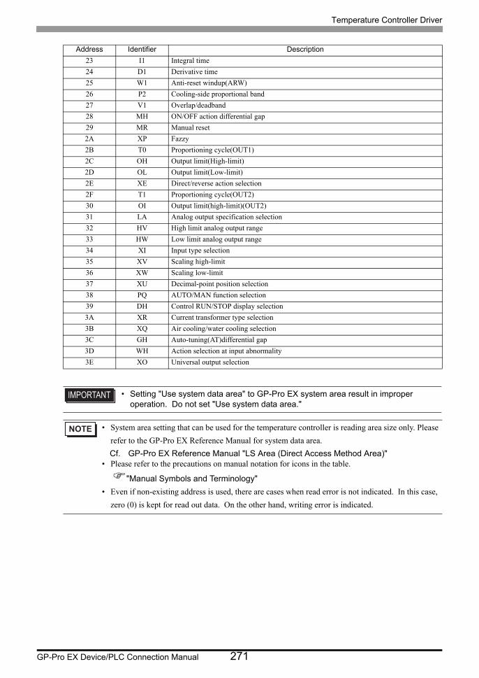
Temperature Controller Driver
GP-Pro EX Device/PLC Connection Manual 271
23 I1 Integral time
24 D1 Derivative time
25 W1 Anti-reset windup(ARW)
26 P2 Cooling-side proportional band
27 V1 Overlap/deadband
28 MH ON/OFF action differential gap
29 MR Manual reset
2A XP Fazzy
2B T0 Proportioning cycle(OUT1)
2C OH Output limit(High-limit)
2D OL Output limit(Low-limit)
2E XE Direct/reverse action selection
2F T1 Proportioning cycle(OUT2)
30 OI Output limit(high-limit)(OUT2)
31 LA Analog output specification selection
32 HV High limit analog output range
33 HW Low limit analog output range
34 XI Input type selection
35 XV Scaling high-limit
36 XW Scaling low-limit
37 XU Decimal-point position selection
38 PQ AUTO/MAN function selection
39 DH Control RUN/STOP display selection
3A XR Current transformer type selection
3B XQ Air cooling/water cooling selection
3C GH Auto-tuning(AT)differential gap
3D WH Action selection at input abnormality
3E XO Universal output selection
• Setting "Use system data area" to GP-Pro EX system area result in improper operation. Do not set "Use system data area."
• System area setting that can be used for the temperature controller is reading area size only. Please
refer to the GP-Pro EX Reference Manual for system data area.
Cf. GP-Pro EX Reference Manual "LS Area (Direct Access Method Area)"• Please refer to the precautions on manual notation for icons in the table.
"Manual Symbols and Terminology"
• Even if non-existing address is used, there are cases when read error is not indicated. In this case,
zero (0) is kept for read out data. On the other hand, writing error is indicated.
Address Identifier Description
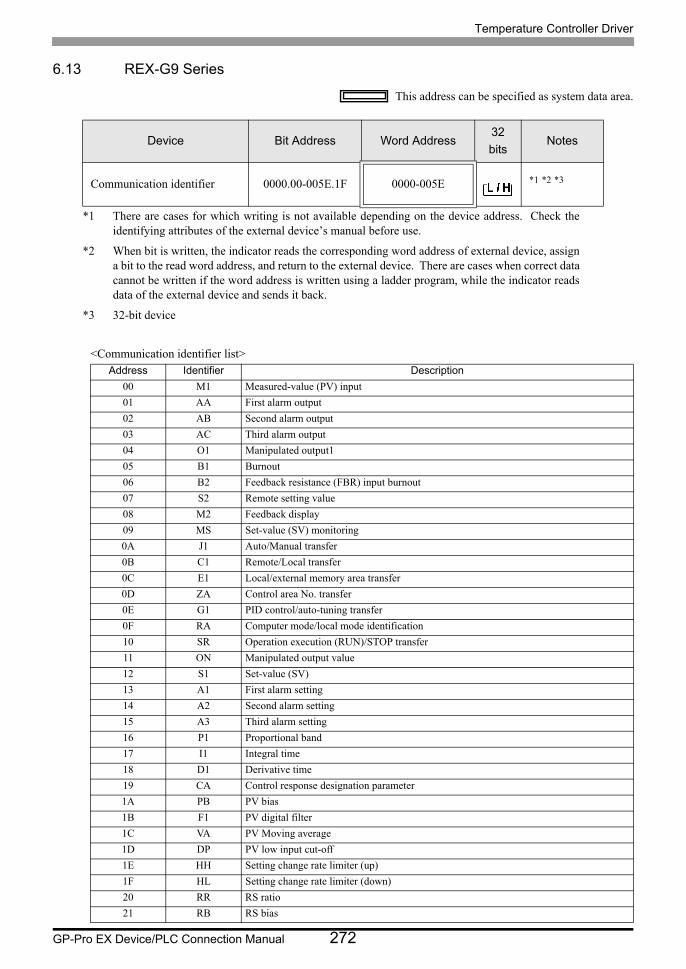
Temperature Controller Driver
GP-Pro EX Device/PLC Connection Manual 272
6.13 REX-G9 Series
This address can be specified as system data area.
<Communication identifier list>
Device Bit Address Word Address32
bitsNotes
Communication identifier 0000.00-005E.1F 0000-005E *1 *2 *3
*1 There are cases for which writing is not available depending on the device address. Check the identifying attributes of the external device’s manual before use.
*2 When bit is written, the indicator reads the corresponding word address of external device, assign a bit to the read word address, and return to the external device. There are cases when correct data cannot be written if the word address is written using a ladder program, while the indicator reads data of the external device and sends it back.
*3 32-bit device
Address Identifier Description
00 M1 Measured-value (PV) input
01 AA First alarm output
02 AB Second alarm output
03 AC Third alarm output
04 O1 Manipulated output1
05 B1 Burnout
06 B2 Feedback resistance (FBR) input burnout
07 S2 Remote setting value
08 M2 Feedback display
09 MS Set-value (SV) monitoring
0A J1 Auto/Manual transfer
0B C1 Remote/Local transfer
0C E1 Local/external memory area transfer
0D ZA Control area No. transfer
0E G1 PID control/auto-tuning transfer
0F RA Computer mode/local mode identification
10 SR Operation execution (RUN)/STOP transfer
11 ON Manipulated output value
12 S1 Set-value (SV)
13 A1 First alarm setting
14 A2 Second alarm setting
15 A3 Third alarm setting
16 P1 Proportional band
17 I1 Integral time
18 D1 Derivative time
19 CA Control response designation parameter
1A PB PV bias
1B F1 PV digital filter
1C VA PV Moving average
1D DP PV low input cut-off
1E HH Setting change rate limiter (up)
1F HL Setting change rate limiter (down)
20 RR RS ratio
21 RB RS bias
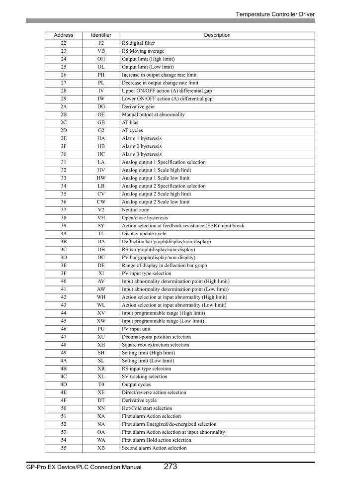
Temperature Controller Driver
GP-Pro EX Device/PLC Connection Manual 273
22 F2 RS digital filter
23 VB RS Moving average
24 OH Output limit (High limit)
25 OL Output limit (Low limit)
26 PH Increase in output change rate limit
27 PL Decrease in output change rate limit
28 IV Upper ON/OFF action (A) differential gap
29 IW Lower ON/OFF action (A) differential gap
2A DG Derivative gain
2B OE Manual output at abnormality
2C GB AT bias
2D G2 AT cycles
2E HA Alarm 1 hysteresis
2F HB Alarm 2 hysteresis
30 HC Alarm 3 hysteresis
31 LA Analog output 1 Specification selection
32 HV Analog output 1 Scale high limit
33 HW Analog output 1 Scale low limit
34 LB Analog output 2 Specification selection
35 CV Analog output 2 Scale high limit
36 CW Analog output 2 Scale low limit
37 V2 Neutral zone
38 VH Open/close hysteresis
39 SY Action selection at feedback resistance (FBR) input break
3A TL Display update cycle
3B DA Deflection bar graph(display/non-display)
3C DB RS bar graph(display/non-display)
3D DC PV bar graph(display/non-display)
3E DE Range of display in deflection bar graph
3F XI PV input type selection
40 AV Input abnormality determination point (High limit)
41 AW Input abnormality determination point (Low limit)
42 WH Action selection at input abnormality (High limit)
43 WL Action selection at input abnormality (Low limit)
44 XV Input programmable range (High limit)
45 XW Input programmable range (Low limit)
46 PU PV input unit
47 XU Decimal-point position selection
48 XH Square root extraction selection
49 SH Setting limit (High limit)
4A SL Setting limit (Low limit)
4B XR RS input type selection
4C XL SV tracking selection
4D T0 Output cycles
4E XE Direct/reverse action selection
4F DT Derivative cycle
50 XN Hot/Cold start selection
51 XA First alarm Action selection
52 NA First alarm Energized/de-energized selection
53 OA First alarm Action selection at input abnormality
54 WA First alarm Hold action selection
55 XB Second alarm Action selection
Address Identifier Description
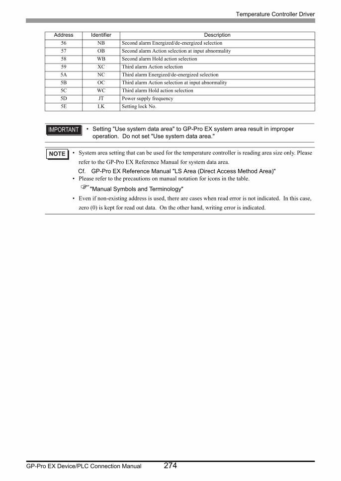
Temperature Controller Driver
GP-Pro EX Device/PLC Connection Manual 274
56 NB Second alarm Energized/de-energized selection
57 OB Second alarm Action selection at input abnormality
58 WB Second alarm Hold action selection
59 XC Third alarm Action selection
5A NC Third alarm Energized/de-energized selection
5B OC Third alarm Action selection at input abnormality
5C WC Third alarm Hold action selection
5D JT Power supply frequency
5E LK Setting lock No.
• Setting "Use system data area" to GP-Pro EX system area result in improper operation. Do not set "Use system data area."
• System area setting that can be used for the temperature controller is reading area size only. Please
refer to the GP-Pro EX Reference Manual for system data area.
Cf. GP-Pro EX Reference Manual "LS Area (Direct Access Method Area)"• Please refer to the precautions on manual notation for icons in the table.
"Manual Symbols and Terminology"
• Even if non-existing address is used, there are cases when read error is not indicated. In this case,
zero (0) is kept for read out data. On the other hand, writing error is indicated.
Address Identifier Description
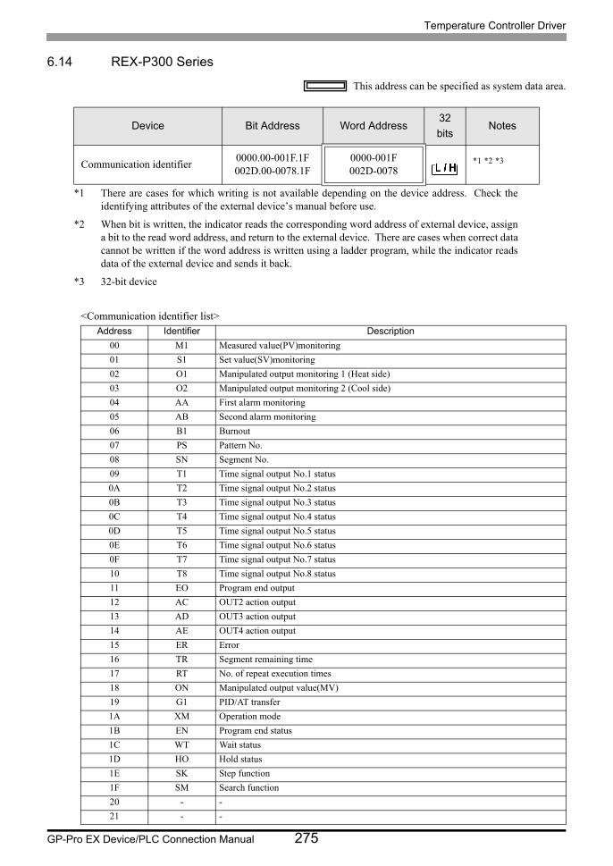
Temperature Controller Driver
GP-Pro EX Device/PLC Connection Manual 275
6.14 REX-P300 Series
This address can be specified as system data area.
<Communication identifier list>
Device Bit Address Word Address32
bitsNotes
Communication identifier0000.00-001F.1F002D.00-0078.1F
0000-001F002D-0078
*1 *2 *3
*1 There are cases for which writing is not available depending on the device address. Check the identifying attributes of the external device’s manual before use.
*2 When bit is written, the indicator reads the corresponding word address of external device, assign a bit to the read word address, and return to the external device. There are cases when correct data cannot be written if the word address is written using a ladder program, while the indicator reads data of the external device and sends it back.
*3 32-bit device
Address Identifier Description
00 M1 Measured value(PV)monitoring
01 S1 Set value(SV)monitoring
02 O1 Manipulated output monitoring 1 (Heat side)
03 O2 Manipulated output monitoring 2 (Cool side)
04 AA First alarm monitoring
05 AB Second alarm monitoring
06 B1 Burnout
07 PS Pattern No.
08 SN Segment No.
09 T1 Time signal output No.1 status
0A T2 Time signal output No.2 status
0B T3 Time signal output No.3 status
0C T4 Time signal output No.4 status
0D T5 Time signal output No.5 status
0E T6 Time signal output No.6 status
0F T7 Time signal output No.7 status
10 T8 Time signal output No.8 status
11 EO Program end output
12 AC OUT2 action output
13 AD OUT3 action output
14 AE OUT4 action output
15 ER Error
16 TR Segment remaining time
17 RT No. of repeat execution times
18 ON Manipulated output value(MV)
19 G1 PID/AT transfer
1A XM Operation mode
1B EN Program end status
1C WT Wait status
1D HO Hold status
1E SK Step function
1F SM Search function
20 - -
21 - -
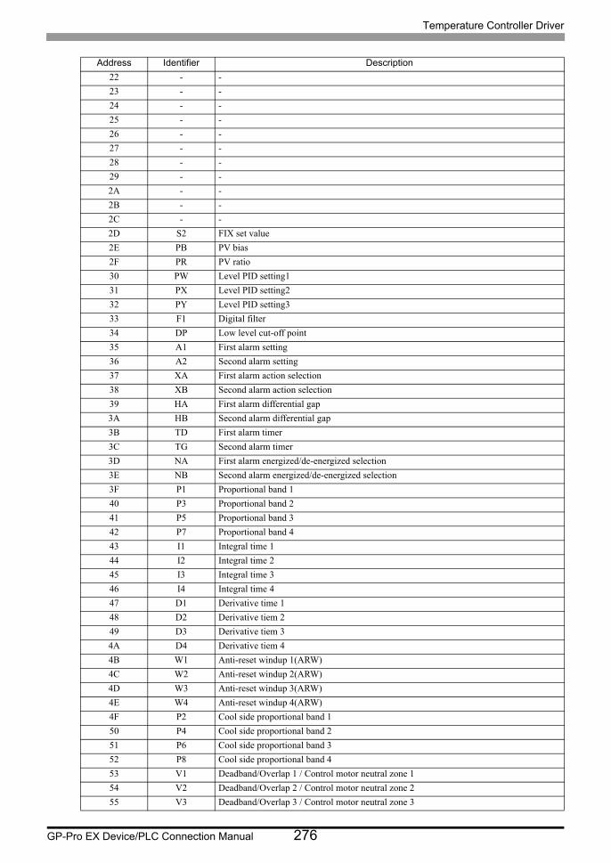
Temperature Controller Driver
GP-Pro EX Device/PLC Connection Manual 276
22 - -
23 - -
24 - -
25 - -
26 - -
27 - -
28 - -
29 - -
2A - -
2B - -
2C - -
2D S2 FIX set value
2E PB PV bias
2F PR PV ratio
30 PW Level PID setting1
31 PX Level PID setting2
32 PY Level PID setting3
33 F1 Digital filter
34 DP Low level cut-off point
35 A1 First alarm setting
36 A2 Second alarm setting
37 XA First alarm action selection
38 XB Second alarm action selection
39 HA First alarm differential gap
3A HB Second alarm differential gap
3B TD First alarm timer
3C TG Second alarm timer
3D NA First alarm energized/de-energized selection
3E NB Second alarm energized/de-energized selection
3F P1 Proportional band 1
40 P3 Proportional band 2
41 P5 Proportional band 3
42 P7 Proportional band 4
43 I1 Integral time 1
44 I2 Integral time 2
45 I3 Integral time 3
46 I4 Integral time 4
47 D1 Derivative time 1
48 D2 Derivative tiem 2
49 D3 Derivative tiem 3
4A D4 Derivative tiem 4
4B W1 Anti-reset windup 1(ARW)
4C W2 Anti-reset windup 2(ARW)
4D W3 Anti-reset windup 3(ARW)
4E W4 Anti-reset windup 4(ARW)
4F P2 Cool side proportional band 1
50 P4 Cool side proportional band 2
51 P6 Cool side proportional band 3
52 P8 Cool side proportional band 4
53 V1 Deadband/Overlap 1 / Control motor neutral zone 1
54 V2 Deadband/Overlap 2 / Control motor neutral zone 2
55 V3 Deadband/Overlap 3 / Control motor neutral zone 3
Address Identifier Description
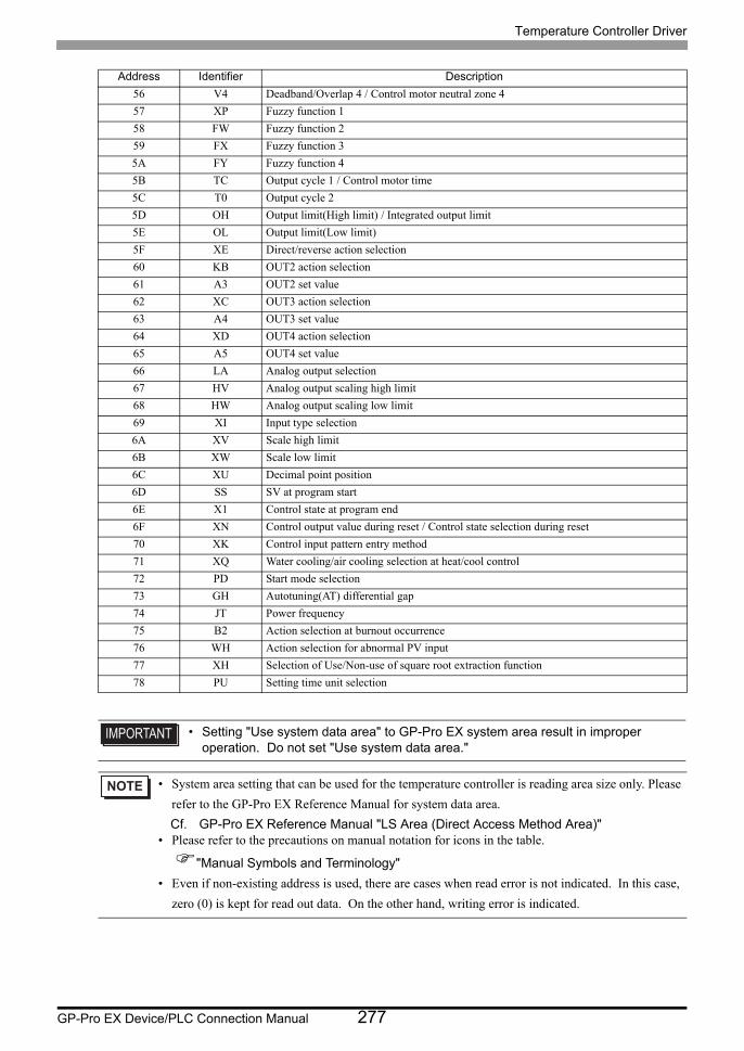
Temperature Controller Driver
GP-Pro EX Device/PLC Connection Manual 277
56 V4 Deadband/Overlap 4 / Control motor neutral zone 4
57 XP Fuzzy function 1
58 FW Fuzzy function 2
59 FX Fuzzy function 3
5A FY Fuzzy function 4
5B TC Output cycle 1 / Control motor time
5C T0 Output cycle 2
5D OH Output limit(High limit) / Integrated output limit
5E OL Output limit(Low limit)
5F XE Direct/reverse action selection
60 KB OUT2 action selection
61 A3 OUT2 set value
62 XC OUT3 action selection
63 A4 OUT3 set value
64 XD OUT4 action selection
65 A5 OUT4 set value
66 LA Analog output selection
67 HV Analog output scaling high limit
68 HW Analog output scaling low limit
69 XI Input type selection
6A XV Scale high limit
6B XW Scale low limit
6C XU Decimal point position
6D SS SV at program start
6E X1 Control state at program end
6F XN Control output value during reset / Control state selection during reset
70 XK Control input pattern entry method
71 XQ Water cooling/air cooling selection at heat/cool control
72 PD Start mode selection
73 GH Autotuning(AT) differential gap
74 JT Power frequency
75 B2 Action selection at burnout occurrence
76 WH Action selection for abnormal PV input
77 XH Selection of Use/Non-use of square root extraction function
78 PU Setting time unit selection
• Setting "Use system data area" to GP-Pro EX system area result in improper operation. Do not set "Use system data area."
• System area setting that can be used for the temperature controller is reading area size only. Please
refer to the GP-Pro EX Reference Manual for system data area.
Cf. GP-Pro EX Reference Manual "LS Area (Direct Access Method Area)"• Please refer to the precautions on manual notation for icons in the table.
"Manual Symbols and Terminology"
• Even if non-existing address is used, there are cases when read error is not indicated. In this case,
zero (0) is kept for read out data. On the other hand, writing error is indicated.
Address Identifier Description

Temperature Controller Driver
GP-Pro EX Device/PLC Connection Manual 278
6.15 REX-P250 Series
This address can be specified as system data area.
<Communication identifier list>
Device Bit Address Word Address32
bitsNotes
Communication identifier 0000.0-0027.F 0000-0027 *1 *2
*1 There are cases for which writing is not available depending on the device address. Check the identifying attributes of the external device’s manual before use.
*2 When bit is written, the indicator reads the corresponding word address of external device, assign a bit to the read word address, and return to the external device. There are cases when correct data cannot be written if the word address is written using a ladder program, while the indicator reads data of the external device and sends it back.
Address Identifier Description
00 M1 Measured-value(PV)
01 S1 Set-value(SV)during operation
02 ON Manipulated-value(MV)or Manual control output set-value
03 TR Segment remaining time
04 RT The number of program execution times
05 M2 Opening feedback input value or Current transformer input value
06 AA Alarm 1 output
07 AB Alarm 2 output
08 B1 Burnout
09 HO Hold status
0A EN End status
0B WT Wait status
0C T1 Time signal No.1 status
0D T2 Time signal No.2 status
0E T3 Time signal No.3 status
0F T4 Time signal No.4 status
10 XM Operation mode
11 PS Execution pattern
12 SN Execution segment
13 RA COMP/LOC identification
14 G1 AT/PID identification
15 TT AT learning function
16 SK Step function
17 S2 Set-value(SV)
18 PP PID memory NO.
19 AP Alarm memory NO.
1A PQ PID memory NO.
1B AQ Alarm memory NO.
1C PB PV bias
1D HA Alarm 1 hysteresis band
1E HB Alarm 2 hysteresis band
1F TC Proportional cycle setting
20 F1 Digital filter
21 XN Start mode selection
22 SS Set-value(SV)selection at start[Program control]
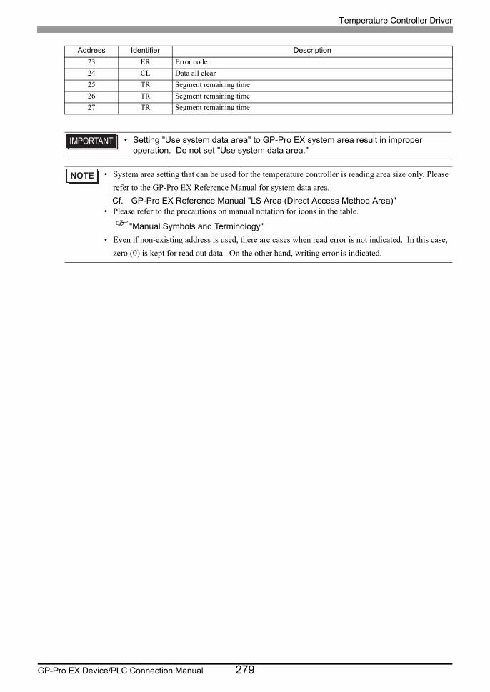
Temperature Controller Driver
GP-Pro EX Device/PLC Connection Manual 279
23 ER Error code
24 CL Data all clear
25 TR Segment remaining time
26 TR Segment remaining time
27 TR Segment remaining time
• Setting "Use system data area" to GP-Pro EX system area result in improper operation. Do not set "Use system data area."
• System area setting that can be used for the temperature controller is reading area size only. Please
refer to the GP-Pro EX Reference Manual for system data area.
Cf. GP-Pro EX Reference Manual "LS Area (Direct Access Method Area)"• Please refer to the precautions on manual notation for icons in the table.
"Manual Symbols and Terminology"
• Even if non-existing address is used, there are cases when read error is not indicated. In this case,
zero (0) is kept for read out data. On the other hand, writing error is indicated.
Address Identifier Description
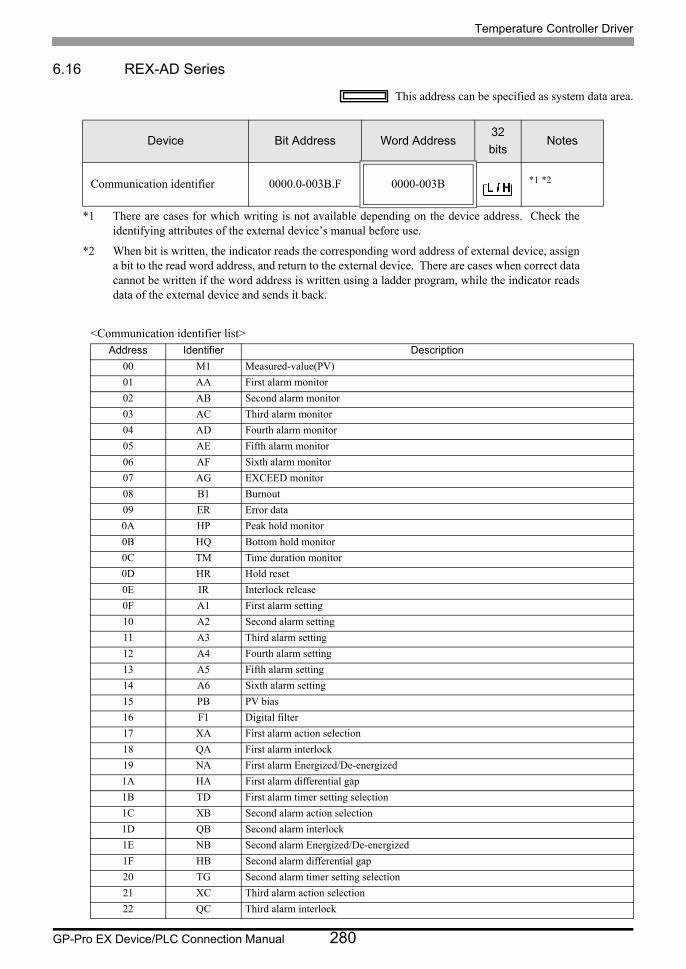
Temperature Controller Driver
GP-Pro EX Device/PLC Connection Manual 280
6.16 REX-AD Series
This address can be specified as system data area.
<Communication identifier list>
Device Bit Address Word Address32
bitsNotes
Communication identifier 0000.0-003B.F 0000-003B *1 *2
*1 There are cases for which writing is not available depending on the device address. Check the identifying attributes of the external device’s manual before use.
*2 When bit is written, the indicator reads the corresponding word address of external device, assign a bit to the read word address, and return to the external device. There are cases when correct data cannot be written if the word address is written using a ladder program, while the indicator reads data of the external device and sends it back.
Address Identifier Description
00 M1 Measured-value(PV)
01 AA First alarm monitor
02 AB Second alarm monitor
03 AC Third alarm monitor
04 AD Fourth alarm monitor
05 AE Fifth alarm monitor
06 AF Sixth alarm monitor
07 AG EXCEED monitor
08 B1 Burnout
09 ER Error data
0A HP Peak hold monitor
0B HQ Bottom hold monitor
0C TM Time duration monitor
0D HR Hold reset
0E IR Interlock release
0F A1 First alarm setting
10 A2 Second alarm setting
11 A3 Third alarm setting
12 A4 Fourth alarm setting
13 A5 Fifth alarm setting
14 A6 Sixth alarm setting
15 PB PV bias
16 F1 Digital filter
17 XA First alarm action selection
18 QA First alarm interlock
19 NA First alarm Energized/De-energized
1A HA First alarm differential gap
1B TD First alarm timer setting selection
1C XB Second alarm action selection
1D QB Second alarm interlock
1E NB Second alarm Energized/De-energized
1F HB Second alarm differential gap
20 TG Second alarm timer setting selection
21 XC Third alarm action selection
22 QC Third alarm interlock
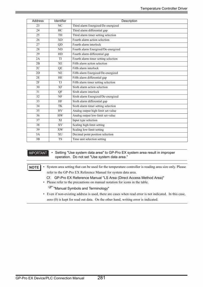
Temperature Controller Driver
GP-Pro EX Device/PLC Connection Manual 281
23 NC Third alarm Energized/De-energized
24 HC Third alarm differential gap
25 TH Third alarm timer setting selection
26 XD Fourth alarm action selection
27 QD Fourth alarm interlock
28 ND Fourth alarm Energized/De-energized
29 HD Fourth alarm differential gap
2A TI Fourth alarm timer setting selection
2B XE Fifth alarm action selection
2C QE Fifth alarm interlock
2D NE Fifth alarm Energized/De-energized
2E HE Fifth alarm differential gap
2F TJ Fifth alarm timer setting selection
30 XF Sixth alarm action selection
31 QF Sixth alarm interlock
32 NF Sixth alarm Energized/De-energized
33 HF Sixth alarm differential gap
34 TK Sixth alarm timer setting selection
35 HV Analog output high-limit set-value
36 HW Analog output low-limit set-value
37 XI Input type selection
38 XV Scaling high-limit setting
39 XW Scaling low-limit setting
3A XU Decimal point position selection
3B TS Time unit selection setting
• Setting "Use system data area" to GP-Pro EX system area result in improper operation. Do not set "Use system data area."
• System area setting that can be used for the temperature controller is reading area size only. Please
refer to the GP-Pro EX Reference Manual for system data area.
Cf. GP-Pro EX Reference Manual "LS Area (Direct Access Method Area)"• Please refer to the precautions on manual notation for icons in the table.
"Manual Symbols and Terminology"
• Even if non-existing address is used, there are cases when read error is not indicated. In this case,
zero (0) is kept for read out data. On the other hand, writing error is indicated.
Address Identifier Description

Temperature Controller Driver
GP-Pro EX Device/PLC Connection Manual 282
6.17 REX-PG Series
This address can be specified as system data area.
<Communication identifier list>
Device Bit Address Word Address32
bitsNotes
Communication identifier 0000.0-0021.F 0000-0021 *1 *2
*1 There are cases for which writing is not available depending on the device address. Check the identifying attributes of the external device’s manual before use.
*2 When bit is written, the indicator reads the corresponding word address of external device, assign a bit to the read word address, and return to the external device. There are cases when correct data cannot be written if the word address is written using a ladder program, while the indicator reads data of the external device and sends it back.
Address Identifier Description
00 M1 Measured-value (PV)
01 AA Alarm 1 monitor
02 AB Alarm 2 monitor
03 B1 Burnout
04 ER Error data
05 HP Peak hold monitor
06 HQ Bottom hold monitor
07 AZ Auto 0
08 HR Hold reset
09 IR Alarm interlock release
0A A1 First alarm setting
0B A2 Second alarm setting
0C IB Operation selection when input break
0D TL Display time setting
0E XA First alarm Action selection
0F QA First alarm interlock function
10 NA First alarm Energized/de-energized selection
11 HA First alarm differential gap
12 TD First alarm timer setting
13 XB Second alarm Action selection
14 QB Second alarm interlock function
15 NB Second alarm Energized/de-energized selection
16 HB Second alarm differential gap
17 TG Second alarm timer setting
18 HW Low limit analog output range
19 HV High limit analog output range
1A TO Analog output time setting
1B XI Input type selection
1C GA Gain setting
1D PU Pressure unit setting
1E XU Decimal-point position selection
1F XW Pressure display low limit setting
20 XV Pressure display high limit setting
21 LI Linearizing type selection
Temperature Controller Driver
GP-Pro EX Device/PLC Connection Manual 283
• Setting "Use system data area" to GP-Pro EX system area result in improper operation. Do not set "Use system data area."
• System area setting that can be used for the temperature controller is reading area size only. Please
refer to the GP-Pro EX Reference Manual for system data area.
Cf. GP-Pro EX Reference Manual "LS Area (Direct Access Method Area)"• Please refer to the precautions on manual notation for icons in the table.
"Manual Symbols and Terminology"
• Even if non-existing address is used, there are cases when read error is not indicated. In this case,
zero (0) is kept for read out data. On the other hand, writing error is indicated.
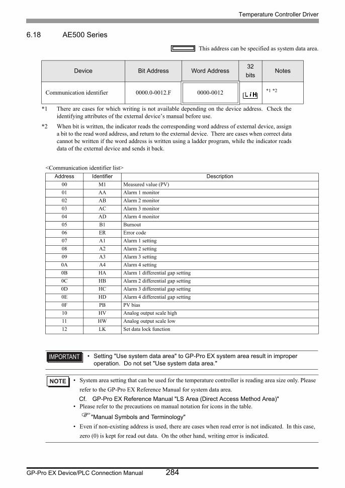
Temperature Controller Driver
GP-Pro EX Device/PLC Connection Manual 284
6.18 AE500 Series
This address can be specified as system data area.
<Communication identifier list>
Device Bit Address Word Address32
bitsNotes
Communication identifier 0000.0-0012.F 0000-0012 *1 *2
*1 There are cases for which writing is not available depending on the device address. Check the identifying attributes of the external device’s manual before use.
*2 When bit is written, the indicator reads the corresponding word address of external device, assign a bit to the read word address, and return to the external device. There are cases when correct data cannot be written if the word address is written using a ladder program, while the indicator reads data of the external device and sends it back.
Address Identifier Description
00 M1 Measured value (PV)
01 AA Alarm 1 monitor
02 AB Alarm 2 monitor
03 AC Alarm 3 monitor
04 AD Alarm 4 monitor
05 B1 Burnout
06 ER Error code
07 A1 Alarm 1 setting
08 A2 Alarm 2 setting
09 A3 Alarm 3 setting
0A A4 Alarm 4 setting
0B HA Alarm 1 differential gap setting
0C HB Alarm 2 differential gap setting
0D HC Alarm 3 differential gap setting
0E HD Alarm 4 differential gap setting
0F PB PV bias
10 HV Analog output scale high
11 HW Analog output scale low
12 LK Set data lock function
• Setting "Use system data area" to GP-Pro EX system area result in improper operation. Do not set "Use system data area."
• System area setting that can be used for the temperature controller is reading area size only. Please
refer to the GP-Pro EX Reference Manual for system data area.
Cf. GP-Pro EX Reference Manual "LS Area (Direct Access Method Area)"• Please refer to the precautions on manual notation for icons in the table.
"Manual Symbols and Terminology"
• Even if non-existing address is used, there are cases when read error is not indicated. In this case,
zero (0) is kept for read out data. On the other hand, writing error is indicated.
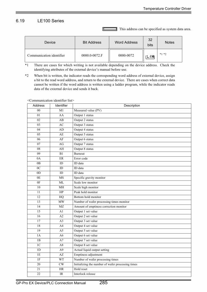
Temperature Controller Driver
GP-Pro EX Device/PLC Connection Manual 285
6.19 LE100 Series
This address can be specified as system data area.
<Communication identifier list>
Device Bit Address Word Address32
bitsNotes
Communication identifier 0000.0-0072.F 0000-0072 *1 *2
*1 There are cases for which writing is not available depending on the device address. Check the identifying attributes of the external device’s manual before use.
*2 When bit is written, the indicator reads the corresponding word address of external device, assign a bit to the read word address, and return to the external device. There are cases when correct data cannot be written if the word address is written using a ladder program, while the indicator reads data of the external device and sends it back.
Address Identifier Description
00 M1 Measured value (PV)
01 AA Output 1 status
02 AB Output 2 status
03 AC Output 3 status
04 AD Output 4 status
05 AE Output 5 status
06 AF Output 6 status
07 AG Output 7 status
08 AH Output 8 status
09 B1 Burnout
0A ER Error code
0B ID ID data
0C ID ID data
0D ID ID data
0E MS Specific gravity monitor
0F ML Scale low monitor
10 MH Scale high monitor
11 HP Peak hold monitor
12 HQ Bottom hold monitor
13 MW Number of wafer processing times monitor
14 MZ Amount of emptiness correction monitor
15 A1 Output 1 set value
16 A2 Output 2 set value
17 A3 Output 3 set value
18 A4 Output 4 set value
19 A5 Output 5 set value
1A A6 Output 6 set value
1B A7 Output 7 set value
1C A8 Output 8 set value
1D A9 Actual liquid output setting
1E AZ Emptiness adjustment
1F WT Number of wafer processing times
20 CW Initializing the number of wafer processing times
21 HR Hold reset
22 IR Interlock release
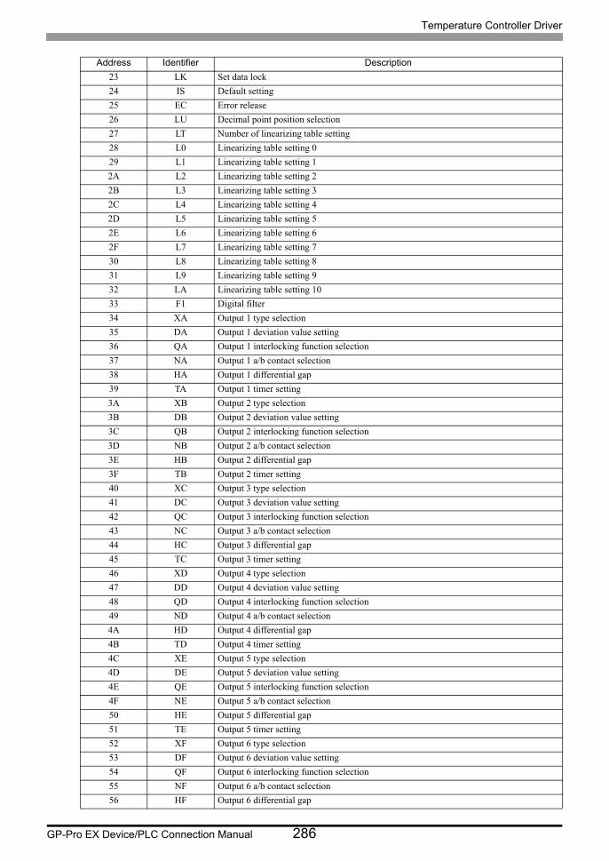
Temperature Controller Driver
GP-Pro EX Device/PLC Connection Manual 286
23 LK Set data lock
24 IS Default setting
25 EC Error release
26 LU Decimal point position selection
27 LT Number of linearizing table setting
28 L0 Linearizing table setting 0
29 L1 Linearizing table setting 1
2A L2 Linearizing table setting 2
2B L3 Linearizing table setting 3
2C L4 Linearizing table setting 4
2D L5 Linearizing table setting 5
2E L6 Linearizing table setting 6
2F L7 Linearizing table setting 7
30 L8 Linearizing table setting 8
31 L9 Linearizing table setting 9
32 LA Linearizing table setting 10
33 F1 Digital filter
34 XA Output 1 type selection
35 DA Output 1 deviation value setting
36 QA Output 1 interlocking function selection
37 NA Output 1 a/b contact selection
38 HA Output 1 differential gap
39 TA Output 1 timer setting
3A XB Output 2 type selection
3B DB Output 2 deviation value setting
3C QB Output 2 interlocking function selection
3D NB Output 2 a/b contact selection
3E HB Output 2 differential gap
3F TB Output 2 timer setting
40 XC Output 3 type selection
41 DC Output 3 deviation value setting
42 QC Output 3 interlocking function selection
43 NC Output 3 a/b contact selection
44 HC Output 3 differential gap
45 TC Output 3 timer setting
46 XD Output 4 type selection
47 DD Output 4 deviation value setting
48 QD Output 4 interlocking function selection
49 ND Output 4 a/b contact selection
4A HD Output 4 differential gap
4B TD Output 4 timer setting
4C XE Output 5 type selection
4D DE Output 5 deviation value setting
4E QE Output 5 interlocking function selection
4F NE Output 5 a/b contact selection
50 HE Output 5 differential gap
51 TE Output 5 timer setting
52 XF Output 6 type selection
53 DF Output 6 deviation value setting
54 QF Output 6 interlocking function selection
55 NF Output 6 a/b contact selection
56 HF Output 6 differential gap
Address Identifier Description
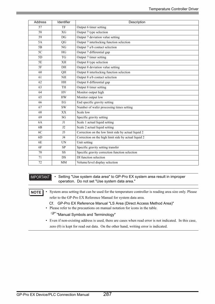
Temperature Controller Driver
GP-Pro EX Device/PLC Connection Manual 287
57 TF Output 6 timer setting
58 XG Output 7 type selection
59 DG Output 7 deviation value setting
5A QG Output 7 interlocking function selection
5B NG Output 7 a/b contact selection
5C HG Output 7 differential gap
5D TG Output 7 timer setting
5E XH Output 8 type selection
5F DH Output 8 deviation value setting
60 QH Output 8 interlocking function selection
61 NH Output 8 a/b contact selection
62 HH Output 8 differential gap
63 TH Output 8 timer setting
64 HV Monitor output high
65 HW Monitor output low
66 EG End specific gravity setting
67 SW Number of wafer processing times setting
68 XX Scale low
69 SG Specific gravity setting
6A J1 Scale 1 actual liquid setting
6B J2 Scale 2 actual liquid setting
6C J3 Correction on the low limit side by actual liquid 2
6D J4 Correction on the high limit side by actual liquid 2
6E UN Unit setting
6F SP Specific gravity setting transfer
70 SS Specific gravity correction function selection
71 DS DI function selection
72 MM Volume/level display selection
• Setting "Use system data area" to GP-Pro EX system area result in improper operation. Do not set "Use system data area."
• System area setting that can be used for the temperature controller is reading area size only. Please
refer to the GP-Pro EX Reference Manual for system data area.
Cf. GP-Pro EX Reference Manual "LS Area (Direct Access Method Area)"• Please refer to the precautions on manual notation for icons in the table.
"Manual Symbols and Terminology"
• Even if non-existing address is used, there are cases when read error is not indicated. In this case,
zero (0) is kept for read out data. On the other hand, writing error is indicated.
Address Identifier Description
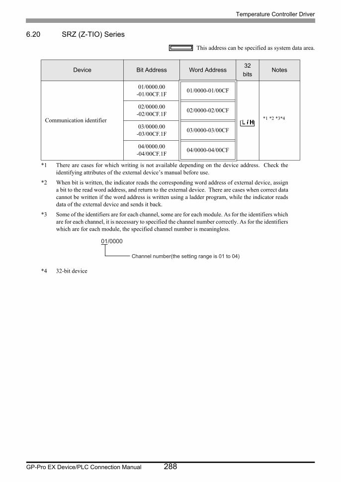
Temperature Controller Driver
GP-Pro EX Device/PLC Connection Manual 288
6.20 SRZ (Z-TIO) Series
This address can be specified as system data area.
Device Bit Address Word Address32
bitsNotes
Communication identifier
01/0000.00-01/00CF.1F
01/0000-01/00CF
*1 *2 *3*4
*1 There are cases for which writing is not available depending on the device address. Check the identifying attributes of the external device’s manual before use.
*2 When bit is written, the indicator reads the corresponding word address of external device, assign a bit to the read word address, and return to the external device. There are cases when correct data cannot be written if the word address is written using a ladder program, while the indicator reads data of the external device and sends it back.
*3 Some of the identifiers are for each channel, some are for each module. As for the identifiers which are for each channel, it is necessary to specified the channel number correctly. As for the identifiers which are for each module, the specified channel number is meaningless.
*4 32-bit device
02/0000.00-02/00CF.1F
02/0000-02/00CF
03/0000.00-03/00CF.1F
03/0000-03/00CF
04/0000.00-04/00CF.1F
04/0000-04/00CF
01/0000
Channel number(the setting range is 01 to 04)

Temperature Controller Driver
GP-Pro EX Device/PLC Connection Manual 289
<Communication identifier list>Address Identifier Description Address Identifier Description
00 VR ROM version 32 A7 Heater break alarm (HBA) set value
01 VR ROM version 33 NE Heater break determination point
02 M1 Measured value (PV) 34 NF Heater melting determination point
03 AJ Comprehensive event state 35 PB PV bias
04 L0 Operation mode state monitor 36 F1 PV digital filter
05 ER Error code 37 PR PV ratio
06 O1 Manipulated output value (MV) monitor [heat-side] 38 DP PV low input cut-off
07 O2 Manipulated output value (MV) monitor [cool-side] 39 RB RS bias
08 M3 Current transformer (CT) input value monitor 3A F2 RS digital filter
09 MS Set value (SV) monitor 3B RR RS ratio
0A S2 Remote setting (RS) input value monitor 3C DV Output distribution selection
0B B1 Burnout state monitor 3D DW Output distribution bias
0C AA Event 1 state monitor 3E DQ Output distribution ratio
0D AB Event 2 state monitor 3F T0 Proportional cycle time
0E AC Event 3 state monitor 40 VI Minimum ON/OFF time of proportioning cycle
0F AD Event 4 state monitor 41 ON Manual manipulated output value
10 AE Heater break alarm (HBA) state monitor 42 RV Area soak time stop function
11 Q1 Output state monitor 43 NG EDS mode (for disturbance 1)
12 TR Memory area soak time monitor 44 NX EDS mode 2 (for disturbance 2)
13 UT Integrated operating time monitor 45 NI EDS value 1 (for disturbance 1)
14 Hp Holding peak value ambient temperature monitor 46 NJ EDS value 1 (for disturbance 2)
15 EM Backup memory state monitor 47 NK EDS value 2 (for disturbance 1)
16 ED Logic output monitor 1 48 NM EDS value 2 (for disturbance 2)
17 EE Logic output monitor 2 49 NN EDS transfer time (for disturbance 1)
18 G1 PID/AT transfer 4A NO EDS transfer time (for disturbance 2)
19 J1 Auto/Manual transfer 4B NQ EDS action time (for disturbance 1)
1A C1 Remote/Local transfer 4C NL EDS action time (for disturbance 2)
1B SR RUN/STOP transfer 4D NR EDS action wait time (for disturbance 1)
1C ZA Memory area transfer 4E NY EDS action wait time (for disturbance 2)
1D AR Interlock release 4F NT EDS value learning times
1E A1 Event 1 set value (EV1) 50 NU EDS start signal
1F A2 Event 2 set value (EV2) 51 EI Operation mode
20 A3 Event 3 set value (EV3) 52 ST Startup tuning (ST)
21 A4 Event 4 set value (EV4) 53 Y8 Automatic temperature rise learning
22 A5 Control loop break alarm (LBA) time 54 EF Communication switch for logic
23 N1 LBA deadband 55 XI Input type
24 S1 Set value (SV) 56 PU Display unit
25 P1 Proportional band [heat-side] 57 XU Decimal point position
26 I1 Integral time [heat-side] 58 XV Input scale high
27 D1 Derivative time [heat-side] 59 XW Input scale low
28 CA Control response parameter 5A AV Input error determination point (high)
29 P2 Proportional band [cool-side] 5B AW Input error determination point (low)
2A I2 Integral time [cool-side] 5C BS Burnout direction
2B D2 Derivative time [cool-side] 5D XH Square root extraction
2C V1 Overlap/Deadband 5E E0 Output assignment (Logic output selection function)
2D MR Manual reset 5F NA Energized/De-energized (Logic output selec-tion function)
2E HH Setting change rate limiter (up) 60 XA Event 1 type
2F HL Setting change rate limiter (down) 61 FA Event 1 channel setting
30 TM Area soak time 62 WA Event 1 hold action
31 LP Link area number 63 LF Event 1 interlock
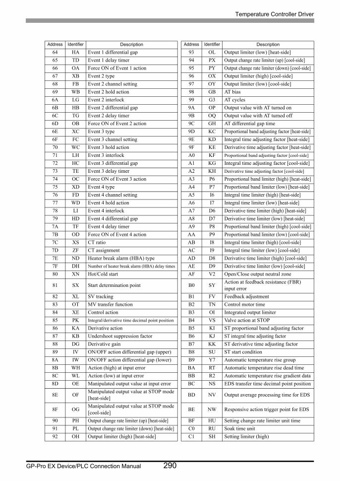
Temperature Controller Driver
GP-Pro EX Device/PLC Connection Manual 290
Address Identifier Description Address Identifier Description
64 HA Event 1 differential gap 93 OL Output limiter (low) [heat-side]
65 TD Event 1 delay timer 94 PX Output change rate limiter (up) [cool-side]
66 OA Force ON of Event 1 action 95 PY Output change rate limiter (down) [cool-side]
67 XB Event 2 type 96 OX Output limiter (high) [cool-side]
68 FB Event 2 channel setting 97 OY Output limiter (low) [cool-side]
69 WB Event 2 hold action 98 GB AT bias
6A LG Event 2 interlock 99 G3 AT cycles
6B HB Event 2 differential gap 9A OP Output value with AT turned on
6C TG Event 2 delay timer 9B OQ Output value with AT turned off
6D OB Force ON of Event 2 action 9C GH AT differential gap time
6E XC Event 3 type 9D KC Proportional band adjusting factor [heat-side]
6F FC Event 3 channel setting 9E KD Integral time adjusting factor [heat-side]
70 WC Event 3 hold action 9F KE Derivative time adjusting factor [heat-side]
71 LH Event 3 interlock A0 KF Proportional band adjusting factor [cool-side]
72 HC Event 3 differential gap A1 KG Integral time adjusting factor [cool-side]
73 TE Event 3 delay timer A2 KH Derivative time adjusting factor [cool-side]
74 OC Force ON of Event 3 action A3 P6 Proportional band limiter (high) [heat-side]
75 XD Event 4 type A4 P7 Proportional band limiter (low) [heat-side]
76 FD Event 4 channel setting A5 I6 Integral time limiter (high) [heat-side]
77 WD Event 4 hold action A6 I7 Integral time limiter (low) [heat-side]
78 LI Event 4 interlock A7 D6 Derivative time limiter (high) [heat-side]
79 HD Event 4 differential gap A8 D7 Derivative time limiter (low) [heat-side]
7A TF Event 4 delay timer A9 P8 Proportional band limiter (high) [cool-side]
7B OD Force ON of Event 4 action AA P9 Proportional band limiter (low) [cool-side]
7C XS CT ratio AB I8 Integral time limiter (high) [cool-side]
7D ZF CT assignment AC I9 Integral time limiter (low) [cool-side]
7E ND Heater break alarm (HBA) type AD D8 Derivative time limiter (high) [cool-side]
7F DH Number of heater break alarm (HBA) delay times AE D9 Derivative time limiter (low) [cool-side]
80 XN Hot/Cold start AF V2 Open/Close output neutral zone
81 SX Start determination point B0 SYAction at feedback resistance (FBR) input error
82 XL SV tracking B1 FV Feedback adjustment
83 OT MV transfer function B2 TN Control motor time
84 XE Control action B3 OI Integrated output limiter
85 PK Integral/derivative time decimal point position B4 VS Valve action at STOP
86 KA Derivative action B5 KI ST proportional band adjusting factor
87 KB Undershoot suppression factor B6 KJ ST integral time adjusting factor
88 DG Derivative gain B7 KK ST derivative time adjusting factor
89 IV ON/OFF action differential gap (upper) B8 SU ST start condition
8A IW ON/OFF action differential gap (lower) B9 Y7 Automatic temperature rise group
8B WH Action (high) at input error BA RT Automatic temperature rise dead time
8C WL Action (low) at input error BB R2 Automatic temperature rise gradient data
8D OE Manipulated output value at input error BC NS EDS transfer time decimal point position
8E OFManipulated output value at STOP mode [heat-side]
BD NV Output average processing time for EDS
8F OGManipulated output value at STOP mode [cool-side]
BE NW Responsive action trigger point for EDS
90 PH Output change rate limiter (up) [heat-side] BF HU Setting change rate limiter unit time
91 PL Output change rate limiter (down) [heat-side] C0 RU Soak time unit
92 OH Output limiter (high) [heat-side] C1 SH Setting limiter (high)

Temperature Controller Driver
GP-Pro EX Device/PLC Connection Manual 291
Address Identifier Description Address Identifier Description
C2 SL Setting limiter (low) C9 DYOutput distribution master channel mod-ule address
C3 TS PV transfer function CA DZOutput distribution master channel selec-tion
C4 EAOperation mode assignment 1(Logic output selection function)Logic output 1 to 4
CB RL Address of interacting modules
C5 EBOperation mode assignment 2(Logic output selection function)Logic output 5 to 8
CC RM Channel selection of interacting modules
C6 KM SV select function CD RN Selection switch of interacting modules
C7 MCRemote SV function master channel module address
CE X1 Control RUN/STOP holding setting
C8 MNRemote SV functionmaster channel selection
CF ZX Interval time
• Setting "Use system data area" to GP-Pro EX system area result in improper operation. Do not set "Use system data area."
• System area setting that can be used for the temperature controller is reading area size only.
Please refer to the GP-Pro EX Reference Manual for system data area.
Cf. GP-Pro EX Reference Manual "LS Area (Direct Access Method Area)"• Please refer to the precautions on manual notation for icons in the table.
"Manual Symbols and Terminology"
• Even if non-existing address is used, there are cases when read error is not indicated. In this
case, zero (0) is kept for read out data. On the other hand, writing error is indicated.
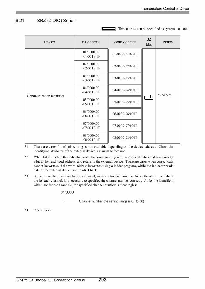
Temperature Controller Driver
GP-Pro EX Device/PLC Connection Manual 292
6.21 SRZ (Z-DIO) Series
This address can be specified as system data area.
Device Bit Address Word Address32
bitsNotes
Communication identifier
01/0000.00-01/001E.1F
01/0000-01/001E
*1 *2 *3*4
*1 There are cases for which writing is not available depending on the device address. Check the identifying attributes of the external device’s manual before use.
*2 When bit is written, the indicator reads the corresponding word address of external device, assign a bit to the read word address, and return to the external device. There are cases when correct data cannot be written if the word address is written using a ladder program, while the indicator reads data of the external device and sends it back.
*3 Some of the identifiers are for each channel, some are for each module. As for the identifiers which are for each channel, it is necessary to specified the channel number correctly. As for the identifiers which are for each module, the specified channel number is meaningless.
*4 32-bit device
02/0000.00-02/001E.1F
02/0000-02/001E
03/0000.00-03/001E.1F
03/0000-03/001E
04/0000.00-04/001E.1F
04/0000-04/001E
05/0000.00-05/001E.1F
05/0000-05/001E
06/0000.00-06/001E.1F
06/0000-06/001E
07/0000.00-07/001E.1F
07/0000-07/001E
08/0000.00-08/001E.1F
08/0000-08/001E
01/0000
Channel number(the setting range is 01 to 08)

Temperature Controller Driver
GP-Pro EX Device/PLC Connection Manual 293
<Communication identifier list>Address Identifier Description Address Identifier Description
00 VR ROM version 10 VJDO minimum ON/OFF time of proportioning cycle
01 VR ROM version 11 H2 DI function assignment
02 L1 Digital input (DI) state 1 12 E1 Memory area setting signal
03 L6 Digital input (DI) state 2 13 LQ DO signal assignment module address 1
04 Q2 Digital output (DO) state 1 14 LR DO signal assignment module address 2
05 Q3 Digital output (DO) state 2 15 LT DO output assignment 1 [DO1 to DO4]
06 ER Error code 16 LX DO output assignment 2 [DO5 to DO8]
07 UT Integrated operating time monitor 17 NB DO energized/de-energized
08 EM Backup memory state monitor 18 DDDO output distribution master channel module address
09 SR RUN/STOP transfer 19 DJDO output distribution master channel selection
0A Q4 DO manual output 1 1A OJDO manipulated output value (MV) at STOP mode
0B Q5 DO manual output 2 1B D3 DO output limiter (high)
0C DO DO output distribution selection 1C D4 DO output limiter (low)
0D O8 DO output distribution bias 1D X1 Control RUN/STOP holding setting
0E O9 DO output distribution ratio 1E ZX Interval time
0F V0 DO proportional cycle time
• Setting "Use system data area" to GP-Pro EX system area result in improper opera-tion. Do not set "Use system data area."
• System area setting that can be used for the temperature controller is reading area size only.
Please refer to the GP-Pro EX Reference Manual for system data area.
Cf. GP-Pro EX Reference Manual "LS Area (Direct Access Method Area)"• Please refer to the precautions on manual notation for icons in the table.
"Manual Symbols and Terminology"
• Even if non-existing address is used, there are cases when read error is not indicated. In this
case, zero (0) is kept for read out data. On the other hand, writing error is indicated.
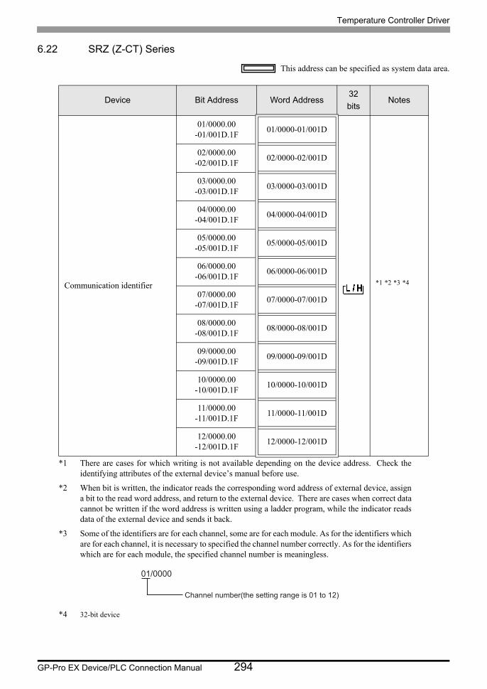
Temperature Controller Driver
GP-Pro EX Device/PLC Connection Manual 294
6.22 SRZ (Z-CT) Series
This address can be specified as system data area.
Device Bit Address Word Address32
bitsNotes
Communication identifier
01/0000.00-01/001D.1F
01/0000-01/001D
*1 *2 *3 *4
*1 There are cases for which writing is not available depending on the device address. Check the identifying attributes of the external device’s manual before use.
*2 When bit is written, the indicator reads the corresponding word address of external device, assign a bit to the read word address, and return to the external device. There are cases when correct data cannot be written if the word address is written using a ladder program, while the indicator reads data of the external device and sends it back.
*3 Some of the identifiers are for each channel, some are for each module. As for the identifiers which are for each channel, it is necessary to specified the channel number correctly. As for the identifiers which are for each module, the specified channel number is meaningless.
*4 32-bit device
02/0000.00-02/001D.1F
02/0000-02/001D
03/0000.00-03/001D.1F
03/0000-03/001D
04/0000.00-04/001D.1F
04/0000-04/001D
05/0000.00-05/001D.1F
05/0000-05/001D
06/0000.00-06/001D.1F
06/0000-06/001D
07/0000.00-07/001D.1F
07/0000-07/001D
08/0000.00-08/001D.1F
08/0000-08/001D
09/0000.00-09/001D.1F
09/0000-09/001D
10/0000.00-10/001D.1F
10/0000-10/001D
11/0000.00-11/001D.1F
11/0000-11/001D
12/0000.00-12/001D.1F
12/0000-12/001D
01/0000
Channel number(the setting range is 01 to 12)

Temperature Controller Driver
GP-Pro EX Device/PLC Connection Manual 295
<Communication identifier list>Address Identifier Description Address Identifier Description
00 VR ROM version 0F BO Heater overcurrent alarm selection
01 VR ROM version 10 CXHeater break alarm (HBA) interlock release
02 M4Current transformer (CT) input value monitor
11 CYHeater overcurrent alarm interlock release
03 M5 Load factor conversion CT monitor 12 LK Set lock
04 AF Heater break alarm (HBA) state monitor 13 BV CT type
05 AG Heater overcurrent alarm state monitor 14 XT CT ratio (CT number of winds)
06 ER Error code 15 DINumber of heater break alarm (HBA) delay times
07 UT Integrated operating time monitor 16 BWAutomatic setting factor for heater break alarm (HBA)
08 EM Backup memory state monitor 17 B9Automatic setting factor for heater over-current alarm
09 CJ Automatic setting state monitor 18 BPDetermination current value for auto-matic setting
0A BTHeater break/Heater overcurrent alarm automatic setting selection
19 BQ Automatic setting time
0B BU Automatic setting transfer 1A BXModule address assignments for CT input
0C A8 Heater break alarm (HBA) set value 1B BYModule channel assignments for CT input
0D BZ Heater break alarm (HBA) selection 1C IC Load factor conversion method
0E A6 Heater overcurrent alarm set value 1D ZX Interval time
• Setting "Use system data area" to GP-Pro EX system area result in improper opera-tion. Do not set "Use system data area."
• System area setting that can be used for the temperature controller is reading area size only.
Please refer to the GP-Pro EX Reference Manual for system data area.
Cf. GP-Pro EX Reference Manual "LS Area (Direct Access Method Area)"• Please refer to the precautions on manual notation for icons in the table.
"Manual Symbols and Terminology"
• Even if non-existing address is used, there are cases when read error is not indicated. In this
case, zero (0) is kept for read out data. On the other hand, writing error is indicated.
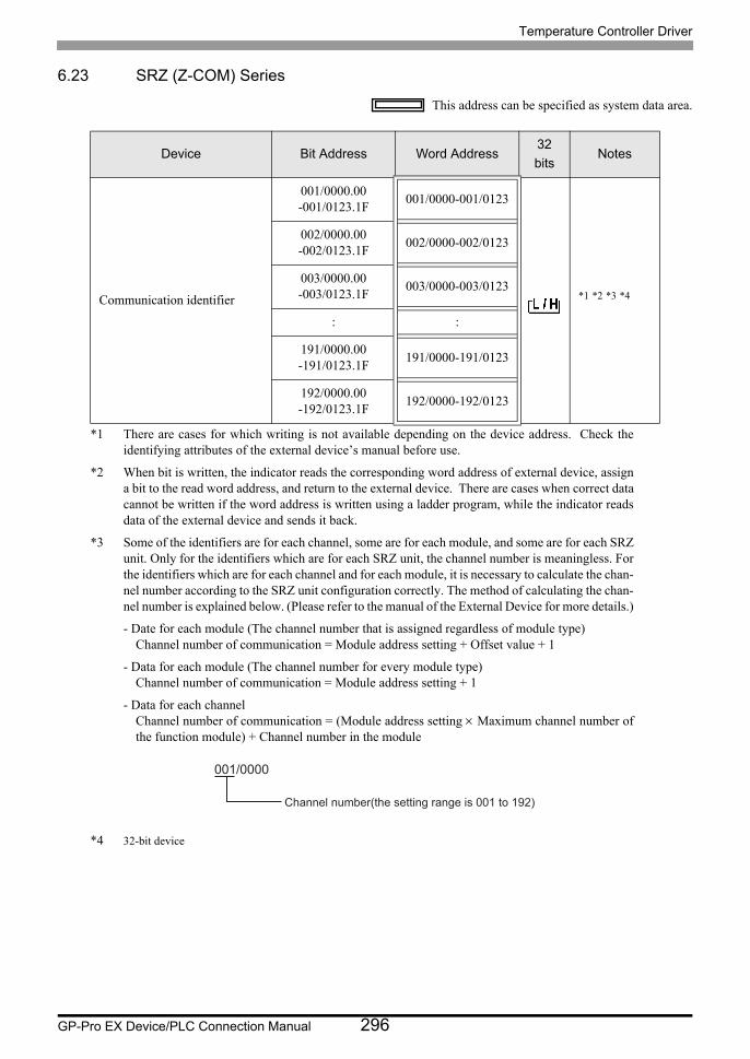
Temperature Controller Driver
GP-Pro EX Device/PLC Connection Manual 296
6.23 SRZ (Z-COM) Series
This address can be specified as system data area.
Device Bit Address Word Address32
bitsNotes
Communication identifier
001/0000.00-001/0123.1F
001/0000-001/0123
*1 *2 *3 *4
*1 There are cases for which writing is not available depending on the device address. Check the identifying attributes of the external device’s manual before use.
*2 When bit is written, the indicator reads the corresponding word address of external device, assign a bit to the read word address, and return to the external device. There are cases when correct data cannot be written if the word address is written using a ladder program, while the indicator reads data of the external device and sends it back.
*3 Some of the identifiers are for each channel, some are for each module, and some are for each SRZ unit. Only for the identifiers which are for each SRZ unit, the channel number is meaningless. For the identifiers which are for each channel and for each module, it is necessary to calculate the chan- nel number according to the SRZ unit configuration correctly. The method of calculating the chan- nel number is explained below. (Please refer to the manual of the External Device for more details.)
- Date for each module (The channel number that is assigned regardless of module type)Channel number of communication = Module address setting + Offset value + 1
- Data for each module (The channel number for every module type)Channel number of communication = Module address setting + 1
- Data for each channelChannel number of communication = (Module address setting Maximum channel number of the function module) + Channel number in the module
*4 32-bit device
002/0000.00-002/0123.1F
002/0000-002/0123
003/0000.00-003/0123.1F
003/0000-003/0123
: :
191/0000.00-191/0123.1F
191/0000-191/0123
192/0000.00-192/0123.1F
192/0000-192/0123
001/0000
Channel number(the setting range is 001 to 192)
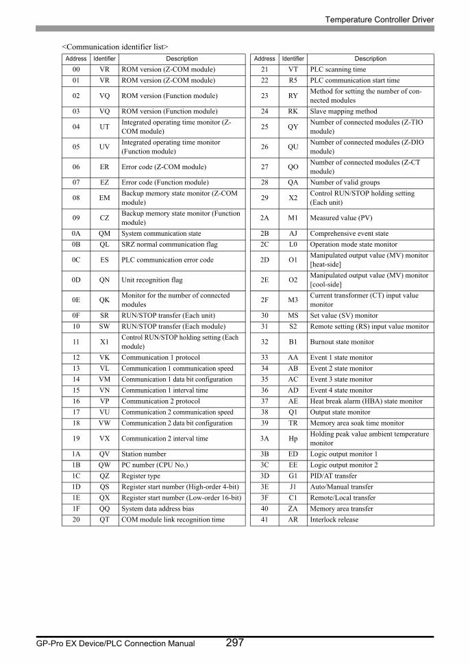
Temperature Controller Driver
GP-Pro EX Device/PLC Connection Manual 297
<Communication identifier list>Address Identifier Description Address Identifier Description
00 VR ROM version (Z-COM module) 21 VT PLC scanning time
01 VR ROM version (Z-COM module) 22 R5 PLC communication start time
02 VQ ROM version (Function module) 23 RYMethod for setting the number of con-nected modules
03 VQ ROM version (Function module) 24 RK Slave mapping method
04 UTIntegrated operating time monitor (Z-COM module)
25 QYNumber of connected modules (Z-TIO module)
05 UVIntegrated operating time monitor (Function module)
26 QUNumber of connected modules (Z-DIO module)
06 ER Error code (Z-COM module) 27 QONumber of connected modules (Z-CT module)
07 EZ Error code (Function module) 28 QA Number of valid groups
08 EMBackup memory state monitor (Z-COM module)
29 X2Control RUN/STOP holding setting (Each unit)
09 CZBackup memory state monitor (Function module)
2A M1 Measured value (PV)
0A QM System communication state 2B AJ Comprehensive event state
0B QL SRZ normal communication flag 2C L0 Operation mode state monitor
0C ES PLC communication error code 2D O1Manipulated output value (MV) monitor [heat-side]
0D QN Unit recognition flag 2E O2Manipulated output value (MV) monitor [cool-side]
0E QKMonitor for the number of connected modules
2F M3Current transformer (CT) input value monitor
0F SR RUN/STOP transfer (Each unit) 30 MS Set value (SV) monitor
10 SW RUN/STOP transfer (Each module) 31 S2 Remote setting (RS) input value monitor
11 X1Control RUN/STOP holding setting (Each module)
32 B1 Burnout state monitor
12 VK Communication 1 protocol 33 AA Event 1 state monitor
13 VL Communication 1 communication speed 34 AB Event 2 state monitor
14 VM Communication 1 data bit configuration 35 AC Event 3 state monitor
15 VN Communication 1 interval time 36 AD Event 4 state monitor
16 VP Communication 2 protocol 37 AE Heat break alarm (HBA) state monitor
17 VU Communication 2 communication speed 38 Q1 Output state monitor
18 VW Communication 2 data bit configuration 39 TR Memory area soak time monitor
19 VX Communication 2 interval time 3A HpHolding peak value ambient temperature monitor
1A QV Station number 3B ED Logic output monitor 1
1B QW PC number (CPU No.) 3C EE Logic output monitor 2
1C QZ Register type 3D G1 PID/AT transfer
1D QS Register start number (High-order 4-bit) 3E J1 Auto/Manual transfer
1E QX Register start number (Low-order 16-bit) 3F C1 Remote/Local transfer
1F QQ System data address bias 40 ZA Memory area transfer
20 QT COM module link recognition time 41 AR Interlock release
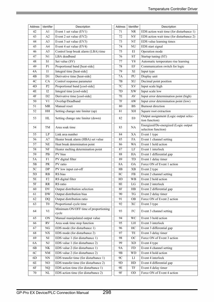
Temperature Controller Driver
GP-Pro EX Device/PLC Connection Manual 298
Address Identifier Description Address Identifier Description
42 A1 Event 1 set value (EV1) 71 NR EDS action wait time (for disturbance 1)
43 A2 Event 2 set value (EV2) 72 NY EDS action wait time (for disturbance 2)
44 A3 Event 3 set value (EV3) 73 NT EDS value learning times
45 A4 Event 4 set value (EV4) 74 NU EDS start signal
46 A5 Control loop break alarm (LBA) time 75 EI Operation mode
47 N1 LBA deadband 76 ST Startup tuning (ST)
48 S1 Set value (SV) 77 Y8 Automatic temperature rise learning
49 P1 Proportional band [heat-side] 78 EF Communication switch for logic
4A I1 Integral time [heat-side] 79 XI Input type
4B D1 Derivative time [heat-side] 7A PU Display unit
4C CA Control response parameter 7B XU Decimal point position
4D P2 Proportional band [cool-side] 7C XV Input scale high
4E I2 Integral time [cool-side] 7D XW Input scale low
4F D2 Derivative time [cool-side] 7E AV Input error determination point (high)
50 V1 Overlap/Deadband 7F AW Input error determination point (low)
51 MR Manual reset 80 BS Burnout direction
52 HH Setting change rate limiter (up) 81 XH Square root extraction
53 HL Setting change rate limiter (down) 82 E0Output assignment (Logic output selec-tion function)
54 TM Area soak time 83 NAEnergized/De-energized (Logic output selection function)
55 LP Link area number 84 XA Event 1 type
56 A7 Heater break alarm (HBA) set value 85 FA Event 1 channel setting
57 NE Heat break determination point 86 WA Event 1 hold action
58 NF Heater melting determination point 87 LF Event 1 interlock
59 PB PV bias 88 HA Event 1 differential gap
5A F1 PV digital filter 89 TD Event 1 delay timer
5B PR PV ratio 8A OA Force ON of Event 1 action
5C DP PV low input cut-off 8B XB Event 2 type
5D RB RS bias 8C FB Event 2 channel setting
5E F2 RS digital filter 8D WB Event 2 hold action
5F RR RS ratio 8E LG Event 2 interlock
60 DV Output distribution selection 8F HB Event 2 differential gap
61 DW Output distribution bias 90 TG Event 2 delay timer
62 DQ Output distribution ratio 91 OB Force ON of Event 2 action
63 T0 Proportional cycle time 92 XC Event 3 type
64 VIMinimum ON/OFF time of proportioning cycle
93 FC Event 3 channel setting
65 ON Manual manipulated output value 94 WC Event 3 hold action
66 RV Area soak time stop function 95 LH Event 3 interlock
67 NG EDS mode (for disturbance 1) 96 HC Event 3 differential gap
68 NX EDS mode (for disturbance 2) 97 TE Event 3 delay timer
69 NI EDS value 1 (for disturbance 1) 98 OC Force ON of Event 3 action
6A NJ EDS value 1 (for disturbance 2) 99 XD Event 4 type
6B NK EDS value 2 (for disturbance 1) 9A FD Event 4 channel setting
6C NM EDS value 2 (for disturbance 2) 9B WD Event 4 hold action
6D NN EDS transfer time (for disturbance 1) 9C LI Event 4 interlock
6E NO EDS transfer time (for disturbance 2) 9D HD Event 4 differential gap
6F NQ EDS action time (for disturbance 1) 9E TF Event 4 delay timer
70 NL EDS action time (for disturbance 2) 9F OD Force ON of Event 4 action
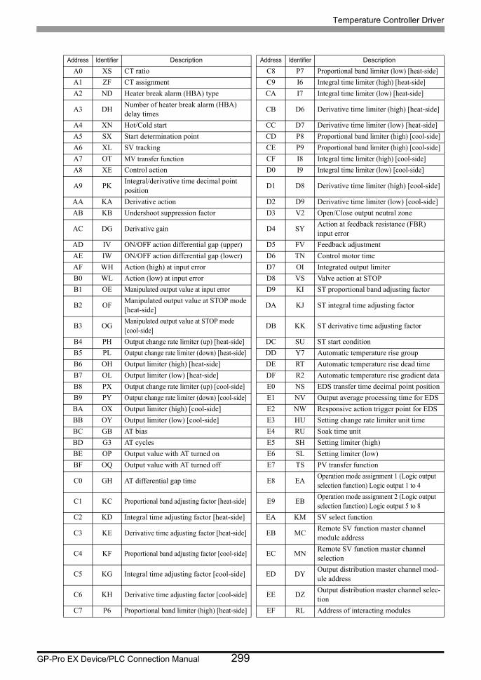
Temperature Controller Driver
GP-Pro EX Device/PLC Connection Manual 299
Address Identifier Description Address Identifier Description
A0 XS CT ratio C8 P7 Proportional band limiter (low) [heat-side]
A1 ZF CT assignment C9 I6 Integral time limiter (high) [heat-side]
A2 ND Heater break alarm (HBA) type CA I7 Integral time limiter (low) [heat-side]
A3 DHNumber of heater break alarm (HBA) delay times
CB D6 Derivative time limiter (high) [heat-side]
A4 XN Hot/Cold start CC D7 Derivative time limiter (low) [heat-side]
A5 SX Start determination point CD P8 Proportional band limiter (high) [cool-side]
A6 XL SV tracking CE P9 Proportional band limiter (high) [cool-side]
A7 OT MV transfer function CF I8 Integral time limiter (high) [cool-side]
A8 XE Control action D0 I9 Integral time limiter (low) [cool-side]
A9 PKIntegral/derivative time decimal point position
D1 D8 Derivative time limiter (high) [cool-side]
AA KA Derivative action D2 D9 Derivative time limiter (low) [cool-side]
AB KB Undershoot suppression factor D3 V2 Open/Close output neutral zone
AC DG Derivative gain D4 SYAction at feedback resistance (FBR) input error
AD IV ON/OFF action differential gap (upper) D5 FV Feedback adjustment
AE IW ON/OFF action differential gap (lower) D6 TN Control motor time
AF WH Action (high) at input error D7 OI Integrated output limiter
B0 WL Action (low) at input error D8 VS Valve action at STOP
B1 OE Manipulated output value at input error D9 KI ST proportional band adjusting factor
B2 OFManipulated output value at STOP mode [heat-side]
DA KJ ST integral time adjusting factor
B3 OGManipulated output value at STOP mode [cool-side]
DB KK ST derivative time adjusting factor
B4 PH Output change rate limiter (up) [heat-side] DC SU ST start condition
B5 PL Output change rate limiter (down) [heat-side] DD Y7 Automatic temperature rise group
B6 OH Output limiter (high) [heat-side] DE RT Automatic temperature rise dead time
B7 OL Output limiter (low) [heat-side] DF R2 Automatic temperature rise gradient data
B8 PX Output change rate limiter (up) [cool-side] E0 NS EDS transfer time decimal point position
B9 PY Output change rate limiter (down) [cool-side] E1 NV Output average processing time for EDS
BA OX Output limiter (high) [cool-side] E2 NW Responsive action trigger point for EDS
BB OY Output limiter (low) [cool-side] E3 HU Setting change rate limiter unit time
BC GB AT bias E4 RU Soak time unit
BD G3 AT cycles E5 SH Setting limiter (high)
BE OP Output value with AT turned on E6 SL Setting limiter (low)
BF OQ Output value with AT turned off E7 TS PV transfer function
C0 GH AT differential gap time E8 EAOperation mode assignment 1 (Logic output selection function) Logic output 1 to 4
C1 KC Proportional band adjusting factor [heat-side] E9 EBOperation mode assignment 2 (Logic output selection function) Logic output 5 to 8
C2 KD Integral time adjusting factor [heat-side] EA KM SV select function
C3 KE Derivative time adjusting factor [heat-side] EB MCRemote SV function master channel module address
C4 KF Proportional band adjusting factor [cool-side] EC MNRemote SV function master channel selection
C5 KG Integral time adjusting factor [cool-side] ED DYOutput distribution master channel mod-ule address
C6 KH Derivative time adjusting factor [cool-side] EE DZOutput distribution master channel selec-tion
C7 P6 Proportional band limiter (high) [heat-side] EF RL Address of interacting modules
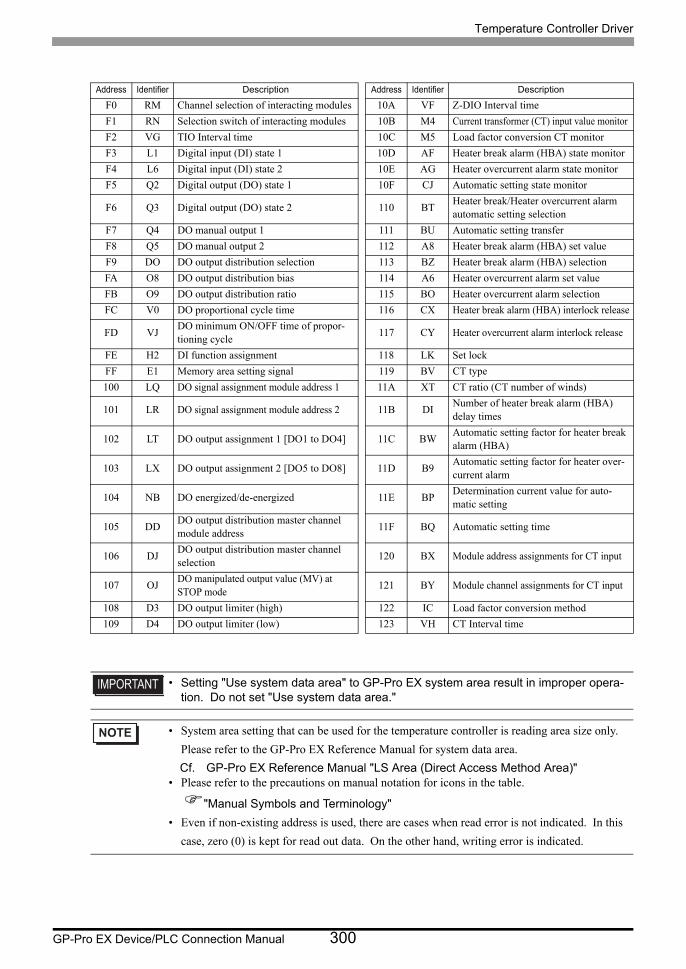
Temperature Controller Driver
GP-Pro EX Device/PLC Connection Manual 300
Address Identifier Description Address Identifier Description
F0 RM Channel selection of interacting modules 10A VF Z-DIO Interval time
F1 RN Selection switch of interacting modules 10B M4 Current transformer (CT) input value monitor
F2 VG TIO Interval time 10C M5 Load factor conversion CT monitor
F3 L1 Digital input (DI) state 1 10D AF Heater break alarm (HBA) state monitor
F4 L6 Digital input (DI) state 2 10E AG Heater overcurrent alarm state monitor
F5 Q2 Digital output (DO) state 1 10F CJ Automatic setting state monitor
F6 Q3 Digital output (DO) state 2 110 BTHeater break/Heater overcurrent alarm automatic setting selection
F7 Q4 DO manual output 1 111 BU Automatic setting transfer
F8 Q5 DO manual output 2 112 A8 Heater break alarm (HBA) set value
F9 DO DO output distribution selection 113 BZ Heater break alarm (HBA) selection
FA O8 DO output distribution bias 114 A6 Heater overcurrent alarm set value
FB O9 DO output distribution ratio 115 BO Heater overcurrent alarm selection
FC V0 DO proportional cycle time 116 CX Heater break alarm (HBA) interlock release
FD VJDO minimum ON/OFF time of propor-tioning cycle
117 CY Heater overcurrent alarm interlock release
FE H2 DI function assignment 118 LK Set lock
FF E1 Memory area setting signal 119 BV CT type
100 LQ DO signal assignment module address 1 11A XT CT ratio (CT number of winds)
101 LR DO signal assignment module address 2 11B DINumber of heater break alarm (HBA) delay times
102 LT DO output assignment 1 [DO1 to DO4] 11C BWAutomatic setting factor for heater break alarm (HBA)
103 LX DO output assignment 2 [DO5 to DO8] 11D B9Automatic setting factor for heater over-current alarm
104 NB DO energized/de-energized 11E BPDetermination current value for auto-matic setting
105 DDDO output distribution master channel module address
11F BQ Automatic setting time
106 DJDO output distribution master channel selection
120 BX Module address assignments for CT input
107 OJDO manipulated output value (MV) at STOP mode
121 BY Module channel assignments for CT input
108 D3 DO output limiter (high) 122 IC Load factor conversion method
109 D4 DO output limiter (low) 123 VH CT Interval time
• Setting "Use system data area" to GP-Pro EX system area result in improper opera-tion. Do not set "Use system data area."
• System area setting that can be used for the temperature controller is reading area size only.
Please refer to the GP-Pro EX Reference Manual for system data area.
Cf. GP-Pro EX Reference Manual "LS Area (Direct Access Method Area)"• Please refer to the precautions on manual notation for icons in the table.
"Manual Symbols and Terminology"
• Even if non-existing address is used, there are cases when read error is not indicated. In this
case, zero (0) is kept for read out data. On the other hand, writing error is indicated.
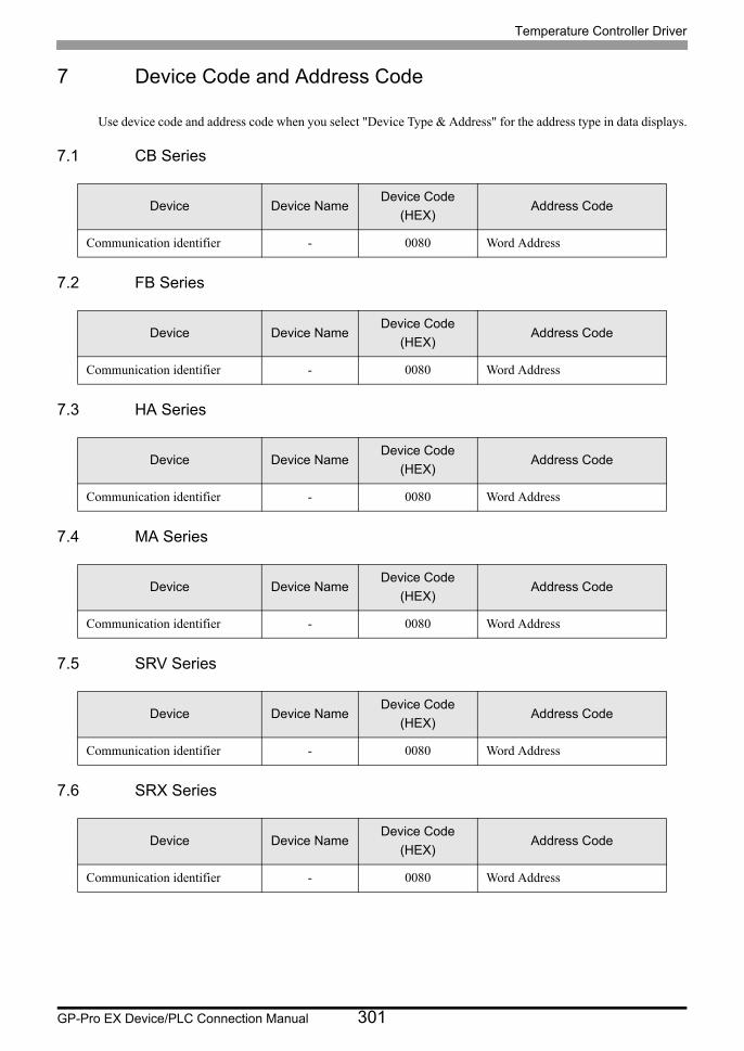
Temperature Controller Driver
GP-Pro EX Device/PLC Connection Manual 301
7 Device Code and Address Code
Use device code and address code when you select "Device Type & Address" for the address type in data displays.
7.1 CB Series
7.2 FB Series
7.3 HA Series
7.4 MA Series
7.5 SRV Series
7.6 SRX Series
Device Device NameDevice Code
(HEX)Address Code
Communication identifier - 0080 Word Address
Device Device NameDevice Code
(HEX)Address Code
Communication identifier - 0080 Word Address
Device Device NameDevice Code
(HEX)Address Code
Communication identifier - 0080 Word Address
Device Device NameDevice Code
(HEX)Address Code
Communication identifier - 0080 Word Address
Device Device NameDevice Code
(HEX)Address Code
Communication identifier - 0080 Word Address
Device Device NameDevice Code
(HEX)Address Code
Communication identifier - 0080 Word Address
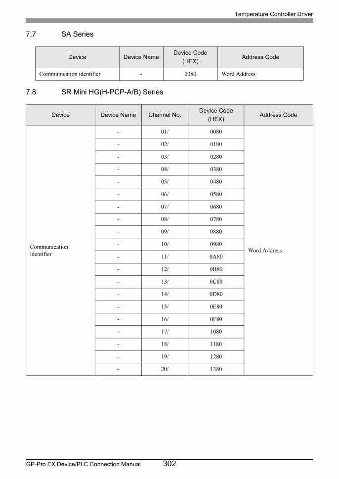
Temperature Controller Driver
GP-Pro EX Device/PLC Connection Manual 302
7.7 SA Series
7.8 SR Mini HG(H-PCP-A/B) Series
Device Device NameDevice Code
(HEX)Address Code
Communication identifier - 0080 Word Address
Device Device Name Channel No.Device Code
(HEX)Address Code
Communication identifier
- 01/ 0080
Word Address
- 02/ 0180
- 03/ 0280
- 04/ 0380
- 05/ 0480
- 06/ 0580
- 07/ 0680
- 08/ 0780
- 09/ 0880
- 10/ 0980
- 11/ 0A80
- 12/ 0B80
- 13/ 0C80
- 14/ 0D80
- 15/ 0E80
- 16/ 0F80
- 17/ 1080
- 18/ 1180
- 19/ 1280
- 20/ 1380
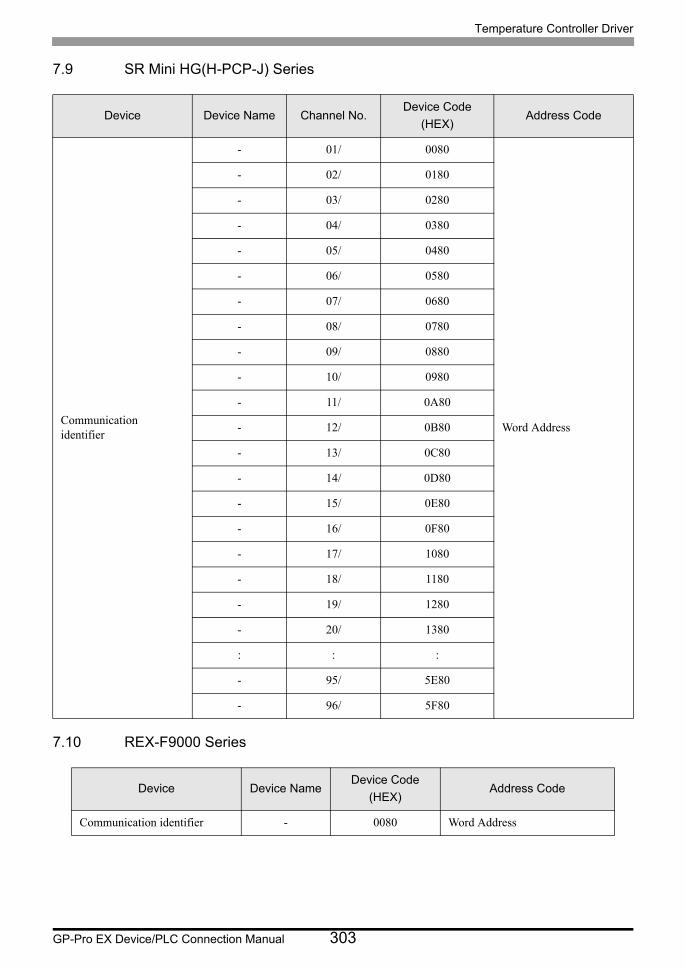
Temperature Controller Driver
GP-Pro EX Device/PLC Connection Manual 303
7.9 SR Mini HG(H-PCP-J) Series
7.10 REX-F9000 Series
Device Device Name Channel No.Device Code
(HEX)Address Code
Communication identifier
- 01/ 0080
Word Address
- 02/ 0180
- 03/ 0280
- 04/ 0380
- 05/ 0480
- 06/ 0580
- 07/ 0680
- 08/ 0780
- 09/ 0880
- 10/ 0980
- 11/ 0A80
- 12/ 0B80
- 13/ 0C80
- 14/ 0D80
- 15/ 0E80
- 16/ 0F80
- 17/ 1080
- 18/ 1180
- 19/ 1280
- 20/ 1380
: : :
- 95/ 5E80
- 96/ 5F80
Device Device NameDevice Code
(HEX)Address Code
Communication identifier - 0080 Word Address
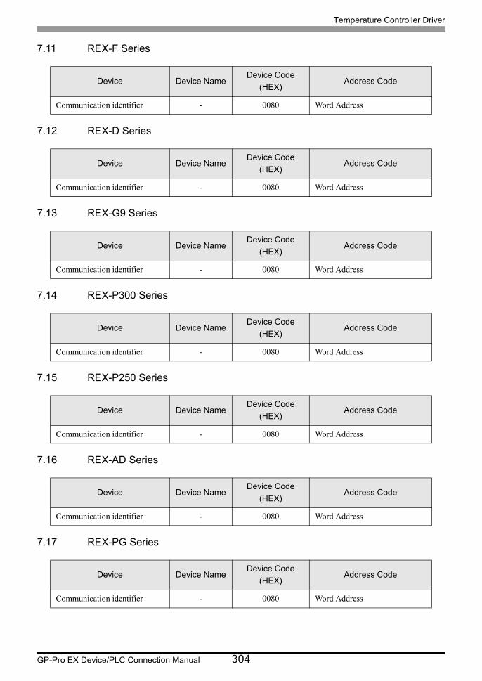
Temperature Controller Driver
GP-Pro EX Device/PLC Connection Manual 304
7.11 REX-F Series
7.12 REX-D Series
7.13 REX-G9 Series
7.14 REX-P300 Series
7.15 REX-P250 Series
7.16 REX-AD Series
7.17 REX-PG Series
Device Device NameDevice Code
(HEX)Address Code
Communication identifier - 0080 Word Address
Device Device NameDevice Code
(HEX)Address Code
Communication identifier - 0080 Word Address
Device Device NameDevice Code
(HEX)Address Code
Communication identifier - 0080 Word Address
Device Device NameDevice Code
(HEX)Address Code
Communication identifier - 0080 Word Address
Device Device NameDevice Code
(HEX)Address Code
Communication identifier - 0080 Word Address
Device Device NameDevice Code
(HEX)Address Code
Communication identifier - 0080 Word Address
Device Device NameDevice Code
(HEX)Address Code
Communication identifier - 0080 Word Address
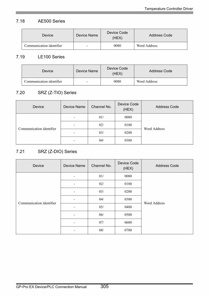
Temperature Controller Driver
GP-Pro EX Device/PLC Connection Manual 305
7.18 AE500 Series
7.19 LE100 Series
7.20 SRZ (Z-TIO) Series
7.21 SRZ (Z-DIO) Series
Device Device NameDevice Code
(HEX)Address Code
Communication identifier - 0080 Word Address
Device Device NameDevice Code
(HEX)Address Code
Communication identifier - 0080 Word Address
Device Device Name Channel No.Device Code
(HEX)Address Code
Communication identifier
- 01/ 0080
Word Address- 02/ 0180
- 03/ 0280
- 04/ 0380
Device Device Name Channel No.Device Code
(HEX)Address Code
Communication identifier
- 01/ 0080
Word Address
- 02/ 0180
- 03/ 0280
- 04/ 0380
- 05/ 0480
- 06/ 0580
- 07/ 0680
- 08/ 0780
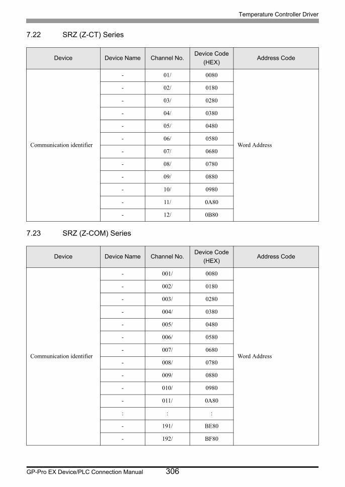
Temperature Controller Driver
GP-Pro EX Device/PLC Connection Manual 306
7.22 SRZ (Z-CT) Series
7.23 SRZ (Z-COM) Series
Device Device Name Channel No.Device Code
(HEX)Address Code
Communication identifier
- 01/ 0080
Word Address
- 02/ 0180
- 03/ 0280
- 04/ 0380
- 05/ 0480
- 06/ 0580
- 07/ 0680
- 08/ 0780
- 09/ 0880
- 10/ 0980
- 11/ 0A80
- 12/ 0B80
Device Device Name Channel No.Device Code
(HEX)Address Code
Communication identifier
- 001/ 0080
Word Address
- 002/ 0180
- 003/ 0280
- 004/ 0380
- 005/ 0480
- 006/ 0580
- 007/ 0680
- 008/ 0780
- 009/ 0880
- 010/ 0980
- 011/ 0A80
: : :
- 191/ BE80
- 192/ BF80
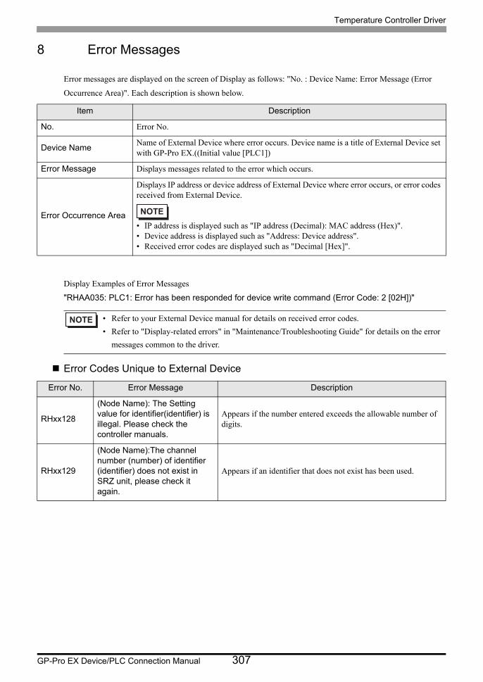
Temperature Controller Driver
GP-Pro EX Device/PLC Connection Manual 307
8 Error Messages
Error messages are displayed on the screen of Display as follows: "No. : Device Name: Error Message (Error
Occurrence Area)". Each description is shown below.
Display Examples of Error Messages
"RHAA035: PLC1: Error has been responded for device write command (Error Code: 2 [02H])"
Error Codes Unique to External Device
Item Description
No. Error No.
Device NameName of External Device where error occurs. Device name is a title of External Device set with GP-Pro EX.((Initial value [PLC1])
Error Message Displays messages related to the error which occurs.
Error Occurrence Area
Displays IP address or device address of External Device where error occurs, or error codes received from External Device.
• IP address is displayed such as "IP address (Decimal): MAC address (Hex)".• Device address is displayed such as "Address: Device address".• Received error codes are displayed such as "Decimal [Hex]".
• Refer to your External Device manual for details on received error codes.
• Refer to "Display-related errors" in "Maintenance/Troubleshooting Guide" for details on the error
messages common to the driver.
Error No. Error Message Description
RHxx128
(Node Name): The Setting value for identifier(identifier) is illegal. Please check the controller manuals.
Appears if the number entered exceeds the allowable number of digits.
RHxx129
(Node Name):The channel number (number) of identifier (identifier) does not exist in SRZ unit, please check it again.
Appears if an identifier that does not exist has been used.

Temperature Controller Driver
GP-Pro EX Device/PLC Connection Manual 308