rev 0 to technical data rept 388, "mechanical integrity analysis of
TRANSCRIPT
p- - ._ . _ _ - _ _
74_;ge MM 0077F'
'o" "o- '8' arv's'oa ao-[r 4J1 Nuclear -
sUDGETTECHNICAL DATA REPORT ACTIVITY NO. 120012 PAGE I OF 7
PROJECT: DEPARTMENT /SECTION Eng's & Des./Eng's Nech.TMI-1 OTsc
RELEASE DATE /f/7/If. REVISION DATE,
DOCUMENT TITLE:,
'
Hechanical Integrity Analysis of TMI-1 OTSG Tubes
APPROVALIS) SIGgRg ( DATEORIGINATOR SIGNATURE DATE .
A. P. Rochino W M /k/(/f2-S. D, Leshnoff
A fl) D 6 L dt- nl+1n' -
Vit,
APPROVAL. FOR EXTER$ DISTflBUTION DATE-
D. K. Croneberger kb b 124 81,I
!o DISTRIBUTION ABSTRACT:-
Purpose
R. O. Earley *Small 1.D. circumferential defects have been identifiedF. R. Clark *
D. K. Croneberger in many steam generator tubes. A fracture inechanicsF. S. Ciscobbe evaluation has been conducted to ascertain the stability
of tube cracks under steady-state and anticipatedM. J. GrahamH. Hukill * transient conditions.R. W. Keaten * .
* ResultsJ. Moore*J. Sipp Crack sizes can be identified which will not propagateD. C. Slear under anticipated loads during the design life of the ,
*J. Tangen
i C. VonNeida plant. De initial size of a crack which will propagatethrough-wall depends on the stress intensity threshold,E. Wallace *the material property indicating that crack size below;
j P. S. Walsh which a crack in a structure will not propagate.R. F. Wilson *i
he initial crack depth, and associated circumferential.,
'
extent, for stable cracks are 61% through wall and .544"! *
circumferential1y to 96% through wall and 0.068" .
* ircumferentially.c -
. ^- . , *
Leakage from through wall cracks is calculated making-
use of the crack opening displacements under anticipatedloads. Single phase leakage flow is assumed.
<
Leakage 'e 500 lb. axial load in 8.409 gal /hr.-
esO6140172 83012sconclusions NJE 897 PDR ,
We present analysis makes possible the identification ofthose initial crack sizes which will not propagate through|
the wall of steam generator tubes during anticipated use.'
| '
Dis information can be used in conjunction with theEddy-current inspection results to determine if cracks
| large enough to jeopardize the tubes can be detected. /j
| Leakage f rom through wall cracks during anticipatedoperating conditions will be detectable. Nf/,
-
"
k_
j,_- - - _
y - .- .. ._-_ _.
* .
* ' . ' ' ' .* '?.
...
'.
*.
O
TDR No. 388Rev. OPage 2 of 7
. ).TABLE OF CONTENTS
,
o. ... .. ,
}., Page a' . . . . :/* '-.
,
1. NAPOSE3*
.
32. W.TNODS*
'
f.." *. .
3 .', - * *2.1 Loads Analysis
42.2 Fracture Mechanics Analysis
52.3 Leakage Analyste -'
3'b'
. ... . ..-?.._'._.__ ., .
' '' '' ' '' ' '- ' -~
3.0 Results -- .. . . . . . . . .
64.0 conclusions
6.
50 Re ferencesFiguresApp. A Ref. 5'' -
-
B Ra f. 6 i .
C Ref. 3 ,
D Sample Leakage Calculation .
.
G
e
*G
e
0* a
*
a
'I e 6
h .
'.
6 P 1
D
5
.
i
I . .
!' .
.L J
_. _
,. ---- - -- _ ----_ _ _ - _ -- . ._ -
. 9.' , ' .4 ,4'* '. D R h . 388 ..
+.
Rev. O**-
page 3 of 7*
,
1.0 PUnpost
A fracture mechanics evaluation has been conducted to ascertain4
the stability of curcumferentially oriented ID cracks in steam ,*
generater tubes in the tube span between the fif teenth lateralAn unacceptable situation would*. , ,
support and the upper tubesheet. '
arise if an undetectable crack had the potential of propagatingthrough us11, escaping detection by reason of a very low leakage.
,
rate, and then to quickly propagate circumferentially to jeopardine~
or possibly to fail a tube.1) to determine if a circumferen-
.,
De aims of this evaluation are:tially oriented flaw that escaped 3ddy current detection would pre-
*
pagate through well under anticipated conditions, and 2) if's flawbecans through well in extent, but before circumferential propaga-
,
' ' ' .~
tion was complete, could such a crack be detected by its leakage.',,1,, ,
,
20 41M003.
It is necessary to establish the tube str ases and to interactthese stresses with the crack geometry in order to determine
In addition, bat separately, the streses arepropagation rate. interacted with the crack geoestry to determine the crack opening
,
,
displacement. ,
2.1 14eds Analysis
he tube loads are derived in part from the design basis document-
(Ref.1) and in part from measurements of the 1M1-2 070G tubesRecourse is made to field measurements because the
steam generator performed better than design assumptions predicted.(Ref. 2). '
1wenty degrees more superheat is measured than predicted.,
De anial load on the tube during anticipated transients, such as,
heat-ups, power changes, and reactor trips, and steady-stateoperation is due te *
.
Dif ferences in tube average temperature and the averagetemperature of the steam generator vessel well.
.
,
gy virtue of the end fixity of the tube, a longitudinalpressure stress evolves through poisson's ratio.
,
. ,
-
A residual tube axial load component exista free.) ''..
.
fabrication.Tubesheet flexure altigates axial load, especially near
' .
the unit center-line.
De first of these effects is magnified during the anticipated-
'
100'F/hr shutdown.
*, ,
1 . .
V 'a
< p _. m y -- .,- _,
.
.p ',i, .
*%,. . . .
.
' '
DA h. Mg-.
o sev. OPage 4 of 7 -
. .
!
superimposed on the steady axial load is a high sysle, flewinduced vibration (FIV) bending lead. We frequency and |
|displacement 'assnitude of FIV was asasured at 981-2 (ref. 2). ,,
22 Fracture Mechanica Analysis. ,
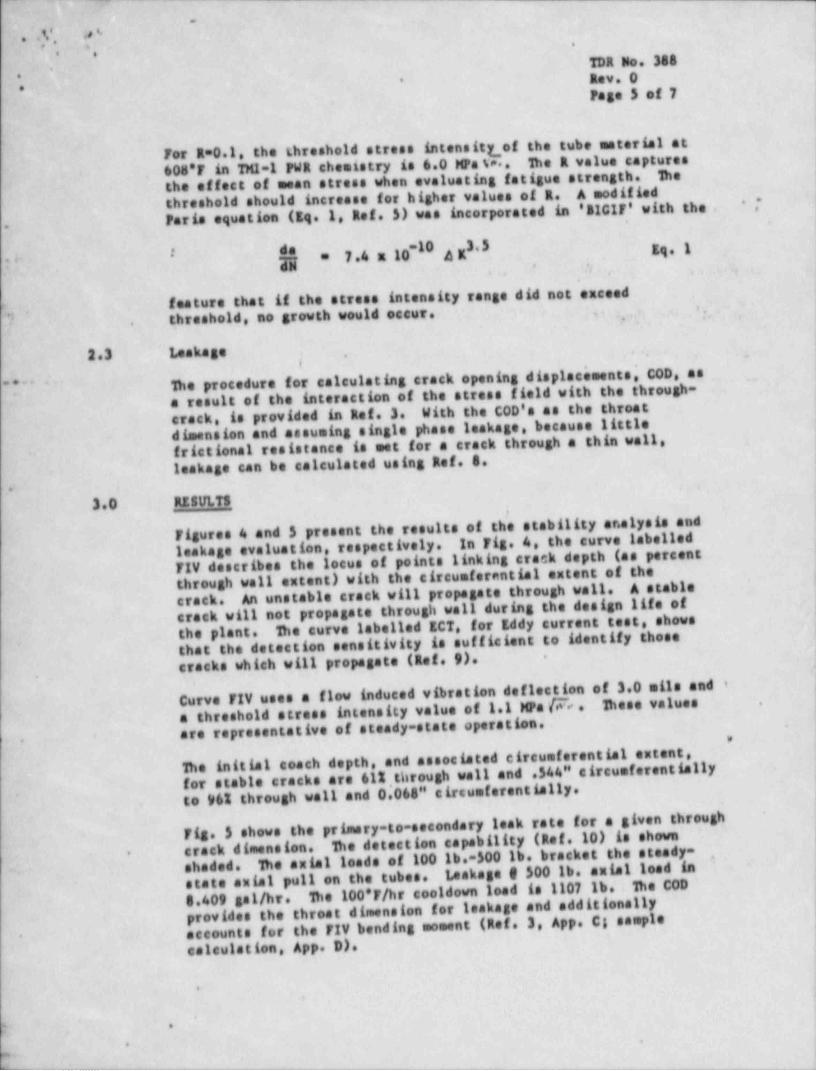
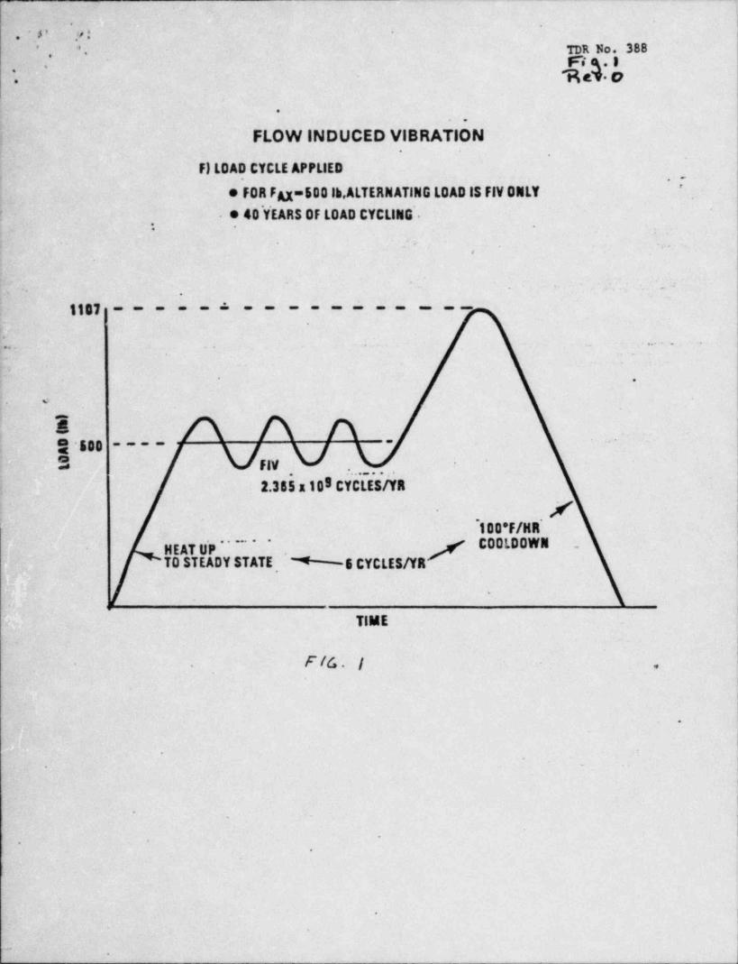
hhe steady axial and high syste bending leeds define the tubeleading (Fig.1). Flaw propagation is determined free a material 4
-
specific erack propagation law that is itself a function of thestress intensity faster, a parameter quantifying the interaction'
of crack sise, shape, boundary geoestry and strass field.
De stress intensity factors for circussierentially oriented I.P.sreaks are calculated in gef. 3. In addition to the leading . , . . . . ,
*
components identified above, the stress intensity facter sateula-.,,
tien admits of the lead caused by the tube sontente pressurisingthe parting faces of the flaw during F1V bending. 1hese stress '
intensity factors are integrated using the glestric power gesearchInstitute Linear Elastic Fracture Mechanics (LEFM) sede "s!CIF"(gaf. 4) to identify when a crask of a given initial sise ses beespected to prepasste through well given the leading of Fig.'1 '
.
(get. S. 63 see Appendices A and 3. respectively).
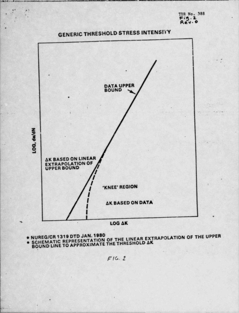
De concept of threshold stress intensity, (SE)h, is used inthis analysis. De threshold stress intensity is that value belowwhich a crack will not propagate at all. Se usefulness of thisconcept can be seen from an emanination of Fig. 2, the semi-quantitative dependence of stack growth, da/dN en stressintensity AE the independent variable.
At higher values of stress intensity, crack growth lasresses .rapidly (the log-los plot shows linear proportionality, where, infas.t, the relationship is exponential). At low values of stressintensity, a point is reached where the crack growth reaches
.
gelow this value of stress intensity there is no measurableAbove thissere.
crack outension even though toed cycling sentinues.> ,
threshold stress intensity, creek growth builds with continuingload cycling. De threshold stress intensity can be intuitivelyunderstood by recalling the endurance limit stress in connection
At the endurance limit, load aan be systedtiith the 3-N surve. At stresses higherindefinitely without damaging a structure.than the endurance limit structural failure een be anticipated*
after a certain number of cycles, presumably because of the-
initlation af ses11, flaws and their subsequent propagetden.
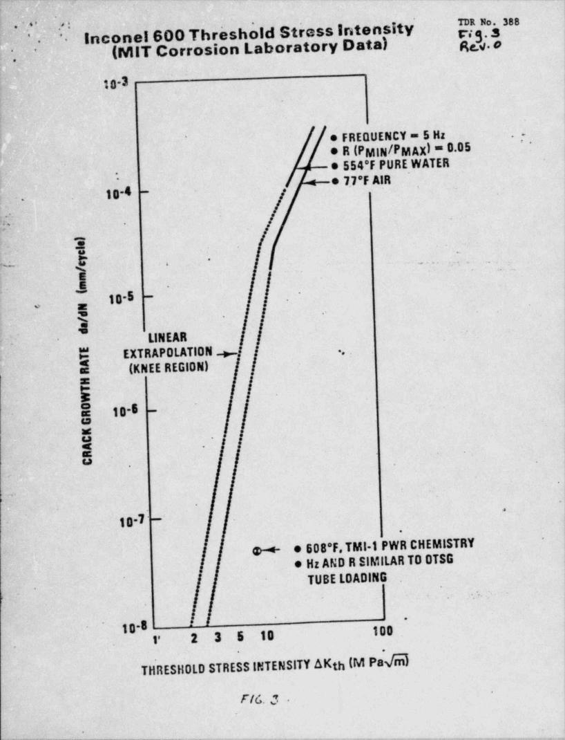
Se ' knee'' region in Fig. 2 'is representative of actual materialThisbehavior, as opposed te extrapolation of upper bound data.-
generic representation can be used to interpret Fig. 3. which is-*
actual experimental data being generated to identify the thresholdstress intensity for the 07sc tube material, Inconcel 600 (Aef. 7).
.
4
~ -. . . _
.
. 1,', ,e '-'
9A..
DR h. Mg'
gav. O. ** Page 5 of 7
,
For R*0.1, the thresheld stress intensittof the tube material at603'F in TM1-1 PWR cheatstry is 6.0 les u.. De R value captures j
the effect of mean stress when evaluating fatigue strength. De j,
threshold should increase for higher values of R. A modified ;
*7 jParis equation (gg.1 Ref. 3) was incorporated in '31GIF' with the . ;- ..
h = 7.4 a 10"I' iR .53 gg, gi" , ,
a.. . , ,
,
feature that if the stress intensity range did not exceed! ,
threshold, no growth would occur. ,,,,,
,
,
2.3 Leakage..
, - - ;
*
De procedure for calculating crack opening displacements. C00, as i, . "
'7~'' a result of the interaction of the stress field with the through-crack, is provided in Ref. 3. With the C00's as the throatdimension and assuming single phase leakage, because little '
frictional resistance is met for a crack through a thin wall.-
leakage can be calculated using Ref. 4. ,
;
. . .
3.0 ggsAn ,
! |
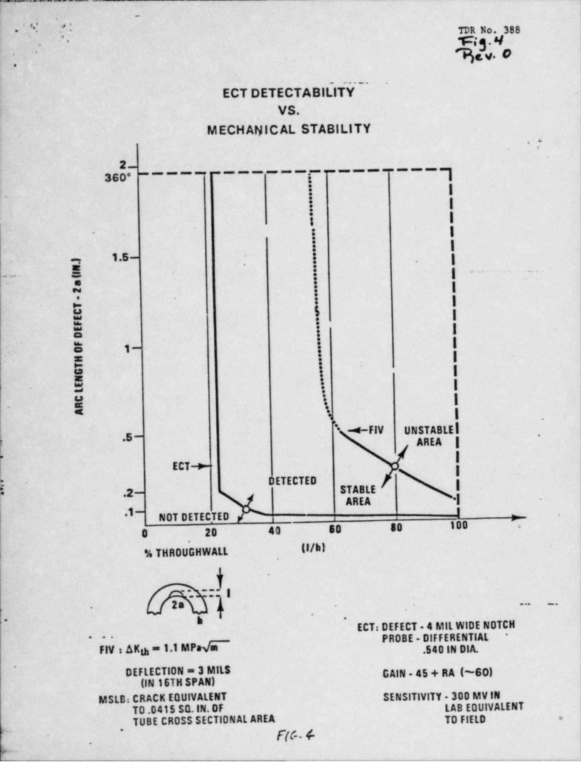
Figures 4 and 5 present the results of the stability analysis and'.1eakage evaluation, respectively. In Fig. 4, the curve labelled
FIV describes the locus of points linking crack depth (as percent -
through wall entent) with the circumferential extent of the I
An unstable crack will propagate through wall. A stablecrack.crack will not propagate through wall during the design life of '
D e curve labelled 3CT, for gddy current test, showsthe plant.that the detection sensitivity is sufficient to identify thosecracks which will propagate (gef. 9). -
.
Curve FIV uses a flow induced vibration deflection of 3 0 sits and i;
a threshold stress intensity value of 1.1 wa @ . D ese values,
.
|are representative of steady-state operation. ,
- e.
he initial coach depth, and associated circumferential extent,for stable cracks are 612,through well and .544" circumferential1y
.
!
to 962 through well and 0 068" circumferentially..
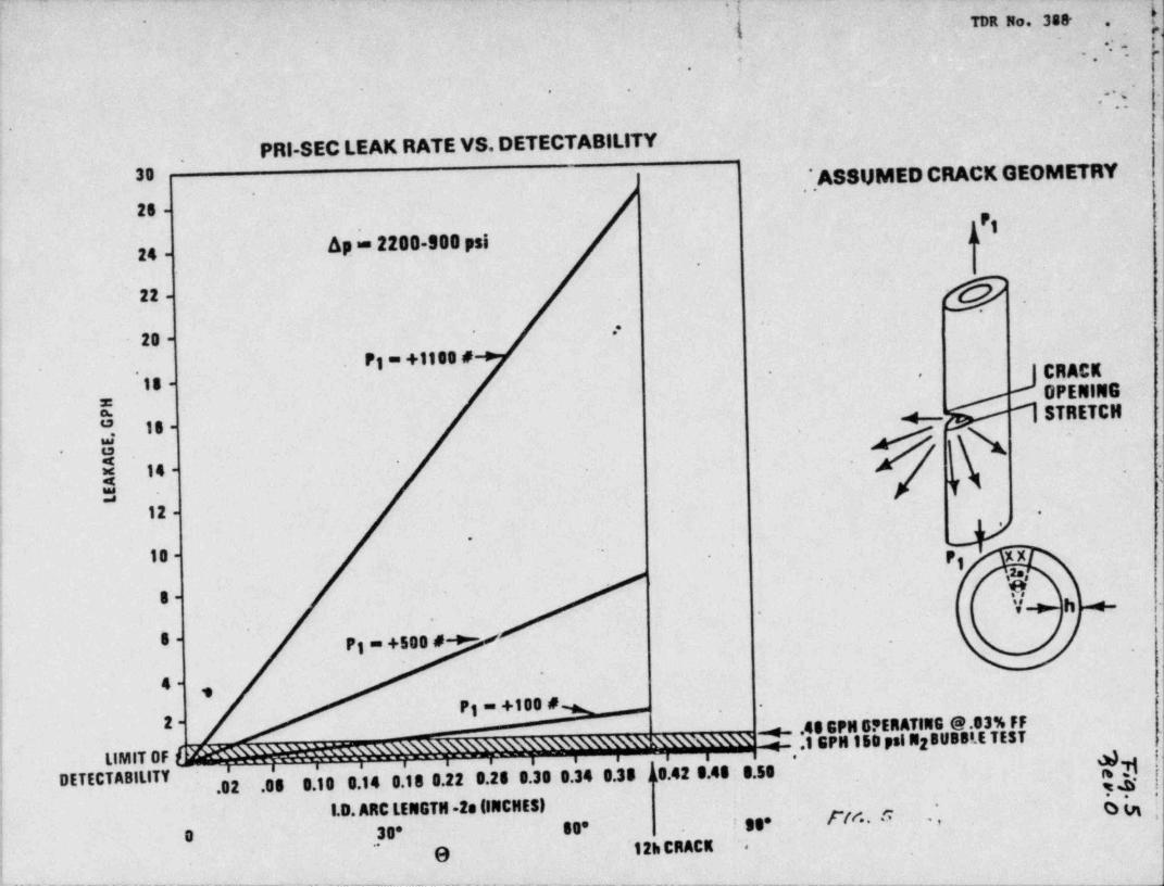
Fig. $ shows the primary-to-secondary leak rate for a given through*
De detection capability (gef.10) is shown j
crack dimension.De axial leads of 100 lb.-300 lb. bracket the steady--,
shaded. 1,aakage f 500 lb. axial lead in ' ;
state axial pull en the tubes. !
De 100'F/hr cooldown load is 1107 lb. D e C00 |8.409 gal /hr.provides the throat dimension for leakage and additionally |accounts for the F1V bending moment (get. 3. App. C; sample !
'
calculation. App. D).
'
. ,
.,
e
'"- - - - - - - - _ - _ _ . . _ _ _ _ _ _ _ _ __.
- -
. . co ' , i,'
*
**. ,
TDR No. 348.,
Rev. O. .
-* Page 6 of 7.
De following factors add conservatism to the above results:.
*
1. De stress intensiyt threshold is about 6 MPsg#m (Re f. 7 ) .(i.K)g = 1.1 MPa V6 was used above. , , ,
An sulal load of 500 lb. is derived from a calculation2.(Ref.1) usins natural frequency change as a function ofs
power level. ,.
,
Only deflection, strain, and frequency were measured.500 lb. axial tension accounts for a frequency change of '
about 50 Ma as power increases. An average frequency changse
with power increase was 10 Ma which can be accounted for by a100 lb. axial tension load at power. .
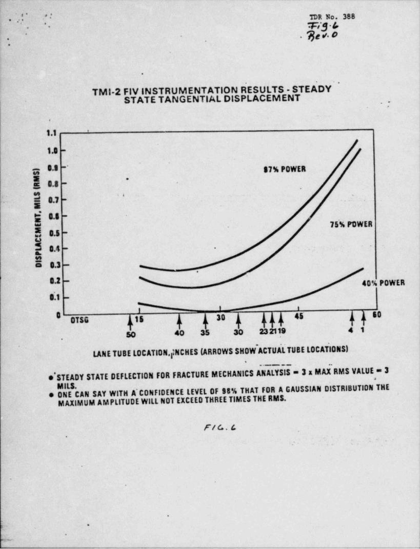
A 3 mil FIV deflection is based on an RMS value of 1 all.'
3.Fig. 6. It can be stated, with 98% confidence, that theusuimum deflection is (3)a(1 mit, RMs) = 3 mLis and that all.
other tubes see less deflection.
De defects are analytically forced to be present at the4. his is the *region where the tube is fiaed at the tubesheet..
,
region of highest FIV bending moment..
4.0 CONCLus10N,
De present analysis makes possible the identification of1. those initial crack sinas which will not propagate through*
the vs11 of steam generator tubes during_ anticipated use..
his information can be used in conjunction with the,
Eddy-current inspection results. to determine if cracks largeenough to jeopardise the tubes can be detected.
Leskage from through wall cracks during antdcipated operating2.conditions will be detectable.
,
5.0 RITERENess_.
Determination of Miniman Required hbe Walt Dickness for1.' 177-FA OTSC's, BAW-10146, October,1980.
.
Flow-Induced Vibration Analysis of 1M1-2 OTSC bbe, EPRI2.NP-1876. Vol.1. Proj. 8140-1. Final Report, June 1981.
i.
Fracture Analysis of Steam Generatur h bes, Part II, stress3.Intensity Factor and Crack Opening Displacement (COD)PreparedDisplacements, by Prof. F. Erdogan, Lehigh Univ.
.
for CPU Nuclear, 9/1$/82..
31CIF Fraction Mechanics Code for Structures EPRI-NP-838.4.
.
e,. . _
, ._
* i* '. . - . .
*e .
2DR No. 388*,
Rev. O**
Page 7 of 7.
.
~;e .
Parameter Evaluat' ion for IMI-1 OTSG Linear Elastic Fracture5.Mechanics (1.EFM) Ibbe Analysis, Babcock & Wilcox Document No.32-1137064-00, by R. A.' Davis , 8/23/82.
J".
'
6.- 'Ib id , B&W Doc. No. 32-1137716-00, by R. A. Davis, 10/13/82.
T MIT Tests Telecom records..
&
Predicted Leakage Flowrates for IVo Types of Cracks in the8.TM1-1 OTSG, Babcock & Wilcox Document No. 32-1135810-00, by*
.,j , , ;.,, .,. j p .. R. W. Winks, 8/9/82. f ; . , .., .-' -
* - , *
IOM ChE 82-222, J. A. Tangen to T. Dran, Sampling for '~~
'l : 1 9.Detection of Primary to Secondary Leakage, 10/28/82.
' '
g; ,, - - - .. - - . . . ,.. _
10. Personal communication from Mr. N. Kazanas.- - --''
, , ,
* r ..,, . s , . : .._.-
'- *
s ,
d
\
I
. .
e
*$> 'Ce- S . S +-d.
#.s**
j ,.[. ? -
* *
\.; ,.,
..
I'
l ..
L
|.
.
* * * * .=; ,-%
,, ,
*,
|-
.
V-
-g- .- - . . . . -. - - . _ - . _. _ _ __ _ _ _
_ _ _
- . - _ . - - . .
|* .
J'-
. . ;e', TDR No. 388#
' ~
. , ' Fig.I'R eT O.
.
FLOW INDUCED VlBRATibN_
.
F) LOAD CYCLE APPLIED1 "
'
e FOR FAX =500 lb, ALTERNATING LOAD IS FIV ONLY
* 40 YEARS OF LOAD CYCLING'.
- ,- ..,
I-
- L'.
-
tis 7 - - -
j1'. \,, ,
. . . -
. .
Y,
a son' ----- '
Fiv . . _.. ...
2.365 x Ig5 CYCLES /YR |
/ |.
'100*F/HR'C00LOOWN |HEATU'P " ~ ~ ' / .
TO STEADY STATE, ; -5 CYCLES /YR |
.
TIME-
!
|. F /C, . | .
|
.
.
.
.
4
L
- 1
I
1r -
. ~ . -- = . - - - .. .n---- -n,.- _ - - - - - . ., ,n .
'
',.-5.-| , TDR Ns. 388.:
Fig.L' ' .
Ae.V . #''.
.
GENERIC THR8SHOLD STRESS INTENSITY ),
|
~f |i
- . ;
* -
..
DATA UPPERBOUND g
,
-. -
:. --, ,:- , -
L s.. 3 - - - - .. . . . , ..
, ,
-~ - . . . .
.
.
2m
.
k .'
g. m
-
a
AK BASED ON LINEAREXTR APOLATION OFUPPER BOUND /
// -
/ '
f ' KNEE' REGION
I -
.
I AK BASED ON DATA'g
i1
..
-
, * LOG AK.
e NUREG/CR 1319 DTD JAN.1980* SCHEMATIC REPRESENTATION OF THE LINEAR EXTRAPOLATION OF THE UPPERBO.UND LINETO APPROXIMATE THE THRESHOLD AK
.
** su
FIG.2
.
.
e:; .
-
p,e- -- -_ _ _ _ - _
. , . . . . _- . - -
,
.-.
D R Ns. 388,:y'' Incenol 600 Throshold Stress Intensity
,
..
$3 $ |,
'' '-
(MIT Corrosion Laboratory Data) ~ J-
' '''
).
~ 10-3
|a* FREQUENCY = 5 Hz' .
i * R (PMIN/PM AX) = 0.05|
' -
!"o 554*F PURE WATER
! * 7.7 F AIR-
,
10-4.-
/. -
:> r.:~; ;
-
.
.S
E'
.
'.. .. ...m.
'f,.'
10-5 -
'4
< - 4 '
LINEAR,"
E EXTRAPOLATION ''
I (KNEE REGION) j, .
Is5 '
E 10-5 -
e i-
4 -|1as-
=* .
.
.
(c.
~
.
10-7 ~~
-
<>+ * 608'F,TMI-1 PWR CHEMISTRY-
,
Hz AND R SIMILAR TO OTSG,
f *
TUBE LDADING. f
- ,
--
...
,
I '
*-
10-8 100r 2 3 5 10
.
THRESHOLD STRESSINTENSITY AKth (M PaM
n G. 3.
v-w -a-- - - - - - _ _ - - - - _ , _ , -,,-----._,_______,,_,--a_- wr,,-.-w-wg-e , n,u.m ,--,,,,-,g-m,.g.m,yy,,,.,,ew,_mg,.m4g4.s,-+gy-mw,my,weg.,pogym,n.,p,,p-> -
_ _ _ - - -
-.
t. ' s'' , ' TDR No. 388* *
Fi3 4,
'*
%ev. O.
'
.'
ECT DETECTABILlT5~
-
VS.
MECHAPflCAL STABILITY- '
,
2-360' ~~~~~~ ~~~~~~~g-~~~~~~~~]-
i i.
i ii ii I~
i 11.5 - Im- -:-
meg ... . . _ ,
=. ! ,.yN :
.
i. .
t; ji= .
E i I
. * 1- i I ,
5 i iE i 1
5 I I
E I-
.i I .,
* 4-FIV UNSTABLEI*
.5 - ,
AREA Ih !
ECT +- I- DETECTED I
- .2 - STABLEAREA *l -
*l - !NOT DETEC,TED m
0 20 40 50 80 100 ',.
(I/bl- % THROUGHWALL
,
-y
~. ~:: |2a A
- - - ---.r
,
g .'.-ECT: DEFECT - 4 MIL WIDE NOTCH
PROBE - DIFFERENTIAL-
- Fly : AKg = 1.1 MPaVm .540 IN DIA..
.
GAIN - 45 + RA (~60)DEFLECTION = 3 MILS(IN 16TH SPAN)
MSLB: CR ACK EQUIVALEN.T SENSITIVITY - 300 MV IN'T0.0415 SQ. IN.0F
hA, TUBE CROSS SECT 10NAL AREA O FIELD .
F(G 4-,
.
-
* e we ==-a, vo- +--,-_n _ _ _ . , , , _ _ _ , , , ,_ , _
e - _ _ _ - - - '
; ~ 'l- -
v:TDR NJ. 38~2
{ -
-: - 1..
* *.
c,.
- ,
< ..
..;-.
,..
PRI-SEC LEAK RATE VS. DETECTABILITY30 ' ASSUMED CRACK GEOMETRY
-
2s -
[1Ap = 2200-900 psi24 -.
22 -
.--
20 -F = +1109 #1
] CRACK. '
-
I' '
| OPENINGx3 -4--- 1 5TRETCH
18 ',
! JI
14 --
T i'
f 12 *
! *
10 - Pg XXi
| sg,i 8-
i V+h +[.
-
1 8 Ps = +500 #-*--
- -
,E = +100 # .
lj 2 + .48 GPM BPERATING @.03% FF
-
+ .1 GPM 150 psi N 8UBBLE TEST1 2i
LIMIT OF [ Mm M [r-
t
.02 .05 0.10 .9.14 0.18 8.22 0.28 8.39 9.34 9.38 ns.42 9.48 g.59DETECTABILITY ?Y j'
:1 I.D. ARC LENGTN -2s GNCHES) O tyg,
0 33* gge gg. / M. S ,
j ,,
j. O '12h CRACK ' .
5'- - - - - _ - _ - - - - _ _ _ _ _ - _ _ _ _ -- - _ - - - . .- . - _ _ _ _ - - - - _ - - - - _ _ _ _ _ _ _ _ - _ _ _ _ _ _ _ - _ _ - - - .-_______ ______ -.
_ _ _ _
' '' '. " . TDR No. 388 j.. ,,
*
p;g.4,. ,
.,
.ges.o |-.
.,.
.
!
I|-
TMI-2 FIV INSTRUMENTATION RESULTS - STEADY ''
- STATE TANGENTIAL DISPLACEMENT -7 i
-
|.
)1.1
'
l
|1.0 -
8.8~
'
g 87% POWER
!O.8'
- -
.
= .., ~ -
._..
E4 8.8 -
- 5 75'% POWER!! s.s -
o5 a.s =- . ...
3E . s.3 -
.-
% 40% POWER0.2 -
S'.1 -
30 45 600 15 a a h h h n h nOTSG h
50 40 35 30 23 2119 4 1-
,
'.
1NCHES (ARROWS SHOW ACTUA5 TUBE LOCAT10NS)~
LANETUBE LOCATION g. . _ . _ _ _ . .
e STEADY STATE DEFLECTION FOR FRACTURE MECHANICS ANALYSIS = 3 x MAX RMS VALUE = 3,
*,
MILS.-e ONE CAN SAY WITH A' CONFIDENCE LEVEL 0F SB% THAT FOR A GAUSSIAN DISTRIBUTION THE
MAXIMUM AMPLITUDE WILL NOT EXCEED THREE TIMES THE RMS.
F/ c. . f. .
*-
- .,.
.
m
5
.
t
e
,W .
_

pu . ,n- -- ,
3-4- g* , e./. .
:x , ,
t _.y-Ytl'
.
I.-
.
(., . .tYy;'
l't -
.
1: e..
_
APPENDIX A'
)s . _ , , ,
*
; .~-- s.
. .
c. - . .. . .-.
v . .
?6 . . 2-
,
,. *I
>-,.- . .. . .
bn- . ,
, , . .
s -s e -, - . - > -
Ie, .; . . . .. . . . _
_..w ..s.$ . >- -- .
. . _ . . . . :., .; , , . - . . . _ ,;. ... . ...
. . . . - 4 .m... ... . .O e
,, t = y e P*' O WdN '
e
f
1-,
ag', g *
[
gt,,,.,,. -
', .-%',
,
9
4
h
\; -
; a. . .
R
*9 s a
. .
O
. U.
,
.
4
4
. . w #9,
,- w O.'" 9
<
I--O
- )1
o
D
_'.
rg; --
N-
.
w -
p-tagoses-
,fe v. O..' :<i) ' ' . *
. .
BWNP-20210-1 (1-78)**
. ,
CALCULATION DATA / TRANSMITTAL SHEET
CALC. 32 - 1137064 00--
*
Doct?.EST IDENTIFIERTRANS. 86 --
. , -
TYPE: __assrs.cu a scir.cmn ,_,,,,sent aw.tsts enour ,,,,,,,wue. sm. zwe ,,,,_,ntstcu nett. _,,_eut a :xtr.,x__are
TITLE OTSG' Tube LEFM Analysis
PRIPARD BY M*,b/ A, deld REVIEWED BY
TITLE Encineer I DATE 9; 3\S'UITLE T 4M e h 0 h. DATE 8 f21($"2v
PURPOSE: .
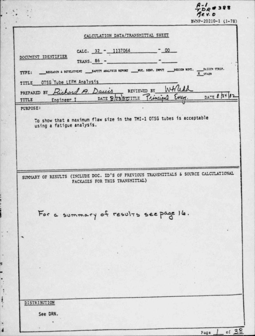
H To show that a maximum flaw size in the TMI-1 OTSG tubes is' acceptable-
using a fatigue analysis.
!; .
fr,
|
|
! SUMMARY OF RESULTS (INCLUDE DOC. ID'S OF PREVIOUS TRANSMITTALS & SOURCE CALCULATIONAL| j
PACKAGES FOR THIS TRANSMITTAL)|
||
.
S f. C- 8 !b.C. ~ SuTnmo.f y ok f*d,60\T bOf
;-
. .* m ,
.
*.
P- .
A'
*.
.
:1
. -
l- DISTRIBUTION-
~*
See DRN.
...
~ _ _ _ _ _ _ . _ _ _
Page / of 38
. -- - . . _ .._._. - _ .. . -
,
g.2 t.roa set. .... -
- -
, .,-
-- }e4 0a .
'
...
.
Babcock &Wilcox 32-1137064-00 >nm. . . , - ,
GENERAL CALCULATIONSNuclear Power Generation Division,
-
..t
~''
"~ - Table of Contents. a. .. .
...
.'
.Section- Title
- Page -*
1;-
- . . . . .,
):b '' 3 E.J W "...
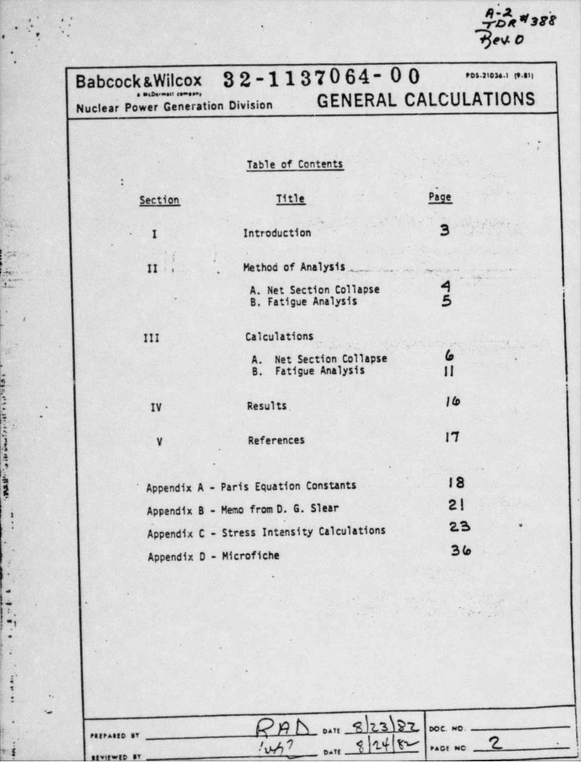
"I Introduction.' .
-'-
*W ' :; | .
'^
-
.sc. II ,. Method of Analysis. . ~.
. . . . . , . ,y.....
._ ,
A. Het Section Collapse N .
. , . , _ . .~
~ B. Fatigue Analysis 5 :)v* ,
t o
. . .
III Calculations :. :, . - ;-:.--
,- . . ,-
A. Net Section Coll. apse 0~,,
.
B. Fatigue Analysis jj i-
.
IV Results. 16-
k.. .-
?
,.
). V References 17
I.s
,
|'
- .
[g . ' I81 ~ Appendix A - Paris Equation Constants
1.-
i Appendix B - Memo from D. G. Slear 21 -
'
2.3 *
ppendix ~C - Stress Intensity Calculations. 36 |Appendix D - Microfiche
J.
.. -
- ~
*.
- ,
1~- e :.,
; .;.,
o. ;,.
J'
I
r -.
1
j; *.
-
k $ b ein _9 h d h - occ. o.! ,. ,.. . ,,
*
N- /M7 t'of t e ,... e- 7..
,
on ;-ter_-- - - -
_
~~
ji.3-
.. . . . rpe *a eg.* *.. .
h u,0, ..
\*
' ..
Babcock &Wilcox 'S2-1137064-00 = = > -n
GENERAL CALCULATIONS. . . . . ,
Nuclear Power. Generation Division -
. u'
.,
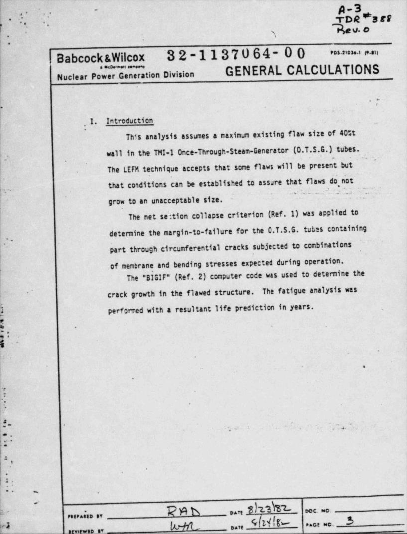
I. Introducticn .- .
. ,
,
This analysis assumes a maximum existing flaw size of 40tt
wallintheTHI-1Once-Through-Steam-Generator (0.T.S.G.) tubes.j.
.
The LEFM technique' accepts that some flaws will be present but-.
that conditions can be established to assure that flaws do not.
'. -. .. .1 e : .: _. .. c' .' '. ., . ' ~ ~;.. . , _ .
grow to an unacceptable size. --
The net sektion collapse criterion (Ref.1) was applied to
determine the margin-to-failure for the 0.T.S.G. tubes containing-
.. part through circumferential cracks subjected to combinations,
.
of membrane and bending stresses expected during operation.
The "BIGIF" (Ref. 2) computer code was used to determine the
crack growth in the flawed structure. The fatigue analysis was' '
3 performed with a resultant life prediction in years. ,
P |
.
6-.
.
w
.
r .
.-.: -
'
\18 '
. - ' - Wa. *. . , . , .
=..i*
|.*
|.,
|1.
:: I- .
pph ,,,,3h3h2-''
Dec. ~o.3 .
PatPAttD ST* PACE NO.,,ej . pggg,
' RfVII ED ST '
. . . . . . . . . _ _ . . _ .. _.
b. p.qroe ,are, ^ . . . -
.
*
.., ,
.
Babcock &Wilcox 32-1137064-00 - = = > " "
GENERAL CALCULATIONS. . . . -
Nucisar' Power Generation Division.
'
.J'
II. Method of Analysis,
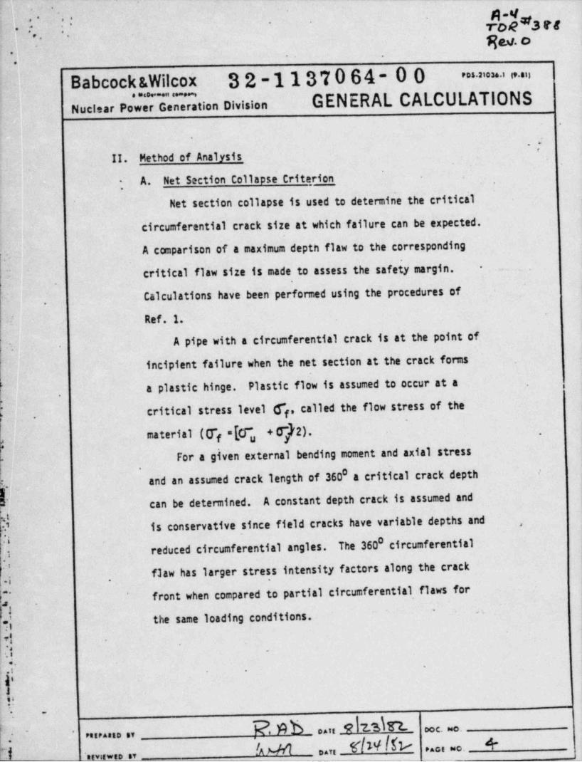
A. Net Section Collapse Criterion-
*
Net section collapse is used to determine the critical.
circumferential crack size at which failure can be expected.
A comparison of a maximum deptn flaw to the corresponding.
I critical flaw size is made to assess the safety margin. -,
i Calculations have been performed using the procedures of,
Ref. 1.'
A pipe with a circumferential crack is at the point of
incipient failure when the net section at the crack fonns
a plastic hinge. Plastic flow is assumed to occur at a,
critical stress level 6*f, called the flow stress of the.
. material ((T =[7 +Ff2). ,
. f u
For a given external bending moment and axial stress0 /
I..and an assumed crack length of 360 a critical crack depth
can be determined. A constant depth crack is assumed and' .
^ is conservative since field cracks have variable depths and ,-
:i 0 circumferentialreduced circumferential angles. The 360yflaw has larger stress intensity factors along the crackf.| 8-
.,=1-
front when compared to partial circumferential flaws for.
^
fthe same loading conditions.
~>
4.,. .
q -
.. .
'^ .
1).
. N b oan 9 7.- E occ.wo.\_' - neenso er
kW I!N k**ce ao.Ni -cevowce er
- - - - - - . -- _ - --___ - _ _ _ _ __
. ,on
. _. . _ . . - . _ _ . _. g-p,..
f .? wo-
-
. = = ' " ' "32-1137064-00 -9
Babcock &WilcoxGENERAL CALCULATIONS
e eration DivisionNuclear Pow
.
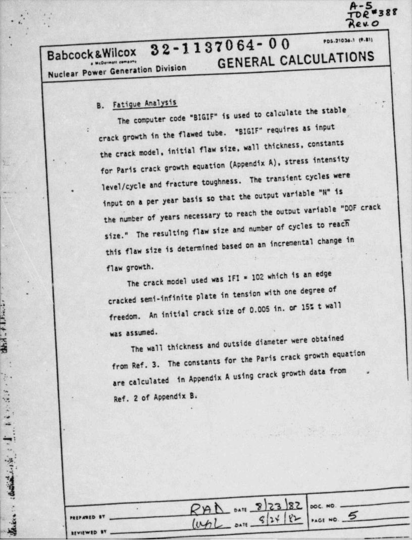
B. Fatigue Analysis _ ~I
The computer code "BIGIF" is used to calculate the stable"BIGIF" requires as input
crack growth in the flawed tube.I
the crack model, initial flaw size, wall . thickness, constants
for Paris crack growth equation (Appendix A), stress intensity3[ .. .,
The transient cycles were4' level / cycle and fr'acture toughness.*
input on a per year basis so that the output variable "N" is,.- - - -
r
the number of years necessary to reach the output variable "DOF crackThe resulting flaw size and number of cycles to react.
size." .)
this flaw size is determined based on an incremental change in!.
,
|'.. .
.
flaw growth. .
The crack model used was IFI = 102 which is an edge|. [ cracked semi-infinite plate in tension with one degree off. An initial crack size of 0.005 in, or 15% t wall
freedom.'_
W was assumed.
h; The wall thickness and outside diameter were obta'inedEE . .
The constants for the Paris crack growth equation: from Ref. 3.
in Appendix A using crack growth data from,,e.,,.
.are calculated'.. ?. Ref. 2 of Appendix B4*
-. . . '
- -;py.
.: . ' ,.
, ,
.-
., ,
.
h.'
'. 55 *,.
.
.
9 W I\ . n_ YT 3 I22 c. o . _.'
5hM L ..n
4W n ... - 6 ;o ,,, m .. ,,
"d. i,,,,...,,- . - -
-
A-6ree%ep ;;* ,- .. . -
Taq. o- -
.
.
Babcock &Wilcox 32-1137064-00 > = = = > " ". .. .. . ....
Nuclear Power Generation Division GENERAL CALCULATIONS.
,'.
III. Calculations .
,
: A. Net'Section Collapse >'-
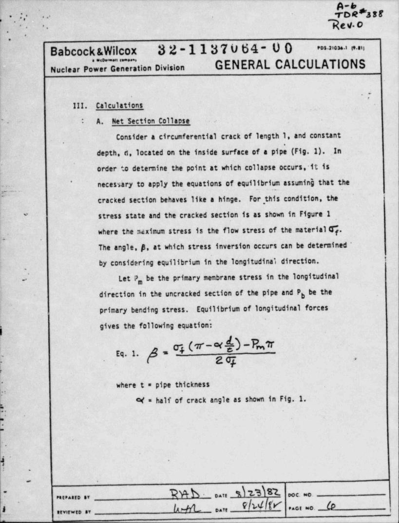
Consider a circumferential crack of length 1, and constant
depth,d,locatedontheinsidesurfaceofapipe(Fig.1). .In
order to detennine, the point at which collapse occurs, it is
necesshry to apply the equations of equilibrium assuming that the'
cracked section behaves like a hinge. For ,this condition, the
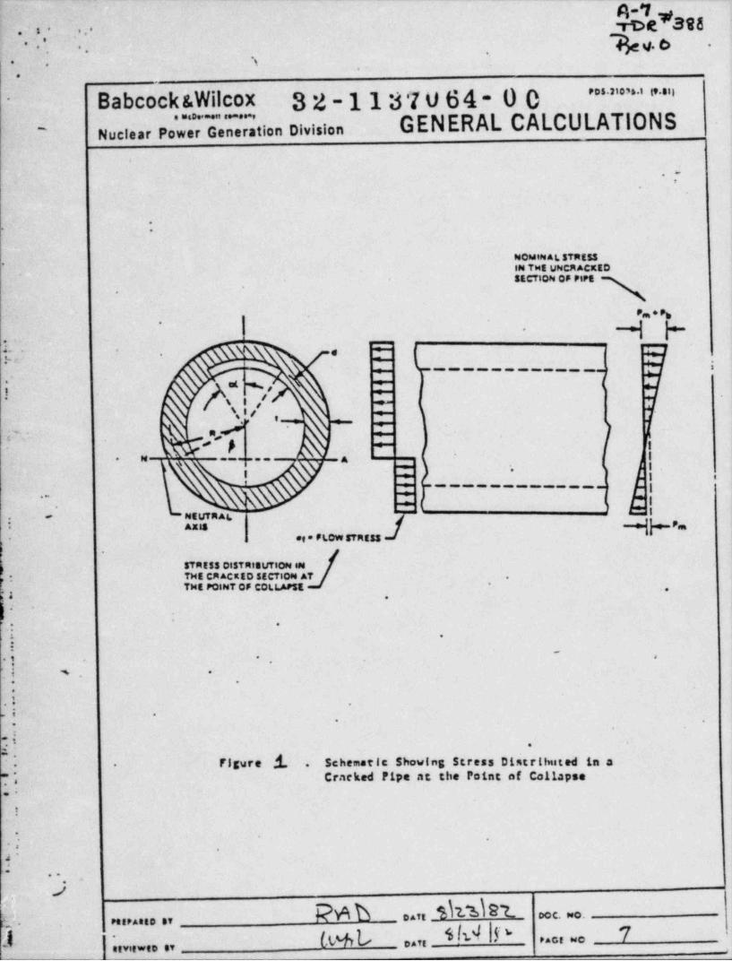
stress state and the cracked section is as shown in Figure I*
wheretheuximumstressistheflowstressofthematerial%.v-. .
Theangle,p,atwhichstressinversionoccurscanbedetermined*
by considering equilibrium in the longitudinal direction.
Let P, be the primary membrane stress in the longitudinalbe the- direction in the uncracked section of the pipe and Pb
primary bending stress. Equilibrium of longitudinal forces..
gives the following equation:
=NEq. 1.-
g z og --
where t = pipe thickness~
-
:c( = half of crack angle as shown in Fig. 1.
;,
F:.
* ~
'
.
4- .
: .
PttPAtfD BY Daft 00C. MC.*
fx & FlW[F ..cf *C. J. Art.fm wf. .,
4yrce#398,. , " .*
hv. c. ' , ..,,
-. s.
.
.
Babcock &Wilcox 32-1137064-00 ' " ' ' ' ' " ' " "-
noci.., pow 7r"d".'n'.7. tion oivision GENERAL CALCULATIONS'
-
.
.-
*> .
NOMIN AL STRESSP IN TME UNCRACKED
~
SECTION OF PIPt.
Pm*Pb'
t. = c.
e.
.%- - .
- - - - . - . . - - - - p
\ el '%y [ k
/\ i /-
- <
\.I / *r , ---es -e - e
; ~- . n,/ *
.o' '
fs e
N- -
====== A.g
*I + j j e
7 ! |---- --
\ * j.
NE uTR Ai.. -
AXIS P*m
og * FLOW STRESS.
.
STRESS DISTRIBUTION eMTHE CR ACKED SECTION AT- .
'THE PQiNT OF COLLAPSE ..,
s .
.
**
i .:i
g .
. i -. ,
li s .
* '
.: .
; -
.
j- .
'
Figure .'i. Schematic Showing Stress Distr!!nited in a.. -
Cracked Pipe aC tlie Point of Co11spse j*
,.<
..
!
*
.
I' -
d'-
..,
,
)QAD otti _%\'l E'l_ ooc.=0.
t. PetPAtt0 ST
(w,L. $M |P 71 ,-,,,, ,,ot O
afvitwtD ST
n-rrd st.*3 F f
.
.
,
g v. o-
- -
,
. .. .
. .
Babcock &Wilcox 32-1137064 .00t " " - " "*
GENERAL CALCULATIONS. . . , _ . .
Nuclear Power Generation Division.
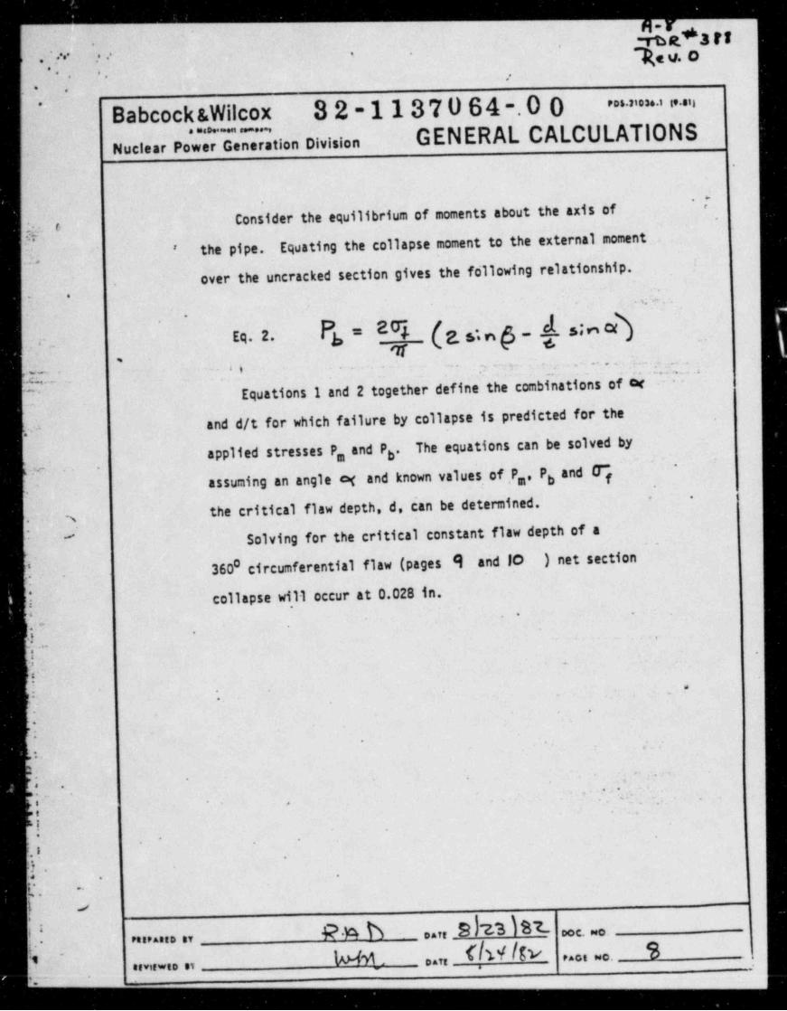
'IConsider the equilibrium of moments about the axis of ,
t
the pipe. Equating the collapse moment to the external moment'
.,
over the uncracked section gives the following relationship.. : .. . . . .
P = 2% (e. op_.d. ;ncdEq. 2. 3 1!,. g.
,.. . . . . . . . - .
4 i . . ,-,_.p .. . .
Equations 1 and 2 together define the combinations of car-
^
and d/t for which failure by collapse is predicted for theC, . -
applied stresses P ,.and P . The equations can be solved byb-
and Fassuming an angle q and known values of P,, Pb f
' -
the critical flaw depth, d, can.be determined.s.
Solving for the critical constant flaw depth of a.
.
'
360 circumferential flaw (pages 9 and 10 ) net section0'
!! collapse wi11 occur at 0.028 in.,
a . .
j.m -
.
.} -.
37L' .
~
13'
;- -
-
.p.
4
-.
.
~
y . ..:.t
.
. > i.. '_,
;;? _
.-
i-
..
'. .
t- ..
X. --
! s
.! 9%h ..,,Bb23IBz- ooe. . ... ... . ,
flw Itv S1
~
1*44 . . . . . .. . , ,........ ., - ,
r_ - - - _ - - - - _ _ _
. s ..._ _ _ - - _ _ . . _ . _ _ _R-9
; . .- mos ur. .
.s ;:p.e,4 -. .
., '..
-
,
'
Babcockswilcox 32-1137064-00 " * " ' ' " ' ' ' " "
GENERAL CALCULATIONS. . . . .
Nuclear Power Generation Division-
1
'
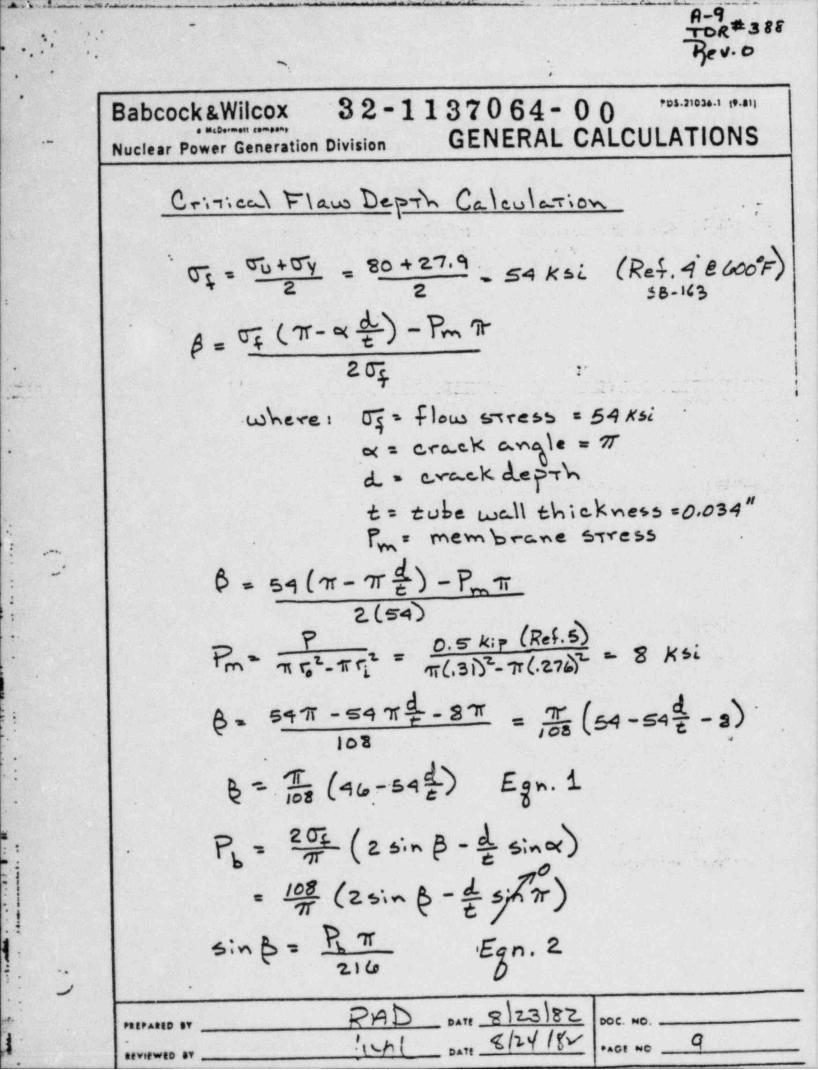
0,v,, ed We be.p r5 Ce.\ eu\ :r,ow |.,- '
.-, ... .
q , % + W so + 1' A ..snNst (Ra?.4 e 6dr) I~
2 2 3 s.iq..
g,g'(.v-xM-Pmt'
r I.i.- 29 - . . - _. ._. ., ,.
2- . --< - . . . . ,
.wbeve: -q s flom snress = 64 #51'
.
.
lx = c.co c.K ug e = 7-
-.
& . _u.r .,
t = t u be we 11 tM e.k n e+ 3 =d,os4 "-
( = rnevn b ec ne ssve ss..
.
,f , . . .
0 = 51 (m '7t h - P,m _4 2.ce4
? o.s uur (Ret s)"
Prn' % q' T fi.' d(,3i?-7r(.2.78 ' 8 N".*'
-
=,@(s4-s4h-s)~-8*! $= 5*T -54
..
. .
| Q =- [y, (As - s A f Ef s. 6.~
,
!j P = *@ ( z * - @ - h s:e4-
s ._.,.
qp (z,,9 -4, x)( -
f.~ +:4 R v,e3 n . z1,o
..
- j .
bb sate 3 ooc. we.*
reeraneo er
1 ;.. .so , .%h L 4 M / P .... . 4o .,,.
- - . -.
*+ . %;,y ,,.
'
...
: .o.* '
-; '.
:- Babcock &Wilcox 32-1137064-00 " " ' * " ' " "
GENERAL CALCULATIONS.-
Nuclear Power Generation Division
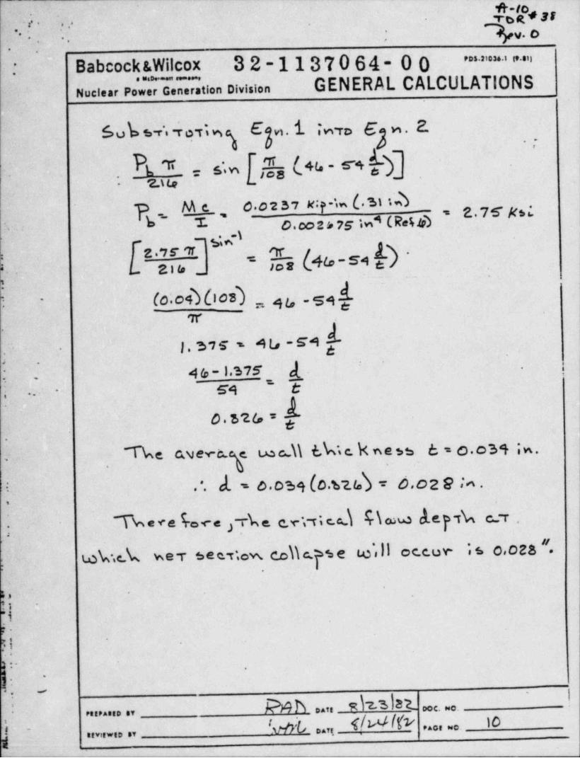
Sub s r' roTNg Egvi,i swro 6 w . 2..- .I
0
L 1 .::. I.w (45-S'93'
. .
2.ua L-
Me 0.o237#;p-in(.31iD 1~
yE~ T ' 4 (Re%5 ' E'7k* ;'
O.m2 6 75 iwM-1, 3;o-
f2. 9 5 R % y
L a n, _ ;;ir (_% - s4 e ) '*..
_
(o.e43 6 os) , 4 u s 4 1-
e.
or
J.3,s-4t,-s4h,,
." .
a ' '
; 45-1.s75 g..,.
- .-
y, ,;
.....
o.s,a L,.
Tbeewer e t.e c \\ t.k, c. k n e as 6 = o.o34 ;w.e
,
'i . . cl. = o.oss (o.s25) = o,o2 e ;4'
.
j ~Tk = v e 4= c e ; rk e. c.r ,,; c.d S \ cow d.e p tk c r .i s o,oza ".
f t.ok.ek wet see.,;ew. cohps e co',ll occow
,.
3.
i.
1-
. . . .
-
..
g: P 4 h ..n sh 3lat
'
!.
c. .. .. .... .,
'vdk ..ro f/WW 10I -
,,,, ... ,,. . . , . . .
%
***'.;. . ;... had C
..
.. ... .
Babcock &Wilcox 32-1137064-00 >' > ~ "'
"-
... . .-.-' GENERAL CALCULATIONS.
Nuclear Power Generation Division.
B. Fatigue Analysis.
~~
In addition to the input data required in "BIGIF" discussed*
in Section IIof this report, two' transients were input to account'
for Flow-Induced-Vibration (FIV) and heatup - cooldown cycling.-8
-
For transient one, a conservative value of 2.37 x 10 cycles
per year (75 Hz) of FIV was assumed (Ref. 5 page 4-7). 'However..
,
this is the fundamental in-air frequency and is conservative.. ;. .
{? because at 977. power for steady-state operation the maximum, . .
frequency is 61 Hz. Transient two has 6 cycles per year of-
heatup and cooldown (Ref. 6, page 5-4).E
In addition to the number of cycles per year for each.
transient a table of crack depth, a, versus the correspondingc.
stress intensity factor is input. Fortransientone(FIV),.
the stress intensity factor in the first K vs. a table is the( maximum stress intensity factor at the corresponding crack depth,!s
In the second K vs. a table for transient one, the stress[.
, intensity is the mean value. "BIGIF" calculates the minimum-'
.
stress intensity factor for each crack size and the transientG ~
i'
>
f. . .is defined'. "BIGIF".also interpolates between the input K
vs. a table values for- the incremental values that are cal-,
b'
culated.4
* .
o .
]*
? !.*.
s' - .
3 DOC. 80DAffPetP AttD SY
T IN ffIk IIbl Dan - ]race o.
k'
neviewe0 sv
p- -- - - - - - _ . - _ _
A.lLd'..;'' ,rde ars--
.; -
3av. o* '
-
.
.
Babcock &Wilcox 3 2-113"r 0 64- 0 0 ' " " ' ' " "
Nuclear Pow Generation Division GENERAL CALCULATIONS
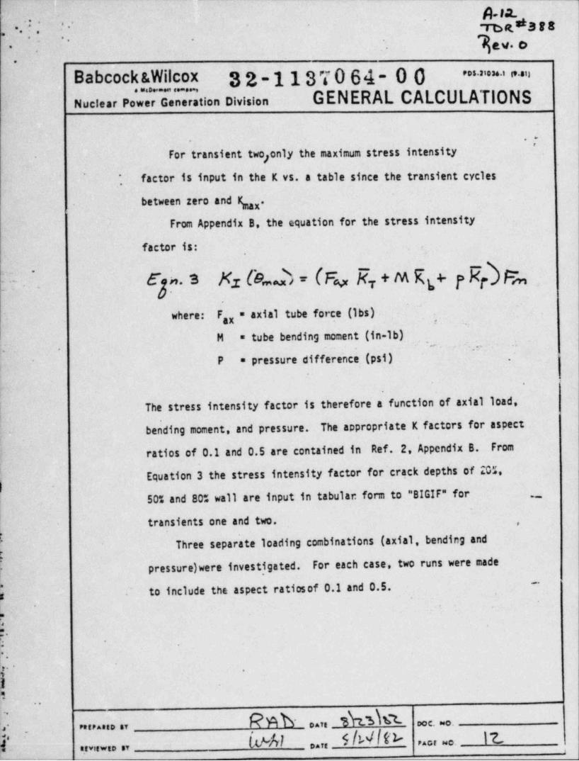
. For transient two enly the maximum stress intensityj
factor is input in the K vs. a table since the transient cycles*
,
between zero and ( x.From Appendix B, the equation for the stress intensity
factor is:
Kz Ce b = (Fv R.,. + M Rg+ y Rd f%.3
where: F,x = axial tube force (1bs) ,
M =tubebendingmoment(in-lb),. , .c
- - "
P = pressure difference.(psi) .
.
i The stress intensity factor is therefore a function of axial load,
bending moment, and pressure. The appropriate K factors for aspect
ratios of 0.1 and 0.5 are contained in Ref. 2, Appendix B. From
Equation 3 the stress intensity factor for crack depths of 20%,
50% and 80% wall are input in tabular form to "BIGIF" for . . , .
!-
transients one and two. ,
k Three separate loading combinations (axial, bending and
pressure)wereinvest,igated. For each case, two runs were made-
p to include the aspect ratiosof 0.1 and 0.5.3
Y .
2- .
al
....
Rnb .. . Shsh:t-l- .
........ ,, oo c. ..
3 (*Al 5Mlfk 17. . . , . . .. . . . . . , , . . , ,
,
. _ _ _ . _ _ _ _ ..
-
+- e.9* r r a ..
g . . .- . . . rog .-.
*; q. 6''- -
Babcock &Wilcox 32-1137064-00 ' * " ' * ' " ". . . -
Nuclear Power Generation Division GENERAL CALCULATIONS,
.a-
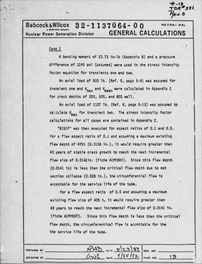
Case I- '
,
'
A bending moment'of 23.73 in-1b (Appendix B) and a pressureJ
-.
difference of 1245 psi (assumed) were used in the stress intensity
factor equation for transients one and two.
An a'xial load of 500 lb. (Ref. 5, page 5-9) was assumed for-
transient one and ( ,x and bean were calculated,in Appendix.C. -
. . . . . ..
for crack depths of 20%, 50%, and 80% wall..
' ''
An axial load of 1107 lb. (Ref. 6, page 5-13)'was assumed.to .
I
calculate ( ,x for transient two. The stress intensity factorcalculations for all cases are contained in Appendix C.
'"BIGIF" was then executed for aspect ratios of 0.1 and 0.5.'
'
For a flaw aspect ratio of 0.1 and assuming a maximum existing
flaw depth of 40tt (0.0136 in.), it would require greater than.
~
40 years of stable crack growth to reach the next incremental
_flawsizeof0.0141tn.(ficheACMYBRV). Since this flaw depth
.
(0.0141 in) is less than the critical flaw depth due to net~
section collapse (0.028 in.), the circumferential flaw is' *
acceptable for the service life of the tube.
For a flaw aspect . ratio of 0.5 and assuming a maximum
existing flaw size of 40% t, it would require greater than
40 years to reach the next incremental flaw size of 0.0141 in.,
'
(ficheACMYBSF). Since this flaw depth is less than the critical
' flaw depth, the circumferentical flaw is acceptable for the
the service life of the tube.-
PREPAttD BY __ Daft DOC. Pec.
P . . . . . . . ' , 64 yhe /r> i3D.,, ..., ..p- .
_
_ - - .. _. _ ___ _ -- -- - _ _
* -+ -r4ron ssa. , -
.' -
..:. : 30.O. .-
...
.
Babcock &Wilcox 32-1137064-00 ' a ' ' = ' i' "
GENERAL CALCULATIONS. . . . . - . .
Nuclear Power Generation Division-
.
.y
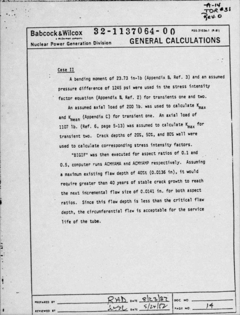
case II
A bending moment of 23.73 in-lb (A,ppendix B, Ref. 3) and an assumed
pressure difference of 1245 psi were used in the stress intensity
factor equation (Appendix B, Ref. 2) for transients one and two.'
An assumed axial load of 200 lb. was used to calculate (,x"
An axial load of~
and bean (Appendix C) for tra sient one.for1107 lb. (Ref. 6, page 5-13) was assumed to calculate ( ,x
transient two. Crack depths of 20t, 50t, and 80% wall were
used to calculate corresponding stress intensity factors.'
"BIGIF" was then executed for aspect ratios of 0.1 andI
*
0.5, computer runs ACMYAMA and ACMYAMP respectively. Assuming
h.a maximum existing flaw depth of 40tt (0.0136 in), it would
require greater than 40 years of stable crack growth to reachI
k
the next in'cremental flaw size of 0.0141 in. for both aspect
ratios. Since 'this flaw depth is less than the critical flaw~
*
depth, the circumferential flaw is acceptable for the service, . .
life of the tube.
-.
*.
4 ~
.
G
,
s
*
1 -
-
,
k po t. No ,D A,1.
- POIPAtID BT
'WO ..,, 5/Wl& /4. . . , . . .i .. . . . . . . . .,
~
||-I5, ?..'.'' ng*3ep
7u. o*- '-- ,.
.
Babcock &Wilcox 32-1137064-00 ' ' ' ' ' ' * ' " ' ". .. . .......,
Nuclear Power Generation Division GENERAL CALCULATIONS
.-"
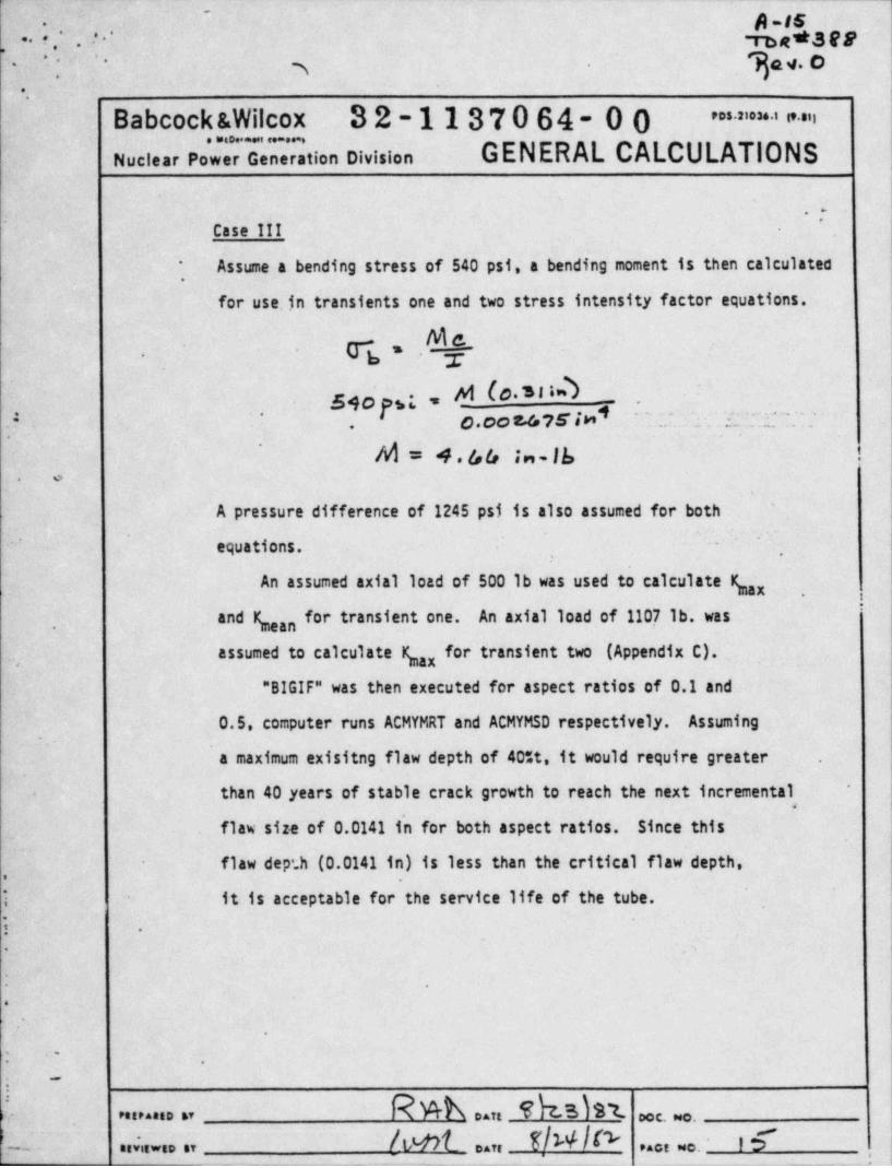
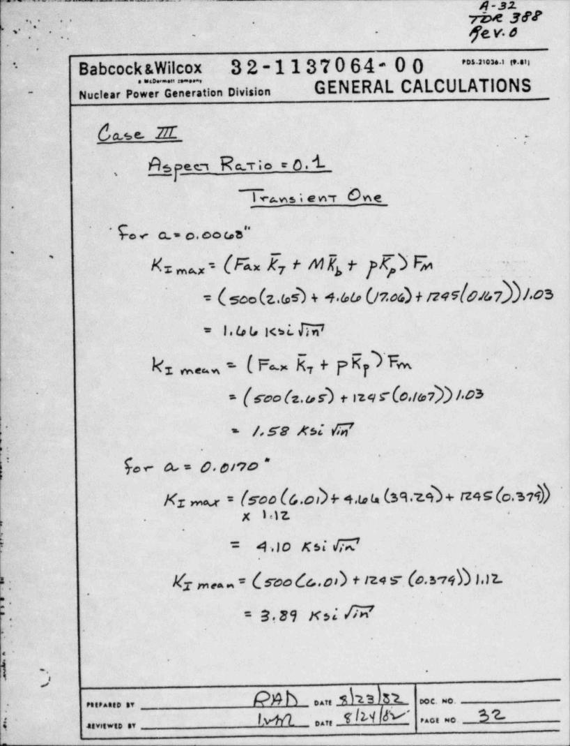
Case III
Assume a bending stress of 540 psi, a bending moment is then calculated*
,
for use.in transients one and two stress intensity factor equations.
b7s 3 x-
8 (0 31 -54 opt o.co z.475id.
^ ~ .. . ir.~' .: ':; *
. .
.
M = 4 66 in-lb !'
o.
A pressure difference of 1245 psi is also assumed for both'
equations. -
,
An assumed axial load of 500 lb was used to calculate (,x,,
and bean f r transient one. An axial load of 1107 lb. was,
assumed to calculate (,x for transient two (Appendix C).. .j
"BIGIF" was then executed for aspect ratios of 0.1 and
0.5, computer runs ACMYMRT and ACMYMSD respectively. Assuming.
a maximum exisitng flaw depth of 40%t, it would require greater.
than 40 years of stable crack growth to reach the next incremental>
,
'
flaw size of 0.0141 in for both aspect ratios. Since this
flaw depth (0.0141 in) is less than the critical flaw depth,,.
I it is acceptable for the service life of the tube.
5 -
~
.
. .
.
.
.
'. .
~
:
k N can T 3 \ 31 oce. wo.r essensen av
enviewsoav [tAfk can 5, IIeact wo.,
-~ _ _ _ . . . . _ _ _ _ . _ _ _ . _ _
r .. n s*ses
.
,
' -J . . : . . 32v.o.
.
3
Babcock &Wilcox 32-1137064-00 .. .- .i . .n--
. . , - . . .
- - Nuclear Power Generation Division GENERAL CALCULATIONS
')IV. Results. :J. Three separate loading cases were analyzed for fatigue'
of the THI-1 0.T.S.G. tubes. For each case, aspect ratios of,
0.1 and 0.5 were considered.
A maximum existing flaw depth of 40tt (0.0136 in.) was,
- assumed. For all case.s, after more than 40 years of stable. . ,
crack growth the next incremental flaw size of 0.0141 in." 21-.. .:. 'p j
'is reached. This flaw size (0.0141 in.) is approximatelyi- .
|half of the critical flaw size due t, net section collapse
(0.028in.). -,
.. _ . .
Therefore, assuming a maximum existing flaw depth of'
.
40%t and the loadings presented in Section III of this~ '. .
report, the 40%t flaw is acceptable for the service lifet-I
-
of the OTSG tubes.; -
.
!.
*-
,
i s''
r
. ...
O
e
.
. .
.
r . .
~
.
s
.
~
. % ..,, - in ....
....A... ..I eo
tM Daft PAGt sec.*.tvtEWS. SY
..
, _ _ -- .- .- .- .. . . .
p - 17-
, , . , .
neO388.
' ' '
6cv.o'
Babcock &Wilcox,
..
82-1137064-00.
. . . . . . . . - . . ,- -
Nuclear Power Generation Division-
* a" > = > n. > >
GENERAL CALCULATIONSV. References
1.
Steel Piping with Circumferential Cracks " EPRI NP 19" Mechanical Fracture Predictions for Sensitized St i l.-
Sept, 1976. a n ess2,. -
; 2.NP-192, Sept.1976."BIGIF" - Fracture Mechanics Code for Structur
es," EPRI3.
620-0005-55, Metropolitan rdison Co. Stress Report.
, Contract No.roll no. 80-8. .keport #1, page 2. Sept. 1973 microfil, m
4. .,
ASME B.&.P.V. Code, Section III Appendix I"
, 1980 Edition.5." Flow-Induced Vibration Analysis of Three Mile Isla dUnit-2 Once-Through-Steam-Generator Tubes " EPRI NP 1876Vol.1 Project 5140-1, June 1981, Page 5-9
n -~
, -.
6. BAW-10146.
Thickness,for 177FA One-Through-Steam-GeneratorDetermination of Minimum Required Tube WallPage 5-6..-
, Nov. 11, 1980O
.
4
'
,,
'
.
.
. .
,
-
:.~2.
.M
?5..
*g e
- $'k.
Mi.
nu. . . . , _P A.b _ ..n M? S } 8L
c. ... n
_ 6wi ..n 8/24/& [.
. ...... ., '
:_ .. .3 .
, . . . . - 17g y & y;&a- .
_--
,F' "".
-
-- _ _ . _ _ _ . _ . ,
-/r_._.. - ..- m....__
.
e*
n ie ,s e r* *
... .. .
.
'- : gc.q, O -* *
. .-.
.-
. .
Babcock &Wilcox 32-1137064-00'* . . . . . . . . . , ,...,- *... .-,
nuci..r pow.r o.n. ration oivision GENERAL CALCULATIONS-.
.
. ..
. .
.
.
., .
..
- -
. . .. ~
. , . .-
.
.
*. . . . .
..-
- .
t, .
'
- **. . . . ~ . . , -, -.. . , .
y~ .
.. . . , , . . . . . . _ . . . . . . . . . ..... ..
. :.- --a.x ; , . . . . . . .
.
- .
.'T =g
--.
Appendix A ,
'
Paris Equation Constants. ,.
.
..
;,.. s ..
.
-.
.
. .
.
* w . , , . .
'* *
,.
.
.
. .. .
.
+
l
I*
..
~
bc ..
.
.
$ .-
.
%-
.
;-
-
,+l ', .
u
.
k N b oan M13 3 L '
ooc. we.es,ean,o sv
lu n/ ..,, r/W /t- is :.-
i.
.... . . .,,,, ... ,,
b_r-..- .-----v- --,.w-- . _e-----
...
. . Y , .' ' 3av.o. .- ,
..
'
iBabcock &Wilcox .32-1137064-00 ' ' " ' * ' ' " "'
noci..r po U.T. tion oivision GENERAL CALCULATIONS'
-
Ii
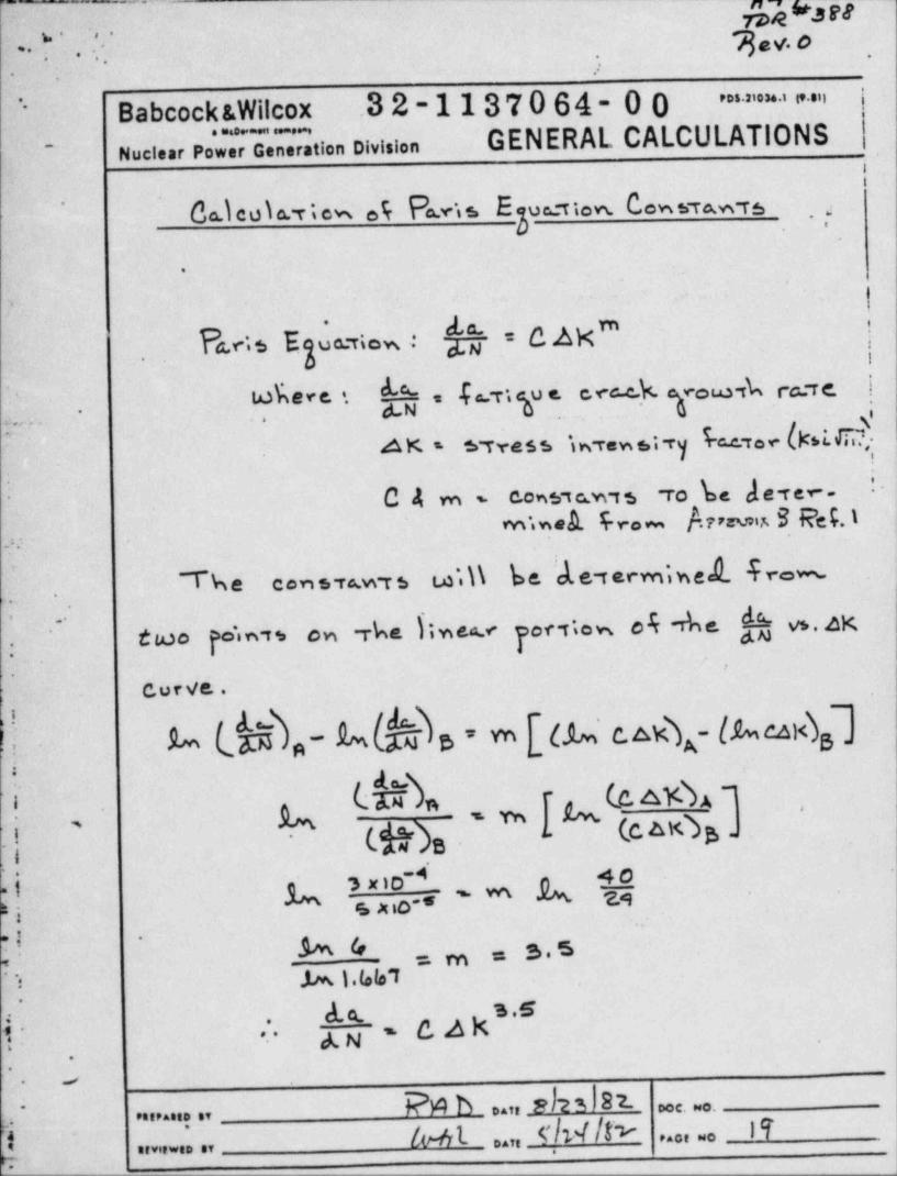
Co.ieoia.riew .5 P vis E uetten. Cowsra.w rs*
3.
-
.
L;s Egua riew, .: fy= CAM",
iwE e < e. '. h = f 6,igu e.<c-c.h gro e ,k ecerc.[(, .
6_r,(k.I.C)~
Ax. - wress m r.w.;-ry.
'ro k dere -C4m- cons,c.wts
m.sek 4r.~ Aum B reg.1*
.>: .
ti.1\ be Ne termiwed. -f rew* '
~The cen sva.w r s
two p'in,* en rba Siwee nor itew e4 -The. f--hvs.4K~
'
.
! Curve.. .
.
kh
A (c.A K b -A - -m .
(g),,, ' . e-
;
A. NI A ?[fo.~
-m .
3
1 . Mk = 3.5' =m,i h 1.(elo~f
.
d.( * O A N.63
4 ,
9' ** Ag. ,
-
.
P A b ..n p I n 8 2- c. o....... .,
I br-41. ..n _ T /14 /f> Ii,
'
..o. ~o ......... ., ,
.
_ _ _ . . . . -
4-ao.
.- - roa =.ut..,t
-.
. . '|'.'' ft V. 0
Babcock &Wilcox 32-1137064-00'' '
..ui.=.....-
. . . . . . . ,
Nuclear Power Generation Division GENERAL CALCULATIONS'
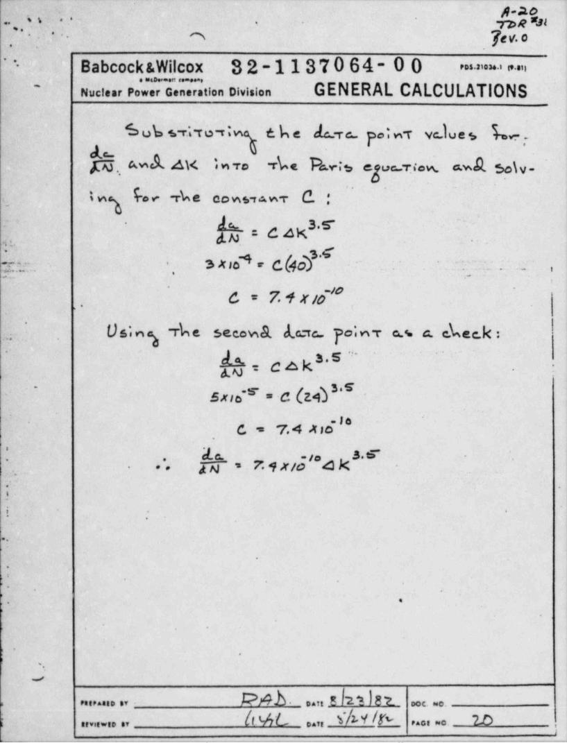
Sub s ra ro riw tbe J.c_rc po; n r vc Iu e 5 b- ,.h.,amAax;wr. rk. Ars egue r.< w. a.wA so\v-
"
b. rk e cows, wr c. :- tw%A d 4 K .s-
-
3..
d.N : .,,. . .. -
$ ;** h k |O S' h,'
|. ..... *
7. . . - . .
C = 7. 4 X /O, ,,
'
Using rbe secewa d. crc po;ny a.s c. ekee.k :.r .
- -
g = c a k , , .....
3-
gy .
' Exis ' = C (L N *~
-
.
-le-
C = 7.4 X IO.
tde c. .ja
4 k . tie ~S ,
\'
[h~ ' 7 4 X/o- * *.
. , .
.
i . ,
e
*e
4
9
L' .
*-
.
g
o
L-
..
'
t -
!.
J
s P8tP AGED BY . DATE DOC. NO.
lt ML ..,, s'4 Y /rv 2.0r ........ ., , . . , . . .,
> 1,. . . _ . - _ . _ . . ._ ..- ,. , . , . . - _ . - . . - . . _ _ . - . - . - . - - , ...-_. i
wT
- roe ser'.; . . .
- .
. {Q,y. O, ~* '-
..
Babcock &Wilcox -32-1137064-00'
" " ' ' ' " "'-
GENERAL CALCULATIONS. . _ . ,
i Nuclear Power Generation Division
-:
s
.
.
.
7.
.
~ . . . - . . . . . .~; g.;-
-. . . . .
'- _
.
.
i' * -,
Appendix ~B.
*
| Meme fromD. G. 51 ear
,
&
w
:. -
? -,-
|t ,
'~
"-
;,.' . *
'.
b! .
r0
.'
: -
pr .
4
,
q- '** .
_ oatt _9 L E-- ooc. ro.I;,' Parraeto sy
Q~ e,,,,.;; e, lwi L ,,,, S 'W !V 2A,,a, no .
r- -. - -- . _ _ _ . _ , _ _ _ _ _ _ , _ _ _ , _ _ _ _ _ ,
__ _ _ __ _ -- -.-%,_m
6 .a / a ,m t 3 8 gulw- -
>. .s- ...
..h-''
-
e.*.
GPU Nuclear100 Interpace Parkway
/~ (- 'y ggf Parsepoany. New Jersey 07054;
201 263 6500TELEX 136-482Writers Direct Deal Nurnber:
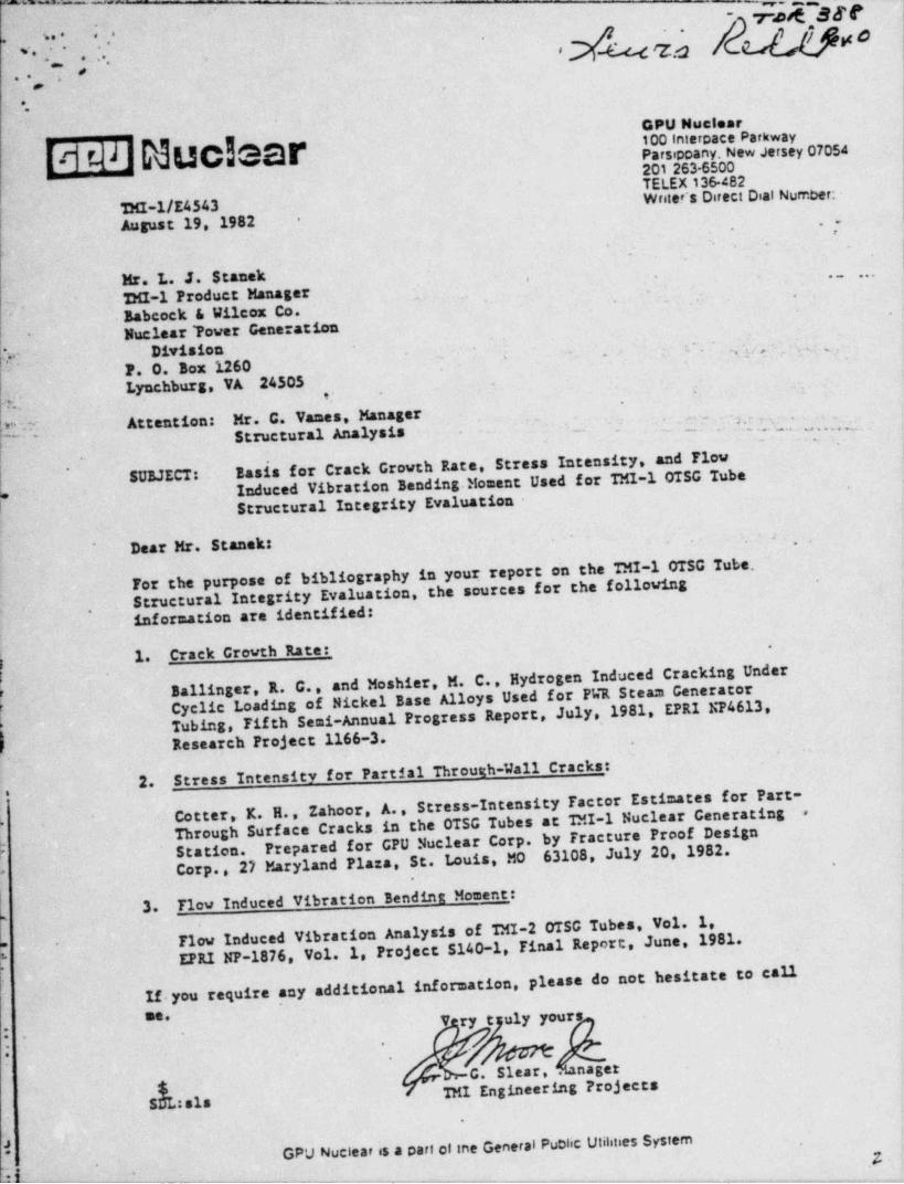
TMI-1/E4543August 19, 1982 . .;
-
- .
,
Mr. L. J. Stanek ~ ~ * *
12M1-1 Product Manager .
,
Babcock & Wilcox Co.'
Nuclear Tower Generation' '
*
i;r Division '-
-- , 3 < ,j _ ,..
F. O. Box 1260.
Lynchburg, VA 24505 - :
. . . .
Attention: Mr. G. Vanes, Manager , ~ ' 7. r --?" R . Structural Analysis . . _ - - . . . . ...... .... .
- . .:
.
Basis for Crack Growth Race, Stress Intensity, and Flow*
SUBJECT: Induced Vibration Bending Moment Used for TM1-1 OTSG Tubef Structural Integrity Evaluation
Dear Mr. Stansk - .*
For the purpose of bibliography in your report on the TMI-1 OTSG Tube.Structural Integrity Evaluation,~the sources for the followinginfornation are identified:
,
1. Crack Growth Rate:_,
Ballinger, R. C., and Moshier, M. C., Hydrogen Induced Cracking Under
Cyclic Loading of Nickel Base Alloys Used for PWR Steam GeneratorTubing, Fif th Semi-Annual Progress Report, July,1981. EPRI NP4613Research Project 1166-3.
for Partial Through-Wall Cracks _:2. Stress Intensity
Cotter, K. H., Zahoor, A., Stress-Intensity Factor Estimates for Part-.
Through Surface Cracks.in the OTSG Tubes at TMI-1 Nuclear Generating.
5
Prepared for CPU Nuclear Corp. by Fracture Proof DesignL
63108, July 20, 1982.I Station.Corp., 27 Maryland Plaza, St. Louis, MO"
3. Flev Induced vibration Bending Moment:
E Flow Induced Vibration Analysis of TMI-2 OTSC Tubes, Vol. 1,EPRI NP-1876, Vol. 1, Project 5140-1, Final Report, June, 1981.
*
<f
If.you require any additional information, please do not hesitate to callme. V ry t uly yours
*.
.
; -.
G. Slear,. nager'
g TML Engineering ProjectsSDL: sis
.
3 GPU Nuclear is a part of sne General Puche Utihties Systern'
.p.
W --- *___- ____ - __ _ _ __ -- -. . _
muus,p. ;. . pv.o.
.. .w . . . ,.
. -. .. ..
Babcock &Wilcox 32-1137064-00 > ~n. . . -
- Nuclear Power Generation Division GENERAL CALCULATIONS.
.-
.
. .
'
.
.- - - -
, , _
- ,
.
,:,. .
... - . . . . - .
*
.*
Appendix C
Stress Intensity Calculations
-.
e
V .
,
3.
.
su
e
0
e
' G
e
.
O
F
Pmb ..,, eh2h r_ c. .. ....... ,,
b / o o t .,, c/v'/fL O. . . . . . ........ ,, ;
7e ._ .: . . . ._,. ,. ._ g e. ; .-- - _ . . . -
- , - . . -
wrur-;wk , . .( . . , . ..
m.-. ..
BabcocktWilcox- 32-1137064-00..
>>=='4 n'
Nuclear Power Generation Division GENERAL CALCULATIONS.-
.
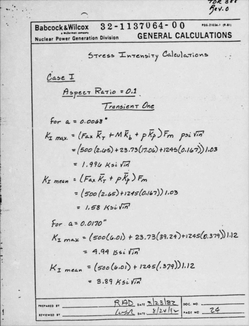
Svcess L rew3;T7 do.leula riows ..,
.
da3eT .
~
''
i.
4 i
A *J'e c r R ' T io " 6'2 . , i...
,-
Tankienr One .;_
. .
k for- a. = o.coss * --
A1 m. = (t% Rr +-M Ks + y My ) F,.n pi fi,7'
.
= [500 (z.04 + 2 s .7s(17.oD +124s(e.ts,$ 1,os--
= I . 9 % xa {|,7.
5! Nz meau, = (Fn Er + F p .) F>,i
= f500 (2 45) HZ45~(as/47)) /.05
= I 68 /<3i, {Tr? , -
.
e w. ...
. for . A = 0.0/'70 "- ,
X rna - (sools.ob + 2s.7s(39.2h+sz+s{c.s,9$ I.12...
1
C A .M issi ri;;'=.
: -
|<1 m aa, = (Soo (4.oD + 1745[,379))l.12.
1. * S 89 Msi fir? -
R #7b ..,, yka\st ,
,o o. .- ...... . ,
1 la ,,,,._ Ir/w IN 7A. . . , . . .,,...... ,,
i_.__--__________-____._-__. _ _ _ _ _ _ _ _ _ _ . _ _ _ _ _
_ . _ . _ _ . _ . . _ . - . . , ,,._,
e ,, 7 . , . . j yev. o. .
- ;. -.. ..
.
Babcock &Wilcox 32-1137064-00 .. .- .i ...n~~
GENERAL CALCULATIONS" . . . . -
Nuclear Power Generation Division ,
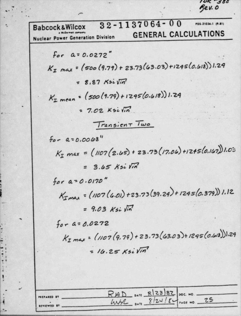
.fo e A = 0. 0 2 7 2 " :.
Ez ma.x = ($~oo (9,71) f 2S.13(4S.03) +-)24S(0. hts $ l.29',
< 8,87 Xsi W|. .
l.
* Kz w , i (soo ls.19) + 124rfo.sie))).24 ' ;V -~ *.
. :,. = 7.02.xsLc ... _
.
.
_
.- .._ .. .
%4n 5,'enT Two.
fo e Q.= 0,00 98 " .
.
e -
K mu = {/to?(z.&b + zs.1s(17,os)+12+sle,isr}|.chT 3
= s.&s xsi a'
fo < a , o . oivo ~
$ m = f//07 f6.0)) f 2ba?3(39,24)f 1245f0.379hb l*IE-3' * f". ,- : . *
= 9 03 K6L EE'
',
'
[ov-4=d.4272-
s
- |(z mm = [//07 f9 79) + 23*13{63 0SD+1295[0.9abI'24 'C; .
= i&. zs xs; >W- -.
.. ,. .
I'*8
4,
'-r -
.
.*,
hdTk __ % h %h,b h
_
M can __N' N 76 -
e4ce wo.'
.neviewio av
' ^ ^ -'------,__ __ _ _
a.,- _ _ _- -- _ _
.__ _ _ __4 - 2 /, ~ l.
g. .*: , J. '- n e.ste-
. .
hey.6* ' '-,-
.-,
BabcockiWilcox 32-1137064-00'= = . . .. i
. . . - , ,
Nuclear Power Generation Division GENERAL CALCULATIONS--
. \
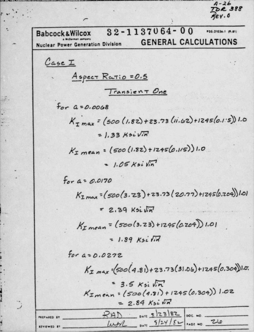
bcse.T. .- ,'
\'
,
1:
A sgee. r 1%r; o = o.s .
i
TA n s' e 6 r 6ne.h_b
- - -
,,..
~
Y her G=D.0048 '
- - -
;. .,
?;~ E ma = {S00 (la 82). + ES.13 (li,62)+124Sfo./ *S)) 1.01
=},35 M*i G
)c'3 m ga n : Woo (I 3z.) + 1'z.45(p,I/S)) 1.0_.,'
~= .
' f. 6S'N$ s' $'
_
.
.- fo, a = 6 0i?o .
-
.
Kz = {s o(s. z3) +n.,s (zo.,,)+124 slo;zo+%I.o1o*
( . .
b8M N6 ~ . . . . g,. T.., .
~
. . . . ,
h w!1
.
N;maan = (S~oo(s.25) +129sfo.zo+b t.oI~
.
'.
..
189 Kd R2f-
-
V. Fo< a = o.o 2n -.
.,
>-N fx ,4,, rh2)o[4.s d +23 73(s1.os)Ijz,r[o,3o4)l.o. .-
j ' 3 6 Ks' NAzm ern = (suo(1.st) + 12+s(e so+)) 1.0z( [' = 1.84 Ksi 72~
;.
rah - ..,, du hs. ,, c. . .
k; 'lu-uL- ........ ,,
, ,, } / w / r ... , .. n o --, , , , . . . , ,
-
' '
##~
yngo. * * * . .,'
.._s. . ..
Babcock &Wilcox 32-1137064-00' " " ' * ' ' " "-
-
GENERAL CALCULATIONSNuclear Pow neration Division^
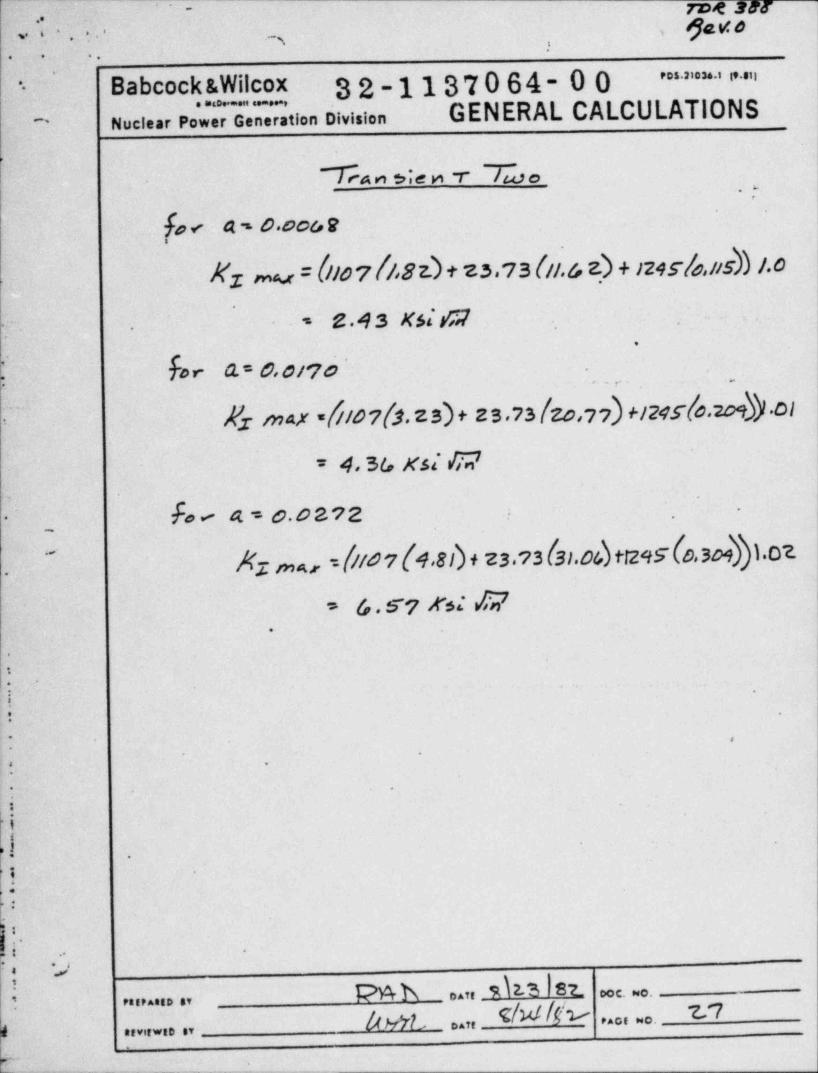
Ta n die r -r /wo.y
fo < a -. o. coa e
Nz mu = [Ilo 7 N,8 z.) + z3.73 (IE & z) + >245/s, tis)) 1.0<
'
z.43 xsita<"- ..
.
(: her Q.= 0,0/70 .
' Es max 8167(3.zs)+ zs.?s(zo,77)+124s(0.209N ol-
= 4 5G K.SE O2~
fo < a=0.0z?2 '. .~
.-
N ,,,,a.,.= f//67 (4,8 D + 23.?3 (31.04) t1295 (o,3041.02
3.
* (o. S*7 N E 2.
e
.
:*
'
.
' -
.
- .
] '
.
iI.
..
k ..
Pnb ..,, 4 3 st ooc. o.: ........ ,,
Av7L ..,, e/xt/tv 2n. . . . . . .
{........ ,,
L - .--. .- _
.< _p)ev. e5; ...- .
~.2..- . . ,.
....
-- Babcock &Wilcox 32-1137064-00 * ' ' * ' ' " "-
GENERAL CALCULATIONS.-
Nuclear Power Generation Division~~
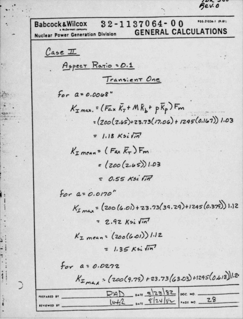
Case Z ...
Y~ A_syeer Es.,;o ,.O.t . _
-
True a n, sea' '
k. ..wy f,, a o. coag- _ _
-
-
.
,
|g. . Erma. = [Gx 5; + M Rf ,5j) Fmf
,,
. . ~ . = . . . ._
= {20olz.45)+zs.7s(I'7,os$+ 1249-(e,147)) 1.'osn ~. . . ''
i'
.
- = | I8 Kss' fi2'
y. . .
Y Xz ,,,e - ( Fu Kr) F*m ; - . - .
'
_
.
= { zoo (z a s-))1.oa;= o.ss n; w
-
f. F o < a = b . o n o '' .
Ky,,,y = (2oo (6.od +23 93/3A.29)+iz45(o,3MI) 1.)zl- .
k.: = z .9 z x ,1 M '-
a.
f'
X . m ea ,, - '(zoo (&.oi))11LhL 1 _
1 SS Ks: W .='.
.
,
) % a=o.os,2.
? Nz,,,u - (2006ad t es.13(6s.os)m+slosisilk3
| :. PMb .. , s\u\%7- e. .
... .... .,
i~ L%t fnW 2.s. . . . . . ...,,........ ..
. _ _. : . . . _._._____ _.
- -. .__ . _ _ _
r'~ae389-~
* :/JeY0, . ..,, '* '
m., :.. . .
- Babcocks. i cox 32-1137064-00 |' ' ' "' i~
Wl~
GENERAL CALCULATIONS. . . - . ,
:nuci.ar Power Generation Division--
>,
'
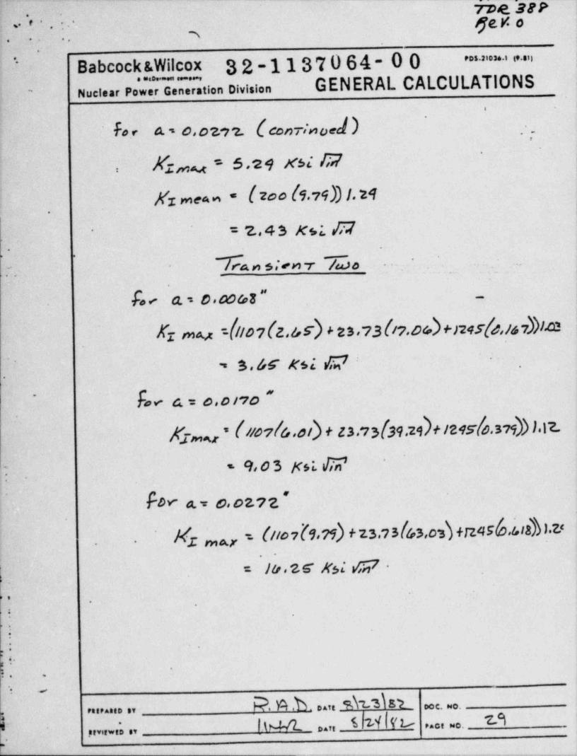
~ for a. , o,ozo z. (con rinoed ) . , .
-
Kzau = s.24 xse ||2-
,
),
Nz mea n - (zoo (1,75)) /.24i
. ,
.
- 2.,4 3 Ksi. ,C7L-
.
Wan s;en r ~/w~ o .
.*
. ' . . -
1.
;-
.
fo N ' a. = 0 a%B '' |-.
Kz my =(11o7(z,&5) + zs,,3(iy.os)+>24s(s,,,,}i.o1'
. s.x xsi ,w -
.
-
fa v- c.= e,osvo "~
.
gs my * [#47/4,0/) + 23,73[39,24)* /215[4,379))).17
9 , 0 3 K s L af7 5 ''
sT-
..
for a.= ca oz?z '.
I m a r ' O '# 1 [9'?ib f 23'1 5 I43<0'S\ +12A SIO*!*'8b I'73W*
..
i
= lo. z S Nsi s(7 -.
.
'.
*
.
-
.
O
?. .
Q,,
'
&
P. v4.b ..,duisi c. ..,....... ,,
h M ..,, s 21 N 7A '
. . . . . . .,,,, ... ,,
,
- ..- - - . _ - - _ _ _ _ _
c . . .. _.. u -- - - - - - ;, ._
roe sn. .. .., pv. e.w.. .- .-.. ..
_-
.
Babcock &Wilcox 3 2-11370 64 ~ 0 0 ' ' * ' " = ''-
. . . . - . ,
Nuclear Power Generation Division GENERAL CALCULATIONS~
-
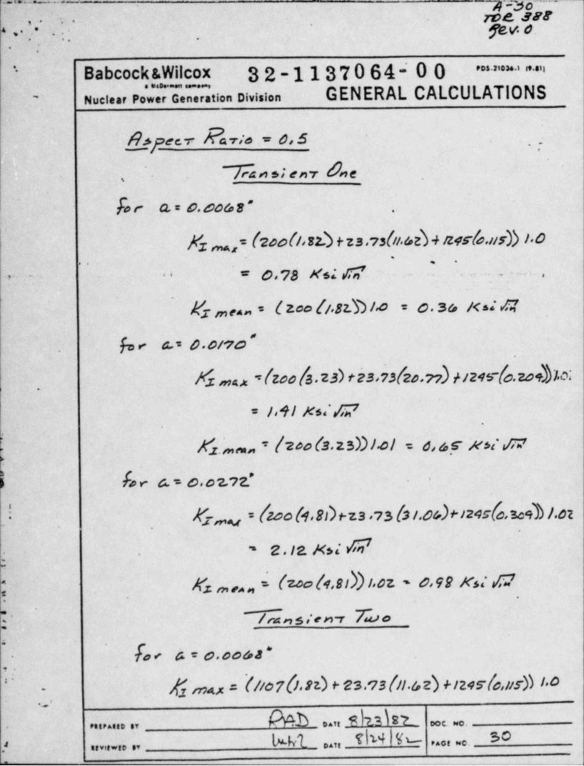
h feev Savio = 0:5 ,
' &nsien r 0ne,
for a = o.oos s - .
Nz n,= (2oo(i,s4 + za .,s(ii.ae) + izes-to.iis)) i.o'
= 0,78 Ms; SY ? .- .,' e*- ~_
.
Esinno,= { 200 (/ 82b I.0 = 0 3 6 K ss' G'
fo e a.= 0 0/70.
Xz ax =(zoola.za) tesa3(2o.ri),vzwfo.20+))1.m.
= lo41 Ks| E2'.
Kz.,,,n,, = {200 (3. 2 sD 1.01 = s, s y xsi s;7
ho e 6. = 0 o 2.,2' .
)
K.7,,,, = 600 (4.sh1-za ,,s (3 i.o&)+i24c6,sog)1.o2. _
' 2.12. Ksi W.
Ks ,,,n,,E (zoo (1,sd)1.oz ~ o,92 xs; C2
.
~ /rAnsien r &o5 '
[o < b=0.co&2'-
gj irpax = (//07h.S2.) + 23.'73(ll.62)?1245'(o,115)) /*O'
-
.'.
6 % b ..,, i n h t. . . . . . . , , m. .. ..
Mt .. , eb4 % so. . . , . . .f , , , , , . , ,
--_.
von = = -y ..
gav.s; .
. . . . + .. . ..
I., ;Babcochgy|c3 32-1137064-00 " " ' " ' ' " "
GENERAL CALCULATIONS, ,, .
~~ - Nuclear Power Generation Division
f-
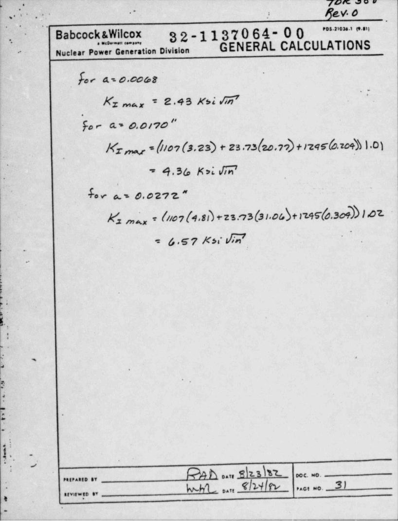
.o< a.no. coa,e
' '
-
Kz na, = e.4s xsi g .
.
Fo e a - o.o no "!
' Mrm -fno,(3.2s) + za .,.s(zo,,,) +i2gs-fo.,o,} } ,oy? -
-' 4 3/., M>I E; .' -
,
e; ~de v- g,0 27 2. "
~ ' '
A s.--
W mNx = N/07[4o8I +2'st73(3104b+119S*[6.309b }.07-.1~
= 6 57 KH E2-
.
;|-
|..
L
.
.,
|s i.
e
:
',
y-
.
I
( .
.
.
' . , ~.; ..j
b .C C. NO.D AT,P4, PAG.D BY
u t ..,,elwIm s;.
P......;.
,,,,.... ,,
,
_
j
_ . . _ . "h __
;g n-
.
7De 5##'. *
. -.. .
.'. fe v. d'
. .'
. ..
,
' " - Babeock&Wilcox .32-1137064-00 ' ' " ' ' * ' ' " ' '
GENERAL CALCULATIONS. . . , - . ,
nuci.ar Power Generation Division-
da 5e. E_ .
.,
A s te.en R c.T;o o. L .,
Tra.ws l e nv dwe,
' Ee < a.= o. oo c.,a"'
-
..
x ms.x = {Yax 5 t M Q t yK,) % _
-'
7.
1.
= { soo(z.lo ) + 4 4l.o ()7ed + rzqSf0Ro7h}.03s.
* I . l.o la l o i I T;i7
k z m .. , = ( F x 5 + g fi 7 4 . -
7 7.
* { coo (z.os) + s19 s-(o,te7))I.05'
| /, .58 Ks * G*
h: . E. , a . o. ono --
'.
Kr = = I5oo l6.od+ 4.t,td3%7D+ rzes(o,sve) |x 1.)z
,
.'
.
,
4.10 Ksi /T2=,
Yr ,,,,. = (roo 6.oe) + iz4 r (o.s-74)i,32.:
..
.
..
- *
?p .
k' .'
,-
Y 3 --DOC. NO,
PttP Att, ,Y Daft*
i l> M S h4 k' ,.., ,.. 3 ?,
-
t ..... ,, . .,E
:
w . _
a.x....:,. ,.
._--
. . . . A-33-_ ..
. .. _ - 72>R " 9 61.
fev.o. , . , . . .
'-
~
IBabcock &Wilcox 32-1137064-00' " '' * ' ' " "
GENERAL CALCULATIONS. . . . . . . .
Nuclear Power Generation Division-
.
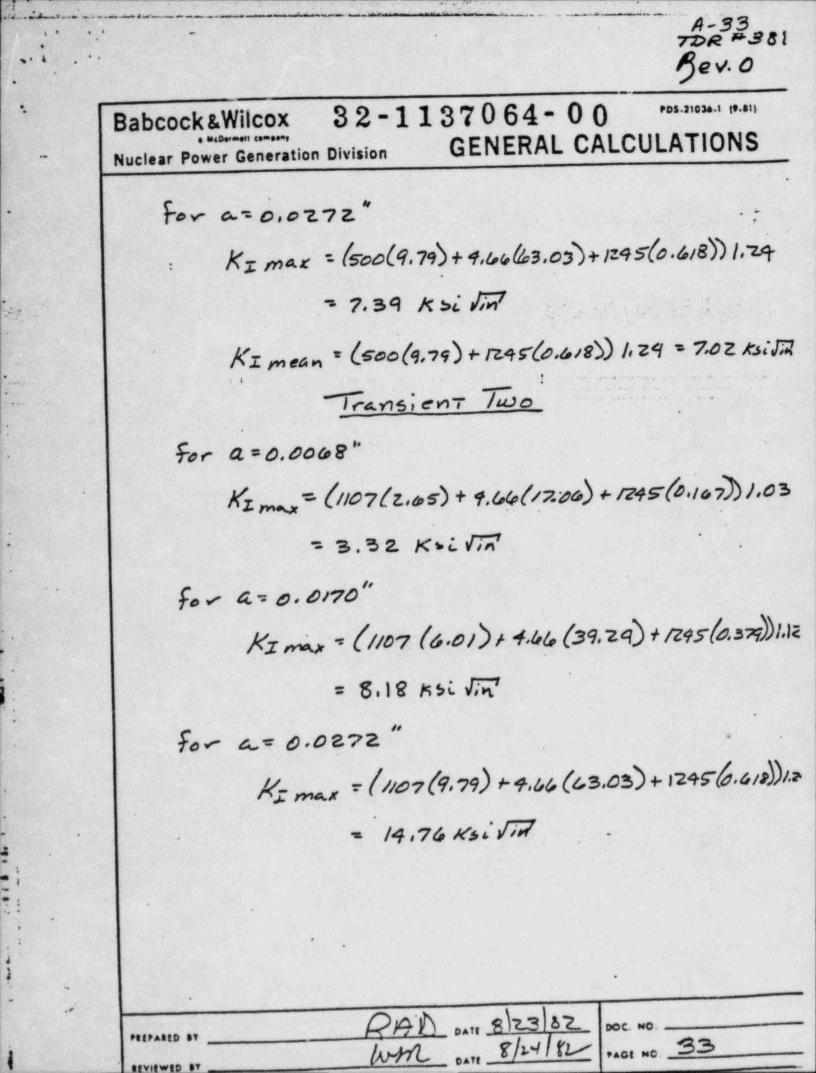
- for c~ = o o i. , z. ' " ..'.
l
Kx max = (s o(9.79)+1.acaQas.cs)+1195(o.6i8))1.'zmc-
\-
W: , 7. s 9 >< >i /T2 . .-
; .
Kz ,,,e.., = &ook. n) + mrlo.sie9 to 29 = 7.0z x.stm, .. - ..,. , ., .
.
-. ,
Icam,en- iuso -- -
..,
-
:
Fse a = o. oo o, e ''-
Wz = (/lo7(z.6,s) + 9.%(/7.ss) Hz45*(bat &7)),0'b'
m'
= s . s 1 xs t c2-
'..
f, < a o. oiro "'~
YKz 4 ~ Gior (s.oi)H.46, (39.29) + ne.rlo..rdbl.m
= 618tstri. G,.
-
,,
Fo< u o.oav2 . .
jf. _, - foor &.vs) + +.&& (cs.os) + s2+s-6.si>Di.>I
.-.
/4,74 Mss.VIIY* = -
-
9 -
Wt.:.; .
~
.
.|.E|b
-) .
- -
of
D A ,, DCC. NO.PR,P.3,0 SV
/u+rt r/w lr v ...,... s.3,
0 -
- - - ,, _ ,_
D.,,
.. . _ _ . _ . _
rwR E388.o . * . .
p,o~' . . - ,-,
' ~
v Babcock &Wilcox 32-1137064-00 ' ' ' * ' " ' ".__
wuci.ar Power Generation Division GENERAL CALCULATIONS-
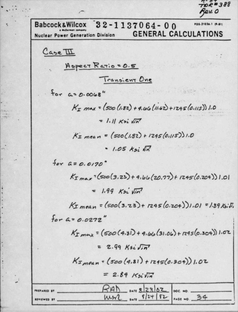
Cee. M ...
gp e.r h - e. s-~
. ' ''
+ s . ..,
|, %ws,e.wr owe.
-
.. g.., a o. s , .. > . . . .. ~.. ..- - -
..
.
.c-. ... . .
::;.- Nz mu - (sco (i.n) n.o,a (sub mgclo,ush 1.o - .;qs
' . . . .T'J/i''
! -.- - , . .
',
= I. Il x> * v 7'
M ,na. , - (rooO,sn + i2+sfs, urb.o.
.:: . i.ogy,; g . . r .-
_
-
..
G a = o. orio ~.
Kr ,,,,, = &Ms,2h + 4,w (zo.v) + iz+s-(s.mm .o g
b = |.99 xd 0;7 -
..
i Kr >>,en = (cools.1h + ms(0.zo+i)i.oi =/.s9s:5.
{ fa < a.- e.oz rz "' '
''
I_
Xz,,,n = (ss' o (+.5D + 1.n(ss.ob e n9s(c.sou I 01.
'
= z.49 Ksz Egr' ~
.
:
Ms,,,a ,, - (roo (4.s n + 121s-(s.so +)) 1. o z.) .
= 2.s4 x,,g,;'*
.
..
k4h .., R 21 6 L.e.ie.... ., c. . .
RA h4.. flit ' f& 34-. . , , ,... .......... ,,g ,
p
- - _ . .. ,, ,,,
fav. o,. . .
-
,- .-. ..
,'
Babcock &Wilcox 32-1137064-00 ""'*''"'i5
GENERAL CALCULATIONS..
Nuclear Power Generation Division*
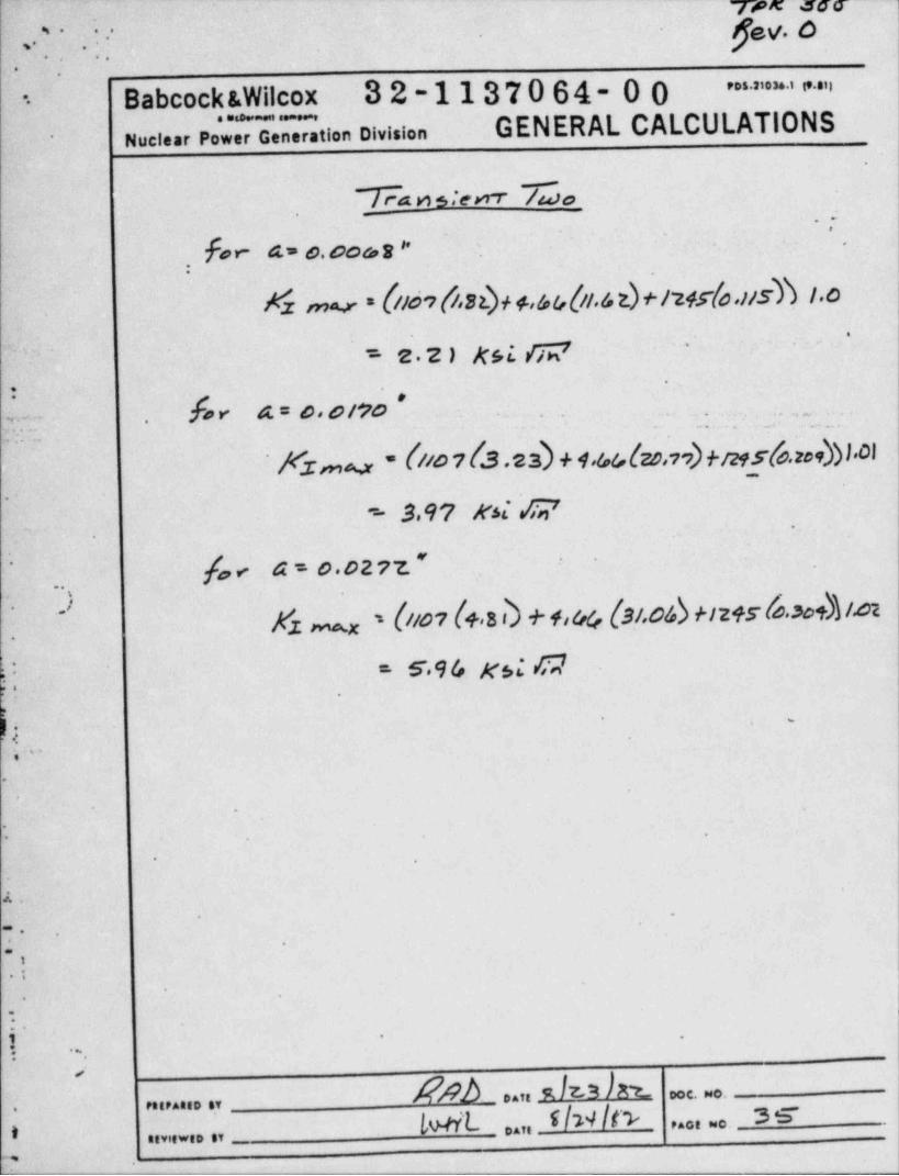
7 74 n stent 7u'so,
fa r- 45 O. OCG S '' .
-
,.
Yz mv = [//d9(/,82). + +,6&(it.& t)+/24r(o.)Ish I.o.
'' = z.2 ) rst 6;~'
'
#hv A= D,0/?O . . . . , _
~ ~ _ - .. .. . ..
~ Kzmo * (//o ?(.3.es) + +.4&(e.o,vv)+/29s(e.zes))).01._
.
- 3,9? Ni /Is',
,
[a < 4 = 0 02 77 " '
,,
$1 mx = {//01 f+>8 I + +i44 (3/.06) Hz+5 b. sot)) /.D2.
0 = 5 94 xsi C2'' .
' *.
. , _ .
O
e
'
--
.
.-
-.
-
.,*
.*
.
..
!- .
...
>DAT, E 3 1 0.C. >80.
Pt,PAa,D ,Y
..,, l'u/ /t> 3er*
5In+it. ... ..> ,,,, .. ,, _
-,
~ - -- - - . .~ 4-.-. *- A 36.
'y.f r . -'
2, v*; v
roe st!, , ,
_
9 fe y. b- - -
.
,
i
Babcocks.Wilcox 32-1137064-00 " " ' ' * ' ' " ". . , _ . - ,
Nuclear Power Generation Division GENERAL CALCULATIONS-
.
-.
.. '..
.; ..
-. . .
. .; ' .*
.
; ,-
.
.
--
. .
.
.
. .. ege '/ . e. *In , 4 A~ * . , * * ~ * t**
"
.'k*
,y
.. . . . . , ... ...
u . , .. . . .
1, ' .t
'
-I * -
.
. . . . .. . . . . .c ..,.
. . . . .,. .
.. ... .. . . . . .. . , - . . . . ..
- . . . ... . . , -*
.
*?.
.. ,- .
.
. s. . . . <. ,w..
' 4j e - ,. . , .
''
Appendix De.
g -
! Microfiche..
< .
9
,, , . . .
s
!
s'
4
e
t I
l
t i
. .
g-'
:. -
:. .
O,,. I .
e
|t- .'
- .: '
..
; ..
.
9 A
\.
l. .
.
e 9A .., s/23/n.''
...,.... ,, < . . . ..
A w L .... t h + / & mg. _ , . . . . . .,,,,.... .,
.- - .-. . . . - . ._ _ . _ - , -
,..
: .- :~ -|s[356 |:.- --
,. . .
fjev.o- - ., -.,,
, _
s
Babcock &Wilcox 3 2-113T0 64- 0 0 * * " ' * ' ' " ' '. . ...
Nuclear Power Generation Division GENERAL CALCULATIONS.
' .~ ,
\'
, . .
b*
|'
_ Title'
Comouter Run-
ACMYBRY Case I a/2c = 0.1;r; , , ...< .- . .
ACMYBSF Case I a/2c = 0.5-
ACMYAMA Case II a/2c = 0.1.,.., ._,
ACMYAMP Case !! a/2c = 0.5 '- ~,, ,
ACMYMRT Case III a/2c = 0.1,
ACMYMSD Case III a/2c = 0.5-
.-
,
' s- | .
t -..
,
-
.
-.
''
.,
'. -
i; -
.
* '', .
. .
*.
* '
, .
i1
'i
1-
.
. .
*
.
.
- .
-
. . .
MMb oar R f23 skEnaranno et oce. no,
Nb TbY 'k enor wo. 37enviewso av 04tr .
..
A -3P. .. t . rz>e ses. ..
--
3 " gev. o''*
...
Babcock &Wilcox 32-1137064-00 ' > > a = ' i' "'
. . . . . .
Nuclear Power Generation Division GENERAL CALCULATIONS-
i
.y
; ig RCafBR7 ~ DAVIS' RR . .:e - * - 313.~28.24~.',.CTBER,758 ' '' ' 46-t - .
'
'*2.i~
~
-.
TURC EgpLUATIOlta TRI BT
- g .. y .-w , .. . ......
;,e s.vaSri DAV Sna.cz c . 3i inizz. ste .75s: -::' - '"/ 1-
-
~'
..A DTSG)TUREW E,VALBAJION-i , .g- yJ 7''
-
y~ '#k%,.
,
g,
.,
s - . . ..,k.' $[?.m : I-: ,. ,
'..
RCRfAHAM DAVIS R4 n 1W5:'. 30-
*,
Ills USEJEVALUATIDah A:
E. . -'
,
CafANPU DSVIS. RA 6M M s'3'
gALUATInn-, ,GIS TUR
4.
f.-
.. -.s,..
,
*
~ 34, s, 4.LN.In ed ww> n t" 3 f.L:;twM.wl M AJ;160f M 4 G"
.
*
..
.
.
.
.
.
'
.
..,.
J
M 8 3 E poc. No.Dat:PstPAsto sv
|s L Av'i Ybs/ f?W , . .. ... &$

-ei_. .g.-
t
eh a
hf
.
OO
=
e 0f
APPENDIK B-
..
e
5@ #
O 4
9 ** *~
a .y ,9 3 er a
>O 06 9
N. *,
Ya
m
B
4 $e
k-
.
O
e
9
6
m
0
s$
D
#
$
44
D
0
e
L .
- - . . - . . . . ... . . . . - _ . . - .. - -. . - - . . ...
B-/e yz:ng pg y -
. , . . . ..
A (* Rev. 0., , I . BWNP-20032A-8(6-82)
.*,, ,
PAGE 1 0F \.g
CONTRACT NO. PLANT ,,
582-7239 1NI-1 DOCUMENT RELEASE;.
CHARGE NO. RELEASE DATE NOTICE (DRIOAN050F39 , ,,,, ,_ ,, ,
... . .. ...
PART-MARK / TASK- B&W DOCUMENT NO. DOCUMENT TITLE sg T**
GROUP-SEQ. mEk STAT. anL no.-
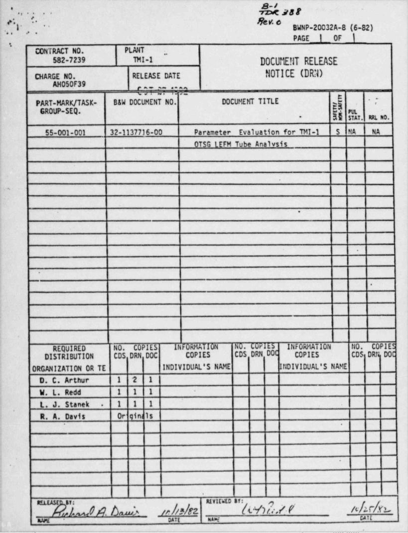
55-001-001 32-1137716-00 Parameter Evaluation for TMI-1 S NA NA
OTSG LEFM Tube Analvsis,
!
. , , .
.
.+
'.
|
|'
|~
.
|
I.
.
REQUIRED N0. COPIES INFORMATION NO. COPIES INFORMATION NO. COPIES i
DISTRIBUTION CDS DRN DOC COPIES CDS DRN DOC COPIES CDS DRN DOCi
'
ORGANIZATION OR TE INDIVIDUAL'S NAME INDIVIDUAL'S NAME
D. C. Arthur 1 2 1
W. L. Redd 1 1 1-
-
L. J. Stanek I 1 1. .
~
R. A. Davis Or < gina ls.
i
.
; '
;
i
.
I RELEASE ST: REVIDiED Bf:
&hk. baju //? /S $2. 5Y)/* *f NA b'
| mAME- DATE na>E DATE
. . . . _ _ , _ - _ . . , _ . . _ _ . . _ _ _ . , _ . . . _ _ _ _ _ - . _ _ _ _ _ _ - _ _ _ _ _ _
_.
M-
72M!! 3FP -gay,c.
a s * ,' i* ,
e
BWNP-20210-1 (1-78)." . . -
'*. ' ' , , -.
t CALCULATION DATA / TRANSMITTAL SHEET,.i
00CALC. 32 _ - 1137716-
DOCUMENT IDESTIFIER '
TRANS. 86--
TYPE: _asstancu a s e n sarm asa'.tsis ancar _ woc. sm. surer _ptsten mm. oostew ruttr; ,*.x awn
*
Parameter Evaluation for TMI-I OTSG LEFM Tube AnalysisTITLE
ehd k hmda REVIEWED BY ik)#8[6!I"PREPARED BY
TITLE Enaineer 1 DATE/0Islyoiin' r M,4 {tV DATE.)
PURPOSE:,
To quantify the affects 'of lowering the fatigue crack initiation threshold~
- value, an alternate method for calculation of stress intensity factors,-and an investigation of the net section collapse criterion using an
increased membrane stress and an alternate crack geometry.
.
*
.
'.
}
SUMMARY OF RESULTS (INCLUDE DOC. ID'S OF PREVIOUS TRANSMITTALS & SOURCE CALCULATIONALPACKAGES FOR THIS TRANSMITIAL)
See.page 14 for a Sumary of Results.. .
b
.
*. e
.
s a
.
E
k -
<4 .
,
I
-
DISTRIBLTION .
.
See DRN. ' .
e
O
.
_. .- _ -- --
. , . ..- a.g ee
.roe s..
.,' ' ., , ' ' ger.o*
,
. Babcock &Wilcox 32-1137716-00 " " ' * ' ' " "
Nuclear Pow G neration Division GENERAL CALCULATIONS.
*
..'
.
.
.
Table of Contents*
.
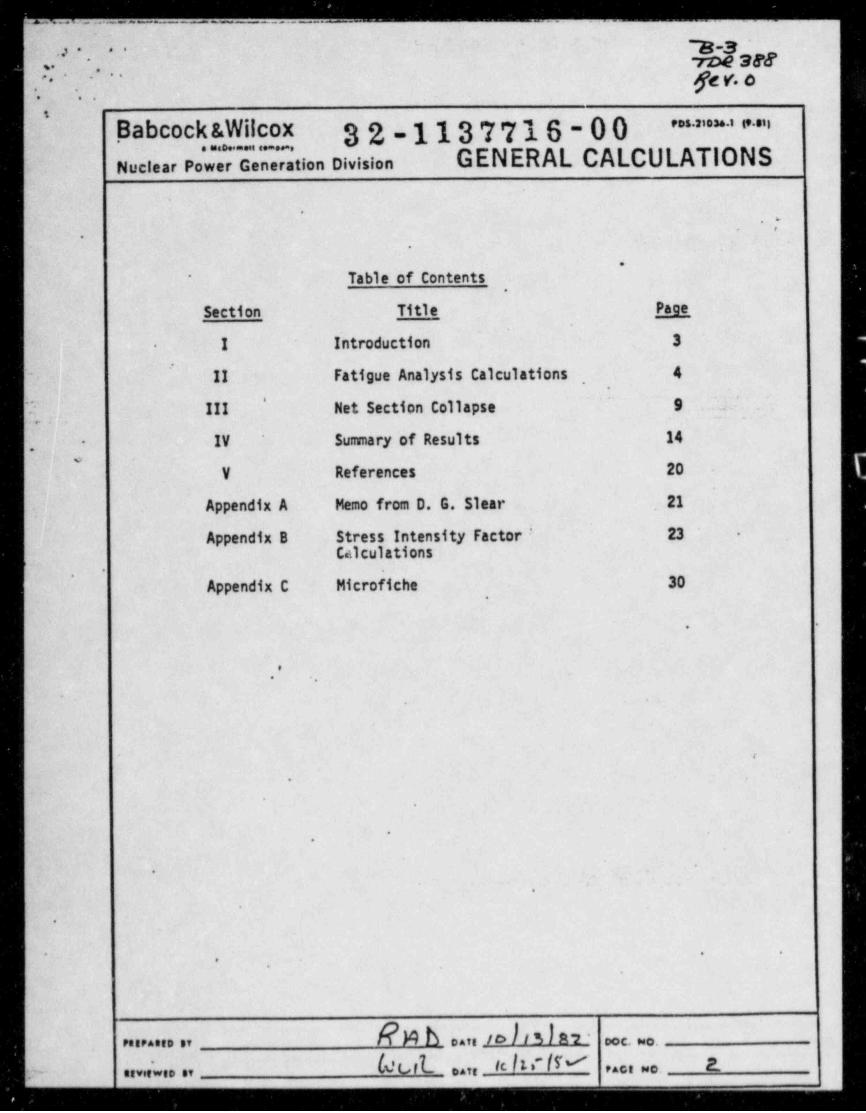
Section Title Page
I Introduction 3.
~
II Fatigue Analysis Calculations , 4' -,
I III Net Section Collapse 9 .. '. .'
.
IV Summary of Results 14-
V References 20'
Appendix A Memo from D. G. Slear 21,
Appendix B Stress Intensity Factor * 23 '-
Calculationsg'
.
Appendix C Microfiche 30,
,
.
.*
.
-
.
<
.
*
.
-
.
.
.
.
- . .
,*
.
N b care /D 13 f 8*2 * occ. wo.Peerases av
nevdwee se t % f b cate tc f t. ''lM 2., ace no.;.-
_
p ,g,at. ', _ , .
.--
..
. . .
. . . . . . .
' ~
''"'**' ""Babcock &Wilcox 32-1137716-00.
GENERAL CALCULATIONS_
Nuclear P we ee tion Division
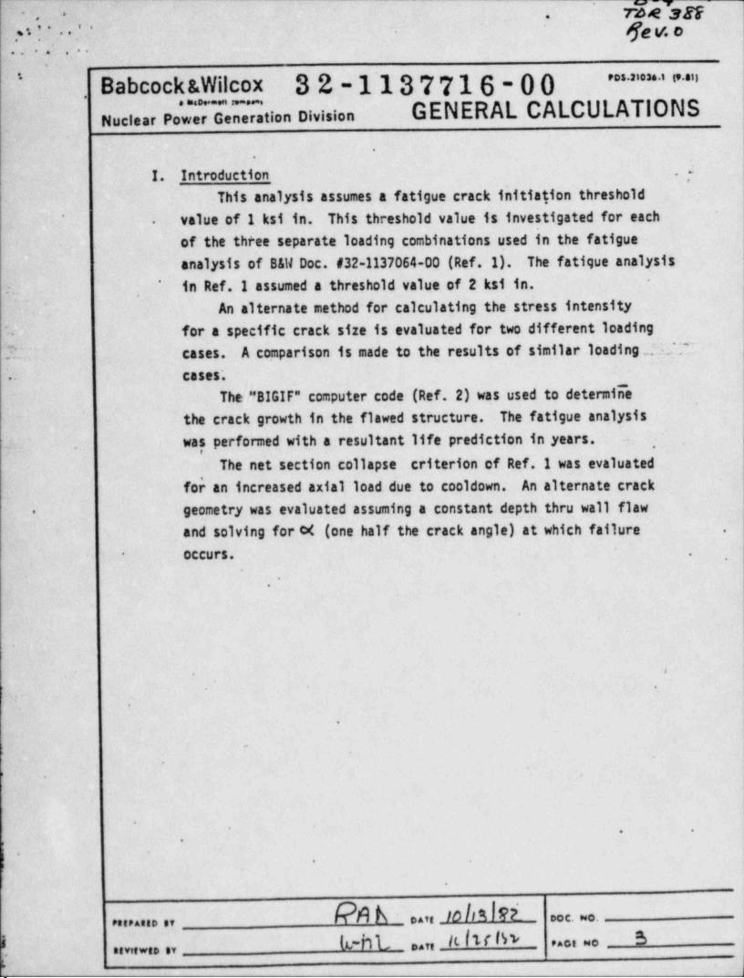
I. Introduct on .[This analysis assumes a fatigue crack initiation threshold
value of-1 ksi in. This threshold value is investigated for each'
.-
of the three separate loading combinations used in the fatigueanalysis of B&W Doc. #32-1137064-00 (Ref. 1). The fatigue analysis
in Ref. I assumed a threshold value of 2 ksi in.'
:sAn alternate method for calculating the stress intensity
'. for a specific crack size is evaluated for two different loading_ !.. cases. A comparison is made to the results of similar loading .te..'7~'t
. cases'.~ The "BIGIF" computer code (Ref. 2) was used to determiiIe
the crack growth in the flawed structure. The fatigue analysiswas performed with a resultant life prediction in years. -
.- ,.
The net section collapse criterion of Ref. I was evaluatedfor an increased axial load due to cooldown. An alternate crackgeometry was evaluated assuming a constant depth thru wall flaw.
and solving for c4 (one half the crack angle) at which failure .
occurs.- .,
*
.
.
9
>.
'|>
1.
|'
_
e
#6
. .
e
t .
PA h .. . ;o bn ei c. .. ...... ,,
k-nL Idu Iw S
|. . , , ... .
. . . , . . , ,
.e - a-s- ;rae .ser ,n... -
-
$2v. o- -
. . *. - .'..
.g - " " ' * * " ' " "Babcock &Wilcox 32-1137716-00
GENERAL CALCULATIONS,
Nuclear Power Generation Division*
.'
.-.
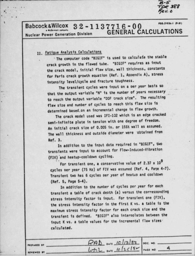
II. - Fatigue Analysis Calculations .
' The computer code "BIGIF" is used to calculafe the stable.
crack growth in the flawed tube. "BIGIF" requires as inoutthe crack model, initial flaw size, wall thickness, constantsforParis-crackgrowthequation'(Ref.1.AppendixA), stress
,
intensity level / cycle and fracture toughness.-
.
The transient cycles were input on a per year basis so. . . . . . _ , . . .
that the output variable "N" is the number of years necessary_,
J.- to reach the output variable "DOF track size".' The resulting!.
flaw size and number of cycles to reach this flaw size 1sdetermined based.on an incremental change in flaw growth.
;The crack model used was IFI-102 which is an edge cracked ,
'
semi-infinite plate in tension with one degree of freedom.*
An initial crack size of 0.005 in. or 15%t wall as assumed.'
The wall thickness and outside diameter were obtained from*
Ref. 3. .
L' In addition to the input data required in "BIGIF", tivotransients were input to account for Flow-Induced-Vibration
f (FIV)*andheatup-cooldowncycling.*
For transient one, a conservative value of 2.37 x 10'
[' cyclesneryear(75Hz)ofFIVwasassumed(Ref.4.Page4-7).Transient two has 6 cycles per year of heatup and cooldown-
(Ref.5.Page5-4). -"
-
I In addition to the number of cycles per year for each|- transient a table of crack depth (a) versus the correspond.ing'
stress intensity factor is input. Fo'rtransientone(FIV),| the stress intensity factor in the first K vs. a table is the' *
,
maximum stress intensity factor for each crack size and the
transient is defined. "BIGIF" also internolates between theinput K vs. a table values for the incremental flaw sizes-
.
calculated..
,
1
kN b nate 10 [/3IS't ooc. wo.: eneeaseo er
b-h L o.tr 10{tfliI' 4,
**oe ao.'
* eeve... e,
~-. mm.
JfE6 d.,. .. . *
. , .'
.
.. .. ... ..
'
* Babcocks.Wilcox 32-1137716-00 ' " ~ " ' ' " "
GENERAL CALCULATIONS..
. ,_
Nuclear Power Generation Division-
.
'
For transient two, only the maximum stress intensity*Ifactor is input in the K vs. a table since the transient
*-
cycles between zero and K ,g .
,
A.- Fatigue' Crack Initiation 7tneshold (Kth)The three separate loading tambinations investigated in-
.
Section III (B) of Ref.1 assumed a fatigue crack initiation..
"
threshold of 2 ksi in. The same loading combinations are.:.
evaluated herein assuming a' threshold value of 1 ksi in. ." . . . . . . , ..
- The stress intensity factor equation for all three ? .
loading cases is;*
..
Eqn. 1 Kgmg = ( F,,KT + MKb + P Kp) Fm-.
,
where: F =axialtubeforce(1bs)ax.,
M=tubebendingmoment(in-In),
P = pressure difference (osi).
The stress intensity factors for all three cases were calculated',
in Appendix C'of Ref. 1. Crack depths of 20%, 50%, and 80%t wall
were used to calculate corresponding st*ess intensity factors.'
The loadings for each cc.se of Ref.1 Section III (8)
I are su:nmarized below.
' .
Case I'
Abendingmomentof23.73in-1b(Ref.1,AopendixB)'*
and a pressure difference of 1245 psi (assumed) were used- in the stress intensity factor equation for transients one
and two. An axial load of 500 lb. (Ref. 4, page 5-9) was,
assumed for transient one and Kg ,and ( ,,, w e calculate
.
from Equation 1. For transient two an axial load of 1107 lb,
h-(Ref. 5, page 5-13) was assumed to calcula'te kax. "BIGIF"
-. was then executed for asnect ratios of 0.1 and 0.5.,
[ 7 $ b pave 1 0 b [ F 2. oog, o,Petraneo or
b IC f N N b 6pact oeo.
3- easteeviewso et
s
rv"Meser :( 1.
;. .
m. . . 4 , ,, ,. .
.
; - -. ..
Babcock 1Wilcox 3.2-1137716-00 - " ' ' " ' " ' ""
'
GENERAL CALCULATIONS._
Nuclear Power Generation Division
..
.
*
Case II'
'IA bending moment of 23.73 in-1b and an assumed pressure ,
difference of 1245 psi were used in the stress intensity. -
factor equation for transients one and two. An assumed axial,'.
load of 200 lb. was used to. calculate Kmax and Kmean for ,
transient one. An axial load of 1107 lb. was assumed to~
calculate bax for transient two.*
'
.
.: . . .
i- Case III-
A bending moment of 4.66 in-1b and a pressure differenceof 1245 psi are assumed in the stress intensity factor equation
for transients one and two. An assumed axial load of 500 lb.was,used to calculate Xmax and Xmean for transient one. An ,
axial load of 1107 lbwas assumed to calculate Max for transient.
.
two.In Ref.1, each loading case was evaluated for aspect
~
ratios of 0.1 and 0.5 with a KTh of 2 ksi in. For the ,,
purposes of this analysis each loading case was evaluated,
*
of 1 ksi in.for aspect ratios of 0.1 and 0.5 with a KTh*
The maximum flaw size before unstable or uncontrolled-.
~ crack growth occurs is plotted for each case in Figure 1 for a,n'
'
aspect ratio of 0.1 and Fig. 2 for aspect ratio of 0.5.'
TwocurvesareplottedinFigure1&2forbh values of ,-
1 ksi in and 2 ksi in. See Appendix C for microfiche.'
.
.
.
.
8 4
h ,
..
'
. .
4
.
R A h ,an soltsI8L .a e . . .o. era... ,,
it2:L ,,,, teI1rI n s.
,,,, ..'..,,.... ,,
m-
7DM.30f.
' '* '' feg e-o*
_-
. . , 1. , . ,.. .. _
'
Babcock &Wilcox 32-1137716-00 ' " = " ' " "'
GENERAL CALCULATIONS.-
Nuclear Power Generation Division
-
.
' .B. Stress Intensity Calculation T
An alternate method for calculating the stress intensityfactor is contained in Ref. 5 of Appendix A (this document).*
An explanation of the nomenclature used and the stress intensitycalculations for the two loading cases investigated are contained
'
in Appendix 5.-.
The loading combinations investigated are sunnarized below:..'
-.
, . ,. .-w .
Case IV- . -. - . .
A bending moment of 23.73 in-1b (Ref. 1 Appendix 3), an*
assumed pressure difference of 1245 osi, and an axial load of500 lb. (Ref. 4, page 5-g) were used to calculate reax and Kmeanusing the methods outlined in Appendix B for Transient one.'
" ' ,
An axial load of 1107 1b. was assumed to calculate Xmax for~
'
Transient two. A value of 2 ksi in was assumed for KTh'.
..
Case 1.
.
A bending moment of 4.66 in-1b (Ref.1, page 15), an::
= assumed pressure difference of 1245 psi, and an axial load'
i of 500 lb were used to calculate K,.x and K ean for Transientm
One. An axial load of 1107 lb was assumed to' calculate Kmax '
|for Transient Two. KTh equal to 1 ksi in was assumed. ,
"BIGIF" was then executed for "a/h" ratios of 1, 2, 4 ,- .
Land 5 for both loading cases. The maximum flaw size before
.
unstable crack growth occurs is plotted for each case in.
,
Figure 3.Case I of Ref.1 is clotted in Fig. 4 for comparison with
'- '
Case IV. Both assume the same loadings and KThjbut utalize .J;'
~#'
different methods for calculating the 5!F's. Case !!! of.
Lthis calculation is plotted in Fig. 5 for comparison with-
' '
Case V, since both assute the same loadings and KTh'.
i
.* .
/h$b eate lob 3f 3Z, sec. ,,o.peerasse av _
'7) (LNb eats b i P **of we,
seviewee av
L'
w m. _ .= _ . . _ _._
3-97be 3EF. . .
' '
.' pv. on.'~ * '
;.
i
Babcock &Wilcox 32,-1137716-00 $ = = ' i' "
GENERAL CALCULATIONS. . . . . . .
Nuclear Power Generation Division
-
.
''
In order to equate the nomenclature used in Ref.1"
,and Appendix 8 the following equations are used: -
Thru wall crack depth, a/t = 1/h',
Inner Surface crack length. 2e = 2a-
Aspect Ratio, a/2c = 1/2a'
.
.Me
O
eO*
O S
*.
.
.
4
e i
*e
.
e
! '',
. .
.
a
. Og
e e
. .e.
/? n /L ..,, jo h418 t.' . c . .. ....,.... .,
6 ,, A-hL toIb'IN 8. . . . . .t o.,,
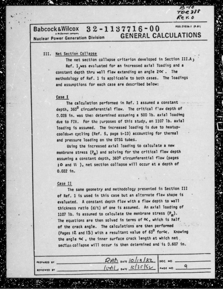
roe 3N...: ...
^- ge g o....-,
" " ' " " " "Babcock &Wilcox 32-1137716-00'
GENERAL CALCULATIONSNuclear Pow Generation Division
.
III. Net Section Collapse ,a'
The net section collapse criterion developed in Section III.A)
Ref.1;was evaluated for an increased axial Toadin~g and a,
constant depth thru wall flaw extending an angle 2c< . Themethodology of Ref. 1 is applicable to both cases. The loadings- .
,
and assumptions for each case are described below:,
-.
Case I !-
.
The calculation performed in Ref. I assumed a constant s- ---.
0~ ~
depth, 360 circumferential flaw. The critical flaw depth of0.028 in, was then determined assuming a 500 lb. axial loading
due to FIV. For the purposes of this study, an 1107 lb. axialloading is assumed. The increased loading is due to heatup-
,..
cooldown cycling (Ref. 5, page S-13) accounting for thermal -
and pressure loading on the OTSG tubes.Using the increased axial loading to calculate a new
membrane stress (P,) and solving for the critical flaw depth'
assuming a constant depth, 3600 circumferential flaw (pagest o and 11 ), net section collapse will occur at a depth of
,
0.022 in. ,
L -.
--..
Case IIThe same geometry and methodology presented in Section III
of Ref.1 is use'd. in this case but an alternate flaw shape is '
,
.evaluated. A constant depth flaw with a flaw depth to wallthickness ratio (d/t) of one is assumed. An axial loading of1107 lb. is assumed to calculate the membrane stress (P,).-
'
The equations are then solved in terms of M, which is half,.
~
of the crack angle. The calculations are then performed-" -.*
0'
(Pages 12. and IS) with a resultant value of 63 forH. Knowing'
the angle c4 , the inner surface crack length at which net ,' section collapse will occur.is then determined and'is 0.607 in.
[.
kNf\ oat IO!/ 9 !A7 - Doc Mo-Parranno or
lC!II 97'
,,6,w,,,, [Ld_, oat __ P^of "o-
y-
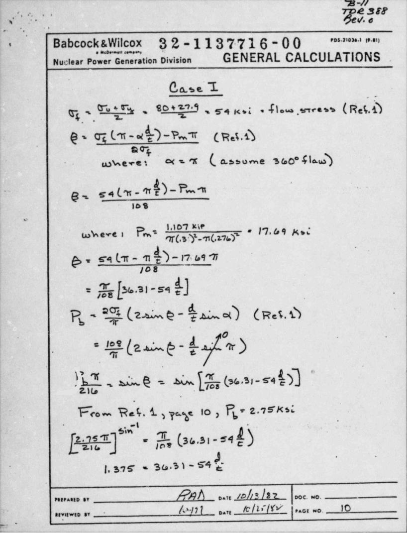
% -l/
., : .- ge.sa' '
.
. ... .. .
'
Babcock &Wilcox 3.2-1137716-00 " " ' " " ' " "i
. . . . . . . .
Nuclear Power Generation Division GENERAL CALCULATIONS .
.
O,a.t e. 1.~
-
. , -
-fl = , m ca w ( N e(, dQ '. " [* 80 T'i . 54 x *I- s =
,
0- ci v-w D - A ,r cas.6t.
209mweres o< s. 'r (, a.n o me sec .flo.Qa
-
~
g g4(m_m - fm 11~
-
~"
los
o
l.10 7 metukeve i pm- - l'7. 6 9 g 6
'
,s,
'
'
&s CA l'TT - m- 1*7, 69 'Ti
JOB
,h %.3)-59: ,,
k' 26 @ - ich (pet,D
a)' '
*l (Zip -*
Or.
.
,b - ,. d @ =. N (%.31 - s42. w . t tos -
!
-
F<o - R t . t 3 7 io , Pg z. 7sxs:r.
-. . . , ..
less (33,3 i . 54 d)''
TL2. . ~7 5 '1T ~~
cL 2.n u\
r , w y % . 5 1 - s 4 )g-. .
!-
84A ..re/o//3/27- ooe wo.reir*eio sv
/c/li /W 10d^/77'
r.or wo.' ~naviewie , ..r _
-
o .
p-:'
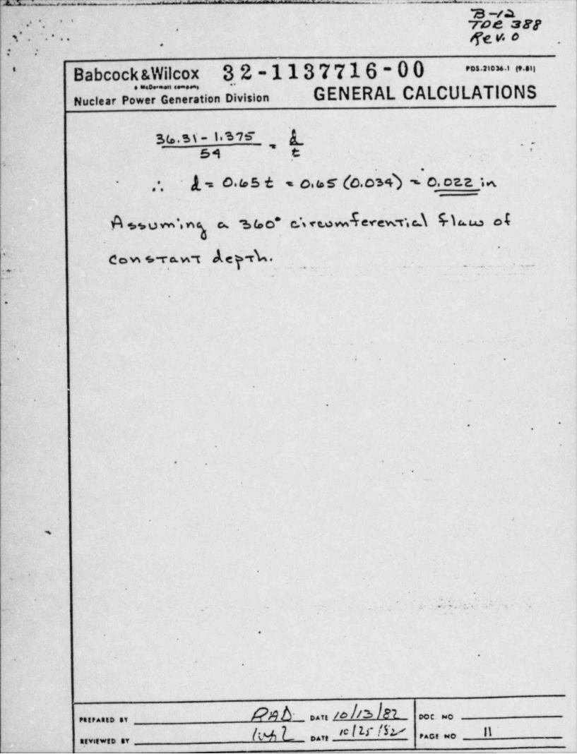
m. . , _ _ _.. ,_. . _ _ . .. . _ - . . _ . .. _.
a -ia., . . . roe an- -
.. . ge y, o -.'. - - - -
.. ,
: :
Babcock &Wilcox 3.2-1137716-00 ' " "*
. ~ . . .GENERAL CALCULATIONSNuclear Power Generation Division
35.ss-i.s w LT
''54 t .
-
b
.
k= o.uss - o,us (c.oiA ,-o caa u'
- .
. .
A .,u m , ng e s ue e , <wJerew-c.d 46 e t
'~
deY-rk."-
dow s-ra.w t. . . - . . .. ... . . . ,... .
,,..
- * -
-.
O
t. e
e s ,
p
0 h
O
.
.g
9
.
D
L
e
4
.I|. L . : i ,'
, n: .~ ~ - .- . _ z.-
..
.
1
.
l-
1
b DAT, /O /b l DCC. Ps0PA,P AG,D ,Y
As L D.,, * Itr Irv n..C,.O.......,D ,,
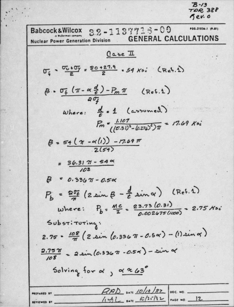
'B -/3rwe ser-. . - . . '
.' . r-
..
n ev. o. .. ..
e ..
,,
Babcock &Wilcox 3.2-1137716-00 "' ' ia"
. . . . . . ,
Nuclear Power Generation Division . GENERAL CALCULATIONS'
l
O a.'se I |,
-
_
i -s
T ' C7*u + 0~y * S o + 2 '1A = M K$s. (E s%.b4 g g ,
.
.
|.-
| P . - oi (5 - *.if .) - 8,, w (w,5.Q'
.
a9t .
1 (,cawwed\, .f. j'',
"~ '
[-k /4) see. s
/./O'T '
Fm*([C.S0*-(6.27d)719.69 Xse'si
@ , 54 ( or -* b1) - r7 ro9 rr'
'
2.Lr1>
?. s &.s> 11 - s4 n=/03*
*
. .
. h * O? % Sir 7f - C.Sc<
Pg. of (z a p-h a d (na.O_
sL-'
e ' '' ' (0 * ')w%e rs - P "| w e.,S.x,;,yD.00 2fr75" Caw)* -
l'
h 6 Uh 5-r; fuTbI.
'
2. ,s !Re 4 (o.sse ,r - s.s.< > - 06 <)c _
.., .. ..- 'm
a a (o.sgi .ri -o.s n -- a e " " . ~I * ' ' ',
/08..
' -
6olving for ,e )ce oc g3
'
,
.
.
/?ph . ,, so/n /n'
e. . .e.. .... .,
4 4 L ..,, /c/v/t u 12.. . . . . .;7...,1
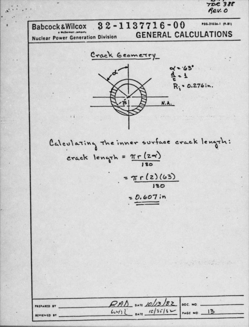
-.
7,e ger. .. . .
4,, ,. ..,,... .. .
.
. .. ...
'
Babcock &Wilcox . 32-1137716-00 - = ~ ' " "'
GENERAL CALCULATIONSNuclear Powe Generation Division
'
' 0**h 6 *~ e' ry_. ... . .
ci f g to s* . = . ;.'
. g,y-
s
R\ - o.27/i*-~.
M. A .,
%#. ,o.
.. . 2.L
'
'
.
. ... .
.
__
bde.olat'sw The $wwer suvhe at c.re c.k } e w k ',
c.rcek \ewyk = tr r (z-d -sto
,
'
= 7 r ( zM6,9 ;.
-. J'so- .
'
= 0. 607 in.
,.
|~ ..
.
,4*
I1'
' . . .
..
.
!' '
~ ;. ,
. .
|. -
' *.
1
/O /3 DOC.Dec.PitPAttD .7 DATE
'*/)L1 'c/"l * 15.. 9.O .-0 r,
.......D ,,
.
'
.
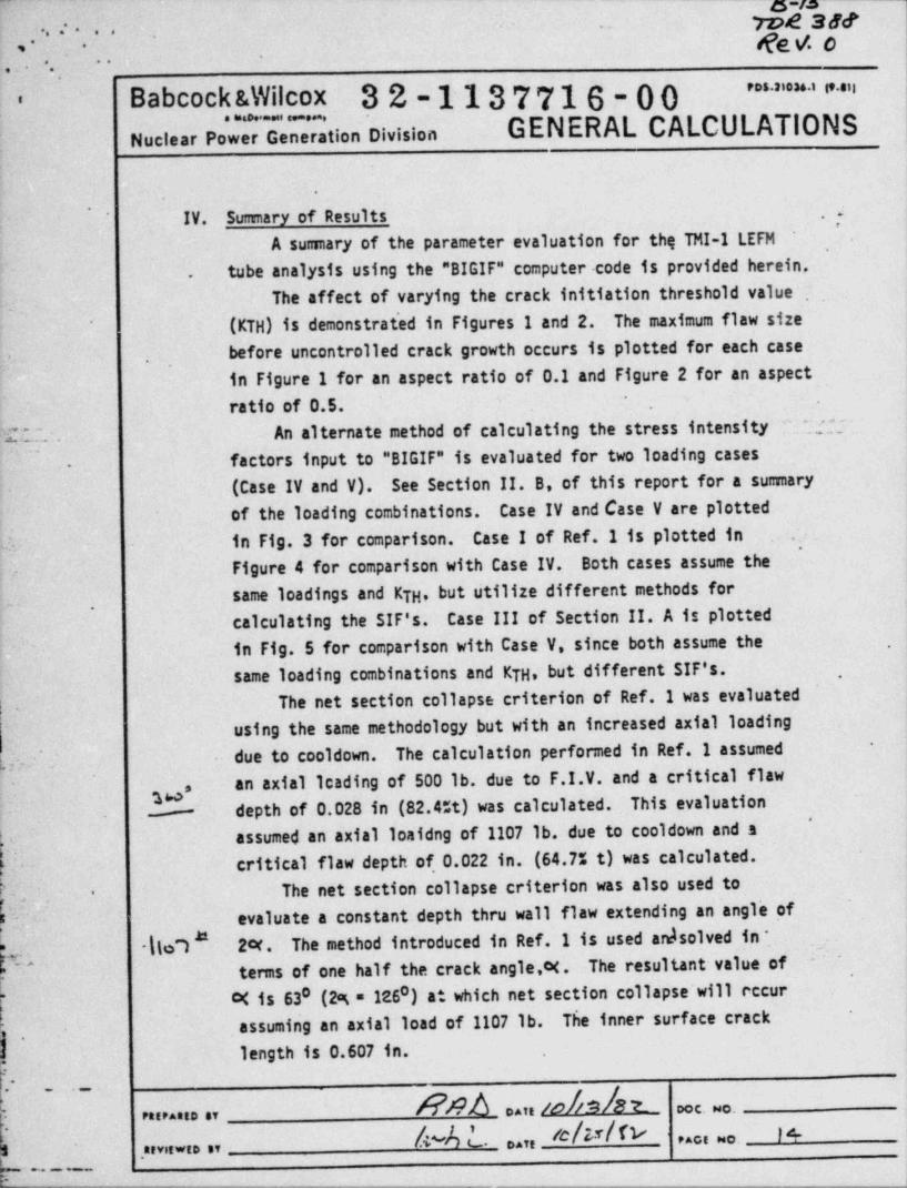
w-m-
yng agt..- .... Re V. O
. . " ..'
- -
_
" " " " ' " "Babcock &Wilcox 32-1137716-00-
GENERAL CALCULATIONS. . . . . . .
Nuclear Power Generation Division
.
f~
IV. Sumary of Results~.
A sumary of the parameter evaluation for thq TMI-I LEFMtube analysis using the "BIGIF" computer . code is provided herein..
The affect of varying the crack initiation threshold value.
(KTH) is demonstrat'ed in Figures 1 and 2. The maximum flaw size~
before uncontrolled crack growth occurs is plotted for each case.
.
in Figure 1 for an aspect ratio of 0.1 and Figure 2 for an aspectratio of 0.5.
'
.
E~... An alternate method of calculating the stress intensity ^';;;~..
factors input to "BIGIF" is evaluated for two loading cases.
(CaseIVandV). See Section II. B, of this report for a sumaryof the loading combinations. Case IV and Case V are plotted
- in Fig. 3 for comparison. Case I of Ref. 1 is plotted in .
.
- Figure 4 for comparison with Case IV. Both cases assume thesame loadings and KTH. but utilize different methods for
,
calculating the SIF's. Case III of Section II. A is plottedin Fig. 5 for comparison with Case V, since both assume the ,
same l'oading combinations and KTH, but different SIF's. ,
'.
The net section collapse criterion of Ref. I was evaluatedusing the same methodology but with an increased axial loading
h. ~due to cooldown. The calculation performed in Ref. I assumed
-
an axial leading of 500 lb. due to F.I.V. and a critical flaw',
depth of 0.028 in (82.4%t) was calculated. This evaluation-d
assumed an axial loaidng of 1107 lb. due to cooldown and a'
critical flaw depth of,0.022 in. (64.7% t) was calculated.The net section collapse criterion was also used to-
3 . evaluate a constant depth thru wall flaw extending an ang1' of |e
llo7 24. The method introduced in Ref.1 is used ardsolved in * . .#
#terms of one half the crack angle,H . The resultant value of
'
;'
c< is 630 (2g = 126 ) at which net section collapse'will cccur0
. assuming an axial load of 1107 lb. The inner surface crack,
length is 0.607 in.*
A?nh ..,,iohn/st. .
e. .. ......... ,,
j 4 - M .. ..,, e M n - s. . , . . ........ ,,
7 _. _ _ __
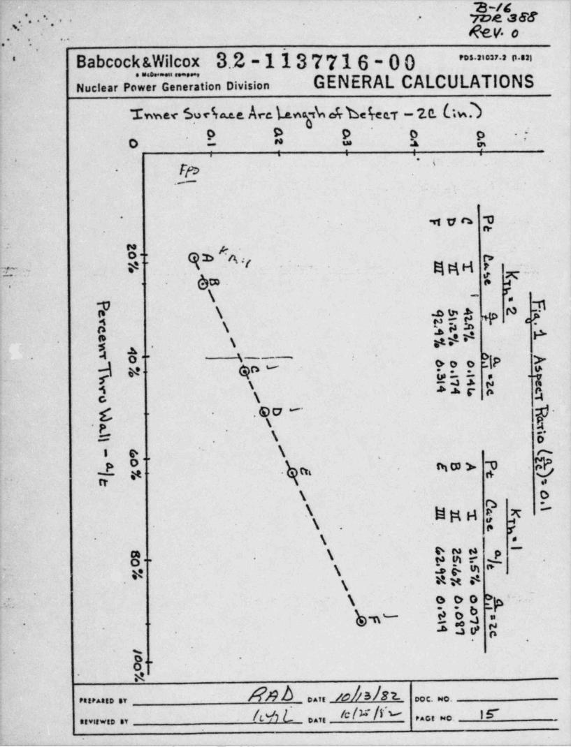
.- . . .
a /c-roe aeg.. .- .-.,:. - .
... . . . . -gy, o .
.
.
Babcock &Wilcox 3.2-1137716-00 " ' ' ' ' " ' " ' ''
.. . ,
'
Nuclear Power Generation Division GENERAL CALCULATIONS
her 5oeb.e.e Arc WybtrbWr -ze. Gw.3 ,.
O D p ^
o p J.
'O L * ? % v, , . . .
~ - c .
_
.-_
.
,5 v a m-
.= n.
: n92 ,w .<
.
o- - n.
. . 6t=.
gga r i--
_-
r .s
$ F..7r,\ -
37 \ 4 * *- +N'
e- <4\
S h$$ *s.
I %,,
3 y. qn - c.,. , o. gip- >.s-.
..
r usI ;, 1-
s4 A .a. s- o ec. \ a
.go-
g-. .
=- \ 6-.
i e \ op m , ggy ,g $s
' ,
O',
- -3 .
ty .
\ 0m -
.\ WMH S y' '
\ as
- r..
.
.
'1
g. g oma -
eme ~p.. .
,a \ 16 8m*-
,aw |'
s[p'
~
. \ o00-
~
*h3 ; !hbn-. .
-* ?.
o.
.
g -
..
- aAPnb .. . olshz. c. .,,,,..., ,,
h e C ... * / * /f " Ir...,~o.,,,,,. , ,,
'
. . - - - - .. .. ... ... _ - .-. - . .-.- -.. - .-_____.- .- - _..-_.._. - - - -. - - - -
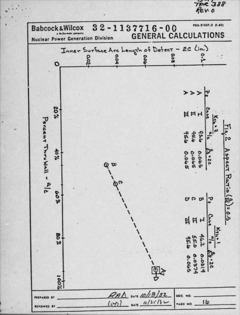
M agg''
fev o, . . .., .
.....
_
.
~ ' " ' ' " ' " ' ',
Babcock &Wilcox 32-1137716-00GENERAL CALCULATIONS
,
Nuclear Power Generation Division
hev Leb.e. Ace. Lewgk of bereex - ac 6w.3f.
9 -9 o 9 0 ..J
o 6 ? 3 % ?- '
..
>>> W-
n-.
*. .
.,
gng ~y- eI. -- 7. , -
er -
-Tj< eo D
* -D .D .O p & ,,P-.g m _m y- "- f*4 k- e r
.-
~Qoo, p= >-{ "t-
-
= o 6b ;, %.s c s- p pf . . Sto m er n.
.>
? A.\- .
I \ pMD P
P -l-
T, ..
\b
o- -
fp,,L vi s
- o o tp m*
| \ Ju
g *o.\ dMW 5 * .
\.
K\
-
I 'i BEj. ;;El'
s e=. . s .. =.
.-
-~.*
\ b*0!
e $ >En,
--
: y w,-
. _.
,8~
L
M )9 $ oate /S // 3 / 8 2.reeeasso sv ,
ooc, ...
Ih[bN *catt Pact No.aswegwso av ,
,
-e-,..-- _____.
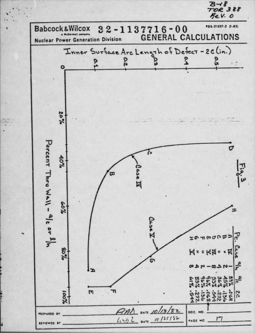
.. - - .- .
avr'
,. ; . .7. .
- rve 3 er- . ..
.
q<.v. o-.
:...'" ' ' ' ' " ' ' " ' '' - Babcock &Wilcox 3.2-1137716-00 ;
.
Nuclear Power Generation Division GENERAL CALCULATIONS :
% < brb.e Ave.L *,k ok befee r - 2 e 6Q.
p 9 o o oO ?. ?. Y ? ?, -
*
. .
. .
-
. .- -. . .
. . . , . .
..
.
re'*'
.. . . _ _ . .,
. , . _ _
e. p_: % \t . . . . . . .. _ e. . . .. s. . . .: ::n . ; . .. ... .., _. . .-
-.
~ p - .
,
5 - 7n ta.
p A '
3 0'-4 32
<
g q.
.
.c $.,,,
..
$-p .
$ e. .
*
.-
I p . ,
9 O-" P
V. o * *
, 4 .
2 z e -utn a D W 3 tt-
y ~$f M==Hiit=vW g
'
. ..
e .
24
- , - - ce A P -co.A ro-'
7 ,...,
e ts -a n tu tWA on- - w e e v a~ w * ,.eY$e Ybt$5%Y
.-
t- = -
.g......ret . 71g' 8-
prabuga Rgsu--c -
sp$' .aL
DAff /O N D DCC. NO.PttPARED SY I
Cb 'b b natt# Pact we.
arviewto av'
-
..
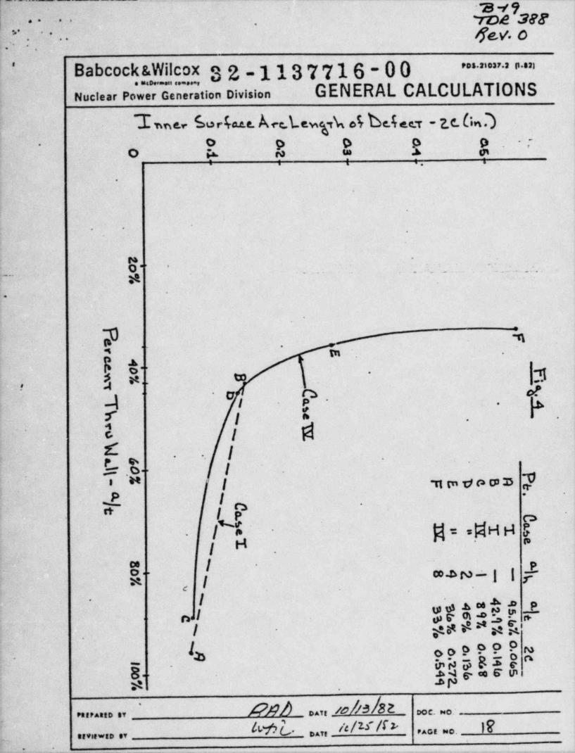
y --. ,-- - . . . . . ... _ _ . . _ _ . _ _ _ , , _ , _ , , . . _ . .
2 -< 9- m ggg. . . , - . . =..
,
[:.'*- 4eV 0.,
Babcock &Wilcox 32-1137716-00' ' ' ' " " >
Nuclear Pow ne ation Division- GENERAL CALCULATIONS
Le,. 6r4u. Acc.Lewpk 4 be.4.. t - 7_e. Co.)-
.o p o o o -
.
o @ w m A e.. . . ..
9
- *
|.
:
: g. -
. .. ..
. ;_
.
... . . . . . .. . ...
, .
__
-...
2. 4.
'" In -
A'
.,. ; .
n} a-
..
A . ,I g- 5.
:r j . ..
4s IL I. .
-s'
e.o- I .-
' " I mmvomm 7P.y |n
--
.
|-
sfd H-
.
H p--
Ih co a ro : .! l [~
-
Ic
I weAatg P~
nl wemaI - ge # * a -
ns h'
h ooP999 m6 aBIS a.
8 .- A t' g. .a s u,>..
-$, .
A)9b aan fo|/3|82'
oce. o:e,,,,,,a ,,
[ M L .a., /e/ 3'/6 IF. . . , . . ., , , , . . . . , , -
:-_ _ _ _ _ _ _ _ _ _ , .- .- ___--- _ . _ - _ _ _ _ _ . _.._ _ _.--
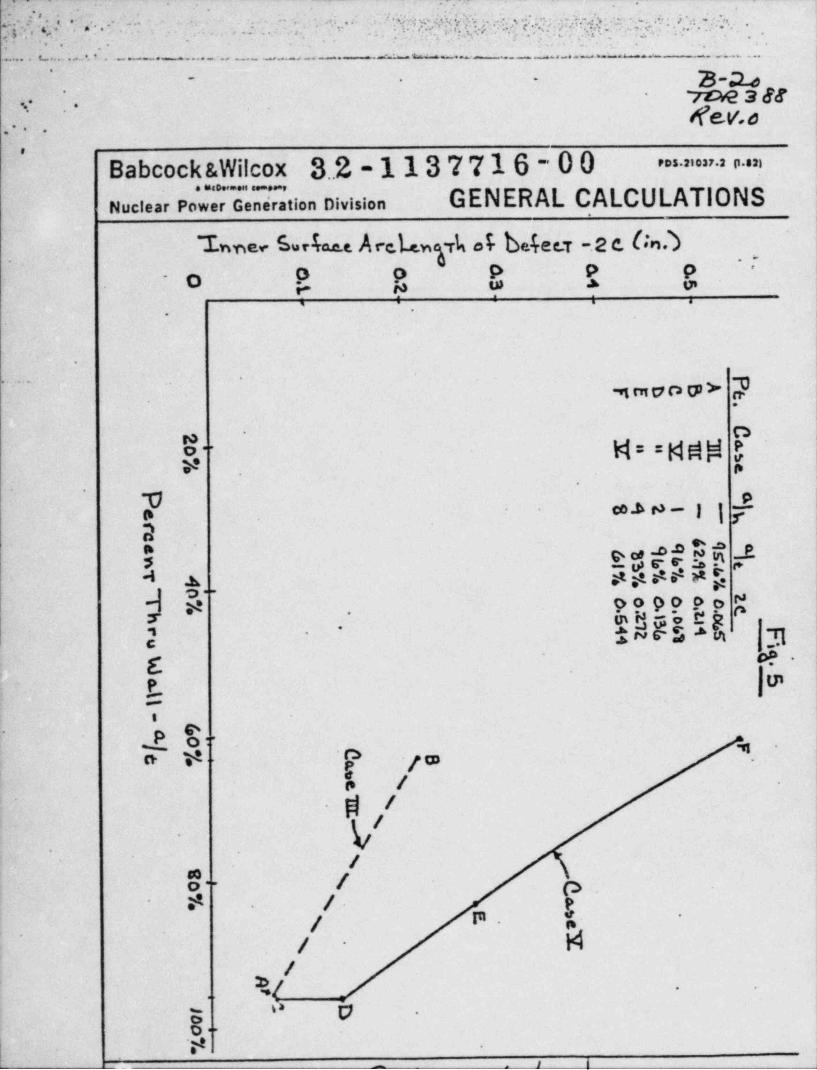
7 -
. -"
,
s.e,a;j...
'
, ..
a ... wgg.wq3.,13 c..wg..;7.;g.m.m, ,7 .n, . ;1 ;;.e.-3.. . i. ;.. -
.....a...-,
. . , . ,.. . . ..
g.<, . ... ,.:. ..-
,...f. 7.,...,., . _, ,.,.,
,--' c .
,;,
..
. _ _. - .-. - ~~ - - - -1-. .. . . _ . . _ . . . _ . _ . _ _ _ . .
-
3a. . .
7E H2 3 88-
.. - ,
f(ev.o-
.. .
|'
Babcock &Wilcox 3.2-1137716-00 ='an > a =>
|
enafration Division GENERAL CALCULATIONSNuclear Pow r
-he, bria.e.e A r e.L.w'6A ei belee.T .2 e Un.) -
o o P P 9 '
. O * * *9-
r. ., ,
1-
.
I
.
>aa.
st en o n D > rr-.
U- M = = Midld 3 i-
24 . '
.
y p )' -
*29-1} F. 1
2xant s* was gres. c.
d A ** $ * * N gk
'
??es9P $ 199"
m es !.x
; .- ;~csa n 3
DC O- .
*E.-
te.
d 0- -
g
g/a. t< 7a .
e
Y|'
.
/so fO~ 4 ('>
-
- $ / pj m. $
-
d*
/-
/%/ -
.
o e- .
Oo..M
I |- .
-. _ _ _ - - -
q q7. m gas; ;~'- ge.v. e .,7. : ', '. * . .
,
Babcock &Wilcox 3.2-1137716-00 ==' ""'
GENERAL CALCULATIONSNuclear Pow Generation Division
.
.
-
~ *
. ,
1 , References-,
1. B&W Doc. f32-1137064-00, "0TSG Tube LEFM Analysis,"
. August 25', 1982.--
-- 2. "BIGIF" - Fracture Mechanics Code for Structures, ,,
'-
EPRI-NP-192, September 1976.' -
a .
3. Metropolitan Edison Co. Stress Report, Contract No.*
620-0005-55, Report #1, page 2. September 1973,
Microfilm Roll No. 80-8.-
.
''
-.
4. " Flow-Induced Vibration Analysis of Three Mile Island.
.
Unit-2 OTSG Tubes," EPRI-NP-1876, Vol. 1, page 5-9,.
June 1981. .
a
.
5. BAH-10146, Determination of Minimum Required Wall
.
Thickness for 177FA OTSG, Page 5-6, Nov.11,1980.* . .
'
.
h
* . ,
e
&
%
=
. " ?
. .
. .
.
Rnh . ,, us hd_u. e. .. .,,,,,, ,,
Awt ..,,/c/w/N 2.o. . e. . . .. , , , . . . , , -
.m.- - . - - - - - - - - _ _ - _ _ _ _ _ _ _ _ _ _ _ _ _ _
___y__ _
as. .__.. ;_c -
._ ._ , m _ m . ._ . . m , ,, , _ ._..-.
3== %1, - vvesega * * *
. .
.. .- gev. o -.- - .--
., _ .
Babcock &Wilcox y.2-1137716-00 mi u.i i ..n'
GENERAL CALCULATIONS i
. . . . . - . . .
Nuclear Power Generation Division
i-
.- |
|-
.-r
.
a
.
..
.
4 - . . . . . ., . - ..
--
M-
.
Appendix A- . . _
' -
Memo from D. G. Slear'
.
b
.
e
4
",,g e .
' '
.-
.
.
1 .
-
1
.
I .
O
,
A NO.
tWrL .,, /ck/W Ei..., .......... ,,
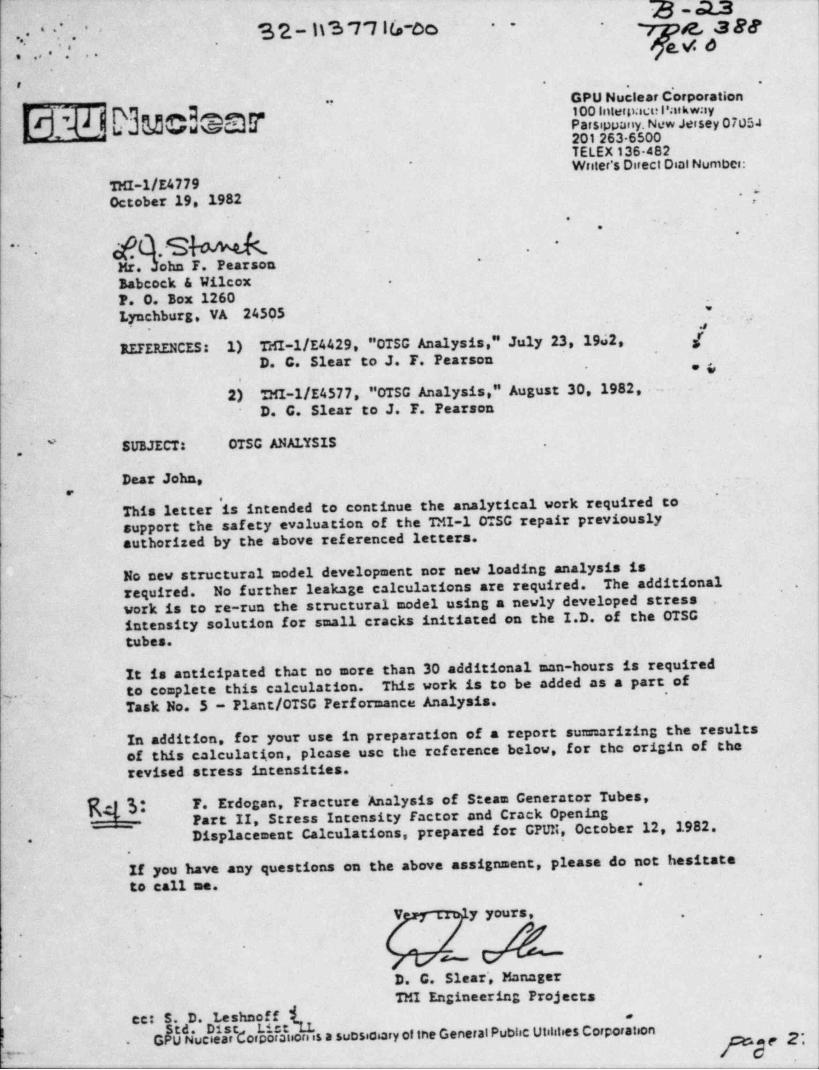
3 -ass..- .
u..-as 77ic,-oc, e_, a se- - -.., go.,
. . , . . ...
- -. .
GPU Nuclear Corporation..
100 lnterpactri'aikway-
4 %j | N %p,
1; % rid Parsippany. New Jersey 07051"
- 201 263 6500m
TELEX 136 482Writer's Direct Dist Numbei:*
'
THI-1/E4779October 19. 1982 .j
'
- .
fc.sM .
.-
.
Mr. .lohn F. Pearson-
Babcock & Wilcox .
F. O. Box 1260.
Lynchburg, VA 24505
REFERENCES: 1) THI-1/E4429. "OTSG Analysis," July 23, 1962, [D. C. Slear to J. F. Pearson
'
- .s2h THI-1/E4577, "0TSG Analysis," August 30, 1982,--- -
-
D. C. Slear to J. F. Pearson
SUBJECT: OTSG ANALYSIS* .
,
Dear John,'
This letter is intended to continue the analytical work required to'
support the safety evaluation of the TMI-1 OTSG repair previouslysuthorized by the above referenced letters.
No new structural model development nor new loading analysis isrequired. No further leakage esiculations are required. The additionalwork is to re-run the structural model using a newly developed stressintensity solution for small cracks initiated on the I.D. of the OTSGtubes.
'
It is anticipated that no more than 30 additional asn-hours is requiredto complete this csiculation. This work is to be added as a part of*~ . .
~ ' Task No. 5 - Plant /0TSG Performance Analysis.
In addition, for your use in preparation of a report sumrsrizing the resultsof this esiculation,'please use the reference below, for the origin of therevised stress intensities.
kM F. Erdogan, Fracture Analysis of Steam Generator Tubes,- T- Part II, Stress Intensity Factor and Crack Opening
Displacement Calculations, prepared for GPUN, October 12, 1982.
.
If you have any questions on the above assignment, please do not hesitateto call me. .
Y y yours, . .
.
' fML .
D. C. Slear', ManagerTMI Engineering Projects
cc: S. D. Leshooff "
I' td. Dis Listi.
G U Nuclear orporsuorns a suDsiciary of the GeneralPublic Utilities Corporation e2. .
V-
- . . - - - . - . - .- -. . _ _
.{.. p-py.
voe3Ms' . ' .
qeg 6 -'
..;..
'
Babcock &Wilcox 3 2 -113 7 716 - 0 0 * * " ' ' * ' ' " ". . . . . . . , - . . .
Nuclear Power Generation Division GENERAL CALCULATIONS.
-
. aF
1, *
. .
.
.
. . , _ .
.. _.
.
.
.
Appendix B
'
Stress Intensity Factor Calculations-
.
.
O
e
E-
% .
.
.
9
* 6
e
9 #
R AB,0 SY D AT, /A M C. NQ.
GM L /c /2,- /N ,,,, ,,. ; za. . , ,,,,,, ,0 ,,
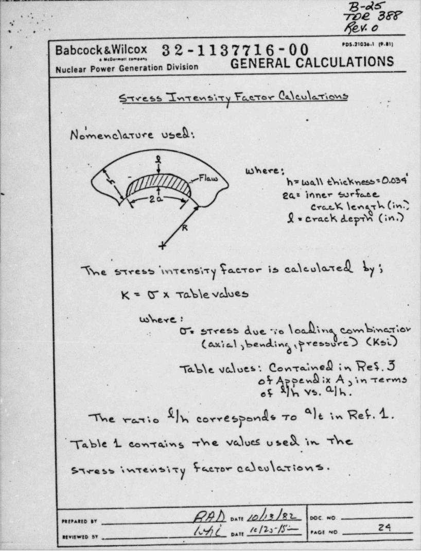
-
8-otc-.._ . - ..
.
yve gg. .
,,. ' : , : - .,
geg o:... .. .
' * " ' * ' ' " "Babcock &Wilcox 32-1137716-00'-
GENERAL . CALCULATIONSNuclear Pow r G neration Division.
.
5sve.ss L,e.ws rv hrev Ode.ubews .
'
I ,.
.
.
No'meweTa:roce useA..
.t.
'
4 // #3"* h too.i\ t% sche 50.ca9-
2b Eb Ion'" *M"b * t-*'cyc.eX \en k(twD <
.R = cra.ek A.eyd(in.)
i
. * J
I$ Ca.C.O\ M C '
h& $"T veh5 W )T f. U S*gT Q. CIT O Y" 3
K = U x ro.kie.velues 1
.
'
tekeve. :-
.- O'. stress due. ya \ odin)r%vnb.we, t.ov-
,
(, au/, , \ .3 beak.n,gye. e3 (Ks0..
'
To.bie. va\ues, . Con ra?iwea i n T?es. 3o rA pe.whix A in reevns .f
os.Rikvs.%.3.
-
h corvespe,nds ro "I t t w Ref . 4- .% ym o r
'
r a.sie i. co m w . w s r w e. vc3 ues u s e a. i m TW.'
'
Never cd so\ca tow s .s.we ss w re.w s i c y , ,
-.
.
nat,/o #I EL poc wo.Pa,eAs,o sv
M i 04,, p /&#" 24,
. . . ~ .,,,,, ,, ,,
.
. 7- .
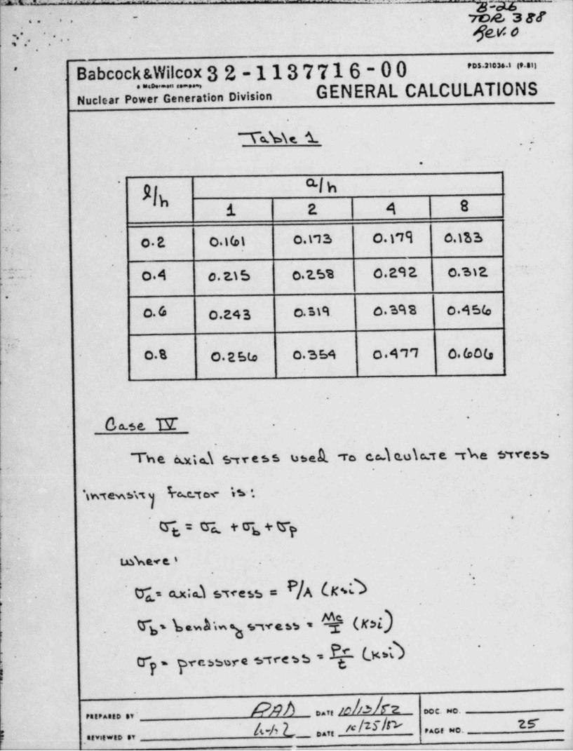
a . _. . .-~ .=. --
-
_ magros a er-
'
' . . - een.
.
r.; . .
Babcock &Wilcox 3 2 - 113 7 716 - 0 0~ ~ ' ' ' ' "'
GENERAL CALCULATIONS..o -. ,
Nuclear Power Generation Division.
To.h\c i-
. , -
.
z g? aIs*
ih .i- 2 4 8:u
O . P. O.t(o1 0.17 3 0. )'19 c.)SS. . .
%' O.4 0.2.15 075% 0.292 0.3)E'-
>. --
,
. 1
!.
0. (s o,g43 c.M9. o.sens o.45(, )
'j,7O.B O.25to 0 354 0 4'Y1 0, (o o'(,
.
b a.54. N .
-
.
Th B kY.i a. STres5 bbek "To C.A,k Q.uka.*T E "The ifTT*8Sb
iwtewsw) ktor h '. .
-
'
i.
. T = Q M T + Tp.
g g,,
- 1.nke.< e. ' .
.-.--
:' r a.x;a.). sve53 = P/g (gdc
T ' bwA'mg vwe$5 ' k (K$l)h.
r - pec33ere s tresd = Q 090'
'
p,
|-
A care /d / I2 occ. wo.PeePAnto sv'
b "/? b _ natt / Pact No.I ,seviewso or_ _ .
- - . . . - - - - - - . , - . . . - . . ~ . . . . . - - . - . . . -
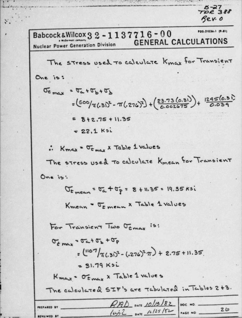
y,3, . ., 7 . .. . y. .- - - . ._. _ _ _ . _
.. -. . -._
, _ _ _.
. .. _ . .w . . . - . . . . . . . . .
ree a erv. - ge.v. o. . . ..
_
' " = * ' '' '"
Babcock &Wilcox 3 2 - 113 7 716 - 0 0'
GENERAL CALCULATIONS. . . . . . . . . .
Nuclear Power Generation Divisioni
The. S. Tress usel.-ro c.cde.u\c Te_ Nm hoc 'TrAwsie wT,-. .
.
cme. h .
,.
. .
W s Ts 4 G~y + G"*g'
t m ,
2B.'7 3 (o.3%) + I?A TIO'S D_ (5o T(.SiY- N 276 + o,c oz,g is o.o 6 9~'
.
.. . .. -.
= b k 2 .'15 + \\.3 S - |~-
*
22.1 ust--
1. xm - ce, x Tabie i.veaues.
The 5,ress use A ro encube kmee 6 h ot.wr,
.
om. w. .
.
Te , = r, + r = 3 + n,3s 7 19,3 s g3 ty
Lem, - %,_ x n.w i va o es .
.
bY Y Y %eD O .
0} - G L.4 G s + 0 p
!T (.3\7 - (,.2747'7T & 2.'76 + 11. 35',:i .
f - 3i.19 x s L. .
N%- c'e, x Tsbie i vdoc s .
Twe. cde.uic.cre A s'tr % c ve rebub,A NTub\es 2 &s.-
/?nb ,,,, jobs h e e. . ........ ,,- ze
1*A 2. ,,,, 4 /u /r2-..
i,, ,,_
, , , , , ,'
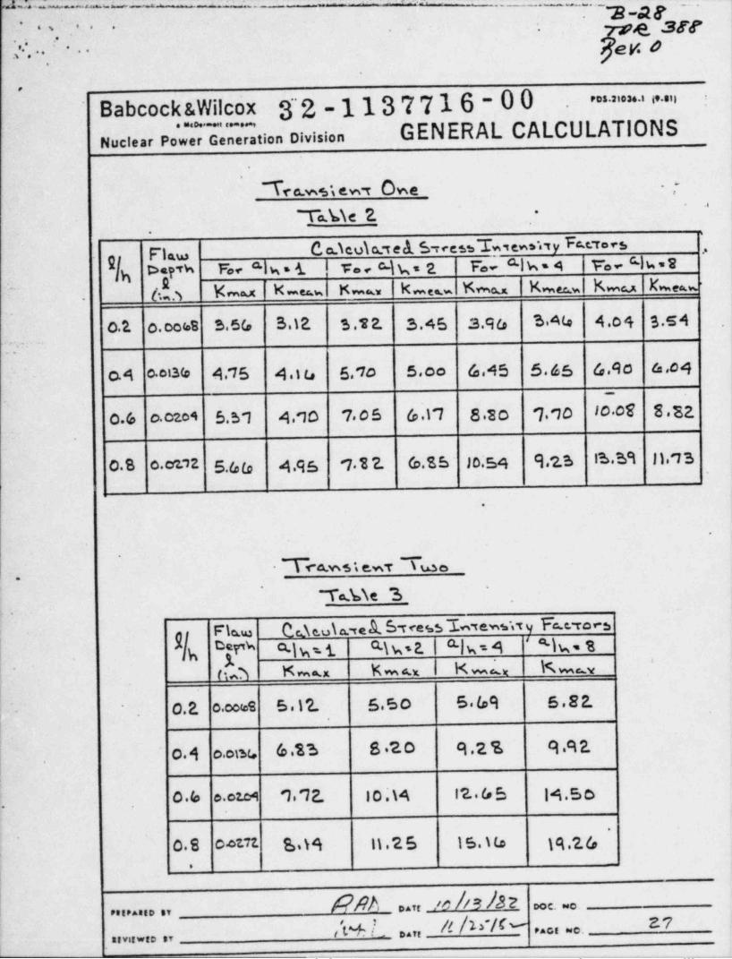
m.--- a . - ..
. ._ . - -_ .-
_-,_3- M ___,
- e arr. ., .. . -- -
, ' . . eg o.
; . . ..
.
Babcock &Wilcox 3~'2 - 113 7 716 - 0 0 |-
>> > " ".
GENERAL CALCULATIONSNuclear Pow Generation Division
'
Tea.we ew r Owe ,-~
T a.k i e 2.' ''
-
.
C a.Teu\ cet el 5 reessTw,ew.wy Fa.eroesFlaw .,
.Ifh *}?'* 6 ' "I* ' 4- I ** * -I b ' E b 'I b ' 4 N' 4 ' 8
63 b=>( K .,.w Kou k m e K m a,x her wl kmu be=w -^
-
c.1 o. oor.B S.5G 3.1E S .T 2. 3.45 3.96 3A4 4.oq 3.s4??
o.4 00G4 4.75 4 10 5,1o 5.co 4.45 5.65 4.4o 4.c4
c.6 o.czo4 5.51 4.10 7 05 6 t'7 8 30 '7 10 10 08 8.E2-
- .
0.8 o.cenz 5.66 49s 7 12. G.S5 ~ Jo.54 9,2S IS.S9 1173
.
.
.
- Tra.ws t e.wt Lo.
"
"Ta.b\e 3 .
'
. ..
Cc e.u\ a. te A. 5 tress'~Lwsewsw y Fa.c. re, sFleuas \
h f %i Ch s 2. Q-| w = 4 ' %. ED b'
hoh K m=x K m a.x km, x K muy,
i
|. .o.2, o.ooms 5 .1 '2. 55o 5 69 5.82.-
i,
o.4 o.om 6.13 8 20 9.2 % 9 9 2.
0.6 e.otc4 1. '72. 10.\4 12.6 5 14.5o['
.
0.8 04t71 S.19 11 . 2 6 15. Ma 19,2 6~
t
._
DAT, _/O - DO C. NO .PR,P Aa,D ,Y
M L D.,, a A>'/(- z7.A., ..., , , , , . , , ,,
.-_ - -.._- -.. - .- ...-... - .... - -._ - .. _ _ _
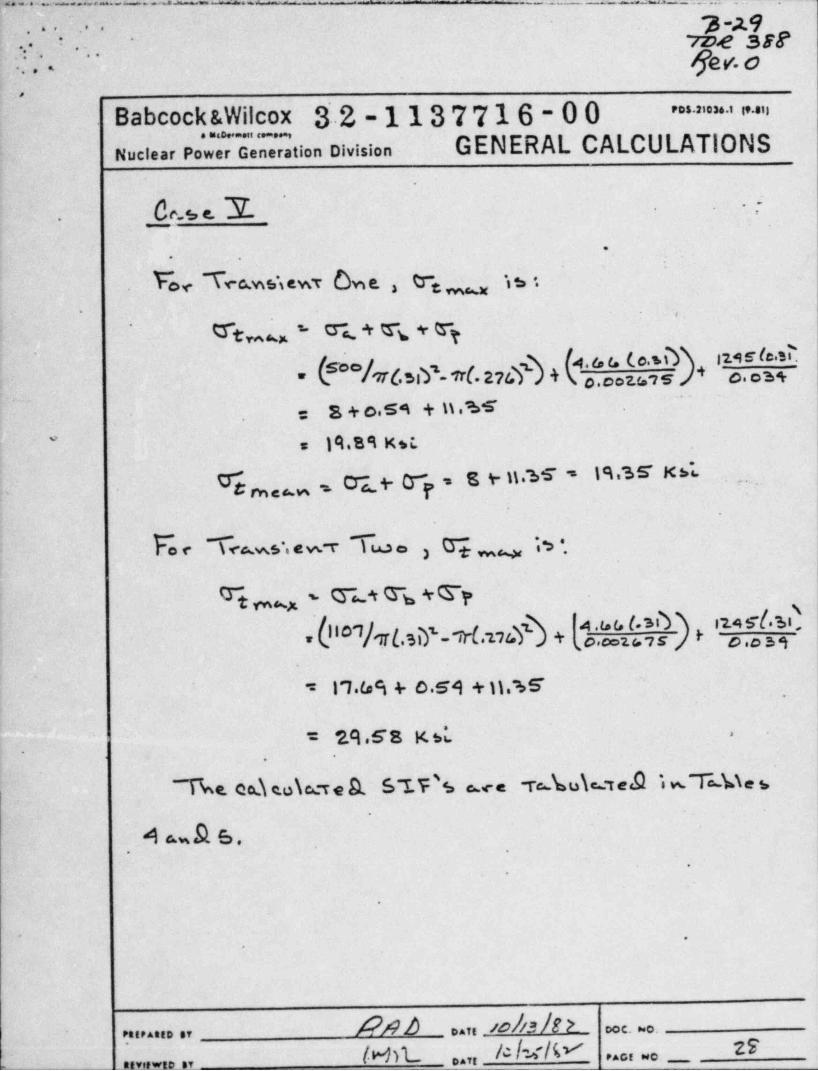
.,a:-z..a.x - , ~ .. - -- - _ . . . . .
y 2.9... . . . .rae ser. .
.-.
' .! . ' < Gev. 0'
-
.,
Babcock &Wilcox.......,31.2-1137716-00 = = 'a ' i' "
Nuclear Power Generation Division GENERAL CALCULATIONS
'
Ce.s c. 3T- .--
.
.
Tec.wstewt Owe. , % mm is-
. ,
We, - %. + % + ry\ 4.6 G (0.%1 11 M IC' -
* (600 /l'7T6 sly 7tl.274$) + |\ o, caters + o.os+' ~
s + o,s4 + n a~~
=
19.B9 Ksi.*s
Cr d~ 7 = 8 %. n. 55 s 1 % S E K b's.7 .,,
g tw e<.w P-
.
F. e s< ms,e - v i m o 3 q m, . , .,
%* % 4 TyT ,4 st
h'O'/1T(. sip Trl.us? + [o',Nz o,,$$*#F= y
17.I.s s 4 0.59 + 11. 65'c5.
*
= 7.A .68 K sw -
.
.
4 sw 9. 6.. .
e
.
*9
APAA eo43 h >..n ooc. ~o.. ,,,,.... ,,
IMn_ A/w/V 2F. . . . . ...,,. ., ,,.,, ,,
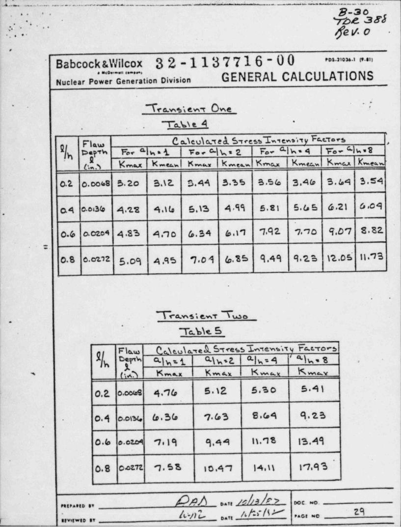
J L - -.a - . -~ _ -- _
- - -
-- - - - + - . . . .
'
g.,o.. .. . yoe ses.
-
.. >.:. ge v. o
. .... . . .
.
Babcock &Wilcox 32-1137716-00 =>nn'
. . . . . . . . . . . . .GENERAL CALCULATIONSNuclear Power Generation Division
Te c.ws s ew t Owe -/'
I a.%\ s A *
..
F' law C. a.icui art e <!L 5 r cessL,en. ,,y Fe.c.v. c3 ,
D=PTh %e "lw = 1 he Clk= 2 F. Cik-4 Fe Clw=2
e ,3 Kmax K -es-w l K mu kme . Kmu Kmee w Kmu Eweuw,
0.2. o.cobB S.2o 3.\ 2. 3.44 3.~6 5 B .5 6 3.46 3.64 3.54- .
.
o.4 0 08 % 4.'2.2 4.ib 6.\3 49"1 5.si 5.65 6.21 6.09:.
L 0.6 0.0204 4 83 4.q o G.34 6.11 '7.91 770 4.O'7 8.81
| :.
I 0.8 c.o2nz 5 09 4.95 '701 6 35 9.49 9 23 \1.0 5' 1173
!i
1 .
. ..
|I T1~4.w5i e.wT Tsa.so
,
T c.bie 5
Fla.w &d e.u\ a. te A. S rcess L7ewsw y I c.c. roe 3e
D{i''b Q-)w s i R\ ws 2. a.| gg4 s)g, gh ,
(A Km x K m a.x K mux K mmy'
0.E o.oores 4.'76 5 12 5.s o 5.4)
o.4 o.otw 6.SG '763 8 G4 9,.23.
.
( 0.6 c.czog 7,iq q,44 1) qs 13Aq
. .
0.8 octu '7 5 8 10.4 7 14,it 17.93_
.
boa o... u 44 4 > oo c. ...,,,,.... ,,
r ; .. .. ., awl o. AN / " ci - 29
e
g_g,- . .. . ..
.v.. | ..7me 388' '
ger'. b-..
.
Babcock &Wilcox 32-1137716-00 = ' ' ~ ' " ". . . . . . .
Nuclear Power Generation Division GENERAL CALCULATIONS.
. . :-
-.
. .y
.-.
.
, u.t'
.
--
-i
.
A*
ao ,en 4 4
"" ' ' ' ~
~', :.. . . .. . ,_ _ . .
.
c,- .. - -- .
.
. .
Appendix'C
*
'
Microfiche-
. .
4
'
.
.. - . .
*
.
~
. .
*.
.
.
. .
.
.
*
.
. .
.
. -.
,
.
PetPAtt0 SY Daft & /4 b DOC.NO,
DAfg PAGE NC.AtVitwtD gy
.-
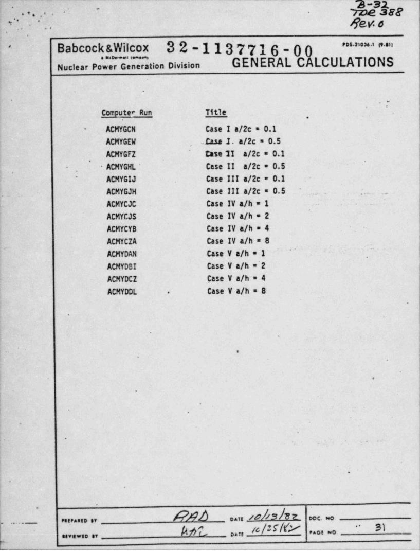
.--
:~
2n_ me see. ,. .. . - .
e' '
Rev. s. ...
Babcock &Wilcox 32-1137716-00~ ' " ' " " ' " "'
Nuclear Pow eneration Division GENERAL CALCULATIONS
.
-
7Computer Run Title .
,
ACMYGCN Case I a/2c = 0.1-
ACMYGEW Insa 1. a/2c = 0.5,
ACMYGFZ tase II a/2c = 0.1' '
ACMYGHL Case II a/2c = 0.5-
,,
ACMYGIJ Case III a/2c = 0.1 -*
ACMYGJH Case III a/2c = 0.5 . . . . _ _
-
,.
ACMYCJC Case IV a/h = 1.
ACMYCJS Case IV a/h = 2ACMYCYB Case IV a/h = 4ACMYCZA Case IV a/h = 8
~~ '
ACMYDAN Case V a/h = 1~ ,
ACMYDBI Case V a/h ='2-ACMYDCZ Case V a/h = 4
ACMYDDL Case V a/h = 8-.
.
.
.
'
..
.
-
i
.
|
. -
-
,_
. ..
r
.
-
.
.
I -
'
APAA .. e4shz ooc. o.g ..... ...... ,,
,,;,,,,,, let ..,,u#rNy si-, , , , , , .
y. _
_ . _ _ _ . . . _ _ - .
s. . . . -
. . . ,. .,
yaeaWv.n:.. = _ .. n .u_.._......." ' _ _
- - w.=y - " - - - - - - fVf.0 .
:* g.. , , . 3. . .-
-
... . . ..
;
J.* . . . t....=. -- - ~ . . . - - .w. . .. ,
.. g. .e- <
,... _
.
.
.. .. ... - _ .- _
.
.y,.......,.3,.,._ . _ , _, , q. . 4,- .g "h
.,.
. ..
.-
....e. . r . s.
.
,. . ..
. w s.~ . 1. . .;.t .e_.,,._ w, . .d. . .;_. . __ _ .aa .
g .,e.h .3:t . 4 .e_ e :c.
. .,... ...e.* -
... .
3 . - -._.L,_*. . . .
. , ,
3 I
7 - e ffd. - . e. A . 4 . w ..,tim . , . . . . . - . -
--.s, . - - . . -. .e. v . i . . . m. ...
. . -- <
,
. ,; . . : %, __ .: * . . . s ..x m..g. . t ;s .2.f. .
. .
m : :.r-.s. > . .. i.;s . .A) . a.. ... .z .es .. . . . . . <
I . . . . . . sj ..: . 9. ._ .%..
t.*._. . .1'.. .-.-
_.. .,.y---._. ;-,.. .
* .
E j]-
.t' M. . yf---. -p.. p.i.. r. . ." ..,w, 7,,. . . .,.r. q
: n. m_ 4 m g. .. .. ..A. i s . . , % , q ,,,r.. .. . v,g... . . 7 8."
,
.....f, ,..,. ' ,, _-
.y.. r.- s .s . <..
1. . .. . . - . . . ... . r. , ' .i. . y?. . .. e .. :s t .. -. et n im. .n ?.o.t a .,n;s . 4._ s - - .~.m. .L.,w-
;-. .. .%.
. :.~ . * . ' ~ . _. a..
. 'a4 *.. . .
_ _ . _ . _ . ._.
.._
,
:. r .- - d. . . . , .-J . . .,~ ;. .c. . . -. , - .e.m. . . - . . ;v #. , g. . .. m.. .
-
,,,,,.g. . e. . m.. . , . . -
..gf.._.,,j,..-......._ __ . .g.
.
;. . .,,. .r . .. .
. _ . .g __ __ ___. . .n... r..s.y. : f. r .:4 :.,. . , ,. .. ...,. .a .. ..i. . . . . .. .
;. ...
.._t...,..; .r_. ,, _:.. ,.s . ;,.
.: .. . . g ., . ..__.u*, .:.
.. _ _,.* . ,i.
-
.._.
. . .._ m .m.._ u,
.""J. 4' N"""."".. . 5 ,. ' w- ;. . . , ar. . *|' ' . . . .
-
.
.t. . U. , v.. . , , .. r<w 'y . m..;.-, .. git , .1
_---
. ,.d.y-.. . d , .
. ..).s.r...n.v.r.,. , . ..t .: ..
\* . . .. ..- . - -,. :
. . .r .<,.y,.. .. .z .~. .. _ _ . . . . . . . ...,3 .,,a yms. .; q,7._,.,
.
.,. ,.. ,3.'4.,L. a. . ...,; ,,% . . . . ,
.
. ). . . . ,;
m.,.;;.,,.,a,,=;,. ,,.,s,m,. . ..,..... u,_ . _ . . , _ . _ . _ . .. ,m ,..ir_. y,. . . . . . . .. - .. .
_
. ....
6,,
. .< i
?.. 4. -?.' q '. i H C '" "......'. "... ,~. w W T ~ c. .. T.. F. ,T..''~~ T i C 'T?.'- Z. k. . . ".. '.~
. i,n m -
J\ C ..__ .. c ..a.
. . . . . . . .: . ..s .. w ..... , ....-mu. .. .. .. ,
_ :t:. '.q.. .u m. t.... s .. .. .. .; . .
_
.q .. . . * .e* . s.s .~_a%. . . . . .*.s. , . :.. ,. ..
. . . . . . *% . . .F d9 .. .e.n .wy.w" *g.uy ,p. m .v. s'' u g a . =...
-
- .. : :_.
%r)W .
G. : . *.I. '.?.DP.. r. W: .S.- O l
W .4T:L.... +: .. .a . .,.. ~@,,. w..W~ ~.n re.c '* "N.,M:c''9 --u v.-
-- --* "'e -
) ~., . . ..... V~: N. . * .'.;. N.u .u., a_o T ,7.s.'~.;M. .s ."* ~C.'.-n. a..,.~.- . ..c:..
f.- .g . .f..f. -? .h..;..t.;!.n :-
*
. ' . - * - s-
n . . . .s.o , . . . .~ mc,;. w m . .. r.-. 1,wu,. ..y :pa
. _ a 6,w_. ~ -- _w. _, ,, u
. . h. , ... .i P.: . . , . - ... , _.
. r. q J f. . ,. .,., . . . _ _, .e
--
w. . : . 4 < , . . r. . n. :. , , . . ced.m.,. ,c.,=,._T _ . .(., 0...i. . .p . y. . .
tt r. . g. .. . .i '.r...;. c...r . ,.
- -. .u.. .. ......
.e. :. . . . ..
4 . .Q.,:, ,w T.s.t ,..a, . 4, e . . . < -
- e. .u c . *j ;.* fg,' . t,., .,, .y . gg ,. .a
.,.~- Ip...s.....a.._. _mgg = ...
.- p s. S .. . ..
w , A .* :. J.__ _. . ,
2,cy*t. 48Y. *#.,"*.a&. *P.* "* *** * -':''' .
c.
*** " .t*
*s w. r.5 .r.,,
- 4. . , ~,.s)s= uw 8.W'**""""=. .wwa :"*** >*V' .C"*O"*e gC'r -'L.*/:""". s w -
g. .W . .
*q.
* L. . % f ig t - &F.i * * .. ,i .
.$. e.*
s= . f '. I. . . ..V . A. .:",. . . - ,, , . * E *.a. , a.$.g e
.f..nr6! .*b
... .l 4i. ..%.,3..t : Lw. . . l .w..,.*
.*.* * d,1-**
* * .e7* .eT.. ,m... n'.' .. 8 8 f .eN 8. .%x ' ..J -.. .f.,
.
:. . -. a. _, t . w .y. - y . .s.t.a_vn 1.t.,-..| -rmymy. .
..s. .., . . . . .
.
. . ,< ., . ..,
J,J.e'i- ;r**r lf e.e. a*...43 y*..4.
ssrswy* am . . r - .. z . .-r.... . - .- . - -
n . .. . 7...., .m D ,,8.*.* .v. . s. .,uv.,,.- .3...g.
. .i .. *.-
. .- f1. l* *.*?8,.w. ,g ,.,". "'.t..6 *.,* * * **.
., .4..
. .: .. - . . . - . , .,.n.., .
.A.;,_ m ._s. h.r.mg. . m,1 %s. .
...,... . -
<-. * . s o. -. .W ;.* Ty.. nJ . ,., ,. . p . . g ,,,jg.f at.h.jg*;,,,, p . . m . g..
*
,: ,,
. - . -gf
.,:.4- . ~;;yx.. .,
/ m.e
. ..L.. .g . . . , u,. , , . A e. . e .
., p:e- . p. ,; . , ' 6. . . . . ._t },y.. . . - ,, _ _ _ .
- ..-
.- m .< . . : . .: .my,rs. g;,,e. $. .:g,u, ,.
. ,, _
..g,...-- - - - + .<;. -,
. . . . - g, , =. . . .Jy .L y.. ..
. .:-
: .. ;... .+ : * g, r. . . .. . . ... ... f . .
. .
g. .u.,,,,,,,,,,, ;g. . .s. .,; , zu, ... c. , .,.,:.3. m.;:
. .. .... .., ....
...A, .
. _ , . .: .. . .
.h . - -|,-
... %,.. 9.L. .,J.p.a.e. 9. f.:n. . . . . .
r...u 9.
gZ,,;.p,.c , _ 4 w.u'
4.; a- -. . . v P.- i u.. w -Ef r . ) . . :.b . t r .=-. . . . . .i
.. m. . e.. ...c .; s... w r.:.3..u.. , ,.,,w..e . .y . . %u. . . .,,.
,4......s.. .. v . ..
.. . a.4
. i,a..c .. . ~.y . ..~ . . . . . : .
.. .. ... .. .. .., .. ....
.J. . [ .. J% *.. .. . . . . ..i"'b.L...... . * . .6 . . . * ..* *%$-. . .
-. . . d.i.. .
* *L . . ..q
.,,
. 44, * . . .
- . . .. 4. . . .
I . . *.,.,A,. .
. .. . . . .. . . .. . .., , .,
.. . . .. .,. .,9..- . :-. ...
. ,
.' . . : .9..
.
.
a.
... ... . . . * . . .
. .y. . . .
. . .8 . . . . . . i
|* * ** *
.r...|*o - | .,,* .. .. . ... . . . . ..., . . ..;. .
e * . . . ,.*= ~
. . . .. . . , * .y=.
,.
. . . , .. . . .. ..
. .. . ;.
4 .
, ,.<,
.*. *.
. .l
.1
1. . .. .
3,. . . <. .
* ..
.t .
.v.u..
%. .'.3* * . g
*.
. . .i..
( ** 1.
. . . .- . . *L.1*.
4
f. .
. J.-
.- . ., *
pt . .
.i, .: ei. * . .
%. ..
...
.N
i*
,1 .n.. - - . .
,
. . ...** ..
.s..s,. . ., - - ,.--;
. .d
' ( . . _ . _ _ _ _ .
O. h b. 40|13 E 2.'
'
y j.?.
- - - _ . - .- ,
]. . . . . . . . - . . . . . - . . . . . . . . . - . .. . - . . - --+
_.______m, ,

y _ _ _ _. .. .-. _. . --. . . . -. - .-_
.. _ . . _ .
. .. ..* = . g
e
t
APPENDIX C.
=*
e
pp.6 , $ % = s - W -e
O A ee-*
e.
S
_ t
4
s
%
%
I 4
46
| - e'
*l
* .
|
| .
O
IL
4
y
G
i
l
iI
6
.-
O
,***e_* .
* wo--- -- . - . -- ---,,_
... .,
f ''. ype 3E8
.-re; .. ge v. o-
.,
Energy Reseach Center'
Lehigh Unw.erssty ( ,,,,,,,,, y,,, ,,.ao- -
_ _ _ , ,
-
440 Brodkend Avenue
Bethlehem, Pennsylvanin 18015
- a.
f
e
'
FRACTURE ANALYSIS OF STEAM-
,
GENERATING TUBES-
, . , .
.
PART II - - .- - i-
.y.'
;,;. __ -
.
*
.
Stress Intensity Factcr and.
- C0D Calculations-
.,
by- .
.
.
.
'
F. Erdogan .
[ Professor of Mechanics .,
. . ,
Prepared forGPU Nuclear Corporation
Parsippany,NJ'
,
l-',.
.
I
;.
.
-
::
l .
.
.
%
- - , , -~,,,--n.,,m , ,-,-- , , . , , - , , , , ,,,,-,,,,--,,w,,-.,,,,.-,.,,,,,,,,n,, - ,.a, e ,,ne,a,,an, , , , , ,.n,w-, , , n,.
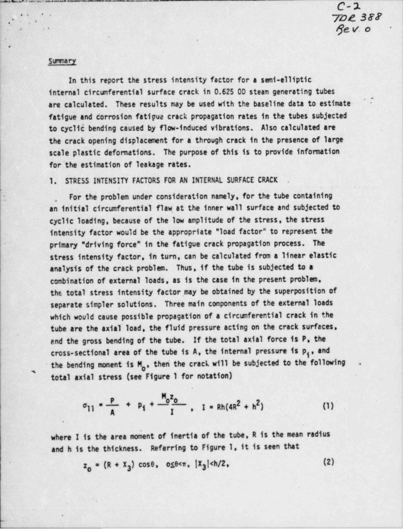
'- , , _ .. _ _ - _._ C-2.
'
. . ' ' . . ' * yog3gy.
ge v. o -- - --
..
_ _
.
:
: Sumary
In this report the stress intensity factor for a semi-ellipticinterrial ciretsnferential surface crack in 0.625 OD steam generating tubes
I*
are calculated. These results may be used with the baseline data to estimate--
fatigue and corrosion fatigua crack propagation rates in the tubes subjected
i to cyclic bending caused by flow-induced vibrations. Also calculated are~
the crack opening displacement for a through crack in the presence of large !
scale plastic defomations.. The purpose of this is to provide infomation i
for'the estimation of leakage rates. j
i
1. STRESS INTENSITY FACTORS FOR AN INTERNAL SURFACE CRACK'
.
For the probkem under consideration namely, for the tube containing i;,
an initial circumferential flaw at the inner wall surface and subjected to,
cyclic ' loading, because of the low amplitude of the stress, the stressintensity factor would be the appropriate " load factor" to represent theprimary " driving force" in the fatigue crack propagation process. The"
stress intensity factor, in turn, can be calculated from a linear elasticanalysis of the crack problem. Thus, if the tube is subjected to acombination of external loads, as is the case in the present problem,the total stress intensity factor,may be obtained by the superposition ofseparate simpler solutions. Three main components of the external loadswhich would cause possible propagation of a circumferential crack in thetube are the axial' load, the fluid pressure acting on the crack surfaces,
.
and the gross bending of the tube. If the total axial force is P, thecross-sectional area of the tube is A, the internal pressure is p , andg
the bending moment is M,, then' the crack will be subjected to the following ,-
totalaxialstress(seeFigure1fornotation).
P N *oo 2811 " I=Rh(4R2+h) (3) -,
A I.
where I is the area moment of inertia of the tube, R is the mean radius
and h is the thickness. Referring to Figure 1, it is seen that
r, = (R +.X ) cose, oie<w, |X |<h/2, (2)'
'
3 3I
9'
S
-.v~ -----,ww..,w------ ,,--.-,-,v, . ~.-v.m... - m e c ww,,,-- m,-_ _,-e.,
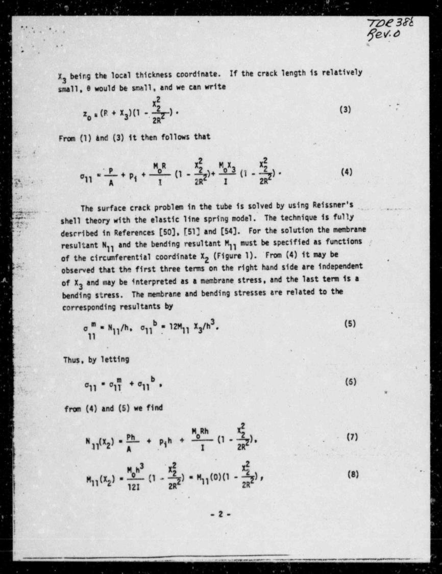
TO O N'
...2 p,o.. . .
. , . .. s-
i*. .
.
X beir.g the local thickness coordinate. If the crack length is relatively ,3
- small, a would be small, and we can write2
X(3) ~ . '
- z, (R + X )(1 ,k) . -
3 -
2R
From (1) &nd (3) it then follows that'
e
~:, , ,f..
k_ . pi) = ~'+pg+ (1- )+ '3(1- ). (4)'
A I 2R .I 2R .,ltis- '
-
3. . ..
h.g, .. The surface crack problem in the tube is solved by using Reissner's'
, ,_ ,
{T shell theory with the elastic line spring model. The technique is fully-
Uj described in References [50]. [51] and [543. For the solution the membranemust be specified as functions -fresultant N ) and the bending resultant Mjjp. j
;f of the ciretaferential coordinate X2 (Figure 1). 'From (4) it may be *
]* observed that the first three terms on the right hand side are independent'
of X and may be interpreted as a membrane. stress, and the last term is a} 3
f- bending stress. The membrane and bending stresses are related to the,
corresponding resultants by ,
*,.
*'
3.
b = 12M X /h .- (5)? o"=Njj/h. ejj jj 3,
11
Thus, by letting .,
,,
&L ~
(6)11"'1$+'11k., 8 e.
Ly ; from(4)and(5)wefind
.
g' g
, 7,-
M,Rh X
+ ph+ (1- ). (7)y(X ) , PhN .
2 '
,
'. . . -. . .,' -,
'
jj(X ) " ' II )"N11(0)(1- ), (8)"
M 2 12I 2R 2R.
.
-2-r
| .
F
L _-__. . _...,.. _ _ _ _
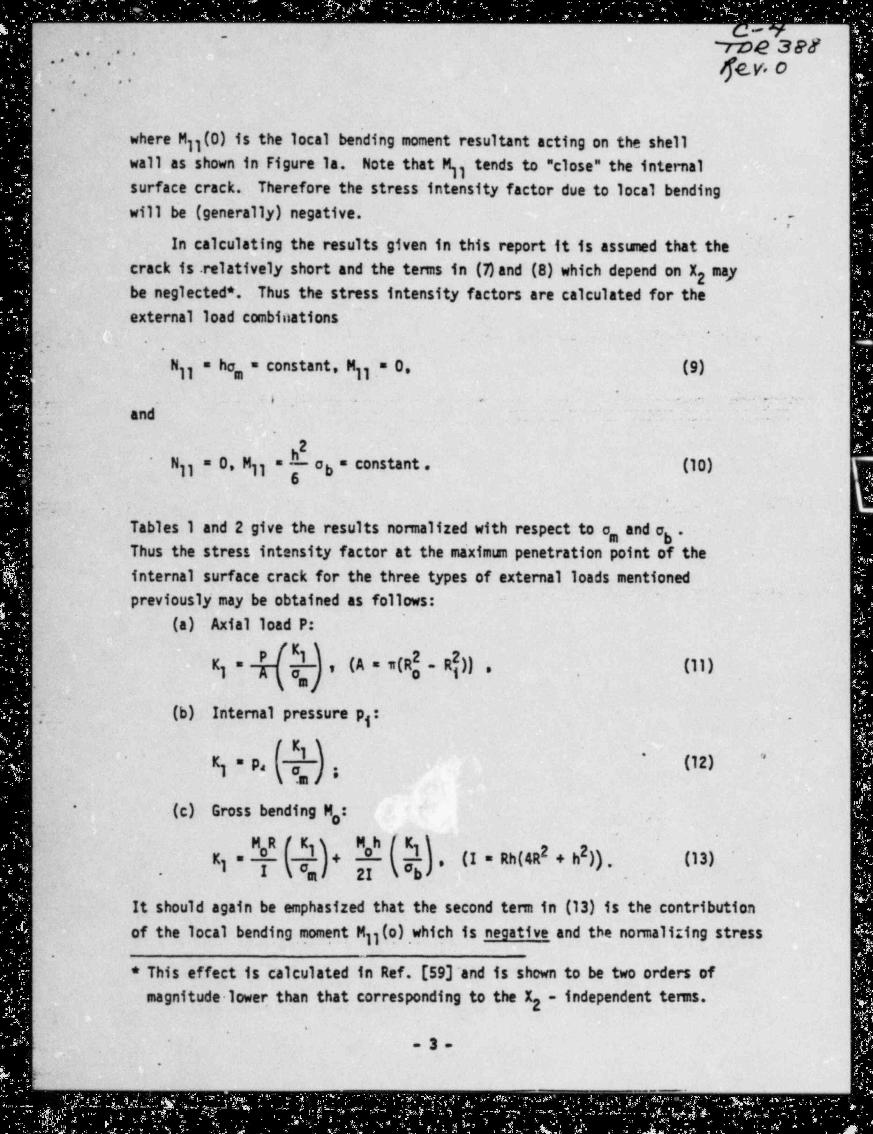
.. . . . . . .. . . ..
rne 3er.. . . .
, " . , ge.W O*
-
,,
.
.
'
where Mjj(0) is the local bending moment resultant acting on the shell
wall as shown in Figure la. Note that M)) tends to "close" the internalsurface crack. Therefore the stress intensity factor due to local bendingwill lie (generally) negative. . , -
In calculating the results given in this report it is assmed that the
crack is relatively short and the tems in (7)and (8) which depend on X2 "*7be neglected *. Thus the stress intensity factors are calculated for theexternal load combinations -
,
:. .
_ N)j~= ha, = constant, Mjj = 0, (9)~
. . . . i , . . . r -
( and . .
~ ~
2"
hNjj = 0, Mjj = 6 ob = constant . (10)
'
'n .-
Tables 1 and 2 give the results nomalized with respect to o, and a *bThus the stress intensity factor at the maximun penetration point of theinternal surface crack for the three types of external loads mentionedpreviously may be obtained as follows:
~ '
(a)-AxialloadP:2 2(A=w(R - R )) , (11)Kj= ,
,
'
(b) Internal pressure p : .,- j
fKj) ' ''
j = p, ( , )I ; (12)K'
.m
.(c) Gross bending M,:*
MRfK) M h .f K )0 j 0 i j 2!, (I=Rh(4R2+h)). (13)Kj= 1+I ( 'a l 2I ( 'b d-
It should again be emphasized that the second tem in (13) is the. contribution
of the local bending moment Mjj(o) which is negative and the nomalizing stress.
.
* This effect is calculated in Ref. [59] and is shown to be two orders ofmagnitude lower than that corresponding to the X2 - independent tems.
'
-
3 ,
*
_.
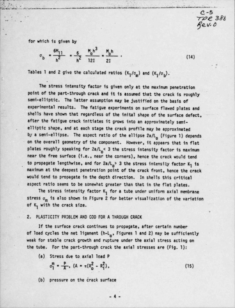
(w:(.A w.,e - - ~ri. ' :.s . - ,-m '.9;..- . . . .a ,-
.
- w . _ - -a
6 -5.
i 7:2:?e 384-
- - - po_
.
.
for which is given by3
6M Mh M,h11 6 oo "b 2 " 'l (14)
* *
h h 12I 2I.
. , -
Tables 1 and 2 give the calculated ratios (K;/e,) and (K /ab)*,
3; .
-
_
The stress intensity factor is given only at the maximum penetrationpoint of the part-through crack and it is assmed that the crack is roughly
_
,
, semi-elliptic. The latter asseption may be justified on the basis ofexperimental results. The fatigue experiments on surface flawed plates and
I, shells have shown that regardless of the inital shape of t'he surface defect. Y ~
after the fatigue crack initiates it grows into an approximately semi-. elliptic shape, and at each stage the crack profile may be approximated I.
by a semi-ellipse. Theaspectratiooftheellipse2a/L,(Figure 1) depends ,on the overall geometry of the component. However, it appears that in flat-
plates roughly speaking for 2a/L,< 3 the stress intensity factor is maximanear the free surface (i.e., near the corners), hence the crack would tend
to propagate lengthwise, and for 2a/L,> 3 the stress intensity factor Kj is -
i
.
,
maximum at the deepest penetration point of.the crack front, hence the crack '
would tend to propagate in the depth direction. In shells this critical. aspect ratio seems to be somewhat greater than that in the flat plates.
The stress intensity factor K) for a tube under uniform axial membranestress e, is also shown in Figure 2 for better visualization of the variationof K with the crack size. 'j
-- 2. PLASTICITY PRDBLEM AND COD FOR A THROUGH CRACK l
|If the surface crack continues to propagate, after certain neber. |
of load cycles the net ligament (h-L,, Figures 1 and 2) may be sufficientlyweak for stable crack growth and rupture under the axial stress acting onthe tube. For the part-through crack the axial stresses are (Fig.1):
'
(a) Stress due to. axial lead P2 2
-
c' = [,(A'=w(R - R ), (15) |,
1
(b) pressure on the crack surface
.
-4-
.-. ..-_.1 .. . . _ _ . _ . . _ _ . _ . - _ . . _ _ _ _ . _ . . . _ . . _ . . . _ . - _ _ _ _ _ . _ . . _ . _ . _ _ _ . .
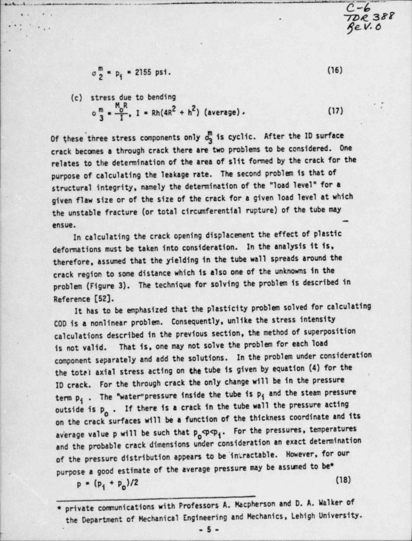
GA - - - - - - - - - -
_ __ _ . ., _ _ _ ,
_
Tag 387..
ge_ y, g', *:. . ..
.
-.
.
o"=p = 2155 psi. (16)g
(c) stress due to bending2
~
,I=Rh(4RI+h)(average), (17)'
o "3=
Of these'three stress components only c$ is cyclic. After the ID surfacecrack becomes a through crack there are two problems to be considered. Onerelates to the detennination of the area of slit fomed by the crack for thepurpose of calculating the leakage rate. The second problem is that ofstructural integrity, namely the determination of the " load level" for a
.~~ given flaw size or of the size of the crack for a given load level at which
the unstable fracture (or total circumferential rupture) of the tube may-
ensue.~In calculating the crack opening displacement the effect of plastic I
: defonnations must be taken into consideration. In the analysis it is, ;
therefore, assumed that the yielding in the tube wall spreads around the |,
crack region to some distance which is al'so one of the unknowns in the'
problem (Figure 3). The technique for solving the problem is described in
Reference [52].'
It has to be emphasized that the plasticity problem solved for calculatingCOD is a nonlinear problem. Consequently, unlike the stress intensitycalculations described in the previous section, the method of superposition
,,
is not valid. That is, one may not solve the problem for each loadI component separately and add the solutions. In the problem under consideration
the totel axial stress acting on the tube is given by equation (4) for the'j
ID crack. For the through crack the only change will be in the pressure.
The " water" pressure inside the tube is pq and the steam pressureterm pg.If there is a crack in the tube wall the pressure acting,
outside is p, .on the crack surfaces will be a function of the thickness coordinate and its
! average value p will be such that p,<p<p . For the pressures, temperatures~
g
and the probable crack' dimensions under consideration an exact determination'
|of the pressure distribution appears to be' intractable. However, for ourpurpose a good estimate of the average pressure may be assumed to be*-
( p * (pg,+p,)/2 (18)
* private connunications with Professors A. Macpherson and D. A. Walker ofthe Department of Mechanical Engineering and Mechanics, Lehigh University.
- 5-p
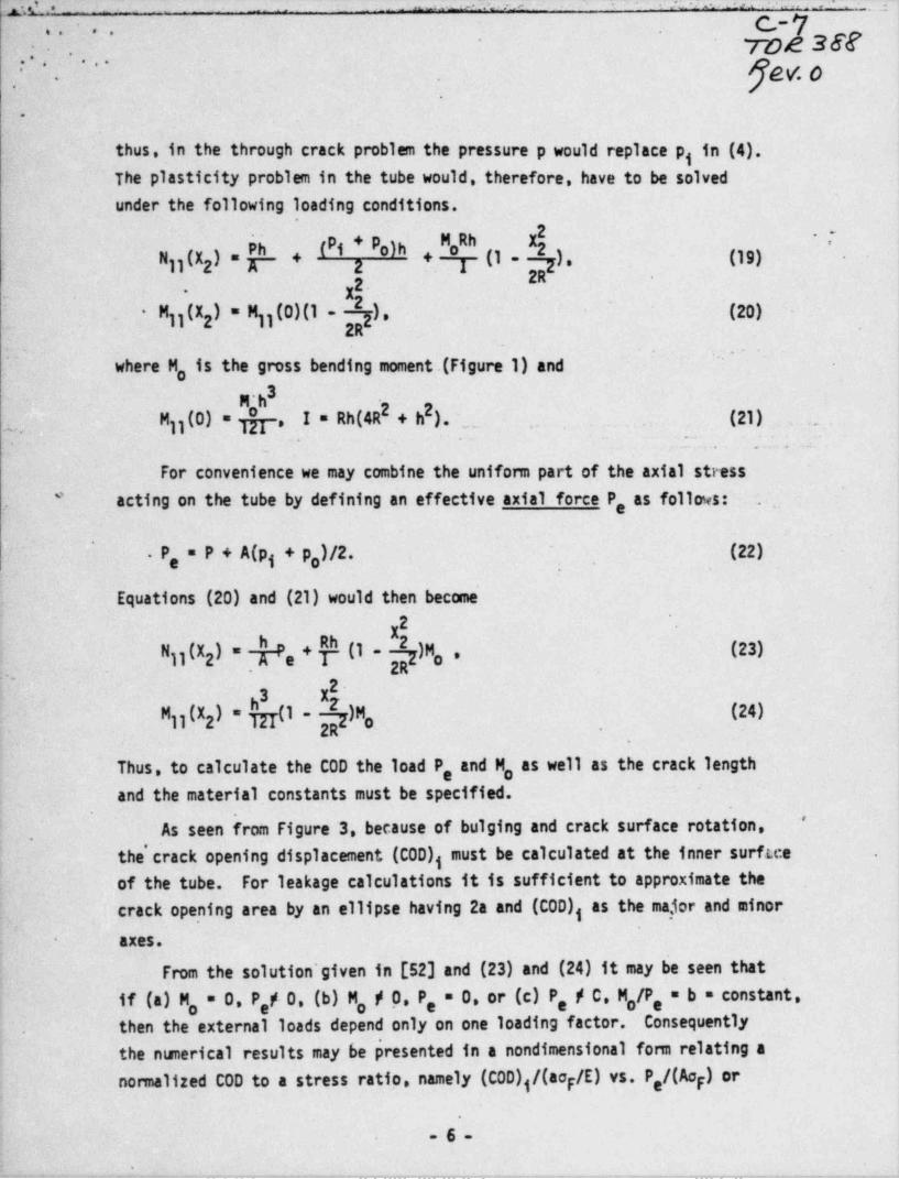
y ,, ^ _ e. =. .2 :x.
. . . _ . , . - "__ .=. ,
=<C-7,. * -.
_ TOA Y*, . , . . .
e% 0'
.
-
.
...
.
thus, in' the through crack problem the pressure p would replace p in(4).g
The plasticity problem in the tube would, therefore, have to be solvedunder the following loading conditions.
h ~TPh (Pi + P )h N Rh
o oj j (X ) " K~ * 2 1 II ~ 7 )' III) ~N +2
2R2
jj(X ) " M11(0)(1- ).~
'(20)M2
2R- .
''
'where M, is the gross bending moment.(Figure 1) and
2+h)._ . (21)2I=Rh(4RMjj(0) = , ... .. -
<- * :~ . ...:
_
For convenience we may combine the unifonn part of the axial stress
acting on the tube by defining an effective axial force P, as follows: . .*
''
.P,=P+A(pg + p,)/2. (22),
Equations (20) and (21) would then become2
X* II ~ )M (23)jj(X ) " .N o.2 e
2R...
23 X'
jj(X ) * I- )M (24)M2 o.2R ,
-
Thus, to calculate the COD the load P, and M, as well as the crack length ;
and the material constants must be specified.'
As seen from Figure 3, because of bulging and crack surface rotation,.
the' crack opening displacement (COD), must be calculated at the inner surftceof the tube. For leakage calculations it is sufficient to approximate the
.crack opening area by an ellipse having 2a and (COD), as the maior and minor
axes.-
From the solution'given in [52] and (23) and (24) it may be seen that
' f (a) M, = 0. P,p 0, (b) M, p 0. P, = 0, or (c) P, p C M,/P, = b = constant,ithen the external loads depend only on one loading factor. ' Consequently-
.
the nunerical results may be presented in a nondimensional form relating a
normalized COD to a stress ratio, namely (COD)g/(aop/E) vs. P,/(Aap) or
.
-6-
._ . _: . _ _ . _ . _ _ . _ . _ _ . _ . _ _ _ _ _ . . _ _ _ _ . _ _ _ . _ _ - . _ . . _ _ _ _ . _ . . _ _ .
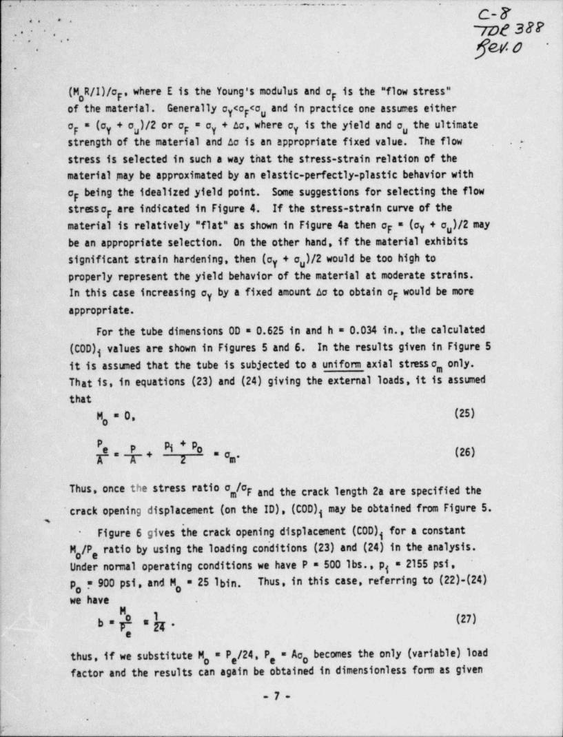
m _
_-. _ - - - . -
* ' - - ~ ~ ~ . - - - - . . . . . _ _ . -
c-y. . . ' . . ,,<.
'7De 387*. .. .. p-,
.
(M,R/I)/o , where E is the Young's modulus and op is the " flow stress"pof the material. Generally c <c <c and in practice one assumes eithery p uo = (cy+ u)/2orop y + ao, where ey=o is the yield and o the ultimatep g
strength of the material and ao is an appropriate fixed value. The flow 7
stress is selected in such a way that the stress-strain relation of the.
material inay be approximated by an elastic-perfectly-plastic behavior with
op being the idealized yield point. Some suggestions for selecting the flowstress o are indicated in Figure 4. If the stress-strain curve of thep
material is relatively " flat" as shown in Figure 4a then op = (cy + o,)/2 maybe an appropriate selection. On the other hand, if the material exhibits
significant strain hardening, then (cy + o )/2 would be too h~igh tou
properly represent the yield behavior of the material at moderate strains.In this case increasing oy by a fixed amount Ao to obtain op would be moreappropriate.
For the tube dimensions OD = 0.625 in and h = 0.034 in., the calculated
(COD)g values are shown in Figures 5 and 6. In the results given in Figure 5
it is asstaned that the tube is subjected to a uniform axial stmss o, only.That is', in equations (23) and (24) giving the external loads, it is assumedthat
M, = 0, (25)
P, p pg + p,T*A 2 * 'm- (26)+
.
Thus, once the stress ratio o ,/oF and the crack length 2a are specified the
'crackopeningdisplacement(ontheID),(COD)g may be obtained from Figure 5.,
Figure 6 gives the crack opening displacement (COD), for a constant-
M,/P, ratio by using the loading con'ditions (23) and (24) in the, analysis..
Under nonnal operating conditions we have P = 500 lbs., pg = 2155 psi,,
p, = 900 psi, and M, = 25 lbin. Thus, in this case, referring to (22)-(24)
we have .
M
.b = p a h . (27)f
e
thus, if we substitute M, = P,/24, P, = Aa, becomes the only (variable) load'
'
factor and the results can again be obtained in dimensionless fonn as given
-7-,
-
;
b )
g7- - - - - - -.
,
~ TDL 38Vn .. . . qu w; ; ... _
- -
.
.
by Figure 6. For example, at the nomal operating conditions e, a 9448 psi.= 0.225 and the nomalizedIf we assume that o = 42,000 psi, then o,/ Fp
(COD)g may be obtained from Figure 6.
The second problem relating to a tube with a through crack is that T
of fracture instability. Development of a fracture instability criterion basedon COD has _been described in detail ~in References [7], [52], and [59]. The
experimental verification of the model for axial and circumferential cracksmaybefoundin[7]and[59),respectively. In sumary, the model is based
-on the following argument: The calculated a'nd experimentally detemined C0Dvs. o curves show that for a given crack dimension, in the neighborhood of
a certain stress ratio e/op a very small increase in the stresslevel wouldcause a very large increase in COD [52, 59]. Physically this indicates that
~
at this particular load level a certain (material-structural) instabilityis setting in the pipe. Theoretically, at thi_s load level COD becomes'
unrealistically large or unbounded. Practically, the fracture processbecomes unstable.
'
In a limited way, the infomation given in Figures 5 and 6 may, therefore,
fbe used to estimate the fracture instability load in the tube for a givencrack length 2a. For this all one needs to do is to detemine the asymptoticvalue of c/o for the particular ' COD vs. o curve corresponding to the given
pcrack length. For example, Figure 6 shows that (if op = 42,000 psi) under
= 2155 psi, p, = 900 psi, and M, = 25 lbin~.normal operating loads P = 500 lb., pg
o,/op = 0.225 and none of the cracks shown (i.e., 2a 11th) could becomeunstable. On the other hand, if P = 1107 lb. , pg = 2155 psi,~p,= 900 psi, ,
= 42,000 psi and assuming M, = 0 during cooldown, we have o /o r 0.454,g popand Figure 5 ~shows that the cracks of length 2a > 12h would be unstable and
2a floh would be stable. If one assumes that during cooldown M; remains
25 lbin. then~we have e/op = 0.518 and the cracks of length 2a 18h would be
stable.
.
.
'
-8-*
!.
_ __.._ ..
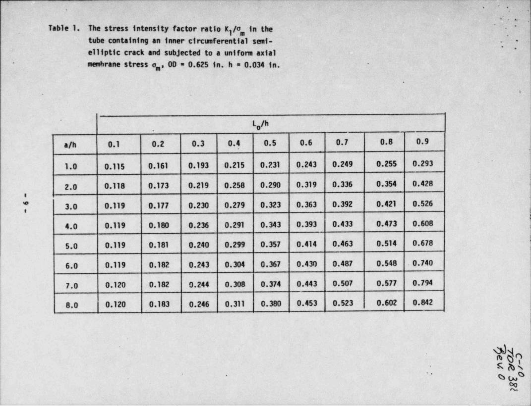
7~
H .( i,
.'
, ,
i c. n.. ,
' ; ;.,e
Tabla 1. The. stress intensity factor ratio K /3h in the- -"
'
j,
tube containing an inner circumferential. semi . ; ,''
, . ,Lelliptic crack and subjected to a unifom axial .*
membrane stress o,, 00 =.0.625 in...h = 0.034-in.* -
.
.. t -'
'
L,/h, -
a/h 0.1 0.2 0.3 0.4 :0.5 0.6 0.7 0.8 - 0.9a
'
1.0 0.115 0.161. 0.193 0.215 0.231 0.243 0.249 0.255 0.293':
2.0 0.118 0.173 0.219 0.258 0.290 0.319 0.336 ~ 0.354' 0.428 i
8
7 3.0 0.119 0.177 0.230 0.279 0.323 0.363 0.392 0.421 0.526:
4.0 0.119 0.180 0.236 .0.291 0.343 0.393 0.433 0.473 0.608
'
5.0 0.119 0.181 0.240 0.299- 0.357 0.414 0.463 0.514 0.678
6.0 0.119 0.182 0.243 0.304 0.367 0.430 0.487 0.548 0.740-
i
,7.0 0.120 0.182 0.244 0.308 0.374 0.443 0.507 0.577 0.794
| 8.0 0.120 0.183 0.246 0.311 0.380 0.453 0.523 0.602 0.842
i
deno,
R ghk!j gs,
.
oo; ~!
!-. . -
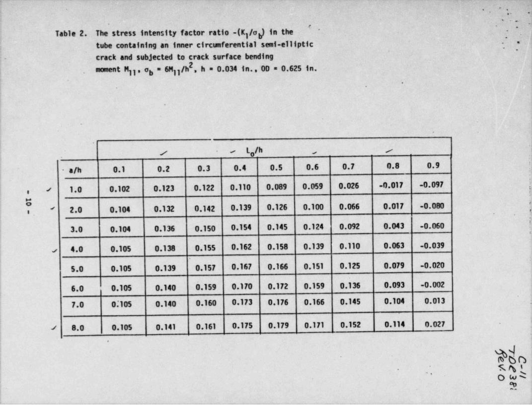
___ _ ,. . . -_ . _ . .. . _. _
"- -
.. . ..- < . . ...
4-~ y ; . .,
4'. w <
-
, ..
;-. *; }Table 2. The stress intensity factor ratio:-(K /o) in the-~ ~
~
,jtubecontaining.aninnercircumferentinisemi-e111ptic
. crack and subjected to crack surface bending~
j ',-,
.-
-
2 ~ '
j moment Mjj,~ob = 6Mjj/h , h'= 0.834 in., 00 = O.625 in.,
|'
*
.
i
( ,,
N
i !
:-
; -
i
(-
,
L lk /|
.
0.9 L
s - ,o.
;.
! a/h 0.1 0.2 0.3 0.4 0.5 0.6 0.7 0.8
( |
! / 1.0 0.102 0.123 0.122 0.110 0.089 0.059 0.026- -0.017- -0.097. !,
i
2.0 0.104 .0.132 0.142- 0.139 0.126 0.100 0.066 0.017 -0.080 l' '
. - ?i.
i 3.0 0.104 0.136 0.150 0.154 0.145 0.124 0.092 0.043 -0.060 !.4
;
1
,e 4.0 0.105 0.138 :0.155 0.162 0.158 0.139 0.110 0.063 -0.039'
5.0 0.105 0.139 0.157 .0.167 0.166 0.151 0.125 0.079. -0.020,
6.0 0.105 0.140 5.159 0.170' O.172 0.159 0.1 36 0.093- -0.002!
7.0 0.*105 ~ 0.140 0.160 0.173 0.176 0.166 0.145 0.104 ~ 0.013 }'
| '
i
j / 8.0 0.105 0.141 0.161 0.175 0.179 0.171 0.152 0.114 0.027. !
j-
,
i-
. g%bn%
f7
<s g i-
.
O to k''
, ** -
i!
'>.
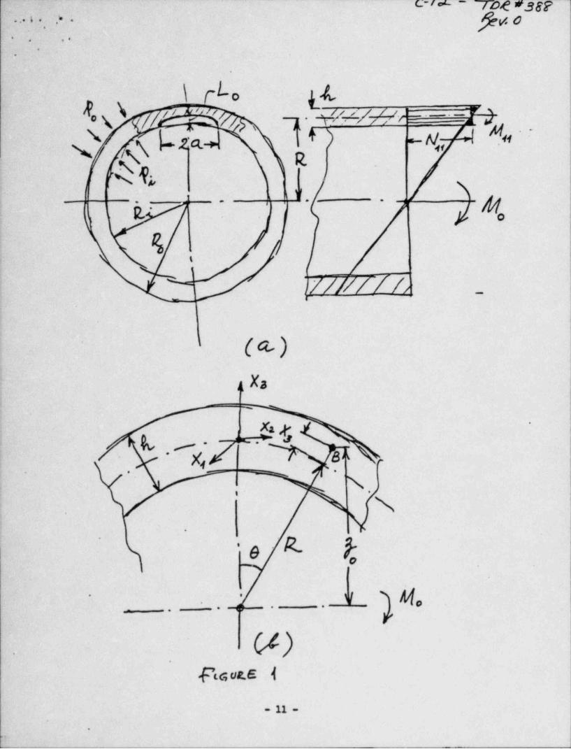
c-/.' - yo g eggppgo. .. s . * .
.,
. .. .
.
e
L\ro .LAox\ p t'3 3.h y z w . .- 9N c ? +) - N.,,
a, 4*' -
g ,. N .2 4.+ -- .
N ik <j
,% g,19
-
, ,-
g. ;.
,
& ,.
1
]/ /// / f //
(M'
a Xa-
_,
%x, -
,.l_.>#.i,
( _
A a L*
c
i N'
$.
~1
b 'e R-t
i
Y* *
l,.
-- - - - *
__
. .,,
f
Eh-
.
ena 1
- 11 -
.
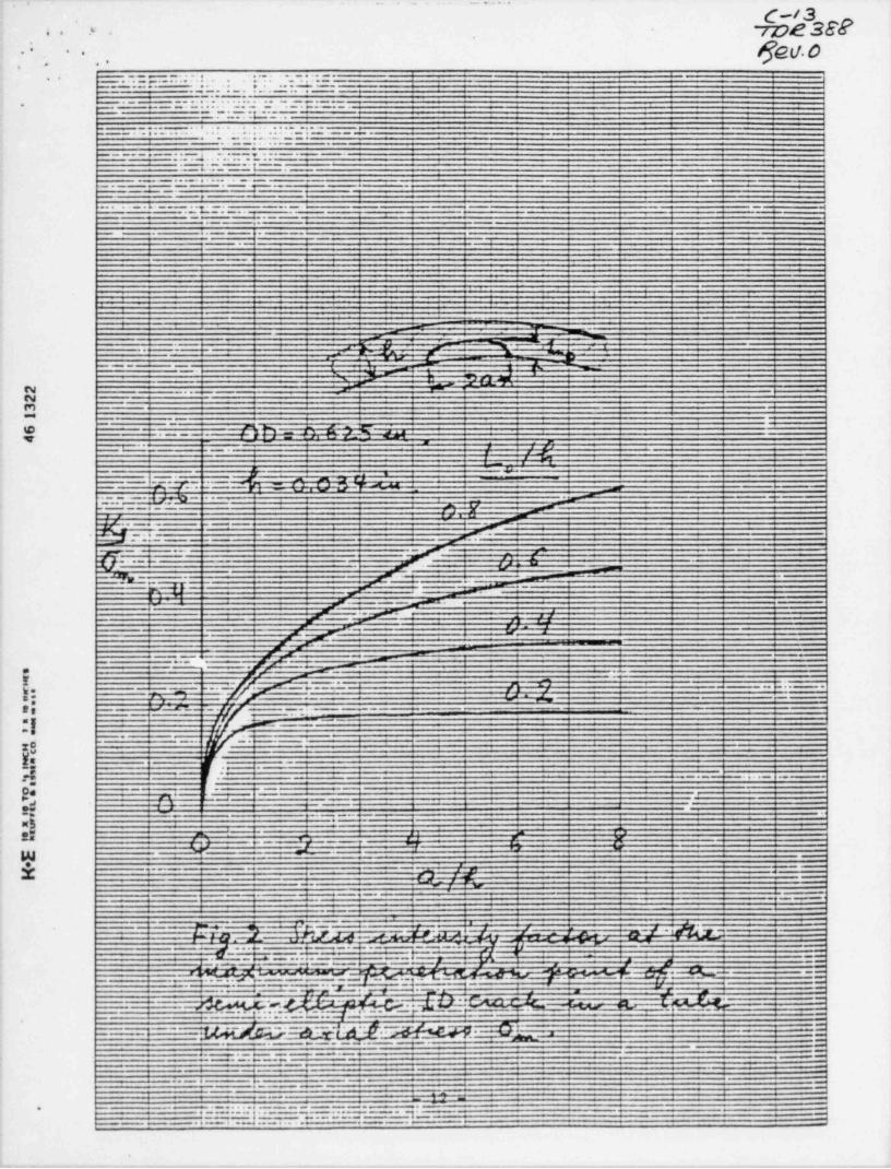
i . _ . .
, - - _ - - _ - - - - _ - _ _ _
C-/ 3rD2382a. .' -
$Gll.O** '
, ..,
_ . _ , . . . . . . . . . .
. . . . . . . . . . . . - . . . . __
_.. ,. . . . - _ ... . . . . ..... . . . .
. ..~-m. ..
.. .... . . ., -. - -. . . . . . . .
- .....I-...
. s ... . . _ . . , . . .... . ..... ..e.. . . - . . -.
,.g... -
- -_, ...,.... ,... .- .
_ . .7......- -.9 .._, _ . . __ . . .. _.
..--..p .
.. --.s.. *2_. _. _.. _.
..
. .-- :.__4
E- 1-
, . . - --,, - . , - _ - - - ._ ,
_L._, _%-.- -- _ . , ,- -
N -M-M--. . ~-,_ _ _
. . .,.' 1- h_,m - _.N M
1:AM__A_
. , _- ~
A 1 .-
f9.e.
R n
p-.,11 1_ ,
-- - .- .g .- x 2 m t. - a m
-
.___a- .
- - - . .
_. __. --.- ,
-
-
--
2 -- - , .' -~
_ \|.~*...., _' gr' - sj ,_;
i
MT f _
-
r ^= _-,- M .
._ -_. _ .4 m._._. , - n-__ -_
_ ._a _ B _M__
- . .F,J. m p. . - . . --
,w... . . ... _ _m y. .
-. _ .- . ;.. 4 -__ _--
7m# -
,-% ,.. , -+ F -. #" _
--,
-'' -'" f
.
M- ,. .-
I__A-
1 .
-
.Ef
- . .-
_m_
-;4 -- -
__ y- ---...-f *- /-o - - - -
-.
.
*.
r- _ -
y _ _ - - - - . . . . .and"-- ,~,'- '; y.my . - ~ , _ _
_.gf_y - w
_
.-g .-tg = -x- .e ,"I a- ---
.7 -
.(
g . .. .: .u _
..i +.-
g _,
... ,, .,
-
,0.2 J- e_.J . .s4 .
-.- ..
at *
- .-
w v' - -
--.-...x +- .
" -
,.
1, - : - ;g-A .-->
-w.
---. ,-4
l
EW Y i E A.,e -.- s & M'-- ' "
- ,: - ni. =Y Y----, . . . . 3 .+ ____ _ y -- -
-
j
; ,. = n - . . .-t--+-.- t"~ W.- - -
:_.- ..
- M.. . ~
.
M M_*%- --"M -
. -,. 1-- ,, ,.. . . .. . _
...._. -...-1_**p-
,
-
- M 3dGC.CL.f.-Mf2EF9 ML__. 2-- -
.. W-
4a ee . . e.
W - - -
em ""'' 9
-4
. 6 . __
*9- e.$ -
e --- , ' ' . ' ' . ' ' ' * . . . .a a
h m
.e.e _.-e. .mg .. 4..
.. e ..e4... .. .. - *I-
;e
&
, , - - , . . _ _ , . _ _ _ ___ , , . . _ , - _. . _ _ , , . . . _ . - - - - . - . , . , - _ , - . . , _ _ , , _ _ , , - - - , , , . .-
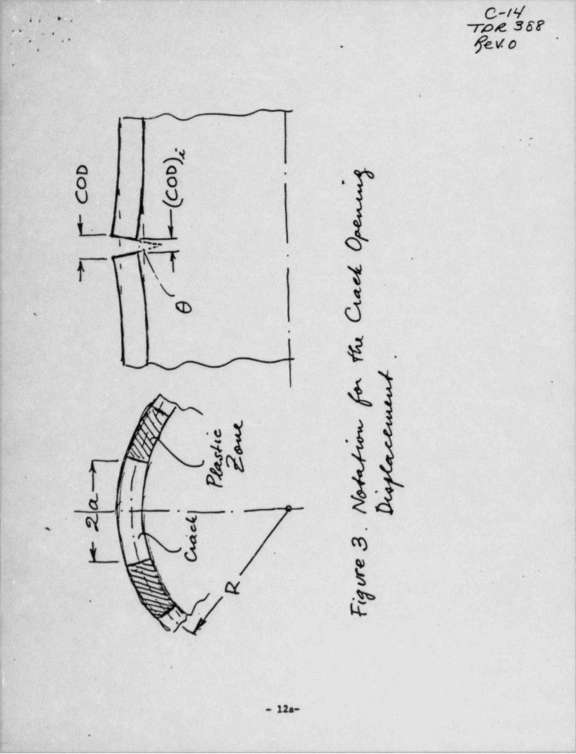
+ -~a .
.
-''C-ty'
'
Tot 36F' . . .
.'. fev o*''
' *
.
S
^
W -
.-
a o -
O o. '
U g'
lI
V t tn ;-
I .y-
'
f -,
A 1.'
, t We d >
_
-
4~
N
,
2 ,0
kA- ,/
-
dg '-
i-uq .g !
.-.
* .
1| a'
3 .m'
;
| g: *
N .
i4.>
-.
.
12a--
'
.
.- ,,,,-,,,rn-,n----,..,_.,---,,--,--,----.~,r,---,,,.-e,_e,.. _,,,ny,, - . . . , - - -. -, -,------,-,-,.---a ,.--
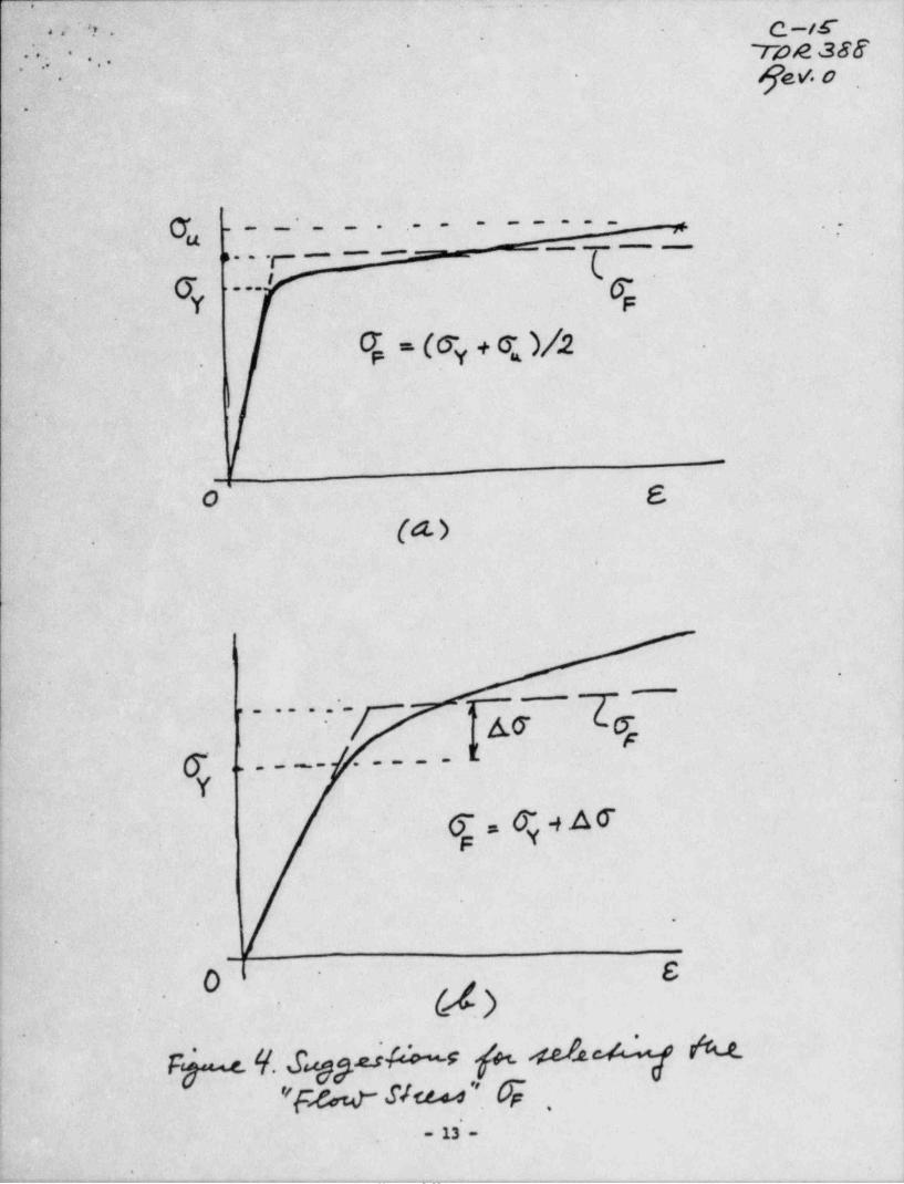
-j - -.. . . .
C._ff-O ' f ''* y , ,-
TOA 38$-** * *
.. . , .
fev. o,
'
.
O'_ _____
7- - _ _ . .__y
__.. . . y .___,,
(Y T ~ l,_..I
.
O '' (T + Q )/.2 .
p y
I|
-
I
f0 E
(d-) |*
.
$
k
A
I _e a e ,m
.
cr .. _ _ _ _ . . _ _ l.Y
.
.
.
F Y
e,
#
.
FVs 4. 6 p.ai% fu .sef.u+Lj h.e_9"Fw s/w'' 0;
i ,
- 13 -F
- '. _ _ . . . . . _ _ . _ _ . _ . . _ . _ . . . _ _ . . . _ . _ _ _ _ . _ . _ _ _ . _ _ _ . _ . . _ , . . _ _ _ . _ . . . _ _ . . _ . _
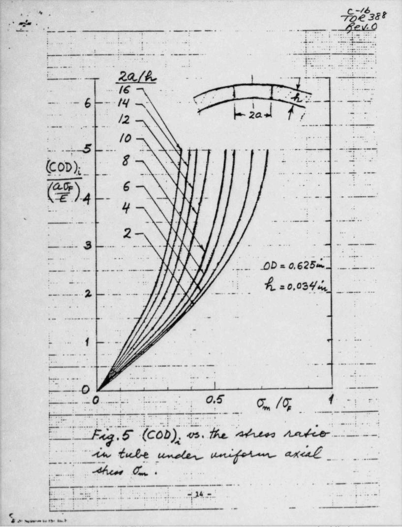
.-
..- - ..
p/d.a ," % ' ~
~7&e 38'.
-;. RN. 6.
..
-.. :._ . . _ . . . _ _ _ . . . .. ..
_......._....o.r..._ _ _ _ s. ... . . ......... .. f.- .g.. . . .
*- *
. . .. . . . ' .;-
. ..r :: -- -* ' *; t...* .
... . _.. . . . . . ; ,.s: ;.... .. .. o.. .... .. ...,. . . ....g . ; .- ., .. . .
t .
- . . - --
. . . ,
. _ . . . ., _,- . . . ..
.-
.........s.
.
t. .... . .. .,.
.. . _ .: .- . *...;. .- . . . .. .;......**
,
.. . .. . . . . ... ..
- . *
. . .i '- . ..
*.
. . .. .
. . ~ . ..*.
.
5.... ..- .k . .
>- . . ..
,^ ' . ,.. . .
' ..' _ .. / ...\.
.
,- *g. , . .~ i
.\_ . ' l% * ' t
* * . W Q Q ,.pu, = = " ~ -* r,
. _ _ _ . . . . . . ... .. . _ _ _ . . .... .-
. Jo . .
. . : .. ., . . ..
.*
_. . ._.
.
... . . . . . . .. _ . . . _ . _ . _ ~ . .,.. t ... ._ .. .., , .
..
.
. . ...... . . . . .. .. . _ . ..
.
O. . . ,
.. .
.. __.._c __ . . _ _ ._.. . . . . . . . . . . .. . .........._ . _
.._ . . .
.
,.. .
. . .
y, .g .. . .; ,.
-._ .
\..
|\,
_ _ . -_g. . . . . _ . _ ..._.. -
.
.. _ . ..
.- :. _. -. . . . _ _ . .. _ . . . . . _ _ _ . . ._. ..
. _ . .
'
2- . . .. ..
..
:4 ._. .. _ _ . . _ _ . ._ . . . . . . . . . . . .. . ...
. ..
_ . . . ... . ... . . . . .. . . . . . ..
.DD = 0. 625%_' _ _ _ . . _ . . _ _ . ._..+_. . ... _ . . ... - . . .. . . _ . _ . .
.
. .. .. ..
=0,03 %..,_. _ . _ _ . .
.
:'
'___ ._. 2, . . .. _ ._ . _ . . . . . . .. _. . . _ . . _ . .
.
. . . . ..
. ..
._ .
. . . . . . _ . . . .. . . ._ ..
_ .. .
..
.:
. _ . . . .g> .. ...
..
i .. . . _. . .. ... .._ _. .
1
_ . . _ . _. . . . . . . . _ _ _ .
.. .
6 _. . . . _ . _ _ _ _ . . . . _ . ....._.. .
_
..
. ..
%. . .
. . . . . . ... ... . . . . . ...
!i ~f ' '_ .; h . E'
... '.'.. .
. . _
- . .,.. .
. _.. ...
. .. ..
_ _ . . _ . . . . ._.. ... . . . . . . .. ..
... . .. .
.
...
.
.. . _.
. ... . . _ _ _ . .
.. . .. . . . .
.._
... .
. ...- .. ... .... .. . . .. . .. _. .. .. . ..._1.... . . ._ . _ . . .. .
... . . . . . . ,.,. . ... -. . . . .. . .
.. ._ ..... .
f ;_. Ay,._ __.f .(C0b,), .os. & A nJ< e . ..'. . . . ..
= . _ . .,
.
{ "_.'.... % .h.f,e 4 ag Q_. . . . _ _
-.
_ . . ..,_ . . . ._
, . ..
,
._..... . . . . ..
..
..
*:.
'.' . _.
* .
1 . _ _ . - .. -.
. _ . _ . . . . . .. . _ . - . ...
__ .. .. .
. _ .. . .. . . . . . . .. ...
. .,. .. . . . . . _ . .. , .. . ... . . . .. . . . . . . .. .. .. t,
..... . .. . . . . .. . .
.
. . _ . _ .. ....._.
.. .
... . . .
.._ . ._ . .
*f'
' h alb Neue.ee . th. Is >. . . _ _ . , _ _ - . . - - . - - - . . -..._._.__.-.__._.-._._.m..._._ _ . - - - _ . _ _ . - . _ -
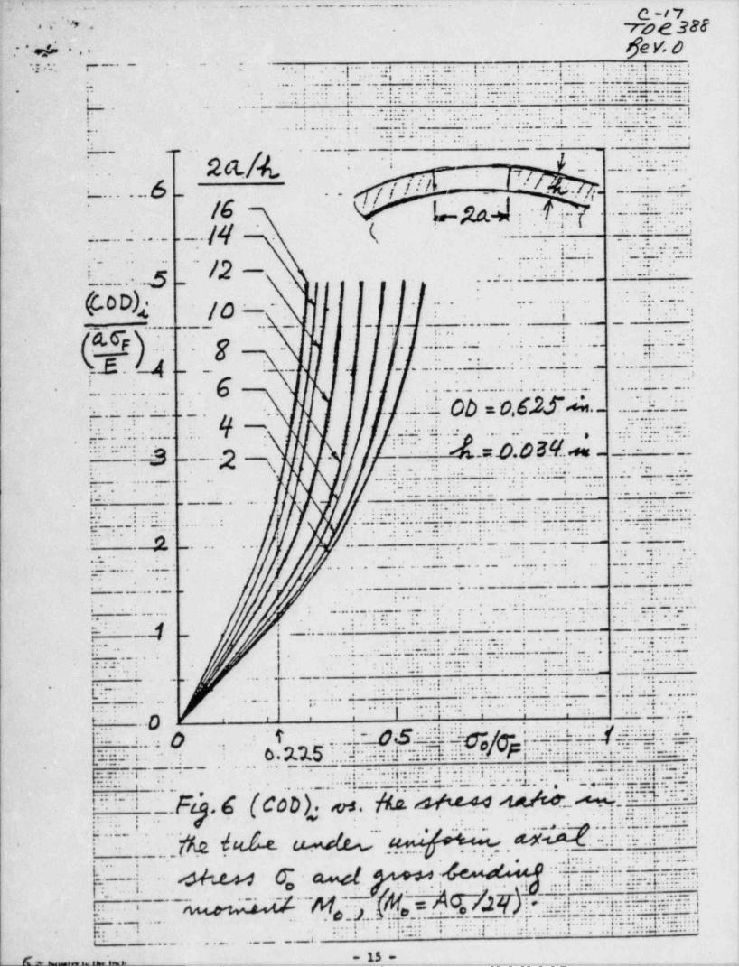
.-' . _. ,. .._
,.. . . , S .........w . - .. . .. . . .. .
c-/ 7.
.* ~7M 328.* * *
f]eV &: *. e 6 ._ . _ .. . .
3
.
-. ... e.. . , . ....3.6 ...
.-4 .... .. . . . _. .
.......
.*.
... .
..; ? . s . .e
.. .,
. .
..
. . ... _... ... . ...... .. $ .. .,. ,,... ..
...
... ... . . .... . .. . . . .s
.
. . . - . . . . . . . . . . . . . . .. .. . . - . .. . . . ..
. . e. ...... ........ . .,. . ..... .4 .
. . . . . . . . ...-
.. ...
. . . . . . . . . . . . . . ..
..
l, .4 .. ... 4. . -....
. . . -... ..
-. . .. . ._.1. .. .. .. ... . . . . . . . . . .
... .. . . . .. - . . .. l, . . . . . .
. ..... . . . ..
- . .. .. .... . ,. ......s .. . ..... ... .. - .--.
. . . . ... ... ..... ..
.
. , . .. ........ . .
... . . . _ . .
. _... -.
.. . -.
.a s..--. _ . .
.
2a i. m _ .. . . ...
-
.
... ..
./ ; .ill e .. i ?' / . .' .t --..-' .
i.
.- . . . . .. _ . .
g. .i . . . . . . ..
. ...
. e .. ..,.,
* .. ;. .; , ;;.. --*....,..i
. ..t
.. .. .... .. (.
.
. . .....|.......b
. . . . . .. . .. .... . ... ...e... . ..
.- .. . . . . . ..
. . .
....e,- .
1. .. . . . ...... .- . . - . .-
| .p-. . . . -
. . .
.. . .. . . . . . ... . . . . . . . .e. . . ..g . .,..
. .
- - . . . . .. .. . . ... - .. _*
_ *
. .. .*L I. a. ..e ... a .. .
..,. . -. .g..-.. ... .- . .
e. .! . . ... . . .
. . . _ . ._ ... ... .- . .- . . . . . . . . . . . _ . . . .
,
g.
.*
. *!a
.
.. . . . . . . . . .... .. . . . . . . . . . . .
. . . . . .....1. 6 .
.. . :- .-- . . ' . ' *. .. . . . . . ..
- .. - .. .-. .,
,
. . . . . . . . ..
.... .. .
.. . . ...
. . . ...
. .. ....=m
. . . . . .. ...
. . . . . . .. . . . . .. . 8s. . . -. ........ . . . . . .
. . . ..
... .. .
...
. . ann e. ..
.... . eu. -. . _ _em., _ - . . ... - .- . g .
...
\ .. .
. . . . . . . ..
. .. .. _...... . . . - . . .
..... .... ..... . . , -. . = ....
.. .... .
. . ..
.-.s .. .
.
. . . . ..=
- .. . ..,. .... . ... ... s.. ..- . - .. ..
.
. . .
.
.. . .... ..
. . . .. . -..
.. . . . . .. . . . . . . . ... .. . . . . . . .. ... ... . .....
.. .. ... ......... ...... ... .. .. . . . -..
.
C..-...... - . . . -. . . _ ... . . .
. . .. . . . . . . . ...
. .....
. . .... ... .,. . ...
..... . -. . .. - ..
...
. .. . .. . . . . .. .. . .
.. ..
. . . . . .
. . . . . . . . . - -.
.. .. . . ..
. . . . - . ... .
.. . . . .
.. . . . ..... . .,
.. . . . . -. ... . .. -
. . . . .
. . . . .
,. . ... . . . . . . . . . . .. . - . . .. . . . . . . . . . ... . . . .... ., .
. . . .
.
.. . . . ..
. ... .. . . . . . . . .. . . .... .. . .... .... .
.. -. . . . . . - - . . . - - .
.
-.= -... ..-- . . . . . . . ' .. .. i. . .
. . .... ... ... .=,6...
. . . . . . . .. .
. . . . . .. . . . . . . .. 7. .. .
...
. .
. . . - . . _ . ...
. - . . . . . ...s. .. . . . .. . . . . .!.... . . . . . . . .. .. .. ..
. ...
. .. .
i........ . . ... ...
.
.. . . . ..
. . , - mu...
. . . . . .
. .. . .
m. .-. . . ....--:...
.. ... ..
., ,
.. . _ . . . . ..
.. .. . .. .. . . .
.
. . . .... .
. . . .... . . ..... ...- .. .-.
.. .. ..... ....!.. ..
.. . .., ...
... s .. .. .
.p . . .t .. ...
0 -
, , e .e e e e. . . . . .. . ...
.... . .. .. . .. .. .. . . . . . . - . . .. .....
1 .. .. . -u- e. .. . . . . . -....
., . . . . . .
..
..... ... . .'... ... ... . .
. . . . . . . . . . . . ....,
. .... . . . . . . . . - . _.. ... ....... ...... .... . . . ..... . .. . . . . ... .... ..... _.. .. . . . . .
. . . .
. . . . . . .,,. . .. ... . . .
..
.. .. .. .. . . _ .. ...... ....
.. . . .. ...... . - . _ . _ . _.... . .
.... . .... .. . . _ . .. . . = . . ._ . . . . . . . . . .,. . . - . . . .. . .
. . . ..
_ _ . . . . _ . _ . . _ . . . .. . .
. . . ... . . . . . . . . .
cod.es. N. d w M M W ~W,_..._. .. . _.. . .i.,.....i.... . . . _ . . . . . . . . _. . .. . . .
i. . .... .
.i.. . _ .. . . . ..
..... .... ..
. . _ . ._ . . _......... ....... .--_ ..
i5..... ...
. . . .,
Y. ~1 .6 . . . ... .. ..,.- . .
.. .. .... . . .,. . . . - . . . .. .. ......
. . . . . - .[ .. .. . .
-.r wy : .!.
r... . . h. A '.... .
.
t . . . . - . .. . . . .. . .. . . ..,. .. ,
M. .4 e. t y@t..?.. a. .k...n.._[.[ _ ..L
. h 0 w.
. i, . ...
. .L o .. . .. , . ... . . ..... . .. .....
~ ~ - - - . * - * "--
."**M *. . . . . . . . . - . . . . . . _ . . . . . . . . . _. . . . . . . . . . . . . . . . ... .. .
.,.... ..... .. .. . . . . ..,s.. _ . . . . . .i. , . .. .. -. . ... ...
.. ..,.... - . . . . ...
..* ..a. . . . . .... . .. .. .. .
. .... ... ....
.
.
. . . ...... .... . . . .
.. . . .... .
1., s, ... . ... . ... ... . . .... . ... . . .. .,. ,
. . . . . .. ..
A & . _ _ - - _ _ _ _~ 15_-.__._. . _ _ . _ . _ _ . _. ._. __
. .
. .,..u., = -- -
|,
Q-f E* [, . . , .,.,' ' W 3N,(..-
.v .-.
ggy:e,
.. .
REFERENCES -
1. M. Reich and E.P. Esztergar, " Compilation of Refe ences, Data Sources,-
and Analysis Methods for LMFBR Piping System Components " Brookhaven'
National Laboratory. BNL-NUREG-50650, March 1977. ~,
2. The Surface Crack, J.L. Swedicw, ed. ASME, New York,1972.
3. . I.S. Raju and 'J.C. Newman, Jr., " Improved Stress Intensity Factors forSemi-Elliptic Surface Cracks in Finite Thickness Plates", NASA TMX-72825,1977.
-4. F. Erdogan, " Crack Problems in Cylindrical and Spherical Shells", in.
Plates and Shells with Cracks, G.C. Sih, ed., Noordhoff Int. Publ.,,
~
Leyden, 1977.
5. F. Erdogan and M. Ratwani, " Plasticity and Crack Opening Displacement inShells", Int.' J. Fracture Mechanics, Vol. 8,1972, pp. 413-426.
6. F. .Erdogan and M. Ratwani, " Fracture Initiation and Propagation in aCylindrical Shell Containing an Initial Flaw", Nuclear Enong. and Design,Vol.-27, 1974, pp. 265-286.
7. F. Erdogan, G.R. Irwin, and M. Ratwani, " Ductile Fracture of Cylindricali Vessels containing a Large Flaw", ASTM-STP 601, 1976, pp. 191-208.
8. S.N. Atluri and K. Kathirtsan, " Outer and Inner Surface Flaws in Thick-Walled Pressure Vessels" Proceed. 4th SMIRT, G5/4, San Francisco,1977.s
9. A.S. Kobayashi, N. Polvanich, d.F. Emergy, and W.J. Love " Inner andOuter Cracks in Internally Pressurized Cylinders", J. Pressure VesselTechnolony. Trans. ASME, Vol. 99, 1977, pp. 83-89.
~
10. S.T. Rolfe and J.M. Barsom, Fracture and Fatigue Control in Structures,Prentice-Hall, 1977.
11. Review and Develo3ments in Plane Strain Fracture Toughness Testing,ASTM-5TP 463, 1970,.
12. Fatigue Cra'ck Propagation, ASTM-STP 415, 1967.
13. Progress in Flaw Growth and Fracture Toughness Testing, ASTM-STP 563 -1973.
'
14. Fracture Toughness Evaluation by R-Curve Methods. ASTM-STP 527,.1973.'
15. J.C. Newman, Jr., " Fracture Analysis of Surface and Through-Cracked Sheetsand Plates", J. Engng. Fracture Mechanics, Vol. 5,1973, pp. 667-689.
i .
16. J.C. Newman, Jr., " Fracture Analysis of Surface and Through Cracks inCylindrical Vessels", NASA-TN D-8325,1976.
- 16 -
.
, - ----,,,,. - - %-__, , , _ , . , . . . , ,,. . . _ , _ -,,,.e., _ - - - , , _ , _ _ _ . - . . . . . _ , _ , . . , . . . . , . . - , _ -_ _ _ . .-....m., . . _ _ . - -
,_ _ _ _ . ._. . . _.
,, _ . . _-
y. C-/ 7.- -..c, ' '7Dd 388. .
' '
de v. s-
; .
.
17. F. Erdogan, " Ductile Fractum Theories for Pmssurized Pipes and Con-tainers", Int. J. Pressure Vessels and Piping, Vol.- 4,1976, pp. 253-283.
18. R. Roberts, J.M. Barsom, J.W. Fisher, and S.T. Rolfe, " Fracture Mechanicsfor Bridge Design" Final Report, Contract No. P.O. No. 5-3-0209 Pre-pared fer DOT Federal HighwRy Administration, Lehigh University, July 1977. -
-,
19. " Consideration of Fracture Mechanics Analysis and Defect Dimension Measure-ment Assessment for the Trans-Alaska 011 Pipeline Girth Weids " VolumesI and II Final Report NBS IR 76-1154 Prepared for DOT Materials Trans- -
portation Bureau, October 1976.;
20. J.F. Kiefner, W. A. Maxey, R.J. Eiber, and A.R. Duffy, " Failure Stress '
; Levels of Flaws in Pressurized Cylinders", in ASTM-STP 536, 1973, pp. 461-481.
21. G.M. Wilkowski, A. Zahoor, and M.F. Kanninen, "A Plastic Fracture MechanicsPrediction of Fracture Instability in a Circumferentially Cracked Pipe inSending-Part II: Experimental Verification on a Type 304 Stainless SteelPipe", Journal of Pressure Vessel Technology ASME, Dec.1981.
'
22. G.M. Wilkowski and R.J. Eiber, " Review of Fracture Mechanics Approaches toDefining Critical Size Girth Weld Discontinuities", Welding ResearchCouncil Bulletin 239, July 1978..
23. G.M. Wilkowski and R.J. Eiber, " Evaluation of Tensil'e Failure of Girth WaldRepair Grooves in Pipe Subjected to Offshore Laying Stresses", Journal ofEnergy Resources Technology Trans. ASME, Vol. 103, pp. 48-55, 1981.
24. J.D. Harrison, "The Welding Institute Studies the Significance of AlyeskaPipeline Defects", TWI Res. Bull., Vol.18, No. 4, pp. 93-95,1977.i
25. H.I. McHenry, D.J. Read, and J.A. Begley, " Fracture Mechanics Analysis of| Pipeline Girth Welds", in Elastic-Plastic Fracture. ASTM-STP-668, pp. 632-'
642,1979..
!
26. E.L. von Rosenberg, " Alternative Girth Weld Defect Assessment Criteria fori
Pipelines" Proc. of Int. Conf. on Pipeline and Energy Plant Piping-Design'
and Technology", Calgary, Alberta, Canada, Pergamon Press, Toronto 1980.4
.1
27. R.P. Reed, H.I. McHenry, and M.B. Kasen, "A Fracture Mechanics Evaluationof Flaws in Pipeline Girth Welds". Welding Research Council Bulletin, 245
,
Jan. 1979.
28. G.D. Fearnehough and D.G. Jones", An Approach to Defect Tolerance in Pipe-; lines", Institution of Mechanical Engineers, C97/78, pp. 205-227,1978.-
29. G.D. Fearnehough and J.M. Greig, " Experience in the Gas Industry, Phil.Trans. R. Soc. Lond., Vol. A299, pp. 203-215,1981.
30. C.I. Chang, M. Nagagaki, C.A. Griffis, and R. A. Masumura, " Piping Inelastic: Fracture Mechanics Analysis", NUREG/CR 1119, NRL Memorandum Report 4259
j June 1980.
17 --
.
,-,..-.,--.-.w,,,-._,-+-,--,,-----.,,,_--,.,,,_-,m,_ .-,.mm._,me,mwww, , , , , , _, -,.- m ., .,#,-w,.,,--
,. . - - - . .. - .- . . - . . -
_
iMs c g,^/ Ok 30$a*4 ' .. .
'
jfe y, g^ ''.
.
.
31. Crack Propagation in Pipelines, Inst, Gas Eng., London,19747
32.._ C. Popelar. A.R. Rosenfield, and M.F. Kanninen, " Steady-State Crack Propa-gation in Pressurized Pipelines", J. Pressure Vessel Technology, Trans..
ASME, Vol. 99, 1977, pp. 112-121.
33. . F. Erdogan, F. Delale, and J.A. Owczarek, " Crack Propagation and Arrestin Pressurized Containers", J. Pressum Vessel Technology, Trans. ASME,
' Vol . 99,1977, pp. 90-99.
34. F'. Erdogan and M. Ratwani, " Fatigue and Fractum of Cylind'rical Shells'
Containing a Circumferential Crack", Int. J. Fracture Mechanics, Vol. 6,4
1970, pp. 379-387.' i
,
35. G.D. Fearnhough, et al. " Practical Application of Fracture Mechanics toPmssure Vessel Technology" Institution of Mechanical Engineering Confer- ;
ence, London (1971), pp. 119-127.
36. C.G. Chipperfield, J.F. Knott, and R.F. Smith Third International Con-ference on Fractum. Munich (1973), Vol.1, p. 233.
,
| 37. J.D. Landes and J.A. Begley, in Fracture Toughness. ASTM STP 514, 1972,pp. 24-39.-
38. Newman, J.C. and Raju, I.S., " Stress Intensity Factors for Internal Surface .
Cracks in Cylindrical Pressure Vessels" NASA Technical Memorandisn 80073, |
July 1979.
39. McGowan, J.J. and Raymund, M., " Stress Intensity Factor Solutions for- Internal Longitudinal Semi-Elliptical Surface Flaws in a cylinder underArbitrary Loadings" Fracture Mechanics ASTM, STP 677, 1979.
40. Heliot, J. and Labbens, R.C. and Pellisier-Tanon. A., " Semi-Elliptic Cracksin a Cylinder Subjected to Stress Gradients". Fracture Mechanics, ASTM,STP 677. pp. 341-364,1979. ,
4
41. Raju, I.S. and Newman, J.C., Jr., "Stmss-Intensity Factors for a WideJ
.- Range of Semi-Elliptical Surface Cracks in Finite-Thickness Plates",
Journal of Engr. Fracture Mechanics, Vol.11, pp. 817-829,1979. |; , .,
42. Newman, J.C., Jr., A Review and Assessment of the Stress-Intensity Factorsfor Surface Cracks, NASA. Technical Memorandum 78805, Nov.1978.
i! 43. ' Atluri, S.N. Kathiresan, K., Kobayashi, A.S., and Nakagaki, M., " Inner-
Surface Cracks in an Internally Pressurized Cylinder Analyzed by a Three-Dimensional Displacenent-Hybrid Finite Element Method", Proc. of the ThirdInt. Conf. on Pmssure Vessel Technology, Part III, pp. 526-533, ASME .New York,1977.
44. Smith, F.W. and Sorensen. D.R., "The Semi-Elliptical Surface Crack - A-
Solution by the Alternating Method", Int. J. of Fracture, Vol. 12,pp. 47-57, 1976. ,
4
18 - --
, .
o
9
- - - - - - - - - ,~__,---,,,--,-,.,,,-c,,,,-,,,--,,-,-,--, ,,m,,-m__,w,,n,_.. _,mn.-,,,,-n,.,_-a.,,,.
vC-2/,; . /D2 3ES'
". . . -- gg g'*i ''
,. ,
.
45. Shah, R.C. and Kobayashi, A.S., On the Surface Flaw Problem, The SurfaceCrack: ' Physical Problems and Computational Solutions, ed. J.L. Swedlow,1972, pp. 79-124.
46. Rice, J.R. and Levy, N., "The Part-Through Surface Crack in an ElasticPlate" Journal of Applied Mechanics, Vol. 39,1972, pp.185-194. 7
1
47. F. Erdogan and M. Bakioglu, " Crack Opening Stretch in a Plate of Finite'
Width". Int. J. Fracture Vol. 11,1975, pp.1031-1039.1
48. V. Kumar, M.D. German, and C.F. Shih, "An Engineering ~ Approach for' |
Elastic-Plastic Fracture Analysis" (EPRI Handbook) EPRI NP-1931Projec,t 1237-1 Topical Report, July 1981.-
43. F. Delale and F. Erdogan, "Effect of Transverse Shear and Orthotropy in |a Cracked Spherical Cap". Int. J. Solids Structures, Vol.15, pp.907-926, 1929.
50. F. Delale and F. Erdogan, " Transverse Shear Effect in Circumferential1y- Cracked Cylindrical Shells" Quarterly of Applied Mathematics, Vol. 37,pp. 239-258,1979.'
51. F. Delale and F. Erdogan, "Line-Spring Model fcr Surface Cracks in aReissner Plate". Int. J. Engng. Science, Vol.19, pp.1331-40,1981.-
52. F. Erdogan and F. Delale, " Ductile Fracture of Pipes and CylindricalContainers With a Circumferential Flaw", J. Pressure Vessel Technology.Trans. ASME, Vol.103, pp.160-168,1981.
53. M.B. Civelek and F. Erdogan, " Elastic-Plastic Problem for a Plate With aPart-Through Crack Under Extension and Bending". Int. J. Engng. Science,-
Vol. 20, 1982..
54. F. Delale and F. Erdogan, " Application of the Line-Spring Model to aCylindrical Shell Containing a Circumferential or an Axial Part-ThroughCrack", J. Applied Mechanics, Vol. 49, pp. 97-102, Trans. ASME,1982.
.
55. F. Delale and F. Erdogan, " Stress Intensity Factors in a Hollow CylinderContaining a Radial Crack". Int. J. of Fracture Mechanics, Vol.19,-
1983.~ '
56. H.F. Nied and F. Erdogan, "The Elasticity Problem for a Thick-WalledCylinder Containing a Circumferential Crack" Int. J. Fracture Mechanics,Vol . 19,1983.
57. H.F. Nied and F. Erdogan, "The Transient Thermal Stress Problem for a-
Circumferentially Cracked Hollow Cylinder", Journal of Thermal*
Stresses,1983.
F. Erdogan and'H.A. ' zzat, " Elastic-Plastic Fracture of CylindricalE58.Shells Containing a Part-Through Circumferential Crack". ASME paper to
.
be presented at 1982 Winter Annual Meeting.
- 19 -
.
e
--
r;; -
?d% ypg 388~
,
t ' 'I.. g y, f' ' _'
,
..
.
F. Erdogan, " Theoretical and Experimental Study of Fracture in Pipe-59. .lines .Containing Circumferential Flaws". Final Report prepared for theU.S. Department of Transportation under the Contract DOT-RC-82007,
~ August 1982..
*i
.
O
.
O
e
P
.
6
4
e
S
e
O
9
.
#
5
e
9
20 --
.
.

r j- --
,u. .<84 s..
'-
, te.
*
9 e *
f
APPENDIX D-
.
O
W
e
4
e
9
e
e
O
I
1
..
O
e
9
.
h ,
L i
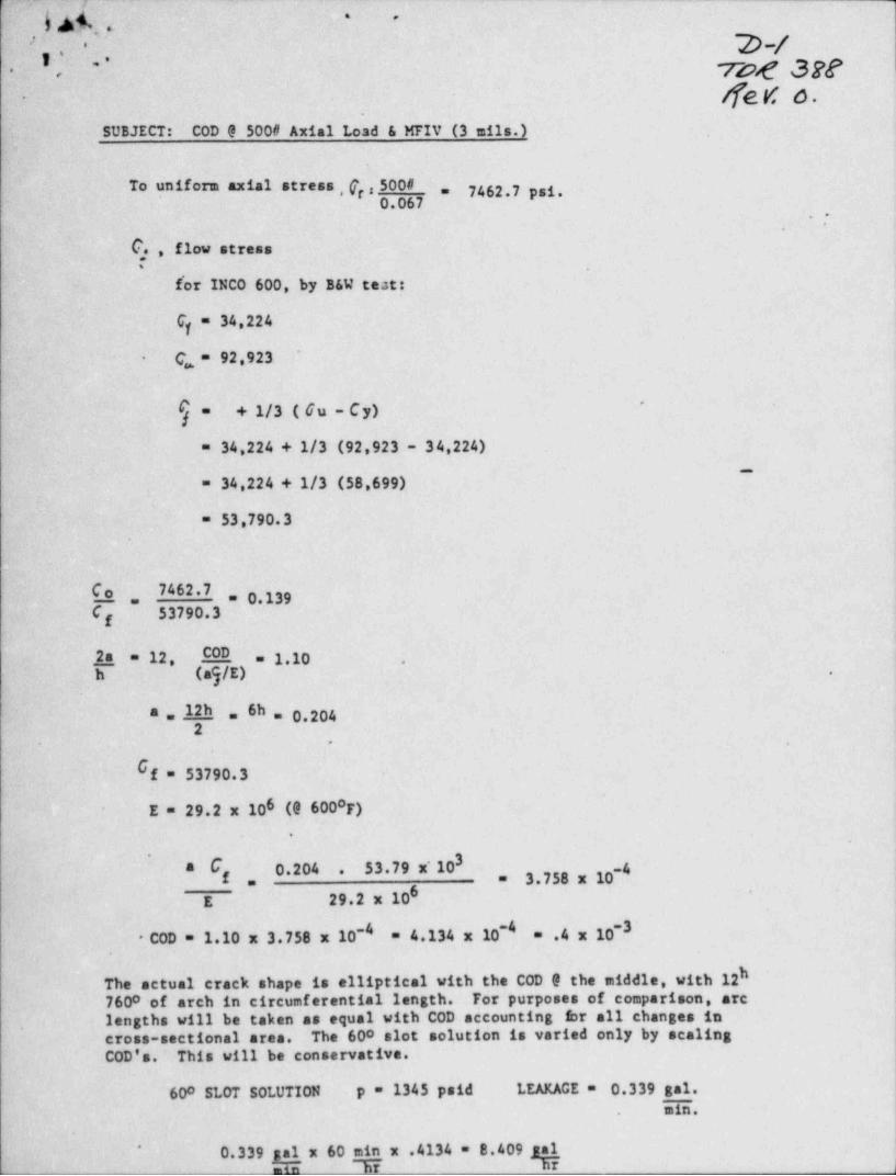
r__
,.
b b4.s-' -
p-/-- .'^, ' vvg 3g2'
..
fe d 6-
SUBJECT:- COD 0 500# Axial Load & MFIV (3 mils.)
To uniform axial stress , fr ,500# 7462.7 psi.=
0.067,'
.
C. , flow stress,
f'or INCO 600, by B&W test:
C = 34,224y
C = 92,923'
-
$ = + 1/3 ( 6u - Cy) '
= 34,224 + 1/3 (92,923 - 34,224)~
= 34,224 + 1/3 (58,699)
= 53,790.3
C o_ 7462.7 = 0.139-.'C 53790.3
f
2.a._= 12 COD = 1.10 .
h (ag/E) .
a ,12h ,, 6h = 0.2042
.
O f = 53790.3
E = 29.2 x 10⁶ (9 6000F).
3'
s C 0.204 53.79 x'10 ~4.f 3.758 x 10-,
6 -
E 29.2 x 10~4 -3'
* COD = 1.10 x 3.758 x 10-' = 4.134 x 10 = .4 x 10.
hThe actual crack shape is elliptical with the COD 9 the middle, with 127600 of arch in circumferential length. For purposes of comparison, arc ,
lengths will be taken as equal with COD accounting br all changes in !, cross-sectional area. The 600 slot solution is varied only by scaling
COD's. This will be conservative.
600 SLOT SOLUTION p = 1345 psid LEAKAGE = 0.339 gal.min..
0.339 g x 60 min x .4134 = 8.409 gal*
.__ _ min Ti nr J
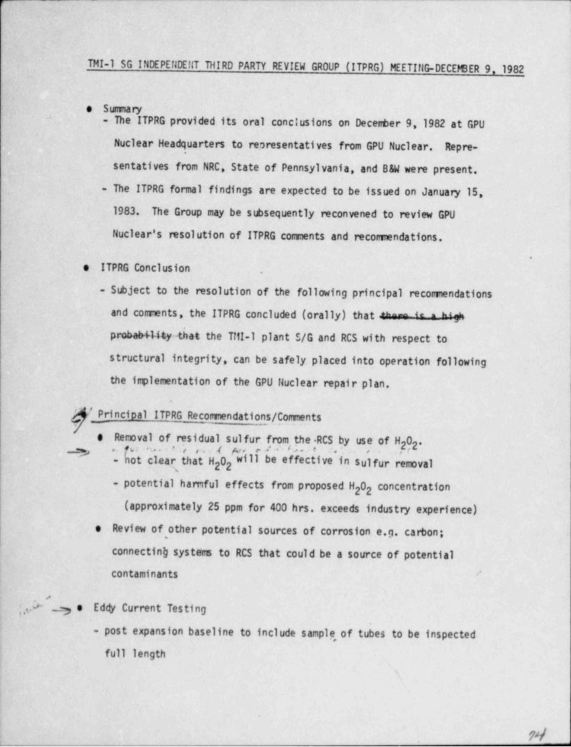
r-
-TMI-1 SG INDEPEf1DEflT THIRD PARTY REVIEW GROUP (ITPRG) MEETIllG-DECEMER 9,1982
e Summary.."
- The ITPRG provided its oral conclusions on December 9,1982 at GPU
Nuclear Headquarters to representatives from GPU Nuclear. Repre-,
sentatives from NRC, State of Pennsylvania, and B&W were present.
- The ITPRG formal ~ findings are expected to be issued on January 15,
1983. The Group may be subsequently-reconvened to review GPU
Nuclear's resolution of ITPRG connents and recommendations.
.
e ITPRG Conclusion .
- Subject to the resolution of the following principal reconnendations
and comments, the ITPRG concluded (orally) that *"- " = "f
probab+14ty4 hat the Till-l plant S/G and RCS with respect to
structural integrity, can be safely placed into operation following
the implementation of the GPU Huclear repair plan.
/ Principal ITPRG Recommendations / Comments
e Removal of residual sulfur from the RCS by use of H 0 ',22. ru: .. . t :, ,.. 4 p.,, a. 2 *' % . e a '. e,.
- hot clear that H 0 will be effective in sulfur removal22
- potential hamful effects from proposed H 02 2 concentration
(approximately 25 ppm for 400 hrs. exceeds industry experience)
Review of other potential sources of corrosion..e.g. carbon;e,
connecting systems to RCS that could be a source of potential
contaminants ''
._) e Eddy Current Testing
- post expansion baseline to include sample, of tubes to be inspected
full length,
m - _
,,
. . . - - . .- .. . - - .. _ _ - - . - - - - .
4; % . = ,
'.
s 9 -2-
h. ~ OTSG REPAIRS DATE 12/14/82!
. DATE '
,
. ITEM . DESCRIPTION RESPONSIBILITY REQUIRED
~ '6. Immunol .
'
- >
. OTSG Flush System for Immunol ApplicationRevision to Spec TF 12/8
Review Spec ~ 12/8. Samples heav meh Colitz .TBD. Barrel Pugs- order 12/10-
. 1600 Gal'Immunol on Order 12/15,
. ' Spec for Disposal of Flush Water'
.
1.
7. Tube Plug Stabilization U
.. Stabilizer Material Deliver -|
B .0TSG .12/23 |A: OTSG 1/15 1
'Practice Nailheads 1/10Explosive Plugs Ordered - 600 on shelf '
490 Ordered B&W 10/15,'
Spec for Tube Plugging-Final spec C. K. Lee .12/13Engineering Requirement Document on 11/30
Stabilization'
E Equipment and procedures to pull stabilizers 1/15FCA Stabilization -B&W TBDDF Stabilization B&W TBD'
Westinghouse Roll Plugs Ordered -1000 On Shelf *
Needed -4 week lead time order to site
8. Miscellaneous Items to Resolve. Resolve 3'W Leakers.at A J. Colitz TED. Plug Tube Lane at A Lower. 2 Tubes Possible Mill and PT at B (MNCR 137-82). Extract Westinghouse plugs to be stabilized '
. 9. Waiting DocumentationW Responsibility'
215-82 Plug exploded at wrong area of tube B&W
.280-82 Tube pull length discrepenclea Eng345-82 2 Tubes plugged-incorrectly354-82 . Documentation for Immur.al-1st Batch Eng426-82 -Wire Brush Tube B 6-1.
'420-82 Damaged Tube Ends '
~"
10. Tube EndmillingReview Process and establish procedure.
B&W Proposal *
ll. Anticipated Jugs
Date Description Responsibility
Vf,
<
- --
r .- . . . . . . . . . . -- -
., .
..
..
-2-.
~
UIW REPAIRS IRTE 12/10/82mTE
ITEra DEbCRIPTIQ4 KEhPuteilbILITY hhyUIRED.
6. T== ml. UISG Fluan Systen zor Inamol application
hevision to Spec TF 12/8haview Spec 12/8
. Sanples Colitz TBD
. Barrel Ptanps-Un order 7,t + L 12/10
.1600 Gal T --ani on order 12/15
7. 'Iboe Plg Stabilization -. . Stabilizer ruterial Deliver
Coupons on Site 12/6,
Practice Hailneads 1/10Explosive Plgs Urdered - 600 on snelt
490 Ordered EW 10/15Spec tar 'Iboe Pluggig-Final spec C. K. Ime 12/13Dgineerig hequirement Em==t on 11/30' Stabilization
E1ph==t and procedures to pull stabilizers TBD
FCA Stabilization M- TBD.DRF Stabilizatim hW TBD-
Westingnouse holl Plgs ordered -1000 Un Snelt
Heeded -4 wenn lead time order to site
8. Miscellaneous Items to hesolve. Resolve 3 W IAakers at A J. Colitz TMD
. Pig Tube D ne at A lower
. 2 'nees Possible raill and Pr at B (tack 137-82)
. Extract Westin, house pigs to be stabilizede-
.
'
9. Waiting DoctmentationtiCR hesponsioility
215-82 P'lg exploded at wrong area ot tube WW280-82 Tube pull leg tn discre p ies Eng
'
345-82 2 Tubes plg aed .tncorrectly354-82 Dmtation tar Timamol-1st Daten Eng426-82 wire urusn Tube B 6-1420-82 Damaged 'Ibbe Ends,
i
10. Tube EndmilligReview Process and establian procedure
11. Anticipated Jtaps'
Date Description Responsioility
.
4
~ , - - - - - ~ , -_ _ . _ . - . ,
Q ] 3, .,
*.
~ ' ~ *; .--2-
OTSG REPAIRS DATE 12/28/82DATE
ITEM DESCRIPTION RESPONSIBILITY REQUIRED
- 7. Tube Plug Stabilization 12/27. Stabilizer Material Deliver
B OTSG '
A OTSG 1/15'
.
Practice Nailheads 1/10Explosive Plugs Ordered - 600 on Shelf
~ 490 Ordered B&W 10/15Spec for Tube Plugging-Final Spec Issued C. K. Lee 12/13Engineering Requirement Document on 11/30
*
StabilizationEquipment and Procedures to Pull Stabilizers 1/15FCA Stabilization . B&W 1/7DRF. Stabilization B&W 1/12. Installation Procedure 1/15. Blast Plan Levin /Pruitt 1/3 -
. Practice Weld CapsB- OTSG B&W 12/24A OTSG B&W 1/7
,
8. Miscellaneous Items to Resolve. Resolve 3 W Leakers at A J. Colitz TBD. Plug Tube rane at'A Lower'
. 2 Tubes Possible Mill and PT at B (MCR 137-82)
. Extract Westinghouse Plugs to be Stabilized
9. Waiting DocumentationMCR Responsibility
2Tli'52 Plug Exploded at Wrong Area of Tube B&W280-82 Tube Pull Length Discrepancies Eng345-8'2 2 Tubes Plugged. Incorrectly354-82 Docuir.c.a.tation for Immunol-1st Batch Eng426-82 Wire Brush Tuba B 6-1
f 420-82- Damaged Tube Ends,
458-82 Felt Plugs
10. Tube EndmillingReview Process and Establish Procedure
; B&W Proposal'
TBD,
TBDl'
11. Anticipated JumpsDate Description Responsibility
*:
,
6
%
.
L
.---- _____.______m_ _ _ _ _ _ _ - - , - + - -
,
^
-2-.
*
CTSG REDAIRS DATE V3/83ITEM ESCRIPTION OATE
ESPONSIBILITY REQUIRED
6. Tute Plug Stabilization. Stabilizer Material Deliver 12/27
B OTSGA OTSG
Practice Nailheads V15.
Explosive Plugs Ordered - 600 on Shelf 1/10490 Ordered. B&W 10/15Spec for Tube Plugging-Final Spec Issued C. K. Lee 12/13Engineering Requirement Document on
Stabilization IV30Equipment and Procedures to Full StabilizersFCA Stabilization 1/15
B&WDfF Stabilization 1/7B&W
. Installation Procedure V12*
. Blast Plan 1/15Levin /Pruitt 1/3. Practice Weld Caps
B OTSG B&W 12/24A OTSG B&W 1/7
7. Miscellaneous Items to Resolve. Resolve 3 W Leakers at A J. Colitz TfD>
. Plug Tube Lane at A Lower
. 2 Tubes Possible Mill and PT at B (MG 137-82)
. Extract Westinghouse Plugs to be Stabilized
8. Waiting DocumentationM4CR Responsibility215-82 Plug Exploded at Wrong Area of Tube B&W280-82 Tube Pull Length Discrepancies QC345-82 2 Tubes Plugged Incorrectly
354-82 Documentation for Immunol-1st Batch Eng420-82 Damaged Tube Ends '
. 426-82 Wire Brush 86-1-
| 458-82 Felt PlugsQC
9. Tube Endmilling,
Review Process and Establish Procedure TfDB&W Proposal -
Issued
10. Anticipated JunpsDate Description - _ Responsibility
A - Lower gA - Upper YOe^b
Le_L;a)%mnewlf.
.
8 - Upper - M
.
8
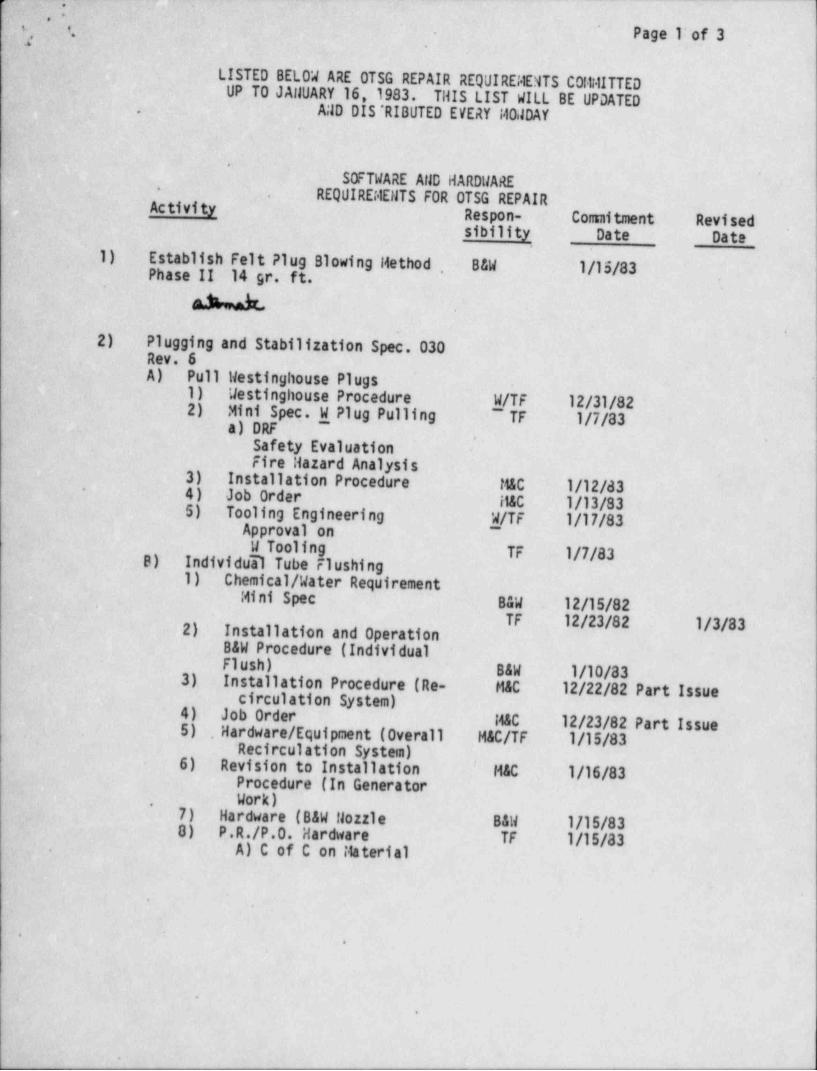
p ;4 . .
'
t t' ' Page l'of 3-*
,
, LISTED BELOW ARE OTSG REPAIR REQUIREi4ENTS C0lt4ITTEDUP ' TO JAllVARY 16, 1983. THIS LIST WILL BE UPDATED
AND DIS'RIBUTED EVERY I40.JDAY,
-
' SOFTWARE AND HARDWARE-
REQUIREt4ENTS FOR OTSG REPAIR. .
Activity Respon- Connitment Revisedsibility Date Date
_ 1) Establish Felt Plug Blowing Method . B&W 1/15/83Phase II 14 gr.-ft.,
A -W.
2) Plugging and Stabilization Spec. 030Rev. 6A) Pull Westinghouse Plugs
1) Westinghouse Procedure W/TF 12/31/822) Mini Spec W Plug Pulling ~ TF 1/7/83a) DRF '~
.
Safety EvaluationFire Hazard Analysis
3) Installation Procedure tGC 1/12/d34) Job Order. H&C 1/13/83
-
5) Tooling Engineering W/TF 1/17/83Approval on ,
W Tooling TF 1/7/83B) Individual Tube Flushing1) Chemical / Water Requirement
Mini Spec B&W 12/15/82-
TF 12/23/82 1/3/832) Installation and OperationB&W Procedure (IndividualFlush) B&W 1/10/833) Installation Procedure (Re- MAC 12/22/82 Part Issuecirculation System)
4) Job Order MAC 12/23/82 Part Issue5) Hardware / Equipment (Overall MAC/TF 1/15/83.
' Recirculation System)6). Revision to Installation ' HAC 1/16/83
,
Procedure (In GeneratorWork),
7) Hardware (B&W Nozzle B&W 1/15/838) P.R./P.O. Hardware TF 1/15/83A) C of C on Material.
-.
,
e
e
S
.
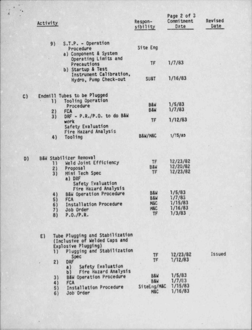
-. .
.
. ..
j''
- *.IPage 2 of 3
Activity Respon- Commitment Revised ,
sibility Date Date-
. .
9) S.T.P. - Operation. Procedure Site Eng .
a) Component & System.
Operating Limits and-
Precautions TF 1/7/83 |, b) Startup & Test
Instrument Calibration,Hydro, Pump Check-out SUAT 1/16/83
,,
C) 'Endmill ubes. to be Plugged .
1) Tooling' Operation-
Procedure B&W 1/5/832) FCA B&W 1/7/83
-
3) DRF - P.R./P.O. to do B&Wwork TF 1/12/83Safety EvaluationFire Hazard Analysis
4) Tooling B&W/MAC t/15/ss
.
.
D) B&W Stabilizer Removal1)' Weld Joint Efficiency TF 12/23/822) Proposal B&W 12/20/823) Mini Tech Spec TF .12/23/82
a) DRFSafety Evaluation'
Fire Hazard Analysis'4) B&W Operation Procedure B&W 1/5/835) FCA B&W 1/7/836) Installation Procedure MAC 1/15/837). Job Order MAC 1/16/83
-
'
8) P.0./P.R. TF 1/3/83
E) Tube Plugging and Stabilization(Inclusive of Welded Caps andExplosive Plugging)1) Plugging and Stabilization .
Spec TF 12/23/82 Issued
2) DRF TF 1/12/83.
a) Safety Evaluation-
b) Fire Hazard Analysis3) B&W Operation Procedure B&W 1/5/834) FCA . B&W 1/7/835) Installation Procedure SiteEng/M&C 1/15/83
-
6) Job' Order MAC 1/16/83
*
.,
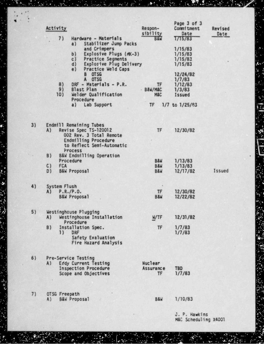
e, . *.
.. .
''' ~ Page 3 of 3Activity Respon- Comitment Revised
sibility Date Date- 7) Hardware - Materials B&W 1/15/83
-
~
a) Stabilizer Jump Packsand Crimpers 1/15/83
b) Explosive Plugs (MK-3) 1/15/83c )' Practice Segments 1/15/83 ,
d) Explosive Plug Delivery 1/15/83-
e) Practice Weld CapsB OTSG 12/24/82A OTSG . 1/7/83
8) DRF - Materials - P.R. TF 1/12/839) Blast Plan B&W/M&C 1/3/83
10) Welder Qualification MAC IssuedProcedurea) Lab Support TF 1/7 to 1/25/83
|
| 3) Endmill Remaining TubesA) Revise Spec TS-120012 TF 12/30/82
002 Rev. 3 Total Remote;
| Endmilling Procedure -
| to Reflect Semi-AutomaticProcess'
B) B&W Endmilling Operation- -
Procedure B&W 1/13/83C) FCA B&W 1/13/83D) B&W Proposal B&W 12/17/82 Issued
.
4) System Flush -
A) P.R./P.O. TF 12/30/82B&W Proposal B&W 12/22/82
5) Westinghouse PluggingA) Westinghouse Installation W/TF 12/31/82
~
Procedure, B) Installation Spec. TF 1/7/83
1) DRF 1/7/83Safety Evaluation'
Fire Hazard Analysis
, .
| 6) Pre-Service Testing! A) Eddy Current Testing Nuclear.
Inspection Procedure Assurance TBDScope and Objectives TF 1/7/83
'
7) OTSG Freepath .
-
[ A) B&W Proposal B&W 1/10/83
, J. P. Hawkins-
| M&C Scheduling X4001
.,
.
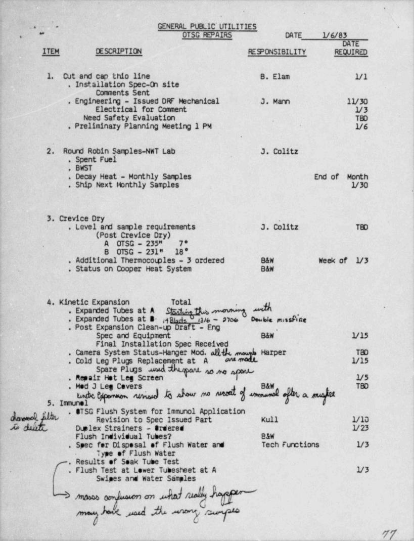
*.
'
GENERAL PUBLIC' UTILITIES_.- o -
OTSG REPAIRS DATE 1/6/83**,
DATEITEM DESCRIPTION RESPONSIBILITY REQUIRED
1. Cut and cap thio line B. Elam 1/1. Installation Spec-On site
Comments Sent. Engineering - Issued DRF Mechanical J. Mann IV30
Electrical for Comment V3Need Safety Evaluation TBD.
. Preliminary Planning Meeting 1 PM 1/6.
2. Round Robin Sag les-NWT Lab J. Colitz. Spent Fuel. BWST. Decay Heat - Monthly Sagles End of Month. Ship Next Monthly Samples V30
,
3. Crevice Dry .
. Level and sam le requirements J. Colitz TBD(Post Crevice Dry)
A OTSG - 235" 7*.
B OTSG - 231" 18'. Additional Thermocotples - 3 ordered B&W Week of V3. Status on Cooper Heat System B&W
4. Kinetic Expansion Total .'
. Expanded Tubes at A Shhh
. Expanded Tubes at B g h as u ,3g _ g)og, ogg ,ng,g,n,
. Post Expansion Clean-up Draft - Eng ,
Spec and Equipment B&W V15.
Final Installation Spec Received. Camera System Status-Hanger Mod ad,&, Harper TBD. Cold Leg Plugs Replacement at A * 1/15
Spare Plugs . wad ea p. Repair Het Leg Screen i V5
B&W TBD. Mod J Leg Covers ,
5. Immune. STSG Flush System for Immunol Application-
Revision to Spec Issued Part Kull 1/1Dle Dtplex Strainers - Ordered 1/23'
Flush Individual Tubes? B&W. Spec for Disposal of Flush Water and Tech Functions 1/3
- Type of. Flush WaterResults of Soak Tube Testf.
[ . Flush Test at Lower Tubesheet at A 1/3.
Swipes and Water Sa'mples
& M & on.kk 4 .A ~g eq
.- W
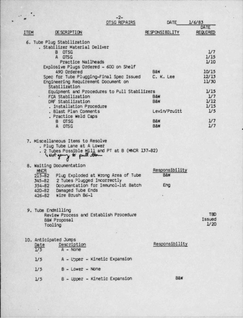
- . - _ _ _ _ _ _ __
.
e; -2-
-;-
* OTSG REPAIRS DATE V6/83 ;
DATE 1
ITEM DESCRIPTION REPONSIBILITY REQUIRED
'
6. Tube Plug Stabilization. Stabilizer Material Deliver ,
'
B OTSG V7A OTSG 1/15
Practice Nailheads V10Explosive Plugs Ordered - 600 on Shelf
490 Ordered B&W 10/15;
Spec for Tube Plugging-Final Spec Issued C. K. Lee 12/13Engineering Requirement Document on IV30
StabilizationEquipment. and Procedures to Pull Stabilizers V15FCA Stabilization B&W V7-
DRF Stabilization B&W V12. Installation Procedure V15. Blast Plan Comments Levirv'PIuitt V5. Practice Weld Caps
B OTSG B&W V7A OTSG B&W V7
A
7. Miscellaneous Items to Resolve. Plug Tube Lane at A Lower. 2 Tubes Possible Mi PT at B (WCR 137-82)
% Uot ky8. Waiting Documentation
- WCR Responsibility
215-82 Plug Exploded at WIong Area of Tube B&W
345-82 2 Tubes Plugged Incorrectly354-82- Documentation for Immunol-1st Batch Eng420-82 Damaged Tube Ends426-82 Wire Brush B6-1 .
,
.-
9. Tube EndmillingReview Process and Establish Procedure TBD
B&W Proposal IssuedTooling V20
.
10. Anticipated JumpsDate Description Responsibility
1/5 A - None
V5 ~A - Upper - Kinetic Expansion
V5 B - Lower - None.
V5 B - Upper - Kinetic Expansion B&W
|!.
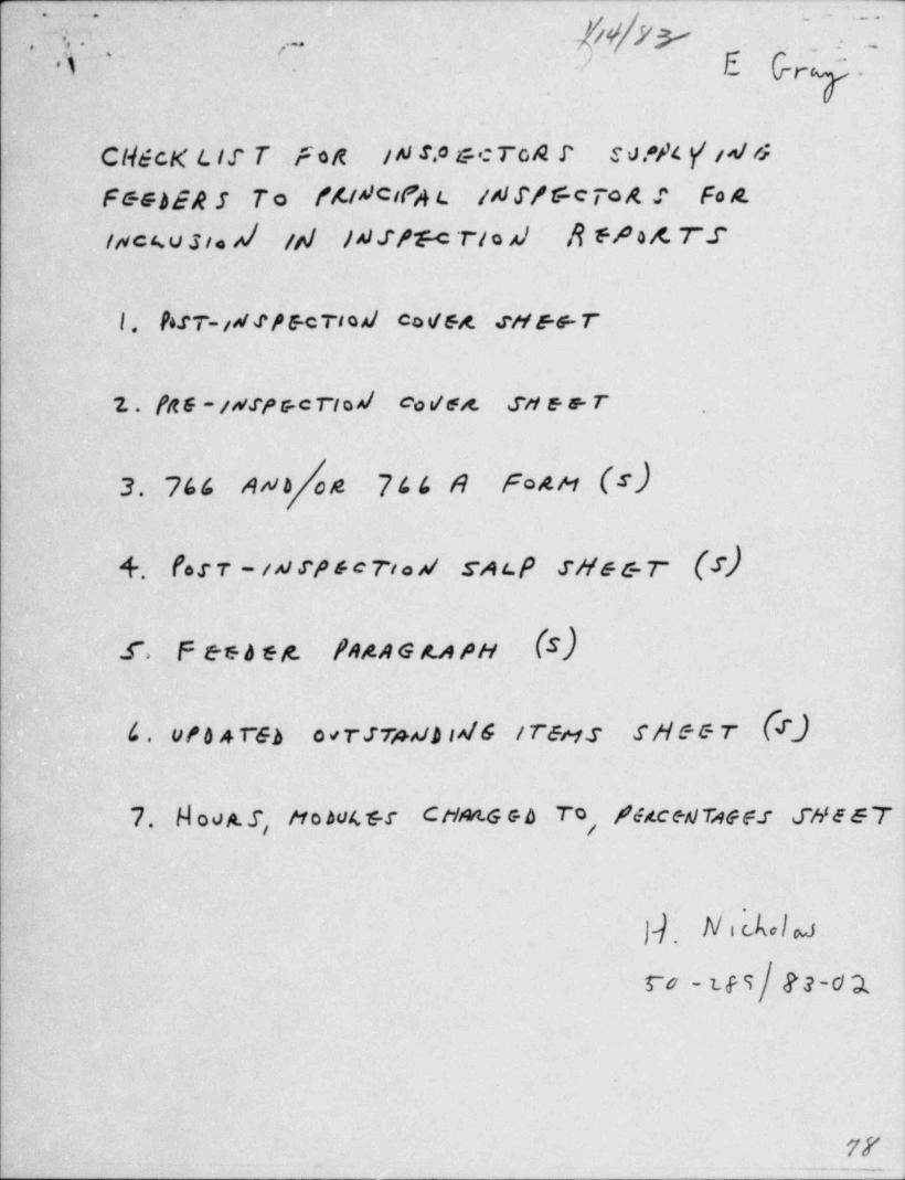
m.~ .. .
f/ V.. ,..
). . .,~
3 .
- . , - [ Q , :- _.. .
'
Y.
CH&cK Lir T fog IN's? &c To A P E 0 ?/4 y' id6
F&GbER S To f4t^1 cit's t ist S/ Sc ro A : Fo A-
lMc4u3ieA| /p/ /4 J/ llc T/ o A) A ff 0 A. TZ
l . bST-iA Jf E c TIo Al co VGA. sM f+ T
7. . (R 6 - /A!!f G c rio A/ c g/gg. ftf g g. T -o ,
ANb|* 7 4 4 A FOAM (s)3. 744
+. 1.s r - ia rn c ri.s sai.e sus s.r (s)
r. F es b eg. fngaen.ApH (S)
4 . vt 6 4 reb o vrsrpab is/G trens sM&&T (f)'
7. H 00A.S, M ohv4 5 r CH&t G eb To, /64ctAlTAGF.T SHE57
]]. W,LGla
ro-tes|ge-d2
77.-_-
-,-=w "'
.>M4-*
'D
.~ ^
C .) 9"' " ' ' ' I"''''
-
A ns.r.L ,- A, ca_ar, * pne, . ee-
-
_ .. . ]_ _ _
h / f .
kA. - 70 nmcs chees to 6 e<s.
,/Xn Gay.:.< ace y.uma cast .
9/skr wn u Liewse.c ps ssur sT.'
/3rW wairik u, caci?<c iJu?nv uersz/?),ainit,aA A % *u J*s m stw y e ds'c k s ,
Gn.s/ctit_ s1s Iso < Mid c4st ,
grj n ro~w y.
ksbyAc, f.m(H7" shts 'co wives c., .
.
!
!,
=
9
9
y , , - . . , , - - . . . - , - . , -, -.,.-r.,,--.- ,, , , , ,
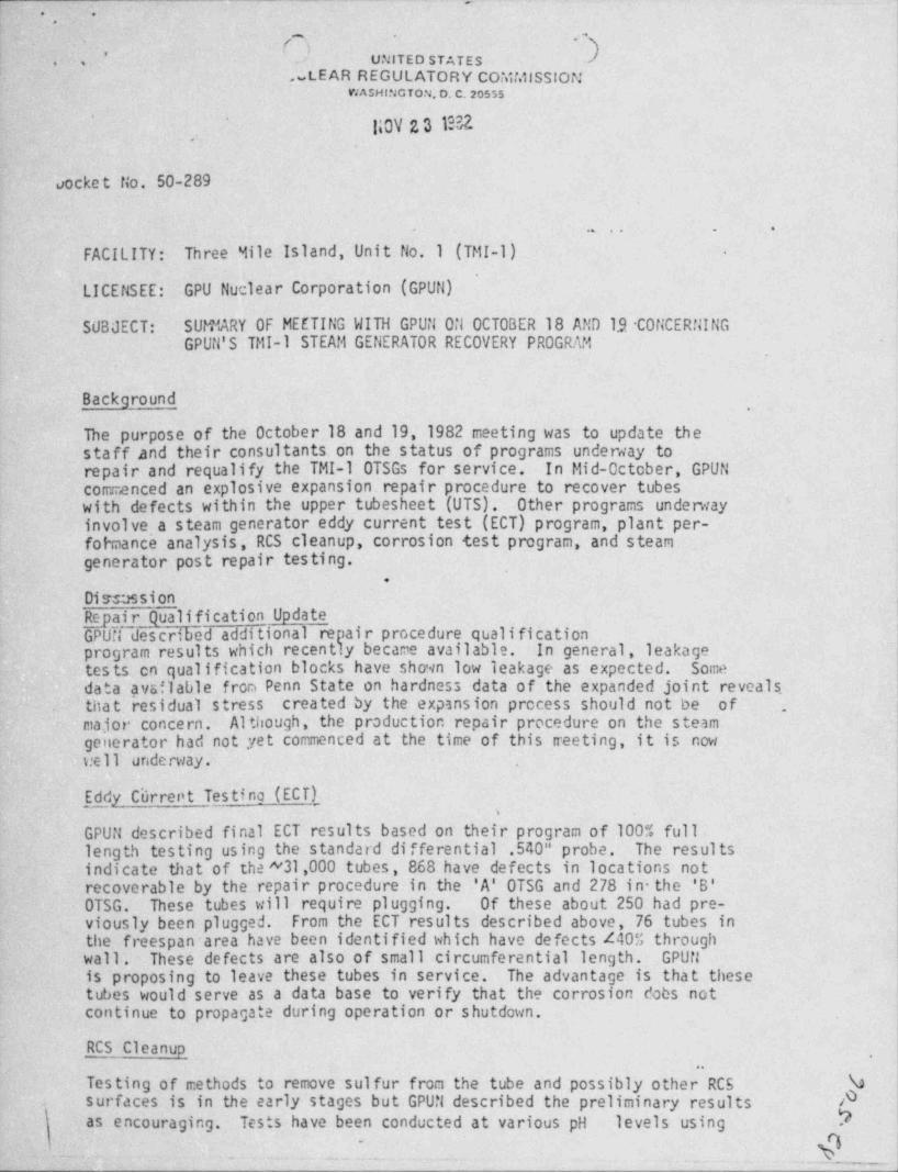
W ;y . _ _ . _
,
,.
"* - E-
'
~ UNITED STATES, ',~- .., LEAR REGULATORY COMMISSION
WASHING TON, D. C. 20555
liOV 23 M' '
,
%ocke t tio. 50-289
.
. . . . . . .
FACILITY:- Three Mile Island, Unit No.1 (TMI-1) -
.
LICENSEE: GP'U Nuclear Corporation (GPUN)-
~
SUBJECT: SUMMARY OF MEETING WITH GPUN ON OCTOBER 18 AND 19 CONCERNING.GPUN'S TMI-l STEAM GENERATOR RECOVERY PROGRAM
.,
Ba'ckground,
The - purpose of- the October 18 ~and 19, .1982 meeting was to update the- staff and their consultants on the. status of programs undersay to' repair. and' requalify the TMI-l' OTSGs for service. In Mid-October, GPUNcommenced an explosive expansion. repair procedure to recover tubes -
: with defects within the upper tubesheet (UTS). Other programs underway-involve a steam generator eddy. current test (ECT) program, plant per-fotTaance analysis, RCS cleanup, corrosion test program, and steam
: generator. post repair-testing.'
- .
Dissassion-' Repair Qualification Update .
~
~'GPUTi described additional repair procedure qualificationt"program. results which recently became available. In general, leakage.
; tests. cn qualification blocks ha've shown. low leakage as expected. Somedata avsflable from Penn State-on hardness data of the expanded joint reveals..
~
' thatiresidual stress -created.by the expansion process should ~ not be of .
major concern. Although,' the production repair procedure on the steam. generator:had not.yet commenced at the -time _of this treeting, it is now
. 7: ell funderway.
Eddy' Ciirrent Testino (ECT)
GPUN described final ECT results based on their program of 100% fulllength ' testing using the.. standard differential .540" probe. The results:-
sindicate that of-the "31,000 tubes, 868 have defects in locations not- irecoverable by.the: repair procedure in the ' A' OTSG and 278 in the 'B'
:0TSG. These tubes will require plugging. Of these about 250 had pre-..viously been p_ lugged. From the- ECT- results described-above, 76 tubes inthe freespan area have been. identified which have defects 440% through
~ wall .. These ' defects are 'also1 of small circumferential length. .GPUN:is ' proposing to' leave Lthese tubes in service. The advantage is that thesetubes would serve as a data base to verify that the corrosion dobs notcontinue to propagate during operation or shutdown.
RCS ' Cleanup,
1 Testing |of meth~ods to remove. sulfur from the tube and possibly other RCS Vsurfaces'is in the early stages but GPUN described the preliminary results A
LasJencouraging. Tests have. been conducted at various pH levels using N.
Qh. --
. .
.- -.
-
ng,g, *o. ,J,,- - -
. .
r. ,.
.).
TMI-l - 2-' %,"' g.
: .
l_. ,
.
,
i.,.
Ahydrogen peroxide as an additive. Hydrogen peroxide reacts with NiS (the7
sulfur form on the tube surface) to form sulfate (50 ) which can be4.; removed by ion exchange. A great deal of testing and analysis rencins to be
*perfor.ned before a decision is made whether or not to cortduct the ~
,
sul fur cleanup. .- The cleanup, if conducted, would require RCP operation-'
and hence, could not be conducted until the steam generators are repaired.
Corrosion Test Program'
~
~ GPUit described an extensive corrosion test program which has been ongoing~since the beginning of the steam generator recovery program. Corrosion
- testing has been conducted to 1) assess if the primary coolant was still4ggressive, 2) to attempt to simulate the tube cracking to verify the'
- failure' mechanism and corrosion. scenario and 3) to support the repair. qualification program. GPUN is also conducting a long term testing pro-gram des,igned to duplicate plant hot functional testing and operation.This cormston program will lead actu'al plant operation by'several monthsand should provide important insight into actdal plant performance.
Post Repair Test Pmgram.
GPUN outlined a post steam generator repair program which would includeeddy current testing of a baseline. number of tubes, cold leak testing including aNo B"doble test and primary plant hydrostatic te'st and precritical op2 rationalte"s ts . The precritical tests will involve several cooldown transients
,
to place tubes under high tension, followed by leak rate . monitoring.Following steam generator testing, the plant would proceed with hot fun-ctional testing for. restart modification testing and then enter therestart sequence, assuming restart is- authorized. GPUN also proposedr
operating for 90 days at full! power before conducting a shutdown .to .
conduct additional .0TSG ECT., The staff expressed some reservations aboutnot. conducting an ECT following hot steam generator testir.g but beforecri ti cali ty. Staff consultants in general felt that more risk of cor-rosion propagation, if it propagates, would occur if the system wereexposed to ' air during an ECT test than if the system were not reexposedto air. It was also pointed out that the cracks tend to . propagate during .Iow temperature, oxidizing environments while the plant operates athigh temperature, reducing environments. This issue will be pursued
. further as . staff r'eview continues.*
Plant Performance Analysis
GPUN has reexamined design basis accident analyses to determine what 'j
.irrpact the repaired steam kenerators would have on plant perfomance.They have concluded that t e repaired steam generators will have no effect /on FSAR conclusions even assuming up to 1500 tubes are plugged. Thestaff asked that GPUN also address the impact, if any, on steam generatoroverfill transients.and to verify that-the effectiver.ess of EFW will notbe significantly degraded due to tube plugging in the periphery of the'
-
tube bundle. -'
' -
O
'W- + = - --* *4 <- % .+ -t- - - , , % . ,Aw. m %%_.- , ,-
-,yy ,-p
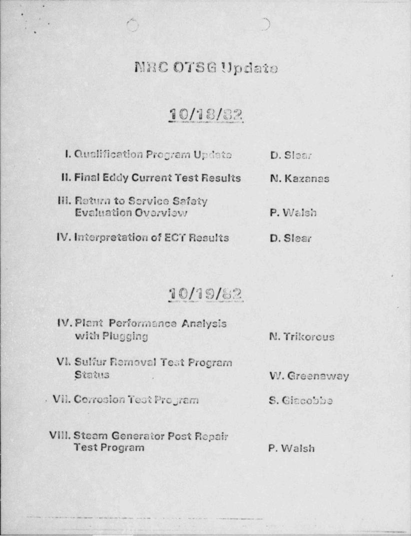
._
, .
-
,s ..)-.
. ,e .,)
NFsC OTSG Update
10/18/02
1. Qualification Program Updato D. Slear
11. Final Eddy Current Test Results N.Kazanas
111. Rettirn to Service SafetyEvaluation. Overview P. Walsh
_IV. Interpretation of ECT Results D. Slear
.
,
10_/.19/._8_2_ ,_ .
.
IV. Plant Performance Analysis,
with Plugging N. Trikorous
VL Sulfur Removal Test Program. Status . W. Greenaway
. Vil. Corrosion Tect Proyam S. Giacobbae
Vill. Steam Generator Post RepairTest Program P. Walsh
. - . . _ . . _ . . _ . . . _ . _ _ _ . . _ _ . _ . . _ _ . _ . _ . . _ . . . . _ . - _
" . % Tee 4-v. +4 m.iluee e ab+ +w +-- e * *ema'-*- =* ' * * .
. - . . - . .
,
PRE-INSPECTION COVER SHEE_Ts*
(7 (Region I Work Form) )-
.
- '' '
30-2.89[u/From: _(Reporting Ins;ector) Report No. 83-OL
To: [ b an./L(Reporting Inspector's Supervisor)
Subj: INSPECTION OF [MT #/ ///2. - ///3/83ON(Facili ty) (Dates)
/- / List of outstanding items up to date, reviewed and proper items selected.
/:</ Inspection plan completed (attached or sumarized below).
Inspection Items:
C a c./ y p e.a Cr/ A m 4 /w/dAro/t. e dsfx vATad v0*ps.n/cnon'
ef h'ovt rse, 57smoaM e/ 7.sdE Soc.s N uAssit Nd/SNrtrJsf 0 7'S4 H /Y / A ~(ExAst J wmx)2.
NAMES OF ACCOMPANYING PERSONNEL: RESIDENT INSPECTORNOTIFIED: .Yrf
Project Section Chief'
/t'Spf, lok 7',j ACKNOWLEDGED: r y' sw4 -o/yowt Project Inspector _
ACKNOWLEDGED:
Acccmpanying Inspector'sSupervisor (ifapplicable)
SUBMITTED: APPROVED:Reporting Inspector Reporting Inspector's
Supervisor
File:Branch Files (Inspector's Branch and Project Branch)
Hotel: M44/e/ar L - Adesav44 Phone: (7n)su- fr// FTS:Site Contact (Name) f. N a4 Phone: ( ) FTS: I90- //ff-
Region I Fonn 1
,i.(Nov1979)
. . . . - . . - . . . -. . - - . -
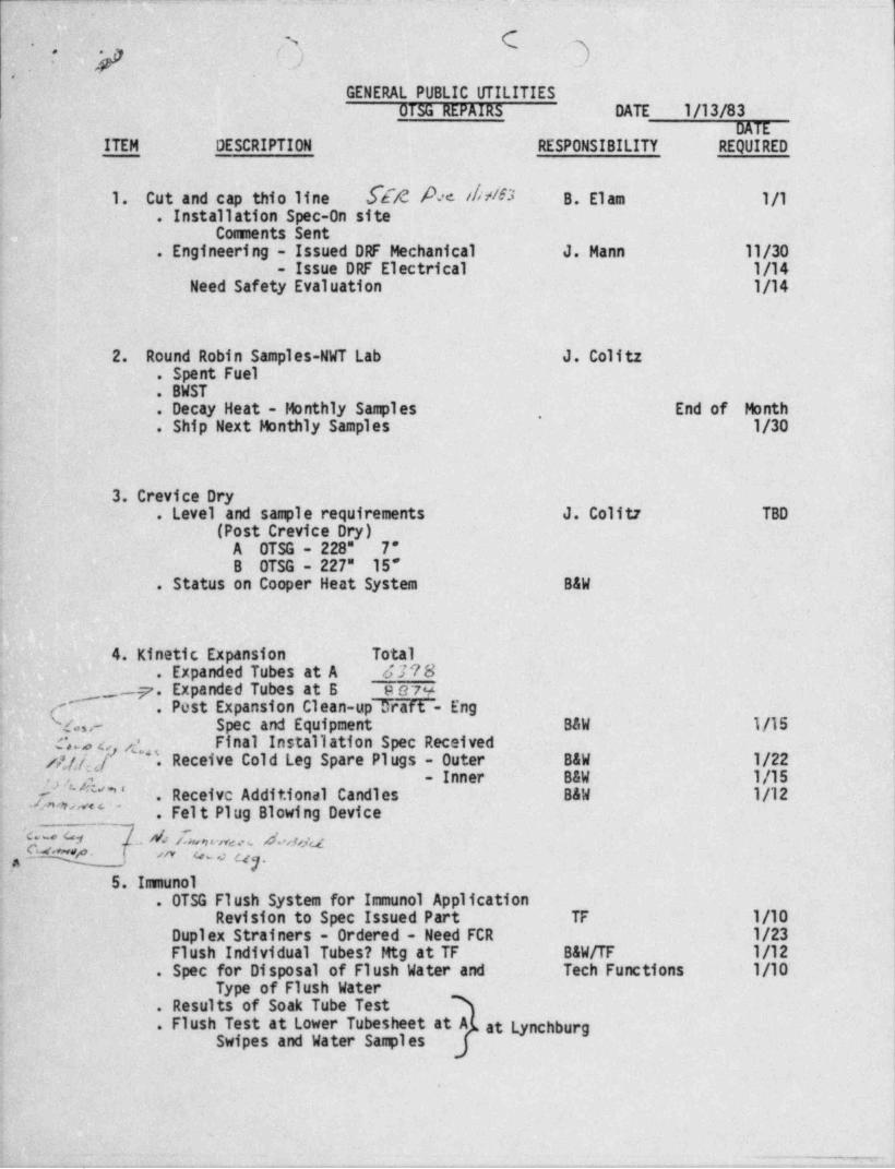
- - - - _ _ _ .
.- ....a
C--s-. .
L) ..)* y.
GENERAL PUBLIC UTILITIESDI5G REPAIRS DATE 1/13/83
DATEITEM DESCRIPTION RESPONSIBILITY REQUIRED
.1. Cut and cap thio line [ E 4 A c di d 3 B. Elam 1/1. Installation Spec-On site
Comments Sent .
. Engineering - Issued DRF Mechanical- J. Mann 11/30- Issue DRF Electrical 1/14
Need Safety Evaluation 1/14
~2. Round Robin Samples-NWT Lab J. Colitz.-Spent Fuel..BWST
.
End of Month. Decay Heat - Monthly Samples.
,
. Ship Next Monthly Samples 1/30
3; Crevice Dry. Level and sagle requirements J. Colitz TBD
(Post Crevice Dry)A OTSG - 228" 7"B OTSG - 227" 15"
. Status on Cooper Heat System- B&W
h4. Kinetic Expansion Total
. Expanded Tubes at A 4T78 '
{2,.e ~ --7.Expanded Tubes at B e974
. Post' Expansion Clean-up Draft - Eng-
Spec and Equipment.
B&W 1/15r,s Final Installation Spec Received
/4/fi[4' f'>~".Receive Cold Leg Spare Plugs - Outer B&W 1/22 i.
Inner B&W 1/15g g"' ' -. Receive Additional Candles B&W 1/12 i
- ,
. a'#'"'*'"'
_
. Felt Plug Blowing DeviceIG ~* [ . 4 Ea,n e,a d. ,1,s a |p Q" %- *
1m 4-a ay.
' 5. Innunol!. OTSG Flush System for Immunol Application-
- Revision to Spec Issued Part TF 1/10Duplex Strainers - Ordered - Need FCR 1/23Flush Individual Tubes? Mtg at TF B&W/TF 1/12
l.- Spec for Disposal of Flush Water and Tech Functions 1/10-Type of Flush Water
. Results of Soak Tube Test S
. Flush Test at Lower Tubesheet at A L at LynchburgSwipes and Water Sagles
..
,.=-.-y , ~ , , , . , ,- e -----,.-e. -,----.-yi_. -.*e. .-Va.--, ..-,-,%--,--,.-4 - r-.-,. 3 .,me -g w- m- y-ww yn ,_r -,.4- m..
. _ _ . _ _ . _ _ ._ ._. __
- . . . .
s,'3 {} }OTSG REPAIRS DATE 1/13/83
-
,
DATEITEM DESCRIPTION RESPONSIBILITY REQUIRED
6. Tube Plug Stabilization::
. Stabilizer Material DeliverB OTSG 1/7A OTSG
. 1/15- Explosive Plugs Ordered - 600 on Shelf !
.490 Ordered B&W 10/15* ..
C. K. LeeSpec for Tube Plugging-Final Spec IssuedEngineering Requirement Document on 11/30
StabilizationEquipment and Procedures to Pull' Stabilizers 1/15FCA Stabilization B&W 1/7'
DRF Stabilization B&W 1/12. Installation Procedure 1/15. Blast Plan Comments Levin /Pruitt 1/5
.
~ 7. Miscellaneous Items to Resolve.--Plug Tube Lane at A Lower. 2 Tubes Possible Hill and PT at B (MNCR 137-82) <
'
.
8. Waiting DocumentationMNCR Responsibility ;
2M2 Plug Exploded.at Wrong Area of Tube Saw i.
345-82 ' 2 Tubes Plugged Incorrectly354-e2. Documentation for Immunol-1st Batch Eng420-82. Damaged Tube Ends
,
426-82 Wire Brush B6-1 '
1
' 9. Tube EndmillingReview Process and Establish Procedure TBDB&W Proposal IssuedTooling 1/20
.10. Anticipated JumpsDate Description Responsibility
L 1/13 A - Upper - Kinetic Expansion *
1/13 B - Upper - Kinetic Expansion B&W ,
,
.. . _ _ . . - , . - , . . - . , _ _ . . . , - , - , - - - . . . - . _ ~ . - . . , - . _ . , _.- - iTT~ ~ . , . , . . - . - ~ .
| - TT JlaiP WAlVER FURH~~ m
s.+.,
TO: G. Ai KUDIN,' MANAGEll . DATE: J h e'L L ~ M l.
RADIOLOGICAL CONTROLS'
-' IJ'l
TMI - UNIT I1 .
I request that Rad Worker Training /Requalification (circle one) he waived for the Lfollowing persons:~
Waiver requested by: F yoo wn Departmen t: usmert.
Waiver for: -
Name E GR04 Company U SNil.C Retraining Schedule(date)
Naue Company. Retraining Schedule-*
Hane . Company Retraining Schedule
Conpany Retraining Schedu'le'Nanc _ __ _ _ ,,
Date of entry dne 12.,7913_,
Reason ."or entry 073h_ yg gdo,J -
_ _ _ ,
... . . . . . . . . . _. ..... ..._...__._ .
j. _ . . . - . . - . _ _ _ . - . . . _ . . . . . . . _ .
The above personnel will he briefed regarding the radiological risks that may exist in areas they will visit. i
Requirenents for protective clothing will be discussed if applicable. lhe personnel will be escorted by RWPtrained personnel who will perform the briefing.Training / Escort provided by F h an Department ose)e.c
. _ . _ . - - - __
,
;
~ h. This section for completion by Manager, Radiological Controls, THI Unit I . ,
-
Waiver expires 14 JAM 83 Moo
Connents: ,
f //ODate: ,/ L>Approved: -- /-- -. - - ,; , ,-
Distribution.!
2 Control Points,1MI Unit I ~; i
Security, TMI Unit I, Processing Center .*
.
,, Requestor.. ,,
*
* File: Original to RWP Waiver File-Rev. 2 9/22/82,
e
. . ~ . ._.
- - _ _ _ _ __
-,n . ., .
.
* --. ..
GENERAL PUBLIC UTILITIES'
OTSG REPAIR 5 DATE 1/14/83DATE-
-ITEM DESCRIPTION RESPONSIBILITY REQUIRED
1. Cut and cap thio line B. Elam I 1/1'
. Installation Spec-On site '
Coments Sent. Engineering - Issued DRF Mechanical J. Mann 11/30
- Issue DRF Electrical v. 1/14Need Safety Evaluation 1/14
-p.
r
'2. Round Robin Samples-NWT Lab J. Colitz
. Spent Fuel .
. BWST
. Decay Heat - Monthly Samplet End of Month,
. Ship Next Monthly Samples 1/30
4
3. Crevice Dry. Level and sample re'quirements J. Colitz TBD
(Post Crevice Dry)*
.,
A OTSG - 228". 6B OTSG - 226 19
. Status on Cooper Heat System B&W
Total Total-,
f4. Kinetic Expansion Last 24 Hours Expanded
{ - . Expanded Tubes at A. Ass s 87i3. Expanded Tubes at.B s saa toyt
,
' . . Post Expansion Clean-up Draft - Eng '
M Spec and Equipment B&W 1/15! Final Installation Spec Received,
.3 . Receive Cold Leg Spare Plugs - Outer- B&W 1/22- Inner B&W 1/15) r' -
\
. . Felt Plug Blowing Devic ~e 1/14
&-
5. Imunel. .tTSG Flush Syicem for Immunel Application .4 Revision to Spec Issued Part TF .
Duplex Strainers - trdered - Need FCR 1/23
. ' Spec for Disposal of Flush Water and Tech Functions 1/10 |-
'.
Type of Flush Water !
. Results of Soak Tube Test ]'
. Flush Test at Lower Tubesheet at Ai at Lynchburf 1
Swipes and Water Samples'
%+ 4 W 19
-. - .;
-! . :. -.
-..,
.i -'
_ g_.
OTSG REPAIRS' DATE 1/14/83 |-
'
DATE
ITEM DESCRIPTION' RESPONSIBILITY REQUIRED.
6. Tube Plug Stabilization. Stabilizer Material Deliver
B: 0TSG r-.
A OTSG 1/15
'* Spec for Tube Plugging-Final Spec Issued C. K. Lee_
Equipment and Procedures to Pull Stabilizers : 1/15' FCA Stabilization B&W 1/14
*
*
DRF Stabilization B&W 1/17.. Installation Procedure TBD
. Blast Plan to State Levin /Pruitt 1/17
.
.7. Miscellaneous Items to Resolve. Plug Tube Lane at A Lower'
i
. 2 Tubes Possible Hill and PT at B (MNCR 137-82)-
,
8, Waiting Documentation!= MNCR Responsibility,
M2 Plug Exploded |at Wrong Area of Tube B&W
; L345-82 2 Tubes Plugged Incorrectly-! 354-82 Documentation for Immunol-1st Batch Eng
420-82 Damaged Tube Ends426-82 Wire Brush B6-1 .
~
i eet-83' Imunol at: Cold Legs:
19. Tube EndmillingIssued
B&W ProposalTBD
Review Process and Establish ProcedureTooling 1/20 .
r.
- .
i 10. Anticipated Jumps
( Date - Description Responsibility'
1/14 A - Upper - Kinetic Expansion.
1/14'- . B - Upper . Kinetic Expansion B&W
.
.. . - - - . . . . _ - , . _ - - . . - . - . . _ . . = _ . . . - _ _ - - - - . - - - - - - _ . . . , -
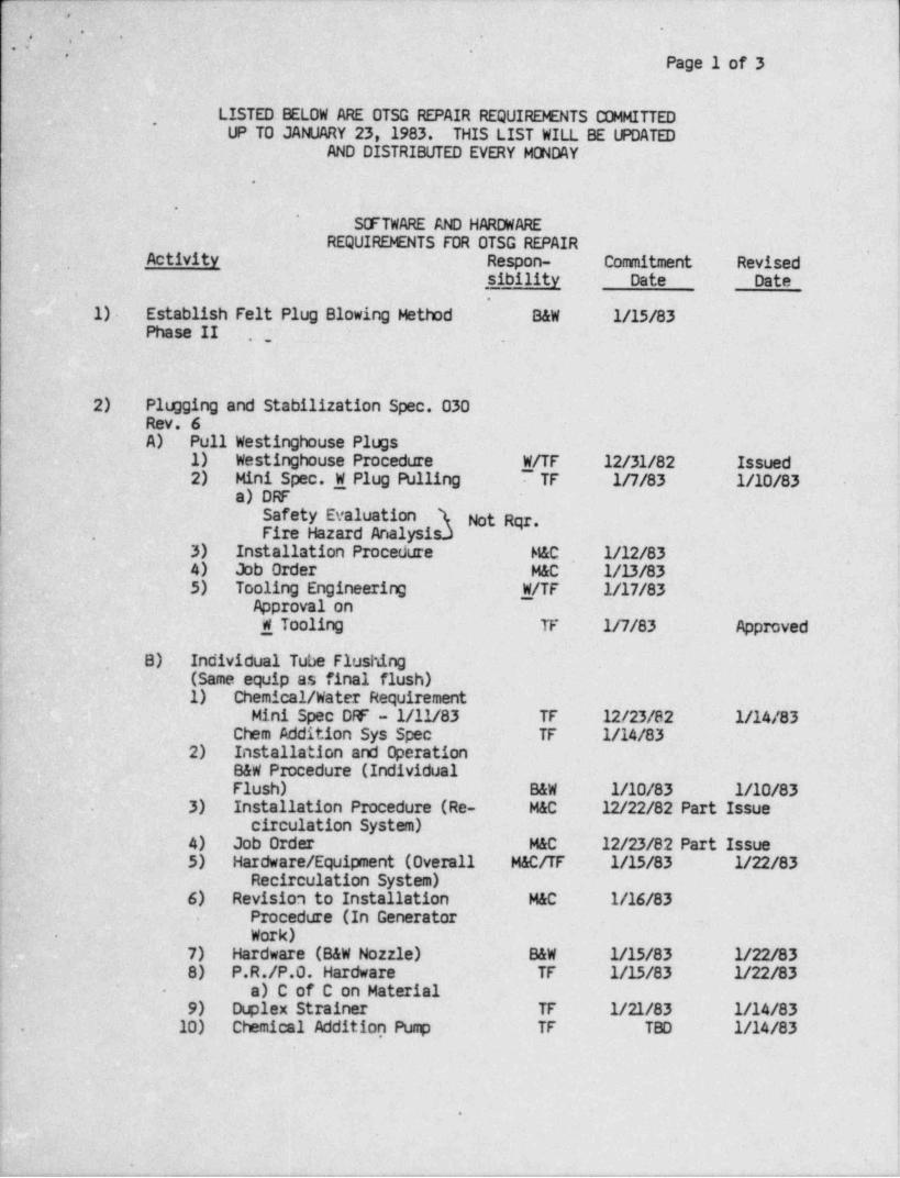
,n.-
n - , -
''
3: : . .,.
' '
_ Pag 3 1 of 3
LISTED BELOW ARE OTSG REPAIR REQUIREENTS COMMITTED~
LUP TO JANUARY 23, 1983. THIS LIST WILL BE UPDATEDAND DISTRIBUTED EVERY MCNDAY-
'
..
.
.'
S(FTWARE AND HARDWARE '
REQUIREENTS FOR OTSG REPAIRActivity Respon- Commitment Revised
_sibility Date Date.
.
- 1)- Establish Felt Plug Blowing Method B&W 1/15/83Phase II ;
.
-
,
>
.~2) Plugging and Stabilization Spec. 030.
-Rev. 6A). . Pull Westinghouse Plugs
.
1) Westinghouse Procedure W/TF 12/31/82 Issued2) .-Mini Spec. W Plug Pulling 7 TF 1/7/83 1/10/83
a) DRFSafety Evaluation T Not Rqr.Fire Hazard Analysis.).
3) Installation Procedure M&C 1/12/83'
4) Job Order M&C 1/13/83'
5) Tooling Engineering W/TF 1/17/83Approval on '
W Tooling TF 1/7/83 Approved
B) Individual Tube Flushing(Same equip as final flush),
1) Chemical / Water RequirementMini Spec DF - 1/11/83 TF 12/23/82 1/14/83 ,
2)..Chem Addition Sys Spec TF 1/14/83Installation and OperationB&W Procedure (IndividualFlush) B&W 1/10/83 1/10/83
3) Installation Procedure (Re- M&C 12/22/82 Part~ Issuei- circulation System)L 4) Job Order M&C 12/23/82 Part Issue-! 5) ! Hardware / Equipment (Overall M&C/TF 1/15/83 1/22/83
Recirculation System)6). -Revision to Installation M&C 1/16/83,
Procedure (In Generator.
Work)-
7) Hardware (B&W Nozzle) B&W 1/15/83 1/22/83'8) P.R./P.O. Hardware TF 1/15/83 1/22/83
a) C of C on Material-
9) - DLplex Strainer TF 1/21/83 1/14/8310) Chemical Addition Pursp TF TBD 1/14/83,.
;
!
!
+.
ie
r . .. .-,--.,4, ,- r .,,.r-..- ..----w..-.. ,.---.w.,.-,w,.,..,,_..,-,,..y.. . - - - - , .,%, , , .
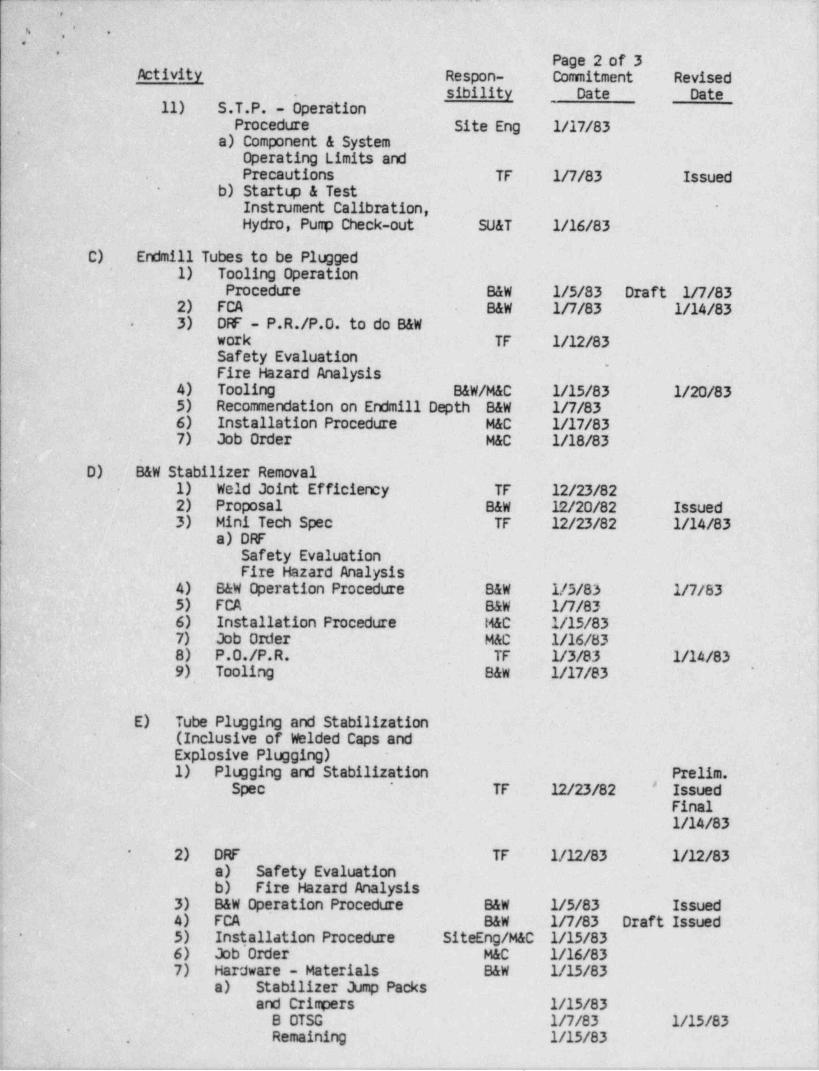
-. _ . .
.,
_|'
...
*
Page 2 of 3Activity .Respon- Comitment Revised
sibility Date Date.
11) S.T.P. - OperationProcedure Site Eng 1/17/83~
a) Component &. SystemOperating Limits andPrecautions TF In/83 Issued
- b) Starttp & TestInstrument Calibration, *
Hydro, Punp Check-out SU&T 1/16/83
C) Endmill Tubes to be Plugged1) Tooling Operation
Procedure B&W 1/5/83 Draft in/832) FCA B&W 1/7/83 1/14/833) DAF - P.R./P.O. to do B&W-
work TF 1/12/83Safety Evaluation
.
Fire Hazard Analysis4) Tooling B&W/M&C 1/15/83 1/20/835) Recommendation on Endmill Depth B&W In/836) Installation Procedure M&C 1/17/837) Job Order M&C 1/18/83
D) -B&W Stabilizer Removal1) Weld Joint Efficiency TF 12/23/822) Proposal
. B&W 12/20/82 Issued3) Mini Tech Spec TF 12/23/82 1/14/83
a) DRF,
Safety EvaluationFire Hazard Analysis
4) B&W Operation Procedure B&W 1/5/83 In/835) FCA B&W In/836) Installation Procedure M&C 1/15/837) -Job Order M&C 1/16/838)~ P.O./P.R. TF _1/3/83 1/14/839) Tooling B&W 1/17/83
'
E) Tube Plugging and Stabilization(Inclusive of Welded Caps andExplosive Plugging) -
1) Plugging and Stabilization Prelim.#Spec TF 12/23/82 Issued
*
Final1/14/83
2) DRF TF 1/12/83 1/12/83*
a) Safety Evaluationb) Fire Hazard Analysis
3) B&W Operation Procedure B&W 1/5/83 Issued4) FCA B&W In/83 Draft Issued5) ~ Installation Procedure SiteEng/M&C 1/15/83-
6) Job Order M&C 1/16/837) Hardware - Materials B&W 1/15/83
a) Stabilizer Jump Packsand Crinpers 1/15/83
8 OTSG I n/83 1/15/83'
Remaining 1/15/83,
-_- _ _ .
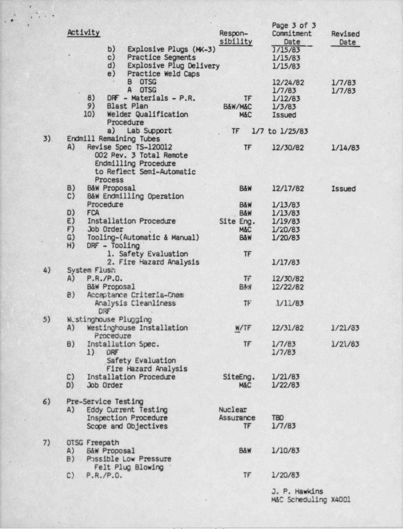
.. . .- ~. _ __
-
,.
* ^y , , . . -
'T '
Pag 3 3 of 3. ,
..
Activity . Respon-- Commitment- Revised i
sibility Date Dateb) Explosive Plugs (M(-3) . J/15/83c) Practice Segments 1/15/83
*
d) Explosive Plug Delivery 1/15/83e) Practice Weld Caps
B ~OTSG 12/24/82 In/83-
. . .A OTSG In/83 1/7/83-8) DF - Materials - P.R. .TF 1/12/839) Blast Plan B&W/M&C 1/3/83
10) Welder Qualification M&C IssuedProcedure*
a) Lab St.pport TF 1/7.to 1/25/83...
Endmill Remaining Tubes.
3) .'A) Revise Spec TS-120012 TF 12/30/82 1/14/83
- 002 Rev. 3 Total RemoteEndmilling Procedureto Reflect Semi-AutomaticProcess
.B) B&W Proposal B&W. 12/17/82 IssuedC) B&W Endmilling Operation
Procedure B&W 1/13/83D) FCA .B&W 1/13/83E) Installation Procedure Site Eng. 1/19/83F) Job Order M&C 1/20/83.
G) Tooling-(Automatic & Manual) B&W 1/20/83,
H) DRF -' Tooling1. Safety Evaluation 'TF.
2. Fire Hazard Analysis 1/17/834).
A) stem FlushSy
P.R./P.O. TF 12/30/82B&W Proposal B&ti 12/22/82
B)_ Acceptance Criteria-Chem' Analysis Cleanliness TF 1/11/83
DRF .;
5) Westinghouse PluggingA) Westinghouse Installation WfTF 12/31/82 1/21/83
; ProcedureB) Installation Spec. TF In/83 1/21/83
1) DRF In/83. Safety Evaluation-Fire Hazard Analysis
C). Installation Procedure SiteEng. 1/21/83D) Job Order M&C 1/22/83
6) Pre-Service TestingA) Eddy Current Testing Nuclear
Inspection Procedure. Assurance TBD'.
Scope and Objectives TF 1R/83
7)- OTSG FreepathA) B&W Proposal B&W 1/10/83B) . Passible Low Pressure.
Felt Plug. Blowing *C) P.R./P.O. TF 1/20/83
J. P. Hawkins,
M&C Scheduling X4001-
* '. - - . - . - - _ . _ . - - - - - . - _ . _ . - . . . - . . . - ~ . -
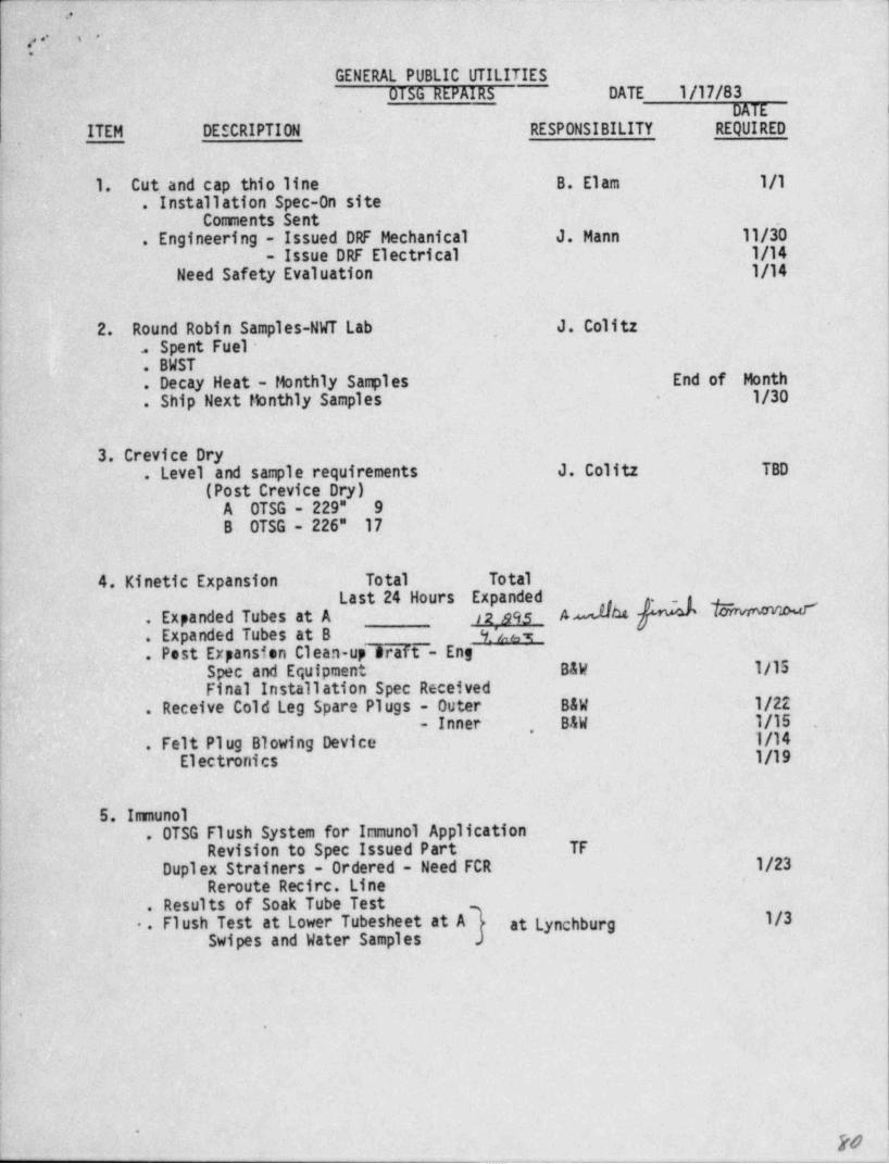
"
.3
;,: _
.,
. .
'
GENERAL PUBLIC UTILITIESOT5G REPAIRS 'DATE 1/17/83
'
DATE
ITEM DESCRIPTION RESPONSIBILITY REQUIRED.
1. Cut and' cap thio line B. Elam 1/1.. Installation Spec-On site:
Comments Sent'.
.
. Engineering - Issued DRF Mechanical J. Mann 11/30'
- Issue DRF Electrical. 1/14Need Safety. Evaluation 1/14
2. Round Robin Samples-NWT Lab J. ColitzSpent. Fuel -1
. BWST-.
.| Decay Heat.- Monthly Sanples End of Month
. Ship Next Monthly Samples - 1/30,
3. Crevice Dry. Level and sample requirements J. Colitz TBD'
(Post Crevice Dry)-A OTSG - 229" 9B OTSG - 226"- 17
4. Kinetic Expansion Total ' TotalLast 24 Hours Expanded
AMMf IM#. Expanded Tubes at A s2 a95. Expanded Tubes at B
_ __
<f. 'z, n. Post Expansion Clean-up sraft - Eng
Spec and Equipment B&W 1/15= Final Installation Spec Received
. Receive Cold Leg Spare Plugs - Outer B&W 1/22- Inner' B&W 1/15 ..,g
' . Felt Plug Blowing Device 1/14,
Electronics 1/19
iI
5. Immunol,
( . OTSG Flush System for Immunol ApplicationRevision to Spec Issued Part TF
'. Duplex Strainers - Ordered - Need FCR 1/23|Reroute Recirc. Line
. Results of- Soak Tube Test-
.. Flush Test at Lower Tubesheet at A3 at Lynchburg 1/3~Swipes and Water Samples )
!.
-
,-
..
I
L
'
F0_ _ _ _ _ _ _
,
:: - -
,,s
-2-OTSG REPAIRS DATE 1/17/83
DATEITEM DESCRIPTION RESPONSIBILITY REQUIRED
'
6. Tube Plug ~ StabilizationStabilizer Material Deliver.
B 0TSG 44A OTSG 4617 1/15490 Ordered B&W
Spec for Prelim. Plugging- PRtun Spec Issued C. K. LeeEquipment and Procedures to Pull Stabilizers 1/15FCA Stabilization - Issued? B&W 1/14
B&W 1/17DRF Stabilization -
Installation Procedure ._
TBD*
.
Blast Plan to State Levin /Pruitt 1/17.
7. Miscellaneous Items to Resolve .
Plug Tube Lane at. A Lower ..
2 Tubes Possible Mill and PT at B (MNCR 137-82). .
.
'
8. Waiting Documentation-MNCR Responsibility-
2T!i E2 Plug Exploded at Wrong Area of Tube BAW345-82 2 Tubes Plugged Incorrectly354-82 Documentation.for Immunol-1st Batch Eng420-82 Damaged Tube Ends426-82~ Wire Brush B6-1009-83 .Immunol at Cold Legs
9. Tube Endmilling '
B&W Proposal IssuedReview Process and Establish Procedure TBD
Tooling 1/20
' 10. Anticipated JumpsDate De scription Responsibility* '
1/17 A - Upper - Kinetic Expansion
1/1-7' B e Upper -Kinetit-Expansion B&W.
m
9
e
4
h
.
'
.,j, ;,
Paga 1 of 3
LISTED BELOW ARE'OTSG REPAIR REQUIREENTS COMMITTEDUP TO JANUARY 23, 1983. THIS LIST WILL BE LPDATED,
AND DISTRIBUTED EVERY MONDAY
SCFTWARE AND HARDWAREREQUIREENTS FOR OTSG REPAIR
Activity Respon- Commitment Revisedsibility Date Date
1) Establish Felt Plug Blowing Method B&W- 1/15/83Phase II 14 gr. ft..
2) Plugging and Stabilization Spec. 030'
Rev. 6A) Pull Westinghouse Plugs
1) Westinghouse Procedure W/TF 12/31/82 Issued-
2) Mini Spec. W Plug Pulling TF 1/7/83 1/10/83a) DRF
Safety Evaluation T Not Rgr.Fire Hazard Analysis.)
3) Installation Procedure M&C 1/12/834) Job Order M&C 1/13/835) Tooling Engineering W/TF 1/17/83
Approval onW Tooling TF 1/7/83 Approved
B) Individual Tube Flushirg(Same e. quip as final flush) -
1) Chemical / Water RequirementMini Spec DRF - 1/11/83 TF 12/23/82 1/14/83
Chem Addition Sys Spec TF 1/14/83 -
2) Installation and OperationB&W Procedure (IndividualFlush) B&W -1/10/83 1/10/83
3) Installation Procedure (Re- M&C 12/22/82 Part Issuecirculation System)
4) Job Order MAC 12/23/82 Part Issue*
5) Hardware / Equipment (Overall M&C/TF 1/15/83 1/22/83Recirculation System)
6) Revision to Installation M&C 1/16/83Procedure (In GeneratorWork)-
7) Hardware (B&W Nozzle) B&W 1/15/83 1/221838) P.R./P.O. Hardware TF 1/15/83 1/22/83
a) C of C on Material9) Duplex Strainer TF 1/21/83 1/14/83
10) Chemical Addition Pump TF TBD 1/14/83
4
%
W -- . . - - . . . - - - - , , , , - - _ . - , . . - - - . - , - . ,, _--, .----,-,,-n- . , , , - , - - - - , , - -.-
,. .-
,
*
. . .. .,
.. Activity._ Paga 2 of 3
-
Respon- Comitment Revisedsibility Date Date
11) S.T.P.' - Operation: Procedure -Site Eng 1/17/83
a) Component & SystemOperating Limits and4-
.
Precautions TF In/83 Issuedb) Starti.p & Test
Instrument Calibration,Hydro, Punp Check-out SU&T 1/16/83
"
C) Endmill Tubes to be Plugged1) Tooling Operation *
Procedure B&W 1/5/83 Draft lH/83- 2) FCA B&W In/83 1/14/833) DF - P.R./P.O. to do B&W
. work TF 1/12/83Safety EvaluationFire Hazard Analysis
_ _
.-
4)- Tooling..
B&W/M&C 1/15/83 1/20/835)- Recommendation on Endmill Depth B&W In/836) -Installation Procedure M&C 1/17/83-7) Job Order M&C ^1/18/83.,
D) B&W Stabilizer Removal ...
1) Weld Joint Efficiency TF 12/23/82-
2) Proposal - B&W 12/20/82 Issued3) Mini Tech Spec TF 12/23/82 1/14/83
.a) ORFSafety EvaluationFire Hazard Analysis
4) B&W Operation Procedure B&W 1/5/83 In/83*
5) FCA B&W In/83.'
6) Installation Procedure M&C 1/15/837)- Job Order * M&C 1/16/838) P.O./P.R. TF 1/3/83 1/14/839) Tooling B&W 1/17/83
E) Tube Plugging and Stabilizationr (Inclusive of Welded Caps and
Explosive Plugging)',
1) Plugging and Stabili'zation Prelim.; Spec TF 12/23/82 Issued
Final1/14/83
,
<
2) DRF . TF 1/12/83 1/12/83'
a) Safety Evaluationb) Fire Hazard Analysis
3) B&W Operation Procedure B&W 1/5/83 Issued'
,
4) FCA B&W In/83 Draft Issued5) Installation Procedure SiteEng/M&C 1/15/83*
| 6) Job Order M&C 1/16/837) Hardware - Materials B&W 1/15/83
a) ' Stabilizer Jump Packsand Crispers 1/15/83,
B OTSG In/83 1/15/83Remainin;; 1/15/83
,
'
, _ . _ _ _ _ _ . _ _ _ _ _ _ . . . _ _ _ _ _ _ _ _ _ . _ _ _ _ _ _ _ _ _ . _ _ _ _ , _ . _ _ . .
. .. . . . . - .. .-. ..
s
. , _
. a ,: ,' 'Page 3 of 3
Activity Respon- Commitment Revised,
.sibility Date Date
'b) Explosive Plugs (M(-3) 1/15/83c) Practice Segments 1/15/83d) Explosive Plug Delivery 1/15/83-e) Practice Weld Caps
B OTSG 12/24/82 In/83A OTSG In/83 1R/83. s
8) DF - Materials - P.R. TF 1/12/839) Blast Plan B&W/M&C 1/3/83 :
10) Welder Qualification M&C IssuedProcedurea) Lab SLpport TF 1/7 to 1/25/83
3) Endmill Remaining TubesA) Revise Spec TS 120012 TF 12/30/82 1/14/83
002 Rev. 3 Total RemoteEndmilling Procedseto Reflect Semi-Automatic -
ProcessB) B&W Proposal B&W 12/17/82 IssuedC) B&W Endmilling Operation
Procedwe B&W 1/13/83D) FCA B&W 1/13/83,:, .
E) ' Installation Procedme Site Eng. 1/19/83F) Job Order M&C 1/20/83G) Tooling-(Automatic & Manual) B&W 1/20/83H) DRF - Tooling
1. Safety Evaluation TF2. Fire Hazard Analysis 1/17/83
4) System FlushA) P.R./P.O. TF 12/30/82
B&W Proposal B&W 12/22/82B) Acceptance Criteria-Cherr.
Analysis Cleanliness TF 1/11/83DRF
5) Westinghouse Plugging -
A) Westinghouse Installation WfTF 12/31/82 1/21/83: Procedure
B) Installation Spec. TF In/83 1/21/831) DRF In/83 '
Safety EvaluationFire Hazard Analysis *
C) Installation Procedse SiteEng. 1/21/83-
D) Job Order M&C 1/22/83
6) Pre-Service TestingA) Eddy Current Testing Nuclear
Inspection Procedure Assurance TEDScope and Objectives TF In/83
7) OTSG FreepathA) B&W Proposal B&W 1/10/83
| B) Possible Low Pressure| Felt Plug Blowing
C) P.R./P.O. TF 1/20/83i
:
; J. P. HawkinsM&C Scheduling X4001
,
_ _ _ _ - . _ . . _ _ _ _ . _ _ _ _ _ . _ - - __ __ __ _ . . _ _ _ _ _ __ ._ __ _..___
p 14- .
;, .
'' g '' GENERAL PUBLI'C UTILITIES9 OTSG REPAIRS DATE 1/19/83
DATE' ITEM DESCRIPTION RESPONSIBILITY REQUIRED
^
1.. Cut and cap thio line B. Elam 1/1--. Installation Spec-On site
Comments Sent >-
' ~
. Engineering - Issued DRF Hechanical' J. Mann 11/30- Issue DRF Electrical 1/14 -'
.
2. Round Robin Sagles-NWT Lab J. Colitz. Spent Fuel ,
. BWST
. Decay Heat - Monthly Sagles End of Month
. Ship Next Monthly Samples 1/30,
3. Crevice Dry.
. Level and sample requirements J. Colitz TBD(Post Crevice Dry)
A OTSG - 229" 9'B OTSG - 226" 17''
.
4. Kinetic Expansion Total TotalLast 24 Hours Expanded
. Expanded Tubes at A
. Expanded Tubes at B'
-
- . Post Expansion Clean-up Draft - EngSpec and Equipment B&W 1/15Final Insta11aticn Spec Received
;- . Receive Cold Leg Spare Plugs - Outer B&W 1/22.
- Inner E&W 1/15. Felt Plug Blowing Device .1/14'
Electronics 1/20Proeddure Revision 1/20
~5. Icaunol. 0TSG Flush System for Immunol Application
Revision to Spec Issued Part TF.
Duplex Strainers - Ordered - Need FCR 1/23Reroute Recire. Line
.. Results .of Soak Tube Test
. Flush Test at Lower Tubesheet at A at Lynchburg.Swipes and Water Samples.
.
___,f'/-'
. . [ -2-4-
'y OTSG REPAIRS DATE 1/19/83DATE
ITEM DESCRIPTION RESPONSIBILITY REQUIRED"
,
6. Tube Plug Stabilization-
Stabilizer liaterial Deliver.
-B OTSGA OTSG 1/15-
-490 Ordered' B&W ,
Spec for' Prelim. Plugging-Prelim Spec Issued C. K. LeeEquipment and Procedures to Pull Stabilizers 1/15.
FCA Stabilization - Issued? B&W 1/14'
DRF Stabilization B&W 1/17Installation Procedure TBD.
.
. 7. !!iscellaneous Items to Resolve'
Plug Tube Lane at. A Lower.
2 Tubes Possible tiill and PT at B (INCR 137-82).
8. Waiting DocumentationMNCR Responsibility
-
21T'U2 Plug Exploded at Wrong Area of Tube B&W
345-82 2 Tubes Plugged Incorrectly354-82 Documentation for Immunol-1st Batch Eng
420-82 Damaged Tube Ends426-82 Wire Brush B6-1
'
009-83. Innunol at Cold Legs
-
.
9. Tube.Endm'illing JN g (, pB&W Proposal g IssuedReview Process and Establish Procedure TBD
Tooling 1/20
MR%0-eo ,k
10. Anticipated JumpsD.a te
' Description Responsibility
1/19 A - Upper - Kinetic Expansion B&W/ CatalyticRemove SpargerDrain ImmunolWipe & Clean Debris
1/19 B - Upper - Kinetic Expansion B&W
Y |ML$ GWd
9
.
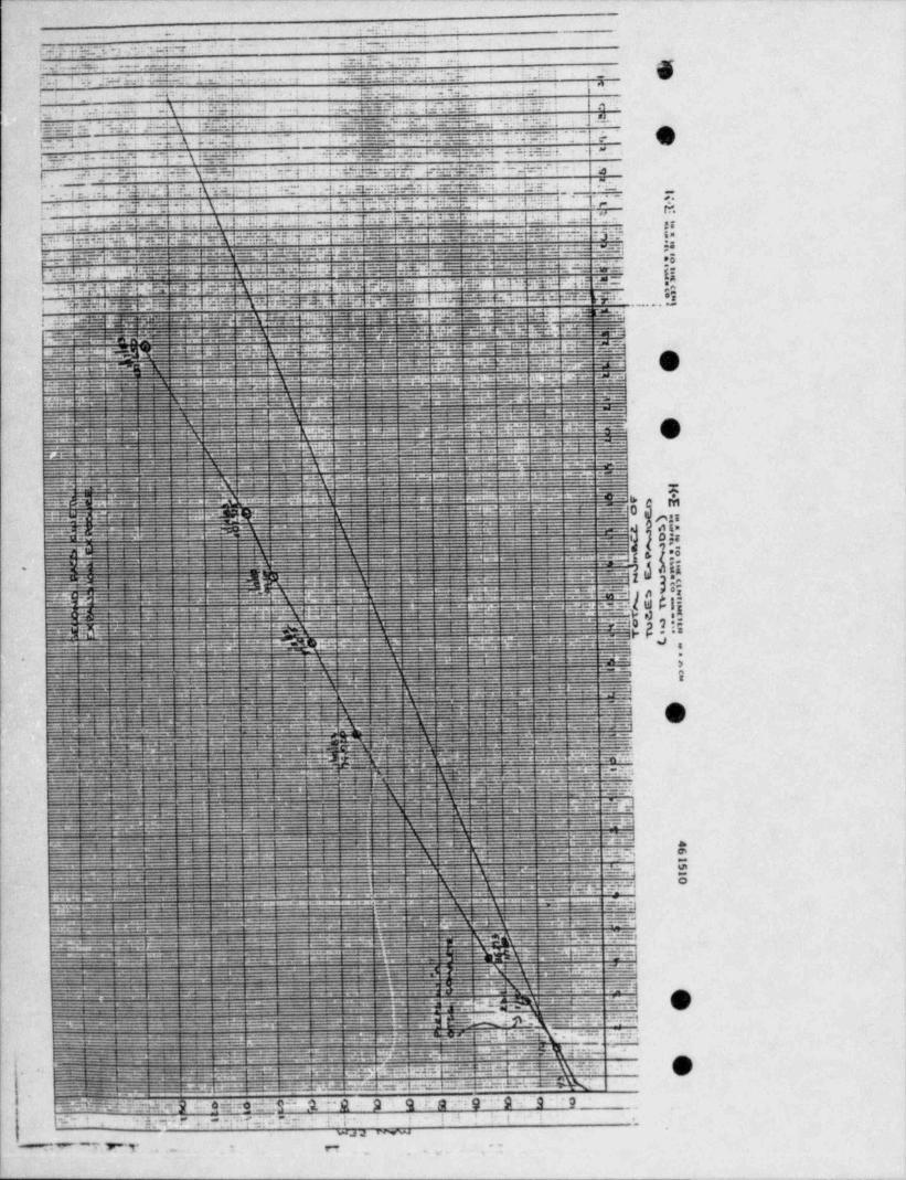
.-e.... 1
-
' ' * ^; '.p.g.: j.g.*r. ., , .. . . .
.I.-"'"=*
I __.._..,u.. - .: =f: 1-j mr-: -a _e . _- .
- ;_ f 1 : ;g.i: ' :. hi..- .
f :.4 .. ;:a r*
1 : . . . i.+. .
-.-- .n
''".k . .Efp *--.de ,,- . . ~ . !",,,,,,:
4: s.m ; V ..i . ;. .; _ _7==: - .. .g.g.-- j : ; :'af- ,q :, - . ;. :g_
j Mkb . : .f. jy..: - i. ._ f ___ --Q{.[ _ T- __; . .c,.'.f;t,_ ; '"-
f. _
--
iE= ri -L' Ms - i-a. 5_::==ul-"':.E._: ; 3'E ? . I; :r. "' -'j.' . \. i.u:N. i .j 3: :. . . :.;.
- , . i .* g.; ;__h c.i:= r-- =2.:e .i -. =n-s.= 2. .e ..p a .. . . -.: a a =' - y . =ew " 'm .. .jf-=; .- r ~ ^ i = --_l-~ - -- : - 8 : M',, ~. ~:p - @ .\" .::ter . :- :"[. :.:.
"~* ' + .* :: . l ii:~23"e:4 i-.. ' J .=- : : fir'I;* :ff=l.%;Oh *.2- N'f4_^i- , .
. n. 1. .; t .q .p f. -. .: .1__-n r:3. a, y =22..g a,. :. 3 a ,f - ]. r= . 7"- ..f.. ni
--
-. _s t .. _. _r._. M,
. . a_.m . . . ;. ._. .-r ;.. .:u .1'=. ; . p . :; =_w. _:
.'- . ::=2 =r_. . - IL_ ., ,.. - .h. . } ;_ . . s. w . .
.:: m. . . .:=. :. . 4 - - _ - - -t : =_.u.r_ ,.2 21 .=..- - ..
-j:!- i *,p -p-:0: +L. .- :-JM M ~. ="$1.ir.--p.M E.i: MJ -@24_ _ . . ;. W _J=-:_._ .l.;-- .: :3
a.. . = . _. _ _ _ _ ~ - . - . _ = , _ _ _ _ . - _r._
___, p__ : ;
e g g=g:...;-. u.m _ _ 2 = m__. __ _. n, . ;=__2_._- :-
._ . _ _. .
. _ 4.. - .. . _ .- ._ _ . _ . -
.- E' - = = = = = = .,?. .
gd_- _ .._ .' -_* ;; e .b
-
. - .e
.g
.-.e. e. .' e .. _ _ = . ._ _ ... ~e=
* E" . h I, . . .
... = . . = .. - - . . - - _ .- . = = . =
#V 120 W=M ?"I=i W-Fi+-* !.T *-
W'.==.4*
~ P:# =# VriM #i>
=-ai=> g = :-K== =p.= :=u. ... .;_.g.:.4=~==a: ~ === rp . 4-
3== y .=l::g=m= = -: .=:n.5=p . - .. ~ * * ' * ~;,,i 61 raa. ..T; E -
.
_e= _=- - =-....-_--:-
. _ . . ,-..5..w. ..=| 3; .33_ _= -:- .4. =.e. . . . . . .
gg _ :..:s=- __._;....:su .,
4 ,,;.;.; :.2__::r .3,- : . _ ,_ . . ~
. _ . - _ .. . . _ _
- ;- - *- ==: :..w . -
.;; .;f _--
--En- =_. _- _ ::t,- - - -m. ::.::.;::::- _ _+--.=a.--.;.: .:==.::. : f:2.u.
. - - - - - - - - -u -. : --_ t- :------ . :- = ,. 2.r. .=.r==m-4
_a :. ,u. r _.- .-
1. ..= .r = ._g : --- = . .2L ;. r -_:. ::::
L_. r. : .. =. .. . . , . - -._: m - ;; ._.:. ;= *.- =-v_= . . _ . u_ . L.n _ -ar- :,,mu
_ . = - . _ = .;Md. - . ..- .
4.._ - - - - ~
.T": _ . , _' = T.*: u - * .=.. 1*:; 70 :6.-4.:.:;;- -.E._ .- . . ' * . =.
.-.'.T.=-"' U. ;. 4= ._ . - - . . _";1="- _ . . -.:... . --.::= ~ -=:=*- - . . = =!:- ~%. ""38] _ u --. _3-"--. - - - - -.-:: _
=.;; =1.i. %== :n : .;=_: . . . _ -:. -== = . - - .= :.a . . . .z_-. .v=- w=.-._-
- ,
2 :- :-=-._ - _= =__.;. .=.;_. :_-.=z .- _
_- -__ 2. . _ ,
-
-
=2:
. ._ --
1- -
_...._s.=_..r.==:=. - - - =.. = . . = . _ .: _= .r---- 1-=-; s.=.:..=- . . - - -
.._.- = . . . ._ . . _ .
J_ .__ _
- . , , . " .'
- , ,. jc_ __
.
- tr- -,__ _
._ '^ ~ - -~.
;,,---
- ';,;,_~ =:r-
-= = . - --'
;. a-'
rs.-- * _m..
. . !'~ ~ [
'"" ' E ..
.;=J .'. _,. _-
*
_.c=.%L_
-
__.___s...__ _;_. __ =_ _ _ _=..m_..._.._. ..;;
-- _ _ _.,_ - _ __ _ .. _-. -,.
.
.. ..
-.. ,. q . ,- . -_ - . , . . -. .;g; . - --7J. Ja -- -. -- _
- - - -1-- - - - - = " - " , ___
.-- -_.... .i .. ~' - ' ' ' ' ~
7.= O...a_..-. ' ' " __, _. W~'" .; ''"- J.;T_ -_'-" ;.
* * * ' '
- ' * - ~7__;2 .,.;-" ' :L':L.'71.:\ ,,.':1- ' - ' ' - ~-
,"
. _ _
=..^ i:: .
:.. _ .- ._g._
_~_.- ._.4 - . " ~"'="*=:" ". *:~- -..-..; 9.-- ,-6 *., .
._ _ _ 0=== -- y_ ;c - "'-. --- =__ gp qp3-r=g <
_ , -._. . _ N1
;. ,,3-
1,. D :s==:23 :== - _.
- :. -.;1:. _. _._.a__. _._ w- a, A Em,. .a,_ .- .- _- - ._g:
-
*
_.
. _ - -___ g .
_
'O.- -- [6==a, a :- - -
.-._w._, a=
,-
.|---
. . . _ - - .-- -_._ .; -._ _ . - - - - . - - ss ---
,'-- w.g
. JJ _ = - - - ,- - -. _-- -; 1
_ . . Gy-
" _' 1"- =----:. . _ . = ,m,
. . _ . . .--g- . _._- . _ ,
- ;.,. _= , - n,-=.m . _ _ c -_ ___ _, . w ,_ , _ _
._.
_ . . . . _ ;.my _ ,. --- y p g)5/t- _ _ . - .
.
-y _ -. _ . . . - - - . - .
- _ . _ -_
_._ -- 4- _. -_.- .- ._..
~- - - --
_.. m p g, 7, *y:-.3 M .O 3.=_t2 ;.nt --"--- - - ~--ag ;=. _._ .
- - ' - - - ---
- . _ . . _ _ _- _ _. -_.-. - _n.g . ' "-,'=:""_
- i.-.. . _--"
_._, _-""'"'y' - - * - * *
. _ _-
.
. _ . .__r ,;, ,,,_..
g_
_ ~ . " -- * - * ""A"*( _- " '- _ . ::i* *
* '"'~~
i_.-- - - --- 2-h-" -~ k 3.,
_ ~ _3-
,
L_ n. . _ . __ ;
__ g. . . - -- .~
,;,_- .- _. . . - _ _ _ -.
_ . .
. _ - w_. - . - - _ _ _.e 4_... _ _.
'.g .
_d,_--'-- - -.e --
h g__N
.
.-- ---- __,_a +
.---y.
r- ~7^ =- - __ _-g--- ~.-
. _ . - - g_ --. _ .,,;;;; . ._ ." ' . "'. .--. - - - = = .- --_
. - - _ . _a_ -_
_,A,- __
,, _ _ _ _ - ,$--- p-. ---
c_
- --__ ~-__ ---
- g-r . - . _. _7 _.u _ __..
_'2_
-p.-w-- .3CE' ~_- ~ " " I ,w__=-
_ r
__
T- w~..^
._.,.h..,. ,"* * " " -
" . ~ -._=-q% _. . ~ . . . _ _- = ''K T
-
-. . .
.: :=.-1-<.. . - _ . . ._ __ _
_ __, ,;.... __..__'=__ _ -7__h.5- ..:=. ;._=_ m _. ==F"'= ~;E : :_=:_: .:
. _.. .- . _ -____; .
^
- .2 " 7. ,. 4 *4 -|* ="":- h_ . _ _ . - Ja * "*.. , _. w_ 3,,; ,_
:.I""R ;
._ _'-"*""'" . _ ,
. , ; "= . ,
.**2,_ _ E".~ --~W_ ,_ _ * : ..:..*J-*
_ -d_ ; ._J-'- J- .;. _**!
-_ _ . -. -?
' - - - - " . _
~ : _ _-k'*_ __ _ -- _ ? "
. . __ _ . . __ __
_L_.: 5- _,: - y.''"_ ._-
. i __ ___- -
-1_- --n
___ _ _ _ -_-
. - - . . h m.P--_
- -u- ---; .- - , . - _ =~-- . ':=._ _ _f_ ..
-
__e..'.Y..em
g
*- . . _ _
_
___ ___ ,,,
M__, _ , _ __. - - . . _ ._ " . _ .. , , _ , _
e.p.-e. _ .m.mmie.g g _-_msam._- ,ew-
- - '.--e-~ . ~ . _-.. _ ._._ = . -
-+- _ . .
~~ -s,.m_mm -_
. . . _ _ . ,__.._
- . . _ _-- ,._ - %_- _ , , __
... _g ,,.
_ - . . _ .
_4. w.... _ _ _ " . =.: T C-'*. em-;""._ .. - _ . ,,
.,a,_ . ,i
: _r- - -
- _c ,
O~ " " ~
-=2:=._ ... - . _ . _ , _ . _. _ . _ ._ .i __ . ' _ . _._._.---f-~=:- r; --: ; _ . .
. _._4
-, . , __ . . _ . - _ , - _. __ . . _ _ _ _ s _;4 . .. -- _, - _ .]
-_ .. - -- - --
_. :- __.
- - *.
-- -'. .A ~~- W -_. T''L*''=- Y* - g.J~*",.- ", _,'7"*^:. - - _ -_-t---'--' _ .:'" : _. .=. -- ~~' ' - * - -
" __ - - - - - " '__ , _ . . . ~_=._5._"._*;,,.~ [d * ~ ' *
^
u .; ;.,. ,
_._ d ;,.W ._. ____h--_-p.
:;; --{- , __ ._;. ,_ __ _ _ _ ,_ . . _ ___.. ._ , . _ _ _ _.
- - - - -. _ . _ . _:--;___ _ _ . _ . . , . , _ __ - . .a-
. 24 -- --
-_-. _ . _ _.
: .. w_: - - -4 --
- =~~T_'~;..=_ _.a.--"_ ^.Y- .:
- - -.
_-. -
. =th _ e-m ww _.e"-
- " ' * " *_ -.-- m-m e
=~1._. _.. _ . - . _ .._._ - _ _ _ ._ a .,__:- - ;; .. n , _. . z --- - - -
g------*---_,,J m q
_ . - - .- _ - . - ._._ . _ . _ _ . . _.. .r _.
. __, _ _ _ . . _ " _ ,9
- -e.. - . _ ._ . ,~-4 %%.. - - _ . - 1 m._ -
_..ee.-._g mm. ,=p e-.m4a. _ . .%. ._
g
_
u *'am.: I e .=-'-?*-.'--:
_, m - - . . . _ . ~ ~ . ~ - -.- ' ' - L ._, . , _ --~% ;" _ - . - -- _ .. ~'-'"|,n n
;_-..b;._...~._, . . . ,L.=.:.:;--- . _ . _ . . _. .
_
. _ . - _._ ,_ .-.
--
__ _ . _ _- - - . _-- ::. _-2 -- ; z-. ;
'$ ~_. ?_ . .
A
.y.~~. m^
'
~
'~~~.|~~ ~ ~ _1 .
=;_,~-!__
--
___ '",___- ___
___=---+_=x,__A.m W_ _r_ , .
.;_.. _. > = _. = - - - -
_
_ . . = ~ - -.- 7 _ = - .
= = ' '. _ f _=. =_h -v-= = -. .
, . . . . ' , .p __- .; ; < :_=.==. ,3 : .= _. __w ;S_ . . ..;_w. ._s.; ;,- r=: q~~
3 _.
,
%= 'r=" MW.:- a :- 9 :..e o =-::=c -- .W ,Q -Q . 9 q. g u : g- 9u 9g,
g
P' - p- c- r . . -m _ p.= y.p ,,_
w #a mw--- .m . .
. r-. . u . .--. - -
. _ _ _ . . _ _ _
r
. cr .' .
' /. ., p" '
GENERAL PUBLIC UTILITIES-OTSG REPAIRS DATE 1/25/83
DATE-ITEM DESCRIPTION RESPONSIBILITY REQUIRED
1. Cut and cap thio line.
B. Elam 1/1 ,
. Installation Spec-On siteCossnents Sent
. Engineering - Issued DRF Mechanical J. Mann 11/30- Issue DRF Electrical 1/14
.
2. Round Robin Samples-NWT Lab J. Colitz. Spent Fuel. BWST'. Decay Heat - Monthly Samples End of Month. Ship Next Monthly Samples 1/30 .
IWai
yIOL 433be pp & b*J m & A3. Restoration Secondary SideA. Dehumidification System 4MwB. Vacuum Pumps bed %C.. Chemical Pumps
d e b h. mu.
D. - Humidification Probes * @A/ QE. Thennocouple Components -9F. Temp Power Crevice Dry EquipmentG. Nitrogen Pressure Secondary SideH. Teg. & Humididy Probes Calibration Check-I. Teg. Chem. System
br M Mg J-- M
4. Kinetic Expansion Total TotalLast 24 Hours Expanded
; . Expanded Tubes at A Complete 15770|- . Expanded Tubes at B Complete 15442
. Post Expansion Clean-up Draft - Eng 1/26;
;_ Spec and Equipment B&W TBDi-
Final Installation Spec Received| . Receive Cold Leg Spare Plugs - Outer B&W 1/22| - Inner B&W d ,J osu 1/15
. Felt Plug Blowing Device B&W 1/14! >
| ..e ww,
- 5. Innunol -
' . OTSG Flush System for Immunol ApplicationRevision to Spec Issued Part S M 1/28-
Duplex Strainert - Ordered - Need FCR 1/23. Results of Soak Tube Test... Flush Test at Lower Tubesheet at A1 at Lynchburg
,
|
| . Swipes ar.d Water Samples J
fGde -
j 9-
eFo2
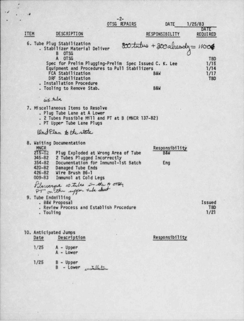
. . o .. _ _ .. _ . , , _ . -. , ._ . . _ .
3' ' '
. . , ,
, ..: -2 - . .
OTSG EPAIRS DATE 1/25/83DATE*
ITEM DESCRIPTION RESPONSIBILITY REQUIRED
I 6. Tube Plug Stabilization gg +g ,__ g. Stabilizer Material Deliver .
-
'
'B OTSGA~ OTSG TBD
Spec for Prelim Plugging-Prelim Spec Issued C.'K. Lee 1/1'S .Equipment and Procedures to Pull Stabilizers, 1/14FCA Stabilization ~ B&W 1/17DRF Stabilization TBD
*
. Installation Procedure:. Tooling to Remove Stab. B&W
' hl. A7. Miscellaneous Items to Resolve .
. Plug Tube Lane at A Lower
. 2 Tubes Possible Mill .and PT at B .(lelCR 137-82)
. PT Upper Tube Lane Plugs~ B0aJ A A A A
8. Waiting Documentation'MNCR ,
Responsibility
2T!PJ2 Plug Exploded at Wrong Area of Tube B&W345-82 2 Tubes Plugged Incorrectly. :
354-82 . Documentation for Immunol-1st Batch Eng420-82 Damaged Tube Ends426-82 Wire Brush B6-1009-83 Immunol at Cold Legs
h) 10% PAk%PT~ AP OM
9. Tube Endmilling,
- . B&W Proposal Issued. Review Process and Establish Procedure TBD. Tooling 1 / 21
.
4
J
10. Anticipated Jumps ,
i Date Description Responsibility
1/25 A - UpperA - Lower
,
| 1/25 B - UpperB - Lower ph
s
e
.
J
. . - - , -- m -..-..,,_.-,,__,._-._,-~,6-. .v,.,. , . - . _m _m._,--,--._.,..,_,,-.,..-,.---.r, _w_.w,c,,my - , - - - - . , - , , , - - - - .
-
..,
* .....,.%,
;;yrg. g*
e
GPU Hu lear.72 , J.7 . ,,
/Ji k: 44 . Soutr.Weetown.Fennspvenia 17057717 G46 6000TE:.EX EG365'
.
January 26, 1983 ...
.
..
.
9
- Mr. Charles Nork~.
Chief, Er.plosivas Safety Section-Bureau cf Mihing and Reclamation -
PA Dept. of' Environmental ResourcesF.O.| Box 2063
- Earrisburg, PA 17120
Dear Mr. Nerk:
.
RE: 3LAST PLAN FOR REPAIRS ON UNIT 1'
ONCE THROUGH STEAM GENERATORS AT.
THREE HILE. ISLAND NUCLEAR STATICXf .
The site Blast Plan for explosive plugging of the stes.= generators isenclosed for your review and approval. Although it is' unnecessary to revisethe Blac: Plan there are several matters which need to 'ce clarified and discusse.d.Tney cre as fellows:4
l. The first page of the Blast Plan, which has been stamped prc.prie: ry,'
ec= s. ins inforr.ation developed by Esbecck 6 k'ile:x in an encensive ;'
!testing and qualification program for repair cf .:ubes in L&W nu .le rplant. steam Eenerators. ELW has determined that the devele;ne n,applicati:n, and use of this infor:stien results in a cepetitiveadvan: age to them. Itams 1 and 3 en Page 1 cf the Elas: P1:n cus:.therefore,. be kept confidential by PaDER.'
I 2. Ite: 9, Page 1, of the Elas: Plar. sta es tha: :he blast trce eill S.inside the Unit 1 s:can generaters in tubes ;ect:ed in a tve-fe.t: hick tubetheet. 3.is is true with the excap i:n cf citfiras .nich
vill *:c de ona:cd in the blas bcx.
2. All m gazines have been apprcpriately licensed f:lictin; inspectica~
by r. Icpresen:stive of the Exp2csives Safety sec:icn cf FADER..
'|pe ecepicticn'of ycur review please indict:e y:ur appr: val by signing :he11 art Flan.:n ? age 3 and return the cripinal te:
,
Mr. J. 1 Coli::
G7U Nuclear C:rt::::ic:P.O. Ier. 450
.,. .....p, ;. . . L CV:. , : r. .tJ/Li.
y*
=*/ ,-
., .-
Mr. Charles Nork -2- January 26, 1983.
A copy of the approved Blast Plan should.be sent-to:
Mr. D. G. Slear*'
THI-l Project Engineering Manager |GPU Nuclear Corporation 1
- 100 Interpace ParkwayParsippany,-NJ 07054 i
By concurring with the Blast Plan for the explosive plugging it is understoodthat we meet with the intent of Pennsylvania's regulation regarding the s,torage,
,
. handling, and use of explosives as applicable.to this program. 1
Your prompt response to this letter will be appreciated. Should you haveany questions concerning the Blast Plan or related issues, please contact me at |
(717) 948-8533.*
Sincerely,
.
I- L d' fU. J. Col tzPlant Enginesring Director, TMI-1
b 'JJC:cm ~
Enclosure
oce: R. O. Earley, Lead Mechanical Engineer, THI-l.F. R. Faist, B&W Resident Engineer, TMI-lD. Hallman, B&WS. Levin, Manager, MLC Production, TMI-l
a ' D. G. Slear, Manager,130E Engineering Projects-
.
e
e
9
4
4
-v.
-- _ _ .
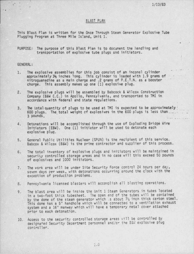
'~. 1/13/83 - }~*
FI , [*. .(, ,
y, ..
|
BLAST PLAN.
This. Blast Plan.is written for the Once Through Steam Generator Explosive TubePlugging Program at Three Mile Island, Unit 1. i
,.
~ PURPOSE: The purpose of this~ Blast Plan is to document'the handling and'transportation of explosive tube plugs and initiators.
i.
GENERAL:
'~ ~~~
1.- The explosive assemblies for this job consist of an inconel cylinder.approximately 3h inches long.- This cylinder is loaded with 1.9 grams of ~ ~
nitroguanadine as a main charge.and .2 grams of P.E.T.N. as a booster ~
charge. This assembly makes up one (1). explosive plug.
2. The explosive plugs will be assembled by Babcock & Wilcox ConstructionCompany (B&W C.C.) in' Apollo, Pennsylvania, and transported to TMI in,_
accordance with federal and state regulations.f
3. ..lbe total quantity of plugs to be used at TMI is expected to be approxima.telyj- '
600 plugs. ?The, total weight of explosives in the 600 plugs is less than.'.~...-.
3 pounds..
- . . . . . . . ...
4 . Detonations will be accomplished through the use of Exploding Bridge WireInitiators (EBW). One (1) initiator will be used to detonate each
, explosive plug.
^ 5 ~. General .Public Utilities . Nuclear (GPUN) is the recipient of this service.Babcox & Wilcox (B&W) is the prime contractor and supplier of this process.
6. The total inventory of ' explosive plugs and initiators will. be maintained inf security controlled storage. areas and in no case will this exceed 50 pounds-
of explosives and 1000 initiators.
7. - The work area will be under Site Security Force control 24 hours per day,seven days per week, with detonations occurring around the clock with the
' exception of production problems.
-8. Pennsylvania licensed blasters will accomplish all blasting operations.
9' -The blast area will be inside the Unit 1 Steam Generators -in tubes located.
in a two-foot thick tubesheet. The open end of the tubes will be containedby the dome of the steam generator ~which .s about 7h inch thick carbon steel.
J This-dome has a 5" handhole which will be connected to a ventilation exhaust'
system and a 16" manway which will have a temporary metal cover attachedprio,r to each detonation.
'10. Access, to the security controlled storage areas will be controlled bydesignated Security Department personnel and/or the B&W explosive plug'
controller.
.
1.0*
. .. .. -- - - _ . .- . - - - - - - .
~
" ..
'
b,, .
dl. Daily use. boxes shall be set up inside the Reactor-Building. Not more thanone (1) day's supply of explosive plug assemblies will be placed in thislocation. At.no time will this exceed 50 explosive plug assemblies.
PROCEDURE:
1. Explosive plugs and initiators will be received by the explosive controllerand inspected for obvious deficiencies then placed in the security controlledstorage areas. -The explosive plug controller will be responsible for inventoryrecords for receipts at Three Mile Island and at the security controller storageareas. Site Security will accompany all transfers of explosives outside the .
'
-Reactor Building.
2. Li_ censed blasters will complete the pre-assembly of explosive plugs andinitiators, to form an explosive plug assembly, in an authorized area outsideof. the Reactor. Build.ing. Explosive plug assemblies will be bagged in groupsof five~(5) and then stored in a licensed magazine.
3.- ' Explosive handlers will be responsible for replenishing the day boxes at .the-start of each shift. They will hand-carry explosive plug assemblies from thesecurity controller storage areas to the day boxes. The shift licensedblaster will be responsible for inventory records for the day boxes.
.
During their work shift, the explosive handlers will-remove explosive plug4.assemblies from the day box and deliver them to the explosive weld engineer. ;
5. The licensed blaster will ensure that the blast initiation area -is checked forstray electrical currents using a blaster's multimeter. If currents aredetected which exceed 50 milliamperes, the source will be sought and eliminatedbefore explosive plugs are loaded into the steam generator tubes.
6. As the tentman and jumper become ready for explosive plug assemblies to beinserted into the steam generator tubes, the explosive weld engineer will handthem into the tent to the tentman.
-7. The tentman and jumper will place the explosive plug assemblies into the tubesas directed by the procedure controller, then hand the bitter ends of the firingcircuit leads through a slit in the far side of the tent to the licensed blaster.~
The temporary manway. cover will then be installed and the tentman and jumper willexit the main. tent to the designated safe area in the tent annex.
8. prior to initiation, the licensed blaster will repeat the checks for strayelectrical currents' using a blaster's multimeter. Again if currents greaterthan 50 milliamperes are detected, the source will be identified and eliminated.During testing, the blaster will verify that the firing cwcuit line is discon-nected from the capacitor bank and properly shunted.,
!
9. After DER regulatory safety checks are completed and the licensed blaster ensuresthat all personnel remaining in the area of the steam generator are located indesignated safe areas, he will make final firing line continuity checks using ablaster's multimeter, connect -the capacitor bank and fire the circuit.
10. Step 9 will be repeated until each individual explosive plug assembly in the-
group of five (5') has been successfully fired.
2.0,
.
m; , , . ., ..
,,a..,
--
,
., ,
11. ' After detonations, the' firing line shall be disconnected from the capacitorbank, the explosive weld engineer or his designated representative will view
-
the blast area visually to verify that all explosive plug assemblies detonated.After the ventilation exhaust system has removed the blast fumes, the sequencein accordance with step 5_ through step H will be repeated.
'
If.a misfire is detected during the inspection, a waiting period of not lessthan 15 minutes must be observed before the misfired explosive plug assemblies
'may be removed under the direction of the licensed blaster, for storage in asecure' area until disposed of.
.
Written by 8[Reviewed by
Reviewed by (B&WCC) cad k TV/FC Mca t-n-s3v
Reviewed by (B&W UPGD) M/:/ M. N O f // M
Reviewed by (GPUN) O. 0 ##Approved by (PENN) 8 A 4..
Chief Explosives Safety Dept.of Environmental Resources
.
8
9
9
3.0
-1
|-
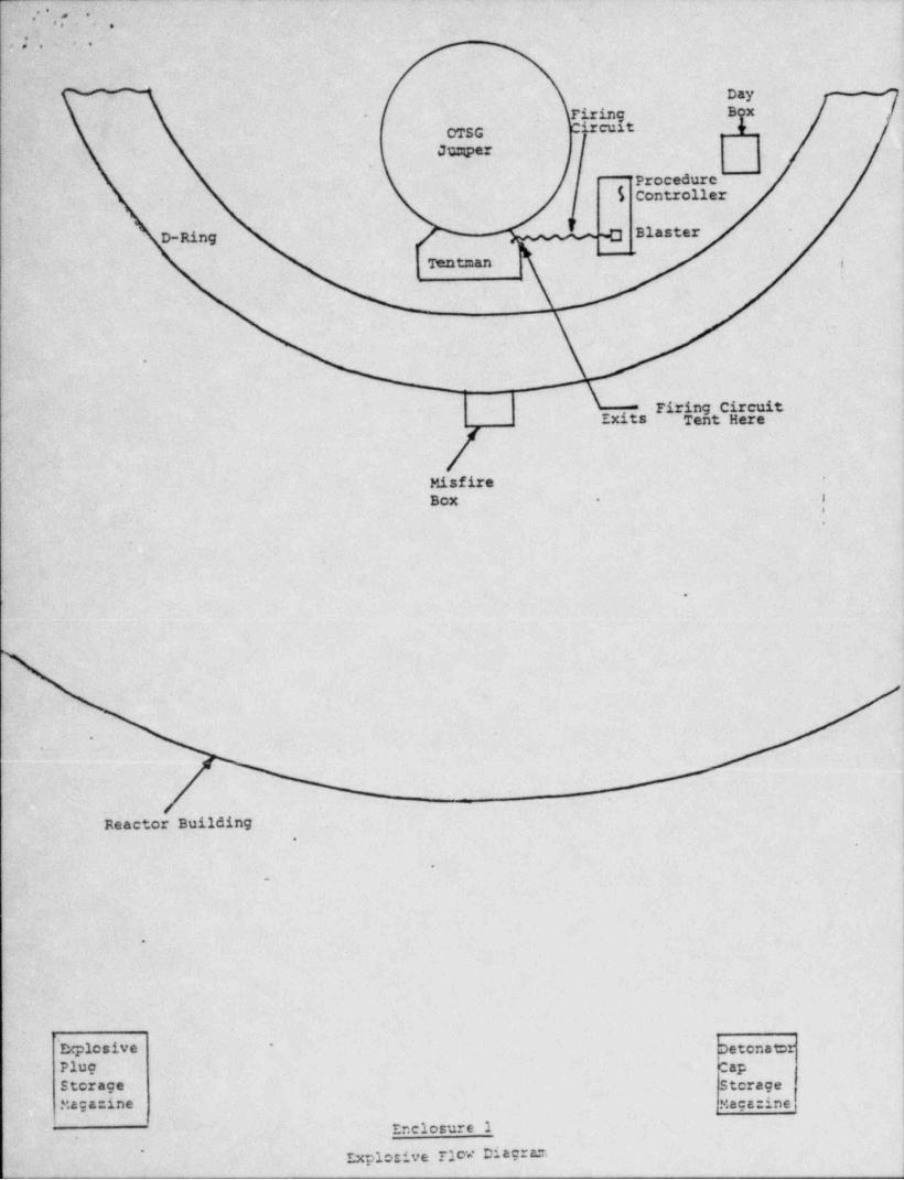
. ' ' , .e, ._,
.
*e> .. .
__- . Day --
- Phhg BgxOTSG Circuit '4
Juzqper1
Procedurc$ Controller
D-Ring ~C) Blaster
'Ientman i
.
.
_
'
Firing CircuitExits Tent Here
/Misfire
*-
I-Box -
.
.
.
.
.
|I
Reactor Building)-
-i
.
1
\.
|
1' Explosive Detonator
*
Plug CapStorage StorageMagazine Magazine
' Enclosure 1.
Explosive Floa Diagrar.'
___
'
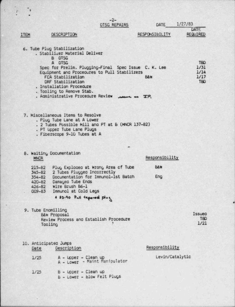
f: .
', . . .. +s. r-
.: .
-2-OTSG REPAIRS DATE 1/27/83
'
- DATEITEM DESCRIPTION RESPONSIBILITY REQUIRED
.
6. Tube Plug Stabilization. Stabilizer Material Deliver
B OTSG'
A .OTSG TBD
. Spec for Prelim. Plugging-Final Spec Issue C. K. Lee 1/31' Equipment and Proceoures to Pull Stabilizers 1/14
-FCA' Stabilization. B&W 1/17*
DRF Stabilization TBD
. Installation Procedure
.. Tooling to Remove Stab.
. Aoministrative Procecure Review - rP,
.
.7. Miscellaneous Items to Resolve. Plug Tube Lane at A Lower. 2 Tubes Possible Hill'ano PT at B (MNCR 137-82). PT-Upper Tube Lane Plugs. Fiberscope 9-10 Tubes at A -
.
.
8. Waiting DocumentationMNCR Responsibility
215-82 Plug Explooeo at krong Area of Tube B&W
345-82 2 Tubes Pluggeo Incorrectly354-82 Documentation for Immunol-1st Batch Eng420-82 Damageo Tube Enos426-82 Wire Brush B6-1009-83 .Immunol at Cold Legs .
,.
A 4 90 PJ 44pred plug.c
.
9. Tube EnomillingB&W Proposal IssueoReview Process ano Establish Procedure TBD
Tooling .* 1/21
~10. Anticipated JumpsDate Description Responsibility
1/25 A - Upper - Clean up Levin /Cata' lyticA - Lower - Maint Manipulator
.
1/25 B - Upper - Clean upB - Lower - blow Felt Plugs
.
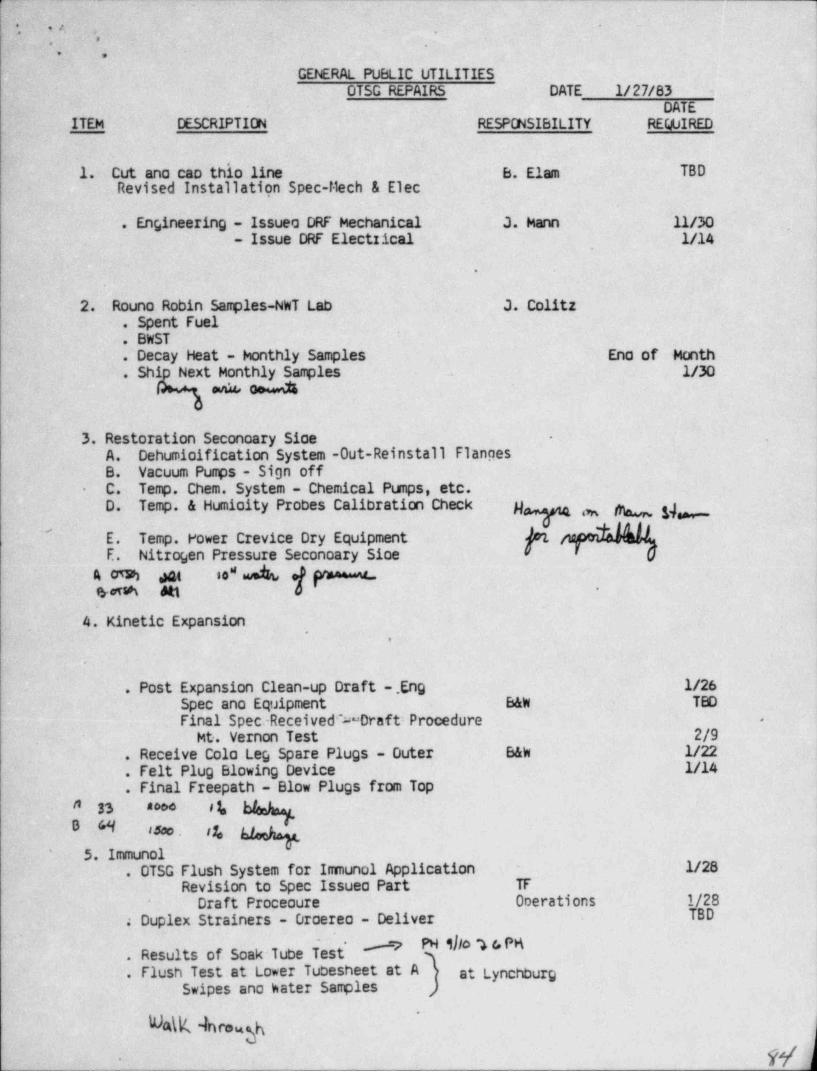
._
*[ - ,/,
*--. .1,
.
-
GENERAL PUBLIC UTILITIESOTSG REPAIRS DATE 1/27/83 -
-DATEITEM' 'DESCRIPTIDN RESPONSIBILITY REQUIRED
1. Cut ano cao thio line B. Elam TBDRevised Installation Spec-Mech & Elec
. Engineering - Issueo DRF Mechanical J. Mann 11/30- Issue DRF Electzical- 1/14
.
2.. Rouno Robin Samples-NWT Lab J. Colitz. Spent Fuel. BWST.' Decay Heat - honthly Samples Ena of Month. Shi Next Monthly Samples . 1/30 _
ev% od
3. Restoration Seconoary Sioe -
A. Dehumioification System -Out-Reinstall FlancesB. Vacuum Pumps - Sign off
.
C. Temp. Chem. System - Chemical Pumps, etc.-
D. Temp. & Humioity Probes Calibration Check y g,
pfiaptrkhN'
E. -Temp. Power Crevice Dry Equipment'E. Nitrogen Pressure Seconoary Sioe
so" d e(> y4 05M det a
eieve Att -
4. Kinetic Expansion,
.
.
. Post Expansion Clean-up Draft .Eng 1/26Spec ano Equipment B&W TBD
Final Spec.-Received % Draft: Procedure .
Mt. Vernon Test ~ 2/9. Receive Cola Leg Spare Plugs - Outer B&W 1/22. Felt Plug Blowing Device 1/14. Final Freepath - Blow Plugs from Top
33 800* # 1.
H - tsoo . r1,
5. Immunol. OTSG Flush System for Imunal Application - 1/28
Revision to Spec Issueo Part TF
. Duplex Strainers - Droereo - Deliver~
1/28Draft Proceoure OoerationsTBD
# NO 4 'Eu'
. Results of Soak Tube Test
. Flush Test at Lower Tubesheet at A at LynchburgSwipes ano hater Samples ,
'
%\K 4ncaghW.-
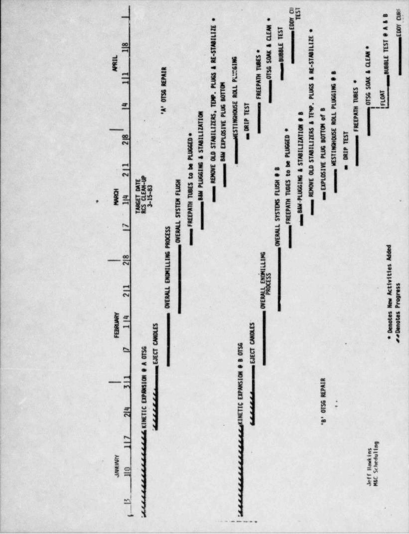
'4 - *_ _ _ _ _
bhm.
o w-- -
a 8o !..
=-
- z u?-
.| k h#m -.e I
5 i j ! .g l s. !!E' ..
11 || i i :1I 8
3=gI|=s-.E.Igaa
'
-
5._s. l- -. = ,e l
-
"-
. .* g. w_saEg-s ,sCk fn'I aa 9 |Q g "$ "t E52 g
|*
| 95 2g35n=g8an-3 . g ,-2!w.-- agg am Bwe ige gElliags i s ' l
ag" "
lo Isil' -
gg gus<1 *
I r 1M 2 g=
R 3 ga C
hE- =-
e I
h "a ~ ii-
"
n!s * I
|1 l g li.'
~
- .
ne i,.
s.s<5 .
*E
a5 E-
g' g*
Es u 'E S-h o
k.
- =
I., ~
.:
H-
5ist
4e,z ux
Ia
Ie
- t
I' " ~ = ~ . . . , _
. _ . - ~ _ _ _ _ . , _ _ _ . _ . - , , , _ _ . ._y_,, y,- . . . . . , _ . . _ . - _ _ _ _ ,m...._._,.-x_.,_.._,r. _ _ , . . , _ - _ _ . . , _ _ _ , _ _ , _ _ , ,
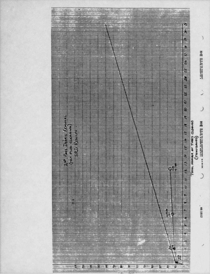
:$'+:|L~N_'='.lF El*+ 5 W - K... --.- =- _ -E 2 ~ ' ~ ~~' ~ ~--^- '~ l'2.~ % .E
~ ^ ';--
-
. . _- . . ~_r __ :._1 . . ' . _. _~~__. J. _ _d.-.._:6.-. r-- - U _ - _ _igi. f ., _- -- _ ___ ---r._.___:_=_='
- -
. . .
.
. . _ . _ _ . . _ . _ _____
.g. 3._- - . = . - _ -- -.;_.. -- w - - - - --- - . - - .-
_
g._25_:5. 51:_- __ - = _-- - _- 7 -- -- :. . _---
- g _. . _ .__ . . _,..._._-..-....______-________g._;-. _ . . . _ _ _ _ . _ _ _ _ _ _ _ _ . . _ _ _ _ . . . . _ _ 7_ _,. _ _ _ . . ..,
| M--..- ._ _ *- _ ___
_
~~--
-siss )-
. m .
=- u _ __ _ _ . .
_
~
: - - m
- - . - . .
y---
_ - _ _.__ _ w .._ _
M- - - - -- -. t =.c ._ . _ - = .;;; -rv
18&=
j5e: .
2 --
[4= - w==_
n
M. es._
1
-_
__
*_-
_
_
-=_
__
-
--
--
-_ -
_~_~-
_-
m-
-
_ _ _ -
_
-
Q E-- _ l.'_ __
__
2 _ ' '
---- - - ^ - __
@Q e$~
=__- _ .
--
-
_ _ _ _
.--
__--- _- ___
-
ga%_
---- =_ - ,. =
- f--
%-'--s
W k3..-_. _- _ w
__ g s
_
5 - 5----- 1_ - - -
_ -_ y
5 "& '|_ -- ?- 4
_-
- -
=_ .
__ _-- __=
'---
_.----
.
-_ ._ -- rrr=:
'-_ r-- _ i
_- |
._ E _ __._ i
-
_..__.- .m ,
. ew- -
_-._. _ .._.-
--
- _ . - .__ g
, = ~ _ ' . _ .-- - _.-- _ _. - _ . . . _ _
_. . _ _ . _ . __
_- ._ ____ _ __ .. Q( g_g_
g ;-
_ x _ __ _ .._. _ . . _ _ _ _ _ _ _ = . _ _ _ = _ ~~.-___3-_ _ __.;,_ _,_
'
. .- . .._
- =-'
r_=- -...~a_._-_---=_.._--.__ - -__. ~. ._ . . _ :u- .=-
__._ .T'*H_ _ . _ _ _ _ _ _ _ _
.___.._.._r___-_. __
_,___ _ . _ _ _ .y . . _ _
_
_._ _ _ _ _ . _ _ .__s_ .. _ ___
-* - ._ - - _ - . _ . - - . - _. - - . . . . . . -_ .- . . .
_ _ _ _ . _ _ _ _ _
.e _m. ..- - - - - - - - _._._-.-__.-yy _ . _ _ - _ e .
_-_. _ _ __.- _ _ _ . _ . . - - -- . _ . . _
,
_ __ _,,
. _ _. . - - - ._ _
|.
_. ,= _ _ - . /. _ . . _ . . . . _ _ . . . . . _ . . - - ~ _ - -. -_
- * * - - - - ~ ~
_ _ _ - _ . - _ . _ - _ _ _ _ _ . _- _ . , , _ . _ _ . - - _ _ _ __-
-
_---=:-.._.-=-=:==-.=_-_=_--.~:::.-----* ** w- : .:=_a : = _ . - . =-- :- : - -:-
_ , gg ,* . _ . _
.7:*''-'----'- -., ! L-'" ! _F--''--"'---__ - - ---A.,_ ]] ...M**.
p----_
- -__ _. :_ n= =:- _ . ._ - - --
m == = ;- - ---
. . . - - - - . QME===D-- :Er-M@ - ft: r$"]*ft- b=-7gF VL; -c-~-~'
.
==w- .==n: = -- -==-- =-n :=-.3 31 -.=.=.:.=w.--=__-g=_..
.
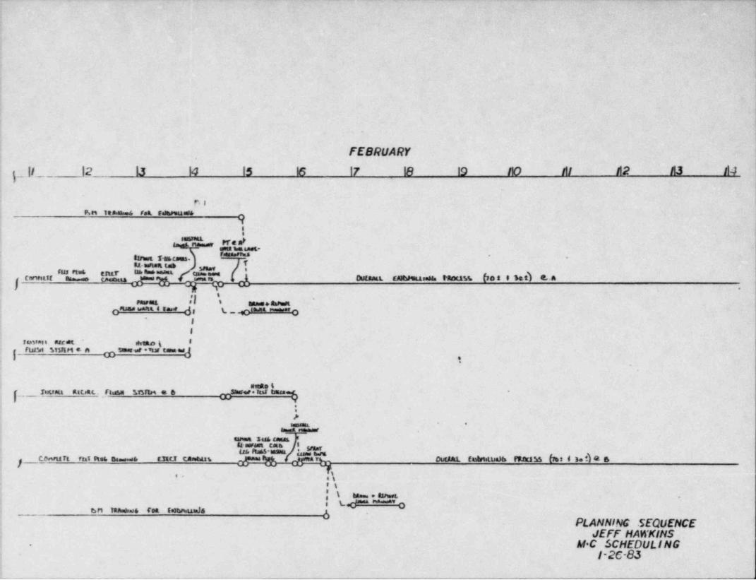
1
.
FEBRUARY'
$. |I._ |2 I3 14 |5 16 17 18 19 I10 Al n2 n3 Il4'
BI| P,n ten.is & ret selwesaas
i 91
"""n'.E , Pra mP.
uset M Lass *I ''''''"'** *
-tinut T-scaans.u-estest tat T." 'rus n=6 r IM' h=* *mani,
emsans c,m,a,.,. ,m. rharam s astm us.na. Nacin (f a t 0 Set) e. Acanntit as u
8 ,, .,. *
I FeePE me Anmest
| C * * **** di L--C " " 3*
II
raneani arc M. si1ao g 8
runne sisun e a sumers ins can= =,3
i ni a. t_Ingr Att Ritett. flisyg if5fts4 a6 Sharereled taas
! :?
*
j i ?"'"avi.= sus aus1
i u wan ens eus n s-insia ; *, m
ourm edn.te ranass bei i ud a sco-u rt na as si . asti taauss rj
'- .ses-
*\ se u n e.! Le ~' o
.
4 sn Tan . rea ren.u.Ja 3PLANNING SEQUENCE,
i JEFF HAWKINS -: - M C SCHEDULING
l-2C-83
__ _ _ _ _ _ _ _ _ _ _ __
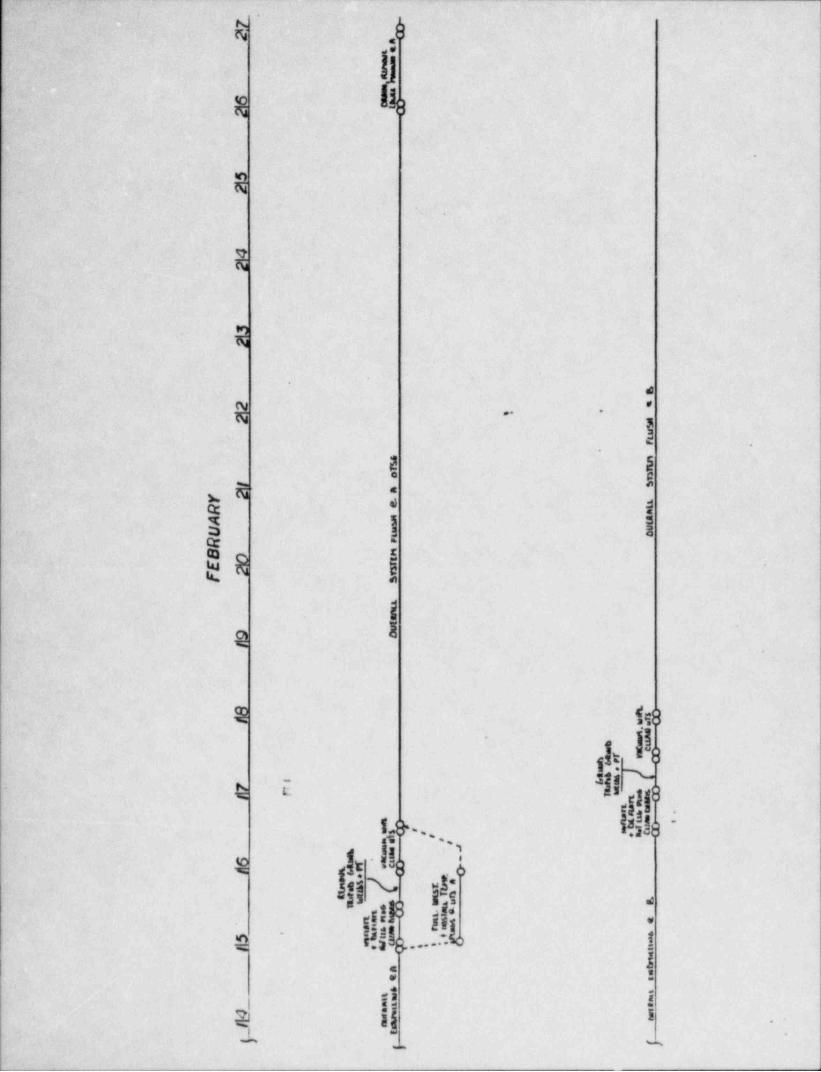
~ F ,4
s k.
n
E
.e
d.
M ...
l .
a: I-nw ,= s3 I i%t R l .
Ie
e 158
IIq,L
s~
k e
'# ' ~ $ 9:% ~.';a
},5N -
it *
r!)8 ;*
'et6...!.'L;^
=i: -
.,
R Il ! .
- N
_
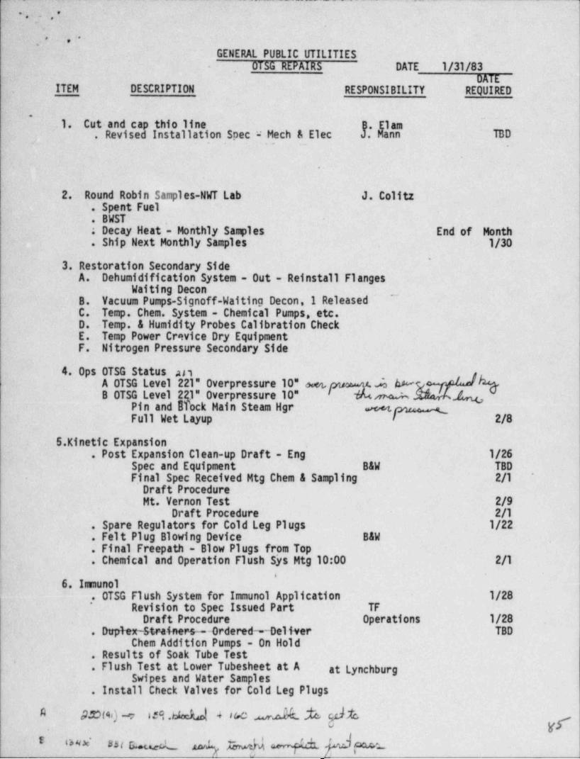
n __ ._. - . _ _
~
.9 . -
-
. 7, , . .,
GENERAL PUBLIC UTILITIES,
DT5G REPAIRS DATE 1 /31/83-
DATE.- ITEM DESCRIPTION RESPONSIBILITY REQUIRED
~~
.1. Cut and cap thio line . . B. Elam. ...-Revised Installation Spec Mech & Elec J. Mann TBDt . . .. .-
.
.
2. 'Round Robin Samples-NWT Lab J. Colitz.- Spent Fuel. BWST' . . .
End of . Month. Decay Heat - Monthly Samples. Ship-Next Monthly Samples 1/30
3. 'estoration Secondary Side'
R
A. Dehumidification System - Out - Reinstall FlangesWaiting Decon
~
B. _ Vacuum Pumps-Signoff-Waiting Decon,1 ReleasedC. Temp. Chem. System - Chemical Pumps, etc.D. Temp. & Humidity Probes Calibration CheckE. Temp Power Crevice Dry EquipmentF. Nitrogen Pressure Secondary Side
4. Ops OTSG Status anA OTSG Level 221" Overpressure 10" oet, AW kB OTSG Level 2R1" Overpressure 10" m Q
Pin and ITock Main Steam Hgr eFull Wet Layup 2/8
.5. Kinetic Expansion. Post Expansion Clean-up Draft - Eng 1/26
Spec and Equipment B&W TBD- F.inal Spec Received Mtg Chem & Sampling 2/1
*
Draft ProcedureMt. Vernon Test 2/9
Draft Procedure 2/1.-Spare Regulators for Cold Leg Plugs 1/22. Felt Plug Blowing Device B&W. Final Freepath - Blow Plugs from Top. Chemical and Operation Flush Sys Mtg 10:00 2/1
'6.~Innunol4
. OTSG Flush System for Immunol Application 1/28' Revision to Spec Issued Part TF
Draft Procedure Operations 1/28,
. D plerstraf r.;r: =-Ordered -Deliver TBDChem Addition Pumps - On Hold
. Results of Soak Tube Test' - . Flush Test at Lower Tubesheet at A at Lynchburg
Swipes and Water Samples. Install Check Valves for Cold Leg Plugs
0.blackM 4 sw .wndh. M [fcA S.t(44) w 13
'
m wa_ 4 4 4 Qewc rw
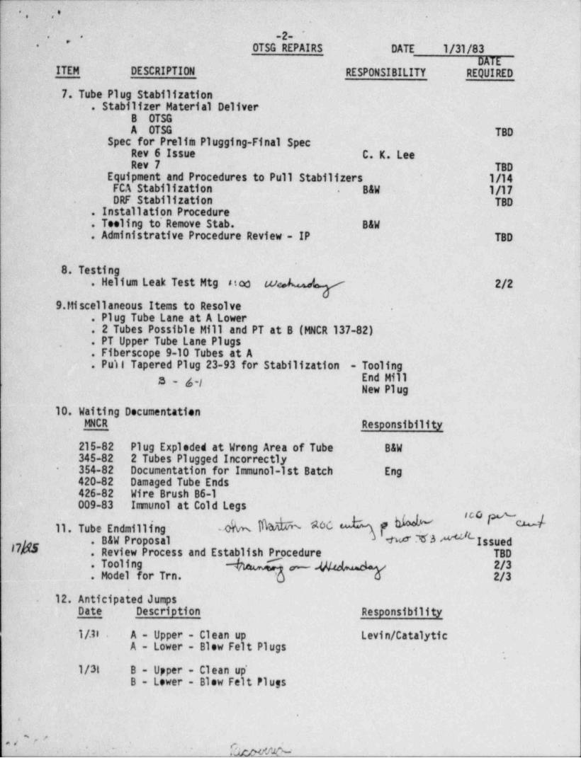
,
3 .,e
-2- '
. .' "
0TSG REPAIRS DATE 1 /31/83-
DATEITEM DESCRIPTION RESPONSIBILITY REQUIRED
7. Tube Plug Stabilization -. Stabilizer Material Deliver -
B OTSG'A ~ MM -
. TM' Spec for Prelim Plugging-Final Spec
Rev 6 Issue C. K. LeeRev 7 TBD
Equipment and Procedures to Pull Stabilizers 1/14FCA Stabilization B&W 1/17-
.
DRF Stabilization TBD'.
. Installation Procedure
. Teeling to' Remove Stab. B&W
. Administrative Procedure Review - IP TBD
8. Testin. He ium Leak Test Mtg stoc cu 2/2
9. Miscellaneous Items to Resolve .
. Plug Tube Lane at A Lower
. 2 Tubes Possible Mill and PT at B (MNCR 137-82)
. PT Upper Tube Lane Plugs.
. Fiberscope 9-10 Tubes at A.
. Puii Tapered Plug 23-93 for Stabilization - ToolingEnd Mill3 g.fNew Plug
10. Waiting DocumentationMICR Responsibility
215-82 Plug Exploded at Wrong Area of' Tube B&W4
345-82 2 Tubes Plugged Incorrectly354-82 Documentation for Immunol-1st Batch Eng
-
.
420-82 Damaged Tube Ends426-82 Wire Brush B6-1009-83 Imunol at Cold Legs
11.TubeEndmilling- M b b MO f. B&W Proposal N I3 ' Issued
17M . Review Process and Establish Procedure TBD
$Mo 1 or Trn. /
12. Anticipated Jumps.
Date' Description Responsibility
-1/.11 - A - Upper - Clean up Levin / Catalytic-
A - Lower - Blow Felt Plugs,
1/31 B - Upper - Clean up'B - Lower - Blow Felt Plugs
-
,
' * . .
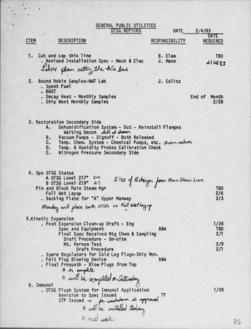
, _7-_ _. _
,
f,;,
+ .
.. ,
3- GENERAL PUBLIC UTILITIES.OTSG REPAIRS DATE -2/4/83
*
DATEITEM DESCRIPTION . RESPONSIBILITY REQUIRED
L1. Cut and cap thio line B. Elam -TBD. Revised Installation Spec - Mech & Elec J. Mann. g| g g :
H YNON ~
2. Round Robin Samples-NWT Lab J. Colitz,
. Spent Fuel
. BWST
. Decy Heat - Monthly Samples - End of Month
. Ship Next Monthly Samples 2/28_ .
_
3. Restoration Secondary SideA. Dehumidification S stem - Out - Reinstall Flanges
Waiting Decon .4 h.
''
B. Vacuum Pumps - Signoff - Both ReleasedC. Temp. Chem. System - Chemical Pumps, etc. %MD. Temp. & Humidity Probes Calibration Check<
,
E. Nitrogen Pressure Secondary Side4
'.
I4. Ops OTSG Status
iUS:t:':1IF,:0 ''M "r /~ " """5;' '
Pin and Block Main Steam Hgr TBDFull Wet Lyup 2/6 '
.
. Backing Plate for "A" Upper Manwy 2/3
well fece bok 6I" *dfM1
5. Kinetic Expansion! . Post Expansion Clean-up Draft - Eng 1/26.
Spec and Equipment. B&W TBDFinal Spec Received Mtg Chem & Sampling 2/1
Draft Procedure - On-site -
Mt. Vernon Test 2/9|. Draft Procedure 2/1| . Spare Regulators for Cold Leg Plugs-Ship Mon.,
( . Felt Plug Blowing Device B&W ... ,'
. Final Freepath - Blow Plugs from Top! A A r 44
6. Immunol,
. OTSG Flush System for Immunol Application 1/28Revision to Spec Issued TFSTP Issued , pA4
4 A ~24J.gS~ M' m
. .
-- . _ _ - - -
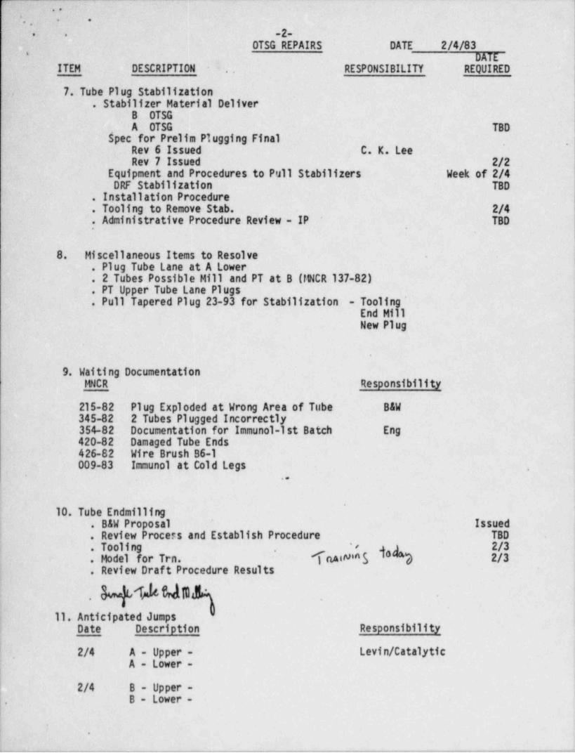
r.. ,
~ ' .' . ; '
- -
2-7. ..
- -
OTSG REPAIRS DATE 2/4/83*
DATE-ITEM DESCRIPTION . . RESPONSIBILITY REQUIRED
-
7. Tube Plug Stabilization,
. Stabilizer Material DeliverB OTSGA OTSG TBD
Spec for Prelim Plugging Final, ,
Rev 6 Issued C. K. LeeRev 7 Issued 2/2
Equipment and Procedures to Pull Stabilizers Week of 2/4DRF Stabilization TBD
. Installation Procedure
. Tooling to Remove Stab. 2/4
. Administrative Procedure Review - IP TBD,
8. Miscellaneous Items to Resolve - !
. Plug Tube Lane at A Lower
._ 2 Tubes Possible Mill and PT at B (IWCR 137-82)
. PT Upper Tube Lane Plugs
. Pull Tapered Plug 23-93 for Stabilization - Tooling'End Mi'lNew Plug
9. Waiting DocumentationMNCR Responsibility
215-82 Plug Exploded at Wrong Area of Tube B&W345-82 2 Tubes Plugged Incorrectly354-82 Documentation for Immunol-1st Batch Eng420-82 Damaged Tube Ends426-82 Wire Brush B6-1009-83 Immunol at Cold Legs .
- ..
i'
'10. Tube Endmilling'
i . B&W Proposal Issued ,
F . Review Process and Establish Procedure TBD [.
9 2/3i . Tooling TrwN*$ g$ 2/3.
'
. Model for Trn. ,
. Review Draft Procedure Results
| . ,
11. Anticipated Jumps.
; Date Description Responsibilityt
i 2/4 A - Upper - Levin / Catalytic,
A - Lower -7
1c
2/4 B - Upper -,
B - Lower -,
'
.
_..,.,,_-%,e .,m, ,,,,y,.y_ 7,,, ,,e<e-rr w-. - , . - , , . es2.r..__,,.,.,...,_%- ____,,.y-, ,,,,,,-,--9y, _ , , . w
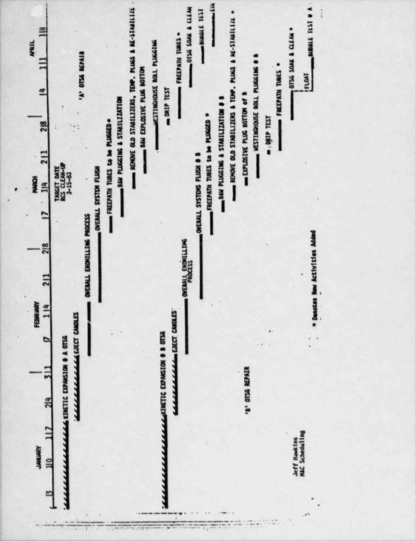
. ._ _ _ --- _ _. --
.
=, s $
-*
e-
! i3
gII ,=
3|.-5 =-
* =a
i.- ! !-11|
-
I j i.
.g I,! ,sii:18
! 4|# '=gI t g= '
|;!I|g's nj|i*I'.
- n
!l: .~ '"~
,jlIgi*,2t'
yl ll||l|. :s-n-|l=s Illl
'
glh n
Il 1|- 1 1-
l g.
..
l I| gll1-
^
; ,, a_- 3
-
E-
'$2 .E"Ee
|~I,
*.
f | -
e .-
M
.-..
:g g ,3-
g'"* - - -* -
.:a,
r s ~ ,
I I 'Im
=hh=
,
-'
-
.?
.E.j;
3c| a - a
.m
-.* * - - ~ ~ - - - , . . . . . , , , , , **'**
. . . . . . . . . . , , , ,,,,,......:.-
, , , .= . ,, :
''~'I~ **7.-,;,---..
- - - . _ . . - . . . - . . - - - .- _ . . ,_ _ - - , . - _ _ . _ _ - - _ . _ _ . . . _ - - . ,
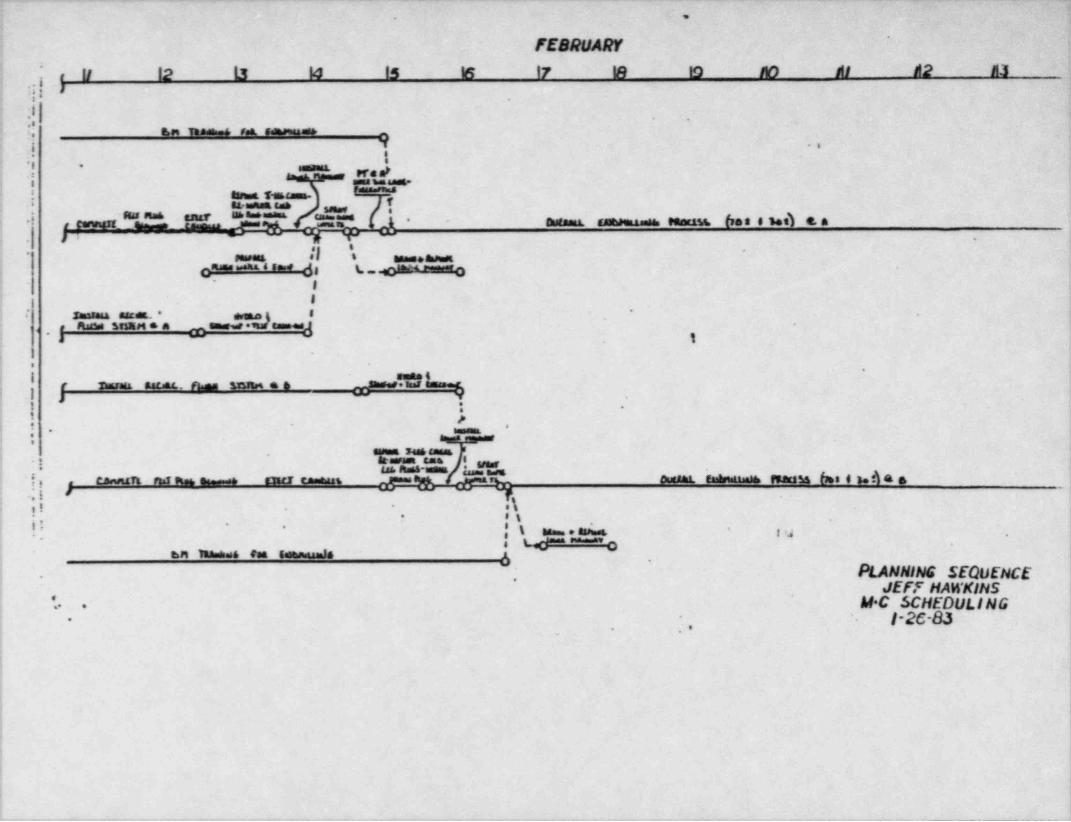
- _ . - - . _ - . _ _ _ - - - - . . _ . , . - . .. _ .
. ,
FEBRUARY'
!12 Li lo is E 17 m to ao As d2 a3
;i .j , Wi:* .
|||-i
~ *
j u___,_____ _
i :i 1 ..
! pre d ,' "
==nansa
! annes s e cas{{.
*
hun.sa.sah 3.,.,.,.,.1 -an n.s m e. .- - ameania. sammma-es, sessana, fee e see) e. ae.nir3 ,eennsu- - -p
i si- -
-. ,
. *! el
..
i sewes i an .ainsa
c""' "''' ' ~ ~ ^ d 8 L- ednesassano* I
31
1 : ammina asear - g .
-
a Rasass SesE M * a ensesaarammnes]4 ,
3 1;
;. .
*
I sene tr - - . . -- sann a a p mir-
i : .
l. .
immL* ** *
,
.,- 't 2 ,: * '::= . "'
w, ness mes ;.-
!, ca ua a. e - -e aimani. em maissa 6.. e un a . ,,
i .; i '.\: ,i .
-
*t-; ,
! !' 's m . ami a'
' -* * W ~a
.
;, ,,,w=._____._,
PLANNING SEQUENCE r
.
_
'
. ,
JEFF HAWKINS'. M C SCHEDULING.-, .
'I-26-83i -
; ..i
..
1
ii :
1
1 1,4
I
!!,
a
|4
_ . _ _ . _ _ _ _ _ _ _ _ . _ _ _ _ _ _ _ _ _ _ _
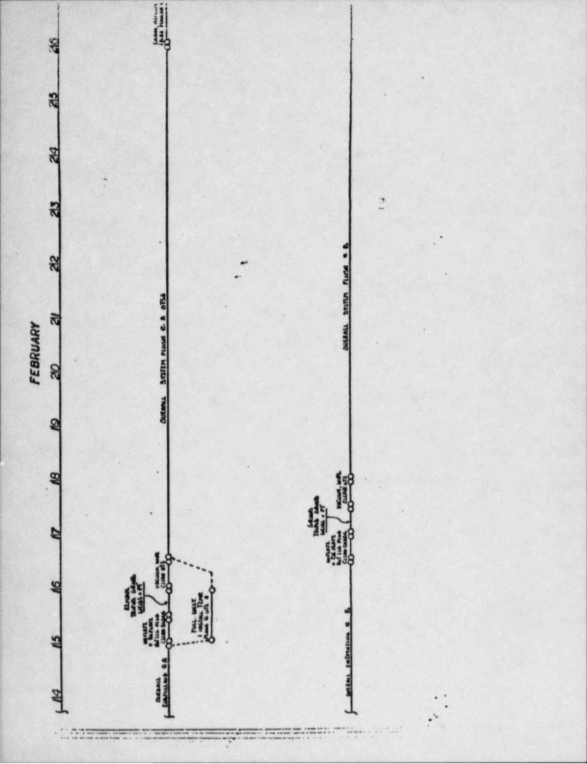
f% -h
.
N-
.
'
E
:
E?
-. 'd
,
.
p .
) ..-
i .
a. . .
|'
.
Is l~
Ie.
,% (g .'
hs ..
. -
I~il"4r
I 1}l8#
,, i
3 4.
1 *
lNgg!!s .j * '... .:L . [P.
,a: (|1
-
1,:\ |f I . . -
--, ,
-
-
' :: 51===.= == -- - _ -- _-t__==-==--=-...-_
-. - . . . . . _ .
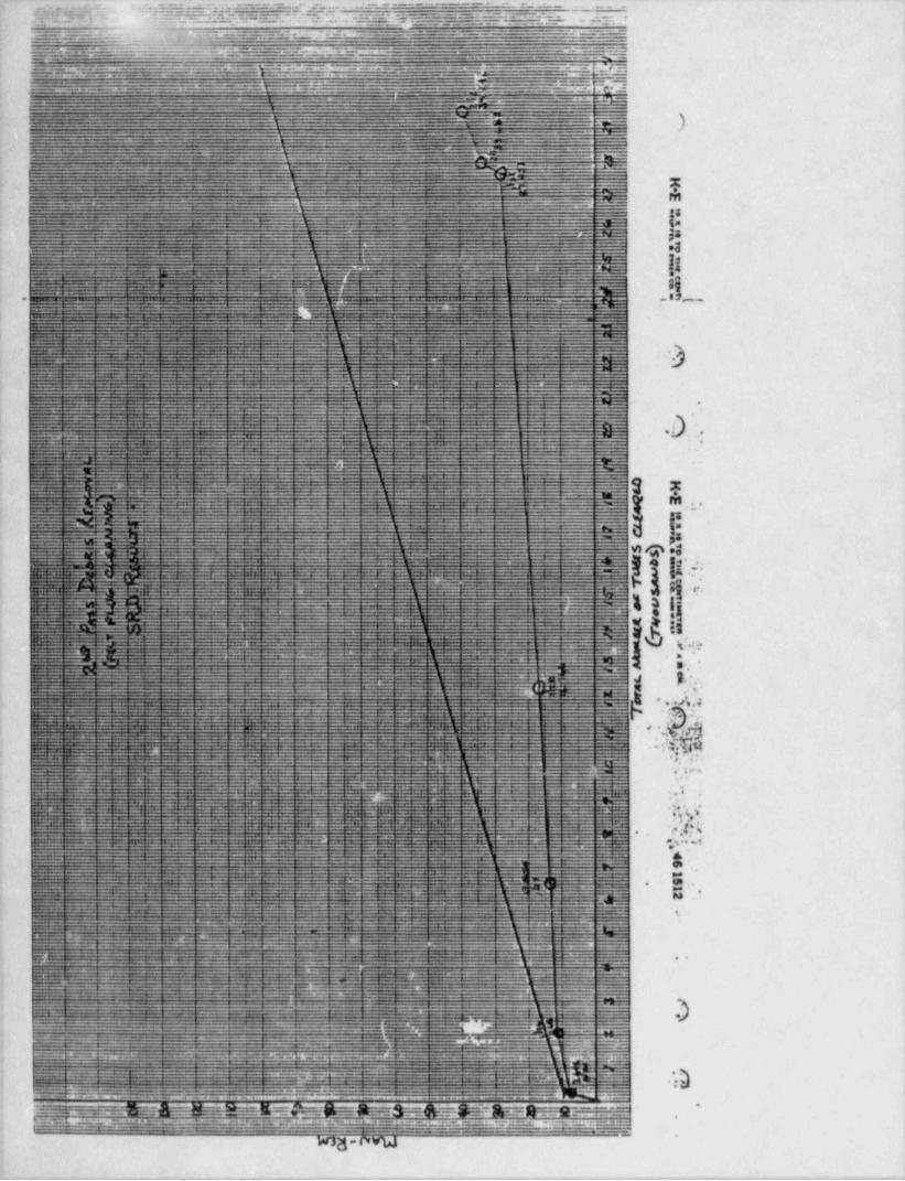
. .~ ~ .:,=.***'.6.".*,"l',.*:.3%~~"*~~~-..'''Cae .d.*"~~~~~^' ~ %-^-- * ~ - -
, = ~ .2[,. . . .'?.'~~~^ _(~~5h5'* ;j'.4.ZK~f"f" ,;=':..'~y'~~. ~~ - - - - . ~T-} , ;~~
* ~,
LKT .'"~B.~. ~.d":L };__ _..V'''''.**.~~=.~
'
.a. - = . - - --- - ::= - " ---.=.: ---=:= -.: z - :, .-:.--- ..*
~~~~- ~ - -
. . . . . , _ _ . - - . . - . . - - - -. - , - - . ~ - -----
, 7 - A w ,
"E=---,.:,.:.._-.-=..=__...-=.%===.=..=.---~.:=--__-------_-=-e--e *~+ -+* %
=~; ._ - - . . .-
--..-==~:L'i=- --
;;
-._ __.,=- ._.__ . . _ _ _ _ _.- _ _---
__ _ _ _ _g , _ ,
___ _ . _ _ _ _ - __ _ _ _ .__ _ _ _ _ _ . _
_ .
mm*
-_
.-- - - - - - M
-
.g
I8is
3
11 '
:f !e.*es _.
.*s
.
0.L.. .
.
M . ., .I3
|na q .g
d.E.
.P,
% 3 i.i **W
I.
Q!.m*n
5g*
.
f.:,. .. . -3b *. u*..;?, Gr :, :a. . y.;, $1
1;. :. v. ..
. b
.-
. . 9, |?;, j; * |.
p .e ,
6' |ee.GB ,.meN
e.|
:i
( 9 |
k
7'
e) \
_-
,1-
.
"
. _ _ , _,mv
$ -n-.v...i sw eee .
N .
_ . - ._ .e . - b . - ..
.. e*A - mO WW .
,
g~ --ky;,,.h-- . ~
~ _ wl. -,_ ' ~ ' E~~?' ' '
b.fE* A^ Y *- ~ SEj; __~.
wag-oww
. _ _ _ _ . ._ __ _ _ . . _ _ _ _ . _ _ _ _ __ - .-.. -- -_. . .. . - - .