restricted - index of
TRANSCRIPT
RESTRICTED
JME Vol. 74 1 RESTRICTED
JME “The Prime Mover”
The Alma Mater of THE PROFESSIONAL JOURNAL OF Marine Engineers MARINE ENGINEERING Volume 74 Jul 17
‘ONBOARD ENERGY MANAGEMENT AND
ENVIRONMENT PROTECTION’
Ser Contents Page 01. Trials with Bio-Diesel on a Marine Diesel Engine in 14
Indian Navy Capt Mohit Goel, NM
02. Energy Savings Through Optimizing Machinery 21 Load and Exploitation Cdr M Sujit
03. Oil Water Separation Using Magnetite Powder 31 Applications Cdr Ayyappa Ramesh, SLt Hitesh Rana, SLt Vinay B Sonna, SLt Sudeep Pilpia, SLt Aradhya Kumar
04. Waste Heat Recovery System (WHRS) 37 Lt Cdr NS Kaushik
GENERAL MARINE ENGINEERING / NOTES FROM SEA 05. Innovative Repair of SME CAC at Sea – INS Tir 45
Cdr Samir Bera, Lt Cdr BK Ganapathy 06. A Short Note on Understanding Diesel Transients 53
in the Framework of Indian Naval Requirements Cdr Girish Gokul
RESTRICTED
JME Vol. 74 2 RESTRICTED
07. Innovative Arrangement for Measurement of Suction 67 Rate of Submersible Pumps – INS Deepak Lt Cdr Nanda Kumar
08. CFD Analysis of Plane and Circular Couette Flow 71 Lt Cdr Pranit Himanshu Rana, Mid Shashi Kumar, Mid Ayush Kumar, Mid Amit Singh
09. Defect Rectification on Port Stabiliser - Teg Class 77
Lt Sunit Sharma 10. Knowledge Enabler Bay – GTTT (Mbi) 88
Cdr AP Singh 11. Experimental Investigation and Analysis of Friction 95
Stir Welding Lt Cdr Vivek Anand, Cdt KP Vignesh Rao, Cdt Shakti Kumar, Cdt Piyush Bhatt, Cdt Akash Sharma
12. Sea State 6 – Poem 106
Lt Vipul Ruperee Staff Student Projects 107 Kaleidoscope of Development & Training Activities 115 Undertaken at Shivaji On the Horizon 126 Awards 137
RESTRICTED
JME Vol. 74 3 RESTRICTED
LETTERS TO THE EDITOR 1. Thank you for forwarding me the 73rd edition of the Journal of Marine Engineering ‘The prime mover’ vide your DO letter DO/242/KPA dated 03 Mar 17 2. The Journal is very interesting and informative. I am sanguine that the theme of this issue ‘Innovation in Marine Engineering- Need of the Hour’ with its special focus on ‘Innovation’ will surely benefit and inspire many of our Engineers.
3. I take this opportunity to congratulate the editorial team of the journal and you, on bringing out a highly informative edition Admiral Sunil Lanba, PVSM, AVSM, ADC Chief of the Naval Staff Integrated Headquarters Ministry of Defence (Navy) New Delhi 110011
**** 1. I thank you for your letter DO/242/KPA of 08 Mar 17 forwarding a copy of the 73nd edition of Journal of Marine Engineering. “The Prime Mover” based on the theme ‘Innovation in Marine Engineering- Need of the Hour’ with particular emphasis on Naval Platforms. 2. I have found contents of the Journal very interesting and informative especially on important issues pertaining to Marine Engineering. The articles on Installation of Indigenously Developed Quick Reaction, Early Warning, Fire Detection and Monitoring System, Water Mist Fire Fighting System, Innovative Measures to Enhance Reliability of Ship’s Boats, Assistance rendered to MCGS Barracuda and Free Rotation of Power Turbine in Operative Gas Turbine are very interesting and highlight innovation in Marine Engineering.
RESTRICTED
JME Vol. 74 4 RESTRICTED
3. My heartiest congratulations to you and editorial team for bringing out an informative and exhaustive professional publication of Marine Engineering. On behalf of all of us here at Ship Building Centre, Visakhapatnam, I wish team Shivaji all the very best in all future endeavors. Vice Admiral KO Thakare, AVSM, NM Project Director Ship Building Centre Krishna Gate, Naval Base Post Visakhapatnam 530014
****
1. Thank you very much for forwarding the 73rd Edition of the Journal of Marine Engineering “The Prime Mover."
2. Please convey my appreciation to the editorial team for compiling such a professional Journal showcasing the innovations in day to day work on board naval platforms and repair yards/establishments.
3. The article on “Free Rotation of Power Turbine of Inoperative Gas Turbine due to Wind- Milling Effect – Kolkata Class Ships” made interesting reading aptly outlines important issues w.r.t inoperative GTs. 4. I wish you and Team Shivaji all the very best in all future endeavors.
Vice Admiral DM Deshpande AVSM. VSM Controller of Warship Production & Acquisition 126 C- Wing Sena Bhawan IHQ MOD (Navy) New Delhi- 110011
****
RESTRICTED
JME Vol. 74 5 RESTRICTED
1. Please refer to your letter DO:242/KPA dated 08 Mar 17. 2. At the outset I would like to thank you for forwarding a very interesting, informative and enriching journal. The theme of the present edition “Innovation in Marine Engineering – Need of the Hour” is indeed an apt and worthy topic in the present day scenario.
3. I take this opportunity to congratulate you and your team on this commendable work and wish you all success in future endeavours. Vice Admiral Atul Kumar Jain, AVSM, VSM Chief of Staff Headquarters Eastern Naval Command Visakhapatnam – 530014
****
1. Refer to your DO letter DO:242/KPA dated 08 Mar 17. 2. At the outset, let me thank you for sending the college a copy of the 73rd edition of the Journal of Marine Engineering, “The Prime Mover”. The Journal and its articles are of relevance to the Navy and make an excellent read. I am sure that it would be of immense value to the participants of the ongoing NHCC and the forthcoming TMC courses and would help them in their research on engineering related topics. 3. Do convey our felicitations to all those involved in putting together this fine publication. We would be placing it in our library to enable greater circulation. Rear Admiral Monty Khanna, AVSM, NM Commandant Naval War College INS Mandovi Verem, Goa 403109
****
RESTRICTED
JME Vol. 74 6 RESTRICTED
1. Refer to your letter DO:242/KPA dated 10 Mar 17. 2. Thank you very much for forwarding a copy of a very interesting 73rd edition of the Journal of Marine Engineering ‘The Prime Mover’. My congratulations to the editorial team and all those who contributed towards making this edition a very interesting read.
3. Wishing you and the editorial team all the very best in the years ahead.
Rear Admiral Suraj Berry, NM, VSM Assistant Chief of Personnel (HRD) 220,C-Wing Sena Bhawan IHQ of MoD (Navy) New Delhi 110011
****
1. Thank you very much for forwarding the copy of 73rd edition of the Journal of Marine Engineering ‘The Prime Mover’. Indeed, the contents of the publication are very informative and the underlying theme of Innovation is a well chosen one. Please convey my compliments and best wishes to the editorial team. 2. I take this opportunity to wish you and team INS Shivaji success in all future endeavors. Rear Admiral Sandeep Naithani, VSM Chief Staff Officer (Technical) Headquarters WNC Ballard Pier, Tiger Gate, Mumbai 400001
****
RESTRICTED
JME Vol. 74 7 RESTRICTED
1. Please accept my sincere thanks for 73rd edition of the journal of Marine Engineering “The Prime Mover”. 2. The contents of the Journal, based on the theme ‘Innovation in Marine Engineering - Need of the Hour” make interesting reading and provide useful insights into the current development in the field Marine Engineering. Some of the technologies covered, such as those related to the water mist fire Fig.hting system and RO plants are also being actively looked at for ongoing at future design projects. 3. I would also like to make a special mention of the Staff-Students Projects undertaken by MESC course which finds a place in the journal. The projects selected are of practical utility on board naval platforms and repair yards and the experience of these projects would be of significant benefit to the students in their future appointments.
4. I take this opportunity to complement the editorial team of the JME for bringing out this insightful journal which also reflects the dynamism of the institution itself. I take this opportunity to wish INS Shivaji to greater success in the years ahead. Rear Admiral Chandra Shekhar Rao, NM Director General Naval Design(SDG) West Block-5 RK Puram New Delhi-110066
**** 1. I am writing this letter to express my appreciation for the 73rd edition of the journal of Marine Engineering ‘The Prime Mover’. 2. The JME has matured over the years and has emerged as a credible technical forum for the mechanical engineering fraternity of the Navy. The Mechanical Engineering cadets at INA undertake Technical Term Paper study, Minor Project and Major Project in Term VI, VII & VIII respectively. The topics chosen for research work pertain to the latest innovation in the field of Mechanical/Marine Engineering and relevant applications
RESTRICTED
JME Vol. 74 8 RESTRICTED
3. The technical reports submitted by the cadets are exhaustive as well as technology - intensive. Some of these reports (the best major projects or technical term papers) is proposed to be considered for inclusion in the succeeding editions of JME as regular feature by way of an article. This would not only motivate the young Mechanical Engineering cadets but also ensure required academy grooming towards meeting the desired end state envisaged. 4. A special word of appreciation for Captain S V Shidore, Oi/CMET (Chief Editor of JME) towards establishing two way communications with INA/HoF (ME) and ensuring the availability of credible inputs at ab-initio level on regular basis. The feedback provided by INS Shivaji has gone a long way in preparing the young cadets for further downstream training. I wish the entire team of Shivaji the very best in all feature endeavors Rear Admiral Amit Vikram Principal Indian Naval Academy Naval Academy PO District Kannur, Kerala 670310
**** 1. Refer to your DO letter DO:242/KPA dated 08 Mar 17. 2. Thank you for forwarding a copy of Journal of Marine Engineering, “The Prime Mover” Vol 73. I congratulate the editorial team for a slickly produced journal with thought provoking articles covering both emerging technology and solutions to problems being encountered on ships. 3. The thrust on producing implementable solutions through project work in tune with the changing times and emerging technology is noteworthy, particularly development of Early Warning Fire Detection System, of sufficient refinement for installation of an FAC and the study on Aluminum Foam. I trust in the coming years these efforts will play an important role in ensuring greater indigenous content in our ships.
RESTRICTED
JME Vol. 74 9 RESTRICTED
4. I take this opportunity to wish you and your team good luck towards your pursuit of transforming young officers into accomplished Marine Engineers. Rear Admiral AK Saxena, NM Director General Naval Design IHQ MOD(Navy) Directorate of Naval Design A-33 Kailash Colony, New Delhi 110048
****
1. Thank you for sending me a copy of 73rd edition of the Journal of Marine Engineering “The Prime Mover”. I have perused the magazine and was highly impressed with the content and presentation, both of which are of a very high quality.
2. I congratulate and your editorial team for their excellent work and wish you all the very best in all your future endeavors. Rear Admiral RJ Nadkarni, VSM Chief of Staff Headquarters Sourhern Naval Command Kochi - 682004
****
1. Please refer your DO letter no DO/242/KPA dated 06 Mar 17 with the copy of the 73rd edition of the Journal of Marine Engineering 2. Please accept my compliments on well thought out theme of the journal and the high quality of the articles included.
3. The article on “Efficacy of 3D Metal Printing in Fleet Ships” and “Innovative Repair of RO Plants at Sea” made an interesting reading. The coverage of MESC staff student project in the journal should provide necessary impetus to student
RESTRICTED
JME Vol. 74 10 RESTRICTED
officers to showcase their ideas to wider marine engineering fraternity through JME. It was nostalgic to browse through the ‘Kaleidoscope of Development and Training Activities’ and heartening to note the major strides taken in this space. The initiatives taken towards the improvement of Sailors documentation deserve special mention. 4. Overall the JME made very interesting and informative reading. I convey my best wishes to the editorial team for having put together a fine journal of a very high standard.
Rear Admiral Dushyant Singh Chauhan, NM Commandant College of Defence Management Sanikpuri Post Secundrabad-500094
****
1. Many thanks for forwarding the 73rd edition of the Journal of Marine Engineering “The Prime Mover”. I found the Journal highly informative and well compiled. Please convey my compliments and best wishes to the editorial team. 2. I take this opportunity to extend my best wishes to Team Shivaji for a glorious future and greater accomplishments. Rear Admiral Dinesh K Tripathi, NM Assistant Chief of the Naval Staff (Policy & Plan) IHQ MOD (Navy) Room No. 25A, South Block New Delhi- 110011
**** 1. Thank you for forwarding a copy of the 73rd edition of the Marine Engineering Journal ‘The Prime Mover’. 2. The Journal comprising notes from sea, experience, sharing articles and articles on new technologies makes very informative reading. The theme of the journal ‘Innovation in
RESTRICTED
JME Vol. 74 11 RESTRICTED
Marine Engineering – Need of the Hour’ is very apt and keeping in with the vision of IN. The article on ‘Recounting the Retubing – INS Jalashwa’, elaborately highlights the mammoth tasks undertaken by ND(V) in retubing of Ships Boiler Tubes. On the other hand, the article on ‘Innovative Measures to Enhance Reliability of Ship’s Boats’, describes sustainable, innovative measures being applied on ships.
3. I would like to congratulate the Editorial Team for preparing a well written journal and take this opportunity to wish ‘Team Shivaji’ in all future endeavors.
Commodore Sunil Kaushik Principal Director Marine Engineering IHQ MOD (Navy) Room No. 306, ‘C’ Wing Sena Bhawan New Delhi – 110011

RESTRICTED
JME Vol. 74 12 RESTRICTED
FROM THE CHIEF EDITOR’S DESK
1. The world today is grappling with crisis of drastic climate change, the process of which can be delayed or hastened by our future course of action. The numerous accords and deals signed by our Government at various international forums highlights the recognition of the crisis at hand and also provides a road map to each one of us as citizens, institutions or organizations to work towards the common goal of a cleaner environment and ensure that we leave a healthier planet for the generations to come. 2. War and protection of environment are diametrical opposite ends of the spectrum. However, as a responsible blue water Navy, the Indian Navy has taken small but definite steps towards preserving clean and green environment. With more than 150 warships operating across the globe, IN recognizes that the colossal task of environment preservation can be impacted by small contributions in reducing its carbon foot print. While our Navy strives to be a cleaner and a greener force, the 74th edition of Journal of Marine Engineering has incorporated articles with the subject “Onboard Energy Management and Environment Protection”, in keeping with UNESCO’s theme for the year 2017 ‘Connecting to Nature’, to make the Journal a platform to connect Marine Engineers onboard ships with nature and encourage innovative steps that can help us save the environment in our own small and efficacious ways. 3. The present edition of JME Vol 74 discusses issues such as new technologies and methods to increase the efficiency of our machines while reducing the impact on the environment, ingenuity shown while carrying out repairs/ maintenance, Defect Investigation/ Defect Rectification activities at sea, thesis on specific challenges and trivia. The innovative projects taken up by student officers of this unit also find place in the journal. A brief on training activities at the Engineer’s Alma Mater, along with plans on the horizon for enhancing the quality of training are also included to give the Engineer’s vision. 4. I sincerely acknowledge the efforts of all those who have authored the articles of such high professional caliber and hope this edition, like always, proves to be a trove of knowledge which
RESTRICTED
JME Vol. 74 13 RESTRICTED
would help us learn and develop as able Marine Engineers with a thirst for knowledge. I would like to thank the editorial team, without whose relentless support this journal would not have been possible. I also would request our readers for their continued support and contributions by sharing their research work, anecdotes, experiences and suggestions, with greater zeal.
(Sumeet V Shidore) Captain Chief Editor
RESTRICTED
JME Vol. 74 14 RESTRICTED
GREEN FUELS – ARE WE READY? TRIALS WITH BIO-DIESEL ON A MARINE DIESEL ENGINE IN
INDIAN NAVY
Captain Mohit Goel, NM
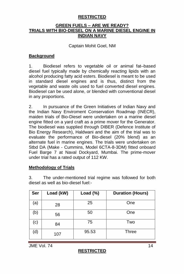
Background 1. Biodiesel refers to vegetable oil or animal fat–based diesel fuel typically made by chemically reacting lipids with an alcohol producing fatty acid esters. Biodiesel is meant to be used in standard diesel engines and is thus, distinct from the vegetable and waste oils used to fuel converted diesel engines. Biodiesel can be used alone, or blended with conventional diesel in any proportions. 2. In pursuance of the Green Initiatives of Indian Navy and the Indian Navy Enviroment Conservation Roadmap (INECR), maiden trials of Bio-Diesel were undertaken on a marine diesel engine fitted on a yard craft as a prime mover for the Generator. The biodiesel was supplied through DIBER (Defence Institute of Bio Energy Research), Haldwani and the aim of the trial was to evaluate the performance of Bio-diesel (20% blend) as an alternate fuel in marine engines. The trials were undertaken on Stbd DA (Make - Cummins, Model 6CTA-8-3DM) fitted onboard Fuel Barge 7 at Naval Dockyard, Mumbai. The prime-mover under trial has a rated output of 112 KW. Methodology of Trials 3. The under-mentioned trial regime was followed for both diesel as well as bio-diesel fuel:-
Ser Load (kW) Load (%) Duration (Hours)
(a) 28
25 One
(b) 56
50 One
(c) 84
75 Two
(d) 107
95.53 Three
RESTRICTED
JME Vol. 74 15 RESTRICTED
4. The following parameters were recorded:-
(a) Load, lub oil pressure, lub oil temp, fresh water temp, sea water pressure and exhaust temp were recorded from the DA control panel. (b) Exhaust emissions viz.; CO, CO2, HC and NOx were measured with a Portable Gas Analyser (Make CUBIC, Model GASBOARD-5020). (c) The reduction in level in the rectangular RU tank was recorded and thereafter converted into litres/hour to get the fuel consumption. Specific gravity of 0.85 and 0.88 was considered for diesel and bio-diesel respectively for calculating the specific fuel consumption.
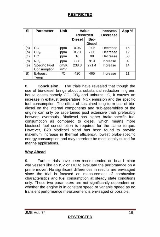
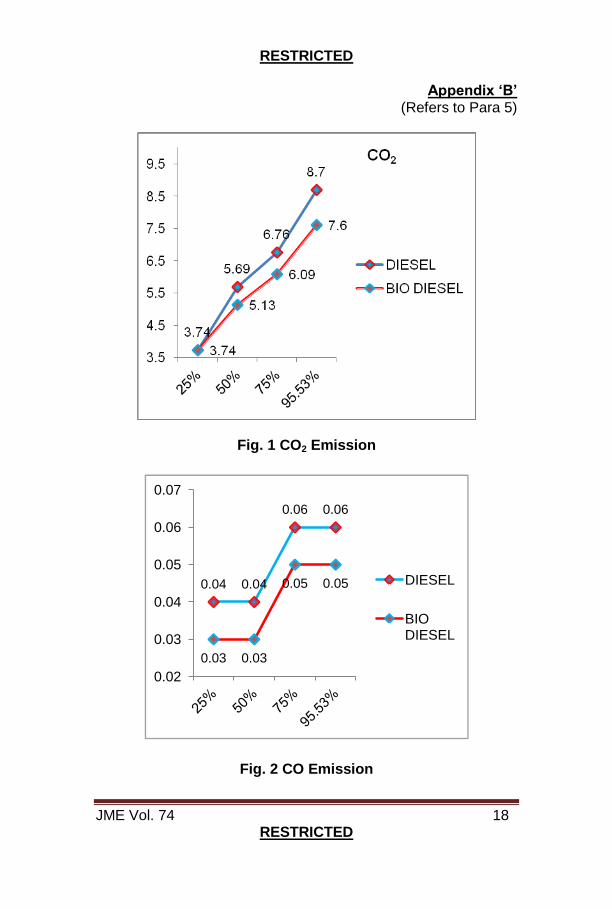
Findings of the Trial 5. The comparative sheet of parameters recorded during the trials is placed at Appendix ‘A’. The important findings of trials with bio-diesel are as below:-
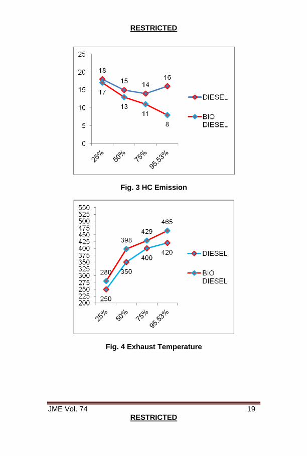
(a) Reduction in CO2 & CO emissions. (b) Reduction in unburnt Hydro Carbon (HC) emissions. (c) Increase in exhaust temperature. (d) Increase in NOx emissions. (e) Increase in specific fuel consumption.
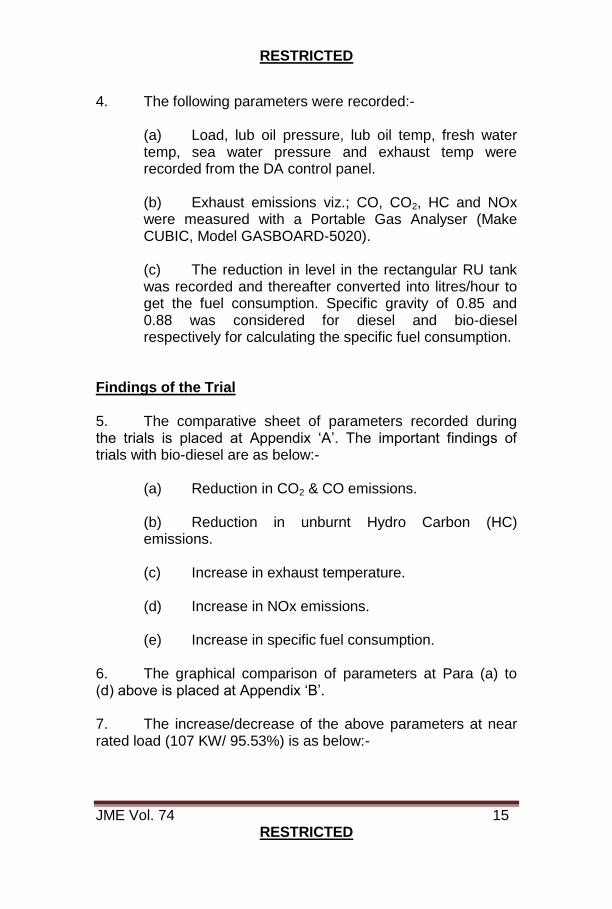
6. The graphical comparison of parameters at Para (a) to (d) above is placed at Appendix ‘B’. 7. The increase/decrease of the above parameters at near rated load (107 KW/ 95.53%) is as below:-
RESTRICTED
JME Vol. 74 16 RESTRICTED
Sl Parameter Unit Value
Recorded Increase/ Decrease
App %
Diesel Bio-Diesel
(a) CO ppm 0.06 0.05 Decrease 15
(b) CO2 ppm 8.70 7.60 Decrease 12
(c) HC ppm 16 08 Decrease 50
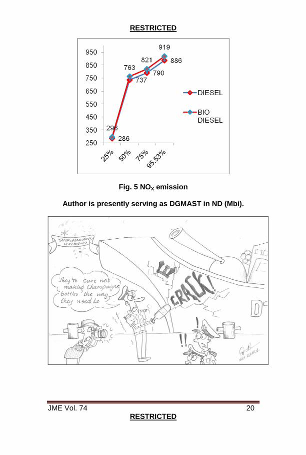
(d) NOx ppm 886 919 Increase 4
(e) Specific Fuel Consumption
gm/Kw/hr
238.3 271.4 Increase 14
(f) Exhaust Temp
ºC 420 465 Increase 11
8. Conclusion. The trials have revealed that though the use of bio-diesel brings about a substantial reduction in green house gases namely CO, CO2 and unburnt HC, it causes an increase in exhaust temperature, NOx emission and the specific fuel consumption. The effect of sustained long term use of bio-diesel on the internal components and sub-assemblies of the engine can only be ascertained post extensive trials preferably between overhauls. Biodiesel has higher brake-specific fuel consumption as compared to diesel, which means more biodiesel fuel consumption is required for the same torque. However, B20 biodiesel blend has been found to provide maximum increase in thermal efficiency, lowest brake-specific energy consumption and may therefore be most ideally suited for marine applications. Way Ahead 9. Further trials have been recommended on board minor war vessels like an ISV or FIC to evaluate the performance on a prime mover. No significant differences in results are envisaged since the trial is focused on measurement of combustion characteristics and fuel consumption at steady state conditions only. These two parameters are not significantly dependent on whether the engine is in constant speed or variable speed as no transient performance measurement is envisaged or possible.
RESTRICTED
JME Vol. 74 17 RESTRICTED
Appendix ‘A’ (Refers to Para 4)
Sl
Load (Kw)
Load (%)
Lub Oil F/W Temp (ºC)
S/W Pr (kg/cm2)
Exhaust Temp (ºC)
CO (ppm)
CO2
(ppm) NOx
(ppm) HC
(ppm) Temp (ºC)
Pr (kg/cm2)
D B D B D B D B D B D B D B D B D B
a. 28 25 82
84 3.5 3.5 82 78 0.4 0.4 250 280 0.04 0.03 3.74 3.74 286 296 18 17
b. 56 50 90
90 3.5 3.5 84 78 0.4 0.4 350 398 0.04 0.03 5.69 5.13 737 763 15 13
c. 84 75 93
92 3.2 3.5 84 78 0.4 0.4 400 429 0.06 0.05 6.76 6.09 790 821 14 11
d. 107 95.5 93
94 3.2 3.2 85 80 0.4 0.4 420 465 0.06 0.05 8.70 7.60 886 919 16 08
RESTRICTED
JME Vol. 74 18 RESTRICTED
Appendix ‘B’ (Refers to Para 5)
Fig. 1 CO2 Emission
0.04 0.04
0.06 0.06
0.03 0.03
0.05 0.05
0.02
0.03
0.04
0.05
0.06
0.07
DIESEL
BIO DIESEL
Fig. 2 CO Emission
RESTRICTED
JME Vol. 74 19 RESTRICTED
Fig. 3 HC Emission
Fig. 4 Exhaust Temperature
RESTRICTED
JME Vol. 74 20 RESTRICTED
Fig. 5 NOX emission
Author is presently serving as DGMAST in ND (Mbi).

RESTRICTED
JME Vol. 74 21 RESTRICTED
ENERGY SAVINGS THROUGH OPTIMIZING MACHINERY LOAD AND EXPLOITATION
Cdr M Sujit
Introduction 1. Energy saving or conservation refers to the reduction of energy consumption by using less of an energy service. Energy conservation is different from efficient energy use which refers to using less energy for a constant service. Driving less is an example of energy conservation. Driving the same amount with a higher mileage vehicle is an example of energy efficiency. Energy conservation and efficiency are both energy saving techniques. Energy conservation also aids in increased environmental quality. Further, it also lowers energy costs by preventing future depletion of non-renewable resources. 2. On board IN ships, “Energy Conservation” is to be given highest impetus during the design, construction and operation stages in order to contribute effectively against future resource depletion. This article brings out various methodologies and infrastructure available which may be implemented to ensure energy saving through optimizing machinery load and exploitation. Optimizing Machinery Load 3. Selection of energy efficient load determines the optimal operation/ utilisation of the generated power. The following are the types of loads which can be integrated in a conventional ship system for achieving better energy efficiency out of the machinery. 4. LED Lighting. Use of energy efficient Light Emitting Diode (LED) lighting in place of conventional lamps and tube lights on ship, contributes to more savings and add up to its energy efficiency model. An Incandescent Globe (bulb) can provide a life span of 1000 hrs and a fluorescent lamp can be used up to 7500 hrs. However, far better performance can be achieved by LED lights which have a lifespan of about 50,000 hours and 60% less energy consumption. Implementing this would not only reduce the no. of maintenance hours but also

RESTRICTED
JME Vol. 74 22 RESTRICTED
bring down the operating costs, which include the generator fuel cost and operation/maintenance cost of the lights. 5. Energy Efficient Motors. Using an energy efficient motor not only overcomes the losses experienced by conventional motors (iron loss, stator and rotor IR loss, frictional loss etc.) but also helps in saving power and improving efficiency, as it requires lower maintenance while still having longer running hours. These motors provide better performance even at low temperatures and the starting torque required is lesser than the conventional type of motors.
Fig. 1 Energy Efficient Motor 6. Electronic Soft Starters. Soft starters are used to help in smooth, step-less acceleration and deceleration of motors which in turn reduces damages to motor winding and bearings, leading to increase in the motor life. An electronic soft start has an advantage of providing improved power factor in hand while lowering mechanical stresses and maintenance.
Fig. 2 Electronic Soft Starter

RESTRICTED
JME Vol. 74 23 RESTRICTED
7. Slip Power Recovery System. Slip ring motors are installed for heavy loads (e.g. slip-ring brake motor of anchor windlass) onboard ships. Installation of slip power recovery system helps in better speed control of slip ring motors, which vary the rotor voltage and control the speed, by collecting the excess power from the slip and transferring it to motor shaft as mechanical or electrical power by utilising external resistors. The slip power recovery (SPR) drive is an external system connected to the rotor circuit in place of the external resistors. The SPR provides speed and torque control like the resistors but can also recover the power taken off the rotor and feed it back into the power system to avoid energy waste. However, as they have a drawback of supplying poor power factor, they are mainly used for high power rating systems.
Fig. 3 Slip Power Recovery Scheme 8. Energy Efficient Transformers. As the name suggests, this transformer has a major advantage of reducing the energy loss over conventional transformer by about 70%. This transformer uses amorphous material, metallic glass alloy, for the core. Other significant advantage of energy efficient transformers is to provide high efficiency even at low loads. At 35% load, approximately 98% efficiency can be achieved. Nowadays, most of the cruise ships are installed with energy efficient transformers.

RESTRICTED
JME Vol. 74 24 RESTRICTED
Fig. 4 Energy Efficient Transformers
9. Variable Frequency Drive. Variable Frequency Drive (VFD), also known as adjustable frequency drive, is normally used in electro-mechanical drives that utilise electric motor to control the speed and toque by adjusting the voltage and input frequency. VFDs can reduce the power consumption by as much as 60% when used for fan and centrifugal pumps. It also reduces the risk of cavitations in the pump. To get the maximum efficiency from the VFD, it is adjusted as per the load demand of the system. Large capacity pumps and fans, which are needed to run continuously at 100% load, will not be benefited from VFD in terms of energy efficiency.
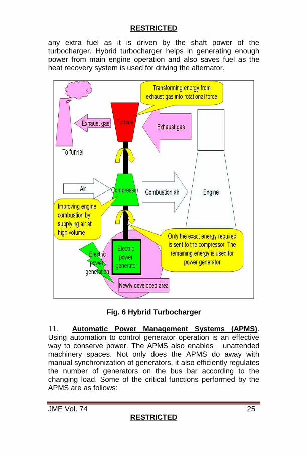
Fig. 5 Variable Frequency Drive 10. Hybrid Turbocharger. In Hybrid turbocharger, exhaust gas energy is recovered to turn a compressor, which supplies scavenge air to the main engine and also generates electricity through an alternator attachment incorporated in the turbocharger known as MET hybrid turbocharger. The turbine and compressor does the heat energy recovery work and the alternator is used to generate electrical power without consuming
RESTRICTED
JME Vol. 74 25 RESTRICTED
any extra fuel as it is driven by the shaft power of the turbocharger. Hybrid turbocharger helps in generating enough power from main engine operation and also saves fuel as the heat recovery system is used for driving the alternator.
Fig. 6 Hybrid Turbocharger 11. Automatic Power Management Systems (APMS). Using automation to control generator operation is an effective way to conserve power. The APMS also enables unattended machinery spaces. Not only does the APMS do away with manual synchronization of generators, it also efficiently regulates the number of generators on the bus bar according to the changing load. Some of the critical functions performed by the APMS are as follows:
RESTRICTED
JME Vol. 74 26 RESTRICTED
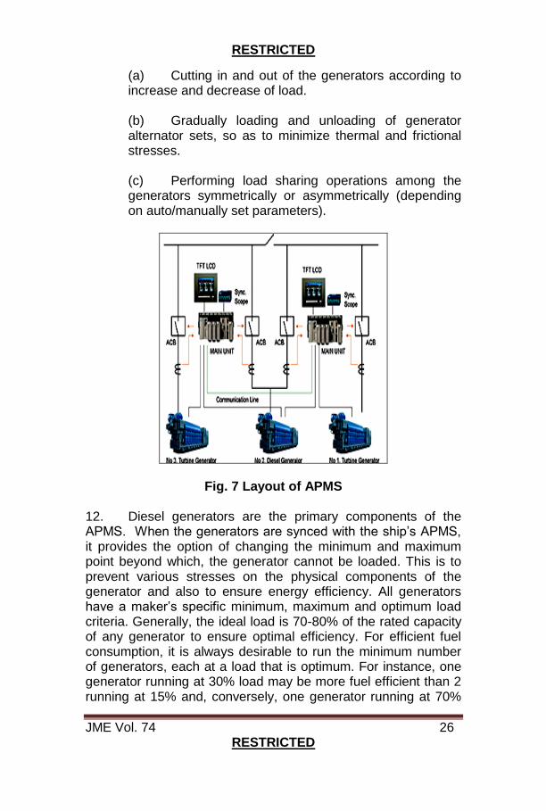
(a) Cutting in and out of the generators according to increase and decrease of load.
(b) Gradually loading and unloading of generator alternator sets, so as to minimize thermal and frictional stresses.
(c) Performing load sharing operations among the generators symmetrically or asymmetrically (depending on auto/manually set parameters).
Fig. 7 Layout of APMS 12. Diesel generators are the primary components of the APMS. When the generators are synced with the ship’s APMS, it provides the option of changing the minimum and maximum point beyond which, the generator cannot be loaded. This is to prevent various stresses on the physical components of the generator and also to ensure energy efficiency. All generators have a maker’s specific minimum, maximum and optimum load criteria. Generally, the ideal load is 70-80% of the rated capacity of any generator to ensure optimal efficiency. For efficient fuel consumption, it is always desirable to run the minimum number of generators, each at a load that is optimum. For instance, one generator running at 30% load may be more fuel efficient than 2 running at 15% and, conversely, one generator running at 70%
RESTRICTED
JME Vol. 74 27 RESTRICTED
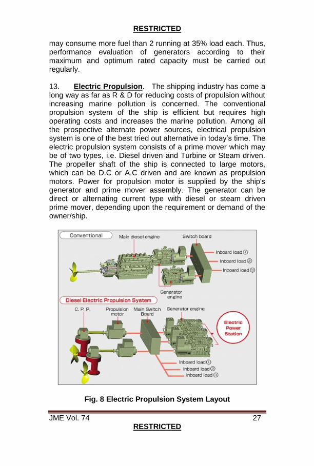
may consume more fuel than 2 running at 35% load each. Thus, performance evaluation of generators according to their maximum and optimum rated capacity must be carried out regularly. 13. Electric Propulsion. The shipping industry has come a long way as far as R & D for reducing costs of propulsion without increasing marine pollution is concerned. The conventional propulsion system of the ship is efficient but requires high operating costs and increases the marine pollution. Among all the prospective alternate power sources, electrical propulsion system is one of the best tried out alternative in today’s time. The electric propulsion system consists of a prime mover which may be of two types, i.e. Diesel driven and Turbine or Steam driven. The propeller shaft of the ship is connected to large motors, which can be D.C or A.C driven and are known as propulsion motors. Power for propulsion motor is supplied by the ship's generator and prime mover assembly. The generator can be direct or alternating current type with diesel or steam driven prime mover, depending upon the requirement or demand of the owner/ship.
Fig. 8 Electric Propulsion System Layout
RESTRICTED
JME Vol. 74 28 RESTRICTED
14. In the electrical propulsion system, the direction of the
rotation of propeller is governed by either the electrical control of
the motor itself or by changing the electrical supply. Usually, the
variable speed electrical motor is used for fixed pitch propeller
system and constant or variable can be used for variable pitch
propeller or CPP.
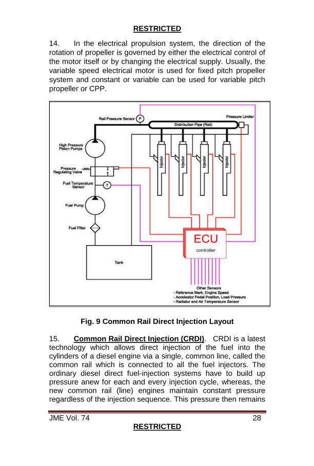
Fig. 9 Common Rail Direct Injection Layout 15. Common Rail Direct Injection (CRDI). CRDI is a latest technology which allows direct injection of the fuel into the cylinders of a diesel engine via a single, common line, called the common rail which is connected to all the fuel injectors. The ordinary diesel direct fuel-injection systems have to build up pressure anew for each and every injection cycle, whereas, the new common rail (line) engines maintain constant pressure regardless of the injection sequence. This pressure then remains
RESTRICTED
JME Vol. 74 29 RESTRICTED
permanently available throughout the fuel line. The engine's electronic timing regulates injection pressure according to engine speed and load. The electronic control unit (ECU) modifies injection pressure precisely and as needed, based on data obtained from sensors on the cam and crankshafts. In other words, compression and injection occur independently of each other. This technique allows fuel to be injected as needed, saving fuel and lowering emissions. Optimising Machinery Exploitation 16. The points brought out in the article can be integrated in the conventional electrical system to achieve maximum energy efficiency onboard ships. Further, correct operating procedures of all electrical machinery systems and planned maintenance are also necessary for achieving the desired overall energy efficiency of all ships. Following are few factors which would help in smart reduction of consumption of power:-
(a) Air Condition System. Any air leaks in the start air or service and working air must be repaired as soon as detected to prevent continuous running of compressors and to prevent frequent loading/unloading of compressors. Running hours of the compressors must be looked at closely and planned maintenance on the compressors must be carried out according to maker’s specification. Further, adequate quantity of refrigerant is to be maintained in the system for proper operation. The AHU filter, cooling elements, fan drive belts and bearings are to be regularly checked and maintained for optimum operation. The auto-capacity cut in/ out devices are to be operational at all times to ensure optimum exploitation and conservation of energy. (b) Propulsion System. Depending on the prevailing wind and sea conditions, care is to be taken to avoid increasing the main engine load without corresponding benefit in ship speed. Maintain components directly affecting M/E performance like the T/C, air cooler, fuel injection system, liner and piston, piston rings etc. to a good condition to ensure maximum possible M/E total efficiency (i.e. the ratio of the shaft power to the power of the fuel burnt in the engine).
RESTRICTED
JME Vol. 74 30 RESTRICTED
(c) Engine Room Ventilation. Ventilation fans are large consumers of power. Engine room pressure and temperature must be carefully evaluated so as to run only the required number of fans. Where fan motors are dual speed or of a variable frequency type, selection of lower speeds, where practical, go a long way in reducing power consumption. (d) Lights. A simple, yet largely unpracticed factor is switching off lights which are not in use. Living space lights, steering gear room lights, deck lights should be switched on only when in use. This practice will go a long way in curtailing power consumption.
Conclusion 17. In review of this article, various solutions in the form of energy saving electrical/ mechanical equipment and optimal exploitation practices have been recommended. Energy conservation will go a long way to reduce cost of operation and will ensure better environmental quality. Further, it also lowers energy costs by preventing future depletion of non-renewable resources. While some of the equipment/ systems recommended in the article have already been implemented in Indian Naval ships, feasibility to introduce the other systems/ equipment may be considered. Author is presently serving as SM (L&W), NSRY (Kochi) and OIC WED (Kochi)
RESTRICTED
JME Vol. 74 31 RESTRICTED
OIL WATER SEPERATION USING MAGNETITE POWDER
Cdr Ayyappa Ramesh, SLt Hitesh Rana, SLt Vinay B Sonna, SLt Sudeep Pilpia, SLt Aradhya Kumar
Introduction 1. In recent years, the frequent occurrence of water pollution by oil spillages and organic-compounds leakages has caused severe environmental and ecological damage. Therefore, in addition to waste disposal to sea, the oil water separation from marine vessels has been a paramount requirement to safeguard the marine environment. Separation of oil from water before it is discharged to sea is a need of the hour as marine pollution and conservation of marine ecology is of prime importance. 2. For safeguarding the marine environment, there exist various MARPOL regulations that govern and regulate disposal of waste from Marine Vessels into the sea. For all marine vessels, disposal of waste water has been a major concern since the discharged water contains substantial amount of oil. Therefore, there exist a requirement for separation of oil from water prior discharge to sea and this done by employing oil-water separator (OWS) fitted on board ships. 3. At present, naval vessels are fitted OWS which are prone to frequent failures due to various reasons such as non availability of spares, calibration issues, limited technical expertise; thus rendering the equipment non-operational for prolonged duration. At the same time the output of the present OWS systems is less making it inefficient for the purpose. Working Principle of OWS Using Magnetite Powder 4. With latest advancement in oily waste water treatment, heightened technological interest in oil water separation has become a worldwide subject. The oil water separation using Magnetite Powder is a new methodology being explored by various researchers. In this process, Magnetite Powder (Fe3O4) which is magnetic in nature is added to the Oil Water mixture and the magnetite particles gets attached to oil whereas water remains as it is. On application of magnetic power with the help

RESTRICTED
JME Vol. 74 32 RESTRICTED
of a permanent magnet or an electromagnet this magnetite powder gets attracted towards the magnet along with oil attached to the magnetite particles and is separated from oil water mixture. 5. The oil is selectively separated out along with the magnetite particles due to application of magnetic attraction. The oil is further selectively absorbed through the Teflon Coating or through specially prepared foam which selectively absorbs oil. Sponge is regarded as a kind of selective oil absorber because of its commercial availability, low density and high porosity. 6. The oil water separation is governed by the interfacial phenomenon; therefore use of special wettability designed material is an effective and facile approach. Materials with superhydrophilicity/ underwater superoleophobicity (termed as “water-removing” types of materials) gained attention in this field because they allowed the water phase to penetrate through the special materials easily while the oil has to be repelled completely. 7. However, such water removal materials are not a best choice to separate oil from water since the amount of oil is less as compared to water as we know that it is always easy to separate out the one which is in lesser quantity. In this case, it is optimal to use materials with superhydrophobic and superoleophilic properties (named as “oil-removing” types of material). Subsequently lots of oil removing types of material have been fabricated to remove oil from water effectively. Preparation of Foam 8. Foam with superhydrophobic and superoleophillic properties is fabricated via simple solution-immersion process. In addition, the driven force used for oil-water separation being only gravity can be efficient upto 97% regardless of quantity and density of oil. Furthermore, the prepared superhydrophobic and superoleophilic foam could effectively and continuously remove the oil under vacuum regime, ensuring collecting and separating out simultaneously.

RESTRICTED
JME Vol. 74 33 RESTRICTED
9. Materials involved in fabrication are as under:- (a) Polyurathene/melamine foam (b) Actyflon – G502 (c) Fe3O4 Nano particles (d) Ethanol (e) Ultrasonic apparatus 10. The superhydrophobic sponge can be easily fabricated via one step process i.e. dipping of commercial sponge in a suspension of Ethanol containing Fe3O4 magnetite particles and low-surface energy compound Actyflon G502 under ultrasonication. This fabricated sponge will have high ability of oil absorption, and can also be driven by a magnet to the polluted water zone to selectively absorb oil from water. The absorption capacities of prepared sponge has been found to be as high as 25-87 times of its own weight, depending upon the types of oil and organic solvents. Adding to its efficiency, the prepared sponge’s recyclability makes it a an ideal option for oil water separation. 11. The surface structures of the sponge are shown in Fig. 1. The original sponge exhibits a porous structure (pore sizes are in the range of ca. 65–300 µm), and the surface is smooth with low surface roughness (Fig. 1a). While as that of the prepared sponge, exhibits highly porous structure that can provide a large surface area and a high uptake capacity is retained (Fig. 1b). Meanwhile, Fe3O4 particles are deposited on the sponge skeleton, forming a considerably rough structure (Fig. 1c).
Fig. 1 FE-SEM Images of (a) Original Sponge, (b, c) Prepared Sponge
RESTRICTED
JME Vol. 74 34 RESTRICTED
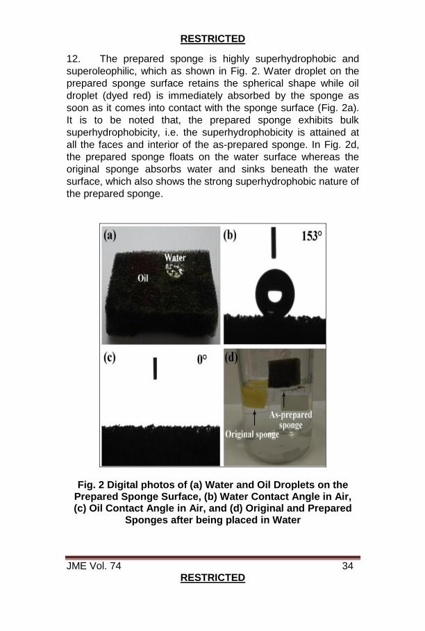
12. The prepared sponge is highly superhydrophobic and
superoleophilic, which as shown in Fig. 2. Water droplet on the
prepared sponge surface retains the spherical shape while oil
droplet (dyed red) is immediately absorbed by the sponge as
soon as it comes into contact with the sponge surface (Fig. 2a).
It is to be noted that, the prepared sponge exhibits bulk
superhydrophobicity, i.e. the superhydrophobicity is attained at
all the faces and interior of the as-prepared sponge. In Fig. 2d,
the prepared sponge floats on the water surface whereas the
original sponge absorbs water and sinks beneath the water
surface, which also shows the strong superhydrophobic nature of
the prepared sponge.
Fig. 2 Digital photos of (a) Water and Oil Droplets on the Prepared Sponge Surface, (b) Water Contact Angle in Air, (c) Oil Contact Angle in Air, and (d) Original and Prepared
Sponges after being placed in Water

RESTRICTED
JME Vol. 74 35 RESTRICTED
13. This superhydrophobic and superoleophilic nature of the
prepared sponge is used for selective absorption of oil. As
shown in Fig. 3, the sponge absorbs oil (dyed red) quickly in
several seconds, while no water is found in the absorbed oil,
thus indicating highly selective oil absorption. Adding to it, the
presence of Fe3O4 particles, makes is magnetic in nature and
hence could be driven under magnetism showing its great
potential in oil spill cleaning too.
Fig. 3 Digital Photos of Hexane Removal Process (dyed red) by a Piece of as-prepared Sponge under Magnetic Field
Observations
14. The absorption capacity (k) can be defined as
k = (M2–M1)/M1 where,
M1 = weight of the prepared sponge before
absorption
M2 = weight of the prepared sponge after
absorption
RESTRICTED
JME Vol. 74 36 RESTRICTED
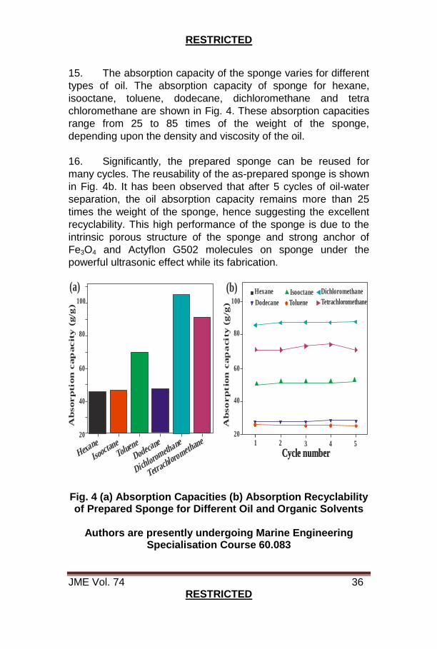
15. The absorption capacity of the sponge varies for different
types of oil. The absorption capacity of sponge for hexane,
isooctane, toluene, dodecane, dichloromethane and tetra
chloromethane are shown in Fig. 4. These absorption capacities
range from 25 to 85 times of the weight of the sponge,
depending upon the density and viscosity of the oil.
16. Significantly, the prepared sponge can be reused for
many cycles. The reusability of the as-prepared sponge is shown
in Fig. 4b. It has been observed that after 5 cycles of oil-water
separation, the oil absorption capacity remains more than 25
times the weight of the sponge, hence suggesting the excellent
recyclability. This high performance of the sponge is due to the
intrinsic porous structure of the sponge and strong anchor of
Fe3O4 and Actyflon G502 molecules on sponge under the
powerful ultrasonic effect while its fabrication.
Ab
sorp
tion
cap
acit
y (
g/g
)
Ab
so
rp
tio
n c
ap
acity (
g/g
)
Hexane
Hexane
Isooctane
Isooctane
Toluene
Toluene
Dodecane
Dodecane
Dichlorometh
ane
Dichloromethane
Tetrachloromethane
Tetrachloromethane
Cycle numberCycle number
(a) (b)
20201 2 3 4 5
4040
6060
8080
100100
Fig. 4 (a) Absorption Capacities (b) Absorption Recyclability of Prepared Sponge for Different Oil and Organic Solvents
Authors are presently undergoing Marine Engineering
Specialisation Course 60.083
RESTRICTED
JME Vol. 74 37 RESTRICTED
WASTE HEAT RECOVERY SYSTEM
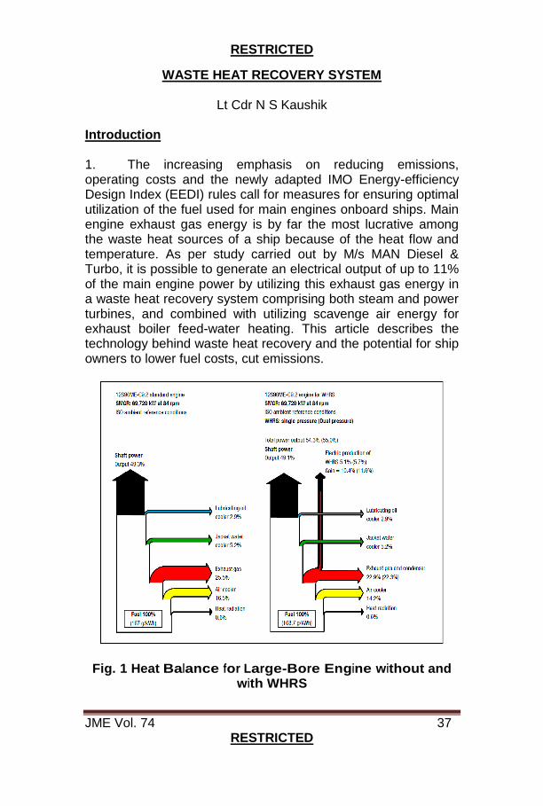
Lt Cdr N S Kaushik Introduction 1. The increasing emphasis on reducing emissions, operating costs and the newly adapted IMO Energy-efficiency Design Index (EEDI) rules call for measures for ensuring optimal utilization of the fuel used for main engines onboard ships. Main engine exhaust gas energy is by far the most lucrative among the waste heat sources of a ship because of the heat flow and temperature. As per study carried out by M/s MAN Diesel & Turbo, it is possible to generate an electrical output of up to 11% of the main engine power by utilizing this exhaust gas energy in a waste heat recovery system comprising both steam and power turbines, and combined with utilizing scavenge air energy for exhaust boiler feed-water heating. This article describes the technology behind waste heat recovery and the potential for ship owners to lower fuel costs, cut emissions.
Fig. 1 Heat Balance for Large-Bore Engine without and with WHRS
RESTRICTED
JME Vol. 74 38 RESTRICTED
2. The Fig. 1 shows a comparison of engine heat balances of a low speed engine of 70,000 KW, with and without WHRS. The Figure shows that for the engine in combination with WHRS the total efficiency will increase to about 55%. The IMO EEDI formula allows for considering adding WHRS into the ship, analyse EEDI effects and EEDI settings. Lower CO2 emission levels can be achieved by installing a waste heat recovery system like EEDI Analyser. Background 3. Following the trend of a requirement for higher overall ship efficiency since the first oil crisis in 1973, the efficiency of main engines has increased, and today the fuel energy efficiency is about 50%. This high efficiency has, among other things, led to low Specific Fuel Consumption (SFC) values, but also a correspondingly lower exhaust gas temperature after the turbochargers. Even though a main engine fuel energy efficiency of 50% is relatively high, the primary objective for the ship owners is to lower ship operational costs further, as the total fuel consumption of the ship is the main target. This may lead to a further reduction of CO2 emissions – a task, which is gaining importance with the new IMO EEDI rules in place from 2013. The primary source of waste heat of a main engine is the exhaust gas heat dissipation, which accounts for about half of the total waste heat, i.e. about 25% of the total fuel energy. In the standard high-efficiency engine version, the exhaust gas temperature is relatively low after the turbocharger, and just high enough for producing the necessary steam for the heating purposes of the ship by means of a standard exhaust gas fired boiler of the smoke tube design. However, a main engine utilized for WHRS can increase the possibilities of producing electricity from the exhaust gas. The result will be an improvement in total efficiency however, a slight reduction of the performance of the main engine will be seen. 4. Today several different WHRSs are readily available. Depending on the level of complexity acceptable to the owner / Shipyard and the actual electrical power consumption onboard, it is possible to choose between the following systems:
RESTRICTED
JME Vol. 74 39 RESTRICTED
(a) ST-PT. Steam Turbine-Power Turbine Generator, a Power turbine and steam turbine generator with single or dual pressure steam turbine.
(b) STG. Steam Turbine Generator unit, (Stand-alone, single or Dual steam pressure). (c) PTG. Power Turbine Generator Power turbine stand-alone generator.
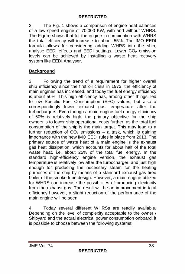
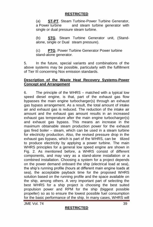
5. In the future, special variants and combinations of the above systems may be possible, particularly with the fulfillment of Tier III concerning Nox emission standards. Description of the Waste Heat Recovery Systems-Power Concept and Arrangement 6. The principle of the WHRS – matched with a typical low speed diesel engine, is that, part of the exhaust gas flow bypasses the main engine turbocharger(s) through an exhaust gas bypass arrangement. As a result, the total amount of intake air and exhaust gas is reduced. The reduction of the intake air amount and the exhaust gas amount results in an increased exhaust gas temperature after the main engine turbocharger(s) and exhaust gas bypass. This means an increase in the maximum obtainable steam production power for the exhaust gas fired boiler – steam, which can be used in a steam turbine for electricity production. Also, the revised pressure drop in the exhaust gas bypass, which is part of the WHRS, can be tilized to produce electricity by applying a power turbine. The main WHRS principles for a general low speed engine are shown in Fig. 2. As mentioned before, a WHRS consist of different components, and may vary as a stand-alone installation or a combined installation. Choosing a system for a project depends on the power demand onboard the ship (electrical load at sea), the ship’s running profile (hours at different main engine loads at sea), the acceptable payback time for the proposed WHRS solution based on the running profile and the space available on the ship, among others. A very important part of selecting the best WHRS for a ship project is choosing the best suited propulsion power and RPM for the ship (biggest possible propeller) so as to ensure the lowest possible fuel consumption for the basic performance of the ship. In many cases, WHRS will
RESTRICTED
JME Vol. 74 40 RESTRICTED
be able to supply the total electricity need of the ship as a standalone power source, but it can also run in parallel with a shaft generator, shaft motor and auxiliary diesel generating sets. This type of advanced power system requires an advanced Power Management System (PMS), with which the engine control system is designed to communicate. Particularly for container ship designs, WHRS has found its place where it contemplates a technological step forward in lowering fuel consumption and CO2 emissions of the ship, but the interest for WHRS solutions is spreading to other ship types with the aim of reducing total fuel costs, ship EEDI and emissions.
Fig. 2 Waste Heat Recovery System Principles
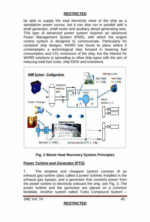
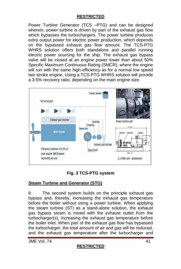
Power Turbine and Generator (PTG) 7. The simplest and cheapest system consists of an exhaust gas turbine (also called a power turbine) installed in the exhaust gas bypass, and a generator that converts power from the power turbine to electricity onboard the ship, see Fig. 3. The power turbine and the generator are placed on a common bedplate. Another system called Turbo Compound System –
Turbo- Charger
RESTRICTED
JME Vol. 74 41 RESTRICTED
Power Turbine Generator (TCS –PTG) and can be designed wherein, power turbine is driven by part of the exhaust gas flow which bypasses the turbochargers. The power turbine produces extra output power for electric power production, which depends on the bypassed exhaust gas flow amount. The TCS-PTG WHRS solution offers both standalone and parallel running electric power sourcing for the ship. The exhaust gas bypass valve will be closed at an engine power lower than about 50% Specific Maximum Continuous Rating (SMCR), where the engine will run with the same high efficiency as for a normal low speed two stroke engine. Using a TCS-PTG WHRS solution will provide a 3-5% recovery ratio, depending on the main engine size.
Fig. 3 TCS-PTG system Steam Turbine and Generator (STG) 8. The second system builds on the principle exhaust gas bypass and, thereby, increasing the exhaust gas temperature before the boiler without using a power turbine. When applying the steam turbine (ST) as a stand-alone solution, the exhaust gas bypass steam is mixed with the exhaust outlet from the turbocharger(s), increasing the exhaust gas temperature before the boiler inlet. When part of the exhaust gas flow has bypassed the turbocharger, the total amount of air and gas will be reduced, and the exhaust gas temperature after the turbocharger and

RESTRICTED
JME Vol. 74 42 RESTRICTED
bypass will increase. This will increase the obtainable steam production power for the exhaust gas fired boiler. By installing a steam turbine (often called a turbo generator), the obtainable steam production from the exhaust boiler system can be used for electric power production. The steam turbine is installed on a common bedplate with the generator in the same manner as the power turbine and the generator. Like the TCS-PTG design, the STG solution can function both as a standalone and as a parallel running electric power source for the ship – depending on the actual demand for the particular ship design. Using a WHRS STG system, it will be possible to recover some 5 to 8%, depending on the main engine size, engine rating, and ambient conditions. Steam Turbine, Power Turbine, and Generator (ST-PT) 9. If the electric power demand on the ship is very high, e.g. a container ship, the power turbine and the steam turbine can be built together to form a combined system. The power turbine and the steam turbine is built onto a common bedplate and, via reduction gearboxes, connected to a common generator. MARC stands for Modular Arrangement Concept and is used both for power plants and for marine WHRS applications, and is the latest development of a steam turbine and power concept started in 1905 in Hamburg Germany. The power output from the power turbine can be added to the generator via a reduction gear with a special clutch. However, first the steam turbine will start at 30 – 35% SMCR main engine power followed by the power turbine which starts power production at 40 to 50% SMCR. The combined WHRS ST & PT schematic diagram can be seen in Fig. 4, which shows a system that, in many conditions, reduces the fuel costs of the ship considerably by being able to cover the total electric power needs in many conditions onboard the ship. Otherwise, a shaft motor / generator (PTI/PTO) connected to the main engine shaft could be an option, making it possible to add either electric power to the ship grid if needed, or to boost propulsion by supplying the electric power to the PTI. Selecting the full WHRS – combining both steam and power turbines – approximately 8-11% power can be recovered, depending on the main engine size, engine rating and ambient conditions. Choosing the system most suitable for a specific ship project requires careful evaluation based on requirements concerning

RESTRICTED
JME Vol. 74 43 RESTRICTED
fuel efficiency, arrangement restrictions, emission requirements, operational profile for the ship, payback time, etc.
Fig. 4 WHRS ST-PT System Emission Effects of using WHRS 10. Based on a HFO fuel saving of 3,555 tons per year (with 3% Sulphur content), the installation of a WHRS on a large container ship/tanker will save the environment for the following emission amounts: (a) CO2 emission saving per year : 11,260 tons (b) Nox emission saving per year : 319 tons (c) Sox emission saving per year : 214 tons (d) Particulates saving per year : 29 tons
RESTRICTED
JME Vol. 74 44 RESTRICTED
Conclusion 11. This paper shows that significant fuel cost savings can be achieved by adding a WHRS to a ship project. Whether a full WHRS (ST & PT), a stand-alone WHRS (ST) or a stand-alone PTG solution are selected, all of these solutions offer large fuel savings. The larger the engine power, the greater the possible fuel saving. In addition to large fuel savings, a WHRS gives large CO2, Nox, Sox and particulate reductions to the benefit of the environment. References 12. The following references were used to prepare the article:- (a) Basic Principles of Ship Propulsion, MAN Diesel
& Turbo SE, Copenhagen, Denmark, Dec 11. (b) BIMCO EEDI:
Link ://www.bimco.org/Products/EEDI.aspx
(c) TCS-PTG Savings with Extra Power, MAN Diesel & Turbo SE, Augsburg, Germany, Dec 11.
Author is presently serving as Deputy Manager (Engg) at NSRY (KOC)

RESTRICTED
JME Vol. 74 45 RESTRICTED
INNOVATIVE REPAIR OF SME CAC AT SEA – INS TIR
Cdr Samir Bera, Lt Cdr BK Ganapathy 1. Background. INS Tir is fitted with two Crossley Pielstic make 8PC2V400MkII Main Engines (3470 HP each). Each Main Engine is fitted with two turbochargers which independently feed charged air to respective air manifolds of ‘A’ and ‘B’ bank cylinders post inter-cooling at Charge Air Cooler (CAC). The high temperature turbocharged air at CAC is cooled by sea water. The CACs are original fit consisting of 276 tubes each. 2. Defect. Whilst on an Overseas Deployment, traces of sea water were found from the SME ‘A’ bank air manifold drain cock during routine checks by the watch keeper. The observation was indicative of sea water breaching the charge air cooler Cu-Ni tubes into the air side of the CAC. The defect necessitated immediate stopping of SME to ascertain the extent of breach and to undertake DI/DR.
Fig. 1 Sea Water Droplets from CAC Air Side Drain Cock
3. Limitations. The defect was observed during a critical deployment with limited repair facilities available at the next port of call. Availability of both Main Engines for propulsion was deemed critical to meet deployment timelines. The enormous size of the intercooler consisting of 276 tubes and non-availability of a suitable test jig onboard for undertaking pressure testing of the affected cooler posed a crippling restriction for ascertaining the extent of the tube breach in a definitive manner

RESTRICTED
JME Vol. 74 46 RESTRICTED
for further DI/DR. The situation was compounded by the non availability of construction details and drawings of the CAC. 4. The normal procedure followed to undertake rectification of such defect entails removal of cooler, chemical cleaning, preparation of suitable jigs with pressure testing adapters, identification and blanking of defective tubes, pressure testing and fitment followed by trials which generally takes at least ten working days by a trained team with adequate facilities. Since the cooler is an engine-mounted non-conventional twin pass, vertically mounted type (original fit), in-situ repair appeared to be impractical, especially at sea in an adverse atmospheric condition without any external support. However, the defect was resolved expeditiously by ship’s staff in less than 24 hours.
Fig. 2 Schematic Layout of CAC and Other Components
5. Construction Details. The Charge Air Cooler (CAC) is a two pass heat exchanger with inlet and outlet passes demarcated at the top cover. The cooler is connected with the ‘A’ bank turbocharger and air intake manifold by a trapezoidal casing. The cooler consists of total 276 tubes of 8mm dia, 138 each for inlet and outlet stacks. The arrangement of the tubes within the CAC is vertical. Layout of CAC, tubes viewed from top and bottom end plates is as shown in the photograph (Fig. 3 & 4). A drain cock is provided at the bottom of air outlet side trapezoidal piece of CAC, which is occasionally checked by the watch keeper for any trace of water. The sea water pressure is maintained at 0.5 to 2.5 bar depending on the rpm of the engine.
MAIN ENGINE AIR INTAKE MANIFOLD (‘A’ BANK)
CHARGE AIR TO ‘A’ BANK CYLINDERS
TURBO CHARGER
DRAIN CHARGE AIR COOLER

RESTRICTED
JME Vol. 74 47 RESTRICTED
In addition, provision for emergency cooling is also available through firemain system in case of drop in system pressure.
Fig. 3 Location of Charge Air Cooler – SME ‘A’ Bank
(A) (B) (C)
Fig. 4 (A) CAC Tube Stack Viewed From Top, (B) Bottom, (C) End Cover
6. Observation. At about 1300 hrs on 15 Mar 17, the MER watch keeper reported traces of sea water (droplets) through drain cock of ‘A’ bank of SME CAC. Bridge was informed and the engine rpm was reduced immediately. Subsequently, Starboard Main Engine was shut down and the ship was propelling through Port Main Engine with Stbd shaft trailing. The CAC of SME was isolated by closing associated system valves. Engine turning was undertaken keeping all indicator cocks in open condition to ascertain ingress of water inside the cylinders. In addition, lub oil samples were collected for testing. Crankcase doors were also opened up for visual inspection of the crank case. However, no trace of water was found inside the cylinders or in the oil sample. No abnormalities were detected during the visual inspection of the crankcase. Post thorough inspection, it was concluded that
CHARGE AIR COOLER
RESTRICTED
JME Vol. 74 48 RESTRICTED
the defect was detected at a very early stage and further damage was avoided by proactive measures implemented by ship’s staff. 7. Defect Analysis and Progressive Defect Rectification. Prima facie it was assumed that the cause of sea water leakage through the drain cock of SME ‘A’ bank CAC was due to failure of one or more cooler tubes since there was no other component in the system which carries sea water. Identification of the leaking tubes through conventional procedure was not feasible due to the following:-
(a) Blanking of air sides of the CAC for testing was not feasible due to large size of trunking and non availability of suitable jigs. (b) Removal of CAC was impractical due to space constraint, requirement of degutting of associated pipes, large size and extremely heavy weight of the cooler.
(c) Chemical cleaning of 276 tubes of such huge cooler was impractical at sea.
(d) Pressure testing of the CAC from any side was not feasible.
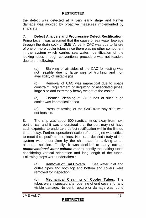
8. The ship was about 600 nautical miles away from next port of call and it was understood that the port may not have such expertise to undertake defect rectification within the limited time of stay. Further, operationalisation of the engine was critical to meet the specified time lines. Hence, a detailed study of the system was undertaken by the ship staff for arriving at an alternate solution. Finally, it was decided to carry out an unconventional water column test to identify the leaking tubes considering vertical orientation and long length of the tubes. Following steps were undertaken :-
(a) Removal of End Covers. Sea water inlet and outlet pipes and both top and bottom end covers were removed for inspection. (b) Mechanical Cleaning of Cooler Tubes. The tubes were inspected after opening of end covers for any visible damage. No dent, rupture or damage was found
RESTRICTED
JME Vol. 74 49 RESTRICTED
on tubes while viewed from external surface area. However, scaling and clogging of tubes with foreign particles was observed. Chemical cleaning of the cooler appeared to be impractical. Mechanical cleaning of each tube was undertaken by using AC condenser cleaning brush post necessary modification. The process of cleaning 276 tubes was tedious and arduous due to space constraint and high temperature and noise in the engine room.
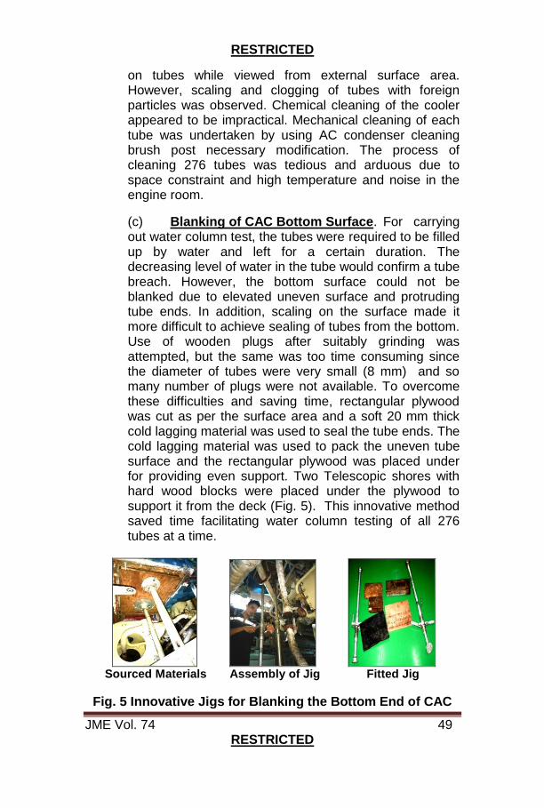
(c) Blanking of CAC Bottom Surface. For carrying out water column test, the tubes were required to be filled up by water and left for a certain duration. The decreasing level of water in the tube would confirm a tube breach. However, the bottom surface could not be blanked due to elevated uneven surface and protruding tube ends. In addition, scaling on the surface made it more difficult to achieve sealing of tubes from the bottom. Use of wooden plugs after suitably grinding was attempted, but the same was too time consuming since the diameter of tubes were very small (8 mm) and so many number of plugs were not available. To overcome these difficulties and saving time, rectangular plywood was cut as per the surface area and a soft 20 mm thick cold lagging material was used to seal the tube ends. The cold lagging material was used to pack the uneven tube surface and the rectangular plywood was placed under for providing even support. Two Telescopic shores with hard wood blocks were placed under the plywood to support it from the deck (Fig. 5). This innovative method saved time facilitating water column testing of all 276 tubes at a time.
Sourced Materials Assembly of Jig Fitted Jig
Fig. 5 Innovative Jigs for Blanking the Bottom End of CAC

RESTRICTED
JME Vol. 74 50 RESTRICTED
(d) Water Column Test. All tubes were filled up slowly with water using a small funnel ensuring no air was trapped inside the tubes and left for two hours. No significant reduction of level was observed except in two tubes where the water was settled at a lower level indicative of crack or hole at that point. The tubes were marked and the plywood and lagging material were removed from the bottom end allowing water in the tubes to drain out. To ascertain the defective tubes, the test was repeated holding the tubes from bottom by finger and using air pressure from top (Fig. 6).
Principle of WaterColumn Test
Filling of Water in tubes using Defective Tube Identified Funnel
Fig. 6 Water Column Test for Identification of Defective Tubes
DEFECTIVE
TUBE
LOCATION
OF DEFECT
REDUCED
WATER
COLUMN
SOFT RUBBER
JOINT USED TO
BLANK TUBES
FROM BOTTOM
NO REDUCTION IN
WATER COLUMN
(HEALTHY TUBES)
APPLIED AIR
PRESSURE
No Reduction in Water Column
(Healthy Tubes)
Soft Rubber Joint to Blank Tubes from Bottom
Defective Tubes

RESTRICTED
JME Vol. 74 51 RESTRICTED
(e) Blanking of Defective Tubes. Post confirmation of the leakage, both the tubes was blanked from top and bottom. Putties were applied on the surface of the blanks to ensure additional sealing. Blanks of suitable size (Mat - Brass) were manufactured in workshop lathe machine. The arrangement was left for curing for four hours prior carrying out pressure testing / further trials (Fig. 7).
Top End Post Repairs Bottom End Post Repairs
Fig. 7 CAC Top and Bottom Surface after Repair
(f) Pressure Testing of CAC. The end covers and sea water inlet and outlet pipes were fitted back. Emergency cooling line from Firemain system was energised for pressure testing of the CAC and system integrity checks post DR. No trace of sea water was observed from the drain cock. (g) Trials. Trials of SME were undertaken in declutched mode to prove the system. The Engine RPM was increased to 300 to confirm any leakage from the tubes. No trace of sea water was observed from the air side drain cock of the CAC establishing the efficacy of the repairs. Trials were found to be satisfactory.
9. Conclusion. The defect of CAC tube failure was successfully rectified in house by ship’s staff at sea in less than 24 hours during the ship’s overseas deployment without any external support using innovative method and the Starboard Main Engine was made operational without imposing any

RESTRICTED
JME Vol. 74 52 RESTRICTED
restriction or limitation on exploitation. The method used to identify the defective tubes has proved to be effective for emergency repair of large size Heat Exchangers with vertically oriented tube stacks at sea.
Authors are serving as Engineer Officer and Senior Engineer Officer onboard INS Tir.
RESTRICTED
JME Vol. 74 53 RESTRICTED
A SHORT NOTE ON UNDERSTANDING DIESEL TRANSIENTS IN THE FRAMEWORK OF INDIAN NAVAL
REQUIREMENTS
Cdr Girish Gokul
1. Introduction. Frequency fluctuations in electrical
supplies onboard operational platforms can cause unexpected
loss of motive power and firepower. Since the power generation
onboard the Naval platforms is governed by restrictions of
Droop, it is necessary to develop the notions leading from droop
onwards to Transient Analysis. Transient analysis of Diesel
Engine and Alternator combination is carried out to ascertain the
nature of their response to sudden change of load, technically
defined as step loads. The governor controls the change in fuel
flow rate corresponding to the load change. The Diesel
Alternators onboard naval ships are allowed an RPM change of
0.875 to 1% (for those fitted with electronic governors) or 3.5-4%
(for those fitted with hydraulic governors) over the full range of
load change. In the standard droop setting procedure followed
onboard the Naval vessels, the frequency corresponding to a
load of 50% is adjusted from the switchboard to equal 50 Hz.
Load is increased to 100 % and frequency noted. Thereafter the
electrical load is decreased to 0% and the corresponding
frequency noted. Droop is calculated as the total frequency
change observed divided by the average frequency change.1 It
can be appreciated that for every loading condition, be it 50%,
80% or 90% loading condition, there is a corresponding steady
state frequency that lies in between the droop band. In other
words, there is a one to one correlation between loading
percentage and resulting generated frequency of the DA2.
1 It is understood that sometimes the denominator in droop calculation is
taken as the frequency at 50%, and at times, the frequency at 0%. Average frequency refers to 0.5*(Frequency at 0% load- Frequency at 100% load). 2 The one to one correlation is also known as a point function. It implies that
no matter how one arrives at a select loading percentage, the frequency corresponding to it will be the same. Elaborating still further, if 50 % loading corresponds to 50.25 Hz, then regardless of whether we arrive at 50 % loading from 100 % loading condition or 10 % loading condition, the resulting frequency would be 50.25 Hz.
RESTRICTED
JME Vol. 74 54 RESTRICTED
2. Transient Analysis. How does the frequency of generated current change if the load is increased suddenly from 50% to 75%? In a control theoretic setting these are called as step changes of loads. The response would be an initial sharp fall, followed by oscillations around a new steady state value and a final steady state value. The zone of frequency change between the initial and final steady state values is called the transient stage. The analysis of this part can be understood as transient analysis. The standards dealing with transient loading conditions are elaborated in ISO 3046.3 3. From the Naval Perspective. On board all Naval ships power generation is manifested through the Diesel Alternators. The selection of the rating is done based on the displacement and weapon complement of the ship. The ETMU trial schedules are designed to determine the speed and stability of response of the DA when sudden loads are imposed on it, which are typical of a Naval environment. However currently there are two principal domains, pre-installation and post installation, from which the major Naval concerns, evolve.
(a) Pre-installation. How do ETMU trial requirements guide or affect the DA rating selection? (b) Post Installation. How do ETMU trial requirements affect/complement the routines carried out on DAs by Yard or outside agencies in ensuring that the transient performance characteristics are maintained? (c) Upgradation Concerns. How should the standards be implemented for a DA in which the hydraulic governor is replaced by an electronic governor as a part of modernisation package?
4. Pre-Installation Perspective: Block Loading and Turbo Ramp Up 4. Block loading can be understood as the maximum sudden loading that an engine can respond to when
3 The application of Modern Control Theory to a Turbocharged Diesel Engine
Power Plant, DE Winterbone, Published in the Proceedings of Institute of
Mechanical Engineers, 1991. 4 Report on Transient Analysis by Team Sigma Power Control Systems Pvt
Limited to Indian Navy, dated May 12, 2014, by Sameer Gosawi, VikasGandhe, Sumeet and Arun Undirwadkar.

RESTRICTED
JME Vol. 74 55 RESTRICTED
operating under no load condition. Turbo Ramp up is the ratio of naturally aspirated power output to turbocharged power output. As per the report cited in the footnote, coupling a Turbocharger to a naturally aspirated Diesel Engine generally increases its power by 35 to 40% on an average. The report further notes that the engine capacity to respond to a block load within 2 seconds will be 60 to 65% of the rated power. Let us assume 60% of rated load is responded to comfortably by the Prime Mover. Response time to the loading is affected by the lags introduced by TC in building up to the required RPM. This will again be predominantly affected by the Moment of Inertia of the TC. Smaller TC would imply faster response while bigger TCs would imply more fuel savings. From a design point of view it implies that since 0-70% load (MWe) should be responded to within 05 seconds (as per Transient requirements applicable in Indian Navy), 70 % of the load should correspond to 60% of the rated capacity. In other words if we want to install a 1000 KW DA, the prime mover should be rated at (700/0.6 KWe) 1167 KW. Multiplying by generator (0.95) and transmission (0.85) efficiencies, it would imply that for a requirement of 1000 Kwe, we choose a Prime mover of 1445 KW (mechanical)! Once chosen, such a prime mover would naturally be subjected to low load running and problems associated with that. Post Installation Perspective 5. The Three Propositions. From a Repair agency perspective, during the course of a refit, the routines carried out on any unit should enable it to meet the Transient requirements. The propositions related to repair actions are introduced as follows:-
(a) Proposition 1. Every load imposed on the prime mover will have a fixed correlation with the amount of fuel and air it consumes, under steady state conditions. In other words if we impose 30 % load on the prime mover, then whether we do so after initially imposing 50% and then reducing to 30% or initially running at no load and then building up to 30 %, the final fuel rack position would be the same. Same amount of fuel is consumed for the same load. Restricting the droop to lie between fixed limits is a direct implication of this proposition.
RESTRICTED
JME Vol. 74 56 RESTRICTED
(b) Proposition 2. The control of fuel supply is primarily a function of the Governor response. Governor tuning would control the rate at which fuel supply is changed in response to a change in load, keeping the RPM within droop limits. Any actuation is based on how the control action is linked up with error measurement. Is it proportional, proportional- integral etc? We can have hydraulic governors which are mechanically actuated and hence have lags in responses due to inertia effects of mechanical components. For that reason the response time and Peak variation limits are both more flexible as compared to electronic governors. Electronic governors allow for faster control action actuation, given the speed of electricity is the same as that of light. (c) Proposition 3. The control of air supply is primarily a function of the Turbocharger efficiency. The cleanliness of the air intake side and any bends in air intake trunking etc affect the flow rate of air supply but it is primarily the rotational speed of the Turbocharger that is going to affect the response.
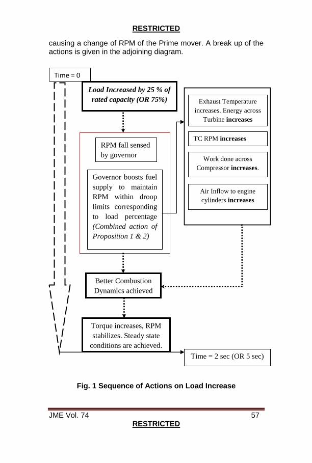
6. The Physics Behind it. Loading can be best understood as a strengthening of the magnetic field around the flywheel connected to the crank shaft. In order to overcome the loading, the torque generated by the prime mover is increased by increasing the fuel flow and the air flow. The sequence of events is - Increased load causes a fall in RPM of crankshaft which is sensed by the governor. The governor would send a signal to increase the fuel flow rate and make more fuel available for combustion through the fuel injectors. This causes the fuel mixture to burn more richly, thus increasing the temperature of the exhaust gases. The increased thermal energy of the exhaust gases causes an RPM increase of the Turbocharger Turbine section and consequently the compressor section also speeds up and increases the mass flow rate of the air into the cylinders. The increased air supply causes the RPM to stabilize at the RPM corresponding to the loading percentage (as per Proposition 1) and a final steady state RPM is achieved. Thus one can postulate that a step load would require fast governor action, followed up by a change in the RPM of the Turbocharger thereby
RESTRICTED
JME Vol. 74 57 RESTRICTED
causing a change of RPM of the Prime mover. A break up of the actions is given in the adjoining diagram.
Fig. 1 Sequence of Actions on Load Increase
Governor boosts fuel
supply to maintain
RPM within droop
limits corresponding
to load percentage
(Combined action of
Proposition 1 & 2)
RPM fall sensed
by governor
Load Increased by 25 % of
rated capacity (OR 75%)
Better Combustion
Dynamics achieved
Torque increases, RPM
stabilizes. Steady state
conditions are achieved.
Time = 0
Time = 2 sec (OR 5 sec)
TC RPM increases
Exhaust Temperature
increases. Energy across
Turbine increases
Work done across
Compressor increases.
Air Inflow to engine
cylinders increases
RESTRICTED
JME Vol. 74 58 RESTRICTED
7. Transient Tuning – The System Theoretic Overview. NES requirements of measuring quality of transient response is given by the following 2 criteria- Load changes of 25 % (step load) are to be responded to by the Prime mover- generator combination within 2 seconds and the peak variation should stay less than1.5 %5 of the nominal value(average of frequencies at 0 and 100% loads). According to control literature, under well-tuned conditions, the responses of the Prime mover- generator combination can be closely approximated to a second order response. In control theoretic framework it is natural to divide the parameters of interest into inputs and outputs. In case of an IC engine, the output is taken as speed of rotation of prime mover or Frequency of generated output current. The inputs are the fuel flow rate and air mass flow rate. Dividing the various components of the IC engine into input- output linked blocks, one can, at least in theory, find out the time constants6 associated with each action unit. The inherent nonlinearities in the system would make the final response action follow a time constant different from the simple summation of the time constants of the individual blocks. The purpose of a governor is to achieve RPM control while load varies. The fact that droop percentage is set implies that RPM is allowed to vary within the limits set by droop. Most industrial governors are PID control based, as in Proportional, Integral and Derivative modes of dealing with error. Tuning implies adjusting the weightage of P, I and D part of the controller response so as to conform to Peak variation and 2 second recovery limits.
8. Control Theoretic View of the Transients. The parameters of interest after division into inputs and outputs are joined by causal links defined by equations. Since the interplay between the parameters are best captured by ordinary differential equations and ODEs are handled best by Laplace domain (in this domain, the time based ODEs change into
5 These are the limits corresponding to electronic governors. Hydraulic
governors have peak variation limit as 2.5% and 2 second recovery limit as 1%. 6 Time constant is derived by representing change in output quantity as an
exponential function of the time. In simple words it is a measure of the time required for the output to change by 63 % of the final value it is going to attain.
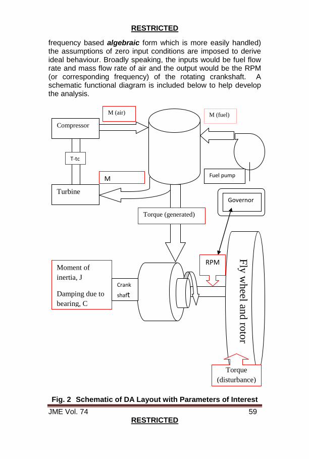
RESTRICTED
JME Vol. 74 59 RESTRICTED
frequency based algebraic form which is more easily handled) the assumptions of zero input conditions are imposed to derive ideal behaviour. Broadly speaking, the inputs would be fuel flow rate and mass flow rate of air and the output would be the RPM (or corresponding frequency) of the rotating crankshaft. A schematic functional diagram is included below to help develop the analysis.
Fig. 2 Schematic of DA Layout with Parameters of Interest
Compressor
Turbine
M (air)
M (exhaust)
T-tc
Torque (generated)
M (fuel)
Fuel pump
Governor
RPM Moment of
inertia, J
Damping due to
bearing, C
Crank
shaft
Fly
wh
eel and
roto
r
Torque
(disturbance)
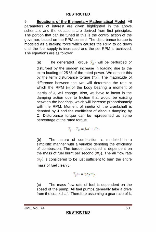
RESTRICTED
JME Vol. 74 60 RESTRICTED
9. Equations of the Elementary Mathematical Model. All
parameters of interest are given highlighted in the above
schematic and the equations are derived from first principles.
The portion that can be tuned in this is the control action of the
governor, based on the RPM sensed. The disturbance torque is
modeled as a braking force which causes the RPM to go down
until the fuel supply is increased and the set RPM is achieved.
The equations are as follows:
(a) The generated Torque ( ) will be perturbed or
disturbed by the sudden increase in loading due to the
extra loading of 25 % of the rated power. We denote this
by the term disturbance torque ( . The magnitude of
difference between the two will determine the rate at
which the RPM ( of the body bearing a moment of
inertia of J, will change. Also, we have to factor in the
damping action due to friction that would be existing
between the bearings, which will increase proportionately
with the RPM. Moment of inertia of the crankshaft is
denoted by J and the coefficient of viscous damping by
C. Disturbance torque can be represented as some
percentage of the rated torque.
(b) The nature of combustion is modeled in a
simplistic manner with a variable denoting the efficiency
of combustion. The torque developed is dependent on
the mass of fuel burnt per second ( ). The air flow rate
( is considered to be just sufficient to burn the entire
mass of fuel cleanly.
(c) The mass flow rate of fuel is dependent on the
speed of the pump. All fuel pumps generally take a drive
from the crankshaft. Therefore assuming a gear ratio of k,
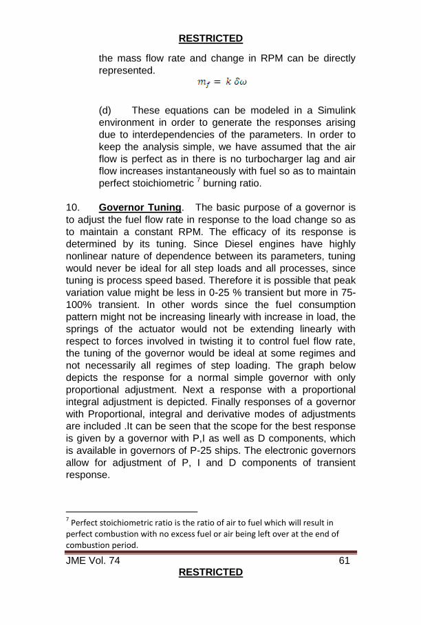
RESTRICTED
JME Vol. 74 61 RESTRICTED
the mass flow rate and change in RPM can be directly
represented.
(d) These equations can be modeled in a Simulink
environment in order to generate the responses arising
due to interdependencies of the parameters. In order to
keep the analysis simple, we have assumed that the air
flow is perfect as in there is no turbocharger lag and air
flow increases instantaneously with fuel so as to maintain
perfect stoichiometric 7 burning ratio.
10. Governor Tuning. The basic purpose of a governor is
to adjust the fuel flow rate in response to the load change so as
to maintain a constant RPM. The efficacy of its response is
determined by its tuning. Since Diesel engines have highly
nonlinear nature of dependence between its parameters, tuning
would never be ideal for all step loads and all processes, since
tuning is process speed based. Therefore it is possible that peak
variation value might be less in 0-25 % transient but more in 75-
100% transient. In other words since the fuel consumption
pattern might not be increasing linearly with increase in load, the
springs of the actuator would not be extending linearly with
respect to forces involved in twisting it to control fuel flow rate,
the tuning of the governor would be ideal at some regimes and
not necessarily all regimes of step loading. The graph below
depicts the response for a normal simple governor with only
proportional adjustment. Next a response with a proportional
integral adjustment is depicted. Finally responses of a governor
with Proportional, integral and derivative modes of adjustments
are included .It can be seen that the scope for the best response
is given by a governor with P,I as well as D components, which
is available in governors of P-25 ships. The electronic governors
allow for adjustment of P, I and D components of transient
response.
7 Perfect stoichiometric ratio is the ratio of air to fuel which will result in
perfect combustion with no excess fuel or air being left over at the end of combustion period.
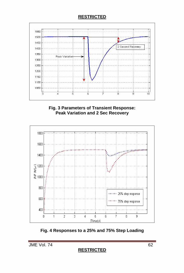
RESTRICTED
JME Vol. 74 62 RESTRICTED
Fig. 3 Parameters of Transient Response: Peak Variation and 2 Sec Recovery
Fig. 4 Responses to a 25% and 75% Step Loading
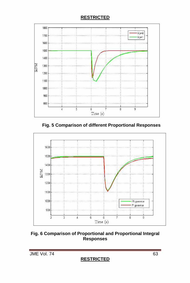
RESTRICTED
JME Vol. 74 63 RESTRICTED
Fig. 5 Comparison of different Proportional Responses
Fig. 6 Comparison of Proportional and Proportional Integral Responses
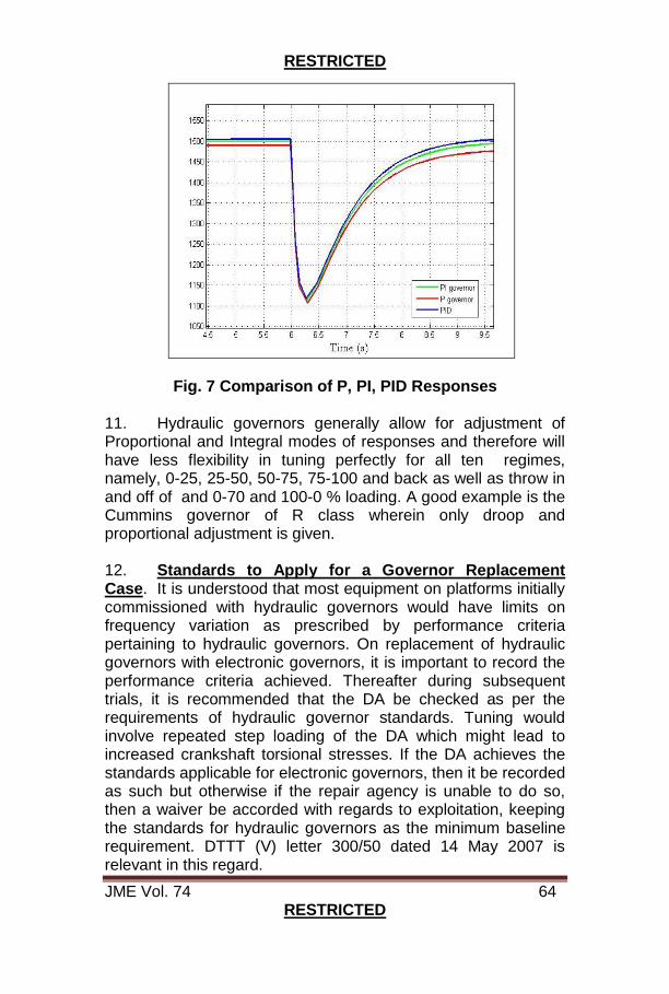
RESTRICTED
JME Vol. 74 64 RESTRICTED
Fig. 7 Comparison of P, PI, PID Responses
11. Hydraulic governors generally allow for adjustment of Proportional and Integral modes of responses and therefore will have less flexibility in tuning perfectly for all ten regimes, namely, 0-25, 25-50, 50-75, 75-100 and back as well as throw in and off of and 0-70 and 100-0 % loading. A good example is the Cummins governor of R class wherein only droop and proportional adjustment is given. 12. Standards to Apply for a Governor Replacement Case. It is understood that most equipment on platforms initially commissioned with hydraulic governors would have limits on frequency variation as prescribed by performance criteria pertaining to hydraulic governors. On replacement of hydraulic governors with electronic governors, it is important to record the performance criteria achieved. Thereafter during subsequent trials, it is recommended that the DA be checked as per the requirements of hydraulic governor standards. Tuning would involve repeated step loading of the DA which might lead to increased crankshaft torsional stresses. If the DA achieves the standards applicable for electronic governors, then it be recorded as such but otherwise if the repair agency is unable to do so, then a waiver be accorded with regards to exploitation, keeping the standards for hydraulic governors as the minimum baseline requirement. DTTT (V) letter 300/50 dated 14 May 2007 is relevant in this regard.
RESTRICTED
JME Vol. 74 65 RESTRICTED
Notion of Time Lag 13. Air Flow Path Dependencies. In the preceding model it has been assumed that air flow path is perfectly tuned. Air increases or decreases perfectly so as to meet the loading requirements. In reality, the state of the filters and the opening of the inlet and exhaust ducting will have an effect in determining the time lag in change of air volume. Any step change in load, by the first proposition, implies that a new equilibrium point will be applicable to the Diesel Engine system and the time lags encountered would imply that additional time and effort are utilized in reaching and maintaining at the new loading point. 14. Effect of Inertia of Turbocharger. Turbocharger (TC) inertia accounts for the lags associated with the time needed to change the rotational speed of TC to meet the new equilibrium. Simplistically speaking, all other things like design and supporting components being the same, bigger TCs are useful for increasing fuel efficiency but smaller ones respond faster. A study of the transient response on ground seems to indicate that in case of P-17 ships, the TC lag (time taken for change of speed of TC) is a major factor which has caused a slowing down of the responses to changes in step loading. The control of aggressiveness of the governor will increase the rate at which the fuel supply is changed but since there is no direct way to change the rotational speed of the TC, 05 second recovery parameter of the throw on load of 0-70% is never satisfied. Other aspects of tuning are covered in an earlier paper dealing with the practical methods adopted by MCD department of Naval Dockyard (Visakhapatnam) in 2015-16. 15. Conclusion. Transient responses arise out of the interplay of various components that make up the Diesel engines. As a prelude to understanding the systemic interdependencies, the block diagram and the causal diagram have been introduced. The main causes have been detailed in the form of 3 propositions, so as to demarcate the contributions of each factor, namely air supply, fuel flow and efficiency of combustion. Since tuning is generally a skill developed by practice, it is important to know the possibilities and the limits in governor tuning. A simple mathematical model has been made based on the above equations, in Simulink. The make of the governor, the model, determine the flexibility available to the
RESTRICTED
JME Vol. 74 66 RESTRICTED
refitting or repair agency and allow for controlling the responses to a degree and the same has been addressed in short by giving elementary fundamental examples. The requirements of the Indian Navy are threefold with past, present and future concerns. The main perspectives of concern are identified as that of the designer (who introduces the DA into the Naval environment), the refitting yard (which sustain the performance parameters achieved during installation), the Ship (which operates/exploits the DA) and the trial agencies (the ones tasked with maintaining records indicating the performance immediately post refits. While all have mutual areas of interest, the physical limitations due to ageing and exploitation related aspects would be the principal determinants in the design of an ‘effective’ policy framework to be adopted in future. References 1. DTTT(V) letter 300/50 dated 14 May 2007. 2. Design and Development of Microcontroller Based Electronic Speed Governor for Genset/ Automotive Engine, SR Burje, Prof SA Kulkarni, NB Dhande, International Journal of Engineering and Science, ISSN:2278-4721, Vol 1, Issue 5(October 2012). Downloaded from www.researchinventy.com 3. Woodward Technical Manual 36523 ( Revision G) for DPG-2201-00X, Digital Controllers, Programmable Controllers for Isochronous Generators with Load Sharing Capability, Installation and Operation Manual. Downloaded from www.woodward.com/publications 4. A Method To Tune The Woodward Electronic Governor ( Dpg 2201-00x) To Comply With Def Stan 08-142 And 02-313, Service Paper by Lt Cdr Girish Gokul, 2015-16. 5. Report on Transient Analysis by Team Sigma Power Control Systems Pvt Limited to Indian Navy, dated May 12, 2014, by Sameer Gosawi, Vikas Gandhe, Sumeet and Arun Undirwadkar.
Author is presently serving as JM (PGS) at ND (Vzg)
RESTRICTED
JME Vol. 74 67 RESTRICTED
INNOVATIVE ARRANGEMENT FOR MEASUREMENT OF
SUCTION RATE OF SUBMERSIBLE PUMPS – INS DEEPAK
Lt Cdr Nanda Kumar
1. Introduction. Indian Naval ships are provided with 40 TPH, 20 TPH and 100 TPH submersible pumps, supplied by M/s Mody Industries (FC) Pvt Ltd. These portable pumps are vital dewatering equipment available with all IN ships as part of Comprehensive NBCD Allowance List (CNAL). Presently, trials of pumps are conducted on a regular basis to check their operational availability. However, the performance of these submersible pumps cannot be ascertained since the pumps are not fitted with any pressure gauge. Consequently, only operational checks are conducted onboard, without assessing any degradation in their suction rate. The need of a pressure gauge at the discharge end of submersible pump was therefore felt to undertake performance checks. The ship undertook a feasibility study for provision of pressure gauge at the discharge end of submersible pump to estimate suction rate. 2. Design Phase. In order to undertake performance checks of these submersible pumps onboard, an auto coupling system has been ingeniously designed by ship staff and manufactured with assistance of M/s Mody Industries. Calculation of velocity head of the submersible pump was a very important factor while designing the auto coupling system. The discharge pressure rises with increase in diameter of the pipe line and hence adaptor piece with same diameter of coupling of submersible pump were selected to ensure equal discharge pressure throughout the auto coupling system. Accurate pressure measurement is feasible only when there is a resistance in the system. Hence, it was decided to provide a rigid hydrant cap at the free end of female coupling to resist the flow of submersible pump to calculate accurate discharge pressure. The block diagram with dimensions of auto coupling system is placed at Appendix A.
3. Development Phase. The auto coupling system was manufactured with male coupling brazed at one end and female coupling threaded at the other end of 1 ft long adapter piece. The auto coupling system was also fitted with pressure gauge (0-10
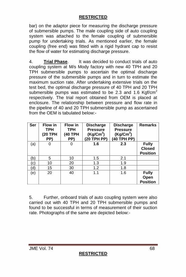
RESTRICTED
JME Vol. 74 68 RESTRICTED
bar) on the adaptor piece for measuring the discharge pressure of submersible pumps. The male coupling side of auto coupling system was attached to the female coupling of submersible pump for undertaking trials. As mentioned earlier, the female coupling (free end) was fitted with a rigid hydrant cap to resist the flow of water for estimating discharge pressure.
4. Trial Phase. It was decided to conduct trials of auto coupling system at M/s Mody factory with new 40 TPH and 20 TPH submersible pumps to ascertain the optimal discharge pressure of the submersible pumps and in turn to estimate the maximum suction rate. After undertaking extensive trials on the test bed, the optimal discharge pressure of 40 TPH and 20 TPH submersible pumps was estimated to be 2.3 and 1.6 Kgf/cm2 respectively. The trial report obtained from OEM is placed at enclosure. The relationship between pressure and flow rate in the pipeline of 40 and 20 TPH submersible pump as ascertained from the OEM is tabulated below:-
5. Further, onboard trials of auto coupling system were also carried out with 40 TPH and 20 TPH submersible pumps and found to be successful in terms of measurement of their suction rate. Photographs of the same are depicted below:-
Ser Flow in TPH
(20 TPH PP)
Flow in TPH
(40 TPH PP)
Discharge Pressure (Kg/Cm
2)
(20 TPH PP)
Discharge Pressure (Kg/Cm
2)
(40 TPH PP)
Remarks
(a) 0 0 1.6 2.3 Fully Closed
Position
(b) 5 10 1.5 2.1
(c) 10 20 1.3 1.9
(d) 15 30 1.2 1.8
(e) 20 40 1.1 1.6 Fully Open
Position
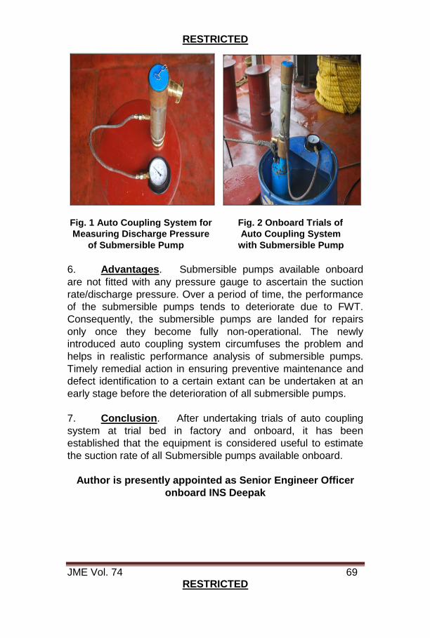
RESTRICTED
JME Vol. 74 69 RESTRICTED
Fig. 1 Auto Coupling System for Fig. 2 Onboard Trials of
Measuring Discharge Pressure Auto Coupling System
of Submersible Pump with Submersible Pump
6. Advantages. Submersible pumps available onboard
are not fitted with any pressure gauge to ascertain the suction
rate/discharge pressure. Over a period of time, the performance
of the submersible pumps tends to deteriorate due to FWT.
Consequently, the submersible pumps are landed for repairs
only once they become fully non-operational. The newly
introduced auto coupling system circumfuses the problem and
helps in realistic performance analysis of submersible pumps.
Timely remedial action in ensuring preventive maintenance and
defect identification to a certain extant can be undertaken at an
early stage before the deterioration of all submersible pumps.
7. Conclusion. After undertaking trials of auto coupling
system at trial bed in factory and onboard, it has been
established that the equipment is considered useful to estimate
the suction rate of all Submersible pumps available onboard.
Author is presently appointed as Senior Engineer Officer
onboard INS Deepak
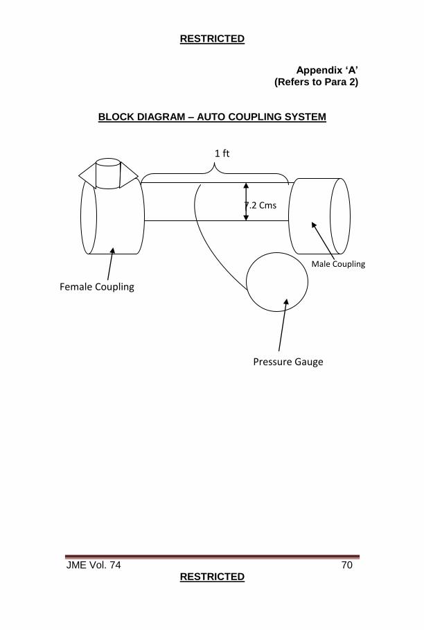
RESTRICTED
JME Vol. 74 70 RESTRICTED
Appendix ‘A’
(Refers to Para 2)
BLOCK DIAGRAM – AUTO COUPLING SYSTEM �
����
��
�� �� ��
��
�
Male Coupling
Female Coupling
1 ft
7.2 Cms
Pressure Gauge
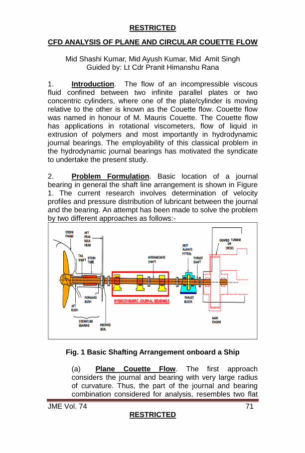
RESTRICTED
JME Vol. 74 71 RESTRICTED
CFD ANALYSIS OF PLANE AND CIRCULAR COUETTE FLOW
Mid Shashi Kumar, Mid Ayush Kumar, Mid Amit Singh Guided by: Lt Cdr Pranit Himanshu Rana
1. Introduction. The flow of an incompressible viscous fluid confined between two infinite parallel plates or two concentric cylinders, where one of the plate/cylinder is moving relative to the other is known as the Couette flow. Couette flow was named in honour of M. Mauris Couette. The Couette flow has applications in rotational viscometers, flow of liquid in extrusion of polymers and most importantly in hydrodynamic journal bearings. The employability of this classical problem in the hydrodynamic journal bearings has motivated the syndicate to undertake the present study. 2. Problem Formulation. Basic location of a journal bearing in general the shaft line arrangement is shown in Figure 1. The current research involves determination of velocity profiles and pressure distribution of lubricant between the journal and the bearing. An attempt has been made to solve the problem by two different approaches as follows:-
Fig. 1 Basic Shafting Arrangement onboard a Ship (a) Plane Couette Flow. The first approach considers the journal and bearing with very large radius of curvature. Thus, the part of the journal and bearing combination considered for analysis, resembles two flat
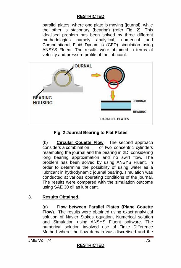
RESTRICTED
JME Vol. 74 72 RESTRICTED
parallel plates, where one plate is moving (journal), while the other is stationary (bearing) (refer Fig. 2). This idealised problem has been solved by three different methodologies namely analytical, numerical and Computational Fluid Dynamics (CFD) simulation using ANSYS Fluent. The results were obtained in terms of velocity and pressure profile of the lubricant.
Fig. 2 Journal Bearing to Flat Plates
(b) Circular Couette Flow. The second approach considers a combination of two concentric cylinders resembling the journal and the bearing in 2D, considering long bearing approximation and no swirl flow. The problem has been solved by using ANSYS Fluent. In order to determine the possibility of using water as a lubricant in hydrodynamic journal bearing, simulation was conducted at various operating conditions of the journal. The results were compared with the simulation outcome using SAE 30 oil as lubricant.
3. Results Obtained.
(a) Flow between Parallel Plates (Plane Couette Flow). The results were obtained using exact analytical solution of Navier Stokes equation, Numerical solution and Simulation using ANSYS Fluent software. The numerical solution involved use of Finite Difference Method where the flow domain was discretised and the
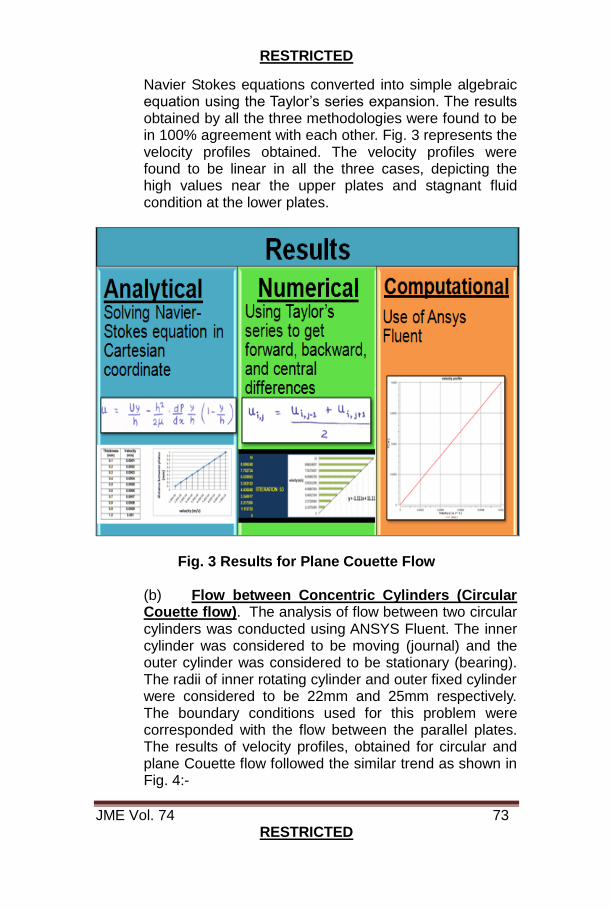
RESTRICTED
JME Vol. 74 73 RESTRICTED
Navier Stokes equations converted into simple algebraic equation using the Taylor’s series expansion. The results obtained by all the three methodologies were found to be in 100% agreement with each other. Fig. 3 represents the velocity profiles obtained. The velocity profiles were found to be linear in all the three cases, depicting the high values near the upper plates and stagnant fluid condition at the lower plates.
Fig. 3 Results for Plane Couette Flow
(b) Flow between Concentric Cylinders (Circular Couette flow). The analysis of flow between two circular cylinders was conducted using ANSYS Fluent. The inner cylinder was considered to be moving (journal) and the outer cylinder was considered to be stationary (bearing). The radii of inner rotating cylinder and outer fixed cylinder were considered to be 22mm and 25mm respectively. The boundary conditions used for this problem were corresponded with the flow between the parallel plates. The results of velocity profiles, obtained for circular and plane Couette flow followed the similar trend as shown in Fig. 4:-

RESTRICTED
JME Vol. 74 74 RESTRICTED
Fig. 4 Comparison of Results for Circular Couette Flow and
Plane Couette Flow (c) Study of Lubricant Suitability using Simulation of Circular Couette Flow. The flow between the concentric cylinders was conducted using water and SAE 30 as lubricants. Various operating parameters like temperature and RPM were varied to determine the suitability of the given fluid as lubricant. Simulation result for the water as lubricant is shown in Fig. 5.
Fig. 5 Results for Circular Couette Flow having Water as Lubricant
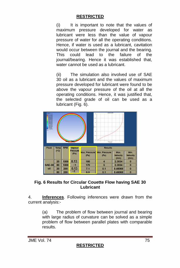
RESTRICTED
JME Vol. 74 75 RESTRICTED
(i) It is important to note that the values of maximum pressure developed for water as lubricant were less than the value of vapour pressure of water for all the operating conditions. Hence, if water is used as a lubricant, cavitation would occur between the journal and the bearing. This could lead to the failure of the journal/bearing. Hence it was established that, water cannot be used as a lubricant.
(ii) The simulation also involved use of SAE 30 oil as a lubricant and the values of maximum pressure developed for lubricant were found to be above the vapour pressure of the oil at all the operating conditions. Hence, it was justified that, the selected grade of oil can be used as a lubricant (Fig. 6).
Fig. 6 Results for Circular Couette Flow having SAE 30 Lubricant
4. Inferences. Following inferences were drawn from the current analysis:-
(a) The problem of flow between journal and bearing with large radius of curvature can be solved as a simple problem of flow between parallel plates with comparable results.

RESTRICTED
JME Vol. 74 76 RESTRICTED
(b) If water is used as lubricant, it would cause excessive wear of journal/bearing material due to cavitation.
(c) Maximum value of pressure of lubricant in a hydrodynamic journal bearing increases with the increase in RPM (Fig. 6) as per the Reynolds equation indicating the effectiveness of hydrodynamic lubrication at higher RPM.
(d) The maximum pressure was observed to reduce with increase in temperature (Fig. 6) which can be attributed to reduction in viscosity of the lubricant with increase in temperature.
(e) The preliminary analysis undertaken depicts that the simulations can be considered more viable compared to the experiments for certain cases where the region of analysis is very small (in the given case, the gap between the journal and the bearing was considered to be 3 mm).
(f) The simulation can also be used to determine suitability of a lubricant between the journal and the bearing for IN Ships to establish various substitutes of lubricants.
(g) Peculiar cases where cause of failure is required to be determined, simulation work may be undertaken with similar operational conditions to find the root cause.
Authors are presently undergoing third year B. Tech in
Mechanical Engineering at Indian Naval Academy, Ezhimala
RESTRICTED
JME Vol. 74 77 RESTRICTED
DEFECT RECTIFICATION ON PORT STABILISER - TEG CLASS
Lt Sunit Sharma
1. Basic Description. Teg class ships are fitted with a pair of hydrodynamic, non-retractable, controllable stabiliser fins (Index: YК6-1) working in tandem. Each fin tilting mechanism consists of a main pump, supplying pressurised oil to a power drive mechanism (Index – MCΠ- 100). The Gear Pump sucks in the working fluid from the pump body and delivers it to the filter unit for distribution to the hydraulic unit assemblies. The Cradle is installed on cylindrical necks of flanges on bearings designated for controlling the output of main pump. The main pump delivers the pressurised oil to fin tilting assembly and the movement of fins is achieved by alternate movement of pressurised oil in the hydraulic cylinders. Background 2. During deployment of one of the Teg class ship, the ship’s Port Stabiliser fin was observed to have stuck at intermittent position with ‘Drive Fail Indication’ displayed on the control panel DM2A. 3. Initial DI Undertaken by Ship’s Staff at Sea. In the absence of pertinent troubleshooting information/ fault diagnosis in the Technical Documents held onboard, the ensuing DI followed a logical pattern of isolating the probable causes and entailed the following activities:-
(a) Filter/ cooler cleaning, calibration of gauges and control system checks.
(b) Operation of Stabiliser in ‘Test’ mode at Mumbai harbour which certified the optimal performance of hydraulic circuit.
(c) Thereafter, the ship had only one occasion, to deploy the stabilisers at sea albeit for a short duration when the performance was satisfactory.
RESTRICTED
JME Vol. 74 78 RESTRICTED
4. Recurrence of Defect. Subsequently, the ship was deployed for an Operational Commitment. Soon after departure from Mumbai, the weather turned significantly inclement upon which the stabilisers had to be deployed. The defect of the Port fin getting stuck at intermittent position recurred, this time with abnormal noise from the Port Stabiliser Pump and concurrent drop in control and cylinder oil pressures. The watch keeper promptly retrieved the fins to zero position using auxiliary pump and locked them to prevent any damage due to heightened sea state. The occurrence of heavy noise, largely symptomatic of presence of air in the hydraulic system entailed complete purging of hydraulic system. However, the exercise did not yield any change in performance characteristics of the Port stabiliser. Operational availability of ship’s stabilisers was extremely critical. Defect Rectification Attempts at Sea 5. Defect Identification Attempt 1. The various activities undertaken for DI/ DR, their results and deductions are tabulated below:-
6. Challenges Faced While Carrying out DI.
(a) The motor, weighing approximately 600 kgs was decoupled from the pump after dismantling the self-aligning coupling housed inside the adaptor flange. The motor was subsequently lifted from its foundation with the help of a chain pulley arrangement and secured safely within the compartment. The team accomplished the task arduously over 08 – 10 hours despite the aggravated sea state.
Ser Activity Result/ Findings Inference
(a) Inspection of Sump and Filter
Dispersed metallic impurities
Damage to Internal Components of Hydraulic Pump
(b) Decoupling of motor
No damage to the self-aligning coupling
No damage to Main Shaft Bearings
(c) Dismantling of pump
Damaged cradle lower end bearings
Cradle Bearings damaged leading to loss of oil pressure
RESTRICTED
JME Vol. 74 79 RESTRICTED
(b) The stabiliser control system is fairly complex with
highly sensitive control devices such as KR11 and HG
3.20. The defect rectification process concurrently
entailed deft segregation and securing of the complete
associated control wiring. The vital KR 11 unit was
extricated mechanically from main pump unit by
dismantling its gear drive.
(c) In order to facilitate the inspection of lower end
bearing, the pump assembly which weighs approximately
700 kgs was efficiently lifted using a chain pulley amidst
considerable space constraints. The process involved
precise and restrained handling of the intricately
designed pump which was then turned upside down for
further assessment.
(d) The cradle assembly has a set of bearings fitted
in the assembly of which, the upper bearing was found
damaged. These bearings have not been included in the
ship’s SPTA. Further scrutiny of the Technical
Documents revealed that the PIL in respect of Hydraulic
Pump has not been incorporated by the OEM. The SS
inferred the Part numbers from the etched marking on the
Cradle bearings dismantled from the pump assembly.
Consultation with SKF reps in India led to an
understanding that bearing SKF 7215 would be the
closest substitute for the fitted Russian bearings.
(e) The troubleshooting chart provided in the
Technical Document was established to be limited in the
range and nature of defects likely to be anticipated on
these pumps. This shortfall was compensated by
exchange of information pertinent to defects on
stabilisers of the same class.
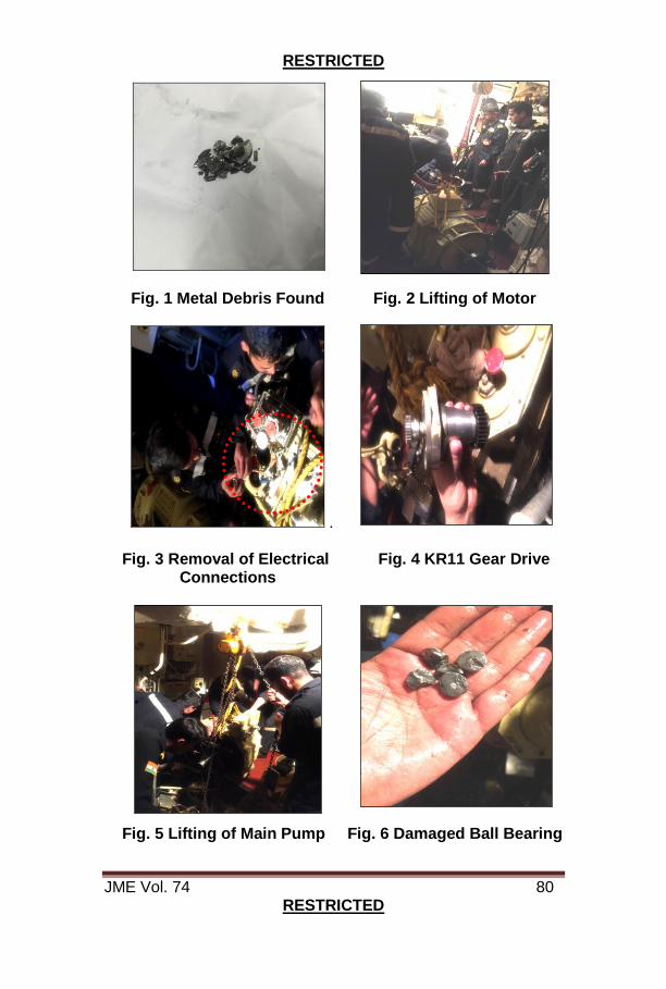
RESTRICTED
JME Vol. 74 80 RESTRICTED
Fig. 1 Metal Debris Found Fig. 2 Lifting of Motor
. Fig. 3 Removal of Electrical Fig. 4 KR11 Gear Drive Connections Fig. 5 Lifting of Main Pump Fig. 6 Damaged Ball Bearing
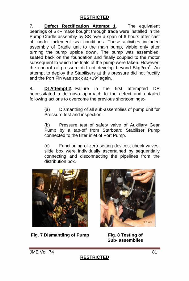
RESTRICTED
JME Vol. 74 81 RESTRICTED
7. Defect Rectification Attempt 1. The equivalent bearings of SKF make bought through trade were installed in the Pump Cradle assembly by SS over a span of 6 hours after cast off under inclement sea conditions. These activities included assembly of Cradle unit to the main pump, viable only after turning the pump upside down. The pump was assembled, seated back on the foundation and finally coupled to the motor subsequent to which the trials of the pump were taken. However, the control oil pressure did not develop beyond 5kgf/cm2. An attempt to deploy the Stabilisers at this pressure did not fructify and the Port Fin was stuck at +190 again.
8. DI Attempt 2. Failure in the first attempted DR necessitated a de–novo approach to the defect and entailed following actions to overcome the previous shortcomings:-
(a) Dismantling of all sub-assemblies of pump unit for Pressure test and inspection. (b) Pressure test of safety valve of Auxiliary Gear Pump by a tap-off from Starboard Stabiliser Pump connected to the filter inlet of Port Pump.
(c) Functioning of zero setting devices, check valves, slide box were individually ascertained by sequentially connecting and disconnecting the pipelines from the distribution box.
Fig. 7 Dismantling of Pump Fig. 8 Testing of Sub- assemblies
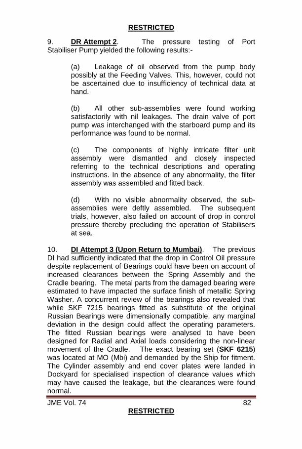
RESTRICTED
JME Vol. 74 82 RESTRICTED
9. DR Attempt 2. The pressure testing of Port Stabiliser Pump yielded the following results:-
(a) Leakage of oil observed from the pump body possibly at the Feeding Valves. This, however, could not be ascertained due to insufficiency of technical data at hand. (b) All other sub-assemblies were found working satisfactorily with nil leakages. The drain valve of port pump was interchanged with the starboard pump and its performance was found to be normal.
(c) The components of highly intricate filter unit assembly were dismantled and closely inspected referring to the technical descriptions and operating instructions. In the absence of any abnormality, the filter assembly was assembled and fitted back.
(d) With no visible abnormality observed, the sub-assemblies were deftly assembled. The subsequent trials, however, also failed on account of drop in control pressure thereby precluding the operation of Stabilisers at sea.
10. DI Attempt 3 (Upon Return to Mumbai). The previous DI had sufficiently indicated that the drop in Control Oil pressure despite replacement of Bearings could have been on account of increased clearances between the Spring Assembly and the Cradle bearing. The metal parts from the damaged bearing were estimated to have impacted the surface finish of metallic Spring Washer. A concurrent review of the bearings also revealed that while SKF 7215 bearings fitted as substitute of the original Russian Bearings were dimensionally compatible, any marginal deviation in the design could affect the operating parameters. The fitted Russian bearings were analysed to have been designed for Radial and Axial loads considering the non-linear movement of the Cradle. The exact bearing set (SKF 6215) was located at MO (Mbi) and demanded by the Ship for fitment. The Cylinder assembly and end cover plates were landed in Dockyard for specialised inspection of clearance values which may have caused the leakage, but the clearances were found normal.

RESTRICTED
JME Vol. 74 83 RESTRICTED
Fig. 9 Scoring Marks on the Surface of Metallic Rings and Conical Washers
11. DR Attempt 3. Assistance of the Central Hydraulic Facility (CHF)/ ND (Mbi) for minor machining of the Rings, Conical Metallic Washers and Springs of the Cradle pump assembly was sought. The trials post machining of the aforementioned components finally proved successful. The Control pressure before and after filter was in the range of 14-18 kgf/cm2and 12-16 kgf/cm2respectively. Further, the oil pressure to oil cooler was also observed to be within permissible range (1-2 kgf/cm2). Test Mode and Sea Trials 12. Test Mode Trials. While the hydraulic pump of the stabilser had been proven in an isolated manner, a sudden movement of the fin and an abnormal sound were noticed during the TEST mode trials in harbour. The Amplifier Card УБ1 which receives feedback signal from the KR11 unit and sends an amplified output to unit HG3.20 for cradle movement of the pump was found to be malfunctioning. The erratic signal led to sudden movement of the Fin leading it to get stuck in extreme position. The card was replaced with a new one from SPTA and the TEST mode was proven satisfactorily.
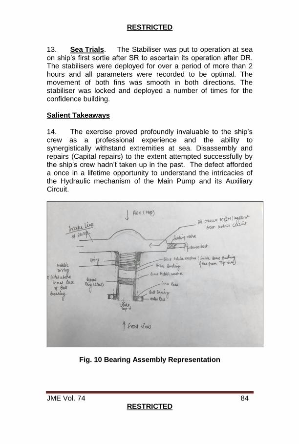
RESTRICTED
JME Vol. 74 84 RESTRICTED
13. Sea Trials. The Stabiliser was put to operation at sea on ship’s first sortie after SR to ascertain its operation after DR. The stabilisers were deployed for over a period of more than 2 hours and all parameters were recorded to be optimal. The movement of both fins was smooth in both directions. The stabiliser was locked and deployed a number of times for the confidence building. Salient Takeaways 14. The exercise proved profoundly invaluable to the ship’s crew as a professional experience and the ability to synergistically withstand extremities at sea. Disassembly and repairs (Capital repairs) to the extent attempted successfully by the ship’s crew hadn’t taken up in the past. The defect afforded a once in a lifetime opportunity to understand the intricacies of the Hydraulic mechanism of the Main Pump and its Auxiliary Circuit.
Fig. 10 Bearing Assembly Representation

RESTRICTED
JME Vol. 74 85 RESTRICTED
Fig. 11 Dismantled Distribution Fig. 12 Cordon Joint Spring Box Mechanism
Conclusion 15. The Amplifier card identified to be malfunctioning during the last phase of trials credibly explains the initiation and manifestation of defect. It has now been conclusively inferred that the malfunctioning Amplifier card led the Hydraulic control mechanism to hinder the designated operation of the Hydraulic pump. While the initial symptoms only showed occasional disruption in the operation of Fin, the same was gradually followed by perceptible changes in acoustic levels. This phenomenon eventually propagated the failure of Cradle Bearing also resulting in scoring of the Conical and Metallic Washers of Spring Assembly between the Bearing top face and the securing end plate of the Cradle Assembly. The deterioration in surface finish and enhanced clearances between the Conical and Metallic washers of the Spring Assembly (provided to support the Cradle Bearing) and securing plate on the pump housing further led to drop in Control Oil Pressure. The continuous cyclic loads on the Cradle bearing due to sudden movements may have exceeded the Creep point resulting in Material failure over a period of time. The physical manifestation of such failures may range from gradual rise in oil temperature and eventual loss of oil pressure. The manifestation of such defects can be summarised by the flow chart elucidated below:-
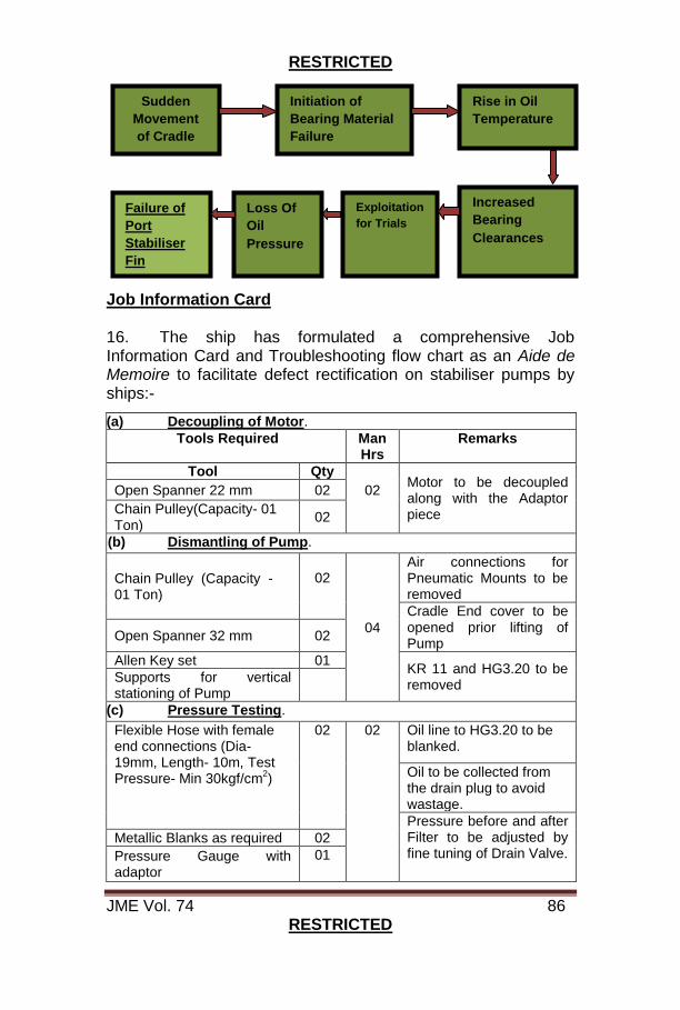
RESTRICTED
JME Vol. 74 86 RESTRICTED
Job Information Card 16. The ship has formulated a comprehensive Job Information Card and Troubleshooting flow chart as an Aide de Memoire to facilitate defect rectification on stabiliser pumps by ships:-
(a) Decoupling of Motor.
Tools Required Man Hrs
Remarks
Tool Qty
02
Motor to be decoupled along with the Adaptor piece
Open Spanner 22 mm 02
Chain Pulley(Capacity- 01 Ton)
02
(b) Dismantling of Pump.
Chain Pulley (Capacity - 01 Ton)
02
04
Air connections for Pneumatic Mounts to be removed
Cradle End cover to be opened prior lifting of Pump
Open Spanner 32 mm 02
Allen Key set 01 KR 11 and HG3.20 to be removed
Supports for vertical stationing of Pump
(c) Pressure Testing.
Flexible Hose with female end connections (Dia-19mm, Length- 10m, Test Pressure- Min 30kgf/cm
2)
02 02 Oil line to HG3.20 to be blanked.
Oil to be collected from the drain plug to avoid wastage.
Pressure before and after Filter to be adjusted by fine tuning of Drain Valve.
Metallic Blanks as required 02
Pressure Gauge with adaptor
01
Sudden
Movement
of Cradle
Initiation of
Bearing Material
Failure
Rise in Oil
Temperature
Increased
Bearing
Clearances
Exploitation
for Trials
Loss Of
Oil
Pressure
Failure of
Port
Stabiliser
Fin
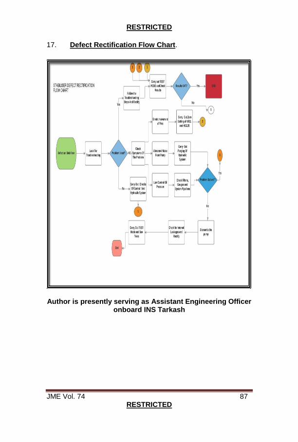
RESTRICTED
JME Vol. 74 87 RESTRICTED
17. Defect Rectification Flow Chart.
Author is presently serving as Assistant Engineering Officer
onboard INS Tarkash
RESTRICTED
JME Vol. 74 88 RESTRICTED
KNOWLEDGE ENABLER BAY GAS TURBINE TESTING AND TUNING TEAM (MBI)
Cdr AP Singh
Background 1. Gas Turbine propulsion was introduced into the Indian Navy in the late 1960s with the induction of Petya class of ships. Since then, Gas turbines have brought in a major ‘boost’ to the propulsive power and have gradually become the mainstay of marine propulsion in the Navy. The Navy today is witnessing a massive upgradation in terms of its strength and capability and the ‘Gas Turbine' continues to be the obvious choice of propulsion and power generation for frontline warships. Considering the critical requirements of these engines, continual training on exploitation and maintenance to ensure sustained reliable availability with minimum downtime becomes utmost important. 2. Gas Turbine Testing and Tuning Team (GTTT), Mumbai was formed 29 years ago with a vision to ensure ‘Mission Ready’ Gas Turbines in perpetuum and its repertoire has grown leaps and bounds since then. GTTT (Mbi) is the nodal agency responsible for all the GTA and GTG assets of the Western Naval Command. In order to succeed in its mission and quality commitment, GTTT (Mbi) also conducts training of Personnel in addition to the mandate of undertaking EHM trials and FPT. The Unit has been conducting short training capsules for Officers/Sailors undergoing PCT course for GT ships as per Annual Training Programme (ATP), Type training for Commissioning Crews and training the Engine Room complement posted onboard ships, wherein training is imparted on basic exposure to vibration diagnostics and equipment exploitation based on field experience. This is done with an aim to familiarise the crew on practical aspects of exploiting GTs and implementing CBPM techniques. However, classes conducted hitherto, mainly comprised of theoretical inputs at the Unit and practical exposure by visit to ships, as no facility for practical demonstration existed. However, onboard ships, accessibility and tampering with tuned operational system was not feasible. This led to the conceptualisation and creation of a Unique Training facility, using in-house resources at GTTT (Mbi) by

RESTRICTED
JME Vol. 74 89 RESTRICTED
installing two BER Gas Turbines (Cruise & Boost GTs of 1241 RE class of ships), one BER GTG (1250-E), one GT starting rectifier and various Fuel & Control Components related to GTs and GTGs. The training facility has been christened as ‘Knowledge Enabler Bay’. Setting up of Knowledge Enabler Bay 3. The facility was set up on the terrace of GTTT (Mbi) in three phases, as follows:-
(a) Phase I- Setting up of GT Practical Training Bay. (b) Phase II-Setting up of GTG hands on Training Bay. (c) Phase III - Setting up of GT/GTG Controls Bay.
Fig. 1 Setting Up of Knowledge Enabler Bay
RESTRICTED
JME Vol. 74 90 RESTRICTED
4. Setting up such a training facility mandated shifting of GTs/GTG & GT starting rectifier to the second floor of the AGM(E) complex in ND (Mbi) {terrace of GTTT (Mbi)} at a height of 70 ft. The execution required detailed planning and modalities for shifting had to be worked out, keeping safety of man and material as paramount. As the space available for the crane to maneuver was limited and the crane operator was in a blind zone with respect to final position of equipment, a comprehensive plan of the entire evolution was prepared to ensure hoisting of GTs was undertaken with utmost precaution and safety consciousness. To ensure all weather training and provide protection for the GTs/GTG and other components, a shelter was also designed and constructed. Further, the shifting of equipment and construction of shelter was undertaken primarily through naval resources, thereby saving approx. 10 lakhs of rupees to the exchequer. To augment the training, a multimedia auditorium has also been set up at KEB to cover sessions on frequent oversights and ‘Near Miss’ observed onboard during trials. 5. KEB has been set up to meet the following Objectives:-
(a) Impart practical training on aspects of vibration recording and analysis, to the trainees for implementation of CBPM onboard.
(b) Enhanced in-house training for the newly joined sailors of GTTT.
(c) Practical Demonstration of various Tuning/Adjustments undertaken on GTs/GTGs.
(d) Practical demonstration of various Pre-Start and Post-Shut down checks on GTs/GTGs as well as ‘Good Engineering Practices’.
(e) Enable trial team sailors to demonstrate various maintenance schedules and assembly/disassembly procedures of GT/GTG equipment including control components.
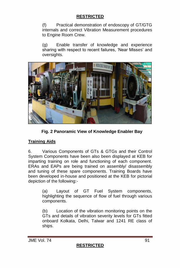
RESTRICTED
JME Vol. 74 91 RESTRICTED
(f) Practical demonstration of endoscopy of GT/GTG internals and correct Vibration Measurement procedures to Engine Room Crew.
(g) Enable transfer of knowledge and experience sharing with respect to recent failures, ‘Near Misses’ and oversights.
Fig. 2 Panoramic View of Knowledge Enabler Bay Training Aids 6. Various Components of GTs & GTGs and their Control System Components have been also been displayed at KEB for imparting training on role and functioning of each component. ERAs and EAPs are being trained on assembly/ disassembly and tuning of these spare components. Training Boards have been developed in-house and positioned at the KEB for pictorial depiction of the following:-
(a) Layout of GT Fuel System components, highlighting the sequence of flow of fuel through various components. (b) Location of the vibration monitoring points on the GTs and details of vibration severity levels for GTs fitted onboard Kolkata, Delhi, Talwar and 1241 RE class of ships.
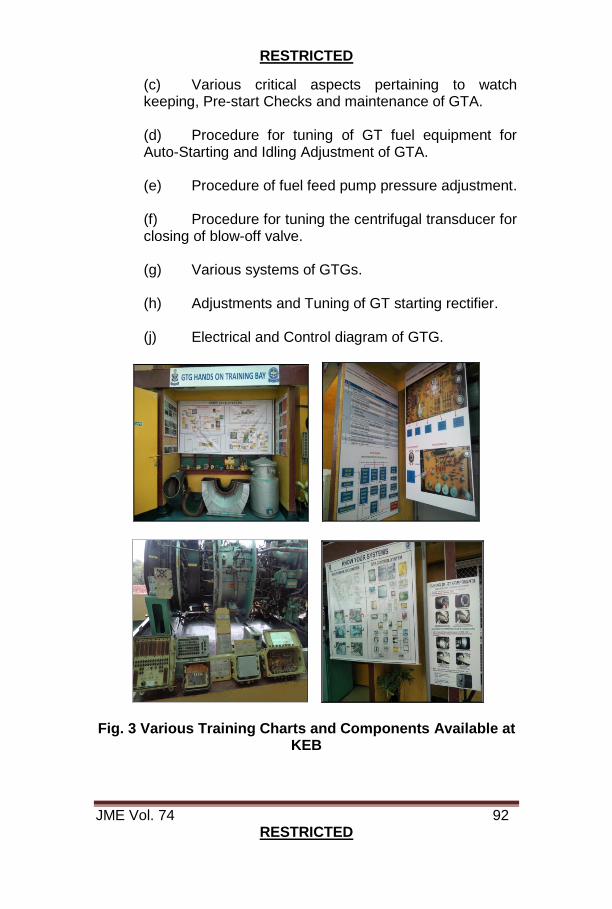
RESTRICTED
JME Vol. 74 92 RESTRICTED
(c) Various critical aspects pertaining to watch keeping, Pre-start Checks and maintenance of GTA. (d) Procedure for tuning of GT fuel equipment for Auto-Starting and Idling Adjustment of GTA.
(e) Procedure of fuel feed pump pressure adjustment.
(f) Procedure for tuning the centrifugal transducer for closing of blow-off valve.
(g) Various systems of GTGs.
(h) Adjustments and Tuning of GT starting rectifier.
(j) Electrical and Control diagram of GTG.
Fig. 3 Various Training Charts and Components Available at KEB
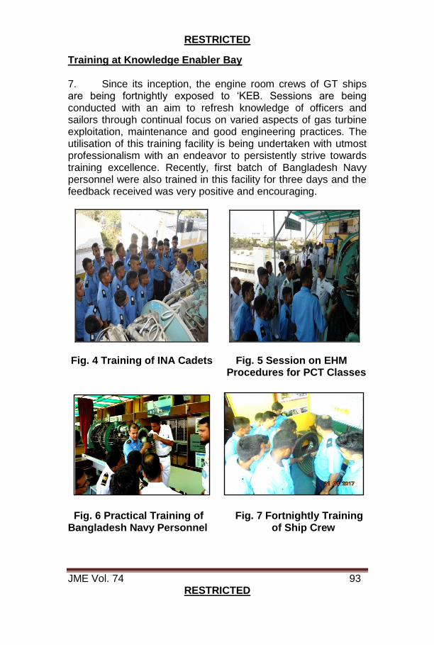
RESTRICTED
JME Vol. 74 93 RESTRICTED
Training at Knowledge Enabler Bay 7. Since its inception, the engine room crews of GT ships are being fortnightly exposed to ‘KEB. Sessions are being conducted with an aim to refresh knowledge of officers and sailors through continual focus on varied aspects of gas turbine exploitation, maintenance and good engineering practices. The utilisation of this training facility is being undertaken with utmost professionalism with an endeavor to persistently strive towards training excellence. Recently, first batch of Bangladesh Navy personnel were also trained in this facility for three days and the feedback received was very positive and encouraging.
Fig. 4 Training of INA Cadets Fig. 5 Session on EHM Procedures for PCT Classes
Fig. 6 Practical Training of Fig. 7 Fortnightly Training Bangladesh Navy Personnel of Ship Crew
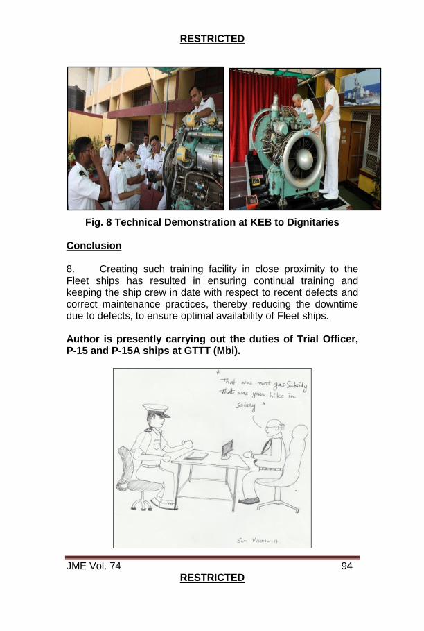
RESTRICTED
JME Vol. 74 94 RESTRICTED
Fig. 8 Technical Demonstration at KEB to Dignitaries Conclusion 8. Creating such training facility in close proximity to the Fleet ships has resulted in ensuring continual training and keeping the ship crew in date with respect to recent defects and correct maintenance practices, thereby reducing the downtime due to defects, to ensure optimal availability of Fleet ships.
Author is presently carrying out the duties of Trial Officer, P-15 and P-15A ships at GTTT (Mbi).
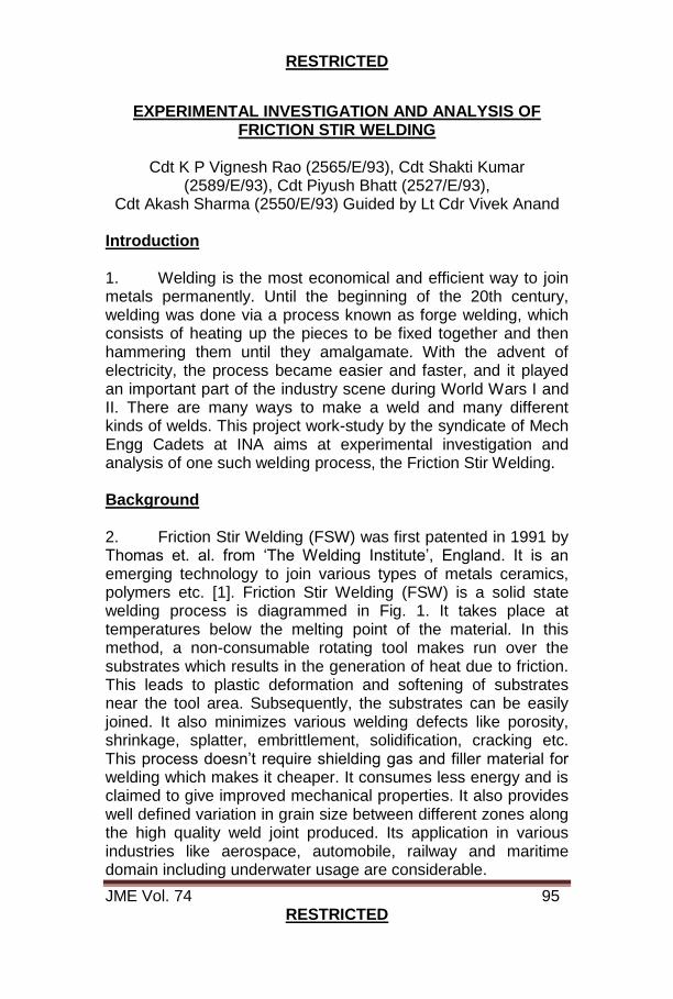
RESTRICTED
JME Vol. 74 95 RESTRICTED
EXPERIMENTAL INVESTIGATION AND ANALYSIS OF
FRICTION STIR WELDING
Cdt K P Vignesh Rao (2565/E/93), Cdt Shakti Kumar (2589/E/93), Cdt Piyush Bhatt (2527/E/93),
Cdt Akash Sharma (2550/E/93) Guided by Lt Cdr Vivek Anand Introduction 1. Welding is the most economical and efficient way to join metals permanently. Until the beginning of the 20th century, welding was done via a process known as forge welding, which consists of heating up the pieces to be fixed together and then hammering them until they amalgamate. With the advent of electricity, the process became easier and faster, and it played an important part of the industry scene during World Wars I and II. There are many ways to make a weld and many different kinds of welds. This project work-study by the syndicate of Mech Engg Cadets at INA aims at experimental investigation and analysis of one such welding process, the Friction Stir Welding. Background 2. Friction Stir Welding (FSW) was first patented in 1991 by Thomas et. al. from ‘The Welding Institute’, England. It is an emerging technology to join various types of metals ceramics, polymers etc. [1]. Friction Stir Welding (FSW) is a solid state welding process is diagrammed in Fig. 1. It takes place at temperatures below the melting point of the material. In this method, a non-consumable rotating tool makes run over the substrates which results in the generation of heat due to friction. This leads to plastic deformation and softening of substrates near the tool area. Subsequently, the substrates can be easily joined. It also minimizes various welding defects like porosity, shrinkage, splatter, embrittlement, solidification, cracking etc. This process doesn’t require shielding gas and filler material for welding which makes it cheaper. It consumes less energy and is claimed to give improved mechanical properties. It also provides well defined variation in grain size between different zones along the high quality weld joint produced. Its application in various industries like aerospace, automobile, railway and maritime domain including underwater usage are considerable.
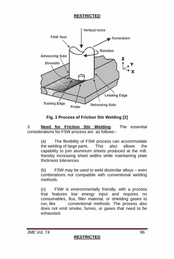
RESTRICTED
JME Vol. 74 96 RESTRICTED
Fig. 1 Process of Friction Stir Welding [2] 3. Need for Friction Stir Welding. The essential considerations for FSW process are as follows:-
(a) The flexibility of FSW process can accommodate the welding of large parts. This also allows the capability to join aluminum sheets produced at the mill, thereby increasing sheet widths while maintaining plate thickness tolerances. (b) FSW may be used to weld dissimilar alloys – even combinations not compatible with conventional welding methods.
(c) FSW is environmentally friendly, with a process that features low energy input and requires no consumables, flux, filler material, or shielding gases to run, like conventional methods. The process also does not emit smoke, fumes, or gases that need to be exhausted.
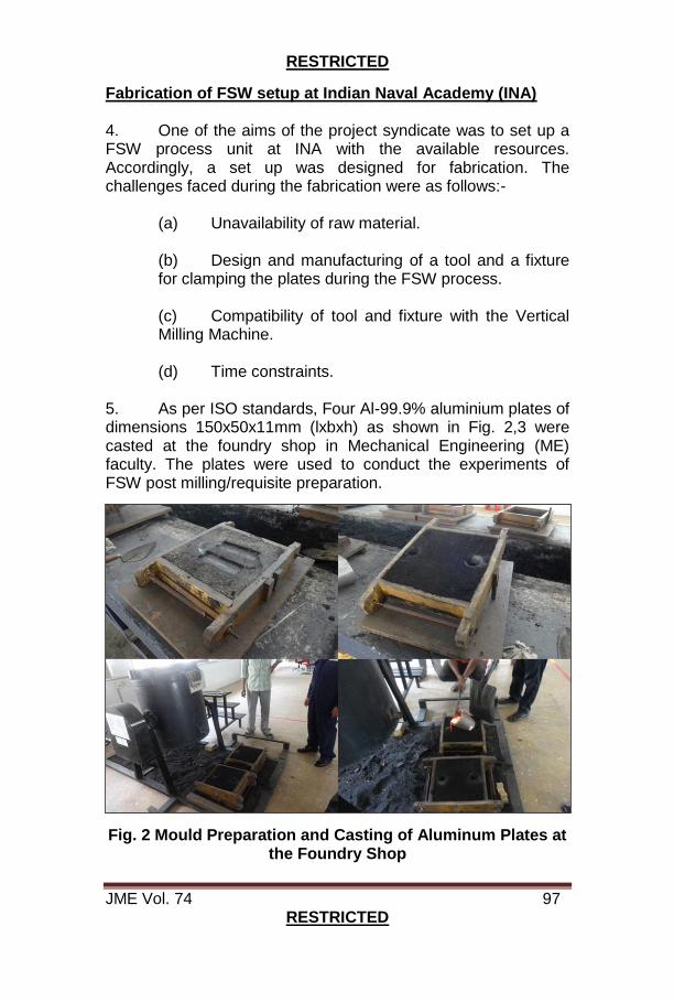
RESTRICTED
JME Vol. 74 97 RESTRICTED
Fabrication of FSW setup at Indian Naval Academy (INA) 4. One of the aims of the project syndicate was to set up a FSW process unit at INA with the available resources. Accordingly, a set up was designed for fabrication. The challenges faced during the fabrication were as follows:-
(a) Unavailability of raw material.
(b) Design and manufacturing of a tool and a fixture for clamping the plates during the FSW process.
(c) Compatibility of tool and fixture with the Vertical Milling Machine.
(d) Time constraints. 5. As per ISO standards, Four Al-99.9% aluminium plates of dimensions 150x50x11mm (lxbxh) as shown in Fig. 2,3 were casted at the foundry shop in Mechanical Engineering (ME) faculty. The plates were used to conduct the experiments of FSW post milling/requisite preparation.
Fig. 2 Mould Preparation and Casting of Aluminum Plates at the Foundry Shop
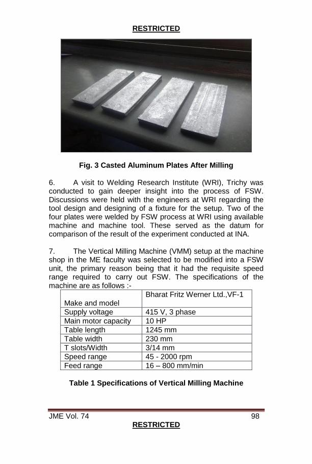
RESTRICTED
JME Vol. 74 98 RESTRICTED
Fig. 3 Casted Aluminum Plates After Milling
6. A visit to Welding Research Institute (WRI), Trichy was conducted to gain deeper insight into the process of FSW. Discussions were held with the engineers at WRI regarding the tool design and designing of a fixture for the setup. Two of the four plates were welded by FSW process at WRI using available machine and machine tool. These served as the datum for comparison of the result of the experiment conducted at INA. 7. The Vertical Milling Machine (VMM) setup at the machine shop in the ME faculty was selected to be modified into a FSW unit, the primary reason being that it had the requisite speed range required to carry out FSW. The specifications of the machine are as follows :-
Make and model
Bharat Fritz Werner Ltd.,VF-1
Supply voltage 415 V, 3 phase
Main motor capacity 10 HP
Table length 1245 mm
Table width 230 mm
T slots/Width 3/14 mm
Speed range 45 - 2000 rpm
Feed range 16 – 800 mm/min
Table 1 Specifications of Vertical Milling Machine

RESTRICTED
JME Vol. 74 99 RESTRICTED
8. There are several tool materials that have been used in the FSW process. These materials include but are not limited to tool steels, high speed steel (HSS), Ni-alloys, metal carbides and ceramics [3]. HCHCr-D2 Tool steel is one of the most commonly used tool materials in the welding/processing of aluminum copper and magnesium alloys and can weld up to 50 mm depth for these materials [4]. However, at INA a tool was manufactured using the MS rods available at the machine shop as shown in Fig. 4. The tool was modified to fit into the collet of the VMM as per ASTM standards. The specifications of the indigenous tool design are as follows:-
Material Mild Steel
Shoulder diameter 27 mm
Pin diameter 8 mm
Pin length 8.4 mm
Pin geometry Cylindrical, Threaded
Pitch of thread 1.5 mm
Table 2 Specifications of Indigenous Tool Design
Fig. 4 Indigenous MS Tool
9. After a thorough literature review [5] [6] and brainstorming, a fixture was designed and manufactured by using the metal plates and angles available at the welding shop as shown in Fig. 5. The individual components were welded together by Shielded Metal Arc Welding (SMAW). Nuts and bolts were used to clamp the plates and to fix the fixture to the VMM. The specifications of the various components are as follows:-

RESTRICTED
JME Vol. 74 100 RESTRICTED
Table 3 Specifications of Components Used for Fixture
Design
Fig. 5 Various Components Used in Manufacturing the Fixture
Fig. 6 Final Fixture Post Welding Fig. 7. Post Weld
Finishing of Fixture
Ser Component Dimensions (mm) Material Qty
(a) Base plate 200x110x8 MS 2
(b) Backing Plate
135x110x8 MS 1
(c) Angle plate 80x50x5 MS 4
(d) Nut and Bolt M16 SS 4
(e) Nut and Bolt M8 SS 4
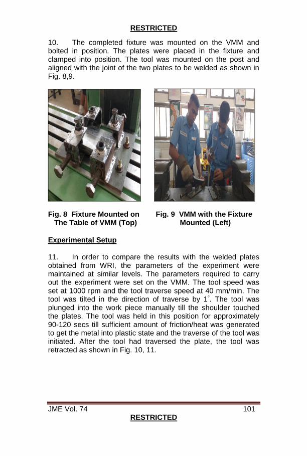
RESTRICTED
JME Vol. 74 101 RESTRICTED
10. The completed fixture was mounted on the VMM and bolted in position. The plates were placed in the fixture and clamped into position. The tool was mounted on the post and aligned with the joint of the two plates to be welded as shown in Fig. 8,9.
Fig. 8 Fixture Mounted on Fig. 9 VMM with the Fixture The Table of VMM (Top) Mounted (Left)
Experimental Setup 11. In order to compare the results with the welded plates obtained from WRI, the parameters of the experiment were maintained at similar levels. The parameters required to carry out the experiment were set on the VMM. The tool speed was set at 1000 rpm and the tool traverse speed at 40 mm/min. The tool was tilted in the direction of traverse by 1ᵒ. The tool was plunged into the work piece manually till the shoulder touched the plates. The tool was held in this position for approximately 90-120 secs till sufficient amount of friction/heat was generated to get the metal into plastic state and the traverse of the tool was initiated. After the tool had traversed the plate, the tool was retracted as shown in Fig. 10, 11.

RESTRICTED
JME Vol. 74 102 RESTRICTED
Fig. 10 Plunging of Tool into the Plates
Fig. 11 Dwelling of Tool Followed by Weld Seam
Results and Observations 12. Observations made during the experiment were as follows:-
(a) Certain weld defects were found on the rear side of the welded plates. This was primarily because the tool pin had travelled very close to the backing plate. (b) Lesser amount of excess material was produced during our experiment compared to the experiment conducted at WRI, Trichy due to lesser travel tool speed.

RESTRICTED
JME Vol. 74 103 RESTRICTED
(c) The weld finish during the experiment was found to be slightly coarse compared to the weld bead obtained at WRI due to MS tool material. (d) A common problem observed both at WRI and at INA was the sticking of the backing plate to the welded plates.
13. The table below shows a comparison of the experiment setup conducted at WRI, and at INA:-
Table 4 Comparison of Experiment Setup Conducted at
WRI and at INA 14. The following Figures show the comparative analysis of the two welded plates. The plate on the left was welded at WRI and the plate on the right, at INA. Various visual defects and weld qualities observed in the plates are marked. Since the plate on the LHS was machined post welding, the flash generated is not seen.
Welding Research Institute
Indian Naval Academy
Machine Universal Milling Machine Vertical Milling Machine
Tool material HCHCr Tool Steel Mild steel
Tool speed 900rpm 1000rpm
Traverse speed
30 mm/min 40 mm/min
Plates used Casted Al plates Casted Al plates
Plate thickness
10mm 8.9mm
Pin geometry Cylindrical, Threaded Cylindrical, Threaded
Pin diameter 8mm 8mm
Pin length 9.6mm 8.4mm
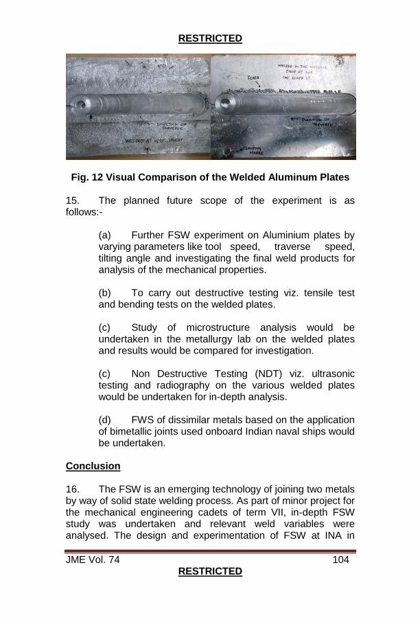
RESTRICTED
JME Vol. 74 104 RESTRICTED
Fig. 12 Visual Comparison of the Welded Aluminum Plates
15. The planned future scope of the experiment is as follows:-
(a) Further FSW experiment on Aluminium plates by varying parameters like tool speed, traverse speed, tilting angle and investigating the final weld products for analysis of the mechanical properties. (b) To carry out destructive testing viz. tensile test and bending tests on the welded plates. (c) Study of microstructure analysis would be undertaken in the metallurgy lab on the welded plates and results would be compared for investigation. (c) Non Destructive Testing (NDT) viz. ultrasonic testing and radiography on the various welded plates would be undertaken for in-depth analysis. (d) FWS of dissimilar metals based on the application of bimetallic joints used onboard Indian naval ships would be undertaken.
Conclusion 16. The FSW is an emerging technology of joining two metals by way of solid state welding process. As part of minor project for the mechanical engineering cadets of term VII, in-depth FSW study was undertaken and relevant weld variables were analysed. The design and experimentation of FSW at INA in
RESTRICTED
JME Vol. 74 105 RESTRICTED
consultation with WRI Trichy, has indictaed its immense potential to be used for IN especially in the repair yards. As future scope, testing of weld properties and FSW for bimetallic joints as planned to be undertaken. References 1. Ákos Meilinger, Imre Török, “The Importance Of Friction Stir Welding Tool”, Production Processes and Systems, Vol. 6. (2013) No. 1., pp. 25-34. 2. www.esabna.com/us/en/education/blog/friction-stir-welding-of-al.cfm. 3. G.Tamizharasi, S.Kathiresan, “Friction Stir Welded Cast and Wrought Aluminium Alloy Joint & Effect of Process Parameters”, International Journal of Advanced Research in Electrical, Electronics and Instrumentation Engineering, Vol. 2, Issue 8, August 2013. 4. R. S. Mishra and M. W. Mahoney, “Friction Stir Welding and Processing”, published by ASM International, Materials Park, Ohio, 2007. 5. Thomas, W. M., Nicholas, E. D., Needham, J. C., Murch, M. G., Temple-Smith, P., and Dawes, C. J., (1991), “Friction stir welding”. Vol.49 No.08 pp.1911-1914. 6. Y. N. Zhang, X. Cao, S. Larose and P. Wanjara, “Review of tools for friction stir welding and processing”, Canadian Metallurgical Quarterly, 2012, Vol 51, No 3, pp. 250-261.
Authors are presently undergoing third year B. Tech in
Mechanical Engineering at Indian Naval Academy, Ezhimala

RESTRICTED
JME Vol. 74 106 RESTRICTED
SEA STATE 6
Lt Vipul Rupree
When warships sail out and disappear into the horizon, When the safe embrace of the shore lets go of mighty men of war No matter how powerful or how mighty the vessel, they all give in They are at the mercy of a thunderous roar The ocean in all her vastness is no stranger to the sailor The powerful, the dubious, the vast sea Just out of the channel the first few waves come as a trailer Of what is to follow, will they have mercy? Like tortured souls the hull twists and cries out in vain Rolling and pitching, being agonised without rest Thunderstorms eclipse the bridge windows, powdered with rain Still they barge forward taking more blows to the chest While glasses, boxes and men clatter to and fro And all efforts are made to endure just that instant As inescapable nausea wreathes down below Not a thought other than to survive as resistant But think of the men who challenge such a deadly foe Those who everyday dare what they do not know The men who sail these metal giants out into dangerous waters To hopefully return to their fair ladies, sons and daughters These men are those who keep our country’s flag flying free I can proudly say these men are none other than you and me
Author is presently serving as Engineer Officer
onboard INS Vipul
RESTRICTED
JME Vol. 74 107 RESTRICTED
MESC STAFF STUDENT PROJECTS UNDERTAKEN
1. Staff-Student Projects are a vital aspect of the curriculum for the Officers undergoing Marine Engineering Specialisation Course (MESC). The under trainee officers are encouraged to apply their knowledge and skills into practical applications and undertake technically challenging projects. Emphasizing on the engineering aspects and research areas currently in vogue that could be useful for the Indian Navy is the main aim behind this exercise. Selected projects are sent for field trials at Naval Dockyards and Fleet Ships.
2. A brief on Staff – Student Projects under taken by the Officers of MESC recently is enumerated in the succeeding paragraphs. Development of Control Based Technique for Precise Lifting and Renewal of SV Mounts of Talwar Class Cruise GT Cradle 3. The Cruise GTs on Talwar class are placed on a hanging cradle which is supported by 96 SV mounts (48 each on either sides) as an acoustic measure to minimize transmission of vibrations generated by equipment to the ship’s hull. Replacement of these mounts is a 10 yearly routine and prescribed OEM procedure is man power intensive and susceptible to misalignment. To overcome the extent manual procedure, a PLC based scaled down model was designed. The lifting mechanism was assembled by integrating servo motor with the screw jack capable of achieving precise lifting. The scope of project involves design of scale down model of cradle and developing a prototype. It also included design of precise control system for lifting of the prototype. 4. As part of the project, actual dimensions, weight and position of various components were obtained during the field visit onboard IN Ships Talwar, Tabar and Trikand. This data was thereafter translated into a 3D model for analysis. The load distribution of each component has been calculated and verified using ANSYS software.

RESTRICTED
JME Vol. 74 108 RESTRICTED
13
FEEDBACK
Fig. 1 Stress Analysis on Fig. 2 Proposed Lifting ANSYS Mechanism 5. Based on the study, use of screw jack based system was found to be more feasible than hydraulic system due to space constraints onboard. A mechanism using screw jacks as the main lifting component was thereafter designed and various electronic components for controlled movement of jacks were integrated. 6. A factor of 22:1 was used to scale down the actual existing model on board. The setup consists of a PLC, servo motor, motor control unit, linear encoder and screw jack along with an HMI touch screen. The mechanism comprises of electronically controlled motor which drives the screw jack with encoders for controlling the precise number of revolutions of the motor. The PLC continuously supplies voltage to the motor and monitor the position of the cradle 7. The PLC sends the control signal to the motor control drive unit based on the input value fed into the system through HMI. The motor control drive unit generates corresponding voltage for driving the motor. The feedback is obtained through an encoder which continuously senses the displacement of the screw. When the required vertical displacement is achieved, the voltage supply is cut off, consequently holding the screw jack in its desired position. All the motors are simultaneously controlled through PLC. The project’s aim of developing a precise lifting prototype mechanism was achieved upon successful tests on the
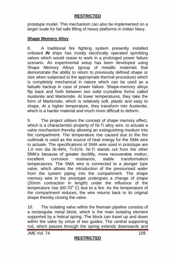
RESTRICTED
JME Vol. 74 109 RESTRICTED
prototype model. This mechanism can also be implemented on a larger scale for fail safe lifting of heavy platforms in Indian Navy. Shape Memory Alloy 8. A traditional fire fighting system presently installed onboard IN ships has mostly electrically operated sprinkling valves which would cease to work in a prolonged power failure scenario. An experimental setup has been developed using Shape Memory Alloys (group of metallic materials that demonstrate the ability to return to previously defined shape or size when subjected to the appropriate thermal procedure) which is completely mechanical in nature which can be used as a failsafe backup in case of power failure. Shape-memory alloys flip back and forth between two solid crystalline forms called Austenite and Martensite. At lower temperatures, they take the form of Martensite, which is relatively soft, plastic and easy to shape. At a higher temperature, they transform into Austenite, which is a harder material and much more difficult to deform. 9. The project utilises the concept of shape memory effect, which is a characteristic property of Ni-Ti alloy wire, to actuate a valve mechanism thereby allowing an extinguishing medium into the compartment. The temperature rise caused due to the fire outbreak is used as the source of heat energy for the SMA wire to actuate. The specifications of SMA wire used in prototype are 1.0 mm dia Ni-49%, Ti-51%. Ni-Ti stands out from the other SMA’s because of greater ductility, more recoverable motion, excellent corrosion resistance, stable transformation temperatures. The SMA wire is connected to a plunger type valve, which allows the introduction of the pressurised water from the system piping into the compartment. The shape memory wire in the prototype undergoes a change of shape (20mm contraction in length) under the influence of the temperature rise (60-700 C) due to a fire. As the temperature of the compartment reduces, the wire returns back to its original shape thereby closing the valve. 10. The isolating valve within the firemain pipeline consists of a rectangular metal block, which is the main isolating element supported by a helical spring. The block can travel up and down within the valve by virtue of two guides. The central supporting rod, which passes through the spring extends downwards and
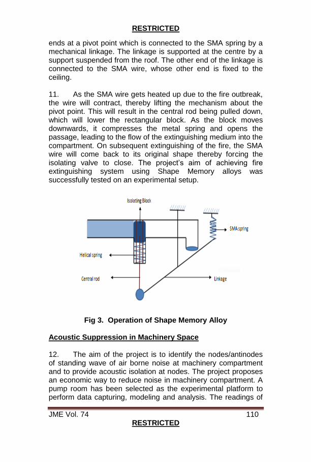
RESTRICTED
JME Vol. 74 110 RESTRICTED
ends at a pivot point which is connected to the SMA spring by a mechanical linkage. The linkage is supported at the centre by a support suspended from the roof. The other end of the linkage is connected to the SMA wire, whose other end is fixed to the ceiling. 11. As the SMA wire gets heated up due to the fire outbreak, the wire will contract, thereby lifting the mechanism about the pivot point. This will result in the central rod being pulled down, which will lower the rectangular block. As the block moves downwards, it compresses the metal spring and opens the passage, leading to the flow of the extinguishing medium into the compartment. On subsequent extinguishing of the fire, the SMA wire will come back to its original shape thereby forcing the isolating valve to close. The project’s aim of achieving fire extinguishing system using Shape Memory alloys was successfully tested on an experimental setup.
Fig 3. Operation of Shape Memory Alloy
Acoustic Suppression in Machinery Space 12. The aim of the project is to identify the nodes/antinodes of standing wave of air borne noise at machinery compartment and to provide acoustic isolation at nodes. The project proposes an economic way to reduce noise in machinery compartment. A pump room has been selected as the experimental platform to perform data capturing, modeling and analysis. The readings of

RESTRICTED
JME Vol. 74 111 RESTRICTED
the noise levels are taken through a multichannel sound level meter (‘A’ and ‘C’ weighted scale) which are generated by a 5TPH pump and motor. The modeling of the room has been done in Catia V5. Thereafter the room has been acoustically mapped by creating different planes and axes with the help of sound level meter. The air has been extracted out of the modeled room and analysed through ANSYS 16.0. The analytical process consists of setting up of parameters of volume contained within it by taking air density of 1.225 kg/m3. The analysis is done under the boundary condition of impedance and boundary admittance of reflecting faces of wall. The FLUID30 element is being used in acoustic analysis upon which the tetrahedron meshing is done. Therefore the ANSYS analysis done at high noise levels are shown in the corners and selected portion of the walls. On the basis of this analysis the sound absorptive material has been strategically placed and thereafter the readings are again recorded. The readings obtained had shown a decrease of 10-12 db at antinodes and 2-4 db in overall noise level when the machineries are running. The future scope of this project is to reduce the sound attenuation in machinery spaces originating from different machines in Indian Naval Ships as an aid to noise reduction and healthy watch keeping. Fig. 4 Analysis on ANSYS Fig. 5 Experimental Setup
PLC Based Control Panel for Steering Gear
13. The project was aimed at designing a PLC based control system for a steering gear and integrating it with existing facility which was received ex-Vijaydurg in 2003. The setup is capable of operating steering gear in various modes of operation through a Human Machine Interface. This system can now be used to impart training for all the ab-initio courses. This system is also being used as a model to familiarize the trainees with PLC based control systems.

RESTRICTED
JME Vol. 74 112 RESTRICTED
14. The present hydraulic system consists of a VSG pump with a swash plate for supply of oil with requisite pressure to the hydraulic ram, which is connected with rudderstock. The movement of the swash plate is controlled by the drive assembly consisting of servo motor, fixed on top of VSG pump. The position of swash plate decides the direction of rotation of rudder. The PLC generates the control signal depending on the demand received (from push buttons in NFU mode / rudder wheel in FU mode) and the actual position (signal received from position sensor), which are available at the comparator. The control signal is then given to servo motor to achieve movement of rudder. The programming of the logic is done in CODESYS software. Part Electric GT 15. The main aim of the project is to develop the working model of a gas turbine using a turbocharger and subsequently develop the part electric GT model. The part electric GT design will feature the compressor coupled to an electric motor run by a battery which will be charged by a dynamo connected to the turbine. The compressor and turbine will be on two separate shafts as contrary to the conventional GT design. Part electric GT has better efficiency for constant loads and low loads. 16. A simple turbocharger can be used as a gas turbine effectively by installing a suitable combustion chamber between the compressor and the turbine stage. Initially German made TSL turbocharger was used along with flame tube from 1241RE class GT. As the combustion chamber was not matched with the turbocharger, the combustion could not be sustained without the help of external air supply. 17. Work Undertaken. During the present project phase, a higher capacity turbocharger (HOLSET HX50 from Cummins NT743 DA) is being used. After carrying out extensive online research, a suitable combustion chamber housing and flame tube has been designed and finally sustained combustion has been achieved without the help of any external air supply.The flame tube and combustion chamber housing have been designed using JetSpecs software and the 3d modeling has been done using Autodesk Solid works. Material used for
RESTRICTED
JME Vol. 74 113 RESTRICTED
fabrication is Stainless Steel 316 grade. The fuel pump operates at a pressure of 8kgf/cm2. The injector capacity is 9.46 L/hr. 18. Features. Some of the salient features of the current model are as follows:-
(a) Sustained combustion without external air supply.
(b) Once the combustion is sustained, only fuel supply is required to get useful power output.
(b) The engine stabilizes at 25000-30000 rpm.
(d) Exhaust temperature at turbine outlet is 750-
850oC. 19. Way Ahead. The present model is a reference model for comparing the performance of part electric GT model. Further work to fine tune the system includes :
(a) Cooling water system for combustion chamber assembly.
(b) Forced lubrication system for turbocharger bearings.
(c) Fuel control system to vary the power output.
(d) Power turbine to get useful work output from the
engine. (e) Design of self-reliant control system to drive all
auxiliaries. Experimental Analysis of Combustion in a Gas Turbine Engine 20. With Gas Turbines coming as the major mode of propulsion for all frontline warships of Indian Navy, there is an urgent need for indigenization and reduce dependence on foreign OEMs for product support and maintenance. A project setup has accordingly been developed to study and analyze the combustion process in a Gas Turbine engine. The scope of this project involved designing and fabrication of a suitable combustion chamber and integrating it with air and fuel systems.

RESTRICTED
JME Vol. 74 114 RESTRICTED
The design involved amalgamation of concepts of Marine Engineering, Combustion, Flame Chemistry and Flame Stabilization. An experimental setup has been installed at EPCT School, through in-house fabricated combustion chamber, incorporating 1241 RE flame tube with connection for main and starting fuel. An ignition unit is used for initial combustion and air is supplied at various flow rates through a venturi meter from a 7000 ltr air reservoir. 35 thermocouples have been placed at different positions to monitor and analyse the combustion characteristics. Future scope of the project would be to undertake an extensive study of temperatures at varying flow rates and pressures of air and fuel. A PLC based control system is also being developed for control of combustion in the experimental setup.
Fig. 6 Combustion as visible from exhaust side
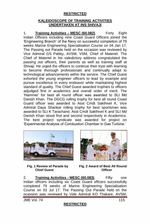
RESTRICTED
JME Vol. 74 115 RESTRICTED
KALEIDOSCOPE OF TRAINING ACTIVITIES UNDERTAKEN AT INS SHIVAJI
1. Training Activities – MESC (60.082). Forty Eight Indian Officers including nine Coast Guard Officers joined the ‘Engineering Branch’ of the Navy on successful completion of 79 weeks Marine Engineering Specialisation Course on 04 Jan 17. The Passing out Parade held on the occasion was reviewed by Vice Admiral GS Pabby, AVSM, VSM, Chief of Materiel. The Chief of Materiel in his valedictory address congratulated the passing out officers, their parents as well as training staff at Shivaji. He urged the officers to continue their tryst with learning to become thorough professionals and continually adapt to technological advancements within the service. The Chief Guest exhorted the young engineer officers to lead by example and pursue excellence in every endeavor while maintaining highest standard of quality. The Chief Guest awarded trophies to officers adjudged first in academics and overall order of merit. The ‘Hammer’ for best all round officer was awarded to SLt Md Danish Khan. The DGCG rolling trophy for best all round Coast Guard officer was awarded to Asst Cmdt Sakthivel K. Vice Admiral Daya Shankar rolling trophy for best sportsman was awarded to SLt K Tarachand. Asst Cmdt Sakthivel K and SLt Md Danish Khan stood first and second respectively in Academics. The best project syndicate was awarded for project on ‘Experimental Analysis of Combustion Chamber in Gas Turbine.’
Fig. 1 Review of Parade by Fig. 2 Award of Best All Round Chief Guest Officer
2. Training Activities - MESC (60.083). Fifty one Indian officers including six Coast Guard officers successfully completed 79 weeks of Marine Engineering Specialisation Course on 03 Jul 17. The Passing Out Parade held on the ocassion was reviewed by Vide Admiral KO Thakare, AVSM,
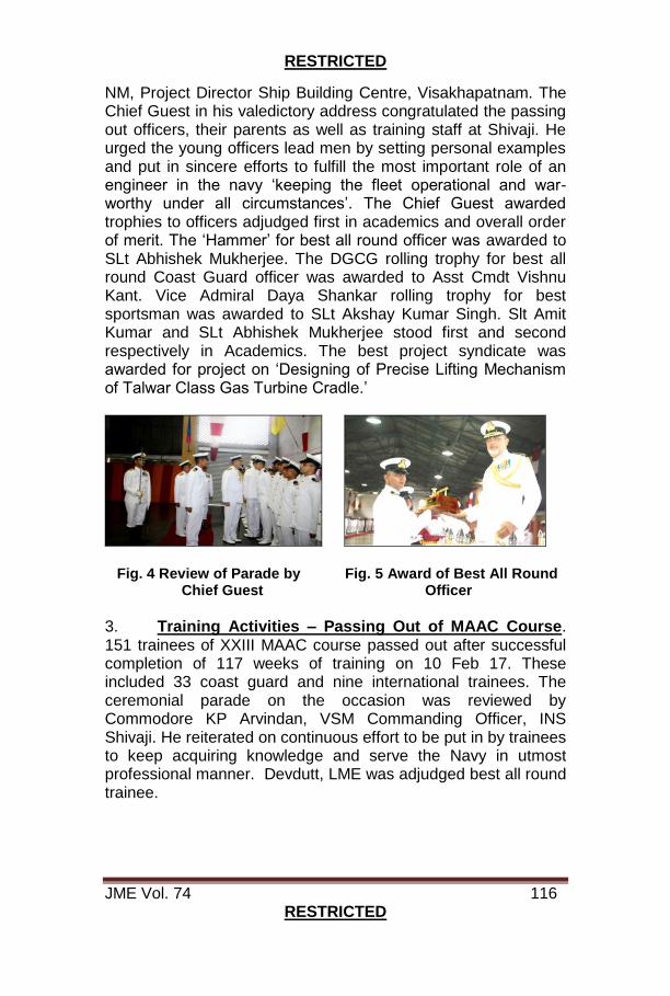
RESTRICTED
JME Vol. 74 116 RESTRICTED
NM, Project Director Ship Building Centre, Visakhapatnam. The Chief Guest in his valedictory address congratulated the passing out officers, their parents as well as training staff at Shivaji. He urged the young officers lead men by setting personal examples and put in sincere efforts to fulfill the most important role of an engineer in the navy ‘keeping the fleet operational and war-worthy under all circumstances’. The Chief Guest awarded trophies to officers adjudged first in academics and overall order of merit. The ‘Hammer’ for best all round officer was awarded to SLt Abhishek Mukherjee. The DGCG rolling trophy for best all round Coast Guard officer was awarded to Asst Cmdt Vishnu Kant. Vice Admiral Daya Shankar rolling trophy for best sportsman was awarded to SLt Akshay Kumar Singh. Slt Amit Kumar and SLt Abhishek Mukherjee stood first and second respectively in Academics. The best project syndicate was awarded for project on ‘Designing of Precise Lifting Mechanism of Talwar Class Gas Turbine Cradle.’
Fig. 4 Review of Parade by Fig. 5 Award of Best All Round Chief Guest Officer
3. Training Activities – Passing Out of MAAC Course. 151 trainees of XXIII MAAC course passed out after successful completion of 117 weeks of training on 10 Feb 17. These included 33 coast guard and nine international trainees. The ceremonial parade on the occasion was reviewed by Commodore KP Arvindan, VSM Commanding Officer, INS Shivaji. He reiterated on continuous effort to be put in by trainees to keep acquiring knowledge and serve the Navy in utmost professional manner. Devdutt, LME was adjudged best all round trainee.
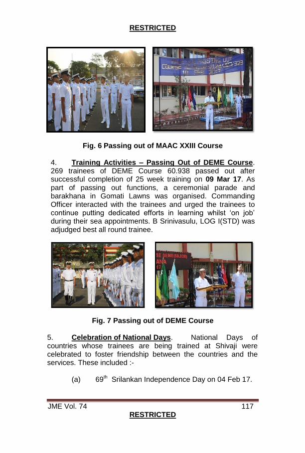
RESTRICTED
JME Vol. 74 117 RESTRICTED
Fig. 6 Passing out of MAAC XXIII Course
4. Training Activities – Passing Out of DEME Course. 269 trainees of DEME Course 60.938 passed out after successful completion of 25 week training on 09 Mar 17. As part of passing out functions, a ceremonial parade and barakhana in Gomati Lawns was organised. Commanding Officer interacted with the trainees and urged the trainees to continue putting dedicated efforts in learning whilst ‘on job’ during their sea appointments. B Srinivasulu, LOG I(STD) was adjudged best all round trainee.
Fig. 7 Passing out of DEME Course 5. Celebration of National Days. National Days of countries whose trainees are being trained at Shivaji were celebrated to foster friendship between the countries and the services. These included :-
(a) 69th Srilankan Independence Day on 04 Feb 17.
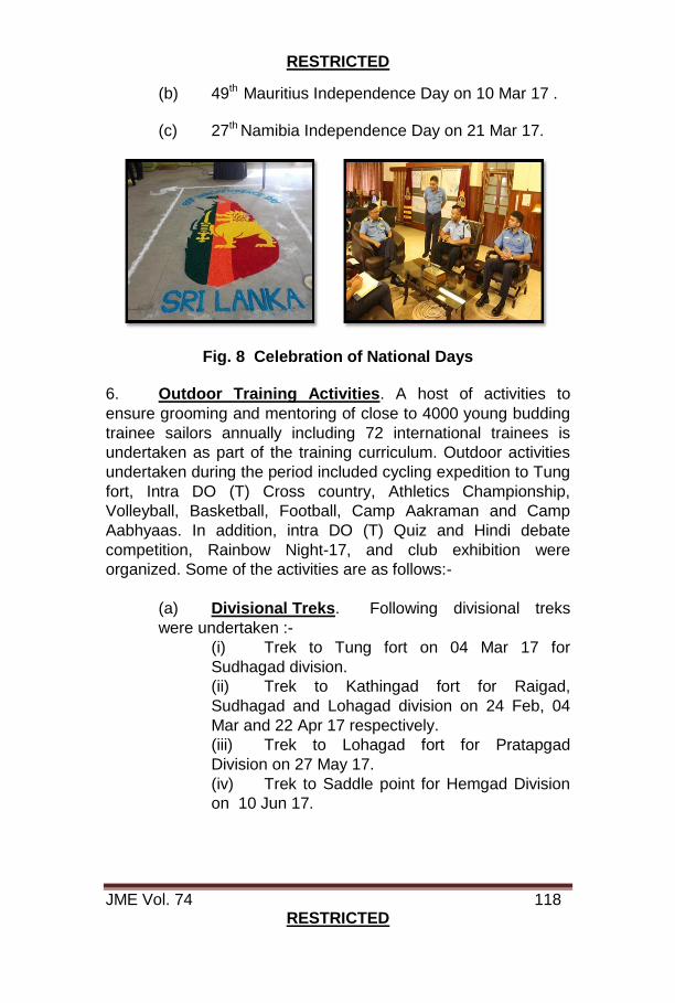
RESTRICTED
JME Vol. 74 118 RESTRICTED
(b) 49th Mauritius Independence Day on 10 Mar 17 .
(c) 27th Namibia Independence Day on 21 Mar 17.
Fig. 8 Celebration of National Days
6. Outdoor Training Activities. A host of activities to
ensure grooming and mentoring of close to 4000 young budding
trainee sailors annually including 72 international trainees is
undertaken as part of the training curriculum. Outdoor activities
undertaken during the period included cycling expedition to Tung
fort, Intra DO (T) Cross country, Athletics Championship,
Volleyball, Basketball, Football, Camp Aakraman and Camp
Aabhyaas. In addition, intra DO (T) Quiz and Hindi debate
competition, Rainbow Night-17, and club exhibition were
organized. Some of the activities are as follows:-
(a) Divisional Treks. Following divisional treks
were undertaken :-
(i) Trek to Tung fort on 04 Mar 17 for
Sudhagad division.
(ii) Trek to Kathingad fort for Raigad,
Sudhagad and Lohagad division on 24 Feb, 04
Mar and 22 Apr 17 respectively.
(iii) Trek to Lohagad fort for Pratapgad
Division on 27 May 17.
(iv) Trek to Saddle point for Hemgad Division
on 10 Jun 17.

RESTRICTED
JME Vol. 74 119 RESTRICTED
Fig. 9 Divisional Treks
(b) Sports Championships. Trainees participated in following sports championships :-
(i) Hockey. Inter Divisional Hockey Championship was conducted from 02 - 09 Feb 17. Panhala won the championship whereas Shivneri was runners up.
Fig. 10 Hockey Championship 2017 (ii) Pulling Regatta. Annual pulling regatta competition was conducted at Shiv Sagar lake on 06 Mar 17. The championship was won by DO(T) team.

RESTRICTED
JME Vol. 74 120 RESTRICTED
Fig. 11 Annual Pulling Regatta 2017
(iii) Basketball. Inter Divisional Basketball Championship 2017 was conducted from 24 Mar - 05 Apr 17. Final was played between Shivneri and Panhala division on 05 Apr 17 at Basketball court where Shivneri emerged as winners.
Fig. 12 Basketball Championship 2017
(iv) Cross Country. Inter Divisional Cross Country Championship was conducted on 15 Apr 17. Pratapgad won the championship.

RESTRICTED
JME Vol. 74 121 RESTRICTED
Fig. 13 Cross Country Championship
(c) Outdoor Camps. (i) Camp Aakraman. A four day training camp Aakraman-17 was conducted from 16 - 19 May 17 near Pawna Lake in which 153 trainee sailors of MAAC-XXV participated including 04 international trainees. Korigad emerged champion division whereas Raigad was runners up.
Fig. 14 Camp Aakraman 2017
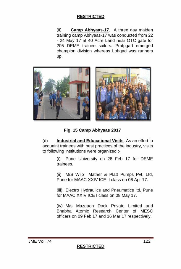
RESTRICTED
JME Vol. 74 122 RESTRICTED
(ii) Camp Abhyaas-17. A three day maiden
training camp Abhyaas-17 was conducted from 22
- 24 May 17 at 40 Acre Land near OTC gate for
205 DEME trainee sailors. Pratpgad emerged
champion division whereas Lohgad was runners
up.
Fig. 15 Camp Abhyaas 2017
(d) Industrial and Educational Visits. As an effort to
acquaint trainees with best practices of the industry, visits
to following institutions were organized :-
(i) Pune University on 28 Feb 17 for DEME
trainees.
(ii) M/S Wilo Mather & Platt Pumps Pvt. Ltd,
Pune for MAAC XXIV ICE II class on 06 Apr 17.
(iii) Electro Hydraulics and Pneumatics ltd, Pune
for MAAC XXIV ICE I class on 08 May 17.
(iv) M/s Mazgaon Dock Private Limited and
Bhabha Atomic Research Center of MESC
officers on 09 Feb 17 and 16 Mar 17 respectively.

RESTRICTED
JME Vol. 74 123 RESTRICTED
Fig. 15 Industrial Visit
(e) Adventure Activities. Some of the adventure activities undertaken for the trainees were :-
(i) Valley Crossing. Valley crossing was organized at Dukes nose on 21 Jan 17 in two groups where 164 trainees participated in the event.
Fig. 16 Valley Crossing
(ii) River Rafting. River rafting was organized at Kundulika river in Vile Village on 09 Feb 17 in two groups where 80 trainees participated in the event.

RESTRICTED
JME Vol. 74 124 RESTRICTED
Fig. 17 River Rafting (iii) Paragliding. Paragliding was conducted from 05-06 Mar 17 at Kamset where 36 trainees participated.
Fig. 18 Paragliding
(f) Cultural Evening. As part of culmination of all Divisional Activities for Year 2017, a Rainbow Night was conducted on 07 Feb 17 at Indrayani Hard where under trainee sailors participated in acts like Group song, western dance, Mime act, and Bhangra and Skit performances.
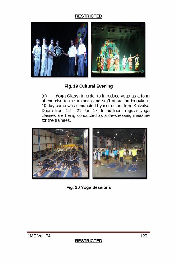
RESTRICTED
JME Vol. 74 125 RESTRICTED
Fig. 19 Cultural Evening
(g) Yoga Class. In order to introduce yoga as a form of exercise to the trainees and staff of station lonavla, a 10 day camp was conducted by instructors from Kaivalya Dham from 12 - 21 Jun 17. In addition, regular yoga classes are being conducted as a de-stressing measure for the trainees.
Fig. 20 Yoga Sessions

RESTRICTED
JME Vol. 74 126 RESTRICTED
ON THE HORIZON
1. To remain abreast with constantly evolving technology, the training methodology at Shivaji for Naval Engineers is also updated to sustain high confidence levels whilst operating new induction ships and state-of-art technologies. Shivaji has always strived hard to impart quality training in Marine Engineering to officers and sailors. Training methodologies have evolved from theoretical instructions to use of Live Equipment for Maintenance Oriented Training (MOT), Computer Based Training Technologies, Simulators, Modern Tools / Test Equipment and Reference Systems. 2. “On the Horizon”, attempts to appraise the technical fraternity and the Naval Community on ongoing activities and future plans of team Shivaji. 3. HoS Training Bays. In order to ensure that all trainees get to work with their own hands a number of new training facilities have been created/ augmented. These include:-
(a) Installation of Nine Yellow Banded Pumps. Nine yellow banded electrically driven pumps from Project 71, have been received and installed in the heat engine lab. Presently these pumps are being used for imparting HoS training to ab-initio courses.
Fig. 4 Yellow Banded Pumps Ex P-71
(b) Valve Overhauling Bay. A valve overhauling bay was setup in the Heat Engine lab premises to impart practical training on overhauling and pressure testing of valves. This facility, created
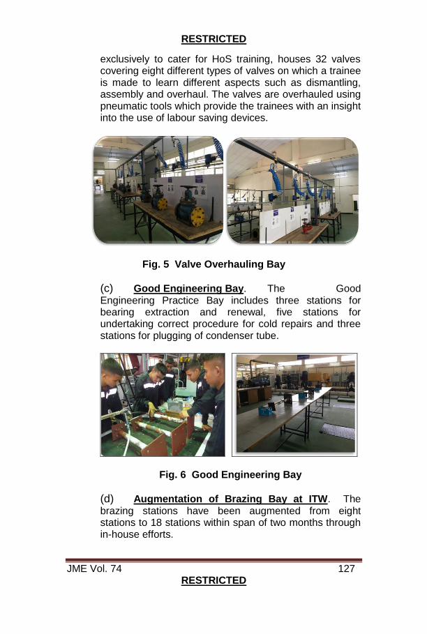
RESTRICTED
JME Vol. 74 127 RESTRICTED
exclusively to cater for HoS training, houses 32 valves covering eight different types of valves on which a trainee is made to learn different aspects such as dismantling, assembly and overhaul. The valves are overhauled using pneumatic tools which provide the trainees with an insight into the use of labour saving devices.
Fig. 5 Valve Overhauling Bay
(c) Good Engineering Bay. The Good Engineering Practice Bay includes three stations for bearing extraction and renewal, five stations for undertaking correct procedure for cold repairs and three stations for plugging of condenser tube.
Fig. 6 Good Engineering Bay
(d) Augmentation of Brazing Bay at ITW. The brazing stations have been augmented from eight stations to 18 stations within span of two months through in-house efforts.

RESTRICTED
JME Vol. 74 128 RESTRICTED
Fig. 7 Brazing Bay
(e) Volvo Penta Boat Engines HoS Bay. Nine Volvo Penta engines (BER) were received from MO(Karwar) in Feb 17. These engines are being utilized for practical training on boat engines for ab-initio courses.
Fig. 8 HoS Bay of Volvo Penta Engines
(f) Fixed Fire Fighting Systems. FOST in a recently promulgated guideline, emphasized a need to enhance the existing know-how on operation and maintenance aspects of Fixed Fire fighting arrangements onboard ships. While basic training on firefighting is covered for all personnel during ab-initio NBCD course and type specific during PCT, a need was felt to augment the methodology through a facility specifically centered upon imparting training on operation and maintenance. Accordingly, a Fixed CO2 Fire-fighting system similar to the one onboard Kamorta class ships has been created at Heat Engine Lab. The facility includes actual working components and utilises compressed air to simulate CO2. The facility is being used for HoS sessions for all ab-initio courses and Kamorta class PCT classes.
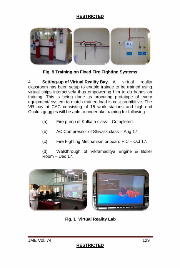
RESTRICTED
JME Vol. 74 129 RESTRICTED
Fig. 9 Training on Fixed Fire Fighting Systems
4. Setting-up of Virtual Reality Bay. A virtual reality classroom has been setup to enable trainee to be trained using virtual ships interactively thus empowering him to do hands on training. This is being done as procuring prototype of every equipment/ system to match trainee load is cost prohibitive. The VR bay at CAC consisting of 15 work stations and high-end Oculus goggles will be able to undertake training for following :-
(a) Fire pump of Kolkata class – Completed. (b) AC Compressor of Shivalik class – Aug 17. (c) Fire Fighting Mechanism onboard FIC – Oct 17. (d) Walkthrough of Vikramaditya Engine & Boiler Room – Dec 17.
Fig. 1 Virtual Reality Lab

RESTRICTED
JME Vol. 74 130 RESTRICTED
5. N-Computing Laboratory. With a vision to
continuously upgrade the facilities, a 57 terminal N-Computing
lab (with one high end server) has been procured at a cost of
nine lakhs. This is the largest congregation of N-computing
devices in the Navy presently. The facility is very cost effective
where-in each n-computing device costs merely 12000 in lieu of
a 35000 traditional PC. Training on MS Office applications, navy
specific software like eDART, eSRAR, SDRS etc and Interactive
Multimedia Training for PCT courses are undertaken through N-
computing devices.
Fig. 2 N-Computing Laboratory
6. NKN Classrooms. The Nationwide Knowledge
Network (NKN) is a state-of-the-art Multi-Gigabit Pan-India
Network that has been used by the establishment to conduct
classes on various subjects. There are 1500 academic
institutions registered with NKN, Shivaji being one of them. With
the good quality of instructional material available on the NKN,
an effort has been made to tap the educational data base
available. Accordingly, six NKN classroom have been set up
where, trainees will be taught theoretical subjects from various
reputed educational institutes such at IITs, NIITs. These classes
will be plotted in the Weekly Training Programme and trainees
as per their time slots are seated in the classroom. Presently 23
lectures in subjects of Manufacturing Technology and metallurgy
have been downloaded and will be covered for Artificer courses.

RESTRICTED
JME Vol. 74 131 RESTRICTED
Fig. 3 NKN Classrooms 7. Real Time Training. Whilst technology such as Virtual Reality can assist training to a great extent, it cannot replace practical training. Accordingly, efforts are in hand to create a complete Engineering facility to further the impetus on Hands on Skill. Civil maritime institutes have such facilities in place where complete compartments have been replicated for personnel to train on watchkeeping, operation and maintenance aspects. The facility would have a complete replica of an engine room with main propulsion and associated equipment for the trainees. Once constructed, it would be one of its kind in the entire Navy. 8. Design of an External Lubricating Oil System for TBU of the Vikramaditya Boiler. Towards operationalisation of the Vikramaditya boiler, the Turbo Blower Unit (TBU) of the boiler is also required to be maintained in a usable condition. The necessity of an external lub oil system prior depreservation, inspection and turning of the TBU was required to be undertaken. A self sustaining external lub oil system for turning the TBU has been designed, fabricated and installed in-house between Oct to Dec 16. This also included conversion of the existing 440 V, 3 phase supply to (Russian) 380 V through a step down transformer to power the turning motor. Availability of OM 100 as per approved changeover of lubricating oil from TП46 after consultation from INS Vikramaditya ships' staff has also been catered. Initial inspection by ND/(MBI) post approval from HQWNC was undertaken in Apr 17 and is observed to be satisfactory.

RESTRICTED
JME Vol. 74 132 RESTRICTED
Fig. 10 New Lub Oil System for TBU 9. Management of Machinery Controls Onboard. The Indian Navy has faced many challenges towards optimal utilisation and maintenance of Machinery Control Systems due to variety of reasons including division of responsibility between engineering and electrical departments’ onboard ships. With increased exposure of engineering personnel on advanced technology system such as Integrated Platform Management System, a need was felt to align responsibility of upkeep and maintenance of control systems to modern ‘systems’ approach with single point responsibility. Accordingly, a case was taken up by Shivaji and IHQMoD(N) in May 17 has approved a roadmap for transfer of complete ownership to Engineering department. The transition in responsibility would be achieved in a phased manner over a five year period. Towards the same, maiden course for Control ERA has commenced on 10 Jul 17 whereas for Control ME is commencing on 21 Aug 17. PCT for Engineer officers have been increased for duration of four weeks commencing Jul 17.
10. Certificate Course in Embedded Technology. In order to expose engineering personnel with sophisticated control systems onboard ships, a maiden three week certificate course on Embedded Technology for 25 personnel (14 Officers and 11 Sailors) was conducted to give an insight of the control systems, Linux operating system, Microcontrollers and interfacing (AVR and ARM) and detailed introduction to embedded & real time operating systems. A Memorandum of Understanding (MoU) between Shivaji and M/s CDAC, Chennai for yearly conduct of the course for next five years has been drafted and forwarded to IHQ MoD through HQSNC.
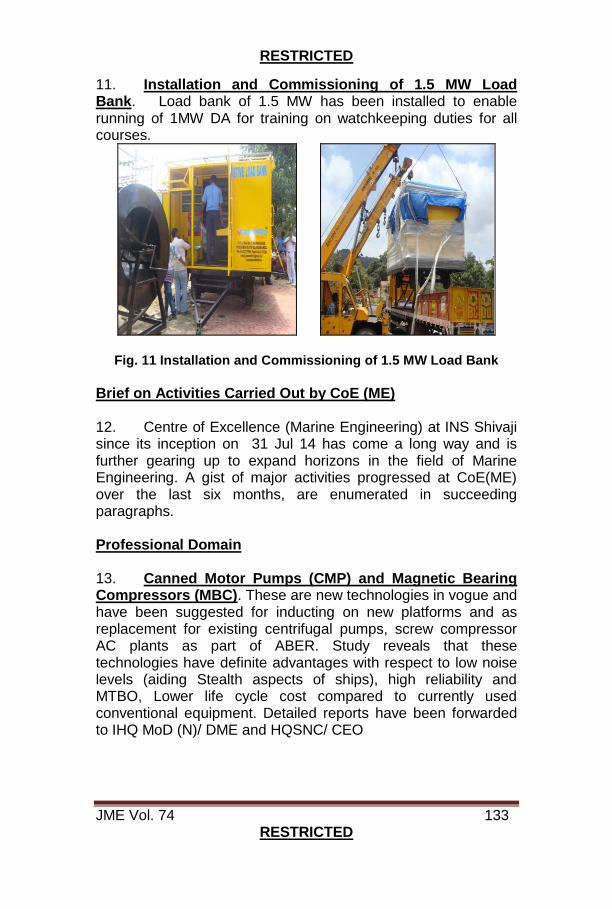
RESTRICTED
JME Vol. 74 133 RESTRICTED
11. Installation and Commissioning of 1.5 MW Load Bank. Load bank of 1.5 MW has been installed to enable running of 1MW DA for training on watchkeeping duties for all courses.
Fig. 11 Installation and Commissioning of 1.5 MW Load Bank
Brief on Activities Carried Out by CoE (ME) 12. Centre of Excellence (Marine Engineering) at INS Shivaji since its inception on 31 Jul 14 has come a long way and is further gearing up to expand horizons in the field of Marine Engineering. A gist of major activities progressed at CoE(ME) over the last six months, are enumerated in succeeding paragraphs. Professional Domain 13. Canned Motor Pumps (CMP) and Magnetic Bearing Compressors (MBC). These are new technologies in vogue and have been suggested for inducting on new platforms and as replacement for existing centrifugal pumps, screw compressor AC plants as part of ABER. Study reveals that these technologies have definite advantages with respect to low noise levels (aiding Stealth aspects of ships), high reliability and MTBO, Lower life cycle cost compared to currently used conventional equipment. Detailed reports have been forwarded to IHQ MoD (N)/ DME and HQSNC/ CEO

RESTRICTED
JME Vol. 74 134 RESTRICTED
Fig. 12 Schematic View of CMP & MBC
14. SOTRs. Following SOTRs were drafted and forwarded to Professional directorate with an aim for ensuring standardisation and rationalisation by undertaking holistic study of existing ship fit, applicable international standards and specifications, technological developments in the field and then defining form fit and material to meet essential functional requirement:-
(a) Refractory Material for INS Vikramaditya KBГ 3Д Boiler. SOTRs have been drawn after detailed study of drawings, chemical compositions, physical properties and the manufacturing processes. Through intensive interaction with design and production teams of industry a path has been paved for indigenization of these materials. (b) HP Air Compressors. SOTRs included inter alia, interaction with design and production teams from industry and have been structured to serve as a template for all future acquisitions. It defines latest Technical Requirements, Functional Aspects, Design Criteria, Environmental Conditions, Applicable Shock, Noise, Vibration and Acceptance Test Criteria which are in vogue keeping with advancements in field of HP Air Compressors.

RESTRICTED
JME Vol. 74 135 RESTRICTED
Academic Domain 15. Marine Engineering Training - Bridging Course. IHQMoD(N) has approved modification of MESC training to include five months of Phase – I for Marine Engineering Specialization at Shivaji wef Dec 17. The Course being Marine Engineering oriented shall be conducted by CoE(ME), as a prelude to equipment focused training during the subsequent MESC Phases. 16. Continuous Education Programmes (CEPs). A CEP on Integrated Full Electric Propulsion was conducted from 24 - 29 Apr 17 for 20 Engineer Officers. The program addressed IN imperatives and challenges covering various aspects of the said technology. Eminent speakers were invited from academic institutes like NIT Delhi, from industries like General Electric, Siemens, L&T, CSL as well as classification societies like IRS.
Fig. 13 CEP on Integrated Full Electric Propulsion
17. MoU with IIT(B) for PhD. CoE(ME) has concluded Memorandum of Understanding (MoU) with IIT(B), for conduct of PhD on 06 Mar 17. IG 147 DTG 241345/ Apr for the same has also been released to this effect to provide wide publicity. Engineering officers from Indian Navy would now be able to pursue PhD in Marine Engineering field under NHESS with course commencing from academic year 2018. 18. Collaborative M.Tech at IIT(B). An MoU with Indian Institute of Technology, Bombay was concluded for Collaborative

RESTRICTED
JME Vol. 74 136 RESTRICTED
M.Tech programme in ‘Thermal & Fluid Engineering’. Selection of Officers is on the basis of Entrance Examination, conducted at IIT(B). As a prelude, a two-week refresher course is conducted at CoE(ME) for the shortlisted candidates from 17 – 28 Apr 17 of M.Tech Batch 2017. Further, M.Tech projects with a potential for application in the IN have been shortlisted by CoE(ME) in consultation with IIT(B) for M.Tech officers of Batch 2016, and their progress is monitored closely. 19. Forthcoming Events at INS Shivaji.
(a) One week CEP on ‘Nuclear Technology for Warships & Submarines’ in end Aug 17.
(b) Technical Seminar on ‘Main Propulsion
Systems- Roadmap towards Self Reliance’ on 09 and 10 Nov 17.
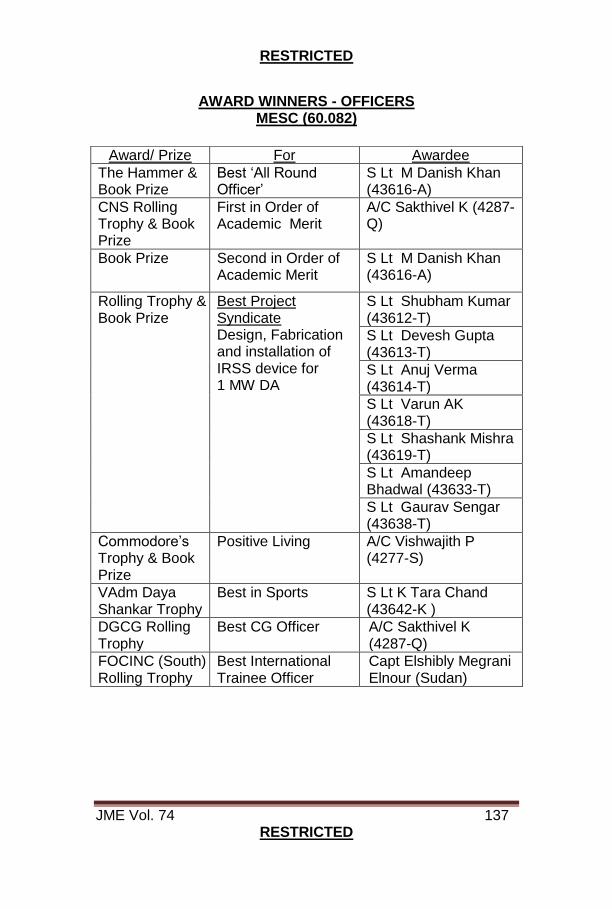
RESTRICTED
JME Vol. 74 137 RESTRICTED
AWARD WINNERS - OFFICERS
MESC (60.082)
Award/ Prize For Awardee
The Hammer & Book Prize
Best ‘All Round Officer’
S Lt M Danish Khan (43616-A)
CNS Rolling Trophy & Book Prize
First in Order of Academic Merit
A/C Sakthivel K (4287-Q)
Book Prize Second in Order of Academic Merit
S Lt M Danish Khan (43616-A)
Rolling Trophy & Book Prize
Best Project Syndicate Design, Fabrication and installation of IRSS device for 1 MW DA
S Lt Shubham Kumar (43612-T)
S Lt Devesh Gupta (43613-T)
S Lt Anuj Verma (43614-T)
S Lt Varun AK (43618-T)
S Lt Shashank Mishra (43619-T)
S Lt Amandeep Bhadwal (43633-T)
S Lt Gaurav Sengar (43638-T)
Commodore’s Trophy & Book Prize
Positive Living A/C Vishwajith P (4277-S)
VAdm Daya Shankar Trophy
Best in Sports S Lt K Tara Chand (43642-K )
DGCG Rolling Trophy
Best CG Officer A/C Sakthivel K (4287-Q)
FOCINC (South) Rolling Trophy
Best International Trainee Officer
Capt Elshibly Megrani Elnour (Sudan)
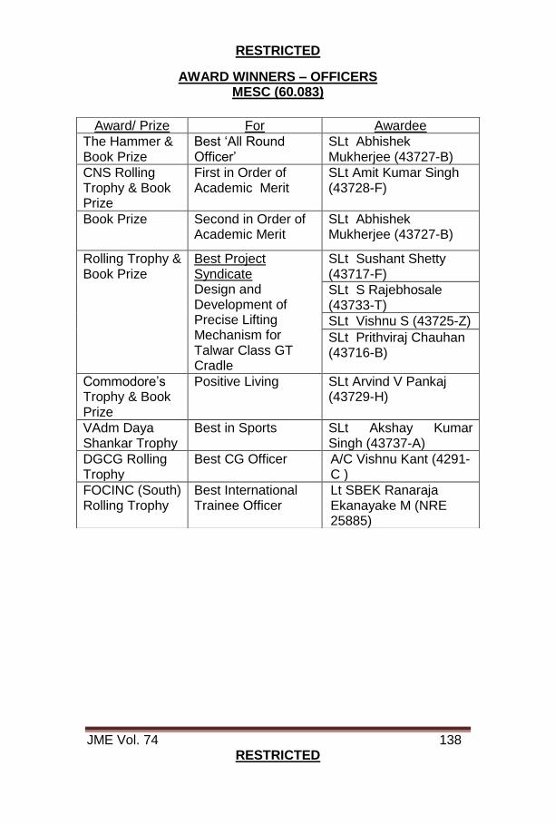
RESTRICTED
JME Vol. 74 138 RESTRICTED
AWARD WINNERS – OFFICERS MESC (60.083)
Award/ Prize For Awardee
The Hammer & Book Prize
Best ‘All Round Officer’
SLt Abhishek Mukherjee (43727-B)
CNS Rolling Trophy & Book Prize
First in Order of Academic Merit
SLt Amit Kumar Singh (43728-F)
Book Prize Second in Order of Academic Merit
SLt Abhishek Mukherjee (43727-B)
Rolling Trophy & Book Prize
Best Project Syndicate Design and Development of Precise Lifting Mechanism for Talwar Class GT Cradle
SLt Sushant Shetty (43717-F)
SLt S Rajebhosale (43733-T)
SLt Vishnu S (43725-Z)
SLt Prithviraj Chauhan (43716-B)
Commodore’s Trophy & Book Prize
Positive Living SLt Arvind V Pankaj (43729-H)
VAdm Daya Shankar Trophy
Best in Sports SLt Akshay Kumar Singh (43737-A)
DGCG Rolling Trophy
Best CG Officer A/C Vishnu Kant (4291-C )
FOCINC (South) Rolling Trophy
Best International Trainee Officer
Lt SBEK Ranaraja Ekanayake M (NRE 25885)
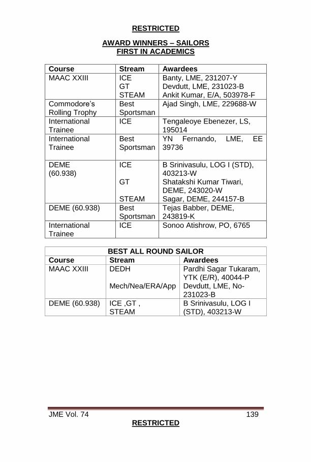
RESTRICTED
JME Vol. 74 139 RESTRICTED
AWARD WINNERS – SAILORS FIRST IN ACADEMICS
Course Stream Awardees
MAAC XXIII ICE GT STEAM
Banty, LME, 231207-Y Devdutt, LME, 231023-B Ankit Kumar, E/A, 503978-F
Commodore’s Rolling Trophy
Best Sportsman
Ajad Singh, LME, 229688-W
International Trainee
ICE
Tengaleoye Ebenezer, LS, 195014
International Trainee
Best Sportsman
YN Fernando, LME, EE 39736
DEME (60.938)
ICE GT STEAM
B Srinivasulu, LOG I (STD), 403213-W Shatakshi Kumar Tiwari, DEME, 243020-W Sagar, DEME, 244157-B
DEME (60.938) Best Sportsman
Tejas Babber, DEME, 243819-K
International Trainee
ICE
Sonoo Atishrow, PO, 6765
BEST ALL ROUND SAILOR
Course Stream Awardees
MAAC XXIII DEDH Mech/Nea/ERA/App
Pardhi Sagar Tukaram, YTK (E/R), 40044-P Devdutt, LME, No- 231023-B
DEME (60.938) ICE ,GT , STEAM
B Srinivasulu, LOG I (STD), 403213-W

RESTRICTED
JME Vol. 74 140 RESTRICTED
KIND ATTENTION TO AUTHORS PLAGIARISM
Plagiarism is defined by the Oxford Dictionary as the “Wrongful Approach”, “Close Imitation” or “Purloining and Publication of another Author’s Thoughts, Language, Ideas or Expressions and the representation of them as one’s own original work”. The increased availability of Intellectual Property due to a rise in Information Technology (IT) has furthered the debate as to whether copyright offences are criminal. Plagiarism is not a crime per se but is disapproved more on the grounds of moral offence; and cases of Plagiarism can involve liability for copyright infringement. While both terms may apply to a particular act, they are difference concepts. Copyright Infringement is a violation of the Rights of a Copyright Holder, when material restricted by copyright is used without consent. On the other hand, the moral concept of Plagiarism is concerned with the “Unearned Increment” to the Plagiarising Author’s reputation that is achieved through false claims of authorship. Technical Manuals routinely copy facts from other manual without attribution, because they assume a common spirit of scientific endeavor. Within an organisation, in its own working levels, standards are not as stringent but definitely not non-existent. If someone helped with a report, or if a paragraph is taken from an existing source, a citation is expected to be written down. The thin line between permissible literary and impermissible source code Plagiarism is finally left to the maturity level, morality, integrity and honesty of the author. In short, authors are requested to adhere to the guideline. If you did not write it yourself, you must, at least, give due credits.