restore uscg station panama city pn 11893259 - aws
TRANSCRIPT

RFP DESIGN/BUILD SPECIFICATIONS
FOR
RESTORE USCG STATION
PANAMA CITY
PN 11893259
STA PANAMA CITY
PANAMA CITY, FL
Date: 6/28/2021
DEPARTMENT OF HOMELAND SECURITY
UNITED STATES COAST GUARD
FACILITIES DESIGN & CONSTRUCTION CENTER
FDCC Norfolk
5505 ROBIN HOOD ROAD SUITE K
NORFOLK, VIRGINIA 23513-2413
UNITED STATES COAST GUARD


Rebuild USCG Station Panama City SFRL: 11893259 Panama City, FL
TABLE OF CONTENTS - Page 1 of 1
PROJECT RFP REQUIREMENTS
Section Title TOC TABLE OF CONTENTS 01110 DESIGN-BUILD GENERAL PARAGRAPHS 01115 01200
DEDICATION PLAQUE DESIGN-BUILD PROGRESS PAYMENTS
01320 DESIGN-BUILD PROGRESS SCHEDULE 01330 DESIGN-BUILD SUBMITTAL PROCEDURES 01450 QUALITY CONTROL 01500 01505
TEMPORARY COR FACILITIES AND EQUIPMENT PROJECT MEETINGS
01781 OPERATION AND MAINTENANCE DATA DOCUMENTATION 01800 DESIGN-BUILD CRITERIA 1.1 GENERAL PROJECT REQUIREMENTS AND DESCRIPTION 1.2 ROLES OF RFP SPECIFICATIONS & DRAWINGS 1.3 GUIDING PRINCIPLES FOR SUSTAINABILITY 1.4 CIVIL AND SITE WORK 1.5 GEOTECHNICAL 1.6 LANDSCAPING 1.7 ARCHITECTURAL 1.8 STRUCTURAL 1.9 DEMOLITION 1.10 FIRE PROTECTION 1.11 PLUMBING 1.12 HEATING VENTILATING AND AIR CONDITIONING 1.13 ELECTRICAL 1.14 CCTV 1.15 CABLE TV 1.16 TELECOMMUNICATIONS AND PUBLIC ADDRESS 1.17 FURNISHINGS, EQUIPMENT AND OUTFITTING 1.18 ENVIRONMENTAL DESIGN, PERMITS, CONTROLS, AND PROTECTION
01802 CONSTRUCTION DESIGN DOCUMENTS 01803 RECORD DOCUMENTS AND DRAWINGS 01900 LIST OF RFP DRAWINGS, EXHIBITS, AND ATTACHMENTS DRAWINGS
APPENDIX A CRITERIA FOR COMPUTER GENERATED DRAWINGS APPENDIX B CRITERIA FOR ELECTRONIC DELIVERABLES APPENDIX C FDCC’S ADEPT FILE NAMING APPENDIX D BASIS OF DESIGN NARRATIVE APPENDIX E INDUSTRY STANDARDS FOR CONSTRUCTION DOCUMENTS APPENDIX F NOT USED APPENDIX G O&M PART 1 EXISTING SAM COAST GUARD MAINTAINED
EQUIPMENT APPENDIX H
O&M PART 2 EQUIPMENT ENROLLMENT FORM O&M PART 3 SAM JOB PLAN OUTFITTING ITEM INFORMATION SHEETS

Restore USCG Station Panama City 11893259
Panama City, FL
SECTION 01110 Page 1 of 8
SECTION 01110 DESIGN-BUILD
GENERAL PARAGRAPHS
PART 1 GENERAL
1.1 SCOPE OF WORK
This project will restore facilities at USCG Station Panama City in Panama City, FL. The scope of this project includes construction of a new Multi-Functional Building, approximately 33,256 GSF (Gross Square Feet); the restoration of the existing Station Building (9460 GSF), restoration of the Waterfront (approximately 3723 SY, Square Yards); restoration of Site Utilities, restoration of Stormwater Drainage System, and the demolition and disposal of about 14,105 GSF of severely damaged buildings. 1.2 ITEMS FURNISHED TO CONTRACTOR BY FDCC
a. One electronic set of the final approved Contract documents at the time of award.
b. One electronic copy of any changed document due to a Contract modification
c. One electronic copy of all FDCC forms referred to herein. Reproduce as necessary.
d. Publications incorporated into the technical provisions by reference will not be provided by the Government. Provide those references at the project site when necessary for clarification, or if required for reference to assist with quality control.
1.3 CONTRACTOR RESPONSIBILITY
This contract contains both prescriptive and performance-based criteria. The design and subsequent construction shall incorporate all ancillary components as necessary to provide a complete and functional facility for the intended purpose. Where direction is given, it is directed to the Contractor. In each case the meaning is as though written “the Contractor shall….”
1.3.1 The term "COR" is an abbreviation for "Contracting Officer's Representative." The Term “GCI” is an abbreviation for “Government Contracted Inspector.”
1.4 WORK HOURS
1.4.1 All personnel involved in the construction and completion of this contract are authorized access to USCG Station Panama City site from 0600 to 1700 HRS Monday through Friday subject to local jurisdiction approval. No work is allowed on weekends or Federal holidays unless approved by the KO and coordinated with the Sector Field Office Station Panama City Base’s FE or his designated representative.
1.5 CONTRACTOR USE OF PREMISES
1.5.1 The Contractor will be working on an operational Coast Guard installation. Perform and conduct the work to minimize interference with Coast Guard operations. Become familiar with and obey station fire, traffic, and security regulations. Personnel shall not stray from the immediate area of work or direct avenues of ingress and egress unless authorized in advance by the Contracting Officer's Representative. Contractor shall submit a list of all personnel who will be working on site for security reasons. The list shall include the following minimum items: Name of employee, current address, and last four digits of social security number, date of birth, citizenship and

Restore USCG Station Panama City 11893259
Panama City, FL
SECTION 01110 Page 2 of 8
gender. The list shall be submitted to the COR, a minimum of 7 calendar days prior to starting work. The Contractor may submit a revised list at any time during the project. Only personnel on the approved list will be allowed on the site. All personnel working on the project site must be legal to work in the United States of America.
All personnel shall carry proper identification (ID) when on site. Proper ID is defined as either the individual's driver's license, or a company issued ID. The identification must be laminated, and show a facial picture of the individual. Individuals without proper ID will be escorted off the Coast Guard premises.
The contractor shall notify the government when an employee on the approved listing departs the company.
1.5.2 All lay down or staging areas for materials, equipment and Contractor vehicle parking must be located within the indicated Contractor staging area and site.
1.5.3 Shipments of equipment, materials, and supplies shall be addressed to the contractor - not the Government. The contractor must be on hand to accept shipments; the Government will not accept shipments.
1.6 Definitions
The following terms are defined as follows:
Day(s): calendar day(s), unless otherwise noted
FDCC: Facilities Design & Construction Center
FE: Facility Engineer
KO: Contracting Officer
PM: FDCC Project Manager
COR: FDCC Contracting Officer's Representative
GCI: FDCC Government Contract Inspector
OR: FDCC Onsite Representative (Inspector)
A/E: Architect-Engineering Firm
EIC: FDCC Engineer-in-Charge
QAM: Contractor's Quality Assurance Manager
DOR: Contractor's Design Engineer of Record and central point of contact for all design issues and questions
KR: Contractor
DCR: Design Clarification Request to the Government clarifying contract/RFP requirements
RFI: Request for Information sent internally between Construction Contractor and the Contractors DOR clarifying design (see Section 01330, Paragraph 1.3.3)

Restore USCG Station Panama City 11893259
Panama City, FL
SECTION 01110 Page 3 of 8
1.7 REFERENCES AND ORDER OF PRECEDENCE
Where specifications or standards documents are referenced in these Contract documents, they apply as if they were incorporated into the contract, except if specifically noted otherwise. If there are differences between referenced documents and any contract documents the following precedence applies.
a. Contract
b. RFP Specification
c. RFP Drawings
d. References
e. Applicable code or standard governing the work in question
1.8 SECURITY
USCG Panama City is a Federal facility. All personnel visiting the site will have to present valid picture identification from their state of residence. All personnel working on the project site must be legal to work in the United States of America. All vehicles entering the site must present and carry proof of insurance at all times. Provide a written list of expected workers with their driver’s license/identification card numbers and expected on site duration to the Unit’s Security Engineer a minimum of 7 calendar days prior to the personnel arriving.
1.8.1 Personnel shall become familiar with and obey Station fire, traffic, and security regulations. Personnel shall not stray from the immediate area of work or direct avenues of ingress and egress unless authorized in advance by the Contracting Officer's Technical Representative.
1.8.2 Contractor shall submit a written list of all personnel who will be working on site for security reasons. The list shall be submitted to the COR and FE seven days prior to the personnel starting work. This allows notice to be sent to base security. The Contractor may submit a revised list at any time during the project. Only personnel on the approved listing will be allowed on the site. The list shall include the following minimum items: Name of employee, current address, social security number, driver’s license/identification numbers, date of birth, citizenship, gender and expected on site duration.
1.9 OTHER STATION WORK
The Coast Guard and other contractors will be performing work at and adjacent to the project site during the time of this Contract. Cooperate and coordinate deliveries, access, and work with the Coast Guard and other contractors in accordance with Contract Clause FAR 52.236-8.
1.10 NEW UTILITY SERVICES
Make all arrangements with the local utility providers and pay all fees, charges, and costs of any nature associated with establishing and installing new temporary (during construction) and subsequent permanent utility services required to ensure permanent and uninterrupted utility service at project completion. The contract documents may provide a conceptual plan for utility layouts. These plans shall be confirmed by the contractor during the bidding stage with the local utility provider to determine the exact materials, equipment placement, and other features that may be required by the specific utility provider. The term utility service includes, but is not limited to meters, mains, service lines, high voltage feeders, transformers, force mains, lift stations, etc. The contractor is responsible for coordinating the work with the utility provider to insure the utility connection to the site is completed and that there is no delay in the prosecution of the work or completion of the project. Utility services include electricity, water, sewer, and telephone. All utilities within the base are owned by the Government.
The local electrical provider is as follows:

Restore USCG Station Panama City 11893259
Panama City, FL
SECTION 01110 Page 4 of 8
Utility Provider Service Telephone Number
City of Panama City Beach Water (850) 2331-5100
City of Panama City Sanitary Sewer (850) 872-3000
Gulf Power Electricity 1-800-225-5797
TECO/People Gas Natural Gas 1-877-832-6747
Century Link Data & Telephone 1-800-261-1691
Time Warner Cable TV 1-855-855-4575
Gulf Power Temporary Electrical Accounts 1-800-225-5797
1.10.1 Water
There will be no charge to connect to the Government water lines. Coordinate with the City of Panama City Beach for connection to existing water.
1.10.2 Sewer
There will be no charge to connect to the Government sewer lines. Coordinate with the City of Panama City for connection to existing sewer.
1.10.3 Telephone Service
Temporary telephone service to the contractor’s trailer is available via the local telephone company at the contractor’s expense. There will be no charge to connect to the Government telephone lines for permanent telephone service to the cutter shore-ties and the new building.
1.10.4 Electrical
Temporary electrical service to the contractor and FDCC trailers is available via the local utility company at the Contractor’s expense. Coordinate with the local power company to establish new service for the new facilities. There will be no charge to connect to the Government electrical lines.
1.11 PERMITS
Contractor’s responsibility for permits is discussed in Section I contract clause 52.236-7 “Permits and Responsibilities” and in Section 01800 paragraph 1.18.3 “Project Related Environmental Permits, Consultations & Certifications”. In addition the contractor shall pay for and obtain all temporary permits for construction of this contract work. The Contractor shall comply with all terms and conditions of permits, whether the Contractor or the Government obtains the permit.
1.12 DRAWINGS FURNISHED
One compact disc (CD) of the plans and specifications will be furnished to the Contractor without charge.
1.13 WORK SEQUENCE
The Contractor shall coordinate and schedule the construction sequencing and phasing according to the following general order:

Restore USCG Station Panama City 11893259
Panama City, FL
SECTION 01110 Page 5 of 8
Construct new Multi Mission Building
Restore Existing Station Building
1.14 GOVERNMENT-FURNISHED ITEMS
None
1.15 RELOCATED EQUIPMENT AND ITEMS
Disconnect, dismantle if necessary, remove, relocate, reinstall, connect, and test items shown on the drawings. Cap disconnected service lines. Provide mechanical and electrical service connections, fittings, fastenings, and other materials needed to assemble and install relocated equipment. Before disconnecting or relocating items, inspect the items in the presence of the COR to determine their existing condition. The contractor is responsible for damage sustained by the items after this inspection.
1.16 UTILITY OUTAGES
Before interrupting or shutting down any utility, make a request for the interruption to the Contracting Officer at least 5 days before the anticipated interruption. Identify the utility, reason for interruption, proposed time of interruption, and duration of interruption. Do not interrupt utilities until authorized by the Contracting Officer.
1.17 UNDERGROUND UTILITIES
The underground utility locations shown on the drawings are not exact. “Miss Utility” locator services are not available at US Coast Guard Panama City. Use a private utility locator service, at contractor expense, to locate underground utilities. Notify the COR and the cognizant utility companies at least 48 hours before excavating. Mark the excavation route and intersecting utilities. The COR or the utility company representative will review the contractor's layout and notify the contractor if any known utilities have been left unmarked. Where excavation will cross an existing utility line, use hand tools to excavate for a distance of 5 feet on each side of the intersection location shown on the drawings. Once exposed, protect underground utilities from damage.
a. Make utility cut-over and interruptions after the normal working hours or on Saturdays, Sundays, and Government holidays. Conform to procedures required in contract clause H.3 "Work outside Regular Work Hours.
b. Ensure that new utility lines are complete, except for the connection, before interrupting existing service.
c. Interruption to water, sanitary sewer, storm sewer, telephone service, electric service, air conditioning, heating, and fire alarm shall be considered utility cut-overs. All outages shall be restored prior to the start of normal working hours on the next work day as defined in contract clause H.3 "Work Outside Regular Work Hours." This time limit includes time for deactivation and reactivation.
d. Operation of Station Utilities: The Contractor shall not operate nor disturb the setting of control devices in the station utilities system, including water, sewer, electrical, and steam services. The Government will operate the control devices as required for the normal conduct of the work. The Contractor shall notify the Contracting Officer giving reasonable advance notice when such operation is required.
1.18 CONTRACTOR USE OF PREMISES

Restore USCG Station Panama City 11893259
Panama City, FL
SECTION 01110 Page 6 of 8
Become familiar with and obey station fire, traffic, and security regulations. Personnel shall not stray from the immediate area of work or direct avenues of ingress and egress unless authorized in advance by the FE or COR. Only U.S. Citizens may enter the base. Contractor shall submit a list of all personnel who will be working on site for security reasons. The list shall include the following minimum items: Name of employee, current address, and social security number, date of birth, citizenship and gender. The list shall be submitted to the COR, a minimum of 7 calendar days prior to starting work. The Contractor may submit a revised list at any time during the project. Only personnel on the approved listing will be allowed on the site.
All personnel shall carry proper identification (ID) when on site. Proper ID is defined as either the individual's driver's license, or a company issued ID. The identification must be laminated, and show a facial picture of the individual. Individuals without proper ID will be escorted off the Coast Guard premises.
1.19 WEATHER
1.19.1 Delays caused by unusually severe weather (FAR Clause 52.249-10). Unusually severe weather will be considered unforeseeable and unusually severe if it is more severe than the statistical 3-year average for the appropriate weather parameters established by the National Weather Service. See Section 01320 “Anticipated Weather Delays” for additional requirements.
1.19.2 Should warnings of severe weather be issued, the Contractor shall take every practical precaution to minimize danger to persons, the work, and to adjacent property. Precautions shall include, but not limited to, closing all openings, removing all loose material, tools and equipment from exposed locations, and removing or securing scaffolding and other temporary work.
1.20 STORM PROTECTION
Should warnings of winds of gale force or stronger be issued, the Contractor shall take every practicable precaution to minimize danger to person, the work, and to adjacent property. Precautions shall include, but not be limited to, closing all openings, removing all loose materials, tools and equipment from exposed locations, and removing or securing scaffolding and other temporary work.
1.21 MANUFACTURER'S INSTRUCTIONS
Particular items and products specified in the sections are to be provided and/or installed according to the manufacturer's printed instructions. For bidding and contract performance purposes, the contractor is deemed to be aware of the requirements of these instructions.
1.22 RECEIPT OF MATERIALS
Shipments of equipment, materials, and supplies shall be addressed to the contractor - not the Government. The contractor must be on hand to accept shipments; the Government will not accept shipments.
1.23 DELIVERY, STORAGE, AND HANDLING OF MATERIALS
Deliver, store, and handle products and materials according to the manufacturer's printed instructions and as follows:
a. Deliver products and materials in manufacturer's original unopened packages or containers bearing manufacturer's labels.
b. Store products subject to damage from the elements in weather tight enclosures; maintain temperature and humidity within the ranges stated in the manufacturer's printed instructions.

Restore USCG Station Panama City 11893259
Panama City, FL
SECTION 01110 Page 7 of 8
c. Store fabricated products off the ground on platforms, blocking, or skids. Cover or protect products that may discolor or deteriorate due to exposure to the elements. Provide ventilation to avoid condensation.
d. Store loose granulated material on solid surfaces such as paving, plywood, or sheet material to prevent mixing with foreign matter. Provide drainage to prevent sheet material to prevent mixing with foreign matter. Provide drainage to prevent flow or ponding of rainwater. Prevent mixing of materials.
1.24 MINOR DEMOLITION, CUTTING, AND PATCHING:
a. Provide Contracting Officer 24 hour notice before commencing demolition.
b. Cut surfaces such as masonry, plaster, tile, and metal in straight lines at natural points of division.
c. Materials for patching, filling-in, repairing, and extending work shall be new, and shall be similar in appearance and equal in quality to the materials used in the adjoining construction or the removed materials when they were new.
d. Protect existing construction, surfaces, and equipment from damage. Damaged existing construction, surfaces, or equipment shall be restored or replaced to match existing conditions or new adjoining work.
e. Dust: Erect and maintain temporary dust tight partitions or barriers to prevent the spread of dust, fumes, and noise to other parts of the building. Seal off return air grilles in the areas enclosed by dust barriers. Vent areas enclosed by dust barriers to the outside and provide filters on these vents. Before removing the dust barrier, completely clean the area enclosed by the barrier and both sides of the barrier itself. Cover existing equipment to protect it from dust.
f. Disassemble, disconnect, cut, remove, and alter existing construction and equipment without damaging other construction or equipment that is to remain or be reused. Cut and remove to the limits shown on the drawings, or, if not shown, to the minimum extent necessary for the proper installation of new work. Piping shall be removed and capped so as to be concealed in the finished work.
g. Cut, move, and remove existing construction as necessary to do the work; replace and restore when work is completed.
h. Completely remove applied finish flooring such as ceramic floor and base, and resilient tile flooring and base, including mastic, to structural floor.
i. Patching: Patch to provide a neatly finished installation and to restore surfaces and items to the condition they were in before the work started. Where removals leave holes and damaged surfaces that will be exposed in the finished work, patch and repair these holes and damaged surfaces to match adjacent finished surfaces and to provide surfaces that are suitable for the provision of the new work. Install materials according to standard trade practice. Provide a smooth, even line of transition where patched work adjoins existing construction or new work. Patches or repairs shall match existing conditions or new adjoining work and shall provide a uniform finish and texture over the entire surface. When existing finish cannot be matched, refinish the entire surface to the nearest intersection.
j. Transitions: Make smooth and even transitions where new work abuts or aligns with existing construction. Where finished surfaces are cut such that a smooth transition with new work is not possible, terminate the existing surface along a straight line at a natural point of division and submit written recommendations to the COR on how to proceed.
k. Adjustments: Where removal of partitions results in adjacent spaces becoming one, rework floors, walls, and ceilings to a smooth plane without breaks, steps, and bulkheads.
1.25 CONTRACTING OFFICER'S AUTHORITY

Restore USCG Station Panama City 11893259
Panama City, FL
SECTION 01110 Page 8 of 8
In no event shall any understanding or agreement between the contractor and any Government employee other than the Contracting Officer on any contract, modification, change order, letter or verbal direction to the Contractor be effective or binding upon the Government. All such actions must be formalized by a proper contractual document executed by an appointed Contracting Officer. The contractor is hereby put on notice that in the event a Government employee, other than the Contracting Officer, directs a change in the work to be performed, or increases the scope of the work to be performed, it is the contractor's responsibility to make inquiry to the Contracting Officer before making the deviation. Payments will not be made without being authorized by an appointed Contracting Officer with the legal authority to bind the Government.
PART 2 PRODUCTS
Not used.
PART 3 EXECUTION
Not used.
END OF SECTION

Restore USCG Station Panama City 11893259 Panama City, FL
SECTION 01115 - Page 1 of 1
SECTION 01115
DEDICATION PLAQUE
1 GENERAL
1.1 SCOPE OF WORK
Building dedication plaque: Furnish and install a 12 inch x 18 inch bronze plaque. Plaque shall be at least 1/8 inch thick with 1/8 inch raised lettering and raised edges burnished to stand out. Plaque will have Coast Guard logo and dedication language similar to the sample plaque image shown below. The amount and sizing of lettering required will be similar, but not identical to the sample below. Mount plaque where directed by the COR. Mounting shall be at all 4 corners using stainless materials and a brass head to match plaque. Coordinate with COR to identify changes in lettering and names.
Plaque Sample:
2 PRODUCTS
NOT USED
3 EXECUTION
NOT USED
END OF SECTION

Restore USCG Station Panama City 11893259 Panama City, FL
SECTION 01200 Page 1 of 3
SECTION 01200 DESIGN-BUILD
PROGRESS PAYMENTS
Part 1 GENERAL
This section covers the submittal requirements for design-build progress payments.
1.1 RELATED CONTRACT CLAUSE
Section I contract clause 52.232-5 "Payments under Fixed-Price Construction Contracts"
1.2 SCHEDULE OF PRICES
The schedule of prices shall be prepared in conjunction with the development of the complete performance schedule. The contractor may elect to separate the design activities from the construction activities. However, the items listed on the Schedule of Prices (construction portion) shall match the activities listed on the complete network schedule. Additionally the contractor is to separately summarize the construction and design costs associated with assets identified in the Project Management Data Sheet. This is a onetime requirement and shall be shown either on the Schedule of Prices form or a separate sheet attached to the Schedule of Prices form. Prepare and deliver to the Contracting Officer a Schedule of Prices on the forms furnished by the Government. Provide a detailed breakdown of the contract price, giving quantities for each of the various kinds of work, design phases, unit prices, and extended prices. The following Permits, Design, and Construction activities should be listed on the Schedule of Prices. See Section 01802 “Construction Design Documents” for additional submittal requirements.
1.2.1 PERMITS – List environmental permits to include application and submission. Permit activities include the following:
Design Phase: (a) Draft Permits for Review (b) Final Permits for Signature
1.2.2 DESIGN – List design activities to include the following.
Design Phase: (a) Initial 35% Design Submittal (b) 65% Design Submittal (c) Final Design Submittal (d) Corrected Final Construction Design Submittal
Construction Phase:
(e) Construction Submittal Reviews (f) Site Visit Reports During Construction (see section 01802) (g) Final Inspection Reports (see section 01802) (h) As-Built Design Drawings (see section 01802)
1.2.3 CONSTRUCTION – List construction activities that are specific and measureable. Use unit prices for items when practical. Provide quantities, units, labor, and materials. When a lump sum price is used, a single payment will be made after the item is 100 percent complete. Allocate overhead expenses such as field superintendent, temporary facilities, and general conditions across all line items; DO NOT show as individual expenses in Schedule of Prices. The bonds may be billed separately upon receipt by the government. Once approved, the values listed in the Schedule of Prices shall not be changed.

Restore USCG Station Panama City 11893259 Panama City, FL
SECTION 01200 Page 2 of 3
1.3 LAYOUT FOR SCHEDULE OF PRICES
The fields for the schedule of prices are defined below:
(a) Activity Number (ID#): The activity number shall be obtained from the complete performance schedule. Activity Numbers shall not change after the Schedule of Prices is approved by the Government.
(b) Activity Description: The activity description shall be obtained from the complete performance schedule for the corresponding Activity Number.
1.4 REQUIRED SCHEDULE UPDATES
In accordance with FAR Clause 52.236-15 “Schedules for Construction Contracts” and Section 01320 “Progress Schedule” submit updated progress documentation along with the request for payment, including request for final payment.
1.5 CONTRACT MODIFICATIONS
Each contract modification shall be added to the end of the approved schedule of prices.
1.6 REQUEST FOR PROGRESS PAYMENT
Payment requests during design may be made upon submission of each design submittal. Apply for progress payments using Contractor's Monthly Estimate for Payment Voucher which includes form FDCC-4 and the required payment certification that are available from the Contracting Officer. Electronic copies are available.
1.7 TIMING FOR SUBMITTALS
1.7.1 ORIGINAL SCHEDULE OF PRICES - Submit an original schedule of prices with the progress documentation required by Section 01320 “Progress Schedule” for the Government's approval.
1.7.2 PROGRESS PAYMENTS - Progress payment requests may be submitted once a month to coincide with the progress update.
1.8 DOCUMENTATION FOR MATERIALS DELIVERED BUT NOT INSTALLED
Paid invoices for materials stored on site for which progress payments are requested shall accompany the application for payment. Requests for payment for materials stored offsite will normally not be approved. Payment requests for services provided for construction submittal review, site visits during construction, and final inspections may be made monthly. Payment request for As-Built Design Drawings may be made upon submission of the as-built drawings.
1.9 PAYMENT FOR STORED MATERIALS
Although Section I contract clause 52.232-5 does not require payment for materials received but not installed, the Contracting Officer may consider requests for, and may authorize payment for the cost of the material based on the lesser of the following: (1) The total value of all invoices submitted for the activity; and (2) The value listed in the material total cost field. In order for requests for payment to be considered, the material shall be per the approved submittal, on site, and properly stored or protected.

Restore USCG Station Panama City 11893259 Panama City, FL
SECTION 01200 Page 3 of 3
1.10 MATERIAL INVOICES
Paid material invoices shall be legible and clearly document the type, quantity and cost of the materials covered by the invoice. The contractor shall clearly mark on each invoice the activity number which payment is being requested. For invoices covering more than one activity, the contractor shall indicate both the activity number and the percentage of the total invoice to be applied. Incomplete or unreadable invoices will not be considered when processing payment requests.
1.11 CONTRACTOR MONTHLY ESTIMATE FOR PAYMENT VOUCHER
The Contractor's Monthly Estimate for Payment Voucher consists of the approved schedule of prices and the data elements below.
(a) Percent of Installation Complete To Date: Insert the percent complete value for this activity.
(b) Material Invoices Submitted To Date: The sum of the paid material invoices for the specific activity shall be placed in this field.
(c) Amount Payable To Date: The value in this field shall be automatically calculated and shall not be overtyped. The amount payable to date for stored material equals the greater of (1) the material invoices submitted to date column or (2) the material activity cost multiplied by the percent of installation complete to date value for the activity. The total amount shall not exceed the material activity cost. The labor value payable to date is calculated by multiplying the labor value activity cost by the percent of installation complete to date.
(d) Amount Payable to Date Last Month: The value in this field is carried over from the previous months approved invoice amount payable to date column.
(e) Amount Payable This Month: This value shall be automatically calculated and shall not be overtyped. The value is calculated by subtracting the amount payable to date last month value from the amount payable to date column. This value represents the amount earned for a specific activity without regard to retainage.
(f) Required Calculations: The last page of the contractor monthly voucher estimate shall include the following calculated values: (1) The Total Contract Value which is the sum of the activity cost field column values which shall also equal the current total contract price, including approved modifications; (2) Subtotals of the amount payable columns (to date, to date last month, this month); (3) Percent Complete Based On Installed Material which is the sum of the activity cost labor column multiplied by the percent of installation complete to date and then divided by the sum of all of the values listed in the activity cost labor column; and, (4) Percent Earned To Date which is the total amount payable to date divided by the total contract value.
(g) Signature of Inspector: During construction phase, voucher should be reviewed and signed by Government’s inspector (if available) with contractor’s superintendent indicating agreement with requested percentage of work complete.
Part 2 PRODUCTS
NOT USED
Part 3 EXECUTION
NOT USED
END OF SECTION

Restore USCG Station Panama City 11893259 Panama City, FL
SECTION 01320 Page 1 of 11
SECTION 01320
DESIGN-BUILD
PROGRESS SCHEDULE
PART 1 GENERAL
1.1 DESCRIPTION
Prepare a time-scaled construction performance schedule pursuant to the clause 52.236-15 "Schedules for Construction Contracts" of the Contract. Include scheduling of construction, creation of the network, production of the reports, execution of the plan described by the network, participation in meetings with the Construction Project Manager, and submission of progress updates and schedule revisions, as set forth below. Utilize conventional network analysis precedence diagram techniques.
1.2 SUMMARY
This Section specifies administrative and procedural requirements for various Design and Construction Progress Documentations required for proper performance of the Work.
1.2.1 All costs incurred by Contractor to correctly implement and update the schedule shall be borne by Contractor and are part of this Contract.
1.2.2 Schedules required include the following
1. Contract Construction Progress Schedule in Critical Path Method (CPM) format and related narrative.
2. Submittals Schedule.
3. Schedule of Tests and Inspections.
4. Record, As-Built CPM Schedule.
1.2.3 Reports required include the following:
1. Daily Construction Reports.
2. Material Location Reports.
3. Field Correction Reports.
4. Special Reports.
5. Monthly Progress Reports.
1.3 DEFINITIONS
1.3.1 Preliminary Performance Schedule
Is defined as the planned operations during the first 90 days after the Contract Award. The preliminary performance schedule shall consist of a diagram as described elsewhere in this section. No progress payments will be processed until the complete performance schedule has been approved by the Government.
1.3.2 Original Complete Performance Schedule
Is defined as the planned operations for the entire contract as described by contract clause 52.236-15.a. The complete performance schedule shall consist of a chart and required reports as described elsewhere in this section. No construction progress payments will be processed until the original complete performance schedule has been approved by the Government.

Restore USCG Station Panama City 11893259 Panama City, FL
SECTION 01320 Page 2 of 11
1.3.3 Float and Slack
Is defined as the amount of time between the early start date and the late start date, or the early finish date and the late finish date of any of the activities in the network analysis schedule. Float or slack is not time for the exclusive use or benefit of either the Government or the contractor.
1.3.4 Schedule Update
A schedule update shall provide actual start, current percent complete, and actual finish field updates to the complete performance schedule. No other fields shall be changed as part of an update.
1.3.5 Schedule Revision
Schedule revisions consist of the addition of new activities, as well as, changes in the approved work schedule, in contract completion date, logic and/or duration of existing activities. Approved schedule revisions change the schedule baseline only from the effective date of the revision for incomplete activities.
1.3.6 Schedule Baseline
The current approved performance schedule prior to updates.
1.3.7 Activity Description
Each activity shall be described to clearly define the feature of work and its location (Example: Phase I, first floor rough electrical).
1.3.8 Responsibility Code
Field identifying the organization completing the specific activity (i.e. prime contractor, subcontractor's name, Government, etc.).
1.4 SUBMITTALS
A. General: Contractor shall provide all schedule submittals on computer disk media as well as tabular printouts, and 24-by-36-inch time-scaled logic diagrams. The latest version of Microsoft Projects® or Primavera P3® scheduling software shall be used. All costs incurred by Contractor to correctly implement, computerize and update the CPM Schedule shall be borne by Contractor and are included in the Contract Price. The number of copies of each submittal shall be as described in this Section or as may be requested by COR.
B. Contract CPM Schedule: The Contract Original Complete Performance Schedule and its related narrative as described in this Section shall be submitted as early as practicable after the Award, but in no event later than 60 calendar days after the Notice to Proceed. Within 21 calendar days, COR will respond with approval or direction to change and Contractor shall resubmit within 10 calendar days, if required.
C. Daily Progress Report: Submit duplicate copies to COR by noon on the day following the date of actual progress.
D. Monthly Progress Report: All components of the Monthly Progress Report described in this Section shall be submitted as attachments to Contractor's monthly Application for Payment.
E. Record As-Built CPM Contract Schedule: A Record Contract Schedule accurately reflecting actual progress of Work shall be submitted, as part of this Contract's Record Documents. All activities shall have actual dates that are true and accurate.

Restore USCG Station Panama City 11893259 Panama City, FL
SECTION 01320 Page 3 of 11
Submit the following in accordance with section 01330 "Submittal Procedures":
1.4.1 SD-01 Preconstruction Submittals
a. Preliminary Performance Schedule
Network Schedule Chart
b. Original Complete Performance Schedule
Network Schedule Chart
Reports
c. Monthly Updates
Electronic Network Schedule Chart
Progress Payments (See section 01200)
Reports
d. Schedule Revisions
Revised Network Schedule Chart
Narrative description of changes to activity
Logic/duration
Reports
1.4.2 Submittal Requirements
For the above submissions submit the following: 3 color copies of all documents plus an electronic copy on CD-ROM except monthly updates of schedule charts may be submitted on the CD-ROM only. Submit both the original software file as well as a .PDF file.
1.5 TIMING
1.5.1 Preliminary Performance Schedule
Within 21 days after Notice of Award, submit a preliminary network defining the planned operations during the first 90 days after Contract Award.
1.5.2 Original Complete Performance Schedule
Submit the complete network analysis, consisting of the network mathematical analysis and network charts, within 60 days after Notice of Award.
1.5.2.1 Resubmittals
Changes necessary as a result of this review shall be submitted for approval of the Contracting Officer within 15 days.
1.5.3 Monthly Updates
Shall be submitted each month along with the request for payment, see section 01200.
1.5.4 Schedule Revisions
Shall be submitted within 15 days of the Contracting Officer's request.

Restore USCG Station Panama City 11893259 Panama City, FL
SECTION 01320 Page 4 of 11
1.6 SOFTWARE
1.6.1 Software Description
The Contractor shall use a commercially available, windows based, scheduling software program to manage the project. The software package shall have the characteristics and be capable of producing the time-scaled charts and reports described elsewhere in this section. The program shall also be capable of accepting revised completion dates as modified by approved time extensions, actual activity start/completion dates, and recompilation of tabulation dates and float accordingly without deleting the original proposed activity dates.
1.6.2 Deliverables
For the schedule software utilized, provide the following:
1) Schedule familiarization shall be provided by your project scheduler or the individual responsible for updating and managing the inputs into this project. The schedule familiarization shall use the project baseline schedule for all examples and exercises.
2) Review all Activity names, durations and indicate what the item encompasses for the listed cost.
3) The meetings shall include creating, displaying and printing the schedule in conformance to the following contract requirements:
(a) Demonstrate the creation of the weekly look-ahead schedule from the Baseline schedule.
(b) Display and verify all activities are linked directly or indirectly to the award and completion dates of this contract.
(c) Identify RPUID sorts and display formats.
(d) Demonstrate the export of the schedule to MS-project 2010 format; discuss limitations.
(e) Demonstrate how the activities will be updated; updates shall be done by the person who will perform the updates monthly. Identify file naming system used to identify updates for dissemination.
(f) Demonstrate from the updated schedule a sample of a complete monthly submission to the government. This shall include the written schedule analysis update.
(g) Trace a minimum of 3 activities from material procurement through to installation to 100% completion. Review each step to include, Submittal review (who, time frame), Pre-installation (who, time frame), QA activities related (who, time frame).
(h) Create an output format of the updated schedule for the monthly posting in the CI trailer.
(i) Create a 3 sample modifications on critical and non-critical activities for purposes of displaying a “fragnet” schedule that demonstrates time impacts to the schedule from a modification. Create modifications to display (increased contract duration, no effect and reduced contract duration)
(j) Create an earned value report from the baseline schedule.
(k) Demonstrate procedures for incorporating Changes to the project Baseline schedule.
Computerized schedule familiarization shall occur in conjunction with the preconstruction meeting.

Restore USCG Station Panama City 11893259 Panama City, FL
SECTION 01320 Page 5 of 11
1.6.3 Payment Requests
Payment request may be prepared for submission using programs other than the scheduling software. See section 01200, Progress Payments for specifics.
1.7 CONTRACT MODIFICATIONS
When change orders or delays are experienced by the Contractor and the Contractor requests an extension of time under one or more of the Contract clauses, the Contractor shall submit a written Time Impact Analysis (TIA) illustrating the influence of each change or delay on the Contract completion date or milestones, utilizing the current updated Project Schedule. Each TIA shall include a fragnet demonstrating how the Contactor proposes to incorporate the changes or delays into the Project Schedule. A fragnet is defined as a sequence of new activities and/or activity revisions that are proposed to be added to the existing schedule to demonstrate the influence of delay and the method for incorporating delays into the schedule as they are encountered.
The TIA shall be submitted with the cost proposal for each proposed change or delay. Incorporate contract modifications into subsequent monthly updates only after approval by the Contracting Officer. Contract Modifications shall be added as items posted at the bottom of the original schedule with new activity numbers.
PART 2 PRODUCTS
2.1 NETWORK SCHEDULE CHART
The network shall consist of time scaled activities with logical interdependencies shown on a diagram with accompanying mathematical analyses.
Prepare a horizontal time scaled performance schedule with the total project divided and subdivided into a sufficient number of work activities to accurately graphically display the work schedule, sequence in which the work is to be accomplished, activity duration, and interdependence of activities. A bar shall depict the start, finish, and duration of each activity. The bar shall be shaded to indicate progress. In addition to construction activities, procurement times for critical items, including submittal turn-around, shall be shown on the schedule. The diagram shall clearly show the activities of the critical path.
2.1.1 Format
Provide network charts on 11 x 18 size sheets. Use continuation sheets as required. Establish the time schedule for the entire project duration across the top of the sheet; divide into months and subdivide into weeks. Extend these division lines vertically from top to bottom of page. Units of 1/2 inch equal to 1 week are suggested. Indicate project name, location, contract number, data date, submission date, and general schedule data on each sheet. Provide a legend defining all symbols.
2.1.1.1 Required Columns
The following columns shall be provided on the left side of each sheet:
Activity Number (ID #)
Activity Name
Duration
Early and late start dates
Late start and late finish dates
Actual start and actual finish dates
Total float

Restore USCG Station Panama City 11893259 Panama City, FL
SECTION 01320 Page 6 of 11
Actual duration
Percent complete
2.1.1.2 Activity Bars
Each of the activity bars shall be color coded and hatched to distinguish between the baseline, critical, non-critical, milestones, and also indicate progress. Critical path activities shall be colored red. Each activity bar shall be labeled with the activity name and percent complete.
2.1.1.3 Required Sorts
The original network chart shall be sorted by early start and then by early finish dates. The activity numbers shall be assigned in ascending order based on the results of this sort and shall not change for the remainder of the project duration.
2.1.2 Quantity and Numbering of Activities
The minimum number of activities in the final performance schedule shall be 200. New activity numbers shall be assigned to activities required to be added to a revised schedule for contract modifications or logic changes.
2.1.3 Required Activities
The following specific activities shall be shown on the diagram and in the numerical analysis. The durations indicated are minimum.
(a) Bond
Design Elements:
(b) Site Visit
(c) 35% Design Submission
(d) 65% Design Submission
(e) Government Review (21 days review)
(f) Final Design Submission
(g) Permits requiring Government signature including stormwater discharge permit
(h) Government Review (21 days review)
(i) Completed Final Design Submission (14 days)
Construction Activities:
(j) Submittal Submission requiring Government review
(k) Critical Submittal Approvals per Submittal Section (Include a 21 day review period activity with each critical submittal approval entry)
(l) Procurement time for critical items
(m) Work by the Government, or utility agencies, and other third parties that may affect or be affected by Contractor's activities.
(n) Government furnished materials and equipment using delivery dates indicated in "FAR 52.245-2, Government Furnished Property (Fixed-Price Contract)."
(o) Pre-Start Meetings with Major Subcontractors (e.g. mason, carpenter, roofer, plumber, and electrician)
(p) Activity durations not in excess of 14 calendar days, except non-construction activities such as procurement and fabrication. Activities shall be broken down in the level of detail prescribed by COR.

Restore USCG Station Panama City 11893259 Panama City, FL
SECTION 01320 Page 7 of 11
(q) A narrative that explains the basis for Contractor's determination of construction logic, estimated durations, estimated quantities and production rates, hours per shift, workdays per week, and types, numbers, and capacities of major construction equipment to be used. A listing of non-working days and holidays incorporated into the schedule shall be provided.
(r) Commissioning Activities
(s) Galley (Kitchen equipment)
(t) Mechanical Testing & Balancing Report Submitted
(u) Mechanical Testing & Balancing Approval (21 day duration)
(v) Draft Operation and Maintenance (O&M) Manuals Preparation
(w) Draft O&M Manual Review
(x) Corrected O&M Manuals Preparation
(y) Corrected O&M Manual Review (Reviewed as part of final inspection)
(z) Final O&M Manual Submission (14 days)
(aa) Request for Final Inspection (minimum of 14 days prior to requested date)
(bb) Final Inspection (3 days)
(cc) Instruction to Government Personnel
(dd) Correct Punchlist (14 days)
(ee) Coast Guard Acceptance (On or before contract completion date)
2.1.4 Final Inspection
2.1.4.1 Contractor Self-Inspection. Prior to the completion date of each task order, the Contractor’s Quality Control Manager shall conduct a self-inspection of the site and document all items needing correction by means of a punch list. The corrected punch list shall be provided to the Contracting Officer’s Representative at the same time the pre-final inspection is requested. All punch list items must be corrected prior to requesting the pre-final inspection.
2.1.4.2 The Contractor and the Contracting Officer’s Representative will jointly conduct a pre-final inspection prior to requesting a final inspection. Any item needing correction shall be noted on the Pre-Final Inspection Punch List. Any discrepancies noted will be corrected prior to any final inspection. The Contracting Officer Representative may schedule more than one pre-final inspection if he determines it necessary.
2.1.4.3 The final inspection activity will only be held after the following events have occurred. Contractor shall ensure that all applicable activities are indicated as predecessors:
(a) Facility ready for use for intended purpose. (b) All systems are operational. (c) All Test & Inspection Reports received. (d) Mechanical Testing & Balancing Report has been approved. (e) Commission Reports are done (f) All submittals approved. (g) Up to date as-built drawings at the site. (h) Corrected O&M Manuals submitted to the Government. (i) Receipt of a letter from the contractor at least 2 weeks in advance requesting the
inspection occur.
2.1.4.3.1 When the Contractor is ready for final inspection, he will request final inspection in writing to the Contracting Officer and Contracting Officer’s Representative (COR). A copy of the Pre-Final Punch List shall be attached to this request with the corrective action taken noted. The final inspection will be requested at least 48 hours before the desired date.

Restore USCG Station Panama City 11893259 Panama City, FL
SECTION 01320 Page 8 of 11
2.1.4.3.2 The final inspection shall be performed with the Contractor by the COR, Contracting Officer, Safety Officer, and representatives of the using activity. Any discrepancies noted will be corrected within the time specified in each task order for the completion of work.
2.2 REPORTS
2.2.1 Narrative Report
A narrative report shall be provided with all schedule revision submissions to identify and explain the changes from the previously approved schedule. The report shall identify each changed activity by ID number, description, and the specific change. The narrative report shall be sorted by ID number.
2.2.2 Logic Report
A logic report shall be provided with the original complete network schedule submission and all subsequent revisions. The report shall be generated with the schedule software, sorted by ID number and include the ID number, activity description, predecessor activity ID number(s), and successor activity ID number(s). Critical path activities in shall be highlighted.
2.2.3 Activity Report
An activity report shall be provided with the original complete performance schedule, updated schedule submissions, and revised schedules. A software generated report of the ID number, activity description, responsibility code, original duration, remaining duration, percent complete, early start date, early finish date, late start date, late finish date, total float or slack, quantity, and units of measure for each activity. Actual start and actual finish dates shall be printed for those activities in progress or completed. The report shall be sorted in ascending order by the total float or slack.
PART 3 EXECUTION
3.1 PROJECT SCHEDULER
Engage a project scheduler, either as Contractor's employee or as Contractor's consultant, to provide planning, evaluation, and reporting using CPM scheduling, and to prepare required schedules.
A. Project Scheduler shall be an active participant at all meetings related to Project progress, alleged delays, and time impact.
B. Time-impact analyses and special reports shall be provided at no additional cost to the Government.
3.2 PRELIMINARY MEETING
The contractor shall participate in a preliminary meeting with the Government as part of the preconstruction conference to discuss the proposed schedule and requirements of this section prior to submission of the schedule. The contractor shall notify the Government in writing at least 7 days prior to the preliminary meeting what scheduling software will be utilized for the project.
3.3 MONTHLY SCHEDULE UPDATES
Monthly schedule updates for progress payments shall be prepared in conjunction with the monthly invoice. The contractor and on-site Government representative shall jointly review the update progress schedule to verify the listed actual start dates, percent complete for activities in progress, and actual finish dates for completed activities. Additionally, field verification of the materials stored on-site including required submittals, the material invoices, and material costs for the applicable activity on the schedule of values shall be conducted. Mutual agreement by the contractor and Government representative for each of the entries on the schedule update and payment voucher is desired, however, the Government’s

Restore USCG Station Panama City 11893259 Panama City, FL
SECTION 01320 Page 9 of 11
estimate of the percent complete for an activity shall govern. Activities not agreed upon shall be so noted by the contractor and initialed by the Government’s on-site representative prior to formal submission. Note: Combination of a schedule update and schedule revision as a single submittal will be immediately rejected and returned to the contractor without review. If a schedule revision is required by the Government or desired by the contractor (concurrently with an update/pay request), it shall be submitted separately for approval by the Government.
3.4 SCHEDULE REVISIONS
3.4.1 Procedures
A revised performance schedule shall be prepared when changes in the approved logic, duration, work schedule, or contract performance time in response to significant deviations from the approved schedule baseline occur. The revised network schedule shall not be utilized for schedule updates until approved by the Government. If a proposed revision is disapproved by the Government, the previously approved network schedule shall continue to be used for monthly updates.
3.4.1.1 Changes in Means and Methods
If changes in the method of operating and scheduling are desired, the Contracting Officer shall be notified in writing stating the reasons for the change. If the Contracting Officer considers these changes to be of a significant nature, the contractor may be required to revise and submit for approval, without additional cost to the Government, the network charts and required sorts.
3.4.2 Contract Modifications
As part of a schedule revision, each contract modification involving either time, money, or both shall be entered into the network schedule as a new activity following the last activity number from the most recent approved schedule. Modifications may be subdivided into multiple activities to facilitate the appropriate logic requirements for the new activities.
3.5 DELAYS AND REQUESTS FOR EXTENSION OF TIME
3.5.1 The determination for an extension of the Contract Time will be made by the Contracting Officer according to the provisions of the Specifications.
3.5.2 Contractor acknowledges and agrees that delays in activities, irrespective of the party causing the delay, which according to the computer mathematical analysis do not affect any critical activity or milestone dates on the CPM network at the time of the delay, shall not become the basis for an extension of the Contract Time. The only basis for any extension of time will be the demonstrated impact of an excusable delay on the critical path. In demonstrating such impact, Contractor shall provide adequate detail as required by the Contract, and Contractor must prove that:
1. An event occurred.
2. Contractor was not responsible for the event in that the event was beyond the control of Contractor, and was without fault or negligence of Contractor, subcontractor, or supplier, and the event was unforeseeable.
3. The event was the type for which an excuse is granted according to the "Default" provision of this Contract.
4. Activities on the critical path of the Work were delayed.
5. The event in fact caused the delay of the Work.
6. The requested additional time is an appropriate and reasonable extension of the Contract Time, given the actual delay encountered.

Restore USCG Station Panama City 11893259 Panama City, FL
SECTION 01320 Page 10 of 11
3.5.3 Time Extensions for Unusually Severe Weather
3.5.3.1 If unusually severe weather conditions are the basis for a request for an extension of the Contract Time, such request shall be documented by data substantiating that weather conditions were abnormal for the period of time and could not have been reasonably anticipated, and that weather conditions had an adverse effect on the critical activities of the scheduled construction.
3.5.3.2 The schedule of anticipated adverse weather below will constitute the base line for monthly (or a prorated portion thereof) weather/time evaluation by the Contracting Officer. On issuance of Contract Award and continuing throughout the Contract on a monthly basis, actual adverse weather days will be recorded by Contractor on a calendar day basis (include weekends and holidays) and compared to the monthly anticipated adverse weather days set forth below.
3.5.4 For purposes of this clause, the term "actual adverse weather days" shall include days that can be demonstrated to have been impacted by adverse weather.
3.5.5 The number of actual adverse weather days shall be calculated chronologically from the first to the last day in each month. Contractor shall not be entitled to any claim for time extension based on adverse weather unless the number of actual adverse weather days exceeds the number of anticipated adverse weather days, and unless such adverse weather days prevent work for 50 percent or more of Contractor's workday. In preparing the Contract Schedule, Contractor must reflect the above anticipated adverse weather days on all weather-dependent activities. Weather-caused delays shall not result in any additional compensation to Contractor.
1. On days where adverse weather is encountered, Contractor shall list all critical activities under progress and shall indicate the impact adverse weather had, if any, on the progress of such activities. This information must be presented at the end of the adverse weather day to COTR or its authorized representative for its review and approval.
2. If Contractor is found eligible for an extension of the Contract Time, the Contracting Officer will issue a modification extending the time for Contract completion. The extension of time will be made on a calendar day basis.
3.5.6 Required Submittals
3.5.6.1 Provide a written Time Impact Analysis (TIA) illustrating the influence of each change or delay on the Contract completion date or milestones, using the current updated Project Schedule. Each TIA shall include a fragnet demonstrating how the Contactor proposes to incorporate the changes or delays into the Project Schedule. A fragnet is defined as a sequence of new activities and/or activity revisions that are proposed to be added to the existing schedule to demonstrate the influence of delay and the method for incorporating delays into the schedule as they are encountered. The TIA shall be submitted with the cost proposal for each proposed change or delay. Incorporate contract modifications into subsequent monthly updates only after approval by the Contracting Officer. Contract Modifications shall be added as items posted at the bottom of the original schedule with new activity numbers
3.5.6.2 Include with request, two copies of submittal of impacted schedule, in electronic format, and photocopies of all relevant documents that support the claim.
3.5.6.3 Submit all required items within the following time periods:
1. 10 calendar days of event occurrence.
2. 10 calendar days of Contractor's knowledge of impact.
3. 14 calendar days of written request by COTR.
3.5.6.4 Expiration of time periods without submittal shall constitute forfeiture of rights for these specific impacts.
3.6 RECORD, AS-BUILT CPM SCHEDULE

Restore USCG Station Panama City 11893259 Panama City, FL
SECTION 01320 Page 11 of 11
3.6.1 After all Contract work items are complete, and as a condition of final payment, Contractor shall submit three copies of a Record, As-Built CPM Schedule showing actual start and finish dates for all work activities and milestones, based on the accepted monthly updates. These schedule submittals shall be in tabular and in time-scaled PDM plot formats.
END OF SECTION

Restore USCG Station Panama City 11893259 Panama City, FL
SECTION 01330 Page 1 of 9
SECTION 01330
DESIGN-BUILD
SUBMITTAL PROCEDURES
PART 1 GENERAL
1.1 PERMIT, DESIGN AND CONSTRUCTION SUBMITTALS REQUIRED
A. Permit Submittals. See requirements in Section 01800, Paragraph 1.18, titled “ENVIRONMENTAL PERMITS, CONTROLS, AND PROTECTION” for required permit submittals.
B. Design Documents. See requirements in Section 01802 for required design submittals, quantities of design submittals and other pertinent requirements.
C. In-Progress Construction Submittals. After the design is submitted and accepted by the Government; submit any technical data, catalog cuts, manufacturers test reports, concrete trip tickets, etc., required and approved by the designer of record.
D. Use the standard Coast Guard submittal forms as cover sheets on all submittals required and approved by the designer of record when submitting for information only copies of submittals. Number submittals sequentially. When re-submitting a submittal due to rejection, keep the same submittal number with the suffix “rev (#)”, where the # is the appropriate revision number. Keep track of all submittals sent and received on the submittal register. The In-Progress submittals will be determined and numbered by the designer of record.
E. See section 01320 Design-Build Schedule Progress for additional information. Update the design-build schedule and equipment delivery schedule at weekly intervals or when schedule has been revised. Reflect any changes occurring since the last update.
F. Shop Drawings are defined in FAR clause 52.236-21 "Specifications and Drawings for Construction."
1.2 TIMING OF SUBMITTALS
Submit submittals in sufficient time and in such sequence to avoid delays in the work. Submittals, test reports and certifications shall be submitted and approved prior to payment for the applicable item.
Except when substitutions or deviations are involved, submittals requiring approval by the contracting officer will be reviewed and returned to the contractor within 3 weeks.
1.3 DEFINITIONS
1.3.1 Types of Submittals
All submittals are classified as indicated in paragraph "Submittal Descriptions (SD)". Submittals also are grouped as follows:
A. Shop drawings: As used in this section, drawings, schedules, diagrams, and other data prepared specifically for this contract, by contractor or through contractor by way of subcontractor, manufacturer, supplier, distributor, or other lower tier contractor, to illustrate portion of work.
B. Product data: Preprinted material such as illustrations, standard schedules, performance charts, instructions, brochures, diagrams, manufacturer's descriptive literature, catalog data, and other data to illustrate portion of work, but not prepared exclusively for this contract.

Restore USCG Station Panama City 11893259 Panama City, FL
SECTION 01330 Page 2 of 9
C. Samples: Physical examples of products, materials, equipment, assemblies, or workmanship that are physically identical to portion of work, illustrating portion of work or establishing standards for evaluating appearance of finished work or both.
D. Administrative submittals: Data presented for reviews and approval to ensure that administrative requirements of project are adequately met but not to ensure directly that work is in accordance with design concept and in compliance with contract documents.
1.3.2 Submittal Descriptions (SD)
1.3.2.1 SD-01 Preconstruction Submittals
a) Certificates of insurance
b) Surety bonds
c) List of proposed subcontractors
d) List of proposed products
e) Construction Progress Schedule
f) Submittal schedule
g) Schedule of prices
h) Health and safety plan
i) Work plan
j) Quality control plan
k) Environmental protection plan
1.3.2.2 SD-02 Shop Drawings
a) Drawings, diagrams and schedules specifically prepared to illustrate some portion of the work.
b) Diagrams and instructions from a manufacturer or fabricator for use in producing the product and as aids to the contractor for integrating the product or system into the project.
c) Drawings prepared by or for the contractor to show how multiple systems and interdisciplinary work will be coordinated.
1.3.2.3 SD-03 Product Data
a) Catalog cuts, illustrations, schedules, diagrams, performance charts, instructions and brochures illustrating size, physical appearance and other characteristics of materials or equipment for some portion of the work.
b) Samples of warranty language when the contract requires extended product warranties.
1.3.2.4 SD-04 Samples
a) Physical examples of materials, equipment or workmanship that illustrate functional and aesthetic characteristics of a material or product and establish standards by which the work can be judged.
b) Color samples from the manufacturer's standard line (or custom color samples if specified) to be used in selecting or approving colors for the project.
c) Field samples and mock-ups constructed on the project site establish standards by which the ensuring work can be judged. Includes assemblies or portions of assemblies which are to be incorporated into the project and those which will be removed at conclusion of the work.

Restore USCG Station Panama City 11893259 Panama City, FL
SECTION 01330 Page 3 of 9
1.3.2.5 SD-05 Design Data – Calculations, mix designs, analyses or other data pertaining to a part of work.
1.3.2.6 SD-06 Test Reports
a) Report signed by authorized official of testing laboratory that a material, product or system identical to the material, product or system to be provided has been tested in accord with specified requirements. (Testing must have been within three years of date of contract award for the project.)
b) Report which includes findings of a test required to be performed by the contractor on an actual portion of the work or prototype prepared for the project before shipment to job site.
c) Report which includes finding of a test made at the job site or on sample taken from the job site, on portion of work during or after installation.
d) Investigation reports
e) Daily checklists
f) Final acceptance test and operational test procedure
1.3.2.7 SD-07 Certificates
a) Statements signed by responsible officials (including DOR for design data) of manufacturer of product or design, system or material attesting that product or design system or material meets specification requirements. Must be dated after award of project contract and clearly name the project.
b) Document required of Contractor, or of a supplier, installer or subcontractor through Contractor, the purpose of which is to further quality of orderly progression of a portion of the work by documenting procedures, acceptability of methods or personnel qualifications.
c) Confined space entry permits.
1.3.2.8 SD-08 Manufacturer's Instructions – Preprinted material describing installation of a product, system or material, including special notices and Material Safety Data sheets concerning impedances, hazards and safety precautions.
1.3.2.9 SD-09 Manufacturer's Field Reports
a) Documentation of the testing and verification actions taken by manufacturer's representative to confirm compliance with manufacturer's standards or instructions.
b) Factory test reports.
1.3.2.10 SD-11 Closeout Submittals
a) Documentation to record compliance with technical or administrative requirements or to establish an administrative mechanism.
b) As-built drawings
1.3.3 Request for Information (RFI)
An RFI is a request from the contractor or a subcontractor (submitted through the prime contractor) to the Government seeking an interpretation or clarification of some requirement of the contract documents. The contractor shall clearly and concisely (e.g. citing specifications and/or drawing references) set forth the issue for which clarification or interpretation is sought and why a response is needed from the Government. The contractor shall, in the written request, set forth their interpretation or understanding of the contract's requirements, along with reasons why such an understanding has been reached. Responses from the Government will not change any requirements of the contract documents unless so noted in the Request for Information response by the Government.

Restore USCG Station Panama City 11893259 Panama City, FL
SECTION 01330 Page 4 of 9
1.3.4 Drawing/Plan Clarification
An answer from the Government, in response to an inquiry from the contractor, intended to make some requirement(s) of the drawings or plans clearly understood. Drawing/plan clarifications may be sketches, drawings, or in narrative form and do not change any requirements of the drawings or plans.
1.3.5 Field Changes/Adjustments
A bilateral agreement between the Government and prime contractor which involve minor changes in the plans and specifications to facilitate the proper execution of work; does not change scope, time, quality or price; and, does not affect terms or conditions of the contract. Field changes are normally prepared by the COR/Government inspector and are effective upon signature by the Coast Guard Project Manager and the prime contractor's authorized representative. Combining of changes to achieve the no impact requirement is not allowable. Deviations in material or means and methods of execution shall not be authorized by use of field changes.
1.4 SUBMITTAL REGISTER
A submittal register will be provided by the contractor on or before the pre-construction conference following award of the contract. Required submittals are identified on the cover sheet of the drawings. The contractor shall indicate critical submittals to the Contracting Officer with dates to be submitted and critical dates for approval prior to the pre-construction conference. Maintain at the site an up-to-date Submittal Register showing the status of all submittals.
1.5 MAILING REQUIREMENTS
Submittals shall be submitted as follows:
Item Submitted to: Copies Required
Permits per section 01800 Contracting Officer (KO) See 01800 and/or Paragraph 1.7 below for quantity of permits required
Design Submittals per section 01802 KO See 01802 and/or Paragraph 1.7 below for quantity of design submittals required
Submittals required by sections 01110 or 01330 or FAR clause
(i.e. Schedule of Values, Progress schedules, Payment vouchers, etc.)
KO See applicable sections and/or paragraph 1.7 below for quantity requirements
Sample Panels or Installations COR (or GC Inspector) at Site
One per discipline or trade

Restore USCG Station Panama City 11893259 Panama City, FL
SECTION 01330 Page 5 of 9
Technical Construction Type: catalog cuts, shop drawings, calculations and certificates required by the DOR except Sample Panels or Installations
Designer of Record (DOR) for approval
KO & COR (or GC Inspector) at Site (with DOR’s annotations)
Test Reports (Factory & Field) and certificates required by DOR
DOR for approval KO & COR (or GC Inspector) at Site (with DOR's annotations)
1.6 IDENTIFYING AND FORMATTING SUBMITTALS
Identify submittals requiring contracting officer approval, except sample panel and sample installation, with the following information permanently adhered to or noted on each separate component of each submittal and noted on the transmittal form. Mark each copy of each submittal identically, with the following:
A. Project title and location.
B. Construction contract number.
C. The section number of the specification from which the submittal is required.
D. The submittal description (SD) number of each component of the submittal.
E. When a resubmission, an alphabetic suffix on the submittal description, for example, SD-10A, to indicate the resubmission.
F. The name, address, and telephone number of the subcontractor, supplier, manufacturer and any other second tier contractor associated with the submittal.
1.6.1 Format for Design Data (only for design data requiring Contracting Officer approval)
1.6.1.1 Present design data submittals for each section as a complete, bound volume. Include a table of contents listing design data.
1.6.1.2 Supplement design data with material prepared for the project to satisfy submittal requirements for which design data does not exist. Identify this data as developed specifically for the project.
1.6.2 Format for Product Data (only for product data requiring Contracting Officer approval)
1.6.2.1 Present product data submittals for each section as a complete, bound volume. Include a table of contents listing page and catalog item numbers for product data.
1.6.2.2 Indicate, by prominent notation, each product which is being submitted; indicate the specification section number and paragraph number to which it pertains.
1.6.2.3 Supplement product data with material prepared for the project to satisfy submittal requirements for which product data does not exist. Identify this material as developed specifically for the project.
1.6.3 Format for Shop Drawings (only for shop drawings requiring Contracting Officer approval)
1.6.3.1 Shop drawings shall not be less than 8 1/2 by 11 inches nor more than 30 x 42 inches and shall be drawn to a minimum scale of 1/8-inch equals 1 foot.
1.6.3.2 Present 8 1/2 x 11 inches sized shop drawings as part of the bound volume for the submittals required by the section. Present larger drawings in sets.

Restore USCG Station Panama City 11893259 Panama City, FL
SECTION 01330 Page 6 of 9
1.6.3.3 Include on each drawing the drawing title, number, date, and revision numbers and dates, in addition to the information required in the paragraph entitled "Identifying Submittals."
1.6.3.4 Dimensional drawings, except diagrams and schematic drawings; prepare drawings demonstrating interface with other trades to scale. Identify materials and products for work shown.
1.6.4 Format of Administrative Submittals:
When the submittal includes a document that is to be used in the project or becomes a part of the project record, other than as a submittal, do not apply the Contractor's approval stamp to the document, but to a separate sheet accompanying the document.
1.7 QUANTITY OF SUBMITTALS
1.7.1 Number of Copies of Design Data:
Submit two hardcopies and an electronic cd of design data requiring review and approval by the Contracting Officer. Coordinate with the COR for the individual mailing addresses of the submittals.
1.7.2 Number of Copies of Product Data:
Submit two hardcopies and an electronic cd of product data requiring review and approval by the Contracting Officer. Coordinate with the COR for the individual mailing addresses of the submittals.
1.7.3 Number of Copies of Shop Drawings
Submit shop drawings in compliance with the quantity requirements specified for product data.
1.7.4 Number of Copies of Administrative Submittals:
1.7.4.1 a. Unless otherwise specified, submit the administrative submittals in compliance with the quantity requirements specified for product data.
1.7.4.2 b. Submit administrative submittals required under "SD-19, Operation and Maintenance Manuals" to conform to section 01781, "Operation and Maintenance Data."
PART 2 PRODUCTS
Not used.
PART 3 EXECUTION
3.1 GENERAL REQUIREMENTS FOR SUBMITTALS REQUIRING CONTRACTING OFFICER APPROVAL

Restore USCG Station Panama City 11893259 Panama City, FL
SECTION 01330 Page 7 of 9
3.1.1 Contractor Review and Certification
Review and certify all submittals before submitting them to the FDCC Construction Project Manager. Word the certification as follows:
I certify that the material or equipment shown and marked in this submittal is the same as that proposed to be incorporated into Contract Number [______________], complies with the contract documents, can be installed in the allocated space, and is submitted for Government approval.
Certified by ____________________________________ Date_______________
The certification shall be signed by the person designated in writing by the contractor as having that authority. Stamp each sheet of submittals except that data submitted in a bound volume or on one sheet printed on two sides may be stamped on the front of the first sheet only. The signature shall be in original ink. Stamped signatures are not acceptable. Submittals will not be processed unless this review and certification has been provided by the contractor.
3.1.2 Design Submission Transmittal or Material Approval Request
3.1.2.1 Every design submittal shall be accompanied by a Design Submission Transmittal form completed in full.
3.1.2.2 Every construction submittal shall be accompanied by a Material Approval Request form completed in full (even if approved by the Designer of Record).
3.1.2.3 Design Submission Transmittal forms and Material Approval Request forms will be provided to the Contractor either as hardcopy or electronic format.
3.1.2.4 For construction submittals requiring Government review only, do not submit items from more than one specification section on the same Material Approval Request Form.
3.1.2.5 As far as practical, submit all submittals for each section as one submission. Each item included with each submittal shall be listed as a separate line item on the Material Approval Request form.
3.1.2.6 In addition to the information to be provided on the Material Approval Request form, submittals shall include the following information:
a) Names of contractor, supplier, or manufacturer, as applicable.
b) Identification of revisions on resubmittals.
c) Identification of Substitution or Deviation: If an item submitted is a substitution or deviation from contract requirements, stamp "Substitution" on the submittal and note and explain the reasons for and details of the substitution or deviation, a list of sources contacted to obtain specified product, a cost comparison, identify variations from contract requirements and changes required in other work or products. In submitting substitutions or deviations, the contractor represents that he/she will coordinate the installation of accepted substitutions or deviations, and additional costs or delays caused by the substitution or deviation will not constitute grounds for any adjustments to the contract price.
NOTE: Substitutions or deviations require approval of the Contracting Officer and if allowed will require a contract modification. Substitutions or deviations may increase the processing time for reviewing submittals.
3.1.3 Resubmittals
Make changes and corrections required by Approving Authority. Indicate changes made which were not requested. Resubmit as originally specified. Use same submittal number as initial submittal except add a suffix of -A, -B, etc. for each subsequent resubmittal. Contractor may be subject to payment of costs incurred by the Government for the review of design or construction resubmittals. Stamp/mark resubmittals as "RESUBMITTAL".

Restore USCG Station Panama City 11893259 Panama City, FL
SECTION 01330 Page 8 of 9
3.2 SUBSTITUTION OR DEVIATION:
If an item submitted is a substitution or deviation from contract requirements, stamp "Substitution" on the submittal and note and explain the reasons for and details of the substitution or deviation, a list of sources contacted to obtain specified product, a cost comparison, identify variations from contract requirements and changes required in other work or products.
A. Substitutions or deviations require approval of the Contracting Officer and if allowed will require a contract modification. Substitutions or deviations may increase the processing time for reviewing submittals.
B. In submitting substitutions or deviations, the contractor represents that he/she will coordinate the installation of accepted substitutions or deviations, and additional costs or delays caused by the substitution or deviation will not constitute grounds for any adjustments to the contract price.
3.3 REQUESTS FOR INFORMATION (RFI)
In the event that the contractor, subcontractor, or supplier, at any tier, determines that some portion of the drawings, specifications, or other contract documents require clarification or interpretation by the Government, the contractor shall submit a Request for Information in writing to the Contracting Officer's Representative.
3.3.1 RFI Submittal
3.3.1.1 Requests for Information may only be submitted by the contractor and shall only be submitted on the Request for Information form provided by the Government.
a) The contractor shall clearly and concisely set forth the issue for which clarification or interpretation is sought and explain why a response is needed from the Government.
b) In the Request for Information, the contractor shall set forth their interpretation or understanding of the requirement, along with reasons why such an understanding has been reached.
3.3.1.2 The Government will review all Requests for Information to determine whether they are requests for information within the meaning of this term. If the Government determines that the document is not a Request for Information or missing required information from the contractor, it will be returned to the contractor, unreviewed as to content, for resubmittal in the proper manner (i.e. submittal, request for deviation, etc.).
3.3.2 RFI Response
3.3.2.1 Responses to requests for information shall be issued within 10 days of receipt of the request from the contractor, unless the Government determines that a longer period of time is necessary to provide an adequate response. If a longer period of time is determined necessary by the Government, the Government will, within 10 days of receipt of the request, notify the contractor of the anticipated response time. The 10 days referred to herein will start on the date stamped received "in from the contractor" by the Government.
3.3.2.2 If the contractor submits a Request for Information on an activity with 10 days or less of float on the current project schedule, the contractor shall not be entitled to any time extension due to the time it takes the Government to respond to the request, provided that the Government responds in the 10 days set forth above.
3.3.2.3 Responses from the Government will not change any requirement of the contract documents unless so noted in the response to the Request for Information. If noted as a change, the Government

Restore USCG Station Panama City 11893259 Panama City, FL
SECTION 01330 Page 9 of 9
will issue either a no-cost Field Adjustment or formal modification under the Changes clause of the contract. If the contractor believes that a response to a Request for Information will cause a change to the requirements of the contract documents, the contractor shall immediately give written notice to the Contracting Officer stating that the contractor considers the response to be a change order. Failure to give such written notice immediately shall waive the contractor's right to seek additional time or cost under the Changes clause of the contract.
END OF SECTION

Restore USCG Station Panama City 11893259 Panama City, FL
SECTION 01450 - Page 1 of 10
SECTION 01450 QUALITY CONTROL
Part 1 GENERAL
1.1 QUALITY PROGRAM
1.1.1 This contract will be administered under Section E contract clause 52.246-12 "Inspection of Construction."
1.1.2 Quality assurance and quality control is the responsibility of the contractor. Establish a method for monitoring the work to ensure compliance with contract requirements. Quality Assurance will be administered under Contract Clause FAR 52.246-12, Inspection of Construction. Provide a Quality Assurance Manager on-site to insure conformance with the contract requirements. The contractor's Quality Assurance Manager (QAM) must keep separate files on the quality assurance actions taken. These files should include internal non-compliance records, verification of material compliance with the approved submittals, verification of compliance with testing requirements, and remedial direction provided for non-compliant work. These files must be made available to the COR for review upon request. Failure to perform quality assurance will result in removal of the QAM, and the contractor must provide a replacement at no cost to the government.
1.1.3 Submit your management system indicating the QAMs reporting role, that demonstrates the QAMs performance reviews are separate from the specific project profitability and schedule and are tied to corporate goals of safety and a quality product.
1.1.4 The objective is to guarantee performance of the work to the required Contract standards for materials, workmanship, construction, finish, functional performance and identification. Quality assurance requirements apply to both on-site and off-site fabrication, all construction materials and operations, and specifically includes all required inspections, tests and submittals.
1.1.5 Note: for an activity to be considered one-hundred percent complete the required testing must be complete and the work must fully comply with the Contract requirements.
1.2 APPLICABLE PUBLICATIONS
1.2.1 AMERICAN SOCIETY for TESTING and MATERIALS (ASTM):
(a) ASTM E329 - Agencies Engaged in the Testing and/or Inspection of Materials Used in Construction
1.2.2 REFERENCES
(a) ASTM C1077 Standard Practice for Laboratories Testing Concrete and Concrete Aggregates for Use in Construction and Criteria for Laboratory Evaluation
(b) ASTM D3666 Standard Practice for Evaluation of Inspection and Testing Agencies for Bituminous Paving Materials
(c) ASTM D3740 Standard Practice for Evaluation of Agencies Engaged in Testing and/or Inspection of Soil and Rock as Used in Engineering Design and Construction
(d) ASTM E329 Standard recommended Practice for Inspection and-Testing Agencies for Concrete, Steel, and Bituminous Materials Used in Construction
(e) ASTM E543 Standard Practice for Determining the Qualifications of Nondestructive Testing Agencies

Restore USCG Station Panama City 11893259 Panama City, FL
SECTION 01450 - Page 2 of 10
(f) ASTM E548 Standard Practice for Preparation of Criteria for Use in the Evaluation of Testing Laboratories and Inspection Bodies
1.3 PERSONAL QUALIFICATIONS
1.3.1 Quality Assurance Manager (QAM). The QAM role is a dedicated individual that must report directly to the principles of the company not to the on-site superintendent.
1.3.2 Quality Assurance Manager (QAM). The QAM role may be designated as a supplemental role to a team member or as a dedicated individual but may not be the same person as the superintendent or project manager. The QAM shall have experience of successful completion of at least 3 design-build projects of a similar size and complexity as this project where his/her role was the QAM overseeing both design and construction phases. The Quality Assurance Manager shall report directly to the principles of the company not to the on-site superintendent.
1.3.3 Project Manager (PM). The project manager shall have experience managing at least 3 prior design-build projects of a similar size and complexity as this project as PM.
1.3.4 Personnel Qualifications are required to be submitted and approved prior to preconstruction meeting. The Government reserves the right to accept or reject any team member substitution after award of this contract. Changes to the design-build team and organization require Contracting Officer’s approval.
1.4 SUBMITTALS
Submit the following as specified in section 01330 "Submittal Procedures":
1.4.1 SD-07 Certificates
(a) Laboratory Accreditation.
1.4.2 Construction Quality Control Documents, Test Reports, Factory Test Reports, Field Test Reports, and Field Inspections
1.4.3 FIELD TESTING LOG
1.4.3.1 Field test reports and field inspections conducted and submitted at the job-site on the same day, shall be attached to the Daily Construction Report in lieu of submission using a Material Approval Request form.
1.4.3.2 Review the project documents and prepare a list of the required field tests. Submit this annotated log with your other Preconstruction submittals. Tie the testing into the Project Schedule Baseline; refer to the instructions on the reverse side of the Form CD-24, Testing Log. The Testing Log shall be signed by your Quality Assurance Manager.
1.4.3.3 Consider this list an As-Built for the Contract and maintain it daily as a log of testing. In the event of a discrepancy between the list and the contract documents, the contract documents take precedence. Submit the As-Built test log at Final Inspection.
Part 2 PRODUCTS
2.1 QUALITY ASSURANCE AND QUALITY CONTROL DOCUMENTATION
2.1.1 CONTRACTOR'S DAILY REPORTS (CONSTRUCTION)
2.1.2 The contractor shall fill out Daily Report using Form CM-03. Submit copies of the report to the COR/CI inspector by noon on the first work day after the day the work was performed.

Restore USCG Station Panama City 11893259 Panama City, FL
SECTION 01450 - Page 3 of 10
E-mail a copy directly to the COR. Utilize the activity number from the approved progress schedule baseline, and the actual start and finish dates for the work performed. Sample forms will be provided to the contractor electronically.
2.1.3 CONTRACTOR'S WEEKLY CONSTRUCTION REPORTS
The contractor shall fill out Form CM-02. This report should indicate any specific items completed in the week. The description should be general and indicate any issues with the work that week. Insert a picture of any significant progress of an activity item. Provide a copy of the report to the COR/GCI by noon of the Monday following the work week.
2.2 TEST REPORTS
2.2.1 Reports must cite the Contract requirements, the test or analysis procedures used, and the actual test results. For each report, stamp conspicuously on the cover sheet in large red letters "CONFORMS" or "DOES NOT CONFORM." Reports must be signed by the authorized representative of the testing laboratory. (Use Form CM-08)
2.2.2 Unless otherwise specified, certified tests performed earlier than one year prior to the Contract Award date are not acceptable.
2.2.3 Information Required
After each inspection or test, provide the COR/GCI with a report that includes the following.
(a) Date of report
(b) Project title and contract number
(c) Name of inspector
(d) Date and time of test, sampling or inspection
(e) Product identification and applicable specification section and paragraph
(f) Location of inspection or test
(g) Type of inspection or test
(h) Results of inspection or test
(i) Statement of conformance or nonconformance with contract requirements
(j) Signature of contractor reviewer
Part 3 EXECUTION
3.1 TESTING, INSPECTION AND LABORATORY ACTIVITIES
3.1.1 Provide all necessary equipment, instruments, qualified personnel, facilities, and test fluids and gases, and perform all inspections, sampling, testing, and certifications specified in the individual sections. Provide the services of independent testing laboratories, subject to the Contracting Officer's approval, to perform all specified inspection and testing.
3.1.2 The following are the requirements for specific parts of the work.
(a) Technicians inspecting concrete delivered to the jobsite must be certified by the American Concrete Institute
(b) Laboratories performing tests on electrical components and systems must be certified by the National Electrical Testing Association
(c) Manufacturer's representatives must present documentation of their delegated authority

Restore USCG Station Panama City 11893259 Panama City, FL
SECTION 01450 - Page 4 of 10
(d) Welders, welding operations, and completed welds must be inspected by an AWS Certified Welding Inspector.
3.1.3 Advance Notification and Documentation
Notify the COR at least 48 hours in advance of the dates and times scheduled for all field tests. Note in block 11 of the Daily Construction Report and submit separate reports for each field test or inspection conducted indicating the following information on the report:
(a) Specification Section
(b) Paragraph Number
(c) Name of the Test or Inspection
(d) Location of Test (provide sketch if necessary to clearly document location at the site)
(e) Name of Inspector/Technician
(f) Name of Laboratory, if applicable
(g) Date and Time of the Inspection/Test
(h) Minimum Requirements/Acceptable Test Results
(i) Actual Inspection/Test Results
(j) Statement indicating whether or not the work meets the specified requirements
3.1.4 Testing Labs
Provide an independent construction materials testing laboratory accredited by a laboratory accreditation authority to perform sampling and tests required by this Contract. Laboratories engaged in testing of construction materials shall meet the requirements of ASTM E329. Laboratories engaged in Hazardous Materials Testing shall meet the requirements of OSHA and EPA. Laboratories must be in compliance with the above ASTM references and must maintain a full-time registered engineer on staff to review the required services. Calibrate testing equipment at reasonable intervals with devices of an accuracy conforming to NIST or industry standards.
3.1.5 Testing
Inform the COR/GCI daily of inspections and tests performed. Provide the COR/GCI with the results and reports when they become available. Record in the Daily Construction Report all inspections and tests performed and their results. Maintain records of all onsite inspections and tests and make them available to the COR/GCI. Submit test and inspection reports as required below and per the Technical Sections. Monitor the inspection effort with the COR/GCI.
3.1.6 Repeated Tests and Inspections
Repeat tests and inspections after each correction made to nonconforming materials and workmanship until tests and inspections indicate the materials, equipment, and workmanship meet contract requirements. Repeated tests and inspections shall be performed at no additional cost to Government.
3.1.6.1 Do not cover or conceal work until required tests and inspection results indicate that the work conforms to contract requirements.
3.1.7 Statement of Special Inspection
3.1.7.1 Provide a “Statement of Special Inspection” in accordance with International Building Code Section 1704 to be approved by the COR. The contractor may use CASE Form 101 or other similar form for this purpose. The statement shall be prepared and sealed by the Designer of Record

Restore USCG Station Panama City 11893259 Panama City, FL
SECTION 01450 - Page 5 of 10
3.2 DAILY INSPECTION REPORTS
Fill out Daily Construction Report (DCR) forms as documentation and submit the forms to the Government inspector by 10:00 a.m. on the first work day after the day the work was performed. Block 7 of the DCR shall include the description and activity number from the approved progress schedule, and the actual start and finish dates for the work performed. Sample forms are at the end of this Section. Daily Construction Report forms will be furnished to the Contractor.
3.2.1 Nonconformance Notice
3.2.1.1 No payment will be made for an activity that is non-compliant. A Notice of Non-Compliance on Form CM-12 will be issued for non-compliant work.
3.2.1.2 A notice issued by the Contracting Officer's Representative documenting that the work, or some portion thereof, has not been performed in accordance with the requirements of the contract documents. Sample forms are at the end of this Section. Payment shall not be made on any portion of the work for which a nonconformance notice has been issued and the work not corrected to the satisfaction of the Contracting Officer's Representative. Upon receipt of a Nonconformance Notice, the contractor shall provide a written response within 7 days. The contractor's response shall detail either (a) why they believe that the work was performed in accordance with the contract documents, or (b) what corrective action they intend to take, at their sole expense, to correct the nonconforming work. If the contractor disputes issuance of the notice, the Government will respond by either (a) withdrawing the Notice of Nonconformance or (b) directing the contractor to correct the work. If directed to correct the work, the contractor shall do so within 7 days after receipt of such direction from the Contracting Officer, or such other time as may be agreed to with the Contracting Officer.
3.2.2 Field change/request for deviation/request for variation
Variations are changes to contractor’s approved design or construction processes that do not affect compliance with meeting terms of the contract or request for proposal. This form attached to the end of this specification section provides a record of the variations to ensure the as-built documents are accurate. Deviations are requests for changes to the contract terms that must be authorized by the contracting officer. Field changes involve minor changes, which are necessary for the proper execution of work, that do not affect the quantity, quality, price, or time of performance of the Contract. Should the Contractor feel a field change represents a cost or additional time, he should notify the COR and request a formal change to the contract.
END OF SECTION

Restore USCG Station Panama City 11893259 Panama City, FL
SECTION 01450 - Page 6 of 10
1. Contractor
2. Report No. 3. % Complete
4. Contract No. Project Title Location
5. Date
6. Weather: AM Temperature PM Temperature
7. Contractor or
Sub-Contractor
Location and Description of Work Performed Today:
Worker Class
No. of Workers
Total Hours
8. Equipment Used on Site 9. Idle Equipment & Personnel on Job
10. Spec Paragraph or Dwg. No.
Material Delivered to Site Submittal No.
DAILY CONSTRUCTION REPORT Complete Report in detail daily and submit to the Government Representative by 10:00AM on the following workday. Attach additional sheets if required. Contractor shall initial and date additional sheets. Attach test reports, records of inspection, delivery slips, and references. Box 7 - Indicate contractor or trade responsible for work described in Box 8. Note all deficiencies where indicated.

Restore USCG Station Panama City 11893259 Panama City, FL
SECTION 01450 - Page 7 of 10
Page 1 of ___
DAILY CONSTRUCTION REPORT
11. Spec Paragraph or Dwg. No.
Inspection and Test Performed
Tester Results
12. Directives Received or Issues: 13. Remarks: Include Visitors & Compliance Notices
14. I certify this report to be complete and accurate, and all equipment and material used, and all work performed during this report period are in compliance with the contract documents to the best of my knowledge, except as noted above.
Date Superintendent
15. Spec Paragraph or Dwg. No.
Discrepancies Discovered Location:
Nature of Discrepancy

Restore USCG Station Panama City 11893259 Panama City, FL
SECTION 01450 - Page 8 of 10
Page 2 of ___
16. Contractors Proposed Remedial 17. Corrective Action Taken
18. COR/Govt Inspector Remarks (attach additional sheets as required)
COR/Govt Inspector Date PM Contract Spec
Page 3 of ______
Routing: Original to Contracting Officer Copy – Contractor Copy – COR

Restore USCG Station Panama City 11893259 Panama City, FL
SECTION 01450 - Page 9 of 10
NOTICE OF NONCONFORMANCE
NOTICE NO. PROJECT TITLE:
CONTRACT NO. HSCG47-
CONTRACTOR:
NONCONFORMANCE INFORMATION
DRAWING REFERENCE
SPECIFICATION SECTION
CONDITION REQUIRING CORRECTION:
GOVERNMENT REPRESENTATIVE:
(SIGNATURE) DATE
ACKNOWLEDGEMENT
I ACKNOWLEDGE RECEIPT OF THIS NOTICE.
CONTRACTOR’S REPRESENTATIVE:
(SIGNATURE) DATE

Restore USCG Station Panama City 11893259 Panama City, FL
SECTION 01450 - Page 10 of 10
Page 1 of ____
CORRECTION INFORMATION
RESOLUTION:
GOVERNMENT REPRESENTATIVE:
(SIGNATURE) DATE
Page 2 of ____
Routing: Original to Contracting Officer Copy – Contractor Copy - C

Restore USCG Station Panama City 11893259 Panama City, FL
SECTION 01500 Page 1 of 5
SECTION 01500
TEMPORARY FACILITIES
PART 1 GENERAL
Provide and maintain temporary facilities during the contract as required by ICC, NEC, OSHA, and NFPA codes, the Coast Guard station's regulations, other health and safety codes, and the requirements of Section 01800 Paragraph 1.18. Obtain the approval of the COR before installing or relocating temporary facilities. Install and/or relocate temporary facilities before starting work unless otherwise approved by the COR.
1.1 REFERENCES
The publications listed below form a part of this specification to the extent referenced. The publications are referred to within the text by the basic designation only.
(a) FEDERAL HIGHWAY ADMINISTRATION (FHWA)
(b) FHWA MUTCD (1988) Manual on Uniform Traffic Control Devices
1.2 SUBMITTALS
Submit the following in accordance with section 01330, "Submittal Procedures."
1.2.1 SD-01 Preconstruction Submittals
1.2.1.1 Traffic Control Plan
Construction site plan. Prior to the start of work, submit a site plan showing the locations of temporary facilities including layouts and details, interior space layout and HVAC provisions, site adaptation drawings and details, and utilities capacity requirements and connection details, equipment and material storage area (onsite and offsite), and access and haul routes used for this contract. Show locations of safety and construction fences, site trailers, construction entrances, trash dumpsters, temporary sanitary facilities, and worker parking areas.
1.2.2 SD-02 Manufacturer's Catalog Data
Government Inspector Trailer
1.3 TEMPORARY CONSTRUCTION COR/CI OFFICE AND EQUIPMENT
1.3.1 Furnish and Install one separate Office trailer as follows:
(a) A weather-tight building, 11’-6” feet wide, minimum 400 square feet, with a heating/air-conditioning system capable of maintaining a temperature of no less than 68 degrees F in the winter and no more than 78 degrees F in the summer. Two entrance doors, each with a standard lock and dead bolt, with two keys for each lock,
(b) One office of not less than 120 square feet, and a separate conference room of not less than 240 square feet;
(c) Six sliding windows, minimum four square feet each.Office with two windows minimum. Venetian blinds on all office windows;
(d) Fluorescent lights providing a minimum illumination of 90 foot candles in each room;
(e) Eight duplex receptacles (15 amp, 120 VAC);
(f) One 3 ft. x 8 ft. plan table, with 30" adjustable, high back, upholstered drafting stool

Restore USCG Station Panama City 11893259 Panama City, FL
SECTION 01500 Page 2 of 5
with foot rest and rollers,
(g) Four 2’-6” ft. x 6 ft. conference tables with 12 folding chairs,
(h) Two desks, two rolling, cushioned office chairs, and two waste baskets,
(i) One plan rack with capacity for 10 sets of full-size plans,
(j) Two file cabinets, legal size—with four drawers,
(k) One 2ft X 6ft table for scanner, fax and copier,
(l) One 4 shelf bookcase, 3ft X 4ft.
(m) One 3’ x 5’ White board with two packets of colored pens and eraser (Mount per
COR/CI)
(n) Large sign posted in trailer that reads “ALL OFFICE FURNISHINGS and EQUIPMENT FOR EXCLUSIVE USE BY THE GOVERNMENT”
(o) Self-contained indoor plumbing facilities; sink, toilet, hot and cold water. Provide necessary maintenance to insure uninterrupted usage of plumbing facilities. This includes providing pumping services for trailer holding tanks on a weekly schedule so that the tank is never too full to be used.
(p) A hot and cold bottled water dispenser, capable of dispensing water at 60 degrees or150 degrees on demand. Provide 10 gallons of bottled water per week.
1.3.2 Sweep out and mop the COR/CI trailer every two weeks minimum, coordinate cleaning with COR/CI.
1.3.3 References & Safety equipment
1.3.3.1 Provide the following latest edition items for the exclusive use of the Government within 60 days of Contract Award.
(a) International Building Code with Local City and State Amendments (b) International Plumbing Code with Local City and State Amendments (c) International Electrical Code with Local City and State Amendments (d) International Mechanical Code with Local City and State Amendments (e) ACI Manual of Concrete Practice Part 3 (f) AISC Manual of Steel Construction (ASD) (g) ASTM Standards in Building Codes (h) Gypsum Construction Handbook (US Gypsum Company) (i) National Electrical Code NFPA-70 (j) National Electrical Code Handbook (k) SMACNA Architectural Sheet Metal Manual (l) US Corps of Engineers, Engineering Manual 385-1-1 (m) OSHA - Labor 29 Part 1926
1.3.3.2 7 adjustable hard hats, 15 pairs of safety glasses and 7 safety vests.
1.3.4 UTILITY USAGE
1.3.4.1 ELECTRICITY FOR USE DURING CONSTRUCTION
The contractor will be allowed to connect to the Coast Guard's electrical distribution system without charge, but Contractor shall limit power usage to 120/208 volt AC, single phase, 60 hertz, 50 amperes. Provide a watt-hour meter so the Government can monitor consumption. Install and maintain the temporary connection, convert and transfer power to the work, and disconnect it upon completion of work. Make connection arrangements with the COR and Engineering Petty Officer.
1.3.4.2 POTABLE WATER FOR USE DURING CONSTRUCTION

Restore USCG Station Panama City 11893259 Panama City, FL
SECTION 01500 Page 3 of 5
The contractor will be allowed to connect to the Coast Guard's potable water system and use reasonable amounts of potable water without charge. Provide a meter so the Government can monitor consumption. Install and maintain the temporary connection, transfer water to the work, and disconnect it upon completion of work. Provide backflow preventers on connections to domestic water lines. Make connection arrangements with the COR and Engineering Petty Officer.
1.3.4.3 SANITARY FACILITIES
Provide chemical toilets or equally effective units for employees and require their use. Periodically empty and dispose of waste. Keep facilities clean and free of nuisance such as pests, odor, and vermin. Place facilities where directed by the COR. Upon completion of the work remove the sanitary facilities and leave the area clean and free of nuisance.
1.4 CONSTRUCTION HAZARD FENCE
Provide a minimum 4’ foot high safety hazard fence around any construction operation that poses any type of hazard if area is left unattended (Note this is fencing in addition to your fully fenced work area). The fence must, at a minimum, be of a durable reflective UV resistant material. Remove the fence upon completion and acceptance of the work.
1.5 CONSTRUCTION PROJECT SIGN
Provide sign as shown on the attached drawing, with graphics painted by a professional sign painter. Coat all exposed surfaces of supports, framing, and surface material with at least one coat of primer and one coat of exterior paint. Coordinate sign location with COR.
1.6 HEATING, COOLING, VENTILATING AND ENCLOSURE OF WORK
Provide as required to accommodate construction; maintain environmental conditions specified in other sections; protect materials and finishes from damage due to temperature, humidity, or weather; cure materials and disperse humidity; and to prevent accumulations of dust, fumes, vapors, and gases. Ensure installation of materials is always in accordance with manufacturer’s requirements for temperature and humidity.
1.7 RAMPS, STAIRS, LADDERS, STAGING AND SIMILAR ACCESS ELEMENTS
Provide as required to perform work and facilitate its inspection during installation. Comply with requests of Government authorities (such as OSHA inspectors) performing inspections. When permanent stairs or elevators are available for access during construction, cover and protect finished surfaces from damage and deterioration.
1.8 BARRIERS AND TRENCH PLATES
1.8.1 Provide temporary barriers with warning lights where construction work intersects existing roads, walkways, at open excavations, and where pedestrian and driver safety may be endangered in the area of work. Provide barriers and warning signs to re-route pedestrians and drivers around potentially dangerous areas. Barriers shall be manufacturer's standard A-frame, barrel, or Jersey style with flashing amber lights and reflective orange/white striping on both sides of the barrier. Minimum barrier height shall be 42".
1.8.2 Provide trench plates for excavations in roads left open overnight on Coast Guard property. Comply with local city, state requirements off Coast guard property.

Restore USCG Station Panama City 11893259 Panama City, FL
SECTION 01500 Page 4 of 5
1.9 INTERRUPTION OF VEHICULAR TRAFFIC
Contractor is required to submit a traffic control plan detailing the proposed controls to traffic movement prior to start of construction. The plan shall be approved prior to the start of construction.
1.9.1 Traffic Modification
1.9.1.1 If during the performance of work, it becomes necessary to modify vehicular traffic patterns at any locations, the contractor shall notify the Contracting Officer at least 30 days prior to the proposed modification date.The plan shall be in accordance with State and local regulations and the FHWA MUTCD, Part VI.
1.9.1.2 Make all notifications and obtain any permits required for modification to traffic movements outside Coast Guard's jurisdiction.
1.9.1.3 Provide cones, signs, barricades, lights or other traffic control devices and personnel required to control traffic. Traffic control plan shall minimize interruptions to permanent traffic patterns. Traffic control plan shall specify alternate traffic patterns proposed, as well as the phases in the project for which they will be used.
1.9.2 Closure Restrictions
1.9.2.1 Single lane traffic must be maintained throughout the Station during regular working hours. Exceptions must be arranged with the EPO and COR 48 hours in advance.
1.9.2.2 The contractor will need to provide signs and barricades/drums with blinking lights to close roads, detour traffic, and reroute traffic.
1.9.2.3 Construction activities that require the closure of a two way street to a single lane traffic flow shall provide all necessary traffic flow devices (including all necessary flagmen) for maintaining traffic flow in both directions at COR approved rates of movement (i.e., no unreasonably traffic flow delays). All public and private citizens and/or residences affected by traffic flow construction related temporary changes shall be notified in writing 24 hours in advance. Contractor shall incorporate these requirements into his Traffic Control Plan.
1.10 WARNING SIGNS
Provide warning signs at the limits of construction stating that access is restricted to authorized personnel and hard hats are required. Also provide warning signs to warn pedestrians and drivers around potentially dangerous areas.
1.11 DISPOSITION OF TEMPORARY FACILITIES
Relocated Coast Guard facilities and contractor-furnished facilities shall become property of the contractor and shall be removed from the site upon completion of the project.
PART 2 PRODUCTS
Not used.
PART 3 EXECUTION
Not used.
END OF SECTION

Restore USCG Station Panama City 11893259 Panama City, FL
SECTION 01500 Page 5 of 5

Restore USCG Station Panama City 11893259 Panama City, FL
Project No. 11893259 Section 01505 – page 1 Project Meetings
SECTION 01505
PROJECT MEETINGS
PART 1 GENERAL
1.1. POST-AWARD/PRE-DESIGN KICK-OFF MEETING
The Post-Award/Pre-Design Kick-off meeting will be held via teleconference as soon as possible post award. Purpose of this meeting will be to familiarize project team members with each other and assist in the development of effective working relationships, as well as to discuss design requirements of this RFP. This may be accomplished either as one or two separate meetings.
1.2. CUSTOMER DESIGN PRESENTATION
The Customer Design Presentation is to be held on the project site prior to the 65% design submittal. Refer to Section 01802 for further details.
1.3. DESIGN REVIEW MEETINGS
When necessary, Design Review Meetings will be held to review the latest design submittal. The design team shall be available to attend the meeting either in person on site or remotely at the Government’s discretion. Each review meeting will be 8 hours in duration.
1.4. PRECONSTRUCTION CONFERENCE
General Requirements: The Preconstruction Conference will be held at the site. Attendees will include the following.
(a) Contractor's project management team (b) Subcontractors, as deemed necessary by the contractor (c) Government project management team
See Section 01330 for a description of required preconstruction submittals. Preconstruction submittals must be received and approved prior to the Preconstruction Conference. See Section 01330 for the required timing of those submittals.
On-site work and any request for progress payments depend on successful completion of the preconstruction requirements and the approval of preconstruction submittals by the Government.
Scope of Meeting Discussion will cover the following.
(a) Proposed Project Schedule (b) List of Technical Submittals (c) Contract administration Issues (d) Request For Information process (e) Any request for variance from original contract
Meeting Minutes: The Contractor will receive Government drafted minutes of the Preconstruction Conference for review and agreement.

Restore USCG Station Panama City 11893259 Panama City, FL
Project No. 11893259 Section 01505 – page 2 Project Meetings
1.5. MONTHLY PROGRESS MEETINGS (CONSTRUCTION)
General: Attend monthly coordination meetings at the COR/CI's on-site office. Meetings will be used to review the following.
(a) Project Schedule update (b) Monthly Look-ahead schedule (c) Status of submittals/catalog cuts and RFI’s (d) Pending modifications (e) Request for Progress Payment (f) Safety Issues (g) Compliance issues
Pre-meeting Submissions
Comply with the following activity requirements to ensure a productive monthly meeting.
Three working days prior to the meeting complete the following:
(a) Deliver the Project Schedule update reports to the CM, COR/CI and the DE
(b) Review your Request for Progress Payment with the COR/CI, and deliver to the KO
Two days prior to the meeting notify the CM and COR/CI of any other agenda items for discussion.
1.6. LABOR INTERVIEWS
The Government will conduct periodic Labor Standard interviews to ensure the on-site workers are being paid the Davis Bacon wage rates, and that the applicable wage rates are properly posted and accessible to the on-site work force. Ensure that access to employees and on-site trade personnel is provided upon request.
PART 2 PRODUCTS
NOT USED.
PART 3 EXECUTION
NOT USED.
END OF SECTION

Restore USCG Station Panama City 11893259 Panama City, FL
SECTION 01781 - Page 1 of 9
SECTION 01781 OPERATION AND MAINTENANCE DATA
Part 1 GENERAL The intent of this section is for the Contractor to prepare and provide a comprehensive Operations and Maintenance (O&M) documentation, including equipment O&M manuals and comprehensive training on new utility and operational systems. In addition, following the format of the Uniformat II Level 4 systems (see Section 01800, Para 1.1.3 - REFERENCES, CODES AND STANDARDS, ASTM E1557) that have been installed under this project, the Contractor shall complete the requirements for the Equipment Enrollment Form spreadsheet (Appendix O&M Part 2) for the purpose of assisting the Coast Guard with its Facilities Preventative Maintenance Program (FPMP). The O&M documentation and FPMP shall be sufficient to ensure all components provided in this contract will function optimally for their useful design life as defined by the manufacturers while keeping their warranties intact. At a minimum, if any of the following items are used in the contract, the Contractor shall provide O&M manuals, training, and both Uniformat II Level 4 and RS Means Facilities Maintenance And Repair Cost systems data.
a. HVAC systems b. Electrical Systems c. Fire alarm systems d. Fire suppression systems e. Water systems f. Compressed air and piping systems g. Carpet care, flooring and cleaning h. Battery systems i. Any machinery or equipment installed as part of this contract
In addition, the Contractor shall include any and all additional equipment and materials found in the contract plans and specifications requiring operating and maintenance instructions, training, and/or inclusion into the FPMP.
1.1 OVERVIEW This Section describes the requirements for:
a. Facilities Preventive Maintenance Program and any systems maintenance contract scopes and estimates
b. Project O&M (Operation and Maintenance) Manual. c. Posted operating instructions. d. Equipment nameplates. e. Valve tags. f. O&M and training Instructions to Coast Guard personnel.
1.1.1 Phased Construction Projects
Provide an O&M Manual, posted operating instructions, nameplates, valve tags, and instruction of Coast Guard personnel upon completion of each phase or stage of projects that are constructed in phases or stages.
1.2 SUBMITTALS Submit in accordance with this section and section 01330, "Submittal Procedures."
1.2.1 SD-10 Operation and Maintenance Data
a. Draft O&M Manuals

Restore USCG Station Panama City 11893259 Panama City, FL
SECTION 01781 - Page 2 of 9
b. Corrected O&M Manuals c. Final O&M Manuals
1.2.1.1 Submissions
1.2.1.1.1 Draft O&M Manuals
a. Submit one copy of a draft O&M manual for review by the Contracting Officer. b. Submit one copy of a draft O&M manual for review by the Designer of Record and
correction by the contractor prior to the final inspection. c. During equipment start-up/testing, compare actual operating procedures to those stated
in the manual; revise manual as needed.
1.2.1.1.2 Corrected O&M Manuals
Submit two copies of the corrected O&M manual for verification to the Designer of Record during the DOR final inspection, and one copy to the Contracting Officer (for information only). Comments and one copy of the manual will be returned by the Designer of Record to the contractor for final correction.
1.2.1.1.3 Final O&M Manuals
a. Provide two sets of final O&M Manuals to Contracting Officer within 14 days after approval of the corrected O&M Manual. Provide one copy of manuals on compact disk in Adobe XI Pro format.
b. If formal commissioning is part of this project, provide a letter from the commissioning agent to the Contracting Officer, stating that all required Operations and maintenance for the products and equipment for this project are included in these manuals.
1.2.2 SD-12 Facilities Preventive Maintenance Program (FPMP)
a. Draft Equipment Enrollment Form (EEF) of equipment inventory and PM procedures b. Corrected Equipment Enrollment Form of equipment inventory and PM procedures. c. Final Equipment Enrollment Form of equipment inventory and PM procedures d. Draft O&M items requiring new SAM’s Job Plan data input e. Corrected O&M items requiring new SAM’s Job Plan data input f. Final O&M items requiring new SAM’s Job Plan data input g. Draft Biddable Contract scopes and budgetary estimates h. Corrected Biddable Contract scopes and budgetary estimates i. Final Biddable Contract scopes and budgetary estimates
1.2.2.1 Submissions
a. Submit two Draft copies of EEF, PM procedures, and SAM’s Job Plan for review by the Contracting Officer and SAM’s Command.
b. Submit two Corrected copies of EEF, PM procedures, and SAM’s Job Plan for review by the KO and SAM’s Command.
c. Submit two Final copies of EEF, PM procedures, and SAM’s Job Plan for review by the Contracting Officer and SAM’s Command.
d. Submit one Draft copy of final maintenance scopes of work and estimated costs for review to KO
e. Submit one Corrected copy of final maintenance scopes of work and estimated costs for review to KO
f. Provide two sets of final maintenance scopes of work and estimated cost to Contracting Officer within 14 days after approval of the corrected submittal.

Restore USCG Station Panama City 11893259 Panama City, FL
SECTION 01781 - Page 3 of 9
1.2.3 Schedule of Instruction Submit a proposed schedule of systems/equipment operational instruction to the Contracting Officer at least 7 days before the first instruction session. Instructions shall be coordinated to occur as part of the last day or two of the Coast Guard final inspection and prior to building acceptance. Provide final approved applicable O&M manuals to attendees for training for each item (minimum 4 copies per training session).
Part 2 PRODUCTS 2.1 O&M MANUAL Provide Operation and Maintenance (O&M) Data/Manuals which are specifically applicable to this contract and a complete and concise depiction of the provided equipment or product. Organize and present information in sufficient detail to clearly explain O&M requirements at the system, equipment, component, and subassembly level. The manual shall be a one-point reference source for Coast Guard personnel and maintenance contractors to operate and maintain the systems and equipment listed in the specification sections. Prepared text and instructions shall be written in modern English and prepared at the appropriate grade level reading ease for the intended O&M audience. Compile the manual using the equipment manufacturers' data along with supplemental instructions and drawings that the Contractor’s DOR prepared. Supplemental instructions shall include a complete description of the system operation along with step-by-step procedures for start-up, shut down, seasonal changes, and dealing with emergency situations. Include tables indicating any set points and drawings indicating location of equipment, valves, etc. as described below. Manuals shall be in vinyl-covered three ring binders sized for 8-1/2-by-11-inch pages. Provide a title page and table of contents. For each chapter provide hard paper tab dividers with chapter title or equipment name printed on the faces and tabs. On the spine and front cover of the manual, print, in lines that are horizontal when the manual is upright on a shelf:
Operation and Maintenance Manual
Title of Project 2.1.1 Format and Content
2.1.1.1 Arrange the manual so there is a separate chapter for each system or major piece of
equipment. Then subdivide each chapter into sections that provide the following information for each system or major piece of equipment:
a. Narrative: Describe the function and sequence of operation, and provide a trouble-shooting chart, for each system and major piece of equipment. Included when any O&M Data Package is specified in an individual technical sections.
b. Equipment Information: Provide manufacturer's printed description, specifications, and drawings for each piece of equipment. Equipment model number, characteristics (BTU, GPM, head, horsepower, voltage, etc.), equipment nameplate symbol, and manufacturer shall be listed. Equipment model provided shall be indicated on all schedules, charts and lists along with accessories provided. Inapplicable information on accessories not provided or unrelated manufacturers equipment shall be crossed out. Correlate identification of equipment with nomenclature used on plans, e.g.: FCU-1 (fan coil unit-1), etc.
c. Operating Instructions: Provide detailed step-by-step instructions for the system or each piece of major equipment as it is used on this project. Discuss operating procedures, sequences, and options; control sequence; start up; adjustments; typical flow rates, pressures, temperatures, and other variables; shut-down; safety precautions; and negative and prohibitive instructions. Data that can only be determined by test operation

Restore USCG Station Panama City 11893259 Panama City, FL
SECTION 01781 - Page 4 of 9
shall be written in blanks provided for that purpose. Make reference to nameplate data, valve numbers, manufacturers' literature, schematics, and other parts of the manual to help personnel understand the procedures.
d. Maintenance Instructions: Describe routine maintenance to be performed and the maintenance interval (daily, weekly, 1,000 hours, etc.) for each piece of equipment including batteries. Develop a maintenance schedule reflecting these intervals based on manufacturer's written data. In a separate subsection, provide overhaul instructions for equipment that can be overhauled. Provide manufacturers' detailed instructions if available.
e. Spare Parts: For major pieces of equipment provide a list of manufacturer's recommended spare parts as well as special tools or instruments needed to perform routine maintenance. Special tools required shall be provided with the equipment at time of installation.
f. Parts List: For major pieces of equipment provide a parts list with part numbers and sources of supply.
g. Motor Data: Identify each motor and provide voltage rating, code letter, full load amperes, horsepower, speed, service factor, duty and type.
h. Drawings, Diagrams, and Charts:
1. Provide piping and duct diagrams and schematics for HVAC, plumbing, fuel, and compressed air systems showing all major equipment, major valves and controls. Identify equipment by nameplate symbol. Identify valves by valve tag number with normal or seasonal operating positions indicated. Provide half-size scaled drawings systems with individual systems highlighted in contrasting colors with system color identification chart. 2. Provide wiring diagrams of HVAC systems electrical power and temperature controls. Ensure operation of the temperature controls is identified in the operating instructions (paragraph 2.1.1.c). 3. Provide wiring diagrams and schematics of all electrical systems, emergency generator and transfer switch systems, fire detection and alarm systems, intrusion detection and alarm systems, public address systems, telephone systems, cable TV systems, computer systems and major pieces of equipment.
i. Provide manufacturer's warranty information. Consolidate manufacturer’s warranty data for all applicable equipment or components into a reference table. The reference table should be inserted as a separate section in the front of the O&M manual deliverable, or provided as a separate folder with the O&M deliverable. This reference table should be organized and sorted by Uniformat II Level 2 systems and should include the following fields for each component or piece of equipment:
1. Equipment/Component Description 2. Building Name 3. Location Number 4. Quantity or Size + UOM (Unit of Measure) 5. Installation Date 6. Manufacturer 7. Model Number 8. Serial Number 9. Manufacturer Warranty end date 10. Equipment Tag Number
j. Location of warranty documentation (in reference to O&M manual).
2.2 BATTERIES Provide charging instructions and maintenance information, e.g. with normal and abnormal reading of:

Restore USCG Station Panama City 11893259 Panama City, FL
SECTION 01781 - Page 5 of 9
a. Voltages b. Currents (charging and float) c. Specific gravity
2.3 POSTED OPERATING INSTRUCTIONS Provide and post operating instructions and valve line-ups for the equipment and systems as specified in the contract plans and specifications. Include start up, adjustment, operation, shutdown, safety-precautions, and other items of instruction necessary for safe operation. Unless otherwise specified in the RFP contract specifications section 01800, the instructions shall be typed or printed, framed under plastic, and posted next to the equipment. Instructions exposed to the weather shall be made weather tight. Safety precautions shall be "double-struck, boldface" red print to draw attention to the precautions. The minimum size of these instructions shall be 11” x 17”.
2.4 NAMEPLATES Unless otherwise specified in the RFP contract specifications section 01800, provide minimum 3/4-by-21/2-by-1/4 inch thick black laminated plastic nameplates with 3/16-inch high white block lettering for the equipment and systems specified in other Sections. Nameplates shall be lettered with the following:
a. Item ID name or symbol shown on drawings. b. Capacity or size if not on manufacturer's nameplate. c. For monitoring and measuring equipment such as meters, gages, and thermometers,
nameplate shall also identify what is being measured. For example, the nameplate for thermometer No. 1 in a hot water supply line shall indicate "Thermometer No. 1 - HWS" or similar wording.
Contractor shall provide a Draft of all nameplates text for CG approval prior to final ordering of nameplates.
2.5 VALVE TAGS Provide stainless steel valve tags for all valves. Secure tags with beaded chains or other means acceptable to the COR. Provide a valve chart that identifies each valve, its function, and the system of which it is a part. Frame one copy of the valve chart under plastic and wall-mount in the Mechanical Room. Provide another copy of the valve chart in the O&M Manual.
2.6 INSTRUCTION/TRAINING FOR COAST GUARD PERSONNEL Provide certified instructors for training purposes to applicable Coast Guard personnel. Instructions/training shall be for the applicable duration and shall focus in the operation, trouble shooting, maintenance, and adjustment of the systems and equipment specified in the contract plans and specifications. Only one system shall have instruction at a time. The instruction sessions shall be recorded on DVD and two copies shall be provided to the Contracting Officer. At a minimum the following shall be covered under the training sessions and/or included in the O&M Manual:
a. Safety precautions b. Operator prestart c. Startup, shutdown & post-shutdown procedures d. Normal operations e. Emergency operations f. Operator service requirements g. Environmental conditions h. Lubrication data

Restore USCG Station Panama City 11893259 Panama City, FL
SECTION 01781 - Page 6 of 9
i. Preventive maintenance plan and schedule j. Trouble shooting guides and diagnostic techniques k. Wiring diagrams and control diagrams l. Maintenance and repair procedures m. Removal and replacement instructions n. Spare parts and supply list o. Corrective maintenance man-hours p. Parts identification q. Warranty certificate and information r. Personnel training requirements s. Testing equipment & special tool information t. Contractor information.
See 2.6.1.2 below for additional Training requirements.
2.6.1.1 SOFTWARE Provide a copy of all programmable inputs on a CD in a protective case. Include CD with final set points of all control software and the control software in each copy of the O&M manual and also attach a copy of the software to the piece of equipment the program is installed on. At a minimum provide programming copies (Backup) for Fire alarm/control, HVAC, security, and access control systems provided under this contract. After the Government is provided a final approved commissioning report and the project is determined to be substantially complete, the Contractor shall ensure that the Coast Guard will have the software administrative rights to make any necessary operational adjustments on all access control systems (e.g., HVAC DDC (Direct Digital Controls), Fire alarm, security, etc).
2.6.1.2 Training The Contractor shall provide training to USCG personnel on how to operate maintain each piece of equipment or system installed in this project. Training shall be on site of project location. At a minimum assume 8 hours of training for each system installed. If the system is more complicated provide additional training as required to meet the intended purpose to train CG personnel. As defined by Uniformat II Level 4, systems shall include the following at a minimum, as applicable: HVAC equipment, HVAC controls, Electrical system, boilers, boiler controls, security system, camera systems, access control systems, Fire alarm, fire suppression, landscaping, landscaping controls, storm drainage, plumbing, telecommunications, towers lock systems and Water systems. Provide an agenda for each training session. All training must be videotaped on a DVD in an approved acceptable player media format. NOTE: Until such time of both the Beneficial Occupancy Date and all training and approved O&M manuals have been provided to the Government, Contractor must provide all required maintenance on equipment, systems, components and machinery provided under this contract at no additional cost to the Government.
2.7 FACILITIES PREVENTATIVE MAINTENANCE PROGRAM The Contractor shall develop and submit an FPMP on all newly constructed or installed infrastructure that accurately identifies the preventive maintenance required to professionally maintain each system or piece of equipment provided in this contract. Work includes, but is not limited to: identifying and documenting all facilities items, systems, equipment, and components requiring maintenance and/or special operation; identifying and documenting the preventative maintenance requirements; and supplying this information on a government provided Excel Spreadsheet. The government will take the contractor supplied information and input it into the Coast Guard Shore Asset Management (SAM) system.
2.7.1 The final FPMP products require the Contractor to evaluate the following three separate O&M logistic systems:

Restore USCG Station Panama City 11893259 Panama City, FL
SECTION 01781 - Page 7 of 9
1. ASTM Uniformat II Level 4 numbering system as listed under the Table of “SAM Listing of Coast Guard Maintained Operations’ Equipment and Systems” (see Appendix O&M Part 1 and Para 2.7.1.1 below).
2. The Coast Guard’s standard Equipment Enrollment Form (see Appendix O&M Part 2 and Para 2.7.1.2 below),
3. The SAM new Job Plan requirements (see Appendix O&M Part 3 and Para 2.7.1.3 below) for listing any new item not covered under the Part 1 Table. Note that any change on the way an item is listed under the Table - be it an item description, a different warranty duration, a different maintenance schedule, etc - that is different from the Table listing will require a new data card submission for uploading into SAM. Also note that any uploading into the SAM system is not the responsibility of the Contractor.
In addition, for any contractual Biddable scopes of work and costs estimates for equipment and/or operational systems that are listed in Para 2.7.2 below, the Contractor shall include in the Final FPMP submission.
2.7.1.1 SAM Listing of Coast Guard Maintained Operations' Equipment and Systems (see Appendix O&M Part 1)
The table shown in Appendix O&M Part 1 is the most current list of Coast Guard Operations’ equipment and systems that are electronically maintained in the SAM database. The following is a summary of the purposes served by the Part 1 Table:
a. Catalogs the equipment that the Coast Guard maintains per CG policy according to ASTM International Designation E1557 “Standard Classification for Building Elements and Related Sitework – UNIFORMAT II” at the level 4 format;
b. Assigns Preventative Maintenance Procedures to the equipment per the RS Means “Facilities Maintenance And Repair Cost Data” (FMRCD) publication; and
c. Finally assigns the SAM “Job Plan” to the respective Means Preventative Maintenance Procedure in a one-to-one database context.
For each contractual piece of equipment provided or installed, the Contractor shall crosscheck that the item is included in the table. For any mechanical piece of equipment not accounted for in the table, the Contractor shall develop a new SAM Job Plan based on the data requirements found in Appendix O&M Part 3 (see Para 2.7.1.3 below). Once all contractual items are accounted for in both the table and the new Job Plans, the Contractor shall fill out all applicable parts of the Equipment Enrollment Form (see Para 2.7.1.2 below).
2.7.1.2 Equipment Enrollment Form (Appendix O&M Part 2) Requirements
2.7.1.2.1 Form Fields: The following fields are listed on the form and shall be filled out. The actual equipment attribute list below may change slightly prior to the actually start of this enrollment task.
a. Uniformat Classification b. Equipment Description c. Physical Location, broken down by Bldg Number, Floor, and Room #. d. Manufacturer Name e. Model # f. Serial # g. Installation Date h. Purchase Price (Cost of equipment, labor, shipping i. Replacement Costs (Cost of equipment only) j. Warranty Expiration Date k. Equipment Attributes (Name Plate information typically indicating Size, Flow, Volume,
Pressure, etc.) l. Coast Guard SAM “Job Plan” (Assigned by Coast Guard) m. PM Job Plan Frequency

Restore USCG Station Panama City 11893259 Panama City, FL
SECTION 01781 - Page 8 of 9
2.7.1.2.2 Only equipment from a single SAM building # is allowed per the “Equipment Enrollment Form”. Contractor shall request a listing of project related SAM building Allow the Coast Guard 14 days to provide a listing of all SAM building #’s.
2.7.1.3 SAM New Job Plan requirements
2.7.1.3.1 Equipment identified for maintenance and required to be submitted on the “Equipment Enrollment Form” but is not listed in Appendix O&M Part 1 shall be cataloged per ASTM E 1557, If the equipment is not listed in ASTM E1557, consult the Coast Guard for the proper naming convention.
2.7.1.3.2 Contractor shall review RS Means “Facilities Maintenance and Repair Cost Data” manual procedure for each piece of equipment that it lists on the “Equipment Enrollment Form”. If the PM procedures and/or frequency requirements are to be modified to protect the Government’s warranty with the manufacturer or to add any unique manufacturer’s required maintenance for the installed equipment, Contractor shall provide the following to assist Coast Guard in creating a new Job Plan or modifying an existing one in the SAM database.
a. As part of that additional information, the Contractor shall furnish the labor-hours, equipment cost, material cost, total in-house field, and total with overhead and profit (O&P) fields for each PM activity similar to what is provided by the RS Means, “Facilities Maintenance and Repair Cost Data” publication. (An example of a SAM job plan is provided as Appendix O&M Part 3)
b. At a minimum, the preventative maintenance plan shall provide a five year schedule indicating when components need what type of maintenance or replacement. The data gathered shall be incorporated into the Equipment Enrollment Form (Appendix O&M Part 2).
2.7.1.3.3 If R. S. MEANS does not have a preventative maintenance plan for a specific piece of equipment, the Contractor shall provide the information as shown in the SAM Job Plan printout of Appendix O&M Part 3 incorporating the manufacturer’s recommendations and sound engineering practices. Show associated frequencies when job plan is to be performed and include detailed preventative maintenance procedures such as inspections, tests, adjustments, required to ensure proper and economical operation and minimize corrective maintenance. Detailed job plans include the following:
a. Safety instruction and precautions, b. Including lock out/tag out precautions, c. Required skill level, d. Number of personnel needed, e. Frequency of performing the job plan, f. Special tools needed, g. Parts needed, h. Estimated time required to complete the task, i. Lubrication schedules indicating types, grades, and capacities.
2.8 BIDDABLE SCOPE OF WORK:
2.8.1 TIMING: Within 180 calendar days after award, the Contractor shall arrange an onsite kick off meeting with Coast Guard personnel. Contractor shall develop an agenda for review and approval describing preliminary Facilities Preventative Maintenance Plan (FPMP), and the Plan of Action and Milestones (POAM). Included shall be the Project Management and staff personnel commitments to accomplish the work. At a minimum, the meeting shall cover the qualifications of the preparer and the data submittal schedule. The FPMP, at a minimum, shall describe the Contractor’s proposed strategy to accomplish the work, as well as identify the separate work activities, along with a description of the proposed training course. Furthermore, the Contractor shall provide a proposed schedule for the Government’s review, which identifies the separate work activities, required and anticipated start date and duration of each individual work activity.

Restore USCG Station Panama City 11893259 Panama City, FL
SECTION 01781 - Page 9 of 9
2.8.1.1 Deliverables include:
a. Electronic Excel files and formatted hard copy print-out of completed APPENDIX O&M Part 2 (Note that Coast Guard will complete data entry into SAM utilizing Contractor’s electronic Excel file).
b. Electronic files and formatted hard copy print out of any required addition to APPENDIX O&M Part 1.
c. Electronic files and formatted hard copy print out of any newly created “Job Plans”.
2.8.1.2 Contractor shall submit 3 deliverables to include a DRAFT, FINAL, and CORRECTED FINAL of the FPMP to the Coast Guard for review, comment and acceptance.
2.8.1.3 Submit the DRAFT FPMP 4 months prior to construction completion date (CCD). Government review for the DRAFT will be 2 weeks. Submit the FINAL FPMP no later than 2 months after receiving the Government’s comments on the DRAFT submission. Government review for the FINAL will be 2 weeks. Submit the CORRECTED FINAL FPMP plan 2 weeks after receiving the Government’s comments on the FINAL submission.
2.8.2 The FPMP Preparer shall have the following qualifications:
a. Possess multi-discipline technical knowledge of the operations and maintenance of
building systems b. Experience with the type of systems that are identified in the project specification and
capable of augmenting manufacturer’s information to clarify operations instructions c. Experience preparing detailed operations and maintenance manuals for facilities of equal
size and complexity as required by this contract. d. Ability to prepare spreadsheets to be manually loaded into the Coast Guard’s SAM
database. e. Experience in presenting training classes and coordinating a team of manufacturer’s
representatives to provide training for facility users and maintenance personnel.
Part 3 EXECUTION Contractor shall provide all the requirements listed above.
END OF SECTION

Restore USCG Station Panama City SFRL: 11893259
Panama City, FL
SECTION 01800 – 1.1-1.3 Page 1 of 9
SECTION 01800_DESIGN-BUILD CRITERIA_PARAGRAPHS 1.1-1.3
1.1 GENERAL PROJECT REQUIREMENTS AND DESCRIPTION
1.1.1 PROJECT DESCRIPTION
This project will construct a new Multi-Functional Building, approximately 33,256 GSF (Gross Square Feet); the restore of the existing Station Building (9460 GSF), restore of the Waterfront (approximately 3723 SY, Square Yards); restore of Site Utilities, restore of Stormwater Drainage System, and demolish and dispose of about 14,105 GSF of severely damaged buildings.
Staffing/Occupancy
The facilities shall be occupied by able-bodied military personnel. The number of occupants will vary, but shall not exceed the maximum allowable by code for the use group and size of spaces.
Anti-Terrorism/Force Protection (ATFP)
It has been determined that the new facilities are exempt from the requirements of UFC 4-010-01, DoD Minimum Antiterrorism Standards for Buildings, dated 12 December 2018, based upon the anticipated occupancy and population density.
Room Requirements/Space Tabulation
See RFP Drawings for room layout and sizes, and refer to the appendices for individual space criteria sheets and outfitting information.
See RFP Drawings for room layout and sizes, and refer to the appendices for individual space criteria sheets and outfitting information.
Accessibility
All spaces except for watchstander berthing rooms, mechanical and equipment rooms shall be accessible to the physically handicapped, in accordance with the Americans with Disabilities Act (ADA) Accessibility Guidelines (ADAAG).
1.1.2 PROJECT SITE
The project site is as indicated on the RFP Drawings. Supplementary information provided is as indicated in Section 01900.
1.1.3 REFERENCES, CODES AND STANDARDS
The codes, standards and publications are referenced in the text by the basic designation only. The latest editions, at the time of bid proposal, shall be used, unless noted otherwise.
New construction and modification to existing construction shall comply with requirements of:
American Disability Act Accessibility Guidelines (ADAAG)
American Association of State Highway and Transportation Officials (AASHTO) A Policy on Geometric
Design of Highways and Streets (2004 or latest edition)
American Association of State Highway and Transportation Officials (AASHTO) Guidelines for Geometric
Design of Very Low-Volume Local Roads (ADT<400), (Latest Edition).
American Association of State Highway and Transportation Officials (AASHTO) Manual on Uniform Traffic
Control Devices (2009 or latest edition)
American Society of Civil Engineers- Min Design Loads for Buildings and Structures (ASCE-7)
American Society of Heating Refrigeration and Air Conditioning (ASHRAE)

Restore USCG Station Panama City SFRL: 11893259
Panama City, FL
SECTION 01800 – 1.1-1.3 Page 2 of 9
ASTM C591 Standard Specification for Unfaced Preformed Rigid Cellular Polyisocyanurate Thermal
Insulation
ASTM C665 Standard Specification For Mineral-Fiber Blanket Thermal Insulation For Light Frame
Construction And Manufactured Housing
ASTM C1289 Standard Specification For Faced Rigid Cellular Polyisocyanurate Thermal Insulation Board
ASTM E 84 Standard Test Method For Surface Burning Characteristics Of Building Materials
American Society of Heating Refrigeration and Air Conditioning (ASHRAE)
American Water Works Association (AWWA)
Configuration Standard Technical Order (CSTO)-Electrical Shore Ties (SILC-CSTO-36-11 21 27 11-
04/2011056)
EPA Office of Water’s “Cross Connection Control Manual, WH 550A, #570/9-89-003
Florida Department of Transportation Standard Specifications for Road and Bridge Construction (FDOT
RBC)
Florida Department of Transportation (FDOT) - Drainage Manual
Florida Department of Environmental Protection (FL DEP) – Environmental Resource Permit Applicant’s
Handbook Volume I
Florida Department of Environmental Protection (FDEP) - State of Florida Erosion & Sediment Control -
Designer & Reviewer Manual
Applicants Handbook Volume II (Design and Performance Standards Including Basin Design and Criteria)
by the Northwest Florida Water Management District (NWFWMD)
DOD Unified Facilities Criteria - UFC 3-201-01 Civil Engineering
DOD Unified Facilities Criteria - UFC 3-250-01FA (Pavement Design for Roads, Streets, Walks, and
Open Storage Areas
International Building Code (IBC)
International Energy Conservation Code (IECC)
International Fire Code (IFC)
International Plumbing Code (IPC)
International Mechanical Code (IMC)
Occupational Safety and Health Association (OSHA)
Code of Federal Regulations (CFR)
Energy Independence and Security Act
Illumination Engineering Society of North America (IESNA) Lighting Handbook (LHBK)
Master Painter’s Institute Inc. (MPI)
National Fire Protection Association (NFPA)
National Life Safety Code (NFPA 101)
National Electrical Code (NEC, NFPA 70)
National Fire Alarm Code (NFPA 72)
National Electrical Safety Code (NESC, IEEE C2)

Restore USCG Station Panama City SFRL: 11893259
Panama City, FL
SECTION 01800 – 1.1-1.3 Page 3 of 9
National Electrical Contractors Association (NECA)
National Electrical Installation Standards (NEIS)
NSF International (NSF)
Plastic Pipe Institute (PPI)
Sheet Metal and Air Conditioning Contractors National Association (SMACNA) Architectural Sheet Metal
Manual
Telecommunications Industry Association (TIA/EIA -310D) Cabinets, Racks, Panels and Associated
Equipment
Telecommunications Industry Association/Electronics Industries Association TIA/EIA-568-B.1
Commercial Building Telecommunications Cabling Standard Part 1: General Requirements (May 2001 or
latest edition).
Telecommunications Industry Association/Electronics Industries Association TIA/EIA-568-B.1-1
Commercial Building Telecommunications Cabling Standard Part 1: General Requirements Addendum 1
– Minimum 4-Pair UTP and 4-Pair ScTP Patch Cable Bend Radius (August 2001 or latest edition).
Telecommunications Industry Association/Electronics Industries Association TIA/EIA-568-B.2
Commercial Building Telecommunications Cabling Standard Part 2: Balanced Twisted-Pair Cabling
Components (May 2001 or latest edition).
Telecommunications Industry Association/Electronics Industries Association TIA/EIA-568-B.3 Optical
Cabling Components Standard (April 2000 or latest edition).
Telecommunications Industry Association/Electronics Industries Association (TIA/EIA-569-B)-Commercial
Building Standard for Telecommunications Pathways and Spaces
Telecommunications Industry Association/Electronics Industries Association (TIA/EIA-606-A)
Administration
Standard Practice for Installation of Chain-Link Fence - ASTM F567-11.
Standard for the Commercial Telecommunications Infrastructure
Telecommunications Industry Association/Electronics Industries Association (TIA/EIA-J-STD-607-A)
Commercial Building Grounding (Earthing) and Bonding Requirements for Telecommunications
Telecommunications Industry Association/Electronics Industries Association (TIA/EIA-758-A) Customer-
Owned Outside Plant Telecommunications Standard
Telecommunications Industry Association/Electronics Industries Association (TIA/EIA-526-7)
Measurement of Optical Power Loss of Installed Single-Mode Fiber Cable Plant – OFSTP-7
Telecommunications Industry Association/Electronics Industries Association(TIA/EIA-526-14A) Optical
Power Loss Measurements of Installed Multimode Fiber Cable Plant – OFSTP-14
Telecommunications Industry Association/Electronics Industries Association (TIA/EIA-598-C) Optical
Telecommunications Industry Association (TIA-942) Telecommunications Infrastructure Standard for Data
Centers Fiber Cable Color Coding
Waterline material, transport, storage, installation, and testing shall comply as a minimum with the requirements of:

Restore USCG Station Panama City SFRL: 11893259
Panama City, FL
SECTION 01800 – 1.1-1.3 Page 4 of 9
AWWA C605-94 - Standard for Underground Installation of Polyvinyl Chloride (PVC) Pressure Pipe and
Fittings for Water
AWWA C651 - Standard for Disinfecting Water Mains
AWWA C900-97 - Standard for Polyvinyl Chloride (PVC) Pressure Pipe and Fabricated Fittings, 4 in.
through 12 in. (100mm through 300mm), for Water Distribution
AWWA C905-97 - Standard for Polyvinyl Chloride (PVC Pressure Pipe and Fabricated Fittings, 14 in.
through 48 in. (350mm-1200mm), for Water Distribution
AWWA M23 - AWWA Manual of Supply Practices PVC Pipe—Design and Installation, Second Edition
ASTM D1784 - Rigid Poly (Vinyl Chloride) (PVC) Compounds and Chlorinated Poly (Vinyl Chloride)
(CPVC) Compounds
ASTM D1785 - Poly (Vinyl Chloride) (PVC) Plastic Pipe, Schedules 40, 80, and 120
ASTM D2152 Test Method for Degree of Fusion of Extruded Poly(Vinyl Chloride) (PVC) Pipe and
Molded Fittings by Acetone Immersion
ASTM D2241 - Poly (Vinyl Chloride) (PVC) Plastic Pipe (SDR-PR)
ASTM F477 - Elastomeric Seals (Gaskets) for Joining Plastic Pipe
ASTM F1057 - Standard Practice for Estimating the Quality of Extruded Poly (Vinyl Chloride) (PVC) Pipe
by the Heat Reversion Technique
NSF-14 - Plastics Piping System Components and Related Materials
NSF-61 - Drinking Water System Components--Health Effects
PPI TR-2 - PVC Range Composition Listing of Qualified Ingredients
1.1.4 Contractor Proposed CYBER/IT Related Solutions
The offeror or contractor shall identify all cyber/IT-related hardware, software and/or services that are included as part of its solution to the government’s requirement to store or process Coast Guard data or connect to Coast Guard networks or other assets. The offeror or contractor shall provide this information in the electronic delimited file format (for example, csv file, docx table, xlsx table, rtf table, or HTML file) as follows in its government response to the solicitation.
Contractor Proposed Cyber/IT Related Solutions
Product
Name
or
Service
Manufacturer
or
Company
Version
(if any)
Release
(if any)
Quantity
(if any)
Brief
Description
Cost
(If not FFP, Contractor is responsible for also enduring inclusion in the cost proposal.)
Recurring
or
Non-Recurring?
(If recurring, state frequency

Restore USCG Station Panama City SFRL: 11893259
Panama City, FL
SECTION 01800 – 1.1-1.3 Page 5 of 9
1.2 ROLES OF RFP (REQUEST FOR PROPOSAL) SPECIFICATIONS AND DRAWINGS
1.2.1 GENERAL
Section 01800, "Design/Build Criteria," and Drawings contain abbreviated minimum facility requirements. The Contractor shall provide all necessary materials, equipment, labor and services required to provide a complete and useable facility for its intended purpose.
1.2.2 CONTRACTOR-PRODUCED CONSTRUCTION DESIGN DOCUMENTS
The Contractor shall provide construction design documents in compliance with Section 01802 “Construction Design Documents”.
1.2.3 RFP DRAWINGS
The Request for Proposal (RFP) specifications and drawings in this contract contain both prescriptive and performance-based criteria. The Contractor generated design documents shall incorporate all prescriptive based criteria indicated in these RFP specifications and drawings as necessary to provide a complete and functional facility for the intended purpose.
Any prescriptive based criteria mentioned in the specifications and not shown on the drawings, or shown on the drawings and not mentioned in the specifications, shall be of like effect as if shown or mentioned in both. The Contractor may make adjustments to conceptual drawings as required in order to provide a unique or innovative final solution, however, any adjustment by the Contractor to the prescriptive based criteria shall be at Contractor’s own risk and expense. In case of difference between drawings and specifications, the specifications shall govern. In case of discrepancy in the drawings, or in the specifications, the matter shall be promptly submitted to the Contracting Officer, who shall promptly make a determination in writing.
(a) Wherever in the specifications or upon the drawings the words “directed”, “required”, “ordered”, “designated”,
“prescribed”, or words of like import are used, it shall be understood that the “direction”, “requirement”, “order”,
“designation”, or “prescription”, of the Contracting Officer is intended.
(b) Where “as shown,” as indicated”, “as detailed”, or words of similar import are used herein or on the RFP
drawings, it shall be understood that the reference is made to the drawings accompanying this contract unless
stated otherwise.
(c) The word “provide” as used herein or on the RFP drawings shall be understood to mean “provide complete in
place,” that is “furnished and installed”.
The design and design data indicated on the RFP drawings are the minimum requirements, i.e.; baseline requirements, to be used by the Contractor to develop the project design. The Contractor shall add to, supplement, and complete these drawings to fully comply with the requirements specified in Section 01800 and 01802. After project award, the design and design data on the RFP drawings shall not be changed unless the requirements of paragraph "Deviations from Procurement Documents" of Section 01802, "Construction Design Documents" are met.
1.2.4 PRECEDENCE
In the event of conflict or inconsistency between provisions of the various portions of this contract (the reconciliation of which is not otherwise provided for herein), precedence shall be given in the following order. The provisions of a particular portion shall prevail over those of a subsequently listed portion.
The provisions of the Requests For Proposal (RFP) issued in connection with this contract including all addenda, amendments, or other modifications issued there under.
The Government reviewed Contractor-produced Design Drawings and Specifications, except to the extent that any deviation therein has been specifically approved in writing pursuant to the provisions of Section 01802, "Construction Design Documents."
1.3 GUIDING PRINCIPLES FOR SUSTAINABILITY

Restore USCG Station Panama City SFRL: 11893259
Panama City, FL
SECTION 01800 – 1.1-1.3 Page 6 of 9
1.3.1 Energy and Sustainability References
New Building Construction shall adopt the following standards:
Energy Standard for Buildings Except Low-Rise Residential Buildings, ASHRAE Standard 90.1 –
2019
Guiding Principles for Sustainable Federal Buildings and Associated Instructions 2016
International Energy Conservation Code (IECC)
International Green Construction Code (IgCC)
The Contractor shall understand the principles of integrated sustainable design contained in the Guiding Principles for Sustainable Federal Buildings as it applies to new construction and will utilize these principles in the design and construction of this project.
The Contractor shall ensure that sufficient evidence and documentation is readily available to demonstrate compliance with the Guiding Principles. Verification of documentation demonstrating compliance with the Guiding Principles shall be provided by the Green Building Initiative’s (GBI) Guiding Principles Compliance Assessment Program. Contractor shall register and pay all fees associated with third-party review and certification.
Under an integrated design approach, specific materials or systems within a facility may have higher first costs, but these are balanced by lower first costs for other components of the design and lower operating expense. The goal is to design a facility for which overall quality is higher, life-cycle costs are lower, sustainability concepts and principles are incorporated to the greatest extent possible, and first costs are held to the Coast Guard's budget amounts.
Sustainable Design: Provide integrated sustainable design strategies and features to minimize the energy consumption of the facilities; and conserve resources; minimize adverse effects to the environment; and improve occupant productivity, health, and comfort. The facility and all site features shall be designed and constructed to meet the guiding principles of sustainability for new construction.
The design effort shall seek out integrated design solutions that provide the best value for the facility, and do not increase the overall cost of the project beyond the available budget. Provide documentation as required and coordinate the sustainable features of the design to assure they are properly installed during construction.
E-PACT 2005: The federal government is mandated to meet the energy requirements set forth in the E-PACT Energy Act of 2005, resulting in a 30% energy reduction from the ASHRAE 90.1 baseline energy model. The Energy Act also requires advanced metering of utilities (i.e., meters that automatically transmit daily usage to a centralized data base accessible from the internet) and that all building equipment shall be "Energy Star" rated.
Full implementation of all principles, elements and sub-elements described in the Guiding Principles is strongly encouraged. During the design process, a principle may be evaluated as not appropriate for the parameters of the project (i.e. a facility's inherent function, mission, safety, or designation prevents compliance). Subsequently, the project record shall be appropriately documented that the principle was fully evaluated and considered not applicable to the project. In such instances, designating a Guiding Principle as "not-applicable" is equivalent to compliance with that Guiding Principle. The table below includes metrics to evaluate compliance with the Guiding Principles. For new construction, metrics 1 through 20 are required.
I: Employ Integrated Design Principles
1. Integrated
Design
Consider the environmental impact of siting decisions and use an integrated project team to:
establish energy and other environmental performance goals in the design process;
follow sustainable landscape design principles; evaluate electric vehicle charging needs;

Restore USCG Station Panama City SFRL: 11893259
Panama City, FL
SECTION 01800 – 1.1-1.3 Page 7 of 9
consider design choices that improve environmental performance; support health and wellness of building occupants, and consider climate risks including wildfire;
and consider all stages of the building’s life cycle.
2. Commissioning Commission and optimize building performance using commissioning agents who are independent of the design and construction or operating team. Commissioning should be consistent with EISA section 432 and the FEMP commissioning guidance.
The Contractor shall commission this project in accordance with the requirements listed throughout this section. The commissioning scope includes all testing and verification requirements which are listed in subsequent sections of the RFP. At a minimum, commissioning shall include a commissioning plan, verification of the installation and performance of systems being commissioned, and a commissioning report that confirms identified issues were appropriately addressed. Use and possession of the project shall not occur until the final commissioning report has been approved and accepted.
II: Optimize Energy Performance
3. Energy
Efficiency
For new construction, ensure minimum energy efficiency is 30%, with an objective of 45%, better than American Society of Heating, Refrigerating and Air-Conditioning Engineers (ASHRAE) 90.1 standard. For new construction, use energy efficient products, as required by statute.
4. Renewable and
Clean Energy
Evaluate and implement, where appropriate, life cycle cost-effective renewable energy projects on-site; utilize clean and alternative energy where possible; do not pursue purchasing off-site Renewable Energy Certificates (RECs).
5. Metering Install building-level meters for electricity, natural gas, and steam; install advanced or standard meters as appropriate.
6. Benchmarking Benchmark building performance at least annually, preferably using ENERGY STAR Portfolio Manager; regularly monitor building energy performance against historic performance data and peer buildings.
III: Protect and Conserve Water
7. Indoor Water
Use
A. Build to ASHRAE standard 189.1-2014 sections 6.3.2, 6.4.2, and 6.4.3, or current comparable ASHRAE standards, and
B. Use water-efficient products; install building-level water meters; optimize cooling tower operations; and eliminate single pass cooling.
8. Outdoor Water
Use
Do not install new irrigation systems. Use of temporary irrigation to establish plant species is allowed.
9. Alternative
Water
Consider alternative sources of water where cost effective and permitted by local laws and regulations.

Restore USCG Station Panama City SFRL: 11893259
Panama City, FL
SECTION 01800 – 1.1-1.3 Page 8 of 9
10. Stormwater
Management
Implement low impact development in accordance with UFC 3-210-10 and EISA Section 438.
IV: Enhance Indoor Environmental Quality
11. Ventilation and
Thermal
Comfort
Meet current ASHRAE standards 55 and either 62.1 or 62.2 for ventilation and thermal comfort.
12. Daylighting and
Lighting
Controls
Maximize opportunities for daylighting in regularly occupied space, automatic dimming controls or accessible manual controls, task lighting, and shade and glare control.
13. Indoor Air
Quality
Develop and implement an indoor air quality policy that considers the following: moisture control, use of low-emitting materials and products with low pollutant emissions, necessary protocols to protect indoor air quality during construction, and, in the finished building, prohibition of smoking in any form inside and within 25 feet of all building entrances, operable windows, and building ventilation intakes, and the use of integrated pest-management techniques.
14. Occupant
Health and
Wellness
Promote opportunities for voluntary increased physical movement of building occupants, such as making stairwells an option for circulation, active workstations, fitness centers, and bicycle commuter facilities, and support convenient access to healthy dining options, potable water, daylight, plants, and exterior views.
V: Reduce the Environmental Impact of Materials
15. Material
Content and
Performance
Procure products that meet the following requirements where applicable:
A. Resource Conservation and Recovery Act section 6002, and
B. Farm Security and Rural Investment Act section 9002, and
C. Federally recommended specifications, standards and ecolabels or are on the Federal Green Procurement Compilation for other green products, as appropriate, and
D. Avoid ozone-depleting compounds and high global warming potential (GWP) chemicals.
16. Waste
Diversion
Where markets exist, provide reuse and recycling services for building occupants and divert at least 50% of non-hazardous, non-construction related materials from landfills.
17. Materials
Management
Where markets exist, divert at least 50% of construction and demolition materials from landfills.
VI: Assess and Consider Climate Change Risks
18. Mission
Criticality
Determine long-term mission criticality of the physical asset and operations to be housed in the facility to inform the design of new construction to increase climate resilience.

Restore USCG Station Panama City SFRL: 11893259
Panama City, FL
SECTION 01800 – 1.1-1.3 Page 9 of 9
19. Floodplain
Considerations
For new construction, avoid, to the extent possible, the long- and short-term adverse impacts associated with the occupancy and modification of floodplains, and avoid floodplain development whenever there is a practicable alternative.
20. Facility Design For new construction, balance options to address predicted climate change impacts against mission criticality, cost, and security to determine design parameters; at a minimum, include low- and no-cost resilience measures to address predicted climate conditions.
1.3.2 DESIGN RELATED PERMITS & CERTIFICATIONS
See Paragraph 1.18 “ENVIRONMENTAL PERMITS, CONTROLS, AND PROTECTION”
END OF PARAGRAPH

Restore USCG Station Panama City 11893259
Panama City, FL
Section 01800 – 1.4 Page 1 of 9
SECTION 01800_DESIGN-BUILD CRITERIA_PARAGRAPHS 1.4 CIVIL
1.4 CIVIL AND SITEWORK DESIGN
1.4.1 Project Site/Existing Conditions
This project is located at US Coast Guard Station Panama City at 1700 Thomas Drive, Panama City, FL 32408. All the work will be within the Station’s fence line. Two 87’ Marine Protector-class US Coast Guard Cutters are homeported at Station Panama City. This project involves the demolition of several existing facilities. The contractor shall break up and remove all foundations. Remove all unused utilities associated with these facilities; in accordance with federal, state and local rules and regulations. Ensure that all utility caps are water tight. After the new facilities are occupied, the contractor shall remove the temporary trailers. Remove all unused utilities associated with the temporary trailers; in accordance with federal, state and local rules and regulations. Ensure that all utility caps are water tight.
The proposed project site is located as shown on the RFP Drawings.
1.4.1.1 Topographic Survey
The topographic survey of the site was procured by the Government, see Attachments. It is the Contractor’s responsibility to verify the Government-furnished survey and obtain all additional survey information that may be required for a completed design and construction project. Any discrepancies, which are found in the Government furnished survey, shall be brought to the immediate attention of the Contracting Officer for clarification. The Contractor shall perform test pits, vacuum excavating, and utility potholing as required to determine the exact locations of underground utilities. Request for digging permits shall be in accordance with current USCG Facilities Engineer’s Office and/or any State, County, and City policies.
The Station has several existing National Geodetic Survey (NGS) benchmarks, see https://geodesy.noaa.gov/NGSDataExplorer/. If these benchmarks are demolished, damaged or disturbed, the Contractor must reset of benchmark(s) in accordance with the following document https://www.ngs.noaa.gov/PUBS_LIB/Benchmark_4_1_2011.pdf. The Contractor shall coordinate with the National Geodetic Survey (NGS).
Any USCG brass discs shall also be reset.
1.4.1.2 Hydrographic Survey
The hydrographic survey of the site was procured by the Government, see Attachments. It is the Contractor’s responsibility to verify the Government-furnished survey and obtain all additional survey information that may be required for a completed design and construction project. Any discrepancies, which are found in the Government furnished survey, shall be brought to the immediate attention of the Contracting Officer for clarification.
1.4.2 Site Planning and Design
1.4.2.1 Site Development Plan
The Contractor shall provide complete Site Plans showing the site fully developed for the station, including waterfront facilities. All existing manholes, inlets, valve boxes, etc. located within the project limits shall have rim elevations adjusted to match the proposed

Restore USCG Station Panama City 11893259
Panama City, FL
Section 01800 – 1.4 Page 2 of 9
finished grade elevations on the site. Plans should ensure an economical, compatible, and functional land use development that utilizes the advantages of the site and fosters visual order. The site development plan should show consideration for the site opportunities and constraints, program requirements and specific design criteria and guidance noted herein. Connection points for provision of water, sanitary sewer, power, natural gas, cable television, and telecommunications shall be coordinated with the Government and private utility companies, as applicable. Large specimen trees should be considered for retention where practical.
1.4.2.2 Buffer Area
Provide appropriate buffer areas and landscaping features to separate and visually isolate parking areas and undesirable site elements. Maximize buffer areas between the proposed facilities and adjacent arterial roadways, to the extent practical.
1.4.3 Grading and Drainage
The grading plan should consider existing topography, while recognizing required gradients. To the extent practicable, provide a balance of the quantity of cut and fill soils, which would create a smooth transition of graded areas into the existing site. The plan should reflect selective site clearing that preserves groups of trees and select trees. The principles of positive drainage should be applied to control the conditions that remove rainfall away from facilities and Coast Guard operations. A minimum slope of 1% is required for paved areas, and a minimum slope of 2% for pervious surfaces (grass/turf).
Corrugated steel, corrugated aluminum, steel pipe, ductile iron, and cast iron are not allowed for storm sewer piping due to corrosive conditions.
All existing and proposed storm sewer lines shall be a min. of 10 feet from any structures, reroute storm lines as needed. Splash blocks are NOT allowed for the Muti-Function Building. All roof drainage from the Multi-Function Building shall discharge directly into the storm sewer system using underground piping. Install a cleanout near each downspout and underground pipe connection. All underground piping shall be sized and sloped to handle the 10 year storm. Manatee Grates shall be installed on all (both existing and proposed) stormwater outlets to Alligator Bayou. Upgrade the storm sewer system and install turf reinforcement matting, please see Attachment E Storm Water Master Plan for US Coast Guard Station Panama City. The study includes 7 options (4.3 Recommendation) to improve the storm sewer system. These 7 options shall be included as part of this project, adjust as needed for the new facilities. These options include installing a turf reinforcement mat to stabilize areas of erosion, regrading ditches, installing larger pipes, removal of gravel, etc. The entire storm sewer systems at the Station shall convey the 10-year storm event, in accordance with FDOT Drainage Manual (latest edition). The Contractor shall provide the FDCC with drainage calculations and/or model.
Site designs should utilize swales, grass depressions and berms to control stormwater discharge and quality wherever possible. Stormwater design shall comply with the Environmental Resource Permit Applicant’s Handbook Volume I, Applicants Handbook Volume II (Design and Performance Standards Including Basin Design and Criteria) by the Northwest Florida Water Management District (NWFWMD) (online document), and Florida stormwater management laws and regulations, as well as EISA Section 438 and the requirements of Section 01800, Paragraph 1.18. The contractor shall use site planning,

Restore USCG Station Panama City 11893259
Panama City, FL
Section 01800 – 1.4 Page 3 of 9
design and construction strategies for site development that will maintain, to the maximum extent technically feasible, the predevelopment hydrology of the property with regard to the temperature, rate, volume, and duration of flow. This will include developing BMP’s that utilizing the LID (Low Impact Development) criteria UFC 3-210-10, as found in www.wbdg.org. The contractor shall ensure that proposed development does not adversely affect drainage at or in any new or existing structures.
Erosion and sediment controls shall be designed in accordance with the State of Florida Erosion & Sediment Control - Designer & Reviewer Manual, latest edition. Federal, State and local regulations shall be considered the minimum design criteria regarding the design and construction of stormwater management systems. Additionally, minimize the impact of construction activities on drainage and prevent loss of soils by water and wind erosion.
All disturbed areas not covered by a structure, pavement, landscaping, or mulch shall receive 4 inches of top soil, fertilizer, and be sodded or seeded for permanent/perennial grass. See Section 01800-1.6 Landscape Design for seeding and sodding requirements, including sodding requirements around new buildings.
1.4.4 Circulation and Parking
The Contractor shall provide a minimum of 11 new parking spaces. The contractor shall place protective bollards to safeguard structures, loading docks, transformers, gas meters, fuel tanks, etc. from vehicular traffic. The new Multi-Function Building has a boat bay, allow for adequate circulation for drive-thru maintenance. The Station will use the new boat bay for maintenance of 26’ TANB, 29’ RB-S II, and the 24’ SPC-SW. Provide maneuvering area and proper turning radii for a truck (assume Ford F-450) with a boat trailer to enter and exit the boat bays. Perform a sweep path analysis, and submit to the US Coast Guard FDCC.
The new Multi-Function Building has a HAZMAT loading dock. Allow for a suitable vehicular access for pickups and deliveries to the HAZMAT dock lift. Perform a sweep path analysis of a delivery truck, and submit to the US Coast Guard FDCC. This project includes a new ATON Boat Storage Building, allow for adequate drive-thru circulation. The Station will use this building to store 26’ TANB boats. Provide for a maneuvering area and proper turning radii for a truck (assume Ford F-450) with a boat trailer to enter and exit the boat storage building. Perform a sweep path analysis, and submit to the US Coast Guard FDCC.
The contractor shall provide a garbage truck sweep path analysis, to ensure that the garbage truck has easy access to dumpster enclosures.
The vehicular and pedestrian circulation system shall promote safe, efficient movement of vehicles and pedestrians within the site area. Site design shall facilitate pedestrian traffic between facilities, and be in accordance with ADAAG requirements. The Contractor shall incorporate the guidelines of the Unified Facilities Criteria – UFC 3-201-01 Civil Engineering for overall traffic circulation and parking lot design.
Provide fire access as required by NFPA and ICC IFC codes.
1.4.5 Utility Meters
Contractor shall provide and install a water meter(s) approved by the local Water Authority. The Contractor shall also provide and install a Data Acquisition Server (DAS) as noted in the paragraph below. The Contractor shall provide a cellular data modem compatible with Obvius

Restore USCG Station Panama City 11893259
Panama City, FL
Section 01800 – 1.4 Page 4 of 9
Data Acquisition Server (DAS) Model A8812. The modem shall only transmit data. It shall be able to operate on Verizon, AT&T, or Sprint cellular service. The Contractor shall inform the COR of the chosen wireless network, IMEI and serial number of the device, and what size SIM card the device accepts (i.e. mini, standard, etc). The USCG will provide a SIM card for the device. The Contractor shall configure the cellular modem, connect it to the DAS, install the modem in a location with at least 2 bars of signal strength, and confirm it is correctly connected and uploading data to the USCG energy management dash board provider. See Attachment for connection procedures. The cell modem shall not be connected to CGOne, the USCG .mil network.
Install new electric and water meters to serve the proposed Multi-Function Building. These meters shall be installed with wireless transceivers, metering devices, and all required appurtenances shall be compatible with the Data Acquisition Server (DAS) Model A8812, manufactured by Obvius, LLC. (The latest installation manuals for the DAS can be found on www.obvius.com.) All equipment, including associated cabling and hardware, shall: (1) be weather-resistant or installed in a weather resistant enclosure per manufacturer’s instructions; (2) be installed per manufacturer’s instructions; and (3) shall comply with NEC standards, industry specifications and standards, and local codes for performance, reliability, and compatibility. Install equipment rigidly and adequately for the operating environment. RS485 cable, power cable, and any other wires shall be neatly routed and secured resulting in a neat, orderly appearance. RS485 wiring shall be protected from abrasion upon passing through electrical panel cutout or hole. Connect transceivers to an existing or new 110-120VAC power supply, as applicable.
See Attachment Q for the current metering system installed throughout the facility. Removal of the existing advanced metering components is necessary as part of the current scope of work, the Contractor shall reuse existing equipment where possible, and return unused equipment to the Facilities Engineer.
Prior to the installation of the equipment, the Contractor shall provide the Coast Guard with the number of metering devices and transceivers to be installed. Upon receipt of the information, meter and transceiver device names will be provided by the Coast Guard to the Contractor. Transceivers shall be numbered. The transceiver numbering scheme shall be approved by the Coast Guard prior to installation. Each transceiver installed shall be physically labeled, with the corresponding number.
Programming of the equipment shall be in accordance with the manufacturer’s Installation and Operation Manual. The Coast Guard will provide the Contractor with access to the existing DAS to obtain the existing Modbus addresses, radio channel, and other pertinent information.
Install transceivers in order to maximize strength of wireless communication. If the wireless connection between transceivers is weak or intermittent, additional relay transceiver(s) or external antennas shall be installed, at no additional cost to the Government to facilitate reliable communication. The Contractor shall provide a screenshot of the Acquisuite route mapping display/transceiver route map to depict the signal strength between transceivers at the meter and DAS. Procedures are outlined in the manufacturer’s installation and operation manual. The graphic shall depict green lines for communications between transceivers, at the meter and DAS indicating good signal strength. Transceiver numbers shall be included in the screenshots. The intent of the screenshot is to verify that the equipment is properly communicating information, at an acceptable quality signal strength from each meter to the DAS.
Upon final installation, equipment shall not interfere with covers or doors.
The Contractor shall provide the following information to the Coast Guard for each meter device installed: CG installation name, the common name of the equipment being metered, location of installation (to include the electrical panel number and building name or number),

Restore USCG Station Panama City 11893259
Panama City, FL
Section 01800 – 1.4 Page 5 of 9
size of meter, device number, device address, serial number, location of associated transceiver, and device number of associated transceiver. The Contractor shall provide a digital photograph of each set of metering devices, after it has been installed in its final location. Multiple devices may be captured in a single photograph, if installed within the same location.
The Contractor shall provide the following information to the Coast Guard for each transceiver device installed: CG installation name, location of installation (to include the building name or number), device number, device address, serial number, location of power supply, transceiver signal strength (bars), location of external antennas (if applicable).
The Contractor shall include the location of metering equipment on the Drawings, including as-builts.
1.4.6 Finished Floor Elevation
The site is in two flood zones, Zone VE and Zone AE per FEMA FIRM Map Number 12005C0317H dated June 2nd 2009. Flood Zone VE has a 100-year flood elevation range from 11 to 10 feet NAVD 88. Flood Zone AE has a 100-year flood elevation range from 10 to 8 feet NAVD 88. For additional information and 500-year flood elevations refer to FEMA Flood Insurance Study Number 2005CV000B, dated June 2nd 2009.
The Contractor shall determine the most efficient and economical main building finish floor elevation, based upon the closest 100-year floodplain elevation to the site established by FEMA, Executive Orders 11988 and 13690, the International Building Code and ASCE 24-14. The proposed Multi-Function Building shall be designed to an ASCE 24 Flood Design Class IV (essential facility). The proposed ATON Boat Storage shall be designed to an ASCE 24 Flood Design Class I. Wet floodproofing can be used for the ATON Boat Storage. The boat maintenance work bays and forklift storage areas in the Multi-Function Building can be considered “functionally dependent on close proximity to water”, thus allowing for wet floodproofing. The requirements for wet floodproofing stated in ASCE 24-14 shall be followed. Account for sea-level change using the US Army Corps of Engineers Sea-Level Change Curve Calculator (latest version), which is available online at http://corpsmapu.usace.army.mil/rccinfo/slc/slcc_calc.html. Use a 50-year projection from project completion, with the USACE intermediate sea-level change curve. Add the estimated sea level change to the Base Flood Elevation or Design Flood Elevation required in ASCE-24.
1.4.6.1 ADA Requirements
All building entrances, parking and sidewalks shall be designed to be accessible to the physically handicapped, in accordance with the latest edition of the ADAAG Standards for Accessible Design.
1.4.7 Water System
The Potable water system shall be designed and installed in accordance with the City of Panama City Beach - Utilities Department requirements and UFC 3-230-01. The new water system shall connect to the nearest existing water line that is adequate to provide the required flow. Provide all materials, equipment, labor, testing, and miscellaneous items including hydrant flow test to provide water distribution mains and service lines to the building. Provide a minimum 30 inches of cover. Aboveground applications shall use flanged ductile iron pipe and fittings. Due to corrosive conditions, underground waterline piping and fittings shall be PVC (Polyvinyl Chloride).

Restore USCG Station Panama City 11893259
Panama City, FL
Section 01800 – 1.4 Page 6 of 9
All existing and proposed waterlines shall be a min. of 10 feet from any proposed building, reroute waterlines as needed.
1.4.7.1 Available Pressure
A water flow test has been conducted for this project. The Contractor shall perform a new flow test and use the new flow information as the basis of design. The flow test shall include the flow in GPM, static pressure, residual pressure, and estimated fire flow available, in accordance with the International Fire Code. If any deficiencies are discovered, notify the COR immediately. Submit one hard copy and one electronic copy of the flow test report to the Contracting Officer, no later than the 35% Design Submittal.
1.4.7.2 Water Demand
The Contractor shall determine the domestic demands for the new facilities, and shall confirm the adequacy of the design of all components of the supply system. Following Florida, Panama City requirements, the Contractor shall design the connections to the existing water system, including the meter assemblies and all necessary pumps, pressure reducing, and backflow-preventing devices.
1.4.7.3 Pressure Test and Disinfection
New water piping and existing water piping affected by the Contractor's operations shall be pressure tested and disinfected, in accordance with AWWA C600 and AWWA C651. Test water mains and water service lines in accordance with the applicable specified standard. Test ductile-iron water mains in accordance with the requirements of AWWA C600 for hydrostatic testing. The amount of leakage on ductile-iron piping with mechanical joints shall not exceed the amounts given in AWWA C600. No leakage will be allowed at joints made by any other method. Test water service lines in accordance with applicable requirements of AWWA C600 for hydrostatic testing. No leakage will be allowed at copper pipe joints, copper tubing joints (soldered, compression type, brazed), and plastic pipe joints.
1.4.7.4 Field Tests and Inspections
The COR will have field inspections, and witness all conducted field tests. The Contractor shall perform field tests, and provide labor, equipment, and incidentals required for testing, except that water needed for field tests will be furnished as set forth in Section 01500, "Temporary Facilities".
1.4.7.5 Gate Valves
System control valves shall be installed at appropriate points in all pipes to allow for interruption of flow to segments of the system, as needed to facilitate operation, maintenance, and repair. Valves shall be provided on new water mains, so that no more than one building will be served from a segmented water main. Locate new valves within paved areas when possible. Valves must be placed where they are practical for maintenance staff to access and operate, without obstruction from parked vehicles. Provide a valve on each side of a surface water or concrete apron crossing. Provide valves at a maximum 500 foot segments. Provide a minimum of four (4) valves at all new water main crosses, one valve for each line, and a minimum of two (2) valves at all new water main tees – at least one (1) valve on the main line and one (1) valve on the branch line.
1.4.7.6 Warning, Tracing and Identification
All waterline piping shall be installed with subsurface utility warning tape. Warning tape shall be installed directly above the waterline, 6 inches below the finished grade. Warning tape shall be color coded, per the American Public Works Association (APWA) uniform color code (ANSI Z535.1). The warning tape shall be imprinted with “CAUTION - WATERLINE BELOW.”

Restore USCG Station Panama City 11893259
Panama City, FL
Section 01800 – 1.4 Page 7 of 9
All nonmetallic piping shall be installed with continuous tracer wire. All tracer wire shall be solid copper, minimum 10 AWG, insulated, and single strand. The tracer wire shall be laid 2 to 6 inches above the plastic pipe. Tracer wire shall be looped through the valve boxes, and shall be of sufficient length to allow the wire to be uncoiled and extended 12 inches above finished grade. Tracer wire must be properly grounded at all dead ends and stubs. Verify tracer wire installation upon completion of rough grading, or final acceptance of project. Continuity testing of the tracer wire system in lieu of using locating equipment shall not be accepted.
1.4.8 Sanitary Sewer
The sanitary sewer system shall be designed and installed in accordance with the City of Panama City requirements and UFC 3-240-01. The Contractor shall connect the new sanitary wastewater collection system to the nearest adequate existing sanitary sewer line. Provide all materials, equipment, labor, testing, and miscellaneous related items to provide sanitary sewage lines necessary for distribution and services to the building. The following materials are not allowed for sanitary sewer piping: clay pipe and fittings, concrete pipe and fittings, steel pipe, or asbestos-cement pipe. Install piping with color coded (per APWA uniform color coding) warning tape. All nonmetallic piping shall have copper tracer wire. All new manholes shall be vacuum tested, in accordance with ASTM C1244. CCTV and perform leakage tests on all new sanitary sewer gravity lines. All existing and proposed sanitary sewer lines shall be a min. of 10 feet from any proposed building, reroute sanitary sewer lines as needed.
1.4.8.1 Sanitary Sewer Cleanouts
The Contractor shall provide sanitary sewer cleanouts on sanitary sewer service lines for adequate maintenance purposes. Clean-outs shall be placed in accessible locations throughout a gravity collection system, and outside the building. The minimum locations are at changes in horizontal alignment on service laterals, and at every 100-feet prior to connection to a main. Clean-outs shall have threaded caps.
1.4.9 Pavement
Install a new concrete pad for the new fuel storage tanks. The contractor can use asphalt pavement for parking spaces and trench patching in asphalt roadways, all other pavement shall be Portland cement concrete pavement. The designer of record shall design an ATON (Aid to Navigation) storage and loading pad. The laydown pad shall be concrete pavement. A forklift is used to move equipment, and to provide proper access aisles and maneuvering room for the forklift to operate. Minimum Storage Requirements: 2 - 5X9LFR Buoys 4 - 3CFR/3NFR Buoys 10 - 5CFR Buoys 10 - 5NFR Buoys 2 - 4CFR/NFR Buoys 4 barrels of ½” chain 2 barrels of ¾” chain 1 barrel of 1” chain 4 - 4000lb Concrete Sinkers 2 - 2000lb Concrete Sinkers 2 - 300/400lb DOR-MOR Anchors

Restore USCG Station Panama City 11893259
Panama City, FL
Section 01800 – 1.4 Page 8 of 9
6 - 135lb DOR-MOR Anchors 10 - 70lb DOR-MOR Anchors 20 - Carmanah M850 LED Lanterns Please note that chain is stored in 55 gallon barrels. The Carmanah M850 LED lanterns are solar powered, and are stored on a rack outdoors to keep them charged. Information about the various buoys, sinkers, anchors, and lanterns can be found in Commandant Instruction Manual 16500.3A Aids to Navigation Manual – Technical, along with other publications found online.
1.4.9.1 Design procedures and materials shall conform to the U.S. Army Corps of Engineers (USACE) Pavement Transportation Computer Assisted Structural Engineering (PCASE) program, AASHTO, UFC 3-250-01 (Pavement Design for Roads and Parking Areas) or the Florida Department of Transportation standards. All pavements shall be designed with a life expectancy of 25 years with normal maintenance unless otherwise indicated. Pavement areas frequently utilized by trucks, cranes and/or forklifts, and those in areas of industrial operations shall be Portland Cement Concrete (PCC). Pavement markings and traffic signage shall comply with FDOT and the FHWA The Manual on Uniform Traffic Control Devices (MUTCD).
The DOR (Designer of Record) shall provide a pavement jointing plan to be reviewed and approved by the US Coast Guard. The Pavement Jointing plan shall conform to UFC 3-250-01, UFC 3-250-04, ACPA (American Concrete Pavement Association) guidelines, and FHWA TA 5040.30.
1.4.9.2 Materials and methods shall be in accordance with the Florida Department of Transportation, and coordinated with the geotechnical report design recommendations. The contractor shall base flexible pavement design for roadways and parking areas on the lowest CBR value taken from two separate proposed on site test locations, and base rigid pavement design on the modulus of subgrade reaction, k. Unless stated otherwise, all on-site pavements may be either PCC or asphalt pavement. All asphalt pavement proposed shall be designed to have a minimum design slope of 1% longitudinally along travel way and 2% cross slope towards pavement edge. All concrete pavements shall have a minimum design slope of 1% longitudinally along travel way and 2% cross slope towards pavement edge.
1.4.9.3 Pervious Pavement
Pervious pavement is acceptable in parking areas only. If proposed, the Contractor will be required to perform infiltration tests to determine if the use of pervious pavement is feasible, and submit a stormwater management plan to comply with city, state, and federal regulations.
1.4.9.4 Non-Parking Pavements
Concrete sidewalks shall be a minimum of 5 feet wide (exclusive of curb width), four inches thick with compacted subgrade, and a minimum compressive strength of 3,000 psi.
Dumpster pads shall be provided for solid waste and recycling material dumpsters, and shall be constructed of reinforced concrete pavement a minimum of six inches thick, with 4” compacted aggregate base. Dumpster pads shall extend a minimum of 10 feet in front of the dumpsters to prevent rutting.
The dumpster enclosure shall be sized to accommodate the dumpster, and any recycling containers. The dumpster enclosure shall be concrete or CMU and shall match the appearance of the new building. The dumpster enclosure shall be placed in a location that can be easily accessed by a dump truck.

Restore USCG Station Panama City 11893259
Panama City, FL
Section 01800 – 1.4 Page 9 of 9
1.4.10 Parking Lots
Provide a minimum of 11 automobile parking spaces, and a minimum of 0 motorcycle parking spaces. The parking lots shall provide parking stalls and sidewalks designed to accommodate the physically handicapped, in accordance with the latest edition of the 2010 ADAAG Standards for Accessible Design. Parking lots shall be striped and signed per the Manual on Uniform Traffic Control Devices (MUTCD). Parking lots shall also be provided with adequate lighting, as specified in Specification 01800 Section 1.13. The contractor shall match the existing curbing used at the Station, this includes any flush curb.
1.4.11 Treated Soil
Treat soil below the buildings, and to a point no less than one foot beyond the exterior wall, for subterranean termites. Use products approved by EPA, and apply in accordance with manufacturer’s recommendations. Provide a five year warranty by the applicator.
1.4.12 Site Physical Security and ATFP
It has been determined that the new facilities are exempt from the requirements of UFC 4-010-01, DoD Minimum Antiterrorism Standards for Buildings, dated 12 December 2018, based upon the anticipated occupancy and population density.
1.4.13 Construction Laydown Areas
See Section 01500 Temporary COR Facilities and Equipment for field office trailers, materials, and equipment storage areas. Upon construction completion, laydown areas shall be returned to their original condition as directed by the Contracting Officer.
END OF PARAGRAPH

Restore USCG Station Panama City 11893259
Panama City, FL
SECTION 01800-1.5 Page 1 of 3
SECTION 01800_DESIGN-BUILD CRITERIA_PARAGRAPHS 1.5 GEOTECH
1.5 GEOTECHNICAL DESIGN
1.5.1 Geotechnical Site Data
For bidding purposes, the Government has commissioned an assessment to characterize the subsurface conditions at the project site. That report will be provided prior to solicitation of the RFP. Additionally, geotechnical boring logs associated with the construction of the existing Multi-Mission building (circa 1988) are provided within Attachment B.
1.5.2 Investigations and Evaluations
The Design-Builder shall retain the services of a geotechnical consultant registered as a Professional Engineer in Florida. The geotechnical consultant shall be experienced with soil conditions in the local region. The Design-Builder’s geotechnical consultant shall review the site investigation, soil borings, and laboratory testing for completeness of the design. Any additional geotechnical investigation deemed necessary by the consultant shall be obtained by the consultant and paid for by the Design-Builder. The Design-Builder’s costs for all geotechnical work shall be included in the Contract Sum. Refer to RFP Specification 01802 for Geotechnical Report submission requirements.
Investigations and evaluations (including soil borings, test pits, ground penetrating radar surveys, seismic refraction surveys, and electrical resistivity testing, laboratory testing) shall be in accordance with ASTM D420 and other applicable ASTM standards to the fullest practical extent. The soil classification and investigation shall be supervised by a registered professional engineer. Where ASTM methods are not applicable, procedures and apparatus used shall be in accordance with generally accepted engineering practice.
All site work, such as geotechnical investigations, topographic, hydrographic, and soil surveys, shall be coordinated with the COR and shall not interfere with normal Coast Guard operations. During execution of field investigation work, the registered design professional shall be responsible for obtaining necessary permits, and complying with applicable laws, codes, and regulations, including OSHA regulations.
The exact location of the geotechnical excavation, whether by drilling or digging, shall be approved by the COR. The registered design professional shall be responsible for all damages to persons and property that occur as a result of their fault or negligence. The registered design professional shall take proper safety precautions to protect all persons and property from physical hazards and unsafe conditions. Upon completion of field investigation, return the property to its original condition except authorized by the COR.
Soil Site Class
If the Government has not provided an assumed site class, or where the soil properties are not known in sufficient detail to determine the site class, Site Class D shall be assumed for preliminary purposes. However, the registered design professional shall be responsible for verification of the site class used for design. Verify the site class by performing at least one boring to a depth of 30.5 m (100 ft) or refusal (defined as N>305 blows per meter (100 blows per foot)) or other method as determined by the building

Restore USCG Station Panama City 11893259
Panama City, FL
SECTION 01800-1.5 Page 2 of 3
official.” Use applicable data to assess liquefaction potential. See IBC for requirements and procedure to determine site class.
Testing
The qualifications of the geotechnical testing laboratory and personnel shall meet ASTM D3740, “Minimum Requirements for Agencies Engaged in the Testing and/or Inspection of Soil and Rock as Used in Engineering Design and Construction”. Adherence to the requirements in the ASTM D420, “Standard Guide to Site Characterization for Engineering Design and Construction Purposes” shall be required for all foundation and soils investigations.
Cone Penetration Test (CPT) holes shall be performed in accordance with ASTM D3441, “Standard Test Method for Mechanical Cone Penetration Tests of Soil” or ASTM D5778, “Standard Test Method for Electronic Friction Cone and Piezocone Penetration Testing of Soils” and the soil classification shall be substantiated by visual and laboratory testing of samples recovered from ASTM D1586, “Standard Penetration Test (SPT) and Split-Barrel Sampling of Soils” soil borings. SPT tests shall be conducted continuously to a depth of 4 m, or 4 m below the lowest floor elevation, whichever is greater. If geophysical methods including: seismic (sonic) methods, electrical and electro-magnetic procedures, gravitational field techniques, and magnetic field methods, are contemplated; then a site visit is required by the registered design professional early in the site characterization process.
Seismic
The assessment of liquefaction potential may be based on the Summary Report and supporting documentation contained in NCEER-97-0022, Proceedings of the NCEER Workshop on Evaluation of Liquefaction Resistance of Soils. An acceptable factor of safety associated with liquefaction potential shall meet or exceed those provided witin the IBC. Factor of safety values stated for risk categories I & II are to prevent structural collapse. Factor of safety values stated for risk categories III & IV are to prevent major non-repairable structural damage. Factor of safety values stated are minimums for an extreme event and some structures or conditions may require a factor of safety in excess of those indicated.
1.5.3 Assumed Foundation Type
Covered Mooring Facility and Finger Piers
For bidding purposes, the Contractor shall base the bid on 14” diameter steel pile foundations, for the new Covered Mooring Facility and finger piers with tip of piles driven to a (-) 50’-0” below the ground surface.
New Multi-Functional Building
For bidding purposes, assume foundations for new buildings and major equipment shall be designed using drilled piers with a structurally-supported ground floor slab.
1.5.4 Actual Foundation Type
The actual foundation type, capacity, etc. will be determined after contract award by the Design-Builder's geotechnical consultant based on the actual loads and geotechnical data. The Design-Builder shall bear all costs of the site preparation and protection, to include removal of topsoil, organics, debris, frozen soil, loose or disturbed soil and other unsuitable materials from the proposed construction, dewatering, and shall include all compacted fill to establish adequate bear capacity and any required foundation drainage

Restore USCG Station Panama City 11893259
Panama City, FL
SECTION 01800-1.5 Page 3 of 3
systems. The Design-Builder shall bear all costs of the actual foundation provided, except under circumstances where adjustments in contract award price may be made under the provisions of Contract Clause FAR 52.236-2, "Differing Site Conditions".
END OF PARAGRAPH

Restore USCG Station Panama City 11893259
Panama City, FL
SECTION 01800 – 1.6 Page 1 of 2
SECTION 01800_DESIGN-BUILD CRITERIA_PARAGRAPHS 1.6
LANDSCAPING
1.6 LANDSCAPE DESIGN
1.6.1 Landscape Planting Plan
Landscaping shall be in accordance with locally acceptable practices. The Contractor shall obtain and use the services of a qualified State certified landscape architect. Choose plant materials on the basis of plant hardiness, climate, soil conditions and quality. Selected plant materials shall be native, easily maintained, and tolerant of the specific site conditions. Incorporate sustainable design principles into the selection of plants. Planting, sodding, or seeding shall occur only during periods when beneficial results can be obtained.
1.6.2 Trees, Shrubs and Ground Cover Plants
Provide planting beds for accent trees, shrubs, and ground covers at building entrances, front elevation foundation planting, walkways from all entrances, and grouped trees. Use drought resistant low maintenance native plantings. No irrigation system is allowed. Provide mulch and weed matting in all planting beds. All trees, shrubs and ground cover plants shall be well-shaped, vigorous, healthy plants free from disease, harmful insects, insect eggs, sunscald injury, disfigurement and abrasion.
1.6.2.1 Percolation Test
Contractor shall test for percolation to ensure positive drainage of all plant pits and beds. Soil and drainage conditions detrimental to the growth of plantings shall be identified and corrected at no additional cost to the Government unless there are unforeseen site conditions.
1.6.2.2 Soil Test
Contractor shall test the soil in accordance with ASTM D5268 for pH, chemical analysis, and mechanical analysis to establish the quantities and type of soil amendment required to meet local growing conditions for the type and variety of plant material specified.
1.6.2.3 Maintenance
Maintain all installed plants in a healthy growing condition. Maintenance shall include straightening plants, tightening stakes and guying material, repairing tree wrap, protecting plant areas from erosion, maintaining erosion material, supplementing mulch, providing wound dressing where required, removing dead or broken tip growth by pruning, maintain edging of beds, checking for girdling of plants, watering, weeding, removing and replacing unhealthy plants. A plant shall be considered unhealthy or dead when the main leader has died back or twenty-five (25) percent of the crown is dead. Remove unhealthy or dead plants immediately upon discovery and replace as soon as seasonal conditions permit.
1.6.2.4 Warranty
Furnished plant material shall be guaranteed to be in a vigorous growing condition for a period of twelve (12) months from the contract acceptance date and unhealthy or dead plants replaced at no additional cost to the Government one time.
1.6.3 Turf

Restore USCG Station Panama City 11893259
Panama City, FL
SECTION 01800 – 1.6 Page 2 of 2
Turf consists of seed, sod and sprigs. Turf type shall be selected based upon hardiness in the project vicinity. Install sod within the first 40 feet around the perimeter of the building. Provide steel edging around all planting beds to prevent migration of grass.
1.6.3.1 Seed
Provide State approved seed of the latest season’s crop in the original sealed packages bearing the producer’s guaranteed analysis for percentages of mixture, purity, germination, hard seed, weed seed content and inert material. Seed mixtures shall be proportioned by weight and weed seed shall not exceed one percent by weight of the total mixture.
1.6.3.2 Sod
Sod shall be State approved sections free of thatch, diseases, nematodes, soil-borne insects, weeds, stones larger than two (2) inches in any dimension, woody plant roots and other material detrimental to a healthy stand of turf. Sod that has become dry, moldy or yellow from heating, or has irregular shaped pieces of sod and torn or uneven ends shall be rejected. Sod shall be machine cut to a uniform thickness of 1-1/4 inches within a tolerance of ¼ inch excluding top growth and thatch. The maximum limit of time between harvesting and placing sod shall be 36 hours.
1.6.3.3 Sprig Quality
The cultivars shall be provided as healthy living stems, stolons or rhizomes with attached roots, including two or three nodes, and shall be from 4 to 6 inches long without adhering soil. Sprigs shall be provided which have been grown under climatic conditions similar to those in the vicinity of the project. Sprigs shall be obtained from heavy and dense sod, free from weeds or other material detrimental to a healthy stand of turf. Sprigs that have been exposed to heat or excessive drying shall be rejected. The maximum limit of time between harvesting and placing sprigs shall be 24 hours.
1.6.3.4 Soil Test
Contractor shall test the soil in accordance with ASTM D5268 for pH, chemical analysis, and mechanical analysis to establish the quantities and type of soil amendment required to meet local growing conditions for the type and variety of turf specified.
1.6.3.5 Satisfactory Stand of Turf
A satisfactory stand of turf for seeded lawn areas is defined as a minimum of 15 grass plants per square foot. Bare spots shall be no larger than 6 inches square. The total bare spots shall not exceed 2 percent of the total seeded areas. For sodded areas, a satisfactory stand of turf is defined as living sod uniform in color and texture with bare spots no larger than 2 inches square. For sprigged areas, a satisfactory stand of turn is defined as a minimum of 2 sprigs per square foot with bare spots no larger than 9 inches square and bare spots not exceeding 2 percent of the total sprigged area.
1.6.3.6 Maintenance
During the establishment period, the Contractor shall eradicate weeds, insects and diseases, protect turf areas from traffic, mow, water, fertilize, patch and replace unsatisfactory turf areas as necessary.
END OF PARAGRAPH

Restore USCG Station Panama City Project No. 11893259
Panama City, FL
1
SECTION 01800_DESIGN-BUILD CRITERIA_PARAGRAPHS 1.7 ARCHITECTURAL DESIGN
1.7 ARCHITECTURAL
1.7.1 Reference Elevations
The RFP Plans and Elevations show Reference Elevations. These elevations are not relative to the
topographical grade elevations. The lowest reference level shown the plans and elevations is 0’-0”. This
reference elevation shall be set by the Designer of Record (DOR) after analyzing the survey information
and establishing this reference level so as to ensure adequate drainage away from the facility.
The First Floor Reference Level shown on the RFP Plans and Elevations is +2’-11”. This reference level
was selected for the RFP plans and elevations after review of the existing survey/grade information
available at the time to place the First Floor Level 2 feet above the 100 year flood plain. It was derived
by rounding up to the nearest 7” stair tread riser above the flood plain elevation. The RFP plan shows 5
stair risers at 7” each equaling +35” or +2’-11”.
If after analyzing the survey topographical data and establishing the final reference 0’-0” lowest floor
level, the relationship between that level and the 2’ above 100 year plain can be reduced, the First Floor
level height may be reduced. It may eventually be determined to be less than +49” (+4’-1”).
The RFP Plans and Elevations indicate a 14’ height between the first floor level and all upper floor levels.
This height between floor levels is a conservative estimate to ensure adequate height for ceiling heights,
systems distribution and structure and is based on historical floor-to-floor height from recent designs of
similar facilities.
If after analyzing the floor-floor height requirements of the final design, the heights may be less or may
be greater.
1.7.2 Building Envelope
Design the building envelope to control the transfer of the following elements: heat, air, moisture,
light/radiation, and noise. Design each control strategy holistically and use an integrated approach.
The RFP anticipates that the facility will consist of two structures that are conjoined. One structure will
be the two high-bay Boat Maintenance Work Bays (BMWB) and the other will be the multistory
structure multi-purpose building housing the Station, Aids to Navigation (ANT) and Electronics Support
Detachment and Information and Technology maintenance shops, personnel support (toilets, lockers
and showers), cutter storage, administrative offices, and similar support spaces.
1.7.2.1 – Exterior Walls
1.7.2.1.1 – Boat Maintenance Work Bay (BMWB)
Exterior walls of the high-bay Boat Maintenance Work Bay (BMWB) structure are shown as precast
insulated concrete panels consisting of rigid insulation sandwiched between outer and inner concrete
panel sections. The panels can be full-height or sectional and are supported by a concrete column and
beam structural system.

Restore USCG Station Panama City Project No. 11893259
Panama City, FL
2
The exterior wall surfaces of the BMWB shall receive an acrylic or silicone-enhanced acrylic textured
paint finish with water repellent finish – see “Finishes Below”.
1.7.2.1.2 – Multistory Structure
The exterior walls of the three-story multipurpose structure and single story portion of the multistory
structure are shown as single-width concrete panels. The panels can be precast (full-height or sectional),
or site-cast tilt-up type panels, or poured-in place concrete panels. The wall panels are shown installed
on an elevated concrete platform with the top of its slab at approximately the First Floor Level height.
This elevated base platform is slightly larger (3 inches) than the upper floor level footprints and forms an
aesthetic water table or plinth-type base on which the upper walls are placed. The wider elevated base
feature extends all around both the high-bay BMWB structure and the multistory structure.
The exterior wall panels can be full-height or sectional and are shown supported by a concrete column
and beam structural system above the First Floor Level. Alternatively, the structural system can be steel.
1.7.2.1.3 – Expansion Joint Position and Location
No single recommendation for positioning and spacing of vertical expansion joints can be applicable to
all structures. Analyze each building to determine the potential horizontal and vertical movements, and
make provisions to relieve excessive stress that might be expected to result from such movement. Place
expansion joints symmetrically on building elevations. Indicate expansion joints on the contract
drawings.
Note: Vertical joints in the exterior wall panels are shown on the RFP plans and specifications for
illustrative purposes. The location of the joints is subjective as they have not been design and should not
be interpreted as being design directives.
1.7.2.1.4 – Inner Metal Stud and Gypsum Wall Board (GWB) wall at Multi-Story Structure Perimeter
An inner 20 gauge 3-5/8” wide steel-framed stud perimeter wall construction is shown around the
perimeter of the multi-story structure and single-story portion on all floor levels. The outside or exterior
face of this stud inner wall is shown at the floor slab edges assumed to be approximately 2” from the
inside face of the exterior concrete panels. The design intent of this RFP requirement is to allow a cavity
for the installation of horizontal and vertical electrical wiring and related systems utilities and
installation of devices related to those systems without affecting the integrity of the exterior concrete
wall panels and to provide a base structure for the interior minimum 5/8” thick GWB finish in most
spaces.
The non-structural inner stud wall shall extend from floor slab to the structure above. Studs smaller than
3-5/8” may be used to encase the columns at the building exterior. Likewise, if a wider stud width is
required in some locations, it can be used.
1.7.2.1.5 – Exterior Wall Insulation
Closed cell, sprayed-in-place insulation/air barrier foam shall be installed in the 2” cavity between the
inner face of the exterior concrete wall panel and the inner stud wall. See “Building Insulation” below. If

Restore USCG Station Panama City Project No. 11893259
Panama City, FL
3
the foam installation is a little thicker than 2” and extends slightly into the stud wall cavity, that’s
acceptable.
1.7.2.1.6 – Exterior Wall Samples
Sample walls shall be constructed on site prior to ordering and installing any exterior materials. The
purpose of the walls is to allow the Government an opportunity to review the materials proposed by the
Contractor and to establish acceptable level of workmanship. Sample walls often include components
such as windows. Samples of all exterior envelope materials shall be submitted to the Government for
review and approval prior to inclusion in the sample wall.
1.7.2.2 – Roof Systems
Roofing design shall follow the recommendations of the National Roofing Contractors Association
(NRCA) as contained in NRCA Publication, NRCA Roofing and Waterproofing Manual. In addition, all
roofing assemblies and rooftop structures must meet the requirements of the International Building
Code (IBC
Low-Slope roof systems shall be used on this facility.
1.7.2.2.1 – BMWB
The roof structure of the BMWB, RFP Space 104, shall be concrete and can be cast-in-place slab and
beam construction or precast construction. It shall be sloped for drainage in one direction (away from
the higher multi-story structure) at a minimum of ½” per foot. The roof deck hall be insulated with rigid
insulation and be surfaced with a low slope membrane roofing consisting of a two-ply Styrene-
Butadiene-styrene (SBS) Modified Bituminous membrane roofing system with a mineral surface cap
sheet, and have a “total system” 20 year warranty. Provide system accessories and compatible flashing
to assure a watertight installation. Provide the roof membrane manufacturer’s walkway pads for
maintenance access to any roof mounted equipment
1.7.2.2.2 –Multistory Structure
The first level, second level and third level roofs of the Multi-Story structure shall be a low slope
membrane roofing system consisting of a two-ply Styrene-Butadiene-styrene (SBS) Modified Bituminous
membrane roofing system with a mineral surface cap sheet, and have a “total system” 20 year warranty.
Roofs shall slope to perimeter drains and cane either include tapered insulation or a sloped roof deck
structure with single-width insulation or be a combination thereof. The low slope roofs above the first
level entry and forklift storage areas, second floor roof areas and third floor area shall be minimum ¼”
per foot but can be greater as determined by the Designer of Record (DOR) in the final design analysis.
1.7.2.3 – Flashing and Sheet Metal
Performance requirements: Sheet metal flashing and trim assemblies shall withstand wind loads,
structural movement, thermally induced movement, and exposure to weather without failure due to
defective manufacture, fabrication, installation, or other defects in construction. Completed sheet metal
flashing and trim shall not rattle, leak, or loosen, and remain watertight.

Restore USCG Station Panama City Project No. 11893259
Panama City, FL
4
Unless more stringent requirements are determined by the Designer of Record, the sheet metal flashing
and trim standards shall comply with SMACNA’s “Architectural Sheet Metal Manual”. Finish shall be 2-
coat/3-coat fluoropolymer complying with AAMA 621 containing not less than 70 percent PVDE resin by
weight in color coating with a fluoropolymer coating with a manufacturer’s warranty against blistering,
peeling, cracking, chipping or experience material rust through for a period of 20 years. Finish color shall
be manufacturer’s standard color.
Penetrations through the roof to support equipment are extremely vulnerable to leaks. Provide flashing
details for all roof penetrations. Details shall illustrate an appropriate continuation of the waterproof
barrier. Do not use pitch pockets as part of the roof design. Supports for any roof mounted mechanical
equipment shall be supported directly by the roof structure. No equipment or other building element
may be supported by the roofing system insulation or finish except walkways. Provide walkways on the
roof along routes to and around equipment for maintenance.
1.7.2.4 – Gutters and Downspouts
The roofs of the BMWB structure and the single-story portion of the multi-purpose structure are shown
on the RFP plans sloped to through-wall scuppers, conductor heads and then down through
downspouts.
A perimeter gutter and downspout system is shown at the upper standing seam steel sheet panel roof
finish system on the multi-story structure.
The roof drainage system including scuppers, gutters and downspouts shall be designed for the
calculated quantity of water as required by the International Plumbing Code and in conjunction with the
Sheet Metal and Air Conditioning Contractors National Association (SMACNA) Architectural Sheet Metal
Manual (Chapter 1- Roof Drainage). Exposed sheet metal drainage system components shall be designed
in accordance with guidelines set forth in (SMACNA) Architectural Sheet Metal Manual. Downspouts
shall terminate above fabricated concrete splash blocks or underground piping that carries the water
away from the structure. Downspouts terminating above low-sloped portions of the roof can terminate
on concrete splash blocks or other devices or built-up roof details as recommended by the roof system
manufacturer, as indicated on the RFP plans and elevations or as determined to be appropriate by the
Designer of Record (DOR).
1.7.2.5 – Insulation and Moisture Protection
1.7.2.5.1 – Building Insulation
As mentioned above, the exterior perimeter wall system may feature insulation factory applied within a
precast architectural concrete wall panel as at the BMWB structure or it may be site applied within the
inner perimeter metal stud wall at the multi-story structure. Site applied perimeter wall insulation shall
be either closed-cell spray foam or a combination of closed-cell spray foam and open-cell spray foam
where an outer (exterior side) layer of closed-cell sprayed foam is applied first and then an inner
(interior side) of open-cell sprayed-in foam is applied to complete the exterior wall insulation system.
R-values for building insulation shall be determined by the coordination of code requirements, energy
saving management plans/ considerations and ASHRAE 189.1 requirements.

Restore USCG Station Panama City Project No. 11893259
Panama City, FL
5
1.7.2.5.2 – Moisture/Air Barriers
An air/moisture barrier is required of all new construction and should be employed wherever possible
during remediation of existing exterior envelopes. Provide moisture and air barriers as required by the
particular exterior envelope systems. Provide waterproofing to protect the building envelope that
occurs below grade.
1.7.2.5.2.1 – Air Barriers
Design and construct the building envelope with a continuous air barrier to control air leakage into, or
out of, the conditioned space that shall meet the requirements of ASHRAE Standard 189.1, Section
7.4.2.9, Continuous Air Barrier. Clearly identify all air barrier components of each envelope assembly on
construction documents and detail the joints, interconnections and penetrations of the air barrier
components. Clearly identify the boundary limits of the building air barriers, and of the zone or zones to
be tested for building air tightness on the drawings. The use of painted interior walls is not an
acceptable air barrier method. The air barrier must be durable to last the anticipated service life of the
assembly.
Seal all penetrations of the air barrier. Unavoidable penetrations of the air barrier (such as electrical
boxes, plumbing fixture boxes, and other assemblies that are not airtight) must be made airtight by
sealing the assembly and the interface between the assembly and the air barrier or by extending the air
barrier over the assembly. Do not install lighting fixtures with ventilation holes through the air barrier.
Seal all openings around doors and windows, lintels, utility penetrations, seams in vapor retarders and
air barriers, intersections of walls, roofs, floors, and foundation walls. Install non-permeable sill gaskets
between floors and the bottom plate of exterior walls. Flash all windows and exterior doors with
corrosion-resistant flashing to prevent water intrusion into the wall cavity. Provide design details in
design drawings for these requirements. Provide details to minimize thermal bridging, especially at door
and window frames and the intersections of walls and roofs.
1.7.2.5.2.2 – Air Barrier Inspection and Testing
Building air barrier system shall be tested in accordance with the requirements of ASHRAE 189.1
Normative Appendix B, “Prescriptive Continuous Air Barrier” except the building air leakage rate shall
not exceed 0.25 cfm/ft2 (1.25 L/s-m2) when tested. Air barrier test results shall be part of the
Commissioning Report.
Other approved methods of whole building air tightness testing include: ASTM E741, and CAN/CGSB
149.15-96; for diagnostic air leakage testing, ASTM E1186 and ASTM C1060 or ISO 6781 can be used.
Detailed inspection and testing requirements and acceptance criteria shall be included in the project
specifications.
The following facility air barrier systems shall require inspection only:
(a) Those facility types outside the scope of ASHRAE 90.1 2007
(b) The BMWB
1.7.2.5.2.3 – Joint Sealants

Restore USCG Station Panama City Project No. 11893259
Panama City, FL
6
Provide appropriate joint sealants for each particular interior and exterior application. Color of sealant
shall match color of adjacent surfaces. Provide bond breaker, backstops, and primers according to the
recommendations of the sealant manufacturer.
1.7.3 – Interior Construction
1.7.3.1 – Floors
Floor construction shall meet the requirements of Structural paragraphs 1.8 of Section 01800. The
multistory structure RFP concept plan has been laid out with column spacing and dimensions to
accommodate standard width precast solid or hollow core panels but poured in place one-way, two-way
or composite floor systems can be employed.
1.7.3.2 – Walls and Partitions
All interior walls shall extend full height from floor to underside of floor structure or roof above.
Interior non-load bearing partitions and some structural walls such as those at stairs and elevators shall
be the types indicated on the drawings consisting of the following:
1.7.3.2.1 – Metal Stud - Minimum 20 gauge steel studs, 3-5/8” wide or 6” wide with minimum 5/8”
thick balanced Gypsum Wall Board (GWB) facings on all facings exposed to interior spaces (column
enclosures and similar void spaces can have unbalanced face board). Provide Type X GWB materials and
assemblies as required to provide fire ratings required by codes or as identified on the drawings. Provide
Moisture and Mold Resistant GWB (moisture resistant gypsum core encased with mold and moisture
and mold resistant paper facings) in all spaces subject to moisture or high humidity. Use cement backer
board, fiber-reinforced gypsum backer board panels, or panels made with a water-resistant treated core
that is covered front and back with fiberglass mats and tiled walls. Exposed GWB panels, except those
that are tiled, shall have a painted finish.
1.7.3.2.2 – Concrete Masonry Unit (CMU) – Provide interior partitions, were indicated, of concrete
masonry units (CMU’s). Minimum Requirement Baseline: 8” nominal (7-5/8” actual) width. Exception:
Nominal 4” (3-5/8” actual) thickness at “plumbing wall” in BMWB. Provide bull-nose units for all
exposed corners. Concrete masonry units shall comply with ASTM C129 Standard Specification for Non-
load bearing Concrete Masonry Units. CMU partitions shall have a painted wall finish.
1.7.3.2.3 – Concrete
Concrete walls are shown on at some locations such as the Entry Vestibule, Stairs and Elevator, and
Mechanical spaces. All are load bearing walls. Exposed concrete walls and structural components shall
have a painted finish.
1.7.3.3 – Ceilings
Ceilings are finished with a Suspended Acoustical Tile (SAT) panel system, GWB systems (either
suspended or directly applied to floor or roof structure above over furring), or are open to the floor or
roof structure above.
1.7.3.3.1 – Suspended Acoustical Tile (SAT) Panel System

Restore USCG Station Panama City Project No. 11893259
Panama City, FL
7
Provide sound controlling units mechanically mounted on a ceiling suspension system for acoustical
treatment.
Suspended acoustical tile panel ceilings shall consist of non-directional fissured, square edge, 24” by 24”
tiles, Flame Spread: Class A 25 or less. Suspension system shall be exposed grid, minimum intermediate
duty, of aluminum or commercial quality galvanized steel with a baked polyester finish.
1 year warranty. Recycled content greater than or equal to 20%. Light reflectance no less than 80%.
Note: Tegular edge tiles and concealed suspension systems may be used in ceiling locations deemed
appropriate for the design by the Designer of Record (DOR).
1.7.3.3.2 – Suspended GWB System
Suspended GWB ceilings may be used in ceiling locations deemed appropriate for the design by the
Designer of Record (DOR). GWB panels shall be minimum 5/8” thick and of the type best suited for the
application.
1.7.3.3.3 – Open with a Directly Applied GWB finished ceiling
At locations of “Open” ceilings such as those occurring in the Telecommunications Equipment spaces or
where an open ceiling would otherwise be open to roof trusses and spaces above the extent of the
surrounding walls, GWB shall be directly applied over furring to totally enclose the space. GWB panels
shall be minimum 5/8” thick and of the type best suited for the application and shall have a painted
finish.
1.7.3.3.4 – Open to Floor or Roof Structure Above
“Open” as it pertains to this project shall mean that no suspended ceiling system is required in that
space. However, such spaces do require a ceiling finish. In open space where there is a floor system
above, the floor structure and components thereof shall be painted – See “Paint” under Wall Finishes
below. In open spaces where there is a monolithic roof structure such as concrete, the roof structure
and components thereof shall be painted. In open spaces where there is not a monolithic roof structure
such as concrete, the roof structure shall receive directly applied GWB and the GWB and components
thereof shall be painted.
1.7.4 – Finishes
Please note that all of the finish selections listed below may be indicated on the RFP Concept Plans.
1.7.4.1 – Floor Finishes
Floor Finish locations are shown on the RFP concept plans and are noted by the abbreviations shown in
parentheses beside each finish type listed below. Each plan provided a Finish Legend and Finish Notes.
Where choices are shown or listed below, the Designer of Record (DOR) can select the best material for
the application and the final design.
1.7.4.1.1 – Terrazzo (TERR)

Restore USCG Station Panama City Project No. 11893259
Panama City, FL
8
Thin-set cast-in-place epoxy terrazzo flooring or terrazzo tile flooring meeting National Terrazzo and
Mosaic Association (NTMA) standards. Color/pattern to be selected by the DOR from manufacturer’s
standard color/pattern selections.
Note: Terrazzo floor finish is shown as the required finish in the Entry Vestibule, Ground floor and First
Floor West Stair Landings, First Floor Main Corridor, Access Corridor the Toilets and Locker Rooms, First
Floor Janitorial Closet and Small Closet 118 off of the main corridor. It can be substituted for any other
finish as determined to be appropriate by the Designer of Record (DOR).
1.7.4.1.2 – Resinous Epoxy (EPX) or Epoxy-Quartz
Note: There are many different compositions of such floor systems. The design intent is to select one
which is applicable to repair and maintenance type facilities.
Slip resistant, thin-section, trowel applied, decorative epoxy (two-component heavy duty polyurethane)
flooring system, designed to produce a seamless floor approximately 3/16” to ¼” thick. It is finished with
clear epoxy top coat that offers superior scratch resistance and withstands heavy abuse and impact.
Light grey finish color.
Note: The primary design intent of the epoxy flooring is to provide a durable, light reflective and easy to
maintain floor surface finish in the BMWB. The finish color in the BMWB shall be a light grey. Epoxy
flooring with a decorative finish (decorative aggregates cast into the base color before the application of
the top clear coat) can also be used in lieu of the terrazzo flooring specified above. A decorative epoxy
floor finish can also be used in lieu the Porcelain Tile specified as a selection for use in the First Floor
level toilets, shower areas and locker rooms. The RFP design for floor finishes in those spaces is also to
provide a durable finish that is easy to maintain.
1.7.4.1.3 – Vinyl Composition Tile (VCT)
Conform to ASTM F1066 Class 2 (through pattern tile), Composition 1 and asbestos free, 12 –inch
square. Minimum 1/8 inch thick. Provide color and pattern uniformly distributed throughout the
thickness of the tile.
Note: Sheet Vinyl or Solid Vinyl Plank flooring may be used in lieu of VCT tiles in those spaces that the
Designer of Record (DOR) decides would be a more appropriate finish or design selection. If sheet vinyl
is select, it shall be homogenous Type I (Clear wear layer 0.020 inches) or Type II (filled wear layer 0.050
inches) installed with color/pattern matching heat welded seams. Solid Vinyl Plank flooring, if selected,
shall be commercial vinyl flooring meeting ASTM F1700 Class II, Type B embossed tile with an overall
thickness of 0.125 inches (wear layer 0.020 inches) consisting of a foundation layer, print film layer, rigid
wear layer and cultured diamond-infused coating.
1.7.4.1.4 – Carpet Tile (CPT)
Provide modular carpet tiles with the following physical Characteristics: Type and Size approximately 24”
by 24’ square with 0.15 percent growth rate in accordance with ISO 2551; Carpet Construction: Tufted;
Pile Type: Multi-level loop; Pile Fiber: Commercial 100 percent branded solution dyed nylon; Gauge or
Pitch: Minimum ½ inch in accordance with ASTM D5793; Stitches or Rows/Wires: 12 per square inch;
Surface Pile Weight: Minimum 24 ounces per square yard (not including weight of backings); Pile

Restore USCG Station Panama City Project No. 11893259
Panama City, FL
9
Thickness: Minimum 0.129 inch in accordance with ASTM D6859; Pile Density: Minimum 6600; Dye
method: Solution Dyed.
Backing Materials: Provide backing materials of synthetic material. Provide secondary backing to suit
project requirements of vinyl or thermoplastic backing with minimal offgassing. Backing system shall
include post-consumer recycled content or post-industrial recycled content.
1.7.4.1.5 – Porcelain Tile (PCT)
Provide slip-resistant porcelain ceramic or ceramic mosaic tile where indicated. Tile shall contain
approximately 60% pre-and post-consumer recycled material content, with crystalline-shield-like layer
of protection, have a high coefficient of friction, be scratch, stain-resistant, protected to inhibit the
growth of stain- and odor-causing bacteria on the surface of the tile, and be Certified by the Porcelain
Tile Certification Agency. Grout colors shall be medium to dark so as to minimize staining.]
1.7.4.1.5 – Static Dissipative Tile (SDT)
Static-dissipative resilient tile must be a homogenous vinyl product and conform to ASTM F1700.
Provide electrical resistance from surface to surface and to ground between 1,000,000 ohms (1.0 x 10 to
the 6th) and 1,000,000,000 ohms (1.0 x 10 to the 9th) when tested in accordance with ASTM F150. Tile
must be 12 inches square and minimum 1/8” thick.
Provide grounding in accordance with the Telecommunication Section 1.16 of the 01800 specification
section.
1.7.4.1.6 – Rubber Stair Treads, Risers and Landings (tiles or sheet rubber flooring) - (RUB)
Stairs shall be finished with homogenous vulcanized rubber stair treads and risers. Materials shall
conform to ASTM F2169, Standard Specification for Resilient Stair Treads, Type TS, Class 1, Group 1 &2,
Grade 1. Provide matching stringer finishes where applicable.
Stair Landings, except where noted otherwise, shall be finished in homogenous vulcanized rubber,
raised surface rubber floor tiles or sheet rubber. Materials shall conform to ASTM F1344 Rubber Tile,
Class 1, Type A & b, Grade 1
Colors shall be selected from the manufacturer’s multi-color chip or fleck on mono-color background
color pallet.
1.7.4.1.7 – Sealed Concrete (SC)
Water- based concrete sealer applied in accordance with sealer manufacturer’s installation instructions
to cured concrete that has been floated and troweled. In spaces where sealed concrete is specified as
the floor finish it is required that the concrete surface be protected during construction from dings,
scrapes, gouges, chips and paint and solvent spills, etc. that may inadvertently occur during
construction. It is a design requirement that the concrete surfaces be free from such blemishes prior to
the application of the sealer.
Hardener must be a colorless aqueous solution containing a blend of organic silicate material and
components combined with a wetting agent; that penetrates, hardens, and densifies concrete surfaces.

Restore USCG Station Panama City Project No. 11893259
Panama City, FL
10
1.7.4.2 – Wall Finishes
1.7.4.2.1 – Paint and Coatings
1.7.4.2.1.1 – Interior Wall Surfaces
All exposed Interior surfaces, except glass and factory pre-finished materials including structure and
utilities such as conduit, junction boxed, piping and ductwork and exposed metal or concrete stair
components, shall be painted a minimum of one prime coat (or block filler on concrete and masonry)
and two finish coats with the paint system best suited for the application. For example, painted walls in
the janitorial area could receive a system including two coats of a tile-like epoxy over a primer and metal
frames, railings and ferrous metals might require acrylic gloss enamel.
Steel handrails and guard rails in stairs shall have a painted finish. Alternatively, handrails and guard rails
can be specified fabricated out of stainless steel.
Semi-gloss, egg shell or satin finishes shall be specified (because they exhibit less scuffing than do flat
finishes). Low VOC paints with at least 50% solids and paints with anti-microbial agents which inhibit the
growth of microbes (mold) should be specified whenever possible.
If color selections are not indicated, select neutral colors for more permanent surfaces to facilitate
future finish material changes. However, accent colors can be selected.
1.7.4.2.1.2 – Acrylic Coating (AC)
Acrylic Coating (AC) - When masonry and concrete walls are exposed in occupied spaces, provide a
textured or smooth, acrylic or acrylic-silicone based coating. Such systems shall be applied in thicknesses
sufficient to “hide” any underlying roughness of the concrete surface and mortar joints in masonry
walls. The interior wall and ceiling surfaces of the boat maintenance work bays will be subject to the
moisture laden costal environment. It shall be the responsibility of the Designer of Record (DOR) to
select the best wall and ceiling surface finishes to withstand such an environmental exposure. The
selected finish or finishes may be the acrylic type noted here or the following Exterior Coating System
1.7.4.2.1.3 – Exterior Coating System – (ECS)
All exposed exterior concrete or precast concrete surfaces shall receive an Acrylic or silicone-enhanced
acrylic textured paint finish with water-repellent coating. If the exterior coating is applied as monolithic
coating as when sprayed-on, ensure that the exterior coating system will adhere to the exterior surface
of the sealant or gasket joints of the precast concrete wall system if used. As noted in the paragraph
above, this type of coating system can be selected for the interior wall and ceiling surface of the boat
maintenance work bays.
1.7.4.2.2 – Ceramic tile (PCT)
Glazed wall tile, porcelain ceramic wall tile, or mosaic wall tile shall be used as a wall finish in public
(Men’s and Women’s first floor toilets) and private (single-occupancy) toilets, Berthing Room Toilet
Compartments , showers (wall portions exposed other than unit shower walls), Gear Drying and Wash-
Down Shower, plumbing wall in BMWB, and in janitorial closets (partial).

Restore USCG Station Panama City Project No. 11893259
Panama City, FL
11
Ceramic wall tile finishes in those spaces shall be full-height except as follows:
Janitorial Closets – Provide a ceramic tile wainscot or apron adjacent to the floor basin or mop sink. The
apron shall be approximately 48” high and extend past the long and short dimensions of the floor basin
by at least 4”. The design intention of this apron is to protect the wall surfaces from any wet mops that
may be stored at the basin location. Alternatively, an apron with the dimensional requirements
fabricated with solid surface material may be used instead of the ceramic wall tile. The remainder of
wall surface in the closet shall receive a painted finish.
Plumbing wall in BMWB – Provide a ceramic tile wall finish on the plumbing wall behind the parts
washer, shop sink, and emergency drench shower as shown on the RFP concept floor plan. This wall
needs only to extend up approximately 10’ to the underside of intermediate horizontal structural
component and not the full height of the BMWB.
No specific tile sizes or colors are specified in this specification. It shall be the responsibility of the
Designer of Record (DOR) to select tile sizes and finish colors and accent patterns, if any, as part of their
overall interiors design concept.
1.7.4.2.3 – Plywood
Provide fire retardant plywood on the walls of the Second and Third Floor Telecommunications
Equipment spaces, RFP spaces 215 and 312.
The requirements, also specified under the 01800 Section 1.16 Telecommunications “General
Requirements”, call for plywood backer boards (for wall-mounted equipment) to be installed on the
three walls other than the entrance wall of each space.
The plywood backer panels will be installed over the gypsum wall board facings in those spaces.
The backer boards shall be fabricated from sheets of ¾” thick fire-rated (fire retardant) 48” by 96” “A/C”
plywood and be continuous across the horizontal wall surfaces of all three walls. The “A” side of the
plywood shall be exposed to the space interior. Mount the plywood panels on the wall with their longer
dimension vertically. The mounting position shall be with the bottom of each 10” to 12” off of the
finished floor. This will place the panel top at 106” to 108” above the finished floor.
Layout the wall panel installation with as many full-width panels on each wall as possible.
All plywood shall be painted with two coats of a light (white) colored paint on all exposed surfaces
except that at least one example of the fire retardant panel stamp on each panel shall remain unpainted
and readily visible.
Any space wall surface not covered by the plywood shall receive a painted wall finish.
Wall-mounted electrical devices such as power receptacles can be installed just below the bottom of the
plywood panels or can be installed at the standard heights so that they are flush with the finished
plywood surfaces.
1.7.4.3 – Wall Base Finishes
Wall base finish materials shall match or complement the floor finish.

Restore USCG Station Panama City Project No. 11893259
Panama City, FL
12
1.7.4.3.1 - Resilient Base (RESIL) – Rubber or vinyl base for Vinyl Composition Tile or Carpeted floor
finishes. Minimum thickness: 0.125 inches. Height: 4 inches. Outside corners: preformed. Inside
corners: preformed.
1.7.4.3.2 – Terrazzo – Where terrazzo floor finishes are indicated provide a matching terrazzo wall base.
The base may be a formed-in-place cove-type bas or it may be a pre-manufactured sectional type wall
base.
1.7.4.3.3 – Ceramic Tile – In those spaces that are indicated with ceramic tile floor and wall finishes, the
base can either be a tile that matches the floor tile or wall tile can extend down to the floor finish and
serve as the wall base.
1.7.4.3.4 – Painted Base – In those spaces where CMU or concrete walls extend down to the floor finish
such as the BMWB, a painted base may be used. The painted base shall be black or dark charcoal in
color and extend the height of one CMU block coarse (nominally 8” or 7-5/8” actual).
Note: The Design intent of the painted base option is to provide a base treatment in spaces where CMU
or concrete walls typically don’t provide a long term suitable base for traditional resilient base.
Experience has shown that resilient bases do not adhere well to CMU or concrete wall surfaces in spaces
like the boat maintenance work bay or shops and that they often fail (become unglued). The 7-5/8”
height is suggested because it is relatively to paint up to the edge one coarse of block instead of having
to tape a lower height all along the wall base.
In spaces where there may be more than one type wall surface requiring a different type of base (for
example in a space that has both GWB with a resilient base and exposed concrete or CMU wall surfaces)
a painted base or a matching resilient base that will achieve the best overall appearance can be used.
1.7.4.3.5 - Epoxy Base – In those spaces where an epoxy floor finish is specified or noted as a selection
option, select the best base option for the application and overall appearance. For example: The epoxy
flooring specified in the BMWB could have either a painted base or an epoxy cove-type base. If an epoxy
flooring material is selected for the locker rooms instead of porcelain ceramic tile, a matching epoxy
cove-type wall base would arguably result in a better overall appearance that meets the design intent of
durability and ease of maintenance.
1.7.4.4 – Ceiling Finishes
Ceiling finishes will either be the manufacturer’s SAT panel finish or a painted finish as discussed under
ceiling construction above.
1.7.5 – Millwork and Cabinets
Millwork and cabinets as applied to this project include the vanities in the toilets and the cabinets in the
Break Room.
1.7.5.1 - General requirements - Quality descriptions for millwork and cabinets are based on the AWI’s
Architectural Woodwork Quality Standards. Quality standards for hardware such as drawer slides,
hinges, pulls, latches and locks, and shelf supports are based on ANSI/BMHA 156.9, Cabinet Hardware.

Restore USCG Station Panama City Project No. 11893259
Panama City, FL
13
1.7.5.2 - Minimum Requirement: AWI Premium Grade. Particle board core with wood veneer on
exposed to view surfaces. Shop fabricated by millworker to custom sizes and configurations. Grade 1
hardware, solid stainless, brass, or bronze.
1.7.5.3 – Vanities
All “public” toilets and single-occupancy toilets shall have vanities instead of wall-mounted or pedestal
mounted sinks. Vanities shall feature solid surface vanity tops with under-cabinet mount type sinks (as
specified in the 1.11 Plumbing 01800 Specification Section). Provide back and side splashes at all walls
adjacent to the vanities. Backsplashes shall be of the same solid surface material as the vanity top,
minimum ½” thick and 2 inches to 4 inches high.
1.7.5.3.1 – “Public” Toilet Vanities
The vanities shown in the first floor level Men’s and Women’s Toilet are approximately 60 inches wide
by 24” deep (and 34” high). The vanity top features two oval under mount lavatory basins. Each vitreous
china basin has an approximately 17” by 13” by 4” depth dimension. Final size and depth of vanity top
and lavatory basins (including square, round or oval configuration) to be selected by the Designer of
Record (DOR). These vanities shall be ADA compliant.
1.7.5.3.2 – Single-Occupancy and Patient Toilet Vanities
Vanities shown in the Second Floor level single-occupancy toilets, patient toilet and Third Floor level
single occupancy toilet are approximately 36” wide by 24” deep (and 34” high) and feature a rectilinear
under mount lavatory basin. The vitreous china basin has an approximately 21” by 14” by 6” depth
dimension. The design intent for these vanities is to provide a relative large basin opening. These
vanities shall be ADA compliant.
1.7.5.4 – Central Kitchen Cabinets
Provide base cabinets, countertops and wall cabinets for the Central Kitchen (RFP Space 209).
1.7.6 – Acoustic Requirements
1.7.6.1 – Sound Attenuation
Provide sound attenuation batts in all walls of the metal stud cavities that border spaces that are
normally occupied or that would be occupied when used. Insulation shall be light-density un-faced
fiberglass batts, classified as non-combustible by the building code and specifically manufactured for
sound attenuation use.
Acoustical performance is described in terms of Sound Transmission Coefficient (STC) as determined by
ASTM E90, Standard Test Method for Laboratory Measurement of Airborne Sound Transmission Loss of
Building Partitions and Elements.
Rules of thumb for interpreting ratings are:
STC 35: Loud speech audible but not intelligible.
STC 40: Onset of "privacy".
STC 45: Loud speech barely audible.

Restore USCG Station Panama City Project No. 11893259
Panama City, FL
14
STC 50: Loud speech not audible; shouting barely audible.
STC 55: Very loud sounds such as musical instruments or a stereo can be faintly heard.
STC 60: Superior soundproofing; most sounds inaudible.
The only spaces in this project that specifically require rated construction assemblies are those walls,
floors and ceiling constructions between the watch stander berthing dwelling units. The requirements
are as follows: Walls separating dwelling units from each other or from public (Corridor) or service areas
(stairs, mechanical rooms, laundry, etc.) shall not have a Sound Transmission Class (STC) rating less than
55 for air-borne noise when tested in accordance with ASTME E 90. Floor and ceiling assemblies shall
not have a STC rating less than 60. Walls and partitions within the room module (such as those between
the toilet compartment and the vanity and sleeping spaces) shall not have a STC rating less than 50.
There are no specific STC wall rated assemblies listed in the RFP. The calculated relative STC rating of the
construction as provided by the construction itself will be sufficient unless determined that a specific
rating is required by the Designer of record (DOR) or by code. However, it shall be the responsibility of
the Designer of Record (DOR) to use good judgement and good practice and provide sound rated
assemblies between spaces which generate an inordinate noise level and those spaces which are
typically occupied. An example of such an occurrence would be the wall assembly between an air
compressor room and an office. The wall assembly between those spaces should be designed to reduce
the sound transmission down so that those occupying the office would not be subject to more than
“loud speech barely audible” using the guidelines listed above.
1.7.7 – Openings
1.7.7.1 - Exterior Doors
1.7.7.1.1 – Exterior Fiberglass Reinforced Plastic (FRP) Personnel Doors
All exterior hinged personnel doors and frames shall be Fiberglass Reinforced Plastic (FRP) with a
seamless, minimum 15 mil thick gel coat color finish that is applied at the time of manufacturing. Doors
shall be minimum 36” wide by 1-3/4” inches thick with reinforced frame perimeters, hinge pockets,
lockset and closer locations and polyurethane core construction between the FRP face panels. Any vision
light openings or louvers required shall be installed by the door manufacturer at the time of
manufacture. Provide vision lights where noted or specified. Glazing shall meet the requirements of the
Large Missile Test of ASTM E 1996. All doors shall be fully weather stripped and include a heavy-duty
fiberglass or metal threshold that prevents drafts, dirt, water, and insect entry. Double-leaf doors shall
be fitted with full-height vertical astragal at the center where the doors join.
Note: Some interior doors and frames, especially ones that may be located below the flood plain, are
also required to be FRP doors. Interior doors and frames that are required to be FRP are noted as such
on the RFP concept plans. The Designer of Record (DOR) has the leeway to make any other door and
frame FRP type if that type of door and frame is deemed to be a better selection for the location and
application.
1.7.7.1.2 – OH Insulated Rolling or Coiling (service) Doors
Air Infiltration: Doors shall be ASHRAE® 90.1 and IECC® 2012 compliant insulated rolling service doors.

Restore USCG Station Panama City Project No. 11893259
Panama City, FL
15
Two overhead Insulated doors with electrical operation are required for the building exterior. Both are
located at the BMWB and will have standard inside controls.
Size of openings: 18 foot wide by 18 foot high
Provide primary electrically motor operation with secondary emergency chain hoist operation.
Unless more stringent design requirements are determined by Designer of Record (DOR), the doors shall
be designed to withstand a basic wind speed required by the Structural portion of the Final
Specifications, without evidencing permanent deformation or disengagement of door components and
to remain operable under uniform pressure (velocity pressure) of 20 lbs./sq. ft. (960 Pa) wind load,
acting inward and outward.
Curtain Slat Material: Slat material shall be an insulated stainless steel slat configuration with the
exterior slat face being minimum 22 gauge AISI type 304 stainless steel and inside slat face being
minimum 22 gauge AISI type 304 stainless steel. Insulation shall be approximately 7/8” thick foamed-in-
place, closed cell urethane. Total slat thickness: Approximately 15/16 inch.
Exterior Slat Finish: Stainless Steel type 304 # 4 finish.
Interior Slat Finish: Stainless Steel type 304 # 4 finish.
Endlocks: Fabricate interlocking sections with high strength nylon or galvanized cast iron Endlocks on
alternate slats each secured with two minimum ¼” diameter rivets. Provide windlocks as required to
meet final specified wind load.
Bottom bar Configuration: Insulated bottom bar shall have a reinforced extruded aluminum face with
full depth insulation and exterior skin slat to match curtain material and gauge. Minimum 4 inch tall by
1-1/16 inch thickness.
Guides:
Fabrication: Thermal break required. Minimum 3/16 inch stainless steel angles. Provide windlock bars of
same material when windlocks are required to meet final specified wind load. Top inner and outer guide
angles to be flared outward to form bell mouth for smooth entry of curtain into guides. Provide
removable guide stoppers to prevent travel of curtain and bottom bar. Top approximately 17” of coil
side guide to be removable for ease of curtain installation and as needed for future curtain service.
Finish: Stainless steel type 304 #4 finish.
Counter balance Shaft Assembly:
Barrel: Steel pipe capable of supporting curtain load.
Spring Balance: Oil-tempered, heat-treated steel helical torsion spring assembly designed for proper
balance of door to ensure that maximum effort to operate will not exceed 25 lbs. Provide a wheel for
applying and adjusting spring torque.
Brackets: fabricate from minimum 3/16 inch steel plate with permanently lubricated ball or roller
bearings at rotating support points to support counterbalance shaft assembly and form end closures.

Restore USCG Station Panama City Project No. 11893259
Panama City, FL
16
Hood: Minimum 24 gauge stainless steel with reinforced top and bottom edges. Finish: Stainless steel
type 304 # 4 finish. Provide intermediate support brackets.
Weather-stripping:
Bottom Bar: Sensing/weather edge with neoprene astragal extending full width of door bottom bar.
Guides: Replaceable vinyl strip guides sealing up against both sides of curtain.
Lintel Seal: Double brush seal with EPDM sandwiched between two brush seals at door header to
impede air flow.
Hood: Neoprene/rayon baffle to impede air flow above coil.
Motor operator and Chain Hoist: Provide electrically motor operated doors with an emergency chain
hoist back-up capability in case of power failure.
Chain Hoist: Manually operated with endless steel chain, chain pocket wheel and guard, geared
reduction unit, can chain secured to guide. Chain hoist to include integral brake mechanism that will
immediately stop upward or downward travel and maintain the door in a stationary position when the
hand chain is released by the operator.
Motor Operator: Industrial duty – rated for maximum of 20 cycles per hour UL listed, totally enclosed
gear head operator(s) of size and capacity recommended by door manufacturer for size and type of
door; complete with electric motor and factory pre-wired motor control terminals, maintenance free
solenoid actuated brake, emergency manual chain hoist and 3-button OPEN/CLOSE/STOP control
station(s). Control station for the three door openings at the FRC Cutter Storage (spaces, 127, 128 and
129) shall be installed on the building exterior (because there is no inside access). Use the door
manufacturer’s most weather resistant control station for the exterior locations. Motor shall be high
starting torque, industrial type, protected against overload with an auto-reset thermal sensing device.
Primary speed reduction shall be heavy-duty, lubricated gears with mechanical braking to hold the door
in any position. Operator shall be equipped with an emergency manual chain hoist assembly that safely
cuts operator power when engaged. A disconnect chain shall not be required to engage or release the
manual chain hoist. The motor shall be removable without affecting the limit switch settings.
Entrapment Protection/Control Operation:
All doors shall feature a sensing/weather edge, constant pressure to close: 2-wire, automatic reversing
(stops downward movement and reverses the direction to a fully open position when touched).
Momentary Contact to Close: Doors shall be additionally provided with photo eye sensors installed at
either side of door bottom that causes the door to automatically immediately stops the downward
movement of door and returns it to open position when the beam between the sensing eyes is
interrupted.
Locking: Provide padlockable slide bolts on coil side coil of bottom bar at each jamb. Provide an integral
motor-mounted interlock system to prevent damage to door and operator when mechanical door
locking devices (padlocks) are provided.

Restore USCG Station Panama City Project No. 11893259
Panama City, FL
17
Trim: Trim package to hide visible bolts, fasteners and other exposed hardware. Finish: #4 type 304
finish stainless steel.
1.7.7.2 - Interior Doors
1.7.7.2.1 – Interior Wood Doors
Wood Doors: All interior doors, except those noted below, shall be flush, solid wood staved lumber core
(NAUF SLC-5) doors with plain sliced (flat sliced) stained white birch veneer faces, Custom (Grade A)
faces, book matched between paired leaves, running match assembly on door of 5-ply construction and
factory applied transparent finish. Any window light openings or louvers required shall be installed by
the door manufacturer at the time of manufacture. Provide vision lights in doors between corridors and
stairwells and where noted or specified. In addition to any vision lights noted or shown, it shall be the
responsibility of the Designer of Record (DOR) to determine the appropriate need and location of any
other door lights. Doors shall have No Added Urea Formaldehyde (NAUF) resin.
Solid stave core construction, AWI Custom Grade. Hardwood (birch or poplar) or medium density
overlay (MDO) veneer for field painting. Grade 1 bored (cylinder) locks with plated finish.
Knock-down hollow metal frame, 0.053-inch (1.3mm) thick, galvanized for installation may be use on
door assemblies that do not require welded frames to meet STC or fire ratings. Twenty-five year
warranty. No acoustical rating.
Fire/Smoke Rated Doors (over 20 minute fire rating): Where indicated or required for fire protection,
provide solid mineral cores with face veneers matching non-rated and 20 minute rated doors specified
above. Hollow metal door frames shall be fabricated from cold-rolled steel sheet, comply with ANSI/SDI
A250.8. Hollow metal frames shall be phosphatized, primed, and field finished.
1.7.7.2.3 - Interior FRP Doors and Frames
Some interior doors and frames may be noted on the plans to be fiberglass reinforced plastic. These
doors and frames shall meet the same requirements as the exterior FRP doors and frames. Also see the
note under exterior doors above.
The single door and frame assemblies opening into the Watch Stander Berthing rooms from the corridor
shall have a minimum 50 STC rating.
1.7.7.2.3 – Interior Metal Doors
Metal doors may be used at locations that the Designer of Record (DOR) determines that that type of
door would be more appropriate for the application.
1.7.7.3 – Door Hardware
All hardware shall be in compliance with the Builders Hardware Manufacturers Association (BHMA), and
shall include but not limited to the following:
Cylinders and Keying: Compatible with “Best Locking System” to match existing base grand master
keying system; 7-pin with “A” keyway (removable cores).

Restore USCG Station Panama City Project No. 11893259
Panama City, FL
18
Furnish one file key, one duplicate key, and one working key for each key change. Furnish a quantity of
key blanks equal to 20 percent of the total number of file keys. Stamp each key with appropriate key
control symbol and "U.S. property - Do not duplicate." Do not place room number on keys
Hinges: Stainless Steel (630) for exterior doors, and dull chrome (626) for interior doors.
Lock/Latch Sets: ANSI A145.2 (cylinder) Series 4000 Grade 1, with lever handles, 626 finish. Provide
locksets for all doors. All locks should function by being able to be locked from outside of the space but
be able to be unlocked and remain unlocked if so desired. All locksets should be operable from inside
the space unless noted otherwise.
FRP doors shall have Mortise locksets conforming to ANSI A156.13, Series 1000.
Doors to the “Public” Toilets, Locker Rooms, and Gear Drying spaces do not need locksets. Provide push
and pull plate hardware on those doors.
Controlled Access Locksets: Provide mechanical pushbutton locksets on all exterior (entry) hinged
personnel doors and on all Watch Stander Berthing Room entry doors. Locksets shall be battery-free,
furnished with key-in-lever cylinder key override and provide pushbutton access and passage operation
mode that allows access without using the access code (activated from the inside with a thumb turn).
Finish shall be the manufacturer’s standard satin chrome
Closers: Grade 1, modern covers.
Exit Devices (if required): Touch bar type, Grade 1.
Padlocks: Provide master keyed padlocks for each overhead door and access panel.
In addition to the items listed above, provide all necessary hardware for a complete installation
including, but not limited to: lock trim, overhead holders, overhead stops, wall or floor mounted stops,
pulls, pushes, door protection kick plates, thresholds, and weather stripping. Entrances, storage rooms,
and utility rooms shall have locking hardware. All exterior doors, toilet room doors, suite corridor entry
doors and fire rated doors shall have closers.
1.7.7.4 – Watertight Door
Watertight Door with Inflatable Gaskets and Frames (at Elevator) – The purpose of this door type is to completely protect the elevator and elevator shaft from flooding and damage during periods of weather contingencies where flooding may occur. The watertight door will typically remain in an open position unless a weather event is imminent. The watertight door opening shall allow full access to the elevator door.
Provide a hinged swinging watertight door and frame with inflatable gaskets making the door both
watertight and air tight at the opening to the First Floor Level elevator. The door shall be minimum 4’-0”
wide by 7’-0” to match the elevator door opening. The door sill shall be a flat bar type installed flush
with the floor finish. The manually operated door shall be able to be opened and closed and latched and
sealed by a single person and be complete without the need for additional bolts, washers, knobs or
wrenches to complete the watertight and airtight sealing. The operating mechanism for
inflation/deflation of the gaskets shall be push button with air inflation equipment, pressure gauges to

Restore USCG Station Panama City Project No. 11893259
Panama City, FL
19
monitor seal pressure and controls mounted within or on the door panel/frame. Provide an nominal 9”
circular “porthole” type sightglass fitting in the door panel. The door and frame including all hardware
and anchors and other accessories necessary for a complete installation shall be from one manufacturer.
Basis-of-design specification: Walz & Krenzer, Inc. Model WT-ID or comparable product.
Please note that this door assembly may weigh approximately 1,250 lbs. and may require connections to
electrical power (24 VDC) and compressed air (120-160 PSI) for operation. The electrical supply shall be
connected to the stand-by generator system.
1.7.7.5 – Windows and Window Treatments
1.7.7.5.1 – Windows
Windows shown on the RFP plans and elevations are all the same width and height, 3’-4” wide by 5’
high, and are single-hung configurations. These windows should be interpreted as an opening
requirement and not necessarily a window size and type requirement. The Designer of Record (DOR) is
free to select different sizes and configuration types of windows that are most suitable or applicable to
the final design. Specify Impact Resistant windows for this coastal located facility.
It is preferable that a portion of the window be operable. For single-hung windows, the bottom sash
would be the logical operable portion.
All portions of a window that are operable shall be protected by full insect screening.
The following specification outline is for the RFP type window. If another type or types of window is
selected for the final design, the specifications may change accordingly.
Operable Window: Single-Hung Impact Resistant.
AAMA Designation: AW-65 (single-Hung).
Description: The window shall be extruded aluminum; approximately 4” frame depth.
Configuration: Single-Hung.
Glazing: Large Missile Impact / Small Missile Impact: Exterior closed cell EPDM sponge glazing tape with
silicone cap bead; 1-1/16” overall thickness glazing units; Interior EPDM (silicone compatible) spacer
with structural silicone sealant; removable, extruded aluminum interior glazing bead. Factory installed
glazing.
Thermal Barrier: Provide a continuous thermal barrier by means of a poured and debridged pocket
consisting of a two-part, chemically curing high density polyurethane which is bonded to the aluminum
frame. Systems employing non-structural type thermal barriers are not acceptable.
Extrusions: ASTM B 221M, 6062-T5 Aluminum Alloy. All members shall have minimum wall thickness
sufficient to meet the finally specified structural requirements.
Accessories:
Provide stainless steel sweep lock and keeper.

Restore USCG Station Panama City Project No. 11893259
Panama City, FL
20
Balances: Class 5 High performance in accordance with 101/I.S.2/NAFS-02 and AAMA 902 (appropriate
size and capacity to hold sash in position and meet minimum .30 manually applied force). Balances shall
be attached to a locking carrier mechanism that slides on extruded rails in the jamb channels.
Weather stripping: Fully weather-stripped.
1.7.7.5.2 – Sills
Sills for exterior window shall consist of a durable material such as 3/4” thick synthetic solid surface
material, 3/4” marble, or anodized aluminum to match the window frames (min. 0.040” thick
1.7.7.5.3 – Window Blinds
All exterior windows shall receive 1” wide horizontal blinds. Blinds shall feature a steel channel top rail,
enclosed metal bottom rail, aluminum alloyed slats and braded slat support “ladder”. Any steel features
shall be treated for corrosion resistance. All blinds shall be capable of nominally 180 degree partial
tilting operation and full-height rising. Controls: Horizontal slats shall be tilted by a transparent tilting
wand, hung vertically by its own weight. The tilter control shall be fully enclosed and shall tilt slats to any
desired angle and be designed to prevent over tightening. Provide lift cords to fully raise and fully lower
the slats and enable the assembly to stop at any intermediate location. The lift cord shall incorporate a
“crash-proof” feature that locks the blind automatically upon release of cord. The horizontal blind slat
finish shall be the manufacturer’s natural anodized aluminum finish. Blinds are not required at glass
block or translucent light panels
1.7.7.5.4 – Sun Shades and Window Protections
Sun shades are indicated on the RFP plans but they are only representative of the anticipated location
for such shades and do not represent the calculated width or depth of such shades.
The RFP concept plans show sun shades on the south and west facing walls above the window openings.
The design intent of these shades to protect windows from direct solar exposure from either sun angle
or sun azimuth angle between the hours of 10 am to 2 pm during the calendar period extending from
May through October. The primary goal is energy efficiency and to reduce initial HVAC costs as well as
long term operating costs.
If the selection of window glazing can meet the design intent, the sunshades may be eliminated as a
requirement or scaled back.
If provided, the sunshades shall be fabricated from durable materials (no fabric allowed) and shall be
designed to withstand wind loads.
1.7.7.6 – Light Panels
1.7.7.6.1 – Glass Block
Glass block panels light panels are shown on the RFP Plans in various spaces. The design intent is to
provide natural day lighting with a relatively hurricane and impact resistant material to those spaces
where windows may be difficult to reach and maintain or where electricity and artificial lighting may not
be available during periods of power outages following a hurricane event.

Restore USCG Station Panama City Project No. 11893259
Panama City, FL
21
Provide the manufacturer’s hurricane impact glass block system utilizing glass block set within a two-
part perimeter anodized or powder coated aluminum channel frame with silicone sealant. The system
shall be hurricane resistant to the threat level specified for the final design.
Physical Properties: Nominal size; Face 8 inches by 8 inches by 4 inches thick.
Glass block panels and accessories shall be by one manufacturer and installed in strict accordance with
the manufacturer’s specifications, sizing, anchorage charts and installation instructions for their
hurricane-resistant system.
1.7.7.7 – Louvers
1.7.7.7.1 – Exterior Louvers
Louvers shall be designed to meet the stringent criteria established by the Florida Building Code
providing high volume flow rates, impact resistance, protection against water penetrations and high
wind-loads. Fixed louvers shall have storm-resistant and drainable blades having gutters that collect
water and drain it to channels in jambs and mullions, which carry it to bottom of unit and away from
opening. For louvers not intended to be connected to intake or exhaust louvered enclosures, provide
bird screening on the inside face. Finish shall either be heavy anodized Architectural Class I (0.7mil or
thicker AA-M10-C22-A41) or a 20 year “Kynar” color finish.
Note: Where exterior louvers may be installed in an exposure location where their inherent storm-
resistant and drainable blade configuration might still allow the passage of high wind-driven water,
install a fabricated sheet metal hopper type baffle on the inside of the louver frame that will direct any
transmitted water to drainage at the bottom of the louver. Such a fabrication would extend full-width
of the louver and be at a 45% angle upward from the louver base.
1.7.7.7.2 – Interior Louvers
Performance criteria for louvers that are part of the building mechanical system shall be coordinated
with mechanical design requirements. Louvers finish shall be clear anodized aluminum.
1.7.8 – Interior Specialties
1.7.8.1 – Interior Signage
Signs, plaques, directories and dimensional letters must be the standard product of a manufacturer
regularly engaged in the manufacturer of such products that essentially duplicate signs that have been
in satisfactory use for at least two years. Interior signage shall comply with ADAAG.
Obtain sign text and numbers from the building users during the design or even construction
development. Room numbers are typically those numbers assigned during the preparation of the
construction documents. Room names or titles preferred by the intended users may be different than
those shown on the RFP concept plans. Coordination for the finalization of room names, titles and/or
numbers can be facilitated by the COR.
1.7.8.1.1 – Room Identification / Directional Signage System

Restore USCG Station Panama City Project No. 11893259
Panama City, FL
22
Provide interior signage for all interior building spaces and for any exterior mechanical, electrical,
telecommunication or fire suppression equipment spaces.
1.7.8.1.1.1 – Standard Room Signs
Signs must consist of laminated thermosetting Type MF plastic (three-ply melamine plastic laminate
with a phenolic core), be frameless, and have minimum 3/8” rounded corners.
1.7.8.1.1.2 – Signs with Changeable Message Strips
Room signs at Watch Stander Berthing Rooms and Private Offices (spaces where the occupants will
periodically change) shall feature changeable message strips so that room name changes and occupant
names can be printed and inserted.
1.7.8.2 – Toilet Compartments
Gang toilet compartments or partitions and urinal screens shall be either solid high density polyethylene
(HDPE) construction with all stainless steel hardware or they may be stainless steel. Toilet partitions
shall be either floor-supported with overhead bracing or ceiling hung. Urinal screen(s) shall be minimum
24” deep and feature both wall and floor supports.
1.7.8.3 – Wire Mesh Partitions
Provide woven wire partition panels, posts and hardware where indicated on the RFP plans.
1.7.8.3.1 - Woven wire panels shall be constructed of 10 gauge steel, woven into 2” by 1” rectangular
mesh and securely welded to a 1-1/4” by 1-1/4” by1/8” steel angle frame. Frames shall have slotted
holes for mounting to posts and adjacent panels. Panels 4’ wide and wider shall feature a ¼” by ¾”
stiffener welded to the frame mid-point.
1.7.8.3.2 - Panels shall be modular and created by stacking 4’ or 5’ high panel units of the same width. For example, an 8’ high panel 4 feet wide is made by stacking two 4’ high by 4’ wide panel units. Required heights and suggested panel widths are shown on the plans and/or noted on the Individual Space Criteria Sheets.
1.7.8.3.3 Posts shall be made of 2” by 2” by 14 gauge (.83) steel tubing welded to base plates of 2” by 7” by ¼” steel flat with two round holes for floor anchoring. Posts heights shall be slightly higher than modular panel height to allow for sweep space below the panel and projection above the modular panel. Posts shall feature drilled holes to accept hardware for mounting panels and doors. As shown on the RFP plan, provide posts at the end and at intermediary location between every two modular panel widths.
1.7.8.3.4 Posts shall be made of 2” by 2” by 14 gauge (.83) steel tubing welded to base plates of 2” by 7” by ¼” steel flat with two round holes for floor anchoring. Posts heights shall be slightly higher than modular panel height to allow for sweep space below the panel and projection above the modular panel. Posts shall feature drilled holes to accept hardware for mounting panels and doors. As shown on the RFP plan, provide posts at the end and at intermediary location between every two modular panel widths.
1.7.8.3.5 Posts shall be made of 2” by 2” by 14 gauge (.83) steel tubing welded to base plates of 2” by 7”
by ¼” steel flat with two round holes for floor anchoring. Posts heights shall be slightly higher than

Restore USCG Station Panama City Project No. 11893259
Panama City, FL
23
modular panel height to allow for sweep space below the panel and projection above the modular
panel. Posts shall feature drilled holes to accept hardware for mounting panels and doors. As shown on
the RFP plan, provide posts at the end and at intermediary location between every two modular panel
widths.
1.7.8.3.6 Doors are to be constructed of the same woven wire mesh and frame as the modular panels and feature additional horizontal and vertical stiffeners. Doors units shall be furnished with flanking posts, hardware, and padlock lugs.
1.7.8.3.7 Provide the manufacturer’s polyester-epoxy hybrid powder coat finish on all non-plated parts. Finish color: standard gray color
1.7.8.4 – Wall and Door Protection
Wall corner guard types and locations are shown on the RFP floor plans. Number, type, locations mat
change with final design.
1.7.8.4.1 – Wall Corner Guards (Type CG-01) Type 2: High Impact Surface Mount Corner Guard with
Metal Retainer. Description: Approximately 48” high molded vinyl corner guard, Snap-on type
installation on aluminum retainer strip fastened to wall corner. Provide end finish caps
1.7.8.4.2 – Wall Corner Guards (Type CG-02) - Metal or vinyl wall protection where indicated on the
drawings in height. Baseline requirement: 1-1/2-inches by 1-1/2-inches by 4 ft. applied above the wall
base.
1.7.8.4.3 – Door protection types and locations have not been shown on the RFP floor plans. The
Designer of Record (DOR) shall select types and location as determined to be applicable.
1.7.8.5 – Toilet, Shower, Wash-Down Drying/Gear Storage and Janitorial Accessories
Toilet and Toilet/Shower Compartment and Janitorial area Accessories: Accessories shall be constructed
of stainless steel unless otherwise noted. Provide the following accessories where indicated on the RFP
Drawings in each area: Please note that the accessories shown on the RFP Drawing may be repositioned
at the discretion of the Designer of Record
1.7.8.5.1 – “Public” Toilets
(a) Individual Mirrors or full-width at Vanity: Minimum 24"x 36" stainless steel tilt framed glass mirrors or full-width, approximately 60” wide by 36” high stainless steel framed mirrors at vanity.
(b) Paper Towel Dispenser: Surface –mounted, cabinet hinged at bottom to allow easy filling, refill slot indicator on face of cabinet. Rolled edge on dispenser opening with a capacity of 525 multi-fold or 400 C-fold paper towels.
(c) Electric hand Dryer: Electric hand dryers shall consist of the following: Cover shall be one of die-cast zinc alloy - One-piece, heavy-duty, rib-reinforced, lightweight, unbreakable, rustproof and all exposed surfaces shall be bright chrome plated or finished with chip-proof, electrostatically applied epoxy paint. All covers will be fastened to a wall plate by two chrome plated tamper-proof bolts. Vacuum motor/blower (5/8 hp / 20,000 rpm) which provides air velocity of up to 19,000 lfm (linear feet per minute) at the air outlet and 16,000

Restore USCG Station Panama City Project No. 11893259
Panama City, FL
24
lfm at the hands (4 inches below air outlet). Heating element (970 w) is constructed of chrome wire and mounted inside the blower housing. It shall be protected by an automatic resetting thermostat, which shall open whenever air flow is cut off and shall close when flow of air is resumed. It shall produce an air temperature of up to 135°F (57°C) at a 72°F (22°C) ambient room temperature at the hands (4 inches below air outlet). Control assembly is activated by an infrared optical sensor located next to the air outlet. The dryer shall operate as long as hands are under the air outlet. There is a 35-second lockout feature if hands are not removed.
(d) Toilet Paper Dispenser with Shelf: Shelf size: approximately 16” by 6”. Shall be fabricated of 18 gauge stainless steel with expose surfaces in architectural satin finish. Tissue dispenser to hold two standard core (approximately 4 ½” by 4 ½”) toilet tissue rolls.
(e) Seat Cover dispenser: Welded construction with full-length hinge front access and with a capacity of 500 standard single-fold or half-fold toilet seat covers
(f) Robe Hook: Provide one stainless steel robe hook in each toilet compartment (wall or door). Bradex No. 931 single robe hook or Bradley heavy-duty robe hook No. 9119 are referenced as the basis of design selection.
(g) Grab Bars: In the accessible toilet compartment provide 1-1/2” O.D. Type 304 Stainless steel grab bars with safety grip finish. Provide one 42” grab bar on the side wall and one 36” grab bar on the rear wall or a one-piece grab bar with those dimensions. Provide a minimum 24” grab bar, vertically mounted above the side (42”) grab bar located at approximately 40” from the face of the back wall.
1.7.8.5.2 – Single-Occupancy Toilets
(h) Individual Mirror at Vanity: Minimum 24"x 36" stainless steel tilt framed glass mirrors
(i) Paper Towel Dispenser: Surface –mounted, cabinet hinged at bottom to allow easy filling, refill slot indicator on face of cabinet. Rolled edge on dispenser opening with a capacity of 525 multi-fold or 400 C-fold paper towels.
(j) Electric hand Dryer: Electric hand dryers shall consist of the following: Cover shall be one of die-cast zinc alloy - One-piece, heavy-duty, rib-reinforced, lightweight, unbreakable, rustproof and all exposed surfaces shall be bright chrome plated or finished with chip-proof, electrostatically applied epoxy paint. All covers will be fastened to a wall plate by two chrome plated tamper-proof bolts. Vacuum motor/blower (5/8 hp / 20,000 rpm) which provides air velocity of up to 19,000 lfm (linear feet per minute) at the air outlet and 16,000 lfm at the hands (4 inches below air outlet). Heating element (970 w) is constructed of chrome wire and mounted inside the blower housing. It shall be protected by an automatic resetting thermostat, which shall open whenever air flow is cut off and shall close when flow of air is resumed. It shall produce an air temperature of up to 135°F (57°C) at a 72°F (22°C) ambient room temperature at the hands (4 inches below air outlet). Control assembly is activated by an infrared optical sensor located next to the air outlet. The dryer shall operate as long as hands are under the air outlet. There is a 35-second lockout feature if hands are not removed.
(k) Toilet Paper Dispenser with Shelf: Shelf size: approximately 16” by 6”. Shall be fabricated of 18 gauge stainless steel with expose surfaces in architectural satin finish. Tissue dispenser to hold two standard core (approximately 4 ½” by 4 ½”) toilet tissue rolls.

Restore USCG Station Panama City Project No. 11893259
Panama City, FL
25
(l) Seat Cover dispenser: Welded construction with full-length hinge front access and with a capacity of 500 standard single-fold or half-fold toilet seat covers
(m) Corner Wastebasket: Surface-mounted corner waste receptacle constructed of stainless steel with all-welded construction. 1.8 cu. Ft. (13.4 gallon) capacity. Furnish with removable vinyl liner.
(n) Robe Hook: Provide one stainless steel robe hook. Bradex No. 931 single robe hook or Bradley heavy-duty robe hook No. 9119 are referenced as the basis of design selection.
(o) Grab Bars: Provide 1-1/2” O.D. Type 304 Stainless steel grab bars with safety grip finish. Provide one 42” grab bar on the side wall and one 36” grab bar on the rear wall or a one-piece grab bar with those dimensions. Provide a minimum 24” grab bar, vertically mounted above the side (42”) grab bar located at approximately 40” from the face of the back wall.
1.7.8.5.4 – Wash-Down Gear Drying Area and Wash-Down Shower
1.7.8.5.4.1 - Wash-Down Gear Drying Area
In RFP Space 110 provide a garment hanging rail as indicated. The garment hanging rail shall have an
approximately 1-inch outside diameter (for garment hangers). Rail can be made of pipe (galvanized or
black) or stainless steel, shall have end brackets or escutcheons, and at least one center support (from
overhead or wall). Rail height: +76”.
1.7.8.5.4.2 - Wash-Down Shower
In RFP Space 111 provide a garment hanging rail as indicated on the RFP concept plan and specified
above and two Garment/Robe hooks as indicated and specified above.
1.7.8.5.5 Janitorial Spaces
In the Janitorial Spaces on each floor level provide a Utility Shelf/Mop and Broom Holder: Surface
mounted mop and broom holder shall be fabricated of 18 gauge stainless steel in satin finish with 16
gauge brackets and 14 gauge hooks and feature a drying rod of ¼” stainless steel and feature spring-
activated rubber cam holders. Shelf Size: 36” wide by approximately 8” depth.
1.7.8.6 – Metal Lockers and Locker Room Benches
1.7.8.6.1 – Type T-1 Lockers: The Type 1 (T-1) metal lockers shown on the RFP concept plan in the Men’s
Locker Room (Space 109) and Women’s Locker Room (Space 113) shall be Gear Type Lockers with Doors.
Especially designed and constructed for storage of bulky protective or tactical gear. Single-tier with
double doors 30” wide by 24” deep by 72” to 76” high. Minimum 16 gauge top, bottom, back and side
box construction. Sides shall feature diamond or rectangular-shaped perforations for ventilation.
Minimum 14 gauge doors may feature diamond or rectangular-shaped perforations for ventilation or
may have horizontal ventilator louvers and have continuous piano type hinges extending the full height
of the door. Door handles shall be a heavy duty turn handle that secures the door at three points
(double doors have one door secured by the other door) and is capable of being secured by a padlock.
Each locker shall feature a top shelf approximately 21” deep and approximately 12” down from the top
of the locker and minimum of two heavy duty coat hooks and a full-width 1” diameter coat rod just
below the shelf. In addition, each locker shall feature a bottom shelf and a foot locker drawer accessory
with ball-bearing drawer glides. All Type 1 lockers shall be installed 4” high cast-in-place concrete slab
base (to protect the base of the locker from moping water damage) – See base description below.

Restore USCG Station Panama City Project No. 11893259
Panama City, FL
26
Provide manufacturer’s standard aluminum numbering plates on each Type 1 locker consecutively
numbered as shown on the RFP Drawings (or as determined by the Designer of Record (DOR) and the
final design layout).
1.7.8.6.2 - Type T-2 Lockers: The Type 2 (T-2) metal lockers shown on the RFP concept plan in the Men’s
Locker Room (Space 109) and Women’s Locker Room (Space 113) shall be heavy duty, single tier 15”
wide by 24” deep by 72” high with Shelf, with tops, bottoms, sides, and shelves fabricated from 16
gauge sheet steel and backs from 18 gauge sheet steel. Locker doors shall be 14 gauge sheet steel;
channel frame not less than 16 gauge steel. Doors and sides shall have standard approximately ¾ inch
wide by 1 ½ inch high diamond-shaped perforations for ventilation. Mid-point door latch with recessed
handle activated by a 14-gauge finger-lift control handle in a 22 gauge drawn stainless steel pocket
fastened to the door. Depth shall be sufficient to prevent a standard combination padlock from
protruding beyond the door face. Provide three 2 inch five—knuckle hinges on doors. All Type 1 lockers
shall be installed 4” high cast-in-place concrete slab base (to protect the base of the locker from moping
water damage) – See base description below. Provide manufacturer’s standard aluminum numbering
plates on each Type 2 locker consecutively numbered as shown on the RFP Drawings (or as determined
by the Designer of Record (DOR) and the final design layout).
1.7.8.6.3 – Concrete Base: Type T1 and T2 Lockers shall be installed on a 4” high concrete base. Lockers
shall be fastened to the concrete base, fastened to each other and fastened to immediately adjacent
walls as a ganged installation and so as to prevent movement and tip-over.
1.7.8.6.4 – Locker Room Benches: Locker room benches shall be laminated selected hardwood, 1-1/4”
full finished thickness. All corners are to be rounded and sanded. Surfaces shall be finished with two
coats of clear lacquer. Bench tops ate to be 9 ½” wide and furnished in the lengths shown on the RFP
drawings. Provide heavy duty bench pedestals consisting of an approximately 16 ¼: high steel tube
welded to top and bottom floor flanges. Pedestal bases must be fastened to the floor
1.7.8.7 – Fire Extinguishers, Cabinets and Hangers
Provide fire extinguishers, fire extinguisher cabinets and hangars in accordance with Section 1.10 of
these specifications. Fire extinguishers, cabinets or hangers are not shown on the RFP concept plans.
Provide a nominal 20 lb. capacity extinguisher with a UL rating of 10A-120BC mounted to the wall at
each end of the in the First Floor Level Boat Maintenance Work Bay on a wall bracket featuring a strap
securing the extinguisher to the bracket. These extinguishers are not shown on the RFP concept plans
but should be installed in the vicinity of the exterior personnel doors. Fire extinguisher cabinets styles, at
locations where ultimately located in the final design shall be selected by the Designer of Record (DOR).
Provide an appropriate fire extinguisher in each cabinet.
1.7.8.8 – Walk-Off Matt
Walk-Off Mat (to be installed in the First Level Entry Lobby. RFP Space 100): Roll-up grill constructed of
hollow extrusion rails joined by low-density polyethylene (LDPE) hinges. Tread inserts to be premium
carpet providing an absorption and scraping function. Tread inserts spaced at approximately 1 1/2
inches on center. Rolling grill mat shall be installed in a floor slab recess framed by level bed cast-in-
place aluminum frame the top of which is at the ground floor slab level. The rolling grill mat shall be

Restore USCG Station Panama City Project No. 11893259
Panama City, FL
27
removable for easy cleaning. Arguably this may be more of an architectural specialty than a finish but it
is however listed here
1.7.9 – Furnishings and Equipment
1.7.9.1 – Furnishings
Furnishings including, Accessories, Seating, Office Furniture, Storage Cabinets, Shelving, Tables and
Workbences been selected and have been specified. Reference the Interior drawings I101 through I104
and the Appendix H Outfitting Item Information Sheets.
1.7.9.2 – Equipment
1.7.9.2.1 – Audio Visual (A/V) Equipment
A/V Equipment including, Television Displays, Wall Mounts and Media shelfs for cable box have been
specified as Outfitting Items. Reference the Interior drawings I101 through I105 and the Appendix H
Outfitting Item Information Sheets.
Important: TV Displays in the Command and Operations Center, Space 205 and Multi-Purpose Training
Room, Space 304 must be able to display both CATV programing and Coast Guard Computer System
information. Provide wall-mounted data device outlets at the displays and wall-mounted data devices at
the console and podium/lectern location that will enable the connections.
1.7.9.2.2 – Shop Equipment
Shop Equipment including tools and part washer have been selected and have been specified. Reference
the Interior drawings I101 through I105 and the Appendix H Outfitting Item Information Sheets.
1.7.9.2.3 – Laundry Equipment
Laundry Equipment – Light Commercial Small Chassis Stack Electric Washer/Dryer: Front electronic
controls with cycle indicator lights; 21.5 lb. capacity washer / 18 lb. capacity dryer; 3.42 cu. ft. cylinder
capacity washer / 7.0 cu. Ft. capacity dryer; Spin speed 440 G-Force (1,200 RPM); Motor size: 0.9 HP
variable speed induction washer / 1/3 HP dryer; 5,350 W (at 240V) heating element in dryer; 3 available
water temperatures in washer; cylinder finish: Washer – stainless steel. Dryer – galvanized.
Available cycles for washer: Heavy Duty, Normal Eco, Permanent Press, Delicate, Rinse and Spin, and
Spin only.
Available cycles for dryer: Regular, Permanent Press, Delicate, Time Dry, Quick Dry, and Fluff Up.
Electrical Requirements: 120/240 Voltage, 60 Hz, 1 Phase – 30 Amp
Basis of design selection: UNIMAC (Alliance Laundry Systems) Stacked Electric Washer/Dryer Model
Number UTEE5ASP. Laundry equipment with similar specifications is available from other manufacturers
including Speed Queen and Dexter.
1.7.10 – Stairs and Ladders
1.7.10.1 – Interior Stairs between Floor Levels

Restore USCG Station Panama City Project No. 11893259
Panama City, FL
28
The RFP concept plans show concrete stairs and landings.
Steel stair systems may be used. Provide interior stairs consisting of steel pan construction with
concrete filled treads and landings.
Stairs shall have painted steel or anodized aluminum or stainless steel hand and guard rails.
Minimum clearance between handrails and walls or guard rails shall be 2 ¼ inches.
Minimum clear width between hand rails shall be 48 inches
1.7.10.2 – Exterior Stairs
Exterior stairs and platform providing access from the Third Flood level down to the BMWB roof shall be
aluminum fabricated construction with standard 11” deep treads and 7” risers. Provide a minimum 48”
clearance between hand rails. Alternatively, construction can be hot-dipped galvanized steel or stainless
steel.
1.7.11 – Security Construction
There are no spaces requiring special security construction in tis project.
1.7.12 – Conveying Systems
1.7.12.1 – Passenger Elevators
Provide a 4,500 Lb. capacity conventional or machine room-less passenger elevator with minimum travel
speed of 150 Feet Per Minute (FPM) and inside clear cab size of approximately 5’-8” (68”) x 7’-10”(94”).
Elevator shall be pass key operated. Front and Rear Doors shall be 4’-0” x 7’-0” minimum, side opening
with stainless steel finish on corridor or entry side. Provide all standard safety controls as required per
local elevator codes and all applicable codes. Elevator shall comply with ASME/ANSI A17.1 Safety Code
for Elevators and Escalators and be ADAAG accessible.
Car Enclosure minimum requirements:
(a) Floor Finish: Floor Finish as selected by the Designer of Record (DOR).
(b) Front Walls (Return Walls): Satin stainless steel.
(c) Side Walls and Back Wall: May be stainless steel or plastic laminate or a combination thereof.
(d) Cab Height: Minimum 8’-0” nominal.
(e) Ceiling: Luminous with fluorescent light fixtures and ceiling panels of translucent acrylic and/or metallic coated plastic grilles set in stainless steel frame.
(f) Car fixtures: Stainless Steel with satin finish
(g) Interior Car Door Finish: Stainless Steel satin finish
(h) Handrails: 1-1/2” round stainless steel at sides and rear of car. Other handrail profiles may be selected by the Designer of Record (DOR).
(i) Car Sill: Aluminum with grooved surface finish.
Hoistway (Corridor) Entrances:

Restore USCG Station Panama City Project No. 11893259
Panama City, FL
29
(a) Door Frames: Stainless Steel satin finish.
(b) Doors: Stainless Steel with satin finish.
Regulatory Requirements: Comply with ASME/ANSI A17.1 Safety Code for Elevators and Escalators
Accessibility Requirements: ADA / ADAAG
Additional Requirements and/or Accessories:
(a) Provide inspection certificate in car, mounted under acrylic cover with frame made from same material as front wall (stainless steel).
(b) Provide blanket hooks and one complete set of full-height protective blankets.
(c) Provide a car top inspection stations giving the inspector complete control of the elevator.
(d) Note: The contractor shall be responsible for providing and coordinating all items normally identified as “Work Not Included” by the elevator manufacture. Such work includes, but is not limited to, the elevator pit, hoistway ventilation in accordance with building code, sump (if required) , pit accessories such as ladders, lights and receptacles, hoisting beam at top of elevator hoistway, hoistway alignment and substructure supports required for the installation of hoist way equipment.
Note: If the Designer of Record (DOR) determines that a machine room is required for the elevation, it
should be located on the second floor. Space 208 has been designated for this purpose. If this space is
not needed for the elevator, it shall become a storage space for the ANT and be named “STORAGE”.
1.7.12.2 Bridge Crane
Provide an under-running or top-running single or double-girder electric overhead traveling (ETO)
“bridge” crane within the Boat Maintenance Work Bay (BMWB). It shall be capable of 125 feet per
minute travel (each direction) and cover the full length and width of the BMWB. Crane/hoist shall be
Crane Manufacturers Association of America, Inc. (CMAA) Class C type rated to accommodate
equipment weighing up to 6,000 lbs. (3 tons). Runway beams shall be supported by building structure
(no dedicated columns for bridge crane below allowed). A minimum vertical clearance of 21 feet shall be
provided below the crane hoist hook when the hook is in the fully raised position. Provide pendant
operation controls.
The crane/hoist shall be load tested per OSHA standards after installation.
END OF SPECIFICATION SECTION

Restore USCG Station Panama City 11893259
Panama City, FL
SECTION 01800-1.8 Page 1 of 8
SECTION 01800_DESIGN-BUILD CRITERIA_PARAGRAPHS 1.8 STRUCTURAL
1.8 STRUCTURAL DESIGN
Scope of Work
The land side structural scope covers the design and construction of a new Multi-Functional Building, approximately 33,256 GSF (Gross Square Feet) and the restoration of the existing Station Building (9,460 GSF).
The waterfront structural scope covers the design and construction of finger piers (piling, pile cap beams, and deck), covered mooring facility, the boat ramp, and modifications and/or improvements to the existing marginal wharf and bulkhead.
1.8.1.1 Proposed Concept Drawings
The RFP drawings are conceptual and not intended to represent a final design solution. Any foundation detail or structural member (i.e. column type or location) depicted is notional and should not be taken as an indication of meeting or exceeding design requirements. The DOR shall ensure all design requirements are identified, met, and an optimal solution provided. The Contractor shall be responsible for field verifying existing information as required/necessary for this project.
Design Life
The design life of all metal railing, stairs, stair landings, access lids, and trench covers (et al) shall be a minimum of 50 years. The design life shall ensure continued use of the structural component with no reduction in strength, function and use during design life.
The design life of all the waterfront structural concrete and steel components of the new fixed pier, marginal wharf, and sheet pile bulkhead shall be a minimum of 75 years. The design life shall ensure continued use of the structural component with no reduction in strength, function and use during design life.
Corrosion Protection
The following corrosion protection requirements apply to specific waterfront structural systems.
1.8.3.1 Precast Concrete Piling or Auger Cast Piling
Materials and mix design of concrete piling shall meet either the Durability Requirements of ACI 318-14 or the current UFC Marine Concrete mix design provisions. All piles shall be designed for continuous submersion in seawater to achieve a minimum 75-year service life.
1.8.3.2 Composite Steel Pipe Piling
Corrosion durability for composite steel pipe piles which are intended to be buried in fill shall protect the portion of the steel pipe above elevation -5 MLLW by hot-dipped galvanizing on the inside and outside pipe surface or application of a protective epoxy coating system. Corrosion durability of composite steel pipe piles at locations directly exposed to the marine environment shall protect the portion of the pile from a minimum elevation of 8’ below the mudline continuous to the pile top by hot-dip galvanizing on the inside and outside pipe surface. Protective epoxy coating is not acceptable for piles which will have direct exposure to the marine environment. As an alternative to galvanizing, pipe piles may be designed with a calculated sacrificial thickness added to the design thickness requirement to achieve a 75-year service life objective. If this alternative is used the Design Builder shall submit structural calculations to justify the design of the pipe pile wall thickness.
1.8.3.3 Steel Sheet Piling
The new steel sheet pile bulkhead shall be designed to achieve a minimum 75-year service life. The steel may be galvanized on both sides, epoxy coated, designed with extra sacrificial thickness, or any combination to achieve a service life objective of 75 years for a marine splash zone

Restore USCG Station Panama City 11893259
Panama City, FL
SECTION 01800-1.8 Page 2 of 8
environment. The galvanized coating may be discontinued at a minimum of 8’ below the mudline. The bulkhead will be inaccessible for maintenance after construction is complete so the designer shall calculate the lifespan of epoxy coatings assuming a maximum coating effectiveness of 20 years.
1.8.3.4 Cast-in-Place Concrete
All cast-in-place concrete for the pier deck, pile caps, beams, foundations and slabs shall be minimum 5,000 psi mix designed to either the Durability Requirements of ACI-314 or the current UFC “Marine Concrete” mix suitable for a splash zone seawater environment to achieve a minimum 75-year service life. All reinforcing shall be epoxy coated. Isolate reinforcing from direct contact with non-coated steel fabrications, anchor bolts, pile dowels and rails.
The following corrosion protection requirements apply to specific building systems.
1.8.3.5 Associated Building Hardware
Panama City’s climate combines heat, humidity, and a highly saline atmosphere that contributes to significant corrosion issues that can cause pre-mature failure of exterior and interior structural elements and fasteners. The DOR shall utilize the most corrosion‐resistant metal materials for building components and assemblies and shall include, but not be limited to (in descending order of
preference), anodized aluminum, stainless steel, and hot‐dipped galvanized steel. Fasteners, and other connections details shall be specified to minimize the effects of the corrosive environment.
1.8.3.6 All exposed metal components of the roof system and portions of wall system shall be protected by either epoxy coatings or other suitable corrosion resistant paint systems conforming to MPI industry standards. Government will approve the finish color recommended by the Contractor’s architect.
1.8.3.7 Structural steel shall conform to guidelines of UFC 3‐301‐01, Appendix B, § B‐5.4, ‘Steel Structures in Corrosive Environments’.
Design Loads
Loads listed below are the minimum design loads and shall be increased by the Designer of Record as deemed necessary to ensure intended continued use and function of the facility or to provide adequate strength to support construction loads. If a load is specifically not noted below, use minimum design loads as listed in ASCE Standard 7 entitled "Minimum Design Loads for Buildings and Other Structures" or UFC 4-152-01 and as amended by the Designer-of-Record. Consider dead loads, live loads, wind loads, seismic loads, truck wheel impact, forklift wheel impact, vehicular wheel loads, and any other load that the structures may be subjected to. In the event of a conflict between the requirements of ASCE 7 and the requirements of any other specified or referenced codes, standards, or design manuals, the criteria given in ASCE 7 shall govern. Consider dead loads, live loads, wind loads, seismic loads, berthing and mooring loads, loads due to wind and passing vessel waves and any other load that the structures may be subjected to.
Structures
Live Load
Stair Access Areas 100 PSF
Other Live Loads IAW the requirements of UFC 3-301-01 and IBC 2015
Risk Category IV Multi-Functional Building
II Covered Mooring Structure
Wind Load Ultimate Wind Speed of 149 MPH, Exposure D
Seismic Site Class The site class shall be based on using the Site Class as recommended by the Contractor’s Geotechnical Engineer IAW the IBC 2021. Assume site class E.
Short Period (Ss) 1.217g
1-Sec Period (S1) 0.039g

Restore USCG Station Panama City 11893259
Panama City, FL
SECTION 01800-1.8 Page 3 of 8
Importance Factor Shall conform to UFC 3-301-01, Table 2-2
Live Loads
- Special Areas Equipment loads shall include curbs and any other appurtenances. Roof areas used to access roof-mounted equipment for maintenance shall be designed for uniform live load of 40 PSF or a concentrated live load of 300 LBS, whichever governs.
- Shop/Storage 125 PSF or 2,000 pounds distributed on a 2.5’x2.5’ area
(whichever governs)
- Mezzanine Storage 300 PSF minimum
- Boat Shelter/Bay Wheel loads from the loaded trailer in addition to any uniformly distributed loads. The total weight of the trailer including the fully loaded boat to be considered in the floor slab design shall be 12,500 lbs. Assume 85% will be on the rear tires with a transverse wheel spacing of 5 feet. The pair of wheel loads shall be located so as to obtain the maximum stresses for concrete and foundation design.
Multi-Functional Building (BASE BID)
1.8.5.1 See RFP Section 1.5 Geotechnical for information and requirements of the foundation design.
1.8.5.2 The anticipated foundation settlements shall be considered in design and detail of the structure to control cracking, distortion, etc. Construction and control joints shall be provided as required to limit cracking, at a minimum, in walls, slabs, and masonry.
1.8.5.3 The basis of design for the ground floor of Multi-Functional Building’s boat maintenance bay is a structurally-supported, reinforced concrete slab-on-grade designed to span to supporting piles or ground improvement columns. The basis of design for the ground floor of Multi-Functional Building’s other areas is a structurally-supported, reinforced concrete elevated slab designed to span to supporting piles or ground improvement columns. The actual design shall be based on the recommendations of the Contractor’s Geotechnical Engineer.
1.8.5.4 The design shall include requirements for granular fill, vapor barrier, compaction requirements, etc. and shall be coordinated with the Contractor’s Geotechnical Engineer. Floor slabs on conditioned spaces shall be constructed over porous fill over a 15 mil (minimum) puncture resistant vapor barrier that meets ASTM E 1745 (Class A), ASTM E 96 / E 96M, ASTM E 1745, and ASTM E 1745. Vapor barrier shall include a 12” (minimum) sealed, overlap. All pipe penetrations shall be fitted
with boots and joints shall be sealed and high‐density polyethylene, pressure sensitive tape.
1.8.5.5 All concrete slabs shall provide control and construction joints for crack control. Joint spacing, reinforcing, details, load transfer, etc. shall be in accordance with industry standards. Floors shall incorporate slopes, within industry minimum standards, to floor drains, sumps, or other water control structures and shall be shown on architectural conceptual floor plans.
1.8.5.6 This building is intended to be sited entirely within either the FEMA A flood zone. All permanent walls and other permanent structural items and fixtures below the Base Flood Elevation (BFE) shall be designed to resist low wave and flood loadings:
1.8.5.6.1 Flood loads may include differential water elevations between the interior and exterior of the building if provisions are not made or do not function to equalize water levels. Flood loads will

Restore USCG Station Panama City 11893259
Panama City, FL
SECTION 01800-1.8 Page 4 of 8
also include impact by floating debris. FEMA and ASCE documents provide guidance for estimating debris impact loading.
1.8.5.6.2 Low waves (3’ or less) may impact the lower-level walls and vertical piles or columns of the building in a design flood event. FEMA and ASCE documents provide guidance for estimating wave heights and wave impact loads on permanent structural items.
1.8.5.6.3 Flood and wave loads on the lower level will likely be substantial – significantly higher than wind loads. It is anticipated that any permanent lower level structural walls will need to be doubly reinforced concrete walls 12” or thicker, particularly at large openings.
1.8.5.6.4 Rigid columns or piles, permanent structural shear walls, or bracing will be required to resist lateral loads from wind and waves. If lower level shear walls or bracing are used, the design will need to consider the possibility they may trap debris and result in increased lateral loads.
1.8.5.6.5 The floor slab of the level above the BFE will need to act as a diaphragm supporting exterior walls being impacted by waves and transferring the lateral loads back to piles, shear walls, or bracing. This may require the floor above to be a thicker structural reinforced concrete slab as opposed to a more traditional light concrete-filled steel deck slab. The final design will determine the requirements.
1.8.5.6.6 The floor level above the BFE shall be a minimum of 2 feet above the BFE.
1.8.5.6.7 Flood and wave loads can lift slabs on grade and can scour grade around piles and grade beams. FEMA and ASCE publications provide guidance on these effects and on design strategies to minimize or accommodate these effects. The design shall incorporate FEMA best practices and allow the building to remain structurally stable even if scour occurs.
1.8.5.6.8 Building utilities exposed in the lower level of the building shall be protected from low wave and debris damage. Exposed site utilities shall be protected from wave and debris damage by protective walls, cages, or vaults.
1.8.5.7 Isolated Utility Equipment Pads, Vaults & Trenches: Short Term Vertical Settlement or heave at any location of these isolated construction elements shall be limited ½ inch in the first 5 years and Long Term limited to a maximum 1” in 25 years. Long Term (25 year) Differential settlement between any two points shall be less than 1” in 20 feet.
1.8.5.8 The project site shall be considered as sited in a Wind-Borne Debris Region. All glazed openings shall be provided with either impact-resistant glazing or impact-protective systems. Doors and other openings shall be rated for the associated wind component and cladding loads as well as impact loads. Buildings shall have all exterior openings protected from windborne debris. Exterior openings shall include exterior windows, exterior doors, garage doors and skylights. Glazed Exterior opening protection for windborne debris shall meet the requirements of the Large Missile Test of using either an approved impact resisting standard, ANSI/DASMA 115 or ASTM E 1996 and ASTM E 1886 referenced therein. Exterior opening protection shall be installed in accordance with the manufacturer’s approved installation instructions for the manner in which they were tested for uniform static wind pressure resistance and for windborne debris resistance. Removable windborne debris protection shall have installation instructions provided.
1.8.5.9 If a structural steel framing system is selected, all exposed metal components of the roof system and portions of wall system shall be protected by either epoxy coatings or other suitable corrosion resistant paint systems conforming to MPI industry standards. Government will approve the finish color recommended by the Contractor’s architect.
1.8.5.10 Design of components and cladding shall be based upon Exposure Category D. Gravel and ballasted roofs shall not be permitted.
1.8.5.11 The framing shall utilize structural steel, open web joists, cast-in-place or pre-cast concrete, masonry, or combination of any of these systems. Exposed exterior element are shown as

Restore USCG Station Panama City 11893259
Panama City, FL
SECTION 01800-1.8 Page 5 of 8
reinforced concrete exterior columns and beams. Cold Formed roof trusses are acceptable. See pertinent sections of paragraph 1.7 ARCHITECTURAL DESIGN for related wall and roof requirements such as insulation, exterior finish, veneer façade, etc.
1.8.5.12 All interior CMU walls shown on architectural conceptual drawings shall be reinforced vertically and horizontally.
1.8.5.13 Hoist - Boat Work Bay: Provide a 3-ton lifting capacity monorail hoist and bridge crane within the Boat Work Bay. Crane support framing, including but is not limited to, crane runway beams, crane rail, lateral, sway, and longitudinal bracing shall support all imposed dead and live loads. Minimum clear hook height, clear span, and clear length are to be IAW the conceptual floor plan and RFP specifications. Scope includes all foundation and slab modifications, where required.
Waterfront (BID OPTION)
1.8.6.1 Existing Infrastructure
The Contractor shall demolish and dispose of the Covered Mooring Shelter (RPUID 11437), the Boat Ramp (RPUID 71205), west and middle pier UTB Pier section (RPUID 11466), and shall relocate the Floating Pier (RPUID 71206), per RFP drawings. The final design shall provide a double-slip for the two 45 RB-M boats, with an extension of the Bulkhead (RPUID 11465), UTB west and middle pier, new covered mooring, a single lane boat ramp, and shall re-utilize the floating pier. The actual design shall be as determined by the DOR.
Refer to the ‘2017 Waterfront Inspection Report’ within Attachment A – Waterfront & Vessel Data for sketches and additional detailed description of the waterfront structures.
1.8.6.1.1 UTB Piers (RPUID 11466): The UTB Piers (RPUID 11466) are made up of an three fixed piers and interconnected at their inshore ends by a wharf connected to the main Wharf with a similar bulkhead along the backside. The west and middle slips are utilized by the two 45 RB-Ms. . There is no work required in the east slip where the 49 BUSL is moored.
The main Wharf consists of an 8” thick concrete deck that measures 10 feet width and 100 feet in length that is integrally cast within a pile cap and 8” thick retaining wall. The deck is supported underneath by an 18” thick concrete pile cap. The pile cap is supported by a 12” x 30” wide concrete sheet pile bulkhead along the land side and supported by 12” x 12” square concrete vertical and batter piles spaced 6 feet to 16 feet apart.
The west and middle piers extend perpendicular off the wharf. The middle finger pier is 11’ in width and has an 8” thick concrete deck. The deck is supported by a 16” pile cap that is then supported by a row of 14” square concrete piles. The west finger pier is 10’ in width and has a 9” thick concrete deck. The decks is supported by an 18” x 30” longitudinal pile caps on one side and a 24” deep longitudinal pile cap on the other side and an 18” x 24” wide transverse concrete pile cap. The west finger pier is supported by a 10” x 30” concrete sheet pile a 12” concrete square vertical and batter piles spaced. The two 45 RB-M slips are bisected with a middle pier. The middle pier is founded on 14” square concrete piles arranged in 4 bents of 1 pile each and a 14” diameter timber pile at the inshore end. The superstructure consists of two longitudinal 4” x 12” split timber pile caps supporting 2” x 5” x 8” timber decking.
Each of the 45 RB-M berths have 24” steel cleats bolted to the deck and two different fender systems between the piers. These include aluminum bracketed 6’ long vertical padded fenders bolted to the deck along the west side and 14” diameter timber fender piles with a 4” x 12” timber wale along the east side.
1.8.6.1.2 Covered Mooring Shelter (RPUID 11437): The two 45 RB-M are protected by a shelter that measures approximately 40’ x 50’. The structure has steel columns that are founded on the east and west piers along the longitudinal pile caps. The steel beams connect to the columns. The covered structure has side an aluminum purlins and an aluminum roof and is partially enclosed on two sides. The structure is outfitted with electrical and has interior and exterior lighting.

Restore USCG Station Panama City 11893259
Panama City, FL
SECTION 01800-1.8 Page 6 of 8
1.8.6.1.3 Bulkhead (RPUID 11465): The bulkhead is constructed of precast concrete sheet piles and a concrete cap integrated with concrete batter piles in front.
1.8.6.1.4 Boat Ramp (RPUID 71205): West of the UTB Pier is the concrete Boat Ramp. The outshore end is cast-in-place concrete measuring approximately 40’ in width by 25’ in length and is in unsatisfactory condition. The ramp is bisected into two sections. The western 20’ wide abandon section now includes a long aluminum ramp and floating dock (see below), which is not included in the Waterfront Inspection Report. The eastern 36’ long x 20’ feet wide 20-ft operational ramp with an approximate 1:8 slope. The boat ramp section consists of 12” wide by 20’ long precast panels that rest on crane rails running longitudinal. The rails are supported concrete blocks that measure 20” x 20” x 8”. The channel bottom generally consists of sand and shell with 6 inches of penetration.
1.8.6.1.5 Floating Pier (RPUID 71206): The fixed pier positioned within the abandon boat ramp, was replaced with a floating pier in 2020. The floating pier measures approximately 6’ x 24’ and consists of a single section, a wooden deck, wooden rub rails, 3 mooring cleats on the eastern side and three exterior mounted guide rail assemblies and three 12” diameter steel guide piles. The floating pier is accessed by an aluminum gangway and attached to a cast in place concrete steps.
1.8.6.2 New Waterfront
1.8.6.2.1 Covered Mooring
The Contractor shall construct a boathouse covered shelter over the two 45 RB-Ms. The shelter shall be a partial height metal side panels on three sides and open to the harbor side. The structure’s foundation shall be integral with the foundation for the new fixed finger piers. The structure shall have a structural steel support framework. The structure shall have a metal roof, which may be supported utilizing pre-engineered building frames, cold formed metal trusses, or conventional steel framing. See pertinent sections of paragraph 01800-1.7 ARCHITECTURAL DESIGN for requirements. Structural framing members that are supporting the roof shall remain completely intact and designed against collapse in the event of a flood. Refer to 01800-1.3 ELECTRICAL for outfitting of electrical, including interior and exterior lighting requirements.
1.8.6.2.2 Fixed UTB Pier
1.8.6.2.2.1 The Contractor shall construct a fixed UTB west pier and extend the bulkhead and other pier sections as necessary to provide two 26.5’ wide 45 RB-M slips, excluding fenders or rub rails. The Contractor’s design shall consider the effects of dead loads, live loads, and service wind/wave on the vessel and pier for the design of all piles, caps, planks, cleats, etc. The fixed pier connections to the bulkhead and existing piers shall be detailed by the DOR.
1.8.6.2.2.2 The Contractor is not responsible for the temporary relocation of the two 45 RB-Ms.
1.8.6.2.2.3 The new fixed pier and pier extensions shall be constructed with concrete pile foundation, cast-in-place or precast pile caps and a concrete deck. The pier structural piles shall be pre-stressed concrete piles, and the pier shall be constructed of cast-in-place or precast pile caps and concrete deck. The fixed, west pier shall have a minimum width of 6’-0”, excluding fenders and a minimum length of 48’-6”.
1.8.6.2.2.4 The contractor is responsible for outfitting the new pier with cleat and fender hardware. All fender mounting hardware, including but not limited to, anchor bolts, pad eyes, chains, shackles, etc shall be made from hot-dipped galvanized metal. Provide ultra-high molecular weight (UHMW) polyethylene rub rail around the pier perimeter and bulkhead at all points where boats may come in contact under normal conditions.
1.8.6.2.2.5 The fixed pier deck shall have a lifetime multi-directional, non-skid surface. All edges shall be

Restore USCG Station Panama City 11893259
Panama City, FL
SECTION 01800-1.8 Page 7 of 8
tooled to a minimum radius of 1/4".
1.8.6.2.2.6 Provide internal utility routing for the entire length of the pier with pull boxes and junction boxes, as required, to accommodate utilities.
1.8.6.2.2.7 The Contractor’s pile driving methods shall be compliant with restrictions and limitation in 01800-1.18.4.1.5 ENVIRONMENTAL. Jetting-assisted pile driving shall be prohibited.
1.8.6.2.2.8 The Contractor is responsible for the vessel layout and calculation of berthing energy and mooring forces in accordance with UFC 4-152-07 and UFC 4-159-03. The Contractor shall provide calculations that demonstrate a starboard or port side mooring arrangements. The exact layout shall be determined by the DOR. All design draft at mooring depths shall be measured at extreme low water.
Vessel Length Beam
Min. Mooring Length
Min. Slip Width
Design Draft at Mooring
45’ RB-M 44’ – 11” 13’ – 8” 45’ 15’ 40”+ 4’
24’ SPC-SW 27’ – ¾” 8’- 4 3/8” 30’ 9’ - 6” 30” + 2’
1.8.6.2.2.9 Where necessary to meet safety requirements, the Contractor shall incorporate railings and handrails. The railing posts shall be affixed to the base structure by flanges anchored to the concrete structure. Railings shall be mill finished aluminum, 2” nominal scheduled 40 pipe ASTM B429/B429M. Fasteners shall be 316 stainless steel. Minimum design loads or clarifications and shall be increased by the DOR as deemed necessary to ensure intended continued use and function or to provide adequate strength to support design loads. As a minimum the railing and handrails shall include a uniform load of 50 lbf/ft, concentrated load of 200 lbf, although uniform and concentrated loads need to act concurrently.
1.8.6.2.3 Boat Ramp
The Contractor shall include all work required to replace construct the upland concrete pavement and the lower boat ramp, per RFP drawings. The boat ramp and floating dock are used by the 29’ RB-S and 24’ SPC-SW vessels. The new boat ramp shall conform to requirement of UFC 4-152-07, Chapter 11. The boat ramp may be constructed of poured in place or pre-cast concrete. The upland area shall be poured in place concrete. The ramp slope shall be no less than 13% and not greater than 15%. Refer to the ‘Boat Ramp and Floating Dock Drawings’ and the ‘2017 Waterfront Inspection Report’ provided within Attachment A.
Vessel Length Beam
Min. Mooring Length
Design Draft at Mooring
Draft EnginesUp
Trailer Single Axel Load
29’ RB-S 31’ – 8” 8’ – 4 1/2” 41’ 33”+ 3’ 19” 6,840 lbs
24’ SPC-SW 27’ – ¾” 8’- 4 3/8” 30’ 30” + 2’ 18” 8,960 lbs
1.8.6.2.4 Floating Dock and Gangway
The Contractor shall relocate and install the existing floating dock and gangway parallel to and immediately adjacent to the new boat ramp. The contractor may re-use the existing steel guide piles. The DOR shall determine the exact position of the existing gangway, however, float modules shall ensure a minimum 2-foot clearance from the ramp or mudline to the bottom of the float measured at extreme low water. Provide cast-in-place access stairs with aluminum

Restore USCG Station Panama City 11893259
Panama City, FL
SECTION 01800-1.8 Page 8 of 8
hand rails upland of the floating ramp. Refer to the ‘Boat Ramp and Floating Dock Drawings’ provided within Attachment A.
END OF SECTION
Restore USCG Station Panama City 11893259
Panama City, FL
SECTION 01800 – 1.9 Page 1 of 4
SECTION 01800_DESIGN-BUILD CRITERIA_PARAGRAPH 1.9 DEMOLITION
1.9 DEMOLITION
1.9.1 This project requires the demolition and removal of various existing buildings and structures. Please review all attachments and drawings. Some BUT NOT ALL of buildings and structures to be demolished are listed below. The building square footages are approximate and are for information only.
a) Temporary Trailers (3 double wide and 2 single wide), construction date 2019.
b) Multi Mission Building (11432) approximate 5,751 SF, construction date 1977.
c) Multi-Unit General Storage (11435), approximate 1,800 SF, construction date 2000.
d) Hazardous Waste Building (11442), approximate 360 SF, construction date 1981.
e) Boathouse (11437), approximate 1,700 SF, construction date 1971. - Option Item
f) Facilities Lawn Equipment Storage (11439), approximate 120 SF, construction date 1983.
g) Transformer/Switch Building (11450), approximate 270 SF, construction date 1999.
h) ANT Boat Shed (11443), approximate 1,378 SF, construction date 1983.
i) ESD Building 2 (11438), approximate 600 SF, construction date 1983.
1.9.2 GENERAL REQUIREMENTS
1.9.2.1 Before beginning any demolition or deconstruction work, survey the site and examine the drawings and specifications to determine the extent of the work. Record existing conditions in the presence of the COR representative showing the condition of structures and other facilities adjacent to areas of alteration or removal. Photographs sized (4” x 6”) will be acceptable as a record of existing conditions. Include in the record the elevation of the top of foundation walls, finish floor elevations, possible conflicting electrical conduits, plumbing lines, alarms systems, the location and extent of existing cracks and other damage and description of surface conditions that exist prior to before starting work. It is the Contractor's responsibility to verify and document all required outages which will be required during the course of work, and to note these outages on the record document. Submit survey results.
1.9.2.2 Prior to site clearing, the Contractor shall obtain all permits required from the appropriate jurisdictional authorities.
1.9.2.3 All deleterious materials are to be removed from the construction site. Demolish, remove, and dispose of all pertinent utilities, paving, ground cover, vegetation, and structures located within the areas of demolition.
1.9.2.4 Remove all existing underground utility lines and aboveground features, underground electrical duct bank and cables and aboveground electrical equipment, and surface utility features not used. Demolish existing items as required after rerouting/relocation is complete to facilities which will remain or are relocated. Demolish concrete curbing, roadways and asphalt or concrete parking areas as required.
1.9.2.5 The Contractor shall attend Contract Officer pre-arranged site visits and obtain all detailed field information required to complete the work.
1.9.2.6 The buildings and structures shall be demolished in their entirety including the structure, foundation and grade beams, slab, steps, sidewalks, exterior equipment pads associated with the building, etc.

Restore USCG Station Panama City 11893259
Panama City, FL
SECTION 01800 – 1.9 Page 2 of 4
Walkways, parking areas and roadway shall be removed where identified for demolition on the RFP Drawings.
1.9.2.7 All existing utilities serving the demolished facilities shall be removed. All utilities serving facilities to remain or not ready for demolition shall be maintained.
1.9.2.8 Comply with USACE EM 385-1-1 and OSHA requirements for all demolition activities.
1.9.2.9 Fill and compact all excavated areas with backfill meeting the specifications of a licensed geotechnical engineer.
1.9.3 Existing Work
1.9.3.1 Protect existing work, which is to remain in place, be reused, or remain the property of the Government. Repair items that are to remain and which are damaged during performance of the work to their original condition, or replace with new. Do not overload structural elements. Provide new supports and reinforcement for existing construction weakened by demolition or removal work. Repairs, reinforcement, or structural replacement must have Contracting Officer approval.
1.9.3.2 All materials shall be disposed of off-site in accordance with all applicable state and federal regulations, codes and ordinances. Reuse of existing materials on-site would only be acceptable if approved as part of LEED certification and if approved by the Contracting Officer. Any materials commonly recycled locally shall be disposed of by the Contractor in an approved recycle site for that type of material. All demolished debris and construction waste materials shall be diverted from landfills in accordance with the principles of integrated sustainable design contained in the latest LEED-NC rating system. Construction waste management is to be prepared in accordance with LEED principles and practices but LEED submittal and accreditation is not required. The contractor shall provide an analysis of the LEED-NC criteria as it applies to the design of this project and include that analysis with each design submittal.
1.9.4 Required Data
1.9.4.1 Submit a demolition plan that shall include procedures for careful removal and disposition of materials specified to be salvaged, coordination with other work in progress, a disconnection schedule of utility services, a detailed description of methods and equipment to be used for each operation and of the sequence of operations. Include statements affirming Contractor inspection of the existing structure and its suitability to perform as a safe working platform or if inspection reveals a safety hazard to workers, state provisions for securing the safety of the workers throughout the performance of the work. Identify components and materials to be salvaged for reuse or recycling.
1.9.5 Demolition and Disposal of Hazardous Materials or Special Waste
The term Hazardous Materials includes specially regulated waste, contaminated soils, contaminated materials, hazardous waste, asbestos, lead, lead paint, treated lumber, Underground Storage Tanks, PCBs, and Ozone Depleting Substances that may be encountered/unearthered during project related demolition or excavation activities. These hazardous materials will require special handling and disposal. The contractor shall meet all local, state, and federal regulations when working with and disposing of hazardous materials.
If unidentified or unexpected hazardous materials are encountered during demolition activities, contractor shall notify the Contracting Officer of this unexpected site condition.
This project will require the following demolition and disposal of known hazardous materials as follows:
1.9.5.1 Asbestos – Asbestos is known to be present as detailed in the Attachments, which provides the most recent asbestos survey(s). The contractor shall further evaluate this site as required to properly abate all asbestos-containing material (ACM) requiring abatement prior to demolition of the structures or renovation that will otherwise disturb the material. All asbestos abatement work shall be completed in accordance with all local, state, and federal asbestos abatement and disposal regulations. All asbestos abatement work must be done by a contractor licensed specifically to abate asbestos in the state the work will be accomplished.
1.9.5.1.1 Submittals for Asbestos Abatement Activities

Restore USCG Station Panama City 11893259
Panama City, FL
SECTION 01800 – 1.9 Page 3 of 4
Prior to commencing asbestos abatement activities, submit an Asbestos Abatement Plan. Contractor shall assume the government will provide comments back within a fourteen (14) day period. This plan shall detail work procedures to be used in the removal and proper disposal of materials containing asbestos. This plan must be prepared by an AHERA Project Designer certified pursuant to 40 CFR 763, Model Accreditation Plan. This plan must be approved by the Coast Guard prior to the start of any asbestos work. The asbestos abatement plan shall also include at a minimum:
(a) Location and layout of asbestos removal areas
(b) Sequencing of Asbestos Related Work
(c) Detailed description of the method(s) that will be used in order to control work site
(d) Safety Plan for Work to include Material Safety Data Sheets (MSDSs) for Hazardous Materials used in abetment process. Description of OSHA complaint Respirator Program.
(e) Copies of all required permits, notifications, disposal/hauling permits, and the asbestos contractor’s state Asbestos Abatement Licenses.
(f) Proof of adequate asbestos worker training for all employees working on asbestos abatement
(g) Hauling and Disposal plan for asbestos. Proof that disposal facility is adequately licensed for the disposal of asbestos.
Within fourteen (14) days of completing asbestos abatement work, submit the following:
(a) Shipping Manifest for Asbestos Disposed of, to include quantity shipped and name of accepting facility
(b) Any required air sampling/monitoring results (pre and post abatement)
Failure to provide this submittal could result in withholding of all or partial payment on this contract.
1.9.5.2 Lead/Lead Paint – Lead/Lead Paint is known to be present as detailed in the Attachments, which provides the most recent lead survey(s). The contractor shall further evaluate this site as required to properly abate all lead-containing material requiring abatement prior to demolition of the structures or renovation that will otherwise disturb the material. All lead abatement work shall be completed in accordance with all local, state, and federal asbestos abatement and disposal regulations. All lead abatement work must be done by a contractor licensed specifically to abate lead in the state the work will be accomplished.
1.9.5.3 Ozone Depleting Substances (ODS) – Contractor shall assume that all refrigeration and air conditioning equipment to be disposed of contains ODS, and that it must be properly recovered and recycled by an EPA certified ODS/refrigerant recovery technician.
Within fourteen (14) days of completing any ODS removal, submit information on the type of ODS/refrigerant, quantity, recovery technician’s name/license, and where materials for sent for recycling.
1.9.5.4 Creosote and Salt Treated Pilings and Timbers – All pier pilings and timbers to be demolished are either creosote or salt treated. Contractor shall ensure that these timbers are handled and disposed of in accordance with applicable local, state, and federal regulations. Contractor shall perform all required sampling and analysis and provide any required shipping and disposal paperwork.
Within fourteen (14) days of completing disposal, submit the following:
(1) Shipping Manifest for Creosote and Salt Treated Pilings and Timbers, to include quantity shipped and name of accepting facility
1.9.5.5 PCBs – PCBs are not known to be present at this site. Should PCBs be encountered, contractor shall notify the Contracting Officer as this is a changed site condition
1.9.5.6 Underground Storage Tanks – Underground Storage Tanks are not known to be present at this site. Should an Underground Storage Tank be encountered, contractor shall notify the Contracting Officer as this is a changed site condition

Restore USCG Station Panama City 11893259
Panama City, FL
SECTION 01800 – 1.9 Page 4 of 4
1.9.5.7 Contaminated Soils – Contaminated Soils are not known to be present at this site. Should Contaminated Soils be encountered, contractor shall notify the Contracting Officer as this is a changed site condition.
END OF PARAGRAPH

Restore USCG Station Panama City 11893259 Panama City, FL
Section 01800 – 1.10 Page 1 of 4
SECTION 01800_DESIGN BUILD CRITERIA_PARAGRAPH 1.10 FIRE PROTECTION
1.10 FIRE PROTECTION
The fire protection design and construction work shall meet the applicable NFPA codes, and the occupancy type(s) shall be as determined by the latest International Building Code, unless specified otherwise.
1.10.1 Fire Detection, Alarm and MASS Notification Systems
1.10.1.1 Fire Detection and Alarm System. Provide a complete, supervised, automatic microprocessor based addressable fire detection and alarm system for coverage of the new Multi-Function Facility. Provide detectors in all spaces; provide heat detectors in locations not subject to false alarm by operations. Locate the system control panel in the Electrical Room and locate a remote annunciator panel in the corridor except for Hazardous Storage areas, which does not require remote annunciator panel unless requested otherwise by the local fire department/responder. The system is required to have a mass notification feature. The system shall have provisions for providing automatic alarm notification to the alarm responder by way of wireless connection. Provide a secondary battery power supply with capacity for system operation for a minimum of 60 hours standby followed by 15 minutes of alarm. Provide power to the system control panel from an emergency power panelboard circuit breaker.
1.10.1.1.1 The pathway class designation for Initiating device circuits, signal line circuits, and notification circuits shall be Class A in accordance with NFPA 72. All wiring shall be run in dedicated conduit; loop wiring shall return to the control panel via separate conduit run. Provide line isolators at a minimum at each floor.
1.10.1.1.2 Provide a notification device in each berthing room as needed for use by both building fire alarm and mass notification systems. Provide clear strobes marked with the word “ALERT” for use by the mass notification and fire alarm systems. Combination speaker/strobes may be used to provide fire alarm tones and mass notification system voice messages. Activation of any berthing room smoke detector shall cause activation of all the fire detection and alarm and MNS system notification devices after alarm verification by the control panel.
1.10.1.1.3 Detectors provided for actuation of the fire suppression system in the Multi-Mission Facility shall be provided as part of the fire suppression system. Provide signal wiring interconnections with the fire suppression system as required to provide notification of system actuation to the fire detection and alarm system control panel.
1.10.1.2 Mass Notification System: Provide a mass notification system (MNS) with stand-alone capability operating with the building fire detection and alarm system. The control panel shall broadcast pre-recorded messages over the fire alarm speakers and on LED text signs with Local Operating Controls (LOC) for local control of the mass notification system. Provide text signs over the doors to each egress stairwell and over (or adjacent to) the substantial means of egress from the level of discharge. Provide exterior rated speakers that have a low profile appearance mounted on the outside of the Multi-Mission Facility for mass notification use only. Provide proper overrides so that the fire alarm system takes precedence over the PA system and the MNS takes precedence over the fire alarm and PA systems. The MNS shall be compatible for use with the fire detection and alarm system and the associated equipment.

Restore USCG Station Panama City 11893259 Panama City, FL
Section 01800 – 1.10 Page 2 of 4
1.10.1.3 Testing and Documentation
Fire Detection and Alarm systems and Mass Notification Systems shall be subjected to complete functional and operational performance tests as required to verify proper operation. Fire Detection and Alarm system tests shall include testing of each installed initiating and notification appliance; the recommended tests in NFPA 72 shall be considered mandatory. Wiring shall be tested by the meggering of system conductors to determine that the system is free from grounded, shorted, or open circuits; the megger test shall be conducted prior to the installation of fire alarm equipment. System tests shall include verification that signals are properly communicated between the control panel, annunciator panel, and the fire department. The Mass Notification System tests shall include verification that voice notification messages are clearly audible throughout the building. Testing shall be coordinated with and witnessed by the COR and any designated representatives of the local Fire Department.
After completion of successful testing, the Contractor shall submit required NFPA 72 documentation to the Contracting Officer and include a copy of the documents in the O&M Manual.
1.10.2 FIRE PROTECTION SYSTEMS
1.10.2.1 Sprinkler System
Provide fire sprinkler systems in accordance with NFPA 101. Design of the sprinkler system shall be in accordance with NFPA 13. Ensure that adequate water and pressure are available for the various types of fire suppression systems utilized within the building. For the purpose of Base Bid, the contractor shall assume that adequate pressure is not available and the cost of providing a fire pump(s), tank(s) (if required), and all appurtenances shall be included. If it is determined during the design development that fire pump(s) and tank(s) are not required, a credit for eliminating the pump(s) and tank(s) shall be provided. Design of the wet pipe sprinkler systems shall be by hydraulic calculations for uniform distribution over the design area and shall conform to the NFPA standards listed above. Calculations shall be provided/approved by a licensed professional engineer. Detail drawings shall conform to the requirements established for working plans as prescribed in NFPA 13. All contract requirements that exceed the minimum requirements of NFPA 13 shall be incorporated into the design. The Contractor's submittal shall be prepared by a NICET IV technician and sealed by a licensed professional engineer.
1.10.2.2 The entire Multi-Mission Building shall be protected by a wet pipe sprinkler system in accordance with NFPA 13. Each system shall be supervised and shall provide a signal to the fire department compatible with the present alarm equipment of the fire department in accordance with all applicable NFPA codes. Where fire pumps are required, the fire pump remote troubles/alarms shall be transmitted via unique building transceiver zones. Ensure controls/signal systems are coordinated with electrical specifications. The sprinkler system shall be interconnected with the fire alarm system so as to provide indication of its activation to the fire alarm system. All Post Indicator Valves (PIVs) shall be electrically supervised. Provide switch with SPDT contacts to automatically transmit alarms upon flow of water. Alarm actuating device shall have mechanical diaphragm controlled retard device adjustable from 10 to 60 seconds and shall instantly recycle.
1.10.2.3 Formal Inspection and Tests (Acceptance Tests)
1.10.2.3.1 Inspection and testing of the wet pipe sprinkler system is to be done in accordance with NFPA 25. The system shall be considered ready for such

Restore USCG Station Panama City 11893259 Panama City, FL
Section 01800 – 1.10 Page 3 of 4
testing only after all necessary preliminary tests have been made and all deficiencies found have been corrected to the satisfaction of the equipment manufacturer's technical representative and written certification to this effect is received by the Contracting Officer. Submit the request for formal inspection at least 15 working days prior to the date the inspection is to take place. The control panel(s) and detection system(s) shall be in continuous service for a "break-in" period of at least 15 consecutive days prior to the formal inspection. Experienced technicians regularly employed by the Contractor in the installation of both the mechanical and electrical portions of such systems shall be present during the inspection and shall conduct the testing. All necessary tests encompassing all aspects of system operation shall be made and any deficiency found shall be corrected and the system retested at no cost to the Government.
1.10.2.3.2 Full hydrostatic testing shall be completed prior to government request for acceptance testing. The contractor shall conduct full flow testing in conjunction with testing fire alarm devices associated with the fire alarm system. As a minimum, fire department personnel shall be present for final acceptance testing.
1.10.2.4 Piping Identification
All exposed and concealed sprinkler piping shall be identified by means of pipe markers or painting. Marker and painting colors shall comply with ANSI and OSHA Standards and shall be either factory or field applied.
1.10.3 Manufacturer’s Representative
Provide the services of representatives or technicians from the manufacturers of the control panel and detectors, experienced in the installation and operation of the type of system being provided, to supervise installation, adjustment, preliminary testing, and final testing of the system and to provide instruction to Government personnel.
1.10.4 Commissioning
Commission all fire protection systems and equipment, including all controls and alarms, in accordance with NFPA 3. The Fire Commissioning Agent shall be a first tier sub-contractor to the General Contractor and may be the same Commissioning Agent as described in section 01800-1.12 if the Commissioning Agent meets the qualifications of NFPA 3. The Contracting Officer’s Representative will act as the Owner in performance of duties spelled out OWNER in NFPA 3.
1.10.5 Operations and Maintenance Manuals:
Provide operations and maintenance manuals for appropriate components for the fire protection systems in accordance with section 01781 – OPERATION & MAINTENANCE DATA.
1.10.6 Training
Provide instruction to Coast Guard personnel for all fire protection systems and equipment. Duration of training shall be a minimum of four hours for each system or discipline. Videotaped training shall be provided to the users for operation and maintenance of all systems.
1.10.7 Fire Extinguishers
Fire extinguishers shall be provided for this facility. Install and locate fire extinguishers in accordance with NFPA 10.

Restore USCG Station Panama City 11893259 Panama City, FL
Section 01800 – 1.10 Page 4 of 4
1.10.8 Fire Protection Requirements
All exit requirements shall be designed in accordance with NFPA 101. Exit requirements shall be based on the occupant load as calculated according to IBC.
END OF PARAGRAPH

Restore USCG Station Panama City 11893259 Panama City, FL
Section 01800 – 1.11 Page 1 of 7
SECTION_01800DESIGN-BUILD_CRITERIAPARAGRAPH 1.11 PLUMBING
PLUMBING
1.11.1 Requirements
1.11.1.1 The plumbing design and construction work shall conform to the applicable requirements of the latest edition of the International Plumbing Code (IPC) and any local codes, whichever is more stringent. The design shall satisfy the criteria of the Energy Policy Act (EPACT) 2005, Energy Independence and Security Act (EISA) 2007 Mandate, Guiding Principles for Sustainability certification, and ASHRAE 90.1-2019 energy criteria for all plumbing systems. Complete plumbing piping systems will be provided for the building. The plumbing installation shall include water and sanitary services including all pipes, fixtures and equipment. The plumbing system shall be supplied by potable water main system and shall drain by gravity to the sanitary sewer system. Plumbing fixtures shall be provided where indicated on the drawings and as noted.
1.11.1.2 Domestic Water Heating system shall be selected based on energy efficiency and a 40 year life-cycle-cost comparison. Life-cycle costs shall include maintenance and replacement costs. Life Cycle Cost Analysis (LCCA) shall be performed using the latest version of the Building Life Cycle Cost (BLCC) computer program developed by NIST and is available for download at:
https://energy.gov/eere/femp/building-life-cycle-cost-programs
EISA 2007 and EPACT-2005 requirements shall be incorporated. As a minimum, solar, gas, fuel oil and electric energy sources shall be compared for the domestic water heating equipment. LCCA of each system compared shall incorporate systems utilizing renewable energy resources.
1.11.2 Piping
1.11.2.1 Drain, Waste and Vent (DWV) pipe and fittings shall be as approved by the IPC and in conformance with industry standard practices. Waste piping below ground supported slabs shall be cast iron or PVC to a point five feet beyond face of building. All piping located in crawlspaces shall be supported from the slab above.
1.11.2.2 Water piping shall be as approved by IPC and in conformance with industry standard practices. Solder shall be lead free. Provide water hammer arresters as required. All distribution water piping shall be protected from freezing. All water piping shall be insulated.
1.11.2.3 The domestic water supply lines to each item of equipment or fixtures, except faucets, flush valves, or other control valves which are supplied with integral stops, shall be equipped with an accessible shut off valve to enable isolation of the item for repair and maintenance without interfering with operation of other equipment or fixtures. A pressure reducing valve shall be provided on each of the incoming water systems if required. Plumbing piping shall be sized to accommodate flush valve plumbing fixtures. Reduced pressure backflow preventers shall also be installed on make-up water lines for hydronic systems and on any other water lines feeding potentially harmful items/systems.
1.11.2.4 Above ground water piping shall be Type K hard-drawn copper. Fittings for hard-drawn copper shall conform to ANSI B16.22, Wrought Copper and Copper Alloy Solder Joint Pressure Fittings. Under slab water supply piping shall be limited to building service entrance only.

Restore USCG Station Panama City 11893259 Panama City, FL
Section 01800 – 1.11 Page 2 of 7
1.11.3 Fixtures
1.11.3.1 Fixtures shall be provided complete with fittings with chromium or nickel -plated brass (polished bright) trim. All shutoff valves shall be metal construction. Plastic valves are not acceptable. All fixtures, fittings, and trim in the project shall be by the same manufacturer and shall have the same finish. Handicap water closets, urinals and lavatories shall conform to ADA Standards for Accessible Design for fixture height and safety insulation. Handicap lavatory faucets shall be ADA compliant.
1.11.3.2 Lavatories shall be manufacturer's standard sink depth, vitreous china, under counter mounts. See architectural specification section for further details. Faucets shall be single lever, washerless type and shall have all brass and copper waterways and ceramic valving. Maximum flow rate shall be 0.5 gpm, provide with vandal resistant spray head. Drain/Strainer shall be copper alloy or stainless steel. Provide lavatories with hardwired sensors for automatic operation.
1.11.3.3 Urinals shall be wall hung with integral trap and extended shields, ASME A112.19.2M, siphon jet, top supply connection, and back outlet. The maximum water use shall be 0.5 gallons per flush. Waterless urinals shall be considered if life cycle cost effective. Provide urinals with hardwired automatic flush valves.
1.11.3.4 Water Closets shall be vitreous china, Siphon-jet, elongated bowl, top supply spud, floor mounted with white plastic, elongated, open front seat. The maximum water use shall be 1.28 gallons per flush or dual-flush type with an effective flush rate of 1.28 gpf. Water closets shall have a minimum MaP flush performance rating of 500. Provide water closets with hardwired automatic flush valves.
1.11.3.5 Service Sinks shall be constructed of 16-guage, type 304 stainless steel with a satin finish. Sizes: 24” wide x 24” deep single compartment or 36” wide x 24” deep single compartment. Sink compartment shall be minimum 14” deep with rolled edges and with minimum 8” back-splash for faucets with 8” centers. Sinks shall be floor supported on galvanized or stainless steel legs with 1” adjustable feet. Provide back mounted combination faucets with vacuum breaker, wall supported pail-hook spout, and 3/4” external hose threads.
1.11.3.6 Mop Sink shall be terrazzo or molded stone and shall have overall dimensions of 36”x24”. The unit shall have 10” high walls. A combination dome strainer and lint basket made from stainless steel shall be included with factory installed stainless steel drain body. Service faucet shall be chrome plated with vacuum breaker, integral stops, adjustable wall brace, pail hook and ¾” hose thread spout. Provide with 30” hose and hose bracket.
1.11.3.7 Break Room Sinks shall be of size and configuration shown on the reference floor plans and shall be constructed of #20 gauge, type 304 (18-8) nickel bearing stainless steel, self-rimming. Bowl depth shall be minimum 7” deep and the underside shall be fully undercoated. Faucets shall be same as the bath faucets in material but designed for kitchen sink application. The Break Room sink shall be a two-handle goose neck faucet with blade handles.
1.11.3.8 Electric Water Coolers shall be stainless steel, wall mounted, air-cooled condensing unit type, with minimum of 4.75 gph capacity meeting ARI 1010 requirements. Install per ADA requirements providing front/side bar operation. Provide a bottle fill station at each water cooler location.
1.11.3.9 Exterior Wall Hydrants shall be provided with an integral vacuum breaker/backflow preventer provided at convenient locations at roughly 100 foot intervals around the exterior wall of the building and adjacent to mechanical room. Hydrants shall have 3/4 inch hose connections.

Restore USCG Station Panama City 11893259 Panama City, FL
Section 01800 – 1.11 Page 3 of 7
1.11.3.10 Hose Bibbs shall be angle type copper alloy hose bibb with lockshield and handwheel, ¾” external hose threads. Provide at least one hose bibb in the mechanical room.
1.11.3.11 Washing Machine Connection Box shall be recessed wall box fabricated of aluminum, stainless steel, or hot-dip galvanized steel. Provide drain nipple and locknut with cover nut for locking drain outlet to box. Provide brass pipe fittings for connecting each supply pipe to valve and locking to box. Provide non-corrosive washing machine valve boxes, cut-off valves, and braided stainless steel hoses for the washing machines. Provide proper drain connections for both the washing machines and the centrifugal machines.
1.11.3.12 Emergency Shower/Eye and Face Wash shall be a combination shower/eye and face wash design meeting ANSI Z358.1 standard. Units shall feature impact resistant eyewash/face wash, 10” impact resistant showerhead and include emergency sign. Design combination unit so components can be operated individually from a common fixture supply line. Provide self-cleaning, non-clogging eye and face wash with quick opening, full flow stay-open valves, stainless steel eye and face wash receptor with float-off dust caps. Install where required by OSHA, IPC and IMC or where indicated on the plans. Mount the emergency sign on the wall in immediate proximity of the shower fixture.
1.11.3.13 Showers: Provide handicapped accessible acrylic or fiberglass, institutional type, shower enclosures, which shall include a grab bar and soap dish and a built-in seat, if handicapped accessible. The control valves shall have front access for adjustment and maintenance. Shower heads shall be adjustable with a maximum flow rate of 1.5 gpm, and shall be on a flexible hose with wall mounting provisions. The faucet/handles shall meet ADA requirements for the handicapped.
1.11.3.14 Wall mounted Mixing Unit-Hose Station: Provide a Mixing Unit-Hose Station in the Common Wash Down space 222. Mixing Unit shall be bronze or stainless steel and provided with a blending chamber, dial-type dual temperature gauge, stainless steel hose rack, ¾” N.P.T. hose connection, and angle valves for back entry of water pipes. Mixing Unit shall be rated for a maximum water temperature of 200F and maximum working pressure of 150 psi. Provide a minimum 10’ long hose with hose trigger nozzle.
1.11.3.15 Floor Drains: Provide floor drains, where required and as indicated on RFP drawings, with drainage flange and slotted or perforated bronze or polished stainless steel strainers. Provide trap primers or barrier-type trap seal protection devices for floor drains in mechanical rooms and in locations used infrequently or where conditions might permit water seal to evaporate, allowing sewer gas or objectionable and contaminating odors to escape through drain.
1.11.4 Major Appliance Plumbing Connections. The Contractor shall provide appropriate connections for all appliances, vending machines, and any other items requiring water and/or drain connections. The contractor shall coordinate appliance connections with kitchen design. For kitchen equipment, the contractor shall provide equipment utilities and any other connections at capacities required by kitchen design.
1.11.5 Access Panels: Access panels shall be provided for all concealed plumbing equipment that requires adjustment or maintenance.
1.11.6 Testing: Plumbing systems shall be cleaned and tested in accordance with ICC International Plumbing Code and NFPA 54 (if applicable).
1.11.7 CONDENSATE DRAIN
Condensate drain systems shall be provided for equipment and appliances containing evaporators or cooling coils. Condensate drain systems shall be designed, constructed, and

Restore USCG Station Panama City 11893259 Panama City, FL
Section 01800 – 1.11 Page 4 of 7
installed in accordance with the IPC. Condensate shall be conveyed to an approved place of disposal and shall not discharge into a street, alley, sidewalk, or other areas so as to cause a nuisance.
1.11.8 COMPRESSED AIR SYSTEMS
1.11.8.1 Shop Compressed Air
1.11.8.1.1 Design, fabrication, installation, and testing of compressed air systems shall conform with all applicable codes. The non-breathing compressed air piping system shall be designed to provide 150 psig compressed air and located in the mechanical room. The system shall be designed to serve the entire building needs. The non-breathing compressed air system shall comprise of a 100% duty cycle air compressor(s), capable of producing sufficient pressure and volume to suit the needs of the shops, an air storage tank, high capacity air dryer, 98.5% coalescing filter, compressor air-inlet muffler, automatic water eliminator/bleeder valve at discharge of compressor, pressure regulator, gauges, isolation valve, quick disconnects, and dirt legs at base of each vertical pipe run. Cut-off valves shall be provided for each of the main branch lines.
1.11.8.1.2 The compressed air system shall be sized to accommodate the number of drops as required, with a maximum total pressure drop of 5 psi. For estimation purposes, assume each compressed air tool uses an average of 5 CFM and 40 CFM for the blast cabinet with 50% diversity use. For each compressed air drop, provide a dirt leg at the base of each vertical pipe run, isolation valve, filter, regulator, lubricator and a female quick-connect hose coupling.
1.11.8.1.3 Hose Reels: Wall/Overhead Reels: Provide spring-wound return reels for shop areas and electric-wound return reels for the hangar areas. Hose reels shall be heavy-duty, high-grade steel hose slow-retraction type reel including steel reel axel with precision bearings, mounting brackets, and with 50 feet of 3/8” I.D. red rubber hose. For the Boatswain Shop, provide hose reel with 25 feet of hose. Provide ball stops, hose extension with air coupler, hose rollers, reel enclosure, non-sparking pawl, and required accessories. Refer to RFP drawings for location.
1.11.8.1.4 TESTING: Hydrostatically test the piping systems in accordance with ASME B31.1. After satisfactory completion of hydrostatic pressure test, blow systems dry with clean, oil-free compressed air, and test with clean, dry air at design working pressure.
1.11.9 FUEL OIL DISTRIBUTION SYSTEM
1.11.9.1 Remove the existing fuel dispensers (diesel and gasoline) and fuel piping back to the existing fuel storage tanks. Remove existing diesel fuel and gasoline tanks and associated pumps. Provide new gasoline and diesel fueling systems, complete and operational, including but not limited to diesel fuel and gasoline dispensers (gasoline and diesel), piping, electrical grounding, electrical utilities, leak detection systems, & testing and commissioning.
1.11.9.1 Comply with all local, State and Federal regulations, to include spill containment, overfill protection, and leak detection monitoring. Regulations include but are not limited to FAC 62-762 and CIM16455.10. Revise the existing Spill Prevention, Control and Countermeasures (SPCC) plan to reflect the approved new work. Elevate electrical consuming and open-to-ambient devices to above the 500 year floodplain elevation.
1.11.9.2 Fueling system & components shall be compatible with salt water marine environments. Provide all exposed hardware and tank appurtenances and accessories of stainless steel construction.

Restore USCG Station Panama City 11893259 Panama City, FL
Section 01800 – 1.11 Page 5 of 7
1.11.9.3 Provide all necessary fueling to complete all functional testing and commissioning actions. After completion of the Work including testing and commissioning, provide (1) complete fill of fuel for each tank – coordinate with the Station.
1.11.9.4 Provide (1) spill kit each for the diesel and the gasoline fueling systems.
1.11.9.5 Fuel Storage Tank
Demolish existing 500 gallon gasoline storage tank and 3,000 gallon diesel storage tank. Provide a new 2,000 gallon gasoline storage tank and a new 4,000 gallon diesel storage tank at the location shown on the RFP drawings. New storage tanks shall be in accordance with NFPA 30 and NFPA 30A and shall be factory fabricated, Styrofoam insulated primary steel tank conforming to UL 142 with secondary containment of polyethylene membrane enclosing the steel tank and insulation. The primary tank and secondary containment shall be encased in six (6) inches of monolithic reinforced concrete. No steel or insulating material shall come in contact with the concrete or other corrosive material. Provide a minimal 5 gallon overfill containment box on the tank fill line. The containment box shall be lockable and shall contain any spillage encountered at the tank during tank filling operations. The interstitial space between the primary tank and the containment reservoir shall be both pressure testable and verifiable. The new storage tank shall be equipped with all alarms, controls and associated appurtenances required for a fully functional fuel distribution system. Alarm system shall be compatible with and connected to the existing fuel alarm panel. Provide direct reading (in gallons) level gage system with 8” circular face compatible with tank dimensions. Provide all exposed hardware and tank appurtenances and accessories of stainless steel construction.
1.11.9.6 Tank Leak Detection System
Provide continuous surveillance probe type tank leak detection system. System shall be suitable for operation in NFPA 70, Class 1, Group D environment. Locate the leak detection system in the leak containment space between the primary tank and the secondary containment. Leak detection system shall mechanically detect fluid leakage into containment space. Leak detector shall consist of stainless steel rod, and stainless steel float with sight indicator glass. Length of rods, gaskets, and material shall be suitable for fuel.
Leak detection system shall electronically detect fluid leakage into containment space. Sensor output and transmission shall be electronic. Probe mounting system shall not restrict the flow of liquid to the sensing area of the probes. Sensor output shall provide control signal to the alarm control panel system.
Probe configuration shall be brass or stainless steel components with BUNA-N float. System shall give alarm condition when no more than 1/2 inch (13 mm) of liquid leakage is present.
1.11.9.7 Provide vertical turbine pump for mounting on fuel storage tank. Comply with API Standard 610. Construct of stainless steel including case, cover, impeller, wear rings, shaft and baseplate all related components compatible with the fuel used. Provide each fuel system with a Class I, Division l, Group D, explosion-proof motor for use in hazardous locations as defined in NFPA 70. Provide motors with lifting lugs on the motor casing. Pump construction shall facilitate servicing without disturbing connected piping.
1.11.9.8 Fuel Dispensing Unit:
Unit shall be in a weather proof stainless steel enclosure with hinged cover and consists of 4” deep spill pan, nozzle, holster, 4-way hose rollers, one (1) -100 ft. long, 1-1/2” diameter high abrasion resistant fuel hose mounted on an electric powered

Restore USCG Station Panama City 11893259 Panama City, FL
Section 01800 – 1.11 Page 6 of 7
retractable hose reel assembly, fuel meter, breakaway hose fitting, emergency shut-off and shut-off valve. Dispensing unit shall be in accordance with NFPA 30A. See RFP drawings for locations. Provide one dispensing unit for the gasoline system and one dispensing unit for the diesel system.
1.11.9.9 Fuel Oil Distribution Piping & Leak Detection System
Fuel oil shall be distributed in a pre-fabricated secondary containment piping system suitable for diesel fuel and gasoline, and equipped with a leak detection/location system. All materials and equipment shall be in accordance with NFPA 30A. Fuel distribution piping shall be connected to the new diesel fuel and gasoline tanks and the new fuel dispensing units. The diesel piping system shall also be connected to the emergency generator. See RFP drawings for location of dispensing units and emergency generator.
All secondary-containment piping shall be an engineered double pipe containment system. Supply and return carrier pipes shall be protected from the exterior environment by one (1) secondary containment. All straight sections, fittings and other accessories shall be factory prefabricated to job dimensions. Secondary-containment joints completed at the factory shall be 100 percent air-tested. The system shall be manufactured to allow the placement of the leak detection cable in the secondary containment. The containment shall be drainable, dryable and air pressure testable. Contractor fabricated systems, whether built on-site or off-site, shall not be acceptable. The secondary containment shall not be exposed to pressures that exceed the maximum pressure for the selected containment material. When product pipe design pressures exceed the maximum allowable pressure for the secondary containment, either a control system activated by the leak detection alarm station relay or a pressure relief valve shall be utilized. When the leak detection/location system is used, the normally energized alarm station relay shall de-energize and break the control circuit, which will de-activate the control relays for valves and/or pumps that supply pressure in the carrier pipe.
All secondary-containment systems shall be equipped with a leak detection/location system supplied by the manufacturer of the double-containment system. Trained field representatives of the piping supplier shall provide technical field support during critical periods of installation including final check out of the leak detection/location system.
1.11.9.9.1 Gasoline and Diesel Fuel Distribution Piping
Carrier pipe supply and return shall be Schedule 80 seamless stainless steel type TP304L in accordance with ASTM A312. Provide aboveground piping with threaded joints and underground piping with welded joints.
The secondary containment shall be epoxy fiberglass provided with test fittings to allow for verification of a detected leak. Provide UV resistant coating for above ground piping. The secondary containment manufacturer shall supply a complete design submittal including layout drawings, leak detection routing, catalog sheets, material data and pipe stress and end load calculations in accordance with ANSI B31.3 latest edition. The calculations shall be stamped by a registered professional engineer.
1.11.9.9.2 Leak Detection System
Furnish a complete, cable-type leak detection and location system consisting of a microprocessor based monitoring unit, sensor cable, probes, system layout map and auxiliary equipment required to provide continuous monitoring of the sensing string(s) for leaks, shorts, breaks and probe activations. If any of these conditions should occur at any point along the cable, an alarm shall sound, type of condition shall be

Restore USCG Station Panama City 11893259 Panama City, FL
Section 01800 – 1.11 Page 7 of 7
clearly identified and the location clearly displayed. The system shall monitor the interstitial space of secondary containment piping. Coordinate location of monitoring unit with Contracting Officer’s Representative (COR).
1.11.9.10 Testing & Commissioning: Gasoline and diesel fuel distribution systems shall be tested in accordance with manufacturer’s recommendations, NFPA 30A and all other applicable codes.
1.11.10 Installation
All Plumbing equipment and systems shall be installed in accordance with manufacturer’s recommendations.
1.11.11 Piping, Valving & Equipment Identification
Provide piping with manufactured labeling (or stenciled labels) having nomenclature consistent with the service, including flow directional arrows (as applies) at appropriate intervals, visible from a floor standing view position. Provide pump and heater equipment with permanently-adhered engraved plastic labels. Provide all valves with a coded, sequentially-numbered brass valve tag system.
1.11.12 Operations and Maintenance Manual
Provide Operations and Maintenance Manuals for all Plumbing systems in accordance with Specification Section 01781 Operation and Maintenance Data.
1.11.13 Training
Provide instruction to Coast Guard personnel for all plumbing and fuel distribution systems and equipment. Duration of training shall be a minimum of four hours for each system or discipline. Videotaped training shall be provided to the users for operation and maintenance of all systems.
END OF PARAGRAPH

Restore USCG Station Panama City 11893259
Panama City, FL
Section 01800 – 1.12 Page 1 of 6
SECTION 01800_DESIGN BUILD CRITERIA_ PARAGRAPH 1.12 HEATING, VENTILATING AND AIR CONDITIONING (HVAC)
1.12 HEATING, VENTILATING AND AIR-CONDITIONING (HVAC)
1.12.1 Requirements:
1.12.1.1 The mechanical design work and construction shall conform to the latest ASHRAE manuals and standards, ICC International Mechanical Code (IMC), SMACNA, 2007 Energy Independence and Security Act (EISA 2007), Guiding Principles for Sustainability, NFPA and the Energy Policy Act (EPACT) as updated in 2009. EPACT requires a 30% energy reduction from the baseline set forth in ASHRAE 90.1. Use ASHRAE 90.1-2019 for establishing the baseline energy model. EPACT also requires advanced metering of utilities with meters that automatically transmit daily usage to a centralized database. Outside design condition shall be based on ASHRAE’s 1% DB and corresponding WB temperature for cooling and 99% DB temperature for heating, or documented local historic condition, whichever is more stringent.
1.12.1.2 HVAC systems shall be selected on 40 year life-cycle-cost comparison. Life-cycle costs analyses shall include maintenance and replacement costs. Each Life Cycle Cost Analysis (LCCA) shall be performed using the latest version of the Building Life Cycle Cost (BLCC) computer program developed by NIST and is available for download at:
https://energy.gov/eere/femp/building-life-cycle-cost-programs
As a minimum chilled water and DX systems shall be compared for the cooling equipment, and gas, solar and electric shall be compared for the heating equipment. LCCA of each system compared shall incorporate systems utilizing renewable energy resources. Variable refrigerant flow (VRF) type systems shall not be considered for this project.
1.12.1.3 Equipment efficiencies shall meet or exceed the requirements of ASHRAE 189.1 Tables C-1 through C-8. All mechanical equipment shall be mounted above the design flood elevation per ASCE 24.
1.12.1.4 For the existing Station Building, demolish existing HVAC system and all associated piping, ductwork, controls, and other appurtenances in its entirety. Provide a new HVAC system for the new layout of the Station Building renovation.
1.12.1.5 All areas of the renovated Station Building and the New Multi-Functional Building, with the exception of Boat Maintenance Area, the storage room, Janitor’s closet, and the mechanical/electrical room, shall be conditioned to meet ASHRAE 55
standards, to 70F in the winter and 76F in the summer. The HVAC systems selection shall be designed to accommodate all building operations and equipment selection shall ensure that the building environment shall be properly maintained within the desired parameters during “off-peak” conditions, as well as during “peak” conditions.
The contractor shall be responsible for a site visit to obtain all of the equipment heat loads, periods of operation, and any other information relevant for use in running their HVAC analysis.
1.12.1.6 The Telecommunication Room shall have its own dedicated air conditioning system and shall be conditioned to 70-75 degrees F. The system shall be sized to meet the room internal equipment loads. If the room internal equipment loads do no warrant a dedicated system then the telecommunication room shall be conditioned by positive air flow from an air-conditioned space at a minimum of 10 air changes per

Restore USCG Station Panama City 11893259
Panama City, FL
Section 01800 – 1.12 Page 2 of 6
hour. If a separate a/c unit is installed, it shall be energized from the emergency electrical panel. The telecommunication rooms shall be provided positive pressure to exclude dust from the space. See section 01800-1.16 Telecommunications for additional heat load information.
1.12.1.7 Fresh air ventilation shall be provided in accordance with ASHRAE 62.1 and the ICC Mechanical Code. Outdoor air shall be conditioned prior to being introduced into air conditioned spaces. All outside air intakes shall be located a minimum of 10 feet above grade. Outdoor air louvers shall be designed for zero water carry over at design cfm. All exhaust outlets shall be located in accordance with the ICC Mechanical Code.
1.12.1.8 Ventilation exhaust shall be continuous. Toilets/locker rooms, janitor closets, and any storage areas, when in A/C zones, may be treated by drawing conditioned air through these areas via exhaust systems. For Toilets/locker rooms, exhaust system shall be capable of providing additional exhaust during periods of high use to compensate for high humidity developed by all showers being used all at once. Air supplied to the locker rooms shall be exhausted through the toilet and shower areas.
1.12.1.9 Provide thermostatically controlled ventilation for the Mechanical, Electrical and Fire Protection Room. The ventilation fan shall have a two-speed motor, which is sized, at the high speed, to have adequate capacity to limit the room dry bulb temperature to a maximum of 10 degrees F above the outdoor dry bulb temperature when both equipment and ambient loads are at their maximum peaks. The high speed will be activated 10 degrees F below the maximum temperature at which the most sensitive item of equipment in the room can operate. The low speed will operate at 20 degrees F below that of the high speed.
1.12.1.10 Provide ventilation for the Boat Work Bay in accordance with ASHRAE 62.1 and IMC.
1.12.1.11 Provide oscillating wall mounted fans as shown on the RFP drawings. Fan shall have heavy-gauge steel frame with steel spiral guards. Oscillator assembly shall be fully enclosed for safety and durability, with adjustable angle of oscillation to 45, 60, or 90 degrees. Fan shall have a speed range of 300-1300 RPM with a minimum operational temperature range of -20F to 120F. Fans shall be provided with wall mounted speed controller to provide on/off function and variable speed.
1.12.1.12 Mechanical, Electrical and Fire Protection Rooms shall be heated to maintain 55 degrees F. Boat Work Bay shall be heated to maintain 65 degrees F (adj.).
1.12.1.13 Laundry dryers shall be vented to the exterior utilizing sheet metal ducting, and compensate for the length of run and weather per manufacturer’s recommendations and IMC. Provide exhaust duct with vent hood and back-draft damper to prevent wind driven rain from entering the duct. Provide manufacturer’s recommended makeup air for the dryers when in operation.
1.12.1.14 Provide specialized ventilation systems in accordance with OSHA, IMC, or the Industrial Ventilation Handbook. Utilize explosion proof exhaust fans when noted. Supplemental make-up air shall be provided as required. Battery charging systems shall be interlocked with the exhaust systems such that the equipment cannot be energized until air flow is proven.
1.12.1.15 The Flammable & Hazmat storage area supply air shall be 100% exhausted.
1.12.1.16 Provide either an exhaust hood for the battery charging area, or a sloped ceiling with an exhaust grille located at the highest point of the space, utilizing an intrinsically safe exhaust fan. All battery charging circuits shall be tied into the exhaust fan system such that the charger is not capable of being energized if the fan is not proven running. Supplemental make-up air shall be provided as required. The vented area shall be equal to but not less than 1 SF per 30CF of room volume (Ref

Restore USCG Station Panama City 11893259
Panama City, FL
Section 01800 – 1.12 Page 3 of 6
29CFR 1910.103(b)(3)(ii)(c) & (3) (iii)(c). Space temperature shall not exceed 95 degrees F per 4.6.1.5 of COMDTINST M10550.25B.
1.12.1.17 Provide a UL listed residential hood for the kitchenettes. Range hood shall be 2-speed with removable grease filter and damper. Exhaust shall be direct to the outdoors.
1.12.1.18 Provide a slot exhaust system in the Weapons Maintenance room. The slot exhaust system shall have a face velocity range between 80 and 100 feet per minute (FPM) and shall be configured to exhaust fumes horizontally such that any fumes or particulates are drawn away from the user’s breathing zone. Locate the slot exhaust grille(s) 4” above the rear portion of the weapons cleaning station(s). All air supplied to the Weapons Maintenance room shall be exhausted to the outdoors by a general exhaust fan or through the slot exhaust system. Provide an exhaust fan interlocked with the slot exhaust system(s) such that activation of the slot exhaust system(s) will de-energize the exhaust fan and the reverse shall happen when the slot exhaust system(s) is de-energized.
1.12.1.19 Provide capability for demand ventilation in the Fitness room.
1.12.1.20 All berthing shall have separate zone controls and be treated as dormitory type occupancy and shall have a minimum of 35 cfm exhaust ventilation for the toilet/bath area and a minimum of 15 cfm for the sleeping area. If each berthing room is independently exhausted to the outdoors, provide exhaust duct with vent hood and back-draft damper to prevent wind driven rain from entering the duct.
1.12.1.21 Provide AHUs serving occupied spaces with minimum MERV 13 rated filters.
1.12.1.22 Sea Salt Spray Resistance: Outdoor equipment coils and fan construction shall, as a minimum, be provided with metallurgy resistance to sea salt-laden air. Equipment furnished shall meet the requirements of ASTM B117 for 10,000 hours of salt spray exposure without exhibiting more than five percent No. 6 blisters in the field and no more than 1/8-inch (3.2 mm) creep corrosion and tape-off from area scribed to the base metal. Provide factory-applied protective coatings (such as Heresite TM or approved equal for coils and two-part epoxy for fans) for internal AHU non-stainless coil and fan components, and include all related heat transfer adjustment (de-rating) factors in coil capacity selections to assure net minimum loads are met in consideration of the coating(s).
1.12.1.23 Provide an emergency shutoff switch in the HVAC control system that can immediately shut down the air distribution system throughout the building except where interior pressure and airflow control would more efficiently prevent the spread of airborne contaminants and/or ensure the safety of egress pathways. Locate the switch (or switches) to be easily accessible by building occupants. Provide all outside air intakes, relief air, and exhaust openings with low leakage dampers that are automatically closed when the emergency air distribution shutoff switch is activated. The low leakage dampers shall have maximum leakage rates of 3 cfm/square foot with a differential pressure of one inch of water gage across the damper. Stand-alone systems that serve telecom rooms shall not be disabled when the emergency shutoff switch is activated. Clothes dryer exhaust vents are excluded from this requirement.
1.12.2 HVAC Controls:
1.12.2.1 Provide direct digital control (DDC) system for the building HVAC systems. The new DDC system shall be provided with remote monitoring access connected to a new front end computer located in the Engineering Petty Officer (EPO) office in the Station Building via fiber optic connection. Provide the DDC front end computer with all necessary components, operating system, and software required to run, access and monitor the new building automation systems (BAS). Local CG unit shall have

Restore USCG Station Panama City 11893259
Panama City, FL
Section 01800 – 1.12 Page 4 of 6
full access and rights to the DDC software, along with a backup copy of the DDC software and all DDC settings and set points.
1.12.2.2 The system shall have stand alone digital controllers, a communication network, and control software. All 120-volt wiring shall comply with NFPA 70. All 24-volt wiring shall comply with the NEC and terminal device manufacturer’s recommendations.
1.12.2.3 Controllers shall be stand alone with an internal clock and modem. Use controllers in a distributed control manner. The total number of I/O hardware points shall not exceed 48 in any controller. Provide sufficient memory for each controller to support required control, communication, trends, alarms, and messages. Provide communications ports for controller to controller, on-site interface, remote workstation interface, and telecommunications interface.
1.12.2.4 Provide separate I/O panels and all system inter-connecting digital communications bus cabling routed in metallic raceway as required. System shall operate with open-protocol communications compatibility (such as LonWorks or BACNet). Provide DDC control panels having any volatile memory with integral Ni-Cad (or similar) battery backup.
1.12.2.5 Each air-conditioned space’s temperature shall be monitored/controlled by the DDC System. Provide, as a minimum, the following monitor and control points for each HVAC system components:
(a) Supply Air, Return Air, Outdoor Air, Mixed Air and Space Temperatures
(b) Hot/chilled Water Temperatures (If Applicable)
(c) Chiller Low Flow, Low/High Pressure Alarms (If Applicable)
(d) Relative Humidity Levels
(e) Fans status
(f) Pumps status (If Applicable)
(g) Dampers / Valves Positions
(h) Boilers/Chillers On/Off and Start/Stop Status (If Applicable)
1.12.2.6 Thermostats shall have a user-adjustable +/- 2 degrees temporary override with an adjustable timer and battery backup.
1.12.2.7 Provide diagrams showing all control points, sensor locations, point names, actuators, controllers and where necessary, points of access, all superimposed on diagrams of the physical equipment with control system schematics, sequence of operations, and Controller, Motor Starter and Relay Wiring Diagrams.
1.12.2.8 Provide a new Building Automation System (BAS),complete with all necessary operating, graphics interface and trend logging software to an individual stand-alone, distributed process control (‘smart’) panel(s) for serving all new terminal units, exhaust fans, the outdoor ventilation air AHUs, chillers, boilers, etc., located in the Mechanical Room. Provide separate I/O panels and all system inter-connecting digital communications bus cabling routed in metallic raceway as required. System shall operate with open-protocol communications compatibility (such as LonWorks or BACNet). Provide DDC control panels having any volatile memory with integral ni-cad (or similar) battery backup.
1.12.2.9 Pneumatic controllers and components shall not be used.
1.12.3 HVAC ductwork:

Restore USCG Station Panama City 11893259
Panama City, FL
Section 01800 – 1.12 Page 5 of 6
1.12.3.1 All HVAC ductwork shall be sheet metal, fabricated, constructed, braced, reinforced, installed, supported, and sealed in accordance with SMACNA DCS.
1.12.3.2 All ducts other than exhaust ducts shall be insulated with exterior duct wrap insulation. Exhaust ducts shall be insulated the last 6 feet to the weather. Ducts located in mechanical rooms or exposed areas subject to abuse shall be insulated with rigid duct insulation.
1.12.3.3 All HVAC equipment returns shall be ducted. Ceiling plenums are not allowed for return air usage.
1.12.4 HVAC Piping:
1.12.4.1 All HVAC system piping installed under slabs shall be supported from the slab.
1.12.4.2 All piping located in unconditioned areas shall be insulated with closed cell insulation.
1.12.4.3 Provide piping with manufactured labeling (or stenciled labels) having nomenclature consistent with the service, including flow directional arrows at appropriate intervals, visible from a floor standing view position.
1.12.5 HVAC System Testing:
1.12.5.1 Balance and adjust systems and equipment to provide the specified operation. Provide system test, control sequence of operation test and an independent certified air/hydronic flow test/adjustment/balance (TAB)(include the coil data sheets). The TAB agency shall be either a member of the Associated Air Balance Council (AABC) or certified by National Environmental Balancing Bureau (NEBB) or Testing, Adjusting, and Balancing Bureau (TABB), and certified in all categories and functions where measurements or performance are specified on the plans and specifications, including TAB of environmental systems. Signed approval shall be obtained from the designer-of-record and three copies of the TAB report shall be submitted to the Contracting Officer for final approval.
1.12.6 Commissioning:
1.12.6.1 Commission all HVAC systems and equipment, including controls, and all systems requiring commissioning, in accordance with ASHRAE Guideline 1 and the Guiding Principles. The contractor shall hire the Commissioning Authority, certified as a Commissioning Authority by AABC, BCA, TABB or NEBB, as described in Guideline 1. The Commissioning Authority shall be a first tier sub contractor to the General Contractor. The Contracting Officer’s Representative will act as the Owner’s representative in performance of duties spelled out under OWNER in Annex A2 of ASHRAE Guideline 1.
1.12.7 Operations and Maintenance Manual:
Provide Operations and Maintenance Manuals for all HVAC systems in accordance with Specification Section 01781 Operation and Maintenance Data.
1.12.8 Training:
Provide instruction to Coast Guard personnel for all HVAC systems and equipment. Duration of training shall be a minimum of one hour for each system or discipline. Videotaped training shall be provided to the users for operation and maintenance of all systems.
1.12.9 Installation:
All HVAC equipment and systems shall be installed in accordance with manufacturer’s recommendations. Provide equipment manufacturer’s recommended clearances for maintenance.

Restore USCG Station Panama City 11893259
Panama City, FL
Section 01800 – 1.12 Page 6 of 6
1.12.10 Piping, Valving & Equipment Identification:
1.12.10.1 Provide piping with manufactured labeling (or stenciled labels) having nomenclature consistent with the service, including flow directional arrows (as applies) at appropriate intervals, visible from a floor standing view position. Provide pump and heater equipment with permanently-adhered engraved plastic labels. Provide all valves with a coded, sequentially-numbered brass valve tag system.
1.12.10.2 Provide engraved laminated phenolic identification plates for each piece of mechanical equipment. Identification plates shall be three layers, black-white-black, engraved to show white letters on black background. Letters shall be upper case. Where equipment is located in concealed spaces (above ceilings, behind walls, etc.) attach equipment tags with compatible adhesive fixed on finished surface or access panel.
END OF PARAGRAPH

Restore USCG Station Panama City 11893259
Panama City, FL
SECTION 01800 – 1.13 Page 1 of 13
SECTION 01800_DESIGN-BUILD CRITERIA_PARAGRAPHS 1.13 ELECTRICAL
1.13 ELECTRICAL
Electrical system design and construction shall comply with NFPA 70 and IEEE C2, as applicable. Install materials and equipment in compliance with applicable codes and manufacturers’ printed instructions. In each code and standard referenced, consider advisory provisions to be mandatory as though the word “shall” had been substituted for “should” everywhere “should” appears.
1.13.1 Electrical Service
1.13.1.1 Existing conditions: Electrical power is provided to USCG Station Panama City via Gulf Power utility company owned 14.4 KV Primary that enters from the Southwest corner of Station Panama City and terminates at the transformer behind the Engineering Building. All transformers and cabling are owned by Gulf Power. Power is distributed underground from the main switchgear via an overhead lines, underground duct, and manhole system with connections to high voltage switches and step down transformers, with most loads connected to the primary loop.
There is an overhead electrical service line that runs along Coast Guard Road. Part of the existing overhead line may interfere with the foot print of the New Multi-Function Building. Therefore, a portion of if not all of this existing overhead line must be removed. At a minimum the overhead line from the southeast corner of the existing Station Building to the New Multi-Function Building location should be removed and re-routed underground.
The overhead electrical service lines from the southeast corner of the existing Station Building to the New Multi-Function Building shall be placed underground. Attachment Y (Topographic Survey) provides a survey of the existing electrical utilities. The electric pole located at the parking lot entrance of the existing Station Building (southeast corner) may be used as a riser pole/underground take-off for proposed underground service. Any electrical equipment (i.e. switches, transformer, etc.) affected the overhead line relocation shall be relocated as required.
Power to the New Multi-Function Building, New Boat Storage Building, Waterfront, and/or any other new electrical service shall be routed underground.
For bidding purposes, the Contractor shall assume an allowance of $200,000 for the new electrical primary service to the new Multi-Function Building. This allowance is for any additional work that may be required by the local utility, Gulf Power. If the actual cost exceeds $200,000, the Contractor shall notify the Contracting Officer for compensation. If the actual cost of work is less than $200,000, the Government will adjust the contract amount accordingly. This cost includes the modification of existing electrical primary electrical utility lines, installation of new primary electrical utility lines, installation of new pad mounted transformer, design, labor, materials, equipment, mobilization, etc.
1.13.1.2 Power to the waterfront is fed from a 14.4V Primary 480Y/277V Secondary 750KVA Pad mounted Transformer. Power distribution to the waterfront comes from 1200A 480Y/277V Switchboard with grouped breakers.
1.13.1.3 Make all arrangements with Gulf Power and provide all documents, calculations, materials and construction as required by Gulf Power for connection of the electrical service. Service shall be underground.
1.13.2 Wiring methods:
All wiring, including wiring for fire alarm, public address, cable television, intrusion, CCTV and other systems, shall be installed in conduit, unless specified otherwise. Provide a green color

Restore USCG Station Panama City 11893259
Panama City, FL
SECTION 01800 – 1.13 Page 2 of 13
insulated equipment grounding conductor in all raceway with ungrounded conductors. Provide a separate neutral conductor with each branch circuit in offices and computer workstation areas.
1.13.2.1 Conduit in exterior locations shall be a minimum size 1 inch and shall be run underground where specified otherwise and where required otherwise by the local utility. Underground conduit shall be either rigid galvanized steel or PVC schedule 80 except that PVC type EB may be used where encased in concrete. Provide PVC schedule 80 conduit where conduit is run exposed in waterfront locations; rigid galvanized steel conduit may be used in freshwater locations. Conduit run under roadways and paved areas subject to vehicular traffic shall be either rigid galvanized steel or encased in steel reinforced concrete. Provide a minimum three inches of concrete between encased conduit and the edges of the encasement. Concrete shall have a minimum 3000 lb/in2 compressive strength. Provide duct spacer support for conduits in ductbanks. Provide a minimum 24 inch cover to the top of the concrete ductbank and to direct buried conduit unless specified otherwise or where other depths are required to avoid existing underground utilities. Provide manholes, handholes or pullboxes where conductors are spliced, where duct runs change direction by 90 or more degrees and where straight duct runs exceed 400 feet in length; select type and size of enclosure based on the number of entering conduits and size and quantities of conductors in the enclosure, unless specified otherwise. Provide a minimum of one spare conduit with pull wire in all electrical and telecommunications ductbanks, with the spare conduit the same size as the largest conduit in the ductbank, unless indicated otherwise.
1.13.2.1.1 Provide detectable aluminum foil plastic-backed or detectable magnetic plastic warning tape at approximately 12 inches above direct buried cable, underground conduit and ductbank installations.; tape shall be a minimum of 2 inches wide and shall have continuous identification “CAUTION ELECTRIC CABLE BELOW” or similar imprinted on the tape.
1.13.2.1.2 Manholes shall be pre-cast or cast-in-place concrete with minimum six inch thick steel reinforced walls, top and bottom. Manholes shall have drain sumps approximately 12 inches in diameter and 4 inches deep. Manhole size shall be 6’ x 6’ x 6’ unless specified otherwise by Gulf Power. Provide cable racks, pulling in irons and other accessories as required for cable installation. Manholes for utility company use shall be in accordance with utility company requirements. Manhole frames and covers shall be rated at H-20 truck load where subject to vehicular traffic.
1.13.2.1.3 Pullboxes shall be pre-cast or cast-in-place concrete with minimum six inch thick walls, top and bottom. Pullboxes shall have a 6 inch drain knockout and shall be set on minimum 6” of crushed rock. Pullbox interior size shall be minimum 3’ x 3’ x 3’. Provide cable racks, pulling in irons and other accessories as required for cable installation. Provide two door steel traffic cover, cover shall be rated at H-20 truck load where subject to vehicular traffic.
1.13.2.1.4 Handholes and covers shall be constructed of polymer concrete, reinforced with heavy weave fiberglass. Handholes may be used only in non-traffic areas.
1.13.2.1.5 Conduit in interior locations shall be minimum size ½ inch except: 1) where larger sizes are recommended by equipment manufacturers or required for code compliance; 2) cable tray may be used to carry telecommunications cable; and 3) where specified otherwise. Type MC Cable is not permitted. Wiring shall be run concealed or above suspended ceilings in finished spaces and may be run exposed elsewhere. Minimize conduit penetrations into secure spaces; conduit penetrations to secure areas should be grouped at common locations. Provide a separate wall mounted ground bar (minimum 12” long by 2” wide) tied to the building grounding system at each electronic workbench location. Provide an equipotential ground plane connected to the building ground loop in Telecommunications Room.

Restore USCG Station Panama City 11893259
Panama City, FL
SECTION 01800 – 1.13 Page 3 of 13
1.13.2.1.6 Conduit shall be: rigid steel (zinc-coated); intermediate metal conduit, zinc-coated steel only; electrical metallic tubing (EMT); flexible metal conduit; liquid-tight flexible steel conduit; and other types as specified for special power systems. Conduits penetrating designated secure area boundaries shall be rigid steel and shall either have a non-electrically conductive section approximately 6 inches in length beginning at the space interior perimeter and extending inward or shall be grounded at the entrance and exit points to the space. Conduit for intrusion detection system wiring shall be rigid steel.
1.13.2.1.6.1 Fittings: Cadmium or zinc coated for metal conduit, EMT and flexible metal conduit; threaded type (split couplings are unacceptable) for rigid metal conduit and IMC; and compression type for EMT.
1.13.2.1.6.2 Cable tray may be aluminum ladder rack or welded steel wire basket type.
1.13.3 Conductors
1.13.3.1 High voltage (>600 volt) conductors shall be copper type EPR or type XLP except provide other type conductors where required by the utility service provider or to match the conductors used existing facility system. Provide feeder identification, as applicable, to match the method used for the existing electrical distribution system.
1.13.3.2 Medium voltage cable splices and terminations shall be made by qualified personnel: submit medium voltage cable terminator certification of competency and experience to the Contracting Officer for approval 30 days before medium voltage cables splices or terminations are made.
1.13.3.3 Low voltage (600 volts or less) conductors .
1.13.3.3.1 Conductors: All conductors shall be copper, manufactured within 12 months of date of delivery. Power and lighting conductors shall be minimum size #12 AWG, 600 volt, type THWN/THHN except: 1) type RHW DLO cable shall be used for services to shore power enclosures exceeding 400 amperes and as required for flexibility and bending of cable for connection in shore power enclosures and 2) type G or W flexible cable shall be used for wiring to floating piers to accommodate changes in pier elevation due to tidal action. Minimum size DLO conductors shall be 535.5 kcmil; larger size DLO conductors shall be used if the calculated voltage drop from the isolation transformer to the shore power enclosure exceeds 2.5% at 50% rated load.
1.13.3.4 Provide color coding of ungrounded phase conductors for voltage systems as follows:
System 208Y/120 480Y/277 450 volt ungrounded
Phase A – black brown brown
Phase B – red orange orange
Phase C – blue yellow yellow
1.13.4 Medium Voltage Switches: New service is required for the New Multi-Function Building and Boat Storage. A new medium voltage switch maybe require to establish a new point service/connection from the electrical utility provider. This medium voltage switch is required for connection to the existing electrical distribution system. The switch shall be a SF6 vacuum interrupter type switch.
Medium voltage switches shall be pad mounted, 4- way, front access, vault style, bottom entry, Sulfur Hexafluoride (SF6) gas vacuum interrupter type switch units with the characteristics listed below and complete with all accessories necessary for switch operation. All gauges shall be located on the front face of switches.
1.13.4.1 Maximum Design Voltage: 15.5 KV

Restore USCG Station Panama City 11893259
Panama City, FL
SECTION 01800 – 1.13 Page 4 of 13
1.13.4.2 Impulse Level (BIL): 110 KV
1.13.4.3 Continuous Current Rating: 630 Amp
1.13.4.4 Momentary Asym. Current: 40 KA
1.13.4.5 Dielectric: Nontoxic, nonflammable, SF6 gas.
1.13.4.6 Switch Contacts:
1.13.4.6.1 Source Switch: Switch contacts shall be of a linear, puffer style, tulip-bayonet design.
1.13.4.7 Operating Handles: Provide 2 position operating handles for each way. Handles shall provide quick-make, quick-break operation.
1.13.4.8 Construction Design: Switchgear shall be front access, dead front construction with vertically mounted, spread configuration bushings.
1.13.4.9 Bushings: Provide 15.5KV, 600A, dead break bushings.
1.13.4.9.1 Parking Stands: Provide one parking stand per bushing.
1.13.4.9.2 Fill Valve: Provide a fill valve to add SF6 gas.
1.13.4.9.3 Pressure Gauge: Provide gauge to continuously measure and display pressure of SF6 gas in tank.
1.13.4.9.4 Viewing Windows: Provide viewing windows for each way to visually verify the position of the switch contacts.
1.13.4.10 Grounding: Provide grounding connections for each switch way and one tank ground.
1.13.4.11 Mounting Frames: Provide galvanized steel mounting frames.
1.13.4.12 Tank & Enclosure:
1.13.4.12.1 The tank and enclosure shall be fabricated from Type 304 stainless steel.
1.13.4.12.2 All hardware, hinges, etc. used in conjunction with the switchgear shall be stainless steel.
1.13.4.12.3 Welds and the immediate area around welds shall not show signs of corrosion when exposed to a moist salt air environment. Proper methods, such as the use of high chromium content weld rods, deburring, and chemical wash neutralizing shall be implemented during the manufacturing process.
1.13.4.12.4 The enclosure shall be capable of being padlocked. In addition to the regular locking provisions, the door shall be secured by a recessed, captive, pentahead bolt.
1.13.4.12.5 The switch enclosure shall be panted Munsell 7GY3.29/1.5 green. Paint coating system shall comply with ANSI C 57.12.28.
1.13.5 Building Electrical Distribution Systems:
Provide service entrance equipment and a system of panelboards, feeders and branch circuits as required to provide electrical power to equipment and outlets. Provide a service entrance main circuit breaker. Provide surge protective devices (SPD) at the main service panel and at each panel serving electronic or telecommunications equipment; SPDs shall be designed to provide coordinated protection. Provide system voltage(s) based on lowest life cycle cost. Provide heavy-duty type disconnect switches where switches are rated higher than 240 volts and for double throw switches.

Restore USCG Station Panama City 11893259
Panama City, FL
SECTION 01800 – 1.13 Page 5 of 13
1.13.6 Provide electronic watt-hour demand metering for each building service and for each cutter shore tie-receptacle outlet service feeder. The meter shall be a “modbus” device compatible for use with AcquiSuite Firmware revision V01.05.0805b. Meters shall record a minimum of KW, KVA, power factor per phase, real-time load in kW, amps per phase and volts per phase. A list of AcquiSuite supported devices is included in the reference documents. Watthour meters for cutter shore tie receptacle outlet service feeders may be located in the power mound where the feeder terminates.
1.13.7 Provide short circuit current analysis coordination and protective device time-current study showing devices and settings. Provide an flash-hazard analysis based on the results of the short circuit current analysis. Short circuit current rating and bracing of equipment shall exceed available fault current by at least 10 percent, based on calculated fault current values; use the infinite bus method for short circuit current calculations if actual system values are not available. Calibrate, adjust, set and test each new adjustable circuit protective device to ensure that they will function properly prior to the initial energizing of the new building electrical system. Provide arc flash hazard labels indicating specific values determined in the arc flash-hazard analysis.
1.13.8 Harmonic Load Mitigation
Provide measures such as K-rated distribution transformers, higher rated neutral conductors, separate neutrals for branch circuits as required to mitigate impact of harmonic loads on electrical distribution systems.
1.13.9 Panelboards:
Provide bolt-on circuit breaker type panelboards with copper busses. Provide 10% spare circuit breakers and 10% space only for all panelboards. Do not use series rated circuit breakers. Do not use fuses. Provide a minimum of one spare conduit to accessible areas from flush mounted panelboards. Directory cards shall identify load locations by room number or name. Panelboards should be located in dedicated electrical rooms, as practical.
1.13.10 Receptacles and Equipment Connections:
Provide electrical receptacle outlets and hard-wired equipment connections as: required for specific equipment items; required by the National Electrical Code (NFPA 70); required by the Space Criteria Sheets; as a minimum in accordance with the following general criteria; and as otherwise specified. Receptacle outlets shall be specification grade, heavy duty, grounding type, wall mounted 12” above the finished floor unless specified otherwise. Receptacle outlets shall be NEMA 5-20R duplex type connected to 20 ampere, 120 volt circuits unless otherwise specified; no more than six duplex or three quad receptacles shall be connected on a single branch circuit. Provide special purpose receptacle outlets for cord and plug connected equipment with configurations to match equipment plug requirements. Provide GFCI and AFCI protected outlets per NFPA 70 and as specified. Receptacles connected to emergency power shall be red color.
1.13.10.1 General Criteria
1.13.10.1.1 Offices:
1) Private offices: Provide one duplex receptacle outlet for every 10 feet of wall space measured at the floor line with a minimum of one outlet on the three non-entry walls except that an outlet shall be provided on the entry wall when a CATV outlet is located on the wall.
2) Open offices:
Provide wall mounted duplex receptacle outlets at each workstation location shown on the RFP drawings. Provide additional duplex outlets so that no point in any wall space is more than six feet from a wall mounted receptacle outlet. Provide power connections to/for systems furniture in open office areas using wall, floor or ceiling outlet/distribution boxes as required for connection to pre-wired systems furniture wall panels or systems furniture receptacle outlets. Provide an overall minimum of one circuit for every three systems furniture workstations, with a maximum of four ungrounded conductors per homerun to the panelboard.

Restore USCG Station Panama City 11893259
Panama City, FL
SECTION 01800 – 1.13 Page 6 of 13
1.13.10.1.2 Lobbies/Vestibules/Corridors: Provide a minimum of one general-purpose hospital grade outlet for every 40 feet of lobby/vestibule/corridor length with a minimum of one outlet per space. Connect lobby, vestibule and corridor receptacles on circuits separate from those serving office areas.
1.13.10.1.3 Janitor's Closet: Provide a minimum of one GFCI protected outlet per space.
1.13.10.1.4 Toilet Rooms/Locker Rooms: Provide one GFCI protected outlet adjacent to each sink, wall mounted 6 inches above the counter top or top of the sink. Shop spaces: All duplex outlets in shop spaces shall be either GFCI type or GFCI protected.
1) At work bench locations where work benches are located along walls, provide multi-outlet assemblies or general purpose duplex outlets with a minimum of one duplex outlet every 24” of work bench length, mounted approximately six inches above the work bench surface. Where work benches are located in open areas away from walls, provide an overhead 20 ampere, 120 volt duplex or quad outlet receptacle cable reel with spring driven auto rewind above the work bench; cable length shall be such to reach all areas of the work bench surface. Provide power connections as required for workbenches with integral factory wired receptacles.
2) Provide duplex outlets on walls in other than workbench locations with a minimum of one outlet per 20 feet of wall length, mounted 36” aff.
3) Provide dedicated special purpose outlets or “hard-wired” connections for specific shop equipment including lathes, drill presses, welders, cranes, hoists, SCBA Compressor and other industrial equipment. Provide overcurrent protection in accordance with the equipment nameplates and/or the manufacturer’s written specifications and installation instructions. Some of the equipment will require 208V connections.
4) Provide emergency “red mushroom” pushbuttons in electronics shop spaces with workbenches with integral factory wired receptacles; actuation of the pushbutton shall disconnect all power from all the workbenches in the space.
1.13.10.1.5 Telecommunications room: provide a dedicated power panel to serve telecommunications room loads with room for expansion. Provide a minimum of one duplex outlet on each wall, or every six feet in larger spaces. Provide a minimum of one 20 ampere circuit for every two duplex outlets to provide power for the wall outlets. Provide one dedicated overhead mounted 20 ampere quad receptacle outlet at each planned equipment rack location to be attached to the top of each rack, not the ceiling.
1.13.10.1.6 Electrical and Mechanical Equipment rooms: Provide one duplex outlet for every 50 feet of wall length with a minimum of one outlet per space.
1.13.10.1.7 Storage Rooms: Provide one outlet for every 50 feet of wall length, with a minimum of one outlet per space, located near the entry door.
1.13.10.1.8 Other spaces: Provide one outlet for every 50 feet of wall length, with minimum of one outlet per space.
1.13.10.1.9 Exterior: Provide GFCI or GFCI protected outlets near main building entrances and on the building perimeter so that there is at least one outlet in every 150 feet of exterior wall length. Outlets provided per NFPA 70 requirements for HVAC equipment maintenance may be counted as a required outlet.
1.13.10.1.10 Provide a duplex NEMA 5-20R receptacle outlet connected to a dedicated 20 ampere circuit for the following equipment:
Copiers
Water Coolers
Vending Machines
Microwaves
Ice Makers
Coffee Makers

Restore USCG Station Panama City 11893259
Panama City, FL
SECTION 01800 – 1.13 Page 7 of 13
1.13.10.1.11 Provide a duplex outlet between 12 and 18 inches from each duplex and quad telecommunications outlet.
1.13.10.1.12 Provide power connections for control panels as required for special systems such as the fire detection and alarm system, intrusion detection, and other system control panels requiring electrical power.
1.13.10.1.13 Laundry room/area: Provide dedicated outlets for washer and dryers mounted at 36” aff; receptacle configuration and branch circuit characteristics shall match the equipment requirements. Provide one general purpose duplex outlet in addition to washer and dryer outlets.
1.13.10.1.14 Provide one duplex receptacle for providing power to a future wireless modbus/pulse transceiver which will be connected to each electronic watthour demand meter.
1.13.10.1.15 Hazardous Storage: Provide outlet and electrical connections per NFPA, Article 501.
1.13.11 Lighting
1.13.11.1 Interior Lighting:
General Requirements: Interior illumination shall be provided by LED type lamps; incandescent lamps shall not be utilized unless they are only type of lamp available for a specific lighting application. Minimize the number of different lamp types utilized. Provide dimming for lighting of areas where tasking requires varying illumination levels (e.g. training rooms, conference rooms, classrooms, etc).
Use the following target maintained illumination levels for the lighting design for the spaces listed; use IESNA recommendations for other spaces unless specified otherwise; calculations shall be based on the IESNA 36 month LDD factor for the category of luminaire. Lighting levels in a given space shall not be less than 80% of target level; any reduction of illumination level below 80% of target illumination level for a space, such as in order to meet ASHRAE 90.1 lighting power density requirements or for obtaining LEED points for optimizing energy performance, shall be approved by the Contracting Officer.
Space FC Illumination
Unoccupied spaces/Hazardous Materials Building 10 FC
Storage, Corridors, Mech & Elec. Rooms 20 FC
Rest Rooms (toilets) 30 FC
Shops, Telecomm Equip rooms 50 FC
Offices 50 FC
1.13.11.1.1 Exit lights shall be LED type with emergency battery back-up.
1.13.11.1.2 Provide emergency battery lighting to illuminate paths of egress and in toilet rooms, stairwells, electrical and telecommunications rooms and other areas where loss of light could present immediate personnel danger upon loss of illumination for the period when the emergency generator is not on line; emergency lighting in other areas should be provided from lighting fixtures powered from emergency power panelboards. Emergency battery lighting shall be provided either by separate battery pack type fixtures or by use of battery packs in standard lighting fixtures. Battery pack type fixtures shall have maintenance free nickel cadmium or lead acid batteries.
1.13.11.1.3 Provide lighting controls as required by ASHRAE 90.1, with exceptions for mechanical, electrical and telecommunications equipment rooms and other spaces where loss of light would endanger occupant safety or impact on operations.
1.13.11.1.4 Coordinate location of lighting fixtures in mechanical, electrical and telecommunications rooms with locations of equipment, duct, piping, cable trays and conduit runs to avoid blocking illumination from fixtures and to provide illumination of panelboards, equipment racks, controllers, equipment access locations, schematic diagrams, etc.
1.13.11.1.5 Provide wall mounted over mirror fixtures in toilet rooms in addition to ceiling mounted lighting fixtures.

Restore USCG Station Panama City 11893259
Panama City, FL
SECTION 01800 – 1.13 Page 8 of 13
1.13.11.1.6 Provide wall switch controlled LED type under cabinet lighting where cabinets are mounted over countertops in break room.
1.13.11.2 Exterior/Site Lighting
1.13.11.2.1 Provide exterior lighting for task illumination, physical security and personnel safety. Use IESNA recommendations for footcandle levels except where higher illumination levels are required for physical security or special operations. Provide individual photocell control of lighting fixtures.
1.13.11.2.2 Provide LED exterior building mounted wall pack lighting for illumination of all building entries and for illumination of adjacent approaches and sidewalks where exterior pole mounted lighting does not provide adequate illumination. Building mounted lighting shall be photocell controlled.
1.13.11.2.3 Provide LED lighting for walkways and sidewalks where building and parking lot lighting do not provide adequate illumination (per IESNA recommendations). Lighting may be provided by use of bollard type lighting.
1.13.12 Emergency power
1.13.12.1 Provide emergency backup power for the existing Station Building and the new Multi-Function Building. The emergency power generation systems will be provided independently for both the existing Station Building and the new Multi-Functional Building. These two systems will be designed with enough fuel supply to support three (3) days of “emergency operations loads only” in each bldg. Generators and tanks will be protected from the elements and against hurricane impact.
The new emergency generator system for the existing Station Building shall be in a detached facility. This new independent emergency power generator and fuel tank to be located adjacent to the Station Building (Bldg. 11447).
The new emergency generator system for the new Multi-Function Building shall be in located in the new building on the equipment platform near the electrical equipment room (as shown in drawing A101).
1.13.12.2 For each of the emergency generator systems provide a standby diesel engine generator set with automatic transfer switch to serve separate emergency power distribution systems with distribution panelboards, wiring and raceway. Each generator shall be certified by the manufacturer to meet EPA Clean Air Act and provided with Certificate of Conformity. Locate generator and fuel storage above the 100 year flood plain. Emergency power system shall meet requirements of NFPA 110 for EPSS level 1, type 10 unless specified otherwise. Provide a 7 day fuel supply & storage system for the Station Building’s generator; and provide a 5 day fuel supply & storage system for the New Multi-Function Building’s generator. Each generator fuel supply shall be based on fuel consumption at 100% rated load. For each generator, a subbase steel storage type tank with secondary containment may be provided if there is least 4 feet of clear space around the tank and the generator base is not more than 3 feet above the finished grade. External tanks other than subbase type shall be factory fabricated, primary steel with integral secondary containment, minimum 6 inch thick reinforced concrete encasement and spill overflow. The generators shall be provided with a remote alarm panel in the Command Control Ops Center. Each emergency power distribution system shall be normally powered from commercial power; upon loss of commercial power the system shall be powered from the generator via an automatic load transfer switch.
1.13.12.3 Emergency power loads shall include the following is a general list of items that are typically connected to emergency power, as applicable: all NFPA 101 required emergency and egress lighting; spaces such as communications center, telecommunications room, the public address system; telecommunications system; intrusion detection system(s); fire detection and alarm system(s); intrusion detection

Restore USCG Station Panama City 11893259
Panama City, FL
SECTION 01800 – 1.13 Page 9 of 13
system; fire suppression system electrical equipment; egress, and exit lighting sewage lift stations: obstruction lights; shore tie outlets for SAR vessels, pier lighting and fueling systems; CCTV system; lighting in areas with emergency power equipment; limited lighting as required for continuing operations during power outages including the galley, dining area and toilet rooms; critical pumps such as fire water booster pumps and storm water pumps; freezers and refrigerators; gate controls and operators; fuel pumps for filling the generator fuel tank; heating system; gate controls; exterior security and pier lighting; and other critical operational loads. Emergency power for air conditioning equipment shall be limited to dedicated equipment serving the communications center, telecommunications equipment room(s) where equipment storage requires continuous humidity control.
1.13.12.4 `Emergency lighting other than stairwell, egress or exit lighting shall be controlled by wall switches or occupancy sensors in the space where the fixtures are located.
1.13.13 Uninterruptible Power Supply (UPS)
Provide an uninterruptible power supply, connected to the emergency power distribution system and provide UPS power to receptacles serving computer servers, telecommunications equipment racks, VTS equipment, workstation and other equipment in the secure area. Receptacle outlets connected to UPS power shall be color coded red. The UPS shall have batteries with sufficient capacity to power the UPS for 15 minutes operation at its full rated capacity. Locate the UPS in the telecommunications equipment room or designated equipment room in the secure area, maintaining NFPA 70 minimum workspace clearances. The UPS shall be an integrated modularsolid state type UPS with rack style enclosures, complete with batteries, circuit breaker type power distribution unit(s), server racks, interconnecting power and control wiring and a manual bypass switch to electrically isolate the UPS from the input and output. The UPS shall have capacity for 25% load growth. Provide additional distribution panelboard(s) as required to provide UPS power to outlets and equipment.
1.13.14 Lightning Protection System:
1.13.14.1 Provide a lightning protection system for the new Multi-Function Building and New Boat Storage Building. System shall be master labeled by a testing laboratory or by a testing laboratory certified installer. Provide a perimeter ground ring around the buildings with minimum size #1/0 bare stranded copper cable,10 foot x ¾ inch copper clad steel ground rods at maximum 20 -foot intervals and with a minimum of two test wells for ground rod access. All connections to the ground ring shall be exothermically welded.
1.13.14.2 Grounding System
Provide a single point ground system with a buried perimeter ground ring around the buildings and Ammo locker. The ground ring shall have minimum size #1/0 bare stranded copper cable, 10 foot by ¾ inch copper clad steel ground rods at maximum 20 foot intervals, and a minimum of two test wells for ground rod access. All connections to the ground ring shall be exothermically welded.
Vessel Shore-Tie Service and Equipment Requirements
Waterfront work may be required. This shall include the Construct New Boat Pier, New Boat Ramp; Replace Mooring Cover, and Demolition of Existing Pier. This waterfront restoration may require new Shore-Ties. The existing shore-tie equipment shall be used to the extent possible and install new equipment as needed. As such, the requirements for shore-tie service are being provided as guidance in the following paragraphs.

Restore USCG Station Panama City 11893259
Panama City, FL
SECTION 01800 – 1.13 Page 10 of 13
1.13.15.1.1 Vessel electrical shore-tie services shall be in compliance with Appendix G, US Coast Guard Configuration Standard Technical Order (CSTO) - Electrical Shore Ties (SILC-CSTO-36-11 21 27 11-04/ 2011056), as relevant to the project scope of work and with exceptions and/or modifications noted in the RFP specifications. Vessel shore tie services include switchboards, panelboards, circuit breakers, isolation transformers, step-down transformer(s), relays, ground fault monitors, watthour meters; power mounds with vessel shore tie receptacles; general purpose receptacles; conduit, cable tray; conductors; lighting; controls and other equipment as required. Locate electrical equipment including vessel shore tie receptacles on the pier in the same location as the existing equipment.
1.13.15.1.2 Ungrounded delta 450 VAC, three-phase, three wire, 60 Hz power is the standard shore-tie service for Coast Guard cutters (defined as vessels 65 feet in length and longer). The circuits intended to supply ungrounded power to vessels shall not be grounded, and shall comply fully with the minimum requirements of Article 250.21 of NFPA 70.
1.13.15.1.3 One or more relays are required for protection from phase loss. Such protective relays shall automatically secure shore power until satisfactory conditions are reestablished. Provide adjustable time delay relay (0.1 - 20 seconds) to prevent power from being secured on momentary voltage dips or surges.
1.13.15.1.4 Surge protective device (SPD) shall be provided on each cutter shore-tie electrical service. Such devices shall be designed to clamp line to line voltages to the lowest values recognized by UL Standard 1449 and safely dissipate the maximum expected surge energy without damage. SPDs shall be self-testing to alert maintenance personnel of surge protection failures.
1.13.15.1.5 The ground detector required by Article 250.21 of NFPA 70 for ungrounded shore power systems shall be an electronic insulation resistance monitor. A separate monitor shall be provided for ungrounded secondary of each isolation transformer. Ground fault monitors shall have both pre-alarm and alarm settings; the monitor shall activate an amber strobe light when the pre-alarm setting is reached and activate a red strobe light and alarm horn when the alarm setting is reached. Audible alarms shall be rated minimum 90dB at 10 feet and shall have a pulse sound distinct from other alarms used at the facility. Strobe lights and the alarm horn shall be in a location readily visible from the general waterfront area, and may be located on the exterior of the equipment shelter. The ground fault monitor shall be capable of being turned off while the vessel served from the monitored shore-tie service is receiving shore power or shall automatically disconnect from the system whenever the ship connects into the power mound receptacle via auxiliary contacts on the individual circuit breakers for the receptacle wired in parallel to the monitor.
1.13.16 Vessel Shore-Tie Receptacles
1.13.16.1.1 The receptacle(s) serving a single vessel shall be on their own disconnect switch(es) or circuit breaker(s) to allow to a vessel to disconnect from and connect to shore power without affecting other vessels. Receptacles serving vessels shall be either a combination mechanically interlocked circuit breaker and receptacle or interlocked power module type which prevents insertion or removal of the plug when the receptacle is energized.
1.13.16.1.2 Each vessel requires connection to two 200 ampere, 480 volt rated, three phase receptacles or power modules with a configuration compatible for connection of a Russellstoll DS2404MP plug to the receptacle. Overcurrent protection shall provide 200 ampere continuous load capacity for each shore-tie-receptacle.
1.13.16.1.3 Shore power circuit breaker closed and power available indicator lights (high brightness light emitting diode type) and related control switches shall be provided at each MIL-C-24368/2 shore-tie receptacle. RED indicator light with the associated pushbutton located at the receptacle shall indicate circuit closed and energized. GREEN indicator light with the associated pushbutton located at the receptacle indicates circuit open and de-energized. Cables feeding LED type indicators shall be shielded type to prevent false indications resulting from induced voltages.

Restore USCG Station Panama City 11893259
Panama City, FL
SECTION 01800 – 1.13 Page 11 of 13
1.13.16.1.4 Locations of the power mounds and shore-tie pedestal shall be in the same location as the existing equipment to the extent possible and typically at the approximate midpoint of the mooring location to allow for the cutter mooring in either direction. Power mounds shall be located such that shore-tie plugs can be connected and disconnected without a significant risk of falling overboard. Cables connected to such receptacles shall not block access to dockside utility service pits or water and sewer connections and other waterfront structures. Adequate space for cable slack, not subject to vehicular traffic, shall also be provided
1.13.17 Electric Vehicle Charging Infrastructure
1.13.17.1 Contractor is responsible for all design, procurement, fabrication, site assessment, site preparation, construction, testing, and any other work necessary for the proper installation and commissioning of two (2) AC level 2 dual-port electric vehicle charging stations for a combined four (4) charging ports. AC level 2 is defined in SAE Standard J1772 as wall or pedestal mounted charging infrastructure with cord set designed to use 208-V or 240-V AC input.
1.13.17.2 Contractor shall provide charging stations to support Four (4) Electric Vehicle Parking Spaces in front of the New Multi-Function Building. Two (2) dual port charging stations shall be installed to support these electric vehicles. Each dual-port electric vehicle charging station shall be positioned to equally serve each parking space.
1.13.17.3 Contractor is responsible for applying for and obtaining applicable certifications, licenses, and permits necessary for the installation and operation of electric vehicle charging stations. All electrical work shall be performed by an electrical contractor licensed in the state where work is to be performed.
1.13.17.4 Contractor shall install, test, commission, and provide training for the electric vehicle charging stations. To ensure proper operation of equipment, the contractor shall oversee a test charge of a vehicle at each charger following installation. The Contracting Officer may waive any/all test charges if an electric vehicle is not available. Submit three (3) written copies of equipment operations and maintenance instructions to the Contracting Officer.
1.13.17.5 The Contractor shall evaluate electrical load capacity at the site in accordance with provisions of the most recent National Electric Code. Construction shall commence only upon confirmation that existing electrical grid, transformer, and panel possess sufficient capacity. If there is not sufficient capacity within the grid, transformer or panel, then the contractor shall provide proposed upgrades for review and acceptance prior to making all necessary upgrades.
See RFP 01802-2.8 for electrical load analysis submittal requirements.
1.13.17.6 All work shall conform to relevant Federal, State, and regional codes and practices.
Contractor must specifically follow NFPA 70: National Electrical Code, 2011, Chapter 6: Special
Equipment, ARTICLE 625 Electric Vehicle Charging System.
1.13.17.7 Electrical wires shall be routed through an approved conduit or jacket from the circuit panel to the charging unit or receptacle. Electrical conduits shall be buried for any runs that cannot be mounted and/or exceed 8-ft in length. Where conduit traverses paved surfaces, either boring or saw cutting is permissible. All surfaces damaged during construction shall be restored to pre-construction conditions.
1.13.17.8 Contractor shall provide a one (1) year warranty shall for all labor and a two (2) year warranty for all equipment and materials.
1.13.17.9 Charging units shall be certified by a nationally recognized testing laboratory and meet the following standards:
(a) SAE Standard J1772

Restore USCG Station Panama City 11893259
Panama City, FL
SECTION 01800 – 1.13 Page 12 of 13
(b) UL Standard for Electric Vehicle Charging System Equipment; UL2202
(c) UL Standard for Plugs, Receptacles and Couplers for Electric Vehicles; UL2251
(d) UL Standard for Personnel Protection Systems for Electric Vehicle Supply Circuits;
UL2231
(e) UL Standard for Enclosures for Electrical Equipment; UL50
1.13.17.10 Design electric installations in accordance with local standard voltages and distribution standards. Charging systems shall be installed on a dedicated, sub-metered circuit with a 2-pole, 40 A, 208-240 V AC, 60 Hz, non-GFCI circuit breaker. Level 2 charging units have built in GFCI protection; no additional GFCI protection upstream of the charging unit should be installed.
1.13.17.11 Pedestal mounted units shall be mounted on foundations/charger pads with a top surface of consistent height. Minimum foundation/charger pad height is 2 inches above grade.
Concrete shall have compressive strength of 2,500 PSI at 28 days. Provide ACI 301 compliant forms for concrete placement. Chamfer above grade exposed joints, edges, and external corners of concrete 0.75 inch unless otherwise approved.
1.13.17.12 Each level 2 charging station shall provide two SAE J1772 connectors and cord sets.
Connectors must be able to function simultaneously, i.e. charge two vehicles at once. All charger connection cables shall be a minimum of 15 feet unless otherwise approved.
1.13.17.13 Charging stations shall be equipped with access controls. Access controls may consist of physical keys, magnetic swipe or Radio Frequency Identification (RFID) cards, or pin entry to confirm authorized user access to chargers. A minimum of 4 keys, magnetic swipe or
RFID cards shall be provided for each level 2 charging station installed (2 per charging port).
Charging stations using pin entry for security do not require keys, magnetic swipe, or RFID cards.
Instructions and accessory equipment necessary to activate/deactivate magnetic swipe or RFID cards shall be provided. Access controls must operate independent from Coast Guard internet/intranet systems. Access controls shall not incur annual service and/or network fees.
1.13.17.14 All equipment, parts, and materials shall be appropriate or protected in such a way as to be appropriate for outdoor use and continuous exposure to temperatures, humidity, and marine air characteristic of the local climate. Charging units shall be rated to maintain consistent operations at ambient temperatures between -20 degrees F and 110 degrees F.
1.13.17.15 Chargers shall have built-in electric nuisance tripping avoidance and auto-reclose features.
1.13.17.16 Chargers must include visual operational status indicators to include at minimum:
Ready to Charge, Charging, Complete, and Fault or equivalent.
1.13.17.17 Protect all charging receptacles with raised footing, bollards, or vehicle parking stops in accordance with COR and On-Site Representative guidance.
1.13.17.18 Provide signage for each parking space supplied by a charger. Signs shall indicate
“Electric Vehicle Parking Only”. On-Site Representative will identify preferred location and style.
1.13.17.19 Cable holders and connector docks shall be provided with charging units to keep charge cords off the ground and neatly stored between uses.
1.13.18 Testing
Provide tests and inspection of electrical systems. Tests shall include: insulation resistance of wiring; ground resistance of grounding systems; security system operation, CCTV system, CATV system,

Restore USCG Station Panama City 11893259
Panama City, FL
SECTION 01800 – 1.13 Page 13 of 13
Grounding system and operational tests of all electrical equipment. Tests shall include those recommended by the equipment manufacturer and those required by applicable codes and NEMA and ANSI standards. Equipment shall not be placed in service until testing has been completed and test results have been evaluated by the Contracting Officer.
1.13.18.1 Generator on site tests shall be in accordance with NFPA 110. Contractor shall provide fuel required for testing and shall provide a full fuel tank on completion of testing.
1.13.19 Operations and Maintenance Manual
Provide Operations and Maintenance Manual for electrical equipment in accordance with Specification 01781.
1.13.20 Training
Provide training for operation and maintenance of each system, including IDS and CCTV in accordance with Specification 01781; provide a minimum of 2 hours training for each system.
END OF PARAGRAPH

Restore USCG Station Panama City 11893259
Panama City, FL
Section 01800 – 1.14 Page 1 of 2
SECTION 01800_DESIGN-BUILD CRITERIA_ PARAGRAPHS 1.14 CCTV
1.14 SECURITY AND CLOSED CIRCUIT TELEVISION (CCTV) SYSTEMS
1.14.1 Security System
Security system shall be intrusion detection system (IDS). Provide intrusion detection systems, including all wiring, equipment and components required to provide intrusion coverage for the Communication Center and Weapons Storage areas located in the new Multi-Mission Facility. Intrusion detection systems shall include a control panel, balanced magnetic switches on doors and operable windows, break glass sensors on first floor windows, volumetric detectors, door access controls, electric strikes, and other equipment as required to provide intrusion protection for the specified area. For an IDS protecting only a Weapons Storage Area (WSA), the control panel shall be installed inside the WSA.
1.14.1.1 The IDS shall be zoned and programmable so that the system can be set not to go into alarm when the programmed entry code is entered in the door access control for entry into a protected space when a protected space is occupied for normal operations.
1.14.1.2 Provide a secondary battery power supply for the system with capacity for system operation for a minimum of 24 hours standby followed by 15 minutes alarm. Provide a remote alarm on outside of building including horn rated 90 db at 10 feet.
1.14.2 Closed Circuit Television (CCTV) System:
Provide a CCTV surveillance and recording system including all wiring, equipment, and components required to provide complete CCTV camera coverage of Building Entrances, Exits, Communication Center, and Weapons Storage. CCTV cameras may be mounted on buildings, the antenna tower, or other structures as required for site coverage.
1.14.2.1 Cameras shall be color CCD type, with minimum 480 lines of resolution, minimum 0.1-lux light sensitivity, automatic white balance, electronic shutter and shall be weatherproof type or mounted in a weatherproof enclosure where installed outdoors. Cameras in outdoor locations shall be rated for operation from 14 degrees F to 120 degrees F without supplementary heating or cooling; and shall have automatic zoom and pan and tilt controls with controls located in the Communication Center. Provide all required mounting hardware and accessories required for camera operation including sunshields, fans, etc. Provide wiring and accessory equipment as required for multiple camera display on monitor(s) in the Communications Center. Coordinate camera locations and exterior lighting to avoid interference.
1.14.2.2 Monitor(s) shall have minimum 19” color LCD screen display with minimum 1024x768 resolution. System shall have capability for split screen display of all cameras or selection of individual camera display.
1.14.2.3 Digital video recorder (DVR) shall have capability of simultaneous recording, viewing and play back of each camera input, shall be networkable and shall have hard drive capacity sufficient for a minimum 24 hour recording time per channel at 30 fps.
1.14.3 Wiring Method:
Wiring methods shall be in accordance with Section 1.13 “Electrical Systems”.
1.14.4 Testing
Provide non-destructive operational tests of security systems as required to demonstrate system operation. Provide operational tests of CCTV systems as required to

Restore USCG Station Panama City 11893259
Panama City, FL
Section 01800 – 1.14 Page 2 of 2
demonstrate system operation, including operation of the DVR and operation of pan, tilt and zoom controls for each camera, as applicable. Equipment shall not be placed in service until testing has been completed and test results have been evaluated by the Contracting Officer.
1.14.5 Operations and Maintenance Manual
Provide Operations and Maintenance Manual for Security and CCTV systems in accordance with Specification 01781.
1.14.6 Training
Provide training for operation and maintenance of each system in accordance with Specification 01781; provide a minimum of 2 hours training for each system.
END OF PARAGRAPH

Restore USCG Station Panama City 11893259
Panama City, FL
Section 01800 – 1.15 Page 1 of 1
SECTION 01800_DESIGN BUILD CRITERIA_ PARAGRAPH 1.15 CABLE TV
1.15 CABLE TELEVISION (CATV) SYSTEMS
1.15.1 Cable Television
Provide a complete CATV system including RG-6/U quad shield cable terminated at flush mounted type F wall outlets, splitters, and amplifiers, as required. Provide outlets in Offices, Open Offices, COMS, Reception/Waiting Area, Break Room, Berthing, Recreation Area, Physical Fitness Area, TV Room, Dining Area, Conference Rooms, Classroom Area, and other designated office spaces. Make arrangements with and coordinate the system installation with the local CATV service supplier so that the system is complete and ready for connection of CATV suppler service to the building system.
1.15.2 Wiring Methods.
Wiring methods shall be in accordance with Section 1.13 “Electrical Systems”. All CATV cabling shall be run in dedicated conduit and pathway systems.
1.15.3 Testing
Test cabling after installation but before system components are connected using time domain reflector (TDR); cable sections showing greater than 6 dB loss due to shorts, kinks and other impedance discontinuities shall be replaced.
1.15.4 Operations and Maintenance Manual
Provide Operations and Maintenance Manual for CATV systems in accordance with Specification 01781.
END OF PARAGRAPH

Restore USCG Station Panama City 11893259
Panama City, FL
Section 01800 – 1.16 Page 1 of 17
SECTION 01800_DESIGN-BUILD CRITERIA_PARAGRAPHS 1.16 TELECOMM
1.16 TELECOMMUNICATION
Provide and test new telecommunications campus, backbone, and horizontal cabling infrastructure including cabling, work area outlets, equipment racks, horizontal and fiber optic patch panels, cable support trays, conduit paths, wireless access points, and miscellaneous support equipment. Installations shall comply with CAT6A standards and shall be designated in construction specifications, and on applicable shop prints. The Government will install all telecommunications cross-connections, and will provide and install patch cords for telephone and data circuits. A cabling pathway for local telephone company (TELCO) access to the new facility is not required. All data, voice and public address services required in the new facility will be provided through telecommunications outside plant cabling originating from the Administration Building Telco Entrance Facility.
1.16.1 References, Codes and Standards
Note: The latest edition, at the time of bid proposal, shall be used.
1.16.1.1 Electronics Components Industry Association (ECIA) EIA/ECA-310 Cabinets, Racks, Panels and Associated Equipment Standard
1.16.1.2 Telecommunications Industry Association (TIA-568) Commercial Building Telecommunications Cabling Standard
1.16.1.3 Telecommunications Industry Association (TIA-569) Commercial Building Standard for Telecommunications Pathways and Spaces
1.16.1.4 Telecommunications Industry Association (TIA-606) Administration Standard for Commercial Telecommunications Infrastructure
1.16.1.5 Telecommunications Industry Association (TIA-607) Generic Telecommunications Bonding and Grounding (Earthing) for Customer Premises Standard
1.16.1.6 Telecommunications Industry Association (TIA-758) Customer-Owned Outside Plant Telecommunications Infrastructure Standard
1.16.1.7 Telecommunications System Bulletin (TSB-162) Telecommunications Guidelines for Wireless Access Points
1.16.1.8 Coast Guard COMDINST M5530.1C Physical Security and Force Protection Program
1.16.1.9 Coast Guard Public Address System Standards (Shore Units Only)
1.16.1.10 Telecommunications Industry Association (TIA-222) Structural Standard for Antenna Supporting Structures and Antennas
1.16.1.11 Telecommunications Industry Association (TIA-570) Residential Telecommunications Infrastructure
1.16.1.12 Coast Guard COMDTINST M11000.4A Tower Manual
1.16.1.13 Telecommunications Industry Association (TIA-942) Telecommunications Infrastructure Standard for Data Centers

Restore USCG Station Panama City 11893259
Panama City, FL
Section 01800 – 1.16 Page 2 of 17
1.16.1.14 Chief of Naval Operations/United States Marine Corps Information Assurance Protected Distribution System (PDS) Publication (FOUO)
1.16.1.15 Coast Guard C5I Shore Tie Cable Standards
1.16.1.16 National Electrical Safety Code (NESC)
1.16.1.17 National Fire Protection Association NFPA 13: Standard for the Installation of Sprinkler Systems
1.16.1.18 National Fire Protection Association NFPA 70: National Electrical Code (NEC)
1.16.1.19 National Fire Protection Association NFPA 2001: Standard on Clean Agent Fire Extinguishing Systems
1.16.1.20 Coast Guard Inside Plant (ISP) Cabling Standards
1.16.1.21 Coast Guard Configuration Standard Technical Order (CSTO) Family Housing
1.16.2 Contract Requirements
1.16.2.1 Contractor/subcontractor designing the campus, backbone, wireless access point locations, and horizontal telecommunications cabling infrastructure shall be a certified BICSI RCDD or hold an industry equivalent certification.
1.16.2.2 Contractor/subcontractor performing campus, backbone, horizontal telecommunications cabling installations, and wireless access point locations shall be a certified BICSI ITS Installer 2 (Copper or Optical Fiber, as appropriate) or hold an industry equivalent certification or higher.
1.16.2.3 Contractor/subcontractor performing campus, backbone, horizontal telecommunications and wireless access point cabling testing shall be a certified BICSI ITS Technician or hold an industry equivalent certification or higher.
1.16.3 Existing Conditions
1.16.3.1 Primary base telecommunications functions are located in the existing Station Panama City building. A combined telecommunications space includes: The Entrance Facility (EF); the Distributor Room (Equipment Room/Telecommunications Room), which houses Distributor C (Main Cross-connect), Distributor A (Horizontal Cross-connect), campus Entrance Facility, Base Telephone Switch, and the Base Computer Network Infrastructure.
1.16.3.2 Four modular temporary facilities were installed in the spring of 2020. The ESD modular temporary facility is fed from the Station Panama City building telecommunications space via 200 pair PE/89 CAT3 and 12-strand multi-mode 50/125 micron armored fiber optic cable. The other three temporary facilities, MSD, ANT, and Cutter offices, are all fed from the ESD temporary facility.
1.16.3.3 A vault was installed between the Station Panama City building and the old MSD building in the spring of 2020 to provide an access location for installed cables and junction for all conduits and outside cable plant (OSP) pathways. See attached as built drawing.
1.16.3.4 Four cutter shore ties are installed, three are set up with C5I services with one of the three remaining non-functional after Hurricane Michael.
1.16.3.4.1 The OSP pathway between shore tie “B” and shore tie “A” is only a 1 inch conduit that is severely damaged. The old cable is unable to be removed and a new cable cannot installed. This was a visiting cutter shore tie was not corrected during the installation of the modular temporary facilities.

Restore USCG Station Panama City 11893259
Panama City, FL
Section 01800 – 1.16 Page 3 of 17
1.16.3.4.2 The conduit between Shore tie “D” and Shore tie “B” is approx. a 1 ½ inch conduit that the existing cabling could not be removed. An armored temporary cable was recently routed allowing the outside of the pier face to ensure the shore tie remain functional.
1.16.3.4.3 The fourth shore tie “C” is a combined Fast Response Cutter (FRC) shore tie box that was installed in approx. 2017 with no C5I OSP pathway or cabling, electrical only. All interior components were installed but not maintained and are severely degraded due to high condensation. Interior components will require replacement if they will be used.
1.16.3.4.4 A new 4 inch conduit was installed from the vault to the first handhole located adjacent to shore tie “D.” The new conduit was installed to allow new shore tie cabling from the Station Panama City building.
1.16.3.4.5 The Station Panama City building sustained damage and water intrusion during Hurricane Michael and the entire first floor is to be reconfigured, including the location of the communications center and telecommunications space, in order to meet current Coast Guard BFR requirements.
1.16.3.4.6 The second floor of Station Panama City contains duty rooms with telephones only, no data connections.
1.16.3.4.7 The Station Panama City building telecommunications space contains three (3) racks which contains the Avaya telephone system, TELCO router, server, Patton modems, UPS’s, and various other patch panels and switches.
1.16.3.4.7.1 The Station Panama City building telecommunications space serves as the demarcation point for all network and telephone lines for the facilities. One telephone line is a direct line to the Navy to provide Intrusion Detection for the Armory, all others are a direct feed to the service provider.
1.16.3.4.8 A Tower exists on the east side of the Station Panama City building with a direction finder antenna and PD-340 VHF-FM antenna with heliax cable and associated lightning protection. The direction finder antenna is no longer operational. The PD-340 VHF-FM antenna provides local VHF communications to the Station Panama City Communications Center and must continue to be utilized after the reconfiguration of the Station first floor.
1.16.4 General Requirements
1.16.4.1 Design, provide, and test all campus, backbone, horizontal cabling, and terminations in accordance (IAW) with the TIA-568 standard.
1.16.4.2 Provide all cabling pathways and telecommunications spaces IAW the TIA-569 standard.
1.16.4.3 Telecommunications campus, backbone, horizontal pathways, and cabling penetrations shall be fire-stopped IAW the NFPA 70 and TIA-569 standard.
1.16.4.4 Administrative requirements of the telecommunications system shall be accomplished IAW the TIA-606 standard and shall include the layout of campus cabling and underground conduits. Cabling run sheets, block diagrams and riser diagrams shall be provided to the Contracting Officer’s Representative in either a spreadsheet format, as part of as-built drawings, or as an appendix to other reports.
1.16.4.5 Grounding and bonding of the telecommunications infrastructure shall be designed and provided IAW the NFPA 70 and the TIA-607 standard.

Restore USCG Station Panama City 11893259
Panama City, FL
Section 01800 – 1.16 Page 4 of 17
1.16.4.6 Dust protection shall be provided for all active telecommunications equipment during construction periods, if applicable.
1.16.4.7 Provide plywood backboards in the telecommunications spaces, including the Station Watch Center space, IAW the TIA-569 standard. The backboards shall be fabricated from sheets of ¾-inch fire-rated (fire retardant) “A/C” plywood to meet applicable codes. The “A side of the plywood shall be exposed. The plywood shall be mounted on each wall vertically, 10 inches off the floor and extended up to the ceiling; or 106 inches (8’-10”) from the floor, whichever is lower. The plywood shall be installed in full 8-foot by 4-foot sheets, where possible. All plywood shall be painted with two coats of light colored paint on all exposed surfaces, leaving at least one example of the fire retardant stamp on the plywood on each sheet exposed.
1.16.4.8 In the Station Watch Center space, provide a 3-foot by 3-foot minimum plywood backboard in the vicinity of the Station Watch Center console furniture 10 inches off the floor.
1.16.4.9 Provide four (4) equipment racks in the MMB 2nd floor telecommunications space, one (1) equipment rack in the MMB 3rd floor, and on any additional floors as needed to ensure CAT 6A runs do not exceed 295 feet where 295 feet represents the total length of cable including horizontal, vertical, and bend distances. The racks shall be open frame or relay style with 19-inch mounting capability. Equipment racks shall be designed for mounting equipment depths of 36 inches, minimum. The racks shall have at least 75 inches of vertical mounting space and shall comply with the EIA/ECA-310 standard. The racks shall be provisioned with vertical cabling management on both sides of racks, and between racks, as applicable. Equipment racks manufactured with anodized aluminum frames shall NOT be provided. Provide a 3-feet minimum clearance space at the front, back, and on non-joined sides of telecommunications and electronic equipment racks.
1.16.4.10 Provide three (3) equipment racks in the Station Panama City 1st floor telecommunications space. The racks shall be open frame or relay style with 19-inch mounting capability. Equipment racks shall be designed for mounting equipment depths of 36 inches, minimum. The racks shall have at least 75 inches of vertical mounting space and shall comply with the EIA/ECA-310 standard. The racks shall be provisioned with vertical cabling management on both sides of racks, and between racks, as applicable. Equipment racks manufactured with anodized aluminum frames shall NOT be provided. Provide a 3-feet minimum clearance space at the front, back, and on non-joined sides of telecommunications and electronic equipment racks.
NOTE: No rack enclosures are needed for the 1st floor as telecommunications to the 1st floor will be fed from the 2nd floor telecommunications space.
1.16.5 Pre-Construction Requirements
1.16.5.1 Some alterations to the existing outside cable plant may be required prior to the demolition of the existing station building.
1.16.6 Demolition Requirements
1.16.6.1 Coast Guard personnel shall remove any desired equipment from the existing buildings prior to demolition. The demolition and/or removal of any remaining equipment/materials shall be the responsibility of the construction contractor.
1.16.6.2 The construction contractor shall be responsible for removing any telecommunications cabling, including outside plant cabling, made obsolete by the demolition of any buildings.

Restore USCG Station Panama City 11893259
Panama City, FL
Section 01800 – 1.16 Page 5 of 17
1.16.6.3 The construction contractor shall be responsible for removing any telecommunications cabling, including outside plant cabling, made obsolete by the renovation of the building.
1.16.7 Architectural Requirements
1.16.7.1 Flooring in telecommunications spaces shall be static dissipative style flooring. Carpeting is not acceptable.
1.16.7.2 Provide raised flooring for the Station Panama City Communications Center. Determine raised floor height based on conduit stub ups, cabling bend radius, etc. Flooring shall have 24-inch by 24-inch panels with laminate finish.
1.16.7.3 Doors for telecommunications spaces shall be outward swinging, 36-inch minimum width. Doors, door hinges, locking hardware, and door signage shall meet the requirements of COMDTINST M5530.1C Physical Security and Force Protection Program.
1.16.7.4 Ceilings in telecommunications spaces shall typically be either a hard floor or roof deck. A gypsum wallboard ceiling at a ten-foot minimum height is acceptable. Lay-in acoustic tile ceilings shall not be used.
1.16.7.5 Walls in telecommunications spaces shall be finished. Gypsum board finish is acceptable
1.16.8 Fire Protection Requirements
1.16.8.1 Sprinklers in telecommunications spaces shall be installed in accordance with NFPA 13. Sprinkler heads shall be provided with wire cage protection, and drain troughs shall be placed under the sprinkler piping to prevent leakage onto the equipment below.
1.16.8.2 Fire detection and alarm system cabling in interior locations shall be run in conduit or pathway systems separate from telecommunications CAT6A systems. Exceptions are CAT5, CAT5e, CAT6, CAT6A, and fiber optic cabling.
1.16.9 Heating, Ventilating and Air-conditioning (HVAC) Requirements
1.16.9.1 Telecommunications spaces shall each be provided with dedicated HVAC services. The HVAC service shall be energized from the emergency electrical panel. Provide climate control (temperature and humidity) that will maintain space conditions in accordance with the TIA-569 standard.
1.16.9.2 The estimated maximum heat dissipation of C5I-related equipment in the MMB 2nd Floor telecommunications space is 27,000 BTU/hr, not including anticipated Building Automated System (BAS) equipment.
1.16.9.3 The estimated maximum heat dissipation of C5I-related equipment in each of the MMB additional floor telecommunications spaces, if required, is 5,000 BTU/hr, not including anticipated Building Automated System (BAS) equipment.
1.16.9.4 The estimated maximum heat dissipation of C5I-related equipment in the Station Panama City 1st Floor telecommunications space is 10,000 BTU/hr, not including anticipated Building Automated System (BAS) equipment.
1.16.9.5 The estimated maximum heat dissipation of C5I-related equipment in the Station Panama City Communications Center is 25,000 BTU/hr.
1.16.10 Electrical Design
1.16.10.1 Interior Electrical Systems

Restore USCG Station Panama City 11893259
Panama City, FL
Section 01800 – 1.16 Page 6 of 17
1.16.10.1.1 In telecommunications spaces, it is preferred that there are no surface-mounted conduit for electrical outlets, and that all electrical outlets be embedded in walls prior to plywood backboard installations.
1.16.10.2 In telecommunications spaces, provide a panel board in each, dedicated to serve load requirements for that space, with room for expansion. Provide one duplex outlet on each wall, or every six feet in larger spaces. Provide a 20 Amp circuit for every two wall-mounted duplex outlets. Provide one quad outlet for each planned equipment rack location, to be attached to the top rear of each rack, not facing down and not attached to the ceiling. Provide a 20 Amp circuit for each of the rack-mounted quad outlets.
1.16.10.3 In the Station Panama City Communications Center, provide a quad outlet for each planned equipment rack or equipment console section, provide 01 (one) L5-30R outlet R-21. Outlets shall be centered under the racks or console sections, and installed under the raised flooring. Provide a 20 Amp circuit for each of the under-floor quad outlets. Provide duplex outlets on walls per office space requirements.
1.16.10.4 Provide between 12 and 36 inches of separation between electrical outlets and telecommunications work area outlets, and install at the same height.
1.16.10.5 Install one duplex 20A outlet within 36 inches of each planned wireless access point location above the ceiling.
NOTE: For wireless networks using POE the following paragraph is not required
1.16.10.6 Lighting
1.16.10.6.1 Illumination level for telecommunications spaces shall be a minimum 50 Foot-Candles (FC) of illumination measured three feet above the finished floor with light fixtures mounted a minimum of nine feet above the finished floor.
1.16.10.6.2 Provide emergency battery lighting in telecommunications spaces where loss of light could present immediate personnel danger upon loss of illumination for the period when the emergency generator is not on line.
1.16.10.7 Emergency Power
1.16.10.7.1 Emergency power loads shall include lighting and receptacles in the telecommunications spaces. Provide a dedicated emergency power panel in the Communications Center for equipment in the Communications Center.
1.16.10.7.2 Provide emergency power for air conditioning equipment in all telecommunications spaces.
1.16.10.7.3 Provide and install one APC rack-mounted 2200W uninterruptible power supply (UPS) at the base of each rack.
NOTE: C5ISC-ISD-PSB does not specify or design intrusion detection systems (IDS), closed circuit television (CCTV) systems, or cable television (CATV) systems.
1.16.10.8 Intrusion Detection System (IDS), Closed Circuit Television (CCTV) System, & Cable Television (CATV)
1.16.10.8.1 Intrusion detection system (IDS), closed circuit television (CCTV), and cable television (CATV) cabling in interior locations shall be run in conduit or pathway systems separate from telecommunications CAT6A systems. Exceptions are CAT5, CAT5e, CAT6, CAT6A, and fiber optic cabling.
1.16.11 Telecommunications Space Allocation and Usage
1.16.11.1 Station Panama City Communications Center: Provide a minimum space of 325 SF with no floor dimension less than 15 feet finished. This room will locate R21

Restore USCG Station Panama City 11893259
Panama City, FL
Section 01800 – 1.16 Page 7 of 17
Station and Duty Stander Area with modular furniture, typical equipment rack drawer, electronics systems and components, computers, writing surfaces, and other associated furnishings for this function. This space shall be within a Controlled Access Area and shall have raised flooring height based on conduit stub ups, cabling bend radius, etc. The Government will provide and install the R21 equipment rack and the associated electronics systems.
1.16.11.2 MMB 2nd Floor Telecommunications Space: Provide a minimum space of 204 SF with no floor dimension less than 11 feet finished. This room will locate four (4) telecommunications equipment racks and all required telecommunications systems and components. This room will provide a cross-connect for outside plant cabling, a cross-connect for building backbone cabling, a horizontal cross-connect for distribution of all horizontal data and voice cabling on the 2nd floor, and space for required voice, data, and public address equipment. This room will also be used for distribution of base-wide outside plant cabling. If all work area outlets on the 1st floor will not exceed 295 feet from the 2nd floor telecommunications space, then it will also provide all horizontal data and voice cabling on the 1st floor.
1.16.11.3 MMB 1st floor Telecommunications Space: If any work area outlets on the 1st Floor will exceed 295 ft from the 2nd floor telecommunications space, then provide a minimum space of 121 SF with no floor dimension less than 11 feet finished. This room will locate one (1) telecommunications equipment racks and all required telecommunications systems and components. This room will provide a cross-connect for building backbone cabling, a horizontal cross-connect for distribution of all horizontal data and voice cabling on the 1st floor, and space for required voice, data, and public address equipment. All equipment and electrical in this room shall be mounted at a minimum height of 48 inches.
1.16.11.4 MMB 3rd floor Telecommunications Space (and any additional floors needed): Provide a minimum space of 121 SF with no floor dimension less than 11 feet finished. This room will locate one (1) telecommunications equipment racks and all required telecommunications systems and components. This room will provide a cross-connect for building backbone cabling, a horizontal cross-connect for distribution of all horizontal data and voice cabling on the 3rd floor, and space for required voice and data equipment.
1.16.11.5 Station Panama City 1st Floor Telecommunications Space: Provide a minimum space of 176 SF with no floor dimension less than 11 feet finished. This room will locate three (3) telecommunications equipment racks and all required telecommunications systems and components. This room will provide a cross-connect for outside plant cabling, a cross-connect for building backbone cabling, a horizontal cross-connect for distribution of all horizontal data and voice cabling on the 1st floor, and space for required voice, data, and public address equipment. This room will also be used for distribution of base-wide outside plant cabling.
1.16.12 Grounding and Bonding
1.16.12.1 Provide a Primary Bonding Busbar (PBB) in the MMB 2nd floor telecommunications space and the Station Panama City 1st floor telecommunications space. Provide a Secondary Bonding Busbar (SBB) in the Communications Center, and all additional telecommunications spaces. The PBB and SBBs shall be installed in accordance with the TIA-607 standard.
1.16.12.2 The PBB shall be a ¼-inch by 4-inch (nominal width) by 20-inch (minimum length) flat copper stock. Each SBB shall be a ¼-inch by 4-inch (nominal width) by 12-inch (minimum length) flat copper stock. The PBB and each SBB shall be drilled to accept two-hole bolt-on compression lugs. The PBB and each SBB shall be isolated from its mounting hardware and any building structural metal. Provide space for four spare ground lugs on the PBB and on each SBB.

Restore USCG Station Panama City 11893259
Panama City, FL
Section 01800 – 1.16 Page 8 of 17
1.16.12.3 Bond all appropriate components (equipment racks, metal conduits, raceways, raceway segments, and raised panel flooring) to the ground system. Provide two-hole bolted type ground lugs for connection of each ground connector. Provide bonding between each SBB and the PBB IAW the TIA-607 standard. Total resistance from the PBB to ground shall be 25 ohms or less. Tie the PBB to the universal building ground or electrical main IAW the NFPA 70 and the TIA-607 standard. Where a single electrode consisting of a rod, pipe, or plate does not have a resistance to ground of 25 ohms or less, an additional electrode shall be installed. Attachment to a cold water pipe is an unacceptable source of ground and shall never be used.
1.16.12.4 Bond all SBBs to PBB using Telecommunications Bonding Backbone (TBB) sized IAW the TIA-607 standard. Bond multiple SBBs on top floor and at a minimum of every third floor in between. Where a panelboard (electrical power panel) is located with the same space as a SBB, bond the alternating current equipment ground (ACEG) to the SBB. Grounding equalizers and bonding conductors shall be sized IAW the TIA-607 standard and no smaller than the Telecommunications Bonding Backbone (TBB) connecting the PBB to the SBBs.
1.16.13 Outside Plant (OSP) and Campus Pathways and Cabling
1.16.13.1 OSP Pathways
1.16.13.1.1 Provide all telecommunications OSP cabling, underground conduits, pathways, and access holes between the new facility and applicable outbuildings and piers. OSP pathways and cabling shall conform to the requirements of the TIA-758 standard, the NFPA 70, and the National Electrical Safety Code (NESC). All OSP conduits shall have a minimum diameter of 4 inches. All conduits shall be encased in concrete with a minimum 2500 lb/in² compressive strength and steel reinforcement where vehicular traffic is above the pathway.
1.16.13.1.2 Hand holes shall be properly sized, installed with removable covers at grade level, and typed for drainage provision. All conduit building penetrations shall be fire-stopped in accordance with the NFPA 70. All conduit runs, whether empty or utilized, shall have nylon pull tape installed. Pull tape shall have footage markings and a 200-pound minimum pull strength. Pull tape shall be secured at each end of the conduit.
1.16.13.1.3 Conduit run design shall factor in cable diameter, minimum cable bend radius, maximum cable pulling tension, and number of 90-degree bends. Conduits used in an OSP duct bank system for telecommunications cabling shall have no more than one 90-degree bend (90 degrees total) between pull points. The cabling run shall be no longer than 400 feet between pull points.
1.16.13.1.4 At boat or cutter moorings, provide hand hole at a common point where telecommunications cabling enters the boat or cutter moorings area.
1.16.13.1.5 Provide additional pathway capacity for 100% cabling growth, either by installing additional conduit, or by doubling the number of actual cables being installed and sizing the conduit to meet the increase in total cable count (both actual and potential growth).
1.16.13.1.6 Coordinate with telephone utilities, Navy utilities, and network service providers to provide adequate pathway from the newly installed vault as marked on the as-built drawings dtd July 9, 2020 to the TELCO access provider street or property point of presence.
1.16.13.1.7 Provide four (4) 4-inch conduits for telecommunications OSP cabling from the vault to the MMB 2nd Floor telecommunications space. Three 4-inch conduits shall be used for copper cabling runs, and the fourth 4-inch conduit shall be used for inner duct fiber optic cable runs.

Restore USCG Station Panama City 11893259
Panama City, FL
Section 01800 – 1.16 Page 9 of 17
1.16.13.1.8 Replace all C5I conduits on the pier with one (1) 4-inch conduits for telecommunications OSP cabling between hand holes and to each shore tie location. New conduit was installed from the vault to the hand hole adjacent to shore tie “D” as of June 2020. At each shore tie location, terminate the conduits in a NEMA 4X stainless steel enclosure, minimum size 20-inches wide by 20-inches high by 6-inches deep, mounted with the bottom a minimum of 24 inches above grade. Provide a galvanized steel mounting stanchion for the enclosure and coordinate its location with the existing structures in the mooring area.
1.16.13.1.9 Conduit ends shall be fit with an insulated bushing to eliminate sharp edges that can damage cables during installation or service.
1.16.13.2 OSP Copper Cable
1.16.13.2.1 Provide lightning protection/Building Entrance Terminals (BETs) at both termination points for all new copper OSP cabling. Protector packs shall be loaded with 350V gas tube modules with 110 IN / 110 OUT style terminations. If non-plenum rated cabling is run for OSP, and the cabling exceeds 50 feet from the building penetration point to the termination point, then all inner-building OSP copper cabling shall be run in metallic conduit IAW the NFPA 70. Locate BETs on plywood backboard, and ground to nearest PBB, SBB, or electrical ground IAW the NFPA 70.
1.16.13.2.2 Provide a 100-pair, PE89/CAT3 copper cable from the MMB 2nd Floor Telecommunications Space, to the Station Panama City 1st Floor telecommunications space. Terminate each end to newly installed BET’s.
1.16.13.2.3 Provide a 100-pair, PE89/CAT3 copper cable from the MMB 2nd Floor Telecommunications Space, to the ESD Modular temporary facility. Terminate each end to newly installed BET’s.
1.16.13.2.4 Provide a 25-pair, PE89/CAT5e copper cable from the MMB 2nd Floor telecommunications space to each of the shore tie locations. Terminate each end to newly installed BET’s.
1.16.13.3 OSP Fiber Optic Cable
1.16.13.3.1 All fiber optic cabling shall be indoor/outdoor, loose tube rated, single-mode OS2 fiber optic cable. Pull fiber optic cabling within an inner duct and leave a pull string in place when finished. Each fiber run shall have a dedicated fiber distribution panel. Label fiber terminations on front panel covers.
1.16.13.3.2 Provide a 24-strand, single-mode OS2 fiber optic cable from the MMB 2nd Floor telecommunications space to the Station Panama City 1st Floor telecommunications space. Terminations of both ends shall be with ceramic LC style connectors. Terminations in the MMB building telecommunications space shall be made to a rack-mounted fiber optic panel. Terminations in the Station Panama City building telecommunications space shall be made to a rack-mounted fiber optic panel.
1.16.13.3.3 Provide a 12-strand, single-mode OS2 fiber optic cable from the MMB 2nd Floor telecommunications space to the ESD Modular temporary facility. Terminations of both ends shall be with ceramic LC style connectors. Terminations in the MMB building telecommunications space shall be made to a rack-mounted fiber optic panel. Terminations in the ESD modular temporary facility telecommunications space shall be made to a rack-mounted fiber optic panel.
1.16.14 Building Backbone or Riser Pathway and Cabling.
1.16.14.1 Backbone Pathways
1.16.14.1.1 Install all conduits in accordance with the TIA-569 standard. All conduit runs, whether empty or utilized, shall have nylon pull tape installed. Pull tape shall have

Restore USCG Station Panama City 11893259
Panama City, FL
Section 01800 – 1.16 Page 10 of 17
footage markings and a 200-pound minimum pull strength. Pull tape shall be secured at each end of the conduit.
1.16.14.1.2 Conduit run design shall factor in cable diameter, minimum cable bend radius, maximum cable pulling tension, and number of 90-degree bends. Conduits used in building backbone raceway system for telecommunications cabling shall have no more than two 90-degree bend (180 degrees total) between pull points. The cabling run shall be no longer than 100 feet between pull points.
1.16.14.1.3 Provide three (3) 4-inch conduits from the MMB 2nd floor telecommunications space to the 1st floor telecommunications space, if stacked. If not stacked, provide five (5) 2-inch conduits, as necessary.
1.16.14.1.4 Provide three (3) 4-inch conduits from the MMB 2nd floor telecommunications space to the 3rd floor telecommunications space, if stacked. If not stacked, provide five (5) 2-inch conduits.
1.16.14.1.5 Provide three (3) 4-inch conduits from the MMB 2nd floor telecommunications space to the 4th floor telecommunications space, if necessary, if stacked. If not stacked, provide five (5) 2-inch conduits, if necessary, and for any necessary additional floors.
1.16.14.1.6 Conduit ends shall be fit with an insulated bushing to eliminate sharp edges that can damage cables during installation or service.
1.16.14.2 Backbone Copper Cable
1.16.14.2.1 Provide 110-style termination blocks on plywood backboards for copper backbone cabling. Termination blocks shall be color coded IAW the TIA-606 standard, and provided with high profile, hinged doors to accommodate colored bridging clips.
1.16.14.2.2 Terminate copper backbone cabling to 110-style termination blocks. Each backbone copper run shall have a dedicated termination block field.
1.16.14.2.3 Provide 50-pair riser rated copper cable from the MMB 2nd Floor Telecommunication space to the 1st floor telecommunications space, if necessary. Terminate from 110-style termination block to rack mounted patch panels on a single pair per port basis.
1.16.14.2.4 Provide 50-pair riser rated copper cable from the MMB 2nd Floor Telecommunication space to the 3rd floor telecommunications space. Terminate from 110-style termination block to rack mounted patch panels on a single pair per port basis.
1.16.14.2.5 Provide 50-pair riser rated copper cable from the MMB 2nd Floor Telecommunication space to the 4th floor telecommunications space, if necessary. Terminate from 110-style termination block to rack mounted patch panels on a single pair per port basis.
1.16.14.3 Backbone Fiber Optic Cable
1.16.14.3.1 All fiber optic cabling shall be indoor/outdoor, loose tube single-mode OS2 cabling. Pull fiber optic cabling within an inner ducting and leave a pull string in place when finished. Each fiber run shall have a dedicated closet connector housing panel. Label fiber terminations on front panel covers.
1.16.14.3.2 Provide a 12-strand, single-mode OS2 fiber optic cable from the MMB 2nd Floor telecommunications space to the 1st floor telecommunications space, if necessary. Terminations of both ends shall be with ceramic LC style connectors. Terminations in the 2nd floor telecommunications space shall be made to a rack-mounted fiber optic panel. Terminations in the 1st floor telecommunications space shall be made to a rack-mounted fiber optic panel.

Restore USCG Station Panama City 11893259
Panama City, FL
Section 01800 – 1.16 Page 11 of 17
1.16.14.3.3 Provide a 12-strand, single-mode OS2 fiber optic cable from the MMB 2nd Floor telecommunications space to the 3rd floor telecommunications space. Terminations of both ends shall be with ceramic LC style connectors. Terminations in the 2nd floor telecommunications space shall be made to a rack-mounted fiber optic panel. Terminations in the 3rd floor telecommunications space shall be made to a rack-mounted fiber optic panel.
1.16.14.3.4 Provide a 12-strand, single-mode OS2 fiber optic cable from the MMB 2nd Floor telecommunications space to the 4tht floor telecommunications space, if necessary. Terminations of both ends shall be with ceramic LC style connectors. Terminations in the 2nd floor telecommunications space shall be made to a rack-mounted fiber optic panel. Terminations in the 4th floor telecommunications space shall be made to a rack-mounted fiber optic panel.
1.16.15 Horizontal Pathway and Cabling
1.16.15.1 Horizontal General Requirements
1.16.15.1.1 All horizontal cabling shall be CAT6A and shall conform to the TIA-568 standard.
1.16.15.1.2 All horizontal cabling for wireless access points shall be CAT6A and shall conform to the TIA-568 Standard.
1.16.15.1.3 All work area outlets shall be terminated to Pin/Pair Assignment T568A in accordance with the TIA-568 standard, and shall be designated in construction specifications and on applicable shop prints.
1.16.15.1.4 CAT6A connections in the telecommunications spaces shall be terminated to Pin/Pair Assignment T568A IAW the TIA-568 standard and in rack-mounted, CAT6A patch panels using 110 style back planes. All patch panel ports shall be installed in a serial format at the patch panels to reflect the work area outlet numbering scheme.
1.16.15.1.5 Provide 2RU horizontal cable management panels at top, bottom, and between each 48 ports of the horizontal patch field.
1.16.15.1.6 Provide and terminate all CAT6A cable IAW the TIA-568 standard. Provide CAT6A patch panels, horizontal cable management, equipment racks, and all other equipment and cabling required unless otherwise specified. Cross-connects will be provided and installed by the Government.
1.16.15.1.7 All wireless access point CAT6A cabling shall be terminated on separate patch panels and labeled appropriately to designate them for the wireless LAN use only.
1.16.15.1.8 All horizontal cabling penetrations shall be fire-stopped IAW the TIA-569 standard.
1.16.15.1.9 All horizontal cabling and associated equipment and materials shall be built to conform to the requirements of the TIA-568, TIA-569, TIA-606, and TIA-607 standards; and to the NFPA 70.
1.16.15.1.10 If all horizontal CAT6A cabling drops on the 1st floor of the MMB will not exceed 295 feet from the MMB 2nd Floor telecommunications space, then horizontal CAT6A cabling drops shall be fed from the 2nd floor telecommunications space. If any exceeds 295 feet, then all shall be fed from the 1st floor telecommunications space. All horizontal CAT6A cabling drops on the 2nd floor shall be fed from the 2nd floor telecommunications space. All horizontal CAT6A cabling drops on the 3rd floor shall be fed from the 3rd floor telecommunications space. All horizontal CAT6A cabling drops on the 4th floor, as necessary, shall be fed from the 4th floor telecommunications space, as necessary.

Restore USCG Station Panama City 11893259
Panama City, FL
Section 01800 – 1.16 Page 12 of 17
1.16.15.1.11 All horizontal CAT6A cabling drops in the Station Panama City building on the 1st floor shall be fed from the 1st floor telecommunications space. All voice connections on the 2nd floor in the Station Panama City building shall be fed from the 1st floor telecommunications space.
1.16.15.2 Horizontal Pathways
1.16.15.2.1 Conduits from communications rough in locations to space overheads, to under raised-floor spaces, to cable trays, and homeruns into telecommunications spaces shall be 1.25-inch minimum and shall be designated in construction specifications and on applicable shop prints.
1.16.15.2.2 Conduit run design shall factor in cable diameter, minimum cable bend radius, maximum cable pulling tension, and number of 90-degree bends. Conduits used in raceway system for horizontal telecommunications cabling shall have no more than two 90-degree bends (180 degrees total) and be no longer than 100 feet between pull points.
1.16.15.2.3 Provide cable tray systems for the majority of the CAT6A cabling runs. In local or low density areas, runs can either utilize J-hooks or be run within conduit as home runs. Horizontal raceway home runs shall be in a minimum 1.25-inch conduit. Home runs shall not be daisy chained.
1.16.15.2.4 Provide a ladder style cable tray system in telecommunications spaces. Each ladder tray system shall surround the upper portion of the room, with a cross tray over the equipment racks. The ladder tray system shall be installed to ensure accessibility to installed cabling. Sizing of each ladder tray system shall provide for 100% expansion of the initial cable fill.
1.16.15.2.5 Provide a basket style cable tray system in the overhead of primary passageways, installed to be continuous with cabling points of entry in the telecommunications spaces, and with the ladder tray systems within these spaces. The basket tray system shall be installed to ensure accessibility to installed cabling. Sizing of the cabling points of entry, and of the basket tray system shall provide for 100% expansion of the initial cable fill.
1.16.15.2.3 Ladder and basket tray sections shall be connected with electrically conductive clamps, or with 6-gauge stranded copper ground wire with green insulation (Wireless Solutions 67G or equivalent).
1.16.15.2.4 CAT 6A cabling pathways shall not be used to run cabling for the public address, closed circuit television, cable television, intrusion detection, or fire alarm systems; or for any radio frequency cabling. Exceptions are CAT5, CAT5e, CAT6, CAT6A, and fiber optic cabling used for building automated systems.
1.16.15.2.5 Conduit ends shall be fit with an insulated bushing to eliminate sharp edges that can damage cables during installation or service.
1.16.15.3 Telecommunications Work Area Outlet (WAO) Requirements
1.16.15.3.1 In general, each office work area shall have a minimum of one quad outlet (drop) with four (4) 8P8C (RJ-45) style jacks. Do not color-code, or designate work area jacks as to intended usage. The choice of data or voice to a work area outlet jack will be determined in telecommunications spaces by cross-connects. All horizontal cabling shall be CAT6A and shall be terminated on the horizontal patch field panel(s), not on 66 or 110-style termination blocks. CAT6A runs shall not exceed 295 feet where 295 feet represents the total length of cable including horizontal, vertical, and bend distances. WAOs shall be provided IAW the following guidelines:

Restore USCG Station Panama City 11893259
Panama City, FL
Section 01800 – 1.16 Page 13 of 17
1.16.15.3.2 Cabling to the wireless access point locations shall be CAT6A and terminated at the WAO with two (2) 8P8C (RJ-45) style connectors and shall be located above the drop ceilings and the quantity of wireless access points shall be determined by a qualified wireless network engineer to insure adequate coverage in all areas of the building. Plan a minimum of three (3) wireless access points per floor adjusted by the design requirements once the composition of the walls are determined for the second and for the first floors. The location of the wireless access points shall be indicated by installing a plate directly below each outlet on the finished side of the ceiling labeled “Wireless Access Point Cabling Termination.”
1.16.15.3.3 In office spaces, reception areas, and training rooms equal to or less than 70 SF, a minimum of one quad outlet shall be installed.
1.16.15.3.4 In office spaces, reception areas, and training rooms greater than 70 SF and equal to or less than 200 SF, a minimum of two quad outlets shall be installed with each outlet installed on a separate wall.
NOTE: In the following paragraph, consider if modular (systems) furniture in open office spaces require “power pole” drops from the ceiling, in addition to wall outlets. Training rooms may require floor-mounted tombstone power/data outlets. Install a duplex outlet at overhead projector locations. Consider placing a dedicated 2 to 3-inch conduit between the overhead projector location and the podium location for routing of video/control cabling.
1.16.15.3.5 In office spaces, reception areas, and training rooms greater than 200 SF, one quad outlet shall be placed every 10 feet along each wall.
NOTE: In the following paragraph, consider placing floor-mounted tombstone power/data outlets at the conference room table location. Install a duplex outlet at overhead projector locations. Consider placing a dedicated 2 to 3-inch conduit between the overhead projector location and the podium location for routing of video/control cabling.
1.16.15.3.6 In conference rooms, dining areas, lounges, and fitness centers, one quad outlet shall be placed every 10 feet along each wall.
1.16.15.3.7 In conference rooms with a designated overhead projector location, install a 2 to 3 inch conduit between the projector location and podium designed location for video/control cabling.
1.16.15.3.8 Each projector location shall have a minimum of one duplex outlet with 02
(two) 8P8C (RJ-45) style jacks.
1.16.15.3.9 Each conference table location shall have a floor mounted tombstone power/data outlet installed with a minimum of 02 (two) 8P8C (RJ-45) style jacks.
1.16.15.3.10 Rooms designated for berthing shall have a minimum of one duplex outlet with two (2) 8P8C (RJ-45) style jacks for each planned occupant.
1.16.15.3.11 Each shop area (excluding storage spaces) shall have a minimum of two duplex outlets installed with each outlet installed on a separate wall, typically above a counter or desk.
1.16.15.3.12 Where work areas are not clearly defined, a minimum of one duplex outlet per 100 SF shall be provided. Outlet locations will be identified by the Government when the floor plan is developed during the design.
1.16.15.3.13 Break rooms, fitness centers, recreation rooms, TV rooms, galley mess deck, galley food preparation area, emergency generator spaces, electrical spaces larger than 100 SF, and locker room vestibules shall have a minimum of one RJ-45 modular wall phone jack with mounting studs for wall-mounted telephones. Work bays

Restore USCG Station Panama City 11893259
Panama City, FL
Section 01800 – 1.16 Page 14 of 17
1000 SF or larger with outside access from opposite ends shall have an RJ-45 modular wall phone jack with mounting studs for wall-mounted telephones installed at each end of the work bay, near the inside of each access doorway. These voice only single jack phone outlets are intended for direct mounting of wall mounted telephones on an outlet wall plate. Wall phone outlets shall be mounted 48 inches AFF, and have at least five inches of clearance on the top, bottom, and sides from any wall surface obstruction (to allow for installation of telephone handsets). Provide CAT6A cabling, jacks, and outlet plates. The Government will provide and install the telephones.
1.16.15.3.14 Provide one quad outlet at every designated printer, fax, and copier/scanner location.
1.16.15.3.15 Deep style (2.75-inch depth) or plaster ring style junction boxes shall be used for outlet jack installations at all work area locations.
1.16.15.3.16 Telecommunications outlets shall be placed no closer than 12 and no further than 36 inches from electrical outlets.
1.16.15.3.17 Partitioned outlet boxes designated for electrical and telecommunications terminations within the same outlet box shall not be used, unless required by modular furniture manufacturer.
1.16.15.3.18 All WAO’s on the first floor of the MMB shall be mount at minimum of height of 48 inches above the floor, preferred height is 60 inches.
1.16.16 Telecommunications and Infrastructure Testing
1.16.16.1 Conduct tests on all CAT3, CAT5e, CAT6A, and fiber optic cables in accordance with TIA standards.
1.16.16.2 For copper cabling to shore ties, conduct wire map testing for continuity, shorts and pair count accuracy from shore tie connector pin to source or opposite end of copper cabling (i.e. testing shall include wiring to shore tie connectors).
1.16.16.3 Notify the Contracting Officer, in writing, at least 10 working days prior to testing. Coordinate testing with the Contracting Officer’s Representative to ensure that all testing is observed by the Contracting Officer’s Representative and/or other designated Coast Guard personnel.
1.16.16.4 Test all telecommunications grounds IAW the TIA-607 standard.
1.16.16.5 CAT6A testing shall be for Permanent Link and not for Channel.
1.16.16.6 Submit hard and soft copies of test results to the Coast Guard. Confirm software compatibility with Coast Guard.
1.16.17 Public Address (PA) System
1.16.17.1 General Requirements if new public address system to be installed
NOTE: Public address system speakers and equipment will be installed by Government.
1.16.17.1.1 Design speaker layout and provide and install PA speaker cabling to each speaker location by using a minimum of ½ inch conduit, a J-hook system, or a combination of both methods. All cabling shall be run in conduit or pathways separate from telecommunications (CAT6A) conduit or pathway systems.
1.16.17.1.2 Each speaker cable shall “home run” to the designated termination point (audio terminal board). Speakers shall not be daisy-chained.

Restore USCG Station Panama City 11893259
Panama City, FL
Section 01800 – 1.16 Page 15 of 17
1.16.17.1.3 PA speaker cabling shall be Belden P/N 2C18FS-CMR-GY-B-BED (non-plenum) or Belden P/N 2C18FS-CMP-NA-RFA-BED (plenum), or equivalent and IAW the Coast Guard Public Address System Standards (Shore Units Only).
1.16.17.1.4 Conduct continuity testing of installed speaker cabling.
1.16.17.1.5 Provide fire-stopping materials as required by the NFPA 70.
1.16.18 Telecommunications Drawings
1.16.18.1 General
1.16.18.1.1 Construction Design Documents shall be in sufficient detail to show compliance with the RFP contract requirements.
1.16.18.2 Telecommunications Construction Design Documents
1.16.18.2.1 Floor Plans: Provide floor plans, separate from electrical plans, showing locations of telecommunications work area outlets; space details including location of plywood backboard, grounding bars, conduit entries, and equipment rack locations; and cable tray systems both within the telecommunications space(s), and throughout the floor plan.
1.16.18.2.2 Riser Diagrams: Provide riser diagram(s) as required to show cabling distribution.
1.16.18.2.3 Elevation Diagrams: Provide elevation diagram(s) as required to show equipment rack locations for horizontal patch panels and locations for other required equipment within the telecommunications space(s).
1.16.18.2.4 Site Plans: Provide a Telecommunications Site Plan showing locations of exterior telecommunications equipment, conduit, and cable runs to the source of connection. Exterior electrical, telecommunications, and special systems may be shown on a common site plan.
1.16.18.2.5 Public Address System Plans: Provide a public address system block diagram showing system components and connectivity. Include floor plans showing speaker locations and style.
1.16.19 RF Communication Design
1.16.19.1 General Requirements
1.16.19.2 Provide a Radio Frequency (RF) communications antenna and cabling installation for Station Panama City Communication Center local VHF-FM radio and ESD workspace for availability of a mock-up.
1.16.19.3 Pathways for RF cabling shall be designed and provided separate from other cabling pathways. Conduits and hand holes for RF cabling shall not be used for electrical or OSP cabling. Conduits for RF cabling may be trenched in with other system conduit along common paths.
1.16.19.4 RF cabling conduit runs shall have no more than two 90-degree bends. If design requires more than two 90-degree bends, then adequately sized pull boxes shall be provided.
1.16.19.5 Radio Frequency (RF) Cabling Pathways and Enclosures
1.16.19.5.1 Provide a NEMA Type 4X stainless steel enclosure on the side of the Station Panama City building nearest to the tower location. The bottom of the enclosure shall be a minimum of three feet above grade level. Dimensions of the enclosure shall be a minimum 30 inches wide by 42 inches high by ten inches deep. Enclosure shall be used exclusively for lightning protection of RF cabling originating from the Station Panama City Communications Center. Provide and install lighting protection designed for RF cabling.
1.16.19.5.2 Provide a NEMA Type 4X stainless steel enclosure on the side of the MMB nearest to the ESD designated work facilities. The bottom of the enclosure shall be a

Restore USCG Station Panama City 11893259
Panama City, FL
Section 01800 – 1.16 Page 16 of 17
minimum of three feet above grade level. Dimensions of the enclosure shall be a minimum 30 inches wide by 42 inches high by ten inches deep. Enclosure shall be used exclusively for lightning protection of RF cabling originating from the ESD work facilities. Provide and install lightning protection designed for RF cabling.
1.16.19.5.3 Provide and mount a SBB in the NEMA 4x enclosure and ground the nearest electrical ground IAW TIA-607.
1.16.19.5.4 Provide one (1) 4-inch steel conduits from the underside (under raised flooring) of the Station Panama City Communications Center, to the NEMA enclosure provided.
1.16.19.5.5 Provide one (1) 4-inch steel conduits from the NEMA enclosure provided, to stub up from within, and at the top of the communications tower foundation. Locate the conduit stub-ups within one foot of the outside tower footprint.
1.16.19.5.6 Provide one (1) 4-inch steel conduits from the overhead of the ESD Workspace to the NEMA enclosure provided.
1.16.19.5.7 Provide one (1) 4-inch steel conduits from the NEMA enclosure provided, to an antenna mount stand-off installed to the side of the MMB. Locate the conduit stub-ups within one foot of the antenna mount stand-off location.
1.16.19.5.8 Provide one (1) 7/8” fire retardant heliax 50-ohm cable from the Station Panama City Communications Center to the NEMA enclosure provided. Terminate cables in the Communications Center with female PL-259 connectors. Terminate cables in the NEMA enclosure with female PL-259 connectors.
1.16.19.5.9 Provide one (1) 7/8” fire retardant heliax 50-ohm cable from the ESD Workspace to the NEMA enclosure provided. Terminate cables in the Communications Center with female PL-259 connectors. Terminate cables in the NEMA enclosure with female PL-259 connectors
1.16.19.5.10 Provide one (1) 7/8” fire retardant heliax 50-ohm cable from the ESD NEMA enclosure to the antenna stand-off location. Terminate cables in the NEMA enclosure with male PL-259 connectors. Terminate cables at the antenna location with female PL-259 connectors.
1.16.19.5.11 Route and Terminate existing heliax on the tower to the NEMA enclosure provided.
1.16.19.5.12 Provide and install weather proofing material at all conduit, NEMA enclosure, and connection points where water intrusion may be possible.
1.16.19.5.13 Provide and install lightning protection for RF cabling using shield-to-ground and Polyphaser style surge suppressor or equivalent. Grounding and bonding shall be made in the Communications Center, ESD workspace, and inside the NEMA enclosures.
1.16.19.6 Antenna Load Requirements
1.16.19.6.1 Provide and install a Shakespeare Model HS-2774 VHF antenna or equivalent with a center frequency of 156.8MHz: Antenna weight is four pounds. Associated mounting hardware is an additional ten pounds. The location of this antenna is planned for nearest to the ESD work space, with an 18 to 24-inch stand-off.
1.16.19.7 Telecommunication Shore Tie Requirements
1.16.19.7.1 Co-locate telecommunications shore tie locations with electrical power shore ties in shore-side pier mounds.

Restore USCG Station Panama City 11893259
Panama City, FL
Section 01800 – 1.16 Page 17 of 17
1.16.19.7.2 Provide at a minimum a single 4-inch conduit from the shore-side termination point to each of the telecommunications shore tie locations. Provide additional empty pathway capacity for 100% growth.
1.16.19.7.3 Provide a minimum 1-inch inner duct in each of the conduits to be used for fiber optic cable in the future.
1.16.19.7.4 At each telecommunications shore tie location, the conduit for telecommunications shall be terminated in a NEMA Type 4X stainless steel enclosure (or pier mound), to be provided by the contractor. The dimensions of the enclosure shall be a minimum 36-inches in height, 24-inches in width, and 12-inches in depth. This enclosure will house both copper and future fiber optic terminations.
1.16.19.7.5 Provide and install one 25-pair PE89/CAT5e 24AWG copper cable from the shore-side termination point to each of the pier telecommunications shore tie locations. Terminate copper cabling to 110-style lightning protection blocks within the NEMA 4X enclosure. From termination blocks, terminate with wiring of same gauge as cabling to two (2) receptacles that will mate without an adapter with the ship shore tie cable Russellstoll SKWP12XG plug.
1.16.20 Temporary Facility Telecommunications Requirements
1.16.20.1 No temporary facility telecommunications requirements are expected.
END OF PARAGRAPH

Restore USCG Station Panama City 11893259
Panama City, FL
Section 01800 – 1.17 Page 1 of 6
SECTION 01800_DESIGN-BUILD CRITERIA_PARAGRAPHS 1.17
FF&E
1.17 FURNISHINGS, EQUIPMENT AND OUTFITTING
The Contractor shall provide new furnishings, equipment and outfitting as described, and/or as shown on the drawings. The Contractor is responsible for coordinating suitable location of all electrical and telecommunications outlets to serve FF&E items. In addition, the Contractor shall coordinate the requirements of this section with other portions of this RFP, including all specifications, drawings, Space Criteria Sheets and other documents related to FF&E, architectural or interior design. Except where quantities are indicated within specifications, contractor must review drawings and calculate number of FF&E items to be provided. See FF&E Submittal Requirements below for more information. Unless otherwise noted, all FF&E items shall be Contractor-Furnished-Contractor-Installed (CFCI). FF&E include, but are not limited to, freestanding furniture, systems furniture, appliances, shop equipment and storage components, and other miscellaneous items to support facility functions, including waste receptacles, recycling containers, clocks, etc. Most required FF&E items are shown on sheets using nomenclature matching items identified below under “FF&E Salient Features.” FF&E documents shall be prepared by an Interior Designer, certified by the National Council for Interior Design Qualification (NCIDQ). Based on RFP floor plans and specifications, the Contractor shall prepare a complete list of all FF&E items to be provided for the project. Contractor shall account for quantity of FF&E items shown on plans and within specifications and submit a proposed FF&E list to USCG for review prior to purchasing. FF&E deliverables shall be submitted in accordance with Section 01802, Construction Design Documents. Each submittal shall include two:
Building floor plans showing each FF&E item, coded to match the FF&E item designations found within these specifications and related appendices.
Lists of each FF&E item, itemized by space.
Proposed FF&E manufacturers’ model numbers, cut sheets and product specifications, including GreenGuard Certification. Include adequate information to verify that proposed products meet RFP specifications.
Furniture material and finish boards providing samples of finish materials mounted on foam core board. Samples shall be actual materials/finishes proposed; photocopies are not acceptable.
Substitutions: Once FF&E submittals are approved, substitutions or changes without prior approval by the Coast Guard will be rejected. If any approved items are discontinued by the manufacturer between design approvals and installation, the Contractor shall submit a minimum of two alternative solutions for review and approval by the Coast Guard prior to incorporation into the project.
1.17.1 Systems Furniture
Provide panel-hung systems furniture components as indicated in the Open Office, Conference Room, and Ops Training areas in the Station Building, and as further described below. Provide lighting units beneath all flipper door shelving. Power and telecommunications data outlets shall be provided in panel bases.

Restore USCG Station Panama City 11893259
Panama City, FL
Section 01800 – 1.17 Page 2 of 6
(Herman Miller Ethospace System product is basis of design). Provide three (3) approximately 8' x 10' cubicles formed by 60-inch (nominal) high panels, with the exception of panels adjacent and parallel to exterior windows, which shall be 36 inches (nominal) in height. Each cubicle shall include 10 linear feet of 30-inch deep work surfaces, with 10 linear feet of enclosed flipper door shelving above; 10 continuous feet of lateral file drawer, with 10 continuous feet of open shelving above; 1 metal pencil drawer, and 2 sets of 6"/12" pedestal drawers. Provide two (2) approximately 6' x 8' cubicles formed by 60-inch (nominal) high panels, with the exception of panels adjacent and parallel to exterior windows, which shall be 36 inches (nominal) in height. Each cubicle shall include 6 linear feet of 30-inch deep work surfaces, with 6 linear feet of enclosed flipper door shelving above; 6 continuous feet of lateral file drawer, with 6 continuous feet of open shelving above; 1 metal pencil drawer, and 1 set of 6"/12" pedestal drawers. Provide seven (7) approximately 4’ x 3’ cubicles formed by 48-inch (nominal) high panels. Each cubicle shall include 4’ of 30-inch deep work surface, and 1 metal pencil drawer. Provide one (1) approximately 12’-4” x 30” deep work surface for office equipment, as shown. Provide one (1) similar 4’ x 3’ cubicle as shown in the Conference Room, and two (2) similar 3’ x 3’ cubicles as shown in the Ops Training room in the Fitness Center.
1.17.2 Freestanding Furniture
1.17.2.1 Office Furniture: All freestanding office furniture, including seating, shall be by the same single manufacturer as selected for Systems Furniture products, and shall be selected from the same product line to the greatest extent practicable.
1.17.2.2 Berthing and Recreation Room Furniture. All berthing and recreation room furniture shall be by a single manufacturer and selected from the same product line to the greatest extent practicable.
1.17.2.3 Dining Room Furniture: All dining room furniture, including outdoor furniture, shall be by a single manufacturer.. Interior furniture shall be selected from a single product line, and exterior furniture shall be selected from a single product line of the same manufacturer.
1.17.3 Stackable Seating
Provide 60 stackable chairs, including rolling storage carts, as indicated in the Ops Training Room.
1.17.4 Personnel Lockers
Provide thirty-two (32) personal use metal lockers as shown in Room 102, Lockers. Each locker shall be 15” wide, 18” deep, and 72” high. Lockers shall be without legs, set on 4-inch concrete curbs, and spaces above lockers shall be
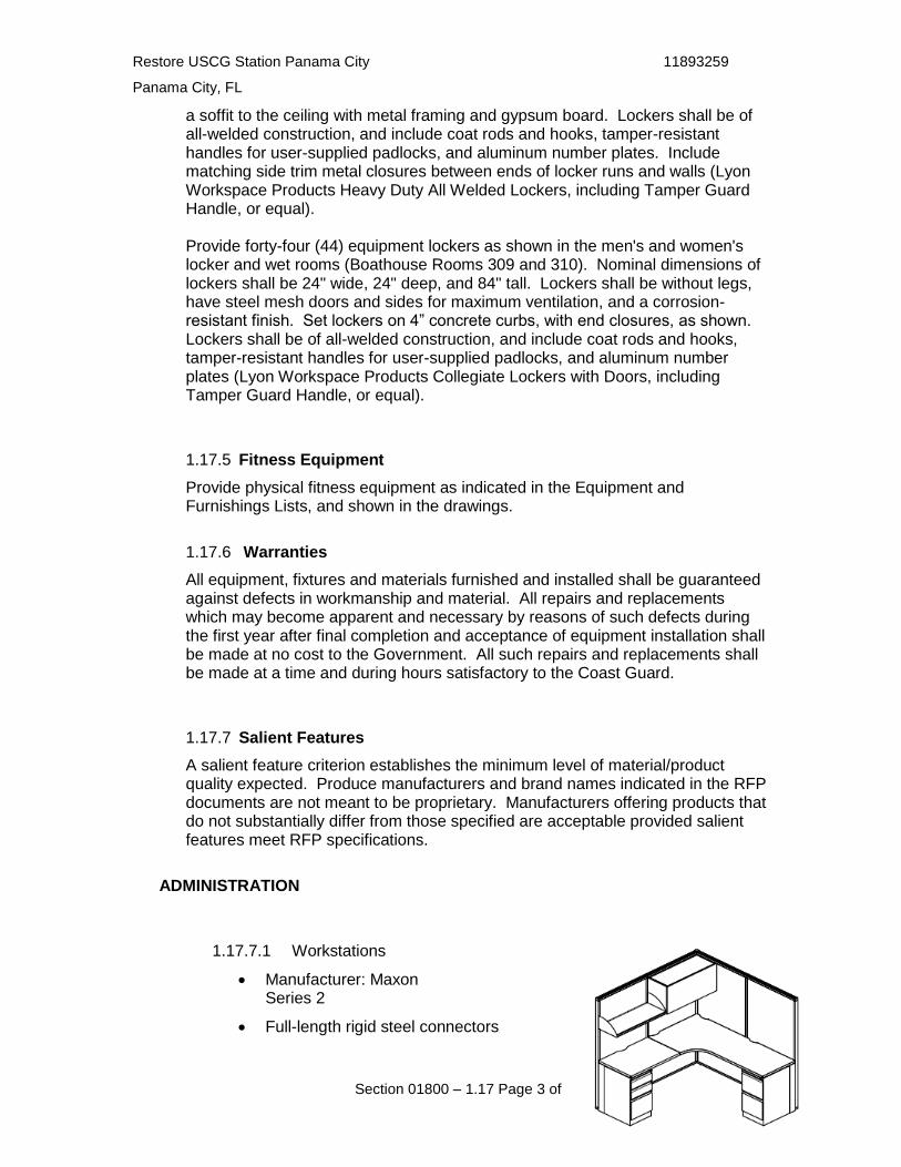
Restore USCG Station Panama City 11893259
Panama City, FL
Section 01800 – 1.17 Page 3 of 6
a soffit to the ceiling with metal framing and gypsum board. Lockers shall be of all-welded construction, and include coat rods and hooks, tamper-resistant handles for user-supplied padlocks, and aluminum number plates. Include matching side trim metal closures between ends of locker runs and walls (Lyon Workspace Products Heavy Duty All Welded Lockers, including Tamper Guard Handle, or equal). Provide forty-four (44) equipment lockers as shown in the men's and women's locker and wet rooms (Boathouse Rooms 309 and 310). Nominal dimensions of lockers shall be 24" wide, 24" deep, and 84" tall. Lockers shall be without legs, have steel mesh doors and sides for maximum ventilation, and a corrosion-resistant finish. Set lockers on 4” concrete curbs, with end closures, as shown. Lockers shall be of all-welded construction, and include coat rods and hooks, tamper-resistant handles for user-supplied padlocks, and aluminum number plates (Lyon Workspace Products Collegiate Lockers with Doors, including Tamper Guard Handle, or equal).
1.17.5 Fitness Equipment
Provide physical fitness equipment as indicated in the Equipment and Furnishings Lists, and shown in the drawings.
1.17.6 Warranties
All equipment, fixtures and materials furnished and installed shall be guaranteed against defects in workmanship and material. All repairs and replacements which may become apparent and necessary by reasons of such defects during the first year after final completion and acceptance of equipment installation shall be made at no cost to the Government. All such repairs and replacements shall be made at a time and during hours satisfactory to the Coast Guard.
1.17.7 Salient Features
A salient feature criterion establishes the minimum level of material/product quality expected. Produce manufacturers and brand names indicated in the RFP documents are not meant to be proprietary. Manufacturers offering products that do not substantially differ from those specified are acceptable provided salient features meet RFP specifications.
ADMINISTRATION
1.17.7.1 Workstations
Manufacturer: Maxon Series 2
Full-length rigid steel connectors

Restore USCG Station Panama City 11893259
Panama City, FL
Section 01800 – 1.17 Page 4 of 6
Frosted glazing
Modular furniture shall match existing in Building 14
1.17.7.2 Workstation Seating
Manufacturer: Maxon
Provides balanced body support with Innovative suspension and easy-to-use controls
Contoured back support with posture fit design
Chairs shall match existing
1.17.7.3 Conference Chairs
Manufacturer: Knoll Regeneration Series
Slim profile back with contour frame
High performance elastomeric Flex Back Net with integral lumbar support
Set-back arms for leg clearance and contoured arm pads
Recline resistance feature for greater upright support
1.17.7.4 Lateral Files
Manufacturer: Knoll Calibre Series
Powder coated low VOC
Optional work surface top in 3 edge style
36”W x 54”H x 18”D

Restore USCG Station Panama City 11893259
Panama City, FL
Section 01800 – 1.17 Page 5 of 6
1.17.7.5 Lobby Chairs
Manufacturer: Florence Knoll Lounge Chair
Exposed metal frame and legs in heavy gauge steel with polished chrome finish
Inner frame is solid wood
Seat suspension with No-Sag springs
GreenGuard indoor air quality certified
LOCKER ROOMS
1.17.7.6 Lockers
16-guage welded channel body construction
24-guage solid steel sides and tops
16-guage door construction with rectangular shaped Perforation for maximum ventilation
Powder coated with premium paint process to provide Scratch resistant finish
8” curb mounted
DINING
1.17.7.7 Tables
Chrome plate steel base
1-1/4” thick high pressure laminate top
41” high

Restore USCG Station Panama City 11893259
Panama City, FL
Section 01800 – 1.17 Page 6 of 6
1.17.7.8 Seating
Contoured one-piece seat and back moves with the body to reduce pressure points
Wipes clean for easy care
300lb minimum weight capacity
Stackable
END OF PARAGRAPH

Restore USCG Station Panama City 11893259
Panama City, FL
Section 01800 – 1.18 Page 1 of 13
SECTION 01800_DESIGN BUILD CRITERIA_ PARAGRAPH 1.18 ENVIRONMENTAL PERMITS, CONTROLS, AND PROTECTION
1.18 GENERAL
During all phases of this project the contractor shall comply with all applicable federal, state, and local environmental requirements. Contractor shall incorporate environmental requirements early in the design phase and ensure environmental compliance throughout all project phases.
Environmental permitting requirements can vary significantly from locality to locality. In addition to federal requirements, the Contractor must understand, incorporate, and manage any unique local and state requirements applicable to this specific site.
The scope of work includes in-water, over-water, and onshore work. Time-of-year restrictions, complex permitting issues, and other environmental restrictions typically encountered in commercial waterfront development/redevelopment are anticipated.
1.18.1 APPLICABLE PUBLICATIONS
The publications listed below form part of this specification. The Contractor shall comply with all applicable federal, state, and local regulations and laws.
1.18.1.1 ENVIRONMENTAL PROTECTION AGENCY (EPA) REGULATIONS:
40 CFR Protection of the Environment
40 CFR 112 Oil Pollution Prevention
40 CFR 136-143 Water Programs
40 CFR 204 Noise Emission Standards for Construction Equipment
40 CFR 260-279 Solid Waste Regulations
40 CFR 280-282 Underground Storage Tank Regulations
40 CFR 311-374 Worker Right-to-Know
40 CFR 761 Polychlorinated Biphenyls (PCBs) Manufacturing, Processing, Distribution in Commerce, and Use Prohibitions
1.18.1.2 U.S. DEPARTMENT OF LABOR OCCUPATIONAL SAFETY AND HEALTH ADMINISTRATION (OSHA) REGULATIONS:
29 CFR 1910 Worker Safety Requirements
1.18.1.3 ADVISORY COUNCIL ON HISTORIC PRESERVATION (ACHP) REGULATIONS:
36 CFR 800 Protection of Historic Properties
1.18.1.4 U.S. DEPARTMENT OF TRANSPORTATION REGULATIONS:
49 CFR 100-199 Hazardous Materials Transportation, Handling, and Storage Regulations
1.18.1.5 ADDITIONAL STATUTES
The statutes listed below form part of this specification:
Clean Air Act (CAA) – 42 U.S.C. 7401 et seq.
Clean Water Act (CWA) – 33 U.S.C. 1251 et seq.

Restore USCG Station Panama City 11893259
Panama City, FL
Section 01800 – 1.18 Page 2 of 13
Safe Drinking Water Act (SDWA) – 42 U.S.C 300F et seq.
Coastal Zone Management Act (CZMA) – 16 U.S.C. 1451 et seq.
Comprehensive Environmental Response, Compensation, and Liability Act (CERCLA) - 42 U.S.C. 9601 et seq.
Federal Insecticide, Fungicide, and Rodenticide Act (FIFRA) - 7 U.S.C. 136 et seq.
National Historic Preservation Act (NHPA) – 16 U.S.C. 470 et seq.
Noise Control Act (NCA) – 42 U.S.C. 4901 et seq.
Pollution Prevention Act (PPA) – 42 U.S.C. 13101 et seq.
Resource Conservation and Recovery Act (RCRA) – 42 U.S.C. 6901 et seq.
Solid Waste Disposal Act (SWDA) – 42 U.S.C. 6901 et seq.
Toxic Substances Control Act (TSCA) – 15 U.S.C. 2601 et seq.
Energy Independence and Security Act of 2007 (EISA) – 42 U.S.C. 17001 et seq.
Endangered Species Act (ESA) – 16 U.S.C. 1531 et seq.
Marine Mammal Protection Act (MMPA) – 16 U.S.C. 1361 et seq.
Magnuson-Stevens Fishery Conservation and Management Act (Magnuson-Stevens) – 16 U.S.C. 1801 et seq.
Emergency Planning and Right-to-Know Act (EPCRA) – 42 U.S.C. 11001 et seq.
1.18.2 PROJECT RELATED ENVIRONMENTAL PERMITS, CONSULTATIONS, AND CERTIFICATIONS
Timely acquisitions of all necessary design and construction related permits shall be the responsibility of the Contractor. Some permits may contain time-of-year restrictions and require substantial lead-time to obtain.
The Contractor shall be responsible for identifying and obtaining all required permits, approvals, notifications, utility permits, utility impacts, Federal Aviation Administration (FAA) notifications/permits, Federal Communications Commission (FCC) notifications/permits, concurrences, consultations, consistency reviews (to include Coastal Zone), and certifications (hereafter called permits) from federal, state, and local regulatory agencies. With the exception of stormwater construction permits for temporary land disturbing activities (see paragraph 1.18.4.4), the Government will not delegate "Agent" authority to the Contractor; the Government will sign all permit applications and submissions to regulatory agencies that require signatures. The Contractor is responsible for preparing all permit applications and for paying all permit application fees and associated costs as part of this contract. The Contractor shall be responsible for incorporating all permit conditions and constraints into the design and ensuring compliance with permits is maintained throughout the project. The Contractor shall be responsible for preparing all permit closure documents required once work governed by the permit is completed. All permit application submittals and other submittals/correspondence with permitting/regulatory agencies will require the Contractor to prepare a professionally written accompanying cover letter.
In close coordination with the Government, the Contractor shall prepare for, and assume a leading role in, any regulatory agency or public meetings/presentations associated with the permitting process.
Permit application packages shall be submitted in written form (in lieu of on-line/internet applications) to regulators wherever possible. On-line applications shall be accomplished by the Contractor after coordination of the contents with the Government.
The Contractor’s key personnel, to include project managers (design and construction) and field superintendents, shall read, understand, and ensure compliance with all permit conditions. All required permits shall be in place prior to beginning any site work.

Restore USCG Station Panama City 11893259
Panama City, FL
Section 01800 – 1.18 Page 3 of 13
1.18.2.1 INITIAL GOVERNMENT PERMIT WORK
The Government has initiated permit work as follows:
Spill Prevention, Control and Countermeasures Plan (SPCC), July 2015, United States Coast Guard Station Panama City, Florida Storm Water Master Plan for US Coast Guard Station Panama City, 1700 Thomas Drive, Panama City, Florida, May 2014 United States Fish and Wildlife Service Standard Manatee Conditions for In-Water Activities (dated 2011) Results from National Marine Fisheries Service online Essential Fish Habitat Mapper (dated 7 April 2021) United States Fish and Wildlife Service IPaC Resource List (dated 7 April 2021) NOAA Fisheries Florida Gulf Coast Threatened and Endangered Species and Critical Habitats Under NOAA Fisheries Jurisdiction (dated 7 April 2021)
Copies of these documents are provided by attachments D through I of this specification. The Contractor shall review and incorporate these documents, identify all additional permit work required, and incorporate all additional requirements into the project.
The Government anticipates preparation of a categorical exclusion to satisfy its responsibilities under the National Environmental Policy Act (NEPA) for the proposed work. The Contractor should assume that no additional NEPA work will be necessary, but should assume that attainment of additional regulatory permits and/or consultation will be necessary once project designs are developed.
1.18.3 ENVIRONMENTAL PLAN AND REQUIRED QUALIFICATIONS FOR PROJECT OVERSIGHT
For the design and construction phases of this project, provide an environmental engineer with a professional engineering license or a Certified Environmental Professional (in either Environmental Assessment or Environmental Planning areas of certification) to manage all environmental aspects of this project. Certified Environmental Professionals are those accredited through the Academy of Board Certified Environmental Professionals. This licensed engineer or Certified Environmental Professional shall have environmental planning experience in permitting, a thorough understanding of all environmental regulatory requirements, and experience leading environmental compliance on construction projects of similar size and scope to this project in the state of Florida, which is where this project takes place. The environmental engineer or Certified Environmental Professional shall:
1. Prepare and sign the project-specific Environmental Protection Plan as specified in Section 1.18.4.1.
2. Prepare and endorse all required environmental permit applications required for this project as specified in Sections 1.18.4.2 and 1.18.4.3. The Government will then sign all permit applications as the owner.
3. Review all environmental sampling, all non-hazardous and hazardous waste shipping documents (prior to shipment) for completeness, and environmental permits (in order to advise construction personnel of permit conditions).
4. Conduct three site visits during the construction phase of this project and submit a report to the Contracting Officer’s Representative (COR) documenting environmental compliance and also any environmental concerns or noncompliance. Site visits shall be scheduled to coincide with the stages of construction when environmental concerns are considered to be most critical. The site visits shall include a review of on-site environmental records, construction stormwater compliance, permit compliance, a review of all project environmental features and permanent/temporary “best management practices,” hazardous waste management, and all other

Restore USCG Station Panama City 11893259
Panama City, FL
Section 01800 – 1.18 Page 4 of 13
environmental issues considered to be most critical to this project. Provide the COR with trip reports summarizing and documenting each trip, compliance with permits, stormwater management, hazardous waste, and all other project-specific environmental issues and concerns.
5. Provide a seven (7) day notice to the COR prior to the inspections.
1.18.4 ENVIRONMENTAL SUBMITTALS
Provide the following submittals to the COR in accordance with Specification 01330, "Design-Build Submittal Procedures."
1.18.4.1 ENVIRONMENTAL PROTECTION PLAN
The purpose of the Environmental Protection Plan is to describe, in detail, methods and procedures by which the Contractor intends to minimize/mitigate adverse impact to the environment resulting from this work. The plan shall be structured/formatted such that the elements below make up the plan’s sections in the same order presented. The plan is to be site and project-specific; discuss elements below as they specifically related to the project and site.
Submit two (2) hard copies and one (1) electronic copy of a draft Environmental Protection Plan for Government review as part of the first design submittal package. Incorporate any Government comments received as appropriate and provide three (3) final hard copies and one (1) final electronic copy of a final Environmental Protection Plan within fourteen (14) days of receiving Government comments.
At a minimum, the plan shall document the Contractor's means and methods for complying with the specification requirements with the following elements included:
1.18.4.1.1 General Information: Provide a general overview of the environmental plan including its purpose, general site information, and a letter designating an Environmental Manager for the project, meeting the requirements detailed in Section 1.18.3, signed by an officer of the firm.
1.18.4.1.2 Environmental Program Management: Provide the names of individuals and/or the environmental consultants who will be responsible for overseeing and ensuring environmental compliance during both the design and construction phases of this project. Discuss their previous work experience working with the state and regional environmental regulators and permitting agencies with authority over this project. Provide a discussion of their responsibilities and experience with maintaining environmental compliance. Include a discussion of how environmental concerns will be managed and incorporated in the design phase and how those measure will be continued through construction. Discuss how specific project environmental concerns and environmental permit conditions will be effectively communicated to key project personnel, project managers, subcontractors, construction workers, and other key Contractor employees associated with this project. Discuss the timing of the three environmental compliance site visits to be conducted in accordance with Section 1.18.3.
1.18.4.1.3 Initial Permit Summary: Provide a complete summary of all anticipated permits/approvals required for the project. At a minimum, the following information shall be provided for each required permit:
Name of permit/approval
Regulatory review agency
Brief description of permit purpose and applicability to project
Anticipated environmental mitigation requirements
Regulatory agency address
Regulatory agency point of contact (name)
Regulatory agency phone number and email address

Restore USCG Station Panama City 11893259
Panama City, FL
Section 01800 – 1.18 Page 5 of 13
Public notice requirements (if needed, include short description)
Application fee information
Anticipated review/processing period
Public meeting requirements (if needed, include short description)
Permit closeout requirements (notifications, as-builts, etc.)
The Contractor shall advise on any difficulties expected in obtaining approval for each permit/authorization.
1.18.4.1.4 Protection and Preservation of Natural Resources: Provide a description of any anticipated natural resources that must be protected during the course of the project and the plan to protect those resources. Discuss management of any endangered species, critical habitat, or essential fish habitat. Provide steps to be taken should unknown natural resources be discovered during construction.
1.18.4.1.5 Waterfront and In-Water Work: Discuss anticipated permits that must be obtained and permitting difficulties associated with project work near, over, on, or in waters of the United States (navigable or non-navigable). Discuss anticipated time-of-year restrictions on project work and other permit conditions that will impact the project. Discuss any difficulties anticipated in obtaining permits and the anticipated lead time required to obtain permits. Discuss steps to be taken during the project to protect waterfront areas within the work zone. Discuss any special considerations for the handling and disposal of creosote and salt treated pilings/timbers required during demolition activities.
Contractor shall plan for and assume that environmental permit time-of-year restrictions on in-water construction work are likely. Contractor shall schedule and plan accordingly to manage any time-of-year work restrictions for in-water work.
1.18.4.1.6 Stormwater Management and Control: Discuss construction permits to be obtained and anticipated stormwater erosion controls. Discuss any anticipated/required permit notifications, closure procedures, or required closure documentation. Discuss how project managers will communicate stormwater controls to be implemented and stormwater permit conditions to their construction workers/employees engaged in earth/ground disturbing activities. Discuss anticipated temporary and permanent stormwater best management practices (BMPs) and the need to develop a Stormwater Pollution Prevention Plan (SWPPP) to be incorporated into the project. Discuss how the requirements of the Energy Independence and Security Act, Section 438 (EISA), associated EPA EISA guidance, and state/local regulations governing permanent stormwater controls will be incorporated into the design and construction. Discuss any anticipated concerns or problems in meeting permanent stormwater requirements.
1.18.4.1.7 Drinking Water: Discuss any anticipated potable water hookup permits, notifications, and requirements related to this project. Provide point-of-contact information for the local water district that will supply potable water to this project. Discuss measures, precautions, and procedures to be taken during the project to ensure existing and any new potable water system components are not contaminated. For any project-specific work that involves connecting water lines and new water lines, discuss disinfectant procedures to be used to prevent contamination of the drinking water system. Discuss any anticipated or required water testing during the duration of the project.
1.18.4.1.8 Waste Management: Discuss the project’s anticipated solid waste streams (to include any hazardous waste) and how these solid wastes will be managed. Include a discussion of any identified waste streams and/or project materials specifically targeted for recycling (scrap metal, cardboard, plastic, concrete rubble, wood, etc.). Discuss on-site storage of solid waste and recyclables and anticipated disposal strategies.
Note: In the event that hazardous waste is identified or generated, the Contractor must

Restore USCG Station Panama City 11893259
Panama City, FL
Section 01800 – 1.18 Page 6 of 13
immediately notify the COR. For all hazardous waste identified and generated, the Contractor shall provide proper storage, labeling, handling, and meet all other applicable RCRA hazardous waste regulation requirements for on-site management of hazardous waste. The Contractor’s personnel managing hazardous waste must have demonstrated experience and knowledge in managing hazardous waste and a working knowledge of all RCRA regulatory requirements. The Contractor shall arrange and provide all shipping and disposal of hazardous waste. The Government’s facility hazardous waste shipping ID shall be used for all manifests as the owner/generator and all hazardous waste on-site storage, management, and shipping requirements shall be coordinated with the Government’s facility on-site manager. The Contractor shall measure and provide actual weights of hazardous waste (no estimates), shall provide the Government’s on-site hazardous waste coordinator with 10 days pre-notification of shipment dates, and with this notification provide all shipping and sampling documentation required by federal and state hazardous waste regulations so that it can be properly reviewed. The Government’s on-site hazardous waste coordinator shall sign all shipping manifests as the owner. Only licensed transport companies and licensed hazardous waste disposal facilities shall be used. Copies of all final shipping manifests must be provided to the COR.
Discuss hazardous waste procedures to be used should hazardous waste be identified or generated and discuss the Contractor’s personnel and subcontractors that would be used to properly manage hazardous waste and their previous experience and qualifications.
1.18.4.1.9 Excess Construction Generated Dirt/Soil/Fill Removal and Disposal: Discuss any anticipated excess dirt/soil/fill material that may be generated as part of the project. Discuss its suitability for reuse or how it will be properly managed and disposed of off-site if it is not required or suitable to complete on-site work. Discuss how all federal, state, and local regulatory requirements related to transport and final disposal will be met.
Discuss management, coordination, testing, and permitting requirements anticipated and what permitted disposal facility is to be used. Discuss alternative disposal plans should contamination levels be encountered over and beyond permitting limits for an EPA RCRA Subtitle D Municipal Solid Waste Landfill (see also Section 1.18.5.3.3 for additional information).
1.18.4.1.10 Wastewater: Discuss any anticipated wastewater hookup permits, notifications, and requirements related to this project. Provide point-of-contact information for the local publicly owned treatment works or sanitary district that this project will discharge to. Discuss anticipated wastewater pretreatment devices and any regulatory approvals or permitting requirements.
1.18.4.1.11 On-Site Petroleum Storage and Fueling: Discuss management of temporary fueling operations to include release prevention, on-site spill kit placement, and cleanup capabilities. Secondary and weatherproof secondary containment are required for all temporary petroleum storage equipment used. Discuss any requirements to register or permit temporary fuel storage tanks with local, state, and/or federal regulators. Discuss how and where secondary containment will be utilized in order to prevent the release of petroleum. All temporary tank tanks utilized shall have weatherproof containment that is integral to the primary storage.
1.18.4.1.12 Fuel and Hazardous Material Spill Response: Discuss contingency plans and procedures for responding to releases to the environment. List regulatory agencies that must be notified in the event of a spill or the discovery of past release condition (encountered contaminated soils, etc.) and provide their contact information.
1.18.4.1.13 Hazardous Materials Management: Discuss management of anticipated hazardous materials that will be used on-site as part of this project. Include information on hazardous material on-site storage, appropriate hazard communication plans, release prevention, and how all OSHA and EPA requirements related to hazardous material management will be met. Discuss how

Restore USCG Station Panama City 11893259
Panama City, FL
Section 01800 – 1.18 Page 7 of 13
construction workers and employees working with hazardous materials that are used in conjunction with this project will be trained on how to safely work with and made aware of potential hazards associated with the specific materials they are utilizing. Include the management of any volatile organic compounds (VOCs) and refrigerants to be used as part of this project.
1.18.4.1.14 Discovery of Suspected Previous Environmental Release: In the event that a suspected previous environmental release is discovered during the course of construction activities, discuss plans, procedures, precautions, and notifications to be taken in order to address this release in accordance with local, state, and federal regulatory requirements. Typical indicators of past releases that may be encountered include stained soils, abandoned buried tanks, soils that smell of oil or other chemicals, abandoned trash or construction debris, etc.
1.18.4.1.15 Air Pollution and Stationary Fuel Burning Equipment: Discuss any anticipated air pollution permits related to the project and the timing of when approvals, permits, permit modifications of existing Station permits would be required. Discuss EPA equipment certification requirements for fuel burning equipment associated with this project and when these documents will be provided to the Government.
1.18.4.1.16 Noise and Dust Control: Discuss project-specific anticipated noise and dust concerns and controls to be incorporated into the design. As applicable, include a discussion of paint overspray.
1.18.4.1.17 Protection and Preservation of Historic and Archaeological Resources: Provide a description of any anticipated historic and archaeological resources that must be protected during the project and the plan to protect those resources. Provide steps to be taken should unknown cultural resources be discovered during construction.
1.18.4.2 DRAFT PERMIT APPLICATION PACKAGES
Submit two (2) copies of the following for Government review and approval:
1. Completed application
2. Draft application cover letter using the template provided as the basis of format (the cover letter shall be addressed to the appropriate person/point of contact within the permitting agency, include a clear and precise narrative describing the scope of the project, and adequately summarize why the permit package is being submitted.)
3. Draft public notice advertisement (if any)
Generally, the signature block utilized for all applications and cover letters shall be as follows (drafts and finals):
Applicant: United States of America in the Person of the U.S. Coast Guard, Facilities Design and Construction Center
Signature: J. D. BERRY Captain, U. S. Coast Guard
The Government shall notify or advise the Contractor of any changes in this signature block or applicant and the Contractor shall adjust accordingly.
The Government shall review draft permit applications within fourteen (14) days and provide comments back to the Contractor.

Restore USCG Station Panama City 11893259
Panama City, FL
Section 01800 – 1.18 Page 8 of 13
1.18.4.3 FINAL PERMIT APPLICATION PACKAGES
Submit three (3) copies of the items listed below for the Government's review and approval. After incorporating edits to address all remaining Government comments, provide final copies for signature and submission (by the Government) to regulatory agency(ies):
1. Final completed application
2. Final permit cover letter
3. Public notice advertisement (if any)
4. Application fees (certified check)
5. Proper number of exhibits/attachments (as required by the regulatory agency) for the application plus two (2) additional paper copies for the Government
6. Electronic copies of all documents, applications, cover letters, exhibits, attachments, plans, etc. in both Adobe pdf format and Microsoft Word format on compact disc (CD) or digital versatile disc (DVD) utilizing fillable forms and editable formats to facilitate any final editing requirements whenever possible
The Government will submit permit application packages to the provided regulatory addresses and will provide the Contractor with copies of all permit packages submitted within fourteen (14) days of their submittal.
The Contractor shall place all public notice advertisements required for each application in the required public forum (newspaper, library, website, etc.) after the details of which newspaper, library location, website, etc. are approved by the COR. Advertisements shall be placed so as to meet regulatory requirements and at critical dates to allow for timely permit approval. The Contractor shall pay for and incorporate all associated public notice fees into this contract.
Should regulatory agencies require additional or corrected information in a permit application package, the Government will notify the Contractor within fourteen (14) days of receiving the request from the regulatory agency. The Contractor shall then be responsible for providing the additional information or permit application corrections in accordance with procedures defined in Sections 1.18.4.2.
1.18.4.4 TEMPORARY AND PERMANENT STORMWATER CONTROLS
The National Pollutant Discharge Elimination System (NPDES) stormwater program requires construction site operators engaged in clearing, grading, and excavating activities that disturb 1 acre or more, including smaller sites in a larger common plan of development or sale, to obtain coverage under a NPDES permit for their stormwater discharges. Most states are authorized to implement the NPDES stormwater permitting program. State and local regulatory requirements may be more restrictive than federal regulatory requirements and should be incorporated into site plans as applicable. The EPA remains the permitting authority in a few states, territories, and on most land in Indian Country. In areas where EPA is the permitting authority, construction site operators must meet the requirements of the EPA Construction General Permit (CGP).
During the design phase, the Contractor shall become familiar with all local, state, and federal stormwater requirements (temporary and permanent stormwater controls) and ensure that these requirements are incorporated into the design and construction activities. The Contractor shall also meet the stormwater requirements defined in the Energy Independence and Security Act (EISA) of 2007, Section 438, and become familiar with and meet the program requirements of any municipal stormwater system that the project will discharge into.

Restore USCG Station Panama City 11893259
Panama City, FL
Section 01800 – 1.18 Page 9 of 13
1.18.4.5 STORMWATER CONSTRUCTION PERMITS – SOIL AND EROSION PERMITS RELATED SPECIFICALLY TO CONSTRUCTION ACTIVITY
For any required federal, state, or local permits related specifically to soil and erosion control during construction activities, and where such agencies allow the Government’s contractor to apply directly for such permits, the Contractor shall apply directly to the appropriate permitting agency for permit coverage. Should agencies require the “owner” to submit permits, the Contractor shall complete this permit process in accordance with requirements detailed in Sections 1.18.4.2 through 1.18.4.3. Application packages submitted by the Contractor directly to the regulator shall be signed by the Contractor and not delegated to any subcontractors or other third parties.
Prior to submitting permit applications and plans, the Contractor shall provide draft copies of all related permit applications, related plans, SWPPPs, and other supporting stormwater documents to the Government for review. The SWPPP shall adequately address all stormwater runoff contamination concerns and meet all federal, state, and local requirements and associated permit conditions/requirements. The Government shall provide comments on draft submittals back to the Contractor within fourteen (14) days.
The Contractor shall address any regulatory agency comments in a timely manner so as not to delay the work subject to the contract. All required permits shall be in place prior to beginning any site work.
Within fourteen (14) days, the Contractor shall provide the Government with written and electronic copies of all final Notices of Intent (NOIs), correspondence submitted to and received by regulatory agencies, project construction startup and closeout notifications, and other permit correspondence (to include copies of the actual permits issued). The Contractor shall provide four (4) copies of the final SWPP to the Government within fourteen (14) days of receiving the Government’s comments on the draft SWPPP.
1.18.4.6 GOVERNMENT FACILITIES WITH EXISITING SPILL PLANS
In the event the project occurs on a Government facility that has a Spill Prevention Control and Countermeasure (SPCC) plan, the Contractor’s design and construction practices shall be in compliance with the SPCC’s guidelines, goals, and objectives.
1.18.4.7 GOVERNMENT FACILITIES WITH EXISTING STORMWATER PLANS OR PERMITS
In the event the project occurs on a Government facility that already has (or discharges to) an established municipal separate storm sewer system (MS4) permit and/or stormwater management (SWM) plan, the Contractor’s design and construction practices shall be in compliance with the MS4 permit and SWM plan guidelines, goals, and objectives.
1.18.5 TEMPORARY ENVIRONMENTAL CONTROLS
The Contractor shall protect the environment, preserve natural and cultural resources, and protect human health during construction by complying with all pertinent federal, state, and local regulations that pertain to the environment.
1.18.5.1 NATURAL RESOURCE PROTECTION
1.18.5.1.1 Fish and Wildlife: Do not disturb fish, wildlife, or critical habitat, except as specifically permitted in writing by regulatory permitting agencies. The Contractor shall maintain compliance with any permit conditions governing fish, wildlife, and critical habitat at all times. At all times, the Contractor shall maintain compliance with the Endangered Species Act. Do not alter water flows or otherwise significantly disturb the native habitat critical to the survival of fish and wildlife, except as specifically permitted in writing by regulatory permitting agencies.
1.18.5.1.2 Water Resources: At all times, the Contractor shall prevent oil or hazardous substances from entering the ground, drainage areas, or waters (navigable or non-navigable).
1.18.5.1.3 Stormwater Controls during Construction: Construction site sediment runoff shall be

Restore USCG Station Panama City 11893259
Panama City, FL
Section 01800 – 1.18 Page 10 of 13
prevented from entering any storm drains and prevented from degrading areas adjacent to the construction site due to siltation and sedimentation through the use of appropriate erosion and sediment controls. The Contractor shall provide erosion protection of the surrounding soils.
The Contractor shall provide temporary protection on sides and back slopes as soon as rough grading is completed or sufficient soil is exposed to require erosion protection. Protect slopes by accelerated growth of permanent vegetation, temporary vegetation, mulching, or netting. Stabilize slopes by hydroseeding, anchoring mulch in place, covering with anchored netting, sodding, or a combination of these and other methods necessary for effective erosion control.
There shall be no discharge of excavation groundwater to the sanitary sewer, storm drains, or bodies of water without appropriate permits and prior specific written authorization of the COR. Discharge of hazardous substances will not be permitted under any circumstances.
The Contractor shall comply with all state and federal regulatory requirements governing construction runoff controls. The Contractor shall comply with all construction stormwater control permit conditions.
1.18.5.1.4 Tree and Vegetation Protection: Except in areas to be cleared, the Contractor shall not remove, cut, deface, injure, or destroy trees, shrubs, or other vegetation without the COR's permission. Do not fasten or attach ropes, cables, or guys to existing nearby trees for anchorages unless authorized by the COR. Where such use of attached ropes, cables, or guys is authorized, the Contractor shall be responsible for any resultant damage. The Contractor shall protect existing trees which are to remain and which may be injured, bruised, defaced, or otherwise damaged by construction operations.
1.18.5.2 MANAGEMENT AND DISPOSAL OF WASTES AND DIRT/SOIL/FILL
1.18.5.2.1 Waste Management: The Contractor shall pick up waste and debris and place in covered containers furnished by the Contractor. The Contractor shall empty containers and remove waste and debris from Government property at least weekly. Do not allow containers to become overfilled. Remove wastes without spilling or contaminating streets, the site, or other areas. Offsite disposal shall be at a licensed landfill and shall comply with all local, state, and federal requirements.
Note: In the event that hazardous waste is identified or generated, the Contractor must immediately notify the COR. For all hazardous waste identified and generated, the Contractor shall provide proper storage, labeling, handling, and meet all other applicable RCRA hazardous waste regulation requirements for on-site management of hazardous waste (see Section 1.18.5.3.3). The Contractor’s personnel managing hazardous waste must have demonstrated experience and knowledge in managing hazardous waste and a working knowledge of all RCRA regulatory requirements. The Contractor shall arrange and provide all shipping and disposal of hazardous waste. The Government’s facility hazardous waste shipping ID shall be used for all manifests as the owner/generator and all hazardous waste on-site storage, management, and shipping requirements shall be coordinated with the Government’s facility on-site manager. The Contractor shall measure and provide actual weights of hazardous waste (no estimates), and shall provide the Government’s on-site hazardous waste coordinator with 10 days pre-notification of shipment dates and with this notification provide all shipping and sampling documentation required by federal and state hazardous waste regulations so that it can be properly reviewed. The Government’s on-site hazardous waste coordinator shall sign all shipping manifests as the owner. Only licensed transport companies and licensed hazardous waste disposal facilities shall be used. Copies of all final shipping manifests must be provided to the COR.
1.18.5.2.2 Excess Construction Dirt/Soil/Fill Removal and Disposal: Any excess soil/dirt/fill material generated as part of the project that is not required or suitable to complete on-site work shall

Restore USCG Station Panama City 11893259
Panama City, FL
Section 01800 – 1.18 Page 11 of 13
not be considered, classified, or defined as an “unrestricted” use material. The Contractor shall transport and dispose of this material at an off-site permitted EPA RCRA Subtitle D Municipal Solid Waste Landfill that routinely accepts the type of material being removed from the site. The Contractor shall also meet all additional state and local landfill regulatory requirements.
The Contractor shall manage, coordinate, and provide all material testing and permit coordination and prepare all manifesting requirements for proper disposal. Any material found to be contaminated beyond what the permitted EPA RCRA Subtitle D Municipal Solid Waste Landfill can accept will be considered a changed site condition.
The Government is the owner of this material and will sign shipping manifests as required. All completed shipping documents will be provided to the Government within 30 days of final disposal.
1.18.5.3 STORAGE, SPILLS, RELEASES, AND DISPOSAL OF OILS AND HAZARDOUS SUBSTANCES
1.18.5.3.1 Temporary Fueling and Fuel Storage: The Contractor shall conduct fueling and lubricating operations of equipment and motor vehicles in a manner that protects against spills and evaporation. Appropriate spill kits shall be provided and readily available at the construction site. All used oil generated on-site shall be managed in accordance with provisions detailed in 40 CFR 279.
When possible, minimize the capacity of aboveground storage tanks (ASTs) placed on-site for the purpose of storing petroleum products. Prior to placing storage tanks on-site, the Contractor shall verify any state requirements for temporary tank registration, prepare any registration documents, and abide by all applicable regulations. All temporary ASTs shall have built-in/integrated secondary weatherproof containment designed to hold the total capacity of the AST, and meet all SPCC requirements found in 40 CFR 112.
1.18.5.3.2 Releases/Spills of Oils or Hazardous Substances: The Contractor shall take precautions to prevent releases/spills of oils and hazardous substances. Maintain adequate and appropriate spill kits at the construction site in order to properly respond to a release. In the event of any releases of oil or hazardous substances, chemicals, or gases, immediately notify the COR. The Contractor shall contain and clean up these spills without cost to the Government. If Government assistance is requested or required, the Contractor shall reimburse the Government for such assistance.
1.18.5.3.3 Control and Disposal of Hazardous Wastes: For all hazardous waste identified and generated, the Contractor shall provide proper storage, labeling, handling, and meet all other applicable RCRA hazardous waste regulation requirements for on-site management of hazardous waste. The Contractor’s personnel managing hazardous waste must have demonstrated experience and knowledge in managing hazardous waste and a working knowledge of all RCRA regulatory requirements. The Contractor shall arrange and provide all shipping and disposal of hazardous waste. The Government’s facility hazardous waste shipping ID shall be used for all manifests as the owner/generator and all hazardous waste on-site storage, management, and shipping requirements shall be coordinated with the Government’s facility on-site manager. The Contractor shall measure and provide actual weights of hazardous waste (no estimates), and shall provide the Government’s on-site hazardous waste coordinator with 10 days pre-notification of shipment dates and with this notification provide all shipping and sampling documentation required by federal and state hazardous waste regulations so that it can be properly reviewed. The Government’s on-site hazardous waste coordinator shall sign all shipping manifest as the owner. Only licensed transport companies and licensed hazardous waste disposal facilities shall be used. Copies of all final shipping manifests must be provided to the COR.
Hazardous wastes that are produced as a result of performing work under this contract shall

Restore USCG Station Panama City 11893259
Panama City, FL
Section 01800 – 1.18 Page 12 of 13
be handled, stored, transported, and disposed of according to provisions detailed in 40 CFR 262, where applicable. Prevent hazardous wastes from entering the ground, drainage areas, and surface waters. Immediately notify the COR of any spills. Hazardous wastes generated on Government property shall be identified as being generated by the Government. All necessary documentation including hazardous waste manifests shall be signed by an authorized representative of the facility prior to removal of waste from the site. This will require coordination with on-site Government representatives to determine shipping manifest information. All completed shipping documents and final manifests will be provided to the Government within 30 days of final disposal. Under no circumstances shall hazardous waste be brought onto Government property.
1.18.5.3.4 Discovery of Suspected Previous Environmental Releases: In the event that a suspected previous environmental release is discovered during the course of construction activities, the Contractor shall immediately notify the COR of this changed site condition, take appropriate action to protect workers, and also take prudent actions to prevent any further release. The Government and the Contractor will then discuss an appropriate plan of action to address the release as it relates to ongoing construction activities in order to comply with local, state, and federal regulations governing the discovery of suspected environmental releases. Indicators of typical past releases that may be encountered during construction activities include stained soils, abandoned buried tanks, soils that smell of oil or other chemicals, abandoned trash or construction debris, etc.
1.18.5.4 AIR QUALITY AND IN-AIR NOISE
1.18.5.4.1 Dust Control: The Contractor shall keep dust down at all times, including during non-working hours. Dry power brooming is not permitted; instead use vacuuming, wet mopping, or wet brooming. Air blowing is permitted only for cleaning non-particulate debris such as steel reinforcing bars. When sandblasting or spray painting, provide tarp drop cloths and windscreens under and around blasting and painting operations to confine and collect dust, sand, paint, and debris. Concrete blocks, concrete, and asphalt shall be wet cut.
1.18.5.4.2 Volatile Organic Compounds (VOCs): The Contractor and all subcontractors are required to comply with the local VOC laws and regulations and shall have an acceptable VOC compliance plan. The plan shall demonstrate that the use of paints, solvents, adhesives, and cleaners comply with local VOC laws and regulations and that all required permits in the air quality district in which the work will be performed have been obtained or will be obtained prior to starting work involving VOCs. An acceptable compliance plan shall contain, at a minimum, a listing of each material subject to restrictions in the air quality management district in question, the rule governing its use, a description of the actions which the Contractor will use to comply with the laws and regulations, and any changes in the status of compliance during the life of the contract. Alternatively, if no materials are subject to the restrictions in the air quality management district where the work will be performed or if there are no restrictions, the compliance plan shall so state.
1.18.5.4.3 Prohibition of Class 1 Ozone Depleting Substances (ODS): Class 1 ODS, as defined in Section 602(a) of the Clean Air Act, shall not be used in the performance of this contract, nor be provided as part of the equipment associated with the work. This prohibition shall be considered to prevail over any other provisions, specifications, drawings, or referenced documents.
1.18.5.4.4 Noise: The Contractor shall make the maximum use of "low-noise-emission products" as certified by EPA and described at 40 CFR 204. No blasting or use of explosives is permitted. The Contractor shall comply with federal, state, and local noise control laws and regulations.
1.18.6 CULTURAL, ARCHAEOLOGICAL, AND HISTORIC RESOURCE PROTECTION
Prior to beginning construction activities, the Contractor must have a clear understanding of any known or

Restore USCG Station Panama City 11893259
Panama City, FL
Section 01800 – 1.18 Page 13 of 13
likely cultural and historic resources as detailed in state and tribal project planning and consultation.
Carefully protect in-place all historic/archaeological items and/or human skeletal remains discovered in the course of work. Upon discovery, the Contractor shall notify the COR immediately and stop work in the immediate area of the discovery until directed by the COR to resume work. The Government retains ownership and control over historic and archaeological resources encountered during the course of work.
1.18.7 ENVIRONMENTAL MITIGATION REQUIREMENTS
The Contractor shall comply with the Standard Manatee Conditions for In-Water Activities (reference Attachment F of this specification).
The Contractor must also cease in-water work, including vessel operation, if sea turtles or other marine mammals (including whales or dolphins) are present within 100 feet (the buffer zone) of the active work area. In-water activities shall not resume until the Contractor is certain that the animal(s) have left the buffer zone. Animals must not be herded or harassed into leaving the buffer zone.
The Contractor shall employ soft-start techniques for impact pile driving. Soft starts require an initial set of strikes at reduced energy followed by a 30-second waiting period and then two subsequent reduced energy strike sets. The soft starts must be implemented at the start of impact pile driving each day and also must be implemented after any period when pile driving has ceased for 30 minutes or longer.
Additional mitigation requirements may be imposed by the U.S. Army Corps of Engineers, the National Marine Fisheries Service, the U.S. Fish and Wildlife Service, and/or the state of Florida as permit conditions for in-water work. Should mitigation requirements be required as part of a permit, the Contractor must coordinate these actions as part of the permit application process. Any required mitigation fund payments or actual increase in scope of work would be considered a changed site condition. The Government’s order of mitigation preferences are to first offer features that are already part of the project, followed by payment into available mitigation funds, followed lastly by additional project mitigating features acceptable to regulatory agencies.
1.18.8 REQUIRED MODIFICATION AND UPDATES TO BASE ENVIRONMENTAL OPERATING PERMITS AND BASE ENVIRONMENTAL PLANS
Station Panama City operates in compliance with an SPCC plan, which they maintain/update.
The Contractor must update the existing Station Panama City SPCC plan (reference Attachment D of this specification) so that it includes all new oil storage facilities being installed under this project. This updated plan must be certified by a professional engineer. The updated plan must be completed prior to new oil storage facilities (aboveground storage tanks, drum areas, oil-cooled transformers, etc.) becoming operational.
The Contractor shall submit an electronic copy and two (2) written SPCC draft copies for the Government's review and approval. The Government will provide review comments within fourteen (14) days of receipt of draft copies. The Contractor shall make edits to address all Government comments and then provide the following final documents:
Three (3) professionally bound hard copies of the final SPCC plan
Electronic copies of the SPCC plan in both Adobe pdf format and Microsoft Word format on CD/DVD.
The Contractor shall provide the Base Facility Engineer with information critical to cataloging all fuel burning equipment (boilers, furnaces, generators, etc.) prior to beginning construction. Typical information includes manufacturer, model numbers, maximum rated British thermal unit (BTU) input, type of fuel to be burned, exhaust stack diameter and height, efficiency, etc.
END OF PARAGRAPH

Restore USCG Station Panama City 11893259
Panama City, FL
Section 01800 – 1.19 Page 1 of 2
SECTION 01800_DESIGN-BUILD CRITERIA PARAGRAPH 1.19 DREDGING
1.19 DREDGING
1.19.1 Method of Measurement
Existing hydrographic survey maps are provided for informational purposes only. The Contractor is responsible to field verify the accuracy of the data for use in preparing construction design documents. A pre-dredge and a post-dredge hydrographic survey shall be performed by the Contractor to determine the volume of material dredged. The material removed shall be measured by cubic yards. The pre-dredge hydrographic survey shall be completed no more than 30 calendar days prior to dredging. The post-dredge hydrographic survey shall be no later than 30 calendar days post dredging. The Government shall be notified 14-calendar days prior to the start of the pre-dredge and the post-dredge hydrographic surveys. The Contractor shall permit the Government representative to accompany the hydrographic survey party to inspect the data and methods used in preparing the final estimate. The dredge area shall be subject to deductions or correction of deductions previously made because of excessive over-depth, dredging outside or authorized areas, or disposal of material in an unauthorized manner.
1.19.2 Time of Year Restrictions
Refer to the Environmental Protection Plan specification for Waterfront and In-Water Work in Section 1.18.
1.19.3 Material to be Removed
The material to be removed is estimated to be silty sands (SM) and soft lean clays (CL).
1.19.4 Artificial Obstructions
The Government has no knowledge of cables, pipes, or other artificial obstructions or of any wrecks, wreckage, or other material that would necessitate the use of explosives or the employment of additional equipment for economical removal. If actual conditions differ from those stated or shown, or both, an adjustment in contract price or time for completion, or both, shall be made in accordance with "FAR 52.236-2, Differing Site Conditions."
1.19.5 Quantity of Material
The estimated quantity for bidding purposes and for application of the "FAR 52.212-11, Variation in Estimated Quantity" shall be 8,650 cubic yards, which is the total quantity, including over-depth. The quantities listed are estimates only. Within the limits of available funds, complete the work specified whether the quantities involved are greater or less than those estimated.
The Contractor shall dredge the area shown on the RFP Drawings to a minimum elevation of -14.5 MLLW. The total estimated amount of material to be removed from within the specified limits, including side slopes, but excluding over-depths, is 4,300 cubic yards. The maximum amount of allowable over-depth dredging is estimated to be 4,350 cubic yards.
1.19.6 Over-depth Dredging
To cover unavoidable inaccuracies of dredging processes, material actually removed to a depth of two feet below the depth specified and within the dredging limits shall be measured and paid for at full contract price.
1.19.7 Side Slopes
Dredging on side slopes shall follow, as closely as practicable, the lines indicated or specified. A two-foot allowance shall be made for dredging beyond the indicated or specified side slopes, except as provided
herein.
1.19.8 Interference with Navigation

Restore USCG Station Panama City 11893259
Panama City, FL
Section 01800 – 1.19 Page 2 of 2
The Contractor shall minimize interference with the use of channels and passages. The Contracting Officer shall direct the shifting or moving of dredges or the interruption of dredging operations to accommodate the movement of vessels and floating equipment, if necessary.
1.19.9 Compensation for Interruption of Operations
If dredging operations are interrupted due to the movement of vessels or floating equipment, an adjustment in the contract price or time for completion, or both, shall be made as provided by the contract. The Contracting Officer shall notify the Contractor 7 calendar days prior to ship movements that shall affect dredging operations.
1.19.10 Dredge Permitting
The contractor shall obtain all required permits and shall comply with all conditions for any permits issued at all times. The contractor shall provide all necessary sampling and surveying required for the permitting application and permit conditions, and shall use qualified personnel with specific permitting experience in the State of Florida to produce professional permit application documents. See Section 1.18 for additional permitting requirements.
1.19.11 Disposal of Excavated Material
The Contractor shall provide for safe transportation and disposal of dredged materials at an approved disposal area. The deposit of dredged materials in unauthorized places is forbidden. Comply with rules and regulations of federal, state, and local regulators and also any local port and harbor governing authorities/entities. Predredge sampling indicates the [presents/absence] of soil contamination. [The following sampling reports and analysis are provided to show the anticipated contaminants and their concentrations.] [Insert samples and Analysis] [Insert Studies] The state of Florida regulates dredge spoils, and the contractor should assume that dredge spoils will be regulated as [insert the state specific category anticipated for dredge spoils] in [insert Project state]. [Provide any specific anticipated hurdles, obstacles, or unique characteristics that the contractor is likely to encounter with dredged materials.]
END OF PARAGRAPH

Restore USCG Station Panama City SFRL: 11893259
Panama City, FL
SECTION 01802 - Page 1 of 19
SECTION 01802_CONSTRUCTION DESIGN DOCUMENTS
Part 1 GENERAL
1.1 GENERAL DOCUMENTATION REQUIREMENTS
The Contractor shall provide design documents for constructing Station Panama City facilities to representatives of the Contracting Officer for review and validation of conformance to specified project criteria. The design documents shall represent a project design that complies with the RFP Drawings and design/build criteria specified in Section 01800, "Design/Build Criteria." Construction Design Documents shall be provided as specified herein.
1.2 DESIGN OWNERSHIP
All design documentation, including all supporting data, when submitted to the Government, shall become the property of the Government, except as specified otherwise in the contract.
1.3 QUALIFICATIONS OF DESIGNER
All of the work specified in this section, in the RFP Drawings, Section 01800, "Design/Build Criteria” and Section 01801, “Temporary Offices and Shop Facilities” shall be designed by and prepared under the direct supervision of the various licensed professionals as required by the project. Such licensed professionals include, but are not limited to the project architects, engineers (Civil, Geotechnical, Environmental, Structural, Mechanical, Electrical), and interior, landscape, and telecommunications designers.
1.4 SUBMITTALS
Contractor-produced Construction Design Documents shall be submitted as specified and shall be accompanied by pertinent calculations and documentation as specified herein [2.11]. See Appendix E – Industry Standards for Construction Design Documents. Form DS(1) shall be utilized for transmittal of all contractor design submittals.
1.5 CONSTRUCTION DESIGN DRAWINGS
Submit Contractor-produced Construction Design Documents for all work required by this Request for Proposals (RFP). Construction Design Documents shall be in sufficient detail to show compliance with the RFP/Contract requirements.
Utilization of the Government’s RFP drawings as part of the Contractor produced Construction Design Documents constitutes acceptance of the design responsibility by the Contractor.
1.5.1 Drawing and Computer Aided Drafting and Design Standards
1.5.1.1 Construction Design Drawings shall meet the applicable drawing standards contained in Appendix A - Criteria for Computer Generated Drawings. Electronic files (“dwg” and “pdf”) shall meet the

Restore USCG Station Panama City SFRL: 11893259
Panama City, FL
SECTION 01802 - Page 2 of 19
requirements of Appendix B - Criteria for Electronic Deliverables. Copies of those documents will be provided to the Contractor. Construction Design Drawings shall be considered to include any and all drawings prepared for use to construct the project. Design drawings such as pre-engineered metal building systems, fire protection systems, special construction, etc. shall all comply with the above referenced standards (including the use of the USCG’s titleblock).
1.5.1.2 USCG Civil Engineering Units and FDCC use AutoCAD 2017 software to develop 2D design and construction drawings. Contractor produced design and construction drawings may be prepared in Building Information Modeling (BIM) software. If BIM software is used to produce design or construction drawings, interim progress submittals must include editable 2D DWG AutoCAD 2017 electronic files for site plans and floor plans. These site and floor plans may be used by FDCC for developing other plans for furnishings and equipment. At all submittals, drawings, specifications, calculations and data shall be supplied in Adobe “pdf” format.
1.5.1.3 In the titleblock of each drawing, indicate the type (35%, 65%, Final, or Corrected Final) and the date of the design submittal. Edit the attributes in the ‘ISSUE’ fields for “MARK”, “DATE“ and “DESCRIPTION“. These same fields shall be used to identify revisions to drawings after the “Corrected Final Design Submittal“.
1.5.1.4 All As-built drawing files shall be 2D DWG files editable by AutoCAD 2017. Each As-built CAD drawing shall be a separate “dwg” file using the FDCC titleblock; multiple sheets may not be combined into one file.
1.5.1.5 A CD (compact disk) containing electronic files of the following will be provided to the Contractor for use in preparing the Contractor-produced Construction Design Documents:
RFP Specifications and Drawings
Appendix A – Criteria for Computer Generated Drawings
Appendix B - Criteria for Electronic Deliverables, Reference Drawings
Appendix C – FDCC File Naming Guide
Appendix D – Design Narrative
Appendix E – Industry Standards for Construction Design Documents
Subsurface Data and Other data as listed in Section 01900
1.5.2 Facilities Design and Construction Center Drawing Numbers
The Contractor-produced Construction Design Drawings shall be numbered in accordance with FDCC’s Adept File Naming Guide, which will be provided to the Contractor prior to the Pre-design Meeting.
1.5.3 Seal on Documents
All Final Contractor-produced Construction Design Drawings and calculations shall be signed, dated, and shall bear the seal of a registered Architect and/or Engineer and a Registered Communications Distribution Designer (RCDD) for Telecommunications Design Documents. The seal shall be the seal of the Designer of Record for that drawing. The Designers of Record shall also be responsible for validating design

Restore USCG Station Panama City SFRL: 11893259
Panama City, FL
SECTION 01802 - Page 3 of 19
compliance of any and all design drawings prepared for construction of the project. This includes pre-engineered metal building systems, fire protection systems, special construction, etc.
1.5.4 Record Construction Design Drawings
Coordinate Record Drawing requirements with Section 01803 Record Documents and Drawings. The Contractor's Designer(s) of Record shall provide as-built CAD drawings. The modified Record Drawing CAD files shall be forwarded, along with the marked-up as-built drawings to the Contracting Officer at the completion of the contract. Record Drawing CAD files shall have all XREFs “bound” (inserted), so that there is only one electronic file required per drawing sheet.
1.6 CONSTRUCTION DESIGN TECHNICAL SPECIFICATIONS
Contractor-produced Construction Design Technical Specifications may be incorporated into the Construction Drawings, in lieu of producing a separate bound specification manual. Specifications included on the Construction Drawings shall identify materials, and methods or standards of installation and execution.
1.6.1 Specifications Furnished with this RFP
Even though a separate bound specification is not required, the requirements of Section 01800, “Design/Build Criteria”, establish a minimum level of material/product quality and execution quality expected by the Government. Where product manufacturers and brand names are indicated in the RFP documents, manufacturers offering products that do not substantially differ from those specified and which comply with the specified requirements may be provided
1.6.2 Submittal Reduction Procedures
Construction product and equipment submittals required by the Contractor’s Construction Design Documents, such as manufacturer's product data, may be waived for this project if the Contractor provides proprietary materials, methods, or systems as specified below.
1.6.3 Contractor Specified Proprietary Materials or Methods
Contractor Construction Design Documents may list manufacturer's names and model numbers for products. Each product description shall include manufacturer, product name, model number, options, and alterations to the standard manufacturer's product.
1.7 STATE AND LOCAL GOVERNMENT CONSULTATION, REVIEW AND INSPECTION
The Contractor’s Designer is required to coordinate its efforts with appropriate state and local officials and designated Coast Guard officials. Designated Coast Guard officials will include the Facility Engineer at Station Panama City, as well as FDCC’s Commanding Officer, or his authorized representative. The Contractor’s Designer is an independent contractor and is not an agent of the Government. Accordingly, during consultations, the Contractor’s Designer must inform state and local officials of its status and cannot bind the Coast Guard to any course of action. The Contractor’s Designer shall, in preparing the design for the facility, consult with appropriate state and local governmental officials from the station's locale.

Restore USCG Station Panama City SFRL: 11893259
Panama City, FL
SECTION 01802 - Page 4 of 19
Upon a request by state or local officials, and on approval by the Contracting Officer, submit the design in a timely manner to such officials for review and comment. Submittal of the design for state and/or local code and zoning review for permitting purposes however, is at the Coast Guard's direction and does not constitute recognition of, or an obligation to, comply with state or local administrative procedural requirements including but not limited to obtaining building permits. Accordingly, the Contractor's Designer will not, without the Contracting Officer's approval, appear at formal local or state public meetings or hearings or make application for building permits or zoning variances. The Contractor will, however, notify the Contracting Officer of any such meetings or hearings where the proposed project is to be considered and may be requested to attend such meetings or hearings with the Contracting Officer or other Government officials.
All necessary permit requirements including anticipated approval timeframes shall be provided at the 35% Design submittal (see 2.2.1 below).
1.8 DESIGN SCHEDULE & POST AWARD/PRE-DESIGN MEETING
1.8.1 Design Schedule
See Section 01320 for schedule requirements. Unless otherwise directed during or prior to the Pre-design Kick-off Meeting, submit a Design Schedule no later than 30 days after award that covers the activities that will occur within the first 90 days of the Contract period.
1.8.2 Fast Tracking
The Contractor is not prohibited from “fast tracking” (e.g. Sitework and Civil Work Phase, Geotechnical Work Phase, Foundation Work Phase, Structural Work Phase, Building Enclosure Work Phase, Remaining Work Phase). If the Contractor elects to fast track the design and construction, it shall be reflected in the Design Schedule.
1.8.3 Post Award/Pre-design Kick-Off Meeting
Within 30 calendar days of Notice to Proceed, the Contractor and his design team, shall schedule a teleconference to meet with the Contracting Officer’s Representative to discuss the design requirements of this RFP.
1.8.4 Customer Design Presentation
Prior to the 65% design submittal, the Contractor and his design team shall meet at the project site and conduct a customer design presentation to update the customer on the design for the project. This presentation is not intended to be an interactive design charrette, although some critical design modifications may be identified through the course of the meeting which may be included later by contract modification. The design presentation shall be a refinement of the design presented in the oral presentation and shall include design modifications and betterments accepted in the contract award. The presentation shall include the building floor plans developed to approximately 35% design level, site plan and key site features, conceptual building elevations and a basic narrative description of the overall project/building systems, including GPFS, Environmental permitting, stormwater management (SWM), structural, mechanical, electrical, telecommunications and security systems for the project. The Contractor shall include an overall discussion of outfitting and finishes as applicable at this stage of design. The Contractor shall use three dimensional BIM models to help the customer in his general understanding of the project. The Contractor shall prepare 12 sets of printed

Restore USCG Station Panama City SFRL: 11893259
Panama City, FL
SECTION 01802 - Page 5 of 19
handouts showing key presentation highlights for the meeting. The actual time and location of the presentation shall be coordinated with the COR.
1.9 DEVIATIONS FROM RFP/CONTRACT REQUIREMENTS
A deviation is considered to occur when the Contractor submits materials, construction methods or design processes that are inconsistent with the requirements of the RFP.
Deviations from RFP/Contract requirements shall not appear on Contractor-produced Construction Design Document submittals unless the deviation has been previously submitted to, reviewed by, and approved by the Contracting Officer. Deviation requests shall clearly present the proposed change and how the change differs from the RFP/Contract, why the change needs to be made or why the change is in the Government's best interest. These differences shall be easily identifiable to the Government during the review process. Any differences in cost (adds or deducts) shall be included in the request.
The Government’s review of design submittals does not constitute approval or acceptance of any deviations from the RFP/Contract, unless such deviations have been specifically pointed out in writing by the Contractor and specifically approved in writing by the Contracting Officer.
1.10 VARIATIONS
A variation is considered to occur when there is a change to a contractor’s submitted design and/or construction method that does not affect compliance with the terms of the contract. Variations require endorsement from the A/E of record prior to implementation. Variations do not require Contracting Officer’s approval, but notification of the planned change is required at least five working days in advance.
1.11 SITE VISIT INSPECTIONS
Provide site visits during construction. Representatives with the Contractor's Designers of Record (DOR) shall periodically visit the site during construction at the completion of major structural work, as well as at the completion of electrical, plumbing and mechanical rough-ins. They shall also be present during the final inspection. Trip reports shall be prepared and signed by the DOR, and submitted to the Government within five working days of the visit. Trip reports shall note the overall quality of construction, percent complete, and whether or not the construction is in conformance with the DOR’s design documents.
In addition to the final inspection, a minimum of three site inspections for each DOR (architect, civil, structural, mechanical, electrical, etc.) shall be provided over the period of construction. Inspections shall be included as tasks in the Contractor’s schedule. The Contractor shall provide seven days notice to the Contracting Officers Representative prior to the inspections.
Part 2 PRODUCT
2.1 DESIGN SUBMITTAL PROCESS
2.1.1 Fast Track/Traditional Design Option

Restore USCG Station Panama City SFRL: 11893259
Panama City, FL
SECTION 01802 - Page 6 of 19
Contractor has the option to either fast track construction or start construction after the design is completed. In either case the contractor is proceeding at his own risk until the Government has completed its review and accepted the particular submitted design documents as meeting Contract requirements. Any work completed, for which design acceptance has not been provided, will not be approved for payment and if found to be non-compliant with Contract requirements, will be removed and replaced at no further cost to the Government. Rework of non-conforming work will not serve as the basis for a time extension.
If the contractor chooses to fast track the project, the work shall be designed and constructed in the following phases:
(a) PHASE I: Sitework, Geotechnical, Foundation, and Civil Work Phase
(b) PHASE II: Structural, Building Enclosure and Remaining Work Phase
The design submittal for each of the above listed construction phases shall be reviewed and validated by the Coast Guard for conformance to the RFP/Contract requirements prior to commencement of procurement, fabrication or construction for that phase. No work is authorized to proceed prior to validation by the Coast Guard. For any work selected for “fast tracking”, final design shall be completed and certified as compliant with the RFP/Contract requirements by the Designer of Record, and approved by the Contractor, before construction work can start. Government validation of “fast track” work does not relieve the Contractor for the additional responsibility and liability associated with coordinating the “fast track” work area with the overall project. “Fast tracking” of the foundation work shall include final design of the column/brace placement in relation to office, berthing, and operational spaces and window locations. The Contractor is allowed to install temporary facilities while the design of the permanent facilities is progressing.
Provide design submittal packages for all work covered by each design submittal phase. Copies of each design submittal sets of drawings shall include a Title Sheet and Index of Drawings sheet unique to that design submittal phase. Copies of each design submittal specification shall be bound and include a table of contents unique to that design submittal phase. The Cover Sheets for the drawings and specifications shall indicate the design phase submitted.
The design package (or packages for fast tracking) shall consist of the following submittals:
(a) 35% Construction Design Submittal (Minimum – Guiding Principles for Sustainability (GPFS) Submittal, Site Design Concept and Mechanical Calculations – See paragraph 2.1.4, 2.3.2 & 2.8.2.2)
(b) 65% Construction Design Submittal
(c) Final Construction Design Documents Submittal
(d) Corrected Final Construction Design Documents Submittal
2.1.2 Design Reviews by the Government
Submit copies of all submittals required by this specification section to:

Restore USCG Station Panama City SFRL: 11893259
Panama City, FL
SECTION 01802 - Page 7 of 19
Contracting Officer
Facilities Design and Construction Center 5505 Robin Hood Road Suite K Norfolk, VA 23513-2431
In addition to FDCC, distribute one (1) set each of the required submittals to other USCG units/persons as noted in the table below. Other recipients are:
Officer in Charge
USCG Station Panama City
1700 Thomas Drive
Panama City, FL 32408
Recipient
35% Design
Submittal
65% Design
Submittal
Final Design
Submittal
Corrected Final Design
Submittal
Donielle Alexander-
Blake
FDCC
5505 Robin Hood Road,
Suite K
Norfolk, VA 23513-2431
4 Copies of half-size drawings 4 Copies of specifications 4 Copies of Design Narrative 4 Copies of calculations, manufacturer's product catalog data, and supporting data
1 CD
5 Copies of half-size drawings 5 Copies of specifications 5 Copies of Design Narrative 5 Copies of calculations, manufacturer's product catalog data, and supporting data
1 CD
5 Copies of half-size drawings 5 Copies of specifications 5 Copies of Design Narrative 5 Copies of calculations, manufacturer's product catalog data, and supporting data
1 CD
1 Full-size set of original signed and sealed drawings and specifications 4 Copies of half-size drawings 4 Copies of specifications 4 Copies of Design Narrative 4 Copies of calculations, manufacturer's product catalog data, and supporting data
1 CD
Facility Engineer
USCG Station Panama City
1700 Thomas Drive
Panama City, FL 32408
2 Copies of half-size drawings 2 Copies of specifications 2 Copies of Design Narrative 2 Copies of calculations, manufacturer's product catalog data, and supporting data
2 Copies of half-size drawings 2 Copies of specifications 2 Copies of Design Narrative 2 Copies of calculations, manufacturer's product catalog data, and supporting data
2 Copies of half-size drawings 2 Copies of specifications 2 Copies of Design Narrative 2 Copies of calculations, manufacturer's product catalog data, and supporting data
2 Copies of half-size drawings 2 Copies of specifications 2 Copies of Design Narrative 2 Copies of calculations, manufacturer's product catalog data, and supporting data

Restore USCG Station Panama City SFRL: 11893259
Panama City, FL
SECTION 01802 - Page 8 of 19
1 CD 1 CD 1 CD 1 CD
Chris Green
Physical Infrastructure
Services (C5ISC-ISD-
PSB)
300 E. Main St., Suite 750
Norfolk, VA 23510
1 Copies of half-size drawings 1 Copies of specifications 1 Copies of Design Narrative 1 Copies of calculations, manufacturer's product catalog data, and supporting data
1 CD
1 Copies of half-size drawings 1 Copies of specifications 1 Copies of Design Narrative 1 Copies of calculations, manufacturer's product catalog data, and supporting data
1 CD
1 Copies of half-size drawings 1 Copies of specifications 1 Copies of Design Narrative 1 Copies of calculations, manufacturer's product catalog data, and supporting data
1 CD
1 Copies of half-size drawings 1 Copies of specifications 1 Copies of Design Narrative 1 Copies of calculations, manufacturer's product catalog data, and supporting data
1 CD
Charlotte Armstrong
FDCC
CEU Miami
15608 SW 117th Ave
Miami, FL 33177
1 Copies of half-size drawings 1 Copies of specifications 1 Copies of Design Narrative 1 Copies of calculations, manufacturer's product catalog data, and supporting data
1 CD
1 Copies of half-size drawings 1 Copies of specifications 1 Copies of Design Narrative 1 Copies of calculations, manufacturer's product catalog data, and supporting data
1 CD
1 Copies of half-size drawings 1 Copies of specifications 1 Copies of Design Narrative 1 Copies of calculations, manufacturer's product catalog data, and supporting data
1 CD
1 Copies of half-size drawings 1 Copies of specifications 1 Copies of Design Narrative 1 Copies of calculations, manufacturer's product catalog data, and supporting data
1 CD
Note: Each submittal shall include responses to Government comments.
2.1.2.1 Government Review and Contractor Responses
As part of the Government's reviews, there will be "critical" and "non-critical" comments identified. The Contractor shall provide responses to "critical" review comments within 7 calendar days of receipt of the Government’s comments. Should the Contractor have “do not concur (DC)” responses or desire “further discussion (FD)” to “non-critical” comments, the Contractor shall provide those responses within the same 7 calendar days. The Government’s desire is that consensus shall be reached between the Government and the Contractor on all “critical”, DC and FD comments before proceeding with the design related to those comments/responses. Should the Contactor proceed with the design prior to reaching consensus, it is doing so at its own risk. Responses to other "non-critical" review comments may be returned with the next design submittal.
2.1.2.2 Duration of Reviews

Restore USCG Station Panama City SFRL: 11893259
Panama City, FL
SECTION 01802 - Page 9 of 19
The Contractor shall allow the number of consecutive calendar days specified below, as the time required by the Government to review each design submittal. The time for review begins upon receipt of the submittal at FDCC and ends when submittal leaves FDCC.
(a) 35% Construction Design Submittals: 14 calendar days
(b) 65% Construction Design Submittal: 21 calendar days
(c) Final Construction Design Submittal: 21 calendar days
(d) Corrected Final Design Submittal: 14 calendar days
2.1.2.3 Quantities of Construction Design Documents
(a) For the 35% Construction Design Submittal: Submit two copies of Drawings and all other documents as described in paragraph 2.1.4, 2.2, & 2.7.
(b) For the 65% Construction Design Submittals: Submit ten copies of half-size (11”x17”) design drawings and specifications, and four copies of calculations, manufacturer's product catalog data, and supporting data. Provide one CD with drawings, specifications, calculations and data files. All PDF drawings shall be provided in a single bookmarked PDF file. Provide one CAD drawing from each discipline.
(c) Final Construction Design Submittal: Submit ten copies of half-size (11”x17”) design drawings and specifications. Submit four copies any new (or revisions to 65%) calculations, manufacturer's product catalog data, and other supporting data. Return the comments from the 65% submittal with Contractor responses to each Government comment. Provide one CD with electronic drawings, specifications, calculations and data files. All PDF drawings shall be provided in a single bookmarked PDF file. Provide all CAD drawings from each discipline.
(d) Corrected Final Construction Design Submittal: Submit one full-size set of sealed and signed original drawings, and four copies of half-size drawings reproduced from the full-size originals. Submit any revisions to Final calculations and other supporting data. Return the comments from the Final submittal with Contractor responses to each Government comment. Provide one CD with electronic drawings, specifications, calculations and data files. All PDF drawings shall be provide in a single bookmarked PDF file. Provide all CAD drawings from each discipline.
(e) Fully Assembled Design Submittal (Fast Tracking Only): Submit ten copies combined, assembled, and bound of the original full-size of all previously reviewed design drawings (and specifications if applicable), and four of half-size copies of the same reproduced from the full-size originals. Provide two compact disks with electronic drawings, specifications, calculations and data files. All PDF drawings shall be provide in a single bookmarked PDF file. Provide all CAD drawings from each discipline.
2.1.3 Revisions to Corrected Final Construction Design Drawings
Any Variations to Corrected Final Design documents must be brought to the attention of the Contracting Officer (as defined above). Approved Deviations from the Corrected Final Design drawings must be submitted for approval by the Contracting Officer (as

Restore USCG Station Panama City SFRL: 11893259
Panama City, FL
SECTION 01802 - Page 10 of 19
defined above). Deviations are considered revisions and must be annotated on the drawing, logged in the revision block and must clearly indicate the specific scope and location of the revision. Drawing revisions shall be accomplished either by revised drawings or revision sketches, and incorporated into as-builts drawings.
2.1.4 GPFS by the Green Building Initiative (GBI) Submittal Process and Efforts (https://thegbi.org/guiding-principles-compliancecertification/new-construction)
Refer to Section 01800 1.3, 1.3.2 Guiding Principles for Sustainability.
2.1.4.1 35%, 65%, Final, and Corrected Final Construction Design Submittals
Contractor shall submit an analysis of the anticipated GPFS Guiding Principles Compliance (GPC) plan to submit for certification and shall include:
(a) An initial, short narrative describing the design and construction using the GPFS
GPC NC Scoping Checklist that shall document the approach for attaining compliance with Executive Order 13834.
(b) The GPC NC Survey shall be the primary document utilized by the design and construction project team, in addition to the assigned third-party assessor, to track and determine compliance throughout the construction project undergoing GPC NC assessment. GBI will provide this survey after purchase by the Contractor.
(c) A statement signed by a GPFS Project Administrator or a registered professional engineer or architect that in their opinion the GPFS items listed in “a” and “b” above, will provide Guiding Principles compliance as defined in Section 01800-1.3.2 Guiding Principles for Sustainability
2.1.4.2 Final Certification Submittals
After the three-part GPC NC Survey is approved by GBI’s Certified Green Globes AssessorTM the Contractor shall submit 2 compact disks with electronic files to include the following:
(a) Final GPFS Checklist
(b) Uploaded documentations
(c) Energy & Daylight Modeling/Calculations/Analysis
(d) Guiding Principles Compliance certificate and plaque, in hardcopy and electronic format (sent via overnight delivery to the FDCC Construction Project Manager).
2.1.5 Environmental Permitting Submittal Efforts
See Section 01800 Paragraph 1.18 and Section 01330.
2.2 ENVIRONMENTAL DESIGN
2.2.1 Environmental Protection Plan - Submit two (2) hardcopies and one (1) electronic copy of a draft Environmental Protection Plan for government review as part of the first design submittal package. Incorporate any government comments received as appropriate and provide three (3) final hardcopies and one (1) final electronic copy of

Restore USCG Station Panama City SFRL: 11893259
Panama City, FL
SECTION 01802 - Page 11 of 19
a final Environmental Protection Plan within fourteen (14) days of receiving government comments. See Section 01800 1.18.4.1 for content of Environmental Protection Plan.
2.3 SITEWORK AND CIVIL WORK DESIGN
2.3.1 Sitework and Civil Work Design Drawings
Construction Design Drawings shall be in sufficient detail to show compliance with the RFP/Contract requirements. Contractor shall use the Appendix E as guidance. The 35% submittal shall include dimensioned site, utilities, stormwater management (SWM) concept, and if required the revised topographic and utilities survey. In addition, a summary of required permits, along with an estimated schedule for their approvals shall be included. The purpose of the submittal is to provide an early review to ensure the direction of project design conforms to the RFP/Contract requirements.
2.3.2 Civil Construction Design Calculation Submittal
Provide design calculations at the 65% Construction Design submittal. Ensure that GPFS and sustainable design documentation is provided NLT the 65% submittal.
2.3.3 Civil Construction Design Specifications and Documents
Construction Design Specifications and Documents shall be in sufficient detail to show compliance with the RFP/Contract requirements.
2.4 GEOTECHNICAL WORK CONSTRUCTION DESIGN
2.4.1 Contractor's Geotechnical Report
Submit a written Geotechnical Report based upon subsurface investigation data and all field and laboratory testing accomplished by the Contractor's Geotechnical Consultant provided by the Government with this RFP and all additional field and laboratory testing accomplished at the discretion of the Contractor's Geotechnical Engineer. A registered Professional Engineer regularly engaged in geotechnical engineering shall seal and sign the Geotechnical Report.
2.4.2 Geotechnical Site Data Drawings
Provide geotechnical site data drawings at the 65% Construction Design Submittal. For borings performed by the Contractor, the boring logs including the hole number, date of drilling, make of drill, type of drilling, sampling depths, blow counts, driller's visual description of the soil, unified soil classifications, surface elevation at each boring referenced to boring referenced to the vertical datum utilized for the project, water table elevations 24 hours after completion of drilling, and locations of these borings shall be indicated on the drawings submitted with the Contractor’s design. Boring data shall not be scanned and must be provided in the AutoCAD drawing files.
2.5 STRUCTURAL DESIGN
2.5.1 General:
2.5.1.1 General notes on the Structural Construction Design Drawings shall show, in addition to the requirements of the IBC, the following:

Restore USCG Station Panama City SFRL: 11893259
Panama City, FL
SECTION 01802 - Page 12 of 19
(a) Material strengths, such as f’c for concrete, Fy, for steel, or Fb for timber.
(b) Codes and criteria used
(c) All waterfront design loads
(d) Pile data or allowable soil bearing capacity
2.5.1.2 On the first sheet of the Structural Construction Design Drawings, provide a statement (certification) that the design includes all seismic load effects required by ASCE 7.
2.5.2 Structural Construction Design Specifications and Documents:
Documents shall be in sufficient detail to show compliance with the RFP/Contract requirements.
2.5.3 Structural Calculations: Provide at Final Construction Design Submittal.
2.6 ARCHITECTURAL AND LANDSCAPE DESIGN
2.6.1 General
On the first sheet of the first submittal of Architectural Construction Design Drawings, provide building code information (i.e. Building area, Use Group, Occupancies, Construction Type, Egress requirements, fire ratings, etc.). In addition, at the 65% and Final Architectural Design Submittals submit complete Facility Interior Design (FID) submittals and complete Furniture, Fixtures and Equipment (FFE) submittals as identified in Section 01800.
The submittals shall include the following:
(a) 65% Submittal
Interior Finish Schedule
(2) Color Boards for review and concurrence
Fixtures, Furniture & Equipment (FFE) list
Coded Interior Furniture Plans
Inventory list of existing FFE to be relocated for concurrence
(b) Final Submittal
Interior Finish Schedule
Interior Finish legend
(1) Color Board for review and concurrence
Fixtures, Furniture & Equipment (FFE) list
Coded Interior Furniture Plans
Inventory list of existing FFE to be relocated for concurrence
2.6.2 Architectural and Landscape Construction Design Documents:
Construction Design Documents shall be in sufficient detail to show compliance with the RFP/Contract requirements. FID and FFE packages shall be designed by and prepared under the direct supervision of an Interior Designer, certified by the National Council for Interior Design Qualification (NCIDQ) and Green Globes Professional (GGP) or Guiding Principles Compliance Professional (GPCP).

Restore USCG Station Panama City SFRL: 11893259
Panama City, FL
SECTION 01802 - Page 13 of 19
Finish, door and other similar schedules shall be included in the drawings as opposed to locating them in specifications and manuals.
Equipment Maintenance and Service Access: With each level of required design submittal indicate equipment manufacturer’s recommended clear service area around each piece of fixed equipment by dashed lines or hatched areas for actual equipment provided.
2.6.3 Architectural Rendering and Photograph:
As part of the 95% Architectural Construction Design Submittal, submit two perspective sketches of the building and its surroundings for review for development of a final rendering. Should neither of the sketches be acceptable, additional sketches shall be prepared at no additional cost to the Government.
After acceptance of one of the sketches, develop the sketch into a professionally prepared two dimensional (2D) architectural rendered perspective in color, nominally 16” x 28” in size. Submit completed fully rendered color perspective using the sketch submitted at the first submittal with Government comments incorporated as part of the Final Construction Design Submittal.
After review of the rendered perspective, provide the following within 30 calendar days:
(a) Two full-size renderings, matted with a nominal 24” x 36” frame, covered with regular clear glass, and mounted in a black metal frame, complete with hanging hardware; include the Project Name, Location and Activity, and the Contractor/A/E firm's name centered in the lower matte area. Rendering shall be “dry mounted” to a stiff backer board to prevent wrinkling, and insure that the finish product remains flat.
(b) One electronic digital (jpeg) image (at 300 dpi minimum) of the rendering saved on a compact disc.
The framed final renderings shall be mailed to separate USCG offices. Obtain mailing addresses from the Contracting Officer’s Technical Representative. The CD shall be mailed to the Contracting Officer.
Contractor shall be responsible for the production of post-construction photographs as provided herein.
(a) Use fish-eye or wide angle lens to capture entire building within its environment.
(b) Capture image using a minimum of 6 mega-pixel resolution.
(c) Be sensitive to direction of light so as to accentuate shadows, textures, and reflections.
(d) Preferred view shall be from a 2 point perspective.
(e) Photograph shall capture or highlight any unique or interesting exterior building features.
As part of the final As-Built submittal, submit three (5x7) exterior building photographs for development of final project photograph. FDCC shall select one of the potential photographs as the final project photograph. If none of the 3 potential photographs are

Restore USCG Station Panama City SFRL: 11893259
Panama City, FL
SECTION 01802 - Page 14 of 19
deemed acceptable, additional photographs shall be submitted at no additional cost to the Government.
After selection of the final photograph, provide the following within 30 calendar days:
(a) Professionally enlarged image to a nominal size of 16” x 20”. Dry mounted to a backer board using acid free materials. Minimum frame size of 24” x 36” covered with regular clear glass, with complete hanging hardware; include the Project Name, Location and Activity, and the Contractor/A/E firm's name centered in the lower matte area.
Sample Framing Diagram
2.7 FIRE PROTECTION DESIGN
2.7.1 Fire Detection and Alarm System Construction Design documents shall be in sufficient detail to show compliance with the RFP/Contract requirements. Fire Detection and Alarm system design drawings may be provided as a separate discipline or included with the electrical plans. Design work and shop drawings shall be prepared by a licensed engineer or a NICET (National Institute for Certification in Engineering Technologies) Level III or Level IV technician. See paragraphs regarding sealing drawings for Designer of Record responsibilities.
2.7.1.1 Floor Plans
Provide floor plan(s) showing locations of fire alarm system devices. Fire alarm plans shall be separate from plans for lighting, power and telecommunications plans.
2.7.1.2 Riser Diagrams
Provide system riser diagram on design drawings as required to convey zoning and other required system characteristics for system installation. Provide riser diagram with shop drawings showing complete system installation.
2.7.2 Fire Protection System
Construction Design Documents shall be in sufficient detail to show compliance with the RFP/Contract requirements and shall be in accordance with NFPA 13. Provide Construction Design Documents NLT than Final Construction Design Documents Submittal. Design work and shop drawings shall be prepared by a licensed engineer or a NICET (National Institute for Certification in Engineering Technologies) Level IV

Restore USCG Station Panama City SFRL: 11893259
Panama City, FL
SECTION 01802 - Page 15 of 19
sprinkler technician. See paragraphs regarding sealing drawings for Designer of Record responsibilities.
2.8 MECHANICAL DESIGN
2.8.1 General
Construction Design Documents shall be in sufficient detail to show compliance with the RFP/Contract requirements.
2.8.2 Mechanical Construction Design Specifications and Documents:
2.8.2.1 Heating, Ventilating and Air Conditioning Plans:
(a) Show a functional layout of mechanical features such as equipment location, ductwork, and all associated accessories.
(b) Provide complete schedules for all equipment.
(c) Location of room thermostats, ventilation air control, and timed setback override switches shall be shown on the drawings.
(d) HVAC Testing Adjusting and Balancing: The Contractor's designer shall indicate on the drawings (in addition to the duct class, seal class, and leakage class) the leakage test pressure to be used to test ductwork, or duct sections. Refer to SMACNA HVACADLTM, Appendix B, "Sample Leakage Analysis" for guidance in determining leakage test pressures. TAB’s testing personnel shall be from an independent, certified NEBB or AABC authorized, testing firm and test report shall be in the form of one of these organization’s samples.
2.8.2.2 HVAC Calculations:
Provide HVAC Load Analysis, pressure calculations and life-cycle cost analysis at the 35% Construction Design Submittal prior to any acceptance of any specific systems selection. Ensure that GPFS, sustainability, and EPACT 2005 requirements are incorporated. The load analysis shall be done utilizing one of the commercially available HVAC programs, such as those developed by Carrier, Trane, Elite, etc. The calculations shall include the flow and friction loss calculations for the various medium (duct and pipe losses). Ensure that all corrected data is provided at the final acceptance submittal. Life Cycle Cost Analysis (LCCA) shall be in report form and include an executive summary, quantitative comparison of the systems analyzed and a conclusion justifying the selection of the system based on the submitted data. Provide updated HVAC calculations at the 65% and Final, if changed from 65%, Construction Design Submittals.
2.8.2.3 Plumbing Plans:
Showing fixture, equipment location, piping runs and all associated accessories; include the following:
(a) Legend and symbols for each item indicated on the drawings.
(b) Location of fixtures, associated equipment, and piping.

Restore USCG Station Panama City SFRL: 11893259
Panama City, FL
SECTION 01802 - Page 16 of 19
(c) Show locations of all access panels required to service, replace or operate concealed plumbing fixtures (isolation valves, water hammer arrestors, shower control valves, etc.)
(d) Provide one-line isometric riser diagrams of major piping systems.
2.8.2.4 Plumbing Calculations
Provide plumbing calculations at 65% and Final (if changed) Construction Design Submittals. Provide Life-Cycle Cost Analysis (LCCA) NLT the 65% Construction Design Submittal prior to any acceptance of any specific systems selection. Ensure that GPFS, sustainability, EISA 2007 and EPACT 2005 requirements are incorporated. Life Cycle Cost Analysis (LCCA) shall be in report form and include an executive summary, quantitative comparison of the systems analyzed and a conclusion justifying the selection of the system based on the submitted data.
2.9 ELECTRICAL DESIGN
2.9.1 General
Construction Design Documents shall be in sufficient detail to show compliance with the RFP/Contract requirements.
2.9.2 Electrical Construction Design Documents
2.9.2.1 Electrical Drawings
(a) Legend and Symbols
Provide legend and symbols for each item indicated on the drawings, and a listing of all abbreviations used on drawings with their meanings.
(b) Floor Plans
Provide separate floor plan(s) for lighting and power. Note, telecommunications plans and details shall be maintained on separate plans.
(c) Riser Diagrams
Power One-Line/Riser Diagrams: Provide a power and/or one-line diagram showing the service feeder, distribution transformer, main distribution panel(MDP), loads served from the MDP, including sub panels and step-down transformers with associated wire and conduit quantities and sizes shown on the diagram.
(d) Schedules
Provide the following schedules on the drawings.
1. Panelboard Schedules
2. Lighting Fixture Schedule
(e) Site Plan
Provide a site plan drawing showing existing and new conditions including locations of electrical lines, manholes, handholes, light poles, transformers and other electrical equipment. Electrical and telecommunications site work may be shown on a common site plan drawing.

Restore USCG Station Panama City SFRL: 11893259
Panama City, FL
SECTION 01802 - Page 17 of 19
2.9.3 Electrical Design Calculations
Submit design calculations for the following requirements:
(a) Short Circuit Current and Arc Flash Hazard Analysis: Provide short circuit current calculations for the electrical distribution system based on the one line/riser diagram. Provide arc flash hazard calculations for equipment based on short circuit current analysis.
(b) Lighting: Interior: provide interior lighting calculations keyed to the lighting floor plan and the lighting fixture schedule. Exterior: Provide site plan of area illuminated with calculated exterior illumination levels shown numerically on the plan.
(c) Load Analysis for Normal Power: Indicate connected load and demand load using appropriate diversity and demand factors. Provide load calculations for panelboards and calculations for associated feeders (conduit and conductor sizes and quantities).
(d) Generator Sizing: Provide calculations based on connected emergency power load and starting KVA load.
2.10 TELECOMMUNICATION DESIGN
2.10.1 General
Construction Design Documents shall be in sufficient detail to show compliance with the RFP/Contract requirements.
2.10.2 Telecommunications Construction Design Documents shall be in sufficient detail to show compliance with the RFP/Contract requirements and shall be BICSI RCDD certified.
2.11 WHOLE BUILDING COMMISSIONING
2.11.1 Use and possession of the project shall not occur until the final commissioning report has been approved and accepted. Provide documented confirmation that building systems function in compliance with criteria set forth in the Project Documents to satisfy the Government’s operational needs. Submit a written commissioning plan with the 65% construction design submittal which includes but is not limited to:
(a) The systems to be commissioned
(b) Definition of the scope of the commissioning process
(c) Define the commissioning roles and lines of communications for each member of the project team
(d) Identify the commissioning schedule
(e) Include requirements for:
1. Submittals 2. Commissioning Meetings 3. Construction checklist development and execution

Restore USCG Station Panama City SFRL: 11893259
Panama City, FL
SECTION 01802 - Page 18 of 19
4. Functional test procedure format and development 5. Startup process 6. Measuring instrument calibration requirements 7. Test readiness confirmation 8. Functional testing process - including management, execution and
documentation 9. Balancing report review and reading validation 10. Issues log process 11. Deferred functional testing
(f) The plan shall include an equipment-specific functional testing scope for each piece of equipment or type of assembly or system. Include test form format requirements, test rigor, any sampling allowed, trending requirements, etc. Functional testing requirements should also list the modes to be tested, under what conditions and give the acceptance criteria. Identify what testing is and is not part of the formal commissioning process. Delineate between commissioning functional testing and contractor quality control and other testing specified elsewhere in the specifications (e.g., duct and pipe pressure testing, generator load bank testing, etc.).
(g) When a central building automation system (BAS) is part of the project, utilize trend logs of temperature, flow, current, status, pressure, set points etc. to confirm proper operation over time of all systems possible. Period of trend log shall be a minimum of one week. This augments the manual functional testing.
2.11.2 Upon completion of the commissioning process prepare and submit a commissioning report that includes:
(a) An evaluation of the operating condition of the systems at the time of functional test completion
(b) Deficiencies that were discovered and the measures taken to correct them
(c) Uncorrected operational deficiencies
(d) Functional test procedures and results
(e) Reports that document all commissioning field activities as they progress
(f) A description and estimated schedule of required deferred functional testing
2.12 BASIS OF DESIGN NARRATIVE SUBMITTAL REQUIREMENTS
Contractor’s Designer shall include the Basis of Design Narrative which shall provide analyses and conclusions of alternatives considered, proposed systems, materials, and justification for architecture and engineered systems. Requirements for the Basis of Design Narratives are provided in Appendix D – Basis of Design Narrative.
Part 3 EXECUTION
(NOT USED)

Restore USCG Station Panama City SFRL: 11893259
Panama City, FL
SECTION 01802 - Page 19 of 19
END OF SECTION

Restore USCG Station Panama City 11893259
Panama City, FL
SECTION 01803 Page 1 of 2
SECTION 01803 RECORD DOCUMENTS AND DRAWINGS
PART 1 GENERAL
1.1 GENERAL REQUIREMENTS
Maintain at the site, for the Government, one as-built record copy of full-size prints of the drawings. Maintain the drawings in clean, dry, legible condition and in good order. Do not use record drawings for construction purposes.
1.2 SUBMITTALS
Submit in accordance with this section and section 01330, "Submittal Procedures."
1.2.1 SD-11 CLOSEOUT SUBMITTALS
Project Record Drawings - The record documents submitted during the design and construction process shall be submitted as electronic (digital) and hardcopies. Digital files shall be provided on CD-R disk, MS-DOS readable ISO 9660 format. Disks shall be labeled with project title and number, date and files identified (drawings, specifications, etc). Files shall not be compressed. AutoCad drawings shall have all xrefs bound to the drawing, and all extraneous model spare data shall be removed. All files shall be scanned and free of virus. To meet the Coast Guard electronic file management software program, “Adept”, all files shall follow a naming convention that will precede the software extensions such as AutoCad (.dwg), Adobe (.pdf ) or Word (.doc) and picture files (.jpg or .tif), etc. The file name shall have a specific order of alphanumeric characters (identifiers) that shall be adhered to for project identification and type of document. See Appendix B Criteria for Electronic Deliverables. Contractor shall adhere to the requirements of Appendix B Criteria for Electronic Deliverables.
1.3 EXAMINATION BY THE CONTRACTING OFFICER
Record drawings shall be available at all times for examination by the Contracting Officer's Representative. Requests for partial payments will be approved only if the record drawings are kept current.
Deliver the record drawings to the Contracting Officer upon completion of the work and prior to final inspection.
PART 2 PRODUCTS
Not Used
PART 3 EXECUTION
3.1 PROJECT RECORD DRAWINGS
Label each drawing "PROJECT RECORD" in neat, large, printed red letters. Record information daily as work progresses. Do not conceal work until information is recorded. Legibly and accurately mark each drawing in red to record actual construction. Information to be recorded includes but is not limited to:
a. Depths of various elements of foundation in relation to finish first floor.
b. Horizontal and vertical locations of underground utilities and appurtenances. Establish with dimensions to permanent surface improvements.

Restore USCG Station Panama City 11893259
Panama City, FL
SECTION 01803 Page 2 of 2
c. Location of utilities and appurtenances concealed in the construction, referenced to visible and accessible features of the structure.
d. Dimensions of equipment and equipment foundations.
e. The topography and gradients of drainage installed during or affected by construction.
f. Changes resulting from modification and field changes.
g. Changes resulting from instructions issued by the Contracting Officer.
h. Details not on original contract drawings.
3.2 FIELD ADJUSTMENTS AND CONTRACT MODIFICATIONS
The following changes require a field changes or a contract modification:
a. Location and dimensions of changes within the structure.
b. Changes in detail or dimensions resulting from approved fabrication drawings and equipment erection and installation details.
c. Changes to duct and pipe sizes and routing.
3.3 FIRE PROTECTION RECORD DRAWINGS
Utilizing the requirements of the above paragraph "PROJECT RECORD DRAWINGS", the Contractor shall provide as-built drawings developed from the working drawings of each fire suppression/extinguishing system for record purposes. Submit D size drawings with the FDCC AutoCAD title block and label each drawing as "PROJECT RECORD DRAWINGS".
END OF SECTION

Restore USCG Station Panama City SFRL: 11893259
Panama City, FL
SECTION 01900 – 1.4 Page 1 of 3
SECTION 01900 LIST OF RFP DRAWINGS, EXHIBITS AND ATTACHMENTS
SUMMARY
This section lists the RFP Drawings and Attachments for the project.
1.2 RFP DRAWINGS
RFP Drawings are provided to the Contractor in electronic format on compact disk. Contractor shall not scale the drawings. When dimensions are given, dimensions shall be used as indicated in the RFP. When dimensions are not given, it is the Contractor's responsibility to determine the dimensions as required to accommodate any necessary building systems and codes to allow for a complete and useable facility. RFP drawings are as follows:
DRAWING NO. SHEET NO. DISCIPLINE DRAWING TITLE
1 G100 General Cover Sheet
2 C101 Civil Existing Conditions
3 C102 Civil Demolition Plan
4 C103 Civil Conceptual Site Plan
5 C104 Civil Waterfront Existing
6 C105 Civil Waterfront Option – Cross Section
7 C106 Civil Waterfront Option – Plan View
8 A101 Architectural First Level Floor Level
9 A102 Architectural Second Level Floor Level
10 A103 Architectural Third Level Floor Level
11 A104 Architectural Boat Storage Bldg Plan
12 A401 Architectural System Furniture Configurations
13 I100 Architectural Interior - First Level Furnishings (West)
14 I101 Architectural Interior - First Level Furnishings (East)
15 I102 Architectural Interior – Second Level Furnishings
16 I103 Architectural Interior – Third Level Furnishings
1.3 SUPPLEMENTAL DRAWINGS, EXHIBITS AND ATTACHMENTS
These supplemental drawings, exhibits and attachments are not part of the contract but are provided to the Contractor for information only.

Restore USCG Station Panama City SFRL: 11893259
Panama City, FL
SECTION 01900 – 1.4 Page 2 of 3
1.3.1 Attachments
The following Attachments are intended only to show the original construction. Attachments are the property of the Government and shall not be used for any purpose other than that intended by the contract. The Government does not guarantee that these Attachments reflect present conditions and the Contractor is responsible for verifying actual conditions. The Attachments are provided in electronic format on compact disk.
ATTACHMENT TITLE
A Waterfront & Vessel Data
B Geotechnical Report
C Benthic Survey Report
D SPCC Plan
E Stormwater Master Plan
F Standard Manatee Conditions
G EFH Mapper Results
H IPAC Resource List
I NOAA Fisheries Species List
J Existing Station Building
K Restoration of Station Building
L As Built Main Station Building
M Miscellaneous Renovations
N Phase I Construction
O Forced Sewer Main
P Intercepting Sub Drain
Q Advanced Metering System
R Design Submission Form
S Government Design Review Form
T Environmental Soil Sampling Report
U Fire Hydrant Flow Test Data
V Temporary Facilities
W AMI Reconnect Instructions

Restore USCG Station Panama City SFRL: 11893259
Panama City, FL
SECTION 01900 – 1.4 Page 3 of 3
X Lead and Asbestos Report
Y Topographic Survey of Station Panama City
Z Hydrographic Survey
1.3.2 Asbestos and Lead Based Paint Investigations
The investigation(s) are provided to the Contractor in Attachment X.
--END OF SECTION--