remedial design work plan, west lake landfill site, ou 2
TRANSCRIPT
REMEDIAL DESIGN WORK PLAN
WEST LAKE LANDFILL SITE
OPERABLE UNIT 2 (OU-2)
BRIDGETON, MISSOURI
Prepared For:
BRIDGETON LANDFILL, LLC
Prepared By:
CIVIL & ENVIRONMENTAL CONSULTANTS, INC.
PHOENIX, ARIZONA
CEC Project 191-750
October 15, 2019
-i- Remedial Design Work Plan
West Lake Landfill Site, OU-2, Bridgeton, MO
October 15, 2019
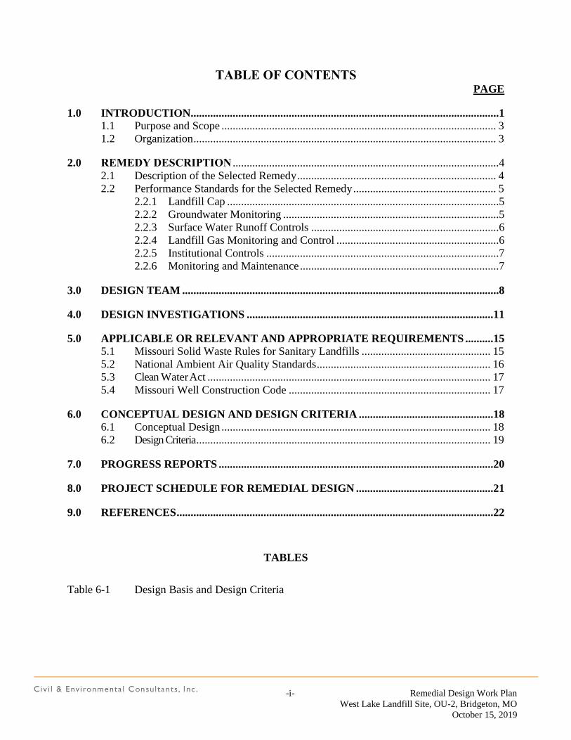
TABLE OF CONTENTS PAGE
1.0 INTRODUCTION..............................................................................................................1 1.1 Purpose and Scope .................................................................................................. 3
1.2 Organization ............................................................................................................ 3
2.0 REMEDY DESCRIPTION ...............................................................................................4
2.1 Description of the Selected Remedy ....................................................................... 4
2.2 Performance Standards for the Selected Remedy ................................................... 5
2.2.1 Landfill Cap .................................................................................................5
2.2.2 Groundwater Monitoring .............................................................................5
2.2.3 Surface Water Runoff Controls ...................................................................6
2.2.4 Landfill Gas Monitoring and Control ..........................................................6
2.2.5 Institutional Controls ...................................................................................7
2.2.6 Monitoring and Maintenance .......................................................................7
3.0 DESIGN TEAM .................................................................................................................8
4.0 DESIGN INVESTIGATIONS ........................................................................................11
5.0 APPLICABLE OR RELEVANT AND APPROPRIATE REQUIREMENTS ..........15 5.1 Missouri Solid Waste Rules for Sanitary Landfills .............................................. 15
5.2 National Ambient Air Quality Standards .............................................................. 16
5.3 Clean Water Act ..................................................................................................... 17
5.4 Missouri Well Construction Code ........................................................................ 17
6.0 CONCEPTUAL DESIGN AND DESIGN CRITERIA ................................................18 6.1 Conceptual Design ................................................................................................ 18
6.2 Design Criteria ......................................................................................................... 19
7.0 PROGRESS REPORTS ..................................................................................................20
8.0 PROJECT SCHEDULE FOR REMEDIAL DESIGN .................................................21
9.0 REFERENCES .................................................................................................................22
TABLES
Table 6-1 Design Basis and Design Criteria
-ii- Remedial Design Work Plan
West Lake Landfill Site, OU-2, Bridgeton, MO
October 15, 2019
Table of Contents (continued)
FIGURES
Figure 2-1 Gas Extraction Well Detail
Figure 8-1 Remedial Design Project Schedule
APPENDICES
Appendix A Conceptual Design Drawing
Appendix B Photographs of Conditions at OU-2
Appendix C Remedial Design Quality Assurance Project Plan
Appendix D Remedial Design Sampling and Analysis Plan
Appendix E Remedial Design Health and Safety Plan
Appendix F Shelby Tube Sample Results
-1- Remedial Design Work Plan
West Lake Landfill Site, OU-2, Bridgeton, MO
October 15, 2019
1.0 INTRODUCTION
This Remedial Design Work Plan (Work Plan) for West Lake Landfill Operable Unit 2 (OU-2) has
been prepared by Civil & Environmental Consultants, Inc. (CEC) (the project team). This Work Plan
and the associated documents have been prepared by the project team on behalf of Bridgeton Landfill,
LLC (the Respondent) to the Administrative Order on Consent (AOC) for OU-2.
This Work Plan and the associated documents including the Quality Assurance Project Plan (QAPP),
Sampling and Analysis Plan (SAP), and Health and Safety Plan (HASP) have been prepared by the
project team in accordance with the requirements of the Third Amendment to the AOC and the
associated Statement of Work (SOW) which describe the requirements for completion of the remedial
design (RD) phase of the implementation of the selected remedy for OU-2. A description of the various
components, design criteria, and performance standards of the selected remedy are provided in this
Work Plan. The project planning activities, additional design investigations, and progress reporting to
be conducted in support of the design of the selected remedy are also described.
Discussion of Updates to the December 2008 Draft OU-2 Work Plan
Subsurface Reaction (SSR)
There is very little chance that the SSR is going to reach the Inactive Sanitary and Closed
Demolition Landfill portions of OU-2 and previous studies have shown little risk
associated with the construction and maintenance of a cap in the SSR affected areas. It is
envisioned that the Bridgeton Landfill, where the reaction has occurred, will continue to
be managed according to the obligations outlined in its MDNR permit requirements. To
confirm that there is no connection between the two waste cells aerial drawings will be
reviewed and if necessary, soil borings, as many as three, will be obtained between the
South Quarry portion of the Bridgeton Landfill and the Inactive Sanitary Landfill.
OU-2 Remedy at Closed Demolition and Bridgeton Landfills (Timeline and Process)
As stated above, the Closed Demolition and Bridgeton Landfills will continue to be
managed according to their respective permit requirements and should not be subject to
further CERCLA action as outlined in the OU-2 ROD.
-2- Remedial Design Work Plan
West Lake Landfill Site, OU-2, Bridgeton, MO
October 15, 2019
Effects of OU-1 RD/RA Process on OU-2 Remedy
Because the OU-1 RD/RA is not complete, it cannot yet be incorporated into the Work
Plan, however, anticipated effects on the OU-2 design effort from OU-1 include definitive
demarcation between cap boundaries OU-1 and OU-2. The grading and transition between
those caps as well as managing stormwater along this demarcation boundary will be
coordinated and defined during the remedial design phase. These coordination and
dependencies have been highlighted on the schedule.
Effects of OU-3 RI/FS process on OU-2 Remedy
Because the OU-3 RI/FS is not complete, it cannot yet be incorporated or accounted for in
the RD Work Plan. However, the future groundwater monitoring investigation under OU-
3, including potential installation of additional groundwater monitoring wells, can
potentially provide useful and efficient collection of data for OU-2. Groundwater
monitoring for OU-2 will be coordinated with OU-3 and the monitoring program will be
finalized at the remedial design phase or as OU-3 infrastructure is designed and developed.
In the interim, existing wells will be sampled for baseline performance monitoring. This
coordination and dependency has been highlighted in the schedule.
Implementation of previous MDNR/USEPA comments from April 2009
These comments have been incorporated into the Work Plan.
Implementation of 2008 SOW Schedule (following submittal of updated draft OU-2
RDWP by June 12, 2019)
The attached schedule reflects the OU-2 timeline known as of the date of this plan and this
schedule will need to be continually coordinated with the parties for OU-1 and OU-3 where
relevant. It also will need to account for additional investigation that may be needed to
support the remedial design efforts. Updates shall be shared and communicated to the
USEPA, MDNR, as well as the responsible parties for OU-1 and OU-3.
Implementation of MDNR/USEPA comments from September 12, 2019.
These comments have been incorporated into the Work Plan.
-3- Remedial Design Work Plan
West Lake Landfill Site, OU-2, Bridgeton, MO
October 15, 2019
1.1 PURPOSE AND SCOPE
This Work Plan describes the activities to be completed in conducting the additional site investigations
and testing necessary to support the design of the remedy. It also includes the project planning
documents required for conducting these investigations. A preliminary conceptual design of the
selected remedy and description of the performance standards that apply to the remedy are also
presented in this Work Plan.
The requirements of other environmental regulations determined to be applicable or relevant and
appropriate to the design and implementation of the remedy are included. In addition, this Work Plan
presents preliminary design criteria upon which the RD will be based.
1.2 ORGANIZATION
This Work Plan includes the following sections:
1.0 Introduction
2.0 Remedy Description
3.0 Team Composition
4.0 Design Investigations
5.0 ARARs Identification
6.0 Conceptual Design and Design Criteria
7.0 Progress Reporting
8.0 Project Schedule for RD
This Work Plan also includes the following appendices:
Appendix A: Conceptual Design Drawings
Appendix B: Photographs of Conditions at OU-2
Appendix C: Quality Assurance Project Plan (QAPP)
Appendix D: Sampling and Analysis Plan (SAP)
Appendix E: Health and Safety Plan (HASP)
Appendix F: Shelby Tube Sample Results

-4- Remedial Design Work Plan
West Lake Landfill Site, OU-2, Bridgeton, MO
October 15, 2019
2.0 REMEDY DESCRIPTION
The remedy will be designed to meet the performance standards, criteria and specifications set forth in
the OU-2 Record of Decision (ROD), the SOW and the AOC, unless subsequently modified in
accordance with the procedures set forth in the AOC.
The performance standards, criteria and specifications will include the substantive requirements set
forth in applicable or relevant and appropriate requirements (ARARs) identified in Section 13.2 of the
ROD.
2.1 DESCRIPTION OF THE SELECTED REMEDY
The remedy for OU-2 was developed to protect human health and the environment by providing
containment with relevant and appropriate closure and post-closure care requirements for the landfilled
waste materials. The containment and post-closure care methods prevent human receptors from
contacting the waste material and control contaminant migration to air or groundwater and include:
1. Install landfill cover meeting the Missouri closure and post-closure care requirements for
sanitary landfills.
2. Apply groundwater monitoring baseline and performance standards consistent with
requirements for sanitary landfills.
3. Surface water runoff control.
4. Landfill Gas Monitoring and Control consistent with sanitary landfill requirements as necessary.
5. Institutional Controls to prevent land uses that are inconsistent with a closed sanitary landfill
site.
6. Long term monitoring and maintenance of the remedy.
-5- Remedial Design Work Plan
West Lake Landfill Site, OU-2, Bridgeton, MO
October 15, 2019
2.2 PERFORMANCE STANDARDS FOR THE SELECTED REMEDY
The Respondents will design the remedy to meet the performance standards and specifications set forth
in the OU-2 ROD and the SOW. The performance standards for the major components of the remedy
are identified below. Alternative standards or requirements may be approved if it can be demonstrated
that the alternative design is at least equivalent in performance.
2.2.1 Landfill Cap
The landfill cover system will be designed to meet, at a minimum, the State of Missouri closure
requirements for sanitary landfills. Consistent with the OU-2 ROD, these requirements are identified
below:
The Missouri Department of Natural Resources (MDNR) rules for sanitary landfill caps are in
10 CSR 80-3.010(17). These rules require that the final cover shall consist of at least two feet
of compacted clay with a coefficient of permeability of 1x10⁻⁵ cm/sec or less and overlaid by at
least one foot of soil capable of sustaining vegetative growth. The minimum sloping
requirement of 5% shall be incorporated into the design, which will also include provisions for
slope stability, proper run-off and erosion control. The maximum sloping requirement of 25%
will be met unless the stability of steeper slopes can be demonstrated.
The design will incorporate plans for decomposition gas monitoring and control consistent with
10 CSR 80-3.010(14).
2.2.2 Groundwater Monitoring
The RD will provide for the design and implementation of a long-term groundwater monitoring
program. The groundwater monitoring program will include the collection of data necessary to track
the movement and direction of flow of the groundwater and to monitor changes in chemical
constituents and chemical concentrations in the groundwater over time. The monitoring plans will
include specific monitoring objectives, monitoring locations, data quality objectives, sampling
frequencies and procedures, and analytical parameters and methods. The plans will describe the
approach to data evaluation and trend analysis. The monitoring program will be designed to meet the
objectives in the OU-2 ROD Section 12.2.1 and will be consistent with the monitoring requirements
and groundwater protection standards found in the Missouri Solid Waste Rules for Sanitary Landfills
[10 CSR 80-3.010 (11)]. This plan will need to be coordinated with the OU-3 team so that common
-6- Remedial Design Work Plan
West Lake Landfill Site, OU-2, Bridgeton, MO
October 15, 2019
infrastructure and/or replacement wells can be understood and incorporated into the design and other
plans.
2.2.3 Surface Water Runoff Controls
Surface water runoff controls may include surface water diversion channels, inlet structures,
underground conveyance systems, and surface water detention basins. These features will be designed
to accommodate the 24-hour, 25-year storm as required by the MDNR Solid Waste Regulations (10
CSR 80-3.010(8)(B)1.F.(III) and as may be required by the Missouri Clean Water Law and
corresponding rules and the state National Pollutant Discharge Elimination System (NPDES) permit
for the Site.
The analysis method for determining stormwater run-on/run-off will use the Rational Method.
Watershed areas and runoff coefficients will be determined. The flows determined by the Rational
Method will be reviewed for impacts or modification to the overall site conveyance. Once run-on/run-
off flows are calculated, appropriate best management practices (BMPs) will be selected to meet the
NPDES permit requirements.
Particular coordination on the surface drainage near the intersection with the OU-1 boundary needs to
occur with the OU-1 project team so that run on and run off for each operable unit can be accounted for
appropriately.
2.2.4 Landfill Gas Monitoring and Control
Characterization of landfill gas occurrences and concentrations will be conducted as part of the
Remedial Design investigations. The MDNR Solid Waste Regulations (2004) [10 CSR 80-
3.010(14)(C)(2)B.] state that decomposition gases shall not be allowed to concentrate above 50% of
the lower explosive limit (LEL) or 2.5% by volume for methane in the soil at the property boundary of
a sanitary landfill. A preliminary assessment of landfill gas occurrence and concentrations will be
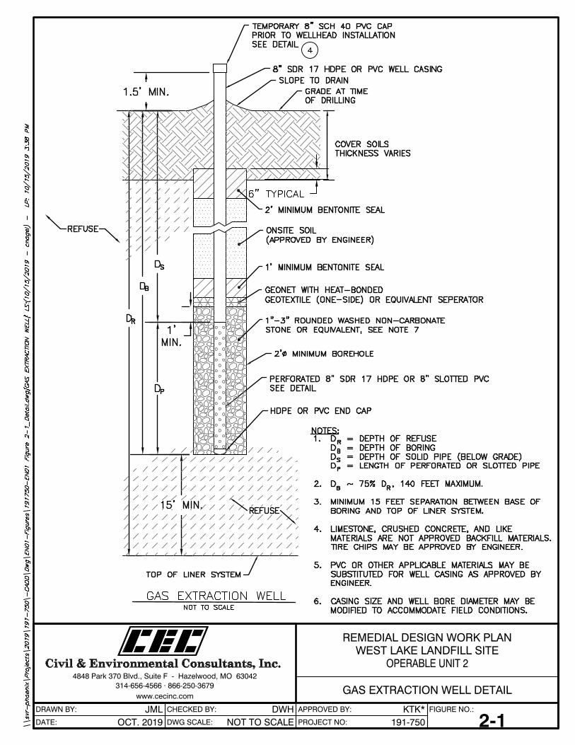
conducted as described in Appendix C, Section 5.3. A general overview of a GCCS design that would
be anticipated is provided in Figure 2-1. In the event that landfill gas occurs, or may reasonably be
expected to occur after construction of the new landfill cover, at levels greater than those allowed by
the MDNR Solid Waste Regulations, then a landfill gas collection and control system will be designed.
It is not currently anticipated that a LFG system will be required and if one would be required it
is not anticipated that such system would impact the design of the proposed cap, especially
considering that a geosynthetic liner is not being considered as part of the design.
-7- Remedial Design Work Plan
West Lake Landfill Site, OU-2, Bridgeton, MO
October 15, 2019
2.2.5 Institutional Controls
The RD will provide for the design and implementation of institutional controls meeting the land and
resource use requirements and objectives identified in the OU-2 ROD Section 12.2.2. Proprietary
controls will be used because they generally run with the land and are enforceable. Missouri
Environmental Covenants Act (MECA) is the preferred instrument for this site. The institutional controls
apply for not only the Inactive Sanitary Landfill but for all of OU-2 as specified in the ROD.
2.2.6 Monitoring and Maintenance
The RD will provide for monitoring and maintenance of the remedy. Plans will be developed
describing the procedures for inspection and maintenance of engineering controls, access controls and
monitoring structures. Plans will also address procedures for maintenance, inspection and
enforcement of land and groundwater use restrictions. Monitoring and maintenance applies for not
only the Inactive Sanitary Landfill but for all of OU-2 as specified in the ROD.
-8- Remedial Design Work Plan
West Lake Landfill Site, OU-2, Bridgeton, MO
October 15, 2019
3.0 DESIGN TEAM
The RD will be managed by CEC. CEC will serve as the Supervising Contractor and will provide
overall project management and technical direction to the project. Mr. Randal Bodnar, P.E., will serve
as the Project Coordinator. Having previously been responsible for the Remedial Investigation (RI) and
Feasibility Study (FS) for OU-2, CEC personnel are familiar with the various aspects of the project and
will be responsible for the following RD activities:
Identification of the various technical requirements of the project, assignment of project tasks
to the various members of the project team, development and tracking of project schedules
and budgets and review and approval of project deliverables;
The overall Quality Assurance of the project and will provide the project Quality Assurance
Officer;
Preparation of this Work Plan;
Coordination of the development of design criteria;
Development of the Institutional Controls Plan for OU-2;
Coordination and preparation of the Preliminary Design submittal;
Coordination and preparation of the Intermediate Design submittal (if necessary);
Coordination and preparation of the Pre-Final Design submittal;
Coordination and preparation of the Final Design submittal;
Coordination and preparation of the O&M Plan;
Coordination and preparation of the Contingency Plan;
Preparation of the Community Relations Plan; and
Preparation of monthly project status reports to USEPA and for scheduling and coordination
of meetings and interactions with USEPA and MDNR.
-9- Remedial Design Work Plan
West Lake Landfill Site, OU-2, Bridgeton, MO
October 15, 2019
CEC will provide design services and will be responsible for development of the RD drawings and
specifications. CEC has extensive experience designing and permitting solid waste landfills and
Subtitle D covers similar to that required for OU-2. CEC will be responsible for the following RD
activities:
Supervision of RD site surveying and base map development;
Identification and geotechnical testing of potential construction materials (rock, low
permeability layer and vegetative layer);
Development of grading and cut and fill plans for waste relocation (if needed);
Design and preparation of the construction drawings and specifications for the landfill cover;
Design and preparation of the construction drawings and specifications for the surface water
runoff control system;
Design and preparation of the construction drawings and specifications for the landfill gas
collection and control system (if necessary);
Preparation of the Construction Quality Assurance (CQA) Plan;
Preparation of a construction schedule; and
Preparation of construction cost estimate.
OU-2 will collaborate and coordinate with the OU-1 and OU-3 RI/FS project teams.
CEC will also be responsible for the following RD activities:
Preparation of the QAPP, SAP, and the HASP included with this Work Plan;
Conducting the additional site investigations required to support the RD;
Installation and testing of landfill gas monitoring wells to assess the presence and extent of
-10- Remedial Design Work Plan
West Lake Landfill Site, OU-2, Bridgeton, MO
October 15, 2019
occurrences of landfill gases along the outer (property) boundaries of Inactive Sanitary
Landfill;
The health and safety program utilized during performance of the design investigations;
Design of the environmental monitoring (stormwater and landfill gas) program portion of the
RD;
Preparation of the construction Field Sampling Plan; and
Preparation of the Spill Prevention, Control and Countermeasure Plan portion of the
Contingency Plan.
Appendix C Figure A-1 presents an organization chart for the project team that will implement the
RD, specific personnel to be involved with the RD, and the generalized lines of communication and
responsibility.
-11- Remedial Design Work Plan
West Lake Landfill Site, OU-2, Bridgeton, MO
October 15, 2019
4.0 DESIGN INVESTIGATIONS
Most of the site characterization was completed as part of the RI (Herst, 2005) and supplemental
investigations completed in conjunction with the FS (Herst, 2006); however, some additional data are
needed to prepare the RD. The additional data needed to complete the RD include the following:
1. During the RD, a more detailed ground survey will be conducted, with the goal of yielding
ground surface elevations accurate to within 0.25 feet throughout the Inactive Sanitary
Landfill. The ground survey will be combined with a more recent aerial flyover and
photography to provide the level of detail sufficient for calculating necessary material volumes
to achieve planned final grades. Field activities associated with the topographic survey will
include, but not necessarily be limited to, surveying ground surface elevations and, if possible,
establishing the routing and discharge points of the existing surface water controls;
2. Landfill gas monitoring wells will be installed to characterize landfill gas occurrences and
concentrations in accordance with MDNR Solid Waste Regulations (2004) [10 CSR 80-
3.010(14)(C)(2)B.] These gas monitoring wells will be installed according to the regulatory
requirements for landfill gas monitoring wells at a maximum 500 feet spacing distance.
Nature and concentration of explosive gases, if any, that are coincident with the landfill
property boundaries to determine if landfill gas is present at levels above 50% of the lower
explosive limit (LEL), which is equivalent to 2.5% methane by volume, such that a landfill
gas collection and control system will be required;
3. Cover thickness testing and geotechnical testing (Atterberg Limits, grain size distribution and
permeability) will be performed during the RD with the intent of optimizing the use of the
existing cover. Sampling of existing cover materials will be conducted to evaluate cover
thickness and assess selected geotechnical soil properties. These evaluations will provide an
estimate the volume of materials needed for construction of the final cover and the suitability
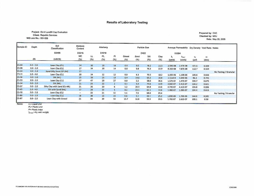
of using the existing material as landfill cover. The collection of ten (10) Shelby Tube samples
has been completed and will be used along with the results of two (2) Sealed Double Ring
Infiltrometer tests that were completed. The results of this testing are included in Appendix
F, and will be incorporated into the RD effort;
4. The existing slope along the western perimeter of OU-2 was established in the mid-1990’s.
Based on observations during a site walkover conducted by the Landfill Design team on
November 11, 2008, and more recently on May 14, 2019, the existing slope appeared to be
-12- Remedial Design Work Plan
West Lake Landfill Site, OU-2, Bridgeton, MO
October 15, 2019
stable. One of the RD tasks is to further document the history and stability of the existing
slope. A slope stability analysis will be conducted in general accordance with 10 CSR 80-3
(17) E and F to better understand current site conditions and to plan for and prevent future
issues related to the final cover and slope stability, including the potential for catastrophic
instability. To meet this objective, geotechnical samples will be collected and analyzed as
necessary to perform the analysis as required by the regulations. Additionally, other effects
such as exposed waste volumes and areas (odor generation, bird attraction, etc), potential
leachate generation, and impacts to stormwater will need to be evaluated.
5. As part of the RD, soil samples will be collected from potential borrow areas with laboratory
testing conducted on potential sources of low-permeability final cover soils. Representative
bulk soil samples will be collected from test pits excavated in each of the proposed borrow
areas. The testing program will include natural moisture content, Atterberg Limits, Standard
proctor dry density determination, and recompacted permeability. The resultant data are
needed for approval of the borrow soils before construction and will be identified in the RA
construction specifications that are developed following completion of the RD phase of this
project;
6. Several issues were noted during the site walkover performed on November 11, 2008, and
more recently on May 14, 2019, and will also need to be investigated as part of the RD.
Photographs from the site walkovers are provided in Appendix B. Issues requiring further
investigation include the following:
o Presence of apparent stormwater “drains” on the west slope that drain stormwater trapped
in the channel. It is uncertain where the conveyances discharge and one of the two was
covered and not recognizable on the day of the 2008 visit. The function and system of this
surface drainage feature will be investigated further by tracing, CCTV inspection, or other
means so that the RD can be completed as well as uncover any considerations that may
impact the analysis or findings of the slope stability. Plans will be provided for point source
discharges, if identified, and will be addressed in the RD so the final design can incorporate
any conveyance and requirements of the stormwater management system in accordance
with the ROD.
o There are two concrete standpipes that rise approximately 20 feet above the ground
surface on the west side of OU-2. It is uncertain what these structures were designed for
or if they will be needed long-term at the site and therefore could be abandoned in place,
-13- Remedial Design Work Plan
West Lake Landfill Site, OU-2, Bridgeton, MO
October 15, 2019
filled or cut and capped. These will be investigated further by records search, CCTV
inspection, or other means so that the RD can be completed as well as uncover any
considerations that may impact the analysis or findings of the slope stability.
o There are fiber optic lines at the base of the steep west slope that may need to be addressed
depending on the design of the cap. The utility owner will be notified for locating and/or
flagging of the infrastructure. The fiber optic line will then be surveyed and located
accurately on the design plans. During RD, the fiber optic line location will be evaluated
for conflict with the proposed improvements.
o The leachate pumping system at the southeast corner of the site also requires additional
investigation. Available historical data will be collected and reviewed and discussions with
MDNR/USEPA will potentially be needed based on findings to determine whether
continued pumping of leachate will be required based on previous leachate characterization
details.
7. During the RD, aerial surveys will be reviewed to determine the character of the material
between the South Quarry portions of the Bridgeton Landfill and the Inactive Sanitary
Landfill (within the common access road). If the aerial surveys do not provide appropriate
and accurate information, up to three borings may be conducted to characterize the area.
Refer to Appendix A Figure A-1 for preliminary boring locations. The soil borings will
determine the composition of the material between these two disposal cells. The findings
will be discussed in a preliminary design report and modification, if any, to the design will
be accommodated at that time. The makeup of the materials between these waste disposal
cells will be evaluated to determine if there exists continuation of waste between these
waste cells and what the thickness of waste is, if present.
8. The RD will provide for the design and implementation of a long-term performance
groundwater monitoring program. The groundwater monitoring program will include the
collection of data necessary to establish baseline groundwater conditions prior to
performance of groundwater monitoring. Five down gradient wells will be sampled and
analyzed according to MDNR monitoring requirements. These wells will include PZ-302-
AS, PZ-302-AI, PZ-303-AS, PZ-304-AS and PZ-304-AI. Eight (8) rounds of background
data will be collected and analyzed along with groundwater data collected by the OU-3
Team to establish current groundwater conditions.
-14- Remedial Design Work Plan
West Lake Landfill Site, OU-2, Bridgeton, MO
October 15, 2019
More detailed information and drawings regarding the sampling and analysis protocols, data needs
and data quality objectives for the RD investigations are presented in the SAP and QAPP (Appendix
C and Appendix D to this Work Plan, respectively) and the anticipated schedule for these investigations
is included in Figure 8-1.
-15- Remedial Design Work Plan
West Lake Landfill Site, OU-2, Bridgeton, MO
October 15, 2019
5.0 APPLICABLE OR RELEVANT AND APPROPRIATE REQUIREMENTS
This section describes the ARARs or other regulations as identified in Section 13.2 of the ROD for
OU-2.
5.1 MISSOURI SOLID WASTE RULES FOR SANITARY LANDFILLS
Missouri is a USEPA-approved state for providing regulations for landfills under the Resource
Conservation and Recovery Act Subtitle D. Missouri promulgated its regulations (22 Mo Reg 1008,
June 2, 1997) as the Missouri Solid Waste Rules which became effective July 1, 1997. The Missouri
Solid Waste Rules establish closure and post-closure requirements for existing sanitary landfills that
close after October 9, 1991. Although not applicable to the closure of OU-2, the requirements
described below are considered relevant and appropriate and therefore will be met.
The MDNR regulations require cover to be applied to minimize fire hazards, infiltration of
precipitation, odors and blowing litter, control gas venting and vectors, discourage scavenging, and
provide a pleasing appearance [10 CSR 80-3.010(17)(A)]. The regulations require final cover
consisting of at least two feet of compacted clay with a coefficient of permeability of 1 x 10⁻⁵ cm/sec
or less overlaid by at least one foot of soil capable of sustaining vegetative growth [10 CSR 80-
3.010(17)(C)(4)]. These requirements are considered to be the design criteria for the RD for OU-2.
Placement of this final soil cover addresses the requirements for minimization of fire hazards, odors,
blowing litter, control of gas venting, and scavenging. Placement of clay meeting the permeability
requirement also addresses the requirement for minimizing precipitation infiltration. Placement of soil
and establishment of a vegetative cover meet the requirement of providing for a pleasing appearance.
The MDNR landfill regulations also contain minimum and maximum slope requirements.
Specifically, these regulations require the final slope of the top of the sanitary landfill shall have a
minimum slope of five percent [10 CSR 80-3.010(17)(B)(7)]. MDNR regulations also require that the
maximum slopes be less than 25 percent unless it has been demonstrated in a detailed slope stability
analysis that the slopes can be constructed and maintained throughout the entire operational life and
post-closure period of the landfill. The objective of these requirements is to promote maximum runoff
without excessive erosion and to account for potential differential settlement. Because the landfilling
of OU-2 was completed over 30 years ago, most compaction of the refuse has taken place and
differential settlement is no longer a significant concern. The five percent minimum sloping
requirement is greater than necessary and may not be optimal in this case. Therefore, the five percent
minimum sloping requirement is not considered appropriate. Sloping specifications will be designed
-16- Remedial Design Work Plan
West Lake Landfill Site, OU-2, Bridgeton, MO
October 15, 2019
to promote drainage and reduce infiltration of precipitation while minimizing the potential for erosion.
It is anticipated that a two percent slope would be sufficient to meet drainage requirements while
resulting in a lower potential for erosion or slope failure. This approach should increase the life of the
cover and overall longevity of the remedy compared to a steeper slope which would be subject to
increased erosion potential. The 2% minimum slope and 25% maximum slope (or steeper if supported
by a geotechnical evaluation and slope stability analysis) will be included as design criteria in the RD.
These requirements may need to be looked at for the disturbed area only. The existing Western slope
exceeds these requirements, but as described above appears to be stable by observation. Additional
investigation into the stability of this existing slope needs to be conducted and discussed during the
RD.
The requirements for decomposition gas monitoring and control in 10 CSR 80-3.010(14) are
considered relevant and appropriate and will be met. The number and locations of gas monitoring
points and the frequency of measurement are described in detail in the attached QAPP and SAP. In
the event landfill gas is detected at the landfill boundaries above the regulatory thresholds during the
RD investigations, a landfill gas control system will be included as part of the RD.
The RD will provide the implementation of a groundwater monitoring program. The monitoring
program will be designed to meet the objectives in OU-2 ROD Section 12.2.1 and will be
consistent with the monitoring requirements and groundwater protection standards found in the
Missouri Solid Waste Rules for Sanitary Landfills [10 CSR 80-3.010 (11)].
The substantive MDNR landfill requirements for post-closure care and corrective action found in 10
CSR 80-2.030 are also considered relevant and appropriate. These substantive provisions provide a
useful framework for O&M and corrective action plans and require post-closure plans describing the
necessary maintenance and monitoring activities and schedules. These requirements will be used in
addition to USEPA CERCLA policy and guidance on developing robust O&M and long-term
monitoring plans. These requirements will be addressed in the development of an O&M Plan to be
prepared as part of the RD.
5.2 NATIONAL AMBIENT AIR QUALITY STANDARDS
The National Ambient Air Quality Standards (NAAQS) apply to six (6) criteria pollutants as
established under the current federal law (40 CFR 50). These standards are designed to establish
maximum exposure limits that are protective of human health and the environment. Since the remedy
for OU-2 will involve grading, compaction, and other soil-related activities, NAAQS for PM10 are
potentially relevant and appropriate requirements during implementation of the RA.
-17- Remedial Design Work Plan
West Lake Landfill Site, OU-2, Bridgeton, MO
October 15, 2019
In addition, should the work include the potential for uncovering waste material, potential air
constituents for the site could include but are not limited to: PM10, PM2.5, and volatile organic
constituents, or VOCs, . Air monitoring for radionuclides will be required for intrusive work conducted
in or near known or suspected areas containing radiologically impacted materials, or RIM, however,
the OU-1 team is planning to perform an investigation for the limits of RIM between the boundaries
of the Inactive Sanitary Landfill and OU-1 as part of the OU-1 RD investigations. The OU-1 work will
be conducted prior to any invasive work by the OU-2 team. Therefore it is highly unlikely that there
will be a potential for OU-2 RD work to be performed in an area in or near known or suspected RIM.
During remedial design phase a plan for air monitoring will be developed on a task specific basis.
5.3 CLEAN WATER ACT
The Clean Water Act sets standards for ambient water quality and incorporates chemical specific
standards including federal water quality criteria and state water quality standards. The substantive
requirements for stormwater runoff are relevant and appropriate. Therefore, these standards will be
identified in the stormwater monitoring plan as appropriate.
5.4 MISSOURI WELL CONSTRUCTION CODE
MDNR has promulgated regulations pertaining to the location and construction of water wells. The
Well Construction Code (10 CSR 23-3.010) prohibits the placement of a well within 300 feet of a
landfill. These rules should provide protection against the placement of wells on or near the Site and
will be incorporated as appropriate into the Institutional Controls Plan for the Site.
MDNR has also established regulations on monitoring well construction (10 CSR 23-4) that will
apply to the construction of new or replacement monitoring wells at the Site.
-18- Remedial Design Work Plan
West Lake Landfill Site, OU-2, Bridgeton, MO
October 15, 2019
6.0 CONCEPTUAL DESIGN AND DESIGN CRITERIA
The solid waste materials in OU-2 will be regraded, where needed, and then will be covered with a
landfill cover that meets the MDNR solid waste requirements where such cover is not already in
place. The final cover for OU-2 will consist of a minimum of 2-ft of clay, silt, or sandy clay compacted
to a density that must result in a factor of permeability for this layer of 10-5 cm/sec or less, and the
existing cover will be optimized to meet these requirements. This low permeability layer in turn will
be overlain by a minimum of 1 ft of uncompacted soil suitable to support development of grassy
vegetation, again optimizing the existing cover.
Figure A-6 shows potential cover sampling locations. During the sampling process, elevations of the
cover and solid waste layers will be recorded. After grading is completed and compacted for the clay
liner cover and prior to placement of top soil, a post construction survey at these same sampling points
will be conducted. Pre vs. post construction grading elevations of the cover will be compared to verify
as-built and appropriate thickness.
6.1 CONCEPTUAL DESIGN
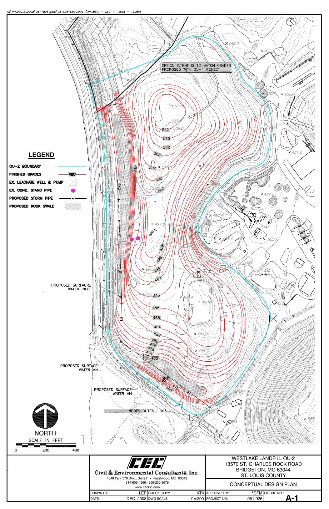
The design team has developed conceptual grading plans for the regraded landfill cover (Appendix
A, Figure A-1) that substantially meet the minimum and maximum slope requirements of the
MDNR Solid Waste Regulations for the area to be disturbed in creating the final closure cap. The
proposed regrading plan was developed based on general topographic elevations of the landfill
surface which may not accurately reflect current conditions. The proposed regrading plan was also
developed based on trying to limit the amount of fill that needs to be trucked on-site by locating areas
within the Inactive Sanitary Landfill that currently have more volume than needed for the selected
remedy. Excess fill from these areas may be relocated to areas with insufficient fill. The proposed cap
(detailed on Appendix A Figure A-1) is consistent with the requirements outlined in the ROD.
It is anticipated that regrading of the waste surface will be minimal with the conceptual design
including if the existing western slope can be maintained in its current state. If this slope needs to be
cut back, significant regrading and movement of waste will be required. If this area requires massive
regrading, there may be significant issues associated with the impact of moving the trash which would
include odor generation, wildlife attraction, stormwater impacts and leachate. A geotechnical analysis
of the western slopes will be conducted to determine stability of the existing slopes. Those findings,
as well as information and data for consideration of the effects of waste relocation, will be discussed
with MDNR/USEPA. Additional plans and/or controls may need to be prepared and developed
-19- Remedial Design Work Plan
West Lake Landfill Site, OU-2, Bridgeton, MO
October 15, 2019
during the RD phase based on the findings of the slope stability report and evaluation. Should waste
relocation be required details are included in the SAP and the QAPP as to how this is to be validated
through implementation of the RD. Further details of materials and construction methods will be
outlined in later submittals of the design reports.
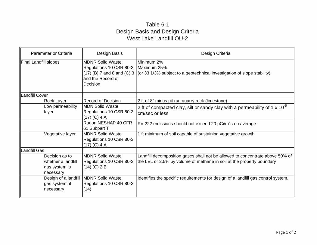
6.2 DESIGN CRITERIA
The design criteria to be used as a basis for the design of the remedy were identified based on the
requirements of the ARARs presented in Section 5 and based on professional engineering judgment.
The design criteria and the basis of the design criteria are summarized in Table 6-1.
-20- Remedial Design Work Plan
West Lake Landfill Site, OU-2, Bridgeton, MO
October 15, 2019
7.0 PROGRESS REPORTS
On behalf of the Respondents, CEC will prepare and submit monthly progress reports by the 10th
day of each following month. These progress reports will include the following items:
1. A description of the actions taken during the prior month to comply with the AOC;
2. Copies of analytical and geotechnical data received by the Respondents during the prior month;
3. A description of the work planned for the next two months; and
4. A description of material problems encountered and any anticipated material problems, as
well as actual or anticipated material delays and solutions developed and implemented to
address any actual or anticipated material problems or delays.
Progress reports will be submitted to the USEPA Remedial Project Manager (RPM) by e-mail with a
copy provided to the MDNR project manager.
-21- Remedial Design Work Plan
West Lake Landfill Site, OU-2, Bridgeton, MO
October 15, 2019
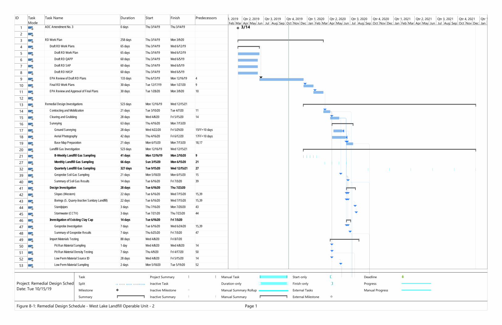
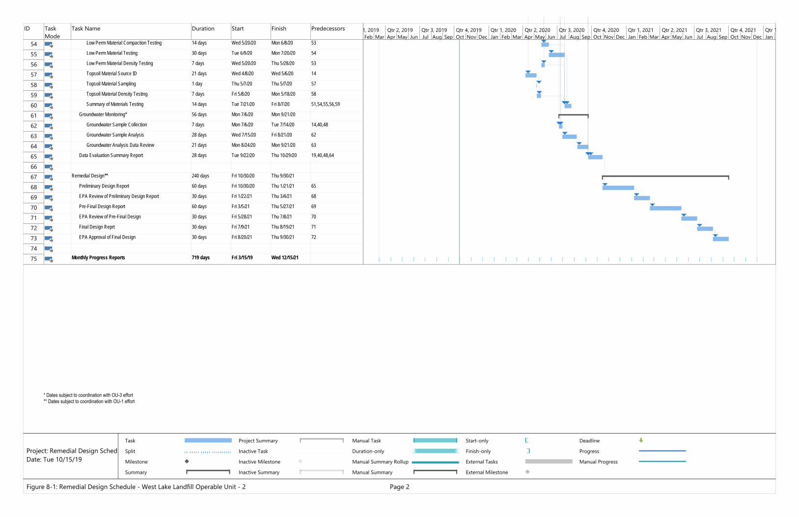
8.0 PROJECT SCHEDULE FOR REMEDIAL DESIGN
Figure 8-1 presents potential durations and a critical path schedule for the various RD activities.
The actual schedule will be affected by the OU-1 RD/RA process, weather conditions during
performance of the RD site investigations, the possible need for follow-up investigations based on
the results of the proposed investigations, and the actual length of agency review periods. Areas
shown on the schedule with asterisks highlight where the OU-1 Team will be required to verify the
extent of the area to be regraded and covered under OU-2 prior to completion of the 30% design
submittals and where the OU-2 Team will provide preliminary info to OU-1 on stormwater runoff as
part of the 30% design submittal and the 90% submittals. These are highlighted to show where
schedule changes might be expected to occur.
-22- Remedial Design Work Plan
West Lake Landfill Site, OU-2, Bridgeton, MO
October 15, 2019
9.0 REFERENCES
Golder Associates, Inc., Draft Report – Inactive Sanitary Landfill Cap Investigation, West Lake Site,
August 25, 1995.
Herst & Associates, Inc., Remedial Investigation Report, West Lake Landfill Operable Unit 2,
September, 2005.
Herst & Associates, Inc., Feasibility Study Report, West Lake Landfill Operable Unit 2, June,
2006.
Missouri Department of Natural Resources (MDNR), Landfill Closure Guidance, Publication 187,
July, 2003.
U.S. Environmental Protection Agency (EPA), Third Amendment to Administrative Settlement
Agreement and Order on Consent in the Matter of Bridgeton Landfill, LLC, Docket No. VII-94- F-
0025, October 16, 2008.
U.S. EPA, Record of Decision, West Lake Landfill Site, Bridgeton, Missouri Operable Unit 2, July,
2008.

TABLE
Page 1 of 2
Final Landfill slopes MDNR Solid Waste Regulations 10 CSR 80-3 (17) (B) 7 and 8 and (C) 3 and the Record of Decision
Minimum 2% Maximum 25% (or 33 1/3% subject to a geotechnical investigation of slope stability)
Landfill CoverRock Layer Record of Decision 2 ft of 8” minus pit run quarry rock (limestone)Low permeability layer
MDN Solid Waste Regulations 10 CSR 80-3 (17) (C) 4 A
2 ft of compacted clay, silt or sandy clay with a permeability of 1 x 10⁻⁵
cm/sec or less
Radon NESHAP 40 CFR 61 Subpart T
Rn-222 emissions should not exceed 20 pCi/m2s on average
Vegetative layer MDNR Solid Waste Regulations 10 CSR 80-3 (17) (C) 4 A
1 ft minimum of soil capable of sustaining vegetative growth
Landfill GasDecision as to whether a landfill gas system is necessary
MDNR Solid Waste Regulations 10 CSR 80-3 (14) (C) 2 B
Landfill decomposition gases shall not be allowed to concentrate above 50% of the LEL or 2.5% by volume of methane in soil at the property boundary
Design of a landfill gas system, if necessary
MDNR Solid Waste Regulations 10 CSR 80-3 (14)
Identifies the specific requirements for design of a landfill gas control system.
West Lake Landfill OU-2Design Basis and Design Criteria
Table 6-1
Design CriteriaDesign BasisParameter or Criteria
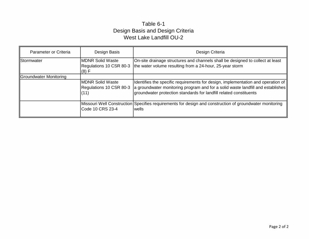
Page 2 of 2
Stormwater MDNR Solid Waste Regulations 10 CSR 80-3 (8) F
On-site drainage structures and channels shall be designed to collect at least the water volume resulting from a 24-hour, 25-year storm
Groundwater MonitoringMDNR Solid Waste Regulations 10 CSR 80-3 (11)
Identifies the specific requirements for design, implementation and operation of a groundwater monitoring program and for a solid waste landfill and establishes groundwater protection standards for landfill related constituents
Missouri Well Construction Code 10 CRS 23-4
Specifies requirements for design and construction of groundwater monitoring wells
Table 6-1Design Basis and Design Criteria
West Lake Landfill OU-2
Parameter or Criteria Design Basis Design Criteria

FIGURES
DATE: DWG SCALE:
DRAWN BY: CHECKED BY: APPROVED BY:
PROJECT NO:
FIGURE NO.:
GAS EXTRACTION WELL DETAIL
191-750NOT TO SCALEOCT. 2019JML DWH KTK*
2-1
REMEDIAL DESIGN WORK PLANWEST LAKE LANDFILL SITE
OPERABLE UNIT 24848 Park 370 Blvd., Suite F - Hazelwood, MO 63042
314-656-4566 · 866-250-3679www.cecinc.com
ID Task Mode
Task Name Duration Start Finish Predecessors
1 AOC Amendment No. 3 0 days Thu 3/14/19 Thu 3/14/19
23 RD Work Plan 258 days Thu 3/14/19 Mon 3/9/20
4 Draft RD Work Plans 65 days Thu 3/14/19 Wed 6/12/19
5 Draft RD Work Plan 65 days Thu 3/14/19 Wed 6/12/19
6 Draft RD QAPP 60 days Thu 3/14/19 Wed 6/5/19
7 Draft RD SAP 60 days Thu 3/14/19 Wed 6/5/19
8 Draft RD HASP 60 days Thu 3/14/19 Wed 6/5/19
9 EPA Review of Draft RD Plans 133 days Thu 6/13/19 Mon 12/16/19 4
10 Final RD Work Plans 30 days Tue 12/17/19 Mon 1/27/20 9
11 EPA Review and Approval of Final Plans 30 days Tue 1/28/20 Mon 3/9/20 10
1213 Remedial Design Investigations 523 days Mon 12/16/19 Wed 12/15/21
14 Contracting and Mobilization 21 days Tue 3/10/20 Tue 4/7/20 11
15 Clearing and Grubbing 28 days Wed 4/8/20 Fri 5/15/20 14
16 Surveying 63 days Thu 4/16/20 Mon 7/13/20
17 Ground Surveying 28 days Wed 4/22/20 Fri 5/29/20 15FF+10 days
18 Aerial Photography 42 days Thu 4/16/20 Fri 6/12/20 17FF+10 days
19 Base Map Preparation 21 days Mon 6/15/20 Mon 7/13/20 18,17
20 Landfill Gas Investigation 523 days Mon 12/16/19 Wed 12/15/21
21 B-Weekly Landfill Gas Sampling 41 days Mon 12/16/19 Mon 2/10/20 9
27 Monthly Landfill Gas Sampling 66 days Sun 3/15/20 Mon 6/15/20 21
32 Quarterly Landfill Gas Sampling 327 days Tue 9/15/20 Wed 12/15/21 27
39 Geoprobe Soil Gas Sampling 21 days Mon 5/18/20 Mon 6/15/20 15
40 Summary of Soil Gas Results 14 days Tue 6/16/20 Fri 7/3/20 39
41 Design Investigation 28 days Tue 6/16/20 Thu 7/23/20
42 Slopes (Western) 22 days Tue 6/16/20 Wed 7/15/20 15,39
43 Borings (S. Quarry-Inactive Sanitary Landfill) 22 days Tue 6/16/20 Wed 7/15/20 15,39
44 Standpipes 3 days Thu 7/16/20 Mon 7/20/20 43
45 Stormwater (CCTV) 3 days Tue 7/21/20 Thu 7/23/20 44
46 Investigation of Existing Clay Cap 14 days Tue 6/16/20 Fri 7/3/20
47 Geoprobe Investigation 7 days Tue 6/16/20 Wed 6/24/20 15,39
48 Summary of Geoprobe Results 7 days Thu 6/25/20 Fri 7/3/20 47
49 Import Materials Testing 88 days Wed 4/8/20 Fri 8/7/20
50 Pit Run Material Sampling 1 day Wed 4/8/20 Wed 4/8/20 14
51 Pit Run Material Density Testing 7 days Thu 4/9/20 Fri 4/17/20 50
52 Low Perm Material Source ID 28 days Wed 4/8/20 Fri 5/15/20 14
53 Low Perm Material Sampling 2 days Mon 5/18/20 Tue 5/19/20 52
3/14Feb Mar Apr May Jun Jul Aug Sep Oct Nov Dec Jan Feb Mar Apr May Jun Jul Aug Sep Oct Nov Dec Jan Feb Mar Apr May Jun Jul Aug Sep Oct Nov Dec Jan
1, 2019 Qtr 2, 2019 Qtr 3, 2019 Qtr 4, 2019 Qtr 1, 2020 Qtr 2, 2020 Qtr 3, 2020 Qtr 4, 2020 Qtr 1, 2021 Qtr 2, 2021 Qtr 3, 2021 Qtr 4, 2021 Qtr 1
Task
Split
Milestone
Summary
Project Summary
Inactive Task
Inactive Milestone
Inactive Summary
Manual Task
Duration-only
Manual Summary Rollup
Manual Summary
Start-only
Finish-only
External Tasks
External Milestone
Deadline
Progress
Manual Progress
Figure 8-1: Remedial Design Schedule - West Lake Landfill Operable Unit - 2 Page 1
Project: Remedial Design SchedDate: Tue 10/15/19
ID Task Mode
Task Name Duration Start Finish Predecessors
54 Low Perm Material Compaction Testing 14 days Wed 5/20/20 Mon 6/8/20 53
55 Low Perm Material Testing 30 days Tue 6/9/20 Mon 7/20/20 54
56 Low Perm Material Density Testing 7 days Wed 5/20/20 Thu 5/28/20 53
57 Topsoil Material Source ID 21 days Wed 4/8/20 Wed 5/6/20 14
58 Topsoil Material Sampling 1 day Thu 5/7/20 Thu 5/7/20 57
59 Topsoil Material Density Testing 7 days Fri 5/8/20 Mon 5/18/20 58
60 Summary of Materials Testing 14 days Tue 7/21/20 Fri 8/7/20 51,54,55,56,59
61 Groundwater Monitoring* 56 days Mon 7/6/20 Mon 9/21/20
62 Groundwater Sample Collection 7 days Mon 7/6/20 Tue 7/14/20 14,40,48
63 Groundwater Sample Analysis 28 days Wed 7/15/20 Fri 8/21/20 62
64 Groundwater Analysis Data Review 21 days Mon 8/24/20 Mon 9/21/20 63
65 Data Evaluation Summary Report 28 days Tue 9/22/20 Thu 10/29/20 19,40,48,64
6667 Remedial Design** 240 days Fri 10/30/20 Thu 9/30/21
68 Preliminary Design Report 60 days Fri 10/30/20 Thu 1/21/21 65
69 EPA Review of Preliminary Design Report 30 days Fri 1/22/21 Thu 3/4/21 68
70 Pre-Final Design Report 60 days Fri 3/5/21 Thu 5/27/21 69
71 EPA Review of Pre-Final Design 30 days Fri 5/28/21 Thu 7/8/21 70
72 Final Design Reprt 30 days Fri 7/9/21 Thu 8/19/21 71
73 EPA Approval of Final Design 30 days Fri 8/20/21 Thu 9/30/21 72
7475 Monthly Progress Reports 719 days Fri 3/15/19 Wed 12/15/21
Feb Mar Apr May Jun Jul Aug Sep Oct Nov Dec Jan Feb Mar Apr May Jun Jul Aug Sep Oct Nov Dec Jan Feb Mar Apr May Jun Jul Aug Sep Oct Nov Dec Jan1, 2019 Qtr 2, 2019 Qtr 3, 2019 Qtr 4, 2019 Qtr 1, 2020 Qtr 2, 2020 Qtr 3, 2020 Qtr 4, 2020 Qtr 1, 2021 Qtr 2, 2021 Qtr 3, 2021 Qtr 4, 2021 Qtr 1
Task
Split
Milestone
Summary
Project Summary
Inactive Task
Inactive Milestone
Inactive Summary
Manual Task
Duration-only
Manual Summary Rollup
Manual Summary
Start-only
Finish-only
External Tasks
External Milestone
Deadline
Progress
Manual Progress
Figure 8-1: Remedial Design Schedule - West Lake Landfill Operable Unit - 2 Page 2
Project: Remedial Design SchedDate: Tue 10/15/19
* Dates subject to coordination with OU-3 effort** Dates subject to coordination with OU-1 effort
APPENDIX A
CONCEPTUAL DESIGN DRAWING
APPENDIX B
PHOTOGRAPHS OF CONDITIONS AT OU-2
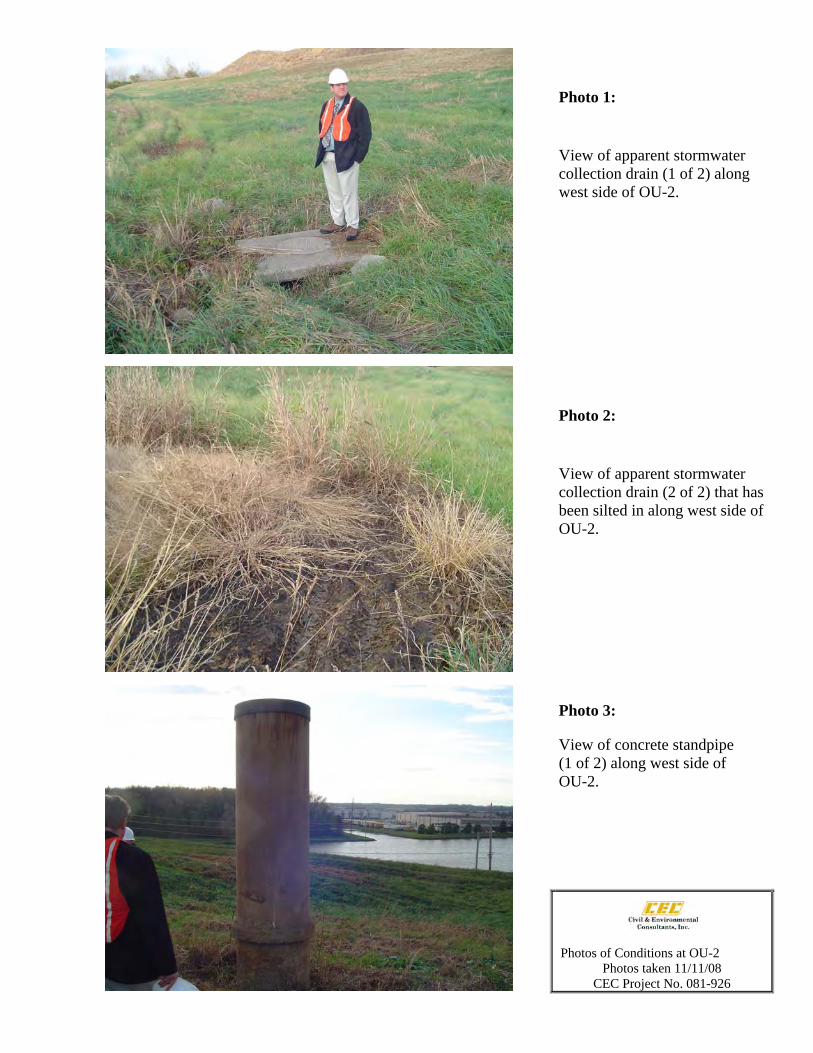
Photo 1:
View of apparent stormwater collection drain (1 of 2) along west side of OU-2.
Photo 2:
View of apparent stormwater collection drain (2 of 2) that has been silted in along west side of OU-2.
Photo 3:
View of concrete standpipe (1 of 2) along west side of OU-2.
Photos of Conditions at OU-2Photos taken 11/11/08
CEC Project No. 081-926
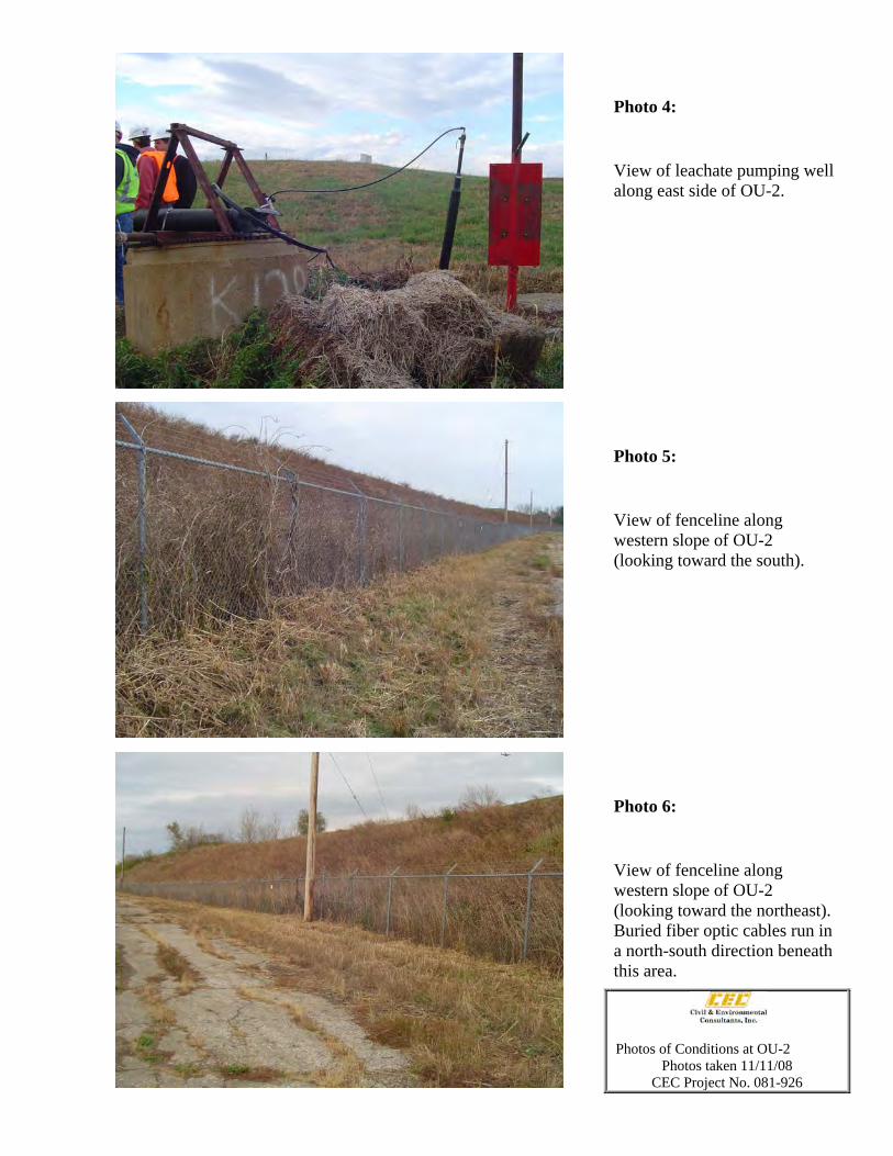
Photo 4:
View of leachate pumping well along east side of OU-2.
Photo 5:
View of fenceline along western slope of OU-2 (looking toward the south).
Photo 6:
View of fenceline along western slope of OU-2 (looking toward the northeast). Buried fiber optic cables run in a north-south direction beneath this area.
Photos of Conditions at OU-2 Photos taken 11/11/08
CEC Project No. 081-926
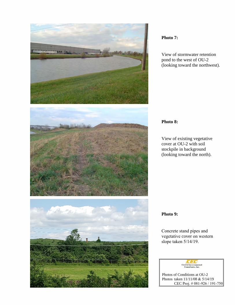
Photo 7:
View of stormwater retention pond to the west of OU-2 (looking toward the northwest).
Photo 8:
View of existing vegetative cover at OU-2 with soil stockpile in background (looking toward the north).
Photo 9:
Concrete stand pipes and vegetative cover on western slope taken 5/14/19.
Photos of Conditions at OU-2Photos taken 11/11/08 & 5/14/19
CEC Proj. # 081-926 / 191-750
APPENDIX C
REMEDIAL DESIGN QUALITY ASSURANCE PROJECT PLAN
REMEDIAL DESIGN ENVIRONMENTAL QUALITY
ASURANCE PROJECT PLAN
(RD-QAPP)
WEST LAKE LANDFILL SITE
OPERABLE UNIT 2 (OU-2)
BRIDGETON, MISSOURI
PREPARED FOR:
BRIDGETON LANDFILL, LLC
Prepared By:
CIVIL & ENVIRONMENTAL CONSULTANTS, INC.
PHOENIX, ARIZONA
CEC Project 191-750
October 15, 2019
-i- Remedial Design Environmental QAPP
West Lake Landfill Site Operable Unit 2 (OU-2), Bridgeton, Missouri
October 15, 2019
TABLE OF CONTENTS
Page
1.0 PROJECT / TASK DESCRIPTION AND SCHEDULE ...............................................1 1.1 Ground and Aerial Topographic Survey and Base Map Preparation ..................... 1
1.3 Installation and Monitoring of Temporary Landfill Gas Perimeter
Monitoring Wells .................................................................................................. 2
1.4 Existing Thickness and Material Evaluation of Inactive Sanitary Landfill
Cover ...................................................................................................................... 3
1.5 Evaluation of Stormwater Conveyance and Leachate Pumping Well
Structures ................................................................................................................ 4 1.6 Validation of Laboratory Analytical Results .......................................................... 5
1.7 Slope Stability Verification Along Western Portion of the Inactive Sanitary
Landfill .................................................................................................................... 5
1.8 Sampling and Analyses of Selected Groundwater Monitoring Wells .................... 6
1.9 Confirmation of Property Ownership Along Old St. Charles Rock Road .............. 6
2.0 DATA QUALITY OBJECTIVES AND CRITERIA .....................................................8
3.0 SPECIAL TRAINING / CERTIFICATION .................................................................10
4.0 DOCUMENTS AND RECORDS ...................................................................................11
5.0 SAMPLING PROCESS DESIGN ..................................................................................12 5.1 Ground and Aerial Topographic Survey and Base Map Preparation ................... 12 5.2 Testing of Potential Borrow Areas ....................................................................... 12
5.3 Installation and Monitoring of Temporary Landfill Gas Perimeter
Monitoring Wells .................................................................................................. 12
5.4 Existing Thickness and Material Evaluation of Inactive Sanitary Landfill
Cover ..................................................................................................................... 13 5.5 Evaluation of Stormwater Conveyance and Leachate Pumping Well Structures ....... 14
5.6 Slope Stability Verification Along Western Portion of the Inactive Sanitary
Landfill ................................................................................................................... 14 5.7 Sampling and Analyses of Selected Groundwater Monitoring Wells ................... 14
6.0 SAMPLING METHODS ................................................................................................15 6.1 Ground and Aerial Topographic Survey and Base Map Preparation ................... 15 6.2 Testing of Potential Borrow Areas ....................................................................... 15 6.3 Installation and Monitoring of Temporary Landfill Gas Perimeter Monitoring
Wells ..................................................................................................................... 15 6.4 Existing Thickness and Material Evaluation of Inactive Sanitary Landfill
Cover ..................................................................................................................... 15 6.5 Evaluation of Stormwater Conveyance and Leachate Pumping Well Structures ....... 16
6.6 Slope Stability Verification Along Western Portion of the Inactive Sanitary
Landfill ................................................................................................................... 16 6.7 Sampling and Analyses of Selected Groundwater Monitoring Wells .................. 17
-ii- Remedial Design Environmental QAPP
West Lake Landfill Site Operable Unit 2 (OU-2), Bridgeton, Missouri
October 15, 2019
Table of Contents (continued)
Page
7.0 SAMPLE HANDLING AND CUSTODY ......................................................................19 7.1 Ground and Aerial Topographic Survey and Base Map Preparation ................... 19 7.2 Testing of Potential Borrow Areas ....................................................................... 19 7.3 Installation and Monitoring of Temporary Landfill Gas Perimeter Monitoring
Wells ..................................................................................................................... 19
7.4 Existing Thickness and Material Evaluation of Inactive Sanitary Landfill
Cover ..................................................................................................................... 19 7.5 Evaluation of Stormwater Conveyance and Leachate Pumping Well Structures ....... 20 7.6 Slope Stability Verification Along Western Portion of the Inactive Sanitary
Landfill ................................................................................................................... 20
7.7 Sampling and Analysis of Selected Groundwater Monitoring Wells ............................ 20
8.0 ANALYTICAL METHODS ...........................................................................................21 8.1 Ground and Aerial Topographic Survey and Base Map Preparation ................... 21 8.2 Testing of Potential Borrow Areas ....................................................................... 21
8.3 Installation and Monitoring of Temporary Landfill Gas Perimeter Monitoring
Wells ..................................................................................................................... 22
8.4 Existing Thickness and Material Evaluation of Inactive Sanitary Landfill
Cover ..................................................................................................................... 22 8.5 Evaluation of Stormwater Conveyance and Leachate Pumping Well Structures ......... 23
8.6 Slope Stability Verification Along Western Portion of the Inactive Sanitary
Landfill ................................................................................................................... 23
8.7 Sampling and Analysis of Selected Groundwater Monitoring Wells ................... 23
9.0 QUALITY CONTROL ....................................................................................................25 9.1 Ground and Aerial Topographic Survey and Base Map Preparation .......................... 25 9.2 Testing of Potential Borrow Areas ....................................................................... 25 9.3 Installation and Monitoring of Temporary Landfill Gas Perimeter Monitoring
Wells ..................................................................................................................... 25 9.4 Existing Thickness and Material Evaluation of Inactive Sanitary Landfill
Cover ..................................................................................................................... 25 9.5 Evaluation of Stormwater Conveyance and Leachate Pumping Well Structures ....... 25
9.6 Slope Stability Verification Along Western Portion of the Inactive Sanitary
Landfill ................................................................................................................... 26 9.7 Sampling and Analyses of Selected Groundwater Monitoring Wells .................. 26
10.0 INSTRUMENT / EQUIPMENT TESTING, INSPECTION, AND
MAINTENANCE .............................................................................................................27 10.1 Instrument / Equipment Calibration and Frequency ............................................. 27
-iii- Remedial Design Environmental QAPP
West Lake Landfill Site Operable Unit 2 (OU-2), Bridgeton, Missouri
October 15, 2019
Table of Contents (continued)
Page
11.0 INSPECTION / ACCEPTANCE OF SUPPLIES AND CONSUMABLES ................28 11.1 Ground and Aerial Topographic Survey and Base Map Preparation ................... 28 11.2 Testing of Potential Borrow Areas ....................................................................... 28 11.3 Installation and Monitoring of Temporary Landfill Gas Perimeter Monitoring
Wells ..................................................................................................................... 28
11.4 Existing Thickness and Material Evaluation of Inactive Sanitary Landfill
Cover ..................................................................................................................... 28 11.5 Evaluation of Stormwater Conveyance and Leachate Pumping Well Structures ....... 28 11.6 Slope Stability Verification Along Western Portion of the Inactive Sanitary
Landfill ................................................................................................................... 29
11.7 Sampling and Analyses of Selected Groundwater Monitoring Wells .................. 29
12.0 NON-DIRECT MEASUREMENTS...............................................................................30
13.0 REPORTS TO MANAGEMENT ...................................................................................31
14.0 DATA REVIEW, VERIFICATION, AND VALIDATION .........................................32
15.0 VERIFICATION AND VALIDATION METHODS ...................................................33
FIGURES
A-1 Project Organization
A-2 Site Location Map
A-3 Existing Facility Features Map
A-4 Approximate Locations of Proposed Temporary Landfill Gas Perimeter Monitoring Wells
A-5 Proposed Sample Grid for Thickness Evaluation of Inactive Sanitary Landfill Cover
A-6 Locations of Existing Stormwater Conveyance Structures
A-7 Existing Western Slope of OU-2
A-8 Locations of Groundwater Monitoring Wells Proposed for Single Monitoring Event
B-1 Example of Temporary Gas Well Construction
TABLES
A-1 Project Individual Contact Information
-iv- Remedial Design Environmental QAPP
West Lake Landfill Site Operable Unit 2 (OU-2), Bridgeton, Missouri
October 15, 2019
Table of Contents (continued)
APPENDICES
Appendix A MDNR Technical Bulletin: Sampling of Landfill Gas Monitoring Wells
Appendix B Quality Assurance Manual for Pace Analytical Services, LLC
-v- Remedial Design Environmental QAPP
West Lake Landfill Site Operable Unit 2 (OU-2), Bridgeton, Missouri
October 15, 2019
REMEDIAL DESIGN ENVIRONMENTAL
QUALITY ASSURANCE PROJECT PLAN (QAPP)
WEST LAKE LANDFILL OU-2 FACILITY
SIGNATURE / APPROVAL PAGE
Approved by:
Justin Barker – USEPA Project Manager Date
Paul Rosasco – Project Coordinator Date
Kevin Kamp – QA Officer/Lead Landfill Designer Date
Randal Bodnar – Design Manager Date
-vi- Remedial Design Environmental QAPP
West Lake Landfill Site Operable Unit 2 (OU-2), Bridgeton, Missouri
October 15, 2019
DISTRIBUTION LIST
The following individuals will receive copies of the approved Remedial Design Environmental Quality
Assurance Project Plan (RD QAPP) and subsequent revisions:
Justin Barker, RPM - US EPA Region 7
Ryan Seabaugh - Missouri Department of Natural Resources
Paul Rosasco, Project Coordinator
Kevin Kamp, PE, Project QA Officer / Lead Landfill Designer - CEC, Inc.
Randal Bodnar, PE, Design Manager- CEC, Inc.
Courtesy copies will be provided to others, including Respondent and Respondent’s individual
contractors.
PROJECT / TASK ORGANIZATION
A project organization chart is provided as Figure A-1. Contact information for the individuals listed
below is provided in Table A-1. The individuals participating in the project and their roles and
responsibilities are discussed below:
Paul Rosasco, Project Coordinator, Engineering Management Support, Inc. (EMSI)
Mr. Rosasco will have overall responsibility for successful project completion and will
provide the interface between the USEPA and MDNR, the Respondent, and the Remedial
Design Group.
Kevin Kamp, PE, Project Quality Assurance Officer and Lead Landfill Designer, CEC, Inc.
Mr. Kamp will have overall responsibility for project quality assurance and landfill design
activities. Mr. Kamp will be responsible for stamping the design plans.
-vii- Remedial Design Environmental QAPP
West Lake Landfill Site Operable Unit 2 (OU-2), Bridgeton, Missouri
October 15, 2019
Randal Bodnar, PE, Design Manager, CEC, Inc.
Mr. Bodnar will have overall responsibility for engineering design activities.
Laboratory Quality Assurance Officer (TBD), CEC, Inc.
The Laboratory Quality Assurance Officer will be responsible for coordination between the
field sampling teams and the analytical laboratory and will be responsible for data validation
activities.
Field Supervisor (TBD), CEC, Inc.
The Field Supervisor will be responsible for day-to-day oversight of field sampling teams
and field sampling equipment.
Health and Safety Officer, Matt Stewart, Bridgeton Landfill, LLC
Mr. Stewart will be responsible for non-radiological health and safety of field sampling team
members. Matt Stewart has the following credentials.
40 Hour HAZWOPER
8 Hour HAZWOPER Supervisor
30 Hour OSHA General Industry
TENORM Worker 1 (GERT training)
NFPA 70E Electrical Safety Training
American Red Cross Adult First Aid/CPR/AED
Laboratory Project Manager (TBD), Pace Analytical Services, LLC
The Laboratory Project Manager will be responsible for laboratory analyses of samples
delivered to Pace Analytical Services, LLC from the West Lake Landfill OU-2 facility and
will be responsible for laboratory analytical report preparation. The Quality Assurance
Manual for Pace Analytical Services, LLC is included in Appendix B.
-viii- Remedial Design Environmental QAPP
West Lake Landfill Site Operable Unit 2 (OU-2), Bridgeton, Missouri
October 15, 2019
PROBLEM DEFINITION / BACKGROUND
Environmental conditions at the West Lake Landfill OU-2 facility (Figure A-2) have been previously
defined by past studies. Existing facility features, including monitoring wells and other environmental
monitoring locations near OU-2, are provided in Figure A-3. Proposed activities described in this RD
QAPP are intended to enhance the decision-making process for the RD Work Plan by providing an
updated assessment of environmental conditions in the vicinity of the West Lake Landfill OU-2
facility.
-1- Remedial Design Environmental QAPP
West Lake Landfill Site Operable Unit 2 (OU-2), Bridgeton, Missouri
October 15, 2019
1.0 PROJECT / TASK DESCRIPTION AND SCHEDULE
Work to be performed in accordance with this RD QAPP consists of:
Ground and aerial topographic survey and base map preparation;
Geotechnical testing and determination of estimated volumes for potential borrow areas;
Installation and monitoring of temporary landfill gas perimeter monitoring wells;
Collection and evaluation of existing cover thickness and material samples from OU-2;
Evaluation of stormwater conveyance and leachate pumping well structures within and near
the boundaries of the Inactive Sanitary Landfill;
Level 4 validation of soil sampling laboratory analytical results;
Verification of slope stability along western side of the Inactive Sanitary Landfill;
Groundwater performance monitoring;
Confirmation of property ownership extent along Old St. Charles Rock Road; and
Report preparation and submittal to the USEPA and the MDNR.
Each of the above-referenced tasks is briefly described below.
1.1 GROUND AND AERIAL TOPOGRAPHIC SURVEY AND BASE MAP
PREPARATION
The current topographic map is based on a 2005 aerial survey combined with typical ground
confirmation and is considered accurate to within plus or minus 1 foot of vertical elevation. This level
of accuracy is insufficient for purposes of calculating volumes of materials necessary to meet the
objectives of the West Lake Landfill OU-2 remedy (i.e., cover placement). Accordingly, during the
RD phase of the project a more detailed ground survey will be conducted, with the goal of yielding
ground surface elevations accurate to within 0.25 feet throughout the Inactive Sanitary Landfill. The
ground survey will be conducted by a registered surveyor. The ground survey will be combined with
a more recent aerial flyover and photography to provide the level of detail sufficient for calculating
necessary material volumes to achieve planned final grades. This data will then be used to create a
more accurate base map of the existing topographic conditions.
-2- Remedial Design Environmental QAPP
West Lake Landfill Site Operable Unit 2 (OU-2), Bridgeton, Missouri
October 15, 2019
1.2 TESTING OF POTENTIAL BORROW AREAS
As part of the West Lake Landfill OU-2 remedy, various materials will be placed and compacted
within the Inactive Sanitary Landfill to achieve planned final grades. In order to accurately estimate
needed volumes of materials, it is necessary to identify the density of materials in their current location
and then conduct testing to quantify the achievable density of those same materials after undergoing
excavation, transport, placement, and compaction. As part of the RD phase of the project, testing will
be conducted on various potential sources of materials to yield this critical information. Testing
methods for soil classification will include sieve analysis and Atterberg Limits. The frequency and
intervals at which these parameters are obtained and measured will be determined by decision criteria
included as part of the RD QAPP.
In addition, any soils that may be used for final cover must meet permeability specifications. As part
of the RD phase of this project, laboratory testing will be conducted on potential sources of low-
permeable final cover soils, with particular attention to the relationship between moisture content,
compaction, and permeability. The resultant data are critical for construction so decision criteria will
be developed as part of the RD QAPP.
The testing and frequency requirements for the clay cap soil samples is as follows:
Soil Property Minimum Frequency Test Requirement
Soil Classification 1/20,0000 cubic yards CL or CH
Maximum Organic Matter 1/20,0000 cubic yards 3 percent max.
Plasticity Index 1/20,0000 cubic yards 13 percent or greater
Permeability 1/20,0000 cubic yards 1x10⁻⁶ cm/sec
Standard Proctor 1/20,0000 cubic yards Laboratory Test
Water Content (As Received) 1/20,0000 cubic yards Laboratory Test
1.3 INSTALLATION AND MONITORING OF TEMPORARY LANDFILL GAS
PERIMETER MONITORING WELLS
For the purposes of the assessment of environmental conditions to support the RD Work Plan,
temporary landfill gas perimeter monitoring wells are proposed to be installed at the West Lake Landfill
OU-2 facility. Well screen elevations will be determined by drilling a test hole initially to sample the
soils logged and also a review of groundwater levels in adjacent monitoring wells. Temporary landfill
-3- Remedial Design Environmental QAPP
West Lake Landfill Site Operable Unit 2 (OU-2), Bridgeton, Missouri
October 15, 2019
gas perimeter monitoring wells are proposed to be installed at the approximate locations presented in
Figure A-4.
Results of the temporary perimeter landfill gas monitoring well installation activities will be provided
in the Data Evaluation Summary Report.
It is anticipated that some of the temporary landfill gas perimeter monitoring wells could be damaged
during construction activities or would otherwise need to be removed to facilitate construction
activities.
Quarterly methane monitoring will be performed on temporary perimeter landfill gas monitoring wells
once they have been installed.
Results of the quarterly methane monitoring are expected to be used during the RD process to assess
the composition of decomposition gases in the West Lake Landfill OU-2 facility. Quarterly methane
monitoring results will be provided to the USEPA and the MDNR in the monthly progress report
following the month in which the data were collected.
1.4 EXISTING THICKNESS AND MATERIAL EVALUATION OF INACTIVE
SANITARY LANDFILL COVER
The Feasibility Study in 2008 included an estimate of the volumes of materials to be needed for final
cover on the Inactive Sanitary Landfill. The estimate was based on existing cover thickness data
collected in 1995. To help refine the volume estimate, and in conjunction with the planned aerial
flyover and topographic survey to be conducted, supplemental cover thickness testing will be
performed during the RD. The program will include collecting cover thickness samples on a surveyed
grid pattern of approximately 150 feet across the Inactive Sanitary Landfill, as illustrated on
Figure A-5.
Each sampling point will initially be surveyed for northing, easting, and ground surface elevation.
Acquisition and management of geospatial data will meet EPA’s “Guidance for Geospatial Data
Quality Assurance Project Plans” (EPA QA/G-5G, March 2003). Clear polyethylene tube samplers
(geoprobes) will then be pushed to depth through the existing cover at each sampling location. Each
sample will be brought to the surface and visually examined to distinguish materials and measure
corresponding material thicknesses. The soils materials will be classified per the Unified Soil
Classification System based on grain size, liquid limit, and plasticity index. The test locations will be
-4- Remedial Design Environmental QAPP
West Lake Landfill Site Operable Unit 2 (OU-2), Bridgeton, Missouri
October 15, 2019
sampled continuously for the full depth of boring using a geoprobe. The sample location will advance
though the clay cap to the top of waste. Testing will include soil classification, maximum organic
matter, plasticity index, water content, and standard proctor.
In addition, approximately thirty (30) Shelby Tube samples will be collected adjacent to selected
sampling locations for permeability (hydraulic conductivity) ASTM5084 testing at an off-site
laboratory. Shelby tube samples will be obtained separately to measure hydraulic conductivity.
These samples will also help indicate and confirm whether excess cover materials are available within
portions of OU-2 or if additional material needs to be added to each localized area. The average
thickness of the topsoil to be removed and reinstalled after construction will be established.
1.5 EVALUATION OF STORMWATER CONVEYANCE AND LEACHATE PUMPING
WELL STRUCTURES
During a recent site walkover of the Inactive Sanitary Landfill to confirm current conditions, the
Landfill Design team noted the presence of various grates along the western portion of OU-2 that appear
to represent stormwater conveyance structures. In addition, a leachate pumping well was observed to
the east of OU-2. These features are displayed in Figure A-6.
At least one of the inferred stormwater conveyance structures appears to be completely silted-in. The
outlets for the inferred stormwater conveyance structures could not be located due to vegetation
growth on the Inactive Sanitary Landfill. Because proper stormwater conveyance is a key goal for the
OU-2 remedy, an evaluation of the inferred stormwater conveyance structures will be performed as
part of the RD phase.
Initially, the locations of the presumed stormwater grates will be plotted on the survey base map
previously described in Section 1.1. Structural details will also be acquired. A geophysical survey or
sewer inspection camera will then be utilized to establish the routing and discharge points of the
stormwater conveyance lines. The surveyors will locate the routing and discharge points for
subsequent use in the design of the OU-2 remedy. If the conveyance lines are completely silted in or
are otherwise unusable, the lines will likely be abandoned. A functional stormwater conveyance
system will then need to be incorporated as part of the RD.
In addition, a design investigation of the existing leachate pumping will also be conducted. The
location of the existing leachate pumping well will be similarly plotted on the survey base map.
Detailed information regarding its structural design and functionality will then be acquired from the
-5- Remedial Design Environmental QAPP
West Lake Landfill Site Operable Unit 2 (OU-2), Bridgeton, Missouri
October 15, 2019
landfill operators. The resulting information will be evaluated to determine whether the pumping well
can be incorporated into the OU-2 RD or if a separate leachate system needs to be designed. The
primary focus of the leachate pumping well evaluation will be on understanding the history of this
system, if such information is available. The secondary focus will be on determining whether or not
this system or another system will be needed after the RD has been implemented. This will be based
on leachate generation volumes attributable to OU-2 and whether or not those volumes would warrant
the continued or expanded use of such systems.
1.6 VALIDATION OF LABORATORY ANALYTICAL RESULTS
All laboratory analytical results for soil samples will be validated in accordance with the requirements
of a Level 4 validation program. Data validation summary reports will be provided to the USEPA and
the MDNR as part of the Data Evaluation Report.
1.7 SLOPE STABILITY VERIFICATION ALONG WESTERN PORTION OF THE
INACTIVE SANITARY LANDFILL
The 2008 OU-2 Feasibility Study Report noted that slopes along the western portion of the Inactive
Sanitary Landfill near Old St. Charles Rock Road were reportedly re-graded in 1992 with a goal of
achieving a 3:1 or less slope (instead of its prior 2:1 ratio). Based on a recent site walkover
completed by the Landfill Design team and a review of the 2005 topography available for the
Inactive Sanitary Landfill, CEC has concluded that portions of the western slope of the Inactive
Sanitary Landfill may not currently meet 3:1. Figure A-7 displays the location and contour
details of the western slope.
During the recent site walkover, there was no evidence of movement of the fence that was
installed along the western slope, reportedly in the mid-1990’s. The existing slopes were also
well-vegetated.
As one of the RD tasks, a design investigation will be conducted to further document the history and
stability of the existing slope. A detailed assessment of the western slopes will be performed upon
completion of the ground and aerial topographic survey previously described in Section 1.1. In
addition, a geotechnical analysis will be performed to assess the stability of the slope. The results
and findings of the design investigation will be incorporated into the design in the preliminary
RD phase.
-6- Remedial Design Environmental QAPP
West Lake Landfill Site Operable Unit 2 (OU-2), Bridgeton, Missouri
October 15, 2019
If additional documentation of slope stability is warranted, an on-site assessment of existing vegetation
along the western slope may be implemented. Derived conclusions would be documented to further
substantiate the stability control provided by existing vegetation.
1.8 SAMPLING AND ANALYSES OF SELECTED GROUNDWATER MONITORING
WELLS
Subsequent to US EPA approval of this RD QAPP, groundwater monitoring will be conducted at
selected groundwater monitoring wells in OU-2. The groundwater monitoring event is proposed to
provide an update to groundwater quality conditions near the Inactive Landfill documented during
Remedial Investigation / Feasibility Study (RI / FS) activities. In 2003 and again in 2004 a series of
monitoring wells were sampled to provide confirmation results. Of the wells sampled in 2003 and 2004,
several were associated with what is now the recently-closed Bridgeton Landfill Active Sanitary
Landfill, while five others were located near the Inactive Sanitary Landfill. These same five monitoring
wells are proposed to be sampled once during the RD phase of the project to provide additional
confirmation data. Locations of monitoring wells proposed for the groundwater monitoring event are
provided in Figure A-8.
The analytical data associated with groundwater sampling will be included in the monthly progress
report following the month in which they were received. Interpretations of the data, including data
validation results, will be provided in the Data Evaluation Summary Report.
1.9 CONFIRMATION OF PROPERTY OWNERSHIP ALONG OLD ST. CHARLES
ROCK ROAD
The extent of property ownership is obviously a key component to a proper RD. With regard to OU-2,
the extent of property ownership along Old St. Charles Rock Road is particularly important due to
planned installation of perimeter landfill gas monitoring wells and as far as final cover slope and extent
on the Inactive Sanitary Landfill. Anecdotal information suggests that property ownership may extend
some distance into what was formerly Old St. Charles Rock Road but has now reportedly been
abandoned.
Given the presence of a high-capacity fiber-optic line along the toe of the Inactive Sanitary Landfill
near Old St. Charles Rock Road, drilling of perimeter landfill gas monitoring wells described earlier in
Section 1.3 may be problematic and will at the least require careful delineation of the fiber-optic line
location. If property ownership extends some distance into Old St. Charles Rock Road, perimeter
-7- Remedial Design Environmental QAPP
West Lake Landfill Site Operable Unit 2 (OU-2), Bridgeton, Missouri
October 15, 2019
landfill gas wells can be located some distance away from the fiber- optic line while still meeting the
goal of obtaining landfill gas data at the property boundary.
Sensitive electronic measuring devices are to be used during RD work. No measurement interference
or other disruption of RD field activities is expected due to the presence of buried utilities. The location
of all buried utilities and fiber optic junction boxes will be identified, surveyed, and noted on design
documents.
Property ownership will be determined using county records, plat surveys, etc. prior to installing any
OU-2 infrastructure such as landfill gas wells.
-8- Remedial Design Environmental QAPP
West Lake Landfill Site Operable Unit 2 (OU-2), Bridgeton, Missouri
October 15, 2019
2.0 DATA QUALITY OBJECTIVES AND CRITERIA
Valid data of known and documented quality are required for the RD decision making process.
The ground and aerial topographic survey and base map preparation is intended to address an
identified need for a more accurate ground surface topography within the Inactive Sanitary Landfill.
The increased ground surface elevation accuracy will be used to refine the material volume estimates.
The testing of potential borrow areas is intended to address an identified need for materials density
both at the source and after excavation, transport, placement, and compaction. This task is also
intended to address an identified need for quantification of permeability for potential final cover soils,
along with moisture/density relationships of the potential final cover soils. These testing activities are
expected to provide data which can be used to address these data needs, which in turn will allow
refinement of materials volume calculations and costs, as well as eventual development of construction
specifications for use during the RA.
Landfill gas perimeter well installation and monitoring are intended to address an identified data need
for determining the current gas generation and movement the perimeter of the Inactive Sanitary
Landfill. Results of the temporary landfill gas perimeter well monitoring will be utilized to assist RD
decision making concerning the potential incorporation of a landfill gas management system in the
West Lake Landfill OU-2 facility.
The evaluation of existing cover thickness and material is intended to address an identified need to
verify the thickness of existing soil and low-permeability cover materials within the boundaries of the
Inactive Sanitary Landfill, as well as to refine the previous thickness estimates based on 200-foot
spacing through collection of data on a closer grid spacing. Results of the cover thickness and material
evaluation are expected to be utilized to assist in scoping cover placement activities necessary during
the RA as well as refining the estimate of material volumes needed to achieve final cover goals.
The evaluation of stormwater conveyance and leachate pumping well structures is intended to address
an identified need to verify the ability of existing stormwater conveyance structures within the Inactive
Sanitary Landfill to pass rainfall / runoff. The results of the evaluation are expected to yield data that
can be incorporated into an overall stormwater management plan for the Inactive Sanitary Landfill
during and after the RA. A similar evaluation will be conducted to assess the functionality of an
existing leachate pumping well and its potential incorporation into the OU-2 RD.
-9- Remedial Design Environmental QAPP
West Lake Landfill Site Operable Unit 2 (OU-2), Bridgeton, Missouri
October 15, 2019
The verification of slope stability along the western portion of the Inactive Sanitary Landfill is intended
to address an identified need for comparing the existing slope to ARARs. The results of the slope
stability verification program are intended to be used to meet the goals of a stability demonstration, or
alternatively, identify the need for a modified slope along the western portion of the Inactive Sanitary
Landfill.
The property ownership confirmation evaluation along Old St. Charles Rock Road is intended to
provide verification of property ownership from which RD and RA decisions can be based. For
example, if Bridgeton Landfill, LLC property ownership is determined to extend some distance into
Old St. Charles Rock Road that has been abandoned, placement of perimeter landfill gas monitoring
wells can be adjusted to provide increased confidence of avoiding fiber-optic lines present at the base
of the Inactive Sanitary Landfill while still meeting the goal of obtaining landfill gas data at the
property boundary.
-10- Remedial Design Environmental QAPP
West Lake Landfill Site Operable Unit 2 (OU-2), Bridgeton, Missouri
October 15, 2019
3.0 SPECIAL TRAINING / CERTIFICATION
Specialized training for field activities off-site analyses (performed by the analytical laboratory), and
data validation have not been identified as necessary during the planning of this project. The proposed
activities are part of routine activities performed by competent, knowledgeable, and experienced
professionals in the fields of environmental science and engineering. The CEC, Inc. field team leader
will be responsible for ensuring that all members of the field team have valid and current specialized
training required by OSHA regulations.
-11- Remedial Design Environmental QAPP
West Lake Landfill Site Operable Unit 2 (OU-2), Bridgeton, Missouri
October 15, 2019
4.0 DOCUMENTS AND RECORDS
Records for this project will include miscellaneous correspondence, field logs, field data worksheets,
laboratory analytical reports, maps/figures, data validation reports, and a final report. Sampling sheets,
chains of custody, analytical data, and a summary will be submitted to the USEPA Project Manager
and to the MDNR Project Manager as part of the Data Evaluation Report. Data validation reports and
final report will include a table of contents. Individual data validation reports will be provided
following the completion of each task identified in Sections 1.1,1.2,1.2,1.4,1.5,1.7, and 1.8.
Field information logs for perimeter landfill gas well monitoring will be used to record field
measurements. Each page of the field information logs will be dated and signed by the person(s)
making the entries.
Spatial data, laboratory analytical data, and field acquired date will be stored and provided in an
electronic database. The active data management for electronic database implementation,
maintenance, and delivery to the USEPA & MDNR will meet EPA’s Best Practices for Data
Management Technical Guide (EPA ID # 542-F-18-003).
-12- Remedial Design Environmental QAPP
West Lake Landfill Site Operable Unit 2 (OU-2), Bridgeton, Missouri
October 15, 2019
5.0 SAMPLING PROCESS DESIGN
For the West Lake Landfill OU-2 facility, the number, placement, and frequency of sampling /
monitoring locations described below are intended to assist in the decision-making process for the RD.
5.1 GROUND AND AERIAL TOPOGRAPHIC SURVEY AND BASE MAP
PREPARATION
There are no specific sampling process design needs associated with the ground and aerial topographic
survey and base map preparation task. A licensed, experienced surveying company will be used to
conduct the needed ground survey in sufficient detail to provide accuracy to within 0.25 feet vertical
ground elevation throughout the Inactive Sanitary Landfill.
5.2 TESTING OF POTENTIAL BORROW AREAS
To meet the objectives of this task, a sufficient number of samples will be collected and tested from
each potential source that the Lead Landfill Designer can attest with confidence that the data are
sufficiently detailed to meet the data quality objectives. It is likely that a minimum of three (3) to five
(5) samples will be required from each potential source. The Design Manager will have final authority
for determining the appropriate number of samples, type of sampling, and testing to be conducted
based on the approved remedial design criteria.
5.3 INSTALLATION AND MONITORING OF TEMPORARY LANDFILL GAS
PERIMETER MONITORING WELLS
Temporary landfill gas perimeter monitoring wells are proposed to be installed near the Inactive
Sanitary Landfill portion of the West Lake Landfill OU-2 facility. These wells will assist in the
assessment of subsurface conditions to support the RD. Temporary wells are proposed for gas
monitoring because the facility believes that use of heavy equipment during subsequent RA activities
(cap construction) will likely result in severe damage or the destruction of some of the landfill gas
perimeter monitoring wells. If required, permanent landfill gas perimeter monitoring wells will be
installed after RA construction activities are completed.
Temporary landfill gas perimeter monitoring wells are proposed to be installed at the approximate
locations presented in Figure A-4. Temporary landfill gas perimeter monitoring well installation
activities will be performed by a Missouri-licensed well driller supervised by CEC, Inc. personnel.
-13- Remedial Design Environmental QAPP
West Lake Landfill Site Operable Unit 2 (OU-2), Bridgeton, Missouri
October 15, 2019
Approximate locations of the proposed temporary landfill gas perimeter monitoring wells were
selected on a 500-foot spacing around the boundaries of Inactive Sanitary Landfill in accordance with
Missouri regulations provided in Division 80 of Title 10 of the Missouri Code of State Regulations
[10 CSR 80-3.010(14)(B)(1)(C)].
Two (2) temporary landfill gas monitoring well screened intervals (upper and lower) are proposed to
be installed at each location to allow monitoring of discrete zones. The screening zones will be
determined in the field based on observations of the conditions. Figure B-1 provides a proposed as-built
monitoring diagram of the proposed upper and lower temporary landfill gas perimeter monitoring
well configuration.
Each temporary perimeter landfill gas monitoring well will be surveyed by a Missouri-licensed
surveyor for state-plane Northing, Easting, ground surface elevation, top of protective casing elevation,
and top of inner riser elevation. Results of the temporary perimeter landfill gas monitoring well survey
will be provided in the Data Summary Evaluation Report.
Quarterly methane monitoring will be performed at the installed temporary landfill gas perimeter
monitoring wells, as required by 10 CSR 80-3.010(14)(C)(4). Quarterly monitoring of these wells
will continue until immediately prior to the commencement of RA construction activities (Refer to
Section 3.0 of the SAP). .
Heavy equipment activities are expected to result in severe damage to the temporary wells or the
destruction of the temporary wells. Those temporary wells that are identified as requiring
decommissioning to facilitate the RA will be abandoned in accordance with applicable Missouri
regulations prior to initiation of RA construction activities. Any temporary wells that remain intact
through the end of construction activities will be incorporated into the long-term landfill gas
monitoring program, if necessary.
5.4 EXISTING THICKNESS AND MATERIAL EVALUATION OF INACTIVE
SANITARY LANDFILL COVER
The cover soil sampling program will include the collection of approximately ninety (90) samples at
150- ft intervals from a surveyed grid across the Inactive Sanitary Landfill to evaluate the existing
cover thickness. Figure A-5 displays the approximate sampling grid and sample locations. This
sampling task will be coordinated with the aerial flyover and topographic survey.
-14- Remedial Design Environmental QAPP
West Lake Landfill Site Operable Unit 2 (OU-2), Bridgeton, Missouri
October 15, 2019
After completing the ninety (90) initial sampling locations, thirty (30) Shelby Tube samples will be
collected in accordance with ASTM D1587 at locations immediately adjacent to selected sampling
locations to further investigate the material properties of the existing cover. Undisturbed soil samples
will be collected for material classification and permeability testing purposes.
5.5 EVALUATION OF STORMWATER CONVEYANCE AND LEACHATE PUMPING
WELL STRUCTURES
There are no specific sampling process design needs associated with this task.
5.6 SLOPE STABILITY VERIFICATION ALONG WESTERN PORTION OF THE
INACTIVE SANITARY LANDFILL
As one of the RD tasks, an evaluation will be conducted to further document the history and stability
of the existing western slope. A geotechnical analysis will be performed to assess the stability of
the slope. Preliminary proposed sampling locations are displayed in Figure A-7. The Design
Manager will determine final sampling locations and frequency during the RD phase.
5.7 SAMPLING AND ANALYSES OF SELECTED GROUNDWATER MONITORING
WELLS
Subsequent to US EPA approval of this RD QAPP, groundwater monitoring will be conducted at
selected groundwater monitoring wells associated with the Inactive Sanitary Landfill. The
groundwater monitoring event is proposed to provide an update to groundwater quality conditions
encountered during Remedial Investigation / Feasibility Study (RI / FS) activities. Groundwater
samples are proposed to be collected from the following five monitoring wells:
PZ-302-AS, PZ-302AI, PZ-303-AS, PZ-304-AS, PZ-304-AI
The wells were selected to provide groundwater quality results from the same list of wells as
included in the 2003 and 2004 supplemental groundwater sampling events near the Inactive Landfill.
The final list of wells sampled is subject to verification of continued access and appropriate well
construction. Locations of monitoring wells proposed for the groundwater monitoring event are
provided by Figure A-8.
-15- Remedial Design Environmental QAPP
West Lake Landfill Site Operable Unit 2 (OU-2), Bridgeton, Missouri
October 15, 2019
6.0 SAMPLING METHODS
For the West Lake Landfill OU-2 facility, the sampling methods described below are designed to
provide defensible, reliable data to assist the decision-making process for the RD.
6.1 GROUND AND AERIAL TOPOGRAPHIC SURVEY AND BASE MAP
PREPARATION
There is no sampling necessary as part of the ground and aerial topographic survey and base map
preparation task.
6.2 TESTING OF POTENTIAL BORROW AREAS
Once potential borrow areas are identified, the Project Quality Assurance Officer will coordinate test
pits to obtain sufficient samples for geotechnical testing. Samples will be collected and containerized
for shipment to a qualified geotechnical testing firm. Evaluation of pre-selected borrow soil samples
for cover materials shall meet quality control measures outlined in EPA/600/R-93/182 Quality
Assurance and Quality Control for Waste Containment Facilities. Materials such as gravel, plant debris,
organic, clodding soil, and over-sized particles will not be acceptable. The process of selecting suitable
cover materials will require MDNR’s and USEPA’s approval.
6.3 INSTALLATION AND MONITORING OF TEMPORARY LANDFILL GAS
PERIMETER MONITORING WELLS
During installation of the temporary landfill gas perimeter monitoring wells, soils will be collected
using plastic sampling sleeves positioned inside the direct-push drilling rods. Upon extraction from
the drilling rods, the plastic sleeves will be sliced open and the soils will be logged for lithology and
visually inspected for the presence or absence of solid waste. Following installation of the wells,
quarterly methane monitoring is proposed to be conducted pursuant to the procedures described by the
MDNR Technical Bulletin: Sampling of Landfill Gas Monitoring Wells (1999), published by the
MDNR (Appendix A).
6.4 EXISTING THICKNESS AND MATERIAL EVALUATION OF INACTIVE
SANITARY LANDFILL COVER
A previous sampling program included the collection of approximately ninety (90) samples at 150- ft
-16- Remedial Design Environmental QAPP
West Lake Landfill Site Operable Unit 2 (OU-2), Bridgeton, Missouri
October 15, 2019
intervals from a surveyed grid across the Inactive Sanitary Landfill. Figure 6-1 displays the
approximate sampling grid and sample locations. Each location was sampled using a direct push drill
rig pushing a tube sampler lined with clear polyethylene liners. Each sampler was brought to the
surface, the liner opened, and the soils visually examined to distinguish materials and measure
corresponding material thicknesses. The field engineer developed a log of the soil conditions
encountered in each soil boring.
Thirty (30) Shelby Tube samples will be collected in accordance with ASTM D1587 at locations
immediately adjacent to previous cap sampling locations. Undisturbed soil samples will be collected
for material classification and permeability testing purposes. The Shelby Tube samples will be
submitted to a qualified testing laboratory where the tubes will be extruded and logged with
representative portion of each tube tested for Atterberg Limits, grain size distribution and
permeability. All samples which penetrate the landfill cover will be sealed properly with hydrated
bentonite clay plug or other approved methods. Sample locations will be visually inspected one month
and one year after they have been sealed to ensure cover integrity. All plugs which need repair will be
fixed immediate with additional hydrated bentonite clay or other approved methods and re-inspected
again one month and one year after the repairs have been made.
6.5 EVALUATION OF STORMWATER CONVEYANCE AND LEACHATE PUMPING
WELL STRUCTURES
No sampling is anticipated for this task.
6.6 SLOPE STABILITY VERIFICATION ALONG WESTERN PORTION OF THE
INACTIVE SANITARY LANDFILL
A geotechnical analysis will be performed to assess the stability of the slope. A separate work
plan will be submitted to address slope stability and sampling locations. In general, the scope of
work for slope stability will consist of the following task:
Updated topographic survey of the slope area.
Borehole staking, recording as-drilled soil boring locations, and subsurface utility
clearance.
The subsurface investigation will include drilling and sampling of an unspecified number
of soil borings. Borings will be staked on 150-foot intervals or closer along the crest and
-17- Remedial Design Environmental QAPP
West Lake Landfill Site Operable Unit 2 (OU-2), Bridgeton, Missouri
October 15, 2019
toe of the slope. Target boring depths to be determined prior to commencing the
subsurface investigation.
Oversight of the drilling operations by experienced personnel including logging of the
soil samples, preparation of field soil boring logs, recording of field testing results, and
preservation of soil samples for laboratory testing.
At a minimum, laboratory testing to include moisture content, unit weight, unconfined
compressive strength, and triaxial compressive strength.
Compilation of field and laboratory data for engineering analysis including preparation of
data tables, boring location plan, detailed soil boring logs, and soil cross
sections. Engineering analysis will include slope stability analysis for up to three critical
surfaces analyzed under both static and dynamic/seismic conditions.
6.7 SAMPLING AND ANALYSES OF SELECTED GROUNDWATER MONITORING
WELLS
Purging of monitoring wells prior to sampling, collection of groundwater samples, and chain of
custody procedures will be conducted in general accordance with the SOPs for Groundwater
Sample Collection provided as an attachment to the Sampling and Analysis Plan.
For the project-specific requirements for groundwater sample collection activities at West Lake
Landfill OU-2 Inactive Sanitary Landfill, the following modifications to the SOPs provided as an
attachment to the Sampling and Analysis Plan are understood to apply.
Containerization of purged groundwater and equipment decontamination water is
required. Containerized water will be disposed of in leachate Sump K-128, associated
with the adjacent closed sanitary landfill.
Bailer purging and sampling will be performed using a pump or with disposable
Teflon® bailers.
Required field Quality Control (QC) samples are described in Section 9.3 of this RD
QAPP.
The recommended sample collection order for analyzed groundwater constituents is
provided by the following table:
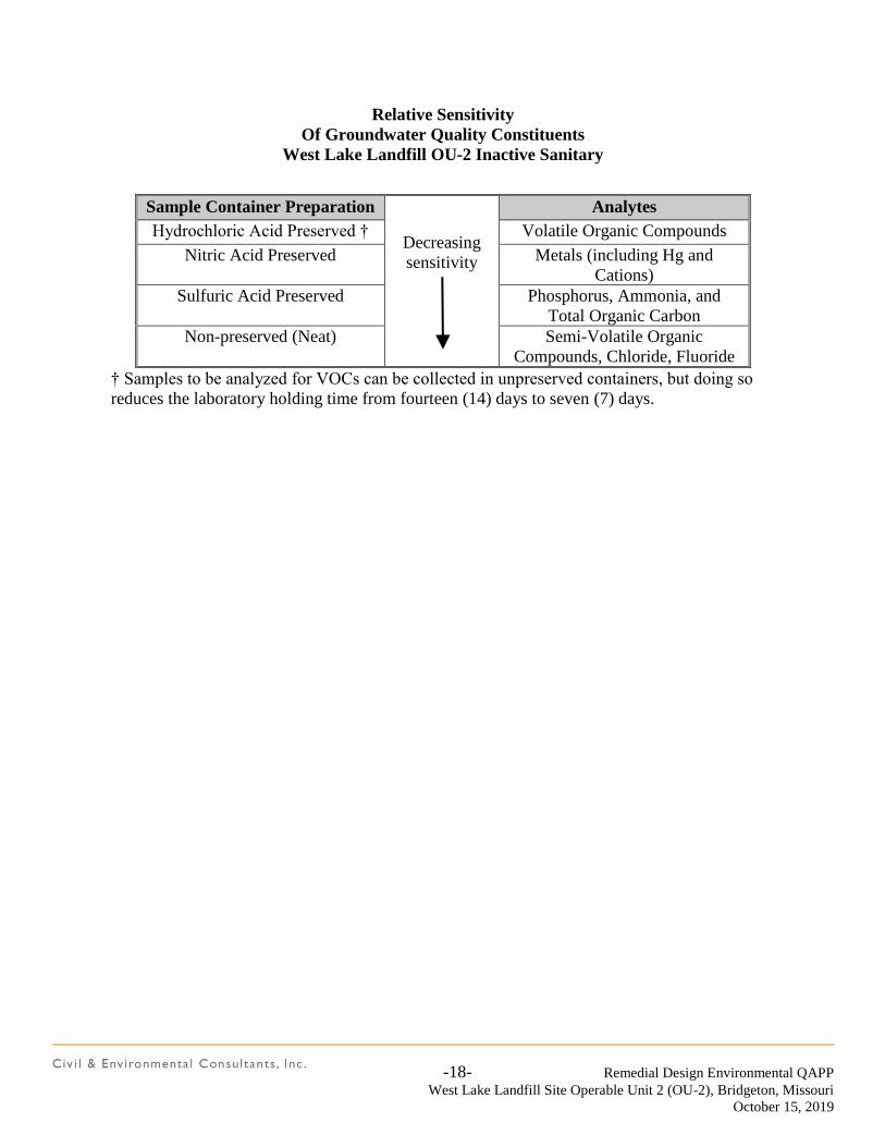
-18- Remedial Design Environmental QAPP
West Lake Landfill Site Operable Unit 2 (OU-2), Bridgeton, Missouri
October 15, 2019
Relative Sensitivity
Of Groundwater Quality Constituents
West Lake Landfill OU-2 Inactive Sanitary
Sample Container Preparation
Decreasing
sensitivity
Analytes
Hydrochloric Acid Preserved † Volatile Organic Compounds
Nitric Acid Preserved Metals (including Hg and
Cations)
Sulfuric Acid Preserved Phosphorus, Ammonia, and
Total Organic Carbon
Non-preserved (Neat) Semi-Volatile Organic
Compounds, Chloride, Fluoride
† Samples to be analyzed for VOCs can be collected in unpreserved containers, but doing so
reduces the laboratory holding time from fourteen (14) days to seven (7) days.
-19- Remedial Design Environmental QAPP
West Lake Landfill Site Operable Unit 2 (OU-2), Bridgeton, Missouri
October 15, 2019
7.0 SAMPLE HANDLING AND CUSTODY
7.1 GROUND AND AERIAL TOPOGRAPHIC SURVEY AND BASE MAP
PREPARATION
There are no sample handling and custody issues associated with the ground and aerial
topographic survey and base map preparation task.
7.2 TESTING OF POTENTIAL BORROW AREAS
Since samples for geotechnical testing are disturbed samples, sample handling will involve
preservation of the initial quantity of sample by sealing the container properly. A soil testing chain of
custody form will be attached to each container including the date of sampling, the location of the
sampling, the sampler’s name, a general description of the material, and the requested tests to be
conducted. A copy of the soils testing request form will be kept by the Lead Landfill Designer.
Tracking numbering system for borrow area soil samples will use the prefix: OU2-BA
7.3 INSTALLATION AND MONITORING OF TEMPORARY LANDFILL GAS
PERIMETER MONITORING WELLS
Neither visual inspections of soil samples collected in plastic sleeves nor quarterly methane
measurements will result in collection of samples for laboratory analysis. Accordingly, sample
handling and custody requirements are not expected to apply to landfill gas perimeter well installations
and measurements.
7.4 EXISTING THICKNESS AND MATERIAL EVALUATION OF INACTIVE
SANITARY LANDFILL COVER
Soil samples collected specifically for determining material thicknesses will be measured and
documented on-site. Since these samples will not be submitted for any further off-site analysis, no
additional sample handling or custody procedures are applicable.
For the portion of soil samples being collected for off-site geotechnical analysis, sample handling will
involve preservation of the sample by proper sealing the container. A soil testing request form will be
-20- Remedial Design Environmental QAPP
West Lake Landfill Site Operable Unit 2 (OU-2), Bridgeton, Missouri
October 15, 2019
attached to each container including the sampling date, location, sampler’s name, a general description
of the material, and the requested laboratory analyses. A copy of the soil testing request form will be
retained by the Lead Landfill Designer.
Tracking numbering system for the existing cover soil samples will use the prefix: OU2-EXC
7.5 EVALUATION OF STORMWATER CONVEYANCE AND LEACHATE PUMPING
WELL STRUCTURES
There are no sample handling and custody issues associated with this task.
7.6 SLOPE STABILITY VERIFICATION ALONG WESTERN PORTION OF THE
INACTIVE SANITARY LANDFILL
For slope stability geotechnical analysis, soil sample handling will involve preservation of the initial
quantity of sample by sealing the container properly. A soil testing chain of custody form will be
attached to each container including the date of sampling, the location of the sampling, the sampler’s
name, a general description of the material, and the requested tests to be conducted. A copy of the
soils testing request form will be kept by the Lead Landfill Designer.
Tracking numbering system for slope stability soil samples will use the prefix: OU2-SS
7.7 SAMPLING AND ANALYSIS OF SELECTED GROUNDWATER MONITORING
WELLS
The groundwater sample handling and custody procedures provided in the Sampling and Analysis
Plan will be followed for samples collected from monitoring wells at the West Lake Landfill OU-
2 Inactive Sanitary Landfill.
Tracking numbering system for groundwater samples will use the prefix: OU2-GW
-21- Remedial Design Environmental QAPP
West Lake Landfill Site Operable Unit 2 (OU-2), Bridgeton, Missouri
October 15, 2019
8.0 ANALYTICAL METHODS
8.1 GROUND AND AERIAL TOPOGRAPHIC SURVEY AND BASE MAP
PREPARATION
There are no analytical methods associated with the ground and aerial topographic survey and base
map preparation task.
8.2 TESTING OF POTENTIAL BORROW AREAS
The following test methods will be employed for geotechnical testing:
Moisture-Density relationships using the Standard Proctor Method
ASTM D698 (2012) Standard Test Methods for Laboratory Compaction
Characteristics of Soil Using Standard Effort (12,400 ft-lbf/ft3 (600kN-m/m3))
Grain size distribution
ASTM D421 (2007) Standard Practice for Dry Preparation of Soil Samples for
Particle –Size Analysis
ASTM D422 (2007) Standard Test Method for Particle Size – Size Analysis
ASTM D1140 (2017) Standard Test Methods for Determining the Amount of
Material Finer than 75-m (No. 200) Sieve n Soils by Washing
Atterberg Limits
ASTM D4318 (2017) Standard Test Methods for Liquid Limit, Plastic Limit
and Plasticity Index of Soils.
Permeability or Hydraulic Conductivity (re-compacted to specified density)
ASTM D5084 (2016)Standard Test Methods for Measurement of Hydraulic
Conductivity of Saturated Porous Materials Using a Flexible Wall Permeameter
-22- Remedial Design Environmental QAPP
West Lake Landfill Site Operable Unit 2 (OU-2), Bridgeton, Missouri
October 15, 2019
8.3 INSTALLATION AND MONITORING OF TEMPORARY LANDFILL GAS
PERIMETER MONITORING WELLS
Neither visual inspections of soil samples collected in plastic sleeves nor quarterly methane
measurements will result in collection of samples for laboratory analysis. Accordingly, analytical
methods are not expected to apply to landfill gas perimeter well installations and measurements.
8.4 EXISTING THICKNESS AND MATERIAL EVALUATION OF INACTIVE
SANITARY LANDFILL COVER
The following analytical methods will be employed for geotechnical testing of the Shelby Tube and
Geoprobe samples:
Moisture Content
ASTM D2216 (2019) Standard Test Methods for Laboratory Determination of
Water (Moisture) Content of Soil and Rock by Mass
Unit Weight
ASTM D2166 (2016) Standard Test Method for Unconfined Compressive
Strength of Cohesive Soil
Grain size distribution
ASTM D421 (2007) Standard Practice for Dry Preparation of Soil Samples
for Particle –Size Analysis
ASTM D422 (2007) Standard Test Method for Particle Size – Size Analysis
ASTM D1140 (2017) Standard Test Methods for Determining the Amount of
Material Finer than 75-m (No. 200) Sieve n Soils by Washing
Atterberg Limits
ASTM D4318 (2017) Standard Test Methods for Liquid Limit, Plastic Limit
and Plasticity Index of Soils.
Permeability or Hydraulic Conductivity
ASTM D5084 (2016)Standard Test Methods for Measurement of Hydraulic
Conductivity of Saturated Porous Materials Using a Flexible Wall Permeameter
-23- Remedial Design Environmental QAPP
West Lake Landfill Site Operable Unit 2 (OU-2), Bridgeton, Missouri
October 15, 2019
8.5 EVALUATION OF STORMWATER CONVEYANCE AND LEACHATE PUMPING
WELL STRUCTURES
There are no analytical methods associated with this task.
8.6 SLOPE STABILITY VERIFICATION ALONG WESTERN PORTION OF THE
INACTIVE SANITARY LANDFILL
The following test methods will be employed for geotechnical testing:
Moisture Content
ASTM D2216 (2019) Standard Test Methods for Laboratory Determination of
Water (Moisture) Content of Soil and Rock by Mass
Unit Weight
ASTM D2166 (2016) Standard Test Method for Unconfined Compressive
Strength of Cohesive Soil
Unconfined Compressive Strength
ASTM D2166 (2016) Standard Test Method for Unconfined Compressive
Strength of Cohesive Soil.
Triaxial Compressive Strength
ASTM D4767 (2011)Standard Test Methods for Consolidated Undrained
Triaxial Compression Test for Cohesive Soils.
8.7 SAMPLING AND ANALYSIS OF SELECTED GROUNDWATER MONITORING
WELLS
Collected groundwater samples will be analyzed by the laboratory for:
Volatile Organic Compounds by SW-846 Method 8260B;
Total Metals by SW-846 Method 6010C;
Total Mercury by SW-846 Method 7470A;
Chloride and Fluoride by EPA Method 300.0;
Total Phosphorus by EPA Method 365.2;
Ammonia (Nitrogen) by EPA Method 350.1;
-24- Remedial Design Environmental QAPP
West Lake Landfill Site Operable Unit 2 (OU-2), Bridgeton, Missouri
October 15, 2019
A copy of the analytical laboratory Statement of Qualifications provided by Pace Analytical is
provided in Appendix B.
-25- Remedial Design Environmental QAPP
West Lake Landfill Site Operable Unit 2 (OU-2), Bridgeton, Missouri
October 15, 2019
9.0 QUALITY CONTROL
9.1 GROUND AND AERIAL TOPOGRAPHIC SURVEY AND BASE MAP PREPARATION
There are no sample quality control issues associated with the ground and aerial topographic survey and
base map preparation task.
9.2 TESTING OF POTENTIAL BORROW AREAS
Geotechnical testing will be conducted by a certified laboratory. Certification must be approved by
the Department of Transportation from the state where the laboratory is located or similar level of
authority or credentials.
9.3 INSTALLATION AND MONITORING OF TEMPORARY LANDFILL GAS
PERIMETER MONITORING WELLS
Neither visual inspections of soil samples collected in plastic sleeves nor quarterly methane
measurements will result in collection of samples for laboratory analysis. Accordingly, sample quality
control issues are not expected to be associated with the landfill gas perimeter well installations and
measurements.
9.4 EXISTING THICKNESS AND MATERIAL EVALUATION OF INACTIVE
SANITARY LANDFILL COVER
Geotechnical testing will be conducted by a certified laboratory. Certification must be approved by
the Department of Transportation from the state where the laboratory is located or similar level of
authority or credentials.
9.5 EVALUATION OF STORMWATER CONVEYANCE AND LEACHATE PUMPING
WELL STRUCTURES
There are no sample quality control issues associated with this task.
-26- Remedial Design Environmental QAPP
West Lake Landfill Site Operable Unit 2 (OU-2), Bridgeton, Missouri
October 15, 2019
9.6 SLOPE STABILITY VERIFICATION ALONG WESTERN PORTION OF THE
INACTIVE SANITARY LANDFILL
Data must be collected using calibrated equipment that meets or exceeds the industry standard. This
data must also be provided as a document that is signed and sealed by a licensed surveyor in the State
of Missouri.
9.7 SAMPLING AND ANALYSES OF SELECTED GROUNDWATER MONITORING
WELLS
The following field Quality Control samples and sample frequencies will be collected for
analysis during the proposed groundwater monitoring event:
Field Duplicate samples – one (1) field duplicate soil sample to be collected per ten
(10) primary soil samples.
Field (Atmospheric) Blank samples – one (1) field blank sample to be collected per
monitoring event.
Equipment Blank samples – one (1) equipment blank sample to be collected per
monitoring event if a non-dedicated pump is utilized for purging and sampling.\
Trip Blank samples – one (1) trip blank sample (provided by the laboratory) to be
included with each sample shipment containing samples for analysis of VOCs.
The following laboratory Quality Control samples and sample frequencies are proposed to be
analyzed concurrently with groundwater samples:
Method Blank samples – one (1) method blank sample to be analyzed per twenty (20)
samples analyzed in the batch;
Laboratory Control Samples (LCS) – one (1) LCS to be analyzed per twenty (20)
samples analyzed in the batch; and
Matrix Spike / Matrix Spike Duplicate (MS / MSD) samples – one (1) MS / MSD
sample pair to be analyzed per twenty (20) samples analyzed in the batch.
-27- Remedial Design Environmental QAPP
West Lake Landfill Site Operable Unit 2 (OU-2), Bridgeton, Missouri
October 15, 2019
10.0 INSTRUMENT / EQUIPMENT TESTING, INSPECTION, AND MAINTENANCE
Field instruments used for landfill gas measurements and health and safety monitoring will be tested,
inspected, and maintained according to manufacturer’s recommendations.
10.1 INSTRUMENT / EQUIPMENT CALIBRATION AND FREQUENCY
Field instrumentation utilized for landfill gas measurements will be calibrated according to the
manufacturers’ recommendations each day of sampling and prior to monitoring activities. The
calibration of field instrumentation will be verified at the end of each sampling day against the
calibration solutions or calibration gases. If potentially anomalous field parameter measurements are
encountered during gas monitoring activities, the calibration frequency may be increased at the
discretion of the field sampling crew to confirm potentially anomalous measurements.
-28- Remedial Design Environmental QAPP
West Lake Landfill Site Operable Unit 2 (OU-2), Bridgeton, Missouri
October 15, 2019
11.0 INSPECTION / ACCEPTANCE OF SUPPLIES AND CONSUMABLES
Supplies and consumables for the activities described by this RD QAPP are described below.
11.1 GROUND AND AERIAL TOPOGRAPHIC SURVEY AND BASE MAP
PREPARATION
The inspection and acceptance of supplies and consumables are not expected to be associated with the
ground and aerial topographic survey and base map preparation task.
11.2 TESTING OF POTENTIAL BORROW AREAS
There will be no need for acceptance of supplies and consumables for this task.
11.3 INSTALLATION AND MONITORING OF TEMPORARY LANDFILL GAS
PERIMETER MONITORING WELLS
Required supplies and consumables for temporary landfill gas perimeter monitoring well installation
activities are expected to consist of environmental-grade one (1)-inch diameter PVC riser and screen,
steel protective casings, locks, bentonite chips, bentonite/cement grout, etc. utilized by the drilling
contractor to construct the wells. Wells will be drilled in accordance with Missouri Well Construction
Code. Required supplies and consumables for quarterly temporary landfill gas perimeter well
monitoring activities are expected to consist of calibration gases for the combustible gas indicator.
11.4 EXISTING THICKNESS AND MATERIAL EVALUATION OF INACTIVE
SANITARY LANDFILL COVER
There will be no need for acceptance of supplies and consumables for this task.
11.5 EVALUATION OF STORMWATER CONVEYANCE AND LEACHATE PUMPING
WELL STRUCTURES
There will be no need for acceptance of supplies and consumables for this task.
-29- Remedial Design Environmental QAPP
West Lake Landfill Site Operable Unit 2 (OU-2), Bridgeton, Missouri
October 15, 2019
11.6 SLOPE STABILITY VERIFICATION ALONG WESTERN PORTION OF THE
INACTIVE SANITARY LANDFILL
There will be no need for acceptance of supplies and consumables for this task.
11.7 SAMPLING AND ANALYSES OF SELECTED GROUNDWATER MONITORING
WELLS
Required supplies and consumables for groundwater monitoring activities are expected to consist
of:
Disposable Teflon® bailers or pump;
Disposable polyethylene / nylon rope;
Groundwater sample containers provided by the laboratory;
Calibration solutions for field pH, Specific Conductance, and Turbidity meters;
LiquiNox® (or equivalent) detergent for equipment decontamination between
monitoring wells;
Deionized water for equipment decontamination between monitoring wells;
Deionized water for field blank and / or equipment blank collection;
Disposable gloves;
Paper towels; and
Ice for maintaining cooled samples prior to delivery to the analytical laboratory.
-30- Remedial Design Environmental QAPP
West Lake Landfill Site Operable Unit 2 (OU-2), Bridgeton, Missouri
October 15, 2019
12.0 NON-DIRECT MEASUREMENTS
Previous information obtained during field activities for the West Lake Landfill OU-2 facility may be
used for planning field activities proposed in this RD QAPP. For example, monitoring well analytical
results from previous sampling events will be used to determine the order of monitoring well purging
and sampling (from least impacted to most impacted).

-31- Remedial Design Environmental QAPP
West Lake Landfill Site Operable Unit 2 (OU-2), Bridgeton, Missouri
October 15, 2019
13.0 REPORTS TO MANAGEMENT
Information gathered as part of the RD phase activities will be provided to USEPA and MDNR
through two primary means – Monthly Reports and the Data Evaluation Summary Report. Monthly
reports will include as attachments copies of raw data provided by the analytical laboratory. The Data
Evaluation Summary Report will include evaluations of the collected data as well as copies of field
documentation sheets, data, validation results, etc.
-32- Remedial Design Environmental QAPP
West Lake Landfill Site Operable Unit 2 (OU-2), Bridgeton, Missouri
October 15, 2019
14.0 DATA REVIEW, VERIFICATION, AND VALIDATION
All laboratory analytical results for soil samples will be validated in accordance with the requirements
of a Level 4 validation program. Components of the Level 4 data validation program are provided in
Section 15.0.
-33- Remedial Design Environmental QAPP
West Lake Landfill Site Operable Unit 2 (OU-2), Bridgeton, Missouri
October 15, 2019
15.0 VERIFICATION AND VALIDATION METHODS
Level 4 data validation will be performed in general accordance with the USEPA National Functional
Guidelines for Inorganic Data Review (revised October 2004), USEPA National Functional
Guidelines for Organic Data Review (revised October 1999), and the USEPA Contract Laboratory
Program National Functional Guidelines for Superfund Organic Methods Data Review, (Final, June
2007).
Elements of the Level 4 data validation program for organic analyses are expected
to consist of:
Holding Times;
Initial Calibration Procedures and Results;
Continuing Calibration Procedures and Results;
Blank Results;
System Monitoring Compound (Surrogate) Recoveries;
Matrix Spike and Matrix Spike Duplicate Recoveries;
Laboratory Control Sample Recoveries;
Internal Standard Performance;
Field Duplicate Sample Analysis – Relative Percent Difference (RPD);
Laboratory Duplicate Sample Analysis – Relative Percent Difference (RPD);
Compound Quantitation;
Transcriptions from Raw Data to Summary Forms;
Reporting Limits; and
Overall Assessment of Data in the Sample Delivery Group (SDG) for
Inorganic Analyses:
ICP Interference Check Sample Results;
MSA and Serial Dilution Check Results;
Level 4 data validation summary reports will be provided to the USEPA and the MDNR. Each
validation summary report will provide a discussion of validation methods, validated analytical results,
and an assessment of data accuracy, data precision, and data completeness.

FIGURES
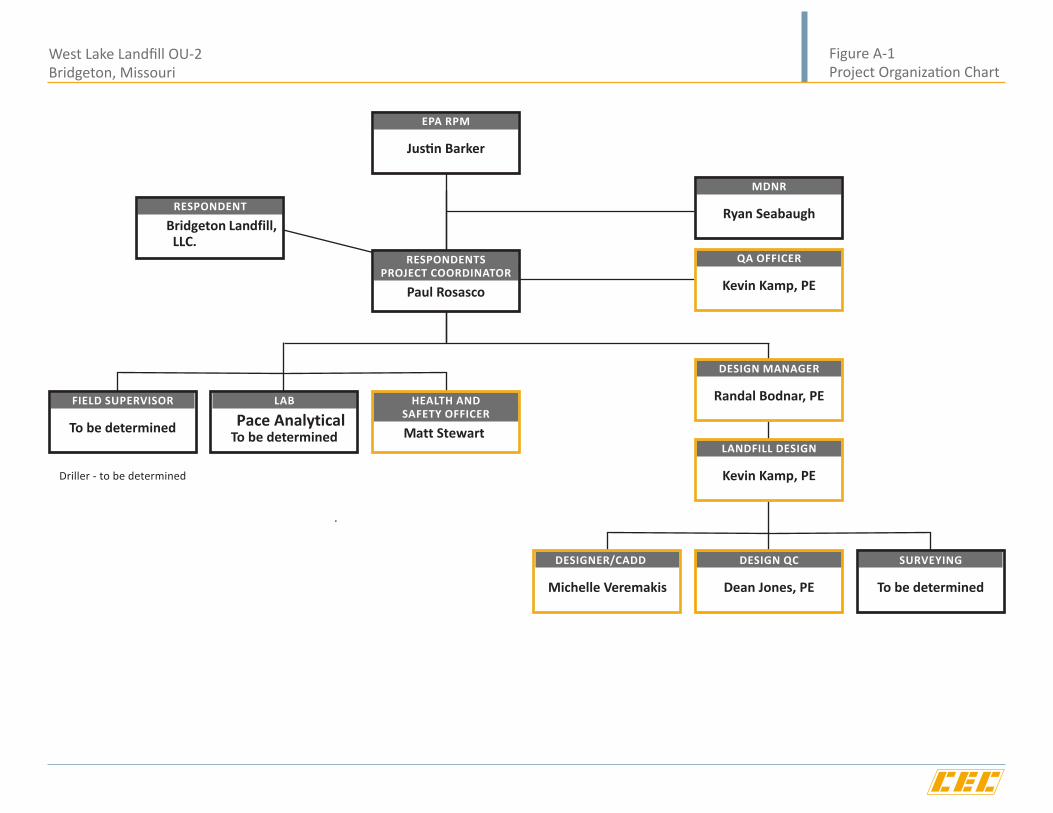
West Lake Landfill OU-2 Bridgeton, Missouri
Figure A-1 Project Organization Chart
RESPONDENTSPROJECT COORDINATOR
Paul Rosasco
FIELD SUPERVISOR
To be determined
LAB
Pace AnalyticalTo be determined
HEALTH ANDSAFETY OFFICER
Matt Stewart
DESIGNER/CADD
Michelle Veremakis
DESIGN QC
Dean Jones, PE
SURVEYING
To be determined
QA OFFICER
Kevin Kamp, PE
RESPONDENT
Bridgeton Landfill, LLC.
EPA RPM
Justin Barker
MDNR
Ryan Seabaugh
DESIGN MANAGER
Randal Bodnar, PE
LANDFILL DESIGN
Kevin Kamp, PEDriller - to be determined
Missouri
Maps courtesy of Microsoft Streets and Trips 2005
West LakeLandfill OU-2
Bridgeton Landfill, LLC (2008)
4630 South Highway 94North Outer Road
St. Charles, Missouri 63304Phone (636) 939-9111
Fax (636) 939-9757West Lake Landfill OU-2
Bridgeton, MissouriFigure A-2
Site Location Map

4630 South Highway 94North Outer Road
St. Charles, Missouri 63304Phone (636) 939-9111
Fax (636) 939-9757West Lake Landfill OU-2
Bridgeton, MissouriFigure 1-2
Existing Facility Features Map
Bridgeton Landfill, LLC (2008)

4630 South Highway 94North Outer Road
St. Charles, Missouri 63304Phone (636) 939-9111
Fax (636) 939-9757West Lake Landfill OU-2
Bridgeton, Missouri
Figure 3-1Approximate Locations of ProposedTemporary Landfill Gas Perimeter
Monitoring Probes
Bridgeton Landfill, LLC (2008)


4630 South Highway 94North Outer Road
St. Charles, Missouri 63304Phone (636) 939-9111
Fax (636) 939-9757West Lake Landfill OU-2
Bridgeton, Missouri
Figure 4-1Locations of Groundwater
Monitoring Wells Proposed forSingle Monitoring Event
Bridgeton Landfill, LLC (2008)
(Not to Scale)
Ground Surface
Riser Material: PVC
Riser Diameter: 1 inch
Secondary Casing: 4 inchWell Protection Cover
Screen Material: Pre-pack screen (Pea Gravel)
Screen Diameter: 1 inch
Screen Slot Size: 0.010 inch
Consulting Firm: Civil & Environmental Consultants, Inc.
Installation Supervisor:
Registered Professional Geologist:
Date Started:
Date Completed:
Northing: Easting:
Drilling Contractor:
Driller:
Helper:
Drilling Method: Direct Push
Surveyor:
Top of Screen: 5 ft. bgs
Bottom of Screen: 20 ft. bgs
Total Depth: 20 ft. bgs
Top of Screen: 25 ft. bgs
Bottom of Screen: 35 ft. bgs
Total Depth: 35 ft. bgs
Top of Bentonite Seal: 1 ft. bgs
Bottom of Bentonite Seal: 23 ft. bgs
Bottom of Bentonite Seal: 3 ft. bgs
Top of Bentonite Seal: 1 ft. bgs
Riser Material: PVC
Riser Diameter: 1 inch
Secondary Casing: 4 inchWell Protection Cover
Screen Material: Pre-pack screen
Screen Diameter: 1 inch
Screen Slot Size: 0.010 inch
4630 South Highway 94North Outer Road
St. Charles, Missouri 63304Phone (636) 939-9111
Fax (636) 939-9757
Figure B-1Example of Temporary Gas
Probe ConstructionWest Lake Landfill OU-2
Bridgeton, Missouri
Bridgeton Landfill, LLC (2019)
(PeaGravel)

TABLES
Table A-1
Name Affiliation Title Mailing Street Address City, State, ZIP Code Telephone Number
Justin Barker United States EPA, Region 7 EPA Remedial Project Manager 11201 Renner Boulevard Lenexa, KS 66219 (913) 551-7789
Ryan Seabaugh Missouri Dept. of Natural Resources MDNR Project Manager P.O. Box 176 Jefferson City, MO 65102 (573) 751-8628
Erin Fanning Bridgeton Landfill, LLC Respondent 13570 Saint Charles Rock Road Bridgeton, MO 63044 (209) 227-9531
Paul Rosasco Engineering Management Support, Inc. Respondent's Project Coordinator 25923 Gateway Drive Golden, CO 80401 (303) 808-7227
Randal Bodnar Civil & Environmental Consultants, Inc. Design Manager 11811 N Tatum Blvd, Suite 3031 Phoenix, AZ 85028 (602) 760-2324
Kevin Kamp Civil & Environmental Consultants, Inc. QA Officer/Lead Landfill Designer 4848 Park 30 Boulevard, Suite F Hazelwood, MO 63042 (314) 656-4566
Matt Stewart Bridgeton Landfill, LLC Health and Safety Officer 13570 Saint Charles Rock Road Bridgeton, MO 63044 (314) 656-2130
Michelle Veremakis Civil & Environmental Consultants, Inc. Designer/CADD 4848 Park 30 Boulevard, Suite F Hazelwood, MO 63042 (314) 656-4566
Dean Jones Civil & Environmental Consultants, Inc. Design QC 1230 East Diehl Road, Suite 200 Naperville, IL 60563 (630) 963-6026
TBD Civil & Environmental Consultants, Inc. Field Supervisor 4848 Park 30 Boulevard, Suite F Hazelwood, MO 63042 (314) 656-4566
TBD Pace Analytical Services, LLC Laboratory Project Manager 7726 Moller Road Indianapolis, IN 46268 (317) 228-3100
TBD Civil & Environmental Consultants, Inc. Laboratory Quality Assurance Manager 4848 Park 30 Boulevard, Suite F Hazelwood, MO 63042 (314) 656-4566
TBD Civil & Environmental Consultants, Inc. Surveyor 4848 Park 30 Boulevard, Suite F Hazelwood, MO 63042 (314) 656-4566
RD QAPP Project Personnel Contact Information
West Lake Landfill OU-2 Facility
Bridgeton, Missouri
APPENDIX A
MDNR TECHNICAL BULLETIN: SAMPLING OF LANDFILL GAS MONITORING
WELLS
MISSOURI DEPARTMENT OFNATURAL RESOURCES
Sampling of Landfill Gas Monitoring WellsTechnical Bulletin9/1999
Division of Environmental QualitySolid Waste Management Program
Recycled Paper
OverviewThis document was prepared by the Missouri Department of Natural Resources� Solid WasteManagement Program (SWMP) to provide guidance regarding the quarterly sampling of gasmonitoring wells as required by 10 CSR 80-3.010(14) and 10 CSR 80-4.010(14). This guidanceapplies to all landfills that monitor for methane migration by means of gas monitoring wells.Sampling results must be submitted at least quarterly to SWMP in an electronic format.
Sampling EquipmentProper selection of sampling equipment is critical in obtaining true soil gas concentrations.Explosimeter-type instruments are not appropriate for measuring methane in gas monitoringwells, because the amount of oxygen which is present in the well may not be sufficient for thesample to �burn.� These instruments will typically give false low readings when high concentra-tions of methane are present.
It is recommended that instruments used to sample gas monitoring wells have an automaticpump that has the ability to withdraw enough volume to bring a fresh sample of soil gas into thewell. It is also beneficial that the instrument reads both oxygen and methane concentrations.Some instruments have the ability to read barometric pressure, which is also desirable.
Sampling ProceduresStep 1 - Make sure the instrument is properly calibrated. Prepare the instrument for samplingby allowing it to properly warm up as directed by the manufacturer.
Step 2 - Connect the instrument to the well head and begin collecting a sample.
Step 3 - Continue collecting the sample until the reading stabilizes. A stable reading is one thatdoes not vary more than 0.5 percent by volume on the instrument�s scale.
Step 4 - A proper reading should have 2 percent oxygen by volume or less. If levels of oxygenare higher, it may indicate that air is being drawn into the system giving a false reading of the truesoil gas concentrations. Possible explanations for this problem are:A. The gas monitoring well seal has failed;B. Well head connectors are leaking; orC. A connection at the instrument is leaking.
When the problem is eliminated repeat Steps 1-3. If the problem cannot be corrected, recordthose values and make sure that the problem is well documented in the report sent to the de-partment.
PUB002053
*PUB002053*
2
Step 5 - Record the stabilized reading including the oxygen concentration and barometric pres-sure, if available.
Obtaining true soil gas concentrations from gas monitoring wells is dependent upon using aconsistent proven method. If you have problems using the sampling procedures described, youshould contact the department as soon as possible.
Sampling TimesSampling times are almost as important as the procedure used to collect the sample. Propermonitoring of the site should include sampling at those times when landfill gas is most likely tomigrate. Scientific evidence indicates that weather and soil conditions influence when gas willmigrate. For these reasons sampling should be considered when:A. Barometric pressure is low and soils are saturated; orB. When snow cover is just beginning to melt; orC. The ground is frozen or ice covered.
RecordsThe Solid Waste Management Regulations require that reports on data collected from wells besubmitted to SWMP at least quarterly. The SWMP recommends that gas monitoring be con-ducted during the months of February, May, August and November and that the results besubmitted within 30 days of sampling. The data must be submitted in electronic form. Theresults submitted should contain:1. The location of monitoring points.2. Sample results obtained should include the date the sampling was performed and the baro-
metric pressure, if available. Methane measurements may be given as a percentage of thetotal air volume or as a percentage of the Lower Explosive Limit (LEL). The following formulacan be used to convert a percentage of LEL into a percentage methane by volume:
% Methane (by volume) = LEL (%) ÷ 203. The amount of time a well is pumped before a stabilized methane reading is taken.4. The percent volume of O2 (if the instrument used is capable of measuring).
The form attached to the end of this bulletin may be used to record the information required bythe department.
ConclusionsMissouri has stringent regulations governing landfill gas migration. The department prefers toaddress the issue of migrating gases before they present a threat to public safety or the environ-ment.
Migrating gases detected above allowable limits at property boundaries do not necessarily meanthat there is an immediate threat to public safety. It does mean that there is a potential problemthat must be addressed. In order to address such a problem, a permit modification to install agas collection system may be necessary.
ReferencesLandtec Landfill Control Technologies, Landfill Gas System Engineering Design: A PracticalApproach, course notes from Landfill Gas System Engineering Design Seminar, 1994.
3
Missouri Department of Natural Resources, Flood Grant Team, Landfill Gas Monitoring Protocol,available on the Solid Waste Management Program�s web site.
For more information call or write:Missouri Department of Natural ResourcesSolid Waste Management ProgramP.O. Box 176, Jefferson City, MO 65102-01761-800-361-4827 or (573) 751-5401 office(573) 526-3902 fax(http://www.dnr.state.mo.us/deq/swmp) Program Home Page
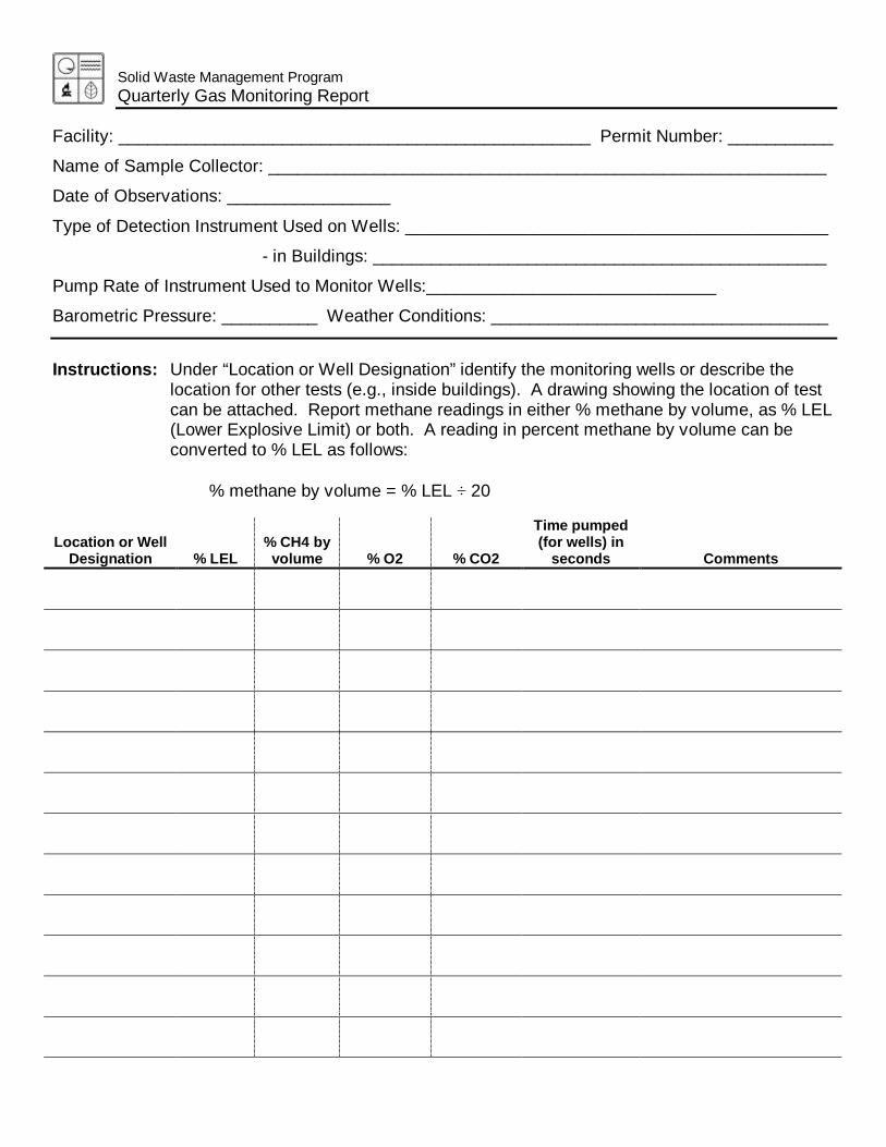
Solid Waste Management ProgramQuarterly Gas Monitoring Report
Facility: _________________________________________________ Permit Number: ___________
Name of Sample Collector: __________________________________________________________
Date of Observations: _________________
Type of Detection Instrument Used on Wells: ____________________________________________
- in Buildings: _______________________________________________
Pump Rate of Instrument Used to Monitor Wells:______________________________
Barometric Pressure: __________ Weather Conditions: ___________________________________
Instructions: Under “Location or Well Designation” identify the monitoring wells or describe thelocation for other tests (e.g., inside buildings). A drawing showing the location of testcan be attached. Report methane readings in either % methane by volume, as % LEL(Lower Explosive Limit) or both. A reading in percent methane by volume can beconverted to % LEL as follows:
% methane by volume = % LEL ÷ 20
Location or WellDesignation % LEL
% CH4 byvolume % O2 % CO2
Time pumped(for wells) in
seconds Comments
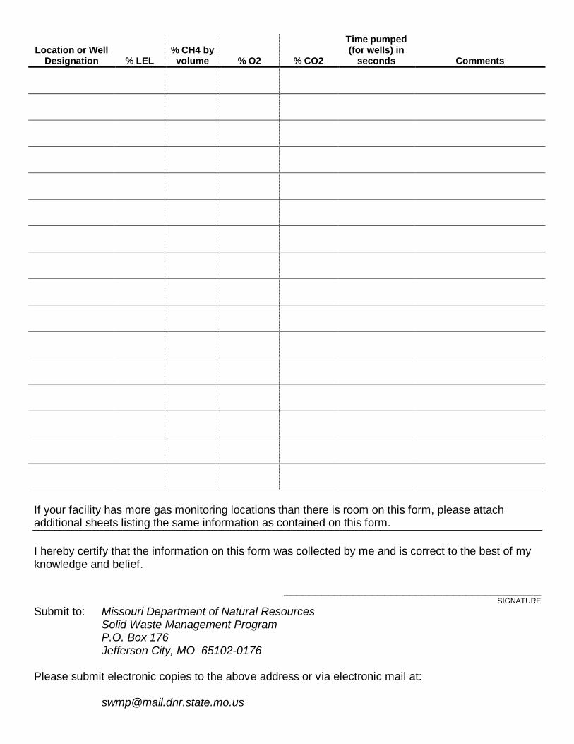
Location or WellDesignation % LEL
% CH4 byvolume % O2 % CO2
Time pumped(for wells) in
seconds Comments
If your facility has more gas monitoring locations than there is room on this form, please attachadditional sheets listing the same information as contained on this form.
I hereby certify that the information on this form was collected by me and is correct to the best of myknowledge and belief.
_________________________________________SIGNATURE
Submit to: Missouri Department of Natural ResourcesSolid Waste Management ProgramP.O. Box 176Jefferson City, MO 65102-0176
Please submit electronic copies to the above address or via electronic mail at:
APPENDIX B
QUALITY ASSURANCE MANUAL FOR PACE ANALYTICAL SERVICES, LLC
Document Name: Quality Assurance Manual
Document Revised: June 14, 2018 Effective Date of Final Signature
Page 1 of 88
Document No.: Quality Assurance Manual rev.19.1
Issuing Authorities: Pace Indianapolis Quality Office
QUALITY ASSURANCE MANUAL Quality Assurance/Quality Control Policies and Procedures
Pace Analytical Services, LLC – Indianapolis 7726 Moller Road
Indianapolis, IN 46268 (317)228-3100
APPROVAL
June 20, 2018
Steve Sayer Date General Manager (317)228-3100
June 19, 2018 Beth Schrage Date Quality Manager (317)228-3100
June 19, 2018 Anne Troyer Date Technical Director (317)228-3100
© 2002 - 2018 Pace Analytical Services, LLC. This Standard Operating Procedure may not be reproduced, in part or in full, without written consent of Pace Analytical Services, LLC. Whether distributed internally or as a “courtesy copy” to clients or regulatory agencies, this document is considered confidential and proprietary information. Any printed documents in use within a Pace Analytical Services, LLC laboratory have been reviewed and approved by the persons listed on the cover page. They can only be deemed official if proper signatures are present. This document is uncontrolled unless distribution information is completed below.
This is COPY#______ distributed on __________ by _________
Document Name: Quality Assurance Manual
Document Revised: June 14, 2018 Effective Date of Final Signature
Page 2 of 88
Document No.: Quality Assurance Manual rev.19.1
Issuing Authorities: Pace Indianapolis Quality Office
Table of Contents
1.0. INTRODUCTION AND ORGANIZATIONAL STRUCTURE 4
1.1. INTRODUCTION TO PACE 4 1.2. STATEMENT OF PURPOSE 4 1.3. QUALITY POLICY STATEMENT AND GOALS OF THE QUALITY SYSTEM 4 1.4. CORE VALUES 4 1.5. CODE OF ETHICS AND STANDARDS OF CONDUCT 5 1.6. ANONYMOUS COMPLIANCE ALERTLINE 6 1.7. LABORATORY ORGANIZATION 7 1.8. LABORATORY JOB DESCRIPTIONS 8 1.9. TRAINING AND ORIENTATION 12 1.10. LABORATORY SAFETY AND WASTE 13 1.11. SECURITY AND CONFIDENTIALITY 13 1.12. COMMUNICATIONS 14
2.0. SAMPLE CUSTODY 15
2.1. PROJECT INITIATION 15 2.2. SAMPLING MATERIALS AND SUPPORT 15 2.3. CHAIN OF CUSTODY 15 2.4. SAMPLE ACCEPTANCE POLICY 16 2.5. SAMPLE LOG-IN 17 2.6. SAMPLE STORAGE 18 2.7. SUBCONTRACTING ANALYTICAL SERVICES 19 2.8. SAMPLE RETENTION AND DISPOSAL 19
3.0. QUALITY CONTROL PROCEDURES 21
3.1. QUALITY CONTROL SAMPLES 21 3.2. METHOD BLANK 21 3.3. LABORATORY CONTROL SAMPLE 21 3.4. MATRIX SPIKE/MATRIX SPIKE DUPLICATE (MS/MSD) 22 3.5. SAMPLE DUPLICATE 23 3.6. SURROGATES 23 3.7. INTERNAL STANDARDS 23 3.8. LIMIT OF DETECTION (LOD) 24 3.9. LIMIT OF QUANTITATION (LOQ) 24 3.10. ESTIMATE OF ANALYTICAL UNCERTAINTY 24 3.11. PROFICIENCY TESTING (PT) STUDIES 25 3.12. ROUNDING AND SIGNIFICANT FIGURES 25 3.13. RETENTION TIME WINDOWS 26 3.14. ANALYTICAL METHOD VALIDATION AND INSTRUMENT VALIDATION 26 3.15. REGULATORY AND METHOD COMPLIANCE 26
4.0. DOCUMENT MANAGEMENT AND CHANGE CONTROL 27
4.1. DOCUMENT MANAGEMENT 27 4.2. DOCUMENT CHANGE CONTROL 27
5.0. EQUIPMENT AND MEASUREMENT TRACEABILITY 29
5.1. STANDARDS AND TRACEABILITY 29 5.2. GENERAL ANALYTICAL INSTRUMENT CALIBRATION PROCEDURES 29 5.3. SUPPORT EQUIPMENT CALIBRATION AND VERIFICATION PROCEDURES 30
Document Name: Quality Assurance Manual
Document Revised: June 14, 2018 Effective Date of Final Signature
Page 3 of 88
Document No.: Quality Assurance Manual rev.19.1
Issuing Authorities: Pace Indianapolis Quality Office
5.4. INSTRUMENT/EQUIPMENT MAINTENANCE 32 5.5. GENERAL HANDLING, STORAGE, MAINTENANCE, AND TRANSPORT OF EQUIPMENT 33
6.0. CONTROL OF DATA 34
6.1. PRIMARY DATA REVIEW 34 6.2. SECONDARY DATA REVIEW 34 6.3. DATA REPORTING 35 6.4. DATA SECURITY 36 6.5. DATA ARCHIVING 36 6.6. DATA DISPOSAL 36
7.0. QUALITY SYSTEM AUDITS AND REVIEWS 37
7.1. INTERNAL AUDITS 37 7.2. EXTERNAL AUDITS 38 7.3. ANNUAL MANAGERIAL REVIEW 38
8.0. CORRECTIVE ACTION 40
8.1. CORRECTIVE AND PREVENTIVE ACTION DOCUMENTATION 40 8.2. CORRECTIVE ACTION COMPLETION 41
9.0. GLOSSARY 43
10.0. REFERENCES 63
11.0. REVISIONS 64
ATTACHMENT I- QUALITY CONTROL CALCULATIONS 66
ATTACHMENT I- QUALITY CONTROL CALCULATIONS (CONTINUED) 67
ATTACHMENT II- LABORATORY ORGANIZATIONAL CHART (CURRENT AS OF ISSUE DATE) 68
ATTACHMENT III- CORPORATE ORGANIZATIONAL CHART (CURRENT AS OF ISSUE DATE) 69
ATTACHMENT IV- EQUIPMENT LIST (CURRENT AS OF ISSUE DATE) 70
ATTACHMENT V- LABORATORY FLOOR PLAN (CURRENT AS OF ISSUE DATE) 71
ATTACHMENT VI- LABORATORY CERTIFICATION LIST (CURRENT AS OF ISSUE DATE) 72
ATTACHMENT VII- PACE CHAIN-OF-CUSTODY (CURRENT AS OF ISSUE DATE) 73
ATTACHMENT VIII- METHOD HOLD TIME, CONTAINER AND PRESERVATION GUIDE (CURRENT AS OF ISSUE DATE) 74
Document Name: Quality Assurance Manual
Document Revised: June 14, 2018 Effective Date of Final Signature
Page 4 of 88
Document No.: Quality Assurance Manual rev.19.1
Issuing Authorities: Pace Indianapolis Quality Office
1.0. INTRODUCTION AND ORGANIZATIONAL STRUCTURE
“Working together to protect our environment and improve our health” Pace Analytical Services LLC - Mission Statement
1.1. Introduction to Pace
1.1.1. Pace Analytical Services, LLC (Pace) is a privately held, full-service analytical testing firm operating a nationwide system of laboratories. Pace offers extensive services beyond standard analytical testing, including: bioassay for aquatic toxicity, air toxics, dioxins and coplanar PCB’s by high resolution mass spectroscopy , radiochemical analyses, product testing, pharmaceutical testing, field services and mobile laboratory capabilities. This document defines the Quality System and Quality Assurance (QA)/Quality Control (QC) protocols.
1.1.2. Pace laboratories are capable of analyzing a full range of environmental samples from a variety of matrices, including air, surface water, wastewater, groundwater, soil, sediment, biota, and other waste products. Methods are applied from regulatory and professional sources including EPA, ASTM, USGS, NIOSH, Standard Methods, and State Agencies. Section 11 of this document is a representative listing of general analytical protocol references.
1.2. Statement of Purpose
1.2.1. To meet the business needs of our customers for high quality, cost-effective analytical measurements and services.
1.3. Quality Policy Statement and Goals of the Quality System
1.3.1. Pace management is committed to maintaining the highest possible standard of service and quality for our customers by following a documented quality system that is compliant with all current applicable state, federal, and industry standards, such as the NELAC Standard, the TNI Standard, and ISO standards and is in accordance with the stated methods and customer requirements. The overall objective of this quality system is to provide reliable data of known quality through adherence to rigorous quality assurance policies and quality control procedures as documented in this Quality Assurance Manual.
1.3.2. All personnel within the Pace network are required to be familiar with all facets of the quality system relevant to their position and implement these policies and procedures in their daily work.
1.4. Core Values
1.4.1. The following are the Pace Core Values:
Integrity
Value Employees
Know Our Customers
Honor Commitments
Document Name: Quality Assurance Manual
Document Revised: June 14, 2018 Effective Date of Final Signature
Page 5 of 88
Document No.: Quality Assurance Manual rev.19.1
Issuing Authorities: Pace Indianapolis Quality Office
Flexible Response To Demand
Pursue Opportunities
Continuously Improve
1.5. Code of Ethics and Standards of Conduct
1.5.1. Code of Ethics:
1.5.1.1. Each Pace employee is responsible for the propriety and consequences of his or her actions;
1.5.1.2. Each Pace employee must conduct all aspects of Company business in an ethical and strictly legal manner, and must obey the laws of the United States and of all localities, states and nations where Pace does business or seeks to do business;
1.5.1.3. Each Pace employee must reflect the highest standards of honesty, integrity and fairness on behalf of the Company with customers, suppliers, the public, and one another.
1.5.1.4. Each Pace employee must recognize and understand that our daily activities in environmental laboratories affect public health as well as the environment and that environmental laboratory analysts are a critical part of the system society depends upon to improve and guard our natural resources:
1.5.2. Standards of Conduct:
1.5.2.1. Data Integrity
1.5.2.1.1. The accuracy and integrity of the analytical results and its supporting documentation produced at Pace are the cornerstones of the company. Employees are to accurately prepare and maintain all technical records, scientific notebooks, calculations, and databases. Employees are prohibited from making false entries or misrepresentations of data for any reason.
1.5.2.1.2. Managerial staff must make every effort to ensure that personnel are free from any undue pressures that may affect the quality or integrity of their work including commercial, financial, over-scheduling, and working condition pressures.
1.5.2.1.3. The data integrity system includes in-depth, periodic monitoring of data integrity including peer data review and validation, internal raw data audits, proficiency testing studies, etc.
1.5.2.1.4. Any documentation related to data integrity issues, including any disciplinary actions involved, corrective actions taken, and notifications to customers must be retained for a minimum of five years.
1.5.2.2. Confidentiality
1.5.2.2.1. Pace employees must not use or disclose confidential or proprietary information except when in connection with their duties at Pace. This is effective over the course of employment and for an additional period of two years thereafter.
1.5.2.2.2. Confidential or proprietary information, belonging to either Pace and/or its customers, includes but is not limited to test results, trade secrets, research and development
Document Name: Quality Assurance Manual
Document Revised: June 14, 2018 Effective Date of Final Signature
Page 6 of 88
Document No.: Quality Assurance Manual rev.19.1
Issuing Authorities: Pace Indianapolis Quality Office
matters, procedures, methods, processes and standards, company-specific techniques and equipment, marketing and customer information, inventions, materials composition, etc.
1.5.2.3. Conflict of Interest
1.5.2.3.1. Pace employees must avoid situations that might involve a conflict of interest or could appear questionable to others. This includes participation in activities that conflict or appear to conflict with the employees’ Pace responsibilities. This would also include offering or accepting anything that might influence the recipient or cause another person to believe that the recipient may be influenced to behave or in a different manner than he would normally (such as bribes, gifts, kickbacks, or illegal payments).
1.5.2.3.2. Employees are not to engage in outside business or economic activity relating to a sale or purchase by the Company. Other problematic activities include service on the Board of Directors of a competing or supplier company, significant ownership in a competing or supplier company, employment for a competing or supplier company, or participation in any outside business during the employee’s work hours.
1.5.3. Strict adherence by each Pace employee to this Code of Ethics and to the Standards of Conduct is essential to the continued vitality of Pace and to continue the pursuit of our common mission to protect our environment and improve our health.
1.5.4. Failure to comply with the Code of Ethics and Standards of Conduct will result in disciplinary action up to and including termination and referral for civil or criminal prosecution where appropriate. An employee will be notified of an infraction and given an opportunity to explain, as prescribed under current disciplinary procedures.
1.5.5. Compliance: all employees undergo annual Data Integrity/Ethics training which includes the concepts listed above. All employees also sign an annual Ethic Policy statement.
1.6. Anonymous Compliance Alertline
1.6.1. An ethical and safe workplace is important to the long-term success of Pace and the well-being of its employees. Pace has a responsibility to provide a work environment where employees feel safe and can report unethical or improper behavior in complete confidence. With this in mind, Pace has engaged Lighthouse Services, Inc. to provide all employees with access to an anonymous ethics and compliance alertline for reporting possible ethics and compliance violations. The purpose of this service is to ensure that any employee can report anonymously and without fear of retaliation.
1.6.2. Lighthouse Services provides a toll-free number along with several other reporting methods, all of which are available 24 hours a day, seven days a week for use by employees and staff.
1.6.3. Telephone: English speaking USA and Canada: (844)-970-0003.
1.6.4. Telephone: Spanish speaking North America: (800)-216-1288.
1.6.5. Website: www.lighthouse-services.com/pacelabs.
1.6.6. Email: [email protected] (must include company name with report).
Document Name: Quality Assurance Manual
Document Revised: June 14, 2018 Effective Date of Final Signature
Page 7 of 88
Document No.: Quality Assurance Manual rev.19.1
Issuing Authorities: Pace Indianapolis Quality Office
1.7. Laboratory Organization
1.7.1. Each laboratory within the system operates with local management, but all labs share common systems and receive support from the Corporate Office. See Attachment III for the Corporate Organizational structure.
1.7.2. A Senior General Manager (SGM) oversees all laboratories and service centers in their assigned region. Each laboratory or facility in the company is then directly managed by an SGM, a General Manager (GM), an Assistant General Manager (AGM), or an Operations Manager (OM). Quality Managers (QM) or Senior Quality Managers (SQM) at each laboratory report directly to the highest level of local laboratory management, however named, that routinely makes day-to-day decisions regarding that facility’s operations. The QMs and SQMs will also receive guidance and direction from the corporate Director of Environmental Quality.
1.7.3. The SGM, GM, AGM or OM, or equivalent functionality in each facility, bears the responsibility for the laboratory operations and serves as the final, local authority in all matters. In the absence of these managers, the SQM/QM serves as the next in command, unless the manager in charge has assigned another designee. He or she assumes the responsibilities of the manager, however named, until the manager is available to resume the duties of their position. In the absence of both the manager and the SQM/QM, management responsibility of the laboratory is passed to the Technical Director, provided such a position is identified, and then to the most senior department manager until the return of the lab manager or SQM/QM. The most senior department manager in charge may include the Client Services Manager (CSM) or the Administrative Business Manager (ABM) at the discretion of the SGM/GM/AGM/OM.
1.7.4. A Technical Director who is absent for a period of time exceeding 15 consecutive calendar days shall designate another full-time staff member meeting the qualifications of the technical director to temporarily perform this function. The laboratory SGM/GM/AGM/OM or SQM/QM has the authority to make this designation in the event the existing Technical Director is unable to do so. If this absence exceeds 35 consecutive calendar days, the primary accrediting authority shall be notified in writing.
1.7.5. The SQM/QM has the responsibility and authority to ensure the Quality System is implemented and followed at all times. In circumstances where a laboratory is not meeting the established level of quality or following the policies set forth in this Quality Assurance Manual, the SQM/QM has the authority to halt laboratory operations should he or she deem such an action necessary. The SQM/QM will immediately communicate the halting of operations to the SGM/GM/AGM/OM and keep them posted on the progress of corrective actions. In the event the SGM/GM/AGM/OM and the SQM/QM are not in agreement as to the need for the suspension, the Chief Operating Officer (COO) and Director of Environmental Quality will be called in to mediate the situation.
1.7.6. The technical staff of the laboratory is generally organized into the following functional groups:
Organic Extractions Wet Chemistry Analysis Metals Analysis Volatiles Analysis Semi-volatiles Analysis
1.7.7. The organizational structure for Pace – Indianapolis is listed in Attachment II. In the event of a change in SGM/GM/AGM/OM, SQM/QM, or any Technical Director, the laboratory will notify its
Document Name: Quality Assurance Manual
Document Revised: June 14, 2018 Effective Date of Final Signature
Page 8 of 88
Document No.: Quality Assurance Manual rev.19.1
Issuing Authorities: Pace Indianapolis Quality Office
accrediting authorities per their individual required timeframes, not to exceed 30 days. The QAM will remain in effect until the next scheduled revision.
1.8. Laboratory Job Descriptions
1.8.1. Senior General Manager
Oversees all functions of all the operations within their designated region; Oversees the development of local GMs/AGMs/OMs within their designated region; Oversees and authorizes personnel development including staffing, recruiting, training, workload scheduling, employee retention and motivation; Oversees the preparation of budgets and staffing plans for all operations within their designated region; Ensures compliance with all applicable state, federal and industry standards; Works closely with Regional Sales Management.
1.8.2. General Manager
Oversees all functions of their assigned operations; Authorizes personnel development including staffing, recruiting, training, workload scheduling, employee retention and motivation; Prepares budgets and staffing plans; Monitors the Quality Systems of the laboratory and advises the SQM/QM accordingly; Presents the Ethics/Data Integrity training annually to all employees in their facilities as an instructor-led training. Ensures compliance with all applicable state, federal and industry standards.
1.8.4. Quality Manager
Responsible for implementing, maintaining and improving the quality system while functioning independently from laboratory operations. Reports directly to the highest level of local laboratory facility management, however named, that routinely makes day-to-day decisions regarding laboratory operations, but receives direction and assistance from the Corporate Director of Environmental Quality; Ensures that communication takes place at all levels within the lab regarding the effectiveness of the quality system and that all personnel understand their contributions to the quality system; Monitors QA/QC activities to ensure that the laboratory achieves established standards of quality (as set forth by the Corporate Environmental Quality office). The QM is responsible for reporting the lab’s level of compliance to these standards to the Corporate Director of Environmental Quality on a quarterly basis; Maintains records of quality control data and evaluates data quality; Conducts periodic internal audits and coordinates external audits performed by regulatory agencies or customer representatives; Reviews select laboratory data and final reports; Reviews tenders, contracts and QAPPs to ensure the laboratory can meet the data quality objectives for any given project; Reviews and maintains records of proficiency testing results;
Document Name: Quality Assurance Manual
Document Revised: June 14, 2018 Effective Date of Final Signature
Page 9 of 88
Document No.: Quality Assurance Manual rev.19.1
Issuing Authorities: Pace Indianapolis Quality Office
Maintains the document control system; Assists in development and implementation of appropriate training programs; Provides technical support to laboratory operations regarding methodology and project QA/QC requirements; Maintains certifications from federal and state programs; Ensures compliance with all applicable state, federal and industry standards; Maintains the laboratory training records, including those in the Learning Management System (LMS), and evaluates the effectiveness of training; Monitors corrective and preventive actions; Maintains calibration of support equipment such as balances and thermometers; Maintains the currency of the Quality Manual.
1.8.5. Technical Director
Monitors the standards of performance in quality assurance and quality control data; Monitors the validity of analyses performed and data generated; May review tenders, contracts and QAPPs to ensure the laboratory can meet the data quality objectives for any given project; Serves as the manager of the laboratory in the absence of the SGM/GM/AGM/OM and SQM/QM; Provides technical guidance in the review, development, and validation of new methodologies.
1.8.6. Administrative Business Manager
Responsible for financial and administrative management for the entire facility; Provides input relative to tactical and strategic planning activities; Organizes financial information so that the facility is run as a fiscally responsible business; Works with staff to confirm that appropriate processes are put in place to track revenues and expenses; Provide ongoing financial information to the SGM/GM/AGM/OM and the management team so they can better manage their business; Utilizes historical information and trends to accurately forecast future financial positions; Works with management to ensure that key measurements are put in place to be utilized for trend analysis—this will include personnel and supply expenses, and key revenue and expense ratios; Works with SGM/GM/AGM/OM to develop accurate budget and track on an ongoing basis; Works with entire management team to submit complete and justified capital budget requests and to balance requests across departments; Works with project management team and administrative support staff to ensure timely and accurate invoicing.
1.8.7. Client Services Manager
Oversees all the day to day activities of the Client Services Department which includes Project Management and, possibly, Sample Control; Responsible for staffing and all personnel management related issues for Client Services;
Document Name: Quality Assurance Manual
Document Revised: June 14, 2018 Effective Date of Final Signature
Page 10 of 88
Document No.: Quality Assurance Manual rev.19.1
Issuing Authorities: Pace Indianapolis Quality Office
Serves as the primary senior consultant to customers on all project related issues such as set up, initiation, execution and closure; Performs or is capable of performing all duties listed for that of Project Manager.
1.8.8. Project Manager
Coordinates daily activities including taking orders, reporting data and analytical results; Serves as the primary technical and administrative liaison between customers and Pace; Communicates with operations staff to update and set project priorities; Provides results to customers in the requested format (verbal, hardcopy, electronic, etc.); Works with customers, laboratory staff, and other appropriate Pace staff to develop project statements of work or resolve problems of data quality; Responsible for solicitation of work requests, assisting with proposal preparation and project initiation with customers and maintain customer records; Mediation of project schedules and scope of work through communication with internal resources and management; Responsible for preparing routine and non-routine quotations, reports and technical papers; Interfaces between customers and management personnel to achieve customer satisfaction; Manages large-scale complex projects; Supervises less experienced project managers and provide guidance on management of complex projects; Arranges bottle orders and shipment of sample kits to customers; Verifies login information relative to project requirements and field sample Chains-of-Custody; Enters project and sample information in the Laboratory Information Management System (LIMS) for scheduling, tracking and reporting purposes.
1.8.9. Project Coordinator
Enters project and sample information in the Laboratory Information Management System (LIMS) for scheduling, tracking and reporting purposes.
1.8.10. Department Manager/Supervisor
Oversees the day-to-day production and quality activities of their assigned department; Ensures that quality assurance and quality control criteria of analytical methods and projects are satisfied; Assesses data quality and takes corrective action when necessary; Approves and releases technical and data management reports; Trains analysts or oversees training of analysts in laboratory operations and analytical procedures; Ensures compliance with all applicable state, federal and industry standards.
1.8.11. Quality Assurance Analyst
Assists the SQM/QM in the performance of quality department responsibilities as delegated by the SQM/QM;
Document Name: Quality Assurance Manual
Document Revised: June 14, 2018 Effective Date of Final Signature
Page 11 of 88
Document No.: Quality Assurance Manual rev.19.1
Issuing Authorities: Pace Indianapolis Quality Office
Reviews select laboratory data and final reports; Generates and reviews QC data validation packages; Assists in monitoring QA/QC data; Assists in internal audits; Assists in maintaining training records; Assists in maintaining the document control system.
1.8.12. Group Supervisor/Leader
Trains analysts in laboratory operations and analytical procedures; Organizes and schedules analyses with consideration for sample holding times; Implements data verification procedures by assigning data verification duties to appropriate personnel; Evaluates instrument performance and supervises instrument calibration and preventive maintenance programs; Reports non-compliance situations to laboratory management including the SQM/QM.
1.8.13. Laboratory Analyst
Performs detailed preparation and analysis of samples according to published methods and laboratory procedures; Processes and evaluates raw data obtained from preparation and analysis steps; Generates final results from raw data, performing primary review against method criteria; Monitors quality control data associated with analysis and preparation. This includes examination of raw data such as chromatograms as well as an inspection of reduced data, calibration curves, and laboratory notebooks; Reports data in LIMS, authorizing for release pending secondary approval; Conducts routine and non-routine maintenance of equipment as required; Performs or is capable of performing all duties associated with that of Laboratory Technician.
1.8.14. Laboratory Technician
Prepares standards and reagents according to published methods or in house procedures; Performs preparation and analytical steps for basic laboratory methods; Works under the direction of a Laboratory Analyst on complex methodologies; Assists Laboratory Analysts on preparation, analytical or data reduction steps for complex methodologies; Monitors quality control data as required or directed. This includes examination of raw data such as chromatograms as well as an inspection of reduced data, calibration curves, and laboratory notebooks.
1.8.15. Field Technician
Prepares and samples according to published methods, PACE Quality Assurance Manual and/or customer directed sampling objectives; Capable of the collection of representative environmental or process samples; Reviews project documentation for completeness, method compliance and contract fulfillment;
Document Name: Quality Assurance Manual
Document Revised: June 14, 2018 Effective Date of Final Signature
Page 12 of 88
Document No.: Quality Assurance Manual rev.19.1
Issuing Authorities: Pace Indianapolis Quality Office
Train less experienced environmental technicians and provide guidance on sampling and analysis; Responsible for project initiation and contact follow-up; Develop sampling plans and prepare test plan documents.
1.8.16. Sample Receiving Personnel
Signs for incoming samples and verifies the data entered on the Chain of custody forms; Stages samples according to EPA requirements; Assists Project Managers and Coordinators in filling bottle orders and sample shipments; May enter project and sample information in the Laboratory Information Management System (LIMS) for scheduling, tracking and reporting purposes; Manages sample storage areas and sample disposal procedures.
1.8.17. Systems Administrator or Systems Manager
Assists with the creation and maintenance of electronic data deliverables (EDDs); Coordinates the installation and use of all hardware, software and operating systems; Performs troubleshooting on all aforementioned systems; Trains new and existing users on systems and system upgrades; Maintains all system security passwords; Maintains the electronic backups of all computer systems.
1.8.18. Safety/Chemical Hygiene Officer
Maintains the laboratory Chemical Hygiene Plan; Plans and implements safety policies and procedures; Maintains safety records; Organizes and/or performs safety training; Performs safety inspections and provides corrective/preventative actions; Assists personnel with safety issues.
1.8.19. Hazardous Waste Coordinator
Evaluates waste streams and helps to select appropriate waste transportation and disposal companies; Maintains complete records of waste disposal including waste manifests and state reports; Assists in training personnel on waste-related issues such as waste handling and storage, waste container labeling, proper satellite accumulation, secondary containment, etc.; Conducts a weekly inspection of the waste storage areas of the laboratory.
1.9. Training and Orientation
1.9.1. Training for Pace employees is managed through web-based training systems. Employees are provided with several training activities for their particular job description and scope of duties. These training activities may include:
Document Name: Quality Assurance Manual
Document Revised: June 14, 2018 Effective Date of Final Signature
Page 13 of 88
Document No.: Quality Assurance Manual rev.19.1
Issuing Authorities: Pace Indianapolis Quality Office
Hands-on training led by supervisors; Job-specific training checklists and worksheets; Lectures and instructor-led training sessions; Method-specific training; External conferences and seminars; Reading Standard Operating Procedures (SOPs); Reading the Quality Assurance Manual and Safety Manual/Chemical Hygiene Plan; Core training modules (basic lab skills, etc.); Quality system training modules (support equipment use, corrective actions/root causes, etc.); Data Integrity/Ethics training; Specialized training by instrument manufacturers; On-line courses.
1.9.2. All procedures and training records are maintained and available for review during laboratory audits. Additional information can be found in the Training Procedures SOP or its equivalent replacement.
1.10. Laboratory Safety and Waste
1.10.1. It is the policy of Pace to make safety and waste compliance an integral part of daily operations and to ensure that all employees are provided with safe working conditions, personal protective equipment, and requisite training to do their work without injury. Each employee is responsible for his/her own safety as well as those working in the immediate area by complying with established company rules and procedures. These rules and procedures as well as a more detailed description of the employees’ responsibilities are contained in the local Safety Manual/Chemical Hygiene Plan.
1.11. Security and Confidentiality
1.11.1. Security is maintained by controlled access to laboratory buildings. Exterior doors to laboratory buildings remain either locked or continuously monitored by Pace staff. Keyless door locks are accessible only to authorized personnel through the use of assigned key fobs. All visitors, including PACE staff from other facilities, must sign the Visitor’s Logbook maintained by the receptionist. A staff member will accompany them during the duration of their stay on the premises unless the SGM/GM/AGM/OM, SQM/QM, or Technical Director specify otherwise. In this instance, the staff member will escort the visitor back to the reception area at the end of his/her visit where he/she signs out.
1.11.2. Additional security is provided where necessary, (e.g., specific secure areas for sample, data, and customer report storage), as requested by customers, or cases where national security is of concern. These areas are lockable within the facilities, or are securely offsite. Access is limited to specific individuals or their designees.
1.11.3. All information pertaining to a particular customer, including national security concerns will remain confidential. Data will be released to outside agencies only with written authorization from the customer or where federal or state law requires the company to do so.
Document Name: Quality Assurance Manual
Document Revised: June 14, 2018 Effective Date of Final Signature
Page 14 of 88
Document No.: Quality Assurance Manual rev.19.1
Issuing Authorities: Pace Indianapolis Quality Office
1.12. Communications
1.12.1. Management within each lab bears the responsibility of ensuring that appropriate communication processes are established and that communication takes place regarding the effectiveness of the management/quality system. These communication processes may include email, regular staff meetings, senior management meetings, etc.
1.12.2. Corporate management bears the responsibility of ensuring that appropriate communication processes are established within the network of facilities and that communication takes place at a company-wide level regarding the effectiveness of the management/quality systems of all Pace facilities. These communication processes may include email, quarterly continuous improvement conference calls for all lab departments, and annual continuous improvement meetings for all department supervisors, quality managers, client services managers, and other support positions.
Document Name: Quality Assurance Manual
Document Revised: June 14, 2018 Effective Date of Final Signature
Page 15 of 88
Document No.: Quality Assurance Manual rev.19.1
Issuing Authorities: Pace Indianapolis Quality Office
2.0. SAMPLE CUSTODY
2.1. Project Initiation
2.1.1. Prior to accepting new work, the laboratory reviews its performance capability. The laboratory confirms that sufficient personnel, equipment capacity, analytical method capability, etc., are available to complete the required work. Customer needs, certification requirements, and data quality objectives are defined and the appropriate sampling and analysis plan is developed to meet the project requirements by project managers or sales representatives. Members of the management staff review current instrument capacity, personnel availability and training, analytical procedures capability, and projected sample load. Management then informs the sales and client services personnel whether or not the laboratory can accept the new project via written correspondence, email, and/or daily operations meetings.
2.1.2. Additional information regarding specific procedures for reviewing new work requests can be found in the Review of Analytical Requests SOP or its equivalent replacement.
2.2. Sampling Materials and Support
2.2.1. Each individual Pace laboratory provides shipping containers, properly preserved sample containers, custody documents, and field quality control samples to support field-sampling events. Guidelines for sample container types, preservatives, and holding times for a variety of methods are listed in Attachment VII. Note that all analyses listed are not necessarily performed at all Pace laboratories and there may be additional laboratory analyses performed that are not included in these tables. Customers are encouraged to contact their local Pace Project Manager for questions or clarifications regarding sample handling. Pace may provide pick-up and delivery services to their customers when needed.
2.2.2. Some Pace facilities provide sampling support through a Field Services department. Field Services operates under the Pace Corporate Quality System, with applicable and necessary provisions to address the activities, methods, and goals specific to Field Services. All procedures and methods used by Field Services are documented in SOPs and Procedure Manuals.
2.3. Chain of Custody
2.3.1. A chain of custody (COC) provides the legal documentation of samples from time of collection to completion of analysis.
2.3.2. Field personnel or client representatives must complete a COC for all samples that are received by the laboratory. Samplers are required to properly complete a COC. This is critical to efficient sample receipt and to ensure the requested methods are used to analyze the correct samples. If sample shipments are not accompanied by the correct documentation, the Sample Receiving department notifies a Project Manager. The Project Manager then obtains the correct documentation/information from the customer in order for analysis of samples to proceed.
2.3.3. The COC is filled out completely and legibly with indelible ink. Errors are corrected by drawing a single line through the initial entry and initialing and dating the change. All transfers of samples are recorded on the chain of custody in the “relinquished” and “received by” sections. All information except signatures is printed.
Document Name: Quality Assurance Manual
Document Revised: June 14, 2018 Effective Date of Final Signature
Page 16 of 88
Document No.: Quality Assurance Manual rev.19.1
Issuing Authorities: Pace Indianapolis Quality Office
2.3.4. Additional information can be found in the Sample Management SOP or its equivalent replacement.
2.4. Sample Acceptance Policy
2.4.1. In accordance with regulatory guidelines, Pace complies with the following sample acceptance policy for all samples received.
2.4.2. If the samples do not meet the sample receipt acceptance criteria outlined below, the laboratory is required to document all non-compliances, contact the customer, and either reject the samples or fully document any decisions to proceed with analyses of samples which do not meet the criteria. Any results reported from samples not meeting these criteria are appropriately communicated to the client.
2.4.3. Sample Acceptance Policy requirements:
Sample containers must have unique client identification designations that are clearly marked with indelible ink on durable, water-resistant labels. The client identifications must match those on the chain-of-custody (COC).
There must be clear documentation on the COC, or related documents that lists the unique sample identification, sampling site location, date and time of sample collection, and name of the sample collector.
There must be clear documentation on the COC, or related documents that lists the requested analyses, the preservatives used, and any special remarks concerning the samples (i.e., data deliverables, samples are for evidentiary purposes, field filtration, etc.).
Samples must be in appropriate sample containers. If the sample containers show signs of damage (i.e., broken or leaking) or if the samples show signs of contamination, the samples will not be processed without prior client approval.
Samples must be correctly preserved upon receipt, unless the method requested allows for laboratory preservation. If the samples are received with inadequate preservation, and the samples cannot be preserved by the lab appropriately, the samples will not be processed without prior client approval.
Samples must be received within required holding time. Any samples with hold times that are exceeded will not be processed without prior client approval.
Samples must be received with sufficient sample volume or weight to proceed with the analytical testing. If insufficient sample volume or weight is received, analysis will not proceed without client approval.
All samples that require thermal preservation are considered acceptable if they are received at a temperature within 2oC of the required temperature, or within the method-specified range. For samples with a required temperature of 4oC, samples with a temperature ranging from just above freezing to 6oC are acceptable. Samples that are delivered to the lab on the same day they are collected are considered acceptable if the samples are received on ice. Any samples that are not received at the required temperature will not be processed without prior client approval.
Samples for drinking water compliance analyses will be rejected at the time of receipt if they are not received in a secure manner, are received in inappropriate containers, are received outside the required temperature range, are received outside the recognized holding time, are received with inadequate identification on sample containers or COC, or are
Document Name: Quality Assurance Manual
Document Revised: June 14, 2018 Effective Date of Final Signature
Page 17 of 88
Document No.: Quality Assurance Manual rev.19.1
Issuing Authorities: Pace Indianapolis Quality Office
improperly preserved (with the exception of VOA samples- tested for pH at time of analysis and TOC- tested for pH in the field).
Some specific clients may require custody seals. For these clients, samples or coolers that are not received with the proper custody seals will not be processed without prior client approval.
Note 1: Temperature will be read and recorded based on the precision of the measuring device. For example, temperatures obtained from a thermometer graduated to 0.1°C will be read and recorded to ± 0.1°C. Measurements obtained from a thermometer graduate to 0.5°C will be read to ± 0.5°C. Measurements read at the specified precision are not to be rounded down to meet the ≤ 6°C limit. Please reference the Support Equipment SOP for more information. Note 2: Some microbiology methods allow sample receipt temperatures of up to 10°C. Consult the specific method for microbiology samples received above 6°C prior to initiating corrective action for out of temperature preservation conditions.
2.4.4. Upon sample receipt, the following items are also checked and recorded:
Presence of custody seals or tapes on the shipping containers; Sample condition: Intact, broken/leaking, bubbles in VOA samples; Sample holding time; Sample pH and residual chlorine when required; Appropriate containers.
2.4.5. Additional information can be found in the Sample Management SOP or its equivalent replacement.
2.5. Sample Log-in
2.5.1. After sample inspection, all sample information on the COC is entered into the Laboratory Information Management System (LIMS). The lab’s permanent records for samples received include the following information:
Customer name and contact Customer number Pace Analytical project number Pace Analytical Project Manager Sample descriptions Due dates List of analyses requested Date and time of laboratory receipt Field ID code Date and time of collection Any comments resulting from inspection for sample rejection
2.5.2. If the time collected for any sample is unspecified and Pace is unable to obtain this information from the customer, the laboratory will use 08:00 as the time sampled. All hold times will be based on this sampling time and qualified accordingly if exceeded.
Document Name: Quality Assurance Manual
Document Revised: June 14, 2018 Effective Date of Final Signature
Page 18 of 88
Document No.: Quality Assurance Manual rev.19.1
Issuing Authorities: Pace Indianapolis Quality Office
2.5.3. The LIMS automatically generates a unique identification number for each sample created in the system. The LIMS sample number follows the general convention of 50XXXXXX. This unique identification number is placed on the sample container as a durable label and becomes the link between the laboratory’s sample management system and the customer’s field identification; it will be a permanent reference number for all future interactions.
2.5.4. Sample labels are printed from the LIMS and affixed to each sample container.
2.5.5. Additional information can be found in the Sample Management SOP or its equivalent replacement.
2.6. Sample Storage
2.6.1. Additional information on sample storage can be found in the Sample Management SOP or its equivalent replacement and in the Waste Handling and Management SOP or its equivalent replacement.
2.6.2. Storage Conditions
2.6.2.1. Samples are stored away from all standards, reagents, or other potential sources of contamination. Samples are stored in a manner that prevents cross contamination. Volatile samples are stored separately from other samples. All sample fractions, extracts, leachates, and other sample preparation products are stored in the same manner as actual samples or as specified by the analytical method.
2.6.2.2. Storage blanks are stored with volatile samples and are used to measure cross-contamination acquired during storage. Laboratories must have documented procedures and criteria for evaluating storage blanks, appropriate to the types of samples being stored.
2.6.2.3. Additional information can be found in the Monitoring Temperature Controlled Units SOP or its equivalent replacement.
2.6.3. Temperature Monitoring
2.6.3.1. Samples are taken to the appropriate storage location immediately after sample receipt and check-in procedures are completed. All sample storage areas are located in limited access areas and are monitored to ensure sample integrity.
2.6.3.2. The temperature of each refrigerated storage area is maintained at ≤ 6°C but above freezing unless state, method or program requirements differ. The temperature of each freezer storage area is maintained at ≤ -10oC unless state, method or program requirements differ. The temperature of each storage area is checked and documented each day of use. If the temperature falls outside the acceptable limits, the following corrective actions are taken and appropriately documented:
The temperature is rechecked after a period of time, usually two hours, to verify temperature exceedance. Corrective action is initiated and documented if necessary.
The SQM/QM and/or laboratory management are notified if the problem persists. The samples are relocated to a proper environment if the temperature cannot be
maintained after corrective actions are implemented. The affected customers are notified and/or documentation is provided on the final
report, if necessary.
Document Name: Quality Assurance Manual
Document Revised: June 14, 2018 Effective Date of Final Signature
Page 19 of 88
Document No.: Quality Assurance Manual rev.19.1
Issuing Authorities: Pace Indianapolis Quality Office
2.6.3.3. Additional information can be found in the Monitoring Temperature Controlled Units SOP
or its equivalent replacement.
2.6.4. Hazardous Materials
2.6.4.1. Samples designated by clients upon receipt as pure product or potentially heavily contaminated samples, or samples found to be designated as such following analysis, must be labeled to indicate the hazard and stored separately from other samples.
2.6.5. Foreign/Quarantined Soils
2.6.5.1. Foreign soils and soils from domestic USDA quarantined areas must be adequately segregated to prevent cross-contamination and enable proper sample disposal. The USDA requires these samples and by-products to be properly identified and handled and to be treated by an approved procedure prior to disposal or as part of disposal.
2.6.5.2. Additional information regarding USDA regulations and sample handling can be found in the laboratory’s Regulated Soil Handling SOP or its equivalent replacement.
2.7. Subcontracting Analytical Services
2.7.1. Every effort is made to perform all analyses for Pace customers within the laboratory that receives the samples. When subcontracting to a laboratory other than the receiving laboratory, whether inside or outside the Pace network, becomes necessary, a preliminary verbal communication with that laboratory is undertaken. Customers are notified in writing of the laboratory’s intention to subcontract any portion of the testing to another laboratory. Work performed under specific protocols may involve special considerations. When possible, subcontracting will be to a TNI-accredited laboratory.
2.7.2. Potential subcontract laboratories must be approved by Pace based on the criteria listed in SOP S-IN-C-003 Subcontracting Samples or its equivalent revision or replacement. All sample reports from the subcontracted labs are appended to the applicable Pace final reports.
2.7.3. Any Pace work sent to other labs within the Pace network is handled as inter-regional work and all final reports are labeled clearly with the name of the laboratory performing the work. Any non-TNI work is clearly identified. Pace will not be responsible for analytical data if the subcontract laboratory was designated by the customer.
2.7.4. Additional information can be found in the Subcontracting Samples SOP or its equivalent replacement.
2.8. Sample Retention and Disposal
2.8.1. Samples, extracts, digestates, and leachates must be retained by the laboratory for the period of time necessary to protect the interests of the laboratory and the customer.
2.8.2. The minimum sample retention time is 45 days from receipt of the samples. Samples requiring thermal preservation may be moved to ambient temperature storage when the hold time is expired, when the report has been delivered, and/or when allowed by the customer, program, or contract. Samples requiring storage beyond the minimum sample retention time due to special requests or contractual obligations may be stored at ambient temperature unless the laboratory has sufficient capacity and their presence does not compromise the integrity of other samples.
Document Name: Quality Assurance Manual
Document Revised: June 14, 2018 Effective Date of Final Signature
Page 20 of 88
Document No.: Quality Assurance Manual rev.19.1
Issuing Authorities: Pace Indianapolis Quality Office
2.8.3. After this period expires, non-hazardous samples are properly disposed of as non-hazardous waste. The preferred method for disposal of hazardous samples is to return the excess sample to the customer. If it is not feasible to return samples, or the customer requires Pace to dispose of excess samples, proper arrangements will be made for disposal by an approved contractor.
2.8.4. Additional information can be found in the Waste Handling and Management SOP and the Sample Management SOP or their equivalent replacements.
Document Name: Quality Assurance Manual
Document Revised: June 14, 2018 Effective Date of Final Signature
Page 21 of 88
Document No.: Quality Assurance Manual rev.19.1
Issuing Authorities: Pace Indianapolis Quality Office
3.0. QUALITY CONTROL PROCEDURES
3.1. Quality Control Samples
3.1.1. The quality control samples described in this section are analyzed per batch as applicable to the method used. Acceptance criteria must be established for all quality control samples and if the acceptance criteria are not met, corrective actions must be performed and samples reanalyzed, or the final report must be appropriately qualified.
3.1.2. Quality control samples must be processed in the same manner as associated client samples.
3.1.3. Please reference the glossary of this Quality Manual for definitions of all quality control samples mentioned in this section.
3.1.4. Any deviations to the policies and procedures governing quality control samples must be approved by the QM/SQM.
3.2. Method Blank
3.2.1. A method blank is a negative control used to assess the preparation/analysis system for possible contamination and is processed through all preparation and analytical steps with its associated client samples. The method blank is processed at a minimum frequency of one per preparation batch and is comprised of a matrix similar to the associated client samples. Method blanks are not applicable for certain analyses (i.e., pH, flash point, temperature, etc.).
3.2.2. Each method blank is evaluated for contamination. Corrective actions for blank contamination may include the re-preparation and re-analysis of all samples (where possible) and quality control samples. Data qualifiers must be applied to results that are affected by contamination in a method blank.
3.2.3. Please reference method-specific SOPs for acceptance criteria and associated corrective actions for method blanks.
3.3. Laboratory Control Sample
3.3.1. The Laboratory Control Sample (LCS) is a positive control used to assess the performance of the entire analytical system including preparation and analysis. The LCS is processed at a minimum frequency of one per preparation batch and is comprised of a matrix similar to the associated client samples.
3.3.2. The LCS contains all analytes required by a specific method or by the customer or regulatory agency, which may not include the full list of target compounds. In the absence of specified components, the laboratory will spike the LCS with the following compounds:
For multi-peak analytes (e.g. PCBs, technical chlordane, toxaphene), a representative standard will be processed. For methods with long lists of analytes, a representative number of target analytes may be chosen. The following criteria is used to determine the number of LCS compounds used:
o For methods with 1-10 target compounds, the laboratory will spike with all compounds; o For methods with 11-20 target compounds, the laboratory will spike with at least 10 compounds or 80%, whichever is greater;
Document Name: Quality Assurance Manual
Document Revised: June 14, 2018 Effective Date of Final Signature
Page 22 of 88
Document No.: Quality Assurance Manual rev.19.1
Issuing Authorities: Pace Indianapolis Quality Office
o For methods with greater than 20 compounds, the laboratory will spike with at least 16 compounds.
3.3.3. The LCS is evaluated against the method default or laboratory-derived acceptance limits. Any compound that is outside of these limits is considered to be ‘out of control’ and must be qualified appropriately. Any sample containing a compound that was ‘out-of-control’ in the associated LCS must either be re-analyzed with a successful LCS or reported with the appropriate data qualifier. When the result of the LCS exceeds the upper control limit, indicating high bias, associated samples determined to be non-detect may be reported without qualification.
3.3.4. For LCSs containing a large number of analytes, it is statistically likely that a few recoveries will be outside of control limits. This does not necessarily mean that the system is out of control, and therefore no corrective action would be necessary other than proper documentation. TNI has allowed for a minimum number of marginal exceedances, defined as recoveries that are beyond the LCS control limits (3X the standard deviation) but within than the marginal exceedance limits (4X the standard deviation). The number of allowable exceedances depends on the number of compounds in the LCS. If more analyte recoveries exceed the LCS control limits than is allowed (see below) or if any one analyte exceeds the marginal exceedance limits, then the LCS is considered non-compliant and corrective actions are necessary. The number of allowable exceedances is as follows:
>90 analytes in the LCS- 5 analytes 71-90 analytes in the LCS- 4 analytes 51-70 analytes in the LCS- 3 analytes 31-50 analytes in the LCS- 2 analytes 11-30 analytes in the LCS- 1 analyte <11 analytes in the LCS- no analytes allowed out)
3.3.5. A matrix spike (MS) can be used in place of a non-compliant LCS in a batch as long as the MS passes the LCS acceptance criteria. When this happens, full documentation must be made available to the data user. If this is not allowed by a customer or regulatory body, the associated samples must be rerun with a compliant LCS when possible or reported with appropriate data qualifiers.
3.3.6. Please reference method-specific SOPs for acceptance criteria and associated corrective actions for LCSs.
3.4. Matrix Spike/Matrix Spike Duplicate (MS/MSD)
3.4.1. A matrix spike (MS) is a positive control used to determine the effect of the sample matrix on compound recovery for a particular method. A matrix spike/matrix spike duplicate (MS/MSD) set or matrix spike/sample duplicate set is processed at a frequency specified in a particular method or as determined by a specific customer request. The MS and MSD consist of the sample matrix that is spiked with known concentrations of target analytes.
3.4.2. The MS and MSD contain all analytes required by a specific method or by the customer or regulatory agency. In the absence of specified components, the laboratory will spike the MS/MSD with the same number of compounds as previously discussed in the LCS section.
Document Name: Quality Assurance Manual
Document Revised: June 14, 2018 Effective Date of Final Signature
Page 23 of 88
Document No.: Quality Assurance Manual rev.19.1
Issuing Authorities: Pace Indianapolis Quality Office
3.4.3. A matrix spike and sample duplicate will be performed instead of a matrix spike and matrix spike duplicate when specified by the customer or method or when limited sample volume or weight prohibits the analysis of an MS/MSD set.
3.4.4. The MS and MSD are evaluated against the method or laboratory derived limits. Any compound that is outside of these limits is considered to be ‘out of control’ and must be qualified appropriately. Batch acceptance; however, is based on method blank and LCS performance, not on MS/MSD recoveries. The spike recoveries give the data user a better understanding of the final results based on their site-specific information.
3.4.5. Please reference method-specific SOPs for acceptance criteria and associated corrective actions for MS/MSDs.
3.5. Sample Duplicate
3.5.1. A sample duplicate is a second portion of sample that is prepared and analyzed in the laboratory along with the first portion. It is used to measure the precision associated with preparation and analysis. A sample duplicate is processed at a frequency specified by the particular method or as determined by a specific customer.
3.5.2. The sample and duplicate are evaluated against the method or laboratory limits for relative percent difference (RPD). Any duplicate that is outside of these limits is considered to be ‘out of control’ and must be qualified appropriately.
3.5.3. Please reference method-specific SOPs for acceptance criteria and associated corrective actions for sample duplicates.
3.6. Surrogates
3.6.1. Surrogates are compounds that reflect the chemistry of target analytes and are added to samples for most organic analyses to measure the extraction efficiency or purge efficiency and to monitor the effect of the sample matrix on surrogate compound recovery.
3.6.2. The surrogates are evaluated against the method or laboratory derived acceptance limits. Any surrogate compound that is outside of these limits is considered to be ‘out of control’ and must be qualified appropriately. Samples with surrogate failures are typically re-extracted and/or re-analyzed to confirm that the out-of-control value was caused by the matrix of the sample and not by some other systemic error. An exception to this would be samples that have surrogate recoveries that exceed the upper control limit but have no reportable hits for target compounds. These samples would be reported and qualified to indicate the implied high bias would not affect the final results.
3.6.3. Please reference method-specific SOPs for acceptance criteria and associated corrective actions for surrogates.
3.7. Internal Standards
3.7.1. Internal Standards are method-specific analytes that are added, as applicable, to every standard, QC sample, and client sample at a known concentration, prior to analysis for the purpose of adjusting the response factor used in quantifying target analytes.
Document Name: Quality Assurance Manual
Document Revised: June 14, 2018 Effective Date of Final Signature
Page 24 of 88
Document No.: Quality Assurance Manual rev.19.1
Issuing Authorities: Pace Indianapolis Quality Office
3.7.2. Please reference method-specific SOPs for acceptance criteria and associated corrective actions for internal standards.
3.8. Limit of Detection (LOD)
3.8.1. Pace laboratories use a documented procedure to determine a limit of detection (LOD) for each analyte of concern in each matrix reported. Unless otherwise noted in a published method, the procedure used by Pace laboratories to determine LODs is based on the Method Detection Limit (MDL) procedure outlined in 40 CFR Part 136, Appendix B, August 28, 2017. All sample processing steps of the preparation and analytical methods are included in the LOD determination including any clean ups.
3.8.2. Additional information can be found in the Determination of Detection and Quantitation Limits SOP or its equivalent replacement.
3.9. Limit of Quantitation (LOQ)
3.9.1. A limit of quantitation (LOQ) for every analyte of concern must be determined. For Pace laboratories, this LOQ is referred to as the RL, or Reporting Limit. The RL may or may not be based on the lowest calibration standard concentration used in the initial calibration. Results below the lowest calibration level may not be reported without qualification since the results would not be substantiated by a calibration standard. For methods with a determined LOD, results can be reported below the LOQ but above the LOD if they are properly qualified (e.g., J flag).
3.9.2. Additional information can be found in the Determination of Detection and Quantitation Limits SOP or its equivalent replacement.
3.10. Estimate of Analytical Uncertainty
3.10.1. Pace can provide an estimation of uncertainty for results generated by the laboratory. The estimate quantifies the error associated with any given result at a 95% confidence interval. This estimate does not include bias that may be associated with sampling or sample matrix. The laboratory has a procedure in place for making this estimation. In the absence of a regulatory or customer-specific procedure, Pace laboratories base this estimation on the recovery data obtained from the Laboratory Control Samples (LCS). The uncertainty is a function of the standard deviation of the recoveries multiplied by the appropriate Student’s t Factor at 95% confidence. Additional information pertaining to the estimation of uncertainty and the exact manner in which it is derived are contained in the Estimation of Measurement Uncertainty SOP or its equivalent replacement.
3.10.2. The measurement of uncertainty is provided only on request by the customer, as required by specification or regulation and when the result is used to determine conformance within a specification limit.
Document Name: Quality Assurance Manual
Document Revised: June 14, 2018 Effective Date of Final Signature
Page 25 of 88
Document No.: Quality Assurance Manual rev.19.1
Issuing Authorities: Pace Indianapolis Quality Office
3.11. Proficiency Testing (PT) Studies
3.11.1. Pace laboratories participate in a defined proficiency testing (PT) program. PT samples are obtained from NIST-approved providers and analyzed and reported a minimum of two times per year for the relevant fields of testing per matrix.
3.11.2. The laboratory initiates an investigation whenever PT results are determined to be ”Not Acceptable” by the PT provider. All findings and corrective actions taken are reported to the SQM/QM or their designee. A corrective action plan is initiated and, when required, this report is sent to the appropriate state accreditation agencies for their review. Additional PTs will be analyzed and reported as needed for certification purposes.
3.11.3. Additional information can be found in the Proficiency Testing Program SOP or its equivalent replacement.
3.12. Rounding and Significant Figures
3.12.1. In general, Pace laboratories report data to no more than three significant figures. The rounding rules listed below are descriptive of the LIMS and not necessarily of any supporting program such as Excel.
3.12.2. Rounding: Pace - Indianapolis follows the odd / even guidelines for rounding numbers:
If the figure following the one to be retained is less than five, that figure is dropped and the retained ones are not changed (with three significant figures, 2.544 is rounded to 2.54).
If the figure following the ones to be retained is greater than five, that figure is dropped and the last retained one is rounded up (with three significant figures, 2.546 is rounded to 2.55).
If the figure following the ones to be retained is five and if there are no figures other than zeros beyond that five, then the five is dropped and the last figure retained is unchanged if it is even and rounded up if it is odd (with three significant figures, 2.525 is rounded to 2.52 and 2.535 is rounded to 2.54).
3.12.3. Significant Figures
3.12.3.1. Pace - Indianapolis observes the following convention for reporting to a specified number of significant figures. Unless specified by federal, state, or local requirements or on specific request by a customer, the laboratory reports:
Values > 10 – Reported to 3 significant figures Values ≤ 10 – Reported to 2 significant figures
Document Name: Quality Assurance Manual
Document Revised: June 14, 2018 Effective Date of Final Signature
Page 26 of 88
Document No.: Quality Assurance Manual rev.19.1
Issuing Authorities: Pace Indianapolis Quality Office
3.13. Retention Time Windows
3.13.1. When chromatographic conditions are changed, retention times and analytical separations are often affected. As a result, two critical aspects of any chromatographic method are the determination and verification of retention times and analyte separation. Retention time windows must be established for the identification of target analytes. The retention times of all target analytes in all calibration verification standards must fall within appropriately determined retention time windows. If an analyte falls outside the retention time window in an ICV or CCV, new absolute retention time windows must be calculated, unless instrument maintenance fixes the problem. New retention time windows must be established when column geometry is affected by maintenance.
3.13.2. Please reference method-specific SOPs for the proper procedure for establishing retention time windows.
3.14. Analytical Method Validation and Instrument Validation
3.14.1. In some situations, Pace develops and validates methodologies that may be more applicable to a specific problem or objective. When non-standard methods are required for specific projects or analytes of interest, when the laboratory develops or modifies a method, or when the laboratory brings new instrumentation online, the laboratory validates the method and/or instrument prior to applying it to customer samples. Method validity is established by meeting criteria for precision and accuracy as established by the data quality objectives specified by the end user of the data. The laboratory records the validation procedure, the results obtained and a statement as to the usability of the method. The minimum requirements for method or instrument validation include evaluation of sensitivity, quantitation, precision, bias, and selectivity of each analyte of interest.
3.15. Regulatory and Method Compliance
3.15.1. It is Pace policy to disclose in a forthright manner any detected noncompliance affecting the usability of data produced by our laboratories. The laboratory will notify customers within 30 days of fully characterizing the nature of the nonconformance, the scope of the nonconformance and the impact it may have on data usability.
Document Name: Quality Assurance Manual
Document Revised: June 14, 2018 Effective Date of Final Signature
Page 27 of 88
Document No.: Quality Assurance Manual rev.19.1
Issuing Authorities: Pace Indianapolis Quality Office
4.0. DOCUMENT MANAGEMENT AND CHANGE CONTROL
4.1. Document Management
4.1.1. Additional information can be found in the Document Control and Management SOP or its equivalent replacement. Information on Pace’s policy for electronic signatures can also be found in this SOP.
4.1.2. Pace has an established procedure for managing documents that are part of the quality system.
4.1.3. A master list of managed documents is maintained at each facility identifying the current revision status and distribution of any controlled documents.
4.1.4. Each managed document is uniquely identified to include the date of issue, the revision identification, page numbers, the total number of pages and the issuing authorities. For complete information on document numbering, refer to the Document Numbering SOP or its equivalent replacement.
4.1.5. Quality Assurance Manual (QAM): The Quality Assurance Manual is the company-wide document that describes all aspects of the quality system for Pace. The base QAM template is distributed by the Corporate Environmental Quality Department to each of the SQMs/QMs. The local management personnel modify the necessary and permissible sections of the base template then applicable lab staff will sign the Quality Assurance Manual. Each SQM/QM is then in charge of distribution to employees, external customers or regulatory agencies and maintaining a distribution list of controlled document copies. The Quality Assurance Manual template is reviewed on an annual basis and revised accordingly by the Corporate Quality office.
4.1.6. Standard Operating Procedures (SOPs)
4.1.6.1. SOPs are reviewed every two years at a minimum; although, a more frequent review may be required by some state or federal agencies or customers. If no revisions are made based on this review, documentation of the review itself is made by the addition of new signatures on the cover page. If revisions are made, documentation of the revisions is made in the revisions section of each SOP and a new revision number is applied to the SOP. This provides a historical record of all revisions.
4.1.6.2. All copies of superseded SOPs are removed from general use and the original copy of each SOP is archived for audit or knowledge preservation purposes. This ensures that all Pace employees use the most current version of each SOP and provides the SQM/QM with a historical record of each SOP.
4.1.6.3. Additional information can be found in the Preparation of SOPs SOP or its equivalent replacement.
4.2. Document Change Control
4.2.1. Additional information can be found in the Document Control and Management SOP or its equivalent replacement.
4.2.2. Changes to managed documents are reviewed and approved in the same manner as the original review. Any revision to a document requires the approval of the applicable signatories. After

Document Name: Quality Assurance Manual
Document Revised: June 14, 2018 Effective Date of Final Signature
Page 28 of 88
Document No.: Quality Assurance Manual rev.19.1
Issuing Authorities: Pace Indianapolis Quality Office
revisions are approved, a revision number is assigned and the previous version of the document is officially retired.
4.2.3. All copies of the previous document are replaced with copies of the revised document and the superseded copies are destroyed or archived. All affected personnel are advised that there has been a revision and any necessary training is scheduled.
Document Name: Quality Assurance Manual
Document Revised: June 14, 2018 Effective Date of Final Signature
Page 29 of 88
Document No.: Quality Assurance Manual rev.19.1
Issuing Authorities: Pace Indianapolis Quality Office
5.0. EQUIPMENT AND MEASUREMENT TRACEABILITY
5.1. Standards and Traceability
5.1.1. Each Pace facility retains pertinent information for standards, reagents, and chemicals to assure traceability to a national standard. This includes documentation of purchase, receipt, preparation, and use.
5.1.2. Upon receipt, all purchased standard reference materials are recorded into a standard logbook or database and assigned a unique identification number. The entries include the facility’s unique identification number, the chemical name, manufacturer name, manufacturer’s identification numbers, receipt date, and expiration date. Vendor’s certificates of analysis for all standards, reagents, or chemicals are retained for future reference.
5.1.3. Subsequent preparations of intermediate or working solutions are also documented in a standard logbook or database. These entries include the stock standard name and lot number, the manufacturer name, the solvents used for preparation, the solvent lot number and manufacturer, the preparation steps, preparation date, expiration dates, preparer’s initials, and a unique Pace identification number. This number is used in any applicable sample preparation or analysis logs so the standard can be traced back to the standard preparation record. This process ensures traceability back to the national standard.
5.1.4. Prepared standard or reagent containers include the Pace identification number, the standard or chemical name, and expiration date. The date of preparation, concentration with units, and the preparer’s initials can be determined by tracing the standard or reagent ID through the standard log database.
5.1.5. Initial calibrations must be verified with a standard obtained from a second manufacturer or a separate lot prepared independently by the same manufacturer, unless client-specific QAPP requirements state otherwise.
5.1.6. Reference standards and reference materials must be handled, stored, and maintained in a manner that prevents contamination and/or deterioration. Reference standards and reference materials must be stored per manufacturer’s recommendations to avoid degradation and stored away from other materials that could contaminate them. Handle reference standards and reference materials with care to avoid evaporation, contamination, degradation or concentration of the material. If it is necessary to package and transport or ship any reference standard or reference material, consult with the manufacturer for proper packaging, labeling and shipping instructions to prevent damage, contamination or deterioration.
5.1.7. Additional information concerning the procurement of standards and reagent and their traceability can be found in the Standard and Reagent Management and Traceability SOP or its equivalent replacement.
5.2. General Analytical Instrument Calibration Procedures
5.2.1. Applicable instrumentation are calibrated or checked before use to ensure proper functioning and verify that laboratory, client and regulatory requirements are met. All calibrations are performed by, or under the supervision of, an experienced analyst at scheduled intervals against either certified standards traceable to recognized national standards or reference standards whose values have been statistically validated.
Document Name: Quality Assurance Manual
Document Revised: June 14, 2018 Effective Date of Final Signature
Page 30 of 88
Document No.: Quality Assurance Manual rev.19.1
Issuing Authorities: Pace Indianapolis Quality Office
5.2.2. Calibration standards for each parameter are chosen to establish the linear range of the instrument and must bracket the concentrations of those parameters measured in the samples. The lowest calibration standard is the lowest concentration for which quantitative data may be reported. Data reported below this level is considered to have less certainty and must be reported using appropriate data qualifiers or explained in a narrative. The highest calibration standard is the highest concentration for which quantitative data may be reported. Data reported above this level is considered to have less certainty and must be reported using appropriate data qualifiers or explained in the narrative.
5.2.3. Instrumentation or support equipment that cannot be calibrated to specification or is otherwise defective is clearly labeled as out-of-service until it has been repaired and tested to demonstrate it meets the laboratory’s specifications. All repair and maintenance activities including service calls are documented in the maintenance log. Equipment sent off-site for calibration testing is packed and transported to prevent breakage and is in accordance with the vendor’s recommendations.
5.2.4. In the event that recalibration of a piece of test equipment indicates the equipment may have been malfunctioning during the course of sample analysis, an investigation is performed. The results of the investigation along with a summary of the information reviewed are documented and maintained by the quality manager. Customers must be notified within 30 days after the data investigation is completed and the impact to final results is assessed. This allows for sufficient investigation and review of documentation to determine the impact on the analytical results. Instrumentation found to be consistently out of calibration is either repaired and positively verified or taken out of service and replaced.
5.2.5. Raw data records are retained to document equipment performance. Sufficient raw data is retained to reconstruct the instrument calibration and explicitly connect the continuing calibration verification to the initial calibration.
5.2.6. Please reference the Calibration Procedures SOP or its equivalent replacement and SOPs for specific methods for more detailed calibration information.
5.3. Support Equipment Calibration and Verification Procedures
5.3.1. All support equipment is calibrated or verified at least annually using NIST traceable references over the entire range of use, as applicable. The results of calibrations or verifications must be within the specifications required or the equipment will be removed from service until brought back into control. Additional information regarding calibration and maintenance of support equipment can be found in the Support Equipment SOP or its equivalent replacement.
5.3.2. On each day of use, balances, ovens, refrigerators, incubators, freezers and water baths are checked in the expected range of use with NIST traceable references in order to ensure the equipment meets laboratory specifications. These checks are documented appropriately.
5.3.3. Analytical Balances
5.3.3.1. Each analytical balance is calibrated or verified annually by a qualified service technician. The calibration of each balance is verified each day of use with weights traceable to NIST bracketing the range of use. Working calibration weights are ASTM Class 1 or other class weights that have been calibrated against a reference weight set that is re-certified every 5 years, at a minimum, by the manufacturer or other qualified vendor, against a NIST traceable reference. If balances are calibrated by an external vendor, verification of their weights must be
Document Name: Quality Assurance Manual
Document Revised: June 14, 2018 Effective Date of Final Signature
Page 31 of 88
Document No.: Quality Assurance Manual rev.19.1
Issuing Authorities: Pace Indianapolis Quality Office
available upon request. All information pertaining to balance maintenance and calibration is recorded on the balance’s monitoring log and/or is maintained on file in the local Quality department.
5.3.4. Thermometers
5.3.4.1. Certified, or reference, thermometers are maintained for checking calibration of working thermometers. Reference thermometers are provided with NIST traceability for initial calibration and are re-certified every 3 years, at a minimum by the manufacturer or other qualified vendor with equipment directly traceable to NIST.
5.3.4.2. Working thermometers and temperature sensors that are electronic, digital or mechanical are verified against the reference thermometer quarterly according to corporate metrology procedures. Working thermometers that are liquid-in-glass are verified against the reference thermometer annually according to corporate metrology procedures. Alternatively, working thermometers may be replaced with new thermometers in lieu of verification against the reference thermometer or may be verified by the manufacturer or other qualified vendor. Each working thermometer is individually numbered and assigned a correction factor, when applicable, based on comparison with the NIST reference source. In addition, working thermometers are visually inspected by laboratory personnel prior to use and when temperatures are documented.
5.3.4.3. Laboratory thermometer inventory and calibration data are maintained in the local Quality department.
5.3.5. pH/Electrometers
5.3.5.1. The meter is calibrated before use each day, at a minimum, using fresh buffer solutions.
5.3.5.2. The pH electrode is inspected daily and cleaned, filled or replaced as needed.
5.3.6. Spectrophotometers
5.3.6.1. During use, spectrophotometer performance is checked at established frequencies in analysis sequences against initial calibration verification (ICV) and continuing calibration verification (CCV) standards.
5.3.7. Mechanical Volumetric Dispensing Devices
5.3.7.1. Mechanical volumetric dispensing devices including bottle top dispensers dispensing critical volumes, pipettes, and burettes, excluding Class A volumetric glassware, are checked for accuracy on a quarterly basis.
Document Name: Quality Assurance Manual
Document Revised: June 14, 2018 Effective Date of Final Signature
Page 32 of 88
Document No.: Quality Assurance Manual rev.19.1
Issuing Authorities: Pace Indianapolis Quality Office
5.4. Instrument/Equipment Maintenance
5.4.1. The objectives of the Pace Analytical maintenance program are twofold: to establish a system of instrument care that maintains instrumentation and equipment at required levels of calibration and sensitivity, and to minimize loss of productivity due to repairs.
5.4.2. Department managers are responsible for providing technical leadership to evaluate new equipment, solve equipment problems, and coordinate instrument repair and maintenance. Analysts have the primary responsibility to perform routine maintenance.
5.4.3. To minimize downtime and interruption of analytical work, preventative maintenance may routinely performed on each analytical instrument. Up-to-date instructions on the use and maintenance of equipment are available to staff in the department where the equipment is used.
5.4.4. Department managers are responsible for maintaining an adequate inventory of spare parts required to minimize equipment downtime. This inventory includes parts and supplies that are subject to frequent failure, have limited lifetimes, or cannot be obtained in a timely manner should a failure occur.
5.4.5. All major equipment and instrumentation items are uniquely identified to allow for traceability. Equipment/instrumentation is, unless otherwise stated, identified as a system and not as individual pieces. The laboratory maintains equipment records that include the following:
The name of the equipment and its software The manufacturer’s name, type, and serial number Approximate date received and date placed into service Current location in the laboratory Condition when received (new, used, etc.) Copy of any manufacturer’s manuals or instructions Dates and results of calibrations and next scheduled calibration (as applicable) Details of past maintenance activities, both routine and non-routine Details of any damage, modification or major repairs
5.4.6. All instrument maintenance is documented in maintenance logbooks that are assigned to each particular instrument or system.
5.4.7. The maintenance log entry must include a summary of the problem encountered, the maintenance performed, and an indication that the instrument has been returned to an in-control status. In addition, each entry must include the initials of the analyst making the entry, the dates the maintenance actions were performed, and the date the entry was made in the maintenance logbook, if different from the date(s) of the maintenance.
5.4.8. Any equipment that has been subjected to overloading or mishandling, or that gives suspect results, or has been shown to be defective, is taken out of service and clearly identified. The equipment shall not be used to analyze customer samples until it has been repaired and shown to perform satisfactorily. In the event of instrumentation failure, to avoid hold time issues, the lab may subcontract the necessary samples to another Pace lab or to an outside subcontract lab if possible.
Document Name: Quality Assurance Manual
Document Revised: June 14, 2018 Effective Date of Final Signature
Page 33 of 88
Document No.: Quality Assurance Manual rev.19.1
Issuing Authorities: Pace Indianapolis Quality Office
5.5. General Handling, Storage, Maintenance and Transport of Equipment
5.5.1. All support, measurement, and reference equipment must be handled, stored, and maintained in a manner that prevents contamination and/or deterioration. Balances, refrigerators, freezers, incubators, ovens, and hot blocks should be kept clean and free from debris inside and outside. Reference thermometers and reference weight sets must be controlled by the Quality Department, kept in pristine condition and inspected before each use. Working thermometers, weight sets, mechanical pipettes, and bottle top dispensers should be kept clean, inspected for damage before use, and handled properly. When it is necessary to package and transport or ship any support, measurement, or reference equipment to an external vendor for repair, maintenance, calibration, or certification, consult with the external vendor for proper packing, labeling and shipping to prevent damage, contamination, or deterioration.
Document Name: Quality Assurance Manual
Document Revised: June 14, 2018 Effective Date of Final Signature
Page 34 of 88
Document No.: Quality Assurance Manual rev.19.1
Issuing Authorities: Pace Indianapolis Quality Office
6.0. CONTROL OF DATA
Analytical results processing, verification, and reporting are procedures employed that result in the delivery of defensible data. These processes include, but are not limited to, calculation of raw data into final concentration values, review of results for accuracy, evaluation of quality control criteria and assembly of technical reports for delivery to the data user. All analytical data undergo a documented multi-tier review process prior to being reported to the customer. This section describes procedures used for translating raw analytical data into accurate final sample reports as well as Pace data storage policies. When analytical data or field data is generated, it is documented appropriately. The resulting logbooks and other laboratory records are kept in accordance with each facility’s SOP for documentation storage and archival. The laboratory must ensure that there are sufficient redundant copies of electronic data so that no data is lost due to unforeseen computer issues
6.1. Primary Data Review
6.1.1. The primary analyst is responsible for initial data reduction and data review. This includes confirming compliance with required methodology, verifying calculations, evaluating quality control data, noting observations or non-conformances in logbooks or as footnotes or narratives, and uploading analytical results into the LIMS. Data review checklists, either hardcopy or electronic, are used to document the primary data review process. The primary analyst must be clearly identified in all applicable logbooks, spreadsheets, LIMS fields, and data review checklists.
6.1.2. The primary analyst compiles the initial data for secondary data review. This compilation must include sufficient documentation for secondary data review.
6.1.3. Additional information regarding data review procedures can be found in the Data Review Process SOP or its equivalent replacement, as well as in the Manual Integration SOP or its equivalent replacement.
6.2. Secondary Data Review
6.2.1. Secondary data review is the process of examining data and accepting or rejecting it based on pre-defined criteria. This review step is designed to ensure that reported data are free from calculation and transcription errors, that quality control parameters are evaluated, and that any non-conformances are properly documented.
6.2.2. The completed data from the primary analyst is sent to a designated qualified secondary data reviewer, which must be someone other than the primary analyst. The secondary data reviewer provides an independent technical assessment of the data package and technical review for accuracy according to methods employed and laboratory protocols. This assessment involves a quality control review for use of the proper methodology and detection limits, compliance to quality control protocol and criteria, presence and completeness of required deliverables, and accuracy of calculations, data quantitation and applicable data qualifiers. The reviewer validates the data entered into the LIMS and documents review and approval of manual integrations. Data review checklists, either hardcopy or electronic, are used to document the secondary data review process.
Document Name: Quality Assurance Manual
Document Revised: June 14, 2018 Effective Date of Final Signature
Page 35 of 88
Document No.: Quality Assurance Manual rev.19.1
Issuing Authorities: Pace Indianapolis Quality Office
6.2.3. Additional information regarding data review procedures can be found in the Data Review Process SOP or its equivalent replacement, as well as in the Manual Integration SOP or its equivalent replacement.
6.3. Data Reporting
6.3.1. Data for each analytical fraction pertaining to a particular Pace project number are released in the LIMS upon validation for assembly into the final report. Anomalies encountered during technical and QC reviews are included in data qualifiers on the final report or in a separate case narrative if there is potential for data to be impacted.
6.3.2. Final reports are prepared according to the level of reporting required by the customer and can be transmitted to the customer via hardcopy or electronic deliverable. A standard Pace final report consists of the following components:
6.3.2.1. A title which designates the report as “Report of Laboratory Analysis”;
6.3.2.2. Name and address of laboratory and/or subcontractor laboratories, if used;
6.3.2.3. Phone number and name of laboratory contact to whom questions can be referred;
6.3.2.4. A unique identification number for the report. The pages of the report are numbered and a total number of pages is indicated;
6.3.2.5. Name and address of customer and name of project;
6.3.2.6. Unique laboratory identification of samples analyzed as well as customer sample IDs;
6.3.2.7. Date and time of sample collection, sample receipt and sample analysis;
6.3.2.8. Identification of the test methods used;
6.3.2.9. Qualifiers to the analytical data, if applicable;
6.3.2.10. Identification of whether results are reported on a dry-weight or wet-weight basis;
6.3.2.11. Reporting limits;
6.3.2.12. Final results or measurements;
6.3.2.13. A signature and title, electronic or otherwise, of person accepting responsibility for the content of the report;
6.3.2.14. Date report was issued;
6.3.2.15. A statement clarifying that the results of the report relate only to the samples tested or to the samples as they were received by the laboratory;
6.3.2.16. A statement indicating that the report must not be reproduced except in full, without the written approval of the laboratory;
6.3.3. Any changes made to a final report shall be designated as “Revised” or equivalent wording. The laboratory must keep sufficient archived records of all laboratory reports and revisions. For higher levels of data deliverables, a copy of all supporting raw data is sent to the customer along with a final report of results. Pace will provide electronic data deliverables (EDD) as required by contracts or upon customer request.
Document Name: Quality Assurance Manual
Document Revised: June 14, 2018 Effective Date of Final Signature
Page 36 of 88
Document No.: Quality Assurance Manual rev.19.1
Issuing Authorities: Pace Indianapolis Quality Office
6.3.4. Customer data that requires transmission by telephone, telex, facsimile or other electronic means undergoes appropriate steps to preserve confidentiality.
6.3.5. The following positions are the only approved signatories for Pace final reports:
Senior General Manager General Manager Quality Manager Client Services Manager Project Manager Project Coordinator
6.3.6. Additional information regarding final reports and data deliverables can be found in the Final Report and Data Deliverable Contents SOP or its equivalent replacement.
6.4. Data Security
6.4.1. All data including electronic files, logbooks, extraction/digestion/distillation worksheets, calculations, project files and reports, and any other information used to produce the technical report are maintained secured and retrievable by the Pace facility.
6.5. Data Archiving
6.5.1. All records compiled by Pace are archived in a suitable, limited-access environment to prevent loss, damage, or deterioration by fire, flood, vermin, theft, and/or environmental deterioration. Records are retained for a minimum of five years unless superseded by federal, state, contractual, and/or accreditation requirements. TNI-related records will be made readily available to accrediting authorities. Access to archived data is controlled by the Quality Department.
6.5.2. Records that are computer-generated have either a hard copy or electronic backup copy. Hardware and software necessary for the retrieval of electronic data is maintained with the applicable records. Archived electronic records are stored protected against electronic and/or magnetic sources.
6.5.3. In the event of a change in ownership, accountability or liability, reports of analyses performed pertaining to accreditation will be maintained per the purchase agreement. In the event of bankruptcy, laboratory reports and/or records will be transferred to the customer and/or the appropriate regulatory entity upon request.
6.6. Data Disposal
6.6.1. Data that has been archived for the facility’s required storage time may be disposed of in a secure manner by shredding, returning to customer, or utilizing some other means that does not jeopardize data confidentiality. Records of data disposal will be archived for a minimum of five years unless superseded by federal, contractual, and/or accreditation requirements. Data disposal includes any preliminary or final reports, raw analytical data, logs or logbooks, and electronic files.
Document Name: Quality Assurance Manual
Document Revised: June 14, 2018 Effective Date of Final Signature
Page 37 of 88
Document No.: Quality Assurance Manual rev.19.1
Issuing Authorities: Pace Indianapolis Quality Office
7.0. QUALITY SYSTEM AUDITS AND REVIEWS
7.1. Internal Audits
7.1.1. Responsibilities
7.1.1.1. The SQM/QM is responsible for managing, assigning and/or conducting internal audits in accordance with a predetermined schedule and procedure. Since internal audits represent an independent assessment of laboratory functions, the auditor must be independent from laboratory operations to ensure objectivity. The auditor must be trained, qualified, and familiar enough with the objectives, principles, and procedures of laboratory operations to be able to perform a thorough and effective evaluation. The SQM/QM evaluates audit observations and verifies the completion of corrective actions. In addition, a periodic corporate audit will be conducted. The corporate audits will focus on the effectiveness of the Quality System as outlined in this manual but may also include other quality programs applicable to an individual laboratory.
7.1.1.2. Additional information can be found in the Internal and External Audits SOP or its equivalent replacement.
7.1.2. Scope and Frequency of Internal Audits
7.1.2.1. The complete internal audit process consists of the following four sections, at a minimum:
Raw Data Review audits- conducted according to a schedule per local SQM/QM. A certain number of these data review audits may be conducted per quarter to accomplish this yearly schedule;
Quality System audits- considered the traditional internal audit function and includes analyst interviews to help determine whether practice matches method requirements and SOP language;
Final Report reviews; Corrective Action Effectiveness Follow-up
7.1.2.2. Internal systems audits are conducted annually at a minimum. The scope of these audits includes evaluation of specific analytical departments or a specific quality related system as applied throughout the laboratory.
7.1.2.3. Where the identification of non-conformities or departures cast doubt on the laboratory’s compliance with its own policies and procedures, the lab must ensure that the appropriate areas of activity are audited as soon as possible.
7.1.2.4. Certain projects may require an internal audit to ensure laboratory conformance to site work plans, sampling and analysis plans, QAPPs, etc.
7.1.2.5. The laboratory, as part of their overall internal audit program, ensures that a review is conducted with respect to any evidence of inappropriate actions or vulnerabilities related to data integrity. Discovery and reporting of potential data integrity issues are handled in a confidential manner. All investigations that result in findings of inappropriate activity are fully documented, including the source of the problem, the samples and customers affected the impact on the data, the corrective actions taken by the laboratory, and identification of final reports that were re-issued. Customers must be notified within 30 days after the data investigation is completed and the impact to final results is assessed.
Document Name: Quality Assurance Manual
Document Revised: June 14, 2018 Effective Date of Final Signature
Page 38 of 88
Document No.: Quality Assurance Manual rev.19.1
Issuing Authorities: Pace Indianapolis Quality Office
7.1.3. Internal Audit Reports and Corrective Action Plans
7.1.3.1. A full description of the audit, including the identification of the operation audited, the date(s) on which the audit was conducted, the specific systems examined, and the observations noted are summarized in an internal audit report. The Quality Department auditor writes and issues the internal audit report identifying which audit observations are deficiencies that require corrective action.
7.1.3.2. When audit findings cast doubt on the effectiveness of the operations or on the correctness of validity of the laboratory’s environmental test results, the laboratory will take timely corrective action and notify the customer in writing within three business days, if investigations show that the laboratory results may have been affected.
7.1.3.3. Additional information can be found in the Internal and External Audits SOP or its equivalent replacement.
7.2. External Audits
7.2.1. Pace laboratories are audited routinely by regulatory agencies to maintain laboratory certifications and by customers to maintain appropriate specific protocols.
7.2.2. External audit teams review the laboratory to assess the effectiveness of quality systems. The SQM/QM host the external audit team and assist in facilitation of the audit process. After the audit, the external auditors will prepare a formalized audit report listing deficiencies observed and follow-up requirements for the laboratory. The laboratory staff and supervisors develop corrective action plans to address any deficiencies with the guidance of the SQM/QM, who provides a written response to the external audit team. The SQM/QM follows-up with the laboratory staff to ensure corrective actions are implemented and that the corrective action was effective.
7.3. Annual Managerial Review
7.3.1. A managerial review of Management and Quality Systems is performed on an annual basis at a minimum. This allows for assessing program effectiveness and introducing changes and/or improvements. Additional information can be found in the Review of Laboratory Management Systems SOP or its equivalent replacement.
7.3.2. The managerial review must include the following topics of discussion:
Suitability of policies and procedures Reports from managerial personnel Internal audit results Corrective and preventive actions External assessment results Proficiency testing studies Sample capacity and scope of work changes Customer feedback, including complaints Recommendations for improvement, Other relevant factors, such as quality control activities, resources, staffing, and safety/waste activities.
Document Name: Quality Assurance Manual
Document Revised: June 14, 2018 Effective Date of Final Signature
Page 39 of 88
Document No.: Quality Assurance Manual rev.19.1
Issuing Authorities: Pace Indianapolis Quality Office
7.3.3. This managerial review must be documented for future reference by the SQM/QM and copies of the report are distributed to laboratory staff. Results must feed into the laboratory planning system and must include goals, objectives, and action plans for the coming year. The laboratory shall ensure that any actions identified during the review are carried out within an appropriate and agreed upon timeframe.
Document Name: Quality Assurance Manual
Document Revised: June 14, 2018 Effective Date of Final Signature
Page 40 of 88
Document No.: Quality Assurance Manual rev.19.1
Issuing Authorities: Pace Indianapolis Quality Office
8.0. CORRECTIVE ACTION
Additional information can be found in the Corrective and Preventive Actions SOP or its equivalent replacement. During the process of sample handling, preparation, and analysis, during review of quality control records, or during reviews of non-technical portions of the lab, certain occurrences may warrant corrective actions. These occurrences may take the form of analyst errors, deficiencies in quality control, method deviations, or other unusual circumstances. The Quality System of Pace provides systematic procedures for the documentation, monitoring, completion of corrective actions, and follow-up verification of the effectiveness of these corrective actions. This can be done using Pace’s LabTrack system or other system that lists at a minimum, the deficiency by issue number, the deficiency source, responsible party, root cause, resolution, due date, and date resolved.
8.1. Corrective and Preventive Action Documentation
8.1.1. The following items are examples of sources of laboratory deviations or non-conformances that may warrant some form of documented corrective action:
Internal Laboratory Non-Conformance Trends Proficiency Testing Sample Results Internal and External Audits Data or Records Review Client Complaints Client Inquiries Holding Time violations
8.1.2. Documentation of corrective actions may be in the form of a comment or footnote on the final report that explains the deficiency or it may be a more formal documentation. This depends on the extent of the deficiency, the impact on the data, and the method or customer requirements for documentation.
8.1.3. The person who discovers the deficiency or non-conformance initiates the corrective action documentation within LabTrack. The documentation must include the affected projects and sample numbers, the name of the applicable Project Manager, the customer name, and any other pertinent information. The person initiating the corrective action documentation must also list the known causes of the deficiency or non-conformance as well as any corrective/preventative actions that they have taken. Preventive actions must be taken in order to prevent or minimize the occurrence of the situation.
8.1.4. Root Cause Analysis: Laboratory personnel and management staff will start a root cause analysis by going through an investigative process. During this process, the following general steps must be taken into account: defining the non-conformance, assigning responsibilities, determining if the condition is significant, and investigating the root cause of the nonconformance. General non-conformance investigative techniques follow the path of the sample through the process looking at each individual step in detail. The root cause must be documented within LabTrack.
8.1.5. Based on the determined root cause(s), the lab implements applicable corrective actions and verifies their effectiveness. In the event that analytical testing or results do not conform to documented
Document Name: Quality Assurance Manual
Document Revised: June 14, 2018 Effective Date of Final Signature
Page 41 of 88
Document No.: Quality Assurance Manual rev.19.1
Issuing Authorities: Pace Indianapolis Quality Office
laboratory policies or procedures Project Management will notify the customer of the situation and will advise of any affect to data quality, if applicable.
8.2. Corrective Action Completion
8.2.1. Internal Laboratory Non-Conformance Trends
8.2.1.1. There are several types of non-conformance trends that may occur in the laboratory that would require the initiation of a corrective action report. Laboratories may choose to initiate a corrective action for all instances of one or more of these categories; however, the intent is that each of these would be handled according to its severity; one time instances could be handled with a footnote or qualifier whereas a systemic problem with any of these categories may require an official corrective action process. These categories, as defined in the Corrective Action SOP are as follows:
Login error Preparation Error Contamination Calibration Failure LCS Failure Calculation error Laboratory accident Instrument Failure Final Reporting/Data Entry error
8.2.2. PE/PT Sample Results
8.2.2.1. Any PT result assessed as “not acceptable” requires an investigation and applicable corrective actions. The operational staff is made aware of the PT failures and they are responsible for reviewing the applicable raw data and calibrations and list possible causes for error. The SQM/QM reviews their findings and initiates a replacement PT sample if required. Replacement PT results must be monitored by the SQM/QM and reported to the applicable regulatory authorities.
8.2.2.2. Additional information, such as requirements regarding time frames for reporting failures to states, makeup PTs, and notifications of investigations, can be found in the Proficiency Testing Program SOP or its equivalent replacement.
8.2.3. Internal and External Audits
8.2.3.1. The SQM/QM or designee is responsible for documenting all audit findings and their corrective actions. This documentation must include the initial finding, the persons responsible for the corrective action, the due date for responding to the auditing body, the root cause of the finding, and the corrective actions needed for resolution. The SQM/QM or designee is also responsible for providing any back-up documentation used to demonstrate that a corrective action has been completed.
Document Name: Quality Assurance Manual
Document Revised: June 14, 2018 Effective Date of Final Signature
Page 42 of 88
Document No.: Quality Assurance Manual rev.19.1
Issuing Authorities: Pace Indianapolis Quality Office
8.2.4. Data Review
8.2.4.1. In the course of performing primary and secondary review of data or in the case of raw data review, errors may be found which require corrective actions. Any finding that affects the quality of the data requires some form of corrective action, which may include revising and re-issuing of final reports.
8.2.5. Client Complaints
8.2.5.1. Project Managers are responsible for issuing corrective action requests, when warranted, for customer complaints. As with other corrective actions, the appropriate analyst or supervisor begin an investigation to determine possible causes and corrective actions. After potential corrective actions have been determined, the Project Manager reviews the corrective action to ensure all customer needs or concerns are being adequately addressed.
8.2.6. Client Inquiries
8.2.6.1. When an error on the customer’s final report is discovered, the Project Manager is responsible for initiating a formal corrective action form that describes the failure (e.g., incorrect analysis reported, reporting units are incorrect, or reporting limits do not meet objectives). The Project Manager is also responsible for revising the final report if necessary and submitting it to the customer.
8.2.7. Holding Time Violations
8.2.7.1. In the event that a holding time has been exceeded due to laboratory error, the analyst or supervisor must complete formal corrective action. The Project Manager and the SQM/QM must be made aware of all holding time violations due to laboratory error.
8.2.7.2. The Project Manager must contact the customer in order that appropriate decisions are made regarding the out-of-hold sample and the ultimate resolution is then documented and included in the customer project file.
Document Name: Quality Assurance Manual
Document Revised: June 14, 2018 Effective Date of Final Signature
Page 43 of 88
Document No.: Quality Assurance Manual rev.19.1
Issuing Authorities: Pace Indianapolis Quality Office
9.0. GLOSSARY
The source of some of the definitions is indicated previous to the actual definition (e.g., TNI, DoD).
Terms and Definitions 3P Program The Pace continuous improvement program that focuses on Process,
Productivity, and Performance. Best Practices are identified that can be used by all Pace labs.
Acceptance Criteria TNI- Specified limits placed on characteristics of an item, process, or service defined in requirement documents.
Accreditation TNI- The process by which an agency or organization evaluates and recognizes a laboratory as meeting certain predetermined qualifications or standards, thereby accrediting the laboratory.
Accreditation Body (AB)
TNI- The organization having responsibility and accountability for environmental laboratory accreditation and which grants accreditation under this program.
Accuracy TNI- The degree of agreement between an observed value and an accepted reference value. Accuracy includes a combination of random error (precision) and systematic error (bias) components that are due to sampling and analytical operations; a data quality indicator.
Activity, Absolute TNI- Rate of nuclear decay occurring in a body of material, equal to the number of nuclear disintegrations per unit time. NOTE: Activity (absolute) may be expressed in becquerels (Bq), curies (Ci), or disintegrations per minute (dpm), and multiples or submultiples of these units.
Activity, Areic TNI- Quotient of the activity of a body of material and its associated area. Activity, Massic TNI- Quotient of the activity of a body of material and its mass; also called
specific activity. Activity, Volumic TNI- Quotient of the activity of a body of material and its volume; also called
activity concentration. NOTE: In this module [TNI Volume 1, Module 6], unless otherwise stated, references to activity shall include absolute activity, areic activity, massic activity, and volumic activity.
Activity Reference Date
TNI- The date (and time, as appropriate to the half-life of the radionuclide) to which a reported activity result is calculated. NOTE: The sample collection date is most frequently used as the Activity Reference Date for environmental measurements, but different programs may specify other points in time for correction of results for decay and ingrowth.
Aliquot A discrete, measured, representative portion of a sample taken for analysis. American Society for Testing and Materials (ASTM)
An international standards organization that develops and publishes voluntary consensus standards for a wide range of materials, products, systems and services.
Analysis A combination of sample preparation and instrument determination. Analysis Code (Acode)
All the set parameters of a test, such as Analytes, Method, Detection Limits and Price.
Analysis Sequence A compilation of all samples, standards and quality control samples run during a specific amount of time on a particular instrument in the order they are analyzed.
Document Name: Quality Assurance Manual
Document Revised: June 14, 2018 Effective Date of Final Signature
Page 44 of 88
Document No.: Quality Assurance Manual rev.19.1
Issuing Authorities: Pace Indianapolis Quality Office
Analyst TNI- The designated individual who performs the “hands-on” analytical methods and associated techniques and who is the one responsible for applying required laboratory practices and other pertinent quality controls to meet the required level of quality.
Analyte TNI- A substance, organism, physical parameter, property, or chemical constituent(s) for which an environmental sample is being analyzed.
Analytical Method A formal process that identifies and quantifies the chemical components of interest (target analytes) in a sample.
Analytical Uncertainty
TNI- A subset of Measurement Uncertainty that includes all laboratory activities performed as part of the analysis.
Annual (or Annually) Defined by Pace as every 12 months ± 30 days. Assessment TNI - The evaluation process used to measure or establish the performance,
effectiveness, and conformance of an organization and/or its system to defined criteria (to the standards and requirements of laboratory accreditation).
Atomic Absorption Spectrometer
Instrument used to measure concentration in metals samples.
Atomization A process in which a sample is converted to free atoms. Audit TNI- A systematic and independent examination of facilities, equipment,
personnel, training, procedures, record-keeping, data validation, data management, and reporting aspects of a system to determine whether QA/QC and technical activities are being conducted as planned and whether these activities will effectively achieve quality objectives.
Batch TNI- Environmental samples that are prepared and/or analyzed together with the same process and personnel, using the same lot(s) of reagents. A preparation batch is composed of one to 20 environmental samples of the same quality systems matrix, meeting the above-mentioned criteria and with a maximum time between the start of processing of the first and last sample in the batch to be 24 hours. An analytical batch is composed of prepared environmental samples (extracts, digestates or concentrates) which are analyzed together as a group. An analytical batch can include prepared samples originating from various quality system matrices and can exceed 20 samples.
Batch, Radiation Measurements (RMB)
TNI- An RMB is composed of 1 to 20 environmental samples that are counted directly without preliminary physical or chemical processing that affects the outcome of the test (e.g., non-destructive gamma spectrometry, alpha/beta counting of air filters, or swipes on gas proportional detectors). The samples in an RMB share similar physical and chemical parameter, and analytical configurations (e.g., analytes, geometry, calibration, and background corrections). The maximum time between the start of processing of the first and last in an RMB is 14 calendar days.
Bias TNI- The systematic or persistent distortion of a measurement process, which causes errors in one direction (i.e., the expected sample measurement is different from the sample’s true value).
Blank TNI - A sample that has not been exposed to the analyzed sample stream in order to monitor contamination during sampling, transport, storage or analysis. The blank is subjected to the usual analytical and measurement process to establish a zero baseline or background value and is sometimes used to adjust or correct routine analytical results (See Method Blank).
Document Name: Quality Assurance Manual
Document Revised: June 14, 2018 Effective Date of Final Signature
Page 45 of 88
Document No.: Quality Assurance Manual rev.19.1
Issuing Authorities: Pace Indianapolis Quality Office
Blind Sample A sub-sample for analysis with a composition known to the submitter. The analyst/laboratory may know the identity of the sample but not its composition. It is used to test the analyst’s or laboratory’s proficiency in the execution of the measurement process.
BNA (Base Neutral Acid compounds)
A list of semi-volatile compounds typically analyzed by mass spectrometry methods. Named for the way they can be extracted out of environmental samples in an acidic, basic or neutral environment.
BOD (Biochemical Oxygen Demand)
Chemical procedure for determining how fast biological organisms use up oxygen in a body of water.
Calibration TNI- A set of operations that establish, under specified conditions, the relationship between values of quantities indicated by a measuring instrument or measuring system, or values represented by a material measure or a reference material, and the corresponding values realized by standards. 1) In calibration of support equipment, the values realized by standards are established through the use of reference standards that are traceable to the International System of Units (SI); 2) In calibration according to test methods, the values realized by standards are typically established through the use of Reference Materials that are either purchased by the laboratory with a certificate of analysis or purity, or prepared by the laboratory using support equipment that has been calibrated or verified to meet specifications.
Calibration Curve TNI- The mathematical relationship between the known values, such as concentrations, of a series of calibration standards and their instrument response.
Calibration Method A defined technical procedure for performing a calibration. Calibration Range The range of values (concentrations) between the lowest and highest
calibration standards of a multi-level calibration curve. For metals analysis with a single-point calibration, the low-level calibration check standard and the high standard establish the linear calibration range, which lies within the linear dynamic range.
Calibration Standard TNI- A substance or reference material used for calibration. Certified Reference Material (CRM)
TNI- Reference material accompanied by a certificate, having a value, measurement uncertainty, and stated metrological traceability chain to a national metrology institute.
Chain of Custody An unbroken trail of accountability that verifies the physical security of samples, data, and records.
Chain of Custody Form (COC)
TNI- Record that documents the possession of the samples from the time of collection to receipt in the laboratory. This record generally includes: the number and type of containers; the mode of collection, the collector, time of collection; preservation; and requested analyses.
Chemical Oxygen Demand (COD)
A test commonly used to indirectly measure the amount of organic compounds in water.
Client (referred to by ISO as Customer)
Any individual or organization for whom items or services are furnished or work performed in response to defined requirements and expectations.
Code of Federal Regulations (CFR)
A codification of the general and permanent rules published in the Federal Register by agencies of the federal government.
Comparability An assessment of the confidence with which one data set can be compared to another. Comparable data are produced through the use of standardized procedures and techniques.
Document Name: Quality Assurance Manual
Document Revised: June 14, 2018 Effective Date of Final Signature
Page 46 of 88
Document No.: Quality Assurance Manual rev.19.1
Issuing Authorities: Pace Indianapolis Quality Office
Completeness The percent of valid data obtained from a measurement system compared to the amount of valid data expected under normal conditions. The equation for completeness is: % Completeness = (Valid Data Points/Expected Data Points)*100
Confirmation TNI- Verification of the identity of a component through the use of an approach with a different scientific principle from the original method. These may include, but are not limited to: second-column confirmation; alternate wavelength; derivatization; mass spectral interpretation; alternative detectors; or additional cleanup procedures.
Conformance An affirmative indication or judgment that a product or service has met the requirements of the relevant specifications, contract, or regulation; also the state of meeting the requirements.
Congener A member of a class of related chemical compounds (e.g., PCBs, PCDDs). Consensus Standard A standard established by a group representing a cross-section of a particular
industry or trade, or a part thereof. Continuing Calibration Blank (CCB)
A blank sample used to monitor the cleanliness of an analytical system at a frequency determined by the analytical method.
Continuing Calibration Check Compounds (CCC)
Compounds listed in mass spectrometry methods that are used to evaluate an instrument calibration from the standpoint of the integrity of the system. High variability would suggest leaks or active sites on the instrument column.
Continuing Calibration Verification
The verification of the initial calibration. Required prior to sample analysis and at periodic intervals. Continuing calibration verification applies to both external and internal standard calibration techniques, as well as to linear and non-linear calibration models.
Continuing Calibration Verification (CCV) Standard
Also referred to as a Calibration Verification Standard (CVS) in some methods, it is a standard used to verify the initial calibration of compounds in an analytical method. CCVs are analyzed at a frequency determined by the analytical method.
Continuous Emission Monitor (CEM)
A flue gas analyzer designed for fixed use in checking for environmental pollutants.
Continuous Improvement Plan (CIP)
The delineation of tasks for a given laboratory department or committee to achieve the goals of that department.
Contract Laboratory Program (CLP)
A national network of EPA personnel, commercial labs, and support contractors whose fundamental mission is to provide data of known and documented quality.
Contract Required Detection Limit (CRDL)
Detection limit that is required for EPA Contract Laboratory Program (CLP) contracts.
Contract Required Quantitation Limit (CRQL)
Quantitation limit (reporting limit) that is required for EPA Contract Laboratory Program (CLP) contracts.
Control Chart A graphic representation of a series of test results, together with limits within which results are expected when the system is in a state of statistical control (see definition for Control Limit)
Document Name: Quality Assurance Manual
Document Revised: June 14, 2018 Effective Date of Final Signature
Page 47 of 88
Document No.: Quality Assurance Manual rev.19.1
Issuing Authorities: Pace Indianapolis Quality Office
Control Limit A range within which specified measurement results must fall to verify that the analytical system is in control. Control limit exceedances may require corrective action or require investigation and flagging of non-conforming data.
Correction Action taken to eliminate a detected non-conformity. Corrective Action The action taken to eliminate the causes of an existing non-conformity, defect,
or other undesirable situation in order to prevent recurrence. A root cause analysis may not be necessary in all cases.
Corrective and Preventative Action (CAPA)
The primary management tools for bringing improvements to the quality system, to the management of the quality system’s collective processes, and to the products or services delivered which are an output of established systems and processes.
Critical Value TNI- Value to which a measurement result is compared to make a detection decision (also known as critical level or decision level). NOTE: The Critical Value is designed to give a specified low probability α of false detection in an analyte-free sample, which implies that a result that exceeds the Critical Value, gives high confidence (1 – α) that the radionuclide is actually present in the material analyzed. For radiometric methods, α is often set at 0.05.
Customer Any individual or organization for which products or services are furnished or work performed in response to defined requirements and expectations.
Data Integrity TNI- The condition that exists when data are sound, correct, and complete, and accurately reflect activities and requirements.
Data Quality Objective (DQO)
Systematic strategic planning tool based on the scientific method that identifies and defines the type, quality, and quantity of data needed to satisfy a specified use or end user.
Data Reduction TNI- The process of transforming the number of data items by arithmetic or statistical calculation, standard curves, and concentration factors, and collating them into a more usable form.
Definitive Data Analytical data of known quantity and quality. The levels of data quality on precision and bias meet the requirements for the decision to be made. Data that is suitable for final decision-making.
Demonstration of Capability (DOC)
TNI- A procedure to establish the ability of the analyst to generate analytical results of acceptable accuracy and precision.
Detection Limit (DL) The smallest analyte concentration that can be demonstrated to be different than zero or a blank concentration with 99% confidence. At the DL, the false positive rate (Type 1 error) is 1%. A DL may be used as the lowest concentration for reliably reporting a detection of a specific analyte in a specific matrix with a specific method with 99% confidence.
Detection Limit (DL) for Safe Drinking Water Act (SDWA) Compliance
TNI- Laboratories that analyze drinking-water samples for SDWA compliance monitoring must use methods that provide sufficient detection capability to meet the detection limit requirements established in 40 CFR 141. The SDWA DL for radioactivity is defined in 40 CFR Part 141.25.c as the radionuclide concentration, which can be counted with a precision of plus or minus 100% at the 95% confidence level (1.96σ where σ is the standard deviation of the net counting rate of the sample).
Deuterated Monitoring Compounds (DMCs)
Deuterated compounds used as surrogates for GC/MS analysis.
Document Name: Quality Assurance Manual
Document Revised: June 14, 2018 Effective Date of Final Signature
Page 48 of 88
Document No.: Quality Assurance Manual rev.19.1
Issuing Authorities: Pace Indianapolis Quality Office
Diesel Range Organics (DRO)
A range of compounds that denote all the characteristic compounds that make up diesel fuel (range can be state or program specific).
Digestion A process in which a sample is treated (usually in conjunction with heat and acid) to convert the target analytes in the sample to a more easily measured form.
Document Control The act of ensuring that documents (and revisions thereto) are proposed, reviewed for accuracy, approved for release by authorized personnel, distributed properly and controlled to ensure use of the correct version at the location where the prescribed activity is performed.
Documents Written components of the laboratory management system (e.g., policies, procedures, and instructions).
Dry Weight The weight after drying in an oven at a specified temperature. Duplicate (also known as Replicate or Laboratory Duplicate)
The analyses or measurements of the variable of interest performed identically on two subsamples of the same sample. The results of duplicate analyses are used to evaluate analytical or measurement precision but not the precision of sampling, preservation or storage internal to the laboratory.
Electron Capture Detector (ECD)
Device used in GC methods to detect compounds that absorb electrons (e.g., PCB compounds).
Electronic Data Deliverable (EDD)
A summary of environmental data (usually in spreadsheet form) which clients request for ease of data review and comparison to historical results.
Eluent A solvent used to carry the components of a mixture through a stationary phase.
Elute To extract, specifically, to remove (absorbed material) from an absorbent by means of a solvent.
Elution A process in which solutes are washed through a stationary phase by movement of a mobile phase.
Environmental Data Any measurements or information that describe environmental processes, locations, or conditions; ecological or health effects and consequences; or the performance of environmental technology.
Environmental Monitoring
The process of measuring or collecting environmental data.
Environmental Protection Agency (EPA)
An agency of the federal government of the United States which was created for the purpose of protecting human health and the environment by writing and enforcing regulations based on laws passed by Congress.
Document Name: Quality Assurance Manual
Document Revised: June 14, 2018 Effective Date of Final Signature
Page 49 of 88
Document No.: Quality Assurance Manual rev.19.1
Issuing Authorities: Pace Indianapolis Quality Office
Environmental Sample
A representative sample of any material (aqueous, non-aqueous, or multimedia) collected from any source for which determination of composition or contamination is requested or required. Environmental samples can generally be classified as follows:
Non Potable Water ( Includes surface water, ground water, effluents, water treatment chemicals, and TCLP leachates or other extracts)
Drinking Water - Delivered (treated or untreated) water designated as potable water
Water/Wastewater - Raw source waters for public drinking water supplies, ground waters, municipal influents/effluents, and industrial influents/effluents
Sludge - Municipal sludges and industrial sludges. Soil - Predominately inorganic matter ranging in classification from
sands to clays. Waste - Aqueous and non-aqueous liquid wastes, chemical solids, and
industrial liquid and solid wastes Equipment Blank A sample of analyte-free media used to rinse common sampling equipment to
check effectiveness of decontamination procedures. Extracted Internal Standard Analyte
Isotopically labeled analogs of analytes of interest added to all standards, blanks and samples analyzed. Added to samples and batch QC samples prior to the first step of sample extraction and to standards and instrument blanks prior to analysis. Used for isotope dilution methods.
Facility A distinct location within the company that has unique certifications, personnel and waste disposal identifications.
False Negative A result that fails to identify (detect) an analyte or reporting an analyte to be present at or below a level of interest when the analyte is actually above the level of interest.
False Positive A result that erroneously identifies (detects) an analyte or reporting an analyte to be present above a level of interest when the analyte is actually present at or below the level of interest.
Field Blank A blank sample prepared in the field by filling a clean container with reagent water and appropriate preservative, if any, for the specific sampling activity being undertaken.
Field Measurement Determination of physical, biological, or radiological properties, or chemical constituents that are measured on-site, close in time and space to the matrices being sampled/measured, following accepted test methods. This testing is performed in the field outside of a fixed-laboratory or outside of an enclosed structure that meets the requirements of a mobile laboratory.
Field of Accreditation TNI- Those matrix, technology/method, and analyte combinations for which the accreditation body offers accreditation.
Field of Proficiency Testing (FoPT)
TNI- Matrix, technology/method, analyte combinations for which the composition, spike concentration ranges and acceptance criteria have been established by the PTPEC.
Finding TNI- An assessment conclusion referenced to a laboratory accreditation standard and supported by objective evidence that identifies a deviation from a laboratory accreditation standard requirement.
Document Name: Quality Assurance Manual
Document Revised: June 14, 2018 Effective Date of Final Signature
Page 50 of 88
Document No.: Quality Assurance Manual rev.19.1
Issuing Authorities: Pace Indianapolis Quality Office
Flame Ionization Detector (FID)
A type of gas detector used in GC analysis where samples are passed through a flame which ionizes the sample so that various ions can be measured.
Gas Chromatography (GC)
Instrumentation which utilizes a mobile carrier gas to deliver an environmental sample across a stationary phase with the intent to separate compounds out and measure their retention times.
Gas Chromatograph/ Mass Spectrometry (GC/MS)
In conjunction with a GC, this instrumentation utilizes a mass spectrometer which measures fragments of compounds and determines their identity by their fragmentation patterns (mass spectra).
Gasoline Range Organics (GRO)
A range of compounds that denote all the characteristic compounds that make up gasoline (range can be state or program specific).
High Pressure Liquid Chromatography (HPLC)
Instrumentation used to separate, identify and quantitate compounds based on retention times which are dependent on interactions between a mobile phase and a stationary phase.
Holding Time TNI- The maximum time that can elapse between two specified activities. 40 CFR Part 136- The maximum time that samples may be held prior to preparation and/or analysis as defined by the method and still be considered valid or not compromised.
Homogeneity The degree to which a property or substance is uniformly distributed throughout a sample.
Homologue One in a series of organic compounds in which each successive member has one more chemical group in its molecule than the next preceding member. For instance, methanol, ethanol, propanol, butanol, etc., form a homologous series.
Incremental Sampling Method (ISM)
Soil preparation for large volume (1 kg or greater) samples.
In-Depth Data Monitoring
TNI- When used in the context of data integrity activities, a review and evaluation of documentation related to all aspects of the data generation process that includes items such as preparation, equipment, software, calculations, and quality controls. Such monitoring shall determine if the laboratory uses appropriate data handling, data use and data reduction activities to support the laboratory’s data integrity policies and procedures.
Inductively Coupled Plasma Atomic Emission Spectrometry (ICP-AES)
Analytical technique used for the detection of trace metals which uses plasma to produce excited atoms that emit radiation of characteristic wavelengths.
Inductively Coupled Plasma- Mass Spectrometry (ICP/MS)
An ICP that is used in conjunction with a mass spectrometer so that the instrument is not only capable of detecting trace amounts of metals and non-metals but is also capable of monitoring isotopic speciation for the ions of choice.
Infrared Spectrometer (IR)
An instrument that uses infrared light to identify compounds of interest.
Initial Calibration (ICAL)
The process of analyzing standards, prepared at specified concentrations, to define the quantitative response relationship of the instrument to the analytes of interest. Initial calibration is performed whenever the results of a calibration verification standard do not conform to the requirements of the method in use or at a frequency specified in the method.
Document Name: Quality Assurance Manual
Document Revised: June 14, 2018 Effective Date of Final Signature
Page 51 of 88
Document No.: Quality Assurance Manual rev.19.1
Issuing Authorities: Pace Indianapolis Quality Office
Initial Calibration Blank (ICB)
A blank sample used to monitor the cleanliness of an analytical system at a frequency determined by the analytical method. This blank is specifically run in conjunction with the Initial Calibration Verification (ICV) where applicable.
Initial Calibration Verification (ICV)
Verifies the initial calibration with a standard obtained or prepared from a source independent of the source of the initial calibration standards to avoid potential bias of the initial calibration.
Instrument Blank A clean sample (e.g., distilled water) processed through the instrumental steps of the measurement process; used to determine instrument contamination.
Instrument Detection Limits (IDLs)
Limits determined by analyzing a series of reagent blank analyses to obtain a calculated concentration. IDLs are determined by calculating the average of the standard deviations of three runs on three non-consecutive days from the analysis of a reagent blank solution with seven consecutive measurements per day.
Interference, spectral Occurs when particulate matter from the atomization scatters incident radiation from the source or when the absorption or emission from an interfering species either overlaps or is so close to the analyte wavelength that resolution becomes impossible.
Interference, chemical Results from the various chemical processes that occur during atomization and later the absorption characteristics of the analyte.
Internal Standard TNI - A known amount of standard added to a test portion of a sample as a reference for evaluating and controlling the precision and bias of the applied analytical method.
International Organization for Standardization (ISO)
An international standard-setting body composed of representatives from various national standards organizations.
Intermediate Standard Solution
Reference solutions prepared by dilution of the stock solutions with an appropriate solvent.
International System of Units (SI)
The coherent system of units adopted and recommended by the General Conference on Weights and Measures.
Ion Chromatography (IC)
Instrumentation or process that allows the separation of ions and molecules based on the charge properties of the molecules.
Isomer One of two or more compounds, radicals, or ions that contain the same number of atoms of the same element but differ in structural arrangement and properties. For example, hexane (C6H14) could be n-hexane, 2-methylpentane, 3-methylpentane, 2,3-dimethylbutane, 2,2-dimethylbutane.
Laboratory A body that calibrates and/or tests. Laboratory Control Sample (LCS)
TNI- (also known as laboratory fortified blank (LFB), spiked blank, or QC check sample): A sample matrix, free from the analytes of interest, spiked with verified known amounts of analytes or a material containing known and verified amounts of analytes and taken through all sample preparation and analytical steps of the procedure unless otherwise noted in a reference method. It is generally used to establish intra-laboratory or analyst-specific precision and bias or to evaluate the performance of all or a portion of the measurement system.
Laboratory Duplicate Aliquots of a sample taken from the same container under laboratory conditions and processed and analyzed independently.
Document Name: Quality Assurance Manual
Document Revised: June 14, 2018 Effective Date of Final Signature
Page 52 of 88
Document No.: Quality Assurance Manual rev.19.1
Issuing Authorities: Pace Indianapolis Quality Office
Laboratory Information Management System (LIMS)
The entirety of an electronic data system (including hardware and software) that collects, analyzes, stores, and archives electronic records and documents.
LabTrack Database used by Pace to store and track corrective actions and other laboratory issues.
Learning Management System (LMS)
A web-based database used by the laboratories to track and document training activities. The system is administered by the corporate training department and each laboratory’s learn centers are maintained by a local administrator.
Legal Chain-of-Custody Protocols
TNI- Procedures employed to record the possession of samples from the time of sampling through the retention time specified by the client or program. These procedures are performed at the special request of the client and include the use of a Chain-of-Custody (COC) Form that documents the collection, transport, and receipt of compliance samples by the laboratory. In addition, these protocols document all handling of the samples within the laboratory.
Limit(s) of Detection (LOD)
TNI- The minimum result, which can be reliably discriminated from a blank with predetermined confidence level.
Limit(s) of Quantitation (LOQ)
TNI- The minimum levels, concentrations, or quantities of a target variable (e.g., target analyte) that can be reported with a specified degree of confidence.
Linear Dynamic Range
Concentration range where the instrument provides a linear response.
Liquid chromatography/ tandem mass spectrometry (LC/MS/MS)
Instrumentation that combines the physical separation techniques of liquid chromatography with the mass analysis capabilities of mass spectrometry.
Lot TNI- A definite amount of material produced during a single manufacturing cycle, and intended to have uniform character and quality.
Management Those individuals directly responsible and accountable for planning, implementing, and assessing work.
Management System System to establish policy and objectives and to achieve those objectives. Manager (however named)
The individual designated as being responsible for the overall operation, all personnel, and the physical plant of the environmental laboratory. A supervisor may report to the manager. In some cases, the supervisor and the manager may be the same individual.
Matrix TNI- The substrate of a test sample. Matrix Duplicate TNI- A replicate matrix prepared in the laboratory and analyzed to obtain a
measure of precision. Matrix Spike (MS) (spiked sample or fortified sample)
TNI- A sample prepared, taken through all sample preparation and analytical steps of the procedure unless otherwise noted in a referenced method, by adding a known amount of target analyte to a specified amount of sample for which an independent test result of target analyte concentration is available. Matrix spikes are used, for example, to determine the effect of the matrix on a method’s recovery efficiency.
Document Name: Quality Assurance Manual
Document Revised: June 14, 2018 Effective Date of Final Signature
Page 53 of 88
Document No.: Quality Assurance Manual rev.19.1
Issuing Authorities: Pace Indianapolis Quality Office
Matrix Spike Duplicate (MSD) (spiked sample or fortified sample duplicate)
TNI- A replicate matrix spike prepared in the laboratory and analyzed to obtain a measure of the precision of the recovery for each analyte.
May EPA – The word “may” is used to provide guidance on aspects of the method that are useful but not essential.
Measurement Quality Objective (MQO)
TNI- The analytical data requirements of the data quality objectives are project- or program-specific and can be quantitative or qualitative. MQOs are measurement performance criteria or objectives of the analytical process. Examples of quantitative MQOs include statements of required analyte detectability and the uncertainty of the analytical protocol at a specified radionuclide activity, such as the action level. Examples of qualitative MQOs include statements of the required specificity of the analytical protocol, e.g., the ability to analyze for the radionuclide of interest given the presence of interferences.
Measurement System TNI- A method, as implemented at a particular laboratory, and which includes the equipment used to perform the test and the operator(s).
Measurement Uncertainty
An estimate of the error in a measurement often stated as a range of values that contain the true value within a certain confidence level. The uncertainty generally includes many components which may be evaluated from experimental standard deviations based on repeated observations or by standard deviations evaluated from assumed probability distributions based on experience or other information.
Method TNI- A body of procedures and techniques for performing an activity (e.g., sampling, chemical analysis, quantification), systematically presented in the order in which they are to be executed.
Method Blank TNI- A sample of a matrix similar to the batch of associated samples (when available) that is free from the analytes of interest and is processed simultaneously with and under the same conditions as samples through all steps of the analytical procedures, and in which no target analytes or interferences are present at concentrations that impact the analytical results for sample analyses.
Method Detection Limit (MDL)
TNI- One way to establish a Detection Limit; defined as the minimum concentration of a substance that can be measured and reported with 99% confidence that the analyte concentration is greater than zero and is determined from analysis of a sample in a given matrix containing the analyte.
Method of Standard Additions
A set of procedures adding one or more increments of a standard solution to sample aliquots of the same size in order to overcome inherent matrix effects. The procedures encompass the extrapolation back to obtain the sample concentration.
Document Name: Quality Assurance Manual
Document Revised: June 14, 2018 Effective Date of Final Signature
Page 54 of 88
Document No.: Quality Assurance Manual rev.19.1
Issuing Authorities: Pace Indianapolis Quality Office
Minimum Detectable Activity (MDA)
TNI- Estimate of the smallest true activity that ensures a specified high confidence, 1 – β, of detection above the Critical Value, and a low probability β of false negatives below the Critical Value. For radiometric methods, β is often set at 0.05. NOTE 1: The MDS is a measure of the detection capability of a measurement process and as such, it is an a priori concept. It may be used in the selection of methods to meet specified MQOs. Laboratories may also calculate a “sample specific” MDA, which indicates how well the measurement process is performing under varying real-world measurement conditions, when sample-specific characteristics (e.g., interferences) may affect the detection capability. However, the MDA must never be used instead of the Critical Value as a detection threshold. NOTE 2: For the purpose of this Standard, the terms MDA and minimum detectable concentration (MDC) are equivalent.
MintMiner Program used by Pace to review large amounts of chromatographic data to monitor for errors or data integrity issues.
Mobile Laboratory TNI- A portable enclosed structure with necessary and appropriate accommodation and environmental conditions for a laboratory, within which testing is performed by analysts. Examples include but are not limited to trailers, vans, and skid-mounted structures configured to house testing equipment and personnel.
Must EPA – The word “must” is used to indicate aspects of the method that are considered essential to its performance, based on sound analytical practices.
National Environmental Laboratory Accreditation Conference (NELAC)
See definition of The NELAC Institute (TNI).
National Institute of Occupational Safety and Health (NIOSH)
National institute charged with the provision of training, consultation and information in the area of occupational safety and health.
National Institute of Standards and Technology (NIST)
TNI- A federal agency of the US Department of Commerce’s Technology Administration that is designed as the United States national metrology institute (or NMI).
National Pollutant Discharge Elimination System (NPDES)
A permit program that controls water pollution by regulating point sources that discharge pollutants into U.S. waters.
Negative Control Measures taken to ensure that a test, its components, or the environment do not cause undesired effects, or produce incorrect test results.
Nitrogen Phosphorus Detector (NPD)
A detector used in GC analyses that utilizes thermal energy to ionize an analyte. With this detector, nitrogen and phosphorus can be selectively detected with a higher sensitivity than carbon.
Nonconformance An indication or judgment that a product or service has not met the requirement of the relevant specifications, contract, or regulation; also the state of failing to meet the requirements.
Not Detected (ND) The result reported for a compound when the detected amount of that compound is less than the method reporting limit.
Document Name: Quality Assurance Manual
Document Revised: June 14, 2018 Effective Date of Final Signature
Page 55 of 88
Document No.: Quality Assurance Manual rev.19.1
Issuing Authorities: Pace Indianapolis Quality Office
Performance Based Measurement System (PBMS)
An analytical system wherein the data quality needs, mandates or limitations of a program or project are specified and serve as criteria for selecting appropriate test methods to meet those needs in a cost-effective manner.
Physical Parameter TNI- A measurement of a physical characteristic or property of a sample as distinguished from the concentrations of chemical and biological components.
Photo-ionization Detector (PID)
An ion detector which uses high-energy photons, typically in the ultraviolet range, to break molecules into positively charged ions.
Polychlorinated Biphenyls (PCB)
A class of organic compounds that were used as coolants and insulating fluids for transformers and capacitors. The production of these compounds was banned in the 1970’s due to their high toxicity.
Positive Control Measures taken to ensure that a test and/or its components are working properly and producing correct or expected results from positive test subjects.
Post-Digestion Spike A sample prepared for metals analyses that has analytes spike added to determine if matrix effects may be a factor in the results.
Power of Hydrogen (pH)
The measure of acidity or alkalinity of a solution.
Practical Quantitation Limit (PQL)
Another term for a method reporting limit. The lowest reportable concentration of a compound based on parameters set up in an analytical method and the laboratory’s ability to reproduce those conditions.
Precision TNI- The degree to which a set of observations or measurements of the same property, obtained under similar conditions, conform to themselves; a data quality indicator. Precision is usually expressed as standard deviation, variance or range, in either absolute or relative terms.
Preservation TNI and DoD- Any conditions under which a sample must be kept in order to maintain chemical, physical, and/or biological integrity prior to analysis.
Primary Accreditation Body (Primary AB)
TNI- The accreditation body responsible for assessing a laboratory’s total quality system, on-site assessment, and PT performance tracking for fields of accreditation.
Procedure TNI- A specified way to carry out an activity or process. Procedures can be documented or not.
Proficiency Testing (PT)
TNI- A means to evaluate a laboratory’s performance under controlled conditions relative to a given set of criteria, through analysis of unknown samples provided by an external source.
Proficiency Testing Program (PT Program)
TNI- The aggregate of providing rigorously controlled and standardized environmental samples to a laboratory for analysis, reporting of results, statistical evaluation of the results and the collective demographics and results summary of all participating laboratories.
Proficiency Testing Provider (PT Provider)
TNI- A person or organization accredited by a TNI-approved Proficiency Testing Provider Accreditor to operate a TNI-compliant PT Program.
Proficiency Testing Provider Accreditor (PTPA)
TNI- An organization that is approved by TNI to accredit and monitor the performance of proficiency testing providers.
Proficiency Testing Reporting Limit (PTRL)
TNI- A statistically derived value that represents the lowest acceptable concentration for an analyte in a PT sample, if the analyte is spiked into the PT sample. The PTRLs are specified in the TNI FoPT tables.
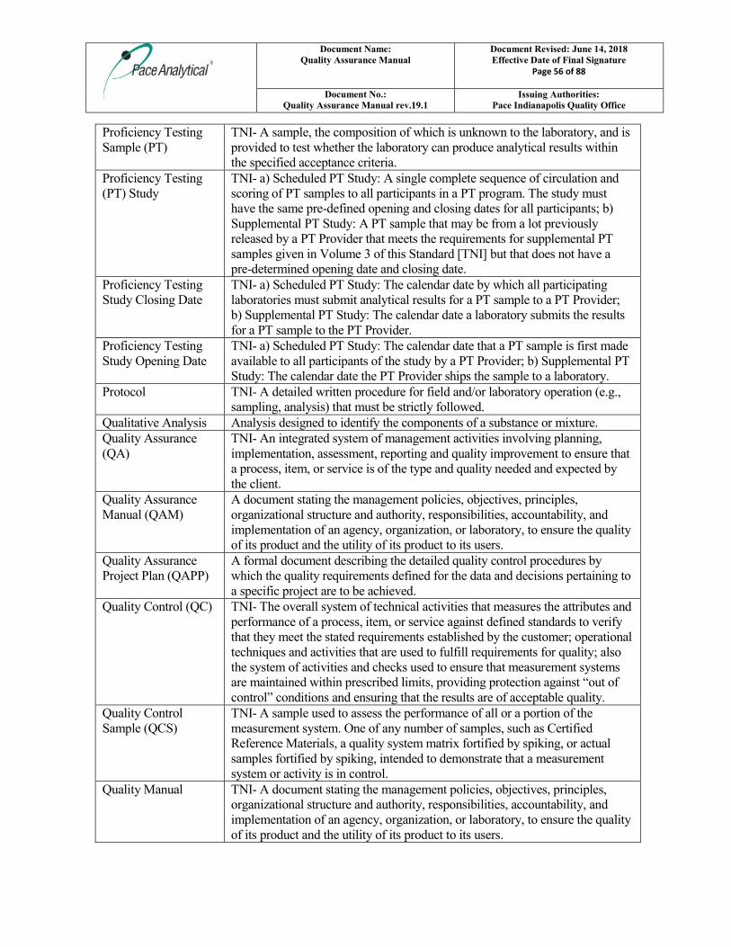
Document Name: Quality Assurance Manual
Document Revised: June 14, 2018 Effective Date of Final Signature
Page 56 of 88
Document No.: Quality Assurance Manual rev.19.1
Issuing Authorities: Pace Indianapolis Quality Office
Proficiency Testing Sample (PT)
TNI- A sample, the composition of which is unknown to the laboratory, and is provided to test whether the laboratory can produce analytical results within the specified acceptance criteria.
Proficiency Testing (PT) Study
TNI- a) Scheduled PT Study: A single complete sequence of circulation and scoring of PT samples to all participants in a PT program. The study must have the same pre-defined opening and closing dates for all participants; b) Supplemental PT Study: A PT sample that may be from a lot previously released by a PT Provider that meets the requirements for supplemental PT samples given in Volume 3 of this Standard [TNI] but that does not have a pre-determined opening date and closing date.
Proficiency Testing Study Closing Date
TNI- a) Scheduled PT Study: The calendar date by which all participating laboratories must submit analytical results for a PT sample to a PT Provider; b) Supplemental PT Study: The calendar date a laboratory submits the results for a PT sample to the PT Provider.
Proficiency Testing Study Opening Date
TNI- a) Scheduled PT Study: The calendar date that a PT sample is first made available to all participants of the study by a PT Provider; b) Supplemental PT Study: The calendar date the PT Provider ships the sample to a laboratory.
Protocol TNI- A detailed written procedure for field and/or laboratory operation (e.g., sampling, analysis) that must be strictly followed.
Qualitative Analysis Analysis designed to identify the components of a substance or mixture. Quality Assurance (QA)
TNI- An integrated system of management activities involving planning, implementation, assessment, reporting and quality improvement to ensure that a process, item, or service is of the type and quality needed and expected by the client.
Quality Assurance Manual (QAM)
A document stating the management policies, objectives, principles, organizational structure and authority, responsibilities, accountability, and implementation of an agency, organization, or laboratory, to ensure the quality of its product and the utility of its product to its users.
Quality Assurance Project Plan (QAPP)
A formal document describing the detailed quality control procedures by which the quality requirements defined for the data and decisions pertaining to a specific project are to be achieved.
Quality Control (QC) TNI- The overall system of technical activities that measures the attributes and performance of a process, item, or service against defined standards to verify that they meet the stated requirements established by the customer; operational techniques and activities that are used to fulfill requirements for quality; also the system of activities and checks used to ensure that measurement systems are maintained within prescribed limits, providing protection against “out of control” conditions and ensuring that the results are of acceptable quality.
Quality Control Sample (QCS)
TNI- A sample used to assess the performance of all or a portion of the measurement system. One of any number of samples, such as Certified Reference Materials, a quality system matrix fortified by spiking, or actual samples fortified by spiking, intended to demonstrate that a measurement system or activity is in control.
Quality Manual TNI- A document stating the management policies, objectives, principles, organizational structure and authority, responsibilities, accountability, and implementation of an agency, organization, or laboratory, to ensure the quality of its product and the utility of its product to its users.
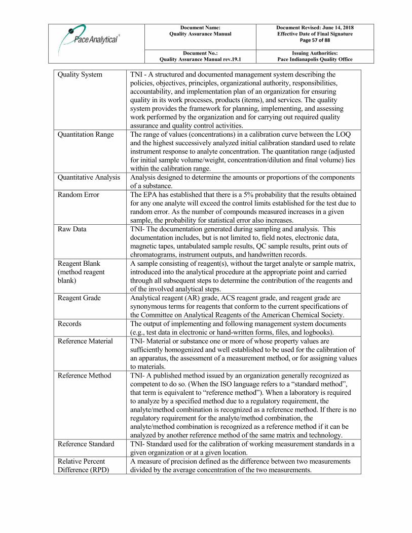
Document Name: Quality Assurance Manual
Document Revised: June 14, 2018 Effective Date of Final Signature
Page 57 of 88
Document No.: Quality Assurance Manual rev.19.1
Issuing Authorities: Pace Indianapolis Quality Office
Quality System TNI - A structured and documented management system describing the policies, objectives, principles, organizational authority, responsibilities, accountability, and implementation plan of an organization for ensuring quality in its work processes, products (items), and services. The quality system provides the framework for planning, implementing, and assessing work performed by the organization and for carrying out required quality assurance and quality control activities.
Quantitation Range The range of values (concentrations) in a calibration curve between the LOQ and the highest successively analyzed initial calibration standard used to relate instrument response to analyte concentration. The quantitation range (adjusted for initial sample volume/weight, concentration/dilution and final volume) lies within the calibration range.
Quantitative Analysis Analysis designed to determine the amounts or proportions of the components of a substance.
Random Error The EPA has established that there is a 5% probability that the results obtained for any one analyte will exceed the control limits established for the test due to random error. As the number of compounds measured increases in a given sample, the probability for statistical error also increases.
Raw Data TNI- The documentation generated during sampling and analysis. This documentation includes, but is not limited to, field notes, electronic data, magnetic tapes, untabulated sample results, QC sample results, print outs of chromatograms, instrument outputs, and handwritten records.
Reagent Blank (method reagent blank)
A sample consisting of reagent(s), without the target analyte or sample matrix, introduced into the analytical procedure at the appropriate point and carried through all subsequent steps to determine the contribution of the reagents and of the involved analytical steps.
Reagent Grade Analytical reagent (AR) grade, ACS reagent grade, and reagent grade are synonymous terms for reagents that conform to the current specifications of the Committee on Analytical Reagents of the American Chemical Society.
Records The output of implementing and following management system documents (e.g., test data in electronic or hand-written forms, files, and logbooks).
Reference Material TNI- Material or substance one or more of whose property values are sufficiently homogenized and well established to be used for the calibration of an apparatus, the assessment of a measurement method, or for assigning values to materials.
Reference Method TNI- A published method issued by an organization generally recognized as competent to do so. (When the ISO language refers to a “standard method”, that term is equivalent to “reference method”). When a laboratory is required to analyze by a specified method due to a regulatory requirement, the analyte/method combination is recognized as a reference method. If there is no regulatory requirement for the analyte/method combination, the analyte/method combination is recognized as a reference method if it can be analyzed by another reference method of the same matrix and technology.
Reference Standard TNI- Standard used for the calibration of working measurement standards in a given organization or at a given location.
Relative Percent Difference (RPD)
A measure of precision defined as the difference between two measurements divided by the average concentration of the two measurements.
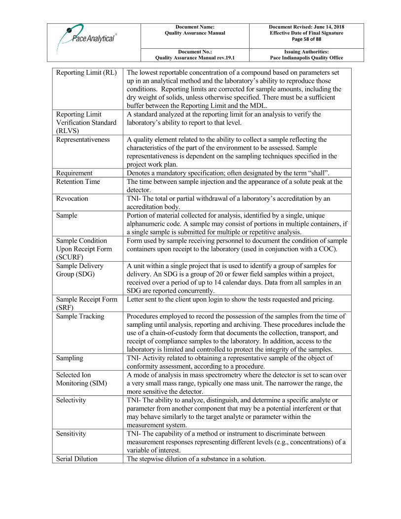
Document Name: Quality Assurance Manual
Document Revised: June 14, 2018 Effective Date of Final Signature
Page 58 of 88
Document No.: Quality Assurance Manual rev.19.1
Issuing Authorities: Pace Indianapolis Quality Office
Reporting Limit (RL) The lowest reportable concentration of a compound based on parameters set up in an analytical method and the laboratory’s ability to reproduce those conditions. Reporting limits are corrected for sample amounts, including the dry weight of solids, unless otherwise specified. There must be a sufficient buffer between the Reporting Limit and the MDL.
Reporting Limit Verification Standard (RLVS)
A standard analyzed at the reporting limit for an analysis to verify the laboratory’s ability to report to that level.
Representativeness A quality element related to the ability to collect a sample reflecting the characteristics of the part of the environment to be assessed. Sample representativeness is dependent on the sampling techniques specified in the project work plan.
Requirement Denotes a mandatory specification; often designated by the term “shall”. Retention Time The time between sample injection and the appearance of a solute peak at the
detector. Revocation TNI- The total or partial withdrawal of a laboratory’s accreditation by an
accreditation body. Sample Portion of material collected for analysis, identified by a single, unique
alphanumeric code. A sample may consist of portions in multiple containers, if a single sample is submitted for multiple or repetitive analysis.
Sample Condition Upon Receipt Form (SCURF)
Form used by sample receiving personnel to document the condition of sample containers upon receipt to the laboratory (used in conjunction with a COC).
Sample Delivery Group (SDG)
A unit within a single project that is used to identify a group of samples for delivery. An SDG is a group of 20 or fewer field samples within a project, received over a period of up to 14 calendar days. Data from all samples in an SDG are reported concurrently.
Sample Receipt Form (SRF)
Letter sent to the client upon login to show the tests requested and pricing.
Sample Tracking Procedures employed to record the possession of the samples from the time of sampling until analysis, reporting and archiving. These procedures include the use of a chain-of-custody form that documents the collection, transport, and receipt of compliance samples to the laboratory. In addition, access to the laboratory is limited and controlled to protect the integrity of the samples.
Sampling TNI- Activity related to obtaining a representative sample of the object of conformity assessment, according to a procedure.
Selected Ion Monitoring (SIM)
A mode of analysis in mass spectrometry where the detector is set to scan over a very small mass range, typically one mass unit. The narrower the range, the more sensitive the detector.
Selectivity TNI- The ability to analyze, distinguish, and determine a specific analyte or parameter from another component that may be a potential interferent or that may behave similarly to the target analyte or parameter within the measurement system.
Sensitivity TNI- The capability of a method or instrument to discriminate between measurement responses representing different levels (e.g., concentrations) of a variable of interest.
Serial Dilution The stepwise dilution of a substance in a solution.
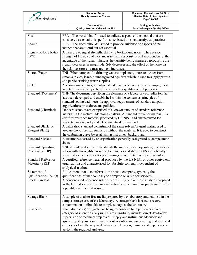
Document Name: Quality Assurance Manual
Document Revised: June 14, 2018 Effective Date of Final Signature
Page 59 of 88
Document No.: Quality Assurance Manual rev.19.1
Issuing Authorities: Pace Indianapolis Quality Office
Shall EPA – The word “shall” is used to indicate aspects of the method that are considered essential to its performance, based on sound analytical practices.
Should EPA – The word “should” is used to provide guidance on aspects of the method that are useful but not essential.
Signal-to-Noise Ratio (S/N)
A measure of signal strength relative to background noise. The average strength of the noise of most measurements is constant and independent of the magnitude of the signal. Thus, as the quantity being measured (producing the signal) decreases in magnitude, S/N decreases and the effect of the noise on the relative error of a measurement increases.
Source Water TNI- When sampled for drinking water compliance, untreated water from streams, rivers, lakes, or underground aquifers, which is used to supply private and public drinking water supplies.
Spike A known mass of target analyte added to a blank sample or sub-sample; used to determine recovery efficiency or for other quality control purposes.
Standard (Document) TNI- The document describing the elements of a laboratory accreditation that has been developed and established within the consensus principles of standard setting and meets the approval requirements of standard adoption organizations procedures and policies.
Standard (Chemical) Standard samples are comprised of a known amount of standard reference material in the matrix undergoing analysis. A standard reference material is a certified reference material produced by US NIST and characterized for absolute content, independent of analytical test method.
Standard Blank (or Reagent Blank)
A calibration standard consisting of the same solvent/reagent matrix used to prepare the calibration standards without the analytes. It is used to construct the calibration curve by establishing instrument background.
Standard Method A test method issued by an organization generally recognized as competent to do so.
Standard Operating Procedure (SOP)
TNI- A written document that details the method for an operation, analysis, or action with thoroughly prescribed techniques and steps. SOPs are officially approved as the methods for performing certain routine or repetitive tasks.
Standard Reference Material (SRM)
A certified reference material produced by the US NIST or other equivalent organization and characterized for absolute content, independent of analytical method.
Statement of Qualifications (SOQ)
A document that lists information about a company, typically the qualifications of that company to compete on a bid for services.
Stock Standard A concentrated reference solution containing one or more analytes prepared in the laboratory using an assayed reference compound or purchased from a reputable commercial source.
Storage Blank A sample of analyte-free media prepared by the laboratory and retained in the sample storage area of the laboratory. A storage blank is used to record contamination attributable to sample storage at the laboratory.
Supervisor The individual(s) designated as being responsible for a particular area or category of scientific analysis. This responsibility includes direct day-to-day supervision of technical employees, supply and instrument adequacy and upkeep, quality assurance/quality control duties and ascertaining that technical employees have the required balance of education, training and experience to perform the required analyses.
Document Name: Quality Assurance Manual
Document Revised: June 14, 2018 Effective Date of Final Signature
Page 60 of 88
Document No.: Quality Assurance Manual rev.19.1
Issuing Authorities: Pace Indianapolis Quality Office
Surrogate A substance with properties that mimic the analyte of interest. It is unlikely to be found in environmental samples and is added to them for quality control purposes.
Suspension TNI- The temporary removal of a laboratory’s accreditation for a defined period of time, which shall not exceed 6 months or the period of accreditation, whichever is longer, in order to allow the laboratory time to correct deficiencies or area of non-conformance with the Standard.
Systems Audit An on-site inspection or assessment of a laboratory’s quality system. Target Analytes Analytes or chemicals of primary concern identified by the customer on a
project-specific basis. Technical Director Individual(s) who has overall responsibility for the technical operation of the
environmental testing laboratory. Technology TNI- A specific arrangement of analytical instruments, detection systems,
and/or preparation techniques. Test A technical operation that consists of the determination of one or more
characteristics or performance of a given product, material, equipment, organism, physical phenomenon, process or service according to a specified procedure. The result of a test is normally recorded in a document sometimes called a test report or a test certificate.
Test Method A definitive procedure that determines one or more characteristics of a given substance or product.
Test Methods for Evaluating Solid Waste, Physical/ Chemical (SW-846)
EPA Waste’s official compendium of analytical and sampling methods that have been evaluated and approved for use in complying with RCRA regulations.
Test Source TNI- A radioactive source that is tested, such as a sample, calibration standard, or performance check source. A Test Source may also be free of radioactivity, such as a Test Source counted to determine the subtraction background, or a short-term background check.
The NELAC Institute (TNI)
A non-profit organization whose mission is to foster the generation of environmental data of known and documented quality through an open, inclusive, and transparent process that is responsive to the needs of the community. Previously known as NELAC (National Environmental Laboratory Accreditation Conference).
Total Petroleum Hydrocarbons (TPH)
A term used to denote a large family of several hundred chemical compounds that originate from crude oil. Compounds may include gasoline components, jet fuel, volatile organics, etc.
Toxicity Characteristic Leaching Procedure (TCLP)
A solid sample extraction method for chemical analysis employed as an analytical method to simulate leaching of compounds through a landfill.
Traceability TNI- The ability to trace the history, application, or location of an entity by means of recorded identifications. In a calibration sense, traceability relates measuring equipment to national or international standards, primary standards, basic physical conditions or properties, or reference materials. In a data collection sense, it relates calculations and data generated throughout the project back to the requirements for the quality of the project.
Document Name: Quality Assurance Manual
Document Revised: June 14, 2018 Effective Date of Final Signature
Page 61 of 88
Document No.: Quality Assurance Manual rev.19.1
Issuing Authorities: Pace Indianapolis Quality Office
Training Document A training resource that provides detailed instructions to execute a specific method or job function.
Trip Blank This blank sample is used to detect sample contamination from the container and preservative during transport and storage of the sample. A cleaned sample container is filled with laboratory reagent water and the blank is stored, shipped, and analyzed with its associated samples.
Tuning A check and/or adjustment of instrument performance for mass spectrometry as required by the method.
Ultraviolet Spectrophotometer (UV)
Instrument routinely used in quantitative determination of solutions of transition metal ions and highly conjugated organic compounds.
Uncertainty, Counting TNI- The component of Measurement Uncertainty attributable to the random nature of radioactive decay and radiation counting (often estimated as the square root of observed counts (MARLAP). Older references sometimes refer to this parameter as Error, Counting Error or Count Error (c.f., Total Uncertainty).
Uncertainty, Expanded
TNI- The product of the Standard Uncertainty and a coverage factor, k, which is chosen to produce an interval about the result that has a high probability of containing the value of the measurand (c.f., Standard Uncertainty). NOTE: Radiochemical results are generally reported in association with the Total Uncertainty. Either if these estimates of uncertainty can be reported as the Standard Uncertainty (one-sigma) or as an Expanded Uncertainty (k-sigma, where k > 1).
Uncertainty, Measurement
TNI- Parameter associated with the result of a measurement that characterizes the dispersion of the values that could reasonably be attributed to the measurand.
Uncertainty, Standard TNI- An estimate of the Measurement Uncertainty expressed as a standard deviation (c.f., Expanded Uncertainty).
Uncertainty, Total TNI- An estimate of the Measurement Uncertainty that accounts for contributions from all significant sources of uncertainty associated with the analytical preparation and measurement of a sample. Such estimates are also commonly referred to as Combined Standard Uncertainty or Total Propagated Uncertainty, and in some older references as the Total Propagated Error, among other similar items (c.f., Counting Uncertainty).
Unethical actions Deliberate falsification of analytical or quality control results where failed method or contractual requirements are made to appear acceptable.
United States Department of Agriculture (USDA)
A department of the federal government that provides leadership on food, agriculture, natural resources, rural development, nutrition and related issues based on public policy, the best available science, and effective management.
United States Geological Survey (USGS)
Program of the federal government that develops new methods and tools to supply timely, relevant, and useful information about the Earth and its processes.
Unregulated Contaminant Monitoring Rule (UCMR)
EPA program to monitor unregulated contaminants in drinking water.
Validation The confirmation by examination and provision of objective evidence that the particular requirements for a specific intended use are fulfilled.
Document Name: Quality Assurance Manual
Document Revised: June 14, 2018 Effective Date of Final Signature
Page 62 of 88
Document No.: Quality Assurance Manual rev.19.1
Issuing Authorities: Pace Indianapolis Quality Office
Verification TNI- Confirmation by examination and objective evidence that specified requirements have been met. In connection with the management of measuring equipment, verification provides a means for checking that the deviations between values indicated by a measuring instrument and corresponding known values of a measured quantity are consistently smaller than the maximum allowable error defined in a standard, regulation or specification peculiar to the management of the measuring equipment.
Voluntary Action Program (VAP)
A program of the Ohio EPA that gives individuals a way to investigate possible environmental contamination, clean it up if necessary and receive a promise from the State of Ohio that no more cleanup is needed.
Whole Effluent Toxicity (WET)
The aggregate toxic effect to aquatic organisms from all pollutants contained in a facility’s wastewater (effluent).
Document Name: Quality Assurance Manual
Document Revised: June 14, 2018 Effective Date of Final Signature
Page 63 of 88
Document No.: Quality Assurance Manual rev.19.1
Issuing Authorities: Pace Indianapolis Quality Office
10.0. REFERENCES
10.1. “Guidelines Establishing Test Procedures for the Analysis of Pollutants Under the Clean Water Act.” Federal Register, 40 CFR Part 136, most current version.
10.2. “Test Methods for Evaluating Solid Wastes: Physical/Chemical Methods.” SW-846.
10.3. “Methods for Chemical Analysis of Water and Wastes”, EPA 600-4-79-020, 1979 Revised 1983, U.S. EPA.
10.4. U.S. EPA Contract Laboratory Program Statement of Work for Organic Analysis.
10.5. U.S. EPA Contract Laboratory Program Statement of Work for Inorganic Analysis.
10.6. “Standard Methods for the Examination of Water and Wastewater.” Current Edition APHA-AWWA-WPCF.
10.7. “Annual Book of ASTM Standards”, Section 4: Construction, Volume 04.04: Soil and Rock; Building Stones, American Society of Testing and Materials.
10.8. “Annual Book of ASTM Standards”, Section 11: Water and Environmental Technology, American Society of Testing and Materials.
10.9. “NIOSH Manual of Analytical Methods”, U.S. Department of Health and Human Services, National Institute for Occupational Safety and Health, most current version.
10.10. “Methods for the Determination of Organic Compounds in Finished Drinking Water and Raw Source Water”, U.S. EPA, Environmental Monitoring and Support Laboratory – Cincinnati (Sep 1986).
10.11. Quality Assurance of Chemical Measurements, Taylor, John K.; Lewis Publishers, Inc. 1987.
10.12. Methods for Non-conventional Pesticides Chemicals Analysis of Industrial and Municipal Wastewater, Test Methods, EPA-440/1-83/079C.
10.13. Environmental Measurements Laboratory (EML) Procedures Manual, HASL-300, US DOE, February, 1992.
10.14. Requirements for Quality Control of Analytical Data, HAZWRAP, DOE/HWP-65/R1, July, 1990.
10.15. Requirements for Quality Control of Analytical Data for the Environmental Restoration Program, Martin Marietta, ES/ER/TM-16, December, 1992.
10.16. Quality Assurance Manual for Industrial Hygiene Chemistry, AIHA, most current version.
10.17. National Environmental Laboratory Accreditation Conference (NELAC) Standard- most current version.
10.18. ISO/IEC 17025, General requirements for the competence of testing and calibration laboratories- most current version.
10.19. Department of Defense Quality Systems Manual (QSM), most current version.
10.20. TNI (The NELAC Institute) Standard- 2003 and 2009.
10.21. UCMR Laboratory Approval Requirements and Information Document, most current version.
10.22. US EPA Drinking Water Manual, most current version.
Document Name: Quality Assurance Manual
Document Revised: June 14, 2018 Effective Date of Final Signature
Page 64 of 88
Document No.: Quality Assurance Manual rev.19.1
Issuing Authorities: Pace Indianapolis Quality Office
11.0. REVISIONS The Pace Corporate Environmental Quality Office files an electronic version of a Microsoft Word document with tracked changes detailing all revisions made to previous versions of the Quality Assurance Manual. This document is available upon request. All current revisions are summarized in the table below. Document Number
Reason for Change Date
Quality Assurance Manual 19.0
General: made administrative edits that do not affect the policies or procedures within the document (including revising company name to Pace Analytical Services, LLC). Cover page: removed corporate approval signature lines and revised document control format. Table of Contents: added Attachment VII – Pace COC Old Section 3: moved to other sections of the QAM as applicable and deleted entire section (All section references below reflect the new section numbers). Section 1.1.2: replaced with section 3.1.1. Sections 1.3, 1.4, 1.11: removed extraneous language. Sections 1.5: added language from old section 1.6. Section 1.6: revised anonymous reporting information. Section 1.8: removed job descriptions for non-applicable personnel. Section 1.8.4: added tasks to QM job description. Section 1.8.8: added tasks to PM job description. Section 1.11.1: added keyless entry using key fobs detail. Section 2: rearranged existing sections. Section 2.4: reworded to match existing Sample Acceptance policy document. Section 2.6.3.2: added some detail regarding temperature monitoring corrective action. Section 2.6.5.1: added by-products of USDA soils. Section 3.2.2: added basic evaluation criteria. Section 3.4.3: added MS and Dup as optional alternative to MS/MSD. Section 3.5.2: added basic evaluation criteria. Section 3.9.1: added that RL may be based on calibration standard. Section 3.14: added new instrumentation as requiring validation. Section 4: in general, for each QC type, removed language regarding frequency and corrective actions and referenced lab-specific SOPs. Section 5: in general, removed extraneous language and Management of Change section. Section 5.1, 5.2: reorganized into Primary and Secondary Review sections and removed extraneous language. Section 5.3.2: specified types of support equipment to be monitored daily. Section 5.3.3.1: specified “working” weights. Section 5.3.4.2: added temperature sensors and added alternatives to annual in-house verification. Section 5.3.5: added pH electrode inspection/maintenance. Section 6: removed extraneous language including Quarterly Report section. Section 8.2.3.1: added “or designee”. Section 9 (glossary): revised and added definitions based on 2016 TNI Standard. Added “may, must, shall and should” based on SW-846 definition. Section 10: Added EPA DW Manual and revised references as applicable. Attachment III: updated corporate organizational chart. Old Attachment IV: removed floor plan attachment. Old Attachment VII: removed COC (available in SOPs). Indy added back in.
22Mar2017
Document Name: Quality Assurance Manual
Document Revised: June 14, 2018 Effective Date of Final Signature
Page 65 of 88
Document No.: Quality Assurance Manual rev.19.1
Issuing Authorities: Pace Indianapolis Quality Office
Document Number
Reason for Change Date
Quality Assurance Manual 19.1
Throughout the document, references to SOP numbers were removed leaving only SOP titles. Section 1.8.9: added for Project Coordinator position. Section 2.4.3: changed “drinking water” to “drinking water compliance” for clarity. Section 2.6.4.1: clarified hazardous sample labeling. Section 3.8.1: updated the 40 CFR Part 136 reference. Section 3.12.1: removed language that limits the use of 3 sig figs. Section 5.1.6: added section to generally cover handling, storage, and transport of reference standards and reference materials. Section 5.2: removed details and added reference to Calibration Procedures SOP. Section 5.3.4: updated to reflect quarterly digital/mechanical thermometer calibration. Section 5.5: added section to generally cover handling, storage, maintenance and transport of measurement equipment. Section 6.3.1: clarified data review anomalies will be qualified or narrated. Section 6.3.2.1: updated to include the actual name of the final report. Section 8.2.2.1: added “calculation error” as a possible type of non-conformance. Glossary: updated definition of Deuterated Monitoring Compounds, removed DoD references, and updated the definition of Reporting Limit (RL). Attachment II: updated Attachment III: updated Attachment VI: updated Attachment V: updated Attachment VI: updated
14Jun2018
Document Name: Quality Assurance Manual
Document Revised: June 14, 2018 Effective Date of Final Signature
Page 66 of 88
Document No.: Quality Assurance Manual rev.19.1
Issuing Authorities: Pace Indianapolis Quality Office
ATTACHMENT I- QUALITY CONTROL CALCULATIONS PERCENT RECOVERY (%REC)
100*)(
%TrueValue
SampleConcMSConcREC
NOTE: The SampleConc is zero (0) for the LCS and Surrogate Calculations PERCENT DIFFERENCE (%D)
100*%TrueValue
TrueValuelueMeasuredVaD
where: TrueValue = Amount spiked (can also be the CF or RF of the ICAL Standards) Measured Value = Amount measured (can also be the CF or RF of the CCV)
PERCENT DRIFT
100*%ionlConcentrtTheoretica
tionlConcentraTheoreticaionConcentratCalculatedDrift
RELATIVE PERCENT DIFFERENCE (RPD)
100*2/)21(
|)21(|
RR
RRRPD
where: R1 = Result Sample 1 R2 = Result Sample 2
CORRELATION COEFFICIENT (R)
CorrCoeff =
With: N Number of standard samples involved in the calibration i Index for standard samples Wi Weight factor of the standard sample no. i Xi X-value of the standard sample no. i X(bar) Average value of all x-values Yi Y-value of the standard sample no. i Y(bar) Average value of all y-values
N
iiii YYXXW
1
)(*)(*
N
iii
N
iii YYWXXW
1
2
1
2 )(**)(*
Document Name: Quality Assurance Manual
Document Revised: June 14, 2018 Effective Date of Final Signature
Page 67 of 88
Document No.: Quality Assurance Manual rev.19.1
Issuing Authorities: Pace Indianapolis Quality Office
ATTACHMENT I- QUALITY CONTROL CALCULATIONS (CONTINUED)
STANDARD DEVIATION (S)
n
i
i
n
XXS
1
2
)1(
)(
where: n = number of data points Xi = individual data point X = average of all data points
AVERAGE (X)
n
X
X
i
ni
1
where: n = number of data points Xi = individual data point
RELATIVE STANDARD DEVIATION (RSD)
100*X
SRSD
where: S = Standard Deviation of the data points X = average of all data points
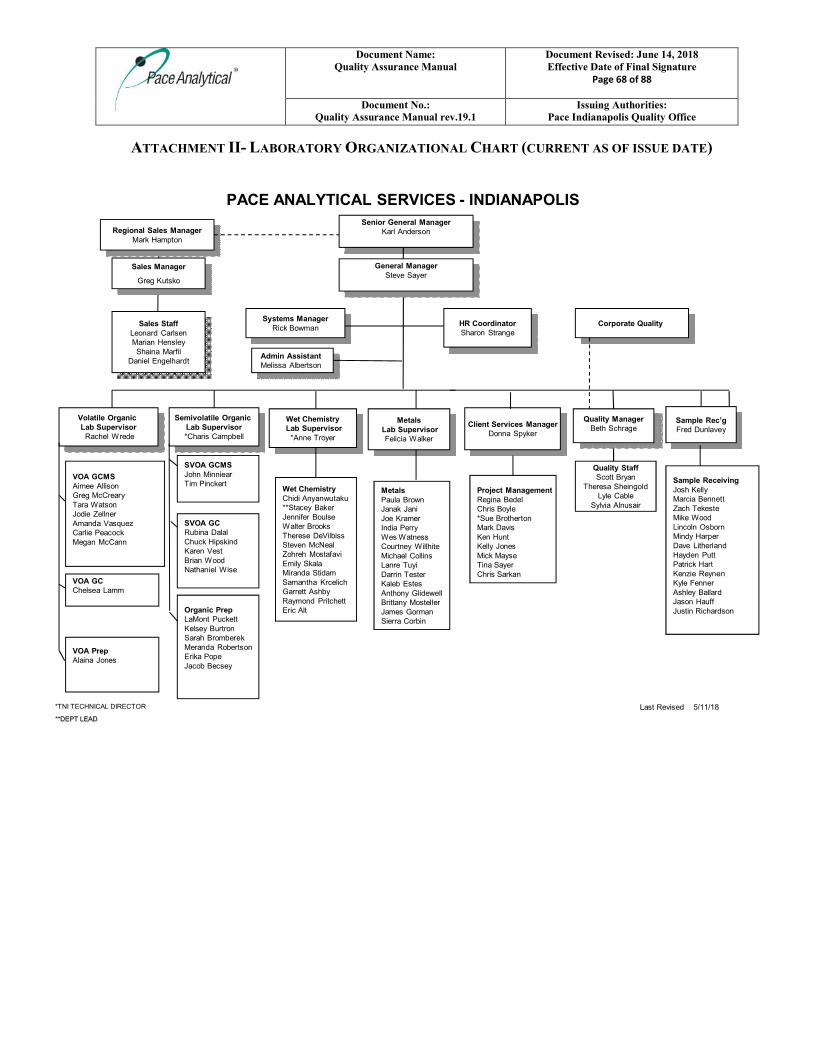
Document Name: Quality Assurance Manual
Document Revised: June 14, 2018 Effective Date of Final Signature
Page 68 of 88
Document No.: Quality Assurance Manual rev.19.1
Issuing Authorities: Pace Indianapolis Quality Office
ATTACHMENT II- LABORATORY ORGANIZATIONAL CHART (CURRENT AS OF ISSUE DATE)
PACE ANALYTICAL SERVICES - INDIANAPOLIS
Last Revised 5/11/18
Systems ManagerRick Bowman
Sales StaffLeonard CarlsenMarian Hensley
Shaina MarfilDaniel Engelhardt
Admin AssistantMelissa Albertson
Volatile Organic Lab Supervisor
Rachel Wrede
MetalsPaula BrownJanak JaniJoe KramerIndia PerryWes WatnessCourtney WillhiteMichael CollinsLanre TuyiDarrin TesterKaleb EstesAnthony GlidewellBrittany MostellerJames GormanSierra Corbin
Regional Sales ManagerMark Hampton
Wet ChemistryLab Supervisor
*Anne Troyer
SVOA GCRubina DalalChuck HipskindKaren VestBrian WoodNathaniel Wise
SVOA GCMSJohn MinniearTim Pinckert
Semivolatile Organic Lab Supervisor*Charis Campbell
VOA GCChelsea Lamm
VOA GCMSAimee AllisonGreg McCrearyTara WatsonJodie ZellnerAmanda VasquezCarlie PeacockMegan McCann
Project ManagementRegina BedelChris Boyle*Sue BrothertonMark DavisKen HuntKelly JonesMick MayseTina SayerChris Sarkan
Organic PrepLaMont PuckettKelsey BurtronSarah BromberekMeranda RobertsonErika PopeJacob Becsey
Senior General ManagerKarl Anderson
Wet ChemistryChidi Anyanwutaku**Stacey BakerJennifer BoulseWalter BrooksTherese DeVilbissSteven McNealZohreh MostafaviEmily SkalaMiranda StidamSamantha KrcelichGarrett AshbyRaymond PritchettEric Alt
Client Services ManagerDonna Spyker
HR CoordinatorSharon Strange
Sample ReceivingJosh KellyMarcia BennettZach TekesteMike WoodLincoln OsbornMindy HarperDave LitherlandHayden PuttPatrick HartKenzie ReynenKyle FennerAshley BallardJason HauffJustin Richardson
Corporate Quality
Quality StaffScott Bryan
Theresa SheingoldLyle Cable
Sylvia Alnusair
*TNI TECHNICAL DIRECTOR
**DEPT LEAD
Sales Manager
Greg Kutsko
General ManagerSteve Sayer
Quality ManagerBeth Schrage
Sample Rec’gFred Dunlavey
VOA PrepAlaina Jones
MetalsLab SupervisorFelicia Walker
Document Name: Quality Assurance Manual
Document Revised: June 14, 2018 Effective Date of Final Signature
Page 69 of 88
Document No.: Quality Assurance Manual rev.19.1
Issuing Authorities: Pace Indianapolis Quality Office
ATTACHMENT III- CORPORATE ORGANIZATIONAL CHART (CURRENT AS OF ISSUE DATE)
Document Name: Quality Assurance Manual
Document Revised: June 14, 2018 Effective Date of Final Signature
Page 70 of 88
Document No.: Quality Assurance Manual rev.19.1
Issuing Authorities: Pace Indianapolis Quality Office
ATTACHMENT IV- EQUIPMENT LIST (CURRENT AS OF ISSUE DATE)
INSTRUMENT MANUFACTURER
MODEL
NUMBER DETECTOR AUTOSAMPLER SERVICE ANALYSIS YEAR GC/MS Agilent 6890 MS 5973 Centurion W/S 8260/624 VOC 2003GC/MS Agilent 6890 MS 5973 Centurion 8260/624/524.2 VOC 2007GC/MS Agilent 6890 MS 5973 Centurion W/S 8260/624 VOC 2003GC/MS Agilent 6850N MS 5975 Centurion 8260/624/524.2 VOC 2007GC/MS Agilent 6890 MS 5973 Centurion W/S 8260/624 VOC 2004GC/MS Agilent 6850N MS 5975 Centurion 8260/624 VOC 2010GC/MS Agilent 6890 MS 5973 OI 8260/624/524.2 VOC 2007GC/MS Agilent 7890 MS 5975C Archon 8260 2008GC/MS Agilent 6890 MS 5975 OI 8260/624/524.2 VOC 2007GC/MS Agilent 6890 5975 Centurion 8260/624 VOC 2008GC/MS Hewlett-Packard 6890 MS 5973 7683 8270 PAH SIM 2000
GC/MS (2) Agilent 7890 MS 5975 7683 8270/625 BNA 2008GC/MS (2) Agilent 6890 MS 5975 7683 8270 PAH SIM 2009GC/MS (3) Agilent 6890 MS 5973 7683 8270/625 BNA 2008
GC/MS Agilent 7890 MS 5975 7683 8270 PAH SIM 2009GC/MS (2) Hewlett-Packard 5890 MS 5971 7673 Solvent Screen 2007
GC/MS Agilent 7890B MS 5977 7693 8270/PAH SIM 2017GC/MS Agilent 7890B MS 5977 7693 8270/PAH SIM 2018
Gas Chromatograph Agilent 6890 FID 7683 8015 Alcohols 2006Gas Chromatograph Hewlett-Packard 6890 FID 6890 8015 Glycols 2008Gas Chromatograph Agilent 7890A FID 7693 8015 DRO/ERO 2009Gas Chromatograph Agilent 7890A Dual ECD 7693 8082/608 PCBs/8011 EDB/DBCP 2009/2013Gas Chromatograph Hewlett-Packard 5890 FID 6890 Benzene 2006Gas Chromatograph Hewlett-Packard 5890 FID 8100 8015 GRO 2011Gas Chromatograph Hewlett-Packard 5890 FID EST LGX50 RSK175 Dissolved gases 2006Gas Chromatograph Agilent 6890N FID 8100 8015 GRO 2008Gas Chromatograph Agilent 6890 Dual NPD 7683 Pesticides 2008
Gas Chromatograph (2) Agilent 6890 Dual ECD 7683 PCBs 2008Gas Chromatograph Hewlett-Packard 6890 Dual ECD 7683 Herbicides 2008Gas Chromatograph Agilent 7890 Dual ECD 7693 Pesticides 2010
Microwave Extractors (2) CEM 230/60 n/a n/a soil extraction 2008/2011Spe-Dex Horizon 4790 n/a n/a 1664A Oil & Grease 2008
Trace ICP (2) Thermo Scientific ICAP 6500 n/a ASX520 6010/200.7 Metals 2008/2011Trace ICP Thermo Scientific ICAP 6500 n/a ESI SC-4 FAST 6010/200.7 Metals 2011ICP/MS Agilent 7700 n/a ASX520 6020/200.8 Metals 2012ICP/MS Agilent 7800 n/a ASX520 6020/200.8 Metals 2018
Mercury Analyzer CETAC M-6100 n/a ASX520 7470/7471/245 Mercury 2012/2010Mercury Analyzer Teledyne Leeman M-7600 n/a ASX520 7470/7471/245 Mercury 2016
Low-Level Mercury Analyzer CETAC M-8000 n/a ASX520 Low-Level Mercury 2015Auto Analyzer (2) Lachat Quick Chem n/a n/a NO3,Cl,Phenol, NH3,TKN 2010/2012
Titrosampler Metrohm 855 n/a n/a Alkalinity, Acidity 2014Automated Flash Point Tanaka APM-8 n/a n/a flash point 2010
Spectrophotometer Spec 20 Labtronics n/a n/a Sulfide 2002Spectrophotometer Hach DR5000 n/a n/a Sulfate,Cr6+,Fe2+, PO4 2007Spectrophotometer Thermo AquaMatePlus n/a n/a Surfactants, COD 2005
Turbidimeter Hach 2100P n/a n/a Turbidity 2006pH/ISE Meter (2) Accumet AR25/XL25 n/a n/a pH, Fluoride, Redox 2003/2010
pH/ISE Meter Thermo Orion Star A214 n/a n/a pH, Fluoride, Redox 2013Conductivity Meter Oakton CON 700 n/a n/a Conductivity 2016
Dissolved Oxygen/pH Meter Hach HQ440d n/a n/a BOD, cBOD 2014BOD Analyzer Thermo AutoEz n/a n/a BOD, cBOD 2013TOC Analyzer Shimadzu TOC-Vwp n/a n/a TOC, DOC 2008
TOC Analyzer Teledyne Phoenix 8000 n/a n/a TOC, DOC 2005
Discrete Analyzer Smart Chem 200 n/a n/a Cyanide, Phosphorus 2006
Ion Chromatogram Dionex IC3000 n/a AS-1 Cl-, F-, SO4-, Br-, NO3/NO2 2008
Ion Chromatogram Dionex ICS2100 n/a AS-AP Cl-, F-, SO4-, Br-, NO3/NO2 2013
Pace Indianapolis Equipment/Instrumentation List
Document Name: Quality Assurance Manual
Document Revised: June 14, 2018 Effective Date of Final Signature
Page 71 of 88
Document No.: Quality Assurance Manual rev.19.1
Issuing Authorities: Pace Indianapolis Quality Office
ATTACHMENT V- LABORATORY FLOOR PLAN (CURRENT AS OF ISSUE DATE)
Cooler
Cooler
VOA
Organic ExtWaste Ship/Receiving Ship/Receiving
Drop Off
TCLP
SVOA SVOA-MS Wet Chem Lab MetalsBOD Project Management
Residue
LL HgConference RoomBreak Room
Break Room
Wet Chem AnalysisRestRooms
Offices
RestRooms
= Eyewash/Drench Hose Available
= ABC Extinguisher Location= Shower/Eyewash Combo
= First Aid Station
OfficesSVOA
Main Entrance
Employee Entrance
Employee Entrance
= Automated External defibrillator
Fire Evacuation Meeting Place(Front Parking lot. Greenway by road between main
entrance and south entrance)
Pace Indianapolis, IN7726 Moller Rd-46268
= Your Location
= Spill Kits
Front of Building (East)
Effective: 3/26/18
Rest Rooms
= Severe Weather Shelters
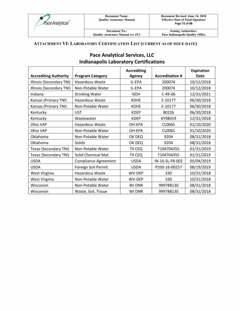
Document Name: Quality Assurance Manual
Document Revised: June 14, 2018 Effective Date of Final Signature
Page 72 of 88
Document No.: Quality Assurance Manual rev.19.1
Issuing Authorities: Pace Indianapolis Quality Office
ATTACHMENT VI- LABORATORY CERTIFICATION LIST (CURRENT AS OF ISSUE DATE)
Pace Analytical Services, LLC Indianapolis Laboratory Certifications
Accrediting Authority Program Category Accrediting
Agency Accreditation # Expiration
Date
Illinois (Secondary TNI) Hazardous Waste IL-EPA 200074 10/12/2018
Illinois (Secondary TNI) Non-Potable Water IL-EPA 200074 10/12/2018
Indiana Drinking Water ISDH C-49-06 12/31/2021
Kansas (Primary TNI) Hazardous Waste KDHE E-10177 06/30/2018
Kansas (Primary TNI) Non-Potable Water KDHE E-10177 06/30/2018
Kentucky UST KDEP 80226 06/30/2018
Kentucky Wastewater KDEP KY98019 12/31/2018
Ohio VAP Hazardous Waste OH-EPA CL0065 01/10/2020
Ohio VAP Non-Potable Water OH-EPA CL0065 01/10/2020
Oklahoma Non-Potable Water OK DEQ 9204 08/31/2018
Oklahoma Solids OK DEQ 9204 08/31/2018
Texas (Secondary TNI) Non-Potable Water TX CEQ T104704355 01/31/2019
Texas (Secondary TNI) Solid Chemical Mat. TX CEQ T104704355 01/31/2019
USDA Compliance Agreement USDA IN-16-SL-FR-002 05/04/2019
USDA Foreign Soil Permit USDA P330-16-00257 08/19/2019
West Virginia Hazardous Waste WV-DEP 330 10/31/2018
West Virginia Non-Potable Water WV-DEP 330 10/31/2018
Wisconsin Non-Potable Water WI DNR 999788130 08/31/2018
Wisconsin Waste, Soil, Tissue WI DNR 999788130 08/31/2018
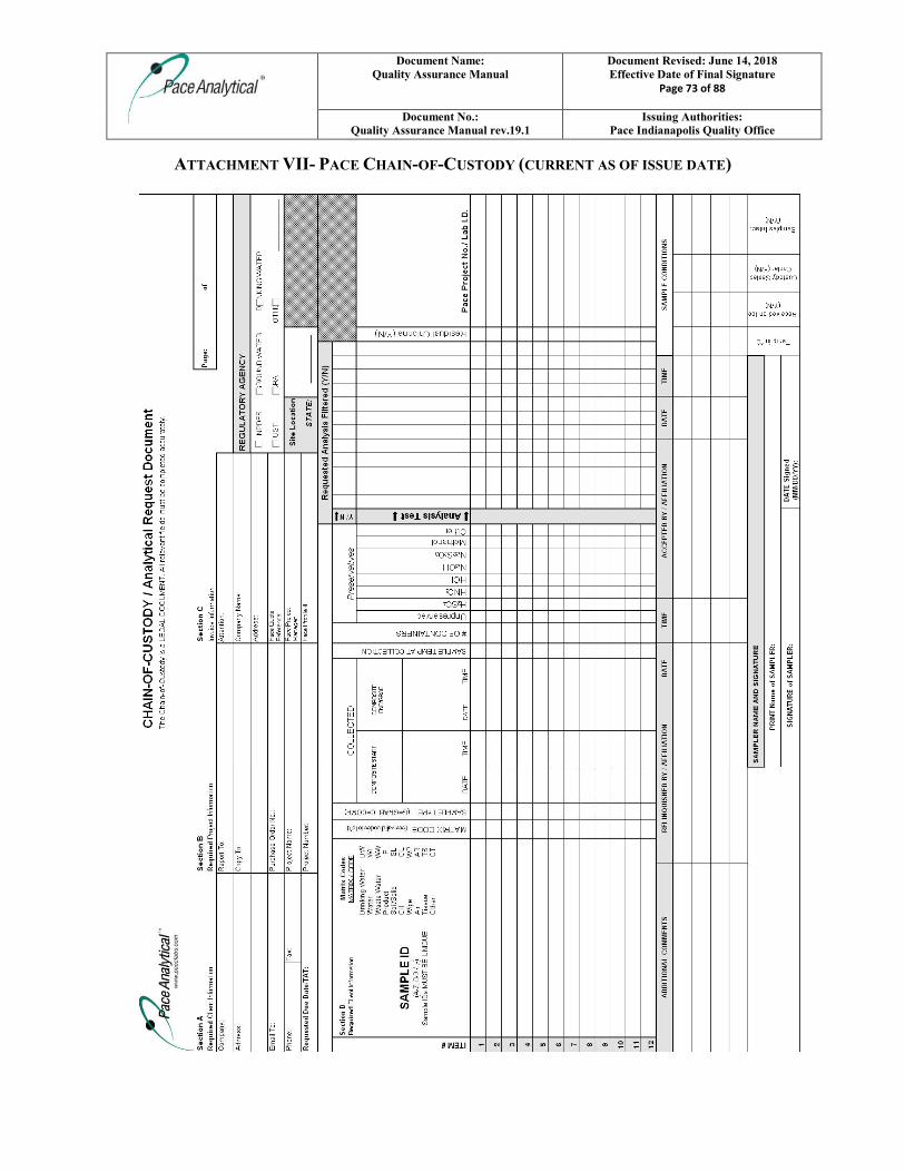
Document Name: Quality Assurance Manual
Document Revised: June 14, 2018 Effective Date of Final Signature
Page 73 of 88
Document No.: Quality Assurance Manual rev.19.1
Issuing Authorities: Pace Indianapolis Quality Office
ATTACHMENT VII- PACE CHAIN-OF-CUSTODY (CURRENT AS OF ISSUE DATE)
Document Name: Quality Assurance Manual
Document Revised: June 14, 2018 Effective Date of Final Signature
Page 74 of 88
Document No.: Quality Assurance Manual rev.19.1
Issuing Authorities: Pace Indianapolis Quality Office
ATTACHMENT VIII- METHOD HOLD TIME, CONTAINER AND PRESERVATION GUIDE
(CURRENT AS OF ISSUE DATE)
THE HOLDING TIME INDICATED IN THE CHART BELOW IS THE MAXIMUM ALLOWABLE TIME
FROM COLLECTION TO EXTRACTION AND/OR ANALYSIS PER THE ANALYTICAL METHOD. FOR
METHODS THAT REQUIRE PROCESSING PRIOR TO ANALYSIS, THE HOLDING TIME IS
DESIGNATED AS ‘PREPARATION HOLDING TIME/ANALYSIS HOLDING TIME’.
Parameter Method Matrix Container Preservative Max Hold
Time
Acid Base Accounting Sobek Solid Plastic/Glass None N/A Acidity SM2310B Water Plastic/Glass ≤ 6oC 14 Days Acid Volatile Sulfide Draft EPA 1629 Solid 8oz Glass < 6oC 14 Days Actinides HASL-300 Water Plastic/Glass pH<2 HNO3 180 Days Actinides HASL-300 Solid Plastic/Glass None 180 Days
Alkalinity SM2320B/310.2 Water
Plastic/Glass (NY requires separate bottle filled to the exclusion of air) < 6oC 14 Days
Alkylated PAHs Water 1L Amber Glass
< 6oC; pH<2 1:1 HCl (optional)
14/40 Days preserved; 7/40 Days unpreserved
Alkylated PAHs Solid 8oz Glass < 10oC 1 Year/40 Days
Anions (Br, Cl, F, NO2, NO3, o-Phos, SO4 , bromate, chlorite, chlorate)
300.0/300.1/SM4110B Water Plastic/Glass
< 6oC; EDA if bromate or chlorite run
All analytes 28 days except: NO2, NO3, o-Phos (48 Hours); chlorite (immediately for 300.0; 14 Days for 300.1). NO2/NO3 combo 28 days.
Anions (Br, Cl, F, NO2, NO3, o-Phos, SO4 , bromate, chlorite, chlorate) 300.0 Solid Plastic/Glass < 6oC
All analytes 28 days except: NO2, NO3, o-Phos (48 hours); chlorite (immediately). NO2/NO3 combo 28 days.
Document Name: Quality Assurance Manual
Document Revised: June 14, 2018 Effective Date of Final Signature
Page 75 of 88
Document No.: Quality Assurance Manual rev.19.1
Issuing Authorities: Pace Indianapolis Quality Office
Parameter Method Matrix Container Preservative Max Hold
Time
Anions (Br, Cl, F, NO2, NO3, o-Phos, SO4 9056
Water/ Solid Plastic/Glass < 6oC 48 hours
Aromatic and Halogenated Volatiles (see note 1) 8021 Solid 5035 vial kit See note 1 14 days
Aromatic and Halogenated Volatiles 602/8021 Water 40mL vials
pH<2 HCl; < 6oC; Na2S2O3 if Cl present
14 Days (7 Days for aromatics if unpreserved)
Asbestos EPA 600/R-93/116 Solid
Plastic/Glass; bulk- 2” square; popcorn ceiling- 2tbsp; soil- 4oz
None (handling must be done in HEPA filtered fume hood; drying may be required) N/A
Bacteria, Total Plate Count SM9221D Water Plastic/WK < 6oC; Na2S2O3 24 Hours Base/Neutrals and Acids 8270 Solid 8oz Glass < 6oC 14/40 Days Base/Neutrals and Acids 625/8270 Water
1L Amber Glass
< 6oC; Na2S2O3 if Cl present 7/40 Days
Base/Neutrals, Acids & Pesticides 525.2 Water
1L Amber Glass
pH<2 HCl; < 6oC; Na sulfite if Cl present 14/30 Days
Biomarkers Water
< 6oC; pH<2 1:1 HCl (optional)
14/40 Days preserved; 7/40 Days unpreserved
< 6oC; pH<2 1:1 HCl (optional)
Biomarkers Solid < 10oC 1 Year/40 Days < 10oC BOD/cBOD SM5210B Water Plastic/Glass < 6oC 48 hours Boiling Range Distribution of Petroleum Fractions ASTM D2887-98 Product
10mL glass vials < 6oC N/A
BTEX/Total Hydrocarbons TO-3 Air
Summa Canister None 28 Days
BTEX/Total Hydrocarbons TO-3 Air
Tedlar Bag or equivalent None 72 Hours
Carbamates 531.1 Water Glass
Na2S2O3, Monochloroacetic acid pH <3; < 6oC 28 Days
Carbamates 8318 Water Glass Monochloroacetic acid pH 4-5; < 6oC 7/40 Days
Carbamates 8318 Solid Glass < 6oC 7/40 Days
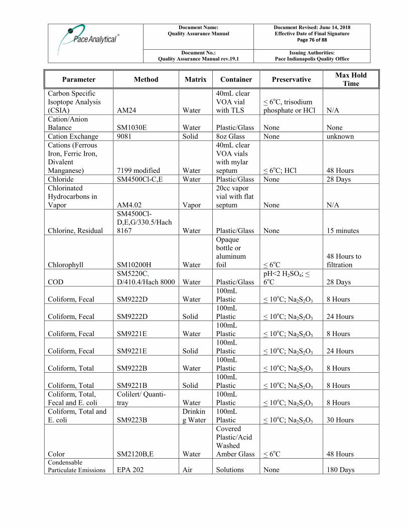
Document Name: Quality Assurance Manual
Document Revised: June 14, 2018 Effective Date of Final Signature
Page 76 of 88
Document No.: Quality Assurance Manual rev.19.1
Issuing Authorities: Pace Indianapolis Quality Office
Parameter Method Matrix Container Preservative Max Hold
Time
Carbon Specific Isoptope Analysis (CSIA) AM24 Water
40mL clear VOA vial with TLS
< 6oC, trisodium phosphate or HCl N/A
Cation/Anion Balance SM1030E Water Plastic/Glass None None Cation Exchange 9081 Solid 8oz Glass None unknown Cations (Ferrous Iron, Ferric Iron, Divalent Manganese) 7199 modified Water
40mL clear VOA vials with mylar septum < 6oC; HCl 48 Hours
Chloride SM4500Cl-C,E Water Plastic/Glass None 28 Days Chlorinated Hydrocarbons in Vapor AM4.02 Vapor
20cc vapor vial with flat septum None N/A
Chlorine, Residual
SM4500Cl-D,E,G/330.5/Hach 8167 Water Plastic/Glass None 15 minutes
Chlorophyll SM10200H Water
Opaque bottle or aluminum foil < 6oC
48 Hours to filtration
COD SM5220C, D/410.4/Hach 8000 Water Plastic/Glass
pH<2 H2SO4; < 6oC 28 Days
Coliform, Fecal SM9222D Water 100mL Plastic < 10oC; Na2S2O3 8 Hours
Coliform, Fecal SM9222D Solid 100mL Plastic < 10oC; Na2S2O3 24 Hours
Coliform, Fecal SM9221E Water 100mL Plastic < 10oC; Na2S2O3 8 Hours
Coliform, Fecal SM9221E Solid 100mL Plastic < 10oC; Na2S2O3 24 Hours
Coliform, Total SM9222B Water 100mL Plastic < 10oC; Na2S2O3 8 Hours
Coliform, Total SM9221B Solid 100mL Plastic < 10oC; Na2S2O3 8 Hours
Coliform, Total, Fecal and E. coli
Colilert/ Quanti-tray Water
100mL Plastic < 10oC; Na2S2O3 8 Hours
Coliform, Total and E. coli SM9223B
Drinking Water
100mL Plastic < 10oC; Na2S2O3 30 Hours
Color SM2120B,E Water
Covered Plastic/Acid Washed Amber Glass < 6oC 48 Hours
Condensable Particulate Emissions EPA 202 Air Solutions None 180 Days
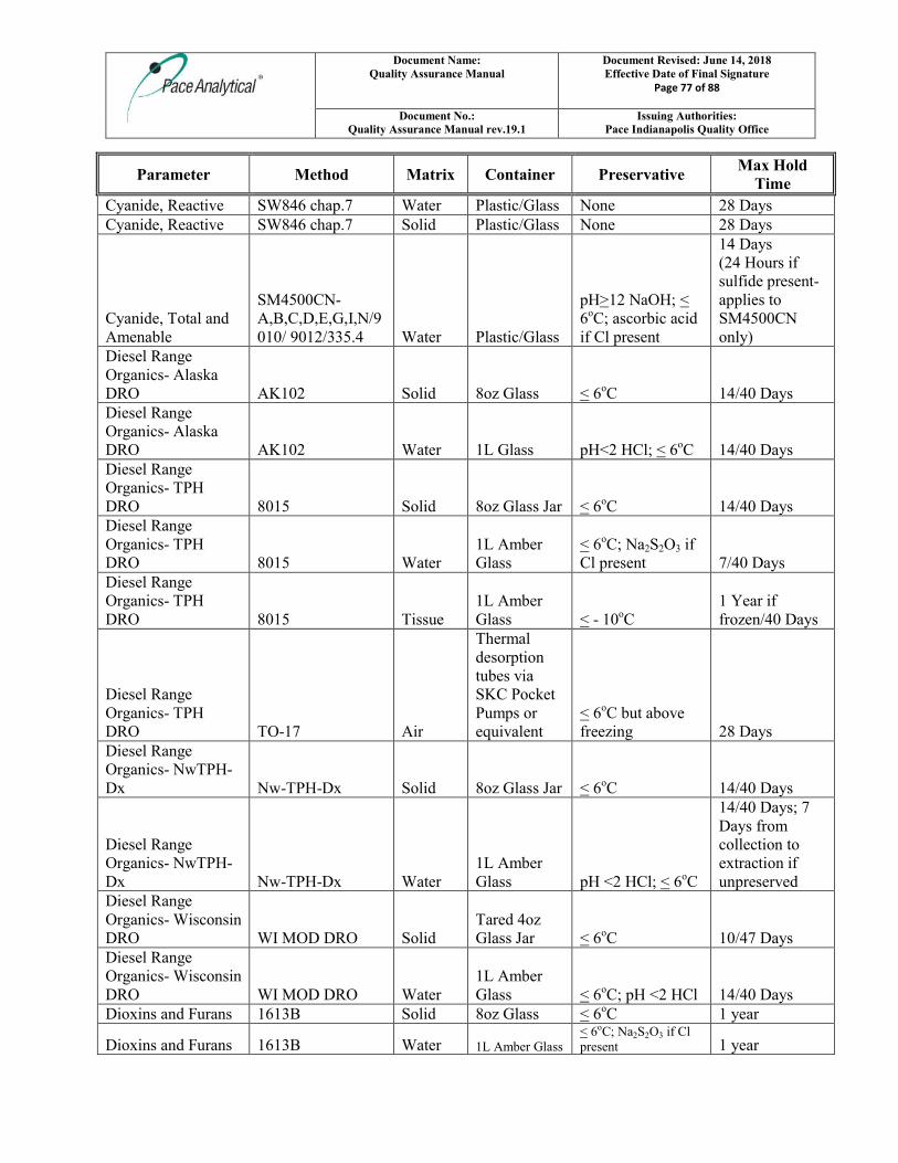
Document Name: Quality Assurance Manual
Document Revised: June 14, 2018 Effective Date of Final Signature
Page 77 of 88
Document No.: Quality Assurance Manual rev.19.1
Issuing Authorities: Pace Indianapolis Quality Office
Parameter Method Matrix Container Preservative Max Hold
Time
Cyanide, Reactive SW846 chap.7 Water Plastic/Glass None 28 Days Cyanide, Reactive SW846 chap.7 Solid Plastic/Glass None 28 Days
Cyanide, Total and Amenable
SM4500CN-A,B,C,D,E,G,I,N/9010/ 9012/335.4 Water Plastic/Glass
pH>12 NaOH; < 6oC; ascorbic acid if Cl present
14 Days (24 Hours if sulfide present- applies to SM4500CN only)
Diesel Range Organics- Alaska DRO AK102 Solid 8oz Glass < 6oC 14/40 Days Diesel Range Organics- Alaska DRO AK102 Water 1L Glass pH<2 HCl; < 6oC 14/40 Days Diesel Range Organics- TPH DRO 8015 Solid 8oz Glass Jar < 6oC 14/40 Days Diesel Range Organics- TPH DRO 8015 Water
1L Amber Glass
< 6oC; Na2S2O3 if Cl present 7/40 Days
Diesel Range Organics- TPH DRO 8015 Tissue
1L Amber Glass < - 10oC
1 Year if frozen/40 Days
Diesel Range Organics- TPH DRO TO-17 Air
Thermal desorption tubes via SKC Pocket Pumps or equivalent
< 6oC but above freezing 28 Days
Diesel Range Organics- NwTPH-Dx Nw-TPH-Dx Solid 8oz Glass Jar < 6oC 14/40 Days
Diesel Range Organics- NwTPH-Dx Nw-TPH-Dx Water
1L Amber Glass pH <2 HCl; < 6oC
14/40 Days; 7 Days from collection to extraction if unpreserved
Diesel Range Organics- Wisconsin DRO WI MOD DRO Solid
Tared 4oz Glass Jar < 6oC 10/47 Days
Diesel Range Organics- Wisconsin DRO WI MOD DRO Water
1L Amber Glass < 6oC; pH <2 HCl 14/40 Days
Dioxins and Furans 1613B Solid 8oz Glass < 6oC 1 year
Dioxins and Furans 1613B Water 1L Amber Glass < 6oC; Na2S2O3 if Cl present 1 year
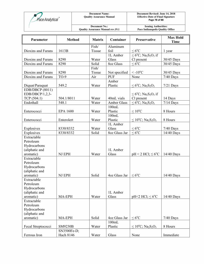
Document Name: Quality Assurance Manual
Document Revised: June 14, 2018 Effective Date of Final Signature
Page 78 of 88
Document No.: Quality Assurance Manual rev.19.1
Issuing Authorities: Pace Indianapolis Quality Office
Parameter Method Matrix Container Preservative Max Hold
Time
Dioxins and Furans 1613B Fish/ Tissue
Aluminum foil < 6oC 1 year
Dioxins and Furans 8290 Water 1L Amber Glass
< 6oC; Na2S2O3 if Cl present 30/45 Days
Dioxins and Furans 8290 Solid 8oz Glass < 6oC 30/45 Days
Dioxins and Furans 8290 Fish/ Tissue Not specified < -10oC 30/45 Days
Dioxins and Furans TO-9 Air PUF None 7/40 Days
Diquat/Paraquat 549.2 Water Amber Plastic < 6oC; Na2S2O3 7/21 Days
EDB/DBCP (8011) EDB/DBCP/1,2,3-TCP (504.1) 504.1/8011 Water 40mL vials
< 6oC; Na2S2O3 if Cl present 14 Days
Endothall 548.1 Water Amber Glass < 6oC; Na2S2O3 7/14 Days
Enterococci EPA 1600 Water 100mL Plastic < 10oC 8 Hours
Enterococci Enterolert Water 100mL Plastic < 10oC; Na2S2O3 8 Hours
Explosives 8330/8332 Water 1L Amber Glass < 6oC 7/40 Days
Explosives 8330/8332 Solid 8oz Glass Jar < 6oC 14/40 Days Extractable Petroleum Hydrocarbons (aliphatic and aromatic) NJ EPH Water
1L Amber Glass pH < 2 HCl; ≤ 6oC 14/40 Days
Extractable Petroleum Hydrocarbons (aliphatic and aromatic) NJ EPH Solid 4oz Glass Jar ≤ 6oC 14/40 Days Extractable Petroleum Hydrocarbons (aliphatic and aromatic) MA-EPH Water
1L Amber Glass pH<2 HCl; < 6oC 14/40 Days
Extractable Petroleum Hydrocarbons (aliphatic and aromatic) MA-EPH Solid 4oz Glass Jar < 6oC 7/40 Days
Fecal Streptococci SM9230B Water 100mL Plastic < 10oC; Na2S2O3 8 Hours
Ferrous Iron SN3500Fe-D; Hach 8146 Water Glass None Immediate
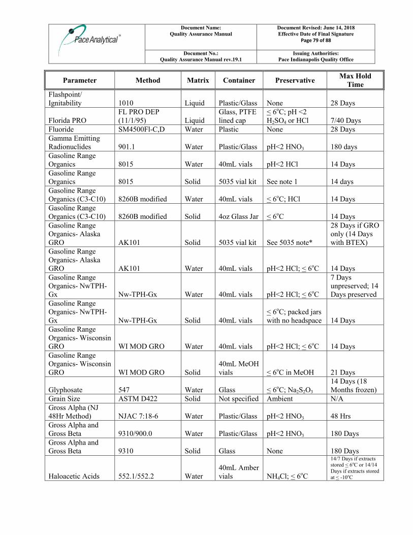
Document Name: Quality Assurance Manual
Document Revised: June 14, 2018 Effective Date of Final Signature
Page 79 of 88
Document No.: Quality Assurance Manual rev.19.1
Issuing Authorities: Pace Indianapolis Quality Office
Parameter Method Matrix Container Preservative Max Hold
Time
Flashpoint/ Ignitability 1010 Liquid Plastic/Glass None 28 Days
Florida PRO FL PRO DEP (11/1/95) Liquid
Glass, PTFE lined cap
< 6oC; pH <2 H2SO4 or HCl 7/40 Days
Fluoride SM4500Fl-C,D Water Plastic None 28 Days Gamma Emitting Radionuclides 901.1 Water Plastic/Glass pH<2 HNO3 180 days Gasoline Range Organics 8015 Water 40mL vials pH<2 HCl 14 Days Gasoline Range Organics 8015 Solid 5035 vial kit See note 1 14 days Gasoline Range Organics (C3-C10) 8260B modified Water 40mL vials < 6oC; HCl 14 Days Gasoline Range Organics (C3-C10) 8260B modified Solid 4oz Glass Jar < 6oC 14 Days Gasoline Range Organics- Alaska GRO AK101 Solid 5035 vial kit See 5035 note*
28 Days if GRO only (14 Days with BTEX)
Gasoline Range Organics- Alaska GRO AK101 Water 40mL vials pH<2 HCl; < 6oC 14 Days Gasoline Range Organics- NwTPH-Gx Nw-TPH-Gx Water 40mL vials pH<2 HCl; < 6oC
7 Days unpreserved; 14 Days preserved
Gasoline Range Organics- NwTPH-Gx Nw-TPH-Gx Solid 40mL vials
< 6oC; packed jars with no headspace 14 Days
Gasoline Range Organics- Wisconsin GRO WI MOD GRO Water 40mL vials pH<2 HCl; < 6oC 14 Days Gasoline Range Organics- Wisconsin GRO WI MOD GRO Solid
40mL MeOH vials < 6oC in MeOH 21 Days
Glyphosate 547 Water Glass < 6oC; Na2S2O3 14 Days (18 Months frozen)
Grain Size ASTM D422 Solid Not specified Ambient N/A Gross Alpha (NJ 48Hr Method) NJAC 7:18-6 Water Plastic/Glass pH<2 HNO3 48 Hrs Gross Alpha and Gross Beta 9310/900.0 Water Plastic/Glass pH<2 HNO3 180 Days Gross Alpha and Gross Beta 9310 Solid Glass None 180 Days
Haloacetic Acids 552.1/552.2 Water 40mL Amber vials NH4Cl; < 6oC
14/7 Days if extracts stored < 6oC or 14/14 Days if extracts stored at < -10oC
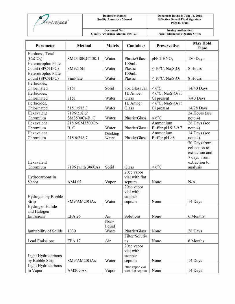
Document Name: Quality Assurance Manual
Document Revised: June 14, 2018 Effective Date of Final Signature
Page 80 of 88
Document No.: Quality Assurance Manual rev.19.1
Issuing Authorities: Pace Indianapolis Quality Office
Parameter Method Matrix Container Preservative Max Hold
Time
Hardness, Total (CaCO3) SM2340B,C/130.1 Water Plastic/Glass pH<2 HNO3 180 Days Heterotrophic Plate Count (SPC/HPC) SM9215B Water
100mL Plastic < 10oC; Na2S2O3 8 Hours
Heterotrophic Plate Count (SPC/HPC) SimPlate Water
100mL Plastic < 10oC; Na2S2O3 8 Hours
Herbicides, Chlorinated 8151 Solid 8oz Glass Jar < 6oC 14/40 Days Herbicides, Chlorinated 8151 Water
1L Amber Glass
< 6oC; Na2S2O3 if Cl present 7/40 Days
Herbicides, Chlorinated 515.1/515.3 Water
1L Amber Glass
< 6oC; Na2S2O3 if Cl present 14/28 Days
Hexavalent Chromium
7196/218.6/ SM3500Cr-B, C Water Plastic/Glass < 6oC
24 Hours (see note 4)
Hexavalent Chromium
218.6/SM3500Cr-B, C Water Plastic/Glass
Ammonium Buffer pH 9.3-9.7
28 Days (see note 4)
Hexavalent Chromium 218.6/218.7
Drinking Water Plastic/Glass
Ammonium Buffer pH >8
14 Days (see note 4)
Hexavalent Chromium 7196 (with 3060A) Solid Glass < 6oC
30 Days from collection to extraction and 7 days from extraction to analysis
Hydrocarbons in Vapor AM4.02 Vapor
20cc vapor vial with flat septum None N/A
Hydrogen by Bubble Strip SM9/AM20GAx Water
20cc vapor vial with stopper septum None 14 Days
Hydrogen Halide and Halogen Emissions EPA 26 Air Solutions None 6 Months
Ignitability of Solids 1030
Non-liquid Waste Plastic/Glass None 28 Days
Lead Emissions EPA 12 Air Filter/Solutions None 6 Months
Light Hydrocarbons by Bubble Strip SM9/AM20GAx Water
20cc vapor vial with stopper septum None 14 Days
Light Hydrocarbons in Vapor AM20GAx Vapor
20cc vapor vial with flat septum None 14 Days
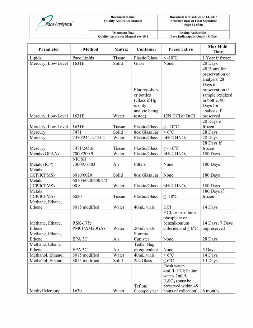
Document Name: Quality Assurance Manual
Document Revised: June 14, 2018 Effective Date of Final Signature
Page 81 of 88
Document No.: Quality Assurance Manual rev.19.1
Issuing Authorities: Pace Indianapolis Quality Office
Parameter Method Matrix Container Preservative Max Hold
Time
Lipids Pace Lipids Tissue Plastic/Glass < -10oC 1 Year if frozen Mercury, Low-Level 1631E Solid Glass None 28 Days
Mercury, Low-Level 1631E Water
Fluoropolymer bottles (Glass if Hg is only analyte being tested) 12N HCl or BrCl
48 Hours for preservation or analysis; 28 Days to preservation if sample oxidized in bottle; 90 Days for analysis if preserved
Mercury, Low-Level 1631E Tissue Plastic/Glass < - 10oC 28 Days if frozen
Mercury 7471 Solid 8oz Glass Jar < 6oC 28 Days Mercury 7470/245.1/245.2 Water Plastic/Glass pH<2 HNO3 28 Days
Mercury 7471/245.6 Tissue Plastic/Glass < - 10oC 28 Days if frozen
Metals (GFAA) 7000/200.9 Water Plastic/Glass pH<2 HNO3 180 Days
Metals (ICP) NIOSH 7300A/7303 Air Filters None 180 Days
Metals (ICP/ICPMS) 6010/6020 Solid 8oz Glass Jar None 180 Days Metals (ICP/ICPMS)
6010/6020/200.7/200.8 Water Plastic/Glass pH<2 HNO3 180 Days
Metals (ICP/ICPMS) 6020 Tissue Plastic/Glass < -10oC
180 Days if frozen
Methane, Ethane, Ethene 8015 modified Water 40mL vials HCl 14 Days
Methane, Ethane, Ethene
RSK-175; PM01/AM20GAx Water 20mL vials
HCl; or trisodium phosphate or benzalkonium chloride and < 6oC
14 Days; 7 Days unpreserved
Methane, Ethane, Ethene EPA 3C Air
Summa Canister None 28 Days
Methane, Ethane, Ethene EPA 3C Air
Tedlar Bag or equivalent None 5 Days
Methanol, Ethanol 8015 modified Water 40mL vials < 6oC 14 Days Methanol, Ethanol 8015 modified Solid 2oz Glass < 6oC 14 Days
Methyl Mercury 1630 Water Teflon/ fluoropolymer
Fresh water- 4mL/L HCl; Saline water- 2mL/L H2SO4 (must be preserved within 48 hours of collection) 6 months
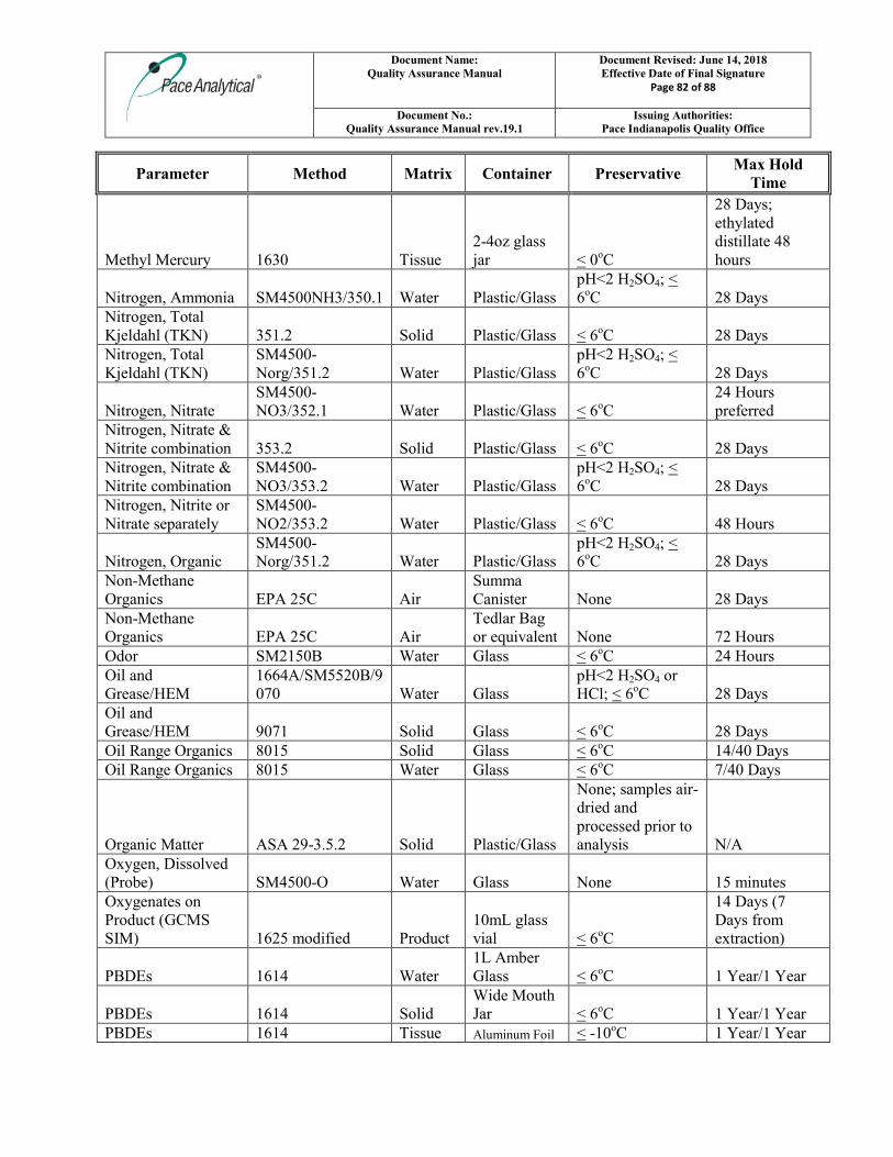
Document Name: Quality Assurance Manual
Document Revised: June 14, 2018 Effective Date of Final Signature
Page 82 of 88
Document No.: Quality Assurance Manual rev.19.1
Issuing Authorities: Pace Indianapolis Quality Office
Parameter Method Matrix Container Preservative Max Hold
Time
Methyl Mercury 1630 Tissue 2-4oz glass jar < 0oC
28 Days; ethylated distillate 48 hours
Nitrogen, Ammonia SM4500NH3/350.1 Water Plastic/Glass pH<2 H2SO4; < 6oC 28 Days
Nitrogen, Total Kjeldahl (TKN) 351.2 Solid Plastic/Glass < 6oC 28 Days Nitrogen, Total Kjeldahl (TKN)
SM4500-Norg/351.2 Water Plastic/Glass
pH<2 H2SO4; < 6oC 28 Days
Nitrogen, Nitrate SM4500-NO3/352.1 Water Plastic/Glass < 6oC
24 Hours preferred
Nitrogen, Nitrate & Nitrite combination 353.2 Solid Plastic/Glass < 6oC 28 Days Nitrogen, Nitrate & Nitrite combination
SM4500-NO3/353.2 Water Plastic/Glass
pH<2 H2SO4; < 6oC 28 Days
Nitrogen, Nitrite or Nitrate separately
SM4500-NO2/353.2 Water Plastic/Glass < 6oC 48 Hours
Nitrogen, Organic SM4500-Norg/351.2 Water Plastic/Glass
pH<2 H2SO4; < 6oC 28 Days
Non-Methane Organics EPA 25C Air
Summa Canister None 28 Days
Non-Methane Organics EPA 25C Air
Tedlar Bag or equivalent None 72 Hours
Odor SM2150B Water Glass < 6oC 24 Hours Oil and Grease/HEM
1664A/SM5520B/9070 Water Glass
pH<2 H2SO4 or HCl; < 6oC 28 Days
Oil and Grease/HEM 9071 Solid Glass < 6oC 28 Days Oil Range Organics 8015 Solid Glass < 6oC 14/40 Days Oil Range Organics 8015 Water Glass < 6oC 7/40 Days
Organic Matter ASA 29-3.5.2 Solid Plastic/Glass
None; samples air-dried and processed prior to analysis N/A
Oxygen, Dissolved (Probe) SM4500-O Water Glass None 15 minutes Oxygenates on Product (GCMS SIM) 1625 modified Product
10mL glass vial < 6oC
14 Days (7 Days from extraction)
PBDEs 1614 Water 1L Amber Glass < 6oC 1 Year/1 Year
PBDEs 1614 Solid Wide Mouth Jar < 6oC 1 Year/1 Year
PBDEs 1614 Tissue Aluminum Foil < -10oC 1 Year/1 Year
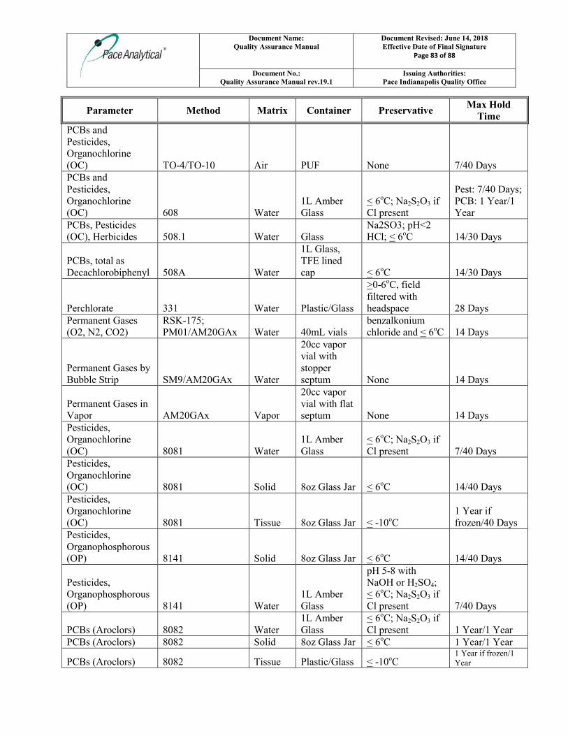
Document Name: Quality Assurance Manual
Document Revised: June 14, 2018 Effective Date of Final Signature
Page 83 of 88
Document No.: Quality Assurance Manual rev.19.1
Issuing Authorities: Pace Indianapolis Quality Office
Parameter Method Matrix Container Preservative Max Hold
Time
PCBs and Pesticides, Organochlorine (OC) TO-4/TO-10 Air PUF None 7/40 Days PCBs and Pesticides, Organochlorine (OC) 608 Water
1L Amber Glass
< 6oC; Na2S2O3 if Cl present
Pest: 7/40 Days; PCB: 1 Year/1 Year
PCBs, Pesticides (OC), Herbicides 508.1 Water Glass
Na2SO3; pH<2 HCl; < 6oC 14/30 Days
PCBs, total as Decachlorobiphenyl 508A Water
1L Glass, TFE lined cap < 6oC 14/30 Days
Perchlorate 331 Water Plastic/Glass
>0-6oC, field filtered with headspace 28 Days
Permanent Gases (O2, N2, CO2)
RSK-175; PM01/AM20GAx Water 40mL vials
benzalkonium chloride and < 6oC 14 Days
Permanent Gases by Bubble Strip SM9/AM20GAx Water
20cc vapor vial with stopper septum None 14 Days
Permanent Gases in Vapor AM20GAx Vapor
20cc vapor vial with flat septum None 14 Days
Pesticides, Organochlorine (OC) 8081 Water
1L Amber Glass
< 6oC; Na2S2O3 if Cl present 7/40 Days
Pesticides, Organochlorine (OC) 8081 Solid 8oz Glass Jar < 6oC 14/40 Days Pesticides, Organochlorine (OC) 8081 Tissue 8oz Glass Jar < -10oC
1 Year if frozen/40 Days
Pesticides, Organophosphorous (OP) 8141 Solid 8oz Glass Jar < 6oC 14/40 Days
Pesticides, Organophosphorous (OP) 8141 Water
1L Amber Glass
pH 5-8 with NaOH or H2SO4; < 6oC; Na2S2O3 if Cl present 7/40 Days
PCBs (Aroclors) 8082 Water 1L Amber Glass
< 6oC; Na2S2O3 if Cl present 1 Year/1 Year
PCBs (Aroclors) 8082 Solid 8oz Glass Jar < 6oC 1 Year/1 Year
PCBs (Aroclors) 8082 Tissue Plastic/Glass < -10oC 1 Year if frozen/1 Year
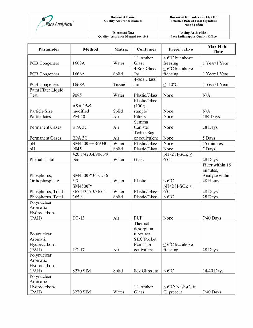
Document Name: Quality Assurance Manual
Document Revised: June 14, 2018 Effective Date of Final Signature
Page 84 of 88
Document No.: Quality Assurance Manual rev.19.1
Issuing Authorities: Pace Indianapolis Quality Office
Parameter Method Matrix Container Preservative Max Hold
Time
PCB Congeners 1668A Water 1L Amber Glass
< 6oC but above freezing 1 Year/1 Year
PCB Congeners 1668A Solid 4-8oz Glass Jar
< 6oC but above freezing 1 Year/1 Year
PCB Congeners 1668A Tissue 4-8oz Glass Jar < -10oC 1 Year/1 Year
Paint Filter Liquid Test 9095 Water Plastic/Glass None N/A
Particle Size ASA 15-5 modified Solid
Plastic/Glass (100g sample) None N/A
Particulates PM-10 Air Filters None 180 Days
Permanent Gases EPA 3C Air Summa Canister None 28 Days
Permanent Gases EPA 3C Air Tedlar Bag or equivalent None 5 Days
pH SM4500H+B/9040 Water Plastic/Glass None 15 minutes pH 9045 Solid Plastic/Glass None 7 Days
Phenol, Total 420.1/420.4/9065/9066 Water Glass
pH<2 H2SO4; < 6oC 28 Days
Phosphorus, Orthophosphate
SM4500P/365.1/365.3 Water Plastic < 6oC
Filter within 15 minutes, Analyze within 48 Hours
Phosphorus, Total SM4500P/ 365.1/365.3/365.4 Water Plastic/Glass
pH<2 H2SO4; < 6oC 28 Days
Phosphorus, Total 365.4 Solid Plastic/Glass < 6oC 28 Days Polynuclear Aromatic Hydrocarbons (PAH) TO-13 Air PUF None 7/40 Days
Polynuclear Aromatic Hydrocarbons (PAH) TO-17 Air
Thermal desorption tubes via SKC Pocket Pumps or equivalent
< 6oC but above freezing 28 Days
Polynuclear Aromatic Hydrocarbons (PAH) 8270 SIM Solid 8oz Glass Jar < 6oC 14/40 Days Polynuclear Aromatic Hydrocarbons (PAH) 8270 SIM Water
1L Amber Glass
< 6oC; Na2S2O3 if Cl present 7/40 Days
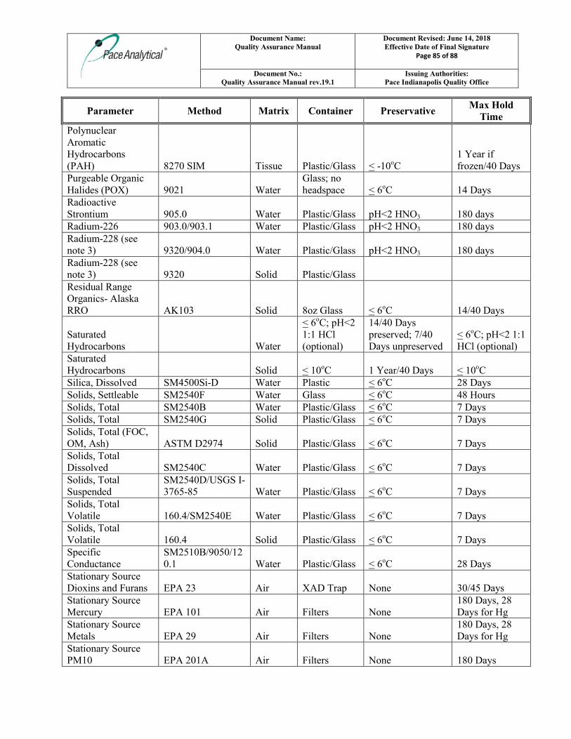
Document Name: Quality Assurance Manual
Document Revised: June 14, 2018 Effective Date of Final Signature
Page 85 of 88
Document No.: Quality Assurance Manual rev.19.1
Issuing Authorities: Pace Indianapolis Quality Office
Parameter Method Matrix Container Preservative Max Hold
Time
Polynuclear Aromatic Hydrocarbons (PAH) 8270 SIM Tissue Plastic/Glass < -10oC
1 Year if frozen/40 Days
Purgeable Organic Halides (POX) 9021 Water
Glass; no headspace < 6oC 14 Days
Radioactive Strontium 905.0 Water Plastic/Glass pH<2 HNO3 180 days Radium-226 903.0/903.1 Water Plastic/Glass pH<2 HNO3 180 days Radium-228 (see note 3) 9320/904.0 Water Plastic/Glass pH<2 HNO3 180 days Radium-228 (see note 3) 9320 Solid Plastic/Glass Residual Range Organics- Alaska RRO AK103 Solid 8oz Glass < 6oC 14/40 Days
Saturated Hydrocarbons Water
< 6oC; pH<2 1:1 HCl (optional)
14/40 Days preserved; 7/40 Days unpreserved
< 6oC; pH<2 1:1 HCl (optional)
Saturated Hydrocarbons Solid < 10oC 1 Year/40 Days < 10oC Silica, Dissolved SM4500Si-D Water Plastic < 6oC 28 Days Solids, Settleable SM2540F Water Glass < 6oC 48 Hours Solids, Total SM2540B Water Plastic/Glass < 6oC 7 Days Solids, Total SM2540G Solid Plastic/Glass < 6oC 7 Days Solids, Total (FOC, OM, Ash) ASTM D2974 Solid Plastic/Glass < 6oC 7 Days Solids, Total Dissolved SM2540C Water Plastic/Glass < 6oC 7 Days Solids, Total Suspended
SM2540D/USGS I-3765-85 Water Plastic/Glass < 6oC 7 Days
Solids, Total Volatile 160.4/SM2540E Water Plastic/Glass < 6oC 7 Days Solids, Total Volatile 160.4 Solid Plastic/Glass < 6oC 7 Days Specific Conductance
SM2510B/9050/120.1 Water Plastic/Glass < 6oC 28 Days
Stationary Source Dioxins and Furans EPA 23 Air XAD Trap None 30/45 Days Stationary Source Mercury EPA 101 Air Filters None
180 Days, 28 Days for Hg
Stationary Source Metals EPA 29 Air Filters None
180 Days, 28 Days for Hg
Stationary Source PM10 EPA 201A Air Filters None 180 Days
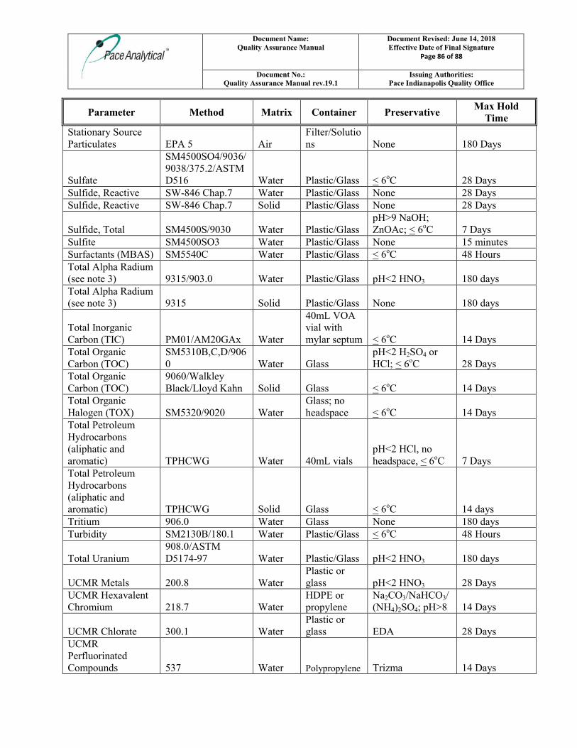
Document Name: Quality Assurance Manual
Document Revised: June 14, 2018 Effective Date of Final Signature
Page 86 of 88
Document No.: Quality Assurance Manual rev.19.1
Issuing Authorities: Pace Indianapolis Quality Office
Parameter Method Matrix Container Preservative Max Hold
Time
Stationary Source Particulates EPA 5 Air
Filter/Solutions None 180 Days
Sulfate
SM4500SO4/9036/ 9038/375.2/ASTM D516 Water Plastic/Glass < 6oC 28 Days
Sulfide, Reactive SW-846 Chap.7 Water Plastic/Glass None 28 Days Sulfide, Reactive SW-846 Chap.7 Solid Plastic/Glass None 28 Days
Sulfide, Total SM4500S/9030 Water Plastic/Glass pH>9 NaOH; ZnOAc; < 6oC 7 Days
Sulfite SM4500SO3 Water Plastic/Glass None 15 minutes Surfactants (MBAS) SM5540C Water Plastic/Glass < 6oC 48 Hours Total Alpha Radium (see note 3) 9315/903.0 Water Plastic/Glass pH<2 HNO3 180 days Total Alpha Radium (see note 3) 9315 Solid Plastic/Glass None 180 days
Total Inorganic Carbon (TIC) PM01/AM20GAx Water
40mL VOA vial with mylar septum < 6oC 14 Days
Total Organic Carbon (TOC)
SM5310B,C,D/9060 Water Glass
pH<2 H2SO4 or HCl; < 6oC 28 Days
Total Organic Carbon (TOC)
9060/Walkley Black/Lloyd Kahn Solid Glass < 6oC 14 Days
Total Organic Halogen (TOX) SM5320/9020 Water
Glass; no headspace < 6oC 14 Days
Total Petroleum Hydrocarbons (aliphatic and aromatic) TPHCWG Water 40mL vials
pH<2 HCl, no headspace, < 6oC 7 Days
Total Petroleum Hydrocarbons (aliphatic and aromatic) TPHCWG Solid Glass < 6oC 14 days Tritium 906.0 Water Glass None 180 days Turbidity SM2130B/180.1 Water Plastic/Glass < 6oC 48 Hours
Total Uranium 908.0/ASTM D5174-97 Water Plastic/Glass pH<2 HNO3 180 days
UCMR Metals 200.8 Water Plastic or glass pH<2 HNO3 28 Days
UCMR Hexavalent Chromium 218.7 Water
HDPE or propylene
Na2CO3/NaHCO3/(NH4)2SO4; pH>8 14 Days
UCMR Chlorate 300.1 Water Plastic or glass EDA 28 Days
UCMR Perfluorinated Compounds 537 Water Polypropylene Trizma 14 Days
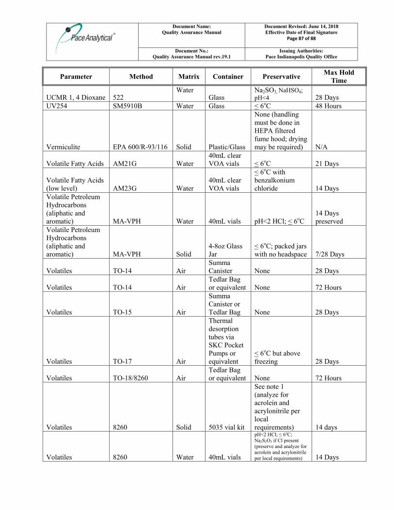
Document Name: Quality Assurance Manual
Document Revised: June 14, 2018 Effective Date of Final Signature
Page 87 of 88
Document No.: Quality Assurance Manual rev.19.1
Issuing Authorities: Pace Indianapolis Quality Office
Parameter Method Matrix Container Preservative Max Hold
Time
UCMR 1, 4 Dioxane 522 Water
Glass Na2SO3, NaHSO4; pH<4 28 Days
UV254 SM5910B Water Glass < 6oC 48 Hours
Vermiculite EPA 600/R-93/116 Solid Plastic/Glass
None (handling must be done in HEPA filtered fume hood; drying may be required) N/A
Volatile Fatty Acids AM21G Water 40mL clear VOA vials < 6oC 21 Days
Volatile Fatty Acids (low level) AM23G Water
40mL clear VOA vials
< 6oC with benzalkonium chloride 14 Days
Volatile Petroleum Hydrocarbons (aliphatic and aromatic) MA-VPH Water 40mL vials pH<2 HCl; < 6oC
14 Days preserved
Volatile Petroleum Hydrocarbons (aliphatic and aromatic) MA-VPH Solid
4-8oz Glass Jar
< 6oC; packed jars with no headspace 7/28 Days
Volatiles TO-14 Air Summa Canister None 28 Days
Volatiles TO-14 Air Tedlar Bag or equivalent None 72 Hours
Volatiles TO-15 Air
Summa Canister or Tedlar Bag None 28 Days
Volatiles TO-17 Air
Thermal desorption tubes via SKC Pocket Pumps or equivalent
< 6oC but above freezing 28 Days
Volatiles TO-18/8260 Air Tedlar Bag or equivalent None 72 Hours
Volatiles 8260 Solid 5035 vial kit
See note 1 (analyze for acrolein and acrylonitrile per local requirements) 14 days
Volatiles 8260 Water 40mL vials
pH<2 HCl; < 6oC; Na2S2O3 if Cl present (preserve and analyze for acrolein and acrylonitrile per local requirements) 14 Days
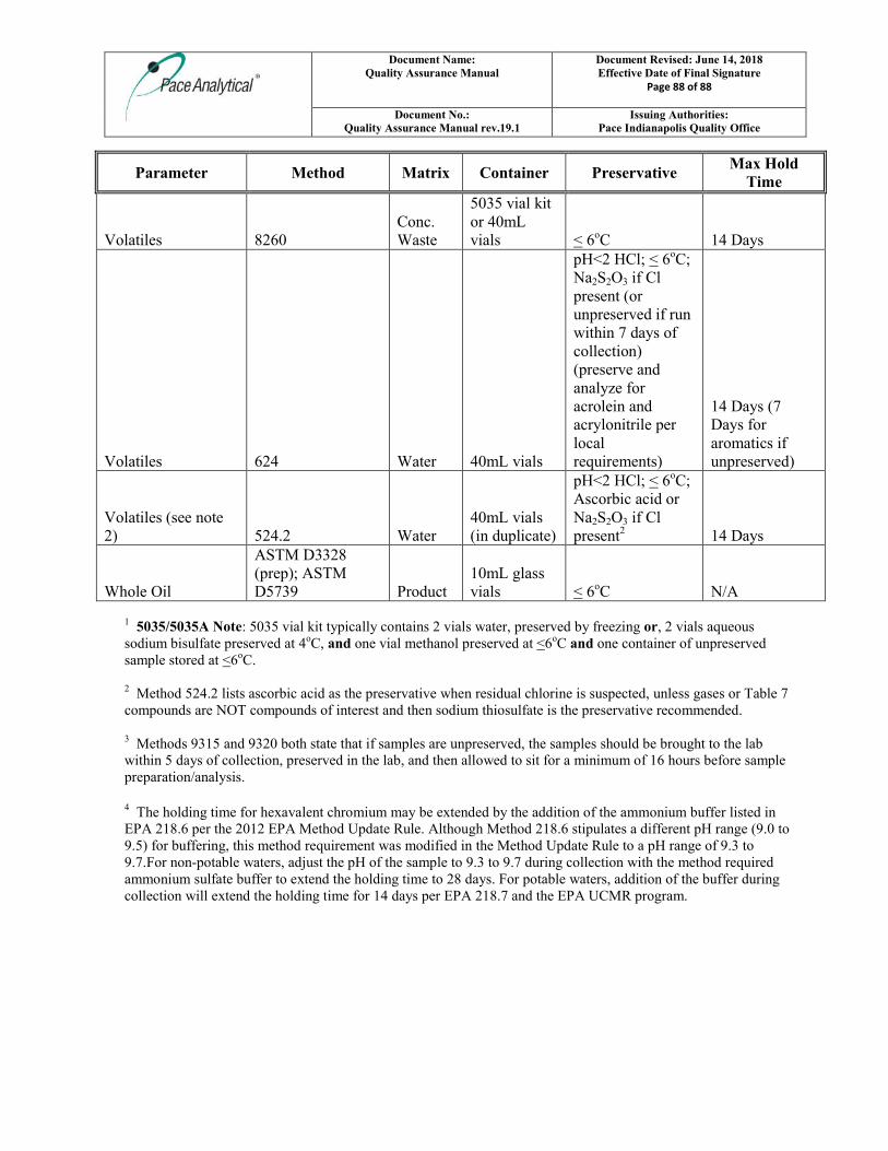
Document Name: Quality Assurance Manual
Document Revised: June 14, 2018 Effective Date of Final Signature
Page 88 of 88
Document No.: Quality Assurance Manual rev.19.1
Issuing Authorities: Pace Indianapolis Quality Office
Parameter Method Matrix Container Preservative Max Hold
Time
Volatiles 8260 Conc. Waste
5035 vial kit or 40mL vials < 6oC 14 Days
Volatiles 624 Water 40mL vials
pH<2 HCl; < 6oC; Na2S2O3 if Cl present (or unpreserved if run within 7 days of collection) (preserve and analyze for acrolein and acrylonitrile per local requirements)
14 Days (7 Days for aromatics if unpreserved)
Volatiles (see note 2) 524.2 Water
40mL vials (in duplicate)
pH<2 HCl; < 6oC; Ascorbic acid or Na2S2O3 if Cl present2 14 Days
Whole Oil
ASTM D3328 (prep); ASTM D5739 Product
10mL glass vials < 6oC N/A
1 5035/5035A Note: 5035 vial kit typically contains 2 vials water, preserved by freezing or, 2 vials aqueous sodium bisulfate preserved at 4oC, and one vial methanol preserved at <6oC and one container of unpreserved sample stored at <6oC. 2 Method 524.2 lists ascorbic acid as the preservative when residual chlorine is suspected, unless gases or Table 7 compounds are NOT compounds of interest and then sodium thiosulfate is the preservative recommended. 3 Methods 9315 and 9320 both state that if samples are unpreserved, the samples should be brought to the lab within 5 days of collection, preserved in the lab, and then allowed to sit for a minimum of 16 hours before sample preparation/analysis.
4 The holding time for hexavalent chromium may be extended by the addition of the ammonium buffer listed in EPA 218.6 per the 2012 EPA Method Update Rule. Although Method 218.6 stipulates a different pH range (9.0 to 9.5) for buffering, this method requirement was modified in the Method Update Rule to a pH range of 9.3 to 9.7.For non-potable waters, adjust the pH of the sample to 9.3 to 9.7 during collection with the method required ammonium sulfate buffer to extend the holding time to 28 days. For potable waters, addition of the buffer during collection will extend the holding time for 14 days per EPA 218.7 and the EPA UCMR program.
APPENDIX D
REMEDIAL DESIGN SAMPLING AND ANALYSIS PLAN
REMEDIAL DESIGN
ENVIRONMENTAL SAMPLING AND
ANALYSIS PLAN
(RD SAP)
WEST LAKE LANDFILL SITE
OPERABLE UNIT 2 (OU-2)
BRIDGETON, MISSOURI
Prepared For:
BRIDGETON LANDFILL, LLC
Prepared By:
CIVIL & ENVIRONMENTAL CONSULTANTS, INC.
PHOENIX, ARIZONA
CEC Project 191-750
OCTOBER 15, 2019

-i- Remedial Design Environmental SAP
West Lake Landfill Site Operable Unit 2 (OU-2), Bridgeton, Missouri
October 15, 2019
TABLE OF CONTENTS
Page
1.0 INTRODUCTION..............................................................................................................1
2.0 SAMPLING OBJECTIVES ..............................................................................................2 2.1 Data Quality Objectives .......................................................................................... 2
3.0 TEMPORARY LANDFILL GAS MONITORING WELL
MEASUREMENTS ...........................................................................................................3
4.0 SAMPLING AND ANALYSIS OF SELECTED GROUNDWATER
MONITORING WELLS ...................................................................................................4 4.1 Groundwater Monitoring Well Sample Analytical Methods .................................. 5
4.2 Groundwater Monitoring Quality Control Samples ............................................... 5
5.0 THICKNESS EVALUATION OF INACTIVE SANITARY LANDFILL
COVER ...............................................................................................................................7 5.1 Landfill Cover Thickness Evaluation ......................................................................... 7
5.2 Existing Material Evaluation .................................................................................. 7
6.0 ANALYSIS OF EXISTING WESTERN SLOPE ...........................................................8
7.0 GEOTECHNICAL TESTING OF POTENTIAL BORROW AREAS ........................9
FIGURES
1-1 Site Location Map
1-2 Existing Facility Features Map
3-1 Approximate Locations of Proposed Temporary Landfill Gas Perimeter Monitoring Wells
4-1 Locations of Groundwater Monitoring Wells Proposed for Single Monitoring Event
5-1 Proposed Sample Grid for Thickness Evaluation of Inactive Sanitary Landfill Cover
6-1 Existing Western Slope of OU-2
-1- Remedial Design Environmental SAP
West Lake Landfill Site Operable Unit 2 (OU-2), Bridgeton, Missouri
October 15, 2019
1.0 INTRODUCTION
This Remedial Design Environmental Sampling and Analysis Plan (RD SAP) has been prepared by
Civil & Environmental Consultants, Inc. (CEC) to provide guidance for field sample collection
activities and field measurements to be performed in accordance with the Remedial Design
Environmental Quality Assurance Project Plan (RD QAPP). The RD QAPP is being submitted as a
companion document to this RD SAP.
Environmental conditions at the West Lake Landfill OU-2 facility (Figure 1-1) have been previously
defined by past studies. Existing facility features, including monitoring wells, the Inactive Sanitary
Landfill boundary, etc., are provided in Figure 1-2. Activities described in this RD SAP are intended
to enhance the decision-making process for the Remedial Design by providing an updated assessment
of environmental conditions in the vicinity of the West Lake Landfill OU-2 facility.
-2- Remedial Design Environmental SAP
West Lake Landfill Site Operable Unit 2 (OU-2), Bridgeton, Missouri
October 15, 2019
2.0 SAMPLING OBJECTIVES
The primary objectives of the West Lake Landfill OU-2 facility RD QAPP and RD SAP are to provide
updated evaluations of groundwater quality conditions and subsurface vapor conditions in the vicinity
of the OU-2 facility and evaluate current cover thickness and slope stability on the Inactive Sanitary
Landfill. Other Remedial Design tasks are discussed in the QAPP, but these tasks are not anticipated to
require field sampling.
Field sampling activities to be performed in accordance with this RD SAP consists of:
Monitoring of temporary landfill gas perimeter monitoring wells after installation;
Performance of a ground and aerial topographic survey;
Collection of samples from selected groundwater monitoring wells for analysis of
constituents of concern;
Collection of cover thickness samples from the Inactive Sanitary Landfill (OU-2);
Geotechnical evaluation for slope stability along the western slope of the Inactive
Sanitary Landfill and any other steep slopes greater than 25% per the MDNR’s
requirements; and
Geotechnical evaluation and estimated volumes for potential borrow areas near OU-2.
Each of the above-referenced tasks is described in the following sections.
2.1 DATA QUALITY OBJECTIVES
Sampling objectives will performed in accordance to the Data Quality Objectives steps (DQO)
identified the Site Quality Assurance Project Plan (QAPP). This process is used to systematically
plan for collecting environmental data of a known quality and quantity to support decisions. The
DQO plan will follow the U.S. Environmental Protection Agency (EPA) “Guidance on Systematic
Planning Using the Data Quality Objectives Process”, EPA QA/G-4, EPA/240/B-06/001, February
2006 (http://www.epa.gov/quality/qs-docs/g4-final.pdf). The DQO will clarify the study
objectives, define the most appropriate type of data to collect, determine the appropriate conditions
from which to collect the data, and specify tolerable limits on decision errors which will be used
as the basis for establishing the quantity and quality of data needed to support the decision.
-3- Remedial Design Environmental SAP
West Lake Landfill Site Operable Unit 2 (OU-2), Bridgeton, Missouri
October 15, 2019
3.0 TEMPORARY LANDFILL GAS MONITORING WELL MEASUREMENTS
To assess the status of subsurface decomposition gases in the vicinity of the West Lake Landfill OU-2
facility, temporary landfill gas perimeter monitoring wells are proposed to be installed. As described
by the RD QAPP, two (2) temporary landfill gas monitoring well screened intervals are proposed to be
installed at each approximate location (Figure 3-1) to allow monitoring of discrete zones.
Subsequent to completion of temporary perimeter landfill gas monitoring well installation activities
described in the RD QAPP, quarterly measurements for methane will be performed at the installed
temporary landfill gas perimeter monitoring wells and will be conducted pursuant to the procedures
described by the Technical Bulletin: Sampling of Landfill Gas Monitoring Wells, dated September
1999, published by the Missouri Department of Natural Resources (MDNR).
-4- Remedial Design Environmental SAP
West Lake Landfill Site Operable Unit 2 (OU-2), Bridgeton, Missouri
October 15, 2019
4.0 SAMPLING AND ANALYSIS OF SELECTED GROUNDWATER MONITORING
WELLS
Subsequent to US EPA approval of this RD SAP, groundwater monitoring will be conducted at
selected groundwater monitoring wells. The groundwater monitoring event is proposed to provide
an update to groundwater quality conditions encountered during Remedial Investigation /
Feasibility Study (RI / FS) activities. Groundwater samples are proposed to be collected from the
following five monitoring wells:
PZ-302-AS, PZ-302-AI, PZ-303-AS, PZ-304-AS, and PZ-304-AI
The wells were selected to provide groundwater quality results for OU-2. Locations of monitoring
wells proposed for the groundwater monitoring event are provided by Figure 4-1.
Purging of monitoring wells prior to sampling, collection of groundwater samples, and chain of
custody procedures will be conducted in general accordance with the SOPs for Groundwater
Sample Collection provided in Appendix A.
For the project-specific requirements for groundwater sample collection activities at West Lake
Landfill OU-2 facility, the following modifications to the SOPs provided in Appendix A are
understood to apply.
Containerization of purged groundwater and equipment decontamination water is
required. Containerized water will be disposed of in leachate Sump K-128, associated
with the adjacent closed sanitary landfill.
Purging and sampling will be performed with a bladder pump or disposable Teflon®
bailers.
Required field Quality Control (QC) samples are described in Section 5.2 4.2 of this RD
SAP.
The recommended sample collection order for analyzed groundwater constituents is
provided by the following table:
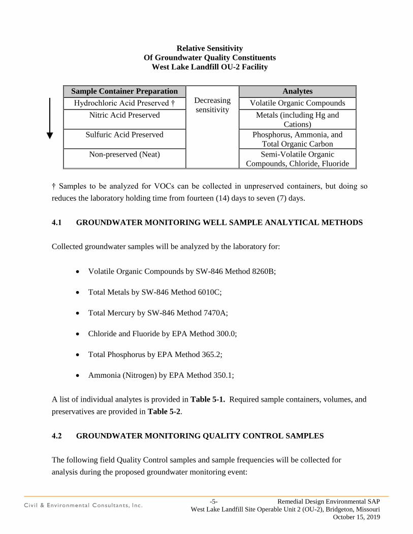
-5- Remedial Design Environmental SAP
West Lake Landfill Site Operable Unit 2 (OU-2), Bridgeton, Missouri
October 15, 2019
Relative Sensitivity
Of Groundwater Quality Constituents
West Lake Landfill OU-2 Facility
Sample Container Preparation
Decreasing
sensitivity
Analytes
Hydrochloric Acid Preserved † Volatile Organic Compounds
Nitric Acid Preserved Metals (including Hg and
Cations)
Sulfuric Acid Preserved Phosphorus, Ammonia, and
Total Organic Carbon
Non-preserved (Neat) Semi-Volatile Organic
Compounds, Chloride, Fluoride
† Samples to be analyzed for VOCs can be collected in unpreserved containers, but doing so
reduces the laboratory holding time from fourteen (14) days to seven (7) days.
4.1 GROUNDWATER MONITORING WELL SAMPLE ANALYTICAL METHODS
Collected groundwater samples will be analyzed by the laboratory for:
Volatile Organic Compounds by SW-846 Method 8260B;
Total Metals by SW-846 Method 6010C;
Total Mercury by SW-846 Method 7470A;
Chloride and Fluoride by EPA Method 300.0;
Total Phosphorus by EPA Method 365.2;
Ammonia (Nitrogen) by EPA Method 350.1;
A list of individual analytes is provided in Table 5-1. Required sample containers, volumes, and
preservatives are provided in Table 5-2.
4.2 GROUNDWATER MONITORING QUALITY CONTROL SAMPLES
The following field Quality Control samples and sample frequencies will be collected for
analysis during the proposed groundwater monitoring event:
-6- Remedial Design Environmental SAP
West Lake Landfill Site Operable Unit 2 (OU-2), Bridgeton, Missouri
October 15, 2019
Field Duplicate samples – one (1) field duplicate groundwater sample to be collected per
ten (10) primary groundwater samples.
Field (Atmospheric) Blank samples – one (1) field blank sample to be collected per
monitoring event.
Equipment Blank samples – one (1) equipment blank sample to be collected per
monitoring event if a non-dedicated pump is utilized for purging and sampling.
Trip Blank samples – one (1) trip blank sample (provided by the laboratory) to be
included with each sample shipment containing samples for analysis of VOCs.
The following laboratory Quality Control samples and sample frequencies are proposed to be
analyzed concurrently with groundwater samples:
Method Blank samples – one (1) method blank sample to be analyzed twenty (20 samples
analyzed in the batch;
Laboratory Control Samples (LCS) – one (1) LCS to be analyzed per twenty (20)
analyzed samples in the batch; and
Matrix Spike / Matrix Spike Duplicate (MS / MSD) samples – one (1) MS / MSD sample
pair to be analyzed per twenty (20) samples analyzed in the batch.
-7- Remedial Design Environmental SAP
West Lake Landfill Site Operable Unit 2 (OU-2), Bridgeton, Missouri
October 15, 2019
5.0 THICKNESS EVALUATION OF INACTIVE SANITARY LANDFILL COVER
Sampling of existing cover materials from the Inactive Sanitary Landfill will be conducted to evaluate
cover thickness and assess selected geotechnical soil properties. The assessments will provide an
estimate the volume of materials needed for construction of the final cover and the suitability of using
the existing material as landfill cover.
Sampling of the landfill cover materials will indicate and confirm where excess cover materials are
available within portions of OU-2 and where additional material needs to be added. The average
thickness of the soils to be removed and reinstalled after construction will be established.
5.1 LANDFILL COVER THICKNESS EVALUATION
The FS sampling program included the collection of approximately ninety (90) samples at 150- ft
intervals from a surveyed grid across the Inactive Sanitary Landfill. Figure 5-1 displays the
approximate sampling grid and sample locations.
Each sampling location was initially be surveyed for northing, easting, and ground surface elevation.
The thickness of the cover was determined by full depth sampling of the cover material. Each location
was sampled using a direct push drill rig pushing a tube sampler lined with clear polyethylene liners.
Each sample was brought to the surface, the liner opened, and the soils visually examined to distinguish
materials and measure corresponding material thicknesses. The field engineer developed a log of the
soil conditions encountered in each soil boring.
5.2 EXISTING MATERIAL EVALUATION
Thirty (30) Shelby Tube samples will be collected in accordance with ASTM D1587 at locations
immediately adjacent to previous cap sampling locations. Undisturbed soil samples will be collected
for material classification and permeability testing purposes. The Shelby Tube samples will be
submitted to a qualified testing laboratory where the tubes will be extruded and logged with
representative portion of each tube tested for Atterberg Limits, grain size distribution and permeability.
Sampling locations which penetrate the landfill cover will be sealed with properly hydrated bentonite or
other appropriate means.
-8- Remedial Design Environmental SAP
West Lake Landfill Site Operable Unit 2 (OU-2), Bridgeton, Missouri
October 15, 2019
6.0 ANALYSIS OF EXISTING WESTERN SLOPE
The existing slope along the western perimeter of OU-2 was established in the mid-1990’s. Figure 6-1
displays the location, contour details, and a cross-section of the western slope. Based on observations
during a site visit conducted by the Landfill Design team on November 11, 2008, as well as more recent
site visits, the existing slope appears to be stable.
One of the RD tasks is to determine the long-term stability of the existing western slope. A geotechnical
sampling investigation will be conducted for the evaluation and analysis of slope stability. Such an
evaluation would require a significant number of soil borings to identify any potential failure planes or
unstable portions of the western slope.
If additional documentation of slope stability is warranted, an on-site biological assessment of existing
vegetation along the western slope may be implemented. Derived conclusions would be documented
to further determine the stability control provided by existing vegetation. This task is not anticipated to
include any soil sampling or laboratory analysis.
-9- Remedial Design Environmental SAP
West Lake Landfill Site Operable Unit 2 (OU-2), Bridgeton, Missouri
October 15, 2019
7.0 GEOTECHNICAL TESTING OF POTENTIAL BORROW AREAS
Soils used for final cover must meet soil classification and permeability specifications. As part of the
RD phase of this project, soil samples will be collected from potential borrow areas with laboratory
testing conducted on potential sources of low-permeability final cover soils. Representative bulk soil
samples will be collected from test pits excavated in each of the proposed borrow areas. The testing
program will include natural moisture content, Atterberg Limits, Standard proctor dry density
determination, and recompacted permeability. The resultant data are needed for approval of the borrow
soils before construction and will be identified in the Remedial Action construction specifications that
are developed following completion of the RD phase of this project.
FIGURES
Missouri
Maps courtesy of Microsoft Streets and Trips 2005
West LakeLandfill OU-2
Bridgeton Landfill, LLC (2008)
4630 South Highway 94North Outer Road
St. Charles, Missouri 63304Phone (636) 939-9111
Fax (636) 939-9757West Lake Landfill OU-2
Bridgeton, MissouriFigure 1-1
Site Location Map
4630 South Highway 94North Outer Road
St. Charles, Missouri 63304Phone (636) 939-9111
Fax (636) 939-9757West Lake Landfill OU-2
Bridgeton, MissouriFigure 1-2
Existing Facility Features Map
Bridgeton Landfill, LLC (2008)
4630 South Highway 94North Outer Road
St. Charles, Missouri 63304Phone (636) 939-9111
Fax (636) 939-9757West Lake Landfill OU-2
Bridgeton, Missouri
Figure 3-1Approximate Locations of ProposedTemporary Landfill Gas Perimeter
Monitoring Probes
Bridgeton Landfill, LLC (2008)

4630 South Highway 94North Outer Road
St. Charles, Missouri 63304Phone (636) 939-9111
Fax (636) 939-9757West Lake Landfill OU-2
Bridgeton, Missouri
Figure 4-1Locations of Groundwater
Monitoring Wells Proposed forSingle Monitoring Event
Bridgeton Landfill, LLC (2008)
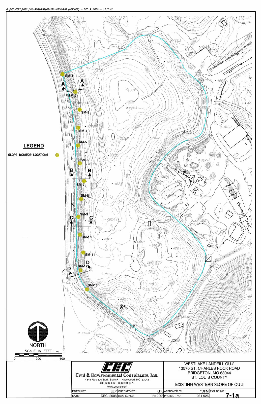
APPENDIX E
REMEDIAL DESIGN HEALTH AND SAFETY PLAN
REMEDIAL DESIGN
HEALTH & SAFETY PLAN
WEST LAKE LANDFILL SITE
OPERABLE UNIT 2 (OU-2
BRIDGETON, MISSOURI
Prepared For:
BRIDGETON LANDFILL, LLC
Prepared By:
CIVIL & ENVIRONMENTAL CONSULTANTS, INC.
PHOENIX, ARIZONA
CEC Project 191-750
October 15, 2019
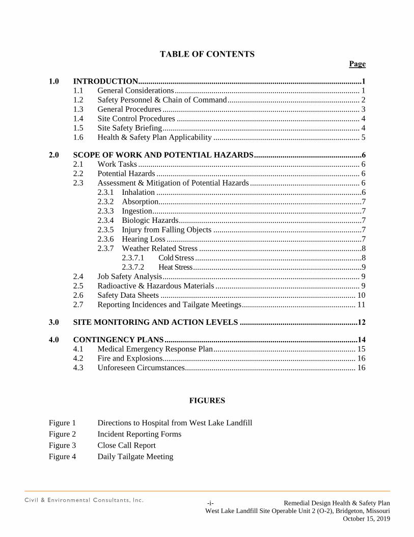
-i- Remedial Design Health & Safety Plan
West Lake Landfill Site Operable Unit 2 (O-2), Bridgeton, Missouri
October 15, 2019
TABLE OF CONTENTS Page
1.0 INTRODUCTION..............................................................................................................1 1.1 General Considerations ........................................................................................... 1 1.2 Safety Personnel & Chain of Command ................................................................. 2
1.3 General Procedures ................................................................................................. 3 1.4 Site Control Procedures .......................................................................................... 4 1.5 Site Safety Briefing ................................................................................................. 4 1.6 Health & Safety Plan Applicability ........................................................................ 5
2.0 SCOPE OF WORK AND POTENTIAL HAZARDS .....................................................6 2.1 Work Tasks ............................................................................................................. 6
2.2 Potential Hazards .................................................................................................... 6
2.3 Assessment & Mitigation of Potential Hazards ...................................................... 6 2.3.1 Inhalation .....................................................................................................6 2.3.2 Absorption....................................................................................................7 2.3.3 Ingestion .......................................................................................................7
2.3.4 Biologic Hazards ..........................................................................................7 2.3.5 Injury from Falling Objects .........................................................................7
2.3.6 Hearing Loss ................................................................................................7 2.3.7 Weather Related Stress ................................................................................8
2.3.7.1 Cold Stress ..................................................................................8
2.3.7.2 Heat Stress ...................................................................................9 2.4 Job Safety Analysis ................................................................................................. 9
2.5 Radioactive & Hazardous Materials ....................................................................... 9
2.6 Safety Data Sheets ................................................................................................ 10
2.7 Reporting Incidences and Tailgate Meetings ........................................................ 11
3.0 SITE MONITORING AND ACTION LEVELS ..........................................................12
4.0 CONTINGENCY PLANS ...............................................................................................14 4.1 Medical Emergency Response Plan ...................................................................... 15
4.2 Fire and Explosions............................................................................................... 16 4.3 Unforeseen Circumstances .................................................................................... 16
FIGURES
Figure 1 Directions to Hospital from West Lake Landfill
Figure 2 Incident Reporting Forms
Figure 3 Close Call Report
Figure 4 Daily Tailgate Meeting
-1- Remedial Design Health & Safety Plan
West Lake Landfill Site Operable Unit 2 (O-2), Bridgeton, Missouri
October 15, 2019
1.0 INTRODUCTION
This document is the Health and Safety Plan (HASP) for remedial design activities for West Lake
Operable Unit 2, Bridgeton, Missouri.
The purpose of this document is to establish standard health and safety procedures for the Contractor
and Subcontractor employees during field activities at and near the facility. The provisions of this plan
aim to eliminate exposure to hazardous materials or activities.
The following paragraphs of Section 1 of the HASP outline general health and safety considerations
to be utilized when conducting field activities for the project. Section 2 details the scope of work and
potential hazards. Site monitoring and action levels are presented in Section 3. Contingency and
emergency response plans are presented in Section 4.
1.1 GENERAL CONSIDERATIONS
The levels of protection and the procedures specified in this HASP are based on information available
at this time and represent the minimum health and safety requirements to be observed by all Contractor
and Subcontractor employees while engaged in this project. Unforeseeable site conditions may
warrant the use of higher levels of protection. The content of this HASP may change or undergo
revision as additional information is obtained during the field activities. Any changes to this HASP
must be reviewed by Health and Safety Officer and are subject to approval by the Environmental
Project Manager.
The safety of all on-site personnel is ultimately the responsibility of each employee and his or her
respective employer. Subcontractors are required to provide the necessary safety equipment, medical
monitoring, and safety training to their personnel in compliance with the Occupational Safety and
Health Administration (OSHA) regulations provided in 29 CFR 1910.120.
Field personnel must read this document carefully. If you have any questions or concerns that you feel
are not adequately addressed, ask the Health and Safety Officer. Follow the designated health and safety
procedures, be alert to the hazards associated with working on any construction site in close proximity
to heavy equipment, and above all else, use common sense and exercise reasonable caution at all times.
Contractors are required to watch a health and safety video prior to working on-site, and should attend
daily safety ‘tailgate’ meetings.
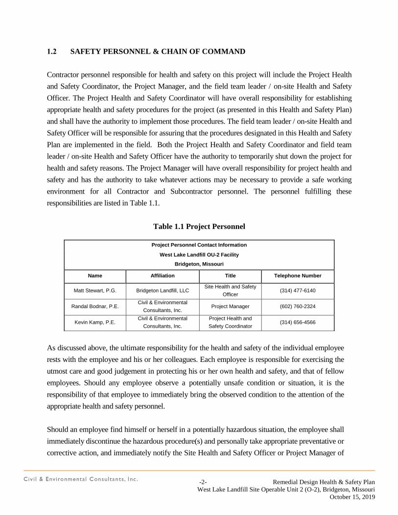
-2- Remedial Design Health & Safety Plan
West Lake Landfill Site Operable Unit 2 (O-2), Bridgeton, Missouri
October 15, 2019
1.2 SAFETY PERSONNEL & CHAIN OF COMMAND
Contractor personnel responsible for health and safety on this project will include the Project Health
and Safety Coordinator, the Project Manager, and the field team leader / on-site Health and Safety
Officer. The Project Health and Safety Coordinator will have overall responsibility for establishing
appropriate health and safety procedures for the project (as presented in this Health and Safety Plan)
and shall have the authority to implement those procedures. The field team leader / on-site Health and
Safety Officer will be responsible for assuring that the procedures designated in this Health and Safety
Plan are implemented in the field. Both the Project Health and Safety Coordinator and field team
leader / on-site Health and Safety Officer have the authority to temporarily shut down the project for
health and safety reasons. The Project Manager will have overall responsibility for project health and
safety and has the authority to take whatever actions may be necessary to provide a safe working
environment for all Contractor and Subcontractor personnel. The personnel fulfilling these
responsibilities are listed in Table 1.1.
Table 1.1 Project Personnel
As discussed above, the ultimate responsibility for the health and safety of the individual employee
rests with the employee and his or her colleagues. Each employee is responsible for exercising the
utmost care and good judgement in protecting his or her own health and safety, and that of fellow
employees. Should any employee observe a potentially unsafe condition or situation, it is the
responsibility of that employee to immediately bring the observed condition to the attention of the
appropriate health and safety personnel.
Should an employee find himself or herself in a potentially hazardous situation, the employee shall
immediately discontinue the hazardous procedure(s) and personally take appropriate preventative or
corrective action, and immediately notify the Site Health and Safety Officer or Project Manager of
Project Personnel Contact Information
West Lake Landfill OU-2 Facility
Bridgeton, Missouri
Name Affiliation Title Telephone Number
Matt Stewart, P.G. Bridgeton Landfill, LLC Site Health and Safety
Officer (314) 477-6140
Randal Bodnar, P.E. Civil & Environmental
Consultants, Inc. Project Manager (602) 760-2324
Kevin Kamp, P.E. Civil & Environmental
Consultants, Inc.
Project Health and
Safety Coordinator (314) 656-4566
-3- Remedial Design Health & Safety Plan
West Lake Landfill Site Operable Unit 2 (O-2), Bridgeton, Missouri
October 15, 2019
the nature of the hazard. In the event of an immediately dangerous or life-threatening situation, the
employee automatically has “stop work” authority.
At least two workers on-site will have current First Aid and CPR certifications during field work
associated with the RD. In the event of inclement weather, all field crews shall rally at the blue
Republic Building located just southwest of the main entrance to St. Charles Rock Road.
1.3 GENERAL PROCEDURES
The following personal hygiene and work practice guidelines are intended to prevent injuries and
adverse health effects. These guidelines represent the minimum standard procedures for reducing
potential risks associated with this project and are to be followed by Contractor and Subcontractor
employees at all times.
The “buddy system” will be used when conducting all field activities;
A multipurpose dry chemical fire extinguisher, a complete field first aid kit, and a bottle of
emergency eye wash solution will be immediately available to project field personnel. For
example, field support vehicles will be stocked with these items when conducting drilling
operations;
Eating, drinking, smoking, taking medications, chewing gum or tobacco, etc. is
prohibited in the immediate vicinity of the drilling operation;
Thoroughly wash hands and, if necessary, face before eating or putting anything in your
mouth (i.e., avoid hand-to-mouth contamination);
Stand upwind of sample locations whenever possible;
Be alert to potentially changing exposure conditions as evidenced by perceptible odors,
unusual appearance of excavated soils, oily sheen on water, etc.;
Be alert to the symptoms or fatigue and heat/cold stress, and their effect on the normal caution
and judgement of personnel;
Establish prearranged hand signals or other means of emergency communication when
wearing respiratory equipment, since this equipment seriously impairs speech
communications;
-4- Remedial Design Health & Safety Plan
West Lake Landfill Site Operable Unit 2 (O-2), Bridgeton, Missouri
October 15, 2019
Noise may pose a health and safety hazard during drilling and construction activities. A good
rule of thumb to follow is that if you have to shout in order to communicate a distance of three
(3) feet in steady state (continuous) noise, you should be wearing hearing protection. Likewise,
any impact noise from activities such as driving casing during drilling which is loud enough
to cause discomfort would also indicate the need for hearing protection;
Stay clear of heavy machinery/drilling equipment, especially in the vicinity of the transfer
station and asphalt operations in the vicinity, which often has truck traffic; and
Always wear an appropriate level of personal protection (Level D is the minimum level
required). Lesser levels of protection can result in preventable exposure; excessive levels of
safety equipment can impair efficiency and increase the potential for accidents to occur.
1.4 SITE CONTROL PROCEDURES
All project personnel will check in with the Field Team Leader on a daily basis. Authorized
personnel will accompany any visitors to the work site.
1.5 SITE SAFETY BRIEFING
Prior to commencement of field investigative activities, field personnel will attend an on-site safety
orientation. This orientation will include, at a minimum, the following topics:
A discussion of the scope of work for the project;
Locations of site emergency equipment and contacts;
Personnel protective equipment requirements and action levels; and
Site safety procedures.
This briefing will be repeated for new employees and supported with weekly “tailgate” health and
safety briefings and daily morning meetings. The weekly briefings will be conducted by CEC
personnel according to a schedule established by the Field Team Leader and will be supplemented
with additional briefings if site conditions change or are different than anticipated by this HASP. Daily
morning tailgate meetings are typically conducted by Bridgeton Landfill personnel.
-5- Remedial Design Health & Safety Plan
West Lake Landfill Site Operable Unit 2 (O-2), Bridgeton, Missouri
October 15, 2019
All personnel in attendance must sign a safety briefing attendance sheet. No employee shall be
permitted to begin field activities until they have received and acknowledged such a briefing.
1.6 HEALTH & SAFETY PLAN APPLICABILITY
This Health and Safety Plan applies specifically to the field activities performed as part of the
remedial design activities. It has been prepared specifically for this project.
-6- Remedial Design Health & Safety Plan
West Lake Landfill Site Operable Unit 2 (O-2), Bridgeton, Missouri
October 15, 2019
2.0 SCOPE OF WORK AND POTENTIAL HAZARDS
2.1 WORK TASKS
The site field tasks identified for the project are:
Field surveying for topography within and near OU-2 areas.
Drilling and installation of perimeter landfill gas wells.
Monitoring well sampling.
This HASP describes health and safety concerns associated with these field tasks.
2.2 POTENTIAL HAZARDS
A recent study by the National Safety Council indicated that the greatest risk to workers at hazardous
waste sites is from traumatic injury from heavy equipment (such as drilling rigs or construction
equipment) rather than from exposure to hazardous materials. Potential hazards anticipated at the
facility include physical and chemical hazards, such as inhalation of vapors and dusts, absorption of
chemicals through the skin, ingestion of chemicals, injury from falling objects during drilling activities,
hearing loss during drilling activities, and weather-related stress. To prevent these potential hazards
from affecting worker performance, the Health and Safety Plan incorporates various levels of
protection to be followed. However, it is recognized the guidelines to be followed cannot replace
worker common sense and experience.
2.3 ASSESSMENT & MITIGATION OF POTENTIAL HAZARDS
2.3.1 Inhalation
Inhalation of vapors is a potential hazard during field activities, although it is most likely to occur
during borehole drilling for well installation. Methane is generally associated with municipal landfills.
Release of these gases may occur during borehole drilling. Site history is a valuable aid in determining
the type of chemical hazards that may be encountered. It is important to know and understand the
physical and chemical properties of the anticipated compounds of concern at the site and evaluate the
potential hazards that may be encountered.
-7- Remedial Design Health & Safety Plan
West Lake Landfill Site Operable Unit 2 (O-2), Bridgeton, Missouri
October 15, 2019
2.3.2 Absorption
Absorption of chemicals can occur whenever chemicals contact the skin or clothing of the worker.
Absorption of chemicals is most likely to occur during drilling activities, but could also occur during
groundwater sampling. To reduce the likelihood of absorption, all workers will be required to wear
gloves when handling soil cuttings generated during drilling activities and while conducting
groundwater sampling.
2.3.3 Ingestion
Ingestion of chemicals generally occurs only when workers do not follow proper decontamination
procedures prior to eating.
2.3.4 Biologic Hazards
Sanitary landfills receiving waste prior to 1980 (pre-RCRA), should particularly be considered suspect
for the presence of biologic hazards. Biological hazards including hospital and laboratory materials
may be encountered at sanitary landfills. These materials may contain microorganisms which cause
hepatitis and influenza as well as other viral and bacterial diseases. Plants such as poison ivy, oak, and
sumac that elicit allergic skin reactions in sensitive individuals are also biologic hazards. Even when
not transmitting disease or producing allergic reactions, insects and other invertebrates such as bees
and wasps, fire ants, and biting flies which produce painful irritations should be considered hazardous.
Awareness of the potential biological hazards that may be encountered at the facility is important to
avoid potentially harmful situations.
2.3.5 Injury from Falling Objects
Injury from falling objects, such as hammers, can occur whenever work activities are performed above
the worker (e.g., on a drill rig). To prevent such injuries, all workers are required to wear protective
headgear (i.e., hard hat) at all times when on-site.
2.3.6 Hearing Loss
Hearing loss can occur whenever the worker is exposed to excessive noise levels. To prevent this type
of injury, all workers will be supplied with earplugs to be worn when necessary. A good rule-of-thumb
is that if workers must shout to be heard when standing only a few feet from each other, earplugs
-8- Remedial Design Health & Safety Plan
West Lake Landfill Site Operable Unit 2 (O-2), Bridgeton, Missouri
October 15, 2019
should be used. Furthermore, all noise producing equipment (i.e., drill rigs) will be maintained in peak
operating condition to reduce their noise levels.
2.3.7 Weather Related Stress
Weather related stress can occur from both heat and cold, and can cause decreased motor skills and
impaired judgement, which in turn can lead to injuries through impaired judgement or physical trauma.
Work will be stopped when lightning is in the vicinity for a minimum of 30 minutes from the last
observed lighting before work may resume. The ‘clock’ restarts if additional lightning is observed.
2.3.7.1 Cold Stress
The American Conference of Governmental Industrial Hygienists (ACGIH) has developed threshold
limit values (TLVs) in the form of work/warm up schedules for working in ambient air temperatures
below -15°F. The ACGIH has also developed criteria to describe exposures to cold working conditions
under which nearly all workers can be repeatedly exposed without adverse health effects.
If work is performed continuously in an equivalent chill temperature of 20°F or less workers will be
encouraged to use heated warming shelters at regular intervals, the frequency depending on the
severity of the environmental exposure. When entering the heated shelter, the outer layer of clothing
will be removed and the remainder of the clothing loosened to permit sweat evaporation. Workers will
be encouraged to drink warm liquids to prevent dehydration, although the intake of coffee or other
caffeinated beverages should be limited.
For work activities at or below an equivalent chill temperature of 10°F, workers will be under constant
supervision and heavy sweating must be avoided. All workers will be trained in:
proper rewarming procedures,
appropriate first aid treatments,
proper clothing practices,
proper eating and drinking habits,
recognition of impending frostbite,
recognition signs and symptoms of impending hypothermia, and
safe work practices.
-9- Remedial Design Health & Safety Plan
West Lake Landfill Site Operable Unit 2 (O-2), Bridgeton, Missouri
October 15, 2019
Tinted eye protection for all workers will be provided when a glare potential (snow or ice) is present.
Air temperature and wind speed monitoring and recording are required every four hours when the
temperature falls below 30°F.
2.3.7.2 Heat Stress
Experience has shown that the most effective heat stress deterrent is worker awareness and
physiological monitoring. When working in Level C or B protection in ambient temperatures greater
than 65°F, employees will use the “buddy system” to monitor each other’s pulse rate at the start of
each test period. If the pulse rate exceeds 110 beats per minute, the employee will take a 10-minute
rest period. The pulse rate shall be monitored again at the beginning of the next rest period and if the
pulse rate exceeds 110 beats per minute, the work period shall be shortened by one-third, until the
pulse rate does not exceed 110 beats per minute.
All employees are to be alert to the possibility and symptoms of heat stress. Should any of the
following symptoms occur (extreme fatigue, cramps, dizziness, headache, nausea, profuse sweating,
or pale clammy skin), the employee is to leave the work area, rest, cool off, and drink plenty of water
or other rehydrating liquids. If the symptoms do not subside after a reasonable rest period, the
employee shall notify the Contractor Project Manager or Project Health and Safety Officer and seek
medical assistance.
2.4 JOB SAFETY ANALYSIS
A Job Safety Analysis (JSA) will be provided for each specific task. A JSA is a procedure, which
helps integrate accepted safety and health principles and practices into a particular task or job operation.
In a JSA, each basic step of the job is to identify potential hazards and to recommend the safest way to
do the job. A JSA may be required are for tasks such as mobilization, demobilization, surveying,
drilling, sampling, investigation derived waste (IDW), working around heavy equipment.
2.5 RADIOACTIVE & HAZARDOUS MATERIALS
There is no concerns of encountering radioactive materials during performance of OU-2 RD field
work. OU-2 RD field work will not be conducted near the known boundary until OU-1 confirms
that boundary. If suspected hazardous waste is encountered during excavation, it will be evaluated
for RCRA hazardous characteristics per 40 CFR 261.21 through 262.24. If the waste is determined
to be a characteristic hazardous waste, then it will be disposed of off-site at a RCRA Subtitle C
-10- Remedial Design Health & Safety Plan
West Lake Landfill Site Operable Unit 2 (O-2), Bridgeton, Missouri
October 15, 2019
landfill if the waste is not above that facility’s permit limits for radioactivity. If the radioactivity
is in excess of the Subtitle C facility permit limits, then it will be disposed at a landfill permitted
to receive both radioactive and hazardous waste materials.
2.6 SAFETY DATA SHEETS
The Hazard Communication Standard (HCS) (29 CFR 1910.1200(g)), revised in 2012, requires
that the chemical manufacturer, distributor, or importer provide Safety Data Sheets (SDSs) each
hazardous chemical to downstream users to communicate information on these hazards. The SDSs
provides guidance to help workers who handle hazardous chemicals to become familiar with the
format and understand the contents of the SDSs.
The SDS includes information such as the properties of each chemical; the physical, health, and
environmental health hazards; protective measures; and safety precautions for handling, storing,
and transporting the chemical. The information contained in the SDS must be in English. In
addition, OSHA requires that SDS preparers provide specific minimum information as detailed in
Appendix D of 29 CFR 1910.1200. The SDS preparers may also include additional information in
various section(s).
Sections 1 through 8 contain general information about the chemical, identification, hazards,
composition, safe handling practices, and emergency control measures. This information should
be helpful to those that need to get the information quickly. Sections 9 through 11 and 16 contain
other technical and scientific information, such as physical and chemical properties, stability and
reactivity information, toxicological information, exposure control information, and other
information including the date of preparation or last revision. The SDS must also state that no
applicable information was found when the preparer does not find relevant information for any
required element. The SDS must also contain Sections 12 through 15, to be consistent with the
UN Globally Harmonized System of Classification and Labeling of Chemicals (GHS). A list of
all 16 sections is presented below:
Section 1: Identification
Section 2: Hazard(s) Identification
Section 3: Composition/Information on Ingredients
Section 4: First-Aid Measures
Section 5: Fire-Fighting Measures
Section 6: Accidental Release Measures
-11- Remedial Design Health & Safety Plan
West Lake Landfill Site Operable Unit 2 (O-2), Bridgeton, Missouri
October 15, 2019
Section 7: Handling and Storage
Section 8: Exposure Controls/Personal Protection
Section 9: Physical and Chemical Properties
Section 10: Stability and Reactivity
Section 11: Toxicological Information
Section 12: Ecological Information
Section 13: Disposal Considerations
Section 14: Transport Information
Section 15: Regulatory Information
Section 16: Other Information
2.7 REPORTING INCIDENCES AND TAILGATE MEETINGS
All incidences and/or accidences shall be reported immediately to the Health and Safety Officer.
All personal involved in an incident and/or accident shall compete the form shown in Figure 2 –
Incident Report. All “near misses” shall be reported using the form shown in Figure 3 – Close
Call Report. To help reduce the risk of injuries, daily safety briefings shall take place every
morning prior to commencement of work. The daily safety briefings shall be logged using the
form shown in Figure 4 – Tailgate Meeting Log. All employees must sign this log daily to prove
attendance. The tailgate meeting logs shall be kept by the Health and Safety Officer.
-12- Remedial Design Health & Safety Plan
West Lake Landfill Site Operable Unit 2 (O-2), Bridgeton, Missouri
October 15, 2019
3.0 SITE MONITORING AND ACTION LEVELS
Monitoring for potentially toxic vapors will be performed in all areas with a potential for the presence
hazardous airborne substances.
All health and safety monitoring readings will be recorded in field document and will include the date,
time, weather conditions, and location of the reading. In addition, on a daily basis background readings
will be measured. Table 3-1 and the following paragraphs describe air monitoring for VOCs and
oxygen.
The vicinity of a waste disposal site may contain isolated quantities of a variety of potentially hazardous
substances. Substances that are of most concern from an inhalation or asphyxiation standpoint are those
that are relatively volatile and are moderately to highly toxic, having odor thresholds higher than the
corresponding TLV (many organic solvents fall into this category), and methane.
Field personnel shall use a photoionization detector (RAE Systems MiniRAE 2000, Thermo
Environmental 580B Organic Vapor Meter, etc.) and a combustible gas indicator equipped with an
oxygen sensor to conduct air monitoring during drilling activities. Background levels must be
established well upwind of the drilling locations.
Prior to initiation of drilling, all utilities will be clearly staked by utility representatives. During drilling,
workers will be aware of the location of overhead lines as well as any changes in drilling that might
indicate the presence of a buried utility line. If it is believed that a utility line has been drilled into,
drilling should immediately cease and the Project Health and Safety Officer will be notified.
The following paragraphs describe air monitoring for combustible gases. Action level information
is summarized in Table 3.1.
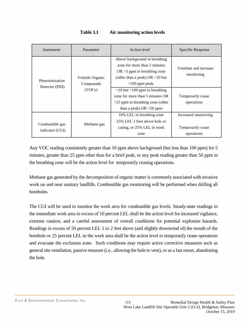
-13- Remedial Design Health & Safety Plan
West Lake Landfill Site Operable Unit 2 (O-2), Bridgeton, Missouri
October 15, 2019
Table 3.1 Air monitoring action levels
Instrument Parameter Action level Specific Response
Photoionization
Detector (PID)
Volatile Organic
Compounds
(VOCs)
Above background in breathing
zone for more than 5 minutes
OR >5 ppm in breathing zone
(other than a peak) OR >10 but
<100 ppm peak.
Ventilate and increase
monitoring
>10 but <100 ppm in breathing
zone for more than 5 minutes OR
>25 ppm in breathing zone (other
than a peak) OR >50 ppm
Temporarily cease
operations
Combustible gas
indicator (CGI)
Methane gas
10% LEL in breathing zone Increased monitoring
25% LEL 1 foot above hole or
casing, or 25% LEL in work
zone
Temporarily cease
operations
Any VOC reading consistently greater than 10 ppm above background (but less than 100 ppm) for 5
minutes, greater than 25 ppm other than for a brief peak, or any peak reading greater than 50 ppm in
the breathing zone will be the action level for temporarily ceasing operations.
Methane gas generated by the decomposition of organic matter is commonly associated with invasive
work on and near sanitary landfills. Combustible gas monitoring will be performed when drilling all
boreholes.
The CGI will be used to monitor the work area for combustible gas levels. Steady-state readings in
the immediate work area in excess of 10 percent LEL shall be the action level for increased vigilance,
extreme caution, and a careful assessment of overall conditions for potential explosion hazards.
Readings in excess of 50 percent LEL 1 to 2 feet above (and slightly downwind of) the mouth of the
borehole or 25 percent LEL in the work area shall be the action level to temporarily cease operations
and evacuate the exclusion zone. Such conditions may require active corrective measures such as
general site ventilation, passive measure (i.e., allowing the hole to vent), or as a last resort, abandoning
the hole.
-14- Remedial Design Health & Safety Plan
West Lake Landfill Site Operable Unit 2 (O-2), Bridgeton, Missouri
October 15, 2019
4.0 CONTINGENCY PLANS
The following procedures have been established to deal with emergency situations that might occur
during drilling or sampling operations. Field personnel should familiarize themselves with the location
of the nearest phone and medical facilities. In the event of an emergency situation, field personnel
shall follow the procedures specified below. When help arrives, Contractor employees shall defer all
emergency response authority to appropriate responding agency personnel.
If an unanticipated, potentially hazardous situation arises as indicated by instrument readings, visible
contamination, unusual or excessive odors, etc., field personnel shall temporarily cease operations,
move away to a safe area, and contact the Contractor Health and Safety Coordinator. In the event of
a serious emergency situation, field personnel shall contact the local fire department or paramedics, as
appropriate, and inform them of the nature of the emergency, and then notify Contractor Health and
Safety personnel as well as the Site Health and Safety Officer.
A cellular phone will be on site during all site activities. Emergency response telephone numbers
are as follows:
Hospital: SSM DePaul Health Center
Address: 12303 DePaul Drive
St. Louis, MO 63044-2588
Telephone: (314) 344-6000
Ambulance 911
Fire: 911
Police: 911
Directions to DePaul Hospital from the West Lake OU-2 Facility site:
Start out going SOUTHEAST on ST CHARLES ROCK RD/MO-115 toward TAUSSIG RD.
Continue to follow ST CHARLES ROCK RD. Turn RIGHT onto MCKELVEY RD. Turn RIGHT
onto DE PAUL DR. Turn LEFT to stay on DE PAUL DR. End at 12303 De Paul Dr. Bridgeton, MO
63044-2512.
The attached Figure 1 illustrates the route to the hospital from the site.
-15- Remedial Design Health & Safety Plan
West Lake Landfill Site Operable Unit 2 (O-2), Bridgeton, Missouri
October 15, 2019
4.1 MEDICAL EMERGENCY RESPONSE PLAN
Employees shall have walkie-talkies or CB radios on site, or be within the immediate vicinity of a
cellular phone, at all times. Employees should familiarize themselves with the location of the nearest
phone and medical facilities. In the event of an emergency situation, employees shall follow the
general procedures specified below. Specific emergency procedures must be either posted at the work
location or available in the vehicle.
Should any person visiting or working at the site be injured or become ill, notify the on-site Health
and Safety Officer and Bridgeton Landfill management, and initiate the following emergency response
plan.
If able, the injured person should proceed to the nearest available source of first aid. If the injured
party is extremely muddy, remove outer garments and if necessary, wash the injured area with soap
and water. If the “injury” involves a potential overexposure to hazardous gases or vapors, (headache,
dizziness, nausea, disorientation), get the victim to fresh air and take him or her to a doctor for a
complete physical examination as soon as possible.
If the injury involves foreign material in the eyes, immediately flush the eyes with emergency eye
wash solution and rinse with copious amounts of water at the nearest emergency eye wash station.
Obtain or administer first aid as required. If further medical treatment is required, seek medical
assistance as discussed below.
If the victim is unable to walk but is conscious and there is no evidence of spinal injury, escort or
transport the injured person to the nearest first aid facility. If the victim cannot be moved without
causing further injury such as in the case of a severe compound fracture, take necessary emergency
steps to control bleeding and immediately call for medical assistance as discussed below.
If the victim is unconscious or unable to move, do not move the injured person unless absolutely
necessary to save his or her life, until the nature of the injury has been determined.
If there is any evidence of spinal injury do not move the victim unless absolutely necessary to save
his or her life. Administer rescue breathing if the victim is not breathing, control severe bleeding and
immediately seek medical assistance.
-16- Remedial Design Health & Safety Plan
West Lake Landfill Site Operable Unit 2 (O-2), Bridgeton, Missouri
October 15, 2019
4.2 FIRE AND EXPLOSIONS
Dry chemical fire extinguishers are effective for fires involving ordinary combustibles such as wood,
grass, etc., flammable liquids, and electrical equipment. They are appropriate for small, localized fires
such as a drum of burning refuse, a small burning gasoline spill, a vehicle engine fire, etc. No attempt
should be made to use the provided extinguishers for well-established fires or large areas or volumes
of flammable liquids.
Regarding fire, prevention is the best contingency plan. There should be no smoking in the vicinity of
a well-head and smoking materials, where permitted, should be extinguished with care.
In the event of a fire or explosion:
If the situation can be readily controlled with available resources without jeopardizing the
health and safety of yourself or other site personnel, take immediate action to do so. If not:
Isolate the fire to prevent spreading if possible.
Clear the area of all personnel working in the immediate vicinity.
Immediately notify site emergency personnel and the local fire department, as well as
Bridgeton Landfill management.
4.3 UNFORESEEN CIRCUMSTANCES
The Health and Safety procedures specified in this plan are based on the best information available at
the time. Unknown conditions may exist and known conditions may change. This plan cannot
possibly account for every unknown or anticipate every contingency. Should substantially higher
levels of contamination be encountered in the soil or groundwater, or should any situation arise which
is obviously beyond the scope of the monitoring, respiratory protection, and decontamination
procedures specified herein, work activities shall be modified (such as moving to another location) or
halted pending discussion with the Contractor Health and Safety Coordinator and implementation of
appropriate protective measures.
All equipment, tools and materials used in drilling, well installation and well development shall be
decontaminated (cleaned) before being used at any hole or well on site and between holes or wells on
-17- Remedial Design Health & Safety Plan
West Lake Landfill Site Operable Unit 2 (O-2), Bridgeton, Missouri
October 15, 2019
site. Water used for decontamination shall be stored, pumped or otherwise maintained so that it
remains free of deleterious substances.
1. The condition of the equipment shall be such that contamination is not created. Leaking seals
or leaking tanks containing fluids other than water shall not be permitted.
2. Distilled water is preferred for use for decontamination so that no metals, chloride, etc. from
a potable water source are introduced. If distilled water is not available, the water used for
decontamination may be from a municipal water supply or other uncontaminated potable
water source.
3. All equipment shall be degreased upon arrival at the site. Any lubrication of equipment after
degreasing will be with vegetable oil.
4. Cleaning operations, including disposal of fluids and trash generated, will be done in
accordance with the site’s safety procedures and material handling policies.
5. Drill rods, augers, casing, soil samplers, pipe wrenches, etc., shall be placed on horses or other
supports and cleaned until all visible signs of grease, oil, mud, etc., are removed. Brushes
shall be used as required.
6. Latex gloves or new clean cotton work gloves shall be used for handling cleaned equipment.
7. Clean hose shall be used for transferring the cleaning water. Water tanks, pumps and mud
pans, including tanks used to transfer water from sources to drill rig tank (e.g., pickup truck
water tanks) shall be clean.
8. Petroleum-based lubricants shall not be used. Fittings on the drilling equipment may be
lubricated with vegetable oil and fluids may be added to the equipment with care after
cleaning.
9. Only cement in bags, powdered or granulated bentonite in bags, and bentonite pellets in sealed
containers shall be used. All materials shall be free of additives.
-18- Remedial Design Health & Safety Plan
West Lake Landfill Site Operable Unit 2 (O-2), Bridgeton, Missouri
October 15, 2019
10. Riser pipe and well screen will be provided in a cleaned condition. Workers shall use clean
cotton gloves or new latex gloves when handling riser pipe and well screen.
11. Riser pipe, well screen and other materials for well construction shall be stored in such a
manner to prevent damage or contamination.
12. The protective casing and any other casing pipe used shall be steam cleaned.
13. Boreholes shall not be left open for extended periods of time or during periods of precipitation.
The boreholes shall be covered with plastic on these occasions to protect the inside of the well
bore from contamination.

FIGURES
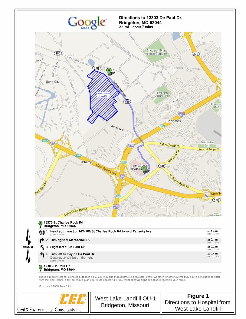
West LakeLandfill
St. Charles Rock Road
Boenker Lane
4630 South Highway 94North Outer Road
St. Charles, Missouri 63304Phone (636) 939-9111
Fax (636) 939-9757
West Lake Landfill OU-1Bridgeton, Missouri
Figure 1Directions to Hospital from
West Lake Landfill

Bridgeton Landfill Health and Safety Plan 2015Bridgeton Landfill, Bridgeton, Missouri Page 43
APPENDIX E
APPENDIX E: INCIDENT REPORT
PROJECT: BRIDGETON LANDFILL
Person Completing this Report Phone Number ( )
Date of Report Date of Incident
month/day/year month/day/year
Employee’s Information:
Name Home Office
Occupation/Job Title
Where did the incident occur?
What was the employee doing when the incident occurred?
What was the type of injury or illness?
What object or substance directly harmed the employee?
Bridgeton Landfill Health and Safety Plan 2015Bridgeton Landfill, Bridgeton, Missouri Page 44
APPENDIX E
Appendix E: Close Call Report
Project: Bridgeton Landfill
Please complete this form after the occurrence of a Close Call (incident causing injury or property damage that almost happened, or could have been worse).
Description of Close Call (who, what, where, when, how):
What went right? What could have been done differently?
Safe Start Assessment. Did the incident involve: Critical error that contributed to incident:
Rushing Eyes not on task
Frustration Mind not on task
Fatigue Line of fire
Complacency Balance/traction/grip
Reported by (optional): Today’s Date:
Project (optional): Project Manager (optional):
Page 1 of 2
REPUBLIC SERVICES Training Attendance Roster Division: Bridgeton Landfill, LLC Date / time: ____ / ____ / ______ @ ____:____ Trainer’s Name: _____________________________________________________________________ Tailgate Safety Topic: ________________________________________________________________ ___________________________________________________________________________________ ___________________________________________________________________________________ Safety briefing on any other current activities: ___________________________________________ ___________________________________________________________________________________ ___________________________________________________________________________________ Discussion of known issues: ___________________________________________________________ ___________________________________________________________________________________ ___________________________________________________________________________________ Discussion of overnight events: ________________________________________________________ ___________________________________________________________________________________ ___________________________________________________________________________________ Assignment of daily tasks: Tasks are assigned your Employee Inbox in the Operations Manager’s office. Acknowledgement: I have attended the daily tailgate meeting to receive assignments, have safety briefing, and discuss known issues and overnight events. I have had the opportunity to ask questions and receive answers on the content of the training presented by the Company. I understand the training and agree to abide by the standards presented therein.
Employee Name Employee Signature Time
Page 2 of 2
Employee Name Employee Signature Time
APPENDIX F
SHELBY TUBE SAMPLE RESULTS