regency greenfire gf55 bay window pellet stove manual
TRANSCRIPT

FPI FIREPLACE PRODUCTS INTERNATIONAL, LTD. 6988 Venture St., Delta, BC, Canada V4G 1H4GF55-919-572 11.10.15
Greenfire® GF55 & GFI55
WARNING: Improper installation, adjustment, alteration, serv ice or ma in tenance can cause injury, property damage, or loss of life. Refer to this manual. For assistance or additional information consult an authorized installer or service agency.
FOR YOUR SAFETY:Do not store or use gasoline or other flammable vapours and liquids in the vicinity of this or any other appliance.
Installation and service must be performed by an authorized installer or service agency.
Tested by:
IMPORTANT: SAVE THESE INSTRUCTIONS
TECHNICAL MANUALFreestanding and Fireplace
Insert Pellet Stove
Greenfire Pellet Stove and Insert Technical Manual2
Safety Note: If this stove is not properly installed, a house fire may result. For your safety, follow the installation instructions, contact local building, fire officials, or authority having jurisdiction about restrictions and installation inspection requirements in your area.
The authority having jurisdiction should be consulted before installation to determine the need to obtain a permit.
Rates: This manual describes the installation and operation of the Regency GF55/GFI55 pellet heater. This heater meets the 2015 U.S. Environmental Protection Agency’s wood emission limits for wood emission limits sold after May 15, 2015. Under specific test condition this heater has been shown to deliver heat at rates raging from: 6500-40,000 Btu/hrEfficiency: 78%
FIRE EXTINGUISHER AND SMOKE DETECTION: All home with a pellet burning stove should have at least one fire extinguisher in a central location known to all the household. Smoke detectors and carbon monoxide detectors should be installed maintained in the room containing the stove. If it sounds the alarm, correct the cause but do not deactivate. You may choose to relocate the smoke the smoke detection device within the room; DO NOT REMOVE THE SMOKE OR CARBON MONOXIDE DETECTORS FROM THE ROOM.
WARNING: This wood heater needs periodic inspection and repair for proper operation. It is against federal regulation to operate this wood heater in a manner inconsistent with operating instructions in this manual. WARNING: This wood heater has a manufacturer set minimum low burn rate that must not be altered. It is against federal regulations to alter this setting or other wise operate this wood heater in a manner inconsistent with operating instructions in this manual.
Greenfire Pellet Stove and Insert Technical Manual 3
TABLE OF CONTENTS
SAFETY LABEL
Copy of Serial No. Decal ...............................................4
UNIT DIMENSIONS
GF55 Freestanding Pellet Stove ...................................5GFI55 Fireplace Pellet Insert .........................................6
INSTALLATION
Important Safety Information .........................................7Safety Warnings & Recommendations ..........................7Removing Pellet Stove From Pallet ...............................8Opening the Door ..........................................................8Locating the Pellet Appliance ........................................8
GF55 Freestanding Pellet Stove ...................................9 Clearances to Combustibles.....................................9 Alcove Clearances ....................................................9 Mobile Home Installation ..........................................9 Vent Termination Requirements .............................10 Exhaust & Fresh Air Intake Location ...................... 11 Outside Fresh Air Connection................................. 11 Corner Through Wall Install .................................... 11 Horizontal Exhaust Through Wall Install .................12 Vertical Rise with Horizontal Termination ...............13 Through Concrete Wall with Vertical Rise ..............13 Inside Vertical Installations .....................................13 Outside Vertical Installations ..................................14 Hearth Mount Installations ......................................14
GFI55 Pellet Insert.......................................................15 Clearances to Combustibles...................................15 Fireplace Specifications..........................................15 Pedestal & Leveling Legs .......................................15 Hopper Cover & Adjusting Hopper Height ..............15 Exhaust & Fresh Air Intake Location ......................16 Outside Fresh Air Connection.................................16 Masonry Fireplace Insert Install..............................16 Positive Flue Connection without a Full Reline (USA only) .........................................17 Control Panel in Surround Panel ............................18 Surround Panel Installation ....................................18
Plated Door Installation ...............................................19Thermostat Installation ................................................19Slider / Damper Set-Up .............................................. 20
TROUBLESHOOTING
Troubleshooting FAQ's ................................................21Wiring Diagram ............................................................23
PARTS LIST
Parts List & Components .............................................24Pellet Stove Components ............................................25GF55 Freestanding Pellet Stove .................................26GFI55 Pellet Insert.......................................................27
WARRANTY
Warranty ......................................................................28Exclusions and Limitations ..........................................29
* This manual is designed for the technician in conjunction with the owner’s manual. *
Greenfire Pellet Stove and Insert Technical Manual4
INS
TALL
ATIO
NSAFETY LABEL
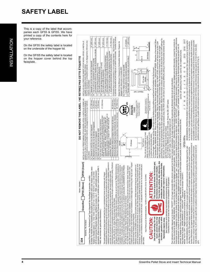
This is a copy of the label that accom-panies each GF55 & GFI55. We have printed a copy of the contents here for your reference.
On the GF55 the safety label is located on the underside of the hopper lid.
On the GFI55 the safety label is located on the hopper cover behind the top faceplate.
To P
rime
Aug
er: R
esta
rt th
e un
it fiv
e (5
) min
utes
into
its
star
tup
or b
y pu
tting
a s
mal
l han
d fu
ll of
pel
lets
into
the
burn
pot.
To O
pera
te S
tove
: MA
NU
AL
MO
DE
: Whe
n a
fire
has
been
est
ablis
hed
the
stov
e se
tting
s ar
e ad
just
able
. / H
IGH
/LO
W M
OD
E: (
Req
uire
s a
ther
mos
tat)
Whe
nth
e th
erm
osta
t cal
ls fo
r hea
t the
sto
ve s
ettin
gs a
re a
djus
tabl
e. W
hen
the
ther
mos
tat c
onta
cts
open
, the
HE
AT L
EV
EL
and
Fans
will
dro
p do
wn
to th
e LO
Wse
tting
unt
il th
e th
erm
osta
t con
tact
s cl
ose
agai
n. /
AU
TO/O
FF M
OD
E: (
Req
uire
s a
ther
mos
tat)
Whe
n th
e th
erm
osta
t con
tact
s cl
ose,
the
unit
will
ligh
tau
tom
atic
ally.
Onc
e up
to te
mpe
ratu
re th
e st
ove
setti
ngs
are
adju
stab
le. W
hen
the
ther
mos
tat c
onta
cts
open
, the
sto
ve w
ill d
rop
dow
n to
the
LOW
set
tings
for
30 m
inut
es. I
f with
in th
e 30
min
the
ther
mos
tat c
onta
cts
clos
e, th
e H
EAT
LE
VE
L w
ill re
turn
to p
revi
ous
MA
NU
AL
setti
ng o
r if t
he th
erm
osta
t con
tact
s re
mai
nop
en th
e st
ove
begi
n its
shu
tdow
n ro
utin
e.To
Tur
n O
ff S
tove
: MA
NU
AL
and
HI /
LO
W m
ode:
Pre
ss th
e O
N /
OFF
but
ton
AU
TO /
OFF
mod
e: T
urn
the
ther
mos
tat d
own
or o
ff
The
unit
can
be in
stal
led
on a
har
d,
stab
le n
on-c
ombu
stib
le s
urfa
ce.
L'un
ité p
eut ê
tre in
stal
lée
sur u
n du
r, la
sur
face
non
-com
bust
ible
sta
ble.
Cer
tifie
d fo
r use
in C
anad
a &
US
AC
ertif
ié p
our i
nsta
llatio
n au
C
anad
a et
aux
Eta
ts-U
nis.
List
ed R
oom
Hea
ter,
Pel
letiz
ed F
uel T
ype
(App
arei
l de
chau
ffage
à g
ranu
les
cer
tifié
)S
uita
ble
For M
obile
Hom
e In
stal
latio
n (A
ccep
té p
our l
'inst
alla
tion
dans
une
mai
son
mob
ile, t
est)
Test
ed to
(Tes
tée
selo
n): U
L 14
82-1
998
/ ULC
S62
7-00
/ A
STM
150
9-95
/ U
LC S
628-
M93
US
Env
ironm
enta
l Pro
tect
ion
Age
ncy,
cer
tifie
d to
com
ply
July
1, 1
990,
par
ticul
ate
emis
sion
st
anda
rds.
(Éta
ts-U
nis
Env
ironn
emen
tal P
rote
ctio
n A
genc
e, a
cer
tifié
pou
r con
form
er a
u Ju
illet
1,
1990
, les
nor
mes
de
parti
cule
s d'
émis
sion
.) Th
is p
elle
t app
lianc
e ha
s be
en te
sted
and
list
ed fo
r use
in m
anuf
actu
red
hom
es in
acc
orda
nce
with
Ore
gon
Adm
inis
tratio
n R
ules
814
-23-
900
thro
ugh
814-
23-9
09. I
nsta
ll an
d us
e on
ly in
acc
orda
nce
with
the
Man
ufac
ture
’s
inst
alla
tion
and
oper
atin
g in
stru
ctio
ns. C
onta
ct lo
cal b
uild
ing
or fi
re o
ffici
als
abou
t res
trict
ions
and
inst
alla
tion
insp
ectio
n in
yo
ur a
rea.
Do
not c
onne
ct th
is u
nit t
o a
chim
ney
flue
serv
ing
anot
her a
pplia
nce.
See
loca
l bui
ldin
g co
des
and
man
ufac
ture
rs in
stru
ctio
ns fo
r pre
caut
ions
requ
ired
for p
assi
ng a
chi
mne
y th
roug
h a
com
bust
ible
wal
l or c
eilin
g. E
lect
rical
ra
ting:
120
vol
ts, 6
0 hz
, 4.3
Am
ps. R
oute
cor
d aw
ay fr
om th
e he
ater
.C
et a
ppar
eil a
été
test
é et
cer
tifié
pou
r util
isat
ion
dans
les
mai
sons
mob
iles
en a
ccor
d av
ec le
s "R
ègle
s Ad
min
istra
tives
de
l'Ore
gon
814-
23-9
00 à
814
-23-
909"
. Ins
talle
z et
util
isez
cet
app
arei
l seu
lem
ent s
elon
les
inst
ruct
ions
d'in
stal
latio
n et
d'
opér
atio
n du
fabr
ican
t. C
onta
ctez
les
auto
rités
loca
les
de v
otre
qua
rtier
con
cern
ant l
es re
stric
tions
et l
es in
spec
tions
d'
inst
alla
tion.
Con
sulte
z le
s co
des
de b
âtim
ent l
ocau
x et
les
inst
ruct
ions
du
fabr
ican
t pou
r les
pré
caut
ions
à p
rend
re
lors
que
une
chem
inée
doi
t être
inst
allé
e au
trav
ers
un m
ur o
u un
pla
fond
com
bust
ible
. CLA
SSEM
ENT
ÉLEC
TRIQ
UE
: 12
0 Vo
lts, 6
0 H
z, 4
.1 A
mps
. Pla
cez
le c
âble
éle
ctriq
ue lo
in d
e la
cha
leur
.Fo
r Use
With
Onl
y Pe
lletiz
ed W
ood
fuel
s. O
pera
te o
nly
with
vie
win
g do
or a
nd a
sh re
mov
al d
oor c
lose
d. O
nly
repl
ace
glas
s w
ith c
eram
ic g
lass
. Com
pone
nts
requ
ired
for i
nsta
llatio
n: a
3 in
ch (7
5 m
m) o
r 4in
ch (1
00 m
m) l
iste
d PL
ven
t, co
mpl
ete
with
com
pone
nts.
Inse
rt an
d H
earth
mou
nt in
stal
latio
ns; a
list
ed s
ingl
e w
all c
him
ney
liner
may
be
used
. In
spec
t an
d cl
ean
Exha
ust V
entin
g sy
stem
freq
uent
ly.
Util
isat
ion
avec
les
com
bust
ible
s so
us fo
rme
de b
oule
ts u
niqu
emen
t. U
tilis
er s
eule
men
t lor
sque
les
porte
s av
ants
et l
a po
rte d
u ré
cept
acle
de
cend
re s
ont f
erm
ées.
Si u
ne o
u de
s vi
tres
deva
ient
être
rem
plac
ées,
util
isez
seu
lem
ent d
u ve
rre
céra
miq
ue. L
es c
ompo
sant
es re
quis
es p
our l
'inst
alla
tion
sont
un
éven
t PL
certi
fié d
e 3i
n/75
mm
or 4
in/1
00m
m a
vec
ses
com
posa
ntes
. Les
inst
alla
tions
inse
rtion
et d
e m
ont d
e fo
yer ;
un
paqu
ebot
de
chem
inée
de
mur
de
seul
énu
mér
é pe
ut
être
util
isé.
Inpu
t Rat
ing
(Les
don
nées
éva
luan
t): 1
2,00
0 to
45,
000
BTU
/Hr (
3.5
to 1
3.2
kWh)
334
DAT
E O
F M
ANU
FAC
TUR
E / D
ATE
DE
FABR
ICAT
ION
:
J
F
M
A
M
J
J
A
S
O
N
D
201
5
201
6
201
7
CA
UTI
ON
:H
ot w
hile
ope
ratin
g. D
o no
t to
uch,
sev
ere
burn
s m
ay
resu
lt. K
eep
child
ren,
clo
thin
g,
furn
iture
, gas
olin
e or
oth
er
flam
mab
le v
apor
s aw
ay.
ATTE
NTI
ON
:Tr
ès c
haud
qua
nd a
llum
é. N
e to
uche
z pa
s,
les
brûl
ures
sév
ères
peu
vent
résu
lter.
Tene
z lo
in d
es e
nfan
ts, d
es v
êtem
ents
, des
m
eubl
es,d
e l’e
ssen
ce o
u d’
autr
es fl
uide
s pr
odui
sant
des
vap
eurs
infla
mm
able
s.
DO
NO
T R
EMO
VE T
HIS
LA
BEL
/ N
E R
ETIR
EZ P
AS
CET
TE É
TIQ
UET
TE
See
inst
alla
tion
and
oper
atin
g in
stru
ctio
ns a
ccom
pany
ing
appl
ianc
e. /
Con
sulte
z le
man
uel a
vec
les
inst
ruct
ions
d’in
stal
latio
n et
d’o
péra
tion.
AS
idew
all t
o U
nit (
Du
mur
de
côté
à l'
appa
reil)
8”
(203
mm
)B
Top
of u
nit t
o an
uns
hiel
ded
8” (2
03 m
m) m
antle
(L
e so
mm
et d
e l'u
nité
à u
n m
ante
au d
e ch
emin
ée n
on b
lindé
)
8” (2
03 m
m)
CU
nit t
o to
p fa
cing
(pro
trudi
ng ¾
” [19
mm
]) (D
e l'u
nité
au
som
met
du
pare
men
t)
8
” (20
3 m
m)
DU
nit t
o si
de fa
cing
(pro
trudi
ng ¾
” [19
mm
]) (D
e l'u
nité
au
côté
du
pare
men
t)
8
” (20
3 m
m)
EFr
om d
oor o
peni
ng o
f uni
t to
edge
of f
loor
pro
tect
ion
(De
la p
orte
ouv
rant
au
deva
nt d
e pr
otec
tion
de p
lanc
her)
6” (1
52 m
m)
FFr
om s
ide
of u
nit t
o ed
ge o
f flo
or p
rote
ctio
n (D
e l'o
uver
ture
de
porte
pou
r pre
ndre
par
ti de
pro
tect
ion
de p
lanc
her)
6
” (15
2 m
m)
Com
bust
ible
floo
rs m
ust b
e pr
otec
ted
by a
non
-com
bust
ible
mat
eria
l. -
See
Own
ers
Man
ual.
Le p
lanc
her c
ombu
stib
le d
oit ê
tre p
roté
gé p
ar u
n m
atér
iel in
com
bust
ible
. - C
onsu
ltez
le m
anua
l.
INS
TALL
ED
AS
A F
IRE
PLA
CE
INS
ER
T S
TOV
E M
OD
EL
(GFI
55) /
A IN
STA
LLE
C
OM
ME
UN
MO
DÈ
LE S
UR
PIE
D D
E P
OE
LE.
Min
imum
cle
aran
ces
to c
ombu
stib
le m
ater
ials
./ Le
s dé
gage
men
ts m
inim
ums
aux
mat
érie
ls c
ombu
stib
les:
AS
idew
all t
o U
nit (
Du
mur
de
côté
à l'
appa
reil)
6” (
152
mm
)B
Bac
kwal
l to
Uni
t (D
u m
ur d
e de
rriè
re à
l'ap
pare
il)
3”
(76
mm
)C
Cor
ner t
o U
nit (
Du
coin
à l'
appa
reil)
2”
(51
mm
)D
Wal
l to
vent
(Le
mur
pou
r don
ner v
ent)
3” (
76 m
m)
EFr
om d
oor o
peni
ng o
f uni
t to
edge
of f
loor
pro
tect
ion
(De
la p
orte
ouv
rant
au
deva
nt d
e pr
otec
tion
de p
lanc
her)
6
” (15
2 m
m)
NO
TE: A
com
bust
ible
floo
r mus
t be
prot
ecte
d by
a n
on-
com
bust
ible
mat
eria
l - W
idth
27"
(686
mm
) by
dept
h 34
" (8
64m
m).
(Un
plan
cher
com
bust
ible
doi
t etre
pro
tege
par
un
mat
erie
l inc
ombu
stib
le. L
a la
rgeu
r 27"
(686
mm
) par
la
prof
onde
ur 3
4" (8
64m
m).)
Min
imum
Alc
ove
Wid
th (L
a la
rgeu
r min
imum
de
l'alc
ove)
3
6” (9
14 m
m)
Min
imum
Alc
ove
Hei
ght (
La h
aute
ur m
inim
um d
e l'
alco
ve)
4
8” (1
219
mm
)M
axim
um A
lcov
e D
epth
(La
prof
onde
ur m
axim
um d
e l'a
lcov
e)
3
0” (7
62 m
m)
INS
TALL
ED
AS
A F
RE
ES
TAN
DIN
G S
TOV
E M
OD
EL
(GF5
5) /
A IN
STA
LLE
CO
MM
E U
N
MO
DÈ
LE F
S, Q
U’IL
SO
IT E
NC
AS
TRÈ
, SU
R P
IED
OU
DA
NS
UN
E M
AIS
ON
MO
BIL
E.
Min
imum
cle
aran
ces
to c
ombu
stib
le m
ater
ials
./ Le
s dé
gage
men
ts m
inim
ums
aux
mat
érie
ls
com
bust
ible
s:
Seria
l No.
/ N
o. D
e Se
rié:
Gre
enfir
e
G
F55
(Sto
ve)
GFI
55 (I
nser
t)M
odel
/ M
odèl
e:
1595
6B
A
D
C
Adjacent wall
FE
Floo
r Pro
tecti
on
A
BC
E
Back
wall
Sidewall
D
Pou
r dém
arre
r le
poêl
e: A
ppuy
er s
ur le
bou
ton
"ON
/OFF
". S
i le
Aug
er n
éces
site
d'ê
tre a
mor
cé, a
ppuy
er s
ur le
bou
ton
man
uel d
'alim
enta
tion
du A
uger
jusq
u'à
ce q
ue le
s gr
anul
es s
e dé
vers
ent d
ans
le p
ot d
e co
mbu
stio
n.P
our f
aire
fonc
tionn
er le
poê
le :
MO
DE
MA
NU
EL
: Lor
sque
le fe
u es
t bie
n ét
abli,
les
régl
ages
peu
vent
être
aju
stés
. / M
OD
E "H
IGH
/LO
W" :
(Néc
essi
te u
n th
erm
osta
t) Lo
rsqu
e le
ther
mos
tat r
equi
ère
de la
cha
leur
, les
régl
ages
peu
vent
être
aju
stés
. Lor
sque
les
cont
acts
du
ther
mos
tat o
uvre
nt, l
e ré
glag
e du
niv
eau
de c
hale
ur e
t les
ven
tilat
eurs
s'a
just
eron
t au
régl
age
" bas
" ju
squ'
à ce
que
les
cont
acts
du
ther
mos
tat s
e re
ferm
ent.
/ MO
DE
"AU
TO/O
FF" :
(Néc
essi
te u
n th
erm
osta
t) Lo
rsqu
e le
s co
ntac
ts d
u th
erm
osta
t fer
men
t, le
poê
le s
'allu
mer
aau
tom
atiq
uem
ent.
Lors
que
la te
mpé
ratu
re a
déqu
ate
est a
ttein
te, l
es ré
glag
es p
euve
nt ê
tre a
just
és. L
orsq
ue le
s co
ntac
ts d
u th
erm
osta
t ouv
rent
, le
poêl
e s'
ajus
tera
aux
régl
ages
"LO
W" p
enda
nt 3
0 m
inut
es. S
i les
con
tact
s du
ther
mos
tat s
ont f
erm
és p
enda
nt c
es 3
0m
inut
es, l
e ré
glag
e de
niv
eau
de c
hale
ur re
tour
nera
en
régl
ages
"MA
NU
EL"
ou
si le
s co
ntac
ts d
u th
erm
osta
t res
tent
ouv
erts
, le
poêl
e en
tam
era
le p
roce
ssus
d'a
rrêt
.P
our é
tein
dre
le p
oêle
: M
OD
E M
AN
UE
L E
T " H
IGH
/LO
W "
: App
uyer
sur
le b
outo
n "O
N/O
FF".
MO
DE
"AU
TO /
OFF
" : R
égle
r le
ther
mos
tat à
la b
aiss
e ou
éte
igne
z le
.
Man
ufac
ture
d in
Can
ada
for /
Fa
briq
ué d
ans
le C
anad
a po
ur:
FPI F
irepl
ace
Pro
duct
s In
tern
atio
nal L
td.
Del
ta, B
C, C
anad
a
Mod
el B
IH O
nly
Min
imum
Cle
aran
ce to
Com
bust
ible
Mat
eria
ls /
Esp
ace
de
déga
gem
ent r
equi
s po
ur le
mod
èle
BIH
:
G
BH
BIH
Mod
elE
FPI o
r BIH
M
odel
s
GFr
om S
ides
and
rear
wal
ls to
sta
ndof
fs
(Les
mur
s cô
té e
t mur
d'a
rriè
re à
spa
cers
)
0” (0
mm
)H
Rec
ess
dept
h (L
e do
s de
poê
le à
une
pro
fond
eur)
11” (
280
mm
)
FS M
odel
GF5
5-08
1a
U.S
. EN
VIRO
NM
ENTA
L PR
OTE
CTI
ON
AG
ENCY
Cer
ti�ed
to c
ompl
y w
ith 2
015
part
icul
ate
emis
sion
sta
ndar
ds. N
ot a
ppro
ved
for s
ale
afte
r May
15,
202
0. T
his
pelle
t hea
ter n
eeds
per
iodi
c in
spec
tion
and
repa
ir fo
r pro
per o
pera
tion.
Con
sult
the
owne
r`s
man
ual f
or
furt
her i
nfor
mat
ion.
It is
aga
inst
fede
ral r
egul
atio
ns to
ope
rate
this
hea
ter i
n a
man
ner i
ncon
sist
ent w
ith th
e op
erat
ing
inst
ruct
ions
in
the
owne
r`s
man
ual.
This
hea
ter m
eets
the
2015
U.S
. Env
ironm
enta
l Pro
tect
ion
Agen
cy’s
pelle
t em
issi
on li
mits
for p
elle
t em
issi
on
limits
sol
d af
ter M
ay 1
5, 2
015.
Und
er s
peci
�c te
st c
ondi
tions
this
hea
ter h
as b
een
show
n to
hav
e a
part
icul
ate
emis
sion
leve
l of 2
.0
g/hr
.
ENVI
RON
MEN
TAL
PRO
TEC
TIO
N A
GEN
CY U
S co
nfor
me
aux
norm
es 2
015
d'ém
issi
on d
e pa
rtic
ules
. Non
app
rouv
é po
ur la
ven
te a
près
le
15
mai
à 2
020.
Ce
poêl
e à
gran
ulés
bes
oins
insp
ectio
n pé
riodi
que
et la
répa
ratio
n po
ur u
n fo
nctio
nnem
ent c
orre
ct. C
onsu
ltez
le
man
uel d
'ow
ner`
s po
ur p
lus
d'in
form
atio
ns. I
l est
con
tre
les
règl
emen
ts fé
déra
ux p
our e
xplo
iter c
ette
pas
tille
cha
u�e
d'un
e m
aniè
re
inco
mpa
tible
ave
c le
s in
stru
ctio
ns d
e fo
nctio
nnem
ent d
ans
le m
anue
l d'o
wne
r`s.
Ce c
hau�
e re
spec
te le
s lim
ites
d'ém
issi
on g
ranu
lés
de l'
Envi
ronm
enta
l Pro
tect
ion
Agen
cy d
es É
tats
-Uni
s po
ur 2
015
limite
s cu
lot d
'ém
issi
on v
endu
s ap
rès
le 1
5 m
ai 2
015.
Dan
s de
s co
nditi
ons
de te
st s
péci
�que
s, ce
poê
le a
été
mon
tré
pour
avo
ir un
niv
eau
d'ém
issi
on d
e pa
rtic
ules
de
2.0
g / h
.
Greenfire Pellet Stove and Insert Technical Manual 5
INS
TALLAT
ION
UNIT DIMENSIONS
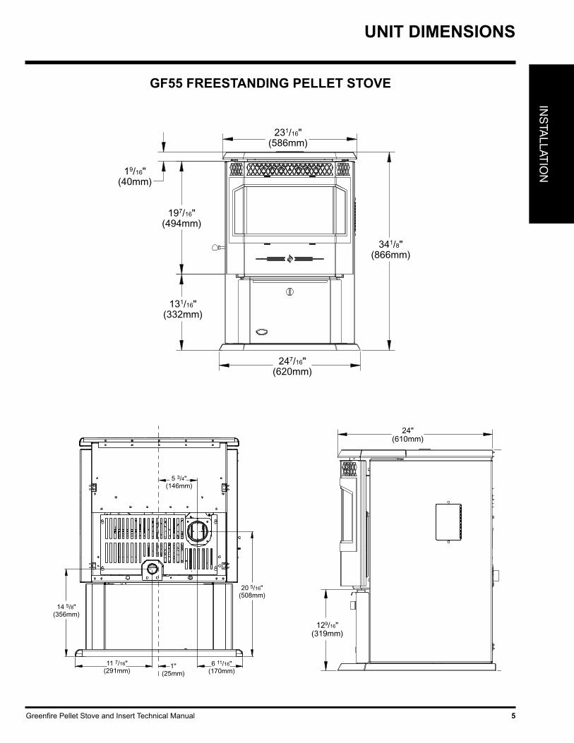
GF55 FREESTANDING PELLET STOVE
341/8"(866mm)
231/16"(586mm)
19/16"(40mm)
197/16"(494mm)
131/16"(332mm)
247/16"(620mm)
24"(610mm)
1" (25mm)
191/8"(866mm)
24"(610mm)
129/16"(319mm)
15/8"(41mm)
145/8"(371mm)
231/16"(586mm)
3"(76mm)
205/16"(516mm)
511/16" (145mm)
1"(25mm)
11 7/16"(291mm)
6 11/16"(170mm)
14 5/8"(356mm)
20 5/16"(508mm)
5 3/4"(146mm)

Greenfire Pellet Stove and Insert Technical Manual6
INS
TALL
ATIO
NUNIT DIMENSIONS
GFI55 FIREPLACE PELLET INSERT
225/16"(567mm)
13/8" (35mm)
303/16"(766mm)
71/4"(183mm)
2215/16"(582mm)
203/8" (517mm)
241/16" (610mm)
11/16"(26mm)
13"(329mm)
10"(253mm)
225/16"(567mm)
13/8" (35mm)
303/16"(766mm)
71/4"(183mm)
2215/16"(582mm)
203/8" (517mm)
241/16" (610mm)
11/16"(26mm)
13"(329mm)
10"(253mm)
FACEPLATE DIMENSIONS
Regular Faceplate
(A) Height 30" (761mm)
(B) Width 39-15/16" (1014mm)
Oversize Faceplate
(A) Height 33" (838mm)
(B) Width 45-15/16" (1167mm)
2315/16" (609mm)
B
A
213/16"(538mm)
Greenfire Pellet Stove and Insert Technical Manual 7
INS
TALLAT
ION
INSTALLATION
CAUTION: Do not connect to any air distribution duct or system. Do not burn garbage or flammable fluids such as gaso- line, naptha or engine oil. Unit hot while in operation. Keep children, clothing and furniture away. Contact may cause skin burns.
SOOT: Operation of the stove with insufficient combustion air will result in the formation of soot which will collect on the glass, the heat exchanger, the exhaust vent system, and may stain the outside of the house. This is a dangerous situation and is inefficient. Frequently check your stove and adjust the slider/damper as needed to ensure proper combustion. See "Slider/Damper Setting".
CLEANING: There will be some build up of fly ash and small amounts of creosote in the exhaust. This will vary due to the ash content of the fuel used and the operation of the stove. It is advisable to inspect and clean the exhaust vent semi-annually or every two tons of pellets.
SAFETY WARNINGS & RECOMMENDATIONS
IMPORTANT SAFETY INFORMATION
Failure to follow these instructions may result in property damage, bodily injury or even death.
Contact your local building or fire official to obtain a permit and any information on installation restrictions and inspection requirements for your area.
To prevent the possibility of a fire, ensure that the appliance is properly installed by adhering to the installation instructions. A Greenfire dealer will be happy to assist you in obtaining information with regards to your local building codes and installation restrictions.
Be sure to maintain the structural integrity of the home when passing a vent through walls, ceilings, or roofs.
The stove's exhaust system works with negative combustion chamber pressure and a slightly positive chimney pressure. It is very important to ensure that the exhaust system be sealed and airtight. The ash pan and viewing door must be locked securely for proper and safe operation of the pellet stove.
Do not burn with insufficient combustion air. A periodic check is recom-mended to ensure proper combustion air is admitted to the combustion chamber. Setting the proper combustion air is achieved by adjusting the slider damper located on the left side of the stove. Refer to "Slider/Damper Set-up" section.
When installing the stove in a mobile home, it must be electrically grounded to the steel chassis of the home and bolted to the floor. Make sure that the structural integrity of the home is maintained and all construction meets local building codes.
Minor soot or creosote may accumulate when the stove is operated under incorrect conditions such as an extremely rich burn (black tipped, lazy orange flames).
If you have any questions with regard to your stove or the above-men-tioned information, please feel free to contact your local dealer for further clarification and comments.
ELECTRICAL: The use of a surge protected power bar is recommended. The unit must be grounded. The grounded electrical cord should be connected to a standard 115 volts (4.6 Amps), 60 hertz electrical outlet. Be careful that the electrical cord is not trapped under the appliance and that it is clear of any hot surfaces or sharp edges and also must be accessible. If this power cord should become damaged, a replacement power cord must be purchased from a Greenfire dealer. This unit's maximum power requirement is 520 watts.
GLASS: Do not abuse the glass by striking or slamming the door. Do not attempt to operate the stove with broken glass. The stove uses ceramic glass. Replacement glass must be purchased from a Greenfire dealer. Do not attempt to open the door and clean the glass while the unit is in operation or if glass is hot. To clean the glass, use a soft cotton cloth and mild window cleaner, gas or wood stove glass cleaner, or take a damp paper towel and dip into the fly ash. This is a very mild abrasive and will not damage the glass.
FLAMMABLE LIQUIDS: Never use gasoline, gasoline-type lantern fuel, kerosene, charcoal lighter fluid, or similar liquids to start or “freshen up” a fire in the heater. Keep all such liquids well away from the heater while it is in use.
SMOKE DETECTOR: Smoke detectors should be installed and maintained in the structure when installing and operating a pellet burning appliance.
OPERATION: The ash pan and door must be closed securely for proper and safe operation of the pellet stove. Also ensure all gaskets on the door are checked and replaced when necessary.
INSTALLATION: Be sure to maintain the structural integrity of your home when passing a vent through walls, ceilings, or roofs. It is recommended that the unit be secured into its position in order to avoid any displacement.
DO NOT INSTALL A FLUE DAMPER IN THE EXHAUST VENTING SYSTEM OF THIS UNIT.
DO NOT CONNECT THIS UNIT TO A CHIMNEY FLUE SERVING ANOTHER APPLIANCE.
FRESH AIR: Outside Fresh Air connection is optional. Must be connected to all units installed in Mobile and “Air Tight Homes” (R2000) or where required by local codes. Consider all large air moving devices when installing your unit and provide room air accordingly. Limited air for combustion may result in poor performance, smoking and other side effects of poor combustion.
If you have any questions with regards to your stove or the above-mentioned information, please feel free to contact your Greenfire dealer for further clarification and comments.
SINCE FPI HAS NO CONTROL OVER THE INSTALLATION OF YOUR STOVE, FPI GRANTS NO WARRANTY IMPLIED OR STATED FOR THE INSTALLATION OR MAINTENANCE OF YOUR STOVE. THEREFORE, FPI ASSUMES NO RESPONSIBILITY FOR ANY CONSEQUENTIAL DAMAGE(S).

Greenfire Pellet Stove and Insert Technical Manual8
INS
TALL
ATIO
NINSTALLATION
1. Check clearances to combustibles. See "Clearance to Combustibles" section.
2. Do not obtain combustion air from an attic, garage or any unventilated space if enough air is available. Combustion air may be obtained from a ventilated crawlspace.
3. Do not install the stove in a bedroom.
4. You can vent the stove through an exterior wall behind the unit or connect it to an existing masonry or metal chimney (must be lined if the chimney is over 6” (15 cm) diameter, or over 28 inches² (180 cm²) cross sectional area). An interior vent can be used with approved pipe passing through the ceiling and roof.
REMOVING PELLET STOVEFROM PALLET
To remove your new stove from its pallet, remove the two (2) screws securing the bottom to the pallet.
Freestanding:One screw can be easily seen from behind but to access the second screw the ashpan must be removed. See figure 1.
Figure 1: Removing GF55 From Pallet. Figure 2: Removing GFI55 From Pallet.
Fireplace Insert:There is one screw on either side of the bottom. See figure 2.
LOCATING THE PELLET APPLIANCE
5. Locate the stove in a large and open room that is centrally located in the house. This will optimize heat circulation.
6. The power cord is 8 feet (2.43 m) long and may require a grounded extension cord to reach the nearest electrical outlet.
OPENING THE DOOR
The door lever can be found inbehind the right side of the door frame. To open the door, pivet the lever outwards and upwards until it unlocks.
Greenfire Pellet Stove and Insert Technical Manual 9
INS
TALLAT
ION
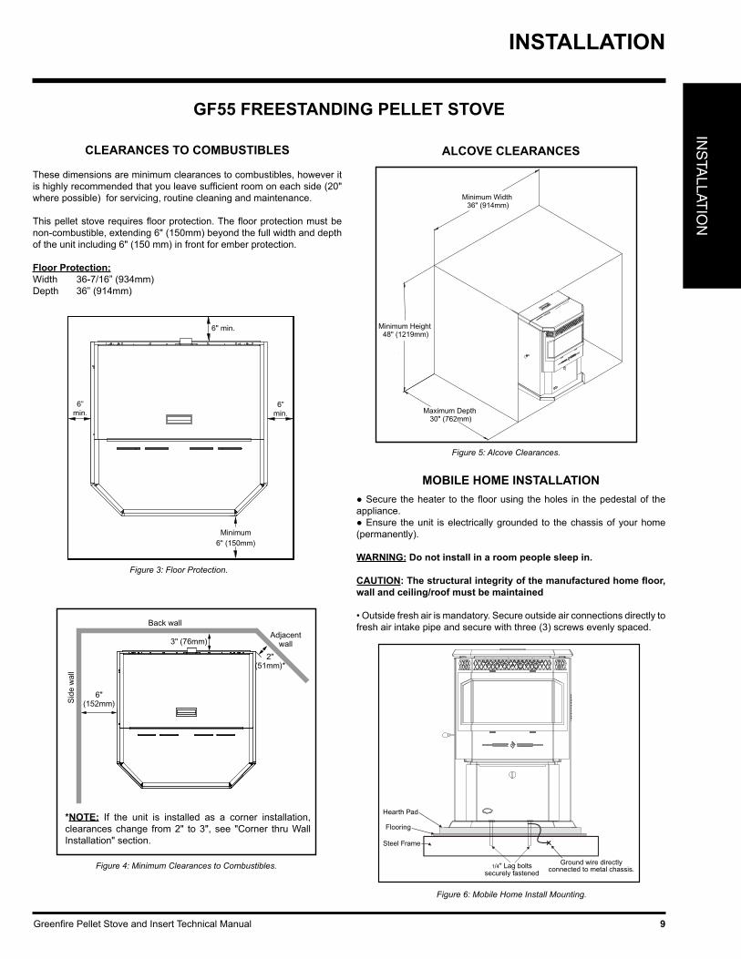
GF55 FREESTANDING PELLET STOVE
These dimensions are minimum clearances to combustibles, however it is highly recommended that you leave sufficient room on each side (20" where possible) for servicing, routine cleaning and maintenance.
This pellet stove requires floor protection. The floor protection must be non-combustible, extending 6" (150mm) beyond the full width and depth of the unit including 6" (150 mm) in front for ember protection.
Floor Protection:Width 36-7/16” (934mm)Depth 36” (914mm)
Figure 3: Floor Protection.
Back wall
Sid
e w
all
Adjacentwall
2"(51mm)*
3" (76mm)
6"(152mm)
Figure 4: Minimum Clearances to Combustibles.
ALCOVE CLEARANCES
Minimum Width 36" (914mm)
Minimum Height 48" (1219mm)
Maximum Depth 30" (762mm)
Figure 5: Alcove Clearances.
CLEARANCES TO COMBUSTIBLES
MOBILE HOME INSTALLATION● Secure the heater to the floor using the holes in the pedestal of the appliance.● Ensure the unit is electrically grounded to the chassis of your home (permanently).
WARNING: Do not install in a room people sleep in.
CAUTION: The structural integrity of the manufactured home floor, wall and ceiling/roof must be maintained
• Outside fresh air is mandatory. Secure outside air connections directly to fresh air intake pipe and secure with three (3) screws evenly spaced.
Figure 6: Mobile Home Install Mounting.
INSTALLATION
*NOTE: If the unit is installed as a corner installation, clearances change from 2" to 3", see "Corner thru Wall Installation" section.
Greenfire Pellet Stove and Insert Technical Manual10
INS
TALL
ATIO
N
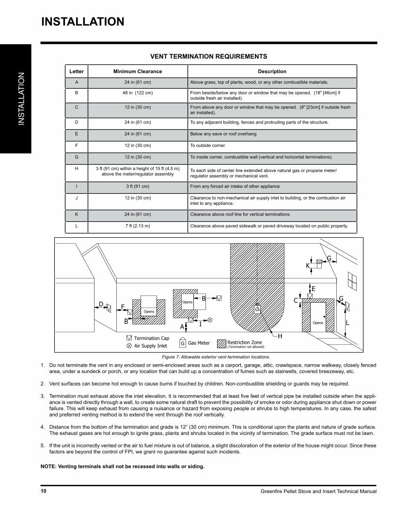
VENT TERMINATION REQUIREMENTS
1. Do not terminate the vent in any enclosed or semi-enclosed areas such as a carport, garage, attic, crawlspace, narrow walkway, closely fenced area, under a sundeck or porch, or any location that can build up a concentration of fumes such as stairwells, covered breezeway, etc.
2. Vent surfaces can become hot enough to cause burns if touched by children. Non-combustible shielding or guards may be required.
3. Termination must exhaust above the inlet elevation. It is recommended that at least five feet of vertical pipe be installed outside when the appli-ance is vented directly through a wall, to create some natural draft to prevent the possibility of smoke or odor during appliance shut down or power failure. This will keep exhaust from causing a nuisance or hazard from exposing people or shrubs to high temperatures. In any case, the safest and preferred venting method is to extend the vent through the roof vertically.
4. Distance from the bottom of the termination and grade is 12” (30 cm) minimum. This is conditional upon the plants and nature of grade surface. The exhaust gases are hot enough to ignite grass, plants and shrubs located in the vicinity of termination. The grade surface must not be lawn.
5. If the unit is incorrectly vented or the air to fuel mixture is out of balance, a slight discoloration of the exterior of the house might occur. Since these factors are beyond the control of FPI, we grant no guarantee against such incidents.
NOTE: Venting terminals shall not be recessed into walls or siding.
Figure 7: Allowable exterior vent termination locations.
Air Supply Inlet Gas Meter Restriction Zone(Termination not allowed)
Termination CapG
GOpens
Opens
Opens
D F
B
B
A I
H
KG
G
L
C
E
Letter Minimum Clearance Description
A 24 in (61 cm) Above grass, top of plants, wood, or any other combustible materials.
B 48 in (122 cm) From beside/below any door or window that may be opened. (18" [46cm] if outside fresh air installed).
C 12 in (30 cm) From above any door or window that may be opened. (9" [23cm] if outside fresh air installed).
D 24 in (61 cm) To any adjacent building, fences and protruding parts of the structure.
E 24 in (61 cm) Below any eave or roof overhang
F 12 in (30 cm) To outside corner.
G 12 in (30 cm) To inside corner, combustible wall (vertical and horizontal terminations).
H 3 ft (91 cm) within a height of 15 ft (4.5 m) above the meter/regulator assembly
To each side of center line extended above natural gas or propane meter/regulator assembly or mechanical vent.
I 3 ft (91 cm) From any forced air intake of other appliance
J 12 in (30 cm) Clearance to non-mechanical air supply inlet to building, or the combustion air inlet to any appliance.
K 24 in (61 cm) Clearance above roof line for vertical terminations.
L 7 ft (2.13 m) Clearance above paved sidewalk or paved driveway located on public property.
INSTALLATION
Greenfire Pellet Stove and Insert Technical Manual 11
INS
TALLAT
ION
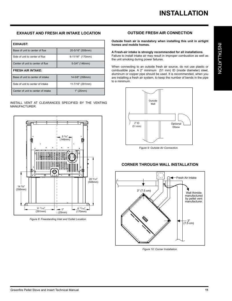
EXHAUST AND FRESH AIR INTAKE LOCATION
EXHAUST:
Base of unit to center of flue 20-5/16" (508mm)
Side of unit to center of flue 6-11/16" (170mm)
Center of unit to center of flue 5-3/4" (146mm)
FRESH AIR INTAKE:
Base of unit to center of intake 14-5/8" (356mm)
Side of unit to center of intake 11-7/16" (291mm)
Center of unit to center of intake 1" (25mm)
1"(25mm)
11 7/16"(291mm)
6 11/16"(170mm)
14 5/8"(356mm)
20 5/16"(508mm)
5 3/4"(146mm)
Figure 8: Freestanding Inlet and Outlet Location.
OUTSIDE FRESH AIR CONNECTION
Outside fresh air is mandatory when installing this unit in airtight homes and mobile homes.
A Fresh-air intake is strongly recommended for all installations. Failure to install intake air may result in improper combustion as well as the unit smoking during power failures.
When connecting to an outside fresh air source, do not use plastic or combustible pipe. A 2” minimum (51 mm) ID (inside diameter) steel, aluminum or copper pipe should be used. It is recommended, when you are installing a fresh air system, to keep the number of bends in the pipe to a minimum.
2" ID(51 mm)
OptionalElbow
OutsideWall
Figure 9: Outside Air Connection.
Figure 10: Corner Installation.
3" (7.5 cm)
3"(7.5 cm)
Fresh Air Intake
Wall thimblemanufacturedby pellet ventmanufacturer.
CORNER THROUGH WALL INSTALLATION
INSTALLATION
INSTALL VENT AT CLEARANCES SPECIFIED BY THE VENTING MANUFACTURER.

Greenfire Pellet Stove and Insert Technical Manual12
INS
TALL
ATIO
N
HORIZONTAL EXHAUSTTHROUGH WALL INSTALLATION
Vent installation: install vent at clearances specified by the vent manufacturer.
A chimney connector shall not pass through an attic or roof space, closet or similar concealed spaces, or a floor, or ceiling. Where passage through a wall or partition of combustible construction is desired, the installation shall conform to CAN/CSA-B365 Installation Code for Solid-Fuel-Burning Appliances and Equipment. Only use venting of L or PL type with an inside diameter of 3 or 4 inches (7.6 or 10.1 cm).
1. Choose a location for your stove that meets the requirements stated in this manual and allows installation with the least amount of interfer-ence to house framing, plumbing, wiring, etc.
2. Install a non-combustible hearth pad (where necessary).
3. Place the appliance 15” (37.5 cm) away from the wall. If the stove is to be set on a hearth pad, set the unit on it.
4. Locate the center of the exhaust pipe on the stove. Extend that line to the wall. Once you have located the center point on the wall, refer to pellet vent manufacturer installation instructions for correct hole size and clearance to combustibles.
5. Install the wall thimble as per the instructions written on the thimble. Maintain an effective vapour barrier in accordance with local building codes.
6. Install a length of 3” (76 mm) or 4” (101 mm) vent pipe into the wall thimble. The pipe should install easily into the thimble.
7. Install the fresh air intake. See "Outside Fresh Air Connection" sec-tion.
8. Connect the exhaust vent pipe to the exhaust pipe on the stove. Seal the connection with high temperature silicone.
9. Push the stove straight back, leaving a minimum of 3” (8 cm) clear-ance from the back of the stove to the wall. Seal the vent pipe to the thimble with high temperature silicone.
10. The pipe must extend at least 12” (30 cm) away from the building. If necessary, bring another length of pipe (PL type) to the outside of the home to connect to the first section. Do not forget to place high tem-perature silicone around the pipe that passes through the thimble.
11. Install a vertical pipe, or if all requirements for direct venting are met, install vent termination. The stainless steel cap termination manufac-tured by the vent manufacturer is recommended. However, when the vent terminates several feet above ground level and there are no trees, plants, etc. within several feet, a 45° elbow can be used as termination. The elbow must be turned down to prevent rain from entering.
Exhaust Tube
3" (75mm) or 4" (100mm)"PL" or "L" vent
Wall Thimble
45° Elbow with screen or Termination Cap
Fresh Air Intake High Temperature RTV Silicone Required
Figure 11: Straight through wall Installation.
Figure 12: Straight through Wall Installation - Side View.
INSTALLATION
NOTE:• Some horizontal through wall installations may require a “T” and 3 to 5 feet (91 to 152 cm) of vertical pipe outside the building to help naturally draft in the unit.
• This may be required if a proper burn cannot be maintained, after the stove has been tested and the airflow set.
• This is due to the back pressure in the exhaust caused by airflow around the structure.
• All sections of pipe must have three (3) screws evenly spaced and all horizontal and vertical vent sections located within the house must have a bead of high temperature silicone installed on the male end of the pipe before installation to create a gas tight seal.
• The termination must be 12 inches (30 cm) from the outside wall and 12 inches (30 cm) above the ground.
• A 45° elbow may be used in place of the termination cap (or stainless steel termination hood).
Greenfire Pellet Stove and Insert Technical Manual 13
INS
TALLAT
ION
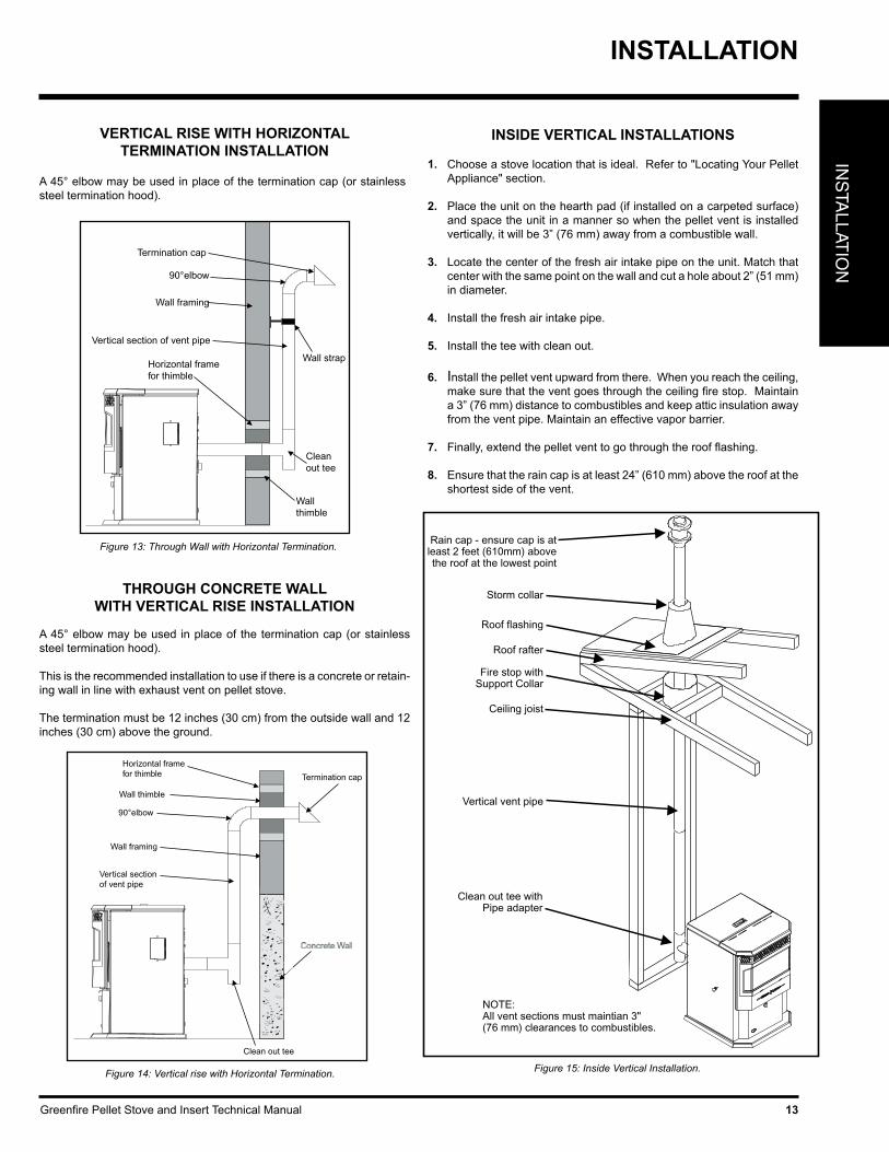
VERTICAL RISE WITH HORIZONTALTERMINATION INSTALLATION
Figure 13: Through Wall with Horizontal Termination.
A 45° elbow may be used in place of the termination cap (or stainless steel termination hood).
THROUGH CONCRETE WALLWITH VERTICAL RISE INSTALLATION
A 45° elbow may be used in place of the termination cap (or stainless steel termination hood).
This is the recommended installation to use if there is a concrete or retain-ing wall in line with exhaust vent on pellet stove.
The termination must be 12 inches (30 cm) from the outside wall and 12 inches (30 cm) above the ground.
Figure 14: Vertical rise with Horizontal Termination.
INSIDE VERTICAL INSTALLATIONS
1. Choose a stove location that is ideal. Refer to "Locating Your Pellet Appliance" section.
2. Place the unit on the hearth pad (if installed on a carpeted surface)
and space the unit in a manner so when the pellet vent is installed vertically, it will be 3” (76 mm) away from a combustible wall.
3. Locate the center of the fresh air intake pipe on the unit. Match that center with the same point on the wall and cut a hole about 2” (51 mm) in diameter.
4. Install the fresh air intake pipe.
5. Install the tee with clean out.
6. Install the pellet vent upward from there. When you reach the ceiling, make sure that the vent goes through the ceiling fire stop. Maintain a 3” (76 mm) distance to combustibles and keep attic insulation away from the vent pipe. Maintain an effective vapor barrier.
7. Finally, extend the pellet vent to go through the roof flashing.
8. Ensure that the rain cap is at least 24” (610 mm) above the roof at the shortest side of the vent.
Rain cap - ensure cap is at
least 2 feet (610mm) above the roof at the lowest point
Storm collar
Roof flashing
Roof rafter
Fire stop with Support Collar
Ceiling joist
Vertical vent pipe
Clean out tee with Pipe adapter
NOTE:All vent sections must maintian 3" (76 mm) clearances to combustibles.
Figure 15: Inside Vertical Installation.
INSTALLATION
Greenfire Pellet Stove and Insert Technical Manual14
INS
TALL
ATIO
N
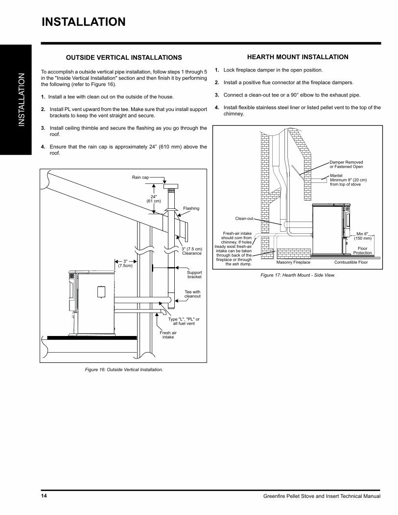
OUTSIDE VERTICAL INSTALLATIONS
To accomplish a outside vertical pipe installation, follow steps 1 through 5 in the "Inside Vertical Installation" section and then finish it by performing the following (refer to Figure 16).
1. Install a tee with clean out on the outside of the house.
2. Install PL vent upward from the tee. Make sure that you install support brackets to keep the vent straight and secure.
3. Install ceiling thimble and secure the flashing as you go through the roof.
4. Ensure that the rain cap is approximately 24” (610 mm) above the roof.
Rain cap
Flashing
24"(61 cm)
3"(7.5cm)
Tee withcleanout
Fresh airintake
3" (7.5 cm)Clearance
Supportbracket
Type "L", "PL" orall fuel vent
Figure 16: Outside Vertical Installation.
HEARTH MOUNT INSTALLATION
1. Lock fireplace damper in the open position.
2. Install a positive flue connector at the fireplace dampers.
3. Connect a clean-out tee or a 90° elbow to the exhaust pipe.
4. Install flexible stainless steel liner or listed pellet vent to the top of the chimney.
FloorProtection
Combustible FloorMasonry Fireplace
Min 6" (150 mm)
MantelMinimum 8" (20 cm) from top of stove
Damper Removedor Fastened Open
Clean-out
Fresh-air intake should com from chimney. If holes
already exist fresh-air intake can be taken through back of the fireplace or through
the ash dump.
Figure 17: Hearth Mount - Side View.
INSTALLATION

Greenfire Pellet Stove and Insert Technical Manual 15
INS
TALLAT
ION
GFI55 PELLET INSERT
CLEARANCES TO COMBUSTIBLES
The fireplace insert is certified to be installed into a masonry fireplace only and/or zero clearance wood burning factory built fireplace where allowed by local codes. This model includes a surround faceplate and a pedestal. When installing this unit, ensure that the pedestal is removed from the inside of the hopper and installed on the bottom of the unit.
From the body of the heater to the:Side Wall 8" (203mm) minimumFacing on Masonry Fireplace: 8" (203mm) minimum8” (203mm) mantle: 8" (203mm) minimum
INSTALLATION OF PEDESTAL AND LEVELING LEGSThere are two parts to the GFI55 insert pedestal and they can be found inside the hopper. Place unit on its back. Two (2) hex head screws are used on each side of the pedestal (refer to Figure 22). Using a 5/16” wrench or socket, secure the pedestal to the bottom of the unit.
OPTIONAL: There are two (2) leveling legs and they can be found inside the manual bag. Each leveling leg consists of a long bolt, a hex nut, a washer, and a square bolt with clip (see Figure 23). For installation of the leveling legs the unit should be on its back and a ½” wrench is required for adjustments.
Install the square bolts into the square holes in the back corners of the bottom. The square bolt should be inserted from inside the unit so that the clip will be facing up.
Thread hex nut onto the bolt till it is approximately 1” (25 mm) from the bolt head, slide washer onto bolt. Thread the bolt into the square nut so length of the bolt shown is the approximately height needed for leveling. When the unit is up right and the bolts can be adjusted to the exact height required. To lock the bolts at a height tighten the hex nut and washer against the square bolt
Leveling Legs
Figure 22: Installing Pedestal.
Figure 23: Square Bolt.
INSTALLING HOPPER COVER ANDADJUSTING HOPPER HEIGHT
The hopper cover initially comes upside-down on top of the hopper. To install the hopper cover flip the cover over and fasten in place with four T-20 screws (see Figure 24).
The back height of this unit can be set to one (1) of three (3) heights; 19½” (495 mm), 21⅛” (537 mm), 22¼” (565 mm). The hopper should be set to the maximum height that can be used in the installation.
To change the height of the hopper back up or down, remove the seven (7) T-20 screws, three (3) on each side and one (1) on the back. The screw placement is shown Figure 25. Move the hopper assembly to the required setting and replace the screws. When the hopper back is in place it is recommended that silicone is used to seal the bottom lip of the hopper back and sides.
Figure 24: Hopper Cover Screw Placement.
Figure 25: Hopper Extension Screw Placement.
INSTALLATION
FIREPLACE SPECIFICATIONS
Your fireplace opening requires the following minimum sizes:
Height 55 lbs hopper (standard) 42 lbs hopper (adjusted)
22.75" (578mm)19.5" (495mm)
Width 26" (660mm)
Depth 15" (381mm)
Greenfire Pellet Stove and Insert Technical Manual16
INS
TALL
ATIO
N
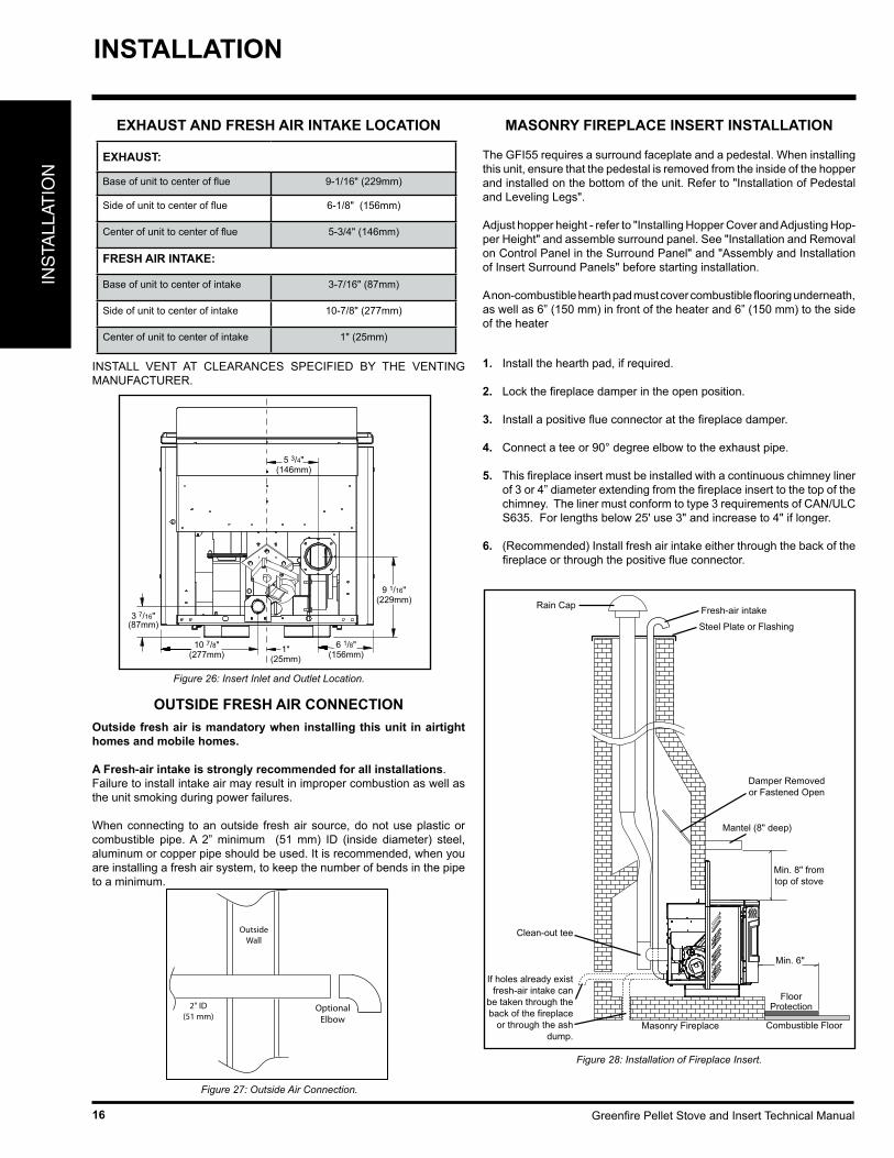
EXHAUST AND FRESH AIR INTAKE LOCATION
EXHAUST:
Base of unit to center of flue 9-1/16" (229mm)
Side of unit to center of flue 6-1/8" (156mm)
Center of unit to center of flue 5-3/4" (146mm)
FRESH AIR INTAKE:
Base of unit to center of intake 3-7/16" (87mm)
Side of unit to center of intake 10-7/8" (277mm)
Center of unit to center of intake 1" (25mm)
INSTALL VENT AT CLEARANCES SPECIFIED BY THE VENTING MANUFACTURER.
1"(25mm)
5 3/4"(146mm)
3 7/16"(87mm)
10 7/8"(277mm)
6 1/8"(156mm)
9 1/16"(229mm)
Figure 26: Insert Inlet and Outlet Location.
OUTSIDE FRESH AIR CONNECTIONOutside fresh air is mandatory when installing this unit in airtight homes and mobile homes.
A Fresh-air intake is strongly recommended for all installations. Failure to install intake air may result in improper combustion as well as the unit smoking during power failures.
When connecting to an outside fresh air source, do not use plastic or combustible pipe. A 2” minimum (51 mm) ID (inside diameter) steel, aluminum or copper pipe should be used. It is recommended, when you are installing a fresh air system, to keep the number of bends in the pipe to a minimum.
2" ID(51 mm)
OptionalElbow
OutsideWall
Figure 27: Outside Air Connection.
MASONRY FIREPLACE INSERT INSTALLATION
The GFI55 requires a surround faceplate and a pedestal. When installing this unit, ensure that the pedestal is removed from the inside of the hopper and installed on the bottom of the unit. Refer to "Installation of Pedestal and Leveling Legs".
Adjust hopper height - refer to "Installing Hopper Cover and Adjusting Hop-per Height" and assemble surround panel. See "Installation and Removal on Control Panel in the Surround Panel" and "Assembly and Installation of Insert Surround Panels" before starting installation.
A non-combustible hearth pad must cover combustible flooring underneath, as well as 6” (150 mm) in front of the heater and 6” (150 mm) to the side of the heater
1. Install the hearth pad, if required.
2. Lock the fireplace damper in the open position.
3. Install a positive flue connector at the fireplace damper.
4. Connect a tee or 90° degree elbow to the exhaust pipe.
5. This fireplace insert must be installed with a continuous chimney liner of 3 or 4” diameter extending from the fireplace insert to the top of the chimney. The liner must conform to type 3 requirements of CAN/ULC S635. For lengths below 25' use 3" and increase to 4" if longer.
6. (Recommended) Install fresh air intake either through the back of the fireplace or through the positive flue connector.
FloorProtection
Combustible FloorMasonry Fireplace
Min. 6"
Rain Cap
Steel Plate or Flashing
Mantel (8" deep)
Fresh-air intake
Clean-out tee
If holes already exist fresh-air intake can
be taken through the back of the fireplace
or through the ash dump.
Damper Removedor Fastened Open
Min. 8" fromtop of stove
Figure 28: Installation of Fireplace Insert.
INSTALLATION
Greenfire Pellet Stove and Insert Technical Manual 17
INS
TALLAT
ION
When installing the insert into a masonry fireplace DO NOT remove any bricks or masonry, with the following exception; masonry or steel, including the damper plate, may be removed from the smoke shelf and adjacent damper frame if necessary to accommodate a chimney liner. Provided that their removal will not weaken the structure of the fireplace and chimney, and will not reduce protection for combustible materials to less than that required by the national building code.
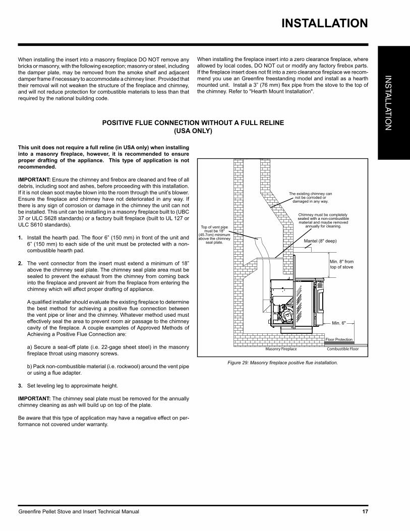
POSITIVE FLUE CONNECTION WITHOUT A FULL RELINE(USA ONLY)
This unit does not require a full reline (in USA only) when installing into a masonry fireplace, however, it is recommended to ensure proper drafting of the appliance. This type of application is not recommended.
IMPORTANT: Ensure the chimney and firebox are cleaned and free of all debris, including soot and ashes, before proceeding with this installation. If it is not clean soot maybe blown into the room through the unit’s blower. Ensure the fireplace and chimney have not deteriorated in any way. If there is any sign of corrosion or damage in the chimney the unit can not be installed. This unit can be installing in a masonry fireplace built to (UBC 37 or ULC S628 standards) or a factory built fireplace (built to UL 127 or ULC S610 standards).
1. Install the hearth pad. The floor 6” (150 mm) in front of the unit and 6” (150 mm) to each side of the unit must be protected with a non-combustible hearth pad.
2. The vent connector from the insert must extend a minimum of 18” above the chimney seal plate. The chimney seal plate area must be sealed to prevent the exhaust from the chimney from coming back into the fireplace and prevent air from the fireplace from entering the chimney which will affect proper drafting of appliance.
A qualified installer should evaluate the existing fireplace to determine the best method for achieving a positive flue connection between the vent pipe or liner and the chimney. Whatever method used must effectively seal the area to prevent room air passage to the chimney cavity of the fireplace. A couple examples of Approved Methods of Achieving a Positive Flue Connection are:
a) Secure a seal-off plate (i.e. 22-gage sheet steel) in the masonry fireplace throat using masonry screws.
b) Pack non-combustible material (i.e. rockwool) around the vent pipe or using a flue adapter.
3. Set leveling leg to approximate height.
IMPORTANT: The chimney seal plate must be removed for the annually chimney cleaning as ash will build up on top of the plate.
Be aware that this type of application may have a negative effect on per-formance not covered under warranty.
Floor Protection
Combustible FloorMasonry Fireplace
Chimney must be completely sealed with a non-combustiblematerial and maybe removed
annually for cleaning.Top of vent pipe must be 18"
(45.7cm) minimum above the chimney
seal plate.
The existing chimney can not be corroded or
damaged in any way.
Mantel (8" deep)
Min. 8" fromtop of stove
Min. 6"
Figure 29: Masonry fireplace positive flue installation.
INSTALLATION
When installing the fireplace insert into a zero clearance fireplace, where allowed by local codes, DO NOT cut or modify any factory firebox parts. If the fireplace insert does not fit into a zero clearance fireplace we recom-mend you use an Greenfire freestanding model and install as a hearth mounted unit. Install a 3” (76 mm) flex pipe from the stove to the top of the chimney. Refer to "Hearth Mount Installation".
Greenfire Pellet Stove and Insert Technical Manual18
INS
TALL
ATIO
N
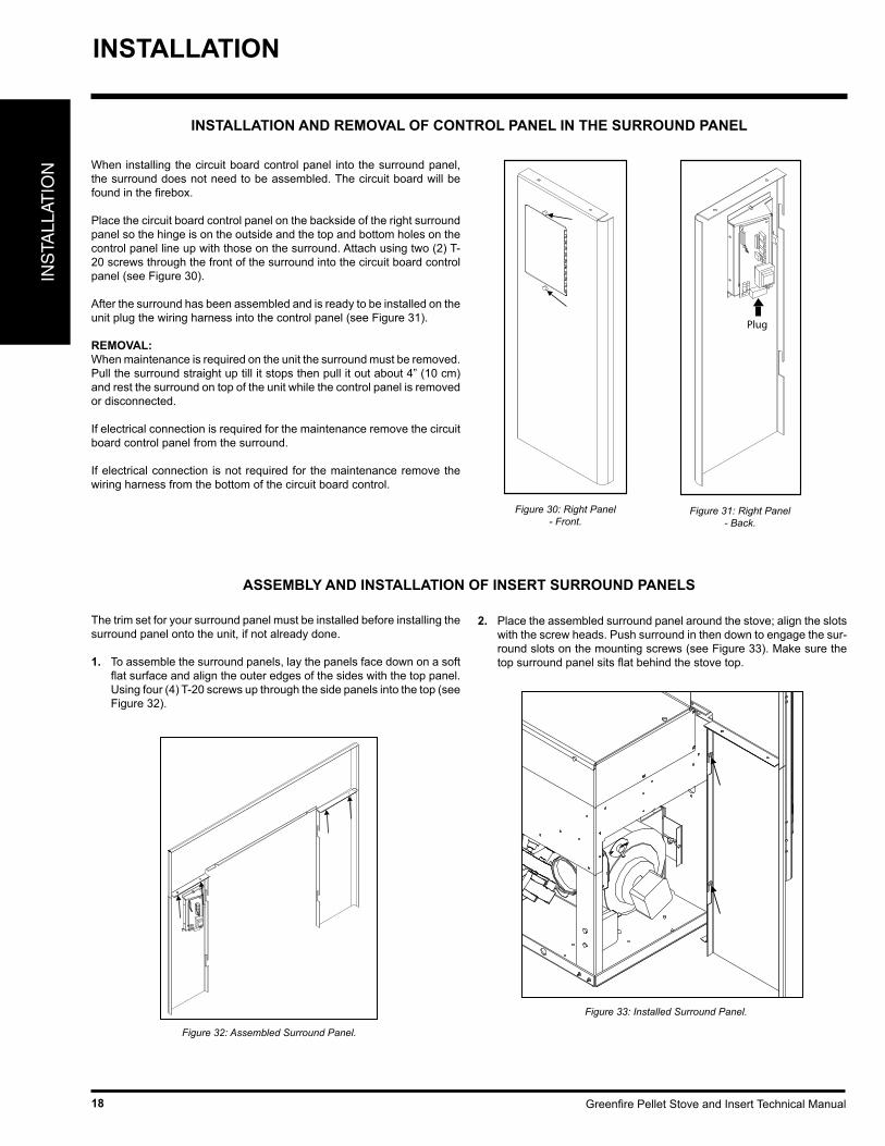
INSTALLATION AND REMOVAL OF CONTROL PANEL IN THE SURROUND PANEL
When installing the circuit board control panel into the surround panel, the surround does not need to be assembled. The circuit board will be found in the firebox.
Place the circuit board control panel on the backside of the right surround panel so the hinge is on the outside and the top and bottom holes on the control panel line up with those on the surround. Attach using two (2) T-20 screws through the front of the surround into the circuit board control panel (see Figure 30).
After the surround has been assembled and is ready to be installed on the unit plug the wiring harness into the control panel (see Figure 31).
REMOVAL:When maintenance is required on the unit the surround must be removed. Pull the surround straight up till it stops then pull it out about 4” (10 cm) and rest the surround on top of the unit while the control panel is removed or disconnected.
If electrical connection is required for the maintenance remove the circuit board control panel from the surround.
If electrical connection is not required for the maintenance remove the wiring harness from the bottom of the circuit board control.
Plug
Figure 31: Right Panel - Back.
Figure 30: Right Panel - Front.
ASSEMBLY AND INSTALLATION OF INSERT SURROUND PANELS
The trim set for your surround panel must be installed before installing the surround panel onto the unit, if not already done.
1. To assemble the surround panels, lay the panels face down on a soft flat surface and align the outer edges of the sides with the top panel. Using four (4) T-20 screws up through the side panels into the top (see Figure 32).
Figure 32: Assembled Surround Panel.
Figure 33: Installed Surround Panel.
2. Place the assembled surround panel around the stove; align the slots with the screw heads. Push surround in then down to engage the sur-round slots on the mounting screws (see Figure 33). Make sure the top surround panel sits flat behind the stove top.
INSTALLATION
Greenfire Pellet Stove and Insert Technical Manual 19
INS
TALLAT
ION
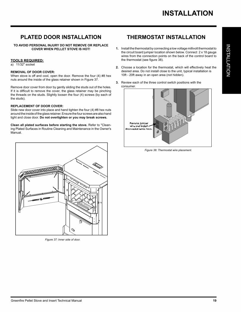
PLATED DOOR INSTALLATIONTO AVOID PERSONAL INJURY DO NOT REMOVE OR REPLACE
COVER WHEN PELLET STOVE IS HOT!
TOOLS REQUIRED:a) 11/32" socket
REMOVAL OF DOOR COVER:When stove is off and cool, open the door. Remove the four (4) #8 hex nuts around the inside of the glass retainer shown in Figure 37.
Remove door cover from door by gently sliding the studs out of the holes. If it is difficult to remove the cover, the glass retainer may be pinching the threads on the studs. Slightly loosen the four (4) screws (by each of the studs).
REPLACEMENT OF DOOR COVER:Slide new door cover into place and hand tighten the four (4) #8 hex nuts around the inside of the glass retainer. Ensure the four screws are also hand tight and close door. Do not overtighten or you may break screws.
Clean all plated surfaces before starting the stove. Refer to "Clean-ing Plated Surfaces in Routine Cleaning and Maintenance in the Owner's Manual.
Figure 37: Inner side of door.
THERMOSTAT INSTALLATION
1. Install the thermostat by connecting a low voltage millivolt thermostat to the circuit board jumper location shown below. Connect 2 x 18 gauge wires from the connection points on the back of the control board to the thermostat (see figure 38).
2. Choose a location for the thermostat, which will effectively heat the desired area. Do not install close to the unit, typical installation is
10ft - 20ft away in an open area (not hidden).
3. Review each of the three control switch positions with the consumer.
Remove jumperwire and install
thermostat wires here.
Figure 38: Thermostat wire placement.
INSTALLATION
Greenfire Pellet Stove and Insert Technical Manual20
INS
TALL
ATIO
N
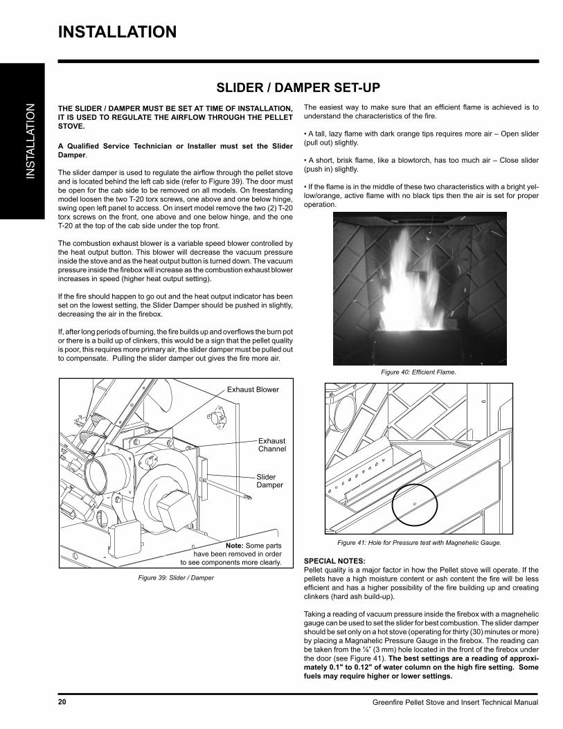
SLIDER / DAMPER SET-UPTHE SLIDER / DAMPER MUST BE SET AT TIME OF INSTALLATION, IT IS USED TO REGULATE THE AIRFLOW THROUGH THE PELLET STOVE.
A Qualified Service Technician or Installer must set the Slider Damper.
The slider damper is used to regulate the airflow through the pellet stove and is located behind the left cab side (refer to Figure 39). The door must be open for the cab side to be removed on all models. On freestanding model loosen the two T-20 torx screws, one above and one below hinge, swing open left panel to access. On insert model remove the two (2) T-20 torx screws on the front, one above and one below hinge, and the one T-20 at the top of the cab side under the top front.
The combustion exhaust blower is a variable speed blower controlled by the heat output button. This blower will decrease the vacuum pressure inside the stove and as the heat output button is turned down. The vacuum pressure inside the firebox will increase as the combustion exhaust blower increases in speed (higher heat output setting).
If the fire should happen to go out and the heat output indicator has been set on the lowest setting, the Slider Damper should be pushed in slightly, decreasing the air in the firebox.
If, after long periods of burning, the fire builds up and overflows the burn pot or there is a build up of clinkers, this would be a sign that the pellet quality is poor, this requires more primary air, the slider damper must be pulled out to compensate. Pulling the slider damper out gives the fire more air.
Slider Damper
Exhaust Channel
Exhaust Blower
Note: Some partshave been removed in order
to see components more clearly.
Figure 39: Slider / Damper
The easiest way to make sure that an efficient flame is achieved is to understand the characteristics of the fire.
• A tall, lazy flame with dark orange tips requires more air – Open slider (pull out) slightly.
• A short, brisk flame, like a blowtorch, has too much air – Close slider (push in) slightly.
• If the flame is in the middle of these two characteristics with a bright yel-low/orange, active flame with no black tips then the air is set for proper operation.
Figure 40: Efficient Flame.
SPECIAL NOTES:Pellet quality is a major factor in how the Pellet stove will operate. If the pellets have a high moisture content or ash content the fire will be less efficient and has a higher possibility of the fire building up and creating clinkers (hard ash build-up).
Taking a reading of vacuum pressure inside the firebox with a magnehelic gauge can be used to set the slider for best combustion. The slider damper should be set only on a hot stove (operating for thirty (30) minutes or more) by placing a Magnahelic Pressure Gauge in the firebox. The reading can be taken from the ⅛” (3 mm) hole located in the front of the firebox under the door (see Figure 41). The best settings are a reading of approxi-mately 0.1" to 0.12" of water column on the high fire setting. Some fuels may require higher or lower settings.
Figure 41: Hole for Pressure test with Magnehelic Gauge.
INSTALLATION
Greenfire Pellet Stove and Insert Technical Manual 21
TR
OU
BLE
SH
OO
TIN
GTROUBLESHOOTING
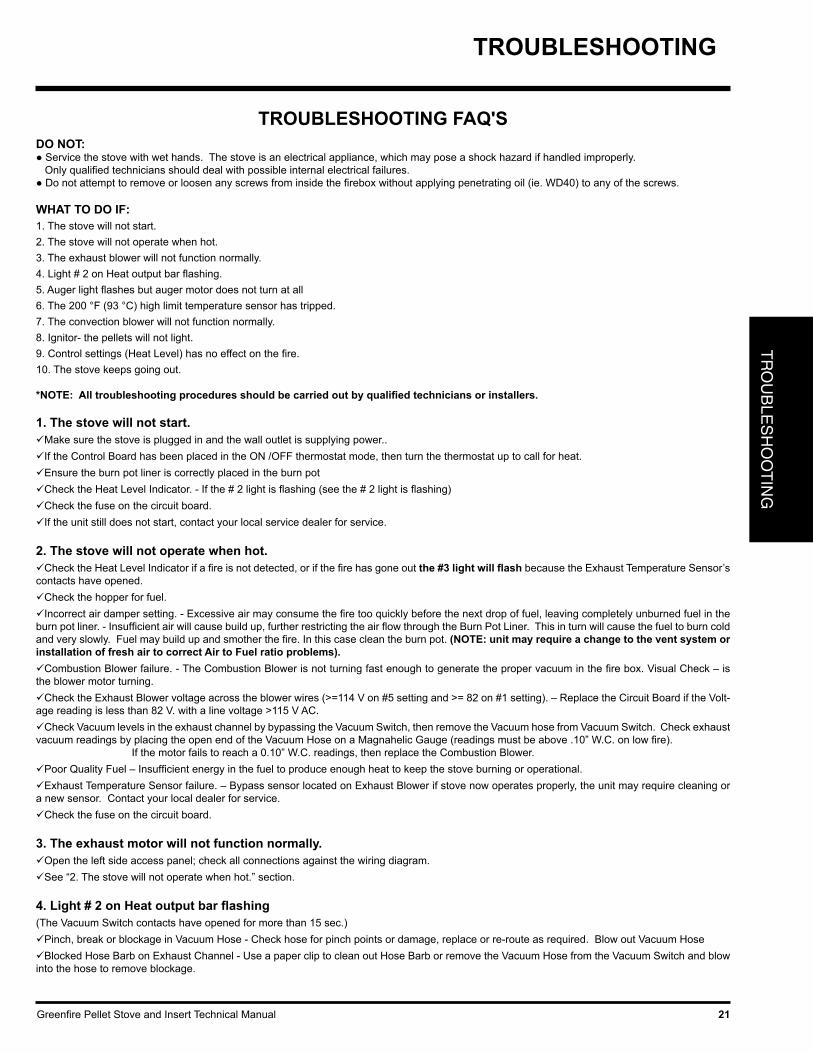
DO NOT:● Service the stove with wet hands. The stove is an electrical appliance, which may pose a shock hazard if handled improperly. Only qualified technicians should deal with possible internal electrical failures.● Do not attempt to remove or loosen any screws from inside the firebox without applying penetrating oil (ie. WD40) to any of the screws.
WHAT TO DO IF:1. The stove will not start.2. The stove will not operate when hot.3. The exhaust blower will not function normally.4. Light # 2 on Heat output bar flashing.5. Auger light flashes but auger motor does not turn at all6. The 200 °F (93 °C) high limit temperature sensor has tripped. 7. The convection blower will not function normally.8. Ignitor- the pellets will not light.9. Control settings (Heat Level) has no effect on the fire.10. The stove keeps going out.
*NOTE: All troubleshooting procedures should be carried out by qualified technicians or installers.
TROUBLESHOOTING FAQ'S
1. The stove will not start.Make sure the stove is plugged in and the wall outlet is supplying power..If the Control Board has been placed in the ON /OFF thermostat mode, then turn the thermostat up to call for heat.Ensure the burn pot liner is correctly placed in the burn potCheck the Heat Level Indicator. - If the # 2 light is flashing (see the # 2 light is flashing) Check the fuse on the circuit board.If the unit still does not start, contact your local service dealer for service.
2. The stove will not operate when hot. Check the Heat Level Indicator if a fire is not detected, or if the fire has gone out the #3 light will flash because the Exhaust Temperature Sensor’s contacts have opened.Check the hopper for fuel.Incorrect air damper setting. - Excessive air may consume the fire too quickly before the next drop of fuel, leaving completely unburned fuel in the burn pot liner. - Insufficient air will cause build up, further restricting the air flow through the Burn Pot Liner. This in turn will cause the fuel to burn cold and very slowly. Fuel may build up and smother the fire. In this case clean the burn pot. (NOTE: unit may require a change to the vent system or installation of fresh air to correct Air to Fuel ratio problems).Combustion Blower failure. - The Combustion Blower is not turning fast enough to generate the proper vacuum in the fire box. Visual Check – is the blower motor turning. Check the Exhaust Blower voltage across the blower wires (>=114 V on #5 setting and >= 82 on #1 setting). – Replace the Circuit Board if the Volt-age reading is less than 82 V. with a line voltage >115 V AC.Check Vacuum levels in the exhaust channel by bypassing the Vacuum Switch, then remove the Vacuum hose from Vacuum Switch. Check exhaust vacuum readings by placing the open end of the Vacuum Hose on a Magnahelic Gauge (readings must be above .10” W.C. on low fire). If the motor fails to reach a 0.10” W.C. readings, then replace the Combustion Blower.Poor Quality Fuel – Insufficient energy in the fuel to produce enough heat to keep the stove burning or operational.Exhaust Temperature Sensor failure. – Bypass sensor located on Exhaust Blower if stove now operates properly, the unit may require cleaning or a new sensor. Contact your local dealer for service.Check the fuse on the circuit board.
3. The exhaust motor will not function normally.Open the left side access panel; check all connections against the wiring diagram.See “2. The stove will not operate when hot.” section.
4. Light # 2 on Heat output bar flashing(The Vacuum Switch contacts have opened for more than 15 sec.)Pinch, break or blockage in Vacuum Hose - Check hose for pinch points or damage, replace or re-route as required. Blow out Vacuum HoseBlocked Hose Barb on Exhaust Channel - Use a paper clip to clean out Hose Barb or remove the Vacuum Hose from the Vacuum Switch and blow into the hose to remove blockage.
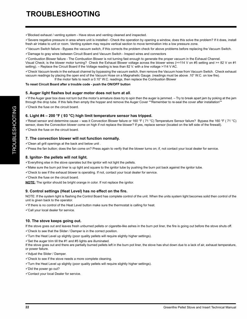
Greenfire Pellet Stove and Insert Technical Manual22
TR
OU
BLE
SH
OO
TIN
GTROUBLESHOOTING
Blocked exhaust / venting system - Have stove and venting cleaned and inspected.Severe negative pressure in area where unit is installed - Check the operation by opening a window, does this solve the problem? If it does, install fresh air intake to unit or room. Venting system may require vertical section to move termination into a low pressure zone.Vacuum Switch failure - Bypass the vacuum switch, if this corrects the problem check for above problems before replacing the Vacuum Switch.Damage to gray wires between Circuit Board and Vacuum Switch - Inspect wires and connectors Combustion Blower failure - The Combustion Blower is not turning fast enough to generate the proper vacuum in the Exhaust Channel. Visual Check; is the blower motor turning? Check the Exhaust Blower voltage across the blower wires (>=114 V on #5 setting and >= 82 V on #1 setting). – Replace the Circuit Board if the Voltage reading is less than 82 V. with a line voltage >114 V AC. Check Vacuum levels in the exhaust channel by bypassing the vacuum switch, then remove the Vacuum hose from Vacuum Switch. Check exhaust vacuum readings by placing the open end of the Vacuum Hose on a Magnahelic Gauge. (readings must be above .10” W.C. on low fire). If the motor fails to reach a 0.10” W.C. readings, then replace the Combustion Blower To reset Circuit Board after a trouble code - push the ON/OFF button
5. Auger light flashes but auger motor does not turn at all.If the Auger gear box does not turn but the motor’s armature does try to spin then the auger is jammed. – Try to break apart jam by poking at the jam through the drop tube. If this fails then empty the hopper and remove the Auger Cover **Remember to re-seal the cover after installation** Check the fuse on the circuit board.
6. Light #4 – 200 °F ( 93 °C) high limit temperature sensor has tripped. Reset sensor and determine cause – was it Convection Blower failure or 160 °F ( 71 °C) Temperature Sensor failure? Bypass the 160 °F ( 71 °C) sensor, does the Convection blower come on high if not replace the blower? If yes, replace sensor (located on the left side of the firewall).Check the fuse on the circuit board.
7. The convection blower will not function normally.Clean all grill openings at the back and below unit .Press the fan button; does the fan come on? Press again to verify that the blower turns on; if, not contact your local dealer for service.
8. Ignitor- the pellets will not light.Everything else in the stove operates but the ignitor will not light the pellets.Make sure the burn pot liner is up tight and square to the ignitor tube by pushing the burn pot back against the ignitor tube.Check to see if the exhaust blower is operating. If not, contact your local dealer for service.Check the fuse on the circuit board.NOTE: The ignitor should be bright orange in color. If not replace the ignitor.
9. Control settings (Heat Level) has no effect on the fire.NOTE: If the system light is flashing the Control Board has complete control of the unit. When the units system light becomes solid then control of the unit is given back to the operator.If there is no control of the Heat Level button make sure the thermostat is calling for heat.Call your local dealer for service.
10. The stove keeps going out.If the stove goes out and leaves fresh unburned pellets or cigarette-like ashes in the burn pot liner, the fire is going out before the stove shuts off.Check to see that the Slider / Damper is in the correct position.Turn the Heat Level up slightly (poor quality pellets will require slightly higher settings).Set the auger trim till the #1 and #5 lights are illuminated.If the stove goes out and there are partially burned pellets left in the burn pot liner, the stove has shut down due to a lack of air, exhaust temperature, or power failure.Adjust the Slider / Damper.Check to see if the stove needs a more complete cleaning.Turn the Heat Level up slightly (poor quality pellets will require slightly higher settings).Did the power go out?Contact your local Dealer for service.
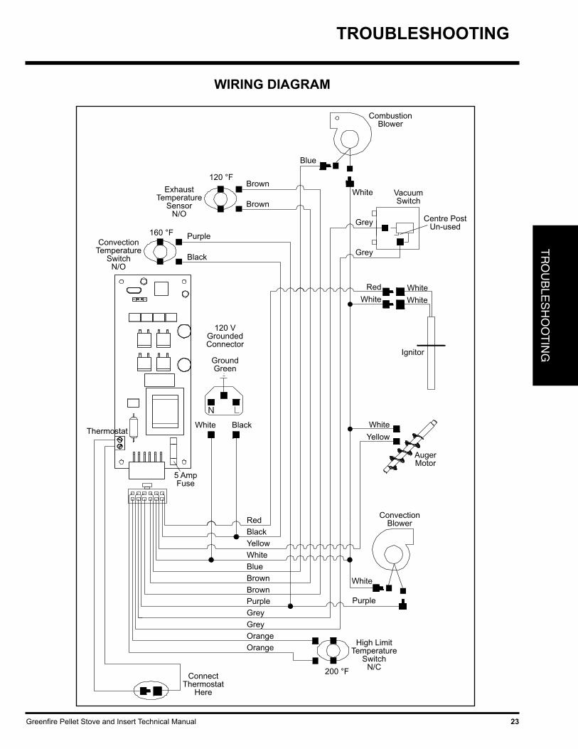
Greenfire Pellet Stove and Insert Technical Manual 23
TR
OU
BLE
SH
OO
TIN
G
WIRING DIAGRAM
ExhaustTemperature
SensorN/O
Brown
Brown
ConvectionTemperature
SwitchN/O
CombustionBlower
Blue
Purple
Black
White
Grey
Grey
VacuumSwitch
BlackWhiteThermostat
120 VGroundedConnector
GroundGreen
White
Red
Ignitor
AugerMotor
White
Yellow
5 AmpFuse
ConvectionBlower
ConnectThermostat
Here
High LimitTemperature
SwitchN/C
White
RedBlackYellowWhiteBlueBrownBrownPurpleGreyGreyOrangeOrange
Purple
White
White
120 °F
160 °F
200 °F
Centre PostUn-used
TROUBLESHOOTING

Greenfire Pellet Stove and Insert Technical Manual24
PAR
TS
LIS
T
PARTS LIST & COMPONENTS
Part # Description Part # Description
PARTS LIST
1) GF55-001 Auger Motor 115V 1 Rpm2) GF55-002 Combustion Blower Motor Only 115V3) GF55-003 Convection Blower 115V4) GF55-004 Ignitor 300 Watt 115V
5) GF55-093 Circuit Board W/Tstat Switch 115V GF55-006 Circuit Board Fuse (Set 2) GF55-007 Circuit Board Wire Harness GF55-094 Circuit Board Control Panel Decal
6) GF55-009 120 Ceramic Exhaust Temp Sensor7) GF55-010 160 Ceramic Convection Fan Sensor8) GF55-011 200 High Limit Sensor Manual Reset9) GF55-012 Vacuum Switch 115V
GF55-013 Silicone Hose GF55-014 Gasket Convection Blower Mtng GF55-015 Gasket Combustion Blower Assembly Mtng GF55-016 Gasket Combustion Blower Motor Mtng GF55-017 Gasket Exhaust Starter Tube GF55-018 Tape Window Channel 72 In. GF55-019 Gasket 5/8 In. Door 7 Ft GF55-020 Gasket Ped & Ash Pan 10 Ft GF55-021 Fastener Bag Pellet Mechanical & Elec.
10) GF55-022 Burn Pot Liner SS High Ash GF55-034 Burn Pot Liner Standard SS GF55/GFI55
GF55-023 Scraper Tool Burn Pot GF55/GFI55 GF55-025 Power Cord Domestic GF55/GFI55
GF55-026 Heyco Strain Releif GF55-027 Sholder Bolt, Roll, Nut GF55/GFI55 2 Set
11) GF55-028 Glass Side GF55/GFI5512) GF55-029 Glass Front GF55/GFI55
GF55-033 Exhaust Starter Tube 3x2.5 GF55/GFI55 GF55-036 Cleaning Rod Heat Tube GF55/GFI55
13) GF55-037 Burn Pot Assembly GF55/GFI5514) GF55-038 Auger GF55/GFI55 GF55-039 Auger Brass Bushing & Plate GF55/GFI55
15) GF55-040 Door Handle GF55/GFI55 GF55-041 Door Handle Bolt, Nut, Washer GF55/GFI55
16) GF55-042 Slider Damper Rod W/Knob GF55/GFI55 GF55-046 Knob 1 in. GF55/GFI55
GF55-047 Auger Collar W/Screw 3/4 in. ID GF/GFI55
17) GF55-051 Handle Hopper Lid GF5518) GF55-053 Latch Ash Drawer GF55
19) GF55-054 Door Control Panel W/Hinge GF55/GFI55
20) GF55-056 Brick Panel Set GF55/GFI5521) GF55-057 Retainers Brick Panel GF55/GFI55
22) GF55-058 Cover Hopper GFI5523) GF55-059 Lid Hopper GFI55
24) GF55-060 Ash Drawer GFI5525) GF55-061 Lid Hopper GF55
26) GF55-062 Front Top Assembly GF5527) GF55-066 Ash Drawer GF55
28) GF55-067 Control Panel W/Decal GF55
29) GF55-068 Main Door Complete Assembly GF55/GFI5530) GF55-069 Front Top Assembly GFI55
31) GF55-072 Control Panel W/Decal GFI55
32) GFI55-910 Faceplate Regular GFI5533) GFI55-912 Faceplate Oversize GFI55
34) GF55-921 Door Overlay Brush Nickel GF55 / GFI55 GF55-923 Door Overlay Antique Copper GF55 / GFI55
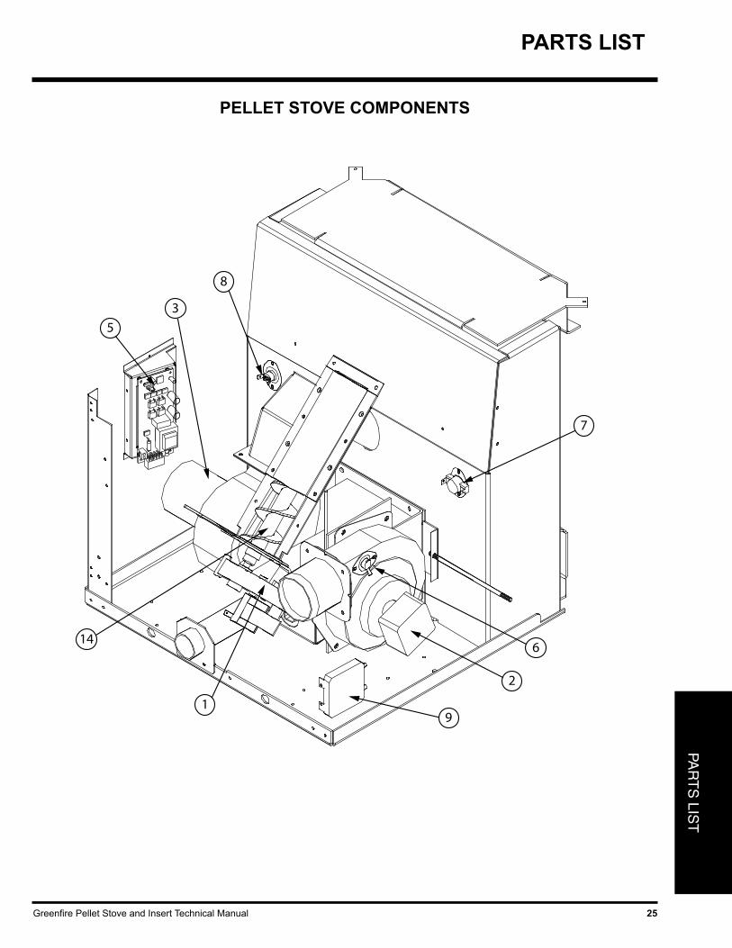
Greenfire Pellet Stove and Insert Technical Manual 25
PAR
TS
LIST
7
6
2
91
14
8
3
5
PELLET STOVE COMPONENTS
PARTS LIST
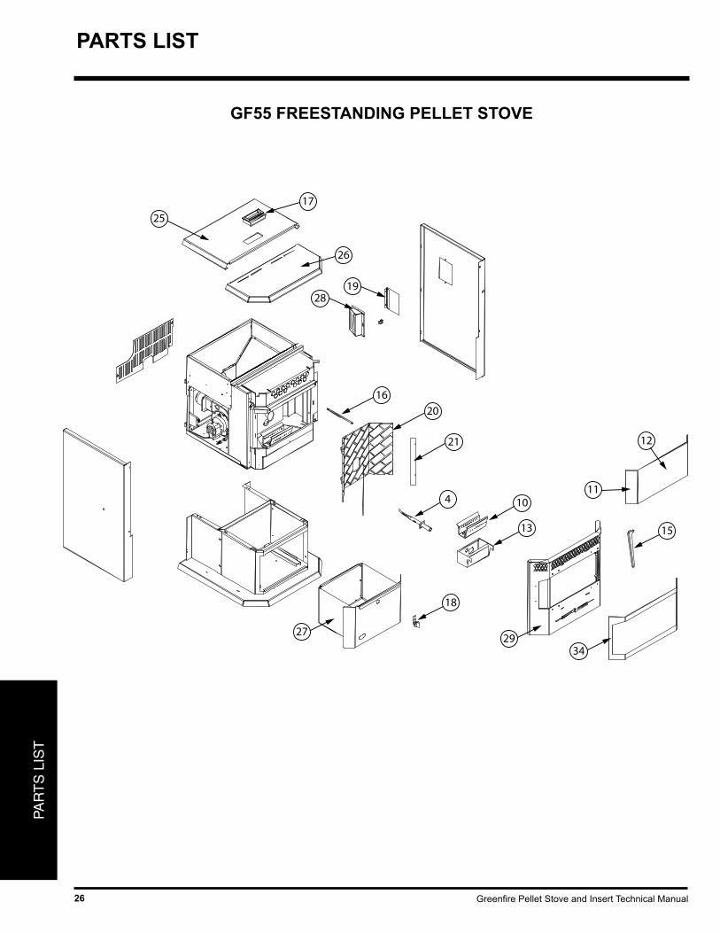
Greenfire Pellet Stove and Insert Technical Manual26
PAR
TS
LIS
T
17
25
26
2819
16
20
21
4 10
13
18
2729
34
15
12
11
GF55 FREESTANDING PELLET STOVE
PARTS LIST
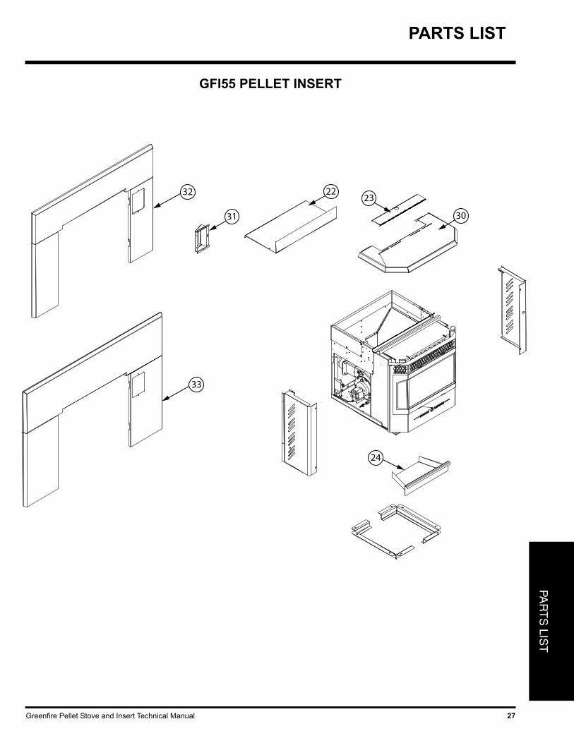
Greenfire Pellet Stove and Insert Technical Manual 27
PAR
TS
LIST
24
32
33
31
2223
30
GFI55 PELLET INSERT
PARTS LIST
Greenfire Pellet Stove and Insert Technical Manual28
WARRANTY
FPI is the manufacturer of the Hampton/Greenfi re line of heating products. At FPI, our commitment to the highest level of quality and customer service is the most important thing we do. Each Hampton/Greenfi re stove is built on a tradition of using only the fi nest materials and is backed by our Exclusive Lifetime Limited Warranty to the original purchaser. With Hampton/Greenfi re, you’re not just buying a stove, you’re buying a company with years of unequalled performance and quality.
Limited Seven (7) Year Warranty:Under this warranty, FPI covers the fi replace or stove body and accessories against defects in materials and workmanship, for part repair or replacement for the fi rst seven (7) years and limited labour for the fi rst two (2) years to the original purchaser. This Warranty covers: Firebox, Heat Exchanger, Burn Pot, Firebox Panels, Ceramic Glass, Pedestals, Panels, Legs, Log Sets and Door Assembly. Please see the exclusions and limitation section below as certain restrictions and exclusions apply to this warranty.
Limited Three (3) Year Warranty:Under this warranty, FPI covers the Burn Pot Liner against defects in materials and workmanship, for part repair or replacement for the fi rst three (3) years and limited labour for the fi rst two (2) years to the original purchaser. Please see the exclusions and limitation section below as certain restrictions and exclusions apply to this warranty.
Limited Two (2) Year Warranty:Under this warranty, FPI covers: Auger Motor, Circuit Board, Timers, Temp Sensors, Blowers, Vacuum Switch, Ignitor and Wire Harness, against defects in materials and workmanship, for part repair or replacement for the fi rst two (2) years and limited labour for the fi rst two (2) years to the original purchaser. Please see the exclusions and limitation section below as certain restrictions and exclusions apply to this warranty.
Limited One (1) Year Warranty:Under this warranty, FPI covers all exterior surface fi nishes against defects in materials and workmanship, for part repair or replacement and limited labour for the fi rst (1) year to the original purchaser. Please see the exclusions and limitation section below as certain restric-tions and exclusions apply to this warranty.
Here is how our Warranty works:If you have any concerns with your Hampton/Greenfi re product please contact the dealer where you purchased the fi replace or stove. Your dealer shall make all claims under this warranty in writing.
Please Note - Burning Corn or Grains - Burning corn or other grains creates a harsher environment than burning wood pellets. The sugar in corn turns to acid during the combustion process and erodes certain components at a faster rate. The burn pot liner and the agitator in your Multi - Fuel stove is a consumable item when burning corn or other grains, and not covered under warranty. We expect that these components will last a couple of burn seasons but due to the wide variety and quality of grains we are not able to accurately predict how long they will last.
To the Dealer:All claims must be submitted to FPI by authorized selling dealers. It is essential that all submitted claims provide all of the necessary information including custromer nam, purchase date, serial #, type of unit, problem, and part or parts requested. A copy of the bill of sale/proof of purchase must also accompany any submitted claims, without this information the warranty will be invalid.
To the Distributor:Sign and verify that work and information are correct.
Hampton/Greenfi re Pellet Warranty 2015
Greenfire Pellet Stove and Insert Technical Manual 29
WARRANTY
Exclusions and Limitations:
1. This Warranty does not cover tarnish, discoloration or wear on the plating or paint.
2. This Warranty excludes wear and tear or breakage caused by cleaning, moving or service on log set.
3. A qualifi ed installer must install this stove or fi replace. This Limited Warranty covers defects in materials and workmanship only if the product has been installed in accordance with local building and fi re codes; in their absence, refer to the owner’s manual. If the product is damaged or broken as a result of any alteration, willful abuse, mishandling, accident, neglect, or misuse of the product, the Limited Warranty does not apply.
4. The stove must be operated and maintained at all times in accordance with the instructions in the Owner’s Manual. If the unit shows signs of neglect or misuse, it is not covered under the terms of this Warranty policy. Performance problems due to operator error will not be covered by the Limited Warranty policy.
5. As this is a heating appliance some changes in colour of surface fi nishes may occur. This is not a fl aw and as such is not covered under this warranty.
6. Some minor expansion, contraction, or movement of certain parts and resulting noise, is normal and not a defect and, therefore, is not covered under this Limited Warranty.
7. Misuse includes over-fi ring. Over-fi ring this appliance can cause serious damage and will nullify the Limited Warranty.
8. The Limited Warranty will cover glass thermal breakage only and will not cover misuse of the stove glass, including but not limited to glass that is struck, has surface contaminates or has had harsh or abrasive cleaners used on it.
9. This warranty does not cover products made or provided by other manufacturers and used in conjunction with the operation of this stove without prior authorization from FPI The use of such products may nullify the Limited Warranty on this stove. If unsure as to the extent of this Limited Warranty, contact your authorized Hampton/Greenfi re dealer before installation.
10. FPI will not be responsible for inadequate performance caused by environmental conditions.
11. The Limited Warranty does not cover installation and operational related problems such as spillage caused by environmental conditions. Environmental conditions include but are not limited to nearby trees, buildings, roof tops, wind, hills, mountains, inadequate venting or ventilation, excessive offsets, negative air pressures or other infl uences caused by mechanical systems such as furnaces, fans, clothes dryers etc.
12. The Limited Warranty is void if: a) The stove has been operated in atmospheres contaminated by chlorine, fl uorine or other damaging chemicals. b) The stove is subject to submersion in water or prolonged periods of dampness or condensation. c) Any damage to the unit, combustion chamber or other components due to water, or weather damage which is the result of, but not limited to, improper
chimney/venting installation. c) Salt air in coastal areas or high humidity can be corrosive to the fi nish; these environments can cause rusting. Damage caused by salt air or high
humidity is not covered by the Limited Warranty.
13. Exclusions to the Limited Warranty include: injury, loss of use, damage, failure to function due to accident, negligence, misuse, improper installation, alteration or adjustment of the manufacturer’s settings of components, lack of proper and regular maintenance, alteration, or act of God.
14. The Limited Warranty does not cover damage caused to the fi replace or stove while in transit. If this occurs, do not operate the stove and contact your courier and/or dealer.
15. The Limited Warranty does not extend to or include fi rebox paint, door or glass gaskets with damage caused by normal wear and tear, or exterior paint discoloration or chipping, worn gaskets, etc.
16. The Limited Warranty does not include damage to the unit caused by abuse, improper installation, or modifi cation of the unit.
17. Damage to plated surfaces caused by fi ngerprints, scratches, melted items, or other external scores and residues left on the plated surfaces from the use of abrasive cleaners or polishes is not covered in this warranty.
18. The Limited Warranty does not cover tarnish, discoloration or wear on the plated surfaces.

Greenfire Pellet Stove and Insert Technical Manual30
WARRANTY
19. The paint on the Metal Brick Liner may peel. This is due to the extreme conditions applied to the paint during normal usage. It is not a fl aw and is not covered under warranty.
20. FPI is free of liability for any damages caused by the fi replace or stove, as well as inconvenience expenses and materials. The Limited Warranty does not cover incidental or consequential damages.
21. The Limited Warranty does not cover any loss or damage incurred by the use or removal of any component or apparatus to or from the Hampton/Greenfi re wood pellet stove or insert without the express written permission of FPI and bearing a FPI label of approval.
22. Any statement or representation of Hampton/Greenfi re products and their performance contained in Hampton/Greenfi re advertising, packaging literature, or printed material is not part of the Limited Warranty.
23. The Limited Warranty is automatically voided if the fi replace or stove’s serial number has been removed or altered in any way. If the stove is used for commercial purposes, it is excluded from the Limited Warranty.
24. No dealer, distributor, or similar person has the authority to represent or warrant Hampton/Greenfi re products beyond the terms contained within the Limited Warranty. FPI assumes no liability for such warranties or representations.
25. FPI will not cover the cost of the removal or re-installation of the stove, hearth, facing, mantels, venting or other components.
26. Labour to replace or repair items under this Limited Warranty will be covered per our warranty service fee reimbursement schedule. Labour rates are set per component and as such total labour costs may not be covered.
27. FPI is not liable for freight or labour on any stove replaced in-fi eld and is not liable for travel costs for service work. In the event of in-home repair work, the customer will pay any in-home travel fees or service charges required by the Authorized Dealer.
28. At no time will FPI be liable for any consequential damages which exceed the purchase price of the unit. FPI has no obligation to enhance or modify any stove once manufactured (example: as a stove evolves, fi eld modifi cations or upgrades will not be performed).
29. This Limited Warranty is applicable only to the original purchaser and it is non-transferable.
30. This warranty only covers Hampton/Greenfi re products that are purchased through an authorized Hampton/Greenfi re dealer.
31. If for any reason any section of the Limited Warranty is declared invalid, the balance of the warranty remains in effect and all other clauses shall remain in effect.
32. The Limited Warranty is the only warranty supplied by FPI, the manufacturer of the stove. All other warranties, whether express or implied, are hereby expressly disclaimed and purchaser’s recourse is expressly limited to the Limited Warranty.
33. FPI and its employees or representatives will not assume any damages, either directly or indirectly, caused by improper usage, operation, instal-lation, servicing or maintenance of this stove.
34. FPI reserves the right to make changes without notice. Please complete and mail the warranty registration card and have the installer fi ll in the installation data sheet in the back of the manual for warranty and future reference.
35. It is the responsibility of the home owner to service and maintain the appliance. If any claims are sent to FPI, you may be asked for service records to ensure the appliance has been maintained. Retain all receipts for both service and/or parts which may have been replaced. Lack of service/maintenance is the largest contributor to malfunction of an appliance and is not covered under the terms of this warranty.

Greenfire Pellet Stove and Insert Technical Manual 31
________________________________________________________________________________________________________________________________________________________________________________________________________________________________________________________________________________________________________________________________________________________________________________________________________________________________________________________________________________________________________________________________________________________________________________________________________________________________________________________________________________________________________________________________________________________________________________________________________________________________________________________________________________________________________________________________________________________________________________________________________________________________________________________________________________________________________________________________________________________________________________________________________________________________________________________________________
NOTES

Printed in Canada
Greenfire is a trademark of FPI Fireplace Products International Ltd.© Copyright 2015, FPI Fireplace Products International Ltd. All rights reserved.
Installer: Please complete the following information
Dealer Name & Address: ______________________________________________
___________________________________________________________________
Installer: ___________________________________________________________
Phone #: ___________________________________________________________
Date Installed: ______________________________________________________
Serial No.: __________________________________________________________
Register your Regency® warranty onlinewww.regency-fire.com
Reasons to register your product online today!
• View and modify a list of all your registered products.• Request automatic email notification of new product updates.• Stay informed about the current promotions, events, and special
offers on related products.