recovery of ego-motion using image stabilization
TRANSCRIPT

Recovery of Ego-Motion Using Image Stabilization �Michal Irani Benny Rousso Shmuel PelegInstitute of Computer ScienceThe Hebrew University of Jerusalem91904 Jerusalem, ISRAELEmail: fmichalb, [email protected] 1993AbstractA robust method is introduced for computing the camera motion (the ego-motion) ina static scene. The method is based on detecting a single image region and computingits 2D motion in the image plane directly from image intensities. The detected 2Dmotion of this image region is used to register the images (so that the detected imageregion appears stationary). The resulting displacement �eld for the entire scene in suchregistered frames is a�ected only by the 3D translation of the camera. Canceling thee�ects of the 3D rotation of the camera by using such 2D image registration simpli�esthe computation of the translation. The 3D translation of the camera is computedby �nding the focus-of-expansion in the translation-only set of registered frames. Thisstep is followed by computing the 3D rotation to complete the computation of theego-motion.The presented method avoids the inherent problems in the computation of optical ow and of feature matching, and does not assume any prior feature detection or featurecorrespondence.�This research has been sponsored by the U.S. O�ce of Naval Research under Grant N00014-93-1-1202,R&T Project Code 4424341|01.

1 IntroductionThe motion observed in an image sequence can be caused by camera motion (ego-motion) and by motions of independently moving objects in the scene. In this paper weaddress the case of a camera moving in a static scene. Complete 3D motion estimation isdi�cult since the image motion at every pixel depends, in addition to the six parametersof the camera motion, on the depth at the corresponding scene point. To overcomethis di�culty, additional constraints are usually added to the motion model or to theenvironment model. Such constraints include the introduction of a regularization term[HS81], assuming a limited model of the world [Adi85], restricting the range of possiblemotions [HW88], or assuming some type of temporal motion constancy over a longersequence [DF90].3D motion is often estimated from the optical or normal ow �eld derived be-tween two frames [Adi85, LR83, HJ90, GU91, JH91, Sun91, NL91, HA91, TS91, AD92,DRD93], or from the correspondence of distinguished features (points, lines, contours)previously extracted from successive frames [OFT87, Hor90, COK93]. Both approachesdepend on the accuracy of the pre-processing stage, which can not always be assured[WHA89].Increasing the temporal region to more than two frames improves the accuracyof the computed motion. Methods for estimating local image velocities with largetemporal regions have been introduced using a combined spatio-temporal analysis[FJ90, Hee88, SM90]. These methods assume motion constancy in the temporal re-gions, i.e. motion should remain uniform in the analyzed sequence. In feature basedmethods, features are tracked over a larger time interval using recursive temporal �l-tering [DF90]. The issue of extracting good features and overcoming occlusions stillremains.Methods for computing the ego-motion directly from image intensities were alsosuggested [Han91, HW88, Taa92]. Horn and Weldon [HW88] deal only with restrictedcases (pure translation, pure rotation, or a general motion with known depth). Hanna[Han91] suggests an iterative method for the most general case, but relies on a rea-sonably accurate initial guess. Taalebinezhaad [Taa92] has a complete mathematicalformulation, but relies on computations at a single image point, which can be highlyunstable.3D rotations and translations induce similar 2D image motions [Adi89, DN93,DMRS88] which cause ambiguities in their interpretation, especially in the pres-ence of noise. At depth discontinuities, however, it is much easier to distinguishbetween the e�ects of 3D rotations and translations, as the 2D motion of neigh-boring pixels at di�erent depths will have very similar rotational components, butvery di�erent translational components. Based on this observation [LHP80], meth-ods using motion parallax were constructed to obtain the 3D motion of the camera[LR83, LHP80, Lee88, LC93, COK93]. In [LR83, LHP80] di�erence vectors are com-puted from the optical ow to cancel the e�ects of rotations, and the intersection ofthese di�erence vectors is computed to yield the focus of expansion (the FOE, whichis the intersection point of the direction of the camera translation with the image2

plane). The optical ow, however, is most inaccurate near depth discontinuities, whichis where motion parallax occurs. These methods therefore su�er from these inaccura-cies. [Lee88] shows that given four coplanar points in an object, and two additionalpoints outside that plane, structure and motion of that object can be recovered fromtwo perspective views using the motion parallax at the two additional points. Thiswork relies on prior point extraction and accurate correspondence because the datais very sparse. [LC93, COK93] locally compute a 2-D a�ne motion from three non-colinear points, and use a fourth point which is non-coplanar with the other threepoints to estimate its local motion parallax. They too require prior point extractionand correspondenceIn this work a method for computing the ego-motion directly from image intensitiesis introduced. It is a coarse-to-�ne technique in the sense that at �rst only a robust 2Dimage motion is extracted, and later this 2D motion is used to simplify the computationof the 3D ego-motion.We use previously developed methods [BBH+91, IRP92, IRP93] to detect and tracka single image region and to compute its 2D parametric image motion. It is impor-tant to emphasize that the 3D camera motion cannot be recovered solely from the 2Dparametric image motion of a single image region, as there are a couple of such 3Dinterpretations [LH84]. It was shown that 3D motion of a planar surface can be com-puted from its 2D a�ne motion in the image and from the motion derivatives [MB92],but the use of motion derivatives might introduce sensitivity to noise. Moreover, theproblem of recovering the 3D camera motion directly from the image motion �eld is anill-conditioned problem, since small errors in the 2D ow �eld usually result in largeperturbations in the 3D motion [WHA89, Adi89].To overcome the di�culties and ambiguities in the computation of the ego-motion,we introduce the following scheme: The �rst frame is warped towards the second frameusing the computed 2D image motion at the detected image region. This registrationcancels the e�ects of the 3D camera rotation for the entire scene, and the resulting im-age displacements between the two registered frames are due only to the 3D translationof the camera. This translation is computed by locating the FOE (focus-of-expansion)between the two registered frames. Once the 3D translation is known it can be used,together with the 2D motion parameters of the detected image region, to compute the3D rotation of the camera by solving a set of linear equations.The 2D image region registration technique used in this work allows easy decou-pling of the translational and rotational motions, as only motion parallax informationremains after the registration. As opposed to other methods using motion parallax[LR83, LHP80, Lee88, LC93, COK93], our method does not rely on 2D motion in-formation computed near depth discontinuities, where it is inaccurate, but on motioncomputed over an entire image region. The e�ect of motion parallax is obtained at allscene points that are not located on the extension of the 3D surface which correspondsto the registered image region. This gives dense parallax data, as these scene pointsneed not be adjacent to the registered 3D surface.The advantage of this technique is in its simplicity and in its robustness. Noprior detection and matching are assumed, it requires solving only small sets of linear3

equations, and each computational step is stated as an overdetermined problem whichis numerically stable.There are no severe restrictions on the camera motion or the structure of the en-vironment, except for the requirement that there be a big enough image region with asingle 2D parametric motion. An imaged planar surface in the 3D scene produces therequired 2D image region (but the scene needs not be piecewise linear, as in [Adi85]).Most indoor scenes have a planar surface (e.g., walls, oor, pictures, windows, etc.),and in outdoor scenes the ground or any distant object can serve as a planar surface.In Section 2 the technique for computing the ego-motion is described, given animage region with its 2D parametric image motion. In Section 3 an application of theego-motion computation to image stabilization is described. In Section 4 the methodfor detecting and computing the 2D motion parameters of an image region whichcorresponds to a 3D planar surface in the scene is described.
4

2 Ego-Motion from 2D Image MotionDirect estimation of 3D camera motion from a 2D displacement �eld can be di�cultand ill-conditioned, since the 2D image motion depends on a very large number ofvariables { the 3D motion parameters of the camera, plus the depth at each scenepoint. 2D motion estimation of a single image region, on the other hand, is numericallystable, since it has only a small number of parameters (see Section 4.2), and is thereforehighly overdetermined when computed from all pixels in the region.In this section we describe the technique for computing the 3D ego-motion giventhe 2D parametric motion of a single region in the image. In Section 4 the method forextracting the 2D parametric motion of a single image region is brie y described.2.1 Basic Model and NotationsThe notations describing the 3D motion of the camera and the corresponding 2Dmotion of a planar surface in the image plane are introduced in this section. Let(X; Y; Z) denote the Cartesian coordinates of a scene point with respect to the camera(see Figure 1), and let (x; y) denote the corresponding coordinates in the image plane.The image plane is located at the focal length: Z = fc. The perspective projection ofa scene point P = (X; Y; Z)t on the image plane at a point p = (x; y)t is expressed by:p = " xy # = " XZ fcYZ fc # (1)The motion of the camera has two components: a translation T = (TX ; TY ; TZ)tand a rotation = (X ;Y ;Z)t. Due to the camera motion the scene point P =(X; Y; Z)t appears to be moving relative to the camera with rotation� and translation�T , and is therefore observed at new world coordinates P 0 = (X 0; Y 0 ; Z 0)t, expressedby: 264 X 0Y 0Z 0 375 = M� � 264 XYZ 375� T (2)where M� is the matrix corresponding to a rotation by �.When the �eld of view is not very large and the rotation is relatively small [Adi85], a3D motion of the camera between two image frames creates a 2D displacement (u; v) ofan image point (x; y) in the image plane, which can be expressed by [LH84, BAHH92]:" uv # = " �fc(TXZ +Y ) + xTZZ + yZ � x2 Yfc + xyXfc�fc(TYZ � X) � xZ + y TZZ � xyYfc + y2Xfc # (3)It is important to note the following points from Equation (3):5

X
Y
Z
P
p
OX
TY
Z
x
y
Z=f c
X
T
T
Y
ZFigure 1: The coordinate system.The coordinate system (X; Y; Z) is attached to the camera, and the correspond-ing image coordinates (x; y) on the image plane are located at Z = fc. A pointP = (X; Y; Z)t in the world is projected onto an image point p = (x; y)t.T = (TX ; TY ; TZ)t and = (X ;Y ;Z)t represent the relative translationand rotation of the camera in the scene.� There is a degree of freedom in the magnitude of the translation and depth,as the ratios TXZ ; TYZ ; and TZZ remain unchanged if both (TX ; TY ; TZ) and Zare multiplied by the same scaling factor. Therefore, only the direction of thetranslation can be recovered, but not its magnitude.� The contribution of the camera rotation to the displacement of an image point isindependent of the depth Z of the corresponding scene point, while the contribu-tion of the camera translation to the displacement of an image point does dependon the depth Z of the scene point.All points (X; Y; Z) of a planar surface in the scene satisfy the equation:Z = A+ B �X + C � Yfor some A, B, and C. Dividing by A � Z and rearranging the terms, we get:1Z = 1A � BA XZ � CA YZwhich can be rewritten using Equation (1) as:1Z = � + � � x+ � y (4)where: � = 1A ; � = � BfcA ; = � CfcA : 6

In a similar manipulation to that in [Adi85], substituting (4) in (3) yields:" uv # = " a + b � x + c � y + g � x2 + h � xyd + e � x + f � y + g � xy + h � y2 # (5)where: a = �fc�TX � fcY e = �Z � fc�TYb = �TZ � fc�TX f = �TZ � fc TYc = Z � fc TX g = �Yfc + �TZd = �fc�TY + fcX h = Xfc + TZ (6)Equation (5) describes the 2D parametric motion in the image plane, expressedby eight parameters (a; b; c; d; e; f; g; h), which corresponds to a general 3D motion ofa planar surface in the scene assuming a small �eld of view and a small rotation.Actually, Equation (5) is a good approximation to the 2D projective transformation ofthat image segment between two frames, as long as the change in angle between theplanar surface and the camera in this time interval was negligible.We call this 2D transformation (Equation (5)) a pseudo 2D projective transforma-tion. A method for computing the parameters of the pseudo projective transformationof an image segment is described in Sections 4.2 and 4.3.2.2 General Framework of the AlgorithmIn this section we present a scheme which utilizes the robustness of the 2D motioncomputation for computing 3D motion between two consecutive frames:1. A single image region is detected, and its 2D parametric image motion is com-puted (Section 4). The current implementation assumes an image region of aplanar surface in the 3D scene, so that its 2D image motion is expressed by a2D parametric transformation in the image plane having eight parameters (Thepseudo 2D projective transformation, Equation (5)).2. The two frames are registered according to the computed 2D parametric motionof the detected image region. This image region stabilization cancels the rota-tional component of the camera motion for the entire scene (Section 2.3), andthe translation of the camera can now be computed from the focus-of-expansionbetween the two registered frames (Section 2.4).3. The 3D rotation of the camera is now computed (Section 2.5) given the 2D motionparameters of the detected image region and the 3D translation of the camera.2.3 Eliminating E�ects of Camera RotationAt this stage we assume that a single image region with a parametric 2D image motionhas been detected, and that the 2D image motion of that region has been computed.7

The computation of the 2D image motion is described in Section 4 for planar 3Dsurfaces.Let (u(x; y); v(x; y)) denote the 2D image motion of the entire scene from framef1 to frame f2, and let (us(x; y); vs(x; y)) denote the 2D image motion of a singleimage region (the detected image region) between the two frames. It was mentionedin Section 2.1 that (us; vs) can be expressed by a 2D parametric transformation inthe image plane if the image region is an image of a planar surface in the 3D scene(Equation (5)). Let s denote the 3D surface of the detected image region, with depthsZs(x; y). Note that only the 2D motion parameters (us(x; y); vs(x; y)) of the planarsurface are known. The 3D shape or motion parameters of the planar surface are stillunknown. Let fReg1 denote the frame obtained by warping the entire frame f1 towardsframe f2 according to the 2D parametric transformation (us; vs) extended to the entireframe. This warping will cause the image region of the detected planar surface as wellas scene parts which are coplanar with it to be stationary between fReg1 and f2. In thewarping process, each pixel (x; y) in f1 is displaced by (us(x; y); vs(x; y)) to form fReg1 .3D points that are not located on the 3D surface s (i.e., Z(x; y) 6= Zs(x; y)) will notbe in registration between fReg1 and f2.We will now show that the residual 2D motion between the registered frames (fReg1and f2) is a�ected only by the camera translation T .Let P1 = (X1; Y1; Z1)t denote the 3D scene point projected onto p1 = (x1; y1)t in f1.According to Equation (1): P1 = (x1Z1fc ; y1Z1fc ; Z1)t. Due to the camera motion (,T )from frame f1 to frame f2, the point P1 will be observed in frame f2 at p2 = (x2; y2)t,which corresponds to the 3D scene point P2 = (X2; Y2; Z2)t. According to Equation (2):P2 = 264 X2Y2Z2 375 = M� � P1 � T (7)The warping of f1 by (us; vs) to form fReg1 is equivalent to applying the cameramotion (,T ) to the 3D points as though they are all located on the detected surfaces (i.e., with depths Zs(x; y)). Let Ps denote the 3D point on the surface s whichcorresponds to the pixel (x; y) with depth Zs(x; y). Then:Ps = 264 x1Zsfcy1ZsfcZs 375 = ZsZ1 � 264 X1Y1Z1 375 = ZsZ1 � P1 : (8)After the image warping, Ps is observed in fReg1 at pReg = (xReg; yReg)t, which corre-sponds to a 3D scene point PReg . Therefore, according to Equations (2) and (8):PReg = M� � Ps � T= ZsZ1 �M� � P1 � T ;and therefore: P1 = Z1Zs �M��1 � (PReg + T ) :8

Using Equation (7) we get:P2 = M� � P1 � T= Z1Zs �M� �M��1 � (PReg + T )� T= Z1Zs � PReg + (1� Z1Zs ) � (�T ) ;and therefore: PReg = ZsZ1 � P2 + (1� ZsZ1 ) � (�T ) : (9)Equation (9) shows that the 3D motion between PReg and P2 is not a�ected by thecamera rotation , but only by its translation T . Moreover, it shows that PReg is onthe straight line going through P2 and �T . Therefore, the projection of PReg on theimage plane (pReg) is on the straight line going through the projection of P2 on theimage plane (i.e., p2) and the projection of �T on the image plane (which is the FOE).This means that pReg is found on the radial line emerging from the FOE towards p2,or in other words, that the residual 2D motion from fReg1 to f2 (i.e., pReg � p2) at eachpixel is directed to, or away from, the FOE, and is therefore induced by the cameratranslation T .In Figure 2, the optical ow is displayed before and after registration of two framesaccording to the computed 2D motion parameters of the image region which corre-sponds to the wall at the back of the scene. The optical ow is given for displaypurposes only, and was not used in the registration. After registration, the rotationalcomponent of the optical ow was canceled for the entire scene, and all ow vectorspoint towards the FOE (Figure 2.d). Before registration (Figure 2.c) the FOE mis-takenly appears to be located elsewhere (in the middle of the frame). This is due tothe ambiguity caused by the rotation around the Y-axis, which visually appears as atranslation along the X-axis. This ambiguity is resolved by the 2D registration.2.4 Computing Camera TranslationOnce the rotation is canceled by the registration of the detected image region, the am-biguity between image motion caused by 3D rotation and that caused by 3D translationno longer exists. Having only camera translation, the ow �eld is directed to, or awayfrom, the FOE. The computation of the 3D translation therefore becomes overdeter-mined and numerically stable, as the only two unknowns indicate the location of theFOE in the image plane.To locate the FOE, the optical ow between the registered frames is computed,and the FOE is located using a search method similar to that described in [LR83].Candidates for the FOE are sampled over a half sphere and projected onto the imageplane. For each such candidate, an error measure is computed.Let (�; �) be a candidate for the FOE, and let (uReg(x; y); vReg(x; y)) denote theoptical ow vector at pixel (x; y) after cancelling the camera rotation by image regis-tration (See Section 2.3). Theoretically, in the case of a pure camera translation, all9

a) b)c) d)Figure 2: The optical ow before and after registration of the image regioncorresponding to the the wall. The optical ow is given only for displaypurposes, and it is not used for the registration.a) The �rst frame.b) The second frame, taken after translating the camera by (TX ; TY ; TZ) =(1:7cm; 0:4cm; 12cm) and rotating it by (X;Y ;Z) = (0�;�1:8�;�3�).c) The optical ow between Figs. 2.a and 2.b (before registration), over-layed on Figure 2.a . The FOE mistakenly appears to be in the wronglocation (in the middle of the frame). This is due to the ambiguity causedby the camera rotation around the Y-axis, which visually appears as atranslation along the X-axis. This ambiguity is resolved by the 2D regis-tration.d) The optical ow after 2D registration of the wall. The ow is inducedby pure camera translation (after the camera rotation was cancelled), andpoints now to the correct FOE (marked by +).10

the ow vectors point to, or away from, the FOE. The error measure computed for thecandidate FOE (�; �) is therefore de�ned by:Err(�; �) = P(x;y) w(x; y) � ((uReg; vReg)?)2P(x;y)w(x; y) = P(x;y)w(x; y) � (uReg�(y��)�vReg�(x��))2(x��)2+(y��)2P(x;y) w(x; y) (10)where (uReg; vReg)? = (uReg(x; y); vReg(x; y))? denotes the ow component perpendic-ular to the radial line emerging from the candidate FOE. w(x; y) are weights determinedby the reliability of the optical ow at (x; y):w(x; y) = cond](x; y) � jf2(x+ uReg ; y + vReg)� fReg1 (x; y)j (11)where cond](x; y) is the a-priori reliability of the optical ow at (x; y), determined bythe condition number of the two well-known optical ow equations [LK81, BAHH92],and jf2(x + uReg; y + vReg) � fReg1 (x; y)j is the posteriori reliability of the computedoptical ow at (x; y), determined by the intensity di�erence between the source locationof (x; y) in image fReg1 and its computed destination in image f2.The search process is repeated by re�ning the sampling (on the sphere) aroundgood FOE candidates. After a few re�nement iterations, the FOE is taken to be thecandidate with the smallest error. (In [LR83] the error is taken to be the sum of themagnitude of the error angles, which we found to give less accurate results).Since the problem of locating the FOE in a purely translational ow �eld is a highlyoverdetermined problem, the computed ow �eld need not be accurate. This is opposedto most methods which try to compute the ego-motion from the ow �eld, and requirean accurate ow �eld in order to resolve the rotation-translation ambiguity.Di�culties in computing the FOE occur when the ow vectors (uReg; vReg) betweenthe two registered frames (after the cancellation of the rotation) are very short. Thecomputation of the FOE therefore becomes sensitive to noise. Observation of Equa-tion (9) shows that this occurs only in the following two cases:1. Zs(x;y)Z1(x;y) � 1 for all (x; y), i.e., there are hardly any depth di�erences between scenepoints and the detected surface s, or in other words, in the current implementation(where s is a planar surface), the entire scene is approximately planar. This case,however, cannot be resolved by humans either, due to a visual ambiguity [LH84].This case can be identi�ed by noticing that the image registration according tothe 2D motion parameters of the detected planar surface brings the entire imageinto registration.2. T = 0, i.e., the motion of the camera is purely rotational. Once again, as inthe previous case, the 2D detection algorithm described in Section 4 will identifythe entire image as a projected region of a single planar surface (even if it isnot planar). In this case, however, the ego-motion can be recovered. SettingTX = TY = TZ = 0 in Equation (6) yields the following equations for the motion11

parameters of the planar surface.8>>>>>>>>>>>><>>>>>>>>>>>>: a = �fcYb = 0c = Zd = fcXe = �Zf = 0g = �Yfch = Xfc (12)From Equation (12) it can be noticed that the case of pure rotation can bedetected by examining the computed 2D motion parameters of the tracked regionfor the case when b � f � 0 and c � �e. The ego-motion in this case is therefore:TX = TY = TZ = 0 (13)X = dfc ; Y = � afc ; Z = c�e2 (14)2.5 Computing Camera RotationLet (a; b; c; d; e; f; g; h) be the 2D motion parameters of the 3D planar surface corre-sponding to the detected image region, as expressed by Equation (5). Given these2D motion parameters and the 3D translation parameters of the camera (TX ; TY ; TZ),then the 3D rotation parameters of the camera (X ;Y ;Z) (as well as the planarsurface parameters (�; �; )) can be obtained by solving the following set of eight linearequations in six unknowns from Equation (6):26666666666664 abcdefgh 37777777777775 = 26666666666664 �fcTX 0 0 0 �fc 0TZ �fcTX 0 0 0 00 0 �fcTX 0 0 1�fcTY 0 0 fc 0 00 �fcTY 0 0 0 �1TZ 0 �fcTY 0 0 00 TZ 0 0 � 1fc 00 0 TZ 1fc 0 0 37777777777775266666664 �� XYZ 377777775 : (15)From our experience, the parameters g and h in the pseudo 2D projective trans-formation, computed by the method described in Section 4, are not as reliable as theother six parameters (a; b; c; d; e; f), as g and h are second order terms in Equation (5).Therefore, whenever possible (when the set of equations (15) is numerically overdeter-mined), we avoid using the last two equations, and use only the �rst six. This yieldsmore accurate results.As a matter of fact, the only case in which all eight equations of (15) must be usedto recover the camera rotation is the case when the camera translation is parallel tothe image plane (i.e., ~T 6= 0 and TZ = 0). This is the only con�guration of camera12

a) b)Figure 3: The inverse depth map, computed after the camera motion hasbeen determined.a) First frame, same as Figure 2.a.b) The obtained inverse depth map. Bright regions correspond to closeobjects. Dark regions correspond to distant objects. Boundary e�ectscause some inaccuracies at the image boundaries.motion in which the �rst six equations of (15) do not su�ce for retrieving the rotationparameters. However, if only the �rst six equations of (15) are used (i.e., using onlythe reliable parameters a; b; c; d; e; f , and disregarding the unreliable ones, g and h),then only Z can be recovered in this case. In order to recover the two other rotationparameters, X and Y , the second order terms g and h must be used. This meansthat for the case of an existing translation with TZ = 0, only the translation parameters(TX ; TY ; TZ) and one rotation parameter Z (the rotation around the optical axis) canbe recovered accurately. The other two rotation parameters, X and Y , can only beapproximated.In all other con�gurations of camera motion the camera rotation can be reliablyrecovered.2.6 Experimental ResultsThe camera motion between Figure 2.a and Figure 2.b was: (TX ; TY ; TZ) =(1:7cm; 0:4cm; 12cm) and (X ;Y ;Z) = (0�;�1:8�;�3�). The computation of the3D motion parameters of the camera (after setting TZ = 12cm) yielded: (TX ; TY ; TZ) =(1:68cm; 0:16cm; 12cm) and (X ;Y ;Z) = (�0:05�;�1:7�;�3:25�).Once the 3D motion parameters of the camera were computed, the 3D scene struc-ture can be reconstructed using a scheme similar to that suggested in [Han91]. Corre-spondence between small image patches (currently 5 � 5 pixels) is computed only onthe radial line emerging from the FOE. The depth is computed from the magnitude ofthese displacements. In Figure 3, the computed inverse depth map of the scene ( 1Z(x;y))is displayed. 13

3 Camera StabilizationOnce the ego-motion of the camera is determined, this information can be used forpost-imaging stabilization of the sequence, as if the camera has been mounted on agyroscopic stabilizer.For example, to make perfect stabilization, the images can be warped back tothe original position of the �rst image to cancel the computed 3D rotations. Sincerotation is depth-independent, such image warping is easy to perform, resulting ina new sequence which contains only 3D translations, and looks as if taken from astabilized platform. An example of such stabilization is shown in Figure 4.a3-4.c3 andin Figure 5. Alternatively, the rotations can be �ltered by a low-pass �lter so that theresulting sequence will appear to have only smooth rotations.
14

a1) b) c1)a2) c2)a3) c3)Figure 4: Canceling camera rotation.a1) The �rst frame. b) The second frame.c1) The average image of (a1) and (b), showing the original motion (rotation and translation). Thewhite lines sparsely display the 2D image motion between (a1) and (b).a2) Frame (a1) warped toward (b) based on the 2D image motion of the detected image region,which is the boy's shirt.c2) The average image of (a2) and (b), showing the image motion obtained after the 2D warping.This warping brings the boy's shirt into registration. The motion after such a warping is purelytranslational (the camera translation), but its magnitude at each pixel does not correspond tothe real depth of the scene. The camera translation (the FOE) is recovered from such a pair ofregistered images.a3) Frame (a1) warped toward (b) based on the computed 3D camera rotation.c3) The average image of (a3) and (b), showing the image motion obtained when only the camerarotation is cancelled. The motion after such warping is purely translational (the camera translation),this time with magnitude at each pixel corresponding to the real depth of the scene. This resultsin a stabilized pair of images ((a3) and (b)), as if the camera has been mounted on a gyroscopicstabilizer. 15

a) b)Figure 5: Camera stabilization.This �gure shows an average of three consecutive frames from the exam-ined sequences, before and after processing.a) Average of the original Sequence. Image motion is highly chaotic.b) Average of the stabilized sequence. Image motion represents cameratranslations only. Camera rotations were cancelled (as if the camera hasbeen mounted on a gyroscopic stabilizer).4 Computing 2D Motion of a Planar SurfaceWe use previously developed methods [BBH+91, IRP92, IRP93] in order to detectan image region corresponding to a planar surface in the scene with its pseudo 2Dprojective transformation. These methods treated dynamic scenes, in which there wereassumed to be multiple moving planar objects. The image plane was segmented intothe di�erently moving objects, and their 2D image motion parameters were computed.In this work we use the 2D detection algorithm in order to detect a single planarsurface and its 2D image motion parameters. Due to camera translation, planes atdi�erent depths will have di�erent 2D motions in the image plane, and will thereforebe identi�ed as di�erently moving planar objects. When the scene is not piecewiseplanar, but contains planar surfaces, the 2D detection algorithm still detects the imagemotion of its planar regions.This section describes very brie y the technique for detecting di�erently movingplanar objects and their 2D motion parameters. For more details refer to [IRP92,IRP93].4.1 Detecting Multiple Moving Planar Objects2D motion estimation is di�cult when the region of support of an object in the imageis not known, which is the common case. It was shown in [BHK91] that the motionparameters of a single translating object in the image plane can be recovered accuratelyby applying the 2D motion computation framework described in Section 4.3 to theentire image, using a 2D translation motion model (see Section 4.2). This can be doneeven in the presence of other di�erently moving objects in the region of analysis, and16

with no prior knowledge of their regions of support. This object is called the dominantobject, and its 2D motion the dominant 2D motion. Thorough analysis of hierarchical2D translation estimation is found in [BHK91]. In [IRP92, IRP93] this method wasextended to compute higher order 2D motions (2D a�ne, 2D projective) of a singleplanar object among di�erently moving objects. A segmentation step was added tothe process, which segments out the region corresponding to the computed dominant2D motion. This is the region of the dominant planar object in the image.After detecting and segmenting the dominant planar object between two imageframes, the dominant planar object is excluded from the region of analysis, and thedetection process is repeated on the remaining parts of the image to �nd other planarobjects and their 2D motions parameters. More details are found in [IRP92].Temporal integration over longer sequences is used in order to improve the segmen-tation and the accuracy of the 2D motion parameters [IRP92, IRP93]. A temporallyintegrated image is obtained by averaging several frames of the sequence after regis-tration with respect to the 2D image motion of the tracked planar surface. After thisregistration the tracked plane is actually registered, while other parts of the scene thathad di�erent image motion are not registered. The temporal average therefore keepsthe tracked object sharp, while other image regions blur out. This e�ect supportscontinued tracking of the already tracked region.Figure 6 shows the detection of the �rst and second dominant planar objects in animage sequence. In this sequence, taken by an infrared camera, the background movesdue to camera motion, while the car has another motion. The results are presentedafter several frames, when the segmentation has improved with temporal integration.Figure 7 shows the detection and tracking of a single planar surface (the boy's shirt)in an image sequence of a static 3D scene with a moving camera. Despite the fact thatall the objects in the scene have the same 3D motion relative to the camera, theycreate di�erent 2D image motions as they are located at di�erent depths. Figure 7.bdisplays a temporally integrated image obtained by averaging frames after registrationwith respect to the 2D image motion of the boy's shirt. The shirt remains sharp, whileother regions blur out.4.2 The 2D Motion ModelsWe approximate the 2D image motion of projected 3D motions of planar objects byEquation (5). Given two grey level images of an object, I(x; y; t) and I(x; y; t+ 1), wealso use the assumption of grey level constancy:I(x+ u(x; y; t); y+ v(x; y; t); t+ 1) = I(x; y; t); (16)where (u(x; y; t); v(x; y; t)) is the displacement induced on pixel (x; y) by the motionof the planar object between frames t and t + 1. Expanding the left hand side ofEquation (16) to its �rst order Taylor expansion around (x; y; t) and neglecting all17
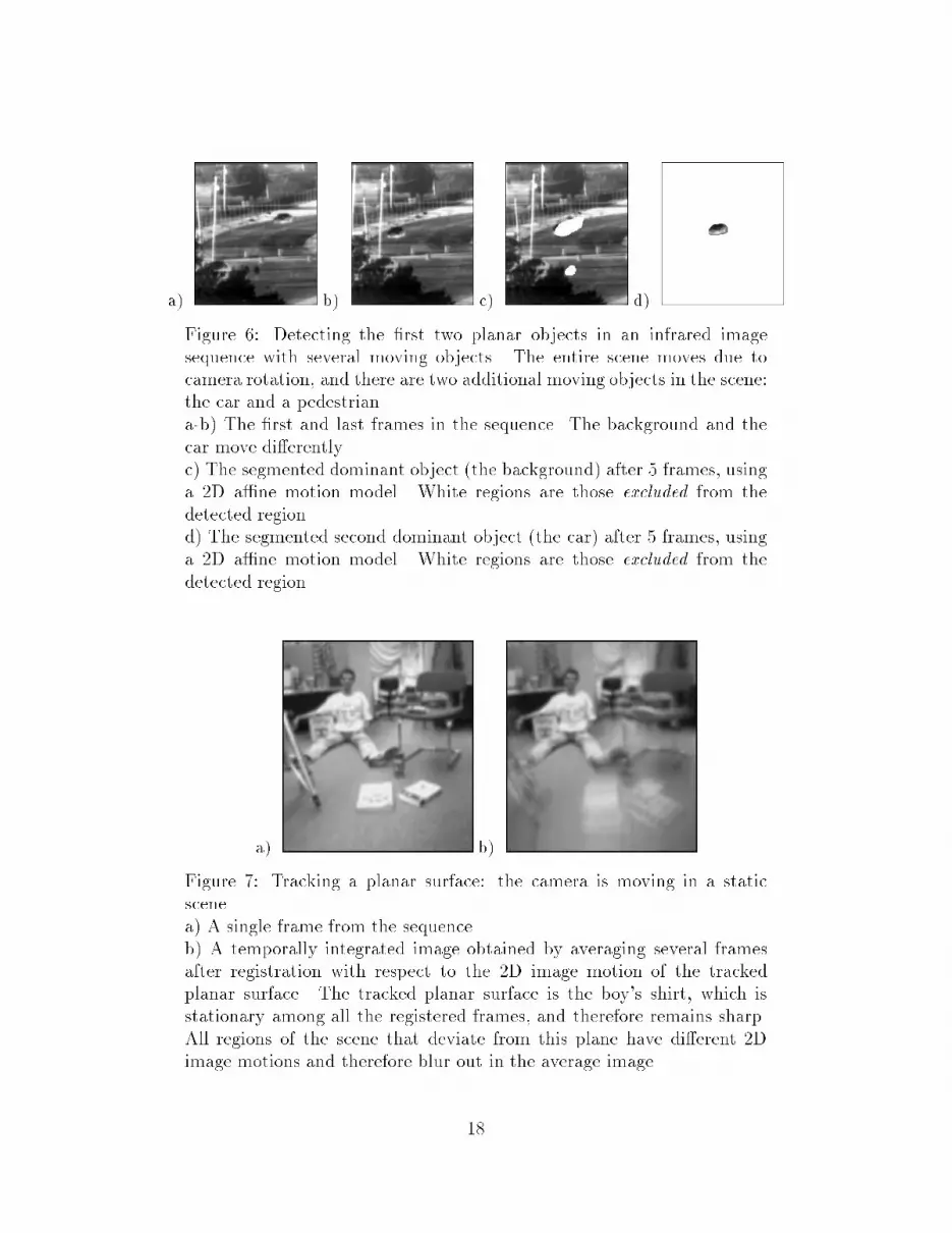
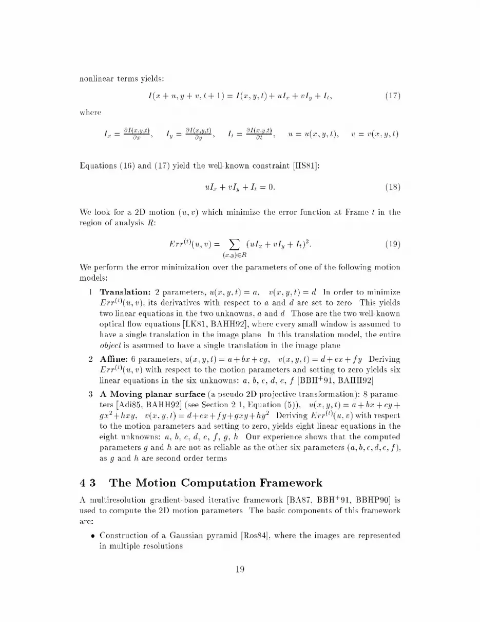
a) b) c) d)Figure 6: Detecting the �rst two planar objects in an infrared imagesequence with several moving objects. The entire scene moves due tocamera rotation, and there are two additional moving objects in the scene:the car and a pedestrian.a-b) The �rst and last frames in the sequence. The background and thecar move di�erently.c) The segmented dominant object (the background) after 5 frames, usinga 2D a�ne motion model. White regions are those excluded from thedetected region.d) The segmented second dominant object (the car) after 5 frames, usinga 2D a�ne motion model. White regions are those excluded from thedetected region.a) b)Figure 7: Tracking a planar surface: the camera is moving in a staticscene.a) A single frame from the sequence.b) A temporally integrated image obtained by averaging several framesafter registration with respect to the 2D image motion of the trackedplanar surface. The tracked planar surface is the boy's shirt, which isstationary among all the registered frames, and therefore remains sharp.All regions of the scene that deviate from this plane have di�erent 2Dimage motions and therefore blur out in the average image.18
nonlinear terms yields:I(x+ u; y + v; t+ 1) = I(x; y; t)+ uIx + vIy + It; (17)where Ix = @I(x;y;t)@x ; Iy = @I(x;y;t)@y ; It = @I(x;y;t)@t ; u = u(x; y; t); v = v(x; y; t).Equations (16) and (17) yield the well-known constraint [HS81]:uIx + vIy + It = 0: (18)We look for a 2D motion (u; v) which minimize the error function at Frame t in theregion of analysis R: Err(t)(u; v) = X(x;y)2R(uIx + vIy + It)2: (19)We perform the error minimization over the parameters of one of the following motionmodels:1. Translation: 2 parameters, u(x; y; t) = a, v(x; y; t) = d. In order to minimizeErr(t)(u; v), its derivatives with respect to a and d are set to zero. This yieldstwo linear equations in the two unknowns, a and d. Those are the two well-knownoptical ow equations [LK81, BAHH92], where every small window is assumed tohave a single translation in the image plane. In this translation model, the entireobject is assumed to have a single translation in the image plane.2. A�ne: 6 parameters, u(x; y; t) = a+ bx+ cy, v(x; y; t) = d+ ex+ fy. DerivingErr(t)(u; v) with respect to the motion parameters and setting to zero yields sixlinear equations in the six unknowns: a, b, c, d, e, f [BBH+91, BAHH92].3. A Moving planar surface (a pseudo 2D projective transformation): 8 parame-ters [Adi85, BAHH92] (see Section 2.1, Equation (5)), u(x; y; t) = a+ bx+ cy+gx2+hxy, v(x; y; t) = d+ex+fy+gxy+hy2 . Deriving Err(t)(u; v) with respectto the motion parameters and setting to zero, yields eight linear equations in theeight unknowns: a, b, c, d, e, f , g, h. Our experience shows that the computedparameters g and h are not as reliable as the other six parameters (a; b; c; d; e; f),as g and h are second order terms.4.3 The Motion Computation FrameworkA multiresolution gradient-based iterative framework [BA87, BBH+91, BBHP90] isused to compute the 2D motion parameters. The basic components of this frameworkare:� Construction of a Gaussian pyramid [Ros84], where the images are representedin multiple resolutions. 19

� Starting at the lowest resolution level:1. Motion parameters are estimated by solving the set of linear equations tominimize Err(t)(u; v) (Equation (19)) according to the appropriate 2D mo-tion model (Section 4.2). When the region of support of the planar objectis known, minimization is done only over that region. Otherwise, it is per-formed over the entire image.2. The two images are registered by warping according to the computed 2Dmotion parameters.Steps 1 and 2 are iterated at each resolution level for further re�nement.3. The 2D motion parameters are interpolated to the next resolution level, andare re�ned by using the higher resolution images.5 Concluding RemarksA method is introduced for computing ego-motion in static scenes. At �rst, an imageregion corresponding to a planar surface in the scene is detected, and its 2D motionparameters between successive frames are computed. The 2D transformation is thenused for image warping, which cancels the rotational component of the 3D cameramotion for the entire scene, and reduces the problem to pure 3D translation. The3D translation (the FOE) is computed from the registered frames, and then the 3Drotation is computed by solving a small set of linear equations.It was shown that the ego-motion can be recovered reliably in all cases, except fortwo: The case of a planar scene, and the case of an ego-motion with a translation inthe x-y plane only. The �rst case cannot be resolved by humans either, due to a visualambiguity. In the second case it was shown that only the translation parameters ofthe camera and the rotation around its optical axis can be recovered accurately. Thepanning parameters (rotation around the x and y axes) can only be roughly estimatedin this special case. In all other con�gurations of camera motion the ego-motion canbe reliably recovered.The advantage of the presented technique is in its simplicity, and in the robustnessand stability of each computational step. The choice of an initial 2D motion modelenables e�cient motion computation and numerical stability. There are no severerestrictions on the ego-motion or on the structure of the environment. Most steps useonly image intensities, and the optical ow is used only for extracting the FOE in thecase of pure 3D translation, which does not require accurate optical ow. The inherentproblems of optical ow and of feature matching are therefore avoided.AcknowledgmentThe authors wish to thank R. Kumar of David Sarno� Research Center for pointingout an error in the �rst version of this paper.20

References[AD92] Y. Aloimonos and Z. Duric. Active egomotion estimation: A qualitativeapproach. In European Conference on Computer Vision, pages 497{510,Santa Margarita Ligure, May 1992.[Adi85] G. Adiv. Determining three-dimensional motion and structure from optical ow generated by several moving objects. IEEE Trans. on Pattern Analysisand Machine Intelligence, 7(4):384{401, July 1985.[Adi89] G. Adiv. Inherent ambiguities in recovering 3Dmotion and structure from anoisy ow �eld. IEEE Trans. on Pattern Analysis and Machine Intelligence,11:477{489, May 1989.[BA87] J.R. Bergen and E.H. Adelson. Hierarchical, computationally e�cient mo-tion estimation algorithm. J. Opt. Soc. Am. A., 4:35, 1987.[BAHH92] J.R. Bergen, P. Anandan, K.J. Hanna, and R. Hingorani. Hierarchicalmodel-based motion estimation. In European Conference on Computer Vi-sion, pages 237{252, Santa Margarita Ligure, May 1992.[BBH+91] J.R. Bergen, P.J. Burt, K. Hanna, R. Hingorani, P. Jeanne, and S. Peleg.Dynamic multiple-motion computation. In Y.A. Feldman and A. Bruck-stein, editors, Arti�cial Intelligence and Computer Vision: Proceedings ofthe Israeli Conference, pages 147{156. Elsevier, 1991.[BBHP90] J.R. Bergen, P.J. Burt, R. Hingorani, and S. Peleg. Computing two motionsfrom three frames. In International Conference on Computer Vision, pages27{32, Osaka, Japan, December 1990.[BHK91] P.J. Burt, R. Hingorani, and R.J. Kolczynski. Mechanisms for isolatingcomponent patterns in the sequential analysis of multiple motion. In IEEEWorkshop on Visual Motion, pages 187{193, Princeton, New Jersey, Octo-ber 1991.[COK93] R. Chipolla, Y. Okamoto, and Y. Kuno. Robust structure from motionusing motion paralax. In International Conference on Computer Vision,pages 374{382, Berlin, May 1993.[DF90] R. Deriche and O. Faugeras. Tracking line segments. In Proc. 1st EuropeanConference on Computer Vision, pages 259{268, Antibes, April 1990.[DMRS88] R. Dutta, R. Manmatha, E.M. Riseman, and M.A. Snyder. Issues in ex-tracting motion parameters and depth from approximate translational mo-tion. In DARPA IU Workshop, pages 945{960, 1988.[DN93] K. Daniilidis and H.-H. Nagel. The coupling of rotation and translation inmotion estimation of planar surfaces. In IEEE Conference on ComputerVision and Pattern Recognition, pages 188{193, New York, June 1993.[DRD93] Z. Duric, A. Rosenfeld, and L. Davis. Egomotion analysis based on theFrenet-Serret motion model. In International Conference on ComputerVision, pages 703{712, Berlin, May 1993.21

[FJ90] D.J. Fleet and A.D. Jepson. Computation of component image velocityfrom local phase information. International Journal of Computer Vision,5(1):77{104, 1990.[GU91] R. Guissin and S. Ullman. Direct computation of the focus of expansionfrom velocity �eld measurements. In IEEE Workshop on Visual Motion,pages 146{155, Princeton, NJ, October 1991.[HA91] L. Huang and Y. Aloimonos. Relative depth frommotion using normal ow:An active and purposive solution. In IEEE Workshop on Visual Motion,pages 196{204, Princeton, NJ, October 1991.[Han91] K. Hanna. Direct multi-resolution estimation of ego-motion and structurefrom motion. In IEEE Workshop on Visual Motion, pages 156{162, Prince-ton, NJ, October 1991.[Hee88] D.J. Heeger. Optical ow using spatiotemporal �lters. International Jour-nal of Computer Vision, 1:279{302, 1988.[HJ90] D.J. Heeger and A. Jepson. Simple method for computing 3d motion anddepth. In International Conference on Computer Vision, pages 96{100,1990.[Hor90] B.K.P. Horn. Relative orientation. International Journal of ComputerVision, 4(1):58{78, June 1990.[HS81] B.K.P. Horn and B.G. Schunck. Determining optical ow. Arti�cial Intel-ligence, 17:185{203, 1981.[HW88] B.K.P. Horn and E.J. Weldon. Direct methods for recovering motion. In-ternational Journal of Computer Vision, 2(1):51{76, June 1988.[IRP92] M. Irani, B. Rousso, and S. Peleg. Detecting and tracking multiple movingobjects using temporal integration. In European Conference on ComputerVision, pages 282{287, Santa Margarita Ligure, May 1992.[IRP93] M. Irani, B. Rousso, and S. Peleg. Computing occluding and transparentmotions. To appear in International Journal of Computer Vision, February1993.[JH91] A.D. Jepson and D.J. Heeger. A fast subspace algorithm for recovering rigidmotion. In IEEE Workshop on Visual Motion, pages 124{131, Princeton,NJ, October 1991.[LC93] J. Lawn and R. Chipolla. Epipole estimation using a�ne motion parallax.Technical Report CUED/F-INFENG/TR-138, Cambridge, July 1993.[Lee88] C.H. Lee. Structure and motion from two perspective views via planarpatch. In International Conference on Computer Vision, pages 158{164,1988.[LH84] H.C. Longuet-Higgins. Visual ambiguity of a moving plane. Proceedings ofThe Royal Society of London B, 223:165{175, 1984.22

[LHP80] H.C. Longuet-Higgins and K. Prazdny. The interpretation of a movingretinal image. Proceedings of The Royal Society of London B, 208:385{397,1980.[LK81] B.D. Lucas and T. Kanade. An iterative image registration technique withan application to stereo vision. In Image Understanding Workshop, pages121{130, 1981.[LR83] D.T. Lawton and J.H. Rieger. The use of di�erence �elds in processingsensor motion. In DARPA IU Workshop, pages 78{83, June 1983.[MB92] F. Meyer and P. Bouthemy. Estimation of time-to-collision maps from �rstorder motion models and normal ows. In International Conference onPattern Recognition, pages 78{82, The Hague, 1992.[NL91] S. Negahdaripour and S. Lee. Motion recovery from image sequences using�rst-order optical ow information. In IEEE Workshop on Visual Motion,pages 132{139, Princeton, NJ, October 1991.[OFT87] F. Lustman O.D. Faugeras and G. Toscani. Motion and structure frommotion from point and line matching. In Proc. 1st International Conferenceon Computer Vision, pages 25{34, London, 1987.[Ros84] A. Rosenfeld, editor. Multiresolution Image Processing and Analysis.Springer-Verlag, 1984.[SM90] M. Shizawa and K. Mase. Simultaneous multiple optical ow estimation. InInternational Conference on Pattern Recognition, pages 274{278, AtlanticCity, New Jersey, June 1990.[Sun91] V. Sundareswaran. Egomotion from global ow �eld data. In IEEE Work-shop on Visual Motion, pages 140{145, Princeton, NJ, October 1991.[Taa92] M.A. Taalebinezhaad. Direct recovery of motion and shape in the generalcase by �xation. IEEE Trans. on Pattern Analysis and Machine Intelli-gence, 14:847{853, August 1992.[TS91] M. Tistarelli and G. Sandini. Direct estimation of time-to-impact from op-tical ow. In IEEE Workshop on Visual Motion, pages 226{233, Princeton,NJ, October 1991.[WHA89] J. Weng, T.S. Huang, and N. Ahuja. Motion and structure from two per-spective views: Algorithms, error analysis, and error estimation. IEEETrans. on Pattern Analysis and Machine Intelligence, 11(5), 1989.23