recirculation phenomena in a natural gas swirl combustor
TRANSCRIPT
Experimental Thermal and Fluid Science 28 (2004) 709–714
www.elsevier.com/locate/etfs
Experimental Thermal and Fluid Science 28 (2004) 709–714
www.elsevier.com/locate/etfs
Recirculation phenomena in a natural gas swirl combustor
Aldo Coghe *, Giulio Solero, Gianfranco Scribano
Dipartimento di Energetica, Politecnico di Milano, Fac. di Ingegneria Milano Bovisa, via La Masa 34, 20156 Milano, Italy
Abstract
This paper presents the experimental results obtained in a natural gas swirl combustor (input thermal power¼ 17 kW) through
different techniques (laser Doppler Anemometry for flow field characterisation, temperature measurements by thin thermocouples,
emission spectroscopy of the flame front and pollutant emissions analysis at the exhaust). The main aim of the performed research
was to investigate the recirculation phenomena induced by the swirl motion imparted to the air stream (swirl number S ¼ 0:82)inside the combustor: in fact, different recirculating regions (central and corner) have been observed and, by integration of the
velocity profile measured by LDV, the corresponding flow rate has been estimated. Particularly, it has been found that flame
confinement in the presence of intense swirl generates a wide central recirculation zone and a large corner vortex. The hot reverse
stream propagating on the burner axis prevents penetration of the fuel jet, induces a rapid mixing and burning and provides flame
stabilisation. The corner recirculation of hot burned gases favours entrainment in the outflowing reactants mixture contributing to
their progressive pre-heating and leaning, thus influencing combustion process development and pollutants formation (especially
thermal NOx).
� 2004 Elsevier Inc. All rights reserved.
Keywords: Swirl burners; Combustion diagnostics
1. Introduction
The multidisciplinary nature of the Combustion Sci-
ence requires different investigation approaches. Among
them, the fluid dynamic analysis is without doubt one of
the most important tools to ascertain the stability and
efficiency of a combustion device. One of the method-
ologies recently developed to minimize the environ-mental impact of combustion processes is founded upon
the improvement and the optimization of the mixing
process between the reactants (fuel and air): in fact, it is
well known [1,2] that, independently from the combus-
tion technology used, the main features of the combus-
tion process (under the point of view of efficiency,
stability and pollutant emissions) are strictly linked to
the efficiency of the mixing process between the reac-tants, because the chemical kinetic time scales are usu-
ally shorter than the turbulent time scales. Therefore,
the fluid dynamic analysis of a combustion process can
*Corresponding author. Tel.: +39-2-2399-8537; fax: +39-2-2399-
8566.
E-mail address: [email protected] (A. Coghe).
0894-1777/$ - see front matter � 2004 Elsevier Inc. All rights reserved.
doi:10.1016/j.expthermflusci.2003.12.007
provide useful informations about the main character-
istics of the phenomenon.
This paper deals with the experimental characterisa-
tion of a natural gas swirl combustor, analysing by
different techniques both the flame front behaviour and
the recirculating regions induced by the swirl inside the
combustion chamber. Swirl effect is often used in com-
bustion devices in order to improve flame stability andenhance mixing process [3]. The present analysis has
been carried out in order to quantify the degree of
mixing between hot products and cold reactants which is
generated by the swirling air motion, both inside and
outside the flame region, suggesting improvement to the
burner design, by promoting or hindering the develop-
ment of these phenomena.
2. Experimental set-up
Fig. 1 reports a schematic view of the investigated
burner. As it can be seen, the burner is equipped with an
axial + tangential swirl generator and with a fuel injector
coaxial to the air stream: it is a configuration quite
similar to those used for typical industrial appliances(diffusive atmospheric pressure burners). A cylindrical
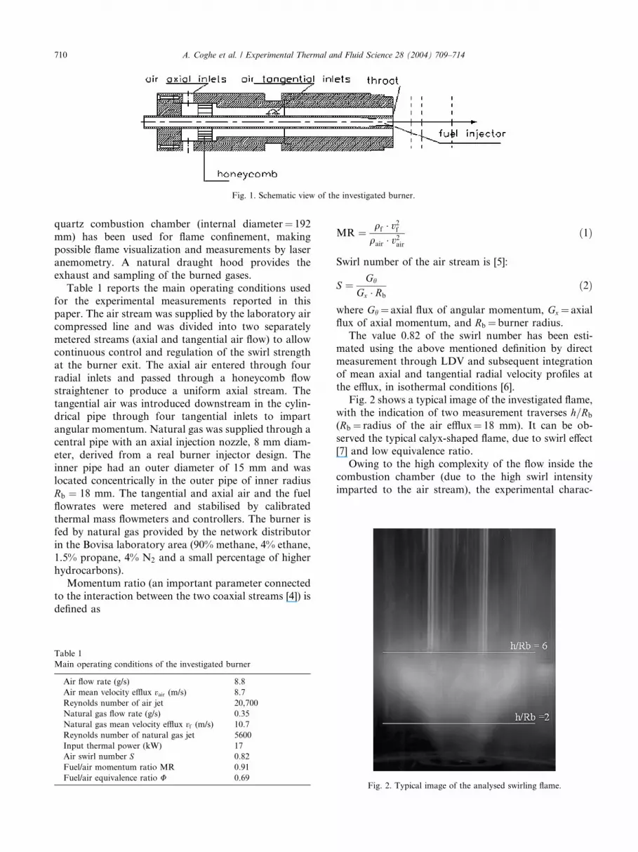
Fig. 1. Schematic view of the investigated burner.
710 A. Coghe et al. / Experimental Thermal and Fluid Science 28 (2004) 709–714
quartz combustion chamber (internal diameter¼ 192
mm) has been used for flame confinement, making
possible flame visualization and measurements by laser
anemometry. A natural draught hood provides the
exhaust and sampling of the burned gases.
Table 1 reports the main operating conditions used
for the experimental measurements reported in thispaper. The air stream was supplied by the laboratory air
compressed line and was divided into two separately
metered streams (axial and tangential air flow) to allow
continuous control and regulation of the swirl strength
at the burner exit. The axial air entered through four
radial inlets and passed through a honeycomb flow
straightener to produce a uniform axial stream. The
tangential air was introduced downstream in the cylin-drical pipe through four tangential inlets to impart
angular momentum. Natural gas was supplied through a
central pipe with an axial injection nozzle, 8 mm diam-
eter, derived from a real burner injector design. The
inner pipe had an outer diameter of 15 mm and was
located concentrically in the outer pipe of inner radius
Rb ¼ 18 mm. The tangential and axial air and the fuel
flowrates were metered and stabilised by calibratedthermal mass flowmeters and controllers. The burner is
fed by natural gas provided by the network distributor
in the Bovisa laboratory area (90% methane, 4% ethane,
1.5% propane, 4% N2 and a small percentage of higher
hydrocarbons).
Momentum ratio (an important parameter connected
to the interaction between the two coaxial streams [4]) is
defined as
Table 1
Main operating conditions of the investigated burner
Air flow rate (g/s) 8.8
Air mean velocity efflux vair (m/s) 8.7
Reynolds number of air jet 20,700
Natural gas flow rate (g/s) 0.35
Natural gas mean velocity efflux vf (m/s) 10.7
Reynolds number of natural gas jet 5600
Input thermal power (kW) 17
Air swirl number S 0.82
Fuel/air momentum ratio MR 0.91
Fuel/air equivalence ratio U 0.69
MR ¼ qf � v2fqair � v2air
ð1Þ
Swirl number of the air stream is [5]:
S ¼ Gh
Gx � Rb
ð2Þ
where Gh ¼ axial flux of angular momentum, Gx ¼ axial
flux of axial momentum, and Rb ¼ burner radius.
The value 0.82 of the swirl number has been esti-mated using the above mentioned definition by direct
measurement through LDV and subsequent integration
of mean axial and tangential radial velocity profiles at
the efflux, in isothermal conditions [6].
Fig. 2 shows a typical image of the investigated flame,
with the indication of two measurement traverses h=Rb
(Rb¼ radius of the air efflux¼ 18 mm). It can be ob-
served the typical calyx-shaped flame, due to swirl effect[7] and low equivalence ratio.
Owing to the high complexity of the flow inside the
combustion chamber (due to the high swirl intensity
imparted to the air stream), the experimental charac-
Fig. 2. Typical image of the analysed swirling flame.
-10
-5
0
5
10
15
20
-0.1 0 0.1 0.2 0.3 0.4 0.5 0.6 0.7 0.8 0.9 1 1.1
r/R
V (m/s)
0
200
400
600
800
1000
1200
1400
T (°C)
V (m/s)T (°C)
-10
-5
0
5
10
15
20
-0.1 0 0.1 0.2 0.3 0.4 0.5 0.6 0.7 0.8 0.9 1 1.1
r/R
V (m/s)
0
200
400
600
800
1000
1200
1400
T (°C)
V (m/s)T (°C)
10
15
20
1000
1200
1400V (m/s)T (°C)
(b)
(a)
A. Coghe et al. / Experimental Thermal and Fluid Science 28 (2004) 709–714 711
terisation has been carried out through different tech-
niques.
Measurement by LDV of the reactive flow field has
been performed at increasing distances h=Rb from the
efflux, in order to analyse the formation of the recircu-lating regions and their possible influence upon flame
development. Velocity fields were measured using a two-
component fiber optics Laser Doppler Velocimeter
equipped with an Argon ion laser and a Bragg cell with
40 MHz frequency shift for directional ambiguity reso-
lution. The optical system was operated in the back-
scatter mode and the signal processors were two Burst
Spectrum Analysers (BSA––Dantec). MicrometricAl2O3 particles were used as scattering centres: at least
10,000 instantaneous velocity data were acquired for
statistical analysis, with estimated statistical errors of
less than 2% in the mean values and 5% in the r.m.s.
fluctuations.
Mean temperature was measured using a Pt/Pt-13%
Rh bare wire thermocouple with 0.3 mm diameter bead.
The amplified signals were sampled at a 500 Hz sam-pling frequency and the mean value was based on 5000
instantaneous data. A correction was made for the
radiation error, following [8] and using the measured
velocity values for the evaluation of convective heat
transfer coefficient.
Emission spectroscopy in the visible range from the
flame front has been carried out to investigate the
presence of CH* radicals (k ¼ 431 nm), which can beconsidered as flame front tracers [9].
Finally, burned gases have been sampled for analysis
of the pollutant emissions (NOx and CO), through a
system based, respectively, upon chemiluminescence
and infrared analysis.
V (m/s)
-10
-5
0
5
-0.1 0 0.1 0.2 0.3 0.4 0.5 0.6 0.7 0.8 0.9 1 1.1
r/R0
200
400
600
800T (°C)
(c)
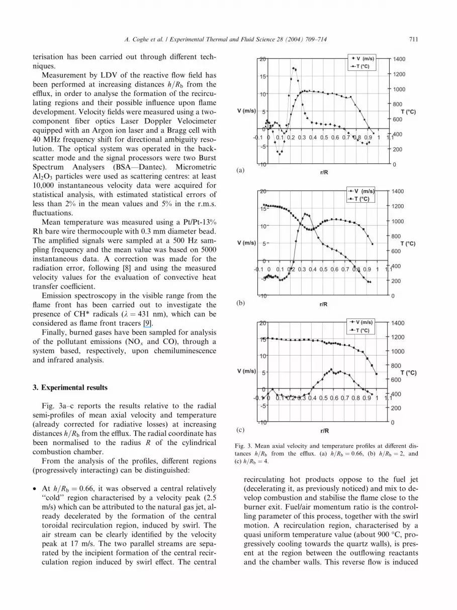
Fig. 3. Mean axial velocity and temperature profiles at different dis-
tances h=Rb from the efflux. (a) h=Rb ¼ 0:66, (b) h=Rb ¼ 2, and
(c) h=Rb ¼ 4.
3. Experimental results
Fig. 3a–c reports the results relative to the radial
semi-profiles of mean axial velocity and temperature
(already corrected for radiative losses) at increasing
distances h=Rb from the efflux. The radial coordinate has
been normalised to the radius R of the cylindrical
combustion chamber.
From the analysis of the profiles, different regions(progressively interacting) can be distinguished:
• At h=Rb ¼ 0:66, it was observed a central relatively
‘‘cold’’ region characterised by a velocity peak (2.5
m/s) which can be attributed to the natural gas jet, al-
ready decelerated by the formation of the central
toroidal recirculation region, induced by swirl. The
air stream can be clearly identified by the velocitypeak at 17 m/s. The two parallel streams are sepa-
rated by the incipient formation of the central recir-
culation region induced by swirl effect. The central
recirculating hot products oppose to the fuel jet
(decelerating it, as previously noticed) and mix to de-
velop combustion and stabilise the flame close to the
burner exit. Fuel/air momentum ratio is the control-
ling parameter of this process, together with the swirl
motion. A recirculation region, characterised by a
quasi uniform temperature value (about 900 �C, pro-gressively cooling towards the quartz walls), is pres-ent at the region between the outflowing reactants
and the chamber walls. This reverse flow is induced
712 A. Coghe et al. / Experimental Thermal and Fluid Science 28 (2004) 709–714
by a corner recirculation due to the air stream radial
expansion and the wall confinement. The high tem-
peratures measured in this zone indicate the presence
of a large fraction of already burned gases which are
entrained by the reactant flow. At this short distancefrom the burner exit, the external recirculating flow is
hotter than the inner reverse stream and produces
a fast pre-heating of the incoming air jet.
• At h=Rb ¼ 2, the central fuel jet completely disap-
pears in the central recirculation region, indicating
complete mixing with the coaxial air stream and
counter-propagating burned gases. The consequent
development of combustion reactions is clearly visibleby the temperature increase (up to 1200 �C) in the
correspondence of the burner axis (see also the flame
visualization in Fig. 2). This traverse seems as crucial
for the onset of combustion reactions. Anyway, mea-
sured combustion temperature is quite low due both
to temporal and spatial averaging produced by the
thermocouple and thermal radiative transfer through
the transparent combustion chamber. Reactant airstream at lower temperature is still noticeable (at
0:22 < r=R < 0:5) both from velocity and tempera-
ture profiles, but the interesting fact is the more
intense strength of the corner recirculation phenome-
non with respect to previous measurement position,
reaching velocity values of )6 m/s and temperatures
higher than 1000 �C.• The profiles result more uniform at h=Rb ¼ 4, where
it can be noticed the weakening of the recirculating
regions, both central and peripheral: combustion
reactions should be almost completed, as indicated
by the uniform temperature profile.
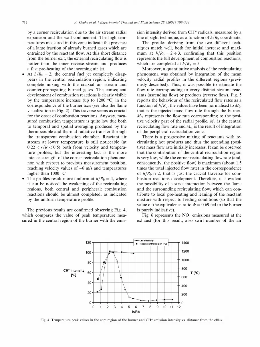
The previous results are confirmed observing Fig. 4,
which compares the value of peak temperature mea-
sured in the central region of the burner with the emis-
0
20
40
60
80
100
120
0 1 2 3 4 5 6h/R
CH* intensity [%]
Fig. 4. Temperature peak values in the core region of the burne
sion intensity derived from CH* radicals, measured by a
line of sight technique, as a function of h=Rb coordinate.
The profiles deriving from the two different tech-
niques match well, both for initial increase and maxi-
mum at h=Rb ¼ 2� 3, confirming that this positionrepresents the full development of combustion reactions,
which are completed at h=Rb ¼ 5.
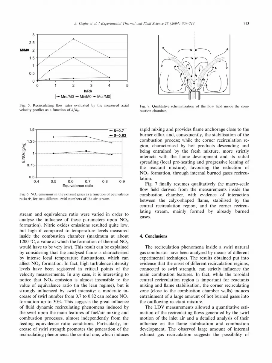
Moreover, a quantitative analysis of the recirculating
phenomena was obtained by integration of the mean
velocity radial profiles in the different regions (previ-
ously described). Thus, it was possible to estimate the
flow rate corresponding to every distinct stream: reac-
tants (ascending flow) or products (reverse flow). Fig. 5reports the behaviour of the recirculated flow rates as a
function of h=Rb: the values have been normalised toM0,
that is the injected mass flow rate through the burner.
Mre represents the flow rate corresponding to the posi-
tive velocity part of the radial profile, Mir is the central
recirculating flow rate andMcr is the result of integration
of the peripheral recirculation zone.
There is a progressive mixing of reactants with re-circulating hot products and thus the ascending (posi-
tive) mass flow rate initially increases. It can be observed
that the contribution of the central recirculation region
is very low, while the corner recirculating flow rate (and,
consequently, the positive flow) is maximum (about 1.5
times the total injected flow rate) in the correspondence
of h=Rb � 2, that is just the crucial traverse for com-
bustion reactions development. Therefore, it is evidentthe possibility of a strict interaction between the flame
and the surrounding recirculating flow, which can con-
tribute to local pre-heating and leaning of the reactant
mixture with respect to feeding conditions (so that the
value of the equivalence ratio U ¼ 0:69 fed to the burneris purely indicative).
Fig. 6 represents the NOx emissions measured at the
exhaust (for this result, also swirl number of the air
7 8 9 10 11 12b
0
200
400
600
800
1000
1200
1400
T (°C)
CH* intensityT peak central region (°C)
r and CH* emission intensity vs. distance from the efflux.
0.5
0.75
1
1.25
1.5
0.4 0.5 0.6 0.7 0.8 0.9Equivalence ratio
EINO
x [g
/kg]
S=0.7S=0.82
Fig. 6. NOx emissions in the exhaust gases as a function of equivalence
ratio U, for two different swirl numbers of the air stream.
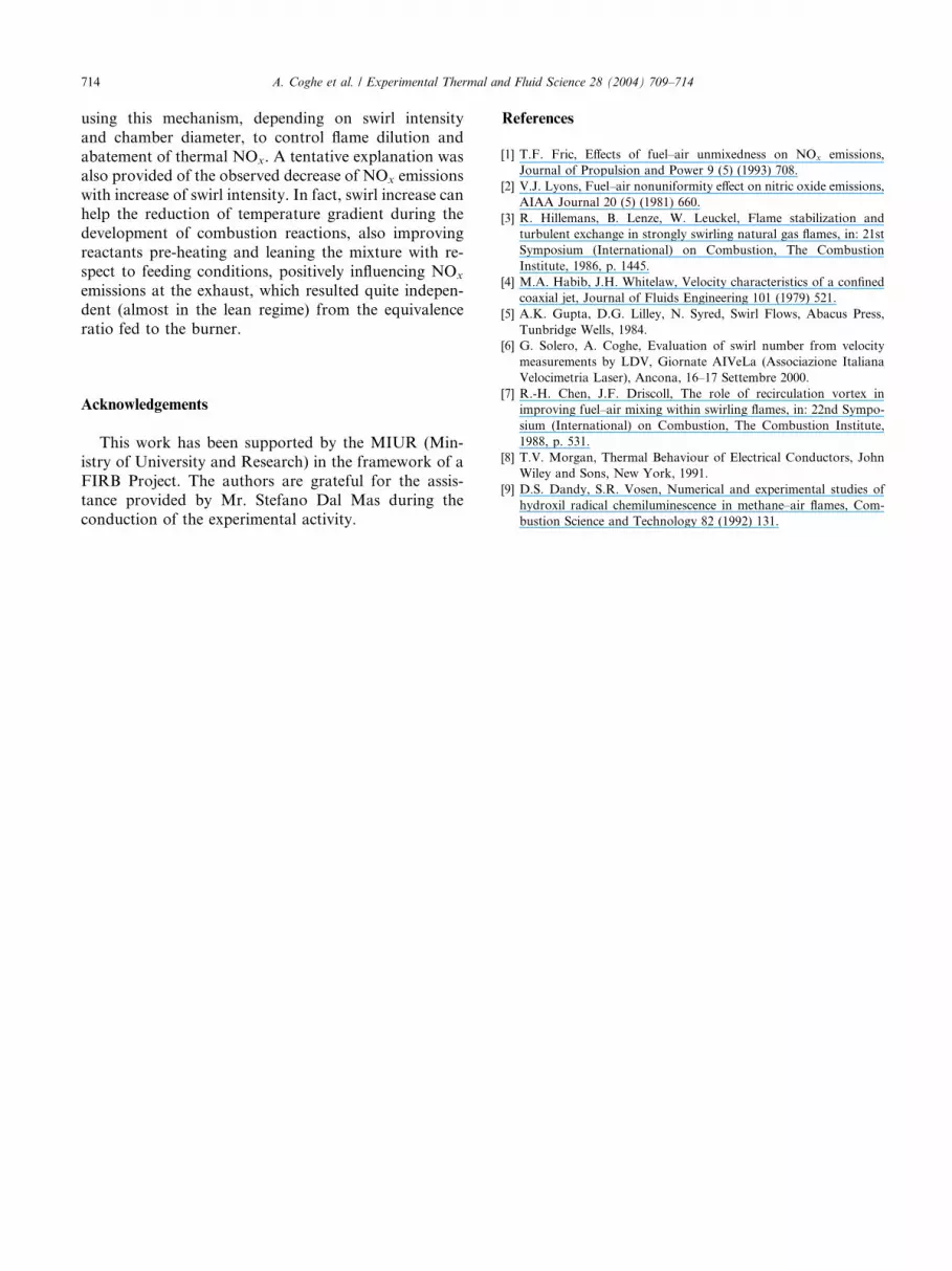
Fig. 7. Qualitative schematization of the flow field inside the com-
bustion chamber.
0
0.5
1
1.5
2
2.5
3
0 1 2 3 4 5h/Rb
Mre/M0 Mir/M0 Mcr/M0
M/M0
Fig. 5. Recirculating flow rates evaluated by the measured axial
velocity profiles as a function of h=Rb.
A. Coghe et al. / Experimental Thermal and Fluid Science 28 (2004) 709–714 713
stream and equivalence ratio were varied in order to
analyse the influence of these parameters upon NOx
formation). Nitric oxides emissions resulted quite low,
but high if compared to temperature levels measured
inside the combustion chamber (maximum at about
1200 �C, a value at which the formation of thermal NOx
would have to be very low). This result can be explained
by considering that the analysed flame is characterised
by intense local temperature fluctuations, which can
affect NOx formation. In fact, high turbulence intensitylevels have been registered in critical points of the
velocity measurements. In any case, it is interesting to
notice that NOx emission is almost insensible to the
value of equivalence ratio (in the lean regime), but is
strongly influenced by swirl intensity: a moderate in-
crease of swirl number from 0.7 to 0.82 can reduce NOx
formation up to 30%. This suggests the great influence
of fluid dynamic recirculating phenomena induced bythe swirl upon the main features of fuel/air mixing and
combustion processes, almost independently from the
feeding equivalence ratio conditions. Particularly, in-
crease of swirl strength promotes the generation of the
recirculating phenomena: the central one, which induces
rapid mixing and provides flame anchorage close to the
burner efflux and, consequently, the stabilisation of the
combustion process; while the corner recirculation re-
gion, characterised by hot products descending andbeing entrained by the fresh mixture, more strictly
interacts with the flame development and its radial
spreading (local pre-heating and progressive leaning of
the reactant mixture), favouring the reduction of
NOx formation, through internal burned gases recircu-
lation.
Fig. 7 finally resumes qualitatively the macro-scale
flow field derived from the measurements inside thecombustion chamber, with evidence of interaction
between the calyx-shaped flame, stabilised by the
central recirculation region, and the corner recircu-
lating stream, mainly formed by already burned
gases.
4. Conclusions
The recirculation phenomena inside a swirl natural
gas combustor have been analysed by means of different
experimental techniques. The results obtained put into
evidence that the onset of different recirculation regions,
connected to swirl strength, can strictly influence the
main combustion features. In fact, while the toroidal
central recirculation region is important for reactantsmixing and flame stabilisation, the corner recirculating
zone (close to the combustion chamber walls) induces
entrainment of a large amount of hot burned gases into
the outflowing reactant mixture.
The LDV measurements allowed a quantitative esti-
mation of the recirculating flows generated by the swirl
motion of the inlet air and a detailed analysis of their
influence on the flame stabilisation and combustiondevelopment. The observed large amount of internal
exhaust gas recirculation suggests the possibility of
714 A. Coghe et al. / Experimental Thermal and Fluid Science 28 (2004) 709–714
using this mechanism, depending on swirl intensity
and chamber diameter, to control flame dilution and
abatement of thermal NOx. A tentative explanation was
also provided of the observed decrease of NOx emissions
with increase of swirl intensity. In fact, swirl increase canhelp the reduction of temperature gradient during the
development of combustion reactions, also improving
reactants pre-heating and leaning the mixture with re-
spect to feeding conditions, positively influencing NOx
emissions at the exhaust, which resulted quite indepen-
dent (almost in the lean regime) from the equivalence
ratio fed to the burner.
Acknowledgements
This work has been supported by the MIUR (Min-
istry of University and Research) in the framework of a
FIRB Project. The authors are grateful for the assis-
tance provided by Mr. Stefano Dal Mas during the
conduction of the experimental activity.
References
[1] T.F. Fric, Effects of fuel–air unmixedness on NOx emissions,
Journal of Propulsion and Power 9 (5) (1993) 708.
[2] V.J. Lyons, Fuel–air nonuniformity effect on nitric oxide emissions,
AIAA Journal 20 (5) (1981) 660.
[3] R. Hillemans, B. Lenze, W. Leuckel, Flame stabilization and
turbulent exchange in strongly swirling natural gas flames, in: 21st
Symposium (International) on Combustion, The Combustion
Institute, 1986, p. 1445.
[4] M.A. Habib, J.H. Whitelaw, Velocity characteristics of a confined
coaxial jet, Journal of Fluids Engineering 101 (1979) 521.
[5] A.K. Gupta, D.G. Lilley, N. Syred, Swirl Flows, Abacus Press,
Tunbridge Wells, 1984.
[6] G. Solero, A. Coghe, Evaluation of swirl number from velocity
measurements by LDV, Giornate AIVeLa (Associazione Italiana
Velocimetria Laser), Ancona, 16–17 Settembre 2000.
[7] R.-H. Chen, J.F. Driscoll, The role of recirculation vortex in
improving fuel–air mixing within swirling flames, in: 22nd Sympo-
sium (International) on Combustion, The Combustion Institute,
1988, p. 531.
[8] T.V. Morgan, Thermal Behaviour of Electrical Conductors, John
Wiley and Sons, New York, 1991.
[9] D.S. Dandy, S.R. Vosen, Numerical and experimental studies of
hydroxil radical chemiluminescence in methane–air flames, Com-
bustion Science and Technology 82 (1992) 131.