real-time indirect illumination with clustered visibility
TRANSCRIPT
Real-time Indirect Illumination with Clustered Visibility
Zhao Dong1 Thorsten Grosch1 Tobias Ritschel1 Jan Kautz2 Hans-Peter Seidel1
1MPI Informatik, Germany 2University College London, UK
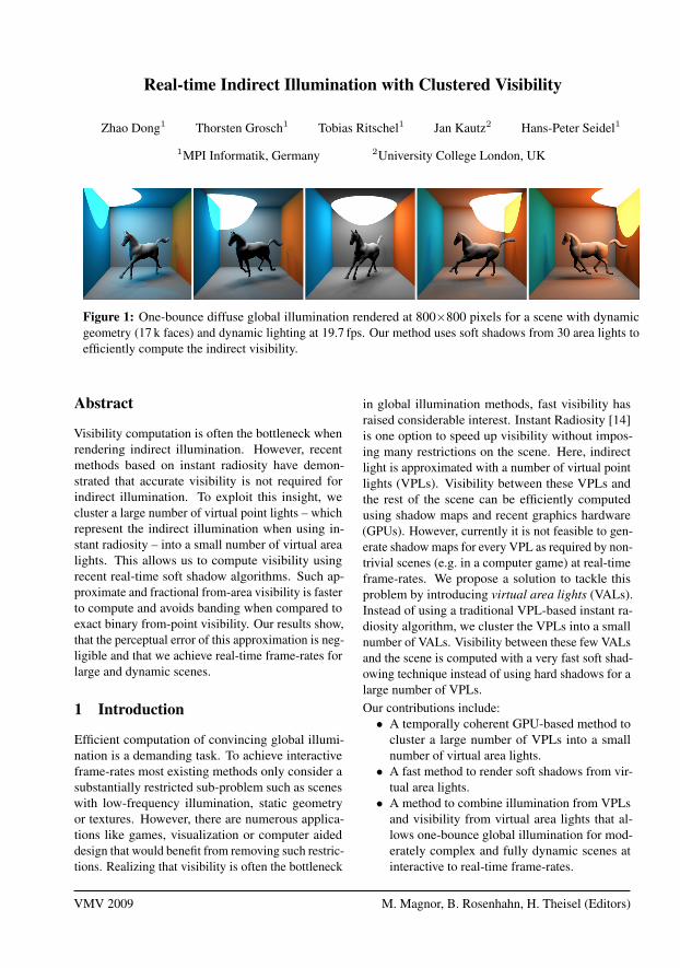
Figure 1: One-bounce diffuse global illumination rendered at 800×800 pixels for a scene with dynamicgeometry (17 k faces) and dynamic lighting at 19.7 fps. Our method uses soft shadows from 30 area lights toefficiently compute the indirect visibility.
Abstract
Visibility computation is often the bottleneck whenrendering indirect illumination. However, recentmethods based on instant radiosity have demon-strated that accurate visibility is not required forindirect illumination. To exploit this insight, wecluster a large number of virtual point lights – whichrepresent the indirect illumination when using in-stant radiosity – into a small number of virtual arealights. This allows us to compute visibility usingrecent real-time soft shadow algorithms. Such ap-proximate and fractional from-area visibility is fasterto compute and avoids banding when compared toexact binary from-point visibility. Our results show,that the perceptual error of this approximation is neg-ligible and that we achieve real-time frame-rates forlarge and dynamic scenes.
1 Introduction
Efficient computation of convincing global illumi-nation is a demanding task. To achieve interactiveframe-rates most existing methods only consider asubstantially restricted sub-problem such as sceneswith low-frequency illumination, static geometryor textures. However, there are numerous applica-tions like games, visualization or computer aideddesign that would benefit from removing such restric-tions. Realizing that visibility is often the bottleneck
in global illumination methods, fast visibility hasraised considerable interest. Instant Radiosity [14]is one option to speed up visibility without impos-ing many restrictions on the scene. Here, indirectlight is approximated with a number of virtual pointlights (VPLs). Visibility between these VPLs andthe rest of the scene can be efficiently computedusing shadow maps and recent graphics hardware(GPUs). However, currently it is not feasible to gen-erate shadow maps for every VPL as required by non-trivial scenes (e.g. in a computer game) at real-timeframe-rates. We propose a solution to tackle thisproblem by introducing virtual area lights (VALs).Instead of using a traditional VPL-based instant ra-diosity algorithm, we cluster the VPLs into a smallnumber of VALs. Visibility between these few VALsand the scene is computed with a very fast soft shad-owing technique instead of using hard shadows for alarge number of VPLs.Our contributions include:• A temporally coherent GPU-based method to
cluster a large number of VPLs into a smallnumber of virtual area lights.• A fast method to render soft shadows from vir-
tual area lights.• A method to combine illumination from VPLs
and visibility from virtual area lights that al-lows one-bounce global illumination for mod-erately complex and fully dynamic scenes atinteractive to real-time frame-rates.
VMV 2009 M. Magnor, B. Rosenhahn, H. Theisel (Editors)
After reviewing previous work in Section 2, wedescribe our approach in Section 3. The InstantRadiosity method and its extension to clustered vis-ibility is described in Section 4. Details about theclustering algorithm are given in Section 5, followedby our GPU implementation in Section 6. We showour results in Section 7 before we conclude in Sec-tion 8.
2 Previous work
Real-time global illumination is possible with a num-ber of different techniques. One of the early meth-ods is precomputed radiance transfer (PRT) [23].Most of the PRT variants require static geometry,even though some recent extensions also allow themovement of rigid objects [13]. Often, only low-frequency illumination is supported for dynamicscenes [17]. A different alternative are Instant Ra-diosity (IR) methods [14]. Here, real-time globalillumination is possible for static scenes with a mov-ing light [16] or for dynamic scenes if the visibilityis ignored, as shown by Dachsbacher et al. [7]. IRcan achieve interactive frame-rates for large scenesby using a crude point-based representation of ge-ometry when computing the shadow map for eachVPL [19]. Avoiding visibility tests by sending nega-tive radiance to occluded regions [9] enables globalillumination for scenes with limited dynamics. In asimilar spirit, visibility can be computed implicitlyfrom a hierarchical radiosity tree [10], but only smallscenes yield interactive frame-rates.
Several global illumination methods use the ideaof clustered visibility. The lightcuts method [25] im-poses a hierarchy over groups of virtual point lights;only a single visibility test is performed for eachgroup. Generating clusters of lights with only a sin-gle shadow map for each cluster was used by Hasanet al. [12] for GPU-friendly illumination from manylights. This idea was further extended to visibilitycuts [1] and GPU implementations [18] [6]. Kris-tensen et al. [15] group VPLs into light clouds forreal-time relighting of static scenes. In all these ap-proaches, a single binary visibility test for a sendercluster is used. We extend this idea by taking theextent of the sender (cluster of VPLs) into accountthrough the use of a soft shadowing method.
Our algorithm is inspired by the idea of clusteringan environment map into a set of area lights forreal-time natural illumination [2]. We extend this
idea to deal with indirect lighting using a real-timeGPU-based clustering technique.
3 Overview
Our goal is to efficiently compute illumination froma large number of virtual points lights (VPLs). SuchVPLs are used to simulate global illumination [14]and can be efficiently generated using reflectiveshadow maps [7]. To compute visibility for everyVPL, shadow mapping [26] is popular but has twolimitations: the entire scene geometry has to be pro-cessed (transformed, clipped, etc.) for every VPLand the total number of depth map pixels is limited.In recent work, visibility was therefore ignored [7,8],approximated [19] or sped up by exploiting temporalcoherence [16].
To enable real-time global illumination, we pro-pose to approximate visibility by clustering theVPLs. Although this significantly reduces the num-ber of required shadow maps, simply drawing a hardshadow for each cluster would result in banding ar-tifacts in penumbra regions. We therefore exploitrecent advantages in the computation of real-timesoft shadows, i.e. each group of VPLs is treated asa virtual area light (VAL) which produces a softshadow. For the final rendering, we still use allVPLs to illuminate the receiver point, however, vis-ibility is computed from a few VALs only. Fig. 2shows an overview of our algorithm. Note that weuse the VPLs only for indirect illumination in thiswork. Other possible uses of VPLs, such as for envi-ronment map lighting, are not considered here.
4 Instant Radiosity with ClusteredVisibility
To compute the global illumination at a point x,instant radiosity approximates the reflected radianceL(x, ωo) in direction ωo with a set ofN VPLs, eachcarrying a radiant flux Φi as
L(x, ωo) =
N∑i=1
Li(x, ωo)V (pi,x),
where
Li(x, ωo) = fr(x, ωi, ωo)Φiπ
cos(θi) cos(θx)
d2i (x)
,
x
1
VPL Generation VAL Clustering Soft Shadow Maps Rendering
2 3 4
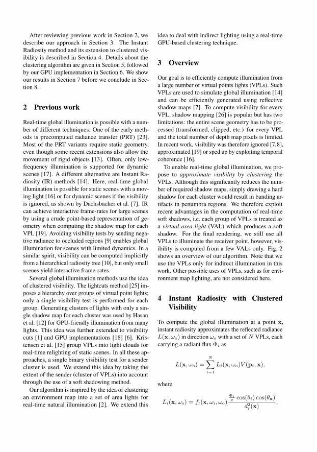
Figure 2: Overview of our algorithm: First, a set of N VPLs is generated to represent the indirect light. Inthe second step, VALs are generated by grouping the VPLs into M clusters. Next, one (soft) shadow mapis rendered for each VAL. The final step is the rendering: The receiver point x is illuminated by all VPLs.Instead of computing a visibility value for each VPL, only M (fractional) visibility values are computed andshared within each cluster. To avoid banding, each cluster generates a soft shadow, so the penumbra region iscomposed of soft shadows.
di(x) is the distance between VPL i and receiver, θiand θx are the angles between VPL i and receivernormal and the transmission direction. V is the bi-nary visibility term between x and the VPL positionpi. fr(x, ωi, ωo) is the BRDF at position x from di-rection ωi to VPL i in direction ωo. Φi
πis the radiant
intensity of VPL i, assuming a Lambertian sender.Next, the general visibility V (which is more suit-
able for raytracing [24]) is replaced with visibility Vifrom VPLs only (which is more suitable for GPUsusing shadow maps):
L(x,ωo) =
N∑i=1
Li(x, ωo)Vi(x).
To accelerate the visibility computation we grouptheN VPLs into a much lower number ofM clusters(VALs) and compute the (now fractional) visibilityonly for individual VALs:
L(x, ωo) ≈N∑i=1
Li(x, ωo)VC(i)(x).
Here we use a mapping function C : [1 . . . N ]→[1 . . .M ] which maps the VPL i to the correspond-ing virtual area light C(i). Details on the creation ofC are found in Sec. 5. Instead of computing the visi-bility Vi(x) between VPL i and x, an approximationVC(i)(x) between the VAL C(i) and x is used. Thisclustering of visibility is based on the insight thatindirect light typically contains few high frequenciesand estimates can be used without much perceptualdifference [19]. Please note that each receiver point
is still illuminated from all N VPLs, only the num-ber of visibility computations is reduced to M .
4.1 Convolution Soft Shadow Maps
To approximate the visibility of one of the M vir-tual area lights, any soft shadow algorithm can beused (see [11] for a recent survey). Due to its highrendering speed, we selected the Convolution SoftShadows Maps (CSSM) [2] in our implementation.To keep our description self-contained, we brieflyreview the CSSM method here.
The basic idea is to compute a soft shadow withpercentage closer filtering (PCF), where the filterkernel adapts to the shape of the light source. Toavoid a large number of depth comparisons insidea possibly large kernel, pre-filtering is applied tothe depth map which allows to express the depthcomparison over a large region as a Fourier series.So a convolution with a kernel w can be used tocompute the clustered visibility:
VC(i)(x) = [w ∗ f(dC(i)(x), z))](p)
≈K∑j=1
aj(dC(i)(x))[w ∗Bj ](p)
Here, a step function f is used, which returns 0 or1, depending on the depth comparison between thedistance to the VAL dC(i)(x) and the depth valuez stored in the shadow map at pixel p. Bj are thebasis images [3] and aj are the corresponding coeffi-cients. As shown in [3], a low number of coefficients
K is sufficient for good quality, significantly reduc-ing the number of filter operations. To computethe appropriate filter size for a given area light anda receiver point x, the average blocker depth zavg
between the area light and x must be determined.To this end, an initial search region is estimated byprojecting the area light into the near plane of theshadow map. Inside this region, the medium blockerdistance is computed by averaging all depth valuesinside the kernel which are smaller than the currentdepth value in the center. Again, determining zavg
can be efficiently implemented by pre-convolvingthe depth maps. Now, the penumbra size is back-projected into the shadow map which results in thefilter kernel w for PCF. See [2] for details.
4.2 CSSM with parabolic projection
Annen et al. [2] demonstrate that environment maplighting can be efficiently rendered by approximat-ing the map with a number of area lights and thenusing CSSMs to render each of the area lights. Wegeneralize this approach to dynamic local area lightsfor indirect illumination. Given the M clusters of NVPLs, we place an area light at each cluster center.
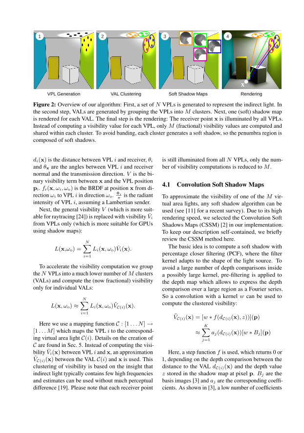
Since a diffuse surface reflects towards the wholeupper hemisphere, both the perspective and the ortho-graphic projection are not sufficient to compute visi-bility of an area light representing a cluster of VPLs.Instead, we use a shadow map with a parabolic pro-jection, where the sender is oriented around the sur-face normal [4]. Parabolic convolution soft shadowmaps can be realized as follows. First, an initial filtersize is estimated from the solid angle of the currentsender VAL. While a VPL does not define an area,a VAL allows for such a computation. Then, theaverage z value zavg is determined in the same wayas for a perspective CSSM. The penumbra size p isthen estimated from zavg as shown in Fig. 3:
p · cos(β) = (d− zavg)∆
zavg,
where d is the distance between sender midpoint andreceiver point x, ∆ is the size of the sender and βis the slope of the receiver surface, viewed from thesender midpoint. Given the penumbra size, the sizeof the filter kernel in the shadow map is adjusted tothe angle α of the penumbra, viewed from the centerof the area light:
α = arctan(p · cos(β)
d).
9/29/2008
1
∆
davgz
βcos⋅pα
β
x
Figure 3: Determining the filter size for aparaboloid map.
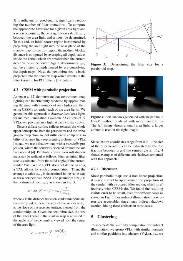
Figure 4: Soft shadows generated with the parabolicCSSM method, rendered with more than 200 fps.The left image shows a small area light, a largeremitter is used in the right image.
Since texture coordinates range from 0 to 1, the sizeof the filter kernel w can be estimated as α/π, thefraction between α and the semi-circle π. Fig. 4shows examples of different soft shadows computedwith this approach.
4.2.1 Discussion
Since parabolic maps use a non-linear projection,it is not correct to approximate the projection ofthe sender with a squared filter region, which is ef-fectively what CSSMs do. We found the resultingvisible error to be small, even for difficult cases asshown in Fig. 5. For indirect illumination these er-rors are acceptable, since many indirect shadowsoverlap, hiding these artifacts in most cases.
5 Clustering
To accelerate the visibility computation for indirectillumination, we group VPLs with similar normalsand similar positions into clusters (VALs), i.e., we
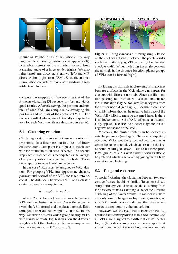
Figure 5: Parabolic CSSM limitations: For verylarge senders, ringing artifacts can appear (left).Penumbra regions are curved when viewed froma grazing angle of a large sender (right). We alsoinherit problems at contact shadows (left) and MIPdiscretization (right) from CSMs. Since the indirectillumination consists of many soft shadows, theseartifacts are hidden.
compute the mapping C. We use a variant of thek-means clustering [5] because it is fast and yieldsgood results. After clustering, the position and nor-mal of each VAL are computed by averaging thepositions and normals of the contained VPLs. Forrendering soft shadows, we additionally compute thearea for each VAL (details are described in Sec. 6).
5.1 Clustering criterion
Clustering a set of points with k-means consists oftwo steps. In a first step, starting from arbitrarycluster centers, each point is assigned to the clusterwith the minimum distance to its center . In a secondstep, each cluster center is recomputed as the averageof all point positions assigned to this cluster. Thesetwo steps are repeated until convergence.
In our case VPLs must be assigned to VAL clus-ters. For grouping VPLs into appropriate clusters,position and normal of the VPL are taken into ac-count. The distance d between a VPL and a clustercenter is therefore computed as:
d = wx∆x+ wα∆α.
where ∆x is the euclidean distance between aVPL and the cluster center and ∆α is the angle be-tween the VPL normal and the cluster normal. Eachterm gets a user-defined weight wx and wα. In thisway, we create clusters which group nearby VPLswith similar normals. Fig. 6 shows how the differentweights affect the clustering. In our examples weuse the weights wx = 0.7, wα = 0.3.
Figure 6: Using k-means clustering simply basedon the euclidean distance between the points resultsin clusters with varying VPL normals, often locatedat edges (left). When including the angle betweenthe normals in the distance function, planar groupsof VPLs can be formed (right).
Including the normals in clustering is importantbecause artifacts in the VAL plane can appear forclusters with different normals. Since the illumina-tion is computed from all VPLs inside the cluster,the illumination may be non-zero at 90 degrees fromthe cluster normal (see Fig. 7). Because there is novisibility information in the negative halfspace of theVAL, full visibility must be assumed here. If thereis a blocker crossing the VAL halfspace, a disconti-nuity appears, because the blocker is ignored in thenegative halfspace of the VAL.
Moreover, the cluster center can be located in-side the geometry (see Fig. 7). To avoid completelyoccluded VALs, geometry located near the clustercenter has to be ignored, which can result in the lossof some existing shadows. Due to all these prob-lems, groups of VPLs with similar normals shouldbe preferred which is achieved by giving them a highweight in the clustering.
5.2 Temporal coherence
To avoid flickering, the clustering between two suc-cessive frames should be similar. To achieve this, asimple strategy would be to use the clustering fromthe previous frame as a starting value for the k-meansclustering of the current frame. In most cases, thereare only small changes in light and geometry, somost VPL positions are similar and this quickly con-verges to a temporally coherent solution.
However, we observed that clusters can be lost,because their center position is in a bad location andall VPLs are assigned to a different cluster center.Fig. 8 (left) shows such a case, here a spot lightmoves from the wall to the ceiling: Because normals
1
2x
1x
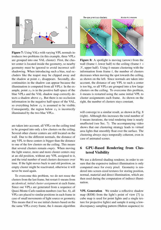
Figure 7: Using VALs with varying VPL normals in-troduces two problems (in this example, three VPLsare grouped into one VAL cluster): First, the clus-ter center is located inside the geometry, so nearbygeometry must be ignored to avoid incorrect self-shadowing. When introducing such a bias, real oc-cluders like the teapot may be clipped away andthe shadow at point x1 disappears. Secondly, dis-continuities in the shadow can appear because theillumination is computed from all VPLs: In the ex-ample, point x2 is in the positive half-space of theblue VPLs and the VAL shadow map correctly de-tects a shadow above x2. But there is no occlusioninformation in the negative half-space of the VAL,so everything below x2 is assumed to be visible.Consequently, the region below x2 is incorrectlyilluminated by the two blue VPLs.
are taken into account, all VPLs on the ceiling tendto be grouped into only a few clusters on the ceiling.Several other cluster centers are still located on thewall. Due to the different normals, the distance ofany VPL to these centers is bigger than the distanceto one of the few clusters on the ceiling. This meansthat several clusters remain empty. When movingthe light source, more and more cluster centers stayat an old position, without any VPL assigned to it,and the total number of used clusters decreases overtime. If the light moves back to and old position, anempty cluster might be reactivated, otherwise it willnever be used again.
To overcome this problem, we do not reuse theclusters from the last frame, but restart k-means froman identical, initial cluster assignment at each frame.Since our VPLs are generated from a sequence ofQuasi-Monte-Carlo random numbers (see Sec. 6), allVPLs are placed to similar positions in each frame incase of small movements of light source or geometry.This means that if we use initial clusters based on thethe same VPLs every frame, the k-means algorithm
Figure 8: A spotlight is moving (arrow) from thewall (frame t, lower half) to the ceiling (frame t +N , upper half). Using k-means clustering with theinformation from frame t, the number of clustersdecreases when moving the spot towards the ceiling,as shown on the left. Since normals are taken intoaccount, the distance of any VPL to such a centeris too big, so all VPLs are grouped into a few largeclusters on the ceiling. To overcome this problem,k-means is restarted using the same initial VPL tocluster assignments each frame. As shown on theright, the number of clusters stays constant.
will converge to a similar result, as shown in Fig. 8(right). Although this increases the total number ofk-means iterations, the total rendering time is nearlyunaffected (see Sec. 7). The accompanying videoshows that our clustering strategy leads to virtualarea lights that smoothly float over the surface. Theclustering always stays temporally coherent, even incase of animated scenes.
6 GPU-Based Rendering from Clus-tered Visibility
We use a deferred shading renderer, in order to en-sure that the expensive indirect illumination is onlycomputed once for every pixel. Geometry is ren-dered into screen-sized textures for storing position,normal, material and direct illumination, which arethen used during the computation of indirect illumi-nation.
VPL Generation We render a reflective shadowmap (RSM) from the light’s point of view [7] (acube map is used for point lights and a single tex-ture for projective lights) and sample it using a low-discrepancy sampling pattern (Halton sequence) to
convert it into N VPLs (Sec. 4). To this end theRSM is fetched at N Halton-distributed locationsusing point sampling and the resulting position, nor-mal and color is stored into three N -texel outputtextures.
Clustering Cluster information is stored in fourM -texel textures for position, normal, irradianceand a count of how many VPLs map to a cluster.For each frame, information from the VPL at indexk·N/M is used as the initial guess for VAL k (i.e.,as cluster k’s center). As mentioned earlier, thisensures temporal coherence.
In every k-means iteration, we use scattering [21]and blending to update clusters. To this end, foreach of the N VPLs a point is drawn using the VPLtextures (position, normal, radiance) as input andthe four VAL information textures (position, normal,irradiance, count) as output. In a vertex shader, everysuch point traverses all M clusters, computes thedistance, finds the one with the minimum distanceand scatters its information to the pixel position ofthat cluster. We use additive blending and write1s to the count texture. After every iteration, wedraw another full-screen quad, that divides position,normal and radiance by the count resulting in theproper average cluster information.
Note, that in this process, we do not store whichVPL maps to which VAL. We create this mappingC in a final pass and store it as a N -texel textureof pointers into the VAL texture. To this end, weloop over all VPLs, compare them to every VAL andoutput the pointer to the VAL with minimal distance.
For soft shadow computation we need to know thearea of each VAL. We define it as the 2D boundingrectangle of the two-dimensional projection s, t ofthe VPL position onto the plane perpendicular to theaverage normal of the cluster it maps to.
In summary, we compute an M -texel texture thatstores cluster position, normal and area comple-mented by anN -texel texture that stores the mappingfrom each VPL to a VAL, i.e., representing C.
Paraboloid CSSM Instancing is used to draw thescene into a texture array of depth maps with a singlepass (the resolution of one paraboloid map is set to256× 256). From this depth map texture array wegenerate an array of Fourier basis textures (4 term, 8bit) and Fourier basis-z textures (4 term, 16 bit half
float) (cf. Sec. 4.1). Finally, a MIP map is built forboth the basis and the basis-z texture array.
Indirect Lighting Indirect lighting is computedusing interleaved sampling [22]. We use blocks of8 × 8 = 64 pixels with 1024 VPLs that result in1024/64 = 16 VPLs per pixel. While we use VALsfor visibility, we still use the full number of VPLsfor lighting. So when shading from VPL i we usethe VAL at index C(i) for visibility, looking up C inthe mapping texture.
We use a geometry aware blur to remove the re-maining Monte Carlo noise without blurring overedges. As noted by Laine et al. [16], using α = 10%of the scene’s extend and β = 0.8 seems to workreasonably well for our results.
7 Results and discussion
In the following, we present results rendered at real-time rates with our technique on a 3 GHz CPU withan NVIDIA GeForce 8800 GTX. All scene compo-nents can be fully dynamic (geometry, materials, andlights), as no precomputation is required.
Fig. 9 shows a global illumination solution com-puted with clustered visibility. To illustrate our ap-proach, we included some individual soft shadow im-ages, generated from selected VAL. To verify the cor-rectness of our approach, we successively increasethe number of VALs and compare our result with theground truth solution from instant radiosity and pathtracing. As shown in Fig. 10, the resulting imagesare similar, even if visibility is computed from a verysmall number of VALs.
The performance for our test scenes is summa-rized in Tbl. 1. The rendering time of each individualpart of our algorithm is described in Tbl. 2.
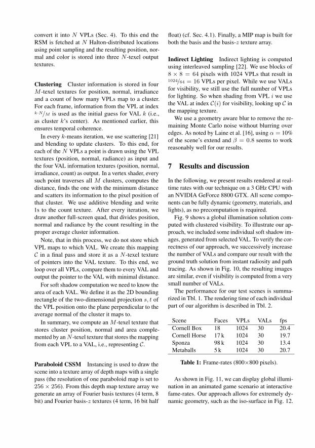
Scene Faces VPLs VALs fpsCornell Box 18 1024 30 20.4Cornell Horse 17 k 1024 30 19.7Sponza 98 k 1024 30 13.4Metaballs 5 k 1024 30 20.7
Table 1: Frame-rates (800×800 pixels).
As shown in Fig. 11, we can display global illumi-nation in an animated game scenario at interactivefame-rates. Our approach allows for extremely dy-namic geometry, such as the iso-surface in Fig. 12.
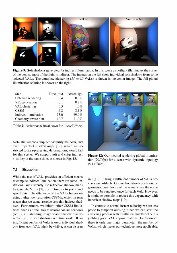
Figure 9: Soft shadows generated for indirect illumination. In this scene a spotlight illuminates the cornerof the box, so most of the light is indirect. The images on the left show individual soft shadows from someselected VALs. The complete clustering (M = 30 VALs) is shown in the center image. The full globalillumination solution is shown on the right.
Step Time (ms) PercentageDeferred rendering 0.4 0.8%VPL generation 0.1 0.2%VAL clustering 0.5 1.0%CSSM 4.2 8.1%Indirect illumination 35.0 69.0%Geometry-aware blur 10.7 21.0%
Table 2: Performance breakdown for Cornell Horse.
Note, that all pre-computed visibility methods, andeven imperfect shadow maps [19], which are re-stricted to area-preserving deformations, would failfor this scene. We support soft and crisp indirectvisibility at the same time, as shown in Fig. 13.
7.1 Discussion
While the use of VALs provides an efficient meansto compute indirect illumination, there are some lim-itations. We currently use reflective shadow mapsto generate VPLs [7], restricting us to point andspot lights. The efficiency of the VALs hinges onusing rather low-resolution CSSMs, which in turnmeans that we cannot resolve very thin indirect shad-ows. Furthermore, we inherit other CSSM limita-tions, such as difficulties to resolve contact shadows(see [2]). Extending image space shadow bias re-moval [20] to soft shadows is future work. If aninsufficient number of VALs is used, individual shad-ows from each VAL might be visible, as can be seen
Figure 12: Our method rendering global illumina-tion (20.7 fps) for a scene with dynamic topology(5.1 k faces).
in Fig. 10. Using a sufficient number of VALs pre-vents any artifacts. Our method also depends on thegeometric complexity of the scene, since the sceneneeds to be rendered once for each VAL. However,it might be possible to reduce this dependency withimperfect shadow maps [19].
In contrast to normal instant radiosity, we are lessprone to temporal aliasing, since we can start theclustering process with a sufficient number of VPLsyielding good VAL approximations. Furthermore,there is only one major parameter: the number ofVALs, which makes our technique more applicable.
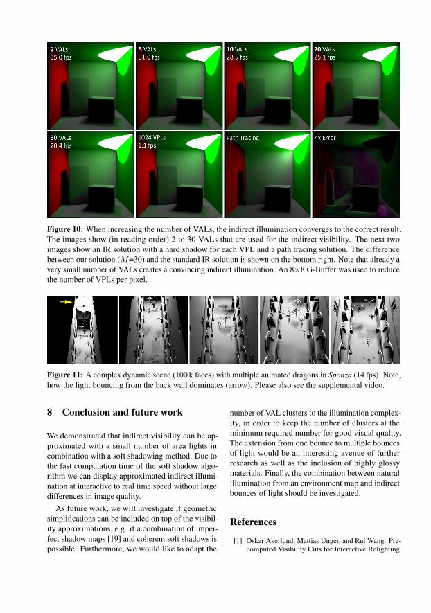
Figure 10: When increasing the number of VALs, the indirect illumination converges to the correct result.The images show (in reading order) 2 to 30 VALs that are used for the indirect visibility. The next twoimages show an IR solution with a hard shadow for each VPL and a path tracing solution. The differencebetween our solution (M=30) and the standard IR solution is shown on the bottom right. Note that already avery small number of VALs creates a convincing indirect illumination. An 8×8 G-Buffer was used to reducethe number of VPLs per pixel.
Figure 11: A complex dynamic scene (100 k faces) with multiple animated dragons in Sponza (14 fps). Note,how the light bouncing from the back wall dominates (arrow). Please also see the supplemental video.
8 Conclusion and future work
We demonstrated that indirect visibility can be ap-proximated with a small number of area lights incombination with a soft shadowing method. Due tothe fast computation time of the soft shadow algo-rithm we can display approximated indirect illumi-nation at interactive to real time speed without largedifferences in image quality.
As future work, we will investigate if geometricsimplifications can be included on top of the visibil-ity approximations, e.g. if a combination of imper-fect shadow maps [19] and coherent soft shadows ispossible. Furthermore, we would like to adapt the
number of VAL clusters to the illumination complex-ity, in order to keep the number of clusters at theminimum required number for good visual quality.The extension from one bounce to multiple bouncesof light would be an interesting avenue of furtherresearch as well as the inclusion of highly glossymaterials. Finally, the combination between naturalillumination from an environment map and indirectbounces of light should be investigated.
References
[1] Oskar Akerlund, Mattias Unger, and Rui Wang. Pre-computed Visibility Cuts for Interactive Relighting
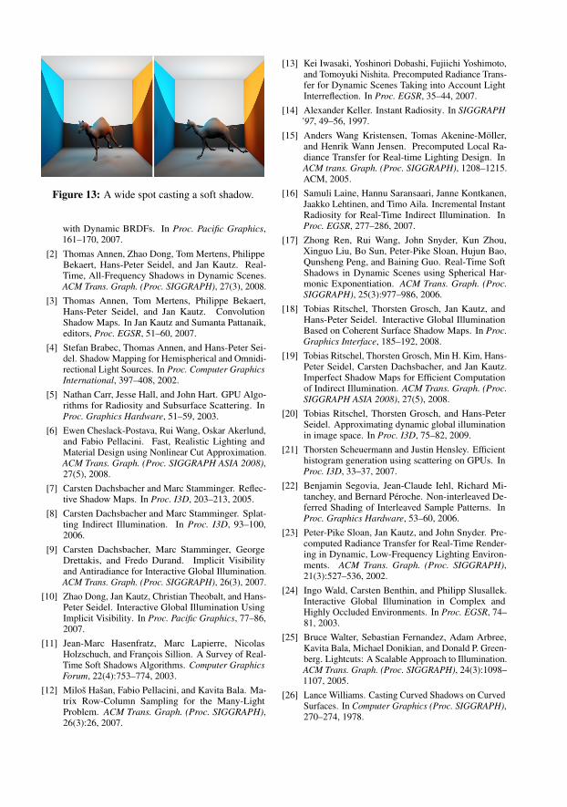
Figure 13: A wide spot casting a soft shadow.
with Dynamic BRDFs. In Proc. Pacific Graphics,161–170, 2007.
[2] Thomas Annen, Zhao Dong, Tom Mertens, PhilippeBekaert, Hans-Peter Seidel, and Jan Kautz. Real-Time, All-Frequency Shadows in Dynamic Scenes.ACM Trans. Graph. (Proc. SIGGRAPH), 27(3), 2008.
[3] Thomas Annen, Tom Mertens, Philippe Bekaert,Hans-Peter Seidel, and Jan Kautz. ConvolutionShadow Maps. In Jan Kautz and Sumanta Pattanaik,editors, Proc. EGSR, 51–60, 2007.
[4] Stefan Brabec, Thomas Annen, and Hans-Peter Sei-del. Shadow Mapping for Hemispherical and Omnidi-rectional Light Sources. In Proc. Computer GraphicsInternational, 397–408, 2002.
[5] Nathan Carr, Jesse Hall, and John Hart. GPU Algo-rithms for Radiosity and Subsurface Scattering. InProc. Graphics Hardware, 51–59, 2003.
[6] Ewen Cheslack-Postava, Rui Wang, Oskar Akerlund,and Fabio Pellacini. Fast, Realistic Lighting andMaterial Design using Nonlinear Cut Approximation.ACM Trans. Graph. (Proc. SIGGRAPH ASIA 2008),27(5), 2008.
[7] Carsten Dachsbacher and Marc Stamminger. Reflec-tive Shadow Maps. In Proc. I3D, 203–213, 2005.
[8] Carsten Dachsbacher and Marc Stamminger. Splat-ting Indirect Illumination. In Proc. I3D, 93–100,2006.
[9] Carsten Dachsbacher, Marc Stamminger, GeorgeDrettakis, and Fredo Durand. Implicit Visibilityand Antiradiance for Interactive Global Illumination.ACM Trans. Graph. (Proc. SIGGRAPH), 26(3), 2007.
[10] Zhao Dong, Jan Kautz, Christian Theobalt, and Hans-Peter Seidel. Interactive Global Illumination UsingImplicit Visibility. In Proc. Pacific Graphics, 77–86,2007.
[11] Jean-Marc Hasenfratz, Marc Lapierre, NicolasHolzschuch, and François Sillion. A Survey of Real-Time Soft Shadows Algorithms. Computer GraphicsForum, 22(4):753–774, 2003.
[12] Miloš Hašan, Fabio Pellacini, and Kavita Bala. Ma-trix Row-Column Sampling for the Many-LightProblem. ACM Trans. Graph. (Proc. SIGGRAPH),26(3):26, 2007.
[13] Kei Iwasaki, Yoshinori Dobashi, Fujiichi Yoshimoto,and Tomoyuki Nishita. Precomputed Radiance Trans-fer for Dynamic Scenes Taking into Account LightInterreflection. In Proc. EGSR, 35–44, 2007.
[14] Alexander Keller. Instant Radiosity. In SIGGRAPH’97, 49–56, 1997.
[15] Anders Wang Kristensen, Tomas Akenine-Möller,and Henrik Wann Jensen. Precomputed Local Ra-diance Transfer for Real-time Lighting Design. InACM trans. Graph. (Proc. SIGGRAPH), 1208–1215.ACM, 2005.
[16] Samuli Laine, Hannu Saransaari, Janne Kontkanen,Jaakko Lehtinen, and Timo Aila. Incremental InstantRadiosity for Real-Time Indirect Illumination. InProc. EGSR, 277–286, 2007.
[17] Zhong Ren, Rui Wang, John Snyder, Kun Zhou,Xinguo Liu, Bo Sun, Peter-Pike Sloan, Hujun Bao,Qunsheng Peng, and Baining Guo. Real-Time SoftShadows in Dynamic Scenes using Spherical Har-monic Exponentiation. ACM Trans. Graph. (Proc.SIGGRAPH), 25(3):977–986, 2006.
[18] Tobias Ritschel, Thorsten Grosch, Jan Kautz, andHans-Peter Seidel. Interactive Global IlluminationBased on Coherent Surface Shadow Maps. In Proc.Graphics Interface, 185–192, 2008.
[19] Tobias Ritschel, Thorsten Grosch, Min H. Kim, Hans-Peter Seidel, Carsten Dachsbacher, and Jan Kautz.Imperfect Shadow Maps for Efficient Computationof Indirect Illumination. ACM Trans. Graph. (Proc.SIGGRAPH ASIA 2008), 27(5), 2008.
[20] Tobias Ritschel, Thorsten Grosch, and Hans-PeterSeidel. Approximating dynamic global illuminationin image space. In Proc. I3D, 75–82, 2009.
[21] Thorsten Scheuermann and Justin Hensley. Efficienthistogram generation using scattering on GPUs. InProc. I3D, 33–37, 2007.
[22] Benjamin Segovia, Jean-Claude Iehl, Richard Mi-tanchey, and Bernard Péroche. Non-interleaved De-ferred Shading of Interleaved Sample Patterns. InProc. Graphics Hardware, 53–60, 2006.
[23] Peter-Pike Sloan, Jan Kautz, and John Snyder. Pre-computed Radiance Transfer for Real-Time Render-ing in Dynamic, Low-Frequency Lighting Environ-ments. ACM Trans. Graph. (Proc. SIGGRAPH),21(3):527–536, 2002.
[24] Ingo Wald, Carsten Benthin, and Philipp Slusallek.Interactive Global Illumination in Complex andHighly Occluded Environments. In Proc. EGSR, 74–81, 2003.
[25] Bruce Walter, Sebastian Fernandez, Adam Arbree,Kavita Bala, Michael Donikian, and Donald P. Green-berg. Lightcuts: A Scalable Approach to Illumination.ACM Trans. Graph. (Proc. SIGGRAPH), 24(3):1098–1107, 2005.
[26] Lance Williams. Casting Curved Shadows on CurvedSurfaces. In Computer Graphics (Proc. SIGGRAPH),270–274, 1978.