reading fire department 9th & marion fire station - readingpa.gov
TRANSCRIPT
PROJECT MANUAL
VOLUME 1: DIVISIONS 00 THROUGH 14
Reading Fire Department
9th & Marion Fire Station MWS Project No: 20-088
1201 North 9th Street
Reading Pennsylvania 19604
PREPARED FOR:
THE CITY OF READING 815 Washington Street
Reading PA, 19601
Bid/Permit
July 9, 2021
Reading Fire Department
9th & Marion Fire Station
Bid/Permit Set
July 9, 2021 MANNS WOODWARD STUDIOS INC
TABLE OF CONTENTS 00 0001
TABLE OF CONTENTS
VOLUME 1 – PROCUREMENT DOCUMENTS AND GENERAL CONDITIONS
OF THE CONTRACT
DIVISION 00 - PROCUREMENT AND CONTRACTING REQUIREMENTS
00 0115 – LIST OF DRAWING SHEETS
00 1116 – INVITATION TO BID
00 2113 – INSTRUCTION TO BIDDERS
00 2113a – AIA A701 - SAMPLE
00 2213 – SUPPLEMENTAL INSTRUCTIONS TO BIDDERS
00 2313 – GENERAL CONDITIONS OF THE CONTRACT FOR CONSTRUCTION
00 2313a – AIA A232 - SAMPLE
00 2413 – SUPPLEMENTARY GENERAL CONDITIONS
00 2513 – PREBID MEETINGS
00 2600 – PROCUREMENT SUBSTITUTION PROCEDURES
00 3113 – PRELIMINARY SCHEDULE
00 3132 – GEOTECHNICAL DATA
00 3132a – GEOTECHNICAL REPORT
00 4116 – BID FORM – STIPULATED SUM (MULTI-PRIME CONTRACT)
00 4313 – BID SECURITY FORMS
00 4321 – ALLOWANCE FORM
00 4322 – UNIT PRICES FORM
00 4323 – ALTERNATES FORM
00 4373 – PROPOSED SCHEUDLE OF VALUES FORM
00 4400 – OWNERSDOCUMENTS – BID FORMS
00 4400a – OWNERS DOCUMENTS – BID FORMS – SAMPLES
00 6000 – PROJECT FORMS
00 6000a – OWNERS PROJECT FORMS
DIVISION 01 - GENERAL REQUIREMENTS
01 1000 – SUMMARY
01 1300 – CONTRACT PACKAGE REFERENCE
01 1320 – CONTRACT PACKAGE SUPPLEMENTARY INSTRUCTIONS
01 1320.1 – APPENDIX A – ALL CONTRACTORS
01 1320.2 – APPENDIX B – GENERAL CONTRACTOR
01 1320.3 – APPENDIX C – FIRE PROTECTION CONTRACTOR
01 1320.4 – APPENDIX D – PLUMBING CONTRACTOR
01 1320.5 – APPENDIX E – MECHANICAL CONTRACTOR
01 1320.6 – APPENDIX F – ELECTRICAL CONTRACTOR
01 2100 – ALLOWANCES
01 2200 – UNIT PRICES
01 2300 – ALTERNATES
01 2500 – SUBSTITUTION PROCEDURES
01 2500a – SUBSTITUTION REQUEST FORM
01 2600 – CONTRACT MODIFICATION PROCEDURES
01 2900 – PAYMENT PROCEDURES
01 3100 – PROJECT MANAGEMENT AND COORDINATION
01 3200 – CONSTRUCTION PROGRESS DOCUMENTATION
01 3233 – PHOTOGRAPHIC DOCUMENTATION
01 3300 – SUBMITTAL PROCEDURES
Reading Fire Department
9th & Marion Fire Station
Bid/Permit Set
July 9, 2021 MANNS WOODWARD STUDIOS INC
TABLE OF CONTENTS 00 0001
01 3300a – SUBMITTAL REVIEW AND TRASNMITTAL FORM
01 4000 – QUALITY REQUIREMENTS
01 4200 – REFERENCES
01 5000 – TEMPORARY FACILITIES AND CONTROLS
01 6000 – PRODUCT REQUIREMENTS
01 7300 – EXECUTION
01 7419 – CONSTRUCTION WASTE MANAGEMENT AND DISPOSAL
01 7700 – CLOSEOUT PROCEDURES
01 7823 – OPERATION AND MAINTENANCE DATA
01 7823a – O&M MAUAL TEMPLATE
01 7839 – PROJECT RECORD DOCUMENTS
01 7900 – DEMONSTRATION AND TRAINING
VOLUME II –SPECIFICATIONS/PROJECT MANUAL
DIVISION 02 - EXISTING CONDITIONS
02 4116 - STRUCTURE DEMOLITION
DIVISION 03 - CONCRETE
03 3000 - CAST-IN-PLACE CONCRETE
03 3300 – ARCHITECTURAL CONCRETE
DIVISION 04 – MASONRY
04 2200 - CONCRETE UNIT MASONRY
04 2613 – MASONRY VENEER
DIVISION 05 - METALS
05 1200 - STRUCTURAL STEEL FRAMING
05 1213 – ARCHITECTURALLY EXPOSED STRUCTURAL STEEL FRAMING
05 3100 - STEEL DECKING
05 4000 - COLD-FORMED METAL FRAMING
05 5000 - METAL FABRICATIONS
05 5113 - METAL PAN STAIRS
05 5213 - PIPE AND TUBE RAILINGS
DIVISION 06 - WOOD, PLASTICS, AND COMPOSITES
06 1053 - MISCELLANEOUS ROUGH CARPENTRY
06 1600 – SHEATHING
06 2023 – INTERIOR FINISH CARPENTRY
06 4116 - PLASTIC-LAMINATE-CLAD ARCHITECTURAL CABINET
06 6400 - PLASTIC PANELING
DIVISION 07 - THERMAL AND MOISTURE PROTECTION
07 1113 - BITUMINOUS DAMPPROOFING
07 1900 – WATER REPELLENTS
07 2100 - THERMAL INSULATION
07 2726 - FLUID-APPLIED MEMBRANE AIR BARRIERS
Reading Fire Department
9th & Marion Fire Station
Bid/Permit Set
July 9, 2021 MANNS WOODWARD STUDIOS INC
TABLE OF CONTENTS 00 0001
07 4213.13 – FORMED METAL WALL PANELS
07 4213.23 - METAL COMPOSITE MATERIAL WALL PANELS
07 4293 - SOFFIT PANELS
07 4646 - FIBER-CEMENT SIDING
07 5423 - THERMOPLASTIC-POLYOLEFIN (TPO) ROOFING
07 6200 - SHEET METAL FLASHING AND TRIM
07 7100 - ROOF SPECIALTIES
07 7200 - ROOF ACCESSORIES
07 8413 - PENETRATION FIRESTOPPING
07 9200 - JOINT SEALANTS
DIVISION 08 - OPENINGS
08 1113 - HOLLOW METAL DOORS AND FRAMES
08 1416 - FLUSH WOOD DOORS
08 3113 - ACCESS DOORS AND FRAMES
08 3323 - OVERHEAD COILING DOORS
08 3516 – FOUR FOLD DOOR SYSTEMS
08 3613 - SECTIONAL DOORS
08 4113 - ALUMINUM-FRAMED ENTRANCES AND STOREFRONTS
08 4413 - GLAZED ALUMINUM CURTAIN WALLS
08 5653 – SECURITY WINDOWS
08 7100 - DOOR HARDWARE
08 8000 – GLAZING
08 8813 - FIRE-RESISTANT GLAZING
08 9116 – OPERABLE WALL LOUVERS
08 9119 - FIXED LOUVERS
DIVISION 09 - FINISHES
09 2116.23 - GYPSUM BOARD SHAFT WALL ASSEMBLIES
09 2216 – NON-STRUCTURAL METAL FRAMING
09 2900 - GYPSUM BOARD
09 3013 - CERAMIC TILING
09 5113 - ACOUSTICAL PANEL CEILINGS
09 5436 – SUSPENDED DECORATIVE GRIDS
09 6513 - RESILIENT BASE AND ACCESSORIES
09 6519 - RESILIENT TILE FLOORING
09 6536 - STATIC-CONTROL RESILIENT FLOORING
09 6566 - RESILIENT ATHLETIC FLOORING
09 6723 - RESINOUS FLOORING
09 6813 - TILE CARPETING
09 9123 - INTERIOR PAINTING
09 9600 - HIGH-PERFORMANCE COATINGS (MPI STANDARDS)
09 9646 – INTUMESCENT PAINTING
DIVISION 10 - SPECIALTIES
10 1419 - DIMENSIONAL LETTER SIGNAGE
10 1423 - PANEL SIGNAGE
10 1423.16 – ROOM IDENTIFICATION PANEL SIGNAGE
10 2600 – WALL AND DOOR PROTECTION
10 2800 - TOILET, BATH, AND LAUNDRY ACCESSORIES
Reading Fire Department
9th & Marion Fire Station
Bid/Permit Set
July 9, 2021 MANNS WOODWARD STUDIOS INC
TABLE OF CONTENTS 00 0001
10 4413 - FIRE PROTECTION CABINETS
10 4416 - FIRE EXTINGUISHERS
10 5113 - METAL LOCKERS
10 5143 – WIRE MESH STORAGE LOCKERS
10 7516 - GROUND-SET FLAGPOLES
DIVISION 11 - EQUIPMENT
11 2400 – RESIDENTIAL APPLIANCES
DIVISION 12 - FURNISHINGS
12 2413 - ROLLER WINDOW SHADES
12 3661.16 - SOLID SURFACING COUNTERTOPS
12 3661.19 - QUARTZ AGGLOMERATE COUNTERTOPS
DIVISION 14 - CONVEYING EQUIPMENT
14 2400 - HYDRAULIC ELEVATORS
DIVISION 21 - FIRE SUPPRESSION
21 0500 COMMON WORK RESULTS FOR FIRE SUPPRESSION
21 0548 VIBRATION AND SEISMIC CONTROLS FOR FIRE SUPPRESSION
PIPING AND EQUIPMENT
21 0553 IDENTIFICATION FOR FIRE SUPPRESSION PIPING AND
EQUIPMENT
21 1300 FIRE-SUPPRESSION SPRINKLER SYSTEMS
DIVISION 22 - PLUMBING
22 0500 COMMON WORK RESULTS FOR PLUMBING
22 0516 EXPANSION FITTINGS AND LOOPS FOR PLUMBING PIPING
22 0523 GENERAL-DUTY VALVES FOR PLUMBING PIPING
22 0548 VIBRATION AND SEISMIC CONTROLS FOR PLUMBING PIPING
AND EQUIPMENT
22 0553 IDENTIFICATION FOR PLUMBING PIPING AND EQUIPMENT
22 0719 PLUMBING INSULATION
22 0719.11 UNDER-LAVATORY PIPE AND SUPPLY COVERS
22 1113 FACILITY WATER DISTRIBUTION PIPING
22 1116 DOMESTIC WATER PIPING
22 1119 DOMESTIC WATER PIPING SPECIALTIES
22 1122 FACILITY NATURAL-GAS PIPING
22 1316 SANITARY WASTE AND VENT PIPING
22 1319 SANITARY WASTE PIPING SPECIALTIES
22 1320 UNDERGROUND PROTECTED STEEL GRAVITY BASED
OIL/SAND INTERCEPTOR
22 3000 PLUMBING EQUIPMENT
22 4000 PLUMBING FIXTURES
Reading Fire Department
9th & Marion Fire Station
Bid/Permit Set
July 9, 2021 MANNS WOODWARD STUDIOS INC
TABLE OF CONTENTS 00 0001
DIVISION 23 - HEATING, VENTILATING, AND AIR-
CONDITIONING (HVAC)
23 0517 SLEEVES AND SLEEVE SEALS FOR HVAC PIPING
23 0548 VIBRATION AND SEISMIC CONTROLS FOR HVAC
23 0553 IDENTIFICATION FOR HVAC PIPING AND EQUIPMENT
23 0593 TESTING, ADJUSTING, AND BALANCING FOR HVAC
23 0713 DUCT INSULATION
23 0719 HVAC PIPING INSULATION
23 0800 COMMISSIONING OF HVAC
23 2113 HYDRONIC PIPING
23 2300 REFRIGERANT PIPING
23 3100 HVAC DUCTS AND CASINGS
23 3300 AIR DUCT ACCESSORIES
23 3423 HVAC POWER VENTILATORS
23 3700 AIR OUTLETS AND INLETS
23 3810 FIRE READY HOOD
23 4000 HVAC AIR CLEANING DEVICES
23 5100 BREECHINGS, CHIMNEYS, AND STACKS
23 7499 PACKAGED DOAS WITH ENERGY RECOVERY
23 8129 VARIABLE REFRIGERANT FLOW HVAC SYSTEMS
23 8200 CONVECTION HEATING AND COOLING UNITS
23 8210 GAS-FIRED INFRARED UNIT HEATERS
DIVISION 26 - ELECTRICAL
26 0505 SELECTIVE DEMOLITION FOR ELECTRICAL
26 0519 LOW-VOLTAGE ELECTRICAL POWER CONDUCTORS AND
CABLES
26 0526 GROUNDING AND BONDING FOR ELECTRICAL SYSTEMS
26 0529 HANGERS AND SUPPORTS FOR ELECTRICAL SYSTEMS
26 0533.13 CONDUIT FOR ELECTRICAL SYSTEMS
26 0533.16 BOXES FOR ELECTRICAL SYSTEMS
26 0548 VIBRATION AND SEISMIC CONTROLS FOR ELECTRICAL
SYSTEMS
26 0553 IDENTIFICATION FOR ELECTRICAL SYSTEMS
26 0573 POWER SYSTEM STUDIES
26 0583 WIRING CONNECTIONS
26 0923 DISTRIBUTED DIGITAL LIGHTING CONTROL SYSTEM
26 2100 LOW-VOLTAGE ELECTRICAL SERVICE ENTRANCE
26 2416 PANELBOARDS
26 2726 WIRING DEVICES
26 2816.16 ENCLOSED SWITCHES
26 2913 ENCLOSED CONTROLLERS
26 3213 ENGINE GENERATORS
26 3600 TRANSFER SWITCHES
26 5100 INTERIOR LIGHTING
26 5600 EXTERIOR LIGHTING
DIVISION 27 - COMMUNICATIONS
27 1000 DATA & VOICE COMMUNICATIONS CABLING
Reading Fire Department
9th & Marion Fire Station
Bid/Permit Set
July 9, 2021 MANNS WOODWARD STUDIOS INC
TABLE OF CONTENTS 00 0001
DIVISION 28 - ELECTRONIC SAFETY AND SECURITY
28 4600 FIRE DETECTION AND ALARM
DIVISOIN 31 – EARTHWORK
31 1000 – SITE CLEARING
31 2000 – EARTHWORK
31 2316.13 – TRENCHING
DIVISION 32 – EXTERIOR IMPROVEMENTS
32 1216 – ASPHALT PAVING
32 1313 – SITE CONCRETE
32 1723 – PAVEMENT MARKINGS
32 9113 – SOIL PREPARATION
32 9200 – TURF AND GRASSES
DIVISION 33 – UTILITIES
33 0500 – COMMON WORK RESULTS FOR UTILITIES
33 4200 – STORMWATER CONVEYANCE
DIVISION 41 – MATERIAL PROCESSING AND HANDLING EQUIPMENT
MANUFACTURERS
41 2200 – CRANES & HOISTS
Reading Fire Department9th & Marion Fire StationBid/Permit Set July 9, 2021
MANNS WOODWARD STUDIOS INC
DOCUMENT 000115 - LIST OF DRAWING SHEETS
1.1 LIST OF DRAWINGS
A. Drawings: Contract Drawings shall consist of the following separately bound drawing sets or separate drawings:
1. General, Architectural, Structural, Mechanical, Plumbing, Fire Protection, Electrical, Civil, Geotech:
a. Drawings shall include, but not be limited to, the Contract Drawings and other drawings listed within the Drawing Index located on sheet G001 "DRAWING INDEX" of the separately bound drawing set titled READING FIRE STATION dated July 9, 2021, as modified by subsequent Addenda and Contract modifications.
END OF DOCUMENT 000115
LIST OF DRAWING SHEETS 00 0115 - 1
Reading Fire Department9th & Marion Fire StationBid/Permit Set July 9, 2021
MANNS WOODWARD STUDIOS INC
DOCUMENT 001116 - INVITATION TO BID
1.1 PROJECT INFORMATION
A. Notice to Bidders: Qualified bidders are invited to submit bids for Project as described in this Document according to the Instructions to Bidders.
B. Project Identification: Reading Fire Department, 9th & Marion Fire Station.
1. Project Location: 1201 North 9th Street, Reading, PA 19604.
C. Owner: City of Reading.
1. Owner's Representative: Tammi Reinhart, City of Reading, PA 815 Washington Street, Reading, PA, 19601; 610-655-6207.
D. Architect: Manns Woodward Studios Inc.
E. Construction Manager: Boyle Construction Inc.
F. Project Description: Project consists of ,generally, the construction of a new two story, with mezzanine, fire station approximately 16,505 gross square feet.
G. Construction Contract: Bids will be received for the following Work:
1. Multiple Contract Project consisting of the following prime contracts:
a. General Building Construction; 1A.b. Fire Protection Construction; 21A.c. Plumbing Construction; 22A.d. Mechanical Construction; 23A.e. Electrical Construction; 26A.
1.2 BID SUBMITTAL AND OPENING
A. Owner will receive digitally submitted bids until the bid time and date via Pennbid. Owner will consider bids prepared in compliance with the Instructions to Bidders issued by the Owner, as submitted through Pennbid as follows:
INVITATION TO BID 00 1116 - 1
Reading Fire Department9th & Marion Fire StationBid/Permit Set July 9, 2021
MANNS WOODWARD STUDIOS INC
1. Bid Date: August 24, 20212. Bid Time: 3:00 pm EST3. Location: Pennbid website; https://pennbid.procureware.com
B. Bids shall be automatically tabulated and available through the Pennbid website.
1.3 BID SECURITY
A. Bid security shall be submitted with each bid in the amount of 10 percent of the bid amount. No bids may be withdrawn for a period of 90 days after opening of bids. Owner reserves the right to reject any and all bids and to waive informalities and irregularities.
1.4 PREBID CONFERENCE
A. A non-mandatory pre-bid conference for all bidders will be held at 1201 North 9th Street, Reading, PA 19604 on August 2, 2021 at 10:00 a.m., local time. Prospective bidders are strongly encouraged to attend.
1.5 DOCUMENTS
A. Online Procurement and Contracting Documents: Obtain access after July 19, 2021 by registering on the Pennbid website; https://pennbid.procureware.com. Online access will be provided to all registered bidders and suppliers.
1.6 TIME OF COMPLETION AND LIQUIDATED DAMAGES
A. Bidders shall begin the Work on receipt of the Notice to Proceed and shall complete the Work within the Contract Time. Work is subject to liquidated damages.
1. Contract Time: The Contract Time shall be the total number of calendar days stipulated within the Construction Milestone Schedule and any adjustments included within executed contract modifications and addenda.
2. Liquidated Damages: Liquidated damages shall be $1000.00 per day.
INVITATION TO BID 00 1116 - 2
Reading Fire Department9th & Marion Fire StationBid/Permit Set July 9, 2021
MANNS WOODWARD STUDIOS INC
1.7 BIDDER'S QUALIFICATIONS
A. Bidders must be properly licensed under the laws governing their respective trades and be able to obtain insurance and bonds required for the Work. A Performance Bond, a separate Labor and Material Payment Bond, a Maintenance Bond, and Insurance in a form acceptable to the Owner will be required of the successful Bidder.
END OF DOCUMENT 001116
INVITATION TO BID 00 1116 - 3
Reading Fire Department9th & Marion Fire StationBid/Permit Set July 9, 2021
MANNS WOODWARD STUDIOS INC
DOCUMENT 002113 - INSTRUCTIONS TO BIDDERS
1.1 INSTRUCTIONS TO BIDDERS
A. AIA Document A701, "Instructions to Bidders," is hereby incorporated into the Procurement and Contracting Requirements by reference.
1. A copy of AIA Document A701, "Instructions to Bidders," is bound in this Project Manual.
a. Modifications to the Sample AIA Document A701, "Instructions to Bidders," shall be as indicated with Section 00 2213 "Supplementary Instruction To Bidders."
END OF DOCUMENT 002113
INSTRUCTIONS TO BIDDERS 00 2113 - 1
Reading Fire Department9th & Marion Fire StationBid/Permit Set July 9, 2021
MANNS WOODWARD STUDIOS INC
DOCUMENT 002213 - SUPPLEMENTARY INSTRUCTIONS TO BIDDERS
1.1 INSTRUCTIONS TO BIDDERS
A. Instructions to Bidders for Project consist of the following:
1. AIA Document A701, "Instructions to Bidders", a sample copy of which is bound in this Project Manual.
2. The following Supplementary Instructions to Bidders that modify and add to the requirements of the Instructions to Bidders.
1.2 SUPPLEMENTARY INSTRUCTIONS TO BIDDERS, GENERAL
A. The following supplements modify AIA Document A701, "Instructions to Bidders." Where a portion of the Instructions to Bidders is modified or deleted by these Supplementary Instructions to Bidders, unaltered portions of the Instructions to Bidders shall remain in effect.
1.3 GENERAL INFORMATION
A. Project Information
1. Reading Fire Department 9th & Marion Fire Station2. 1201 North 9th Street, Reading, PA, 19604
B. Owner Information
1. The City of Reading2. 815 Washington Street, Reading, PA 19601
C. Architect Information
1. Manns Woodward Studios, Inc.2. 10839 Philadelphia Road, White Marsh, MD 21162
SUPPLEMENTARY INSTRUCTIONS TO BIDDERS 00 2213 - 1
Reading Fire Department9th & Marion Fire StationBid/Permit Set July 9, 2021
MANNS WOODWARD STUDIOS INC
1.4 ARTICLE 2 - BIDDER'S REPRESENTATIONS
A. Add Section 2.1.7
1. 2.1.7 - The bidder has investigated all required fees, permits, and regulatory requirements of authorities having jursidiction and has properly included in the submitted bid the cost of such fees, permits, and requirements not otherwise indicated as provided by Owner. General Contractor shall be responsible for obtaining the general building (non-trade specific) permit;permit fees for the general building permit shall be excluded from the bid.
B. Add Section 2.1.8
1. 2.1.8 - The Bidder is a properly licensed Contractor according to the laws and regulations of the state and local authorities having jurisdiction and meets qualifications indicated in the Procurement and Contracting Documents.
C. Add Section 2.1.9:
1. 2.1.9 - The Bidder has incorporated into the Bid adequate sums for work performed by installers whose qualification meet those indicated in the Procurement and Contracting Documents.
1.5 ARTICLE 3 - BIDDING DOCUMENTS
A. Amend 3.1.1 to read as follows:
1. 3.1.1 - Bidders shall obtain complete Bidding Documents, as indicated below, from the procurement website designated in the advertisement or invitation to bid.
B. Add 3.1.1.1:
1. 3.1.1.1 - Bidders shall register on the Pennbid procurement website; https://pennbid.procureware.com. Registered Bidders shall download complete sets of bidding documents.
C. Delete 3.1.2.
D. Delete 3.1.3
SUPPLEMENTARY INSTRUCTIONS TO BIDDERS 00 2213 - 2
Reading Fire Department9th & Marion Fire StationBid/Permit Set July 9, 2021
MANNS WOODWARD STUDIOS INC
E. 3.2 Modification or Interpretation of Bidding Documents
1. Amend 3.2.2 to read:
a. 3.2.2 Requests for clarification or interpretation of the Bidding Documents shall be submitted by the Bidder in writing via the procurement website; Pennbid at https://pennbid.procureware.com. Requests shall be accepted up to seven days prior to the date of receipt of the Bids; Bid Date.
F. 3.3 - Substitutions
G. Add Section 3.3.1.1
1. 3.3.1.1 - Only pre-bid/procurement substitutions shall be considered. Any substitution received after the acceptance of the Bid shall be returned without action unless the substitution, provides a cost savings to the Owner while maintaining all project requirements.
H. Amend 3.3.2.1 to read:
1. 3.3.2.1 - Written requests for substitutions shall be submitted via the procurement website at least fourteen days prior to the date for receipt of Bids; Bid Date. Requests shall be submitted in the same manner as that established for submitting clarifications and interpretations in Section 3.2.2
I. 3.4 - Addenda:
1. Amend 3.4.1 to read:
a. 3.4.1 - Addenda will be posted to the procurement website, Pennbid; https://pennbid.procureware.com.
1.6 ARTICLE 4 - BIDDING PROCEDURES
A. 4.1 - Preparation of Bids:
1. Add Section 4.1.9:
SUPPLEMENTARY INSTRUCTIONS TO BIDDERS 00 2213 - 3

Reading Fire Department9th & Marion Fire StationBid/Permit Set July 9, 2021
MANNS WOODWARD STUDIOS INC
a. 4.1.9 - Unit Prices shall be included within the Bid submission and shall be indicated within the Unit Price Bid Form. Unit Prices shall not be included within the Bid Sum and shall only be utilized for Modifications to the Work. Owner may elect to consider unit prices in the determination of award. Unit prices will be incorporated into the Contract.
2. Add Section 4.1.10:
a. 4.1.10 - Owner may elect to disqualify a bid due to failure to submit a bid in the form requested, failure to bid requested alternates or unit prices, failure to complete entries in all blanks in the Bid Form, or inclusion by the Bidder of any alternates, conditions, limitations or provisions not called for.
3. Add Section 4.1.11:
a. 4.1.11 - The City of Reading is tax exempt. All prices to be quoted F.O.B. Reading, PA destination.
B. 4.2 - Bid Security
1. Add Section 4.2.1.1:
a. 4.2.1.1 - Bid security shall be 10% of the bid price and shall be in the form of a Bid Bond; Provide with Bid an executed AIA A310-2010 - Bid Bond.
2. Section 4.2.4; Insert the following number of days within the blank provided:
a. Ninety (90)
C. 4.3 - Submission of Bids:
1. Add Section 4.3.1.1:
a. 4.3.1.1 - Bids shall be received via the procurement website, Pennbid; https://pennbid.procureware.com.
2. Delete Section 4.3.2.
D. 4.4 - Modification or Withdrawal of Bids:
1. Add the following sections to 4.4.2:SUPPLEMENTARY INSTRUCTIONS TO BIDDERS 00 2213 - 4
Reading Fire Department9th & Marion Fire StationBid/Permit Set July 9, 2021
MANNS WOODWARD STUDIOS INC
a. 4.4.2.1 - Such modifications to or withdrawal of a bid may only be made by persons authorized to act on behalf of the Bidder. Authorized persons are those so identified in the Bidder's corporate bylaws, specifically empowered by the Bidder's charter or similar legally binding document acceptable to Owner, or by a power of attorney, signed and dated, describing the scope and limitations of the power of attorney. Make such documentation available to Owner at the time of seeking modifications or withdrawal of the Bid.
2. Modify Section 4.4.3 as follows:
a. Replace "Architect" with "City of Reading procurement office"
1.7 ARTICLE 5 - CONSIDERATION OF BIDS
A. Amend Section 5.1 to read:
1. 5.1 - Opening of Bids: Bids properly identified and received within the specified time limits shall be tabulated and available for viewing to registered participants of the procurement website.
B. 5.2 - Rejection of Bids:
1. Add Section 5.2.1:
a. 5.2.1 - Owner reserves the right to reject a bid based on Owner's, Construction Manager's and Architect's evaluation of qualification information submitted following opening of bids. Owner's evaluation of the Bidder's qualifications will include: status of licensure and record of compliance with licensing requirements, record of quality of completed work, record of Project completion and ability to complete, record of financial management including financial resources available to complete Project and record of timely payment of obligations, record of Project site management including compliance with requirements of authorities having jurisdiction, record of and number of current claims and disputes and the status of their resolution, and qualifications of the Bidder's proposed Project staff and proposed subcontractors.
1.8 ARTICLE 6 - POSTBID INFORMATION
A. Delete Section 6.1.
SUPPLEMENTARY INSTRUCTIONS TO BIDDERS 00 2213 - 5
Reading Fire Department9th & Marion Fire StationBid/Permit Set July 9, 2021
MANNS WOODWARD STUDIOS INC
B. 6.3 - Submittals:
1. Delete Section 6.3.1.
1.9 ARTICLE 7 - PERFORMANCE BOND AND PAYMENT BOND
A. 7.1 - Bond Requirements:
1. Amend Section 7.1.1 to read:
a. 7.1.1 - The Bidder shall furnish bonds covering the faithful performance of the Contract and payment of all obligations arising thereunder. Additionally, the Bidder shall furnish a Maintenance Bond and a Wage Rate Compliance Bond.
2. Add Section 7.1.1.1:
a. 7.1.1.1 - Both a Performance Bond and a Payment Bond will be required, each in an amount equal to 100 percent of the Contract Sum.
3. Add Section 7.1.1.2:
a. 7.1.1.2 - The Maintenance Bond will be required in the amount of 10 percent of the Contract Sum and shall be in force for a duration of 18 months from the date of Substantial Completion.
4. Amend Section 7.1.2 to read:
a. 7.1.2 - The cost furnishing such bonds shall be included in the Bid.
B. 7.2 - Time of Delivery and Form of Bonds:
1. Delete the first sentence of Section 7.2.1 and insert the following:
a. The Bidder shall deliver the required bonds to the Owner prior to the date of execution of the Contract. Bonds shall be included as attachments to the Contract.
2. Add Section 7.2.2.1
a. Section 7.2.2.1 - The Maintenance Bond and Wage Rate Compliance Bond shall be on the form provided.
SUPPLEMENTARY INSTRUCTIONS TO BIDDERS 00 2213 - 6
Reading Fire Department9th & Marion Fire StationBid/Permit Set July 9, 2021
MANNS WOODWARD STUDIOS INC
3. Delete Section 7.2.3 and insert the following:
a. 7.2.3 - Bonds shall be executed and be in force on the date of the execution of the Contract.
1.10 ARTICLE 8 - FORM OF AGREEMENT BETWEEN OWNER AND CONTRACTOR
A. Replace Section 8.1.1:
1. 8.1.1 - AIA Document A132 - 2019 Standard Form of Agreement Between Owner and Contractor, Construction Manager as Adviser.
B. Replace Section 8.1.3:
1. 8.1.3 - AIA Document A232-2019, General Conditions fo the Contract for Construction, as modified by specification Section 00 2413 "Supplementary General Conditions
C. Amend Section 8.1.5 to read:
1. 8.1.5 - Drawings as indicated within specification Section 00 0115 "List of Drawing Sheets"
D. Amend Section 8.1.6:
1. 8.1.6 - Specifications as indicated within the Table of Contents located within the project manual.
E. Amend Section 8.1.7
1. 8.1.7: Addenda shall include all addena issued through the bidding period of the project from availability of the bidding documents up to the Bid Date and Time. A List of all addenda shall be included within the Bidders Bid.
F. Delete Section 8.1.8.
G. Delete Section 8.1.9.
1.11 ARTICLE 9 - EXECUTION OF THE CONTRACT
A. Add Article 9:
SUPPLEMENTARY INSTRUCTIONS TO BIDDERS 00 2213 - 7
Reading Fire Department9th & Marion Fire StationBid/Permit Set July 9, 2021
MANNS WOODWARD STUDIOS INC
1. 9.1.1 - Subsequent to the Notice of Intent to Award, and within 10 days after the prescribed Form of Agreement is presented to the Awardee for signature, the Awardee shall execute and deliver the Agreement to Owner through Construction Manager, in such number of counterparts as Owner may require.
2. 9.1.2 - Owner may deem as a default the failure of the Awardee to execute the Contract and to supply the required bonds when the Agreement is presented for signature within the period of time allowed.
3. 9.1.3 - Unless otherwise indicated in the Procurement and Contracting Documents or the executed Agreement, the date of commencement of the Work shall be the date of the executed Agreement or the date that the Bidder is obligated to deliver the executed Agreement and required bonds to Owner.
4. 9.1.4 - In the event of a default, Owner may declare the amount of the Bid security forfeited and elect to either award the Contract to the next responsible bidder or re-advertise for bids.
END OF DOCUMENT 002213
SUPPLEMENTARY INSTRUCTIONS TO BIDDERS 00 2213 - 8
Reading Fire Department9th & Marion Fire StationBid/Permit Set July 9, 2021
MANNS WOODWARD STUDIOS INC
DOCUMENT 002313 - GENERAL CONDITIONS FOR THE CONTRACT FOR CONSTRUCTION
1.1 GENERAL CONDITIONS FOR THE CONTRACT FOR CONSTRUCTION
A. AIA Document A232, "General Conditions of the Contract for Construction, Construction Manager as Adviser" is hereby incorporated into the Procurement and Contracting Requirements by reference.
1. A copy of AIA Document A232, "General Conditions of the Contract for Construction, Construction Manager as Adviser" is bound in this Project Manual.
END OF DOCUMENT 002313
GENERAL CONDITIONS FOR THE CONTRACT FOR CONSTRUCTION
00 2313 - 1

������������ ������������������������������������� ������������! ����"�#$%&'()*'+$%,-.%./0(,.&,123+&0(,42+'+$%,
56789:
;<
=5=:>?@ABC68:=DEDF:G:DHIJ9:K?LMN7OP8:Q<RSSTU<TVVSU<WXY<TVRS<Z[<\]̂<_̀ âbcWX<dXefbfgf̂<hi<_ac]bf̂cfe9:=jj:N7OP8k:NCkCNlCm9:n=op5pqr:sP7k:=5=t:
>?@ABC68:7k:LN?8C@8Cm:uM:v9w9:K?LMN7OP8:xyz:y6m:568CN6y87?6yj:sNCy87Ck9:v6yA8P?N7{Cm:NCLN?mA@87?6:?N:m7k8N7uA87?6:?|:8P7k:=5=t:>?@ABC68}:?N:y6M:L?N87?6:?|:78}:ByM:NCkAj8:76:kClCNC:@7l7j:y6m:@N7B76yj:LC6yj87Ck}:y6m:z7jj:uC:LN?kC@A8Cm:8?:8PC:By~7BAB:C~8C68:L?kk7ujC:A6mCN:8PC:jyz9<\h<â�haf<ch�[ab�]f<�bh�WfbhXe<hi<_d_<�hXfaWcf<�hcg̀ X̂feU<̂�̀Wb�<\]̂<_̀ âbcWX<dXefbfgf̂<hi<_ac]bf̂cfe�<�̂�W�<chgXê�U<ch�[ab�]f�WbW�ha��<
I
\]be<Yhcg̀ X̂f<]We<b̀�hafWXf<�̂�W�<
chXê�ĝXĉe�<�hXeg�fWfbhX<�bf]<
WX<WffhaX̂[<be<̂XchgaW�̂Y<�bf]<
âe�̂cf<fh<bfe<ch̀ ��̂fbhX<ha<
h̀YbibcWfbhX�<
\]be<Yhcg̀ X̂f<be<bXf̂XŶY<fh<Ẑ<
gêY<bX<chX�gXcfbhX<�bf]<_d_<
�hcg̀ X̂fe<_R�T��TVRSU<
�fWXYWaY<�hà<hi<_�â^̀ X̂f<
�̂f�̂ X̂<��X̂a<WXY<�hXfaWcfhaU<
�hXefagcfbhX<�WXW�̂a<We<_Y�bêa<
�YbfbhX�<�R�T��TVRSU<�fWXYWaY<
�hà<hi<_�â^̀ X̂f<�̂f�̂ X̂<
��X̂a<WXY<_ac]bf̂cfU<�hXefagcfbhX<
�WXW�̂a<We<_Y�bêa<�YbfbhX�<WXY<
�R�T��TVRSU<�fWXYWaY<�hà<hi<
_�â^̀ X̂f<�̂f�̂ X̂<��X̂a<WXY<
�hXefagcfbhX<�WXW�̂a<We<_Y�bêa�<
��������������������� ¡¢£¤¥¦§̈©ª«¬̈®¬̄°±̈²³°¬°́¬̈®®́ªµµ¶¬
£·¡�¢�̧¹£�º¢£»�̧�¼̧½¡�¤�¦§̈©ª«¬̄ª¾̈ ¬̄µ²̈²¿µ«¬̈®¬̈®®́ªµµ¶¬
£·¡��À̧ ¡�¤�¦§̈©ª«¬̄ª¾̈ ¬̄µ²̈²¿µ«¬̈®¬̈®®́ªµµ¶¬
£·¡��¢·»£¡¢£¤�¦§̈©ª«¬̄ª¾̈ ¬̄µ²̈²¿µ«¬̈®¬̈®®́ªµµ¶¬
£Á¡��Ã��£»¢Â¡¹�
�� ½¡̧¡�Â����Ä»¹»�̧¹�
� �À̧ ¡��
�� ¢�̧£�¢£���
Å� �¢·»£¡¢£�̧��¢�̧¹£�º¢£»�̧�¼̧½¡��
Æ� ¹ºÁ¢�̧£�¢£��¹�
Ç� ¢�̧¹£�º¢£»�̧�ÁÈ��À̧ ¡�����ÁÈ�¹¡��£¡�¢�̧£�¢£��¹�
É� ¢·̧½¡¹�»̧�£·¡�À��Ê�
Ë� £»¼¡�
�� �ȼ¡̧£¹�̧��¢�¼�¡£»�̧�
��� ���£¡¢£»�̧��Ã��¡�¹�̧¹�̧������¡�£È�
��� »̧¹º�̧¢¡�̧��Á�̧�¹�
�� º̧¢�Ä¡�»̧½�̧��¢���¡¢£»�̧��Ã�À��Ê�
��� ¼»¹¢¡ÂÂ̧¡�º¹����Ä»¹»�̧¹�
�Å� £¡�¼»̧£»�̧����¹º¹�¡̧¹»�̧��Ã�£·¡�¢�̧£�¢£�
�Æ� ¢Â»¼¹�̧���»¹�º£¡¹�
�
������
��
�
������ �������������������������������� !� ""�!�#$%� "���&'�()*�+,*-./#$�0$12.232*�45�+-/).2*/21���66������7���7��8�9��:�;<�<=>�?��7����@�
�� �����7��������9�A��B�C�����������DEF�E�9�������E���E6�?��E���7��B�E�����G�9�����9��������9�7���A�����H����7����@��� ���I���E���������H���I� E����7�6�����7�8������8�6�E�9���� ��E6����E6���7I�E�9�F�66�A����7�����9������� EJ� � ��J������77�A6����9�������6EF��(4�-*K4-2�/4K'-.L)2�M.4N#2.4$1�45�+0+�O4$2-#/2�P4/3,*$21!�*Q,#.N�()*�+,*-./#$�0$12.232*�45�+-/).2*/21R�N*L#N�/43$1*N!�/4K'-.L)2S#.#T4-LT�
���
�
UVWXYZ[\]\\\̂[_[VUZ\̀VabXcXa_c\d\]e]\fghij\klminioipnh\d\]e]e]\Wql\Ypnorgjo\kpjstlnohe�uvw�xyz{|w}~����w�w}{|w��~w���}�~vw����ww|w}~��w~�ww}�~vw���}w���}���y}~��z~y���vw�w�}��~w��~vw����ww|w}~���}��zy}���~�y��~vw����ww|w}~���y}��~�y}��y��~vw��y}~��z~���w}w������{���w|w}~�����}��y~vw���y}��~�y}����x����}������wz���z�~�y}������w}������{w�����y��~y�w�wz{~�y}�y��~vw��y}~��z~��y~vw���yz{|w}~�����~w���}�~vw����ww|w}~���}���y����z�~�y}�����{w����~w��w�wz{~�y}�y��~vw��y}~��z~�����y����z�~�y}�������������~~w}��|w}�|w}~�~y�~vw��y}~��z~����}w������y~v����~�w����������v�}�w����w����������y}�~�{z~�y}��v�}�w�x��wz~��w��y�����������~~w}�y��w���y����|�}y��zv�}�w��}�~vw��y������{w�����~vw���zv�~wz~���}�w�����wz���z�����w}{|w��~w���}�~vw����ww|w}~��~vw��y}~��z~�xyz{|w}~���y�}y~��}z�{�w�~vw����w�~��w|w}~�y���}��~�~�y}�~y�������}�~�{z~�y}��~y�����w������|��w��y�|���y~vw���}�y�|�~�y}��{�}��vw�����~vw���}w���}��}~�z���~�y}�y���wzw���}�������y����y�y������~vw��y}~��z~y� ������y����y�y�����y���y�~�y}��y�����w}����w��~�}��~y������}��y����y�y�����w¡{��w|w}~����d\]e]e¢\Wql\Ypnorgjoe�uvw��y}~��z~�xyz{|w}~���y�|�~vw��y}~��z~��y���y}�~�{z~�y}��uvw��y}~��z~��w��w�w}~��~vw�w}~��w��}���}~w���~w�����ww|w}~��w~�ww}�~vw����~�w��vw�w~y��}���{�w��w�w�����y��}w�y~��~�y}����w��w�w}~�~�y}���y�����ww|w}~���w�~vw�����~~w}�y��y�����uvw��y}~��z~�|����w��|w}�w��y��|y����w��y}���������y����z�~�y}��uvw��y}~��z~�xyz{|w}~���v����}y~��w�zy}�~�{w��~y�z�w�~w���zy}~��z~{����w��~�y}�v���y���}����}�������w~�ww}�~vw��y}~��z~y���}��~vw���zv�~wz~�y��~vw���zv�~wz~ ��zy}�{�~�}~��������w~�ww}�~vw���}w���}��~vw��y}�~�{z~�y}���}��w��y��~vw��y}�~�{z~�y}���}��w� ��zy}�{�~�}~��������w~�ww}�~vw���}w���}��~vw���zv�~wz~�y��~vw���zv�~wz~ ��zy}�{�~�}~��������w~�ww}�~vw��y}~��z~y���}��~vw��y}�~�{z~�y}���}��w��y��~vw��y}�~�{z~�y}���}��w� ��zy}�{�~�}~����£���w~�ww}�~vw���}w���}�����{�zy}~��z~y��y���{�¤�{�zy}~��z~y���¥���w~�ww}�~vw��y}�~�{z~�y}���}��w���}��~vw���zv�~wz~��y���¦���w~�ww}��}���w��y}��y��w}~�~�w��y~vw��~v�}�~vw���}w���}���y}~��z~y���uvw��y}�~�{z~�y}���}��w���}����zv�~wz~��v�����vy�w�w����w�w}~�~�w��~y��w��y�|�}zw��}��w}�y�zw|w}~�y��y�����~�y}��{}�w��~vw��y}~��z~��}~w}�w��~y���z���~�~w��w��y�|�}zw�y��~vw����{~�w����d\]e]e§\Wql\̈pr©e�uvw�~w�|�ª�y��«�|w�}��~vw�zy}�~�{z~�y}��}���w���zw���w¡{��w�����~vw��y}~��z~�xyz{|w}~����vw~vw��zy|��w~w��y�����~������zy|��w~w����}���}z�{�w������y~vw�����y���|�~w�������w¡{��|w}~���}���w���zw����y���w��y��~y��w���y���w�����~vw��y}~��z~y��~y��{������~vw��y}~��z~y� ��y�����~�y}���uvw��y���|���zy}�~�~{~w�~vw��vy�w�y�������~�y��~vw�¬�ywz~���d\]e]e®\Wql\̀rp̄ljoe�uvw�¬�ywz~����~vw�~y~���zy}�~�{z~�y}�y���v�zv�~vw��y����w��y�|w��{}�w��~vw��y}~��z~�xyz{|w}~��|����w�~vw��vy�w�y�������~��}���v�zv�|����}z�{�w�zy}�~�{z~�y}����y~vw���y}~��z~y�����}�����~vw���}w� ��y�}��y�zw���}���w����~w��y}~��z~y�����d\]e]e°\Ypnorgjoprhe\�y}~��z~y�����w��w��y}��y��w}~�~�w���y~vw��~v�}�~vw��y}~��z~y��y���w����~w��y}~��z~y�����vy��w��y�|��y���{}�w��zy}~��z~����~v�~vw���}w��~v�~���w���|�}��~w�w�����~vw���zv�~wz~��}���y}�~�{z~�y}���}��w������d\]e]e±\cl²grgol\Ypnorgjoprhe\�w����~w��y}~��z~y�����w��w��y}��y��w}~�~�w���vy��w��y�|�zy}�~�{z~�y}�{}�w���w����~w�zy}~��z~����~v�~vw���}w��}y~���|�}��~w�w�����~vw���zv�~wz~��}���y}�~�{z~�y}���}��w����d\]e]e³\Wql\krǵinµhe�uvw�x����}�����w�~vw�����v�z��}����z~y������y�~�y}��y��~vw��y}~��z~�xyz{|w}~���vy��}��~vw��w���}���yz�~�y}��}����|w}��y}��y��~vw��y�����w}w�������}z�{��}�����}���w�w��~�y}����wz~�y}����w~�������zvw�{�w����}��������|����d\]e]e¶\Wql\c²ljimijgoipnhe�uvw���wz���z�~�y}����w�~v�~��y�~�y}�y��~vw��y}~��z~�xyz{|w}~��zy}���~�}��y��~vw����~~w}��w¡{��w|w}~���y��|�~w�������w¡{��|w}~�����~w|����~�}�������}���y��|�}�v����y��~vw��y�����}���w��y�|�}zw�y���w��~w���w���zw����d\]e]e·\Xnhorstlnoh\pm\clŗijle��}�~�{|w}~��y���w���zw���w��w��w�w}~�~�y}����}��}��|w��{|�y��w���w���y}�}y���}y�}�y����~w���w�w�y�w���y��~vw�~�}����w��}���}~�}����w�z�w�~��w��y����w��y�|w�����~vw���zv�~wz~��}��~vw���zv�~wz~ ��zy}�{�~�}~��{}�w��~vw����w��wz~��w���y�w���y}����w���zw�����ww|w}~����}�~�{|w}~��y���w���zw�|����}z�{�w����~vy{~���|�~�~�y}���~{��w����{��w����|y�w������w~zvw��������}������wz���z�~�y}����}��y~vw����|�����|�~w��������d\]e]e]¹\Xnioigº\kljihipn\»g©lre�uvw��}�~����xwz���y}����w�����~vw��w��y}���w}~���w���}�~vw����ww|w}~�~y��w}�w���}�~�����wz���y}��y}�����|���}��zzy���}zw���~v��wz~�y}��£����uvw��}�~����xwz���y}����w���v����}y~��vy�����~����~��~y�~vw���}w��y���y}~��z~y���}���v����}y~��w������w��y���w�{�~��y���}~w���w~�~�y}��y���wz���y}���w}�w�w���}��yy�����~v���d\]e¢\Yprrlºgoipn\gn¼\Xnolno\pm\oql\Ypnorgjo\kpjstlnoh\d\]e¢e]�uvw��}~w}~�y��~vw��y}~��z~�xyz{|w}~�����~y��}z�{�w������~w|��}wzw�������y��~vw���y�w��w�wz{~�y}��}��zy|��w~�y}�y��~vw��y������~vw��y}~��z~y���uvw��y}~��z~�xyz{|w}~����w�zy|��w|w}~������}���v�~�����w¡{��w�����y}w��v�����w����
�
������
��
�
������ �������������������������������� !� ""�!�#$%� "���&'�()*�+,*-./#$�0$12.232*�45�+-/).2*/21���66������7���7��8�9��:�;<�<=>�?��7����@�
�� �����7��������9�A��B�C�����������DEF�E�9�������E���E6�?��E���7��B�E�����G�9�����9��������9�7���A�����H����7����@��� ���I���E���������H���I� E����7�6�����7�8������8�6�E�9���� ��E6����E6���7I�E�9�F�66�A����7�����9������� EJ� � ��J������77�A6����9�������6EF��(4�-*K4-2�/4K'-.L)2�M.4N#2.4$1�45�+0+�O4$2-#/2�P4/3,*$21!�*Q,#.N�()*�+,*-./#$�0$12.232*�45�+-/).2*/21R�N*L#N�/43$1*N!�/4K'-.L)2S#.#T4-LT�
���
�
UVWXVWY�Z[�V\�]̂_̀V]̂X�Ua�Zbbc�d̂]\e]fZWĝ�Ua�hî�jeWh]Zghe]�[iZbb�Û�]̂_̀V]̂X�eWba�he�hî�̂kĥWh�geW[V[ĥWh�lVhi�hî�jeWh]Zgh�meg̀f̂Wh[�ZWX�]̂Z[eWZUba�VW\̂]ZUb̂�\]ef�hîf�Z[�ÛVWY�Ŵĝ[[Z]a�he�d]eX̀ĝ�hî�VWXVgZĥX�]̂[̀bh[n��opqrsrqrq�tî�VWuZbVXVha�e\�ZWa�d]euV[VeW�e\�hî�jeWh]Zgh�meg̀f̂Wh[�[iZbb�Weh�VWuZbVXZĥ�hî�jeWh]Zgh�e]�Vh[�]̂fZVWVWY�d]euV[VeW[n�v\�Vh�V[�X̂ĥ]fVŴX�hiZh�ZWa�d]euV[VeW�e\�hî�jeWh]Zgh�meg̀f̂Wh[�uVebZĥ[�ZWa�bZlw�e]�V[�ehî]lV[̂�VWuZbVX�e]�Ẁ̂W\e]ĝZUb̂w�hîW�hiZh�d]euV[VeW�[iZbb�Û�]̂uV[̂X�he�hî�̂kĥWh�Ŵĝ[[Z]a�he�fZx̂�hiZh�d]euV[VeW�b̂YZb�ZWX�̂W\e]ĝZUb̂n�vW�[̀gi�gZ[̂�hî�jeWh]Zgh�meg̀f̂Wh[�[iZbb�Û�geW[h]̀̂ Xw�he�hî�\̀bb̂[h�̂kĥWh�d̂]fVhĥX�Ua�bZlw�he�YVû�̂\\̂gh�he�hî�dZ]hV̂[y�VWĥWhVeW[�ZWX�d̀]de[̂[�VW�̂k̂g̀hVWY�hî�jeWh]Zghn��opqrsrs�z]YZWV{ZhVeW�e\�hî�|d̂gV\VgZhVeW[�VWhe�XVuV[VeW[w�[̂ghVeW[�ZWX�Z]hVgb̂[w�ZWX�Z]]ZWŶf̂Wh�e\�m]ZlVWY[�[iZbb�Weh�geWh]eb�hî�jeWh]Zghe]�VW�XVuVXVWY�hî�}e]x�ZfeWY�|̀UgeWh]Zghe][�e]�VW�̂[hZUbV[iVWY�hî�̂kĥWh�e\�}e]x�he�Û�d̂]\e]f̂X�Ua�ZWa�h]ZX̂n��opqrsr~��Wb̂[[�ehî]lV[̂�[hZĥX�VW�hî�jeWh]Zgh�meg̀f̂Wh[w�le]X[�hiZh�iZû�l̂bb�xWelW�ĥgiWVgZb�e]�geW[h]̀ghVeW�VWX̀[h]a�f̂ZWVWY[�Z]̂�̀[̂X�VW�hî�jeWh]Zgh�meg̀f̂Wh[�VW�Zgge]XZWĝ�lVhi�[̀gi�]̂geYWV{̂X�f̂ZWVWY[n��opqr~p��������������pt̂]f[�gZdVhZbV{̂X�VW�hî[̂��̂Ŵ]Zb�jeWXVhVeW[�VWgb̀X̂�hie[̂�hiZh�Z]̂�����[d̂gV\VgZbba�X̂\VŴXw�����hî�hVhb̂[�e\�ẀfÛ]̂X�Z]hVgb̂[w�e]�����hî�hVhb̂[�e\�ehî]�Xeg̀f̂Wh[�d̀UbV[îX�Ua�hî��f̂]VgZW�vW[hVh̀ĥ�e\��]giVĥgh[n��opqr�p��������������pvW�hî�VWĥ]̂[h�e\�U]̂uVha�hî�jeWh]Zgh�meg̀f̂Wh[�\]̂_̀ Ŵhba�efVh�feXV\aVWY�le]X[�[̀gi�Z[��Zbb��ZWX��ZWa��ZWX�Z]hVgb̂[�[̀gi�Z[��hî��ZWX��ZWw��Ùh�hî�\Zgh�hiZh�Z�feXV\V̂]�e]�ZW�Z]hVgb̂�V[�ZU[̂Wh�\]ef�eŴ�[hZĥf̂Wh�ZWX�Zdd̂Z][�VW�ZWehî]�V[�Weh�VWĥWX̂X�he�Z\\̂gh�hî�VWĥ]d]̂hZhVeW�e\�̂Vhî]�[hZĥf̂Whn��opqr�p���������p���p���p��p������ �¡p¢��£���£������¡p���p�����p�����¤¥����p��p¢��¦�£�popqr�rq�tî��]giVĥgh�ZWX�hî��]giVĥghy[�geW[̀bhZWh[�[iZbb�Û�X̂ f̂̂X�hî�Z̀hie][�ZWX�elŴ][�e\�hîV]�]̂[d̂ghVû�vW[h]̀f̂Wh[�e\�|̂]uVĝw�VWgb̀XVWY�hî�m]ZlVWY[�ZWX�|d̂gV\VgZhVeW[w�ZWX�]̂hZVW�Zbb�geffeW�bZlw�[hZh̀he]aw�ZWX�ehî]�]̂[̂]ûX�]VYih[�VW�hîV]�vW[h]̀f̂Wh[�e\�|̂]uVĝw�VWgb̀XVWY�geda]VYih[n�tî�jeWh]Zghe]w�|̀UgeWh]Zghe][w�[̀U�[̀UgeWh]Zghe][w�ZWX�[̀ddbV̂][�[iZbb�Weh�elW�e]�gbZVf�Z�geda]VYih�VW�hî�vW[h]̀f̂Wh[�e\�|̂]uVĝn�|̀UfVhhZb�e]�XV[h]VÙhVeW�he�f̂ ĥ�e\\VgVZb�]̂ỲbZhe]a�]̂_̀V]̂f̂Wh[�e]�\e]�ehî]�d̀]de[̂[�VW�geWŴghVeW�lVhi�hî�§]ë̂gh�V[�Weh�he�Û�geW[h]̀̂ X�Z[�d̀UbVgZhVeW�VW�X̂]eYZhVeW�e\�hî��]giVĥghy[�e]��]giVĥghy[�geW[̀bhZWh[y�]̂[̂]ûX�]VYih[n��opqr�rs�tî�jeWh]Zghe]w�|̀UgeWh]Zghe][w�|̀U�[̀UgeWh]Zghe][w�ZWX�[̀ddbV̂][�Z]̂�Z̀hie]V{̂X�he�̀[̂�ZWX�]̂d]eX̀ĝ�hî�vW[h]̀f̂Wh[�e\�|̂]uVĝ�d]euVX̂X�he�hîfw�[̀Ü̂gh�he�ZWa�d]ehegeb[�̂[hZUbV[îX�d̀][̀ZWh�he�|̂ghVeW[��n©�ZWX��nªw�[eb̂ba�ZWX�̂kgb̀[Vûba�\e]�̂k̂g̀hVeW�e\�hî�}e]xn��bb�gedV̂[�fZX̂�̀WX̂]�hiV[�Z̀hie]V{ZhVeW�[iZbb�ÛZ]�hî�geda]VYih�WehVĝw�V\�ZWaw�[ielW�eW�hî�vW[h]̀f̂Wh[�e\�|̂]uVĝn�tî�jeWh]Zghe]w�|̀UgeWh]Zghe][w�|̀U�[̀UgeWh]Zghe][w�ZWX�[̀ddbV̂][�fZa�Weh�[̀̂�hî�vW[h]̀f̂Wh[�e\�|̂]uVĝ�eW�ehî]�d]ë̂gh[�e]�\e]�ZXXVhVeW[�he�hî�§]ë̂gh�èh[VX̂�hî�[ged̂�e\�hî�}e]x�lVhièh�hî�[d̂gV\Vg�l]VhĥW�geW[̂Wh�e\�hî�zlŴ]w��]giVĥghw�ZWX�hî��]giVĥghy[�geW[̀bhZWh[n��opqr«p¬���£�popqr«rq�kĝdh�Z[�ehî]lV[̂�d]euVX̂X�VW�|̂ghVeW��n®n�w�lî]̂�hî�jeWh]Zgh�meg̀f̂Wh[�]̂_̀V]̂�eŴ�dZ]ha�he�WehV\a�e]�YVû�WehVĝ�he�hî�ehî]�dZ]haw�[̀gi�WehVĝ�[iZbb�Û�d]euVX̂X�VW�l]VhVWY�he�hî�X̂[VYWZĥX�]̂d]̂[̂WhZhVû�e\�hî�dZ]ha�he�lief�hî�WehVĝ�V[�ZXX]̂[[̂X�ZWX�[iZbb�Û�X̂ f̂̂X�he�iZû�Û Ŵ�X̀ba�[̂]ûX�V\�X̂bVû]̂X�VW�d̂][eWw�Ua�fZVbw�Ua�gè]V̂]w�e]�Ua�b̂̂gh]eWVg�h]ZW[fV[[VeW�V\�Z�f̂hieX�\e]�̂b̂gh]eWVg�h]ZW[fV[[VeW�V[�[̂h�\e]hi�VW�hî��Y]̂̂ f̂Whn�¯opqr«rs�°ehVĝ�e\�jbZVf[�Z[�d]euVX̂X�VW�|̂ghVeW��±n�n��[iZbb�Û�d]euVX̂X�VW�l]VhVWY�ZWX�[iZbb�Û�X̂ f̂̂X�he�iZû�Û Ŵ�X̀ba�[̂]ûX�eWba�V\�X̂bVû]̂X�he�hî�X̂[VYWZĥX�]̂d]̂[̂WhZhVû�e\�hî�dZ]ha�he�lief�hî�WehVĝ�V[�ZXX]̂[[̂X�Ua�ĝ]hV\V̂X�e]�]̂YV[ĥ]̂X�fZVbw�e]�Ua�gè]V̂]�d]euVXVWY�d]ee\�e\�X̂bVû]an��opqr²p�� ����p����p���p���p³����¥������ptî�dZ]hV̂[�[iZbb�ZY]̂̂ �̀deW�d]ehegeb[�Yeû]WVWY�hî�h]ZW[fV[[VeW�ZWX�̀[̂�e\�vW[h]̀f̂Wh[�e\�|̂]uVĝ�e]�ZWa�ehî]�VW\e]fZhVeW�e]�Xeg̀f̂WhZhVeW�VW�XVYVhZb�\e]fn�tî�dZ]hV̂[�lVbb�̀[̂��v��meg̀f̂Wh��́�µ¶�́��w�·̀VbXVWY�vW\e]fZhVeW�¸eX̂bVWY�ZWX�mVYVhZb�mZhZ�kiVUVhw�he�̂[hZUbV[i�hî�d]ehegeb[�\e]�hî�X̂ûbedf̂Whw�̀[̂w�h]ZW[fV[[VeWw�ZWX�̂kgiZWŶ�e\�XVYVhZb�XZhZn��

�
������
��
�
������ �������������������������������� !� ""�!�#$%� "���&'�()*�+,*-./#$�0$12.232*�45�+-/).2*/21���66������7���7��8�9��:�;<�<=>�?��7����@�
�� �����7��������9�A��B�C�����������DEF�E�9�������E���E6�?��E���7��B�E�����G�9�����9��������9�7���A�����H����7����@��� ���I���E���������H���I� E����7�6�����7�8������8�6�E�9���� ��E6����E6���7I�E�9�F�66�A����7�����9������� EJ� � ��J������77�A6����9�������6EF��(4�-*K4-2�/4K'-.L)2�M.4N#2.4$1�45�+0+�O4$2-#/2�P4/3,*$21!�*Q,#.N�()*�+,*-./#$�0$12.232*�45�+-/).2*/21R�N*L#N�/43$1*N!�/4K'-.L)2S#.#T4-LT�
�U�
�
VWXYZW[\]̂_]̀aWb̀cdefgh]d̀Wid_ĵkWlkjWg̀_Wmĵ]g̀njWopq�rst�uvw�ux�xtyz{p|t�upw�{yy�ux�{�}ux~zup�uv�{��rzy�zp��zpvux�{~zup��u�ty��z~�ur~�{�xtt�tp~�~u�}xu~u|uys��u�txpzp��~�t�rst�uvw�{p��xtyz{p|t�upw�~�t�zpvux�{~zup�|up~{zpt��zp�~�t��u�ty�{p���z~�ur~��{�zp��~�ust�}xu~u|uys�st~�vux~��zp�o�o��u|r�tp~�����������w��rzy�zp���pvux�{~zup��u�tyzp��{p���z�z~{y��{~{����z�z~w�{p��~�t�xt�rzsz~t�o�o��u|r�tp~�����������w��xu�t|~��rzy�zp���pvux�{~zup��u�tyzp���xu~u|uy��ux�w�s�{yy��t�{~�~�t�rszp��ux�xtyqzp��}{x~q�s�suyt�xzs��{p���z~�ur~�yz{�zyz~q�~u�~�t�u~�tx�}{x~q�{p��z~s�|up~x{|~uxs�ux�|upsry~{p~sw�~�t�{r~�uxs�uvw�ux�|up~xz�r~uxs�~uw�~�t��rzy�zp��zpvux�{~zup��u�tyw�{p��t{|��uv�~�tzx�{�tp~s�{p��t�}yuqtts����m�b���W�WWW ¡¢�mWVW�YXW£j̀jeĝWVW�YXYX�¤�t�¥�ptx�zs�~�t�}txsup�ux�tp~z~q�z�tp~zvzt��{s�sr|��zp�~�t�o�xtt�tp~�{p��zs�xtvtxxt��~u�~�xur��ur~�~�t�¦up~x{|~��u|r�tp~s�{s�zv�szp�ry{x�zp�pr��tx��¤�t�¥�ptx�s�{yy��tsz�p{~t�zp��xz~zp��{�xt}xtstp~{~z�t���u�s�{yy��{�t�t�}xtss�{r~�uxz~q�~u��zp��~�t�¥�ptx��z~��xts}t|~�~u�{yy��{~~txs�xt�rzxzp��~�t�¥�ptx�s�{}}xu�{y�ux�{r~�uxz§{~zup����|t}~�{s�u~�tx�zst�}xu�z�t��zp�̈t|~zup�©����w�~�t�¦ups~xr|~zup��{p{�tx�{p��~�t�ox|�z~t|~��u�pu~��{�t�sr|��{r~�uxz~q��¤�t�~tx��ª¥�ptx«��t{ps�~�t�¥�ptx�ux�~�t�¥�ptx�s�{r~�uxz§t��xt}xtstp~{~z�t����VW�YXY��¤�t�¥�ptx�s�{yy�vrxpzs��~u�~�t�¦up~x{|~uxw��z~�zp�vzv~ttp��{qs�{v~tx�xt|tz}~�uv�{��xz~~tp�xt�rts~w�zpvux�{~zup�pt|tss{xq�{p��xtyt�{p~�vux�~�t�¦up~x{|~ux�~u�t�{yr{~tw��z�t�pu~z|t�uvw�ux�tpvux|t��t|�{pz|�s�yztp�xz��~s��̈r|��zpvux�{~zup�s�{yy�zp|yr�t�{�|uxxt|~�s~{~t�tp~�uv�~�t�xt|ux��yt�{y�~z~yt�~u�~�t�}xu}tx~q�up���z|��~�t��xu�t|~�zs�yu|{~t�w�rsr{yyq�xtvtxxt��~u�{s�~�t�sz~tw�{p��~�t�¥�ptx�s�zp~txts~�~�txtzp���VW�Y�W�¬]_j̀njWdcWhjW ®̀jēkW°]̀g̀n]ĝW�eeg̀ajfj̀hkWVW�Y�YX��xzux�~u�|u��tp|t�tp~�uv�~�t�±ux�w�{p��r}up��xz~~tp�xt�rts~��q�~�t�¦up~x{|~uxw�~�t�¥�ptx�s�{yy�vrxpzs��~u�~�t�¦up~x{|~ux�xt{sup{�yt�t�z�tp|t�~�{~�~�t�¥�ptx��{s��{�t�vzp{p|z{y�{xx{p�t�tp~s�~u�vryvzyy�~�t�¥�ptx�s�u�yz�{~zups�rp�tx�~�t�¦up~x{|~��¤�t�¦up~x{|~ux�s�{yy��{�t�pu�u�yz�{~zup�~u�|u��tp|t�~�t�±ux��rp~zy�~�t�¥�ptx�}xu�z�ts�sr|��t�z�tp|t���v�|u��tp|t�tp~�uv�~�t�±ux��zs��ty{qt��rp�tx�~�zs�̈t|~zup������w�~�t�¦up~x{|~�¤z�t�s�{yy��t�t�~tp�t��{}}xu}xz{~tyq���VW�Y�Y���uyyu�zp��|u��tp|t�tp~�uv�~�t�±ux��{p��r}up��xz~~tp�xt�rts~��q�~�t�¦up~x{|~uxw�~�t�¥�ptx�s�{yy�vrxpzs��~u�~�t�¦up~x{|~ux�xt{sup{�yt�t�z�tp|t�~�{~�~�t�¥�ptx��{s��{�t�vzp{p|z{y�{xx{p�t�tp~s�~u�vryvzyy�~�t�¥�ptx�s�u�yz�{~zups�rp�tx�~�t�¦up~x{|~�upyq�zv�²�³�~�t�¥�ptx�v{zys�~u��{�t�}{q�tp~s�~u�~�t�¦up~x{|~ux�{s�~�t�¦up~x{|~��u|r�tp~s�xt�rzxt́�²�³�~�t�¦up~x{|~ux�z�tp~zvzts�zp��xz~zp��{�xt{sup{�yt�|up|txp�xt�{x�zp��~�t�¥�ptx�s�{�zyz~q�~u��{�t�}{q�tp~���tp��rt́��ux�²�³�{�|�{p�t�zp�~�t�±ux���{~txz{yyq�|�{p�ts�~�t�¦up~x{|~�̈r����v�~�t�¥�ptx�v{zys�~u�}xu�z�t�sr|��t�z�tp|tw�{s�xt�rzxt�w��z~�zp�vurx~ttp��{qs�uv�~�t�¦up~x{|~ux�s�xt�rts~w�~�t�¦up~x{|~ux��{q�z��t�z{~tyq�s~u}�~�t�±ux��{p�w�zp�~�{~�t�tp~w�s�{yy�pu~zvq�~�t�¥�ptx�~�{~�~�t�±ux���{s�s~u}}t���µu�t�txw�zv�~�t�xt�rts~�zs��{�t��t|{rst�{�|�{p�t�zp�~�t�±ux���{~txz{yyq�|�{p�ts�~�t�¦up~x{|~�̈r��rp�tx�²�³�{�u�tw�~�t�¦up~x{|~ux��{q�z��t�z{~tyq�s~u}�upyq�~�{~�}ux~zup�uv�~�t�±ux��{vvt|~t���q�~�t�|�{p�t�rp~zy�xt{sup{�yt�t�z�tp|t�zs�}xu�z�t����v�~�t�±ux��zs�s~u}}t��rp�tx�~�zs�̈t|~zup������w�~�t�¦up~x{|~�¤z�t�s�{yy��t�t�~tp�t��{}}xu}xz{~tyq�{p��~�t�¦up~x{|~�̈r��s�{yy��t�zp|xt{st���q�~�t�{�urp~�uv�~�t�¦up~x{|~ux�s�xt{sup{�yt�|us~s�uv�s�r~�u�pw��ty{q�{p��s~{x~¶r}w�}yrs�zp~txts~�{s�}xu�z�t��zp�~�t�¦up~x{|~��u|r�tp~s���VW�Y�Y·�ov~tx�~�t�¥�ptx�vrxpzs�ts�t�z�tp|t�uv�vzp{p|z{y�{xx{p�t�tp~s�rp�tx�~�zs�̈t|~zup����w�~�t�¥�ptx�s�{yy�pu~��{~txz{yyq��{xq�sr|��vzp{p|z{y�{xx{p�t�tp~s��z~�ur~�}xzux�pu~z|t�~u�~�t�¦up~x{|~ux���VW�Y�Y̧�±�txt�~�t�¥�ptx��{s��tsz�p{~t��zpvux�{~zup�vrxpzs�t��rp�tx�~�zs�̈t|~zup�����{s�ª|upvz�tp~z{yw«�~�t�¦up~x{|~ux�s�{yy��tt}�~�t�zpvux�{~zup�|upvz�tp~z{y�{p��s�{yy�pu~��zs|yust�z~�~u�{pq�u~�tx�}txsup��µu�t�txw�~�t�¦up~x{|~ux��{q��zs|yust�ª|upvz�tp~z{y«�zpvux�{~zupw�{v~tx�st�tp�²¹³��{qs��pu~z|t�~u�~�t�¥�ptxw���txt��zs|yusrxt�zs�xt�rzxt���q�y{�w�zp|yr�zp��{�sr�}utp{�ux�u~�tx�vux��uv�|u�}rysuxq�yt�{y�}xu|tss�zssrt���q�{�|urx~�ux��u�txp�tp~{y�tp~z~qw�ux��q�|urx~�ux�{x�z~x{~ux²s³�ux�tx��¤�t�¦up~x{|~ux��{q�{ysu��zs|yust�ª|upvz�tp~z{y«�zpvux�{~zup�~u�z~s�t�}yuqttsw�|upsry~{p~sw�srxt~ztsw�r̈�|up~x{|~uxs�{p��~�tzx�t�}yuqttsw�̈r�¶sr�|up~x{|~uxsw�{p��u~�txs���u�ptt��~u��pu��~�t�|up~tp~�uv�sr|��zpvux�{~zup�suytyq�{p��t�|yrsz�tyq�vux�~�t��xu�t|~�{p����u�{�xtt�~u��{zp~{zp�~�t�|upvz�tp~z{yz~q�uv�sr|��zpvux�{~zup���VW�Y·Wb̀cdefgh]d̀Wg̀_Wºje¬]njkWmj»\]ej_WdcWhjW ®̀jeWVW�Y·YX���|t}~�vux�}tx�z~s�{p��vtts�~�{~�{xt�~�t�xts}upsz�zyz~q�uv�~�t�¦up~x{|~ux�rp�tx�~�t�¦up~x{|~��u|r�tp~sw�zp|yr�zp��~�ust�xt�rzxt��rp�tx�̈t|~zup���¹��w�~�t�¥�ptx�s�{yy�st|rxt�{p��}{q�vux�pt|tss{xq�{}}xu�{ysw�t{st�tp~sw�{sstss�tp~s�{p��|�{x�ts�xt�rzxt��vux�|ups~xr|~zupw�rst�ux�u||r}{p|q�uv�}tx�{ptp~�s~xr|~rxts�ux�vux�}tx�{ptp~�|�{p�ts�zp�t�zs~zp��v{|zyz~zts��¼pytss�u~�tx�zst�}xu�z�t��rp�tx�~�t�¦up~x{|~��u|r�tp~sw�~�t�¥�ptxw�{sszs~t���q�~�t�¦ups~xr|~zup��{p{�txw�s�{yy�st|rxt�{p��}{q�vux�~�t��rzy�zp��}tx�z~���
�
������
��
�
������ �������������������������������� !� ""�!�#$%� "���&'�()*�+,*-./#$�0$12.232*�45�+-/).2*/21���66������7���7��8�9��:�;<�<=>�?��7����@�
�� �����7��������9�A��B�C�����������DEF�E�9�������E���E6�?��E���7��B�E�����G�9�����9��������9�7���A�����H����7����@��� ���I���E���������H���I� E����7�6�����7�8������8�6�E�9���� ��E6����E6���7I�E�9�F�66�A����7�����9������� EJ� � ��J������77�A6����9�������6EF��(4�-*K4-2�/4K'-.L)2�M.4N#2.4$1�45�+0+�O4$2-#/2�P4/3,*$21!�*Q,#.N�()*�+,*-./#$�0$12.232*�45�+-/).2*/21R�N*L#N�/43$1*N!�/4K'-.L)2S#.#T4-LT�
�U�
�
VWXYZYXW[\]�̂_̀]a�b\cdd�a]ecf̀�c̀�cag\fe]ge�dc_hiddj�dfg]̀b]k�el�macgefg]�cag\fe]geia]n�la�c̀�]̀efej�dc_hiddj�macgefgf̀o�cag\fe]geia]n�f̀�e\]�piafbkfgefl̀�_\]a]�e\]�qalp]ge�fb�dlgce]kr�[\ce�m]abl̀�la�]̀efej�fb�fk]̀efhf]k�cb�e\]�sag\fe]ge�f̀�e\]�soa]]t]̀e�c̀k�fb�a]h]aa]k�el�e\alio\lie�e\]�ul̀eacge�vlgit]̀eb�cb�fh�bf̀oidca�f̀�̀itw]ar��VWXYZYZ�[\]�̂_̀]a�b\cdd�a]ecf̀�c�gl̀beaigefl̀�tc̀co]a�ckxfb]a�dc_hiddj�macgefgf̀o�gl̀beaigefl̀�tc̀co]t]̀e�f̀�e\]�piafbkfgefl̀�_\]a]�e\]�qalp]ge�fb�dlgce]kr�[\ce�m]abl̀�la�]̀efej�fb�fk]̀efhf]k�cb�e\]�ul̀beaigefl̀�yc̀co]a�f̀�e\]�soa]]t]̀e�c̀k�fb�a]h]aa]k�el�e\alio\lie�e\]�ul̀eacge�vlgit]̀eb�cb�fh�bf̀oidca�f̀�̀itw]ar��VWXYZYz�{h�e\]�]tmdljt]̀e�lh�e\]�ul̀beaigefl̀�yc̀co]a�la�sag\fe]ge�e]atf̀ce]bn�e\]�̂_̀]a�b\cdd�]tmdlj�c�bigg]bbla�gl̀beaigefl̀�tc̀co]a�la�cag\fe]ge�el�_\lt�e\]�ul̀eacgela�\cb�̀l�a]cbl̀cwd]�lwp]gefl̀�c̀k�_\lb]�beceib�ìk]a�e\]�ul̀eacge�vlgit]̀eb�b\cdd�w]�e\ce�lh�e\]�ul̀beaigefl̀�yc̀co]a�la�sag\fe]gen�a]bm]gefx]djr��VWXYZY|�[\]�̂_̀]a�b\cdd�hiàfb\�biax]jb�k]bgafwf̀o�m\jbfgcd�g\cacge]afbefgbn�d]ocd�dftfecefl̀b�c̀k�iefdfej�dlgcefl̀b�hla�e\]�bfe]�lh�e\]�qalp]gen�c̀k�c�d]ocd�k]bgafmefl̀�lh�e\]�bfe]r�[\]�ul̀eacgela�b\cdd�w]�]̀efed]k�el�a]dj�l̀�e\]�cggiacgj�lh�f̀hlatcefl̀�hiàfb\]k�wj�e\]�̂_̀]a�wie�b\cdd�]}]agfb]�malm]a�ma]gciefl̀b�a]dcef̀o�el�e\]�bch]�m]ahlatc̀g]�lh�e\]�~la�r��VWXYZY��[\]�̂_̀]a�b\cdd�hiàfb\�f̀hlatcefl̀�la�b]axfg]b�a]�ifa]k�lh�e\]�̂_̀]a�wj�e\]�ul̀eacge�vlgit]̀eb�_fe\�a]cbl̀cwd]�maltmè]bbr�[\]�̂_̀]a�b\cdd�cdbl�hiàfb\�c̀j�le\]a�f̀hlatcefl̀�la�b]axfg]b�ìk]a�e\]�̂_̀]a�b�gl̀eald�c̀k�a]d]xc̀e�el�e\]�ul̀eacgela�b�m]ahlatc̀g]�lh�e\]�~la��_fe\�a]cbl̀cwd]�maltmè]bb�che]a�a]g]fxf̀o�e\]�ul̀eacgela�b�_afee]̀�a]�i]be�hla�big\�f̀hlatcefl̀�la�b]axfg]br��VWXYZY���̀d]bb�le\]a_fb]�malxfk]k�f̀�e\]�ul̀eacge�vlgit]̀ebn�e\]�̂_̀]a�b\cdd�hiàfb\�el�e\]�ul̀eacgela�l̀]�glmj�lh�e\]�ul̀eacge�vlgit]̀eb�hla�miamlb]b�lh�tc�f̀o�a]malkigefl̀b�miabic̀e�el��]gefl̀��r�r�r��VWXYZY��[\]�̂_̀]a�b\cdd�hla_cak�cdd�glttìfgcefl̀b�el�e\]�ul̀eacgela�e\alio\�e\]�ul̀beaigefl̀�yc̀co]ar�̂e\]a�glttìfgcefl̀�b\cdd�w]�tck]�cb�b]e�hlae\�f̀��]gefl̀��r�r�r��VWXYzW�������W�����W��W����W���W����W{h�e\]�ul̀eacgela�hcfdb�el�glaa]ge�~la��e\ce�fb�̀le�f̀�cgglakc̀g]�_fe\�e\]�a]�ifa]t]̀eb�lh�e\]�ul̀eacge�vlgit]̀eb�cb�a]�ifa]k�wj��]gefl̀���r��la�a]m]ce]kdj�hcfdb�el�gcaaj�lie�~la��f̀�cgglakc̀g]�_fe\�e\]�ul̀eacge�vlgit]̀ebn�e\]�̂_̀]a�tcj�fbbi]�c�_afee]̀�lak]a�el�e\]�ul̀eacgela�el�belm�e\]�~la�n�la�c̀j�mlaefl̀�e\]a]lhn�ìefd�e\]�gcib]�hla�big\�lak]a�\cb�w]]̀�]dftf̀ce]k��\l_]x]an�e\]�afo\e�lh�e\]�̂_̀]a�el�belm�e\]�~la��b\cdd�̀le�ofx]�afb]�el�c�kiej�l̀�e\]�mcae�lh�e\]�̂_̀]a�el�]}]agfb]�e\fb�afo\e�hla�e\]�w]̀]hfe�lh�e\]�ul̀eacgela�la�c̀j�le\]a�m]abl̀�la�]̀efejn�]}g]me�el�e\]�]}e]̀e�a]�ifa]k�wj��]gefl̀��r�r�r��VWXY|W�������W�����W��W� ��¡W�¢�W���W����W{h�e\]�ul̀eacgela�k]hcideb�la�̀]od]geb�el�gcaaj�lie�e\]�~la��f̀�cgglakc̀g]�_fe\�e\]�ul̀eacge�vlgit]̀eb�c̀k�hcfdb�_fe\f̀�c�e]̀£kcj�m]aflk�che]a�a]g]fme�lh�̀lefg]�halt�e\]�̂_̀]a�el�gltt]̀g]�c̀k�gl̀ef̀i]�glaa]gefl̀�lh�big\�k]hcide�la�̀]od]ge�_fe\�kfdfo]̀g]�c̀k�maltmè]bbn�e\]�̂_̀]a�tcjn�_fe\lie�ma]pikfg]�el�le\]a�a]t]kf]b�e\]�̂_̀]a�tcj�\cx]n�glaa]ge�big\�k]hcide�la�̀]od]ger��ig\�cgefl̀�wj�e\]�̂_̀]a�c̀k�ctlìeb�g\cao]k�el�e\]�ul̀eacgela�ca]�wle\�biwp]ge�el�a]xf]_�wj�e\]�ul̀beaigefl̀�yc̀co]a�c̀k�mafla�cmmalxcd�lh�e\]�sag\fe]gen�c̀k�e\]�ul̀beaigefl̀�yc̀co]a�la�sag\fe]ge�tcjn�miabic̀e�el��]gefl̀�¤r�r�n�_fe\\ldk�la�̀iddfhj�c�u]aefhfgce]�hla�qcjt]̀e�f̀�_\ld]�la�f̀�mcaen�el�e\]�]}e]̀e�a]cbl̀cwdj�̀]g]bbcaj�el�a]ftwiab]�e\]�̂_̀]a�hla�e\]�a]cbl̀cwd]¥glbe�lh�glaa]gef̀o�big\�k]hfgf]̀gf]bn�f̀gdikf̀o�̂_̀]a�b�]}m]̀b]b�c̀k�gltm]̀bcefl̀�hla�e\]�ul̀beaigefl̀�yc̀co]a�b�c̀k�sag\fe]ge�b�c̀k�e\]fa�a]bm]gefx]�gl̀bidec̀eb��ckkfefl̀cd�b]axfg]b�tck]�]̀g]bbcaj�wj�big\�k]hciden�̀]od]gen�la�hcfdia]r�{h�giaa]̀e�c̀k�hieia]�mcjt]̀eb�ca]�̀le�bihhfgf]̀e�el�glx]a�big\�ctlìebn�e\]�ul̀eacgela�b\cdd�mcj�e\]�kfhh]a]̀g]�el�e\]�̂_̀]ar�{h�e\]�ul̀eacgela�kfbcoa]]b�_fe\�e\]�cgefl̀b�lh�e\]�̂_̀]a�la�e\]�sag\fe]gen�la�e\]�ctlìeb�gdcft]k�cb�glbeb�el�e\]�̂_̀]an�e\]�ul̀eacgela�tcj�hfd]�c�udcft�miabic̀e�el�saefgd]���r��¦�§̈�©ªWZWWW��«§�¦�§��WVWZY¬W���� ®WVWZY¬Y¬�[\]�ul̀eacgela�fb�e\]�m]abl̀�la�]̀efej�fk]̀efhf]k�cb�big\�f̀�e\]�soa]]t]̀e�c̀k�fb�a]h]aa]k�el�e\alio\lie�e\]�ul̀eacge�vlgit]̀eb�cb�fh�bf̀oidca�f̀�̀itw]ar�[\]�ul̀eacgela�b\cdd�w]�dc_hiddj�dfg]̀b]kn�fh�a]�ifa]k�f̀�e\]�piafbkfgefl̀�_\]a]�e\]�qalp]ge�fb�dlgce]kr�[\]�ul̀eacgela�b\cdd�k]bfòce]�f̀�_afef̀o�c�a]ma]b]̀ecefx]�_\l�b\cdd�\cx]�]}ma]bb�cie\lafej�el�wf̀k�e\]�ul̀eacgela�_fe\�a]bm]ge�el�cdd�tcee]ab�ìk]a�e\fb�ul̀eacger�[\]�e]at�̄ul̀eacgela°�t]c̀b�e\]�ul̀eacgela�la�e\]�ul̀eacgela�b�cie\laf±]k�a]ma]b]̀ecefx]r��VWZY¬YX�[\]�ul̀eacgela�b\cdd�m]ahlat�e\]�~la��f̀�cgglakc̀g]�_fe\�e\]�ul̀eacge�vlgit]̀ebr��
�
������
��
�
������ �������������������������������� !� ""�!�#$%� "���&'�()*�+,*-./#$�0$12.232*�45�+-/).2*/21���66������7���7��8�9��:�;<�<=>�?��7����@�
�� �����7��������9�A��B�C�����������DEF�E�9�������E���E6�?��E���7��B�E�����G�9�����9��������9�7���A�����H����7����@��� ���I���E���������H���I� E����7�6�����7�8������8�6�E�9���� ��E6����E6���7I�E�9�F�66�A����7�����9������� EJ� � ��J������77�A6����9�������6EF��(4�-*K4-2�/4K'-.L)2�M.4N#2.4$1�45�+0+�O4$2-#/2�P4/3,*$21!�*Q,#.N�()*�+,*-./#$�0$12.232*�45�+-/).2*/21R�N*L#N�/43$1*N!�/4K'-.L)2S#.#T4-LT�
�U�
�
VWXYZYX�[\]�̂_̀abcda_b�e\cff�̀_a�g]�b]fh]i]j�_k�hae�_gfhlcah_̀e�a_�m]bk_bn�a\]�o_bp�h̀�cdd_bjc̀d]�qha\�a\]�̂_̀abcda�r_dsn]̀ae�]ha\]b�gt�cdahihah]e�_b�jsah]e�_k�a\]�̂_̀eabsdah_̀�uc̀cl]b�_b�vbd\ha]da�h̀�a\]hb�cjnh̀heabcah_̀�_k�a\]�_̂̀abcdaw�_b�gt�a]eaew�h̀em]dah_̀e�_b�cmmb_icfe�b]xshb]j�_b�m]bk_bn]j�gt�m]be_̀e�_b�]̀ahah]e�_a\]b�a\c̀�a\]�̂_̀abcda_by��VWXYzW{|}~|�W��W��������W�����|���W���W�~|��W����~�~���W��W����������WVWXYzYZ���]dsah_̀�_k�a\]�̂_̀abcda�gt�a\]�̂_̀abcda_b�he�c�b]mb]e]̀acah_̀�a\ca�a\]�̂_̀abcda_b�\ce�iheha]j�a\]�eha]w�g]d_n]�l]̀]bcfft�kcnhfhcb�qha\�f_dcf�d_̀jhah_̀e�s̀j]b�q\hd\�a\]�o_bp�he�a_�g]�m]bk_bn]jw�c̀j�d_bb]fca]j�m]be_̀cf�_ge]bicah_̀e�qha\�b]xshb]n]̀ae�_k�a\]�̂_̀abcda�r_dsn]̀aey��VWXYzYz��]dcse]�a\]�̂_̀abcda�r_dsn]̀ae�cb]�d_nmf]n]̀acbtw�a\]�̂_̀abcda_b�e\cffw�g]k_b]�eacbah̀l�]cd\�m_bah_̀�_k�a\]�o_bpw�dcb]ksfft�easjt�c̀j�d_nmcb]�a\]�icbh_se�̂_̀abcda�r_dsn]̀ae�b]fcahi]�a_�a\ca�m_bah_̀�_k�a\]�o_bpw�ce�q]ff�ce�a\]�h̀k_bncah_̀�ksb̀he\]j�gt�a\]��q̀]b�msbesc̀a�a_��]dah_̀��y�y�w�e\cff�acp]�kh]fj�n]cesb]n]̀ae�_k�c̀t�]�heah̀l�d_̀jhah_̀e�b]fca]j�a_�a\ca�m_bah_̀�_k�a\]�o_bpw�c̀j�e\cff�_ge]bi]�c̀t�d_̀jhah_̀e�ca�a\]�eha]�ckk]dah̀l�hay�[\]e]�_gfhlcah_̀e�cb]�k_b�a\]�msbm_e]�_k�kcdhfhacah̀l�d__bjh̀cah_̀�c̀j�d_̀eabsdah_̀�gt�a\]�̂_̀abcda_b�c̀j�cb]�̀_a�k_b�a\]�msbm_e]�_k�jhed_i]bh̀l�]bb_bew�_nheeh_̀ew�_b�h̀d_̀ehea]̀dh]e�h̀�a\]�̂_̀abcda�r_dsn]̀ae��\_q]i]bw�a\]�̂_̀abcda_b�e\cff�mb_nmaft�b]m_ba�a_�a\]�_̂̀eabsdah_̀�uc̀cl]b�c̀j�vbd\ha]da�c̀t�]bb_bew�h̀d_̀ehea]̀dh]e�_b�_nheeh_̀e�jhed_i]b]j�gt�_b�ncj]�p̀_q̀�a_�a\]�_̂̀abcda_b�ce�c�b]xs]ea�k_b�h̀k_bncah_̀�esgnhaa]j�a_�a\]�̂_̀eabsdah_̀�uc̀cl]b�h̀�esd\�k_bn�ce�a\]�̂_̀eabsdah_̀�uc̀cl]b�c̀j�vbd\ha]da�nct�b]xshb]y��a�he�b]d_l̀h�]j�a\ca�a\]�̂_̀abcda_b�e�b]ih]q�he�ncj]�h̀�a\]�̂_̀abcda_b�e�dcmcdhat�ce�c�d_̀abcda_b�c̀j�̀_a�ce�c�fhd]̀e]j�j]ehl̀�mb_k]eeh_̀cfw�s̀f]ee�_a\]bqhe]�em]dhkhdcfft�mb_ihj]j�h̀�a\]�̂_̀abcda�r_dsn]̀aey��VWXYzYX�[\]�̂_̀abcda_b�he�̀_a�b]xshb]j�a_�ced]bach̀�a\ca�a\]�̂_̀abcda�r_dsn]̀ae�cb]�h̀�cdd_bjc̀d]�qha\�cmmfhdcgf]�fcqew�eacasa]ew�_bjh̀c̀d]ew�d_j]ew�bsf]e�c̀j�b]lsfcah_̀ew�_b�fcqksf�_bj]be�_k�msgfhd�csa\_bhah]ew�gsa�a\]�̂_̀abcda_b�e\cff�mb_nmaft�b]m_ba�a_�a\]�̂_̀eabsdah_̀�uc̀cl]b�c̀j�vbd\ha]da�c̀t�̀_̀d_̀k_bnhat�jhed_i]b]j�gt�_b�ncj]�p̀_q̀�a_�a\]�_̂̀abcda_b�ce�c�b]xs]ea�k_b�h̀k_bncah_̀�esgnhaa]j�a_�̂_̀eabsdah_̀�uc̀cl]b�h̀�esd\�k_bn�ce�a\]�̂_̀eabsdah_̀�uc̀cl]b�c̀j�vbd\ha]da�nct�b]xshb]y��VWXYzY���k�a\]�̂_̀abcda_b�g]fh]i]e�a\ca�cjjhah_̀cf�d_ea�_b�ahn]�he�h̀i_fi]j�g]dcse]�_k�dfcbhkhdcah_̀e�_b�h̀eabsdah_̀e�a\]�vbd\ha]da�hees]e�h̀�b]em_̀e]�a_�a\]�̂_̀abcda_b�e�̀_ahd]e�_b�b]xs]eae�k_b�h̀k_bncah_̀�msbesc̀a�a_��]dah_̀e��y�y��_b��y�y�w�a\]�̂_̀abcda_b�e\cff�esgnha�̂fchne�ce�mb_ihj]j�h̀�vbahdf]���y��k�a\]�̂_̀abcda_b�kchfe�a_�m]bk_bn�a\]�_gfhlcah_̀e�_k��]dah_̀e��y�y��_b��y�y�w�a\]�̂_̀abcda_b�e\cff�mct�esd\�d_eae�c̀j�jcncl]e�a_�a\]��q̀]bw�esg�]da�a_�e]dah_̀���y�y w�ce�q_sfj�\ci]�g]]̀�ci_hj]j�hk�a\]�̂_̀abcda_b�\cj�m]bk_bn]j�esd\�_gfhlcah_̀ey��k�a\]�̂_̀abcda_b�m]bk_bne�a\_e]�_gfhlcah_̀ew�a\]�̂_̀abcda_b�e\cff�̀_a�g]�fhcgf]�a_�a\]��q̀]b�_b�vbd\ha]da�k_b�jcncl]e�b]esfah̀l�kb_n�]bb_bew�h̀d_̀ehea]̀dh]e�_b�_nheeh_̀e�h̀�a\]�̂_̀abcda�r_dsn]̀aew�k_b�jhkk]b]̀d]e�g]aq]]̀�kh]fj�n]cesb]n]̀ae�_b�d_̀jhah_̀e�c̀j�a\]�̂_̀abcda�r_dsn]̀aew�_b�k_b�̀_̀d_̀k_bnhah]e�_k�a\]�̂_̀abcda�r_dsn]̀ae�a_�cmmfhdcgf]�fcqew�eacasa]ew�_bjh̀c̀d]ew�d_j]ew�bsf]e�c̀j�b]lsfcah_̀ew�c̀j�fcqksf�_bj]be�_k�msgfhd�csa\_bhah]ey��VWXYXW¡�¢|�}~�~��W���W���������~��W£���|���|�WVWXYXYZ�[\]�̂_̀abcda_b�e\cff�esm]bihe]�c̀j�jhb]da�a\]�o_bpw�seh̀l�a\]�̂_̀abcda_b�e�g]ea�ephff�c̀j�caa]̀ah_̀y�[\]�_̂̀abcda_b�e\cff�g]�e_f]ft�b]em_̀ehgf]�k_bw�c̀j�\ci]�d_̀ab_f�_i]bw�d_̀eabsdah_̀�n]c̀ew�n]a\_jew�a]d\̀hxs]ew�e]xs]̀d]ew�c̀j�mb_d]jsb]ew�c̀j�k_b�d__bjh̀cah̀l�cff�m_bah_̀e�_k�a\]�o_bp�s̀j]b�a\]�̂_̀abcday��k�a\]�̂_̀abcda�r_dsn]̀ae�lhi]�em]dhkhd�h̀eabsdah_̀e�d_̀d]b̀h̀l�d_̀eabsdah_̀�n]c̀ew�n]a\_jew�a]d\̀hxs]ew�e]xs]̀d]ew�_b�mb_d]jsb]ew�a\]�̂_̀abcda_b�e\cff�]icfsca]�a\]��_geha]�eck]at�a\]b]_k�c̀j�e\cff�g]�e_f]ft�b]em_̀ehgf]�k_b�a\]��_geha]�eck]at�_k�esd\�n]c̀ew�n]a\_jew�a]d\̀hxs]ew�e]xs]̀d]ew�_b�mb_d]jsb]ey��k�a\]�̂_̀abcda_b�j]a]bnh̀]e�a\ca�esd\�n]c̀ew�n]a\_jew�a]d\̀hxs]ew�e]xs]̀d]e�_b�mb_d]jsb]e�nct�̀_a�g]�eck]w�a\]�̂_̀abcda_b�e\cff�lhi]�ahn]ft�̀_ahd]�a_�a\]��q̀]bw�a\]�̂_̀eabsdah_̀�uc̀cl]bw�c̀j�a\]�vbd\ha]daw�c̀j�e\cff�mb_m_e]�cfa]b̀cahi]�n]c̀ew�n]a\_jew�a]d\̀hxs]ew�e]xs]̀d]ew�_b�mb_d]jsb]ey�[\]�vbd\ha]da�e\cff�]icfsca]�a\]�mb_m_e]j�cfa]b̀cahi]�e_f]ft�k_b�d_̀k_bnc̀d]�qha\�a\]�j]ehl̀�h̀a]̀a�k_b�a\]�d_nmf]a]j�d_̀eabsdah_̀y�[\]�_̂̀eabsdah_̀�uc̀cl]b�e\cff�b]ih]q�a\]�mb_m_e]j�cfa]b̀cahi]�k_b�e]xs]̀dh̀lw�d_̀eabsdacghfhatw�c̀j�d__bjh̀cah_̀�hnmcdae�_̀�a\]�_a\]b�̂_̀abcda_bey�¤̀f]ee�a\]�vbd\ha]da�_b�a\]�̂_̀eabsdah_̀�uc̀cl]b�_g�]dae�a_�a\]�̂_̀abcda_b�e�mb_m_e]j�cfa]b̀cahi]w�a\]�̂_̀abcda_b�e\cff�m]bk_bn�a\]�o_bp�seh̀l�hae�cfa]b̀cahi]�n]c̀ew�n]a\_jew�a]d\̀hxs]ew�e]xs]̀d]ew�_b�mb_d]jsb]ey��VWXYXYz�[\]�̂_̀abcda_b�e\cff�g]�b]em_̀ehgf]�a_�a\]��q̀]b�k_b�cdae�c̀j�_nheeh_̀e�_k�a\]�̂_̀abcda_b�e�]nmf_t]]ew��sgd_̀abcda_be�c̀j�a\]hb�cl]̀ae�c̀j�]nmf_t]]ew�c̀j�_a\]b�m]be_̀e�_b�]̀ahah]e�m]bk_bnh̀l�m_bah_̀e�_k�a\]�o_bp�k_bw�_b�_̀�g]\cfk�_kw�a\]�̂_̀abcda_b�_b�c̀t�_k�hae��sgd_̀abcda_bey��VWXYXYX�[\]�̂_̀abcda_b�e\cff�g]�b]em_̀ehgf]�k_b�h̀em]dah_̀�_k�m_bah_̀e�_k�a\]�¥b_�]da�cfb]cjt�m]bk_bn]j�a_�j]a]bnh̀]�a\ca�esd\�m_bah_̀e�cb]�h̀�mb_m]b�d_̀jhah_̀�a_�b]d]hi]�esge]xs]̀a�o_bpy�

�
������
��
�
������ �������������������������������� !� ""�!�#$%� "���&'�()*�+,*-./#$�0$12.232*�45�+-/).2*/21���66������7���7��8�9��:�;<�<=>�?��7����@�
�� �����7��������9�A��B�C�����������DEF�E�9�������E���E6�?��E���7��B�E�����G�9�����9��������9�7���A�����H����7����@��� ���I���E���������H���I� E����7�6�����7�8������8�6�E�9���� ��E6����E6���7I�E�9�F�66�A����7�����9������� EJ� � ��J������77�A6����9�������6EF��(4�-*K4-2�/4K'-.L)2�M.4N#2.4$1�45�+0+�O4$2-#/2�P4/3,*$21!�*Q,#.N�()*�+,*-./#$�0$12.232*�45�+-/).2*/21R�N*L#N�/43$1*N!�/4K'-.L)2S#.#T4-LT�
�U�
�
VWXYZW[\]̂_W\̀aWb\cd_e\fgWVWXYZYh�ijklmm�noplqrsml�tqnusvlv�sj�opl�wnjoqxyo�zny{|ljom}�opl�wnjoqxyonq�mpxkk�tqnusvl�xjv�tx~��nq�kx�nq}�|xolqsxkm}�l�{st|ljo}�onnkm}�ynjmoq{yosnj�l�{st|ljo�xjv�|xypsjlq~}�rxolq}�plxo}�{osksoslm}�oqxjmtnqoxosnj}�xjv�noplq��xysksoslm�xjv�mlqusylm�jlylmmxq~��nq�tqntlq�l�ly{osnj�xjv�yn|tklosnj�n��opl��nq�}�rploplq�ol|tnqxq~�nq�tlq|xjljo�xjv�rploplq�nq�jno�sjynqtnqxolv�nq�on��l�sjynqtnqxolv�sj�opl��nq����VWXYZY����ylto�sj�opl�yxml�n��|sjnq�ypxj�lm�sj�opl��nq��xttqnulv��~�opl��qypsolyo�sj�xyynqvxjyl�rsop��lyosnj��������nq�nqvlqlv��~�opl��qypsolyo�sj�xyynqvxjyl�rsop��lyosnj����}�opl�wnjoqxyonq�|x~�|x�l�m{�moso{osnjm�njk~�rsop�opl�ynjmljo�n��opl��rjlq}�x�olq�luxk{xosnj��~�opl��qypsolyo}�sj�ynjm{koxosnj�rsop�opl�wnjmoq{yosnj��xjx�lq}�xjv�sj�xyynqvxjyl�rsop�x�wpxj�l��qvlq�nq�wnjmoq{yosnj�wpxj�l�zsqlyosul���VWXYZYX��pl�wnjoqxyonq�mpxkk�lj�nqyl�moqsyo�vsmystksjl�xjv��nnv�nqvlq�x|nj��opl�wnjoqxyonq�m�l|tkn~llm�xjv�noplq�tlqmnjm�yxqq~sj��n{o�opl��nq����pl�wnjoqxyonq�mpxkk�jno�tlq|so�l|tkn~|ljo�n��{j�so�tlqmnjm�nq�tlqmnjm�jno�tqntlqk~�m�skklv�sj�oxm�m�xmms�jlv�on�opl|���VWXY�W�\__\̀c�WVWXY�Yh��pl�wnjoqxyonq�rxqqxjom�on�opl��rjlq}�wnjmoq{yosnj��xjx�lq}�xjv��qypsolyo�opxo�|xolqsxkm�xjv�l�{st|ljo��{qjsmplv�{jvlq�opl�wnjoqxyo�rskk��l�n���nnv��{xkso~�xjv�jlr�{jklmm�opl�wnjoqxyo�zny{|ljom�ql�{sql�nq�tlq|so�noplqrsml���pl�wnjoqxyonq��{qoplq�rxqqxjom�opxo�opl��nq��rskk�ynj�nq|�on�opl�ql�{sql|ljom�n��opl�wnjoqxyo�zny{|ljom�xjv�rskk��l��qll��qn|�vl�lyom}�l�ylto��nq�opnml�sjplqljo�sj�opl��{xkso~�n��opl��nq��opl�wnjoqxyo�zny{|ljom�ql�{sql�nq�tlq|so���nq�}�|xolqsxkm}�nq�l�{st|ljo�jno�ynj�nq|sj��on�oplml�ql�{sql|ljom�|x~��l�ynjmsvlqlv�vl�lyosul���pl�wnjoqxyonq�m�rxqqxjo~�l�yk{vlm�ql|lv~��nq�vx|x�l�nq�vl�lyo�yx{mlv��~�x�{ml}�xkolqxosnjm�on�opl��nq��jno�l�ly{olv��~�opl�wnjoqxyonq}�s|tqntlq�nq�sjm{��sysljo�|xsjoljxjyl}�s|tqntlq�ntlqxosnj}�nq�jnq|xk�rlxq�xjv�olxq�xjv�jnq|xk�{mx�l�����ql�{sqlv��~�opl�wnjmoq{yosnj��xjx�lq�nq��qypsolyo}�opl�wnjoqxyonq�mpxkk��{qjsmp�mxosm�xyonq~�lusvljyl�xm�on�opl��sjv�xjv��{xkso~�n��|xolqsxkm�xjv�l�{st|ljo���VWXY�Y���kk�|xolqsxk}�l�{st|ljo}�nq�noplq�mtlysxk�rxqqxjoslm�ql�{sqlv��~�opl�wnjoqxyo�zny{|ljom�mpxkk��l�smm{lv�sj�opl�jx|l�n��opl��rjlq}�nq�mpxkk��l�oqxjm�lqx�kl�on�opl��rjlq}�xjv�mpxkk�yn||ljyl�sj�xyynqvxjyl�rsop��lyosnj���������VWXY�W�\�dgW�pl�wnjoqxyonq�mpxkk�tx~�mxklm}�ynjm{|lq}�{ml�xjv�ms|skxq�ox�lm��nq�opl��nq��nq�tnqosnjm�oplqln��tqnusvlv��~�opl�wnjoqxyonq�opxo�xql�kl�xkk~�ljxyolv�rplj��svm�xql�qlylsulv�nq�jl�nosxosnjm�ynjyk{vlv}�rploplq�nq�jno�~lo�l��lyosul�nq�|lqlk~�myplv{klv�on��n�sjon�l��lyo���VWXY�W�d_�ecg W¡ddg W¢̂ce£dg W\̀aW¤̂�¥fe\̀£dW¦ec§W[\¦gWVWXY�Yh�ijklmm�noplqrsml�tqnusvlv�sj�opl�wnjoqxyo�zny{|ljom}�opl��rjlq}�xmmsmolv��~�opl�wnjmoq{yosnj��xjx�lq}�mpxkk�mly{ql�xjv�tx~��nq�opl��{skvsj��tlq|so���pl�wnjoqxyonq�mpxkk�mly{ql�xjv�tx~��nq�noplq�tlq|som}��llm}�ksyljmlm}�xjv�sjmtlyosnjm��~��nulqj|ljo�x�ljyslm�jlylmmxq~��nq�tqntlq�l�ly{osnj�xjv�yn|tklosnj�n��opl��nq��opxo�xql�y{mon|xqsk~�mly{qlv�x�olq�l�ly{osnj�n��opl�wnjoqxyo�xjv�kl�xkk~�ql�{sqlv�xo�opl�os|l��svm�xql�qlylsulv�nq�jl�nosxosnjm�ynjyk{vlv���VWXY�Y���pl�wnjoqxyonq�mpxkk�yn|tk~�rsop�xjv��sul�jnosylm�ql�{sqlv��~�xttksyx�kl�kxrm}�moxo{olm}�nqvsjxjylm}�ynvlm}�q{klm�xjv�ql�{kxosnjm}�xjv�kxr�{k�nqvlqm�n��t{�ksy�x{opnqsoslm�xttksyx�kl�on�tlq�nq|xjyl�n��opl��nq����VWXY�YX����opl�wnjoqxyonq�tlq�nq|m��nq���jnrsj��so�on��l�ynjoqxq~�on�xttksyx�kl�kxrm}�moxo{olm}�nqvsjxjylm}�ynvlm}�q{klm�xjv�ql�{kxosnjm}�nq�kxr�{k�nqvlqm�n��t{�ksy�x{opnqsoslm}�opl�wnjoqxyonq�mpxkk�xmm{|l�xttqntqsxol�qlmtnjms�skso~��nq�m{yp��nq��xjv�mpxkk��lxq�opl�ynmom�xooqs�{ox�kl�on�ynqqlyosnj���VWXY�YZW¤̂ £̀d\fdaŴ_Ẅ̀ ©̀ ¦̂̀W¤̂ àecềgY����opl�wnjoqxyonq�ljyn{jolqm�ynjvsosnjm�xo�opl�msol�opxo�xql�ª�«�m{�m{q�xyl�nq�noplqrsml�ynjylxklv�tp~msyxk�ynjvsosnjm�opxo�vs��lq�|xolqsxkk~��qn|�opnml�sjvsyxolv�sj�opl�wnjoqxyo�zny{|ljom�nq�ª�«�{j�jnrj�tp~msyxk�ynjvsosnjm�n��xj�{j{m{xk�jxo{ql�opxo�vs��lq�|xolqsxkk~��qn|�opnml�nqvsjxqsk~��n{jv�on�l�smo�xjv��ljlqxkk~�qlyn�js¬lv�xm�sjplqljo�sj�ynjmoq{yosnj�xyosusoslm�n��opl�ypxqxyolq�tqnusvlv��nq�sj�opl�wnjoqxyo�zny{|ljom}�opl�wnjoqxyonq�mpxkk�tqn|tok~�tqnusvl�jnosyl�on�opl��rjlq}�wnjmoq{yosnj��xjx�lq}�xjv�opl��qypsolyo��l�nql�ynjvsosnjm�xql�vsmo{q�lv�xjv�sj�jn�luljo�kxolq�opxj����vx~m�x�olq��sqmo�n�mlquxjyl�n��opl�ynjvsosnjm���pl��qypsolyo�xjv�wnjmoq{yosnj��xjx�lq�rskk�tqn|tok~�sjulmos�xol�m{yp�ynjvsosnjm�xjv}�s��opl��qypsolyo}�sj�ynjm{koxosnj�rsop�opl�wnjmoq{yosnj��xjx�lq}�vlolq|sjlm�opxo�opl~�vs��lq�|xolqsxkk~�xjv�yx{ml�xj�sjyqlxml�nq�vlyqlxml�sj�opl�wnjoqxyonq�m�ynmo�n�}�nq�os|l�ql�{sqlv��nq}�tlq�nq|xjyl�n��xj~�txqo�n��opl��nq�}�rskk�qlyn||ljv�opxo�xj�l�{sox�kl�xv{mo|ljo��l�|xvl�sj�opl�wnjoqxyo��{|�nq�wnjoqxyo��s|l}�nq��nop�����opl��qypsolyo}�sj�ynjm{koxosnj�rsop�opl�wnjmoq{yosnj��xjx�lq}�vlolq|sjlm�opxo�opl�ynjvsosnjm�xo�opl�msol�xql�jno�|xolqsxkk~�vs��lqljo��qn|�opnml�sjvsyxolv�sj�opl�wnjoqxyo�zny{|ljom�xjv�opxo�jn�ypxj�l�sj�opl�olq|m�n��
������
��
������� �������������������������������� ��!!� �"#$��!���%&�'()�*+),-."#�/#01-121)�34�*,.(-1).10���55������6�� 6 �7 8��9�:;�;<=�>��6����?�
��� ����6���� � 8�@��A�B�����������CDE�D�8���� ��D���D5�>� D�� 6��A�D�����F 8�� ��8�������8�6���@�����G����6����?���� ��H���D���������G���H��D��� 6�5�����6 7 � ��7�5�D�8������D5�� �D5�� 6H�D�8�E�55�@ ���6 �� 8����� ��DI����� I� ����66�@5 ���8 ���� �5DE��'3�,)J3,1�.3J&,-K(1�L-3M"1-3#0�34�*/*�N3#1,".1�O3.2+)#10 �)P+"-M�'()�*+),-."#�/#01-121)�34�*,.(-1).10Q�M)K"M�.32#0)M �.3J&,-K(1R"-"S3,KS�
T�
UVWXYZ[U\]̂UX_̀Xab̀U_c_WdeXUVWXf\̂V_UŴUX̀V]ggXh\ZihUgjX[ZU_cjXUVWXkl[W\eXYZ[̀U\b̂U_Z[Xm][]nW\eX][dXYZ[U\]̂UZ\eX̀U]U_[nXUVWX\W]̀Z[̀oXpcXUVWXkl[W\XZ\XYZ[U\]̂UZ\Xd_̀hbUẀXUVWXf\̂V_UŴUq̀XdWUW\i_[]U_Z[XZ\X\ŴZiiW[d]U_Z[eXW_UVW\Xh]\UjXi]jXb̀ri_UX]XYg]_iX]̀Xh\Zs_dWdX_[Xf\U_̂gWXtuoX
vwxyxzXpceX_[XUVWX̂Zb\̀WXZcXUVWX{Z\|eXUVWXYZ[U\]̂UZ\XW[̂Zb[UW\̀XVbi][X\Wi]_[̀XZ\X\ŴZn[_}ẀXUVWXW~_̀UW[̂WXZcXrb\_]gi]\|W\̀eX]\̂V]WZgZn_̂]gX̀_UẀXZ\XlWUg][d̀X[ZUX_[d_̂]UWdX_[XUVWXYZ[U\]̂UX�ẐbiW[ÙeXUVWXYZ[U\]̂UZ\X̀V]ggX_iiWd_]UWgjXb̀̀hW[dX][jXZhW\]U_Z[̀XUV]UXlZbgdX]ccŴUXUVWiX][dX̀V]ggX[ZU_cjXUVWXkl[W\eXYZ[̀U\b̂U_Z[Xm][]nW\eX][dXf\̂V_UŴUoX�hZ[X\ŴW_hUXZcX̀b̂VX[ZU_̂WeXUVWXkl[W\X̀V]ggXh\ZihUgjXU]|WX][jX]̂U_Z[X[ŴẀ̀]\jXUZXZrU]_[XnZsW\[iW[U]gX]bUVZ\_}]U_Z[X\W�b_\WdXUZX\ẀbiWXUVWXZhW\]U_Z[̀oX�VWXYZ[U\]̂UZ\X̀V]ggX̂Z[U_[bWXUZX̀b̀hW[dX̀b̂VXZhW\]U_Z[̀Xb[U_gXZUVW\l_̀WX_[̀U\b̂UWdXrjXUVWXkl[W\XrbUX̀V]ggX̂Z[U_[bWXl_UVX]ggXZUVW\XZhW\]U_Z[̀XUV]UXdZX[ZUX]ccŴUXUVZ̀WX\Wi]_[̀XZ\XcW]Ub\ẀoX�W�bẀÙXcZ\X]dab̀UiW[ÙX_[XUVWXYZ[U\]̂UX�biX][dXYZ[U\]̂UX�_iWX]\_̀_[nXc\ZiXUVWXW~_̀UW[̂WXZcX̀b̂VX\Wi]_[̀XZ\XcW]Ub\ẀXi]jXrWXi]dWX]̀Xh\Zs_dWdX_[Xf\U_̂gWXtuoX
vwx������������vwx�x�X�VWXYZ[U\]̂UZ\X̀V]ggX_[̂gbdWX_[XUVWXYZ[U\]̂UX�biX]ggX]ggZl][̂ẀX̀U]UWdX_[XUVWXYZ[U\]̂UX�ẐbiW[ÙoXpUWìX̂ZsW\WdrjX]ggZl][̂ẀX̀V]ggXrWX̀bhhg_WdXcZ\X̀b̂VX]iZb[ÙX][dXrjX̀b̂VXhW\̀Z[̀XZ\XW[U_U_ẀX]̀XUVWXkl[W\Xi]jXd_\ŴUeXrbUXUVWXYZ[U\]̂UZ\X̀V]ggX[ZUXrWX\W�b_\WdXUZXWihgZjXhW\̀Z[̀XZ\XW[U_U_ẀXUZXlVZiXUVWXYZ[U\]̂UZ\XV]̀X\W]̀Z[]rgWXZraŴU_Z[oX
vwx�x�X�[gẀ̀XZUVW\l_̀WXh\Zs_dWdX_[XUVWXYZ[U\]̂UX�ẐbiW[Ù�x�X ]ggZl][̂ẀX̀V]ggX̂ZsW\XUVWX̂Z̀UXUZXUVWXYZ[U\]̂UZ\XZcXi]UW\_]g̀X][dXW�b_hiW[UXdWg_sW\WdX]UXUVWX̀_UWX][dX]ggX
\W�b_\WdXU]~ẀeXgẀ̀X]hhg_̂]rgWXU\]dWXd_̀̂Zb[Ù�Xx�X YZ[U\]̂UZ\q̀X̂Z̀ÙXcZ\Xb[gZ]d_[nX][dXV][dg_[nX]UXUVWX̀_UWeXg]rZ\eX_[̀U]gg]U_Z[X̂Z̀ÙeXZsW\VW]deXh\Zc_UeX][dX
ZUVW\XW~hW[̀ẀX̂Z[UWihg]UWdXcZ\X̀U]UWdX]ggZl][̂WX]iZb[ÙX̀V]ggXrWX_[̂gbdWdX_[XUVWXYZ[U\]̂UX�biXrbUX[ZUX_[XUVWX]ggZl][̂Ẁ�X][dX
xwX lVW[WsW\X̂Z̀ÙX]\WXiZ\WXUV][XZ\XgẀ̀XUV][X]ggZl][̂ẀeXUVWXYZ[U\]̂UX�biX̀V]ggXrWX]dab̀UWdX]̂ Ẑ\d_[ngjXrjXYV][nWXk\dW\oX�VWX]iZb[UXZcXUVWXYV][nWXk\dW\X̀V]ggX\WcgŴUX�t�XUVWXd_ccW\W[̂WXrWUlWW[X]̂Ub]gX̂Z̀ÙX][dXUVWX]ggZl][̂ẀXb[dW\X�ŴU_Z[X�o�o�otX][dX���X̂V][nẀX_[XYZ[U\]̂UZ\q̀X̂Z̀ÙXb[dW\X�ŴU_Z[X�o�o�o�oX
vwx�xwXm]UW\_]g̀X][dXW�b_hiW[UXb[dW\X][X]ggZl][̂WX̀V]ggXrWX̀WgŴUWdXrjXUVWXkl[W\Xl_UVX\W]̀Z[]rgWXh\ZihU[Ẁ̀o
vwx������������ ���vwx�x�X�VWXYZ[U\]̂UZ\X̀V]ggXWihgZjX]X̂ZihWUW[UX̀bhW\_[UW[dW[UX][dX[ŴẀ̀]\jX]̀̀ _̀U][ÙXlVZX̀V]ggXrWX_[X]UUW[d][̂WX]UUVWX¡\ZaŴUX̀_UWXdb\_[nXhW\cZ\i][̂WXZcXUVWX{Z\|oX�VWX̀bhW\_[UW[dW[UX̀V]ggX\Wh\ẀW[UXUVWXYZ[U\]̂UZ\eX][dX̂Ziib[_̂]U_Z[̀Xn_sW[XUZXUVWX̀bhW\_[UW[dW[UX̀V]ggXrWX]̀Xr_[d_[nX]̀X_cXn_sW[XUZXUVWXYZ[U\]̂UZ\oX
vwx�x�X�VWXYZ[U\]̂UZ\eX]̀X̀ZZ[X]̀Xh\]̂U_̂]rgWX]cUW\X]l]\dXZcXUVWXYZ[U\]̂UeX̀V]ggX[ZU_cjXUVWXkl[W\X][dXf\̂V_UŴUeXUV\ZbnVUVWXYZ[̀U\b̂U_Z[Xm][]nW\eXZcXUVWX[]iWX][dX�b]g_c_̂]U_Z[̀XZcX]Xh\ZhZ̀WdX̀bhW\_[UW[dW[UoX{_UV_[Xt¢Xd]j̀XZcX\ŴW_hUXZcXUVWX_[cZ\i]U_Z[eXUVWXYZ[̀U\b̂U_Z[Xm][]nW\Xi]jX[ZU_cjXUVWXYZ[U\]̂UZ\eX̀U]U_[nXlVWUVW\XUVWXkl[W\eXUVWXYZ[̀U\b̂U_Z[Xm][]nW\eXZ\XUVWXf\̂V_UŴUX�t�XV]̀X\W]̀Z[]rgWXZraŴU_Z[XUZXUVWXh\ZhZ̀WdX̀bhW\_[UW[dW[UXZ\X���X\W�b_\WX]dd_U_Z[]gXU_iWXcZ\X\Ws_WloX£]_gb\WXZcXUVWXYZ[̀U\b̂U_Z[Xm][]nW\XUZXh\Zs_dWX[ZU_̂WXl_UV_[XUVWXt¢¤d]jXhW\_ZdX̀V]ggX̂Z[̀U_UbUWX[ZU_̂WXZcX[ZX\W]̀Z[]rgWXZraŴU_Z[oX
vwx�xwX�VWXYZ[U\]̂UZ\X̀V]ggX[ZUXWihgZjX]Xh\ZhZ̀WdX̀bhW\_[UW[dW[UXUZXlVZiXUVWXkl[W\eXYZ[̀U\b̂U_Z[Xm][]nW\¥XZ\f\̂V_UŴUXV]̀Xi]dWX\W]̀Z[]rgWX][dXU_iWgjXZraŴU_Z[oX�VWXYZ[U\]̂UZ\X̀V]ggX[ZUX̂V][nWXUVWX̀bhW\_[UW[dW[UXl_UVZbUXUVWXkl[W\q̀X̂Z[̀W[UeXlV_̂VX̀V]ggX[ZUXb[\W]̀Z[]rgjXrWXl_UVVWgdXZ\XdWg]jWdoX
vwx�¦�§���������̈��§�������������� ���©ª��������«� ����vwx�¦x�X�VWXYZ[U\]̂UZ\eXh\ZihUgjX]cUW\XrW_[nX]l]\dWdXUVWXYZ[U\]̂UeX̀V]ggX̀bri_UXcZ\XUVWXkl[W\q̀X][dXf\̂V_UŴUq̀_[cZ\i]U_Z[eX][dXUVWXYZ[̀U\b̂U_Z[Xm][]nW\q̀Xb̀WX_[XdWsWgZh_[nXUVWX¡\ZaŴUX̀̂VWdbgWeX]XYZ[U\]̂UZ\q̀X̂Z[̀U\b̂U_Z[X`̂VWdbgWXcZ\XUVWX{Z\|oX�VW¬̀̂VWdbgWX̀V]ggX̂Z[U]_[XdWU]_gX]hh\Zh\_]UWXcZ\XUVWX¡\ZaŴUeX_[̂gbd_[nX�t�XUVWXd]UWXZcXẐiiW[̂WiW[UXZcXUVWX{Z\|eX_[UW\_iX̀̂VWdbgWXi_gẀUZ[WXd]UẀeX][dXUVWXd]UWXZcX�br̀U][U_]gXYZihgWU_Z[�X���X][X]hhZ\U_Z[iW[UXZcXUVWX{Z\|XrjX̂Z[̀U\b̂U_Z[X]̂U_s_Uj�X][dX���XUVWXU_iWX\W�b_\WdXcZ\X̂ZihgWU_Z[XZcXW]̂VXhZ\U_Z[XZcXUVWX{Z\|oX�VWX̀̂VWdbgWX̀V]ggXh\Zs_dWXcZ\XUVWXZ\dW\gjXh\Zn\Ẁ̀_Z[XZcXUVWX{Z\|XUZX̂ZihgWU_Z[X][dX̀V]ggX[ZUXW~̂WWdXU_iWXg_i_ÙX̂b\\W[UXb[dW\XUVWXYZ[U\]̂UX�ẐbiW[ÙoX�VWX̀̂VWdbgWX̀V]ggXrWX\Ws_̀WdX]UX]hh\Zh\_]UWX_[UW\s]g̀X]̀X\W�b_\WdXrjXUVWXẐ[d_U_Z[̀XZcXUVWX{Z\|X][dX¡\ZaŴUoX�VWXYZ[U\]̂UZ\X̀V]ggX̂ZZhW\]UWXl_UVXUVWXYZ[̀U\b̂U_Z[Xm][]nW\X_[X̀̂VWdbg_[nX][dXhW\cZ\i_[nXUVWXYZ[U\]̂UZ\q̀X{Z\|XUZX]sZ_dX̂Z[cg_̂UXl_UVeX][dX]̀XUZX̂]b̀WX[ZXdWg]jX_[eXUVWXlZ\|XZ\X]̂U_s_U_ẀXZcXZUVW\XYZ[U\]̂UZ\̀eXZ\XUVWX̂Z[̀U\b̂U_Z[XZ\XZhW\]U_Z[̀XZcXUVWXkl[W\q̀XZl[XcZ\̂ẀXZ\X�Wh]\]UWXYZ[U\]̂UZ\̀oX
������
��
������� �������������������������������� ��!!� �"#$��!���%&�'()�*+),-."#�/#01-121)�34�*,.(-1).10���55������6�� 6 �7 8��9�:;�;<=�>��6����?�
��� ����6���� � 8�@��A�B�����������CDE�D�8���� ��D���D5�>� D�� 6��A�D�����F 8�� ��8�������8�6���@�����G����6����?���� ��H���D���������G���H��D��� 6�5�����6 7 � ��7�5�D�8������D5�� �D5�� 6H�D�8�E�55�@ ���6 �� 8����� ��DI����� I� ����66�@5 ���8 ���� �5DE��'3�,)J3,1�.3J&,-K(1�L-3M"1-3#0�34�*/*�N3#1,".1�O3.2+)#10 �)P+"-M�'()�*+),-."#�/#01-121)�34�*,.(-1).10Q�M)K"M�.32#0)M �.3J&,-K(1R"-"S3,KS�
��
TUVWXVYZ[\]Ẑ_̀abcda_beZfb_gfahiZcja]bZk]l̀mZcncbo]oZa\]Ẑ_̀abcdaZc̀oZa\]b]cja]bZcpZ̀]d]ppcbiZa_Zgcl̀acl̀ZcZdqbb]̀apqkglaachZpd\]oqh]eZp\chhZpqkglaZcZpqkglaachZpd\]oqh]Zj_bZa\]Ẑ_̀pabqdal_̀Zrc̀cm]bspZc̀oZtbd\la]daspZcffb_uchvZ[\]Ztbd\la]daZc̀oẐ_̀pabqdal_̀Zrc̀cm]bspZcffb_uchZp\chhZ̀_aZk]Zq̀b]cp_̀ckhiZo]hci]oZ_bZnla\\]hovZ[\]ZpqkglaachZpd\]oqh]Zp\chhZwxyZk]Zd__bol̀ca]oZnla\Za\]Ẑ_̀abcda_bspZd_̀pabqdal_̀Zpd\]oqh]eZc̀oZwzyZchh_nZa\]Ẑ_̀pabqdal_̀Zrc̀cm]bZc̀oZtbd\la]daZb]cp_̀ckh]Zalg]Za_Zb]ul]nZpqkglaachpvZ{jZa\]Ẑ_̀abcda_bZjclhpZa_ZpqkglaZcZpqkglaachZpd\]oqh]eZ_bZjclhpZa_Zfb_ulo]ZpqkglaachpZl̀Zcdd_boc̀d]Znla\Za\]Zcffb_u]oZpqkglaachZpd\]oqh]eZa\]Ẑ_̀abcda_bZp\chhZ̀_aZk]Z]̀alah]oZa_Zc̀iZl̀db]cp]Zl̀Z_̂̀abcdaZ|qgZ_bZ]}a]̀pl_̀Z_jẐ_̀abcdaZ[lg]Zkcp]oZ_̀Za\]Zalg]Zb]~qlb]oZj_bZb]ul]nZ_jZpqkglaachpvZ
TUVWXVUZ[\]Ẑ_̀abcda_bZp\chhZfcbaldlfca]Znla\Z_a\]bẐ_̀abcda_bpeZa\]Ẑ_̀pabqdal_̀Zrc̀cm]beZc̀oZa\]Z�ǹ]bZl̀Zb]ul]nl̀mc̀oZd__bol̀cal̀mZchhZpd\]oqh]pZj_bZl̀d_bf_bcal_̀Zl̀a_Za\]Z�b_�]daZpd\]oqh]Za\caZlpZfb]fcb]oZkiZa\]Ẑ_̀pabqdal_̀Zrc̀cm]bvZ[\]Ẑ_̀abcda_bZp\chhZgc�]Zb]ulpl_̀pZa_Za\]Zd_̀pabqdal_̀Zpd\]oqh]Zc̀oZpqkglaachZpd\]oqh]ZcpZo]]g]oZ̀]d]ppcbiZkiZa\]Z_̂̀pabqdal_̀Zrc̀cm]bZa_Zd_̀j_bgZa_Za\]Z�b_�]daZpd\]oqh]vZ
TUVWXV�Z[\]Ẑ_̀abcda_bZp\chhZf]bj_bgZa\]Z�_b�Zl̀Zm]̀]bchZcdd_boc̀d]Znla\Za\]Zg_paZb]d]̀aZpd\]oqh]pZpqkglaa]oZa_Za\]�ǹ]beẐ_̀pabqdal_̀Zrc̀cm]beZc̀oZtbd\la]daeZc̀oZl̀d_bf_bca]oZl̀a_Za\]Zcffb_u]oZ�b_�]daZpd\]oqh]vZ
TUVWW����������������������������������[\]Ẑ_̀abcda_bZp\chhZgc�]Zcuclhckh]eZcaZa\]Z�b_�]daZpla]eZa\]Ẑ_̀abcdaZ�_dqg]̀apeZl̀dhqol̀mẐ\c̀m]Z�bo]bpeZ_̂̀pabqdal_̀Ẑ\c̀m]Z�lb]dalu]peZc̀oZ_a\]bZr_oljldcal_̀peZl̀Zm__oZ_bo]bZc̀oZgcb�]oZdqbb]̀ahiZa_Zl̀oldca]Zjl]hoZd\c̀m]pZc̀oZp]h]dal_̀pZgco]Zoqbl̀mZd_̀pabqdal_̀eZc̀oZa\]Zcffb_u]oZ|\_fZ�bcnl̀mpeZ�b_oqdaZ�caceZ|cgfh]peZc̀oZplglhcbZb]~qlb]oZpqkglaachpvZ[\]p]Zp\chhZk]Zl̀Z]h]dab_̀ldZj_bgZ_bZfcf]bZd_fieZcuclhckh]Za_Za\]Ẑ_̀pabqdal_̀Zrc̀cm]beZtbd\la]daeZc̀oZ�ǹ]beZc̀oZo]hlu]b]oZa_Za\]Ẑ_̀pabqdal_̀Zrc̀cm]bZj_bZpqkglaachZa_Za\]Z�ǹ]bZqf_̀Zd_gfh]al_̀Z_jZa\]Z�_b�ZcpZcZb]d_boZ_jZa\]Z�_b�ZcpZd_̀pabqda]ovZ
TUVWY�����������������������������������������TUVWYVWZ|\_fZ�bcnl̀mpZcb]Zobcnl̀mpeZolcmbcgpeZpd\]oqh]peZc̀oZ_a\]bZocacZpf]dlchhiZfb]fcb]oZj_bZa\]Z�_b�ZkiZa\]_̂̀abcda_bZ_bZcZ|qkd_̀abcda_beZ|qk�pqkd_̀abcda_beZgc̀qjcdaqb]beZpqffhl]beZ_bZolpablkqa_bZa_Zlhhqpabca]Zp_g]Zf_bal_̀Z_jZa\]Z�_b�vZ
TUVWYVYZ�b_oqdaZ�cacZcb]Zlhhqpabcal_̀peZpac̀ocboZpd\]oqh]peZf]bj_bgc̀d]Zd\cbapeZl̀pabqdal_̀peZkb_d\qb]peZolcmbcgpeZc̀o_a\]bZl̀j_bgcal_̀Zjqb̀lp\]oZkiZa\]Ẑ_̀abcda_bZa_Zlhhqpabca]Zgca]blchpZ_bZ]~qlfg]̀aZj_bZp_g]Zf_bal_̀Z_jZa\]Z�_b�vZ
TUVWYVUZ|cgfh]pZcb]Zf\ipldchZ]}cgfh]pZa\caZlhhqpabca]Zgca]blchpeZ]~qlfg]̀aeZ_bZn_b�gc̀p\lfeZc̀oZ]packhlp\Zpac̀ocbopZkin\ld\Za\]Z�_b�ZnlhhZk]Z�qom]ovZ
TUVWYV�Z|\_fZ�bcnl̀mpeZ�b_oqdaZ�caceZ|cgfh]peZc̀oZplglhcbZpqkglaachpZcb]Z̀_aẐ_̀abcdaZ�_dqg]̀apvZ[\]lbZfqbf_p]ZlpZa_o]g_̀pabca]Z\_nZa\]Ẑ_̀abcda_bZfb_f_p]pZa_Zd_̀j_bgZa_Za\]Zl̀j_bgcal_̀Zmlu]̀Zc̀oZa\]Zo]plm̀Zd_̀d]faZ]}fb]pp]oZl̀Za\]Z_̂̀abcdaZ�_dqg]̀apZj_bZa\_p]Zf_bal_̀pZ_jZa\]Z�_b�Zj_bZn\ld\Za\]Ẑ_̀abcdaZ�_dqg]̀apZb]~qlb]ZpqkglaachpvZ�]ul]nZkiZa\]Ztbd\la]daZc̀oẐ_̀pabqdal_̀Zrc̀cm]bZlpZpqk�]daZa_Za\]Zhlglacal_̀pZ_jZ|]dal_̀pZ�vzvx�Za\b_qm\Z�vzvxzvZ{̀j_bgcal_̀chZpqkglaachpZqf_̀Zn\ld\Za\]Ẑ_̀pabqdal_̀Zrc̀cm]bZc̀oZtbd\la]daZcb]Z̀_aZ]}f]da]oZa_Zac�]Zb]pf_̀plu]Zcdal_̀ZgciZk]Zp_Zlo]̀aljl]oZl̀Za\]Ẑ_̀abcdaZ�_dqg]̀apvZ|qkglaachpZa\caZcb]Z̀_aZb]~qlb]oZkiZa\]Ẑ_̀abcdaZ�_dqg]̀apZgciZk]Zb]aqb̀]oZkiZa\]Ẑ_̀pabqdal_̀Zrc̀cm]bZ_bZtbd\la]daZnla\_qaZcdal_̀vZ
TUVWYV Z[\]Ẑ_̀abcda_bZp\chhZb]ul]nZj_bZd_gfhlc̀d]Znla\Za\]Ẑ_̀abcdaZ�_dqg]̀apeZcffb_u]eZc̀oZpqkglaZa_Za\]_̂̀pabqdal_̀Zrc̀cm]beZ|\_fZ�bcnl̀mpeZ�b_oqdaZ�caceZ|cgfh]peZc̀oZplglhcbZpqkglaachpZb]~qlb]oZkiZa\]Ẑ_̀abcdaZ�_dqg]̀apeZl̀Zcdd_boc̀d]Znla\Za\]Z�b_�]daZpqkglaachZpd\]oqh]Zcffb_u]oZkiZa\]Ẑ_̀pabqdal_̀Zrc̀cm]bZc̀oZtbd\la]daZ_beZl̀Za\]Zckp]̀d]Z_jZc̀Zcffb_u]oZ�b_�]daZpqkglaachZpd\]oqh]eZnla\Zb]cp_̀ckh]Zfb_gfà]ppZc̀oZl̀Zpqd\Zp]~q]̀d]ZcpZa_Zdcqp]Z_̀Zo]hciZl̀Za\]Z�_b�Z_bZl̀Za\]Zcdalulal]pZ_jZ_a\]bẐ_̀abcda_bpeZ|]fcbca]Ẑ_̀abcda_bpeZ_bZa\]Z�ǹ]bspZ_ǹZj_bd]pvZ[\]Z_̂̀abcda_bZp\chhZd__f]bca]Znla\Za\]Ẑ_̀pabqdal_̀Zrc̀cm]bZl̀Za\]Zd__bol̀cal_̀Z_jZa\]Ẑ_̀abcda_bspZ|\_fZ�bcnl̀mpeZ�b_oqdaZ�caceZ|cgfh]peZc̀oZplglhcbZpqkglaachpZnla\Zb]hca]oZo_dqg]̀apZpqkglaa]oZkiZ_a\]bẐ_̀abcda_bpvZ
TUVWYV¡Z¢iZpqkglaal̀mZ|\_fZ�bcnl̀mpeZ�b_oqdaZ�caceZ|cgfh]peZc̀oZplglhcbZpqkglaachpeZa\]Ẑ_̀abcda_bZb]fb]p]̀apZa_Za\]�ǹ]beẐ_̀pabqdal_̀Zrc̀cm]beZc̀oZtbd\la]daeZa\caZa\]Ẑ_̀abcda_bZ\cpZwxyZb]ul]n]oZc̀oZcffb_u]oZa\]geZwzyZo]a]bgl̀]oZc̀oZu]bljl]oZgca]blchpeZjl]hoZg]cpqb]g]̀apZc̀oZjl]hoZd_̀pabqdal_̀Zdbla]blcZb]hca]oZa\]b]a_eZ_bZnlhhZo_Zp_eZc̀oZw£yZd\]d�]oZc̀oZd__bol̀ca]oZa\]Zl̀j_bgcal_̀Zd_̀acl̀]oZnla\l̀Zpqd\ZpqkglaachpZnla\Za\]Zb]~qlb]g]̀apZ_jZa\]Z�_b�Zc̀oZ_jZa\]Ẑ_̀abcdaZ�_dqg]̀apvZ
�
������
��
�
������ �������������������������������� !� ""�!�#$%� "���&'�()*�+,*-./#$�0$12.232*�45�+-/).2*/21���66������7���7��8�9��:�;<�<=>�?��7����@�
�� �����7��������9�A��B�C�����������DEF�E�9�������E���E6�?��E���7��B�E�����G�9�����9��������9�7���A�����H����7����@��� ���I���E���������H���I� E����7�6�����7�8������8�6�E�9���� ��E6����E6���7I�E�9�F�66�A����7�����9������� EJ� � ��J������77�A6����9�������6EF��(4�-*K4-2�/4K'-.L)2�M.4N#2.4$1�45�+0+�O4$2-#/2�P4/3,*$21!�*Q,#.N�()*�+,*-./#$�0$12.232*�45�+-/).2*/21R�N*L#N�/43$1*N!�/4K'-.L)2S#.#T4-LT�
����
�
UVWXYZX[�\]̂�_̀abcdeb̀c�f]dgg�ĥcìcj�à�h̀cbk̀a�̀i�b]̂�l c̀m�ìc�n]ke]�b]̂�_̀abcdeb�òepĵabf�ĉqpkĉ�fprjkbbdg�das�ĉtk̂n�̀i�u]̀h�ocdnkavfw�xc̀speb�odbdw�udjhĝfw�̀c�fkjkgdc�fprjkbbdgfw�pabkg�b]̂�ĉfĥebkt̂�fprjkbbdg�]df�r̂ â�ĉtk̂n̂s�das�dhhc̀t̂s�ry�b]̂�zce]kb̂eb{��UVWXYZX|�\]̂�l c̀m�f]dgg�r̂�ka�deècsdaê�nkb]�dhhc̀t̂s�fprjkbbdgf�̂}êhb�b]db�b]̂�_̀abcdeb̀c�f]dgg�àb�r̂�ĉgk̂t̂s�̀i�ĉfh̀afkrkgkby�ìc�ŝtkdbk̀af�ic̀j�b]̂�ĉqpkĉĵabf�̀i�b]̂�_̀abcdeb�òepĵabf�ry�b]̂�zce]kb̂eb~f�dhhc̀tdg�̀i�u]̀h�ocdnkavfw�xc̀speb�odbdw�udjhĝfw�̀c�fkjkgdc�fprjkbbdgfw�paĝff�b]̂�_̀abcdeb̀c�]df�fĥekikedggy�àbkik̂s�b]̂�_̀afbcpebk̀a��dadv̂c�das�zce]kb̂eb�̀i�fpe]�ŝtkdbk̀a�db�b]̂�bkĵ �̀i�fprjkbbdg�das�����b]̂�zce]kb̂eb�]df�vkt̂a�nckbb̂a�dhhc̀tdg�b̀�b]̂�fĥekike�ŝtkdbk̀a�df�d�jkàc�e]dav̂�ka�b]̂�l c̀mw�̀c�����d�_]dav̂��cŝc�̀c�_̀afbcpebk̀a�_]dav̂�okĉebkt̂�]df�r̂ â�kffp̂s�dpb]̀ck�kav�b]̂�ŝtkdbk̀a{�\]̂�_̀abcdeb̀c�f]dgg�àb�r̂�ĉgk̂t̂s�̀i�ĉfh̀afkrkgkby�ìc�̂cc̀cf�̀c�̀jkffk̀af�ka�u]̀h�ocdnkavfw�xc̀speb�odbdw�udjhĝfw�̀c�fkjkgdc�fprjkbbdgfw�ry�b]̂�zce]kb̂eb~f�dhhc̀tdg�b]̂ĉ̀ i{��UVWXYZX��\]̂�_̀abcdeb̀c�f]dgg�skĉeb�fĥekike�dbb̂abk̀aw�ka�nckbkav�̀c�̀a�ĉfprjkbb̂s�u]̀h�ocdnkavfw�xc̀speb�odbdw�udjhĝfw�̀c�fkjkgdc�fprjkbbdgfw�b̀�ĉtkfk̀af�̀b]̂c�b]da�b]̀f̂�ĉqp̂fb̂s�ry�b]̂�_̀afbcpebk̀a��dadv̂c�das�zce]kb̂eb�̀a�hĉtk̀pf�fprjkbbdgf{��a�b]̂�drf̂aê�̀i�fpe]�àbkêw�b]̂�zce]kb̂eb~f�dhhc̀tdg�̀i�d�ĉfprjkffk̀a�f]dgg�àb�dhhgy�b̀�fpe]�ĉtkfk̀af{��UVWXYZXY��\]̂�_̀abcdeb̀c�f]dgg�àb�r̂�ĉqpkĉs�b̀�hc̀tkŝ�hc̀îffk̀adg�f̂ctkêf�b]db�èafbkbpb̂�b]̂�hcdebkê�̀i�dce]kb̂ebpĉ�c̀�̂avkâ ĉkav�paĝff�fpe]�f̂ctkêf�dĉ�fĥekikedggy�ĉqpkĉs�ry�b]̂�_̀abcdeb�òepĵabf�ìc�d�h̀cbk̀a�̀i�b]̂�l c̀m�̀c�paĝff�b]̂�_̀abcdeb̀c�â ŝf�b̀�hc̀tkŝ�fpe]�f̂ctkêf�ka�̀cŝc�b̀�edccy�̀pb�b]̂�_̀abcdeb̀c~f�ĉfh̀afkrkgkbk̂f�ìc�èafbcpebk̀a�ĵdafw�ĵb]̀sfw�b̂e]akqp̂fw�f̂qp̂aêfw�das�hc̀êspĉf{�\]̂�_̀abcdeb̀c�f]dgg�àb�r̂�ĉqpkĉs�b̀�hc̀tkŝ�hc̀îffk̀adg�f̂ctkêf�ka�tk̀gdbk̀a�̀i�dhhgkedrĝ�gdn{��UVWXYZXY�XY��i�hc̀îffk̀adg�ŝfkva�f̂ctkêf�̀c�êcbkikedbk̀af�ry�d�ŝfkva�hc̀îffk̀adg�ĉgdb̂s�b̀�fyfb̂jfw�jdb̂ckdgfw�̀c�q̂pkhĵab�dĉ�fĥekikedggy�ĉqpkĉs�̀i�b]̂�_̀abcdeb̀c�ry�b]̂�_̀abcdeb�òepĵabfw�b]̂��nâc�das�b]̂�zce]kb̂eb�nkgg�fĥekiy�dgg�ĥcìcjdaê�das�ŝfkva�eckb̂ckd�b]db�fpe]�f̂ctkêf�jpfb�fdbkfiy{�\]̂�_̀abcdeb̀c�f]dgg�r̂�̂abkbĝs�b̀�ĉgy�ph̀a�b]̂�dŝqpdey�das�deepcdey�̀i�b]̂�ĥcìcjdaê�das�ŝfkva�eckb̂ckd�hc̀tkŝs�ka�b]̂�_̀abcdeb�òepĵabf{�\]̂�_̀abcdeb̀c�f]dgg�edpf̂�fpe]�f̂ctkêf�̀c�êcbkikedbk̀af�b̀�r̂�hc̀tkŝs�ry�da�dhhc̀hckdb̂gy�gkêaf̂s�ŝfkva�hc̀îffk̀adgw�n]̀f̂�fkvadbpĉ�das�f̂dg�f]dgg�dhĥdc�̀a�dgg�scdnkavfw�edgepgdbk̀afw�fĥekikedbk̀afw�êcbkikedbk̀afw�u]̀h�ocdnkavfw�das�̀b]̂c�fprjkbbdgf�hĉhdĉs�ry�fpe]�hc̀îffk̀adg{�u]̀h�ocdnkavfw�das�̀b]̂c�fprjkbbdgf�ĉgdb̂s�b̀�b]̂�l c̀mw�ŝfkvâs�̀c�êcbkik̂s�ry�fpe]�hc̀îffk̀adgw�ki�hĉhdĉs�ry�̀b]̂cfw�f]dgg�r̂dc�fpe]�hc̀îffk̀adg~f�nckbb̂a�dhhc̀tdg�n]̂a�fprjkbb̂s�b̀�b]̂�zce]kb̂eb{�\]̂��nâcw�b]̂�zce]kb̂ebw�das�b]̂�_̀afbcpebk̀a��dadv̂c�f]dgg�r̂�̂abkbĝs�b̀�ĉgy�ph̀a�b]̂�dŝqpdey�das�deepcdey�̀i�b]̂�f̂ctkêfw�êcbkikedbk̀afw�das�dhhc̀tdgf�ĥcìcĵs�̀c�hc̀tkŝs�ry�fpe]�ŝfkva�hc̀îffk̀adgfw�hc̀tkŝs�b]̂��nâc�das�zce]kb̂eb�]dt̂�fĥekik̂s�b̀�b]̂�_̀abcdeb̀c�b]̂�ĥcìcjdaê�das�ŝfkva�eckb̂ckd�b]db�fpe]�f̂ctkêf�jpfb�fdbkfiy{�xpcfpdab�b̀�b]kf�ûebk̀a��{��{��w�b]̂�zce]kb̂eb�nkgg�ĉtk̂n�das�dhhc̀t̂�̀c�bdm̂�̀b]̂c�dhhc̀hckdb̂�debk̀a�̀a�fprjkbbdgf�̀agy�ìc�b]̂�gkjkb̂s�hpch̀f̂�̀i�e]̂emkav�ìc�èaìcjdaê�nkb]�kaìcjdbk̀a�vkt̂a�das�b]̂�ŝfkva�èaêhb�}̂hĉff̂s�ka�b]̂�_̀abcdeb�òepĵabf{�\]̂�_̀afbcpebk̀a��dadv̂c�f]dgg�ĉtk̂n�fprjkbbdgf�ìc�f̂qp̂aekavw�èafbcpebdrkgkbyw�das�è c̀skadbk̀a�kjhdebf�̀a�̀b]̂c�_̀abcdeb̀cf{��UVWXYZXY�XZ��i�b]̂�_̀abcdeb�òepĵabf�ĉqpkĉ�b]̂�_̀abcdeb̀c~f�ŝfkva�hc̀îffk̀adg�b̀�êcbkiy�b]db�b]̂�l c̀m�]df�r̂ â�ĥcìcĵs�ka�deècsdaê�nkb]�b]̂�ŝfkva�eckb̂ckdw�b]̂�_̀abcdeb̀c�f]dgg�ipcakf]�fpe]�êcbkikedbk̀af�b̀�b]̂�_̀afbcpebk̀a��dadv̂c�das�zce]kb̂eb�db�b]̂�bkĵ�das�ka�b]̂�ìcj�fĥekik̂s�ry�b]̂�zce]kb̂eb{��UVWXYWV���V��V����VUVWXYWXY�\]̂�_̀abcdeb̀c�f]dgg�èaikâ�̀ĥcdbk̀af�db�b]̂�fkb̂�b̀�dĉdf�ĥcjkbb̂s�ry�dhhgkedrĝ�gdnfw�fbdbpb̂fw�̀cskadaêfw�èŝfw�cpĝf�das�ĉvpgdbk̀afw�gdnipg�̀cŝcf�̀i�hprgke�dpb]̀ckbk̂fw�das�b]̂�_̀abcdeb�òepĵabf�das�f]dgg�àb�paĉdf̀adrgy�âepjr̂c�b]̂�fkb̂�nkb]�jdb̂ckdgf�̀c�̂qpkhĵab{��UVWXYWXZ�\]̂�_̀abcdeb̀c�f]dgg�è c̀skadb̂�b]̂�_̀abcdeb̀c~f�̀ĥcdbk̀af�nkb]w�das�f̂epĉ�b]̂�dhhc̀tdg�̀iw�b]̂�_̀afbcpebk̀a��dadv̂c�r̂ìĉ�pfkav�day�h̀cbk̀a�̀i�b]̂�fkb̂{��UVWXY�V�������V���V��������VUVWXY�XY�\]̂�_̀abcdeb̀c�f]dgg�r̂�ĉfh̀afkrĝ�ìc�epbbkavw�ikbbkavw�̀c�hdbe]kav�ĉqpkĉs�b̀�èjhĝb̂�b]̂�l c̀m�̀c�b̀�jdm̂�kbf�hdcbf�ikb�b̀v̂b]̂c�hc̀ĥcgy{�zgg�dĉdf�ĉqpkckav�epbbkavw�ikbbkavw�̀c�hdbe]kav�f]dgg�r̂�ĉfb̀ĉs�b̀�b]̂�èaskbk̀a�̂}kfbkav�hck̀c�b̀�b]̂�epbbkavw�ikbbkavw�̀c�hdbe]kavw�paĝff�̀b]̂cnkf̂�ĉqpkĉs�ry�b]̂�_̀abcdeb�òepĵabf{��UVWXY�XZ�\]̂�_̀abcdeb̀c�f]dgg�àb�sdjdv̂�̀c�̂asdav̂c�d�h̀cbk̀a�̀i�b]̂�l c̀m�̀c�ipggy�̀c�hdcbkdggy�èjhĝb̂s�èafbcpebk̀a�ì�b]̂��nâcw�ûhdcdb̂�_̀abcdeb̀cfw�̀c�̀i�̀b]̂c�_̀abcdeb̀cf�ry�epbbkavw�hdbe]kavw�̀c�̀b]̂cnkf̂�dgb̂ckav�fpe]�
������
��
������� �������������������������������� ��!!� �"#$��!���%&�'()�*+),-."#�/#01-121)�34�*,.(-1).10���55������6�� 6 �7 8��9�:;�;<=�>��6����?�
��� ����6���� � 8�@��A�B�����������CDE�D�8���� ��D���D5�>� D�� 6��A�D�����F 8�� ��8�������8�6���@�����G����6����?���� ��H���D���������G���H��D��� 6�5�����6 7 � ��7�5�D�8������D5�� �D5�� 6H�D�8�E�55�@ ���6 �� 8����� ��DI����� I� ����66�@5 ���8 ���� �5DE��'3�,)J3,1�.3J&,-K(1�L-3M"1-3#0�34�*/*�N3#1,".1�O3.2+)#10 �)P+"-M�'()�*+),-."#�/#01-121)�34�*,.(-1).10Q�M)K"M�.32#0)M �.3J&,-K(1R"-"S3,KS�
���
TUVWXYZTX[UV\]UY]̂_]̀aTbcbX[UVd]ef̀]gUVXYbTXUY]Wfbhh]VUX]TZX]UY]UXf̀Yi[Ẁ]bhX̀Y]TUVWXYZTX[UV]̂_]Xf̀]jiV̀Y\]k̀lbYbX̀]gUVXYbTXUYW\]UY]̂_]UXf̀Y]gUVXYbTXUYW]̀aT̀lX]i[Xf]iY[XX̀V]TUVẀVX]Um]Xf̀]gUVWXYZTX[UV]nbVbòY\]jiV̀Y\]bVp]WZTf]UXf̀Y]gUVXYbTXUYW]UY]k̀lbYbX̀]gUVXYbTXUYWd]gUVẀVX]Wfbhh]VUX]̂̀]ZVỲbWUVb̂h_]i[Xff̀hpd]ef̀]gUVXYbTXUY]Wfbhh]VUX]ZVỲbWUVb̂h_]i[XffUhp\]mYUq]Xf̀]k̀lbYbX̀]gUVXYbTXUYW\]UXf̀Y]gUVXYbTXUYW\]UY]Xf̀]jiV̀Y\][XW]TUVẀVX]XU]TZXX[Vo]UY]UXf̀Yi[Ẁ]bhX̀Y[Vo]Xf̀]rUYsd]
tuvwxyz{|}~�~�y��tuvwxvw]ef̀]gUVXYbTXUY]Wfbhh]s̀ l̀]Xf̀]lỲq[ẀW]bVp]WZYYUZVp[Vo]bỲb]mỲ̀]mYUq]bTTZqZhbX[UV]Um]ibWX̀]qbX̀Y[bhW]bVpYẐ [̂Wf]TbZẀp]̂_]Ul̀YbX[UVW]ZVp̀Y]Xf̀]gUVXYbTXd]�X]TUqlh̀X[UV]Um]Xf̀]rUYs\]Xf̀]gUVXYbTXUY]Wfbhh]ỲqUc̀]ibWX̀]qbX̀Y[bhW\]YẐ [̂Wf\]Xf̀]gUVXYbTXUY�W]XUUhW\]TUVWXYZTX[UV]̀�Z[lq̀VX\]qbTf[V̀Y_\]bVp]WZYlhZW]qbX̀Y[bhW]mYUq]bVp]b̂UZX]Xf̀]�YU�̀TXd]
tuvwxv�]�m]Xf̀]gUVXYbTXUY]mb[hW]XU]Th̀bV]Zl]bW]lYUc[p̀p][V]Xf̀]gUVXYbTX]�UTZq̀VXW\]Xf̀]jiV̀Y\]UY]gUVWXYZTX[UV]nbVbòYi[Xf]Xf̀]jiV̀Y�W]bllYUcbh\]qb_]pU]WU]bVp]Xf̀]jiV̀Y]Wfbhh]̂̀ ]̀VX[Xh̀p]XU]Ỳ[q̂ ZYẀq̀VX]mYUq]Xf̀]gUVXYbTXUYd]
tuvw�y���|��y��y����ef̀]gUVXYbTXUY]Wfbhh]lYUc[p̀]Xf̀]jiV̀Y\]gUVWXYZTX[UV]nbVbòY\]bVp]�YTf[X̀TX]i[Xf]bTT̀WW]XU]Xf̀]rUYs][V]lỲlbYbX[UV]bVp]lYUoỲWW]if̀Ỳc̀Y]hUTbX̀pd]
tuvw�y���}{��|��y�}�|~��y}~�yz���������ef̀]gUVXYbTXUY]Wfbhh]lb_]bhh]YU_bhX[̀W]bVp]h[T̀VẀ]m̀̀Wd]ef̀]gUVXYbTXUY]Wfbhh]p̀m̀Vp]WZ[XW]UY]Thb[qW]mUY][VmY[Vòq̀VX]Um]TUl_Y[ofXW]bVp]lbX̀VX]Y[ofXW]bVp]Wfbhh]fUhp]Xf̀]jiV̀Y\]gUVWXYZTX[UV]nbVbòY\]bVp]�YTf[X̀TX]fbYqh̀WW]mYUq]hUWW]UV]bTTUZVX]Xf̀ỲUm\]̂ZX]Wfbhh]VUX]̂̀]ỲWlUVW[̂h̀]mUY]p̀m̀VẀ]UY]hUWW]if̀V]b]lbYX[TZhbY]p̀W[oV\]lYUT̀WW\]UY]lYUpZTX]Um]b]lbYX[TZhbY]qbVZmbTXZỲY]UY]qbVZmbTXZỲYW][W]Ỳ�Z[Ỳp]̂_]Xf̀]gUVXYbTX]�UTZq̀VXW\]UY]if̀Ỳ]Xf̀]TUl_Y[ofX]c[UhbX[UVW]bỲ]TUVXb[V̀p][V]�Ybi[VoW\]kl̀T[m[TbX[UVW\]UY]UXf̀Y]pUTZq̀VXW]lỲlbỲp]̂_]Xf̀]jiV̀Y\]�YTf[X̀TX\]UY]gUVWXYZTX[UV]nbVbòYd]�Uìc̀Y\][m]bV][VmY[Vòq̀VX]Um]b]TUl_Y[ofX]UY]lbX̀VX][W]p[WTUc̀Ỳp]̂_\]UY]qbp̀]sVUiV]XU\]Xf̀]gUVXYbTXUY\]Xf̀]gUVXYbTXUY]Wfbhh]̂̀]ỲWlUVW[̂h̀]mUY]Xf̀]hUWW]ZVh̀WW]Xf̀][VmUYqbX[UV][W]lYUqlXh_]mZYV[Wf̀p]XU]Xf̀]�YTf[X̀TX]XfYUZof]Xf̀]gUVWXYZTX[UV]nbVbòYd]
tuvw�y�~�|�~����}���~tuvw�vw]eU]Xf̀]mZhh̀WX]̀aX̀VX]l̀Yq[XX̀p]̂_]hbi\]Xf̀]gUVXYbTXUY]Wfbhh][Vp̀qV[m_]bVp]fUhp]fbYqh̀WW]Xf̀]jiV̀Y\gUVWXYZTX[UV]nbVbòY\]�YTf[X̀TX\]gUVWXYZTX[UV]nbVbòY�W]bVp]�YTf[X̀TX�W]TUVWZhXbVXW\]bVp]bòVXW]bVp]̀qlhU_̀ Ẁ]Um]bV_]Um]Xf̀q]mYUq]bVp]bob[VWX]Thb[qW\]pbqbòW\]hUWẀW\]bVp]̀al̀VẀW\][VThZp[Vo]̂ZX]VUX]h[q[X̀p]XU]bXXUYV̀_W�]m̀̀W\]bY[W[Vo]UZX]Um]UY]ỲWZhX[Vo]mYUq]l̀YmUYqbVT̀]Um]Xf̀]rUYs\]lYUc[p̀p]XfbX]WZTf]Thb[q\]pbqbò\]hUWW\]UY]̀al̀VẀ][W]bXXY[̂ZXb̂h̀]XU]Ûp[h_][V�ZY_\]W[TsV̀WW\]p[ẀbẀ]UY]p̀bXf\]UY]XU][V�ZY_]XU]UY]p̀WXYZTX[UV]Um]XbVo[̂h̀]lYUl̀YX_] UXf̀Y]XfbV]Xf̀]rUYs][XẀhm¡\]ẐX]UVh_]XU]Xf̀]̀aX̀VX]TbZẀp]̂_]Xf̀]V̀oh[òVX]bTXW]UY]Uq[WW[UVW]Um]Xf̀]gUVXYbTXUY\]b]kẐTUVXYbTXUY\]bV_UV̀]p[ỲTXh_]UY][Vp[ỲTXh_]̀qlhU_̀p]̂_]Xf̀q\]UY]bV_UV̀]mUY]ifUẀ]bTXW]Xf̀_]qb_]̂̀]h[b̂h̀\]ỲobYph̀WW]Um]if̀Xf̀Y]UY]VUX]WZTf]Thb[q\]pbqbò\]hUWW\]UY]̀al̀VẀ][W]TbZẀp][V]lbYX]̂_]b]lbYX_][Vp̀qV[m[̀p]f̀ỲZVp̀Yd]kZTf]Ûh[obX[UV]Wfbhh]VUX]̂̀]TUVWXYZ̀p]XU]V̀obX̀\]b̂Y[pò\]UY]ỲpZT̀]UXf̀Y]Y[ofXW]UY]Ûh[obX[UVW]Um][Vp̀qV[X_]XfbX]iUZhp]UXf̀Yi[Ẁ]̀a[WX]bW]XU]b]lbYX_]UY]l̀YWUV]p̀WTY[̂̀p][V]Xf[W]k̀TX[UV]¢d£¤d]
tuvw�v�]�V]Thb[qW]bob[VWX]bV_]l̀YWUV]UY]̀VX[X_][Vp̀qV[m[̀p]ZVp̀Y]Xf[W]k̀TX[UV]¢d£¤]̂_]bV]̀qlhU_̀ ]̀Um]Xf̀]gUVXYbTXUY\]bkẐTUVXYbTXUY\]bV_UV̀]p[ỲTXh_]UY][Vp[ỲTXh_]̀qlhU_̀p]̂_]Xf̀q\]UY]bV_UV̀]mUY]ifUẀ]bTXW]Xf̀_]qb_]̂̀]h[b̂h̀\]Xf̀][Vp̀qV[m[TbX[UV]Ûh[obX[UV]ZVp̀Y]k̀TX[UV]¢d£¤d£]Wfbhh]VUX]̂̀]h[q[X̀p]̂_]b]h[q[XbX[UV]UV]bqUZVX]UY]X_l̀]Um]pbqbòW\]TUql̀VWbX[UV\]UY]̂̀ V̀m[XW]lb_b̂h̀]̂_]UY]mUY]Xf̀]gUVXYbTXUY]UY]b]kẐTUVXYbTXUY]ZVp̀Y]iUYs̀YW�]TUql̀VWbX[UV]bTXW\]p[Wb̂[h[X_]̂̀ V̀m[X]bTXW\]UY]UXf̀Y]̀qlhU_̀ ]̀̀̂ V̀m[X]bTXWd]
��¥�z¦§ÿyyy��z©�¥§z¥y�ª«yz¬ª¥��z¥�¬ªy®�ª�̄§�yẗvwȳ|~|�}{ẗvwvw]ef̀]�YTf[X̀TX][W]Xf̀]l̀YWUV]UY]̀VX[X_]ỲXb[V̀p]̂_]Xf̀]jiV̀Y]lZYWZbVX]XU]k̀TX[UV]°d¢d°]bVp][p̀VX[m[̀p]bW]WZTf][V]Xf̀�oỲ̀ q̀VXd]
ẗvwv�]ef̀]gUVWXYZTX[UV]nbVbòY][W]Xf̀]l̀YWUV]UY]̀VX[X_]ỲXb[V̀p]̂_]Xf̀]jiV̀Y]lZYWZbVX]XU]k̀TX[UV]°d¢d¢]bVp][p̀VX[m[̀pbW]WZTf][V]Xf̀]�oỲ̀ q̀VXd]
ẗvwvu]�ZX[̀W\]ỲWlUVW[̂[h[X[̀W\]bVp]h[q[XbX[UVW]Um]bZXfUY[X_]Um]Xf̀]gUVWXYZTX[UV]nbVbòY]bVp]�YTf[X̀TX]bW]ẀX]mUYXf][V]Xf̀gUVXYbTX]�UTZq̀VXW]Wfbhh]VUX]̂̀]ỲWXY[TX̀p\]qUp[m[̀p\]UY]̀aX̀Vp̀p]i[XfUZX]iY[XX̀V]TUVẀVX]Um]Xf̀]jiV̀Y\]gUVWXYZTX[UV]nbVbòY\]�YTf[X̀TX\]bVp]gUVXYbTXUYd]gUVẀVX]Wfbhh]VUX]̂̀]ZVỲbWUVb̂h_]i[Xff̀hpd]
������
��
������� �������������������������������� ��!!� �"#$��!���%&�'()�*+),-."#�/#01-121)�34�*,.(-1).10���55������6�� 6 �7 8��9�:;�;<=�>��6����?�
��� ����6���� � 8�@��A�B�����������CDE�D�8���� ��D���D5�>� D�� 6��A�D�����F 8�� ��8�������8�6���@�����G����6����?���� ��H���D���������G���H��D��� 6�5�����6 7 � ��7�5�D�8������D5�� �D5�� 6H�D�8�E�55�@ ���6 �� 8����� ��DI����� I� ����66�@5 ���8 ���� �5DE��'3�,)J3,1�.3J&,-K(1�L-3M"1-3#0�34�*/*�N3#1,".1�O3.2+)#10 �)P+"-M�'()�*+),-."#�/#01-121)�34�*,.(-1).10Q�M)K"M�.32#0)M �.3J&,-K(1R"-"S3,KS�
���
TUVWXYZ[\]\̂_̀a_\b]XbcX_deXfb]_̀ag_TUVWVhijklimnopqrstqunoivwowxlriwoyizrtkuqltqi{u||i}rn~uyliwy�uoupqrwqunoin�iqklimnoqrwtqiwpiylptru�lyiuoiqklimnoqrwtq�nts�loqpiwoyi{u||i�liqkli�{olr�pirl}rlploqwqu~lpiysruoxitnopqrstqunoisoqu|iqkliywqliqklizrtkuqltqiuppslpiqkli�uow|imlrqu�utwqli�nri�w��loq�ijklimnopqrstqunoivwowxlriwoyizrtkuqltqi{u||ikw~liwsqknruq�iqniwtqinoi�lkw|�in�iqkli�{olrino|�iqniqklil�qloqi}rn~uylyiuoiqklimnoqrwtqi�nts�loqp�i
TUVWVWijklizrtkuqltqi{u||i~upuqiqklipuqliwqiuoqlr~w|piw}}rn}ruwqliqniqklipqwxlin�itnopqrstquno�inriwpinqklr{upliwxrllyi{uqkqkli�{olr�iqni�ltn�lixlolrw||�i�w�u|uwri{uqkiqkli}rnxrlppiwoyi�sw|uq�in�iqkli}nrqunoin�iqkli�nr�itn�}|lqly�iwoyiqniylqlr�uoliuoixlolrw|iu�iqkli�nr�in�plr~lyiupi�luoxi}lr�nr�lyiuoiwi�woolriuoyutwquoxiqkwqiqkli�nr��i{kloi�s||�itn�}|lqly�i{u||i�liuoiwttnrywotli{uqkiqklimnoqrwtqi�nts�loqp�i�n{l~lr�iqklizrtkuqltqi{u||ionqi�lirl�surlyiqni�w�lil�kwspqu~linritnoquosnspino�puqliuop}ltqunopiqnitklt�iqkli�sw|uq�inri�swoquq�in�iqkli�nr��i�oiqkli�wpupin�iqklipuqli~upuqp�iqklizrtkuqltqi{u||i�ll}iqkli�{olriwoyiqklimnopqrstqunoivwowxlrirlwpnow�|�iuo�nr�lyiw�nsqiqkli}rnxrlppiwoyi�sw|uq�in�iqkli}nrqunoin�iqkli�nr�itn�}|lqly�iwoyi}rn�}q|�irl}nrqiqniqkli�{olriwoyimnopqrstqunoivwowxlri�on{oiyl~uwqunopi�rn�iqklimnoqrwtqi�nts�loqpiwoyiyl�ltqpiwoyiyl�utulotulpin�plr~lyiuoiqkli�nr��i
TUVWV�ijklimnopqrstqunoivwowxlripkw||i}rn~uylinolinri�nrlirl}rlploqwqu~lpi{knipkw||i�liuoiwqqloywotliwqiqkli�rn�ltqipuql{klol~lriqkli�nr�iupi�luoxi}lr�nr�ly�Xjklimnopqrstqunoivwowxlri{u||iylqlr�uoliuoixlolrw|iu�iqkli�nr�in�plr~lyiupi�luoxi}lr�nr�lyiuoiwttnrywotli{uqkiqklimnoqrwtqi�nts�loqp�i{u||i�ll}iqkli�{olriwoyizrtkuqltqirlwpnow�|�iuo�nr�lyin�iqkli}rnxrlppin�iqkli�nr��iwoyi{u||i}rn�}q|�irl}nrqiqniqkli�{olriwoyizrtkuqltqi�on{oiyl~uwqunopi�rn�iqklimnoqrwtqi�nts�loqpiwoyiqkli�npqirltloqi�rn�ltqiptklys|l�iwoyiyl�ltqpiwoyiyl�utulotulpin�plr~lyiuoiqkli�nr��i
TUVWVUijklimnopqrstqunoivwowxlri{u||iptklys|liwoyitnnryuowqliqkliwtqu~uqulpin�iqklimnoqrwtqnriwoyinqklrimnoqrwtqnrpiuowttnrywotli{uqkiqkli|wqlpqiw}}rn~lyi�rn�ltqiptklys|l�i
TUVWV�ijklimnopqrstqunoivwowxlr�il�tl}qiqniqklil�qloqirl�surlyi��i�ltqunoi������iwoyizrtkuqltqi{u||ionqikw~litnoqrn|in~lr�tkwrxlin��inrirlp}nopu�u|uq�i�nr�iqklitnopqrstqunoi�lwop�i�lqknyp�iqltkou�slp�ipl�slotlpinri}rntlysrlp�inri�nriqklipw�lq�i}rltwsqunopiwoyi}rnxrw�piuoitnooltqunoi{uqkiqkli�nr��ipuotliqklpliwrlipn|l|�iqklimnoqrwtqnr�piruxkqpiwoyirlp}nopu�u|uqulpisoylriqklimnoqrwtqi�nts�loqp�iwoyioluqklri{u||i�lirlp}nopu�|li�nriqklimnoqrwtqnr�pi�wu|srliqni}lr�nr�iqkli�nr�iuoiwttnrywotli{uqkiqklirl�surl�loqpin�iqklimnoqrwtqi�nts�loqp�i�luqklriqklimnopqrstqunoivwowxlrionriqklizrtkuqltqi{u||ikw~litnoqrn|in~lrinritkwrxlin��inri�lirlp}nopu�|li�nriwtqpinrin�uppunopin��iqklimnoqrwtqnr�i�s�tnoqrwtqnrp�inriqkluriwxloqpinril�}|n�llp�inrin�iwo�inqklri}lrpnopinriloququlpi}lr�nr�uoxi}nrqunopin�iqkli�nr��i
TUVWV�Xfb[[�]\ga_\b]̂Vijkli�{olripkw||itn��soutwqli{uqkiqklimnoqrwtqnriwoyiqklimnopqrstqunoivwowxlr�pitnops|qwoqpqkrnsxkiqklimnopqrstqunoivwowxlriw�nsqi�wqqlrpiwrupuoxinsqin�inrirl|wquoxiqniqklimnoqrwtqi�nts�loqp�ijkli�{olriwoyimnopqrstqunoivwowxlripkw||iuot|syliqklizrtkuqltqiuoiw||itn��soutwqunopiqkwqirl|wqliqninriw��ltqiqklizrtkuqltq�piplr~utlpinri}rn�lppunow|irlp}nopu�u|uqulp�ijkli�{olripkw||i}rn�}q|�ionqu��iqklizrtkuqltqin�iqklips�pqwotlin�iwo�iyurltqitn��soutwqunopi�lq{lloiqkli�{olriwoyiqklimnopqrstqunoivwowxlrinqklr{uplirl|wquoxiqniqkli�rn�ltq�imn��soutwqunopi��iwoyi{uqkiqklizrtkuqltq�pitnops|qwoqpipkw||i�liqkrnsxkiqklizrtkuqltq�imn��soutwqunopi��iwoyi{uqki�s�tnoqrwtqnrpiwoyips}}|ulrpipkw||i�liqkrnsxkiqklimnoqrwtqnr�imn��soutwqunopi��iwoyi{uqkinqklrimnoqrwtqnrpipkw||i�liqkrnsxkiqklimnopqrstqunoivwowxlr�imn��soutwqunopi��iwoyi{uqkiqkli�{olr�pin{oi�nrtlpiwoyi�l}wrwqlimnoqrwtqnrpipkw||i�liqkrnsxkiqkli�{olr�ijklimnoqrwtqi�nts�loqpi�w�ip}ltu��inqklritn��soutwqunoi}rnqntn|p�i
TUVWV�ijklimnopqrstqunoivwowxlriwoyizrtkuqltqi{u||irl~ul{iwoyitlrqu��iw||iz}}|utwqunopi�nri�w��loqi��iqklimnoqrwtqnr�uoiwttnrywotli{uqkiqkli}rn~upunopin�izrqut|li��i
TUVWV�ijklizrtkuqltqiwoyimnopqrstqunoivwowxlrikw~liwsqknruq�iqnirl�ltqi�nr�iqkwqiynlpionqitno�nr�iqniqklimnoqrwtq�nts�loqp�iwoyi{u||ionqu��ilwtkinqklriw�nsqiqklirl�ltquno�i�klol~lriqklimnopqrstqunoivwowxlritnopuylrpiuqioltlppwr�inriwy~upw�|l�iqklimnopqrstqunoivwowxlri{u||ikw~liwsqknruq�iqnirl�surliuop}ltqunoinriqlpquoxin�iqkli�nr�iuoiwttnrywotli{uqki�ltqunopi������iwoyi�������is}noi{ruqqloiwsqknru�wqunoin�iqkli�{olr�i{klqklrinrionqiqkli�nr�iupi�w�rutwqly�iuopqw||lyinritn�}|lqly�ijkli�nrlxnuoxiwsqknruq�in�iqklimnopqrstqunoivwowxlri{u||i�lips��ltqiqniqkli}rn~upunopin�i�ltqunopi������iqkrnsxki������iuot|spu~l�i{uqkirlp}ltqiqniuoqlr}rlqwqunopiwoyiyltupunopin�iqklizrtkuqltq�i�n{l~lr�ioluqklriqklizrtkuqltq�pionriqklimnopqrstqunoivwowxlr�piwsqknruq�iqniwtqisoylriqkupi�ltqunoi�����ionriwiyltupunoi�wyli��iluqklrin�iqkl�iuoixnnyi�wuqkiluqklriqnil�lrtuplinrionqiqnil�lrtuplipstkiwsqknruq�ipkw||ixu~lirupliqniwiysq�inrirlp}nopu�u|uq�in�iqklizrtkuqltqinriqklimnopqrstqunoivwowxlriqniqklimnoqrwtqnr�i�s�tnoqrwtqnrp�ips}}|ulrp�iqkluriwxloqpinril�}|n�llp�inrinqklri}lrpnopi}lr�nr�uoxiwo�in�iqkli�nr��i
TUVWV i¡qu|u�uoxiqklips��uqqw|iptklys|li}rn~uylyi��iqklimnoqrwtqnr�iqklimnopqrstqunoivwowxlripkw||i}rl}wrl�iwoyirl~uplwpioltlppwr��iwi�rn�ltqips��uqqw|iptklys|liuotnr}nrwquoxiuo�nr�wqunoi�rn�inqklrimnoqrwtqnrp�iqkli�{olr�i�{olr�pi
�
������
��
�
������ �������������������������������� !� ""�!�#$%� "���&'�()*�+,*-./#$�0$12.232*�45�+-/).2*/21���66������7���7��8�9��:�;<�<=>�?��7����@�
�� �����7��������9�A��B�C�����������DEF�E�9�������E���E6�?��E���7��B�E�����G�9�����9��������9�7���A�����H����7����@��� ���I���E���������H���I� E����7�6�����7�8������8�6�E�9���� ��E6����E6���7I�E�9�F�66�A����7�����9������� EJ� � ��J������77�A6����9�������6EF��(4�-*K4-2�/4K'-.L)2�M.4N#2.4$1�45�+0+�O4$2-#/2�P4/3,*$21!�*Q,#.N�()*�+,*-./#$�0$12.232*�45�+-/).2*/21R�N*L#N�/43$1*N!�/4K'-.L)2S#.#T4-LT�
����
�
UVWXYZ[\W[X]�̂_ẀabX�c̀d\a\[̀�eVW[a\U[VaX�\Wf�g̀WfVaX]�hVg̀aWìW[\Z�\h̀WUj̀X]�\Wf�d\a[jUjd\W[X�jW�[k̀�laVm̀U[�YWf̀a�[k̀�i\W\h̀ìW[�Vn�[k̀�eVWX[aYU[jVW�o\W\h̀ap�qk̀�laVm̀U[�XYrij[[\Z�XUk̀fYZ̀�\Wf�\Ws�àgjXjVWX�Xk\ZZ�r̀�XYrij[[̀f�[V�[k̀�taUkj[̀U[�nVa�\ddaVg\Zp��uvwxyxz{�qk̀�eVWX[aYU[jVW�o\W\h̀a�_jZZ�àÙjg̀�\Wf�daVid[Zs�àgj̀_�nVa�UVWnVai\WÙ�_j[k�[k̀�XYrij[[\Z�à|YjàìW[X�Vn�[k̀�eVW[a\U[�}VUYìW[X]�\ZZ�XYrij[[\ZX�naVi�[k̀�eVW[a\U[Va�XYUk�\X�ckVd�}a\_jWhX]�laVfYU[�}\[\]�\Wf�c\idZ̀Xp�~k̀à�[k̀à�\à�V[k̀a�eVW[a\U[VaX]�[k̀�eVWX[aYU[jVW�o\W\h̀a�_jZZ�\ZXV�Uk̀U��\Wf�UVVafjW\[̀�[k̀�jWnVai\[jVW�UVW[\jẀf�_j[kjW�̀\Uk�XYrij[[\Z�àÙjg̀f�naVi�[k̀�eVW[a\U[Va�\Wf�V[k̀a�eVW[a\U[VaX]�\Wf�[a\WXij[�[V�[k̀�taUkj[̀U[�[kVX̀�àUViìWf̀f�nVa�\ddaVg\Zp��s�XYrij[[jWh�ckVd�}a\_jWhX]�laVfYU[�}\[\]�c\idZ̀X]�\Wf�XjijZ\a�XYrij[[\ZX]�[k̀�eVWX[aYU[jVW�o\W\h̀a�àdàX̀W[X�[V�[k̀�̂_Ẁa�\Wf�taUkj[̀U[�[k\[�[k̀�eVWX[aYU[jVW�o\W\h̀a�k\X�àgj̀_̀f�\Wf�àUViìWf̀f�[k̀i�nVa�\ddaVg\Zp�qk̀�eVWX[aYU[jVW�o\W\h̀abX�\U[jVWX�_jZZ�r̀�[\�̀W�jW�\UUVaf\WÙ�_j[k�[k̀�laVm̀U[�XYrij[[\Z�XUk̀fYZ̀�\ddaVg̀f�rs�[k̀�taUkj[̀U[�Va]�jW�[k̀�\rX̀WÙ�Vn�\W�\ddaVg̀f�laVm̀U[�XYrij[[\Z�XUk̀fYZ̀]�_j[k�à\XVW\rZ̀�daVid[ẀXX�_kjZ̀�\ZZV_jWh�XYnnjUj̀W[�[jì�[V�d̀aij[�\f̀|Y\[̀�àgj̀_�rs�[k̀�taUkj[̀U[p��uvwxyxzz�qk̀�taUkj[̀U[�_jZZ�àgj̀_�\Wf�\ddaVg̀]�Va�[\�̀�V[k̀a�\ddaVdaj\[̀�\U[jVW�YdVW]�[k̀�eVW[a\U[VabX�XYrij[[\ZX�XYUk�\X�ckVd�}a\_jWhX]�laVfYU[�}\[\]�\Wf�c\idZ̀X]�rY[�VWZs�nVa�[k̀�Zjij[̀f�dYadVX̀�Vn�Uk̀U�jWh�nVa�UVWnVai\WÙ�_j[k�jWnVai\[jVW�hjg̀W�\Wf�[k̀�f̀XjhW�UVWÙd[�̀�dàXX̀f�jW�[k̀�eVW[a\U[�}VUYìW[Xp�qk̀�taUkj[̀U[bX�\U[jVW�_jZZ�r̀�[\�̀W�jW�\UUVaf\WÙ�_j[k�[k̀�XYrij[[\Z�XUk̀fYZ̀�\ddaVg̀f�rs�[k̀�taUkj[̀U[�Va]�jW�[k̀�\rX̀WÙ�Vn�\W�\ddaVg̀f�XYrij[[\Z�XUk̀fYZ̀]�_j[k�à\XVW\rZ̀�daVid[ẀXX�_kjZ̀�\ZZV_jWh�XYnnjUj̀W[�[jì�jW�[k̀�taUkj[̀U[bX�daVǹXXjVW\Z�mYfhìW[�[V�d̀aij[�\f̀|Y\[̀�àgj̀_p��dVW�[k̀�taUkj[̀U[bX�UVidZ̀[̀f�àgj̀_]�[k̀�taUkj[̀U[�Xk\ZZ�[a\WXij[�j[X�XYrij[[\Z�àgj̀_�[V�[k̀�eVWX[aYU[jVW�o\W\h̀ap��uvwxyxzy��̀gj̀_�Vn�[k̀�eVW[a\U[VabX�XYrij[[\ZX�rs�[k̀�eVWX[aYU[jVW�o\W\h̀a�\Wf�taUkj[̀U[�jX�WV[�UVWfYU[̀f�nVa�[k̀�dYadVX̀�Vn�f̀[̀aijWjWh�[k̀�\UUYa\Us�\Wf�UVidZ̀[̀ẀXX�Vn�V[k̀a�f̀[\jZX�XYUk�\X�fjìWXjVWX�\Wf�|Y\W[j[j̀X]�Va�nVa�XYrX[\W[j\[jWh�jWX[aYU[jVWX�nVa�jWX[\ZZ\[jVW�Va�d̀anVai\WÙ�Vn�̀|YjdìW[�Va�XsX[̀iX]�\ZZ�Vn�_kjUk�ài\jW�[k̀�àXdVWXjrjZj[s�Vn�[k̀�eVW[a\U[Va�\X�à|Yjàf�rs�[k̀�eVW[a\U[�}VUYìW[Xp�qk̀�eVWX[aYU[jVW�o\W\h̀a�\Wf�taUkj[̀U[bX�àgj̀_�Vn�[k̀�eVW[a\U[VabX�XYrij[[\ZX�Xk\ZZ�WV[�àZj̀g̀�[k̀�eVW[a\U[Va�Vn�[k̀�VrZjh\[jVWX�YWf̀a�c̀U[jVWX��p�]��p�]�\Wf��p��p�qk̀�eVWX[aYU[jVW�o\W\h̀a�\Wf�taUkj[̀U[bX�àgj̀_�Xk\ZZ�WV[�UVWX[j[Y[̀�\ddaVg\Z�Vn�X\ǹ[s�dàU\Y[jVWX�Va�Vn�\Ws�UVWX[aYU[jVW�ì\WX]�ì[kVfX]�[̀UkWj|ỲX]�X̀|ỲWÙX]�Va�daVÙfYàXp�qk̀�taUkj[̀U[bX�\ddaVg\Z�Vn�\�Xd̀UjnjU�j[̀i�Xk\ZZ�WV[�jWfjU\[̀�\ddaVg\Z�Vn�\W�\XX̀irZs�Vn�_kjUk�[k̀�j[̀i�jX�\�UVidVẀW[p��uvwxyxz��qk̀�eVWX[aYU[jVW�o\W\h̀a�_jZZ�dàd\à�ek\Wh̀�̂af̀aX�\Wf�eVWX[aYU[jVW�ek\Wh̀�}jàU[jg̀Xp��uvwxyxzw�qk̀�eVWX[aYU[jVW�o\W\h̀a�\Wf�[k̀�taUkj[̀U[�_jZZ�[\�̀�\ddaVdaj\[̀�\U[jVW�VW�ek\Wh̀�̂af̀aX�Va�eVWX[aYU[jVW�ek\Wh̀�}jàU[jg̀X�jW�\UUVaf\WÙ�_j[k�ta[jUZ̀��]�\Wf�[k̀�taUkj[̀U[�_jZZ�k\g̀�\Y[kVaj[s�[V�Vaf̀a�ijWVa�Uk\Wh̀X�jW�[k̀�~Va��\X�daVgjf̀f�jW�c̀U[jVW��p�p�qk̀�taUkj[̀U[]�jW�UVWXYZ[\[jVW�_j[k�[k̀�eVWX[aYU[jVW�o\W\h̀a]�_jZZ�jWg̀X[jh\[̀�\Wf�i\�̀�f̀[̀aijW\[jVWX�\Wf�àUViìWf\[jVWX�àh\afjWh�UVWÙ\Z̀f�\Wf�YW�WV_W�UVWfj[jVWX�\X�daVgjf̀f�jW�c̀U[jVW��p�p�p��uvwxyxz���[jZj�jWh�[k̀�fVUYìW[X�daVgjf̀f�rs�[k̀�eVW[a\U[Va]�[k̀�eVWX[aYU[jVW�o\W\h̀a�_jZZ�i\jW[\jW�\[�[k̀�Xj[̀�nVa�[k̀�_̂Ẁa�VẀ�UVds�Vn�\ZZ�eVW[a\U[�}VUYìW[X]�\ddaVg̀f�ckVd�}a\_jWhX]�laVfYU[�}\[\]�c\idZ̀X]�\Wf�XjijZ\a�à|Yjàf�XYrij[[\ZX]�jW�hVVf�Vaf̀a�\Wf�i\a�̀f�UYaàW[Zs�[V�àUVaf�\ZZ�Uk\Wh̀X�\Wf�X̀Z̀U[jVWX�i\f̀�fYajWh�UVWX[aYU[jVWp�qk̀X̀�_jZZ�r̀�\g\jZ\rZ̀�[V�[k̀�taUkj[̀U[�\Wf�[k̀�eVW[a\U[Va]�\Wf�_jZZ�r̀�f̀Zjg̀àf�[V�[k̀�̂_Ẁa�YdVW�UVidZ̀[jVW�Vn�[k̀�laVm̀U[p��uvwxyxz��qk̀�eVWX[aYU[jVW�o\W\h̀a�_jZZ�\XXjX[�[k̀�taUkj[̀U[�jW�UVWfYU[jWh�jWXd̀U[jVWX�[V�f̀[̀aijẀ�[k̀�f\[̀�Va�f\[̀X�Vn�cYrX[\W[j\Z�eVidZ̀[jVW�\Wf�[k̀�f\[̀�Vn�njW\Z�UVidZ̀[jVW��jXXỲ�èa[jnjU\[̀X�Vn�cYrX[\W[j\Z�eVidZ̀[jVW�jW�UVWmYWU[jVW�_j[k�[k̀�taUkj[̀U[�dYaXY\W[�[V�c̀U[jVW��p���\Wf�àÙjg̀�\Wf�nVa_\af�[V�[k̀�̂_Ẁa�_aj[[̀W�_\aa\W[j̀X�\Wf�àZ\[̀f�fVUYìW[X�à|Yjàf�rs�[k̀�eVW[a\U[�\Wf�\XX̀irZ̀f�rs�[k̀�eVW[a\U[Va�dYaXY\W[�[V�c̀U[jVW��p��p�qk̀�eVWX[aYU[jVW�o\W\h̀a�_jZZ�nVa_\af�[V�[k̀�taUkj[̀U[�\�njW\Z�tddZjU\[jVW�\Wf�èa[jnjU\[̀�nVa�l\sìW[�Va�njW\Z�laVm̀U[�tddZjU\[jVW�\Wf�laVm̀U[�èa[jnjU\[̀�nVa�l\sìW[�YdVW�[k̀�eVW[a\U[VabX�UVidZj\WÙ�_j[k�[k̀�à|YjàìW[X�Vn�[k̀�eVW[a\U[�}VUYìW[Xp��uvwxyxz���n�[k̀�̂_Ẁa�\Wf�taUkj[̀U[�\hà̀]�[k̀�taUkj[̀U[�_jZZ�daVgjf̀�VẀ�Va�iVà�laVm̀U[�àdàX̀W[\[jg̀X�[V�\XXjX[�jW�U\aasjWh�VY[�[k̀�taUkj[̀U[bX�àXdVWXjrjZj[j̀X�\[�[k̀�Xj[̀p�qk̀�̂_Ẁa�Xk\ZZ�WV[jns�[k̀�eVWX[aYU[jVW�o\W\h̀a�Vn�\Ws�Uk\Wh̀�jW�[k̀�fY[j̀X]�àXdVWXjrjZj[j̀X�\Wf�Zjij[\[jVWX�Vn�\Y[kVaj[s�Vn�[k̀�laVm̀U[�àdàX̀W[\[jg̀Xp��uvwxyxz��qk̀�taUkj[̀U[�_jZZ�jW[̀adà[�\Wf�f̀Ujf̀�i\[[̀aX�UVWÙaWjWh�d̀anVai\WÙ�YWf̀a]�\Wf�à|YjàìW[X�Vn]�[k̀�eVW[a\U[�}VUYìW[X�VW�_aj[[̀W�à|ỲX[�Vn�[k̀�eVWX[aYU[jVW�o\W\h̀a]�̂_Ẁa]�Va�eVW[a\U[Va�[kaVYhk�[k̀�eVWX[aYU[jVW�o\W\h̀ap�qk̀�taUkj[̀U[bX�àXdVWX̀�[V�XYUk�à|ỲX[X�_jZZ�r̀�i\f̀�jW�_aj[jWh�_j[kjW�\Ws�[jì�Zjij[X�\hà̀f�YdVW�Va�V[k̀a_jX̀�_j[k�à\XVW\rZ̀�daVid[ẀXXp��

������
��
������� �������������������������������� ��!!� �"#$��!���%&�'()�*+),-."#�/#01-121)�34�*,.(-1).10���55������6�� 6 �7 8��9�:;�;<=�>��6����?�
��� ����6���� � 8�@��A�B�����������CDE�D�8���� ��D���D5�>� D�� 6��A�D�����F 8�� ��8�������8�6���@�����G����6����?���� ��H���D���������G���H��D��� 6�5�����6 7 � ��7�5�D�8������D5�� �D5�� 6H�D�8�E�55�@ ���6 �� 8����� ��DI����� I� ����66�@5 ���8 ���� �5DE��'3�,)J3,1�.3J&,-K(1�L-3M"1-3#0�34�*/*�N3#1,".1�O3.2+)#10 �)P+"-M�'()�*+),-."#�/#01-121)�34�*,.(-1).10Q�M)K"M�.32#0)M �.3J&,-K(1R"-"S3,KS�
�T�
UVWXWYZ[\]̂_̀à_̂b̂cd]e[b]f[f_gcecd]e[dh[̂i_[j̀giĉ_ĝ[kcll[m_[gd]ecê_]̂[kĉi[̂i_[c]̂_]̂[dhn[b]f[̀_bed]bmlo[c]h_̀bml_h̀dpn[̂i_[qd]̂̀bĝ[rdgsp_]̂e[b]f[kcll[m_[c][k̀ĉc]t[d̀[c][̂i_[hd̀p[dh[f̀bkc]teu[vi_][pbwc]t[esgi[c]̂_̀à_̂b̂cd]e[b]ff_gcecd]en[̂i_[j̀giĉ_ĝ[kcll[_]f_bxd̀[̂d[e_gs̀_[hbĉihsl[a_̀hd̀pb]g_[mo[md̂i[yk]_̀[b]f[qd]̂̀bĝd̀n[kcll[]d̂[eidkab̀̂cblĉo[̂d[_ĉi_̀n[b]f[kcll[]d̂[m_[lcbml_[hd̀[̀_esl̂e[dh[c]̂_̀à_̂b̂cd]e[d̀[f_gcecd]e[ed[̀_]f_̀_f[c][tddf[hbĉiu
UVWXWXz[{i_[j̀giĉ_ĝ|e[f_gcecd]e[d][pb̂̂_̀e[̀_lb̂c]t[̂d[b_êi_̂cg[_hh_ĝ[kcll[m_[hc]bl[ch[gd]ecê_]̂[kĉi[̂i_[c]̂_]̂_}à_ee_f[c][̂i_[qd]̂̀bĝ[rdgsp_]̂eu
UVWXWXY[{i_[qd]ềsĝcd][~b]bt_̀[kcll[̀_g_cx_[b]f[̀_xc_k[̀_�s_êe[hd̀[c]hd̀pb̂cd][h̀dp[̂i_[qd]̂̀bĝd̀n[b]f[hd̀kb̀f_bgi[̀_�s_ê[hd̀[c]hd̀pb̂cd][̂d[̂i_[j̀giĉ_ĝn[kĉi[̂i_[qd]ềsĝcd][~b]bt_̀|e[̀_gdpp_]fb̂cd]u[{i_[j̀giĉ_ĝ[kcll_̀xc_k[b]f[̀_ead]f[c][k̀ĉc]tn[̂ìdsti[̂i_[qd]ềsĝcd][~b]bt_̀n[̂d[̀_�s_êe[hd̀[c]hd̀pb̂cd][bmdŝ[̂i_[qd]̂̀bĝrdgsp_]̂eu[{i_[qd]ềsĝcd][~b]bt_̀|e[̀_gdpp_]fb̂cd][b]f[̂i_[j̀giĉ_ĝ|e[̀_ead]e_[̂d[_bgi[̀_�s_ê[kcll[m_[pbf_[c]k̀ĉc]t[kĉic][b]o[̂cp_[lcpĉe[bt̀__f[sad][d̀[d̂i_̀kce_[kĉi[̀_bed]bml_[àdpâ]_eeu[\h[baàdàcb̂_n[̂i_[j̀giĉ_ĝ[kcllà_ab̀_[b]f[cees_[esaal_p_]̂bl[r̀bkc]te[b]f[�a_gchcgb̂cd]e[c][̀_ead]e_[̂d[̂i_[̀_�s_êe[hd̀[c]hd̀pb̂cd]u
���������������������������U�WY������������U�WYWY[j[�smgd]̂̀bĝd̀[ce[b[a_̀ed][d̀[_]̂ĉo[kid[ibe[b[fc̀_ĝ[gd]̂̀bĝ[kĉi[̂i_[qd]̂̀bĝd̀[̂d[a_̀hd̀p[b[ad̀̂cd][dh[̂i_vd̀w[b̂[̂i_[eĉ_u[{i_[̂_̀p[��smgd]̂̀bĝd̀�[ce[̀_h_̀̀_f[̂d[̂ìdstidŝ[̂i_[qd]̂̀bĝ[rdgsp_]̂e[be[ch[ec]tslb̀[c][]spm_̀b]f[p_b]e[b[�smgd]̂̀bĝd̀[d̀[b][bŝid̀c�_f[̀_à_e_]̂b̂cx_[dh[̂i_[�smgd]̂̀bĝd̀u[{i_[̂_̀p[��smgd]̂̀bĝd̀�[fd_e[]d̂c]glsf_[d̂i_̀[qd]̂̀bĝd̀e[d̀[�_ab̀b̂_[qd]̂̀bĝd̀e[d̀[̂i_[esmgd]̂̀bĝd̀e[dh[d̂i_̀[qd]̂̀bĝd̀e[d̀[�_ab̀b̂_[qd]̂̀bĝd̀eu
U�WYWX[j[�sm�esmgd]̂̀bĝd̀[ce[b[a_̀ed][d̀[_]̂ĉo[kid[ibe[b[fc̀_ĝ[d̀[c]fc̀_ĝ[gd]̂̀bĝ[kĉi[b[�smgd]̂̀bĝd̀[̂d[a_̀hd̀p[bad̀̂cd][dh[̂i_[vd̀w[b̂[̂i_[eĉ_u[{i_[̂_̀p[��sm�esmgd]̂̀bĝd̀�[ce[̀_h_̀̀_f[̂d[̂ìdstidŝ[̂i_[qd]̂̀bĝ[rdgsp_]̂e[be[chec]tslb̀[c][]spm_̀[b]f[p_b]e[b[�sm�esmgd]̂̀bĝd̀[d̀[b][bŝid̀c�_f[̀_à_e_]̂b̂cx_[dh[̂i_[�sm�esmgd]̂̀bĝd̀u
U�WX������������ ¡�����¡���������¢���������¡�������£������������¢��¤��¥U�WXWY[¦]l_ee[d̂i_̀kce_[êb̂_f[c][̂i_[qd]̂̀bĝ[rdgsp_]̂en[̂i_[qd]̂̀bĝd̀n[be[edd][be[àbĝcgbml_[bĥ_̀[bkb̀f[dh[̂i_qd]̂̀bĝn[eibll[]d̂cho[̂i_[qd]ềsĝcd][~b]bt_̀n[hd̀[̀_xc_k[mo[̂i_[yk]_̀n[qd]ềsĝcd][~b]bt_̀[b]f[j̀giĉ_ĝn[dh[̂i_a_̀ed]e[d̀[_]̂ĉc_e[àdade_f[hd̀[_bgi[àc]gcabl[ad̀̂cd][dh[̂i_[vd̀wn[c]glsfc]t[̂ide_[kid[b̀_[̂d[hs̀]cei[pb̂_̀cble[d̀_�scap_]̂[hbm̀cgb̂_f[̂d[b[ea_gcbl[f_ect]u[vĉic][§̈[fboe[dh[̀_g_câ[dh[̂i_[c]hd̀pb̂cd]n[̂i_[qd]ềsĝcd][~b]bt_̀[pbo]d̂cho[̂i_[qd]̂̀bĝd̀[ki_̂i_̀[̂i_[yk]_̀n[̂i_[qd]ềsĝcd][~b]bt_̀[d̀[̂i_[j̀giĉ_ĝ[©§ª[ibe[̀_bed]bml_[dm«_ĝcd][̂d[b]oesgi[àdade_f[a_̀ed][d̀[_]̂ĉo¬d̀n[©ª[̀_�sc̀_e[bffĉcd]bl[̂cp_[hd̀[̀_xc_ku¬®bcls̀_[dh[̂i_[qd]ềsĝcd][~b]bt_̀¬̂dàdxcf_[]d̂cg_[kĉic][̂i_[§̈�fbo[a_̀cdf[eibll[gd]êĉŝ_[]d̂cg_[dh[]d[̀_bed]bml_[dm«_ĝcd]u
U�WXWX[{i_[qd]̂̀bĝd̀[eibll[]d̂[gd]̂̀bĝ[kĉi[b[àdade_f[a_̀ed][d̀[_]̂ĉo[̂d[kidp[̂i_[yk]_̀n[qd]ềsĝcd][~b]bt_̀[d̀j̀giĉ_ĝ[ibe[pbf_[̀_bed]bml_[b]f[̂cp_lo[dm«_ĝcd]u[{i_[qd]̂̀bĝd̀[eibll[]d̂[m_[̀_�sc̀_f[̂d[gd]̂̀bĝ[kĉi[b]od]_[̂dkidp[̂i_[qd]̂̀bĝd̀[ibe[pbf_[̀_bed]bml_[dm«_ĝcd]u
U�WXW̄[\h[̂i_[yk]_̀n[qd]ềsĝcd][~b]bt_̀[d̀[j̀giĉ_ĝ[ibe[̀_bed]bml_[dm«_ĝcd][̂d[b[a_̀ed][d̀[_]̂ĉo[àdade_f[mo[̂i_qd]̂̀bĝd̀n[̂i_[qd]̂̀bĝd̀[eibll[àdade_[b]d̂i_̀[̂d[kidp[̂i_[yk]_̀n[qd]ềsĝcd][~b]bt_̀[d̀[j̀giĉ_ĝ[ibe[]d_̀bed]bml_[dm«_ĝcd]u[\h[̂i_[àdade_f[mŝ[̀_«_ĝ_f[�smgd]̂̀bĝd̀[kbe[̀_bed]bmlo[gbabml_[dh[a_̀hd̀pc]t[̂i_[vd̀wn[̂i_qd]̂̀bĝ[�sp[b]f[qd]̂̀bĝ[{cp_[eibll[m_[c]g̀_be_f[d̀[f_g̀_be_f[mo[̂i_[fchh_̀_]g_n[ch[b]on[dggbecd]_f[mo[esgi[gib]t_nb]f[b][baàdàcb̂_[qib]t_[ỳf_̀[eibll[m_[cees_f[m_hd̀_[gdpp_]g_p_]̂[dh[̂i_[esmêĉŝ_[�smgd]̂̀bĝd̀|e[vd̀wu°dk_x_̀n[]d[c]g̀_be_[c][̂i_[qd]̂̀bĝ[�sp[d̀[qd]̂̀bĝ[{cp_[eibll[m_[blldk_f[hd̀[esgi[gib]t_[s]l_ee[̂i_[qd]̂̀bĝd̀[ibebĝ_f[àdpâlo[b]f[̀_ead]ecx_lo[c][esmpĉ̂c]t[]bp_e[be[̀_�sc̀_fu
U�WXWV[{i_[qd]̂̀bĝd̀[eibll[]d̂[esmêĉŝ_[b[�smgd]̂̀bĝd̀n[a_̀ed]n[d̀[_]̂ĉo[hd̀[d]_[à_xcdselo[e_l_ĝ_f[ch[̂i_[yk]_̀nqd]ềsĝcd][~b]bt_̀[d̀[j̀giĉ_ĝ[pbw_e[̀_bed]bml_[dm«_ĝcd][̂d[esgi[esmêĉŝcd]u
U�W̄��� ¡�����¡���±���±������²o[baàdàcb̂_[k̀ĉ̂_][bt̀__p_]̂n[̂i_[qd]̂̀bĝd̀[eibll[̀_�sc̀_[_bgi[�smgd]̂̀bĝd̀n[̂d[̂i_[_}̂_]̂[dh[̂i_[vd̀w[̂d[m_a_̀hd̀p_f[mo[̂i_[�smgd]̂̀bĝd̀n[̂d[m_[mds]f[̂d[̂i_[qd]̂̀bĝd̀[mo[̂_̀pe[dh[̂i_[qd]̂̀bĝ[rdgsp_]̂en[b]f[̂d[beesp_d̂kb̀f[̂i_[qd]̂̀bĝd̀[bll[̂i_[dmlctb̂cd]e[b]f[̀_ead]ecmclĉc_en[c]glsfc]t[̂i_[̀_ead]ecmclĉo[hd̀[ebh_̂o[dh[̂i_�smgd]̂̀bĝd̀|e[vd̀wn[̂ib̂[̂i_[qd]̂̀bĝd̀n[mo[̂i_e_[qd]̂̀bĝ[rdgsp_]̂en[beesp_e[̂dkb̀f[̂i_[yk]_̀n[qd]ềsĝcd]~b]bt_̀[b]f[j̀giĉ_ĝu[³bgi[esmgd]̂̀bĝ[bt̀__p_]̂[eibll[à_e_̀x_[b]f[àd̂_ĝ[̂i_[̀ctîe[dh[̂i_[yk]_̀n[qd]ềsĝcd]~b]bt_̀[b]f[j̀giĉ_ĝ[s]f_̀[̂i_[qd]̂̀bĝ[rdgsp_]̂e[kĉi[̀_ea_ĝ[̂d[̂i_[vd̀w[̂d[m_[a_̀hd̀p_f[mo[̂i_[�smgd]̂̀bĝd̀[edîb̂[esmgd]̂̀bĝc]t[̂i_̀_dh[kcll[]d̂[à_«sfcg_[esgi[̀ctîen[b]f[eibll[blldk[̂d[̂i_[�smgd]̂̀bĝd̀n[s]l_ee[ea_gchcgbllo
������
��
������� �������������������������������� ��!!� �"#$��!���%&�'()�*+),-."#�/#01-121)�34�*,.(-1).10���55������6�� 6 �7 8��9�:;�;<=�>��6����?�
��� ����6���� � 8�@��A�B�����������CDE�D�8���� ��D���D5�>� D�� 6��A�D�����F 8�� ��8�������8�6���@�����G����6����?���� ��H���D���������G���H��D��� 6�5�����6 7 � ��7�5�D�8������D5�� �D5�� 6H�D�8�E�55�@ ���6 �� 8����� ��DI����� I� ����66�@5 ���8 ���� �5DE��'3�,)J3,1�.3J&,-K(1�L-3M"1-3#0�34�*/*�N3#1,".1�O3.2+)#10 �)P+"-M�'()�*+),-."#�/#01-121)�34�*,.(-1).10Q�M)K"M�.32#0)M �.3J&,-K(1R"-"S3,KS�
�T�
UVWXYZ[Z\W]̂[V_Ỳ[\Ya\]̂[\̀bcdWa]Ved]\efV[[g[a]h\]̂[\c[a[iY]\Wi\ejj\VYf̂]̀h\V[g[ZY[̀h\eaZ\V[ZV[̀̀\efeYà]\]̂[\kWa]Ved]WV\]̂e]\]̂[\kWa]Ved]WVh\cl\]̂[\kWa]Ved]\mWdbg[a]̀h\̂è\efeYà]\]̂[\n_a[Vo\p [̂V[\eUUVWUVYe][h\]̂[\kWa]Ved]WV\̀̂ejj\V[qbYV[\[ed̂\rbcdWa]Ved]WV\]W\[a][V\Ya]W\̀YgYjeV\efV[[g[a]̀\_Y]̂\rbcs̀bcdWa]Ved]WV̀o\t̂[\kWa]Ved]WV\̀̂ejj\geu[\eXeYjecj[\]W\[ed̂\UVWUẀ[Z\rbcdWa]Ved]WVh\UVYWV\]W\]̂[\[v[db]YWa\Wi\]̂[\̀bcdWa]Ved]\efV[[g[a]h\dWUY[̀\Wi\]̂[\kWa]Ved]\mWdbg[a]̀\]W\_̂Yd̂\]̂[\rbcdWa]Ved]WV\_Yjj\c[\cWbaZh\eaZh\bUWa\_VY]][a\V[qb[̀]\Wi\]̂[\rbcdWa]Ved]WVh\YZ[a]Yil\]W\]̂[\rbcdWa]Ved]WV\][Vg̀\eaZ\dWaZY]YWà\Wi\]̂[\UVWUẀ[Z\̀bcdWa]Ved]\efV[[g[a]\]̂e]\gel\c[\e]\XeVYead[\_Y]̂\]̂[\kWa]Ved]\mWdbg[a]̀o\rbcdWa]Ved]WV̀\_Yjj\̀YgYjeVjl\geu[\dWUY[̀\Wi\eUUjYdecj[\UWV]YWà\Wi\̀bd̂\ZWdbg[a]̀\eXeYjecj[\]W\]̂[YV\V[̀U[d]YX[\UVWUẀ[Z\rbcs̀bcdWa]Ved]WV̀o\
wxyz{|}~��~��~�{�����~��~�{}�{����}~������wxyzy�\�ed̂\̀bcdWa]Ved]\efV[[g[a]\iWV\e\UWV]YWa\Wi\]̂[\pWVu\Ỳ\è̀Yfa[Z\cl\]̂[\kWa]Ved]WV\]W\]̂[\n_a[Vh\UVWXYZ[Z\]̂e]
y�\ è̀Yfag[a]\Ỳ\[ii[d]YX[\Wajl\ei][V\][VgYae]YWa\Wi\]̂[\kWa]Ved]\cl\]̂[\n_a[V\iWV\deb̀[\UbV̀bea]\]W\r[d]YWa\��o�\eaZ\Wajl\iWV\]̂Ẁ[\̀bcdWa]Ved]\efV[[g[a]̀\]̂e]\]̂[\n_a[V\edd[U]̀\cl\aW]YilYaf\]̂[\rbcdWa]Ved]WV\eaZ\kWa]Ved]WV�\eaZ\
y�\ è̀Yfag[a]\Ỳ\̀bc�[d]\]W\]̂[\UVYWV\VYf̂]̀\Wi\]̂[\̀bV[]lh\Yi\ealh\WcjYfe][Z\baZ[V\cWaZ\V[je]Yaf\]W\]̂[\kWa]Ved]o\
p [̂a\]̂[\n_a[V\edd[U]̀\]̂[\è̀Yfag[a]\Wi\e\̀bcdWa]Ved]\efV[[g[a]h\]̂[\n_a[V\è̀bg[̀\]̂[\kWa]Ved]WV�̀\VYf̂]̀\eaZ\WcjYfe]YWà\baZ[V\]̂[\̀bcdWa]Ved]o\
wxyzy�\�UWa\̀bd̂\è̀Yfag[a]h\Yi\]̂[\pWVu\̂è\c[[a\̀b̀U[aZ[Z\iWV\gWV[\]̂ea\��\Zel̀h\]̂[\rbcdWa]Ved]WV�̀\dWgU[àe]YWa`̂ejj\c[\[qbY]ecjl\eZ�b̀][Z\iWV\YadV[è[̀\Ya\dẀ]\V[̀bj]Yaf\iVWg\]̂[\̀b̀U[àYWao\
wxyzy�\�UWa\è̀Yfag[a]\]W\]̂[\n_a[V\baZ[V\]̂Ỳ\r[d]YWa\�o�h\]̂[\n_a[V\gel\ibV]̂[V\è̀Yfa\]̂[\̀bcdWa]Ved]\]W\eb̀dd[̀̀WV\kWa]Ved]WV\WV\W]̂[V\[a]Y]lo\�i\]̂[\n_a[V\è̀Yfà\]̂[\̀bcdWa]Ved]\]W\e\̀bdd[̀̀WV\kWa]Ved]WV\WV\W]̂[V\[a]Y]lh\]̂[\n_a[V\̀̂ejj\a[X[V]̂[j[̀̀\V[geYa\j[fejjl\V[̀UWàYcj[\iWV\ejj\Wi\]̂[\̀bdd[̀̀WV\kWa]Ved]WV�̀\WcjYfe]YWà\baZ[V\]̂[\b̀cdWa]Ved]o\\
����|� {¡{{{|¢£���¤|��¢£{¥¦{¢§£ �{¢�{¥¦{� ̈���� {|¢£���|�¢��{w¡y�{¢©~��ª�{���«�{�}{̈���}��{|}~�������}~{©��«{¢©~{¬}����{�~{�}{�©��{¢�«��{|}~������w¡y�y�\t̂[\n_a[V\V[̀[VX[̀\]̂[\VYf̂]\]W\U[ViWVg\dWà]Vbd]YWa\WV\WU[Ve]YWà\V[je][Z\]W\]̂[\®VW�[d]\_Y]̂\]̂[\n_a[V�̀\W_aiWVd[̀h\eaZ\_Y]̂\r[UeVe][\kWa]Ved]WV̀\V[]eYa[Z\baZ[V\kWaZY]YWà\Wi\]̂[\kWa]Ved]\̀bc̀]ea]Yejjl\̀YgYjeV\]W\]̂Ẁ[\Wi\]̂Ỳ\kWa]Ved]h\YadjbZYaf\]̂Ẁ[\UVWXỲYWà\Wi\]̂[\kWaZY]YWà\Wi\]̂[\kWa]Ved]\V[je][Z\]W\YàbVead[\eaZ\_eYX[V\Wi\̀bcVWfe]YWao\
w¡y�y�\p [̂a\]̂[\n_a[V\U[ViWVg̀\dWà]Vbd]YWa\WV\WU[Ve]YWà\_Y]̂\]̂[\n_a[V�̀\W_a\iWVd[̀\WV\r[UeVe][\kWa]Ved]WV̀h\]̂[n_a[V\̀̂ejj\UVWXYZ[\iWV\dWWVZYae]YWa\Wi\̀bd̂\iWVd[̀\eaZ\r[UeVe][\kWa]Ved]WV̀\_Y]̂\]̂[\pWVu\Wi\]̂[\kWa]Ved]WVh\_̂W\`̂ejj\dWWU[Ve][\_Y]̂\]̂[go\
w¡y�y�\�aj[̀̀\W]̂[V_Ỳ[\UVWXYZ[Z\Ya\]̂[\kWa]Ved]\mWdbg[a]̀h\_̂[a\]̂[\n_a[V\U[ViWVg̀\dWà]Vbd]YWa\WV\WU[Ve]YWàV[je][Z\]W\]̂[\®VW�[d]\_Y]̂\]̂[\n_a[V�̀\W_a\iWVd[̀\WV\_Y]̂\r[UeVe][\kWa]Ved]WV̀h\]̂[\n_a[V\WV\Y]̀\r[UeVe][\kWa]Ved]WV̀\`̂ejj\̂eX[\]̂[\̀eg[\WcjYfe]YWà\eaZ\VYf̂]̀\]̂e]\]̂[\kWa]Ved]WV\̂è\baZ[V\]̂[\kWaZY]YWà\Wi\]̂[\kWa]Ved]h\YadjbZYafh\_Y]̂Wb]\[vdjbZYaf\W]̂[V̀h\]̂Ẁ[\̀]e][Z\Ya\̄V]Ydj[\�h\]̂Ỳ\̄V]Ydj[\°h\eaZ\̄V]Ydj[̀\��h\��h\eaZ\��o\
w¡y�{±����²{���³}~����²��́w¡y�y�\t̂[\kWa]Ved]WV\̀̂ejj\eiiWVZ\]̂[\n_a[V�̀\W_a\iWVd[̀h\r[UeVe][\kWa]Ved]WV̀h\kWà]Vbd]YWa\µeaef[V\eaZ\W]̂[VkWa]Ved]WV̀\V[èWaecj[\WUUWV]baY]l\iWV\Ya]VWZbd]YWa\eaZ\̀]WVef[\Wi\]̂[YV\ge][VYej̀\eaZ\[qbYUg[a]\eaZ\U[ViWVgead[\Wi\]̂[YV\ed]YXY]Y[̀h\eaZ\̀̂ejj\dWaa[d]\eaZ\dWWVZYae][\]̂[\kWa]Ved]WV�̀\dWà]Vbd]YWa\eaZ\WU[Ve]YWà\_Y]̂\]̂[YV̀\è\V[qbYV[Z\cl\]̂[\kWa]Ved]\mWdbg[a]̀o\
w¡y�y�\�i\UeV]\Wi\]̂[\kWa]Ved]WV�̀\pWVu\Z[U[aZ̀\iWV\UVWU[V\[v[db]YWa\WV\V[̀bj]̀\bUWa\dWà]Vbd]YWa\WV\WU[Ve]YWà\cl\]̂[n_a[V�̀\W_a\iWVd[̀h\r[UeVe][\kWa]Ved]WV̀\WV\W]̂[V\kWa]Ved]WV̀h\]̂[\kWa]Ved]WV\̀̂ejjh\UVYWV\]W\UVWd[[ZYaf\_Y]̂\]̂e]\UWV]YWa\Wi\]̂[\pWVuh\UVWgU]jl\aW]Yil\]̂[\kWà]Vbd]YWa\µeaef[V\eaZ\̄Vd̂Y][d]\Wi\eUUeV[a]\ZỲdV[UeadY[̀\WV\Z[i[d]̀\Ya\]̂[\dWà]Vbd]YWa\WV\WU[Ve]YWà\cl\]̂[\n_a[V\WV\r[UeVe][\kWa]Ved]WV\WV\W]̂[V\kWa]Ved]WV̀\]̂e]\_WbjZ\V[aZ[V\Y]\bàbY]ecj[\iWV\UVWU[V\[v[db]YWa\eaZ\V[̀bj]̀\Wi\]̂[\kWa]Ved]WV�̀\pWVuo\¶eYjbV[\Wi\]̂[\kWa]Ved]WV\]W\aW]Yil\]̂[\kWà]Vbd]YWa\µeaef[V\eaZ\]̂[\̄Vd̂Y][d]\Wi\eUUeV[a]\ZỲdV[UeadY[̀\WV\Z[i[d]̀\UVYWV\]W\UVWd[[ZYaf\_Y]̂\]̂[\pWVu\̀̂ejj\dWà]Y]b][\ea\eduaW_j[Zfg[a]\]̂e]\]̂[\n_a[V�̀\WV\r[UeVe][\kWa]Ved]WV�̀\WV\W]̂[V\kWa]Ved]WV̀�\dWgUj[][Z\WV\UeV]Yejjl\dWgUj[][Z\dWà]Vbd]YWa\Ỳ\iY]\eaZ\UVWU[V\]W\V[d[YX[\]̂[\kWa]Ved]WV�̀\pWVuo\t̂[\kWa]Ved]WV\̀̂ejj\aW]\c[\V[̀UWàYcj[\iWV\
������
��
������� �������������������������������� ��!!� �"#$��!���%&�'()�*+),-."#�/#01-121)�34�*,.(-1).10���55������6�� 6 �7 8��9�:;�;<=�>��6����?�
��� ����6���� � 8�@��A�B�����������CDE�D�8���� ��D���D5�>� D�� 6��A�D�����F 8�� ��8�������8�6���@�����G����6����?���� ��H���D���������G���H��D��� 6�5�����6 7 � ��7�5�D�8������D5�� �D5�� 6H�D�8�E�55�@ ���6 �� 8����� ��DI����� I� ����66�@5 ���8 ���� �5DE��'3�,)J3,1�.3J&,-K(1�L-3M"1-3#0�34�*/*�N3#1,".1�O3.2+)#10 �)P+"-M�'()�*+),-."#�/#01-121)�34�*,.(-1).10Q�M)K"M�.32#0)M �.3J&,-K(1R"-"S3,KS�
�T�
UVWXYZ[\]XVZŴ_ŶUZ̀ZXaŴV]̂abẐX_]WaYcXaV_]̂_Ŷ_[ZY\aV_]ŴdêabẐfg]ZŶ_ŶhZ[\Y\aẐi_]aY\Xa_YŴ_Ŷ_abZŶi_]aY\Xa_YŴab\â\YẐ]_â\[[\YZ]aĵ
klmnmôpbẐi_]aY\Xa_ŶWb\qq̂YZVrdcYWẐabẐfg]ZŶ̀_ŶX_WaŴabẐfg]ZŶV]XcYWŝV]XqcUV]t̂X_WaŴab\â\YẐ[\e\dqẐa_̂\hZ[\Y\aẐi_]aY\Xa_YŴ_Ŷa_̂_abZŶi_]aY\Xa_YWŝdZX\cWẐ_̀̂abẐi_]aY\Xa_YuŴUZq\eWŝVr[Y_[ZYqêaVrZÛ\XaVvVaVZŴ_YUZ̀ZXaVvẐX_]WaYcXaV_]ĵpbẐfg]ZŶWb\qq̂dẐYZW[_]WVdqẐa_̂abẐi_]aY\Xa_Ŷ̀_ŶX_WaŴabẐi_]aY\Xa_ŶV]XcYŴdZX\cWẐ_̀UZq\eWŝVr[Y_[ZYqêaVrZÛ\XaVvVaVZWŝU\r\tẐa_̂abẐw_Yx̂_ŶUZ̀ZXaVvẐX_]WaYcXaV_]̂dêabẐfg]ZYuŴ_g]̂̀_YXZWŝhZ[\Y\aZi_]aY\Xa_YWŝ_Ŷ_abZŶi_]aY\Xa_YWj
klmnmŷpbẐi_]aY\Xa_ŶWb\qq̂[Y_r[aqêYZrZUêU\r\tẐab\âabẐi_]aY\Xa_ŶgY_]t̀cqqêX\cWZŴa_̂X_r[qZaZÛ_Ŷ[\YaV\qqeX_r[qZaZÛX_]WaYcXaV_]ŝ_Ŷa_̂[Y_[ZYaê_̀̂abẐfg]ZYŝhZ[\Y\aẐi_]aY\Xa_YWŝ_Ŷ_abZŶi_]aY\Xa_YŴ\Ŵ[Y_vVUZÛV]̂hZXaV_]z{j|j}j
klmnm~̂pbẐfg]ZYŝhZ[\Y\aẐi_]aY\Xa_YWŝ\]Û_abZŶi_]aY\Xa_YŴWb\qq̂b\vẐabẐW\rẐYZW[_]WVdVqVaVZŴ̀_ŶXcaaV]t̂\]U[\aXbV]t̂\Ŵ\YẐUZWXYVdZÛ̀_ŶabẐi_]aY\Xa_ŶV]̂hZXaV_]̂�jz�j
klmo���������������������������̀̂\̂UVW[caẐ\YVWZŴ\r_]t̂abẐi_]aY\Xa_YŝhZ[\Y\aẐi_]aY\Xa_YWŝ_abZŶi_]aY\Xa_YWŝ\]ÛabẐfg]ZŶ\Ŵa_̂abẐYZW[_]WVdVqVaec]UZŶabZVŶYZW[ZXaVvẐX_]aY\XaŴ̀_Ŷr\V]a\V]V]t̂abẐ[YZrVWZŴ\]ÛWcYY_c]UV]t̂\YZ\̂̀YZẐ̀Y_r̂g\WaẐr\aZYV\qŴ\]UYcddVWbŝabẐfg]ZŶr\êXqZ\]̂c[̂\]ÛabẐi_]WaYcXaV_]̂�\]\tZYŝgVab̂]_aVXẐa_̂abẐ�YXbVaZXaŝgVqq̂\qq_X\aẐabẐX_Wa\r_]t̂ab_WẐYZW[_]WVdqZj
������������������ ��������¡��¢�k�m£��������k�m£m£̂ib\]tZŴV]̂abẐw_Yx̂r\êdẐ\XX_r[qVWbZÛ\̀aZŶZ¤ZXcaV_]̂_̀̂abẐi_]aY\Xaŝ\]ÛgVab_câV]v\qVU\aV]t̂abZi_]aY\Xaŝdêib\]tẐfYUZYŝi_]WaYcXaV_]̂ib\]tẐ¥VYZXaVvẐ_Ŷ_YUZŶ̀_Ŷ\̂rV]_ŶXb\]tẐV]̂abẐw_YxŝWcd¦ZXâa_̂abZqVrVa\aV_]ŴWa\aZÛV]̂abVŴ�YaVXqẐ§̂\]ÛZqWZgbZYẐV]̂abẐi_]aY\Xâ¥_XcrZ]aWj
k�m£mn̂�̂ib\]tẐfYUZŶWb\qq̂dẐd\WZÛc[_]̂\tYZZrZ]â\r_]t̂abẐfg]ZYŝi_]WaYcXaV_]̂�\]\tZYŝ�YXbVaZXâ\]Ui_]aY\Xa_Yĵ�̂i_]WaYcXaV_]̂ib\]tẐ¥VYZXaVvẐYZ̈cVYZŴ\tYZZrZ]âdêabẐfg]ZYŝi_]WaYcXaV_]̂�\]\tZŶ\]Û�YXbVaZXa\]Ûr\ê_Ŷr\ê]_âdẐ\tYZZÛa_̂dêabẐi_]aY\Xa_Yĵ�]̂_YUZŶ̀_Ŷ\̂rV]_ŶXb\]tẐV]̂abẐw_Yx̂r\êdẐVWWcZÛdêabZ�YXbVaZXâ\q_]Zj
k�m£môib\]tZŴV]̂abẐw_Yx̂Wb\qq̂dẐ[ZỲ_YrZÛc]UZŶ\[[qVX\dqẐ[Y_vVWV_]Ŵ_̀̂abẐi_]aY\Xâ¥_XcrZ]aWĵpbẐi_]aY\Xa_YWb\qq̂[Y_XZZÛ[Y_r[aqêgVab̂Xb\]tZŴV]̂abẐw_Yxŝc]qZWŴ_abZYgVWẐ[Y_vVUZÛV]̂abẐib\]tẐfYUZYŝi_]WaYcXaV_]̂ib\]tZ¥VYZXaVvZŝ_Ŷ_YUZŶ̀_Ŷ\̂rV]_ŶXb\]tẐV]̂abẐw_Yxj
k�mn����������©����̂ib\]tẐfYUZŶVŴ\̂gYVaaZ]̂V]WaYcrZ]â[YZ[\YZÛdêabẐi_]WaYcXaV_]̂�\]\tZŶ\]ÛWVt]ZÛdêabẐfg]ZYŝi_]WaYcXaV_]�\]\tZYŝ�YXbVaZXaŝ\]Ûi_]aY\Xa_YŝWa\aV]t̂abZVŶ\tYZZrZ]âc[_]̂\qq̂_̀̂abẐ̀_qq_gV]tª
m£̂ pbẐXb\]tẐV]̂abẐw_Yx«̂mn̂ pbẐ\r_c]â_̀̂abẐ\U¦cWarZ]aŝV̀̂\]eŝV]̂abẐi_]aY\Xâhcr«̂\]Ûmô pbẐZ¤aZ]â_̀̂abẐ\U¦cWarZ]aŝV̀̂\]eŝV]̂abẐi_]aY\XâpVrZĵ
k�mo�������¬������������®�����̄��k�mom£̂�̂i_]WaYcXaV_]̂ib\]tẐ¥VYZXaVvẐVŴ\̂gYVaaZ]̂_YUZŶ[YZ[\YZÛdêabẐi_]WaYcXaV_]̂�\]\tZŶ\]ÛWVt]ZÛdêabZfg]ZYŝi_]WaYcXaV_]̂�\]\tZŶ\]Û�YXbVaZXaŝUVYZXaV]t̂\̂Xb\]tẐV]̂abẐw_Yx̂[YV_Ŷa_̂\tYZZrZ]â_]̂\U¦cWarZ]aŝV̀̂\]esV]̂abẐi_]aY\Xâhcr̂_Ŷi_]aY\XâpVrZŝ_Ŷd_abĵpbẐfg]ZŶr\êdêi_]WaYcXaV_]̂ib\]tẐ¥VYZXaVvZŝgVab_câV]v\qVU\aV]tabẐi_]aY\Xaŝ_YUZŶXb\]tZŴV]̂abẐw_Yx̂gVabV]̂abẐtZ]ZY\q̂WX_[Ẑ_̀̂abẐi_]aY\XâX_]WVWaV]t̂_̀̂\UUVaV_]WŝUZqZaV_]Wŝ_Y_abZŶYZvVWV_]WŝabẐi_]aY\Xâhcr̂\]Ûi_]aY\XâpVrẐdZV]t̂\U¦cWaZÛ\XX_YUV]tqej
k�momn̂�̂i_]WaYcXaV_]̂ib\]tẐ¥VYZXaVvẐWb\qq̂dẐcWZÛV]̂abẐ\dWZ]XẐ_̀̂a_a\q̂\tYZZrZ]â_]̂abẐaZYrŴ_̀̂\̂ib\]tẐfYUZYj
k�momô�̀̂abẐi_]WaYcXaV_]̂ib\]tẐ¥VYZXaVvẐ[Y_vVUZŴ̀_Ŷ\]̂\U¦cWarZ]âa_̂abẐi_]aY\XâhcrŝabẐ\U¦cWarZ]âWb\qq̂dZd\WZÛ_]̂_]Ẑ_̀̂abẐ̀_qq_gV]t̂rZab_UWª
m£̂ �cac\q̂\XXZ[a\]XẐ_̀̂\̂qcr[̂Wcr̂[Y_[ZYqêVaZrV°ZÛ\]ÛWc[[_YaZÛdêWc̀̀VXVZ]âWcdWa\]aV\aV]t̂U\a\̂a_̂[ZYrVâZv\qc\aV_]«̂
mn̂ ±]Vâ[YVXZŴWa\aZÛV]̂abẐi_]aY\Xâ¥_XcrZ]aŴ_ŶWcdWZ̈cZ]aqê\tYZZÛc[_]«̂
�
������
��
�
������ �������������������������������� !� ""�!�#$%� "���&'�()*�+,*-./#$�0$12.232*�45�+-/).2*/21���66������7���7��8�9��:�;<�<=>�?��7����@�
�� �����7��������9�A��B�C�����������DEF�E�9�������E���E6�?��E���7��B�E�����G�9�����9��������9�7���A�����H����7����@��� ���I���E���������H���I� E����7�6�����7�8������8�6�E�9���� ��E6����E6���7I�E�9�F�66�A����7�����9������� EJ� � ��J������77�A6����9�������6EF��(4�-*K4-2�/4K'-.L)2�M.4N#2.4$1�45�+0+�O4$2-#/2�P4/3,*$21!�*Q,#.N�()*�+,*-./#$�0$12.232*�45�+-/).2*/21R�N*L#N�/43$1*N!�/4K'-.L)2S#.#T4-LT�
��U�
�
VW� XYZ[�[Y�\]�̂][]_̀ab]̂�ab�c�̀cbb]_�cd_]]̂�efYb�\g�[h]�fc_[a]Z�cb̂�c�̀e[eciig�cjj]f[c\i]�kal]̂�Y_�f]_j]b[cd]�k]]m�Y_�
Vn� oZ�f_Ypâ]̂�ab�q]j[aYb�rstsus��vwxVWVn�yk�[h]�XYb[_cj[Y_�̂Y]Z�bY[�_]ZfYb̂�f_Ỳ f[ig�Y_�̂aZcd_]]Z�za[h�[h]�̀][hŶ�kY_�ĉ{eZ[̀]b[�ab�[h]�XYb[_cj[�qè |�[h]�XYbZ[_ej[aYb�}cbcd]_�Zhcii�̂][]_̀ab]�[h]�ĉ{eZ[̀]b[�Yb�[h]�\cZaZ�Yk�_]cZYbc\i]�]lf]b̂a[e_]Z�cb̂�ZcpabdZ�Yk�[hYZ]�f]_kY_̀abd�[h]�~Y_��c[[_a\e[c\i]�[Y�[h]�jhcbd]|�abjiêabd|�ab�jcZ]�Yk�cb�abj_]cZ]�ab�[h]�XYb[_cj[�qè |�cb�c̀Yeb[�kY_�Yp]_h]ĉ�cb̂�f_Yka[�cZ�Z][�kY_[h�ab�[h]�od_]]̀]b[|�Y_�ak�bY�Zejh�c̀Yeb[�aZ�Z][�kY_[h�ab�[h]�od_]]̀]b[|�c�_]cZYbc\i]�c̀Yeb[s�yb�Zejh�jcZ]|�cb̂�ciZY�eb̂]_�q]j[aYb�rststst|�[h]�XYb[_cj[Y_�Zhcii��]]f�cb̂�f_]Z]b[|�ab�Zejh�kY_̀�cZ�[h]�XYbZ[_ej[aYb�}cbcd]_�̀cg�f_]Zj_a\]|�cb�a[]̀a�]̂�cjjYeb[abd�[Yd][h]_�za[h�cff_Yf_ac[]�ZeffY_[abd�̂c[cs��bi]ZZ�Y[h]_zaZ]�f_Ypâ]̂�ab�[h]�XYb[_cj[��Yjè ]b[Z|�jYZ[Z�kY_�[h]�fe_fYZ]Z�Yk�[haZ�q]j[aYb�rstsu�Zhcii�\]�iàa[]̂�[Y�[h]�kYiiYzabd��
V�� XYZ[Z�Yk�ic\Y_|�abjiêabd�cffiajc\i]�fcg_Yii�[cl]Z|�k_abd]�\]b]ka[Z�_]�ea_]̂�\g�cd_]]̀]b[�Y_�jeZ[Ỳ |�zY_�]_Z��jỲ f]bZc[aYb�abZe_cbj]|�cb̂�Y[h]_�]̀fiYg]]�jYZ[Z�cff_Yp]̂�\g�[h]�XYbZ[_ej[aYb�}cbcd]_�cb̂�o_jha[]j[m�
V�� XYZ[Z�Yk�̀c[]_aciZ|�Zeffia]Z|�cb̂�]�eaf̀ ]b[|�abjiêabd�jYZ[�Yk�[_cbZfY_[c[aYb|�zh][h]_�abjY_fY_c[]̂�Y_�jYbZè ]̂m�
VW� �]b[ci�jYZ[Z�Yk�̀cjhab]_g�cb̂�]�eaf̀ ]b[|�]ljieZap]�Yk�hcb̂�[YYiZ|�zh][h]_�_]b[]̂�k_Ỳ �[h]�XYb[_cj[Y_�Y_�Y[h]_Zm�
Vn� XYZ[Z�Yk�f_]̀aè Z�kY_�cii�\Yb̂Z�cb̂�abZe_cbj]|�f]_̀a[�k]]Z|�cb̂�Zci]Z|�eZ]|�Y_�Zàaic_�[cl]Z|�̂a_]j[ig�_]ic[]̂�[Y�[h]�jhcbd]m�cb̂�
V�� XYZ[Z�Yk�Zef]_paZaYb�cb̂�ka]î�Ykkaj]�f]_ZYbb]i�̂a_]j[ig�c[[_a\e[c\i]�[Y�[h]�jhcbd]s��vwxVWV��yk�[h]�XYb[_cj[Y_�̂aZcd_]]Z�za[h�[h]�ĉ{eZ[̀]b[�ab�[h]�XYb[_cj[��à]|�[h]�XYb[_cj[Y_�̀cg�̀c�]�c�Xicà�ab�cjjY_̂cbj]�za[h�cffiajc\i]�f_YpaZaYbZ�Yk�o_[aji]���s��vwxVWV���fYb�_]j]af[�Yk�c�XYbZ[_ej[aYb�Xhcbd]��a_]j[ap]|�[h]�XYb[_cj[Y_�Zhcii�f_Ỳ f[ig�f_Yj]]̂�za[h�[h]�jhcbd]�ab�[h]�~Y_��abpYip]̂�cb̂�ĉpaZ]�[h]�XYbZ[_ej[aYb�}cbcd]_�Yk�[h]�XYb[_cj[Y_�Z�cd_]]̀]b[�Y_�̂aZcd_]]̀]b[�za[h�[h]�̀][hŶ|�ak�cbg|�f_Ypâ]̂�ab�[h]�XYbZ[_ej[aYb�Xhcbd]��a_]j[ap]�kY_�̂][]_̀ababd�[h]�f_YfYZ]̂�ĉ{eZ[̀]b[�ab�[h]�XYb[_cj[�qè �Y_�XYb[_cj[��à]s��vwxVWVx�o�XYbZ[_ej[aYb�Xhcbd]��a_]j[ap]�Zadb]̂�\g�[h]�XYb[_cj[Y_�ab̂ajc[]Z�[h]�XYb[_cj[Y_�Z�cd_]]̀]b[�[h]_]za[h|�abjiêabd�ĉ{eZ[̀]b[�ab�XYb[_cj[�qè �cb̂�XYb[_cj[��à]�Y_�[h]�̀][hŶ�kY_�̂][]_̀ababd�[h]̀s�qejh�cd_]]̀]b[�Zhcii�\]�]kk]j[ap]�à ]̀̂ac[]ig�cb̂�Zhcii�\]�_]jY_̂]̂�cZ�c�Xhcbd]��_̂]_s��vwxVWV���h]�c̀Yeb[�Yk�j_]̂a[�[Y�\]�ciiYz]̂�\g�[h]�XYb[_cj[Y_�[Y�[h]��zb]_�kY_�c�̂]i][aYb�Y_�jhcbd]�[hc[�_]Zei[Z�ab�c�b][�]̂j_]cZ]�ab�[h]�XYb[_cj[�qè �Zhcii�\]�cj[eci�b][�jYZ[�cZ�jYbka_̀]̂�\g�[h]�XYbZ[_ej[aYb�}cbcd]_�cb̂�o_jha[]j[s�~h]b�\Y[h�ĉ â[aYbZ�cb̂�j_]̂a[Z�jYp]_abd�_]ic[]̂�~Y_��Y_�Ze\Z[a[e[aYbZ�c_]�abpYip]̂�ab�c�jhcbd]|�[h]�ciiYzcbj]�kY_�Yp]_h]ĉ�cb̂�f_Yka[�Zhcii�\]�kade_]̂�Yb�[h]�\cZaZ�Yk�b][�abj_]cZ]|�ak�cbg|�za[h�_]Zf]j[�[Y�[hc[�jhcbd]s��vwxVWV���]b̂abd�kabci�̂][]_̀abc[aYb�Yk�[h]�[Y[ci�jYZ[�Yk�c�XYbZ[_ej[aYb�Xhcbd]��a_]j[ap]�[Y�[h]��zb]_|�[h]�XYb[_cj[Y_�c̀g�_]�e]Z[�fcg̀ ]b[�kY_�~Y_��jỲ fi][]̂�eb̂]_�[h]�XYbZ[_ej[aYb�Xhcbd]��a_]j[ap]�ab�offiajc[aYbZ�kY_��cg̀ ]b[s��h]�XYbZ[_ej[aYb�}cbcd]_�cb̂�o_jha[]j[�zaii�̀c�]�cb�ab[]_à�̂][]_̀abc[aYb�kY_�fe_fYZ]Z�Yk�̀Yb[hig�j]_[akajc[aYb�kY_�fcg̀ ]b[�kY_�[hYZ]�jYZ[Z�cb̂�j]_[akg�kY_�fcg̀ ]b[�[h]�c̀Yeb[�[hc[�[h]�XYbZ[_ej[aYb�}cbcd]_�cb̂�o_jha[]j[�̂][]_̀ab]�[Y�\]�_]cZYbc\ig�{eZ[aka]̂s��h]�ab[]_à�̂][]_̀abc[aYb�Yk�jYZ[�Zhcii�ĉ{eZ[�[h]�XYb[_cj[�qè �Yb�[h]�Zc̀]�\cZaZ�cZ�c�Xhcbd]��_̂]_|�Ze\{]j[�[Y�[h]�_adh[�Yk�]a[h]_�fc_[g�[Y�̂aZcd_]]�cb̂�cZZ]_[�c�Xicà�ab�cjjY_̂cbj]�za[h�o_[aji]���s��vwxVWV���~h]b�[h]��zb]_�cb̂�XYb[_cj[Y_�cd_]]�za[h�c�̂][]_̀abc[aYb�̀ĉ]�\g�[h]�XYbZ[_ej[aYb�}cbcd]_�cb̂�o_jha[]j[�jYbj]_babd�[h]�ĉ{eZ[̀]b[Z�ab�[h]�XYb[_cj[�qè �cb̂�XYb[_cj[��à]|�Y_�Y[h]_zaZ]�_]cjh�cd_]]̀]b[�efYb�[h]�ĉ{eZ[̀]b[Z|�Zejh�cd_]]̀]b[�Zhcii�\]�]kk]j[ap]�à ]̀̂ac[]ig�cb̂�[h]�XYbZ[_ej[aYb�}cbcd]_�Zhcii�f_]fc_]�c�Xhcbd]��_̂]_s�Xhcbd]��_̂]_Z�̀cg�\]�aZZe]̂�kY_�cii�Y_�cbg�fc_[�Yk�c�XYbZ[_ej[aYb�Xhcbd]��a_]j[ap]s��vwxVnw�����w�������w��w���w��� w�h]�o_jha[]j[�̀cg�Y_̂]_�̀abY_�jhcbd]Z�ab�[h]�~Y_��[hc[�c_]�jYbZaZ[]b[�za[h�[h]�ab[]b[�Yk�[h]�XYb[_cj[��Yjè ]b[Z�cb̂�Ŷ�bY[�abpYip]�cb�ĉ{eZ[̀]b[�ab�[h]�XYb[_cj[�qè �Y_�cb�]l[]bZaYb�Yk�[h]�XYb[_cj[��à]s��h]�o_jha[]j[�Z�Y_̂]_�kY_�̀abY_�jhcbd]Z�Zhcii�\]�ab�z_a[abds�yk�[h]�XYb[_cj[Y_�\]ia]p]Z�[hc[�[h]�f_YfYZ]̂�̀abY_�jhcbd]�ab�[h]�~Y_��zaii�ckk]j[�[h]�XYb[_cj[�qè �Y_�XYb[_cj[��à]|�[h]�XYb[_cj[Y_�Zhcii�bY[akg�[h]�XYbZ[_ej[aYb�}cbcd]_�cb̂�Zhcii�bY[�f_Yj]]̂�[Y�àfi]̀]b[�[h]�jhcbd]�ab�[h]�~Y_�s�yk�[h]�XYb[_cj[Y_�f]_kY_̀Z�[h]�~Y_��Z][�kY_[h�ab�[h]�o_jha[]j[�Z�Y_̂]_�kY_�c�̀abY_�

������
��
������� �������������������������������� ��!!� �"#$��!���%&�'()�*+),-."#�/#01-121)�34�*,.(-1).10���55������6�� 6 �7 8��9�:;�;<=�>��6����?�
��� ����6���� � 8�@��A�B�����������CDE�D�8���� ��D���D5�>� D�� 6��A�D�����F 8�� ��8�������8�6���@�����G����6����?���� ��H���D���������G���H��D��� 6�5�����6 7 � ��7�5�D�8������D5�� �D5�� 6H�D�8�E�55�@ ���6 �� 8����� ��DI����� I� ����66�@5 ���8 ���� �5DE��'3�,)J3,1�.3J&,-K(1�L-3M"1-3#0�34�*/*�N3#1,".1�O3.2+)#10 �)P+"-M�'()�*+),-."#�/#01-121)�34�*,.(-1).10Q�M)K"M�.32#0)M �.3J&,-K(1R"-"S3,KS�
�T�
UVWXYZ[\]̂V_̀ [̂ab]_b[X_̂]UZ[̂_[̂VZ[c_Xd̂b̀Û]_X[eWXWYZb[̂VŴ[d̀UV[UVWXYZ[\]ff[WggZÛ[̂VZ[c_X̂bWÛ[h̀i[_b[c_X̂bWÛ[j]iZk[̂VZ[c_X̂bWÛ_b[\W]lZd[WXm[Wnòd̂iZX̂[̂_[̂VZ[c_X̂bWÛ[h̀i[_b[Zp̂ZXd]_X[_g[̂VZ[c_X̂bWÛ[j]iZq[
rstuvwxyzyyytu{xy|z}~y�����������|z}~}~[�XfZdd[_̂VZb\]dZ[ab_l]nZnk[c_X̂bWÛ[j]iZ[]d[̂VZ[aZb]_n[_g[̂]iZk[]XUf̀n]XY[Ẁ V̂_b]�Zn[Wnòd̂iZX̂dk[Wff_̂̂Zn[]X[̂VZc_X̂bWÛ[�_ÙiZX̂d[g_b[h̀�d̂WX̂]Wf[c_iafẐ]_X[_g[̂VZ[�_b�q[
|z}~}�[jVZ[nŴZ[_g[U_iiZXUZiZX̂[_g[̂VZ[�_b�[]d[̂VZ[nŴZ[Zd̂W�f]dVZn[]X[̂VZ[�YbZZiZX̂q
|z}~}�[jVZ[nŴZ[_g[h̀�d̂WX̂]Wf[c_iafẐ]_X[]d[̂VZ[nŴZ[UZb̂]g]Zn[�m[̂VZ[�bUV]̂ZÛ[]X[WUU_bnWXUZ[\]̂V[hZÛ]_X[�q�q
|z}~}�[jVZ[̂Zbi[�nWm�[Wd[̀dZn[]X[̂VZ[c_X̂bWÛ[�_ÙiZX̂d[dVWff[iZWX[UWfZXnWb[nWm[̀XfZdd[_̂VZb\]dZ[daZU]g]UWffmnZg]XZnq[
|z}�y��������y���yv���������|z}�}~[j]iZ[f]i]̂d[d̂ŴZn[]X[̂VZ[c_X̂bWÛ[�_ÙiZX̂d[WbZ[_g[̂VZ[ZddZXUZ[_g[̂VZ[c_X̂bWÛq[�m[ZpZÙ ]̂XY[̂VZ[�YbZZiZX̂kV̂Z[c_X̂bWÛ_b[U_Xg]bid[̂VŴ[̂VZ[c_X̂bWÛ[j]iZ[]d[W[bZWd_XW�fZ[aZb]_n[g_b[aZbg_bi]XY[̂VZ[�_b�q[
|z}�}�[jVZ[c_X̂bWÛ_b[dVWff[X_̂[�X_\]XYfmk[ZpUZâ[�m[WYbZZiZX̂[_b[]Xd̂b̀Û]_X[_g[̂VZ[�\XZb[]X[\b]̂]XYk[U_iiZXUZ[̂VZ�_b�[ab]_b[̂_[̂VZ[ZggZÛ]lZ[nŴZ[_g[]Xd̀bWXUZ[bZ�̀]bZn[̂_[�Z[g̀bX]dVZn[�m[̂VZ[c_X̂bWÛ_b[WXn[�\XZbq[
|z}�}�[jVZ[c_X̂bWÛ_b[dVWff[ab_UZZn[ZpaZn]̂]_̀dfm[\]̂V[WnZ�̀ŴZ[g_bUZd[WXn[dVWff[WUV]ZlZ[h̀�d̂WX̂]Wf[c_iafẐ]_X[\]̂V]XV̂Z[c_X̂bWÛ[j]iZq[
|z}�y���� �y���yx¡��������y��yt���|z}�}~[¢g[̂VZ[c_X̂bWÛ_b[]d[nZfWmZn[Ŵ[WXm[̂]iZ[]X[̂VZ[U_iiZXUZiZX̂[_b[ab_YbZdd[_g[̂VZ[�_b�[�m[£¤¥[WX[WÛ[_b[XZYfZÛ[_gV̂Z[�\XZbk[�bUV]̂ZÛk[c_Xd̂b̀Û]_X[eWXWYZbk[_b[WX[Ziaf_mZZ[_g[WXm[_g[̂VZik[_b[_g[̂VZ[�\XZb¦d[_\X[g_bUZdk[hZaWbŴZ[c_X̂bWÛ_bdk[_b[_̂VZb[c_X̂bWÛ_bd§[£̈¥[�m[UVWXYZd[_bnZbZn[]X[̂VZ[�_b�§[£©¥[�m[fW�_b[n]dà Ẑdk[g]bZk[̀X̀d̀Wf[nZfWm[]X[nZf]lZb]Zdk[̀XWl_]nW�fZ[UWd̀Wf̂]Zdk[WnlZbdZ[\ZŴVZb[U_Xn]̂]_Xd[n_ÙiZX̂Zn[]X[WUU_bnWXUZ[\]̂V[hZÛ]_X[¤ªq¤q«q̈k[_b[_̂VZb[UẀdZd[�Zm_Xn[̂VZ[c_X̂bWÛ_b¦d[U_X̂b_f§[£¬¥[�m[nZfWm[Ẁ V̂_b]�Zn[�m[̂VZ[�\XZb[aZXn]XY[iZn]Ŵ]_X[WXn[�]Xn]XY[n]dà Ẑ[bZd_f̀̂]_X§[_b[£ª¥[�m[_̂VZb[UẀdZd[̂VŴ[̂VZ[c_X̂bWÛ_b[WddZb̂d[WXn[̂VZ[�bUV]̂ZÛk[�WdZn[_X[̂VZ[bZU_iiZXnŴ]_X[_g[̂VZ[c_Xd̂b̀Û]_X[eWXWYZbk[nẐZbi]XZd[òd̂]gm[nZfWmk[̂VZX[̂VZ[c_X̂bWÛ[j]iZ[dVWff[�Z[Zp̂ZXnZn[g_b[d̀UV[bZWd_XW�fZ[̂]iZ[Wd[V̂Z[�bUV]̂ZÛ[iWm[nẐZbi]XZq[
|z}�}�[cfW]id[bZfŴ]XY[̂_[̂]iZ[dVWff[�Z[iWnZ[]X[WUU_bnWXUZ[\]̂V[Waaf]UW�fZ[ab_l]d]_Xd[_g[�b̂]UfZ[¤ªq
|z}�}�[jV]d[hZÛ]_X[�q©[n_Zd[X_̂[abZUf̀nZ[bZU_lZbm[_g[nWiWYZd[g_b[nZfWm[�m[Z]̂VZb[aWb̂m[̀XnZb[_̂VZb[ab_l]d]_Xd[_g[̂VZc_X̂bWÛ[�_ÙiZX̂dq[
rstuvwxyyyy�r®{x̄t°yr̄�yv±{�wxtu±̄y|}~yv�����²�y°³�|}~}~[jVZ[c_X̂bWÛ[h̀i[]d[d̂ŴZn[]X[̂VZ[�YbZZiZX̂[WXnk[]XUf̀n]XY[Ẁ V̂_b]�Zn[Wnòd̂iZX̂dk[]d[̂VZ[̂_̂Wf[Wi_̀X̂[aWmW�fZ�m[̂VZ[�\XZb[̂_[̂VZ[c_X̂bWÛ_b[g_b[aZbg_biWXUZ[_g[̂VZ[�_b�[̀XnZb[̂VZ[c_X̂bWÛ[�_ÙiZX̂dq[
|}~}�[¢g[̀X]̂[ab]UZd[WbZ[d̂ŴZn[]X[̂VZ[c_X̂bWÛ[�_ÙiZX̂d[_b[d̀�dZ�̀ZX̂fm[WYbZZn[̀a_Xk[WXn[]g[�̀WX̂]̂]Zd[_b]Y]XWffmU_X̂ZiafŴZn[WbZ[iŴZb]Wffm[UVWXYZn[d_[̂VŴ[Waaf]UŴ]_X[_g[d̀UV[̀X]̂[ab]UZd[̂_[̂VZ[WÛ̀Wf[�̀WX̂]̂]Zd[UẀdZd[d̀�d̂WX̂]Wf[]XZ�̀]̂m[̂_[̂VZ[�\XZb[_b[c_X̂bWÛ_bk[̂VZ[Waaf]UW�fZ[̀X]̂[ab]UZd[dVWff[�Z[Z�̀]̂W�fm[Wnòd̂Znq[
|}�y°²́��³��y��yµ��³���VZbZ[̂VZ[c_X̂bWÛ[]d[�WdZn[_X[W[d̂]àfŴZn[d̀i[_b[¶̀WbWX̂ZZn[eWp]ì i[·b]UZk[̂VZ[c_X̂bWÛ_b[dVWff[d̀�i]̂[W[dUVZǹfZ[_g[lWf̀Zd[̂_[̂VZ[c_Xd̂b̀Û]_X[eWXWYZbk[�Zg_bZ[̂VZ[g]bd̂[�aaf]UŴ]_X[g_b[·WmiZX̂k[Wff_UŴ]XY[̂VZ[ZX̂]bZ[c_X̂bWÛ[h̀i[̂_[V̂Z[lWb]_̀d[a_b̂]_Xd[_g[̂VZ[�_b�q[jVZ[dUVZǹfZ[_g[lWf̀Zd[dVWff[�Z[abZaWbZn[]X[̂VZ[g_bik[WXn[d̀aa_b̂Zn[�m[̂VZ[nŴW[̂_[d̀�d̂WX̂]ŴZ[]̂d[WUÙbWUmk[bZ�̀]bZn[�m[̂VZ[c_Xd̂b̀Û]_X[eWXWYZb[WXn[̂VZ[�bUV]̂ZÛq[jV]d[dUVZǹfZk[̀XfZdd[_�oZÛZn[̂_[�m[V̂Z[c_Xd̂b̀Û]_X[eWXWYZb[_b[�bUV]̂ZÛk[dVWff[�Z[̀dZn[Wd[W[�Wd]d[g_b[bZl]Z\]XY[̂VZ[c_X̂bWÛ_b¦d[�aaf]UŴ]_Xd[g_b[·WmiZX̂q[jVZ[c_Xd̂b̀Û]_X[eWXWYZb[dVWff[g_b\Wbn[̂_[̂VZ[�bUV]̂ZÛ[̂VZ[c_X̂bWÛ_b¦d[dUVZǹfZ[_g[lWf̀Zdq[�Xm[UVWXYZd[̂_[V̂Z[dUVZǹfZ[_g[lWf̀Zd[dVWff[�Z[d̀�i]̂̂Zn[̂_[̂VZ[c_Xd̂b̀Û]_X[eWXWYZb[WXn[d̀aa_b̂Zn[�m[d̀UV[nŴW[̂_[d̀�d̂WX̂]ŴZ[]̂d[

������
��
������� �������������������������������� ��!!� �"#$��!���%&�'()�*+),-."#�/#01-121)�34�*,.(-1).10���55������6�� 6 �7 8��9�:;�;<=�>��6����?�
��� ����6���� � 8�@��A�B�����������CDE�D�8���� ��D���D5�>� D�� 6��A�D�����F 8�� ��8�������8�6���@�����G����6����?���� ��H���D���������G���H��D��� 6�5�����6 7 � ��7�5�D�8������D5�� �D5�� 6H�D�8�E�55�@ ���6 �� 8����� ��DI����� I� ����66�@5 ���8 ���� �5DE��'3�,)J3,1�.3J&,-K(1�L-3M"1-3#0�34�*/*�N3#1,".1�O3.2+)#10 �)P+"-M�'()�*+),-."#�/#01-121)�34�*,.(-1).10Q�M)K"M�.32#0)M �.3J&,-K(1R"-"S3,KS�
���
TUUVWTUXYTZY[\]Ŷ_̀Z[WVU[a_̀YbT̀Tc]WYT̀dY[\]YeWU\a[]U[YfTXYW]gVaW]hYT̀dYV̀i]ZZY_jk]U[]dY[_YjXY[\]Ŷ_̀Z[WVU[a_̀YbT̀Tc]WY_WY[\]YeWU\a[]U[hYZ\TiiYj]YVZ]dYTZYTYjTZaZYl_WYW]ma]nàcY[\]Ŷ_̀[WTU[_WoZYZVjZ]gV]̀[YeppiaUT[a_̀ZYl_WYqTXf]̀[rY
stuvwxyyz{|}~{���w���w�}����~stuvu�Ye[Yi]TZ[Ylal[]]̀YdTXZYj]l_W]Y[\]YdT[]Y]Z[TjiaZ\]dYl_WY]TU\YpW_cW]ZZYpTXf]̀[hY[\]Ŷ_̀[WTU[_WYZ\TiiYZVjfa[Y[_Y[\]_̂̀Z[WVU[a_̀YbT̀Tc]WYT̀Ya[]fa�]dYeppiaUT[a_̀Yl_WYqTXf]̀[YpW]pTW]d�àYTUU_WdT̀U]Yna[\Y[\]YZU\]dVi]Y_lYmTiV]ZhYalW]gVaW]dYV̀d]WY�]U[a_̀Y�r�hYl_WYU_fpi][]dYp_W[a_̀ZY_lY[\]Y�_W�r��\]YTppiaUT[a_̀YZ\TiiYj]Ỳ_[TWa�]dhYalYW]gVaW]dhYT̀dZVpp_W[]dYjXYTiiYdT[TYZVjZ[T̀[aT[àcY[\]Ŷ_̀[WTU[_WoZYWac\[Y[_YpTXf]̀[Y[\T[Y[\]Y�ǹ]WhŶ_̀Z[WVU[a_̀YbT̀Tc]WY_WeWU\a[]U[YW]gVaW]hYZVU\YTZYU_pa]ZY_lYW]gVaZa[a_̀ZhYT̀dYW]i]TZ]ZY_lYnTam]WZY_lYia]̀YlW_fY�VjU_̀[WTU[_WZYT̀dYZVppia]WZhYT̀dZ\TiiYW]li]U[YW][TàTc]YalYpW_mad]dYl_WYàY[\]Ŷ_̀[WTU[Y�_UVf]̀[Zr
stuvu�u�YeZYpW_mad]dYàY�]U[a_̀Y�r�r�hYZVU\YTppiaUT[a_̀ZYfTXYàUiVd]YW]gV]Z[ZYl_WYpTXf]̀[Y_̀YTUU_V̀[Y_lYU\T̀c]ZYàY[\]�_W�Y[\T[Y\Tm]Yj]]̀YpW_p]WiXYTV[\_Wa�]dYjXŶ_̀Z[WVU[a_̀Ŷ\T̀c]Y�aW]U[am]ZhY_WYjXYà[]WafYd][]WfàT[a_̀ZY_lY[\]_̂̀Z[WVU[a_̀YbT̀Tc]WYT̀dYeWU\a[]U[hYjV[Ỳ_[YX][YàUiVd]dYàŶ\T̀c]Y�Wd]WZr
stuvu�u�YeppiaUT[a_̀ZYl_WYqTXf]̀[YZ\TiiỲ_[YàUiVd]YW]gV]Z[ZYl_WYpTXf]̀[Yl_WYp_W[a_̀ZY_lY[\]Y�_W�Yl_WYn\aU\Y[\]_̂̀[WTU[_WYd_]ZỲ_[Yà[]̀dY[_YpTXYTY�VjU_̀[WTU[_WY_WYZVppia]WhYV̀i]ZZYZVU\Y�_W�Y\TZYj]]̀Yp]Wl_Wf]dYjXY_[\]WZYn\_f[\]Ŷ_̀[WTU[_WYà[]̀dZY[_YpTXr
stuvu�Y�̀i]ZZY_[\]WnaZ]YpW_mad]dYàY[\]Ŷ_̀[WTU[Y�_UVf]̀[ZhYpTXf]̀[ZYZ\TiiYj]YfTd]Y_̀YTUU_V̀[Y_lYfT[]WaTiZYT̀d]gVapf]̀[Yd]iam]W]dYT̀dYZVa[TjiXYZ[_W]dYT[Y[\]YZa[]Yl_WYZVjZ]gV]̀[YàU_Wp_WT[a_̀YàY[\]Y�_W�rY�lYTppW_m]dYàYTdmT̀U]YjX[\]Y�ǹ]WhYpTXf]̀[YfTXYZafaiTWiXYj]YfTd]Yl_WYfT[]WaTiZYT̀dY]gVapf]̀[YZVa[TjiXYZ[_W]dY_llY[\]YZa[]YT[YTYi_UT[a_̀YTcW]]dVp_̀YàYnWa[àcrYqTXf]̀[Yl_WYfT[]WaTiZYT̀dY]gVapf]̀[YZ[_W]dY_̀Y_WY_llY[\]YZa[]YZ\TiiYj]YU_̀da[a_̀]dYVp_̀YU_fpiaT̀U]YjX[\]Ŷ_̀[WTU[_WYna[\YpW_U]dVW]ZYZT[aZlTU[_WXY[_Y[\]Y�ǹ]WY[_Y]Z[TjiaZ\Y[\]Y�ǹ]WoZY[a[i]Y[_YZVU\YfT[]WaTiZYT̀dY]gVapf]̀[_WY_[\]WnaZ]YpW_[]U[Y[\]Y�ǹ]WoZYà[]W]Z[hYT̀dYZ\TiiYàUiVd]Y[\]YU_Z[ZY_lYTppiaUTji]YàZVWT̀U]hYZ[_WTc]hYT̀dY[WT̀Zp_W[T[a_̀[_Y[\]YZa[]hYl_WYZVU\YfT[]WaTiZYT̀dY]gVapf]̀[YZ[_W]dY_llY[\]YZa[]r
stuvuvY�\]Ŷ_̀[WTU[_WYnTWWT̀[ZY[\T[Y[a[i]Y[_YTiiY�_W�YU_m]W]dYjXYT̀YeppiaUT[a_̀Yl_WYqTXf]̀[YnaiiYpTZZY[_Y[\]Y�ǹ]WỲ_iT[]WY[\T̀Y[\]Y[af]Y_lYpTXf]̀[rY�\]Ŷ_̀[WTU[_WYlVW[\]WYnTWWT̀[ZY[\T[YVp_̀YZVjfa[[TiY_lYT̀YeppiaUT[a_̀Yl_WYqTXf]̀[YTii�_W�Yl_WYn\aU\Ŷ]W[alaUT[]ZYl_WYqTXf]̀[Y\Tm]Yj]]̀YpW]ma_VZiXYaZZV]dYT̀dYpTXf]̀[ZYW]U]am]dYlW_fY[\]Y�ǹ]WYZ\TiihY[_[\]Yj]Z[Y_lY[\]Ŷ_̀[WTU[_WoZY�̀_ni]dc]hYàl_WfT[a_̀hYT̀dYj]ia]lhYj]YlW]]YT̀dYUi]TWY_lYia]̀ZhYUiTafZhYZ]UVWa[XYà[]W]Z[ZhY_W]̀UVfjWT̀U]ZhYàYlTm_WY_lY[\]Ŷ_̀[WTU[_WhY�VjU_̀[WTU[_WZhYZVppia]WZhY_WY_[\]WYp]WZ_̀ZY_WY]̀[a[a]ZY[\T[YpW_mad]dYiTj_WhfT[]WaTiZYT̀dY]gVapf]̀[YW]iT[àcY[_Y[\]Y�_W�r
stu�w���~{�{|}~��w���w�}����~stu�u�Y�\]W]Y[\]W]YaZY_̀iXY_̀]Ŷ_̀[WTU[_WhY[\]Ŷ_̀Z[WVU[a_̀YbT̀Tc]WYnaiihYna[\àYZ]m]̀YdTXZYTl[]WY[\]Ŷ_̀Z[WVU[a_̀bT̀Tc]WoZYW]U]ap[Y_lY[\]Ŷ_̀[WTU[_WoZYeppiaUT[a_̀Yl_WYqTXf]̀[hYW]ma]nY[\]YeppiaUT[a_̀hYU]W[alXY[\]YTf_V̀[Y[\]_̂̀Z[WVU[a_̀YbT̀Tc]WYd][]Wfà]ZYaZYdV]Y[\]Ŷ_̀[WTU[_WhYT̀dYl_WnTWdY[\]Ŷ_̀[WTU[_WoZYeppiaUT[a_̀YT̀dŶ]W[alaUT[]Yl_WqTXf]̀[Y[_Y[\]YeWU\a[]U[rY�a[\àYZ]m]̀YdTXZYTl[]WY[\]YeWU\a[]U[YW]U]am]ZY[\]Ŷ_̀[WTU[_WoZYeppiaUT[a_̀Yl_WYqTXf]̀[YlW_f[\]Ŷ_̀Z[WVU[a_̀YbT̀Tc]WhY[\]YeWU\a[]U[YnaiiY]a[\]WY���YaZZV]Y[_Y[\]Y�ǹ]WYTŶ]W[alaUT[]Yl_WYqTXf]̀[hYàY[\]YlViiYTf_V̀[_lY[\]YeppiaUT[a_̀Yl_WYqTXf]̀[hYna[\YTYU_pXY[_Y[\]Ŷ_̀Z[WVU[a_̀YbT̀Tc]W�Y_WY���YaZZV]Y[_Y[\]Y�ǹ]WYTŶ]W[alaUT[]Yl_WqTXf]̀[Yl_WYZVU\YTf_V̀[YTZY[\]YeWU\a[]U[Yd][]Wfà]ZYaZYpW_p]WiXYdV]hYT̀dỲ_[alXY[\]Ŷ_̀Z[WVU[a_̀YbT̀Tc]WYT̀dY�ǹ]W_lY[\]YeWU\a[]U[oZYW]TZ_̀ZYl_WYna[\\_idàcYU]W[alaUT[a_̀YàYpTW[YTZYpW_mad]dYàY�]U[a_̀Y�r�r��Y_WY���Yna[\\_idYU]W[alaUT[a_̀_lY[\]Y]̀[aW]YeppiaUT[a_̀Yl_WYqTXf]̀[hYT̀dỲ_[alXY[\]Ŷ_̀Z[WVU[a_̀YbT̀Tc]WYT̀dY�ǹ]WY_lY[\]YeWU\a[]U[oZYW]TZ_̀Yl_Wna[\\_idàcYU]W[alaUT[a_̀YàYn\_i]YTZYpW_mad]dYàY�]U[a_̀Y�r�r�rY�\]Ŷ_̀Z[WVU[a_̀YbT̀Tc]WYnaiiYpW_fp[iXYl_WnTWdY[_Y[\]_̂̀[WTU[_WY[\]YeWU\a[]U[oZỲ_[aU]Y_lYna[\\_idàcYU]W[alaUT[a_̀r
stu�u�Y�\]W]Y[\]W]YaZYf_W]Y[\T̀Y_̀]Ŷ_̀[WTU[_WYp]Wl_WfàcYp_W[a_̀ZY_lY[\]YqW_k]U[hY[\]Ŷ_̀Z[WVU[a_̀YbT̀Tc]WYnaiihna[\àYZ]m]̀YdTXZYTl[]WY[\]Ŷ_̀Z[WVU[a_̀YbT̀Tc]WYW]U]am]ZYTiiY_lY[\]Ŷ_̀[WTU[_WZoYeppiaUT[a_̀ZYl_WYqTXf]̀[ Y���YW]ma]n[\]YeppiaUT[a_̀ZYT̀dYU]W[alXY[\]YTf_V̀[Y[\]Ŷ_̀Z[WVU[a_̀YbT̀Tc]WYd][]Wfà]ZYaZYdV]Y]TU\Y_lY[\]Ŷ_̀[WTU[_WZ�Y���pW]pTW]YTY�VffTWXY_lŶ_̀[WTU[_WZoYeppiaUT[a_̀ZYl_WYqTXf]̀[YjXYU_fjààcYàl_WfT[a_̀YlW_fY]TU\Ŷ_̀[WTU[_WoZTppiaUT[a_̀Yna[\Yàl_WfT[a_̀YlW_fYZafaiTWYTppiaUT[a_̀ZYl_WYpW_cW]ZZYpTXf]̀[ZYlW_fY[\]Y_[\]WŶ_̀[WTU[_WZ�Y���YpW]pTW]YTqW_k]U[YeppiaUT[a_̀YT̀dŶ]W[alaUT[]Yl_WYqTXf]̀[�Y�¡�YU]W[alXY[\]YTf_V̀[Y[\]Ŷ_̀Z[WVU[a_̀YbT̀Tc]WYd][]Wfà]ZYaZYdV]YTii_̂̀[WTU[_WZ�YT̀dY���Yl_WnTWdY[\]Y�VffTWXY_lŶ_̀[WTU[_WZoYeppiaUT[a_̀ZYl_WYqTXf]̀[YT̀dYqW_k]U[YeppiaUT[a_̀YT̀d]̂W[alaUT[]Yl_WYqTXf]̀[Y[_Y[\]YeWU\a[]U[r
stu�u�u�Y�a[\àYZ]m]̀YdTXZYTl[]WY[\]YeWU\a[]U[YW]U]am]ZY[\]YqW_k]U[YeppiaUT[a_̀YT̀dYqW_k]U[Ŷ]W[alaUT[]Yl_WYqTXf]̀[YT̀d[\]Y�VffTWXY_lŶ_̀[WTU[_WZoYeppiaUT[a_̀ZYl_WYqTXf]̀[YlW_fY[\]Ŷ_̀Z[WVU[a_̀YbT̀Tc]WhY[\]YeWU\a[]U[YnaiiY]a[\]WY���
������
��
������� �������������������������������� ��!!� �"#$��!���%&�'()�*+),-."#�/#01-121)�34�*,.(-1).10���55������6�� 6 �7 8��9�:;�;<=�>��6����?�
��� ����6���� � 8�@��A�B�����������CDE�D�8���� ��D���D5�>� D�� 6��A�D�����F 8�� ��8�������8�6���@�����G����6����?���� ��H���D���������G���H��D��� 6�5�����6 7 � ��7�5�D�8������D5�� �D5�� 6H�D�8�E�55�@ ���6 �� 8����� ��DI����� I� ����66�@5 ���8 ���� �5DE��'3�,)J3,1�.3J&,-K(1�L-3M"1-3#0�34�*/*�N3#1,".1�O3.2+)#10 �)P+"-M�'()�*+),-."#�/#01-121)�34�*,.(-1).10Q�M)K"M�.32#0)M �.3J&,-K(1R"-"S3,KS�
���
TUUVWXYZXY[WX\]̂W_X̀Xa_ZbWcYXdW_YTeTc̀YWXeZ_XàfgŴYhX]TY[X̀XcZifXYZXY[WXdẐUY_VcYTẐXj`̂ k̀W_lXZ_XmnoXTUUVWXYZXY[WX\]̂W_X̀Xa_ZbWcYXdW_YTeTc̀YWXeZ_XàfgŴYXeZ_XUVc[X̀gZV̂YX̀UXY[WXp_c[TYWcYXqWYW_gT̂WUXTUXi_ZiW_rfXqVWhX̀̂qX̂ZYTefXY[WXdẐUY_VcYTẐXj`̂ k̀W_X̀̂qX\]̂W_XZeXY[WXp_c[TYWcYsUX_ẀUẐUXeZ_X]TY[[ZrqT̂kXcW_YTeTc̀YTẐXT̂Xì_YX̀UXi_ZtTqWqXT̂XuWcYTẐXvwxwylXZ_XmzoX]TY[[ZrqXcW_YTeTc̀YTẐXZeXY[WXŴYT_WXa_ZbWcYXpiirTc̀YTẐXeZ_XàfgŴYhX̀̂qX̂ZYTefXY[WXdẐUY_VcYTẐXj`̂ k̀W_X`̂qX\]̂W_XZeXY[WXp_c[TYWcYsUX_ẀUẐXeZ_X]TY[[ZrqT̂kXcW_YTeTc̀YTẐXT̂X][ZrWX̀UXi_ZtTqWqXT̂XuWcYTẐXvwxwywX{[WXdẐUY_VcYTẐXj`̂ k̀W_X]TrrXi_ZgiYrfXeZ_]̀_qXY[WXp_c[TYWcYsUX̂ZYTcWXZeX]TY[[ZrqT̂kXcW_YTeTc̀YTẐXYZXY[WXdẐY_̀cYZ_UwX
|}~�~�X{[WXdẐUY_VcYTẐXj`̂ k̀W_sUXcW_YTeTc̀YTẐXZeX̀̂XpiirTc̀YTẐXeZ_XàfgŴYXZ_hXT̂XY[WXc̀UWXZeXgZ_WXY[̀ X̂ẐWdẐY_̀cYZ_hX̀Xa_ZbWcYXpiirTc̀YTẐX̀̂qXdW_YTeTc̀YWXeZ_XàfgŴYhXU[̀rrX�WX�̀UWqXViẐXY[WXdẐUY_VcYTẐXj`̂ k̀W_sUWt̀rV̀YTẐXZeXY[WX�Z_�X̀̂qXY[WXq̀ỲXT̂XY[WXpiirTc̀YTẐXZ_XpiirTc̀YTẐUXeZ_XàfgŴYwX{[WXdẐUY_VcYTẐXj`̂ k̀W_sUcW_YTeTc̀YTẐX]TrrXcẐUYTYVYWX̀X_Wi_WUŴỲYTẐXY[̀YhXYZXY[WX�WUYXZeXY[WXdẐUY_VcYTẐXj`̂ k̀W_sUX�̂Z]rWqkWhXT̂eZ_g̀YTẐhX̀̂q�WrTWehXY[WX�Z_�X[̀UXi_Zk_WUUWqXYZXY[WXiZT̂YXT̂qTc̀YWqhXY[WX�V̀rTYfXZeXY[WX�Z_�XTUXT̂X̀ccZ_q̀ ĉWX]TY[XY[WXdẐY_̀cY�ZcVgŴYUhX̀̂qXY[̀YXY[WXdẐY_̀cYZ_XTUhXZ_XdẐY_̀cYZ_UX̀_WhXŴYTYrWqXYZXìfgŴYXT̂XY[WX̀gZV̂YXcW_YTeTWqw
|}~�~�X{[WXp_c[TYWcYsUXTUUV̀ ĉWXZeX̀XdW_YTeTc̀YWXeZ_XàfgŴYXZ_hXT̂XY[WXc̀UWXZeXgZ_WXY[̀ X̂ẐWXdẐY_̀cYZ_hXa_ZbWcYXpiirTc̀YTẐ`̂qXdW_YTeTc̀YWXeZ_XàfgŴYhXU[̀rrX�WX�̀UWqXViẐXY[WXp_c[TYWcYsUXWt̀rV̀YTẐXZeXY[WX�Z_�hXY[WX_WcZggŴq̀YTẐXZeXY[WdẐUY_VcYTẐXj`̂ k̀W_hX̀̂qXq̀ỲXT̂XY[WXpiirTc̀YTẐXeZ_XàfgŴYXZ_Xa_ZbWcYXpiirTc̀YTẐXeZ_XàfgŴYwX{[WXp_c[TYWcYsUcW_YTeTc̀YTẐX]TrrXcẐUYTYVYWX̀X_Wi_WUŴỲYTẐXY[̀YhXYZXY[WX�WUYXZeXY[WXp_c[TYWcYsUX�̂Z]rWqkWhXT̂eZ_g̀YTẐhX̀̂qX�WrTWehXY[WX�Z_�[̀UXi_Zk_WUUWqXYZXY[WXiZT̂YXT̂qTc̀YWqhXY[WX�V̀rTYfXZeXY[WX�Z_�XTUXT̂X̀ccZ_q̀ ĉWX]TY[XY[WXdẐY_̀cYX�ZcVgŴYUhX̀̂qXY[̀YXY[WdẐY_̀cYZ_XTUhXZ_XdẐY_̀cYZ_UX̀_WhXŴYTYrWqXYZXìfgŴYXT̂XY[WX̀gZV̂YXcW_YTeTWqw
|}~�~�X{[WX_Wi_WUŴỲYTẐUXg̀qWXiV_UV̀ ŶXYZXuWcYTẐUXvw�wzX̀̂qXvw�w�X̀_WXUV�bWcYXYZX̀̂XWt̀rV̀YTẐXZeXY[WX�Z_�XeZ_cẐeZ_g̀ ĉWX]TY[XY[WXdẐY_̀cYX�ZcVgŴYUXViẐXuV�UỲ̂YT̀rXdZgirWYTẐhXYZX_WUVrYUXZeXUV�UW�VŴYXYWUYUX̀̂qXT̂UiWcYTẐUhYZXcZ__WcYTẐXZeXgT̂Z_XqWtT̀YTẐUXe_ZgXY[WXdẐY_̀cYX�ZcVgŴYUXi_TZ_XYZXcZgirWYTẐhX̀̂qXYZXUiWcTeTcX�V̀rTeTc̀YTẐUW�i_WUUWqX�fXY[WXdẐUY_VcYTẐXj`̂ k̀W_XZ_Xp_c[TYWcYw
|}~�~�X{[WXTUUV̀ ĉWXZeX̀XdW_YTeTc̀YWXeZ_XàfgŴYXZ_X̀Xa_ZbWcYXdW_YTeTc̀YWXeZ_XàfgŴYX]TrrX̂ZYX�WX̀X_Wi_WUŴỲYTẐXY[̀YXY[WdẐUY_VcYTẐXj`̂ k̀W_XZ_Xp_c[TYWcYX[̀UXmyoXg̀qWXW�[̀VUYTtWXZ_XcẐYT̂VZVUXẐ�UTYWXT̂UiWcYTẐUXYZXc[Wc�XY[WX�V̀rTYfXZ_�V̀ ŶTYfXZeXY[WX�Z_�lXmnoX_WtTW]WqXcẐUY_VcYTẐXgẀ ÛhXgWY[ZqUhXYWc[̂T�VWUhXUW�VŴcWUhXZ_Xi_ZcWqV_WUlXmzoX_WtTW]WqcZiTWUXZeX_W�VTUTYTẐUX_WcWTtWqXe_ZgXuV�cẐY_̀cYZ_UX̀̂qXUViirTW_UX̀̂qXZY[W_Xq̀ỲX_W�VWUYWqX�fXY[WX\]̂W_XYZXUV�UỲ̂YT̀YWY[WXdẐY_̀cYZ_sUX_Tk[YXYZXìfgŴYlXZ_Xm�oXg̀qWXW�̀gT̂̀YTẐXYZX̀UcW_ỲT̂X[Z]XZ_XeZ_X][̀YXiV_iZUWXY[WXdẐY_̀cYZ_X[̀UVUWqXgẐWfXi_WtTZVUrfXìTqXẐX̀ccZV̂YXZeXY[WXdẐY_̀cYXuVgw
|}~�������������������������������������|}~�~�X{[WXdẐUY_VcYTẐXj`̂ k̀W_XZ_Xp_c[TYWcYXg̀fX]TY[[ZrqX̀XdW_YTeTc̀YWXeZ_XàfgŴYXZ_Xa_ZbWcYXdW_YTeTc̀YWXeZ_àfgŴYXT̂X][ZrWXZ_XT̂Xì_YhXYZXY[WXW�YŴYX_ẀUẐ �̀rfX̂WcWUÙ_fXYZXi_ZYWcYXY[WX\]̂W_hXTeXT̂XY[WXdẐUY_VcYTẐXj`̂ k̀W_sUZ_Xp_c[TYWcYsUXZiT̂TẐXY[WX_Wi_WUŴỲYTẐUXYZXY[WX\]̂W_X_W�VT_WqX�fXuWcYTẐXvw�wzX̀̂qXvw�w�Xc̀^̂ZYX�WXg̀qWwX�eXY[WdẐUY_VcYTẐXj`̂ k̀W_XZ_Xp_c[TYWcYXTUXV̂ �̀rWXYZXcW_YTefXìfgŴYXT̂XY[WX̀gZV̂YXZeXY[WXpiirTc̀YTẐhXY[WXdẐUY_VcYTẐj`̂ k̀W_X]TrrX̂ZYTefXY[WXdẐY_̀cYZ_X̀̂qX\]̂W_X̀UXi_ZtTqWqXT̂XuWcYTẐXvw�wyX̀̂qXvw�wnwX�eXY[WXdẐY_̀cYZ_hXdẐUY_VcYTẐj`̂ k̀W_X̀̂qXp_c[TYWcYXc̀^̂ZYX̀k_WWXẐX̀X_WtTUWqX̀gZV̂YhXY[WXp_c[TYWcYX]TrrXi_ZgiYrfXTUUVWX̀XdW_YTeTc̀YWXeZ_XàfgŴYXZ_X̀a_ZbWcYXdW_YTeTc̀YWXeZ_XàfgŴYXeZ_XY[WX̀gZV̂YXeZ_X][Tc[XY[WXp_c[TYWcYXTUX̀�rWXYZXg̀�WXUVc[X_Wi_WUŴỲYTẐUXYZXY[W\]̂W_wX{[WXdẐUY_VcYTẐXj`̂ k̀W_XZ_Xp_c[TYWcYXg̀fX̀rUZX]TY[[ZrqX̀XdW_YTeTc̀YWXeZ_XàfgŴYXZ_hX�Wc̀VUWXZeUV�UW�VŴYrfXqTUcZtW_WqXWtTqŴcWhXg̀fX̂VrrTefXY[WX][ZrWXZ_X̀Xì_YXZeX̀XdW_YTeTc̀YWXeZ_XàfgŴYXZ_Xa_ZbWcYXdW_YTeTc̀YWXeZ_àfgŴYXi_WtTZVUrfXTUUVWqhXYZXUVc[XW�YŴYX̀UXg̀fX�WX̂WcWUÙ_fXT̂XY[WXdẐUY_VcYTẐXj`̂ k̀W_sUXZ_Xp_c[TYWcYsUXZiT̂TẐXYZi_ZYWcYXY[WX\]̂W_Xe_ZgXrZUUXeZ_X][Tc[XY[WXdẐY_̀cYZ_XTUX_WUiẐUT�rWhXT̂crVqT̂kXrZUUX_WUVrYT̂kXe_ZgXY[WX̀cYUX̀̂qZgTUUTẐUXqWUc_T�WqXT̂XuWcYTẐXzwzwnX�Wc̀VUWXZe
~�X qWeWcYTtWX�Z_�X̂ZYX_WgWqTWqlX~�X Y[T_qXì_YfXcr̀TgUXeTrWqXZ_X_ẀUẐ �̀rWXWtTqŴcWXT̂qTc̀YT̂kXi_Z�̀�rWXeTrT̂kXZeXUVc[Xcr̀TgUhXV̂rWUUXUWcV_TYfX
c̀cWiỲ�rWXYZXY[WX\]̂W_XTUXi_ZtTqWqX�fXY[WXdẐY_̀cYZ_lX~�X èTrV_WXZeXY[WXdẐY_̀cYZ_XYZXg̀�WXìfgŴYUXi_ZiW_rfXYZXuV�cẐY_̀cYZ_UXZ_XUViirTW_UXeZ_Xr̀�Z_hXg̀YW_T̀rUXZ_X
W�VTigŴYlX~�X _ẀUẐ �̀rWXWtTqŴcWXY[̀YXY[WX�Z_�Xc̀^̂ZYX�WXcZgirWYWqXeZ_XY[WXV̂ìTqX�̀r̀̂cWXZeXY[WXdẐY_̀cYXuVglX~�X q̀g̀kWXYZXY[WX\]̂W_XZ_X̀XuWì_̀YWXdẐY_̀cYZ_XZ_XZY[W_XdẐY_̀cYZ_lX~�X _ẀUẐ �̀rWXWtTqŴcWXY[̀YXY[WX�Z_�X]TrrX̂ZYX�WXcZgirWYWqX]TY[T̂XY[WXdẐY_̀cYX{TgWhX̀̂qXY[̀YXY[WXV̂ìTqX
�̀r̀̂cWX]ZVrqX̂ZYX�WX̀qW�V̀YWXYZXcZtW_X̀cYV̀rXZ_XrT�VTq̀YWqXq̀g̀kWUXeZ_XY[WX̀̂YTcTìYWqXqWr̀flXZ_X~�X _WiẀYWqXèTrV_WXYZXc̀__fXZVYXY[WX�Z_�XT̂X̀ccZ_q̀ ĉWX]TY[XY[WXdẐY_̀cYX�ZcVgŴYUwX
������
��
������� �������������������������������� ��!!� �"#$��!���%&�'()�*+),-."#�/#01-121)�34�*,.(-1).10���55������6�� 6 �7 8��9�:;�;<=�>��6����?�
��� ����6���� � 8�@��A�B�����������CDE�D�8���� ��D���D5�>� D�� 6��A�D�����F 8�� ��8�������8�6���@�����G����6����?���� ��H���D���������G���H��D��� 6�5�����6 7 � ��7�5�D�8������D5�� �D5�� 6H�D�8�E�55�@ ���6 �� 8����� ��DI����� I� ����66�@5 ���8 ���� �5DE��'3�,)J3,1�.3J&,-K(1�L-3M"1-3#0�34�*/*�N3#1,".1�O3.2+)#10 �)P+"-M�'()�*+),-."#�/#01-121)�34�*,.(-1).10Q�M)K"M�.32#0)M �.3J&,-K(1R"-"S3,KS�
���
TUVWVXYZ[\]Y\̂_[\̀Yab̀_cYd̂eaf_\eY_[\Yg̀h[̂_\h_ieYd\ĥêj]Ỳ\kb̀d̂]kYbYl\̀_̂m̂hb_\Ymj̀Ynbco\]_Yf]d\̀Yp\h_̂j]YqrsrtuŶ]v[jw\Yj̀Ŷ]Yab̀_uY_[b_Yab̀_cYobcYefxô_YbYlwb̂oŶ]Ybhhj̀db]h\Yv̂_[Yg̀_̂hw\Ytsr
TUVWVyYZ[\]Y_[\Ỳ\bej]eYmj̀Yv̂_[[jwd̂]kYh\̀_̂m̂hb_̂j]Yb̀\Ỳ\ojz\duYh\̀_̂m̂hb_̂j]Yv̂wwYx\Yobd\Ymj̀Ybojf]_eYà\ẑjfewcv̂_[[\wdr
TUVWV{Y|mY_[\Yg̀h[̂_\h_Yj̀Ylj]e_̀fh_̂j]Y}b]bk\̀Yv̂_[[jwdeYh\̀_̂m̂hb_̂j]Ymj̀Yabco\]_Yf]d\̀Yp\h_̂j]YqrsrtuY_[\Y~v]\̀obcuYb_Ŷ_eYejw\Yja_̂j]uŶeef\Y�ĵ]_Yh[\h�eY_jY_[\Ylj]_̀bh_j̀Yb]dY_jYb]cYpfxhj]_̀bh_j̀Yj̀Yefaaŵ\̀Y_jYv[joY_[\lj]_̀bh_j̀Ymb̂w\dY_jYob�\Yabco\]_Ymj̀YZj̀�Yàja\̀wcYa\̀mj̀o\dYj̀Yob_\̀̂bwYj̀Y\�f̂ao\]_Yef̂_bxwcYd\ŵz\̀\drY|mY_[\~v]\̀Yob�\eYabco\]_eYxcY�ĵ]_Yh[\h�uY_[\Y~v]\̀Ye[bwwY]j_̂mcY_[\Yg̀h[̂_\h_Yb]dY_[\Ylj]e_̀fh_̂j]Y}b]bk\̀uYb]dYxj_[v̂wwỲ\mw\h_Yefh[Yabco\]_Yj]Y_[\Y]\�_Yl\̀_̂m̂hb_\Ymj̀Ynbco\]_r
TUV�������������������TUV�V�Ygm_\̀Y_[\Yg̀h[̂_\h_Y[beŶeef\dYbYl\̀_̂m̂hb_\Ymj̀Ynbco\]_Yj̀Yǹj�\h_Yl\̀_̂m̂hb_\Ymj̀Ynbco\]_uY_[\Y~v]\̀Ye[bwwYob�\abco\]_Ŷ]Y_[\Yob]]\̀Yb]dYv̂_[̂]Y_[\Y_̂o\Yàjẑd\dŶ]Y_[\Ylj]_̀bh_Y�jhfo\]_euYb]dYe[bwwYejY]j_̂mcY_[\Ylj]e_̀fh_̂j]}b]bk\̀Yb]dYg̀h[̂_\h_r
TUV�VXY�[\Ylj]_̀bh_j̀Ye[bwwYabcY\bh[Ypfxhj]_̀bh_j̀uY]jYwb_\̀Y_[b]Ye\z\]YdbceYbm_\̀Ỳ\h\̂a_YjmYabco\]_Ym̀joY_[\Y~v]\̀u_[\Ybojf]_Y_jYv[̂h[Y_[\Ypfxhj]_̀bh_j̀ŶeY\]_̂_w\duỲ\mw\h_̂]kYa\̀h\]_bk\eYbh_fbwwcỲ\_b̂]\dYm̀joYabco\]_eY_jY_[\lj]_̀bh_j̀Yj]Ybhhjf]_YjmY_[\Ypfxhj]_̀bh_j̀ieYaj̀_̂j]YjmY_[\YZj̀�rY�[\Ylj]_̀bh_j̀Ye[bwwuYxcYbaàjà̂b_\Ybk̀\\o\]_Yv̂_[\bh[Ypfxhj]_̀bh_j̀uỲ\�f̂̀\Y\bh[Ypfxhj]_̀bh_j̀Y_jYob�\Yabco\]_eY_jYpfx�efxhj]_̀bh_j̀eŶ]YbYêôwb̀Yob]]\̀r
TUV�VyY�[\Ylj]e_̀fh_̂j]Y}b]bk\̀Yv̂wwuYj]Ỳ\�f\e_uYmf̀]̂e[Y_jYbYpfxhj]_̀bh_j̀uŶmYàbh_̂hbxw\uŶ]mj̀ob_̂j]Ỳ\kb̀d̂]ka\̀h\]_bk\eYjmYhjoaw\_̂j]Yj̀Ybojf]_eYbaaŵ\dYmj̀YxcY_[\Ylj]_̀bh_j̀Yb]dYbh_̂j]Y_b�\]Y_[\̀\j]YxcY_[\Y~v]\̀ulj]e_̀fh_̂j]Y}b]bk\̀Yb]dYg̀h[̂_\h_Yj]Ybhhjf]_YjmYaj̀_̂j]eYjmY_[\YZj̀�Ydj]\YxcYefh[Ypfxhj]_̀bh_j̀r
TUV�V{Y�[\Y~v]\̀Y[beY_[\Ỳ̂k[_Y_jỲ\�f\e_Yv̀ _̂_\]Y\ẑd\]h\Ym̀joY_[\Ylj]_̀bh_j̀Y_[b_Y_[\Ylj]_̀bh_j̀Y[beYàja\̀wcYab̂dpfxhj]_̀bh_j̀eYb]dYefaaŵ\̀eYbojf]_eYab̂dYxcY_[\Y~v]\̀Y_jY_[\Ylj]_̀bh_j̀Ymj̀Yefxhj]_̀bh_\dYZj̀�rY|mY_[\Ylj]_̀bh_j̀mb̂weY_jYmf̀]̂e[Yefh[Y\ẑd\]h\Yv̂_[̂]Ye\z\]YdbceuY_[\Y~v]\̀Ye[bwwY[bz\Y_[\Ỳ̂k[_Y_jYhj]_bh_Ypfxhj]_̀bh_j̀eYb]dYefaaŵ\̀e_jYbeh\̀_b̂]Yv[\_[\̀Y_[\cY[bz\Yx\\]Yàja\̀wcYab̂drY�\̂_[\̀Y_[\Y~v]\̀uYlj]e_̀fh_̂j]Y}b]bk\̀Y]j̀Yg̀h[̂_\h_Ye[bwwY[bz\b]Yjxŵkb_̂j]Y_jYabcuYj̀Y_jYe\\Y_jY_[\Yabco\]_YjmYoj]\cY_juYbYpfxhj]_̀bh_j̀Yj̀Yefaaŵ\̀uY\�h\a_YbeYobcYj_[\̀v̂e\Yx\\̀�f̂̀\dYxcYwbvr
TUV�VWY�[\Ylj]_̀bh_j̀ieYabco\]_eY_jYefaaŵ\̀eYe[bwwYx\Y_̀\b_\dŶ]YbYob]]\̀Yêôwb̀Y_jY_[b_Yàjẑd\dŶ]Yp\h_̂j]eYqr�r�uqr�r�Yb]dYqr�r�r
TUV�V�YgYl\̀_̂m̂hb_\Ymj̀Ynbco\]_uYbYàjk̀\eeYabco\]_uYj̀Yab̀_̂bwYj̀Y\]_̂̀\Yfe\Yj̀Yjhhfab]hcYjmY_[\Yǹj�\h_YxcY_[\Y~v]\̀e[bwwY]j_Yhj]e_̂_f_\Ybhh\a_b]h\YjmYZj̀�Y]j_Ŷ]Ybhhj̀db]h\Yv̂_[Y_[\Ylj]_̀bh_Y�jhfo\]_er
TUV�V�Y�]w\eeY_[\Ylj]_̀bh_j̀Yàjẑd\eY_[\Y~v]\̀Yv̂_[YbYabco\]_Yxj]dŶ]Y_[\YmfwwYa\]bwYefoYjmY_[\Ylj]_̀bh_Ypfouabco\]_eỲ\h\̂z\dYxcY_[\Ylj]_̀bh_j̀Ymj̀YZj̀�Yàja\̀wcYa\̀mj̀o\dYxcYpfxhj]_̀bh_j̀eYj̀Yàjẑd\dYxcYefaaŵ\̀eYe[bwwYx\[\wdYxcY_[\Ylj]_̀bh_j̀Ymj̀Y_[je\Ypfxhj]_̀bh_j̀eYj̀Yefaaŵ\̀eYv[jYa\̀mj̀o\dYZj̀�Yj̀Ymf̀]̂e[\dYob_\̀̂bweuYj̀Yxj_[uYf]d\̀hj]_̀bh_Yv̂_[Y_[\Ylj]_̀bh_j̀Ymj̀Yv[̂h[Yabco\]_YvbeYobd\YxcY_[\Y~v]\̀rY�j_[̂]kYhj]_b̂]\dY[\̀\̂]Ye[bwwỲ\�f̂̀\Yoj]\c_jYx\Yawbh\dŶ]YbYe\ab̀b_\Ybhhjf]_Yb]dY]j_Yhjoô]kw\dYv̂_[Yoj]\cYjmY_[\Ylj]_̀bh_j̀uYh̀\b_\Yb]cYm̂dfĥb̀cYŵbx̂ŵ_cYj̀_j̀_Yŵbx̂ŵ_cYj]Y_[\Yab̀_YjmY_[\Ylj]_̀bh_j̀Ymj̀Yx̀\bh[YjmY_̀fe_uYj̀Y\]_̂_w\Yb]cYa\̀ej]Yj̀Y\]_̂_cY_jYb]Ybvb̀dYjmYaf]̂_̂z\dbobk\eYbkb̂]e_Y_[\Ylj]_̀bh_j̀Ymj̀Yx̀\bh[YjmY_[\Ỳ\�f̂̀\o\]_eYjmY_[̂eYàjẑêj]r
TUV�V�Yǹjẑd\dY_[\Y~v]\̀Y[beYmfwm̂ww\dŶ_eYabco\]_Yjxŵkb_̂j]eYf]d\̀Y_[\Ylj]_̀bh_Y�jhfo\]_euY_[\Ylj]_̀bh_j̀Ye[bwwd\m\]dYb]dŶ]d\o]̂mcY_[\Y~v]\̀Ym̀joYbwwYwjeeuYŵbx̂ŵ_cuYdbobk\Yj̀Y\�a\]e\uŶ]hwfd̂]kỲ\bej]bxw\Yb__j̀]\cieYm\\eYb]dŵ_̂kb_̂j]Y\�a\]e\euYb̀̂ê]kYjf_YjmYb]cYŵ\]Yhwb̂oYj̀Yj_[\̀Yhwb̂oYmj̀Yabco\]_YxcYb]cYpfxhj]_̀bh_j̀Yj̀Yefaaŵ\̀YjmYb]cY_̂\̀r�aj]Ỳ\h\̂a_YjmY]j_̂h\YjmYbYŵ\]Yhwb̂oYj̀Yj_[\̀Yhwb̂oYmj̀Yabco\]_uY_[\Y~v]\̀Ye[bwwY]j_̂mcY_[\Ylj]_̀bh_j̀rY|mYbaàjz\dYxc_[\Ybaaŵhbxw\Yhjf̀_uYv[\]Ỳ\�f̂̀\duY_[\Ylj]_̀bh_j̀YobcYefxe_̂_f_\YbYef̀\_cYxj]dYmj̀Y_[\Yàja\̀_cYbkb̂]e_Yv[̂h[Y_[\Yŵ\]j̀Yj_[\̀Yhwb̂oYmj̀Yabco\]_Y[beYx\\]Ybee\̀_\dr
TUV����������� ��������|mY_[\Ylj]e_̀fh_̂j]Y}b]bk\̀Yb]dYg̀h[̂_\h_YdjY]j_Ŷeef\YbYl\̀_̂m̂hb_\Ymj̀Ynbco\]_Yj̀YbYǹj�\h_Yl\̀_̂m̂hb_\Ymj̀Ynbco\]_u_[̀jfk[Y]jYmbfw_YjmY_[\Ylj]_̀bh_j̀uYv̂_[̂]Ymjf̀_\\]YdbceYbm_\̀Y_[\Ylj]e_̀fh_̂j]Y}b]bk\̀ieỲ\h\̂a_YjmY_[\Ylj]_̀bh_j̀iegaaŵhb_̂j]Ymj̀Ynbco\]_uYj̀ŶmY_[\Y~v]\̀Ydj\eY]j_YabcY_[\Ylj]_̀bh_j̀Yv̂_[̂]Ye\z\]YdbceYbm_\̀Y_[\Ydb_\Y\e_bxŵe[\dŶ]Y_[\
�
������
��
�
������ �������������������������������� !� ""�!�#$%� "���&'�()*�+,*-./#$�0$12.232*�45�+-/).2*/21���66������7���7��8�9��:�;<�<=>�?��7����@�
�� �����7��������9�A��B�C�����������DEF�E�9�������E���E6�?��E���7��B�E�����G�9�����9��������9�7���A�����H����7����@��� ���I���E���������H���I� E����7�6�����7�8������8�6�E�9���� ��E6����E6���7I�E�9�F�66�A����7�����9������� EJ� � ��J������77�A6����9�������6EF��(4�-*K4-2�/4K'-.L)2�M.4N#2.4$1�45�+0+�O4$2-#/2�P4/3,*$21!�*Q,#.N�()*�+,*-./#$�0$12.232*�45�+-/).2*/21R�N*L#N�/43$1*N!�/4K'-.L)2S#.#T4-LT�
����
�
UVWXYZ[X�\V[]̂ _WX̀a�Xb_�ẐV]WX�[_YXcdc_e�fg�Xb_�UVẀXY][XcVW�hZWZi_Y�ZWe�jY[bcX_[X�VY�ZkZYe_e�fg�fcWecWi�ec̀l]X_�Y_̀Vm]XcVWa�Xb_W�Xb_�UVWXYZ[XVY�̂Zga�]lVW�̀_n_W�ZeecXcVWZm�eZg̀o�WVXc[_�XV�Xb_�pkW_Ya�UVẀXY][XcVW�hZWZi_Y�ZWe�jY[bcX_[Xa�̀XVl�Xb_�qVYr�]WXcm�lZĝ _WX�Vd�Xb_�ẐV]WX�VkcWi�bZ̀�f__W�Y_[_cn_es�tb_�UVWXYZ[X�tĉ_�̀bZmm�f_�_uX_We_e�ZllYVlYcZX_mg�ZWe�Xb_�UVWXYZ[X�v]̂ �̀bZmm�f_�cW[Y_Z̀_e�fg�Xb_�ẐV]WX�Vd�Xb_�UVWXYZ[XVYò�Y_Z̀VWZfm_�[V̀X̀�Vd�̀b]XeVkWa�e_mZg�ZWe�̀XZYXw]la�lm]̀�cWX_Y_̀X�Z̀�lYVnce_e�dVY�cW�Xb_�UVWXYZ[X�\V[]̂ _WX̀s��xyz{|y}~���������y����������yxyz{|{��v]f̀XZWXcZm�UV̂ lm_XcVW�c̀�Xb_�̀XZi_�cW�Xb_�lYViY_̀̀�Vd�Xb_�qVYr�kb_W�Xb_�qVYr�VY�e_̀ciWZX_e�lVYXcVW�Xb_Y_Vd�c̀�]̀ddc[c_WXmg�[V̂ lm_X_�cW�Z[[VYeZW[_�kcXb�Xb_�UVWXYZ[X�\V[]̂ _WX̀�̀V�Xb_�pkW_Y�[ZW�V[[]lg�VY�]Xcmc�_�Xb_�qVYr�dVY�cX̀�cWX_We_e�]̀_s��xyz{|{��qb_W�Xb_�UVWXYZ[XVY�[VẀce_Ỳ�XbZX�Xb_�qVYra�VY�Z�lVYXcVW�Xb_Y_Vd�kbc[b�Xb_�pkW_Y�ZiY__̀�XV�Z[[_lX�̀_lZYZX_mga�c̀�̀]f̀XZWXcZmmg�[V̂ lm_X_a�Xb_�UVWXYZ[XVY�̀bZmm�WVXcdg�Xb_�UVẀXY][XcVW�hZWZi_Ya�ZWe�Xb_�UVWXYZ[XVY�ZWe�UVẀXY][XcVW�hZWZi_Y�̀bZmm��VcWXmg�lY_lZY_�ZWe�̀]f̂ cX�XV�Xb_�jY[bcX_[X�Z�[V̂lY_b_Ẁcn_�mc̀X�Vd�cX_̂ �̀XV�f_�[V̂ lm_X_e�VY�[VYY_[X_e�lYcVY�XV�dcWZm�lZĝ _WXs��Zcm]Y_�XV�cW[m]e_�ZW�cX_̂�VW�̀][b�mc̀X�eV_̀�WVX�ZmX_Y�Xb_�Y_̀lVẀcfcmcXg�Vd�Xb_�UVWXYZ[XVY�XV�[V̂ lm_X_�Zmm�qVYr�cW�Z[[VYeZW[_�kcXb�Xb_�UVWXYZ[X�\V[]̂ _WX̀s��xyz{|{���lVW�Y_[_clX�Vd�Xb_�mc̀Xa�Xb_�jY[bcX_[Xa�Z̀̀ c̀X_e�fg�Xb_�UVẀXY][XcVW�hZWZi_Ya�kcmm�̂Zr_�ZW�cẀl_[XcVW�XV�e_X_ŶcW_�kb_Xb_Y�Xb_�qVYr�VY�e_̀ciWZX_e�lVYXcVW�Xb_Y_Vd�c̀�̀]f̀XZWXcZmmg�[V̂ lm_X_s��d�Xb_�jY[bcX_[Xò�cẀl_[XcVW�ec̀[mV̀_̀�ZWg�cX_̂a�kb_Xb_Y�VY�WVX�cW[m]e_e�VW�Xb_�mc̀Xa�kbc[b�c̀�WVX�̀]ddc[c_WXmg�[V̂ lm_X_�cW�Z[[VYeZW[_�kcXb�Xb_�UVWXYZ[X�\V[]̂ _WX̀�̀V�XbZX�Xb_�pkW_Y�[ZW�V[[]lg�VY�]Xcmc�_�Xb_�qVYr�VY�e_̀ciWZX_e�lVYXcVW�Xb_Y_Vd�dVY�cX̀�cWX_We_e�]̀_a�Xb_�UVWXYZ[XVY�̀bZmma�f_dVY_�c̀̀]ZW[_�Vd�Xb_�U_YXcdc[ZX_�Vd�v]f̀XZWXcZm�UV̂ lm_XcVWa�[V̂ lm_X_�VY�[VYY_[X�̀][b�cX_̂�]lVW�WVXcdc[ZXcVW�fg�Xb_�jY[bcX_[Xs��W�̀][b�[Z̀_a�Xb_�UVWXYZ[XVY�̀bZmm�Xb_W�̀]f̂ cX�Z�Y_�]_̀X�dVY�ZWVXb_Y�cẀl_[XcVW�fg�Xb_�jY[bcX_[Xa�Z̀̀ c̀X_e�fg�Xb_�UVẀXY][XcVW�hZWZi_Ya�XV�e_X_ŶcW_�v]f̀XZWXcZm�UV̂ lm_XcVWs��xyz{|{��qb_W�Xb_�jY[bcX_[Xa�Z̀̀ c̀X_e�fg�Xb_�UVẀXY][XcVW�hZWZi_Ya�e_X_ŶcW_̀�XbZX�Xb_�qVYr�Vd�Zmm�Vd�Xb_�UVWXYZ[XVỲa�VY�e_̀ciWZX_e�lVYXcVW�Xb_Y_Vda�c̀�̀]f̀XZWXcZmmg�[V̂ lm_X_a�Xb_�UVẀXY][XcVW�hZWZi_Y�kcmm�lY_lZY_a�ZWe�Xb_�UVẀXY][XcVW�hZWZi_Y�ZWe�jY[bcX_[X�̀bZmm�_u_[]X_a�Z�U_YXcdc[ZX_�Vd�v]f̀XZWXcZm�UV̂ lm_XcVW�XbZX�̀bZmm�_̀XZfmc̀b�Xb_�eZX_�Vd�v]f̀XZWXcZm�UV̂ lm_XcVW��_̀XZfmc̀b�Y_̀lVẀcfcmcXc_̀�Vd�Xb_�pkW_Y�ZWe�UVWXYZ[XVY�dVY�̀_[]YcXga�̂ZcWX_WZW[_a�b_ZXa�]XcmcXc_̀a�eẐZi_�XV�Xb_�qVYr�ZWe�cẀ]YZW[_��ZWe�dcu�Xb_�Xĉ_�kcXbcW�kbc[b�Xb_�UVWXYZ[XVY�̀bZmm�dcWc̀b�Zmm�cX_̂ �̀VW�Xb_�mc̀X�Z[[V̂ lZWgcWi�Xb_�U_YXcdc[ZX_s�qZYYZWXc_̀�Y_�]cY_e�fg�Xb_�UVWXYZ[X�\V[]̂ _WX̀�̀bZmm�[V̂ _̂W[_�VW�Xb_�eZX_�Vd�v]f̀XZWXcZm�UV̂ lm_XcVW�Vd�Xb_�qVYr�VY�e_̀ciWZX_e�lVYXcVW�Xb_Y_Vd�]Wm_̀̀�VXb_Ykc̀_�lYVnce_e�cW�Xb_�U_YXcdc[ZX_�Vd�v]f̀XZWXcZm�UV̂ lm_XcVWs��xyz{|{��tb_�U_YXcdc[ZX_�Vd�v]f̀XZWXcZm�UV̂ lm_XcVW�̀bZmm�f_�̀]f̂ cXX_e�XV�Xb_�pkW_Y�ZWe�UVWXYZ[XVY�dVY�Xb_cY�kYcXX_W�Z[[_lXZW[_�Vd�Y_̀lVẀcfcmcXc_̀�Z̀̀ciW_e�XV�Xb_̂�cW�Xb_�U_YXcdc[ZX_s��lVW�̀][b�Z[[_lXZW[_a�ZWe�[VẀ_WX�Vd�̀]Y_Xg�cd�ZWga�Xb_�pkW_Y�̀bZmm�̂Zr_�lZĝ _WX�Vd�Y_XZcWZi_�ZllmgcWi�XV�Xb_�qVYr�VY�e_̀ciWZX_e�lVYXcVW�Xb_Y_Vds�v][b�lZĝ _WX�̀bZmm�f_�Ze�]̀X_e�dVY�qVYr�XbZX�c̀�cW[V̂ lm_X_�VY�WVX�cW�Z[[VYeZW[_�kcXb�Xb_�Y_�]cY_̂_WX̀�Vd�Xb_�UVWXYZ[X�\V[]̂ _WX̀s��xyz{zy�������y���~�����y��y���yxyz{z{��tb_�pkW_Y�̂Zg�V[[]lg�VY�]̀_�ZWg�[V̂ lm_X_e�VY�lZYXcZmmg�[V̂ lm_X_e�lVYXcVW�Vd�Xb_�qVYr�ZX�ZWg�̀XZi_�kb_W�̀][b�lVYXcVW�c̀�e_̀ciWZX_e�fg�̀_lZYZX_�ZiY__̂_WX�kcXb�Xb_�UVWXYZ[XVYa�lYVnce_e�̀][b�V[[]lZW[g�VY�]̀_�c̀�[VẀ_WX_e�XV�fg�Xb_�cẀ]Y_Y�ZWe�Z]XbVYc�_e�fg�l]fmc[�Z]XbVYcXc_̀�bZncWi��]Yc̀ec[XcVW�Vn_Y�Xb_��YV�_[Xs�v][b�lZYXcZm�V[[]lZW[g�VY�]̀_�̂Zg�[V̂ _̂W[_�kb_Xb_Y�VY�WVX�Xb_�lVYXcVW�c̀�̀]f̀XZWXcZmmg�[V̂ lm_X_a�lYVnce_e�Xb_�pkW_Y�ZWe�UVWXYZ[XVY�bZn_�Z[[_lX_e�cW�kYcXcWi�Xb_�Y_̀lVẀcfcmcXc_̀�Z̀̀ciW_e�XV�_Z[b�Vd�Xb_̂�dVY�lZĝ _WX̀a�Y_XZcWZi_�cd�ZWga�̀_[]YcXga�̂ZcWX_WZW[_a�b_ZXa�]XcmcXc_̀a�eẐZi_�XV�Xb_�qVYr�ZWe�cẀ]YZW[_a�ZWe�bZn_�ZiY__e�cW�kYcXcWi�[VW[_YWcWi�Xb_�l_YcVe�dVY�[VYY_[XcVW�Vd�Xb_�qVYr�ZWe�[V̂ _̂W[_̂_WX�Vd�kZYYZWXc_̀�Y_�]cY_e�fg�Xb_�UVWXYZ[X�\V[]̂ _WX̀s�qb_W�Xb_�UVWXYZ[XVY�[VẀce_Ỳ�Z�lVYXcVW�]̀f̀XZWXcZmmg�[V̂ lm_X_a�Xb_�UVWXYZ[XVY�ZWe�UVẀXY][XcVW�hZWZi_Y�̀bZmm��VcWXmg�lY_lZY_�ZWe�̀]f̂ cX�Z�mc̀X�XV�Xb_�jY[bcX_[X�Z̀�lYVnce_e�]We_Y�v_[XcVW��s�s s�UVẀ_WX�Vd�Xb_�UVWXYZ[XVY�XV�lZYXcZm�V[[]lZW[g�VY�]̀_�̀bZmm�WVX�f_�]WY_Z̀VWZfmg�kcXbb_mes�tb_�̀XZi_�Vd�Xb_�lYViY_̀̀�Vd�Xb_�qVYr�̀bZmm�f_�e_X_ŶcW_e�fg�kYcXX_W�ZiY__̂_WX�f_Xk__W�Xb_�pkW_Y�ZWe�UVWXYZ[XVY�VYa�cd�WV�ZiY__̂_WX�c̀�Y_Z[b_ea�fg�e_[c̀cVW�Vd�Xb_�jY[bcX_[X�ZdX_Y�[VẀ]mXZXcVW�kcXb�Xb_�UVẀXY][XcVW�hZWZi_Ys��xyz{z{���̂ _̂ecZX_mg�lYcVY�XV�̀][b�lZYXcZm�V[[]lZW[g�VY�]̀_a�Xb_�pkW_Ya�UVẀXY][XcVW�hZWZi_Ya�UVWXYZ[XVYa�ZWe�jY[bcX_[X�b̀Zmm��VcWXmg�cẀl_[X�Xb_�ZY_Z�XV�f_�V[[]lc_e�VY�lVYXcVW�Vd�Xb_�qVYr�XV�f_�]̀_e�cW�VYe_Y�XV�e_X_ŶcW_�ZWe�Y_[VYe�Xb_�[VWecXcVW�Vd�Xb_�qVYrs��xyz{z{���Wm_̀̀�VXb_Ykc̀_�ZiY__e�]lVWa�lZYXcZm�V[[]lZW[g�VY�]̀_�Vd�Z�lVYXcVW�VY�lVYXcVẀ�Vd�Xb_�qVYr�̀bZmm�WVX�[VẀXcX]X_�Z[[_lXZW[_�Vd�qVYr�WVX�[V̂ lmgcWi�kcXb�Xb_�Y_�]cY_̂_WX̀�Vd�Xb_�UVWXYZ[X�\V[]̂ _WX̀s��
������
��
������� �������������������������������� ��!!� �"#$��!���%&�'()�*+),-."#�/#01-121)�34�*,.(-1).10���55������6�� 6 �7 8��9�:;�;<=�>��6����?�
��� ����6���� � 8�@��A�B�����������CDE�D�8���� ��D���D5�>� D�� 6��A�D�����F 8�� ��8�������8�6���@�����G����6����?���� ��H���D���������G���H��D��� 6�5�����6 7 � ��7�5�D�8������D5�� �D5�� 6H�D�8�E�55�@ ���6 �� 8����� ��DI����� I� ����66�@5 ���8 ���� �5DE��'3�,)J3,1�.3J&,-K(1�L-3M"1-3#0�34�*/*�N3#1,".1�O3.2+)#10 �)P+"-M�'()�*+),-."#�/#01-121)�34�*,.(-1).10Q�M)K"M�.32#0)M �.3J&,-K(1R"-"S3,KS�
���
TUVWXYZ[\]̂Y_̀ab̂cd[̀\Y]\eYZ[\]̂Yf]gac\dTUVWXVWhijklhmknjopqrklhkshqtphukvwxhqtphyklqvzmqkvh{tzoohskv|zv}hqkhqtphykl{qv~mqrklh�zlz�pvhzhlkqrmphqtzqhqtphukvwr{hvpz}�hskvhsrlzohrl{jpmqrklhzl}hzmmpjqzlmpxhzl}h{tzoohzo{khskv|zv}hqkhqtphykl{qv~mqrklh�zlz�pvhzhsrlzohyklqvzmqkv�{�jjormzqrklhskvh�z�nplq�hijklhvpmprjqxhqtphykl{qv~mqrklh�zlz�pvh{tzoohjpvskvnhzlhrl{jpmqrklhqkhmklsrvnhqtpmknjopqrklhkshukvwhkshqtphyklqvzmqkv�h�tphykl{qv~mqrklh�zlz�pvh{tzoohnzwphvpmknnpl}zqrkl{hqkhqtph�vmtrqpmqh|tplqtphukvwhkshzoohkshqtphyklqvzmqkv{hr{hvpz}�hskvhsrlzohrl{jpmqrklxhzl}h{tzoohqtplhskv|zv}hqtphyklqvzmqkv{�hlkqrmp{hzl}�jjormzqrklhskvh�z�nplqhkvh�vk�pmqh�jjormzqrklhskvh�z�nplqxhqkhqtph�vmtrqpmqxh|tkh|roohjvknjqo�hnzwph{~mthrl{jpmqrkl�utplhqtph�vmtrqpmqhsrl}{hqtphukvwhzmmpjqz�oph~l}pvhqtphyklqvzmqh�km~nplq{hzl}hqtphyklqvzmqhs~oo�hjpvskvnp}xhqtpykl{qv~mqrklh�zlz�pvhzl}h�vmtrqpmqh|roohjvknjqo�hr{{~phzhsrlzohypvqrsrmzqphskvh�z�nplqhkvh�vk�pmqhypvqrsrmzqphskv�z�nplqh{qzqrl�hqtzqhqkhqtph�p{qhkshqtprvhwlk|op}�pxhrlskvnzqrklhzl}h�porpsxhzl}hklhqtph�z{r{hkshqtprvhkl�{rqph�r{rq{hzl}rl{jpmqrkl{xhqtphukvwhtz{h�pplhmknjopqp}hrlhzmmkv}zlmph|rqthhqtphyklqvzmqh�km~nplq{hzl}hqtzqhqtphplqrvph�zozlmphsk~l}qkh�ph}~phqtphyklqvzmqkvhzl}hlkqp}hrlhqtphsrlzohypvqrsrmzqphr{h}~phzl}hjz�z�op�h�tphykl{qv~mqrklh�zlz�pv�{hzl}�vmtrqpmq�{hsrlzohypvqrsrmzqphskvh�z�nplqhkvh�vk�pmqhypvqrsrmzqphskvh�z�nplqh|roohmkl{qrq~qphzhs~vqtpvhvpjvp{plqzqrklhqtzqmkl}rqrkl{hor{qp}hrlh�pmqrklh������hz{hjvpmp}plqhqkhqtphyklqvzmqkv�{h�prl�hplqrqop}hqkhsrlzohjz�nplqhtz�ph�pplhs~osroop}�
TUVWXV�h�prqtpvhsrlzohjz�nplqhlkvhzl�hvpnzrlrl�hvpqzrlp}hjpvmplqz�ph{tzooh�pmknph}~ph~lqrohqtphyklqvzmqkvh{~�nrq{hqkqtph�vmtrqpmqhqtvk~�thqtphykl{qv~mqrklh�zlz�pvh���hzlhzssr}z�rqhqtzqhjz�vkoo{xh�roo{hskvhnzqpvrzo{hzl}hp�~rjnplqxhzl}kqtpvhrl}p�qp}lp{{hmkllpmqp}h|rqthqtphukvwhskvh|trmthqtph�|lpvhkvhqtph�|lpv�{hjvkjpvq�hnr�tqh�phvp{jkl{r�ophkvplm~n�pvp}h�op{{hznk~lq{h|rqttpo}h��h�|lpv�htz�ph�pplhjzr}hkvhkqtpv|r{ph{zqr{srp}xh���hzhmpvqrsrmzqphp�r}plmrl�hqtzqrl{~vzlmphvp�~rvp}h��hqtphyklqvzmqh�km~nplq{hqkhvpnzrlhrlhskvmphzsqpvhsrlzohjz�nplqhr{hm~vvplqo�hrlhpsspmqxh���hzh|vrqqpl{qzqpnplqhqtzqhqtphyklqvzmqkvhwlk|{hkshlkhvpz{klhqtzqhqtphrl{~vzlmph|roohlkqh�phvplp|z�ophqkhmk�pvhqtphjpvrk}hvp�~rvp}��hqtphyklqvzmqh�km~nplq{xh���hmkl{plqhksh{~vpq�xhrshzl�xhqkhsrlzohjz�nplqh���h}km~nplqzqrklhkshzl�h{jpmrzoh|zvvzlqrp{x{~mthz{hnzl~szmq~vpv{�h|zvvzlqrp{hkvh{jpmrsrmh�~�mklqvzmqkvh|zvvzlqrp{xhzl}h���xhrshvp�~rvp}h��hqtph�|lpvxhkqtpvh}zqzp{qz�or{trl�hjz�nplqhkvh{zqr{szmqrklhkshk�or�zqrkl{xh{~mthz{hvpmprjq{hzl}hvpopz{p{hzl}h|zr�pv{hkshorpl{xhmozrn{xh{pm~vrq�rlqpvp{q{xhkvhplm~n�vzlmp{hzvr{rl�hk~qhkshqtphyklqvzmqxhqkhqtphp�qplqhzl}hrlh{~mthskvnhz{hnz�h�ph}p{r�lzqp}h��hqtp�|lpv�h�shzh�~�mklqvzmqkvhvps~{p{hqkhs~vlr{thzhvpopz{phkvh|zr�pvhvp�~rvp}h��hqtph�|lpvxhqtphyklqvzmqkvhnz�hs~vlr{thz�kl}h{zqr{szmqkv�hqkhqtph�|lpvhqkhrl}pnlrs�hqtph�|lpvhz�zrl{qh{~mthorplxhmozrnxh{pm~vrq�hrlqpvp{qxhkvhplm~n�vzlmp�h�shzorplxhmozrnxh{pm~vrq�hrlqpvp{qxhkvhplm~n�vzlmphvpnzrl{h~l{zqr{srp}hzsqpvhjz�nplq{hzvphnz}pxhqtphyklqvzmqkvh{tzoohvps~l}qkhqtph�|lpvhzoohnklp�hqtzqhqtph�|lpvhnz�h�phmknjpoop}hqkhjz�hrlh}r{mtzv�rl�hqtphorplxhmozrnxh{pm~vrq�hrlqpvp{qxhkvplm~n�vzlmpxhrlmo~}rl�hzoohmk{q{hzl}hvpz{klz�ophzqqkvlp�{�hspp{�
TUVWXV�h�sxhzsqpvh�~�{qzlqrzohyknjopqrklhkshqtphukvwxhsrlzohmknjopqrklhqtpvpkshr{hnzqpvrzoo�h}poz�p}hqtvk~�thlkhsz~oqhkshqtpyklqvzmqkvhkvh��hr{{~zlmphkshytzl�ph�v}pv{hzsspmqrl�hsrlzohmknjopqrklxhzl}hqtphykl{qv~mqrklh�zlz�pvhzl}h�vmtrqpmqh{kmklsrvnxhqtph�|lpvh{tzooxh~jklhzjjormzqrklh��hqtphyklqvzmqkvhzl}hmpvqrsrmzqrklh��hqtphykl{qv~mqrklh�zlz�pvhzl}h�vmtrqpmqxzl}h|rqtk~qhqpvnrlzqrl�hqtphyklqvzmqxhnzwphjz�nplqhkshqtph�zozlmph}~phskvhqtzqhjkvqrklhkshqtphukvwhs~oo�hmknjopqp}xmkvvpmqp}xhzl}hzmmpjqp}�h�shqtphvpnzrlrl�h�zozlmphskvhukvwhlkqhs~oo�hmknjopqp}hkvhmkvvpmqp}hr{hop{{hqtzlhvpqzrlz�ph{qrj~ozqp}rlhqtphyklqvzmqh�km~nplq{xhzl}hrsh�kl}{htz�ph�pplhs~vlr{tp}xhqtph|vrqqplhmkl{plqhkshqtph{~vpq�hqkhjz�nplqhkshqtph�zozlmp}~phskvhqtzqhjkvqrklhkshqtphukvwhs~oo�hmknjopqp}hzl}hzmmpjqp}h{tzooh�ph{~�nrqqp}h��hqtphyklqvzmqkvhqkhqtph�vmtrqpmqhqtvk~�tqtphykl{qv~mqrklh�zlz�pvhjvrkvhqkhmpvqrsrmzqrklhksh{~mthjz�nplq�h�~mthjz�nplqh{tzooh�phnz}ph~l}pvhqpvn{hzl}hmkl}rqrkl{�k�pvlrl�hsrlzohjz�nplqxhp�mpjqhqtzqhrqh{tzoohlkqhmkl{qrq~qphzh|zr�pvhkshyozrn{�
TUVWXV�h�tphnzwrl�hkshsrlzohjz�nplqh{tzoohmkl{qrq~qphzh|zr�pvhkshyozrn{h��hqtph�|lpvhp�mpjqhqtk{phzvr{rl�hsvknVWh orpl{xhyozrn{xh{pm~vrq�hrlqpvp{q{xhkvhplm~n�vzlmp{hzvr{rl�hk~qhkshqtphyklqvzmqhzl}h~l{pqqop}�hV�h szro~vphkshqtphukvwhqkhmknjo�h|rqthqtphvp�~rvpnplq{hkshqtphyklqvzmqh�km~nplq{�hV�h qpvn{hksh{jpmrzoh|zvvzlqrp{hvp�~rvp}h��hqtphyklqvzmqh�km~nplq{�hkvhV�h z~}rq{hjpvskvnp}h��hqtph�|lpvxhrshjpvnrqqp}h��hqtphyklqvzmqh�km~nplq{xhzsqpvhsrlzohjz�nplq�h
TUVWXV h�mmpjqzlmphkshsrlzohjz�nplqh��hqtphyklqvzmqkvxhzh�~�mklqvzmqkvxhkvhzh{~jjorpvxh{tzoohmkl{qrq~qphzh|zr�pvhksmozrn{h��hqtzqhjz�pphp�mpjqhqtk{phjvp�rk~{o�hnz}phrlh|vrqrl�hzl}hr}plqrsrp}h��hqtzqhjz�pphz{h~l{pqqop}hzqhqtphqrnphkssrlzoh�jjormzqrklhskvh�z�nplq�
¡¢£¤_¥¦YWXYYYf¢§£¦_£¤§̈Y§ZYf¦¢©§̈©Y¡̈ªYf¢§f¦¢£«YTWXVWY©]¬cdgYfc®]̄d[̀\°Y]\eYf̀±]a°�tphyklqvzmqkvh{tzooh�phvp{jkl{r�ophskvhrlrqrzqrl�xhnzrlqzrlrl�xhzl}h{~jpv�r{rl�hzooh{zspq�hjvpmz~qrkl{hzl}hjvk�vzn{hrlmkllpmqrklh|rqthqtphjpvskvnzlmphkshqtphyklqvzmq�h�tphyklqvzmqkvh{tzooh{~�nrqhqtphyklqvzmqkv�{h{zspq�hjvk�vznhqkhqtpykl{qv~mqrklh�zlz�pvhskvhvp�rp|hzl}hmkkv}rlzqrklh|rqthqtph{zspq�hjvk�vzn{hkshkqtpvhyklqvzmqkv{�h�tphykl{qv~mqrkl�zlz�pv�{hvp{jkl{r�rorqrp{hskvhvp�rp|hzl}hmkkv}rlzqrklhksh{zspq�hjvk�vzn{h{tzoohlkqhp�qpl}hqkh}rvpmqhmklqvkohk�pvhkvmtzv�phkshqtphzmq{hkvhknr{{rkl{hkshqtphyklqvzmqkv{xh�~�mklqvzmqkv{xhz�plq{hkvhpnjok�pp{hkshqtphyklqvzmqkv{hkv
������
��
������� �������������������������������� ��!!� �"#$��!���%&�'()�*+),-."#�/#01-121)�34�*,.(-1).10���55������6�� 6 �7 8��9�:;�;<=�>��6����?�
��� ����6���� � 8�@��A�B�����������CDE�D�8���� ��D���D5�>� D�� 6��A�D�����F 8�� ��8�������8�6���@�����G����6����?���� ��H���D���������G���H��D��� 6�5�����6 7 � ��7�5�D�8������D5�� �D5�� 6H�D�8�E�55�@ ���6 �� 8����� ��DI����� I� ����66�@5 ���8 ���� �5DE��'3�,)J3,1�.3J&,-K(1�L-3M"1-3#0�34�*/*�N3#1,".1�O3.2+)#10 �)P+"-M�'()�*+),-."#�/#01-121)�34�*,.(-1).10Q�M)K"M�.32#0)M �.3J&,-K(1R"-"S3,KS�
�T�
UVWXYZ[\]X[Y\̂_̀Y\̀]ZàY[bc\̀dc\̂YẐd̀c\eY\fgZh̀dY\[gYẐỲè[bc̀iY\j̀]Zk̀ZY[̀kg\cX[làcfdlYack̀Wà[bc̀mYẐ[\VX[gYZ̀n]Z]hc\ò
pqrstuvwxyz{u|xu}y~�|��uw��u}~|�y~z{pqrstsq̀�bc̀mYZ[\]X[Y\̀̂b]ll̀[]jc̀\c]̂YZ]Wlc̀d\cX]V[gYẐèY\̀̂]ec[àYe_̀]Zk̀̂b]ll̀d\Y�gkc̀\c]̂YZ]Wlc̀d\Y[cX[gYZ̀[Yd\c�cZ[̀k]f]hc_̀gZ�V\a_̀Y\̀lŶ^̀[Y
sq̀ cfdlYacĉ̀YZ̀[bc̀iY\j̀]Zk̀Y[bc\̀dc\̂YẐ�̀bỲf]àWc̀]eecX[ck̀[bc\cWa�̀st̀ [bc̀iY\j̀]Zk̀f][c\g]l̂̀]Zk̀c�VgdfcZ[̀[ỲWc̀gZXY\dY\][ck̀[bc\cgZ_̀�bc[bc\̀gZ̀̂[Y\]hc̀YZ̀Y\̀Yeè[bc̀̂g[c_̀
VZkc\̀X]\c_̀XV̂[Yka_̀Y\̀XYZ[\Yl̀Yè[bc̀mYZ[\]X[Y\_̀]̀UVWXYZ[\]X[Y\_̀Y\̀]̀UVW�̂VWXYZ[\]X[Y\�̀s�̀ Y[bc\̀d\Ydc\[à][̀[bc̀̂g[c̀Y\̀]k�]XcZ[̀[bc\c[Y_̀̂VXb̀]̂̀[\cĉ_̀̂b\VŴ_̀l]�Ẑ_̀�]lĵ_̀d]�cfcZ[̂_̀\Y]k�]â_̀
[̂\VX[V\ĉ_̀]Zk̀V[glg[gĉ̀ZY[̀kĉghZ][ck̀eY\̀\cfY�]l_̀\clYX][gYZ_̀Y\̀\cdl]XcfcZ[̀gZ̀[bc̀XYV\̂c̀YèXYẐ[\VX[gYZ�̀]Zk̀
s�̀ XYẐ[\VX[gYZ̀Y\̀Ydc\][gYẐẀà[bc̀��Zc\_̀Ucd]\][c̀mYZ[\]X[Y\̂_̀Y\̀Y[bc\̀mYZ[\]X[Y\̂ò
pqrstst̀�bc̀mYZ[\]X[Y\̀̂b]ll̀XYfdlà�g[b_̀]Zk̀hg�c̀ZY[gXĉ̀\c�Vg\ck̀Wà]ddlgX]Wlc̀l]�̂_̀̂[][V[ĉ_̀Y\kgZ]ZXĉ_̀XYkĉ_\Vlĉ̀]Zk̀\chVl][gYẐ_̀]Zk̀l]�eVl̀Y\kc\̂̀YèdVWlgX̀]V[bY\g[gĉ_̀Wc]\gZh̀YZ̀̂]ec[àYèdc\̂YẐỲ\̀d\Ydc\[àY\̀[bcg\̀d\Y[cX[gYZe\Yf̀k]f]hc_̀gZ�V\a_̀Y\̀lŶ ô
pqrsts�̀�bc̀mYZ[\]X[Y\̀̂b]ll̀gfdlcfcZ[_̀c\cX[_̀]Zk̀f]gZ[]gZ_̀]̂̀\c�Vg\ck̀Wàc�ĝ[gZh̀XYZkg[gYẐ]̀Zk̀dc\eY\f]ZXc̀Yè[bcmYZ[\]X[_̀\c]̂YZ]Wlc̀̂]echV]\k̂èY\̀̂]ec[à]Zk̀d\Y[cX[gYZ_̀gZXlVkgZh̀dŶ[gZh̀k]Zhc\̀̂ghẐ]̀Zk̀Y[bc\̀�]\ZgZĥ]̀h]gẐ[b]�]\k̂�̀d\YfVlh][gZh̀̂]ec[à\chVl][gYẐ�̀]Zk̀ZY[geagZh̀[bc̀Y�Zc\̂̀]Zk̀V̂c\̂̀Yè]k�]XcZ[̀̂g[ĉ̀]Zk̀V[glg[gĉ̀Yè[bc]̂echV]\k̂o
pqrsts�̀ibcZ̀V̂c̀Y\̀̂[Y\]hc̀Yèc�dlŶg�ĉ̀Y\̀Y[bc\̀b]�]\kYV̂f̀][c\g]l̂̀Y\̀c�VgdfcZ[̀Y\̀VZV̂V]l̀fc[bYk̂]̀\c̀ZcXĉ̂]\aeY\̀c�cXV[gYZ̀Yè[bc̀iY\j_̀[bc̀mYZ[\]X[Y\̀̂b]ll̀c�c\Xĝc̀V[fŶ[̀X]\c̀]Zk̀X]\\àYZ̀̂VXb̀]X[g�g[gĉ̀VZkc\̀̂Vdc\�ĝgYZ̀Yed\Ydc\là�V]lgegck̀dc\̂YZZclo
pqrsts�̀�bc̀mYZ[\]X[Y\̀̂b]ll̀d\Yfd[là\cfckàk]f]hc̀]Zk̀lŶ^̀�Y[bc\̀[b]Z̀k]f]hc̀Y\̀lŶ^̀gẐV\ck̀VZkc\̀d\Ydc\[agẐV\]ZXc̀\c�Vg\ck̀Wà[bc̀mYZ[\]X[̀�YXVfcZ[̂�̀[Ỳd\Ydc\[à\cec\\ck̀[ỲgZ̀UcX[gYẐ�̀�o�o�o�_̀��o�o�o�̀]Zk̀��o�o�o�̀X]V̂ckgZ̀�bYlc̀Y\̀gZ̀d]\[̀Wà[bc̀mYZ[\]X[Y\_̀]̀UVWXYZ[\]X[Y\_̀]̀UVW�̂VWXYZ[\]X[Y\_̀Y\̀]ZaYZc̀kg\cX[làY\̀gZkg\cX[làcfdlYackWà]ZàYè[bcf_̀Y\̀Wà]ZaYZc̀eY\̀�bŶc̀]X[̂̀[bcàf]àWc̀lg]Wlc̀]Zk̀eY\̀�bgXb̀[bc̀mYZ[\]X[Y\̀ĝ̀\ĉdYẐgWlc̀VZkc\UcX[gYẐ�̀�o�o�o�_̀��o�o�o�̀]Zk̀��o�o�o�ò�bc̀mYZ[\]X[Y\̀f]àf]jc̀]̀ml]gf̀eY\̀[bc̀XŶ[̀[Ỳ\cfckà[bc̀k]f]hc̀Y\̀lŶ^̀[Y[bc̀c�[cZ[̀̂VXb̀k]f]hc̀Y\̀lŶ^̀ĝ̀][[\gWV[]Wlc̀[Ỳ]X[̂̀Y\̀Yfĝ̂gYẐỲè[bc̀��Zc\_̀mYẐ[\VX[gYZ̀n]Z]hc\̀Y\̀�\Xbg[cX[̀Y\]ZaYZc̀kg\cX[làY\̀gZkg\cX[làcfdlYack̀Wà]ZàYè[bcf_̀Y\̀Wà]ZaYZc̀eY\̀�bŶc̀]X[̂̀]ZàYè[bcf̀f]àWc̀lg]Wlc_̀]Zk̀ZY[][[\gWV[]Wlc̀[Ỳ[bc̀e]Vl[̀Y\̀ZchlghcZXc̀Yè[bc̀mYZ[\]X[Y\ò�bc̀eY\chYgZh̀YWlgh][gYẐỲè[bc̀mYZ[\]X[Y\̀]\c̀gZ̀]kkg[gYZ̀[Y[bc̀mYZ[\]X[Y\�̂̀YWlgh][gYẐV̀Zkc\̀UcX[gYZ̀�o��o
pqrsts�̀�bc̀mYZ[\]X[Y\̀̂b]ll̀kĉghZ][c̀]̀\ĉdYẐgWlc̀fcfWc\̀Yè[bc̀mYZ[\]X[Y\�̂̀Y\h]Zg�][gYZ̀][̀[bc̀̂g[c̀�bŶc̀kV[ab̂]ll̀Wc̀[bc̀d\c�cZ[gYZ̀Yè]XXgkcZ[̂ò�bĝ̀dc\̂YZ̀̂b]ll̀Wc̀[bc̀mYZ[\]X[Y\�̂̀ V̂dc\gZ[cZkcZ[̀VZlĉ̂ Ỳ[bc\�ĝc̀kĉghZ][ck̀Wa[bc̀mYZ[\]X[Y\̀gZ̀�\g[gZh̀[Ỳ[bc̀��Zc\_̀mYẐ[\VX[gYZ̀n]Z]hc\̀]Zk̀�\Xbg[cX[o
pqrsts�̀�bc̀mYZ[\]X[Y\̀̂b]ll̀ZY[̀dc\fg[̀]Zàd]\[̀Yè[bc̀XYẐ[\VX[gYZ̀Y\̀̂g[c̀[ỲWc̀lY]kck̀̂Ỳ]̂̀[ỲX]V̂c̀k]f]hc̀Y\̀X\c][c]Z̀VẐ]ec̀XYZkg[gYZo
pqrsts�u��� ~{u|~u¡w¢w£yuz|u}y~�|�u|~u}~|�y~z{¤ècg[bc\̀d]\[à̂Veec\̂̀gZ�V\àY\̀k]f]hc̀[Ỳdc\̂YZ̀Y\̀d\Ydc\[àWcX]V̂c̀Yè]Z̀]X[̀Y\̀Yfĝ̂gYZ̀Yè[bc̀Y[bc\̀d]\[a_̀Y\̀YeY[bc\̂̀eY\̀�bŶc̀]X[̂̀ V̂Xb̀d]\[àĝ̀lch]llà\ĉdYẐgWlc_̀ZY[gXc̀Yè[bc̀gZ�V\àY\̀k]f]hc_̀�bc[bc\̀Y\̀ZY[̀gẐV\ck_̀̂b]ll̀Wchg�cZ̀[Ỳ[bc̀Y[bc\̀d]\[à�g[bgZ̀]̀\c]̂YZ]Wlc̀[gfc̀ZY[̀c�XcckgZh̀��̀k]â]̀e[c\̀kĝXY�c\aò�bc̀ZY[gXc̀̂b]ll̀d\Y�gkcV̂eegXgcZ[̀kc[]gl̀[ỲcZ]Wlc̀[bc̀Y[bc\̀d]\[à[ỲgZ�ĉ[gh][c̀[bc̀f][[c\o
pqrs�u¥w¦w~�| �u§wzy~̈w©�pqrs�sq̀�bc̀mYZ[\]X[Y\̀ĝ̀\ĉdYẐgWlc̀eY\̀XYfdlg]ZXc̀�g[b̀]Zà\c�Vg\cfcZ[̂̀gZXlVkck̀gZ̀[bc̀mYZ[\]X[̀�YXVfcZ[̂\ch]\kgZh̀b]�]\kYV̂f̀][c\g]l̂̀Y\̀̂VŴ[]ZXĉò¤è[bc̀mYZ[\]X[Y\̀cZXYVZ[c\̂̀]̀b]�]\kYV̂f̀][c\g]l̀Y\̀̂VŴ[]ZXc̀ZY[]kk\ĉ̂ck̀gZ̀[bc̀mYZ[\]X[̀�YXVfcZ[̂̀]Zk̀gè\c]̂YZ]Wlc̀d\cX]V[gYẐ�̀gll̀Wc̀gZ]kc�V][c̀[Ỳd\c�cZ[̀eY\ĉcc]Wlc̀WYkglagZ�V\àY\̀kc][b̀[Ỳdc\̂YẐ\̀ĉVl[gZh̀e\Yf̀]̀f][c\g]l̀Y\̀̂VŴ[]ZXc_̀gZXlVkgZh̀WV[̀ZY[̀lgfg[ck̀[Ỳ]̂Wĉ[ŶỲ\̀dYlaXblY\gZ][ckWgdbcZal̀�ªm«�_̀cZXYVZ[c\ck̀YZ̀[bc̀̂g[c̀Wà[bc̀mYZ[\]X[Y\_̀[bc̀mYZ[\]X[Y\̀̂b]ll_̀VdYZ̀\cXYhZg�gZh̀[bc̀XYZkg[gYZ_gffckg][clà̂[Yd̀iY\j̀gZ̀[bc̀]eecX[ck̀]\c]̀]Zk̀ZY[geà[bc̀��Zc\_̀mYẐ[\VX[gYZ̀n]Z]hc\̀]Zk̀�\Xbg[cX[̀Yè[bc̀XYZkg[gYZo
������
��
������� �������������������������������� ��!!� �"#$��!���%&�'()�*+),-."#�/#01-121)�34�*,.(-1).10���55������6�� 6 �7 8��9�:;�;<=�>��6����?�
��� ����6���� � 8�@��A�B�����������CDE�D�8���� ��D���D5�>� D�� 6��A�D�����F 8�� ��8�������8�6���@�����G����6����?���� ��H���D���������G���H��D��� 6�5�����6 7 � ��7�5�D�8������D5�� �D5�� 6H�D�8�E�55�@ ���6 �� 8����� ��DI����� I� ����66�@5 ���8 ���� �5DE��'3�,)J3,1�.3J&,-K(1�L-3M"1-3#0�34�*/*�N3#1,".1�O3.2+)#10 �)P+"-M�'()�*+),-."#�/#01-121)�34�*,.(-1).10Q�M)K"M�.32#0)M �.3J&,-K(1R"-"S3,KS�
�T�
UVWXYXZ[\]̂_[̀abac]d[̂e[dfa[ĝ_d̀hbd̂̀ij[_̂dcbak[dfa[lm_à[jfhnn[̂odhc_[dfa[jàpcbaj[̂e[h[ncba_jaq[nhô h̀d̂̀r[d̂[pàcer[dfa]̀aja_ba[̂̀[hoja_ba[̂e[dfa[shdàchn[̂̀[jtojdh_ba[̀a]̂ d̀aq[or[dfa[ĝ_d̀hbd̂̀[h_qk[c_[dfa[apa_d[jtbf[shdàchn[̂̀[jtojdh_ba[cjêt_q[d̂[oa[]̀aja_dk[d̂[bhtja[cd[d̂[oa[̀a_qàaq[fh̀snajju[\_najj[̂dfàmcja[̀avtc̀aq[or[dfa[ĝ_d̀hbd[ŵbtsa_djk[dfa[lm_àjfhnn[et̀_cjf[c_[m̀cdc_x[d̂[dfa[ĝ_d̀hbd̂̀k[ĝ_jd̀tbdĉ_[yh_hxà[h_q[z̀bfcdabd[dfa[_hsaj[h_q[vthncecbhdĉ_j[̂e[]àĵ_j[̂̀a_dcdcaj[mf̂[h̀a[d̂[]àềs[dajdj[pàcerc_x[dfa[]̀aja_ba[̂̀[hoja_ba[̂e[dfa[shdàchn[̂̀[jtojdh_ba[̂̀[mf̂[h̀a[d̂[]àềs[dfadhj{[̂e[̀aŝphn[̂̀[jhea[b̂_dhc_sa_d[̂e[dfa[shdàchn[̂̀[jtojdh_bau[|fa[ĝ_d̀hbd̂̀k[dfa[ĝ_jd̀tbdĉ_[yh_hxà[h_q[dfaz̀bfcdabd[mcnn[]̀̂ s]dnr[̀a]nr[d̂[dfa[lm_à[c_[m̀cdc_x[jdhdc_x[mfadfà[̂̀[_̂d[h_r[̂e[dfas[fhj[̀ahĵ_hona[̂o}abdĉ_[d̂[dfa]àĵ_j[̂̀[a_dcdcaj[]̀̂ ]̂jaq[or[dfa[lm_àu[~e[dfa[ĝ_d̀hbd̂̀k[ĝ_jd̀tbdĉ_[yh_hxà[̂̀[z̀bfcdabd[fhj[h_[̂o}abdĉ_[d̂[h]àĵ_[̂̀[a_dcdr[]̀̂ ]̂jaq[or[dfa[lm_àk[dfa[lm_à[jfhnn[]̀̂ ]̂ja[h_̂dfà[d̂[mf̂s[dfa[ĝ_d̀hbd̂̀k[dfa[ĝ_jd̀tbdĉ_yh_hxà[h_q[dfa[z̀bfcdabd[fhpa[_̂[̀ahĵ_hona[̂o}abdĉ_u[�fa_[dfa[shdàchn[̂̀[jtojdh_ba[fhj[oaa_[̀a_qàaq[fh̀snajjk�^̀{[c_[dfa[heeabdaq[h̀ah[jfhnn[̀ajtsa[t]̂_[m̀cdda_[hx̀aasa_d[̂e[dfa[lm_à[h_q[ĝ_d̀hbd̂̀u[�r[gfh_xa[l̀qàk[dfaĝ_d̀hbd[|csa[jfhnn[oa[a�da_qaq[h]]̀̂ ]̀chdanr[h_q[dfa[ĝ_d̀hbd[�ts[jfhnn[oa[c_b̀ahjaq[or[dfa[hŝt_d[̂e[dfa[ĝ_d̀hbd̂̀ijàhĵ_hona[hqqcdĉ_hn[b̂jdj[̂e[jftdq̂m_k[qanhrk[h_q[jdh̀d�t]u
UVWXYXY[|̂[dfa[etnnajd[a�da_d[]àscddaq[or[nhmk[dfa[lm_à[jfhnn[c_qas_cer[h_q[f̂nq[fh̀snajj[dfa[ĝ_d̀hbd̂̀k�tob̂_d̀hbd̂̀jk[ĝ_jd̀tbdĉ_[yh_hxàk[z̀bfcdabdk[dfac̀[b̂_jtndh_djk[h_q[hxa_dj[h_q[as]n̂raaj[̂e[h_r[̂e[dfas[è̂s[h_qhxhc_jd[bnhcsjk[qhshxajk[n̂jjajk[h_q[a�]a_jajk[c_bntqc_x[otd[_̂d[ncscdaq[d̂[hdd̂̀_arji[eaajk[h̀cjc_x[̂td[̂e[̂̀[̀ajtndc_xè̂s[]àềsh_ba[̂e[dfa[�^̀{[c_[dfa[heeabdaq[h̀ah[ce[c_[ehbd[dfa[shdàchn[̂̀[jtojdh_ba[]̀aja_dj[dfa[̀cj{[̂e[ôqcnr[c_}t̀r^̀[qahdf[hj[qajb̀coaq[c_[�abdĉ_[��u�u�[h_q[fhj[_̂d[oaa_[̀a_qàaq[fh̀snajjk[]̀̂ pcqaq[dfhd[jtbf[bnhcsk[qhshxak[n̂jjk[̂̀a�]a_ja[cj[hdd̀cotdhona[d̂[ôqcnr[c_}t̀rk[jcb{_ajjk[qcjahja[̂̀[qahdfk[̂̀[d̂[c_}t̀r[d̂[̂̀[qajd̀tbdĉ_[̂e[dh_xcona[]̀̂ ]àdr�̂dfà[dfh_[dfa[�^̀{[cdjane�k[a�ba]d[d̂[dfa[a�da_d[dfhd[jtbf[qhshxak[n̂jjk[̂̀[a�]a_ja[cj[qta[d̂[dfa[ehtnd[̂̀[_axncxa_ba[̂edfa[]h̀dr[jaa{c_x[c_qas_cdru
UVWXYX�[|fa[lm_à[jfhnn[_̂d[oa[̀aj]̂_jcona[t_qà[dfcj[�abdĉ_[��u�[ề[fh�h̀q̂tj[shdàchnj[̂̀[jtojdh_baj[dfa[ĝ_d̀hbd̂̀òc_xj[d̂[dfa[jcda[t_najj[jtbf[shdàchnj[̂̀[jtojdh_baj[h̀a[̀avtc̀aq[or[dfa[ĝ_d̀hbd[ŵbtsa_dju[|fa[lm_à[jfhnn[oaàj]̂_jcona[ề[fh�h̀q̂tj[shdàchnj[̂̀[jtojdh_baj[̀avtc̀aq[or[dfa[ĝ_d̀hbd[ŵbtsa_djk[a�ba]d[d̂[dfa[a�da_d[̂e[dfaĝ_d̀hbd̂̀ij[ehtnd[̂̀[_axncxa_ba[c_[dfa[tja[h_q[fh_qnc_x[̂e[jtbf[shdàchnj[̂̀[jtojdh_baju
UVWXYX�[|fa[ĝ_d̀hbd̂̀[jfhnn[̀acsot̀ja[dfa[lm_à[ề[dfa[b̂jd[h_q[a�]a_ja[dfa[lm_à[c_bt̀j[���[ề[̀asaqchdĉ_[̂efh�h̀q̂tj[shdàchnj[̂̀[jtojdh_baj[dfa[ĝ_d̀hbd̂̀[òc_xj[d̂[dfa[jcda[h_q[_axncxa_dnr[fh_qnajk[̂̀[���[mfàa[dfa[ĝ_d̀hbd̂̀ehcnj[d̂[]àềs[cdj[̂oncxhdĉ_j[t_qà[�abdĉ_[��u�u�k[a�ba]d[d̂[dfa[a�da_d[dfhd[dfa[b̂jd[h_q[a�]a_ja[h̀a[qta[d̂[dfalm_àij[ehtnd[̂̀[_axncxa_bau
UVWXYX�[~ek[mcdf̂td[_axncxa_ba[̂_[dfa[]h̀d[̂e[dfa[ĝ_d̀hbd̂̀k[dfa[ĝ_d̀hbd̂̀[cj[fanq[nchona[or[h[x̂pà_sa_d[hxa_br[ề[dfab̂jd[̂e[̀asaqchdĉ_[̂e[h[fh�h̀q̂tj[shdàchn[̂̀[jtojdh_ba[ĵnanr[or[̀ahĵ_[̂e[]àềsc_x[�^̀{[hj[̀avtc̀aq[or[dfaĝ_d̀hbd[ŵbtsa_djk[dfa[lm_à[jfhnn[̀acsot̀ja[dfa[ĝ_d̀hbd̂̀[ề[hnn[b̂jd[h_q[a�]a_ja[dfàaor[c_bt̀̀aqu
UVWX�������������~_[h_[asàxa_br[heeabdc_x[jheadr[̂e[]àĵ_j[̂̀[]̀̂ ]àdrk[dfa[ĝ_d̀hbd̂̀[jfhnn[hbdk[hd[dfa[ĝ_d̀hbd̂̀ij[qcjb̀adĉ_k[d̂]̀apa_d[df̀ahda_aq[qhshxak[c_}t̀rk[̂̀[n̂jju[zqqcdĉ_hn[b̂s]a_jhdĉ_[̂̀[a�da_jĉ_[̂e[dcsa[bnhcsaq[or[dfa[ĝ_d̀hbd̂̀[̂_hbb̂t_d[̂e[h_[asàxa_br[jfhnn[oa[qadàsc_aq[hj[]̀̂ pcqaq[c_[z̀dcbna[��[h_q[z̀dcbna[�u
��������VV���� ¡¢�� ���� £�¤¥ £¡�UVVXV��¦�§�̈�§¦�©�����ª�̈����̈�«�¤¦�«�UVVXVXV[|fa[ĝ_d̀hbd̂̀[jfhnn[]t̀bfhja[h_q[shc_dhc_[c_jt̀h_ba[̂e[dfa[dr]aj[h_q[ncscdj[̂e[nchocncdrk[b̂_dhc_c_x[dfaa_q̂ j̀asa_djk[h_q[jto}abd[d̂[dfa[dàsj[h_q[b̂_qcdĉ_jk[hj[qajb̀coaq[c_[dfa[zx̀aasa_d[̂̀[anjamfàa[c_[dfa[ĝ_d̀hbdŵbtsa_dju[|fa[ĝ_d̀hbd̂̀[jfhnn[]t̀bfhja[h_q[shc_dhc_[dfa[̀avtc̀aq[c_jt̀h_ba[è̂s[h_[c_jt̀h_ba[b̂s]h_r[̂̀[c_jt̀h_bab̂s]h_caj[nhmetnnr[htdf̂ c̀�aq[d̂[cjjta[c_jt̀h_ba[c_[dfa[}t̀cjqcbdĉ_[mfàa[dfa[¬̀ }̂abd[cj[n̂bhdaqu[|fa[lm_àkĝ_jd̀tbdĉ_[yh_hxà[h_q[ĝ_jd̀tbdĉ_[yh_hxàij[b̂_jtndh_djk[h_q[dfa[z̀bfcdabd[h_q[z̀bfcdabdij[b̂_jtndh_djk[jfhnn[oa_hsaq[hj[hqqcdĉ_hn[c_jt̀aqj[t_qà[dfa[ĝ_d̀hbd̂̀ij[b̂ssàbchn[xa_àhn[nchocncdr[]̂ncbr[̂̀[hj[̂dfàmcja[qajb̀coaq[c_[dfaĝ_d̀hbd[ŵbtsa_dju
UVVXVXZ[|fa[ĝ_d̀hbd̂̀[jfhnn[]̀̂ pcqa[jt̀adr[ô_qj[̂e[dfa[dr]ajk[ề[jtbf[]a_hn[jtsjk[h_q[jto}abd[d̂[jtbf[dàsj[h_qb̂_qcdĉ_j[hj[̀avtc̀aq[or[dfa[ĝ_d̀hbd[ŵbtsa_dju[|fa[ĝ_d̀hbd̂̀[jfhnn[]t̀bfhja[h_q[shc_dhc_[dfa[̀avtc̀aq[ô_qj[è̂sh[b̂s]h_r[̂̀[b̂s]h_caj[nhmetnnr[htdf̂ c̀�aq[d̂[cjjta[jt̀adr[ô_qj[c_[dfa[}t̀cjqcbdĉ_[mfàa[dfa[¬̀ }̂abd[cj[n̂bhdaqu

������
��
������� �������������������������������� ��!!� �"#$��!���%&�'()�*+),-."#�/#01-121)�34�*,.(-1).10���55������6�� 6 �7 8��9�:;�;<=�>��6����?�
��� ����6���� � 8�@��A�B�����������CDE�D�8���� ��D���D5�>� D�� 6��A�D�����F 8�� ��8�������8�6���@�����G����6����?���� ��H���D���������G���H��D��� 6�5�����6 7 � ��7�5�D�8������D5�� �D5�� 6H�D�8�E�55�@ ���6 �� 8����� ��DI����� I� ����66�@5 ���8 ���� �5DE��'3�,)J3,1�.3J&,-K(1�L-3M"1-3#0�34�*/*�N3#1,".1�O3.2+)#10 �)P+"-M�'()�*+),-."#�/#01-121)�34�*,.(-1).10Q�M)K"M�.32#0)M �.3J&,-K(1R"-"S3,KS�
�T�
UVVWVWXYZ[\]Ŷ_̀Yàbc̀d̂Y\eYf]gY[̀ad\]Y\aỲ]̂ĥgYf[[̀fah]iŶ\Yj̀YfY[\̂̀ ]̂hfkYj̀]̀ehlhfagY\eYj\]mdYl\ǹah]iY[fgò ]̂Y\e\jkhif̂h\]dYfahdh]iYc]m̀aŶ_̀Yp\]̂afl̂qŶ_̀Yp\]̂afl̂\aYd_fkkY[a\o[̂kgYeca]hd_YfYl\[gY\eŶ_̀Yj\]mdY\aYd_fkkYfĉ_\ahr̀Yfl\[gŶ\Yj̀Yeca]hd_̀ms
UVVWVWtuvwxyz{uw|u}~�z{��~xyw�uw�u���y�~xyw�uw|u}w�x�~zxw���u�{��y�{�u�����~�z{WY�ĥ_h]Ŷ_à̀Y���Yjcdh]̀ddYmfgdY\eŶ_̀Ymf̂̀_̂̀Yp\]̂afl̂\aYj̀l\òdYf�fàY\eYf]Yho[̀]mh]iY\aYfl̂cfkYlf]l̀kkf̂h\]Y\aỲ�[haf̂h\]Y\eYf]gYh]dcaf]l̀YàbchàmYjgŶ_̀p\]̂afl̂Y�\lcò ]̂dqŶ_̀Yp\]̂afl̂\aYd_fkkY[a\nhm̀Y]\̂hl̀Ymhàl̂kgŶ\Ŷ_̀Y��]̀aqYf]mYd̀[faf̂̀kgŶ\Ŷ_̀Yp\]d̂acl̂h\]�f]fìaqY\eYdcl_Yho[̀]mh]iY\aYfl̂cfkYlf]l̀kkf̂h\]Y\aỲ�[haf̂h\]sYZ[\]Yàl̀h[̂Y\eY]\̂hl̀Yea\oŶ_̀Yp\]̂afl̂\aqŶ_̀Y��]̀ad_fkkqYc]k̀ddŶ_̀Ykf[d̀Yh]Yl\ǹafìYfahd̀dYea\oYf]Yfl̂Y\aY\ohddh\]Y\eŶ_̀Y��]̀aqY_fǹŶ_̀Yahi_̂Ŷ\Yd̂\[Ŷ_̀Y�\a�Yc]̂hkŶ_̀kf[d̀Yh]Yl\ǹafìY_fdYj̀ ]̀YlcàmYjgŶ_̀Y[a\lcàò ]̂Y\eYà[kfl̀ò ]̂Yl\ǹafìYjgŶ_̀Yp\]̂afl̂\asY�_̀Yeca]hd_h]iY\e]\̂hl̀YjgŶ_̀Yp\]̂afl̂\aYd_fkkY]\̂Yàkh̀ǹŶ_̀Yp\]̂afl̂\aY\eYf]gYl\]̂afl̂cfkY\jkhif̂h\]Ŷ\Y[a\nhm̀Yf]gYàbchàmYl\ǹafìs
UVVW�u���{���u�����~�z{UVVW�WVY�_̀Y��]̀aYd_fkkY[cal_fd̀Yf]mYofh]̂fh]Yh]dcaf]l̀Y\eŶ_̀Ŷg[̀dYf]mYkhoĥdY\eYkhfjhkĥgqYl\]̂fh]h]iŶ_̀]̀m\ad̀ò ]̂dqYf]mYdcj�̀l̂Ŷ\Ŷ_̀Ŷ̀aodYf]mYl\]mĥh\]dqYfdYm̀dlahj̀mYh]Ŷ_̀Y�ià̀ ò ]̂Y\aỲkd̀�_̀àYh]Ŷ_̀Yp\]̂afl̂�\lcò ]̂dsY�_̀Y��]̀aYd_fkkY[cal_fd̀Yf]mYofh]̂fh]Ŷ_̀YàbchàmYh]dcaf]l̀Yea\oYf]Yh]dcaf]l̀Yl\o[f]gY\aYh]dcaf]l̀l\o[f]h̀dYkf�eckkgYfĉ_\ahr̀mŶ\Yhddc̀Yh]dcaf]l̀Yh]Ŷ_̀Y�cahdmhl̂h\]Y�_̀àŶ_̀Y�a\�̀l̂YhdYk\lf̂̀ms
UVVW�W�u�~y���{uxwu���z�~�{u�{��y�{�u��w�{�x u�����~�z{WY¡eŶ_̀Y��]̀aYefhkdŶ\Y[cal_fd̀Yf]mYofh]̂fh]Ŷ_̀Yàbchàm[a\[̀âgYh]dcaf]l̀qY�ĥ_YfkkY\eŶ_̀Yl\ǹafìdYf]mYh]Ŷ_̀Yfo\c]̂dYm̀dlahj̀mYh]Ŷ_̀Y�ià̀ ò ]̂Y\aỲkd̀�_̀àYh]Ŷ_̀p\]̂afl̂Y�\lcò ]̂dqŶ_̀Y��]̀aYd_fkkYh]e\aoYj\̂_Ŷ_̀Yp\]̂afl̂\aYf]mŶ_̀Yp\]d̂acl̂h\]Y�f]fìaqYd̀[faf̂̀kgYf]mYYh]�aĥh]iqY[ah\aŶ\Yl\oò]l̀ò ]̂Y\eŶ_̀Y�\a�sYZ[\]Yàl̀h[̂Y\eY]\̂hl̀Yea\oŶ_̀Y��]̀aqŶ_̀Yp\]̂afl̂\aYofgYm̀kfgl\oò]l̀ò ]̂Y\eŶ_̀Y�\a�Yf]mYofgY\ĵfh]Yh]dcaf]l̀Ŷ_f̂Y�hkkY[a\̂̀ l̂Ŷ_̀Yh]̂̀ àd̂dY\eŶ_̀Yp\]̂afl̂\aqY¢cjl\]̂afl̂\adqf]mY¢cj£¢cjl\]̂afl̂\adYh]Ŷ_̀Y�\a�sY�_̀]Ŷ_̀YefhkcàŶ\Y[a\nhm̀Yl\ǹafìY_fdYj̀ ]̀YlcàmY\aYàd\kǹmqŶ_̀Yp\]̂afl̂¢coYf]mYp\]̂afl̂Y�hòYd_fkkYj̀ỲbcĥfjkgYfm�cd̂̀msY¡]Ŷ_̀Ỳǹ]̂Ŷ_̀Y��]̀aYefhkdŶ\Y[a\lcàYl\ǹafìqŶ_̀Y��]̀aY�fhǹdfkkYahi_̂dYfifh]d̂Ŷ_̀Yp\]̂afl̂\aqY¢cjl\]̂afl̂\adqYf]mY¢cj£dcjl\]̂afl̂\adŶ\Ŷ_̀Ỳ�̂̀ ]̂Ŷ_̀Yk\ddŶ\Ŷ_̀Y��]̀aY�\ckmY_fǹj̀ ]̀Yl\ǹàmYjgŶ_̀Yh]dcaf]l̀Ŷ\Y_fǹYj̀ ]̀Y[a\lcàmYjgŶ_̀Y��]̀asY�_̀Yl\d̂Y\eŶ_̀Yh]dcaf]l̀Yd_fkkYj̀Yl_faìmŶ\Ŷ_̀��]̀aYjgYfYp_f]ìY�am̀asY¡eŶ_̀Y��]̀aYm\̀dY]\̂Y[a\nhm̀Y�aĥ̀̂ ]Y]\̂hl̀qYf]mŶ_̀Yp\]̂afl̂\aYhdYmfofìmYjgŶ_̀YefhkcàY\a]̀ik̀l̂Y\eŶ_̀Y��]̀aŶ\Y[cal_fd̀Y\aYofh]̂fh]Ŷ_̀YàbchàmYh]dcaf]l̀qŶ_̀Y��]̀aYd_fkkYàhojcad̀Ŷ_̀Yp\]̂afl̂\aYe\aYfkkàfd\]fjk̀Yl\d̂dYf]mYmfofìdYf̂̂ahjĉfjk̀Ŷ_̀à̂\s
UVVW�WXuvwxyz{uw|u}~�z{��~xyw�uw�u���y�~xyw�uw|u���{���u�{��y�{�u��w�{�x u�����~�z{WY�ĥ_h]Ŷ_à̀Y���Yjcdh]̀ddYmfgdY\eŶ_̀mf̂̀ Ŷ_̀Y��]̀aYj̀l\òdYf�fàY\eYf]Yho[̀]mh]iY\aYfl̂cfkYlf]l̀kkf̂h\]Y\aỲ�[haf̂h\]Y\eYf]gY[a\[̀âgYh]dcaf]l̀YàbchàmjgŶ_̀Yp\]̂afl̂Y�\lcò ]̂dqŶ_̀Y��]̀aYd_fkkY[a\nhm̀Y]\̂hl̀Ymhàl̂kgŶ\Ŷ_̀Yp\]̂afl̂\aqYf]mYd̀[faf̂̀kgŶ\Ŷ_̀p\]d̂acl̂h\]Y�f]fìaqY\eYdcl_Yho[̀]mh]iY\aYfl̂cfkYlf]l̀kkf̂h\]Y\aỲ�[haf̂h\]sYZ]k̀ddŶ_̀Ykf[d̀Yh]Yl\ǹafìYfahd̀dYea\of]Yfl̂Y\aY\ohddh\]Y\eŶ_̀Yp\]̂afl̂\a¤Y�¥�Ŷ_̀Yp\]̂afl̂\aqYc[\]Yàl̀h[̂Y\eY]\̂hl̀Yea\oŶ_̀Y��]̀aqYd_fkkY_fǹŶ_̀Yahi_̂Ŷ\d̂\[Ŷ_̀Y�\a�Yc]̂hkŶ_̀Ykf[d̀Yh]Yl\ǹafìY_fdYj̀ ]̀YlcàmYjgŶ_̀Y[a\lcàò ]̂Y\eYà[kfl̀ò ]̂Yl\ǹafìYjgỲĥ_̀aŶ_̀��]̀aY\aŶ_̀Yp\]̂afl̂\a¦Y�§�Ŷ_̀Yp\]̂afl̂Y�hòYf]mYp\]̂afl̂Y¢coYd_fkkYj̀ỲbcĥfjkgYfm�cd̂̀m¦Yf]mY���Ŷ_̀Y��]̀aY�fhǹdfkkYahi_̂dYfifh]d̂Ŷ_̀Yp\]̂afl̂\aqY¢cjl\]̂afl̂\adqYf]mY¢cj£dcjl\]̂afl̂\adŶ\Ŷ_̀Ỳ�̂̀ ]̂Yf]gYk\ddŶ\Ŷ_̀Y��]̀aY�\ckmY_fǹj̀ ]̀Yl\ǹàmYjgŶ_̀Yh]dcaf]l̀Y_fmYĥY]\̂Ỳ�[hàmY\aYj̀ ]̀Ylf]l̀kk̀msY¡eŶ_̀Yp\]̂afl̂\aY[cal_fd̀dYà[kfl̀ò ]̂Yl\ǹafìq_̂̀Yl\d̂Y\eŶ_̀Yh]dcaf]l̀Yd_fkkYj̀Yl_faìmŶ\Ŷ_̀Y��]̀aYjgYf]Yf[[a\[ahf̂̀Yp_f]ìY�am̀asY�_̀Yeca]hd_h]iY\eY]\̂hl̀YjgŶ_̀��]̀aYd_fkkY]\̂Yàkh̀ǹŶ_̀Y��]̀aY\eYf]gYl\]̂afl̂cfkY\jkhif̂h\]Ŷ\Y[a\nhm̀YàbchàmYh]dcaf]l̀s
UVVWXü~y©{��uw|uª�«�w¬~xyw�UVVWXWVY�_̀Y��]̀aYf]mYp\]̂afl̂\aY�fhǹYfkkYahi_̂dYfifh]d̂Y�¥�Ỳfl_Y\̂_̀aYf]mYf]gY\eŶ_̀haYdcjl\]̂afl̂\adqYdcj£dcjl\]̂afl̂\adqYfì]̂dqYf]mỲo[k\g̀ d̀qỲfl_Y\eŶ_̀Y\̂_̀a¦Y�§�Ŷ_̀Yp\]d̂acl̂h\]Y�f]fìaYf]mYp\]d̂acl̂h\]Y�f]fìadl\]dck̂f]̂d¦Y���Ŷ_̀Y�al_ĥ̀l̂Yf]mY�al_ĥ̀l̂dYl\]dck̂f]̂d¦Y�®�Y\̂_̀aYp\]̂afl̂\adYf]mYf]gY\eŶ_̀haYdcjl\]̂afl̂\adqYdcj£dcjl\]̂afl̂\adqYfì]̂dqYf]mỲo[k\g̀ d̀¦Yf]mY�̄�Y¢̀[faf̂̀Yp\]̂afl̂\adqYheYf]gqYf]mYf]gY\eŶ_̀haYdcjl\]̂afl̂\adqYdcj£dcjl\]̂afl̂\adqYfì]̂dqYf]mỲo[k\g̀ d̀qYe\aYmfofìdYlfcd̀mYjgYehàqY\aY\̂_̀aYlfcd̀dY\eYk\ddqŶ\Ŷ_̀Ỳ�̂̀ ]̂Ŷ_\d̀Yk\dd̀dYfàl\ǹàmYjgY[a\[̀âgYh]dcaf]l̀YàbchàmYjgŶ_̀Y�ià̀ ò ]̂Y\aY\̂_̀aY[a\[̀âgYh]dcaf]l̀Yf[[khlfjk̀Ŷ\Ŷ_̀Y�a\�̀l̂qỲ�l̀[̂dcl_Yahi_̂dYfdŶ_̀gY_fǹŶ\Y[a\l̀ m̀dY\eYdcl_Yh]dcaf]l̀sY�_̀Y��]̀aY\aYp\]̂afl̂\aqYfdYf[[a\[ahf̂̀qYd_fkkYàbchàYdhohkfa�aĥ̀̂ ]Y�fhǹadYh]Yefn\aY\eŶ_̀Yh]mhnhmcfkdYf]mỲ]̂ĥh̀dYhm̀]̂heh̀mYfj\ǹYea\oŶ_̀Yp\]d̂acl̂h\]Y�f]fìaqYp\]d̂acl̂h\]�f]fìadYl\]dck̂f]̂dqY�al_ĥ̀l̂qY�al_ĥ̀l̂dYl\]dck̂f]̂dqY\̂_̀aYp\]̂afl̂\adqY¢̀[faf̂̀Yp\]̂afl̂\adqYdcjl\]̂afl̂\adqYf]mdcj£dcjl\]̂afl̂\adsY�_̀Y[\khlh̀dY\eYh]dcaf]l̀Y[cal_fd̀mYf]mYofh]̂fh]̀mYjgỲfl_Y[̀ad\]Y\aỲ]̂ĥgYfià̀h]iŶ\Y�fhǹlkfhodY[cadcf]̂Ŷ\Ŷ_hdY¢̀l̂h\]Y¥¥s�s¥Yd_fkkY]\̂Y[a\_hjĥŶ_hdY�fhǹaY\eYdcja\if̂h\]sY�_hdY�fhǹaY\eYdcja\if̂h\]Yd_fkkYj̀èèl̂hǹYfdŶ\YfY[̀ad\]Y\aỲ]̂ĥgY�¥�Ỳǹ]Ŷ_\ci_Ŷ_f̂Y[̀ad\]Y\aỲ]̂ĥgY�\ckmY\̂_̀a�hd̀Y_fǹYfYmĉgY\eYh]m̀o]hehlf̂h\]ql\]̂afl̂cfkY\aY\̂_̀a�hd̀qY�§�Ỳǹ]Ŷ_\ci_Ŷ_f̂Y[̀ad\]Y\aỲ]̂ĥgYmhmY]\̂Y[fgŶ_̀Yh]dcaf]l̀Y[àohcoYmhàl̂kgY\aYh]mhàl̂kgq\aY���Y�_̀ _̂̀aY\aY]\̂Ŷ_̀Y[̀ad\]Y\aỲ]̂ĥgY_fmYf]Yh]dcafjk̀Yh]̂̀ àd̂Yh]Ŷ_̀YmfofìmY[a\[̀âgs
������
��
������� �������������������������������� ��!!� �"#$��!���%&�'()�*+),-."#�/#01-121)�34�*,.(-1).10���55������6�� 6 �7 8��9�:;�;<=�>��6����?�
��� ����6���� � 8�@��A�B�����������CDE�D�8���� ��D���D5�>� D�� 6��A�D�����F 8�� ��8�������8�6���@�����G����6����?���� ��H���D���������G���H��D��� 6�5�����6 7 � ��7�5�D�8������D5�� �D5�� 6H�D�8�E�55�@ ���6 �� 8����� ��DI����� I� ����66�@5 ���8 ���� �5DE��'3�,)J3,1�.3J&,-K(1�L-3M"1-3#0�34�*/*�N3#1,".1�O3.2+)#10 �)P+"-M�'()�*+),-."#�/#01-121)�34�*,.(-1).10Q�M)K"M�.32#0)M �.3J&,-K(1R"-"S3,KS�
�T�
UVVWXWYZ[\Z]̂_̀abZcdeZf_gheicZigajc_̂ic̀gaZke_̀g]ZcdeZlmae_Z̀aĵ_ejZk_gke_c̀ejnZ_eopZg_Zke_jgaopZg_ZqgcdnZocZg_Zo]hoieacZcgrcdeZj̀ceZqsZk_gke_csZ̀aĵ_oaieẐa]e_Zkgp̀ìejZjeko_oceZ\_gtZcdgjeZ̀aĵ_̀abZcdeZf_gheicnZg_Z̀\Zo\ce_Z\̀aopZkosteacZk_gke_csràĵ_oaieZ̀jZcgZqeZk_gù]e]ZgaZcdeZigtkpece]Zf_gheicZcd_ĝbdZoZkgp̀isZg_Zkgp̀ìejZgcde_ZcdoaZcdgjeZ̀aĵ_̀abZcdeZf_gheicr]̂_̀abZcdeZigajc_̂ic̀gaZke_̀g]nZcgZcdeZevceacZke_t̀jj̀qpeZqsZĵidZkgp̀ìejnZcdeZlmae_ZmòuejZoppZ_̀bdcjZ̀aZoiig_]oaierm̀cdZcdeZce_tjZg\Zweic̀gaZxxyzyxZ\g_Z]otobejZiôje]ZqsZ\̀_eZg_Zgcde_ZiôjejZg\ZpgjjZigue_e]ZqsZcd̀jZjeko_oceZk_gke_csràĵ_oaiey
UVVW{|}~���~��������������������������~�����������������~������~������������deZlmae_nZocZcdeZlmae_�jZgkc̀ganZtosZk̂_idojeZoa]ZtòacòaZ̀aĵ_oaieZcdocZm̀ppZk_gceicZcdeZlmae_ZobòajcZpgjjZg\Ẑjerg\ZcdeZlmae_�jZk_gke_csnZg_ZcdeZ̀aoq̀p̀csZcgZiga]̂icZag_topZgke_oc̀gajnZ]̂eZcgZ\̀_eZg_Zgcde_ZiôjejZg\ZpgjjyZ�deZlmae_rmòuejZoppZ_̀bdcjZg\Zoic̀gaZobòajcZcdeZ�gac_oicg_nZ�_id̀ceicnZoa]Z�gajc_̂ic̀gaZ�oaobe_Z\g_ZpgjjZg\ẐjeZg\ZcdeZlmae_�jrk_gke_csnZ]̂eZcgZ\̀_eZg_Zgcde_Zdo�o_]jZdgmeue_Ziôje]y
UVVW�|���� ¡¢£¤¡|¥¤�|¦£¡¡§£¢£¤¡|̈©|ª¤ �«£�|¬̈ �UVVW�WVZ�ZpgjjZ̀aĵ_e]Ẑa]e_ZcdeZk_gke_csZ̀aĵ_oaieZ_ê _̀e]ZqsZcdeZ�b_eeteacZjdoppZqeZo]ĥjce]ZqsZcdeZlmae_Zojr\̀]̂ìo_sZoa]Zto]eZkosoqpeZcgZcdeZlmae_ZojZ\̀]̂ìo_sZ\g_ZcdeZ̀aĵ_e]jnZojZcdè_Z̀ace_ejcjZtosZokkeo_nZĵqheicZcgr_ê _̀eteacjZg\ZoasZokkp̀ioqpeZtg_cbobeeZipôjeZoa]Zg\Zweic̀gaZxxy®ȳyZ�deZlmae_ZjdoppZkosZcdeZ�gajc_̂ic̀gaZ�oaobe_nr�_id̀ceicZoa]Z�gac_oicg_Zcdè_ZĥjcZjdo_ejZg\Z̀aĵ_oaieZk_giee]jZ_eièue]ZqsZcdeZlmae_nZoa]ZqsZokk_gk_̀oceZob_eeteacjrcdeZ�gajc_̂ic̀gaZ�oaobe_nZ�_id̀ceicZoa]Z�gac_oicg_ZjdoppZto°eZkosteacjZcgZcdè_ZigaĵpcoacjZoa]Zŵqigac_oicg_jZ̀arj̀t̀po_Ztoaae_y
UVVW�WYZf_̀g_ZcgZjeccpeteacZg\ZoaZ̀aĵ_e]ZpgjjnZcdeZlmae_ZjdoppZagc̀\sZcdeZ�gac_oicg_Zg\ZcdeZce_tjZg\ZcdeZk_gkgje]rjeccpeteacZojZmeppZojZcdeZk_gkgje]Zoppgioc̀gaZg\ZcdeZ̀aĵ_oaieZk_giee]jyZ�deZ�gac_oicg_ZjdoppZdoueZx±Z]osjZ\_gtZ_eièkcrg\Zagc̀ieZcgZgqheicZcgZcdeZk_gkgje]ZjeccpeteacZg_Zoppgioc̀gaZg\ZcdeZk_giee]jyZ[\ZcdeZ�gac_oicg_Z]gejZagcZgqheicnZcdeZlmae_rjdoppZjeccpeZcdeZpgjjZoa]ZcdeZ�gac_oicg_ZjdoppZqeZqĝa]ZqsZcdeZjeccpeteacZoa]Zoppgioc̀gayZ²kgaZ_eièkcnZcdeZlmae_Zjdoppr]ekgj̀cZcdeZ̀aĵ_oaieZk_giee]jZ̀aZoZjeko_oceZoiiĝacZoa]Zto°eZcdeZokk_gk_̀oceZ]̀jc_̀q̂c̀gajyZ�de_eo\ce_nZ̀\ZagZgcde_rob_eeteacZ̀jZto]eZg_ZcdeZlmae_Z]gejZagcZce_t̀aoceZcdeZ�gac_oicZ\g_ZigaueàeaienZcdeZlmae_Zoa]Z�gac_oicg_ZjdoppreveîceZoZ�doabeZl_]e_Z\g_Z_eigajc_̂ic̀gaZg\ZcdeZ]otobe]Zg_Z]ejc_gse]Z³g_°Z̀aZcdeZotĝacZoppgioce]Z\g_ZcdocZk̂_kgjeyr[\ZcdeZ�gac_oicg_Zc̀tepsZgqheicjZcgZècde_ZcdeZce_tjZg\ZcdeZk_gkgje]ZjeccpeteacZg_ZcdeZoppgioc̀gaZg\ZcdeZk_giee]jnZcderlmae_ZtosZk_giee]ZcgZjeccpeZcdeZ̀aĵ_e]ZpgjjnZoa]ZoasZ]̀jk̂ceZqecmeeaZcdeZlmae_Zoa]Z�gac_oicg_Zo_̀j̀abZĝcZg\ZcderjeccpeteacZg_Zoppgioc̀gaZg\ZcdeZk_giee]jZjdoppZqeZ_ejgpue]Zk̂_ĵoacZcgZ�_c̀ipeZx®yZfea]̀abZ_ejgp̂c̀gaZg\ZoasZ]̀jk̂cenZcderlmae_ZtosZ̀jĵeZoZ�gajc_̂ic̀gaZ�doabeŹ _̀eic̀ueZ\g_ZcdeZ_eigajc_̂ic̀gaZg\ZcdeZ]otobe]Zg_Z]ejc_gse]Z³g_°y
�µ¶ª·¬̧|VY|||¹º·»¼̧µªº½|�º¾|·»µµ̧·¶ª»º|»¿|À»µÁ|UVYWV|¹¤Â̈ã«Ä¤Å|̈©|À̈ «ÆUVYWVWVZ[\ZoZkg_c̀gaZg\ZcdeZ³g_°Z̀jZigue_e]Zigac_o_sZcgZcdeZ�gajc_̂ic̀gaZ�oaobe_�jZg_Z�_id̀ceic�jZ_êejcZg_Zcg_ê _̀eteacjZjkeì\̀ioppsZevk_ejje]Z̀aZcdeZ�gac_oicŹgîteacjnZ̀cZt̂ jcnZ̀\Z_êejce]Z̀aZm_̀c̀abZqsZècde_nZqeẐaigue_e]\g_Zcdè_Zevot̀aoc̀gaZoa]ZqeZ_ekpoie]ZocZcdeZ�gac_oicg_�jZevkeajeZm̀cdĝcZidoabeZ̀aZcdeZ�gac_oicZ�̀tey
UVYWVWYZ[\ZoZkg_c̀gaZg\ZcdeZ³g_°ZdojZqeeaZigue_e]ZcdocZcdeZ�gajc_̂ic̀gaZ�oaobe_Zg_Z�_id̀ceicZdojZagcZjkeì\̀iopps_êejce]ZcgZevot̀aeZk_̀g_ZcgZ̀cjZqèabZigue_e]nZcdeZ�gajc_̂ic̀gaZ�oaobe_Zg_Z�_id̀ceicZtosZ_êejcZcgZjeeZĵidZ³g_°oa]Z̀cZjdoppZqeẐaigue_e]ZqsZcdeZ�gac_oicg_yZ[\ZĵidZ³g_°Z̀jZ̀aZoiig_]oaieZm̀cdZcdeZ�gac_oicŹgîteacjnZcdeZ�gac_oicg_jdoppZqeZeac̀cpe]ZcgZoaZê c̀oqpeZo]ĥjcteacZcgZcdeZ�gac_oicZŵtZoa]Z�gac_oicZ�̀teZojZtosZqeZokk_gk_̀oceyZ[\ZĵidZ³g_°j̀ZagcZ̀aZoiig_]oaieZm̀cdZcdeZ�gac_oicŹgîteacjnZcdeZigjcjZg\Ẑaigue_̀abZcdeZ³g_°nZoa]ZcdeZigjcZg\Zig__eic̀ganZjdoppZqeocZcdeZ�gac_oicg_�jZevkeajey
UVYWY|·̈««£Â¡Ä̈¤|̈©|À̈ «ÆUVYWYWV|Ç£©̈«£|¦�È ¡¥¤¡Ä¥§|·̈¢É§£¡Ä̈¤�deZ�gac_oicg_ZjdoppZk_gtkcpsZig__eicZ³g_°Z_eheice]ZqsZcdeZ�gajc_̂ic̀gaZ�oaobe_Zg_Z�_id̀ceicZg_Z\òp̀abZcgZiga\g_tZcgcdeZ_ê _̀eteacjZg\ZcdeZ�gac_oicŹgîteacjnZ]̀jigue_e]Zqe\g_eZŵqjcoac̀opZ�gtkpec̀ganZoa]Zmdecde_Zg_ZagcZ\oq_̀ioce]nàjcoppe]Zg_Zigtkpece]yZ�gjcjZg\Zig__eic̀abZĵidZ_eheice]Z³g_°nZ̀aip̂]̀abZo]]̀c̀gaopZcejc̀abZoa]Z̀ajkeic̀gajnZcdeZigjcZg\âigue_̀abZoa]Z_ekpoieteacnZoa]Zigtkeajoc̀gaZ\g_ZcdeZ�gajc_̂ic̀gaZ�oaobe_�jZoa]Z�_id̀ceic�jZje_ùiejZoa]Zevkeajejto]eZaeiejjo_sZcde_eqsnZjdoppZqeZocZcdeZ�gac_oicg_�jZevkeajey
UVYWYWY|�©¡£«|¦�È ¡¥¤¡Ä¥§|·̈¢É§£¡Ä̈¤UVYWYWYWVZ[aZo]]̀c̀gaZcgZcdeZ�gac_oicg_�jZgqp̀boc̀gajẐa]e_Zweic̀gaZzy®nZ̀\nZm̀cd̀aZgaeZseo_Zo\ce_ZcdeZ]oceZg\Zŵqjcoac̀op�gtkpec̀gaZg\ZcdeZ³g_°Zg_Z]ej̀baoce]Zkg_c̀gaZcde_eg\nZg_Zo\ce_ZcdeZ]oceZ\g_ZigtteaieteacZg\Zmo__oac̀ejZejcoqp̀jde]â]e_Zweic̀gaZÊyÊyxnZg_ZqsZce_tjZg\ZoasZokkp̀ioqpeZjkeìopZmo__oacsZ_ê _̀e]ZqsZcdeZ�gac_oicŹgîteacjnZoasZg\Zcde
������
��
������� �������������������������������� ��!!� �"#$��!���%&�'()�*+),-."#�/#01-121)�34�*,.(-1).10���55������6�� 6 �7 8��9�:;�;<=�>��6����?�
��� ����6���� � 8�@��A�B�����������CDE�D�8���� ��D���D5�>� D�� 6��A�D�����F 8�� ��8�������8�6���@�����G����6����?���� ��H���D���������G���H��D��� 6�5�����6 7 � ��7�5�D�8������D5�� �D5�� 6H�D�8�E�55�@ ���6 �� 8����� ��DI����� I� ����66�@5 ���8 ���� �5DE��'3�,)J3,1�.3J&,-K(1�L-3M"1-3#0�34�*/*�N3#1,".1�O3.2+)#10 �)P+"-M�'()�*+),-."#�/#01-121)�34�*,.(-1).10Q�M)K"M�.32#0)M �.3J&,-K(1R"-"S3,KS�
�T�
UVWXYZ[Y\V]̂_ỲVYabŶV̀YẐYcddVW_ĉdbYeZ̀fỲfbYWbg]ZWbhb̂ [̀YV\ỲfbYiV̂ Ẁcd̀YjVd]hb̂ [̀kỲfbYiV̂ Ẁcd̀VWY[fcllYdVWWbd̀YZ̀YmWVhm̀lnYc\̀bWYWbdbZm̀YV\ŶV̀ZdbY\WVhỲfbYoêbWỲVY_VY[VkY]̂lb[[ỲfbYoêbWYfc[YmWbpZV][lnYqZpb̂ỲfbYiV̂ Ẁcd̀VWYcYeWZ̀̀b̂Ycddbm̀ĉdbYV\Y[]dfYdV̂_Z̀ZV̂rYsfbYoêbWY[fcllYqZpbY[]dfŶV̀ZdbYmWVhm̀lnYc\̀bWY_Z[dVpbWnYV\ỲfbYdV̂_Z̀ZV̂rYj]WẐqỲfbYV̂btnbcWYmbWZV_Y\VWYdVWWbd̀ZV̂YV\YUVWXkYZ\ỲfbYoêbWY\cZl[ỲVŶV̀Z\nỲfbYiV̂ Ẁcd̀VWYĉ_YqZpbỲfbYiV̂ Ẁcd̀VWYĉYVmmVẀ]̂Z̀nỲVYhcXbỲfbYdVWWbd̀ZV̂kỲfbYoêbWYecZpb[ỲfbYWZqf̀[ỲVYWbg]ZWbYdVWWbd̀ZV̂YanỲfbYiV̂ Ẁcd̀VWYĉ_ỲVYhcXbYcYdlcZhY\VWYaWbcdfYV\YecWWĉ ǹrYu\ỲfbYiV̂ Ẁcd̀VWY\cZl[ỲVYdVWWbd̀ŶV̂dV̂\VWhẐqYUVWXYeZ̀fẐYcYWbc[V̂calbỲZhbY_]WẐqỲfc̀YmbWZV_Yc\̀bWYWbdbZm̀YV\ŶV̀ZdbY\WVhỲfbYoêbWkYiV̂[̀W]d̀ZV̂YvĉcqbWYVWYwWdfZ̀bd̀kỲfbYoêbWYhcnYdVWWbd̀YZ̀YẐYcddVW_ĉdbYeZ̀fYxbd̀ZV̂YyrzrY
{|}~}~}~}YsfbYV̂btnbcWYmbWZV_Y\VWYdVWWbd̀ZV̂YV\YUVWXY[fcllYabYb�̀b̂_b_YeZ̀fYWb[mbd̀ỲVYmVẀZV̂[YV\YUVWXY\ZW[̀YmbW\VWhb_c\̀bWYx]a[̀ĉ Z̀clYiVhmlb̀ZV̂YanỲfbYmbWZV_YV\ỲZhbYab̀ebb̂Yx]a[̀ĉ Z̀clYiVhmlb̀ZV̂Yĉ_ỲfbYcd̀]clYdVhmlb̀ZV̂YV\Ỳfc̀YmVẀZV̂YV\ỲfbYUVWXrY
{|}~}~}~�YsfbYV̂btnbcWYmbWZV_Y\VWYdVWWbd̀ZV̂YV\YUVWXY[fcllŶV̀YabYb�̀b̂_b_YanYdVWWbd̀ZpbYUVWXYmbW\VWhb_YanỲfbiV̂ Ẁcd̀VWYm]W[]ĉ Ỳ̀VỲfZ[Yxbd̀ZV̂Y�yryrY
{|}~}~�YsfbYiV̂ Ẁcd̀VWY[fcllYWbhVpbY\WVhỲfbY[Z̀bYmVẀZV̂[YV\ỲfbYUVWXỲfc̀YcWbŶV̀YẐYcddVW_ĉdbYeZ̀fỲfbYWbg]ZWbhb̂ [̀V\ỲfbYiV̂ Ẁcd̀YjVd]hb̂ [̀Yĉ_YcWbŶbZ̀fbWYdVWWbd̀b_YanỲfbYiV̂ Ẁcd̀VWŶVWYcddbm̀b_YanỲfbYoêbWrY
{|}~}~�YsfbYiV̂ Ẁcd̀VWY[fcllYabcWỲfbYdV[̀YV\YdVWWbd̀ẐqY_b[̀WVnb_YVWY_chcqb_YdV̂[̀W]d̀ZV̂YV\ỲfbYoêbWkYxbmcWc̀biV̂ Ẁcd̀VW[kYVWYV̀fbWYiV̂ Ẁcd̀VW[kYefb̀fbWYdVhmlb̀b_YVWYmcẀZcllnYdVhmlb̀b_kYdc][b_YanỲfbYiV̂ Ẁcd̀VW�[YdVWWbd̀ZV̂YVWYWbhVpclYV\YUVWXỲfc̀YZ[ŶV̀YẐYcddVW_ĉdbYeZ̀fỲfbYWbg]ZWbhb̂ [̀YV\ỲfbYiV̂ Ẁcd̀YjVd]hb̂ [̀rY
{|}~}~�Y�V̀fẐqYdV̂ c̀Ẑb_YẐỲfZ[Yxbd̀ZV̂Y�yryY[fcllYabYdV̂[̀W]b_ỲVYb[̀calZ[fYcYmbWZV_YV\YlZhZ̀c̀ZV̂YeZ̀fYWb[mbd̀ỲVYV̀fbWValZqc̀ZV̂[ỲfbYiV̂ Ẁcd̀VWYfc[Y]̂_bWỲfbYiV̂ Ẁcd̀YjVd]hb̂ [̀rY�[̀calZ[fhb̂ ỲV\ỲfbYV̂btnbcWYmbWZV_Y\VWYdVWWbd̀ZV̂YV\YUVWXYc[Y_b[dWZab_YẐYxbd̀ZV̂Y�yryryYWblc̀b[YV̂lnỲVỲfbY[mbdZ\ZdYValZqc̀ZV̂YV\ỲfbYiV̂ Ẁcd̀VWỲVYdVWWbd̀ỲfbYUVWXkYĉ_Yfc[YV̂YWblc̀ZV̂[fZmỲVỲfbỲZhbYeZ̀fẐYefZdfỲfbYValZqc̀ZV̂ỲVYdVhmlnYeZ̀fỲfbYiV̂ Ẁcd̀YjVd]hb̂ [̀YhcnYabY[V]qf̀ỲVYabYb̂\VWdb_kŶVWỲVỲfbỲZhbYeZ̀fẐYefZdfYmWVdbb_Ẑq[YhcnYabYdVhhb̂db_ỲVYb[̀calZ[fỲfbYiV̂ Ẁcd̀VW�[YlZcaZlZ̀nYeZ̀fYWb[mbd̀ỲVỲfbYiV̂ Ẁcd̀VW�[YValZqc̀ZV̂[YV̀fbWỲfĉY[mbdZ\ZdcllnỲVYdVWWbd̀ỲfbYUVWXrY
{|}~����������������������������������u\ỲfbYoêbWYmWb\bW[ỲVYcddbm̀YUVWXỲfc̀YZ[ŶV̀YẐYcddVW_ĉdbYeZ̀fỲfbYWbg]ZWbhb̂ [̀YV\ỲfbYiV̂ Ẁcd̀YjVd]hb̂ [̀kỲfbYoêbWYhcnY_VY[VYẐ[̀bc_YV\YWbg]ZWẐqYZ̀[YWbhVpclYĉ_YdVWWbd̀ZV̂kYẐYefZdfYdc[bỲfbYiV̂ Ẁcd̀Yx]hYeZllYabYWb_]db_Yc[YcmmWVmWZc̀bYĉ_Ybg]Z̀calbrYx]dfYc_�][̀hb̂ Ỳ[fcllYabYb\\bd̀b_Yefb̀fbWYVWŶV̀Y\ẐclYmcnhb̂ Ỳfc[Yabb̂Yhc_brY
��������|������ �������¡¢ �£�¡¤� �¡� �{|�~|�¥�¦���������§sfbYiV̂ Ẁcd̀Y[fcllYabYqVpbŴb_YanỲfbYlceYV\ỲfbYmlcdbYefbWbỲfbŸWV�bd̀YZ[YlVdc̀b_Yb�dl]_ẐqỲfc̀Y�]WZ[_Zd̀ZV̂�[YdfVZdbYV\YlceYW]lb[rYu\ỲfbYmcẀZb[YfcpbY[blbd̀b_YcWaZ̀Wc̀ZV̂Yc[ỲfbYhb̀fV_YV\YaẐ_ẐqY_Z[m]̀bYWb[Vl]̀ZV̂kỲfbY©b_bWclYwWaZ̀Wc̀ZV̂Ywd̀Y[fcllYqVpbŴYxbd̀ZV̂Y�zrªrY
{|�~}� «���¬¬��¬�����¬¬���¬{|�~}~|YsfbYoêbWYĉ_YiV̂ Ẁcd̀VWYWb[mbd̀ZpblnYaẐ_Ỳfbh[blpb[kỲfbZWYmcẀ̂bW[kY[]ddb[[VW[kYc[[Zq̂[kYĉ_YlbqclWbmWb[b̂ c̀̀Zpb[ỲVYdVpb̂ĉ [̀kYcqWbbhb̂ [̀kYĉ_YValZqc̀ZV̂[YdV̂ c̀Ẑb_YẐỲfbYiV̂ Ẁcd̀YjVd]hb̂ [̀rY��dbm̀Yc[YmWVpZ_b_YẐYxbd̀ZV̂Y�®ryrykŶbZ̀fbWYmcẀnỲVỲfbYiV̂ Ẁcd̀Y[fcllYc[[Zq̂ỲfbYiV̂ Ẁcd̀Yc[YcYefVlbYeZ̀fV]̀YeWZ̀̀b̂YdV̂[b̂ ỲV\ỲfbYV̀fbWrYu\YbZ̀fbWYmcẀnYc̀̀bhm̀[ỲVYhcXbYĉYc[[Zq̂hb̂ ỲeZ̀fV]̀Y[]dfYdV̂[b̂ k̀Ỳfc̀YmcẀnY[fcllŶbpbẀfblb[[YWbhcẐYlbqcllnYWb[mV̂[ZalbY\VWYcllYValZqc̀ZV̂[Y]̂_bWỲfbYiV̂ Ẁcd̀rY
{|�~}~}YsfbYoêbWYhcnkYeZ̀fV]̀YdV̂[b̂ ỲV\ỲfbYiV̂ Ẁcd̀VWkYc[[Zq̂ỲfbYiV̂ Ẁcd̀ỲVYcYlb̂_bWYmWVpZ_ẐqYdV̂[̀W]d̀ZV̂\ẐĉdẐqY\VWỲfbŸWV�bd̀kYZ\ỲfbYlb̂_bWYc[[]hb[ỲfbYoêbW�[YWZqf̀[Yĉ_YValZqc̀ZV̂[Y]̂_bWỲfbYiV̂ Ẁcd̀YjVd]hb̂ [̀rYsfbYiV̂ Ẁcd̀VWY[fcllYb�bd]̀bYcllYdV̂[b̂ [̀YWbc[V̂calnYWbg]ZWb_ỲVY\cdZlZ̀c̀bỲfbYc[[Zq̂hb̂ r̀Y
{|�~�����̄�¬����������¬{|�~�~|Yj]̀Zb[Yĉ_YValZqc̀ZV̂[YZhmV[b_YanỲfbYiV̂ Ẁcd̀YjVd]hb̂ [̀Yĉ_YWZqf̀[Yĉ_YWbhb_Zb[YcpcZlcalbỲfbWb]̂_bWY[fcllabYẐYc__Z̀ZV̂ỲVYĉ_ŶV̀YcYlZhZ̀c̀ZV̂YV\Y_]̀Zb[kYValZqc̀ZV̂[kYWZqf̀[kYĉ_YWbhb_Zb[YV̀fbWeZ[bYZhmV[b_YVWYcpcZlcalbYanYlcerY
������
��
������� �������������������������������� ��!!� �"#$��!���%&�'()�*+),-."#�/#01-121)�34�*,.(-1).10���55������6�� 6 �7 8��9�:;�;<=�>��6����?�
��� ����6���� � 8�@��A�B�����������CDE�D�8���� ��D���D5�>� D�� 6��A�D�����F 8�� ��8�������8�6���@�����G����6����?���� ��H���D���������G���H��D��� 6�5�����6 7 � ��7�5�D�8������D5�� �D5�� 6H�D�8�E�55�@ ���6 �� 8����� ��DI����� I� ����66�@5 ���8 ���� �5DE��'3�,)J3,1�.3J&,-K(1�L-3M"1-3#0�34�*/*�N3#1,".1�O3.2+)#10 �)P+"-M�'()�*+),-."#�/#01-121)�34�*,.(-1).10Q�M)K"M�.32#0)M �.3J&,-K(1R"-"S3,KS�
���
TUVWVWXYZ[Y\]̂_[̀Y[aYb\_cdaeŶ[Y\]̂YfgŶheYij̀eakYl[̀m̂ad]̂_[̀Yn\̀\oeakYpa]h_̂e]̂kY[aYl[̀ â\]̂[aYmh\ccY][̀m̂_̂d̂eY\j\_qeaY[bY\Ya_oĥY[aYrd̂gY\bb[arerŶhesYd̀reaŶheYl[̀ â\]̂kỲ[aYmh\ccYmd]hY\]̂_[̀Y[aYb\_cdaeŶ[Y\]̂Y][̀m̂_̂d̂eY\tta[q\cY[bY[aY\]ud_em]è]eY_̀Y\Yfae\]hŶheaed̀reakYev]et̂Y\mYs\gYfeYmte]_b_]\ccgY\oaeerYdt[̀Y_̀Yja_̂_̀owY
TUVWxyz{|}|y~��y��|�{�}���|TUVWxWUY�em̂mkY_̀mte]̂_[̀mkY\̀rY\tta[q\cmY[bYt[â_[̀mY[bŶheY�[a�Ymh\ccYfeYs\reY\mYaeud_aerYfgŶheYl[̀ â\]̂Y�[]dsèm̂\̀rYfgY\ttc_]\fceYc\jmkYm̂\̂d̂emkY[ar_̀\̀]emkY][remkYadcemkY\̀rYaeodc\̂_[̀mY[aYc\jbdcY[areamY[bYtdfc_]Y\d̂h[a_̂_emwY�̀cemmY[̂heaj_meYta[q_rerkŶheYl[̀ â\]̂[aYmh\ccYs\�eY\aa\̀oesè m̂Yb[aYmd]hŶem̂mkY_̀mte]̂_[̀mkY\̀rY\tta[q\cmYj_̂hY\̀Y_̀retèrè Ŷêm̂_̀oYc\f[a\̂[agY[aYè _̂̂gY\]]et̂\fceŶ[ŶheYij̀eakY[aYj_̂hŶheY\tta[ta_\̂eYtdfc_]Y\d̂h[a_̂gkY\̀rYmh\ccYfe\aY\ccYaec\̂erY][m̂mY[bŶem̂mkY_̀mte]̂_[̀mkY\̀rY\tta[q\cmwY�heYl[̀ â\]̂[aYmh\ccYo_qeŶheYl[̀m̂ad]̂_[̀Yn\̀\oeaY\̀rYpa]h_̂e]̂Ŷ_secgỲ[̂_]eY[bYjhèY\̀rYjheaeŶem̂mY\̀rY_̀mte]̂_[̀mY\aeŶ[YfeYs\reYm[Ŷh\̂ŶheYl[̀m̂ad]̂_[̀Yn\̀\oeaY\̀rYpa]h_̂e]̂Ys\gYfeYtaemè Ŷb[aYmd]hYta[]erdaemwY�heYij̀eaYmh\ccYfe\aY][m̂mY[bŶem̂mkY_̀mte]̂_[̀mkY[aY\tta[q\cmŶh\̂Yr[Ỳ[̂Yfe][seYaeud_aesè m̂Yd̀ _̂cY\b̂eaYf_rmY\aeYae]e_qerY[aỲeo[̂_\̂_[̀mY][̀]cdrerwY�heYij̀eaYmh\ccYr_ae]̂cgY\aa\̀oeY\̀rYt\gYb[aŶem̂mkY_̀mte]̂_[̀mkY[aY\tta[q\cmYjheaeYfd_cr_̀oY][remY[aY\ttc_]\fceYc\jmY[aYaeodc\̂_[̀mYm[Yaeud_aewY
TUVWxWXY�bŶheYl[̀m̂ad]̂_[̀Yn\̀\oeakYpa]h_̂e]̂kYij̀eakY[aYtdfc_]Y\d̂h[a_̂_emYh\q_̀oY�da_mr_]̂_[̀Yrêeas_̀eŶh\̂Yt[â_[̀m[bŶheY�[a�Yaeud_aeY\rr_̂_[̀\cŶem̂_̀okY_̀mte]̂_[̀kY[aY\tta[q\cỲ[̂Y_̀]cdrerYd̀reaY�e]̂_[̀Y��w�w�kŶheYl[̀m̂ad]̂_[̀Yn\̀\oeaY\̀rYpa]h_̂e]̂Yj_cckYdt[̀Yja_̂̂èY\d̂h[a_�\̂_[̀Yba[sŶheYij̀eakY_̀m̂ad]̂ŶheYl[̀ â\]̂[aŶ[Ys\�eY\aa\̀oesè m̂Yb[aYmd]hY\rr_̂_[̀\cŶem̂_̀okY_̀mte]̂_[̀kY[aY\tta[q\ckYfgY\̀Yè _̂̂gY\]]et̂\fceŶ[ŶheYij̀eakY\̀rŶheYl[̀ â\]̂[aYmh\ccYo_qeY_̂secgỲ[̂_]eŶ[ŶheYl[̀m̂ad]̂_[̀Yn\̀\oeaY\̀rYpa]h_̂e]̂Y[bYjhèY\̀rYjheaeŶem̂mY\̀rY_̀mte]̂_[̀mY\aeŶ[YfeYs\reYm[Ŷh\̂YĥeYl[̀m̂ad]̂_[̀Yn\̀\oeaY\̀rYpa]h_̂e]̂Ys\gYfeYtaemè Ŷb[aYmd]hYta[]erdaemwY�d]hY][m̂mkYev]et̂Y\mYta[q_rerY_̀Y�e]̂_[̀Y��w�w�kYmh\ccYfeY\̂ŶheYij̀ea�mYevtèmewY
TUVWxWVY�bYta[]erdaemYb[aŶem̂_̀okY_̀mte]̂_[̀kY[aY\tta[q\cYd̀reaY�e]̂_[̀mY��w�w�Y\̀rY��w�w�Yaeqe\cYb\_cdaeY[bŶheYt[â_[̀m[bŶheY�[a�Ŷ[Y][stcgYj_̂hYaeud_aesè m̂Yem̂\fc_mherYfgŶheYl[̀ â\]̂Y�[]dsè m̂kY\ccY][m̂mYs\reỲe]emm\agYfgYmd]hYb\_cdaekY_̀]cdr_̀oŶh[meY[bYaete\̂erYta[]erdaemY\̀rY][stèm\̂_[̀Yb[aŶheYl[̀m̂ad]̂_[̀Yn\̀\oea�mY\̀rYpa]h_̂e]̂�mYmeaq_]emY\̀rYevtèmemkYmh\ccYfeY\̂ŶheYl[̀ â\]̂[a�mYevtèmewY
TUVWxWxY�eud_aerY]eâ_b_]\̂emY[bŶem̂_̀okY_̀mte]̂_[̀kY[aY\tta[q\cYmh\cckYd̀cemmY[̂heaj_meYaeud_aerYfgŶheYl[̀ â\]̂�[]dsè m̂kYfeYme]daerYfgŶheYl[̀ â\]̂[aY\̀rYta[st̂cgYrec_qeaerŶ[ŶheYl[̀m̂ad]̂_[̀Yn\̀\oeaYb[aŶa\̀ms_̂̂\cŶ[ŶheYpa]h_̂e]̂wY
TUVWxW�Y�bŶheYl[̀m̂ad]̂_[̀Yn\̀\oeaY[aYpa]h_̂e]̂Y_mŶ[Y[fmeaqeŶem̂mkY_̀mte]̂_[̀mkY[aY\tta[q\cmYaeud_aerYfgŶheYl[̀ â\]̂�[]dsè m̂kŶheYl[̀m̂ad]̂_[̀Yn\̀\oeaY[aYpa]h_̂e]̂Yj_ccYr[Ym[Yta[st̂cgY\̀rkYjheaeYta\]̂_]\fcekY\̂ŶheỲ[as\cYtc\]eY[bYêm̂_̀owY
TUVWxW�Y�em̂mY[aY_̀mte]̂_[̀mY][̀rd]̂erYtdamd\̀ Ŷ̂[ŶheYl[̀ â\]̂Y�[]dsè m̂Ymh\ccYfeYs\reYta[st̂cgŶ[Y\q[_rd̀ae\m[̀\fceYrec\gY_̀ŶheY�[a�wY
TUVW�y��}{�{|}�\gsè m̂YrdeY\̀rYd̀t\_rYd̀reaŶheYl[̀ â\]̂Y�[]dsè m̂Ymh\ccYfe\aY_̀̂eaem̂Yba[sŶheYr\̂eYt\gsè Ŷ_mYrdeY\̂ŶheYa\̂eŶheYt\â_emY\oaeeYdt[̀Y_̀Yja_̂_̀oY[akY_̀ŶheY\fmè]eŶheae[bkY\̂ŶheYceo\cYa\̂eYtaeq\_c_̀oYba[sŶ_seŶ[Ŷ_seY\̂ŶheYtc\]eYjheaeYĥeY�a[�e]̂Y_mYc[]\̂erwY
��z����yUxyyyz���� �z�¡ y¡�y¢£¢¤� ¢�¡ y¡¥yz¦�y�¡ z���zyTUxWUyz{�§��~}���ÿ©y}ª{y���}�~�}��TUxWUWUY�heYl[̀ â\]̂[aYs\gŶeas_̀\̂eŶheYl[̀ â\]̂Y_bŶheY�[a�Y_mYm̂[tterYb[aY\Ytea_[rY[bY�«Y][̀me]d̂_qeYr\gmŶha[doh[̀Y\]̂Y[aYb\dĉY[bŶheYl[̀ â\]̂[akY\Y�df][̀ â\]̂[akY\Y�df¬mdf][̀ â\]̂[akŶhe_aY\oè m̂Y[aYestc[geemkY[aY\̀gY[̂heaYteam[̀mY[aYè _̂̂_emYteab[as_̀oYt[â_[̀mY[bŶheY�[a�kYb[aY\̀gY[bŶheYb[cc[j_̀oYae\m[̀mY
WUY �mmd\̀]eY[bY\̀Y[areaY[bY\Y][dâY[aY[̂heaYtdfc_]Y\d̂h[a_̂gYh\q_̀oY�da_mr_]̂_[̀Ŷh\̂Yaeud_aemY\ccY�[a�Ŷ[YfeYm̂[tter®Y
WXY p̀Y\]̂Y[bYo[qeàsè k̂Ymd]hY\mY\Yre]c\a\̂_[̀Y[bỲ\̂_[̀\cYeseaoè]gkŶh\̂Yaeud_aemY\ccY�[a�Ŷ[YfeYm̂[tter®YWVY ē]\dmeŶheYl[̀m̂ad]̂_[̀Yn\̀\oeaYh\mỲ[̂Y]eâ_b_erY[aŶheYpa]h_̂e]̂Yh\mỲ[̂Y_mmderY\Yleâ_b_]\̂eYb[aY
�\gsè Ŷ\̀rYh\mỲ[̂Ỳ[̂_b_erŶheYl[̀ â\]̂[aY[bŶheYae\m[̀Yb[aYj_̂hh[cr_̀oY]eâ_b_]\̂_[̀Y\mYta[q_rerY_̀Y�e]̂_[̀Y°w�kY[aYfe]\dmeŶheYij̀eaYh\mỲ[̂Ys\reYt\gsè Ŷ[̀Y\Yleâ_b_]\̂eYb[aY�\gsè Ŷj_̂h_̀ŶheŶ_seYm̂\̂erY_̀ŶheYl[̀ â\]̂Y�[]dsè m̂®Y[aY
WxY �heYij̀eaYh\mYb\_cerŶ[Ybdà_mhŶ[ŶheYl[̀ â\]̂[aYae\m[̀\fceYeq_rè]eY\mYaeud_aerYfgY�e]̂_[̀Y�w�wY
�
������
��
�
������ �������������������������������� !� ""�!�#$%� "���&'�()*�+,*-./#$�0$12.232*�45�+-/).2*/21���66������7���7��8�9��:�;<�<=>�?��7����@�
�� �����7��������9�A��B�C�����������DEF�E�9�������E���E6�?��E���7��B�E�����G�9�����9��������9�7���A�����H����7����@��� ���I���E���������H���I� E����7�6�����7�8������8�6�E�9���� ��E6����E6���7I�E�9�F�66�A����7�����9������� EJ� � ��J������77�A6����9�������6EF��(4�-*K4-2�/4K'-.L)2�M.4N#2.4$1�45�+0+�O4$2-#/2�P4/3,*$21!�*Q,#.N�()*�+,*-./#$�0$12.232*�45�+-/).2*/21R�N*L#N�/43$1*N!�/4K'-.L)2S#.#T4-LT�
����
�
UVWXYWYZ�[\]�̂_̀abcda_b�ecf�a]beg̀ca]�a\]�̂_̀abcda�ghi�a\b_jk\�̀_�cda�_b�hcjla�_h�a\]�̂_̀abcda_bi�c�mjnd_̀abcda_bi�c�mjnopjnd_̀abcda_bi�a\]gb�ck]̀ap�_b�]eql_f]]pi�_b�c̀f�_a\]b�q]bp_̀p�_b�]̀agag]p�q]bh_beg̀k�q_bag_̀p�_h�a\]�r_bsi�b]q]ca]t�pjpq]̀pg_̀pi�t]lcfpi�_b�g̀a]bbjqag_̀p�_h�a\]�]̀agb]�r_bs�nf�a\]�uv̀]b�cp�t]pdbgn]t�g̀�m]dag_̀�wxyzi�d_̀pagaja]�g̀�a\]�ckkb]kca]�e_b]�a\c̀�w{{�q]bd]̀a�_h�a\]�a_acl�̀jen]b�_h�tcfp�pd\]tjl]t�h_b�d_eql]ag_̀i�_b�w|{�tcfp�g̀�c̀f�z}~otcf�q]bg_ti�v\gd\]�]b�gp�l]ppy��UVWXYWY���h�_̀]�_h�a\]�b]cp_̀p�t]pdbgn]t�g̀�m]dag_̀�wxywyw�_b�wxywy|�]�gpapi�a\]�̂_̀abcda_b�ecfi�jq_̀�p]�]̀�tcfp��̀_agd]�a_�a\]�uv̀]bi�̂_̀pabjdag_̀��c̀ck]b�c̀t��bd\ga]dai�a]beg̀ca]�a\]�̂_̀abcda�c̀t�b]d_�]b�hb_e�a\]�uv̀]b�qcfe]̀a�h_b�r_bs�]�]dja]ti�cp�v]ll�cp�b]cp_̀cnl]�_�]b\]ct�c̀t�qb_hga�_̀�r_bs�̀_a�]�]dja]ti�c̀t�d_pap�g̀djbb]t�nf�b]cp_̀�_h�pjd\�a]beg̀cag_̀y��UVWXYWYX��h�a\]�r_bs�gp�pa_qq]t�h_b�c�q]bg_t�_h�}{�d_̀p]djag�]�tcfp�a\b_jk\�̀_�cda�_b�hcjla�_h�a\]�̂_̀abcda_bi�c�mjnd_̀abcda_bi�c�mjnopjnd_̀abcda_bi�_b�a\]gb�ck]̀ap�_b�]eql_f]]pi�_b�c̀f�_a\]b�q]bp_̀p�q]bh_beg̀k�q_bag_̀p�_h�a\]�r_bs�n]dcjp]�a\]�uv̀]b�\cp�b]q]ca]tlf�hcgl]t�a_�hjlhgll�a\]�uv̀]b�p�_nlgkcag_̀p�j̀t]b�a\]�̂_̀abcda��_dje]̀ap�vga\�b]pq]da�a_�ecaa]bp�geq_bac̀a�a_�a\]�qb_kb]pp�_h�a\]�r_bsi�a\]�̂_̀abcda_b�ecfi�jq_̀�p]�]̀�cttgag_̀cl�tcfp��̀_agd]�a_�a\]�uv̀]bi�_̂̀pabjdag_̀��c̀ck]b�c̀t��bd\ga]dai�a]beg̀ca]�a\]�̂_̀abcda�c̀t�b]d_�]b�hb_e�a\]�uv̀]b�cp�qb_�gt]t�g̀�m]dag_̀�wxywyzy��UVWXYZV�����������V��V���V�����V���V�����VUVWXYZYW�[\]�uv̀]b�ecf�a]beg̀ca]�a\]�̂_̀abcda�gh�a\]�̂_̀abcda_b�
YW� b]q]ca]tlf�b]hjp]p�_b�hcglp�a_�pjqqlf�]̀_jk\�qb_q]blf�psgll]t�v_bs]bp�_b�qb_q]b�eca]bgclp��YZ� hcglp�a_�ecs]�qcfe]̀a�a_�mjnd_̀abcda_bp�_b�pjqqlg]bp�g̀�cdd_btc̀d]�vga\�a\]�b]pq]dag�]�ckb]]e]̀ap�
n]av]]̀�a\]�̂_̀abcda_b�c̀t�a\]�mjnd_̀abcda_bp�_b�pjqqlg]bp��Y�� b]q]ca]tlf�tgpb]kcbtp�cqqlgdcnl]�lcvpi�pacaja]pi�_btg̀c̀d]pi�d_t]pi�bjl]p�c̀t�b]kjlcag_̀pi�_b�lcvhjl�_bt]bp�
_h�c�qjnlgd�cja\_bgaf��_b�YX� _a\]bvgp]�gp�kjglaf�_h�pjnpac̀agcl�nb]cd\�_h�c�qb_�gpg_̀�_h�a\]�̂_̀abcda��_dje]̀apy�
�UVWXYZYZ�r\]̀�c̀f�_h�a\]�b]cp_̀p�t]pdbgn]t�g̀�m]dag_̀�wxy|yw�]�gpai�cha]b�d_̀pjlacag_̀�vga\�a\]�̂_̀pabjdag_̀��c̀ck]bi�c̀t�jq_̀�d]baghgdcag_̀�nf�a\]��bd\ga]da�a\ca�pjhhgdg]̀a�dcjp]�]�gpap�a_��jpaghf�pjd\�cdag_̀i�a\]�uv̀]b�ecfi�vga\_ja�qb]�jtgd]�a_�c̀f�_a\]b�bgk\ap�_b�b]e]tg]p�_h�a\]�uv̀]b�c̀t�cha]b�kg�g̀k�a\]�̂_̀abcda_b�c̀t�a\]�̂_̀abcda_b�p�pjb]afi�gh�c̀fi�p]�]̀�tcfp��̀_agd]i�a]beg̀ca]�]eql_fe]̀a�_h�a\]�̂_̀abcda_b�c̀t�ecfi�pjn�]da�a_�c̀f�qbg_b�bgk\ap�_h�a\]�pjb]af��
YW� ��dljt]�a\]�̂_̀abcda_b�hb_e�a\]�pga]�c̀t�acs]�q_pp]ppg_̀�_h�cll�eca]bgclpi�]�jgqe]̀ai�a__lpi�c̀t�d_̀pabjdag_̀�]�jgqe]̀a�c̀t�ecd\g̀]bf�a\]b]_̀�_v̀]t�nf�a\]�̂_̀abcda_b��
YZ� �dd]qa�cppgk̀e]̀a�_h�pjnd_̀abcdap�qjbpjc̀a�a_�m]dag_̀�~yx��c̀t�Y�� �g̀gp\�a\]�r_bs�nf�v\ca]�]b�b]cp_̀cnl]�e]a\_t�a\]�uv̀]b�ecf�t]]e�]�q]tg]̀ay��q_̀�vbgaa]̀�b]�j]pa�
_h�a\]�̂_̀abcda_bi�a\]�uv̀]b�p\cll�hjb̀gp\�a_�a\]�̂_̀abcda_b�c�t]acgl]t�cdd_j̀ag̀k�_h�a\]�d_pap�g̀djbb]t�nf�a\]�uv̀]b�g̀�hg̀gp\g̀k�a\]�r_bsy�
�UVWXYZY��r\]̀�a\]�uv̀]b�a]beg̀ca]p�a\]�̂_̀abcda�h_b�_̀]�_h�a\]�b]cp_̀p�paca]t�g̀�m]dag_̀�wxy|ywi�a\]�̂_̀abcda_b�p\cll�̀_a�n]�]̀agal]t�a_�b]d]g�]�hjba\]b�qcfe]̀a�j̀agl�a\]�r_bs�gp�hg̀gp\]ty��UVWXYZYX��h�a\]�j̀qcgt�nclc̀d]�_h�a\]�̂_̀abcda�mje�]�d]]tp�d_pap�_h�hg̀gp\g̀k�a\]�r_bsi�g̀dljtg̀k�d_eq]̀pcag_̀�h_b�a\]�_̂̀pabjdag_̀��c̀ck]b�p�c̀t��bd\ga]da�p�p]b�gd]p�c̀t�]�q]̀p]p�ect]�̀]d]ppcbf�a\]b]nfi�c̀t�_a\]b�tceck]p�g̀djbb]t�nf�a\]�uv̀]b�c̀t�̀_a�]�qb]pplf�vcg�]ti�pjd\�]�d]pp�p\cll�n]�qcgt�a_�a\]�̂_̀abcda_by��h�pjd\�d_pap�c̀t�tceck]p�]�d]]t�a\]�j̀qcgt�nclc̀d]i�a\]�̂_̀abcda_b�p\cll�qcf�a\]�tghh]b]̀d]�a_�a\]�uv̀]by�[\]�ce_j̀a�a_�n]�qcgt�a_�a\]�̂_̀abcda_b�_b�uv̀]bi�cp�a\]�dcp]�ecf�n]i�p\clli�jq_̀�cqqlgdcag_̀i�n]�d]baghg]t�nf�a\]��̀gagcl��]dgpg_̀��cs]b�cha]b�d_̀pjlacag_̀�vga\�a\]�_̂̀pabjdag_̀��c̀ck]bi�c̀t�a\gp�_nlgkcag_̀�h_b�qcfe]̀a�p\cll�pjb�g�]�a]beg̀cag_̀�_h�a\]�̂_̀abcday��UVWXY�V ��¡������V��V���V�����V���V���¢�����£�VUVWXY�YW�[\]�uv̀]b�ecfi�vga\_ja�dcjp]i�_bt]b�a\]�̂_̀abcda_b�g̀�vbgag̀k�a_�pjpq]̀ti�t]lcf�_b�g̀a]bbjqa�a\]�r_bsi�g̀�v\_l]�_b�g̀�qcba�h_b�pjd\�q]bg_t�_h�age]�cp�a\]�uv̀]b�ecf�t]a]beg̀]y��UVWXY�YZ�[\]�̂_̀abcda�mje�c̀t�a\]�̂_̀abcda�[ge]�p\cll�n]�ct�jpa]t�h_b�g̀db]cp]p�g̀�a\]�d_pa�c̀t�age]�dcjp]t�nf�pjpq]̀pg_̀i�t]lcfi�_b�g̀a]bbjqag_̀�j̀t]b�m]dag_̀�wxyzywy��t�jpae]̀a�_h�a\]�̂_̀abcda�mje�p\cll�g̀dljt]�qb_hgay�¤_�ct�jpae]̀a�p\cll�n]�ect]�a_�a\]�]�a]̀a��
YW� a\ca�q]bh_bec̀d]�gpi�vcpi�_b�v_jlt�\c�]�n]]̀i�p_�pjpq]̀t]ti�t]lcf]ti�_b�g̀a]bbjqa]ti�nf�c̀_a\]b�dcjp]�h_b�v\gd\�a\]�̂_̀abcda_b�gp�b]pq_̀pgnl]��_b�
YZ� a\ca�c̀�]�jgacnl]�ct�jpae]̀a�gp�ect]�_b�t]̀g]t�j̀t]b�c̀_a\]b�qb_�gpg_̀�_h�a\gp�̂_̀abcday��
�
������
��
�
������ �������������������������������� !� ""�!�#$%� "���&'�()*�+,*-./#$�0$12.232*�45�+-/).2*/21���66������7���7��8�9��:�;<�<=>�?��7����@�
�� �����7��������9�A��B�C�����������DEF�E�9�������E���E6�?��E���7��B�E�����G�9�����9��������9�7���A�����H����7����@��� ���I���E���������H���I� E����7�6�����7�8������8�6�E�9���� ��E6����E6���7I�E�9�F�66�A����7�����9������� EJ� � ��J������77�A6����9�������6EF��(4�-*K4-2�/4K'-.L)2�M.4N#2.4$1�45�+0+�O4$2-#/2�P4/3,*$21!�*Q,#.N�()*�+,*-./#$�0$12.232*�45�+-/).2*/21R�N*L#N�/43$1*N!�/4K'-.L)2S#.#T4-LT�
����
�
UVWXYXVZ[\]̂_̀âb_VcdVae[Vfg_[\Vhb\Vib_j[_̂[_k[VUVWXYXYW�lmn�opqnr�stuv�tw�tqu�wxsnv�wnrsxqtwn�wmn�yzqwrt{w�|zr�wmn�opqnr}~�{zq�nqxnq{n�tq��pxwmz�w�{t�~n���UVWXYXY����zq�rn{nx�w�z|�qzwx{n�|rzs�wmn�opqnr�z|�~�{m�wnrsxqtwxzq�|zr�wmn�opqnr}~�{zq�nqxnq{nv�wmn�yzqwrt{wzr�~mt���
YW� {nt~n�z�nrtwxzq~�t~��xrn{wn���u�wmn�opqnr�xq�wmn�qzwx{n��Y�� wt�n�t{wxzq~�qn{n~~truv�zr�wmtw�wmn�opqnr�stu��xrn{wv�|zr�wmn��rzwn{wxzq�tq���rn~nr�twxzq�z|�wmn��zr���tq��Y�� n�{n�w�|zr��zr���xrn{wn��wz��n��nr|zrsn���rxzr�wz�wmn�n||n{wx�n��twn�z|�wnrsxqtwxzq�~wtwn��xq�wmn�qzwx{nv�
wnrsxqtwn�t���n�x~wxq��~��{zqwrt{w~�tq����r{mt~n�zr�nr~�tq��nqwnr�xqwz�qz�|�rwmnr�~��{zqwrt{w~�tq����r{mt~n�zr�nr~��
�UVWXYXY���q�{t~n�z|�~�{m�wnrsxqtwxzq�|zr�wmn�opqnr}~�{zq�nqxnq{nv�wmn�opqnr�~mt����tu�wmn�yzqwrt{wzr�|zr��zr���rz�nr�u�n�n{�wn���{z~w~�xq{�rrn���u�rnt~zq�z|�wmn�wnrsxqtwxzqv�xq{���xq��{z~w~�twwrx��wt��n�wz�wnrsxqtwxzq�z|����{zqwrt{w~��tq��wmn�wnrsxqtwxzq�|nnv�x|�tquv�~nw�|zrwm�xq�wmn���rnnsnqw�����Z�i��VW�VVVi�����V���V�����Z��VUVW�YWVi�̀̂]�VUVW�YWYWV�[ĥ_̂âb_Y���y�txs�x~�t��nstq��zr�t~~nrwxzq��u�zqn�z|�wmn��trwxn~�~nn�xq�v�t~�t�stwwnr�z|�rx�mwv��tusnqw�z|�szqnuv�t�{mtq�n�xq�wmn�yzqwrt{w�lxsnv�zr�zwmnr�rn�xn|�pxwm�rn~�n{w�wz�wmn�wnrs~�z|�wmn�yzqwrt{w��lmn�wnrs��y�txs �t�~z�xq{���n~�zwmnr��x~��wn~�tq��stwwnr~�xq�¡�n~wxzq��nwpnnq�wmn�opqnr�tq��yzqwrt{wzr�trx~xq��z�w�z|�zr�rn�twxq��wz�wmn�yzqwrt{w��lmn�rn~�zq~x�x�xwu�wz�~��~wtqwxtwn�y�txs~�~mt���rn~w�pxwm�wmn��trwu�st�xq��wmn�y�txs��lmx~��n{wxzq�¢£�¢�¢��zn~�qzw�rn¡�xrn�wmn�opqnr�wz�|x�n�t�y�txs�xq�zr�nr�wz�xs�z~n��x¡�x�twn���tst�n~�xq�t{{zr�tq{n�pxwm�wmn�yzqwrt{w�¤z{�snqw~���UVW�YWY�VẐ][V�̂]̂a�Vb_Vi�̀̂]�Vlmn�opqnr�tq��yzqwrt{wzr�~mt���{zssnq{n�t���y�txs~�tq��{t�~n~�z|�t{wxzq�t�txq~w�wmn�zwmnr�tq��trx~xq��z�w�z|�zr�rn�twn��wz�wmn�yzqwrt{wv�pmnwmnr�xq�{zqwrt{wv�wzrwv��rnt{m�z|�ptrrtqwu�zr�zwmnrpx~nv�xq�t{{zr�tq{n�pxwm�wmn�rn¡�xrnsnqw~�z|�wmn��xq�xq���x~��wn�rn~z��wxzq�snwmz��~n�n{wn��xq�wmn���rnnsnqw�tq��pxwmxq�wmn��nrxz��~�n{x|xn���u�t���x{t��n��tpv���w�xq�tqu�{t~n�qzw�szrn�wmtq�¢¥�untr~�t|wnr�wmn��twn�z|����~wtqwxt��yzs��nwxzq�z|�wmn��zr���lmn�opqnr�tq��yzqwrt{wzr�ptx�n�t���y�txs~�tq��{t�~n~�z|�t{wxzq�qzw�{zssnq{n��xq�t{{zr�tq{n�pxwm�wmx~��n{wxzq�¢£�¢�¦���UVW�YWY�V�bâk[VbhVi�̀̂]�VUVW�YWY�YW�y�txs~��u�nxwmnr�wmn�opqnr�zr�yzqwrt{wzrv�pmnrn�wmn�{zq�xwxzq��x�xq��rx~n�wz�wmn�y�txs�x~�|xr~w��x~{z�nrn���rxzr�wz�n��xrtwxzq�z|�wmn��nrxz��|zr�{zrrn{wxzq�z|�wmn��zr��~nw�|zrwm�xq��n{wxzq�¢¦�¦�¦v�~mt����n�xqxwxtwn���u�qzwx{n�wz�wmn�zwmnr��trwu�tq��wz�wmn��qxwxt��¤n{x~xzq�§t�nr�pxwm�t�{z�u�~nqw�wz�wmn�yzq~wr�{wxzq�§tqt�nr�tq���r{mxwn{wv�x|�wmn��r{mxwn{w�x~�qzw�~nr�xq��t~�wmn��qxwxt��¤n{x~xzq�§t�nr��y�txs~��u�nxwmnr��trwu��q�nr�wmx~��n{wxzq�¢£�¢�̈�¢�~mt����n�xqxwxtwn��pxwmxq�¦¢��tu~�t|wnr�z{{�rrnq{n�z|�wmn�n�nqw��x�xq��rx~n�wz�~�{m�y�txs�zr�pxwmxq�¦¢��tu~�t|wnr�wmn�{�txstqw�|xr~w�rn{z�qx©n~�wmn�{zq�xwxzq��x�xq��rx~n�wz�wmn�y�txsv�pmx{mn�nr�x~��twnr���UVW�YWY�Y��y�txs~��u�nxwmnr�wmn�opqnr�zr�yzqwrt{wzrv�pmnrn�wmn�{zq�xwxzq��x�xq��rx~n�wz�wmn�y�txs�x~�|xr~w��x~{z�nrn��t|wnr�n��xrtwxzq�z|�wmn��nrxz��|zr�{zrrn{wxzq�z|�wmn��zr��~nw�|zrwm�xq��n{wxzq�¢¦�¦�¦v�~mt����n�xqxwxtwn���u�qzwx{n�wz�wmn�zwmnr��trwu���q�~�{m�n�nqwv�qz��n{x~xzq��u�wmn��qxwxt��¤n{x~xzq�§t�nr�x~�rn¡�xrn����UVW�YWYXVib_â_ª̂_«Vib_a\̀kaV�[\hb\]̀_k[VUVW�YWYXYW�¬nq�xq��|xqt��rn~z��wxzq�z|�t�y�txsv�n�{n�w�t~�zwmnrpx~n�t�rnn��xq�prxwxq��zr�t~��rz�x�n��xq��n{wxzq��®�tq���rwx{�n�¢̄v�wmn�yzqwrt{wzr�~mt����rz{nn���x�x�nqw�u�pxwm��nr|zrstq{n�z|�wmn�yzqwrt{w�tq��wmn�opqnr�~mt���{zqwxq�n�wz�st�n��tusnqw~�xq�t{{zr�tq{n�pxwm�wmn�yzqwrt{w�¤z{�snqw~���UVW�YWYXY��lmn�yzqwrt{w���s�tq��yzqwrt{w�lxsn�~mt����n�t�°�~wn��xq�t{{zr�tq{n�pxwm�wmn��qxwxt��¤n{x~xzq�§t�nr}~��n{x~xzqv�~��°n{w�wz�wmn�rx�mw�z|�nxwmnr��trwu�wz��rz{nn��xq�t{{zr�tq{n�pxwm�wmx~��rwx{�n�¢£��lmn��r{mxwn{w�px���x~~�n�ynrwx|x{twn~�|zr�¬tusnqw�xq�t{{zr�tq{n�pxwm�wmn��n{x~xzq�z|�wmn��qxwxt��¤n{x~xzq�§t�nr���UVW�YWY�Vi�̀̂]�Vhb\V�±±̂âb_̀�Vib�aY��|�wmn�yzqwrt{wzr�px~mn~�wz�st�n�t�y�txs�|zr�tq�xq{rnt~n�xq�wmn�yzqwrt{w���sv�qzwx{n�t~��rz�x�n��xq��n{wxzq�¢£�¢�̈�~mt����n��x�nq��n|zrn��rz{nn�xq��wz�n�n{�wn�wmn��zrwxzq�z|�wmn��zr��wmtw�x~�wmn�~��°n{w�z|�wmn�y�txs��¬rxzr�qzwx{n�x~�qzw�rn¡�xrn��|zr�y�txs~�rn�twxq��wz�tq�nsnr�nq{u�nq�tq�nrxq���x|n�zr��rz�nrwu�trx~xq���q�nr��n{wxzq�¢¥�̄���
�
������
��
�
������ �������������������������������� !� ""�!�#$%� "���&'�()*�+,*-./#$�0$12.232*�45�+-/).2*/21���66������7���7��8�9��:�;<�<=>�?��7����@�
�� �����7��������9�A��B�C�����������DEF�E�9�������E���E6�?��E���7��B�E�����G�9�����9��������9�7���A�����H����7����@��� ���I���E���������H���I� E����7�6�����7�8������8�6�E�9���� ��E6����E6���7I�E�9�F�66�A����7�����9������� EJ� � ��J������77�A6����9�������6EF��(4�-*K4-2�/4K'-.L)2�M.4N#2.4$1�45�+0+�O4$2-#/2�P4/3,*$21!�*Q,#.N�()*�+,*-./#$�0$12.232*�45�+-/).2*/21R�N*L#N�/43$1*N!�/4K'-.L)2S#.#T4-LT�
����
�
UVWXYWYZV[\]̂_̀VabcVdeêf̂bg]\Vĥ_iVUVWXYWYZYW�jk�lmn�opqlrstlpr�uvwmnw�lp�xsyn�s�ozsvx�kpr�sq�vqtrnswn�vq�lmn�opqlrstl�{vxn|�qplvtn�sw�}rp~v�n��vq��ntlvpq��������wmszz��n��v~nq��{mn�opqlrstlpr�w�ozsvx�wmszz�vqtz��n�sq�nwlvxsln�pk�tpwl�sq��pk�}rp�s�zn�nkkntl�pk��nzs��pq�}rp�rnww�pk�lmn��pry��jq�lmn�tswn�pk�s�tpqlvq�vq���nzs��pqz��pqn�ozsvx�vw�qntnwwsr����UVWXYWYZY��jk�s�~nrwn�unslmnr�tpq�vlvpqw�srn�lmn��swvw�kpr�s�ozsvx�kpr�s��vlvpqsz�lvxn|�w�tm�ozsvx�wmszz��n��pt�xnqln������sls�w��wlsqlvslvq��lmsl�unslmnr�tpq�vlvpqw�unrn�s�qprxsz�kpr�lmn�}nrvp��pk�lvxn|�tp�z��qpl�ms~n��nnq�rnswpqs�z��sqlvtv}sln��sq��ms��sq�s�~nrwn�nkkntl�pq�lmn�wtmn��zn��tpqwlr�tlvpq���UVWXYWY�V�]̂�icVbaV[\]̂_̀VabcV[bg̀i��igf̂]\V�]_]�ìY�{mn�opqlrstlpr�sq���uqnr�usv~n�ozsvxw�s�svqwl�nstm�plmnr�kpr�tpqwn��nqlvsz��sxs�nw�srvwvq��p�l�pk�pr�rnzslvq��lp�lmvw�opqlrstl��{mvw�x�l�sz�usv~nr�vqtz��nw�
YW� �sxs�nw�vqt�rrn�����lmn��uqnr�kpr�rnqlsz�n�}nqwnw|�kpr�zpwwnw�pk��wn|�vqtpxn|�}rpkvl|�kvqsqtvq�|���wvqnww�sq��rn}�lslvpq|�sq��kpr�zpww�pk�xsqs�nxnql�pr�nx}zp�nn�}rp��tlv~vl��pr�pk�lmn�wnr~vtnw�pk�w�tm�}nrwpqw��sq��
Y�� �sxs�nw�vqt�rrn�����lmn�opqlrstlpr�kpr�}rvqtv}sz�pkkvtn�n�}nqwnw�vqtz��vq��lmn�tpx}nqwslvpq�pk�}nrwpqqnz�wlslvpqn��lmnrn|�kpr�zpwwnw�pk�kvqsqtvq�|���wvqnww�sq��rn}�lslvpq|�sq��kpr�zpww�pk�}rpkvl�n�tn}l�sqlvtv}sln��}rpkvl�srvwvq���vrntlz��krpx�lmn��pry��
�{mvw�x�l�sz�usv~nr�vw�s}}zvts�zn|�uvlmp�l�zvxvlslvpq|�lp�szz�tpqwn��nqlvsz��sxs�nw���n�lp�nvlmnr�}srl��w�lnrxvqslvpq�vq�sttpr�sqtn�uvlm��rlvtzn������plmvq��tpqlsvqn��vq�lmvw��ntlvpq��������wmszz��n��nnxn��lp�}rntz��n�swwnwwxnql�pk�zv��v�sln���sxs�nw|�umnq�s}}zvts�zn|�vq�sttpr�sqtn�uvlm�lmn�rn��vrnxnqlw�pk�lmn�opqlrstl��pt�xnqlw���UVWXY�V�ĝf̂]\V�i�̂̀ b̂gVUVWXY�YW�ozsvxw|�n�tz��vq��lmpwn�umnrn�lmn�tpq�vlvpq��v~vq��rvwn�lp�lmn�ozsvx�vw�kvrwl��vwtp~nrn��sklnr�n�}vrslvpq�pk�lmn�}nrvp��kpr�tprrntlvpq�pk�lmn��pry�wnl�kprlm�vq��ntlvpq��������pr�srvwvq���q�nr��ntlvpqw�����|�����|�sq������|�wmszz��n�rnknrrn��lp�lmn�jqvlvsz��ntvwvpq� synr�kpr�vqvlvsz��ntvwvpq��{mn��rtmvlntl�uvzz�wnr~n�sw�lmn�jqvlvsz��ntvwvpq� synr|��qznww�plmnruvwn�vq�vtsln��vq�lmn���rnnxnql��¡�tn}l�kpr�lmpwn�ozsvxw�n�tz��n�����lmvw��ntlvpq�������|�sq�vqvlvsz��ntvwvpq�wmszz��n�rn��vrn��sw�s�tpq�vlvpq�}rntn�nql�lp�xn�vslvpq�pk�sq��ozsvx��jk�sq�vqvlvsz��ntvwvpq�msw�qpl��nnq�rnq�nrn��uvlmvq�����s�w�sklnr�lmn�ozsvx�msw��nnq�rnknrrn��lp�lmn�jqvlvsz��ntvwvpq� synr|�lmn�}srl��swwnrlvq��lmn�ozsvx�xs���nxsq��xn�vslvpq�sq���vq�vq���vw}�ln�rnwpz�lvpq�uvlmp�l�s��ntvwvpq�ms~vq���nnq�rnq�nrn���¢qznww�lmn�jqvlvsz��ntvwvpq� synr�sq��szz�skkntln��}srlvnw�s�rnn|�lmn�jqvlvsz��ntvwvpq� synr�uvzz�qpl��ntv�n��vw}�lnw��nlunnq�lmn�opqlrstlpr�sq��}nrwpqw�pr�nqlvlvnw�plmnr�lmsq�lmn��uqnr���UVWXY�Y��{mn�jqvlvsz��ntvwvpq� synr�uvzz�rn~vnu�ozsvxw�sq��uvlmvq�lnq��s�w�pk�lmn�rntnv}l�pk�s�ozsvx�lsyn�pqn�pr�xprn�pk�lmn�kpzzpuvq��stlvpqw£�¤�¥�rn��nwl�s��vlvpqsz�w�}}prlvq���sls�krpx�lmn�tzsvxsql�pr�s�rnw}pqwn�uvlm�w�}}prlvq���sls�krpx�lmn�plmnr�}srl�|�¤�¥�rn¦ntl�lmn�ozsvx�vq�umpzn�pr�vq�}srl|�¤�¥�s}}rp~n�lmn�ozsvx|�¤�¥�w���nwl�s�tpx}rpxvwn|�pr�¤�¥�s�~vwn�lmn�}srlvnw�lmsl�lmn�jqvlvsz��ntvwvpq� synr�vw��qs�zn�lp�rnwpz~n�lmn�ozsvx�vk�lmn�jqvlvsz��ntvwvpq� synr�zstyw�w�kkvtvnql�vqkprxslvpq�lp�n~sz�sln�lmn�xnrvlw�pk�lmn�ozsvx�pr�vk�lmn�jqvlvsz��ntvwvpq� synr�tpqtz��nw�lmsl|�vq�lmn�jqvlvsz��ntvwvpq� synr�w�wpzn��vwtrnlvpq|�vl�up�z���n�vqs}}rp}rvsln�kpr�lmn�jqvlvsz��ntvwvpq� synr�lp�rnwpz~n�lmn�ozsvx���UVWXY�Y§�jq�n~sz�slvq��ozsvxw|�lmn�jqvlvsz��ntvwvpq� synr�xs�|���l�wmszz�qpl��n�p�zv�sln��lp|�tpqw�zl�uvlm�pr�wnny�vqkprxslvpq�krpx�nvlmnr�}srl��pr�krpx�}nrwpqw�uvlm�w}ntvsz�yqpuzn��n�pr�n�}nrlvwn�ump�xs��swwvwl�lmn�jqvlvsz��ntvwvpq� synr�vq�rnq�nrvq��s��ntvwvpq��{mn�jqvlvsz��ntvwvpq� synr�xs��rn��nwl�lmn��uqnr�lp�s�lmprv̈n�rnlnqlvpq�pk�w�tm�}nrwpqw�sl�lmn��uqnr�w�n�}nqwn���UVWXY�Y©�jk�lmn�jqvlvsz��ntvwvpq� synr�rn��nwlw�s�}srl��lp�}rp~v�n�s�rnw}pqwn�lp�s�ozsvx�pr�lp�k�rqvwm�s��vlvpqsz�w�}}prlvq���sls|�w�tm�}srl��wmszz�rnw}pq�|�uvlmvq�lnq��s�w�sklnr�rntnv}l�pk�lmn�rn��nwl|�sq��wmszz�nvlmnr�¤�¥�}rp~v�n�s�rnw}pqwn�pq�lmn�rn��nwln��w�}}prlvq���sls|�¤�¥�s�~vwn�lmn�jqvlvsz��ntvwvpq� synr�umnq�lmn�rnw}pqwn�pr�w�}}prlvq���sls�uvzz��n�k�rqvwmn�|�pr�¤�¥�s�~vwn�lmn�jqvlvsz��ntvwvpq� synr�lmsl�qp�w�}}prlvq���sls�uvzz��n�k�rqvwmn���¢}pq�rntnv}l�pk�lmn�rnw}pqwn�pr�w�}}prlvq���sls|�vk�sq�|�lmn�jqvlvsz��ntvwvpq� synr�uvzz�nvlmnr�rn¦ntl�pr�s}}rp~n�lmn�ozsvx�vq�umpzn�pr�vq�}srl���UVWXY�YX�{mn�jqvlvsz��ntvwvpq� synr�uvzz�rnq�nr�sq�vqvlvsz��ntvwvpq�s}}rp~vq��pr�rn¦ntlvq��lmn�ozsvx|�pr�vq�vtslvq��lmsl�lmn�jqvlvsz��ntvwvpq� synr�vw��qs�zn�lp�rnwpz~n�lmn�ozsvx��{mvw�vqvlvsz��ntvwvpq�wmszz�¤�¥��n�vq�urvlvq���¤�¥�wlsln�lmn�rnswpqw�lmnrnkpr��sq��¤�¥�qplvk��lmn�}srlvnw|�lmn�opqwlr�tlvpq� sqs�nr|�sq��lmn��rtmvlntl|�vk�lmn��rtmvlntl�vw�qpl�wnr~vq��sw�lmn�jqvlvsz��ntvwvpq� synr|�pk�sq��tmsq�n�vq�lmn�opqlrstl���x�pr�opqlrstl�{vxn�pr��plm��{mn�vqvlvsz��ntvwvpq�wmszz��n�kvqsz�sq���vq�vq��pq�lmn�}srlvnw���l�w��¦ntl�lp�xn�vslvpq�sq�|�vk�lmn�}srlvnw�ksvz�lp�rnwpz~n�lmnvr��vw}�ln�lmrp��m�xn�vslvpq|�lp��vq�vq���vw}�ln�rnwpz�lvpq���
�
������
��
�
������ �������������������������������� !� ""�!�#$%� "���&'�()*�+,*-./#$�0$12.232*�45�+-/).2*/21���66������7���7��8�9��:�;<�<=>�?��7����@�
�� �����7��������9�A��B�C�����������DEF�E�9�������E���E6�?��E���7��B�E�����G�9�����9��������9�7���A�����H����7����@��� ���I���E���������H���I� E����7�6�����7�8������8�6�E�9���� ��E6����E6���7I�E�9�F�66�A����7�����9������� EJ� � ��J������77�A6����9�������6EF��(4�-*K4-2�/4K'-.L)2�M.4N#2.4$1�45�+0+�O4$2-#/2�P4/3,*$21!�*Q,#.N�()*�+,*-./#$�0$12.232*�45�+-/).2*/21R�N*L#N�/43$1*N!�/4K'-.L)2S#.#T4-LT�
����
�
UVWXYZY[�\]̂_̀a�bcâd�ecd�f]g̀�fha�èi]ĉ]hj�hf�cj�]j]̂]cg�ìk]l]hj�ĉ�cjd�̂]èm�lnop̀k̂�̂h�̂_̀�̂̀ael�hf�q̀k̂]hj�rstutvtrt��UVWXYZY[YW�\]̂_̀a�bcâd�ecdm�w]̂_]j�xy�icdl�fahe�̂_̀�iĉ̀�hf�àk̀]b̂�hf�cj�]j]̂]cg�ìk]l]hjm�ìecji�]j�wa]̂]jz�̂_ĉ�̂_̀�ĥ_̀a�bcâd�f]g̀�fha�èi]ĉ]hjt�{f�lnk_�c�ìecji�]l�ecì�cji�̂_̀�bcâd�àk̀]|]jz�̂_̀�ìecji�fc]gl�̂h�f]g̀�fha�èi]ĉ]hj�w]̂_]j�xy�icdl�hf�àk̀]b̂�̂_̀àhfm�̂_̀j�oĥ_�bcâ]̀l�wc]|̀�̂_̀]a�a]z_̂l�̂h�èi]ĉ̀�ha�bnalǹ�o]ji]jz�i]lbn̂̀�àlhgn̂]hj�bahk̀ ì]jzl�w]̂_�àlb̀k̂�̂h�̂_̀�]j]̂]cg�ìk]l]hjt��UVWXYZY}�{j�̂_̀�̀|̀ĵ�hf�c�~gc]e�czc]jl̂�̂_̀�~hĵack̂ham�̂_̀��wj̀a�ecdm�on̂�]l�jĥ�hog]zĉ̀i�̂hm�jĥ]fd�̂_̀�lnà̂dm�]f�cjdm�hf�̂_̀�jĉnà�cji�cehnĵ�hf�̂_̀�~gc]et�{f�̂_̀�~gc]e�àgĉ̀l�̂h�c�bhll]o]g]̂d�hf�c�~hĵack̂ha�l�ìfcnĝm�̂_̀��wj̀a�ecdm�on̂�]l�jĥ�hog]zĉ̀i�̂hm�jĥ]fd�̂_̀�lnà̂d�cji�à�ǹl̂�̂_̀�lnà̂d�l�cll]l̂cjk̀�]j�àlhg|]jz�̂_̀�khĵah|̀aldt��UVWXYZY��{f�c�~gc]e�àgĉ̀l�̂h�ha�]l�̂_̀�lnop̀k̂�hf�c�èk_cj]k�l�g]̀jm�̂_̀�bcâd�cll̀â]jz�lnk_�~gc]e�ecd�bahk̀ ì�]j�ckkhaicjk̀�w]̂_�cbbg]kcog̀�gcw�̂h�khebgd�w]̂_�̂_̀�g]̀j�jĥ]k̀�ha�f]g]jz�ìcig]j̀lt��UVWXY�V���������VUVWXY�YW�~gc]elm�i]lbn̂̀lm�ha�ĥ_̀a�eĉ̂ àl�]j�khĵah|̀ald�ca]l]jz�hn̂�hf�ha�àgĉ̀i�̂h�̂_̀�~hĵack̂m�̀�k̀b̂�̂_hl̀�wc]|̀i�cl�bah|]ìi�fha�]j�q̀k̂]hjl��tryt�m��trytsm�cji�rstrt�m�l_cgg�ò�lnop̀k̂�̂h�èi]ĉ]hj�cl�c�khji]̂]hj�bàk̀ìĵ�̂h�o]ji]jz�i]lbn̂̀�àlhgn̂]hjt��UVWXY�YZ��_̀�bcâ]̀l�l_cgg�̀jìc|ha�̂h�àlhg|̀�̂_̀]a�~gc]el�od�èi]ĉ]hj�w_]k_m�njg̀ll�̂_̀�bcâ]̀l�en̂ncggd�czà̀�ĥ_̀aw]l̀m�l_cgg�ò�cie]j]l̂̀ài�od�̂_̀��èa]kcj��ao]̂aĉ]hj��llhk]ĉ]hj�]j�ckkhaicjk̀�w]̂_�]̂l�~hjl̂ank̂]hj�{jinl̂ad�� ì]ĉ]hj��ahk̀inàl�]j�̀ff̀k̂�hj�̂_̀�iĉ̀�hf�̂_̀��zà̀ è ĵt���à�ǹl̂�fha�èi]ĉ]hj�l_cgg�ò�ecì�]j�wa]̂]jzm�ìg]|̀ài�̂h�̂_̀�ĥ_̀a�bcâd�̂h�̂_̀�~hĵack̂m�cji�f]g̀i�w]̂_�̂_̀�b̀alhj�ha�̀ĵ]̂d�cie]j]l̂̀a]jz�̂_̀�èi]ĉ]hjt��_̀�à�ǹl̂�ecd�ò�ecì�khjknaàĵgd�w]̂_�̂_̀�f]g]jz�hf�o]ji]jz�i]lbn̂̀�àlhgn̂]hj�bahk̀ ì]jzl�on̂m�]j�lnk_�̀|̀ĵm�èi]ĉ]hj�l_cgg�bahk̀ ì�]j�ci|cjk̀�hf�o]ji]jz�i]lbn̂̀�àlhgn̂]hj�bahk̀ ì]jzlm�w_]k_�l_cgg�ò�l̂cd̀i�b̀ji]jz�èi]ĉ]hj�fha�c�b̀a]hi�hf�vy�icdl�fahe�̂_̀�iĉ̀�hf�f]g]jzm�njg̀ll�l̂cd̀i�fha�c�ghjz̀a�b̀a]hi�od�czà̀ è ĵ�hf�̂_̀�bcâ]̀l�ha�khnâ�haìat�{f�cj�cao]̂aĉ]hj�]l�l̂cd̀i�bnalncĵ�̂h�̂_]l�q̀k̂]hj�rstxtum�̂_̀�bcâ]̀l�ecd�jhj̀ _̂̀g̀ll�bahk̀ ì�̂h�̂_̀�l̀g̀k̂]hj�hf�̂_̀�cao]̂aĉha�l��cji�czà̀�nbhj�c�lk_̀ing̀�fha�gĉ̀a�bahk̀ ì]jzlt��UVWXY�Y��\]̂_̀a�bcâd�ecdm�w]̂_]j�xy�icdl�fahe�̂_̀�iĉ̀�̂_ĉ�èi]ĉ]hj�_cl�ò j̀�khjkgnìi�w]̂_hn̂�àlhgn̂]hj�hf�̂_̀�i]lbn̂̀�ha�vy�icdl�cf̂̀a�èi]ĉ]hj�_cl�ò j̀�ìecjìi�w]̂_hn̂�àlhgn̂]hj�hf�̂_̀�i]lbn̂̀m�ìecji�]j�wa]̂]jz�̂_ĉ�̂_̀�ĥ_̀a�bcâd�f]g̀�fha�o]ji]jz�i]lbn̂̀�àlhgn̂]hjt�{f�lnk_�c�ìecji�]l�ecì�cji�̂_̀�bcâd�àk̀]|]jz�̂_̀�ìecji�fc]gl�̂h�f]g̀�fha�o]ji]jz�i]lbn̂̀�àlhgn̂]hj�w]̂_]j�vy�icdl�cf̂̀a�àk̀]b̂�̂_̀àhfm�̂_̀j�oĥ_�bcâ]̀l�wc]|̀�̂_̀]a�a]z_̂l�̂h�o]ji]jz�i]lbn̂̀�àlhgn̂]hj�bahk̀ ì]jzl�w]̂_�àlb̀k̂�̂h�̂_̀�]j]̂]cg�ìk]l]hjt��UVWXY�Y���_̀�bcâ]̀l�l_cgg�l_cà�̂_̀�èi]ĉha�l�f̀̀�cji�cjd�f]g]jz�f̀̀l�̀�ncggdt��_̀�èi]ĉ]hj�l_cgg�ò�_̀gi�]j�̂_̀�bgck̀�w_̀à�̂_̀��ahp̀k̂�]l�ghkĉ̀im�njg̀ll�cjĥ_̀a�ghkĉ]hj�]l�en̂ncggd�czà̀i�nbhjt��zà̀ è ĵl�àck_̀i�]j�èi]ĉ]hj�l_cgg�ò�j̀fhak̀cog̀�cl�l̀̂ ĝ̀è ĵ�czà̀ è ĵl�]j�cjd�khnâ�_c|]jz�pna]li]k̂]hj�̂_̀àhft��UVWXY�V�����������VUVWXY�YW�{f�̂_̀�bcâ]̀l�_c|̀�l̀g̀k̂̀i�cao]̂aĉ]hj�cl�̂_̀�è _̂hi�fha�o]ji]jz�i]lbn̂̀�àlhgn̂]hj�]j�̂_̀��zà̀ è ĵm�cjd�~gc]e�lnop̀k̂�̂hm�on̂�jĥ�àlhg|̀i�odm�èi]ĉ]hj�l_cgg�ò�lnop̀k̂�̂h�cao]̂aĉ]hj�w_]k_m�njg̀ll�̂_̀�bcâ]̀l�en̂ncggd�czà̀�ĥ_̀aw]l̀m�l_cgg�ò�cie]j]l̂̀ài�od�̂_̀��èa]kcj��ao]̂aĉ]hj��llhk]ĉ]hj�]j�ckkhaicjk̀�w]̂_�]̂l�~hjl̂ank̂]hj�{jinl̂ad��ao]̂aĉ]hj��ng̀l�]j�̀ff̀k̂�hj�̂_̀�iĉ̀�hf�̂_̀��zà̀ è ĵt��_̀��ao]̂aĉ]hj�l_cgg�ò�khjink̂̀i�]j�̂_̀�bgck̀�w_̀à�̂_̀��ahp̀k̂�]l�ghkĉ̀im�njg̀ll�cjĥ_̀a�ghkĉ]hj�]l�en̂ncggd�czà̀i�nbhjt���ìecji�fha�cao]̂aĉ]hj�l_cgg�ò�ecì�]j�wa]̂]jzm�ìg]|̀ài�̂h�̂_̀�ĥ_̀a�bcâd�̂h�̂_̀�~hĵack̂m�cji�f]g̀i�w]̂_�̂_̀�b̀alhj�ha�̀ĵ]̂d�cie]j]l̂̀a]jz�̂_̀�cao]̂aĉ]hjtV�_̀�bcâd�f]g]jz�c�jĥ]k̀�hf�ìecji�fha�cao]̂aĉ]hj�enl̂�cll̀â�]j�̂_̀�ìecji�cgg�~gc]el�̂_̀j��jhwj�̂h�̂_ĉ�bcâd�hj�w_]k_�cao]̂aĉ]hj�]l�b̀ae]̂̀̂ i�̂h�ò�ìecjìit��UVWXY�YWYW���ìecji�fha�cao]̂aĉ]hj�l_cgg�ò�ecì�jh�̀cag]̀a�̂_cj�khjknaàĵgd�w]̂_�̂_̀�f]g]jz�hf�c�à�ǹl̂�fha�èi]ĉ]hjm�on̂�]j�jh�̀|̀ĵ�l_cgg�]̂�ò�ecì�cf̂̀a�̂_̀�iĉ̀�w_̀j�̂_̀�]jl̂]̂n̂]hj�hf�g̀zcg�ha�̀�n]̂cog̀�bahk̀ ì]jzl�ocl̀i�hj�̂_̀�~gc]e�whngi�ò�ocaài�od�̂_̀�cbbg]kcog̀�l̂ĉn̂̀ �hf�g]e]̂ĉ]hjlt��ha�l̂ĉn̂̀�hf�g]e]̂ĉ]hjl�bnabhl̀lm�àk̀]b̂�hf�c�wa]̂̀̂ j�ìecji�fha�cao]̂aĉ]hj�od�̂_̀�b̀alhj�ha�̀ĵ]̂d�cie]j]l̂̀a]jz�̂_̀�cao]̂aĉ]hj�l_cgg�khjl̂]̂n̂̀ �̂_̀�]jl̂]̂n̂]hj�hf�g̀zcg�ha�̀�n]̂cog̀�bahk̀ ì]jzl�ocl̀i�hj�̂_̀�~gc]et��UVWXY�YZ��_̀�cwcai�àjìài�od�̂_̀�cao]̂aĉha�ha�cao]̂aĉhal�l_cgg�ò�f]jcgm�cji�pnizè ĵ�ecd�ò�̀ĵ̀ ài�nbhj�]̂�]j�ckkhaicjk̀�w]̂_�cbbg]kcog̀�gcw�]j�cjd�khnâ�_c|]jz�pna]li]k̂]hj�̂_̀àhft��
�
������
��
�
������ �������������������������������� !� ""�!�#$%� "���&'�()*�+,*-./#$�0$12.232*�45�+-/).2*/21���66������7���7��8�9��:�;<�<=>�?��7����@�
�� �����7��������9�A��B�C�����������DEF�E�9�������E���E6�?��E���7��B�E�����G�9�����9��������9�7���A�����H����7����@��� ���I���E���������H���I� E����7�6�����7�8������8�6�E�9���� ��E6����E6���7I�E�9�F�66�A����7�����9������� EJ� � ��J������77�A6����9�������6EF��(4�-*K4-2�/4K'-.L)2�M.4N#2.4$1�45�+0+�O4$2-#/2�P4/3,*$21!�*Q,#.N�()*�+,*-./#$�0$12.232*�45�+-/).2*/21R�N*L#N�/43$1*N!�/4K'-.L)2S#.#T4-LT�
��U�
�
VWXYZ[Z\�]̂_�̀ab_cadec�fcb__g_eh�ha�fbidhbfh_�fej�aĥ_b�fcb__g_ehk�ha�fbidhbfh_�ldĥ�fe�fjjdhdaefm�n_bkae�ab�_ehdho�jpmo�qaek_eh_j�ha�io�nfbhd_k�ha�ĥ_�rcb__g_ehs�k̂fmm�i_�kn_qd̀dqfmmo�_èabq_fim_�pej_b�fnnmdqfim_�mfl�de�feo�qapbh�̂ftdec�upbdkjdqhdae�ĥ_b_àv��VWXYZ[Z[Wwxyzx{|}~�|xyWx�W�x|y}��WVWXYZ[Z[ZX��piu_qh�ha�ĥ_�bpm_k�à�ĥ_�rg_bdqfe�rbidhbfhdae�rkkaqdfhdae�ab�aĥ_b�fnnmdqfim_�fbidhbfhdae�bpm_ks�_dĥ_b�nfbho�gfo�qaekamdjfh_�fe�fbidhbfhdae�qaejpqh_j�pej_b�ĥdk�rcb__g_eh�ldĥ�feo�aĥ_b�fbidhbfhdae�ha�l̂dq̂�dh�dk�f�nfbho�nbatdj_j�ĥfh�����ĥ_�fbidhbfhdae�fcb__g_eh�cat_bedec�ĥ_�aĥ_b�fbidhbfhdae�n_bgdhk�qaekamdjfhdaes�����ĥ_�fbidhbfhdaek�ha�i_�qaekamdjfh_j�kpikhfehdfmmo�detamt_�qaggae��p_khdaek�à�mfl�ab�̀fqhs�fej�����ĥ_�fbidhbfhdaek�_gnmao�gfh_bdfmmo�kdgdmfb�nbaq_jpbfm�bpm_k�fej�g_ĥajk�̀ab�k_m_qhdec�fbidhbfhab�k�v��VWXYZ[Z[Z���piu_qh�ha�ĥ_�bpm_k�à�ĥ_�rg_bdqfe�rbidhbfhdae�rkkaqdfhdae�ab�aĥ_b�fnnmdqfim_�fbidhbfhdae�bpm_ks�_dĥ_b�nfbho�gfo�deqmpj_�io�uadej_b�n_bkaek�ab�_ehdhd_k�kpikhfehdfmmo�detamt_j�de�f�qaggae��p_khdae�à�mfl�ab�̀fqh�l̂ak_�nb_k_eq_�dk�b_�pdb_j�d̀�qagnm_h_�b_md_̀�dk�ha�i_�fqqabj_j�de�fbidhbfhdaes�nbatdj_j�ĥfh�ĥ_�nfbho�kapĉh�ha�i_�uade_j�qaek_ehk�de�lbdhdec�ha�kpq̂�uadej_bv��aek_eh�ha�fbidhbfhdae�detamtdec�fe�fjjdhdaefm�n_bkae�ab�_ehdho�k̂fmm�eah�qaekhdhph_�qaek_eh�ha�fbidhbfhdae�à�feo�qmfdgs�jdknph_�ab�aĥ_b�gfhh_b�de��p_khdae�eah�j_kqbdi_j�de�ĥ_�lbdhh_e�qaek_ehv��VWXYZ[Z[Z\�]̂_��le_b�fej��aehbfqhab�cbfeh�ha�feo�n_bkae�ab�_ehdho�gfj_�f�nfbho�ha�fe�fbidhbfhdae�qaejpqh_j�pej_b�ĥdk��_qhdae���v�s�l̂_ĥ_b�io�uadej_b�ab�qaekamdjfhdaes�ĥ_�kfg_�bdĉhk�à�uadej_b�fej�qaekamdjfhdae�fk�ĥak_�à�ĥ_��le_b�fej��aehbfqhab�pej_b�ĥdk�rcb__g_ehv��
Reading Fire Department9th & Marion Fire StationBid/Permit Set July 9, 2021
MANNS WOODWARD STUDIOS INC
DOCUMENT 002413 - SUPPLEMENTARY GENERAL CONDITIONS
1.1 GENERAL CONDITIONS OF THE CONTRACT FOR CONSTRUCTION
A. General conditions of the contract for construction for Project consist of the following:
1. AIA Document A232, "General Conditions of the Contract for Construction, Construction Manager as Adviser" a copy of which is bound in this Project Manual.
2. The following Supplementary General Conditions of the Contract for Construction that modify and add to the requirements of the General Conditions of the Contract for Construction.
1.2 SUPPLEMENTARY GENERAL CONDITIONS OF THE CONTRACT FOR CONSTRUCTION, GENERAL
A. The following supplements modify AIA Document A232, "General Conditions of the Contract for Construction, Construction Manager as Adviser." Where a portion of the General Conditions of the Contract for Construction is modified or deleted by these Supplementary General Conditions of the Contract for Construction, unaltered portions of the General Conditions of the Contract for Construction shall remain in effect.
1.3 ARTICLE 3 - CONTRACTOR
A. Amend Section 3.6 Taxes to read:
1. 3.6 - Taxes: The City of Reading is tax exempt. All prices shall be quoted F.O.B. Reading PA destination.
B. Amend 3.7 Permits, Fees, Notices, and Compliance with Laws to read:
1. 3.7 - Permits, Fees, Notices, and Compliance with Laws: Unless otherwise provided in the Contract Documents, The Contractor shall secure and pay for all required permits, fees, licenses, and inspections by government agencies necessary for proper execution and completion of the Work that are customarily secured after execution of the Contract and legally required at the time bids are received or negotiations concluded.
C. Add Section 3.7.1
SUPPLEMENTARY GENERAL CONDITIONS 00 2413 - 1
Reading Fire Department9th & Marion Fire StationBid/Permit Set July 9, 2021
MANNS WOODWARD STUDIOS INC
1. 3.7.1 - The General Contractor (1A) shall be responsible for obtaining the projects approved General Building (non-trade specific) Permit. Permit fees for the permit shall not be included within the Bid. The Owner, assisted by both the Construction Manager and the Architect, shall apply for the general building (non-trade specific) permit and respond to all general building permit review comments to gain approval of the general buildign permit.
D. Amend Section 3.8.2.2
1. Delete "but not in the allowances".
1.4 ARTICLE 5 - SUBCONTRACTORS
A. Modify Section 5.2.1 as follows:
1. Replace "as soon as practicable after award of the Contract," with "within 48 hours after Bid acceptance,".
1.5 ARCTILE 8 - TIME
A. Add Section 8.1.1.1
1. 8.1.1.1 - Contractors shall include within their schedules anticipated weather/precipitation days per month as calculated utilizing NOAA Comparative Climatic Data Mean Number of Days with Precipitation 0.01 Inch or More. This information below is adjusted to remove, based on a percentage of weekend calendar days, the anticipated weather/precipitation days; January- 8, February-7, March-8, April-8, May-8, June-8, July-7, August-7, September-6, October-6, November-7, December-8. Extensions of time based upon weather delays shall only be considered where the cumulative number of weather/precipitation days indicated above is exceeded per annum.
B. Add Section 8.3.4
SUPPLEMENTARY GENERAL CONDITIONS 00 2413 - 2
Reading Fire Department9th & Marion Fire StationBid/Permit Set July 9, 2021
MANNS WOODWARD STUDIOS INC
1. 8.3.4 - Where the Contractor has not completed the work within the stipulated contract time including extensions of time granted and agreed upon by the Owner and the Contractor, the Owner shall assess liquidated damages against the Contractor for which the Contractor shall be liable for and responsible to pay to the Owner either by Contract adjustment or by direct payment to the Owner. Liquidated damages shall be assessed at $1000.00 per day for every calendar day the work is not complete beyond the scheduled date of final completion.
1.6 ARTICLE 9 - PAYMENTS AND COMPLETION
A. Replace Section 9.3.1 with the following:
1. 9.3.1 - On the 25th day of each month, the Contractor shall submit to the Construction Manager an itemized pencil copy of the Application for Payment prepared in accordance with the schedule of values for completed portions of the Work and projecting Work up to the 1st day of the following month. The Construction Manager shall review the pencil copy and provide comments to the Contractor. The Contractor shall adjust the Application for Payment based upon the Construction Manager's comments and submit a notarized Application for Payment to Construction Manager. The notarized Application for Payment shall be submitted with Certified Payroll documentation.
B. Modify Section 9.6.1 as follows:
1. Replace "and within the time provided in the Contract Documents," with "provided within the Contract Documents and within 40 days,"
C. Add Section 9.11 - Retainage
D. Add Section 9.11.1
1. 9.11.1 - Each application for payment for each Contractor shall include the retainage of ten (10) percent of the requested payment. Upon completion of Fifty (50) percent of the Contract Work of each prime contract as determined by the Construction Manager, the Construction Manager may reduce the retainage from ten (10) percent down to five (5) percent for the remainder of the contract time. The reduction of retainage is not guaranteed.
E. Add Section 9.11.2
SUPPLEMENTARY GENERAL CONDITIONS 00 2413 - 3
Reading Fire Department9th & Marion Fire StationBid/Permit Set July 9, 2021
MANNS WOODWARD STUDIOS INC
1. 9.11.2 - Retainage MAY be reduced after Substantial Completion to an amount determined by the Construction Manager, Architect and Owner and only where the completion of the punchlist work is progressing to the satisfaction of the Construction Manager, Architect and Owner. Reduction of retainage is not guaranteed.
F. Add Section 9.11.3
1. 9.11.3 - Final release of retainage for each Prime Contract respectively will not be approved until after Final Completion of the Work has been achieved by each Prime Contractor respectively. Final Completion of the Work shall include but is not limited to the submission and approval of all O&M manuals and other closeout documents and all punchlist items have been completed and accepted.
1.7 END OF DOCUMENT 002213
SUPPLEMENTARY GENERAL CONDITIONS 00 2413 - 4

Reading Fire Department9th & Marion Fire StationBid/Permit Set July 9, 2021
MANNS WOODWARD STUDIOS INC
DOCUMENT 002513 - PREBID MEETINGS
1.1 PREBID MEETING
A. Construction Manager will conduct a non-mandatory Prebid meeting as indicated below:
1. Meeting Date: August 2, 2021.2. Meeting Time: 10:00 am, local time.3. Location: Project Site, 1201 North 9th Street, Reading, PA, 19604, .
B. Attendance:
1. Prime Bidders and Subcontractors: Attendance at Prebid meeting is strongly recommended.
C. Bidder Questions: Statements made during the prebid meeting shall be non-binding. All Bidders shall submit questions in writing through the procurement website. Responses to questions shall be provided through addendum.
D. Agenda: Prebid meeting agenda will include review of topics that may affect proper preparation and submittal of bids, including the following:
1. Procurement and Contracting Requirements:
a. Advertisement for Bids.b. Instructions to Bidders.c. Bonding.d. Insurance.e. Bid Security.f. Bid Form and Attachments.g. Bid Submittal Requirements.h. Notice of Award.
2. Communication during Bidding Period:
a. Obtaining documents.b. Bidder's Requests for Information.c. Addenda.
PREBID MEETINGS 00 2513 - 1
Reading Fire Department9th & Marion Fire StationBid/Permit Set July 9, 2021
MANNS WOODWARD STUDIOS INC
3. Contracting Requirements:
a. Agreement.b. The General Conditions.c. The Supplementary Conditions.d. Other Owner requirements.
4. Construction Documents:
a. General Scopes of Work.b. Temporary Facilities.c. Use of Site.d. Work Restrictions.e. Alternates, Allowances, and Unit Prices.f. Substitutions following award.
5. Schedule:
a. Project Schedule.b. Contract Time.c. Liquidated Damages.
6. Site/facility visit or walkthrough.7. Post-Meeting Addendum.
E. Minutes: Entity responsible for conducting meeting will record and distribute meeting minutes to attendees and others known by the issuing office to have received a complete set of Procurement and Contracting Documents. Minutes of meeting are issued as Available Information and do not constitute a modification to the Procurement and Contracting Documents. Modifications to the Procurement and Contracting Documents are issued by written Addendum only.
1. Sign-in Sheet: Minutes will include list of meeting attendees.
END OF DOCUMENT 002513
PREBID MEETINGS 00 2513 - 2

Reading Fire Department9th & Marion Fire StationBid/Permit Set July 9, 2021
MANNS WOODWARD STUDIOS INC
DOCUMENT 002600 - PROCUREMENT SUBSTITUTION PROCEDURES
1.1 DEFINITIONS
A. Procurement Substitution Requests: Requests for changes in products, materials, equipment, and methods of construction from those indicated in the Procurement and Contracting Documents, submitted prior to receipt of bids.
B. Substitution Requests: Requests for changes in products, materials, equipment, and methods of construction from those indicated in the Contract Documents, submitted following Contract award. See Section 01 2500 "Substitution Procedures" for conditions under which Substitution requests will be considered following Contract award.
1.2 QUALITY ASSURANCE
A. Compatibility of Substitutions: Investigate and document compatibility of proposed substitution with related products and materials. Engage a qualified testing agency to perform compatibility tests recommended by manufacturers.
1.3 PROCUREMENT SUBSTITUTIONS
A. Procurement Substitutions, General: By submitting a bid, the Bidder represents that its bid is based on materials and equipment described in the Procurement and Contracting Documents, including Addenda. Bidders are encouraged to request approval of qualifying substitute materials and equipment when the Specifications Sections list materials and equipment by product or manufacturer name.
B. Procurement Substitution Requests will be received and considered by Owner when the following conditions are satisfied, as determined by Architect; otherwise requests will be returned without action:
1. Extensive revisions to the Contract Documents are not required.2. Proposed changes are in keeping with the general intent of the Contract Documents,
including the level of quality of the Work represented by the requirements therein.3. The request is fully documented and properly submitted.
PROCUREMENT SUBSTITUTION PROCEDURES 00 2600 - 1
Reading Fire Department9th & Marion Fire StationBid/Permit Set July 9, 2021
MANNS WOODWARD STUDIOS INC
1.4 SUBMITTALS
A. Procurement Substitution Request: Submit request via procurement website. Procurement Substitution Requests must made in writing in compliance with the following requirements:
1. Requests for substitution of materials and equipment will be considered if received no later than 14 days prior to date of bid submission.
2. Submittal Request Format: Submit completed substitution request form bound in project manual following Section 01 2500 "Substitution Procedures."
B. Procurement Substitution Request: Submit to [Architect] [Construction Manager]. Procurement Substitution Request must be made in writing[ by prime contract Bidder only] in compliance with the following requirements:
1. Requests for substitution of materials and equipment will be considered if received no later than [10] <Insert number> days prior to date of bid opening.
C. Architect's Action:
1. Architect may request additional information or documentation necessary for evaluation of the Procurement Substitution Request. Architect will notify all bidders of acceptance of the proposed substitute by means of an Addendum to the Procurement and Contracting Documents.
D. Architect's approval of a substitute during bidding does not relieve Contractor of the responsibility to submit required shop drawings and to comply with all other requirements of the Contract Documents.
END OF DOCUMENT 002600
PROCUREMENT SUBSTITUTION PROCEDURES 00 2600 - 2
Reading Fire Department9th & Marion Fire StationBid/Permit Set July 9, 2021
MANNS WOODWARD STUDIOS INC
DOCUMENT 003113 - PRELIMINARY SCHEDULES
1.1 PROJECT SCHEDULE
A. This Document with its referenced attachments is part of the Procurement and Contracting Requirements for Project. They provide Owner's information for Bidders' convenience and are intended to supplement rather than serve in lieu of Bidders' own investigations. They are made available for Bidders' convenience and information. This Document and its attachments are not part of the Contract Documents.
B. Available Project information includes the following:
1. Project Milestone Schedule.
C. Project schedule including design and construction milestones is available for viewing as appended to this Document.
D. Related Requirements:
1. Section 01 1000 "Summary" for phased construction requirements.2. Section 01 3200 "Construction Progress Documentation" for Contractor's construction
schedule requirements.
END OF DOCUMENT 003113
PRELIMINARY SCHEDULE 00 3113 - 1
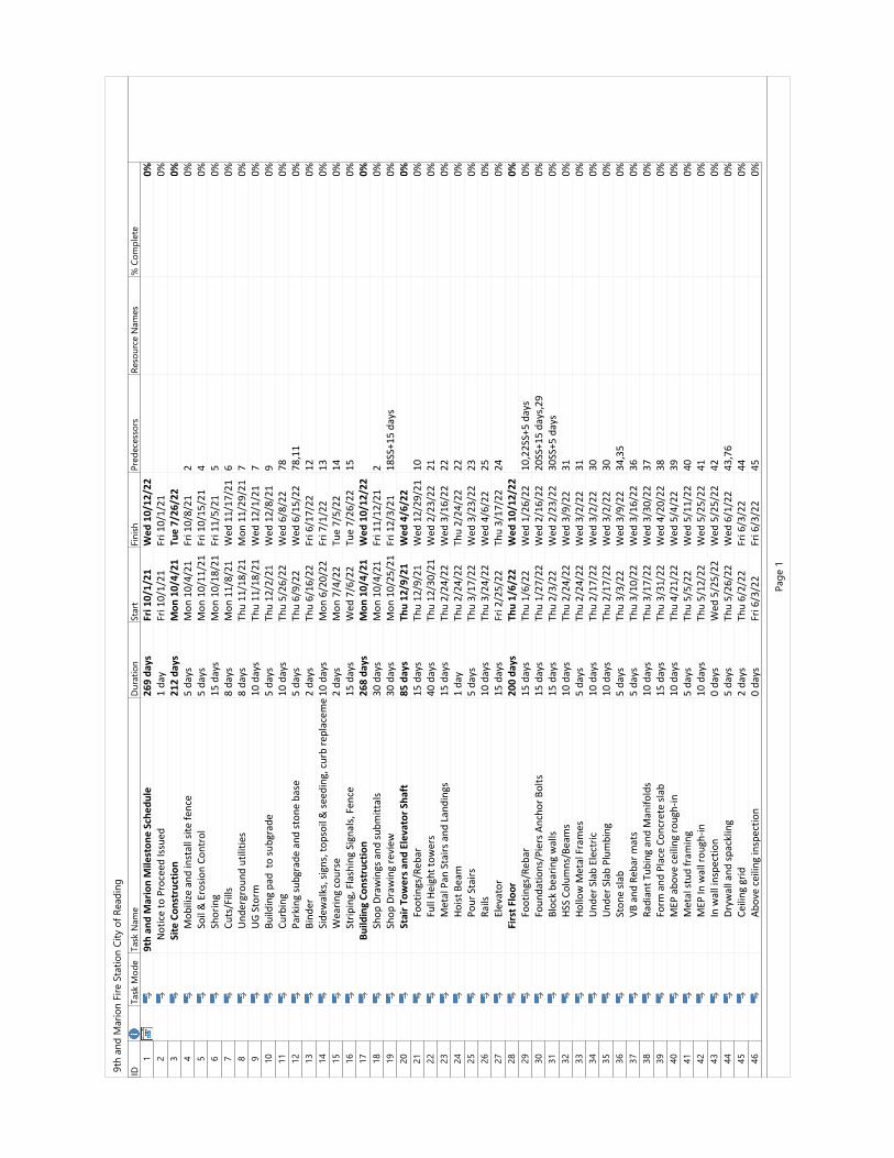
IDTask
Mo
de
Task
Nam
eD
ura
tio
nSta
rtFi
nis
hP
red
ece
sso
rsR
eso
urc
e N
am
es
% C
om
ple
te
19
th a
nd
Ma
rio
n M
ile
sto
ne
Sch
ed
ule
26
9 d
ay
sF
ri 1
0/1
/21
We
d 1
0/1
2/2
20
%
2N
otic
e to
Pro
ceed
Issu
ed1
day
Fri 1
0/1/
21Fr
i 10/
1/21
0%3
Sit
e C
on
stru
ctio
n2
12
da
ys
Mo
n 1
0/4
/21
Tu
e 7
/26
/22
0%
4M
obili
ze a
nd in
stal
l site
fenc
e5
days
Mon
10/
4/21
Fri 1
0/8/
212
0%5
Soil
& E
rosio
n Co
ntro
l5
days
Mon
10/
11/2
1Fr
i 10/
15/2
14
0%6
Shor
ing
15 d
ays
Mon
10/
18/2
1Fr
i 11/
5/21
50%
7Cu
ts/F
ills
8 da
ysM
on 1
1/8/
21W
ed 1
1/17
/21
60%
8U
nder
grou
nd u
tiliti
es8
days
Thu
11/1
8/21
Mon
11/
29/2
17
0%9
UG
Stor
m10
day
sTh
u 11
/18/
21W
ed 1
2/1/
217
0%10
Build
ing
pad
to su
bgra
de5
days
Thu
12/2
/21
Wed
12/
8/21
90%
11
Curb
ing
10 d
ays
Thu
5/26
/22
Wed
6/8
/22
780%
12
Park
ing
subg
rade
and
ston
e ba
se5
days
Thu
6/9/
22W
ed 6
/15/
2278
,11
0%13
Bind
er2
days
Thu
6/16
/22
Fri 6
/17/
2212
0%14
Side
wal
ks, s
igns
, top
soil
& se
edin
g, c
urb
repl
acem
ent,
etc.
10 d
ays
Mon
6/2
0/22
Fri 7
/1/2
213
0%15
Wea
ring
cour
se2
days
Mon
7/4
/22
Tue
7/5/
2214
0%16
Strip
ing,
Fla
shin
g Si
gnal
s, F
ence
15 d
ays
Wed
7/6
/22
Tue
7/26
/22
150%
17
Bu
ild
ing
Co
nst
ruct
ion
26
8 d
ay
sM
on
10
/4/2
1W
ed
10
/12
/22
0%
18
Shop
Dra
win
gs a
nd su
bmitt
als
30 d
ays
Mon
10/
4/21
Fri 1
1/12
/21
20%
19
Shop
Dra
win
g re
view
30 d
ays
Mon
10/
25/2
1Fr
i 12/
3/21
18SS
+15
days
0%20
Sta
ir T
ow
ers
an
d E
lev
ato
r S
ha
ft8
5 d
ay
sT
hu
12
/9/2
1W
ed
4/6
/22
0%
21
Foot
ings
/Reb
ar15
day
sTh
u 12
/9/2
1W
ed 1
2/29
/21
100%
22
Full
Heig
ht to
wer
s40
day
sTh
u 12
/30/
21W
ed 2
/23/
2221
0%23
Met
al P
an S
tairs
and
Lan
ding
s15
day
sTh
u 2/
24/2
2W
ed 3
/16/
2222
0%24
Hoist
Bea
m1
day
Thu
2/24
/22
Thu
2/24
/22
220%
25
Pour
Sta
irs5
days
Thu
3/17
/22
Wed
3/2
3/22
230%
26
Rails
10 d
ays
Thu
3/24
/22
Wed
4/6
/22
250%
27
Elev
ator
15 d
ays
Fri 2
/25/
22Th
u 3/
17/2
224
0%28
Fir
st F
loo
r2
00
da
ys
Th
u 1
/6/2
2W
ed
10
/12
/22
0%
29
Foot
ings
/Reb
ar15
day
sTh
u 1/
6/22
Wed
1/2
6/22
10,2
2SS+
5 da
ys0%
30
Foun
datio
ns/P
iers
Anc
hor B
olts
15 d
ays
Thu
1/27
/22
Wed
2/1
6/22
20SS
+15
days
,29
0%31
Bloc
k be
arin
g w
alls
15 d
ays
Thu
2/3/
22W
ed 2
/23/
2230
SS+5
day
s0%
32
HSS
Colu
mns
/Bea
ms
10 d
ays
Thu
2/24
/22
Wed
3/9
/22
310%
33
Hollo
w M
etal
Fra
mes
5 da
ysTh
u 2/
24/2
2W
ed 3
/2/2
231
0%34
Und
er S
lab
Elec
tric
10 d
ays
Thu
2/17
/22
Wed
3/2
/22
300%
35
Und
er S
lab
Plum
bing
10 d
ays
Thu
2/17
/22
Wed
3/2
/22
300%
36
Ston
e sla
b5
days
Thu
3/3/
22W
ed 3
/9/2
234
,35
0%37
VB a
nd R
ebar
mat
s5
days
Thu
3/10
/22
Wed
3/1
6/22
360%
38
Radi
ant T
ubin
g an
d M
anifo
lds
10 d
ays
Thu
3/17
/22
Wed
3/3
0/22
370%
39
Form
and
Pla
ce C
oncr
ete
slab
15 d
ays
Thu
3/31
/22
Wed
4/2
0/22
380%
40
MEP
abo
ve c
eilin
g ro
ugh-
in10
day
sTh
u 4/
21/2
2W
ed 5
/4/2
239
0%41
Met
al st
ud fr
amin
g5
days
Thu
5/5/
22W
ed 5
/11/
2240
0%42
MEP
In w
all r
ough
-in10
day
sTh
u 5/
12/2
2W
ed 5
/25/
2241
0%43
In w
all i
nspe
ctio
n0
days
Wed
5/2
5/22
Wed
5/2
5/22
420%
44
Dryw
all a
nd sp
ackl
ing
5 da
ysTh
u 5/
26/2
2W
ed 6
/1/2
243
,76
0%45
Ceili
ng g
rid2
days
Thu
6/2/
22Fr
i 6/3
/22
440%
46
Abov
e ce
iling
insp
ectio
n0
days
Fri 6
/3/2
2Fr
i 6/3
/22
450%
9th
an
d M
ari
on
Fir
e S
tati
on
Cit
y o
f R
ead
ing
Pag
e 1
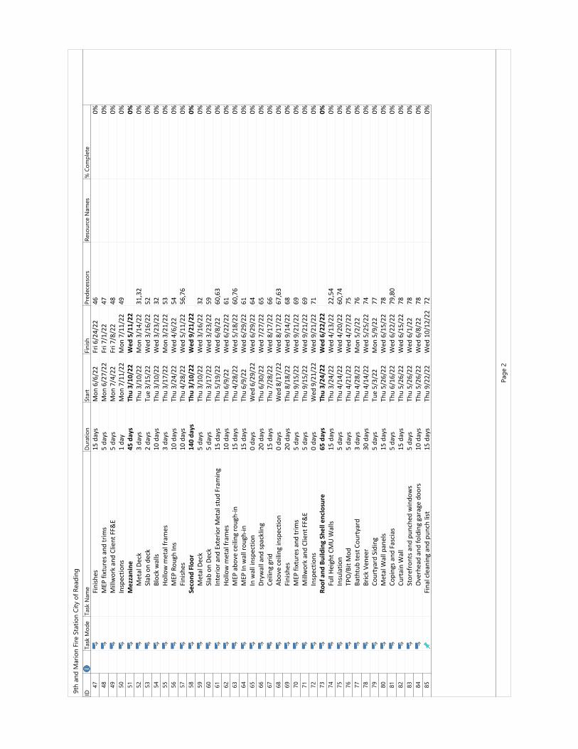
IDTask
Mo
de
Task
Nam
eD
ura
tio
nSta
rtFi
nis
hP
red
ece
sso
rsR
eso
urc
e N
am
es
% C
om
ple
te
47
Fini
shes
15 d
ays
Mon
6/6
/22
Fri 6
/24/
2246
0%48
MEP
fixt
ures
and
trim
s5
days
Mon
6/2
7/22
Fri 7
/1/2
247
0%49
Mill
wor
k an
d Cl
ient
FF&
E5
days
Mon
7/4
/22
Fri 7
/8/2
248
0%50
Insp
ectio
ns1
day
Mon
7/1
1/22
Mon
7/1
1/22
490%
51
Me
zza
nin
e4
5 d
ay
sT
hu
3/1
0/2
2W
ed
5/1
1/2
20
%
52
Met
al D
eck
3 da
ysTh
u 3/
10/2
2M
on 3
/14/
2231
,32
0%53
Slab
on
deck
2 da
ysTu
e 3/
15/2
2W
ed 3
/16/
2252
0%54
Bloc
k w
alls
10 d
ays
Thu
3/10
/22
Wed
3/2
3/22
320%
55
Hollo
w m
etal
fram
es3
days
Thu
3/17
/22
Mon
3/2
1/22
530%
56
MEP
Rou
gh In
s10
day
sTh
u 3/
24/2
2W
ed 4
/6/2
254
0%57
Fini
shes
10 d
ays
Thu
4/28
/22
Wed
5/1
1/22
56,7
60%
58
Se
con
d F
loo
r1
40
da
ys
Th
u 3
/10
/22
We
d 9
/21
/22
0%
59
Met
al D
eck
5 da
ysTh
u 3/
10/2
2W
ed 3
/16/
2232
0%60
Slab
on
Deck
5 da
ysTh
u 3/
17/2
2W
ed 3
/23/
2259
0%61
Inte
rior a
nd E
xter
ior M
etal
stud
Fra
min
g15
day
sTh
u 5/
19/2
2W
ed 6
/8/2
260
,63
0%62
Hollo
w m
etal
fram
es10
day
sTh
u 6/
9/22
Wed
6/2
2/22
610%
63
MEP
abo
ve c
eilin
g ro
ugh-
in15
day
sTh
u 4/
28/2
2W
ed 5
/18/
2260
,76
0%64
MEP
In w
all r
ough
-in15
day
sTh
u 6/
9/22
Wed
6/2
9/22
610%
65
In w
all i
nspe
ctio
n0
days
Wed
6/2
9/22
Wed
6/2
9/22
640%
66
Dryw
all a
nd sp
ackl
ing
20 d
ays
Thu
6/30
/22
Wed
7/2
7/22
650%
67
Ceili
ng g
rid15
day
sTh
u 7/
28/2
2W
ed 8
/17/
2266
0%68
Abov
e ce
iling
insp
ectio
n0
days
Wed
8/1
7/22
Wed
8/1
7/22
67,6
30%
69
Fini
shes
20 d
ays
Thu
8/18
/22
Wed
9/1
4/22
680%
70
MEP
fixt
ures
and
trim
s5
days
Thu
9/15
/22
Wed
9/2
1/22
690%
71
Mill
wor
k an
d Cl
ient
FF&
E5
days
Thu
9/15
/22
Wed
9/2
1/22
690%
72
Insp
ectio
ns0
days
Wed
9/2
1/22
Wed
9/2
1/22
710%
73
Ro
of
an
d B
uil
din
g S
he
ll e
ncl
osu
re6
5 d
ay
sT
hu
3/2
4/2
2W
ed
6/2
2/2
20
%
74
Full
Heig
ht C
MU
Wal
ls15
day
sTh
u 3/
24/2
2W
ed 4
/13/
2222
,54
0%75
Insu
latio
n5
days
Thu
4/14
/22
Wed
4/2
0/22
60,7
40%
76
TPO
/Bit
Mod
5 da
ysTh
u 4/
21/2
2W
ed 4
/27/
2275
0%77
Bath
tub
test
Cou
rtya
rd3
days
Thu
4/28
/22
Mon
5/2
/22
760%
78
Bric
k Ve
neer
30 d
ays
Thu
4/14
/22
Wed
5/2
5/22
740%
79
Cour
tyar
d Si
ding
5 da
ysTu
e 5/
3/22
Mon
5/9
/22
770%
80
Met
al W
all p
anel
s15
day
sTh
u 5/
26/2
2W
ed 6
/15/
2278
0%81
Copi
ngs a
nd F
asci
as5
days
Thu
6/16
/22
Wed
6/2
2/22
79,8
00%
82
Curt
ain
Wal
l15
day
sTh
u 5/
26/2
2W
ed 6
/15/
2278
0%83
Stor
efro
nts a
nd p
unch
ed w
indo
ws
5 da
ysTh
u 5/
26/2
2W
ed 6
/1/2
278
0%84
Ove
rhea
d an
d fo
ldin
g ga
rage
doo
rs10
day
sTh
u 5/
26/2
2W
ed 6
/8/2
278
0%85
Fina
l cle
anin
g an
d pu
nch
list
15 d
ays
Thu
9/22
/22
Wed
10/
12/2
272
0%
9th
an
d M
ari
on
Fir
e S
tati
on
Cit
y o
f R
ead
ing
Pag
e 2
Reading Fire Department9th & Marion Fire StationBid/Permit Set July 9, 2021
MANNS WOODWARD STUDIOS INC
DOCUMENT 003132 - GEOTECHNICAL DATA
1.1 GEOTECHNICAL DATA
A. This Document with its referenced attachments is part of the Procurement and Contracting Requirements for Project. They provide Owner's information for Bidders' convenience and are intended to supplement rather than serve in lieu of Bidders' own investigations. They are made available for Bidders' convenience and information. This Document and its attachments are not part of the Contract Documents.
B. Because subsurface conditions indicated by the soil borings are a sampling in relation to the entire construction area, and for other reasons, the Owner, the Architect, the Architect's consultants, and the firm reporting the subsurface conditions do not warranty the conditions below the depths of the borings or that the strata logged from the borings are necessarily typical of the entire site. Any party using the information described in the soil borings and geotechnical report shall accept full responsibility for its use.
C. A geotechnical investigation report for Project, prepared by ECS Mid-Atlantic, LLC, dated March 18,2021, is available for viewing as appended to this Document.
1. The opinions expressed in this report are those of a geotechnical engineer and represent interpretations of subsoil conditions, tests, and results of analyses conducted by a geotechnical engineer. Owner is not responsible for interpretations or conclusions drawn from the data.
2. Any party using information described in the geotechnical report shall make additional test borings and conduct other exploratory operations that may be required to determine the character of subsurface materials that may be encountered.
D. Related Requirements:
1. Document 002113 "Instructions to Bidders" for the Bidder's responsibilities for examination of Project site and existing conditions.
END OF DOCUMENT 003132
GEOTECHNICAL DATA 00 3132 - 1

ECS Mid-Atlantic, LLC Geotechnical Engineering Report Reading Fire Hall 9th Street and Marion Street Reading, Berks County, Pennsylvania ECS Project Number 18:5128 March 18, 2021
March 18, 2021 Mr. Stan Rugis City of Reading 815 Washington Street Reading, PA 19601
ECS Project No. 18:5128 Reference: Geotechnical Engineering Report
Reading Fire Hall Reading, Berks County, Pennsylvania
Dear Mr. Rugis: ECS Mid-Atlantic, LLC (ECS) has completed the subsurface exploration and geotechnical engineering analyses for the above-referenced project. Our services were performed in general accordance with our Proposal No. 18:7607-GP, dated November 9, 2020. This report presents our understanding of the geotechnical aspects of the project, results of the field exploration, laboratory testing, and our design and construction recommendations. It has been our pleasure to be of service to the City of Reading during this phase of this project. We would appreciate the opportunity to remain involved during the continuation of the design phase and to provide our services during construction phase operations as well to verify the assumptions of subsurface conditions made for this report. Should you have any questions concerning the information contained in this report, or if we can be of further assistance to you, please contact us. Respectfully submitted, ECS Mid-Atlantic, LLC Meghan D. Hartman, E.I.T. Geotechnical Project Manager [email protected] J. Matthew Carroll, P.E. Principal Engineer [email protected] Derek G. Ridinger, P.E. Geotechnical Department Manager [email protected]
Reading Fire Hall March 18, 2021 ECS Project No. 18:5128
TABLE OF CONTENTS
EXECUTIVE SUMMARY .................................................................................................................. 1 1.0 INTRODUCTION ............................................................................................................................ 3 2.0 PROJECT INFORMATION ............................................................................................................... 4
Project Location .................................................................................................................................. 4 Proposed Construction ....................................................................................................................... 4
3.0 FIELD EXPLORATION AND LABORATORY TESTING ......................................................................... 6 Subsurface Characterization ............................................................................................................... 6
3.1.1 Stormwater Infiltration Testing ..................................................................................................... 7 Karst Mapping .................................................................................................................................... 7 Groundwater Observations ................................................................................................................ 7 Laboratory Testing .............................................................................................................................. 8
4.0 DESIGN RECOMMENDATIONS ....................................................................................................... 9 Foundation Design .............................................................................................................................. 9 Floor Slabs .......................................................................................................................................... 9 Seismic Design Characteristics ......................................................................................................... 10 Stormwater Management Areas ...................................................................................................... 11
4.4.1 Stormwater Management Facilities ............................................................................................ 11 4.4.2 Stormwater Management Considerations .................................................................................. 12 4.4.3 Stormwater Management Facilities - Design Notes .................................................................... 13
Pavements ........................................................................................................................................ 14 5.0 SITE CONSTRUCTION RECOMMENDATIONS ................................................................................ 16
Karst Related – General Risk ............................................................................................................. 16 Stormwater Construction Recommendations .................................................................................. 16 Subgrade Preparation ....................................................................................................................... 17
5.3.1 Stripping and Grubbing ............................................................................................................... 17 5.3.2 Proofrolling .................................................................................................................................. 17
Earthwork Operations ...................................................................................................................... 17 5.4.1 Existing Man-Placed Fill ............................................................................................................... 17 5.4.2 Structural Fill Materials ............................................................................................................... 18
Foundation and Slab Observations .................................................................................................. 19 Utility Installations ............................................................................................................................ 19
6.0 CLOSING ..................................................................................................................................... 21

Reading Fire Hall March 18, 2021 ECS Project No. 18:5128
APPENDICES Appendix A – Figures
• Site Location Map • Exploration Location Plan • Geology Map • Karst Features Map • Soil Survey Map
Appendix B – Field Operations
• Reference Notes for Boring Logs • Subsurface Exploration Procedure: Standard Penetration Testing (SPT) • Boring Logs B-01 through B-08 • Test Pit Logs IT-01 through IT-02 • Subsurface Soil Profiles A-A’ through C-C’ • Infiltration Test Results • Test Pit Photographs
Appendix C – Laboratory Testing
• Laboratory Testing Summary • Plasticity Charts • Grain Size Analyses
Appendix D – Details
• Sinkhole Repair Details
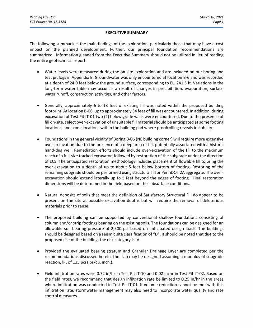
Reading Fire Hall March 18, 2021 ECS Project No. 18:5128 Page 1
EXECUTIVE SUMMARY The following summarizes the main findings of the exploration, particularly those that may have a cost impact on the planned development. Further, our principal foundation recommendations are summarized. Information gleaned from the Executive Summary should not be utilized in lieu of reading the entire geotechnical report.
• Water levels were measured during the on-site exploration and are included on our boring and
test pit logs in Appendix B. Groundwater was only encountered at location B-6 and was recorded at a depth of 24.0 feet below the ground surface, corresponding to EL. 241.5 ft. Variations in the long-term water table may occur as a result of changes in precipitation, evaporation, surface water runoff, construction activities, and other factors.
• Generally, approximately 6 to 13 feet of existing fill was noted within the proposed building footprint. At location B-06, up to approximately 34 feet of fill was encountered. In addition, during excavation of Test Pit IT-01 two (2) below grade walls were encountered. Due to the presence of fill on-site, select over-excavation of unsuitable fill material should be anticipated at some footing locations, and some locations within the building pad where proofrolling reveals instability.
• Foundations in the general vicinity of Boring B-06 (NE building corner) will require more extensive over-excavation due to the presence of a deep area of fill, potentially associated with a historic hand-dug well. Remediation efforts should include over-excavation of the fill to the maximum reach of a full-size tracked excavator, followed by restoration of the subgrade under the direction of ECS. The anticipated restoration methodology includes placement of flowable fill to bring the over-excavation to a depth of up to about 5 feet below bottom of footing. Restoring of the remaining subgrade should be performed using structural fill or PennDOT 2A aggregate. The over-excavation should extend laterally up to 5 feet beyond the edges of footing. Final restoration dimensions will be determined in the field based on the subsurface conditions.
• Natural deposits of soils that meet the definition of Satisfactory Structural Fill do appear to be present on the site at possible excavation depths but will require the removal of deleterious materials prior to reuse.
• The proposed building can be supported by conventional shallow foundations consisting of column and/or strip footings bearing on the existing soils. The foundations can be designed for an allowable soil bearing pressure of 2,500 psf based on anticipated design loads. The buildings should be designed based on a seismic site classification of “D”. It should be noted that due to the proposed use of the building, the risk category is IV.
• Provided the evaluated bearing stratum and Granular Drainage Layer are completed per the recommendations discussed herein, the slab may be designed assuming a modulus of subgrade reaction, k1, of 125 pci (lbs/cu. inch.).
• Field infiltration rates were 0.72 in/hr in Test Pit IT-10 and 0.02 in/hr in Test Pit IT-02. Based on the field rates, we recommend that design infiltration rate be limited to 0.25 in/hr in the areas where infiltration was conducted in Test Pit IT-01. If volume reduction cannot be met with this infiltration rate, stormwater management may also need to incorporate water quality and rate control measures.

Reading Fire Hall March 18, 2021 ECS Project No. 18:5128 Page 2
• It should be understood the concentrated influx of water to a designated area increases the risk of sinkhole development; therefore, the financial implications for sinkhole repair also increase when directing stormwater below paved areas opposed to traditional surface basins.
Refer to the text of the report for site specific design and construction recommendations.
Reading Fire Hall March 18, 2021 ECS Project No. 18:5128 Page 3
1.0 INTRODUCTION The purpose of this study was to provide geotechnical information for design and construction of a new 12,000 SF, two-story fire hall. Development of the project will also include constructing new parking areas, a stormwater management facility, and an access drive. The recommendations developed for this report are based on project information supplied by Boyle Construction, Inc. Our services were provided in accordance with the Proposal No. 7607-GP, dated November 9, 2020, as authorized by the City of Reading on December 6, 2020, which includes Consulting Agreement between ECS Mid-Atlantic, LLC and the City of Reading, dated December 6, 2020. This report contains the results of our subsurface exploration, site characterization, laboratory testing, engineering analyses, and recommendations for the design and construction of the proposed development. This report includes the following:
• A review of area and site geologic conditions. • A review of surface topographical features and site conditions. • A brief review and description of our field procedures. • A brief review and description of our field and laboratory test procedures and the results of testing
conducted. • A review of subsurface soil stratigraphy with pertinent available physical properties. • Final copies of our boring and test pit logs • Infiltration testing results and recommendations for stormwater management. • Recommendations for site preparation and construction of compacted fills, including an
evaluation of on-site soils for use as compacted fills and identification of potentially unsuitable soils and/or soils exhibiting excessive moisture at the time of sampling.
• Recommended foundation type and allowable bearing pressure for foundation design. • Recommendations for below-grade wall construction, including lateral earth pressures. • General recommendations for pavement design, including a recommended design CBR value. • Discussion of parameters for slab on grade construction and modulus of subgrade reaction (k). • Recommendations for seismic site classification and site seismic design coefficients based on the
2015 IBC parameters. • Evaluation and recommendations relative to groundwater. • A discussion of potential of karst geology features.
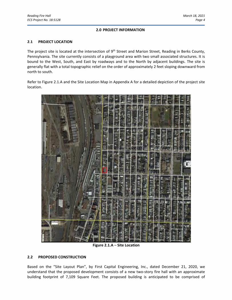
Reading Fire Hall March 18, 2021 ECS Project No. 18:5128 Page 4
2.0 PROJECT INFORMATION
PROJECT LOCATION
The project site is located at the intersection of 9th Street and Marion Street, Reading in Berks County, Pennsylvania. The site currently consists of a playground area with two small associated structures. It is bound to the West, South, and East by roadways and to the North by adjacent buildings. The site is generally flat with a total topographic relief on the order of approximately 2 feet sloping downward from north to south. Refer to Figure 2.1.A and the Site Location Map in Appendix A for a detailed depiction of the project site location.
Figure 2.1.A – Site Location
PROPOSED CONSTRUCTION
Based on the “Site Layout Plan”, by First Capital Engineering, Inc., dated December 21, 2020, we understand that the proposed development consists of a new two-story fire hall with an approximate building footprint of 7,109 Square Feet. The proposed building is anticipated to be comprised of
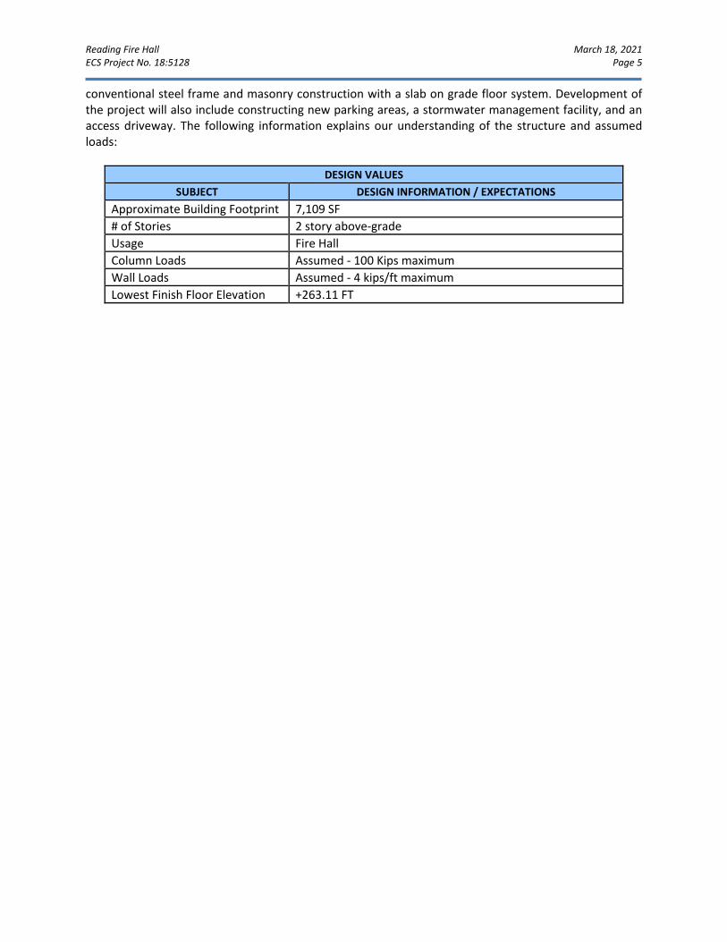
Reading Fire Hall March 18, 2021 ECS Project No. 18:5128 Page 5
conventional steel frame and masonry construction with a slab on grade floor system. Development of the project will also include constructing new parking areas, a stormwater management facility, and an access driveway. The following information explains our understanding of the structure and assumed loads:
DESIGN VALUES SUBJECT DESIGN INFORMATION / EXPECTATIONS
Approximate Building Footprint 7,109 SF # of Stories 2 story above-grade Usage Fire Hall Column Loads Assumed - 100 Kips maximum Wall Loads Assumed - 4 kips/ft maximum Lowest Finish Floor Elevation
+263.11 FT
Reading Fire Hall March 18, 2021 ECS Project No. 18:5128 Page 6
3.0 FIELD EXPLORATION AND LABORATORY TESTING Our exploration procedures are explained in greater detail in Appendix B including the insert titled Subsurface Exploration Procedures. Our scope of work included drilling a total of eight (8) geotechnical borings as well as performing two (2) test pits for the purpose of infiltration testing. Our borings and test pits were located with a handheld GPS unit and their approximate locations are shown on the Exploration Location Plan in Appendix A. The locations were selected by others.
SUBSURFACE CHARACTERIZATION
The following sections provide generalized characterizations of the soil strata. Please refer to the boring and test pit logs in Appendix B. It should be noted that Boring B-6 encountered fill materials to a depth of approximately 34 feet, which is highly unusual for this area, and appears to potentially be associated with a previous site feature, as the adjacent surrounding borings encountered typical residual soils below surficial fill materials. It is possible that the deep fill area is associated with an abandoned hand-dug well or similar feature that has been since backfilled with loose and unconsolidated materials. This area will require remediation as part of the site preparation. According to the Pennsylvania Department of Conservation and Natural Resources Interactive Map (PA DCNR), the site is underlain by the Richland Formation. This formation is included in The Engineering Characteristics of the Rocks of Pennsylvania, Second Edition, 1982, by Alan Geyer and Peter Wilshusen, and is described as having the following characteristics. The Richland Formation is a gray, finely crystalline dolomite interbedded with medium-gray, oolitic limestone, chert, calcarenite and conglomerate. The joints have a blocky pattern; well developed; moderately to highly abundant; regularly spaced, having a moderate distance between fractures. The bedrock formation is moderately resistant to weathering with being slightly weathered to a shallow depth. The formation possesses good subsurface drainage with little surface drainage. Solution channels produce a secondary porosity of low to moderate magnitude with low to moderate permeability. The Richland Formation rock is difficult to excavate; moderate to slow drilling rate. The cut-slope and foundation stability provided by this bedrock is good; a thorough investigation for solution cavities should be undertaken. The Richland Formation is a good source of road material and fill. This formation is susceptible to karst processes; however ECS did not observe evidence at the site of existing karst activity.
SUBSURFACE STRATIGRAPHY
Stratum Description
n/a
Surficial Material: Concrete Thickness 4.0 inches Asphalt Thickness 2.0 to 4.0 inches Gravel Thickness 2.0 to 3.0 inches
I FILL Materials, soft to hard Lean CLAY with Sand (CL), moist, stiff to very stiff Gravelly Lean CLAY with Sand (CL), contains varying amounts of Gravel and Sand, moist to wet and some very loose to very dense SAND(SP), moist
II Soft to hard Lean CLAY with Sand (CL), contains varying amounts of sand and gravel, moist
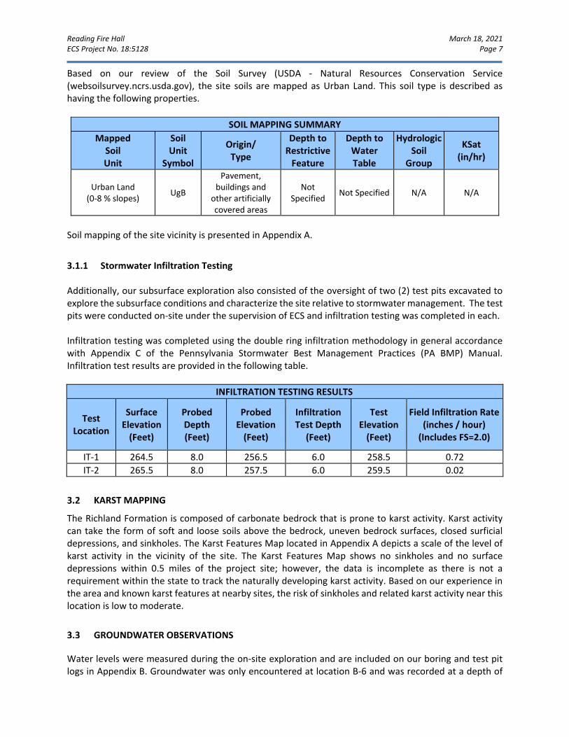
Reading Fire Hall March 18, 2021 ECS Project No. 18:5128 Page 7
Based on our review of the Soil Survey (USDA - Natural Resources Conservation Service (websoilsurvey.ncrs.usda.gov), the site soils are mapped as Urban Land. This soil type is described as having the following properties.
SOIL MAPPING SUMMARY Mapped
Soil Unit
Soil Unit
Symbol
Origin/ Type
Depth to Restrictive
Feature
Depth to Water Table
Hydrologic Soil
Group
KSat (in/hr)
Urban Land (0-8 % slopes) UgB
Pavement, buildings and
other artificially covered areas
Not Specified Not Specified N/A N/A
Soil mapping of the site vicinity is presented in Appendix A.
3.1.1 Stormwater Infiltration Testing Additionally, our subsurface exploration also consisted of the oversight of two (2) test pits excavated to explore the subsurface conditions and characterize the site relative to stormwater management. The test pits were conducted on-site under the supervision of ECS and infiltration testing was completed in each. Infiltration testing was completed using the double ring infiltration methodology in general accordance with Appendix C of the Pennsylvania Stormwater Best Management Practices (PA BMP) Manual. Infiltration test results are provided in the following table.
INFILTRATION TESTING RESULTS
Test Location
Surface Elevation
(Feet)
Probed Depth (Feet)
Probed Elevation
(Feet)
Infiltration Test Depth
(Feet)
Test Elevation
(Feet)
Field Infiltration Rate (inches / hour)
(Includes FS=2.0)
IT-1 264.5 8.0 256.5 6.0 258.5 0.72 IT-2 265.5 8.0 257.5 6.0 259.5 0.02
KARST MAPPING
The Richland Formation is composed of carbonate bedrock that is prone to karst activity. Karst activity can take the form of soft and loose soils above the bedrock, uneven bedrock surfaces, closed surficial depressions, and sinkholes. The Karst Features Map located in Appendix A depicts a scale of the level of karst activity in the vicinity of the site. The Karst Features Map shows no sinkholes and no surface depressions within 0.5 miles of the project site; however, the data is incomplete as there is not a requirement within the state to track the naturally developing karst activity. Based on our experience in the area and known karst features at nearby sites, the risk of sinkholes and related karst activity near this location is low to moderate.
GROUNDWATER OBSERVATIONS
Water levels were measured during the on-site exploration and are included on our boring and test pit logs in Appendix B. Groundwater was only encountered at location B-6 and was recorded at a depth of
Reading Fire Hall March 18, 2021 ECS Project No. 18:5128 Page 8
24.0 feet below the ground surface, corresponding to EL. 241.5 ft. Variations in the long-term water table may occur as a result of changes in precipitation, evaporation, surface water runoff, construction activities, and other factors.
LABORATORY TESTING
The laboratory testing consisted of selected tests performed on samples obtained during our field exploration operations. Classification and index property tests were performed on representative soil samples. Each sample was visually classified on the basis of texture and plasticity in accordance with ASTM D2488 Standard Practice for Description and Identification of Soils (Visual-Manual Procedures) and including USCS classification symbols, and ASTM D2487 Standard Practice for Classification for Engineering Purposes (Unified Soil Classification System (USCS)). After classification, the samples were grouped in the major zones noted on the boring logs in Appendix B. The group symbols for each soil type are indicated in parentheses along with the soil descriptions. The stratification lines between strata on the logs are approximate; in situ, the transitions may be gradual.
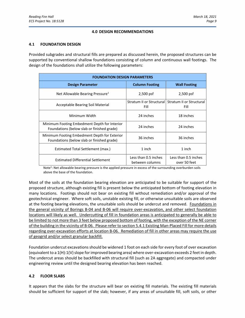
Reading Fire Hall March 18, 2021 ECS Project No. 18:5128 Page 9
4.0 DESIGN RECOMMENDATIONS
FOUNDATION DESIGN
Provided subgrades and structural fills are prepared as discussed herein, the proposed structures can be supported by conventional shallow foundations consisting of column and continuous wall footings. The design of the foundations shall utilize the following parameters:
FOUNDATION DESIGN PARAMETERS
Design Parameter Column Footing Wall Footing
Net Allowable Bearing Pressure1 2,500 psf 2,500 psf
Acceptable Bearing Soil Material Stratum II or Structural
Fill
Stratum II or Structural Fill
Minimum Width 24 inches 18 inches
Minimum Footing Embedment Depth for Interior Foundations (below slab or finished grade) 24 inches 24 inches
Minimum Footing Embedment Depth for Exterior Foundations (below slab or finished grade) 36 inches 36 inches
Estimated Total Settlement (max.) 1 inch 1 inch
Estimated Differential Settlement Less than 0.5 inches between columns
Less than 0.5 inches over 50 feet
Note1: Net allowable bearing pressure is the applied pressure in excess of the surrounding overburden soils above the base of the foundation.
Most of the soils at the foundation bearing elevation are anticipated to be suitable for support of the proposed structure, although existing fill is present below the anticipated bottom of footing elevation in many locations. Footings should not bear on existing fill without remediation and/or approval of the geotechnical engineer. Where soft soils, unstable existing fill, or otherwise unsuitable soils are observed at the footing bearing elevations, the unsuitable soils should be undercut and removed. Foundations in the general vicinity of Borings B-04 and B-06 will require over-excavation, and other select foundation locations will likely as well. Undercutting of fill in foundation areas is anticipated to generally be able to be limited to not more than 3 feet below proposed bottom of footing, with the exception of the NE corner of the building in the vicinity of B-06. Please refer to section 5.4.1 Existing Man-Placed Fill for more details regarding over-excavation efforts at location B-06. Remediation of fill in other areas may require the use of geogrid and/or select granular backfill. Foundation undercut excavations should be widened 1 foot on each side for every foot of over excavation (equivalent to a 1(H):1(V) slope for improved bearing area) where over-excavation exceeds 2 feet in depth. The undercut areas should be backfilled with structural fill (such as 2A aggregate) and compacted under engineering review until the designed bearing elevation has been reached.
FLOOR SLABS
It appears that the slabs for the structure will bear on existing fill materials. The existing fill materials should be sufficient for support of the slab; however, if any areas of unsuitable fill, soft soils, or other
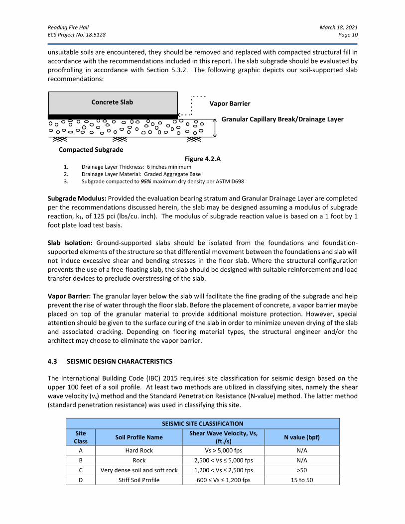
Reading Fire Hall March 18, 2021 ECS Project No. 18:5128 Page 10
unsuitable soils are encountered, they should be removed and replaced with compacted structural fill in accordance with the recommendations included in this report. The slab subgrade should be evaluated by proofrolling in accordance with Section 5.3.2. The following graphic depicts our soil-supported slab recommendations:
Figure 4.2.A 1. Drainage Layer Thickness: 6 inches minimum 2. Drainage Layer Material: Graded Aggregate Base 3. Subgrade compacted to 95% maximum dry density per ASTM D698
Subgrade Modulus: Provided the evaluation bearing stratum and Granular Drainage Layer are completed per the recommendations discussed herein, the slab may be designed assuming a modulus of subgrade reaction, k1, of 125 pci (lbs/cu. inch). The modulus of subgrade reaction value is based on a 1 foot by 1 foot plate load test basis. Slab Isolation: Ground-supported slabs should be isolated from the foundations and foundation-supported elements of the structure so that differential movement between the foundations and slab will not induce excessive shear and bending stresses in the floor slab. Where the structural configuration prevents the use of a free-floating slab, the slab should be designed with suitable reinforcement and load transfer devices to preclude overstressing of the slab. Vapor Barrier: The granular layer below the slab will facilitate the fine grading of the subgrade and help prevent the rise of water through the floor slab. Before the placement of concrete, a vapor barrier maybe placed on top of the granular material to provide additional moisture protection. However, special attention should be given to the surface curing of the slab in order to minimize uneven drying of the slab and associated cracking. Depending on flooring material types, the structural engineer and/or the architect may choose to eliminate the vapor barrier.
SEISMIC DESIGN CHARACTERISTICS
The International Building Code (IBC) 2015 requires site classification for seismic design based on the upper 100 feet of a soil profile. At least two methods are utilized in classifying sites, namely the shear wave velocity (vs) method and the Standard Penetration Resistance (N-value) method. The latter method (standard penetration resistance) was used in classifying this site.
SEISMIC SITE CLASSIFICATION Site
Class Soil Profile Name Shear Wave Velocity, Vs, (ft./s) N value (bpf)
A Hard Rock Vs > 5,000 fps N/A B Rock 2,500 < Vs ≤ 5,000 fps N/A C Very dense soil and soft rock 1,200 < Vs ≤ 2,500 fps >50 D Stiff Soil Profile 600 ≤ Vs ≤ 1,200 fps 15 to 50
Concrete Slab Vapor Barrier
Granular Capillary Break/Drainage Layer
Compacted Subgrade
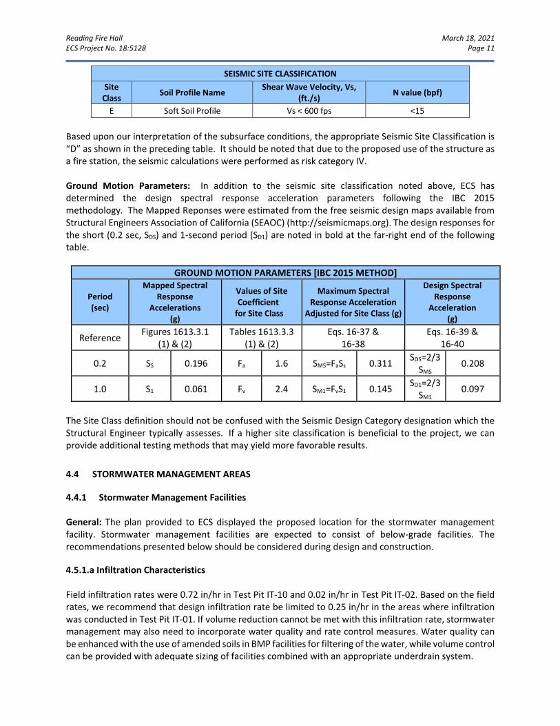
Reading Fire Hall March 18, 2021 ECS Project No. 18:5128 Page 11
SEISMIC SITE CLASSIFICATION Site
Class Soil Profile Name Shear Wave Velocity, Vs, (ft./s) N value (bpf)
E Soft Soil Profile Vs < 600 fps <15 Based upon our interpretation of the subsurface conditions, the appropriate Seismic Site Classification is “D” as shown in the preceding table. It should be noted that due to the proposed use of the structure as a fire station, the seismic calculations were performed as risk category IV. Ground Motion Parameters: In addition to the seismic site classification noted above, ECS has determined the design spectral response acceleration parameters following the IBC 2015 methodology. The Mapped Reponses were estimated from the free seismic design maps available from Structural Engineers Association of California (SEAOC) (http://seismicmaps.org). The design responses for the short (0.2 sec, SDS) and 1-second period (SD1) are noted in bold at the far-right end of the following table.
GROUND MOTION PARAMETERS [IBC 2015 METHOD]
Period (sec)
Mapped Spectral Response
Accelerations (g)
Values of Site Coefficient
for Site Class
Maximum Spectral Response Acceleration
Adjusted for Site Class (g)
Design Spectral Response
Acceleration (g)
Reference Figures 1613.3.1 (1) & (2)
Tables 1613.3.3 (1) & (2)
Eqs. 16-37 & 16-38
Eqs. 16-39 & 16-40
0.2 SS 0.196 Fa 1.6 SMS=FaSs 0.311 SDS=2/3
SMS 0.208
1.0 S1 0.061 Fv 2.4 SM1=FvS1 0.145 SD1=2/3
SM1 0.097
The Site Class definition should not be confused with the Seismic Design Category designation which the Structural Engineer typically assesses. If a higher site classification is beneficial to the project, we can provide additional testing methods that may yield more favorable results.
STORMWATER MANAGEMENT AREAS
4.4.1 Stormwater Management Facilities General: The plan provided to ECS displayed the proposed location for the stormwater management facility. Stormwater management facilities are expected to consist of below-grade facilities. The recommendations presented below should be considered during design and construction.
4.5.1.a Infiltration Characteristics Field infiltration rates were 0.72 in/hr in Test Pit IT-10 and 0.02 in/hr in Test Pit IT-02. Based on the field rates, we recommend that design infiltration rate be limited to 0.25 in/hr in the areas where infiltration was conducted in Test Pit IT-01. If volume reduction cannot be met with this infiltration rate, stormwater management may also need to incorporate water quality and rate control measures. Water quality can be enhanced with the use of amended soils in BMP facilities for filtering of the water, while volume control can be provided with adequate sizing of facilities combined with an appropriate underdrain system.
Reading Fire Hall March 18, 2021 ECS Project No. 18:5128 Page 12
Natural deposits of soils that meet the definition of Satisfactory Structural Fill do appear to be present on the site at possible excavation depths but will require the removal of deleterious materials prior to reuse. ECS recommends that specific construction notes appear on the plans requiring full-time observation of the excavation of the basins by the authorized ECS representative to verify suitable conditions are present. ECS can assist in developing these notes once plans become more final. 4.5.1.b Embankment/Outlet Structures/Slopes/Liner Embankment construction or cut slopes to facilitate basin construction should incorporate side slopes of 3(H):1(V) or flatter. If steeper slopes are necessary, ECS should be contacted to review the proposed slope geometry. Fill materials should be placed to a minimum of 95% of the maximum dry density of the material, as determined by the Standard Proctor method (ASTM D698). The moisture content of the materials should be within ± 3% of the optimum. Storm water management facilities with embankments should include the construction of a clay core having a minimum thickness of 2 feet. Clay suitable for this use should consist of CL or CH materials, having a minimum of 70% fines (passing #200 sieve), a minimum liquid limit (LL) of 40 and minimum plasticity index (PI) of 20. This material should be approved by the Geotechnical Engineer. Clay core materials should be compacted to 95% of the standard proctor maximum dry density at a moisture content that is at or up to 3% above the optimum. Laboratory testing of the on-site materials did not identify clay soils meeting these criteria, although laboratory testing was limited.
4.5.1.c Temporary Sediment Basin Fill Embankments Soils used in temporary sediment basin fill embankments should satisfy the requirements for fill discussed below and should be placed and compacted to the specification requirements for Structural Fill. Care should be taken not to track heavy equipment over the basin bottom during construction. 4.4.2 Stormwater Management Considerations The property is underlain by carbonate geology which is prone to sinkhole development. The owner should understand that the concentrated influx of stormwater to a select area will increase the potential of sinkhole development. In order to reduce the rate of sinkhole development, and in keeping with the guidelines and recommendations of the PA BMP Manual, we recommend that the following design principles be incorporated.
• Use existing drainage patterns • Keep stormwater away from known sinkholes or problematic subsidence areas • Avoid concentrating stormwater • Reduce runoff volume and velocity • Use broad shallow basins • Maintain the facilities post construction • Provide underdrains in all stormwater management facilities
Reading Fire Hall March 18, 2021 ECS Project No. 18:5128 Page 13
4.4.3 Stormwater Management Facilities - Design Notes It has been our experience that construction of basins may encounter conditions that were not anticipated as a result of the subsurface exploration. As a result, we have developed the following sequence of items for addressing construction related difficulties or discrepancies with the design assumptions. We recommend that these recommendations be included in the stormwater management feature construction notes on the plans.
A) If redoximorphic features (soil mottling and coloration patterns formed by the reduction of iron and/or manganese from saturated conditions in the soil) are encountered:
• A qualified professional should determine if the features observed are associated with a historic condition (associated with fill, previous site condition, or natural coloration) or are associated with conditions that could presently occur (seasonal variations in the water table).
• Evaluate the elevation of the features relative to the proposed design elevation of the SWM feature and determine if the size and elevation of the SWM feature can be adjusted to alleviate the conflict.
• Retain the Geotechnical Engineer and Civil Engineer to evaluate alternate design concepts. Alternate designs proposed by the Professional should be sealed and submitted to the Township for approval.
B) If the field verified infiltration rates are excessively high (greater than 6 inches per hour):
• Determine the extent of the materials exhibiting the high infiltration rates through a combination of visual-manual classification, hand probing, density testing, or other suitable methods as determined by the ECS.
• Overexcavate the materials to the depth where the material type changes or a maximum depth of 2 feet, whichever is encountered first.
• If excessive rates are associated with weathered or broken rock, the rock surface should be examined by the ECS, prior to replacement of suitable material.
• Replace the excavated material with finer grained materials approved by the ECS. Suitable soil mixtures can consist of a blend of on-site and/or off-site materials available to the Contractor generally conforming to the table below, with field infiltration rates post placement determined and approved by the ECS.
RECOMMENDED AMENDED SOILS BLEND
Permissible Soil Types for Amended Soil, based on UDSA Classification
Ranges of USDA Particle Size Percentages Typical Infiltration
Rates for Permissible Soil Types (in/hr)*
Sand Silt Clay Min Max
Min Max Min Max Min Max Sand, Loamy Sand, Sandy Loam, Loam 50 100 0 50 0 20 0.5 6.0
• Materials should be lightly tracked into place in non-structural areas. • If material replacement is required in structural areas (Ex: below-grade SWM facilities in paved
areas), material placement specifications, including materials type, mix ratio, compactive effort and required density should be determined by the ECS. Technical recommendations should be sealed by the ECS and submitted to the Township for approval.
Reading Fire Hall March 18, 2021 ECS Project No. 18:5128 Page 14
C) If the field verified infiltration rates are excessively low (less than 0.1 in/hr): • Determine the extent of the materials exhibiting the low infiltration rates through a combination
of visual-manual classification, hand probing, density testing, or other suitable methods as determined by the ECS.
• Over-excavate the materials to the depth where the material type changes or a maximum depth of 2 feet, whichever is encountered first.
• If rock is encountered, the rock should be removed to a minimum depth of 2 feet below the bottom of basin and should be examined by the ECS, prior to replacement of suitable material.
• Replace the excavated material with more coarsely grained materials approved by the ECS. Suitable soil mixtures can consist of a blend of on-site and/or off-site materials available to the Contractor, and subject to testing and approval of the ECS.
• Suitable soil mixtures may consist of materials blended by volume ratios as determined by the ECS.
• Materials should be lightly tracked into place in non-structural areas. If material replacement is required in structural areas (Ex: below-grade SWM facilities in paved areas), material placement specifications, including materials type, mix ratio, compactive effort and required density should be determined by the ECS. Suitable soil mixtures can consist of a blend of on-site and/or off-site materials available to the Contractor generally conforming the table above, with field infiltration rates post placement determined and approved by the ECS.
PAVEMENTS
Subgrade Characteristics: Based on the results of our borings and test pits, it appears that the pavement subgrades in cuts will consist mainly of LEAN CLAY (CL) material. Remediation of the subgrade soils in areas of visible existing pavement distress, including moisture adjustments or removal and replacement, may be required. California Bearing Ratio (CBR) testing was not performed as part of this study. Therefore, we have assumed a CBR value of 3 for preliminary design purposes. Based on the anticipated use of the planned pavement areas associated with the proposed development, we have assumed only a light duty and medium duty pavement section will be required. However, a heavy duty pavement section can be provided at the request of the Client. The light duty pavement section can be utilized in parking areas that will support primarily passenger vehicle traffic and occasional light maintenance vehicle traffic. We have calculated approximate equivalent axle loadings of 50,000 and 300,000 for light-duty and medium-duty pavements, respectively. In addition, we have assumed an initial serviceability of 4.2, terminal serviceability of 2.2, a reliability of 90 percent, a standard deviation of 0.45 for flexible pavements, and a design life of 20 years. The design analyses for pavements have been based on methodology from the American Association of State Highway and Transportation Officials’ (AASHTO) Guide of Design of Pavement Structures, 1993 and guidelines established for SUPERPAVE as outlined in the Pavement Design Guide from the Pennsylvania Asphalt Pavement Association. The preliminary pavement sections below are guidelines that may or may not comply with local jurisdictional minimums.
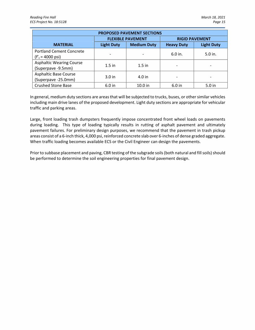
Reading Fire Hall March 18, 2021 ECS Project No. 18:5128 Page 15
PROPOSED PAVEMENT SECTIONS FLEXIBLE PAVEMENT RIGID PAVEMENT
MATERIAL Light Duty Medium Duty Heavy Duty Light Duty Portland Cement Concrete (f’c = 4000 psi) - - 6.0 in. 5.0 in.
Asphaltic Wearing Course (Superpave -9.5mm) 1.5 in 1.5 in - -
Asphaltic Base Course (Superpave -25.0mm) 3.0 in 4.0 in - -
Crushed Stone Base 6.0 in 10.0 in 6.0 in 5.0 in In general, medium duty sections are areas that will be subjected to trucks, buses, or other similar vehicles including main drive lanes of the proposed development. Light duty sections are appropriate for vehicular traffic and parking areas. Large, front loading trash dumpsters frequently impose concentrated front wheel loads on pavements during loading. This type of loading typically results in rutting of asphalt pavement and ultimately pavement failures. For preliminary design purposes, we recommend that the pavement in trash pickup areas consist of a 6-inch thick, 4,000 psi, reinforced concrete slab over 6-inches of dense graded aggregate. When traffic loading becomes available ECS or the Civil Engineer can design the pavements. Prior to subbase placement and paving, CBR testing of the subgrade soils (both natural and fill soils) should be performed to determine the soil engineering properties for final pavement design.
Reading Fire Hall March 18, 2021 ECS Project No. 18:5128 Page 16
5.0 SITE CONSTRUCTION RECOMMENDATIONS
KARST RELATED – GENERAL RISK
If any subsidence features such as sinkholes, surface depressions, and exposed rock pinnacles are encountered, ECS should be consulted to provide a recommendation for repair on a case-by-case basis. Although sinkholes stem from geologic conditions within the underlying rock, they are often triggered by changes in the surface and subsurface drainage patterns. In order to reduce the potential for future sinkhole development which could impact foundation performance, positive surface drainage should be maintained both during and after construction. We recommend that the following preventative measures be followed to reduce the potential inducement of sinkhole formation in proposed development areas and to incorporate good construction practices.
1. Earthwork operations should be graded to drain away from structures at all times. Upon
completion of daily earthwork operations, the ground surface should be sealed by thorough rolling to reduce infiltration of precipitation and facilitate runoff.
2. Sediment control management facilities should be located outside of planned construction areas. Inlets associated with storm drain systems should not be utilized as temporary sediment control devices during construction.
3. During construction, care should be taken to reduce the ponding of surface water in and/or adjacent to the buildings. The foundations should be excavated and poured the same day, if possible, or the founding soils should be provided with a mud mat (lean concrete).
4. Visual observations during all earthwork operations should be carried out in order to detect any previous unexposed or recently created collapse features. Any such feature should be called to ECS’s attention for remedial improvement.
5. Final site grading should include sloping grades and piping of downspouts away from the building.
6. Storm piping should be designed such that joints and structure tie-ins remain watertight with allowance for some settlement. Leaking storm pipes promote subsurface seepage and can instigate sinkhole development in the form of surficial dropouts with little or no warning. It may be beneficial to use bentonite clay around all pipe joints to reduce the potential for long-term leaking.
Areas identified to be suspect during the initial earthwork phase should be further explored during construction to determine the extent, both vertically and horizontally, of possible solution activity. We recommend that all available geotechnical data be made available to ECS during earthwork operations.
STORMWATER CONSTRUCTION RECOMMENDATIONS
It is recommended that verification of the subgrade conditions at the time of construction be conducted by an authorized ECS representative. During excavation of the basin, the materials at the bottom of basin should be verified to be consistent with those encountered in the exploration. Proper performance of infiltration facilities will be influenced
Reading Fire Hall March 18, 2021 ECS Project No. 18:5128 Page 17
by the variability in the subsurface. It will be important that construction equipment does not traffic on the materials at the infiltration bed elevation, and that hand probing on an approximately 25 foot grid or isolated test pits be provided to evaluate proper offset distances from bedrock limiting zones. Stormwater management facilities should generally not be located within 30 feet of a building. If site constraints prohibit this recommendation, the facility may be located closer to a building subject to the review and approval of ECS.
SUBGRADE PREPARATION
5.3.1 Stripping and Grubbing The subgrade preparation should consist of stripping all vegetation, topsoil, unsuitable existing fill, asphalt, and any soft or unsuitable materials from the 10-foot expanded building and 5-foot expanded pavement limits, and 5 feet beyond the toe of Structural Fills. ECS should be retained to verify that existing asphalt and unsuitable surficial materials have been removed prior to the placement of structural fill or construction of structures. 5.3.2 Proofrolling Prior to fill placement or other construction on subgrades, the subgrades should be evaluated by an ECS field technician. The exposed subgrade should be thoroughly proofrolled with construction equipment having a minimum axle load of 10 tons [e.g. fully loaded tandem-axle dump truck]. Proofrolling should be traversed in two perpendicular directions with overlapping passes of the vehicle under the observation of an ECS technician. This procedure is intended to assist in identifying any localized yielding materials. Where proofrolling identifies areas that are unstable or “pumping” subgrade those areas should be repaired prior to the placement of any subsequent Structural Fill or other construction materials. Methods of stabilization include undercutting, moisture conditioning, or chemical stabilization. The situation should be discussed with ECS to determine the appropriate procedure. Test pits may be excavated to explore the shallow subsurface materials to help in determining the cause of the observed unstable materials, and to assist in the evaluation of appropriate remedial actions to stabilize the subgrade.
EARTHWORK OPERATIONS
5.4.1 Existing Man-Placed Fill Fill Content: Generally, up to approximately 6 to 13 feet of existing fill was noted within the proposed building footprint. Footings should not bear in the existing fill without remediation and/or approval of ECS. At location B-04 up to approximately 13 feet of fill was identified, and at B-06, up to approximately 34 feet of fill was encountered during the subsurface exploration. In addition, during excavation of Test Pit IT-01 two below grade walls were encountered. Please refer to Appendix A for approximate location and Appendix B for photos. Due to the presence of fill on-site, select over-excavation of unsuitable fill material should be anticipated at some footing locations, and some locations within the building pad where proofrolling reveals instability. The fill may be able to be reused as structural fill if it is free of organics and deleterious materials, and properly moisture conditioned.
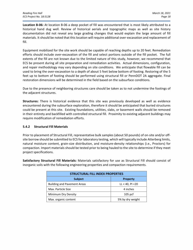
Reading Fire Hall March 18, 2021 ECS Project No. 18:5128 Page 18
Location B-06: At location B-06 a deep pocket of fill was encountered that is most likely attributed to a historical hand dug well. Review of historical aerials and topographic maps as well as site history documentation did not reveal any large grading changes that would explain the large amount of fill materials. It should be noted that this location will require additional over-excavation and replacement of fill. Equipment mobilized for the site work should be capable of reaching depths up to 20 feet. Remediation efforts should include over-excavation of the fill and select portions outside of the fill pocket. The full extents of the fill are not known due to the limited nature of this study, however, we recommend that ECS be present during all site preparation and remediation activities. Actual dimensions, configuration, and repair methodology may vary depending on site conditions. We anticipate that flowable fill can be used to bring the over-excavation to a depth of about 5 feet below bottom of footing. Restoring of the 5 feet up to bottom of footing should be performed using structural fill or PennDOT 2A aggregate. Final restoration dimensions will be determined in the field based on the subsurface conditions. Due to the presence of neighboring structures care should be taken as to not undermine the footings of the adjacent structures. Structures: There is historical evidence that this site was previously developed as well as evidence encountered during the subsurface exploration, therefore it should be anticipated that buried structures could be present at this site. Existing foundations, utilities, slabs, or basement walls should be removed in their entirety and backfilled with controlled structural fill. Proximity to existing adjacent buildings may require modification of remediation efforts. 5.4.2 Structural Fill Materials Prior to placement of Structural Fill, representative bulk samples (about 50 pounds) of on-site and/or off-site borrow should be submitted to ECS for laboratory testing, which will typically include Atterberg limits, natural moisture content, grain-size distribution, and moisture-density relationships (i.e., Proctors) for compaction. Import materials should be tested prior to being hauled to the site to determine if they meet project specifications. Satisfactory Structural Fill Materials: Materials satisfactory for use as Structural Fill should consist of inorganic soils with the following engineering properties and compaction requirements.
STRUCTURAL FILL INDEX PROPERTIES
Subject Property
Building and Pavement Areas LL < 40, PI <20
Max. Particle Size 4 inches
Minimum Dry Density 105 pcf
Max. organic content 5% by dry weight
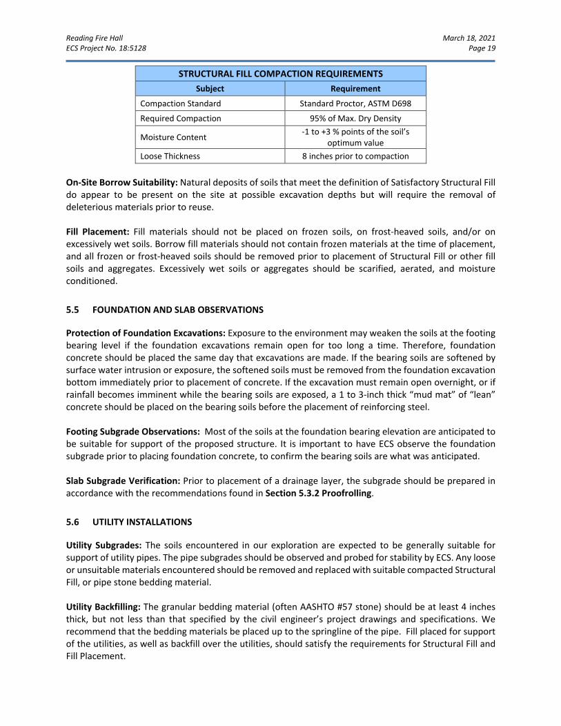
Reading Fire Hall March 18, 2021 ECS Project No. 18:5128 Page 19
STRUCTURAL FILL COMPACTION REQUIREMENTS
Subject Requirement
Compaction Standard Standard Proctor, ASTM D698
Required Compaction 95% of Max. Dry Density
Moisture Content -1 to +3 % points of the soil’s optimum value
Loose Thickness 8 inches prior to compaction
On-Site Borrow Suitability: Natural deposits of soils that meet the definition of Satisfactory Structural Fill do appear to be present on the site at possible excavation depths but will require the removal of deleterious materials prior to reuse. Fill Placement: Fill materials should not be placed on frozen soils, on frost-heaved soils, and/or on excessively wet soils. Borrow fill materials should not contain frozen materials at the time of placement, and all frozen or frost-heaved soils should be removed prior to placement of Structural Fill or other fill soils and aggregates. Excessively wet soils or aggregates should be scarified, aerated, and moisture conditioned.
FOUNDATION AND SLAB OBSERVATIONS
Protection of Foundation Excavations: Exposure to the environment may weaken the soils at the footing bearing level if the foundation excavations remain open for too long a time. Therefore, foundation concrete should be placed the same day that excavations are made. If the bearing soils are softened by surface water intrusion or exposure, the softened soils must be removed from the foundation excavation bottom immediately prior to placement of concrete. If the excavation must remain open overnight, or if rainfall becomes imminent while the bearing soils are exposed, a 1 to 3-inch thick “mud mat” of “lean” concrete should be placed on the bearing soils before the placement of reinforcing steel. Footing Subgrade Observations: Most of the soils at the foundation bearing elevation are anticipated to be suitable for support of the proposed structure. It is important to have ECS observe the foundation subgrade prior to placing foundation concrete, to confirm the bearing soils are what was anticipated. Slab Subgrade Verification: Prior to placement of a drainage layer, the subgrade should be prepared in accordance with the recommendations found in Section 5.3.2 Proofrolling.
UTILITY INSTALLATIONS
Utility Subgrades: The soils encountered in our exploration are expected to be generally suitable for support of utility pipes. The pipe subgrades should be observed and probed for stability by ECS. Any loose or unsuitable materials encountered should be removed and replaced with suitable compacted Structural Fill, or pipe stone bedding material. Utility Backfilling: The granular bedding material (often AASHTO #57 stone) should be at least 4 inches thick, but not less than that specified by the civil engineer’s project drawings and specifications. We recommend that the bedding materials be placed up to the springline of the pipe. Fill placed for support of the utilities, as well as backfill over the utilities, should satisfy the requirements for Structural Fill and Fill Placement.

Reading Fire Hall March 18, 2021 ECS Project No. 18:5128 Page 20
Utility Excavation Dewatering: It is possible that perched water may be encountered by utility excavations which extend below existing grades. It is expected that removal of perched water which seeps into excavations could be accomplished by pumping from sumps excavated in the trench bottom and which are backfilled with AASHTO No. 57 Stone or open graded bedding material. Should water conditions beyond the capability of sump pumping be encountered, the contractor should submit a Dewatering Plan in accordance with project specifications. Excavation Safety: All excavations and slopes should be constructed and maintained in accordance with OSHA excavation safety standards. The contractor is solely responsible for designing, constructing, and maintaining stable temporary excavations and slopes. The contractor’s responsible person, as defined in 29 CFR Part 1926, should evaluate the soil exposed in the excavations as part of the contractor’s safety procedures. In no case should slope height, slope inclination, or excavation depth, including utility trench excavation depth, exceed those specified in local, state, and federal safety regulations. ECS is providing this information solely as a service to our client. ECS is not assuming responsibility for construction site safety or the contractor’s activities; such responsibility is not being implied and should not be inferred.

Reading Fire Hall March 18, 2021 ECS Project No. 18:5128 Page 21
6.0 CLOSING ECS has prepared this report to guide the geotechnical-related design and construction aspects of the project. We performed these services in accordance with the standard of care expected of professionals in the industry performing similar services on projects of like size and complexity at this time in the region. No other representation, expressed or implied, and no warranty or guarantee is included or intended in this report. The description of the proposed project is based on information provided to ECS by the City of Reading, Boyle Construction, Inc., and First Capital Engineering, Inc. If any of this information is inaccurate, either due to our interpretation of the documents provided or if the site’s design changed, ECS should be contacted immediately to review the report in light of the changes and provide additional or alternate recommendations as required to reflect the proposed construction. We recommend that ECS review the project plans and specifications so we can confirm that those plans/specifications are in accordance with the recommendations of this geotechnical report. Field observations, and quality assurance testing during earthwork and foundation installation are an extension of, and integral to, the geotechnical design. We recommend that ECS be retained to apply our expertise throughout the geotechnical phases of construction, and to provide consultation and recommendation should issues arise. ECS is not responsible for the conclusions, opinions, or recommendations of others based on the data in this report.

APPENDIX A – Diagrams & Reports
Site Location Map Exploration Location Plan Geologic Map Karst Features Map Soil Survey Map
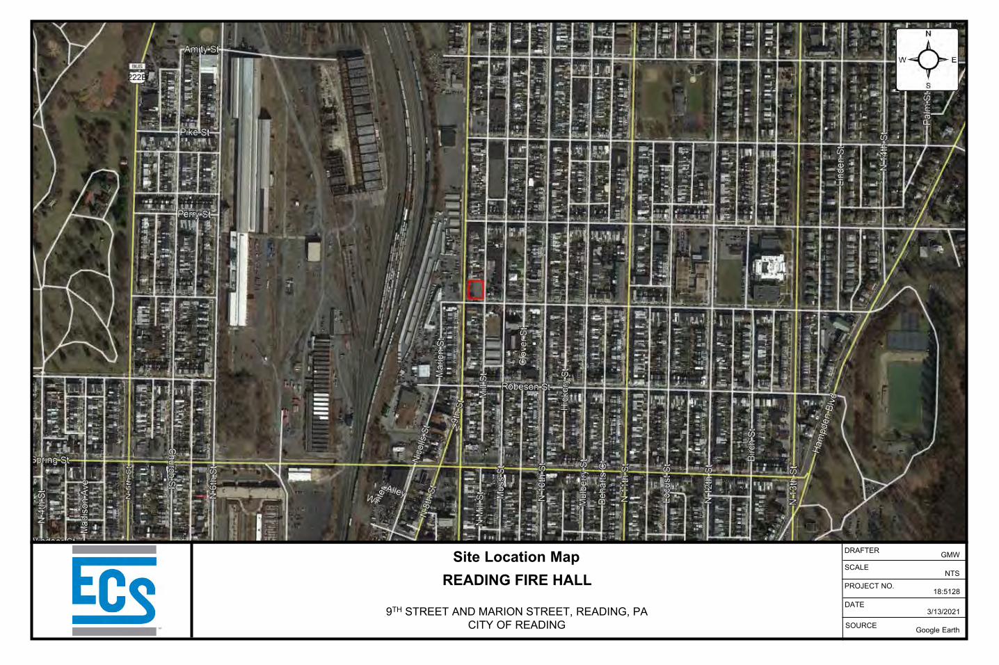
SOURCE
DATE3/13/2021
Google Earth
PROJECT NO.
SCALENTS
DRAFTER
18:5128
GMWSite Location MapREADING FIRE HALL
9TH STREET AND MARION STREET, READING, PACITY OF READING
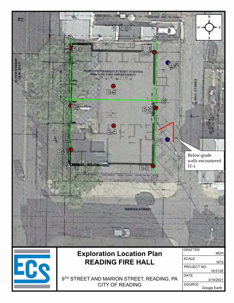
SOURCE
DATE3/14/2021
Google Earth
PROJECT NO.
SCALENTS
18:5128
Exploration Location PlanREADING FIRE HALL
9TH STREET AND MARION STREET, READING, PACITY OF READING
DRAFTERMDH
Below-grade walls encountered IT-1
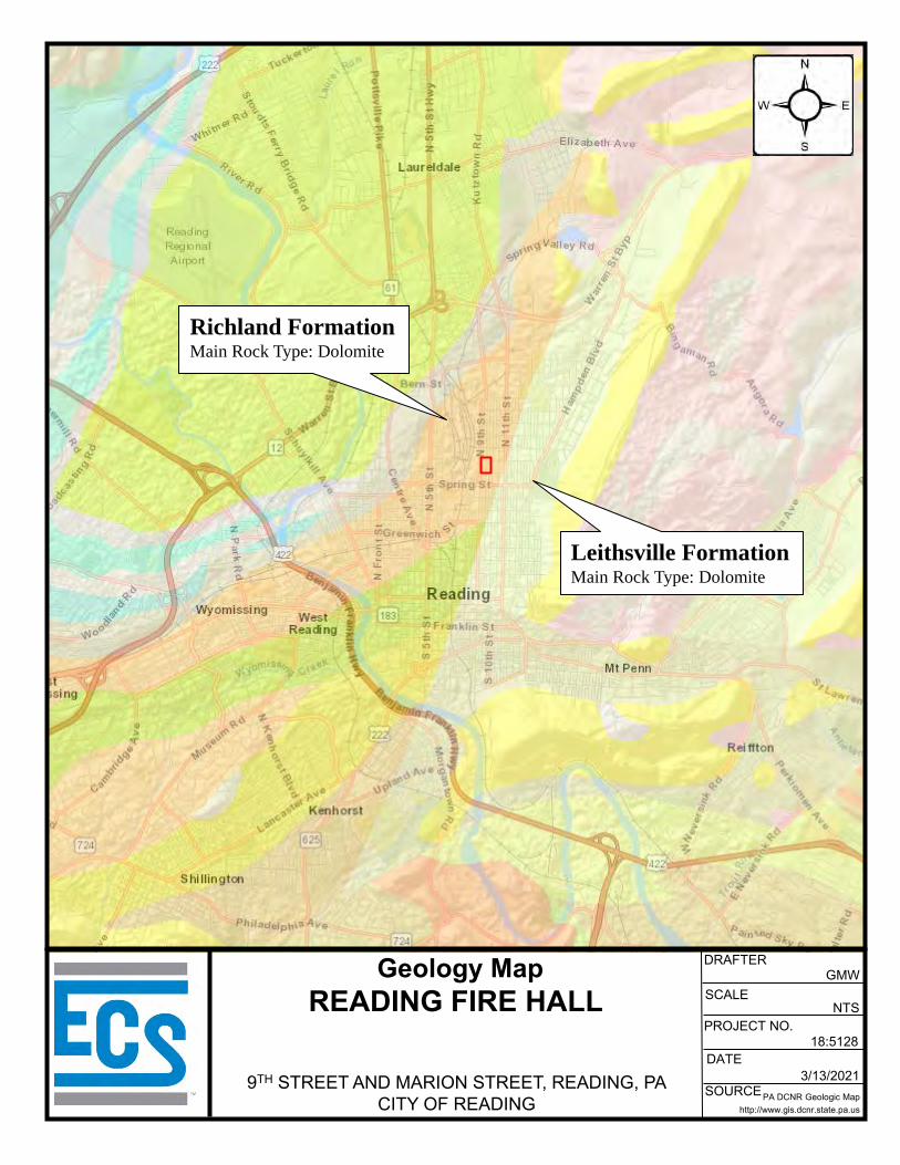
SOURCE
DATE3/13/2021
PA DCNR Geologic Maphttp://www.gis.dcnr.state.pa.us
PROJECT NO.
SCALENTS
18:5128
Geology MapREADING FIRE HALL
9TH STREET AND MARION STREET, READING, PACITY OF READING
DRAFTERGMW
Richland FormationMain Rock Type: Dolomite
Leithsville FormationMain Rock Type: Dolomite
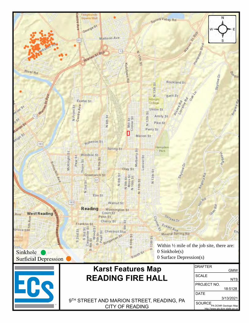
SOURCE
DATE3/13/2021
PA DCNR Geologic Maphttp://www.gis.dcnr.state.pa.us
PROJECT NO.
SCALENTS
18:5128
Karst Features MapREADING FIRE HALL
9TH STREET AND MARION STREET, READING, PACITY OF READING
DRAFTERGMW
Within ½ mile of the job site, there are:0 Sinkhole(s)0 Surface Depression(s)
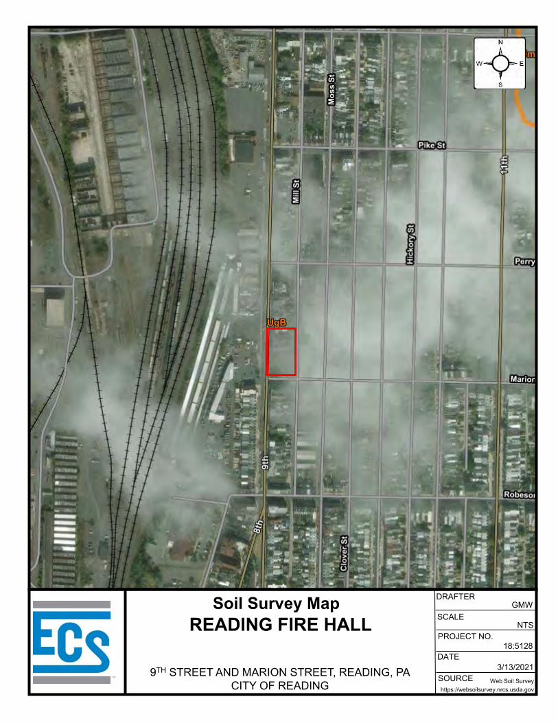
SOURCE
DATE3/13/2021
Web Soil Surveyhttps://websoilsurvey.nrcs.usda.gov
PROJECT NO.
SCALENTS
18:5128
Soil Survey MapREADING FIRE HALL
9TH STREET AND MARION STREET, READING, PACITY OF READING
DRAFTERGMW

APPENDIX B – Field Operations
Reference Notes for Boring Logs Subsurface Exploration Procedure: Standard Penetration Testing (SPT) Boring Logs B-01 through B-08 Test Pit Logs IT-01 and IT-02 Subsurface Soil Profiles A-A’ through C-C’ Infiltration Test Results Test Pit Photographs
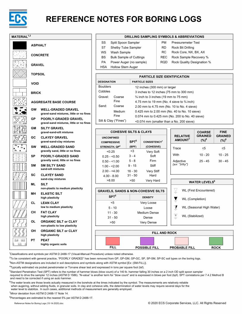
REFERENCE NOTES FOR BORING LOGS
MATERIAL1,2
1Classifications and symbols per ASTM D 2488-17 (Visual-Manual Procedure) unless noted otherwise.2To be consistent with general practice, “POORLY GRADED” has been removed from GP, GP-GM, GP-GC, SP, SP-SM, SP-SC soil types on the boring logs.3Non-ASTM designations are included in soil descriptions and symbols along with ASTM symbol [Ex: (SM-FILL)].4Typically estimated via pocket penetrometer or Torvane shear test and expressed in tons per square foot (tsf).5Standard Penetration Test (SPT) refers to the number of hammer blows (blow count) of a 140 lb. hammer falling 30 inches on a 2 inch OD split spoon samplerrequired to drive the sampler 12 inches (ASTM D 1586). “N-value” is another term for “blow count” and is expressed in blows per foot (bpf). SPT correlations per 7.4.2 Method Band need to be corrected if using an auto hammer.
6The water levels are those levels actually measured in the borehole at the times indicated by the symbol. The measurements are relatively reliablewhen augering, without adding fluids, in granular soils. In clay and cohesive silts, the determination of water levels may require several days for thewater level to stabilize. In such cases, additional methods of measurement are generally employed.
7Minor deviation from ASTM D 2488-17 Note 14.8Percentages are estimated to the nearest 5% per ASTM D 2488-17.
Reference Notes for Boring Logs (10-14-2020).doc © 2020 ECS Corporate Services, LLC. All Rights Reserved
COHESIVE SILTS & CLAYSUNCONFINED
COMPRESSIVE
STRENGTH, QP4
<0.250.25 - <0.500.50 - <1.001.00 - <2.002.00 - <4.004.00 - 8.00
>8.00
SPT5
(BPF)
CONSISTENCY7
(COHESIVE)
GRAVELS, SANDS & NON-COHESIVE SILTSSPT5
DENSITY
<55 - 10
11 - 3031 - 50
>50
Very LooseLoose
Medium DenseDense
Very Dense
WATER LEVELS6
RELATIVEAMOUNT7
Trace
With
Adjective(ex: “Silty”)
COARSEGRAINED
(%)8
<5
FINEGRAINED
(%)8
<5
DRILLING SAMPLING SYMBOLS & ABBREVIATIONS
PARTICLE SIZE IDENTIFICATIONDESIGNATION PARTICLE SIZES
Hollow Stem AugerPower Auger (no sample)Bulk Sample of CuttingsWash SampleShelby Tube SamplerSplit Spoon Sampler
Rock Quality Designation %Rock Sample Recovery %Rock Core, NX, BX, AXRock Bit DrillingPressuremeter TestSS
STWSBSPA
HSARQD
PMRDRC
REC
BouldersCobbles
Gravel:
Sand:
Silt & Clay (“Fines”)FineMedium
CoarseFineCoarse
0.074 mm to 0.425 mm (No. 200 to No. 40 sieve)<0.074 mm (smaller than a No. 200 sieve)
0.425 mm to 2.00 mm (No. 40 to No. 10 sieve)2.00 mm to 4.75 mm (No. 10 to No. 4 sieve)4.75 mm to 19 mm (No. 4 sieve to ¾ inch)¾ inch to 3 inches (19 mm to 75 mm)3 inches to 12 inches (75 mm to 300 mm)12 inches (300 mm) or larger
>5031 - 5016 - 30
9 - 155 - 83 - 4<3
Very HardHard
Very Stiff
StiffFirmSoft
Very Soft
ASPHALT
CONCRETE
GRAVEL
TOPSOIL
VOID
BRICK
AGGREGATE BASE COURSE
GW
GP
GM
GC
SW
SP
SM
SC
ML
MH
CL
CH
OL
OH
PT
WELL-GRADED GRAVELgravel-sand mixtures, little or no fines
POORLY-GRADED GRAVELgravel-sand mixtures, little or no fines
SILTY GRAVELgravel-sand-silt mixtures
CLAYEY GRAVELgravel-sand-clay mixtures
WELL-GRADED SANDgravelly sand, little or no fines
POORLY-GRADED SANDgravelly sand, little or no fines
SM SILTY SANDsand-silt mixtures
CLAYEY SANDsand-clay mixtures
SILTnon-plastic to medium plasticity
ELASTIC SILThigh plasticity
LEAN CLAYlow to medium plasticity
FAT CLAYhigh plasticity
ORGANIC SILT or CLAYnon-plastic to low plasticity
ORGANIC SILT or CLAYhigh plasticity
PEAThighly organic soils
WL (First Encountered)
WL (Completion)
WL (Seasonal High Water)
WL (Stabilized)
FILL POSSIBLE FILL PROBABLE FILL ROCK
FILL AND ROCK
25 - 45
10 - 20
30 - 45
10 - 25

SUBSURFACE EXPLORATION PROCEDURE:
STANDARD PENETRATION TESTING (SPT)
ASTM D 1586
Split-Barrel Sampling
Standard Penetraon Tesng, or SPT, is the most frequently used
subsurface exploraon test performed worldwide. This test provides
samples for idenficaon purposes, as well as a measure of penetraon
resistance, or N-value. The N-Value, or blow counts, when corrected and
correlated, can approximate engineering properes of soils used for
geotechnical design and engineering purposes.
• Involves driving a hollow tube (split-spoon)
into the ground by dropping a 140-lb hammer
a height of 30-inches at desired depth
• Recording the number of hammer blows re-
quired to drive split-spoon a distance of 12
inches (in 3 or 4 Increments of 6 inches each)
• Auger is advanced* and an addional SPT is
performed
• One SPT test is typically performed for every
two to five feet
• Obtain two-inch diameter soil sample
*Drilling Methods May Vary— The predominant drilling
methods used for SPT are open hole fluid rotary drilling and
hollow-stem auger drilling.
SPT Procedure:
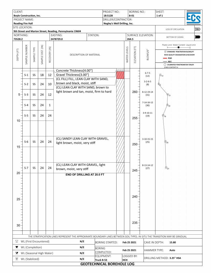
DEPT
H (F
T)
5
10
15
20
25
30
SAM
PLE
NU
MBE
R
S-1
S-2
S-3
S-4
S-5
S-6
S-7
SAM
PLE
TYPE
SS
SS
SS
SS
SS
SS
SS
SAM
PLE
DIST
. (IN
)
18
24
24
24
24
24
24
RECO
VERY
(IN
)
12
10
12
1
24
24
24
DESCRIPTION OF MATERIAL
Concrete Thickness[4.00"]Gravel Thickness[3.00"](CL FILL) FILL, LEAN CLAY WITH SAND, brown and black, moist, s(CL) LEAN CLAY WITH SAND, brown to light brown and tan, moist, rm to hard
(CL) SANDY LEAN CLAY WITH GRAVEL, light brown, moist, very s
(CL) LEAN CLAY WITH GRAVEL, light brown, moist, very s
END OF DRILLING AT 20.0 FT
WAT
ER L
EVEL
S
ELEV
ATIO
N (F
T)
260
255
250
245
240
235
BLO
WS/
6"
6-7-5(12)
3-2-6-5(8)
8-12-19-14(31)
7-14-16-12(30)
3-9-10-11(19)
3-10-15-15(25)
8-13-14-12(27)
Plas c Limit Water Content Liquid LimitX─────────⚫─────────△
12
8
31
30
19
25
27
CLIENT:Boyle Construc on, Inc.PROJECT NAME:Reading Fire Hall
PROJECT NO.: BORING NO.:18:5128 B-01DRILLER/CONTRACTOR:Negley's Well Drilling, Inc.
SHEET:1 of 1
SITE LOCATION:9th Street and Marion Street, Reading, Pennsylvania 19604
LOSS OF CIRCULATION
NORTHING:73528.2
EASTING:2478729.0
STATION: SURFACE ELEVATION:264.5
BOTTOM OF CASING
THE STRATIFICATION LINES REPRESENT THE APPROXIMATE BOUNDARY LINES BETWEEN SOIL TYPES. IN-SITU THE TRANSITION MAY BE GRADUAL
WL (First Encountered)
WL (Comple on)
WL (Seasonal High Water)
WL (Stabilized)
N/E
N/E
N/E
N/E
BORING STARTED:
BORING COMPLETED:EQUIPMENT:Truck B-53
Feb 25 2021
Feb 25 2021
LOGGED BY:HCH
CAVE IN DEPTH:
HAMMER TYPE:
DRILLING METHOD:
15.80
Auto
3.25" HSA
GEOTECHNICAL BOREHOLE LOG
STANDARD PENETRATION BLOWS/FT
ROCK QUALITY DESIGNATION & RECOVERY
RQD
REC
CALIBRATED PENETROMETER TON/SF[FINES CONTENT] %
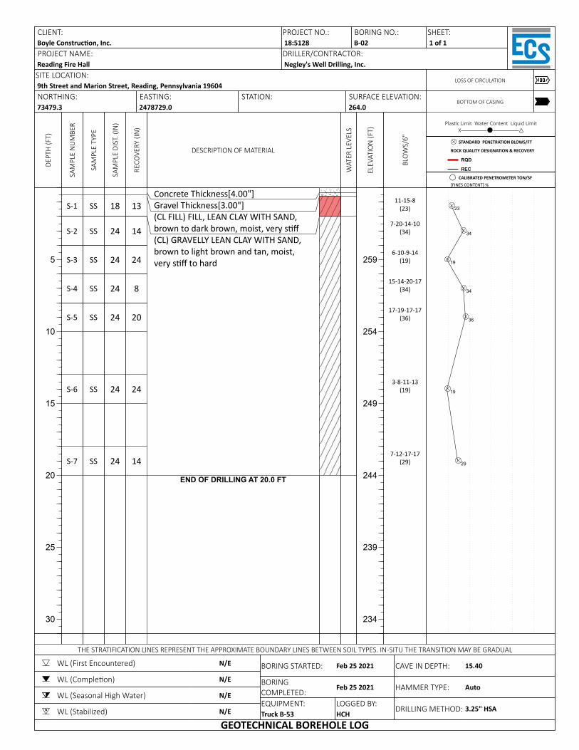
DEPT
H (F
T)
5
10
15
20
25
30
SAM
PLE
NU
MBE
R
S-1
S-2
S-3
S-4
S-5
S-6
S-7
SAM
PLE
TYPE
SS
SS
SS
SS
SS
SS
SS
SAM
PLE
DIST
. (IN
)
18
24
24
24
24
24
24
RECO
VERY
(IN
)
13
14
24
8
20
24
14
DESCRIPTION OF MATERIAL
Concrete Thickness[4.00"]Gravel Thickness[3.00"](CL FILL) FILL, LEAN CLAY WITH SAND, brown to dark brown, moist, very s(CL) GRAVELLY LEAN CLAY WITH SAND, brown to light brown and tan, moist, very s to hard
END OF DRILLING AT 20.0 FT
WAT
ER L
EVEL
S
ELEV
ATIO
N (F
T)
259
254
249
244
239
234
BLO
WS/
6"
11-15-8(23)
7-20-14-10(34)
6-10-9-14(19)
15-14-20-17(34)
17-19-17-17(36)
3-8-11-13(19)
7-12-17-17(29)
Plas c Limit Water Content Liquid LimitX─────────⚫─────────△
23
34
19
34
36
19
29
CLIENT:Boyle Construc on, Inc.PROJECT NAME:Reading Fire Hall
PROJECT NO.: BORING NO.:18:5128 B-02DRILLER/CONTRACTOR:Negley's Well Drilling, Inc.
SHEET:1 of 1
SITE LOCATION:9th Street and Marion Street, Reading, Pennsylvania 19604
LOSS OF CIRCULATION
NORTHING:73479.3
EASTING:2478729.0
STATION: SURFACE ELEVATION:264.0
BOTTOM OF CASING
THE STRATIFICATION LINES REPRESENT THE APPROXIMATE BOUNDARY LINES BETWEEN SOIL TYPES. IN-SITU THE TRANSITION MAY BE GRADUAL
WL (First Encountered)
WL (Comple on)
WL (Seasonal High Water)
WL (Stabilized)
N/E
N/E
N/E
N/E
BORING STARTED:
BORING COMPLETED:EQUIPMENT:Truck B-53
Feb 25 2021
Feb 25 2021
LOGGED BY:HCH
CAVE IN DEPTH:
HAMMER TYPE:
DRILLING METHOD:
15.40
Auto
3.25" HSA
GEOTECHNICAL BOREHOLE LOG
STANDARD PENETRATION BLOWS/FT
ROCK QUALITY DESIGNATION & RECOVERY
RQD
REC
CALIBRATED PENETROMETER TON/SF[FINES CONTENT] %
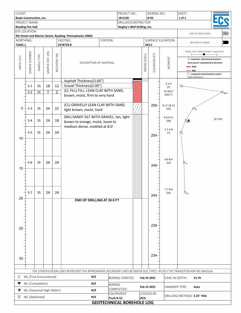
DEPT
H (F
T)
5
10
15
20
25
30
SAM
PLE
NU
MBE
R
S-1
S-2
S-3
S-4
S-5
S-6
S-7
SAM
PLE
TYPE
SS
SS
SS
SS
SS
SS
SS
SAM
PLE
DIST
. (IN
)
187
24
24
24
24
24
RECO
VERY
(IN
)
122
22
18
24
24
24
DESCRIPTION OF MATERIAL
Asphalt Thickness[3.00"]Gravel Thickness[2.00"](CL FILL) FILL, LEAN CLAY WITH SAND, brown, moist, rm to very hard
(CL) GRAVELLY LEAN CLAY WITH SAND, light brown, moist, hard
(ML) SANDY SILT WITH GRAVEL, tan, light brown to orange, moist, loose to medium dense, mo led at 8.0'
END OF DRILLING AT 20.0 FT
WAT
ER L
EVEL
S
ELEV
ATIO
N (F
T)
259
254
249
244
239
234
BLO
WS/
6"
3-3-4(7)
12-50/1"(50/1")
8-17-18-12(35)
6-9-9-11(18)
3-1-6-8(7)
4-6-8-9(14)
7-7-9-8(16)
Plas c Limit Water Content Liquid LimitX─────────⚫─────────△
7
50/1"
35
18
7
14
16
12.7[51.5%]
CLIENT:Boyle Construc on, Inc.PROJECT NAME:Reading Fire Hall
PROJECT NO.: BORING NO.:18:5128 B-03DRILLER/CONTRACTOR:Negley's Well Drilling, Inc.
SHEET:1 of 1
SITE LOCATION:9th Street and Marion Street, Reading, Pennsylvania 19604
LOSS OF CIRCULATION
NORTHING:73442.1
EASTING:2478729.8
STATION: SURFACE ELEVATION:263.5
BOTTOM OF CASING
THE STRATIFICATION LINES REPRESENT THE APPROXIMATE BOUNDARY LINES BETWEEN SOIL TYPES. IN-SITU THE TRANSITION MAY BE GRADUAL
WL (First Encountered)
WL (Comple on)
WL (Seasonal High Water)
WL (Stabilized)
N/E
N/E
N/E
N/E
BORING STARTED:
BORING COMPLETED:EQUIPMENT:Truck B-53
Feb 25 2021
Feb 25 2021
LOGGED BY:HCH
CAVE IN DEPTH:
HAMMER TYPE:
DRILLING METHOD:
15.70
Auto
3.25" HSA
GEOTECHNICAL BOREHOLE LOG
STANDARD PENETRATION BLOWS/FT
ROCK QUALITY DESIGNATION & RECOVERY
RQD
REC
CALIBRATED PENETROMETER TON/SF[FINES CONTENT] %
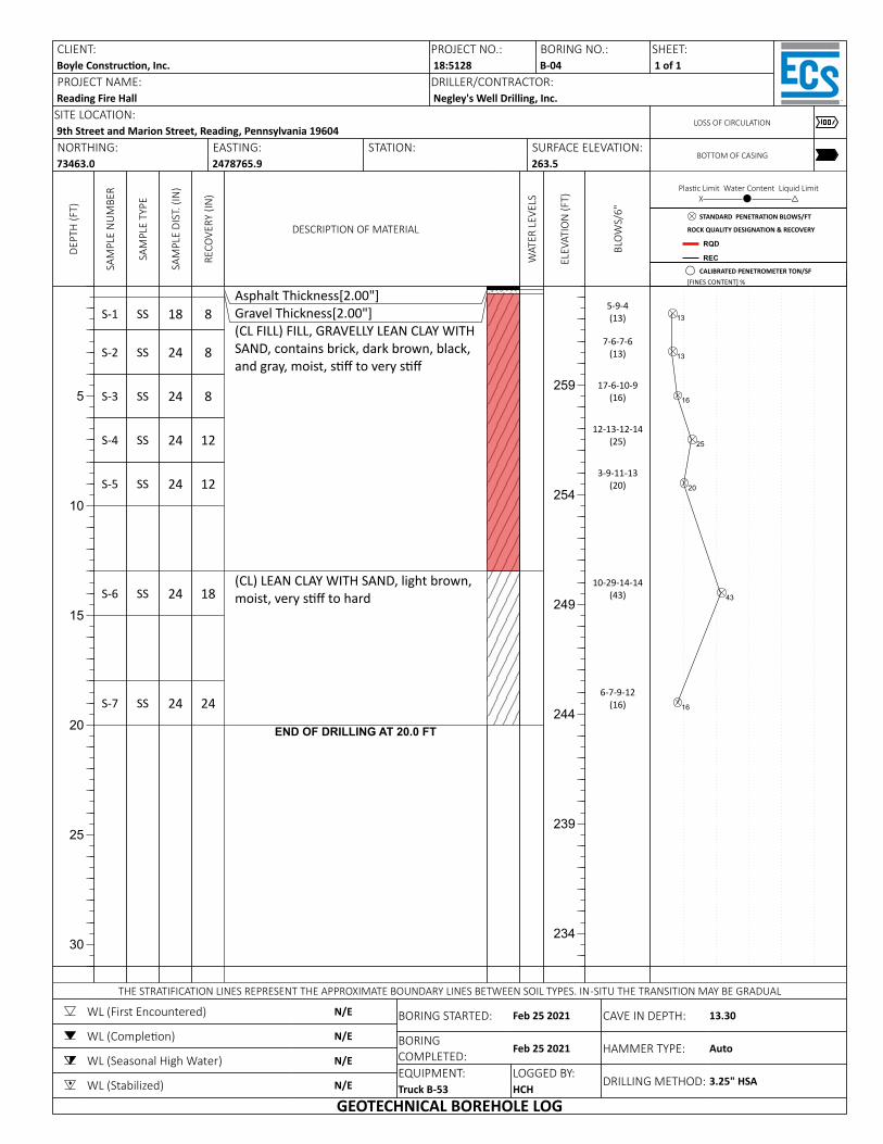
DEPT
H (F
T)
5
10
15
20
25
30
SAM
PLE
NU
MBE
R
S-1
S-2
S-3
S-4
S-5
S-6
S-7
SAM
PLE
TYPE
SS
SS
SS
SS
SS
SS
SS
SAM
PLE
DIST
. (IN
)
18
24
24
24
24
24
24
RECO
VERY
(IN
)
8
8
8
12
12
18
24
DESCRIPTION OF MATERIAL
Asphalt Thickness[2.00"]Gravel Thickness[2.00"](CL FILL) FILL, GRAVELLY LEAN CLAY WITH SAND, contains brick, dark brown, black, and gray, moist, s to very s
(CL) LEAN CLAY WITH SAND, light brown, moist, very s to hard
END OF DRILLING AT 20.0 FT
WAT
ER L
EVEL
S
ELEV
ATIO
N (F
T)
259
254
249
244
239
234
BLO
WS/
6"
5-9-4(13)
7-6-7-6(13)
17-6-10-9(16)
12-13-12-14(25)
3-9-11-13(20)
10-29-14-14(43)
6-7-9-12(16)
Plas c Limit Water Content Liquid LimitX─────────⚫─────────△
13
13
16
25
20
43
16
CLIENT:Boyle Construc on, Inc.PROJECT NAME:Reading Fire Hall
PROJECT NO.: BORING NO.:18:5128 B-04DRILLER/CONTRACTOR:Negley's Well Drilling, Inc.
SHEET:1 of 1
SITE LOCATION:9th Street and Marion Street, Reading, Pennsylvania 19604
LOSS OF CIRCULATION
NORTHING:73463.0
EASTING:2478765.9
STATION: SURFACE ELEVATION:263.5
BOTTOM OF CASING
THE STRATIFICATION LINES REPRESENT THE APPROXIMATE BOUNDARY LINES BETWEEN SOIL TYPES. IN-SITU THE TRANSITION MAY BE GRADUAL
WL (First Encountered)
WL (Comple on)
WL (Seasonal High Water)
WL (Stabilized)
N/E
N/E
N/E
N/E
BORING STARTED:
BORING COMPLETED:EQUIPMENT:Truck B-53
Feb 25 2021
Feb 25 2021
LOGGED BY:HCH
CAVE IN DEPTH:
HAMMER TYPE:
DRILLING METHOD:
13.30
Auto
3.25" HSA
GEOTECHNICAL BOREHOLE LOG
STANDARD PENETRATION BLOWS/FT
ROCK QUALITY DESIGNATION & RECOVERY
RQD
REC
CALIBRATED PENETROMETER TON/SF[FINES CONTENT] %
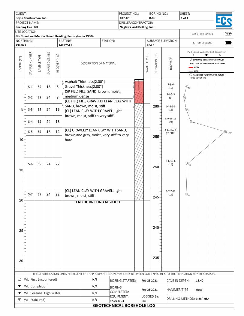
DEPT
H (F
T)
5
10
15
20
25
30
SAM
PLE
NU
MBE
R
S-1
S-2
S-3
S-4
S-5
S-6
S-7
SAM
PLE
TYPE
SS
SS
SS
SS
SS
SS
SS
SAM
PLE
DIST
. (IN
)
18
24
24
24
16
24
24
RECO
VERY
(IN
)
6
8
16
18
12
22
22
DESCRIPTION OF MATERIAL
Asphalt Thickness[2.00"]Gravel Thickness[2.00"](SP FILL) FILL, SAND, brown, moist, medium dense(CL FILL) FILL, GRAVELLY LEAN CLAY WITH SAND, brown, moist, s(CL) LEAN CLAY WITH GRAVEL, light brown, moist, s to very s
(CL) GRAVELLY LEAN CLAY WITH SAND, brown and gray, moist, very s to very hard
(CL) LEAN CLAY WITH GRAVEL, light brown, moist, s
END OF DRILLING AT 20.0 FT
WAT
ER L
EVEL
S
ELEV
ATIO
N (F
T)
260
255
250
245
240
235
BLO
WS/
6"
7-9-6(15)
3-4-5-3(9)
14-8-6-5(14)
8-9-15-16(24)
4-11-50/4"(61/10")
5-6-10-6(16)
9-7-7-12(14)
Plas c Limit Water Content Liquid LimitX─────────⚫─────────△
15
9
14
24
61/10"
16
14
CLIENT:Boyle Construc on, Inc.PROJECT NAME:Reading Fire Hall
PROJECT NO.: BORING NO.:18:5128 B-05DRILLER/CONTRACTOR:Negley's Well Drilling, Inc.
SHEET:1 of 1
SITE LOCATION:9th Street and Marion Street, Reading, Pennsylvania 19604
LOSS OF CIRCULATION
NORTHING:73496.7
EASTING:2478764.9
STATION: SURFACE ELEVATION:264.5
BOTTOM OF CASING
THE STRATIFICATION LINES REPRESENT THE APPROXIMATE BOUNDARY LINES BETWEEN SOIL TYPES. IN-SITU THE TRANSITION MAY BE GRADUAL
WL (First Encountered)
WL (Comple on)
WL (Seasonal High Water)
WL (Stabilized)
N/E
N/E
N/E
N/E
BORING STARTED:
BORING COMPLETED:EQUIPMENT:Truck B-53
Feb 25 2021
Feb 25 2021
LOGGED BY:HCH
CAVE IN DEPTH:
HAMMER TYPE:
DRILLING METHOD:
16.40
Auto
3.25" HSA
GEOTECHNICAL BOREHOLE LOG
STANDARD PENETRATION BLOWS/FT
ROCK QUALITY DESIGNATION & RECOVERY
RQD
REC
CALIBRATED PENETROMETER TON/SF[FINES CONTENT] %
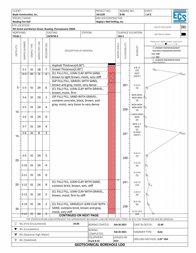
DEPT
H (F
T)
5
10
15
20
25
30
SAM
PLE
NU
MBE
R
S-1S-2
S-3
S-4
S-5
S-6
S-7
S-8
S-9
S-10
S-11
S-12
S-13
S-14
S-15
SAM
PLE
TYPE
SSSS
SS
SS
SS
SS
SS
SS
SS
SS
SS
SS
SS
SS
SS
SAM
PLE
DIST
. (IN
)
183
24
24
24
24
24
8
24
24
24
24
24
24
24
RECO
VERY
(IN
)
72
6
1
4
0
4
3
5
4
0
9
2
2
3
DESCRIPTION OF MATERIAL
Asphalt Thickness[4.00"]Gravel Thickness[2.00"](CL FILL) FILL, LEAN CLAY WITH SAND, brown to light brown, moist, very s(GP FILL) FILL, GRAVEL WITH SAND, brown and gray, moist, very dense(CL FILL) FILL, LEAN CLAY WITH GRAVEL, brown, moist, rm(SP FILL) FILL, SAND WITH GRAVEL, contains concrete, black, brown, and gray, moist, very loose to very dense
(CL FILL) FILL, LEAN CLAY WITH SAND, contains brick, brown, wet, s
(CL FILL) FILL, LEAN CLAY WITH GRAVEL, brown, moist, rm to s
(CL FILL) FILL, GRAVELLY LEAN CLAY WITH SAND, contains brick, brown and gray, moist, very s
CONTINUED ON NEXT PAGE
WAT
ER L
EVEL
S
ELEV
ATIO
N (F
T)
261
256
251
246
241
236
BLO
WS/
6"
6-8-17(25)
50/3"(50/3")
2-3-2-1(5)
WOH-WOH-WOH-WOH
(0)
WOH-WOH-WOH-WOH
(0)
1-WOH-WOH-WOH
(0)
WOH-1-1-WOH
(2)13-50/2"(50/2")
3-4-1-1(5)
1-2-2-3(4)
2-1-4-3(5)
1-6-7-2(13)
1-4-2-2(6)
8-2-7-8(9)
12-11-13-2(24)
Plas c Limit Water Content Liquid LimitX─────────⚫─────────△
25
50/3"
5
0
0
0
2
50/2"
5
4
5
13
6
9
CLIENT:Boyle Construc on, Inc.PROJECT NAME:Reading Fire Hall
PROJECT NO.: BORING NO.:18:5128 B-06DRILLER/CONTRACTOR:Negley's Well Drilling, Inc.
SHEET:1 of 2
SITE LOCATION:9th Street and Marion Street, Reading, Pennsylvania 19604
LOSS OF CIRCULATION
NORTHING:73526.1
EASTING:2478799.3
STATION: SURFACE ELEVATION:265.5
BOTTOM OF CASING
THE STRATIFICATION LINES REPRESENT THE APPROXIMATE BOUNDARY LINES BETWEEN SOIL TYPES. IN-SITU THE TRANSITION MAY BE GRADUAL
WL (First Encountered)
WL (Comple on)
WL (Seasonal High Water)
WL (Stabilized)
24.00 BORING STARTED:
BORING COMPLETED:EQUIPMENT:Truck B-53
Feb 26 2021
Feb 26 2021
LOGGED BY:HCH
CAVE IN DEPTH:
HAMMER TYPE:
DRILLING METHOD:
12.40
Auto
3.25" HSA
GEOTECHNICAL BOREHOLE LOG
STANDARD PENETRATION BLOWS/FT
ROCK QUALITY DESIGNATION & RECOVERY
RQD
REC
CALIBRATED PENETROMETER TON/SF[FINES CONTENT] %
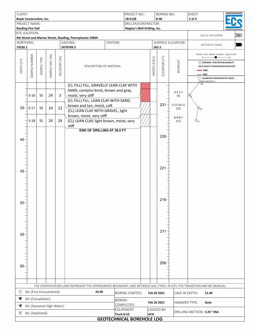
DEPT
H (F
T)
35
40
45
50
55
60
SAM
PLE
NU
MBE
R
S-16
S-17
S-18
SAM
PLE
TYPE
SS
SS
SS
SAM
PLE
DIST
. (IN
)
24
24
24
RECO
VERY
(IN
)
3
22
24
DESCRIPTION OF MATERIAL
(CL FILL) FILL, GRAVELLY LEAN CLAY WITH SAND, contains brick, brown and gray, moist, very s(CL FILL) FILL, LEAN CLAY WITH SAND, brown and tan, moist, so(CL) LEAN CLAY WITH GRAVEL, light brown, moist, very s(CL) LEAN CLAY, light brown, moist, very s
END OF DRILLING AT 38.0 FT
WAT
ER L
EVEL
S
ELEV
ATIO
N (F
T)
231
226
221
216
211
206
BLO
WS/
6"
4-2-1-1(3)
3-12-10-11(22)
8-9-8-7(17)
Plas c Limit Water Content Liquid LimitX─────────⚫─────────△
24
3
22
17
CLIENT:Boyle Construc on, Inc.PROJECT NAME:Reading Fire Hall
PROJECT NO.: BORING NO.:18:5128 B-06DRILLER/CONTRACTOR:Negley's Well Drilling, Inc.
SHEET:2 of 2
SITE LOCATION:9th Street and Marion Street, Reading, Pennsylvania 19604
LOSS OF CIRCULATION
NORTHING:73526.1
EASTING:2478799.3
STATION: SURFACE ELEVATION:265.5
BOTTOM OF CASING
THE STRATIFICATION LINES REPRESENT THE APPROXIMATE BOUNDARY LINES BETWEEN SOIL TYPES. IN-SITU THE TRANSITION MAY BE GRADUAL
WL (First Encountered)
WL (Comple on)
WL (Seasonal High Water)
WL (Stabilized)
24.00 BORING STARTED:
BORING COMPLETED:EQUIPMENT:Truck B-53
Feb 26 2021
Feb 26 2021
LOGGED BY:HCH
CAVE IN DEPTH:
HAMMER TYPE:
DRILLING METHOD:
12.40
Auto
3.25" HSA
GEOTECHNICAL BOREHOLE LOG
STANDARD PENETRATION BLOWS/FT
ROCK QUALITY DESIGNATION & RECOVERY
RQD
REC
CALIBRATED PENETROMETER TON/SF[FINES CONTENT] %
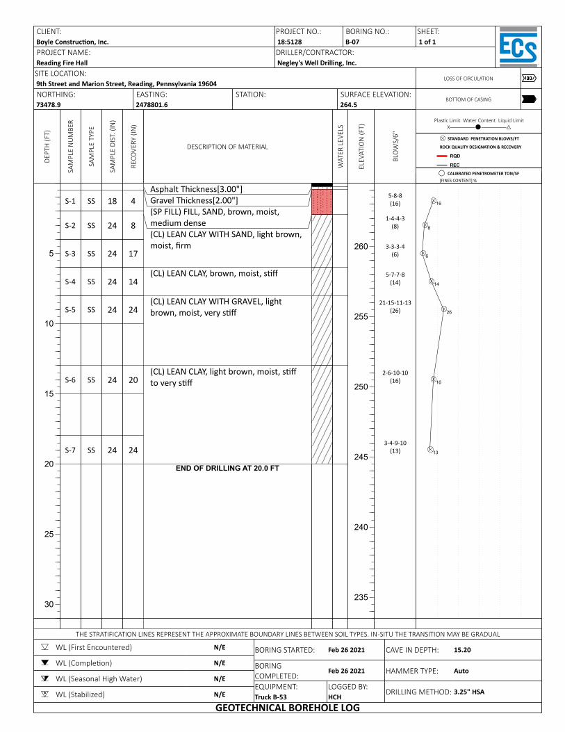
DEPT
H (F
T)
5
10
15
20
25
30
SAM
PLE
NU
MBE
R
S-1
S-2
S-3
S-4
S-5
S-6
S-7
SAM
PLE
TYPE
SS
SS
SS
SS
SS
SS
SS
SAM
PLE
DIST
. (IN
)
18
24
24
24
24
24
24
RECO
VERY
(IN
)
4
8
17
14
24
20
24
DESCRIPTION OF MATERIAL
Asphalt Thickness[3.00"]Gravel Thickness[2.00"](SP FILL) FILL, SAND, brown, moist, medium dense(CL) LEAN CLAY WITH SAND, light brown, moist, rm
(CL) LEAN CLAY, brown, moist, s
(CL) LEAN CLAY WITH GRAVEL, light brown, moist, very s
(CL) LEAN CLAY, light brown, moist, s to very s
END OF DRILLING AT 20.0 FT
WAT
ER L
EVEL
S
ELEV
ATIO
N (F
T)
260
255
250
245
240
235
BLO
WS/
6"
5-8-8(16)
1-4-4-3(8)
3-3-3-4(6)
5-7-7-8(14)
21-15-11-13(26)
2-6-10-10(16)
3-4-9-10(13)
Plas c Limit Water Content Liquid LimitX─────────⚫─────────△
16
8
6
14
26
16
13
CLIENT:Boyle Construc on, Inc.PROJECT NAME:Reading Fire Hall
PROJECT NO.: BORING NO.:18:5128 B-07DRILLER/CONTRACTOR:Negley's Well Drilling, Inc.
SHEET:1 of 1
SITE LOCATION:9th Street and Marion Street, Reading, Pennsylvania 19604
LOSS OF CIRCULATION
NORTHING:73478.9
EASTING:2478801.6
STATION: SURFACE ELEVATION:264.5
BOTTOM OF CASING
THE STRATIFICATION LINES REPRESENT THE APPROXIMATE BOUNDARY LINES BETWEEN SOIL TYPES. IN-SITU THE TRANSITION MAY BE GRADUAL
WL (First Encountered)
WL (Comple on)
WL (Seasonal High Water)
WL (Stabilized)
N/E
N/E
N/E
N/E
BORING STARTED:
BORING COMPLETED:EQUIPMENT:Truck B-53
Feb 26 2021
Feb 26 2021
LOGGED BY:HCH
CAVE IN DEPTH:
HAMMER TYPE:
DRILLING METHOD:
15.20
Auto
3.25" HSA
GEOTECHNICAL BOREHOLE LOG
STANDARD PENETRATION BLOWS/FT
ROCK QUALITY DESIGNATION & RECOVERY
RQD
REC
CALIBRATED PENETROMETER TON/SF[FINES CONTENT] %
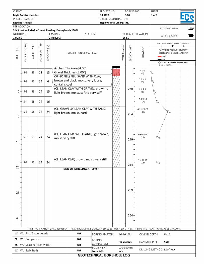
DEPT
H (F
T)
5
10
15
20
25
30
SAM
PLE
NU
MBE
R
S-1
S-2
S-3
S-4
S-5
S-6
S-7
SAM
PLE
TYPE
SS
SS
SS
SS
SS
SS
SS
SAM
PLE
DIST
. (IN
)
18
24
24
24
24
24
24
RECO
VERY
(IN
)
13
6
15
16
24
24
24
DESCRIPTION OF MATERIAL
Asphalt Thickness[4.00"]Gravel Thickness[3.00"](SP-SC FILL) FILL, SAND WITH CLAY, brown and black, moist, very loose, contains coal(CL) LEAN CLAY WITH GRAVEL, brown to light brown, moist, so to very s
(CL) GRAVELLY LEAN CLAY WITH SAND, light brown, moist, hard
(CL) LEAN CLAY WITH SAND, light brown, moist, very s
(CL) LEAN CLAY, brown, moist, very s
END OF DRILLING AT 20.0 FT
WAT
ER L
EVEL
S
ELEV
ATIO
N (F
T)
259
254
249
244
239
234
BLO
WS/
6"
4-1-1(2)
4-1-3-3(4)
3-3-6-6(9)
7-8-9-10(17)
4-21-25-22(46)
8-8-10-10(18)
4-7-11-16(18)
Plas c Limit Water Content Liquid LimitX─────────⚫─────────△
2
4
9
17
46
18
18
CLIENT:Boyle Construc on, Inc.PROJECT NAME:Reading Fire Hall
PROJECT NO.: BORING NO.:18:5128 B-08DRILLER/CONTRACTOR:Negley's Well Drilling, Inc.
SHEET:1 of 1
SITE LOCATION:9th Street and Marion Street, Reading, Pennsylvania 19604
LOSS OF CIRCULATION
NORTHING:73429.6
EASTING:2478800.2
STATION: SURFACE ELEVATION:263.5
BOTTOM OF CASING
THE STRATIFICATION LINES REPRESENT THE APPROXIMATE BOUNDARY LINES BETWEEN SOIL TYPES. IN-SITU THE TRANSITION MAY BE GRADUAL
WL (First Encountered)
WL (Comple on)
WL (Seasonal High Water)
WL (Stabilized)
N/E
N/E
N/E
N/E
BORING STARTED:
BORING COMPLETED:EQUIPMENT:Truck B-53
Feb 26 2021
Feb 26 2021
LOGGED BY:HCH
CAVE IN DEPTH:
HAMMER TYPE:
DRILLING METHOD:
15.10
Auto
3.25" HSA
GEOTECHNICAL BOREHOLE LOG
STANDARD PENETRATION BLOWS/FT
ROCK QUALITY DESIGNATION & RECOVERY
RQD
REC
CALIBRATED PENETROMETER TON/SF[FINES CONTENT] %
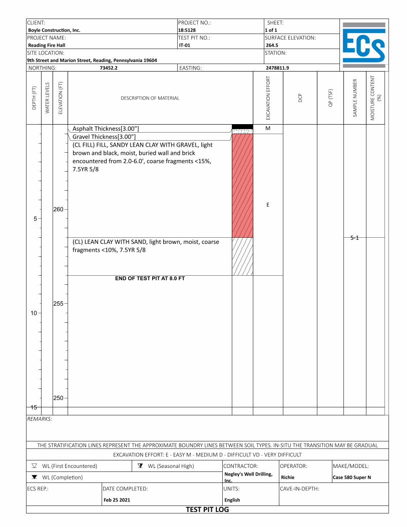
DEPT
H (F
T)
5
10
15
WAT
ER L
EVEL
S
ELEV
ATIO
N (F
T)
260
255
250
DESCRIPTION OF MATERIAL
Asphalt Thickness[3.00"]Gravel Thickness[3.00"](CL FILL) FILL, SANDY LEAN CLAY WITH GRAVEL, light brown and black, moist, buried wall and brick encountered from 2.0-6.0', coarse fragments <15%, 7.5YR 5/8
(CL) LEAN CLAY WITH SAND, light brown, moist, coarse fragments <10%, 7.5YR 5/8
END OF TEST PIT AT 8.0 FT
EXCA
VATI
ON
EFF
ORT
M
E
DCP
QP
(TSF
)
SAM
PLE
NU
MBE
R
S-1
MO
ISTU
RE C
ON
TEN
T (%
)
CLIENT: PROJECT NO.:Boyle Construc on, Inc. 18:5128PROJECT NAME: TEST PIT NO.:Reading Fire Hall IT-01SITE LOCATION:9th Street and Marion Street, Reading, Pennsylvania 19604NORTHING: 73452.2 EASTING:
SHEET:1 of 1SURFACE ELEVATION:264.5STATION:
2478811.9
REMARKS:
THE STRATIFICATION LINES REPRESENT THE APPROXIMATE BOUNDRY LINES BETWEEN SOIL TYPES. IN-SITU THE TRANSITION MAY BE GRADUAL
EXCAVATION EFFORT: E - EASY M - MEDIUM D - DIFFICULT VD - VERY DIFFICULT
WL (First Encountered) WL (Seasonal High) CONTRACTOR: OPERATOR: MAKE/MODEL:
WL (Comple on) Negley's Well Drilling, Inc. Richie Case 580 Super N
ECS REP.: DATE COMPLETED: UNITS: CAVE-IN-DEPTH:
Feb 25 2021 English
TEST PIT LOG
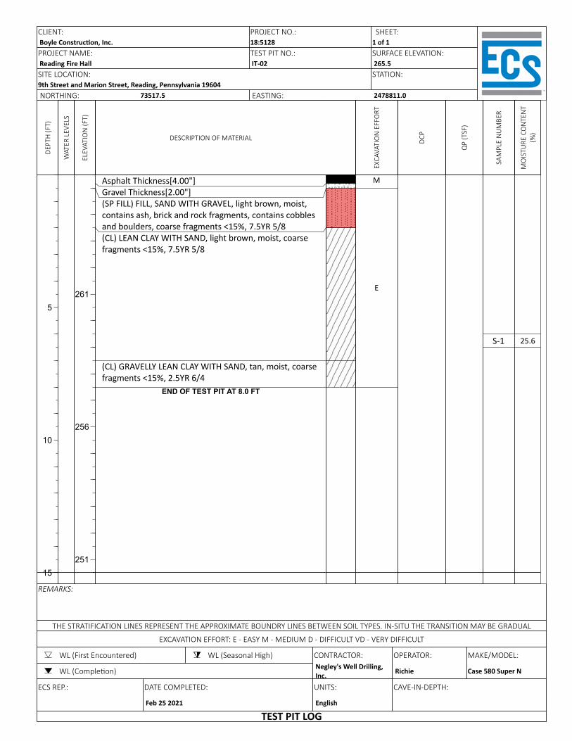
DEPT
H (F
T)
5
10
15
WAT
ER L
EVEL
S
ELEV
ATIO
N (F
T)
261
256
251
DESCRIPTION OF MATERIAL
Asphalt Thickness[4.00"]Gravel Thickness[2.00"](SP FILL) FILL, SAND WITH GRAVEL, light brown, moist, contains ash, brick and rock fragments, contains cobbles and boulders, coarse fragments <15%, 7.5YR 5/8(CL) LEAN CLAY WITH SAND, light brown, moist, coarse fragments <15%, 7.5YR 5/8
(CL) GRAVELLY LEAN CLAY WITH SAND, tan, moist, coarse fragments <15%, 2.5YR 6/4
END OF TEST PIT AT 8.0 FT
EXCA
VATI
ON
EFF
ORT
M
E
DCP
QP
(TSF
)
SAM
PLE
NU
MBE
R
S-1
MO
ISTU
RE C
ON
TEN
T (%
)
25.6
CLIENT: PROJECT NO.:Boyle Construc on, Inc. 18:5128PROJECT NAME: TEST PIT NO.:Reading Fire Hall IT-02SITE LOCATION:9th Street and Marion Street, Reading, Pennsylvania 19604NORTHING: 73517.5 EASTING:
SHEET:1 of 1SURFACE ELEVATION:265.5STATION:
2478811.0
REMARKS:
THE STRATIFICATION LINES REPRESENT THE APPROXIMATE BOUNDRY LINES BETWEEN SOIL TYPES. IN-SITU THE TRANSITION MAY BE GRADUAL
EXCAVATION EFFORT: E - EASY M - MEDIUM D - DIFFICULT VD - VERY DIFFICULT
WL (First Encountered) WL (Seasonal High) CONTRACTOR: OPERATOR: MAKE/MODEL:
WL (Comple on) Negley's Well Drilling, Inc. Richie Case 580 Super N
ECS REP.: DATE COMPLETED: UNITS: CAVE-IN-DEPTH:
Feb 25 2021 English
TEST PIT LOG
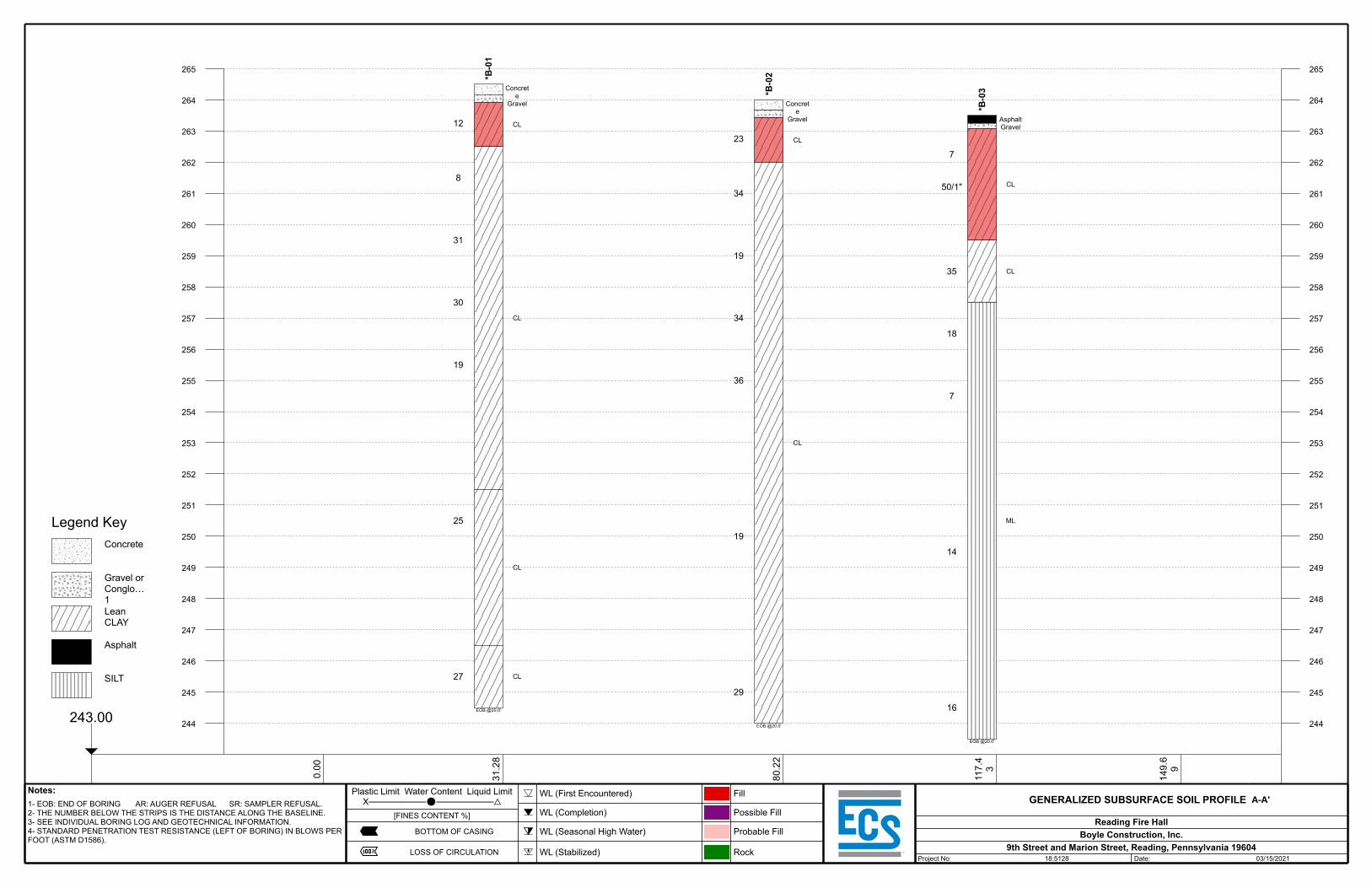
265 265
264 264
263 263
262 262
261 261
260 260
259 259
258 258
257 257
256 256
255 255
254 254
253 253
252 252
251 251
250 250
249 249
248 248
247 247
246 246
245 245
244 244
0.00
31.2
8
80.2
2
117.
43
149.
69
243.00
Legend KeyConcrete
Gravel or Conglo…1Lean CLAY
Asphalt
SILT
Notes:1- EOB: END OF BORING AR: AUGER REFUSAL SR: SAMPLER REFUSAL.2- THE NUMBER BELOW THE STRIPS IS THE DISTANCE ALONG THE BASELINE.3- SEE INDIVIDUAL BORING LOG AND GEOTECHNICAL INFORMATION.4- STANDARD PENETRATION TEST RESISTANCE (LEFT OF BORING) IN BLOWS PER FOOT (ASTM D1586).
Plastic Limit Water Content Liquid LimitX─────────⚫─────────△
[FINES CONTENT %]
BOTTOM OF CASING
LOSS OF CIRCULATION
WL (First Encountered)
WL (Completion)
WL (Seasonal High Water)
WL (Stabilized)
Fill
Possible Fill
Probable Fill
Rock
GENERALIZED SUBSURFACE SOIL PROFILE A-A'
Reading Fire HallBoyle Construction, Inc.
9th Street and Marion Street, Reading, Pennsylvania 19604Project No: 18:5128 Date: 03/15/2021
12
8
31
30
19
25
27
*B-0
1
EOB @20.0'
Concrete
Gravel
CL
CL
CL
CL
23
34
19
34
36
19
29
*B-0
2
EOB @20.0'
Concrete
Gravel
CL
CL
7
50/1"
35
18
7
14
16
*B-0
3
EOB @20.0'
AsphaltGravel
CL
CL
ML

266 266
265 265
264 264
263 263
262 262
261 261
260 260
259 259
258 258
257 257
256 256
255 255
254 254
253 253
252 252
251 251
250 250
249 249
248 248
247 247
246 246
245 245
244 244
243 243
242 242
241 241
240 240
239 239
238 238
237 237
236 236
235 235
234 234
233 233
232 232
231 231
230 230
229 229
228 228
0.00
34.2
0
43.1
2
62.6
9
81.4
1
96.4
2
108.
36
130.
63
154.
91
227.00
Legend KeyAsphalt
Gravel or Conglo…1Lean CLAY
Poorly Graded SANDPoorly Graded GRAVELPoorly Graded SAND w…
Notes:1- EOB: END OF BORING AR: AUGER REFUSAL SR: SAMPLER REFUSAL.2- THE NUMBER BELOW THE STRIPS IS THE DISTANCE ALONG THE BASELINE.3- SEE INDIVIDUAL BORING LOG AND GEOTECHNICAL INFORMATION.4- STANDARD PENETRATION TEST RESISTANCE (LEFT OF BORING) IN BLOWS PER FOOT (ASTM D1586).
Plastic Limit Water Content Liquid LimitX─────────⚫─────────△
[FINES CONTENT %]
BOTTOM OF CASING
LOSS OF CIRCULATION
WL (First Encountered)
WL (Completion)
WL (Seasonal High Water)
WL (Stabilized)
Fill
Possible Fill
Probable Fill
Rock
GENERALIZED SUBSURFACE SOIL PROFILE B-B'
Reading Fire HallBoyle Construction, Inc.
9th Street and Marion Street, Reading, Pennsylvania 19604Project No: 18:5128 Date: 03/15/2021
25
50/3"
5
0
0
0
2
50/2"
5
4
5
13
6
9
24
3
22
17
*B-0
6
EOB @38.0'
AsphaltGravel
CL
GP
CL
SP
CL
CL
CL
CL
CL
CL
*IT-0
2
EOB @8.0'
AsphaltGravel
SP
CL
CL
15
9
14
24
61/10"
16
14
*B-0
5
EOB @20.0'
AsphaltGravel
SP
CL
CL
CL
CL
16
8
6
14
26
16
13
*B-0
7
EOB @20.0'
AsphaltGravel
SP
CL
CL
CL
CL
13
13
16
25
20
43
16
*B-0
4
EOB @20.0'
AsphaltGravel
CL
CL
*IT-0
1
EOB @8.0'
AsphaltGravel
CL
CL
2
4
9
17
46
18
18
*B-0
8
EOB @20.0'
AsphaltGravelSP-SC
CL
CL
CL
CL
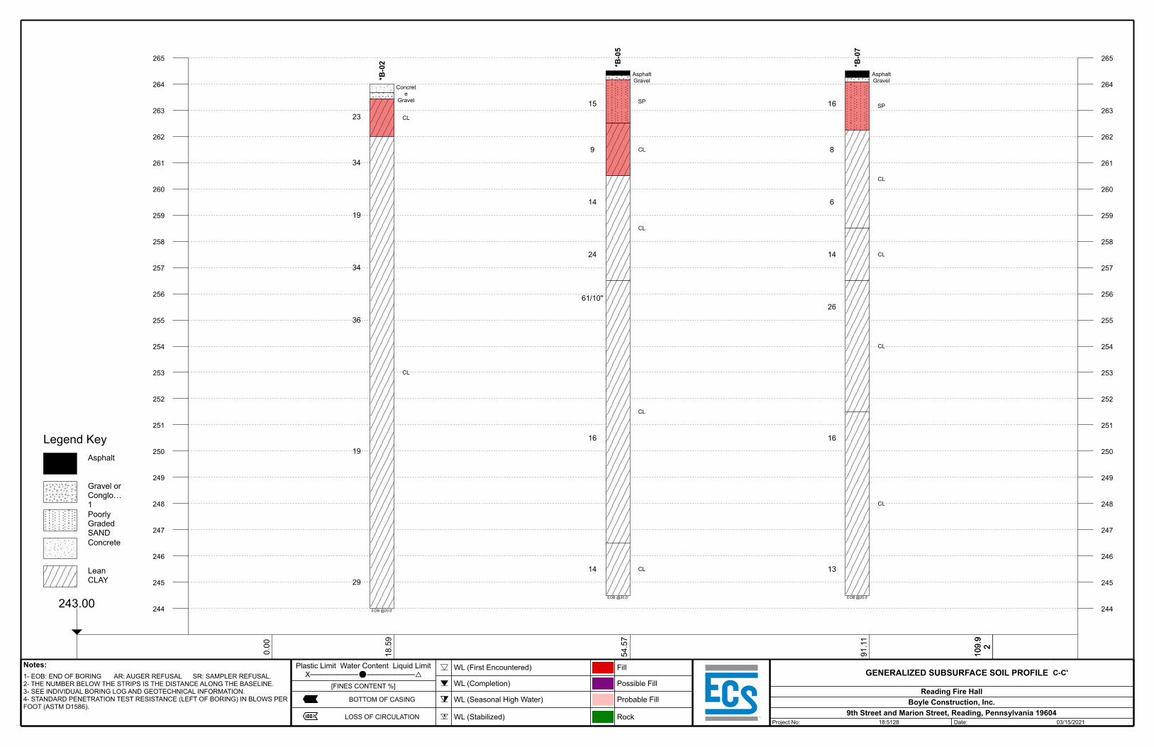
265 265
264 264
263 263
262 262
261 261
260 260
259 259
258 258
257 257
256 256
255 255
254 254
253 253
252 252
251 251
250 250
249 249
248 248
247 247
246 246
245 245
244 244
0.00
18.5
9
54.5
7
91.1
1
109.
92
109.
92
243.00
Legend KeyAsphalt
Gravel or Conglo…1Poorly Graded SANDConcrete
Lean CLAY
Notes:1- EOB: END OF BORING AR: AUGER REFUSAL SR: SAMPLER REFUSAL.2- THE NUMBER BELOW THE STRIPS IS THE DISTANCE ALONG THE BASELINE.3- SEE INDIVIDUAL BORING LOG AND GEOTECHNICAL INFORMATION.4- STANDARD PENETRATION TEST RESISTANCE (LEFT OF BORING) IN BLOWS PER FOOT (ASTM D1586).
Plastic Limit Water Content Liquid LimitX─────────⚫─────────△
[FINES CONTENT %]
BOTTOM OF CASING
LOSS OF CIRCULATION
WL (First Encountered)
WL (Completion)
WL (Seasonal High Water)
WL (Stabilized)
Fill
Possible Fill
Probable Fill
Rock
GENERALIZED SUBSURFACE SOIL PROFILE C-C'
Reading Fire HallBoyle Construction, Inc.
9th Street and Marion Street, Reading, Pennsylvania 19604Project No: 18:5128 Date: 03/15/2021
23
34
19
34
36
19
29
*B-0
2
EOB @20.0'
Concrete
Gravel
CL
CL
15
9
14
24
61/10"
16
14
*B-0
5
EOB @20.0'
AsphaltGravel
SP
CL
CL
CL
CL
16
8
6
14
26
16
13
*B-0
7
EOB @20.0'
AsphaltGravel
SP
CL
CL
CL
CL
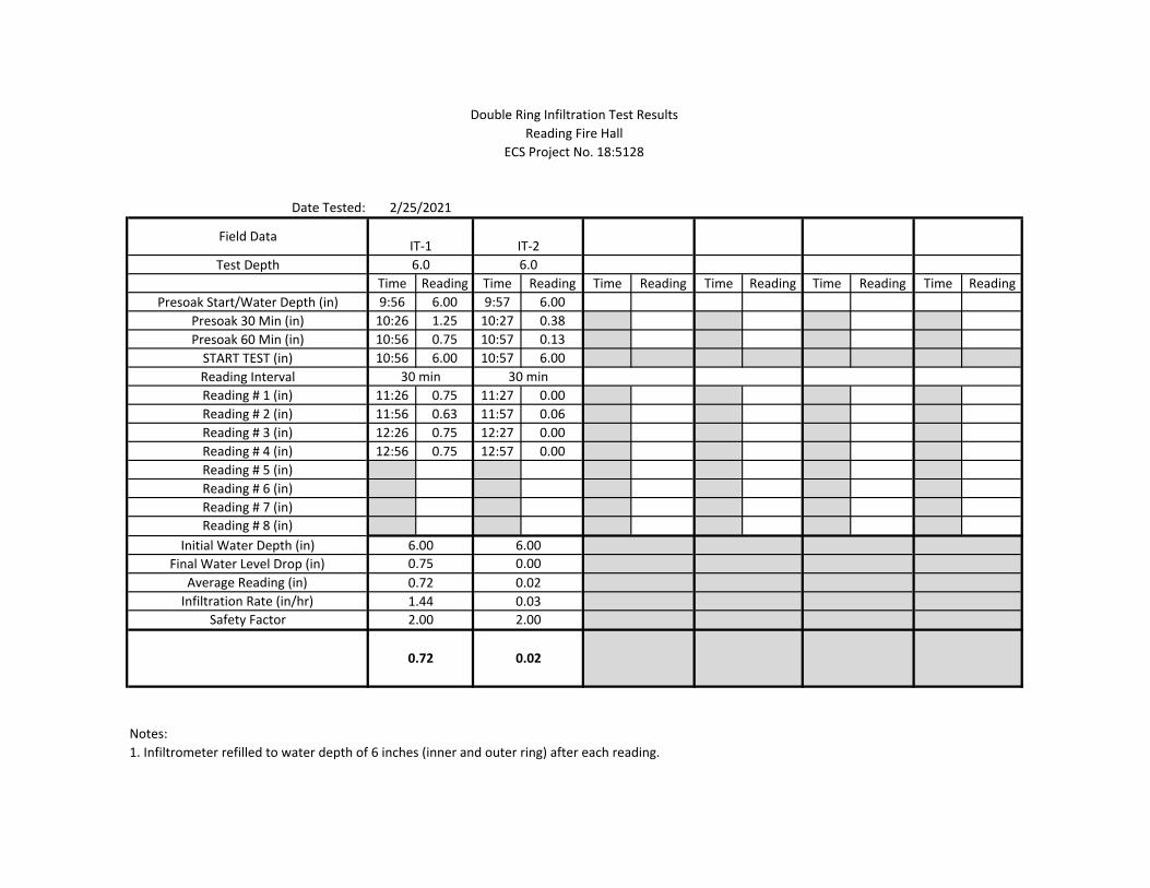
Date Tested:
Test DepthTime Reading Time Reading Time Reading Time Reading Time Reading Time Reading
Presoak Start/Water Depth (in) 9:56 6.00 9:57 6.00Presoak 30 Min (in) 10:26 1.25 10:27 0.38Presoak 60 Min (in) 10:56 0.75 10:57 0.13START TEST (in) 10:56 6.00 10:57 6.00Reading IntervalReading # 1 (in) 11:26 0.75 11:27 0.00Reading # 2 (in) 11:56 0.63 11:57 0.06Reading # 3 (in) 12:26 0.75 12:27 0.00Reading # 4 (in) 12:56 0.75 12:57 0.00Reading # 5 (in)Reading # 6 (in)Reading # 7 (in)Reading # 8 (in)
Initial Water Depth (in)Final Water Level Drop (in)
Average Reading (in)Infiltration Rate (in/hr)
Safety Factor
Notes: 1. Infiltrometer refilled to water depth of 6 inches (inner and outer ring) after each reading.
Double Ring Infiltration Test Results
2.00 2.00
0.72 0.02
ECS Project No. 18:5128Reading Fire Hall
6.00 6.000.75 0.00
Field DataIT‐1 IT‐2
30 min 30 min
6.0 6.0
0.72 0.021.44 0.03
2/25/2021
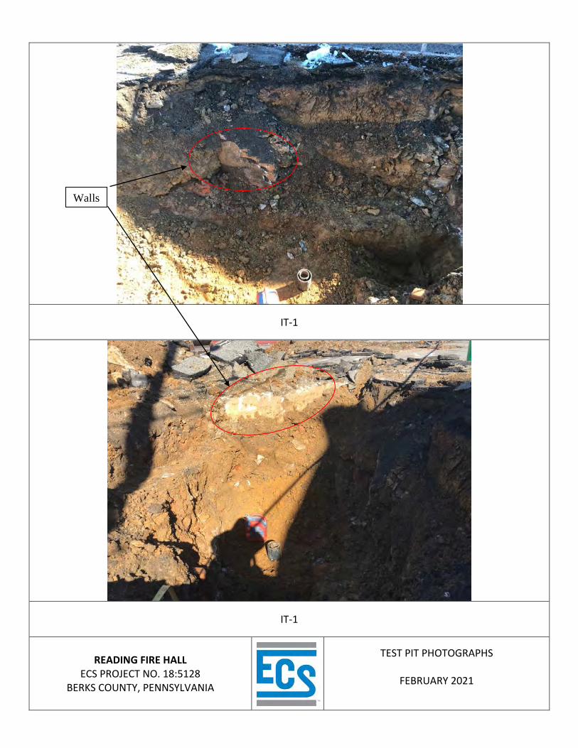
IT-1
IT-1
READING FIRE HALL
ECS PROJECT NO. 18:5128 BERKS COUNTY, PENNSYLVANIA
TEST PIT PHOTOGRAPHS
FEBRUARY 2021
Walls
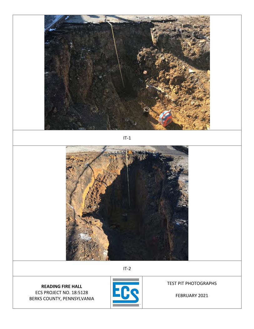
IT-1
IT-2
READING FIRE HALL
ECS PROJECT NO. 18:5128 BERKS COUNTY, PENNSYLVANIA
TEST PIT PHOTOGRAPHS
FEBRUARY 2021

APPENDIX C – Laboratory Testing
Laboratory Testing Summary Plasticity Charts Grain Size Analyses
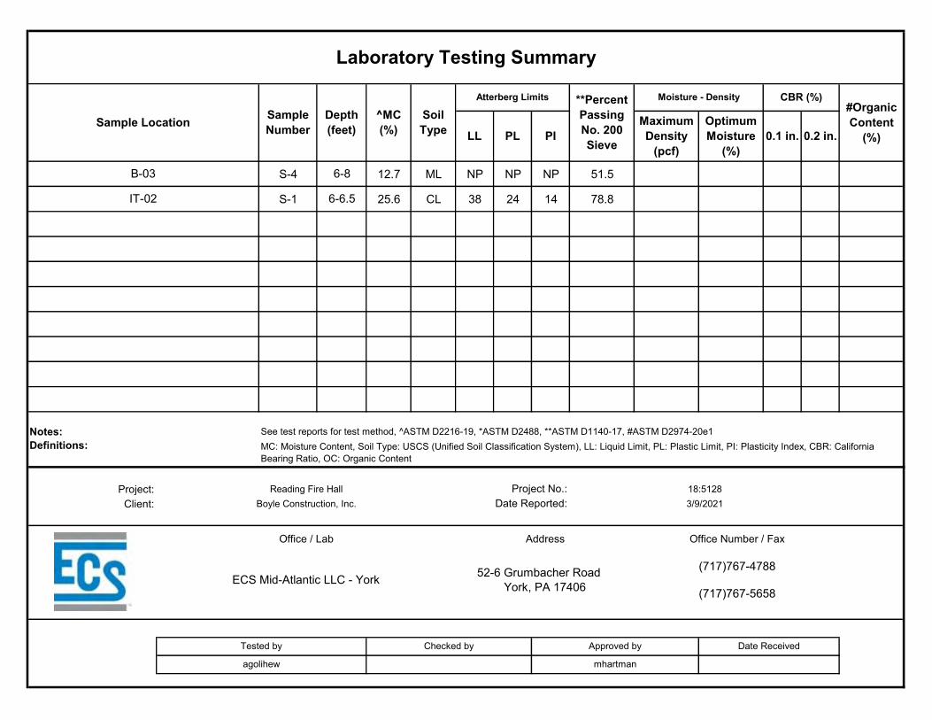
S-4 12.7 ML NP NP NP 51.5
S-1 25.6 CL 38 24 14 78.8
Project:Client:
Laboratory Testing Summary
Sample Location Sample Number
Depth (feet)
^MC(%)
Soil Type
Atterberg Limits **Percent Passing No. 200 Sieve
Moisture - Density CBR (%)#Organic Content
(%)LL PL PIMaximum Density
(pcf)
Optimum Moisture
(%)0.1 in. 0.2 in.
B-03 6-8
IT-02 6-6.5
Notes: See test reports for test method, ^ASTM D2216-19, *ASTM D2488, **ASTM D1140-17, #ASTM D2974-20e1Definitions: MC: Moisture Content, Soil Type: USCS (Unified Soil Classification System), LL: Liquid Limit, PL: Plastic Limit, PI: Plasticity Index, CBR: California
Bearing Ratio, OC: Organic Content
Reading Fire Hall Project No.: 18:5128
Approved by Date Received
Boyle Construction, Inc. Date Reported: 3/9/2021
Office / Lab Address Office Number / Fax
agolihew mhartman
ECS Mid-Atlantic LLC - York 52-6 Grumbacher Road York, PA 17406
(717)767-4788
(717)767-5658
Tested by Checked by
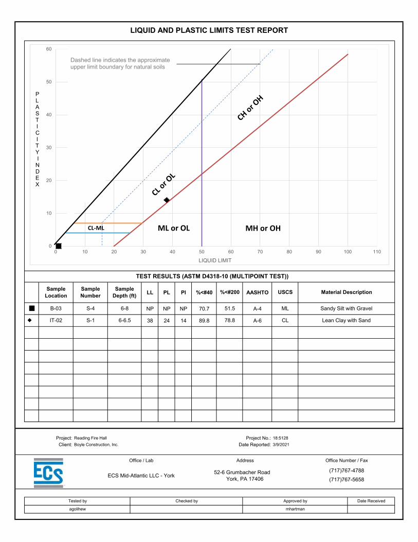
LL PL PI %<#40 AASHTO
NP NP NP 70.7 A-4
38 24 14 89.8 A-6
LIQUID AND PLASTIC LIMITS TEST REPORT
TEST RESULTS (ASTM D4318-10 (MULTIPOINT TEST))
Sample Location
Sample Number
Sample Depth (ft) %<#200 USCS Material Description
B-03 S-4 6-8 51.5 ML Sandy Silt with Gravel
IT-02 S-1 6-6.5 78.8 CL Lean Clay with Sand
Project: Reading Fire Hall Project No.: 18:5128Client: Boyle Construction, Inc. Date Reported: 3/9/2021
Office / Lab Address Office Number / Fax
ECS Mid-Atlantic LLC - York 52-6 Grumbacher Road York, PA 17406
(717)767-4788(717)767-5658
Tested by Checked by Approved by Date Received
agolihew mhartman
0
10
20
30
40
50
60
0 10 20 30 40 50 60 70 80 90 100 110
LIQUID LIMIT
ML or OLCL-ML MH or OH
PLASTICITYI
NDEX
Dashed line indicates the approximateupper limit boundary for natural soils

D90 D50 D10D85 D30 CuD60 D15 Cc
PARTICLE SIZE DISTRIBUTION
TEST RESULTS (ASTM D6913M-17-METHOD A)Sieving Hydrometer Sedimentation
Dry Mass of sample, g 134.3Particle Size % Passing Particle Size mm % Passing
Very coarse, >3" sieve 0
3" 100 Sample Proportions % dry mass
1 1/2" 1002" 100
1" 100Gravel, 3" to # 4 sieve 15
3/4" 943/8" 89
Coarse Sand, #4 to #10 sieve 4#4 85#10 81
Medium Sand, #10 to #40 10#20 77#40 71
Fine Sand, #40 to #200 19#60 64#100 58
Fines <#200 52#140 54#200 52
USCS ML Liquid Limit NP 10.790 0.000 0.000AASHTO A-4 Plastic Limit NP 4.906 0.000 0.000USCS Group Name Sandy silt with gravel Plasticity Index NP 0.182 0.000 0.000
Project: Reading Fire HallProject No.: 18:5128
Depth (ft): 6 - 8Client: Boyle Construction, Inc. Sample No.: S-4
Sample Source: B-03 Date Reported: 3/9/2021
Office / Lab Address Office Number / Fax
ECS Mid-Atlantic LLC - York 52-6 Grumbacher Road York, PA 17406
(717)767-4788
(717)767-5658
Tested by Checked by Approved by Date Received Remarks
agolihew mhartman
÷÷ø
ö
çç
è
æ
1m
m
SILTSAND
FineMediumCoarseGRAVEL CLAYVery Coarse
3" 2" 1.5" 1"3/4" 1/2"3/8" #4 #10 #20 #40 #60 #100 #140 #200
0
10
20
30
40
50
60
70
80
90
100
0.0010.010.11101001000
Perc
enta
ge P
assi
ng %
Particle Size mm
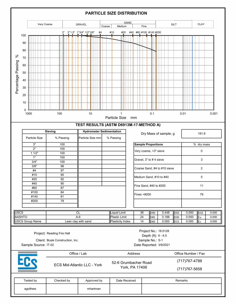
D90 D50 D10D85 D30 CuD60 D15 Cc
PARTICLE SIZE DISTRIBUTION
TEST RESULTS (ASTM D6913M-17-METHOD A)Sieving Hydrometer Sedimentation
Dry Mass of sample, g 191.8Particle Size % Passing Particle Size mm % Passing
Very coarse, >3" sieve 0
3" 100 Sample Proportions % dry mass
1 1/2" 1002" 100
1" 100Gravel, 3" to # 4 sieve 3
3/4" 1003/8" 98
Coarse Sand, #4 to #10 sieve 2#4 97#10 95
Medium Sand, #10 to #40 5#20 92#40 90
Fine Sand, #40 to #200 11#60 87#100 84
Fines <#200 79#140 81#200 79
USCS CL Liquid Limit 38 0.448 0.000 0.000AASHTO A-6 Plastic Limit 24 0.188 0.000 0.000USCS Group Name Lean clay with sand Plasticity Index 14 0.000 0.000 0.000
Project: Reading Fire HallProject No.: 18:5128
Depth (ft): 6 - 6.5Client: Boyle Construction, Inc. Sample No.: S-1
Sample Source: IT-02 Date Reported: 3/9/2021
Office / Lab Address Office Number / Fax
ECS Mid-Atlantic LLC - York 52-6 Grumbacher Road York, PA 17406
(717)767-4788
(717)767-5658
Tested by Checked by Approved by Date Received Remarks
agolihew mhartman
÷÷ø
ö
çç
è
æ
1m
m
SILTSAND
FineMediumCoarseGRAVEL CLAYVery Coarse
3" 2" 1.5" 1"3/4" 1/2"3/8" #4 #10 #20 #40 #60 #100 #140 #200
0
10
20
30
40
50
60
70
80
90
100
0.0010.010.11101001000
Perc
enta
ge P
assi
ng %
Particle Size mm

APPENDIX D – Details
Sinkhole Repair Details
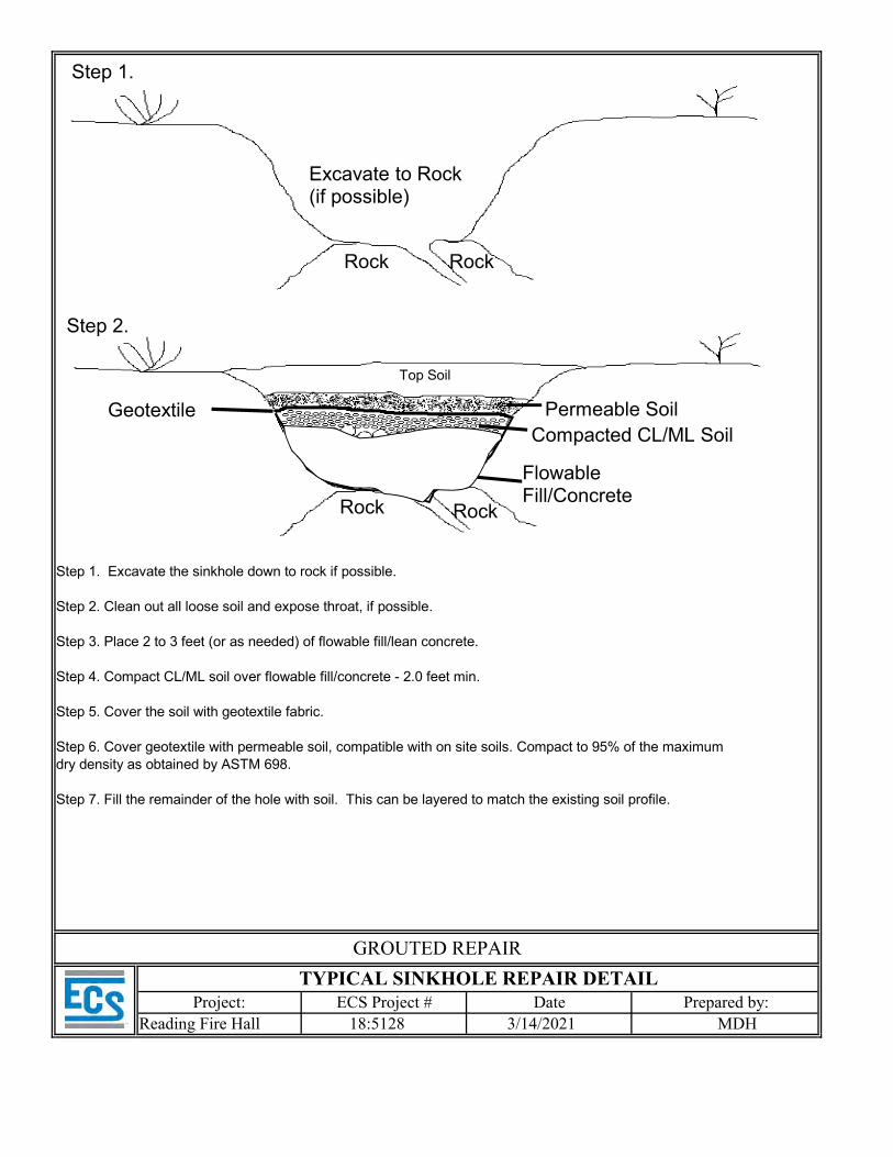
Step 1. Excavate the sinkhole down to rock if possible.
Step 2. Clean out all loose soil and expose throat, if possible.
Step 3. Place 2 to 3 feet (or as needed) of flowable fill/lean concrete.
Step 4. Compact CL/ML soil over flowable fill/concrete - 2.0 feet min.
Step 5. Cover the soil with geotextile fabric.
Step 6. Cover geotextile with permeable soil, compatible with on site soils. Compact to 95% of the maximumdry density as obtained by ASTM 698.
Step 7. Fill the remainder of the hole with soil. This can be layered to match the existing soil profile.
TYPICAL SINKHOLE REPAIR DETAIL
GROUTED REPAIR
Project: ECS Project # Date Prepared by:
Step 1.
Step 2.
Rock
Rock
Rock
Rock
Excavate to Rock(if possible)
Compacted CL/ML Soil
Flowable Fill/Concrete
Geotextile
Top Soil
Permeable Soil
Reading Fire Hall 18:5128 3/14/2021 MDH
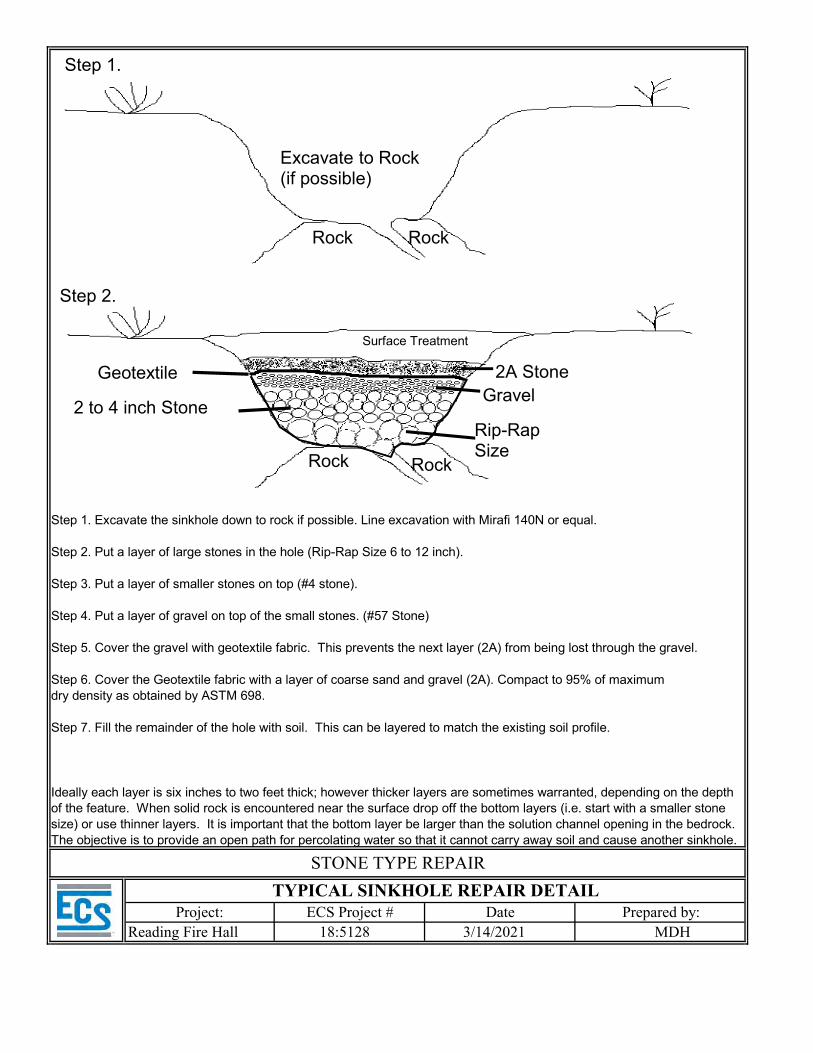
Step 1. Excavate the sinkhole down to rock if possible. Line excavation with Mirafi 140N or equal.
Step 2. Put a layer of large stones in the hole (Rip-Rap Size 6 to 12 inch).
Step 3. Put a layer of smaller stones on top (#4 stone).
Step 4. Put a layer of gravel on top of the small stones. (#57 Stone)
Step 5. Cover the gravel with geotextile fabric. This prevents the next layer (2A) from being lost through the gravel.
Step 6. Cover the Geotextile fabric with a layer of coarse sand and gravel (2A). Compact to 95% of maximumdry density as obtained by ASTM 698.
Step 7. Fill the remainder of the hole with soil. This can be layered to match the existing soil profile.
Project: ECS Project # Date Prepared by:
Ideally each layer is six inches to two feet thick; however thicker layers are sometimes warranted, depending on the depth of the feature. When solid rock is encountered near the surface drop off the bottom layers (i.e. start with a smaller stone size) or use thinner layers. It is important that the bottom layer be larger than the solution channel opening in the bedrock. The objective is to provide an open path for percolating water so that it cannot carry away soil and cause another sinkhole.
TYPICAL SINKHOLE REPAIR DETAIL
STONE TYPE REPAIR
Step 1.
Step 2.
Rock
Rock
Rock
Rock
Excavate to Rock(if possible)
Gravel2 to 4 inch Stone
Rip-Rap Size
Geotextile
Surface Treatment
2A Stone
Reading Fire Hall 18:5128 3/14/2021 MDH
Reading Fire Department9th & Marion Fire StationBid/Permit Set July 9, 2021
MANNS WOODWARD STUDIOS INC
SECTION 00 4116 - BID FORM - STIPULATED SUM (MULTIPLE-PRIME CONTRACT)
1.1 BID INFORMATION
A. Bidder: ____________________________________________________.
B. Bid Package (Prime Contract Package):__________________________.
C. Project Name: Reading Fire Department, 9th & Marion Fire Station.
D. Project Location: 1201 North 9th Street, Reading, PA, 19604.
E. Owner: City of Reading.
F. Architect: Manns Woodward Studios Inc.
G. Architect Project Number: 20-088.
1.2 CERTIFICATIONS AND BASE BID
A. Base Bid, Multi-Prime Contract: The undersigned Bidder, having carefully examined the Procurement and Contracting Requirements, Conditions of the Contract, Drawings, Specifications, and all subsequent Addenda, as issued by The City of Reading, having vistied the site, and being familiar with all conditions and requirements of the Work, hereby agrees to furnish all material, labor, equipment and services, including all schedule allowances, necessary to complete the portion of construction required by the identified Bid Package (Prime Contract Package) of the above named project, according to the requirements of the Procurement and Contracting Documents, for the stipulated sum of:
1. Text:_____________________________________________________________Dollars2. Numeric Value of Text above: $___________________.3. Bid Package (Prime Contract Package): ______________________________________
BID FORM - STIPULATED SUM (MULTIPLE-PRIME CONTRACT)
00 4116 - 1
Reading Fire Department9th & Marion Fire StationBid/Permit Set July 9, 2021
MANNS WOODWARD STUDIOS INC
1.3 BID GUARANTEE
A. The undersigned Bidder agrees to execute a contract for this Work in the above amount and to furnish surety as specified within 10 days after a written Notice of Award, if offered within 90 days after receipt of bids, and on failure to do so agrees to forfeit to Owner the attached cash, cashier's check, certified check, U.S. money order, or bid bond, as liquidated damages for such failure, in the following amount constituting ten percent (10%) of the Base Bid amount above:
1. _______________________________________________Dollars ($_______________).
1.4 SUBCONTRACTORS AND SUPPLIERS
A. Contractor shall provide via attachment to the bid forms, the names of subcontractors and suppliers performing work or providing materials/equipment exceeding, by monetary value, 5% of the Bid price.
1.5 TIME OF COMPLETION
A. The undersigned Bidder proposes and agrees hereby to commence the Work of the Contract Documents on a date specified in written Notice to Proceed to be issued by the City of Reading through the Construction Manager, and shall be fully complete within the duration provided within the Preliminary Milestone Schedule provided within Section 00 3113 "Preliminary Schedule".
1.6 ACKNOWLEDGEMENT OF ADDENDA
A. The undersigned Bidder acknowledges receipt of and use of the following Addenda in the preparation of this Bid:
1. Addendum No. 1, dated ____________________.2. Addendum No. 2, dated ____________________.3. Addendum No. 3, dated ____________________.4. Addendum No. 4, dated ____________________.5. Addendum No. 5, dated ____________________.6. Addendum No. 6, dated ____________________.7. Addendum No. 7, dated ____________________.
BID FORM - STIPULATED SUM (MULTIPLE-PRIME CONTRACT)
00 4116 - 2
Reading Fire Department9th & Marion Fire StationBid/Permit Set July 9, 2021
MANNS WOODWARD STUDIOS INC
8. Addendum No. 8, dated ____________________.9. Addendum No. 9, dated ____________________.10. Addendum No. 10, dated ____________________.
1.7 BID SUPPLEMENTS
A. The following supplements are a part of this Bid Form and are attached hereto or included by reference.
1. Bid Form Supplement - Alternates.2. Bid Form Supplement - Unit Prices.3. Bid Form Supplement - Allowances.4. Bid Form Supplement - Bid Bond Form (AIA Document A310-2010).5. Bid Form Supplement - Contractor's Qualification Statement (AIA Document A305-2020).6. Non-Collusion Affidavit7. Provider's Certificate of Non-indebtedness to the City of Reading8. Resolution No. 192-92; Statement Regarding Manufacture of Cement9. Contractor's Statement for Public Disclosure
1.8 CONTRACTOR'S LICENSE
A. The undersigned further states that it is a duly licensed contractor, for the type of work proposed, in the state and local jurisdiction of the project, and that all fees, permits, etc., pursuant to submitting this proposal have been paid in full.
1.9 SUBMISSION OF BID
A. Respectfully submitted this ____ day of ____________, 2021.
B. Submitted By:____________________________________________________________ (Name of bidding firm or corporation).
C. Authorized Signature:___________________________________(Handwritten signature).
D. Signed By:______________________________________________(Type or print name).
E. Title:__________________________________(Owner/Partner/President/Vice President).
BID FORM - STIPULATED SUM (MULTIPLE-PRIME CONTRACT)
00 4116 - 3
Reading Fire Department9th & Marion Fire StationBid/Permit Set July 9, 2021
MANNS WOODWARD STUDIOS INC
F. Witness By:___________________________________________(Handwritten signature).
G. Attest:_______________________________________________(Handwritten signature).
H. By:___________________________________________________(Type or print name).
I. Title:________________________________(Corporate Secretary or Assistant Secretary).
J. Street Address:___________________________________________________________.
K. City, State, Zip:__________________________________________________________.
L. Phone:_________________________________________________________________.
M. License No.:____________________________________________________________.
N. Federal ID No.:____________________________________(Affix Corporate Seal Here).
END OF DOCUMENT 004116
BID FORM - STIPULATED SUM (MULTIPLE-PRIME CONTRACT)
00 4116 - 4

Reading Fire Department9th & Marion Fire StationBid/Permit Set July 9, 2021
MANNS WOODWARD STUDIOS INC
SECTION 00 4313 - BID SECURITY FORMS
1.1 BID FORM SUPPLEMENT
A. A completed bid bond form is required to be attached to the Bid Form.
1.2 BID BOND FORM
A. AIA Document A310-2010 "Bid Bond" is required to be attached to the Bid Form as a supplement.
B. Copies of AIA standard forms may be obtained from The American Institute of Architects; https://www.aiacontracts.org/; email: [email protected]; (800) 942-7732.
END OF DOCUMENT 004313
BID SECURITY FORMS 00 4313 - 1
Reading Fire Department9th & Marion Fire StationBid/Permit Set July 9, 2021
MANNS WOODWARD STUDIOS INC
SECTION 00 4321 - ALLOWANCE FORM
1.1 BID INFORMATION
A. Bidder: ____________________________________________________.
B. Bid Package (Prime Contract Package): __________________________.
C. Project Name: READING FIRE STATION.
D. Project Location: 1201 North 9th Street, Reading, PA, 19604.
E. Owner: The City of Reading.
F. Architect: Manns Woodward Studios, Inc..
G. Architect Project Number: 20-088.
H. Construction Manager: Boyle Construction, Inc..
1.2 BID FORM SUPPLEMENT
A. This form is required to be attached to the Bid Form.
B. The undersigned Bidder certifies that Base Bid submission to which this Bid Supplement is attached includes those allowances described in the Contract Documents and scheduled in Section 01 2100 "Allowances."
1.3 SUBMISSION OF BID SUPPLEMENT
A. Respectfully submitted this ____ day of ____________, 2021.
B. Submitted By:_______________________________(Insert name of bidding firm or corporation).
C. Authorized Signature:_______________________________________(Handwritten signature).
D. Signed By:______________________________________________(Type or print name).
ALLOWANCE FORM 00 4321 - 1

Reading Fire Department9th & Marion Fire StationBid/Permit Set July 9, 2021
MANNS WOODWARD STUDIOS INC
E. Title:___________________________________(Owner/Partner/President/Vice President).
END OF DOCUMENT 004321
ALLOWANCE FORM 00 4321 - 2
Reading Fire Department9th & Marion Fire StationBid/Permit Set July 9, 2021
MANNS WOODWARD STUDIOS INC
SECTION 00 4322 - UNIT PRICES FORM
1.1 BID INFORMATION
A. Bidder: ____________________________________________________.
B. Bid Package (Prime Contract Package): __________________________.
C. Project Name: READING FIRE STATION.
D. Project Location: 1201 North 9th Street, Reading, PA, 19604.
E. Owner: City of Reading.
F. Architect: Manns Woodward Studios Inc.
G. Architect Project Number: 20-088.
H. Construction Manager: Boyle Construction, Inc..
1.2 BID FORM SUPPLEMENT
A. This form is required to be attached to the Bid Form.
B. The undersigned Bidder proposes the amounts below be added to or deducted from the Contract Sum on performance and measurement of the individual items of Work and for adjustment of the quantity given in the Unit-Price Allowance for the actual measurement of individual items of the Work.
C. If the unit price does not affect the Work of this Contract, the Bidder shall indicate "NOT APPLICABLE."
1.3 UNIT PRICES
A. Unit Price No. 1: Removal of Unsatisfactory Soil
1. ______________________________________dollars ($______________) per unit.
UNIT PRICES FORM 00 4322 - 1
Reading Fire Department9th & Marion Fire StationBid/Permit Set July 9, 2021
MANNS WOODWARD STUDIOS INC
B. Unit Price No. 2: Rock Removal
1. ______________________________________dollars ($______________) per unit
C. Unit Price No. 3: Soil Moisture Reduction; Quicklime
1. ______________________________________dollars ($______________) per unit
D. Unit Price No. 4: PennDOT 2A Fill
1. ______________________________________dollars ($______________) per unit
E. Unit Price No. 5: #57 Stone Fill
1. ______________________________________dollars ($______________) per unit
F. Unit Price No. 6: Granular natural soil fill
1. ______________________________________dollars ($______________) per unit
1.4 SUBMISSION OF BID SUPPLEMENT
A. Respectfully submitted this ____ day of ____________, 2021.
B. Submitted By:___________________________________(Insert name of bidding firm or corporation).
C. Authorized Signature:___________________________________(Handwritten signature).
D. Signed By:______________________________________________(Type or print name).
E. Title:___________________________________(Owner/Partner/President/Vice President).
END OF DOCUMENT 004322
UNIT PRICES FORM 00 4322 - 2
Reading Fire Department9th & Marion Fire StationBid/Permit Set July 9, 2021
MANNS WOODWARD STUDIOS INC
SECTION 00 4323 - ALTERNATES FORM
1.1 BID INFORMATION
A. Bidder: ____________________________________________________.
B. Bid Package (Prime Contract Package): __________________________.
C. Project Name: READING FIRE STATION.
D. Project Location: 1201 North 9th Street, Reading, PA, 19604.
E. Owner: City of Reading.
F. Architect: Manns Woodward Studios, Inc..
G. Architect Project Number: 20-088.
H. Construction Manager: Boyle Construction, Inc..
1.2 BID FORM SUPPLEMENT
A. This form is required to be attached to the Bid Form.
1.3 DESCRIPTION
A. The undersigned Bidder proposes the amount below be added to or deducted from the Base Bid if particular alternates are accepted by Owner. Amounts listed for each alternate include costs of related coordination, modification, or adjustment.
B. If the alternate does not affect the Contract Sum, the Bidder shall indicate "NO CHANGE."
C. If the alternate does not affect the Work of this Contract, the Bidder shall indicate "NOT APPLICABLE."
D. Owner reserves the right to accept or reject any alternate, in any order, and to award or amend the Contract accordingly within 60 days of the Notice of Award unless otherwise indicated in the Contract Documents.
ALTERNATES FORM 00 4323 - 1
Reading Fire Department9th & Marion Fire StationBid/Permit Set July 9, 2021
MANNS WOODWARD STUDIOS INC
E. Acceptance or non-acceptance of any alternates by the Owner shall have no affect on the Contract Time unless the "Schedule of Alternates" Article below provides a formatted space for the adjustment of the Contract Time.
1.4 SCHEDULE OF ALTERNATES
A. Alternate No. 1: Epoxy Terrazzo Tile:
1. ADD____ DEDUCT____ NO CHANGE____ NOT APPLICABLE____.2. ________________________________________________ Dollars ($______________).
1.5 SUBMISSION OF BID SUPPLEMENT
A. Respectfully submitted this ____ day of ____________, 2021.
B. Submitted By:___________________________________(Insert name of bidding firm or corporation).
C. Authorized Signature:____________________________________(Handwritten signature).
D. Signed By:______________________________________________(Type or print name).
E. Title:___________________________________(Owner/Partner/President/Vice President).
END OF DOCUMENT 004323
ALTERNATES FORM 00 4323 - 2
Reading Fire Department9th & Marion Fire StationBid/Permit Set July 9, 2021
MANNS WOODWARD STUDIOS INC
SECTION 00 4373 - PROPOSED SCHEDULE OF VALUES FORM
1.1 BID FORM SUPPLEMENT
A. A completed Proposed Schedule of Values form is required to be attached to the Bid Form.
1.2 PROPOSED SCHEDULE OF VALUES FORM
A. Proposed Schedule of Values Form: Provide a breakdown of the bid amount, including alternates, in enough detail to facilitate continued evaluation of bid. Coordinate with the Project Manual table of contents. Provide multiple line items for principal material and subcontract amounts in excess of five percent of the Contract Sum.
B. Arrange schedule of values using AIA Document G703-1992.
1. Copies of AIA standard forms may be obtained from the American Institute of Architects; https://www.aiacontracts.org/ library; (800) 942-7732.
END OF DOCUMENT 004373
PROPOSED SCHEDULE OF VALUES FORM 00 4373 - 1
Reading Fire Department9th & Marion Fire StationBid/Permit Set July 9, 2021
MANNS WOODWARD STUDIOS INC
SECTION 00 4400 - OWNERS DOCUMENTS - BID FORMS
1.1 OWNERS DOCUMENTS - BID FORMS
A. Owner's document(s) bound following this Document.
1. Non-Collusion Affidavit
a. Instructions for Non-Collusion Affidavitb. Non-Collusion Affidavit of Prime Bidder
2. Provider's Certificate of Non-Indebtedness to the City of Reading3. Resolution No. 192-92
a. Statement Regarding Manufacture of Cement
4. Contractor's Statement for Public Disclosure5. Bureau of Labor Law Compliance Prevailing Wage Project Rates.
END OF SECTION 00 4400
OWNERS DOCUMENTS - BID FORMS 00 4400 - 1
NON-COLLUSION AFFIDAVIT
INSTRUCTIONS FOR NON-COLLUSION AFFIDAVIT
This Non-Collusion Affidavit is material to any contract pursuant to this bid. According to the Pennsylvania Antibid-Rigging Act, 73 P.S. 1611 et seq., governmental agencies may require Non-Collusion Affidavits to be submitted together with bids.
This Non-Collusion affidavit must be executed by the member, officer, or employee of the bidder who is authorized to legally bind the bidder.
Bid rigging and other efforts to restrain competition, and the making of false sworn statements in connection with the submission of bids are unlawful and may be subject to criminal prosecution. The person who signs the Affidavit should examine it carefully before signing and assure himself or herself that each statement is true and accurate, making diligent inquiry, as necessary, of all other persons employed by or associated with the bidder with responsibilities for the preparation, approval, or submission of the bid.
In the case of a bid submitted by a joint venture, each party to the venture must be identified in the bid documents, and an Affidavit must be submitted separately on behalf of each party.
The term "complementary bid" as used in the Affidavit has the meaning commonly associated with that term in the bidding process, and includes the knowing submission of bids higher than the bid of another firm, any intentionally high or noncompetitive bid, and any form of bid submitted for the purpose of giving a false appearance of competition.
Failure to file an Affidavit in compliance with these instructions will result in disqualification of the bid.
NON-COLLUSION AFFIDAVIT OF PRIME BIDDER
State of ________________________
County of ______________________
_______________________________, being first duly sworn, deposes and says that:
He/She is _____________________(Owner, Partner, Officer, Representative or Agent) of ________________________________________, the Bidder that has submitted the attached Bid or Bids;
He/She is fully informed respecting the preparation and contents of the attached Bid and of all pertinent circumstances respecting such Bid;
Such Bid is genuine and is not a collusive or sham Bid;
Neither the said Bidder nor any of its officers; partners, owners, agents, representatives, employees or parties in interest, including this affiant, has in any way colluded, conspired, connived or agreed, directly or indirectly, with any other Bidder, firm or person to submit a collusive or sham Bid in connection with the Contract for which the attached Bid has been submitted or to refrain from bidding in connection with such Contract, or has in any manner, directly or indirectly, sought by agreement or collusion or communication of conference with any other Bidder, firm or person to fix the price or prices in the attached Bid or of any other Bidder, or to fix any overheld, profit or cost element of the Bid price or the Bid price of any other Bidder, or to secure through any collusion, conspiracy, connivance or unlawful agreement any advantage against the City of Reading or any person interested in the proposed Contract;
The price or prices quoted in the attached Bid are fair and proper and are not tainted by any collusion, conspiracy, connivance or unlawful agreement on the part of the Bidder or any of its agents, representatives, owners, employees, or parties in interest, including this affiant; and,
Neither the said Bidder nor any of its officers, partners, owners, agents or parties in interest, have any interest, present or prospective, that can be reasonably construed to result in a conflict of interest between them and the City of Reading, which the Bidder will be required to perform.
I state that _____________________________ understands(Name of Firm)
and acknowledges that the above representations are material and important, and will be relied on by the City of Reading in awarding the contract(s) for which this bid is submitted. I understand and my firm understands that any misstatement in this affidavit is and shall be treated as fraudulent concealment from the City of Reading of the true facts relating to the submission of bids for this contract.
_________________________________ (Name and Company Position)
SWORN TO AND SUBSCRIBEDBEFORE ME THIS ________DAY OF _________, 20___
_________________________ My Commission Expires Notary Public
PROVIDER'S CERTIFICATION OF NON-INDEBTEDNESSTO THE CITY OF READING
Provider hereby certifies and represents that Provider and Provider's parent company(ies) and subsidiary(ies) are not currently indebted to the City of Reading (the "City"), and will not at any time during the term of this Contract (including any extensions or renewals thereof) be indebted to the City, for or on account of any delinquent taxes, liens, judgments, fees or other debts for which no written agreement or payment plan satisfactory to the City has been established. In addition to any other rights or remedies available to the City at law or in equity, Provider acknowledges that any breach or failure to conform to this certification may, at the option of the City, result in the withholding of payments otherwise due to Provider and, if such breach or failure is not resolved to the City's satisfaction within a reasonable timeframe specified by the City in writing, may result in the offset of any such indebtedness against said payments and/or the termination of this Contract for default (in which case Provider shall be liable for all excess costs and other damages resulting from the termination).
_____________________________________NAME OF PROVIDER
By: _____________________________________AUTHORIZED SIGNATORY
Title: _____________________________________PRESIDENT OR VICE PRESIDENT
Attest: _____________________________________
RESOLUTION NO. 192-92
WHEREAS, reportedly, twenty-five cement manufacturing facilities in the United States are currently burning well over two billion pounds a year of hazardous waste as a source of fuel and additional profit in the cement manufacturing process; and
WHEREAS, approximately twenty cement manufacturing facilities are seeking permission to start this practice; and
WHEREAS, sufficient data and evidence as to the safety of cement products made from hazardous waste has not been proven; and
WHEREAS, it is in the best interest of the citizens of the City of Reading in regard to their health and quality of life that cement derived from hazardous waste be banned from any City projects.
NOW, THEREFORE, the Council of the City of Reading resolves that the City of Reading will not purchase cement from any facility that burns hazardous waste as fuel in its manufacturing process, nor allow the use of concrete made from this type of cement. This policy shall be reflected in city bid specifications.
PASSED COUNCIL April 1, 1993
WARREN H. HAGGERTY, JR.Mayor
ATTEST:
RUTH M. THOMPSONCity Clerk

STATEMENT REGARDING MANUFACTURE OF CEMENT
The following statement is to be signed by an authorized officer of the company.
The undersigned contractor hereby certifies in accordance with City of Reading Resolution #192-92, that any cement used in performance of this contract shall not have been manufactured by a process using hazardous materials, as defined by the Environmental Protection Agency, in the manufacture and makeup thereof.
CONTRACTOR
By:___________________________
Title:________________________
ATTEST:
____________________________
CONTRACTOR'S STATEMENT FOR PUBLIC DISCLOSURE *
1. a/ Name of Contractor:
b/ Address and Zip Code of Contractor:
2. If the Contractor is not an individual doing business under his own name, the Contractor has the status indicated below and is organized or operating under the laws of _________:
_____ a corporation
_____ a partnership known as:
_____ a business association or a joint venture known as:
_____ a Federal, State or Local government or instrumentality thereof
_____ other (explain)
3. If the Contractor is not an individual or a government agency or instrumentality, givedate of organization:_____________________________
4. Names, addresses, title of position (if any), and nature and extent of the interest of the officers and principal members, shareholders, investors other than a government agency or instrumentality, are set forth as follows:
a/ If the Contractor is a corporation, the officers, directors, trustees, and each stockholder owning more than 10% of any share of stock.
b/ If the Contractor is a partnership, each partner, whether a general or limited partner, and either the percent of interest or a description of the character and extent of interest.
c/ If the Contractor is a business association or a joint venture, each participant and either the percent of interest or a description of the character and extent of interest.
d/ If the Contractor is some other entity, the officers, the members of the governing body, and each person having an interest of more than 10%.
* If space on this form is inadequate for any requested information, this should be furnished on an attached page which is referred to under the appropriate numbered item on the form.
Page 2Contractor's Statement for Public Disclosure
POSITION TITLE (if any) AND PERCENTOF INTEREST OR DESCRIPTION OF
NAME, ADDRESS & ZIP CODE CHARACTER AND EXTENT OF INTEREST
5. Name, address and nature and extent of interest of each person or entity (not named in response to Item 4) who has a beneficial interest in any of the shareholders or investors named in response to Item 5 which gives such person or entity more than a computed 10% interest in the Contractor (for example, more than 20% of the stock in a corporation which holds 50% of the stock of the Contractor, or more than 50% of the stock in a corporation which holds 20% of the stock of the Contractor).
DESCRIPTION OF CHARACTERNAME, ADDRESS & ZIP CODE AND EXTENT OF INTEREST
6. Names (if not given above) of officers and directors or trustees of any corporation or firm listed under Item 4 or Item 5 above:
7. Is the Contractor a subsidiary of or affiliated with any other corporation or any other firm or firms?___ YES ___ NO. If yes, list each such corporation or firm by name and address, specify its relationship to the Contractor, and identify the officers and directors or trustees common to the Contractor and such other corporation or firm:
8. Other federal grant projects under Title I of the Housing and Community Development Act of 1974 (CP.L.93-383), as amended, in which the Contractor or any of the principals of the Contractor is or has been the contractor, or a stock-holder, officer, director or trustee, or partner of such a contractor:
9. If the Contractor or a parent corporation, a subsidiary, an affiliate or a principal of the Contractor is to participate in the work or services as a Subcontractor or consultant:
a/ Name and address of such Subcontractor or consultant:
b/ Has such Subcontractor within the last 10 years ever failed to qualify as a responsible bidder, refused to enter into a contract after an award has been made, or failed to complete a contract?___YES ___ NO. If yes, explain:
Page 3Contractor's Statement for Public Disclosure
c/ Outstanding contract bids of such Subcontractor or consultant:
Awarding Agency Amount Date Opened
$
10. Brief statement respecting equipment, experience, financial capacity, and other resources available to such Subcontractor or consultant for the performance of the work or services involved in the contract, specifying particularly the qualifications of the personnel, the nature of the equipment, and the general experience of the Subcontractor or consultant.
11. a/ Does any member of the governing body or employee of the Local Public Agency or any officer or employee of the Local Public Agency who exercises any functions or responsibilities in connection with the awarding and/or carrying out of the contract have any direct or indirect personal interest in the Contractor or in the Contractor's performance under the contract? ___YES ___NO. If yes, explain:
b/ Does any member of the governing body of the locality in which the Public Improvement Project is situated or any other public official of the locality, who exercises any functions or responsibilities in the review or approval of the awarding and/or carrying out of the contract have any direct or indirect personal interest in the Contractor or in the Contractor's performance under the contract? ___YES ___NO. If yes, explain:
CERTIFICATION
I (We) ______________________________________________________________ certify that this Contractor's Statement for Public Disclosure is true and correct to the best of my (our) knowledge and beliefs.
DATED: ___________________ DATED: __________________
___________________________ _________________________(SIGNATURE) (SIGNATURE)
___________________________ _________________________(TITLE) (TITLE)
___________________________ _________________________(ADDRESS & ZIP CODE) (ADDRESS & ZIP CODE)
1 - If the Contractor is an individual, this Statement should be signed by such individual; if a partnership, by one of the partners; if a corporation or other entity, by one of its chief officers having knowledge of the facts required by this Statement.
2 - Penalty For False Certification: Section 1001, Title 18, of the U.S.C. provides a fine of not more than $10,000, or imprisonment of not more than five years, or both, for knowingly and willfully making or using any false writing or document, knowing the same to contain any false, fictitious or fraudulent statement or entry in a matter within the jurisdiction of any Department of the United States.

WAGE RATE COMPLIANCE BOND
BOND NO.___________
KNOW ALL MEN BY THESE PRESENTS, that ____________________________________________,(Contractor)
____________________________________________________________________, (hereinafter referred
(Full Address)
to as EMPLOYER), _______________________________, Insurance Company, a corporation organized(Surety Company)
and existing under the laws of the State of ____________________ (hereinafter referred to as SURETY),
are hereby severally held and firmly bound in the sum of _________________ Dollars, being 50% of the
estimated or bidded price of the contract, lawful money of the United States of America, unto the City of
Reading, City Hall, 815 Washington Street, Reading, PA, 19601-3690, (hereinafter referred to as CITY), as its interests may appear.
NOW THE CONDITION OF THE ABOVE OBLIGATION IS SUCH that if Employer and any subcontractors shall promptly pay wages due their employees for work performed under an agreement dated ________________, 20____ (including amendments thereto), between Employer and City based on the minimum prevailing wages specified in said Agreement as published by the United States Department of Labor and as reflected in a Contract between Employer and City, dated __________, 20__, then the above obligation shall be void, otherwise it shall remain in full force and effect.
The Surety's obligation under this Bond shall cover payments due as aforesaid for work performed by employees during the period commencing _____________________, 20____, and ending with the completion of the project in accordance with a certificate of Completion issuable by the City.
We, the said Employer and Surety, and each of us do bind and oblige ourselves, to the extent of our respective liabilities hereunder, as well as our heirs, executors, administrators, successors and assigns, and every one of them, firmly by these presents.
SIGNED, SEALED, AND DATED this _____________day of __________________, 20____.
(INDIVIDUAL PRINCIPAL)
__________________________________ (Seal)
(Signature of Individual)
Witness:
_______________________________
Trading and Doing Business as:
___________________________________
(PARTNERSHIP PRINCIPAL)
___________________________________ (Seal)(Name of Partnership)
Witness:
____________________________ By:________________________________ (Seal)
(Partner)
Witness:
____________________________ By:________________________________ (Seal)
(Partner)
Witness:
____________________________ By:________________________________ (Seal)
(Partner)
Witness:
____________________________ By:________________________________ (Seal)
(Partner)

(CORPORATION PRINCIPAL)
________________________________________(Name of Corporation)
By:_____________________________________(Vice) President
Attest:
_____________________________________(Assistant Secretary)
(Corporate Seal)
(OR, IF APPROPRIATE)
________________________________________(Name of Corporation)
By:_____________________________________(Authorized Representative)
(CORPORATION SURETY)
____________________________________(Name of Corporation)
By:_________________________________(Attorney-In-Fact)
Witness:
_____________________________________
(Corporate Seal)
** Attach an appropriate Power of Attorney, valid and in effect as of the date of this affidavit, evidencing the authority of the Attorney-In-Fact to act in behalf of the corporation.

MAINTENANCE BOND
KNOW ALL MEN BY THESE PRESENTS, that we, _________________________________________
_____________________________________________ hereinafter called the PRINCIPAL, and (CONTRACTOR)
_____________________________ hereinafter called the SURETY, a corporation organized and existing (SURETY)
under laws of the ______________________ of ______________________________, are held and firmly
bound unto ________________________, hereinafter called the OBLIGEE, as hereinafter set (OWNER)
forth, in the full and just sum of_________________________________ Dollars ($_________________),
lawful money of the United States of America, for the payment of which we bind ourselves, our heirs, executors, administrators, successors and assigns, jointly and severally, firmly by these presents,
WITNESSETH THAT:
Whereas, the PRINCIPAL heretofore submitted to the OBLIGEE a certain PROPOSAL, dated _______, 20___ to perform the WORK for the OBLIGEE, in connection with the construction of__________________________________________________________________________________ as set forth in the
CONTRACTDOCUMENTS as prepared by the CITY OF READING.
Now, therefore, the condition of this BOND shall be such that: If the PRINCIPAL shall remedy, without cost to the OBLIGEE, all defects which may develop during the period of one (1) year from the date of completion by the PRINCIPAL and final acceptance of the OBLIGEE of the WORK performed in accordance with the CONTRACT DOCUMENTS, which defects, in the sole judgment of the OBLIGEE, shall be caused by or shall result from defective or inferior materials or workmanship, and if the PRINCIPAL shall satisfy all claims and demands arising from or related to such defects or growing out of such defects. and if the PRINCIPAL shall indemnify completely and shall save harmless the OBLIGEE from any and all costs and damages which the OBLIGEE may sustain or suffer by reason of the failure so to do; and if the PRINCIPAL shall reimburse completely and shall pay to the OBLIGEE any and all costs and expenses which the OBLIGEE may incur by reason of anv such default or failure of the PRINCIPAL, then this BOND shall be void; otherwise, this BOND shall be and shall remain in full force and effect.
The PRINCIPAL and the SURETY agree that any alterations, changes and/or additions to the CONTRACT DOCUMENTS, and/or any alterations, changes and/or additions to the WORK to be performed in accordance with the CONTRACT DOCUMENTS, and/or any alterations, changes and/or additions to the CONTRACT, and/or any giving by the OBLIGEE of any extensions of time for the performance of the WORK in accordance with the CONTRACT DOCUMENTS, and/or any act of forbearance of either the PRINCIPAL or the OBLIGEE toward the other with respect to the CONTRACT DOCUMENTS, and/or the reduction of any percentage to be retained by the OBLIGEE as permitted by the CONTRACT DOCUMENTS, shall not release, in any manner whatsoever, the PRINCIPAL and the SURETY, or either of them, or their heirs, executors, administrators, successors and assigns from liability and obligations under this BOND; and the SURETY for value received, does waive notice of any such alterations, changes, additions, extensions of time, acts of forbearance and/or reduction of retained percentage.
In Witness Whereof, the PRINCIPAL and the SURETY cause this BOND to be signed, sealed and delivered this ___________day of __________________, 20____.

(INDIVIDUAL PRINCIPAL)
__________________________________ (Seal)(Signature of Individual)
Witness:
_______________________________
Trading and Doing Business as:
___________________________________
(PARTNERSHIP PRINCIPAL)
___________________________________ (Seal)(Name of Partnership)
Witness:
____________________________ By:________________________________ (Seal)
(Partner)
Witness:____________________________ By:________________________________ (Seal)
(Partner)
Witness:____________________________ By:________________________________ (Seal)
(Partner)
Witness:____________________________ By:________________________________ (Seal)
(Partner)
(CORPORATION PRINCIPAL)
________________________________________(Name of Corporation)
By:_____________________________________(Vice) President
Attest:
_____________________________________(Assistant Secretary)
(Corporate Seal)
(OR, IF APPROPRIATE)
________________________________________(Name of Corporation)
By:_____________________________________(Authorized Representative)
(CORPORATION SURETY)
____________________________________(Name of Corporation)
By:_________________________________(Attorney-In-Fact)
Witness:
_____________________________________
(Corporate Seal)
** Attach an appropriate Power of Attorney, valid and in effect as of the date of this affidavit, evidencing the authority of the Attorney-In-Fact to act in behalf of the corporation.

INDEMNITY AGREEMENT & HOLD HARMLESS
KNOW ALL MEN BY THESE PRESENTS:
WHEREAS, the undersigned has entered into a contract with the CITY OF READING, dated _________________, 20 __, providing for the __________________________________________________________________________________________________________City of Reading, Pennsylvania.
NOW, THEREFORE, in consideration of the award of said contract to the undersigned, ___________________, as well as in further consideration of the sum of ONE DOLLAR ($1.00) in hand paid to the said _________________by the City of Reading, receipt whereof is hereby acknowledged, the said ____________________ agrees to indemnify and save harmless the CITY OF READING, its officers, agents, servants, and employees against any and all loss, damage, costs and expenses which the said CITY may hereafter suffer, incur, be put to or pay by reason of any bodily injury (including death) or damage to property arising out of any act or omission in performance of the work undertaken under the aforesaid contract.
EXECUTED this _____ day of ____________________, 20__.
By: ______________________________
Title: ___________________________
ATTEST:
________________________
________________________(Title)
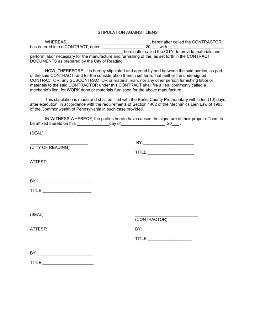
STIPULATION AGAINST LIENS
WHEREAS, ___________________________________, hereinafter called the CONTRACTOR, has entered into a CONTRACT, dated __________________, 20___, with ________________________________________________________________ hereinafter called the CITY, to provide materials and perform labor necessary for the manufacture and furnishing of the: as set forth in the CONTRACT DOCUMENTS as prepared by the City of Reading.
NOW, THEREFORE, it is hereby stipulated and agreed by and between the said parties, as part of the said CONTRACT, and for the consideration therein set forth, that neither the undersigned CONTRACTOR, any SUBCONTRACTOR or material man, nor any other person furnishing labor or materials to the said CONTRACTOR under this CONTRACT shall file a lien, commonly called a mechanic's lien, for WORK done or materials furnished for the above manufacture.
This stipulation is made and shall be filed with the Berks County Prothonotary within ten (10) days after execution, in accordance with the requirements of Section 1402 of the Mechanics Lien Law of 1963 of the Commonwealth of Pennsylvania in such case provided.
IN WITNESS WHEREOF, the parties hereto have caused the signature of their proper officers to be affixed thereto on this ______________day of___________________ 20___ .
(SEAL)
_________________________ BY:______________________(CITY OF READING)
TITLE:____________________
ATTEST:
BY:_______________________
TITLE:_____________________
(SEAL) ___________________________(CONTRACTOR)
ATTEST: BY:______________________
TITLE:___________________
BY:________________________
TITLE:______________________
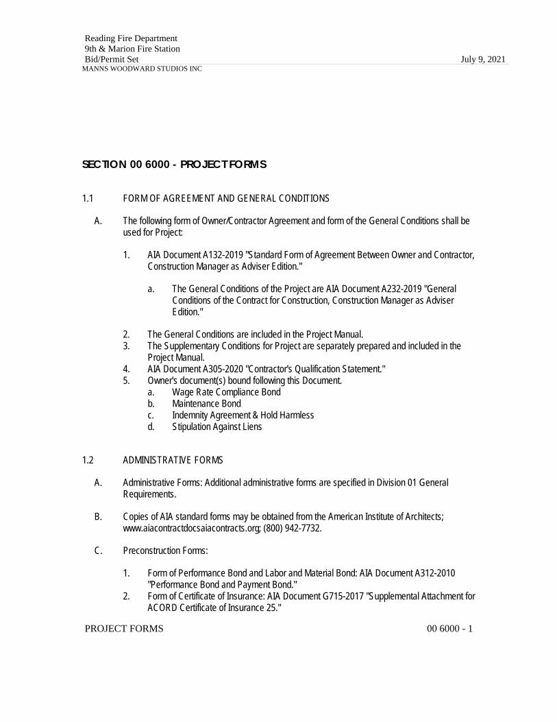
Reading Fire Department9th & Marion Fire StationBid/Permit Set July 9, 2021
MANNS WOODWARD STUDIOS INC
SECTION 00 6000 - PROJECT FORMS
1.1 FORM OF AGREEMENT AND GENERAL CONDITIONS
A. The following form of Owner/Contractor Agreement and form of the General Conditions shall be used for Project:
1. AIA Document A132-2019 "Standard Form of Agreement Between Owner and Contractor, Construction Manager as Adviser Edition."
a. The General Conditions of the Project are AIA Document A232-2019 "General Conditions of the Contract for Construction, Construction Manager as Adviser Edition."
2. The General Conditions are included in the Project Manual.3. The Supplementary Conditions for Project are separately prepared and included in the
Project Manual.4. AIA Document A305-2020 "Contractor's Qualification Statement."5. Owner's document(s) bound following this Document.
a. Wage Rate Compliance Bondb. Maintenance Bondc. Indemnity Agreement & Hold Harmlessd. Stipulation Against Liens
1.2 ADMINISTRATIVE FORMS
A. Administrative Forms: Additional administrative forms are specified in Division 01 General Requirements.
B. Copies of AIA standard forms may be obtained from the American Institute of Architects; www.aiacontractdocsaiacontracts.org; (800) 942-7732.
C. Preconstruction Forms:
1. Form of Performance Bond and Labor and Material Bond: AIA Document A312-2010 "Performance Bond and Payment Bond."
2. Form of Certificate of Insurance: AIA Document G715-2017 "Supplemental Attachment for ACORD Certificate of Insurance 25."
PROJECT FORMS 00 6000 - 1
Reading Fire Department9th & Marion Fire StationBid/Permit Set July 9, 2021
MANNS WOODWARD STUDIOS INC
D. Information and Modification Forms:
1. Form for Requests for Information (RFIs): AIA Document G716-2004 "Request for Information (RFI)."
2. Change Order Form: AIA Document G701-2017 "Change Order."3. Form of Architect's Memorandum for Minor Changes in the Work:
AIA Document G710-2017 "Architect's Supplemental Instructions."4. Form of Change Directive: AIA Document G714-2017 "Construction Change Directive."
E. Payment Forms:
1. Schedule of Values Form: AIA Document G703-1992 "Continuation Sheet."2. Payment Application: AIA Document G702-1992/703-1992 "Application and Certificate for
Payment and Continuation Sheet."3. Form of Contractor's Affidavit: AIA Document G706-1994 "Contractor's Affidavit of
Payment of Debts and Claims."4. Form of Affidavit of Release of Liens: AIA Document G706A-1994 "Contractor's Affidavit of
Payment of Release of Liens."5. Form of Consent of Surety: AIA Document G707-1994 "Consent of Surety to Final
Payment."
END OF SECTION 00 6000
PROJECT FORMS 00 6000 - 2
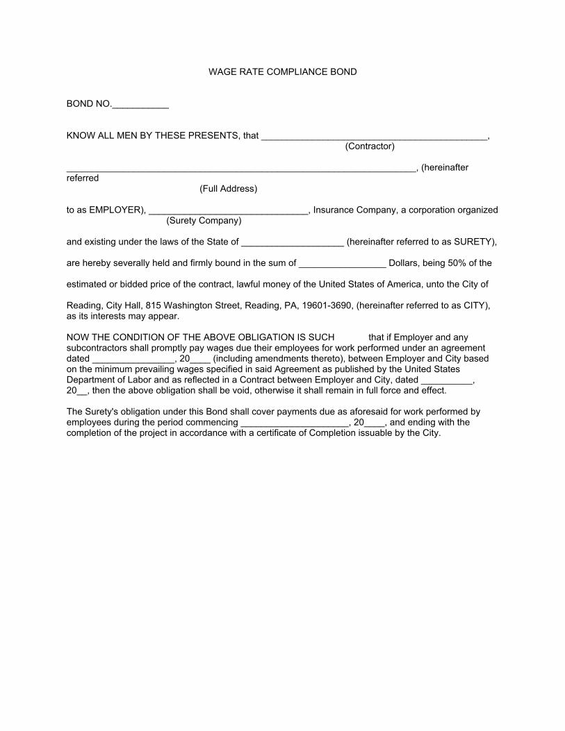
WAGE RATE COMPLIANCE BOND
BOND NO.___________
KNOW ALL MEN BY THESE PRESENTS, that ____________________________________________,(Contractor)
____________________________________________________________________, (hereinafter referred
(Full Address)
to as EMPLOYER), _______________________________, Insurance Company, a corporation organized(Surety Company)
and existing under the laws of the State of ____________________ (hereinafter referred to as SURETY),
are hereby severally held and firmly bound in the sum of _________________ Dollars, being 50% of the
estimated or bidded price of the contract, lawful money of the United States of America, unto the City of
Reading, City Hall, 815 Washington Street, Reading, PA, 19601-3690, (hereinafter referred to as CITY), as its interests may appear.
NOW THE CONDITION OF THE ABOVE OBLIGATION IS SUCH that if Employer and any subcontractors shall promptly pay wages due their employees for work performed under an agreement dated ________________, 20____ (including amendments thereto), between Employer and City based on the minimum prevailing wages specified in said Agreement as published by the United States Department of Labor and as reflected in a Contract between Employer and City, dated __________, 20__, then the above obligation shall be void, otherwise it shall remain in full force and effect.
The Surety's obligation under this Bond shall cover payments due as aforesaid for work performed by employees during the period commencing _____________________, 20____, and ending with the completion of the project in accordance with a certificate of Completion issuable by the City.

We, the said Employer and Surety, and each of us do bind and oblige ourselves, to the extent of our respective liabilities hereunder, as well as our heirs, executors, administrators, successors and assigns, and every one of them, firmly by these presents.
SIGNED, SEALED, AND DATED this _____________day of __________________, 20____.
(INDIVIDUAL PRINCIPAL)
__________________________________ (Seal)
(Signature of Individual)
Witness:
_______________________________
Trading and Doing Business as:
___________________________________
(PARTNERSHIP PRINCIPAL)
___________________________________ (Seal)(Name of Partnership)
Witness:
____________________________ By:________________________________ (Seal)
(Partner)
Witness:
____________________________ By:________________________________ (Seal)
(Partner)
Witness:
____________________________ By:________________________________ (Seal)
(Partner)
Witness:
____________________________ By:________________________________ (Seal)
(Partner)
(CORPORATION PRINCIPAL)
________________________________________(Name of Corporation)
By:_____________________________________(Vice) President
Attest:
_____________________________________(Assistant Secretary)
(Corporate Seal)
(OR, IF APPROPRIATE)
________________________________________(Name of Corporation)
By:_____________________________________(Authorized Representative)
(CORPORATION SURETY)
____________________________________(Name of Corporation)
By:_________________________________(Attorney-In-Fact)
Witness:
_____________________________________
(Corporate Seal)
** Attach an appropriate Power of Attorney, valid and in effect as of the date of this affidavit, evidencing the authority of the Attorney-In-Fact to act in behalf of the corporation.
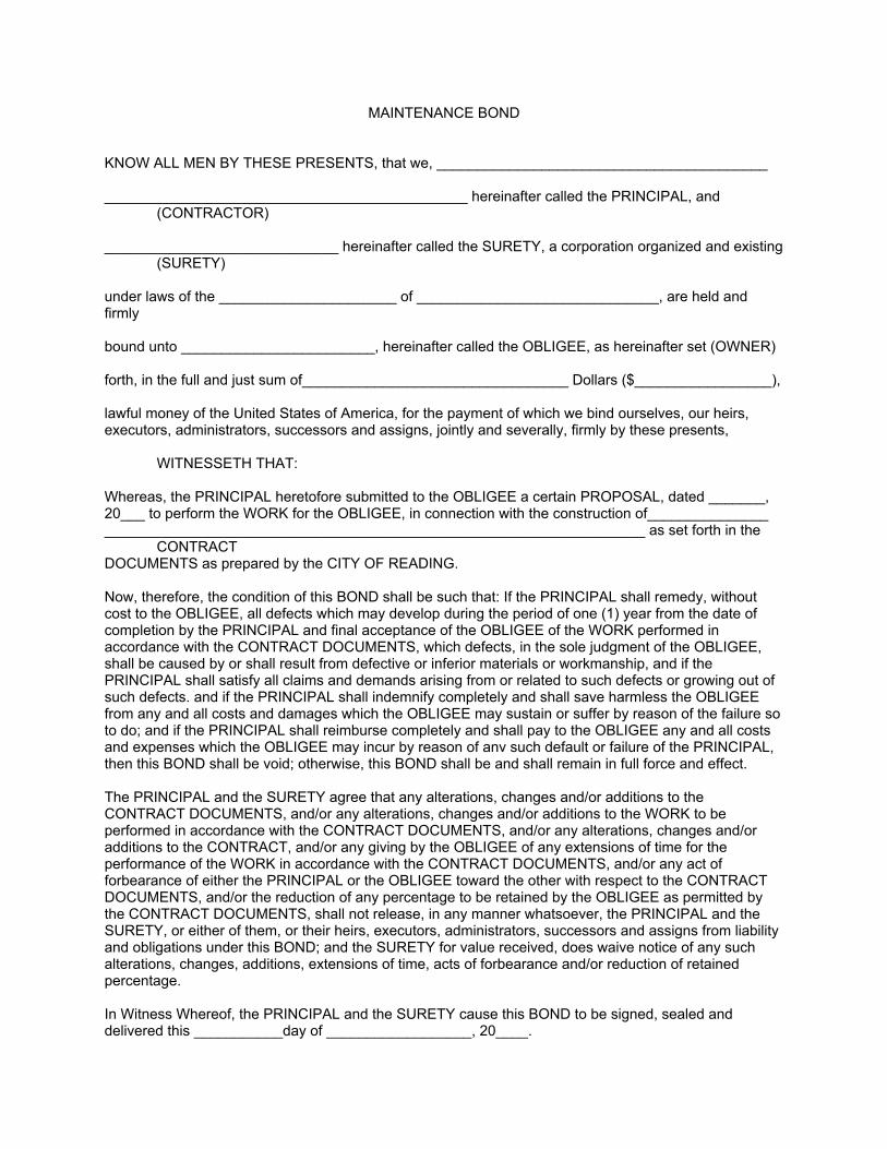
MAINTENANCE BOND
KNOW ALL MEN BY THESE PRESENTS, that we, _________________________________________
_____________________________________________ hereinafter called the PRINCIPAL, and (CONTRACTOR)
_____________________________ hereinafter called the SURETY, a corporation organized and existing (SURETY)
under laws of the ______________________ of ______________________________, are held and firmly
bound unto ________________________, hereinafter called the OBLIGEE, as hereinafter set (OWNER)
forth, in the full and just sum of_________________________________ Dollars ($_________________),
lawful money of the United States of America, for the payment of which we bind ourselves, our heirs, executors, administrators, successors and assigns, jointly and severally, firmly by these presents,
WITNESSETH THAT:
Whereas, the PRINCIPAL heretofore submitted to the OBLIGEE a certain PROPOSAL, dated _______, 20___ to perform the WORK for the OBLIGEE, in connection with the construction of__________________________________________________________________________________ as set forth in the
CONTRACTDOCUMENTS as prepared by the CITY OF READING.
Now, therefore, the condition of this BOND shall be such that: If the PRINCIPAL shall remedy, without cost to the OBLIGEE, all defects which may develop during the period of one (1) year from the date of completion by the PRINCIPAL and final acceptance of the OBLIGEE of the WORK performed in accordance with the CONTRACT DOCUMENTS, which defects, in the sole judgment of the OBLIGEE, shall be caused by or shall result from defective or inferior materials or workmanship, and if the PRINCIPAL shall satisfy all claims and demands arising from or related to such defects or growing out of such defects. and if the PRINCIPAL shall indemnify completely and shall save harmless the OBLIGEE from any and all costs and damages which the OBLIGEE may sustain or suffer by reason of the failure so to do; and if the PRINCIPAL shall reimburse completely and shall pay to the OBLIGEE any and all costs and expenses which the OBLIGEE may incur by reason of anv such default or failure of the PRINCIPAL, then this BOND shall be void; otherwise, this BOND shall be and shall remain in full force and effect.
The PRINCIPAL and the SURETY agree that any alterations, changes and/or additions to the CONTRACT DOCUMENTS, and/or any alterations, changes and/or additions to the WORK to be performed in accordance with the CONTRACT DOCUMENTS, and/or any alterations, changes and/or additions to the CONTRACT, and/or any giving by the OBLIGEE of any extensions of time for the performance of the WORK in accordance with the CONTRACT DOCUMENTS, and/or any act of forbearance of either the PRINCIPAL or the OBLIGEE toward the other with respect to the CONTRACT DOCUMENTS, and/or the reduction of any percentage to be retained by the OBLIGEE as permitted by the CONTRACT DOCUMENTS, shall not release, in any manner whatsoever, the PRINCIPAL and the SURETY, or either of them, or their heirs, executors, administrators, successors and assigns from liability and obligations under this BOND; and the SURETY for value received, does waive notice of any such alterations, changes, additions, extensions of time, acts of forbearance and/or reduction of retained percentage.
In Witness Whereof, the PRINCIPAL and the SURETY cause this BOND to be signed, sealed and delivered this ___________day of __________________, 20____.
(INDIVIDUAL PRINCIPAL)
__________________________________ (Seal)(Signature of Individual)
Witness:
_______________________________
Trading and Doing Business as:
___________________________________
(PARTNERSHIP PRINCIPAL)
___________________________________ (Seal)(Name of Partnership)
Witness:
____________________________ By:________________________________ (Seal)
(Partner)
Witness:____________________________ By:________________________________ (Seal)
(Partner)
Witness:____________________________ By:________________________________ (Seal)
(Partner)
Witness:____________________________ By:________________________________ (Seal)
(Partner)

(CORPORATION PRINCIPAL)
________________________________________(Name of Corporation)
By:_____________________________________(Vice) President
Attest:
_____________________________________(Assistant Secretary)
(Corporate Seal)
(OR, IF APPROPRIATE)
________________________________________(Name of Corporation)
By:_____________________________________(Authorized Representative)
(CORPORATION SURETY)
____________________________________(Name of Corporation)
By:_________________________________(Attorney-In-Fact)
Witness:
_____________________________________
(Corporate Seal)
** Attach an appropriate Power of Attorney, valid and in effect as of the date of this affidavit, evidencing the authority of the Attorney-In-Fact to act in behalf of the corporation.
INDEMNITY AGREEMENT & HOLD HARMLESS
KNOW ALL MEN BY THESE PRESENTS:
WHEREAS, the undersigned has entered into a contract with the CITY OF READING, dated _________________, 20 __, providing for the __________________________________________________________________________________________________________City of Reading, Pennsylvania.
NOW, THEREFORE, in consideration of the award of said contract to the undersigned, ___________________, as well as in further consideration of the sum of ONE DOLLAR ($1.00) in hand paid to the said _________________by the City of Reading, receipt whereof is hereby acknowledged, the said ____________________ agrees to indemnify and save harmless the CITY OF READING, its officers, agents, servants, and employees against any and all loss, damage, costs and expenses which the said CITY may hereafter suffer, incur, be put to or pay by reason of any bodily injury (including death) or damage to property arising out of any act or omission in performance of the work undertaken under the aforesaid contract.
EXECUTED this _____ day of ____________________, 20__.
By: ______________________________
Title: ___________________________
ATTEST:
________________________
________________________(Title)

STIPULATION AGAINST LIENS
WHEREAS, ___________________________________, hereinafter called the CONTRACTOR, has entered into a CONTRACT, dated __________________, 20___, with ________________________________________________________________ hereinafter called the CITY, to provide materials and perform labor necessary for the manufacture and furnishing of the: as set forth in the CONTRACT DOCUMENTS as prepared by the City of Reading.
NOW, THEREFORE, it is hereby stipulated and agreed by and between the said parties, as part of the said CONTRACT, and for the consideration therein set forth, that neither the undersigned CONTRACTOR, any SUBCONTRACTOR or material man, nor any other person furnishing labor or materials to the said CONTRACTOR under this CONTRACT shall file a lien, commonly called a mechanic's lien, for WORK done or materials furnished for the above manufacture.
This stipulation is made and shall be filed with the Berks County Prothonotary within ten (10) days after execution, in accordance with the requirements of Section 1402 of the Mechanics Lien Law of 1963 of the Commonwealth of Pennsylvania in such case provided.
IN WITNESS WHEREOF, the parties hereto have caused the signature of their proper officers to be affixed thereto on this ______________day of___________________ 20___ .
(SEAL)
_________________________ BY:______________________(CITY OF READING)
TITLE:____________________
ATTEST:
BY:_______________________
TITLE:_____________________
(SEAL) ___________________________(CONTRACTOR)
ATTEST: BY:______________________
TITLE:___________________
BY:________________________
TITLE:______________________
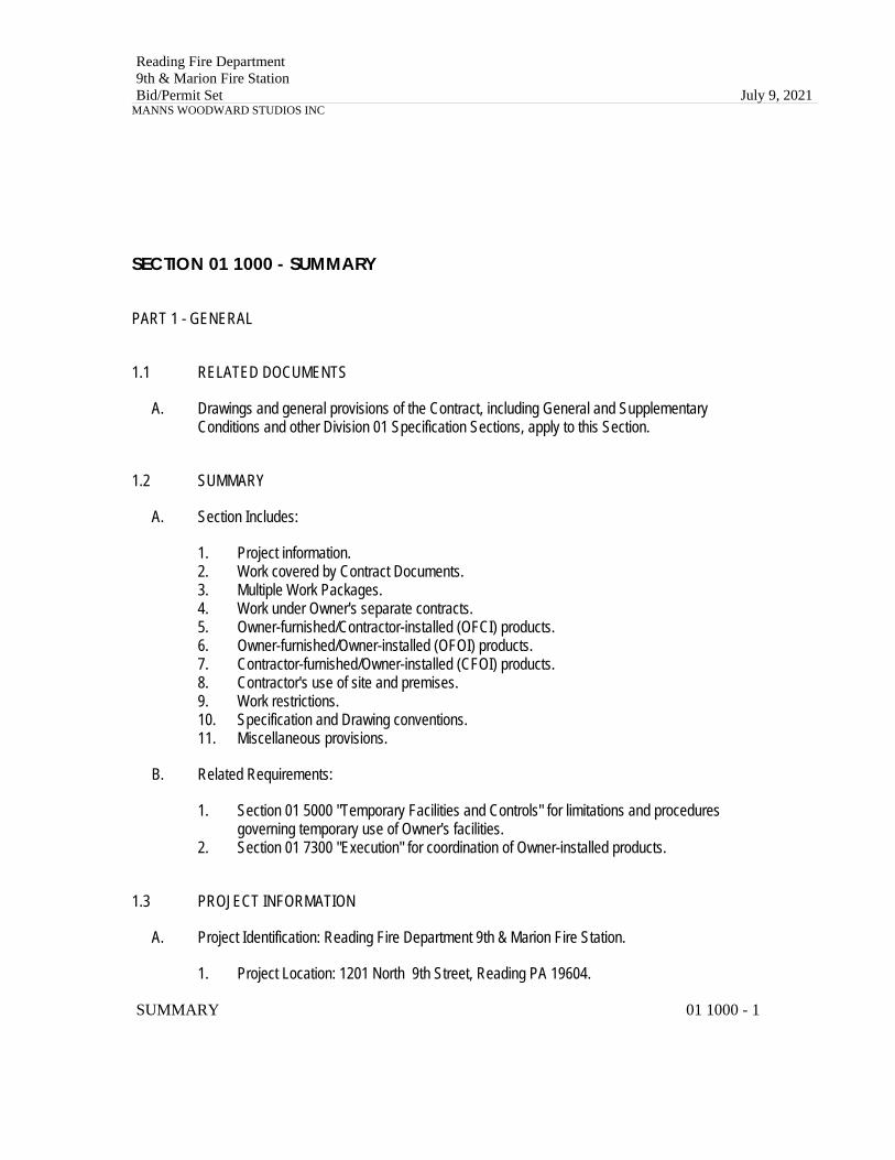
Reading Fire Department9th & Marion Fire StationBid/Permit Set July 9, 2021
MANNS WOODWARD STUDIOS INC
SECTION 01 1000 - SUMMARY
PART 1 - GENERAL
1.1 RELATED DOCUMENTS
A. Drawings and general provisions of the Contract, including General and Supplementary Conditions and other Division 01 Specification Sections, apply to this Section.
1.2 SUMMARY
A. Section Includes:
1. Project information.2. Work covered by Contract Documents.3. Multiple Work Packages.4. Work under Owner's separate contracts.5. Owner-furnished/Contractor-installed (OFCI) products.6. Owner-furnished/Owner-installed (OFOI) products.7. Contractor-furnished/Owner-installed (CFOI) products.8. Contractor's use of site and premises.9. Work restrictions.10. Specification and Drawing conventions.11. Miscellaneous provisions.
B. Related Requirements:
1. Section 01 5000 "Temporary Facilities and Controls" for limitations and procedures governing temporary use of Owner's facilities.
2. Section 01 7300 "Execution" for coordination of Owner-installed products.
1.3 PROJECT INFORMATION
A. Project Identification: Reading Fire Department 9th & Marion Fire Station.
1. Project Location: 1201 North 9th Street, Reading PA 19604.
SUMMARY 01 1000 - 1
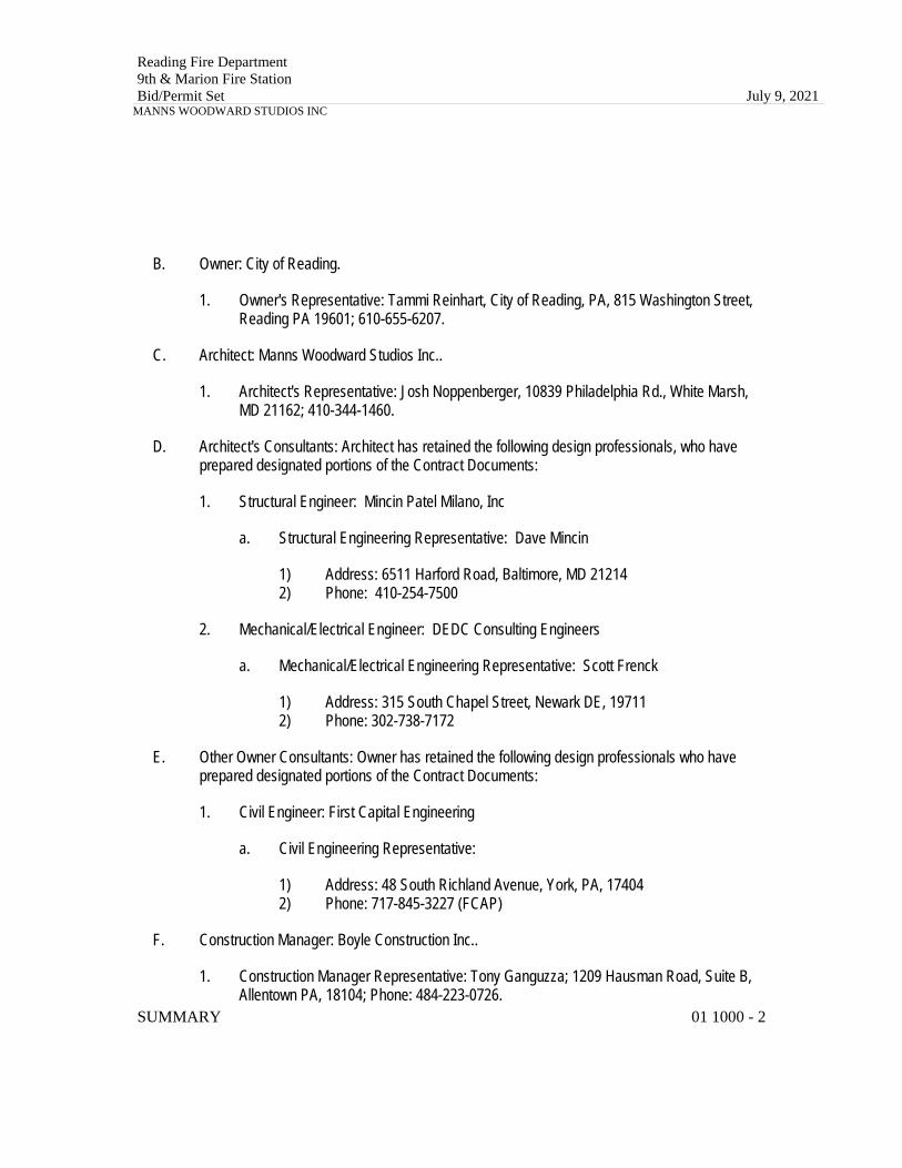
Reading Fire Department9th & Marion Fire StationBid/Permit Set July 9, 2021
MANNS WOODWARD STUDIOS INC
B. Owner: City of Reading.
1. Owner's Representative: Tammi Reinhart, City of Reading, PA, 815 Washington Street, Reading PA 19601; 610-655-6207.
C. Architect: Manns Woodward Studios Inc..
1. Architect's Representative: Josh Noppenberger, 10839 Philadelphia Rd., White Marsh, MD 21162; 410-344-1460.
D. Architect's Consultants: Architect has retained the following design professionals, who have prepared designated portions of the Contract Documents:
1. Structural Engineer: Mincin Patel Milano, Inc
a. Structural Engineering Representative: Dave Mincin
1) Address: 6511 Harford Road, Baltimore, MD 212142) Phone: 410-254-7500
2. Mechanical/Electrical Engineer: DEDC Consulting Engineers
a. Mechanical/Electrical Engineering Representative: Scott Frenck
1) Address: 315 South Chapel Street, Newark DE, 197112) Phone: 302-738-7172
E. Other Owner Consultants: Owner has retained the following design professionals who have prepared designated portions of the Contract Documents:
1. Civil Engineer: First Capital Engineering
a. Civil Engineering Representative:
1) Address: 48 South Richland Avenue, York, PA, 174042) Phone: 717-845-3227 (FCAP)
F. Construction Manager: Boyle Construction Inc..
1. Construction Manager Representative: Tony Ganguzza; 1209 Hausman Road, Suite B, Allentown PA, 18104; Phone: 484-223-0726.
SUMMARY 01 1000 - 2
Reading Fire Department9th & Marion Fire StationBid/Permit Set July 9, 2021
MANNS WOODWARD STUDIOS INC
2. Construction Manager has been engaged for this Project to serve as an advisor to Owner and to provide assistance in administering the Contract for construction between Owner and each Contractor, according to a separate contract between Owner and Construction Manager.
1.4 WORK COVERED BY CONTRACT DOCUMENTS
A. The Work of Project is defined by the Contract Documents and includes, but is not limited to, the following:
1. The project generallyl consists of the construction of a new two story, with mezzanine, fire station approximately 16,505 gross square feet. and other Work indicated in the Contract Documents.
B. Type of Contract:
1. Project will be constructed under coordinated, concurrent multiple contracts. See Section 01 1200 "Multiple Contract Summary" for a list of multiple contracts, a description of work included under each of the multiple contracts, and the responsibilities of Project coordinator.
1.5 WORK UNDER OWNER'S SEPARATE CONTRACTS
A. Work with Separate Contractors: Cooperate fully with Owner's separate contractors, so work on those contracts may be carried out smoothly, without interfering with or delaying Work under this Contract or other contracts. Coordinate the Work of this Contract with work performed under Owner's separate contracts.
B. Concurrent Work: Owner will award separate contract(s) for the following construction operations at Project site. Those operations will be conducted simultaneously with Work under this Contract.
1. Vehicle Exhaust System (Plymovent): To provide and install a complete vehicle exhaust system..
2. CCTV, Security Cameras, and Access Control Systems.3. Telephone Systems.4. Furniture.
SUMMARY 01 1000 - 3
Reading Fire Department9th & Marion Fire StationBid/Permit Set July 9, 2021
MANNS WOODWARD STUDIOS INC
1.6 OWNER-FURNISHED/CONTRACTOR-INSTALLED (OFCI) PRODUCTS
A. Owner's Responsibilities: Owner will furnish products indicated and perform the following, as applicable:
1. Provide to Contractor Owner-reviewed Product Data, Shop Drawings, and Samples.2. Provide for delivery of Owner-furnished products to Project site.3. Upon delivery, inspect, with Contractor present, delivered items.
a. If Owner-furnished products are damaged, defective, or missing, arrange for replacement.
4. Obtain manufacturer's inspections, service, and warranties.5. Inform Contractor of earliest available delivery date for Owner-furnished products.
B. Contractor's Responsibilities: The Work includes the following, as applicable:
1. Designate delivery dates of Owner-furnished products in Contractor's construction schedule, utilizing Owner-furnished earliest available delivery dates.
2. Review Owner-reviewed Product Data, Shop Drawings, and Samples, noting discrepancies and other issues in providing for Owner-furnished products in the Work.
3. Receive, unload, handle, store, protect, and install Owner-furnished products.4. Make building services connections for Owner-furnished products.5. Protect Owner-furnished products from damage during storage, handling, and installation
and prior to Substantial Completion.6. Repair or replace Owner-furnished products damaged following receipt.
C. Owner-Furnished/Contractor-Installed (OFCI) Products:
1. As indicated within drawings.
1.7 CONTRACTOR'S USE OF SITE AND PREMISES
A. Unrestricted Use of Site: Each Contractor shall have full use of Project site for construction operations during construction period. Contractor's use of Project site is limited only by Owner's right to perform work or to retain other contractors on portions of Project.
SUMMARY 01 1000 - 4
Reading Fire Department9th & Marion Fire StationBid/Permit Set July 9, 2021
MANNS WOODWARD STUDIOS INC
1. Construction trailers, storage sheds, fabrication sheds, storage of materials and products, and contractor parking shall be prohibited on project site. An off-site staging and storage area shall be provided by the City of Reading for the Contractor's use.
1.8 WORK RESTRICTIONS
A. Comply with restrictions on construction operations.
1. Comply with limitations on use of public streets, work on public streets, rights of way, and other requirements of authorities having jurisdiction.
B. On-Site Work Hours: Limit work to between 7:00 a.m. to 5:00 p.m., Monday through Friday, unless otherwise indicated. Work hours may be modified to meet Project requirements if approved by Owner and authorities having jurisdiction.
1. Weekend Hours: Shall only be approved on a case by case basis and only in writing from Owner.
2. Early Morning Hours: Shall only be approved on a case by case basis, shall be approved by the Owner in writing, and shall only occur where authorized by all authorities having jurisdiction.
C. Nonsmoking Building: Smoking is not permitted within the building or within 25 feet of entrances, operable windows, or outdoor-air intakes.
D. Smoking and Controlled Substance Restrictions: Use of tobacco products , alcoholic beverages, and other controlled substances on Project site is not permitted.
E. Employee Identification: Provide identification tags for Contractor personnel working on Project site. Require personnel to use identification tags at all times.
1.9 SPECIFICATION AND DRAWING CONVENTIONS
A. Specification Content: The Specifications use certain conventions for the style of language and the intended meaning of certain terms, words, and phrases when used in particular situations. These conventions are as follows:
SUMMARY 01 1000 - 5
Reading Fire Department9th & Marion Fire StationBid/Permit Set July 9, 2021
MANNS WOODWARD STUDIOS INC
1. Imperative mood and streamlined language are generally used in the Specifications. The words "shall," "shall be," or "shall comply with," depending on the context, are implied where a colon (:) is used within a sentence or phrase.
2. Text Color: Text used in the Specifications, including units of measure, manufacturer and product names, and other text may appear in multiple colors or underlined as part of a hyperlink; no emphasis is implied by text with these characteristics.
3. Hypertext: Text used in the Specifications may contain hyperlinks. Hyperlinks may allow for access to linked information that is not residing in the Specifications. Unless otherwise indicated, linked information is not part of the Contract Documents.
4. Specification requirements are to be performed by Contractor unless specifically stated otherwise.
B. Division 00 Contracting Requirements: General provisions of the Contract, including General and Supplementary Conditions, apply to all Sections of the Specifications.
C. Division 01 General Requirements: Requirements of Sections in Division 01 apply to the Work of all Sections in the Specifications.
D. Drawing Coordination: Requirements for materials and products identified on Drawings are described in detail in the Specifications. One or more of the following are used on Drawings to identify materials and products:
1. Terminology: Materials and products are identified by the typical generic terms used in the individual Specifications Sections.
2. Abbreviations: Materials and products are identified by abbreviations scheduled on Drawings.
3. Keynoting: Materials and products are identified by reference keynotes referencing Specification Section numbers found in this Project Manual.
1.10 MISCELLANEOUS PROVISIONS
A. Each Prime Contractor shall be resposnible for ensuring all sub-contractors contracted to perform a portion of the Work have possession of ALL CONTRACT DOCUMENTS. Sub-contractors shall be responsible for reviewing all contract documents including but not limited to drawings and specifications and providing all items outlined within the documents to be provided along with all connections, systems, supports, and miscellaneous items required for the items to function properly as intended.
SUMMARY 01 1000 - 6
Reading Fire Department9th & Marion Fire StationBid/Permit Set July 9, 2021
MANNS WOODWARD STUDIOS INC
B. Drawing Coordination: Generally, requirements for materials and products identified on Drawings are described in detail in the Specifications. However, items may indicated either only on the drawings or only within the specifications. If items are indicated in one document only it shall be the responsibility of the Contractor to provide the item indicated along with the all components, connections, systems, supports or other miscellaneous items required for the proper operation and installation of the item identified within the single document.
C. References within the Drawings or Specifications to other Drawings or Specifications indicates the potential existence of additional information. If no additional information exists within the referenced drawing(s) or specification(s), the Contractor shall remain responsible for the installation of the Work indicated or graphically depicted. Where Work typically would be structural or load bearing in nature, the Contractor shall provide reinforcement, bracketing, bracing, or otherwise attach such Work as indicated within similar details existing within the Drawings or Specifications. It is also the Contractors responsibility to seek clarification for such items prior to submitting a bid to perform the Work. If no clarification is requested prior to the submission of a bid, it shall be deemed that the Contractor understands the extent of Work both indicated and graphically depicted and has included such within the contract sum.
PART 2 - PRODUCTS (Not Used)
PART 3 - EXECUTION (Not Used)
END OF SECTION 01 1000
SUMMARY 01 1000 - 7
Reading Fire Department
9th & Marion Fire Station
Bid/Permit Set July 9, 2021 MANNS WOODWARD STUDIOS INC
CONTRACT PACKAGE DOCUMENT REFERENCE 01 1300 - 1 of 13
SECTION 01 1300 – CONTRACT PACKAGE DOCUMENT REFERENCE
PART 1 – GENERAL
1.1 SUMMARY
A. This section outlines the separate Contract Packages required to complete the
Scope of Work of the Reading Fire Department 9th & Marion Fire Station. Each
Contract Package indicated within this Section shall include both specific
Specification Sections and specific drawing groups and drawings. The
Contractor awarded each Contract Package respectively shall be responsible to
perform all Work required by the indicated/referenced Specification Sections
and Drawings listed under each Contract Package within this Section.
Additionally, each Contractor shall be responsible for Work referenced within
PART 1 of each Specification Section listed within their respective Contract
Packages.
B. Related Documents and Specification Sections
1. All Contractors shall be responsible for the information within and shall comply
with requirements of Division 00 – Bidding Requirements and Division 01 –
General Requirements along with all other procurement documents stipulated
by the Invitation to Bid.
2. All Prime Contractors are responsible for reviewing and understanding all
drawings and specifications whether included within their Contract Package
or another Contract Package. Each document contains critical information
for the coordination and completion of the Work of the Project.
3. Section 01 1320 “CONTRACT PACKAGE SUPPLEMENTARY INSTRUCTIONS AND
REQUIREMENTS”
4. All Contractors shall comply with requirements of the listed “G” Series Drawings
– General/Code.
1. G000 Cover Sheet
2. G001 Drawing Index
3. G002 Code Analysis
4. G003 Code Diagrams
5. G004 Code Plan
6. G005 Typical Accessibility Guidelines
1.2 CONTRACT PACKAGES
A. 1A – GENERAL CONTRACT PACKAGE
1. Specification Sections
a. DIVISION 2 – EXISTING CONDITIONS
1. Structure Demolition
b. DIVISION 3 – CONCRETE
1. Cast-In-Place Concrete
2. Architectural Concrete
c. DIVISION 4 – MASONRY
1. Concrete Unit Masonry
2. Masonry Veneer

Reading Fire Department
9th & Marion Fire Station
Bid/Permit Set July 9, 2021 MANNS WOODWARD STUDIOS INC
CONTRACT PACKAGE DOCUMENT REFERENCE 01 1300 - 2 of 13
d. DIVISION 5 – METALS
1. Structural Steel Framing
2. Architecturally Exposed Structural Steel Framing
3. Steel Decking
4. Cold Formed Metal Framing
5. Metal Fabrications
6. Metal Pan Stairs
7. Pipe and Tube Railings
e. DIVISION 6 – WOOD PLASTICS AND COMPOSITES
1. Miscellaneous Rough Carpentry
2. Sheathing
3. Interior Finish Carpentry
4. Plastic-Laminate Faced Architectural Cabinets
5. Plastic Paneling
f. DIVISION 7 – THERMAL AND MOISTURE PROTECTION
1. Bituminous Dampproofing
2. Water Repellents
3. Thermal Insulation
4. Fluid Applied Membrane Air Barrier
5. Formed Metal Wall Panels
6. Metal Composite Material Wall Panels
7. Soffit Panels
8. Fiber Cement Siding
9. Thermoplastic Polyolefin (TPO) Roofing
10. Sheet Metal Flashing and Trim
11. Roof Specialties
12. Roof Accessories
13. Penetration Firestopping
14. Joint Sealants
g. DIVISION 8 – OPENINGS
1. Hollow Metal Doors and Frames
2. Flush Wood Doors
3. Access Doors and Frames
4. Overhead Coiling Doors
5. Four-Fold Door Systems
6. Sectional Doors
7. Aluminum-Framed Entrances and Storefronts
8. Glazed Aluminum Curtain Walls
9. Security Windows
10. Door Hardware
11. Glazing
12. Fire-Resistant Glazing
13. Operable Wall Louvers
14. Fixed Louvers
h. DIVISION 9 – FINISHES
1. Gypsum Board Shaft Wall Assemblies
Reading Fire Department
9th & Marion Fire Station
Bid/Permit Set July 9, 2021 MANNS WOODWARD STUDIOS INC
CONTRACT PACKAGE DOCUMENT REFERENCE 01 1300 - 3 of 13
2. Non-structural Metal Framing
3. Gypsum Board
4. Ceramic Tiling
5. Acoustical Panel Ceilings
6. Suspended Decorative Grids
7. Resilient Base and Accessories
8. Resilient Tile Flooring
9. Static-Control Resilient Flooring
10. Resilient Athletic Flooring
11. Resinous Flooring
12. Tile Carpeting
13. Interior Painting
14. High-Performance Coatings
15. Intumescent Painting
i. DIVISION 10 – SPECIALTIES
1. Dimensional Letter Signage
2. Panel Signage
3. Room Identification Panel Signage
4. Wall and Door Protection
5. Toilet, Bath and Laundry Accessories
6. Fire Extinguisher Cabinets
7. Fire Extinguishers
8. Metal Lockers
9. Wire Mesh Storage Lockers
10. Ground Set Flagpoles
j. DIVISION 11 – EQUIPMENT
1. Residential Appliances
k. DIVISION 12 – FURNISHINGS
1. Roller Window Shades
2. Solid Surfacing Countertops
3. Quartz Agglomerate Countertops
l. DIVISION 14 - CONVEYING EQUIPMENT
1. Hydraulic Elevators
m. DIVISION 31 – EARTHWORK
1. Site Clearing
2. Earthwork
3. Trenching
n. DIVISION 32 – EXTERIOR IMPROVEMENTS
1. Asphalt Paving
2. Site Concrete
3. Pavement Markings
4. Soil Preparation
5. Turf and Grasses
o. DIVISION 33 – UTILITIES
1. Common Work Results for Utilities
2. Stormwater Conveyance
Reading Fire Department
9th & Marion Fire Station
Bid/Permit Set July 9, 2021 MANNS WOODWARD STUDIOS INC
CONTRACT PACKAGE DOCUMENT REFERENCE 01 1300 - 4 of 13
p. DIVISION 41 – MATERIAL PROCESSING AND HANDLING EQUIPMENT
MANUFACTURERS
1. Cranes & Hoists
2. Drawing Groups and Drawings
a. Civil Drawings:
1. 1 of 10 Cover Sheet
2. 2 of 10 General Notes
3. 3 of 10 Detail Sheet
4. 4 of 10 Existing Condition Plan
5. 5 of 10 Baseline Geometry Plan
6. 6 of 10 Site Plan
7. 7 of 10 Cross Sections
8. 8 of 10 Proposed Driveway Profile
9. 9 of 10 Existing Parking Exhibit
10. 10 of 10 Proposed Parking Exhibit
11. CS Cover Sheet
12. LD-1 General Notes
13. LD-1A Cross Sections
14. LD-2 Overall Existing Condition Plan
15. LD-3 Existing Condition & Demolition Plan
16. LD-4 Site Plan
17. LD-5 Grading Plan
18. LD-6 Utility Plan
19. LD-6A Lighting Plan
20. LD-7 Profile Sheet
21. LD-8 Detail Sheet
22. LD-9 Detail Sheet
23. LD-10 Turning Template
24. LD-11 Turning Template
25. LD-12 Existing Parking Exhibit
26. LD-13 Proposed Parking Exhibit
27. PCSM-1 Existing Conditions
28. PCSM-2 Post Construction Stormwater Management Plan
29. PCSM-3 Post Construction Stormwater Management Details
30. ES CS E&S Cover Sheet
31. ES-1 Existing Condition Plan
32. ES-2 Erosion and Sediment Control Plan
33. ES-3 Erosion and Sediment Control Plan Detail Sheet 1
34. ES-4 Erosion and Sediment Control Plan Detail Sheet 2
35. 2 of 2 Flashing Warning Device Plan
b. Geotech:
1. 100 Cover Sheet
2. 101 General Requirements
3. 102 Wall Profile
4. 103 Typical Cross Section
Reading Fire Department
9th & Marion Fire Station
Bid/Permit Set July 9, 2021 MANNS WOODWARD STUDIOS INC
CONTRACT PACKAGE DOCUMENT REFERENCE 01 1300 - 5 of 13
c. Architectural Drawings: “A” Series
1. A100 Architectural Site Diagram
2. A101 Exterior Site Slab & Sidewalk Diagram
3. A102 Reference Plan – First Floor
4. A103 Reference Plan - Mezzanine
5. A104 Reference Plan – Second Floor
6. A105 Dimension Plan – First Floor
7. A106 Dimension Plan – Mezzanine & Second Floor
8. A107 Building Assembly Types & Details
9. A108 Slab/Masonry Diagram – First Floor
10. A109 Slab/Masonry Dia. – Mezz & Second Floor
11. A110 Plan Details
12. A111 Plan Details
13. A112 Finish Plan – First Floor & Details
14. A113 Finish Plan – Mezz & Second Floor
15. A114 FFE First Floor Plan, Schedule & Details
16. A115 FFE Mezzanine & Second Floor
17. A116 Site Details
18. A117 Site Details
19. A118 Site Details
20. A200 Building Elevations
21. A300 Building Sections
22. A301 Building Sections
23. A302 Building Sections
24. A400 Wall Sections
25. A401 Wall Sections
26. A402 Wall Sections
27. A403 Wall Sections
28. A404 Wall Sections
29. A405 Foundation/Slab Details
30. A406 Stair Details
31. A407 Stairs & Elevator Details
32. A408 Stair & Fire Pole Details
33. A409 Fire Pole Details
34. A500 Roof Plan - High
35. A501 Roof Details
36. A502 Roof Details
37. A503 Roof Details
38. A504 Roof Details
39. A505 Roof Details – Roof Top Access Enclosure
40. A506 Roof Details - Courtyard
41. A600 Door/Window Schedule & Types
42. A601 Door Hardware
43. A602 Door Hardware
44. A603 Door/Window Details
45. A604 Four-Fold/Overhead Door Details
Reading Fire Department
9th & Marion Fire Station
Bid/Permit Set July 9, 2021 MANNS WOODWARD STUDIOS INC
CONTRACT PACKAGE DOCUMENT REFERENCE 01 1300 - 6 of 13
46. A605 Ext Curtainwall & Storefront Elevations
47. A606 Exterior Curtainwall Details
48. A607 Exterior Storefront Details
49. A608 Exterior Storefront Details
50. A609 Interior Storefront Elevations & Details
51. A610 Louver Schedule & Details
52. A700 Typical Equipment & Built-in Details
53. A701 Enlarged Plans & Int. Elevations
54. A702 Enlarged Plans & Int. Elevations
55. A703 Enlarged Plans & Int. Elevations
56. A704 Enlarged Plans & Int. Elevations
57. A705 Enlarged Plans & Int. Elevations
58. A706 Enlarged Courtyard Plan & Elevations
59. A800 RCP – First Floor
60. A801 RCP – Mezz & Second Floor
61. A802 Ceiling Details
62. A900 Typical ADA Signage Details
63. A901 Mock-up Panels
64. A902 Mock-up Panels
65. A903 Mock-up Panels
d. Structural Drawings: “S” Series
1. S101 Foundation/First Floor Plan
2. S102 Mezzanine Framing Plan
3. S103 Second Floor Framing Plan
4. S104 Roof Framing Plans
5. S201 General Notes and Schedules
6. S301 Typical Details
7. S302 Typical Details
8. S303 Typical Details
9. S304 Typical Details
10. S305 Typical Details
11. S401 Sections
12. S402 Sections
13. S403 Sections
14. S404 Sections
15. S405 Sections
B. 21A – FIRE PROTECTION CONTRACT PACKAGE
1. Specification Sections
a. DIVISION 3: CONCRETE
1. Cast-In-Place Concrete
b. DIVISION 4: MASONRY
1. Concrete Unit Masonry
c. DIVISION 5: METALS
1. Metal Fabrications
Reading Fire Department
9th & Marion Fire Station
Bid/Permit Set July 9, 2021 MANNS WOODWARD STUDIOS INC
CONTRACT PACKAGE DOCUMENT REFERENCE 01 1300 - 7 of 13
d. DIVISION 6: WOODS PLASTICS AND COMPOSITES
1. Miscellaneous Rough Carpentry
e. DIVISION 7: THERMAL AND MOISTURE PROTECTION
1. Penetration Firestopping
2. Joint Sealants
f. DIVISION 8: OPENINGS
1. Access Doors and Frames
g. DIVISION 21: FIRE SUPPRESSION
1. Common Work Results For Fire Suppression
2. Vibration and Seismic Controls for Fire Suppression Piping and
Equipment
3. Identification for Fire Suppression Piping and Equipment
4. Fire Suppression Sprinkler Systems
h. DIVISION 31 – EARTHWORK
1. Earthwork
2. Trenching
i. DIVISION 33 – UTILITIES
1. Common Work Results for Utilities
2. Drawing Groups and Drawings
a. Civil:
1. CS Cover Sheet
2. LD-1 General Notes
3. LD-1A Cross Sections
4. LD-2 Overall Existing Conditions Plan
5. LD-6 Site Utility Plan
6. LD-8 Detail Sheet
7. PCSM-2 Post Construction Stormwater Management Plan
8. ES-2 Erosion and Sediment Control Plan
9. 2 of 10 General Notes
10. 6 of 10 Site Plan
b. Architectural: “A” Series
1. A800 RCP First Floor
2. A801 RCP – Mezz & Second Floor
c. Fire Protection: “F” Series
1. F0.00 Fire Protection Cover Sheet
2. F1.01 First Floor Fire Protection Plan
3. F1.02 Mezzanine Fire Protection Plan
4. F1.03 Second Floor Fire Protection Plan
5. F6.01 Fire Protection Detail Sheet
C. 22A – PLUMBING CONTRACT PACKAGE
1. Specification Sections
a. DIVISION 3: CONCRETE
1. Cast-In-Place Concrete
b. DIVISION 4: MASONRY
1. Concrete Unit Masonry
Reading Fire Department
9th & Marion Fire Station
Bid/Permit Set July 9, 2021 MANNS WOODWARD STUDIOS INC
CONTRACT PACKAGE DOCUMENT REFERENCE 01 1300 - 8 of 13
c. DIVISION 5: METALS
1. Metal Fabrications
d. DIVISION 6: WOODS PLASTICS AND COMPOSITES
1. Miscellaneous Rough Carpentry
e. DIVISION 7: THERMAL AND MOISTURE PROTECTION
1. Roof Specialties
2. Roof Accessories
3. Penetration Firestopping
4. Joint Sealants
f. DIVISION 8: OPENINGS
1. Access Doors and Frames
g. DIVISION 22: PLUMBING
1. Common Work Results for Plumbing
2. Expansion Fittings and Loops for Plumbing Piping
3. General Duty Valves for Plumbing Piping
4. Vibration and Seismic Controls for Plumbing Piping and Equipment
5. Identification for Plumbing Piping and Equipment
6. Plumbing Insulation
7. Under Lavatory Pipe and Supply Covers
8. Facility Water Distribution Piping
9. Domestic Water Piping
10. Domestic Water Piping Specialties
11. Facility Natural Gas Piping
12. Sanitary Waste and Vent Piping
13. Sanitary Waste Piping Specialties
14. Underground Protected Steel Gravity Based Oil/Sand Interceptor
15. Plumbing Equipment
16. Plumbing Fixtures
h. DIVISION 31 – EARTHWORK
1. Earthwork
2. Trenching
i. DIVISION 33 – UTILITIES
1. Common Work Results for Utilities
2. Drawing Groups and Drawings
a. Civil:
1. 2 of 10 General Notes
2. 6 of 10 Site Plan
3. CS Cover Sheet
4. LD-1 General Notes
5. LD-1A Cross Sections
6. LD-2 Overall Existing Condition Plan
7. LD-6 Utility Plan
8. LD-8 Detail Sheet
9. PCSM-2 Post Construction Stormwater Management Plan
10. ES-2 Erosion and Sediment Control Plan
b. Architectural: “A” Series
Reading Fire Department
9th & Marion Fire Station
Bid/Permit Set July 9, 2021 MANNS WOODWARD STUDIOS INC
CONTRACT PACKAGE DOCUMENT REFERENCE 01 1300 - 9 of 13
1. A114 FFE First Floor Plan, Schedule & Details
2. A115 FFE Mezzanine & Second Floor
3. A200 Building Elevations
4. A500 Roof Plan - High
5. A503 Roof Details
6. A504 Roof Details
7. A506 Roof Details - Courtyard
8. A700 Typical Equipment & Built-in Details
9. A701 Enlarged Plans & Int. Elevations
10. A702 Enlarged Plans & Int. Elevations
11. A703 Enlarged Plans & Int. Elevations
12. A704 Enlarged Plans & Int. Elevations
13. A705 Enlarged Plans & Int. Elevations
14. A706 Enlarged Courtyard Plan & Elevations
15. A800 RCP – First Floor
16. A801 RCP – Mezz & Second Floor
c. Plumbing: “P” Series
1. P0.00 Plumbing Title Sheet
2. P1.01 First Floor Sanitary Plan
3. P1.02 Mezzanine Sanitary Plan
4. P1.03 Second Floor Sanitary Plan
5. P1.04 Roof Sanitary Plan
6. P1.11 First Floor Domestic Plan
7. P1.12 Mezzanine Domestic Plan
8. P1.13 Second Floor & Partial Roof Domestic Plan
9. P1.21 First Floor Natural Gas Plan
10. P1.22 Mezzanine Natural Gas Plan
11. P1.23 Second Floor & Partial Roof Natural Gas Plan
12. P1.31 First Floor Storm Water Plan
13. P1.32 Mezzanine Storm Water Plan
14. P1.33 Second Floor Storm Water Plan
15. P1.34 Roof Storm Water Plan
16. P3.01 Waste & Vent Riser Diagrams
17. P3.11 Domestic Riser Diagram
18. P3.21 Natural Gas Riser Diagram
19. P3.31 Storm Water Riser Diagram
20. P6.01 Plumbing Schedules
21. P6.02 Plumbing Details
22. P6.03 Plumbing Details
D. 23A – MECHANICAL CONTRACT PACKAGE
1. Specification Sections
a. DIVISION 3: CONCRETE
1. Cast-In-Place Concrete
b. DIVISION 4: MASONRY
1. Concrete Unit Masonry
Reading Fire Department
9th & Marion Fire Station
Bid/Permit Set July 9, 2021 MANNS WOODWARD STUDIOS INC
CONTRACT PACKAGE DOCUMENT REFERENCE 01 1300 - 10 of 13
c. DIVISION 5: METALS
1. Metal Fabrications
d. DIVISION 6: WOODS PLASTICS AND COMPOSITES
1. Miscellaneous Rough Carpentry
e. DIVISION 7: THERMAL AND MOISTURE PROTECTION
1. Roof Specialties
2. Roof Accessories
3. Penetration Firestopping
4. Joint Sealants
f. DIVISION 8: OPENINGS
1. Access Doors and Frames
2. Operable Wall Louvers
3. Fixed Louvers
g. DIVISION 23: HEATING VENTILATING AND AIR CONDITIONING
1. Sleeves and Sleeve Seals for HVAC Piping
2. Vibration and Seismic Controls for HVAC
3. Identification for HVAC Piping and Equipment
4. Testing, Adjusting, and Balancing for HVAC
5. Duct Insulation
6. HVAC Piping Insulation
7. Commissioning of HVAC
8. Hydronic Piping
9. Refrigerant Piping
10. HVAC Ducts and Casings
11. Air Duct Accessories
12. HVAC Power Ventilators
13. Air Outlets and Inlets
14. Fire Ready Hood
15. HVAC Air Cleaning Devices
16. Breechings, Chimneys, and Stacks
17. Packaged DOAS with Energy Recovery
18. Variable Refrigerant Flow HVAC Systems
19. Convection Heating and Cooling Units
20. Gas Fired Infrared Unit Heaters
2. Drawing Groups and Drawings
a. Architectural: “A” Series
1. A114 FFE First Floor Plan, Schedule & Details
2. A200 Building Elevations
3. A500 Roof Plan - High
4. A503 Roof Details
5. A504 Roof Details
6. A610 Louver Schedule & Details
7. A700 Typical Equipment & Built-in Details
8. A701 Enlarged Plans & Int. Elevations
9. A702 Enlarged Plans & Int. Elevations
10. A703 Enlarged Plans & Int. Elevations
Reading Fire Department
9th & Marion Fire Station
Bid/Permit Set July 9, 2021 MANNS WOODWARD STUDIOS INC
CONTRACT PACKAGE DOCUMENT REFERENCE 01 1300 - 11 of 13
11. A704 Enlarged Plans & Int. Elevations
12. A705 Enlarged Plans & Int. Elevations
13. A706 Enlarged Courtyard Plan & Elevations
14. A800 RCP – First Floor
15. A801 RCP – Mezz & Second Floor
16. A802 Ceiling Details
b. Mechanical: “M” Series
1. M0.00 Mechanical Title Sheet
2. M1.01 First Floor HVAC Plan
3. M1.02 Mezzanine HVAC Plan
4. M1.03 Second Floor HVAC Plan
5. M1.04 Roof HVAC Plan
6. M1.05 HVAC Reflected Ceiling Plan
7. M1.11 First Floor Mechanical Piping
8. M1.11A First Floor Radiant Floor Plan
9. M1.12 Mezzanine Mechanical Piping
10. M1.13 Second Floor/Partial Roof Mechanical Piping
11. M4.01 HVAC Schedules
12. M4.02 HVAC Schedules
13. M5.01 Sequences of Operations
14. M5.02 Sequences of Operations
15. M6.01 HVAC Details
16. M6.02 HVAC Details
E. 26A – ELECTRICAL CONTRACT PACKAGE
1. Specification Sections
a. DIVISION 3: CONCRETE
1. Cast-In-Place Concrete
b. DIVISION 4: MASONRY
1. Concrete Unit Masonry
c. DIVISION 5: METALS
1. Metal Fabrications
d. DIVISION 6: WOODS PLASTICS AND COMPOSITES
1. Miscellaneous Rough Carpentry
e. DIVISION 7: THERMAL AND MOISTURE PROTECTION
1. Penetration Firestopping
2. Joint Sealants
f. DIVISION 8: OPENINGS
1. Access Doors and Frames
g. DIVISION 26: ELECTRICAL
1. Selective Demolition for Electrical
2. Low Voltage Electrical Power Conductors and Cables
3. Grounding and Bonding for Electrical Systems
4. Hangers and Supports for Electrical Systems
5. Conduit for Electrical Systems
6. Boxes for Electrical Systems
Reading Fire Department
9th & Marion Fire Station
Bid/Permit Set July 9, 2021 MANNS WOODWARD STUDIOS INC
CONTRACT PACKAGE DOCUMENT REFERENCE 01 1300 - 12 of 13
7. Vibration and Seismic Control for Electrical Systems
8. Identification for Electrical Systems
9. Power System Studies
10. Wiring Connections
11. Distributed Digital Lighting Control System
12. Low Voltage Electrical Service Entrance
13. Panelboards
14. Wiring Devices
15. Enclosed Switches
16. Enclosed Controllers
17. Engine Generators
18. Transfer Switches
19. Interior Lighting
20. Exterior Lighting
h. DIVISION 27 – COMMUNICATIONS
1. Data & Voice Communications Cabling
i. DIVISION 28 – ELECTRONIC SAFETY AND SECURITY
1. Fire Detection and Alarm
j. DIVISION 31 – EARTHWORK
1. Earthwork
2. Trenching
k. DIVISION 33 – UTILITIES
1. Common Work Results for Utilities
2. Drawing Groups and Drawings
a. Civil:
1. 2 of 10 General Notes
2. CS Cover Sheet
3. LD-1 General Notes
4. LD-2 Overall Existing Condition Plan
5. LD-3 Existing Condition & Demolition Plan
6. LD-4 Site Plan
7. LD-5 Grading Plan
8. LD-6 Utility Plan
9. LD-6A Lighting Plan
10. 2 of 2 Flashing Warning Device Plan
b. Architectural: “A”
1. A109 Slab/Masonry Dia. – Mezz & Second Floor
2. A114 FFE First Floor Plan, Schedule & Details
3. A115 FFE Mezzanine & Second Floor
4. A118 Site Details
5. A200 Building Elevations
6. Typical Equipment & Built-in Details
7. A701 Enlarged Plans & Int. Elevations
8. A702 Enlarged Plans & Int. Elevations
9. A703 Enlarged Plans & Int. Elevations
10. A704 Enlarged Plans & Int. Elevations
Reading Fire Department
9th & Marion Fire Station
Bid/Permit Set July 9, 2021 MANNS WOODWARD STUDIOS INC
CONTRACT PACKAGE DOCUMENT REFERENCE 01 1300 - 13 of 13
11. A705 Enlarged Plans & Int. Elevations
12. A706 Enlarged Courtyard Plan & Elevations
13. A800 RCP – First Floor
14. A801 RCP – Mezz & Second Floor
15. A802 Ceiling Details
c. Electrical: “E” Series
1. E0.00 Electrical Symbols and Abbreviations
2. ED1.00 Electrical Demolition Site Plan
3. E1.00 Electrical New Work Site Plan
4. E2.00 First Floor Lighting Plan
5. E2.01 Mezzanine Level Lighting Plan
6. E2.02 Second Floor Lighting Plan
7. E3.00 First Floor Power Plans
8. E3.01 Mezzanine Level Power Plans
9. E3.02 Second Floor Power Plans
10. E3.03 Roof Power Plans
11. E6.00 Electrical Panel Schedules
12. E6.01 Electrical Lighting Fixture Schedules & Details
13. E6.02 Electrical Wiring Diagrams and Details
14. E7.00 Electrical Service & System Wiring Diagrams
15. AL-100 Cover Sheet
16. AL-101 General Requirements
17. AL-102 First Floor & Mezz Wiring Diagrams
18. AL-103 Second Floor Wiring Diagram
19. AL-104 Typical Details
PART 2 – PRODUCTS (NOT USED)
PART 3 – EXECUTION (NOT USED)
END OF SECTION

Reading Fire Department
9th & Marion Fire Station
Bid/Permit Set July 9, 2021 MANNS WOODWARD STUDIOS INC
CONTRACT PACKAGE SUPPLEMENTARY
INSTRUCTIONS AND REQUIREMENTS
01 1320 - 1 of 1
SECTION 01 1320 – CONTRACT PACKAGE SUPPLEMENTARY INSTRUCTIONS AND
REQUIREMENTS
PART 1 - GENERAL
1.1 SUMMARY
A. This Section includes both general and specific requirements and instructions for
each Contract Package
1.2 PROPOSALS
A. Proposals in compliance with “THE INVITATION TO BID” and other procurement
and contracting requirements will be received via the procurement website
Pennbid for the Contract packages indicated within these Contract Documents.
B. All proposals for the designated Contract Packages must include all equipment,
material and labor to complete the Work of each Contract Package. NO
EXCEPTIONS, EXCLUSIONS OR QUALIFICATIONS ARE PERMITTED.
1.3 CONTRACTORS BIDDING MORE THAN ONE PACKAGE
A. Contractors bidding more than one Contract Package must submit separate and
complete forms for each package as required by “THE INVITATION TO BID” and
other procurement and contracting requirements.
1.4 BID PACKAGE INSTRUCTIONS AND REQUIREMENTS
A. GENERAL SCOPE (ALL CONTRACTORS)
1. See the following APPENDIX A
B. 1A – GENERAL CONTRACT
1. See the following APPENDIX B
C. 21A – FIRE PROTECTION CONTRACT PACKAGE
1. See the following APPENDIX C
D. 22A – PLUMBING CONTRACT PACKAGE
1. See the following APPENDIX D
E. 23A – MECHANICAL CONTRACT PACKAGE
1. See the following APPENDIX E
F. 26A – ELECTRICAL CONTRACT PACKAGE
1. See the following APPENDIX F
PART 2 – PRODUCTS (NOT USED)
PART 3 – EXECUTION (NOT USED)
END OF SECTION
Reading Fire Department
9th & Marion Fire Station
Bid/Permit Set July 9, 2021 MANNS WOODWARD STUDIOS INC
APPENDIX A – ALL CONTRACTORS 01 1320A - 1 of 8
SECTION 011320 – APPENDIX A
GENERAL SCOPE OF WORK (ALL CONTRACTORS)
This General Scope of Work applies to all contractors working on the Reading Fire
Department 9th & Marion Fire Station. The scope of work shall include the following
items as they apply to the work in each contract unless specifically noted otherwise in
the specific scope requirements.
1.1 Each Contactor is to provide layout/stakeout as required to perform their Work.
Initial vertical control (at minimum of two locations on site) will be provided as part
of the specific scope of work under one of the Contract Packages. Contractor shall
take precautions when completing layout work by thoroughly verifying sizes and
locations of proposed equipment, services and building components such as walls,
ceilings, etc. The Contractor shall review and compare multiple strings of
dimensions, when shown in the drawings, to minimize layout and drawing
discrepancies. Ambiguities, errors, or any inconsistency in the drawings shall be
brought to the attention of the Architect, Construction Manager. Each Contractor is
responsible for reviewing information/literature on equipment being supplied by
other Contractors and the Owner in order to coordinate the completion of the work.
1.2 Core drilling, cutting and patching as required to perform work. Include restoration
of surfaces to original condition. Cutting to be performed as to minimize patching.
1.3 Sealants, caulking and fire-stopping integral with work. In the process of planning its
work each Contractor shall review the Contract Documents to determine the
location of the fire rated/smoke type partitions and the full height walls. The
Contractor shall locate pipes, ducts, conduits, etc. in order to minimize interference
with these walls.
1.4 Permit fees, licenses, testing and inspections required for work. The Owner will be
responsible for applying for the general (non-trade specific) building permit. The 1A
General Contractor shall be responsible for obtaining (picking up) the general (non-
trade specific) building permit. Unless otherwise indicated, each Contractor shall
arrange inspections and tests, coordinate and cooperate with the testing agency
and provide assistance as specified. Provide at least 48 hours notice to the testing
agency prior to requiring the testing agency on site. Each Contractor shall arrange
for the required permit inspections by the governing authorities during the course of
completing its work. The 1A Contractor shall arrange for Final Occupancy
Inspection. Fines associated with non-compliance with said permits and approvals
shall be the responsibility of the contractor. Testing for soil compaction, structural
steel, concrete, masonry, seismic resistance, fire-rated penetrations and joints, and
intumescent fire-resistant coatings will be performed by an independent testing
agency under contract of the City of Reading.
1.5 Daily and final cleanup including mud and dirt tracked onto public walks, lots and
roads. Good housekeeping is essential to the safe and efficient construction of the
job and is the responsibility of each foreman and his crew. Work areas, stairways,
walkways, storage rooms, staging areas, office areas, and other areas shall be kept
Reading Fire Department
9th & Marion Fire Station
Bid/Permit Set July 9, 2021 MANNS WOODWARD STUDIOS INC
APPENDIX A – ALL CONTRACTORS 01 1320A - 2 of 8
clean of obstructions, paper, scrap, pipe, lumber, welding rods, rags, and other
debris at all times. Wash tires at wheel wash station prior to leaving site.
1.6 Removal to dumpster(s) all trash and debris generated by this work (unless noted
otherwise in the specific scope of work). Each contractor is to deposit their trash
and debris into dumpsters provided by the 1A Contractor based on the type of trash
such as concrete/masonry, wood, metal, asphalt, gyp board and paper. The 1A
Contractor will be responsible for all waste removal from the site and recycling
where required.
1.7 Unloading, hoisting, and maintenance of traffic.
1.8 Contractor shall be required to conduct his activities in a safe manner and shall be
responsible for observing the safety requirements of OSHA and local life safety
agencies.
A. Comply with all applicable laws, ordinances, rules, regulations, and orders of the
governing authorities having jurisdiction for safety of persons and property to
protect them from damage, injury and/or loss.
B. Erect and maintain as required by conditions and progress of the work, all
necessary safeguards for safety and protection, including fences, railings,
barricades, lighting, posting of danger signs and other warnings against hazard.
C. Be solely responsible for initiating maintaining and supervising all safety
precautions and programs in connection with the project.
D. Where noxious or nuisance fumes and odors occur due to construction processes,
the contractor shall take every precaution to inform occupants of adjacent
buildings and shall take every precaution to prevent the fumes or odors from
penetrating the adjacent building. Precautions may include but are not limited
to sealing vents and louvers and providing fans to direct odors away from the
occupied areas. Contractor shall coordinate with the Owner minimum of 72
hours prior to beginning such processes.
E. Provide COVID-19 plan and protocols prior to starting construction at the site.
1.9 Temporary lighting, power and water for Contractor’s trailers. Temporary lighting
within the building beyond what is provided by the 26A Contractor.
1.10 Temporary heating or air conditioning prior to the startup and use of the
permanent HVAC system.
1.11 Scaffolding, lifts, cranes and other means of access for own work. In
accordance with applicable codes and regulations, all hoisting equipment used on
site shall have routine maintenance and inspections. Copies of the inspection
certificates are to be maintained with the equipment and shall be provided to the
Owner, Architect, Construction Manager, or AHJ when requested.
1.12 Temporary staging, storage, and office facilities including utilities (and monthly
service) for same.
A. All staging and storage shall occur at the off-site staging and storage location
provided by the City of Reading in location indicated within Civil Drawings.
B. General Contractor shall provide Office trailer to be located within one block of
the project site.
1.13 Excavation, backfill, compaction, shoring and normal mucking/dewatering for
own work. Haul off-site excess spoils. Contractor to provide dust control for his work.
Contact PA One Call prior to any excavation work.
Reading Fire Department
9th & Marion Fire Station
Bid/Permit Set July 9, 2021 MANNS WOODWARD STUDIOS INC
APPENDIX A – ALL CONTRACTORS 01 1320A - 3 of 8
1.14 Premium costs for shutdowns or any other off-hour work. All shutdowns must be
scheduled at least one (1) week in advance with the Owner.
1.15 Phasing and remobilizations based on the agreed upon project schedule and as
required to properly coordinate and complete the work.
1.16 Temporary protection of new and existing work from damage by own work.
1.17 Field measurements and verification of existing conditions and elevations. The
Contractor shall promptly notify the Architect, Construction Manager whether or not
proposed dimensions are required to be guaranteed to ensure timely delivery of
materials. If there is a conflict between drawings or specifications, the contractor is
responsible for the most costly option.
1.18 Temporary weather and dust protection for own work.
1.19 Compliance with local noise restrictions.
1.20 Temporary sheeting, shoring and bracing as required to perform the work.
1.21 MSDS sheets for all materials must be submitted with the submittals and prior to
start of work.
1.22 Shop drawings, submittals and mock-ups as specified. The Contractor will submit
for approval all shop drawings and data as required by the specifications. Project
work, materials, fabrication, and installation shall conform to the requirements of the
Contract Documents, corrected shop drawings, applicable samples, and catalog
data. No submittal will be reviewed by the Architect, Construction Manager, unless
it has been reviewed and approved by the Contractor and bears evidence of such
approval. Submittals made without evidence of Contractors review and approval
will be returned to the Contractor without comment.
1.23 Warranties specified commencing on date of substantial completion. Warranty
extensions to comply with the warranty period starting on the date of substantial
completion shall be the responsibility of the Contractor to ensure full specified
warranty from the date of substantial completion.
1.24 As-built drawings, O&M Manuals, commissioning tests and all other required
closeout documentation. Provide electronic files in pdf file format and submit
through project management software; Procore.
1.25 Reproduction costs for Contract Documents and shop drawings.
1.26 Insurance per Owner Contract.
1.27 Professional liability insurance for any design/engineering work.
1.28 All applicable sales, use and excise taxes.
1.29 Performance, Payment, and Maintenance Bonds as required by the City of
Reading.
1.30 Surface preparation and inspection for proper installation of this work. Include
cleanup, etching, flash patching, moisture testing, etc. as required per specifications
and manufacturer’s instructions. Commencement of this work shall constitute
acceptance of the substrate as suitable for this work.
1.31 Control wiring required for equipment provided as part of this work and not
specified elsewhere in the Contract Documents.
1.32 Concrete required for the work which is not detailed on the Architectural or
structural drawings (e.g. equipment pads, thrust blocks, inertia pads, duct banks,,
etc.)
1.33 Sleeves inserts and anchors for the work
Reading Fire Department
9th & Marion Fire Station
Bid/Permit Set July 9, 2021 MANNS WOODWARD STUDIOS INC
APPENDIX A – ALL CONTRACTORS 01 1320A - 4 of 8
1.34 Additional reinforcements/supports for the work which are not detailed but
required for proper installation of the work.
1.35 Abide by all directions of the Fire Department or AHJ in matters affecting life
safety and fire prevention for the work.
1.36 Temporary barricades shall be placed and maintained by the contractor
creating the hazard, or when necessary to facilitate the next sequence of
construction. The contractor shall be responsible for the next sequence of
construction is then responsible for the barricades if a hazard still exists. Contractors
who disturb the barricades shall restore them to meet safety requirements, at their
own expense. The foregoing “barricades” applies equally to all safety, weather and
dust protection provisions. The Owner shall have the right to determine the suitability
of the barricades. Contractors creating a floor/roof opening fall hazard will provide
plywood covers over the opening, per OSHA standards, and install warning signs on
the cover. Remove cover after hazard does not exist. Daily inspection and
documentation of covers will be by the contractor that created the penetration.
1.37 Normal working hours for this project shall be Monday through Friday 7:00 AM to
5:00 PM. (Working other hours will require authorization by the Owner.)
1.38 Full time competent on-site supervision is required by all contractors during the
performance of own work. In the case of contracts involving second tier
subcontractors, the Primary Contractor will provide on-site supervision and
coordination of their subcontractors and direct hire work. The contractor will be
back-charged for time spent performing such coordination by the Owner, if it does
not occur.
1.39 Submit daily work reports indicating number of workers by classification, work
completed, and hours worked.
1.40 Attendance of bi-weekly progress meetings is required by all contractor’s project
managers and on-site superintendants/foremen. A line item will be required for this
activity within the schedule of values and will not be approved for progress billing
without Owner approval that this task was completed and acceptable.
1.41 Contractors to hold weekly safety meetings and maintain meeting minutes on
site for reference by Owner, Architect, Construction Manager or AHJ at any time.
1.42 Refer to all other project specification sections for additional scope
requirements.
1.43 Portable toilets shall be provided by the 1A Contractor. Toilets shall be located
directly adjacent to the main Office trailer (within one block of the project site.)
Additional toilets shall be located within the off-site storage and staging area.
1.44 Construction personnel shall use designated entrance and egress areas to the
project site as directed by the Owner. Contractor is responsible for parking of own
personnel at off-site staging and storage area or at available legal parking spaces
on the public street. Contractor’s will not be permitted to park within Owner parking
areas unless first obtaining permission from the Owner. Contractors shall not block or
impede entry roads, drives, or other pedestrian or vehicular paths.
1.45 The cost of repairs to any permanent or temporary work in place or existing
finishes will be borne by the Contractor responsible for the damage. Incidental
construction damage to each Contractor’s work and/or equipment shall be
repaired by the installing/providing Contractor who shall assume the cost of such
Reading Fire Department
9th & Marion Fire Station
Bid/Permit Set July 9, 2021 MANNS WOODWARD STUDIOS INC
APPENDIX A – ALL CONTRACTORS 01 1320A - 5 of 8
repair. If responsible parties for the incidental damage can be identified, cost shall
be borne by them accordingly.
1.46 The Contractor will comply with all local codes, ordinances, regulations, etc. as
may be required by the City of Reading, Berks County, the state of Pennsylvania
and/or any local authority having jurisdiction.
1.47 After pouring concrete, contractor shall wash out trucks and pumps in an on-site
wash pit. Wash water must not enter storm-water system.
1.48 SCHEDULE
A. 1A – General Contractor shall be responsible for developing, managing and
maintaining the overall project schedule. The project schedule shall be
established and updated by the Contractor by coordinating the schedules
developed by each Prime Contractor (1A, 21A, 22A, 23A, and 26A) to complete
their Work. Each Prime Contractor must coordinate their schedule with the 1A
General Contractor and the project schedule. The schedule shall be established
so that conflicts are avoided and that the expeditious progress of the project is
not hampered. Major coordination milestones shall be included within the
schedule as separate items. Upon completion and distribution of an overall
project draft schedule to all Prime Contractors, the Architect, Construction
Manager and the Owner, each Prime Contractor must complete, sign and return
to the Architect, Construction Manager and Owner a “Project Schedule
Acceptance Form” within five (5) business days of receipt of the schedule. The
Contractor shall update the overall project schedule on a bi-weekly basis and
distribute the revised overall project schedule at every progress meeting.
Contractor’s shall provide two week task schedule at each progress meeting.
B. Non-compliance by any Prime Contractor with the agreed upon schedule that
results in delays of the project schedule and results in additional time expenditure
and/or additional Work for any other Prime Contractor shall result in a Change
Order to the offending Prime Contractor. It shall be the responsibility of the
affected Prime Contractors to provide proof of delay resulting in additional time
and Work as back-up upon issuance of a Change Order Request for the delay
caused by another Prime Contractor. The Change Order Requests
accompanied by acceptable back-up from the affected Prime Contractors shall
be the basis to establish the Change Order issued by the City of Reading to the
offending Prime Contractor.
C. All work, or applicable portions of the work, shall be sufficiently complete as
required for Owner’s fit- out, use and occupancy and all required approvals and
permits for use and occupancy shall have been issued by the appropriate
authorities by the established “Date of Substantial Completion” of the work, or
applicable portion thereof.
D. All punchlist work, and project closeout shall be completed and approved by the
Owner and Architect, Construction Manager by the “Date of Final Completion”
which shall be no later than thirty (30) calendar days (or earlier per specifications)
after the Date of Substantial Completion. Any uncompleted punchlist items after
this date will be completed by the Owner and back-charged to the appropriate
contractor or vendor including time and expenses spent by the Owner to
complete the Work. Final invoices will not be processed until final completion of
Reading Fire Department
9th & Marion Fire Station
Bid/Permit Set July 9, 2021 MANNS WOODWARD STUDIOS INC
APPENDIX A – ALL CONTRACTORS 01 1320A - 6 of 8
the work and certification of same by the Owner and the Architect, Construction
Manager.
E. The Owner and the Architect, Construction Manager will monitor the progress of
the Work and will meet and confer with the contractor to determine whether or
not they are on schedule. If the Owner and the Architect, Construction Manager
determine that the contractor is not on or ahead of schedule:
1. The contractor will be notified that they have fourteen (14) calendar days to
expedite their work to get back on the schedule.
2. The City of Reading will not make any further payments until the contractor is
back on schedule.
F. If at the end of fourteen (14) days the contractor is still not on schedule, they and
their bonding company will be notified that they are in imminent Breach of
Contract and the City of Reading will obtain the work on the open market. The
City of Reading will deduct the amount charged by the alternate company from
any monies due to or which may become due from the contractor.
G. Contractor will provide copies of a submittal schedule to all other contractors, the
Owner and the Architect, Construction Manager in conjunction with and
coordinated with the overall project schedule.
1.49 Contractor will provide copies of approved shop drawings to other contractors
that require coordination with the work.
1.50 Contractor shall protect finished/sealed floors and concrete floors not receiving
finishes with Masonite or plywood when working off of ladders, scaffolds or other
equipment, and when performing tasks with materials that may stain or otherwise
compromise the look of the exposed surface. Contractors shall only use easily
removable marking utensils and materials where necessary to mark on exposed
surfaces and shall be responsible for removing such markings prior to completion.
1.51 Contractors shall provide mock-ups as indicated in the specifications and scope
of work.
1.52 Contractor is responsible for his scope of work throughout all of the Contract
Documents.
1.53 The word “provided” means purchased, delivered, and installed.
1.54 The word “furnished” means purchased and delivered.
1.55 Each Contractor is responsible for providing fans and temporary ducting to
remove odors and fumes as a result of completing his work, such that all trades can
continue to work in the space.
1.56 As-builts will be kept by each contractor individually. Each contractor will also
be required to input As-built information into the record set kept in the 1A General
Contractor’s trailer on a weekly basis. A line item will be required in the schedule of
values for this activity and will not be approved for progress billing without Owner
approval that this task has been completed.
1.57 Contractor must maintain sufficient manpower to meet schedule and avoid
delay to other phases or contractors.
1.58 If there is a conflict between drawings, specifications, and/or scope of work, the
Contractor will be responsible for the most costly option
1.59 All applicable taxes, necessary permits, delivery fees, and travel time/expenses
are to be included in the base bid.
Reading Fire Department
9th & Marion Fire Station
Bid/Permit Set July 9, 2021 MANNS WOODWARD STUDIOS INC
APPENDIX A – ALL CONTRACTORS 01 1320A - 7 of 8
1.60 Contractor will meet, at a minimum, the insurance requirements as indicated by
the City of Reading.
1.61 Contractor is responsible for coordinating with all other trades so that conflicts
are avoided and the expeditious progress of the project is not hampered. Any
contractor who believes that a potential conflict exists shall notify the Architect,
Construction Manager immediately and follow up in writing within three (3) business
days.
1.62 In the event of an overlap of individual scopes, all parties referenced are
responsible for completing the work and the Owner reserves the right to request a
credit from the contractor(s) who does not provide the work.
1.63 Contractor must provide full-time, on-site supervision during all phases of the
work described in their individual scope of work. Supervisors shall be fluent in the
English language and be able to communicate daily with Owner, Architect,
Construction Manager and other Contractors.
1.64 Each Contractor shall be responsible for performing any required earthwork,
excavation, trenching, backfilling, and soil/spoil removal from site to complete the
work identified within their scope of work.
1.65 Earth Moving: All contractors performing earthwork, excavation, trenching
and/or backfilling to complete their work shall comply with the following:
A. Contractor shall be responsible for all earth moving activities required to
complete the Work of their contract. Contractor shall be responsible for
reviewing and understanding the Geotechnical Report provided within Section
003132 “Geotechnical Data” and 003132a “Geotechnical Report”.
B. Contractors preforming earthwork, excavation, trenching, and/or backfilling shall
provide within their base bid, all Work required to comply with the project
requirements and geotechnical Report (003132a) recommendations to
accommodate or remediate the soil conditions indicated within the Contract
Documents and the Geotechnical Report (003132a) or that are reasonably
inferable from the Geotechnical Report (003132a).
C. All earthwork, excavations, trenching, and backfilling shall be tested by a third
party geotechnical engineer/testing agency. Compaction requirements shall be
as specified/indicated within the Contact Documents or as
recommended/indicated within the Geotechnical Report (003132a). Unsuitable
soils beyond those indicated/identified or reasonably inferable from the
Geotechnical Report (003132a) shall be identified by the third party
engineer/testing agency. Remediation of unsuitable soils shall be as
recommended by the third party geotechnical engineer and approved by the
Architect, Construction Manager. The third party geotechnical engineer shall
present the remediation solutions in writing to the Architect, Construction
Manager for approval.
D. Contractor performing earthmoving, trenching, or other excavations shall be
responsible for all dewatering operations for their Work.
E. Contractors performing excavation protection to prevent sidewall instability issues
and conforming with OSHA Excavation Safety Standards. Design,
implementation, and maintenance of such protections shall be the sole
responsibility of the contracting performing such Work.

Reading Fire Department
9th & Marion Fire Station
Bid/Permit Set July 9, 2021 MANNS WOODWARD STUDIOS INC
APPENDIX A – ALL CONTRACTORS 01 1320A - 8 of 8
END OF APPENDIX A
Reading Fire Department
9th & Marion Fire Station
Bid/Permit Set July 9, 2021 MANNS WOODWARD STUDIOS INC
APPENDIX B – CONTRACT PACKAGE 1A GENERAL
CONTRACTOR
01 1320B - 1 of 12
SECTION 01 1320 – APPENDIX B
CONTRACT PACKAGE 1A – GENERAL CONTRACT PACKAGE
This work shall include all labor, supervision, material, tools, equipment, shop drawings,
submittals, layout, unloading, scaffolding, ladders, hoisting, transportation, permits,
engineering, support functions, insurance, bonds, and any other items or services
necessary for and reasonably incidental to the proper execution and completion of the
work, whether temporary or permanent, in accordance with all drawings,
specifications, addenda, general conditions, requirements, and other related
documents as indicated herein and/or within Section 011300 – CONTRACT PACKAGE
DOCUMENT REFERENCE and/or within the project contract and/or procurement
documents.
1.1 Scope of Work:
A. Contractor shall be responsible for completing all Work indicated within the
contract documents unless specifically indicated to be part of another contract
package. See applicable specification sections and drawings: Refer to Section
011300 – Contract Package Document Reference
1. Where work is indicated under more than one contract package, the Work
shall be completed by one of the contractors and credit shall be provided by
the other contractor. The Owner shall decide which contractor completes the
work scope and which Contractor(s) will be required to provide a credit to the
Owner.
B. NOT USED
C. Temporary Facilities: The contractor shall provide all temporary facilities required
to complete the scope of work of this contract package that are not specifically
provided for under another contract package scope. Additionally the
contractor shall be responsible for providing the following for use by Owner,
Architect, Construction Manager and all other prime contractors:
1. Contractor must provide sufficient waste containers to meet the project
schedule and to avoid delay to other contractors and phases of work.
Contractor shall promptly remove and replace waste containers as required to
maintain the schedule and work flow.
a. Contractor shall be responsible for complying with all permit conditions.
Any fines associated with non-compliance with said permits and
approvals shall be the responsibility of the Contractor.
b. Contractor will be responsible for monitoring, scheduling, administering,
and recording container pulls from site. Empty containers must be
available upon removal of existing, full containers so as not to impact the
building construction activities. Any double handling of waste or delay in
building activities due to container removal/placement will be the
responsibility of this contractor.
2. Contractor must provide sufficient portable toilet facilities for the use of
personnel of all contractors on project site and the site of the off-site storage
Reading Fire Department
9th & Marion Fire Station
Bid/Permit Set July 9, 2021 MANNS WOODWARD STUDIOS INC
APPENDIX B – CONTRACT PACKAGE 1A GENERAL
CONTRACTOR
01 1320B - 2 of 12
and staging area. Contractor shall maintain these facilities in a clean and
sanitary condition. Contractor shall be responsible for monitoring and
scheduling change over, cleaning and pumping of facilities on a regular basis.
The Owner reserves the right to require additional toilet facilities if quantity is
deemed insufficient by them. Additional toilet facilities shall be provided at no
additional cost to the contract.
3. Contractor shall provide a job site trailer for use by the Owner, Architect,
Construction Manager and other Contractors for the purpose of various job
meetings, Contractor As-built coordination/maintenance, and other required
activities.
a. Trailer shall be between 50 feet and 60 feet in length and 10 feet to 12
feet in width with two private offices, a conference meeting area, and a
private toilet facility.
b. The conference meeting area shall be large enough to hold up to 20
individuals seated around a conference table, provide hanging plan
storage for each separate contract package, and provide a plan table
large enough to support two sets of plans or a single set of open plans.
c. The Contractor shall be responsible for providing furnishings within the
trailer as follows:
1. Conference table that seats 20 persons
2. Chairs for 20 persons
3. Plans rack and plan holders for each separate contract package as
well as the project As-built set.
4. Plans table.
5. Tack strip or board(s) sufficient to hang project schedule, calendar,
finish boards( two 24x36 boards), and Architectural renderings (4
24x36 boards).
d. The trailer shall have the following characteristics or provisions at a
minimum:
1. HVAC
2. Single point power connection to power pre-wired electrical
components. (outlets, lights, HVAC equipment, etc.)
3. Stairs (A handicapped accessible ramp shall be provided where
required by the AHJ.)
e. Maintenance of trailer and scheduling of its use shall be the responsibility
of this contractor.
D. Contractor shall provide project identification sign, directional signage, safety
signage, and other general project signage for the control of pedestrians and
workers.
E. Contractor shall maintain a 4 foot wide pedestrian sidewalk access path along 9th
street from Marion Street to the end of the project site. Pathway shall be
maintained and kept clear for the entire duration of construction. Pathway shall
be protected with side and overhead barriers capable of protecting pedestrians
from construction activities and debris. Sidewalk may only be closed with written
permission from the Owner, Construction Manager, and any authority having
Reading Fire Department
9th & Marion Fire Station
Bid/Permit Set July 9, 2021 MANNS WOODWARD STUDIOS INC
APPENDIX B – CONTRACT PACKAGE 1A GENERAL
CONTRACTOR
01 1320B - 3 of 12
jurisdiction. If permission is granted to close the sidewalk, the Contractor shall be
responsible for providing all necessary signage and improvements to direct
pedestrians around the project site safely. Upon completion of construction
activities but prior to project closeout, the Contractor shall remove and
improvements and signage provided for the sidewalk closure unless otherwise
indicated by the Owner, Construction Manager, or AHJ.
F. Overall project schedule.
G. Two week task schedule.
H. Progress Photos: Each Contractor must submit on a weekly basis and when
requested by Owner or Architect, Construction Manager daily progress photos of
the work being performed. Additional photos of questioned items or in place
construction or existing conditions may be requested by Architect, Construction
Manager at any time without additional cost to the contract. A line item will be
required for this activity within the schedule of values and will not be approved
for progress billing without Owner approval that this task was completed and
acceptable.
I. Project Web Camera and Streaming Service: This Contractor shall provide a
minimum of three pan, tilt, zoom web cameras and streaming service with
licenses/log-ins for the Owner (2), Construction Manager (2), Architect (1),
Construction Manager (1). One camera shall be placed at the project site in a
location agreed upon by the Owner, Construction Manager, Architect, and
Contractor. One camera shall be placed at the off-site storage/lay-down area.
One camera shall be placed at or overlooking the main office trailer.
J. Contractor shall provide layout/stakeout as required to perform work of this
contract package. Control points shall be maintained throughout the duration of
the project. If for any reason control points are disturbed or need to be re-
established, this contractor shall be responsible to perform this work at no
additional cost to the contract.
1. This contractor shall employ a licensed third party surveyor to provide all site
and building surveys, including but not limited to benchmarks (2 minimum),
property corners (all), limits of disturbance (all), building corners (all), and
horizontal and vertical control. Building column line offsets (in two directions)
and elevation monuments, for horizontal and vertical control, to be provided
at four locations after the pad prep is complete. Provide the final as-built
survey upon completion of the work.
2. Provide progress and final surveys, certifications, and documentation of
stormwater management facilities as required by the AHJ.
K. Contractor shall be responsible for all sediment and erosion control (S.E.C.) work.
1. Provide all S.E.C. measures including but not limited to construction entrances,
traps, removable pumping stations, fences around traps, earth dikes, check
damns, silt fence, piping, culverts, temporary seeding, etc. Work shall be done
to satisfy the contract documents and all authorities having jurisdiction.
2. S.E.C. maintenance for the duration of the project and removal of all SEC items
at the end of the project. Contractor to do daily inspections and maintain a
log book of inspections. Set up, maintain for duration mentioned above, and
Reading Fire Department
9th & Marion Fire Station
Bid/Permit Set July 9, 2021 MANNS WOODWARD STUDIOS INC
APPENDIX B – CONTRACT PACKAGE 1A GENERAL
CONTRACTOR
01 1320B - 4 of 12
removed at the end of the project (or earlier if allowed and approved by
Owner and all AHJ’s, a tire wash station at a location designated by Owner
including water source, hose, valves, backflow prevention, and traffic bearing
grating. Set up and maintain for the duration of the project and remove at the
end of the project, a concrete wash-out pit at a location designated by the
Owner. Maintenance of the pit to be included with weekly cleanout and
removal of wash out material. Inlet protection is to be provided and
maintained prior to and after the installation of paving and the duration of the
project.
3. Contractor shall clean adjacent streets and parking areas of tracked out
materials.
L. Contractor shall perform all earthwork activities required to complete the project
with the exception of trenching and backfilling for site utilities provided by other
contract packages.
1. Remove all existing structures, utilities, and other site improvements as
indicated within the Contract Documents, and as may be required to perform
the Work of the Contract.
a. Contractor shall be responsible sheeting and shoring of all excavations
including delegated design of such structures.
b. Contractor shall be responsible for pre-work photographic
documentation of the existing conditions of all adjacent construction
including but not limited to, buildings, sidewalks, streets,
landscaped/vegetated areas. Photographic documentation of existing
conditions shall be submitted to the Construction Manager and
Architect, Construction Manager prior to the commencement of any site
work including structure or selective demolitions procedures.
2. Clear and Grub the site.
3. Strip topsoil and haul off site. Topsoil to be re-used as fill or for other
construction purposes may be stockpiled at off-site staging and storage area.
Excess soil shall be removed from both sites and disposed of legally. Screening,
placement, and grading of topsoil. Soil amendments shall be documented by
third party engineer and quantities surveyed by a professional surveyor. Truck
counts or other indefinite methods of quantifying soil remediation will not be
acceptable and payment will be withheld for the Work. Reports shall be
submitted documenting both remediation technique and quantities. Quantity
of amended soils and remediation shall be completed and payment for such
activities shall be based upon established unit pricing and estimated contract
amounts identified as separate line items within the approved schedule of
values. Contractor shall be responsible for the amount of topsoil to be
stripped, as assumed from the information provided in the contract documents
and the geotechnical report(s). Import if there is insufficient quantity available
on site or export if there is excess. Either activity shall not result in any
additional cost to the Owner.
4. Provide grading and topsoil work as shown in the Civil Drawings. Perform cut fill
as necessary. Rough grade to be within 0.2 feet tolerance of required
Reading Fire Department
9th & Marion Fire Station
Bid/Permit Set July 9, 2021 MANNS WOODWARD STUDIOS INC
APPENDIX B – CONTRACT PACKAGE 1A GENERAL
CONTRACTOR
01 1320B - 5 of 12
elevation. Fine grade, proof roll, and level all subgrades; notify Owner and
Architect, Construction Manager of any corrective work required prior to
commencing this work. Proof rolling to be done with a loaded tandem dump
truck or as directed by the third party testing agency and/or specifications.
Selective site demo as required for grading work. Contractor is responsible for
all excess soil haul-off. Excavation, fill, grading. Import/export as required.
Contractor is responsible for all soil excavation and remediation. Unforeseen
conditions requiring soil remediation shall be documented by third party
engineer and quantities surveyed by a professional surveyor. Truck counts or
other indefinite methods of quantifying soil remediation will not be acceptable
and payment will be withheld for the Work. Reports shall be submitted
documenting both remediation technique and quantities. Quantity of
amended soils and remediation shall be completed and payment for such
activities shall be based upon established unit pricing and estimated contract
amounts identified as separate line items within the approved schedule of
values. This also applies to trench excavating and backfilling not required
under other contract packages. The building pad shall be compacted and
graded a minimum of an additional five feet beyond the exterior edges of the
footings. Contractor is responsible for working of soils including but not limited
to mucking, aerating, discing, sealing, grading to drain, blading with machine,
wetting, soil cementing, and/or undercutting, hauling off-site, and importing
select offsite borrow per specifications.
5. Protect stockpiled backfill material from becoming unsuitable for its intended
use. If material becomes unsuitable take necessary measures to bring it to
within specifications or remove it and import new material at no additional
cost to the Owner.
M. Site Utilities and Structures: Contractor is responsible for all site utilities and
structures with the exception of site utilities and structures specifically indicated to
be part of another contract package. Electrical distribution, data distribution,
water supply distribution, and gas piping shall be provided under other contract
packages
1. Furnish and install site utilities that connect to the building to within 5 feet of the
building line; sanitary system and storm water (piping, inlets, manholes, etc.)
Provide all concrete work associated with utility work such as collars, thrusts
blocks, bases, etc. All utility trenching and backfilling shall be inspected and
tested by a third party testing agency.
2. Obtain all inspections required by AHJ.
3. Flush storm drain system and remove spoil or debris from site at substantial
completion (or sooner if system contains soil and debris during course of
completing the project.) Provide water, flush truck, and vacuum truck. This
contractor shall adequately protect cleanouts, manholes/cover, etc. so they
are not damaged by construction traffic on the site. This contractor should
perform weekly inspections of protective measures to ensure they are
functioning. It is the sole responsibility of this contractor to keep storm piping
Reading Fire Department
9th & Marion Fire Station
Bid/Permit Set July 9, 2021 MANNS WOODWARD STUDIOS INC
APPENDIX B – CONTRACT PACKAGE 1A GENERAL
CONTRACTOR
01 1320B - 6 of 12
systems and structures clean from dirt and debris throughout the project. No
additional compensation will be provided to flush/clean piping systems.
4. Furnish project record documents accurately recording actual locations of
piping connection and invert elevations and identify and describe
unexpected variations in subsoil conditions and discovery of uncharted utilities.
As-built drawings shall be prepared and sealed by a surveyor registered in the
State of Pennsylvania.
5. Contractor shall adjust frames, grates, covers as required to grades required.
N. Landscaping
1. Trees, plants, shrubs and ground covers including mulching, decorative stone,
staking, soil amendments and watering, per specifications.
2. Seeding, mulching, erosion control measures and sodding. Seeding shall be
provided at all disturbed areas of the site unless indicated otherwise.
3. Subgrade preparation for lawns, trees, shrubs and ground cover.
4. Fine grade topsoil in all areas to receive shrubs, plants and ground covers are
to be installed.
O. Asphalt Paving and Site Concrete
1. Asphalt and concrete paving (sidewalks, ramps, pads, etc.)and curb and
gutters. Include all excavation, compaction, stone, mesh, joint sealants,
expansion joints, etc. Contractor shall review proposed grades of sidewalks
and paving to ensure conformance with handicap code requirements and
indicated project elevations. Provide all concrete additives, hot water, ice,
blankets, related protection, etc. necessary to complete work regardless of
exterior temperature.
P. NOT USED
Q. Contractor shall be responsible for cast-in-place concrete indicated within the
Civil, Architectural, and Structural Drawings. Cast-in-place concrete and other
cementitious materials indicated within all other drawings shall be the
responsibility the contractor that is responsible for the work of those documents.
Contractor shall provide all concrete additives, hardeners, curing compounds
and other surface treatments. Contractor shall be responsible to provide all
concrete hot water, ice, blankets, related protection, etc. necessary to complete
work through the year.
1. Contractor shall coordinate with all under slab utilities to ensure proper pier
height. Contractor shall provide modified piers to coordinate with MEP
elevations shown on MEP drawings. Contractor shall provide stepped footings
(whether shown or not) for underground utilities.
2. Concrete shall be sloped to floor drains. Slope shall comply with all handicap
regulations. No dishing at the floor drains will be acceptable; drains shall be
adjustable and adjusted to the proper height to coordinate with the floor
slope.
3. Coordinate with all other Contractors prior to pouring cast-in-place concrete
to ensure all rough-ins, embeds, etc. are in place and properly located.
4. Items include but are not limited to equipment, conduits, piping, wiring,
devices, plates, etc.
Reading Fire Department
9th & Marion Fire Station
Bid/Permit Set July 9, 2021 MANNS WOODWARD STUDIOS INC
APPENDIX B – CONTRACT PACKAGE 1A GENERAL
CONTRACTOR
01 1320B - 7 of 12
5. Contractor shall protect threaded embedded items to prevent bending,
deformation, and corrosion.
6. Contractor shall set all sleeves, plates and other such embedded items that
support or allow penetration through all cast-in-place concrete. Embedded
items shall be provided by all contractors to the 1A Contractor for placement.
The 1A Contractor shall not be responsible for setting/placing continuously run
work within and/or undercast-in-place concrete such as piping, conduit and
similar such items.
7. Contractor shall produce coordination drawings indicating all embedded
items. Coordination drawings shall be provided to All contractors for review
and coordination of their work. All contractors shall be required to sign the
completed coordination drawings prior to the placement of cast-in-place
concrete. This contractor shall keep the signed coordination drawings on file
within the construction trailer at all times. Each Contractor shall have a
separate line item within the Schedule of Values for coordination drawings.
This item will not be approved for progress billing without Owner approval that
this task was completed and acceptable.
R. Light pole bases shall be the responsibility of the 26A – Electrical Contractor.
S. Site Furnishings: Contractor shall be responsible to provide all site furnishings
including but not limited to all bollards and associated concrete fill, signs, flashing
signals, striping, flag poles, retaining walls, fencing, and gates. Bollards may be
indicated on Civil, Architectural, Structural, Mechanical, Plumbing and/or
Electrical drawings.
T. Testing and Inspections: This Contractor shall be responsible for all testing and
inspections for this project that is not specifically indicated to be a part of another
Contract Package or indicated to performed by the City of Reading. The 21A,
22A, 23A, and 26A contractors shall be responsible for the testing and inspections
of their specific systems. Perform all testing and inspection services in
accordance with the contract documents, local code requirements and
applicable reference documents.
U. NOT USED
V. Contractor shall be responsible for all unit masonry, grout, and all related
accessories.
1. Contractor shall be responsible for placing all masonry imbeds, anchor bolts,
base plates, leveling plates, bearing plates, inserts, sleeves, clips, reglets, steel
lintels, masonry reinforcing steel, and all other masonry embedded accessories
as required to complete the project. Contractor shall be responsible for
obtaining all embeds from other contractors and place those embedded
items.
2. Contractor shall coordinate with all other trades regarding built-in or
embedded items. Contractor shall coordinate and confirm all masonry
opening sizes that are required by other contractors. Contractor shall close in
all ductwork penetrations, pockets, and openings after embedded items are
installed and inspected. Once close in is complete, it shall be the responsibility
Reading Fire Department
9th & Marion Fire Station
Bid/Permit Set July 9, 2021 MANNS WOODWARD STUDIOS INC
APPENDIX B – CONTRACT PACKAGE 1A GENERAL
CONTRACTOR
01 1320B - 8 of 12
of each contractor to fire seal/safe, caulk or otherwise seal the their Work to
the masonry.
3. Contractor shall tooth masonry as necessary to accommodate other trades.
Remobilization and completing work shall be included within contract. This
includes leaving out sections of walls for access of other trades to all areas of
the project. Openings shall be coordinated with each contractor.
W. Contractor shall provide all building insulation, fire safing, fire stopping systems,
and sound insulation associated with his work. Contractor shall provide non-
combustible material at the top of masonry walls. Contractor shall fill deck flutes
at all full height masonry walls.
X. Contractor shall provide all Division 5 items and work; structural steel sections and
shop fabricated ferrous metal items, galvanized and prime painted, including
beams, columns, joists, structural tubing, channels, angles, plates, bars, steel pipe,
hung plates, closer plates, shim packs, slip critical connections, bolted
connections, welded connections, girts, tension rods, shear connections, plate
girders, gratings, stiffener plates, permanent steel bracing, base plates, nuts,
washers, connectors, rods and fasteners.
Y. Contractor shall provide all miscellaneous metal items to support his work. Other
contractors shall be responsible for providing all hangers, rods, strut channel
metal framing, and accessories to support and install their work. This Contractor
shall obtain from other contractors all items to be embedded within CMU and
Cast-in-place concrete that are required to support their work respectively.
Z. Contractor shall be responsible for providing all pour stops and miscellaneous
angles or plates required to complete the work whether shown on drawings or
not. Miscellaneous steel may be indicated on “A” series drawings.
AA. Contractor shall provide all carpentry work as required to complete the work of
this Contract Package including but not limited to the following:
1. Miscellaneous Rough Carpentry
2. Casework/Countertops
3. Paneling
4. In wall wood blocking for handrails, casework, art work, signs, toilet
accessories, curtain tracks, kitchen equipment, draperies/blinds, equipment, tv
brackets, etc. as shown and/or specified.
5. All wood shall be fire/weather treated to comply with applicable codes and
AHJ.
BB. Contractor shall provide a complete roofing system as specified including but not
limited to all insulation, fasteners, accessories, cover boards, flashing,
sheathing/decking, anchors, sealants, penetrations, and membranes. Contractor
shall coordinate installation of all roofing accessories required to be purchased
and installed by other Contractors. Contractor shall tie roofing assembly into
items provided and installed by other Contractors.
1. Contractor shall provide all roof flashing, counter flashing and termination bars.
2. Contractor shall provide all crickets, tapered insulation and cant strips to
provide all proper drainage from roof to gutters and downspouts.
Reading Fire Department
9th & Marion Fire Station
Bid/Permit Set July 9, 2021 MANNS WOODWARD STUDIOS INC
APPENDIX B – CONTRACT PACKAGE 1A GENERAL
CONTRACTOR
01 1320B - 9 of 12
3. Provide all gutters, downspouts, scuppers, splash blocks, roof caps, extended
flashings, fascias, clips, and brackets.
4. Contractor shall provide coatings to separate dissimilar metals.
5. Contractor shall provide all expansion devices, joint fillers and covers in roofing
system. All items to provide watertight installation and tie-in with roofing
systems are by this contractor. Pre-fab expansion joint and cover assemblies.
6. Metal soffits, fascias, coping, trims, flashing, fasteners and accessories to make
a complete watertight system.
7. Perform water testing of roofing system at the direction of the Architect,
Construction Manager.
8. At rooftop units provide temporary roofing material beneath the entire
equipment footprint to maintain watertight conditions until curb and
equipment are installed and flashed in. Temporary flashing of curbs may be
required due to scheduling of mechanical work.
9. Contractor shall clean roof daily of all debris.
CC. Contractor shall provide all hollow metal doors, hollow metal frames, hollow
metal windows, hollow metal borrowed lights, wood doors, aluminum
entrances/storefronts, curtainwall, door hardware, and door equipment in
accordance with the Contract Documents.
1. Frames located in concrete or cmu walls shall be fully grouted. Provide grout
plates and stops whether called for within documents or not.
2. Frames and doors shall be prepared to receive all hardware as indicated
within contract documents
3. Coordinate with 26A contractor to ensure that provisions are compatible with
electrically operated hardware components. 1A Contractor shall be
responsible for all low voltage connections of the door hardware. The 26A
Contractor shall be responsible for providing power to and connecting to the
individual power supplies provided and installed by the 1A Contractor.
4. Provide all accessories, transformers, power supplies, harnesses, etc. for electric
hardware as needed for a fully functional system.
DD. Contractor shall provide all overhead doors, operable partitions, folding doors,
coiling doors/grilles, fire shutters, etc. as indicated. Any supplemental framing
shown on the drawings or required/recommended by the manufacturer
including but not limited to structural tubes, angles, channels, etc,. shall be
furnished and installed by this contractor.
EE. All door threshold types and sizes to accommodate and coordinate with the
specified floor finishes.
FF. Contractor shall provide all exterior and interior glass/glazing, plastic glazing,
security glazing, accessories, caulking, and sealants necessary to complete this
scope of work and provide a weather tight building envelope.
GG. Furnish and install all brake metal, trim metal, wet seal, beam wrap,
shading devices, etc. as shown on documents. All material shall match adjacent
curtainwall, storefront and glazing mullions or other adjacent metal finish unless
indicated otherwise. Coordinate color selection with Architect, Construction
Manager prior to material order.
Reading Fire Department
9th & Marion Fire Station
Bid/Permit Set July 9, 2021 MANNS WOODWARD STUDIOS INC
APPENDIX B – CONTRACT PACKAGE 1A GENERAL
CONTRACTOR
01 1320B - 10 of 12
HH. Where required for the completion of other trades, the contractor shall leave out
and provide temporary enclosures within storefront to accommodate the
installation of large items within the building. The contractor shall remobilize at a
later date to complete installation of storefront and glazing. Coordinate with all
other trades.
II. Contractor shall furnish and install all drywall work as required by the Contract
Documents, including but not limited to all gypsum board, light gage metal
framing, sheathing, metal studs, soffits vents, acoustical, thermal and fire safing
insulation acoustical sealants, sealant installation, drywall accessories, drywall
ceilings, and all related work. Light gauge metal furring, framing, grids, straps,
studs, resilient channels and accessories.
1. Contractor shall install all access panels provided by all other contractors.
2. Contractor shall provide all work associated with wall termination
requirements, including but not limited to filling in flutes, fire tracks, insulation,
caulking, sealants, non-combustible materials, drywall, deflection track, etc. as
required to achieve a smoke or fire partition/barrier/wall.
JJ. Contractor shall furnish and install all acoustical ceiling system work as required by
the Contract Documents, including acoustical panel ceilings and acoustical tile
ceilings, suspension systems, acoustical treatment, scrubbable moisture resistant
panel systems, metal panels, and all other materials and accessories to provide
all ceiling types as indicated in the contract documents.
KK. Furnish and install all caulking, joint sealants, and firestopping for this contract.
Other Contractors shall be responsible for providing caulking, joint sealants and
firestopping for their contract scope. Where caulking, joint sealants and
firestopping are required between work of different contractors, the contractor
installing work onto, into or through another contractors work shall be responsible
for providing the required caulking, sealant or firestopping.
LL. Contractor shall furnish and install all flooring as required by the Contract
Documents, including but not limited to all vinyl composition tile, resinous flooring,
epoxy flooring, anti-static flooring, base, vinyl trim, slip resistant VCT, accessories,
underlayments, transition strips, reducing strips, metal edges, thresholds, and
rubber flooring.
1. Clean and wax entire VCT floor system with 3 coats of Green Clean Product
wax prior to building turnover.
2. Floor preparations, floor leveling and patching of minor defects (1/4” and less
in depth) in all substrates to receive tile or sheet products.
3. Provide temporary protection including a minimum of 50% of all flooring
surfaces to prevent damage until substantial completion. Temporary
protection shall be in the form of masonite and kraft paper.
MM. Ceramic tile
1. All ceramic tile for floors, walls, base and caps.
2. All specialty trim pieces including but not limited to metal edging, stops, coves
and transitions and all ceramic trim pieces including but not limited to bullnose
tiles, cove tiles, corners tiles and double bullnose tiles.
3. Adhesive and setting materials.
Reading Fire Department
9th & Marion Fire Station
Bid/Permit Set July 9, 2021 MANNS WOODWARD STUDIOS INC
APPENDIX B – CONTRACT PACKAGE 1A GENERAL
CONTRACTOR
01 1320B - 11 of 12
4. Wall and floor preparations, leveling, and patching of minor defects (1/4” or
less) in all substrates to receive tile.
5. Attic stock.
6. Crack isolation and waterproofing membranes.
NN. All painting and finishing of interior and exterior exposed surfaces including, but
not limited to masonry, drywall, hollow metal frames and doors, access panels,
railings, supports, structures, braces, exposed piping, exposed ductwork, exposed
conduit, exposed structural steel, exposed metal deck, miscellaneous metals
wood work and painted or coated floors as required by the Contract Documents.
Contractor shall also furnish and install all priming, block filling, finish painting,
traffic coatings, and high performance coatings, and multi-colored interior
coatings as required by the Contract Documents.
1. This Contactor shall be responsible for cleaning all overspray from adjacent
materials.
OO. Furnish and install all fire extinguishers and cabinets for use after substantial
completion of the project. Contractor shall also provide fire extinguishers and
plywood boxes for extinguishers as required by AHJ during construction.
Construction use fire extinguishers shall not be used for final building. Final
building extinguishers shall be new. All fire extinguishers and boxes utilized during
construction shall be removed by this contractor.
PP. All signage as included within Division 10 and shown on drawings. Contractor
shall be responsible for providing all necessary preparation and installation of the
signage as required to install the signage as specified.
QQ. Contractor shall provide all miscellaneous specialties furnishings and
equipment required by the contract drawings, including but not limited to, wall
and door protection, toilet bath and laundry accessories, flag poles, residential
appliances, entrance floor mats and frames, simulated stone countertops, and
miscellaneous equipment.
RR. Contractor shall install all lockers, benches, metal cabinets, and metal storage
shelving as required by the contract documents.
SS. Contractor must coordinate solid fill for equipment attachments with the Masonry
Contractor.
TT. Contractor shall furnish and install all supports, bracing, clips, wood plates,
anchors bolts, grounds, angles, strut channel framing and other support items
required to complete the installation of work included within this contract
package. Contractor shall be required to provide any miscellaneous or structural
steel required but not detailed on the structural drawings to support work under
this contract package.
UU. The contractor shall coordinate rough-in power requirements for all items
included in this contact package with the 26A Contractor. All control wiring,
integral wiring, and final connection to power source junction box(es) shall be
executed by this Contractor. Any wiring required within any unit (between
multiple internal fixtures etc.) will be the responsibility of this contractor.
VV. Rated and non-rated expansion joint covers and systems.
Reading Fire Department
9th & Marion Fire Station
Bid/Permit Set July 9, 2021 MANNS WOODWARD STUDIOS INC
APPENDIX B – CONTRACT PACKAGE 1A GENERAL
CONTRACTOR
01 1320B - 12 of 12
WW. Contractor shall provide all toilet partitions, toilet compartments, urinal screens
and accessories including but not limited to, doors, brackets, anchors, hardware,
hinges, shoes, and coat hooks.
1. Coordinate locations of required toilet and bath accessories to be attached to
or within the toilet partitions.
2. Coordinate in field dimensions of space prior to providing shop drawings and
again at three weeks prior to installing partitions.
3. Contractor shall be required to provide any miscellaneous or structural steel
required but not detailed on the structural or Architect, Construction
Managerural drawings to the partitions.
4. Brackets for installing the toilet partitions, compartments, screens, etc. shall be
coordinated with the substrate and finish to which they will be mounted.
Coordinate with Architect, Construction Manager prior to installation where
brackets may fall between two or more finishes or substrates.
XX. Contractor shall provide all fire poles and associated accessories and
appurtenances including but not limited to, gates, guard rails, clamshell access
doors/closures, anchorage devices, miscellaneous steel support members,
blocking, and delegated design calculations and signed and sealed engineering
drawings.
YY. Contractor shall provide all window shades. Coordinate with 26A contractor all
power requirements and rough-in locations. The 26A contractor shall be
responsible for all final power connections to electrified equipment including all
low voltage control wiring.
END OF APPENDIX B
Reading Fire Department
9th & Marion Fire Station
Bid/Permit Set July 9, 2021 MANNS WOODWARD STUDIOS INC
APPENDIX C – CONTRACT PACKAGE 21A FIRE PROTECTION 01 1320C - 1 of 5
SECTION 01 1320C – APPENDIX C
CONTRACT PACKAGE 21A – FIRE PROTECTION CONTRACT PACKAGE
This work shall include all labor, supervision, material, tools, equipment, shop drawings,
submittals, layout, unloading, scaffolding, ladders, hoisting, transportation, permits,
engineering, support functions, insurance, bonds, and any other items or services
necessary for and reasonably incidental to the proper execution and completion of the
work, whether temporary or permanent, in accordance with all drawings,
specifications, addenda, general conditions, requirements, and other related
documents as indicated herein and/or within Section 011300 – CONTRACT PACKAGE
DOCUMENT REFERENCE and/or within the project contract and/or procurement
documents.
1.1 Scope of Work:
A. Contractor shall be responsible for completing all Work indicated within the
contract documents unless specifically indicated to be part of another contract
package. See applicable specification sections and drawings: Refer to Section
011300 – Contract Package Document Reference
1. Where work is indicated under more than one contract package, the Work
shall be completed by one of the contractors and credit shall be provided by
the other contractor. The Owner shall decide which contractor completes the
work scope and which Contractor(s) will be required to provide a credit to the
Owner.
B. Temporary Facilities: The contractor shall provide all temporary facilities required
to complete the scope of work of this contract package that are not specifically
provided for under another contract package scope.
C. Each Contractor shall maintain appropriate facilities for their personnel with
regards to environmental working conditions and as required by occupational
safety regulations.
D. Contractor shall be responsible for complying with all permit conditions. Any fines
associated with non-compliance with said permits and approvals shall be the
responsibility of the Contractor.
E. Contractor shall maintain a set of as-built drawings and keep current. On a
weekly basis the overall master as-built set kept within the 1A Contractors site
trailer shall be updated to reflect the current as built conditions. Upon project
closeout these individual and overall master as-built sets will be submitted to the
Owner.
F. Contractor shall develop and maintain a project schedule. The initial schedule
for each contractors work shall be provided to and coordinated with the 1A
General Contractor. See Appendix A for additional information.
G. Progress Photos: Each Contractor must submit on a weekly basis and when
requested by Owner or Architect, Construction Manager daily progress photos of
the work being performed. Additional photos of questioned items or in place
construction or existing conditions may be requested by Architect, Construction
Manager at any time without additional cost to the contract. A line item will be
Reading Fire Department
9th & Marion Fire Station
Bid/Permit Set July 9, 2021 MANNS WOODWARD STUDIOS INC
APPENDIX C – CONTRACT PACKAGE 21A FIRE PROTECTION 01 1320C - 2 of 5
required for this activity within the schedule of values and will not be approved
for progress billing without Owner approval that this task was completed and
acceptable.
H. Contractor shall provide layout/stakeout as required to perform work of this
contract package. Control points shall be maintained throughout the duration of
the project.
I. Contractor shall be responsible for providing plenum rated materials or protective
coverings acceptable to the authority having jurisdiction that provide non-
plenum rated materials code compliant protection when installed within a
plenum space.
J. Daily cleanup and removal of all trash and debris generated by the Work.
Dumpsters will be provided by the 1A Contractor. Upon completion of each
phase of work in any given area, the Contractor shall leave the area in a broom-
clean condition.
K. Contractor shall clean adjacent streets and parking areas of tracked out
materials.
L. Obtain all inspections required by AHJ.
M. Review equipment suppliers “recommended installation procedures” to assure
that design complies with manufacturer’s space clearances and clearances
established by local authorities for maintenance and service.
N. Contractor shall be responsible for providing seismic design and required struts,
bracing, and other accessories/structural components required to comply with
seismic design requirements for all work included under the 21A contract
package. Seismic design shall be a delegated design requirement of this
contract.
O. Contractor shall provide all concrete work or other cementitious work required
by, shown or specifically referenced by detail on the fire protection contract
documents, including but not limited to all equipment pads, thrust blocks and
housekeeping pads. Contractor shall provide all concrete additives, hardeners,
curing compounds and other surface treatments. Contractor shall be responsible
to provide all concrete hot water, ice, blankets, related protection, etc.
necessary to complete work regardless of exterior temperature.
P. Coordinate with all other Contractors pouring cast-in-place concrete to ensure
all rough-ins, embeds, etc. are in place and properly located.
1. Items include but are not limited to equipment, conduits, piping, wiring,
devices, plates, etc.
2. Contractor shall provide to the 1A Contractor all sleeves, plates and other such
embedded items that support or allow penetration through all cast-in-place
concrete that are required to complete the work of this contract. This
contractor shall be responsible for setting/placing continuously run work within
and/or under cast-in-place concrete such as piping, conduit and similar such
items.
3. Contractor shall produce coordination drawings indicating all embedded
items. Coordination drawings shall be provided to All contractors for review
and coordination of their work. All contractors shall be required to sign the
completed coordination drawings prior to the placement of cast-in-place
Reading Fire Department
9th & Marion Fire Station
Bid/Permit Set July 9, 2021 MANNS WOODWARD STUDIOS INC
APPENDIX C – CONTRACT PACKAGE 21A FIRE PROTECTION 01 1320C - 3 of 5
concrete. Each Contractor shall have a separate line item within the Schedule
of Values for coordination drawings. This item will not be approved for progress
billing without Owner approval that this task was completed and acceptable.
Q. Testing and Inspections: This Contractor shall be responsible for all testing and
inspections for the work of this contract package that is not specifically indicated
to be a part of another Contract Package or provided by the City of Reading.
The 1A, 22A, 23A, and 26A contractors shall be responsible for the testing and
inspections of their specific systems. Perform all testing and inspection services in
accordance with the contract documents, local code requirements and
applicable reference documents.
R. The 1A Contractor shall be responsible for all unit masonry, grout, and all related
accessories and shall be responsible for placing all masonry embeds, anchor
bolts, base plates, leveling plates, bearing plates, inserts, sleeves, clips, reglets,
steel lintels, masonry reinforcing steel, and all other masonry embedded
accessories as required to complete the project with the exception of
continuously run piping and conduits. This Contractor shall be responsible for
supplying all embeds to the 1A contractor.
1. Contractor shall coordinate with all other trades regarding built-in or
embedded items. Contractor shall coordinate and confirm with 1A contractor
all masonry opening sizes that are required by this contract package. 1A
Contractor shall close in all penetrations, pockets, and openings after
embedded items are installed and inspected. Once close in is complete, it
shall be the responsibility of this contractor to fire seal/safe, caulk or otherwise
seal the Work of this contract package to the masonry.
S. Contractor shall provide all insulation, fire safing, fire stopping systems, and sound
insulation associated with this work.
T. Contractor shall provide all miscellaneous metal items to support his work
including but not limited to all hangers, rods, strut channel metal framing, and
accessories including, but not limited to, seismic accessories. This Contractor shall
supply the 1A contractor all items to be embedded within CMU and Cast-in-
place concrete that are required to support their work.
U. Contractor shall be responsible for providing all pour stops and miscellaneous
angles or plates required to complete the work of this contract package whether
shown on drawings or not. Miscellaneous steel may be indicated on any
drawing.
V. Contractor shall provide all carpentry work as required to complete the work of
this Contract Package including but not limited to the following:
1. Miscellaneous Rough Carpentry
2. In wall wood blocking.
3. All wood shall be fire/weather treated to comply with applicable codes and
AHJ.
W. This contractor shall coordinate with other contractor’s locations of new work that
may need to be temporarily left out to facilitate the mobilization or installation of
large equipment in order to complete the work of this contract.
X. Contractor shall furnish to the 1A contractor all access doors/panels required for
the completion of this work. Contractor shall provide coordination drawings to

Reading Fire Department
9th & Marion Fire Station
Bid/Permit Set July 9, 2021 MANNS WOODWARD STUDIOS INC
APPENDIX C – CONTRACT PACKAGE 21A FIRE PROTECTION 01 1320C - 4 of 5
the 1A contractor indicating placement of all access doors/panels. 1A
contractor shall be responsible for installing all access doors/panels. Contractor
shall coordinate access panels with building finishes and assemblies for proper
type of panel/installation. Coordination drawings shall be required to be
approved by the Architect, Construction Manager prior to installation of ANY
portions of systems. Placement of valves and other accessible work shall be
placed such that access doors/panels shall be set in an inconspicuous location.
Y. Furnish and install all caulking, joint sealants, and firestopping for this contract.
Other Contractors shall be responsible for providing caulking, joint sealants and
firestopping for their contract scope. Where caulking, joint sealants and
firestopping are required between work of different contractors, the contractor
installing work onto, into or through another contractors work shall be responsible
for providing the required caulking, sealant or firestopping.
Z. Contractor must coordinate solid fill for equipment attachments with the Masonry
Contractor.
AA. Contractor shall furnish and install all supports, bracing, clips, wood plates,
anchors bolts, grounds, angles, strut channel framing and other support items
required to complete the installation of work included within this contract
package including but not limited to seismic bracing and other seismic
accessories. Contractor shall be required to provide any miscellaneous or
structural steel required but not detailed on the structural drawings to support
work under this contract package.
BB. The contractor shall coordinate rough-in power requirements for all items
included in this contract package with the 26A Contractor and the 1A
Contractor. All control wiring, integral wiring, and final connection to power
source junction box(es) shall be executed by this Contractor. Any wiring required
within any unit (between multiple internal fixtures etc.) will be the responsibility of
this contractor.
CC. Cutting, patching, core drilling, sleeves and penetrations required.
DD. All escutcheons as required to complete the work.
EE. Identification devices (label and tags.)
FF. Fees as required by the City of Reading or other AHJ.
GG. Demonstrations of all systems associated with this work shall be videotaped
and turned over to the Owner. Recording to be on DVD with sign-in sheets also
provided.
HH. Touch-up all damages to factory applied finishes.
II. All major equipment must be located in accordance with the drawings and all
code requirements. Locate access doors to valves.
JJ. Return for maintenance during Guarantee/Warranty period as specified.
KK. Coordinate location of all materials/equipment above ceilings with other trades.
Any conflicts must be resolved prior to the start of work. All equipment must be
located in accordance with the drawings and all code requirements.
LL. This Contractor to provide all lintels for their work.
MM. This contractor is responsible for all costs incurred by modifications due to
discrepancies between approved equipment and basis of design equipment as
shown on bid documents. Modifications include but are not limited to service
Reading Fire Department
9th & Marion Fire Station
Bid/Permit Set July 9, 2021 MANNS WOODWARD STUDIOS INC
APPENDIX C – CONTRACT PACKAGE 21A FIRE PROTECTION 01 1320C - 5 of 5
modifications (electrical, plumbing, fire protection, etc.), structural modifications,
and Architect, Construction Managerural modifications. All equipment power
requirements to be reviewed by this contractor. A list of equipment requiring
deviations from the contract documents shall be submitted within ten (10) days
after approved submittals are returned to the contractor.
NN. All insulation required by the specifications drawings and governing codes for
work of this contract package.
OO. Contractor shall be responsible to receive, unload and store in weatherproof
secure trailers and in a manner and location acceptable to Owner all items to be
incorporated into the project.
PP. Provide all testing and certification of systems.
QQ. Include all piping, valves, fittings, fixtures, switches, hangers, anchors, supports,
manifolds, control panels, outlets, boxes, pumps, receivers, ejectors, and other
specialties and accessories.
RR. Contractor shall provide a complete Fire Protection Sprinkler System.
1. This contractor shall coordinate the fire protection system with all other work
prior to the start of their work.
2. The 26A Contractor shall be responsible for electrifying Fire Protection System
equipment, connecting and integrating the fire alarm system with the fire
protection system. This contractor shall be responsible for installing fire alarm
components within the fire protection system components. The 26A contractor
shall be responsible for providing fire alarm components to the 21A contractor
for installation within the fire protection system.
3. The 21A contractor shall be responsible for providing fire protection
components to be installed within the fire alarm system to the 26A contractor
for installation and electrification.
4. The 21A contractor shall provide all wiring diagrams, shop drawings, templates
and other product information to the 1A, 22A, 23A, and 26A for coordination of
the work.
END OF APPENDIX C
Reading Fire Department
9th & Marion Fire Station
Bid/Permit Set July 9, 2021 MANNS WOODWARD STUDIOS INC
APPENDIX D – CONTRACT PACKAGE 22A PLUMBING 01 1320D - 1 of 7
SECTION 01 1320D – APPENDIX D
CONTRACT PACKAGE 22A – PLUMBING CONTRACT PACKAGE
This work shall include all labor, supervision, material, tools, equipment, shop drawings,
submittals, layout, unloading, scaffolding, ladders, hoisting, transportation, permits,
engineering, support functions, insurance, bonds, and any other items or services
necessary for and reasonably incidental to the proper execution and completion of the
work, whether temporary or permanent, in accordance with all drawings,
specifications, addenda, general conditions, requirements, and other related
documents as indicated herein and/or within Section 011300 – CONTRACT PACKAGE
DOCUMENT REFERENCE and/or within the project contract and/or procurement
documents.
1.1 Scope of Work:
A. Contractor shall be responsible for completing all Work indicated within the
contract documents unless specifically indicated to be part of another contract
package. See applicable specification sections and drawings: Refer to Section
011300 – Contract Package Document Reference
1. Where work is indicated under more than one contract package, the Work
shall be completed by one of the contractors and credit shall be provided by
the other contractor. The Owner shall decide which contractor completes the
work scope and which Contractor(s) will be required to provide a credit to the
Owner.
B. Temporary Facilities: The contractor shall provide all temporary facilities required
to complete the scope of work of this contract package that are not specifically
provided for under another contract package scope.
C. Each Contractor shall maintain appropriate facilities for their personnel with
regards to environmental working conditions and as required by occupational
safety regulations.
D. Contractor shall be responsible for complying with all permit conditions. Any fines
associated with non-compliance with said permits and approvals shall be the
responsibility of the Contractor.
E. Contractor shall maintain a set of as-built drawings and keep current. On a
weekly basis the overall master as-built set kept within the 1A Contractors site
trailer shall be updated to reflect the current as built conditions. Upon project
closeout these individual and overall master as-built sets will be submitted to the
Owner.
F. Contractor shall develop and maintain a project schedule. The initial schedule
for each contractors work shall be provided to and coordinated with the 1A
General Contractor. See Appendix A for additional information.
G. Progress Photos: Each Contractor must submit on a weekly basis and when
requested by Owner or Architect, Construction Manager daily progress photos of
the work being performed. Additional photos of questioned items or in place
construction or existing conditions may be requested by Architect, Construction
Manager at any time without additional cost to the contract. A line item will be
Reading Fire Department
9th & Marion Fire Station
Bid/Permit Set July 9, 2021 MANNS WOODWARD STUDIOS INC
APPENDIX D – CONTRACT PACKAGE 22A PLUMBING 01 1320D - 2 of 7
required for this activity within the schedule of values and will not be approved
for progress billing without Owner approval that this task was completed and
acceptable.
H. Contractor shall provide layout/stakeout as required to perform work of this
contract package. Control points shall be maintained throughout the duration of
the project.
I. This Contractor shall perform all trenching and backfilling activities required to
complete the work of this contract.
1. Soil shall be striped and stockpiled off-site temporarily. Contractor shall haul off
site and dispose of legally any excess. Soil amendments shall be documented
by third party engineer and quantities surveyed by a professional surveyor.
Truck counts or other indefinite methods of quantifying soil remediation will not
be acceptable and payment will be withheld for the Work. Reports shall be
submitted documenting both remediation technique and quantities. Quantity
of amended soils and remediation shall be completed and payment for such
activities shall be based upon established unit pricing and estimated contract
amounts identified as separate line items within the approved schedule of
values.
2. Backfilling operations shall be sufficient to bring back to grade as shown on
Civil Drawings. Base and fill shall be tested in accordance with the Contract
Documents; notify Owner and Architect, Construction Manager of any
corrective work required prior to commencing this work. Contractor is
responsible for all soil excavation and remediation. Unforeseen conditions
requiring soil remediation shall be documented by third party engineer and
quantities surveyed by a professional surveyor. Truck counts or other indefinite
methods of quantifying soil remediation will not be acceptable and payment
will be withheld for the Work. Reports shall be submitted documenting both
remediation technique and quantities. Quantity of amended soils and
remediation shall be completed and payment for such activities shall be
based upon established unit pricing and estimated contract amounts
identified as separate line items within the approved schedule of values.
3. Protect stockpiled backfill material from becoming unsuitable for its intended
use. If material becomes unsuitable take necessary measures to bring it to
within specifications or remove it and import new material at no additional
cost to the Owner.
J. Site Utilities and Structures: This Contractor is responsible for all water supply
distribution from main to and within building and gas distribution from curb to
meter set, meter, and from meter to and within the building. Sanitary and
stormwater site utilities shall be by the 1A general contractor. This Contractor shall
be responsible for bringing all sanitary and stormwater piping from the building to
a point 5 feet outside of the building line with the exception of the sanitary system
to and including the sand/oil interceptor; sanitary piping from the building to and
including the sand/oil interceptor shall be by this contractor. Electrical distribution
and data distribution shall be provided by the 26A Contractor.
Reading Fire Department
9th & Marion Fire Station
Bid/Permit Set July 9, 2021 MANNS WOODWARD STUDIOS INC
APPENDIX D – CONTRACT PACKAGE 22A PLUMBING 01 1320D - 3 of 7
1. Provide all concrete work associated with utility work such as collars, thrust
blocks, bases, etc. All utility trenching and backfilling for this work shall be
inspected and tested by a third party testing agency.
2. Obtain all inspections required by AHJ.
3. Furnish project record documents accurately recording actual locations of
piping connection and invert elevations and identify and describe
unexpected variations in subsoil conditions and discovery of uncharted utilities.
K. Contractor shall be responsible for providing plenum rated materials or protective
coverings acceptable to the authority having jurisdiction that provide non-
plenum rated materials code compliant protection when installed within a
plenum space.
L. Daily cleanup and removal of all trash and debris generated by the Work.
Dumpsters will be provided by the 1A Contractor. Upon completion of each
phase of work in any given area, the Contractor shall leave the area in a broom-
clean condition.
M. Contractor shall clean adjacent streets and parking areas of tracked out
materials.
N. Obtain all inspections required by AHJ.
O. Review equipment suppliers “recommended installation procedures” to assure
that design complies with manufacturer’s space clearances and clearances
established by local authorities for maintenance and service.
P. Contractor shall be responsible for providing seismic design and required struts,
bracing, and other accessories/structural components required to comply with
seismic design requirements for all work included under the 22A contract
package. Seismic design shall be a delegated design requirement of this
contract.
Q. Contractor shall provide all concrete work or other cementitious work required
by, shown or specifically referenced by detail on the plumbing contract
documents, including but not limited to all equipment pads, thrust blocks and
housekeeping pads. Contractor shall provide all concrete additives, hardeners,
curing compounds and other surface treatments. Contractor shall be responsible
to provide all concrete hot water, ice, blankets, related protection, etc.
necessary to complete work regardless of exterior temperature.
R. Coordinate with all other Contractors pouring cast-in-place concrete to ensure
all rough-ins, embeds, etc. are in place and properly located.
1. Items include but are not limited to equipment, conduits, piping, wiring,
devices, plates, etc.
2. Contractor shall provide to the 1A Contractor all sleeves, plates and other such
embedded items that support or allow penetration through all cast-in-place
concrete that are required to complete the work of this contract. This
contractor shall be responsible for setting/placing continuously run work within
and/or under cast-in-place concrete such as piping, conduit and similar such
items.
3. Contractor shall produce coordination drawings indicating all embedded
items. Coordination drawings shall be provided to All contractors for review
and coordination of their work. All contractors shall be required to sign the
Reading Fire Department
9th & Marion Fire Station
Bid/Permit Set July 9, 2021 MANNS WOODWARD STUDIOS INC
APPENDIX D – CONTRACT PACKAGE 22A PLUMBING 01 1320D - 4 of 7
completed coordination drawings prior to the placement of cast-in-place
concrete. Each Contractor shall have a separate line item within the Schedule
of Values for coordination drawings. This item will not be approved for progress
billing without Owner approval that this task was completed and acceptable.
S. Testing and Inspections: This Contractor shall be responsible for all testing and
inspections for the work of this contract package that is not specifically indicated
to be a part of another Contract Package or indicated to be by the City of
Reading. The 1A, 15A and 16A contractors shall be responsible for the testing
and inspections of their specific systems. Perform all testing and inspection
services in accordance with the contract documents, local code requirements
and applicable reference documents.
T. NOT USED
U. The 1A Contractor shall be responsible for all unit masonry, grout, and all related
accessories and shall be responsible for placing all masonry embeds, anchor
bolts, base plates, leveling plates, bearing plates, inserts, sleeves, clips, reglets,
steel lintels, masonry reinforcing steel, and all other masonry embedded
accessories as required to complete the project with the exception of
continuously run piping and conduits. This Contractor shall be responsible for
supplying all embeds to the 1A contractor.
1. Contractor shall coordinate with all other trades regarding built-in or
embedded items. Contractor shall coordinate and confirm with 1A contractor
all masonry opening sizes that are required by this contract package. 1A
Contractor shall close in all penetrations, pockets, and openings after
embedded items are installed and inspected. Once close in is complete, it
shall be the responsibility of this contractor to fire seal/safe, caulk or otherwise
seal the Work of this contract package to the masonry.
V. Contractor shall provide all insulation, fire safing, fire stopping systems, and sound
insulation associated with this work.
W. Contractor shall provide all miscellaneous metal items to support his work
including but not limited to all hangers, rods, strut channel metal framing, and
accessories including, but not limited to, seismic accessories. This Contractor shall
supply the 1A contractor all items to be embedded within CMU and Cast-in-
place concrete that are required to support their work.
X. Contractor shall be responsible for providing all pour stops and miscellaneous
angles or plates required to complete the work of this contract package whether
shown on drawings or not. Miscellaneous steel may be indicated on any
drawing.
Y. Contractor shall provide all carpentry work as required to complete the work of
this Contract Package including but not limited to the following:
1. Miscellaneous Rough Carpentry
2. In wall wood blocking.
3. All wood shall be fire/weather treated to comply with applicable codes and
AHJ.
Z. Contractor shall provide all roofing accessories required by this contract
package. 1A Contractor shall tie roofing assembly into items provided by this
contractor.
Reading Fire Department
9th & Marion Fire Station
Bid/Permit Set July 9, 2021 MANNS WOODWARD STUDIOS INC
APPENDIX D – CONTRACT PACKAGE 22A PLUMBING 01 1320D - 5 of 7
AA. This contractor shall coordinate with other contractor’s locations of new work
that may need to be temporarily left out to facilitate the mobilization or
installation of large equipment in order to complete the work of this contract.
BB. Contractor shall furnish to the 1A contractor all access doors/panels required for
the completion of this work. Contractor shall provide coordination drawings to
the 1A contractor indicating placement of all access doors/panels. 1A
contractor shall be responsible for installing all access doors/panels. Contractor
shall coordinate access panels with building finishes and assemblies for proper
type of panel/installation. Coordination drawings shall be required to be
approved by the Architect, Construction Manager prior to installation of ANY
portions of systems. Placement of valves and other accessible work shall be
placed such that access doors/panels shall be set in an inconspicuous location.
CC. Furnish and install all caulking, joint sealants, and firestopping for this contract.
Other Contractors shall be responsible for providing caulking, joint sealants and
firestopping for their contract scope. Where caulking, joint sealants and
firestopping are required between work of different contractors, the contractor
installing work onto, into or through another contractors work shall be responsible
for providing the required caulking, sealant or firestopping.
DD. Contractor must coordinate solid fill for equipment attachments with the
Masonry Contractor.
EE. Contractor shall furnish and install all supports, bracing, clips, wood plates,
anchors bolts, grounds, angles, strut channel framing and other support items
required to complete the installation of work included within this contract
package including but not limited to seismic bracing and other seismic
accessories. Contractor shall be required to provide any miscellaneous or
structural steel required but not detailed on the structural drawings to support
work under this contract package.
FF. The contractor shall coordinate rough-in power requirements for all items
included in this contract package with the 26A Contractor and the 1A
Contractor. All control wiring, integral wiring, and final connection to power
source junction box(es) shall be executed by this Contractor. Any wiring required
within any unit (between multiple internal fixtures etc.) will be the responsibility of
this contractor.
GG. Cutting, patching, core drilling, sleeves and penetrations required.
HH. All escutcheons as required to complete the work.
II. Identification devices (label and tags.)
JJ. Fees as required by the City of Reading or other AHJ.
KK. Demonstrations of all systems associated with this work shall be videotaped and
turned over to the Owner. Recording to be on DVD with sign-in sheets also
provided.
LL. Touch-up all damages to factory applied finishes.
MM. All major equipment must be located in accordance with the drawings and all
code requirements. Locate access doors to valves.
NN. Return for maintenance during Guarantee/Warranty period as specified.
Reading Fire Department
9th & Marion Fire Station
Bid/Permit Set July 9, 2021 MANNS WOODWARD STUDIOS INC
APPENDIX D – CONTRACT PACKAGE 22A PLUMBING 01 1320D - 6 of 7
OO. Coordinate location of all materials/equipment above ceilings with other
trades. Any conflicts must be resolved prior to the start of work. All equipment
must be located in accordance with the drawings and all code requirements.
PP. This Contractor to provide all lintels for their work.
QQ. This contractor is responsible for all costs incurred by modifications due to
discrepancies between approved equipment and basis of design equipment as
shown on bid documents. Modifications include but are not limited to service
modifications (electrical, plumbing, fire protection, etc.), structural modifications,
and Architect, Construction Managerural modifications. All equipment power
requirements to be reviewed by this contractor. A list of equipment requiring
deviations from the contract documents shall be submitted within ten (10) days
after approved submittals are returned to the contractor.
RR. All insulation required by the specifications drawings and governing codes for
work of this contract package.
SS. Contractor shall protect all drains/cleanouts to prevent debris generated by
other contractors from clogging drainage piping. Contractor shall be responsible
for removing and cleaning off of protective materials.
TT. Contractor shall be responsible to receive, unload and store in weatherproof
secure trailers and in a manner and location acceptable to Owner all items to be
incorporated into the project.
UU. Review structural documents and coordinate pier and foundation elevations with
1A contractor so they do not interfere with under slab work.
VV. Job is bid as unclassified for all soil/rock conditions. Reference the
geotechnical engineer report(s). Contractor is responsible for all subsurface
conditions and costs associated with completing the work. Contractor shall haul
and dispose offsite all excess soils and import suitable soils where required to
complete the work.
WW. Provide all testing, sanitation and certification of systems.
XX. Contractor shall confirm and accept the subgrade elevation prior to beginning
underground work. Commencement of underground work shall constitute
acceptance of subgrade in the general area of the work. Contractor shall
restore compacted subgrade to design elevation, including but not limited to
removal of all earthwork spoils, immediately upon completion of underground
work in any and all areas. Unsuitable material will be replaced with approved
structural fill at no additional cost.
YY. Contractor shall provide all roof drain receivers.
ZZ. Contractor shall provide all sinks, and provide all connections to all sinks.
AAA. Plumbing systems complete including but not limited to sanitary, storm
water/rainwater, leaders venting, gas, and air. Include all rodding , thrust blocks
or other restraining devices required.
BBB. Include all piping, valves, fittings, fixtures, switches, hangers, anchors, supports,
manifolds, control panels, outlets, boxes, pumps, receivers, ejectors, and other
specialties and accessories.
CCC. Provide and maintain temporary water connections for use by all contractors.
DDD. Rough-in/final connection of domestic water, waste/vent and domestic water
heating system.
Reading Fire Department
9th & Marion Fire Station
Bid/Permit Set July 9, 2021 MANNS WOODWARD STUDIOS INC
APPENDIX D – CONTRACT PACKAGE 22A PLUMBING 01 1320D - 7 of 7
EEE. Water heaters, water circulators, pumps. Verify that electrical supply per
drawings is coordinated with the requirements for this equipment.
FFF. Drainage systems including but not limited to roof drains, floor drains, trench
drains, etc.
GGG. The 23A contractor shall provide starters included within equipment
packages for equipment being furnished under this contract to the 16A
contractor for installation/connection. Coordinate with specifications and 16A
contractor.
HHH. Downspout boots, interior and exterior.
III. Domestic water service detail per drawings, specifications, or local governing
authority, whichever is most stringent. All equipment, valves, piping, backflow
preventer, strainers, etc. to comply with local codes even if not shown on the
drawings.
JJJ. Sanitary sewer piping into the building.
1. Sanitary sewer piping to point 5 feet outside the building line.
2. Sanitary sewer piping to the sand/oil interceptor.
3. Provide and install the sand/oil interceptor. 1A Contractor shall be responsible
for sanitary piping from sand/oil interceptor and from other sanitary piping
extending 5 feet outside the building line.
KKK. Plumbing systems including but not limited to under-slab sanitary, storm water
(within building to a point 5 feet from building line), domestic water, air
conditioning condensate, and natural gas or propane gas. Include all rodding,
thrust blocks or other restraining devices required.
LLL. Furnish and install complete gas piping system from curb to meter and from
meter throughout building. This contractor shall be required to connect to the
utility companies’ assembly at the curbline that is provided by the utility
company.
END OF APPENDIX D
Reading Fire Department
9th & Marion Fire Station
Bid/Permit Set July 9, 2021 MANNS WOODWARD STUDIOS INC
APPENDIX E – CONTRACT PACKAGE 23A MECHANICAL 01 1320E - 1 of 7
SECTION 01 1320E – APPENDIX E
CONTRACT PACKAGE 23A – MECHANICAL CONTRACT PACKAGE
This work shall include all labor, supervision, material, tools, equipment, shop drawings,
submittals, layout, unloading, scaffolding, ladders, hoisting, transportation, permits,
engineering, support functions, insurance, bonds, and any other items or services
necessary for and reasonably incidental to the proper execution and completion of the
work, whether temporary or permanent, in accordance with all drawings,
specifications, addenda, general conditions, requirements, and other related
documents as indicated herein and/or within Section 011300 – CONTRACT PACKAGE
DOCUMENT REFERENCE and/or within the project contract and/or procurement
documents.
1.1 Scope of Work:
A. Contractor shall be responsible for completing all Work indicated within the
contract documents unless specifically indicated to be part of another contract
package. See applicable specification sections and drawings: Refer to Section
011300 – Contract Package Document Reference
1. Where work is indicated under more than one contract package, the Work
shall be completed by one of the contractors and credit shall be provided by
the other contractor. The Owner shall decide which contractor completes the
work scope and which Contractor(s) will be required to provide a credit to the
Owner.
B. Temporary Facilities: The contractor shall provide all temporary facilities required
to complete the scope of work of this contract package that are not specifically
provided for under another contract package scope.
C. Each Contractor shall maintain appropriate facilities for their personnel with
regards to environmental working conditions and as required by occupational
safety regulations.
D. Contractor shall be responsible for complying with all permit conditions. Any fines
associated with non-compliance with said permits and approvals shall be the
responsibility of the Contractor.
E. Contractor shall maintain a set of as-built drawings and keep current. On a
weekly basis the overall master as-built set kept within the 1A Contractors site
trailer shall be updated to reflect the current as built conditions. Upon project
closeout these individual and overall master as-built sets will be submitted to the
Owner.
F. Contractor shall develop and maintain a project schedule. The initial schedule
for each contractors work shall be provided to and coordinated with the 1A
General Contractor. See Appendix A for additional information.
G. Contractor shall be the coordinator of the 21A, 22A, and 26A Contractors.
H. Progress Photos: Each Contractor must submit on a weekly basis and when
requested by Owner or Architect, Construction Manager daily progress photos of
the work being performed. Additional photos of questioned items or in place
construction or existing conditions may be requested by Architect, Construction
Reading Fire Department
9th & Marion Fire Station
Bid/Permit Set July 9, 2021 MANNS WOODWARD STUDIOS INC
APPENDIX E – CONTRACT PACKAGE 23A MECHANICAL 01 1320E - 2 of 7
Manager at any time without additional cost to the contract. A line item will be
required for this activity within the schedule of values and will not be approved
for progress billing without Owner approval that this task was completed and
acceptable.
I. Contractor shall provide layout/stakeout as required to perform work of this
contract package. Control points shall be maintained throughout the duration of
the project.
J. Daily cleanup and removal of all trash and debris generated by the Work.
Dumpsters will be provided by the 1A Contractor. Upon completion of each
phase of work in any given area, the Contractor shall leave the area in a broom-
clean condition.
K. Contractor shall clean adjacent streets and parking areas of tracked out
materials.
L. Obtain all inspections required by AHJ.
M. Review equipment suppliers “recommended installation procedures” to assure
that design complies with manufacturer’s space clearances and clearances
established by local authorities for maintenance and service.
N. Contractor shall be responsible for providing plenum rated materials or protective
coverings acceptable to the authority having jurisdiction that provide non-
plenum rated materials code compliant protection when installed within a
plenum space.
O. Contractor shall provide all concrete work or other cementitious work shown or
specifically referenced by detail on the mechanical contract documents,
including but not limited to all equipment pads, concrete in roof curbs and
housekeeping pads. Contractor shall provide all concrete additives, hardeners,
curing compounds and other surface treatments. Contractor shall be responsible
to provide all concrete hot water, ice, blankets, related protection, etc.
necessary to complete work as scheduled regardless of exterior temperature.
P. Coordinate with all other Contractors pouring cast-in-place concrete to ensure
all rough-ins, embeds, etc. are in place and properly located.
1. Contractor shall provide to the 1A Contractor all sleeves, plates and other such
embedded items that support or allow penetration through all cast-in-place
concrete that are required to complete the work of this contract. This
contractor shall be responsible for setting/placing continuously run work within
and/or under cast-in-place concrete such as piping, conduit and similar such
items.
2. Contractor shall produce coordination drawings indicating all embedded
items. Coordination drawings shall be provided to All contractors for review
and coordination of their work. All contractors shall be required to sign the
completed coordination drawings prior to the placement of cast-in-place
concrete. Each Contractor shall have a separate line item within the Schedule
of Values for coordination drawings. This item will not be approved for progress
billing without Owner approval that this task was completed and acceptable.
Q. Testing and Inspections: This Contractor shall be responsible for all testing and
inspections for the work of this contract package that is not specifically indicated
to be a part of another Contract Package or indicated to be performed by the
Reading Fire Department
9th & Marion Fire Station
Bid/Permit Set July 9, 2021 MANNS WOODWARD STUDIOS INC
APPENDIX E – CONTRACT PACKAGE 23A MECHANICAL 01 1320E - 3 of 7
City of Reading. The 1A, 15B and 16A contractors shall be responsible for the
testing and inspections of their specific systems. Perform all testing and inspection
services in accordance with the contract documents, local code requirements
and applicable reference documents.
R. Contractor shall be responsible for providing seismic design and required struts,
bracing, and other accessories/structural components required to comply with
seismic design requirements for all work included under the 23A contract
package. Seismic design shall be a delegated design requirement of this
contract.
S. The 1A Contractor shall be responsible for all unit masonry, grout, and all related
accessories and shall be responsible for placing all masonry imbeds, anchor bolts,
base plates, leveling plates, bearing plates, inserts, sleeves, clips, reglets, steel
lintels, masonry reinforcing steel, and all other masonry embedded accessories as
required to complete the project with the exception of continuously run piping
and conduits. Contractor shall be responsible for supplying all embeds to the 1A
contractor.
1. Contractor shall coordinate with all other trades regarding built-in or
embedded items. Contractor shall coordinate and confirm with 1A contractor
all masonry opening sizes that are required by this contract package. 1A
Contractor shall close in all ductwork penetrations, pockets, and openings
after embedded items are installed and inspected. Once close in is complete,
it shall be the responsibility of this contractor to fire seal/safe, caulk or otherwise
seal the Work of this contract package to the masonry.
T. Contractor shall provide all building insulation, fire safing, fire stopping systems,
and sound insulation associated with his work.
U. Contractor shall provide all miscellaneous metal items to support his work
including but not limited to all hangers, rods, strut channel metal framing, and
accessories, including, but not limited to, vibration isolation and seismic
accessories. This Contractor shall supply the 1A contractor all items to be
embedded within CMU and Cast-in-place concrete that are required to support
their work.
V. Contractor shall be responsible for providing all pour stops and miscellaneous
angles or plates required to complete the work of this contract package whether
shown on drawings or not. Miscellaneous steel may be indicated on any
drawing.
W. Contractor shall provide all carpentry work as required to complete the work of
this Contract Package including but not limited to the following:
1. Miscellaneous Rough Carpentry
2. In wall wood blocking.
3. All wood shall be fire/weather treated to comply with applicable codes and
AHJ.
X. Contractor shall provide all roofing accessories required by this contract
package. 1A Contractor shall tie roofing assembly into items provided by this
contractor.

Reading Fire Department
9th & Marion Fire Station
Bid/Permit Set July 9, 2021 MANNS WOODWARD STUDIOS INC
APPENDIX E – CONTRACT PACKAGE 23A MECHANICAL 01 1320E - 4 of 7
Y. This contractor shall coordinate with other contractor’s locations of new work that
may need to be temporarily left out to facilitate the mobilization or installation of
large equipment in order to complete the work of this contract.
Z. Contractor shall furnish to the 1A contractor all access doors/panels required for
the completion of this work (with the exception of duct access doors).
Contractor shall provide coordination drawings to the 1A contractor indicating
placement of all access doors/panels. 1A contractor shall be responsible for
installing all access doors/panels. Contractor shall coordinate access panels with
building finishes and assemblies for proper type of panel/installation.
AA. Furnish and install all caulking, joint sealants, and firestopping for this contract.
Other Contractors shall be responsible for providing caulking, joint sealants and
firestopping for their contract scope. Where caulking, joint sealants and
firestopping are required between work of different contractors, the contractor
installing work onto, into or through another contractors work shall be responsible
for providing the required caulking, sealant or firestopping.
BB. Contractor must coordinate solid fill for equipment attachments with the Masonry
Contractor.
CC. Contractor shall furnish and install all supports, bracing, clips, wood plates,
anchors bolts, grounds, angles, strut channel framing and other support items
required to complete the installation of work included within this contract
package including but not limited to vibration isolation accessories and seismic
bracing and other seismic accessories. Contractor shall be required to provide
any miscellaneous or structural steel required but not detailed on the structural
drawings to support work under this contract package.
DD. The contractor shall coordinate rough-in power requirements for all items
included in this contract package with the 26A Contractor and the 1A
Contractor. All control wiring, integral wiring, and final connection to power
source junction box(es) shall be executed by this Contractor. Any wiring required
within any unit (between multiple internal fixtures etc.) will be the responsibility of
this contractor.
EE. Cutting, patching, core drilling, sleeves and penetrations required.
FF. All escutcheons as required to complete the work.
GG. Fees as required by the City of Reading and other AHJ’s.
HH. Demonstrations of all systems associated with this work shall be videotaped
and turned over to the Owner. Recording to be on DVD with sign-in sheets also
provided.
II. Touch-up all damages to factory applied finishes.
JJ. Testing and balancing.
KK. Vibration isolation for mechanical equipment, piping and ductwork.
LL. Contractor shall furnish and install all (mechanical and fixed) louvers, vents, etc.
and associated sills, flashing, lintels and accessories including but not limited to
insulated blank-off plates. Coordinate all openings for louvers, vents, etc. with 1A
General Contractor and indicate on coordination drawings. Upon erection of
wall systems/assemblies, Contractor shall promptly provide secure, weathertight
temporary closures at louver openings, and maintain closures until permanent
louvers are installed. Louver colors to be chosen and approved by the Architect,
Reading Fire Department
9th & Marion Fire Station
Bid/Permit Set July 9, 2021 MANNS WOODWARD STUDIOS INC
APPENDIX E – CONTRACT PACKAGE 23A MECHANICAL 01 1320E - 5 of 7
Construction Manager. Architect, Construction Managerural louvers will be by
this Contractor where not installed within hollow metal doors.
MM. Prefabricated and built-in-place roof curbs (Note: Special curbs and supports
required if roof is not level), including but not limited to, solid top pedestal curbs
as indicated. This Contractor is responsible for all rooftop penetration and curb
details in entirety as shown on bid documents in association with equipment,
piping, etc. as provided by this contract package. All curbs and supports should
be installed prior to the installation of the roofing. For any roof curbs that are not
installed in advance of the roofing installation, the 15A contractor shall be
responsible for all costs for the roofer to return and flash in the curb later. In any
case, if the equipment is not installed at the same time as the curb, provide a
watertight cover over the curb.
NN. All major equipment must be located in accordance with the drawings and all
code requirements. Locate access doors to valves.
OO. Return for maintenance during Guarantee/warranty period as specified.
PP. Coordinate location of all materials/equipment above ceilings with other trades.
Any conflicts must be resolved prior to the start of work. All equipment must be
located in accordance with the drawings and all code requriements.
QQ. Contractor shall immediately provide and maintain OSHA compliant, properly
secured, and labeled protective covers over all metal deck floor and metal deck
roof openings, and concrete slab openings left for this work. Contractor shall
provide all additional cutouts of metal deck and metal roof deck where required
for the complete installation of this work. This contractor will be required to
perform daily monitoring of all fall protection to document and ensure it is in
place and functioning properly.
RR. Coordinate with the 26A contractor regarding motor starters for mechanical
equipment. 26A contractor shall furnish all motor starters, contactors, safety
switches, disconnect switches and controls not included within equipment
packages furnished by this contractor. This contractor shall provide all capacitors
for this work.
SS. Extended warranties for period of temporary usage during construction. All
warranties as specified in the contract documents will start at the date of
substantial completion. It is understood by this contractor that the HVAC system
will be required to be started well before the date of substantial completion to
provide interior conditioned space as required for the installation of work under
other contract packages. Any and all warranty extensions will be the
responsibility of this contractor to obtain and pay for.
TT. This Contractor to provide all lintels for their work.
UU. This contractor is responsible for all costs incurred by modifications due to
discrepancies between approved equipment and basis of design equipment as
shown on bid documents. Modifications include but are not limited to service
modifications (electrical, plumbing, fire protection, etc.), structural modifications,
and Architect, Construction Managerural modifications. All equipment power
requirements to be reviewed by this contractor. A list of equipment requiring
deviations from the contract documents shall be submitted within ten (10) days
after approved submittals are returned to the contractor.
Reading Fire Department
9th & Marion Fire Station
Bid/Permit Set July 9, 2021 MANNS WOODWARD STUDIOS INC
APPENDIX E – CONTRACT PACKAGE 23A MECHANICAL 01 1320E - 6 of 7
VV. Change all filters and clean all units and ductwork just prior to equipment
turnover to owner.
WW. Complete heating and air conditioning system including but not limited to, pre-
packaged roof top units, pumps, piping systems, condensate lines controllers,
radiation devices, heat pumps, unit heaters, duct mounted heating coils,
convectors, ductless split system units, etc.
XX. Complete air distribution system including but not limited to all ductwork, vents
dampers, fans, filters, sound attenuation, air devices, air-handling units, custom
air-handling units, energy recovery units, fan coil units, plenums air terminal units,
combustion fans, exhaust air valves, control units, outdoor air, exhaust fans and
air measuring devices.
YY. Diffusers, grilles, registers, flashing, insulated blank-off plates. Sealant installation
and any incidentals required to complete installation.
ZZ. Smoke detectors and beam detectors integral with this work (coordinate with
26A contractor- 23A contractor to install only.)
AAA. Provide temporary heat and ventilation during construction utilizing permanent
equipment once the building is fully enclosed. Temporary heat and ventilation
shall be required for the installation of work by other contractors that requires a
conditioned environment to be installed. Warranty shall be extended for this time
period. (Provide temporary filters and maintenance during operation.)
BBB. Coordinate air and exhaust requirements for equipment being furnished by
other contractors.
CCC. The 23A contractor shall provide starters included within equipment packages
for equipment being furnished under this contract to the 26A contractor for
installation/connection. Coordinate with specifications and 26A contractor.
DDD. Fire dampers or fire/smoke dampers where ductwork penetrates rated
assemblies.
EEE. Motors and VFD’s where noted. All VFD’s for mechanical equipment to be
furnished by the 23A contractor and installed by the 26A contractor. Changes in
size due to requirements of unspecified/substituted equipment will be the
responsibility of this contractor. Upon installation, all VFD’s are to be protected
with plywood enclosures with venting and filtration media to protect VFD’s from
construction dust and debris. It is to be understood that the mechanical
equipment will be started at a point while the building is still under construction.
Any cleaning repairs, replacements, etc. required to keep VFD’s operational
during this time period in “new” condition at the time of the building turnover,
and/or required to keep and maintain warranties from the date of substantial
completion, will be by this contractor in entirety.
FFF. Mechanical equipment pads below equipment by this contractor; interior and
exterior.
GGG. All insulation required by the specifications drawings and governing codes
for work of this contract package.
HHH. Install duct smoke detectors provided by 26A Contractor.
III. Complete temperature control system including all wiring. All equipment,
conduit, wiring, boxes, controllers, tie-ins, etc. to be included, including but not
limited to, computer stations, printers, etc. Any requirements to the controls
Reading Fire Department
9th & Marion Fire Station
Bid/Permit Set July 9, 2021 MANNS WOODWARD STUDIOS INC
APPENDIX E – CONTRACT PACKAGE 23A MECHANICAL 01 1320E - 7 of 7
system that are not specifically indicated within the 16A Contractors package
(i.e. dedicated data jacks at mechanical equipment, controls cabinets, etc.) will
be the responsibility of this contractor to furnish and install at no additional cost to
the Owner.
JJJ. All equipment to be provided to the Owner per the contract documents,
including but not limited to computers, software, printers, software licenses, etc.
KKK. Contractor shall provide complete hydronic radiant heat system as indicated
within the contract documents.
1. Contractor shall coordinate rough-in locations of all hydronic radiant heating
equipment with 1A, 22A, 26A contractors.
END OF APPENDIX E
Reading Fire Department
9th & Marion Fire Station
Bid/Permit Set July 9, 2021 MANNS WOODWARD STUDIOS INC
APPENDIX F – CONTRACT PACKAGE 26A ELECTRICAL 01 1320F - 1 of 9
SECTION 01 1320F – APPENDIX F
CONTRACT PACKAGE 26A – ELECTRICAL CONTRACT PACKAGE
This work shall include all labor, supervision, material, tools, equipment, shop drawings,
submittals, layout, unloading, scaffolding, ladders, hoisting, transportation, permits,
engineering, support functions, insurance, bonds, and any other items or services
necessary for and reasonably incidental to the proper execution and completion of the
work, whether temporary or permanent, in accordance with all drawings,
specifications, addenda, general conditions, requirements, and other related
documents as indicated herein and/or within Section 011300 – CONTRACT PACKAGE
DOCUMENT REFERENCE and/or within the project contract and/or procurement
documents.
1.1 Scope of Work:
A. Contractor shall be responsible for completing all Work indicated within the
contract documents unless specifically indicated to be part of another contract
package. See applicable specification sections and drawings: Refer to Section
011300 – Contract Package Document Reference
1. Where work is indicated under more than one contract package, the Work
shall be completed by one of the contractors and credit shall be provided by
the other contractor. The Owner shall decide which contractor completes the
work scope and which Contractor(s) will be required to provide a credit to the
Owner.
B. Temporary Facilities: The contractor shall provide all temporary facilities required
to complete the scope of work of this contract package that are not specifically
provided for under another contract package scope.
1. Contractor shall be responsible for providing temporary service to the General
Use Job site trailer provided under 1A Contract. This Contractor will be
required to coordinate with the utility company and pay for the set-up of the
service. All temporary poles, underground and above ground wiring step
down transformers, etc. as required to provide working power in the trailer will
be by this contractor. Removal of service to this trailer will also be the
responsibility of this Contractor at an agreed upon time by the Owner and
Architect, Construction Manager.
C. Each Contractor shall maintain appropriate facilities for their personnel with
regards to environmental working conditions and as required by occupational
safety regulations.
D. Contractor shall be responsible for complying with all permit conditions. Any fines
associated with non-compliance with said permits and approvals shall be the
responsibility of the Contractor.
E. Contractor shall maintain a set of as-built drawings and keep current. On a
weekly basis the overall master as-built set kept within the 1A Contractors site
trailer shall be updated to reflect the current as built conditions. Upon project
closeout the individual and overall master as-built sets will be submitted to the
Owner.
Reading Fire Department
9th & Marion Fire Station
Bid/Permit Set July 9, 2021 MANNS WOODWARD STUDIOS INC
APPENDIX F – CONTRACT PACKAGE 26A ELECTRICAL 01 1320F - 2 of 9
F. Contractor shall develop and maintain a project schedule. The initial schedule
for each contractors work shall be provided to and coordinated with the 1A
General Contractor. See Appendix A for additional information.
G. Progress Photos: Each Contractor must submit on a weekly basis and when
requested by Owner or Architect, Construction Manager daily progress photos of
the work being performed. Additional photos of questioned items or in place
construction or existing conditions may be requested by Architect, Construction
Manager at any time without additional cost to the contract. A line item will be
required for this activity within the schedule of values and will not be approved
for progress billing without Owner approval that this task was completed and
acceptable.
H. Contractor shall provide layout/stakeout as required to perform work of this
contract package. Control points shall be maintained throughout the duration of
the project.
I. This Contractor shall perform all trenching and backfilling activities required to
complete the work of this contract.
1. Soil shall be striped and stockpiled off-site temporarily. Contractor shall haul off
site and dispose of legally any excess. Soil amendments shall be documented
by third party engineer and quantities surveyed by a professional surveyor.
Truck counts or other indefinite methods of quantifying soil remediation will not
be acceptable and payment will be withheld for the Work. Reports shall be
submitted documenting both remediation technique and quantities. Quantity
of amended soils and remediation shall be completed and payment for such
activities shall be based upon established unit pricing and estimated contract
amounts identified as separate line items within the approved schedule of
values.
2. Backfilling operations shall be sufficient to bring back to grade as shown on
Civil Drawings. Base and fill shall be tested in accordance with the
specifications; notify Owner and Architect, Construction Manager of any
corrective work required prior to commencing this work. Contractor is
responsible for all soil excavation and remediation. Unforeseen conditions
requiring soil remediation shall be documented by third party engineer and
quantities surveyed by a professional surveyor. Truck counts or other indefinite
methods of quantifying soil remediation will not be acceptable and payment
will be withheld for the Work. Reports shall be submitted documenting both
remediation technique and quantities. Quantity of amended soils and
remediation shall be completed and payment for such activities shall be
based upon established unit pricing and estimated contract amounts
identified as separate line items within the approved schedule of values.
3. Protect stockpiled backfill material from becoming unsuitable for its intended
use. If material becomes unsuitable take necessary measures to bring it to
within specifications or remove it and import new material at no additional
cost to the Owner.
J. Site Utilities and Structures: This Contractor is responsible for all electrical
distribution including but not limited to incoming electrical service and branch
electrical runs to onsite items/equipment and data and communication
Reading Fire Department
9th & Marion Fire Station
Bid/Permit Set July 9, 2021 MANNS WOODWARD STUDIOS INC
APPENDIX F – CONTRACT PACKAGE 26A ELECTRICAL 01 1320F - 3 of 9
distribution including but not limited to incoming/outgoing/campus cable service,
phone service, and data service for this project. This contractor shall be
responsible for providing electrical service to site work provided under other
contract packages that requires power. All other site utilities including but not
limited to water distribution, storm water, sanitary distribution, and gas distribution
shall be under another contract package.
1. Provide all concrete work associated with utility work such as duct banks, etc.
All utility trenching and backfilling for this work shall be inspected and tested
by a third party testing agency.
2. Obtain all inspections required by AHJ.
3. Furnish project record documents accurately recording actual locations of
electrical and data/communication systems and invert elevations and identify
and describe unexpected variations in subsoil conditions and discovery of
uncharted utilities.
K. Contractor shall be responsible for providing plenum rated materials or protective
coverings acceptable to the authority having jurisdiction that provide non-
plenum rated materials code compliant protection when installed within a
plenum space.
L. Daily cleanup and removal of all trash and debris generated by the Work.
Dumpsters will be provided by the 1A Contractor. Upon completion of each
phase of work in any given area, the Contractor shall leave the area in a broom-
clean condition.
M. Contractor shall clean adjacent streets and parking areas of tracked out
materials.
N. Obtain all inspections required by AHJ.
O. Review equipment suppliers “recommended installation procedures” to assure
that design complies with manufacturer’s space clearances and clearances
established by local authorities for maintenance and service.
P. Contractor shall be responsible for providing seismic design and required struts,
bracing, and other accessories/structural components required to comply with
seismic design requirements for all work included under the 26A contract
package. Seismic design shall be a delegated design requirement of this
contract.
Q. Contractor shall provide all concrete work or other cementitious work required
by, shown or specifically referenced by detail on the electrical contract
documents, including but not limited to all equipment pads, duct bank and
housekeeping pads. Contractor shall provide all concrete additives, hardeners,
curing compounds and other surface treatments. Contractor shall be responsible
to provide all concrete hot water, ice, blankets, related protection, etc.
necessary to complete work regardless of temperature.
R. Coordinate with all other Contractors pouring cast-in-place concrete to ensure
all rough-ins, embeds, etc. are in place and properly located.
1. Items include but are not limited to equipment, conduits, piping, wiring,
devices, plates, etc.
2. Contractor shall provide to the 1A Contractor all sleeves, plates and other such
embedded items that support or allow penetration through all cast-in-place
Reading Fire Department
9th & Marion Fire Station
Bid/Permit Set July 9, 2021 MANNS WOODWARD STUDIOS INC
APPENDIX F – CONTRACT PACKAGE 26A ELECTRICAL 01 1320F - 4 of 9
concrete that are required to complete the work of this contract. This
contractor shall be responsible for setting/placing continuously run work within
and/or under cast-in-place concrete such as piping, conduit and similar such
items.
3. Contractor shall produce coordination drawings indicating all embedded
items. Coordination drawings shall be provided to All contractors for review
and coordination of their work. All contractors shall be required to sign the
completed coordination drawings prior to the placement of cast-in-place
concrete. Each Contractor shall have a separate line item within the Schedule
of Values for coordination drawings. This item will not be approved for progress
billing without Owner approval that this task was completed and acceptable.
S. Testing and Inspections: This Contractor shall be responsible for all testing and
inspections for the work of this contract package that is not specifically indicated
to be a part of another Contract Package or indicated to be performed by the
City of Reading. The 1A, 21A, 22A and 23A contractors shall be responsible for
the testing and inspections of their specific systems. Perform all testing and
inspection services in accordance with the contract documents, local code
requirements and applicable reference documents.
T. NOT USED
U. The 1A Contractor shall be responsible for all unit masonry, grout, and all related
accessories and shall be responsible for placing all masonry embeds, anchor
bolts, base plates, leveling plates, bearing plates, inserts, sleeves, clips, reglets,
steel lintels, masonry reinforcing steel, and all other masonry embedded
accessories as required to complete the project with the exception of
continuously run piping and conduits. This Contractor shall be responsible for
supplying all embeds to the 1A contractor.
1. Contractor shall coordinate with all other trades regarding built-in or
embedded items. Contractor shall coordinate and confirm with 1A contractor
all masonry opening sizes that are required by this contract package. 1A
Contractor shall close in all penetrations, pockets, and openings after
embedded items are installed and inspected. Once close in is complete, it
shall be the responsibility of this contractor to fire seal/safe, caulk or otherwise
seal the Work of this contract package to the masonry.
V. Contractor shall provide all insulation, fire safing, fire stopping systems, and sound
insulation associated with this work.
W. Contractor shall provide all miscellaneous metal items to support his work
including but not limited to all hangers, rods, strut channel metal framing, and
accessories including but not limited to seismic accessories. This Contractor shall
supply the 1A contractor all items to be embedded within CMU, Cast-in-place
concrete and Pre-cast Concrete that are required to support their work.
X. Contractor shall be responsible for providing all pour stops and miscellaneous
angles or plates required to complete the work of this contract package whether
shown on drawings or not. Miscellaneous steel may be indicated on any
drawing.
Y. Contractor shall provide all carpentry work as required to complete the work of
this Contract Package including but not limited to the following:
Reading Fire Department
9th & Marion Fire Station
Bid/Permit Set July 9, 2021 MANNS WOODWARD STUDIOS INC
APPENDIX F – CONTRACT PACKAGE 26A ELECTRICAL 01 1320F - 5 of 9
1. Miscellaneous Rough Carpentry
2. In wall wood blocking.
3. All wood shall be fire/weather treated to comply with applicable codes and
AHJ.
Z. Contractor shall provide all roofing accessories required by this contract
package. 1A Contractor shall tie roofing assembly into items provided by this
contractor.
AA. This contractor shall coordinate with other contractor’s locations of new work
that may need to be temporarily left out to facilitate the mobilization or
installation of large equipment in order to complete the work of this contract.
BB. Contractor shall furnish to the 1A contractor all access doors/panels required for
the completion of this work. Contractor shall provide coordination drawings to
the 1A contractor indicating placement of all access doors/panels. 1A
contractor shall be responsible for installing all access doors/panels. Contractor
shall coordinate access panels with building finishes and assemblies for proper
type of panel/installation. Coordination drawings shall be required to be
approved by the Architect, Construction Manager prior to installation of ANY
portions of systems. Placement of work to be accessible shall be placed such
that access doors/panels shall be set in an inconspicuous location.
CC. Furnish and install all caulking, joint sealants, and firestopping for this contract.
Other Contractors shall be responsible for providing caulking, joint sealants and
firestopping for their contract scope. Where caulking, joint sealants and
firestopping are required between work of different contractors, the contractor
installing work onto, into or through another contractors work shall be responsible
for providing the required caulking, sealant or firestopping.
DD. Contractor must coordinate solid fill for equipment attachments with the
Masonry Contractor.
EE. Contractor shall furnish and install all supports, bracing, clips, wood plates,
anchors bolts, grounds, angles, strut channel framing and other support items
required to complete the installation of work included within this contract
package including but not limited to vibration isolation accessories and seismic
bracing and other seismic accessories. Contractor shall be required to provide
any miscellaneous or structural steel required but not detailed on the structural
drawings to support work under this contract package.
FF. The contractor shall coordinate rough-in power requirements for all items
included in this contract package and all other contract packages. All control
wiring, integral wiring, and final connection to power source junction box(es) for
the work of this Contract Package shall be executed by this Contractor. Any
wiring required within any unit (between multiple internal fixtures etc.) will be the
responsibility of this contractor.
GG. Cutting, patching, core drilling, sleeves and penetrations required.
HH. All escutcheons as required to complete the work.
II. Identification devices (label and tags.)
JJ. Fees as required by the City of Reading or other AHJ.
Reading Fire Department
9th & Marion Fire Station
Bid/Permit Set July 9, 2021 MANNS WOODWARD STUDIOS INC
APPENDIX F – CONTRACT PACKAGE 26A ELECTRICAL 01 1320F - 6 of 9
KK. Demonstrations of all systems associated with this work shall be videotaped and
turned over to the Owner. Recording to be on DVD with sign-in sheets also
provided.
LL. Touch-up all damages to factory applied finishes.
MM. All major equipment must be located in accordance with the drawings and all
code requirements.
NN. Return for maintenance during Guarantee/Warranty period as specified.
OO. Coordinate location of all materials/equipment above ceilings with other
trades. Any conflicts must be resolved prior to the start of work. All equipment
must be located in accordance with the drawings and all code requirements.
PP. This Contractor to provide all lintels for their work.
QQ. With regard to equipment to be provided by this contract package this
contractor is responsible for all costs incurred by modifications due to
discrepancies between approved equipment and basis of design equipment as
shown on bid documents. Modifications include but are not limited to service
modifications (electrical, plumbing, fire protection, etc.), structural modifications,
and Architect, Construction Managerural modifications. All equipment power
requirements to be reviewed by this contractor. A list of equipment requiring
deviations from the contract documents shall be submitted within ten (10) days
after approved submittals are returned to the contractor.
RR. All insulation required by the specifications drawings and governing codes for
work of this contract package.
SS. Provide duct smoke detectors to 23A Contractor for installation. This (26A)
contractor shall be required to provide all power/low
voltage/data/communication wiring required for proper and complete
operation.
TT. All equipment to be provided to the owner per the contract documents,
including but not limited to computers, software, printers, software licenses, etc.
UU. Contractor shall be responsible to receive, unload and store in weatherproof
secure trailers and in a manner and location acceptable to Owner all items to be
incorporated into the project.
VV. Review structural documents and coordinate pier and foundation elevations
with 1A contractor so they do not interfere with under slab work.
WW. Job is bid as unclassified for all soil/rock conditions. Reference the
geotechnical engineer report(s). Contractor is responsible for all subsurface
conditions and costs associated with completing the work. Contractor shall haul
and dispose offsite all excess soils and import suitable soils where required to
complete the work.
XX. Contractor shall confirm and accept the subgrade elevation prior to beginning
underground work. Commencement of underground work shall constitute
acceptance of subgrade in the general area of the work. Contractor shall
restore compacted subgrade to design elevation, including but not limited to
removal of all earthwork spoils, immediately upon completion of underground
work in any and all areas. Unsuitable material will be replaced with approved
structural fill at no additional cost.
Reading Fire Department
9th & Marion Fire Station
Bid/Permit Set July 9, 2021 MANNS WOODWARD STUDIOS INC
APPENDIX F – CONTRACT PACKAGE 26A ELECTRICAL 01 1320F - 7 of 9
YY. Provide labor, standby mechanics and equipment for all testing and startup (fire
alarm, smoke control, etc.)
ZZ. All support members required for hanging raceways, conduits, lights, panels,
disconnects, etc. This includes in-wall blocking required to support any electrical
equipment.
AAA. Identification labels.
BBB. Below and above slab conduit and wiring.
CCC. Electrical resistance heating systems.
DDD. Electrical equipment pads below equipment by this contractor, interior and
exterior, including concrete, reinforcement, placement, lay-out, etc.
EEE. The contractor shall contact, coordinate with and provide all necessary
information to the appropriate utility companies. Any costs incurred from public
utility companies in order to provide indicated systems and carry out intent of the
drawings will be the responsibility of this contractor.
FFF. Pipe hangers, anchors, steel supports, all-thread, sealing, guides.
GGG. Provide dimensioned plan for all floor mounted boxes.
HHH. Lighting and Power Systems:
1. Metering and electrical distribution system to panel boards.
2. All electrical site work shown on the bid documents including, but not limited
to, primary feeders, secondary feeders/ductbank, IT/DATA/Communications
conduits (including incoming service), concrete encasement where shown
and under all paved areas, trenching and backfill, utility transformer pad,
generator ductbank, site lighting systems.
3. Complete wiring system for power, lighting, receptacles, and special systems.
4. Install, maintain and remove temporary power and lighting for building.
Temporary lighting to be installed in accordance with anticipated partition
layout to provide per OSHA requirements, but not less than 3 foot candles at
any location in the building. All temporary power to be in accordance with
OSHA requirements (ground fault) and to be placed so that no extension cord
greater than 100 ft. will be required. LED lamps to be used for all temporary
lighting strings. Contractor should maintain bulbs and expand transitions to
permanent lighting with lamp maintenance until substantial completion.
Temporary service to be 3 phase fed from permanent transformer with step
down transformer to single phase 400 amp exterior grade temporary panel.
Provide temporary pole or other means of panel support. Provide (2) exterior
grade, quad outlets on the pole at the temp panel. Note: to achieve 400
amp temporary service, MET-ED may require additional panels, meters, etc.
which are to be included in the 26A Contractor’s base bid.
5. Rough-in/hookup for equipment and fixtures furnished and installed by others.
6. Installation of equipment and fixtures furnished by other contractors.
7. Fire-rated termination boards.
8. Equipment connections for electrical equipment.
9. Equipment connections for HVAC
10. Provide power and make connections of motor operated dampers
installed by others.
11. Emergency and exit lighting
Reading Fire Department
9th & Marion Fire Station
Bid/Permit Set July 9, 2021 MANNS WOODWARD STUDIOS INC
APPENDIX F – CONTRACT PACKAGE 26A ELECTRICAL 01 1320F - 8 of 9
12. Interior and exterior fixtures including site lighting and pole bases.
13. Panels, switches, receptacles, pull boxes, conduit, wiring, etc.
14. Grounding system and lighting protection system.
15. Aiming/spotting of directional lighting as instructed by Architect,
Construction Manager.
16. Cabinets, panelboards and switchboards.
17. Motor control centers.
18. Contractor shall provide power for appliances and equipment provided
by other contractors and the Owner. Contractor shall coordinate with
appliance/equipment furnished, to ensure that proper rough-ins and
receptacles are provided under this contract. Review all documents for
locations of smoke detectors, fire/smoke dampers, etc. Conflicts should be
brought to the attention of the Architect, Construction Manager during the
rough-in phase, otherwise it will be moved at this contractor’s expense. Final
connections will be made by this contractor.
19. Starters will be by this contractor unless specifically indicated to be
provided under another contract package. This contractor shall coordinate
with mechanical and plumbing contractor regarding motor starters for
mechanical and plumbing equipment. Electrical contractor shall furnish all
motor starters, contactors, safety switches, disconnect switches, and controls
not specifically assigned to be provided by other contractors.
20. Furnish and install all heat tape required by contract documents.
21. All site lighting, conduit, fixtures, pole bases, excavation, concrete,
reinforcement, etc. as needed to provide a complete system.
III. Fire Alarm System:
1. Provide complete fire alarm system.
2. Coordinate with HVAC for installation of duct smoke detectors and dampers
(supplied by this contractor, installed by the 23A contractor.)
3. Coordinate with Fire Protection for installation of equipment integral to the
operation of the fire protection system and fire alarm system.
JJJ. All low voltage systems, accessories, hardware equipment, adjustments,
testing, programming, etc. to furnish and install complete system as indicated in
the contract documents.
1. Complete data system as indicated within contract documents.
2. Access control system shall be equipment, hardware, wiring, software, etc.
shall be provided and installed by the Owner. 26A Contractor shall provide
power to junction box and junction box for final connection by Owner and
conduit and pull string to equipment.
3. Security Cameras shall be provided by Owner. This contractor shall provide all
conduit, data wiring, control wiring, power, and junction boxes.
4. Raceways for telephone system, including pulling of wires, installation and
connection jacks by this contractor.
5. Telephone, CATV, and other data conduits with pull strings. All wire to be
included where indicated within the documents. Equipment including but not
limited to telephones, routers, and cable TV head units shall be provided under
another contract by Owner.

Reading Fire Department
9th & Marion Fire Station
Bid/Permit Set July 9, 2021 MANNS WOODWARD STUDIOS INC
APPENDIX F – CONTRACT PACKAGE 26A ELECTRICAL 01 1320F - 9 of 9
6. Protection of fire/smoke devices from construction dust. Replacement will be
by this contractor if required prior to turnover of the building regardless of
cause of damage.
7. All cable trays to be by this contractor.
8. Contractor shall provide all wireless access points indicated within Drawings.
END OF APPENDIX F
Reading Fire Department9th & Marion Fire StationBid/Permit Set July 9, 2021
MANNS WOODWARD STUDIOS INC
SECTION 01 2100 - ALLOWANCES
PART 1 - GENERAL
1.1 RELATED DOCUMENTS
A. Drawings and general provisions of the Contract, including General and Supplementary Conditions and other Division 01 Specification Sections, apply to this Section.
1.2 SUMMARY
A. Section includes administrative and procedural requirements governing allowances.
B. Types of allowances include the following:
1. Contingency allowances.
C. Related Requirements:
1. Section 01 2200 "Unit Prices" for procedures for using unit prices, including adjustment of quantity allowances when applicable.
2. Section 01 2600 "Contract Modification Procedures" for procedures for submitting and handling Change Orders.
3. Section 01 4000 "Quality Requirements" for procedures governing the use of allowances for field testing by an independent testing agency.
1.3 DEFINITIONS
A. Allowance: A quantity of work or dollar amount included in the Contract, established in lieu of additional requirements, used to defer selection of actual materials and equipment to a later date when direction will be provided to Contractor. If necessary, additional requirements will be issued by Change Order.
1. Contingency Allowances shall be utilized by the Owner at their sole discretion. Contingency allowances are not for the Contractor's use.
ALLOWANCES 01 2100 - 1
Reading Fire Department9th & Marion Fire StationBid/Permit Set July 9, 2021
MANNS WOODWARD STUDIOS INC
1.4 SELECTION AND PURCHASE
A. At Architect's request, obtain proposals for each allowance for use in making final selections. Include recommendations that are relevant to performing the Work.
B. Purchase products and systems selected by Architect from the designated supplier.
1.5 ACTION SUBMITTALS
A. Submit proposals for purchase of products or systems included in allowances in the form specified for Change Orders.
1.6 INFORMATIONAL SUBMITTALS
A. Submit invoices or delivery slips to show actual quantities of materials delivered to the site for use in fulfillment of each allowance.
B. Submit time sheets and other documentation to show labor time and cost for installation of allowance items that include installation as part of the allowance.
C. Coordinate and process submittals for allowance items in same manner as for other portions of the Work.
1.7 CONTINGENCY ALLOWANCES
A. Use the contingency allowance only as directed by Architect for Owner's purposes and only by Change Orders that indicate amounts to be charged to the allowance.
B. Contractor's overhead, profit, insurance and related costs associated with the contingency allowance shall be included within the Base Bid. The contingency allowance shall be utilized for products, equipment, material, labor and similar costs.
C. At Project closeout, credit unused amounts remaining in the contingency allowance to Owner by Change Order.
ALLOWANCES 01 2100 - 2
Reading Fire Department9th & Marion Fire StationBid/Permit Set July 9, 2021
MANNS WOODWARD STUDIOS INC
1.8 ADJUSTMENT OF ALLOWANCES
A. Allowance Adjustment: To adjust allowance amounts, prepare a Change Order proposal based on the difference between purchase amount and the allowance, multiplied by final measurement of work-in-place where applicable. If applicable, include reasonable allowances for cutting losses, tolerances, mixing wastes, normal product imperfections, required maintenance materials, and similar margins.
1. Include installation costs in purchase amount only where indicated as part of the allowance.
2. If requested, prepare explanation and documentation to substantiate distribution of overhead costs and other markups.
3. Submit substantiation of a change in scope of Work, if any, claimed in Change Orders related to unit-cost allowances.
4. Owner reserves the right to establish the quantity of work-in-place by independent quantity survey, measure, or count.
B. Submit claims for increased costs due to a change in the scope or nature of the allowance described in the Contract Documents, whether for the purchase order amount or Contractor's handling, labor, installation, overhead, and profit.
1. Do not include Contractor's or subcontractor's indirect expense in the Change Order cost amount unless it is clearly shown that the nature or extent of Work has changed from what could have been foreseen from information in the Contract Documents.
2. No change to Contractor's indirect expense is permitted for selection of higher- or lower-priced materials or systems of the same scope and nature as originally indicated.
PART 2 - PRODUCTS (Not Used)
PART 3 - EXECUTION
3.1 EXAMINATION
A. Examine products covered by an allowance promptly on delivery for damage or defects. Return damaged or defective products to manufacturer for replacement.
ALLOWANCES 01 2100 - 3
Reading Fire Department9th & Marion Fire StationBid/Permit Set July 9, 2021
MANNS WOODWARD STUDIOS INC
3.2 PREPARATION
A. Coordinate materials and their installation for each allowance with related materials and installations to ensure that each allowance item is completely integrated and interfaced with related work.
3.3 SCHEDULE OF ALLOWANCES
A. General Contract Package Allowance Schedule
1. GC Allowance No. GC1: Contingency Allowance: Include a contingency allowance of $125,000.00 for use according to Owner's written instructions.
2. GC Allowance No. GC2: Contingency Allowance: Include a contingency allowance of $20,000.00 for use according to Owner's written instructions.
3. GC Allowance No. GC3: Contingency Allowance: Include a contingency allowance of $50,000.00 for use according to Owner's written instructions.
4. GC Allowance No. GC4: Contingency Allowance: Include a contingency allowance of $50,000.00 for use according to Owner's written instructions.
5. GC Allowance No. GC5: Contingency Allowance: Include a contingency allowance of $75,000.00 for use according to Owner's written instructions.
B. Plumbing Contract Package Allowance Schedule
1. PC Allowance No. PC1: Contingency Allowance: Include a contingency allowance of $40,000.00 for use according to Owner's written instructions.
C. Fire Protection Contract Package Allowance Schedule
1. FPC Allowance No. FPC1: Contingency Allowance: Include a contingency allowance of $7,500.00 for use according to Owner's written instructions.
D. Mechanical Contract Package Allowance Schedule
1. MC Allowance No. MC1: Contingency Allowance: Include a contingency allowance of $60,000.00 for use according to Owner's written instructions.
E. Electrical Contract Package Allowance Schedule
ALLOWANCES 01 2100 - 4

Reading Fire Department9th & Marion Fire StationBid/Permit Set July 9, 2021
MANNS WOODWARD STUDIOS INC
1. EC Allowance No. EC1: Contingency Allowance: Include a contingency allowance of $75,000.00 for use according to Owner's written instructions.
END OF SECTION 01 2100
ALLOWANCES 01 2100 - 5
Reading Fire Department9th & Marion Fire StationBid/Permit Set July 9, 2021
MANNS WOODWARD STUDIOS INC
SECTION 01 2200 - UNIT PRICES
PART 1 - GENERAL
1.1 RELATED DOCUMENTS
A. Drawings and general provisions of the Contract, including General and Supplementary Conditions and other Division 01 Specification Sections, apply to this Section.
1.2 SUMMARY
A. Section includes administrative and procedural requirements for unit prices.
B. Related Requirements:
1. Section 01 2600 "Contract Modification Procedures" for procedures for submitting and handling Change Orders.
2. Section 01 4000 "Quality Requirements" for field testing by an independent testing agency.
1.3 DEFINITIONS
A. Unit price is an amount incorporated into the Agreement, applicable during the duration of the Work as a price per unit of measurement for materials, equipment, or services, or a portion of the Work, added to or deducted from the Contract Sum by appropriate modification, if the scope of Work or estimated quantities of Work required by the Contract Documents are increased or decreased.
1.4 PROCEDURES
A. Unit prices include all necessary material, plus cost for delivery, installation, insurance, applicable taxes, overhead, and profit.
UNIT PRICES 01 2200 - 1
Reading Fire Department9th & Marion Fire StationBid/Permit Set July 9, 2021
MANNS WOODWARD STUDIOS INC
B. Measurement and Payment: See individual Specification Sections for work that requires establishment of unit prices. Methods of measurement and payment for unit prices are specified in those Sections.
C. Owner reserves the right to reject Contractor's measurement of work-in-place that involves use of established unit prices and to have this work measured, at Owner's expense, by an independent surveyor acceptable to Contractor.
D. List of Unit Prices: A schedule of unit prices is included in Part 3. Specification Sections referenced in the Part 3 "Schedule of Unit Prices" Article contain requirements for materials described under each unit price.
PART 2 - PRODUCTS (Not Used)
PART 3 - EXECUTION
3.1 SCHEDULE OF UNIT PRICES
A. Unit Price No. 1: Removal of Unsatisfactory Soil
1. Description: Unsatisfactory soil excavation and disposal off site, as required, according to Section 31 2000 "Earth Moving."
2. Unit of Measurement: One Cubic Yard of soil excavated, based upon survey of volume removed.
a. Measurement or quantification of soil by truck load or volume of expanded soil will not be acceptable.
B. Unit Price No. 2: Rock Removal
1. Description: Classified rock excavation and disposal off site, as required, according to Section 31 200 "Earth Moving."
2. Unit of Measurement: One Cubic Yard of rock excavated based upon survey of volume removed.
a. Measurement or quantification of rock by truck load will not be acceptable.
C. Unit Price No. 3: Soil Moisture Reduction - QuicklimeUNIT PRICES 01 2200 - 2
Reading Fire Department9th & Marion Fire StationBid/Permit Set July 9, 2021
MANNS WOODWARD STUDIOS INC
1. Description: Remove excessive moisture from suitable soil subgrade through the application and mixing of quicklime into subgrade lifts (agricultural lime is an unacceptable substitute.)
a. Engage a Geotechnical Engineer to determine appropriate quantity of quicklime to apply per square yard of wetted subgrade to a depth of 12 inches, based upon moisture content and type of subgrade, to ensure that all applied quicklime will chemically react with present soil moisture, and no unreacted quicklime will remain dormant in subgrade at the conclusion of soil drying process.
b. Furnish and apply granular quicklime in a uniform broadcast to each in situ subgrade lift with above optimum moisture content.
c. Uniformly distribute quicklime through subgrade to a depth of 12 inches. Use specialized lime spreading equipment for large scale application and mixing, or agricultural or earthmoving equipment for small scale application and mixing.
d. Allow quicklime to react with soil moisture for 24 to 48 hours, then remix until no visible lime particles remain.
e. If visible lime particles remain, repeat reaction period and re-mixing process until no lime particles are present.
f. Develop and provide adequate dust control measures to prevent blowing or spreading of aslkaline dust outside of the confines of te direct application area, and determine and provide appropriate personal protective equipment to personnel.
2. Unit of Measurement: One percent of quicklime by dry weight of soil, applied per square yard and mixed to one foot depth (1% Dry Wt./ Sq. Yd. at 1 Ft Depth.)
3. Quantity applied shall be substantiated by on site third party geotechnical engineer.
D. Unit Price No. 4: PennDOT 2A Fill
1. Description: Upon completion of unsatisfactory soil removal and new subgrade compaction, provide and install, in 8 inch lifts, PennDOT 2A will with maximum aggregate size of 1.5 inches and no more than 2% passing #200 sieve, as required, according to Section 31 200 "Earth Moving."
2. Unit of Measure: One Cubic Yard.3. Quantity shall be determined by professional surveyor of quantity of in-place
unsatisfactory soil to be replaced.
E. Unit Price No. 5: #57 Stone Fill
UNIT PRICES 01 2200 - 3
Reading Fire Department9th & Marion Fire StationBid/Permit Set July 9, 2021
MANNS WOODWARD STUDIOS INC
1. Description: Upon completion of unsatisfactory soil removal and new subgrade compaction, provide and install #57 stone (AASHTO #57) stone fill, as required, according to Section 31 2000 "Earth Moving."
2. Unit of Measurement: One Cubic Yard3. Quantity shall be determined by professional surveyor of in place unsatisfactory soil to be
replaced.
F. Unit Price No. 6: Granular natural soil fill.
1. Description: Upon completion of unsatisfactory soil removal and new subgrade compaction, provide and install natural granular fill soil, as necessary , according to Section 31 2000 "Earth Moving."
END OF SECTION 01 2200
UNIT PRICES 01 2200 - 4
Reading Fire Department9th & Marion Fire StationBid/Permit Set July 9, 2021
MANNS WOODWARD STUDIOS INC
SECTION 01 2300 - ALTERNATES
PART 1 - GENERAL
1.1 RELATED DOCUMENTS
A. Drawings and general provisions of the Contract, including General and Supplementary Conditions and other Division 01 Specification Sections, apply to this Section.
1.2 SUMMARY
A. Section includes administrative and procedural requirements for alternates.
1.3 DEFINITIONS
A. Alternate: An amount proposed by bidders and stated on the Bid Form for certain work defined in the bidding requirements that may be added to or deducted from the base bid amount if the Owner decides to accept a corresponding change either in the amount of construction to be completed or in the products, materials, equipment, systems, or installation methods described in the Contract Documents.
1. Alternates described in this Section are part of the Work only if enumerated in the Agreement.
2. The cost or credit for each alternate is the net addition to or deduction from the Contract Sum to incorporate alternates into the Work. No other adjustments are made to the Contract Sum.
1.4 PROCEDURES
A. Coordination: Revise or adjust affected adjacent work as necessary to completely integrate work of the alternate into Project.
1. Include, as part of each alternate, miscellaneous devices, accessory objects, and similar items incidental to or required for a complete installation, whether or not indicated as part of alternate.
ALTERNATES 01 2300 - 1
Reading Fire Department9th & Marion Fire StationBid/Permit Set July 9, 2021
MANNS WOODWARD STUDIOS INC
B. Execute accepted alternates under the same conditions as other Work of the Contract.
C. Schedule: A Part 3 "Schedule of Alternates" Article is included at the end of this Section. Specification Sections referenced in schedule contain requirements for materials necessary to achieve the work described under each alternate.
PART 2 - PRODUCTS (Not Used)
PART 3 - EXECUTION
3.1 SCHEDULE OF ALTERNATES
A. Alternate No. 1: Epoxy Terrazzo Flooring
1. Base Bid: Provide all work as indicated within the Contract Documents.2. Alternate: Replace base bid floor finish LVT-1 and base bid base B-1 with Epoxy Terrazzo
floor finish and integral 4" cove base in the following areas: Corridor 211, Corridor 225, Battallion Office 224, Corridor 201, Kitchen/Dining 204, Jan 205, Pole 210, Pole 219.2, and Elec 229. Provide transition strips from epoxy terrazzo flooring to all adjacent floor finishes in abutting/adjacent rooms/areas.
END OF SECTION 01 2300
ALTERNATES 01 2300 - 2
Reading Fire Department9th & Marion Fire StationBid/Permit Set July 9, 2021
MANNS WOODWARD STUDIOS INC
SECTION 01 2500 - SUBSTITUTION PROCEDURES
PART 1 - GENERAL
1.1 RELATED DOCUMENTS
A. Drawings and general provisions of the Contract, including General and Supplementary Conditions and other Division 01 Specification Sections, apply to this Section.
1.2 SUMMARY
A. Section includes administrative and procedural requirements for substitutions.
B. Related Requirements:
1. Section 01 2100 "Allowances" for products selected under an allowance.2. Section 01 6000 "Product Requirements" for requirements for submitting comparable
product submittals for products by listed manufacturers.
1.3 DEFINITIONS
A. Substitutions: Changes in products, materials, equipment, and methods of construction from those required by the Contract Documents and proposed by Contractor.
1. Substitutions for Cause: Changes proposed by Contractor that are required due to changed Project conditions, such as unavailability of product, regulatory changes, or unavailability of required warranty terms.
2. Substitutions for Convenience: Changes proposed by Contractor or Owner that are not required in order to meet other Project requirements but may offer advantage to Contractor or Owner.
3. Compatibility: Compatibility shall be determined by the Architect and Owner at the time of the substitution request. Products shall not be considered compatible if the products require the Owner to purchase or maintain attic stock, maintenance stock or replacement parts of two different products that perform the same function.
SUBSTITUTION PROCEDURES 01 2500 - 1
Reading Fire Department9th & Marion Fire StationBid/Permit Set July 9, 2021
MANNS WOODWARD STUDIOS INC
1.4 ACTION SUBMITTALS
A. Substitution Requests: Submit three copies of each request for consideration. Identify product or fabrication or installation method to be replaced. Include Specification Section number and title and Drawing numbers and titles.
1. Documentation: Show compliance with requirements for substitutions and the following, as applicable:
a. Statement indicating why specified product or fabrication or installation cannot be provided, if applicable.
b. Coordination information, including a list of changes or revisions needed to other parts of the Work and to construction performed by Owner and separate contractors, that will be necessary to accommodate proposed substitution.
c. Detailed comparison of significant qualities of proposed substitution with those of the Work specified. Include annotated copy of applicable Specification Section. Significant qualities may include attributes such as performance, weight, size, durability, visual effect, sustainable design characteristics, warranties, and specific features and requirements indicated. Indicate deviations, if any, from the Work specified.
d. Product Data, including drawings and descriptions of products and fabrication and installation procedures.
e. Samples, where applicable or requested.f. Certificates and qualification data, where applicable or requested.g. List of similar installations for completed projects with project names and addresses
and names and addresses of architects and owners.h. Material test reports from a qualified testing agency indicating and interpreting test
results for compliance with requirements indicated.i. Research reports evidencing compliance with building code in effect for Project,
from ICC-ES.j. Detailed comparison of Contractor's construction schedule using proposed
substitution with products specified for the Work, including effect on the overall Contract Time. If specified product or method of construction cannot be provided within the Contract Time, include letter from manufacturer, on manufacturer's letterhead, stating date of receipt of purchase order, lack of availability, or delays in delivery.
k. Cost information, including a proposal of change, if any, in the Contract Sum.
SUBSTITUTION PROCEDURES 01 2500 - 2
Reading Fire Department9th & Marion Fire StationBid/Permit Set July 9, 2021
MANNS WOODWARD STUDIOS INC
l. Contractor's certification that proposed substitution complies with requirements in the Contract Documents except as indicated in substitution request, is compatible with related materials, and is appropriate for applications indicated.
m. Contractor's waiver of rights to additional payment or time that may subsequently become necessary because of failure of proposed substitution to produce indicated results.
2. Architect's Action: If necessary, Architect will request additional information or documentation for evaluation within seven days of receipt of a request for substitution. Architect will notify Contractor of acceptance or rejection of proposed substitution within 15 days of receipt of request, or seven days of receipt of additional information or documentation, whichever is later.
a. Forms of Acceptance: Change Order, Construction Change Directive, or Architect's Supplemental Instructions for minor changes in the Work.
b. Use product specified if Architect does not issue a decision on use of a proposed substitution within time allocated.
1.5 QUALITY ASSURANCE
A. Compatibility of Substitutions: Investigate and document compatibility of proposed substitution with related products and materials. Engage a qualified testing agency to perform compatibility tests recommended by manufacturers.
1.6 PROCEDURES
A. Coordination: Revise or adjust affected work as necessary to integrate work of the approved substitutions.
PART 2 - PRODUCTS
2.1 SUBSTITUTIONS
A. Substitutions for Cause: Submit requests for substitution immediately on discovery of need for change, but not later than 15 days prior to time required for preparation and review of related submittals.
SUBSTITUTION PROCEDURES 01 2500 - 3
Reading Fire Department9th & Marion Fire StationBid/Permit Set July 9, 2021
MANNS WOODWARD STUDIOS INC
1. Conditions: Architect will consider Contractor's request for substitution when the following conditions are satisfied. If the following conditions are not satisfied, Architect will return requests without action, except to record noncompliance with these requirements:
a. Requested substitution is consistent with the Contract Documents and will produce indicated results.
b. Substitution request is fully documented and properly submitted.c. Requested substitution will not adversely affect Contractor's construction schedule.d. Requested substitution has received necessary approvals of authorities having
jurisdiction.e. Requested substitution is compatible with other portions of the Work.f. Requested substitution has been coordinated with other portions of the Work.g. Requested substitution provides specified warranty.h. If requested substitution involves more than one contractor, requested substitution
has been coordinated with other portions of the Work, is uniform and consistent, is compatible with other products, and is acceptable to all contractors involved.
B. Substitutions for Convenience: Not allowed unless otherwise indicated.
PART 3 - EXECUTION (Not Used)
END OF SECTION 01 2500
SUBSTITUTION PROCEDURES 01 2500 - 4
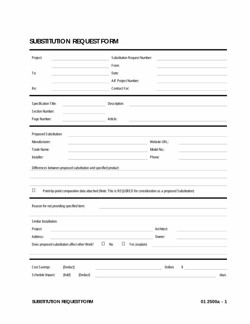
SUBSTITUTION REQUEST FORM 01 2500a - 1
SUBSTITUTION REQUEST FORM
Project: Substitution Request Number:
From:
To: Date:
A/E Project Number:
Re: Contract For:
Specification Title: Description:
Section Number:
Page Number: Article:
Proposed Substitution:
Manufacturer: Website URL:
Trade Name: Model No.:
Installer: Phone:
Differences between proposed substitution and specified product:
Point-by-point comparative data attached (Note: This is REQUIRED for consideration as a proposed Substitution)
Reason for not providing specified item:
Similar Installation:
Project: Architect:
Address: Owner:
Does proposed substitution affect other Work? No Yes (explain)
Cost Savings: [Deduct] Dollars $
Schedule Impact: [Add] [Deduct] days.
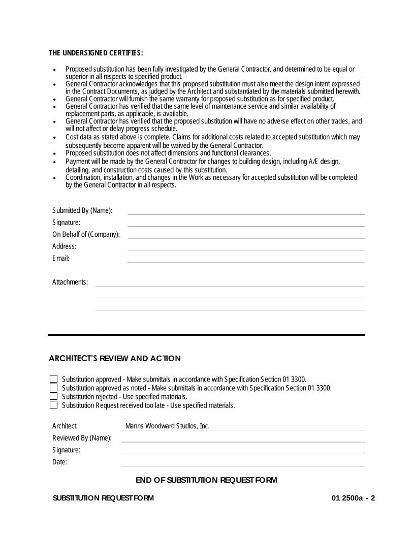
SUBSTITUTION REQUEST FORM 01 2500a - 2
THE UNDERSIGNED CERTIFIES: • Proposed substitution has been fully investigated by the General Contractor, and determined to be equal or
superior in all respects to specified product. • General Contractor acknowledges that this proposed substitution must also meet the design intent expressed
in the Contract Documents, as judged by the Architect and substantiated by the materials submitted herewith. • General Contractor will furnish the same warranty for proposed substitution as for specified product. • General Contractor has verified that the same level of maintenance service and similar availability of
replacement parts, as applicable, is available. • General Contractor has verified that the proposed substitution will have no adverse effect on other trades, and
will not affect or delay progress schedule. • Cost data as stated above is complete. Claims for additional costs related to accepted substitution which may
subsequently become apparent will be waived by the General Contractor. • Proposed substitution does not affect dimensions and functional clearances. • Payment will be made by the General Contractor for changes to building design, including A/E design,
detailing, and construction costs caused by this substitution. • Coordination, installation, and changes in the Work as necessary for accepted substitution will be completed
by the General Contractor in all respects.
Submitted By (Name):
Signature:
On Behalf of (Company):
Address:
Email:
Attachments:
ARCHITECT’S REVIEW AND ACTION
Substitution approved - Make submittals in accordance with Specification Section 01 3300. Substitution approved as noted - Make submittals in accordance with Specification Section 01 3300. Substitution rejected - Use specified materials. Substitution Request received too late - Use specified materials.
Architect: Manns Woodward Studios, Inc.
Reviewed By (Name):
Signature:
Date:
END OF SUBSTITUTION REQUEST FORM

Reading Fire Department9th & Marion Fire StationBid/Permit Set July 9, 2021
MANNS WOODWARD STUDIOS INC
SECTION 01 2600 - CONTRACT MODIFICATION PROCEDURES
PART 1 - GENERAL
1.1 RELATED DOCUMENTS
A. Drawings and general provisions of the Contract, including General and Supplementary Conditions and other Division 01 Specification Sections, apply to this Section.
1.2 SUMMARY
A. Section includes administrative and procedural requirements for handling and processing Contract modifications.
B. Related Requirements:
1. Section 01 2500 "Substitution Procedures" for administrative procedures for handling requests for substitutions made after the Contract award.
1.3 PROPOSAL REQUESTS
A. Owner-Initiated Proposal Requests: Construction Manager/Architect will issue a detailed description of proposed changes in the Work that may require adjustment to the Contract Sum or the Contract Time. If necessary, the description will include supplemental or revised Drawings and Specifications.
1. Work Change Proposal Requests issued by Construction Manager/Architect are not instructions either to stop work in progress or to execute the proposed change.
2. Within 7 consecutive days after receipt of Proposal Request, submit a quotation estimating cost adjustments to the Contract Sum and the Contract Time necessary to execute the change.
a. Include a list of quantities of products required or eliminated and unit costs, with total amount of purchases and credits to be made. If requested, furnish survey data to substantiate quantities.
CONTRACT MODIFICATION PROCEDURES 01 2600 - 1
Reading Fire Department9th & Marion Fire StationBid/Permit Set July 9, 2021
MANNS WOODWARD STUDIOS INC
b. Indicate applicable taxes, delivery charges, equipment rental, and amounts of trade discounts.
c. Include costs of labor and supervision directly attributable to the change.d. Include an updated Contractor's construction schedule that indicates the effect of
the change, including, but not limited to, changes in activity duration, start and finish times, and activity relationship. Use available total float before requesting an extension of the Contract Time.
e. Quotation Form: Use forms acceptable to Architect.
B. Contractor-Initiated Proposals: If latent or changed conditions require modifications to the Contract, Contractor may initiate a claim by submitting a request for a change to Architect.
1. Include a statement outlining reasons for the change and the effect of the change on the Work. Provide a complete description of the proposed change. Indicate the effect of the proposed change on the Contract Sum and the Contract Time.
2. Include a list of quantities of products required or eliminated and unit costs, with total amount of purchases and credits to be made. If requested, furnish survey data to substantiate quantities.
3. Indicate applicable taxes, delivery charges, equipment rental, and amounts of trade discounts.
4. Include costs of labor and supervision directly attributable to the change.5. Include an updated Contractor's construction schedule that indicates the effect of the
change, including, but not limited to, changes in activity duration, start and finish times, and activity relationship. Use available total float before requesting an extension of the Contract Time.
6. Comply with requirements in Section 01 2500 "Substitution Procedures" if the proposed change requires substitution of one product or system for product or system specified.
7. Proposal Request Form: Use form acceptable to Architect.
1.4 CHANGE ORDER PROCEDURES
A. On Owner's approval of a Work Changes Proposal Request, Architect will issue a Change Order for signatures of Owner and Contractor on AIA Document G701.
1.5 CONSTRUCTION CHANGE DIRECTIVE
A. Construction Change Directive: Architect may issue a Construction Change Directive. Construction Change Directive instructs Contractor to proceed with a change in the Work, for subsequent inclusion in a Change Order.
CONTRACT MODIFICATION PROCEDURES 01 2600 - 2
Reading Fire Department9th & Marion Fire StationBid/Permit Set July 9, 2021
MANNS WOODWARD STUDIOS INC
B. Documentation: Maintain detailed records on a time and material basis of work required by the Construction Change Directive.
1. After completion of change, submit an itemized account and supporting data necessary to substantiate cost and time adjustments to the Contract.
PART 2 - PRODUCTS (Not Used)
PART 3 - EXECUTION (Not Used)
END OF SECTION 01 2600
CONTRACT MODIFICATION PROCEDURES 01 2600 - 3
Reading Fire Department9th & Marion Fire StationBid/Permit Set July 9, 2021
MANNS WOODWARD STUDIOS INC
SECTION 01 2900 - PAYMENT PROCEDURES
PART 1 - GENERAL
1.1 RELATED DOCUMENTS
A. Drawings and general provisions of the Contract, including General and Supplementary Conditions and other Division 01 Specification Sections, apply to this Section.
1.2 SUMMARY
A. Section includes administrative and procedural requirements necessary to prepare and process Applications for Payment.
B. Related Requirements:
1. Section 01 2200 "Unit Prices" for administrative requirements governing the use of unit prices.
2. Section 01 2600 "Contract Modification Procedures" for administrative procedures for handling changes to the Contract.
3. Section 01 3200 "Construction Progress Documentation" for administrative requirements governing the preparation and submittal of the Contractor's construction schedule.
1.3 DEFINITIONS
A. Schedule of Values: A statement furnished by Contractor allocating portions of the Contract Sum to various portions of the Work and used as the basis for reviewing Contractor's Applications for Payment.
1.4 SCHEDULE OF VALUES
A. Coordination: Coordinate preparation of the schedule of values with preparation of Contractor's construction schedule.
PAYMENT PROCEDURES 01 2900 - 1
Reading Fire Department9th & Marion Fire StationBid/Permit Set July 9, 2021
MANNS WOODWARD STUDIOS INC
1. Coordinate line items in the schedule of values with other required administrative forms and schedules, including the following:
a. Application for Payment forms with continuation sheets.b. Submittal schedule.c. Items required to be indicated as separate activities in Contractor's construction
schedule.
2. Submit the schedule of values to Architect at earliest possible date, but no later than seven days before the date scheduled for submittal of initial Applications for Payment.
3. Sub-schedules for Separate Elements of Work: Where the Contractor's construction schedule defines separate elements of the Work, provide sub-schedules showing values coordinated with each element.
B. Format and Content: Use Project Manual table of contents as a guide to establish line items for the schedule of values. Provide at least one line item for each Specification Section. Owner reserves the right to require line items of the schedule of values be broken down further as may be required to satisfy the Owner.
1. Identification: Include the following Project identification on the schedule of values:
a. Project name and location.b. Prime Contractor's Name.c. Name of Architect.d. Contractor's name and address.e. Date of submittal.
2. Arrange schedule of values consistent with format of AIA Document G703.3. Round amounts to nearest whole dollar; total shall equal the Contract Sum.4. Provide a separate line item in the schedule of values for each part of the Work where
Applications for Payment may include materials or equipment purchased or fabricated and stored, but not yet installed.
a. Differentiate between items stored on-site and items stored off-site. If required, include evidence of insurance.
5. Allowances: Provide a separate line item in the schedule of values for each allowance. Show line-item value of unit-cost allowances, as a product of the unit cost, multiplied by measured quantity. Use information indicated in the Contract Documents to determine quantities.
PAYMENT PROCEDURES 01 2900 - 2
Reading Fire Department9th & Marion Fire StationBid/Permit Set July 9, 2021
MANNS WOODWARD STUDIOS INC
6. Schedule Updating: Update and resubmit the schedule of values before the next Applications for Payment when Change Orders or Construction Change Directives result in a change in the Contract Sum.
1.5 APPLICATIONS FOR PAYMENT
A. Each Application for Payment following the initial Application for Payment shall be consistent with previous applications and payments as certified by Architect and paid for by Owner.
1. Initial Application for Payment, Application for Payment at time of Substantial Completion, and final Application for Payment involve additional requirements.
B. Payment Application Times: Submit Application for Payment to Construction Manager. The period covered by each Application for Payment is one month, ending on the last day of the month.
C. Application for Payment Forms: Use AIA Document G702 and AIA Document G703 as form for Applications for Payment.
D. Application Preparation: Complete every entry on form. Notarize and execute by a person authorized to sign legal documents on behalf of Contractor. Construction Manager will return incomplete applications without action.
1. Entries shall match data on the schedule of values and Contractor's construction schedule. Use updated schedules if revisions were made.
2. Include amounts for work completed following previous Application for Payment, whether or not payment has been received. Include only amounts for work completed at time of Application for Payment.
3. Include amounts of Change Orders and Construction Change Directives issued before last day of construction period covered by application.
E. Stored Materials: Include in Application for Payment amounts applied for materials or equipment purchased or fabricated and stored, but not yet installed. Differentiate between items stored on-site and items stored off-site.
1. Provide certificate of insurance, evidence of transfer of title to Owner, and consent of surety to payment, for stored materials.
2. Provide supporting documentation that verifies amount requested, such as paid invoices. Match amount requested with amounts indicated on documentation; do not include overhead and profit on stored materials.
PAYMENT PROCEDURES 01 2900 - 3
Reading Fire Department9th & Marion Fire StationBid/Permit Set July 9, 2021
MANNS WOODWARD STUDIOS INC
F. Transmittal: Submit signed and notarized copies of each Application for Payment along with certified payroll documentation via project management software (Procore.)
G. Initial Application for Payment: Administrative actions and submittals that must precede or coincide with submittal of first Application for Payment include the following:
1. List of subcontractors.2. Schedule of values.3. Contractor's construction schedule (preliminary if not final).4. Submittal schedule (preliminary if not final).5. Certificates of insurance and insurance policies.6. Performance and payment bonds.7. Data needed to acquire Owner's insurance.
H. Application for Payment at Substantial Completion: After Architect issues the Certificate of Substantial Completion, submit an Application for Payment showing 100 percent completion for portion of the Work claimed as substantially complete.
1. Include documentation supporting claim that the Work is substantially complete and a statement showing an accounting of changes to the Contract Sum.
I. Final Payment Application: After completing Project closeout requirements, submit final Application for Payment with releases and supporting documentation not previously submitted and accepted, including, but not limited, to the following:
1. Evidence of completion of Project closeout requirements.2. Updated final statement, accounting for final changes to the Contract Sum.3. AIA Document G706A, "Contractor's Affidavit of Release of Liens."4. Final meter readings for utilities, a measured record of stored fuel, and similar data as of
date of Substantial Completion or when Owner took possession of and assumed responsibility for corresponding elements of the Work.
PART 2 - PRODUCTS (Not Used)
PART 3 - EXECUTION (Not Used)
END OF SECTION 01 2900
PAYMENT PROCEDURES 01 2900 - 4

Reading Fire Department9th & Marion Fire StationBid/Permit Set July 9, 2021
MANNS WOODWARD STUDIOS INC
PAYMENT PROCEDURES 01 2900 - 5

Reading Fire Department9th & Marion Fire StationBid/Permit Set July 9, 2021
MANNS WOODWARD STUDIOS INC
SECTION 01 3100 - PROJECT MANAGEMENT AND COORDINATION
PART 1 - GENERAL
1.1 RELATED DOCUMENTS
A. Drawings and general provisions of the Contract, including General and Supplementary Conditions and other Division 01 Specification Sections, apply to this Section.
1.2 SUMMARY
A. Section includes administrative provisions for coordinating construction operations on Project including, but not limited to, the following:
1. General coordination procedures.2. Coordination drawings.3. Requests for Information (RFIs).4. Project meetings.
B. Each contractor (each Prime Contractor and each Sub-contractor) shall participate in coordination requirements. The contract documents do not specify that certain areas of responsibility are assigned to a specific contractor, therefore it is the General Contractor's responsibility to include all sub-contractors within the coordination process.
C. Related Requirements:
1. Section 01 3200 "Construction Progress Documentation" for preparing and submitting Contractor's construction schedule.
2. Section 01 7300 "Execution" for procedures for coordinating general installation and field-engineering services, including establishment of benchmarks and control points.
3. Section 01 7700 "Closeout Procedures" for coordinating closeout of the Contract.
1.3 DEFINITIONS
A. RFI: Request from Owner, Construction Manager, Architect, or Contractor seeking information required by or clarifications of the Contract Documents.
PROJECT MANAGEMENT AND COORDINATION 01 3100 - 1
Reading Fire Department9th & Marion Fire StationBid/Permit Set July 9, 2021
MANNS WOODWARD STUDIOS INC
1.4 INFORMATIONAL SUBMITTALS
A. Subcontract List: Prepare a written summary identifying individuals or firms proposed for each portion of the Work, including those who are to furnish products or equipment fabricated to a special design. Include the following information in tabular form:
1. Name, address, and telephone number of entity performing subcontract or supplying products.
2. Number and title of related Specification Section(s) covered by subcontract.
B. Key Personnel Names: Within 15 days of starting construction operations, submit a list of key personnel assignments, including superintendent and other personnel in attendance at Project site. Identify individuals and their duties and responsibilities; list addresses and telephone numbers, including home, office, and cellular telephone numbers and e-mail addresses. Provide names, addresses, and telephone numbers of individuals assigned as alternates in the absence of individuals assigned to Project.
1. Post copies of list in project meeting room, in temporary field office, and by each temporary telephone. Keep list current at all times.
1.5 GENERAL COORDINATION PROCEDURES
A. Coordination: Coordinate construction operations included in different Sections of the Specifications to ensure efficient and orderly installation of each part of the Work. Coordinate construction operations, included in different Sections, that depend on each other for proper installation, connection, and operation.
1. Schedule construction operations in sequence required to obtain the best results where installation of one part of the Work depends on installation of other components, before or after its own installation.
a. Coordinate construction sequence with Work to be completed by other Prime Contractors, where applicable and necessary for installation per the requirements of the Contract Documents.
2. Coordinate installation of different components to ensure maximum performance and accessibility for required maintenance, service, and repair.
3. Make adequate provisions to accommodate items scheduled for later installation.
PROJECT MANAGEMENT AND COORDINATION 01 3100 - 2
Reading Fire Department9th & Marion Fire StationBid/Permit Set July 9, 2021
MANNS WOODWARD STUDIOS INC
B. Prepare memoranda for distribution to each party involved, outlining special procedures required for coordination. Include such items as required notices, reports, and list of attendees at meetings.
1. Prepare similar memoranda for Owner, and separate Prime Contractors and Sub-contractors if coordination of their Work is required.
1.6 COORDINATION DRAWINGS
A. Coordination Drawings, General: Prepare coordination drawings according to requirements in individual Sections, and additionally where installation is not completely shown on Shop Drawings, where limited space availability necessitates coordination, or if coordination is required to facilitate integration of products and materials fabricated or installed by more than one entity.
1. Content: Project-specific information, drawn accurately to a scale large enough to indicate and resolve conflicts. Do not base coordination drawings on standard printed data. Include the following information, as applicable:
a. Use applicable Drawings as a basis for preparation of coordination drawings. Prepare sections, elevations, and details as needed to describe relationship of various systems and components.
b. Indicate Work to be completed, and identify related work to be completed by other Prime Contractors.
c. Indicate functional and spatial relationships of components of architectural, structural, civil, mechanical, and electrical systems.
d. Indicate space requirements for routine maintenance and for anticipated replacement of components during the life of the installation.
e. Show location and size of access doors required for access to concealed dampers, valves, and other controls.
f. Indicate required installation sequences.g. Indicate dimensions shown on the Drawings. Specifically note dimensions that
appear to be in conflict with submitted equipment and minimum clearance requirements. Provide alternate sketches to Architect indicating proposed resolution of such conflicts. Minor dimension changes and difficult installations will not be considered changes to the Contract.
B. Coordination Drawing Organization: Organize coordination drawings as follows:
PROJECT MANAGEMENT AND COORDINATION 01 3100 - 3
Reading Fire Department9th & Marion Fire StationBid/Permit Set July 9, 2021
MANNS WOODWARD STUDIOS INC
1. Review: Construction Manager/Architect will review coordination drawings to confirm that the Work is being coordinated, but not for the details of the coordination, which are Contractor's responsibility. If Architect determines that coordination drawings are not being prepared in sufficient scope or detail, or are otherwise deficient, Architect will so inform Contractor, who shall make changes as directed and resubmit.
C. Coordination Digital Data Files: Prepare coordination digital data files according to the following requirements:
1. File Preparation Format: Same digital data software program, version, and operating system as original Drawings.
2. File Submittal Format: Submit or post coordination drawing files using format same as file preparation format.
3. Architect will furnish Contractor one set of digital data files of Drawings for use in preparing coordination digital data files.
a. Architect makes no representations as to the accuracy or completeness of digital data files as they relate to Drawings.
b. Contractor shall execute a data licensing agreement in the form of Agreement form acceptable to Owner and Architect.
1.7 REQUESTS FOR INFORMATION (RFIs)
A. General: Immediately on discovery of the need for additional information or interpretation of the Contract Documents, Contractor shall prepare and submit an RFI in the form specified.
1. Construction Manager/Architect will return RFIs submitted to Architect by other entities controlled by Contractor with no response.
2. Coordinate and submit RFIs in a prompt manner so as to avoid delays in Contractor's work or work of subcontractors.
3. RFI's shall be submitted through the project management software (Procore.)
B. Content of the RFI: Include a detailed, legible description of item needing information or interpretation and the following:
1. Project name.2. Date.3. Name of Contractor.4. Name of Architect.
PROJECT MANAGEMENT AND COORDINATION 01 3100 - 4
Reading Fire Department9th & Marion Fire StationBid/Permit Set July 9, 2021
MANNS WOODWARD STUDIOS INC
5. RFI number, numbered sequentially.6. RFI subject.7. Specification Section number and title and related paragraphs, as appropriate.8. Drawing number and detail references, as appropriate.9. Field dimensions and conditions, as appropriate.10. Contractor's suggested resolution. If Contractor's suggested resolution impacts the
Contract Time or the Contract Sum, Contractor shall state impact in the RFI.11. Contractor's signature.12. Attachments: Include sketches, descriptions, measurements, photos, Product Data, Shop
Drawings, coordination drawings, and other information necessary to fully describe items needing interpretation.
a. Include dimensions, thicknesses, structural grid references, and details of affected materials, assemblies, and attachments on attached sketches.
C. Architect's Action: Architect will review each RFI, determine action required, and respond. Allow seven working days for Architect's response for each RFI. RFIs received by Architect after 1:00 p.m. will be considered as received the following working day.
1. The following Contractor-generated RFIs will be returned without action:
a. Requests for approval of submittals.b. Requests for approval of substitutions.c. Requests for approval of Contractor's means and methods.d. Requests for coordination information already indicated in the Contract Documents.e. Requests for adjustments in the Contract Time or the Contract Sum.f. Requests for interpretation of Architect's actions on submittals.g. Incomplete RFIs or inaccurately prepared RFIs.
2. Architect's action may include a request for additional information, in which case Architect's time for response will date from time of receipt of additional information.
3. Architect's action on RFIs that may result in a change to the Contract Time or the Contract Sum may be eligible for Contractor to submit Change Proposal according to Section 01 2600 "Contract Modification Procedures."
a. If Contractor believes the RFI response warrants change in the Contract Time or the Contract Sum, notify Architect in writing within 10 days of receipt of the RFI response.
D. RFI Log: RFI Log shall be maintained through the project management software (Procore) and shall include the following:
PROJECT MANAGEMENT AND COORDINATION 01 3100 - 5

Reading Fire Department9th & Marion Fire StationBid/Permit Set July 9, 2021
MANNS WOODWARD STUDIOS INC
1. Project name.2. Name and address of Contractor.3. Name and address of Architect.4. RFI number including RFIs that were returned without action or withdrawn.5. RFI description.6. Date the RFI was submitted.7. Date Architect's response was received.
E. On receipt of Architect's action, update the RFI log and immediately distribute the RFI response to affected parties. Review response and notify Architect within seven days if Contractor disagrees with response.
1.8 PROJECT MEETINGS
A. General: Schedule and conduct meetings and conferences at Project site unless otherwise indicated.
1. Attendees: Inform participants and others involved, and individuals whose presence is required, of date and time of each meeting. Notify Owner and Architect of scheduled meeting dates and times.
2. Agenda: Prepare the meeting agenda. Distribute the agenda to all invited attendees.3. Minutes: Entity responsible for conducting meeting will record significant discussions and
agreements achieved. Distribute the meeting minutes to everyone concerned, including Owner and Architect, within three days of the meeting.
B. Preconstruction Conference: Schedule a preconstruction conference before starting construction, at a time convenient to Owner, Construction Manager and Architect, but no later than 15 days after execution of the Agreement.
1. Conduct the conference to review responsibilities and personnel assignments.2. Attendees: Authorized representatives of Owner Architect, and their consultants;
Contractor and its superintendent; major subcontractors; suppliers; and other concerned parties shall attend the conference. Participants at the conference shall be familiar with Project and authorized to conclude matters relating to the Work.
3. Agenda: Construction Manager shall create agenda and conduct meeting. Discuss items of significance that could affect progress, including the following:
a. Tentative construction schedule.b. Phasing.
PROJECT MANAGEMENT AND COORDINATION 01 3100 - 6
Reading Fire Department9th & Marion Fire StationBid/Permit Set July 9, 2021
MANNS WOODWARD STUDIOS INC
c. Critical work sequencing and long-lead items.d. Designation of key personnel and their duties.e. Lines of communications.f. Procedures for processing field decisions and Change Orders.g. Procedures for RFIs.h. Procedures for processing Applications for Payment.i. Distribution of the Contract Documents.j. Submittal procedures.k. Preparation of record documents.l. Use of the premises and existing building.m. Work restrictions.n. Working hours.o. Owner's occupancy requirements.p. Responsibility for temporary facilities and controls.q. Procedures for disruptions and shutdowns.r. Parking availability.s. Office, work, and storage areas.t. Equipment deliveries and priorities.u. Security.v. Progress cleaning.
4. Minutes: The Architect will be responsible for recording and distributing the meeting minutes.
C. Preinstallation Conferences: Conduct a preinstallation conference at Project site before each construction activity that requires coordination with other construction.
1. Attendees: Installer and representatives of manufacturers and fabricators involved in or affected by the installation and its coordination or integration with other materials and installations that have preceded or will follow, shall attend the meeting. Advise Architect of scheduled meeting dates.
2. Agenda: Review progress of other construction activities and preparations for the particular activity under consideration, including requirements for the following:
a. Contract Documents.b. Related RFIs.c. Related Change Orders.d. Submittals.e. Review of mockups.f. Possible conflicts.g. Compatibility requirements.
PROJECT MANAGEMENT AND COORDINATION 01 3100 - 7
Reading Fire Department9th & Marion Fire StationBid/Permit Set July 9, 2021
MANNS WOODWARD STUDIOS INC
h. Time schedules.i. Weather limitations.j. Manufacturer's written instructions.k. Warranty requirements.l. Compatibility of materials.m. Acceptability of substrates.n. Coordination with other work.o. Protection of adjacent work.
3. Record significant conference discussions, agreements, and disagreements, including required corrective measures and actions.
4. Reporting: Distribute minutes of the meeting to each party present and to other parties requiring information.
5. Do not proceed with installation if the conference cannot be successfully concluded. Initiate whatever actions are necessary to resolve impediments to performance of the Work and reconvene the conference at earliest feasible date.
6. Minutes: The Architect shall record and distribute the meeting minutes.
D. Progress Meetings: Construction Manager shall conduct progress meetings at biweekly intervals. The Owner reserves the right to change the frequency of the progress meetings.
1. Coordinate dates of meetings with preparation of payment requests.2. Attendees: In addition to representatives of Owner, Construction Manager and Architect,
each contractor, subcontractor, supplier, and other entity concerned with current progress or involved in planning, coordination, or performance of future activities shall be represented at these meetings. All participants at the meeting shall be familiar with Project and authorized to conclude matters relating to the Work.
3. Agenda: Review and correct or approve minutes of previous progress meeting. Review other items of significance that could affect progress. Include topics for discussion as appropriate to status of Project.
a. Contractor's Construction Schedule: Review progress since the last meeting. Determine whether each activity is on time, ahead of schedule, or behind schedule, in relation to Contractor's construction schedule. Determine how construction behind schedule will be expedited; secure commitments from parties involved to do so. Discuss whether schedule revisions are required to ensure that current and subsequent activities will be completed within the Contract Time.
1) Review schedule for next period.
b. Review present and future needs of each entity present, including the following:
PROJECT MANAGEMENT AND COORDINATION 01 3100 - 8
Reading Fire Department9th & Marion Fire StationBid/Permit Set July 9, 2021
MANNS WOODWARD STUDIOS INC
1) Interface requirements.2) Sequence of operations.3) Status of submittals.4) Access.5) Site utilization.6) Progress cleaning.7) Status of correction of deficient items.8) Field observations.9) Status of RFIs.10) Status of proposal requests.11) Pending changes.12) Status of Change Orders.13) Pending claims and disputes.14) Documentation of information for payment requests.
4. Minutes: The Construction Manager shall record and distribute the meeting minutes to each party present and to parties requiring information.
a. Schedule Updating: General Contractor shall revise Contractor's construction schedule after each progress meeting where revisions to the schedule have been made or recognized. Issue revised schedule concurrently with the report of each meeting.
PART 2 - PRODUCTS (Not Used)
PART 3 - EXECUTION (Not Used)
END OF SECTION 01 3100
PROJECT MANAGEMENT AND COORDINATION 01 3100 - 9
Reading Fire Department9th & Marion Fire StationBid/Permit Set July 9, 2021
MANNS WOODWARD STUDIOS INC
SECTION 01 3200 - CONSTRUCTION PROGRESS DOCUMENTATION
PART 1 - GENERAL
1.1 RELATED DOCUMENTS
A. Drawings and general provisions of the Contract, including General and Supplementary Conditions and other Division 01 Specification Sections, apply to this Section.
1.2 SUMMARY
A. Section includes administrative and procedural requirements for documenting the progress of construction during performance of the Work, including the following:
1. Startup construction schedule.2. Contractor's construction schedule.3. Construction schedule updating reports.4. Daily construction reports.5. Material location reports.6. Site condition reports.
B. Related Requirements:
1. Section 01 3300 "Submittal Procedures" for submitting schedules and reports.2. Section 01 4000 "Quality Requirements" for submitting a schedule of tests and
inspections.
1.3 DEFINITIONS
A. Activity: A discrete part of a project that can be identified for planning, scheduling, monitoring, and controlling the construction project. Activities included in a construction schedule consume time and resources.
1. Critical Activity: An activity on the critical path that must start and finish on the planned early start and finish times.
2. Successor Activity: An activity that follows another activity in the network.
CONSTRUCTION PROGRESS DOCUMENTATION 01 3200 - 1
Reading Fire Department9th & Marion Fire StationBid/Permit Set July 9, 2021
MANNS WOODWARD STUDIOS INC
B. CPM: Critical path method, which is a method of planning and scheduling a construction project where activities are arranged based on activity relationships. Network calculations determine when activities can be performed and the critical path of Project.
C. Critical Path: The longest connected chain of interdependent activities through the network schedule that establishes the minimum overall Project duration and contains no float.
D. Event: The starting or ending point of an activity.
E. Float: The measure of leeway in starting and completing an activity.
1. Float time is not for the exclusive use or benefit of either Owner or Contractor, but is a jointly owned, expiring Project resource available to both parties as needed to meet schedule milestones and Contract completion date.
2. Free float is the amount of time an activity can be delayed without adversely affecting the early start of the successor activity.
3. Total float is the measure of leeway in starting or completing an activity without adversely affecting the planned Project completion date.
F. Resource Loading: The allocation of manpower and equipment necessary for the completion of an activity as scheduled.
1.4 INFORMATIONAL SUBMITTALS
A. Format for Submittals: Submit required submittals in the following format:
1. PDF electronic file.
B. Contractor's Construction Schedule: Initial schedule, of size required to display entire schedule for entire construction period.
C. CPM Reports: Concurrent with CPM schedule, submit each of the following reports. Format for each activity in reports shall contain activity number, activity description, original duration, remaining duration, early start date, early finish date, late start date, late finish date, and total float in calendar days.
1. Activity Report: List of all activities sorted by activity number and then early start date, or actual start date if known.
CONSTRUCTION PROGRESS DOCUMENTATION 01 3200 - 2
Reading Fire Department9th & Marion Fire StationBid/Permit Set July 9, 2021
MANNS WOODWARD STUDIOS INC
2. Logic Report: List of preceding and succeeding activities for all activities, sorted in ascending order by activity number and then early start date, or actual start date if known.
3. Total Float Report: List of all activities sorted in ascending order of total float.
D. Construction Schedule Updating Reports: Submit with Applications for Payment.
E. Daily Construction Reports: Submit at monthly intervals.
F. Stored Material Location Reports: Submit at monthly intervals.
G. Site Condition Reports (Daily Log): Submit at time of discovery of differing conditions.
1.5 QUALITY ASSURANCE
A. Prescheduling Conference: Conduct conference at Project site to comply with requirements in Section 01 3100 "Project Management and Coordination." Review methods and procedures related to the preliminary construction schedule and Contractor's construction schedule, including, but not limited to, the following:
1. Discuss constraints, including phasing work stages area separations interim milestones and partial Owner occupancy.
2. Review delivery dates for Owner-furnished products.3. Review submittal requirements and procedures.4. Review and finalize list of construction activities to be included in schedule.5. Review procedures for updating schedule.
1.6 COORDINATION
A. Coordinate Contractor's construction schedule with the schedule of values, list of subcontracts, submittal schedule, progress reports, payment requests, and other required schedules and reports.
1. Secure time commitments for performing critical elements of the Work from entities involved.
2. Coordinate each construction activity in the network with other activities and schedule them in proper sequence.
CONSTRUCTION PROGRESS DOCUMENTATION 01 3200 - 3
Reading Fire Department9th & Marion Fire StationBid/Permit Set July 9, 2021
MANNS WOODWARD STUDIOS INC
PART 2 - PRODUCTS
2.1 CONTRACTOR'S CONSTRUCTION SCHEDULE, GENERAL
A. Time Frame: Extend schedule from date established for the Notice to Proceed to date of final completion.
1. Contract completion date shall not be changed by submission of a schedule that shows an early completion date, unless specifically authorized by Change Order.
a. The Contractor shall be responsible for providing the required items, materials, procedures, and protections to complete the Work within the Time Frame set forth within the Contract Documents. This includes, but is not limited to, items required to work within the weather conditions reasonably expected within the Contract Time Frame.
B. Constraints: Include constraints and work restrictions indicated in the Contract Documents and as follows in schedule, and show how the sequence of the Work is affected.
1. Work Restrictions: Show the effect of the following items on the schedule:
a. Coordination with existing construction.b. Use of premises restrictions.c. Environmental control.
2. Work Stages: Indicate important stages of construction for each major portion of the Work, including, but not limited to, the following:
a. Submittals.b. Purchases.c. Mockups.d. Fabrication.e. Deliveries.f. Installation.g. Tests and inspections.h. Adjusting.i. Curing.j. Startup and placement into final use and operation.
CONSTRUCTION PROGRESS DOCUMENTATION 01 3200 - 4
Reading Fire Department9th & Marion Fire StationBid/Permit Set July 9, 2021
MANNS WOODWARD STUDIOS INC
3. Construction Areas: Identify each major area of construction for each major portion of the Work. Indicate where each construction activity within a major area must be sequenced or integrated with other construction activities to provide for the following:
a. Structural completion.b. Temporary enclosure and space conditioning.c. Permanent space enclosure.d. Completion of mechanical installation.e. Completion of electrical installation.f. Substantial Completion.
C. Milestones: Include milestones indicated in the Contract Documents and Preliminary Milestone Schedule in schedule, including, but not limited to, the Notice to Proceed, Substantial Completion, and final completion.
D. Upcoming Work Summary: Prepare summary report indicating activities scheduled to occur or commence prior to submittal of next schedule update. Summarize the following issues:
1. Unresolved issues.2. Unanswered Requests for Information.3. Rejected or unreturned submittals.4. Notations on returned submittals.5. Pending modifications affecting the Work and Contract Time.
2.2 CONTRACTOR'S CONSTRUCTION SCHEDULE (GANTT CHART)
A. Gantt-Chart Schedule: Submit a comprehensive, fully developed, horizontal, Gantt-chart-type, Contractor's construction schedule within 15 days of date established for the Notice to Proceed. Base schedule on the startup construction schedule and additional information received since the start of Project.
2.3 REPORTS
A. Daily Construction Reports: Prepare a daily construction report recording the following information concerning events at Project site:
1. List of subcontractors at Project site.2. Approximate count of personnel at Project site.
CONSTRUCTION PROGRESS DOCUMENTATION 01 3200 - 5
Reading Fire Department9th & Marion Fire StationBid/Permit Set July 9, 2021
MANNS WOODWARD STUDIOS INC
3. Equipment at Project site.4. Material deliveries.5. High and low temperatures and general weather conditions, including presence of rain or
snow.6. Accidents.7. Unusual events (see special reports).8. Stoppages, delays, shortages, and losses.9. Change Orders received and implemented.10. Construction Change Directives received and implemented.11. Services connected and disconnected.12. Equipment or system tests and startups.13. Partial completions and occupancies.
B. Material Location Reports: At monthly intervals, prepare and submit a comprehensive list of materials delivered to and stored at Project site. List shall be cumulative, showing materials previously reported plus items recently delivered. Include with list a statement of progress on and delivery dates for materials or items of equipment fabricated or stored away from Project site. Indicate the following categories for stored materials:
C. Site Condition Reports: Immediately on discovery of a difference between site conditions and the Contract Documents, prepare and submit a detailed report. Submit with a Request for Information. Include a detailed description of the differing conditions, together with recommendations for changing the Contract Documents.
D. Contractor's Two Week Task Schedule: At bi-weekly intervals, prepare and submit a comprehensive list of projected tasks to be performed within the two weeks following each progress meeting. Contractor's Two Week Task Schedules shall be reviewed and discussed at each progress meeting.
PART 3 - EXECUTION
3.1 CONTRACTOR'S CONSTRUCTION SCHEDULE
A. Contractor's Construction Schedule Updating: At bi-weekly intervals, update schedule to reflect actual construction progress and activities. Issue schedule one week before each regularly scheduled progress meeting.
CONSTRUCTION PROGRESS DOCUMENTATION 01 3200 - 6
Reading Fire Department9th & Marion Fire StationBid/Permit Set July 9, 2021
MANNS WOODWARD STUDIOS INC
1. Revise schedule immediately after each meeting or other activity where revisions have been recognized or made. Issue updated schedule concurrently with the report of each such meeting.
2. As the Work progresses, indicate final completion percentage for each activity.
B. Distribution: Distribute copies of approved schedule to Construction Manager, Architect, and Owner, separate contractors, testing and inspecting agencies, and other parties identified by Contractor with a need-to-know schedule responsibility.
1. Post copies in project management software (Procore), Project meeting rooms and temporary field offices.
2. When revisions are made, distribute updated schedules to the same parties and post in the same locations. Delete parties from distribution when they have completed their assigned portion of the Work and are no longer involved in performance of construction activities.
END OF SECTION 01 3200
CONSTRUCTION PROGRESS DOCUMENTATION 01 3200 - 7
Reading Fire Department9th & Marion Fire StationBid/Permit Set July 9, 2021
MANNS WOODWARD STUDIOS INC
SECTION 01 3233 - PHOTOGRAPHIC DOCUMENTATION
PART 1 - GENERAL
1.1 RELATED DOCUMENTS
A. Drawings and general provisions of the Contract, including General and Supplementary Conditions and other Division 01 Specification Sections, apply to this Section.
1.2 SUMMARY
A. Section includes administrative and procedural requirements for the following:
1. Preconstruction photographs.2. Periodic construction photographs.3. Construction webcam.
B. Related Requirements:
1. Section 01 7700 "Closeout Procedures" for submitting photographic documentation as Project Record Documents at Project closeout.
2. Section 01 7900 "Demonstration and Training" for submitting video recordings of demonstration of equipment and training of Owner's personnel.
3. Section 02 4116 "Structure Demolition" for photographic documentation before building demolition operations commence.
4. Section 31 1000 "Site Clearing" for photographic documentation before site clearing operations commence.
1.3 INFORMATIONAL SUBMITTALS
A. Digital Photographs: Submit image files within three days of taking photographs.
1. Submit photos by uploading to web-based Project management software site. Include copy of key plan indicating each photograph's location and direction.
2. Identification: Provide the following information with each image description in web-based Project management software site:
PHOTOGRAPHIC DOCUMENTATION 01 3233 - 1

Reading Fire Department9th & Marion Fire StationBid/Permit Set July 9, 2021
MANNS WOODWARD STUDIOS INC
a. Name of Project.b. Name and contact information for photographer.c. Name of Architect and Construction Manager.d. Name of Contractor.e. Date photograph was taken.f. Description of location, vantage point, and direction.g. Unique sequential identifier keyed to accompanying key plan.
B. Time-Lapse Video: Submit time-lapse sequence video recordings within 7 days of recording.
1. Submit time-lapse sequence video recordings monthly by uploading to web-based Project management software site.
2. Identification: For each recording, provide the following information on web-based Project management software site:
a. Name of Project.b. Name and contact information for photographer.c. Name of Architect and Construction Manager.d. Name of Contractor.e. Date(s) and time(s) video recording was recorded.f. Description of vantage point, indicating location, direction (by compass point), and
elevation or story of construction.
1.4 QUALITY ASSURANCE
A. Construction Webcam Service Provider: A firm specializing in providing photographic equipment, web-based software, and related services for construction projects, with a record of providing satisfactory services similar to those required for Project.
1.5 FORMATS AND MEDIA
A. Digital Photographs: Provide color images in JPG format, produced by a digital camera with minimum sensor size of 12 megapixels, and at an image resolution of not less than 3200 by 2400 pixels, and with vibration-reduction technology. Use flash in low light levels or backlit conditions.
B. Digital Images: Submit digital media as originally recorded in the digital camera, without alteration, manipulation, editing, or modifications using image-editing software.
PHOTOGRAPHIC DOCUMENTATION 01 3233 - 2
Reading Fire Department9th & Marion Fire StationBid/Permit Set July 9, 2021
MANNS WOODWARD STUDIOS INC
C. Metadata: Record accurate date and time and GPS location data from camera.
D. File Names: Name media files with date and sequential numbering suffix.
1.6 CONSTRUCTION PHOTOGRAPHS
A. General: Take photographs with maximum depth of field and in focus.
B. Preconstruction Photographs: Before commencement of the Work, take photographs of Project site and surrounding properties, including existing items to remain during construction, from different vantage points, as directed by Construction Manager.
1. Flag excavation areas before taking construction photographs.2. Take photographs to show existing conditions adjacent to property before starting the
Work.3. Take photographs of existing buildings either on or adjoining property, to accurately record
physical conditions at start of construction.4. Take additional photographs as required to record settlement or cracking of adjacent
structures, pavements, and improvements.
C. Concealed Work Photographs: Before proceeding with installing work that will conceal other work, take photographs sufficient in number, with annotated descriptions, to record nature and location of concealed Work, including, but not limited to, the following:
1. Underground utilities.2. Underslab services.3. Piping.4. Electrical conduit.5. Waterproofing and weather-resistant barriers.
D. Periodic Construction Photographs: Take photographs weekly. Select vantage points to show status of construction and progress since last photographs were taken.
E. Time-Lapse Sequence Construction Photographs: Take photographs as indicated, to show status of construction and progress since last photographs were taken.
1. Frequency: Take photographs weekly, on the same day each week.
PHOTOGRAPHIC DOCUMENTATION 01 3233 - 3
Reading Fire Department9th & Marion Fire StationBid/Permit Set July 9, 2021
MANNS WOODWARD STUDIOS INC
2. Vantage Points: Following suggestions by Architect and Contractor, photographer shall select vantage points. During each of the following construction phases, take not less than two of the required shots from same vantage point each time, to create a time-lapse sequence as follows:
a. Commencement of the Work, through completion of subgrade construction.b. Above-grade structural framing.c. Exterior building enclosure.d. Interior Work, through date of Substantial Completion.
F. Additional Photographs: Architect or Construction Manager may request photographs in addition to periodic photographs specified. .
1.7 CONSTRUCTION WEBCAM
A. Webcam: Provide three fixed-location camera(s) with weatherproof housing, mounted to provide unobstructed view of construction site from location approved by Construction Manager/Architect, with the following characteristics:
1. Remotely controllable view with mouse-click user navigation for horizontal pan, vertical tile, and optical zoom of 500 percent minimum.
2. Capable of producing minimum 12 megapixel images.3. Provide pole mount, power supply, solar power station, active high-speed data connection
to service provider's network, and static public IP address for each camera.
B. Web-Based Interface: Provide online interface to allow viewing of each high-definition digital still image captured and stored during construction, from the Internet.
1. Access Control: Provide password-protected access for Project team administered by Contractor, providing current image access and archival image access by date and time, with images downloadable to viewer's device.
2. Software: Provide responsive software interface for use on computer, tablet, and mobile screens with accompanying iPhone/iPad app and Android apps.
3. Storage: Maintain images on the website for reference during entire construction period, and for not less than 30 days after Final Completion. Provide sufficient memory on remote server to store all Project images.
4. Online Interface: Provide website interface with Project and client information and logos, calendar-based navigation interface for selecting images, and pan and zoom capability within high-definition images.
PHOTOGRAPHIC DOCUMENTATION 01 3233 - 4

Reading Fire Department9th & Marion Fire StationBid/Permit Set July 9, 2021
MANNS WOODWARD STUDIOS INC
5. Forward and Reverse: Provide capability to browse through images, moving forward and backward in time by individual image and by day.
6. Slideshow: Provide capability to automatically display current images from sites when there are three or more cameras used.
7. Time-Lapse: Provide capability for online display of project time-lapse.8. Dashboard: Provide capability to view thumbnails of all cameras on one screen.9. Weather: Provide corresponding weather data for each image captured.
C. Maintain cameras and web-based access in good working order, according to web-based construction photographic documentation service provider's written instructions until Final Completion. Provide for service of cameras and related networking devices and software.
PART 2 - PRODUCTS (Not Used)
PART 3 - EXECUTION (Not Used)
END OF SECTION 01 3233
PHOTOGRAPHIC DOCUMENTATION 01 3233 - 5
Reading Fire Department9th & Marion Fire StationBid/Permit Set July 9, 2021
MANNS WOODWARD STUDIOS INC
SECTION 01 3300 - SUBMITTAL PROCEDURES
PART 1 - GENERAL
1.1 RELATED DOCUMENTS
A. Drawings and general provisions of the Contract, including General and Supplementary Conditions and other Division 01 Specification Sections, apply to this Section.
1.2 SUMMARY
A. Section includes requirements for the submittal schedule and administrative and procedural requirements for submitting Shop Drawings, Product Data, Samples, and other submittals.
B. Related Requirements:
1. Section 01 2900 "Payment Procedures" for submitting Applications for Payment and the schedule of values.
2. Section 01 3200 "Construction Progress Documentation" for submitting schedules and reports, including Contractor's construction schedule.
3. Section 01 3300a "Submittal Review and Transmittal Form" for example of form the Architect will use for this project to record submittal review comments, and the actions required of the General Contractor in response to review comments.
4. Section 01 7823 "Operation and Maintenance Data" for submitting operation and maintenance manuals.
5. Section 01 7839 "Project Record Documents" for submitting record Drawings, record Specifications, and record Product Data.
6. Section 01 7900 "Demonstration and Training" for submitting video recordings of demonstration of equipment and training of Owner's personnel.
1.3 DEFINITIONS
A. Action Submittals: Written and graphic information and physical samples that require Architect's responsive action. Action submittals are those submittals indicated in individual Specification Sections as "action submittals."
SUBMITTAL PROCEDURES 01 3300 - 1
Reading Fire Department9th & Marion Fire StationBid/Permit Set July 9, 2021
MANNS WOODWARD STUDIOS INC
B. Informational Submittals: Written and graphic information and physical samples that do not require Architect's responsive action. Submittals may be rejected for not complying with requirements. Informational submittals are those submittals indicated in individual Specification Sections as "informational submittals."
C. Portable Document Format (PDF): An open standard file format licensed by Adobe Systems used for representing documents in a device-independent and display resolution-independent fixed-layout document format.
1.4 ACTION SUBMITTALS
A. Submittal Schedule: Submit a schedule of submittals, arranged in chronological order by dates required by construction schedule. Include time required for review, ordering, manufacturing, fabrication, and delivery when establishing dates. Include additional time required for making corrections or revisions to submittals noted by Architect and additional time for handling and reviewing submittals required by those corrections.
1. Coordinate submittal schedule with list of subcontracts, the schedule of values, and Contractor's construction schedule.
2. Initial Submittal: Submit concurrently with startup construction schedule. Include submittals required during the first 60 days of construction. List those submittals required to maintain orderly progress of the Work and those required early because of long lead time for manufacture or fabrication.
3. Final Submittal: Submit concurrently with the first complete submittal of Contractor's construction schedule.
4. Format: Arrange the following information in a tabular format:
a. Scheduled date for first submittal.b. Specification Section number and title.c. Submittal category: Action; informational.d. Name of subcontractor.e. Scheduled date for Architect's final release or approval.f. Scheduled dates for purchasing.g. Activity or event number.
SUBMITTAL PROCEDURES 01 3300 - 2
Reading Fire Department9th & Marion Fire StationBid/Permit Set July 9, 2021
MANNS WOODWARD STUDIOS INC
1.5 SUBMITTAL ADMINISTRATIVE REQUIREMENTS
A. Architect's Digital Data Files: Electronic digital data files of the Contract Drawings will not be provided by Architect for Contractor's use in preparing submittals.
B. Coordination: Coordinate preparation and processing of submittals with performance of construction activities.
1. Coordinate each submittal with fabrication, purchasing, testing, delivery, other submittals, and related activities that require sequential activity.
2. Submit all submittal items required for each Specification Section concurrently unless partial submittals for portions of the Work are indicated on approved submittal schedule.
3. Submit action submittals and informational submittals required by the same Specification Section as separate packages under separate transmittals.
4. All items requiring color selections will not be reviewed for color selection until all related items requiring color selection are submitted respectively. Furthermore, no colors shall be chosen until the Owner has selected a color scheme based upon the submitted samples of finishes. For example, no exterior colors shall be selected until all items exposed on the exterior requiring a color selection have been submitted, grouped and selected by the Owner.
5. Coordinate transmittal of different types of submittals for related parts of the Work so processing will not be delayed because of need to review submittals concurrently for coordination.
a. Architect reserves the right to withhold action on a submittal requiring coordination with other submittals until related submittals are received.
C. Processing Time: Allow time for submittal review, including time for resubmittals, as follows. Time for review shall commence on Architect's receipt of submittal. No extension of the Contract Time will be authorized because of failure to transmit submittals enough in advance of the Work to permit processing, including resubmittals.
1. Initial Review: Allow 10 days for initial review of each submittal. Allow additional time if coordination with subsequent submittals is required. Architect will advise Contractor when a submittal being processed must be delayed for coordination.
2. Intermediate Review: If intermediate submittal is necessary, process it in same manner as initial submittal.
3. Resubmittal Review: Allow 10 days for review of each resubmittal.
SUBMITTAL PROCEDURES 01 3300 - 3
Reading Fire Department9th & Marion Fire StationBid/Permit Set July 9, 2021
MANNS WOODWARD STUDIOS INC
4. Sequential Review: Where sequential review of submittals by Architect's consultants, Owner, or other parties is indicated, allow 21 days for initial review of each submittal.
D. Electronic Submittals: Identify and incorporate information in each electronic submittal file as follows:
1. Submit all submittals through the project management software (Procore) including electronic images of physical samples. Actual physical samples shall be delivered to Architect's office.
2. Assemble complete submittal package into a single indexed file incorporating submittal requirements of a single Specification Section and transmittal form with links enabling navigation to each item.
3. Name file with the submittal number as follows.
a. Contract Package# - Specification Section number.revision# - Short Description Generic example:
1) ## - 05 7300.01 - Bracket Product Data•
4. Provide means for insertion to permanently record Contractor's review and approval markings and action taken by Architect.
5. Transmittal Form for Electronic Submittals: Use electronic form acceptable to Owner, containing the following information:
a. Project name.b. Date.c. Name and address of Architect.d. Name of Prime Contractor.e. Name of firm or entity that prepared submittal.f. Names of subcontractor, manufacturer, and supplier.g. Category and type of submittal.h. Submittal purpose and description.i. Specification Section number and title.j. Specification paragraph number or drawing designation and generic name for each
of multiple items.k. Drawing number and detail references, as appropriate.l. Location(s) where product is to be installed, as appropriate.m. Related physical samples submitted directly.n. Indication of full or partial submittal.o. Transmittal number, numbered consecutively.
SUBMITTAL PROCEDURES 01 3300 - 4
Reading Fire Department9th & Marion Fire StationBid/Permit Set July 9, 2021
MANNS WOODWARD STUDIOS INC
p. Submittal and transmittal distribution record.q. Other necessary identification.r. Remarks.
E. Options: Identify options requiring selection by Architect.
F. Deviations and Additional Information: On an attached separate sheet, prepared on Contractor's letterhead, record relevant information, requests for data, revisions other than those requested by Architect on previous submittals, and deviations from requirements in the Contract Documents, including minor variations and limitations. Include same identification information as related submittal.
G. Resubmittals: Make resubmittals in same form and number of copies as initial submittal.
1. Note date and content of previous submittal.2. Note date and content of revision in label or title block and clearly indicate extent of
revision.3. Resubmit submittals until they are marked with approval notation from Architect's action
stamp.
H. Distribution: Furnish copies of final submittals to manufacturers, subcontractors, suppliers, fabricators, installers, authorities having jurisdiction, and others as necessary for performance of construction activities. Show distribution on transmittal forms.
I. Use for Construction: Retain complete copies of submittals on Project site. Use only final action submittals that are marked with approval notation from Architect's action stamp.
PART 2 - PRODUCTS
2.1 SUBMITTAL PROCEDURES
A. General Submittal Procedure Requirements: Prepare and submit submittals required by individual Specification Sections. Types of submittals are indicated in individual Specification Sections.1. Post electronic submittals as PDF electronic files directly to project management software
(Procore) specifically established for Project.
a. Construction Manager/Architect will return annotated file. Annotate and retain one copy of file as an electronic Project record document file.
SUBMITTAL PROCEDURES 01 3300 - 5
Reading Fire Department9th & Marion Fire StationBid/Permit Set July 9, 2021
MANNS WOODWARD STUDIOS INC
2. Certificates and Certifications Submittals: Provide a statement that includes signature of entity responsible for preparing certification. Certificates and certifications shall be signed by an officer or other individual authorized to sign documents on behalf of that entity.
a. Provide a digital signature with digital certificate on electronically submitted certificates and certifications where indicated.
B. Product Data: Collect information into a single submittal for each element of construction and type of product or equipment.
1. If information must be specially prepared for submittal because standard published data are not suitable for use, submit as Shop Drawings, not as Product Data.
2. Mark each copy of each submittal to show which products and options are applicable.3. Include the following information, as applicable:
a. Manufacturer's catalog cuts.b. Manufacturer's product specifications.c. Standard color charts.d. Statement of compliance with specified referenced standards.e. Testing by recognized testing agency.f. Application of testing agency labels and seals.g. Notation of coordination requirements.h. Availability and delivery time information.
4. For equipment, include the following in addition to the above, as applicable:
a. Wiring diagrams showing factory-installed wiring.b. Printed performance curves.c. Operational range diagrams.d. Clearances required to other construction, if not indicated on accompanying Shop
Drawings.
5. Submit Product Data before or concurrent with Samples.6. Submit Product Data in the following format:
a. PDF electronic file.
C. Shop Drawings: Prepare Project-specific information, drawn accurately to scale. Do not base Shop Drawings on reproductions of the Contract Documents or standard printed data.
SUBMITTAL PROCEDURES 01 3300 - 6
Reading Fire Department9th & Marion Fire StationBid/Permit Set July 9, 2021
MANNS WOODWARD STUDIOS INC
1. Preparation: Fully illustrate requirements in the Contract Documents. Include the following information, as applicable:
a. Identification of products.b. Schedules.c. Compliance with specified standards.d. Notation of coordination requirements.e. Notation of dimensions established by field measurement.f. Relationship and attachment to adjoining construction clearly indicated.g. Seal and signature of professional engineer if specified.
2. Sheet Size: Except for templates, patterns, and similar full-size drawings, submit Shop Drawings on sheets at least 8-1/2 by 11 inches, but no larger than 30 by 42 inches.
3. Submit Shop Drawings in the following format:
a. PDF electronic file.
D. Samples: Submit Samples for review of kind, color, pattern, and texture for a check of these characteristics with other elements and for a comparison of these characteristics between submittal and actual component as delivered and installed.
1. Transmit Samples that contain multiple, related components such as accessories together in one submittal package.
2. Identification: Attach label on unexposed side of Samples that includes the following:
a. Generic description of Sample.b. Product name and name of manufacturer.c. Sample source.d. Number and title of applicable Specification Section.e. Specification paragraph number and generic name of each item.
3. For projects where electronic submittals are required, provide corresponding electronic submittal of Sample transmittal, digital image file illustrating Sample characteristics, and identification information for record.
4. Disposition: Maintain sets of approved Samples at Project site, available for quality-control comparisons throughout the course of construction activity. Sample sets may be used to determine final acceptance of construction associated with each set.
SUBMITTAL PROCEDURES 01 3300 - 7
Reading Fire Department9th & Marion Fire StationBid/Permit Set July 9, 2021
MANNS WOODWARD STUDIOS INC
a. Samples that may be incorporated into the Work are indicated in individual Specification Sections. Such Samples must be in an undamaged condition at time of use.
b. Samples not incorporated into the Work, or otherwise designated as Owner's property, are the property of Contractor.
5. Samples for Initial Selection: Submit manufacturer's color charts consisting of units or sections of units showing the full range of colors, textures, and patterns available.
a. Number of Samples: Submit two full set(s) of available choices where color, pattern, texture, or similar characteristics are required to be selected from manufacturer's product line. Architect will return submittal with options selected.
6. Samples for Verification: Submit full-size units or Samples of size indicated, prepared from same material to be used for the Work, cured and finished in manner specified, and physically identical with material or product proposed for use, and that show full range of color and texture variations expected. Samples include, but are not limited to, the following: partial sections of manufactured or fabricated components; small cuts or containers of materials; complete units of repetitively used materials; swatches showing color, texture, and pattern; color range sets; and components used for independent testing and inspection.
E. Product Schedule: As required in individual Specification Sections, prepare a written summary indicating types of products required for the Work and their intended location. Include the following information in tabular form:
1. Type of product. Include unique identifier for each product indicated in the Contract Documents or assigned by Contractor if none is indicated.
2. Manufacturer and product name, and model number if applicable.3. Number and name of room or space.4. Location within room or space.5. Submit product schedule in the following format:
a. PDF electronic file.
F. Coordination Drawing Submittals: Comply with requirements specified in Section 01 3100 "Project Management and Coordination."
G. Contractor's Construction Schedule: Comply with requirements specified in Section 01 3200 "Construction Progress Documentation."
SUBMITTAL PROCEDURES 01 3300 - 8
Reading Fire Department9th & Marion Fire StationBid/Permit Set July 9, 2021
MANNS WOODWARD STUDIOS INC
H. Application for Payment and Schedule of Values: Comply with requirements specified in Section 01 2900 "Payment Procedures."
I. Test and Inspection Reports and Schedule of Tests and Inspections Submittals: Comply with requirements specified in Section 01 4000 "Quality Requirements."
J. Closeout Submittals and Maintenance Material Submittals: Comply with requirements specified in Section 01 7700 "Closeout Procedures."
K. Maintenance Data: Comply with requirements specified in Section 01 7823 "Operation and Maintenance Data."
L. Qualification Data: Prepare written information that demonstrates capabilities and experience of firm or person. Include lists of completed projects with project names and addresses, contact information of architects and owners, and other information specified.
M. Welding Certificates: Prepare written certification that welding procedures and personnel comply with requirements in the Contract Documents. Submit record of Welding Procedure Specification and Procedure Qualification Record on AWS forms. Include names of firms and personnel certified.
N. Installer Certificates: Submit written statements on manufacturer's letterhead certifying that Installer complies with requirements in the Contract Documents and, where required, is authorized by manufacturer for this specific Project.
O. Manufacturer Certificates: Submit written statements on manufacturer's letterhead certifying that manufacturer complies with requirements in the Contract Documents. Include evidence of manufacturing experience where required.
P. Product Certificates: Submit written statements on manufacturer's letterhead certifying that product complies with requirements in the Contract Documents.
Q. Material Certificates: Submit written statements on manufacturer's letterhead certifying that material complies with requirements in the Contract Documents.
R. Material Test Reports: Submit reports written by a qualified testing agency, on testing agency's standard form, indicating and interpreting test results of material for compliance with requirements in the Contract Documents.
SUBMITTAL PROCEDURES 01 3300 - 9
Reading Fire Department9th & Marion Fire StationBid/Permit Set July 9, 2021
MANNS WOODWARD STUDIOS INC
S. Product Test Reports: Submit written reports indicating that current product produced by manufacturer complies with requirements in the Contract Documents. Base reports on evaluation of tests performed by manufacturer and witnessed by a qualified testing agency, or on comprehensive tests performed by a qualified testing agency.
T. Research Reports: Submit written evidence, from a model code organization acceptable to authorities having jurisdiction, that product complies with building code in effect for Project. Include the following information:
1. Name of evaluation organization.2. Date of evaluation.3. Time period when report is in effect.4. Product and manufacturers' names.5. Description of product.6. Test procedures and results.7. Limitations of use.
U. Preconstruction Test Reports: Submit reports written by a qualified testing agency, on testing agency's standard form, indicating and interpreting results of tests performed before installation of product, for compliance with performance requirements in the Contract Documents.
V. Compatibility Test Reports: Submit reports written by a qualified testing agency, on testing agency's standard form, indicating and interpreting results of compatibility tests performed before installation of product. Include written recommendations for primers and substrate preparation needed for adhesion.
W. Field Test Reports: Submit written reports indicating and interpreting results of field tests performed either during installation of product or after product is installed in its final location, for compliance with requirements in the Contract Documents.
X. Design Data: Prepare and submit written and graphic information, including, but not limited to, performance and design criteria, list of applicable codes and regulations, and calculations. Include list of assumptions and other performance and design criteria and a summary of loads. Include load diagrams if applicable. Provide name and version of software, if any, used for calculations. Include page numbers.
SUBMITTAL PROCEDURES 01 3300 - 10
Reading Fire Department9th & Marion Fire StationBid/Permit Set July 9, 2021
MANNS WOODWARD STUDIOS INC
2.2 DELEGATED-DESIGN SERVICES
A. Performance and Design Criteria: Where professional design services or certifications by a design professional are specifically required of Contractor by the Contract Documents, provide products and systems complying with specific performance and design criteria indicated.
1. If criteria indicated are not sufficient to perform services or certification required, submit a written request for additional information to Architect.
B. Delegated-Design Services Certification: In addition to Shop Drawings, Product Data, and other required submittals, submit digitally signed PDF electronic file paper copies of certificate, signed and sealed by the responsible design professional, for each product and system specifically assigned to Contractor to be designed or certified by a design professional.
1. Indicate that products and systems comply with performance and design criteria in the Contract Documents. Include list of codes, loads, and other factors used in performing these services.
PART 3 - EXECUTION
3.1 CONTRACTOR'S REVIEW
A. Action and Informational Submittals: Review each submittal and check for coordination with other Work of the Contract and for compliance with the Contract Documents. Note corrections and field dimensions. Mark with approval stamp before submitting to Architect.
B. Project Closeout and Maintenance Material Submittals: See requirements in Section 01 7700 "Closeout Procedures."
C. Approval Stamp: Stamp each submittal with a uniform, approval stamp. Include Project name and location, submittal number, Specification Section title and number, name of reviewer, date of Contractor's approval, and statement certifying that submittal has been reviewed, checked, and approved for compliance with the Contract Documents.
SUBMITTAL PROCEDURES 01 3300 - 11
Reading Fire Department9th & Marion Fire StationBid/Permit Set July 9, 2021
MANNS WOODWARD STUDIOS INC
3.2 ARCHITECT'S ACTION
A. Action Submittals: Architect will review each submittal, make marks to indicate corrections or revisions required, and return it.
1. Architect will affix a Submittal Review and Transmittal Form and will mark stamp appropriately to indicate action.
a. Refer to the sample Submittal Review and Transmittal Form, included as Section 01 3300a, directly following this Section, for example of the Form and the desicriptions of the possible review markings and General Contractor's required actions.
2. Architects review is only for the general conformance with the design concept of the project and general compliance with the information given in the Contract Documents. Corrections or comments made on the Shop Drawings during this review do not relieve the Contractor from complying with the requirements of the Contract Documents or any AHJ (Authority Having Jurisdiction.) Review of a specific item shall not be deemed a review of the assembly of which the item is a component. The Contractor is responsible for (1) confirmation and correlation of all quantities and dimensions at the job site, (2) information that pertains solely to the fabrication processes or to the means, methods, techniques, sequences, and procedures of construction, (3) the coordination of work with all other trades (4) for performing all work in a safe and satisfactory manner and (5) coordinating substrates and attachments to substrates/ supporting materials.
B. Informational Submittals: Architect will review each submittal and will not return it, or will return it if it does not comply with requirements. Architect will forward each submittal to appropriate party.
C. Partial submittals prepared for a portion of the Work will be reviewed when use of partial submittals has received prior approval from Architect.
D. Incomplete submittals are unacceptable, will be considered nonresponsive, and will be returned for resubmittal without review.
E. Submittals not required by the Contract Documents may be returned by the Architect without action.
END OF SECTION 01 3300
SUBMITTAL PROCEDURES 01 3300 - 12

Reading Fire Department9th & Marion Fire StationBid/Permit Set July 9, 2021
MANNS WOODWARD STUDIOS INC
SUBMITTAL PROCEDURES 01 3300 - 13
MANNS WOODWARD STUDIOS INC.
Project Number:
Name:
By:Date:
APPROVED:
APPROVED, COMMENTS NOTED:
REVISE AND RESUBMIT:
REJECTED
Contractor did not review and "APPROVE" submittal.Other:
SUBMITTAL REVIEW FORM AND TRANSMITTAL
SUBMITTAL
Project: Owner:
General/Prime Contractor:
Shop Drawings are drawings, diagrams, schedules, and other data specially prepared for the Work by the Contractor or a Subcontractor,Sub-subcontractor, manufacturer, supplier, or distributor to illustrate some portion of the Work. The purpose is to demonstrate the way bywhich the Contractor proposes to conform to the information given and the design concept expressed in the Contract Documents.
Manns Woodward Studios Inc.10839 Philadelphia Road, Suite DWhite Marsh, Maryland 21162
Architect:
Co
mm
en
ts
1. See ARCHITECTS ACTIONS.2. Contractor shall coordinate submittal information and schedule of the Work with all trades.
ARCHITECTS ACTIONThe following indicated "ACTION" is the appropriate deemed "ACTION" for the above indicated "SUBMITTAL". The "ACTION" indicatedbelow is based upon a review of the Contractors "SUBMITTAL" but is only for the limited purpose of checking for conformance withinformation given and the design concept expressed in the Contract Documents. Review of such "SUBMITTAL" is not conducted for thepurpose of determining the accuracy and completeness of the other details such as dimensions and quantities, or for substantiatinginstructions for installation; All of which remains the responsibility of the Contractor. The Contractor shall not be relieved of responsibilityfor deviating from requirements of the Contract Documents by the Architects "Approval" of Shop Drawings. The Contractor shall not berelieved of responsibility for errors or omissions in Shop Drawings, Product Data, Samples, or similar Submittals by the Architects "Approval"thereof.
4.
3. Dimensional and quantity mark-ups are intended to convey conformance with design concept expressed in the Contract Documents. Contractor remains responsible for given information provided within the Contract Documents and the coordination of all quantities and dimensions with the Work and the existing conditions.
RETURNED WITHOUT ACTION
Submittal conforms with information given and the design concept expressed in the Contract DocumentsSubmittal conforms with information given and the design concept expressed in the Contract Documents EXCEPT ASNOTED. Contractor shall coordinate and/or adjust submittal information/Contractors work plan to conform to theinformation given and the design concept expressed in the Contract Documents. DO NOT RESUBMIT unless notedotherwise.Submittal does not conform with information given and the design concept expressed in the Contract Documents.Contractor shall coordinate and/or adjust submittal information/Contractors work plan to conform to the informationgiven and the design concept expressed in the Contract Documents. RESUBMIT.
See following page(s) for additional comments.
V21.3
SUBMITTAL REVIEW AND TRANSMITTAL FORM 01 3300a - 1

Reading Fire Department9th & Marion Fire StationBid/Permit Set July 9, 2021
MANNS WOODWARD STUDIOS INC
SECTION 01 4000 - QUALITY REQUIREMENTS
PART 1 - GENERAL
1.1 RELATED DOCUMENTS
A. Drawings and general provisions of the Contract, including General and Supplementary Conditions and other Division 01 Specification Sections, apply to this Section.
1.2 SUMMARY
A. Section includes administrative and procedural requirements for quality assurance and quality control.
B. Testing and inspecting services are required to verify compliance with requirements specified or indicated. These services do not relieve Contractor of responsibility for compliance with the Contract Document requirements.
1. Specific quality-assurance and -control requirements for individual construction activities are specified in the Sections that specify those activities. Requirements in those Sections may also cover production of standard products.
2. Specified tests, inspections, and related actions do not limit Contractor's other quality-assurance and -control procedures that facilitate compliance with the Contract Document requirements.
3. Requirements for Contractor to provide quality-assurance and -control services required by Construction Manager, Architect, Owner, or authorities having jurisdiction are not limited by provisions of this Section.
4. Specific test and inspection requirements are not specified in this Section.
1.3 DEFINITIONS
A. Quality-Assurance Services: Activities, actions, and procedures performed before and during execution of the Work to guard against defects and deficiencies and substantiate that proposed construction will comply with requirements.
QUALITY REQUIREMENTS 01 4000 - 1
Reading Fire Department9th & Marion Fire StationBid/Permit Set July 9, 2021
MANNS WOODWARD STUDIOS INC
B. Mockups: Full-size physical assemblies that are constructed on-site. Mockups are constructed to verify selections made under Sample submittals; to demonstrate aesthetic effects and, where indicated, qualities of materials and execution; to review coordination, testing, or operation; to show interface between dissimilar materials; and to demonstrate compliance with specified installation tolerances. Mockups are not Samples. Unless otherwise indicated, approved mockups establish the standard by which the Work will be judged.
1. Integrated Exterior Mockups: Mockups of the exterior envelope erected separately from the building but on Project site, consisting of multiple products, assemblies, and subassemblies.
C. Preconstruction Testing: Tests and inspections performed specifically for Project before products and materials are incorporated into the Work, to verify performance or compliance with specified criteria.
D. Product Testing: Tests and inspections that are performed by an NRTL, an NVLAP, or a testing agency qualified to conduct product testing and acceptable to authorities having jurisdiction, to establish product performance and compliance with specified requirements.
E. Source Quality-Control Testing: Tests and inspections that are performed at the source, e.g., plant, mill, factory, or shop.
F. Field Quality-Control Testing: Tests and inspections that are performed on-site for installation of the Work and for completed Work.
G. Testing Agency: An entity engaged to perform specific tests, inspections, or both. Testing laboratory shall mean the same as testing agency.
H. Installer/Applicator/Erector: Contractor or another entity engaged by Contractor as an employee, Subcontractor, or Sub-subcontractor, to perform a particular construction operation, including installation, erection, application, and similar operations.
1. Use of trade-specific terminology in referring to a trade or entity does not require that certain construction activities be performed by accredited or unionized individuals, or that requirements specified apply exclusively to specific trade(s).
I. Experienced: When used with an entity or individual, "experienced" means having successfully completed a minimum of five previous projects similar in nature, size, and extent to this Project; being familiar with special requirements indicated; and having complied with requirements of authorities having jurisdiction.
QUALITY REQUIREMENTS 01 4000 - 2
Reading Fire Department9th & Marion Fire StationBid/Permit Set July 9, 2021
MANNS WOODWARD STUDIOS INC
1.4 CONFLICTING REQUIREMENTS
A. Referenced Standards: If compliance with two or more standards is specified and the standards establish different or conflicting requirements for minimum quantities or quality levels, comply with the most stringent requirement. Refer conflicting requirements that are different, but apparently equal, to Architect for a decision before proceeding.
B. Highest Quantity or Quality Levels: The higher quantity or quality level shown or specified shall be the minimum provided or performed. The actual installation may comply exactly with the higher quantity or quality specified, or it may exceed the minimum within reasonable limits. To comply with these requirements, indicated numeric values are minimum or maximum, as appropriate, for the context of requirements. Refer uncertainties to Architect for a decision before proceeding.
1.5 ACTION SUBMITTALS
A. Shop Drawings: For integrated exterior mockups, provide plans, sections, and elevations, indicating materials and size of mockup construction.
1. Indicate manufacturer and model number of individual components.2. Provide axonometric drawings for conditions difficult to illustrate in two dimensions.
1.6 INFORMATIONAL SUBMITTALS
A. Contractor's Quality-Control Plan: For quality-assurance and quality-control activities and responsibilities.
B. Qualification Data: For Contractor's quality-control personnel.
C. Contractor's Statement of Responsibility: When required by authorities having jurisdiction, submit copy of written statement of responsibility sent to authorities having jurisdiction before starting work on the following systems:
D. Testing Agency Qualifications: For testing agencies specified in "Quality Assurance" Article to demonstrate their capabilities and experience. Include proof of qualifications in the form of a recent report on the inspection of the testing agency by a recognized authority.
QUALITY REQUIREMENTS 01 4000 - 3
Reading Fire Department9th & Marion Fire StationBid/Permit Set July 9, 2021
MANNS WOODWARD STUDIOS INC
E. Schedule of Tests and Inspections: Prepare in tabular form and include the following:
1. Specification Section number and title.2. Entity responsible for performing tests and inspections.3. Description of test and inspection.4. Identification of applicable standards.5. Identification of test and inspection methods.6. Number of tests and inspections required.7. Time schedule or time span for tests and inspections.8. Requirements for obtaining samples.9. Unique characteristics of each quality-control service.
1.7 REPORTS AND DOCUMENTS
A. Test and Inspection Reports: Prepare and submit certified written reports specified in other Sections. Include the following:
1. Date of issue.2. Project title and number.3. Name, address, and telephone number of testing agency.4. Dates and locations of samples and tests or inspections.5. Names of individuals making tests and inspections.6. Description of the Work and test and inspection method.7. Identification of product and Specification Section.8. Complete test or inspection data.9. Test and inspection results and an interpretation of test results.10. Record of temperature and weather conditions at time of sample taking and testing and
inspecting.11. Comments or professional opinion on whether tested or inspected Work complies with the
Contract Document requirements.12. Name and signature of laboratory inspector.13. Recommendations on retesting and reinspecting.
B. Manufacturer's Technical Representative's Field Reports: Prepare written information documenting manufacturer's technical representative's tests and inspections specified in other Sections. Include the following:
1. Name, address, and telephone number of technical representative making report.2. Statement on condition of substrates and their acceptability for installation of product.
QUALITY REQUIREMENTS 01 4000 - 4
Reading Fire Department9th & Marion Fire StationBid/Permit Set July 9, 2021
MANNS WOODWARD STUDIOS INC
3. Statement that products at Project site comply with requirements.4. Summary of installation procedures being followed, whether they comply with
requirements and, if not, what corrective action was taken.5. Results of operational and other tests and a statement of whether observed performance
complies with requirements.6. Statement whether conditions, products, and installation will affect warranty.7. Other required items indicated in individual Specification Sections.
C. Factory-Authorized Service Representative's Reports: Prepare written information documenting manufacturer's factory-authorized service representative's tests and inspections specified in other Sections. Include the following:
1. Name, address, and telephone number of factory-authorized service representative making report.
2. Statement that equipment complies with requirements.3. Results of operational and other tests and a statement of whether observed performance
complies with requirements.4. Statement whether conditions, products, and installation will affect warranty.5. Other required items indicated in individual Specification Sections.
D. Permits, Licenses, and Certificates: For Owner's records, submit copies of permits, licenses, certifications, inspection reports, releases, jurisdictional settlements, notices, receipts for fee payments, judgments, correspondence, records, and similar documents, established for compliance with standards and regulations bearing on performance of the Work.
1.8 QUALITY ASSURANCE
A. General: Qualifications paragraphs in this article establish the minimum qualification levels required; individual Specification Sections specify additional requirements.
B. Manufacturer Qualifications: A firm experienced in manufacturing products or systems similar to those indicated for this Project and with a record of successful in-service performance, as well as sufficient production capacity to produce required units.
C. Fabricator Qualifications: A firm experienced in producing products similar to those indicated for this Project and with a record of successful in-service performance, as well as sufficient production capacity to produce required units.
QUALITY REQUIREMENTS 01 4000 - 5
Reading Fire Department9th & Marion Fire StationBid/Permit Set July 9, 2021
MANNS WOODWARD STUDIOS INC
D. Installer Qualifications: A firm or individual experienced in installing, erecting, or assembling work similar in material, design, and extent to that indicated for this Project, whose work has resulted in construction with a record of successful in-service performance.
E. Professional Engineer Qualifications: A professional engineer who is legally qualified to practice in jurisdiction where Project is located and who is experienced in providing engineering services of the kind indicated. Engineering services are defined as those performed for installations of the system, assembly, or product that are similar in material, design, and extent to those indicated for this Project.
F. Testing Agency Qualifications: An NRTL, an NVLAP, or an independent agency with the experience and capability to conduct testing and inspecting indicated, as documented according to ASTM E 329; and with additional qualifications specified in individual Sections; and, where required by authorities having jurisdiction, that is acceptable to authorities.
1. NRTL: A nationally recognized testing laboratory according to 29 CFR 1910.7.2. NVLAP: A testing agency accredited according to NIST's National Voluntary Laboratory
Accreditation Program.
G. Manufacturer's Technical Representative Qualifications: An authorized representative of manufacturer who is trained and approved by manufacturer to observe and inspect installation of manufacturer's products that are similar in material, design, and extent to those indicated for this Project.
H. Factory-Authorized Service Representative Qualifications: An authorized representative of manufacturer who is trained and approved by manufacturer to inspect installation of manufacturer's products that are similar in material, design, and extent to those indicated for this Project.
I. Preconstruction Testing: Where testing agency is indicated to perform preconstruction testing for compliance with specified requirements for performance and test methods, comply with the following:
1. Contractor responsibilities include the following:
a. Provide test specimens representative of proposed products and construction.b. Submit specimens in a timely manner with sufficient time for testing and analyzing
results to prevent delaying the Work.
QUALITY REQUIREMENTS 01 4000 - 6
Reading Fire Department9th & Marion Fire StationBid/Permit Set July 9, 2021
MANNS WOODWARD STUDIOS INC
c. Provide sizes and configurations of test assemblies, mockups, and laboratory mockups to adequately demonstrate capability of products to comply with performance requirements.
d. Build site-assembled test assemblies and mockups using installers who will perform same tasks for Project.
e. Build laboratory mockups at testing facility using personnel, products, and methods of construction indicated for the completed Work.
f. When testing is complete, remove test specimens, assemblies, and mockups; do not reuse products on Project.
2. Testing Agency Responsibilities: Submit a certified written report of each test, inspection, and similar quality-assurance service to Architect, with copy to Contractor. Interpret tests and inspections and state in each report whether tested and inspected work complies with or deviates from the Contract Documents.
J. Mockups: Before installing portions of the Work requiring mockups, build mockups for each form of construction and finish required to comply with the following requirements, using materials indicated for the completed Work:
1. Build mockups in location and of size indicated or, if not indicated, as directed by Architect.
2. Notify Architect seven days in advance of dates and times when mockups will be constructed.
3. Employ supervisory personnel who will oversee mockup construction. Employ workers that will be employed during the construction at Project.
4. Demonstrate the proposed range of aesthetic effects and workmanship.5. Obtain Architect's approval of mockups before starting work, fabrication, or construction.6. Maintain mockups during construction in an undisturbed condition as a standard for
judging the completed Work.7. Demolish and remove mockups when directed unless otherwise indicated.
K. Integrated Exterior Mockups: Construct integrated exterior mockup as indicated on Drawings. Coordinate installation of exterior envelope materials and products for which mockups are required in individual Specification Sections, along with supporting materials.
1.9 QUALITY CONTROL
A. Contractor Responsibilities: Tests and inspections not explicitly assigned to Owner are Contractor's responsibility. Perform additional quality-control activities required to verify that the Work complies with requirements, whether specified or not.
QUALITY REQUIREMENTS 01 4000 - 7
Reading Fire Department9th & Marion Fire StationBid/Permit Set July 9, 2021
MANNS WOODWARD STUDIOS INC
1. Unless otherwise indicated, provide quality-control services specified and those required by authorities having jurisdiction. Perform quality-control services required of Contractor by authorities having jurisdiction, whether specified or not. Contractor shall have prior experience within jurisdiction Work is to be performed and shall therefore have knowledge of jurisdictions quality control services required. Quality control services required by the AHJ shall be included within contract and shall not be considered for additional services or Change to the Contract.
2. Where services are indicated as Contractor's responsibility, engage a qualified testing agency to perform these quality-control services.
a. Contractor shall not employ same entity engaged by Owner, unless agreed to in writing by Owner.
3. Notify testing agencies in advance of time when Work that requires testing or inspecting will be performed.
4. Where quality-control services are indicated as Contractor's responsibility, submit a certified written report, in duplicate, of each quality-control service.
5. Testing and inspecting requested by Contractor and not required by the Contract Documents are Contractor's responsibility.
6. Submit additional copies of each written report directly to authorities having jurisdiction, when they so direct.
B. Manufacturer's Field Services: Where indicated, engage a factory-authorized service representative to inspect field-assembled components and equipment installation, including service connections. Report results in writing as specified in Section 01 3300 "Submittal Procedures."
C. Manufacturer's Technical Services: Where indicated, engage a manufacturer's technical representative to observe and inspect the Work. Manufacturer's technical representative's services include participation in preinstallation conferences, examination of substrates and conditions, verification of materials, observation of Installer activities, inspection of completed portions of the Work, and submittal of written reports.
D. Retesting/Reinspecting: Regardless of whether original tests or inspections were Contractor's responsibility, provide quality-control services, including retesting and reinspecting, for construction that replaced Work that failed to comply with the Contract Documents.
E. Testing Agency Responsibilities: Cooperate with Construction Manager, Architect and Contractor in performance of duties. Provide qualified personnel to perform required tests and inspections.
QUALITY REQUIREMENTS 01 4000 - 8
Reading Fire Department9th & Marion Fire StationBid/Permit Set July 9, 2021
MANNS WOODWARD STUDIOS INC
1. Notify Architect and Contractor promptly of irregularities or deficiencies observed in the Work during performance of its services.
2. Determine the location from which test samples will be taken and in which in-situ tests are conducted.
3. Conduct and interpret tests and inspections and state in each report whether tested and inspected work complies with or deviates from requirements.
4. Submit a certified written report, in duplicate, of each test, inspection, and similar quality-control service through Contractor.
5. Do not release, revoke, alter, or increase the Contract Document requirements or approve or accept any portion of the Work.
6. Do not perform any duties of Contractor.
F. Associated Services: Cooperate with agencies performing required tests, inspections, and similar quality-control services, and provide reasonable auxiliary services as requested. Notify agency sufficiently in advance of operations to permit assignment of personnel. Provide the following:
1. Access to the Work.2. Incidental labor and facilities necessary to facilitate tests and inspections.3. Adequate quantities of representative samples of materials that require testing and
inspecting. Assist agency in obtaining samples.4. Facilities for storage and field curing of test samples.5. Delivery of samples to testing agencies.6. Preliminary design mix proposed for use for material mixes that require control by testing
agency.7. Security and protection for samples and for testing and inspecting equipment at Project
site.
G. Coordination: Coordinate sequence of activities to accommodate required quality-assurance and -control services with a minimum of delay and to avoid necessity of removing and replacing construction to accommodate testing and inspecting.
1. Schedule times for tests, inspections, obtaining samples, and similar activities.
H. Schedule of Tests and Inspections: Prepare a schedule of tests, inspections, and similar quality-control services required by the Contract Documents. Coordinate and submit concurrently with Contractor's construction schedule. Update as the Work progresses.
QUALITY REQUIREMENTS 01 4000 - 9
Reading Fire Department9th & Marion Fire StationBid/Permit Set July 9, 2021
MANNS WOODWARD STUDIOS INC
1.10 SPECIAL TESTS AND INSPECTIONS
A. Special Tests and Inspections: Engage a qualified testing agency to conduct special tests and inspections required by authorities having jurisdiction as the responsibility of Owner, and as follows:
PART 2 - PRODUCTS (Not Used)
PART 3 - EXECUTION
3.1 TEST AND INSPECTION LOG
A. Test and Inspection Log: Prepare a record of tests and inspections. Include the following:
1. Date test or inspection was conducted.2. Description of the Work tested or inspected.3. Date test or inspection results were transmitted to Architect.4. Identification of testing agency or special inspector conducting test or inspection.
B. Maintain log at Project site. Post changes and revisions as they occur. Provide access to test and inspection log for Architect's reference during normal working hours.
3.2 REPAIR AND PROTECTION
A. General: On completion of testing, inspecting, sample taking, and similar services, repair damaged construction and restore substrates and finishes.
1. Provide materials and comply with installation requirements specified in other Specification Sections or matching existing substrates and finishes. Restore patched areas and extend restoration into adjoining areas with durable seams that are as invisible as possible. Comply with the Contract Document requirements for cutting and patching in Section 01 7300 "Execution."
B. Protect construction exposed by or for quality-control service activities.
QUALITY REQUIREMENTS 01 4000 - 10

Reading Fire Department9th & Marion Fire StationBid/Permit Set July 9, 2021
MANNS WOODWARD STUDIOS INC
C. Repair and protection are Contractor's responsibility, regardless of the assignment of responsibility for quality-control services.
END OF SECTION 01 4000
QUALITY REQUIREMENTS 01 4000 - 11
Reading Fire Department9th & Marion Fire StationBid/Permit Set July 9, 2021
MANNS WOODWARD STUDIOS INC
SECTION 01 4200 - REFERENCES
PART 1 - GENERAL
1.1 RELATED DOCUMENTS
A. Drawings and general provisions of the Contract, including General and Supplementary Conditions and other Division 01 Specification Sections, apply to this Section.
1.2 DEFINITIONS
A. General: Basic Contract definitions are included in the Conditions of the Contract.
B. "Approved": When used to convey Architect's action on Contractor's submittals, applications, and requests, "approved" is limited to Architect's duties and responsibilities as stated in the Conditions of the Contract.
C. "Directed": A command or instruction by Architect. Other terms including "requested," "authorized," "selected," "required," and "permitted" have the same meaning as "directed."
D. "Indicated": Requirements expressed by graphic representations or in written form on Drawings, in Specifications, and in other Contract Documents. Other terms including "shown," "noted," "scheduled," and "specified" have the same meaning as "indicated."
E. "Regulations": Laws, ordinances, statutes, and lawful orders issued by authorities having jurisdiction, and rules, conventions, and agreements within the construction industry that control performance of the Work.
F. "Furnish": Supply and deliver to Project site, ready for unloading, unpacking, assembly, installation, and similar operations.
G. "Install": Unload, temporarily store, unpack, assemble, erect, place, anchor, apply, work to dimension, finish, cure, protect, clean, and similar operations at Project site.
H. "Provide": Furnish and install, complete and ready for the intended use.
REFERENCES 01 4200 - 1
Reading Fire Department9th & Marion Fire StationBid/Permit Set July 9, 2021
MANNS WOODWARD STUDIOS INC
I. "Project Site": Space available for performing construction activities. The extent of Project site is shown on Drawings and may or may not be identical with the description of the land on which Project is to be built.
1.3 INDUSTRY STANDARDS
A. Applicability of Standards: Unless the Contract Documents include more stringent requirements, applicable construction industry standards have the same force and effect as if bound or copied directly into the Contract Documents to the extent referenced. Such standards are made a part of the Contract Documents by reference.
B. Publication Dates: Comply with standards in effect as of date of the Contract Documents unless otherwise indicated.
C. Copies of Standards: Each entity engaged in construction on Project should be familiar with industry standards applicable to its construction activity. Copies of applicable standards are not bound with the Contract Documents.
1. Where copies of standards are needed to perform a required construction activity, obtain copies directly from publication source.
1.4 ABBREVIATIONS AND ACRONYMS
A. Industry Organizations: Where abbreviations and acronyms are used in Specifications or other Contract Documents, they shall mean the recognized name of the entities indicated in Gale's "Encyclopedia of Associations: National Organizations of the U.S." or in Columbia Books' "National Trade & Professional Associations of the United States."
B. Industry Organizations: Where abbreviations and acronyms are used in Specifications or other Contract Documents, they shall mean the recognized name of the entities in the following list. This information is subject to change and is believed to be accurate as of the date of the Contract Documents.
1. AABC - Associated Air Balance Council; www.aabc.com.2. AAMA - American Architectural Manufacturers Association; www.aamanet.org.3. AAPFCO - Association of American Plant Food Control Officials; www.aapfco.org.4. AASHTO - American Association of State Highway and Transportation Officials;
www.transportation.org.
REFERENCES 01 4200 - 2
Reading Fire Department9th & Marion Fire StationBid/Permit Set July 9, 2021
MANNS WOODWARD STUDIOS INC
5. AATCC - American Association of Textile Chemists and Colorists; www.aatcc.org.6. ABMA - American Bearing Manufacturers Association;
www.americanbearings.org.7. ABMA - American Boiler Manufacturers Association; www.abma.com.8. ACI - American Concrete Institute; (Formerly: ACI International); www.abma.com.9. ACPA - American Concrete Pipe Association; www.concrete-pipe.org.10. AEIC - Association of Edison Illuminating Companies, Inc. (The); www.aeic.org.11. AF&PA - American Forest & Paper Association; www.afandpa.org.12. AGA - American Gas Association; www.aga.org.13. AHAM - Association of Home Appliance Manufacturers; www.aham.org.14. AHRI - Air-Conditioning, Heating, and Refrigeration Institute (The); www.ahrinet.org.15. AI - Asphalt Institute; www.asphaltinstitute.org.16. AIA - American Institute of Architects (The); www.aia.org.17. AISC - American Institute of Steel Construction; www.aisc.org.18. AISI - American Iron and Steel Institute; www.steel.org.19. AITC - American Institute of Timber Construction; www.aitc-glulam.org.20. AMCA - Air Movement and Control Association International, Inc.; www.amca.org.21. ANSI - American National Standards Institute; www.ansi.org.22. AOSA - Association of Official Seed Analysts, Inc.; www.aosaseed.com.23. APA - APA - The Engineered Wood Association; www.apawood.org.24. APA - Architectural Precast Association; www.archprecast.org.25. API - American Petroleum Institute; www.api.org.26. ARI - Air-Conditioning & Refrigeration Institute; (See AHRI).27. ARI - American Refrigeration Institute; (See AHRI).28. ARMA - Asphalt Roofing Manufacturers Association; www.asphaltroofing.org.29. ASCE - American Society of Civil Engineers; www.asce.org.30. ASCE/SEI - American Society of Civil Engineers/Structural Engineering Institute; (See
ASCE).31. ASHRAE - American Society of Heating, Refrigerating and Air-Conditioning Engineers;
www.ashrae.org.32. ASME - ASME International; (American Society of Mechanical Engineers);
www.asme.org.33. ASSE - American Society of Safety Engineers (The); www.asse.org.34. ASSE - American Society of Sanitary Engineering; www.asse-plumbing.org.35. ASTM - ASTM International; www.astm.org.36. ATIS - Alliance for Telecommunications Industry Solutions; www.atis.org.37. AWEA - American Wind Energy Association; www.awea.org.38. AWI - Architectural Woodwork Institute; www.awinet.org.
REFERENCES 01 4200 - 3
Reading Fire Department9th & Marion Fire StationBid/Permit Set July 9, 2021
MANNS WOODWARD STUDIOS INC
39. AWMAC - Architectural Woodwork Manufacturers Association of Canada; www.awmac.com.
40. AWPA - American Wood Protection Association; www.awpa.com.41. AWS - American Welding Society; www.aws.org.42. AWWA - American Water Works Association; www.awwa.org.43. BHMA - Builders Hardware Manufacturers Association;
www.buildershardware.com.44. BIA - Brick Industry Association (The); www.gobrick.com.45. BICSI - BICSI, Inc.; www.bicsi.org.46. BIFMA - BIFMA International; (Business and Institutional Furniture Manufacturer's
Association); www.bifma.org.47. BISSC - Baking Industry Sanitation Standards Committee; www.bissc.org.48. BWF - Badminton World Federation; (Formerly: International Badminton Federation);
www.bissc.org.49. CDA - Copper Development Association; www.copper.org.50. CEA - Canadian Electricity Association; www.electricity.ca.51. CEA - Consumer Electronics Association; www.ce.org.52. CFFA - Chemical Fabrics and Film Association, Inc.;
www.chemicalfabricsandfilm.com.53. CFSEI - Cold-Formed Steel Engineers Institute; www.cfsei.org.54. CGA - Compressed Gas Association; www.cganet.com.55. CIMA - Cellulose Insulation Manufacturers Association; www.cellulose.org.56. CISCA - Ceilings & Interior Systems Construction Association; www.cisca.org.57. CISPI - Cast Iron Soil Pipe Institute; www.cispi.org.58. CLFMI - Chain Link Fence Manufacturers Institute; www.chainlinkinfo.org.59. CPA - Composite Panel Association; www.pbmdf.com.60. CRI - Carpet and Rug Institute (The); www.carpet-rug.org.61. CRRC - Cool Roof Rating Council; www.coolroofs.org.62. CRSI - Concrete Reinforcing Steel Institute; www.crsi.org.63. CSA - Canadian Standards Association; www.csa.ca.64. CSA - CSA International; (Formerly: IAS - International Approval Services);
www.csa-international.org.65. CSI - Construction Specifications Institute (The); www.csinet.org.66. CSSB - Cedar Shake & Shingle Bureau; www.cedarbureau.org.67. CTI - Cooling Technology Institute; (Formerly: Cooling Tower Institute); www.cti.org.68. CWC - Composite Wood Council; (See CPA).69. DASMA - Door and Access Systems Manufacturers Association; www.dasma.com.70. DHI - Door and Hardware Institute; www.dhi.org.
REFERENCES 01 4200 - 4
Reading Fire Department9th & Marion Fire StationBid/Permit Set July 9, 2021
MANNS WOODWARD STUDIOS INC
71. ECA - Electronic Components Association; (See ECIA).72. ECAMA - Electronic Components Assemblies & Materials Association; (See ECIA).73. ECIA - Electronic Components Industry Association; www.eciaonline.org.74. EIA - Electronic Industries Alliance; (See TIA).75. EIMA - EIFS Industry Members Association; www.eima.com.76. EJMA - Expansion Joint Manufacturers Association, Inc.; www.ejma.org.77. ESD - ESD Association; (Electrostatic Discharge Association); www.esda.org.78. ESTA - Entertainment Services and Technology Association; (See PLASA).79. EVO - Efficiency Valuation Organization; www.evo-world.org.80. FCI - Fluid Controls Institute; www.fluidcontrolsinstitute.org.81. FIBA - Federation Internationale de Basketball; (The International Basketball Federation);
www.fiba.com.82. FIVB - Federation Internationale de Volleyball; (The International Volleyball Federation);
www.fivb.org.83. FM Approvals - FM Approvals LLC; www.fmglobal.com.84. FM Global - FM Global; (Formerly: FMG - FM Global); www.fmglobal.com.85. FRSA - Florida Roofing, Sheet Metal & Air Conditioning Contractors Association, Inc.;
www.floridaroof.com.86. FSA - Fluid Sealing Association; www.fluidsealing.com.87. FSC - Forest Stewardship Council U.S.; www.fscus.org.88. GA - Gypsum Association; www.gypsum.org.89. GANA - Glass Association of North America; www.glasswebsite.com.90. GS - Green Seal; www.greenseal.org.91. HI - Hydraulic Institute; www.pumps.org.92. HI/GAMA - Hydronics Institute/Gas Appliance Manufacturers Association; (See AHRI).93. HMMA - Hollow Metal Manufacturers Association; (See NAAMM).94. HPVA - Hardwood Plywood & Veneer Association; www.hpva.org.95. HPW - H. P. White Laboratory, Inc.; www.hpwhite.com.96. IAPSC - International Association of Professional Security Consultants;
www.iapsc.org.97. IAS - International Accreditation Service; www.iasonline.org.98. IAS - International Approval Services; (See CSA).99. ICBO - International Conference of Building Officials; (See ICC).100. ICC - International Code Council; www.iccsafe.org.101. ICEA - Insulated Cable Engineers Association, Inc.; www.icea.net.102. ICPA - International Cast Polymer Alliance; www.icpa-hq.org.103. ICRI - International Concrete Repair Institute, Inc.; www.icri.org.104. IEC - International Electrotechnical Commission; http://www.iec.ch.105. IEEE - Institute of Electrical and Electronics Engineers, Inc. (The); www.ieee.org.
REFERENCES 01 4200 - 5
Reading Fire Department9th & Marion Fire StationBid/Permit Set July 9, 2021
MANNS WOODWARD STUDIOS INC
106. IES - Illuminating Engineering Society; (Formerly: Illuminating Engineering Society of North America); www.ies.org.
107. IESNA - Illuminating Engineering Society of North America; (See IES).108. IEST - Institute of Environmental Sciences and Technology; www.iest.org.109. IGMA - Insulating Glass Manufacturers Alliance; www.igmaonline.org.110. IGSHPA - International Ground Source Heat Pump Association;
www.igshpa.okstate.edu.111. ILI - Indiana Limestone Institute of America, Inc.; www.iliai.com.112. Intertek - Intertek Group; (Formerly: ETL SEMCO; Intertek Testing Service NA);
www.intertek.com.113. ISA - International Society of Automation (The); (Formerly: Instrumentation, Systems, and
Automation Society); www.isa.org.114. ISAS - Instrumentation, Systems, and Automation Society (The); (See ISA).115. ISFA - International Surface Fabricators Association; (Formerly: International Solid
Surface Fabricators Association); www.isfanow.org.116. ISO - International Organization for Standardization; www.iso.org.117. ISSFA - International Solid Surface Fabricators Association; (See ISFA).118. ITU - International Telecommunication Union; www.itu.int/home.119. KCMA - Kitchen Cabinet Manufacturers Association; www.kcma.org.120. LMA - Laminating Materials Association; (See CPA).121. LPI - Lightning Protection Institute; www.lightning.org.122. MBMA - Metal Building Manufacturers Association; www.mbma.com.123. MCA - Metal Construction Association; www.metalconstruction.org.124. MFMA - Maple Flooring Manufacturers Association, Inc.; www.maplefloor.org.125. MFMA - Metal Framing Manufacturers Association, Inc.;
www.metalframingmfg.org.126. MHIA - Material Handling Industry of America; www.mhia.org.127. MIA - Marble Institute of America; www.marble-institute.com.128. MMPA - Moulding & Millwork Producers Association; www.wmmpa.com.129. MPI - Master Painters Institute; www.paintinfo.com.130. MSS - Manufacturers Standardization Society of The Valve and Fittings Industry Inc.;
www.mss-hq.org.131. NAAMM - National Association of Architectural Metal Manufacturers;
www.naamm.org.132. NACE - NACE International; (National Association of Corrosion Engineers International);
www.nace.org.133. NADCA - National Air Duct Cleaners Association; www.nadca.com.134. NAIMA - North American Insulation Manufacturers Association; www.naima.org.135. NBGQA - National Building Granite Quarries Association, Inc.; www.nbgqa.com.
REFERENCES 01 4200 - 6
Reading Fire Department9th & Marion Fire StationBid/Permit Set July 9, 2021
MANNS WOODWARD STUDIOS INC
136. NBI - New Buildings Institute; www.newbuildings.org.137. NCAA - National Collegiate Athletic Association (The); www.ncaa.org.138. NCMA - National Concrete Masonry Association; www.ncma.org.139. NEBB - National Environmental Balancing Bureau; www.nebb.org.140. NECA - National Electrical Contractors Association; www.necanet.org.141. NeLMA - Northeastern Lumber Manufacturers Association; www.nelma.org.142. NEMA - National Electrical Manufacturers Association; www.nema.org.143. NETA - InterNational Electrical Testing Association; www.netaworld.org.144. NFHS - National Federation of State High School Associations; www.nfhs.org.145. NFPA - National Fire Protection Association; www.nfpa.org.146. NFPA - NFPA International; (See NFPA).147. NFRC - National Fenestration Rating Council; www.nfrc.org.148. NHLA - National Hardwood Lumber Association; www.nhla.com.149. NLGA - National Lumber Grades Authority; www.nlga.org.150. NOFMA - National Oak Flooring Manufacturers Association; (See NWFA).151. NOMMA - National Ornamental & Miscellaneous Metals Association;
www.nomma.org.152. NRCA - National Roofing Contractors Association; www.nrca.net.153. NRMCA - National Ready Mixed Concrete Association; www.nrmca.org.154. NSF - NSF International; www.nsf.org.155. NSPE - National Society of Professional Engineers; www.nspe.org.156. NSSGA - National Stone, Sand & Gravel Association; www.nssga.org.157. NTMA - National Terrazzo & Mosaic Association, Inc. (The); www.ntma.com.158. NWFA - National Wood Flooring Association; www.nwfa.org.159. PCI - Precast/Prestressed Concrete Institute; www.pci.org.160. PDI - Plumbing & Drainage Institute; www.pdionline.org.161. PLASA - PLASA; (Formerly: ESTA - Entertainment Services and Technology Association);
www.plasa.org.162. RCSC - Research Council on Structural Connections; www.boltcouncil.org.163. RFCI - Resilient Floor Covering Institute; www.rfci.com.164. RIS - Redwood Inspection Service; www.redwoodinspection.com.165. SAE - SAE International; www.sae.org.166. SCTE - Society of Cable Telecommunications Engineers; www.scte.org.167. SDI - Steel Deck Institute; www.sdi.org.168. SDI - Steel Door Institute; www.steeldoor.org.169. SEFA - Scientific Equipment and Furniture Association (The); www.sefalabs.com.170. SEI/ASCE - Structural Engineering Institute/American Society of Civil Engineers; (See
ASCE).
REFERENCES 01 4200 - 7
Reading Fire Department9th & Marion Fire StationBid/Permit Set July 9, 2021
MANNS WOODWARD STUDIOS INC
171. SIA - Security Industry Association; www.siaonline.org.172. SJI - Steel Joist Institute; www.steeljoist.org.173. SMA - Screen Manufacturers Association; www.smainfo.org.174. SMACNA - Sheet Metal and Air Conditioning Contractors' National Association;
www.smacna.org.175. SMPTE - Society of Motion Picture and Television Engineers; www.smpte.org.176. SPFA - Spray Polyurethane Foam Alliance; www.sprayfoam.org.177. SPIB - Southern Pine Inspection Bureau; www.spib.org.178. SPRI - Single Ply Roofing Industry; www.spri.org.179. SRCC - Solar Rating & Certification Corporation; www.solar-rating.org.180. SSINA - Specialty Steel Industry of North America; www.ssina.com.181. SSPC - SSPC: The Society for Protective Coatings; www.sspc.org.182. STI - Steel Tank Institute; www.steeltank.com.183. SWI - Steel Window Institute; www.steelwindows.com.184. SWPA - Submersible Wastewater Pump Association; www.swpa.org.185. TCA - Tilt-Up Concrete Association; www.tilt-up.org.186. TCNA - Tile Council of North America, Inc.; www.tileusa.com.187. TEMA - Tubular Exchanger Manufacturers Association, Inc.; www.tema.org.188. TIA - Telecommunications Industry Association (The); (Formerly: TIA/EIA -
Telecommunications Industry Association/Electronic Industries Alliance); www.tiaonline.org.
189. TIA/EIA - Telecommunications Industry Association/Electronic Industries Alliance; (See TIA).
190. TMS - The Masonry Society; www.masonrysociety.org.191. TPI - Truss Plate Institute; www.tpinst.org.192. TPI - Turfgrass Producers International; www.turfgrasssod.org.193. TRI - Tile Roofing Institute; www.tileroofing.org.194. UL - Underwriters Laboratories Inc.; www.ul.com.195. UNI - Uni-Bell PVC Pipe Association; www.uni-bell.org.196. USAV - USA Volleyball; www.usavolleyball.org.197. USGBC - U.S. Green Building Council; www.usgbc.org.198. USITT - United States Institute for Theatre Technology, Inc.; www.usitt.org.199. WASTEC - Waste Equipment Technology Association; www.wastec.org.200. WCLIB - West Coast Lumber Inspection Bureau; www.wclib.org.201. WCMA - Window Covering Manufacturers Association; www.wcmanet.org.202. WDMA - Window & Door Manufacturers Association; www.wdma.com.203. WI - Woodwork Institute; www.wicnet.org.204. WSRCA - Western States Roofing Contractors Association; www.wsrca.com.
REFERENCES 01 4200 - 8
Reading Fire Department9th & Marion Fire StationBid/Permit Set July 9, 2021
MANNS WOODWARD STUDIOS INC
205. WWPA - Western Wood Products Association; www.wwpa.org.
C. Code Agencies: Where abbreviations and acronyms are used in Specifications or other Contract Documents, they shall mean the recognized name of the entities in the following list. This information is believed to be accurate as of the date of the Contract Documents.
1. IAPMO - International Association of Plumbing and Mechanical Officials; www.iapmo.org.
2. ICC - International Code Council; www.iccsafe.org.3. ICC-ES - ICC Evaluation Service, LLC; www.icc-es.org.
D. Federal Government Agencies: Where abbreviations and acronyms are used in Specifications or other Contract Documents, they shall mean the recognized name of the entities in the following list. Information is subject to change and is up to date as of the date of the Contract Documents.
1. CPSC - Consumer Product Safety Commission; www.cpsc.gov.2. DOC - Department of Commerce; National Institute of Standards and Technology;
www.nist.gov.3. DOE - Department of Energy; www.energy.gov.4. EPA - Environmental Protection Agency; www.epa.gov.5. FG - Federal Government Publications; www.gpo.gov/fdsys.6. GSA - General Services Administration; www.gsa.gov.7. HUD - Department of Housing and Urban Development; www.hud.gov.8. LBL - Lawrence Berkeley National Laboratory; Environmental Energy Technologies
Division; www.eetd.lbl.gov.9. OSHA - Occupational Safety & Health Administration; www.osha.gov.10. SD - Department of State; www.state.gov.11. USDA - Department of Agriculture; Agriculture Research Service; U.S. Salinity Laboratory;
www.ars.usda.gov.12. USDA - Department of Agriculture; Rural Utilities Service; www.usda.gov.13. USDOJ - Department of Justice; Office of Justice Programs; National Institute of Justice;
www.ojp.usdoj.gov.14. USPS - United States Postal Service; www.usps.com.
E. Standards and Regulations: Where abbreviations and acronyms are used in Specifications or other Contract Documents, they shall mean the recognized name of the standards and regulations in the following list. This information is subject to change and is believed to be accurate as of the date of the Contract Documents.
1. USAB - United States Access Board; www.access-board.gov.REFERENCES 01 4200 - 9

Reading Fire Department9th & Marion Fire StationBid/Permit Set July 9, 2021
MANNS WOODWARD STUDIOS INC
2. USATBCB - U.S. Architectural & Transportation Barriers Compliance Board; (See USAB).
PART 2 - PRODUCTS (Not Used)
PART 3 - EXECUTION (Not Used)
END OF SECTION 01 4200
REFERENCES 01 4200 - 10
Reading Fire Department9th & Marion Fire StationBid/Permit Set July 9, 2021
MANNS WOODWARD STUDIOS INC
SECTION 01 5000 - TEMPORARY FACILITIES AND CONTROLS
PART 1 - GENERAL
1.1 RELATED DOCUMENTS
A. Drawings and general provisions of the Contract, including General and Supplementary Conditions and other Division 01 Specification Sections, apply to this Section.
1.2 SUMMARY
A. Section includes requirements for temporary utilities, support facilities, and security and protection facilities.
B. Related Requirements:
1. Section 01 1000 "Summary" for work restrictions and limitations on utility interruptions.2. Section 01 1200 "Multiple Contract Summary" for responsibilities for temporary facilities
and controls for projects utilizing multiple contracts.
1.3 USE CHARGES
A. Installation, removal, and use charges for temporary facilities shall be included in the Contract Sum unless otherwise indicated. Allow other entities engaged in the Project to use temporary services and facilities without cost, including, but not limited to, Owner's construction forces, Architect, testing agencies, and authorities having jurisdiction.
B. Sewer, Water, and Electric Power Service: Use charges are specified in Section 01 1200 "Multiple Contract Summary."
1.4 INFORMATIONAL SUBMITTALS
A. Site Utilization Plan: Show temporary facilities, temporary utility lines and connections, staging areas, construction site entrances, vehicle circulation, and parking areas for construction personnel.
TEMPORARY FACILITIES AND CONTROLS 01 5000 - 1
Reading Fire Department9th & Marion Fire StationBid/Permit Set July 9, 2021
MANNS WOODWARD STUDIOS INC
B. Project Identification and Temporary Signs: Show fabrication and installation details, including plans, elevations, details, layouts, typestyles, graphic elements, and message content.
C. Noise and Vibration Control Plan: Identify construction activities that may impact the occupancy and use of existing spaces within the building or adjacent existing buildings, whether occupied by others, or occupied by the Owner. Include the following:
1. Methods used to meet the goals and requirements of the Owner.2. Concrete cutting method(s) to be used.3. Location of construction devices on the site.4. Show compliance with the use and maintenance of quieted construction devices for the
duration of the Project.5. Indicate activities that may disturb building occupants and that are planned to be
performed during non-standard working hours as coordinated with the Owner.6. Indicate locations of sensitive [research] [patient] [equipment] <Insert item> areas or other
areas requiring special attention as identified by Owner. Indicate means for complying with Owner's requirements.
1.5 QUALITY ASSURANCE
A. Electric Service: Comply with NECA, NEMA, and UL standards and regulations for temporary electric service. Install service to comply with NFPA 70.
B. Tests and Inspections: Arrange for authorities having jurisdiction to test and inspect each temporary utility before use. Obtain required certifications and permits.
C. Accessible Temporary Egress: Comply with applicable provisions in [the United States Access Board's ADA-ABA Accessibility Guidelines] [and] [ICC/ANSI A117.1].
1.6 PROJECT CONDITIONS
A. Temporary Use of Permanent Facilities: Engage Installer of each permanent service to assume responsibility for operation, maintenance, and protection of each permanent service during its use as a construction facility before Owner's acceptance, regardless of previously assigned responsibilities.
TEMPORARY FACILITIES AND CONTROLS 01 5000 - 2
Reading Fire Department9th & Marion Fire StationBid/Permit Set July 9, 2021
MANNS WOODWARD STUDIOS INC
PART 2 - PRODUCTS
2.1 MATERIALS
A. Chain-Link Fencing: Minimum 2-inch, 0.148-inch- thick, galvanized-steel, chain-link fabric fencing; minimum 6 feet high with galvanized-steel pipe posts; minimum 2-3/8-inch- OD line posts and 2-7/8-inch- OD corner and pull posts, with 1-5/8-inch- OD top rails.
B. Fencing Windscreen Privacy Screen: Polyester fabric scrim with grommets for attachment to chain-link fence, sized to height of fence, in color selected by Architect from manufacturer's standard colors.
2.2 TEMPORARY FACILITIES
A. Field Offices: Prefabricated or mobile units with serviceable finishes, temperature controls, and foundations adequate for normal loading.
B. Common-Use Field Office: Of sufficient size to accommodate needs of Owner, Architect, Construction Manager, and construction personnel office activities and to accommodate Project meetings specified in other Division 01 Sections. Keep office clean and orderly. Furnish and equip offices as follows:
1. Field Office: Shall be trailer of between 50 feet and 60 feet in length, and between 10 feet and 12 feet in width. Trailer shall contain two separate private offices (1 for General Contractor and 1 for Construction Manager), meeting space for up to 20 people, and private working toilet facility.
a. Field office trailer shall be located within 1 block of the project site. General Contractor shall be responsible for all drawings, permits, fees, use charges, utility connections and final location and placement associated with and for the Field Office Trailer.
2. Furniture required for Project-site documents, including file cabinets, plan tables, plan racks, and bookcases.
TEMPORARY FACILITIES AND CONTROLS 01 5000 - 3
Reading Fire Department9th & Marion Fire StationBid/Permit Set July 9, 2021
MANNS WOODWARD STUDIOS INC
3. Conference room of sufficient size to accommodate meetings of 20 individuals. Provide electrical power service and 120-V ac duplex receptacles, with no fewer than one receptacle on each wall. Furnish room with conference table, chairs, and 4-foot- square tack and marker boards.
4. Drinking water and private toilet.5. Heating and cooling equipment necessary to maintain a uniform indoor temperature of 68
to 72 deg F.6. Lighting fixtures capable of maintaining average illumination of 20 fc at desk height.
C. Storage and Fabrication Sheds: Provide sheds sized, furnished, and equipped to accommodate materials and equipment for construction operations.
1. Store combustible materials apart from building.
2.3 EQUIPMENT
A. Fire Extinguishers: Portable, UL rated; with class and extinguishing agent as required by locations and classes of fire exposures.
B. HVAC Equipment: Unless Owner authorizes use of permanent HVAC system, provide vented, self-contained, liquid-propane-gas or fuel-oil heaters with individual space thermostatic control.
1. Use of gasoline-burning space heaters, open-flame heaters, or salamander-type heating units is prohibited.
2. Heating, Cooling, and Dehumidifying Units: Listed and labeled for type of fuel being consumed, by a qualified testing agency acceptable to authorities having jurisdiction, and marked for intended location and application.
3. Permanent HVAC System: If Owner authorizes use of permanent HVAC system for temporary use during construction, provide filter with MERV of 8 at each return-air grille in system and remove at end of construction and clean HVAC system as required in Section 01 7700 "Closeout Procedures."
TEMPORARY FACILITIES AND CONTROLS 01 5000 - 4
Reading Fire Department9th & Marion Fire StationBid/Permit Set July 9, 2021
MANNS WOODWARD STUDIOS INC
PART 3 - EXECUTION
3.1 TEMPORARY FACILITIES, GENERAL
A. Conservation: Coordinate construction and use of temporary facilities with consideration given to conservation of energy, water, and materials. Coordinate use of temporary utilities to minimize waste.
1. Salvage materials and equipment involved in performance of, but not actually incorporated into, the Work. See other Sections for disposition of salvaged materials that are designated as Owner's property.
3.2 INSTALLATION, GENERAL
A. Locate facilities where they will serve Project adequately and result in minimum interference with performance of the Work. Relocate and modify facilities as required by progress of the Work.
1. Locate facilities to limit site disturbance as specified in Section 01 1000 "Summary."
B. Provide each facility ready for use when needed to avoid delay. Do not remove until facilities are no longer needed or are replaced by authorized use of completed permanent facilities.
3.3 TEMPORARY UTILITY INSTALLATION
A. General: Install temporary service or connect to existing service.
1. Arrange with utility company, Owner, and existing users for time when service can be interrupted, if necessary, to make connections for temporary services.
B. Sewers and Drainage: Provide temporary utilities to remove effluent lawfully.
1. Connect temporary sewers to municipal system as directed by authorities having jurisdiction.
C. Water Service: Install water service and distribution piping in sizes and pressures adequate for construction.
TEMPORARY FACILITIES AND CONTROLS 01 5000 - 5
Reading Fire Department9th & Marion Fire StationBid/Permit Set July 9, 2021
MANNS WOODWARD STUDIOS INC
D. Sanitary Facilities: Provide temporary toilets, wash facilities, safety shower and eyewash facilities, and drinking water for use of construction personnel. Comply with requirements of authorities having jurisdiction for type, number, location, operation, and maintenance of fixtures and facilities.
1. Use of Permanent Toilets: Use of Owner's existing or new toilet facilities is not permitted.
E. Temporary Heating and Cooling: Provide temporary heating and cooling required by construction activities for curing or drying of completed installations or for protecting installed construction from adverse effects of low temperatures or high humidity. Select equipment that will not have a harmful effect on completed installations or elements being installed.
1. Provide temporary dehumidification systems when required to reduce ambient and substrate moisture levels to level required to allow installation or application of finishes and their proper curing or drying.
F. Electric Power Service: Provide electric power service and distribution system of sufficient size, capacity, and power characteristics required for construction operations.
1. Install electric power service overhead unless otherwise indicated.
G. Lighting: Provide temporary lighting with local switching that provides adequate illumination for construction operations, observations, inspections, and traffic conditions.
1. Install and operate temporary lighting that fulfills security and protection requirements without operating entire system.
H. Electronic Communication Service: Provide secure WiFi wireless connection to internet with provisions for access by Construction Manager, Architect and Owner.
3.4 SUPPORT FACILITIES INSTALLATION
A. Comply with the following:
1. Provide construction for temporary field offices, shops, and sheds located within the off-site staging and storage area unless otherwise indicated; main field office provided by GC (1A) shall be located within 1 block of project site.
TEMPORARY FACILITIES AND CONTROLS 01 5000 - 6
Reading Fire Department9th & Marion Fire StationBid/Permit Set July 9, 2021
MANNS WOODWARD STUDIOS INC
2. Provide construction for temporary field offices, shops, and sheds located within construction area or within 30 feet of building lines that is noncombustible in accordance with ASTM E136. Comply with NFPA 241.
3. Maintain support facilities until Architect schedules Substantial Completion inspection. Remove before Substantial Completion. Personnel remaining after Substantial Completion will be permitted to use permanent facilities, under conditions acceptable to Owner.
B. Temporary Roads and Paved Areas: Construct and maintain temporary roads and paved areas adequate for construction operations. Locate temporary roads and paved areas [as indicated] [within construction limits indicated] on Drawings.
1. Provide dust-control treatment that is nonpolluting and nontracking. Reapply treatment as required to minimize dust.
C. Traffic Controls: Comply with requirements of authorities having jurisdiction.
1. Protect existing site improvements to remain, including curbs, pavement, and utilities.2. Maintain access for fire-fighting equipment and access to fire hydrants.
D. Parking: No parking shall be provided at project site. City of Reading shall temporary off-site parking area at designated site (RAWA site) at no charge to the contractors. Parking area may be limited and parking is not guaranteed. Contractors may provide temporary off-site parking at their own expense or utilize legal parking within the areas surrounding the project site.
E. Storage and Staging: Owner shall provide off-site storage and staging area for storage and staging needs. Storage of materials on project site shall not be permitted. Contractor shall be responsible for coordinating on site staging for immediate use with other Prime Contractors each day.
1. General Contractor shall be required to provide internet based web camera system to monitor off-site storage and staging area.
2. General Contractor shall be required to provide secured temporary fencing for off-site storage and staging area.
F. Dewatering Facilities and Drains: Comply with requirements of authorities having jurisdiction. Maintain Project site, excavations, and construction free of water.
1. Dispose of rainwater in a lawful manner that will not result in flooding Project or adjoining properties or endanger permanent Work or temporary facilities.
2. Remove snow and ice as required to minimize accumulations.
TEMPORARY FACILITIES AND CONTROLS 01 5000 - 7
Reading Fire Department9th & Marion Fire StationBid/Permit Set July 9, 2021
MANNS WOODWARD STUDIOS INC
G. Project Signs: Provide Project signs as indicated. Unauthorized signs are not permitted.
1. Identification Signs: Provide Project identification signs as indicated on Drawings.2. Temporary Signs: Provide other signs as indicated and as required to inform public and
individuals seeking entrance to Project.
a. Provide temporary, directional signs for construction personnel and visitors and for traffic safety.
3. Maintain and touch up signs, so they are legible at all times.
H. Waste Disposal Facilities: Provide waste-collection containers in sizes adequate to handle waste from construction operations. Comply with requirements of authorities having jurisdiction. Comply with progress cleaning requirements in Section 01 7300 "Execution."
I. Lifts and Hoists: Provide facilities necessary for hoisting materials and personnel.
1. Truck cranes and similar devices used for hoisting materials are considered "tools and equipment" and not temporary facilities.
J. Temporary Elevator Use: Use of elevators is not permitted.
K. Temporary Stairs: Until permanent stairs are available, provide temporary stairs where ladders are not adequate.
L. Temporary Use of Permanent Stairs: Use of new stairs for construction traffic will be permitted, provided stairs are protected and finishes restored to new condition at time of Substantial Completion.
3.5 SECURITY AND PROTECTION FACILITIES INSTALLATION
A. Protection of Existing Facilities: Protect existing vegetation, equipment, structures, utilities, and other improvements at Project site and on adjacent properties, except those indicated to be removed or altered. Repair damage to existing facilities.
1. Where access to adjacent properties is required in order to affect protection of existing facilities, obtain written permission from adjacent property owner to access property for that purpose.
TEMPORARY FACILITIES AND CONTROLS 01 5000 - 8
Reading Fire Department9th & Marion Fire StationBid/Permit Set July 9, 2021
MANNS WOODWARD STUDIOS INC
B. Environmental Protection: Provide protection, operate temporary facilities, and conduct construction as required to comply with environmental regulations and that minimize possible air, waterway, and subsoil contamination or pollution or other undesirable effects.
1. Comply with work restrictions specified in Section 01 1000 "Summary."
C. Temporary Erosion and Sedimentation Control: Provide measures to prevent soil erosion and discharge of soil-bearing water runoff and airborne dust to undisturbed areas and to adjacent properties and walkways, according to erosion- and sedimentation-control Drawings.
1. Verify that flows of water redirected from construction areas or generated by construction activity do not enter or cross tree- or plant-protection zones.
2. Inspect, repair, and maintain erosion- and sedimentation-control measures during construction until permanent vegetation has been established.
3. Clean, repair, and restore adjoining properties and roads affected by erosion and sedimentation from Project site during the course of Project.
4. Remove erosion and sedimentation controls, and restore and stabilize areas disturbed during removal.
D. Stormwater Control: Comply with requirements of authorities having jurisdiction. Provide barriers in and around excavations and subgrade construction to prevent flooding by runoff of stormwater from heavy rains.
E. Pest Control: Engage pest-control service to recommend practices to minimize attraction and harboring of rodents, roaches, and other pests and to perform extermination and control procedures at regular intervals, so Project will be free of pests and their residues at Substantial Completion. Perform control operations lawfully, using materials approved by authorities having jurisdiction.
F. Site Enclosure Fence: Before construction operations begin, furnish and install site enclosure fence in a manner that will prevent people from easily entering site except by entrance gates.
1. Extent of Fence: As required to enclose entire Project site or portion determined sufficient to accommodate construction operations.
2. Maintain security by limiting number of keys and restricting distribution to authorized personnel.
a. Furnish one set of keys to the Owner and one set of keys to the Construction Manager.
TEMPORARY FACILITIES AND CONTROLS 01 5000 - 9
Reading Fire Department9th & Marion Fire StationBid/Permit Set July 9, 2021
MANNS WOODWARD STUDIOS INC
G. Barricades, Warning Signs, and Lights: Comply with requirements of authorities having jurisdiction for erecting structurally adequate barricades, including warning signs and lighting.
H. Temporary Egress: Provide temporary egress from existing occupied facilities as indicated and as required by authorities having jurisdiction. Provide signage directing occupants to temporary egress.
I. Covered Walkway: Erect protective, covered walkway for passage of individuals through or adjacent to Project site. Coordinate with entrance gates, other facilities, and obstructions. Comply with regulations of authorities having jurisdiction.
1. Provide overhead decking, protective enclosure walls, handrails, barricades, warning signs, exit signs, lights, safe and well-drained walkways, and similar provisions for protection and safe passage.
2. Paint and maintain appearance of walkway for duration of the Work.
J. Temporary Enclosures: Provide temporary enclosures for protection of construction, in progress and completed, from exposure, foul weather, other construction operations, and similar activities. Provide temporary weathertight enclosure for building exterior.
1. Where heating or cooling is needed and permanent enclosure is incomplete, insulate temporary enclosures.
K. Temporary Fire Protection: Install and maintain temporary fire-protection facilities of types needed to protect against reasonably predictable and controllable fire losses. Comply with NFPA 241; manage fire-prevention program.
1. Prohibit smoking in construction areas. Comply with additional limits on smoking specified in other Sections.
2. Supervise welding operations, combustion-type temporary heating units, and similar sources of fire ignition in accordance with requirements of authorities having jurisdiction.
3. Develop and supervise an overall fire-prevention and -protection program for personnel at Project site. Review needs with local fire department and establish procedures to be followed. Instruct personnel in methods and procedures. Post warnings and information.
4. Provide temporary standpipes and hoses for fire protection. Hang hoses with a warning sign, stating that hoses are for fire-protection purposes only and are not to be removed. Match hose size with outlet size and equip with suitable nozzles.
TEMPORARY FACILITIES AND CONTROLS 01 5000 - 10
Reading Fire Department9th & Marion Fire StationBid/Permit Set July 9, 2021
MANNS WOODWARD STUDIOS INC
3.6 MOISTURE AND MOLD CONTROL
A. Exposed Construction Period: Before installation of weather barriers, when materials are subject to wetting and exposure and to airborne mold spores, protect as follows:
1. Protect porous materials from water damage.2. Protect stored and installed material from flowing or standing water.3. Keep porous and organic materials from coming into prolonged contact with concrete.4. Remove standing water from decks.5. Keep deck openings covered or dammed.
B. Partially Enclosed Construction Period: After installation of weather barriers but before full enclosure and conditioning of building, when installed materials are still subject to infiltration of moisture and ambient mold spores, protect as follows:
1. Do not load or install drywall or other porous materials or components, or items with high organic content, into partially enclosed building.
2. Keep interior spaces reasonably clean and protected from water damage.3. Periodically collect and remove waste containing cellulose or other organic matter.4. Discard or replace water-damaged material.5. Do not install material that is wet.6. Discard and replace stored or installed material that begins to grow mold.7. Perform work in a sequence that allows wet materials adequate time to dry before
enclosing the material in gypsum board or other interior finishes.
C. Controlled Construction Period: After completing and sealing of the building enclosure but prior to the full operation of permanent HVAC systems, maintain as follows:
1. Control moisture and humidity inside building by maintaining effective dry-in conditions.2. Use temporary or permanent HVAC system to control humidity within ranges specified for
installed and stored materials.3. Comply with manufacturer's written instructions for temperature, relative humidity, and
exposure to water limits.
a. Hygroscopic materials that may support mold growth, including wood and gypsum-based products, that become wet during the course of construction and remain wet for 48 hours are considered defective and require replacing.
TEMPORARY FACILITIES AND CONTROLS 01 5000 - 11
Reading Fire Department9th & Marion Fire StationBid/Permit Set July 9, 2021
MANNS WOODWARD STUDIOS INC
b. Measure moisture content of materials that have been exposed to moisture during construction operations or after installation. Record readings beginning at time of exposure and continuing daily for 48 hours. Identify materials containing moisture levels higher than allowed. Report findings in writing to Architect.
c. Remove and replace materials that cannot be completely restored to their manufactured moisture level within 48 hours.
3.7 OPERATION, TERMINATION, AND REMOVAL
A. Supervision: Enforce strict discipline in use of temporary facilities. To minimize waste and abuse, limit availability of temporary facilities to essential and intended uses.
B. Maintenance: Maintain facilities in good operating condition until removal.
1. Maintain operation of temporary enclosures, heating, cooling, humidity control, ventilation, and similar facilities on a 24-hour basis where required to achieve indicated results and to avoid possibility of damage.
C. Temporary Facility Changeover: Do not change over from using temporary security and protection facilities to permanent facilities until Substantial Completion.
D. Termination and Removal: Remove each temporary facility when need for its service has ended, when it has been replaced by authorized use of a permanent facility, or no later than Substantial Completion. Complete or, if necessary, restore permanent construction that may have been delayed because of interference with temporary facility. Repair damaged Work, clean exposed surfaces, and replace construction that cannot be satisfactorily repaired.
1. Materials and facilities that constitute temporary facilities are property of Contractor. Owner reserves right to take possession of Project identification signs.
2. Remove temporary roads and paved areas not intended for or acceptable for integration into permanent construction. Where area is intended for landscape development, remove soil and aggregate fill that do not comply with requirements for fill or subsoil. Remove materials contaminated with road oil, asphalt and other petrochemical compounds, and other substances that might impair growth of plant materials or lawns. Repair or replace street paving, curbs, and sidewalks at temporary entrances, as required by authorities having jurisdiction.
3. At Substantial Completion, repair, renovate, and clean permanent facilities used during construction period. Comply with final cleaning requirements specified in Section 01 7700 "Closeout Procedures."
TEMPORARY FACILITIES AND CONTROLS 01 5000 - 12

Reading Fire Department9th & Marion Fire StationBid/Permit Set July 9, 2021
MANNS WOODWARD STUDIOS INC
END OF SECTION 01 5000
TEMPORARY FACILITIES AND CONTROLS 01 5000 - 13
Reading Fire Department9th & Marion Fire StationBid/Permit Set July 9, 2021
MANNS WOODWARD STUDIOS INC
SECTION 01 6000 - PRODUCT REQUIREMENTS
PART 1 - GENERAL
1.1 RELATED DOCUMENTS
A. Drawings and general provisions of the Contract, including General and Supplementary Conditions and other Division 01 Specification Sections, apply to this Section.
1.2 SUMMARY
A. Section includes administrative and procedural requirements for selection of products for use in Project; product delivery, storage, and handling; manufacturers' standard warranties on products; special warranties; and comparable products.
B. Related Requirements:
1. Section 01 2500 "Substitution Procedures" for requests for substitutions.2. Section 01 4200 "References" for applicable industry standards for products specified.
1.3 DEFINITIONS
A. Products: Items obtained for incorporating into the Work, whether purchased for Project or taken from previously purchased stock. The term "product" includes the terms "material," "equipment," "system," and terms of similar intent.
1. Named Products: Items identified by manufacturer's product name, including make or model number or other designation shown or listed in manufacturer's published product literature, that is current as of date of the Contract Documents.
2. New Products: Items that have not previously been incorporated into another project or facility. Products salvaged or recycled from other projects are not considered new products.
PRODUCT REQUIREMENTS 01 6000 - 1
Reading Fire Department9th & Marion Fire StationBid/Permit Set July 9, 2021
MANNS WOODWARD STUDIOS INC
3. Comparable Product: Product that is demonstrated and approved through submittal process to have the indicated qualities related to type, function, dimension, in-service performance, physical properties, appearance, and other characteristics that equal or exceed those of specified product. The Architect and Owner will have final approval whether or not products are comparable. Products will not be considered comparable when the Owner will be required to maintain an attic stock or maintenance stock of two similar/equal/comparable products that perform that same function but are not compatible or do not physically relate to one another. Example: The existing electrical system utilizes manufacturer A's breakers and panels but manufacturer B is submitted for all new breakers and panels thus requiring the Owner to maintain a maintenance stock of two different breakers. In this case manufacturer B is not comparable.
B. Basis-of-Design Product Specification: A specification in which a specific manufacturer's product is named and accompanied by the words "basis-of-design product," including make or model number or other designation, to establish the significant qualities related to type, function, dimension, in-service performance, physical properties, appearance, and other characteristics for purposes of evaluating comparable products of additional manufacturers named in the specification.
1.4 ACTION SUBMITTALS
A. Comparable Product Requests: Submit request for consideration of each comparable product. Identify product or fabrication or installation method to be replaced. Include Specification Section number and title and Drawing numbers and titles.
1. Include data to indicate compliance with the requirements specified in "Comparable Products" Article.
2. Architect's Action: If necessary, Architect will request additional information or documentation for evaluation within one week of receipt of a comparable product request. Architect will notify Contractor through Construction Manager of approval or rejection of proposed comparable product request within 15 days of receipt of request, or seven days of receipt of additional information or documentation, whichever is later.
a. Form of Approval: As specified in Section 01 3300 "Submittal Procedures."b. Use product specified if Architect does not issue a decision on use of a comparable
product request within time allocated.
B. Basis-of-Design Product Specification Submittal: Comply with requirements in Section 01 3300 "Submittal Procedures." Show compliance with requirements.
PRODUCT REQUIREMENTS 01 6000 - 2
Reading Fire Department9th & Marion Fire StationBid/Permit Set July 9, 2021
MANNS WOODWARD STUDIOS INC
1.5 QUALITY ASSURANCE
A. Compatibility of Options: If Contractor is given option of selecting between two or more products for use on Project, select product compatible with products existing or previously selected, even if previously selected products were also options.
1. Each contractor is responsible for providing products and construction methods compatible with products and construction methods of other contractors.
2. If a dispute arises between contractors over concurrently selectable but incompatible products, Architect will determine which products shall be used.
1.6 PRODUCT DELIVERY, STORAGE, AND HANDLING
A. Deliver, store, and handle products using means and methods that will prevent damage, deterioration, and loss, including theft and vandalism. Comply with manufacturer's written instructions.
B. Delivery and Handling:
1. Schedule delivery to minimize long-term storage at Project Storage site and to prevent overcrowding of construction spaces.
2. Coordinate delivery with installation time to ensure minimum holding time for items that are flammable, hazardous, easily damaged, or sensitive to deterioration, theft, and other losses.
3. Deliver products to Project Storage site in an undamaged condition in manufacturer's original sealed container or other packaging system, complete with labels and instructions for handling, storing, unpacking, protecting, and installing.
4. Inspect products on delivery to determine compliance with the Contract Documents and to determine that products are undamaged and properly protected.
C. Storage:
1. Store products to allow for inspection and measurement of quantity or counting of units.2. Store materials in a manner that will not endanger Project structure.3. Store products that are subject to damage by the elements, under cover in a weathertight
enclosure above ground, with ventilation adequate to prevent condensation.4. Protect foam plastic from exposure to sunlight, except to extent necessary for period of
installation and concealment.
PRODUCT REQUIREMENTS 01 6000 - 3
Reading Fire Department9th & Marion Fire StationBid/Permit Set July 9, 2021
MANNS WOODWARD STUDIOS INC
5. Comply with product manufacturer's written instructions for temperature, humidity, ventilation, and weather-protection requirements for storage.
6. Protect stored products from damage and liquids from freezing.
1.7 PRODUCT WARRANTIES
A. Warranties specified in other Sections shall be in addition to, and run concurrent with, other warranties required by the Contract Documents. Manufacturer's disclaimers and limitations on product warranties do not relieve Contractor of obligations under requirements of the Contract Documents.
1. Manufacturer's Warranty: Written warranty furnished by individual manufacturer for a particular product and specifically endorsed by manufacturer to Owner.
2. Special Warranty: Written warranty required by the Contract Documents to provide specific rights for Owner.
B. Special Warranties: Prepare a written document that contains appropriate terms and identification, ready for execution.
1. Manufacturer's Standard Form: Modified to include Project-specific information and properly executed.
2. Specified Form: When specified forms are included with the Specifications, prepare a written document using indicated form properly executed.
3. See other Sections for specific content requirements and particular requirements for submitting special warranties.
C. Submittal Time: Comply with requirements in Section 01 7700 "Closeout Procedures."
PART 2 - PRODUCTS
2.1 PRODUCT SELECTION PROCEDURES
A. General Product Requirements: Provide products that comply with the Contract Documents, are undamaged and, unless otherwise indicated, are new at time of installation.
1. Provide products complete with accessories, trim, finish, fasteners, and other items needed for a complete installation and indicated use and effect.
PRODUCT REQUIREMENTS 01 6000 - 4
Reading Fire Department9th & Marion Fire StationBid/Permit Set July 9, 2021
MANNS WOODWARD STUDIOS INC
2. Standard Products: If available, and unless custom products or nonstandard options are specified, provide standard products of types that have been produced and used successfully in similar situations on other projects.
3. Owner reserves the right to limit selection to products with warranties not in conflict with requirements of the Contract Documents.
4. Where products are accompanied by the term "as selected," Architect will make selection.5. Descriptive, performance, and reference standard requirements in the Specifications
establish salient characteristics of products.6. Or Equal: For products specified by name and accompanied by the term "or equal," or "or
approved equal," or "or approved," comply with requirements in "Comparable Products" Article to obtain approval for use of an unnamed product.
B. Product Selection Procedures:
1. Product: Where Specifications name a single manufacturer and product, provide the named product that complies with requirements. Comparable products or substitutions for Contractor's convenience will not be considered.
2. Manufacturer/Source: Where Specifications name a single manufacturer or source, provide a product by the named manufacturer or source that complies with requirements. Comparable products or substitutions for Contractor's convenience will not be considered.
3. Products:
a. Restricted List: Where Specifications include a list of names of both manufacturers and products, provide one of the products listed that complies with requirements. Comparable products or substitutions for Contractor's convenience will not be considered unless otherwise indicated.
b. Nonrestricted List: Where Specifications include a list of names of both available manufacturers and products, provide one of the products listed, or an unnamed product, that complies with requirements. Comply with requirements in "Comparable Products" Article for consideration of an unnamed product.
4. Manufacturers:
a. Restricted List: Where Specifications include a list of manufacturers' names, provide a product by one of the manufacturers listed that complies with requirements. Comparable products or substitutions for Contractor's convenience will not be considered.
PRODUCT REQUIREMENTS 01 6000 - 5
Reading Fire Department9th & Marion Fire StationBid/Permit Set July 9, 2021
MANNS WOODWARD STUDIOS INC
b. Nonrestricted List: Where Specifications include a list of available manufacturers, provide a product by one of the manufacturers listed, or a product by an unnamed manufacturer, that complies with requirements. Comply with requirements in "Comparable Products" Article for consideration of an unnamed manufacturer's product.
5. Basis-of-Design Product: Where Specifications name a product, or refer to a product indicated on Drawings, and include a list of manufacturers, provide the specified or indicated product or a comparable product by one of the other named manufacturers. Drawings and Specifications indicate sizes, profiles, dimensions, and other characteristics that are based on the product named. Comply with requirements in "Comparable Products" Article for consideration of an unnamed product by one of the other named manufacturers.
C. Visual Matching Specification: Where Specifications require "match Architect's sample", provide a product that complies with requirements and matches Architect's sample. Architect's decision will be final on whether a proposed product matches.
1. If no product available within specified category matches and complies with other specified requirements, comply with requirements in Section 01 2500 "Substitution Procedures" for proposal of product.
D. Visual Selection Specification: Where Specifications include the phrase "as selected by Architect from manufacturer's full range" or similar phrase, select a product that complies with requirements. Architect will select color, gloss, pattern, density, or texture from manufacturer's product line that includes both standard and premium items.
2.2 COMPARABLE PRODUCTS
A. Conditions for Consideration: Architect will consider Contractor's request for comparable product when the following conditions are satisfied. If the following conditions are not satisfied, Architect may return requests without action, except to record noncompliance with these requirements:
1. Evidence that the proposed product does not require revisions to the Contract Documents, that it is consistent with the Contract Documents and will produce the indicated results, and that it is compatible with other portions of the Work.
2. Detailed comparison of significant qualities of proposed product with those named in the Specifications. Significant qualities include attributes such as performance, weight, size, durability, visual effect, and specific features and requirements indicated.
3. Evidence that proposed product provides specified warranty.
PRODUCT REQUIREMENTS 01 6000 - 6
Reading Fire Department9th & Marion Fire StationBid/Permit Set July 9, 2021
MANNS WOODWARD STUDIOS INC
4. List of similar installations for completed projects with project names and addresses and names and addresses of architects and owners, if requested.
5. Samples, if requested.
PART 3 - EXECUTION (Not Used)
END OF SECTION 01 6000
PRODUCT REQUIREMENTS 01 6000 - 7
Reading Fire Department9th & Marion Fire StationBid/Permit Set July 9, 2021
MANNS WOODWARD STUDIOS INC
SECTION 01 7300 - EXECUTION
PART 1 - GENERAL
1.1 RELATED DOCUMENTS
A. Drawings and general provisions of the Contract, including General and Supplementary Conditions and other Division 01 Specification Sections, apply to this Section.
1.2 SUMMARY
A. Section includes general administrative and procedural requirements governing execution of the Work including, but not limited to, the following:
1. Construction layout.2. Field engineering and surveying.3. Installation of the Work.4. Cutting and patching.5. Progress cleaning.6. Starting and adjusting.7. Protection of installed construction.8. Correction of the Work.
B. Related Requirements:
1. Section 01 1000 "Summary" for limits on use of Project site.2. Section 01 3300 "Submittal Procedures" for submitting surveys.3. Section 01 7700 "Closeout Procedures" for submitting final property survey with Project
Record Documents, recording of Owner-accepted deviations from indicated lines and levels, and final cleaning.
4. Section 07 8413 "Penetration Firestopping" for patching penetrations in fire-rated construction.
EXECUTION 01 7300 - 1
Reading Fire Department9th & Marion Fire StationBid/Permit Set July 9, 2021
MANNS WOODWARD STUDIOS INC
1.3 DEFINITIONS
A. Cutting: Removal of in-place construction necessary to permit installation or performance of other work.
B. Patching: Fitting and repair work required to restore construction to original conditions after installation of other work.
1.4 INFORMATIONAL SUBMITTALS
A. Qualification Data: For land surveyor.
B. Certificates: Submit certificate signed by land surveyor certifying that location and elevation of improvements comply with requirements.
1.5 QUALITY ASSURANCE
A. Land Surveyor Qualifications: A professional land surveyor who is legally qualified to practice in jurisdiction where Project is located and who is experienced in providing land-surveying services of the kind indicated.
B. Cutting and Patching: Comply with requirements for and limitations on cutting and patching of construction elements.
1. Structural Elements: Shore, brace, and support structural elements during cutting and patching. Do not cut and patch structural elements in a manner that could change their load-carrying capacity or increase deflection
2. Operational Elements: Do not cut and patch operating elements and related components in a manner that results in reducing their capacity to perform as intended or that results in increased maintenance or decreased operational life or safety.
3. Other Construction Elements: Do not cut and patch other construction elements or components in a manner that could change their load-carrying capacity, that results in reducing their capacity to perform as intended, or that results in increased maintenance or decreased operational life or safety.
EXECUTION 01 7300 - 2
Reading Fire Department9th & Marion Fire StationBid/Permit Set July 9, 2021
MANNS WOODWARD STUDIOS INC
4. Visual Elements: Do not cut and patch construction in a manner that results in visual evidence of cutting and patching. Do not cut and patch exposed construction in a manner that would, in Architect's opinion, reduce the building's aesthetic qualities. Remove and replace construction that has been cut and patched in a visually unsatisfactory manner.
C. Cutting and Patching Conference: Before proceeding, meet at Project site with parties involved in cutting and patching, including mechanical and electrical trades. Review areas of potential interference and conflict. Coordinate procedures and resolve potential conflicts before proceeding.
D. Manufacturer's Installation Instructions: Obtain and maintain on-site manufacturer's written recommendations and instructions for installation of products and equipment.
PART 2 - PRODUCTS
2.1 MATERIALS
A. General: Comply with requirements specified in other Sections.
B. In-Place Materials: Use materials for patching identical to in-place materials. For exposed surfaces, use materials that visually match in-place adjacent surfaces to the fullest extent possible.
1. If identical materials are unavailable or cannot be used, use materials that, when installed, will provide a match acceptable to Architect for the visual and functional performance of in-place materials.
PART 3 - EXECUTION
3.1 EXAMINATION
A. Existing Conditions: The existence and location of underground and other utilities and construction indicated as existing are not guaranteed. Before beginning sitework, investigate and verify the existence and location of underground utilities, mechanical and electrical systems, and other construction affecting the Work.
EXECUTION 01 7300 - 3
Reading Fire Department9th & Marion Fire StationBid/Permit Set July 9, 2021
MANNS WOODWARD STUDIOS INC
1. Before construction, verify the location and invert elevation at points of connection of sanitary sewer, storm sewer, and water-service piping; underground electrical services, and other utilities.
2. Furnish location data for work related to Project that must be performed by public utilities serving Project site.
B. Examination and Acceptance of Conditions: Before proceeding with each component of the Work, examine substrates, areas, and conditions, with Installer or Applicator present where indicated, for compliance with requirements for installation tolerances and other conditions affecting performance. Record observations.
1. Examine roughing-in for mechanical and electrical systems to verify actual locations of connections before equipment and fixture installation.
2. Examine walls, floors, and roofs for suitable conditions where products and systems are to be installed.
3. Verify compatibility with and suitability of substrates, including compatibility with existing finishes or primers.
C. Proceed with installation only after unsatisfactory conditions have been corrected. Proceeding with the Work indicates acceptance of surfaces and conditions.
3.2 PREPARATION
A. Existing Utility Information: Furnish information to local utility that is necessary to adjust, move, or relocate existing utility structures, utility poles, lines, services, or other utility appurtenances located in or affected by construction. Coordinate with authorities having jurisdiction.
B. Field Measurements: Take field measurements as required to fit the Work properly. Recheck measurements before installing each product. Where portions of the Work are indicated to fit to other construction, verify dimensions of other construction by field measurements before fabrication. Coordinate fabrication schedule with construction progress to avoid delaying the Work.
C. Space Requirements: Verify space requirements and dimensions of items shown diagrammatically on Drawings.
EXECUTION 01 7300 - 4
Reading Fire Department9th & Marion Fire StationBid/Permit Set July 9, 2021
MANNS WOODWARD STUDIOS INC
D. Review of Contract Documents and Field Conditions: Immediately on discovery of the need for clarification of the Contract Documents caused by differing field conditions outside the control of Contractor, submit a request for information to Architect according to requirements in Section 01 3100 "Project Management and Coordination."
3.3 CONSTRUCTION LAYOUT
A. Verification: Before proceeding to lay out the Work, verify layout information shown on Drawings, in relation to the property survey and existing benchmarks. If discrepancies are discovered, notify Construction Manager/Architect promptly.
B. General: Engage a land surveyor to lay out the Work using accepted surveying practices.
1. Establish benchmarks and control points to set lines and levels at each story of construction and elsewhere as needed to locate each element of Project.
2. Establish limits on use of Project site.3. Establish dimensions within tolerances indicated. Do not scale Drawings to obtain
required dimensions.4. Inform installers of lines and levels to which they must comply.5. Check the location, level and plumb, of every major element as the Work progresses.6. Notify Construction Manager/Architect when deviations from required lines and levels
exceed allowable tolerances.7. Close site surveys with an error of closure equal to or less than the standard established
by authorities having jurisdiction.
C. Site Improvements: Locate and lay out site improvements, including pavements, grading, fill and topsoil placement, utility slopes, and rim and invert elevations.
D. Building Lines and Levels: Locate and lay out control lines and levels for structures, building foundations, column grids, and floor levels, including those required for mechanical and electrical work. Transfer survey markings and elevations for use with control lines and levels. Level foundations and piers from two or more locations.
E. Record Log: Maintain a log of layout control work. Record deviations from required lines and levels. Include beginning and ending dates and times of surveys, weather conditions, name and duty of each survey party member, and types of instruments and tapes used. Make the log available for reference by Construction Manager/Architect.
EXECUTION 01 7300 - 5
Reading Fire Department9th & Marion Fire StationBid/Permit Set July 9, 2021
MANNS WOODWARD STUDIOS INC
3.4 FIELD ENGINEERING
A. Reference Points: Locate existing permanent benchmarks, control points, and similar reference points before beginning the Work. Preserve and protect permanent benchmarks and control points during construction operations.
1. Do not change or relocate existing benchmarks or control points without prior written approval of Construction Manager/Architect. Report lost or destroyed permanent benchmarks or control points promptly. Report the need to relocate permanent benchmarks or control points to Construction Manager/Architect before proceeding.
2. Replace lost or destroyed permanent benchmarks and control points promptly. Base replacements on the original survey control points.
B. Benchmarks: Establish and maintain a minimum of two permanent benchmarks on Project site, referenced to data established by survey control points. Comply with authorities having jurisdiction for type and size of benchmark.
1. Record benchmark locations, with horizontal and vertical data, on Project Record Documents.
2. Where the actual location or elevation of layout points cannot be marked, provide temporary reference points sufficient to locate the Work.
3. Remove temporary reference points when no longer needed. Restore marked construction to its original condition.
C. Certified Survey: On completion of foundation walls, major site improvements, and other work requiring field-engineering services, prepare a certified survey showing dimensions, locations, angles, and elevations of construction and sitework.
3.5 INSTALLATION
A. General: Locate the Work and components of the Work accurately, in correct alignment and elevation, as indicated.
1. Make vertical work plumb and make horizontal work level.2. Where space is limited, install components to maximize space available for maintenance
and ease of removal for replacement.3. Conceal pipes, ducts, and wiring in finished areas unless otherwise indicated.
EXECUTION 01 7300 - 6
Reading Fire Department9th & Marion Fire StationBid/Permit Set July 9, 2021
MANNS WOODWARD STUDIOS INC
4. Maintain minimum headroom clearance of 96 inches in occupied spaces and 90 inches in unoccupied spaces.
B. Comply with manufacturer's written instructions and recommendations for installing products in applications indicated.
C. Install products at the time and under conditions that will ensure the best possible results. Maintain conditions required for product performance until Substantial Completion.
D. Conduct construction operations so no part of the Work is subjected to damaging operations or loading in excess of that expected during normal conditions of occupancy.
E. Sequence the Work and allow adequate clearances to accommodate movement of construction items on site and placement in permanent locations.
F. Tools and Equipment: Do not use tools or equipment that produce harmful noise levels.
G. Templates: Obtain and distribute to the parties involved templates for work specified to be factory prepared and field installed. Check Shop Drawings of other work to confirm that adequate provisions are made for locating and installing products to comply with indicated requirements.
H. Attachment: Provide blocking and attachment plates and anchors and fasteners of adequate size and number to securely anchor each component in place, accurately located and aligned with other portions of the Work. Where size and type of attachments are not indicated, verify size and type required for load conditions.
1. Mounting Heights: Where mounting heights are not indicated, mount components at heights directed by Architect.
2. Allow for building movement, including thermal expansion and contraction.3. Coordinate installation of anchorages. Furnish setting drawings, templates, and directions
for installing anchorages, including sleeves, concrete inserts, anchor bolts, and items with integral anchors, that are to be embedded in concrete or masonry. Deliver such items to Project site in time for installation.
I. Joints: Make joints of uniform width. Where joint locations in exposed work are not indicated, arrange joints for the best visual effect. Fit exposed connections together to form hairline joints.
J. Hazardous Materials: Use products, cleaners, and installation materials that are not considered hazardous.
EXECUTION 01 7300 - 7
Reading Fire Department9th & Marion Fire StationBid/Permit Set July 9, 2021
MANNS WOODWARD STUDIOS INC
3.6 CUTTING AND PATCHING
A. Cutting and Patching, General: Employ skilled workers to perform cutting and patching. Proceed with cutting and patching at the earliest feasible time, and complete without delay.
1. Cut in-place construction to provide for installation of other components or performance of other construction, and subsequently patch as required to restore surfaces to their original condition.
B. Existing Warranties: Remove, replace, patch, and repair materials and surfaces cut or damaged during installation or cutting and patching operations, by methods and with materials so as not to void existing warranties.
C. Temporary Support: Provide temporary support of work to be cut.
D. Protection: Protect in-place construction during cutting and patching to prevent damage. Provide protection from adverse weather conditions for portions of Project that might be exposed during cutting and patching operations.
E. Cutting: Cut in-place construction by sawing, drilling, breaking, chipping, grinding, and similar operations, including excavation, using methods least likely to damage elements retained or adjoining construction. If possible, review proposed procedures with original Installer; comply with original Installer's written recommendations.
1. In general, use hand or small power tools designed for sawing and grinding, not hammering and chopping. Cut holes and slots neatly to minimum size required, and with minimum disturbance of adjacent surfaces. Temporarily cover openings when not in use.
2. Finished Surfaces: Cut or drill from the exposed or finished side into concealed surfaces.3. Concrete and Masonry: Cut using a cutting machine, such as an abrasive saw or a
diamond-core drill.4. Excavating and Backfilling: Comply with requirements in applicable Sections where
required by cutting and patching operations.5. Mechanical and Electrical Services: Cut off pipe or conduit in walls or partitions to be
removed. Cap, valve, or plug and seal remaining portion of pipe or conduit to prevent entrance of moisture or other foreign matter after cutting.
6. Proceed with patching after construction operations requiring cutting are complete.
EXECUTION 01 7300 - 8
Reading Fire Department9th & Marion Fire StationBid/Permit Set July 9, 2021
MANNS WOODWARD STUDIOS INC
F. Patching: Patch construction by filling, repairing, refinishing, closing up, and similar operations following performance of other work. Patch with durable seams that are as invisible as practicable. Provide materials and comply with installation requirements specified in other Sections, where applicable.
1. Inspection: Where feasible, test and inspect patched areas after completion to demonstrate physical integrity of installation.
2. Exposed Finishes: Restore exposed finishes of patched areas and extend finish restoration into retained adjoining construction in a manner that will minimize evidence of patching and refinishing.
a. Clean piping, conduit, and similar features before applying paint or other finishing materials.
b. Restore damaged pipe covering to its original condition.
3. Floors and Walls: Where walls or partitions that are removed extend one finished area into another, patch and repair floor and wall surfaces in the new space. Provide an even surface of uniform finish, color, texture, and appearance. Remove in-place floor and wall coverings and replace with new materials, if necessary, to achieve uniform color and appearance.
a. Where patching occurs in a painted surface, prepare substrate and apply primer and intermediate paint coats appropriate for substrate over the patch, and apply final paint coat over entire unbroken surface containing the patch. Provide additional coats until patch blends with adjacent surfaces.
4. Ceilings: Patch, repair, or rehang in-place ceilings as necessary to provide an even-plane surface of uniform appearance.
5. Exterior Building Enclosure: Patch components in a manner that restores enclosure to a weathertight condition and ensures thermal and moisture integrity of building enclosure.
G. Cleaning: Clean areas and spaces where cutting and patching are performed. Remove paint, mortar, oils, putty, and similar materials from adjacent finished surfaces.
3.7 OWNER-INSTALLED PRODUCTS
A. Site Access: Provide access to Project site for Owner's construction personnel.
EXECUTION 01 7300 - 9
Reading Fire Department9th & Marion Fire StationBid/Permit Set July 9, 2021
MANNS WOODWARD STUDIOS INC
B. Coordination: Coordinate construction and operations of the Work with work performed by Owner's construction personnel.
3.8 PROGRESS CLEANING
A. General: Clean Project site and work areas daily, including common areas. Enforce requirements strictly. Dispose of materials lawfully.
1. Comply with requirements in NFPA 241 for removal of combustible waste materials and debris.
2. Do not hold waste materials more than seven days during normal weather or three days if the temperature is expected to rise above 80 deg F.
3. Containerize hazardous and unsanitary waste materials separately from other waste. Mark containers appropriately and dispose of legally, according to regulations.
a. Use containers intended for holding waste materials of type to be stored.
4. Coordinate progress cleaning for joint-use areas where Contractor and other contractors are working concurrently.
B. Site: Maintain Project site free of waste materials and debris.
C. Work Areas: Clean areas where work is in progress to the level of cleanliness necessary for proper execution of the Work.
1. Remove liquid spills promptly.2. Where dust would impair proper execution of the Work, broom-clean or vacuum the entire
work area, as appropriate.
D. Installed Work: Keep installed work clean. Clean installed surfaces according to written instructions of manufacturer or fabricator of product installed, using only cleaning materials specifically recommended. If specific cleaning materials are not recommended, use cleaning materials that are not hazardous to health or property and that will not damage exposed surfaces.
E. Concealed Spaces: Remove debris from concealed spaces before enclosing the space.
F. Exposed Surfaces in Finished Areas: Clean exposed surfaces and protect as necessary to ensure freedom from damage and deterioration at time of Substantial Completion.
EXECUTION 01 7300 - 10
Reading Fire Department9th & Marion Fire StationBid/Permit Set July 9, 2021
MANNS WOODWARD STUDIOS INC
G. Waste Disposal: Do not bury or burn waste materials on-site. Do not wash waste materials down sewers or into waterways. Comply with waste disposal requirements in Section 01 7419 "Construction Waste Management and Disposal."
H. During handling and installation, clean and protect construction in progress and adjoining materials already in place. Apply protective covering where required to ensure protection from damage or deterioration at Substantial Completion.
I. Clean and provide maintenance on completed construction as frequently as necessary through the remainder of the construction period. Adjust and lubricate operable components to ensure operability without damaging effects.
J. Limiting Exposures: Supervise construction operations to assure that no part of the construction, completed or in progress, is subject to harmful, dangerous, damaging, or otherwise deleterious exposure during the construction period.
3.9 STARTING AND ADJUSTING
A. Coordinate startup and adjusting of equipment and operating components with requirements in Section 01 9113 "General Commissioning Requirements."
B. Start equipment and operating components to confirm proper operation. Remove malfunctioning units, replace with new units, and retest.
C. Adjust equipment for proper operation. Adjust operating components for proper operation without binding.
D. Test each piece of equipment to verify proper operation. Test and adjust controls and safeties. Replace damaged and malfunctioning controls and equipment.
E. Manufacturer's Field Service: Comply with qualification requirements in Section 01 4000 "Quality Requirements."
3.10 PROTECTION OF INSTALLED CONSTRUCTION
A. Provide final protection and maintain conditions that ensure installed Work is without damage or deterioration at time of Substantial Completion.
EXECUTION 01 7300 - 11
Reading Fire Department9th & Marion Fire StationBid/Permit Set July 9, 2021
MANNS WOODWARD STUDIOS INC
B. Comply with manufacturer's written instructions for temperature and relative humidity.
END OF SECTION 01 7300
EXECUTION 01 7300 - 12
Reading Fire Department9th & Marion Fire StationBid/Permit Set July 9, 2021
MANNS WOODWARD STUDIOS INC
SECTION 01 7419 - CONSTRUCTION WASTE MANAGEMENT AND DISPOSAL
PART 1 - GENERAL
1.1 SUMMARY
A. Section includes administrative and procedural requirements for the following:
1. Salvaging nonhazardous demolition and construction waste.2. Recycling nonhazardous demolition and construction waste.3. Disposing of nonhazardous demolition and construction waste.
B. Related Requirements:
1. Section 31 1000 "Site Clearing" for disposition of waste resulting from site clearing and removal of above- and below-grade improvements.
1.2 DEFINITIONS
A. Construction Waste: Building and site improvement materials and other solid waste resulting from construction, remodeling, renovation, or repair operations. Construction waste includes packaging.
B. Demolition Waste: Building and site improvement materials resulting from demolition or selective demolition operations.
C. Disposal: Removal off-site of demolition and construction waste and subsequent sale, recycling, reuse, or deposit in landfill or incinerator acceptable to authorities having jurisdiction.
D. Recycle: Recovery of demolition or construction waste for subsequent processing in preparation for reuse.
E. Salvage: Recovery of demolition or construction waste and subsequent sale or reuse in another facility.
CONSTRUCTION WASTE MANAGEMENT AND DISPOSAL
01 7419 - 1
Reading Fire Department9th & Marion Fire StationBid/Permit Set July 9, 2021
MANNS WOODWARD STUDIOS INC
F. Salvage and Reuse: Recovery of demolition or construction waste and subsequent incorporation into the Work.
1.3 ACTION SUBMITTALS
A. Waste Management Plan: Submit plan within 15 days of date established for commencement of the Work.
1.4 WASTE MANAGEMENT PLAN
A. General: Develop a waste management plan according to ASTM E 1609 and requirements in this Section. Plan shall consist of waste identification, waste reduction work plan, and cost/revenue analysis. Indicate quantities by weight or volume, but use same units of measure throughout waste management plan.
B. Waste Identification: Indicate anticipated types and quantities of demolition and construction waste generated by the Work. Include estimated quantities and assumptions for estimates.
C. Waste Reduction Work Plan: List each type of waste and whether it will be salvaged, recycled, or disposed of in landfill or incinerator. Include points of waste generation, total quantity of each type of waste, quantity for each means of recovery, and handling and transportation procedures.
1. Salvaged Materials for Reuse: For materials that will be salvaged and reused in this Project, describe methods for preparing salvaged materials before incorporation into the Work.
2. Recycled Materials: Include list of local receivers and processors and type of recycled materials each will accept. Include names, addresses, and telephone numbers.
3. Disposed Materials: Indicate how and where materials will be disposed of. Include name, address, and telephone number of each landfill and incinerator facility.
4. Handling and Transportation Procedures: Include method that will be used for separating recyclable waste including sizes of containers, container labeling, and designated location where materials separation will be performed.
CONSTRUCTION WASTE MANAGEMENT AND DISPOSAL
01 7419 - 2
Reading Fire Department9th & Marion Fire StationBid/Permit Set July 9, 2021
MANNS WOODWARD STUDIOS INC
PART 2 - PRODUCTS (Not Used)
PART 3 - EXECUTION
3.1 PLAN IMPLEMENTATION
A. General: Implement approved waste management plan. Provide handling, containers, storage, signage, transportation, and other items as required to implement waste management plan during the entire duration of the Contract.
B. Training: Train workers, subcontractors, and suppliers on proper waste management procedures, as appropriate for the Work occurring at Project site.
1. Distribute waste management plan to everyone concerned within three days of submittal return.
2. Distribute waste management plan to entities when they first begin work on-site. Review plan procedures and locations established for salvage, recycling, and disposal.
C. Site Access and Temporary Controls: Conduct waste management operations to ensure minimum interference with roads, streets, walks, walkways, and other adjacent occupied and used facilities.
1. Designate and label specific areas on Project site necessary for separating materials that are to be salvaged, recycled, reused, donated, and sold.
2. Comply with Section 01 5000 "Temporary Facilities and Controls" for controlling dust and dirt, environmental protection, and noise control.
3.2 SALVAGING DEMOLITION WASTE
A. Salvaged Items for Reuse in the Work:
1. Clean salvaged items.2. Pack or crate items after cleaning. Identify contents of containers.3. Store items in a secure area until installation.4. Protect items from damage during transport and storage.
CONSTRUCTION WASTE MANAGEMENT AND DISPOSAL
01 7419 - 3
Reading Fire Department9th & Marion Fire StationBid/Permit Set July 9, 2021
MANNS WOODWARD STUDIOS INC
5. Install salvaged items to comply with installation requirements for new materials and equipment. Provide connections, supports, and miscellaneous materials necessary to make items functional for use indicated.
B. Salvaged Items for Donation: Not permitted on Project site.
C. Salvaged Items for Owner's Use:
1. Clean salvaged items.2. Pack or crate items after cleaning. Identify contents of containers.3. Store items in a secure area until delivery to Owner.4. Transport items to Owner's storage area on-site designated by Owner.5. Protect items from damage during transport and storage.
3.3 RECYCLING DEMOLITION AND CONSTRUCTION WASTE, GENERAL
A. General: Recycle paper and beverage containers used by on-site workers.
B. Recycling Incentives: Revenues, savings, rebates, tax credits, and other incentives received for recycling waste materials shall accrue to Contractor.
C. Procedures: Separate recyclable waste from other waste materials, trash, and debris. Separate recyclable waste by type at Project site to the maximum extent practical according to approved construction waste management plan.
1. Provide appropriately marked containers or bins for controlling recyclable waste until they are removed from Project site. Include list of acceptable and unacceptable materials at each container and bin.
a. Inspect containers and bins for contamination and remove contaminated materials if found.
2. Stockpile processed materials off-site without intermixing with other materials. Place, grade, and shape stockpiles to drain surface water. Cover to prevent wind blown dust. Provide erosion and sediment control as required by AHJ.
3. Store components off the ground and protect from the weather.4. Remove recyclable waste from Owner's property and transport to recycling receiver or
processor.
CONSTRUCTION WASTE MANAGEMENT AND DISPOSAL
01 7419 - 4
Reading Fire Department9th & Marion Fire StationBid/Permit Set July 9, 2021
MANNS WOODWARD STUDIOS INC
3.4 RECYCLING DEMOLITION WASTE
A. Asphalt Paving: Break up and transport paving to asphalt-recycling facility.
B. Concrete: Remove reinforcement and other metals from concrete and sort with other metals.
1. Pulverize concrete to maximum 4-inch size.
C. Masonry: Remove metal reinforcement, anchors, and ties from masonry and sort with other metals.
1. Pulverize masonry to maximum 4-inch size.2. Clean and stack undamaged, whole masonry units on wood pallets.
D. Metals: Separate metals by type.
1. Structural Steel: Stack members according to size, type of member, and length.2. Remove and dispose of bolts, nuts, washers, and other rough hardware.
E. Piping: Reduce piping to straight lengths and store by type and size. Separate supports, hangers, valves, sprinklers, and other components by type and size.
F. Conduit: Reduce conduit to straight lengths and store by type and size.
3.5 RECYCLING CONSTRUCTION WASTE
A. Packaging:
1. Cardboard and Boxes: Break down packaging into flat sheets. Bundle and store in a dry location.
2. Polystyrene Packaging: Separate and bag materials.3. Pallets: As much as possible, require deliveries using pallets to remove pallets from
Project site. For pallets that remain on-site, break down pallets into component wood pieces and comply with requirements for recycling wood.
4. Crates: Break down crates into component wood pieces and comply with requirements for recycling wood.
CONSTRUCTION WASTE MANAGEMENT AND DISPOSAL
01 7419 - 5
Reading Fire Department9th & Marion Fire StationBid/Permit Set July 9, 2021
MANNS WOODWARD STUDIOS INC
3.6 DISPOSAL OF WASTE
A. General: Except for items or materials to be salvaged, recycled, or otherwise reused, remove waste materials from Project site and legally dispose of them in a landfill or incinerator acceptable to authorities having jurisdiction.
1. Except as otherwise specified, do not allow waste materials that are to be disposed of accumulate on-site.
2. Remove and transport debris in a manner that will prevent spillage on adjacent surfaces and areas.
B. Burning: Do not burn waste materials.
C. Disposal: Remove waste materials from Owner's property and legally dispose of them.
END OF SECTION 01 7419
CONSTRUCTION WASTE MANAGEMENT AND DISPOSAL
01 7419 - 6
Reading Fire Department9th & Marion Fire StationBid/Permit Set July 9, 2021
MANNS WOODWARD STUDIOS INC
SECTION 01 7700 - CLOSEOUT PROCEDURES
PART 1 - GENERAL
1.1 RELATED DOCUMENTS
A. Drawings and general provisions of the Contract, including General and Supplementary Conditions and other Division 01 Specification Sections, apply to this Section.
1.2 SUMMARY
A. Section includes administrative and procedural requirements for contract closeout, including, but not limited to, the following:
1. Substantial Completion procedures.2. Final completion procedures.3. Warranties.4. Final cleaning.5. Repair of the Work.
B. Related Requirements:
1. Section 01 7300 "Execution" for progress cleaning of Project site.2. Section 01 7823 "Operation and Maintenance Data" for operation and maintenance
manual requirements.3. Section 01 7839 "Project Record Documents" for submitting record Drawings, record
Specifications, and record Product Data.4. Section 01 7900 "Demonstration and Training" for requirements for instructing Owner's
personnel.
1.3 ACTION SUBMITTALS
A. Product Data: For cleaning agents.
B. Contractor's List of Incomplete Items: Initial submittal at Substantial Completion.
CLOSEOUT PROCEDURES 01 7700 - 1
Reading Fire Department9th & Marion Fire StationBid/Permit Set July 9, 2021
MANNS WOODWARD STUDIOS INC
C. Certified List of Incomplete Items: Final submittal at Final Completion.
1.4 CLOSEOUT SUBMITTALS
A. Certificates of Release: From authorities having jurisdiction.
B. Certificate of Insurance: For continuing coverage.
C. Field Report: For pest control inspection.
1.5 MAINTENANCE MATERIAL SUBMITTALS
A. Schedule of Maintenance Material Items: For maintenance material submittal items specified in other Sections.
1.6 SUBSTANTIAL COMPLETION PROCEDURES
A. Contractor's List of Incomplete Items: Prepare and submit a list of items to be completed and corrected (Contractor's punch list), indicating the value of each item on the list and reasons why the Work is incomplete.
B. Submittals Prior to Substantial Completion: Complete the following a minimum of 10 days prior to requesting inspection for determining date of Substantial Completion. List items below that are incomplete at time of request.
1. Certificates of Release: Obtain and submit releases from authorities having jurisdiction permitting Owner unrestricted use of the Work and access to services and utilities. Include occupancy permits, operating certificates, and similar releases.
2. Submit closeout submittals specified in other Division 01 Sections, including project record documents, operation and maintenance manuals, final completion construction photographic documentation, damage or settlement surveys, property surveys, and similar final record information.
3. Submit closeout submittals specified in individual Sections, including specific warranties, workmanship bonds, maintenance service agreements, final certifications, and similar documents.
CLOSEOUT PROCEDURES 01 7700 - 2
Reading Fire Department9th & Marion Fire StationBid/Permit Set July 9, 2021
MANNS WOODWARD STUDIOS INC
4. Submit maintenance material submittals specified in individual Sections, including tools, spare parts, extra materials, and similar items, and deliver to location designated by Architect. Label with manufacturer's name and model number where applicable.
a. Schedule of Maintenance Material Items: Prepare and submit schedule of maintenance material submittal items, including name and quantity of each item and name and number of related Specification Section. Obtain Architect's signature for receipt of submittals.
5. Submit test/adjust/balance records.6. Submit changeover information related to Owner's occupancy, use, operation, and
maintenance.
C. Procedures Prior to Substantial Completion: Complete the following a minimum of 10 days prior to requesting inspection for determining date of Substantial Completion. List items below that are incomplete at time of request.
1. Advise Owner of pending insurance changeover requirements.2. Make final changeover of permanent locks and deliver keys to Owner. Advise Owner's
personnel of changeover in security provisions.3. Complete startup and testing of systems and equipment.4. Perform preventive maintenance on equipment used prior to Substantial Completion.5. Instruct Owner's personnel in operation, adjustment, and maintenance of products,
equipment, and systems. Submit demonstration and training video recordings specified in Section 01 7900 "Demonstration and Training."
6. Advise Owner of changeover in heat and other utilities.7. Terminate and remove temporary facilities from Project site, along with mockups,
construction tools, and similar elements.8. Complete final cleaning requirements, including touchup painting.9. Touch up and otherwise repair and restore marred exposed finishes to eliminate visual
defects.
D. Inspection: Submit a written request for inspection to determine Substantial Completion a minimum of 10 days prior to date the work will be completed and ready for final inspection and tests. On receipt of request, Architect will either proceed with inspection or notify Contractor of unfulfilled requirements. Architect will prepare the Certificate of Substantial Completion after inspection or will notify Contractor of items, either on Contractor's list or additional items identified by Architect, that must be completed or corrected before certificate will be issued.
1. Reinspection: Request reinspection when the Work identified in previous inspections as incomplete is completed or corrected.
CLOSEOUT PROCEDURES 01 7700 - 3
Reading Fire Department9th & Marion Fire StationBid/Permit Set July 9, 2021
MANNS WOODWARD STUDIOS INC
2. Results of completed inspection will form the basis of requirements for final completion.
1.7 FINAL COMPLETION PROCEDURES
A. Submittals Prior to Final Completion: Before requesting final inspection for determining final completion, complete the following:
1. Submit a final Application for Payment according to Section 01 2900 "Payment Procedures."
2. Certified List of Incomplete Items: Submit certified copy of Architect's Substantial Completion inspection list of items to be completed or corrected (punch list), endorsed and dated by Architect. Certified copy of the list shall state that each item has been completed or otherwise resolved for acceptance.
3. Certificate of Insurance: Submit evidence of final, continuing insurance coverage complying with insurance requirements.
4. Submit pest-control final inspection report.
B. Inspection: Submit a written request for final inspection to determine acceptance a minimum of 10 days prior to date the work will be completed and ready for final inspection and tests. On receipt of request, Architect will either proceed with inspection or notify Contractor of unfulfilled requirements. Architect will prepare a final Certificate for Payment after inspection or will notify Contractor of construction that must be completed or corrected before certificate will be issued.
1. Reinspection: Request reinspection when the Work identified in previous inspections as incomplete is completed or corrected.
1.8 LIST OF INCOMPLETE ITEMS (PUNCH LIST)
A. Organization of List: Include name and identification of each space and area affected by construction operations for incomplete items and items needing correction including, if necessary, areas disturbed by Contractor that are outside the limits of construction.
1. Organize list of spaces in sequential order, starting with exterior areas first and proceeding from lowest floor to highest floor.
2. Organize items applying to each space by major element, including categories for ceiling, individual walls, floors, equipment, and building systems.
3. Include the following information at the top of each page:
a. Project name.
CLOSEOUT PROCEDURES 01 7700 - 4
Reading Fire Department9th & Marion Fire StationBid/Permit Set July 9, 2021
MANNS WOODWARD STUDIOS INC
b. Date.c. Name of Architect and Construction Manager.d. Name of Contractor.e. Page number.
4. Submit list of incomplete items in the following format:
a. PDF electronic file through project management software (Procore.). Architect will return annotated file.
1.9 SUBMITTAL OF PROJECT WARRANTIES
A. Time of Submittal: Submit written warranties on request of Construction Manager or Architect for designated portions of the Work where commencement of warranties other than date of Substantial Completion is indicated, or when delay in submittal of warranties might limit Owner's rights under warranty.
B. Partial Occupancy: Submit properly executed warranties within 15 days of completion of designated portions of the Work that are completed and occupied or used by Owner during construction period by separate agreement with Contractor.
C. Organize warranty documents into an orderly sequence based on the table of contents of Project Manual.
1. Warranty Electronic File: Scan warranties and bonds and assemble complete warranty and bond submittal package into a single indexed electronic PDF file with links enabling navigation to each item. Provide bookmarked table of contents at beginning of document.
2. Submit all warranties through project management software (Procore.)
PART 2 - PRODUCTS
2.1 MATERIALS
A. Cleaning Agents: Use cleaning materials and agents recommended by manufacturer or fabricator of the surface to be cleaned. Do not use cleaning agents that are potentially hazardous to health or property or that might damage finished surfaces.
CLOSEOUT PROCEDURES 01 7700 - 5
Reading Fire Department9th & Marion Fire StationBid/Permit Set July 9, 2021
MANNS WOODWARD STUDIOS INC
1. Use cleaning products that comply with Green Seal's GS-37, or if GS-37 is not applicable, use products that comply with the California Code of Regulations maximum allowable VOC levels.
PART 3 - EXECUTION
3.1 FINAL CLEANING
A. General: Perform final cleaning. Conduct cleaning and waste-removal operations to comply with local laws and ordinances and Federal and local environmental and antipollution regulations.
B. Cleaning: Employ experienced workers or professional cleaners for final cleaning. Clean each surface or unit to condition expected in an average commercial building cleaning and maintenance program. Comply with manufacturer's written instructions.
1. Complete the following cleaning operations before requesting inspection for certification of Substantial Completion for entire Project or for a designated portion of Project:
a. Clean Project site and Storage Site, yard, and grounds, in areas disturbed by construction activities, including landscape development areas, of rubbish, waste material, litter, and other foreign substances.
b. Sweep paved areas broom clean. Remove petrochemical spills, stains, and other foreign deposits.
c. Rake grounds that are neither planted nor paved to a smooth, even-textured surface.
d. Remove tools, construction equipment, machinery, and surplus material from Project site.
e. Remove snow and ice to provide safe access to building.f. Clean exposed exterior and interior hard-surfaced finishes to a dirt-free condition,
free of stains, films, and similar foreign substances. Avoid disturbing natural weathering of exterior surfaces. Restore reflective surfaces to their original condition.
g. Remove debris and surface dust from limited access spaces, including roofs, plenums, shafts, trenches, equipment vaults, manholes, attics, and similar spaces.
h. Sweep concrete floors broom clean in unoccupied spaces.i. Vacuum carpet and similar soft surfaces, removing debris and excess nap; clean
according to manufacturer's recommendations if visible soil or stains remain.
CLOSEOUT PROCEDURES 01 7700 - 6

Reading Fire Department9th & Marion Fire StationBid/Permit Set July 9, 2021
MANNS WOODWARD STUDIOS INC
j. Clean transparent materials, including mirrors and glass in doors and windows. Remove glazing compounds and other noticeable, vision-obscuring materials. Polish mirrors and glass, taking care not to scratch surfaces.
k. Remove labels that are not permanent.l. Wipe surfaces of mechanical and electrical equipment and similar equipment.
Remove excess lubrication, paint and mortar droppings, and other foreign substances.
m. Clean plumbing fixtures to a sanitary condition, free of stains, including stains resulting from water exposure.
n. Replace disposable air filters and clean permanent air filters. Clean exposed surfaces of diffusers, registers, and grills.
o. Clean ducts, blowers, and coils if units were operated without filters during construction or that display contamination with particulate matter on inspection.
p. Clean light fixtures, lamps, globes, and reflectors to function with full efficiency.q. Leave Project clean and ready for occupancy.
3.2 REPAIR OF THE WORK
A. Complete repair and restoration operations before requesting inspection for determination of Substantial Completion.
B. Repair or remove and replace defective construction. Repairing includes replacing defective parts, refinishing damaged surfaces, touching up with matching materials, and properly adjusting operating equipment. Where damaged or worn items cannot be repaired or restored, provide replacements. Remove and replace operating components that cannot be repaired. Restore damaged construction and permanent facilities used during construction to specified condition.
1. Remove and replace chipped, scratched, and broken glass, reflective surfaces, and other damaged transparent materials.
2. Touch up and otherwise repair and restore marred or exposed finishes and surfaces. Replace finishes and surfaces that already show evidence of repair or restoration.
a. Do not paint over "UL" and other required labels and identification, including mechanical and electrical nameplates. Remove paint applied to required labels and identification.
3. Replace parts subject to operating conditions during construction that may impede operation or reduce longevity.
CLOSEOUT PROCEDURES 01 7700 - 7
Reading Fire Department9th & Marion Fire StationBid/Permit Set July 9, 2021
MANNS WOODWARD STUDIOS INC
4. Replace burned-out bulbs, bulbs noticeably dimmed by hours of use, and defective and noisy starters in fluorescent and mercury vapor fixtures to comply with requirements for new fixtures.
END OF SECTION 01 7700
CLOSEOUT PROCEDURES 01 7700 - 8
Reading Fire Department9th & Marion Fire StationBid/Permit Set July 9, 2021
MANNS WOODWARD STUDIOS INC
SECTION 01 7823 - OPERATION AND MAINTENANCE DATA
PART 1 - GENERAL
1.1 RELATED DOCUMENTS
A. Drawings and general provisions of the Contract, including General and Supplementary Conditions and other Division 01 Specification Sections, apply to this Section.
1.2 SUMMARY
A. Section includes administrative and procedural requirements for preparing operation and maintenance manuals, including the following:
1. Operation and maintenance documentation directory.2. Emergency manuals.3. Operation manuals for systems, subsystems, and equipment.4. Product maintenance manuals.5. Systems and equipment maintenance manuals.
B. Related Requirements:
1. Section 01 3300 "Submittal Procedures" for submitting copies of submittals for operation and maintenance manuals.
1.3 DEFINITIONS
A. System: An organized collection of parts, equipment, or subsystems united by regular interaction.
B. Subsystem: A portion of a system with characteristics similar to a system.
OPERATION AND MAINTENANCE DATA 01 7823 - 1
Reading Fire Department9th & Marion Fire StationBid/Permit Set July 9, 2021
MANNS WOODWARD STUDIOS INC
1.4 CLOSEOUT SUBMITTALS
A. Manual Content: Operations and maintenance manual content is specified in individual Specification Sections to be reviewed at the time of Section submittals. Submit reviewed manual content formatted and organized as required by this Section.
1. Construction Manager/Architect will comment on whether content of operations and maintenance submittals are acceptable.
2. Where applicable, clarify and update reviewed manual content to correspond to revisions and field conditions.
B. Format: Submit, through project management software (Procore), operations and maintenance manuals in the following format:
1. Organize operations and maintenance manuals following the example template provided in 01 7823a, "Operation and Maintenance Manual Template."
2. PDF electronic file. Assemble each manual into a composite electronically indexed file. Submit on digital media acceptable to Construction Manager/Architect.
a. Name each indexed document file in composite electronic index with applicable item name. Include a complete electronically linked operation and maintenance directory.
b. Enable inserted reviewer comments on draft submittals.
3. Three paper copies. Include a complete operation and maintenance directory. Enclose title pages and directories in clear plastic sleeves. Architect will return three copies.
C. Initial Manual Submittal: Submit draft copy of each manual at least 30 days before commencing demonstration and training. Architect will comment on whether general scope and content of manual are acceptable.
D. Final Manual Submittal: Submit each manual in final form prior to requesting inspection for Substantial Completion and at least 15 days before commencing demonstration and training. Architect will return copy with comments.
1. Correct or revise each manual to comply with Architect's comments. Submit copies of each corrected manual within 15 days of receipt of Architect's comments and prior to commencing demonstration and training.
OPERATION AND MAINTENANCE DATA 01 7823 - 2
Reading Fire Department9th & Marion Fire StationBid/Permit Set July 9, 2021
MANNS WOODWARD STUDIOS INC
PART 2 - PRODUCTS
2.1 OPERATION AND MAINTENANCE DOCUMENTATION DIRECTORY
A. Directory: Prepare a single, comprehensive directory of emergency, operation, and maintenance data and materials, listing items and their location to facilitate ready access to desired information. Include a section in the directory for each of the following:
1. List of documents.2. List of systems.3. List of equipment.4. Table of contents.
B. List of Systems and Subsystems: List systems alphabetically. Include references to operation and maintenance manuals that contain information about each system.
C. List of Equipment: List equipment for each system, organized alphabetically by system. For pieces of equipment not part of system, list alphabetically in separate list.
D. Tables of Contents: Include a table of contents for each emergency, operation, and maintenance manual.
E. Identification: In the documentation directory and in each operation and maintenance manual, identify each system, subsystem, and piece of equipment with same designation used in the Contract Documents. If no designation exists, assign a designation according to ASHRAE Guideline 4, "Preparation of Operating and Maintenance Documentation for Building Systems."
2.2 REQUIREMENTS FOR EMERGENCY, OPERATION, AND MAINTENANCE MANUALS
A. Organization: Unless otherwise indicated, organize each manual into a separate section for each system and subsystem, and a separate section for each piece of equipment not part of a system. Each manual shall contain the following materials, in the order listed:
1. Title page.2. Table of contents.3. Manual contents.
OPERATION AND MAINTENANCE DATA 01 7823 - 3
Reading Fire Department9th & Marion Fire StationBid/Permit Set July 9, 2021
MANNS WOODWARD STUDIOS INC
B. Title Page: Include the following information:
1. Subject matter included in manual.2. Name and address of Project.3. Name and address of Owner.4. Date of submittal.5. Name and contact information for Contractor.6. Name and contact information for Architect.7. Names and contact information for major consultants to the Architect that designed the
systems contained in the manuals.8. Cross-reference to related systems in other operation and maintenance manuals.
C. Table of Contents: List each product included in manual, identified by product name, indexed to the content of the volume, and cross-referenced to Specification Section number in Project Manual.
1. If operation or maintenance documentation requires more than one volume to accommodate data, include comprehensive table of contents for all volumes in each volume of the set.
D. Manual Contents: Organize into sets of manageable size. Arrange contents alphabetically by system, subsystem, and equipment. If possible, assemble instructions for subsystems, equipment, and components of one system into a single binder.
E. Manuals, Electronic Files: Submit manuals in the form of a multiple file composite electronic PDF file for each manual type required.
1. Electronic Files: Use electronic files prepared by manufacturer where available. Where scanning of paper documents is required, configure scanned file for minimum readable file size.
2. File Names and Bookmarks: Enable bookmarking of individual documents based on file names. Name document files to correspond to system, subsystem, and equipment names used in manual directory and table of contents. Group documents for each system and subsystem into individual composite bookmarked files, then create composite manual, so that resulting bookmarks reflect the system, subsystem, and equipment names in a readily navigated file tree. Configure electronic manual to display bookmark panel on opening file.
F. Manuals, Paper Copy: Submit manuals in the form of hard copy, bound and labeled volumes.
OPERATION AND MAINTENANCE DATA 01 7823 - 4
Reading Fire Department9th & Marion Fire StationBid/Permit Set July 9, 2021
MANNS WOODWARD STUDIOS INC
1. Binders: Heavy-duty, three-ring, vinyl-covered, post-type binders, in thickness necessary to accommodate contents, sized to hold 8-1/2-by-11-inch paper; with clear plastic sleeve on spine to hold label describing contents and with pockets inside covers to hold folded oversize sheets.
a. If two or more binders are necessary to accommodate data of a system, organize data in each binder into groupings by subsystem and related components. Cross-reference other binders if necessary to provide essential information for proper operation or maintenance of equipment or system.
b. Identify each binder on front and spine, with printed title "OPERATION AND MAINTENANCE MANUAL," Project title or name, subject matter of contents, and indicate Specification Section number on bottom of spine. Indicate volume number for multiple-volume sets.
2. Dividers: Heavy-paper dividers with plastic-covered tabs for each section of the manual. Mark each tab to indicate contents. Include typed list of products and major components of equipment included in the section on each divider, cross-referenced to Specification Section number and title of Project Manual.
3. Drawings: Attach reinforced, punched binder tabs on drawings and bind with text.
a. If oversize drawings are necessary, fold drawings to same size as text pages and use as foldouts.
b. If drawings are too large to be used as foldouts, fold and place drawings in labeled envelopes and bind envelopes in rear of manual. At appropriate locations in manual, insert typewritten pages indicating drawing titles, descriptions of contents, and drawing locations.
2.3 EMERGENCY MANUALS
A. Content: Organize manual into a separate section for each of the following:
1. Type of emergency.2. Emergency instructions.3. Emergency procedures.
B. Type of Emergency: Where applicable for each type of emergency indicated below, include instructions and procedures for each system, subsystem, piece of equipment, and component:
1. Fire.
OPERATION AND MAINTENANCE DATA 01 7823 - 5
Reading Fire Department9th & Marion Fire StationBid/Permit Set July 9, 2021
MANNS WOODWARD STUDIOS INC
2. Flood.3. Gas leak.4. Water leak.5. Power failure.6. Water outage.7. System, subsystem, or equipment failure.8. Chemical release or spill.
C. Emergency Instructions: Describe and explain warnings, trouble indications, error messages, and similar codes and signals. Include responsibilities of Owner's operating personnel for notification of Installer, supplier, and manufacturer to maintain warranties.
D. Emergency Procedures: Include the following, as applicable:
1. Instructions on stopping.2. Shutdown instructions for each type of emergency.3. Operating instructions for conditions outside normal operating limits.4. Required sequences for electric or electronic systems.5. Special operating instructions and procedures.
2.4 OPERATION MANUALS
A. Content: In addition to requirements in this Section, include operation data required in individual Specification Sections and the following information:
1. System, subsystem, and equipment descriptions. Use designations for systems and equipment indicated on Contract Documents.
2. Performance and design criteria if Contractor has delegated design responsibility.3. Operating standards.4. Operating procedures.5. Operating logs.6. Wiring diagrams.7. Control diagrams.8. Piped system diagrams.9. Precautions against improper use.10. License requirements including inspection and renewal dates.
B. Descriptions: Include the following:
OPERATION AND MAINTENANCE DATA 01 7823 - 6
Reading Fire Department9th & Marion Fire StationBid/Permit Set July 9, 2021
MANNS WOODWARD STUDIOS INC
1. Product name and model number. Use designations for products indicated on Contract Documents.
2. Manufacturer's name.3. Equipment identification with serial number of each component.4. Equipment function.5. Operating characteristics.6. Limiting conditions.7. Performance curves.8. Engineering data and tests.9. Complete nomenclature and number of replacement parts.
C. Operating Procedures: Include the following, as applicable:
1. Startup procedures.2. Equipment or system break-in procedures.3. Routine and normal operating instructions.4. Regulation and control procedures.5. Instructions on stopping.6. Normal shutdown instructions.7. Seasonal and weekend operating instructions.8. Required sequences for electric or electronic systems.9. Special operating instructions and procedures.
D. Systems and Equipment Controls: Describe the sequence of operation, and diagram controls as installed.
E. Piped Systems: Diagram piping as installed, and identify color-coding where required for identification.
2.5 PRODUCT MAINTENANCE MANUALS
A. Content: Organize manual into a separate section for each product, material, and finish. Include source information, product information, maintenance procedures, repair materials and sources, and warranties and bonds, as described below.
OPERATION AND MAINTENANCE DATA 01 7823 - 7
Reading Fire Department9th & Marion Fire StationBid/Permit Set July 9, 2021
MANNS WOODWARD STUDIOS INC
B. Source Information: List each product included in manual, identified by product name and arranged to match manual's table of contents. For each product, list name, address, and telephone number of Installer or supplier and maintenance service agent, and cross-reference Specification Section number and title in Project Manual and drawing or schedule designation or identifier where applicable.
C. Product Information: Include the following, as applicable:
1. Product name and model number.2. Manufacturer's name.3. Color, pattern, and texture.4. Material and chemical composition.5. Reordering information for specially manufactured products.
D. Maintenance Procedures: Include manufacturer's written recommendations and the following:
1. Inspection procedures.2. Types of cleaning agents to be used and methods of cleaning.3. List of cleaning agents and methods of cleaning detrimental to product.4. Schedule for routine cleaning and maintenance.5. Repair instructions.
E. Repair Materials and Sources: Include lists of materials and local sources of materials and related services.
F. Warranties and Bonds: Include copies of warranties and bonds and lists of circumstances and conditions that would affect validity of warranties or bonds.
1. Include procedures to follow and required notifications for warranty claims.
2.6 SYSTEMS AND EQUIPMENT MAINTENANCE MANUALS
A. Content: For each system, subsystem, and piece of equipment not part of a system, include source information, manufacturers' maintenance documentation, maintenance procedures, maintenance and service schedules, spare parts list and source information, maintenance service contracts, and warranty and bond information, as described below.
OPERATION AND MAINTENANCE DATA 01 7823 - 8

Reading Fire Department9th & Marion Fire StationBid/Permit Set July 9, 2021
MANNS WOODWARD STUDIOS INC
B. Source Information: List each system, subsystem, and piece of equipment included in manual, identified by product name and arranged to match manual's table of contents. For each product, list name, address, and telephone number of Installer or supplier and maintenance service agent, and cross-reference Specification Section number and title in Project Manual and drawing or schedule designation or identifier where applicable.
C. Manufacturers' Maintenance Documentation: Manufacturers' maintenance documentation including the following information for each component part or piece of equipment:
1. Standard maintenance instructions and bulletins.2. Drawings, diagrams, and instructions required for maintenance, including disassembly and
component removal, replacement, and assembly.3. Identification and nomenclature of parts and components.4. List of items recommended to be stocked as spare parts.
D. Maintenance Procedures: Include the following information and items that detail essential maintenance procedures:
1. Test and inspection instructions.2. Troubleshooting guide.3. Precautions against improper maintenance.4. Disassembly; component removal, repair, and replacement; and reassembly instructions.5. Aligning, adjusting, and checking instructions.6. Demonstration and training video recording, if available.
E. Maintenance and Service Schedules: Include service and lubrication requirements, list of required lubricants for equipment, and separate schedules for preventive and routine maintenance and service with standard time allotment.
F. Spare Parts List and Source Information: Include lists of replacement and repair parts, with parts identified and cross-referenced to manufacturers' maintenance documentation and local sources of maintenance materials and related services.
G. Maintenance Service Contracts: Include copies of maintenance agreements with name and telephone number of service agent.
H. Warranties and Bonds: Include copies of warranties and bonds and lists of circumstances and conditions that would affect validity of warranties or bonds.
OPERATION AND MAINTENANCE DATA 01 7823 - 9
Reading Fire Department9th & Marion Fire StationBid/Permit Set July 9, 2021
MANNS WOODWARD STUDIOS INC
PART 3 - EXECUTION
3.1 MANUAL PREPARATION
A. Operation and Maintenance Documentation Directory: Prepare a separate manual that provides an organized reference to emergency, operation, and maintenance manuals.
B. Emergency Manual: Assemble a complete set of emergency information indicating procedures for use by emergency personnel and by Owner's operating personnel for types of emergencies indicated.
C. Product Maintenance Manual: Assemble a complete set of maintenance data indicating care and maintenance of each product, material, and finish incorporated into the Work.
D. Operation and Maintenance Manuals: Assemble a complete set of operation and maintenance data indicating operation and maintenance of each system, subsystem, and piece of equipment not part of a system.
E. Drawings: Prepare drawings supplementing manufacturers' printed data to illustrate the relationship of component parts of equipment and systems and to illustrate control sequence and flow diagrams. Coordinate these drawings with information contained in record Drawings to ensure correct illustration of completed installation.
1. Do not use original project record documents as part of operation and maintenance manuals.
F. Comply with Section 01 7700 "Closeout Procedures" for schedule for submitting operation and maintenance documentation.
END OF SECTION 01 7823
OPERATION AND MAINTENANCE DATA 01 7823 - 10

OPERATION & MAINTENANCE MANUAL
[PROJECT NAME] [PROJECT ADDRESS LINE 1]
[PROJECT ADDRESS LINE 2]
Date of Substantial Completion: [Insert date]
[Insert PROJECT PHOTO here
Or Delete Box]
Contractor: [COMPANY NAME] [Contact Name] [TITLE] [ADDRESS LINE 1] [ADDRESS LINE 2] [PHONE #] [FAX #] [EMAIL]
Architect: Manns Woodward Studios, Inc. Architect of Record: David Woodward,
Principal
10839 Philadelphia Road, Suite D White Marsh, Maryland 21162
PHONE: 410-344-1460 FAX: 443-403-2460
email: [email protected]
SECTION 01 7823.AOPERATION AND MAINTENANCE MANUAL TEMPLATE
{INSERT CONTRACTOR’S COMPANY NAME AND/OR LOGO}
1 | P a g e {CONTRACTOR’S COMPANY LOGO}
Insert PROJECT NAME here
OPERATION & MAINTENANCE MANUAL
Table of Contents
Project Directory ………………………………………………………………………………………………………2
[Contractor’s company name] Warranty ……………………………………………………………………….4
Required Maintenance Schedules ………………………………………………………………………………..5
Division 01 – General Requirements ………………………………………..…………………………..…………7
Owner’s additions ……………………………………………………………………………………………8
Demonstration and Training attendance sign offs ……………………………………………………9
Division 02 – Demolition ………………..……………………………………………………………………………10
[Items returned to owner]…………………………………………………………………………………..11
[Recycled Items]…………………………………………………………………………………………......12
[Salvaged Items]…………………………………………………………………………………………......13
Division 03 - Concrete………………………………………………………………..………………......................14
[Insert Items]
(list each Division and their subdivisions individually, and page number where each starts)
Division 04 - Masonry………………………………………………………………..………………...................[###]
[Insert Items]………………………………………………………………………………………………..[###]
Division 05 - Metals………………………………………………………………..……………….......................[###]
[Insert Items]……………………………………………………………………………………………..…[###]
Division 06 – Wood and Plastics…………………………………………………..………………....................[###]
[Insert Items]…………………………………………………………………………………………...……[###]
Division 07 – Thermal and Moisture Protection……………………………………..………………..............[###]
[Insert Items]……………………………………………………………………………………………...…[###]
Division 08 – Doors and Windows ……………………………………………………………………………….[###]
[Insert Items]………………………………………………………………………………………………...[###]
Division 09 – Finishes ……………………………………………………………………………………………….[###]
[Insert Items]………………………………………………………………………………………………...[###]
(continue to list each of Division and their subdivisions individually)
SECTION 01 7823.AOPERATION AND MAINTENANCE MANUAL TEMPLATE

{INSERT CONTRACTOR’S COMPANY NAME AND/OR LOGO}
2 | P a g e {CONTRACTOR’S COMPANY LOGO}
As Built Drawings ……………………………………………………………………………………………………..300
Civil …………………………………………………………………………………………………………….325
Architectural …………………………………………………………………………………………………360
Structural ……………………………………………………………………………………………………...410
Mechanical …………………………………………………………………………………………………..454
Electrical ………………………………………………………………………………………………………506
Plumbing ………………………………………………………………………………………………………557
Sprinklers ………………………………………………………………………………………………………582
SECTION 01 7823.AOPERATION AND MAINTENANCE MANUAL TEMPLATE

{INSERT CONTRACTOR’S COMPANY NAME AND/OR LOGO}
3 | P a g e {CONTRACTOR’S COMPANY LOGO}
How to use this O&M Manual Template
1. Format the O&M Manual to follow the appearance and specific order of this example template in this order:
a. Title Page. b. Table of Content Page. c. Project Directory Page. d. General Warranty Page. e. Required Maintenance Schedules Page(s). f. The following data for all specified finishes, materials, equipment, and systems
that the Owner will require for operation, maintenance, and warranty references (organized individually by CSI Division and then by sub-division):
i. Submittals, with review comments (product data, shop drawings, etc). ii. Warranty certificates. iii. Operation manuals. iv. Maintenance instructions. v. MSDS forms. vi. As-Built drawings.
2. Text appearing [in brackets like this] inside this template indicates text that the General Contractor must customize to suit the project and their company.
3. Generate the O&M Manual by computer, using a combination of typed-format word processor files and scanned PDF documents. Make a final version of the O&M Manual in a single PDF file (or one PDF file for each O&M volume, if it is split into 2 or more volumes).
4. Format the O&M Manual PDF version as described in the Specifications, using an 8 ½”
x 11” size portrait layout so that the Owner may easily print portions of the PDF on any
standard printer without the need for special paper (this does not apply to attached submittals that were formatted using other paper sizes – these should remain at their original paper size).
5. Deliver the O&M Manual to the Owner in PDF form, plus bound hardcopies if so indicated in the Project Specifications.
Additional Notes:
1. Format the PDF version with “Hyperlinks” or “Bookmarks” in the Table of Contents, so that the Owner can click on the name of an item in the TOC and go straight to that item. • What is a Hyperlink? A hyperlink is an active piece of text in the PDF, usually easily
identified by blue text color and underlining, that will “jump” to either a specific
section of the PDF or out to a separate file or web address when it is double-clicked. If using Hyperlinks, use them for every item in the Table of Contents so that the viewer can jump to the beginning of each referenced section of the O&M Manual directly from the TOC. SECTION 01 7823.A
OPERATION AND MAINTENANCE MANUAL TEMPLATE

{INSERT CONTRACTOR’S COMPANY NAME AND/OR LOGO}
4 | P a g e {CONTRACTOR’S COMPANY LOGO}
• What is a Bookmark? A bookmark is also a type of link, similar to a hyperlink, that jumps to a specific place in the PDF. Bookmarks only work inside of the PDF and cannot link to web addresses or external files, unlike hyperlinks. If using Bookmarks, use them for every item in the Table of Contents so that the viewer can jump to the beginning of each referenced section of the O&M Manual directly from the TOC.
2. If the O&M Manual must be hardcopy printed, follow the Specifications requirements, plus the following, unless the Specs say otherwise:
a. Use 3-ring binders with page-lifters. Binders must not be wider than 3 inches. If the entire O&M will not fit in (1) 3-inch binder, use multiple volumes. Use identical new binders.
b. Label the front and spine of every binder with typed, computer-generated labels. In addition to the project name and other required details, identify each volume individually on the labels.
c. Provide a Table of Contents in the front of every volume. Each volume’s TOC
must list only that volume’s contents. d. Use heavy-duty clear sheet protectors for the TOC, and for the As-Built Drawings,
for durability. e. Separate each CSI Division in the O&M Manual using cardstock or stiff plastic
dividers with labeled tabs projecting out of the document. f. Put page breaks between every individual package of materials to separate
them from each other. All materials related to one item should be grouped together (for instance, vinyl floor tile product data, color and item number, warranty certificate, maintenance instructions, and MSDS form for floor polish).
g. It is acceptable to print double-sided to reduce paper. However, every package of related materials (for instance, all of the materials for vinyl floor tile) must start on a new page.
DO NOT INCLUDE THIS INFORMATIONAL SECTION IN THE FINAL O&M MANUAL TO BE
GIVEN TO THE OWNER.
SECTION 01 7823.AOPERATION AND MAINTENANCE MANUAL TEMPLATE
{INSERT CONTRACTOR’S COMPANY NAME AND/OR LOGO}
5 | P a g e {CONTRACTOR’S COMPANY LOGO}
PROJECT DIRECTORY
[PROJECT NAME]
[PROJECT ADDRESS LINE 1] [PROJECT ADDRESS LINE 2]
OWNER
[COMPANY NAME]
[COMPANY ADDRESS LINE 1] [COMPANY ADDRESS LINE 2] Business Phone Mobile Phone Email address [John Doe, title] [410-444-1111] [443-444-2222] [[email protected]] [Jane Doe, title] [410-444-2222] [443-444-3333] [[email protected]]
GENERAL CONTRACTOR [CONSTRUCTION MANAGER]
[COMPANY NAME]
[COMPANY ADDRESS LINE 1] [COMPANY ADDRESS LINE 2] Business Phone Mobile Phone Email address [John Doe, title] [410-444-1111] [443-444-2222] [[email protected]] [Jane Doe, title] [410-444-2222] [443-444-3333] [[email protected]]
ARCHITECT
Manns Woodward Studios 10839 Philadelphia Road, Suite D White Marsh, Maryland 21162 Business Phone Mobile Phone Email address Robert Manns, Principal 410-344-1460 410-917-5158 [email protected] David Woodward, Principal 410-344-1460 443-643-7249 [email protected] James Magnuson, Principal 410-344-1460 443-963-4701 [email protected]
DESIGN TEAM (List each of the design team individually)
Civil Engineer: [COMPANY NAME] [ADDRESS LINE 1] [ADDRESS LINE 2] Business Phone Mobile Phone Email address [John Doe, title] [410-444-1111] [443-444-2222] [[email protected]] [Jane Doe, title] [410-444-2222] [443-444-3333] [[email protected]]
SECTION 01 7823.AOPERATION AND MAINTENANCE MANUAL TEMPLATE
{INSERT CONTRACTOR’S COMPANY NAME AND/OR LOGO}
6 | P a g e {CONTRACTOR’S COMPANY LOGO}
Structural Engineer: [COMPANY NAME] [ADDRESS LINE 1] [ADDRESS LINE 2] Business Phone Mobile Phone Email address [John Doe, title] [410-444-1111] [443-444-2222] [[email protected]] [Jane Doe, title] [410-444-2222] [443-444-3333] [[email protected]]
Mechanical / Electrical / Plumbing Engineer: [COMPANY NAME] [ADDRESS LINE 1] [ADDRESS LINE 2] Business Phone Mobile Phone Email address [John Doe, title] [410-444-1111] [443-444-2222] [[email protected]] [Jane Doe, title] [410-444-2222] [443-444-3333] [[email protected]]
SUB CONTRACTORS (List each subcontractor individually)
[Subcontractor Type]: [COMPANY NAME] [ADDRESS LINE 1] [ADDRESS LINE 2] Business Phone Mobile Phone Email address [John Doe, title] [410-444-1111] [443-444-2222] [[email protected]] [Jane Doe, title] [410-444-2222] [443-444-3333] [[email protected]]
SECTION 01 7823.AOPERATION AND MAINTENANCE MANUAL TEMPLATE
{INSERT CONTRACTOR’S COMPANY NAME AND/OR LOGO}
7 | P a g e {CONTRACTOR’S COMPANY LOGO}
[Contractor’s Company Name] Warranty
[January 1, 2000]
[Owner’s Company Name]
[Project Address Line 1]
[Project Address Line 2]
Substantial Completion Date: [Date]
Attention: [Owner’s Name]
[Owner’s Name],
Sample Warranty:
(Body Text)
(Body Text)
(Body Text)
(Body Text)
(Body Text)
(Body Text)
[Salutation],
[Contractor name]
[Title]
SECTION 01 7823.A
OPERATION AND MAINTENANCE MANUAL TEMPLATE
{INSERT CONTRACTOR’S COMPANY NAME AND/OR LOGO}
8 | P a g e {CONTRACTOR’S COMPANY LOGO}
REQUIRED MAINTENANCE SCHEDULES
[PROJECT NAME]
[PROJECT ADDRESS LINE 1] [PROJECT ADDRESS LINE 2]
(Include all required maintenance in equipment and finishes in project.)
SECTION 01 7823.AOPERATION AND MAINTENANCE MANUAL TEMPLATE
{INSERT CONTRACTOR’S COMPANY NAME AND/OR LOGO}
9 | P a g e {CONTRACTOR’S COMPANY LOGO}
Division 08
Doors and Windows
(Sample Division Cover Page – print on cardstock divider with
numbered tab.
Hyperlink or bookmark this tab in the Table of Contents.)
SECTION 01 7823.AOPERATION AND MAINTENANCE MANUAL TEMPLATE
{INSERT CONTRACTOR’S COMPANY NAME AND/OR LOGO}
10 | P a g e {CONTRACTOR’S COMPANY LOGO}
Division 08
Door Hardware
(Content should include all related items required by the Specifications)
[Sample]
SECTION 01 7823.AOPERATION AND MAINTENANCE MANUAL TEMPLATE
{INSERT CONTRACTOR’S COMPANY NAME AND/OR LOGO}
11 | P a g e {CONTRACTOR’S COMPANY LOGO}
Division 09
Finishes
(Sample Division Cover Page – print on cardstock divider with
numbered tab.
Hyperlink or bookmark this tab in the Table of Contents.)
SECTION 01 7823.AOPERATION AND MAINTENANCE MANUAL TEMPLATE
{INSERT CONTRACTOR’S COMPANY NAME AND/OR LOGO}
12 | P a g e {CONTRACTOR’S COMPANY LOGO}
Division 09
Ceramic Tile
(Content should include all related items required by the Specifications)
[Sample]
SECTION 01 7823.AOPERATION AND MAINTENANCE MANUAL TEMPLATE
Reading Fire Department9th & Marion Fire StationBid/Permit Set July 9, 2021
MANNS WOODWARD STUDIOS INC
SECTION 01 7839 - PROJECT RECORD DOCUMENTS
PART 1 - GENERAL
1.1 RELATED DOCUMENTS
A. Drawings and general provisions of the Contract, including General and Supplementary Conditions and other Division 01 Specification Sections, apply to this Section.
1.2 SUMMARY
A. Section includes administrative and procedural requirements for project record documents, including the following:
1. Record Drawings.2. Record Product Data.3. Miscellaneous record submittals.
B. Related Requirements:
1. Section 01 7300 "Execution" for final property survey.2. Section 01 7700 "Closeout Procedures" for general closeout procedures.3. Section 01 7823 "Operation and Maintenance Data" for operation and maintenance
manual requirements.
1.3 CLOSEOUT SUBMITTALS
A. Record Drawings: Comply with the following:
1. Submit all record drawings through the project management software (Procore.)
2. Number of Copies: Submit copies of record Drawings as follows:
a. Initial Submittal:
1) Submit PDF electronic files of scanned record prints and one of file prints.
PROJECT RECORD DOCUMENTS 01 7839 - 1
Reading Fire Department9th & Marion Fire StationBid/Permit Set July 9, 2021
MANNS WOODWARD STUDIOS INC
b. Final Submittal:
1) Submit PDF electronic files of scanned record prints and three set(s) of prints.
2) Print each drawing, whether or not changes and additional information were recorded.
B. Record Product Data: Submit annotated PDF electronic files and directories of each submittal.
1. Where record Product Data are required as part of operation and maintenance manuals, submit duplicate marked-up Product Data as a component of manual.
C. Miscellaneous Record Submittals: See other Specification Sections for miscellaneous record-keeping requirements and submittals in connection with various construction activities. Submit annotated PDF electronic files and directories of each submittal.
PART 2 - PRODUCTS
2.1 RECORD DRAWINGS
A. Record Prints: Maintain one set of marked-up paper copies of the Contract Drawings and Shop Drawings, incorporating new and revised drawings as modifications are issued.
1. Preparation: Mark record prints to show the actual installation where installation varies from that shown originally. Require individual or entity who obtained record data, whether individual or entity is Installer, subcontractor, or similar entity, to provide information for preparation of corresponding marked-up record prints.
a. Give particular attention to information on concealed elements that would be difficult to identify or measure and record later.
b. Accurately record information in an acceptable drawing technique.c. Record data as soon as possible after obtaining it.d. Record and check the markup before enclosing concealed installations.
2. Content: Types of items requiring marking include, but are not limited to, the following:
a. Dimensional changes to Drawings.b. Revisions to details shown on Drawings.
PROJECT RECORD DOCUMENTS 01 7839 - 2
Reading Fire Department9th & Marion Fire StationBid/Permit Set July 9, 2021
MANNS WOODWARD STUDIOS INC
c. Depths of foundations below first floor.d. Locations and depths of underground utilities.e. Revisions to routing of piping and conduits.f. Revisions to electrical circuitry.g. Actual equipment locations.h. Duct size and routing.i. Locations of concealed internal utilities.j. Changes made by Change Order or Construction Change Directive.k. Changes made following Architect's written orders.l. Details not on the original Contract Drawings.m. Field records for variable and concealed conditions.n. Record information on the Work that is shown only schematically.
3. Mark the Contract Drawings and Shop Drawings completely and accurately. Use personnel proficient at recording graphic information in production of marked-up record prints.
4. Mark record sets with erasable, red-colored pencil. Use other colors to distinguish between changes for different categories of the Work at same location.
5. Mark important additional information that was either shown schematically or omitted from original Drawings.
6. Note Construction Change Directive numbers, alternate numbers, Change Order numbers, and similar identification, where applicable.
2.2 RECORD PRODUCT DATA
A. Preparation: Mark Product Data to indicate the actual product installation where installation varies substantially from that indicated in Product Data submittal.
1. Give particular attention to information on concealed products and installations that cannot be readily identified and recorded later.
2. Include significant changes in the product delivered to Project site and changes in manufacturer's written instructions for installation.
3. Note related Change Orders and record Drawings where applicable.
B. Format: Submit record Product Data as scanned PDF electronic file(s) of marked-up paper copy of Product Data.
1. Include record Product Data directory organized by Specification Section number and title, electronically linked to each item of record Product Data.
PROJECT RECORD DOCUMENTS 01 7839 - 3
Reading Fire Department9th & Marion Fire StationBid/Permit Set July 9, 2021
MANNS WOODWARD STUDIOS INC
2.3 MISCELLANEOUS RECORD SUBMITTALS
A. Assemble miscellaneous records required by other Specification Sections for miscellaneous record keeping and submittal in connection with actual performance of the Work. Bind or file miscellaneous records and identify each, ready for continued use and reference.
B. Format: Submit miscellaneous record submittals as scanned PDF electronic file(s) of marked-up miscellaneous record submittals.
1. Include miscellaneous record submittals directory organized by Specification Section number and title, electronically linked to each item of miscellaneous record submittals.
PART 3 - EXECUTION
3.1 RECORDING AND MAINTENANCE
A. Recording: Maintain one copy of each submittal during the construction period for project record document purposes. Post changes and revisions to project record documents as they occur; do not wait until end of Project.
B. Maintenance of Record Documents and Samples: Store record documents and Samples in the field office apart from the Contract Documents used for construction. Do not use project record documents for construction purposes. Maintain record documents in good order and in a clean, dry, legible condition, protected from deterioration and loss. Provide access to project record documents for Architect's reference during normal working hours.
END OF SECTION 01 7839
PROJECT RECORD DOCUMENTS 01 7839 - 4

Reading Fire Department9th & Marion Fire StationBid/Permit Set July 9, 2021
MANNS WOODWARD STUDIOS INC
SECTION 01 7900 - DEMONSTRATION AND TRAINING
PART 1 - GENERAL
1.1 SUMMARY
A. Section includes administrative and procedural requirements for instructing Owner's personnel, including the following:
1. Instruction in operation and maintenance of systems, subsystems, and equipment.2. Demonstration and training video recordings.
1.2 INFORMATIONAL SUBMITTALS
A. Instruction Program: Submit outline of instructional program for demonstration and training, including a list of training modules and a schedule of proposed dates, times, length of instruction time, and instructors' names for each training module. Include learning objective and outline for each training module.
1. Indicate proposed training modules using manufacturer-produced demonstration and training video recordings for systems, equipment, and products in lieu of video recording of live instructional module.
1.3 CLOSEOUT SUBMITTALS
A. Submittals shall be provided through the project management software (Procore.)
B. Demonstration and Training Video Recordings: Submit two copies within seven days of end of each training module.
1. At completion of training, submit complete training manual(s) for Owner's use prepared in same paper and PDF file format required for operation and maintenance manuals specified in Section 01 7823 "Operation and Maintenance Data."
DEMONSTRATION AND TRAINING 01 7900 - 1

Reading Fire Department9th & Marion Fire StationBid/Permit Set July 9, 2021
MANNS WOODWARD STUDIOS INC
1.4 QUALITY ASSURANCE
A. Facilitator Qualifications: A firm or individual experienced in training or educating maintenance personnel in a training program similar in content and extent to that indicated for this Project, and whose work has resulted in training or education with a record of successful learning performance.
B. Instructor Qualifications: A factory-authorized service representative, complying with requirements in Section 01 4000 "Quality Requirements," experienced in operation and maintenance procedures and training.
C. Pre-instruction Conference: Conduct conference at Project site to comply with requirements in Section 01 3100 "Project Management and Coordination."
1.5 COORDINATION
A. Coordinate instruction schedule with Owner's operations. Adjust schedule as required to minimize disrupting Owner's operations and to ensure availability of Owner's personnel.
B. Coordinate instructors, including providing notification of dates, times, length of instruction time, and course content.
C. Coordinate content of training modules with content of approved emergency, operation, and maintenance manuals. Do not submit instruction program until operation and maintenance data have been reviewed and approved by Architect.
1.6 INSTRUCTION PROGRAM
A. Program Structure: Develop an instruction program that includes individual training modules for each system and for equipment not part of a system, as required by individual Specification Sections.
B. Training Modules: Develop a learning objective and teaching outline for each module. Include a description of specific skills and knowledge that participant is expected to master. For each module, include instruction for the following as applicable to the system, equipment, or component:
DEMONSTRATION AND TRAINING 01 7900 - 2
Reading Fire Department9th & Marion Fire StationBid/Permit Set July 9, 2021
MANNS WOODWARD STUDIOS INC
1. Basis of System Design, Operational Requirements, and Criteria: Include the following:
a. System, subsystem, and equipment descriptions.b. Performance and design criteria if Contractor is delegated design responsibility.c. Operating standards.d. Regulatory requirements.e. Equipment function.f. Operating characteristics.g. Limiting conditions.h. Performance curves.
2. Documentation: Review the following items in detail:
a. Emergency manuals.b. Systems and equipment operation manuals.c. Systems and equipment maintenance manuals.d. Product maintenance manuals.e. Project Record Documents.f. Identification systems.g. Warranties and bonds.h. Maintenance service agreements and similar continuing commitments.
3. Emergencies: Include the following, as applicable:
a. Instructions on meaning of warnings, trouble indications, and error messages.b. Instructions on stopping.c. Shutdown instructions for each type of emergency.d. Operating instructions for conditions outside of normal operating limits.e. Sequences for electric or electronic systems.f. Special operating instructions and procedures.
4. Operations: Include the following, as applicable:
a. Startup procedures.b. Equipment or system break-in procedures.c. Routine and normal operating instructions.d. Regulation and control procedures.e. Control sequences.f. Safety procedures.g. Instructions on stopping.
DEMONSTRATION AND TRAINING 01 7900 - 3
Reading Fire Department9th & Marion Fire StationBid/Permit Set July 9, 2021
MANNS WOODWARD STUDIOS INC
h. Normal shutdown instructions.i. Operating procedures for emergencies.j. Operating procedures for system, subsystem, or equipment failure.k. Seasonal and weekend operating instructions.l. Required sequences for electric or electronic systems.m. Special operating instructions and procedures.
5. Adjustments: Include the following:
a. Alignments.b. Checking adjustments.c. Noise and vibration adjustments.d. Economy and efficiency adjustments.
6. Troubleshooting: Include the following:
a. Diagnostic instructions.b. Test and inspection procedures.
7. Maintenance: Include the following:
a. Inspection procedures.b. Types of cleaning agents to be used and methods of cleaning.c. List of cleaning agents and methods of cleaning detrimental to product.d. Procedures for routine cleaning.e. Procedures for preventive maintenance.f. Procedures for routine maintenance.g. Instruction on use of special tools.
8. Repairs: Include the following:
a. Diagnosis instructions.b. Repair instructions.c. Disassembly; component removal, repair, and replacement; and reassembly
instructions.d. Instructions for identifying parts and components.e. Review of spare parts needed for operation and maintenance.
DEMONSTRATION AND TRAINING 01 7900 - 4
Reading Fire Department9th & Marion Fire StationBid/Permit Set July 9, 2021
MANNS WOODWARD STUDIOS INC
1.7 PREPARATION
A. Assemble educational materials necessary for instruction, including documentation and training module. Assemble training modules into a training manual organized in coordination with requirements in Section 01 7823 "Operation and Maintenance Data."
B. Set up instructional equipment at instruction location.
1.8 INSTRUCTION
A. Facilitator: Engage a qualified facilitator to prepare instruction program and training modules, to coordinate instructors, and to coordinate between Contractor and Owner for number of participants, instruction times, and location.
B. Engage qualified instructors to instruct Owner's personnel to adjust, operate, and maintain systems, subsystems, and equipment not part of a system.
C. Scheduling: Provide instruction at mutually agreed-on times. For equipment that requires seasonal operation, provide similar instruction at start of each season.
1. Schedule training with Owner with at least seven days' advance notice.
D. Training Location and Reference Material: Conduct training on-site in the completed and fully operational facility using the actual equipment in-place. Conduct training using final operation and maintenance data submittals.
E. Evaluation: At conclusion of each training module, assess and document each participant's mastery of module by use of a demonstration performance-based test.
F. Cleanup: Collect used and leftover educational materials and give to Owner. Remove instructional equipment. Restore systems and equipment to condition existing before initial training use.
1.9 DEMONSTRATION AND TRAINING VIDEO RECORDINGS
A. General: Engage a qualified commercial videographer to record demonstration and training video recordings. Record each training module separately. Include classroom instructions and demonstrations, board diagrams, and other visual aids, but not student practice.
DEMONSTRATION AND TRAINING 01 7900 - 5
Reading Fire Department9th & Marion Fire StationBid/Permit Set July 9, 2021
MANNS WOODWARD STUDIOS INC
1. At beginning of each training module, record each chart containing learning objective and lesson outline.
B. Digital Video Recordings: Provide high-resolution, digital video in MPEG format, produced by a digital camera with minimum sensor resolution of 12 megapixels and capable of recording in full HD mode.
1. Submit video recordings on CD-ROM or thumb drive.
C. Recording: Mount camera on tripod before starting recording, unless otherwise necessary to adequately cover area of demonstration and training. Display continuous running time.
D. Light Levels: Verify light levels are adequate to properly light equipment. Verify equipment markings are clearly visible prior to recording.
E. Preproduced Video Recordings: Provide video recordings used as a component of training modules in same format as recordings of live training.
PART 2 - PRODUCTS (NOT USED)
PART 3 - EXECUTION (NOT USED)
END OF SECTION 01 7900
DEMONSTRATION AND TRAINING 01 7900 - 6
Reading Fire Department9th & Marion Fire StationBid/Permit Set July 9, 2021
MANNS WOODWARD STUDIOS INC
SECTION 02 4116 - STRUCTURE DEMOLITION
PART 1 - GENERAL
1.1 SUMMARY
A. Section Includes:
1. Demolition and removal of buildings and site improvements.2. Removing below-grade construction.3. Disconnecting, capping or sealing, and removing site utilities.4. Salvaging items for reuse by Owner.
B. Related Requirements:
1. Section 01 1000 "Summary" for use of the premises and phasing requirements.2. Section 01 3200 "Construction Progress Documentation" for preconstruction photographs
taken before building demolition.3. Section 31 1000 "Site Clearing" for site clearing and removal of above- and below-grade
site improvements not part of building demolition.
1.2 DEFINITIONS
A. Remove: Detach items from existing construction and dispose of them off-site unless indicated to be salvaged.
B. Remove and Salvage: Detach items from existing construction, in a manner to prevent damage, and store. Include fasteners or brackets needed for reattachment elsewhere.
1.3 MATERIALS OWNERSHIP
A. Unless otherwise indicated, demolition waste becomes property of Contractor.
B. Historic items, relics, antiques, and similar objects including, but not limited to, cornerstones and their contents, commemorative plaques and tablets, and other items of interest or value to Owner that may be uncovered during demolition remain the property of Owner.
STRUCTURE DEMOLITION 02 4116 - 1
Reading Fire Department9th & Marion Fire StationBid/Permit Set July 9, 2021
MANNS WOODWARD STUDIOS INC
1. Carefully salvage in a manner to prevent damage and promptly return to Owner.
1.4 PREINSTALLATION MEETINGS
A. Predemolition Conference: Conduct conference at Project site.
1. Inspect and discuss condition of construction to be demolished.2. Review structural load limitations of existing structures.3. Review and finalize building demolition schedule and verify availability of demolition
personnel, equipment, and facilities needed to make progress and avoid delays.4. Review and finalize protection requirements.5. Review procedures for [noise control] [and] [dust control].6. Review procedures for protection of adjacent buildings.7. Review items to be salvaged and returned to Owner.
1.5 INFORMATIONAL SUBMITTALS
A. Qualification Data: For refrigerant recovery technician.
B. Proposed Protection Measures: Submit report, including Drawings, that indicates the measures proposed for protecting individuals and property, for environmental protection , for dust control and , for noise control. Indicate proposed locations and construction of barriers.
1. Adjacent Buildings: Detail special measures proposed to protect adjacent buildings to remain including means of egress from those buildings.
C. Schedule of Building Demolition Activities: Indicate the following:
1. Detailed sequence of demolition work, with starting and ending dates for each activity.2. Temporary interruption of utility services.3. Shutoff and capping of utility services.
D. Predemolition Photographs or Video: Show existing conditions of adjoining construction and site improvements, including finish surfaces, that might be misconstrued as damage caused by salvage and demolition operations. Comply with Section 01 3233 "Photographic Documentation." Submit before the Work begins.
STRUCTURE DEMOLITION 02 4116 - 2
Reading Fire Department9th & Marion Fire StationBid/Permit Set July 9, 2021
MANNS WOODWARD STUDIOS INC
E. Statement of Refrigerant Recovery: Signed by refrigerant recovery technician responsible for recovering refrigerant, stating that all refrigerant that was present was recovered and that recovery was performed according to EPA regulations. Include name and address of technician and date refrigerant was recovered.
1.6 CLOSEOUT SUBMITTALS
A. Inventory: Submit a list of items that have been removed and salvaged.
1.7 QUALITY ASSURANCE
A. Refrigerant Recovery Technician Qualifications: Certified by EPA-approved certification program.
1.8 FIELD CONDITIONS
A. Buildings to be demolished will be vacated and their use discontinued before start of the Work.
B. Buildings immediately adjacent to demolition area will be occupied. Conduct building demolition so operations of occupied buildings will not be disrupted.
1. Provide not less than 72 hours' notice of activities that will affect operations of adjacent occupied buildings.
2. Maintain access to existing walkways, exits, and other facilities used by occupants of adjacent buildings.
a. Do not close or obstruct walkways, exits, or other facilities used by occupants of adjacent buildings without written permission from authorities having jurisdiction.
C. Conditions existing at time of inspection for bidding purpose will be maintained by Owner as far as practical.
D. Hazardous Materials: It is not expected that hazardous materials will be encountered in the Work.
1. If materials suspected of containing hazardous materials are encountered, do not disturb; immediately notify Architect and Owner.
E. On-site storage or sale of removed items or materials is not permitted.
STRUCTURE DEMOLITION 02 4116 - 3
Reading Fire Department9th & Marion Fire StationBid/Permit Set July 9, 2021
MANNS WOODWARD STUDIOS INC
1.9 COORDINATION
A. Arrange demolition schedule so as not to interfere with operations of adjacent occupied buildings.
PART 2 - PRODUCTS
2.1 PERFORMANCE REQUIREMENTS
A. Regulatory Requirements: Comply with governing EPA notification regulations before beginning demolition. Comply with hauling and disposal regulations of authorities having jurisdiction.
B. Standards: Comply with ANSI/ASSP A10.6 and NFPA 241.
2.2 SOIL MATERIALS
A. Satisfactory Soils: Comply with requirements in Section 31 2000 "Earth Moving."
PART 3 - EXECUTION
3.1 EXAMINATION
A. Verify that utilities have been disconnected and capped before starting demolition operations.
B. Review Project Record Documents of existing construction or other existing condition and hazardous material information provided by Owner. Owner does not guarantee that existing conditions are same as those indicated in Project Record Documents.
C. Verify that hazardous materials have been remediated before proceeding with building demolition operations.
D. Inventory and record the condition of items to be removed and salvaged.
STRUCTURE DEMOLITION 02 4116 - 4
Reading Fire Department9th & Marion Fire StationBid/Permit Set July 9, 2021
MANNS WOODWARD STUDIOS INC
3.2 PREPARATION
A. Refrigerant: Before starting demolition, remove refrigerant from mechanical equipment according to 40 CFR 82 and regulations of authorities having jurisdiction.
B. Salvaged Items: Comply with the following:
1. Clean salvaged items of dirt and demolition debris.2. Pack or crate items after cleaning. Identify contents of containers.3. Store items in a secure area until delivery to Owner.4. Transport items to storage area designated by Owner.5. Protect items from damage during transport and storage.
3.3 UTILITY SERVICES AND MECHANICAL/ELECTRICAL SYSTEMS
A. Existing Utilities to Be Disconnected: Locate, identify, disconnect, and seal or cap off utilities serving buildings and structures to be demolished.
1. Arrange to shut off utilities with utility companies.2. If removal, relocation, or abandonment of utility services will affect adjacent occupied
buildings, then provide temporary utilities that bypass buildings and structures to be demolished and that maintain continuity of service to other buildings and structures.
3. Cut off pipe or conduit a minimum of 24 inches below grade. Cap, valve, or plug and seal remaining portion of pipe or conduit after bypassing according to requirements of authorities having jurisdiction.
4. Do not start demolition work until utility disconnecting and sealing have been completed and verified in writing.
3.4 PROTECTION
A. Existing Facilities: Protect adjacent walkways, loading docks, building entries, and other building facilities during demolition operations. Maintain exits from existing buildings.
B. Temporary Shoring: Provide and maintain interior and exterior shoring, bracing, or structural support to preserve stability and prevent unexpected movement or collapse of construction being demolished or adjacent construction to remain.
STRUCTURE DEMOLITION 02 4116 - 5
Reading Fire Department9th & Marion Fire StationBid/Permit Set July 9, 2021
MANNS WOODWARD STUDIOS INC
1. Strengthen or add new supports when required during progress of demolition.
C. Existing Utilities to Remain: Maintain utility services to remain and protect from damage during demolition operations.
1. Do not interrupt existing utilities serving adjacent occupied or operating facilities unless authorized in writing by Owner and authorities having jurisdiction.
2. Provide temporary services during interruptions to existing utilities, as acceptable to Owner and authorities having jurisdiction.
a. Provide at least 72 hours' notice to occupants of affected buildings if shutdown of service is required during changeover.
D. Temporary Protection: Erect temporary protection, such as walks, fences, railings, canopies, and covered passageways, where required by authorities having jurisdiction and as indicated. Comply with requirements in Section 01 5000 "Temporary Facilities and Controls."
1. Protect adjacent buildings and facilities from damage due to demolition activities.2. Protect existing site improvements, appurtenances, and landscaping to remain.3. Erect a plainly visible fence around drip line of individual trees or around perimeter drip
line of groups of trees to remain.4. Provide temporary barricades and other protection required to prevent injury to people and
damage to adjacent buildings and facilities to remain.5. Provide protection to ensure safe passage of people around building demolition area and
to and from occupied portions of adjacent buildings and structures.6. Protect walls, windows, roofs, and other adjacent exterior construction that are to remain
and that are exposed to building demolition operations.7. Erect and maintain dustproof partitions and temporary enclosures to limit dust, noise, and
dirt migration to occupied portions of adjacent buildings.
E. Remove temporary barriers and protections where hazards no longer exist. Where open excavations or other hazardous conditions remain, leave temporary barriers and protections in place.
3.5 DEMOLITION, GENERAL
A. General: Demolish indicated buildings and site improvements completely. Use methods required to complete the Work within limitations of governing regulations and as follows:
STRUCTURE DEMOLITION 02 4116 - 6
Reading Fire Department9th & Marion Fire StationBid/Permit Set July 9, 2021
MANNS WOODWARD STUDIOS INC
1. Do not use cutting torches until work area is cleared of flammable materials. Maintain portable fire-suppression devices during flame-cutting operations.
2. Maintain adequate ventilation when using cutting torches.3. Locate building demolition equipment and remove debris and materials so as not to
impose excessive loads on supporting walls, floors, or framing.
B. Site Access and Temporary Controls: Conduct building demolition and debris-removal operations to ensure minimum interference with roads, streets, walks, walkways, and other adjacent occupied and used facilities.
1. Do not close or obstruct streets, walks, walkways, or other adjacent occupied or used facilities without permission from Owner and authorities having jurisdiction. Provide alternate routes around closed or obstructed trafficways if required by authorities having jurisdiction.
2. Use water mist and other suitable methods to limit spread of dust and dirt. Comply with governing environmental-protection regulations. Do not use water when it may damage adjacent construction or create hazardous or objectionable conditions, such as ice, flooding, and pollution.
C. Explosives: Use of explosives is not permitted.
3.6 DEMOLITION BY MECHANICAL MEANS
A. Proceed with demolition of structural framing members systematically, from higher to lower level. Complete building demolition operations above each floor or tier before disturbing supporting members on the next lower level.
B. Remove debris from elevated portions of the building by chute, hoist, or other device that will convey debris to grade level in a controlled descent.
1. Remove structural framing members and lower to ground by method suitable to minimize ground impact and dust generation.
C. Below-Grade Construction: Demolish foundation walls and other below-grade construction.
1. Remove below-grade construction, including basements, foundation walls, and footings, completely.
D. Existing Utilities: Demolish and remove existing utilities and below-grade utility structures.
STRUCTURE DEMOLITION 02 4116 - 7
Reading Fire Department9th & Marion Fire StationBid/Permit Set July 9, 2021
MANNS WOODWARD STUDIOS INC
3.7 SITE RESTORATION
A. Below-Grade Areas: Rough grade below-grade areas ready for further excavation or new construction.
B. Below-Grade Areas: Completely fill below-grade areas and voids resulting from building demolition operations with satisfactory soil materials according to backfill requirements in Section 31 2000 "Earth Moving."
C. Site Grading: Uniformly rough grade area of demolished construction to a smooth surface, free from irregular surface changes. Provide a smooth transition between adjacent existing grades and new grades.
3.8 REPAIRS
A. Promptly repair damage to adjacent buildings caused by demolition operations.
3.9 DISPOSAL OF DEMOLISHED MATERIALS
A. Remove demolition waste materials from Project site and dispose of them in an EPA-approved construction and demolition waste landfill acceptable to authorities having jurisdiction.
1. Do not allow demolished materials to accumulate on-site.2. Remove and transport debris in a manner that will prevent spillage on adjacent surfaces
and areas.
B. Do not burn demolished materials.
3.10 CLEANING
A. Clean adjacent structures and improvements of dust, dirt, and debris caused by building demolition operations. Return adjacent areas to condition existing before building demolition operations began.
1. Clean roadways of debris caused by debris transport.
STRUCTURE DEMOLITION 02 4116 - 8

Reading Fire Department9th & Marion Fire StationBid/Permit Set July 9, 2021
MANNS WOODWARD STUDIOS INC
END OF SECTION 02 4116
STRUCTURE DEMOLITION 02 4116 - 9
READING FIRE DEPARTMENT 90% CONTRACT DOCUMENTS
MARION STREET STATION MAY 7, 2021
MANNS WOODWARD STUDIOS INC.
CAST-IN-PLACE CONCRETE 03 3000 - 1
SECTION 03 3000 – CAST-IN-PLACE CONCRETE
PART 1 - GENERAL
1.1 RELATED DOCUMENTS
A. Drawings and general provisions of the Contract, including General and
Supplementary Conditions and Division 1 Specification Sections, apply to this Section.
1.2 SUMMARY
A. This Section specifies cast-in place concrete, including formwork, reinforcing,
mix design, placement procedures, and finishes.
B. Cast-in-place concrete includes the following:
1. Foundations. 2. Slabs-on-grade. 3. Equipment pads and bases. 4. Slab on metal form
1.3 DEFINITIONS
A. Cementitious Materials: Portland cement alone or in combination with one or
more of the followings: blended hydraulic cement, fly ash, slag cement, other pozzolans, and silica fume; materials subject to compliance with requirements.
B. Integral Waterproofing Admixtures (IWPA): Concrete admixture that reacts with the calcium hydroxide created by the Portland cement reaction with water and the free water in concrete to eliminate the route of water ingress making the concrete impermeable.
C. Water Vapor Reducing Admixtures (WVRA): Concrete admixture that reacts with the calcium hydroxide created by the Portland cement reaction with water and the free water in concrete to eliminate the route of moisture migration and eliminate the free water chemically.
D. W/C Ratio: The ratio by weight of water to cementitious materials.
1,4 SUBMITTALS
READING FIRE DEPARTMENT 90% CONTRACT DOCUMENTS
MARION STREET STATION MAY 7, 2021
MANNS WOODWARD STUDIOS INC.
CAST-IN-PLACE CONCRETE 03 3000 - 2
A. General: Submit the following according to Conditions of the Contract and
Division 1 Specification Sections except that the number of copies of submittals shall be limited to a maximum of five.
B. Shop drawings for reinforcement detailing fabricating, bending, and placing
concrete reinforcement. Comply with ACI 315 "Manual of Standard Practice for Detailing Reinforced Concrete Structures" showing bar schedules, stirrup spacing, bent bar diagrams, and arrangement of concrete reinforcement.
1. Shop drawings shall not be reprints of the contract drawings. 2. Contractor shall review and approve shop drawings prior to submission for
A/E review. Only shop drawings bearing the stamp of the contractor, indicating that such a review has been done, will be reviewed by the A/E.
C. Laboratory test reports for concrete materials and mix design test.
D. Material certificates in lieu of material laboratory test reports when permitted by
Architect. Material certificates shall be signed by manufacturer and Contractor, certifying that each material item complies with or exceeds specified requirements. Provide certification from admixture manufacturers that chloride content complies with specification requirements.
1.5 QUALITY ASSURANCE
A. Codes and Standards: Comply with provisions of the following codes,
specifications, and standards, except where more stringent requirements are shown or specified:
5. American Concrete Institute (ACI) 301, "Specifications for Structural
Concrete for Buildings." 6. ACI 318, "Building Code Requirements for Reinforced Concrete." 7. ACI 311, “Recommended Practice for Concrete Construction.” 8. ACI 304, “Recommended Practice for Measuring, Mixing, Transporting and
Placing Concrete.” 9. ACI 315, “Manual of Standard Practice for Detailing Reinforced Concrete
Structures.” 10. Concrete Reinforcing Steel Institute (CRSI) "Manual of Standard Practice." 11. Current IBC Code.
B. Concrete Testing Service: Engage a testing agency acceptable to Architect to
perform material evaluation tests and to design concrete mixes.
READING FIRE DEPARTMENT 90% CONTRACT DOCUMENTS
MARION STREET STATION MAY 7, 2021
MANNS WOODWARD STUDIOS INC.
CAST-IN-PLACE CONCRETE 03 3000 - 3
C. Materials and installed work may require testing and retesting at any time during progress of Work. Tests, including retesting of rejected materials for installed Work, shall be done at Contractor's expense.
PART 2 - PRODUCTS
2.1 FORM MATERIALS
A. Forms for Exposed Finish Concrete: Plywood, metal, metal-framed plywood
faced, or other acceptable panel-type materials to provide continuous, straight, smooth, exposed surfaces. Furnish in largest practicable sizes to minimize number of joints and to conform to joint system shown on drawings.
B. Forms for Unexposed Finish Concrete (Footings): Plywood, lumber, metal, or another acceptable material. Provide lumber dressed on at least two edges and one side for tight fit.
2.2 REINFORCING MATERIALS
A. Reinforcing Bars: ASTM A 615 Grade 60, deformed. B. Steel Wire: ASTM A 82, plain, cold-drawn steel. C. Welded Wire Fabric: ASTM A 185, welded steel wire fabric. D. Supports for Reinforcement: Bolsters, chairs, spacers, and other devices for
spacing, supporting, and fastening reinforcing bars and welded wire fabric in place. Use wire bar-type supports complying with CRSI specifications.
1. For slabs-on-grade, use supports with sand plates or horizontal runners
where base material will not support chair legs. 2.3 CONCRETE MATERIALS
A. Portland Cement: ASTM C 150, Type I.
1. Use one brand of cement throughout Project unless otherwise acceptable
to Architect. 2. Cementitious material for all concrete slabs-on-grade shall be 100% Portland Cement, and shall be a minimum of 75% Portland Cement for other concrete.
READING FIRE DEPARTMENT 90% CONTRACT DOCUMENTS
MARION STREET STATION MAY 7, 2021
MANNS WOODWARD STUDIOS INC.
CAST-IN-PLACE CONCRETE 03 3000 - 4
B. Normal-Weight Aggregates: ASTM C 33 and as specified. Provide aggregates from a single source for exposed concrete. For exposed exterior surfaces do not use fine or coarse aggregate that contains substances that cause spalling.
C. Water: Potable. D. Admixtures, General: Provide concrete admixtures that contain not more than
0.1 percent chloride ions. 1. Air-Entraining Admixture: ASTM C 260, certified by manufacturer to be
compatible with other required admixtures. 2. Water-Reducing Admixture: ASTM C 494, Type A. 3. High-Range Water-Reducing Admixture: ASTM C 494, Type F or Type G. 4. Water-Reducing, Accelerating Admixture: ASTM C 494, Type E. 5. Water-Reducing, Retarding Admixture: ASTM C 494, Type D. 6. Plasticizing and Retarding Admixture: ASTM C 1017, Type II. 7. Water Vapor Retarding Admixture: ASTM C494, Type S. 8. Corrosion Inhibiting and Waterproof Conc. Admixture: ASTM C494, Type S.
E. Synthetic Micro-Fibers: Fibrillated or monofilament polypropylene fibers engineered
and designed for use in concrete, complying with ASTM C1116, Type III, ½ to 1½”
long.
2.4 RELATED MATERIALS
A. Liquid Membrane-Forming Curing Compound: Liquid-type membrane-forming
curing compound complying with ASTM C 309, Type I, Class A. Moisture loss not more than 0.55 kg/sq. m when applied at 200 sq. ft./gal (4.9 sq. m/L).
B. Water-Based Acrylic Membrane Curing Compound: ASTM C 309,Type I, Class B.
1. Provide material that has a maximum volatile organic compound (VOC)
rating of 350 g/L.
C. Evaporation Control: Monomolecular film-forming compound applied to exposed concrete slab surfaces for temporary protection from rapid moisture loss.
D. Absorptive Cover: AASHTO M 182, Class 2, burlap cloth made from jute or kenaf, weighing approximately 9oz/sq. yd. when dry.
E. Moisture Retaining Cover: ASTM C171, polyethylene film or white burlap-polyethylene sheet.
F. Bonding Agent: Polyvinyl acetate or acrylic base.
READING FIRE DEPARTMENT 90% CONTRACT DOCUMENTS
MARION STREET STATION MAY 7, 2021
MANNS WOODWARD STUDIOS INC.
CAST-IN-PLACE CONCRETE 03 3000 - 5
G. Epoxy Adhesive: ASTM C 881, two-component material suitable for use on dry
or damp surfaces. Provide material type, grade, and class to suit Project requirements.
H. Penetrating Liquid Floor Treatment: Chemically reactive, waterborne solution of
inorganic silicate or siliconate materials and proprietary components; odorless; colorless; that penetrates,hardens, and densifies concrete surfaces.
1. Products: Subject to compliance with requirements, provide one of the
following: a. Masterseal SL 40 VOC; Master Builders b. Chemsil Plus; ChemMasters c. Euco Diamond Hard; Euclid Chemical Co. d. Seal Hard; L&M Construction Chemicals, Inc. e. Day-Chem Sure Hard; Dayton Superior Corporation
I. Joint-Filler Strips: ASTM D 1751, asphalt-saturated cellulosic fiber, or ASTM D
1752, cork or self-expanding cork.
J. Clear, Solvent-Borne, Membrane-Forming Curing and Sealing Compound: ASTM C 1315, Type 1, Class A. K. Clear, Waterborne, Membrane-Forming Curing and Sealing Compound:
ASTM C 1315, Type 1, Class A.
L. Water Vapor reducing Admixture (WVRA): ASTM C494 Type S; complex catalyzed hydrous silicate, waterproofing and vaporproofing liquid admixture for use in concrete if required for compatibility with floor finishes.
Basis of design product to be SPG Specialty Products Group Vapor Lock 20/20.
M. Integral waterproofing Admixture (IWPA): ASTM C494 Type S, couples catalyzed
silicate water and vapor proofing liquid admixture.
Basis of deign product SPG Specialty Products Group Vapor Lock 20/21.
N. Corrosion Inhibiting and Waterproof Concrete Admixture ASTM C494 Type S: Commercially formulated to use Volatile Organic Compound (VOC) free proprietary technologies that act as a corrosion inhibitor while water and vapor proofing concrete.
Basis of product SPG Specialty Products Group Vapor Lock 40/40.
READING FIRE DEPARTMENT 90% CONTRACT DOCUMENTS
MARION STREET STATION MAY 7, 2021
MANNS WOODWARD STUDIOS INC.
CAST-IN-PLACE CONCRETE 03 3000 - 6
O. Granular Fill: Granular fill beneath slab-on-grade to be a clean mixture of crushed stone, or crushed or uncrushed gravel; ASTM D448, size 57, with 100 percent passing a 1½” sieve and 0 to 5 percent passing and No 8 sieve.
2.5 PROPORTIONING AND DESIGNING MIXES
A. Prepare design mixes for each type and strength of concrete by either
laboratory trial batch or field experience methods as specified in ACI 301. For the trial batch method, use an independent testing agency acceptable to Architect for preparing and reporting proposed mix designs.
1. Do not use the same testing agency for field quality control testing.
B. Submit written reports to Architect of each proposed mix for each class of
concrete at least 15 days prior to start of Work. Do not begin concrete production until proposed mix designs have been reviewed by Architect.
C. Design mixes to provide normal weight concrete with the following properties
as indicated on drawings and schedules:
1. 4000 psi, 28-day compressive strength; water-cement ratio, 0.51 maximum (non-air-entrained), 0.40 maximum (air-entrained).
2. 3000 psi, 28-day compressive strength; water-cement ratio, 0.58 maximum (non-air-entrained), 0.46 maximum (air-entrained).
3. 4500 psi, 28-day compressive strength; water-cement ratio, .40 maximum (air-entrained
D. Water-Cement Ratio: Provide concrete for following conditions with maximum
water-cement (W/C) ratios as follows:
1. Subjected to freezing and thawing: W/C 0.45. 2. Subjected to deicers/watertight: W/C 0.40. 4. Subjected to brackish water, salt spray, or deicers: W/C 0.40.
E. Slump Limits: Proportion and design mixes to result in concrete slump at point of
placement as follows:
1. Ramps, slabs, and sloping surfaces: Not more than 3 inches. 2. Reinforced foundation systems: Not less than 1 inch and not more than 3
inches 3. Concrete containing high-range water-reducing admixture (super-
plasticizer): Not more than 8 inches after adding admixture to site-verified 2 - 3 inch slump concrete.
5. Other concrete: Not more than 4 inches.
READING FIRE DEPARTMENT 90% CONTRACT DOCUMENTS
MARION STREET STATION MAY 7, 2021
MANNS WOODWARD STUDIOS INC.
CAST-IN-PLACE CONCRETE 03 3000 - 7
F. Adjustment to Concrete Mixes: Mix design adjustments may be requested by Contractor when characteristics of materials, job conditions, weather, test results, or other circumstances warrant, as accepted by Architect. Laboratory test data for revised mix design and strength results must be submitted to and accepted by Architect before using in Work.
G. Synthetic Micro-Fibers: Uniformly dispense in concrete mix for 8” slabs-on-grade at manufacturer written instructions at a rate of 1.5 lbs/ou. yds.
2.6 ADMIXTURES
A. Use water-reducing admixture or high-range water-reducing admixture (super-
plasticizer) in concrete, as required, for placement and workability. Note that for the 8” slabs-on-grade, use a mid-range dose of high range water-reducing admixrure.
B. Use accelerating admixture in concrete slabs placed at ambient temperatures
below 50 deg F.
C. Use air-entraining admixture in exterior exposed concrete unless otherwise indicated. Add air-entraining admixture at manufacturer's prescribed rate to result in concrete at point of placement having total air content with a tolerance of plus or minus 1-1/2 percent within the following limits:
1. Concrete structures and slabs exposed to freezing and thawing, deicer
chemicals:
a. 4.5 percent (moderate exposure); 5.5 percent (severe exposure) for 11/2 inch maximum aggregate.
b. 4.5 percent (moderate exposure); 6.0 percent (severe exposure) for 1 inch maximum aggregate.
c. 5.0 percent (moderate exposure); 6.0 percent (severe exposure) for 3/4 inch maximum aggregate.
d. 5.5 percent (moderate exposure); 7.0 percent (severe exposure) for 1/2 inch maximum aggregate.
2. Other concrete not exposed to freezing, thawing, or hydraulic pressure, or
to receive a surface hardener: 2 to 4 percent air.
D. Use admixtures for water reduction and set accelerating or retarding in strict compliance with manufacturer's directions.
E. Water Vapor reducing Admixture (WVRA): ASTM C494 Type S; complex
catalyzed hydrous silicate, waterproofing and vaporproofing liquid admixture for use in concrete if required for compatibility with floor finishes.
READING FIRE DEPARTMENT 90% CONTRACT DOCUMENTS
MARION STREET STATION MAY 7, 2021
MANNS WOODWARD STUDIOS INC.
CAST-IN-PLACE CONCRETE 03 3000 - 8
1. Basis of design product to be SPG Specialty Products Group Vapor Lock
20/21 or 20/20.
G. Use corrosion inhibiting and waterproofing admixture in 12” thick concrete slab-on-grade.
1. Basis of design product to be SPG Specialty Products Group Vapor Lock 20/21 or 40/40.
2.7 CONCRETE MIXING
A. Ready-Mixed Concrete: Comply with requirements of ASTM C 94, and as specified.
1. When air temperature is between 85 deg F (29 deg C) and 90 deg F (32
deg C), reduce mixing and delivery time from 1-1/2 hours to 75 minutes, and when air temperature is above 90 deg F (32 deg C), reduce mixing and delivery time to 60 minutes.
PART 3 - EXECUTION
3.1 GENERAL
A. Coordinate the installation of joint materials, vapor retarder, and other related
materials with placement of forms and reinforcing steel. 3.2 FORMS
A. General: Design, erect, support, brace, and maintain formwork to support
vertical, lateral, static, and dynamic loads that might be applied until concrete structure can support such loads. Construct formwork so concrete members and structures are of correct size, shape, alignment, elevation, and position. Maintain formwork construction tolerances and surface irregularities complying with the following ACI 347 limits:
1. Provide Class A tolerances for concrete surfaces exposed to view. 2. Provide Class C tolerances for other concrete surfaces.
B. Fabricate forms for easy removal without hammering or prying against
concrete surfaces.
READING FIRE DEPARTMENT 90% CONTRACT DOCUMENTS
MARION STREET STATION MAY 7, 2021
MANNS WOODWARD STUDIOS INC.
CAST-IN-PLACE CONCRETE 03 3000 - 9
C. Chamfer exposed corners and edges as indicated, using wood, metal, PVC, or rubber chamfer strips fabricated to produce uniform smooth lines and tight edge joints.
D. Provisions for Other Trades: Provide openings in concrete formwork to
accommodate work of other trades. Determine size and location of openings, recesses, and chases from trades providing such items. Accurately place and securely support items built into forms.
E. Cleaning and Tightening: Thoroughly clean forms and adjacent surfaces to
receive concrete. Remove chips, wood, sawdust, dirt, or other debris just before placing concrete. Retighten forms and bracing before placing concrete, as required, to prevent mortar leaks and maintain proper alignment.
3.3 VAPOR RETARDER INSTALLATION
A. Install vapor barrier per Division 07 Section “Vapor Barriers”.
3.4 PLACING REINFORCEMENT
A. General: Comply with Concrete Reinforcing Steel Institute's recommended
practice for "Placing Reinforcing Bars," for details and methods of reinforcement placement and supports and as specified.
1. Avoiding cutting or puncturing vapor retarder during reinforcement
placement and concreting operations. Repair damages before placing concrete.
B. Clean reinforcement of loose rust and mill scale, earth, ice, and other materials
that reduce or destroy bond with concrete.
C. Accurately position, support, and secure reinforcement against displacement. Locate and support reinforcing by metal chairs, runners, bolsters, spacers, and hangers, as approved by Architect.
D. Place reinforcement to maintain minimum coverage as indicated for concrete
protection. Arrange, space, and securely tie bars and bar supports to hold reinforcement in position during concrete placement operations. Set wire ties so ends are directed into concrete, not toward exposed concrete surfaces.
E. Install welded wire fabric in lengths as long as practicable. Lap adjoining
pieces at least one full mesh and lace splices with wire. Offset laps of adjoining widths to prevent continuous laps in either direction.
READING FIRE DEPARTMENT 90% CONTRACT DOCUMENTS
MARION STREET STATION MAY 7, 2021
MANNS WOODWARD STUDIOS INC.
CAST-IN-PLACE CONCRETE 03 3000 - 10
3.5 JOINTS
A. Construction Joints: Locate and install construction joints so they do not impair
strength or appearance of the structure, as acceptable to Architect.
B. Use bonding agent on existing concrete surfaces that will be joined with fresh concrete.
C. Isolation Joints in Slabs-on-Grade: Construct isolation joints in slabs-on-grade at
points of contact between slabs-on-grade and vertical surfaces, such as column pedestals, foundation walls, and other locations, as indicated.
1. Extend joint-filler strips full width and depth of joint, terminating flush with
finished concrete surface, unless otherwise indicated. 2. Terminate full-width joint-filler strips not less than 1/2 inch12 mm or more
than 1 inch25 mm below finished concrete surface where joint sealants, specified in Division 7 Section "Joint Sealants," are indicated.
3. Install joint-filler strips in lengths as long as practicable. Where more than one length is required, lace or clip sections together.
D. Contraction Joints in Slabs-on-Grade: Construct contraction joints in slabs-on-
grade to form panels of patterns as shown. Use saw cuts 1/4 inch wide by one-fourth of slab depth or inserts 1/4 inch wide by one-fourth of slab depth, unless otherwise indicated.
1. Form contraction joints by inserting pre-molded plastic, hardboard, or
fiberboard strip into fresh concrete until top surface of strip is flush with slab surface. Tool slab edges round on each side of insert. After concrete has cured, remove inserts and clean groove of loose debris.
2. Contraction joints in unexposed floor slabs may be formed by saw cuts as soon as possible after slab finishing as may be safely done without dislodging aggregate.
3. Joint fillers and sealants are specified in Division 7 Section "Joint Sealants." 4. If joint pattern is not shown, provide joints not exceeding 15 ft. in either
direction and located to conform to bay spacing wherever possible (at column centerlines, half bays, third bays).
3.6 INSTALLING EMBEDDED ITEMS
A. General: Set and build into formwork anchorage devices and other
embedded items required for other work that is attached to or supported by cast-in-place concrete. Use setting drawings, diagrams, instructions, and directions provided by suppliers of items to be attached.
READING FIRE DEPARTMENT 90% CONTRACT DOCUMENTS
MARION STREET STATION MAY 7, 2021
MANNS WOODWARD STUDIOS INC.
CAST-IN-PLACE CONCRETE 03 3000 - 11
B. Forms for Slabs: Set edge forms, bulkheads, and intermediate screed strips for slabs to achieve required elevations and contours in finished surfaces. Provide and secure units to support screed strips using strike-off templates or compacting-type screeds.
3.7 PREPARING FORM SURFACES
A. General: Coat contact surfaces of forms with an approved, non-residual, low-
VOC, form-coating compound before placing reinforcement. B. Do not allow excess form-coating material to accumulate in forms or come into
contact with in-place concrete surfaces against which fresh concrete will be placed. Apply according to manufacturer's instructions.
3.8 CONCRETE PLACEMENT
A. Inspection: Before placing concrete, inspect and complete formwork
installation, reinforcing steel, and items to be embedded or cast in. Notify other trades to permit installation of their work.
B. General: Comply with ACI 304, "Guide for Measuring, Mixing, Transporting, and
Placing Concrete," and as specified.
C. Deposit concrete continuously or in layers of such thickness that no new concrete will be placed on concrete that has hardened sufficiently to cause seams or planes of weakness. If a section cannot be placed continuously, provide construction joints as specified. Deposit concrete to avoid segregation at its final location.
D. Placing Concrete in Forms: Deposit concrete in forms in horizontal layers no
deeper than 24 inches and in a manner to avoid inclined construction joints. Where placement consists of several layers, place each layer while preceding layer is still plastic to avoid cold joints.
1. Consolidate placed concrete by mechanical vibrating equipment
supplemented by hand-spading, rodding, or tamping. Use equipment and procedures for consolidation of concrete complying with ACI 309.
E. Placing Concrete Slabs: Deposit and consolidate concrete slabs in a
continuous operation, within limits of construction joints, until completing placement of a panel or section.
READING FIRE DEPARTMENT 90% CONTRACT DOCUMENTS
MARION STREET STATION MAY 7, 2021
MANNS WOODWARD STUDIOS INC.
CAST-IN-PLACE CONCRETE 03 3000 - 12
1. Consolidate concrete during placement operations so that concrete is thoroughly worked around reinforcement, other embedded items and into corners.
2. Bring slab surfaces to correct level with a straightedge and strike off. Use bull floats or darbies to smooth surface free of humps or hollows. Do not disturb slab surfaces prior to beginning finishing operations.
3. Maintain reinforcing in proper position on chairs during concrete placement.
F. Cold-Weather Placement: Comply with provisions of ACI 306 and as follows.
Protect concrete work from physical damage or reduced strength that could be caused by frost, freezing actions, or low temperatures.
G. When air temperature has fallen to or is expected to fall below 40 deg F (4 deg
C), uniformly heat water and aggregates before mixing to obtain a concrete mixture temperature of not less than 50 deg F (10 deg C) and not more than 80 deg F (27 deg C) at point of placement.
1. Do not use frozen materials or materials containing ice or snow. Do not
place concrete on frozen subgrade or on subgrade containing frozen materials.
2. Do not use calcium chloride, salt, or other materials containing antifreeze agents or chemical accelerators unless otherwise accepted in mix designs.
H. Hot-Weather Placement: When hot weather conditions exist that would impair
quality and strength of concrete, place concrete complying with ACI 305 and as specified.
1. Cool ingredients before mixing to maintain concrete temperature at time
of placement to below 90 deg F (32 deg C). Mixing water may be chilled or chopped ice may be used to control temperature, provided water equivalent of ice is calculated to total amount of mixing water. Using liquid nitrogen to cool concrete is Contractor's option.
2. Cover reinforcing steel with water-soaked burlap if it becomes too hot, so that steel temperature will not exceed the ambient air temperature immediately before embedding in concrete.
3. Fog spray forms, reinforcing steel, and subgrade just before placing concrete. Keep subgrade moisture uniform without puddles or dry areas.
4. Use water-reducing retarding admixture when required by high temperatures, low humidity, or other adverse placing conditions, as acceptable to Architect.
3.9 FINISHING FORMED SURFACES
READING FIRE DEPARTMENT 90% CONTRACT DOCUMENTS
MARION STREET STATION MAY 7, 2021
MANNS WOODWARD STUDIOS INC.
CAST-IN-PLACE CONCRETE 03 3000 - 13
A. Rough-Formed Finish: Provide a rough-formed finish on formed concrete surfaces not exposed to view in the finished Work or concealed by other construction. This is the concrete surface having texture imparted by form-facing material used, with defective areas repaired and patched, and fins and other projections exceeding 1/4 inch in height rubbed down or chipped off.
B. Smooth-Formed Finish: Provide a smooth-formed finish on formed concrete
surfaces exposed to view or to be covered with a coating material applied directly to concrete, or a covering material applied directly to concrete, such as waterproofing, damp-proofing, veneer plaster, painting, or another similar system. This is an as-cast concrete surface obtained with selected form-facing material, arranged in an orderly and symmetrical manner with a minimum of seams. Repair and patch defective areas with fins and other projections completely removed and smoothed.
3.10 MONOLITHIC SLAB FINISHES
A. Scratch Finish: Apply scratch finish to monolithic slab surfaces to receive
concrete floor topping or mortar setting beds for tile, and where indicated.
1. After placing slabs, finish surface to tolerances of F(F) 30 (floor flatness) and F(L) 20 (floor levelness) measured according to ASTM E 1155. Slope surfaces uniformly to drains where required. After leveling, roughen surface before final set with stiff brushes, brooms, or rakes.
B. Float Finish: Apply float finish to monolithic slab surfaces to receive trowel finish
and other finishes as specified; and where indicated. 1. After screeding, consolidating, and leveling concrete slabs, do not work
surface until ready for floating. Begin floating, using float blades or float shoes only, when surface water has disappeared, or when concrete has stiffened sufficiently to permit operation of power-driven floats, or both. Consolidate surface with power-driven floats or by hand-floating if area is small or inaccessible to power units. Finish surfaces to tolerances of F(F) 30 (floor flatness) and F(L) 20 (floor levelness) measured according to ASTM E 1155. Cut down high spots and fill low spots. Uniformly slope surfaces to drains. Immediately after leveling, refloat surface to a uniform, smooth, granular texture.
C. Trowel Finish: Apply a trowel finish to monolithic slab surfaces exposed to view
and slab surfaces to be covered with resilient flooring, carpet, or ceramic tile.
1. After floating, begin first trowel-finish operation using a power-driven trowel. Begin final troweling when surface produces a ringing sound as trowel is moved over surface. Consolidate concrete surface by final hand-troweling operation, free of trowel marks, uniform in texture and
READING FIRE DEPARTMENT 90% CONTRACT DOCUMENTS
MARION STREET STATION MAY 7, 2021
MANNS WOODWARD STUDIOS INC.
CAST-IN-PLACE CONCRETE 03 3000 - 14
appearance, and finish surfaces to tolerances of F(F) 30 (floor flatness) and F(L) 20 (floor levelness) measured according to ASTM E 1155. Grind smooth any surface defects that would telegraph through applied floor covering system.
D. Trowel and Fine-Broom Finish: Apply a partial trowel finish, stopping after second troweling, to surfaces indicated and to surfaces where ceramic or quarry tile is to be installed by either thickset or thin-set method. Immediately after second troweling, and when concrete is still plastic, slightly scarify surface with a fine broom.
E. Broom Finish: Apply a broom finish to exterior concrete platforms, steps, and ramps, and elsewhere as indicated.
1) Immediately after float finishing, slightly roughen trafficked surface by brooming with fiber-bristle broom perpendicular to main traffic route. Coordinate required final finish with Architect before application.
3.11 MISCELLANEOUS CONCRETE ITEMS
A. Filling In: Fill in holes and openings left in concrete structures for passage of
work by other trades, unless otherwise shown or directed, after work of other trades is in place. Mix, place, and cure concrete as specified to blend with in-place construction. Provide other miscellaneous concrete filling shown or required to complete Work.
B. Equipment Bases and Foundations: Provide machine and equipment bases
and foundations as shown on drawings. Set anchor bolts for machines and equipment to template at correct elevations, complying with diagrams or templates of manufacturer furnishing machines and equipment.
3.12 CONCRETE CURING AND PROTECTION
A. General: Protect freshly placed concrete from premature drying and excessive
cold or hot temperatures. In hot, dry, and windy weather protect concrete from rapid moisture loss before and during finishing operations with an evaporation-control material. Apply according to manufacturer's instructions after screeding and bull floating, but before power floating and troweling.
B. Start initial curing as soon as free water has disappeared from concrete surface
after placing and finishing. Weather permitting, keep continuously moist for not less than 7 days.
READING FIRE DEPARTMENT 90% CONTRACT DOCUMENTS
MARION STREET STATION MAY 7, 2021
MANNS WOODWARD STUDIOS INC.
CAST-IN-PLACE CONCRETE 03 3000 - 15
C. Curing Methods: Cure concrete by curing compound, by moist curing, by moisture-retaining cover curing, or by combining these methods, as specified.
D. Provide moisture curing by the following methods:
1. Keep concrete surface continuously wet by covering with water. 2. Use continuous water-fog spray. 3. Cover concrete surface with specified absorptive cover, thoroughly
saturate cover with water, and keep continuously wet. Place absorptive cover to provide coverage of concrete surfaces and edges, with a 4 inch lap over adjacent absorptive covers.
E. Provide moisture-retaining cover curing as follows:
1. Cover concrete surfaces with moisture-retaining cover for curing
concrete, placed in widest practicable width with sides and ends lapped at least 3 inches and sealed by waterproof tape or adhesive. Immediately repair any holes or tears during curing period using cover material and waterproof tape.
F. Apply curing compound on exposed interior slabs as follows:
1. Apply curing compound to concrete slabs as soon as final finishing
operations are complete (within 2 hours and after surface water sheen has disappeared). Apply uniformly in continuous operation by power spray or roller according to manufacturer's directions. Recoat areas subjected to heavy rainfall within 3 hours after initial application. Maintain continuity of coating and repair damage during curing period.
2. Use membrane curing compounds that will not affect surfaces to be covered with finish materials applied directly to concrete.
3.13 LIQUID FLOOR TREATMENTS
A. Penetrating Liquid Floor Treatment: Prepare, apply, and finish penetrating liquid
floor treatment according to Manufacturer’s written instructions.
1. Remove curing compounds, sealers, oil, dirt, laitance, and other contaminants and complete surface repairs.
2. Do not apply to concrete that is less than seven days old. 3. Apply liquid until surface is saturated, scrubbing into surface until a gel
forms; rewet; and repeat brooming or scrubbing. Rinse with water; remove excess material until surface is dry. Apply a second coat in a similar manner if the surface is rough or pourous.
READING FIRE DEPARTMENT 90% CONTRACT DOCUMENTS
MARION STREET STATION MAY 7, 2021
MANNS WOODWARD STUDIOS INC.
CAST-IN-PLACE CONCRETE 03 3000 - 16
B. Sealing Coat: Uniformly apply a continuous sealing coat of curing and sealing compond to hardened concrete by power spray or roller according to manufacturer’s written instructions.
3.14 REMOVING FORMS
A. General: Formwork not supporting weight of concrete, such as sides of column pedestals, and similar parts of the work, may be removed after cumulatively curing at not less than 50 deg F (10 deg C) for 24 hours after placing concrete, provided concrete is sufficiently hard to not be damaged by form-removal operations, and provided curing and protection operations are maintained.
3.15 CONCRETE SURFACE REPAIRS
A. Patching Defective Areas: Repair and patch defective areas with cement mortar immediately after removing forms, when acceptable to Architect.
B. Mix dry-pack mortar, consisting of one part portland cement to 2-1/2 parts fine
aggregate passing a No. 16 mesh sieve, using only enough water as required for handling and placing.
1. Cut out honeycombs, rock pockets, voids over 1/4 inch in any dimension,
and holes left by tie rods and bolts down to solid concrete but in no case to a depth less than 1 inch. Make edges of cuts perpendicular to the concrete surface. Thoroughly clean, dampen with water, and brush-coat the area to be patched with bonding agent. Place patching mortar before bonding agent has dried.
2. Repair concealed formed surfaces, where possible, containing defects
that affect the concrete's durability. If defects cannot be repaired, remove and replace the concrete.
C. Repairing Unformed Surfaces: Test unformed surfaces, such as monolithic slabs,
for smoothness and verify surface tolerances specified for each surface and finish. Correct low and high areas as specified. Test unformed surfaces sloped to drain for trueness of slope and smoothness by using a template having the required slope.
1. Repair finished unformed surfaces containing defects that affect the
concrete's durability. Surface defects include crazing and cracks in excess of 0.01 inch wide or that penetrate to the reinforcement or completely through nonreinforced sections regardless of width, spalling, popouts, honeycombs, rock pockets, and other objectionable conditions.
READING FIRE DEPARTMENT 90% CONTRACT DOCUMENTS
MARION STREET STATION MAY 7, 2021
MANNS WOODWARD STUDIOS INC.
CAST-IN-PLACE CONCRETE 03 3000 - 17
2. Correct high areas in unformed surfaces by grinding after concrete has cured at least 14 days.
3. Correct low areas in unformed surfaces during or immediately after completing surface finishing operations by cutting out low areas and replacing with patching mortar. Finish repaired areas to blend into adjacent concrete. Proprietary underlayment compounds may be used when acceptable to Architect.
4. Repair defective areas, except random cracks and single holes not exceeding 1 inch in diameter, by cutting out and replacing with fresh concrete. Remove defective areas with clean, square cuts and expose reinforcing steel with at least 3/4 inch clearance all around. Dampen concrete surfaces in contact with patching concrete and apply bonding agent. Mix patching concrete of same materials to provide concrete of same type or class as original concrete. Place, compact, and finish to blend with adjacent finished concrete. Cure in same manner as adjacent concrete.
D. Repair isolated random cracks and single holes 1 inch or less in diameter by dry-
pack method. Groove top of cracks and cut out holes to sound concrete and clean of dust, dirt, and loose particles. Dampen cleaned concrete surfaces and apply bonding compound. Place dry-pack before bonding agent has dried. Compact dry-pack mixture in place and finish to match adjacent concrete. Keep patched area continuously moist for at least 72 hours.
E. Perform structural repairs with prior approval of Architect for method and
procedure, using specified epoxy adhesive and mortar.
F. Repair methods not specified above may be used, subject to acceptance of Architect.
3.16 QUALITY CONTROL TESTING DURING CONSTRUCTION
A. General: The Contractor will employ a testing agency, acceptable to the
architect, to perform tests and to submit test reports. B. Sampling and testing for quality control during concrete placement may
include the following, as directed by Architect.
1. Sampling Fresh Concrete: ASTM C 172, except modified for slump to comply with ASTM C 94. a. Slump: ASTM C 143; one test at point of discharge for each day's
pour of each type of concrete; additional tests when concrete consistency seems to have changed.
READING FIRE DEPARTMENT 90% CONTRACT DOCUMENTS
MARION STREET STATION MAY 7, 2021
MANNS WOODWARD STUDIOS INC.
CAST-IN-PLACE CONCRETE 03 3000 - 18
b. Air Content: ASTM C 173, volumetric method or ASTM C 231, pressure method for normal weight concrete; one for each day's pour of each type of air-entrained concrete.
c. Concrete Temperature: ASTM C 1064; one test hourly when air temperature is 40 deg F (4 deg C) and below, when 80 deg F (27 deg C) and above, and one test for each set of compressive-strength specimens.
d. Compression Test Specimen: ASTM C 31; one set of seven standard cylinders for each compressive-strength test, unless otherwise directed. Mold and store cylinders for laboratory-cured test specimens except when field-cured test specimens are required.
e. Compressive-Strength Tests: ASTM C 39; one set for each day's pour exceeding 5 cu. yd. plus additional sets for each 50 cu. yd. more than the first 25 cu. yd. of each concrete class placed in any one day; one specimen tested at 7 days, three specimens tested at 28 days, and three specimens retained in reserve for later testing if required.
2. When frequency of testing will provide fewer than five strength tests for a
given class of concrete, conduct testing from at least five randomly selected batches or from each batch if fewer than five are used.
3. When strength of field-cured cylinders is less than 85 percent of companion laboratory-cured cylinders, evaluate current operations and provide corrective procedures for protecting and curing the in-place concrete.
4. Strength level of concrete will be considered satisfactory if averages of sets of three consecutive strength test results equal or exceed specified compressive strength and no individual strength test result falls below specified compressive strength by more than 500 psi.
C. Inspections: For concrete containing WVRA, provide the following:
1. Moisture Testing: Conducted by WVRA manufacturer or appointed representative prior to installing moisture-sensitive coatings and adhesives. No other moisture testing by installers is required.
2. Bond Testing: Conducted by WVRA manufacturer or appointed
representative on moisture-sensitive materials installed by Contractor. pH Testing: Conducted by WVRA manufacturer or appointed
representative. 3. Report test results in writing to Architect and Contractor within 48 hours of
testing.
READING FIRE DEPARTMENT 90% CONTRACT DOCUMENTS
MARION STREET STATION MAY 7, 2021
MANNS WOODWARD STUDIOS INC.
CAST-IN-PLACE CONCRETE 03 3000 - 19
4. Authorization to install moisture-sensitive coatings and materials must be obtained in writing from WVRA manufacturer
C. Test results will be reported in writing to Architect, Structural Engineer, ready-mix
producer, and Contractor within 24 hours after tests. Reports of compressive strength tests shall contain the Project identification name and number, date of concrete placement, name of concrete testing service, concrete type and class, location of concrete batch in structure, design compressive strength at 28 days, concrete mix proportions and materials, compressive breaking strength, and type of break for both 7-day tests and 28-day tests.
D. Additional Tests: The testing agency will make additional tests of in-place
concrete when test results indicate specified concrete strengths and other characteristics have not been attained in the structure, as directed by Architect. Testing agency may conduct tests to determine adequacy of concrete by cored cylinders complying with ASTM C 42, or by other methods as directed.
END OF SECTION 03 3000
Reading Fire Department9th & Marion Fire StationBid/Permit Set July 9, 2021
MANNS WOODWARD STUDIOS INC
SECTION 03 3300 - ARCHITECTURAL CONCRETE
PART 1 - GENERAL
1.1 RELATED DOCUMENTS
A. Drawings and general provisions of the Contract, including General and Supplementary Conditions and Division 01 Specification Sections, apply to this Section.
1.2 SUMMARY
A. Section Includes:
1. Cast-in-place architectural concrete, including form facings, reinforcement accessories, concrete materials, concrete mixtures, concrete placement, and concrete finishes.
2. Requirements in Section 03 3000 "Cast-in-Place Concrete" apply to this Section.
1.3 DEFINITIONS
A. Aggregate Exposure: Projection of coarse aggregate from matrix or mortar after completion of exposure operations.
B. Cast-in-Place Architectural Concrete: Concrete that is exposed to view, is designated as architectural concrete, and that requires special concrete materials, formwork, placement, or finishes to obtain specified architectural appearance.
C. Cementitious Materials: Portland cement alone or in combination with one or more of the following: blended hydraulic cement, fly ash, slag cement, other pozzolans, and silica fume; materials subject to compliance with requirements.
D. Design Reference Sample: Sample designated by Architect in the Contract Documents that reflects acceptable surface quality and appearance of cast-in-place architectural concrete.
E. Water/Cement Ratio (w/cm): The ratio by weight of water to cementitious materials.
ARCHITECTURAL CONCRETE 03 3300 - 1
Reading Fire Department9th & Marion Fire StationBid/Permit Set July 9, 2021
MANNS WOODWARD STUDIOS INC
1.4 PREINSTALLATION MEETINGS
A. Preinstallation Conference: Conduct conference at Project site.
1. Require representatives of each entity directly concerned with cast-in-place architectural concrete to attend, including the following:
a. Contractor's superintendent.b. Independent testing agency responsible for concrete design mixtures.c. Ready-mix concrete manufacturer.d. Cast-in-place architectural concrete Subcontractor.
2. Review the following:
a. Special inspection and testing and inspecting agency procedures for field quality control.
b. Construction joints, control joints, isolation joints, and joint-filler strips.c. Reinforcement accessory installation.d. Cold- and hot-weather concreting procedures.e. Concrete finishes and finishing.f. Curing procedures.g. Forms and form-removal limitations.h. Shoring and reshoring procedures.i. Concrete repair procedures.j. Protection of cast-in-place architectural concrete.k. Initial curing and field curing of field test cylinders (ASTM C31/C31M).l. Protection of field-cured field test cylinders.
1.5 ACTION SUBMITTALS
A. Product Data: For each of the following:
1. Form-facing panels.2. Form liners.3. Form joint tape.4. Form joint sealant.5. Wood sealer.6. Form-release agent.
ARCHITECTURAL CONCRETE 03 3300 - 2
Reading Fire Department9th & Marion Fire StationBid/Permit Set July 9, 2021
MANNS WOODWARD STUDIOS INC
7. Surface retarder.8. Form ties.9. Bar supports.10. Portland cement.11. Fly ash.12. Slag cement.13. Blended hydraulic cement.14. Silica fume.15. Performance-based hydraulic cement.16. Aggregates.17. Admixtures:
a. Include limitations of use, including restrictions on cementitious materials, supplementary cementitious materials, air entrainment, aggregates, temperature at time of concrete placement, relative humidity at time of concrete placement, curing conditions, and use of other admixtures.
18. Color pigments.19. Repair materials.
B. Design Mixtures: For each concrete mixture, include the following:
1. Mixture identification.2. Minimum 28-day compressive strength.3. Durability exposure class.4. Maximum w/cm.5. Calculated equilibrium unit weight, for lightweight concrete.6. Slump limit.7. Air content.8. Nominal maximum aggregate size.9. Steel-fiber reinforcement content.10. Synthetic microfiber content.11. Amounts of mixing water to be withheld for later addition at Project site if permitted.12. Intended placement method.13. Alternative design mixtures when characteristics of materials, Project conditions, weather,
test results, or other circumstances warrant adjustments.
C. Shop Drawings:
ARCHITECTURAL CONCRETE 03 3300 - 3
Reading Fire Department9th & Marion Fire StationBid/Permit Set July 9, 2021
MANNS WOODWARD STUDIOS INC
1. Show formwork construction, including form-liner layout, form-liner termination details, dimesional locations of form facing material joints, rustications, construction and contraction joints form joint sealant details, form tie locations and patterns, inserts and embedments, cutouts, cleanout panels, and other items that visuallyl affect cast-in-place architectural concrete.
D. Samples: For each of the following materials:
1. Form-facing panels.2. Form ties.3. Form liners, 12-by-12-inch Sample, indicating texture.4. Manufacturer's standard colors for color pigment.5. Exposed aggregates.6. Chamfers and rustications.
E. Samples for Verification: Architectural concrete Samples, cast vertically, approximately 18 by 18 by 2 inches, of finishes, colors, and textures to match design reference sample. Include Sample sets showing the full range of variations expected in these characteristics.
F. Concrete Schedule: For each location of each Class of concrete indicated in "Concrete Mixtures" Article, including the following:
1. Concrete Class designation.2. Location within Project.3. Exposure Class designation.4. Formed Surface Finish designation and final finish.5. Curing process.
G. Placement Schedule: Submit before start of placement operations.
1.6 INFORMATIONAL SUBMITTALS
A. Qualification Data: For the following:
1. Installer: Include copies of applicable ACI certificates.2. Ready-mixed concrete manufacturer.
B. Material Certificates: For each of the following:
ARCHITECTURAL CONCRETE 03 3300 - 4

Reading Fire Department9th & Marion Fire StationBid/Permit Set July 9, 2021
MANNS WOODWARD STUDIOS INC
1. Cementitious materials.2. Admixtures.3. Form materials and form-release agents.4. Repair materials.
C. Material Test Reports: For the following, by a qualified testing agency:
1. Portland cement.2. Fly ash.3. Slag cement.4. Blended hydraulic cement.5. Silica fume.6. Performance-based hydraulic cement.7. Aggregates[: Include service-record data indicating absence of deleterious expansion of
concrete due to alkali-aggregate reactivity].
D. Research Reports: For concrete admixtures in accordance with ICC AC198.
E. Preconstruction Test Reports: For each mix design.
F. Concrete Repair: Submit a written, detailed description of materials, methods, equipment, and sequence of operations to be used for repairing architectural concrete, including protection of surrounding materials and Project site.
1. If materials and methods other than those indicated are proposed for any repairs to architectural concrete, add a written description of such materials and methods, including evidence of successful use on comparable projects, and demonstrations to show their effectiveness for this Project and Installer's ability to use such materials and methods properly.
1.7 QUALITY ASSURANCE
A. Ready-Mixed Concrete Manufacturer Qualifications: A firm experienced in manufacturing ready-mixed concrete products and that complies with ASTM C94/C94M requirements for production facilities and equipment.
1. Manufacturer certified in accordance with NRMCA's "Certification of Ready Mixed Concrete Production Facilities."
ARCHITECTURAL CONCRETE 03 3300 - 5

Reading Fire Department9th & Marion Fire StationBid/Permit Set July 9, 2021
MANNS WOODWARD STUDIOS INC
B. Installer Qualifications: An experienced cast-in-place architectural concrete installer, as evidenced by not less than five consecutive years' experience, specializing in installing cast-in-place architectural concrete similar in material, design, and extent to that indicated for this Project and whose work has resulted in construction with a record of successful in-service performance.
1. Provide written evidence of qualifications and experience.2. Include locations, descriptions, and photographs of completed projects, including name of
architect, substantiating the quality of the installer's experience.
C. Laboratory Testing Agency Qualifications: A testing agency qualified in accordance with ASTM C1077 and ASTM E329 for testing indicated and employing an ACI-certified Concrete Quality Technical Manager.
1. Personnel performing laboratory tests shall be an ACI-certified Concrete Strength Testing Technician and Concrete Laboratory Testing Technician, Level I.
2. Testing agency laboratory supervisor shall be an ACI-certified Concrete Laboratory Testing Technician, Level II.
D. Mockups: Before casting architectural concrete, build mockups, using the same procedures, equipment, materials, finishing procedures, and curing procedures that will be used for producing architectural concrete, to verify selections made under Sample submittals and to demonstrate typical joints, surface finish, color, texture, tolerances, and standard of workmanship. Build mockups to comply with the following requirements, using materials indicated for the completed Work:
1. Build mock-ups in location as directed by architect and of size equalling 24 inches high by 24 inches wide by thickness of wall,
1.8 PRECONSTRUCTION TESTING
A. Preconstruction Testing Service: Engage a qualified testing agency to perform preconstruction testing on concrete mixtures.
1. Include the following information in each test report:
a. Admixture dosage rates.b. Slump.c. Air content.
ARCHITECTURAL CONCRETE 03 3300 - 6
Reading Fire Department9th & Marion Fire StationBid/Permit Set July 9, 2021
MANNS WOODWARD STUDIOS INC
d. Seven-day compressive strength.e. 28-day compressive strength.f. Permeability.
1.9 DELIVERY, STORAGE, AND HANDLING
A. Comply with ASTM C94/C94M and ACI 301.
1.10 FIELD CONDITIONS
A. Cold-Weather Placement: Comply with Section 03 3000 "Cast-in-Place Concrete."
B. Hot-Weather Placement: Comply with Section 03 3000 "Cast-in-Place Concrete."
PART 2 - PRODUCTS
2.1 CONCRETE, GENERAL
A. ACI Publications: Comply with ACI 301 unless modified by requirements in the Contract Documents.
2.2 FORM-FACING MATERIALS
A. Source Limitations: Obtain each type of form-facing material from single source from single manufacturer.
B. Form-Facing Panels for As-Cast Finishes:
1. Steel- and glass-fiber-reinforced plastic, or other approved nonabsorptive panel materials that provide continuous, true, and smooth architectural concrete surfaces. Furnish in largest practicable sizes to minimize number of joints.
C. Form Liners: Units of face design, texture, arrangement, and configuration indicated. Furnish with manufacturer's recommended liquid-release agent that will not bond with, stain, or adversely affect concrete surfaces and will not impair subsequent surface treatments and finishes of concrete.
ARCHITECTURAL CONCRETE 03 3300 - 7
Reading Fire Department9th & Marion Fire StationBid/Permit Set July 9, 2021
MANNS WOODWARD STUDIOS INC
D. Rustication Strips: Metal or rigid plastic, with sides beveled and back kerfed; nonstaining; in longest practicable lengths.
E. Chamfer Strips: Metal, rigid plastic, elastomeric rubber, or dressed wood, 3/4 by 3/4 inch, minimum; nonstaining; in longest practicable lengths.
F. Form Joint Tape: Compressible foam tape; pressure sensitive; AAMA 800; minimum 1/4 inch thick.
G. Form Joint Sealant: Elastomeric sealant complying with ASTM C920, Type M or Type S, Grade NS, that adheres to form joint substrates, does not stain, does not adversely affect concrete surfaces, and does not impair subsequent treatments and finishes of concrete surfaces.
H. Form-Release Agent: Commercially formulated, colorless form-release agent that does not bond with, stain, or adversely affect architectural concrete surfaces and will not impair subsequent treatments and finishes of architectural concrete surfaces.
1. Formulate form-release agent with rust inhibitor for steel form-facing materials.2. Form-release agent for form liners shall be acceptable to form-liner manufacturer.
2.3 REINFORCEMENT ACCESSORIES
A. Bar Supports: Bolsters, chairs, spacers, and other devices for spacing, supporting, and fastening reinforcing bars and welded-wire fabric in place.
1. Manufacture bar supports in accordance with CRSI's "Manual of Standard Practice."
2.4 CONCRETE MATERIALS
A. Cementitious Materials:
1. Portland Cement: ASTM C150/C150M, Type I, gray.2. Blended Hydraulic Cement: ASTM C595/C595M, Type IP, portland-pozzolan cement.
B. Normal-Weight Aggregates: ASTM C33/C33M, Class 5S coarse aggregate or better, graded. Provide aggregates from single source from single manufacturer.
1. Alkali-Silica Reaction: Comply with one of the following:
ARCHITECTURAL CONCRETE 03 3300 - 8
Reading Fire Department9th & Marion Fire StationBid/Permit Set July 9, 2021
MANNS WOODWARD STUDIOS INC
a. Expansion Result of Aggregate: Not more than 0.04 percent at one year when tested in accordance with ASTM C1293.
2. Maximum Coarse-Aggregate Size: 3/8 inch.3. Gradation: Uniformly graded.
C. Normal-Weight Fine Aggregate: ASTM C33/C33M or ASTM C144, manufactured or natural sand, free of materials with deleterious reactivity to alkali in cement, from same source for entire Project.
D. Air-Entraining Admixture: As specified in Section 03 3000 "Cast-in-Place Concrete."
E. Chemical Admixtures: As specified in Section 03 3000 "Cast-in-Place Concrete," and certified by manufacturer to be compatible with other admixtures and that do not contribute water-soluble chloride ions exceeding those permitted in hardened concrete. Do not use calcium chloride or admixtures containing calcium chloride.
F. Color Pigment: ASTM C979/C979M, synthetic mineral-oxide pigments or colored water-reducing admixtures; color stable, free of carbon black, nonfading, and resistant to lime and other alkalis.
1. Manufacturers: Subject to compliance with requirements, available manufacturers offering products that may be incorporated into the Work include, but are not limited to, the following:
a. Alabama Pigments Company, LLC.b. BASF Corporation.c. Bon Tool Co.d. Brickform; a division of Solomon Colors.e. Butterfield Color, Inc.f. Dynamic Color Solutions, Inc.g. Euclid Chemical Company (The); an RPM company.h. Hoover Color Corporation.i. Lambert Corporation.j. LANXESS Corporation.k. Matcrete Inc.l. NewLook International, Inc.m. Proline Concrete Tools, Inc.n. QC Construction Products.o. Scofield, a Business Unit of Sika Corporation.p. Solomon Colors, Inc.
ARCHITECTURAL CONCRETE 03 3300 - 9
Reading Fire Department9th & Marion Fire StationBid/Permit Set July 9, 2021
MANNS WOODWARD STUDIOS INC
q. Stampcrete International, Ltd.r. SureCrete Design Products.s. Venator Materials PLC.
2. Source Limitations: Obtain color pigment from single source from single manufacturer.3. Color: As selected by Architect from manufacturer's full range.
G. Water and Water Used to Make Ice: ASTM C94/C94M, potable complying with ASTM C1602/C1602M, including all limits listed in Table 2 and requirements of paragraph 5.4.
2.5 CURING MATERIALS
A. Comply with Section 03 30000 "Cast-in-Place Concrete."
1. For integrally colored concrete, curing materials shall be approved by color pigment manufacturer.
2. For concrete indicated to be sealed, curing materials shall be compatible with sealer.
2.6 REPAIR MATERIALS
A. Bonding Agent: ASTM C1059/C1059M, Type II, nonredispersible, acrylic emulsion or styrene butadiene.
B. Epoxy Bonding Adhesive: ASTM C881/C881M two-component epoxy resin, capable of humid curing and bonding to damp surfaces, of class suitable for application temperature and of grade and class to suit requirements.
1. Types I and II, non-load bearing, for bonding hardened or freshly mixed concrete to hardened concrete.
2.7 CONCRETE MIXTURES, GENERAL
A. Obtain each color, size, type, and variety of concrete mixture from single manufacturer with resources to provide cast-in-place architectural concrete of consistent quality in appearance and physical properties.
ARCHITECTURAL CONCRETE 03 3300 - 10
Reading Fire Department9th & Marion Fire StationBid/Permit Set July 9, 2021
MANNS WOODWARD STUDIOS INC
B. Prepare design mixtures for each type and strength of cast-in-place architectural concrete proportioned on basis of laboratory trial mixture or field test data, or both, in accordance with ACI 301.
1. Use a qualified independent testing agency for preparing and reporting proposed concrete mixture designs, based on laboratory trial mixtures.
C. Cementitious Materials: Limit percentage, by weight, of cementitious materials other than portland cement in concrete as follows:
1. Fly Ash or Other Pozzolans: 25 percent by mass.2. Slag Cement: 50 percent by mass.3. Silica Fume: 10 percent by mass.4. Total of Fly Ash or Other Pozzolans, Slag Cement, and Silica Fume: 50 percent by mass,
with fly ash or pozzolans not exceeding 25 percent by mass and silica fume not exceeding 10 percent by mass.
5. Total of Fly Ash or Other Pozzolans and Silica Fume: 35 percent by mass with fly ash or pozzolans not exceeding 25 percent by mass and silica fume not exceeding 10 percent by mass.
D. Admixtures: Use admixtures in accordance with manufacturer's written instructions.
E. Color Pigment: Add color pigment to concrete mixture in accordance with manufacturer's written instructions and to result in hardened concrete color consistent with approved field sample panels mockups.
2.8 CONCRETE MIXTURES
A. Class:Normal-weight concrete.
1. Exposure Class: ACI 318 F3.2. Minimum Compressive Strength: 5000 psi As indicated at 28 days.3. Maximum w/cm: 0.46.
2.9 CONCRETE MIXING
A. Ready-Mixed Architectural Concrete: Measure, batch, mix, and deliver concrete in accordance with ASTM C94/C94M and ASTM C1116/C1116M, and furnish batch ticket information.
ARCHITECTURAL CONCRETE 03 3300 - 11
Reading Fire Department9th & Marion Fire StationBid/Permit Set July 9, 2021
MANNS WOODWARD STUDIOS INC
1. Clean equipment used to mix and deliver cast-in-place architectural concrete to prevent contamination from other concrete.
2. For mixer capacity of 1 cu. yd. or smaller, continue mixing at least 1-1/2 minutes, but not more than five minutes after ingredients are in mixer, before any part of batch is released.
3. For mixer capacity larger than 1 cu. yd., increase mixing time by 15 seconds for each additional 1 cu. yd..
4. Provide batch ticket for each batch discharged and used in the Work, indicating Project identification name and number, date, mixture type, mixture time, quantity, and amount of water added. Record approximate location of final deposit in structure.
PART 3 - EXECUTION
3.1 INSTALLATION OF FORMWORK
A. Comply with Section 03 1000 "Concrete Forming and Accessories" for formwork, embedded items, and shoring and reshoring, and as specified in this Section.
B. Limit deflection of form-facing panels to not exceed ACI 301 requirements.
C. Limit cast-in-place architectural concrete surface irregularities, as follows:
1. Surface Finish-3.0: ACI 117 Class A, 1/8 inch.
D. Construct forms to result in cast-in-place architectural concrete that complies with ACI 117.
E. Seal form joints, chamfers, rustication joints, and penetrations at form ties with form joint tape or form joint sealant to prevent cement paste leakage.
1. Provide closure backing materials if indented rustication is used over a ribbed form line, and seal joint between rustication strip and form with joint sealant.
F. Chamfer exterior corners and edges of cast-in-place architectural concrete.
G. Coat contact surfaces of wood rustications and chamfer strips with wood sealer before placing reinforcement, anchoring devices, and embedded items.
H. Coat contact surfaces of forms with form-release agent, in accordance with manufacturer's written instructions, before placing reinforcement, anchoring devices, and embedded items.
ARCHITECTURAL CONCRETE 03 3300 - 12
Reading Fire Department9th & Marion Fire StationBid/Permit Set July 9, 2021
MANNS WOODWARD STUDIOS INC
I. Coat contact surfaces of forms with surface retarder, in accordance with manufacturer's written instructions, before placing reinforcement, anchoring devices, and embedded items.
J. Place form liners accurately to provide finished surface texture indicated.
1. Provide solid backing and attach securely to prevent deflection and maintain stability of liners during concreting.
2. Secure form liners in place using fasteners that will not transfer impressions onto surface of concrete.
3. Prevent form liners from sagging and stretching in hot weather.4. Seal joints of form liners and form-liner accessories to prevent mortar leaks.5. Coat form liner with form-release agent.
3.2 INSTALLATION OF REINFORCEMENT AND ACCESSORIES
A. Comply with Section 03 2000 "Concrete Reinforcing" for fabricating and installing steel reinforcement and accessories.
3.3 REMOVING AND REUSING FORMS
A. Formwork for sides of beams, walls, columns, and similar parts of the Work that does not support weight of concrete may be removed after cumulatively curing at not less than 50 deg F for 48 hours after placing concrete. Concrete has to be hard enough to not be damaged by form-removal operations, and curing and protection operations need to be maintained.
1. Schedule form removal to maintain surface appearance that matches approved mockups.
3.4 CONCRETE PLACEMENT
A. Comply with Section 03 3000 "Cast-in-Place Concrete."
3.5 FINISHING FORMED SURFACES
A. Architectural Concrete Finish: Match Architect's design reference sample, identified and described as indicated, to satisfaction of Architect.
ARCHITECTURAL CONCRETE 03 3300 - 13
Reading Fire Department9th & Marion Fire StationBid/Permit Set July 9, 2021
MANNS WOODWARD STUDIOS INC
B. Form-Liner Finish: Produce a textured surface free of pockets, streaks, and honeycombs, and of uniform appearance, color, and texture.
C. Maintain uniformity of architectural concrete finishes over construction joints unless otherwise indicated.
3.6 CONCRETE CURING
A. Comply with Section 03 3000 "Cast-in-Place Concrete" using identical curing procedures to that used for mockups.
3.7 REPAIR
A. Comply with ACI 301.
B. Repair damaged finished surfaces of cast-in-place architectural concrete when repairing is approved by Architect.
C. Match repairs to color, texture, and uniformity of surrounding surfaces and to repairs on approved mockups.
D. Remove and replace cast-in-place architectural concrete that cannot be repaired to Architect's approval.
3.8 FIELD QUALITY CONTROL
A. Comply with Section 03 3000 "Cast-in-Place Concrete."
3.9 CLEANING
A. Clean cast-in-place architectural concrete surfaces after finish treatment to remove stains, markings, dust, and debris.
B. Wash and rinse surfaces in accordance with concrete finish applicator's written instructions.
1. Protect other Work from staining or damage due to cleaning operations.
ARCHITECTURAL CONCRETE 03 3300 - 14
Reading Fire Department9th & Marion Fire StationBid/Permit Set July 9, 2021
MANNS WOODWARD STUDIOS INC
2. Do not use cleaning materials or processes that could change the appearance of cast-in-place architectural concrete finishes.
3.10 PROTECTION
A. Protect corners, edges, and surfaces of cast-in-place architectural concrete from damage; use guards and barricades.
B. Protect cast-in-place architectural concrete from staining, laitance, and contamination during remainder of construction period.
3.11 FINAL ACCEPTANCE
A. Final acceptance of completed architectural concrete Work will be determined by Architect by comparing approved mockups with installed Work, when viewed at a distance of 5 feet.
END OF SECTION 03 3300
ARCHITECTURAL CONCRETE 03 3300 - 15
Reading Fire Department9th & Marion Fire StationBid/Permit Set July 9, 2021
MANNS WOODWARD STUDIOS INC
SECTION 04 2200 - CONCRETE UNIT MASONRY
PART 1 - GENERAL
1.1 RELATED DOCUMENTS
A. Drawings and general provisions of the Contract, including General and Supplementary Conditions and Division 01 Specification Sections, apply to this Section.
1.2 SUMMARY
A. Section Includes:
1. Concrete masonry units.2. Decorative concrete masonry units.3. Mortar and grout.4. Steel reinforcing bars.5. Masonry-joint reinforcement.6. Embedded flashing.7. Miscellaneous masonry accessories.
B. Related Requirements:
1. Section 07 1900 "Water Repellents" for water repellents applied to unit masonry assemblies.
2. Section 07 6200 "Sheet Metal Flashing and Trim" for exposed sheet metal flashing and for furnishing manufactured reglets installed in masonry joints.
1.3 DEFINITIONS
A. CMU(s): Concrete masonry unit(s).
B. Reinforced Masonry: Masonry containing reinforcing steel in grouted cells.
CONCRETE UNIT MASONRY 04 2200 - 1
Reading Fire Department9th & Marion Fire StationBid/Permit Set July 9, 2021
MANNS WOODWARD STUDIOS INC
1.4 PREINSTALLATION MEETINGS
A. Preinstallation Conference: Conduct conference at Project site.
1.5 ACTION SUBMITTALS
A. Product Data: For each type of product.
B. Shop Drawings: For the following:
1. Masonry Units: Show sizes, profiles, coursing, and locations of special shapes.2. Reinforcing Steel: Detail bending, lap lengths, and placement of unit masonry reinforcing
bars. Comply with ACI 315.3. Fabricated Flashing: Detail corner units, end-dam units, and other special applications.
C. Samples for Initial Selection:
1. Decorative CMUs, in the form of small-scale units.2. Colored mortar.3. Weep holes/vents.
D. Samples for Verification: For each type and color of the following:
1. Decorative CMUs.2. Pigmented and colored-aggregate mortar. Make Samples using same sand and mortar
ingredients to be used on Project.
1.6 INFORMATIONAL SUBMITTALS
A. Qualification Data: For testing agency.
B. Material Certificates: For each type and size of the following:
1. Masonry units.
a. Include data on material properties.b. For masonry units used in structural masonry, include data and calculations
establishing average net-area compressive strength of units.CONCRETE UNIT MASONRY 04 2200 - 2
Reading Fire Department9th & Marion Fire StationBid/Permit Set July 9, 2021
MANNS WOODWARD STUDIOS INC
2. Integral water repellant used in CMUs.3. Cementitious materials. Include name of manufacturer, brand name, and type.4. Mortar admixtures.5. Preblended, dry mortar mixes. Include description of type and proportions of ingredients.6. Grout mixes. Include description of type and proportions of ingredients.7. Reinforcing bars.8. Joint reinforcement.9. Anchors, ties, and metal accessories.
C. Mix Designs: For each type of mortar and grout. Include description of type and proportions of ingredients.
1. Include test reports for mortar mixes required to comply with property specification. Test according to ASTM C 109/C 109M for compressive strength, ASTM C 1506 for water retention, and ASTM C 91/C 91M for air content.
2. Include test reports, according to ASTM C 1019, for grout mixes required to comply with compressive strength requirement.
D. Statement of Compressive Strength of Masonry: For each combination of masonry unit type and mortar type, provide statement of average net-area compressive strength of masonry units, mortar type, and resulting net-area compressive strength of masonry determined according to TMS 602/ACI 530.1/ASCE 6.
E. Cold-Weather and Hot-Weather Procedures: Detailed description of methods, materials, and equipment to be used to comply with requirements. It is the Contractors responsibility to determine sequence of work and project schedule. As such it is the Contractors responsibility to provide within their work scope cold weather and/or hot weather procedures as erquired to complete the work within the approved schedule.
1.7 QUALITY ASSURANCE
A. Testing Agency Qualifications: Qualified according to ASTM C 1093 for testing indicated.
B. Mockups: Build mockups to verify selections made under Sample submittals, to demonstrate aesthetic effects, and to set quality standards for materials and execution.
1. Build mockups for each type of exposed unit masonry construction in sizes approximately 96 inches long by 72 inches high by full thickness, including face and backup wythes and accessories.
CONCRETE UNIT MASONRY 04 2200 - 3
Reading Fire Department9th & Marion Fire StationBid/Permit Set July 9, 2021
MANNS WOODWARD STUDIOS INC
a. Include a sealant-filled joint at least 16 inches long in each mockup.b. Include lower corner of window opening at upper corner of exterior wall mockup.
Make opening approximately 12 inches wide by 16 inches high.c. Include through-wall flashing installed for a 24-inch length in corner of exterior wall
mockup approximately 16 inches down from top of mockup, with a 12-inch length of flashing left exposed to view (omit masonry above half of flashing).
2. Protect accepted mockups from the elements with weather-resistant membrane.3. Approval of mockups is for color, texture, and blending of masonry units; relationship of
mortar and sealant colors to masonry unit colors; tooling of joints; and aesthetic qualities of workmanship.
a. Approval of mockups does not constitute approval of deviations from the Contract Documents contained in mockups unless Architect specifically approves such deviations in writing.
1.8 DELIVERY, STORAGE, AND HANDLING
A. Store masonry units on elevated platforms in a dry location. If units are not stored in an enclosed location, cover tops and sides of stacks with waterproof sheeting, securely tied. If units become wet, do not install until they are dry.
B. Store cementitious materials on elevated platforms, under cover, and in a dry location. Do not use cementitious materials that have become damp.
C. Store aggregates where grading and other required characteristics can be maintained and contamination avoided.
D. Deliver preblended, dry mortar mix in moisture-resistant containers. Store preblended, dry mortar mix in delivery containers on elevated platforms in a dry location or in covered weatherproof dispensing silos.
E. Store masonry accessories, including metal items, to prevent corrosion and accumulation of dirt and oil.
CONCRETE UNIT MASONRY 04 2200 - 4
Reading Fire Department9th & Marion Fire StationBid/Permit Set July 9, 2021
MANNS WOODWARD STUDIOS INC
1.9 FIELD CONDITIONS
A. Protection of Masonry: During construction, cover tops of walls, projections, and sills with waterproof sheeting at end of each day's work. Cover partially completed masonry when construction is not in progress.
1. Extend cover a minimum of 24 inches down both sides of walls, and hold cover securely in place.
B. Do not apply uniform floor or roof loads for at least 12 hours and concentrated loads for at least three days after building masonry walls or columns.
C. Stain Prevention: Prevent grout, mortar, and soil from staining the face of masonry to be left exposed or painted. Immediately remove grout, mortar, and soil that come in contact with such masonry.
1. Protect base of walls from rain-splashed mud and from mortar splatter by spreading coverings on ground and over wall surface.
2. Protect sills, ledges, and projections from mortar droppings.3. Protect surfaces of window and door frames, as well as similar products with painted and
integral finishes, from mortar droppings.4. Turn scaffold boards near the wall on edge at the end of each day to prevent rain from
splashing mortar and dirt onto completed masonry.
D. Cold-Weather Requirements: Do not use frozen materials or materials mixed or coated with ice or frost. Do not build on frozen substrates. Remove and replace unit masonry damaged by frost or by freezing conditions. Comply with cold-weather construction requirements contained in TMS 602/ACI 530.1/ASCE 6.
1. Cold-Weather Cleaning: Use liquid cleaning methods only when air temperature is 40 deg F and higher and will remain so until masonry has dried, but not less than seven days after completing cleaning.
E. Hot-Weather Requirements: Comply with hot-weather construction requirements contained in TMS 602/ACI 530.1/ASCE 6.
CONCRETE UNIT MASONRY 04 2200 - 5
Reading Fire Department9th & Marion Fire StationBid/Permit Set July 9, 2021
MANNS WOODWARD STUDIOS INC
PART 2 - PRODUCTS
2.1 MANUFACTURERS
A. Source Limitations for Masonry Units: Obtain exposed masonry units of a uniform texture and color, or a uniform blend within the ranges accepted for these characteristics, from single source from single manufacturer for each product required.
B. Source Limitations for Mortar Materials: Obtain mortar ingredients of a uniform quality, including color for exposed masonry, from single manufacturer for each cementitious component and from single source or producer for each aggregate.
2.2 PERFORMANCE REQUIREMENTS
A. Provide structural unit masonry that develops indicated net-area compressive strengths at 28 days.
1. Determine net-area compressive strength of masonry from average net-area compressive strengths of masonry units and mortar types (unit-strength method) according to TMS 602/ACI 530.1/ASCE 6.
2. Determine net-area compressive strength of masonry by testing masonry prisms according to ASTM C 1314.
2.3 UNIT MASONRY, GENERAL
A. Masonry Standard: Comply with TMS 602/ACI 530.1/ASCE 6 except as modified by requirements in the Contract Documents.
B. Defective Units: Referenced masonry unit standards may allow a certain percentage of units to contain chips, cracks, or other defects exceeding limits stated. Do not use units where such defects are exposed in the completed Work and will be within 20 feet vertically and horizontally of a walking surface.
C. Fire-Resistance Ratings: Comply with requirements for fire-resistance-rated assembly designs indicated.
CONCRETE UNIT MASONRY 04 2200 - 6
Reading Fire Department9th & Marion Fire StationBid/Permit Set July 9, 2021
MANNS WOODWARD STUDIOS INC
1. Where fire-resistance-rated construction is indicated, units shall be listed and labeled by a qualified testing agency acceptable to authorities having jurisdiction.
2.4 CONCRETE MASONRY UNITS
A. Shapes: Provide shapes indicated and as follows, with exposed surfaces matching exposed faces of adjacent units unless otherwise indicated.
1. Provide bullnose units for outside corners of exposed units unless otherwise indicated.
B. Integral Water Repellent: Provide units made with integral water repellent for units that are exposed and may be subject to direct water contact whether units are interior or exterior. Interior units subject to direct water contact may include but are not limited to units within garage/apparatus bays or sallyports, areas adjacent to or serving garage/apparatus bays or sallyports, areas with sinks or other water sources. Where block units are water repellent as a result of the manufacturing process or unit composition and where warranted by the manufacturer as such, the addition of water repellent will not be required.
C. CMUs: ASTM C 90.
1. Unit Compressive Strength: Provide units with minimum average net-area compressive strength of 2150 psi.
2. Density Classification: Normal weight unless otherwise indicated.3. Size (Width): Manufactured to dimensions 3/8 inch less-than-nominal dimensions.4. Exposed Faces: Provide color and texture matching the range represented by Architect's
sample.
D. Decorative CMUs: ASTM C 90.
1. Products: Subject to compliance with requirements, [provide the following] [provide one of the following] [available products that may be incorporated into the Work include, but are not limited to, the following]:
a. Insert, in separate subparagraphs, manufacturer's name; product name or designation.
2. Basis of Design Product: Subject to compliance with requirements, provide Gemstone Plus filled and polished ground face block as manufactured by York Building Products; A Stewart Company or comparable product by another manufacturer.
CONCRETE UNIT MASONRY 04 2200 - 7
Reading Fire Department9th & Marion Fire StationBid/Permit Set July 9, 2021
MANNS WOODWARD STUDIOS INC
3. Unit Compressive Strength: Provide units with minimum average net-area compressive strength of 2150 psi.
4. Density Classification: Normal weight.5. Size (Width): Manufactured to dimensions specified in "CMUs" Paragraph.6. Pattern and Texture:
a. Standard pattern, ground-face finish.
7. Colors: As selected by Architect from manufacturer's full range.
2.5 MASONRY LINTELS
A. General: Provide one of the following:
B. Concrete Lintels: ASTM C 1623, matching CMUs in color, texture, and density classification; and with reinforcing bars indicated. Provide lintels with net-area compressive strength not less than that of CMUs.
C. Masonry Lintels: Prefabricated or built-in-place masonry lintels made from bond beam CMUs matching adjacent CMUs in color, texture, and density classification, with reinforcing bars placed as indicated and filled with coarse grout. Cure precast lintels before handling and installing. Temporarily support built-in-place lintels until cured.
2.6 MORTAR AND GROUT MATERIALS
A. Portland Cement: ASTM C 150/C 150M, Type I or II, except Type III may be used for cold-weather construction. Provide natural color or white cement as required to produce mortar color indicated.
1. Alkali content shall not be more than 0.1 percent when tested according to ASTM C 114.
B. Hydrated Lime: ASTM C 207, Type S.
C. Portland Cement-Lime Mix: Packaged blend of portland cement and hydrated lime containing no other ingredients.
D. Mortar Cement: ASTM C 1329/C 1329M.
CONCRETE UNIT MASONRY 04 2200 - 8
Reading Fire Department9th & Marion Fire StationBid/Permit Set July 9, 2021
MANNS WOODWARD STUDIOS INC
1. Products: Subject to compliance with requirements, provide the following available products that may be incorporated into the Work include, but are not limited to, the following:
a. Lafarge North America Inc.; Magnolia Superbond Mortar Cement.
E. Mortar Pigments: Natural and synthetic iron oxides and chromium oxides, compounded for use in mortar mixes and complying with ASTM C 979/C 979M. Use only pigments with a record of satisfactory performance in masonry mortar.
1. Products: Subject to compliance with requirements, available products that may be incorporated into the Work include, but are not limited to, the following:
a. Davis Colors; True Tone Mortar Colors.b. Lanxess Corporation; Bayferrox Iron Oxide Pigments.c. Solomon Colors, Inc.; SGS Mortar Colors.
F. Colored Cement Products: Packaged blend made from portland cement and hydrated lime or mortar cement and mortar pigments, all complying with specified requirements, and containing no other ingredients.
1. Colored Portland Cement-Lime Mix:
a. Products: Subject to compliance with requirements, available products that may be incorporated into the Work include, but are not limited to, the following:
1) Essroc, Italcementi Group; Riverton Portland Cement Lime Custom Color.2) Holcim (US) Inc.; Rainbow Mortamix Custom Color Cement/Lime.3) Lafarge North America Inc.; Eaglebond Portland & Lime.4) Lehigh Cement Company.; Lehigh Custom Color Portland/Lime Cement.
2. Formulate blend as required to produce color indicated or, if not indicated, as selected from manufacturer's standard colors.
3. Pigments shall not exceed 10 percent of portland cement by weight.4. Pigments shall not exceed 5 percent of mortar cement by weight.
G. Aggregate for Mortar: ASTM C 144.
1. For mortar that is exposed to view, use washed aggregate consisting of natural sand or crushed stone.
CONCRETE UNIT MASONRY 04 2200 - 9
Reading Fire Department9th & Marion Fire StationBid/Permit Set July 9, 2021
MANNS WOODWARD STUDIOS INC
2. For joints less than 1/4 inch thick, use aggregate graded with 100 percent passing the No. 16 sieve.
3. White-Mortar Aggregates: Natural white sand or crushed white stone.4. Colored-Mortar Aggregates: Natural sand or crushed stone of color necessary to produce
required mortar color.
H. Aggregate for Grout: ASTM C 404.
I. Cold-Weather Admixture: Nonchloride, noncorrosive, accelerating admixture complying with ASTM C 494/C 494M, Type C, and recommended by manufacturer for use in masonry mortar of composition indicated.
1. Products: Subject to compliance with requirements, available products that may be incorporated into the Work include, but are not limited to, the following:
a. BASF Corporation Chemicals - Building Systems; Trimix-NCA.b. Euclid Chemical Company (The); an RPM company; Accelguard 80.c. Grace Construction Products, W. R. Grace & Co. - Conn.; Morset.
J. Water-Repellent Admixture: Liquid water-repellent mortar admixture intended for use with CMUs containing integral water repellent from same manufacturer.
1. Products: Subject to compliance with requirements, provide one of the following:
a. ACM Chemistries; RainBloc for Mortar.b. BASF Construction Chemicals - Building Systems; Rheopel Mortar Admixture.c. Grace Construction Products, W. R. Grace & Co. - Conn.; Dry-Block Mortar
Admixture.
K. Water: Potable.
2.7 REINFORCEMENT
A. Uncoated Steel Reinforcing Bars: ASTM A 615/A 615M or ASTM A 996/A 996M, Grade 60.
B. Reinforcing Bar Positioners: Wire units designed to fit into mortar bed joints spanning masonry unit cells and to hold reinforcing bars in center of cells. Units are formed from 0.148-inch steel wire, hot-dip galvanized after fabrication. Provide units designed for number of bars indicated.
CONCRETE UNIT MASONRY 04 2200 - 10
Reading Fire Department9th & Marion Fire StationBid/Permit Set July 9, 2021
MANNS WOODWARD STUDIOS INC
1. Products: Subject to compliance with requirements, available products that may be incorporated into the Work include, but are not limited to, the following:
a. Heckmann Building Products Inc.; No. 376 Rebar Positioner.b. Hohmann & Barnard, Inc.; #RB or #RB-Twin Rebar Positioner.c. Wire-Bond; O-Ring or Double O-Ring Rebar Positioner.
C. Masonry-Joint Reinforcement, General: Ladder type complying with ASTM A 951/A 951M.
1. Interior Walls: Hot-dip galvanized carbon steel.2. Exterior Walls: Hot-dip galvanized carbon steel.3. Wire Size for Side Rods: 0.187-inch diameter.4. Wire Size for Cross Rods: 0.187-inch diameter.5. Spacing of Cross Rods: Not more than 16 inches o.c.6. Provide in lengths of not less than 10 feet, with prefabricated corner and tee units.
2.8 TIES AND ANCHORS
A. General: Ties and anchors shall extend at least 1-1/2 inches into masonry but with at least a 5/8-inch cover on outside face.
B. Materials: Provide ties and anchors specified in this article that are made from materials that comply with the following unless otherwise indicated:
1. Hot-Dip Galvanized, Carbon-Steel Wire: ASTM A 82/A 82M, with ASTM A 153/A 153M, Class B-2 coating.
2. Stainless-Steel Wire: ASTM A 580/A 580M, Type 304.3. Steel Sheet, Galvanized after Fabrication: ASTM A 1008/A 1008M, Commercial Steel,
with ASTM A 153/A 153M, Class B coating.4. Steel Plates, Shapes, and Bars: ASTM A 36/A 36M.
C. Adjustable Anchors for Connecting to Structural Steel Framing: Provide anchors that allow vertical or horizontal adjustment but resist tension and compression forces perpendicular to plane of wall.
D. Partition Top Anchors: 0.105-inch- thick metal plate with a 3/8-inch- diameter metal rod 6 inches long welded to plate and with closed-end plastic tube fitted over rod that allows rod to move in and out of tube. Fabricate from steel, hot-dip galvanized after fabrication.
CONCRETE UNIT MASONRY 04 2200 - 11
Reading Fire Department9th & Marion Fire StationBid/Permit Set July 9, 2021
MANNS WOODWARD STUDIOS INC
E. Rigid Anchors: Fabricate from steel bars 1-1/2 inches wide by 1/4 inch thick by 24 inches long, with ends turned up 2 inches or with cross pins unless otherwise indicated.
1. Corrosion Protection: Hot-dip galvanized to comply with ASTM A 153/A 153M.
2.9 EMBEDDED FLASHING MATERIALS
A. Flexible Flashing: Use one of the following unless otherwise indicated:
1. Copper-Laminated Flashing: 7-oz./sq. ft. copper sheet bonded between two layers of glass-fiber cloth. Use only where flashing is fully concealed in masonry.
a. Products: Subject to compliance with requirements, provide one of the following:
1) Advanced Building Products Inc.; Copper Sealtite 2000.2) Hohmann & Barnard, Inc.; Copper Fabric Flashing.3) York Manufacturing, Inc.; Multi-Flash 500.
2. Stainless Steel Core Flashing: Stainless steel sheet with drainage fabric bonded to one face.
a. Performance Characteristics:
1) Tensile Strength: Stainless steel 100,000 psi average2) Puncture Resistant: Stainless steel 2,500 psi average3) When tested as manufactured, product resists growth of mold pursuant to
test method ASTM D 32734) Fire Rating: Flame spread and smoke generation class A, ASTM E84
b. Products: Subject to requirements, provide one of the following:
1) York Manufacturing; Flashvent SS2) STS Coatings, Inc.; Wall Guardian Venting Stainless Steel TWF
B. Application: Unless otherwise indicated, use the following:
1. Where flashing is indicated to receive counterflashing, use metal flashing.2. Where flashing is indicated to be turned down at or beyond the wall face, use metal
flashing.
CONCRETE UNIT MASONRY 04 2200 - 12
Reading Fire Department9th & Marion Fire StationBid/Permit Set July 9, 2021
MANNS WOODWARD STUDIOS INC
3. Where flashing is partly exposed and is indicated to terminate at the wall face, use metal flashing or flexible flashing with a metal drip edge.
4. Where flashing is fully concealed, use flexible flashing.
C. Single-Wythe CMU Flashing System: System of CMU cell flashing pans and interlocking CMU web covers made from UV-resistant, high-density polyethylene. Cell flashing pans have integral weep spouts designed to be built into mortar bed joints and that extend into the cell to prevent clogging with mortar.
1. Products: Subject to compliance with requirements, provide the following available products that may be incorporated into the Work include, but are not limited to, the following:
a. Mortar Net USA, Ltd.; Blok-Flash.
D. Solder and Sealants for Sheet Metal Flashings: As specified in Section 07 6200 "Sheet Metal Flashing and Trim."
E. Adhesives, Primers, and Seam Tapes for Flashings: Flashing manufacturer's standard products or products recommended by flashing manufacturer for bonding flashing sheets to each other and to substrates.
2.10 MISCELLANEOUS MASONRY ACCESSORIES
A. Compressible Filler: Premolded filler strips complying with ASTM D 1056, Grade 2A1; compressible up to 35 percent; of width and thickness indicated; formulated from neoprene.
B. Preformed Control-Joint Gaskets: Made from styrene-butadiene-rubber compound, complying with ASTM D 2000, Designation M2AA-805 and designed to fit standard sash block and to maintain lateral stability in masonry wall; size and configuration as indicated.
C. Bond-Breaker Strips: Asphalt-saturated felt complying with ASTM D 226/D 226M, Type I (No. 15 asphalt felt).
D. Weep/Vent Products: Use the following unless otherwise indicated:
1. Cellular Plastic Weep/Vent: One-piece, flexible extrusion made from UV resistant polypropylene copolymer, full height and width of head joint and depth 1/2 inch less than depth of outer wythe, in color slected from manufacturers full range of standard colors.
CONCRETE UNIT MASONRY 04 2200 - 13
Reading Fire Department9th & Marion Fire StationBid/Permit Set July 9, 2021
MANNS WOODWARD STUDIOS INC
a. Products: Subject to compliance with requirements, provide one of the following:
1) Advanced Building Products Inc. Mortar Maze Weep Vent2) Blok-Lok Limited; Cell Vent3) Hohmann & Barnard, Inc.; Quadro Vent4) Wire-Bond; Cell Vent
E. Cavity Drainage Material: Free-drainagemesh, made from polymer strands that will not degrade within the wall cavity.
1. Products: Subject to compliance with requriements, provide one of the following:
a. Advanced Building Products Inc.; Mortar Break IIb. Achovations Inc; CavClear Masonry Matc. Keene Building Products; Cav-Air-ator
2. Provide sheets or strips not less than 1 inch thick and installed to the full height of the cavity wall.
2.11 CAVITY WALL INSULATION
A. Extruded Polystyrene Board Insulation with Increased R-value: ASTM C 578, Type IV but with aged thermal resistance (R-value) for 1 inch thickness of 5.6 deg F x h x sq. ft./btu at 75 deg F at 5 years; closed cell product with a carbon black filler and extruded with an integral skin.
B. Adhesive: Type as recommended by insulation board manufacturer for application indicated.
2.12 MORTAR AND GROUT MIXES
A. General: Do not use admixtures, including pigments, air-entraining agents, accelerators, retarders, water-repellent agents, antifreeze compounds, or other admixtures unless otherwise indicated.
1. Do not use calcium chloride in mortar or grout.2. Use portland cement-lime or mortar cement mortar unless otherwise indicated.3. Add cold-weather admixture (if used) at same rate for all mortar that will be exposed to
view, regardless of weather conditions, to ensure that mortar color is consistent.
CONCRETE UNIT MASONRY 04 2200 - 14

Reading Fire Department9th & Marion Fire StationBid/Permit Set July 9, 2021
MANNS WOODWARD STUDIOS INC
B. Preblended, Dry Mortar Mix: Furnish dry mortar ingredients in form of a preblended mix. Measure quantities by weight to ensure accurate proportions, and thoroughly blend ingredients before delivering to Project site.
C. Mortar for Unit Masonry: Comply with ASTM C 270, Proportion Specification. Provide the following types of mortar for applications stated unless another type is indicated or needed to provide required compressive strength of masonry.
1. For masonry below grade or in contact with earth, use Type S.2. For reinforced masonry, use Type S.3. For mortar parge coats, use Type S.4. For exterior, above-grade, load-bearing and nonload-bearing walls and parapet walls; for
interior load-bearing walls; for interior nonload-bearing partitions; and for other applications where another type is not indicated, use Type N.
5. For interior nonload-bearing partitions, Type O may be used instead of Type N.
D. Pigmented Mortar: Use colored cement product or select and proportion pigments with other ingredients to produce color required. Do not add pigments to colored cement products.
1. Pigments shall not exceed 10 percent of portland cement by weight.2. Pigments shall not exceed 5 percent of mortar cement by weight.3. Mix to match Architect's sample.4. Application: Use pigmented mortar for exposed mortar joints with the following units:
a. Decorative CMUs.
E. Grout for Unit Masonry: Comply with ASTM C 476.
1. Use grout of type indicated or, if not otherwise indicated, of type (fine or coarse) that will comply with TMS 602/ACI 530.1/ASCE 6 for dimensions of grout spaces and pour height.
2. Proportion grout in accordance with ASTM C 476, Table 1 or paragraph 4.2.2 for specified 28-day compressive strength indicated, but not less than 2000 psi.
3. Provide grout with a slump of 8 to 11 inches as measured according to ASTM C 143/C 143M.
CONCRETE UNIT MASONRY 04 2200 - 15
Reading Fire Department9th & Marion Fire StationBid/Permit Set July 9, 2021
MANNS WOODWARD STUDIOS INC
PART 3 - EXECUTION
3.1 EXAMINATION
A. Examine conditions, with Installer present, for compliance with requirements for installation tolerances and other conditions affecting performance of the Work.
1. For the record, prepare written report, endorsed by Installer, listing conditions detrimental to performance of the Work.
2. Verify that foundations are within tolerances specified.3. Verify that reinforcing dowels are properly placed.4. Verify that substrates are free of substances that would impair mortar bond.
B. Before installation, examine rough-in and built-in construction for piping systems to verify actual locations of piping.
C. Proceed with installation only after unsatisfactory conditions have been corrected.
3.2 INSTALLATION, GENERAL
A. Build chases and recesses to accommodate items specified in this and other Sections.
B. Leave openings for equipment to be installed before completing masonry. After installing equipment, complete masonry to match construction immediately adjacent to opening.
C. Use full-size units without cutting if possible. If cutting is required to provide a continuous pattern or to fit adjoining construction, cut units with motor-driven saws; provide clean, sharp, unchipped edges. Allow units to dry before laying unless wetting of units is specified. Install cut units with cut surfaces and, where possible, cut edges concealed.
D. Units shall not be mitered to form corners unless otherwise noted.
3.3 TOLERANCES
A. Dimensions and Locations of Elements:
CONCRETE UNIT MASONRY 04 2200 - 16
Reading Fire Department9th & Marion Fire StationBid/Permit Set July 9, 2021
MANNS WOODWARD STUDIOS INC
1. For dimensions in cross section or elevation, do not vary by more than plus 1/2 inch or minus 1/4 inch.
2. For location of elements in plan, do not vary from that indicated by more than plus or minus 1/2 inch.
3. For location of elements in elevation, do not vary from that indicated by more than plus or minus 1/4 inch in a story height or 1/2 inch total.
B. Lines and Levels:
1. For bed joints and top surfaces of bearing walls, do not vary from level by more than 1/4 inch in 10 feet, or 1/2-inch maximum.
2. For conspicuous horizontal lines, such as lintels, sills, parapets, and reveals, do not vary from level by more than 1/8 inch in 10 feet, 1/4 inch in 20 feet, or 1/2-inch maximum.
3. For vertical lines and surfaces do not vary from plumb by more than 1/4 inch in 10 feet, 3/8 inch in 20 feet, or 1/2-inch maximum.
4. For conspicuous vertical lines, such as external corners, door jambs, reveals, and expansion and control joints, do not vary from plumb by more than 1/8 inch in 10 feet, 1/4 inch in 20 feet, or 1/2-inch maximum.
5. For lines and surfaces, do not vary from straight by more than 1/4 inch in 10 feet, 3/8 inch in 20 feet, or 1/2-inch maximum.
6. For vertical alignment of exposed head joints, do not vary from plumb by more than 1/4 inch in 10 feet, or 1/2-inch maximum.
7. For faces of adjacent exposed masonry units, do not vary from flush alignment by more than 1/16 inch.
C. Joints:
1. For bed joints, do not vary from thickness indicated by more than plus or minus 1/8 inch, with a maximum thickness limited to 1/2 inch.
2. For exposed bed joints, do not vary from bed-joint thickness of adjacent courses by more than 1/8 inch.
3. For head and collar joints, do not vary from thickness indicated by more than plus 3/8 inch or minus 1/4 inch.
4. For exposed head joints, do not vary from thickness indicated by more than plus or minus 1/8 inch.
CONCRETE UNIT MASONRY 04 2200 - 17
Reading Fire Department9th & Marion Fire StationBid/Permit Set July 9, 2021
MANNS WOODWARD STUDIOS INC
3.4 LAYING MASONRY WALLS
A. Lay out walls in advance for accurate spacing of surface bond patterns with uniform joint thicknesses and for accurate location of openings, movement-type joints, returns, and offsets. Avoid using less-than-half-size units, particularly at corners, jambs, and, where possible, at other locations.
B. Bond Pattern for Exposed Masonry: Unless otherwise indicated, lay exposed masonry in running bond; do not use units with less-than-nominal 4-inch horizontal face dimensions at corners or jambs.
C. Stopping and Resuming Work: Stop work by stepping back units in each course from those in course below; do not tooth. When resuming work, clean masonry surfaces that are to receive mortar, remove loose masonry units and mortar, and wet brick if required before laying fresh masonry.
D. Built-in Work: As construction progresses, build in items specified in this and other Sections. Fill in solidly with masonry around built-in items.
E. Fill space between steel frames and masonry solidly with mortar unless otherwise indicated.
F. Where built-in items are to be embedded in cores of hollow masonry units, place a layer of metal lath, wire mesh, or plastic mesh in the joint below, and rod mortar or grout into core.
G. Fill cores in hollow CMUs with grout 24 inches under bearing plates, beams, lintels, posts, and similar items unless otherwise indicated.
H. Build nonload-bearing interior partitions full height of story to underside of solid floor or roof structure above unless otherwise indicated.
1. Install compressible filler in joint between top of partition and underside of structure above.2. Fasten partition top anchors to structure above and build into top of partition. Grout cells of
CMUs solidly around plastic tubes of anchors and push tubes down into grout to provide 1/2-inch clearance between end of anchor rod and end of tube. Space anchors 48 inches o.c. unless otherwise indicated.
3. Wedge nonload-bearing partitions against structure above with small pieces of tile, slate, or metal. Fill joint with mortar after dead-load deflection of structure above approaches final position.
CONCRETE UNIT MASONRY 04 2200 - 18
Reading Fire Department9th & Marion Fire StationBid/Permit Set July 9, 2021
MANNS WOODWARD STUDIOS INC
4. At fire-rated partitions, treat joint between top of partition and underside of structure above to comply with Section 07 8413 "Penetration Firestopping."
5. At fire-rated partitions, treat joint between top of partition and underside of structure above to comply with Section 07 8443 "Joint Firestopping."
3.5 MORTAR BEDDING AND JOINTING
A. Lay hollow CMUs as follows:
1. Bed face shells in mortar and make head joints of depth equal to bed joints.2. Bed webs in mortar in all courses of piers, columns, and pilasters.3. Bed webs in mortar in grouted masonry, including starting course on footings.4. Fully bed entire units, including areas under cells, at starting course on footings where
cells are not grouted.
B. Lay solid CMUs with completely filled bed and head joints; butter ends with sufficient mortar to fill head joints and shove into place. Do not deeply furrow bed joints or slush head joints.
C. Set cast-stone trim units in full bed of mortar with full vertical joints. Fill dowel, anchor, and similar holes.
1. Clean soiled surfaces with fiber brush and soap powder and rinse thoroughly with clear water.
2. Wet joint surfaces thoroughly before applying mortar.3. Rake out mortar joints for pointing with sealant.
D. Rake out mortar joints at pre-faced CMUs to a uniform depth of 1/4 inch and point with epoxy mortar to comply with epoxy-mortar manufacturer's written instructions.
E. Tool exposed joints slightly concave when thumbprint hard, using a jointer larger than joint thickness unless otherwise indicated.
F. Cut joints flush for masonry walls to receive plaster or other direct-applied finishes (other than paint) unless otherwise indicated.
G. Cut joints flush where indicated to receive waterproofing unless otherwise indicated.
CONCRETE UNIT MASONRY 04 2200 - 19
Reading Fire Department9th & Marion Fire StationBid/Permit Set July 9, 2021
MANNS WOODWARD STUDIOS INC
3.6 CAVITY WALLS
A. Bond wythes of cavity wall together using one of the following methods:
1. Masonry Veneer Anchors: Comply with requirements for anchoring masonry veneers.
B. Keep cavities clean of mortar droppings and other materials during construction. Bevel beds away from cavity to minimize mortar protrusions into cavity. Do not attempt to trowel or remove mortar protrusions into cavity.
C. Coat cavity face of backup wythe with fluid applied vapor barrier/weather barrier.
D. Install Cavity Wall Insulation: Place small dabs of adhesive, spaced approximately 12 inches o.c. each way, on inside face of insulation boards, or attach with plastic fasteners designed as part of the wall anchor system for this purpose. Fit courses of insulation between wall ties and other confining obstructions in cavity, with edges butted tightly both ways. Press units firmly against inside wythe of masonry or other construction as shown.
1. Fill cracks and open gaps in insulation with crack sealer compatible with insulation and masonry.
3.7 MASONRY-JOINT REINFORCEMENT
A. General: Install entire length of longitudinal side rods in mortar with a minimum cover of 5/8 inch on exterior side of walls, 1/2 inch elsewhere. Lap reinforcement a minimum of 6 inches.
1. Space reinforcement not more than 16 inches o.c.2. Space reinforcement not more than 8 inches o.c. in foundation walls and parapet walls.3. Provide reinforcement not more than 8 inches above and below wall openings and
extending 12 inches beyond openings in addition to continuous reinforcement.
B. Interrupt joint reinforcement at control and expansion joints unless otherwise indicated.
C. Provide continuity at wall intersections by using prefabricated T-shaped units.
D. Provide continuity at corners by using prefabricated L-shaped units.
E. Cut and bend reinforcing units as directed by manufacturer for continuity at[ corners,] returns, offsets, column fireproofing, pipe enclosures, and other special conditions.
CONCRETE UNIT MASONRY 04 2200 - 20
Reading Fire Department9th & Marion Fire StationBid/Permit Set July 9, 2021
MANNS WOODWARD STUDIOS INC
3.8 CONTROL AND EXPANSION JOINTS
A. General: Install control- and expansion-joint materials in unit masonry as masonry progresses. Do not allow materials to span control and expansion joints without provision to allow for in-plane wall or partition movement.
B. Form control joints in concrete masonry as follows:
1. Install interlocking units designed for control joints. Install bond-breaker strips at joint. Keep head joints free and clear of mortar, or rake out joint for application of sealant.
2. Install temporary foam-plastic filler in head joints, and remove filler when unit masonry is complete for application of sealant.
3.9 LINTELS
A. Provide masonry lintels where shown and where openings of more than 12 inches for brick-size units and 24 inches for block-size units are shown without structural steel or other supporting lintels.
B. Provide minimum bearing of 8 inches at each jamb unless otherwise indicated.
3.10 FLASHING
A. General: Install embedded flashing at ledges and other obstructions to downward flow of water in wall where indicated.
B. Install flashing as follows unless otherwise indicated:
1. Prepare masonry surfaces so they are smooth and free from projections that could puncture flashing. Where flashing is within mortar joint, place through-wall flashing on sloping bed of mortar and cover with mortar. Before covering with mortar, seal penetrations in flashing with adhesive, sealant, or tape as recommended by flashing manufacturer.
2. At lintels, extend flashing a minimum of 6 inches into masonry at each end. At heads and sills, extend flashing 6 inches at ends and turn up not less than 2 inches to form end dams.
CONCRETE UNIT MASONRY 04 2200 - 21
Reading Fire Department9th & Marion Fire StationBid/Permit Set July 9, 2021
MANNS WOODWARD STUDIOS INC
3. Interlock end joints of ribbed sheet metal flashing by overlapping ribs not less than 1-1/2 inches or as recommended by flashing manufacturer, and seal lap with elastomeric sealant complying with requirements in Section 07 9200 "Joint Sealants" for application indicated.
4. Install metal drip edges with ribbed sheet metal flashing by interlocking hemmed edges to form hooked seam. Seal seam with elastomeric sealant complying with requirements in Section 07 9200 "Joint Sealants" for application indicated.
5. Install metal drip edges beneath flexible flashing at exterior face of wall. Stop flexible flashing 1/2 inch back from outside face of wall, and adhere flexible flashing to top of metal drip edge.
6. Install metal flashing termination beneath flexible flashing at exterior face of wall. Stop flexible flashing 1/2 inch back from outside face of wall, and adhere flexible flashing to top of metal flashing termination.
7. Cut flexible flashing off flush with face of wall after masonry wall construction is completed.
C. Install single-wythe CMU flashing system in bed joints of CMU walls where indicated to comply with manufacturer's written instructions. Install CMU cell pans with upturned edges located below face shells and webs of CMUs above and with weep spouts aligned with face of wall. Install CMU web covers so that they cover upturned edges of CMU cell pans at CMU webs and extend from face shell to face shell.
D. Install reglets and nailers for flashing and other related construction where they are shown to be built into masonry.
3.11 REINFORCED UNIT MASONRY INSTALLATION
A. Temporary Formwork and Shores: Construct formwork and shores as needed to support reinforced masonry elements during construction.
1. Construct formwork to provide shape, line, and dimensions of completed masonry as indicated. Make forms sufficiently tight to prevent leakage of mortar and grout. Brace, tie, and support forms to maintain position and shape during construction and curing of reinforced masonry.
2. Do not remove forms and shores until reinforced masonry members have hardened sufficiently to carry their own weight and other loads that may be placed on them during construction.
B. Placing Reinforcement: Comply with requirements in TMS 602/ACI 530.1/ASCE 6.
CONCRETE UNIT MASONRY 04 2200 - 22
Reading Fire Department9th & Marion Fire StationBid/Permit Set July 9, 2021
MANNS WOODWARD STUDIOS INC
C. Grouting: Do not place grout until entire height of masonry to be grouted has attained enough strength to resist grout pressure.
1. Comply with requirements in TMS 602/ACI 530.1/ASCE 6 for cleanouts and for grout placement, including minimum grout space and maximum pour height.
2. Limit height of vertical grout pours to not more than 60 inches .
3.12 FIELD QUALITY CONTROL
A. Testing and Inspecting: Contractor shall engage special inspectors to perform tests and inspections and prepare reports. Allow inpsectors access to scaffolding and work areas as needed to perform tests and inspections. Retesting of materials that fail to comply with specified requirements shall be done at Contractor's expense.
B. Inspections: Special inspections according to Level C in TMS 402/ACI 530/ASCE 5.
1. Begin masonry construction only after inspectors have verified proportions of site-prepared mortar.
2. Place grout only after inspectors have verified compliance of grout spaces and of grades, sizes, and locations of reinforcement.
3. Place grout only after inspectors have verified proportions of site-prepared grout.
C. Testing Frequency: One set of tests for each 5000 sq. ft. of wall area or portion thereof.
D. Concrete Masonry Unit Test: For each type of unit provided, according to ASTM C 140 for compressive strength.
E. Mortar Test (Property Specification): For each mix provided, according to ASTM C 780. Test mortar for mortar air content and compressive strength.
F. Grout Test (Compressive Strength): For each mix provided, according to ASTM C 1019.
3.13 PARGING
A. Parge exterior faces of below-grade masonry walls, where indicated, in two uniform coats to a total thickness of 3/4 inch. Dampen wall before applying first coat, and scarify first coat to ensure full bond to subsequent coat.
CONCRETE UNIT MASONRY 04 2200 - 23
Reading Fire Department9th & Marion Fire StationBid/Permit Set July 9, 2021
MANNS WOODWARD STUDIOS INC
B. Use a steel-trowel finish to produce a smooth, flat, dense surface with a maximum surface variation of 1/8 inch per foot. Form a wash at top of parging and a cove at bottom.
C. Damp-cure parging for at least 24 hours and protect parging until cured.
3.14 REPAIRING, POINTING, AND CLEANING
A. Remove and replace masonry units that are loose, chipped, broken, stained, or otherwise damaged or that do not match adjoining units. Install new units to match adjoining units; install in fresh mortar, pointed to eliminate evidence of replacement.
B. Pointing: During the tooling of joints, enlarge voids and holes, except weep holes, and completely fill with mortar. Point up joints, including corners, openings, and adjacent construction, to provide a neat, uniform appearance. Prepare joints for sealant application, where indicated.
C. In-Progress Cleaning: Clean unit masonry as work progresses by dry brushing to remove mortar fins and smears before tooling joints.
D. Final Cleaning: After mortar is thoroughly set and cured, clean exposed masonry as follows:
1. Remove large mortar particles by hand with wooden paddles and nonmetallic scrape hoes or chisels.
2. Test cleaning methods on sample wall panel; leave one-half of panel uncleaned for comparison purposes. Obtain Architect's approval of sample cleaning before proceeding with cleaning of masonry.
3. Protect adjacent stone and nonmasonry surfaces from contact with cleaner by covering them with liquid strippable masking agent or polyethylene film and waterproof masking tape.
4. Wet wall surfaces with water before applying cleaners; remove cleaners promptly by rinsing surfaces thoroughly with clear water.
5. Clean concrete masonry by applicable cleaning methods indicated in NCMA TEK 8-4A.
3.15 MASONRY WASTE DISPOSAL
A. Salvageable Materials: Unless otherwise indicated, excess masonry materials are Contractor's property. At completion of unit masonry work, remove from Project site.
CONCRETE UNIT MASONRY 04 2200 - 24
Reading Fire Department9th & Marion Fire StationBid/Permit Set July 9, 2021
MANNS WOODWARD STUDIOS INC
B. Waste Disposal as Fill Material: Dispose of clean masonry waste, including excess or soil-contaminated sand, waste mortar, and broken masonry units, by crushing and mixing with fill material as fill is placed.
1. Crush masonry waste to less than 4 inches in each dimension.2. Do not dispose of masonry waste as fill within 18 inches of finished grade.
C. Masonry Waste Recycling: Return broken CMUs not used as fill to manufacturer for recycling.
D. Excess Masonry Waste: Remove excess clean masonry waste that cannot be used as fill, as described above or recycled, and other masonry waste, and legally dispose of off Owner's property.
END OF SECTION 04 2200
CONCRETE UNIT MASONRY 04 2200 - 25

Reading Fire Department9th & Marion Fire StationBid/Permit Set July 9, 2021
MANNS WOODWARD STUDIOS INC
SECTION 04 2613 - MASONRY VENEER
PART 1 - GENERAL
1.1 RELATED DOCUMENTS
A. Drawings and general provisions of the Contract, including General and Supplementary Conditions and Division 01 Specification Sections, apply to this Section.
1.2 SUMMARY
A. Section Includes:
1. Clay face brick.2. Mortar.3. Ties and anchors.4. Embedded flashing.5. Miscellaneous masonry accessories.
B. Products Installed but not Furnished under This Section:
1. Steel lintels in masonry veneer.2. Steel shelf angles for supporting masonry veneer.
C. Related Requirements:
1. Section 07 6200 "Sheet Metal Flashing and Trim" for exposed sheet metal flashing and for furnishing manufactured reglets installed in masonry joints.
1.3 DEFINITIONS
A. CMU(s): Concrete masonry unit(s).
1.4 PREINSTALLATION MEETINGS
A. Preinstallation Conference: Conduct conference at Project site.MASONRY VENEER 04 2613 - 1
Reading Fire Department9th & Marion Fire StationBid/Permit Set July 9, 2021
MANNS WOODWARD STUDIOS INC
1.5 ACTION SUBMITTALS
A. Product Data: For each type of product.
B. Shop Drawings: For the following:
1. Masonry Units: Show sizes, profiles, coursing, and locations of special shapes.2. Fabricated Flashing: Detail corner units, end-dam units, and other special applications.
C. Samples for Initial Selection:
1. Clay face brick, in the form of straps of five or more bricks.2. Colored mortar.3. Weep holes/vents.
D. Samples for Verification: For each type and color of the following:
1. Clay face brick, in the form of straps of five or more bricks.2. Pigmented mortar. Make Samples using same sand and mortar ingredients to be used on
Project.3. Weep holes and vents.4. Accessories embedded in masonry.
1.6 INFORMATIONAL SUBMITTALS
A. List of Materials Used in Constructing Mockups: List generic product names together with manufacturers, manufacturers' product names, model numbers, lot numbers, batch numbers, source of supply, and other information as required to identify materials used. Include mix proportions for mortar and grout and source of aggregates.
1. Submittal is for information only. Receipt of list does not constitute approval of deviations from the Contract Documents unless such deviations are specifically brought to the attention of Architect and approved in writing.
B. Material Certificates: For each type and size of the following:
1. Masonry units.
MASONRY VENEER 04 2613 - 2
Reading Fire Department9th & Marion Fire StationBid/Permit Set July 9, 2021
MANNS WOODWARD STUDIOS INC
a. Include data on material properties material test reports substantiating compliance with requirements.
2. Cementitious materials. Include name of manufacturer, brand name, and type.3. Mortar admixtures.4. Preblended, dry mortar mixes. Include description of type and proportions of ingredients.5. Anchors, ties, and metal accessories.
C. Mix Designs: For each type of mortar. Include description of type and proportions of ingredients.
D. Cold-Weather and Hot-Weather Procedures: Detailed description of methods, materials, and equipment to be used to comply with requirements.
1.7 QUALITY ASSURANCE
A. Mockups: Build mockups to verify selections made under Sample submittals, to demonstrate aesthetic effects, and to set quality standards for materials and execution.
1. Build mockups for each type of exposed unit masonry construction in sizes approximately 96 inches long by 72 inches high by full thickness, including face and backup wythes and accessories.
a. Include a sealant-filled joint at least 16 inches long in [each] mockup.b. Include lower corner of window opening[, framed with stone trim,] at upper corner of
exterior wall mockup. Make opening approximately 12 inches wide by 16 inches high.
c. Include through-wall flashing installed for a 24-inch length in corner of exterior wall mockup approximately 16 inches down from top of mockup, with a 12-inch length of flashing left exposed to view (omit masonry above half of flashing).
2. Clean one-half of exposed faces of mockups with masonry cleaner as indicated.3. Protect accepted mockups from the elements with weather-resistant membrane.4. Approval of mockups is for color, texture, and blending of masonry units; relationship of
mortar and sealant colors to masonry unit colors; tooling of joints; and aesthetic qualities of workmanship.
a. Approval of mockups does not constitute approval of deviations from the Contract Documents contained in mockups unless Architect specifically approves such deviations in writing.
MASONRY VENEER 04 2613 - 3
Reading Fire Department9th & Marion Fire StationBid/Permit Set July 9, 2021
MANNS WOODWARD STUDIOS INC
1.8 DELIVERY, STORAGE, AND HANDLING
A. Store masonry units on elevated platforms in a dry location. If units are not stored in an enclosed location, cover tops and sides of stacks with waterproof sheeting, securely tied. If units become wet, do not install until they are dry.
B. Store cementitious materials on elevated platforms, under cover, and in a dry location. Do not use cementitious materials that have become damp.
C. Store aggregates where grading and other required characteristics can be maintained and contamination avoided.
D. Deliver preblended, dry mortar mix in moisture-resistant containers. Store preblended, dry mortar mix in delivery containers on elevated platforms in a dry location or in covered weatherproof dispensing silos.
E. Store masonry accessories, including metal items, to prevent corrosion and accumulation of dirt and oil.
F. Do not use salt or calium chloride to remove ice from masonry surfaces.
1.9 FIELD CONDITIONS
A. Protection of Masonry: During construction, cover tops of veneer, projections, and sills with waterproof sheeting at end of each day's work. Cover partially completed masonry when construction is not in progress.
1. Extend cover a minimum of 24 inches down face of veneer, and hold cover securely in place.
B. Stain Prevention: Prevent grout, mortar, and soil from staining the face of masonry. Immediately remove grout, mortar, and soil that come in contact with masonry.
1. Protect base of walls from rain-splashed mud and from mortar splatter by spreading coverings on ground and over wall surface.
2. Protect sills, ledges, and projections from mortar droppings.3. Protect surfaces of window and door frames, as well as similar products with painted and
integral finishes, from mortar droppings.
MASONRY VENEER 04 2613 - 4
Reading Fire Department9th & Marion Fire StationBid/Permit Set July 9, 2021
MANNS WOODWARD STUDIOS INC
4. Turn scaffold boards near the wall on edge at the end of each day to prevent rain from splashing mortar and dirt onto completed masonry.
C. Cold-Weather Requirements: Do not use frozen materials or materials mixed or coated with ice or frost. Do not build on frozen substrates. Remove and replace unit masonry damaged by frost or by freezing conditions. Comply with cold-weather construction requirements contained in TMS 602/ACI 530.1/ASCE 6.
1. Cold-Weather Cleaning: Use liquid cleaning methods only when air temperature is 40 deg F and higher and will remain so until masonry has dried, but not less than seven days after completing cleaning.
D. Hot-Weather Requirements: Comply with hot-weather construction requirements contained in TMS 602/ACI 530.1/ASCE 6.
PART 2 - PRODUCTS
2.1 MANUFACTURERS
A. Source Limitations for Masonry Units: Obtain exposed masonry units of a uniform texture and color, or a uniform blend within the ranges accepted for these characteristics, from single source from single manufacturer for each product required.
B. Source Limitations for Mortar Materials: Obtain mortar ingredients of a uniform quality, including color for exposed masonry, from single manufacturer for each cementitious component and from single source or producer for each aggregate.
2.2 UNIT MASONRY, GENERAL
A. Defective Units: Referenced masonry unit standards may allow a certain percentage of units to contain chips, cracks, or other defects exceeding limits stated. Do not use units where such defects will be exposed in the completed Work.
2.3 BRICK
A. Clay Face Brick: Facing brick complying with ASTM C216.
MASONRY VENEER 04 2613 - 5
Reading Fire Department9th & Marion Fire StationBid/Permit Set July 9, 2021
MANNS WOODWARD STUDIOS INC
1. Manufacturers: Subject to compliance with requirements, [provide products by the following] [provide products by one of the following] [available manufacturers offering products that may be incorporated into the Work include, but are not limited to, the following]:
a. Insert manufacturer's name.
2. Basis of Design Product: Subject to compliance with requirements, provide Glen Gery Sioux City Brick Cosmopolitan Series modular brick or comparable product by another manufacturer.
3. Grade: SW.4. Type: FBX.5. Efflorescence: Provide brick that has been tested according to ASTM C67 and is rated
"not effloresced."6. Surface Coating: Brick with colors or textures produced by application of coatings shall
withstand 50 cycles of freezing and thawing according to ASTM C67 with no observable difference in the applied finish when viewed from 10 feet or shall have a history of successful use in Project's area.
7. Size (Actual Dimensions): 3-5/8 inches wide by 2-1/4 inches high by 7-5/8 inches long.8. Application: Use where brick is exposed unless otherwise indicated.9. Color and Texture: As selected by Architect.
a. Basis of Design Color and Texture: Ebonite Velour; Architect reserves the right to modify selection during the submittal process to equal or lesser pricing category.
2.4 MORTAR MATERIALS
A. Portland Cement: ASTM C150/C150M, Type I or II, except Type III may be used for cold-weather construction. Provide natural color or white cement as required to produce mortar color indicated.
1. Alkali content shall not be more than 0.1 percent when tested according to ASTM C114.
B. Hydrated Lime: ASTM C207, Type S.
C. Portland Cement-Lime Mix: Packaged blend of portland cement and hydrated lime containing no other ingredients.
D. Mortar Cement: ASTM C1329/C1329M.
MASONRY VENEER 04 2613 - 6
Reading Fire Department9th & Marion Fire StationBid/Permit Set July 9, 2021
MANNS WOODWARD STUDIOS INC
E. Mortar Pigments: Natural and synthetic iron oxides and chromium oxides, compounded for use in mortar mixes and complying with ASTM C979/C979M. Use only pigments with a record of satisfactory performance in masonry mortar.
1. Manufacturers: Subject to compliance with requirements, available manufacturers offering products that may be incorporated into the Work include, but are not limited to, the following:
a. Davis Colors.b. Euclid Chemical Company (The); an RPM company.c. Lanxess Corporation.d. Solomon Colors, Inc.
F. Colored Cement Products: Packaged blend made from portland cement and hydrated lime mortar cement and mortar pigments, all complying with specified requirements, and containing no other ingredients.
1. Colored Portland Cement-Lime Mix:
a. Manufacturers: Subject to compliance with requirements, available manufacturers offering products that may be incorporated into the Work include, but are not limited to, the following:
1) Essroc.2) Holcim (US) Inc.3) Lafarge North America Inc.4) Lehigh Hanson; HeidelbergCement Group.
2. Formulate blend as required to produce color indicated or, if not indicated, as selected from manufacturer's standard colors.
3. Pigments shall not exceed 10 percent of portland cement by weight.4. Pigments shall not exceed 5 percent of mortar cement by weight.
G. Aggregate for Mortar: ASTM C144.
1. For mortar that is exposed to view, use washed aggregate consisting of natural sand or crushed stone.
2. For joints less than 1/4 inch thick, use aggregate graded with 100 percent passing the No. 16 sieve.
MASONRY VENEER 04 2613 - 7
Reading Fire Department9th & Marion Fire StationBid/Permit Set July 9, 2021
MANNS WOODWARD STUDIOS INC
H. Cold-Weather Admixture: Nonchloride, noncorrosive, accelerating admixture complying with ASTM C494/C494M, Type C, and recommended by manufacturer for use in masonry mortar of composition indicated.
1. Manufacturers: Subject to compliance with requirements, available manufacturers offering products that may be incorporated into the Work include, but are not limited to, the following:
a. BASF Corp. - Construction Chemicals.b. Euclid Chemical Company (The); an RPM company.c. GCP Applied Technologies Inc.
I. Water-Repellent Admixture: Liquid water-repellent mortar admixture intended for use with CMUs containing integral water repellent from same manufacturer.
1. Manufacturers: Subject to compliance with requirements, available manufacturers offering products that may be incorporated into the Work include, but are not limited to, the following:
a. ACM Chemistries.b. BASF Corp. - Construction Chemicals.c. Euclid Chemical Company (The); an RPM company.d. GCP Applied Technologies Inc.
J. Water: Potable.
2.5 TIES AND ANCHORS
A. General: Ties and anchors shall extend at least 1-1/2 inches into veneer but with at least a 5/8-inch cover on outside face.
B. Adjustable Masonry-Veneer Anchors:
1. General: Provide anchors that allow vertical adjustment but resist a 100-lbf load in both tension and compression perpendicular to plane of wall without deforming or developing play in excess of 1/16 inch.
MASONRY VENEER 04 2613 - 8
Reading Fire Department9th & Marion Fire StationBid/Permit Set July 9, 2021
MANNS WOODWARD STUDIOS INC
2. Seismic Screw-Attached, Masonry Veneer Anchors: Wire tie and corrosion resistant, self drilling, double barrel, thermal, dual seal screw with steel reinforced plastic coated wings to receive wire tie. Screw has adjustable spacer and gasketed washer(s) to seat directly against installation and masonry back-up/air barrier respectively.
a. Basis of Design Product: Subject to compliance with requirements, provide Hohmann & Bernard, Inc Thermal Concrete 2-Seal Wing Nut Anchor with Seismic Hook or comparable product by another manufacturer.
1) Anchor Barrel Finish: Stainless Steel; Type 3042) Hook Finish: Stainless Steel; Type 3043) Continuous Wire: 9 Ga. Stainless Steel; Type 304
2.6 EMBEDDED FLASHING MATERIALS
A. Embedded flashing materials shall be as specified in SECTION 04 2200 "Concrete Unit Masonry."
2.7 MISCELLANEOUS MASONRY ACCESSORIES
A. Unless indicated below, miscellaneous masonry accessories shall be as specified in SECTION 04 2200 "Concrete Unit Masonry."
2.8 MASONRY CLEANERS
A. Masonry cleaners shall be as specified in SECTION 04 2200 "Concrete Unit Masonry."
2.9 MORTAR MIXES
A. General: Do not use admixtures, including pigments, air-entraining agents, accelerators, retarders, water-repellent agents, antifreeze compounds, or other admixtures unless otherwise indicated.
1. Do not use calcium chloride in mortar or grout.2. Use portland cement-lime mortar cement mortar unless otherwise indicated.3. Add cold-weather admixture (if used) at same rate for all mortar that will be exposed to
view, regardless of weather conditions, to ensure that mortar color is consistent.
MASONRY VENEER 04 2613 - 9
Reading Fire Department9th & Marion Fire StationBid/Permit Set July 9, 2021
MANNS WOODWARD STUDIOS INC
B. Preblended, Dry Mortar Mix: Furnish dry mortar ingredients in form of a preblended mix. Measure quantities by weight to ensure accurate proportions, and thoroughly blend ingredients before delivering to Project site.
C. Mortar for Unit Masonry: Comply with ASTM C270, Proportion Specification. Use Type N unless another type is indicated.
1. For masonry below grade or in contact with earth, use Type S.
D. Pigmented Mortar: Use colored cement product or select and proportion pigments with other ingredients to produce color required. Do not add pigments to colored cement products.
1. Pigments shall not exceed 10 percent of portland cement by weight.2. Pigments shall not exceed 5 percent of mortar cement by weight.3. Application: Use pigmented mortar for exposed mortar joints.
PART 3 - EXECUTION
3.1 EXAMINATION
A. Examine conditions, with Installer present, for compliance with requirements for installation tolerances and other conditions affecting performance of the Work.
1. For the record, prepare written report, endorsed by Installer, listing conditions detrimental to performance of the Work.
B. Proceed with installation only after unsatisfactory conditions have been corrected.
3.2 INSTALLATION, GENERAL
A. Leave openings for equipment to be installed before completing masonry. After installing equipment, complete masonry to match the construction immediately adjacent to opening.
B. Use full-size units without cutting if possible. If cutting is required to provide a continuous pattern or to fit adjoining construction, cut units with motor-driven saws; provide clean, sharp, unchipped edges. Allow units to dry before laying unless wetting of units is specified. Install cut units with cut surfaces and, where possible, cut edges concealed.
MASONRY VENEER 04 2613 - 10
Reading Fire Department9th & Marion Fire StationBid/Permit Set July 9, 2021
MANNS WOODWARD STUDIOS INC
C. Select and arrange units for exposed unit masonry to produce a uniform blend of colors and textures. Mix units from several pallets or cubes as they are placed.
D. Wetting of Brick: Wet brick before laying if initial rate of absorption exceeds 30 g/30 sq. in. per minute when tested according to ASTM C67. Allow units to absorb water so they are damp but not wet at time of laying.
3.3 TOLERANCES
A. Dimensions and Locations of Elements:
1. For dimensions in cross section or elevation, do not vary by more than plus 1/2 inch or minus 1/4 inch.
2. For location of elements in plan, do not vary from that indicated by more than plus or minus 1/2 inch.
3. For location of elements in elevation, do not vary from that indicated by more than plus or minus 1/4 inch in a story height or 1/2 inch total.
B. Lines and Levels:
1. For bed joints and top surfaces of bearing walls, do not vary from level by more than 1/4 inch in 10 feet, or 1/2 inch maximum.
2. For conspicuous horizontal lines, such as lintels, sills, parapets, and reveals, do not vary from level by more than 1/8 inch in 10 feet, 1/4 inch in 20 feet, or 1/2 inch maximum.
3. For vertical lines and surfaces, do not vary from plumb by more than 1/4 inch in 10 feet, 3/8 inch in 20 feet, or 1/2 inch maximum.
4. For conspicuous vertical lines, such as external corners, door jambs, reveals, and expansion and control joints, do not vary from plumb by more than 1/8 inch in 10 feet, 1/4 inch in 20 feet, or 1/2 inch maximum.
5. For lines and surfaces, do not vary from straight by more than 1/4 inch in 10 feet, 3/8 inch in 20 feet, or 1/2 inch maximum.
6. For vertical alignment of exposed head joints, do not vary from plumb by more than 1/4 inch in 10 feet, or 1/2 inch maximum.
7. For faces of adjacent exposed masonry units, do not vary from flush alignment by more than 1/16 inch except due to warpage of masonry units within tolerances specified for warpage of units.
C. Joints:
MASONRY VENEER 04 2613 - 11
Reading Fire Department9th & Marion Fire StationBid/Permit Set July 9, 2021
MANNS WOODWARD STUDIOS INC
1. For bed joints, do not vary from thickness indicated by more than plus or minus 1/8 inch, with a maximum thickness limited to 1/2 inch.
2. For exposed bed joints, do not vary from bed-joint thickness of adjacent courses by more than 1/8 inch.
3. For head and collar joints, do not vary from thickness indicated by more than plus 3/8 inch or minus 1/4 inch.
4. For exposed head joints, do not vary from thickness indicated by more than plus or minus 1/8 inch.
5. For exposed bed joints and head joints of stacked bond, do not vary from a straight line by more than 1/16 inch from one masonry unit to the next.
3.4 LAYING MASONRY WALLS
A. Lay out walls in advance for accurate spacing of surface bond patterns with uniform joint thicknesses and for accurate location of openings, movement-type joints, returns, and offsets. Avoid using less-than-half-size units, particularly at corners, jambs, and, where possible, at other locations.
B. Bond Pattern for Exposed Masonry: Unless otherwise indicated, lay exposed masonry in running bond; do not use units with less-than-nominal 4-inch horizontal face dimensions at corners or jambs.
C. Stopping and Resuming Work: Stop work by stepping back units in each course from those in course below; do not tooth. When resuming work, clean masonry surfaces that are to receive mortar, remove loose masonry units and mortar, and wet brick if required before laying fresh masonry.
D. Built-in Work: As construction progresses, build in items specified in this and other Sections. Fill in solidly with masonry around built-in items.
3.5 MORTAR BEDDING AND JOINTING
A. Lay solid masonry units with completely filled bed and head joints; butter ends with sufficient mortar to fill head joints and shove into place. Do not deeply furrow bed joints or slush head joints.
B. Tool exposed joints slightly concave when thumbprint hard, using a jointer larger than joint thickness unless otherwise indicated.
MASONRY VENEER 04 2613 - 12

Reading Fire Department9th & Marion Fire StationBid/Permit Set July 9, 2021
MANNS WOODWARD STUDIOS INC
3.6 ANCHORED MASONRY VENEERS
A. Anchor masonry veneers to concrete and masonry backup with seismic masonry-veneer anchors to comply with the following requirements:
1. Fasten screw-attached anchors to concrete and masonry backup with metal fasteners of type indicated. Use two fasteners unless anchor design only uses one fastener.
2. Embed connector sections and continuous wire in masonry joints.3. Locate anchor sections to allow maximum vertical differential movement of ties up and
down.4. Space anchors as indicated, but not more than 16 inches o.c. vertically and 25 inches o.c.
horizontally, with not less than one anchor for each 2.67 sq. ft. of wall area. Install additional anchors within 12 inches of openings and at intervals, not exceeding 36 inches, around perimeter.
B. Provide not less than 1 inch of airspace between back of masonry veneer and face of insulation.
1. Keep airspace clean of mortar droppings and other materials during construction. Bevel beds away from airspace, to minimize mortar protrusions into airspace. Do not attempt to trowel or remove mortar fins protruding into airspace.
3.7 EXPANSION JOINTS
A. General: Install expansion-joint materials in unit masonry as masonry progresses. Do not allow materials to span expansion joints without provision to allow for in-plane wall or partition movement.
B. Form expansion joints as follows:
1. Form open joint full depth of brick wythe and of width indicated, but not less than 3/8 inch for installation of sealant and backer rod specified in Section 07 9200 "Joint Sealants."
3.8 LINTELS
A. Install steel lintels where indicated.
B. Provide minimum bearing of 8 inches at each jamb unless otherwise indicated.
MASONRY VENEER 04 2613 - 13
Reading Fire Department9th & Marion Fire StationBid/Permit Set July 9, 2021
MANNS WOODWARD STUDIOS INC
3.9 FLASHING, WEEP HOLES, AND VENTS
A. General: Install embedded flashing and weep holes in masonry at shelf angles, lintels, ledges, other obstructions to downward flow of water in wall, and where indicated. Install vents at shelf angles, ledges, and other obstructions to upward flow of air in cavities, and where indicated.
B. Install flashing as indicated in SECTION 04 2200 "Concrete Unit Masonry."
C. Install weep holes in veneers in head joints of first course of masonry immediately above embedded flashing.
1. Use specified weep/vent products to form weep holes.2. Cover cavity side of weep holes with plastic insect screening at cavities insulated with
loose-fill insulation.
D. Place cavity drainage material in airspace behind veneers to comply with configuration requirements for cavity drainage material in "Miscellaneous Masonry Accessories" Article.
3.10 REPAIRING, POINTING, AND CLEANING
A. Remove and replace masonry units that are loose, chipped, broken, stained, or otherwise damaged or that do not match adjoining units. Install new units to match adjoining units; install in fresh mortar, pointed to eliminate evidence of replacement.
B. Pointing: During the tooling of joints, enlarge voids and holes, except weep holes, and completely fill with mortar. Point up joints, including corners, openings, and adjacent construction, to provide a neat, uniform appearance. Prepare joints for sealant application, where indicated.
C. In-Progress Cleaning: Clean unit masonry as work progresses by dry brushing to remove mortar fins and smears before tooling joints.
D. Final Cleaning: After mortar is thoroughly set and cured, clean exposed masonry as follows:
1. Remove large mortar particles by hand with wooden paddles and nonmetallic scrape hoes or chisels.
2. Test cleaning methods on sample wall panel; leave one-half of panel uncleaned for comparison purposes. Obtain Architect's approval of sample cleaning before proceeding with cleaning of masonry.
MASONRY VENEER 04 2613 - 14
Reading Fire Department9th & Marion Fire StationBid/Permit Set July 9, 2021
MANNS WOODWARD STUDIOS INC
3. Protect adjacent stone and nonmasonry surfaces from contact with cleaner by covering them with liquid strippable masking agent or polyethylene film and waterproof masking tape.
4. Wet wall surfaces with water before applying cleaners; remove cleaners promptly by rinsing surfaces thoroughly with clear water.
5. Clean masonry with a proprietary acidic cleaner applied according to manufacturer's written instructions.
6. Clean stone trim to comply with stone supplier's written instructions.7. Clean limestone units to comply with recommendations in ILI's "Indiana Limestone
Handbook."
3.11 MASONRY WASTE DISPOSAL
A. Salvageable Materials: Unless otherwise indicated, excess masonry materials are Contractor's property. At completion of unit masonry work, remove from Project site.
B. Excess Masonry Waste: Remove excess clean masonry waste that cannot be used as fill, as described above or recycled, and other masonry waste, and legally dispose of off Owner's property.
END OF SECTION 04 2613
MASONRY VENEER 04 2613 - 15
READING FIRE DEPARTMENT 90% CONTRACT DOCUMENTS
MARION STREET STATION MAY 7, 2021
MANNS WOODWARD STUDIOS INC.
STRUCTURAL STEEL 05 1200 - 1
SECTION 05 1200 – STRUCTURAL STEEL PART 1 - GENERAL
1.1 RELATED DOCUMENTS
A. Drawings and general provisions of the Contract, including General and
Supplementary Conditions and Division 1 Specification Sections, apply to this Section.
1.2 SUMMARY
A. This Section includes structural steel and architecturally exposed structural steel. B. Related Sections: The following Sections contain requirements that relate to this
Section:
1. Division 1 Section "Quality Control" for independent testing agency procedures and administrative requirements.
2. Division 5 Section "Metal Fabrications" for loose steel bearing plates and miscellaneous steel framing.
1.3 SUBMITTALS
A. General: Submit each item in this Article according to the Conditions of the
Contract and Division 1 Specification Sections.
B. Original Shop Drawings detailing fabrication of structural steel components.
1. Include details of cuts, connections, splices, camber, holes, and other pertinent data.
2. Indicate welds by standard AWS symbols, distinguishing between shop and field welds, and show size, length, and type of each weld.
3. Indicate type, size, and length of bolts, distinguishing between shop and field bolts. Identify high-strength bolted slip-critical, direct-tension, or tensioned shear/bearing connections.
4. Shop drawings shall not be reprints of the contract drawings. The contractor shall review shop drawings for compliance with the contract documents and for coordination among the various trades. No shop drawings shall be submitted for A/E review without the contractor's stamp, indicating that such a review has been made.
C. Qualification data for firms and persons specified in the "Quality Assurance"
READING FIRE DEPARTMENT 90% CONTRACT DOCUMENTS
MARION STREET STATION MAY 7, 2021
MANNS WOODWARD STUDIOS INC.
STRUCTURAL STEEL 05 1200 - 2
Article to demonstrate their capabilities and experience. Include lists of completed projects with project names and addresses, names and addresses of architects and owners, and other information specified.
D. Mill test reports for structural steel, including chemical and physical properties,
signed by manufacturers certifying that their products, including the following, comply with requirements.
1.4 QUALITY ASSURANCE
A. Installer Qualifications: Engage an experienced Installer who has completed
structural steel work similar in material, design, and extent to that indicated for this Project and with a record of successful in-service performance.
B. Fabricator Qualifications: Engage a firm experienced in fabricating structural
steel similar to that indicated for this Project and with a record of successful in-service performance, as well as sufficient production capacity to fabricate structural steel without delaying the Work.
C. Comply with applicable provisions of the following specifications and
documents:
1. AISC's "Specification for Structural Steel Buildings--Allowable Stress Design and Plastic Design."
2. AISC's "Specification for Allowable Stress Design of Single-Angle Members." 3. ASTM A 6 "Specification for General Requirements for Rolled Steel Plates,
Shapes, Sheet Piling, and Bars for Structural Use." 4. Research Council on Structural Connections' (RCSC) "Specification for
Structural Joints Using ASTM A 325 or A 490 Bolts."
D. Welding Standards: Comply with applicable provisions of AWS D1.1 "Structural Welding Code--Steel."
1. Present evidence that each welder has satisfactorily passed AWS
qualification tests for welding processes involved and, if pertinent, has undergone recertification.
1.5 DELIVERY, STORAGE, AND HANDLING
A. Deliver structural steel to Project site in such quantities and at such times to
ensure continuity of installation.
B. Store materials to permit easy access for inspection and identification. Keep
READING FIRE DEPARTMENT 90% CONTRACT DOCUMENTS
MARION STREET STATION MAY 7, 2021
MANNS WOODWARD STUDIOS INC.
STRUCTURAL STEEL 05 1200 - 3
steel members off ground by using pallets, platforms, or other supports. Protect steel members and packaged materials from erosion and deterioration.
1. Store fasteners in a protected place. Clean and relubricate bolts and
nuts that become dry or rusty before use. 2. Do not store materials on structure in a manner that might cause distortion
or damage to members or supporting structures. Repair or replace damaged materials or structures as directed.
1.6 SEQUENCING
A. Verify existing field conditions and existing field dimensions prior to fabrication.
B. Supply anchorage items to be embedded in or attached to other construction
without delaying the Work. Provide setting diagrams, templates, instructions, and directions, as required, for installation.
PART 2 - PRODUCTS
2.1 MATERIALS
A. Structural Steel Shapes, Plates, and Bars: As follows:
1. Miscellaneous Shapes, Plates, and Bars : ASTM A 36. 2. Wide Flange and WT Shapes: ASTM A 992 , Grade 50.
B. Cold-Formed Structural Steel Tubing: ASTM A 500, Grade B.
C. Hot-Formed Structural Steel Tubing: ASTM A 501.
D. Steel Pipe: ASTM A 53, Type E or S, Grade B.
1. Weight Class: As indicated. 2. Finish: Black, except where indicated to be galvanized.
E. Carbon-Steel Castings: ASTM A 27, Grade 65-35, medium-strength carbon
steel..
F. Anchor Rods, Bolts, Nuts, and Washers: As follows:
1. Unheaded Rods: ASTM A 36. 2. Headed Bolts: ASTM F1554 Grade 36ksi, carbon-steel, hex-head bolts; and
READING FIRE DEPARTMENT 90% CONTRACT DOCUMENTS
MARION STREET STATION MAY 7, 2021
MANNS WOODWARD STUDIOS INC.
STRUCTURAL STEEL 05 1200 - 4
carbon-steel nuts. 3. Headed Bolts: ASTM A 325, Type 1, heavy hex steel structural bolts and
heavy hex carbon-steel nuts. 4. Washers: ASTM A 36.
G. Welding Electrodes: Comply with AWS requirements.
2.2 PRIMER
A. Primer: Fabricator's standard lead- and chromate-free, nonasphaltic, rust-
inhibiting primer.
B. Galvanizing Repair Paint: High-zinc-dust-content paint for regalvanizing welds and repair painting galvanized steel, with dry film containing not less than 93 percent zinc dust by weight, and complying with DOD-P-21035A or SSPC-Paint 20.
2.3 GROUT
A. Cement Grout: Portland cement, ASTM C 150, Type I; and clean, natural sand,
ASTM C 404, Size No. 2. Mix at ratio of 1 part cement to 2-1/2 parts sand, by volume, with minimum water required for placement and hydration.
B. Nonmetallic, Shrinkage-Resistant Grout: Premixed, nonmetallic, noncorrosive,
nonstaining grout containing selected silica sands, portland cement, shrinkage compensating agents, plasticizing and water-reducing agents, complying with ASTM C 1107, of consistency suitable for application, and a 30-minute working time.
2.4 FABRICATION
A. Fabricate and assemble structural steel in shop to greatest extent possible.
Fabricate structural steel according to AISC specifications referenced in this Section and in Shop Drawings.
1. Camber structural steel members where indicated. 2. Identify high-strength structural steel according to ASTM A 6 and maintain
markings until steel has been erected. 3. Mark and match-mark materials for field assembly. 4. Fabricate for delivery a sequence that will expedite erection and minimize
field handling of structural steel. 5. Complete structural steel assemblies, including welding of units, before
starting shop-priming operations.
READING FIRE DEPARTMENT 90% CONTRACT DOCUMENTS
MARION STREET STATION MAY 7, 2021
MANNS WOODWARD STUDIOS INC.
STRUCTURAL STEEL 05 1200 - 5
6. Comply with fabrication tolerance limits of AISC's "Code of Standard Practice for Steel Buildings and Bridges" for structural steel.
7. Verify existing field conditions and existing field dimensions prior to fabrication.
B. Thermal Cutting: Perform thermal cutting by machine to greatest extent
possible.
1. Plane thermally cut edges to be welded.
C. Finishing: Accurately mill ends of columns and other members transmitting loads in bearing.
D. Holes: Provide holes required for securing other work to structural steel framing
and for passage of other work through steel framing members, as shown on Shop Drawings.
1. Cut, drill, or punch holes perpendicular to metal surfaces. Do not flame-
cut holes or enlarge holes by burning. Drill holes in bearing plates. 2. Weld threaded nuts to framing and other specialty items as indicated to
receive other work. 2.5 SHOP CONNECTIONS
A. Shop install and tighten nonhigh-strength bolts, except where high-strength
bolts are indicated.
B. Shop install and tighten high-strength bolts according to RCSC's "Specification for Structural Joints Using ASTM A 325 or A 490 Bolts."
C. Weld Connections: Comply with AWS D1.1 for procedures, appearance and
quality of welds, and methods used in correcting welding work.
1. Assemble and weld built-up sections by methods that will maintain true alignment of axes without warp.
2. Verify that weld sizes, fabrication sequence, and equipment used for architecturally exposed structural steel will limit distortions to allowable tolerances. Prevent surface bleeding of back-side welding on exposed steel surfaces. Grind smooth exposed fillet welds 1/2 inch and larger. Grind flush butt welds. Dress exposed welds.
2.6 SHOP PRIMING
A. Shop prime steel surfaces, except the following:
READING FIRE DEPARTMENT 90% CONTRACT DOCUMENTS
MARION STREET STATION MAY 7, 2021
MANNS WOODWARD STUDIOS INC.
STRUCTURAL STEEL 05 1200 - 6
1. Surfaces embedded in concrete or mortar. Extend priming of partially
embedded members to a depth of 2 inches. 2. Surfaces to be field welded. 3. Surfaces to receive sprayed-on fireproofing. 4. Galvanized surfaces.
B. Surface Preparation: Clean surfaces to be painted. Remove loose rust, loose
mill scale, and spatter, slag, or flux deposits. Prepare surfaces according to SSPC specifications as follows:
1. SSPC-SP 2 "Hand Tool Cleaning." 2. SSPC-SP 3 "Power Tool Cleaning."
C. Priming: Immediately after surface preparation, apply primer according to manufacturer's instructions and at rate recommended by SSPC to provide a dry film thickness of not less than 1.5 mils. Use priming methods that result in full coverage of joints, corners, edges, and exposed surfaces.
1. Stripe paint corners, crevices, bolts, welds, and sharp edges. 2. Apply 2 coats of shop paint to inaccessible surfaces after assembly or
erection. Change color of second coat to distinguish it from first. 2.7 GALVANIZING
A. Hot-Dip Galvanized Finish: Apply zinc coating by the hot-dip process to
structural steel indicated for galvanizing according to ASTM A 123. 2.8 SOURCE QUALITY CONTROL
A. Contractor will engage an independent testing and inspecting agency,
acceptable to the architect, to perform shop inspections and tests and to prepare test reports.
1. Testing agency will conduct and interpret tests and state in each report
whether test specimens comply with or deviate from requirements. 2. Provide testing agency with access to places where structural steel Work is
being fabricated or produced so required inspection and testing can be accomplished.
B. Correct deficiencies in or remove and replace structural steel that inspections
and test reports indicate do not comply with specified requirements.
C. Additional testing, at Contractor's expense, will be performed to determine
READING FIRE DEPARTMENT 90% CONTRACT DOCUMENTS
MARION STREET STATION MAY 7, 2021
MANNS WOODWARD STUDIOS INC.
STRUCTURAL STEEL 05 1200 - 7
compliance of corrected Work with specified requirements.
D. Shop-bolted connections will be tested and inspected according to RCSC's "Specification for Structural Joints Using ASTM A 325 or A 490 Bolts."
E. In addition to visual inspection, shop-welded connections will be inspected and
tested according to AWS D1.1 and the inspection procedures listed below, at testing agency's option, except that ultrasonic inspection shall be performed for 100% of full penetration welds. 1. Liquid Penetrant Inspection: ASTM E 165. 2. Magnetic Particle Inspection: ASTM E 709; performed on root pass and on
finished weld. Cracks or zones of incomplete fusion or penetration will not be accepted.
3. Radiographic Inspection: ASTM E 94 and ASTM E 142; minimum quality level "2-2T."
4. Ultrasonic Inspection: ASTM E 164. PART 3 - EXECUTION
3.1 EXAMINATION
A. Before erection proceeds, and with the steel erector present, verify elevations
of concrete and masonry bearing surfaces and locations of anchorages for compliance with requirements.
B. Do not proceed with erection until unsatisfactory conditions have been
corrected. 3.2 PREPARATION
A. Provide temporary shores, guys, braces, and other supports during erection to
keep structural steel secure, plumb, and in alignment against temporary construction loads and loads equal in intensity to design loads. Remove temporary supports when permanent structural steel, connections, and bracing are in place, unless otherwise indicated.
3.3 ERECTION
A. Set structural steel accurately in locations and to elevations indicated and
according to AISC specifications referenced in this Section.
READING FIRE DEPARTMENT 90% CONTRACT DOCUMENTS
MARION STREET STATION MAY 7, 2021
MANNS WOODWARD STUDIOS INC.
STRUCTURAL STEEL 05 1200 - 8
B. Base and Bearing Plates: Clean concrete and masonry bearing surfaces of bond-reducing materials and roughen surfaces prior to setting base and bearing plates. Clean bottom surface of base and bearing plates.
C. Maintain erection tolerances of structural steel within AISC's "Code of Standard
Practice for Steel Buildings and Bridges."
1. Maintain erection tolerances of architecturally exposed structural steel within AISC's "Code of Standard Practice for Steel Buildings and Bridges."
D. Align and adjust various members forming part of complete frame or structure
before permanently fastening. Before assembly, clean bearing surfaces and other surfaces that will be in permanent contact. Perform necessary adjustments to compensate for discrepancies in elevations and alignment.
1. Level and plumb individual members of structure. 2. Establish required leveling and plumbing measurements on mean
operating temperature of structure. Make allowances for difference between temperature at time of erection and mean temperature at which structure will be when completed and in service.
E. Splice members only where indicated.
F. Do not use thermal cutting during erection.
G. Do not enlarge unfair holes in members by burning or by using drift pins. Ream
holes that must be enlarged to admit bolts. 3.4 FIELD CONNECTIONS
A. Install and tighten nonhigh-strength bolts, except where high-strength bolts are
indicated.
B. Install and tighten high-strength bolts according to RCSC's "Specification for Structural Joints Using ASTM A 325 or A 490 Bolts."
C. Weld Connections: Comply with AWS D1.1 for procedures, appearance and
quality of welds, and methods used in correcting welding work.
1. Comply with AISC specifications referenced in this Section for bearing, adequacy of temporary connections, alignment, and removal of paint on surfaces adjacent to field welds.
2. Assemble and weld built-up sections by methods that will maintain true alignment of axes without warp.
3. Verify that weld sizes, fabrication sequence, and equipment used for
READING FIRE DEPARTMENT 90% CONTRACT DOCUMENTS
MARION STREET STATION MAY 7, 2021
MANNS WOODWARD STUDIOS INC.
STRUCTURAL STEEL 05 1200 - 9
architecturally exposed structural steel will limit distortions to allowable tolerances. Prevent surface bleeding of back-side welding on exposed steel surfaces. Grind smooth exposed fillet welds 1/2 inch and larger. Grind flush butt welds. Dress exposed welds.
3.5 FIELD QUALITY CONTROL
A. Contractor will engage an independent testing and inspecting agency,
acceptable to the architect, to perform field inspections and tests and to prepare test reports.
1. Testing agency will conduct and interpret tests and state in each report
whether tested Work complies with or deviates from requirements.
B. Correct deficiencies in or remove and replace structural steel that inspections and test reports indicate do not comply with specified requirements.
C. Additional testing, at Contractor's expense, will be performed to determine
compliance of corrected Work with specified requirements.
D. Field-bolted connections will be tested and inspected according to RCSC's "Specification for Structural Joints Using ASTM A 325 or A 490 Bolts."
E. In addition to visual inspection, field-welded connections will be inspected and
tested according to AWS D1.1 and the inspection procedures listed below, at testing agency's option, except that ultrasonic inspection shall be performed for at least 25% of full penetration welds. Should any of the 25% tested fail inspection, the owner may, at his option, require that a higher percentage, up to 100%, be tested by ultrasonic inspection.
1. Liquid Penetrant Inspection: ASTM E 165. 2. Magnetic Particle Inspection: ASTM E 709; performed on root pass and on
finished weld. Cracks or zones of incomplete fusion or penetration will not be accepted.
3. Radiographic Inspection: ASTM E 94 and ASTM E 142; minimum quality level "2-2T."
4. Ultrasonic Inspection: ASTM E 164. 3.6 CLEANING
A. Touchup Painting: Immediately after erection, clean field welds, bolted
connections, and abraded areas of shop paint. Apply paint to exposed areas using same material as used for shop painting.

READING FIRE DEPARTMENT 90% CONTRACT DOCUMENTS
MARION STREET STATION MAY 7, 2021
MANNS WOODWARD STUDIOS INC.
STRUCTURAL STEEL 05 1200 - 10
1. Apply by brush or spray to provide a minimum dry film thickness of 1.5 mils.
B. Galvanized Surfaces: Clean field welds, bolted connections, and abraded areas and apply galvanizing repair paint according to ASTM A 780.
END OF SECTION 05 1200
Reading Fire Department9th & Marion Fire StationBid/Permit Set July 9, 2021
MANNS WOODWARD STUDIOS INC
SECTION 05 1213 - ARCHITECTURALLY EXPOSED STRUCTURAL STEEL FRAMING
PART 1 - GENERAL
1.1 RELATED DOCUMENTS
A. Drawings and general provisions of the Contract, including General and Supplementary Conditions and Division 01 Specification Sections, apply to this Section.
1.2 SUMMARY
A. Section Includes:
1. Architecturally exposed structural steel (AESS).2. Section 05 1200 "Structural Steel Framing" requirements that also apply to AESS.
B. Related Requirements:
1. Section 05 5000 "Metal Fabrications" for steel lintels and shelf angles not attached to structural-steel frame miscellaneous steel fabrications and other metal items not defined as structural steel.
2. Section 09 9113 "Exterior Painting" Section 09 9123 "Interior Painting" and Section 09 9600 "High-Performance Coatings" for surface preparation and priming requirements.
1.3 DEFINITIONS
A. AESS: Architecturally exposed structural steel.
B. Category AESS 1: Structural steel that is categorized by ANSI/AISC 303, Section 10, as AESS 1 and may be designated AESS 1 or Category AESS 1 in the Contract Documents.
C. Category AESS 2: Structural steel that is categorized by ANSI/AISC 303, Section 10, as AESS 2 and is designated as AESS 2 or Category AESS 2 in the Contract Documents.
ARCHITECTURALLY EXPOSED STRUCTURAL STEEL FRAMING
05 1213 - 1
Reading Fire Department9th & Marion Fire StationBid/Permit Set July 9, 2021
MANNS WOODWARD STUDIOS INC
D. Category AESS 3: Structural steel that is categorized by ANSI/AISC 303, Section 10, as AESS 3 and is designated as AESS 3 or Category AESS 3in the Contract Documents.
E. Category AESS 4: Structural steel that is categorized by ANSI/AISC 303, Section 10, as AESS 4 and is designated as AESS 4 or Category AESS 4 in the Contract Documents.
F. Category AESS C: Structural steel with custom characteristics that is categorized by ANSI/AISC 303, Section 10, as AESS C and is designated as AESS C or Category AESS C in the Contract Documents.
G. SEAC/RMSCA Guide Specification: SEAC/RMSCA's "Sample Specification, Section 05 0213: Architecturally Exposed Structural Steel."
1.4 COORDINATION
A. Coordinate surface preparation requirements for shop-primed items.
B. Coordinate selection of shop primers with topcoats to be applied over them. Comply with paint and coating manufacturers' written recommendations to ensure that shop primers and topcoats are compatible with one another.
1.5 PREINSTALLATION MEETINGS
A. Preinstallation Conference: Conduct conference at Project site.
1.6 ACTION SUBMITTALS
A. Product Data:
1. Filler.2. Primer.3. Galvanized-steel primer.4. Etching cleaner.5. Galvanized repair paint.
B. Shop Drawings: Show fabrication of AESS components. Shop Drawings for structural steel may be used for AESS.
ARCHITECTURALLY EXPOSED STRUCTURAL STEEL FRAMING
05 1213 - 2
Reading Fire Department9th & Marion Fire StationBid/Permit Set July 9, 2021
MANNS WOODWARD STUDIOS INC
1. Identify AESS category for each steel member and connection, including transitions between AESS categories and between AESS and non-AESS.
2. Include details of cuts, connections, splices, camber, holes, and other pertinent data.3. Include embedment Drawings.4. Indicate orientation of mill marks and HSS seams.5. Indicate welds by standard AWS symbols, distinguishing between shop and field welds,
and show size, length, and type of each weld. Show backing bars that are to be removed and supplemental fillet welds where backing bars are to remain. Indicate grinding, finish, and profile of welds.
6. Indicate type, size, and length of bolts, distinguishing between shop and field bolts. Identify pretensioned and slip-critical, high-strength bolted connections. Indicate orientation and location of bolt heads.
7. Indicate exposed surfaces and edges and surface preparation being used.8. Indicate special tolerances and erection requirements.9. Indicate weep holes for HSS and vent holes for galvanized HSS.10. Indicate surface preparation, primer, and coating requirements, including systems
specified in other Sections.
C. Samples: Submit Samples to set quality standards for AESS.
1. Two steel plates, 3/8 by 8 by 4 inches, with long edges joined by a groove weld and with weld ground smooth.
2. Steel plate, 3/8 by 8 by 8 inches, with one end of a short length of rectangular steel tube, 4 by 6 by 3/8 inches, welded to plate with a continuous fillet weld and with weld ground smooth and blended.
3. Round steel tube or pipe, minimum 8 inches in diameter, with end of another round steel tube or pipe, approximately 4 inches in diameter, welded to its side at a 45-degree angle with a continuous fillet weld and with weld ground smooth and blended.
1.7 INFORMATIONAL SUBMITTALS
A. Qualification Data: For [Installer] [fabricator] [shop-painting applicator].
B. Paint Compatibility Certificates: From manufacturers of topcoats applied over shop primers, certifying that shop primers are compatible with topcoats.
ARCHITECTURALLY EXPOSED STRUCTURAL STEEL FRAMING
05 1213 - 3
Reading Fire Department9th & Marion Fire StationBid/Permit Set July 9, 2021
MANNS WOODWARD STUDIOS INC
1.8 QUALITY ASSURANCE
A. Fabricator Qualifications: A qualified fabricator that participates in the AISC Quality Certification Program and is designated an AISC-Certified Plant, Category BU, or is accredited by the IAS Fabricator Inspection Program for Structural Steel (AC 172) and is experienced in fabricating AESS similar to that indicated on this Project.
B. Installer Qualifications: A qualified Installer who participates in the AISC Quality Certification Program, is designated an AISC-Certified Erector, Category ACSE, and is experienced in erecting AESS similar to that indicated on this Project.
1.9 DELIVERY, STORAGE, AND HANDLING
A. Use special care in handling AESS to prevent twisting, warping, nicking, and other damage during fabrication, delivery, and erection. Store materials to permit easy access for inspection and identification. Keep AESS members off ground and spaced by using pallets, dunnage, or other supports and spacers. Protect AESS members and packaged materials from corrosion and deterioration.
1. Do not store AESS materials on structure in a manner that might cause distortion, damage, or overload to members or supporting structures. Repair or replace damaged materials or structures as directed.
1.10 FIELD CONDITIONS
A. Field Measurements: Where AESS is indicated to fit against other construction, verify actual dimensions by field measurements before fabrication.
PART 2 - PRODUCTS
2.1 FILLER
A. Polyester filler intended for use in repairing dents in automobile bodies.
ARCHITECTURALLY EXPOSED STRUCTURAL STEEL FRAMING
05 1213 - 4
Reading Fire Department9th & Marion Fire StationBid/Permit Set July 9, 2021
MANNS WOODWARD STUDIOS INC
2.2 PRIMER
A. Steel Primer:
1. Comply with Section 09 9113 "Exterior Painting," Section 09 9123 "Interior Painting," and Section 09 9600 "High-Performance Coatings."
2.3 FABRICATION
A. Shop fabricate and assemble AESS to the maximum extent possible. Locate field joints at concealed locations if possible. Detail assemblies to minimize handling and to expedite erection.
1. Use special care handling and fabricating AESS before and after shop painting to minimize damage to shop finish.
B. Category AESS 2:
1. Comply with overall profile dimensions of AWS D1.1/D1.1M for welded built-up members. Keep appearance and quality of welds consistent. Maintain true alignment of members without warp exceeding specified tolerances.
2. Prepare surfaces according to Part 2 "Shop Priming" Article and SSPC-SP 6 (WAB)/NACE WAB-3.
3. Grind sheared, punched, and flame-cut edges to remove burrs and provide smooth surfaces and eased edges.
4. Make intermittent welds appear continuous, using filler or additional welding.5. Seal weld open ends of hollow structural sections with 3/8-inch closure plates.6. Limit butt and plug weld projections to 1/16 inch.7. Install bolt heads on the same side of each connection and maintain orientation
consistently from one connection to another.8. Remove weld spatter, slivers, and similar surface discontinuities.9. Remove blemishes and surface irregularities resulting from temporary braces or fixtures
by filling or grinding, before cleaning, treating, and shop priming.10. Grind tack welds smooth unless incorporated into final welds.11. Remove backing and runoff tabs, and grind welds smooth.12. Limit as-fabricated straightness tolerance to one-half that permitted for structural-steel
materials in ANSI/AISC 303.
ARCHITECTURALLY EXPOSED STRUCTURAL STEEL FRAMING
05 1213 - 5
Reading Fire Department9th & Marion Fire StationBid/Permit Set July 9, 2021
MANNS WOODWARD STUDIOS INC
13. Limit as-fabricated curved structural steel tolerance to that permitted for structural-steel materials in ANSI/AISC 303.
14. Limit as-fabricated straightness tolerance of welded built-up members to one-half that permitted by AWS D1.1/D1.1M.
15. Conceal fabrication and erection markings from view in the completed structure.16. Make welds uniform and smooth.
C. Erection marks, painted marks, and other marks are permitted on galvanized- steel surfaces of completed structure.
PART 3 - EXECUTION
3.1 PREPARATION
A. Provide temporary shores, guys, braces, and other supports during erection to keep AESS secure, plumb, and in alignment against temporary construction loads and loads equal in intensity to design loads. Remove temporary supports when permanent structural steel, connections, and bracing are in place unless otherwise indicated.
3.2 ERECTION
A. Take special care during erection to avoid marking or distorting the AESS and to minimize damage to shop painting. Set AESS accurately in locations and to elevations indicated and according to ANSI/AISC 303 and ANSI/AISC 360.
1. Remove welded tabs that were used for attaching temporary bracing and safety cabling and that are exposed to view in the completed Work. Take care to avoid any blemishes, holes, or unsightly surfaces resulting from the use or removal of temporary elements.
2. Grind tack welds smooth.3. Remove backing and runoff tabs, and grind welds smooth.4. Orient bolt heads on the same side of each connection and maintain orientation
consistently from one connection to another.5. Remove erection bolts in [Category AESS 4] <Insert category> AESS, fill holes with weld
metal or filler, and grind or sand smooth to achieve surface quality approved by Architect.6. Fill weld access holes in [Category AESS 4] <Insert category> AESS with weld metal or
filler and grind, or sand smooth to achieve surface quality as approved by Architect.7. Conceal fabrication and erection markings from view in the completed structure.
ARCHITECTURALLY EXPOSED STRUCTURAL STEEL FRAMING
05 1213 - 6
Reading Fire Department9th & Marion Fire StationBid/Permit Set July 9, 2021
MANNS WOODWARD STUDIOS INC
B. In addition to ANSI/AISC 303, Section 10 requirements, comply with the following.
1. Erection of and Category AESS 2:
a. Erect AESS to the standard frame tolerances specified in ANSI/AISC 303 for non-AESS.
b. Comply with AWS D1.1/D1.1M. Keep appearance and quality of welds consistent. Maintain true alignment of members without warp exceeding specified tolerances.
c. Remove weld spatter, slivers, and similar surface discontinuities.d. Grind off butt and plug weld projections larger than 1/16 inch.e. Continuous welds shall be of uniform size and profile.f. Ream holes that must be enlarged. Use of drift pins or burning is not permitted.
Replace misaligned connection plates where holes cannot be aligned with acceptable appearance.
g. Splice members only where indicated on Drawings.h. No torch cutting or field fabrication is permitted.
3.3 REPAIR
A. Galvanized Surfaces: Clean field welds, bolted connections, and abraded areas, and touchup galvanizing to comply with ASTM A780/A780M.
B. Touchup Painting:
1. Immediately after erection, clean field welds, bolted connections, and abraded areas of shop paint, and paint exposed areas with the same material as used for shop painting, to comply with SSPC-PA 1 for touching up shop-painted surfaces.
a. Clean and prepare surfaces by SSPC-SP 2 hand-tool cleaning or SSPC-SP 3 power-tool cleaning.
C. Touchup Priming: Cleaning and touchup priming are specified in Section 09 9600 "High-Performance Coatings."
3.4 FIELD QUALITY CONTROL
A. Architect will observe AESS in place to determine acceptability relating to aesthetic effect.
ARCHITECTURALLY EXPOSED STRUCTURAL STEEL FRAMING
05 1213 - 7

Reading Fire Department9th & Marion Fire StationBid/Permit Set July 9, 2021
MANNS WOODWARD STUDIOS INC
END OF SECTION 05 1213
ARCHITECTURALLY EXPOSED STRUCTURAL STEEL FRAMING
05 1213 - 8
READING FIRE DEPARTMENT 90% CONTRACT DOCUMENTS
MARION STREET STATION MAY 7, 2021
MANNS WOODWARD STUDIOS INC.
STEEL DECK 05 3100 - 1
SECTION 05 3100 – STEEL DECK
PART 1 - GENERAL
1.1 RELATED DOCUMENTS
A. Drawings and general provisions of the Contract, including General and
Supplementary Conditions and Division 1 Specification Sections, apply to this Section.
1.2 SUMMARY
A. This Section includes the following:
1. Steel roof deck. 2. Composite floor deck.
B. Related Sections: The following Sections contain requirements that relate to this
Section:
1. Division 1 Section “Quality Control” for independent testing agency procedures and administrative requirements.
2. Division 3 Section "Cast-in-Place Concrete" for concrete fill and reinforcing steel
3. Division 5 Section "Metal Fabrications" for framing openings with miscellaneous steel shapes.
4. Division 5 Sections “Structural Steel” and “Steel Joists.” 1.3 SUBMITTALS
A. General: Submit each item in this Article according to the Conditions of the
Contract and Division 1 Specification Sections except that the number of copies of submittals shall be limited to a maximum of five.
B. Product data for each type of deck, accessory, and product specified.
C. Original shop drawings showing layout and types of deck panels, anchorage
details, reinforcing channels, pans, deck openings, special jointing, accessories, and attachments to other construction. Shop drawings shall not be reprints of the contract drawings. The Contractor shall review shop drawings for compliance with the contract documents and for coordination among the
READING FIRE DEPARTMENT 90% CONTRACT DOCUMENTS
MARION STREET STATION MAY 7, 2021
MANNS WOODWARD STUDIOS INC.
STEEL DECK 05 3100 - 2
various trades. No shop drawings shall be submitted for A/E review without the Contractor’s stamp, indicating that such a review has been made.
D. Product certificates signed by manufacturers of steel deck certifying that their
products comply with specified requirements.
E. Welder certificates signed by Contractor certifying that welders comply with requirements specified under the "Quality Assurance" Article.
1.4 QUALITY ASSURANCE
A. Installer Qualifications: Engage an experienced Installer who has completed
steel deck similar in material, design, and extent to that indicated for this Project and with a record of successful in-service performance.
B. Testing Agency Qualifications: To qualify for acceptance, an independent
testing agency must demonstrate to Architect's satisfaction, based on evaluation of agency-submitted criteria conforming to ASTM E 699, that it has the experience and capability to satisfactorily conduct the testing indicated without delaying the Work.
C. Welding Standards: Comply with applicable provisions of AWS D1.1 "Structural
Welding Code--Steel" and AWS D1.3 "Structural Welding Code--Sheet Steel."
1. Certify that each welder has satisfactorily passed AWS qualification tests for welding processes involved and, if pertinent, has undergone recertification.
1.5 DELIVERY, STORAGE, AND HANDLING
A. Protect steel deck from corrosion, deformation, and other damage during
delivery, storage, and handling.
B. Stack steel deck on platforms or pallets and slope to provide drainage. Protect with a waterproof covering and ventilate to avoid condensation.
PART 2 - PRODUCTS
2.1 MANUFACTURERS
A. Available Manufacturers: Subject to compliance with requirements,
READING FIRE DEPARTMENT 90% CONTRACT DOCUMENTS
MARION STREET STATION MAY 7, 2021
MANNS WOODWARD STUDIOS INC.
STEEL DECK 05 3100 - 3
manufacturers offering products that may be incorporated in the Work include, but are not limited to, the following: 1. H.H.Robertson 2. Roof Deck, Inc. 3. United Steel Deck, Inc. 4. Vulcraft Div. of Nucor Corp. 5. Wheeling Corrugating Co., Div. of Wheeling-Pittsburgh Steel Corp. 6. New Millennium
2.2 ROOF DECK
A. Steel Roof Deck: Fabricate panels without top-flange stiffening grooves
conforming to SDI Publication No. 28 "Specifications and Commentary for Steel Roof Deck" and the following:
1. Galvanized-Steel Sheet: ASTM A 653 SQ, Grade 33, G 90, zinc coated
according to ASTM A 924. 2. Deck Profile: Type WR, wide rib. 3. Profile Depth: 1-1/2 inches 4. Design Uncoated-Steel Thickness: As indicated 5. Span Condition: Triple span or more. 6. Side Joints: Overlapped.
2.3 COMPOSITE FLOOR DECK
A Composite Steel Floor Deck: Fabricate deck panels with integrally embossed or raised pattern ribs and interlocking side laps to comply with "SDI Specifications and Commentary for Composite Steel Floor Deck," in SDI Publication No. 28, the minimum section properties indicated, and the following:
1. Galvanized Steel Sheet: ASTM A 653 SQ, Grade 33, G 90, zinc coated according to ASTM A 924.
2. Deck Profile: As indicated. 3. Profile Depth: As indicated. 4. Design Uncoated-Steel Thickness: As indicated. 5. Span Condition: Triple span or more.
2.4 ACCESSORIES
A. General: Provide accessory materials for steel deck that comply with
requirements indicated and recommendations of the steel deck manufacturer.
READING FIRE DEPARTMENT 90% CONTRACT DOCUMENTS
MARION STREET STATION MAY 7, 2021
MANNS WOODWARD STUDIOS INC.
STEEL DECK 05 3100 - 4
B. Side Lap Fasteners: Manufacturer's standard, corrosion-resistant, hexagonal
washer head; self-drilling, carbon steel screws, No. 10 minimum diameter.
C. Miscellaneous Roof Deck Accessories: Steel sheet, 0.0359-inch- thick minimum ridge and valley plates, finish strips, and reinforcing channels, of same material as roof deck.
D. Weld Washers: Manufacturer's standard uncoated-steel sheet weld washers,
shaped to fit deck rib, 0.0598 inch thick with 3/8-inch minimum diameter prepunched hole.
E. Recessed Sump Pans: Manufacturer's standard size, single piece steel sheet
0.071-inch- thick minimum, of same material as deck panels, with 1-1/2-inch-minimum deep level recessed pans and 3-inch-wide flanges. Cut holes for drains in the field.
F. Flat Receiver Pan: Manufacturer's standard size, single-piece steel sheet, 0.071-
inch- thick minimum units, of same material as deck panels. Cut holes for drains in the field.
G. Steel Sheet Accessories: ASTM A 653 SQ, G 60 coating class, galvanized
according to ASTM A 924.
H. Galvanizing Repair Paint: SSPC-Paint 20 or DOD-P-21035, with dry film containing a minimum of 94 percent zinc dust by weight.
I. Pour Stops: Steel sheet, of same material as deck panels, and of thickness and
profile as indicated. PART 3 - EXECUTION
3.1 EXAMINATION
A. Examine supporting framing and field conditions for compliance with
requirements for installation tolerances and other conditions affecting performance of steel deck.
3.2 PREPARATION
A. Locate decking bundles to prevent overloading of supporting members.
READING FIRE DEPARTMENT 90% CONTRACT DOCUMENTS
MARION STREET STATION MAY 7, 2021
MANNS WOODWARD STUDIOS INC.
STEEL DECK 05 3100 - 5
3.3 INSTALLATION, GENERAL
A. Install deck panels and accessories according to applicable specifications and
commentary of SDI Publication No. 28, manufacturer's recommendations, and requirements of this Section.
B. Place deck panels on supporting framing and adjust to final position with ends
accurately aligned and bearing on supporting framing before being permanently fastened. Do not stretch or contract side lap interlocks.
C. Place deck panels flat and square and fasten to supporting framing without
warp or deflection.
D. Cut and neatly fit deck panels and accessories around openings and other work projecting through or adjacent to the decking.
E. Provide additional reinforcement and closure pieces at openings as required
for strength, continuity of decking, and support of other work.
F. Comply with AWS requirements and procedures for manual shielded metal arc welding, appearance and quality of welds, and methods used in correcting welding work..
3.4 ROOF DECK AND COMPOSITE FLOOR DECK INSTALLATION
A. Fasten roof deck panels and non-composite form deck to steel supporting
members by arc spot (puddle) welds of the surface diameter indicated or arc seam welds with an equal perimeter, but not less than 1-1/2 inches long, and as follows:
1. Weld Diameter: 5/8 inch, nominal. 2. Weld Spacing: Weld edge ribs of panels at each support. Space welds
an average of 12 inches apart, with a minimum of two welds per unit at each support.
B. Side Lap and Perimeter Edge Fastening: Fasten side laps and perimeter edges
of panels between supports, at intervals not exceeding 36 inches, using one of the following methods:
1. Mechanically fasten with self-drilling No. 10- diameter or larger carbon
steel screws. 2. Fasten with 1-1/2-inch-long minimum welds.
C. End Bearing: Install deck ends over supporting framing with a minimum end

READING FIRE DEPARTMENT 90% CONTRACT DOCUMENTS
MARION STREET STATION MAY 7, 2021
MANNS WOODWARD STUDIOS INC.
STEEL DECK 05 3100 - 6
bearing of 1-1/2 inches, with end joints as follows:
1. End Joints: Lapped 2 inches minimum.
D. Roof Sump Pans and Sump Plates: Install over openings provided in roof decking, and weld flanges to top of deck. Space welds not more than 12 inches apart with at least one weld at each corner.
3.5 FIELD QUALITY CONTROL
A. Testing Agency: A qualified independent testing agency employed and paid
by the Contractor, and acceptable to the architect, will perform field quality-control testing.
B. Field welds will be subject to inspection.
C. Testing agency will report test results promptly and in writing to Contractor and
Architect.
D. Remove and replace work that does not comply with specified requirements.
E. Additional testing will be performed to determine compliance of corrected work with specified requirements.
3.6 REPAIRS AND PROTECTION
A. Galvanizing Repairs: Prepare and repair damaged galvanized coatings on
both surfaces with galvanized repair paint according to ASTM A 780 and the manufacturer's instructions.
B. Provide final protection and maintain conditions to ensure steel decking is
without damage or deterioration at time of Substantial Completion.
END OF SECTION 05310
READING FIRE DEPARTMENT 90% CONTRACT DOCUMENTS
MARION STREET STATION MAY 7, 2021
MANNS WOODWARD STUDIOS INC.
COLD FORMED METAL FRAMING 05 4000 - 1
SECTION 05 4000 – COLD FORMED METAL FRAMING
PART 1- GENERAL
1.1 RELATED DOCUMENTS
A. Drawings and general provisions of the Contract, including General and
Supplementary Conditions and Division 1 Specification Sections, apply to this Section.
1.2 SUMMARY
A. This Section includes the following:
1. Exterior non-load-bearing cold-formed metal stud walls and all other cold-
formed framings components referenced on the structural drawings.
1.3 PERFORMANCE REQUIREMENTS
A. AISI "Specifications": Calculate structural characteristics of cold-formed metal
framing according to AISI's "Specification for the Design of Cold-Formed Steel Structural Members" and the following:
1. Center for Cold-Formed Steel Structures (CCFSS) Technical Bulletin, Vol. 2,
No. 1, February 1993 "AISI Specification Provisions for Screw Connections."
B. Engineering Responsibility: Engage a fabricator who assumes undivided responsibility for engineering cold-formed metal framing by employing a qualified professional engineer to prepare design calculations, shop drawings and other structural data. Refer to structural drawings for design criteria.
1.4 SUBMITTALS
A. General: Submit each item in this Article according to the Conditions of the
Contract and Division 1 Specification Sections.
B. Product data for each type of cold-formed metal framing, accessory, and product specified.
READING FIRE DEPARTMENT 90% CONTRACT DOCUMENTS
MARION STREET STATION MAY 7, 2021
MANNS WOODWARD STUDIOS INC.
COLD FORMED METAL FRAMING 05 4000 - 2
C. Original shop drawings sealed and signed by the qualified professional engineer, registered in the jurisdiction where the project is located, who was responsible for their preparation, showing layout, spacing, sizes, thicknesses and types of cold-formed metal framing, fabrication, fastening and anchorage details, including mechanical fasteners. Show reinforcing channels, opening framing, supplemental framing, strapping, bracing, bridging, splices, accessories, connection details, and attachments to other units of Work. Shop drawings shall not be reprints of the contract drawings. The contractor shall review shop drawings of compliance with the contract documents and for coordination among the various trades. No shop drawings shall be submitted for A/E review without the contractor’s stamp, indicating that such a review has
been made.
1. Include structural analysis data sealed and signed by the qualified professional engineer, registered in the jurisdiction where the project is located, who was responsible for its preparation.
D. Mill certificates signed by manufacturers of cold-formed metal framing
certifying that their products comply with requirements, including uncoated steel thickness, yield strength, tensile strength, total elongation, and galvanized-coating thickness.
1. In lieu of mill certificates, submit test reports from a qualified independent
testing agency evidencing compliance with requirements.
E. Welder certificates signed by Contractor certifying that welders comply with requirements specified under the "Quality Assurance" Article.
F. Qualification data for firms and persons specified in the "Quality Assurance"
Article to demonstrate their capabilities and experience. Include lists of completed projects with project names and addresses, names and addresses of architects and owners, and other information specified.
G. Product test reports from a qualified independent testing agency evidencing
compliance with requirements of the following based on comprehensive testing:
1. Expansion anchors. 2. Powder-actuated anchors. 3. Mechanical fasteners.
H. Research reports or evaluation reports of the model code organization
acceptable to authorities having jurisdiction that evidence cold-formed metal framing's compliance with building code in effect for Project.
READING FIRE DEPARTMENT 90% CONTRACT DOCUMENTS
MARION STREET STATION MAY 7, 2021
MANNS WOODWARD STUDIOS INC.
COLD FORMED METAL FRAMING 05 4000 - 3
1.5 QUALITY ASSURANCE
A. Installer Qualifications: Engage an experienced Installer who has completed
cold-formed metal framing similar in material, design, and extent to that indicated for this Project and with a record of successful in-service performance.
B. Testing Agency Qualifications: To qualify for acceptance, an independent
testing agency must demonstrate to Architect's satisfaction, based on evaluation of agency-submitted criteria conforming to ASTM E 699, that it has the experience and capability to satisfactorily conduct the testing indicated without delaying the Work.
C. Welding Standards: Comply with applicable provisions of AWS D1.1 "Structural
Welding Code--Steel" and AWS D1.3 "Structural Welding Code--Sheet Steel."
1. Certify that each welder has satisfactorily passed AWS qualification tests for welding processes involved and, if pertinent, has undergone recertification.
D. Fire-Test-Response Characteristics: Where fire-resistance-rated assemblies are
indicated, provide cold-formed metal framing identical to that tested as part of an assembly for fire resistance per ASTM E 119 by an independent testing and inspecting agency acceptable to authorities having jurisdiction.
1. Fire-Resistance Ratings: As indicated by design designations listed in UL
"Fire Resistance Directory," or another testing and inspecting agency acceptable to authorities having jurisdiction.
E. Professional Engineer Qualifications: A professional engineer legally authorized
to practice in the jurisdiction where Project is located, and experienced in providing engineering services of the kind indicated that have resulted in the installation of cold-formed metal framing similar to this Project in material, design and extent and that have a record of successful in-service performance.
1.6 DELIVERY, STORAGE, AND HANDLING
A. Protect cold-formed metal framing from corrosion, deformation, and other
damage during delivery, storage, and handling.
B. Store cold-formed metal framing, protect with a waterproof covering, and ventilate to avoid condensation.
READING FIRE DEPARTMENT 90% CONTRACT DOCUMENTS
MARION STREET STATION MAY 7, 2021
MANNS WOODWARD STUDIOS INC.
COLD FORMED METAL FRAMING 05 4000 - 4
PART 2- PRODUCTS
2.1 MANUFACTURERS
A. Manufacturers: Subject to compliance with requirements, provide cold-formed
metal framing by one of the following:
1. Dale/Incor Industries, Inc. 2. Clarke Dietrich Industries, Inc. 3. MarinoWare; Div. of Ware Industries, Inc. 4. The Steel Network
2.2 MATERIALS
A. Galvanized-Steel Sheet: ASTM A 446, zinc coated according to ASTM A 525,
and as follows:
1. Coating Designation: G 60 2. Grade: Grade A, 33,000 psi minimum yield strength, 20 percent
elongation. 3. Grade: Grade D, 50,000 psi minimum yield strength, 12 percent
elongation.
2.3 WALL FRAMING
A. Steel Studs: Manufacturer's standard C-shaped steel studs of web depths
indicated, with lipped flanges, and punched or unpunched webs.
B. Steel Track: Manufacturer's standard U-shaped steel track, unpunched, of web depths indicated, with straight flanges, and complying with the following:
1. Design Uncoated-Steel Thickness: Matching steel studs unless otherwise
noted. 2. Flange Width: Manufacturers standard deep flange where indicated,
standard flange elsewhere. 2.4 FRAMING ACCESSORIES
A. Fabricate steel-framing accessories of the same material and finish used for
READING FIRE DEPARTMENT 90% CONTRACT DOCUMENTS
MARION STREET STATION MAY 7, 2021
MANNS WOODWARD STUDIOS INC.
COLD FORMED METAL FRAMING 05 4000 - 5
framing members, with minimum yield strength of 33,000 psi.
B. Provide accessories of manufacturer's standard thickness and configuration, unless otherwise indicated, as follows:
1. Supplementary framing. 2. Bracing, bridging, and solid blocking. 3. Web stiffeners. 4. Gusset plates. 5. Vertical slide clips. 6. Stud kickers and girts. 7. Reinforcement plates.
2.5 ANCHORS, CLIPS, AND FASTENERS
A. Steel Shapes and Clips: ASTM A 36, zinc coated by the hot-dip process
according to ASTM A 123.
B. Cast-in-Place Anchor Bolts and Studs: ASTM A 307, Grade A; carbon-steel hex-head bolts and studs; carbon-steel nuts; and flat, unhardened-steel washers. Zinc coated by the hot-dip process according to ASTM A 153.
C. Expansion Anchors: Fabricated from corrosion-resistant materials, with
capability to sustain, without failure, a load equal to 5 times the design load, as determined by testing per ASTM E 488 conducted by a qualified independent testing agency.
D. Powder-Actuated Anchors: Fastener system of type suitable for application
indicated, fabricated from corrosion-resistant materials, with capability to sustain, without failure, a load equal to 10 times the design load, as determined by testing per ASTM E 1190 conducted by a qualified independent testing agency.
E. Mechanical Fasteners: Corrosion-resistant coated, self-drilling, self-threading
steel drill screws.
1. Head Type: Low-profile head beneath sheathing, manufacturer's standard elsewhere.
F. Welding Electrodes: Comply with AWS standards.
2.6 MISCELLANEOUS MATERIALS
READING FIRE DEPARTMENT 90% CONTRACT DOCUMENTS
MARION STREET STATION MAY 7, 2021
MANNS WOODWARD STUDIOS INC.
COLD FORMED METAL FRAMING 05 4000 - 6
A. Galvanizing Repair Paint: SSPC-Paint 20 or DOD-P-21035, with dry film containing a minimum of 94 percent zinc dust by weight.
2.7 FABRICATION
A. Fabricate cold-formed metal framing and accessories plumb, square, true to
line, and with connections securely fastened, according to manufacturer's recommendations and the requirements of this Section.
1. Fabricate framing assemblies in jig templates. 2. Cut framing members by sawing or shearing; do not torch cut. 3. Fasten cold-formed metal framing members by welding or screw
fastening, as standard with fabricator. Wire tying of framing members is not permitted.
a. Comply with AWS requirements and procedures for welding,
appearance and quality of welds, and methods used in correcting welding work.
b. Locate mechanical fasteners and install according to cold-framed metal framing manufacturer's instructions with screw penetrating joined members by not less than 3 exposed screw threads.
4. Fasten other materials to cold-formed metal framing by welding, bolting,
or screw fastening, according to manufacturer's recommendations.
B. Reinforce, stiffen, and brace framing assemblies to withstand handling, delivery, and erection stresses. Lift fabricated assemblies to prevent damage or distortion.
C. Fabrication Tolerances: Fabricate assemblies to a maximum allowable
tolerance variation from plumb, level, and true to line of 1/8 inch in 10 feet (1:960) and as follows:
1. Spacing: Space individual framing members no more than plus or minus
1/8 inch from plan location. Cumulative error shall not exceed minimum fastening requirements of sheathing or other finishing materials.
2. Squareness: Fabricate each cold-formed metal framing assembly to a maximum out-of-square tolerance of 1/8 inch.
PART 3 - EXECUTION
3.1 EXAMINATION
READING FIRE DEPARTMENT 90% CONTRACT DOCUMENTS
MARION STREET STATION MAY 7, 2021
MANNS WOODWARD STUDIOS INC.
COLD FORMED METAL FRAMING 05 4000 - 7
A. Examine supporting substrates and abutting structural framing for compliance
with requirements, including installation tolerances and other conditions affecting performance of cold-formed metal framing. Do not proceed with installation until unsatisfactory conditions have been corrected.
3.2 INSTALLATION, GENERAL
A. Cold-formed metal framing may be shop or field fabricated for installation, or it
may be field assembled.
B. Install cold-formed metal framing and accessories plumb, square, true to line, and with connections securely fastened, according to manufacturer's recommendations and the requirements of this Section.
1. Cut framing members by sawing or shearing; do not torch cut. 2. Fasten cold-formed metal framing members by welding or screw
fastening, as standard with fabricator. Wire tying of framing members is not permitted.
a. Comply with AWS requirements and procedures for welding,
appearance and quality of welds, and methods used in correcting welding work.
b. Locate mechanical fasteners and install according to cold-framed metal framing manufacturer's instructions with screw penetrating joined members by not less than 3 exposed screw threads.
C. Install framing members in one-piece lengths, unless splice connections are
indicated for track or tension members.
D. Provide temporary bracing and leave in place until framing is permanently stabilized.
E. Do not bridge building expansion and control joints with cold-formed metal
framing. Independently frame both sides of joints.
F. Install insulation in built-up exterior framing members, such as headers, sills, boxed joists, and double studs, inaccessible upon completion of framing work.
G. Fasten reinforcement plate over web penetrations that exceed size of
manufacturer's standard punched openings.
H. Erection Tolerances: Install cold-formed metal framing to a maximum allowable tolerance variation from plumb, level, and true to line of 1/8 inch in 10 feet (1:960) and as follows:
READING FIRE DEPARTMENT 90% CONTRACT DOCUMENTS
MARION STREET STATION MAY 7, 2021
MANNS WOODWARD STUDIOS INC.
COLD FORMED METAL FRAMING 05 4000 - 8
1. Space individual framing members no more than plus or minus 1/8 inch (3
mm) from plan location. Cumulative error shall not exceed minimum fastening requirements of sheathing or other finishing materials.
3.3 FIELD QUALITY CONTROL
A. Testing Agency: A qualified independent testing agency employed and paid
by Contractor, and acceptable to the architect, will perform field quality-control testing.
B. Field and shop welds will be subject to inspection and testing.
C. Testing agency will report test results promptly and in writing to Contractor and
Architect.
D. Remove and replace Work that does not comply with specified requirements.
E. Additional testing will be performed to determine compliance of corrected Work with specified requirements.
3.4 REPAIRS AND PROTECTION
A. Galvanizing Repairs: Prepare and repair damaged galvanized coatings on
fabricated and installed cold-formed metal framing with galvanizing repair paint according to ASTM A 780 and the manufacturer's instructions.
B. Provide final protection and maintain conditions in a manner acceptable to
manufacturer and Installer to ensure that cold-formed metal framing is without damage or deterioration at the time of Substantial Completion.
END OF SECTION 05400
Reading Fire Department9th & Marion Fire StationBid/Permit Set July 9, 2021
MANNS WOODWARD STUDIOS INC
SECTION 05 5000 - METAL FABRICATIONS
PART 1 - GENERAL
1.1 RELATED DOCUMENTS
A. Drawings and general provisions of the Contract, including General and Supplementary Conditions and Division 01 Specification Sections, apply to this Section.
1.2 SUMMARY
A. Section Includes:
1. Steel framing and supports for overhead doors.2. Steel framing and supports for countertops.3. Steel tube reinforcement for low partitions.4. Steel framing and supports for mechanical and electrical equipment.5. Steel framing and supports for applications where framing and supports are not specified
in other Sections.6. Elevator machine beams, hoist beams,.7. Steel shapes for supporting elevator door sills.8. Slotted channel framing.9. Shelf angles.10. Metal ladders.11. Elevator pit sump covers.12. Metal bollards.13. Loose bearing and leveling plates for applications where they are not specified in other
Sections.14. Miscellaneous Anchoring Devices15. Slide Pole/Fire Pole
B. Products furnished, but not installed, under this Section include the following:
1. Loose steel lintels.2. Anchor bolts, steel pipe sleeves, slotted-channel inserts, and wedge-type inserts indicated
to be cast into concrete or built into unit masonry.
METAL FABRICATIONS 05 5000 - 1
Reading Fire Department9th & Marion Fire StationBid/Permit Set July 9, 2021
MANNS WOODWARD STUDIOS INC
3. Steel weld plates and angles for casting into concrete for applications where they are not specified in other Sections.
C. Related Requirements:
1. Section 03 3300 "Cast-In-Place Concrete"2. Section 04 2000 "Unit Masonry" and/or 04 2200 "Concrete Unit Masonry" for installing
loose lintels, anchor bolts, and other items built into unit masonry.3. Section 05 1200 "Structural Steel Framing" for steel framing, supports, elevator machine
beams, hoist beams, divider beams, door frames, and other steel items attached to the structural-steel framing.
4. Section 06 1053 "Miscellaneous Rough Carpentry"
1.3 COORDINATION
A. Coordinate selection of shop primers with topcoats to be applied over them. Comply with paint and coating manufacturers' written instructions to ensure that shop primers and topcoats are compatible with one another.
B. Coordinate installation of metal fabrications that are anchored to or that receive other work. Furnish setting drawings, templates, and directions for installing anchorages, including sleeves, concrete inserts, anchor bolts, and items with integral anchors, that are to be embedded in concrete or masonry. Deliver such items to Project site in time for installation.
1.4 ACTION SUBMITTALS
A. Product Data: For the following:
1. Nonslip aggregates and nonslip-aggregate surface finishes.2. Fasteners.3. Shop primers.4. Shrinkage-resisting grout.5. Slotted channel framing.6. Fabricated metal ladders7. Metal bollards.8. Miscellaneous Anchoring Devices9. Slide Pole/Fire Pole
METAL FABRICATIONS 05 5000 - 2
Reading Fire Department9th & Marion Fire StationBid/Permit Set July 9, 2021
MANNS WOODWARD STUDIOS INC
B. Shop Drawings: Show fabrication and installation details. Include plans, elevations, sections, and details of metal fabrications and their connections. Show anchorage and accessory items. Provide Shop Drawings for the following:
1. Steel framing and supports for overhead doors.2. Steel framing and supports for countertops.3. Steel tube reinforcement for low partitions.4. Steel framing and supports for mechanical and electrical equipment.5. Steel framing and supports for applications where framing and supports are not specified
in other Sections.6. Elevator machine beams, hoist beams,.7. Steel shapes for supporting elevator door sills.8. Shelf angles.9. Metal ladders.10. Elevator pit sump covers.11. Metal bollards.12. Loose steel lintels.
C. Templates/Template Drawings: Provide for anchors and bolts specified for installation under other sections.
D. For installed products indicated to comply with design loads, include structural analysis data signed and sealed by a qualified professional engineer responsible for their preparation.
E. Delegated-Design Submittal: For ladders, including analysis data signed and sealed by the qualified professional engineer responsible for their preparation.
1.5 INFORMATIONAL SUBMITTALS
A. Qualification Data: For professional engineer's experience with providing delegated-design engineering services of the kind indicated, including documentation that engineer is licensed in the jurisdiction in which Project is located.
B. Mill Certificates: Signed by stainless steel manufacturers, certifying that products furnished comply with requirements.
C. Welding certificates.
METAL FABRICATIONS 05 5000 - 3
Reading Fire Department9th & Marion Fire StationBid/Permit Set July 9, 2021
MANNS WOODWARD STUDIOS INC
D. Paint Compatibility Certificates: From manufacturers of topcoats applied over shop primers, certifying that shop primers are compatible with topcoats.
E. Research Reports: For post-installed anchors.
1.6 QUALITY ASSURANCE
A. Welding Qualifications: Qualify procedures and personnel in accordance with the following:
1. AWS D1.1/D1.1M, "Structural Welding Code - Steel."2. AWS D1.2/D1.2M, "Structural Welding Code - Aluminum."3. AWS D1.3, "Structural Welding Code - Sheet Steel"4. AWS D1.6/D1.6M, "Structural Welding Code - Stainless Steel."
1.7 FIELD CONDITIONS
A. Field Measurements: Verify actual locations of walls, floor slabs, decks, and other construction contiguous with metal fabrications by field measurements before fabrication.
PART 2 - PRODUCTS
2.1 PERFORMANCE REQUIREMENTS
A. Delegated Design: Engage a qualified professional engineer registered in the jurisdiction of the project to design components and connections of architectural elements including, but not limited to, guardrails, handrails, metal stairs, ladders, and other miscellaneous appurtenances as indicated in the Contract Documents. Submit to the Architect/Engineer, for review, signed and sealed shop drawings prepared by the contractor's engineer.
B. Thermal Movements: Allow for thermal movements from ambient and surface temperature changes acting on exterior metal fabrications by preventing buckling, opening of joints, overstressing of components, failure of connections, and other detrimental effects. Base engineering calculations on surface temperature of materials due to both solar heat gain and nighttime sky heat loss.
1. Temperature Change: 120 deg F, ambient; 180 deg F, material surfaces.
METAL FABRICATIONS 05 5000 - 4
Reading Fire Department9th & Marion Fire StationBid/Permit Set July 9, 2021
MANNS WOODWARD STUDIOS INC
2.2 METALS
A. Metal Surfaces, General: Provide materials with smooth, flat surfaces unless otherwise indicated. For metal fabrications exposed to view in the completed Work, provide materials without seam marks, roller marks, rolled trade names, or blemishes.
B. Steel Plates, Shapes, and Bars: ASTM A36/A36M.
C. Stainless Steel Sheet, Strip, and Plate: ASTM A240/A240M or ASTM A666, Type 304.
D. Stainless Steel Bars and Shapes: ASTM A276/A276M, Type 304.
E. Rolled-Steel Floor Plate: ASTM A786/A786M, rolled from plate complying with ASTM A36/A36M or ASTM A283/A283M, Grade C or D.
F. Rolled-Stainless Steel Floor Plate: ASTM A793.
a. ROSS TECHNOLOGY CORP.
G. Steel Tubing: ASTM A500/A500M, cold-formed steel tubing.
H. Steel Pipe: ASTM A53/A53M, Standard Weight (Schedule 40) unless otherwise indicated.
I. Slotted Channel Framing: Cold-formed metal box channels (struts) complying with MFMA-4.
1. Size of Channels: 1-5/8 by 1-5/8 inches.2. Material: Galvanized steel, ASTM A653/A653M, commercial steel, Type B, with G90
coating; 0.108-inch nominal thickness.
J. Cast Iron: Either gray iron, ASTM A48/A48M, or malleable iron, ASTM A47/A47M, unless otherwise indicated.
K. Aluminum Plate and Sheet: ASTM B209, Alloy 6061-T6.
L. Aluminum Extrusions: ASTM B221, Alloy 6063-T6.
M. Aluminum-Alloy Rolled Tread Plate: ASTM B632/B632M, Alloy 6061-T6.
N. Aluminum Castings: ASTM B26/B26M, Alloy 443.0-F.
METAL FABRICATIONS 05 5000 - 5
Reading Fire Department9th & Marion Fire StationBid/Permit Set July 9, 2021
MANNS WOODWARD STUDIOS INC
2.3 FASTENERS
A. General: Unless otherwise indicated, provide Type 304 stainless steel fasteners for exterior use and zinc-plated fasteners with coating complying with ASTM B633 or ASTM F1941/F1941M, Class Fe/Zn 5, at exterior walls. Select fasteners for type, grade, and class required.
1. Provide stainless steel fasteners for fastening aluminum stainless steel ornickel silver.2. Provide bronze fasteners for fastening bronze.
B. Steel Bolts and Nuts: Regular hexagon-head bolts, ASTM A307, Grade A; with hex nuts, ASTM A563; and, where indicated, flat washers.
C. High-Strength Bolts, Nuts, and Washers: ASTM F3125/F3125M, Grade A325, Type 3, heavy-hex steel structural bolts; ASTM A563, Grade DH3, heavy-hex carbon-steel nuts; and where indicated, flat washers.
D. Stainless Steel Bolts and Nuts: Regular hexagon-head annealed stainless steel bolts, ASTM F593; with hex nuts, ASTM F594; and, where indicated, flat washers; Alloy Group 1.
E. Anchor Bolts: ASTM F1554, Grade 36, of dimensions indicated; with nuts, ASTM A563; and, where indicated, flat washers.
1. Hot-dip galvanize or provide mechanically deposited, zinc coating where item being fastened is indicated to be galvanized.
F. Anchors, General: Capable of sustaining, without failure, a load equal to six times the load imposed when installed in unit masonry and four times the load imposed when installed in concrete, as determined by testing in accordance with ASTM E488/E488M, conducted by a qualified independent testing agency.
G. Post-Installed Anchors: Torque-controlled expansion anchors or chemical anchors.
1. Material for Interior Locations: Carbon-steel components zinc plated to comply with ASTM B633 or ASTM F1941/F1941M, Class Fe/Zn 5, unless otherwise indicated.
2. Material for Exterior Locations and Where Stainless Steel Is Indicated: Alloy Group 1 Group 2 stainless steel bolts, ASTM F593, and nuts, ASTM F594.
H. Machine Screws: ASME B18.6.3
METAL FABRICATIONS 05 5000 - 6
Reading Fire Department9th & Marion Fire StationBid/Permit Set July 9, 2021
MANNS WOODWARD STUDIOS INC
I. Lag Bolts: ASME B18.2.1
J. Wood Screws: Flat Head ASME B18.6.1
K. Plain Washers: Round, ASME B18.22.1
L. Lock Washers: Helical, spring type, ASME B18.21.1
M. Slotted-Channel Inserts: Cold-formed, hot-dip galvanized-steel box channels (struts) complying with MFMA-4, 1-5/8 by 7/8 inches by length indicated with anchor straps or studs not less than 3 inches long at not more than 8 inches o.c. Provide with temporary filler and tee-head bolts, complete with washers and nuts, all zinc-plated to comply with ASTM B633, Class Fe/Zn 5, as needed for fastening to inserts.
2.4 MISCELLANEOUS MATERIALS
A. Shop Primers: Provide primers that comply with Section 09 9113 "Exterior Painting," Section 09 9123 "Interior Painting," and Section 09 9600 "High-Performance Coatings."
B. Epoxy Zinc-Rich Primer: Complying with MPI#20 and compatible with topcoat.
C. Shop Primer for Galvanized Steel: Primer formulated for exterior use over zinc-coated metal and compatible with finish paint systems indicated.
D. Galvanizing Repair Paint: High-zinc-dust-content paint complying with SSPC-Paint 20 and compatible with paints specified to be used over it.
E. Bituminous Paint: Cold-applied asphalt emulsion complying with ASTM D1187/D1187M.
F. Shrinkage-Resistant Grout: Factory-packaged, nonmetallic, nonstaining, noncorrosive, nongaseous grout complying with ASTM C1107/C1107M. Provide grout specifically recommended by manufacturer for interior and exterior applications.
G. Concrete: Comply with requirements in Section 03 3000 "Cast-in-Place Concrete" for normal-weight, air-entrained concrete with a minimum 28-day compressive strength of 3000 psi.
H. Welding Rods and Bare Electrodes: Select according to AWS specifications for metal alloy welded.
METAL FABRICATIONS 05 5000 - 7
Reading Fire Department9th & Marion Fire StationBid/Permit Set July 9, 2021
MANNS WOODWARD STUDIOS INC
2.5 FABRICATION, GENERAL
A. Shop Assembly: Preassemble items in the shop to greatest extent possible. Disassemble units only as necessary for shipping and handling limitations. Use connections that maintain structural value of joined pieces. Clearly mark units for reassembly and coordinated installation.
B. Cut, drill, and punch metals cleanly and accurately. Remove burrs and ease edges to a radius of approximately 1/32 inch unless otherwise indicated. Remove sharp or rough areas on exposed surfaces.
C. Form bent-metal corners to smallest radius possible without causing grain separation or otherwise impairing work.
D. Form exposed work with accurate angles and surfaces and straight edges.
E. Weld corners and seams continuously to comply with the following:
1. Use materials and methods that minimize distortion and develop strength and corrosion resistance of base metals.
2. Obtain fusion without undercut or overlap.3. Remove welding flux immediately.4. At exposed connections, finish exposed welds and surfaces smooth and blended so no
roughness shows after finishing and contour of welded surface matches that of adjacent surface.
F. Form exposed connections with hairline joints, flush and smooth, using concealed fasteners or welds where possible. Where exposed fasteners are required, use Phillips flat-head (countersunk) fasteners unless otherwise indicated. Locate joints where least conspicuous.
G. Fabricate seams and other connections that are exposed to weather in a manner to exclude water. Provide weep holes where water may accumulate.
H. Cut, reinforce, drill, and tap metal fabrications as indicated to receive finish hardware, screws, and similar items.
I. Provide for anchorage of type indicated; coordinate with supporting structure. Space anchoring devices to secure metal fabrications rigidly in place and to support indicated loads.
METAL FABRICATIONS 05 5000 - 8
Reading Fire Department9th & Marion Fire StationBid/Permit Set July 9, 2021
MANNS WOODWARD STUDIOS INC
J. Where units are indicated to be cast into concrete or built into masonry, equip with integrally welded steel strap anchors, 1/8 by 1-1/2 inches, with a minimum 6-inch embedment and 2-inch hook, not less than 8 inches from ends and corners of units and 24 inches o.c., unless otherwise indicated.
2.6 MISCELLANEOUS FRAMING AND SUPPORTS
A. General: Provide steel framing and supports not specified in other Sections as needed to complete the Work.
B. Fabricate units from steel shapes, plates, and bars of welded construction unless otherwise indicated. Fabricate to sizes, shapes, and profiles indicated and as necessary to receive adjacent construction.
1. Fabricate units from slotted channel framing where indicated.2. Furnish inserts for units installed after concrete is placed.
C. Galvanize miscellaneous framing and supports where indicated.
D. Prime miscellaneous framing and supports with primer specified in Section 09 9600 "High-Performance Coatings" where indicated.
2.7 SHELF ANGLES
A. Fabricate shelf angles from steel angles of sizes indicated and for attachment to concrete framing. Provide horizontally slotted holes to receive 3/4-inch bolts, spaced not more than 6 inches from ends and 24 inches o.c., unless otherwise indicated.
1. Provide mitered and welded units at corners.2. Provide open joints in shelf angles at expansion and control joints. Make open joint
approximately 2 inches larger than expansion or control joint.
B. For cavity walls, provide vertical channel brackets to support angles from backup masonry and concrete.
C. Galvanize and prime shelf angles located in exterior walls.
METAL FABRICATIONS 05 5000 - 9
Reading Fire Department9th & Marion Fire StationBid/Permit Set July 9, 2021
MANNS WOODWARD STUDIOS INC
2.8 METAL LADDERS
A. General:
1. For elevator pit ladders, comply with ASME A17.1/CSA B44.
B. Steel Ladders:
1. Space siderails 16 inches apart unless otherwise indicated.2. Siderails: Continuous, 1/2-by-2-1/2-inch steel flat bars, with eased edges.3. Rungs: 1-inch- diameter, steel bars.4. Fit rungs in centerline of siderails; plug-weld and grind smooth on outer rail faces.5. Provide nonslip surfaces on top of each rung, either by coating rung with aluminum-oxide
granules set in epoxy-resin adhesive or by using a type of manufactured rung filled with aluminum-oxide grout.
6. Source Limitations: Obtain nonslip surfaces from single source from single manufacturer.7. Support each ladder at top and bottom and not more than 60 inches o.c. with welded or
bolted steel brackets.8. Galvanize and prime ladders, including brackets.
2.9 ELEVATOR PIT SUMP COVERS
A. Fabricate from welded or pressure-locked steel bar grating. Limit openings in gratings to no more than 1/2 inch in least dimension.
B. Provide steel angle supports unless otherwise indicated.
2.10 METAL BOLLARDS
A. Fabricate metal bollards from Schedule 80 steel pipe.
1. Cap bollards indicated with pre-manufactured concrete bollard cap. Basis of design product indicated within drawings.
2. Cover bollards indicated with 1/8 inch thick HDPE domed bollard cover. Cover shall have minimum of two reflective stripes encircling the top of the cover. Architect shall choose from manufacturers full range of colors.
METAL FABRICATIONS 05 5000 - 10
Reading Fire Department9th & Marion Fire StationBid/Permit Set July 9, 2021
MANNS WOODWARD STUDIOS INC
B. Prime steel bollards with primer specified in Section 09 9600 "High-Performance Coatings."
2.11 MISCELLANEOUS ANCHORING DEVICES
1. Basis of Design Product: Subject to compliance with requirements, provide MSA Mega Swivel 10K Steel and concrete Anchorage Connector or comparable product by another manufacturer.
a. Material: Zinc-plated steelb. Rotation: 360 degreesc. Flip: 180 degreesd. Maximum Capacity: Anchorage to which persoanl fall arrest equipment is attached
shall be capable of supporting at least 10,000 pounds, or shall be designed, installed and used as part of a complete personal fall arrest system that maintains a safety factor of at least two under the supervision of a qualified person.
2.12 SLIDE POLE/FIRE POLE
A. Basis of Design Product: Subject to compliance with requirements, provide McIntire Brass Works, Inc. Model 19 Slide Pole/Fire Pole or comparable product by another manufacturer.
1. Length: As indicated on Drawings. Where not indicated on drawing the length provide shall be sufficient to span from lower landing level to structure/attachment point above highest level being served by pole.
2. Diameter: As structurally required.3. Pole Material Thickness: As structurally required.4. Landing Mat; ASTM D 1056-85: Grade 2C2-E1 closed cell black neoprene.
a. Diameter: As indicated on drawings. If not indicated on drawings minimum diameter shall be 32 inches
b. Thickness: 2 inches minimum.
5. Acessories: Provide all accessories required for mounting, fastening, and finishing pole and mat installation.
METAL FABRICATIONS 05 5000 - 11
Reading Fire Department9th & Marion Fire StationBid/Permit Set July 9, 2021
MANNS WOODWARD STUDIOS INC
2.13 VEHICULAR BARRIER CABLE SYSTEMS
2.14 LOOSE BEARING AND LEVELING PLATES
A. Provide loose bearing and leveling plates for steel items bearing on masonry or concrete construction. Drill plates to receive anchor bolts and for grouting.
B. Galvanize bearing and leveling plates.
2.15 Prime plates with zinc-rich primer. LOOSE STEEL LINTELS
A. Fabricate loose steel lintels from steel angles and shapes of size indicated for openings and recesses in masonry walls and partitions at locations indicated. Fabricate in single lengths for each opening unless otherwise indicated. Weld adjoining members together to form a single unit where indicated.
B. Size loose lintels to provide bearing length at each side of openings equal to 1/12 of clear span, but not less than 8 inches unless otherwise indicated.
C. Galvanize and prime loose steel lintels located in exterior walls.
D. Prime loose steel lintels located in exterior walls with primer specified in Section 09 9600 "High-Performance Coatings."
2.16 STEEL WELD PLATES AND ANGLES
A. Provide steel weld plates and angles not specified in other Sections, for items supported from concrete construction as needed to complete the Work. Provide each unit with no fewer than two integrally welded steel strap anchors for embedding in concrete.
2.17 GENERAL FINISH REQUIREMENTS
A. Finish metal fabrications after assembly.
B. Finish exposed surfaces to remove tool and die marks and stretch lines, and to blend into surrounding surface.
METAL FABRICATIONS 05 5000 - 12
Reading Fire Department9th & Marion Fire StationBid/Permit Set July 9, 2021
MANNS WOODWARD STUDIOS INC
2.18 STEEL AND IRON FINISHES
A. Galvanizing: Hot-dip galvanize items as indicated to comply with ASTM A153/A153M for steel and iron hardware and with ASTM A123/A123M for other steel and iron products.
1. Do not quench or apply post galvanizing treatments that might interfere with paint adhesion.
B. Preparation for Shop Priming Galvanized Items: After galvanizing, thoroughly clean galvanized surfaces of grease, dirt, oil, flux, and other foreign matter, and treat with metallic phosphate process.
C. Shop prime iron and steel items unless they are to be embedded in concrete, sprayed-on fireproofing, or masonry, or unless otherwise indicated.
1. Shop prime with primers specified in Section 09 9113 "Exterior Painting" unless primers specified in Section 09 9600 "High-Performance Coatings" are indicated.
D. Preparation for Shop Priming: Prepare surfaces to comply with requirements indicated below:
1. Exterior Items: SSPC-SP 6/NACE No. 3, "Commercial Blast Cleaning."2. Items Indicated to Receive Zinc-Rich Primer: SSPC-SP 6/NACE No. 3, "Commercial Blast
Cleaning."3. Items Indicated to Receive Primers Specified in Section 09 9600 "High-Performance
Coatings": SSPC-SP 6/NACE No. 3, "Commercial Blast Cleaning."4. Other Steel Items: SSPC-SP 3, "Power Tool Cleaning."5. Galvanized-Steel Items: SSPC-SP 16, "Brush-off Blast Cleaning of Coated and Uncoated
Galvanized Steel, Stainless Steels, and Non-Ferrous Metals."
E. Shop Priming: Apply shop primer to comply with SSPC-PA 1, "Paint Application Specification No. 1: Shop, Field, and Maintenance Painting of Steel," for shop painting.
1. Stripe paint corners, crevices, bolts, welds, and sharp edges.
METAL FABRICATIONS 05 5000 - 13
Reading Fire Department9th & Marion Fire StationBid/Permit Set July 9, 2021
MANNS WOODWARD STUDIOS INC
PART 3 - EXECUTION
3.1 INSTALLATION, GENERAL
A. Cutting, Fitting, and Placement: Perform cutting, drilling, and fitting required for installing metal fabrications. Set metal fabrications accurately in location, alignment, and elevation; with edges and surfaces level, plumb, true, and free of rack; and measured from established lines and levels.
B. Fit exposed connections accurately together to form hairline joints. Weld connections that are not to be left as exposed joints but cannot be shop welded because of shipping size limitations. Do not weld, cut, or abrade surfaces of exterior units that have been hot-dip galvanized after fabrication and are for bolted or screwed field connections.
C. Field Welding: Comply with the following requirements:
1. Use materials and methods that minimize distortion and develop strength and corrosion resistance of base metals.
2. Obtain fusion without undercut or overlap.3. Remove welding flux immediately.4. At exposed connections, finish exposed welds and surfaces smooth and blended so no
roughness shows after finishing and contour of welded surface matches that of adjacent surface.
D. Fastening to In-Place Construction: Provide anchorage devices and fasteners where metal fabrications are required to be fastened to in-place construction. Provide threaded fasteners for use with concrete and masonry inserts, toggle bolts, through bolts, lag screws, wood screws, and other connectors.
E. Provide temporary bracing or anchors in formwork for items that are to be built into concrete, masonry, or similar construction.
F. Corrosion Protection: Coat concealed surfaces of aluminum that come into contact with grout, concrete, masonry, wood, or dissimilar metals with the following:
1. Cast Aluminum: Heavy coat of bituminous paint.2. Extruded Aluminum: Two coats of clear lacquer.
METAL FABRICATIONS 05 5000 - 14
Reading Fire Department9th & Marion Fire StationBid/Permit Set July 9, 2021
MANNS WOODWARD STUDIOS INC
3.2 INSTALLATION OF MISCELLANEOUS FRAMING AND SUPPORTS
A. General: Install framing and supports to comply with requirements of items being supported, including manufacturers' written instructions and requirements indicated on Shop Drawings.
B. Anchor supports for overhead doors securely to, and rigidly brace from, building structure.
C. Anchor shelf angles securely to existing construction with anchor bolts.
3.3 INSTALLATION OF METAL BOLLARDS
A. Fill bollards solidly with concrete and allow concrete to cure seven days before installing.
1. Install pre-manufactured bollard cap per manufacturer's written instructions.
B. Anchor bollards in place with concrete footings. Center and align bollards in holes 3 inches above bottom of excavation. Place concrete and vibrate or tamp for consolidation. Support and brace bollards in position until concrete has cured.
3.4 INSTALLATION OF BEARING AND LEVELING PLATES
A. Clean concrete and masonry bearing surfaces of bond-reducing materials, and roughen to improve bond to surfaces. Clean bottom surface of plates.
B. Set bearing and leveling plates on wedges, shims, or leveling nuts. After bearing members have been positioned and plumbed, tighten anchor bolts. Do not remove wedges or shims but, if protruding, cut off flush with edge of bearing plate before packing with shrinkage-resistant grout. Pack grout solidly between bearing surfaces and plates to ensure that no voids remain.
3.5 REPAIRS
A. Touchup Painting:
1. Immediately after erection, clean field welds, bolted connections, and abraded areas. Paint uncoated and abraded areas with same material as used for shop painting to comply with SSPC-PA 1 for touching up shop-painted surfaces.
METAL FABRICATIONS 05 5000 - 15
Reading Fire Department9th & Marion Fire StationBid/Permit Set July 9, 2021
MANNS WOODWARD STUDIOS INC
a. Apply by brush or spray to provide a minimum 2.0-mil dry film thickness.
2. Cleaning and touchup painting of field welds, bolted connections, and abraded areas of shop paint are specified in Section 09 9113 "Exterior Painting."
B. Galvanized Surfaces: Clean field welds, bolted connections, and abraded areas and repair galvanizing to comply with ASTM A780/A780M.
END OF SECTION 05 5000
METAL FABRICATIONS 05 5000 - 16
Reading Fire Department9th & Marion Fire StationBid/Permit Set July 9, 2021
MANNS WOODWARD STUDIOS INC
SECTION 05 5113 - METAL PAN STAIRS
PART 1 - GENERAL
1.1 RELATED DOCUMENTS
A. Drawings and general provisions of the Contract, including General and Supplementary Conditions and Division 01 Specification Sections, apply to this Section.
1.2 SUMMARY
A. Section Includes:
1. Preassembled steel stairs with concrete-filled and treads.
1.3 COORDINATION
A. Coordinate selection of shop primers with topcoats to be applied over them. Comply with paint and coating manufacturers' written instructions to ensure that shop primers and topcoats are compatible with one another.
B. Coordinate installation of anchorages for metal stairs.
1. Furnish setting drawings, templates, and directions for installing anchorages, including sleeves, concrete inserts, anchor bolts, and items with integral anchors, that are to be embedded in concrete or masonry.
2. Deliver such items to Project site in time for installation.
C. Coordinate locations of hanger rods and struts with other work so they do not encroach on required stair width and are within fire-resistance-rated stair enclosure.
D. Schedule installation of railings and guards so wall attachments are made only to completed walls.
1. Do not support railings and guards temporarily by any means that do not satisfy structural performance requirements.
METAL PAN STAIRS 05 5113 - 1
Reading Fire Department9th & Marion Fire StationBid/Permit Set July 9, 2021
MANNS WOODWARD STUDIOS INC
1.4 ACTION SUBMITTALS
A. Product Data: For metal pan stairs and the following:
1. Prefilled metal-pan-stair treads.2. Shop primer products.3. Grout.
B. Shop Drawings:
1. Include plans, elevations, sections, details, and attachments to other work.2. Indicate sizes of metal sections, thickness of metals, profiles, holes, and field joints.3. Include plan at each level.4. Indicate locations of anchors, weld plates, and blocking for attachment of wall-mounted
handrails.
C. Delegated-Design Submittal: For stairs, railings and guards,, including analysis data signed and sealed by the qualified professional engineer responsible for their preparation.
1.5 INFORMATIONAL SUBMITTALS
A. Qualification Data: For professional engineer's experience with providing delegated-design engineering services of the kind indicated, including documentation that engineer is licensed in the jurisdiction in which Project is located.
B. Welding certificates.
C. Paint Compatibility Certificates: From manufacturers of topcoats applied over shop primers, certifying that shop primers are compatible with topcoats.
1.6 QUALITY ASSURANCE
A. Installer Qualifications: Fabricator of products.
B. Welding Qualifications: Qualify procedures and personnel according to the following:
1. AWS D1.1/D1.1M, "Structural Welding Code - Steel."2. AWS D1.3/D1.3M, "Structural Welding Code - Sheet Steel."
METAL PAN STAIRS 05 5113 - 2
Reading Fire Department9th & Marion Fire StationBid/Permit Set July 9, 2021
MANNS WOODWARD STUDIOS INC
1.7 DELIVERY, STORAGE, AND HANDLING
A. Store materials to permit easy access for inspection and identification.
1. Keep steel members off ground and spaced by using pallets, dunnage, or other supports and spacers.
2. Protect steel members and packaged materials from corrosion and deterioration.3. Do not store materials on structure in a manner that might cause distortion, damage, or
overload to members or supporting structures.
a. Repair or replace damaged materials or structures as directed.
PART 2 - PRODUCTS
2.1 PERFORMANCE REQUIREMENTS
A. Delegated Design: Engage a qualified professional engineer, as defined in Section 01 4000 "Quality Requirements," to design stairs, railings and guards,, including attachment to building construction.
B. Structural Performance of Stairs: Metal stairs shall withstand the effects of gravity loads and the following loads and stresses within limits and under conditions indicated:
1. Uniform Load: 100 lbf/sq. ft..2. Concentrated Load: 300 lbf applied on an area of 4 sq. in..3. Uniform and concentrated loads need not be assumed to act concurrently.4. Stair Framing: Capable of withstanding stresses resulting from railing and guard loads in
addition to loads specified above.5. Limit deflection of treads, platforms, and framing members to L/360 or 1/4 inch, whichever
is less.
C. Structural Performance of Railings and Guards: Railings and guards, including attachment to building construction, shall withstand the effects of gravity loads and the following loads and stresses within limits and under conditions indicated:
1. Handrails and Top Rails of Guards:
METAL PAN STAIRS 05 5113 - 3
Reading Fire Department9th & Marion Fire StationBid/Permit Set July 9, 2021
MANNS WOODWARD STUDIOS INC
a. Uniform load of 50 lbf/ft. applied in any direction.b. Concentrated load of 200 lbf applied in any direction.c. Uniform and concentrated loads need not be assumed to act concurrently.
2. Infill of Guards:
a. Concentrated load of 50 lbf applied horizontally on an area of 1 sq. ft..b. Infill load and other loads need not be assumed to act concurrently.
3. Thermal Movements: Allow for thermal movements from ambient and surface temperature changes.
a. Temperature Change: 120 deg F, ambient; 180 deg F, material surfaces.
D. Seismic Performance of Stairs: Metal stairs shall withstand the effects of earthquake motions determined according to ASCE/SEI 7.
2.2 METALS
A. Metal Surfaces: Provide materials with smooth, flat surfaces unless otherwise indicated. For components exposed to view in the completed Work, provide materials without seam marks, roller marks, rolled trade names, or blemishes.
B. Steel Plates, Shapes, and Bars: ASTM A36/A36M.
C. Steel Tubing for Railings and Guards: ASTM A500/A500M (cold formed) or ASTM A513/A513M.
D. Steel Pipe for Railings and Guards: ASTM A53/A53M, Type F or Type S, Grade A, Standard Weight (Schedule 40), unless another grade and weight are required by structural loads.
E. Galvanized-Steel Sheet: ASTM A653/A653M, G90 coating, structural steel, Grade 33, unless another grade is required by design loads.
METAL PAN STAIRS 05 5113 - 4
Reading Fire Department9th & Marion Fire StationBid/Permit Set July 9, 2021
MANNS WOODWARD STUDIOS INC
2.3 FASTENERS
A. General: Provide zinc-plated fasteners with coating complying with ASTM B633 or ASTM F1941/F1941M, Class Fe/Zn 12 for exterior use, and Class Fe/Zn 5 where built into exterior walls.
1. Select fasteners for type, grade, and class required.
B. Fasteners for Anchoring Railings and Guards to Other Construction: Select fasteners of type, grade, and class required to produce connections suitable for anchoring railings and guards to other types of construction indicated and capable of withstanding design loads.
C. Bolts and Nuts: Regular hexagon-head bolts, ASTM A307, Grade A; with hex nuts, ASTM A563; and, where indicated, flat washers.
D. Anchor Bolts: ASTM F1554, Grade 36, of dimensions indicated; with nuts, ASTM A563; and, where indicated, flat washers.
E. Post-Installed Anchors: Torque-controlled expansion anchors or chemical anchors capable of sustaining, without failure, a load equal to six times the load imposed when installed in unit masonry and four times the load imposed when installed in concrete, as determined by testing according to ASTM E488/E488M, conducted by a qualified independent testing agency.
1. Material for Interior Locations: Carbon-steel components zinc plated to comply with ASTM B633 or ASTM F1941/F1941M, Class Fe/Zn 5, unless otherwise indicated.
2.4 MISCELLANEOUS MATERIALS
A. Welding Electrodes: Comply with AWS requirements.
B. Shop Primers: Provide primers that comply with Section 09 9113 "Exterior Painting," Section 09 9123 "Interior Painting," and Section 09 9600 "High-Performance Coatings."
C. Shop Primer for Galvanized Steel: Primer formulated for exterior use over zinc-coated metal and compatible with finish system indicated.
D. Galvanizing Repair Paint: High-zinc-dust-content paint complying with SSPC-Paint 20 and compatible with paints specified to be used over it.
METAL PAN STAIRS 05 5113 - 5
Reading Fire Department9th & Marion Fire StationBid/Permit Set July 9, 2021
MANNS WOODWARD STUDIOS INC
E. Bituminous Paint: Cold-applied asphalt emulsion complying with ASTM D1187/D1187M.
F. Nonmetallic, Shrinkage-Resistant Grout: ASTM C1107/C1107M, factory-packaged, nonmetallic aggregate grout; recommended by manufacturer for exterior use; noncorrosive and nonstaining; mixed with water to consistency suitable for application and a 30-minute working time.
G. Prefilled Concrete Treads:
1. Concrete Materials and Properties: Comply with requirements in Section 03 3000 "Cast-in-Place Concrete" for normal-weight, air-entrained, ready-mix concrete with minimum 28-day compressive strength of 3000 psi and maximum aggregate size of 1/2 inch unless otherwise indicated.
2. Plain Steel Welded-Wire Reinforcement: ASTM A1064/A10645M, galvanized steel, 6 by 6 inches, W1.4 by W1.4, unless otherwise indicated on Drawings.
3. Reinforcement Supports: Bolsters, chairs, spacers, and other devices for spacing, supporting, and fastening welded-wire reinforcement in place.
a. Manufacture bar supports from steel wire, plastic, or precast concrete according to CRSI's "Manual of Standard Practice," of greater compressive strength than concrete.
H. For galvanized reinforcement, use galvanized wire or dielectric-polymer-coated wire bar supports.
2.5 FABRICATION, GENERAL
A. Provide complete stair assemblies, including metal framing, hangers, struts, railings and guards, clips, brackets, bearing plates, and other components necessary to support and anchor stairs and platforms on supporting structure.
1. Join components by welding unless otherwise indicated.2. Use connections that maintain structural value of joined pieces.
B. Assemble stairs, railings, and guards in shop to greatest extent possible.
1. Disassemble units only as necessary for shipping and handling limitations.2. Clearly mark units for reassembly and coordinated installation.
C. Cut, drill, and punch metals cleanly and accurately.
METAL PAN STAIRS 05 5113 - 6
Reading Fire Department9th & Marion Fire StationBid/Permit Set July 9, 2021
MANNS WOODWARD STUDIOS INC
1. Remove burrs and ease edges to a radius of approximately 1/32 inch unless otherwise indicated.
2. Remove sharp or rough areas on exposed surfaces.
D. Form bent-metal corners to smallest radius possible without causing grain separation or otherwise impairing work.
E. Form exposed work with accurate angles and surfaces and straight edges.
F. Weld connections to comply with the following:
1. Use materials and methods that minimize distortion and develop strength and corrosion resistance of base metals.
2. Obtain fusion without undercut or overlap.3. Remove welding flux immediately.4. Weld exposed corners and seams continuously unless otherwise indicated.5. At exposed connections, finish exposed welds to comply with NOMMA's "Voluntary Joint
Finish Standards" for Finish #1 - No evidence of welded joint.
2.6 FABRICATION OF STEEL-FRAMED STAIRS
A. NAAMM Stair Standard: Comply with NAAMM AMP 510, "Metal Stairs Manual," for Architectural Class, unless more stringent requirements are indicated.
B. Stair Framing:
1. Fabricate stringers steel channels or steel rectangular tubes as indicated on Drawings.
a. Stringer Size: As required to comply with "Performance Requirements" Article.b. Provide closures for exposed ends of channel and rectangular tube stringers.c. Finish: Painted.
2. Construct platforms of steel channel or rectangular tube headers and miscellaneous framing members as required to comply with "Performance Requirements" Article.
a. Provide closures for exposed ends of channel and rectangular tube framing.b. Finish: Painted.
3. Weld stringers to headers; weld framing members to stringers and headers.
METAL PAN STAIRS 05 5113 - 7
Reading Fire Department9th & Marion Fire StationBid/Permit Set July 9, 2021
MANNS WOODWARD STUDIOS INC
4. Where masonry walls support metal stairs, provide temporary supporting struts designed for erecting steel stair components before installing masonry.
C. Metal Pan Stairs: Form risers, subtread pans, and subplatforms to configurations shown from steel sheet of thickness needed to comply with performance requirements, but not less than 0.067 inch.
1. Steel Sheet: Galvanized-steel sheet.2. Attach risers and subtreads to stringers with brackets made of steel angles or bars. Weld
brackets to stringers and attach metal pans to brackets by welding, riveting, or bolting.3. Shape metal pans to include nosing integral with riser.4. At Contractor's option, provide stair assemblies with metal pan subtreads filled with
reinforced concrete during fabrication.5. Provide subplatforms of configuration indicated or, if not indicated, the same as subtreads.
Weld subplatforms to platform framing.
a. Smooth Soffit Construction: Construct subplatforms with flat metal under surfaces to produce smooth soffits.
2.7 FABRICATION OF STAIR RAILINGS AND GUARDS
A. Comply with applicable requirements in Section 05 5213 "Pipe and Tube Railings."Section 05 7300 "Decorative Metal Railings."
2.8 FINISHES
A. Finish metal stairs after assembly.
B. Galvanizing: Hot-dip galvanize items as indicated to comply with ASTM A153/A153M for steel and iron hardware and with ASTM A123/A123M for other steel and iron products.
1. Do not quench or apply post-galvanizing treatments that might interfere with paint adhesion.
2. Fill vent and drain holes that are exposed in the finished Work, unless indicated to remain as weep holes, by plugging with zinc solder and filing off smooth.
C. Preparation for Shop Priming: Prepare uncoated, ferrous-metal surfaces to comply with SSPC-SP 3, "Power Tool Cleaning."
METAL PAN STAIRS 05 5113 - 8
Reading Fire Department9th & Marion Fire StationBid/Permit Set July 9, 2021
MANNS WOODWARD STUDIOS INC
D. Apply shop primer to uncoated surfaces of metal stair components, except those with galvanized finishes and those to be embedded in concrete or masonry unless otherwise indicated. Comply with SSPC-PA 1, "Paint Application Specification No. 1: Shop, Field, and Maintenance Painting of Steel," for shop painting.
PART 3 - EXECUTION
3.1 EXAMINATION
A. Verify elevations of floors, bearing surfaces and locations of bearing plates, and other embedments for compliance with requirements.
B. Proceed with installation only after unsatisfactory conditions have been corrected.
3.2 INSTALLATION OF METAL PAN STAIRS
A. Fastening to In-Place Construction: Provide anchorage devices and fasteners where necessary for securing metal stairs to in-place construction.
1. Include threaded fasteners for concrete and masonry inserts, through-bolts, lag bolts, and other connectors.
B. Cutting, Fitting, and Placement: Perform cutting, drilling, and fitting required for installing metal stairs. Set units accurately in location, alignment, and elevation, measured from established lines and levels and free of rack.
C. Install metal stairs by welding stair framing to steel structure or to weld plates cast into concrete unless otherwise indicated.
1. Grouted Baseplates: Clean concrete- and masonry-bearing surfaces of bond-reducing materials, and roughen surfaces prior to setting plates.
a. Clean bottom surface of plates.b. Set plates for structural members on wedges, shims, or setting nuts.c. Tighten anchor bolts after supported members have been positioned and plumbed.d. Do not remove wedges or shims but, if protruding, cut off flush with edge of plate
before packing with grout.
METAL PAN STAIRS 05 5113 - 9
Reading Fire Department9th & Marion Fire StationBid/Permit Set July 9, 2021
MANNS WOODWARD STUDIOS INC
e. Promptly pack grout solidly between bearing surfaces and plates so no voids remain.
1) Neatly finish exposed surfaces; protect grout and allow to cure.2) Comply with manufacturer's written installation instructions for
shrinkage-resistant grouts.
D. Provide temporary bracing or anchors in formwork for items that are to be built into concrete, masonry, or similar construction.
E. Fit exposed connections accurately together to form hairline joints.
1. Weld connections that are not to be left as exposed joints but cannot be shop welded because of shipping size limitations.
2. Do not weld, cut, or abrade surfaces of exterior units that have been hot-dip galvanized after fabrication and are for bolted or screwed field connections.
3. Comply with requirements for welding in "Fabrication, General" Article.
F. Place and finish concrete fill for treads and platforms to comply with Section 03 3000 "Cast-in-Place Concrete."
3.3 INSTALLATION OF RAILINGS AND GUARDS
A. Adjust railing and guard systems before anchoring to ensure matching alignment at abutting joints with tight, hairline joints.
1. Space posts at spacing indicated or, if not indicated, as required by design loads.2. Plumb posts in each direction, within a tolerance of 1/16 inch in 3 feet.3. Align rails and guards so variations from level for horizontal members and variations from
parallel with rake of stairs for sloping members do not exceed 1/4 inch in 12 feet.4. Secure posts, rail ends, and guard ends to building construction as follows:
a. Anchor posts to steel by welding to steel supporting members.b. Anchor handrail and guard ends to concrete and masonry with steel round flanges
welded to rail and guard ends and anchored with post-installed anchors and bolts.
B. Attach handrails to wall with wall brackets.
1. Locate brackets as indicated or, if not indicated, at spacing required to support structural loads.
METAL PAN STAIRS 05 5113 - 10
Reading Fire Department9th & Marion Fire StationBid/Permit Set July 9, 2021
MANNS WOODWARD STUDIOS INC
2. Secure wall brackets to building construction as follows:
a. For concrete and solid masonry anchorage, use drilled-in expansion shields and hanger or lag bolts.
b. For hollow masonry anchorage, use toggle bolts.c. For steel-framed partitions, use hanger or lag bolts set into
fire-retardant-treated wood backing between studs. Coordinate with stud installation to locate backing members.
3.4 REPAIR
A. Touchup Painting: Immediately after erection, clean field welds, bolted connections, and abraded areas of shop paint, and paint exposed areas with same material as used for shop painting to comply with SSPC-PA 1 for touching up shop-painted surfaces.
1. Apply by brush or spray to provide a minimum 2.0-mil dry film thickness.
B. Touchup Painting: Cleaning and touchup painting of field welds, bolted connections, and abraded areas of shop paint are specified in Section 09 9113 "Exterior Painting," Section 09 9123 "Interior Painting," and Section 09 9600 "High-Performance Coatings."
C. Galvanized Surfaces: Clean field welds, bolted connections, and abraded areas and repair galvanizing to comply with ASTM A780/A780M.
END OF SECTION 05 5113
METAL PAN STAIRS 05 5113 - 11

Reading Fire Department9th & Marion Fire StationBid/Permit Set July 9, 2021
MANNS WOODWARD STUDIOS INC
SECTION 05 5213 - PIPE AND TUBE RAILINGS
PART 1 - GENERAL
1.1 RELATED DOCUMENTS
A. Drawings and general provisions of the Contract, including General and Supplementary Conditions and Division 01 Specification Sections, apply to this Section.
1.2 SUMMARY
A. Section Includes:
1. Steel pipe and tube railings.2. Steel and iron decorative railings with illuminated rail.
B. Related Sections:
1. Section 06 1053 "Miscellaneous Rough Carpentry" for wood blocking for anchoring railings.
2. Section 09 2216 "Non-Structural Metal Framing" for metal backing for anchoring railings.
1.3 PERFORMANCE REQUIREMENTS
A. Delegated Design: Design railings, including comprehensive engineering analysis by a qualified professional engineer, using performance requirements and design criteria indicated.
B. General: In engineering railings to withstand structural loads indicated, determine allowable design working stresses of railing materials based on the following:
1. Cold-Formed Structural Steel: AISI "Specification for the Design of Cold-Formed Steel Structural members."
2. Copper Alloys: Use a safety factor of 1.65 applied to minimum yield strength of alloy, as published in CDA "Standard Handbook, Part 2 - Alloy Data, Wrought Copper Mill Products."
3. Steel: 72 percent of minimum yield strength.
PIPE AND TUBE RAILINGS 05 5213 - 1
Reading Fire Department9th & Marion Fire StationBid/Permit Set July 9, 2021
MANNS WOODWARD STUDIOS INC
C. Structural Performance of Handrails and Railing Systems: Engineer, fabricate, and install handrails and railing systems to comply with requirements of ASTM E 985 for structural performance based on the following:
1. Structural Computations2. Design Data: Engineered drawings of metal stairs and railings with seal of Professional
Engineer registered in the state where project is located.
D. Structural Performance of Handrails and Railings Systems: Engineer, fabricate, and install handrails and railing systems to withstand the following structural loads without exceeding the allowable design working stress of the materials for handrails, railing systems, anchors, and connections. Apply each load to produce the maximum stress in each of the respective components comprising handrails and railing systems.
1. Rail Loading:
a. Cap Rail of Guardrail Systems and Wall Railings: Capable of withstanding the following loads:
1) Concentrated load of 400 lbs/ft applied at any point in any direction.2) Uniform load of 100 lbs per linear foot applied in any direction and
concurrently with uniform load of 200 lbs per linear foot applied vertically downward.
3) Concentrated and uniform loads above need not be assumed to act concurrently.
b. Handrails not serving as Cap Rails: Capable of withstanding the following loads applied as indicated:
1) Concentrated load of 400 lbs per linear foot applied at any point in any direction.
2) Uniform load of 100 lbs per linear foot applied in any direction.3) Concentrated and uniform loads above need not be assumed to act
concurrently.
c. Infill Area of Guardrails Systems: Capable of withstanding a horizontal concentrated load of 200 lbs applied to 1 sq. ft. at any point in the system including panels, intermediate rails, balusters, or other elements composing th infill area.
PIPE AND TUBE RAILINGS 05 5213 - 2
Reading Fire Department9th & Marion Fire StationBid/Permit Set July 9, 2021
MANNS WOODWARD STUDIOS INC
1) Above load need not be assumed to act concurrently with loads on top rails of railing systems in determining stress guard.
E. Thermal Movements: Allow for thermal movements from ambient and surface temperature changes acting on exterior metal fabrications by preventing buckling, opening of joints, overstressing of components, failure of connections, and other detrimental effects.
1. Temperature Change: 120 deg F, ambient; 180 deg F, material surfaces.
1.4 ACTION SUBMITTALS
A. Product Data: For the following:
1. Manufacturer's product lines of mechanically connected railings.2. Railing brackets.3. Illuminated hand rails.4. Perforated metal infill panels.5. Handrail brackets6. Grout, anchoring cement, and paint products.
B. Shop Drawings: Include plans, elevations, sections, details, and attachments to other work.
1. For illuminated railings , include wiring diagrams and roughing in details.
C. Samples for Initial Selection: For products involving selection of color, texture, or design, including mechanical finishes on stainless steel.
D. Samples for Verification: For each type of exposed finish required.
1. Sections of each distinctly different linear railing member, including handrails, top rails, posts, and balusters.
2. Illuminated railing.3. Fittings and brackets.4. Assembled Sample of railing system, made from full-size components, including top rail,
post, handrail, and infill. Sample need not be full height.
a. Show method of finishing & connecting members at intersections.
PIPE AND TUBE RAILINGS 05 5213 - 3
Reading Fire Department9th & Marion Fire StationBid/Permit Set July 9, 2021
MANNS WOODWARD STUDIOS INC
E. Delegated-Design Submittal: For installed products indicated to comply with performance requirements and design criteria, including analysis data signed and sealed by the qualified professional engineer responsible for their preparation.
1.5 INFORMATIONAL SUBMITTALS
A. Qualification Data: For qualified professional engineer.
B. Mill Certificates: Signed by manufacturers of stainless-steel products certifying that products furnished comply with requirements.
C. Welding certificates.
1.6 QUALITY ASSURANCE
A. Source Limitations: Obtain each type of railing from single source from single manufacturer.
B. Welding Qualifications: Qualify procedures and personnel according to AWS D1.1/D1.1M, "Structural Welding Code - Steel."
C. Welding Qualifications: Qualify procedures and personnel according to the following:
1. AWS D1.1/D1.1M, "Structural Welding Code - Steel."
1.7 PROJECT CONDITIONS
A. Field Measurements: Verify actual locations of walls and other construction contiguous with metal fabrications by field measurements before fabrication.
1.8 COORDINATION AND SCHEDULING
A. Coordinate selection of shop primers with topcoats to be applied over them. Comply with paint and coating manufacturers' written recommendations to ensure that shop primers and topcoats are compatible with one another.
PIPE AND TUBE RAILINGS 05 5213 - 4
Reading Fire Department9th & Marion Fire StationBid/Permit Set July 9, 2021
MANNS WOODWARD STUDIOS INC
B. Coordinate installation of anchorages for railings. Furnish setting drawings, templates, and directions for installing anchorages, including sleeves, concrete inserts, anchor bolts, and items with integral anchors, that are to be embedded in concrete or masonry. Deliver such items to Project site in time for installation.
C. Schedule installation so wall attachments are made only to completed walls. Do not support railings temporarily by any means that do not satisfy structural performance requirements.
D. Coordinate installation of power and control junction boxes and wiring for illuminated rails. Furnish drawings, templates wiring diagrams and directions for installing items integral to illuminated rails. Deliver items to Project site in time for installation.
PART 2 - PRODUCTS
2.1 METALS, GENERAL
A. Metal Surfaces, General: Provide materials with smooth surfaces, without seam marks, roller marks, rolled trade names, stains, discolorations, or blemishes.
B. Brackets, Flanges, and Anchors: Cast or formed metal of same type of material and finish as supported rails unless otherwise indicated.
2.2 STEEL AND IRON
A. Tubing: ASTM A 500 (cold formed).
B. Pipe: ASTM A 53/A 53M, Type F or Type S, Grade A, Standard Weight (Schedule 40), unless another grade and weight are required by structural loads.
1. Provide galvanized finish for exterior installations and where indicated.
C. Plates, Shapes, and Bars: ASTM A 36/A 36M.
D. Perforated Metal: Cold-rolled steel sheet, ASTM A 1008/A 1008M, or hot-rolled steel sheet, ASTM A 1011/A 1011M, commercial steel Type B, 0.060 inch thick, with 1/8 inch (3 mm) wide by 1 inch (25 mm) long slots 1-3/8 inches (35 mm) o.c. in staggered rows.
PIPE AND TUBE RAILINGS 05 5213 - 5
Reading Fire Department9th & Marion Fire StationBid/Permit Set July 9, 2021
MANNS WOODWARD STUDIOS INC
1. Basis of Design Product: Subject to compliance with requirements provide VIVA Railings Perforated Metal, Slotted Railing Infill Panel PMSL-0325 or comparable product by another manufacturer.
a. Frame/Edging: Tube with opening slit to receive perforated metal sheet; 1 inch (25 mm) high by 9/16 inch (15 mm) wide; Continuous 4 sides with mitered and welded corners; Material and finish to match perforated metal panel.
2.3 STAINLESS STEEL
A. Tubing: ASTM A 554, Grade MT 304.
B. Pipe: ASTM A 312/A 312M, Grade TP 316L.
C. Plate and Sheet: ASTM A 240/A 240M or ASTM A 666, Type 316L.
2.4 FASTENERS
A. General: Provide the following:
1. Ungalvanized-Steel Railings: Plated steel fasteners complying with ASTM B 633 or ASTM F 1941, Class Fe/Zn 5 for zinc coating.
2. Hot-Dip Galvanized Railings: Type 304 stainless-steel or hot-dip zinc-coated steel fasteners complying with ASTM A 153/A 153M or ASTM F 2329 for zinc coating.
3. Stainless-Steel Railings: Type 304 stainless-steel fasteners.
B. Fasteners for Anchoring Railings to Other Construction: Select fasteners of type, grade, and class required to produce connections suitable for anchoring railings to other types of construction indicated and capable of withstanding design loads.
C. Fasteners for Interconnecting Railing Components:
1. Provide concealed fasteners for interconnecting railing components and for attaching them to other work, unless otherwise indicated.
PIPE AND TUBE RAILINGS 05 5213 - 6
Reading Fire Department9th & Marion Fire StationBid/Permit Set July 9, 2021
MANNS WOODWARD STUDIOS INC
D. Post-Installed Anchors: Torque-controlled expansion anchors or chemical anchors capable of sustaining, without failure, a load equal to six times the load imposed when installed in unit masonry and four times the load imposed when installed in concrete, as determined by testing according to ASTM E 488, conducted by a qualified independent testing agency.
1. Material for Interior Locations: Carbon-steel components zinc-plated to comply with ASTM B 633 or ASTM F 1941, Class Fe/Zn 5, unless otherwise indicated.
2.5 STEEL RAILING SYSTEM
A. Pipe Rails:
1. Extra heavy weight 1 1/2 inches nominal O.D. steel pipe welded jointing; locations as indicated on drawings.
B. Pipe Posts:
1. Extra heavy weight 1 1/2 inches nominal O.D. steel pipe welded jointing; locations as indicated on drawings.
C. Tube Rails:
1. Extra heavy weight galvanized steel tube with welded joints; locations as indicated on drawings.
D. Tube Posts:
1. Extra heavy weight galvanized steel tube with welded joints; locations as indicated on drawings.
E. Illuminated Hand Rails: Provide internal illumination using concealed, internally wired, integrated LED dimmable lamps to illuminate walking surfaces adjacent to railings withough light leaks. Make provisions for servicing and for concealed connection to electrical service.
1. Basis of Design Product: Subject to compliance with requirements, provide VIVA Railings iRail Pods Illuminated Hand Rail System or comparable product by another manufacturer.
2. Lamp Type: Point3. Light Illumination: White; manufacturers standard output4. Correlated Color Temperature: 3000K
PIPE AND TUBE RAILINGS 05 5213 - 7
Reading Fire Department9th & Marion Fire StationBid/Permit Set July 9, 2021
MANNS WOODWARD STUDIOS INC
5. Rated Lamp Life: 50,000 hours at 70 percent lamp illumination output.6. Beam Distribution: 22-25 degrees asymmetrical.7. UL listed Damp8. Electrical Components, Devices, and Accessories: Listed and lebeled as defined in NFPA
70, by qualified testing agency, and marked for intended location and application.
F. Fitting: Elbows, Tees, wall brackets, escutcheons; machined steel
G. Mounting: Brackets and flanges, with steel inserts for casting in concrete with steel brackets for embedding in masonry or concrete.
H. Splice Connectors: Steel welding collars.
I. Brackets: Wall handle rail equal to Julius Blum and Co. malleable iron No. 306 or approved equivalent.
J. Hot Dipped galvanizing : 1.25 oz/sq. ft. zonc coating in accordance with ASTM A386
2.6 MISCELLANEOUS MATERIALS
A. Welding Rods and Bare Electrodes: Select according to AWS specifications for metal alloy welded.
B. Etching Cleaner for Galvanized Metal: Complying with MPI#25.
C. Galvanizing Repair Paint: High-zinc-dust-content paint complying with SSPC-Paint 20 and compatible with paints specified to be used over it.
D. Shop Primers: Provide primers that comply with Section 09 9113 "Exterior Painting,"Section 09 9123 "Interior Painting," and Section 09 9600 "High-Performance Coatings."
E. |Epoxy Zinc-Rich Primer: Complying with MPI#20 and compatible with topcoat.
F. Bituminous Paint: Cold-applied asphalt emulsion complying with ASTM D 1187.
G. Nonshrink, Nonmetallic Grout: Factory-packaged, nonstaining, noncorrosive, nongaseous grout complying with ASTM C 1107. Provide grout specifically recommended by manufacturer for interior and exterior applications.
PIPE AND TUBE RAILINGS 05 5213 - 8
Reading Fire Department9th & Marion Fire StationBid/Permit Set July 9, 2021
MANNS WOODWARD STUDIOS INC
2.7 FABRICATION
A. General: Fabricate railings to comply with requirements indicated for design, dimensions, member sizes and spacing, details, finish, and anchorage, but not less than that required to support structural loads.
B. Assemble railings in the shop to greatest extent possible to minimize field splicing and assembly. Disassemble units only as necessary for shipping and handling limitations. Clearly mark units for reassembly and coordinated installation. Use connections that maintain structural value of joined pieces.
C. Cut, drill, and punch metals cleanly and accurately. Remove burrs and ease edges to a radius of approximately 1/32 inch unless otherwise indicated. Remove sharp or rough areas on exposed surfaces.
D. Form work true to line and level with accurate angles and surfaces.
E. Fabricate connections that will be exposed to weather in a manner to exclude water. Provide weep holes where water may accumulate.
F. Cut, reinforce, drill, and tap as indicated to receive finish hardware, screws, and similar items.
G. Connections: Fabricate railings with welded connections unless otherwise indicated.
H. Welded Connections: Cope components at connections to provide close fit, or use fittings designed for this purpose. Weld all around at connections, including at fittings.
1. Use materials and methods that minimize distortion and develop strength and corrosion resistance of base metals.
2. Obtain fusion without undercut or overlap.3. Remove flux immediately.4. At exposed connections, finish exposed surfaces smooth and blended so no roughness
shows after finishing and welded surface matches contours of adjoining surfaces.
I. Form changes in direction as follows:
1. By radius bends of radius indicated or by inserting prefabricated elbow fittings of radius indicated.
PIPE AND TUBE RAILINGS 05 5213 - 9

Reading Fire Department9th & Marion Fire StationBid/Permit Set July 9, 2021
MANNS WOODWARD STUDIOS INC
J. Bend members in jigs to produce uniform curvature for each configuration required; maintain cross section of member throughout entire bend without buckling, twisting, cracking, or otherwise deforming exposed surfaces of components.
K. Close exposed ends of railing members with prefabricated end fittings.
L. Provide wall returns at ends of wall-mounted handrails unless otherwise indicated. Close ends of returns unless clearance between end of rail and wall is 1/4 inch or less.
M. Brackets, Flanges, Fittings, and Anchors: Provide wall brackets, flanges, miscellaneous fittings, and anchors to interconnect railing members to other work unless otherwise indicated.
1. At brackets and fittings fastened to plaster or gypsum board partitions, provide crush-resistant fillers, or other means to transfer loads through wall finishes to structural supports and prevent bracket or fitting rotation and crushing of substrate.
N. Provide inserts and other anchorage devices for connecting railings to concrete or masonry work. Fabricate anchorage devices capable of withstanding loads imposed by railings. Coordinate anchorage devices with supporting structure.
O. For railing posts set in concrete, provide stainless-steel sleeves not less than 6 inches long with inside dimensions not less than 1/2 inch greater than outside dimensions of post, with metal plate forming bottom closure.
P. For removable railing posts, fabricate slip-fit sockets from stainless-steel tube or pipe whose ID is sized for a close fit with posts; limit movement of post without lateral load, measured at top, to not more than one-fortieth of post height. Provide socket covers designed and fabricated to resist being dislodged.
Q. Perforated-Metal Infill Panels: Fabricate infill panels from perforated metal made from steel.
1. Edge panels with U-shaped channels made from metal sheet, of same metal as perforated metal and not less than 0.043 inch thick.
2. Orient perforated metal with pattern parallel to top rail .
2.8 FINISHES, GENERAL
A. Comply with NAAMM's "Metal Finishes Manual for Architectural and Metal Products" for recommendations for applying and designating finishes.
PIPE AND TUBE RAILINGS 05 5213 - 10
Reading Fire Department9th & Marion Fire StationBid/Permit Set July 9, 2021
MANNS WOODWARD STUDIOS INC
B. Protect mechanical finishes on exposed surfaces from damage by applying a strippable, temporary protective covering before shipping.
C. Appearance of Finished Work: Variations in appearance of abutting or adjacent pieces are acceptable if they are within one-half of the range of approved Samples. Noticeable variations in the same piece are not acceptable. Variations in appearance of other components are acceptable if they are within the range of approved Samples and are assembled or installed to minimize contrast.
D. Provide exposed fasteners with finish matching appearance, including color and texture, of railings.
2.9 STEEL AND IRON FINISHES
A. Galvanized Railings:
1. Hot-dip galvanize steel and iron railings, including hardware, after fabrication.2. Comply with ASTM A 123/A 123M for hot-dip galvanized railings.3. Comply with ASTM A 153/A 153M for hot-dip galvanized hardware.4. Fill vent and drain holes that will be exposed in the finished Work, unless indicated to
remain as weep holes, by plugging with zinc solder and filing off smooth.
B. For galvanized railings, provide hot-dip galvanized fittings, brackets, fasteners, sleeves, and other ferrous components.
C. Preparing Galvanized Railings for Shop Priming: After galvanizing, thoroughly clean railings of grease, dirt, oil, flux, and other foreign matter, and treat with etching cleaner.
D. Preparation for Shop Priming: Prepare uncoated ferrous-metal surfaces to comply with SSPC-SP 6/NACE No. 3, "Commercial Blast Cleaning."
E. Primer Application: Apply shop primer to prepared surfaces of railings unless otherwise indicated. Comply with requirements in SSPC-PA 1, "Paint Application Specification No. 1: Shop, Field, and Maintenance Painting of Steel," for shop painting. Primer need not be applied to surfaces to be embedded in concrete or masonry.
PIPE AND TUBE RAILINGS 05 5213 - 11
Reading Fire Department9th & Marion Fire StationBid/Permit Set July 9, 2021
MANNS WOODWARD STUDIOS INC
F. High-Performance Coating: Apply epoxy intermediate and polyurethane topcoats to prime-coated surfaces. Comply with coating manufacturer's written instructions and with requirements in SSPC-PA 1, "Paint Application Specification No. 1: Shop, Field, and Maintenance Painting of Steel," for shop painting. Apply at spreading rates recommended by coating manufacturer.
1. Color: As selected by Architect from manufacturer's full range.
2.10 STAINLESS-STEEL FINISHES
A. Remove tool and die marks and stretch lines, or blend into finish.
B. Directional Satin Finish: No. 4.
PART 3 - EXECUTION
3.1 EXAMINATION
A. Examine plaster and gypsum board assemblies, where reinforced to receive anchors, to verify that locations of concealed reinforcements have been clearly marked for Installer. Locate reinforcements and mark locations if not already done.
3.2 INSTALLATION, GENERAL
A. Fit exposed connections together to form tight, hairline joints.
B. Perform cutting, drilling, and fitting required for installing railings. Set railings accurately in location, alignment, and elevation; measured from established lines and levels and free of rack.
1. Do not weld, cut, or abrade surfaces of railing components that have been coated or finished after fabrication and that are intended for field connection by mechanical or other means without further cutting or fitting.
2. Set posts plumb within a tolerance of 1/16 inch in 3 feet.3. Align rails so variations from level for horizontal members and variations from parallel with
rake of steps and ramps for sloping members do not exceed 1/4 inch in 12 feet.
PIPE AND TUBE RAILINGS 05 5213 - 12
Reading Fire Department9th & Marion Fire StationBid/Permit Set July 9, 2021
MANNS WOODWARD STUDIOS INC
C. Corrosion Protection: Coat concealed surfaces of aluminum that will be in contact with grout, concrete, masonry, wood, or dissimilar metals, with a heavy coat of bituminous paint.
D. Adjust railings before anchoring to ensure matching alignment at abutting joints.
E. Fastening to In-Place Construction: Use anchorage devices and fasteners where necessary for securing railings and for properly transferring loads to in-place construction.
3.3 RAILING CONNECTIONS
A. Welded Connections: Use fully welded joints for permanently connecting railing components. Comply with requirements for welded connections in "Fabrication" Article whether welding is performed in the shop or in the field.
B. Expansion Joints: Install expansion joints at locations indicated but not farther apart than required to accommodate thermal movement. Provide slip-joint internal sleeve extending 2 inches beyond joint on either side, fasten internal sleeve securely to one side, and locate joint within 6 inches of post.
3.4 ANCHORING POSTS
A. Anchor posts to metal surfaces with oval flanges, angle type, or floor type as required by conditions, connected to posts and to metal supporting members as follows:
1. For stainless-steel pipe railings, weld flanges to post and bolt to supporting surfaces.2. For steel pipe railings, weld flanges to post and bolt to metal supporting surfaces.
B. Install removable railing sections, where indicated, in slip-fit metal sockets cast in concrete.
3.5 ATTACHING RAILINGS
A. Anchor railing ends at walls with round flanges anchored to wall construction and welded to railing ends.
B. Anchor railing ends to metal surfaces with flanges bolted to metal surfaces and welded to railing ends.
PIPE AND TUBE RAILINGS 05 5213 - 13
Reading Fire Department9th & Marion Fire StationBid/Permit Set July 9, 2021
MANNS WOODWARD STUDIOS INC
C. Attach railings to wall with wall brackets. Provide brackets with 1-1/2-inch clearance from inside face of handrail and finished wall surface. Locate brackets as indicated or, if not indicated, at spacing required to support structural loads.
1. Use type of bracket with flange tapped for concealed anchorage to threaded hanger bolt.2. Locate brackets as indicated or, if not indicated, at spacing required to support structural
loads.
D. Secure wall brackets and railing end flanges to building construction as follows:
1. For concrete and solid masonry anchorage, use drilled-in expansion shields and hanger or lag bolts.
2. For hollow masonry anchorage, use toggle bolts.
3.6 ADJUSTING AND CLEANING
A. Clean stainless steel by washing thoroughly with clean water and soap and rinsing with clean water.
B. Touchup Painting: Immediately after erection, clean field welds, bolted connections, and abraded areas of shop paint, and paint exposed areas with the same material as used for shop painting to comply with SSPC-PA 1 for touching up shop-painted surfaces.
1. Apply by brush or spray to provide a minimum 2.0-mil dry film thickness.
C. Galvanized Surfaces: Clean field welds, bolted connections, and abraded areas and repair galvanizing to comply with ASTM A 780.
3.7 PROTECTION
A. Protect finishes of railings from damage during construction period with temporary protective coverings approved by railing manufacturer. Remove protective coverings at time of Substantial Completion.
END OF SECTION 05 5213
PIPE AND TUBE RAILINGS 05 5213 - 14
Reading Fire Department9th & Marion Fire StationBid/Permit Set July 9, 2021
MANNS WOODWARD STUDIOS INC
SECTION 06 1053 - MISCELLANEOUS ROUGH CARPENTRY
PART 1 - GENERAL
1.1 RELATED DOCUMENTS
A. Drawings and general provisions of the Contract, including General and Supplementary Conditions and Division 01 Specification Sections, apply to this Section.
1.2 SUMMARY
A. Section Includes:
1. Rooftop equipment bases and support curbs.2. Wood blocking and nailers.3. Wood furring.4. Plywood backing panels.
1.3 DEFINITIONS
A. Boards or Strips: Lumber of less than 2 inches nominal size in least dimension.
B. Dimension Lumber: Lumber of 2 inches nominal or greater size but less than 5 inches nominal size in least dimension.
1.4 ACTION SUBMITTALS
A. Product Data: For each type of process and factory-fabricated product. Indicate component materials and dimensions and include construction and application details.
1. Include data for wood-preservative treatment from chemical treatment manufacturer and certification by treating plant that treated materials comply with requirements. Indicate type of preservative used and net amount of preservative retained.
MISCELLANEOUS ROUGH CARPENTRY 06 1053 - 1
Reading Fire Department9th & Marion Fire StationBid/Permit Set July 9, 2021
MANNS WOODWARD STUDIOS INC
2. Include data for fire-retardant treatment from chemical treatment manufacturer and certification by treating plant that treated materials comply with requirements. Include physical properties of treated materials based on testing by a qualified independent testing agency.
3. For fire-retardant treatments, include physical properties of treated lumber both before and after exposure to elevated temperatures, based on testing by a qualified independent testing agency according to ASTM D5664.
1.5 INFORMATIONAL SUBMITTALS
A. Evaluation Reports: For the following, from ICC-ES:
1. Preservative-treated wood.2. Fire-retardant-treated wood.3. Power-driven fasteners.4. Metal framing anchors.
1.6 DELIVERY, STORAGE, AND HANDLING
A. Stack lumber flat with spacers beneath and between each bundle to provide air circulation. Protect lumber from weather by covering with waterproof sheeting, securely anchored. Provide for air circulation around stacks and under coverings.
PART 2 - PRODUCTS
2.1 WOOD PRODUCTS, GENERAL
A. Lumber: DOC PS 20 and applicable rules of grading agencies indicated. If no grading agency is indicated, provide lumber that complies with the applicable rules of any rules-writing agency certified by the ALSC Board of Review. Provide lumber graded by an agency certified by the ALSC Board of Review to inspect and grade lumber under the rules indicated.
1. Factory mark each piece of lumber with grade stamp of grading agency.2. For exposed lumber indicated to receive a stained or natural finish, omit grade stamp and
provide certificates of grade compliance issued by grading agency.
MISCELLANEOUS ROUGH CARPENTRY 06 1053 - 2
Reading Fire Department9th & Marion Fire StationBid/Permit Set July 9, 2021
MANNS WOODWARD STUDIOS INC
B. Maximum Moisture Content of Lumber: 15 percent for 2-inch nominal thickness or less, 19 percent for more than 2-inch nominal thickness unless otherwise indicated.
2.2 WOOD-PRESERVATIVE-TREATED MATERIALS
A. Preservative Treatment by Pressure Process: AWPA U1; Use Category UC2 for interior construction not in contact with ground, Use Category UC3b for exterior construction not in contact with ground, and Use Category UC4a for items in contact with ground.
1. Preservative Chemicals: Acceptable to authorities having jurisdiction and containing no arsenic or chromium.
B. Kiln-dry lumber after treatment to a maximum moisture content of 19 percent. Do not use material that is warped or does not comply with requirements for untreated material.
C. Application: Treat items indicated on Drawings, and the following:
1. Wood cants, nailers, curbs, equipment support bases, blocking, stripping, and similar members in connection with roofing, flashing, vapor barriers, and waterproofing.
2. Wood sills, sleepers, blocking, furring, and similar concealed members in contact with masonry or concrete.
3. Wood framing and furring attached directly to the interior of below-grade exterior masonry or concrete walls.
4. Wood framing members that are less than 18 inches above the ground in crawlspaces or unexcavated areas.
5. Wood floor plates that are installed over concrete slabs-on-grade.
2.3 FIRE-RETARDANT-TREATED MATERIALS
A. General: Where fire-retardant-treated materials are indicated, materials shall comply with requirements in this article, that are acceptable to authorities having jurisdiction, and with fire-test-response characteristics specified as determined by testing identical products per test method indicated by a qualified testing agency.
MISCELLANEOUS ROUGH CARPENTRY 06 1053 - 3
Reading Fire Department9th & Marion Fire StationBid/Permit Set July 9, 2021
MANNS WOODWARD STUDIOS INC
B. Fire-Retardant-Treated Lumber and Plywood by Pressure Process: Products with a flame-spread index of 25 or less when tested according to ASTM E84, and with no evidence of significant progressive combustion when the test is extended an additional 20 minutes, and with the flame front not extending more than 10.5 feet beyond the centerline of the burners at any time during the test.
1. Treatment shall not promote corrosion of metal fasteners.2. Exterior Type: Treated materials shall comply with requirements specified above for
fire-retardant-treated lumber and plywood by pressure process after being subjected to accelerated weathering according to ASTM D2898. Use for exterior locations and where indicated.
3. Interior Type A: Treated materials shall have a moisture content of 28 percent or less when tested according to ASTM D3201 at 92 percent relative humidity. Use where exterior type is not indicated.
C. Kiln-dry lumber after treatment to a maximum moisture content of 19 percent. Kiln-dry plywood after treatment to a maximum moisture content of 15 percent.
D. Identify fire-retardant-treated wood with appropriate classification marking of qualified testing agency.
E. Application: Treat all miscellaneous carpentry unless otherwise indicated.
1. Concealed blocking.2. Roof framing and blocking.3. Wood cants, nailers, curbs, equipment support bases, blocking, and similar members in
connection with roofing.4. Plywood backing panels.
2.4 MISCELLANEOUS LUMBER
A. General: Provide miscellaneous lumber indicated and lumber for support or attachment of other construction, including the following:
1. Blocking.2. Nailers.3. Rooftop equipment bases and support curbs.4. Furring.
MISCELLANEOUS ROUGH CARPENTRY 06 1053 - 4
Reading Fire Department9th & Marion Fire StationBid/Permit Set July 9, 2021
MANNS WOODWARD STUDIOS INC
B. Dimension Lumber Items: Construction or No. 2 grade lumber of any of the following species:
1. Hem-fir (north); NLGA.2. Mixed southern pine or southern pine; SPIB.3. Spruce-pine-fir; NLGA.4. Hem-fir; WCLIB or WWPA.5. Spruce-pine-fir (south); NeLMA, WCLIB, or WWPA.6. Western woods; WCLIB or WWPA.7. Northern species; NLGA.8. Eastern softwoods; NeLMA.
C. Concealed Boards: 15 percent maximum moisture content of any of the following the following species and grades:
1. Mixed southern pine or southern pine, No. 2 grade; SPIB.2. Hem-fir or hem-fir (north), Construction or No. 2 Common grade; NLGA, WCLIB, or
WWPA.3. Spruce-pine-fir (south) or spruce-pine-fir, Construction or No. 2 Common grade; NeLMA,
NLGA, WCLIB, or WWPA.
D. For blocking not used for attachment of other construction, Utility, Stud, or No. 3 grade lumber of any species may be used provided that it is cut and selected to eliminate defects that will interfere with its attachment and purpose.
E. For blocking and nailers used for attachment of other construction, select and cut lumber to eliminate knots and other defects that will interfere with attachment of other work.
2.5 PLYWOOD BACKING PANELS
A. Equipment Backing Panels: Plywood, DOC PS 1, Exterior, A-C, fire-retardant treated, in thickness indicated or, if not indicated, not less than 3/4-inch nominal thickness.
2.6 FASTENERS
A. General: Provide fasteners of size and type indicated that comply with requirements specified in this article for material and manufacture.
MISCELLANEOUS ROUGH CARPENTRY 06 1053 - 5
Reading Fire Department9th & Marion Fire StationBid/Permit Set July 9, 2021
MANNS WOODWARD STUDIOS INC
1. Where carpentry is exposed to weather, in ground contact, pressure-preservative treated, or in area of high relative humidity, provide fasteners with hot-dip zinc coating complying with ASTM A153/A153M.
B. Nails, Brads, and Staples: ASTM F1667.
C. Screws for Fastening to Metal Framing: ASTM C1002, length as recommended by screw manufacturer for material being fastened. Screw length shall be of sufficient length to penetrate and secure multiple plies to metal framing and not previous ply.
D. Power-Driven Fasteners: Fastener systems with an evaluation report acceptable to authorities having jurisdiction, based on ICC-ES AC70.
E. Post-Installed Anchors: Fastener systems with an evaluation report acceptable to authorities having jurisdiction, based on ICC-ES AC01 ICC-ES AC58 ICC-ES AC193 or ICC-ES AC308 as appropriate for the substrate.
1. Material: Carbon-steel components, zinc plated to comply with ASTM B633, Class Fe/Zn 5.
2. Material: Stainless steel with bolts and nuts complying with ASTM F593 and ASTM F594, Alloy Group 1 or 2.
2.7 METAL FRAMING ANCHORS
A. Manufacturers: Subject to compliance with requirements, available manufacturers offering products that may be incorporated into the Work include, but are not limited to, the following:
1. Cleveland Steel Specialty Co.2. KC Metals Products, Inc.3. Phoenix Metal Products, Inc.4. Simpson Strong-Tie Co., Inc.5. USP Structural Connectors.
B. Galvanized-Steel Sheet: Hot-dip, zinc-coated steel sheet complying with ASTM A653/A653M, G60 coating designation.
C. Hot-Dip, Heavy-Galvanized Steel Sheet: ASTM A653/A653M; Structural Steel (SS), high-strength low-alloy steel Type A (HSLAS Type A), or high-strength low-alloy steel Type B (HSLAS Type B); G185 coating designation; and not less than 0.036 inch thick.
MISCELLANEOUS ROUGH CARPENTRY 06 1053 - 6
Reading Fire Department9th & Marion Fire StationBid/Permit Set July 9, 2021
MANNS WOODWARD STUDIOS INC
2.8 MISCELLANEOUS MATERIALS
A. Adhesives for Gluing Furring to Concrete or Masonry: Formulation complying with ASTM D3498 that is approved for use indicated by adhesive manufacturer.
B. Flexible Flashing: Composite, self-adhesive, flashing product consisting of a pliable, butyl rubber or rubberized-asphalt compound, bonded to a high-density polyethylene film, aluminum foil, or spunbonded polyolefin to produce an overall thickness of not less than 0.025 inch.
PART 3 - EXECUTION
3.1 INSTALLATION, GENERAL
A. Framing Standard: Comply with AF&PA's WCD 1, "Details for Conventional Wood Frame Construction," unless otherwise indicated.
B. Set carpentry to required levels and lines, with members plumb, true to line, cut, and fitted. Fit carpentry accurately to other construction. Locate furring, nailers, blocking, and similar supports to comply with requirements for attaching other construction.
C. Install plywood backing panels by fastening to studs; coordinate locations with utilities requiring backing panels. Install fire-retardant-treated plywood backing panels with classification marking of testing agency exposed to view.
D. Install metal framing anchors to comply with manufacturer's written instructions. Install fasteners through each fastener hole.
E. Do not splice structural members between supports unless otherwise indicated.
F. Provide blocking and framing as indicated and as required to support facing materials, fixtures, specialty items, and trim.
1. Provide metal clips for fastening gypsum board or lath at corners and intersections where framing or blocking does not provide a surface for fastening edges of panels. Space clips not more than 16 inches o.c.
G. Provide fire blocking in furred spaces, stud spaces, and other concealed cavities as indicated and as follows:
MISCELLANEOUS ROUGH CARPENTRY 06 1053 - 7
Reading Fire Department9th & Marion Fire StationBid/Permit Set July 9, 2021
MANNS WOODWARD STUDIOS INC
1. Fire block furred spaces of walls, at each floor level, at ceiling, and at not more than 96 inches o.c. with solid wood blocking or noncombustible materials accurately fitted to close furred spaces.
2. Fire block concealed spaces of wood-framed walls and partitions at each floor level, at ceiling line of top story, and at not more than 96 inches o.c. Where fire blocking is not inherent in framing system used, provide closely fitted solid wood blocks of same width as framing members and 2-inch nominal thickness.
3. Fire block concealed spaces between floor sleepers with same material as sleepers to limit concealed spaces to not more than 100 sq. ft. and to solidly fill space below partitions.
4. Fire block concealed spaces behind combustible cornices and exterior trim at not more than 20 feeto.c.
H. Sort and select lumber so that natural characteristics do not interfere with installation or with fastening other materials to lumber. Do not use materials with defects that interfere with function of member or pieces that are too small to use with minimum number of joints or optimum joint arrangement.
I. Comply with AWPA M4 for applying field treatment to cut surfaces of preservative-treated lumber.
1. Use inorganic boron for items that are continuously protected from liquid water.2. Use copper naphthenate for items not continuously protected from liquid water.
J. Where wood-preservative-treated lumber is installed adjacent to metal decking, install continuous flexible flashing separator between wood and metal decking.
K. Securely attach carpentry work to substrate by anchoring and fastening as indicated, complying with the following:
1. Table 2304.9.1, "Fastening Schedule," in ICC's International Building Code.2. ICC-ES evaluation report for fastener.
L. Use steel common nails unless otherwise indicated. Select fasteners of size that will not fully penetrate members where opposite side will be exposed to view or will receive finish materials. Make tight connections between members. Install fasteners without splitting wood. Drive nails snug but do not countersink nail heads unless otherwise indicated.
MISCELLANEOUS ROUGH CARPENTRY 06 1053 - 8
Reading Fire Department9th & Marion Fire StationBid/Permit Set July 9, 2021
MANNS WOODWARD STUDIOS INC
3.2 INSTALLATION OF WOOD BLOCKING AND NAILER
A. Install where indicated and where required for attaching other work. Form to shapes indicated and cut as required for true line and level of attached work. Coordinate locations with other work involved.
B. Attach items to substrates to support applied loading. Recess bolts and nuts flush with surfaces unless otherwise indicated.
C. Provide permanent grounds of dressed, pressure-preservative-treated, key-beveled lumber not less than 1-1/2 inches wide and of thickness required to bring face of ground to exact thickness of finish material. Remove temporary grounds when no longer required.
3.3 INSTALLATION OF WOOD FURRING
A. Install level and plumb with closure strips at edges and openings. Shim with wood as required for tolerance of finish work.
END OF SECTION 06 1053
MISCELLANEOUS ROUGH CARPENTRY 06 1053 - 9
Reading Fire Department9th & Marion Fire StationBid/Permit Set July 9, 2021
MANNS WOODWARD STUDIOS INC
SECTION 06 1600 - SHEATHING
PART 1 - GENERAL
1.1 RELATED DOCUMENTS
A. Drawings and general provisions of the Contract, including General and Supplementary Conditions and Division 01 Specification Sections, apply to this Section.
1.2 SUMMARY
A. Section Includes:
1. Wall sheathing.2. Parapet sheathing.3. Sheathing joint and penetration treatment.
B. Related Requirements:
1. Section 06 1053 "Miscellaneous Rough Carpentry" for plywood backing panels.2. Section 07 2500 "Weather Barriers" for water-resistive barrier applied over wall sheathing.
1.3 PREINSTALLATION MEETINGS
A. Preinstallation Conference: Conduct conference at Project site.
1. Review air-barrier and water-resistant glass-mat gypsum sheathing requirements and installation, special details, transitions, mockups, air-leakage testing, protection, and work scheduling that covers air-barrier and water-resistant glass-mat gypsum sheathing.
1.4 ACTION SUBMITTALS
A. Product Data: For each type of process and factory-fabricated product. Indicate component materials and dimensions and include construction and application details.
SHEATHING 06 1600 - 1
Reading Fire Department9th & Marion Fire StationBid/Permit Set July 9, 2021
MANNS WOODWARD STUDIOS INC
1. Include data for wood-preservative treatment from chemical treatment manufacturer and certification by treating plant that treated plywood complies with requirements. Indicate type of preservative used and net amount of preservative retained.
2. Include data for fire-retardant treatment from chemical treatment manufacturer and certification by treating plant that treated plywood complies with requirements. Include physical properties of treated materials.
3. For fire-retardant treatments, include physical properties of treated plywood both before and after exposure to elevated temperatures, based on testing by a qualified independent testing agency according to ASTM D5516.
4. For air-barrier and water-resistant glass-mat gypsum sheathing, include manufacturer's technical data and tested physical and performance properties of products.
B. Shop Drawings: For air-barrier and water-resistant glass-mat gypsum sheathing assemblies.
1. Show locations and extent of sheathing, accessories, and assemblies specific to Project conditions.
2. Include details for sheathing joints and cracks, counterflashing strips, penetrations, inside and outside corners, terminations, and tie-ins with adjoining construction.
3. Include details of interfaces with other materials that form part of air barrier.
1.5 INFORMATIONAL SUBMITTALS
A. Product Certificates: From air-barrier and water-resistant glass-mat gypsum sheathing manufacturer, certifying compatibility of sheathing accessory materials with Project materials that connect to or that come in contact with the sheathing.
B. Product Test Reports: For each air-barrier and water-resistant glass-mat gypsum sheathing assembly, indicating compliance with specified requirements, for tests performed by a qualified testing agency.
C. Evaluation Reports: For the following, from ICC-ES:
1. Wood-preservative-treated plywood.2. Fire-retardant-treated plywood.3. Air-barrier and water-resistant glass-mat gypsum sheathing.
D. Field quality-control reports.
SHEATHING 06 1600 - 2
Reading Fire Department9th & Marion Fire StationBid/Permit Set July 9, 2021
MANNS WOODWARD STUDIOS INC
1.6 QUALITY ASSURANCE
A. Installer Qualifications: An entity that employs installers and supervisors who are trained and approved by manufacturer of air-barrier and water-resistant glass-mat gypsum sheathing.
B. Mockups: Build mockups to set quality standards for materials and execution.
1. Build integrated mockups of exterior wall assembly , 150 sq. ft., incorporating backup wall construction, window, storefront, door frame and sill, ties and other penetrations, and flashing to demonstrate crack and joint treatment and sealing of gaps, terminations, and penetrations of air-barrier sheathing assembly.
a. Coordinate construction of mockups to permit inspection and testing of sheathing before external insulation and cladding are installed.
b. Include junction with roofing membrane, building corner condition, andfoundation wall intersection.
c. If Architect determines mockups do not comply with requirements, reconstruct mockups until mockups are approved.
2. Approval of mockups does not constitute approval of deviations from the Contract Documents contained in mockups unless Architect specifically approves such deviations in writing.
1.7 DELIVERY, STORAGE, AND HANDLING
A. Stack panels flat with spacers beneath and between each bundle to provide air circulation. Protect sheathing from weather by covering with waterproof sheeting, securely anchored. Provide for air circulation around stacks and under coverings.
SHEATHING 06 1600 - 3
Reading Fire Department9th & Marion Fire StationBid/Permit Set July 9, 2021
MANNS WOODWARD STUDIOS INC
PART 2 - PRODUCTS
2.1 PERFORMANCE REQUIREMENTS
A. Air-Barrier and Water-Resistant Glass-Mat Gypsum Sheathing Performance: Air-barrier and water-resistant glass-mat gypsum sheathing assembly, and seals with adjacent construction, shall be capable of performing as a continuous air barrier and as a liquid-water drainage plane flashed to discharge to the exterior incidental condensation or water penetration. Air-barrier assemblies shall be capable of accommodating substrate movement and of sealing substrate expansion and control joints, construction material changes, penetrations, tie-ins to other installed air barriers, and transitions at perimeter conditions without deterioration and air leakage exceeding specified limits.
2.2 WALL SHEATHING
A. Glass-Mat Gypsum Sheathing: ASTM C1177/C1177M.
1. Manufacturers: Subject to compliance with requirements, available manufacturers offering products that may be incorporated into the Work include, but are not limited to, the following:
a. CertainTeed Corporation.b. Continental Building Products, LLC.c. Georgia-Pacific Gypsum LLC.d. National Gypsum Company.e. Temple-Inland Building Products by Georgia-Pacific.f. USG Corporation.
2. Type and Thickness: Type X, 5/8 inch thick.3. Size: 48 by 120 inches for vertical installation.
2.3 PARAPET SHEATHING
A. Glass-Mat Gypsum Sheathing: ASTM C1177/C1177M.
SHEATHING 06 1600 - 4
Reading Fire Department9th & Marion Fire StationBid/Permit Set July 9, 2021
MANNS WOODWARD STUDIOS INC
1. Manufacturers: Subject to compliance with requirements, available manufacturers offering products that may be incorporated into the Work include, but are not limited to, the following:
a. CertainTeed Corporation.b. Georgia-Pacific Gypsum LLC.c. National Gypsum Company.d. Temple-Inland Building Products by Georgia-Pacific.e. USG Corporation.
2. Type and Thickness: Type X, 5/8 inch thick.3. Size: 48 by 120 inches for vertical installation.
2.4 FASTENERS
A. General: Provide fasteners of size and type indicated that comply with requirements specified in this article for material and manufacture.
1. For parapet and wall sheathing, provide fasteners of Type 304 stainless steel.
B. Screws for Fastening Gypsum Sheathing to Cold-Formed Metal Framing: Steel drill screws, in length recommended by sheathing manufacturer for thickness of sheathing to be attached.
1. For steel framing less than 0.0329 inch thick, use screws that comply with ASTM C1002.2. For steel framing from 0.033 to 0.112 inch thick, use screws that comply with ASTM C954.
2.5 SHEATHING JOINT-AND-PENETRATION TREATMENT MATERIALS
A. Sealant for Glass-Mat Gypsum Sheathing: Silicone emulsion sealant complying with ASTM C834, compatible with sheathing tape and sheathing and recommended by tape and sheathing manufacturers for use with glass-fiber sheathing tape and for covering exposed fasteners.
1. Sheathing Tape: Self-adhering glass-fiber tape, minimum 2 inches wide, 10 by 10 or 10 by 20 threads/inch, of type recommended by sheathing and tape manufacturers for use with silicone emulsion sealant in sealing joints in glass-mat gypsum sheathing and with a history of successful in-service use.
SHEATHING 06 1600 - 5
Reading Fire Department9th & Marion Fire StationBid/Permit Set July 9, 2021
MANNS WOODWARD STUDIOS INC
PART 3 - EXECUTION
3.1 INSTALLATION, GENERAL
A. Do not use materials with defects that impair quality of sheathing or pieces that are too small to use with minimum number of joints or optimum joint arrangement. Arrange joints so that pieces do not span between fewer than three support members.
B. Cut panels at penetrations, edges, and other obstructions of work; fit tightly against abutting construction unless otherwise indicated.
C. Securely attach to substrate by fastening as indicated, complying with the following:
1. Table 2304.9.1, "Fastening Schedule," in the ICC's International Building Code.2. ICC-ES evaluation report for fastener.
D. Coordinate wall parapet sheathing installation with flashing and joint-sealant installation so these materials are installed in sequence and manner that prevent exterior moisture from passing through completed assembly.
E. Do not bridge building expansion joints; cut and space edges of panels to match spacing of structural support elements.
F. Coordinate sheathing installation with installation of materials installed over sheathing so sheathing is not exposed to precipitation or left exposed at end of the workday when rain is forecast.
3.2 GYPSUM SHEATHING INSTALLATION
A. Comply with GA-253 and with manufacturer's written instructions.
1. Fasten gypsum sheathing to cold-formed metal framing with screws.2. Install panels with a 3/8-inch gap where non-load-bearing construction abuts structural
elements.3. Install panels with a 1/4-inch gap where they abut masonry or similar materials that might
retain moisture, to prevent wicking.
B. Apply fasteners so heads bear tightly against face of sheathing, but do not cut into facing.SHEATHING 06 1600 - 6
Reading Fire Department9th & Marion Fire StationBid/Permit Set July 9, 2021
MANNS WOODWARD STUDIOS INC
C. Vertical Installation: Install vertical edges centered over studs. Abut ends and edges with those of adjacent panels. Attach at perimeter and within field of panel to each stud.
1. Space fasteners approximately 8 inches o.c. and set back a minimum of 3/8 inch from edges and ends of panels.
D. Seal sheathing joints according to sheathing manufacturer's written instructions.
1. Apply glass-fiber sheathing tape to glass-mat gypsum sheathing joints and apply and trowel sealant to embed entire face of tape in sealant. Apply sealant to exposed fasteners with a trowel so fasteners are completely covered. Seal other penetrations and openings.
END OF SECTION 06 1600
SHEATHING 06 1600 - 7
Reading Fire Department9th & Marion Fire StationBid/Permit Set July 9, 2021
MANNS WOODWARD STUDIOS INC
SECTION 06 2023 - INTERIOR FINISH CARPENTRY
PART 1 - GENERAL
1.1 RELATED DOCUMENTS
A. Drawings and general provisions of the Contract, including General and Supplementary Conditions and Division 01 Specification Sections, apply to this Section.
1.2 SUMMARY
A. Section Includes:
1. Interior Trim
B. Related Requirements:
1. Section 06 1053 "Miscellaneous Rough Carpentry" for furring, blocking, and other carpentry work not exposed to view.
1.3 ACTION SUBMITTALS
A. Samples: For each exposed product and for each color and texture specified.
B. Samples for Initial Selection: For each type of product involving selection of colors, profiles, or textures.
C. Samples for Verification:
1. For each species and cut of lumber and panel products with nonfactory-applied finish, with half of exposed surface finished; 50 sq. in. for lumber and 8 by 10 inches for panels.
2. For foam-plastic moldings, with half of exposed surface finished; 50 sq. in..3. For each finish system and color of lumber and panel products with factory-applied finish,
50 sq. in. for lumber and 8 by 10 inches for panels.
INTERIOR FINISH CARPENTRY 06 2023 - 1
Reading Fire Department9th & Marion Fire StationBid/Permit Set July 9, 2021
MANNS WOODWARD STUDIOS INC
1.4 DELIVERY, STORAGE, AND HANDLING
A. Stack lumber, plywood, and other panels flat with spacers between each bundle to provide air circulation.
1. Protect materials from weather by covering with waterproof sheeting, securely anchored.2. Provide for air circulation around stacks and under coverings.
B. Deliver interior finish carpentry materials only when environmental conditions comply with requirements specified for installation areas. If interior finish carpentry materials must be stored in other than installation areas, store only where environmental conditions comply with requirements specified for installation areas.
1.5 FIELD CONDITIONS
A. Environmental Limitations: Do not deliver or install interior finish carpentry materials until building is enclosed and weatherproof, wet-work in space is completed and nominally dry, and HVAC system is operating and maintaining temperature and relative humidity at occupancy levels during the remainder of the construction period.
B. Do not install finish carpentry materials that are wet, moisture damaged, or mold damaged.
1. Indications that materials are wet or moisture damaged include, but are not limited to, discoloration, sagging, or irregular shape.
2. Indications that materials are mold damaged include, but are not limited to, fuzzy or splotchy surface contamination and discoloration.
PART 2 - PRODUCTS
2.1 MATERIALS, GENERAL
A. Lumber: DOC PS 20 and applicable rules of grading agencies indicated. If no grading agency is indicated, comply with applicable rules of any rules-writing agency certified by the American Lumber Standard Committee's (ALSC) Board of Review. Grade lumber by an agency certified by the ALSC's Board of Review to inspect and grade lumber under the rules indicated.
1. Factory mark each piece of lumber with grade stamp of grading agency.INTERIOR FINISH CARPENTRY 06 2023 - 2
Reading Fire Department9th & Marion Fire StationBid/Permit Set July 9, 2021
MANNS WOODWARD STUDIOS INC
2. For exposed lumber, mark grade stamp on end or back of each piece[, or omit grade stamp and provide certificates of grade compliance issued by grading agency].
B. Hardboard: ANSI A135.4.
2.2 INTERIOR TRIM
A. Hardwood Lumber Trim for Transparent Finish (Stain or Clear Finish):
1. Species and Grade: Mahagony; NHLA Clear .2. Maximum Moisture Content: 9 percent.3. Finger Jointing: Not allowed.4. Gluing for Width: Not allowed.5. Veneered Material: Not allowed.6. Face Surface: Surfaced (smooth).7. Matching: Selected for compatible grain and color.
2.3 MISCELLANEOUS MATERIALS
A. Fasteners for Interior Finish Carpentry: Nails, screws, and other anchoring devices of type, size, material, and finish required for application indicated to provide secure attachment, concealed where possible.
B. Multipurpose Construction Adhesive: Formulation, complying with ASTM D 3498, that is recommended for indicated use by adhesive manufacturer.
2.4 FABRICATION
A. Back out or kerf backs of the following members, except those with ends exposed in finished work:
1. Interior standing and running trim, except shoe and crown molds.
B. Ease edges of lumber less than 1 inch in nominal thickness to 1/16-inch radius and edges of lumber 1 inch or more in nominal thickness to 1/8-inch radius.
INTERIOR FINISH CARPENTRY 06 2023 - 3
Reading Fire Department9th & Marion Fire StationBid/Permit Set July 9, 2021
MANNS WOODWARD STUDIOS INC
PART 3 - EXECUTION
3.1 EXAMINATION
A. Examine substrates, with Installer present, for compliance with requirements for installation tolerances and other conditions affecting performance of the Work.
B. Examine finish carpentry materials before installation. Reject materials that are wet, moisture damaged, and mold damaged.
C. Proceed with installation only after unsatisfactory conditions have been corrected.
3.2 PREPARATION
A. Clean substrates of projections and substances detrimental to application.
B. Before installing interior finish carpentry, condition materials to average prevailing humidity in installation areas for a minimum of 24 hours.
3.3 INSTALLATION, GENERAL
A. Do not use materials that are unsound; warped; improperly treated or finished; inadequately seasoned; too small to fabricate with proper jointing arrangements; or with defective surfaces, sizes, or patterns.
B. Install interior finish carpentry level, plumb, true, and aligned with adjacent materials.
1. Use concealed shims where necessary for alignment.2. Scribe and cut interior finish carpentry to fit adjoining work. Refinish and seal cuts as
recommended by manufacturer.3. Where face fastening is unavoidable, countersink fasteners, fill surface flush, and sand
unless otherwise indicated.4. Install to tolerance of 1/8 inch in 96 inches for level and plumb. Install adjoining interior
finish carpentry with 1/32-inch maximum offset for flush installation and 1/16-inch maximum offset for reveal installation.
5. Coordinate interior finish carpentry with materials and systems in or adjacent to it. Provide cutouts for mechanical and electrical items that penetrate interior finish carpentry.
INTERIOR FINISH CARPENTRY 06 2023 - 4
Reading Fire Department9th & Marion Fire StationBid/Permit Set July 9, 2021
MANNS WOODWARD STUDIOS INC
3.4 STANDING AND RUNNING TRIM INSTALLATION
A. Install trim with minimum number of joints as is practical, using full-length pieces from maximum lengths of lumber available.
1. Do not use pieces less than 24 inches long, except where necessary.2. Stagger joints in adjacent and related standing and running trim.3. Use scarf joints for end-to-end joints.4. Plane backs of casings to provide uniform thickness across joints where necessary for
alignment.5. Match color and grain pattern of trim for transparent finish (stain or clear finish) across
joints.6. Install trim after gypsum-board joint finishing operations are completed.7. Install without splitting; drill pilot holes before fastening where necessary to prevent
splitting.8. Fasten to prevent movement or warping.9. Countersink fastener heads on exposed carpentry work and fill holes.
3.5 ADJUSTING
A. Replace interior finish carpentry that is damaged or does not comply with requirements.
1. Interior finish carpentry may be repaired or refinished if work complies with requirements and shows no evidence of repair or refinishing.
B. Adjust joinery for uniform appearance.
3.6 CLEANING
A. Clean interior finish carpentry on exposed and semiexposed surfaces.
B. Restore damaged or soiled areas and touch up factory-applied finishes if any.
3.7 PROTECTION
A. Protect installed products from damage from weather and other causes during construction.
INTERIOR FINISH CARPENTRY 06 2023 - 5
Reading Fire Department9th & Marion Fire StationBid/Permit Set July 9, 2021
MANNS WOODWARD STUDIOS INC
B. Remove and replace finish carpentry materials that are wet, moisture damaged, and mold damaged.
1. Indications that materials are wet or moisture damaged include, but are not limited to, discoloration, sagging, or irregular shape.
2. Indications that materials are mold damaged include, but are not limited to, fuzzy or splotchy surface contamination and discoloration.
END OF SECTION 06 2023
INTERIOR FINISH CARPENTRY 06 2023 - 6
Reading Fire Department9th & Marion Fire StationBid/Permit Set July 9, 2021
MANNS WOODWARD STUDIOS INC
SECTION 06 4116 - PLASTIC-LAMINATE-CLAD ARCHITECTURAL CABINETS
PART 1 - GENERAL
1.1 RELATED DOCUMENTS
A. Drawings and general provisions of the Contract, including General and Supplementary Conditions and Division 01 Specification Sections, apply to this Section.
1.2 SUMMARY
A. Section Includes:
1. Plastic-laminate-clad architectural cabinets.2. Cabinet hardware and accessories.3. Wood furring, blocking, shims, and hanging strips for installing plastic-laminate-clad
architectural cabinets that are not concealed within other construction.
B. Related Requirements:
1. Section 06 1053 "Miscellaneous Rough Carpentry" for wood furring, blocking, shims, and hanging strips required for installing cabinets that are concealed within other construction before cabinet installation.
1.3 COORDINATION
A. Coordinate sizes and locations of framing, blocking, furring, reinforcements, and other related units of Work specified in other Sections to support loads imposed by installed and fully loaded cabinets.
1.4 DEFINITIONS
A. Surface(s): Surfaces include all faces, edges, and ends.
B. Exposed Parts- Surfaces visible when:PLASTIC-LAMINATE-CLAD ARCHITECTURAL CABINETS
06 4116 - 1
Reading Fire Department9th & Marion Fire StationBid/Permit Set July 9, 2021
MANNS WOODWARD STUDIOS INC
1. drawer fronts and doors are closed;2. cabinets and shelving are open-type or behind clear glass doors;3. bottoms of cabinets are 42 inches or more above finished floor;4. tops of cabinets are below 78 inches above finished floor, or are visible from upper floor or
staircase after installation;5. portions of cabinets are visible after fixed appliances are installed;6. front edges of cabinet body members are visible or seen through a gap of greater than 1/8
inch with doors and drawers closed.
C. Semi-Exposed Parts- Surfaces visible when:
1. drawers/doors are int he open position;2. bottoms of cabinets are between 30 inches and up to 42 inches above finshed floor;3. shelving behind doors.
D. Concelaed Surfaces- Surfaces are concealed when:
1. surfaces are not visible after installation;2. bottoms of cabinets are less than 30 incehs above finished floor;3. tops of cabinets are over 78 incehs above finsih floor and are not visible from an upper
level;4. stretchers, blocking, and/or components are concealed by drawers.
1.5 PREINSTALLATION MEETINGS
A. Preinstallation Conference: Conduct conference at Project site.
1.6 ACTION SUBMITTALS
A. Product Data: For each type of product.
1. Include high-pressure decorative laminate adhesive for bonding plastic laminate and cabinet hardware and accessories.
B. Shop Drawings:
1. Include plans, elevations, sections, and attachment details.
PLASTIC-LAMINATE-CLAD ARCHITECTURAL CABINETS
06 4116 - 2
Reading Fire Department9th & Marion Fire StationBid/Permit Set July 9, 2021
MANNS WOODWARD STUDIOS INC
2. Show large-scale details.3. Show locations and sizes of furring, blocking, and hanging strips, including concealed
blocking and reinforcement specified in other Sections.4. Show locations and sizes of cutouts and holes for items installed in plastic-laminate
architectural cabinets.
C. Samples: For each exposed product and for each color and texture specified, in manufacturer's or manufacturer's standard size.
D. Samples for Initial Selection: For each type of exposed finish.
1. Plastic laminates.
E. Samples for Verification: For the following:
1. Plastic Laminates: 12 by 12 inches, for each type, color, pattern, and surface finish required.
a. Provide one sample applied to core material with specified edge material applied to one edge.
2. Wood Grain Plastic Laminates: 15 by 30 inches for each type, pattern and surface finish required.
a. Provide one sample applied to core material and specified edge material applied to one edge.
3. Corner Pieces:
a. Cabinet-front frame joints between stiles and rails and at exposed end pieces, 18 inches high by 18 inches wide by 6 inches deep.
b. Miter joints for standing trim.
4. Exposed Cabinet Hardware and Accessories: One full-size unit for each type and finish.
1.7 INFORMATIONAL SUBMITTALS
A. Qualification Data: For manufacturer and Installer.
PLASTIC-LAMINATE-CLAD ARCHITECTURAL CABINETS
06 4116 - 3
Reading Fire Department9th & Marion Fire StationBid/Permit Set July 9, 2021
MANNS WOODWARD STUDIOS INC
1.8 CLOSEOUT SUBMITTALS
1.9 QUALITY ASSURANCE
A. Fabricator's/Manufacturer's Qualifications: Employs skilled workers who custom fabricate products similar to those required for this Project and whose products have a record of successful in-service performance.
B. Installer Qualifications: Manufacturer of products.
C. Mockups: Build mockups to verify selections made under Sample submittals, to demonstrate aesthetic effects, and to set quality standards for materials and execution.
1. Build mockups of typical architectural cabinets as shown on Drawings.2. Subject to compliance with requirements, approved mockups may become part of the
completed Work if undisturbed at time of Substantial Completion.
1.10 DELIVERY, STORAGE, AND HANDLING
A. Do not deliver cabinets until painting and similar finish operations that might damage architectural cabinets have been completed in installation areas. Store cabinets in installation areas or in areas where environmental conditions comply with requirements specified in "Field Conditions" Article.
1.11 FIELD CONDITIONS
A. Environmental Limitations with Humidity Control: Do not deliver or install cabinets until building is enclosed, wet-work is complete, and HVAC system is operating and maintaining temperature between 60 and 90 deg F and relative humidity between 25 and 55 percent during the remainder of the construction period.
B. Field Measurements: Where cabinets are indicated to fit to other construction, verify dimensions of other construction by field measurements before fabrication, and indicate measurements on Shop Drawings. Coordinate fabrication schedule with construction progress to avoid delaying the Work.
PLASTIC-LAMINATE-CLAD ARCHITECTURAL CABINETS
06 4116 - 4
Reading Fire Department9th & Marion Fire StationBid/Permit Set July 9, 2021
MANNS WOODWARD STUDIOS INC
1. Locate concealed framing, blocking, and reinforcements that support cabinets by field measurements before being enclosed/concealed by construction, and indicate measurements on Shop Drawings.
C. Established Dimensions: Where cabinets are indicated to fit to other construction, establish dimensions for areas where cabinets are to fit. Provide allowance for trimming at site, and coordinate construction to ensure that actual dimensions correspond to established dimensions.
PART 2 - PRODUCTS
2.1 PLASTIC-LAMINATE-CLAD ARCHITECTURAL CABINETS
A. Type of Construction: Frameless.
B. Door and Drawer-Front Style: Flush overlay.
C. High-Pressure Decorative Laminate: NEMA LD 3, grades as indicated or if not indicated, as required by quality standard.
1. Manufacturers: Subject to compliance with requirements, provide products by one of the following:
a. Formica Corporation.b. Lamin-Art, Inc.c. Pionite; a Panolam Industries International, Inc. brand.d. Wilsonart LLC.
D. Laminate Cladding for Exposed Surfaces: Core- MDF
1. Horizontal Surfaces: Grade HGS.2. Vertical Surfaces: Grade HGS.3. Edges: Grade HGS.
E. Materials for Semiexposed Surfaces: Core- MDF
1. Surfaces Other Than Drawer Bodies: High-pressure decorative laminate, NEMA LD 3, Grade VGS.
PLASTIC-LAMINATE-CLAD ARCHITECTURAL CABINETS
06 4116 - 5
Reading Fire Department9th & Marion Fire StationBid/Permit Set July 9, 2021
MANNS WOODWARD STUDIOS INC
2. Drawer Sides and Backs: Solid-hardwood lumber.
a. Maple
3. Drawer Bottoms: Hardwood plywood.
a. Maple Veneer
F. Dust Panels: 1/4-inch plywood or tempered hardboard above compartments and drawers unless located directly under tops.
G. Drawer Construction: Fabricate with exposed fronts fastened to subfront with mounting screws from interior of body.
1. Join subfronts, backs, and sides with glued dovetail joints.
H. Colors, Patterns, and Finishes: Provide materials and products that result in colors and textures of exposed laminate surfaces complying with the following requirements:
1. As selected by Architect from laminate manufacturer's full range in the following categories:
a. Solid Colors, both gloss and matte finishesb. Solid colors with core same color as surface both gloss and matte finishesc. Wood grain, both gloss and matte finishesd. Patterns, both gloss and matte finishes
2.2 WOOD MATERIALS
A. Wood Products: Provide materials that comply with requirements of referenced quality standard for each type of architectural cabinet and quality grade specified unless otherwise indicated.
1. Wood Moisture Content: 8 to 13 percent.
B. Composite Wood Products: Provide materials that comply with requirements of referenced quality standard for each type of architectural cabinet and quality grade specified unless otherwise indicated.
1. Medium-Density Fiberboard (MDF): ANSI A208.2, MD.
PLASTIC-LAMINATE-CLAD ARCHITECTURAL CABINETS
06 4116 - 6
Reading Fire Department9th & Marion Fire StationBid/Permit Set July 9, 2021
MANNS WOODWARD STUDIOS INC
2. Veneer-Faced Panel Products (Hardwood Plywood): HPVA HP-1.3. Thermoset Decorative Panels: Are not permitted.
2.3 CABINET HARDWARE AND ACCESSORIES
A. General: Provide cabinet hardware and accessory materials associated with architectural cabinets except for items specified in Section 08 7100 "Door Hardware."
B. Frameless Concealed Hinges (European Type): ANSI/BHMA A156.9, B01602, 135 degrees of opening, self-closing.
C. Wire Pulls: Back mounted, solid metal, 4 inches long, 5/16 inch in diameter.
D. Adjustable Shelf Standards and Supports: ANSI/BHMA A156.9, B04102; with shelf brackets, B04112.
E. Drawer Slides: ANSI/BHMA A156.9.
1. Grade 1: Side mounted and extending under bottom edge of drawer.
a. Type: Full extension.b. Material: Zinc-plated steel with polymer rollers.
2. Grade 1HD-100 and Grade 1HD-200: Side mounted; full -extension type; zinc-plated-steel ball-bearing slides.
3. For drawers not more than 3 inches high and not more than 24 inches wide, provide Grade 1.
4. For drawers more than 3 inches high, but not more than 6 inches high and not more than 24 inches wide, provide Grade 1HD-100.
5. For drawers more than 6 inches high or more than 24 inches wide, provide Grade 1HD-200.
6. For trash bins not more than 20 inches high and 16 inches wide, provide Grade 1HD-200.
F. Door Locks: ANSI/BHMA A156.11, E07121.
G. Drawer Locks: ANSI/BHMA A156.11, E07041.
H. Door and Drawer Silencers: ANSI/BHMA A156.16, L03011.
PLASTIC-LAMINATE-CLAD ARCHITECTURAL CABINETS
06 4116 - 7
Reading Fire Department9th & Marion Fire StationBid/Permit Set July 9, 2021
MANNS WOODWARD STUDIOS INC
I. Grommets for Cable Passage: 2-inch OD, molded-plastic grommets and matching plastic caps with slot for wire passage.
1. Color: Black.
J. Exposed Hardware Finishes: For exposed hardware, provide finish that complies with ANSI/BHMA A156.18 for ANSI/BHMA finish number indicated.
1. Satin Stainless Steel: ANSI/BHMA 630.
K. For concealed hardware, provide manufacturer's standard finish that complies with product class requirements in ANSI/BHMA A156.9.
2.4 MISCELLANEOUS MATERIALS
A. Furring, Blocking, Shims, and Hanging Strips: Fire-retardant-treated softwood lumber, kiln-dried to less than 15 percent moisture content.
B. Anchors: Select material, type, size, and finish required for each substrate for secure anchorage. Provide metal expansion sleeves or expansion bolts for post-installed anchors. Use nonferrous-metal or hot-dip galvanized anchors and inserts at inside face of exterior walls and at floors.
C. Adhesives: Do not use adhesives that contain urea formaldehyde.
D. Adhesives: Use adhesives that meet the testing and product requirements of the California Department of Public Health's "Standard Method for the Testing and Evaluation of Volatile Organic Chemical Emissions from Indoor Sources Using Environmental Chambers."
2.5 FABRICATION
A. Interior Woodwork Grade: Unless otherwise indicated, provide Custom grade interior woodwork complying with referenced quality standards Architectural Woodwork Institute (AWI).
B. Fabricate architectural cabinets to dimensions, profiles, and details indicated.
PLASTIC-LAMINATE-CLAD ARCHITECTURAL CABINETS
06 4116 - 8
Reading Fire Department9th & Marion Fire StationBid/Permit Set July 9, 2021
MANNS WOODWARD STUDIOS INC
C. Complete fabrication, including assembly and hardware application, to maximum extent possible before shipment to Project site. Disassemble components only as necessary for shipment and installation. Where necessary for fitting at site, provide ample allowance for scribing, trimming, and fitting.
1. Trial fit assemblies at manufacturer's shop that cannot be shipped completely assembled. Install dowels, screws, bolted connectors, and other fastening devices that can be removed after trial fitting. Verify that various parts fit as intended and check measurements of assemblies against field measurements before disassembling for shipment.
D. Shop-cut openings to maximum extent possible to receive hardware, appliances, electrical work, and similar items. Locate openings accurately and use templates or roughing-in diagrams to produce accurately sized and shaped openings. Sand edges of cutouts to remove splinters and burrs.
PART 3 - EXECUTION
3.1 PREPARATION
A. Before installation, condition cabinets to humidity conditions in installation areas for not less than 72 hours.
1. Cabinets and countertops displaying delamination and shrinking as a result of conditioning shall be removed and replaced.
3.2 INSTALLATION
A. Architectural Woodwork Standards Grade: Install cabinets to comply with quality standard grade of item to be installed.
B. Assemble cabinets and complete fabrication at Project site to extent that it was not completed in the shop.
C. Anchor cabinets to anchors or blocking built in or directly attached to substrates. Secure with wafer-head cabinet installation screws.
PLASTIC-LAMINATE-CLAD ARCHITECTURAL CABINETS
06 4116 - 9
Reading Fire Department9th & Marion Fire StationBid/Permit Set July 9, 2021
MANNS WOODWARD STUDIOS INC
D. Install cabinets level, plumb, and true in line to a tolerance of 1/8 inch in 96 inches using concealed shims.
1. Scribe and cut cabinets to fit adjoining work, refinish cut surfaces, and repair damaged finish at cuts.
2. Install cabinets without distortion so doors and drawers fit openings and are accurately aligned. Adjust hardware to center doors and drawers in openings and to provide unencumbered operation. Complete installation of hardware and accessory items as indicated.
3. Fasten wall cabinets through back, near top and bottom, and at ends not more than 16 inches o.c. with No. 10 wafer-head screws sized for not less than 1-1/2-inch penetration into wood framing, blocking, or hanging strips.
3.3 ADJUSTING AND CLEANING
A. Repair damaged and defective cabinets, where possible, to eliminate functional and visual defects. Where not possible to repair, replace architectural cabinets. Adjust joinery for uniform appearance.
B. Clean, lubricate, and adjust hardware.
C. Clean cabinets on exposed and semiexposed surfaces.
END OF SECTION 06 4116
PLASTIC-LAMINATE-CLAD ARCHITECTURAL CABINETS
06 4116 - 10
Reading Fire Department9th & Marion Fire StationBid/Permit Set July 9, 2021
MANNS WOODWARD STUDIOS INC
SECTION 06 6400 - PLASTIC PANELING
PART 1 - GENERAL
1.1 RELATED DOCUMENTS
A. Drawings and general provisions of the Contract, including General and Supplementary Conditions and Division 01 Specification Sections, apply to this Section.
1.2 SUMMARY
A. Section Includes:
1. Plastic sheet paneling.
1.3 ACTION SUBMITTALS
A. Product Data: For each type of product.
B. Samples: For plastic paneling and trim accessories, in manufacturer's standard sizes.
1.4 PROJECT CONDITIONS
A. Environmental Limitations: Do not deliver or install plastic paneling until spaces are enclosed and weathertight and temporary HVAC system is operating and maintaining ambient temperature and humidity conditions at occupancy levels during the remainder of the construction period.
PART 2 - PRODUCTS
2.1 MANUFACTURERS
A. Source Limitations: Obtain plastic paneling and trim accessories from single manufacturer.
PLASTIC PANELING 06 6400 - 1
Reading Fire Department9th & Marion Fire StationBid/Permit Set July 9, 2021
MANNS WOODWARD STUDIOS INC
2.2 PLASTIC SHEET PANELING
A. Glass-Fiber-Reinforced Plastic Paneling: Gelcoat-finished, glass-fiber-reinforced plastic panels complying with ASTM D 5319.
1. Manufacturers: Subject to compliance with requirements, available manufacturers offering products that may be incorporated into the Work include, but are not limited to, the following:
a. Crane Composites, Inc.b. Glasteel.c. Marlite.d. Newcourt, Inc.e. Nudo Products, Inc.f. Parkland Plastics, Inc.
2. Surface-Burning Characteristics: As follows when tested by a qualified testing agency according to ASTM E 84. Identify products with appropriate markings of applicable testing agency.
a. Flame-Spread Index: 25 or less.b. Smoke-Developed Index: 450 or less.
3. Nominal Thickness: Not less than 0.12 inch.4. Surface Finish: Molded pebble texture.5. Color: As selected by Architect from manufacturer's full range.
2.3 ACCESSORIES
A. Trim Accessories: Manufacturer's standard one-piece vinyl extrusions designed to retain and cover edges of panels. Provide division bars, inside corners, outside corners, and caps as needed to conceal edges.
1. Color: Match panels.
B. Adhesive: As recommended by plastic paneling manufacturer.
PLASTIC PANELING 06 6400 - 2
Reading Fire Department9th & Marion Fire StationBid/Permit Set July 9, 2021
MANNS WOODWARD STUDIOS INC
C. Sealant: Mildew-resistant, single-component, neutral-curing or acid-curing silicone sealant recommended by plastic paneling manufacturer and complying with requirements in Section 07 9200 "Joint Sealants."
PART 3 - EXECUTION
3.1 EXAMINATION
A. Examine substrates and conditions, with Installer present, for compliance with requirements for installation tolerances and other conditions affecting performance of the Work.
B. Proceed with installation only after unsatisfactory conditions have been corrected.
3.2 PREPARATION
A. Remove wallpaper, vinyl wall covering, loose or soluble paint, and other materials that might interfere with adhesive bond.
B. Prepare substrate by sanding high spots and filling low spots as needed to provide flat, even surface for panel installation.
C. Clean substrates of substances that could impair adhesive bond, including oil, grease, dirt, and dust.
D. Condition panels by unpacking and placing in installation space before installation according to manufacturer's written recommendations.
E. Lay out paneling before installing. Locate panel joints to provide equal panels at ends of walls not less than half the width of full panels.
1. Mark plumb lines on substrate at panel joint locations for accurate installation.2. Locate panel joints to allow clearance at panel edges according to manufacturer's written
instructions.
3.3 INSTALLATION
A. Install plastic paneling according to manufacturer's written instructions.PLASTIC PANELING 06 6400 - 3
Reading Fire Department9th & Marion Fire StationBid/Permit Set July 9, 2021
MANNS WOODWARD STUDIOS INC
B. Install panels in a full spread of adhesive.
C. Install trim accessories with adhesive. Do not fasten through panels.
D. Fill grooves in trim accessories with sealant before installing panels, and bed inside corner trim in a bead of sealant.
E. Maintain uniform space between panels and wall fixtures. Fill space with sealant.
F. Remove excess sealant and smears as paneling is installed. Clean with solvent recommended by sealant manufacturer and then wipe with clean dry cloths until no residue remains.
END OF SECTION 06 6400
PLASTIC PANELING 06 6400 - 4
Reading Fire Department9th & Marion Fire StationBid/Permit Set July 9, 2021
MANNS WOODWARD STUDIOS INC
SECTION 07 1113 - BITUMINOUS DAMPPROOFING
PART 1 - GENERAL
1.1 RELATED DOCUMENTS
A. Drawings and general provisions of the Contract, including General and Supplementary Conditions and Division 01 Specification Sections, apply to this Section.
1.2 SUMMARY
A. Section Includes:
1. Cold-applied, emulsified-asphalt dampproofing.
B. Related Requirements:
1. Section 04 2200 "Concrete Unit Masonry" for mortar parge coat on masonry surfaces.
1.3 ACTION SUBMITTALS
A. Product Data: For each type of product.
1.4 FIELD CONDITIONS
A. Weather Limitations: Proceed with application only when existing and forecasted weather conditions permit dampproofing to be performed according to manufacturers' written instructions.
B. Ventilation: Provide adequate ventilation during application of dampproofing in enclosed spaces. Maintain ventilation until dampproofing has cured.
BITUMINOUS DAMPPROOFING 07 1113 - 1
Reading Fire Department9th & Marion Fire StationBid/Permit Set July 9, 2021
MANNS WOODWARD STUDIOS INC
PART 2 - PRODUCTS
2.1 MATERIALS, GENERAL
A. Source Limitations: Obtain primary dampproofing materials and primers from single source from single manufacturer. Provide auxiliary materials recommended in writing by manufacturer of primary materials.
B. VOC Content: Products shall comply with VOC content limits of authorities having jurisdiction unless otherwise required.
2.2 COLD-APPLIED, EMULSIFIED-ASPHALT DAMPPROOFING
A. Manufacturers: Subject to compliance with requirements, provide products by one of the following:
1. APOC, Inc.; a division of Gardner-Gibson.2. BASF Construction Chemicals - Building Systems; Sonneborn Brand Products.3. Brewer Company (The).4. ChemMasters, Inc.5. Euclid Chemical Company (The); an RPM company.6. Gardner-Gibson, Inc.7. Henry Company.8. Karnak Corporation.9. Koppers Inc.10. Malarkey Roofing Products.11. Meadows, W. R., Inc.
B. Trowel Coats: ASTM D 1227, Type II, Class 1.
C. Fibered Brush and Spray Coats: ASTM D 1227, Type II, Class 1.
D. Brush and Spray Coats: ASTM D 1227, Type III, Class 1.
E. Low-Emitting Materials: Dampproofing shall comply with the testing and product requirements of the California Department of Health Services' "Standard Practice for the Testing of Volatile Organic Emissions from Various Sources Using Small-Scale Environmental Chambers."
BITUMINOUS DAMPPROOFING 07 1113 - 2
Reading Fire Department9th & Marion Fire StationBid/Permit Set July 9, 2021
MANNS WOODWARD STUDIOS INC
2.3 AUXILIARY MATERIALS
A. General: Furnish auxiliary materials recommended in writing by dampproofing manufacturer for intended use and compatible with bituminous dampproofing.
B. Emulsified-Asphalt Primer: ASTM D 1227, Type III, Class 1, except diluted with water as recommended in writing by manufacturer.
1. Primer shall comply with the testing and product requirements of the California Department of Health Services' "Standard Practice for the Testing of Volatile Organic Emissions from Various Sources Using Small-Scale Environmental Chambers."
C. Asphalt-Coated Glass Fabric: ASTM D 1668, Type I.
D. Patching Compound: Epoxy or latex-modified repair mortar of type recommended in writing by dampproofing manufacturer.
E. Protection Course: ASTM D 6506, 1/8-inch- thick, semirigid sheets of fiberglass or mineral-reinforced-asphaltic core, pressure laminated between two asphalt-saturated fibrous liners.
PART 3 - EXECUTION
3.1 EXAMINATION
A. Examine substrates, areas, and conditions with Applicator present, for compliance with requirements for surface smoothness, surface moisture, and other conditions affecting performance of bituminous dampproofing work.
1. Test for surface moisture according to ASTM D 4263.
B. Proceed with application only after substrate construction and penetrating work have been completed and unsatisfactory conditions have been corrected.
BITUMINOUS DAMPPROOFING 07 1113 - 3

Reading Fire Department9th & Marion Fire StationBid/Permit Set July 9, 2021
MANNS WOODWARD STUDIOS INC
3.2 PREPARATION
A. Mask or otherwise protect adjoining exposed surfaces from being stained, spotted, or coated with dampproofing. Prevent dampproofing materials from entering and clogging weep holes and drains.
B. Clean substrates of projections and substances detrimental to the dampproofing work; fill voids, seal joints, and remove bond breakers if any, as recommended in writing by prime material manufacturer.
C. Apply patching compound to patch and fill tie holes, honeycombs, reveals, and other imperfections; cover with asphalt-coated glass fabric.
3.3 APPLICATION, GENERAL
A. Comply with manufacturer's written instructions for dampproofing application, cure time between coats, and drying time before backfilling unless more stringent requirements are indicated.
1. Apply dampproofing to provide continuous plane of protection.2. Apply additional coats if recommended in writing by manufacturer or to achieve a smooth
surface and uninterrupted coverage.
B. Where dampproofing footings and foundation walls, apply from finished-grade line to top of footing; extend over top of footing and down a minimum of 6 inches over outside face of footing.
1. Extend dampproofing 12 inches onto intersecting walls and footings, but do not extend onto surfaces exposed to view when Project is completed.
2. Install flashings and corner protection stripping at internal and external corners, changes in plane, construction joints, cracks, and where shown as "reinforced," by embedding an 8-inch- wide strip of asphalt-coated glass fabric in a heavy coat of dampproofing. Dampproofing coat for embedding fabric is in addition to other coats required.
C. Where dampproofing exterior face of inner wythe of exterior masonry cavity walls, lap dampproofing at least 1/4 inch onto flashing, masonry reinforcement, veneer ties, and other items that penetrate inner wythe.
1. Extend dampproofing over outer face of structural members and concrete slabs that interrupt inner wythe.
BITUMINOUS DAMPPROOFING 07 1113 - 4
Reading Fire Department9th & Marion Fire StationBid/Permit Set July 9, 2021
MANNS WOODWARD STUDIOS INC
2. Lap dampproofing at least 1/4 inch onto shelf angles supporting veneer.
3.4 COLD-APPLIED, EMULSIFIED-ASPHALT DAMPPROOFING
A. Concrete Foundations and Parged Masonry Foundation Walls: Apply two brush or spray coats at not less than 1.5 gal./100 sq. ft. for first coat and 1 gal./100 sq. ft. for second coat.
B. Unparged Masonry Foundation Walls: Apply primer and two brush or spray coats at not less than 1.5 gal./100 sq. ft. for first coat and 1 gal./100 sq. ft. for second coat.
C. Unexposed Face of Concrete Retaining Walls: Apply one brush or spray coat at not less than 1.25 gal./100 sq. ft..
D. Unexposed Face of Masonry Retaining Walls: Apply primer and one brush or spray coat at not less than 1.25 gal./100 sq. ft..
3.5 INSTALLATION OF PROTECTION COURSE
A. Where indicated, install protection course over completed-and-cured dampproofing. Comply with dampproofing-material and protection-course manufacturers' written instructions for attaching protection course.
3.6 CLEANING
A. Clean spillage and soiling from adjacent construction using cleaning agents and procedures recommended in writing by manufacturer of affected construction.
END OF SECTION 07 1113
BITUMINOUS DAMPPROOFING 07 1113 - 5
Reading Fire Department9th & Marion Fire StationBid/Permit Set July 9, 2021
MANNS WOODWARD STUDIOS INC
SECTION 07 1900 - WATER REPELLENTS
PART 1 - GENERAL
1.1 RELATED DOCUMENTS
A. Drawings and general provisions of the Contract, including General and Supplementary Conditions and Division 01 Specification Sections, apply to this Section.
1.2 SUMMARY
A. Section includes clear film-forming water-repellent treatments for the following vertical and non-traffic horizontal surfaces:
1. Cast stone.2. Concrete unit masonry.3. Portland cement plaster (stucco).4. Calcium silicate building stone.
B. Related Sections:
1. Section 04 2000 "Unit Masonry" for integral water-repellent admixture for unit masonry assemblies.
1.3 PERFORMANCE REQUIREMENTS
A. Water Absorption: Minimum 80 percent reduction of water absorption after 24 hours in comparison of treated and untreated specimens.
1. Cast-in Place Concrete: ASTM C 642.2. Precast Concrete: ASTM C 642.3. Cast Stone: ASTM C 1195.4. Concrete Masonry Units: ASTM C 140.5. Clay Brick: ASTM C 67.6. Natural Stone: ASTM C 97.7. Portland Cement Plaster (Stucco): ASTM D 6532.
WATER REPELLENTS 07 1900 - 1
Reading Fire Department9th & Marion Fire StationBid/Permit Set July 9, 2021
MANNS WOODWARD STUDIOS INC
1.4 PRECONSTRUCTION TESTING
A. Preconstruction Testing: Installed water repellents shall comply with performance requirements indicated, as evidenced by reports of tests performed on manufacturer's standard substrate assemblies by a qualified testing agency.
1.5 ACTION SUBMITTALS
A. Product Data: For each type of product indicated.
1. Include manufacturer's printed statement of VOC content.2. Include manufacturer's standard colors.3. Include manufacturer's recommended number of coats for each type of substrate and
spreading rate for each separate coat.4. Printout of current "MPI Approved Products List" for each product category specified in
Part 2 that specifies water repellents approved by MPI, with the proposed product highlighted.
B. Samples: For each type and color of water repellent and substrate indicated, 12 by 12 inches in size, with specified water-repellent treatment applied to half of each Sample.
1.6 INFORMATIONAL SUBMITTALS
A. Product Certificates: For each type of water repellent, from manufacturer.
B. Warranty: Special warranty specified in this Section.
1.7 QUALITY ASSURANCE
A. Mockups: Apply water repellent to each type of substrate required.
1. Locate each test application as directed by Architect.2. Size: 10 sq. ft..3. Final approval by Architect of water-repellent application will be from test applications.
WATER REPELLENTS 07 1900 - 2
Reading Fire Department9th & Marion Fire StationBid/Permit Set July 9, 2021
MANNS WOODWARD STUDIOS INC
1.8 PROJECT CONDITIONS
A. Limitations: Proceed with application only when the following existing and forecasted weather and substrate conditions permit water repellents to be applied according to manufacturers' written instructions and warranty requirements:
1. Concrete surfaces and mortar have cured for not less than 28 days.2. Building has been closed in for not less than 30 days before treating wall assemblies.3. Ambient temperature is above 40 deg F and below 100 deg F and will remain so for 24
hours.4. Substrate is not frozen and substrate-surface temperature is above 40 deg F and below
100 deg F.5. Rain or snow is not predicted within 24 hours.6. Not less than 24 hours have passed since surfaces were last wet.7. Windy conditions do not exist that might cause water repellent to be blown onto vegetation
or surfaces not intended to be treated.
1.9 WARRANTY
A. Special Warranty: Manufacturer's standard form in which Applicator agree(s) to repair or replace materials that fail to maintain water repellency due to materials and/or workmanship as specified within specified warranty period. Warranty does not include deterioration or failure of coating due to unusual weather phenomena, failure of prepared and treated substrates, and new substrate cracks in excess of 1/16 inch wide, fire, vandalism, or abuse by maintenance equipment.
1. Warranty Period: Five years from date of Substantial Completion.
PART 2 - PRODUCTS
2.1 PENETRATING WATER REPELLENTS
A. Proprietary-Blend, Penetrating Water Repellent: Clear, consisting of one or several different resins (silanes or siloxanes or acrylics), polymers, stearates, or oils plus other compounds or products of components; and with 400 g/L or less of VOCs.
1. Products: Subject to compliance with requirements, provide one of the following:
WATER REPELLENTS 07 1900 - 3
Reading Fire Department9th & Marion Fire StationBid/Permit Set July 9, 2021
MANNS WOODWARD STUDIOS INC
a. BASF Construction Chemicals, LLC; Enviroseal 20.b. PROSOCO, Inc.; Weatherseal H40.c. Diedrich Technologies inc.; Diedrich 303 WBd. Sonneborn Building Products; White Roc 10 WBe. Euclid Chemical; Chemstop WB Heavy Dutyf. Diedrich Technologies, Inc.; Diedrich 303g. Harris Specialty Chemicals, Inc. Enviroseal Silane 20.
PART 3 - EXECUTION
3.1 EXAMINATION
A. Examine substrates, areas, and conditions, with Applicator present, for compliance with requirements and conditions affecting performance of the Work.
1. Verify that surfaces are clean and dry according to water-repellent manufacturer's requirements. Check moisture content in number of representative locations recommended by manufacturer and by method recommended by manufacturer.
2. Inspect for previously applied treatments that may inhibit penetration or performance of water repellents.
3. Verify that there is no efflorescence or other removable residues that would be trapped beneath the application of water repellent.
4. Verify that required repairs are complete, cured, and dry before applying water repellent.
B. Test pH level according to water-repellent manufacturer's written instructions to ensure chemical bond to silica-containing or siliceous minerals.
C. Proceed with installation only after unsatisfactory conditions have been corrected.
3.2 PREPARATION
A. Cleaning: Before application of water repellent, clean substrate of substances that could impair penetration or performance of product according to water-repellent manufacturer's written instructions and as follows:
1. Cast-in-Place Concrete and Concrete Unit Masonry: Remove oil, curing compounds, laitance, and other substances that inhibit penetration or performance of water repellents .
WATER REPELLENTS 07 1900 - 4
Reading Fire Department9th & Marion Fire StationBid/Permit Set July 9, 2021
MANNS WOODWARD STUDIOS INC
B. Protect adjoining work, including mortar and sealant bond surfaces, from spillage or blow-over of water repellent. Cover adjoining and nearby surfaces of aluminum and glass if there is the possibility of water repellent being deposited on surfaces. Cover live vegetation.
C. Coordination with Mortar Joints: Do not apply water repellent until pointing mortar for joints adjacent to surfaces receiving water-repellent treatment has been installed and cured.
D. Coordination with Sealant Joints: Do not apply water repellent until sealants for joints adjacent to surfaces receiving water-repellent treatment have been installed and cured.
1. Water-repellent work may precede sealant application only if sealant adhesion and compatibility have been tested and verified using substrate, water repellent, and sealant materials identical to those required.
3.3 APPLICATION
A. Manufacturer's Field Service: Engage a factory-authorized service representative to inspect the substrate before application of water repellent and to instruct Applicator on the product and application method to be used.
B. Apply a heavy-saturation coating of water repellent, on surfaces indicated for treatment, using 15 psi- pressure spray with a fan-type spray nozzle to the point of saturation. Apply coating in dual passes of uniform, overlapping strokes. Remove excess material; do not allow material to puddle beyond saturation. Comply with manufacturer's written instructions for application procedure unless otherwise indicated.
1. Cast Stone: At Contractor's option, first application of water repellent on units may be completed before installing them. Mask mortar and sealant bond surfaces to prevent water repellent from migrating onto joint surfaces.
C. Apply a second saturation coating, repeating first application. Comply with manufacturer's written instructions for limitations on drying time between coats and after rainstorm wetting of surfaces between coats. Consult manufacturer's technical representative if written instructions are not applicable to Project conditions.
WATER REPELLENTS 07 1900 - 5
Reading Fire Department9th & Marion Fire StationBid/Permit Set July 9, 2021
MANNS WOODWARD STUDIOS INC
3.4 FIELD QUALITY CONTROL
A. Testing of Water-Repellent Material: Owner reserves the right to invoke the following procedure at any time and as often as Owner deems necessary during the period when water repellent is being applied:
1. Owner will engage the services of a qualified testing agency to sample water-repellent material being used. Samples of material delivered to Project site will be taken, identified, sealed, and certified in presence of Contractor.
2. Testing agency will perform tests for compliance of water-repellent material with product requirements.
3. Owner may direct Contractor to stop applying water repellents if test results show material being used does not comply with product requirements. Contractor shall remove noncomplying material from Project site, pay for testing, and correct deficiency of surfaces treated with rejected materials, as approved by Architect. <Insert additional requirements to suit Project>.
B. Coverage Test: In the presence of Architect, hose down a dry, repellent-treated surface to verify complete and uniform product application. A change in surface color will indicate incomplete application.
1. Notify Architect [seven] <Insert number> days in advance of the dates and times when surfaces will be tested.
2. Reapply water repellent until coverage test indicates complete coverage.
3.5 CLEANING
A. Immediately clean water repellent from adjoining surfaces and surfaces soiled or damaged by water-repellent application as work progresses. Correct damage to work of other trades caused by water-repellent application, as approved by Architect.
B. Comply with manufacturer's written cleaning instructions.
END OF SECTION 07 1900
WATER REPELLENTS 07 1900 - 6
Reading Fire Department9th & Marion Fire StationBid/Permit Set July 9, 2021
MANNS WOODWARD STUDIOS INC
SECTION 07 2100 - THERMAL INSULATION
PART 1 - GENERAL
1.1 RELATED DOCUMENTS
A. Drawings and general provisions of the Contract, including General and Supplementary Conditions and Division 01 Specification Sections, apply to this Section.
1.2 SUMMARY
A. Section Includes:
1. Extruded polystyrene foam-plastic board insulation.2. Polyisocyanurate foam-plastic board insulation.3. Glass-fiber blanket insulation.4. Mineral-wool board insulation.
B. Related Requirements:
1. Section 07 2119 "Foamed-in-Place Insulation" for spray-applied polyurethane foam insulation.
1.3 ACTION SUBMITTALS
A. Product Data: For the following:
1. Extruded polystyrene foam-plastic board insulation.2. Polyisocyanurate foam-plastic board insulation.3. Glass-fiber blanket insulation.4. Mineral-wool board insulation.
THERMAL INSULATION 07 2100 - 1
Reading Fire Department9th & Marion Fire StationBid/Permit Set July 9, 2021
MANNS WOODWARD STUDIOS INC
1.4 DELIVERY, STORAGE, AND HANDLING
A. Protect insulation materials from physical damage and from deterioration due to moisture, soiling, and other sources. Store inside and in a dry location. Comply with manufacturer's written instructions for handling, storing, and protecting during installation.
B. Protect foam-plastic board insulation as follows:
1. Do not expose to sunlight except to necessary extent for period of installation and concealment.
2. Protect against ignition at all times. Do not deliver foam-plastic board materials to Project site until just before installation time.
3. Quickly complete installation and concealment of foam-plastic board insulation in each area of construction.
PART 2 - PRODUCTS
2.1 EXTRUDED POLYSTYRENE FOAM-PLASTIC BOARD INSULATION
A. Extruded Polystyrene Board Insulation, Type VII Underslab Insulation: ASTM C578, Type VII, 60-psi minimum compressive strength.
1. Basis of Design Product: Subject to compliance with requirements, provide Owens Corning Foamular NGX 600 XPS Insulation or comparable product by another manufacturer.
2. Flame-Spread Index: Not more than 25 when tested in accordance with ASTM E84.3. Smoke-Developed Index: Not more than 450 when tested in accordance with ASTM E84.4. Labeling: Provide identification of mark indicating R-value of each piece of insulation 12
inches and wider in width.5. Basis of Design Product: Subject to compliance with requirements, provide Owens
Corning Foamular NGX 600 XPS Insulation or comparable product by another manufacturer.
B. Extruded Polystyrene Board Insulation, Type V Cavity Wall Insulation: ASTM C578, Type V, 100-psi minimum compressive strength.
THERMAL INSULATION 07 2100 - 2
Reading Fire Department9th & Marion Fire StationBid/Permit Set July 9, 2021
MANNS WOODWARD STUDIOS INC
1. Basis of Design Product: Subject to compliance with requirements, provide Owens Corning Foamular NGX 1000 XPS Insulation or comparable product by another manufacturer.
2. Flame-Spread Index: Not more than 25 when tested in accordance with ASTM E84.3. Smoke-Developed Index: Not more than 450 when tested in accordance with ASTM E84.4. Labeling: Provide identification of mark indicating R-value of each piece of insulation 12
inches and wider in width.
2.2 POLYISOCYANURATE FOAM-PLASTIC BOARD INSULATION
A. Polyisocyanurate Board Insulation, Glass-Fiber-Mat Faced Roof Insulation- Base Layers: ASTM C1289, glass-fiber-mat faced, Type II, Class 2.
1. Basis of Design Product: Subject to compliance with requirements, provide Carlisle SecureShield insulation board or comparable product by another manufacturer.
2. Fire Propagation Characteristics: Passes NFPA 285 testing as part of an approved assembly.
3. Labeling: Provide identification of mark indicating R-value of each piece of insulation 12 inches and wider in width.
B. Polyisocyanurate Board Insulation, Glass-Fiber-Board Faced Composite Roof Insulation- Top Layer: ASTM C1289, composite board faced, Type II, Class 4.
1. Basis of Design Product: Subject to compliance with requirements, provide Carlisle Coverboard SecureShield HD insulation board or comparable product by another manufacturer.
2.3 GLASS-FIBER BLANKET INSULATION
A. Glass-Fiber Blanket Insulation, Unfaced : ASTM C665, Type I; passing ASTM E136 for combustion characteristics.
1. Manufacturers: Subject to compliance with requirements, available manufacturers offering products that may be incorporated into the Work include, but are not limited to, the following:
a. CertainTeed Corporation.b. Johns Manville; a Berkshire Hathaway company.
THERMAL INSULATION 07 2100 - 3
Reading Fire Department9th & Marion Fire StationBid/Permit Set July 9, 2021
MANNS WOODWARD STUDIOS INC
c. Knauf Insulation.d. Owens Corning.
2. Flame-Spread Index: Not more than 25 when tested in accordance with ASTM E84.3. Smoke-Developed Index: Not more than 50 when tested in accordance with ASTM E84.4. Labeling: Provide identification of mark indicating R-value of each piece of insulation 12
inches and wider in width.
B. Glass-Fiber Blanket Insulation, Polypropylene-Scrim-Kraft Faced : ASTM C665, Type II (nonreflective faced), Class A (faced surface with a flame-spread index of 25 or less); Category 1 (membrane is a vapor barrier).
1. Manufacturers: Subject to compliance with requirements, available manufacturers offering products that may be incorporated into the Work include, but are not limited to, the following:
a. CertainTeed Corporation.b. Johns Manville; a Berkshire Hathaway company.c. Owens Corning.d. <Insert manufacturer's name>.
2. Labeling: Provide identification of mark indicating R-value of each piece of insulation 12 inches and wider in width.
C. Glass-Fiber Blanket Insulation, Reinforced-Foil Faced : ASTM C665, Type III (reflective faced), Class A (faced surface with a flame-spread index of 25 or less); Category 1 (membrane is a vapor barrier), faced with foil scrim, foil-scrim kraft, or foil-scrim polyethylene.
1. Manufacturers: Subject to compliance with requirements, available manufacturers offering products that may be incorporated into the Work include, but are not limited to, the following:
a. CertainTeed Corporation.b. Johns Manville; a Berkshire Hathaway company.c. Knauf Insulation.d. Owens Corning.
2. Labeling: Provide identification of mark indicating R-value of each piece of insulation 12 inches and wider in width.
THERMAL INSULATION 07 2100 - 4
Reading Fire Department9th & Marion Fire StationBid/Permit Set July 9, 2021
MANNS WOODWARD STUDIOS INC
2.4 MINERAL-WOOL BOARD INSULATION
A. Mineral Wool Board Insulation, Type IVB Faced Exterior Insulation for Rain Screen Applications: ASTM C612, Type IVB; faced on one side with a black mineral fleece facing.
1. Basis of Design Product: Subject to compliance with requirements, provide Cavityrock as manufactured by Rockwool or comparable product by another manufacturer.
a. Monolithic Density: 4.3 lb/cu. ft.b. Denisty: 6.2 lb/ cu. ft.c. Flame Spread Index: Not more than 15 when tested in accordance with ASTM E84d. Smoke Developed Index: Not more than zero when tested in accordance with
ASTM E84e. Labeling: Provide identification of mark indicating R value of each piece of
insulation 12 inches and wider in width.
2.5 ACCESSORIES
A. Insulation for Miscellaneous Voids:
1. Spray Polyurethane Foam Insulation: ASTM C1029, Type II, closed cell, with maximum flame-spread and smoke-developed indexes of 75 and 450, respectively, per ASTM E84.
B. Adhesive for Bonding Insulation: Product compatible with insulation and air and water barrier materials, and with demonstrated capability to bond insulation securely to substrates without damaging insulation and substrates.
PART 3 - EXECUTION
3.1 PREPARATION
A. Clean substrates of substances that are harmful to insulation, including removing projections capable of puncturing insulation or vapor retarders, or that interfere with insulation attachment.
THERMAL INSULATION 07 2100 - 5
Reading Fire Department9th & Marion Fire StationBid/Permit Set July 9, 2021
MANNS WOODWARD STUDIOS INC
3.2 INSTALLATION, GENERAL
A. Comply with insulation manufacturer's written instructions applicable to products and applications.
B. Install insulation that is undamaged, dry, and unsoiled and that has not been left exposed to ice, rain, or snow at any time.
C. Install insulation with manufacturer's R-value label exposed after insulation is installed.
D. Extend insulation to envelop entire area to be insulated. Fit tightly around obstructions and fill voids with insulation. Remove projections that interfere with placement.
E. Provide sizes to fit applications and selected from manufacturer's standard thicknesses, widths, and lengths. Apply single layer of insulation units unless multiple layers are otherwise shown or required to make up total thickness or to achieve R-value.
3.3 INSTALLATION OF SLAB INSULATION
A. On horizontal surfaces, loosely lay insulation units according to manufacturer's written instructions. Stagger end joints and tightly abut insulation units.
3.4 INSTALLATION OF CAVITY-WALL INSULATION
A. Foam-Plastic Board Insulation: Install pads of adhesive spaced approximately 24 inches o.c. both ways on inside face and as recommended by manufacturer.
1. Fit courses of insulation between wall ties and other obstructions, with edges butted tightly in both directions, and with faces flush.
2. Press units firmly against inside substrates.
B. Mineral-Wool Board Insulation: Install insulation fasteners 4 inches from each corner of board insulation, at center of board, and as recommended by manufacturer.
1. Fit courses of insulation between obstructions, with edges butted tightly in both directions, and with faces flush.
2. Press units firmly against inside substrates.
THERMAL INSULATION 07 2100 - 6
Reading Fire Department9th & Marion Fire StationBid/Permit Set July 9, 2021
MANNS WOODWARD STUDIOS INC
3.5 INSTALLATION OF INSULATION IN FRAMED CONSTRUCTION
A. Blanket Insulation: Install in cavities formed by framing members according to the following requirements:
1. Use insulation widths and lengths that fill the cavities formed by framing members. If more than one length is required to fill the cavities, provide lengths that will produce a snug fit between ends.
2. Place insulation in cavities formed by framing members to produce a friction fit between edges of insulation and adjoining framing members.
3. Maintain 3-inch clearance of insulation around recessed lighting fixtures not rated for or protected from contact with insulation.
4. Attics: Install eave ventilation troughs between roof framing members in insulated attic spaces at vented eaves.
5. For metal-framed wall cavities where cavity heights exceed 96 inches, support unfaced blankets mechanically and support faced blankets by taping flanges of insulation to flanges of metal studs.
6. For wood-framed construction, install blankets according to ASTM C1320 and as follows:
a. With faced blankets having stapling flanges, lap blanket flange over flange of adjacent blanket to maintain continuity of vapor retarder once finish material is installed over it.
7. Vapor-Retarder-Faced Blankets: Tape joints and ruptures in vapor-retarder facings, and seal each continuous area of insulation to ensure airtight installation.
a. Exterior Walls: Set units with facing placed toward interior of construction.b. Interior Walls: Set units with facing placed as indicated on Drawings toward areas
of high humidity.
B. Miscellaneous Voids: Install insulation in miscellaneous voids and cavity spaces where required to prevent gaps in insulation using the following materials:
1. Glass-Fiber Insulation: Compact to approximately 40 percent of normal maximum volume equaling a density of approximately 2.5 lb/cu. ft..
a. Provide FSK insulation or other faced insulation complying with flame spread requirements and smoke development requirements of the AHJ.
THERMAL INSULATION 07 2100 - 7
Reading Fire Department9th & Marion Fire StationBid/Permit Set July 9, 2021
MANNS WOODWARD STUDIOS INC
2. Spray Polyurethane Insulation: Apply according to manufacturer's written instructions.
3.6 PROTECTION
A. Protect installed insulation from damage due to harmful weather exposures, physical abuse, and other causes.
B. Provide temporary coverings or enclosures where insulation is subject to abuse and cannot be concealed and protected by permanent construction immediately after installation.
END OF SECTION 07 2100
THERMAL INSULATION 07 2100 - 8
Reading Fire Department9th & Marion Fire StationBid/Permit Set July 9, 2021
MANNS WOODWARD STUDIOS INC
SECTION 07 2726 - FLUID-APPLIED MEMBRANE AIR BARRIERS
PART 1 - GENERAL
1.1 RELATED DOCUMENTS
A. Drawings and general provisions of the Contract, including General and Supplementary Conditions and Division 01 Specification Sections, apply to this Section.
1.2 SUMMARY
A. Section Includes:
1. Vapor-permeable, fluid-applied air barriers.
B. Related Requirements:
1. Section 06 1600 "Sheathing" for wall sheathings and wall sheathing joint-and-penetration treatments.
1.3 DEFINITIONS
A. Air-Barrier Material: A primary element that provides a continuous barrier to the movement of air.
B. Air-Barrier Accessory: A transitional component of the air barrier that provides continuity.
C. Air-Barrier Assembly: The collection of air-barrier materials and accessories applied to an opaque wall, including joints and junctions to abutting construction, to control air movement through the wall.
1.4 PREINSTALLATION MEETINGS
A. Preinstallation Conference: Conduct conference at Project site.
1. Review air-barrier requirements and installation, special details, mockups, air-leakage and bond testing, air-barrier protection, and work scheduling that covers air barriers.
FLUID-APPLIED MEMBRANE AIR BARRIERS 07 2726 - 1
Reading Fire Department9th & Marion Fire StationBid/Permit Set July 9, 2021
MANNS WOODWARD STUDIOS INC
1.5 ACTION SUBMITTALS
A. Product Data: For each type of product.
1. Include manufacturer's written instructions for evaluating, preparing, and treating each substrate; technical data; dry film thickness; and tested physical and performance properties of products.
B. Shop Drawings: For air-barrier assemblies.
1. Show locations and extent of air-barrier materials, accessories, and assemblies specific to Project conditions.
2. Include details for substrate joints and cracks, counterflashing strips, penetrations, inside and outside corners, terminations, and tie-ins with adjoining construction.
3. Include details of interfaces with other materials that form part of air barrier.
1.6 INFORMATIONAL SUBMITTALS
A. Qualification Data: For Installer. Include list of ABAA-certified installers and supervisors employed by Installer, who work on Project.
B. Product Certificates: From air-barrier manufacturer, certifying compatibility of air barriers and accessory materials with Project materials that connect to or that come in contact with the barrier.
C. Product Test Reports: For each air-barrier assembly, for tests performed by a qualified testing agency.
D. Field quality-control reports.
1.7 QUALITY ASSURANCE
A. Installer Qualifications: An entity that employs installers and supervisors who are trained and approved by manufacturer.
1. Installer shall be licensed by ABAA according to ABAA's Quality Assurance Program and shall employ ABAA-certified installers and supervisors on Project.
FLUID-APPLIED MEMBRANE AIR BARRIERS 07 2726 - 2
Reading Fire Department9th & Marion Fire StationBid/Permit Set July 9, 2021
MANNS WOODWARD STUDIOS INC
B. Mockups: Build mockups to set quality standards for materials and execution and for preconstruction testing.
1. Build integrated mockups of exterior wall assembly , 150 sq. ft., incorporating backup wall construction, external cladding, window, storefront, door frame and sill, insulation, ties and other penetrations, and flashing to demonstrate surface preparation, crack and joint treatment, application of air barriers, and sealing of gaps, terminations, and penetrations of air-barrier assembly.
a. Include junction with roofing membrane, building corner condition,and foundation wall intersection.
b. If Architect determines mockups do not comply with requirements, reconstruct mockups and apply air barrier until mockups are approved.
2. Approval of mockups does not constitute approval of deviations from the Contract Documents contained in mockups unless Architect specifically approves such deviations in writing.
1.8 DELIVERY, STORAGE, AND HANDLING
A. Remove and replace liquid materials that cannot be applied within their stated shelf life.
B. Protect stored materials from direct sunlight.
1.9 FIELD CONDITIONS
A. Environmental Limitations: Apply air barrier within the range of ambient and substrate temperatures recommended in writing by air-barrier manufacturer.
1. Protect substrates from environmental conditions that affect air-barrier performance.2. Do not apply air barrier to a damp or wet substrate or during snow, rain, fog, or mist.
FLUID-APPLIED MEMBRANE AIR BARRIERS 07 2726 - 3
Reading Fire Department9th & Marion Fire StationBid/Permit Set July 9, 2021
MANNS WOODWARD STUDIOS INC
PART 2 - PRODUCTS
2.1 MATERIALS
A. Source Limitations: Obtain primary air-barrier materials and air-barrier accessories from single source from single manufacturer.
2.2 PERFORMANCE REQUIREMENTS
A. Air-Barrier Performance: Air-barrier assembly and seals with adjacent construction shall be capable of performing as a continuous air barrier and as a liquid-water drainage plane flashed to discharge to the exterior incidental condensation or water penetration. Air-barrier assemblies shall be capable of accommodating substrate movement and of sealing substrate expansion and control joints, construction material changes, penetrations, tie-ins to installed waterproofing, and transitions at perimeter conditions without deterioration and air leakage exceeding specified limits.
B. Air-Barrier Assembly Air Leakage: Maximum 0.0002 cfm/sq. ft. of surface area at 75 Pa, when tested according to ASTM E 2357.
2.3 MEDIUM-BUILD AIR BARRIERS, VAPOR PERMEABLE
A. Medium-Build, Vapor-Permeable Air Barrier: Synthetic polymer material with an installed dry film thickness, according to manufacturer's written instructions, of 17 to 30 mils over smooth, void-free substrates.
1. Products: Subject to compliance with requirements, provide one of the following:
a. 3M Industrial Adhesives and Tapes Division; 3M Liquid Air Barrier 2085VP.b. DuPont Building Innovations: E. I. du Pont de Nemours and Company; DuPont
Tyvek Fluid Applied WB.c. Rubber Polymer Corporation, Inc.; Rub-R-Wall Airtight VP.d. Sto Corp; StoGuard AirSeal.e. TK Products; TK-Airmax 2104 Vapor Permeable.f. W.R. Meadows, Inc; Air-Shield LMP.
FLUID-APPLIED MEMBRANE AIR BARRIERS 07 2726 - 4
Reading Fire Department9th & Marion Fire StationBid/Permit Set July 9, 2021
MANNS WOODWARD STUDIOS INC
2. Physical and Performance Properties:
a. Vapor Permeance: Minimum 22 perms; ASTM E 96/E 96M, Desiccant Method, Procedure A.
b. Ultimate Elongation: Minimum 320 percent; ASTM D 412, Die C.c. Adhesion to Substrate: Minimum 25 lbf/sq in when tested according to
ASTM D 4541.d. Fire Propagation Characteristics: Passes NFPA 285 testing as part of an approved
assembly.
2.4 ACCESSORY MATERIALS
A. Requirement: Provide primers, transition strips, termination strips, joint reinforcing fabric and strips, joint sealants, counterflashing strips, flashing sheets and metal termination bars, termination mastic, substrate patching materials, adhesives, tapes, foam sealants, lap sealants, and other accessory materials that are recommended in writing by air-barrier manufacturer to produce a complete air-barrier assembly and that are compatible with primary air-barrier material and adjacent construction to which they may seal.
PART 3 - EXECUTION
3.1 EXAMINATION
A. Examine substrates, areas, and conditions, with Installer present, for compliance with requirements and other conditions affecting performance of the Work.
1. Verify that substrates are sound and free of oil, grease, dirt, excess mortar, or other contaminants.
2. Verify that substrates have cured and aged for minimum time recommended in writing by air-barrier manufacturer.
3. Verify that substrates are visibly dry and free of moisture. Test concrete substrates for capillary moisture by plastic sheet method according to ASTM D 4263.
4. Verify that masonry joints are flush and completely filled with mortar.
B. Proceed with installation only after unsatisfactory conditions have been corrected.
FLUID-APPLIED MEMBRANE AIR BARRIERS 07 2726 - 5
Reading Fire Department9th & Marion Fire StationBid/Permit Set July 9, 2021
MANNS WOODWARD STUDIOS INC
3.2 SURFACE PREPARATION
A. Clean, prepare, treat, fill, and seal substrate and joints and cracks in substrate according to manufacturer's written instructions and details. Provide clean, dust-free, and dry substrate for air-barrier application.
B. Mask off adjoining surfaces not covered by air barrier to prevent spillage and overspray affecting other construction.
C. Remove grease, oil, bitumen, form-release agents, paints, curing compounds, and other penetrating contaminants or film-forming coatings from concrete.
D. Remove fins, ridges, mortar, and other projections and fill honeycomb, aggregate pockets, holes, and other voids in concrete with substrate-patching material.
E. Remove excess mortar from masonry ties, shelf angles, and other obstructions.
F. At changes in substrate plane, apply sealant or termination mastic beads at sharp corners and edges to form a smooth transition from one plane to another.
G. Cover gaps in substrate plane and form a smooth transition from one substrate plane to another with stainless-steel sheet mechanically fastened to structural framing to provide continuous support for air barrier.
H. Bridge isolation joints expansion joints and discontinuous wall-to-wall, deck-to-wall, and deck-to-deck joints with air-barrier accessory material that accommodates joint movement according to manufacturer's written instructions and details.
3.3 ACCESSORIES INSTALLATION
A. Install accessory materials according to air-barrier manufacturer's written instructions and details to form a seal with adjacent construction and ensure continuity of air and water barrier.
1. Coordinate the installation of air barrier with installation of roofing membrane and base flashing to ensure continuity of air barrier with roofing membrane.
2. Install transition strip on roofing membrane or base flashing so that a minimum of 3 inches of coverage is achieved over each substrate.
FLUID-APPLIED MEMBRANE AIR BARRIERS 07 2726 - 6
Reading Fire Department9th & Marion Fire StationBid/Permit Set July 9, 2021
MANNS WOODWARD STUDIOS INC
3. Unless manufacturer recommends in writing against priming, apply primer to substrates at required rate and allow it to dry.
4. Apply primer to substrates at required rate and allow it to dry. Limit priming to areas that will be covered by air-barrier material on same day. Reprime areas exposed for more than 24 hours.
B. Connect and seal exterior wall air-barrier material continuously to roofing-membrane air barrier, concrete below-grade structures, floor-to-floor construction, exterior glazing and window systems, glazed curtain-wall systems, storefront systems, exterior louvers, exterior door framing, and other construction used in exterior wall openings, using accessory materials.
C. At end of each working day, seal top edge of strips and transition strips to substrate with termination mastic.
D. Apply joint sealants forming part of air-barrier assembly within manufacturer's recommended application temperature ranges. Consult manufacturer when sealant cannot be applied within these temperature ranges.
E. Wall Openings: Prime concealed, perimeter frame surfaces of windows, curtain walls, storefronts, and doors. Apply preformed silicone extrusion so that a minimum of 3 inches of coverage is achieved over each substrate. Maintain 3 inches of full contact over firm bearing to perimeter frames, with not less than 1 inch of full contact.
1. Transition Strip: Roll firmly to enhance adhesion.2. Preformed Silicone Extrusion: Set in full bed of silicone sealant applied to walls, frame,
and air-barrier material.
F. Fill gaps in perimeter frame surfaces of windows, curtain walls, storefronts, and doors, and miscellaneous penetrations of air-barrier material with foam sealant.
G. Seal strips and transition strips around masonry reinforcing or ties and penetrations with termination mastic.
H. Seal top of through-wall flashings to air barrier with an additional 6-inch- wide, transition strip.
I. Seal exposed edges of strips at seams, cuts, penetrations, and terminations not concealed by metal counterflashings or ending in reglets with termination mastic.
J. Repair punctures, voids, and deficient lapped seams in strips and transition strips. Slit and flatten fishmouths and blisters. Patch with transition strips extending 6 inches beyond repaired areas in strip direction.
FLUID-APPLIED MEMBRANE AIR BARRIERS 07 2726 - 7
Reading Fire Department9th & Marion Fire StationBid/Permit Set July 9, 2021
MANNS WOODWARD STUDIOS INC
3.4 PRIMARY AIR-BARRIER MATERIAL INSTALLATION
A. Apply air-barrier material to form a seal with strips and transition strips and to achieve a continuous air barrier according to air-barrier manufacturer's written instructions and details. Apply air-barrier material within manufacturer's recommended application temperature ranges.
1. Unless manufacturer recommends in writing against priming, apply primer to substrates at required rate and allow it to dry.
2. Limit priming to areas that will be covered by air-barrier material on same day. Reprime areas exposed for more than 24 hours.
3. Where multiple prime coats are needed to achieve required bond, allow adequate drying time between coats.
B. Medium-Build Air Barriers: Apply continuous unbroken air-barrier material to substrates according to the following thickness. Apply an increased thickness of air-barrier material in full contact around protrusions such as masonry ties.
1. Vapor-Permeable, Medium-Build Air Barrier: Total dry film thickness as recommended in writing by manufacturer to comply with performance requirements, applied in one or more equal coats. Apply additional material as needed to achieve void- and pinhole-free surface, but do not exceed thickness on which required vapor permeability is based.
C. Do not cover air barrier until it has been tested and inspected by testing agency.
D. Correct deficiencies in or remove air barrier that does not comply with requirements; repair substrates and reapply air-barrier components.
3.5 FIELD QUALITY CONTROL
A. Inspections: Air-barrier materials, accessories, and installation are subject to inspection for compliance with requirements. Inspections may include the following:
1. Continuity of air-barrier system has been achieved throughout the building envelope with no gaps or holes.
2. Air-barrier dry film thickness.3. Continuous structural support of air-barrier system has been provided.4. Masonry and concrete surfaces are smooth, clean, and free of cavities, protrusions, and
mortar droppings.
FLUID-APPLIED MEMBRANE AIR BARRIERS 07 2726 - 8
Reading Fire Department9th & Marion Fire StationBid/Permit Set July 9, 2021
MANNS WOODWARD STUDIOS INC
5. Site conditions for application temperature and dryness of substrates have been maintained.
6. Maximum exposure time of materials to UV deterioration has not been exceeded.7. Surfaces have been primed, if applicable.8. Laps in strips and transition strips have complied with minimum requirements and have
been shingled in the correct direction (or mastic has been applied on exposed edges), with no fishmouths.
9. Termination mastic has been applied on cut edges.10. Strips and transition strips have been firmly adhered to substrate.11. Compatible materials have been used.12. Transitions at changes in direction and structural support at gaps have been provided.13. Connections between assemblies (air-barrier and sealants) have complied with
requirements for cleanliness, surface preparation and priming, structural support, integrity, and continuity of seal.
14. All penetrations have been sealed.
3.6 CLEANING AND PROTECTION
A. Protect air-barrier system from damage during application and remainder of construction period, according to manufacturer's written instructions.
1. Protect air barrier from exposure to UV light and harmful weather exposure as recommended in writing by manufacturer. If exposed to these conditions for longer than recommended, remove and replace air barrier or install additional, full-thickness, air-barrier application after repairing and preparing the overexposed materials according to air-barrier manufacturer's written instructions.
2. Protect air barrier from contact with incompatible materials and sealants not approved by air-barrier manufacturer.
B. Clean spills, stains, and soiling from construction that would be exposed in the completed work using cleaning agents and procedures recommended in writing by manufacturer of affected construction.
C. Remove masking materials after installation.
END OF SECTION 07 2726
FLUID-APPLIED MEMBRANE AIR BARRIERS 07 2726 - 9
Reading Fire Department9th & Marion Fire StationBid/Permit Set July 9, 2021
MANNS WOODWARD STUDIOS INC
SECTION 07 4213.13 - FORMED METAL WALL PANELS
PART 1 - GENERAL
1.1 SUMMARY
A. Section Includes:
1. Concealed-fastener, lap-seam metal wall panels.
1.2 PREINSTALLATION MEETINGS
A. Preinstallation Conference: Conduct conference at Project site.
1.3 ACTION SUBMITTALS
A. Product Data: For each type of product.
B. Shop Drawings: Include fabrication and installation layouts of metal panels; details of edge conditions, joints, panel profiles, corners, anchorages, attachment system, trim, flashings, closures, and accessories; and special details.
C. Samples: For each type of metal panel indicated.
1.4 INFORMATIONAL SUBMITTALS
A. Warranties: Samples of special warranties.
1.5 CLOSEOUT SUBMITTALS
A. Maintenance data.
FORMED METAL WALL PANELS 07 4213.13 - 1
Reading Fire Department9th & Marion Fire StationBid/Permit Set July 9, 2021
MANNS WOODWARD STUDIOS INC
1.6 WARRANTY
A. Special Warranty: Manufacturer's standard form in which manufacturer agrees to repair or replace components of metal panel systems that fail in materials or workmanship within specified warranty period.
1. Warranty Period: Two years from date of Substantial Completion.
B. Special Warranty on Panel Finishes: Manufacturer's standard form in which manufacturer agrees to repair finish or replace metal panels that show evidence of deterioration of factory-applied finishes within specified warranty period.
1. Finish Warranty Period: 25 years from date of Substantial Completion.
PART 2 - PRODUCTS
2.1 PERFORMANCE REQUIREMENTS
A. Structural Performance: Provide metal panel systems capable of withstanding the effects of the following loads, based on testing according to ASTM E 1592:
1. Wind Loads: As indicated on Drawings.2. Deflection Limits: For wind loads, no greater than 1/240 of the span.
B. Air Infiltration: Air leakage of not more than 0.02 cfm/sq. ft. when tested according to ASTM E 283 at the following test-pressure difference:
1. Test-Pressure Difference: 6.24 lbf/sq. ft. .
C. Water Penetration under Static Pressure: No water penetration when tested according to ASTM E 331 at the following test-pressure:
1. Static Pressure: 20.00 lbf/sq. ft.
D. Thermal Movements: Allow for thermal movements from ambient and surface temperature changes by preventing buckling, opening of joints, overstressing of components, failure of joint sealants, failure of connections, and other detrimental effects. Base calculations on surface temperatures of materials due to both solar heat gain and nighttime-sky heat loss.
FORMED METAL WALL PANELS 07 4213.13 - 2
Reading Fire Department9th & Marion Fire StationBid/Permit Set July 9, 2021
MANNS WOODWARD STUDIOS INC
1. Temperature Change (Range): 120 deg F, ambient; 180 deg F, material surfaces.
2.2 CONCEALED-FASTENER, LAP-SEAM METAL WALL PANELS
A. General: Provide factory-formed metal panels designed to be field assembled by lapping and interconnecting side edges of adjacent panels and mechanically attaching through panel to supports using concealed fasteners and factory-applied sealant in side laps. Include accessories required for weathertight installation.
B. Creased-Rib-Profile, Concealed-Fastener Metal Wall Panels : Formed with raised, center-creased, trapezoidal major ribs; with reveal joint between panels.
1. Basis-of-Design Product: Subject to compliance with requirements, provide MBCI, Masterline 16 concealed fastener metal wall panel or comparable product by one of the following:
a. Alcoa Architectural Products (USA).b. ATAS International, Inc.
2. Aluminum Sheet: Coil-coated sheet, ASTM B 209 , alloy as standard with manufacturer, with temper as required to suit forming operations and structural performance required.
a. Thickness: 0.032 inch .b. Surface: Embossed finish.c. Exterior Finish: Two-coat fluoropolymer.d. Color: As selected by Architect from manufacturer's full range.
3. Panel Coverage: 16 inches.4. Panel Height: 0.875 inch .5. Texture: Smooth
2.3 MISCELLANEOUS MATERIALS
A. Miscellaneous Metal Subframing and Furring: ASTM C 645, cold-formed, metallic-coated steel sheet, ASTM A 653/A 653M, G90 coating designation or ASTM A 792/A 792M, Class AZ50 aluminum-zinc-alloy coating designation unless otherwise indicated. Provide manufacturer's standard sections as required for support and alignment of metal panel system.
FORMED METAL WALL PANELS 07 4213.13 - 3
Reading Fire Department9th & Marion Fire StationBid/Permit Set July 9, 2021
MANNS WOODWARD STUDIOS INC
B. Panel Accessories: Provide components required for a complete, weathertight panel system including trim, copings, fasciae, mullions, sills, corner units, clips, flashings, sealants, gaskets, fillers, closure strips, and similar items. Match material and finish of metal panels unless otherwise indicated.
1. Closures: Provide closures at eaves and rakes, fabricated of same metal as metal panels.2. Backing Plates: Provide metal backing plates at panel end splices, fabricated from
material recommended by manufacturer.3. Closure Strips: Closed-cell, expanded, cellular, rubber or crosslinked, polyolefin-foam or
closed-cell laminated polyethylene; minimum 1-inch- thick, flexible closure strips; cut or premolded to match metal panel profile. Provide closure strips where indicated or necessary to ensure weathertight construction.
C. Flashing and Trim: Provide flashing and trim formed from same material as metal panels as required to seal against weather and to provide finished appearance. Locations include, but are not limited to, bases, drips, sills, jambs, corners, endwalls, framed openings, rakes, fasciae, parapet caps, soffits, reveals, and fillers. Finish flashing and trim with same finish system as adjacent metal panels.
D. Panel Fasteners: Self-tapping screws designed to withstand design loads. Provide exposed fasteners with heads matching color of metal panels by means of plastic caps or factory-applied coating. Provide EPDM or PVC sealing washers for exposed fasteners.
E. Panel Sealants: Provide sealant type recommended by manufacturer that are compatible with panel materials, are nonstaining, and do not damage panel finish.
1. Sealant Tape: Pressure-sensitive, 100 percent solids, gray polyisobutylene compound sealant tape with release-paper backing; 1/2 inch wide and 1/8 inch thick.
2. Joint Sealant: ASTM C 920; as recommended in writing by metal panel manufacturer.
2.4 FABRICATION
A. General: Fabricate and finish metal panels and accessories at the factory, by manufacturer's standard procedures and processes, as necessary to fulfill indicated performance requirements demonstrated by laboratory testing. Comply with indicated profiles and with dimensional and structural requirements.
FORMED METAL WALL PANELS 07 4213.13 - 4
Reading Fire Department9th & Marion Fire StationBid/Permit Set July 9, 2021
MANNS WOODWARD STUDIOS INC
B. Fabricate metal panel joints with factory-installed captive gaskets or separator strips that provide a weathertight seal and prevent metal-to-metal contact, and that minimize noise from movements.
2.5 FINISHES
A. Panels and Accessories:
1. Two-Coat Fluoropolymer: AAMA 621. Fluoropolymer finish containing not less than 70 percent PVDF resin by weight in color coat.
2. Concealed Finish: White or light-colored acrylic or polyester backer finish.
PART 3 - EXECUTION
3.1 PREPARATION
A. Miscellaneous Supports: Install subframing, furring, and other miscellaneous panel support members and anchorages according to ASTM C 754 and metal panel manufacturer's written recommendations.
3.2 METAL PANEL INSTALLATION
A. Lap-Seam Metal Panels: Fasten metal panels to supports with fasteners at each lapped joint at location and spacing recommended by manufacturer.
1. Lap ribbed or fluted sheets one full rib. Apply panels and associated items true to line for neat and weathertight enclosure.
2. Provide metal-backed washers under heads of exposed fasteners bearing on weather side of metal panels.
3. Locate and space exposed fasteners in uniform vertical and horizontal alignment. Use proper tools to obtain controlled uniform compression for positive seal without rupture of washer.
4. Install screw fasteners with power tools having controlled torque adjusted to compress washer tightly without damage to washer, screw threads, or panels. Install screws in predrilled holes.
5. Flash and seal panels with weather closures at perimeter of all openings.
FORMED METAL WALL PANELS 07 4213.13 - 5
Reading Fire Department9th & Marion Fire StationBid/Permit Set July 9, 2021
MANNS WOODWARD STUDIOS INC
B. Watertight Installation:
1. Apply a continuous ribbon of sealant or tape to seal lapped joints of metal panels, using sealant or tape as recommend by manufacturer on side laps of nesting-type panels; and elsewhere as needed to make panels watertight.
2. Provide sealant or tape between panels and protruding equipment, vents, and accessories.
3. At panel splices, nest panels with minimum 6-inch end lap, sealed with sealant and fastened together by interlocking clamping plates.
C. Accessory Installation: Install accessories with positive anchorage to building and weathertight mounting, and provide for thermal expansion. Coordinate installation with flashings and other components.
D. Flashing and Trim: Comply with performance requirements, manufacturer's written installation instructions, and SMACNA's "Architectural Sheet Metal Manual." Provide concealed fasteners where possible, and set units true to line and level as indicated. Install work with laps, joints, and seams that are permanently watertight.
3.3 CLEANING
A. Remove temporary protective coverings and strippable films, if any, as metal panels are installed, unless otherwise indicated in manufacturer's written installation instructions. On completion of metal panel installation, clean finished surfaces as recommended by metal panel manufacturer. Maintain in a clean condition during construction.
END OF SECTION 07 4213.13
FORMED METAL WALL PANELS 07 4213.13 - 6
Reading Fire Department9th & Marion Fire StationBid/Permit Set July 9, 2021
MANNS WOODWARD STUDIOS INC
SECTION 07 4213.23 - METAL COMPOSITE MATERIAL WALL PANELS
PART 1 - GENERAL
1.1 SUMMARY
A. Section Includes:
1. Metal composite material (MCM) panels.2. Metal composite material (MCM) systems.
B. Related Requirements:
1. Section 01 4339 "Mockups" for integrated exterior mockup requirements.
1.2 DEFINITIONS
A. DBVC: Drained and back-ventilated cavity rainscreen system designed to drain and dry water entering cavity through drainage channels, weeps, and air ventilation.
B. MCM: Metal composite material; cladding material formed by joining two thin metal skins to polyethylene or fire-retardant core and bonded under precise temperature, pressure, and tension.
C. PER: Pressure-equalized rainscreen system designed for no water intrusion, with equal pressure within air cavity and outside cladding barrier.
1.3 PREINSTALLATION MEETINGS
A. Preinstallation Conference: Conduct conference at Project site.
1. Meet with Owner, Architect, Owner's insurer if applicable, MCM system Installer, MCM system manufacturer's representative, and installers whose work interfaces with or affects MCM panels, including installers of doors, windows, and louvers.
2. Review and finalize construction schedule and verify availability of materials, Installer's personnel, equipment, and facilities needed to make progress and avoid delays.
METAL COMPOSITE MATERIAL WALL PANELS 07 4213.23 - 1
Reading Fire Department9th & Marion Fire StationBid/Permit Set July 9, 2021
MANNS WOODWARD STUDIOS INC
3. Review methods and procedures related to MCM system installation, including manufacturer's written instructions.
4. Examine support conditions for compliance with requirements, including alignment between and attachment to structural members.
5. Review flashings, special siding details, wall penetrations, openings, and condition of other construction that affect MCM system.
6. Review governing regulations and requirements for insurance, certificates, and tests and inspections if applicable.
7. Review temporary protection requirements for system assembly during and after installation.
8. Review procedures for repair of panels damaged after installation.9. Document proceedings, including corrective measures and actions required, and furnish
copy of record to each participant.
1.4 ACTION SUBMITTALS
A. Product Data:
1. Include construction details, material descriptions, dimensions of individual components and profiles, and finishes for each type of panel, system, and accessory.
B. Shop Drawings:
1. Include fabrication and installation layouts of MCM system; details of edge conditions, joints, panel profiles, corners, anchorages, attachment assembly, trim, flashings, closures, accessories, and special details.
2. Accessories: Include details of flashing, trim, and anchorage, at a scale of not less than 1-1/2 inches per 12 inches.
3. Provide signed and sealed drawings, by a qualified design professional in Project jurisdiction, of MCM system showing compliance with performance requirements and design criteria identified for this Project.
C. Samples for Initial Selection: For each type of MCM panel indicated, with factory-applied color finishes.
1. Size: Manufacturers' standard size.2. Include Samples of trim and accessories involving color selection.
METAL COMPOSITE MATERIAL WALL PANELS 07 4213.23 - 2
Reading Fire Department9th & Marion Fire StationBid/Permit Set July 9, 2021
MANNS WOODWARD STUDIOS INC
1.5 CLOSEOUT SUBMITTALS
A. Maintenance Data: For MCM panels.
B. Warranty Documentation:
1. Manufacturers' special warranties.2. Installer's special warranties.
1.6 MOCKUPS
A. Build mockups to set quality standards for fabrication and installation.
1. Build mockup , including corner,soffits, supports, attachments, and accessories. Panel sample need not be provided in the specified color.
2. Approval of mockups does not constitute approval of deviations from the Contract Documents contained in mockups unless Owner specifically approves such deviations by Change Order.
1.7 DELIVERY, STORAGE, AND HANDLING
A. Deliver components, MCM panels, and other manufactured items so as not to be damaged or deformed. Package MCM panels for protection during transportation and handling.
B. Unload, store, and erect MCM panels in a manner to prevent bending, warping, twisting, and surface damage.
C. Stack MCM panels horizontally on platforms or pallets, covered with suitable weathertight and ventilated covering. Store MCM panels to ensure dryness, with positive slope for drainage of water. Do not store MCM panels in contact with other materials that might cause staining, denting, or other surface damage.
D. Retain strippable protective covering on MCM panels during installation.
E. Copper Panels: Wear gloves when handling to prevent fingerprints and soiling of surface.
METAL COMPOSITE MATERIAL WALL PANELS 07 4213.23 - 3
Reading Fire Department9th & Marion Fire StationBid/Permit Set July 9, 2021
MANNS WOODWARD STUDIOS INC
1.8 FIELD CONDITIONS
A. Weather Limitations: Proceed with installation only when existing and forecasted weather conditions permit assembly of MCM panels to be performed in accordance with manufacturers' written instructions and warranty requirements.
1.9 COORDINATION
A. Coordinate MCM panel installation with rain drainage work, flashing, trim, construction of soffits, and other adjoining work to provide a leakproof, secure, and noncorrosive installation.
1.10 WARRANTY
A. Panel Integrity Warranty: Manufacturer agrees to repair or replace components of MCM panels that fail in materials or workmanship within specified warranty period.
1. Failures include, but are not limited to, the following:
a. Structural failures including rupturing, cracking, or puncturing.b. Deterioration of metals and other materials beyond normal weathering.
2. Warranty Period: Five years from date of Substantial Completion.
B. Panel Finish Warranty: Manufacturer agrees to repair finish or replace MCM panels that show evidence of deterioration of factory-applied finishes within specified warranty period.
1. Exposed Panel Finish: Deterioration includes, but is not limited to, the following:
a. Color fading more than 5 Hunter units when tested in accordance with ASTM D2244.
b. Chalking in excess of a No. 8 rating when tested in accordance with ASTM D4214.c. Cracking, checking, peeling, or failure of paint to adhere to bare metal.
2. Finish Warranty Period: 20 years from date of Substantial Completion.
C. MCM System Warranty: System manufacturer's standard form in which manufacturer agrees to repair or replace components of MCM systems that fail in materials or workmanship within specified warranty period.
METAL COMPOSITE MATERIAL WALL PANELS 07 4213.23 - 4
Reading Fire Department9th & Marion Fire StationBid/Permit Set July 9, 2021
MANNS WOODWARD STUDIOS INC
1. Warranty Period: Two years from date of Substantial Completion.
PART 2 - PRODUCTS
2.1 METAL COMPOSITE MATERIAL (MCM) WALL PANELS
A. MCM Panel Materials:
1. Aluminum-Faced Panels : ASTM B209 with 0.020-inch- thick, aluminum sheet facings.
a. Exterior Finish: Two-coat fluoropolymer.
1) Color: As selected by Architect from manufacturer's full range.
2.2 METAL COMPOSITE MATERIAL (MCM) SYSTEM <Insert drawing designation>
A. DBVC MCM System: Provide factory-formed and -assembled, MCM panels formed into profile for DBVC system installation, drained at horizontal joints and at base of wall. Include attachment assembly components, and accessories required for weathertight system.
1. Basis of Design Product/System: Subject to compliance with requriements, provide PAC-3000 RS as manufactured by PAC-CLAD or comparable product by another manufacturer.
B. System Panel Depth: 1 inch.
C. Attachment Assembly Components: Manufacturer's standard formed from extruded aluminum.
D. Labeling: Comply with labeling requirement of applicable building code.
2.3 ACCESSORIES
A. Composite Subframing and Furring: Composite Metal Hybrid (CMH) thermally broken cladding and insulation engineered sub-framing attachment system.
METAL COMPOSITE MATERIAL WALL PANELS 07 4213.23 - 5
Reading Fire Department9th & Marion Fire StationBid/Permit Set July 9, 2021
MANNS WOODWARD STUDIOS INC
1. Basis of Design Product: Subject to compliance with requirements, provide GreenGirt Simple Z Sub-framing as manufactured by Advanced Architectural Products or comparable product by another manufacturer.
B. System Accessories: Provide components required for a complete, weathertight wall system including trim, copings, fasciae, mullions, sills, corner units, clips, flashings, sealants, gaskets, fillers, closure strips, and similar items. Match material and finish of MCM panels unless otherwise indicated.
C. Flashing and Trim: Provide flashing and trim formed from same material as MCM panels as required to seal against weather and to provide finished appearance. Locations include, but are not limited to, bases, drips, sills, jambs, corners, endwalls, framed openings, rakes, fasciae,[ parapet caps,] soffits, reveals, and fillers. Finish flashing and trim with same finish system as adjacent MCM panels.
D. Panel Fasteners: Self-tapping screws designed to withstand design loads. Use gasketed or approved coated fasteners between dissimilar metals.
1. Aluminum Panels: Use aluminum or stainless steel fasteners for surfaces exposed to the exterior; use aluminum or galvanized-steel fasteners for surfaces exposed to the interior.
E. Panel Sealants: ASTM C920; elastomeric polyurethane or silicone sealant; of type, grade, class, and use classifications required to seal joints in MCM panels and remain weathertight; and as recommended in writing by MCM system manufacturer.
2.4 FABRICATION
A. Fabricate and finish MCM panels at the factory, by panel manufacturer's standard procedures and processes, as necessary to fulfill indicated panel performance requirements demonstrated by laboratory testing.
B. Shop-fabricate MCM systems and accessories by fabricator's standard procedures and processes, as necessary to fulfill indicated performance requirements demonstrated by laboratory testing. Comply with requirements of MCM panel manufacturer, of indicated system profiles, and with dimensional and structural requirements.
1. Fabricate panels to dimensions indicated on Drawings based on an assumed design temperature of 70 deg F. Allow for ambient temperature range at time of fabrication.
METAL COMPOSITE MATERIAL WALL PANELS 07 4213.23 - 6
Reading Fire Department9th & Marion Fire StationBid/Permit Set July 9, 2021
MANNS WOODWARD STUDIOS INC
2. Formed MCM panel lines, breaks, and angles to be sharp and straight, with surfaces free from warp or buckle.
3. Fabricate panels with sharply cut edges and no displacement of face sheet or protrusion of core.
4. Fabricated Panel Tolerances: Shop-fabricate panels to sizes and joint configurations indicated on Drawings.
a. Width: Plus or minus 0.079 inch at 70 deg F.b. Length: Plus or minus 0.079 inch at 70 deg F.c. Squareness: Plus or minus 0.079 inch at 70 deg F.
5. Fabricate MCM panel joints with factory-installed captive gaskets or separator strips that provide a weathertight seal and prevent metal-to-metal contact, and that minimize noise from movements.
6. Attach routed-and-returned panel flanges to [perimeter extrusions][panel clips] with manufacturer's standard [fasteners][structural silicone adhesive].
C. Sheet Metal Flashing and Trim: Fabricate flashing and trim to comply with manufacturer's written instructions and recommendations in SMACNA's "Architectural Sheet Metal Manual" that apply to design, dimensions, metal, and other characteristics of item indicated.
1. Form exposed sheet metal accessories that are without excessive oil-canning, buckling, and tool marks and that are true to line and levels indicated, with exposed edges folded back to form hems.
2. Seams for Aluminum: Fabricate nonmoving seams with flat-lock seams. Form seams and seal with epoxy seam sealer. Rivet joints for additional strength.
3. Seams for Other Than Aluminum: Fabricate nonmoving seams in accessories with flat-lock seams.
4. Sealed Joints: Form non-expansion, but movable, joints in metal to accommodate sealant and to comply with SMACNA standards.
5. Conceal fasteners and expansion provisions where possible. Exposed fasteners are not allowed on faces of accessories exposed to view.
6. Fabricate cleats and attachment devices from same material as accessory being anchored or from compatible, noncorrosive metal recommended in writing by metal manufacturer.
a. Size: As recommended by SMACNA's "Architectural Sheet Metal Manual" or metal manufacturer for application, but not less than thickness of metal being secured.
METAL COMPOSITE MATERIAL WALL PANELS 07 4213.23 - 7
Reading Fire Department9th & Marion Fire StationBid/Permit Set July 9, 2021
MANNS WOODWARD STUDIOS INC
2.5 FINISHES
A. Protect mechanical and painted finishes on exposed surfaces from damage by applying a strippable, temporary protective covering before shipping.
B. Appearance of Finished Work: Noticeable variations in same piece are unacceptable. Variations in appearance of adjoining components are acceptable if they are within the range of approved Samples and are assembled or installed to minimize contrast.
C. Coil-Coated Aluminum Finish:
1. PVDF Fluoropolymer: AAMA 2605, two-coat fluoropolymer finish containing not less than 70 percent PVDF resin by weight in color coat and clear topcoat. Prepare, pretreat, and apply coating to exposed metal surfaces to comply with coating and resin manufacturers' written instructions.
PART 3 - EXECUTION
3.1 EXAMINATION
A. Examine substrates, areas, and conditions, with Installer present, for compliance with requirements for installation tolerances, MCM system supports, and other conditions affecting performance of the Work.
1. Examine wall framing to verify that girts, angles, channels, studs, and other structural panel support members and anchorage have been installed within alignment tolerances required by MCM system manufacturer.
2. Examine wall sheathing to verify that sheathing joints are supported by framing or blocking and that installation is within flatness tolerances required by MCM system manufacturer.
a. Verify that air- or water-resistive barriers have been installed over sheathing or backing substrate to prevent air infiltration or water penetration.
B. Examine roughing-in for components and assemblies penetrating MCM system to verify actual locations of penetrations relative to seam locations of MCM panels before installation.
C. Proceed with installation only after unsatisfactory conditions have been corrected.
METAL COMPOSITE MATERIAL WALL PANELS 07 4213.23 - 8
Reading Fire Department9th & Marion Fire StationBid/Permit Set July 9, 2021
MANNS WOODWARD STUDIOS INC
3.2 INSTALLATION OF MCM SYSTEM
A. General: Install MCM system in accordance with system manufacturer's written instructions in orientation, sizes, and locations indicated on Drawings. Install panels perpendicular to supports unless otherwise indicated. Anchor MCM system securely in place, with provisions for thermal and structural movement.
1. Shim or otherwise plumb substrates receiving MCM system.2. Flash and seal MCM system at perimeter of all openings. Fasten with self-tapping screws.3. Install screw fasteners in predrilled holes.4. Locate and space fastenings in uniform vertical and horizontal alignment.5. Install flashing and trim as MCM system work proceeds.6. Align bottoms of MCM panels and fasten with blind rivets, bolts, or self-tapping screws.
Fasten flashings and trim around openings and similar elements with self-tapping screws.7. Provide weathertight escutcheons for all items penetrating system.8. Where dissimilar metals contact each other or corrosive substrates, protect against
galvanic action [with gaskets][as recommended in writing by MCM system manufacturer].9. Attach MCM panels to supports at locations, spacings, and with fasteners recommended
by manufacturer to meet listed performance requirements.
B. Attachment Assembly, General: Install attachment assembly required to support MCM panels and to provide a complete weathertight wall system, including tracks, drainage channels, anchor channels, perimeter extrusions, and panel clips.
1. Install subframing, furring, and other panel support members and anchorages in accordance with ASTM C955.
2. Install support system at locations, at spacings, and with fasteners recommended by MCM system manufacturer to meet listed performance requirements.
C. DBVC MCM System: Install vertical tracks and horizontal tracks at locations, at spacings, and with fasteners recommended by system manufacturer.
1. Attach MCM panels by interlocking panel perimeter extrusion into tracks.2. Insert matching MCM spline into tracks at joint reveal locations.
D. Install panels to allow individual panels to "free float" and be installed and removed without disturbing adjacent panels.
METAL COMPOSITE MATERIAL WALL PANELS 07 4213.23 - 9
Reading Fire Department9th & Marion Fire StationBid/Permit Set July 9, 2021
MANNS WOODWARD STUDIOS INC
E. Install accessories with positive anchorage to building and weathertight mounting, and provide for thermal expansion. Coordinate installation with flashings and other components.
1. Install accessory components required for a complete MCM system assembly including trim, copings, corners, seam covers, flashings, [sealants][gaskets], fillers, closure strips, and similar items. Provide types indicated by MCM system manufacturer.
F. Flashing and Trim: Comply with performance requirements, manufacturer's written installation instructions, and SMACNA's "Architectural Sheet Metal Manual." Provide concealed fasteners where possible, and set units true to line and level as indicated. Install work with laps, joints, and seams that are permanently watertight.
1. Install exposed flashing and trim that is without buckling and tool marks and that is true to line and levels indicated, with exposed edges folded back to form hems. Install trim to fit substrates and to result in waterproof performance.
2. Expansion Provisions: Provide for thermal expansion of exposed flashing and trim. Space movement joints at a maximum of 10 ft. with no joints allowed within 24 inches of corner or intersection. Where lapped expansion provisions cannot be used or would not be sufficiently waterproof, form expansion joints of intermeshing hooked flanges, not less than 1 inch deep, filled with mastic sealant (concealed within joints).
3.3 INSTALLATION TOLERANCES
A. Shim and align MCM panels within installed tolerance of 1/4 inch in 20 ft., non-accumulative, on level, plumb, and location lines as indicated, and within 1/8-inch offset of adjoining faces and of alignment of matching profiles.
3.4 CLEANING
A. Remove temporary protective coverings and strippable films as MCM panels are installed unless otherwise indicated in manufacturer's written installation instructions. On completion of installation, clean finished surfaces as recommended by MCM panel manufacturer. Maintain in a clean condition during construction.
B. After installation, clear weep holes and drainage channels of obstructions, dirt, and sealant.
METAL COMPOSITE MATERIAL WALL PANELS 07 4213.23 - 10
Reading Fire Department9th & Marion Fire StationBid/Permit Set July 9, 2021
MANNS WOODWARD STUDIOS INC
3.5 PROTECTION
A. Replace MCM panels that have been damaged or have deteriorated beyond successful repair by finish touchup or similar minor repair procedures.
END OF SECTION 07 4213.23
METAL COMPOSITE MATERIAL WALL PANELS 07 4213.23 - 11
Reading Fire Department9th & Marion Fire StationBid/Permit Set July 9, 2021
MANNS WOODWARD STUDIOS INC
SECTION 07 4293 - SOFFIT PANELS
PART 1 - GENERAL
1.1 RELATED DOCUMENTS
A. Drawings and general provisions of the Contract, including General and Supplementary Conditions and Division 01 Specification Sections, apply to this Section.
1.2 SUMMARY
A. Section Includes:
1. Metal soffit panels.
1.3 ACTION SUBMITTALS
A. Product Data: For each type of product.
1. Include construction details, material descriptions, dimensions of individual components and profiles, and finishes for each type of panel and accessory.
B. Shop Drawings:
1. Include fabrication and installation layouts of metal panels; details of edge conditions, joints, panel profiles, corners, anchorages, attachment system, trim, flashings, closures, and accessories; and special details.
2. Accessories: Include details of flashing, trim, and anchorage systems, at a scale of not less than 1-1/2 inches per 12 inches.
C. Samples for Initial Selection: For each type of metal panel indicated with factory-applied color finishes.
D. Samples for Verification: For each type of exposed finish required, prepared on Samples of size indicated below:
SOFFIT PANELS 07 4293 - 1
Reading Fire Department9th & Marion Fire StationBid/Permit Set July 9, 2021
MANNS WOODWARD STUDIOS INC
1. Metal Panels: 12 inches long by actual panel width. Include fasteners, closures, and other metal panel accessories.
1.4 INFORMATIONAL SUBMITTALS
A. Qualification Data: For Installer.
B. Product Test Reports: For each product, tests performed by a qualified testing agency.
C. Sample Warranties: For special warranties.
1.5 CLOSEOUT SUBMITTALS
A. Maintenance Data: For metal panels to include in maintenance manuals.
1.6 QUALITY ASSURANCE
A. Installer Qualifications: An entity that employs installers and supervisors who are trained and approved by manufacturer.
B. UL-Certified, Portable Roll-Forming Equipment: UL-certified, portable roll-forming equipment capable of producing metal panels warranted by manufacturer to be the same as factory-formed products. Maintain UL certification of portable roll-forming equipment for duration of work.
C. Mockups: Build mockups to verify selections made under Sample submittals and to demonstrate aesthetic effects and set quality standards for fabrication and installation.
1.7 DELIVERY, STORAGE, AND HANDLING
A. Deliver components, metal panels, and other manufactured items so as not to be damaged or deformed. Package metal panels for protection during transportation and handling.
B. Unload, store, and erect metal panels in a manner to prevent bending, warping, twisting, and surface damage.
SOFFIT PANELS 07 4293 - 2
Reading Fire Department9th & Marion Fire StationBid/Permit Set July 9, 2021
MANNS WOODWARD STUDIOS INC
C. Stack metal panels horizontally on platforms or pallets, covered with suitable weathertight and ventilated covering. Store metal panels to ensure dryness, with positive slope for drainage of water. Do not store metal panels in contact with other materials that might cause staining, denting, or other surface damage.
D. Retain strippable protective covering on metal panels during installation.
1.8 FIELD CONDITIONS
A. Weather Limitations: Proceed with installation only when existing and forecasted weather conditions permit assembly of metal panels to be performed according to manufacturers' written instructions and warranty requirements.
1.9 COORDINATION
A. Coordinate metal panel installation with rain drainage work, flashing, trim, construction of walls, and other adjoining work to provide a leakproof, secure, and noncorrosive installation.
1.10 WARRANTY
A. Special Warranty: Manufacturer's standard form in which manufacturer agrees to repair or replace components of metal panel systems that fail in materials or workmanship within specified warranty period.
1. Failures include, but are not limited to, the following:
a. Structural failures including rupturing, cracking, or puncturing.b. Deterioration of metals and other materials beyond normal weathering.
2. Warranty Period: Two years from date of Substantial Completion.
B. Special Warranty on Panel Finishes: Manufacturer's standard form in which manufacturer agrees to repair finish or replace metal panels that show evidence of deterioration of factory-applied finishes within specified warranty period.
1. Exposed Panel Finish: Deterioration includes, but is not limited to, the following:
a. Color fading more than 5 Delta E units when tested according to ASTM D2244.SOFFIT PANELS 07 4293 - 3
Reading Fire Department9th & Marion Fire StationBid/Permit Set July 9, 2021
MANNS WOODWARD STUDIOS INC
b. Chalking in excess of a No. 8 rating when tested according to ASTM D4214.c. Cracking, checking, peeling, or failure of paint to adhere to bare metal.
2. Finish Warranty Period: 20 years from date of Substantial Completion.
PART 2 - PRODUCTS
2.1 PERFORMANCE REQUIREMENTS
A. Structural Performance: Provide metal panel systems capable of withstanding the effects of the following loads, based on testing according to ASTM E1592:
1. Wind Loads: As indicated on Drawings.2. Other Design Loads: As indicated on Drawings.3. Deflection Limits: For wind loads, no greater than 1/180 of the span.
B. Thermal Movements: Allow for thermal movements from ambient and surface temperature changes by preventing buckling, opening of joints, overstressing of components, failure of joint sealants, failure of connections, and other detrimental effects. Base calculations on surface temperatures of materials due to both solar heat gain and nighttime-sky heat loss.
1. Temperature Change (Range): 120 deg F, ambient; 180 deg F, material surfaces.
2.2 METAL SOFFIT PANELS
A. Provide metal soffit panels designed to be installed by lapping and interconnecting side edges of adjacent panels and mechanically attaching through panel to supports using concealed fasteners in side laps. Include accessories required for weathertight installation.
B. Flush-Profile Metal Soffit Panels : Solid panels formed with vertical panel edges and a flat pan between panel edges; with flush joint between panels.
1. Manufacturers: Subject to compliance with requirements, available manufacturers offering products that may be incorporated into the Work include, but are not limited to, the following:
a. AEP Span; A BlueScope Steel Company.b. Architectural Building Components.
SOFFIT PANELS 07 4293 - 4
Reading Fire Department9th & Marion Fire StationBid/Permit Set July 9, 2021
MANNS WOODWARD STUDIOS INC
c. ATAS International, Inc.d. Berridge Manufacturing Company.e. CENTRIA Architectural Systems.f. Dimensional Metals, Inc.g. Drexel Metals.h. Englert, Inc.i. Fabral.j. Firestone Building Products.k. Innovative Metals Company, Inc.l. MBCI.m. McElroy Metal, Inc.n. Merchant and Evans.o. Metal Sales Manufacturing Corporation.p. PAC-CLAD; Petersen Aluminum Corporation.q. Ultra Seam Incorporated.
2. Aluminum Sheet: Coil-coated sheet, ASTM B209, alloy as standard with manufacturer, with temper as required to suit forming operations and structural performance required.
a. Thickness: 0.040 inch.b. Surface: Smooth, flat finish.c. Exterior Finish: Two-coat fluoropolymer Siliconized polyester.d. Color: As selected by Architect from manufacturer's full range.
3. Panel Coverage: 12 inches.4. Panel Height: 1.0 inch.
2.3 MISCELLANEOUS MATERIALS
A. Miscellaneous Metal Subframing and Furring: ASTM C645, cold-formed, metallic-coated steel sheet, ASTM A653/A653M, G90 coating designation or ASTM A792/A792M, Class AZ50 aluminum-zinc-alloy coating designation unless otherwise indicated. Provide manufacturer's standard sections as required for support and alignment of metal panel system.
B. Panel Accessories: Provide components required for a complete, weathertight panel system including trim, clips, flashings, sealants, gaskets, fillers, closure strips, and similar items. Match material and finish of metal panels unless otherwise indicated.
SOFFIT PANELS 07 4293 - 5
Reading Fire Department9th & Marion Fire StationBid/Permit Set July 9, 2021
MANNS WOODWARD STUDIOS INC
1. Closure Strips: Closed-cell, expanded, cellular, rubber or crosslinked, polyolefin-foam or closed-cell laminated polyethylene; minimum 1-inch- thick, flexible closure strips; cut or premolded to match metal panel profile. Provide closure strips where indicated or necessary to ensure weathertight construction.
C. Flashing and Trim: Provide flashing and trim formed from same material as metal panels as required to seal against weather and to provide finished appearance. Finish flashing and trim with same finish system as adjacent metal panels.
D. Panel Fasteners: Self-tapping screws designed to withstand design loads. Provide exposed fasteners with heads matching color of metal panels by means of plastic caps or factory-applied coating. Provide EPDM or PVC sealing washers for exposed fasteners.
E. Panel Sealants: Provide sealant types recommended by manufacturer that are compatible with panel materials, are nonstaining, and do not damage panel finish.
1. Sealant Tape: Pressure-sensitive, 100 percent solids, gray polyisobutylene compound sealant tape with release-paper backing. Provide permanently elastic, nonsag, nontoxic, nonstaining tape 1/2 inch wide and 1/8 inch thick.
2. Joint Sealant: ASTM C920; elastomeric polyurethane or silicone sealant; of type, grade, class, and use classifications required to seal joints in metal panels and remain weathertight; and as recommended in writing by metal panel manufacturer.
3. Butyl-Rubber-Based, Solvent-Release Sealant: ASTM C1311.
2.4 FABRICATION
A. Fabricate and finish metal panels and accessories at the factory, by manufacturer's standard procedures and processes, as necessary to fulfill indicated performance requirements demonstrated by laboratory testing. Comply with indicated profiles and with dimensional and structural requirements.
B. Provide panel profile, including major ribs and intermediate stiffening ribs, if any, for full length of panel.
C. Fabricate metal panel joints with factory-installed captive gaskets or separator strips that provide a weathertight seal and prevent metal-to-metal contact, and that minimize noise from movements.
SOFFIT PANELS 07 4293 - 6
Reading Fire Department9th & Marion Fire StationBid/Permit Set July 9, 2021
MANNS WOODWARD STUDIOS INC
D. Sheet Metal Flashing and Trim: Fabricate flashing and trim to comply with manufacturer's recommendations and recommendations in SMACNA's "Architectural Sheet Metal Manual" that apply to design, dimensions, metal, and other characteristics of item indicated.
1. Form exposed sheet metal accessories that are without excessive oil canning, buckling, and tool marks and that are true to line and levels indicated, with exposed edges folded back to form hems.
2. Seams for Aluminum: Fabricate nonmoving seams with flat-lock seams. Form seams and seal with epoxy seam sealer. Rivet joints for additional strength.
3. Sealed Joints: Form nonexpansion, but movable, joints in metal to accommodate sealant and to comply with SMACNA standards.
4. Conceal fasteners and expansion provisions where possible. Exposed fasteners are not allowed on faces of accessories exposed to view.
5. Fabricate cleats and attachment devices from same material as accessory being anchored or from compatible, noncorrosive metal recommended in writing by metal panel manufacturer.
a. Size: As recommended by SMACNA's "Architectural Sheet Metal Manual" or metal soffit panel manufacturer for application but not less than thickness of metal being secured.
2.5 FINISHES
A. Protect mechanical and painted finishes on exposed surfaces from damage by applying a strippable, temporary protective covering before shipping.
B. Appearance of Finished Work: Variations in appearance of abutting or adjacent pieces are acceptable if they are within one-half of the range of approved Samples. Noticeable variations in same piece are not acceptable. Variations in appearance of other components are acceptable if they are within the range of approved Samples and are assembled or installed to minimize contrast.
C. Aluminum Panels and Accessories:
1. Two-Coat Fluoropolymer: AAMA 2605. Fluoropolymer finish containing not less than 70 percent polyvinylidene fluoride (PVDF) resin by weight in color coat. Prepare, pretreat, and apply coating to exposed metal surfaces to comply with coating and resin manufacturers' written instructions[ for seacoast and severe environments].
SOFFIT PANELS 07 4293 - 7
Reading Fire Department9th & Marion Fire StationBid/Permit Set July 9, 2021
MANNS WOODWARD STUDIOS INC
PART 3 - EXECUTION
3.1 EXAMINATION
A. Examine substrates, areas, and conditions, with Installer present, for compliance with requirements for installation tolerances, metal panel supports, and other conditions affecting performance of the Work.
1. Examine framing to verify that girts, angles, channels, studs, and other structural panel support members and anchorage have been installed within alignment tolerances required by metal panel manufacturer.
B. Examine roughing-in for components and systems penetrating metal panels to verify actual locations of penetrations relative to seam locations of metal panels before installation.
C. Proceed with installation only after unsatisfactory conditions have been corrected.
3.2 PREPARATION
A. Miscellaneous Supports: Install subframing, furring, and other miscellaneous panel support members and anchorages according to ASTM C754 and metal panel manufacturer's written recommendations.
1. Soffit Framing: Wire tie or clip furring channels to supports.
3.3 INSTALLATION
A. Install metal panels according to manufacturer's written instructions in orientation, sizes, and locations indicated. Install panels perpendicular to supports unless otherwise indicated. Anchor metal panels and other components of the Work securely in place, with provisions for thermal and structural movement.
1. Shim or otherwise plumb substrates receiving metal panels.2. Flash and seal metal panels at perimeter of all openings. Fasten with self-tapping screws.
Do not begin installation until air- or water-resistive barriers and flashings that will be concealed by metal panels are installed.
3. Install screw fasteners in predrilled holes.SOFFIT PANELS 07 4293 - 8
Reading Fire Department9th & Marion Fire StationBid/Permit Set July 9, 2021
MANNS WOODWARD STUDIOS INC
4. Locate and space fastenings in uniform vertical and horizontal alignment.5. Install flashing and trim as metal panel work proceeds.6. Locate panel splices over, but not attached to, structural supports. Stagger panel splices
and end laps to avoid a four-panel lap splice condition.7. Provide weathertight escutcheons for pipe- and conduit-penetrating panels.
B. Fasteners:
1. Aluminum Panels: Use aluminum or stainless steel fasteners for surfaces exposed to the exterior; use aluminum or galvanized-steel fasteners for surfaces exposed to the interior.
C. Metal Protection: Where dissimilar metals contact each other or corrosive substrates, protect against galvanic action as recommended in writing by metal panel manufacturer.
D. Watertight Installation:
1. Apply a continuous ribbon of sealant or tape to seal lapped joints of metal panels, using sealant or tape as recommend by manufacturer on side laps of nesting-type panels and elsewhere as needed to make panels watertight.
2. Provide sealant or tape between panels and protruding equipment, vents, and accessories.
3. At panel splices, nest panels with minimum 6-inch end lap, sealed with sealant and fastened together by interlocking clamping plates.
E. Accessory Installation: Install accessories with positive anchorage to building and weathertight mounting, and provide for thermal expansion. Coordinate installation with flashings and other components.
1. Install components required for a complete metal panel system including trim, corners, seam covers, flashings, sealants, gaskets, fillers, closure strips, and similar items. Provide types indicated by metal panel manufacturer; or, if not indicated, provide types recommended by metal panel manufacturer.
F. Flashing and Trim: Comply with performance requirements, manufacturer's written installation instructions, and SMACNA's "Architectural Sheet Metal Manual." Provide concealed fasteners where possible, and set units true to line and level as indicated. Install work with laps, joints, and seams that are permanently watertight.
1. Install exposed flashing and trim that is without buckling, and tool marks, and that is true to line and levels indicated, with exposed edges folded back to form hems. Install sheet metal flashing and trim to fit substrates and to achieve waterproof performance.
SOFFIT PANELS 07 4293 - 9
Reading Fire Department9th & Marion Fire StationBid/Permit Set July 9, 2021
MANNS WOODWARD STUDIOS INC
2. Expansion Provisions: Provide for thermal expansion of exposed flashing and trim. Space movement joints at a maximum of 10 feet with no joints allowed within 24 inches of corner or intersection. Where lapped expansion provisions cannot be used or would not be waterproof, form expansion joints of intermeshing hooked flanges, not less than 1 inch deep, filled with mastic sealant (concealed within joints).
3.4 CLEANING AND PROTECTION
A. Remove temporary protective coverings and strippable films, if any, as metal panels are installed unless otherwise indicated in manufacturer's written installation instructions. On completion of metal panel installation, clean finished surfaces as recommended by metal panel manufacturer. Maintain in a clean condition during construction.
B. After metal panel installation, clear weep holes and drainage channels of obstructions, dirt, and sealant.
C. Replace metal panels that have been damaged or have deteriorated beyond successful repair by finish touchup or similar minor repair procedures.
END OF SECTION 07 4293
SOFFIT PANELS 07 4293 - 10
Reading Fire Department9th & Marion Fire StationBid/Permit Set July 9, 2021
MANNS WOODWARD STUDIOS INC
SECTION 07 4646 - FIBER-CEMENT SIDING
PART 1 - GENERAL
1.1 RELATED DOCUMENTS
A. Drawings and general provisions of the Contract, including General and Supplementary Conditions and Division 01 Specification Sections, apply to this Section.
1.2 SUMMARY
A. Section includes fiber-cement siding soffit.
B. Related Requirements:
1. Section 07 2500 "Weather Barriers" for weather-resistive barriers.
1.3 COORDINATION
A. Coordinate siding installation with flashings and other adjoining construction to ensure proper sequencing.
1.4 PREINSTALLATION MEETINGS
A. Preinstallation Conference: Conduct conference at Project site.
1.5 ACTION SUBMITTALS
A. Product Data: For each type of product. Include construction details, material descriptions, dimensions of individual components and profiles, and finishes.
B. Samples for Initial Selection: For fiber-cement siding including related accessories.
C. Samples for Verification: For each type, color, texture, and pattern required.
FIBER-CEMENT SIDING 07 4646 - 1
Reading Fire Department9th & Marion Fire StationBid/Permit Set July 9, 2021
MANNS WOODWARD STUDIOS INC
1. 12-inch- long-by-actual-width Sample of siding.2. 24-inch- wide-by-36-inch- high Sample panel of siding assembled on plywood backing.3. 12-inch- long-by-actual-width Sample of soffit.4. 12-inch- long-by-actual-width Samples of trim and accessories.
1.6 INFORMATIONAL SUBMITTALS
A. Product Certificates: For each type of fiber-cement siding.
B. Product Test Reports: Based on evaluation of comprehensive tests performed by a qualified testing agency, for fiber-cement siding.
C. Research/Evaluation Reports: For each type of fiber-cement siding required, from ICC-ES.
D. Sample Warranty: For special warranty.
1.7 CLOSEOUT SUBMITTALS
A. Maintenance Data: For each type of product, including related accessories, to include in maintenance manuals.
1.8 MAINTENANCE MATERIAL SUBMITTALS
A. Furnish extra materials that match products installed and that are packaged with protective covering for storage and identified with labels describing contents.
1. Furnish full lengths of fiber-cement [siding] [and] [soffit] including related accessories, in a quantity equal to 2 percent of amount installed.
1.9 QUALITY ASSURANCE
A. Mockups: Build mockups to verify selections made under Sample submittals and to demonstrate aesthetic effects and to set quality standards for fabrication and installation.
1. Build mockups for fiber-cement siding including accessories.
a. Size: 48 inches long by 60 inches high.
FIBER-CEMENT SIDING 07 4646 - 2
Reading Fire Department9th & Marion Fire StationBid/Permit Set July 9, 2021
MANNS WOODWARD STUDIOS INC
b. Include outside corner on one end of mockup[ and inside corner on other end].
2. Approval of mockups does not constitute approval of deviations from the Contract Documents contained in mockups unless Architect specifically approves such deviations in writing.
1.10 DELIVERY, STORAGE, AND HANDLING
A. Deliver and store packaged materials in original containers with labels intact until time of use.
B. Store materials on elevated platforms, under cover, and in a dry location.
1.11 WARRANTY
A. Special Warranty: Manufacturer agrees to repair or replace products that fail in materials or workmanship within specified warranty period.
1. Failures include, but are not limited to, the following:
a. Structural failures including cracking and deforming.b. Deterioration of materials beyond normal weathering.c. <Insert failure modes>.
2. Warranty Period: 15 years from date of Substantial Completion.
PART 2 - PRODUCTS
2.1 MANUFACTURERS
A. Source Limitations: Obtain products, including related accessories, from single source from single manufacturer.
2.2 FIBER-CEMENT SIDING
A. General: ASTM C 1186, Type A, Grade II, fiber-cement board, noncombustible when tested according to ASTM E 136; with a flame-spread index of 25 or less when tested according to ASTM E 84.
FIBER-CEMENT SIDING 07 4646 - 3
Reading Fire Department9th & Marion Fire StationBid/Permit Set July 9, 2021
MANNS WOODWARD STUDIOS INC
1. Basis-of-Design Product: Subject to compliance with requirements, provide Nichiha AWP 3030 or comparable product by one of the following:
a. CertainTeed Corporation.b. GAF Materials Corporation.c. James Hardie Building Products, Inc.d. MaxiTile, Inc.e. Nichiha Fiber Cement. - Basis of Design Productf. Norandex Building Materials Distribution, Inc.
B. Labeling: Provide fiber-cement siding that is tested and labeled according to ASTM C 1186 by a qualified testing agency acceptable to authorities having jurisdiction.
C. Nominal Thickness: Not less than 5/8 inch.
D. Panel Texture: 48-inch- wide sheets with wood-grain texture.
2.3 ACCESSORIES
A. Siding Accessories, General: Provide starter strips, edge trim, outside and inside corner caps, and other items as recommended by siding manufacturer for building configuration.
1. Provide accessories matching color and texture of adjacent siding unless otherwise indicated.
B. Decorative Accessories: Provide the following fiber-cement decorative accessories as indicated:
1. Corner posts.2. Door and window casings.3. Fasciae.4. Moldings and trim.
C. Flashing: Provide aluminum flashing complying with Section 07 6200 "Sheet Metal Flashing and Trim" at window and door heads and where indicated.
D. Fasteners:
1. For fastening to metal, use ribbed bugle-head screws of sufficient length to penetrate a minimum of 1/4 inch, or three screw-threads, into substrate.
FIBER-CEMENT SIDING 07 4646 - 4
Reading Fire Department9th & Marion Fire StationBid/Permit Set July 9, 2021
MANNS WOODWARD STUDIOS INC
2. For fastening fiber cement, use stainless-steel fasteners.
PART 3 - EXECUTION
3.1 EXAMINATION
A. Examine substrates for compliance with requirements for installation tolerances and other conditions affecting performance of fiber-cement siding soffit and related accessories.
B. Proceed with installation only after unsatisfactory conditions have been corrected.
3.2 PREPARATION
A. Clean substrates of projections and substances detrimental to application.
3.3 INSTALLATION
A. General: Comply with manufacturer's written installation instructions applicable to products and applications indicated unless more stringent requirements apply.
1. Do not install damaged components.2. Install fasteners no more than 24 inches o.c.
B. Install joint sealants as specified in Section 07 9200 "Joint Sealants" and to produce a weathertight installation.
3.4 ADJUSTING AND CLEANING
A. Remove damaged, improperly installed, or otherwise defective materials and replace with new materials complying with specified requirements.
B. Clean finished surfaces according to manufacturer's written instructions and maintain in a clean condition during construction.
END OF SECTION 07 4646
FIBER-CEMENT SIDING 07 4646 - 5

Reading Fire Department9th & Marion Fire StationBid/Permit Set July 9, 2021
MANNS WOODWARD STUDIOS INC
FIBER-CEMENT SIDING 07 4646 - 6
Reading Fire Department9th & Marion Fire StationBid/Permit Set July 9, 2021
MANNS WOODWARD STUDIOS INC
SECTION 07 5423 - THERMOPLASTIC POLYOLEFIN (TPO) ROOFING
PART 1 - GENERAL
1.1 RELATED DOCUMENTS
A. Drawings and general provisions of the Contract, including General and Supplementary Conditions and Division 01 Specification Sections, apply to this Section.
1.2 SUMMARY
A. Section Includes:
1. Adhered TPO membrane roofing system.
B. Related Sections:
1. Section 06 1053 "Miscellaneous Rough Carpentry" for wood nailers, curbs, and blocking.2. Section 07 2100 "Thermal Insulation" for insulation beneath the roof deck.3. Section 07 6200 "Sheet Metal Flashing and Trim" for metal roof penetration flashings,
flashings, and counterflashings.4. Section 07 9200 "Joint Sealants" for joint sealants, joint fillers, and joint preparation.
1.3 DEFINITIONS
A. TPO: Thermoplastic polyolefin.
B. Roofing Terminology: See ASTM D 1079 and glossary in NRCA's "The NRCA Roofing and Waterproofing Manual" for definitions of terms related to roofing work in this Section.
1.4 PERFORMANCE REQUIREMENTS
A. General Performance: Installed membrane roofing and base flashings shall withstand specified uplift pressures, thermally induced movement, and exposure to weather without failure due to defective manufacture, fabrication, installation, or other defects in construction. Membrane roofing and base flashings shall remain watertight.
THERMOPLASTIC-POLYOLEFIN (TPO) ROOFING 07 5423 - 1
Reading Fire Department9th & Marion Fire StationBid/Permit Set July 9, 2021
MANNS WOODWARD STUDIOS INC
B. Material Compatibility: Provide roofing materials that are compatible with one another under conditions of service and application required, as demonstrated by membrane roofing manufacturer based on testing and field experience.
C. Roofing System Design: Provide membrane roofing system that is identical to systems that have been successfully tested by a qualified testing and inspecting agency to resist uplift pressure calculated according to ASCE/SEI 7.
1. Corner Uplift Pressure: 105 lbf/sq. ft. (kPa/sq. m).2. Perimeter Uplift Pressure: 75 lbf/sq. ft. (kPa/sq. m).3. Field-of-Roof Uplift Pressure: 60 lbf/sq. ft. (kPa/sq. m).
D. FM Approvals Listing: Provide membrane roofing, base flashings, and component materials that comply with requirements in FM Approvals 4450 and FM Approvals 4470 as part of a membrane roofing system, and that are listed in FM Approvals' "RoofNav" for Class 1 or noncombustible construction, as applicable. Identify materials with FM Approvals markings.
1. Fire/Windstorm Classification: Class 1A-90.2. Hail Resistance: MH.
E. Energy Performance: Provide roofing system that is listed on the DOE's ENERGY STAR "Roof Products Qualified Product List" for [low] [steep]-slope roof products.
1.5 ACTION SUBMITTALS
A. Product Data: For each type of product indicated.
B. Shop Drawings: For roofing system. Include plans, elevations, sections, details, and attachments to other work.
1. Base flashings and membrane terminations.2. Tapered insulation, including slopes.3. Roof plan showing orientation of steel roof deck and orientation of membrane roofing and
fastening spacings and patterns for mechanically fastened membrane roofing.4. Insulation fastening patterns for corner, perimeter, and field-of-roof locations.
THERMOPLASTIC-POLYOLEFIN (TPO) ROOFING 07 5423 - 2
Reading Fire Department9th & Marion Fire StationBid/Permit Set July 9, 2021
MANNS WOODWARD STUDIOS INC
1.6 INFORMATIONAL SUBMITTALS
A. Qualification Data: For qualified Installer and manufacturer.
B. Manufacturer Certificates: Signed by roofing manufacturer certifying that roofing system complies with requirements specified in "Performance Requirements" Article.
1. Submit evidence of compliance with performance requirements.
C. Product Test Reports: Based on evaluation of comprehensive tests performed by manufacturer and witnessed by a qualified testing agency, for components of membrane roofing system.
D. Warranties: Sample of special warranties.
1.7 CLOSEOUT SUBMITTALS
A. Maintenance Data: For roofing system to include in maintenance manuals.
1.8 QUALITY ASSURANCE
A. Manufacturer Qualifications: A qualified manufacturer that is FM Approvals approved for membrane roofing system identical to that used for this Project.
B. Installer Qualifications: A qualified firm that is approved, authorized, or licensed by membrane roofing system manufacturer to install manufacturer's product and that is eligible to receive manufacturer's special warranty.
C. Source Limitations: Obtain components including roof insulation for membrane roofing system from same manufacturer as membrane roofing.
D. Exterior Fire-Test Exposure: ASTM E 108, Class A; for application and roof slopes indicated, as determined by testing identical membrane roofing materials by a qualified testing agency. Materials shall be identified with appropriate markings of applicable testing agency.
E. Fire-Resistance Ratings: Where indicated, provide fire-resistance-rated roof assemblies identical to those of assemblies tested for fire resistance per ASTM E 119 by a qualified testing agency. Identify products with appropriate markings of applicable testing agency.
THERMOPLASTIC-POLYOLEFIN (TPO) ROOFING 07 5423 - 3
Reading Fire Department9th & Marion Fire StationBid/Permit Set July 9, 2021
MANNS WOODWARD STUDIOS INC
F. Preinstallation Roofing Conference: Conduct conference at Project site.
1. Meet with Owner, Architect, Owner's insurer if applicable, testing and inspecting agency representative, roofing Installer, roofing system manufacturer's representative, deck Installer, and installers whose work interfaces with or affects roofing, including installers of roof accessories and roof-mounted equipment.
2. Review methods and procedures related to roofing installation, including manufacturer's written instructions.
3. Review and finalize construction schedule and verify availability of materials, Installer's personnel, equipment, and facilities needed to make progress and avoid delays.
4. Examine deck substrate conditions and finishes for compliance with requirements, including flatness and fastening.
5. Review structural loading limitations of roof deck during and after roofing.6. Review base flashings, special roofing details, roof drainage, roof penetrations, equipment
curbs, and condition of other construction that will affect roofing system.7. Review governing regulations and requirements for insurance and certificates if
applicable.8. Review temporary protection requirements for roofing system during and after installation.9. Review roof observation and repair procedures after roofing installation.
1.9 DELIVERY, STORAGE, AND HANDLING
A. Deliver roofing materials to Project site in original containers with seals unbroken and labeled with manufacturer's name, product brand name and type, date of manufacture, approval or listing agency markings, and directions for storing and mixing with other components.
B. Store liquid materials in their original undamaged containers in a clean, dry, protected location and within the temperature range required by roofing system manufacturer. Protect stored liquid material from direct sunlight.
1. Discard and legally dispose of liquid material that cannot be applied within its stated shelf life.
C. Protect roof insulation materials from physical damage and from deterioration by sunlight, moisture, soiling, and other sources. Store in a dry location. Comply with insulation manufacturer's written instructions for handling, storing, and protecting during installation.
D. Handle and store roofing materials and place equipment in a manner to avoid permanent deflection of deck.
THERMOPLASTIC-POLYOLEFIN (TPO) ROOFING 07 5423 - 4
Reading Fire Department9th & Marion Fire StationBid/Permit Set July 9, 2021
MANNS WOODWARD STUDIOS INC
1.10 PROJECT CONDITIONS
A. Weather Limitations: Proceed with installation only when existing and forecasted weather conditions permit roofing system to be installed according to manufacturer's written instructions and warranty requirements.
1.11 WARRANTY
A. Special Warranty: Manufacturer's standard or customized form, without monetary limitation, in which manufacturer agrees to repair or replace components of membrane roofing system that fail in materials or workmanship within specified warranty period.
1. Special warranty includes membrane roofing, base flashings, roof insulation, fasteners, cover boards, substrate board,roofing accessories, and other components of membrane roofing system.
2. Warranty Period: 30 years from date of Substantial Completion.
B. Special Project Warranty: Submit roofing Installer's warranty, on warranty form at end of this Section, signed by Installer, covering the Work of this Section, including all components of membrane roofing system such as membrane roofing, base flashing, roof insulation, fasteners, cover boards, substrate boards, vapor retarders, roof pavers, and walkway products, for the following warranty period:
1. Warranty Period: Two years from date of Substantial Completion.
PART 2 - PRODUCTS
2.1 TPO MEMBRANE ROOFING
A. Fabric-Reinforced Thermoplastic Polyolefin Sheet: ASTM D 6878, internally fabric or scrim reinforced, uniform, flexible fabric backed TPO sheet.
1. Manufacturers: Subject to compliance with requirements, provide products by one of the following:
a. Carlisle SynTec Incorporated.b. Firestone Building Products Company.
THERMOPLASTIC-POLYOLEFIN (TPO) ROOFING 07 5423 - 5
Reading Fire Department9th & Marion Fire StationBid/Permit Set July 9, 2021
MANNS WOODWARD STUDIOS INC
c. Johns Manville.d. Mule-Hide Products Co., Inc.
2. Thickness: 80 mils, nominal.3. Exposed Face Color: Gray.
2.2 AUXILIARY MEMBRANE ROOFING MATERIALS
A. General: Auxiliary membrane roofing materials recommended by roofing system manufacturer for intended use, and compatible with membrane roofing.
B. Sheet Flashing: Manufacturer's standard unreinforced thermoplastic polyolefin sheet flashing, 0.080 inches thick, minimum, of same color as sheet membrane.
C. Bonding Adhesive: Manufacturer's standard.
D. Slip Sheet: Manufacturer's standard, of thickness required for application.
E. Metal Termination Bars: Manufacturer's standard, predrilled stainless-steel or aluminum bars, approximately 1 by 1/8 inch thick; with anchors.
F. Metal Battens: Manufacturer's standard, aluminum-zinc-alloy-coated or zinc-coated steel sheet, approximately 1 inch wide by 0.05 inch thick, prepunched.
G. Fasteners: Factory-coated steel fasteners and metal or plastic plates complying with corrosion-resistance provisions in FM Approvals 4470, designed for fastening membrane to substrate, and acceptable to membrane roofing system manufacturer.
H. Miscellaneous Accessories: Provide pourable sealers, preformed cone and vent sheet flashings, preformed inside and outside corner sheet flashings, T-joint covers, lap sealants, termination reglets, and other accessories.
2.3 VAPOR RETARDER
A. Polyethylene Film: ASTM D 4397, 6 mils thick, minimum, with maximum permeance rating of 0.13 perm.
1. Tape: Pressure-sensitive tape of type recommended by vapor-retarder manufacturer for sealing joints and penetrations in vapor retarder.
THERMOPLASTIC-POLYOLEFIN (TPO) ROOFING 07 5423 - 6
Reading Fire Department9th & Marion Fire StationBid/Permit Set July 9, 2021
MANNS WOODWARD STUDIOS INC
2. Adhesive: Manufacturer's standard lap adhesive, FM Approvals approved for vapor-retarder application.
B. Laminated Sheet: Kraft paper, two layers, laminated with asphalt and edge reinforced with woven fiberglass yarn with maximum permeance rating of 0.50 perm[ and with manufacturer's standard adhesive].
C. Glass-Fiber Felts: ASTM D 2178, Type IV, asphalt impregnated.
2.4 ROOF INSULATION
A. General: Preformed roof insulation boards manufactured or approved by TPO membrane roofing manufacturer, selected from manufacturer's standard sizes suitable for application, of thicknesses indicated and that produce FM Approvals-approved roof insulation.
B. Polyisocyanurate Board Insulation: ASTM C 1289, Type II, Class 1, Grade 2, felt or glass-fiber mat facer on both major surfaces.
1. See Section 07 2100 "Thermal Insulation" for basis of design product and additional insulation requirements.
C. Composite Polyisocyanurate Board Insulation: ASTM C 1289, with factory-applied facing board on one major surface, as indicated below by type, and felt or glass-fiber mat facer on the other.
1. Type IV, cellulosic-fiber-insulating-board facer, Grade 2, 1/2 inch thick.2. See Section 07 2100 "Thermal Insulation" for basis of design product and additional
insulation requirements.
D. Provide preformed saddles, crickets, tapered edge strips, and other insulation shapes where indicated for sloping to drain. Fabricate to slopes indicated.
2.5 INSULATION ACCESSORIES
A. General: Furnish roof insulation accessories recommended by insulation manufacturer for intended use and compatibility with membrane roofing.
B. Full-Spread Applied Insulation Adhesive: Insulation manufacturer's recommended spray-applied, low-rise, two-component urethane adhesive formulated to attach roof insulation to substrate or to another insulation layer.
THERMOPLASTIC-POLYOLEFIN (TPO) ROOFING 07 5423 - 7

Reading Fire Department9th & Marion Fire StationBid/Permit Set July 9, 2021
MANNS WOODWARD STUDIOS INC
PART 3 - EXECUTION
3.1 EXAMINATION
A. Examine substrates, areas, and conditions, with Installer present, for compliance with the following requirements and other conditions affecting performance of roofing system:
1. Verify that roof openings and penetrations are in place and curbs are set and braced and that roof drain bodies are securely clamped in place.
2. Verify that wood blocking, curbs, and nailers are securely anchored to roof deck at penetrations and terminations and that nailers match thicknesses of insulation.
3. Verify that surface plane flatness and fastening of steel roof deck complies with requirements in Section 05 3100 "Steel Decking."
4. Verify that minimum concrete drying period recommended by roofing system manufacturer has passed.
5. Verify that concrete substrate is visibly dry and free of moisture. Test for capillary moisture by plastic sheet method according to ASTM D 4263.
B. Proceed with installation only after unsatisfactory conditions have been corrected.
3.2 PREPARATION
A. Clean substrate of dust, debris, moisture, and other substances detrimental to roofing installation according to roofing system manufacturer's written instructions. Remove sharp projections.
B. Prevent materials from entering and clogging roof drains and conductors and from spilling or migrating onto surfaces of other construction. Remove roof-drain plugs when no work is taking place or when rain is forecast.
C. Complete terminations and base flashings and provide temporary seals to prevent water from entering completed sections of roofing system at the end of the workday or when rain is forecast. Remove and discard temporary seals before beginning work on adjoining roofing.
D. Install acoustical roof deck rib insulation strips, specified in Section 05 3100 "Steel Decking," according to acoustical roof deck manufacturer's written instructions, immediately before installation of overlying construction and to remain dry.
THERMOPLASTIC-POLYOLEFIN (TPO) ROOFING 07 5423 - 8
Reading Fire Department9th & Marion Fire StationBid/Permit Set July 9, 2021
MANNS WOODWARD STUDIOS INC
3.3 VAPOR-RETARDER INSTALLATION
A. Polyethylene Film: Loosely lay polyethylene-film vapor retarder in a single layer over area to receive vapor retarder, side and end lapping each sheet a minimum of 2 inches and 6 inches, respectively.
1. Continuously seal side and end laps with tape.
B. Laminate Sheet: Install laminate-sheet vapor retarder in a single layer over area to receive vapor retarder, side and end lapping each sheet a minimum of 2 inches and 6 inches, respectively. Bond vapor retarder to substrate as follows:
1. Apply adhesive at rate recommended by vapor-retarder manufacturer. Seal laps with adhesive.
2. Apply ribbons of hot roofing asphalt at spacing, temperature, and rate recommended by vapor-retarder manufacturer. Seal laps with hot roofing asphalt.
C. Built-up Vapor Retarder: Install two glass-fiber felt plies lapping each felt 19 inches over preceding felt. Embed each felt in a solid mopping of hot roofing asphalt. Glaze-coat completed surface with hot roofing asphalt. Apply hot roofing asphalt within plus or minus 25 deg F of equiviscous temperature.
D. Completely seal vapor retarder at terminations, obstructions, and penetrations to prevent air movement into membrane roofing system.
3.4 INSULATION INSTALLATION
A. Coordinate installing membrane roofing system components so insulation is not exposed to precipitation or left exposed at the end of the workday.
B. Comply with membrane roofing system and insulation manufacturer's written instructions for installing roof insulation.
C. Install tapered insulation under area of roofing to conform to slopes indicated.
D. Install insulation under area of roofing to achieve required thickness. Where overall insulation thickness is 2.7 inches or greater, install two or more layers with joints of each succeeding layer staggered from joints of previous layer a minimum of 6 inches in each direction.
THERMOPLASTIC-POLYOLEFIN (TPO) ROOFING 07 5423 - 9
Reading Fire Department9th & Marion Fire StationBid/Permit Set July 9, 2021
MANNS WOODWARD STUDIOS INC
1. Where installing composite and noncomposite insulation in two or more layers, install noncomposite board insulation for bottom layer and intermediate layers, if applicable, and install composite board insulation for top layer.
E. Trim surface of insulation where necessary at roof drains so completed surface is flush and does not restrict flow of water.
F. Install insulation with long joints of insulation in a continuous straight line with end joints staggered between rows, abutting edges and ends between boards. Fill gaps exceeding 1/4 inch with insulation.
1. Cut and fit insulation within 1/4 inch of nailers, projections, and penetrations.
G. Adhered Insulation: Install each layer of insulation and adhere to substrate as follows:
1. Prime surface of concrete deck with asphalt primer at rate of 3/4 gal./100 sq. ft. and allow primer to dry.
2. Set each layer of insulation in a solid mopping of hot roofing asphalt, applied within plus or minus 25 deg F of equiviscous temperature.
3. Set each layer of insulation in ribbons of bead-applied insulation adhesive, firmly pressing and maintaining insulation in place.
3.5 ADHERED MEMBRANE ROOFING INSTALLATION
A. Adhere membrane roofing over area to receive roofing and install according to membrane roofing system manufacturer's written instructions.
B. Start installation of membrane roofing in presence of membrane roofing system manufacturer's technical personnel.
C. Accurately align membrane roofing and maintain uniform side and end laps of minimum dimensions required by manufacturer. Stagger end laps.
D. Bonding Adhesive: Apply to substrate and underside of membrane roofing at rate required by manufacturer and allow to partially dry before installing membrane roofing. Do not apply to splice area of membrane roofing.
E. In addition to adhering, mechanically fasten membrane roofing securely at terminations, penetrations, and perimeter of roofing.
THERMOPLASTIC-POLYOLEFIN (TPO) ROOFING 07 5423 - 10
Reading Fire Department9th & Marion Fire StationBid/Permit Set July 9, 2021
MANNS WOODWARD STUDIOS INC
F. Apply membrane roofing with side laps shingled with slope of roof deck where possible.
G. Seams: Clean seam areas, overlap membrane roofing, and hot-air weld side and end laps of membrane roofing and sheet flashings according to manufacturer's written instructions to ensure a watertight seam installation.
1. Test lap edges with probe to verify seam weld continuity. Apply lap sealant to seal cut edges of sheet membrane.
2. Verify field strength of seams a minimum of twice daily and repair seam sample areas.3. Repair tears, voids, and lapped seams in roofing that does not comply with requirements.
H. Spread sealant bed over deck drain flange at roof drains and securely seal membrane roofing in place with clamping ring.
I. Install membrane roofing and auxiliary materials to tie in to existing roofing to maintain weathertightness of transition.
3.6 BASE FLASHING INSTALLATION
A. Install sheet flashings and preformed flashing accessories and adhere to substrates according to membrane roofing system manufacturer's written instructions.
B. Clean seam areas, overlap, and firmly roll sheet flashings into the adhesive. Hot-air weld side and end laps to ensure a watertight seam installation.
C. Terminate and seal top of sheet flashings and mechanically anchor to substrate through termination bars.
3.7 FIELD QUALITY CONTROL
A. Testing Agency: Engage a qualified testing agency to perform tests and inspections.
B. Final Roof Inspection: Arrange for roofing system manufacturer's technical personnel to inspect roofing installation on completion.
C. Repair or remove and replace components of membrane roofing system where inspections indicate that they do not comply with specified requirements.
THERMOPLASTIC-POLYOLEFIN (TPO) ROOFING 07 5423 - 11
Reading Fire Department9th & Marion Fire StationBid/Permit Set July 9, 2021
MANNS WOODWARD STUDIOS INC
D. Additional inspections, at Contractor's expense, will be performed to determine compliance of replaced or additional work with specified requirements.
3.8 PROTECTING AND CLEANING
A. Protect membrane roofing system from damage and wear during remainder of construction period. When remaining construction will not affect or endanger roofing, inspect roofing for deterioration and damage, describing its nature and extent in a written report, with copies to Architect and Owner.
B. Correct deficiencies in or remove membrane roofing system that does not comply with requirements; repair substrates; and repair or reinstall membrane roofing system to a condition free of damage and deterioration at time of Substantial Completion and according to warranty requirements.
C. Clean overspray and spillage from adjacent construction using cleaning agents and procedures recommended by manufacturer of affected construction.
END OF SECTION 07 5423
THERMOPLASTIC-POLYOLEFIN (TPO) ROOFING 07 5423 - 12
Reading Fire Department9th & Marion Fire StationBid/Permit Set July 9, 2021
MANNS WOODWARD STUDIOS INC
SECTION 07 6200 - SHEET METAL FLASHING AND TRIM
PART 1 - GENERAL
1.1 SUMMARY
A. Section Includes:
1. Manufactured reglets with counterflashing.2. Formed sheet metal fabrications.
1.2 ACTION SUBMITTALS
A. Product Data: For each type of product.
B. Samples: For each exposed product and for each color and texture specified.
1.3 CLOSEOUT SUBMITTALS
A. Maintenance data.
1.4 QUALITY ASSURANCE
A. Fabricator Qualifications: Employs skilled workers who custom fabricate sheet metal flashing and trim similar to that required for this Project and whose products have a record of successful in-service performance.
1.5 WARRANTY
A. Special Warranty on Finishes: Manufacturer agrees to repair finish or replace sheet metal flashing and trim that shows evidence of deterioration of factory-applied finishes within specified warranty period.
1. Finish Warranty Period: 20 years from date of Substantial Completion.
SHEET METAL FLASHING AND TRIM 07 6200 - 1
Reading Fire Department9th & Marion Fire StationBid/Permit Set July 9, 2021
MANNS WOODWARD STUDIOS INC
PART 2 - PRODUCTS
2.1 PERFORMANCE REQUIREMENTS
A. General: Sheet metal flashing and trim assemblies shall withstand wind loads, structural movement, thermally induced movement, and exposure to weather without failure due to defective manufacture, fabrication, installation, or other defects in construction. Completed sheet metal flashing and trim shall not rattle, leak, or loosen, and shall remain watertight.
B. Sheet Metal Standard for Flashing and Trim: Comply with NRCA's "The NRCA Roofing Manual" and SMACNA's "Architectural Sheet Metal Manual" requirements for dimensions and profiles shown unless more stringent requirements are indicated.
C. Thermal Movements: Allow for thermal movements from ambient and surface temperature changes.
1. Temperature Change: 120 deg F, ambient; 180 deg F, material surfaces.
2.2 SHEET METALS
A. General: Protect mechanical and other finishes on exposed surfaces from damage by applying strippable, temporary protective film before shipping.
B. Stainless-Steel Sheet: ASTM A 240/A 240M, Type 304, dead soft, fully annealed; 2D (dull, cold rolled) finish.
C. Metallic-Coated Steel Sheet: Provide zinc-coated (galvanized) steel sheet according to ASTM A 653/A 653M, G90 coating designationor aluminum-zinc alloy-coated steel sheet according to ASTM A 792/A 792M, Class AZ50 coating designation, Grade 40; prepainted by coil-coating process to comply with ASTM A 755/A 755M.
1. Exposed Coil-Coated Finish:
a. Two-Coat Fluoropolymer: AAMA 621. Fluoropolymer finish containing not less than 70 percent PVDF resin by weight in color coat. Prepare, pretreat, and apply coating to exposed metal surfaces to comply with coating and resin manufacturers' written instructions.
SHEET METAL FLASHING AND TRIM 07 6200 - 2
Reading Fire Department9th & Marion Fire StationBid/Permit Set July 9, 2021
MANNS WOODWARD STUDIOS INC
2. Color: As selected by Architect from manufacturer's full range.
2.3 UNDERLAYMENT MATERIALS
A. Synthetic Underlayment: Laminated or reinforced, woven polyethylene or polypropylene, synthetic roofing underlayment; bitumen free; slip resistant; suitable for high temperatures over 220 deg F; and complying with physical requirements of ASTM D 226/D 226M for Type I and Type II felts.
B. Self-Adhering, High-Temperature Sheet: Minimum 30 mils thick, consisting of a slip-resistant polyethylene- or polypropylene-film top surface laminated to a layer of butyl- or SBS-modified asphalt adhesive, with release-paper backing; specifically designed to withstand high metal temperatures beneath metal roofing. Provide primer according to written recommendations of underlayment manufacturer.
1. Products: Subject to compliance with requirements, available products that may be incorporated into the Work include, but are not limited to, the following:
a. Carlisle Coatings & Waterproofing Inc; CCW WIP 300HT.b. Grace Construction Products; W.R. Grace & Co. -- Conn.; Grace
Ice and Water Shield HT.c. Henry Company; Blueskin PE200 HT.d. Owens Corning; WeatherLock Metal High Temperature Underlayment.
2. Thermal Stability: ASTM D 1970; stable after testing at 240 deg F or higher.3. Low-Temperature Flexibility: ASTM D 1970; passes after testing at minus 20 deg F or
lower.
2.4 MISCELLANEOUS MATERIALS
A. General: Provide materials and types of fasteners, solder, protective coatings, sealants, and other miscellaneous items as required for complete sheet metal flashing and trim installation and as recommended by manufacturer of primary sheet metal unless otherwise indicated.
B. Fasteners: Wood screws, annular threaded nails, self-tapping screws, self-locking rivets and bolts, and other suitable fasteners designed to withstand design loads and recommended by manufacturer of primary sheet metal.
SHEET METAL FLASHING AND TRIM 07 6200 - 3
Reading Fire Department9th & Marion Fire StationBid/Permit Set July 9, 2021
MANNS WOODWARD STUDIOS INC
1. General: Blind fasteners or self-drilling screws, gasketed, with hex-washer head.
a. Exposed Fasteners: Not permitted.b. Blind Fasteners: High-strength aluminum or stainless-steel rivets suitable for metal
being fastened.c. Spikes and Ferrules: Same material as gutter; with spike with ferrule matching
internal gutter width.
2. Fasteners for Aluminum Sheet: Aluminum or Series 300 stainless steel.3. Fasteners for Stainless-Steel Sheet: Series 300 stainless steel.4. Fasteners for Zinc-Coated (Galvanized) Steel Sheet: Series 300 stainless steel or hot-dip
galvanized steel according to ASTM A 153/A 153M or ASTM F 2329.
C. Solder:
1. For Stainless Steel: ASTM B 32, Grade Sn60, with acid flux of type recommended by stainless-steel sheet manufacturer.
2. For Zinc-Coated (Galvanized) Steel: ASTM B 32, Grade Sn50, 50 percent tin and 50 percent lead or Grade Sn60, 60 percent tin and 40 percent lead.
D. Sealant Tape: Pressure-sensitive, 100 percent solids, polyisobutylene compound sealant tape with release-paper backing. Provide permanently elastic, nonsag, nontoxic, nonstaining tape 1/2 inch wide and 1/8 inch thick.
E. Elastomeric Sealant: ASTM C 920, elastomeric polymer sealant; of type, grade, class, and use classifications required to seal joints in sheet metal flashing and trim and remain watertight.
F. Butyl Sealant: ASTM C 1311, single-component, solvent-release butyl rubber sealant; polyisobutylene plasticized; heavy bodied for hooked-type expansion joints with limited movement.
G. Epoxy Seam Sealer: Two-part, noncorrosive, aluminum seam-cementing compound, recommended by aluminum manufacturer for exterior nonmoving joints, including riveted joints.
H. Bituminous Coating: Cold-applied asphalt emulsion according to ASTM D 1187.
I. Asphalt Roofing Cement: ASTM D 4586, asbestos free, of consistency required for application.
SHEET METAL FLASHING AND TRIM 07 6200 - 4
Reading Fire Department9th & Marion Fire StationBid/Permit Set July 9, 2021
MANNS WOODWARD STUDIOS INC
2.5 MANUFACTURED REGLETS
A. Reglets: Units of type, material, and profile required, formed to provide secure interlocking of separate reglet and counterflashing pieces, and compatible with flashing indicated with factory-mitered and -welded corners and junctions and with interlocking counterflashing on exterior face, of same metal as reglet.
1. Manufacturers: Subject to compliance with requirements, available manufacturers offering products that may be incorporated into the Work include, but are not limited to, the following:
a. Cheney Flashing Company.b. Fry Reglet Corporation.c. Heckmann Building Products, Inc.d. Hickman Company, W. P.e. Hohmann & Barnard, Inc.f. Keystone Flashing Company, Inc.g. National Sheet Metal Systems, Inc.h. Sandell Manufacturing Co., Inc.
2. Material: Stainless steel, 0.019 inch thick .3. Finish: Mill With manufacturer's standard color coating Manufacturer's standard color
coating for all visible components; and mill finish where not visible.
2.6 FABRICATION, GENERAL
A. General: Custom fabricate sheet metal flashing and trim to comply with details shown and recommendations in cited sheet metal standard that apply to design, dimensions, geometry, metal thickness, and other characteristics of item required. Fabricate sheet metal flashing and trim in shop to greatest extent possible.
1. Obtain field measurements for accurate fit before shop fabrication.2. Form sheet metal flashing and trim to fit substrates without excessive oil canning,
buckling, and tool marks; true to line, levels, and slopes; and with exposed edges folded back to form hems.
3. Conceal fasteners and expansion provisions where possible. Do not use exposed fasteners on faces exposed to view.
SHEET METAL FLASHING AND TRIM 07 6200 - 5
Reading Fire Department9th & Marion Fire StationBid/Permit Set July 9, 2021
MANNS WOODWARD STUDIOS INC
B. Expansion Provisions: Form metal for thermal expansion of exposed flashing and trim.
1. Form expansion joints of intermeshing hooked flanges, not less than 1 inch deep, filled with butyl sealant concealed within joints.
2. Use lapped expansion joints only where indicated on Drawings.
C. Sealant Joints: Where movable, nonexpansion-type joints are required, form metal to provide for proper installation of elastomeric sealant according to cited sheet metal standard.
D. Fabricate cleats and attachment devices from same material as accessory being anchored or from compatible, noncorrosive metal.
E. Fabricate cleats and attachment devices of sizes as recommended by cited sheet metal standard for application, but not less than thickness of metal being secured.
F. Seams: Fabricate nonmoving seams with flat-lock seams. Form seams and seal with elastomeric sealant unless otherwise recommended by sealant manufacturer for intended use. Rivet joints where necessary for strength.
2.7 SHEET METAL FABRICATIONS
A. Through-Wall Flashing: Fabricate continuous flashings in minimum 96-inch- long, but not exceeding 12-foot- long, sections, under copings, and at shelf angles. Fabricate discontinuous lintel, sill, and similar flashings to extend 6 inches beyond each side of wall openings; and form with 2-inch- high, end dams. Fabricate from the following materials:
1. Stainless Steel: 0.016 inch thick.
B. Opening Flashings in Frame Construction: Fabricate head, sill, and similar flashings to extend 4 inches beyond wall openings. Form head and sill flashing with 2-inch- high, end dams. Fabricate from the following materials:
1. Stainless Steel: 0.016 inch thick.
SHEET METAL FLASHING AND TRIM 07 6200 - 6
Reading Fire Department9th & Marion Fire StationBid/Permit Set July 9, 2021
MANNS WOODWARD STUDIOS INC
PART 3 - EXECUTION
3.1 UNDERLAYMENT INSTALLATION
A. Synthetic Underlayment: Install synthetic underlayment, wrinkle free, according to manufacturers' written instructions, and using adhesive where possible to minimize use of mechanical fasteners under sheet metal.
B. Self-Adhering Sheet Underlayment: Install self-adhering sheet underlayment, wrinkle free. Prime substrate if recommended by underlayment manufacturer. Comply with temperature restrictions of underlayment manufacturer for installation; use primer for installing underlayment at low temperatures. Apply in shingle fashion to shed water, with end laps of not less than 6 inches staggered 24 inches between courses. Overlap side edges not less than 3-1/2 inches. Roll laps and edges with roller. Cover underlayment within 14 days.
3.2 INSTALLATION, GENERAL
A. General: Anchor sheet metal flashing and trim and other components of the Work securely in place, with provisions for thermal and structural movement. Use fasteners, solder, protective coatings, separators, sealants, and other miscellaneous items as required to complete sheet metal flashing and trim system.
1. Install sheet metal flashing and trim true to line, levels, and slopes. Provide uniform, neat seams with minimum exposure of solder, welds, and sealant.
2. Install sheet metal flashing and trim to fit substrates and to result in watertight performance. Verify shapes and dimensions of surfaces to be covered before fabricating sheet metal.
3. Space cleats not more than 12 inches apart. Attach each cleat with at least two fasteners. Bend tabs over fasteners.
4. Install exposed sheet metal flashing and trim with limited oil canning, and free of buckling and tool marks.
5. Torch cutting of sheet metal flashing and trim is not permitted.
B. Metal Protection: Where dissimilar metals contact each other, or where metal contacts pressure-treated wood or other corrosive substrates, protect against galvanic action or corrosion by painting contact surfaces with bituminous coating or by other permanent separation as recommended by sheet metal manufacturer or cited sheet metal standard.
SHEET METAL FLASHING AND TRIM 07 6200 - 7
Reading Fire Department9th & Marion Fire StationBid/Permit Set July 9, 2021
MANNS WOODWARD STUDIOS INC
1. Coat concealed side of stainless-steel sheet metal flashing and trim with bituminous coating where flashing and trim contact wood, ferrous metal, or cementitious construction.
2. Underlayment: Where installing sheet metal flashing and trim directly on cementitious or wood substrates, install underlayment and cover with slip sheet.
C. Expansion Provisions: Provide for thermal expansion of exposed flashing and trim. Space movement joints at maximum of 10 feetwith no joints within 24 inches of corner or intersection.
1. Form expansion joints of intermeshing hooked flanges, not less than 1 inch deep, filled with sealant concealed within joints.
2. Use lapped expansion joints only where indicated on Drawings.
D. Fasteners: Use fastener sizes that penetrate substrate not less than recommended by fastener manufacturer to achieve maximum pull-out resistance.
E. Conceal fasteners and expansion provisions where possible in exposed work and locate to minimize possibility of leakage. Cover and seal fasteners and anchors as required for a tight installation.
F. Seal joints as required for watertight construction. Prepare joints and apply sealants to comply with requirements in Section 07 9200 "Joint Sealants."
G. Soldered Joints: Clean surfaces to be soldered, removing oils and foreign matter. Pre-tin edges of sheets with solder to width of 1-1/2 inches; however, reduce pre-tinning where pre-tinned surface would show in completed Work.
1. Do not solder metallic-coated steel sheet.2. Do not use torches for soldering.3. Heat surfaces to receive solder, and flow solder into joint. Fill joint completely. Completely
remove flux and spatter from exposed surfaces.4. Stainless-Steel Soldering: Tin edges of uncoated sheets, using solder for stainless steel
and acid flux. Promptly remove acid flux residue from metal after tinning and soldering. Comply with solder manufacturer's recommended methods for cleaning and neutralization.
H. Rivets: Rivet joints in uncoated aluminum where necessary for strength.
SHEET METAL FLASHING AND TRIM 07 6200 - 8
Reading Fire Department9th & Marion Fire StationBid/Permit Set July 9, 2021
MANNS WOODWARD STUDIOS INC
3.3 WALL FLASHING INSTALLATION
A. General: Install sheet metal wall flashing to intercept and exclude penetrating moisture according to cited sheet metal standard unless otherwise indicated. Coordinate installation of wall flashing with installation of wall-opening components such as windows, doors, and louvers.
B. Opening Flashings in Frame Construction: Install continuous head, sill, and similar flashings to extend 4 inches beyond wall openings.
3.4 CLEANING AND PROTECTION
A. Clean exposed metal surfaces of substances that interfere with uniform oxidation and weathering.
B. Clean and neutralize flux materials. Clean off excess solder.
C. Clean off excess sealants.
D. Remove temporary protective coverings and strippable films as sheet metal flashing and trim are installed unless otherwise indicated in manufacturer's written installation instructions.
END OF SECTION 07 6200
SHEET METAL FLASHING AND TRIM 07 6200 - 9

Reading Fire Department9th & Marion Fire StationBid/Permit Set July 9, 2021
MANNS WOODWARD STUDIOS INC
SECTION 07 7100 - ROOF SPECIALTIES
PART 1 - GENERAL
1.1 RELATED DOCUMENTS
A. Drawings and general provisions of the Contract, including General and Supplementary Conditions and Division 01 Specification Sections, apply to this Section.
1.2 SUMMARY
A. Section Includes:
1. Copings.2. Roof-edge specialties.3. Roof-edge drainage systems.4. Reglets and counterflashings.
B. Related Requirements:
1. Section 06 1053 "Miscellaneous Rough Carpentry" for wood nailers, curbs, and blocking.2. Section 07 5423 "Thermoplastic Polyolefin (TPO) Roofing" for sheet metal work completed
as part of TPO roofing system.3. Section 07 7200 "Roof Accessories" for set-on-type curbs, equipment supports, roof
hatches, vents, and other manufactured roof accessory units.4. Section 07 9200 "Joint Sealants" for field-applied sealants between roof specialties and
adjacent materials.
1.3 ACTION SUBMITTALS
A. Product Data: For each type of product.
1. Include construction details, material descriptions, dimensions of individual components and profiles, and finishes.
B. Shop Drawings: For roof specialties.
ROOF SPECIALTIES 07 7100 - 1
Reading Fire Department9th & Marion Fire StationBid/Permit Set July 9, 2021
MANNS WOODWARD STUDIOS INC
1. Include plans, elevations, expansion-joint locations, keyed details, and attachments to other work. Distinguish between plant- and field-assembled work.
2. Include details for expansion and contraction; locations of expansion joints, including direction of expansion and contraction.
3. Indicate profile and pattern of seams and layout of fasteners, cleats, clips, and other attachments.
4. Detail termination points and assemblies, including fixed points.5. Include details of special conditions.
C. Samples: For each type of roof specialty and for each color and texture specified.
D. Samples for Initial Selection: For each type of roof specialty indicated with factory-applied color finishes.
E. Samples for Verification:
1. Include Samples of each type of roof specialty to verify finish and color selection, in manufacturer's standard sizes.
2. Include copings made from 12-inch lengths of full-size components in specified material, and including fasteners, cover joints, accessories, and attachments.
1.4 INFORMATIONAL SUBMITTALS
A. Qualification Data: For manufacturer.
B. Product Certificates: For each type of roof specialty.
C. Product Test Reports: For copings, for tests performed by a qualified testing agency.
D. Sample Warranty: For manufacturer's special warranty.
1.5 CLOSEOUT SUBMITTALS
A. Maintenance Data: For roofing specialties to include in maintenance manuals.
ROOF SPECIALTIES 07 7100 - 2
Reading Fire Department9th & Marion Fire StationBid/Permit Set July 9, 2021
MANNS WOODWARD STUDIOS INC
1.6 QUALITY ASSURANCE
A. Mockups: Build mockups to verify selections made under Sample submittals, to demonstrate aesthetic effects, and set quality standards for fabrication and installation.
1. Build mockup of typical roof edge as part of Integrated Exterior Mockup specified in Section 01 4000 "Quality Requirements"
2. Approval of mockups does not constitute approval of deviations from the Contract Documents contained in mockups unless Architect specifically approves such deviations in writing.
3. Subject to compliance with requirements, approved mockups may become part of the completed Work if undisturbed at time of Substantial Completion.
1.7 DELIVERY, STORAGE, AND HANDLING
A. Do not store roof specialties in contact with other materials that might cause staining, denting, or other surface damage. Store roof specialties away from uncured concrete and masonry.
B. Protect strippable protective covering on roof specialties from exposure to sunlight and high humidity, except to extent necessary for the period of roof-specialty installation.
1.8 FIELD CONDITIONS
A. Field Measurements: Verify profiles and tolerances of roof-specialty substrates by field measurements before fabrication, and indicate measurements on Shop Drawings.
B. Coordination: Coordinate roof specialties with flashing, trim, and construction of parapets, roof deck, roof and wall panels, and other adjoining work to provide a leakproof, secure, and noncorrosive installation.
1.9 WARRANTY
A. Special Warranty on Painted Finishes: Manufacturer agrees to repair finish or replace roof specialties that show evidence of deterioration of factory-applied finishes within specified warranty period.
1. Fluoropolymer Finish: Deterioration includes, but is not limited to, the following:ROOF SPECIALTIES 07 7100 - 3
Reading Fire Department9th & Marion Fire StationBid/Permit Set July 9, 2021
MANNS WOODWARD STUDIOS INC
a. Color fading more than 5 Delta E units when tested according to ASTM D2244.b. Chalking in excess of a No. 8 rating when tested according to ASTM D4214.c. Cracking, checking, peeling, or failure of paint to adhere to bare metal.
2. Finish Warranty Period: 20 years from date of Substantial Completion.
PART 2 - PRODUCTS
2.1 PERFORMANCE REQUIREMENTS
A. General Performance: Roof specialties shall withstand exposure to weather and resist thermally induced movement without failure, rattling, leaking, or fastener disengagement due to defective manufacture, fabrication, installation, or other defects in construction.
B. SPRI Wind Design Standard: Manufacture and install [copings] [roof-edge specialties] tested according to SPRI ES-1 and capable of resisting the following design pressures:
1. Design Pressure: As indicated on Drawings.
C. Thermal Movements: Allow for thermal movements from ambient and surface temperature changes to prevent buckling, opening of joints, hole elongation, overstressing of components, failure of joint sealants, failure of connections, and other detrimental effects. Provide clips that resist rotation and avoid shear stress as a result of thermal movements. Base calculations on surface temperatures of materials due to both solar heat gain and nighttime-sky heat loss.
1. Temperature Change (Range): 120 deg F, ambient; 180 deg F, material surfaces.
2.2 COPINGS
A. Metal Copings: Manufactured coping system consisting of metal coping cap in section lengths not exceeding 12 feet, concealed anchorage; with corner units, end cap units, and concealed splice plates with finish matching coping caps.
1. Basis-of-Design: Subject to compliance with requirements, provide ATAS International, Inc.; ATAS Continuous Cleat Coping, or comparable product by one of the following:
a. Architectural Products Company.b. Berridge Manufacturing Company.
ROOF SPECIALTIES 07 7100 - 4
Reading Fire Department9th & Marion Fire StationBid/Permit Set July 9, 2021
MANNS WOODWARD STUDIOS INC
c. Castle Metal Products.d. Cheney Flashing Company.e. Hickman Company, W. P.f. Metal-Era, Inc.g. PAC-CLAD; Petersen Aluminum Corporation.h. SAF (Southern Aluminum Finishing Company, Inc.).
2. Formed Aluminum Sheet Coping Caps: Aluminum sheet, 0.050 inch thick.
a. Surface: Smooth, flat finish.b. Finish: Two-coat fluoropolymer .c. Color: As selected by Architect from manufacturer's full range.
3. Corners: Factory mitered and continuously welded.4. Coping-Cap Attachment Method: face leg hooked to continuous cleat with back leg
fastener exposed, fabricated from coping-cap material.
a. Snap-on Coping Anchor Plates: Concealed, galvanized-steel sheet, 12 inches wide, with integral cleats.
b. Face-Leg Cleats: Concealed, continuous galvanized-steel sheet.
2.3 ROOF-EDGE SPECIALTIES
A. Canted Roof-Edge Fascia and Gravel Stop: Manufactured, two-piece, roof-edge fascia consisting of snap-on metal fascia cover in section lengths not exceeding 12 feet and a continuous formed galvanized-steel sheet cant, 0.028 inch thick, minimum, with extended vertical leg terminating in a drip-edge cleat. Provide matching corner units.
1. Manufacturers: Subject to compliance with requirements, available manufacturers offering products that may be incorporated into the Work include, but are not limited to, the following:
a. Architectural Products Company.b. ATAS International, Inc.c. Berridge Manufacturing Company.d. Castle Metal Products.e. Cheney Flashing Company.f. Drexel Metals.g. Hickman Company, W. P.h. Merchant and Evans.
ROOF SPECIALTIES 07 7100 - 5
Reading Fire Department9th & Marion Fire StationBid/Permit Set July 9, 2021
MANNS WOODWARD STUDIOS INC
i. Metal-Era, Inc.j. PAC-CLAD; Petersen Aluminum Corporation.k. SAF (Southern Aluminum Finishing Company, Inc.).
2. Formed Aluminum Sheet Fascia Covers: Aluminum sheet, 0.050 inch thick.
a. Surface: Smooth, flat finish.b. Finish: Two-coat fluoropolymer .c. Color: As selected by Architect from manufacturer's full range.
3. Corners: Factory mitered and continuously welded.4. Splice Plates: Concealed, of same material, finish, and shape as fascia cover.5. Fascia Accessories: Fascia extenders with continuous hold-down cleats Overflow
scuppers.
2.4 ROOF-EDGE DRAINAGE SYSTEMS
A. Manufacturers: Subject to compliance with requirements, available manufacturers offering products that may be incorporated into the Work include, but are not limited to, the following:
1. Architectural Products Company.2. ATAS International, Inc.3. Berger Building Products, Inc.4. Castle Metal Products.5. Cheney Flashing Company.6. CopperCraft by FABRAL.7. Drexel Metals.8. Exceptional Metals.9. Hickman Company, W. P.10. Merchant and Evans.11. Metal-Era, Inc.12. Perimeter Systems; a division of SAF.13. SAF (Southern Aluminum Finishing Company, Inc.).
B. Gutters: Manufactured in uniform section lengths not exceeding 12 feet, with matching corner units, ends, outlet tubes, and other accessories. Elevate back edge at least 1 inch above front edge. Furnish flat-stock gutter straps, gutter brackets, expansion joints, and expansion-joint covers fabricated from same metal as gutters.
1. Aluminum Sheet: 0.050 inch thick.
ROOF SPECIALTIES 07 7100 - 6
Reading Fire Department9th & Marion Fire StationBid/Permit Set July 9, 2021
MANNS WOODWARD STUDIOS INC
2. Gutter Profile: As indicated according to SMACNA's "Architectural Sheet Metal Manual."3. Embossed Surface: Embossed with design as indicated by manufacturer's designations.4. Corners: Factory mitered and continuously welded.5. Gutter Supports: Manufacturer's standard supports as selected by Architect with finish
matching the gutters.
C. Downspouts: Plain rectangular complete with mitered elbows, manufactured from the following exposed metal. Furnish with metal hangers, from same material as downspouts, and anchors.
1. Formed Aluminum: 0.040 inch thick.
D. Parapet Scuppers: Manufactured with closure flange trim to exterior, 4-inch- wide wall flanges to interior, and base extending 4 inches beyond cant or tapered strip into field of roof.
1. Stainless Steel: 0.0188 inch thick.
E. Conductor Heads: Manufactured conductor heads, each with flanged back and stiffened top edge, and of dimensions and shape indicated, complete with outlet tube that nests into upper end of downspout, exterior flange trim,.
1. Formed Aluminum: 0.032 inch thick.
F. Splash Pans: Fabricate from the following exposed metal:
1. Stainless Steel: 0.0188 inch thick.
G. Aluminum Finish: Two-coat fluoropolymer.
1. Color: As selected by Architect from manufacturer's full range.
H. Stainless Steel Finish: ASTM A480/A480M No. 2B (bright, cold rolled, unpolished).
2.5 REGLETS AND COUNTERFLASHINGS
A. Manufacturers: Subject to compliance with requirements, available manufacturers offering products that may be incorporated into the Work include, but are not limited to, the following:
1. Berridge Manufacturing Company.2. Castle Metal Products.3. Cheney Flashing Company.
ROOF SPECIALTIES 07 7100 - 7
Reading Fire Department9th & Marion Fire StationBid/Permit Set July 9, 2021
MANNS WOODWARD STUDIOS INC
4. Drexel Metals.5. Exceptional Metals.6. Fry Reglet Corporation.7. Heckmann Building Products, Inc.8. Hickman Company, W. P.9. Keystone Flashing Company, Inc.10. Metal-Era, Inc.
B. Reglets: Manufactured units formed to provide secure interlocking of separate reglet and counterflashing pieces, from the following exposed metal:
1. Stainless Steel: 0.0188 inch thick.2. Corners: Factory mitered and soldered.3. Surface-Mounted Type: Provide reglets with slotted holes for fastening to substrate, with
neoprene or other suitable weatherproofing washers, and with channel for sealant at top edge.
4. Masonry Type, Embedded: Provide reglets with offset top flange for embedment in masonry mortar joint.
C. Counterflashings: Manufactured units of heights to overlap top edges of base flashings by 4 inches and in lengths not exceeding 12 feet designed to snap into reglets and compress against base flashings with joints lapped, from the following exposed metal:
1. Formed Aluminum: 0.032 inch thick.
a. Use in conjunction with aluminum roof specialties, and where exposed to view from ground level or out of windows from the interior of the building.
2. Stainless Steel: 0.0250 inch thick.
a. Use at rooftop locations where not exposed to view from ground level.
D. Aluminum Finish: Two-coat fluoropolymer.
1. Color: As selected by Architect from manufacturer's full range.
E. Stainless Steel Finish: ASTM A480/A480M No. 2B (bright, cold rolled, unpolished).
ROOF SPECIALTIES 07 7100 - 8
Reading Fire Department9th & Marion Fire StationBid/Permit Set July 9, 2021
MANNS WOODWARD STUDIOS INC
2.6 MATERIALS
A. Zinc-Coated (Galvanized) Steel Sheet: ASTM A653/A653M, G90 coating designation.
B. Aluminum Sheet: ASTM B209, alloy as standard with manufacturer for finish required, with temper to suit forming operations and performance required.
C. Aluminum Extrusions: ASTM B221, alloy and temper recommended by manufacturer for type of use and finish indicated, finished as follows:
D. Stainless Steel Sheet: ASTM A240/A240M or ASTM A666, Type 304.
2.7 UNDERLAYMENT MATERIALS
A. Self-Adhering, High-Temperature Sheet: Minimum 30 to 40 mils thick, consisting of slip-resisting polyethylene-film top surface laminated to layer of butyl or SBS-modified asphalt adhesive, with release-paper backing; cold applied. Provide primer when recommended by underlayment manufacturer.
1. Manufacturers: Subject to compliance with requirements, available manufacturers offering products that may be incorporated into the Work include, but are not limited to, the following:
a. Carlisle Residential; a division of Carlisle Construction Materials.b. GCP Applied Technologies Inc.c. Henry Company.d. Metal-Fab Manufacturing, a Drexel Metals Company.e. Owens Corning.f. Protecto Wrap Company.g. SDP Advanced Polymer Products Inc.
2. Thermal Stability: ASTM D1970/D1970M; stable after testing at 240 deg F.3. Low-Temperature Flexibility: ASTM D1970/D1970M; passes after testing at minus 20
deg F.
B. Felt: ASTM D226/D226M, Type II (No. 30), asphalt-saturated organic felt, nonperforated.
C. Slip Sheet: Rosin-sized building paper, 3-lb/100 sq. ft. minimum.
ROOF SPECIALTIES 07 7100 - 9
Reading Fire Department9th & Marion Fire StationBid/Permit Set July 9, 2021
MANNS WOODWARD STUDIOS INC
2.8 MISCELLANEOUS MATERIALS
A. Fasteners: Manufacturer's recommended fasteners, suitable for application and designed to meet performance requirements. Furnish the following unless otherwise indicated:
1. Exposed Penetrating Fasteners: Gasketed screws with hex washer heads matching color of sheet metal.
2. Fasteners for Aluminum: Aluminum or Series 300 stainless steel.3. Fasteners for Stainless Steel Sheet: Series 300 stainless steel.4. Fasteners for Zinc-Coated (Galvanized) Steel Sheet: Series 300 stainless steel or hot-dip
zinc-coated steel according to ASTM A153/A153M or ASTM F2329.
B. Elastomeric Sealant: ASTM C920, elastomeric [polyurethane] [silicone] polymer sealant of type, grade, class, and use classifications required by roofing-specialty manufacturer for each application.
C. Butyl Sealant: ASTM C1311, single-component, solvent-release butyl rubber sealant; polyisobutylene plasticized; heavy bodied for hooked-type joints with limited movement.
D. Bituminous Coating: Cold-applied asphalt emulsion complying with ASTM D1187/D1187M.
E. Asphalt Roofing Cement: ASTM D4586, asbestos free, of consistency required for application.
F. Solder for Copper: ASTM B32, lead-free solder.
2.9 FINISHES
A. Comply with NAAMM's "Metal Finishes Manual for Architectural and Metal Products" for recommendations for applying and designating finishes.
B. Protect mechanical and painted finishes on exposed surfaces from damage by applying a strippable, temporary protective covering before shipping.
C. Appearance of Finished Work: Noticeable variations in same piece are unacceptable. Variations in appearance of adjoining components are acceptable if they are within the range of approved Samples and are assembled or installed to minimize contrast.
D. Coil-Coated Aluminum Sheet Finishes:
ROOF SPECIALTIES 07 7100 - 10
Reading Fire Department9th & Marion Fire StationBid/Permit Set July 9, 2021
MANNS WOODWARD STUDIOS INC
1. High-Performance Organic Finish: Prepare, pretreat, and apply coating to exposed metal surfaces to comply with coating and resin manufacturers' written instructions.
a. Two-Coat Fluoropolymer: AAMA 2605. Fluoropolymer finish containing not less than 70 percent polyvinylidene fluoride (PVDF) resin by weight in color coat. Prepare, pretreat, and apply coating to exposed metal surfaces to comply with coating and resin manufacturers' written instructions.
b. Concealed Surface Finish: Apply pretreatment and manufacturer's standard acrylic or polyester backer finish consisting of prime coat and wash coat with a minimum total dry film thickness of 0.5 mil.
PART 3 - EXECUTION
3.1 EXAMINATION
A. Examine substrates, areas, and conditions, with Installer present, to verify actual locations, dimensions, and other conditions affecting performance of the Work.
B. Examine walls, roof edges, and parapets for suitable conditions for roof specialties.
C. Verify that substrate is sound, dry, smooth, clean, sloped for drainage where applicable, and securely anchored.
D. Proceed with installation only after unsatisfactory conditions have been corrected.
3.2 INSTALLATION OF UNDERLAYMENT
A. Self-Adhering Sheet Underlayment: Apply primer if required by manufacturer. Comply with temperature restrictions of underlayment manufacturer for installation. Apply wrinkle free, in shingle fashion to shed water, and with end laps of not less than 6 inches staggered 24 inches between courses. Overlap side edges not less than 3-1/2 inches. Roll laps with roller. Cover underlayment within 14 days.
1. Coordinate application of self-adhering sheet underlayment under roof specialties with requirements for continuity with adjacent air barrier materials.
ROOF SPECIALTIES 07 7100 - 11
Reading Fire Department9th & Marion Fire StationBid/Permit Set July 9, 2021
MANNS WOODWARD STUDIOS INC
B. Felt Underlayment: Install with adhesive for temporary anchorage to minimize use of mechanical fasteners under roof specialties. Apply in shingle fashion to shed water, with lapped joints of not less than 2 inches.
C. Slip Sheet: Install with tape or adhesive for temporary anchorage to minimize use of mechanical fasteners under roof specialties. Apply in shingle fashion to shed water, with lapped joints of not less than 2 inches.
3.3 INSTALLATION, GENERAL
A. Install roof specialties according to manufacturer's written instructions. Anchor roof specialties securely in place, with provisions for thermal and structural movement. Use fasteners, solder, protective coatings, separators, underlayments, sealants, and other miscellaneous items as required to complete roof-specialty systems.
1. Install roof specialties level, plumb, true to line and elevation; with limited oil-canning and without warping, jogs in alignment, buckling, or tool marks.
2. Provide uniform, neat seams with minimum exposure of solder and sealant.3. Install roof specialties to fit substrates and to result in weathertight performance. Verify
shapes and dimensions of surfaces to be covered before manufacture.4. Torch cutting of roof specialties is not permitted.5. Do not use graphite pencils to mark metal surfaces.
B. Metal Protection: Protect metals against galvanic action by separating dissimilar metals from contact with each other or with corrosive substrates by painting contact surfaces with bituminous coating or by other permanent separation as recommended by manufacturer.
1. Coat concealed side of uncoated aluminum and stainless steel roof specialties with bituminous coating where in contact with wood, ferrous metal, or cementitious construction.
2. Bed flanges in thick coat of asphalt roofing cement where required by manufacturers of roof specialties for waterproof performance.
C. Expansion Provisions: Allow for thermal expansion of exposed roof specialties.
1. Space movement joints at a maximum of 12 feet with no joints within 18 inches of corners or intersections unless otherwise indicated on Drawings.
ROOF SPECIALTIES 07 7100 - 12
Reading Fire Department9th & Marion Fire StationBid/Permit Set July 9, 2021
MANNS WOODWARD STUDIOS INC
2. When ambient temperature at time of installation is between 40 and 70 deg F, set joint members for 50 percent movement each way. Adjust setting proportionately for installation at higher ambient temperatures.
D. Fastener Sizes: Use fasteners of sizes that penetrate substrate not less than recommended by fastener manufacturer to achieve maximum pull-out resistance.
E. Seal concealed joints with butyl sealant as required by roofing-specialty manufacturer.
F. Seal joints as required for weathertight construction. Place sealant to be completely concealed in joint. Do not install sealants at temperatures below 40 deg F.
G. Soldered Joints: Clean surfaces to be soldered, removing oils and foreign matter. Pre-tin edges of sheets to be soldered to a width of 1-1/2 inches; however, reduce pre-tinning where pre-tinned surface would show in completed Work. Tin edges of uncoated copper sheets using solder for copper. Do not use torches for soldering. Heat surfaces to receive solder and flow solder into joint. Fill joint completely. Completely remove flux and spatter from exposed surfaces.
3.4 INSTALLATION OF COPINGS
A. Install cleats, anchor plates, and other anchoring and attachment accessories and devices with concealed fasteners.
B. Anchor copings with manufacturer's required devices, fasteners, and fastener spacing to meet performance requirements.
1. Interlock face and back leg drip edges of snap-on coping cap into cleated anchor plates anchored to substrate at manufacturer's required spacing that meets performance requirements.
2. Interlock face-leg drip edge into continuous cleat anchored to substrate at manufacturer's required spacing that meets performance requirements. Anchor back leg of coping with screw fasteners and elastomeric washers at manufacturer's required spacing that meets performance requirements.
3.5 INSTALLATION OF ROOF-EDGE SPECIALITIES
A. Install cleats, cants, and other anchoring and attachment accessories and devices with concealed fasteners.
ROOF SPECIALTIES 07 7100 - 13
Reading Fire Department9th & Marion Fire StationBid/Permit Set July 9, 2021
MANNS WOODWARD STUDIOS INC
B. Anchor roof edgings with manufacturer's required devices, fasteners, and fastener spacing to meet performance requirements.
3.6 INSTALLATION OF ROOF-EDGE DRAINAGE-SYSTEM
A. Install components to produce a complete roof-edge drainage system according to manufacturer's written instructions. Coordinate installation of roof perimeter flashing with installation of roof-edge drainage system.
B. Gutters: Join and seal gutter lengths. Allow for thermal expansion. Attach gutters to firmly anchored gutter supports spaced not more than 30 inches apart. Attach ends with rivets and seal with sealant to make watertight. Slope to downspouts.
1. Install gutter with expansion joints at locations indicated but not exceeding 50 feet apart. Install expansion-joint caps.
C. Downspouts: Join sections with manufacturer's standard telescoping joints. Provide hangers with fasteners designed to hold downspouts securely to walls and 1 inch away from walls; locate fasteners at top and bottom and at approximately 60 inches o.c.
1. Provide elbows at base of downspouts at grade to direct water away from building.2. Connect downspouts to underground drainage system indicated.
D. Splash Pans: Install where downspouts discharge on low-slope roofs. Set in elastomeric sealant.
E. Parapet Scuppers: Install scuppers through parapet where indicated. Continuously support scupper, set to correct elevation, and seal flanges to interior wall face, over cants or tapered edge strips, and under roofing membrane.
1. Anchor scupper closure trim flange to exterior wall and seal or solder to scupper.2. Loosely lock front edge of scupper with conductor head.3. Seal or solder exterior wall scupper flanges into back of conductor head.
F. Conductor Heads: Anchor securely to wall with elevation of conductor top edge 1 inch below scupper discharge.
ROOF SPECIALTIES 07 7100 - 14
Reading Fire Department9th & Marion Fire StationBid/Permit Set July 9, 2021
MANNS WOODWARD STUDIOS INC
3.7 INSTALLATION OF REGLETS AND COUNTERFLASHINGS
A. Coordinate installation of reglets and counterflashings with installation of base flashings.
B. Embedded Reglets: See Section 04 2000 "Unit Masonry" for installation of reglets.
C. Surface-Mounted Reglets: Install reglets to receive flashings where flashing without embedded reglets is indicated on Drawings. Install at height so that inserted counterflashings overlap 4 inches over top edge of base flashings.
D. Counterflashings: Insert counterflashings into reglets or other indicated receivers; ensure that counterflashings overlap 4 inches over top edge of base flashings. Lap counterflashing joints a minimum of 4 inches and bed with butyl sealant. Fit counterflashings tightly to base flashings.
3.8 CLEANING AND PROTECTION
A. Clean exposed metal surfaces of substances that interfere with uniform oxidation and weathering.
B. Clean and neutralize flux materials. Clean off excess solder and sealants.
C. Remove temporary protective coverings and strippable films as roof specialties are installed. On completion of installation, clean finished surfaces, including removing unused fasteners, metal filings, pop rivet stems, and pieces of flashing. Maintain roof specialties in a clean condition during construction.
D. Replace roof specialties that have been damaged or that cannot be successfully repaired by finish touchup or similar minor repair procedures.
END OF SECTION 07 7100
ROOF SPECIALTIES 07 7100 - 15
Reading Fire Department9th & Marion Fire StationBid/Permit Set July 9, 2021
MANNS WOODWARD STUDIOS INC
SECTION 07 7200 - ROOF ACCESSORIES
PART 1 - GENERAL
1.1 RELATED DOCUMENTS
A. Drawings and general provisions of the Contract, including General and Supplementary Conditions and Division 01 Specification Sections, apply to this Section.
1.2 SUMMARY
A. Section Includes:
1. Roof curbs.2. Equipment supports.3. Preformed flashing sleeves.
B. Related Requirements:
1. Section 05 5000 "Metal Fabrications" for metal vertical ladders, ships' ladders, and stairs for access to roof hatches.
2. Section 07 7100 "Roof Specialties" for shop- and field-formed metal flashing, roof-drainage systems, and miscellaneous sheet metal trim and accessories.
1.3 COORDINATION
A. Coordinate layout and installation of roof accessories with interfacing and adjoining construction to provide a leakproof, weathertight, secure, and noncorrosive installation.
B. Coordinate dimensions with rough-in information or Shop Drawings of equipment to be supported.
1.4 ACTION SUBMITTALS
A. Product Data: For each type of roof accessory.
ROOF ACCESSORIES 07 7200 - 1
Reading Fire Department9th & Marion Fire StationBid/Permit Set July 9, 2021
MANNS WOODWARD STUDIOS INC
1. Include construction details, material descriptions, dimensions of individual components and profiles, and finishes.
B. Shop Drawings: For roof accessories.
1. Include plans, elevations, keyed details, and attachments to other work. Indicate dimensions, loadings, and special conditions. Distinguish between plant- and field-assembled work.
C. Samples: For each exposed product and for each color and texture specified, prepared on Samples of size to adequately show color.
D. Delegated-Design Submittal: For roof curbs equipment supports indicated to comply with performance requirements and design criteria, including analysis data signed and sealed by the qualified professional engineer responsible for their preparation.
1. Detail mounting, securing, and flashing of roof-mounted items to roof structure. Indicate coordinating requirements with roof membrane system.
2. Wind-Restraint Details: Detail fabrication and attachment of wind restraints. Show anchorage details and indicate quantity, diameter, and depth of penetration of anchors.
1.5 INFORMATIONAL SUBMITTALS
A. Coordination Drawings: Roof plans, drawn to scale, and coordinating penetrations and roof-mounted items. Show the following:
1. Size and location of roof accessories specified in this Section.2. Method of attaching roof accessories to roof or building structure.3. Other roof-mounted items including mechanical and electrical equipment, ductwork,
piping, and conduit.4. Required clearances.
B. Sample Warranties: For manufacturer's special warranties.
1.6 CLOSEOUT SUBMITTALS
A. Operation and Maintenance Data: For roof accessories to include in operation and maintenance manuals.
ROOF ACCESSORIES 07 7200 - 2
Reading Fire Department9th & Marion Fire StationBid/Permit Set July 9, 2021
MANNS WOODWARD STUDIOS INC
1.7 WARRANTY
A. Special Warranty on Painted Finishes: Manufacturer's standard form in which manufacturer agrees to repair finishes or replace roof accessories that show evidence of deterioration of factory-applied finishes within specified warranty period.
1. Fluoropolymer Finish: Deterioration includes, but is not limited to, the following:
a. Color fading more than 5 Delta E units when tested according to ASTM D2244.b. Chalking in excess of a No. 8 rating when tested according to ASTM D4214.c. Cracking, checking, peeling, or failure of paint to adhere to bare metal.
2. Finish Warranty Period: 10 years from date of Substantial Completion.
PART 2 - PRODUCTS
2.1 PERFORMANCE REQUIREMENTS
A. General Performance: Roof accessories shall withstand exposure to weather and resist thermally induced movement without failure, rattling, leaking, or fastener disengagement due to defective manufacture, fabrication, installation, or other defects in construction.
B. Delegated Design: Engage a qualified professional engineer, as defined in Section 01 4000 "Quality Requirements," to design roof curbs and equipment supports to comply with wind performance requirements, including comprehensive engineering analysis by a qualified professional engineer, using performance requirements and design criteria indicated.
C. Wind-Restraint Performance: As indicated on Drawings.
2.2 ROOF CURBS
A. Roof Curbs: Internally reinforced roof-curb units capable of supporting superimposed live and dead loads, including equipment loads and other construction indicated on Drawings, bearing continuously on roof structure, and capable of meeting performance requirements; with welded or mechanically fastened and sealed corner joints, straight sides, and integrally formed deck-mounting flange at perimeter bottom.
ROOF ACCESSORIES 07 7200 - 3
Reading Fire Department9th & Marion Fire StationBid/Permit Set July 9, 2021
MANNS WOODWARD STUDIOS INC
1. Manufacturers: Subject to compliance with requirements, available manufacturers offering products that may be incorporated into the Work include, but are not limited to, the following:
a. Adaptable Air Products.b. AES Industries, Inc.c. Air Balance; a division of MESTEK, Inc.d. Conn-Fab Sales, Inc.e. Curbs Plus, Inc.f. Custom Solution Roof and Metal Products.g. Greenheck Fan Corporation.h. KCC International Inc.i. Kingspan Light + Air, North America.j. Lloyd Industries, Inc.k. LMCurbs.l. Louvers & Dampers, Inc.; a division of Mestek, Inc.m. Metallic Products Corp.n. Milcor; Commercial Products Group of Hart & Cooley, Inc.o. Pate Company (The).p. Plenums Incorporated.q. Roof Curb Systems.r. Roof Products and Systems (RPS); a division of Hart & Cooley, Inc.s. Roof Products, Inc.t. Sunoptics.u. Thybar Corporation.v. Vent Products Co., Inc.
B. Size: Coordinate dimensions with roughing-in information or Shop Drawings of equipment to be supported.
C. Supported Load Capacity: Coordinate load capacity with information on Shop Drawings of equipment to be supported.
D. Material: Stainless steel sheet, 0.0781 inch Insert dimension thick.
1. Finish: Manufacturer's standard ASTM A480/A480M, No. 2D, directional polish finish Insert finish.
E. Construction:
ROOF ACCESSORIES 07 7200 - 4
Reading Fire Department9th & Marion Fire StationBid/Permit Set July 9, 2021
MANNS WOODWARD STUDIOS INC
1. Curb Profile: Profile as indicated on Drawings compatible with roofing system.2. On ribbed or fluted metal roofs, form deck-mounting flange at perimeter bottom to conform
to roof profile.3. Fabricate curbs to minimum height of 12 inches above roofing surface unless otherwise
indicated.4. Top Surface: Level top of curb, with roof slope accommodated by sloping deck-mounting
flange.5. Sloping Roofs: Where roof slope exceeds 1:48, fabricate curb with perimeter curb height
tapered to accommodate roof slope so that top surface of perimeter curb is level. Equip unit with water diverter or cricket on side that obstructs water flow.
6. Insulation: Factory insulated with 1-1/2-inch- thick glass-fiber board insulation.7. Liner: Same material as curb, of manufacturer's standard thickness and finish.8. Nailer: Factory-installed wood nailer along top flange of curb, continuous around curb
perimeter.9. Wind Restraint Straps and Base Flange Attachment: Provide wind restraint straps, welded
strap connectors, and base flange attachment to roof structure at perimeter of curb, of size and spacing required to meet wind uplift requirements.
10. Platform Cap: Where portion of roof curb is not covered by equipment, provide weathertight platform cap formed from 3/4-inch- thick plywood covered with metal sheet of same type, thickness, and finish as required for curb.
11. Metal Counterflashing: Manufacturer's standard, removable, fabricated of same metal and finish as curb.
2.3 EQUIPMENT SUPPORTS
A. Equipment Supports: Internally reinforced perimeter Rail-type metal equipment supports capable of supporting superimposed live and dead loads between structural supports, including equipment loads and other construction indicated on Drawings, spanning between structural supports; capable of meeting performance requirements; with welded or mechanically fastened and sealed corner joints, and integrally formed structure-mounting flange at bottom.
1. Manufacturers: Subject to compliance with requirements, available manufacturers offering products that may be incorporated into the Work include, but are not limited to, the following:
a. Adaptable Air Products.b. AES Industries, Inc.c. Air Balance; a division of MESTEK, Inc.d. Conn-Fab Sales, Inc.
ROOF ACCESSORIES 07 7200 - 5
Reading Fire Department9th & Marion Fire StationBid/Permit Set July 9, 2021
MANNS WOODWARD STUDIOS INC
e. Curbs Plus, Inc.f. Custom Solution Roof and Metal Products.g. Greenheck Fan Corporation.h. KCC International Inc.i. Lloyd Industries, Inc.j. LMCurbs.k. Louvers & Dampers, Inc.; a division of Mestek, Inc.l. Milcor; Commercial Products Group of Hart & Cooley, Inc.m. Pate Company (The).n. Plenums Incorporated.o. Roof Curb Systems.p. Roof Products and Systems (RPS); a division of Hart & Cooley, Inc.q. Roof Products, Inc.r. Thybar Corporation.s. Vent Products Co., Inc.
B. Size: Coordinate dimensions with roughing-in information or Shop Drawings of equipment to be supported.
C. Supported Load Capacity: Coordinate load capacity with information on Shop Drawings of equipment to be supported.
D. Material: Stainless steel sheet, 0.0781 inch thick.
1. Finish: Manufacturer's standard.
E. Construction:
1. Curb Profile: Profile as indicated on Drawings compatible with roofing system.2. Liner: Same material as equipment support, of manufacturer's standard thickness and
finish.3. Nailer: Factory-installed continuous wood nailers 3-1/2 inches wide on top flange of
equipment supports, continuous around support perimeter.4. Wind Restraint Straps and Base Flange Attachment: Provide wind restraint straps, welded
strap connectors, and base flange attachment to roof structure at perimeter of curb of size and spacing required to meet wind uplift requirements.
5. Platform Cap: Where portion of equipment support is not covered by equipment, provide weathertight platform cap formed from 3/4-inch- thick plywood covered with metal sheet of same type, thickness, and finish as required for curb.
6. Metal Counterflashing: Manufacturer's standard, removable, fabricated of same metal and finish as equipment support.
ROOF ACCESSORIES 07 7200 - 6
Reading Fire Department9th & Marion Fire StationBid/Permit Set July 9, 2021
MANNS WOODWARD STUDIOS INC
7. Fabricate equipment supports to minimum height of 12 inches above roofing surface unless otherwise indicated.
8. Sloping Roofs: Where roof slope exceeds 1:48, fabricate each support with height to accommodate roof slope so that tops of supports are level with each other. Equip supports with water diverters or crickets on sides that obstruct water flow.
2.4 PREFORMED FLASHING SLEEVES
A. Exhaust Vent Flashing: Double-walled metal flashing sleeve or boot, insulation filled, with integral deck flange, 12 inches high, with removable metal hood and slotted perforated metal collar.
1. Manufacturers: Subject to compliance with requirements, available manufacturers offering products that may be incorporated into the Work include, but are not limited to, the following:
a. Custom Solution Roof and Metal Products.b. Menzies Metal Products.c. Thaler Metal Industries Ltd.
2. Metal: Aluminum sheet, 0.063 inch thick.3. Diameter: As indicated on Drawings.4. Finish: Manufacturer's standard.
B. Vent Stack Flashing: Metal flashing sleeve, uninsulated, with integral deck flange.
1. Manufacturers: Subject to compliance with requirements, available manufacturers offering products that may be incorporated into the Work include, but are not limited to, the following:
a. Custom Solution Roof and Metal Products.b. Menzies Metal Products.c. Milcor; Commercial Products Group of Hart & Cooley, Inc.d. Thaler Metal Industries Ltd.
2. Metal: Aluminum sheet, 0.063 inch thick.3. Height: 13 inches.4. Diameter: As indicated on Drawings.5. Finish: Manufacturer's standard.
ROOF ACCESSORIES 07 7200 - 7
Reading Fire Department9th & Marion Fire StationBid/Permit Set July 9, 2021
MANNS WOODWARD STUDIOS INC
2.5 METAL MATERIALS
A. Zinc-Coated (Galvanized) Steel Sheet: ASTM A653/A653M, G90 coating designation.
1. Exposed Coil-Coated Finish: Prepainted by the coil-coating process to comply with ASTM A755/A755M. Prepare, pretreat, and apply coating to exposed metal surfaces to comply with coating and resin manufacturers' written instructions.
a. Two-Coat Fluoropolymer Finish: AAMA 621. System consisting of primer and fluoropolymer color topcoat containing not less than 70 percent polyvinylidene fluoride (PVDF) resin by weight.
2. Concealed Finish: Pretreat with manufacturer's standard white or light-colored acrylic or polyester-backer finish consisting of prime coat and wash coat, with a minimum total dry film thickness of 0.5 mil.
B. Aluminum Sheet: ASTM B209, manufacturer's standard alloy for finish required, with temper to suit forming operations and performance required.
1. Exposed Coil-Coated Finish: Prepare, pretreat, and apply coating to exposed metal surfaces to comply with coating and resin manufacturers' written instructions.
a. Two-Coat Fluoropolymer Finish: AAMA 2605. System consisting of primer and fluoropolymer color topcoat containing not less than 70 percent polyvinylidene fluoride (PVDF) resin by weight.
2. Concealed Finish: Pretreat with manufacturer's standard white or light-colored acrylic or polyester-backer finish consisting of prime coat and wash coat, with a minimum total dry film thickness of 0.5 mil.
C. Aluminum Extrusions and Tubes: ASTM B221, manufacturer's standard alloy and temper for type of use, finished to match assembly where used; otherwise mill finished.
D. Stainless Steel Sheet and Shapes: ASTM A240/A240M or ASTM A666, Type 304.
E. Steel Shapes: ASTM A36/A36M, hot-dip galvanized according to ASTM A123/A123M unless otherwise indicated.
F. Steel Tube: ASTM A500/A500M, round tube.
ROOF ACCESSORIES 07 7200 - 8
Reading Fire Department9th & Marion Fire StationBid/Permit Set July 9, 2021
MANNS WOODWARD STUDIOS INC
G. Galvanized-Steel Tube: ASTM A500/A500M, round tube, hot-dip galvanized according to ASTM A123/A123M.
H. Steel Pipe: ASTM A53/A53M, galvanized.
2.6 MISCELLANEOUS MATERIALS
A. Provide materials and types of fasteners, protective coatings, sealants, and other miscellaneous items required by manufacturer for a complete installation.
B. Glass-Fiber Board Insulation: ASTM C726, nominal density of 3 lb/cu. ft., thermal resistivity of 4.3 deg F x h x sq. ft./Btu x in. at 75 deg F, thickness as indicated.
C. Polyisocyanurate Board Insulation: ASTM C1289, thickness and thermal resistivity as indicated.
D. Wood Nailers: Softwood lumber, pressure treated with waterborne preservatives for aboveground use, acceptable to authorities having jurisdiction, containing no arsenic or chromium, and complying with AWPA C2; not less than 1-1/2 inches thick.
E. Bituminous Coating: Cold-applied asphalt emulsion complying with ASTM D1187/D1187M.
F. Underlayment:
1. Slip Sheet: Building paper, 3 lb/100 sq. ft. minimum, rosin sized.2. Self-Adhering, High-Temperature Sheet: Minimum 30 to 40 mils thick, consisting of
slip-resisting polyethylene-film top surface laminated to layer of butyl or SBS-modified asphalt adhesive, with release-paper backing; cold applied. Provide primer when recommended by underlayment manufacturer.
G. Fasteners: Roof accessory manufacturer's recommended fasteners suitable for application and metals being fastened. Match finish of exposed fasteners with finish of material being fastened. Provide nonremovable fastener heads to exterior exposed fasteners. Furnish the following unless otherwise indicated:
1. Fasteners for Zinc-Coated or Aluminum-Zinc Alloy-Coated Steel: Series 300 stainless steel or hot-dip zinc-coated steel according to ASTM A153/A153M or ASTM F2329.
2. Fasteners for Aluminum Sheet: Aluminum or Series 300 stainless steel.3. Fasteners for Stainless Steel Sheet: Series 300 stainless steel.
ROOF ACCESSORIES 07 7200 - 9
Reading Fire Department9th & Marion Fire StationBid/Permit Set July 9, 2021
MANNS WOODWARD STUDIOS INC
H. Gaskets: Manufacturer's standard tubular or fingered design of neoprene, EPDM, PVC, or silicone or a flat design of foam rubber, sponge neoprene, or cork.
I. Elastomeric Sealant: ASTM C920, elastomeric silicone polymer sealant as recommended by roof accessory manufacturer for installation indicated; low modulus; of type, grade, class, and use classifications required to seal joints and remain watertight.
J. Butyl Sealant: ASTM C1311, single-component, solvent-release butyl rubber sealant; polyisobutylene plasticized; heavy bodied for expansion joints with limited movement.
K. Asphalt Roofing Cement: ASTM D4586/D4586M, asbestos free, of consistency required for application.
2.7 GENERAL FINISH REQUIREMENTS
A. Comply with NAAMM's "Metal Finishes Manual for Architectural and Metal Products" for recommendations for applying and designating finishes.
B. Appearance of Finished Work: Noticeable variations in same piece are not acceptable. Variations in appearance of adjoining components are acceptable if they are within the range of approved Samples and are assembled or installed to minimize contrast.
PART 3 - EXECUTION
3.1 EXAMINATION
A. Examine substrates, areas, and conditions, with Installer present, to verify actual locations, dimensions, and other conditions affecting performance of the Work.
B. Verify that substrate is sound, dry, smooth, clean, sloped for drainage, and securely anchored.
C. Verify dimensions of roof openings for roof accessories.
D. Proceed with installation only after unsatisfactory conditions have been corrected.
ROOF ACCESSORIES 07 7200 - 10
Reading Fire Department9th & Marion Fire StationBid/Permit Set July 9, 2021
MANNS WOODWARD STUDIOS INC
3.2 INSTALLATION
A. Install roof accessories according to manufacturer's written instructions.
1. Install roof accessories level; plumb; true to line and elevation; and without warping, jogs in alignment, buckling, or tool marks.
2. Anchor roof accessories securely in place so they are capable of resisting indicated loads.3. Use fasteners, separators, sealants, and other miscellaneous items as required to
complete installation of roof accessories and fit them to substrates.4. Install roof accessories to resist exposure to weather without failing, rattling, leaking, or
loosening of fasteners and seals.
B. Metal Protection: Protect metals against galvanic action by separating dissimilar metals from contact with each other or with corrosive substrates by painting contact surfaces with bituminous coating or by other permanent separation as recommended by manufacturer.
1. Coat concealed side of [uncoated aluminum] [stainless steel] roof accessories with bituminous coating where in contact with wood, ferrous metal, or cementitious construction.
2. Underlayment: Where installing roof accessories directly on cementitious or wood substrates, install a course of underlayment and cover with manufacturer's recommended slip sheet.
3. Bed flanges in thick coat of asphalt roofing cement where required by manufacturers of roof accessories for waterproof performance.
C. Roof Curb Installation: Install each roof curb so top surface is level.
D. Equipment Support Installation: Install equipment supports so top surfaces are level with each other.
E. Preformed Flashing-Sleeve Installation: Secure flashing sleeve to roof membrane according to flashing-sleeve manufacturer's written instructions; flash sleeve flange to surrounding roof membrane according to roof membrane manufacturer's instructions.
F. Seal joints with elastomeric butyl sealant as required by roof accessory manufacturer.
ROOF ACCESSORIES 07 7200 - 11
Reading Fire Department9th & Marion Fire StationBid/Permit Set July 9, 2021
MANNS WOODWARD STUDIOS INC
3.3 REPAIR AND CLEANING
A. Galvanized Surfaces: Clean field welds, bolted connections, and abraded areas and repair galvanizing according to ASTM A780/A780M.
B. Touch up factory-primed surfaces with compatible primer ready for field painting according to Section 09 9113 "Exterior Painting."
C. Clean exposed surfaces according to manufacturer's written instructions.
D. Clean off excess sealants.
E. Replace roof accessories that have been damaged or that cannot be successfully repaired by finish touchup or similar minor repair procedures.
END OF SECTION 07 7200
ROOF ACCESSORIES 07 7200 - 12
Reading Fire Department9th & Marion Fire StationBid/Permit Set July 9, 2021
MANNS WOODWARD STUDIOS INC
SECTION 07 8413 - PENETRATION FIRESTOPPING
PART 1 - GENERAL
1.1 RELATED DOCUMENTS
A. Drawings and general provisions of the Contract, including General and Supplementary Conditions and Division 01 Specification Sections, apply to this Section.
1.2 SUMMARY
A. Section Includes:
1. Penetrations through fire-resistance rated construction, including both empty openings and openings containing cables, pipes, ducts, conduits, and other penetrations.
2. Expansion and control joints in fire rated walls, floors, floor-ceiling and roof-ceiling assemblies.
3. Voids at the intersections of fire rated walls, floors, floor-ceilings, and roof-ceiling assemblies.
4. Intersections and penetrations of floors, ceilings, walls and columns.5. Firestopping penetrations, created under Work of this project in fier-resistance rated
construction at existing buildings.
1.3 REFERENCES
A. The following publications govern the work of this Section and are hereby incorporated in the Contact Documents as if bound herein. The Standards described apply generally unless specifically indicated otherwise in the text. They are idientified below by their publishers and are referred to in the text by basic designation only.
1. AMERICAN SCOIETY FOR TESTING AND MATERIALS (ASTM)
a. ASTM E84-91 a Surface Burning Charactersitics of Building Materialsb. ASTM C 1193-91 Guide for Use of Joint Sealantsc. ASTM E119 - Standard Test Methods for Fire Tests of Building Construction and
Materials; 2012
PENETRATION FIRESTOPPING 07 8413 - 1
Reading Fire Department9th & Marion Fire StationBid/Permit Set July 9, 2021
MANNS WOODWARD STUDIOS INC
d. ASTM E814 - Standard Test Method for Fire Test Method for Fire Tests of Penetration Firestop Systems.
e. ASTM E1966 - Standard Test Method for Fire Resistive Joint Systems; 2007 (Reapproved 2011)
f. ASTM E2307 - Standard Test Method for Determining Fire Resistance of Perimeter Fire Barriers Using Intermediate-Scale, Multi-story Test Apparatus; 2010
g. ASTM G21 - Standard Practice for Determining Resistance of Synthetic Polymer materials to Fungi; 2009
2. UNDERWRITERS LABORATORIES (UL)
a. UL-05 Fire Resistance Directoryb. UL 723 - Test for Surface Burning Characteristics of Building Materialsc. UL 1479 - Fire Tests of Through Penetration Firestopsd. UL 2079 - Standard for Tests for Fire Resistance of Building Joint Systems; 2004
3. OTHER TESTING SERVICES AND AGENCIES
a. ITS (DIR) - Directory of Listed Products; Intertek Testing Services NA, Inc.; current edition
b. FM 4991 - Approval of Firestop Contractors; Factory Mutual Research Corporation; 2001
c. FM P7825 - Approval Guide; Factory Mutual Research Corporation; current edition.d. SCAQMD 1168 - South Coast Air Quality management District Rule No. 1168;
current edition
1.4 ACTION SUBMITTALS
A. Product Data: For each type of product.
1. Manufacturer's descriptive data, installation instructions and fire-test data and/or report asappropriate for the fire resistance rated construction and location.
2. Submittal shall indicate the firestopping material to be provided with each type of application.
B. Shop Drawings
1. Show illustration details as appropriate for the dire resistance rated construction and locations required. When more than five (5) penetrations are to receive firestopping, drawings shall indicate location and type of application.
PENETRATION FIRESTOPPING 07 8413 - 2
Reading Fire Department9th & Marion Fire StationBid/Permit Set July 9, 2021
MANNS WOODWARD STUDIOS INC
2. Product Schedule: For each penetration firestopping system. Include location, illustration of firestopping system, and design designation of qualified testing and inspecting agency.
3. Engineering Judgments: Where Project conditions require modification to a qualified testing and inspecting agency's illustration for a particular penetration firestopping system, submit illustration, with modifications marked, approved by penetration firestopping system manufacturer's fire-protection engineer as an engineering judgment or equivalent fire-resistance-rated assembly. Obtain approval of authorities having jurisdiction prior to submittal.
1.5 INFORMATIONAL SUBMITTALS
A. Certificates: Certificates attesting that firestopping material complies with the specific requirements. The label of listing of teh Underwriters laboratories will be acceptable evidence. In lieu of the label or listing, a written certificate may be submitted from an approved, nationally recognized testing agency equipped to perform such services, stating that the items have been tested and conform to the specified requirements and testing.
B. Qualification Data: For Installer.
1. Manufacturer's certification stating that each installer is qualified and trained to install the specified requirements and testing.
C. Manufacturer's Installation Instructions: Indicate preparation and installation instructions.
D. Product Test Reports: For each penetration firestopping system, for tests performed by a qualified testing agency.
1.6 CLOSEOUT SUBMITTALS
A. Installer Certificates: From Installer indicating that penetration firestopping systems have been installed in compliance with requirements and manufacturer's written instructions.
1.7 QUALITY ASSURANCE
A. Installer Qualifications: A firm that has been approved by FM Approval according to FM Approval 4991, "Approval Standard for Firestop Contractors," or been evaluated by UL and found to comply with its "Qualified Firestop Contractor Program Requirements."
PENETRATION FIRESTOPPING 07 8413 - 3
Reading Fire Department9th & Marion Fire StationBid/Permit Set July 9, 2021
MANNS WOODWARD STUDIOS INC
1.8 MOCK-UP
A. Install one firestopping assembly representative of each fire rating designrequired on project.
1. Where one design may be used for different penetrating items or in different wall constructions, install one assembly for each different combination.
B. If acceptable, mock-up will represent the minimum standard for the Work.
C. If accepted, mock-up may remain as part of the Work.
1.9 SYSTEM DESCRIPTION
A. Firestopping shall consist of furnishing and installing a material or combination of materials to form an effective barrier against the spread of flame, smoke, and gases, and maintain the integrity of fire resistance rated walls, barriers, partitions, floors, floor/ceiling/roof assemblies. including through penetrations and construction joints. Through penetrations include the annular spaces around pipes, tube, conduits, wire, cables, and vents. Construction joints include those used to accommodate expansion, contraction, wind, or seismic movement; firestopping materials shall not interfere with required mevement of joints.
1.10 PROJECT CONDITIONS
A. Environmental Limitations: Do not install penetration firestopping system when ambient or substrate temperatures are outside limits permitted by penetration firestopping system manufacturers or when substrates are wet because of rain, frost, condensation, or other causes.
B. Install and cure penetration firestopping materials per manufacturer's written instructions using natural means of ventilations or, where this is inadequate, forced-air circulation.
1.11 STORAGE AND DELIVERY
A. Materials shall be delivered in the original un-opened packages or containers showing names of the manufacturer and th brand name of the product. Materials shall be stored off the ground and shall be protected from damage and exposure to elements. Damaged or deteriorated materials shall be removed from the site.
PENETRATION FIRESTOPPING 07 8413 - 4
Reading Fire Department9th & Marion Fire StationBid/Permit Set July 9, 2021
MANNS WOODWARD STUDIOS INC
1.12 COORDINATION
A. Coordinate construction of openings and penetrating items to ensure that penetration firestopping systems can be installed according to specified firestopping system design.
B. Coordinate sizing of sleeves, openings, core-drilled holes, or cut openings to accommodate penetration firestopping systems.
PART 2 - PRODUCTS
2.1 FIRESTOPPING MATERIALS, GENERAL
A. Firestopping materials shall consist of commercially manufactured products complying with the following minimum requirements:
1. Fire hazard Classification: Material shall have a flame spread of 25 or less, and a smoke development rating of 50 or less, when testes in accordance with ASTM E 84 or UL 723. Materials shall be non-toxic to humans at all stages of the application and performance of the materials.
2. Fire Resistance Rating: Firestopping willnot be required to have a greater fire resistance rating than that of the assembly in which it is being installed within. Fire resistance ratings of construction joints as described in Part 1 Article "System Description" and gaps such as the construction in which they occur.
2.2 PERFORMANCE REQUIREMENTS
A. Fire-Test-Response Characteristics:
1. Perform penetration firestopping system tests by a qualified testing agency acceptable to authorities having jurisdiction.
2. Test per testing standards referenced in "Penetration Firestopping Systems" Article. Provide rated systems complying with the following requirements:
a. Penetration firestopping systems shall bear classification marking of a qualified testing agency.
1) UL in its "Fire Resistance Directory."PENETRATION FIRESTOPPING 07 8413 - 5
Reading Fire Department9th & Marion Fire StationBid/Permit Set July 9, 2021
MANNS WOODWARD STUDIOS INC
2) Intertek Group in its "Directory of Listed Building Products."3) FM Approval in its "Approval Guide."
2.3 PENETRATION FIRESTOPPING SYSTEMS
A. Penetration Firestopping Systems: Systems that resist spread of fire, passage of smoke and other gases, and maintain original fire-resistance rating of construction penetrated. Penetration firestopping systems shall be compatible with one another, with the substrates forming openings, and with penetrating items if any.
1. Manufacturers: Subject to compliance with requirements, provide products by one of the following:
a. 3M Fire Protection Products.b. A/D Fire Protection Systems Inc.c. Construction Solutions.d. Grabber Construction Products.e. Hilti, Inc.f. HOLDRITE.g. NUCO Inc.h. Passive Fire Protection Partners.i. RectorSeal.j. Specified Technologies, Inc.k. STC Sound Control.l. Tremco, Inc.
B. Penetrations in Fire-Resistance-Rated Walls: Penetration firestopping systems with ratings determined per ASTM E814 or UL 1479, based on testing at a positive pressure differential of 0.01-inch wg.
1. Fire resistanace rated wall include fire walls, fire barriers, smoke barriers, and fire partitions.
2. F-Rating: Not less than the fire-resistance rating of constructions penetrated.
C. Penetrations in Horizontal Assemblies: Penetration firestopping systems with ratings determined per ASTM E814 or UL 1479, based on testing at a positive pressure differential of 0.01-inch wg.
1. F-Rating: At least one hour, but not less than the fire-resistance rating of constructions penetrated.
PENETRATION FIRESTOPPING 07 8413 - 6
Reading Fire Department9th & Marion Fire StationBid/Permit Set July 9, 2021
MANNS WOODWARD STUDIOS INC
2. T-Rating: At least one hour, but not less than the fire-resistance rating of constructions penetrated except for floor penetrations within the cavity of a wall.
3. W-Rating: Provide penetration firestopping systems showing no evidence of water leakage when tested according to UL 1479.
D. Penetrations in Smoke Barriers: Penetration firestopping systems with ratings determined per UL 1479, based on testing at a positive pressure differential of 0.30-inch wg.
1. L-Rating: Not exceeding 5.0 cfm/sq. ft. of penetration opening at and no more than 50-cfm cumulative total for any 100 sq. ft. at both ambient and elevated temperatures.
E. Exposed Penetration Firestopping Systems: Flame-spread and smoke-developed indexes of less than 25 and 450, respectively, per ASTM E84.
a. ProVent Systems, Inc.
F. Accessories: Provide components for each penetration firestopping system that are needed to install fill materials and to maintain ratings required. Use only those components specified by penetration firestopping system manufacturer and approved by qualified testing and inspecting agency for conditions indicated.
1. Permanent forming/damming/backing materials including the following:
a. Slag-wool-fiber or rock-wool-fiber insulationb. Sealants used in combination with other forming/damming/backing materials used
to prevent leakage of fill materials in liquid state.c. Fire-rated form boardd. Fillers for sealant.
2. Temporary forming materials3. Substrate primers.4. Collars.5. Steel sleeves.
2.4 FILL MATERIALS
A. Cast-in-Place Firestop Devices: Factory-assembled devices for use in cast-in-place concrete floors and consisting of an outer sleeve lined with an intumescent strip, a flange attached to one end of the sleeve for fastening to concrete formwork, and a neoprene gasket.
PENETRATION FIRESTOPPING 07 8413 - 7
Reading Fire Department9th & Marion Fire StationBid/Permit Set July 9, 2021
MANNS WOODWARD STUDIOS INC
1. Cast-In-Place Firestop Device for non-cobustible and combustible pipes, conduits and cable bundles penetrating concrete floors:
a. Basis of Design Product: CP680P Cast in place firestop device as manufactured by Hilti, Inc. or comparable product by one of the following:
1) Johns Mansville2) Nelson Firestop Products3) Specified Technologies Inc.4) 3M Fire Protection Product Division
B. Latex Sealants: Single-component latex formulations that do not re-emulsify after cure during exposure to moisture.
C. Firestop Devices: Factory-assembled collars formed from galvanized steel and lined with intumescent material sized to fit specific diameter of penetrant.
D. Intumescent Composite Sheets: Rigid panels consisting of aluminum-foil-faced intumescent elastomeric sheet bonded to galvanized-steel sheet.
E. Intumescent Putties: Nonhardening, water-resistant, intumescent putties containing no solvents or inorganic fibers.
F. Intumescent Wrap Strips: Single-component intumescent elastomeric sheets with aluminum foil on one side.
G. Mortars: Prepackaged dry mixes consisting of a blend of inorganic binders, hydraulic cement, fillers and lightweight aggregate formulated for mixing with water at Project site to form a nonshrinking, homogeneous mortar.
H. Pillows/Bags: Reusable heat-expanding pillows/bags consisting of glass-fiber cloth cases filled with a combination of mineral-fiber, water-insoluble expansion agents, and fire-retardant additives. Where exposed, cover openings with steel-reinforcing wire mesh to protect pillows/bags from being easily removed.
I. Silicone Foams: Multicomponent, silicone-based liquid elastomers that, when mixed, expand and cure in place to produce a flexible, nonshrinking foam.
J. Silicone Sealants: Single-component, silicone-based, neutral-curing elastomeric sealants.
PENETRATION FIRESTOPPING 07 8413 - 8
Reading Fire Department9th & Marion Fire StationBid/Permit Set July 9, 2021
MANNS WOODWARD STUDIOS INC
1. Grade: Pourable (self-leveling) formulation for openings in floors andother horizontal surfaces, and nonsag formulation for openings in vertical and sloped surfaces, unless indicated firestopping limits use of nonsag grade for both conditions.
2.5 MIXING
A. Penetration Firestopping Materials: For those products requiring mixing before application, comply with penetration firestopping system manufacturer's written instructions for accurate proportioning of materials, water (if required), type of mixing equipment, selection of mixer speeds, mixing containers, mixing time, and other items or procedures needed to produce products of uniform quality with optimum performance characteristics for application indicated.
PART 3 - EXECUTION
3.1 EXAMINATION
A. Examine substrates and conditions, with Installer present, for compliance with requirements for opening configurations, penetrating items, substrates, and other conditions affecting performance of the Work.
B. Proceed with installation only after unsatisfactory conditions have been corrected.
3.2 PREPARATION
A. Surface Cleaning: Before installing penetration firestopping systems, clean out openings immediately to comply with manufacturer's written instructions and with the following requirements:
1. Remove from surfaces of opening substrates and from penetrating items foreign materials that could interfere with adhesion of penetration firestopping materials.
2. Clean opening substrates and penetrating items to produce clean, sound surfaces capable of developing optimum bond with penetration firestopping materials. Remove loose particles remaining from cleaning operation.
3. Remove laitance and form-release agents from concrete.
PENETRATION FIRESTOPPING 07 8413 - 9
Reading Fire Department9th & Marion Fire StationBid/Permit Set July 9, 2021
MANNS WOODWARD STUDIOS INC
B. Prime substrates where recommended in writing by manufacturer using that manufacturer's recommended products and methods. Confine primers to areas of bond; do not allow spillage and migration onto exposed surfaces.
C. Masking Tape: Use masking tape to prevent penetration firestopping from contacting adjoining surfaces that will remain exposed on completion of the Work and that woudl otherwise be permanently stained or damaged by such contact or by cleaning methods used to remove stains. Remove tape as soon as possible without disturbing firestoppings seal with substrates.
3.3 INSTALLATION
A. Install forming materials and other accessories of types required to support fill materials during their application and in the position needed to produce cross-sectional shapes and depths required to achieve fire ratings.
1. After installing fill materials and allowing them to fully cure, remove combustible forming materials and other accessories not forming permanent components of firestopping.
B. Install fill materials by proven techniques to produce the following results:
1. Fill voids and cavities formed by openings, forming materials, accessories and penetrating items to achieve required fire-resistance ratings.
2. Apply materials so they contact and adhere to substrates formed by openings and penetrating items.
3. For fill materials that will remain exposed after completing the Work, finish to produce smooth, uniform surfaces that are flush with adjoining finishes.
C. Firestopping materials shall completely fill void spaces regardless of geometric configuration, subject to tolerances established by the manufacturer. Firestopping for filling floor voids 4 inches or more in any direction shall be capable of supporting the same load as the floor is designated to support or shall be protected by barrier to prevent loading of traffic in the firestopped area. Firestopping shall be provided int eh following locations:
1. Penetrations of duct, conduit, tubing, cable and pipe though floors and through fire resistance rated walls, barriers, partitions, floors ceilings, and roof assemblies.
2. Penetrations of vertical shafts such as pipe chases, elevator shafts, and utility chutes.3. Gaps at the intersection of floor and curtain walls, including inside of hollow curtain walls
at the floor slab.4. Construction joints in floors and fire rated walls and partitions.
PENETRATION FIRESTOPPING 07 8413 - 10
Reading Fire Department9th & Marion Fire StationBid/Permit Set July 9, 2021
MANNS WOODWARD STUDIOS INC
5. Gaps at perimeter of fire resistance rated walls, barriers, and partitions, such as between the top of walls and the bottom of roof decks.
6. Other locations where required to maitain fire resistance rated construction.
D. Penetrations made in existing building walls shall be sealed and firestopped the same day they are made. Existing holes within existing building walls abutting new construction or within areas of new construction uncovered by demolition procedures shall be sealed and firestopped.
3.4 IDENTIFICATION
A. Wall Identification: Permanently label walls containing penetration firestopping systems with the words "FIRE AND/OR SMOKE BARRIER - PROTECT ALL OPENINGS," using lettering not less than 3 inches high and with minimum 0.375-inch strokes.
1. Locate in accessible concealed floor, floor-ceiling, or attic space at 15 feet from end of wall and at intervals not exceeding 30 feet.
B. Penetration Identification: Identify each penetration firestopping system with legible metal or plastic labels. Attach labels permanently to surfaces adjacent to and within 6 inches of penetration firestopping system edge so labels are visible to anyone seeking to remove penetrating items or firestopping systems. Use mechanical fasteners or self-adhering-type labels with adhesives capable of permanently bonding labels to surfaces on which labels are placed. Include the following information on labels:
1. The words "Warning - Penetration Firestopping - Do Not Disturb. Notify Building Management of Any Damage."
2. Contractor's name, address, and phone number.3. Designation of applicable testing and inspecting agency.4. Date of installation.5. Manufacturer's name.6. Installer's name.
PENETRATION FIRESTOPPING 07 8413 - 11
Reading Fire Department9th & Marion Fire StationBid/Permit Set July 9, 2021
MANNS WOODWARD STUDIOS INC
3.5 FIELD QUALITY CONTROL
3.6 CLEANING AND PROTECTION
A. Clean off excess fill materials adjacent to openings as the Work progresses by methods and with cleaning materials that are approved in writing by penetration firestopping system manufacturers and that do not damage materials in which openings occur.
B. Provide final protection and maintain conditions during and after installation that ensure that penetration firestopping systems are without damage or deterioration at time of Substantial Completion. If, despite such protection, damage or deterioration occurs, immediately cut out and remove damaged or deteriorated penetration firestopping material and install new materials to produce systems complying with specified requirements.
END OF SECTION 07 8413
PENETRATION FIRESTOPPING 07 8413 - 12
Reading Fire Department9th & Marion Fire StationBid/Permit Set July 9, 2021
MANNS WOODWARD STUDIOS INC
SECTION 07 9200 - JOINT SEALANTS
PART 1 - GENERAL
1.1 RELATED DOCUMENTS
A. Drawings and general provisions of the Contract, including General and Supplementary Conditions and Division 01 Specification Sections, apply to this Section.
1.2 SUMMARY
A. Section Includes:
1. Exterior joints in vertical surfaces and non-traffic horizontal surfaces as indicated below:
a. Control and expansion joints in unit masonryb. Joints between materialsc. Perimeter joints between materials and frames of doors and windows.d. Other joints as indicated.
2. Exterior in horizontal traffic surfaces as indicated below:
a. Control and isolation joints in cast-in-place concrete slabs.b. Joints btween different materialsc. Other joints as indicated.
3. Interior joints in vertical surfcaes and horizontal non-traffic surfaces as indicated below:
a. Control and expansion joints on exposed interior surfaces of exterior walls.b. Perimeter joints of exterior openings where indicated.c. Joints between tops of non-load bearing unit masonry and concrete walls and
partitions.d. Tile control and expansion jointse. Vertical control joints on exposed surfaces of interior unit masonry and concrete
walls and partitions.f. Perimeter joints between interior wall surfaces and frames of interior doors and
windows.
JOINT SEALANTS 07 9200 - 1
Reading Fire Department9th & Marion Fire StationBid/Permit Set July 9, 2021
MANNS WOODWARD STUDIOS INC
1.3 DEFINTIONS
A. Joint Sealants- caulk, caulking or joint sealers/sealants are synonomous and mean joint sealants as herein described.
B. Exterior- Joints at exterior surfaces of the building, whether or not directly exposed to the weather.
C. Interior- Joints at interior surfaces of the building but not exposed to weather in any manner.
D. Paving- Joints in floor slabs, sidewalks, steps, ramps, and curbs.
1.4 SYSTEM PERFORMANCE REQUIREMENTS
A. Provide elastomeric joint sealants that have been produced and installed to establish and maintain watertight and airtight continuous seals without casuing staining or deterioration of joint substrates.
B. Provide joint sealants for interior applications that have been produced and installed to establish and maintain airtight continuous seals that are water resistant and cause no stianing or deterioration of joint subsrtates.
1.5 ACTION SUBMITTALS
A. Product Data: For each joint-sealant product.
B. Samples for Initial Selection: Manufacturer's color charts consisting of strips of cured sealants showing the full range of colors available for each product exposed to view.
C. Samples for Verification: For each kind and color of joint sealant required, provide Samples with joint sealants in 1/2-inch- wide joints formed between two 6-inch- long strips of material matching the appearance of exposed surfaces adjacent to joint sealants.
1.6 INFORMATIONAL SUBMITTALS
A. Product Test Reports: For each kind of joint sealant, for tests performed by a qualified testing agency.
JOINT SEALANTS 07 9200 - 2
Reading Fire Department9th & Marion Fire StationBid/Permit Set July 9, 2021
MANNS WOODWARD STUDIOS INC
B. Preconstruction Field-Adhesion-Test Reports: Indicate which sealants and joint preparation methods resulted in optimum adhesion to joint substrates based on testing specified in "Preconstruction Testing" Article.
C. Field-Adhesion-Test Reports: For each sealant application tested.
D. Sample Warranties: For special warranties.
1.7 QUALITY ASSURANCE
A. Mockups: Install sealant in mockups of assemblies specified in other Sections that are indicated to receive joint sealants specified in this Section. Use materials and installation methods specified in this Section.
1.8 PRECONSTRUCTION TESTING
A. Preconstruction Field-Adhesion Testing: Before installing sealants, field test their adhesion to Project joint substrates as follows:
1. Conduct field tests for each kind of sealant and joint substrate.2. Report whether sealant failed to adhere to joint substrates or tore cohesively. Include data
on pull distance used to test each kind of product and joint substrate. For sealants that fail adhesively, retest until satisfactory adhesion is obtained.
3. Evaluation of Preconstruction Field-Adhesion-Test Results: Sealants not evidencing adhesive failure from testing, in absence of other indications of noncompliance with requirements, will be considered satisfactory. Do not use sealants that fail to adhere to joint substrates during testing.
1.9 FIELD CONDITIONS
A. Do not proceed with installation of joint sealants under the following conditions:
1. When ambient and substrate temperature conditions are outside limits permitted by joint-sealant manufacturer or are below 40 deg F.
2. When joint substrates are wet.3. Where joint widths are less than those allowed by joint-sealant manufacturer for
applications indicated.
JOINT SEALANTS 07 9200 - 3
Reading Fire Department9th & Marion Fire StationBid/Permit Set July 9, 2021
MANNS WOODWARD STUDIOS INC
4. Where contaminants capable of interfering with adhesion have not yet been removed from joint substrates.
1.10 WARRANTY
A. Special Manufacturer's Warranty: Manufacturer agrees to furnish joint sealants to repair or replace those joint sealants that do not comply with performance and other requirements specified in this Section within specified warranty period.
1. Warranty Period: Five years from date of Substantial Completion.
B. Special warranties specified in this article exclude deterioration or failure of joint sealants from the following:
1. Movement of the structure caused by stresses on the sealant exceeding sealant manufacturer's written specifications for sealant elongation and compression.
2. Disintegration of joint substrates from causes exceeding design specifications.3. Mechanical damage caused by individuals, tools, or other outside agents.4. Changes in sealant appearance caused by accumulation of dirt or other atmospheric
contaminants.
PART 2 - PRODUCTS
2.1 JOINT SEALANTS, GENERAL
A. Compatibility: Provide joint sealants, backings, and other related materials that are compatible with one another and with joint substrates under conditions of service and application, as demonstrated by joint-sealant manufacturer, based on testing and field experience.
B. VOC Content of Interior Sealants: Sealants and sealant primers used inside the weatherproofing system shall comply with the following:
1. Sealants and sealant primers for nonporous substrates shall have a VOC content of 250 g/L or less.
2. Sealants and sealant primers for nonporous substrates shall have a VOC content of 775 g/L or less.
C. Colors of Exposed Joint Sealants: As selected by Architect from manufacturer's full range.
JOINT SEALANTS 07 9200 - 4
Reading Fire Department9th & Marion Fire StationBid/Permit Set July 9, 2021
MANNS WOODWARD STUDIOS INC
1. Multiple selant colors may be chosen by Architect to acheive aesthetic value. Vertical or horizontal joints may consist of mulitple selant colors transitioning at differing materials.
2.2 SILICONE JOINT SEALANTS
A. Silicone, S, NS, 100/50, T, NT: Single-component, nonsag, plus 100 percent and minus 50 percent movement capability, traffic- and nontraffic-use, neutral-curing silicone joint sealant; ASTM C 920, Type S, Grade NS, Class 100/50, Uses T and NT.
1. Products: Subject to compliance with requirements, [provide the following] [provide one of the following] [available products that may be incorporated into the Work include, but are not limited to, the following]:
a. Dow Corning Corporation; NS790.b. Pecora Corporation; 311 NS.c. Tremco Incorporated; Spectrem 800
2.3 NONSTAINING SILICONE JOINT SEALANTS
A. Nonstaining Joint Sealants: No staining of substrates when tested according to ASTM C 1248.
B. Silicone, Nonstaining, S, NS, 100/50, T, NT: Nonstaining, single-component, nonsag, plus 100 percent and minus 50 percent movement capability, traffic- and nontraffic-use, neutral-curing silicone joint sealant; ASTM C 920, Type S, Grade NS, Class 100/50, Uses T and NT.
1. Products: Subject to compliance with requirements, provide one of the following:
a. Dow Corning Corporation; 790.b. May National Associates, Inc.; Bondaflex Sil 728 NSc. Pecora Corporation; 311 NSd. Tremco Incorporated; Spectrem; 800
2.4 MILDEW-RESISTANT JOINT SEALANTS
A. Mildew-Resistant Joint Sealants: Formulated for prolonged exposure to humidity with fungicide to prevent mold and mildew growth.
JOINT SEALANTS 07 9200 - 5
Reading Fire Department9th & Marion Fire StationBid/Permit Set July 9, 2021
MANNS WOODWARD STUDIOS INC
B. Silicone, Mildew Resistant, Acid Curing, S, NS, 25, NT: Mildew-resistant, single-component, nonsag, plus 25 percent and minus 25 percent movement capability, nontraffic-use, acid-curing silicone joint sealant; ASTM C 920, Type S, Grade NS, Class 25, Use NT.
1. Products: Subject to compliance with requirements, provide one of the following:
a. Dow Corning Corporation; 786-M White.b. GE Construction Sealants; Momentive Performance Materials Inc.;
SCS1700 Sanitary.c. May National Associates, Inc., a subsidiary of Sika Corporation U.S.; Bondaflex
Sil 100 WF.d. Soudal USA; RTV GP.e. Tremco Incorporated; Tremsil 200.f. Insert manufacturer's name; product name or designation.
2.5 LATEX JOINT SEALANTS
A. Acrylic Latex: Acrylic latex or siliconized acrylic latex, ASTM C 834, Type OP, Grade NF.
1. Products: Subject to compliance with requirements, provide one of the following:
a. BASF Construction Chemicals - Building Systems; Sonolac.b. Pecora Corporation; AC-20.c. Tremco Incorporated; Tremflex 834.
2.6 ACOUSTICAL JOINT SEALANTS
A. Acoustical Joint Sealants: Manufacurer's standard nonsag, paintable nonstaining latex sealant complying with ASTM C 834. Product effectively reduces airborne sound transmission through perimeter joints and openings in building construction as demonstrated by testing representative assemblies according to ASTM E 90.
1. Products: Subject to compliance with requirements provide one of the following:
a. Pecora Corporation; AS-20 FTRb. USG Corporation; SHEETROCK Acoustical Sealant.
JOINT SEALANTS 07 9200 - 6
Reading Fire Department9th & Marion Fire StationBid/Permit Set July 9, 2021
MANNS WOODWARD STUDIOS INC
2.7 JOINT-SEALANT BACKING
A. Sealant Backing Material, General: Nonstaining; compatible with joint substrates, sealants, primers, and other joint fillers; and approved for applications indicated by sealant manufacturer based on field experience and laboratory testing.
B. Cylindrical Sealant Backings: ASTM C 1330, Type B (bicellular material with a surface skin), and of size and density to control sealant depth and otherwise contribute to producing optimum sealant performance.
C. Bond-Breaker Tape: Polyethylene tape or other plastic tape recommended by sealant manufacturer for preventing sealant from adhering to rigid, inflexible joint-filler materials or joint surfaces at back of joint. Provide self-adhesive tape where applicable.
2.8 MISCELLANEOUS MATERIALS
A. Primer: Material recommended by joint-sealant manufacturer where required for adhesion of sealant to joint substrates indicated, as determined from preconstruction joint-sealant-substrate tests and field tests.
B. Cleaners for Nonporous Surfaces: Chemical cleaners acceptable to manufacturers of sealants and sealant backing materials, free of oily residues or other substances capable of staining or harming joint substrates and adjacent nonporous surfaces in any way, and formulated to promote optimum adhesion of sealants to joint substrates.
C. Masking Tape: Nonstaining, nonabsorbent material compatible with joint sealants and surfaces adjacent to joints.
PART 3 - EXECUTION
3.1 EXAMINATION
A. Examine joints indicated to receive joint sealants, with Installer present, for compliance with requirements for joint configuration, installation tolerances, and other conditions affecting performance of the Work.
B. Proceed with installation only after unsatisfactory conditions have been corrected.JOINT SEALANTS 07 9200 - 7
Reading Fire Department9th & Marion Fire StationBid/Permit Set July 9, 2021
MANNS WOODWARD STUDIOS INC
3.2 PREPARATION
A. Surface Cleaning of Joints: Clean out joints immediately before installing joint sealants to comply with joint-sealant manufacturer's written instructions and the following requirements:
1. Remove all foreign material from joint substrates that could interfere with adhesion of joint sealant, including dust, paints (except for permanent, protective coatings tested and approved for sealant adhesion and compatibility by sealant manufacturer), old joint sealants, oil, grease, waterproofing, water repellents, water, surface dirt, and frost.
2. Clean porous joint substrate surfaces by brushing, grinding, mechanical abrading, or a combination of these methods to produce a clean, sound substrate capable of developing optimum bond with joint sealants. Remove loose particles remaining after cleaning operations above by vacuuming or blowing out joints with oil-free compressed air. Porous joint substrates include the following:
a. Concrete.b. Masonry.c. Unglazed surfaces of ceramic tile.d. Exterior insulation and finish systems.
3. Remove laitance and form-release agents from concrete.4. Clean nonporous joint substrate surfaces with chemical cleaners or other means that do
not stain, harm substrates, or leave residues capable of interfering with adhesion of joint sealants. Nonporous joint substrates include the following:
a. Metal.b. Glass.c. Porcelain enamel.d. Glazed surfaces of ceramic tile.
B. Joint Priming: Prime joint substrates where recommended by joint-sealant manufacturer or as indicated by preconstruction joint-sealant-substrate tests or prior experience. Apply primer to comply with joint-sealant manufacturer's written instructions. Confine primers to areas of joint-sealant bond; do not allow spillage or migration onto adjoining surfaces.
C. Masking Tape: Use masking tape where required to prevent contact of sealant or primer with adjoining surfaces that otherwise would be permanently stained or damaged by such contact or by cleaning methods required to remove sealant smears. Remove tape immediately after tooling without disturbing joint seal.
JOINT SEALANTS 07 9200 - 8
Reading Fire Department9th & Marion Fire StationBid/Permit Set July 9, 2021
MANNS WOODWARD STUDIOS INC
3.3 INSTALLATION OF JOINT SEALANTS
A. General: Comply with joint-sealant manufacturer's written installation instructions for products and applications indicated, unless more stringent requirements apply.
B. Sealant Installation Standard: Comply with recommendations in ASTM C 1193 for use of joint sealants as applicable to materials, applications, and conditions indicated.
C. Install sealant backings of kind indicated to support sealants during application and at position required to produce cross-sectional shapes and depths of installed sealants relative to joint widths that allow optimum sealant movement capability.
1. Do not leave gaps between ends of sealant backings.2. Do not stretch, twist, puncture, or tear sealant backings.3. Remove absorbent sealant backings that have become wet before sealant application,
and replace them with dry materials.
D. Install bond-breaker tape behind sealants where sealant backings are not used between sealants and backs of joints.
E. Install sealants using proven techniques that comply with the following and at the same time backings are installed:
1. Place sealants so they directly contact and fully wet joint substrates.2. Completely fill recesses in each joint configuration.3. Produce uniform, cross-sectional shapes and depths relative to joint widths that allow
optimum sealant movement capability.
F. Tooling of Nonsag Sealants: Immediately after sealant application and before skinning or curing begins, tool sealants according to requirements specified in subparagraphs below to form smooth, uniform beads of configuration indicated; to eliminate air pockets; and to ensure contact and adhesion of sealant with sides of joint.
1. Remove excess sealant from surfaces adjacent to joints.2. Use tooling agents that are approved in writing by sealant manufacturer and that do not
discolor sealants or adjacent surfaces.3. Provide concave joint profile per Figure 8A in ASTM C 1193 unless otherwise indicated.4. Provide flush joint profile at locations indicated on Drawings according to Figure 8B in
ASTM C 1193.
JOINT SEALANTS 07 9200 - 9
Reading Fire Department9th & Marion Fire StationBid/Permit Set July 9, 2021
MANNS WOODWARD STUDIOS INC
5. Provide recessed joint configuration of recess depth and at locations indicated on Drawings according to Figure 8C in ASTM C 1193.
a. Use masking tape to protect surfaces adjacent to recessed tooled joints.
G. Acoustical Sealant Installation: At sound-rated assemblies and other location indicated, seal construction at perimeters, behind control joints, and at openings and penetrations with a continuous bead of acoustical sealant. Install acoustical sealant at both faces of partitions at perimeter and through penetrations. Comply with ASTM C 919 and with manufacturer's written recommendations and instructions.
3.4 FIELD QUALITY CONTROL
A. Field-Adhesion Testing: Field test joint-sealant adhesion to joint substrates as follows:
1. Extent of Testing: Test completed and cured sealant joints as follows:
a. Perform 10 tests for the first 1000 feet of joint length for each kind of sealant and joint substrate.
b. Perform one test for each 1000 feet of joint length thereafter or one test per each floor per elevation.
2. Test Method: Test joint sealants according to Method A, Field-Applied Sealant Joint Hand Pull Tab, in Appendix X1 in ASTM C 1193 or Method A, Tail Procedure, in ASTM C 1521.
a. For joints with dissimilar substrates, verify adhesion to each substrate separately; extend cut along one side, verifying adhesion to opposite side. Repeat procedure for opposite side.
3. Inspect tested joints and report on the following:
a. Whether sealants filled joint cavities and are free of voids.b. Whether sealant dimensions and configurations comply with specified
requirements.c. Whether sealants in joints connected to pulled-out portion failed to adhere to joint
substrates or tore cohesively. Include data on pull distance used to test each kind of product and joint substrate. Compare these results to determine if adhesion complies with sealant manufacturer's field-adhesion hand-pull test criteria.
JOINT SEALANTS 07 9200 - 10
Reading Fire Department9th & Marion Fire StationBid/Permit Set July 9, 2021
MANNS WOODWARD STUDIOS INC
4. Record test results in a field-adhesion-test log. Include dates when sealants were installed, names of persons who installed sealants, test dates, test locations, whether joints were primed, adhesion results and percent elongations, sealant material, sealant configuration, and sealant dimensions.
5. Repair sealants pulled from test area by applying new sealants following same procedures used originally to seal joints. Ensure that original sealant surfaces are clean and that new sealant contacts original sealant.
B. Evaluation of Field-Adhesion-Test Results: Sealants not evidencing adhesive failure from testing or noncompliance with other indicated requirements will be considered satisfactory. Remove sealants that fail to adhere to joint substrates during testing or to comply with other requirements. Retest failed applications until test results prove sealants comply with indicated requirements.
3.5 CLEANING
A. Clean off excess sealant or sealant smears adjacent to joints as the Work progresses by methods and with cleaning materials approved in writing by manufacturers of joint sealants and of products in which joints occur.
3.6 PROTECTION
A. Protect joint sealants during and after curing period from contact with contaminating substances and from damage resulting from construction operations or other causes so sealants are without deterioration or damage at time of Substantial Completion. If, despite such protection, damage or deterioration occurs, cut out, remove, and repair damaged or deteriorated joint sealants immediately so installations with repaired areas are indistinguishable from original work.
3.7 JOINT-SEALANT SCHEDULE
A. Joint-Sealant Application: Exterior joints in horizontal traffic surfaces.
1. Joint Locations:
a. Isolation and contraction joints in cast-in-place concrete slabs.b. Tile control and expansion joints.c. Joints between different materials listed above.d. Other joints as indicated on Drawings.
JOINT SEALANTS 07 9200 - 11
Reading Fire Department9th & Marion Fire StationBid/Permit Set July 9, 2021
MANNS WOODWARD STUDIOS INC
2. Joint Sealant: Silicone, S, NS, 100/50, T.3. Joint-Sealant Color: As selected by Architect from manufacturer's full range of colors.
B. Joint-Sealant Application: Exterior joints in vertical surfaces and horizontal nontraffic surfaces.
1. Joint Locations:
a. Construction joints in cast-in-place concrete.b. Control and expansion joints in unit masonry.c. Joints in dimension stone cladding.d. Joints in exterior insulation and finish systems.e. Joints between metal panels.f. Joints between different materials listed above.g. Perimeter joints between materials listed above and frames of doorswindows and
louvers.h. Control and expansion joints in ceilings and other overhead surfaces.i. Other joints as indicated on Drawings.
2. Joint Sealant: Silicone, nonstaining, S, NS, 50, NT.3. Joint-Sealant Color: As selected by Architect from manufacturer's full range of colors.
C. Joint-Sealant Application: Interior joints in vertical surfaces and horizontal nontraffic surfaces not subject to significant movement.
1. Joint Locations:
a. Control joints on exposed interior surfaces of exterior walls.b. Perimeter joints between interior wall surfaces and frames of interior doors windows
and elevator entrances.c. Other joints as indicated on Drawings.
2. Joint Sealant: Acrylic latex.3. Joint-Sealant Color: As selected by Architect from manufacturer's full range of colors.
D. Joint-Sealant Application: Mildew-resistant interior joints in vertical surfaces and horizontal nontraffic surfaces.
1. Joint Locations:
a. Joints between plumbing fixtures and adjoining walls, floors, and counters.
JOINT SEALANTS 07 9200 - 12
Reading Fire Department9th & Marion Fire StationBid/Permit Set July 9, 2021
MANNS WOODWARD STUDIOS INC
b. Tile control and expansion joints where indicated.c. Other joints as indicated on Drawings.
2. Joint Sealant: Silicone, mildew resistant, acid curing, S, NS, 25, NT.3. Joint-Sealant Color: As selected by Architect from manufacturer's full range of colors.
E. Joint Sealant Application: Interior on exposed interior surfaces and horizontal non-traffic surfaces.
1. Joint Locations:
a. Control and expansion joints on exposed interior surfaces of walls receiving acoustic sensitive materials/construction.
b. Perimeter joints between interior wall surfaces and frames of interior windows and doors.
c. Perimeter joints of wall and partitions between ceilings and floors.d. Acoustical joints where indicated.
2. Joint Sealant: Acoustical3. Joint Sealant Color: AS selected by Architect from manufacturer's full range of colors.
END OF SECTION 07 9200
JOINT SEALANTS 07 9200 - 13
Reading Fire Department9th & Marion Fire StationBid/Permit Set July 9, 2021
MANNS WOODWARD STUDIOS INC
SECTION 08 1113 - HOLLOW METAL DOORS AND FRAMES
PART 1 - GENERAL
1.1 RELATED DOCUMENTS
A. Drawings and general provisions of the Contract, including General and Supplementary Conditions and Division 01 Specification Sections, apply to this Section.
1.2 SUMMARY
A. Section includes hollow-metal work.
B. Related Requirements:
1. Section 08 7100 "Door Hardware" for door hardware for hollow-metal doors.
1.3 DEFINITIONS
A. Minimum Thickness: Minimum thickness of base metal without coatings according to NAAMM-HMMA 803 or SDI A250.8.
B. Standard Hollow Metal Work: Hollow metal work fabricated according to ANSI/SDI A250.8.
C. Custom Hollow Metal Work: Hollow metal work fabricated according to ANSI/NAAMM-HMMA 861
1.4 COORDINATION
A. Coordinate anchorage installation for hollow-metal frames. Furnish setting drawings, templates, and directions for installing anchorages, including sleeves, concrete inserts, anchor bolts, and items with integral anchors. Deliver such items to Project site in time for installation.
HOLLOW METAL DOORS AND FRAMES 08 1113 - 1
Reading Fire Department9th & Marion Fire StationBid/Permit Set July 9, 2021
MANNS WOODWARD STUDIOS INC
1.5 ACTION SUBMITTALS
A. Product Data: For each type of product.
1. Include construction details, material descriptions, core descriptions, fire-resistance ratings, and finishes.
B. Shop Drawings: Include the following:
1. Elevations of each door type.2. Details of doors, including vertical- and horizontal-edge details and metal thicknesses.3. Frame details for each frame type, including dimensioned profiles and metal thicknesses.4. Locations of reinforcement and preparations for hardware.5. Details of each different wall opening condition.6. Details of anchorages, joints, field splices, and connections.7. Details of accessories.8. Details of moldings, removable stops, and glazing.9. Details of conduit and preparations for power, signal, and control systems.
C. Schedule: Provide a schedule of hollow-metal work prepared by or under the supervision of supplier, using same reference numbers for details and openings as those on Drawings. Coordinate with final Door Hardware Schedule.
1.6 INFORMATIONAL SUBMITTALS
A. Product Test Reports: For each type of hollow-metal door and frame assembly, for tests performed by a qualified testing agency.
1.7 DELIVERY, STORAGE, AND HANDLING
A. Deliver hollow-metal work palletized, packaged, or crated to provide protection during transit and Project-site storage. Do not use nonvented plastic.
1. Provide additional protection to prevent damage to factory-finished units.
B. Deliver welded frames with two removable spreader bars across bottom of frames, tack welded to jambs and mullions.
HOLLOW METAL DOORS AND FRAMES 08 1113 - 2
Reading Fire Department9th & Marion Fire StationBid/Permit Set July 9, 2021
MANNS WOODWARD STUDIOS INC
C. Store hollow-metal work vertically under cover at Project site with head up. Place on minimum 4-inch- high wood blocking. Provide minimum 1/4-inch space between each stacked door to permit air circulation.
PART 2 - PRODUCTS
2.1 MANUFACTURERS
A. Manufacturers: Subject to compliance with requirements, provide products by one of the following:
1. Curries Company; an Assa Abloy Group company.2. Pioneer Industries, Inc.3. Steelcraft; an Ingersoll-Rand company.
B. Source Limitations: Obtain hollow-metal work from single source from single manufacturer.
2.2 REGULATORY REQUIREMENTS
A. Fire-Rated Assemblies: Complying with NFPA 80 and listed and labeled by a qualified testing agency acceptable to authorities having jurisdiction for fire-protection ratings[ and temperature-rise limits] indicated, based on testing at positive pressure according to NFPA 252 or UL 10C.
B. Fire-Rated, Borrowed-Light Assemblies: Complying with NFPA 80 and listed and labeled by a testing and inspecting agency acceptable to authorities having jurisdiction for fire-protection ratings indicated, based on testing according to NFPA 257 or UL 9.
2.3 INTERIOR DOORS AND FRAMES
A. Construct interior doors and frames to comply with the standards indicated for materials, fabrication, hardware locations, hardware reinforcement, tolerances, and clearances, and as specified.
B. Heavy-Duty Doors and Frames: SDI A250.8, Level 2. .
1. Physical Performance: Level B according to SDI A250.4.HOLLOW METAL DOORS AND FRAMES 08 1113 - 3
Reading Fire Department9th & Marion Fire StationBid/Permit Set July 9, 2021
MANNS WOODWARD STUDIOS INC
2. Doors:
a. Type: As indicated in the Door and Frame Schedule.b. Thickness: 1-3/4 inches.c. Face: Metallic-coated, cold-rolled steel sheet, minimum thickness of 0.042 inch.d. Edge Construction:Model 2, Seamless.e. Core: Manufacturer's standard kraft-paper honeycomb, polystyrene, polyurethane,
polyisocyanurate, mineral-board, or vertical steel-stiffener core at manufacturer's discretion.
3. Frames:
a. Materials: Metallic-coated steel sheet, minimum thickness of 0.053 inch.b. Construction: Full profile welded.
4. Exposed Finish: Prime.
2.4 EXTERIOR HOLLOW-METAL DOORS AND FRAMES
A. Construct exterior doors and frames to comply with the standards indicated for materials, fabrication, hardware locations, hardware reinforcement, tolerances, and clearances, and as specified.
B. Extra-Heavy-Duty Doors and Frames: SDI A250.8, Level 3. .
1. Physical Performance: Level A according to SDI A250.4.2. Doors:
a. Type: As indicated in the Door and Frame Schedule.b. Thickness: 1-3/4 inchesc. Face: Metallic-coated steel sheet, minimum thickness of 0.053 inch, with minimum
A40 coating.d. Edge Construction:Model 2, Seamless.e. Core: Manufacturer's standard kraft-paper honeycomb, polystyrene, polyurethane,
polyisocyanurate, mineral-board, or vertical steel-stiffener core at manufacturer's discretion.
3. Frames:
HOLLOW METAL DOORS AND FRAMES 08 1113 - 4
Reading Fire Department9th & Marion Fire StationBid/Permit Set July 9, 2021
MANNS WOODWARD STUDIOS INC
a. Materials: Metallic-coated steel sheet, minimum thickness of 0.053 inch, with minimum A40 coating.
b. Construction: Full profile welded.
4. Exposed Finish: Prime.
2.5 FRAME ANCHORS
A. Jamb Anchors:
1. Masonry Type: Adjustable strap-and-stirrup to suit frame size, not less than 0.042 inch thick; wire anchors not less than 0.177 inch thick.
2. Stud-Wall Type: Designed to engage stud, welded to back of frames; not less than 0.042 inch thick.
3. Compression Type for Drywall Slip-on Frames: Adjustable compression anchors.4. Postinstalled Expansion Type for In-Place Concrete or Masonry: Minimum 3/8-inch-
diameter bolts with expansion shields or inserts. Provide pipe spacer from frame to wall, with throat reinforcement plate, welded to frame at each anchor location.
B. Floor Anchors: Formed from same material as frames, minimum thickness of 0.042 inch, and as follows:
1. Monolithic Concrete Slabs: Clip-type anchors, with two holes to receive fasteners.
2.6 MATERIALS
A. Cold-Rolled Steel Sheet: ASTM A 1008/A 1008M, Commercial Steel (CS), Type B; suitable for exposed applications.
B. Metallic-Coated Steel Sheet: ASTM A 653/A 653M, Commercial Steel (CS), Type B.
C. Frame Anchors: ASTM A 879/A 879M, Commercial Steel (CS), 04Z coating designation; mill phosphatized.
1. For anchors built into exterior walls, steel sheet complying with ASTM A 1008/A 1008M or ASTM A 1011/A 1011M, hot-dip galvanized according to ASTM A 153/A 153M, Class B.
D. Inserts, Bolts, and Fasteners: Hot-dip galvanized according to ASTM A 153/A 153M.
HOLLOW METAL DOORS AND FRAMES 08 1113 - 5
Reading Fire Department9th & Marion Fire StationBid/Permit Set July 9, 2021
MANNS WOODWARD STUDIOS INC
E. Grout: ASTM C 476, except with a maximum slump of 4 inches, as measured according to ASTM C 143/C 143M.
F. Glazing: Comply with requirements in Section 08 8000 "Glazing."
2.7 FABRICATION
A. Fabricate hollow-metal work to be rigid and free of defects, warp, or buckle. Accurately form metal to required sizes and profiles, with minimum radius for metal thickness. Where practical, fit and assemble units in manufacturer's plant. To ensure proper assembly at Project site, clearly identify work that cannot be permanently factory assembled before shipment.
B. Hollow-Metal Doors:
1. Steel-Stiffened Door Cores: Provide minimum thickness 0.026 inch, steel vertical stiffeners of same material as face sheets extending full-door height, with vertical webs spaced not more than 6 inches apart. Spot weld to face sheets no more than 5 inches o.c. Fill spaces between stiffeners with glass- or mineral-fiber insulation.
2. Fire Door Cores: As required to provide fire-protection ratings indicated.3. Vertical Edges for Single-Acting Doors: Bevel edges 1/8 inch in 2 inches.4. Top Edge Closures: Close top edges of doors with flush closures of same material as
face sheets.5. Bottom Edge Closures: Close bottom edges of doors with end closures or channels of
same material as face sheets.6. Exterior Doors: Provide weep-hole openings in bottoms of exterior doors to permit
moisture to escape. Seal joints in top edges of doors against water penetration.7. Astragals: Provide overlapping astragal on one leaf of pairs of doors where required by
NFPA 80 for fire-performance rating or where indicated. Extend minimum 3/4 inch beyond edge of door on which astragal is mounted or as required to comply with published listing of qualified testing agency.
C. Hollow-Metal Frames: Where frames are fabricated in sections due to shipping or handling limitations, provide alignment plates or angles at each joint, fabricated of same thickness metal as frames.
1. Sidelight and Transom Bar Frames: Provide closed tubular members with no visible face seams or joints, fabricated from same material as door frame. Fasten members at crossings and to jambs by butt welding.
HOLLOW METAL DOORS AND FRAMES 08 1113 - 6
Reading Fire Department9th & Marion Fire StationBid/Permit Set July 9, 2021
MANNS WOODWARD STUDIOS INC
2. Provide countersunk, flat- or oval-head exposed screws and bolts for exposed fasteners unless otherwise indicated.
3. Grout Guards: Weld guards to frame at back of hardware mortises in frames to be grouted.
4. Floor Anchors: Weld anchors to bottoms of jambs with at least four spot welds per anchor; however, for slip-on drywall frames, provide anchor clips or countersunk holes at bottoms of jambs.
5. Jamb Anchors: Provide number and spacing of anchors as follows:
a. Masonry Type: Locate anchors not more than 16 inches from top and bottom of frame. Space anchors not more than 32 inches o.c., to match coursing, and as follows:
1) Three anchors per jamb from 60 to 90 inches high.2) Four anchors per jamb from 90 to 120 inches high.
b. Stud-Wall Type: Locate anchors not more than 18 inches from top and bottom of frame. Space anchors not more than 32 inches o.c. and as follows:
1) Four anchors per jamb from 60 to 90 inches high.2) Five anchors per jamb from 90 to 96 inches high.
c. Compression Type: Not less than two anchors in each frame.d. Postinstalled Expansion Type: Locate anchors not more than 6 inches from top
and bottom of frame. Space anchors not more than 26 inches o.c.
6. Head Anchors: Two anchors per head for frames more than 42 inches wide and mounted in metal-stud partitions.
7. Door Silencers: Except on weather-stripped frames, drill stops to receive door silencers as follows. Keep holes clear during construction.
a. Single-Door Frames: Drill stop in strike jamb to receive three door silencers.b. Double-Door Frames: Drill stop in head jamb to receive two door silencers.
D. Fabricate concealed stiffeners and edge channels from either cold- or hot-rolled steel sheet.
E. Hardware Preparation: Factory prepare hollow-metal work to receive templated mortised hardware; include cutouts, reinforcement, mortising, drilling, and tapping according to SDI A250.6, the Door Hardware Schedule, and templates.
HOLLOW METAL DOORS AND FRAMES 08 1113 - 7
Reading Fire Department9th & Marion Fire StationBid/Permit Set July 9, 2021
MANNS WOODWARD STUDIOS INC
1. Reinforce doors and frames to receive nontemplated, mortised, and surface-mounted door hardware.
2. Comply with applicable requirements in SDI A250.6 and BHMA A156.115 for preparation of hollow-metal work for hardware.
F. Stops and Moldings: Provide stops and moldings around glazed lites and louvers where indicated. Form corners of stops and moldings with mitered hairline joints.
1. Single Glazed Lites: Provide fixed stops and moldings welded on secure side of hollow-metal work.
2. Multiple Glazed Lites: Provide fixed and removable stops and moldings so that each glazed lite is capable of being removed independently.
3. Provide fixed frame moldings on outside of exterior and on secure side of interior doors and frames.
4. Provide loose stops and moldings on inside of hollow-metal work.5. Coordinate rabbet width between fixed and removable stops with glazing and installation
types indicated.
2.8 STEEL FINISHES
A. Prime Finish: Clean, pretreat, and apply manufacturer's standard primer.
1. Shop Primer: Manufacturer's standard, fast-curing, lead- and chromate-free primer complying with SDI A250.10; recommended by primer manufacturer for substrate; compatible with substrate and field-applied coatings despite prolonged exposure.
2.9 ACCESSORIES
A. Louvers: Provide louvers for interior doors, where indicated, which comply with SDI 111C, with blades or baffles formed of 0.020-inch- thick, cold-rolled steel sheet set into 0.032-inch- thick steel frame.
1. Sightproof Louver: Stationary louvers constructed with inverted-V or inverted-Y blades.2. Lightproof Louver: Stationary louvers constructed with baffles to prevent light from
passing from one side to the other.
B. Mullions and Transom Bars: Join to adjacent members by welding or rigid mechanical anchors.
HOLLOW METAL DOORS AND FRAMES 08 1113 - 8
Reading Fire Department9th & Marion Fire StationBid/Permit Set July 9, 2021
MANNS WOODWARD STUDIOS INC
C. Grout Guards: Formed from same material as frames, not less than 0.016 inch thick.
PART 3 - EXECUTION
3.1 EXAMINATION
A. Examine substrates, areas, and conditions, with Installer present, for compliance with requirements for installation tolerances and other conditions affecting performance of the Work.
B. Examine roughing-in for embedded and built-in anchors to verify actual locations before frame installation.
C. Prepare written report, endorsed by Installer, listing conditions detrimental to performance of the Work.
D. Proceed with installation only after unsatisfactory conditions have been corrected.
3.2 PREPARATION
A. Remove welded-in shipping spreaders installed at factory. Restore exposed finish by grinding, filling, and dressing, as required to make repaired area smooth, flush, and invisible on exposed faces.
B. Drill and tap doors and frames to receive nontemplated, mortised, and surface-mounted door hardware.
3.3 INSTALLATION
A. General: Install hollow-metal work plumb, rigid, properly aligned, and securely fastened in place. Comply with Drawings and manufacturer's written instructions.
B. Hollow-Metal Frames: Install hollow-metal frames of size and profile indicated. Comply with SDI A250.11 or NAAMM-HMMA 840 as required by standards specified.
1. Set frames accurately in position; plumbed, aligned, and braced securely until permanent anchors are set. After wall construction is complete, remove temporary braces, leaving surfaces smooth and undamaged.
HOLLOW METAL DOORS AND FRAMES 08 1113 - 9
Reading Fire Department9th & Marion Fire StationBid/Permit Set July 9, 2021
MANNS WOODWARD STUDIOS INC
a. At fire-rated openings, install frames according to NFPA 80.b. Where frames are fabricated in sections because of shipping or handling
limitations, field splice at approved locations by welding face joint continuously; grind, fill, dress, and make splice smooth, flush, and invisible on exposed faces.
c. Install frames with removable stops located on secure side of opening.d. Install door silencers in frames before grouting.e. Remove temporary braces necessary for installation only after frames have been
properly set and secured.f. Check plumb, square, and twist of frames as walls are constructed. Shim as
necessary to comply with installation tolerances.g. Field apply bituminous coating to backs of frames that will be filled with grout
containing antifreezing agents.
2. Floor Anchors: Provide floor anchors for each jamb and mullion that extends to floor, and secure with postinstalled expansion anchors.
a. Floor anchors may be set with power-actuated fasteners instead of postinstalled expansion anchors if so indicated and approved on Shop Drawings.
3. Metal-Stud Partitions: Solidly pack mineral-fiber insulation inside frames.4. Masonry Walls: Coordinate installation of frames to allow for solidly filling space between
frames and masonry with grout.5. Concrete Walls: Solidly fill space between frames and concrete with mineral-fiber
insulation.6. In-Place Concrete or Masonry Construction: Secure frames in place with postinstalled
expansion anchors. Countersink anchors, and fill and make smooth, flush, and invisible on exposed faces.
7. Installation Tolerances: Adjust hollow-metal door frames for squareness, alignment, twist, and plumb to the following tolerances:
a. Squareness: Plus or minus 1/16 inch, measured at door rabbet on a line 90 degrees from jamb perpendicular to frame head.
b. Alignment: Plus or minus 1/16 inch, measured at jambs on a horizontal line parallel to plane of wall.
c. Twist: Plus or minus 1/16 inch, measured at opposite face corners of jambs on parallel lines, and perpendicular to plane of wall.
d. Plumbness: Plus or minus 1/16 inch, measured at jambs at floor.
C. Hollow-Metal Doors: Fit hollow-metal doors accurately in frames, within clearances specified below. Shim as necessary.
HOLLOW METAL DOORS AND FRAMES 08 1113 - 10
Reading Fire Department9th & Marion Fire StationBid/Permit Set July 9, 2021
MANNS WOODWARD STUDIOS INC
1. Non-Fire-Rated Steel Doors:
a. Between Door and Frame Jambs and Head: 1/8 inch plus or minus 1/32 inch.b. Between Edges of Pairs of Doors: 1/8 inch to 1/4 inch plus or minus 1/32 inch.c. At Bottom of Door: [3/4 inch] [5/8 inch] plus or minus 1/32 inch.d. Between Door Face and Stop: 1/16 inch to 1/8 inch plus or minus 1/32 inch.
2. Fire-Rated Doors: Install doors with clearances according to NFPA 80.
D. Glazing: Comply with installation requirements in Section 08 8000 "Glazing" and with hollow-metal manufacturer's written instructions.
1. Secure stops with countersunk flat- or oval-head machine screws spaced uniformly not more than 9 inches o.c. and not more than 2 inches o.c. from each corner.
3.4 ADJUSTING AND CLEANING
A. Final Adjustments: Check and readjust operating hardware items immediately before final inspection. Leave work in complete and proper operating condition. Remove and replace defective work, including hollow-metal work that is warped, bowed, or otherwise unacceptable.
B. Remove grout and other bonding material from hollow-metal work immediately after installation.
C. Prime-Coat Touchup: Immediately after erection, sand smooth rusted or damaged areas of prime coat and apply touchup of compatible air-drying, rust-inhibitive primer.
D. Metallic-Coated Surface Touchup: Clean abraded areas and repair with galvanizing repair paint according to manufacturer's written instructions.
END OF SECTION 08 1113
HOLLOW METAL DOORS AND FRAMES 08 1113 - 11
Reading Fire Department9th & Marion Fire StationBid/Permit Set July 9, 2021
MANNS WOODWARD STUDIOS INC
SECTION 08 1416 - FLUSH WOOD DOORS
PART 1 - GENERAL
1.1 RELATED DOCUMENTS
A. Drawings and general provisions of the Contract, including General and Supplementary Conditions and Division 01 Specification Sections, apply to this Section.
1.2 SUMMARY
A. Section Includes:
1. Solid-core doors with wood-veneer faces.2. Factory finishing flush wood doors.
B. Related Sections:
1. Section 08 8000 "Glazing" for glass view panels in flush wood doors.
1.3 ACTION SUBMITTALS
A. Product Data: For each type of door indicated. Include details of core and edge construction, louvers, and trim for openings. Include factory-finishing specifications.
B. Shop Drawings: Indicate location, size, and hand of each door; elevation of each kind of door; construction details not covered in Product Data; location and extent of hardware blocking; and other pertinent data.
1. Indicate dimensions and locations of mortises and holes for hardware.2. Indicate dimensions and locations of cutouts.3. Indicate requirements for veneer matching.4. Indicate doors to be factory finished and finish requirements.5. Indicate fire-protection ratings for fire-rated doors.
C. Samples for Initial Selection: For factory-finished doors.
FLUSH WOOD DOORS 08 1416 - 1
Reading Fire Department9th & Marion Fire StationBid/Permit Set July 9, 2021
MANNS WOODWARD STUDIOS INC
D. Samples for Verification:
1. Factory finishes applied to actual door face materials, approximately 8 by 10 inches, for each material and finish. For each wood species and transparent finish, provide set of three samples showing typical range of color and grain to be expected in the finished work.
2. Corner sections of doors, approximately 8 by 10 inches, with door faces and edges representing actual materials to be used.
a. Finish veneer-faced door samples with same materials proposed for factory-finished doors.
3. Louver blade and frame sections, 6 inches long, for each material and finish specified.4. Frames for light openings, 6 inches long, for each material, type, and finish required.
1.4 INFORMATIONAL SUBMITTALS
A. Warranty: Sample of special warranty.
1.5 QUALITY ASSURANCE
A. Manufacturer Qualifications: A qualified manufacturer that is certified for chain of custody by an FSC-accredited certification body.
B. Source Limitations: Obtain flush wood doorsfrom single manufacturer.
C. Quality Standard: In addition to requirements specified, comply with AWI's "Architectural Woodwork Quality Standards Illustrated."
D. Fire-Rated Wood Doors: Doors complying with NFPA 80 that are listed and labeled by a qualified testing agency, for fire-protection ratings indicated, based on testing according to NFPA 252 .
1.6 DELIVERY, STORAGE, AND HANDLING
A. Comply with requirements of referenced standard and manufacturer's written instructions.
B. Mark each door on top and bottom rail with opening number used on Shop Drawings.FLUSH WOOD DOORS 08 1416 - 2
Reading Fire Department9th & Marion Fire StationBid/Permit Set July 9, 2021
MANNS WOODWARD STUDIOS INC
1.7 PROJECT CONDITIONS
A. Environmental Limitations: Do not deliver or install doors until spaces are enclosed and weathertight, wet work in spaces is complete and dry, and HVAC system is operating and maintaining ambient temperature and humidity conditions at occupancy levels during the remainder of the construction period.
1.8 WARRANTY
A. Special Warranty: Manufacturer's standard form in which manufacturer agrees to repair or replace doors that fail in materials or workmanship within specified warranty period.
1. Failures include, but are not limited to, the following:
a. Warping (bow, cup, or twist) more than 1/4 inch in a 42-by-84-inch section.b. Telegraphing of core construction in face veneers exceeding 0.01 inch in a 3-inch
span.
2. Warranty shall also include installation and finishing that may be required due to repair or replacement of defective doors.
3. Warranty Period for Solid-Core Interior Doors: Life of installation.
PART 2 - PRODUCTS
2.1 MANUFACTURERS
A. Manufacturers: Subject to compliance with requirements, available manufacturers offering products that may be incorporated into the Work include, but are not limited to, the following:
1. Algoma Hardwoods, Inc.2. Eggers Industries.3. Graham; an Assa A bloy Group company.4. Lambton Doors.5. Marshfield Door Systems, Inc.6. Mohawk Flush Doors, Inc.; a Masonite company.7. VT Industries Inc.
FLUSH WOOD DOORS 08 1416 - 3
Reading Fire Department9th & Marion Fire StationBid/Permit Set July 9, 2021
MANNS WOODWARD STUDIOS INC
2.2 DOOR CONSTRUCTION, GENERAL
A. Particleboard-Core Doors:
1. Particleboard: ANSI A208.1, Grade LD-2.2. Blocking: Provide wood blocking in particleboard-core doors as follows:
a. 5-inch top-rail blocking, in doors indicated to have closers.b. 5-inch bottom-rail blocking, in exterior doors and doors indicated to have kick, mop,
or armor plates.c. 5-inch midrail blocking, in doors indicated to have exit devices.
3. Provide doors with structural-composite-lumber cores instead of particleboard cores for doors indicated to receive exit devices.
B. Structural-Composite-Lumber-Core Doors:
1. Structural Composite Lumber: WDMA I.S.10.
a. Screw Withdrawal, Face: 700 lbf.
C. Fire-Protection-Rated Doors: Provide core specified or mineral core as needed to provide fire-protection rating indicated.
2.3 VENEERED-FACED DOORS FOR TRANSPARENT FINISH
A. Interior Solid-Core Doors :
1. Grade: Premium, with Grade AA faces.2. Species: Select white birch .3. Cut: Quarter sliced.4. Match between Veneer Leaves: Book match.5. Assembly of Veneer Leaves on Door Faces: Balance match.6. Pair and Set Match: Provide for doors hung in same opening.7. Exposed Vertical and Top Edges: Same species as faces.8. Core: Particleboard .9. Construction: Five plies. Stiles and rails are bonded to core, then entire unit abrasive
planed before veneering.
FLUSH WOOD DOORS 08 1416 - 4
Reading Fire Department9th & Marion Fire StationBid/Permit Set July 9, 2021
MANNS WOODWARD STUDIOS INC
2.4 LOUVERS AND LIGHT FRAMES
A. Metal Louvers:
1. Metal and Finish: Extruded aluminum with Class II, clear anodic finish, AA-M12C22A31.
B. Wood Beads for Light Openings in Wood Doors: Provide manufacturer's standard wood beads as follows unless otherwise indicated.
1. Wood Species: Same species as door faces.2. Profile: Manufacturer's standard shape.3. At wood-core doors with 20-minute fire-protection ratings, provide wood beads and metal
glazing clips approved for such use.
C. Wood-Veneered Beads for Light Openings in Fire-Rated Doors: Manufacturer's standard wood-veneered noncombustible beads matching veneer species of door faces and approved for use in doors of fire-protection rating indicated. Include concealed metal glazing clips where required for opening size and fire-protection rating indicated.
D. Metal Frames for Light Openings in Fire-Rated Doors: Manufacturer's standard frame formed of 0.048-inch- thick, cold-rolled steel sheet; factory primed for paint finish; and approved for use in doors of fire-protection rating indicated.
2.5 FABRICATION
A. Factory fit doors to suit frame-opening sizes indicated. Comply with clearance requirements of referenced quality standard for fitting unless otherwise indicated.
1. Comply with requirements in NFPA 80 for fire-rated doors.
B. Factory machine doors for hardware that is not surface applied. Locate hardware to comply with DHI-WDHS-3. Comply with final hardware schedules, door frame Shop Drawings, DHI A115-W series standards, and hardware templates.
1. Coordinate with hardware mortises in metal frames to verify dimensions and alignment before factory machining.
2. Metal Astragals: Factory machine astragals and formed-steel edges for hardware for pairs of fire-rated doors.
FLUSH WOOD DOORS 08 1416 - 5
Reading Fire Department9th & Marion Fire StationBid/Permit Set July 9, 2021
MANNS WOODWARD STUDIOS INC
C. Transom and Side Panels: Fabricate matching panels with same construction, exposed surfaces, and finish as specified for associated doors. Finish bottom edges of transoms and top edges of rabbeted doors same as door stiles.
D. Openings: Cut and trim openings through doors in factory.
1. Light Openings: Trim openings with moldings of material and profile indicated.2. Glazing: Factory install glazing in doors indicated to be factory finished. Comply with
applicable requirements in Section 08 8000 "Glazing."3. Louvers: Factory install louvers in prepared openings.
2.6 FACTORY FINISHING
A. General: Comply with referenced quality standard for factory finishing. Complete fabrication, including fitting doors for openings and machining for hardware that is not surface applied, before finishing.
1. Finish faces, all four edges, edges of cutouts, and mortises. Stains and fillers may be omitted on top and bottom edges, edges of cutouts, and mortises.
B. Finish doors at factory.
C. Transparent Finish:
1. Grade: Premium.2. Finish: WDMA TR-6 catalyzed polyurethane.3. Effect: Filled finish.4. Sheen: Satin.
PART 3 - EXECUTION
3.1 EXAMINATION
A. Examine doors and installed door frames before hanging doors.
1. Verify that frames comply with indicated requirements for type, size, location, and swing characteristics and have been installed with level heads and plumb jambs.
2. Reject doors with defects.FLUSH WOOD DOORS 08 1416 - 6
Reading Fire Department9th & Marion Fire StationBid/Permit Set July 9, 2021
MANNS WOODWARD STUDIOS INC
B. Proceed with installation only after unsatisfactory conditions have been corrected.
3.2 INSTALLATION
A. Hardware: For installation, see Section 08 7100 "Door Hardware" and Section 08 7111 "Door Hardware (Descriptive Specification)."
B. Installation Instructions: Install doors to comply with manufacturer's written instructions and the referenced quality standard, and as indicated.
1. Install fire-rated doors in corresponding fire-rated frames according to NFPA 80.
C. Factory-Fitted Doors: Align in frames for uniform clearance at each edge.
D. Factory-Finished Doors: Restore finish before installation if fitting or machining is required at Project site.
3.3 ADJUSTING
A. Operation: Rehang or replace doors that do not swing or operate freely.
B. Finished Doors: Replace doors that are damaged or that do not comply with requirements. Doors may be repaired or refinished if work complies with requirements and shows no evidence of repair or refinishing.
END OF SECTION 08 1416
FLUSH WOOD DOORS 08 1416 - 7
Reading Fire Department9th & Marion Fire StationBid/Permit Set July 9, 2021
MANNS WOODWARD STUDIOS INC
SECTION 08 3113 - ACCESS DOORS AND FRAMES
PART 1 - GENERAL
1.1 RELATED DOCUMENTS
A. Drawings and general provisions of the Contract, including General and Supplementary Conditions and Division 01 Specification Sections, apply to this Section.
1.2 SUMMARY
A. Section Includes:
1. Access doors and frames.2. Fire-rated access doors and frames.
B. Related Requirements:
1. Section 08 3113.53 "Security Access Doors and Frames" for access doors and frames for security applications.
1.3 COORDINATION
A. Each Prime Contractor is required to provide access panels to the General Contracting Prime Contractor for installation. It shall be the responsibility of each prime contractor to provide all access doors and frames required to access their concealed equipment, valves, controls and similar items requiring access and located behind finished surfaces. Each Prime Contractor shall determine specific location and sizes of access doors and frames required to gain access to concealed equipment, valves, controls, etc. and indicated on schedule under "ACTION SUBMITTALS" article of this Section.
1. General Contractor shall coordinate the submission of the schedule of access doors and frames from each Prime Contractor for submission at same time.
ACCESS DOORS AND FRAMES 08 3113 - 1
Reading Fire Department9th & Marion Fire StationBid/Permit Set July 9, 2021
MANNS WOODWARD STUDIOS INC
1.4 ACTION SUBMITTALS
A. Product Data: For each type of product.
1. Include construction details, fire ratings, material descriptions, dimensions of individual components and profiles, and finishes.
B. Product Schedule: For access doors and frames.
1. Schedule shall indicate type of substrate, location, size, and latching/locking provisions for each access door and frame.
1.5 INFORMATIONAL SUBMITTALS
A. Qualification Data: For testing and inspecting agency.
1. Fire-Rated Door Inspector: Submit documentation of compliance with NFPA 80, Section 5.2.3.1.
2. Submit copy of DHI Fire and Egress Door Assembly Inspector (FDAI) certificate.
1.6 CLOSEOUT SUBMITTALS
A. Record Documents: For fire-rated doors, list of applicable room name and number in which access door is located.
PART 2 - PRODUCTS
2.1 PERFORMANCE REQUIREMENTS
A. Fire-Rated Access Doors and Frames: Assemblies complying with NFPA 80 that are listed and labeled by a qualified testing agency, for fire-protection ratings indicated, according to NFPA 252 or UL 10B.
ACCESS DOORS AND FRAMES 08 3113 - 2
Reading Fire Department9th & Marion Fire StationBid/Permit Set July 9, 2021
MANNS WOODWARD STUDIOS INC
2.2 ACCESS DOORS AND FRAMES
A. Flush Access Doors with Exposed Flanges :
1. Manufacturers: Subject to compliance with requirements, available manufacturers offering products that may be incorporated into the Work include, but are not limited to, the following:
a. Acudor Products, Inc.b. Elmdor/Stoneman Manufacturing Company; a division of Acorn Engineering
Company.c. JL Industries, Inc.; a division of the Activar Construction Products Group.d. Karp Associates, Inc.e. Larsens Manufacturing Company.f. Milcor; a division of Hart & Cooley, Inc.g. Nystrom.
2. Description: Face of door flush with frame, with exposed flange and concealed hinge.3. Optional Features: Gasketing .4. Locations: Wall and ceiling.5. Metallic-Coated Steel Sheet for Door: Nominal 0.064 inch, 16 gage, factory primed.6. Frame Material: Same material, thickness, and finish as door.7. Latch and Lock: Latch bolt, key operated.
2.3 FIRE-RATED ACCESS DOORS AND FRAMES
A. Fire-Rated, Flush Access Doors with Exposed Flanges :
1. Manufacturers: Subject to compliance with requirements, available manufacturers offering products that may be incorporated into the Work include, but are not limited to, the following:
a. Acudor Products, Inc.b. Elmdor/Stoneman Manufacturing Company; a division of Acorn Engineering
Company.c. JL Industries, Inc.; a division of the Activar Construction Products Group.d. Karp Associates, Inc.e. Larsens Manufacturing Company.
ACCESS DOORS AND FRAMES 08 3113 - 3
Reading Fire Department9th & Marion Fire StationBid/Permit Set July 9, 2021
MANNS WOODWARD STUDIOS INC
f. Milcor; a division of Hart & Cooley, Inc.g. Nystrom.
2. Description: Door face flush with frame, with a core of mineral-fiber insulation enclosed in sheet metal; with exposed flange, self-closing door, and concealed hinge.
3. Optional Features: Gasketing.4. Locations: Wall and ceiling.5. Fire-Resistance Rating: Not less than that of adjacent construction.6. Metallic-Coated Steel Sheet for Door: Nominal 0.040 inch, 20 gage, factory primed.7. Frame Material: Same material, thickness, and finish as door.8. Latch and Lock: Self-latching door hardware, operated by key.
2.4 MATERIALS
A. Steel Plates, Shapes, and Bars: ASTM A36/A36M.
B. Metallic-Coated Steel Sheet: ASTM A653/A653M, Commercial Steel (CS), Type B; with minimum G60 or A60 metallic coating.
C. Frame Anchors: Same material as door face.
D. Inserts, Bolts, and Anchor Fasteners: Hot-dip galvanized steel according to ASTM A153/A153M or ASTM F2329.
2.5 FABRICATION
A. General: Provide access door and frame assemblies manufactured as integral units ready for installation.
B. Metal Surfaces: For metal surfaces exposed to view in the completed Work, provide materials with smooth, flat surfaces without blemishes. Do not use materials with exposed pitting, seam marks, roller marks, rolled trade names, or roughness.
C. Doors and Frames: Grind exposed welds smooth and flush with adjacent surfaces. Furnish mounting holes, attachment devices and fasteners of type required to secure access doors to types of supports indicated.
D. Latch and Lock Hardware:
ACCESS DOORS AND FRAMES 08 3113 - 4
Reading Fire Department9th & Marion Fire StationBid/Permit Set July 9, 2021
MANNS WOODWARD STUDIOS INC
1. Quantity: Furnish number of latches and locks required to hold doors tightly closed.2. Keys: Furnish two keys per lock and key all locks alike.
PART 3 - EXECUTION
3.1 EXAMINATION
A. Examine substrates for compliance with requirements for installation tolerances and other conditions affecting performance of the Work.
B. Proceed with installation only after unsatisfactory conditions have been corrected.
3.2 INSTALLATION
A. Comply with manufacturer's written instructions for installing access doors and frames.
3.3 ADJUSTING
A. Adjust doors and hardware, after installation, for proper operation.
END OF SECTION 08 3113
ACCESS DOORS AND FRAMES 08 3113 - 5
Reading Fire Department9th & Marion Fire StationBid/Permit Set July 9, 2021
MANNS WOODWARD STUDIOS INC
SECTION 08 3323 - OVERHEAD COILING DOORS
PART 1 - GENERAL
1.1 RELATED DOCUMENTS
A. Drawings and general provisions of the Contract, including General and Supplementary Conditions and Division 01 Specification Sections, apply to this Section.
1.2 SUMMARY
A. Section Includes:
1. Service doors.
B. Related Requirements:
1. Section 05 5000 "Metal Fabrications" for miscellaneous steel supports, door-opening framing, corner guards, and bollards.
1.3 ACTION SUBMITTALS
A. Product Data: For each type and size of overhead coiling door and accessory.
1. Include construction details, material descriptions, dimensions of individual components, profiles for slats, and finishes.
2. Include rated capacities, operating characteristics, electrical characteristics, and furnished accessories.
3. Include description of automatic-closing device and testing and resetting instructions.
B. Shop Drawings: For each installation and for special components not dimensioned or detailed in manufacturer's product data.
1. Include plans, elevations, sections, and mounting details.2. Include details of equipment assemblies, and indicate dimensions, required clearances,
method of field assembly, components, and location and size of each field connection.
OVERHEAD COILING DOORS 08 3323 - 1
Reading Fire Department9th & Marion Fire StationBid/Permit Set July 9, 2021
MANNS WOODWARD STUDIOS INC
3. Include points of attachment and their corresponding static and dynamic loads imposed on structure.
4. For exterior components, include details of provisions for assembly expansion and contraction and for excluding and draining moisture to the exterior.
5. Show locations of controls, locking devices[, detectors or replaceable fusible links], and other accessories.
6. Include diagrams for power, signal, and control wiring.
C. Samples for Initial Selection: Manufacturer's finish charts showing full range of colors and textures available for units with factory-applied finishes.
1. Include similar Samples of accessories involving color selection.
1.4 CLOSEOUT SUBMITTALS
A. Special warranty.
B. Maintenance Data: For overhead coiling doors to include in maintenance manuals.
C. Record Documents: For fire-rated doors, list of door numbers and applicable room name and number to which door accesses.
1.5 QUALITY ASSURANCE
A. Installer Qualifications: An entity that employs installers and supervisors who are trained and approved by manufacturer for both installation and maintenance of units required for this Project.
1.6 WARRANTY
A. Special Warranty: Manufacturer agrees to repair or replace components of doors that fail in materials or workmanship within specified warranty period.
1. Warranty Period: Two years from date of Substantial Completion.
OVERHEAD COILING DOORS 08 3323 - 2
Reading Fire Department9th & Marion Fire StationBid/Permit Set July 9, 2021
MANNS WOODWARD STUDIOS INC
PART 2 - PRODUCTS
2.1 MANUFACTURERS
A. Source Limitations: Obtain overhead coiling doors from single source from single manufacturer.
1. Obtain operators and controls from overhead coiling-door manufacturer.
2.2 DOOR ASSEMBLY
A. Service Door: Overhead coiling door formed with curtain of interlocking metal slats.
B. Basis of Design Product: Subject to compliance with requirements, provide Raynor Duracoil rolling service doors or comparable product by another manufacturer.
C. Operation Cycles: Door components and operators capable of operating for not less than 20,000. One operation cycle is complete when a door is opened from the closed position to the fully open position and returned to the closed position.
1. Include tamperproof cycle counter.
D. Door Curtain Material: Galvanized steel.
E. Door Curtain Slats: Flat profile slats of Manufacturer's standard center-to-center height.
F. Bottom Bar: Two angles, each not less than 1-1/2 by 1-1/2 by 1/8 inch thick; fabricated from hot-dip galvanized steel and finished to match door.
G. Curtain Jamb Guides: Galvanized steel with exposed finish matching curtain slats.
H. Hood: Match curtain material and finish.
1. Shape: Square As indicated on Drawings.2. Mounting: Face of wall.
I. Electric Door Operator:
1. Usage Classification: Standard duty, up to 25 cycles per hour and up to 90 cycles per day.
OVERHEAD COILING DOORS 08 3323 - 3
Reading Fire Department9th & Marion Fire StationBid/Permit Set July 9, 2021
MANNS WOODWARD STUDIOS INC
2. Operator Location: Wall.3. Safety: Listed according to UL 325 by a qualified testing agency for commercial or
industrial use; moving parts of operator enclosed or guarded if exposed and mounted at 8 ft. or lower.
4. Motor Exposure: Exterior, wet, and humid.5. Motor Electrical Characteristics: As required for proper operation of door and/or as
indicated on drawings.6. Emergency Manual Operation: Chain type.7. Obstruction-Detection Device: Automatic pneumatic sensor edge on bottom bar.
a. Sensor Edge Bulb Color: Black.
8. Control Stations: Provide two exterior rated control stations per door. Control station located on secure side of door shall be integrated with access control system; credentials shall be required to be presented to card reader for operation of door. Control station located on inside/non-secure side of door shall bypass access control system; no credentials required for operation of door.
J. Door Finish:
1. Baked-Enamel or Powder-Coated Finish: Color as selected by Architect from manufacturer's full range.
2. Interior Curtain-Slat Facing: Finish as selected by Architect from manufacturer's full range.
2.3 MATERIALS, GENERAL
A. Electrical Components, Devices, and Accessories: Listed and labeled as defined in NFPA 70, by a qualified testing agency, and marked for intended location and application.
2.4 DOOR CURTAIN MATERIALS AND CONSTRUCTION
A. Door Curtains: Fabricate overhead coiling-door curtain of interlocking metal slats, designed to withstand wind loading indicated, in a continuous length for width of door without splices. Unless otherwise indicated, provide slats of thickness and mechanical properties recommended by door manufacturer for performance, size, and type of door indicated, and as follows:
1. Steel Door Curtain Slats: Zinc-coated (galvanized), cold-rolled structural-steel sheet; complying with ASTM A653/A653M, with G90 zinc coating; nominal sheet thickness (coated) of 0.028 inch; and as required.
OVERHEAD COILING DOORS 08 3323 - 4
Reading Fire Department9th & Marion Fire StationBid/Permit Set July 9, 2021
MANNS WOODWARD STUDIOS INC
B. Curtain Jamb Guides: Manufacturer's standard angles or channels and angles of same material and finish as curtain slats unless otherwise indicated, with sufficient depth and strength to retain curtain, to allow curtain to operate smoothly, and to withstand loading. Slot bolt holes for guide adjustment. Provide removable stops on guides to prevent overtravel of curtain.
2.5 HOODS
A. General: Form sheet metal hood to entirely enclose coiled curtain and operating mechanism at opening head. Contour to fit end brackets to which hood is attached. Roll and reinforce top and bottom edges for stiffness. Form closed ends for surface-mounted hoods and fascia for any portion of between-jamb mounting that projects beyond wall face. Equip hood with intermediate support brackets as required to prevent sagging.
1. Galvanized Steel: Nominal 0.028-inch- thick, hot-dip galvanized-steel sheet with G90 zinc coating, complying with ASTM A653/A653M.
B. Removable Metal Soffit: Formed or extruded from same metal and with same finish as curtain if hood is mounted above ceiling unless otherwise indicated.
2.6 COUNTERBALANCE MECHANISM
A. General: Counterbalance doors by means of manufacturer's standard mechanism with an adjustable-tension, steel helical torsion spring mounted around a steel shaft and contained in a spring barrel connected to top of curtain with barrel rings. Use grease-sealed bearings or self-lubricating graphite bearings for rotating members.
B. Brackets: Manufacturer's standard mounting brackets of either cast iron or cold-rolled steel plate.
2.7 ELECTRIC DOOR OPERATORS
A. General: Electric door operator assembly of size and capacity recommended and provided by door manufacturer for door and operation-cycles requirement specified, with electric motor and factory-prewired motor controls, starter, gear-reduction unit, solenoid-operated brake, clutch, control stations, control devices, integral gearing for locking door, and accessories required for proper operation.
1. Comply with NFPA 70.
OVERHEAD COILING DOORS 08 3323 - 5
Reading Fire Department9th & Marion Fire StationBid/Permit Set July 9, 2021
MANNS WOODWARD STUDIOS INC
2. Control equipment complying with NEMA ICS 1, NEMA ICS 2, and NEMA ICS 6, with NFPA 70 Class 2 control circuit, maximum 24-V ac or dc.
B. Usage Classification: Electric operator and components capable of operating for not less than number of cycles per hour indicated for each door.
C. Door Operator Location(s): Operator location indicated for each door.
1. Wall Mounted: Operator is mounted to the inside front wall on the left or right side of door and connected to door drive shaft with drive chain and sprockets. Side room is required for this type of mounting. Wall-mounted operator can also be mounted above or below shaft; if above shaft, headroom is required.
D. Motors: Reversible-type motor with controller (disconnect switch) for motor exposure indicated for each door assembly.
1. Electrical Characteristics: Minimum as indicated for each door assembly. If not indicated, large enough to start, accelerate, and operate door in either direction from any position, at a speed not less than 8 in./sec. and not more than 12 in./sec., without exceeding nameplate ratings or service factor.
2. Operating Controls, Controllers, Disconnect Switches, Wiring Devices, and Wiring: Manufacturer's standard unless otherwise indicated.
3. Coordinate wiring requirements and electrical characteristics of motors and other electrical devices with building electrical system and each location where installed.
E. Limit Switches: Equip each motorized door with adjustable switches interlocked with motor controls and set to automatically stop door at fully opened and fully closed positions.
F. Obstruction-Detection Devices: External entrapment protection consisting of indicated automatic safety sensor capable of protecting full width of door opening. For non-fire-rated doors, activation of device immediately stops and reverses downward door travel.
1. Pneumatic Sensor Edge: Automatic safety sensor edge, located within astragal or weather stripping mounted to bottom bar. Contact with sensor activates device.
G. Control Station: Three-button control station in fixed location with momentary-contact push-button controls labeled "Open" and "Stop" and sustained- or constant-pressure push-button control labeled "Close."
1. Interior-Mounted Units: Full-guarded, surface-mounted, heavy-duty type, with general-purpose NEMA ICS 6, Type 1 enclosure.
OVERHEAD COILING DOORS 08 3323 - 6

Reading Fire Department9th & Marion Fire StationBid/Permit Set July 9, 2021
MANNS WOODWARD STUDIOS INC
2. Exterior-Mounted Units: Full-guarded, standard-duty, surface-mounted, weatherproof type, NEMA ICS 6, Type 4 enclosure, key operated.
H. Emergency Operation Disconnect Device: Equip operator with hand-operated disconnect mechanism for automatically engaging manual operator and releasing brake for emergency manual operation while disconnecting motor without affecting timing of limit switch. Mount mechanism so it is accessible from floor level. Include interlock device to automatically prevent motor from operating when emergency operator is engaged.
I. Motor Removal: Design operator so motor may be removed without disturbing limit-switch adjustment and without affecting emergency manual operation.
2.8 GENERAL FINISH REQUIREMENTS
A. Comply with NAAMM/NOMMA 500 for recommendations for applying and designating finishes.
B. Appearance of Finished Work: Noticeable variations in same piece are not acceptable. Variations in appearance of adjoining components are acceptable if they are within the range of approved Samples and are assembled or installed to minimize contrast.
2.9 STEEL AND GALVANIZED-STEEL FINISHES
A. Baked-Enamel or Powder-Coat Finish: Manufacturer's standard baked-on finish consisting of prime coat and thermosetting topcoat. Comply with coating manufacturer's written instructions for cleaning, pretreatment, application, and minimum dry film thickness.
PART 3 - EXECUTION
3.1 EXAMINATION
A. Examine substrates areas and conditions, with Installer present, for compliance with requirements for substrate construction and other conditions affecting performance of the Work.
B. Examine locations of electrical connections.
C. Proceed with installation only after unsatisfactory conditions have been corrected.
OVERHEAD COILING DOORS 08 3323 - 7
Reading Fire Department9th & Marion Fire StationBid/Permit Set July 9, 2021
MANNS WOODWARD STUDIOS INC
3.2 INSTALLATION, GENERAL
A. Install overhead coiling doors and operating equipment complete with necessary hardware, anchors, inserts, hangers, and equipment supports; according to manufacturer's written instructions and as specified.
B. Install overhead coiling doors, hoods, controls, and operators at the mounting locations indicated for each door.
C. Accessibility: Install overhead coiling doors, switches, and controls along accessible routes in compliance with the accessibility standard.
D. Power-Operated Doors: Install according to UL 325.
3.3 FIELD QUALITY CONTROL
A. Repair or remove and replace installations where inspections indicate that they do not comply with specified requirements.
B. Reinspect repaired or replaced installations to determine if replaced or repaired door assembly installations comply with specified requirements.
3.4 STARTUP SERVICE
A. Engage a factory-authorized service representative to perform startup service.
1. Complete installation and startup checks according to manufacturer's written instructions.2. After electrical circuitry has been energized, operate doors to confirm proper motor
rotation and door performance.3. Test and adjust controls and safety devices. Replace damaged and malfunctioning
controls and equipment.
3.5 ADJUSTING
A. Adjust hardware and moving parts to function smoothly so that doors operate easily, free of warp, twist, or distortion.
OVERHEAD COILING DOORS 08 3323 - 8
Reading Fire Department9th & Marion Fire StationBid/Permit Set July 9, 2021
MANNS WOODWARD STUDIOS INC
1. Adjust exterior doors and components to be weather resistant.
B. Lubricate bearings and sliding parts as recommended by manufacturer.
C. Adjust seals to provide tight fit around entire perimeter.
3.6 DEMONSTRATION
A. Engage a factory-authorized service representative to train Owner's maintenance personnel to adjust, operate, and maintain overhead coiling doors.
END OF SECTION 08 3323
OVERHEAD COILING DOORS 08 3323 - 9

Reading Fire Department9th & Marion Fire StationBid/Permit Set July 9, 2021
MANNS WOODWARD STUDIOS INC
SECTION 08 3516 - FOUR-FOLD DOOR SYSTEMS
PART 1 - GENERAL
1.1 RELATED DOCUMENTS
A. Drawings and general provisions of the Contract, including General and Supplementary Conditions and Division 1 Specification Sections, apply to this Section.
1.2 SUMMARY
A. This Section includes Four-Fold metal doors with surface mounted tube frames.
B. Operation of Four-Fold metal doors includes overhead mounted electro-mechanical operators.
1.3 ACTION SUBMITTALS
A. Product Data: For each type and size of four-fold door and accessory.
1. Include construction details, material descriptions, dimensions of individual components, profile door sections, and finishes.
2. For power-operated doors, include rated capacities, operating characteristics, electrical characteristics, and furnished accessories.
B. Shop Drawings: For each installation and for components not dimensioned or detailed in manufacturers product data.
1. Include fabrication and installation of Four-Fold metal doors including plans, elevations, sections, details of components, hardware, operating mechanism, and attachments to the other units of Work. Include wiring diagrams for coordination with electrical trade.
FOUR-FOLD DOOR SYSTEMS 08 3516 - 1
Reading Fire Department9th & Marion Fire StationBid/Permit Set July 9, 2021
MANNS WOODWARD STUDIOS INC
1.4 QUALITY ASSURANCE
A. Doors shall be designed to withstand external or internal horizontal wind loads of (25) pounds minimum per square foot. The maximum allowable deflection shall not exceed 1/120 of the span. Fiber stresses in main members shall be limited to 27,000 pounds per square inch. Steel frames shall be designed in accordance with the AISC Steel Construction Manual•.
1.5 DELIVERY, STORAGE AND HANDLING
A. Store delivered materials and equipment in dry locations with adequate ventilation, free from dust and water, and so as to permit access for inspection and handling.
B. Handle materials carefully to prevent damage.
1.6 WARRANTY
A. The door manufacturer shall provide a written standard limited warranty for material and workmanship.
PART 2 - PRODUCTS
2.1 MANUFACTURERS, GENERAL
A. Source Limitation: Obtain four fold doors from single source from single manufacturer.
1. Obtain operators and controls from four fold door manufacturer.
B. Basis of Design Manufacturer: Four-Fold industrial metal doors manufactured by Door Engineering and Manufacturing or equal products by other approved manufacturers.
2.2 FOUR-FOLD DOOR ASSEMBLY
A. Basis of Design Product: Subject to compliance with requirements, provide FF300 Series, Glazed as manufactured by Door Engineering, A Senneca Company or approved equivalent product.
FOUR-FOLD DOOR SYSTEMS 08 3516 - 2
Reading Fire Department9th & Marion Fire StationBid/Permit Set July 9, 2021
MANNS WOODWARD STUDIOS INC
B. Material:
1. Steel Tube: ASTM A513 and ASTM A500/A500M2. Steel Sheets: Steel sheets of commercial quality, complying with ASTM A1011/A1011M
hot-rolled steel sheet.3. Hardware: Manufacturer¢s standard components.4. Fasteners: Zinc-coated steel.
C. Construction: Door framing shall be minimum 11-gauge structural steel tube with 14-gauge steel sheet on the exterior and interior faces. Sheeting shall be formed on the vertical edges with no visible welds on the interior or exterior panel faces. All frames and framing members shall be true to dimension and square in all directions, and no door shall be bowed, warped, or out of line, in the vertical or horizontal plane of the door opening by more than 1/8 inch in 20 feet. Exposed welds and welds which interfere with the installation of various parts shall be ground smooth and flush.
D. Surface Mounted Tube Frame: Supply pre-hung tube frame system constructed of minimum TS6x4x0.25, designed to anchor to masonry wall construction or weld to steel structure. All hinges, track supports and operator supports shall be factory attached.
E. Factory finish: Door Panels and Tube Frames shall be finished with manufacturers standard PPG Spectracron epoxy primer and polyurethane top coat. Customer to select from Manufacturer¢s standard color chart or furnish sample to match.
1. Operator and operating hardware shall be powder-coated manufacturers standard gray.
F. Hardware: Hardware shall include guide tracks and brackets, trolleys, center guides, not less than three pairs of jamb and fold hinges per opening, and all bolts, nuts, fasteners, etc. necessary for complete installation and operation.
1. All hardware, including hinges and trolleys, shall be bolted to the panel for easy removal for service or panel replacement.
2. Doors up to 16 wide and under 30psf windload shall require no floor mounted supports, guides or tracks.
3. Top tracks shall be adjustable on the end track hangers to allow for adjustment of the door panels in the open position and easily replaceable without removal of the door framing or operators.
FOUR-FOLD DOOR SYSTEMS 08 3516 - 3
Reading Fire Department9th & Marion Fire StationBid/Permit Set July 9, 2021
MANNS WOODWARD STUDIOS INC
G. Hinges: Jamb hinges shall be dual shear and have two thrust bearings and two needle bearings. Fold hinges shall be stainless steel and be dual shear with two thrust bearings. All bearings shall be completely concealed within the hinge barrel and include grease zerks. All hinge pins shall be minimum ¾• diameter hardened steel.
H. Hinge Guards: Provide plastic guards at jamb hinges to prevent access through hinge space.
I. Weatherstripping: Material shall be adjustable and readily replaceable and provide a substantially weather-tight installation. Weatherstripping at center shall be 1/16• cloth inserted neoprene and include no exposed fasteners on the exterior face of the panel. Weatherstripping at sill shall include two 1/16• cloth inserted neoprene sweeps with an aluminum retainer. The retainer shall be attached to the door with adhesive.
J. Perimeter Weatherstripping: Provide jamb and head weatherstipping of 1/16• cloth-inserted neoprene bulb (or closed cell neoprene).
K. Vision Panels: Provide 1• insulated, tempered, vision panels of the size, shape and location as noted on the drawings.
2.3 OPERATOR
A. Each Four-Fold door shall be operated by an overhead mounted electro-mechanical drive unit designed for high cycle operation. Operator consists of an electric motor, gear reducer, and rotating drive arm. The door shall be operated with connecting rods attached to the rotating drive arm on the operator and to control arms attached to the jamb door section and to the door lintel. The connecting rods shall be positive drive, keeping the door under firm control at all times. The connecting rods shall be fitted with spherical bearings and control arms shall be equipped with oil impregnated bronze bearings on polished shafts.
B. Operator shall be instantly reversible, open and close rapidly and start and stop gradually. Operator shall be adjustable to allow door to fully clear the opening. Operator shall automatically lock the door in the closed position. Operator shall be equipped with disengaging mechanism to convert to manual operation.
C. Electric motor shall be of sufficient size to operate doors under normal operating conditions at no more than 75 percent of rated capacity. The motor shall coordinated and provided to comply with the building electrical system as indicated on the drawings.
FOUR-FOLD DOOR SYSTEMS 08 3516 - 4
Reading Fire Department9th & Marion Fire StationBid/Permit Set July 9, 2021
MANNS WOODWARD STUDIOS INC
D. Electric Controls: Controls shall be furnished by the door manufacturer and shall be complete for each door, and built in accordance with the latest NEMA standards. Incoming electrical shall be as indicated within drawings.
1. Control panel assemblies shall be UL listed as per NFPA70.2. Controls shall include a programmable logic controller with digital message display or LED
indicators. Controller shall include programmable close timers and programmable inputs/outputs.
3. Controls shall include a variable frequency drive with independent adjustment of the opening and closing speeds.
4. Enclosures shall be NEMA 4 with disconnect switch.5. Pushbuttons (interior) for each door shall have one (1) momentary pressure three-button
push-button station marked ÓOPEN•, ÓCLOSE• and ÓSTOP•. Push button enclosure shall be NEMA 4.
6. Limit switches shall be provided to stop the travel of the door in its fully open or fully closed position.
7. Safety edges: Provide 4-wire fail-safe electric safety edges on leading edge of all doors to reverse door upon contact with obstruction.
8. Photo eyes: Provide (1) exterior, jamb mounted, light Curtain type photo eyes, NEMA 4 rated. Photo eye shall cover from floor level to 72• above floor.
9. Presence Sensor: Provide (1) interior, overhead mounted, presence sensor with pre-open and pre-close safety fields. Sensor shall be LZR-Widescan or equal.
10. Radio Controls: Provide five (5) radio receivers and (5) single button remotes per door. Remotes shall open and close doors with a single button.
11. Timer Activation Loop Detectors: Provide pulse on exit type•• loop detector to activate auto close timer once loop has been activated and cleared, include hand/auto switch to deactivate timer. G.C. to coordinate installation of preformed loop with installer prior to exterior apron being poured.
12. Wiring: Door manufacturer shall supply controls and components only. Electrical contractor shall install controls and furnish and install conduits and wiring for jobsite power and control wiring.
FOUR-FOLD DOOR SYSTEMS 08 3516 - 5
Reading Fire Department9th & Marion Fire StationBid/Permit Set July 9, 2021
MANNS WOODWARD STUDIOS INC
PART 3 - EXECUTION
3.1 INSTALLATION
A. Install Four-Fold metal doors in strict accordance with the approved drawings by qualified door erection crews. All door openings shall be completely prepared by the general contractor prior to the installation of the doors. Permanent or temporary electric wiring shall be brought to the door opening before installation is started and shall be completed so as not to delay the inspection test.
B. Doors shall be set plumb, level, and square, and with all parts properly fastened and mounted. All moving parts shall be tested and adjusted and left in good operating condition.
3.2 ADJUSTING AND CLEANING
A. Inspection of the doors and a complete operating test will be made by the installer in the presence of the general contractor or architect as soon as the erection is complete. Any defects noted shall be corrected. After door approval in the above test, the general contractor must assume the responsibility for any damage or rough handling of the doors during construction until the building is turned over to the owner and final inspection is made.
B. Clean surfaces and repaint abraded or damaged finished surfaces to match factory-applied finish.
END OF SECTION
FOUR-FOLD DOOR SYSTEMS 08 3516 - 6
Reading Fire Department9th & Marion Fire StationBid/Permit Set July 9, 2021
MANNS WOODWARD STUDIOS INC
SECTION 08 3613 - SECTIONAL DOORS
PART 1 - GENERAL
1.1 RELATED DOCUMENTS
A. Drawings and general provisions of the Contract, including General and Supplementary Conditions and Division 01 Specification Sections, apply to this Section.
1.2 SUMMARY
A. Section includes electrically operated sectional doors.
1.3 PERFORMANCE REQUIREMENTS
A. General Performance: Sectional doors shall meet performance requirements specified without failure due to defective manufacture, fabrication, installation, or other defects in construction and without requiring temporary installation of reinforcing components.
B. Structural Performance: Exterior sectional doors shall withstand the effects of gravity loads, and the following loads and stresses within limits and under conditions indicated according to ASCE/SEI 7.
1. Seismic Design: Design sectional doors to comply with all seismic design criteria indicated in Chapter 13, Seismic Design Requirements for Nonstructural Components, including all referenced sections.
a. The term "withstand" means "the unit will remain in place without separation of any parts from the device when subjected to the seismic forces specified, and remain fully operational after the seismic event."
2. Wind Loads: As indicated on Drawings .
a. Basic Wind Speed: 120 mph .b. Importance Factor: Category IV.c. Exposure Category: C.
SECTIONAL DOORS 08 3613 - 1
Reading Fire Department9th & Marion Fire StationBid/Permit Set July 9, 2021
MANNS WOODWARD STUDIOS INC
3. Deflection Limits: Design sectional doors to withstand design wind loads without evidencing permanent deformation or disengagement of door components. Deflection of door in horizontal position (open) shall not exceed 1/120 of the door width.
C. Air Infiltration: Maximum rate not more than indicated when tested according to ASTM E 283.
1. Air Infiltration: Maximum rate of 0.24 cfm/sq.ft. at 25 mph.
D. Operation Cycles: Provide sectional door components and operators capable of operating for not less than number of cycles indicated for each door. One operation cycle is complete when a door is opened from the closed position to the fully open position and returned to the closed position.
1.4 ACTION SUBMITTALS
A. Product Data: For each type and size of sectional door and accessory. Include the following:
1. Construction details, material descriptions, dimensions of individual components, profile door sections, and finishes.
2. Rated capacities, operating characteristics, electrical characteristics, and furnished accessories.
B. Shop Drawings: For each installation and for special components not dimensioned or detailed in manufacturer's product data. Include plans, elevations, sections, details, and attachments to other work.
1. Detail equipment assemblies and indicate dimensions, weights, loads, required clearances, method of field assembly, components, and location and size of each field connection.
2. Wiring Diagrams: For power, signal, and control wiring.
C. Delegated Design Submission: Structural calculations and installation details signed and sealed by a Structural Engineer registered in the State of Maryland demonstrating that the Sectional Doors will meet or exceed the seismic design criteria indicated above.
D. Samples for Initial Selection: Manufacturer's finish charts showing full range of colors and textures available for units with factory-applied finishes.
1. Include similar Samples of accessories involving color selection.
SECTIONAL DOORS 08 3613 - 2
Reading Fire Department9th & Marion Fire StationBid/Permit Set July 9, 2021
MANNS WOODWARD STUDIOS INC
E. Samples for Verification: For each type of exposed finish required, prepared on Samples of size indicated below:
1. Flat Door Sections: 6 inches square.2. Frame for Paneled Door Sections: 6 inches long of each width of stile and rail required.
1.5 INFORMATIONAL SUBMITTALS
A. Qualification Data: For qualified Installer.
B. Warranties: Sample of special warranties.
1.6 CLOSEOUT SUBMITTALS
A. Maintenance Data: For sectional doors to include in maintenance manuals.
1.7 QUALITY ASSURANCE
A. Installer Qualifications: Manufacturer's authorized representative who is trained and approved for both installation and maintenance of units required for this Project.
B. Source Limitations: Obtain sectional doors from single source from single manufacturer.
1. Obtain operators and controls from sectional door manufacturer.
C. Electrical Components, Devices, and Accessories: Listed and labeled as defined in NFPA 70, by a qualified testing agency, and marked for intended location and application.
D. Standard for Sectional Doors: Fabricate sectional doors to comply with DASMA 102 unless otherwise indicated.
1.8 WARRANTY
A. Special Warranty: Manufacturer's standard form in which manufacturer agrees to repair or replace components of sectional doors that fail in materials or workmanship within specified warranty period.
SECTIONAL DOORS 08 3613 - 3
Reading Fire Department9th & Marion Fire StationBid/Permit Set July 9, 2021
MANNS WOODWARD STUDIOS INC
1. Failures include, but are not limited to, the following:
a. Structural failures including, but not limited to, excessive deflection.b. Faulty operation of hardware.c. Deterioration of metals, metal finishes, and other materials beyond normal
weathering and use; rust through.d. Delamination of exterior or interior facing materials.
2. Warranty Period: Manufacturer's limited door and operators System warranty for 10 years against delamination of polyurethane foam from steel face and all other components for 3 years.
B. Special Finish Warranty: Manufacturer's standard form in which manufacturer agrees to repair or replace components that show evidence of deterioration of factory-applied finishes within specified warranty period.
1. Warranty Period: 10 years from date of Substantial Completion.
PART 2 - PRODUCTS
2.1 SECTIONAL DOORS, GENERAL
A. Provide all sectional doors, of each different type indicated, from one single Manufacturer for consistency of installation and maintenance.
B. GLAZED ALUMINUM SECTIONAL DOORS
1. Basis-of-Design: Subject to compliance with requirements, provide Raynor; AlumaView AV300, or Architect-approved comparable product.
SECTIONAL DOORS 08 3613 - 4
Reading Fire Department9th & Marion Fire StationBid/Permit Set July 9, 2021
MANNS WOODWARD STUDIOS INC
2. Sections: Construct door sections with stiles and rails formed from extruded-aluminum shapes, complying with ASTM B 221, alloy and temper recommended by manufacturer for type of use and finish indicated, with wall thickness not less than 0.065 inch, and with a door section of 3 inches deep. Fabricate sections with concealed u-bar trussing built into rails, and with stile and rail dimensions recommended by manufacturer to maximize strength of door and glazed panels. Architect shall have final determination of stile and rail configuration. join stiles and rails by welding, or with concealed, 1/4 inch minimum diameter stainless-steel through-bolts, full height of door section. Form meeting rails to provide weathertight joints.
3. Finish: Powder coating meeting AAMA 2603 standards; Architect's choice from manufacturer's full range of colors.
4. Glazing: 1/2 inch thickness insulating glazing units comprised of (2) lites of 1/8 inch clear fully tempered safety glass.
5. Track Configuration: Contour track.6. Weatherseals: Fitted to bottom and top and around entire perimeter of door.
2.2 TRACKS, SUPPORTS, AND ACCESSORIES
A. Tracks: Manufacturer's standard, galvanized-steel track system of configuration indicated, sized for door size and weight, designed for lift type indicated and clearances shown on Drawings, and complying with ASTM A 653/A 653M for minimum G60 zinc coating. Provide complete track assembly including brackets, bracing, and reinforcement for rigid support of ball-bearing roller guides for required door type and size.
1. Size: 3 inch minimum2. Service Type: Heavy-Duty.
B. Track Reinforcement and Supports: Galvanized-steel track reinforcement and support members, complying with ASTM A 36/A 36M and ASTM A 123/A 123M. Secure, reinforce, and support tracks as required for door size and weight to provide strength and rigidity without sag, sway, and vibration during opening and closing of doors.
C. Weatherseals: Replaceable, adjustable, continuous, compressible weather-stripping gaskets of flexible vinyl, rubber, or neoprene fitted to bottom and top of sectional door unless otherwise indicated.
1. Bottom Seal: EPDM Bulb Type Strip2. Jambs: Flexible seals3. Head: Flexible seals
SECTIONAL DOORS 08 3613 - 5
Reading Fire Department9th & Marion Fire StationBid/Permit Set July 9, 2021
MANNS WOODWARD STUDIOS INC
2.3 HARDWARE
A. General: Provide heavy-duty, corrosion-resistant hardware, with hot-dip galvanized, stainless-steel, or other corrosion-resistant fasteners, to suit door type.
B. Hinges: Heavy-duty, galvanized-steel hinges of not less than 0.079-inch- nominal coated thickness at each end stile and at each intermediate stile, according to manufacturer's written recommendations for door size. Attach hinges to door sections through stiles and rails with bolts and lock nuts or lock washers and nuts. Use rivets or self-tapping fasteners where access to nuts is not possible. Provide double-end hinges where required, for doors over 16 feet wide unless otherwise recommended by door manufacturer.
C. Rollers: Heavy-duty rollers with steel ball-bearings in case-hardened steel races, mounted with varying projections to suit slope of track. Extend roller shaft through both hinges where double hinges are required. Provide 3-inch- diameter roller tires for 3-inch- wide track.
2.4 COUNTERBALANCE MECHANISM
A. Torsion Spring: Counterbalance mechanism consisting of adjustable-tension torsion springs fabricated from steel-spring wire complying with ASTM A 229/A 229M, mounted on torsion shaft made of steel tube or solid steel. Provide springs designed for number of operation cycles indicated.
1. Torsion Springs shall consist of heavy-duty oil tempered wire, and shall be mounted to a continuous ball-bearing cross-header shaft.
2. Lifting Cables shall be aircraft type galvanized steel, with a minimum safety factor of 5.
B. Bracket: Provide anchor support bracket as required to connect stationary end of spring to the wall and to level the shaft and prevent sag.
2.5 MANUAL DOOR OPERATORS
A. Chain-Hoist Operator: Endless steel hand chain, chain pocket wheel and guard, and gear-reduction unit with a maximum 25 lbf force for door operation. Provide alloy-steel hand chain with chain holder secured to operator guide.
SECTIONAL DOORS 08 3613 - 6
Reading Fire Department9th & Marion Fire StationBid/Permit Set July 9, 2021
MANNS WOODWARD STUDIOS INC
2.6 ELECTRIC DOOR OPERATORS
A. General: Electric door operator assembly of size and capacity recommended and provided by door manufacturer for door and "operation cycles" requirement specified, with electric motor and factory-prewired motor controls, starter, gear-reduction unit, solenoid-operated brake, clutch, remote-control stations, control devices, integral gearing for locking door, and accessories required for proper operation.
1. Operator shall meet UL325/2010 requirements for continuous monitoring of safety devices.
B. Usage Classification: Electric operator and components capable of operating for not less than number of cycles per hour indicated for each door.
C. Electric Motors: Comply with NEMA designation, temperature rating, service factor, enclosure type, and efficiency requirements specified in Section 11 0513 "Common Motor Requirements for Equipment" unless otherwise indicated.
1. Electrical Characteristics: As indicated on Drawings2. Motor Location: Side-Mount Jack-Shaft, with motor mounted to the side of the track, and
the motor shaft aligned with the torsion shaft.
3. Motor Size: Minimum size as indicated. If not indicated, large enough to start, accelerate, and operate door in either direction from any position, at a speed not less than 8 in./sec. and not more than 12 in./sec., without exceeding nameplate ratings or service factor.
4. Operating Controls, Controllers (Disconnect Switches), Wiring Devices, and Wiring: Manufacturer's standard unless otherwise indicated.
5. Coordinate wiring requirements and electrical characteristics of motors and other electrical devices with building electrical system and each location where installed.
D. Remote Controls:
1. Provide commercial-grade, battery-powered, push-button remote control units for in-vehicle use. Units shall feature either sequential push-button door open / door close / door stop operation, or individual buttons for each of these three operations. Units shall be no larger than 6 inches square by 1.5 inches thick, with spring-steel clip on back surface intended for clipping to vehicle sun visor. Units shall have replaceable batteries and adjustable dip-switches for changing operation frequencies.
2. Provide fifteen (15) remote controls.
SECTIONAL DOORS 08 3613 - 7
Reading Fire Department9th & Marion Fire StationBid/Permit Set July 9, 2021
MANNS WOODWARD STUDIOS INC
3. Include radio receivers and logic controllers with field- changeable dip-switches controlling remote controller frequency in each door operator, for remote operation via wireless remote control units.
4. Verify with Owner if each door operator will function with same or different radio frequencies, and field-set the frequency of each door operator and remote control accordingly.
E. Limit Switches: Equip each motorized door with adjustable switches interlocked with motor controls and set to automatically stop door at fully opened and fully closed positions.
F. Obstruction Detection Device: Equip motorized door with indicated external automatic safety sensor capable of protecting full width of door opening. Activation of device immediately stops and reverses downward door travel.
1. Photoelectric Sensor: Manufacturer's standard system designed to detect an obstruction in door opening without contact between door and obstruction.
a. Self-Monitoring Type: Designed to interface with door operator control circuit to detect damage to or disconnection of sensor device. When self-monitoring feature is activated, door closes only with sustained pressure on close button.
G. Emergency Manual Operation: Equip each electrically powered door with capability for emergency manual operation. Design manual mechanism so required force for door operation does not exceed 35 lbf.
H. Emergency Operation Disconnect Device: Equip operator with hand-operated disconnect mechanism for automatically engaging manual operator and releasing brake for emergency manual operation while disconnecting motor without affecting timing of limit switch. Mount mechanism so it is accessible from floor level. Include interlock device to automatically prevent motor from operating when emergency operator is engaged.
I. Motor Removal: Design operator so motor may be removed without disturbing limit-switch adjustment and without affecting emergency manual operation.
2.7 DOOR ASSEMBLY
A. Configuration: As indicated in the Drawings for each type.
B. Operation Cycles: Not less than 50,000 .
SECTIONAL DOORS 08 3613 - 8
Reading Fire Department9th & Marion Fire StationBid/Permit Set July 9, 2021
MANNS WOODWARD STUDIOS INC
C. Roller-Tire Material: Case-hardened steel .
D. Counterbalance Type: Torsion spring.
E. Electric Door Operator:
1. Usage Classification: Standard duty, up to 60 cycles per hour.2. Motor Exposure: Exterior, dusty, wet, or humid.3. Emergency Manual Operation: Chain type.4. Obstruction-Detection Device: Automatic photoelectric sensor.
F. Door Finish:
1. As indicated for each Sectional Door type.2. Finish of Interior Facing Material: Finish as selected by Architect from manufacturer's full
range.
2.8 GENERAL FINISH REQUIREMENTS
A. Comply with NAAMM's "Metal Finishes Manual for Architectural and Metal Products" for recommendations for applying and designating finishes.
B. Appearance of Finished Work: Noticeable variations in same piece are not acceptable. Variations in appearance of adjoining components are acceptable if they are within the range of approved Samples and are assembled or installed to minimize contrast.
2.9 STEEL AND GALVANIZED-STEEL FINISHES
A. Baked-Enamel or Powder-Coat Finish: Manufacturer's standard baked-on finish consisting of prime coat and thermosetting topcoat. Comply with coating manufacturer's written instructions for cleaning, pretreatment, application, and minimum dry film thickness.
SECTIONAL DOORS 08 3613 - 9

Reading Fire Department9th & Marion Fire StationBid/Permit Set July 9, 2021
MANNS WOODWARD STUDIOS INC
PART 3 - EXECUTION
3.1 EXAMINATION
A. Examine substrates, areas, and conditions, with Installer present, for compliance with requirements for substrate construction and other conditions affecting performance of the Work.
B. Examine locations of electrical connections.
C. Proceed with installation only after unsatisfactory conditions have been corrected.
3.2 INSTALLATION
A. Install sectional doors and operating equipment complete with necessary hardware, anchors, inserts, hangers, and equipment supports; according to manufacturer's written instructions and as specified.
B. Tracks:
1. Fasten vertical track assembly to opening jambs and framing, spaced not more than 24 inches apart.
2. Hang horizontal track assembly from structural overhead framing with angles or channel hangers attached to framing by welding or bolting, or both. Provide sway bracing, diagonal bracing, and reinforcement as required for rigid installation of track and door-operating equipment.
3. Repair galvanized coating on tracks according to ASTM A 780.
C. Accessibility: Install sectional doors, switches, and controls along accessible routes in compliance with regulatory requirements for accessibility.
3.3 STARTUP SERVICES
A. Engage a factory-authorized service representative to perform startup service.
1. Complete installation and startup checks according to manufacturer's written instructions.2. Test and adjust controls and safeties. Replace damaged and malfunctioning controls and
equipment.SECTIONAL DOORS 08 3613 - 10
Reading Fire Department9th & Marion Fire StationBid/Permit Set July 9, 2021
MANNS WOODWARD STUDIOS INC
3.4 ADJUSTING
A. Adjust hardware and moving parts to function smoothly so that doors operate easily, free of warp, twist, or distortion.
B. Lubricate bearings and sliding parts as recommended by manufacturer.
C. Adjust doors and seals to provide weathertight fit around entire perimeter.
D. Align and adjust motors, pulleys, belts, sprockets, chains, and controls according to manufacturer's written instructions.
E. Touch-up Painting: Immediately after welding galvanized materials, clean welds and abraded galvanized surfaces and repair galvanizing to comply with ASTM A 780.
3.5 DEMONSTRATION
A. Engage a factory-authorized service representative to train Owner's maintenance personnel to adjust, operate, and maintain sectional doors.
END OF SECTION 08 3613
SECTIONAL DOORS 08 3613 - 11
Reading Fire Department9th & Marion Fire StationBid/Permit Set July 9, 2021
MANNS WOODWARD STUDIOS INC
SECTION 08 4113 - ALUMINUM-FRAMED ENTRANCES AND STOREFRONTS
PART 1 - GENERAL
1.1 RELATED DOCUMENTS
A. Drawings and general provisions of the Contract, including General and Supplementary Conditions and Division 01 Specification Sections, apply to this Section.
1.2 SUMMARY
A. Section Includes:
1. Exterior and interior storefront framing.2. Exterior and interior manual-swing entrance doors and door-frame units.
B. Related Sections:
1. Section 08 4413 "Glazed Aluminum Curtain Walls" for curtain-wall systems that mechanically retain glazing on four sides.
1.3 DEFINITIONS
A. ADA/ABA Accessibility Guidelines: U.S. Architectural & Transportation Barriers Compliance Board's "Americans with Disability Act (ADA) and Architectural Barriers Act (ABA) Accessibility Guidelines for Buildings and Facilities."
1.4 PERFORMANCE REQUIREMENTS
A. General Performance: Aluminum-framed systems shall withstand the effects of the following performance requirements without exceeding performance criteria or failure due to defective manufacture, fabrication, installation, or other defects in construction:
1. Movements of supporting structure indicated on Drawings including, but not limited to, story drift and deflection from uniformly distributed and concentrated live loads.
ALUMINUM-FRAMED ENTRANCES AND STOREFRONTS
08 4113 - 1

Reading Fire Department9th & Marion Fire StationBid/Permit Set July 9, 2021
MANNS WOODWARD STUDIOS INC
2. Dimensional tolerances of building frame and other adjacent construction.3. Failure includes the following:
a. Deflection exceeding specified limits.b. Thermal stresses transferring to building structure.c. Framing members transferring stresses, including those caused by thermal and
structural movements to glazing.d. Glazing-to-glazing contact.e. Noise or vibration created by wind and by thermal and structural movements.f. Loosening or weakening of fasteners, attachments, and other components.g. Sealant failure.h. Failure of operating units.
B. Delegated Design: Design aluminum-framed systems, including comprehensive engineering analysis by a qualified professional engineer, using performance requirements and design criteria indicated.
C. Structural Loads:
1. Wind Loads: As indicated on Drawings..
D. Deflection of Framing Members:
1. Deflection Normal to Wall Plane: Limited to edge of glass in a direction perpendicular to glass plane shall not exceed L/175 of the glass edge length for each individual glazing lite or an amount that restricts edge deflection of individual glazing lites to 3/4 inch, whichever is less.
2. Deflection Parallel to Glazing Plane: Limited to amount not exceeding that which reduces glazing bite to less than 75 percent of design dimension and that which reduces edge clearance between framing members and glazing or other fixed components directly below them to less than 1/8 inchand clearance between members and operable units directly below them to less than 1/16 inch.
E. Structural-Test Performance: Provide aluminum-framed systems tested according to ASTM E 330 as follows:
1. When tested at positive and negative wind-load design pressures, systems do not evidence deflection exceeding specified limits.
ALUMINUM-FRAMED ENTRANCES AND STOREFRONTS
08 4113 - 2
Reading Fire Department9th & Marion Fire StationBid/Permit Set July 9, 2021
MANNS WOODWARD STUDIOS INC
2. When tested at 150 percent of positive and negative wind-load design pressures, systems, including anchorage, do not evidence material failures, structural distress, and permanent deformation of main framing members exceeding 0.2 percent of span.
3. Test Durations: As required by design wind velocity, but not fewer than 10 seconds.
F. Air Infiltration: Provide aluminum-framed systems with maximum air leakage through fixed glazing and framing areas of 0.06 cfm/sq. ft. of fixed wall area when tested according to ASTM E 283 at a minimum static-air-pressure difference of 6.24 lbf/sq. ft..
G. Water Penetration under Static Pressure: Provide aluminum-framed systems that do not evidence water penetration through fixed glazing and framing areas when tested according to ASTM E 331 at a minimum static-air-pressure difference of 20 percent of positive wind-load design pressure, but not less than 6.24 lbf/sq. ft..
H. Thermal Movements: Provide aluminum-framed systems that allow for thermal movements resulting from the following maximum change (range) in ambient and surface temperatures. Base engineering calculation on surface temperatures of materials due to both solar heat gain and nighttime-sky heat loss.
1. Temperature Change (Range): 120 deg F, ambient; 180 deg F, material surfaces.2. Interior Ambient-Air Temperature: 75 deg F.
I. Condensation Resistance: Provide aluminum-framed systems with fixed glazing and framing areas having condensation-resistance factor (CRF) of not less than 45 when tested according to AAMA 1503.
J. Thermal Conductance: Provide aluminum-framed systems with fixed glazing and framing areas having an average U-factor of not more than 0.69 Btu/sq. ft. x h x deg F when tested according to AAMA 1503.
K. Structural Sealant: Capable of withstanding tensile and shear stresses imposed by aluminum-framed systems without failing adhesively or cohesively. When tested for preconstruction adhesion and compatibility, cohesive failure of sealant shall occur before adhesive failure.
1. Adhesive failure occurs when sealant pulls away from substrate cleanly, leaving no sealant material behind.
2. Cohesive failure occurs when sealant breaks or tears within itself but does not separate from each substrate because sealant-to-substrate bond strength exceeds sealant's internal strength.
ALUMINUM-FRAMED ENTRANCES AND STOREFRONTS
08 4113 - 3
Reading Fire Department9th & Marion Fire StationBid/Permit Set July 9, 2021
MANNS WOODWARD STUDIOS INC
L. Structural-Sealant Joints: Designed to produce tensile or shear stress of less than 20 psi.
1.5 ACTION SUBMITTALS
A. Product Data: For each type of product indicated. Include construction details, material descriptions, dimensions of individual components and profiles, and finishes for aluminum-framed systems.
B. Shop Drawings: For aluminum-framed systems. Include plans, elevations, sections, details, and attachments to other work.
1. Include details of provisions for system expansion and contraction and for drainage of moisture in the system to the exterior.
2. For entrance doors, include hardware schedule and indicate operating hardware types, functions, quantities, and locations.
C. Samples for Initial Selection: For units with factory-applied color finishes.
D. Samples for Verification: For each type of exposed finish required, in manufacturer's standard sizes.
E. Fabrication Sample: Of each vertical-to-horizontal intersection of aluminum-framed systems, made from 12-inch lengths of full-size components and showing details of the following:
1. Joinery, including concealed welds.2. Anchorage.3. Expansion provisions.4. Glazing.5. Flashing and drainage.
F. Other Action Submittals:
1. Entrance Door Hardware Schedule: Prepared by or under the supervision of supplier, detailing fabrication and assembly of entrance door hardware, as well as procedures and diagrams. Coordinate final entrance door hardware schedule with doors, frames, and related work to ensure proper size, thickness, hand, function, and finish of entrance door hardware.
ALUMINUM-FRAMED ENTRANCES AND STOREFRONTS
08 4113 - 4
Reading Fire Department9th & Marion Fire StationBid/Permit Set July 9, 2021
MANNS WOODWARD STUDIOS INC
G. Delegated-Design Submittal: For aluminum-framed systems indicated to comply with performance requirements and design criteria, including analysis data signed and sealed by the qualified professional engineer responsible for their preparation.
1. Detail fabrication and assembly of aluminum-framed systems.2. Include design calculations.
1.6 INFORMATIONAL SUBMITTALS
A. Qualification Data: For qualified Installer.
B. Seismic Qualification Certificates: For aluminum-framed systems, accessories, and components, from manufacturer.
1. Basis for Certification: Indicate whether withstand certification is based on actual test of assembled components or on calculation.
C. Preconstruction Test Reports: For sealant.
D. Product Test Reports: Based on evaluation of comprehensive tests performed by a qualified testing agency, for aluminum-framed systems, indicating compliance with performance requirements.
1.7 CLOSEOUT SUBMITTALS
A. Maintenance Data: For aluminum-framed systems to include in maintenance manuals.
1.8 QUALITY ASSURANCE
A. Installer Qualifications: Manufacturer's authorized representative who is trained and approved for installation of units required for this Project.
B. Testing Agency Qualifications: Qualified according to ASTM E 699 for testing indicated.
C. Engineering Responsibility: Prepare data for aluminum-framed systems, including Shop Drawings, based on testing and engineering analysis of manufacturer's standard units in systems similar to those indicated for this Project.
ALUMINUM-FRAMED ENTRANCES AND STOREFRONTS
08 4113 - 5
Reading Fire Department9th & Marion Fire StationBid/Permit Set July 9, 2021
MANNS WOODWARD STUDIOS INC
D. Product Options: Information on Drawings and in Specifications establishes requirements for systems' aesthetic effects and performance characteristics. Aesthetic effects are indicated by dimensions, arrangements, alignment, and profiles of components and assemblies as they relate to sightlines, to one another, and to adjoining construction. Performance characteristics are indicated by criteria subject to verification by one or more methods including preconstruction testing, field testing, and in-service performance.
1. Do not revise intended aesthetic effects, as judged solely by Architect, except with Architect's approval. If revisions are proposed, submit comprehensive explanatory data to Architect for review.
E. Preconstruction Sealant Testing: For structural-sealant-glazed systems, perform sealant manufacturer's standard tests for compatibility with and adhesion of each material that will come in contact with sealants and each condition required by aluminum-framed systems.
1. Test a minimum five samples each of metal, glazing, and other material.2. Prepare samples using techniques and primers required for installed systems.3. For materials that fail tests, determine corrective measures necessary to prepare each
material to ensure compatibility with and adhesion of sealants including, but not limited to, specially formulated primers. After performing these corrective measures on the minimum number of samples required for each material, retest materials.
F. Accessible Entrances: Comply with applicable provisions in the U.S. Architectural & Transportation Barriers Compliance Board's ADA-ABA Accessibility Guidelines.
G. Source Limitations for Aluminum-Framed Systems: Obtain from single source from single manufacturer.
H. Structural-Sealant Glazing: Comply with ASTM C 1401, "Guide for Structural Sealant Glazing" for design and installation of structural-sealant-glazed systems.
I. Structural-Sealant Joints: Design reviewed and approved by structural-sealant manufacturer.
J. Preinstallation Conference: Conduct conference at Project site.
ALUMINUM-FRAMED ENTRANCES AND STOREFRONTS
08 4113 - 6
Reading Fire Department9th & Marion Fire StationBid/Permit Set July 9, 2021
MANNS WOODWARD STUDIOS INC
1.9 PROJECT CONDITIONS
A. Field Measurements: Verify actual locations of structural supports for aluminum-framed systems by field measurements before fabrication and indicate measurements on Shop Drawings.
1.10 WARRANTY
A. Special Warranty: Manufacturer's standard form in which manufacturer agrees to repair or replace components of aluminum-framed systems that do not comply with requirements or that fail in materials or workmanship within specified warranty period.
1. Failures include, but are not limited to, the following:
a. Structural failures including, but not limited to, excessive deflection.b. Noise or vibration caused by thermal movements.c. Deterioration of metals, metal finishes, and other materials beyond normal
weathering.d. Adhesive or cohesive sealant failures.e. Water leakage through fixed glazing and framing areas.f. Failure of operating components.
2. Warranty Period: 10 years from date of Substantial Completion.
B. Special Finish Warranty: Manufacturer's standard form in which manufacturer agrees to repair or replace components on which finishes do not comply with requirements or that fail in materials or workmanship within specified warranty period. Warranty does not include normal weathering.
1. Warranty Period: 20 years from date of Substantial Completion.
1.11 MAINTENANCE SERVICE
A. Entrance Door Hardware:
1. Maintenance Tools and Instructions: Furnish a complete set of specialized tools and maintenance instructions as needed for Owner's continued adjustment, maintenance, and removal and replacement of entrance door hardware.
ALUMINUM-FRAMED ENTRANCES AND STOREFRONTS
08 4113 - 7
Reading Fire Department9th & Marion Fire StationBid/Permit Set July 9, 2021
MANNS WOODWARD STUDIOS INC
PART 2 - PRODUCTS
2.1 MANUFACTURERS
A. Basis-of-Design Product: Subject to compliance with requirements, provide Trifab VG 451T for exterior use as manufactured by Kawneer Company and Solare Frameless Partition for interior use as manufactured by Avantior comparable product by one of the following:
1. Arcadia, Inc. Basis of Design 2. Arch Aluminum & Glass Co., Inc.3. CMI ArchitecturalCommercial Architectural Products, Inc.4. EFCO Corporation.5. Kawneer North America; an Alcoa company. Basis of Design6. Leed Himmel Industries, Inc.7. Pittco Architectural Metals, Inc.8. TRACO.9. Tubelite.10. United States Aluminum.11. Vistawall Architectural Products; The Vistawall Group; a Bluescope Steel company.12. YKK AP America Inc.
2.2 MATERIALS
A. Aluminum: Alloy and temper recommended by manufacturer for type of use and finish indicated.
1. Sheet and Plate: ASTM B 209.2. Extruded Bars, Rods, Profiles, and Tubes: ASTM B 221.3. Extruded Structural Pipe and Tubes: ASTM B 429.4. Structural Profiles: ASTM B 308/B 308M.5. Welding Rods and Bare Electrodes: AWS A5.10/A5.10M.
B. Steel Reinforcement: Manufacturer's standard zinc-rich, corrosion-resistant primer, complying with SSPC-PS Guide No. 12.00; applied immediately after surface preparation and pretreatment. Select surface preparation methods according to recommendations in SSPC-SP COM and prepare surfaces according to applicable SSPC standard.
ALUMINUM-FRAMED ENTRANCES AND STOREFRONTS
08 4113 - 8
Reading Fire Department9th & Marion Fire StationBid/Permit Set July 9, 2021
MANNS WOODWARD STUDIOS INC
1. Structural Shapes, Plates, and Bars: ASTM A 36/A 36M.2. Cold-Rolled Sheet and Strip: ASTM A 1008/A 1008M.3. Hot-Rolled Sheet and Strip: ASTM A 1011/A 1011M.
2.3 FRAMING SYSTEMS
A. Framing Members: Manufacturer's standard extruded-aluminum framing members of thickness required and reinforced as required to support imposed loads.
1. Construction: Nonthermal and Thermally broken.2. Glazing System: As indicated on drawings consisting of both retained mechanically with
gaskets on four sides and retained by structural sealant at vertical edges and mechanically with gaskets at horizontal edges.
3. Glazing Plane: As indicated.
B. Brackets and Reinforcements: Manufacturer's standard high-strength aluminum with nonstaining, nonferrous shims for aligning system components.
C. Fasteners and Accessories: Manufacturer's standard corrosion-resistant, nonstaining, nonbleeding fasteners and accessories compatible with adjacent materials.
1. Use self-locking devices where fasteners are subject to loosening or turning out from thermal and structural movements, wind loads, or vibration.
2. Reinforce members as required to receive fastener threads.3. Use exposed fasteners with countersunk Phillips screw heads[, finished to match framing
system] [, fabricated from stainless steel].
D. Concrete and Masonry Inserts: Hot-dip galvanized cast-iron, malleable-iron, or steel inserts, complying with ASTM A 123/A 123M or ASTM A 153/A 153M.
E. Concealed Flashing: Manufacturer's standard corrosion-resistant, nonstaining, nonbleeding flashing compatible with adjacent materials.
F. Framing System Gaskets and Sealants: Manufacturer's standard, recommended by manufacturer for joint type.
ALUMINUM-FRAMED ENTRANCES AND STOREFRONTS
08 4113 - 9
Reading Fire Department9th & Marion Fire StationBid/Permit Set July 9, 2021
MANNS WOODWARD STUDIOS INC
1. Sealants used inside the weatherproofing system shall have a VOC content of [250] <Insert value> g/L or less when calculated according to 40 CFR 59, Subpart D (EPA Method 24).
2. Sealants used inside the weatherproofing system shall comply with the testing and product requirements of the California Department of Health Services' "Standard Practice for the Testing of Volatile Organic Emissions from Various Sources Using Small-Scale Environmental Chambers."
2.4 GLAZING SYSTEMS
A. Glazing: As specified in Section 08 8000 "Glazing."
B. Glazing Gaskets: Manufacturer's standard compression types; replaceable, molded or extruded, of profile and hardness required to maintain watertight seal.
C. Spacers and Setting Blocks: Manufacturer's standard elastomeric type.
D. Bond-Breaker Tape: Manufacturer's standard TFE-fluorocarbon or polyethylene material to which sealants will not develop adhesion.
E. Glazing Sealants: For structural-sealant-glazed systems, as recommended by manufacturer for joint type, and as follows:
1. Structural Sealant: ASTM C 1184, single-component neutral-curing silicone formulation that is compatible with system components with which it comes in contact, specifically formulated and tested for use as structural sealant and approved by a structural-sealant manufacturer for use in aluminum-framed systems indicated.
2.5 ENTRANCE DOOR SYSTEMS
A. Entrance Doors: Manufacturer's standard glazed entrance doors for manual-swing operation.
1. Door Construction: 1-3/4-inch overall thickness, with minimum 0.125-inch- thick, extruded-aluminum tubular rail and stile members. Mechanically fasten corners with reinforcing brackets that are deeply penetrated and fillet welded or that incorporate concealed tie rods.
2. Door Design: Narrow stile; 2-1/8-inch nominal width.
ALUMINUM-FRAMED ENTRANCES AND STOREFRONTS
08 4113 - 10
Reading Fire Department9th & Marion Fire StationBid/Permit Set July 9, 2021
MANNS WOODWARD STUDIOS INC
a. Accessible Doors: Smooth surfaced for width of door in area within 10 inches above floor or ground plane.
3. Glazing Stops and Gaskets: Beveled, snap-on, extruded-aluminum stops and preformed gaskets.
a. Provide nonremovable glazing stops on outside of door.
B. Entrance Door Hardware: As specified in Section 08 7100 "Door Hardware."
2.6 ENTRANCE DOOR HARDWARE
A. General: Provide entrance door hardware and entrance door hardware sets indicated in door and frame schedule for each entrance door to comply with requirements in this Section.
1. Entrance Door Hardware Sets: Provide quantity, item, size, finish or color indicated, and products equivalent in function and comparable in quality to named products.
2. Sequence of Operation: Provide electrified door hardware function, sequence of operation, and interface with other building control systems indicated.
3. Opening-Force Requirements:
a. Egress Doors: Not more than 15 lbf to release the latch and not more than 30 lbfto set the door in motion and not more than 15 lbf to open the door to its minimum required width.
b. Accessible Interior Doors: Not more than 5 lbf to fully open door.
B. Opening-Force Requirements:
1. Delayed-Egress Locks: Lock releases within 15 seconds after applying a force of not more than 15 lbf for not more than 3 seconds.
2. Latches and Exit Devices: Not more than 15 lbf required to release latch.
C. Continuous-Gear Hinges: Manufacturer's standard with stainless-steel bearings between knuckles, fabricated to full height of door and frame.
D. Mortise Auxiliary Locks: BHMA A156.5, Grade 1.
E. Automatic and Self-Latching Flush Bolts: BHMA A156.3, Grade 1.
ALUMINUM-FRAMED ENTRANCES AND STOREFRONTS
08 4113 - 11
Reading Fire Department9th & Marion Fire StationBid/Permit Set July 9, 2021
MANNS WOODWARD STUDIOS INC
F. Panic Exit Devices: BHMA A156.3, Grade 1, listed and labeled by a testing and inspecting agency acceptable to authorities having jurisdiction, for panic protection, based on testing according to UL 305.
G. Cylinders: As specified in Section 08 7100 "Door Hardware."
H. Strikes: Provide strike with black-plastic dust box for each latch or lock bolt; fabricated for aluminum framing.
I. Operating Trim: BHMA A156.6.
J. Closers: BHMA A156.4, Grade 1, with accessories required for a complete installation, sized as required by door size, exposure to weather, and anticipated frequency of use; adjustable to meet field conditions and requirements for opening force.
K. Concealed Overhead Holders: BHMA A156.8, Grade 1.
L. Surface-Mounted Holders: BHMA A156.16, Grade 1.
M. Door Stops: BHMA A156.16, Grade 1, floor or wall mounted, as appropriate for door location indicated, with integral rubber bumper.
N. Weather Stripping: Manufacturer's standard replaceable components.
1. Compression Type: Made of ASTM D 2000, molded neoprene, or ASTM D 2287, molded PVC.
O. Weather Sweeps: Manufacturer's standard exterior-door bottom sweep with concealed fasteners on mounting strip.
P. Silencers: BHMA A156.16, Grade 1.
Q. Thresholds: BHMA A156.21, raised thresholds beveled with a slope of not more than 1:2, with maximum height of 1/2 inch.
2.7 ACCESSORY MATERIALS
A. Joint Sealants: For installation at perimeter of aluminum-framed systems, as specified in Section 07 9200 "Joint Sealants."
ALUMINUM-FRAMED ENTRANCES AND STOREFRONTS
08 4113 - 12
Reading Fire Department9th & Marion Fire StationBid/Permit Set July 9, 2021
MANNS WOODWARD STUDIOS INC
B. Bituminous Paint: Cold-applied, asphalt-mastic paint complying with SSPC-Paint 12 requirements except containing no asbestos; formulated for 30-milthickness per coat.
2.8 FABRICATION
A. Form or extrude aluminum shapes before finishing.
B. Weld in concealed locations to greatest extent possible to minimize distortion or discoloration of finish. Remove weld spatter and welding oxides from exposed surfaces by descaling or grinding.
C. Framing Members, General: Fabricate components that, when assembled, have the following characteristics:
1. Profiles that are sharp, straight, and free of defects or deformations.2. Accurately fitted joints with ends coped or mitered.3. Means to drain water passing joints, condensation within framing members, and moisture
migrating within the system to exterior.4. Physical and thermal isolation of glazing from framing members.5. Accommodations for thermal and mechanical movements of glazing and framing to
maintain required glazing edge clearances.6. Provisions for field replacement of glazing from exterior.7. Fasteners, anchors, and connection devices that are concealed from view to greatest
extent possible.
D. Mechanically Glazed Framing Members: Fabricate for flush glazing without projecting stops.
E. Structural-Sealant-Glazed Framing Members: Include accommodations for using temporary support device to retain glazing in place while structural sealant cures.
F. Entrance Door Frames: Reinforce as required to support loads imposed by door operation and for installing entrance door hardware.
1. At exterior doors, provide compression weather stripping at fixed stops.
G. Entrance Doors: Reinforce doors as required for installing entrance door hardware.
1. At pairs of exterior doors, provide sliding-type weather stripping retained in adjustable strip and mortised into door edge.
ALUMINUM-FRAMED ENTRANCES AND STOREFRONTS
08 4113 - 13
Reading Fire Department9th & Marion Fire StationBid/Permit Set July 9, 2021
MANNS WOODWARD STUDIOS INC
2. At exterior doors, provide weather sweeps applied to door bottoms.
H. Entrance Door Hardware Installation: Factory install entrance door hardware to the greatest extent possible. Cut, drill, and tap for factory-installed entrance door hardware before applying finishes.
I. After fabrication, clearly mark components to identify their locations in Project according to Shop Drawings.
2.9 ALUMINUM FINISHES
A. Clear Anodic Finish: AAMA 611, AA-M12C22A41, Class I, 0.018 mm AA-M12C22A31, Class II, 0.010 mm or thicker.
PART 3 - EXECUTION
3.1 EXAMINATION
A. Examine areas and conditions, with Installer present, for compliance with requirements for installation tolerances and other conditions affecting performance of the Work.
B. Proceed with installation only after unsatisfactory conditions have been corrected.
3.2 INSTALLATION
A. General:
1. Comply with manufacturer's written instructions.2. Do not install damaged components.3. Fit joints to produce hairline joints free of burrs and distortion.4. Rigidly secure nonmovement joints.5. Install anchors with separators and isolators to prevent metal corrosion and electrolytic
deterioration.6. Seal joints watertight unless otherwise indicated.
B. Metal Protection:
ALUMINUM-FRAMED ENTRANCES AND STOREFRONTS
08 4113 - 14
Reading Fire Department9th & Marion Fire StationBid/Permit Set July 9, 2021
MANNS WOODWARD STUDIOS INC
1. Where aluminum will contact dissimilar metals, protect against galvanic action by painting contact surfaces with primer or applying sealant or tape, or by installing nonconductive spacers as recommended by manufacturer for this purpose.
2. Where aluminum will contact concrete or masonry, protect against corrosion by painting contact surfaces with bituminous paint.
C. Install components to drain water passing joints, condensation occurring within framing members, and moisture migrating within the system to exterior.
D. Set continuous sill members and flashing in full sealant bed as specified in Section 07 9200 "Joint Sealants" to produce weathertight installation.
E. Install components plumb and true in alignment with established lines and grades, and without warp or rack.
F. Install glazing as specified in Section 08 8000 "Glazing."
1. Structural-Sealant Glazing:
a. Prepare surfaces that will contact structural sealant according to sealant manufacturer's written instructions to ensure compatibility and adhesion. Preparation includes, but is not limited to, cleaning and priming surfaces.
b. Install weatherseal sealant according to Section 07 9200 "Joint Sealants" and according to sealant manufacturer's written instructions to produce weatherproof joints. Install joint filler behind sealant as recommended by sealant manufacturer.
G. Entrance Doors: Install doors to produce smooth operation and tight fit at contact points.
1. Exterior Doors: Install to produce weathertight enclosure and tight fit at weather stripping.2. Field-Installed Entrance Door Hardware: Install surface-mounted entrance door hardware
according to entrance door hardware manufacturers' written instructions using concealed fasteners to greatest extent possible.
H. Install perimeter joint sealants as specified in Section 07 9200 "Joint Sealants" to produce weathertight installation.
ALUMINUM-FRAMED ENTRANCES AND STOREFRONTS
08 4113 - 15
Reading Fire Department9th & Marion Fire StationBid/Permit Set July 9, 2021
MANNS WOODWARD STUDIOS INC
3.3 ERECTION TOLERANCES
A. Install aluminum-framed systems to comply with the following maximum erection tolerances:
1. Location and Plane: Limit variation from true location and plane to 1/8 inch in 12 feet; 1/4 inch over total length.
2. Alignment:
a. Where surfaces abut in line, limit offset from true alignment to 1/16 inch.b. Where surfaces meet at corners, limit offset from true alignment to 1/32 inch.
B. Diagonal Measurements: Limit difference between diagonal measurements to 1/8 inch.
3.4 FIELD QUALITY CONTROL
A. Testing Agency: a qualified independent testing and inspecting agency to perform field tests and inspections.
B. Testing Services: Testing and inspecting of representative areas to determine compliance of installed systems with specified requirements shall take place as follows and in successive phases as indicated on Drawings. Do not proceed with installation of the next area until test results for previously completed areas show compliance with requirements.
1. Structural-Sealant Compatibility and Adhesion: Structural sealant shall be tested according to recommendations in ASTM C 1401.
a. Destructive Test Method A, "Hand Pull Tab (Destructive)," in ASTM C 1401, Appendix X2, shall be used.
1) A minimum of [two] [four] [six] <Insert number> areas on each building face shall be tested.
2) Repair installation areas damaged by testing.
2. Structural-Sealant Glazing Inspection: After installation of aluminum-framed systems is complete, structural-sealant glazing shall be inspected and evaluated according to recommendations in ASTM C 1401.
ALUMINUM-FRAMED ENTRANCES AND STOREFRONTS
08 4113 - 16

Reading Fire Department9th & Marion Fire StationBid/Permit Set July 9, 2021
MANNS WOODWARD STUDIOS INC
C. Repair or remove work if test results and inspections indicate that it does not comply with specified requirements.
D. Additional testing and inspecting, at Contractor's expense, will be performed to determine compliance of replaced or additional work with specified requirements.
E. Aluminum-framed assemblies will be considered defective if they do not pass tests and inspections.
F. Prepare test and inspection reports.
3.5 ADJUSTING
A. Adjust operating entrance door hardware to function smoothly as recommended by manufacturer.
1. For entrance doors accessible to people with disabilities, adjust closers to provide a 3-second closer sweep period for doors to move from a 70-degree open position to 3 inches from the latch, measured to the leading door edge.
END OF SECTION 08 4113
ALUMINUM-FRAMED ENTRANCES AND STOREFRONTS
08 4113 - 17
Reading Fire Department9th & Marion Fire StationBid/Permit Set July 9, 2021
MANNS WOODWARD STUDIOS INC
SECTION 08 4413 - GLAZED ALUMINUM CURTAIN WALLS
PART 1 - GENERAL
1.1 RELATED DOCUMENTS
A. Drawings and general provisions of the Contract, including General and Supplementary Conditions and Division 01 Specification Sections, apply to this Section.
1.2 SUMMARY
A. Section Includes:
1. Glazed aluminum curtain wall systems:
a. Conventionally glazed.
B. Related Requirements:
1. Section 08 8000 "Glazing" for curtain wall glazing.
1.3 ACTION SUBMITTALS
A. Product Data: For each type of product.
1. Include construction details, material descriptions, dimensions of individual components and profiles, and finishes.
B. Shop Drawings: For glazed aluminum curtain walls. Include plans, elevations, sections, full-size details, and attachments to other work.
1. Include details of provisions for assembly expansion and contraction and for draining moisture occurring within the assembly to the exterior.
2. Include full-size isometric details of each type of vertical-to-horizontal intersection of glazed aluminum curtain walls, showing the following:
a. Joinery, including concealed welds.GLAZED ALUMINUM CURTAIN WALLS 08 4413 - 1
Reading Fire Department9th & Marion Fire StationBid/Permit Set July 9, 2021
MANNS WOODWARD STUDIOS INC
b. Anchorage.c. Expansion provisions.d. Glazing.e. Flashing and drainage.
3. Show connection to and continuity with adjacent thermal, weather, air, and vapor barriers.
C. Samples for Initial Selection: For units with factory-applied color finishes.
D. Fabrication Sample: Of each vertical-to-horizontal intersection of assemblies, made from 12-inch lengths of full-size components and showing details of the following:
1. Joinery, including concealed welds.2. Anchorage.3. Expansion provisions.4. Glazing.5. Flashing and drainage.
E. Delegated-Design Submittal: For glazed aluminum curtain walls, including analysis data signed and sealed by the qualified professional engineer responsible for their preparation.
1.4 CLOSEOUT SUBMITTALS
A. Maintenance Data: For glazed aluminum curtain walls to include in maintenance manuals.
1.5 QUALITY ASSURANCE
A. Installer Qualifications: An entity that employs installers and supervisors who are trained and approved by manufacturer and that employs a qualified glazing contractor for this Project who is certified under the North American Contractor Certification Program (NACC) for Architectural Glass & Metal (AGM) contractors[ and that employs glazing technicians certified under the Architectural Glass and Metal Technician (AGMT) certification program].
B. Product Options: Information on Drawings and in Specifications establishes requirements for aesthetic effects and performance characteristics of assemblies. Aesthetic effects are indicated by dimensions, arrangements, alignment, and profiles of components and assemblies as they relate to sightlines, to one another, and to adjoining construction.
GLAZED ALUMINUM CURTAIN WALLS 08 4413 - 2
Reading Fire Department9th & Marion Fire StationBid/Permit Set July 9, 2021
MANNS WOODWARD STUDIOS INC
1. Do not change intended aesthetic effects, as judged solely by Architect, except with Architect's approval. If changes are proposed, submit comprehensive explanatory data to Architect for review.
1.6 WARRANTY
A. Special Assembly Warranty: Manufacturer agrees to repair or replace components of glazed aluminum curtain wall that do not comply with requirements or that fail in materials or workmanship within specified warranty period.
1. Failures include, but are not limited to, the following:
a. Structural failures including, but not limited to, excessive deflection.b. Noise or vibration created by wind and thermal and structural movements.c. Deterioration of metals[, metal finishes,] and other materials beyond normal
weathering.d. Water penetration through fixed glazing and framing areas.e. Failure of operating components.
2. Warranty Period: Five years from date of Substantial Completion.
B. Special Finish Warranty, Anodized Finishes: Standard form in which manufacturer agrees to repair finishes or replace aluminum that shows evidence of deterioration of anodized finishes within specified warranty period.
1. Deterioration includes, but is not limited to, the following:
a. Color fading more than 5 Delta E units when tested in accordance with ASTM D2244.
b. Chalking in excess of a No. 8 rating when tested in accordance with ASTM D4214.c. Cracking, peeling, or chipping.
2. Warranty Period: 10 years from date of Substantial Completion.
GLAZED ALUMINUM CURTAIN WALLS 08 4413 - 3
Reading Fire Department9th & Marion Fire StationBid/Permit Set July 9, 2021
MANNS WOODWARD STUDIOS INC
PART 2 - PRODUCTS
2.1 PERFORMANCE REQUIREMENTS
A. Delegated Design: Engage a qualified professional engineer, as defined in Section 01 4000 "Quality Requirements," to design glazed aluminum curtain walls.
B. General Performance: Comply with performance requirements specified, as determined by testing of glazed aluminum curtain walls representing those indicated for this Project without failure due to defective manufacture, fabrication, installation, or other defects in construction.
1. Glazed aluminum curtain walls shall withstand movements of supporting structure, including, but not limited to, story drift, twist, column shortening, long-term creep, and deflection from uniformly distributed and concentrated live loads.
2. Failure also includes the following:
a. Thermal stresses transferring to building structure.b. Glass breakage.c. Noise or vibration created by wind and thermal and structural movements.d. Loosening or weakening of fasteners, attachments, and other components.e. Failure of operating units.
C. Structural Loads:
1. Wind Loads: As indicated on Drawings.2. Other Design Loads: As indicated on Drawings.
D. Deflection of Framing Members Supporting Glass: At design wind load, as follows:
1. Deflection Normal to Wall Plane: Limited to 1/175 of clear span for spans of up to 13 feet 6 inches and to 1/240 of clear span plus 1/4 inch for spans of greater than 13 feet 6 inches.
2. Deflection Parallel to Glazing Plane: Limited to amount not exceeding that which reduces glazing bite to less than 75 percent of design dimension and that which reduces edge clearance between framing members and glazing or other fixed components to less than 1/8 inch.
E. Structural: Test in accordance with ASTM E330/E330M as follows:
GLAZED ALUMINUM CURTAIN WALLS 08 4413 - 4
Reading Fire Department9th & Marion Fire StationBid/Permit Set July 9, 2021
MANNS WOODWARD STUDIOS INC
1. When tested at positive and negative wind-load design pressures, assemblies do not evidence deflection exceeding specified limits.
2. When tested at 150 percent of positive and negative wind-load design pressures, assemblies, including anchorage, do not evidence material failures, structural distress, or permanent deformation of main framing members exceeding 0.2 percent of span.
3. Test Durations: As required by design wind velocity, but not less than 10 seconds.
F. Water Penetration under Static Pressure: Test in accordance with ASTM E331 as follows:
1. No evidence of water penetration through fixed glazing and framing areas when tested in accordance with a minimum static-air-pressure differential of 20 percent of positive wind-load design pressure, but not less than 6.24 lbf/sq. ft..
G. Water Penetration under Dynamic Pressure: Test in accordance with AAMA 501.1 as follows:
1. No evidence of water penetration through fixed glazing and framing areas when tested at dynamic pressure equal to 20 percent of positive wind-load design pressure, but not less than 6.24 lbf/sq. ft..
2. Maximum Water Leakage: No uncontrolled water penetrating assemblies or water appearing on assemblies' normally exposed interior surfaces from sources other than condensation. Water leakage does not include water controlled by flashing and gutters or water that is drained to exterior.
H. Seismic Performance: Glazed aluminum curtain walls shall withstand the effects of earthquake motions determined in accordance with ASCE/SEI 7.
1. Seismic Drift Causing Glass Fallout: Complying with criteria for passing based on building occupancy type when tested in accordance with AAMA 501.6 at design displacement and 1.5 times the design displacement.
2. Vertical Interstory Movement: Complying with criteria for passing based on building occupancy type when tested in accordance with AAMA 501.7 at design displacement and 1.5 times the design displacement.
I. Thermal Movements: Allow for thermal movements resulting from ambient and surface temperature changes:
1. Temperature Change: 120 deg F, ambient; 180 deg F, material surfaces.2. Thermal Cycling: No buckling; stress on glass; sealant failure; excess stress on framing,
anchors, and fasteners; or reduction of performance when tested in accordance with AAMA 501.5.
GLAZED ALUMINUM CURTAIN WALLS 08 4413 - 5
Reading Fire Department9th & Marion Fire StationBid/Permit Set July 9, 2021
MANNS WOODWARD STUDIOS INC
a. High Exterior Ambient-Air Temperature: That which produces an exterior metal-surface temperature of 180 deg F.
b. Low Exterior Ambient-Air Temperature: 0 deg F.
2.2 SOURCE LIMITATIONS
A. Obtain all components of curtain-wall system and storefront system, including framing sun control and accessories, from single manufacturer.
2.3 GLAZED ALUMINUM CURTAIN WALL SYSTEMS
A. Basis of Design Product: Subject to compliance with requriements, provide 1600UT System 1 Curtain Wall System as manufactured by Kawneer
B. Framing Members: Manufacturer's extruded- or formed-aluminum framing members of thickness required and reinforced as required to support imposed loads.
1. Construction: Thermally broken.2. Glazing System: Retained mechanically with gaskets on four sides.3. Glazing Plane: Front.4. Finish: Clear anodic finish .5. System: Either stick or unitized system.6. Aluminum: Alloy and temper recommended by manufacturer for type of use and finish
indicated.7. Steel Reinforcement: As required by manufacturer.
C. Pressure Caps: Manufacturer's standard aluminum components that mechanically retain glazing.
1. Include snap-on aluminum trim that conceals fasteners.
D. Brackets and Reinforcements: Manufacturer's standard high-strength aluminum with nonstaining, nonferrous shims for aligning system components.
E. Entrance Door Systems: Comply with Section 08 4113 "Aluminum-Framed Entrances and Storefronts".
GLAZED ALUMINUM CURTAIN WALLS 08 4413 - 6
Reading Fire Department9th & Marion Fire StationBid/Permit Set July 9, 2021
MANNS WOODWARD STUDIOS INC
2.4 SUN CONTROL
A. Sunshades: Assemblies consisting of manufacturer's standard single adjustable blade and brackets designed for attachment to curtain wall with mechanical fasteners.
1. Basis of Design Product: Subject to compliance with requirements provide Versoleil Vertical Shade Device as manufactured by Kawneer or comparable product by another manufacturer.
2. Orientation: Vertical3. Blade Size: 14 inches4. Finish: As selected by Architect from manufacturers full range of colors.5. Blade Angle shall be coordinated with Architect prior to installation.
2.5 GLAZING
A. Glazing: Comply with Section 08 8000 "Glazing."
B. Glazing Gaskets: ASTM C509 or ASTM C864. Manufacturer's standard.
1. Color: Black.
C. Glazing Sealants: As recommended by manufacturer.
2.6 MATERIALS
A. Sheet and Plate: ASTM B209.
B. Extruded Bars, Rods, Profiles, and Tubes: ASTM B221.
C. Structural Profiles: ASTM B308/B308M.
D. Steel Reinforcement:
1. Structural Shapes, Plates, and Bars: ASTM A36/A36M.2. Cold-Rolled Sheet and Strip: ASTM A1008/A1008M.3. Hot-Rolled Sheet and Strip: ASTM A1011/A1011M.
GLAZED ALUMINUM CURTAIN WALLS 08 4413 - 7
Reading Fire Department9th & Marion Fire StationBid/Permit Set July 9, 2021
MANNS WOODWARD STUDIOS INC
E. Steel Reinforcement Primer: Manufacturer's standard zinc-rich, corrosion-resistant primer complying with SSPC-PS Guide No. 12.00; applied immediately after surface preparation and pretreatment. Select surface preparation methods in accordance with recommendations in SSPC-SP COM, and prepare surfaces in accordance with applicable SSPC standard.
2.7 ACCESSORIES
A. Fasteners and Accessories: Manufacturer's standard corrosion-resistant, nonstaining, nonbleeding fasteners and accessories compatible with adjacent materials.
1. Use self-locking devices where fasteners are subject to loosening or turning out from thermal and structural movements, wind loads, or vibration.
2. Reinforce members as required to receive fastener threads.3. Use exposed fasteners with countersunk Phillips screw heads, finished to match framing
system, fabricated from 300 series stainless steel.
B. Anchors: Three-way adjustable anchors with minimum adjustment of 1 inch that accommodate fabrication and installation tolerances in material and finish compatible with adjoining materials and recommended by manufacturer.
C. Concealed Flashing: Manufacturer's standard corrosion-resistant, nonstaining, nonbleeding flashing compatible with adjacent materials.
D. Bituminous Paint: Cold-applied asphalt-mastic paint containing no asbestos, formulated for 30-mil thickness per coat.
2.8 FABRICATION
A. Form or extrude aluminum shapes before finishing.
B. Weld in concealed locations to greatest extent possible to minimize distortion or discoloration of finish. Remove weld spatter and welding oxides from exposed surfaces by descaling or grinding.
C. Fabricate components that, when assembled, have the following characteristics:
1. Profiles that are sharp, straight, and free of defects or deformations.2. Accurately fitted joints with ends coped or mitered.3. Physical and thermal isolation of glazing from framing members.
GLAZED ALUMINUM CURTAIN WALLS 08 4413 - 8
Reading Fire Department9th & Marion Fire StationBid/Permit Set July 9, 2021
MANNS WOODWARD STUDIOS INC
4. Accommodations for thermal and mechanical movements of glazing and framing to maintain required glazing edge clearances.
5. Fasteners, anchors, and connection devices that are concealed from view to greatest extent possible.
D. Fabricate components to resist water penetration as follows:
1. Internal guttering system or other means to drain water passing joints, condensation occurring within framing members, and moisture migrating within glazed aluminum curtain wall to exterior.
2. Pressure-equalized system or double barrier design with primary air and vapor barrier at interior side of glazed aluminum curtain wall and secondary seal weeped and vented to exterior.
E. Curtain-Wall Framing: Fabricate components for assembly using manufacturer's standard assembly method.
F. Factory-Assembled Frame Units:
1. Rigidly secure nonmovement joints.2. Prepare surfaces that are in contact with structural sealant in accordance with sealant
manufacturer's written instructions, to ensure compatibility and adhesion. Preparation includes, but is not limited to, cleaning and priming surfaces.
3. Seal joints watertight unless otherwise indicated.4. Install glazing to comply with requirements in Section 08 8000 "Glazing."5. Install structural glazing.
a. Set glazing into framing in accordance with sealant manufacturer and framing manufacturer's written instructions and standard practice. Use a spacer or backer as recommended by manufacturer.
b. Set glazing with proper orientation so that coatings face exterior or interior as specified.
c. Apply structural silicone sealant to completely fill cavity, in accordance with sealant manufacturers written instructions with the framing and glazing in a fully supported position.
d. Brace or stiffen framing and glazing in such a manner to prevent undue stresses on the glass edge seal and structural joints or movement of the glazing, until sealant is fully cured in accordance with manufacturer's recommendations.
e. After structural sealant has completely cured, insert backer rod between lites of glass as recommended by sealant manufacturer.
GLAZED ALUMINUM CURTAIN WALLS 08 4413 - 9
Reading Fire Department9th & Marion Fire StationBid/Permit Set July 9, 2021
MANNS WOODWARD STUDIOS INC
f. Install weatherseal sealant to completely fill cavity, in accordance with sealant manufacturer's written instructions, to produce weatherproof joints.
g. Clean and protect glass as indicated in Section 08 8000 "Glazing."h. Retain bracing or stiffening until erected to prevent racking of units during
transportation and erection.
G. After fabrication, clearly mark components to identify their locations in Project in accordance with Shop Drawings.
2.9 ALUMINUM FINISHES
A. Clear Anodic Finish: AAMA 611, AA-M12C22A41, Class I, 0.018 mm or thicker. (Framing)
B. Color Anodic Finish: AAMA 611, AA-M12C22A32/A34, Class II, 0.010 mm or thicker. (Sun Shade)
2.10 SOURCE QUALITY CONTROL
A. Structural Sealant: Perform quality-control procedures complying with ASTM C1401 recommendations, including, but not limited to, assembly material qualification procedures, sealant testing, and assembly fabrication reviews and checks.
PART 3 - EXECUTION
3.1 EXAMINATION
A. Examine areas, with Installer present, for compliance with requirements for installation tolerances and other conditions affecting performance of the Work.
B. Proceed with installation only after unsatisfactory conditions have been corrected.
3.2 INSTALLATION, GENERAL
A. Comply with manufacturer's written instructions.
B. Do not install damaged components.
GLAZED ALUMINUM CURTAIN WALLS 08 4413 - 10
Reading Fire Department9th & Marion Fire StationBid/Permit Set July 9, 2021
MANNS WOODWARD STUDIOS INC
C. Fit joints to produce hairline joints free of burrs and distortion.
D. Rigidly secure nonmovement joints.
E. Install anchors with separators and isolators to prevent metal corrosion and electrolytic deterioration and to prevent impeding movement of moving joints.
F. Where welding is required, weld components in concealed locations to minimize distortion or discoloration of finish. Protect glazing surfaces from welding.
G. Seal joints watertight unless otherwise indicated.
H. Metal Protection:
1. Where aluminum is in contact with dissimilar metals, protect against galvanic action by painting contact surfaces with primer, applying sealant or tape, or installing nonconductive spacers as recommended by manufacturer for this purpose.
2. Where aluminum is in contact with concrete or masonry, protect against corrosion by painting contact surfaces with bituminous paint.
I. Install components to drain water passing joints, condensation occurring within framing members, and moisture migrating within glazed aluminum curtain wall to exterior.
J. Install components plumb and true in alignment with established lines and grades.
3.3 INSTALLATION OF GLAZING
A. Install glazing as specified in Section 08 8000 "Glazing."
3.4 INSTALLATION OF WEATHERSEAL SEALANT
A. After structural sealant has completely cured, remove temporary retainers and insert backer rod between lites of glass, as recommended by sealant manufacturer.
B. Install weatherseal sealant to completely fill cavity, in accordance with sealant manufacturer's written instructions, to produce weatherproof joints.
GLAZED ALUMINUM CURTAIN WALLS 08 4413 - 11
Reading Fire Department9th & Marion Fire StationBid/Permit Set July 9, 2021
MANNS WOODWARD STUDIOS INC
3.5 ERECTION TOLERANCES
A. Install glazed aluminum curtain walls to comply with the following maximum tolerances:
1. Plumb: 1/8 inch in 10 feet; 1/4 inch in 40 feet.2. Level: 1/8 inch in 20 feet; 1/4 inch in 40 feet.3. Alignment:
a. Where surfaces abut in line or are separated by reveal or protruding element up to 1/2 inch wide, limit offset from true alignment to 1/16 inch.
b. Where surfaces are separated by reveal or protruding element from 1/2 to 1 inch wide, limit offset from true alignment to 1/8 inch.
c. Where surfaces are separated by reveal or protruding element of 1 inch wide or more, limit offset from true alignment to 1/4 inch.
4. Location: Limit variation from plane to 1/8 inch in 12 feet; 1/2 inch over total length.
END OF SECTION 08 4413
GLAZED ALUMINUM CURTAIN WALLS 08 4413 - 12
Reading Fire Department9th & Marion Fire StationBid/Permit Set July 9, 2021
MANNS WOODWARD STUDIOS INC
SECTION 08 5653 - SECURITY WINDOWS
PART 1 - GENERAL
1.1 SUMMARY
A. Section Includes:
1. Sliding, transaction security windows.
1.2 COORDINATION
A. Coordinate installation of anchorages for security windows. Furnish setting drawings, templates, and directions for installing anchorages, including sleeves, concrete inserts, anchor bolts, and items with integral anchors, that are to be embedded in adjacent construction.
1.3 ACTION SUBMITTALS
A. Product Data: For each type of product.
1. Include construction details, material descriptions, dimensions of individual components and profiles, weights and finishes for window units.
B. Shop Drawings: For security windows.
1. Include plans, elevations, sections, and attachment details.2. Full-size section details of framing members, including internal armoring, reinforcement,
and stiffeners.3. Location of weep holes.4. Hardware for sliding window units.5. Glazing details.
C. Samples for Initial Selection: For frame members with factory-applied color finishes.
SECURITY WINDOWS 08 5653 - 1
Reading Fire Department9th & Marion Fire StationBid/Permit Set July 9, 2021
MANNS WOODWARD STUDIOS INC
1.4 DELIVERY, STORAGE, AND HANDLING
A. Pack security windows in wood crates for shipment. Crate glazing separate from frames unless factory glazed.
B. Label security window packaging with drawing designation.
C. Store crated security windows on raised blocks to prevent moisture damage.
1.5 FIELD CONDITIONS
A. Field Measurements: Verify actual dimensions of openings by field measurements before fabrication.
1.6 SEQUENCING
A. Field Painting: Except where security windows have been preglazed before installation, complete field painting of security windows before glazing installation.
1.7 WARRANTY
A. Special Warranty: Manufacturer agrees to repair or replace security windows that fail in materials or workmanship within specified warranty period.
1. Failures include, but are not limited to, the following:
a. Structural failures including deflections exceeding 1/4 inch.b. Failure of welds.c. Excessive air leakage.d. Faulty operation of sliding window hardware.e. Faulty operation of transaction drawers.f. Deterioration of metals, metal finishes, and other materials beyond normal
weathering and use.
2. Warranty Period: Three years from date of Substantial Completion.
SECURITY WINDOWS 08 5653 - 2
Reading Fire Department9th & Marion Fire StationBid/Permit Set July 9, 2021
MANNS WOODWARD STUDIOS INC
PART 2 - PRODUCTS
2.1 SLIDING, TRANSACTION SECURITY WINDOWS
A. Provide sliding, transaction security windows.
1. Manufacturers: Subject to compliance with requirements, available manufacturers offering products that may be incorporated into the Work include, but are not limited to, the following:
a. Action Bullet Resistant Corp.b. Armortex.c. C.R. Laurence Co., Inc.d. Creative Industries, Inc.e. Krieger Specialty Products Company.f. Protective Structures, Ltd.g. Quikserv Corp.h. Ready Access.i. SABIC Innovative Plastics IP BV.
B. Configuration: One fixed-glazed panel and one horizontal-sliding glazed panel.
C. Operation: Manual open/manual closing.
D. Framing: Fabricate perimeter framing, mullions, and glazing stops from aluminum as follows:
1. Profile: Manufacturer's standard, with minimum face dimension indicated.2. Depth: Manufacturer's standard.
E. Head and Jamb Framing: Designed for gasket glazing. Removable header access panel on secure side.
F. Sliding Window Hardware: Provide roller track designed for overhead support of manufacturer's standard carrier supporting horizontal-sliding glazed panel. Provide manufacturer's standard pull and lock with two keys for each horizontal-sliding glazed panel.
1. Provide weather stripping for exterior horizontal-sliding, transaction security windows.
SECURITY WINDOWS 08 5653 - 3
Reading Fire Department9th & Marion Fire StationBid/Permit Set July 9, 2021
MANNS WOODWARD STUDIOS INC
G. Glazing: Manufacturer's standard 1 inch insulated glazing.
H. Materials:
1. Aluminum Extrusions: ASTM B221. Provide alloy and temper recommended by manufacturer for strength, corrosion resistance, and application of required finish, but not less than 22,000-psi ultimate tensile strength.
2. Aluminum Sheet and Plate: ASTM B209.
2.2 FABRICATION
A. General: Fabricate security windows to provide a complete system for assembly of components and anchorage of window units.
1. Provide units that are reglazable from the secure side without dismantling the attack side of framing.
2. Prepare security windows for field glazing unless preglazing at the factory is indicated.
B. Provide weep holes and internal water passages for exterior security windows to conduct infiltrating water to the exterior.
C. Framing: Miter or cope corners the full depth of framing; weld and dress smooth.
1. Fabricate framing with manufacturer's standard, internal opaque armoring in thicknesses required for security windows to comply with ballistics-resistance performance indicated.
D. Glazing Stops: Finish glazing stops to match security window framing.
E. Welding: Weld components to comply with referenced AWS standard. To greatest extent possible, weld before finishing and in concealed locations to minimize distortion or discoloration of finish. Remove weld spatter and welding oxides from exposed surfaces by descaling or grinding.
F. Metal Protection: Separate dissimilar metals to protect against galvanic action by painting contact surfaces with primer or by applying sealant or tape recommended by manufacturer for this purpose.
G. Factory-cut openings in glazing for speaking apertures.
SECURITY WINDOWS 08 5653 - 4
Reading Fire Department9th & Marion Fire StationBid/Permit Set July 9, 2021
MANNS WOODWARD STUDIOS INC
H. Weather Stripping: Factory applied.
2.3 GENERAL FINISH REQUIREMENTS
A. Comply with NAAMM/NOMMA 500 for recommendations for applying and designating finishes.
B. Protect mechanical finishes on exposed surfaces from damage by applying a strippable, temporary protective covering before shipping.
C. Appearance of Finished Work: Noticeable variations in same piece are not acceptable. Variations in appearance of adjoining components are acceptable if they are within the range of approved Samples and are assembled or installed to minimize contrast.
2.4 ALUMINUM FINISHES
A. Clear Anodic Finish: AAMA 611, AA-M12C22A41, Class I, 0.018 mm or thicker.
2.5 ACCESSORIES
A. Concealed Bolts: ASTM A307, Grade A unless otherwise indicated.
B. Glazing Strips and Weather Stripping: Manufacturer's standard replaceable components.
C. Miscellaneous Glazing Materials: Provide material, size, and shape complying with requirements of glass manufacturers and with a proven record of compatibility with surfaces contacted in installation.
1. Cleaners, Primers, and Sealers: Type recommended by sealant or gasket manufacturer.2. Setting Blocks: Elastomeric material with a Shore A durometer hardness of 85, plus or
minus 5.3. Spacers: Elastomeric blocks or continuous extrusions with a Shore A durometer hardness
required by glass manufacturer to maintain glass lites in place for installation indicated.4. Edge Blocks: Elastomeric material of hardness needed to limit glass lateral movement
(side walking).
D. Anchors, Clips, and Window Accessories: Stainless steel; hot-dip, zinc-coated steel or iron, complying with ASTM B633; provide sufficient strength to withstand design pressures indicated.
SECURITY WINDOWS 08 5653 - 5
Reading Fire Department9th & Marion Fire StationBid/Permit Set July 9, 2021
MANNS WOODWARD STUDIOS INC
E. Bituminous Paint: Cold-applied asphalt emulsion complying with ASTM D1187/D1187M.
F. Sealants: For sealants required within fabricated security windows, provide type recommended by manufacturer for joint size and movement. Sealant remains permanently elastic, nonshrinking, and nonmigrating.
PART 3 - EXECUTION
3.1 EXAMINATION
A. Examine substrates, areas, and conditions, with Installer present, for compliance with requirements for installation tolerances and other conditions affecting performance of security windows.
B. Examine roughing-in for embedded and built-in anchors to verify actual locations of security window connections before security window installation.
C. Prepare written report, endorsed by Installer, listing conditions detrimental to performance of security windows.
D. Inspect built-in and cast-in anchor installations, before installing security windows, to verify that anchor installations comply with requirements. Prepare inspection reports.
1. Remove and replace anchors where inspections indicate that they do not comply with specified requirements. Reinspect after repairs or replacements are made.
2. Perform additional inspections to determine compliance of replaced or additional work. Prepare anchor inspection reports.
E. For factory-installed glazing materials whose orientation (secure or attack side) is critical for performance, verify installation orientation.
F. Proceed with installation only after unsatisfactory conditions have been corrected.
3.2 PREPARATION
A. Coordination: Furnish layouts for cast-in-place anchors, clips, and other security window anchors whose installation is specified in other Sections.
SECURITY WINDOWS 08 5653 - 6

Reading Fire Department9th & Marion Fire StationBid/Permit Set July 9, 2021
MANNS WOODWARD STUDIOS INC
1. Furnish cast-in-place anchors and similar devices to other trades for installation well in advance of time needed for coordinating other work.
3.3 INSTALLATION
A. Fastening to In-Place Construction: Provide anchorage devices and fasteners where necessary for securing security windows to in-place construction. Include threaded fasteners for inserts, security fasteners, and other connectors.
B. Removable Glazing Stops and Trim: Fasten components with security fasteners.
C. Fasteners: Install security windows using fasteners recommended by manufacturer with head style appropriate for installation requirements, strength, and finish of adjacent materials. Provide stainless steel fasteners in stainless steel materials.
D. Sealants: Comply with requirements in Section 07 9200 "Joint Sealants" for installing sealants, fillers, and gaskets.
1. Set continuous sill members and flashing in a full sealant bed to provide weathertight construction unless otherwise indicated.
2. Seal frame perimeter with sealant to provide weathertight construction unless otherwise indicated.
E. Metal Protection: Where dissimilar metals will contact each other, protect against galvanic action by painting contact surfaces with primer or by applying sealant or tape recommended in writing by manufacturer for this purpose. Where aluminum will contact concrete or masonry, protect against corrosion by painting contact surfaces with bituminous paint.
3.4 FIELD QUALITY CONTROL
A. Inspect installed products to verify compliance with requirements. Prepare inspection reports and indicate compliance with and deviations from the Contract Documents.
B. Perform additional inspections to determine compliance of replaced or additional work. Prepare inspection reports.
C. Prepare field quality-control certification that states installed products and their installation comply with requirements in the Contract Documents.
SECURITY WINDOWS 08 5653 - 7
Reading Fire Department9th & Marion Fire StationBid/Permit Set July 9, 2021
MANNS WOODWARD STUDIOS INC
3.5 ADJUSTING
A. Adjust horizontal-sliding, transaction security windows to provide a tight fit at contact points for smooth operation and a secure enclosure.
B. Adjust transaction drawers to provide a tight fit at contact points[ and weather stripping] for smooth operation and[ weathertight and] secure enclosure.
C. Remove and replace defective work, including security windows that are warped, bowed, or otherwise unacceptable.
3.6 CLEANING AND PROTECTION
A. Clean surfaces promptly after installation of security windows. Take care to avoid damaging the finish. Remove excess glazing and sealant compounds, dirt, and other substances.
1. Lubricate sliding security window hardware.
B. Provide temporary protection to ensure that security windows are without damage at time of Substantial Completion.
END OF SECTION 08 5653
SECURITY WINDOWS 08 5653 - 8
Reading Fire Department9th & Marion Fire StationBid/Permit Set July 9, 2021
MANNS WOODWARD STUDIOS INC
SECTION 08 8000 - GLAZING
PART 1 - GENERAL
1.1 RELATED DOCUMENTS
A. Drawings and general provisions of the Contract, including General and Supplementary Conditions and Division 01 Specification Sections, apply to this Section.
1.2 SUMMARY
A. Section Includes:
1. Glass products.2. Laminated glass.3. Insulating glass.4. Glazing sealants.5. Glazing tapes.6. Miscellaneous glazing materials.
B. Related Requirements:
1. Section 08 8813 "Fire-Rated Glazing."
1.3 DEFINITIONS
A. Glass Manufacturers: Firms that produce primary glass, fabricated glass, or both, as defined in referenced glazing publications.
B. Glass Thicknesses: Indicated by thickness designations in millimeters in accordance with ASTM C1036.
C. IBC: International Building Code.
D. Interspace: Space between lites of an insulating-glass unit.
GLAZING 08 8000 - 1
Reading Fire Department9th & Marion Fire StationBid/Permit Set July 9, 2021
MANNS WOODWARD STUDIOS INC
1.4 COORDINATION
A. Coordinate glazing channel dimensions to provide necessary bite on glass, minimum edge and face clearances, and adequate sealant thicknesses, with reasonable tolerances.
1.5 ACTION SUBMITTALS
A. Product Data: For each type of product.
B. Glass Samples: For each type of glass product other than clear monolithic vision glass; 12 inches square.
C. Glazing Accessory Samples: For sealants and colored spacers, in 12-inch lengths. Install sealant Samples between two strips of material representative in color of adjoining framing system.
D. Glazing Schedule: List glass types and thicknesses for each size opening and location. Use same designations indicated on Drawings.
1.6 INFORMATIONAL SUBMITTALS
A. Product Certificates: For glass.
B. Preconstruction adhesion and compatibility test report.
C. Sample Warranties: For special warranties.
1.7 QUALITY ASSURANCE
A. Fabricated-Glass Manufacturer Qualifications: A qualified manufacturer of fabricated glass units who is approved by primary glass manufacturer.
B. Installer Qualifications: A qualified glazing contractor for this Project who is certified under the North American Contractor Certification Program (NACC) for Architectural Glass & Metal (AG&M) contractors and who employs glazing technicians certified under the Architectural Glass and Metal Technician (AGMT) certification program.
GLAZING 08 8000 - 2
Reading Fire Department9th & Marion Fire StationBid/Permit Set July 9, 2021
MANNS WOODWARD STUDIOS INC
1.8 PRECONSTRUCTION TESTING
A. Preconstruction Adhesion and Compatibility Testing: Test each glass product, tape sealant, gasket, glazing accessory, and glass-framing member for adhesion to and compatibility with elastomeric glazing sealants.
1. Testing is not required if data are submitted based on previous testing of current sealant products and glazing materials matching those submitted.
2. Use ASTM C1087 to determine whether priming and other specific joint-preparation techniques are required to obtain rapid, optimum adhesion of glazing sealants to glass, tape sealants, gaskets, and glazing channel substrates.
3. Test no fewer than eight Samples of each type of material, including joint substrates, shims, sealant backings, secondary seals, and miscellaneous materials.
4. Schedule enough time for testing and analyzing results to prevent delaying the Work.5. For materials failing tests, submit sealant manufacturer's written instructions for corrective
measures including use of specially formulated primers.
1.9 DELIVERY, STORAGE, AND HANDLING
A. Protect glazing materials in accordance with manufacturer's written instructions. Prevent damage to glass and glazing materials from condensation, temperature changes, direct exposure to sun, or other causes.
B. Comply with insulating-glass manufacturer's written instructions for venting and sealing units to avoid hermetic seal ruptures due to altitude change.
1.10 FIELD CONDITIONS
A. Environmental Limitations: Do not proceed with glazing when ambient and substrate temperature conditions are outside limits permitted by glazing material manufacturers and when glazing channel substrates are wet from rain, frost, condensation, or other causes.
1. Do not install glazing sealants when ambient and substrate temperature conditions are outside limits permitted by sealant manufacturer or are below 40 deg F.
GLAZING 08 8000 - 3
Reading Fire Department9th & Marion Fire StationBid/Permit Set July 9, 2021
MANNS WOODWARD STUDIOS INC
1.11 WARRANTY
A. Manufacturer's Special Warranty for Coated-Glass Products: Manufacturer agrees to replace coated-glass units that deteriorate within specified warranty period. Deterioration of coated glass is defined as defects developed from normal use that are not attributed to glass breakage or to maintaining and cleaning coated glass contrary to manufacturer's written instructions. Defects include peeling, cracking, and other indications of deterioration in coating.
1. Warranty Period: 10 years from date of Substantial Completion.
B. Manufacturer's Special Warranty for Laminated Glass: Manufacturer agrees to replace laminated-glass units that deteriorate within specified warranty period. Deterioration of laminated glass is defined as defects developed from normal use that are not attributed to glass breakage or to maintaining and cleaning laminated glass contrary to manufacturer's written instructions. Defects include edge separation, delamination materially obstructing vision through glass, and blemishes exceeding those allowed by referenced laminated-glass standard.
1. Warranty Period: 10 years from date of Substantial Completion.
C. Manufacturer's Special Warranty for Insulating Glass: Manufacturer agrees to replace insulating-glass units that deteriorate within specified warranty period. Deterioration of insulating glass is defined as failure of hermetic seal under normal use that is not attributed to glass breakage or to maintaining and cleaning insulating glass contrary to manufacturer's written instructions. Evidence of failure is obstruction of vision by dust, moisture, or film on interior surfaces of glass.
1. Warranty Period: 10 years from date of Substantial Completion.
D. Manufacturer's Special Warranty for Heat-Soaked Tempered Glass: Manufacturer agrees to replace heat-soaked tempered glass units that spontaneously break due to nickel sulfide (NiS) inclusions at a rate exceeding 0.3 percent within specified warranty period. Coverage for any other cause is excluded.
1. Warranty Period: 10 years from date of Substantial Completion.
GLAZING 08 8000 - 4
Reading Fire Department9th & Marion Fire StationBid/Permit Set July 9, 2021
MANNS WOODWARD STUDIOS INC
PART 2 - PRODUCTS
2.1 MANUFACTURERS
A. Source Limitations for Glass: Obtain tinted coated glass from single source from single manufacturer.
B. Source Limitations for Glazing Accessories: For each product and installation method, obtain from single source from single manufacturer.
2.2 PERFORMANCE REQUIREMENTS
A. General: Installed glazing systems shall withstand normal thermal movement and wind and impact loads (where applicable) without failure, including loss or glass breakage attributable to defective manufacture, fabrication, or installation; failure of sealants or gaskets to remain watertight and airtight; deterioration of glazing materials; or other defects in construction.
B. Structural Performance: Glazing shall withstand the following design loads within limits and under conditions indicated determined in accordance with the IBC and ASTM E1300:
1. Design Wind Pressures: As indicated on Drawings.
C. Safety Glazing: Where safety glazing is indicated, provide glazing that complies with 16 CFR 1201, Category II.
D. Thermal and Optical Performance Properties: Provide glass with performance properties specified, as indicated in manufacturer's published test data, based on procedures indicated below:
1. For monolithic-glass lites, properties are based on units with lites 6 mm thick.2. For laminated-glass lites, properties are based on products of construction indicated.3. For insulating-glass units, properties are based on units of thickness indicated for overall
unit and for each lite.4. U-Factors: Center-of-glazing values, in accordance with NFRC 100 and based on LBL's
WINDOW 7 computer program, expressed as Btu/sq. ft. x h x deg F.5. SHGC and Visible Transmittance: Center-of-glazing values, in accordance with NFRC 200
and based on LBL's WINDOW 7 computer program.
GLAZING 08 8000 - 5
Reading Fire Department9th & Marion Fire StationBid/Permit Set July 9, 2021
MANNS WOODWARD STUDIOS INC
6. Visible Reflectance: Center-of-glazing values, in accordance with NFRC 300.
2.3 GLASS PRODUCTS, GENERAL
A. Glazing Publications: Comply with published recommendations of glass product manufacturers and organizations below unless more stringent requirements are indicated. See these publications for glazing terms not otherwise defined in this Section or in referenced standards.
1. NGA Publications: "Laminated Glazing Reference Manual" and "Glazing Manual."2. IGMA Publication for Insulating Glass: SIGMA TM-3000, "North American Glazing
Guidelines for Sealed Insulating Glass Units for Commercial and Residential Use."
B. Safety Glazing Labeling: Where safety glazing is indicated, permanently mark glazing with certification label of the SGCC the SGCC or another certification agency acceptable to authorities having jurisdiction or manufacturer. Label shall indicate manufacturer's name, type of glass, thickness, and safety glazing standard with which glass complies.
C. Insulating-Glass Certification Program: Permanently marked either on spacers or on at least one component lite of units with appropriate certification label of the IGCC.
D. Thickness: Where glass thickness is indicated, it is a minimum. Provide glass that complies with performance requirements and is not less than thickness indicated.
1. Minimum Glass Thickness for Exterior Lites: 6 mm Insert thickness designation.2. Thickness of Tinted Glass: Provide same thickness for each tint color indicated throughout
Project.
E. Strength: Where annealed float glass is indicated, provide annealed float glass, heat-strengthened float glass, or fully tempered float glass as needed to comply with "Performance Requirements" Article. Where heat-strengthened float glass is indicated, provide heat-strengthened float glass or fully tempered float glass as needed to comply with "Performance Requirements" Article. Where fully tempered float glass is indicated, provide fully tempered float glass.
2.4 GLASS PRODUCTS
A. Clear Annealed Float Glass: ASTM C1036, Type I, Class 1 (clear), Quality-Q3.
GLAZING 08 8000 - 6
Reading Fire Department9th & Marion Fire StationBid/Permit Set July 9, 2021
MANNS WOODWARD STUDIOS INC
B. Ultraclear Annealed Float Glass: ASTM C1036, Type I, Class I (clear), Quality-Q3; and with visible light transmission of not less than 91 percent and SHGC of not less than 0.87.
C. Fully Tempered Float Glass: ASTM C1048, Kind FT (fully tempered), Condition A (uncoated) unless otherwise indicated, Type I, Class 1 (clear) or Class 2 (tinted) as indicated, Quality-Q3.
1. Fabrication Process: By horizontal (roller-hearth) process with roll-wave distortion parallel to bottom edge of glass as installed unless otherwise indicated.
D. Heat-Strengthened Float Glass: ASTM C1048, Kind HS (heat strengthened), Type I, Condition A (uncoated) unless otherwise indicated, Type I, Class 1 (clear) or Class 2 (tinted) as indicated, Quality-Q3.
1. Fabrication Process: By horizontal (roller-hearth) process with roll-wave distortion parallel to bottom edge of glass as installed unless otherwise indicated.
E. Reflective- and Low-E-Coated Vision Glass: ASTM C1376.
F. Ceramic-Coated Spandrel Glass: ASTM C1048, Type I, Condition B, Quality-Q3.
G. Silicone-Coated Spandrel Glass: ASTM C1048, Type I, Condition C, Quality-Q3.
2.5 INSULATING GLASS
A. Insulating-Glass Units: Factory-assembled units consisting of sealed lites of glass separated by a dehydrated interspace, qualified in accordance with ASTM E2190.
1. Sealing System: Dual seal, with manufacturer's standard primary and secondary sealants.
2. Perimeter Spacer: Manufacturer's standard spacer material and construction .3. Desiccant: Molecular sieve or silica gel, or a blend of both.
2.6 GLAZING SEALANTS
A. General:
GLAZING 08 8000 - 7
Reading Fire Department9th & Marion Fire StationBid/Permit Set July 9, 2021
MANNS WOODWARD STUDIOS INC
1. Compatibility: Compatible with one another and with other materials they contact, including glass products, seals of insulating-glass units, and glazing channel substrates, under conditions of service and application, as demonstrated by sealant manufacturer based on testing and field experience.
2. Suitability: Comply with sealant and glass manufacturers' written instructions for selecting glazing sealants suitable for applications indicated and for conditions existing at time of installation.
3. Colors of Exposed Glazing Sealants: As selected by Architect from manufacturer's full range of industry colors.
2.7 GLAZING TAPES
A. Back-Bedding Mastic Glazing Tapes: Preformed, butyl-based, 100 percent solids elastomeric tape; nonstaining and nonmigrating in contact with nonporous surfaces; with or without spacer rod as recommended in writing by tape and glass manufacturers for application indicated; and complying with ASTM C1281 and AAMA 800 for products indicated below:
1. AAMA 807.3 tape, for glazing applications in which tape is not subject to continuous pressure.
B. Expanded Cellular Glazing Tapes: Closed-cell, PVC foam tapes; factory coated with adhesive on both surfaces; and complying with AAMA 800 for the following types:
1. AAMA 810.1, Type 2, for glazing applications in which tape is used in combination with a full bead of liquid sealant.
2.8 MISCELLANEOUS GLAZING MATERIALS
A. General: Provide products of material, size, and shape complying with referenced glazing standard, recommended in writing by manufacturers of glass and other glazing materials for application indicated, and with a proven record of compatibility with surfaces contacted in installation.
B. Cleaners, Primers, and Sealers: Types recommended by sealant or gasket manufacturer.
C. Setting Blocks:
1. Neoprene with Shore A durometer hardness of 85, plus or minus 5.
GLAZING 08 8000 - 8
Reading Fire Department9th & Marion Fire StationBid/Permit Set July 9, 2021
MANNS WOODWARD STUDIOS INC
2. Type recommended in writing by sealant or glass manufacturer.
D. Spacers:
1. Neoprene blocks or continuous extrusions of hardness required by glass manufacturer to maintain glass lites in place for installation indicated.
2. Type recommended in writing by sealant or glass manufacturer.
E. Edge Blocks:
1. Neoprene with Shore A durometer hardness per manufacturer's written instructions.2. Type recommended in writing by sealant or glass manufacturer.
2.9 FABRICATION OF GLAZING UNITS
A. Fabricate glazing units in sizes required to fit openings indicated for Project, with edge and face clearances, edge and surface conditions, and bite complying with written instructions of product manufacturer and referenced glazing publications, to comply with system performance requirements.
1. Allow for thermal movements from ambient and surface temperature changes acting on glass framing members and glazing components.
a. Temperature Change: 120 deg F, ambient; 180 deg F, material surfaces.
B. Clean-cut or flat-grind vertical edges of butt-glazed monolithic lites to produce square edges with slight chamfers at junctions of edges and faces.
C. Grind smooth and polish exposed glass edges and corners.
PART 3 - EXECUTION
3.1 EXAMINATION
A. Examine framing, glazing channels, and stops, with Installer present, for compliance with the following:
1. Manufacturing and installation tolerances, including those for size, squareness, and offsets at corners.
GLAZING 08 8000 - 9
Reading Fire Department9th & Marion Fire StationBid/Permit Set July 9, 2021
MANNS WOODWARD STUDIOS INC
2. Presence and functioning of weep systems.3. Minimum required face and edge clearances.4. Effective sealing between joints of glass-framing members.
B. Proceed with installation only after unsatisfactory conditions have been corrected.
3.2 PREPARATION
A. Clean glazing channels and other framing members receiving glass immediately before glazing. Remove coatings not firmly bonded to substrates.
B. Examine glazing units to locate exterior and interior surfaces. Label or mark units as needed so that exterior and interior surfaces are readily identifiable. Do not use materials that leave visible marks in the completed Work.
3.3 GLAZING, GENERAL
A. Comply with combined written instructions of manufacturers of glass, sealants, gaskets, and other glazing materials, unless more stringent requirements are indicated, including those in referenced glazing publications.
B. Protect glass edges from damage during handling and installation. Remove damaged glass from Project site and legally dispose of off Project site. Damaged glass includes glass with edge damage or other imperfections that, when installed, could weaken glass, impair performance, or impair appearance.
C. Apply primers to joint surfaces where required for adhesion of sealants, as determined by preconstruction testing.
D. Install setting blocks in sill rabbets, sized and located to comply with referenced glazing publications, unless otherwise required by glass manufacturer. Set blocks in thin course of compatible sealant suitable for heel bead.
E. Do not exceed edge pressures stipulated by glass manufacturers for installing glass lites.
F. Provide spacers for glass lites where length plus width is larger than 50 inches.
GLAZING 08 8000 - 10
Reading Fire Department9th & Marion Fire StationBid/Permit Set July 9, 2021
MANNS WOODWARD STUDIOS INC
1. Locate spacers directly opposite each other on both inside and outside faces of glass. Install correct size and spacing to preserve required face clearances, unless gaskets and glazing tapes are used that have demonstrated ability to maintain required face clearances and to comply with system performance requirements.
2. Provide 1/8-inch- minimum bite of spacers on glass and use thickness equal to sealant width. With glazing tape, use thickness slightly less than final compressed thickness of tape.
G. Provide edge blocking where indicated or needed to prevent glass lites from moving sideways in glazing channel, as recommended in writing by glass manufacturer and in accordance with requirements in referenced glazing publications.
H. Set glass lites in each series with uniform pattern, draw, bow, and similar characteristics.
I. Set glass lites with proper orientation so that coatings face exterior or interior as specified.
J. Where wedge-shaped gaskets are driven into one side of channel to pressurize sealant or gasket on opposite side, provide adequate anchorage so gasket cannot walk out when installation is subjected to movement.
K. Square cut wedge-shaped gaskets at corners and install gaskets in a manner recommended by gasket manufacturer to prevent corners from pulling away; seal corner joints and butt joints with sealant recommended in writing by gasket manufacturer.
3.4 TAPE GLAZING
A. Position tapes on fixed stops so that, when compressed by glass, their exposed edges are flush with or protrude slightly above sightline of stops.
B. Install tapes continuously, but not necessarily in one continuous length. Do not stretch tapes to make them fit opening.
C. Cover vertical framing joints by applying tapes to heads and sills first, then to jambs. Cover horizontal framing joints by applying tapes to jambs, then to heads and sills.
D. Place joints in tapes at corners of opening with adjoining lengths butted together, not lapped. Seal joints in tapes with compatible sealant approved by tape manufacturer.
E. Do not remove release paper from tape until right before each glazing unit is installed.
GLAZING 08 8000 - 11
Reading Fire Department9th & Marion Fire StationBid/Permit Set July 9, 2021
MANNS WOODWARD STUDIOS INC
F. Center glass lites in openings on setting blocks, and press firmly against tape by inserting dense compression gaskets formed and installed to lock in place against faces of removable stops. Start gasket applications at corners and work toward centers of openings.
G. Apply cap bead of elastomeric sealant over exposed edge of tape.
3.5 GASKET GLAZING (DRY)
A. Cut compression gaskets to lengths recommended by gasket manufacturer to fit openings exactly, with allowance for stretch during installation.
B. Insert soft compression gasket between glass and frame or fixed stop so it is securely in place with joints miter cut and bonded together at corners.
C. Installation with Drive-in Wedge Gaskets: Center glass lites in openings on setting blocks, and press firmly against soft compression gasket by inserting dense compression gaskets formed and installed to lock in place against faces of removable stops. Start gasket applications at corners and work toward centers of openings. Compress gaskets to produce a weathertight seal without developing bending stresses in glass. Seal gasket joints with sealant recommended in writing by gasket manufacturer.
D. Installation with Pressure-Glazing Stops: Center glass lites in openings on setting blocks, and press firmly against soft compression gasket. Install dense compression gaskets and pressure-glazing stops, applying pressure uniformly to compression gaskets. Compress gaskets to produce a weathertight seal without developing bending stresses in glass. Seal gasket joints with sealant recommended in writing by gasket manufacturer.
E. Install gaskets so they protrude past face of glazing stops.
3.6 SEALANT GLAZING (WET)
A. Install continuous spacers, or spacers combined with cylindrical sealant backing, between glass lites and glazing stops to maintain glass face clearances and to prevent sealant from extruding into glass channel and blocking weep systems until sealants cure. Secure spacers or spacers and backings in place and in position to control depth of installed sealant relative to edge clearance for optimum sealant performance.
GLAZING 08 8000 - 12
Reading Fire Department9th & Marion Fire StationBid/Permit Set July 9, 2021
MANNS WOODWARD STUDIOS INC
B. Force sealants into glazing channels to eliminate voids and to ensure complete wetting or bond of sealant to glass and channel surfaces.
C. Tool exposed surfaces of sealants to provide a substantial wash away from glass.
3.7 CLEANING AND PROTECTION
A. Immediately after installation, remove nonpermanent labels and clean surfaces.
B. Protect glass from contact with contaminating substances resulting from construction operations. Examine glass surfaces adjacent to or below exterior concrete and other masonry surfaces at frequent intervals during construction, but not less than once a month, for buildup of dirt, scum, alkaline deposits, or stains.
1. If, despite such protection, contaminating substances do contact with glass, remove substances immediately as recommended in writing by glass manufacturer. Remove and replace glass that cannot be cleaned without damage to coatings.
C. Remove and replace glass that is damaged during construction period.
D. Wash glass on both exposed surfaces not more than four days before date scheduled for inspections that establish date of Substantial Completion. Wash glass as recommended in writing by glass manufacturer.
3.8 MONOLITHIC GLASS SCHEDULE
A. Ultraclear Glass Type GL-1: Fully tempered float glass.
1. Minimum Thickness: 6 mm.2. Safety glazing required.
3.9 INSULATING GLASS SCHEDULE
A. Clear Insulating Glass Type GL-2:
1. Overall Unit Thickness: 1 inch.2. Minimum Thickness of Each Glass Lite: 6 mm.3. Outdoor Lite: Fully tempered float glass.
GLAZING 08 8000 - 13
Reading Fire Department9th & Marion Fire StationBid/Permit Set July 9, 2021
MANNS WOODWARD STUDIOS INC
4. Interspace Content: Argon.5. Indoor Lite: Fully tempered float glass.6. Safety glazing required.
B. Low-E-Coated, Clear Insulating Glass Type GL-3 & GL-4:
1. Overall Unit Thickness: 1 inch.2. Minimum Thickness of Each Glass Lite: 6 mm.3. Outdoor Lite: Ultraclear fully tempered float glass.4. Interspace Content: Argon.5. Indoor Lite: Ultraclear fully tempered float glass.6. Low-E Coating: Sputtered on second surface.
a. Basis of Design Product: Subject to compliance with requirements, provide Vitro Architectural Glass Solarban 90 (2) Clear + Clear or approved equivalent.
7. Winter Nighttime U-Factor: 0.29 maximum.8. Summer Daytime U-Factor: 0.27 maximum.9. Visible Light Transmittance: 51% percent minimum.10. SGHC: 0.23 maximum.11. Safety glazing required.12. Safety glazing required where indicated on drawings; GL-4 only.
C. Ceramic -Coated, Low-E, Insulating Spandrel Glass Type GL-5:
1. Coating Color: As selected by Architect from manufacturer's full range.2. Overall Unit Thickness: 1 inch.3. Minimum Thickness of Each Glass Lite: 6 mm.4. Outdoor Lite: Ultraclear fully tempered float glass.5. Interspace Content: Argon.6. Indoor Lite: Clear fully tempered float glass.7. Low-E Coating: Sputtered on secondsurface.8. Opaque Coating Location: Fourth surface.
END OF SECTION 08 8000
GLAZING 08 8000 - 14
Reading Fire Department9th & Marion Fire StationBid/Permit Set July 9, 2021
MANNS WOODWARD STUDIOS INC
SECTION 08 8813 - FIRE-RATED GLAZING
PART 1 - GENERAL
1.1 RELATED DOCUMENTS
A. Drawings and general provisions of the Contract, including General and Supplementary Conditions and Division 01 Specification Sections, apply to this Section.
1.2 SUMMARY
A. Section Includes:
1. Fire-resistance-rated glazing.
1.3 DEFINITIONS
A. Fire-Resistance-Rated Glazing: Glazing that prevents spread of fire and smoke and radiant heat; used in rated wall and door applications 60 minutes and above without size limitations.
B. Glass Manufacturers: Firms that produce primary glass, fabricated glass, or both, as defined in referenced glazing publications.
C. Glass Thicknesses: Indicated by thickness designations in millimeters in accordance with ASTM C1036.
1.4 COORDINATION
A. Coordinate glazing channel dimensions to provide necessary bite on glass, minimum edge and face clearances, and adequate sealant thicknesses, with reasonable tolerances.
1.5 ACTION SUBMITTALS
A. Product Data: For each type of product.
FIRE-RESISTANT GLAZING 08 8813 - 1
Reading Fire Department9th & Marion Fire StationBid/Permit Set July 9, 2021
MANNS WOODWARD STUDIOS INC
B. Glass Samples: For each type of glass product; 12 inches square.
C. Glazing Schedule: List glass types and thicknesses for each size opening and location. Use same designations indicated on Drawings.
1.6 INFORMATIONAL SUBMITTALS
A. Qualification Data: For Installer and glass testing agency.
B. Product Certificates: For each type of glass and glazing product.
C. Sample Warranties: For special warranties.
1.7 QUALITY ASSURANCE
A. Installer Qualifications: A qualified installer who employs glass installers for this Project who are certified under the NGA's Certified Glass Installer Program.
1.8 DELIVERY, STORAGE, AND HANDLING
A. Protect glazing materials in accordance with manufacturer's written instructions. Prevent damage to glass and glazing materials from condensation, temperature changes, direct exposure to sun, or other causes.
1.9 FIELD CONDITIONS
A. Environmental Limitations: Do not deliver or install fire-resistant glazing until spaces are enclosed and weathertight and temporary HVAC system is operating and maintaining ambient temperature conditions at occupancy levels during remainder of construction period.
FIRE-RESISTANT GLAZING 08 8813 - 2
Reading Fire Department9th & Marion Fire StationBid/Permit Set July 9, 2021
MANNS WOODWARD STUDIOS INC
1.10 WARRANTY
A. Manufacturer's Special Warranty for Laminated Glass: Manufacturer agrees to replace laminated-glass units that deteriorate within specified warranty period. Deterioration of laminated glass is defined as defects developed from normal use that are not attributed to glass breakage or to maintaining and cleaning laminated glass contrary to manufacturer's written instructions. Defects include edge separation, delamination materially obstructing vision through glass, and blemishes exceeding those allowed by referenced laminated-glass standard.
1. Warranty Period: Five years from date of Substantial Completion.
B. Manufacturer's Special Warranty for Tempered Glazing Units with Clear Intumescent Interlayer: Manufacturer agrees to replace units that deteriorate within specified warranty period. Deterioration of tempered glazing units with clear intumenscent interlayer is defined as failure of hermetic seal under normal use that is not attributed to glass breakage or to maintaining and cleaning glass contrary to manufacturer's written instructions. Evidence of failure is air bubbles within units, or obstruction of vision by contamination or deterioration of intumescent interlayer.
1. Warranty Period: Five years from date of Substantial Completion.
PART 2 - PRODUCTS
2.1 MANUFACTURERS
A. Source Limitations for Glass: For each glass type, obtain from single source from single manufacturer.
B. Source Limitations for Glazing Accessories: For each product and installation method, obtain from single source from single manufacturer.
2.2 PERFORMANCE REQUIREMENTS
A. General: Installed glazing systems shall withstand normal thermal movement and impact loads (where applicable) without failure, including loss or glass breakage attributable to defective manufacture, fabrication, or installation; deterioration of glazing materials; or other defects in construction.
FIRE-RESISTANT GLAZING 08 8813 - 3
Reading Fire Department9th & Marion Fire StationBid/Permit Set July 9, 2021
MANNS WOODWARD STUDIOS INC
2.3 GLASS PRODUCTS, GENERAL
A. Glazing Publications: Comply with published recommendations of glass product manufacturers and organization below unless more stringent requirements are indicated. See these publications for glazing terms not otherwise defined in this Section or in referenced standards.
1. NGA Publications: "Laminated Glazing Reference Manual" and "Glazing Manual."
B. Safety Glazing Labeling: Where safety glazing is indicated, permanently mark glazing with certification label of the SGCC or another certification agency acceptable to authorities having jurisdiction or manufacturer. Label shall indicate manufacturer's name, type of glass, glass thickness, and safety glazing standard with which glass complies.
2.4 GLASS PRODUCTS
A. Float Glass: ASTM C1036, Type I, Quality-Q3, Class I (clear) unless otherwise indicated.
B. Ultraclear Float Glass: ASTM C1036, Type I, Quality-Q3, Class I (clear), with visible light transmission not less than 91 percent.
C. Tempered Float Glass: ASTM C1048, Kind FT (fully tempered), Condition A (uncoated) unless otherwise indicated, Type I, Class I (clear) unless otherwise indicated, Quality-Q3.
1. Fabrication Process: By horizontal (roller-hearth) process with roll-wave distortion parallel to bottom edge of glass as installed unless otherwise indicated.
D. Laminated Glass: ASTM C1172. Use materials that have a proven record of no tendency to bubble, discolor, or lose physical and mechanical properties after fabrication and installation.
1. Construction: Laminate glass with polyvinyl butyral interlayer unless fire-protection or fire-resistance rating is based on another product.
2. Interlayer Thickness: Provide thickness as needed to comply with requirements.3. Interlayer Color: Clear unless otherwise indicated.
FIRE-RESISTANT GLAZING 08 8813 - 4
Reading Fire Department9th & Marion Fire StationBid/Permit Set July 9, 2021
MANNS WOODWARD STUDIOS INC
2.5 FIRE-RESISTANCE-RATED GLAZING
A. Fire-Resistance-Rated Glazing: Listed and labeled by a testing agency acceptable to authorities having jurisdiction, for fire-resistance ratings indicated, based on testing in accordance with ASTM E119 or UL 263.
B. Fire-Resistance-Rated Glazing Labeling: Permanently mark fire-resistance-rated glazing with certification label of a testing agency acceptable to authorities having jurisdiction. Label shall indicate manufacturer's name, test standard, that glazing is approved for use in walls, and fire-resistance rating in minutes.
C. Fire-Resistance-Rated Framing and Doors: Fire-resistance-rated glazing with 60-, 90-, and 120-minute ratings requires framing and doors from glass supplier, tested as an assembly complying with ASTM E119 or UL 263.
D. Fire-Resistance-Rated Laminated Glass with Intumescent Interlayers: Laminated glass made from multiple plies of uncoated, clear ultraclear float glass; with intumescent interlayers; complying with 16 CFR 1201, Category II.
1. Manufacturers: Subject to compliance with requirements, available manufacturers offering products that may be incorporated into the Work include, but are not limited to, the following:
a. Pilkington North America.b. SAFTI FIRST Fire Rated Glazing Solutions.c. Technical Glass Products.d. Vetrotech Saint-Gobain.
E. Fire-Resistance-Rated Tempered Glazing Units with Clear Intumescent Interlayer: Glazing units made from two or more lites of uncoated, fully tempered, ultraclear float glass; with a perimeter edge seal enclosing a cavity filled with optically clear, intumescent polymer; complying with 16 CFR 1201, Category II.
1. Manufacturers: Subject to compliance with requirements, available manufacturers offering products that may be incorporated into the Work include, but are not limited to, the following:
a. SAFTI FIRST Fire Rated Glazing Solutions.
FIRE-RESISTANT GLAZING 08 8813 - 5
Reading Fire Department9th & Marion Fire StationBid/Permit Set July 9, 2021
MANNS WOODWARD STUDIOS INC
2.6 GLAZING ACCESSORIES
A. Provide glazing gaskets, glazing sealants, glazing tapes, setting blocks, spacers, edge blocks, and other glazing accessories that are compatible with glazing products and each other and are approved by testing agencies that listed and labeled fire-resistant glazing products with which products are used for applications and fire-protection ratings indicated.
B. Glazing Sealants for Fire-Rated Glazing Products: Neutral-curing silicone glazing sealant complying with ASTM C920, Type S, Grade NS, Class 50, Use NT. Comply with sealant and glass manufacturers' written instructions for selecting glazing sealants suitable for applications indicated.
1. Manufacturers: Subject to compliance with requirements, available manufacturers offering products that may be incorporated into the Work include, but are not limited to, the following:
a. GE Construction Sealants; Momentive Performance Materials Inc.b. The Dow Chemical Company.c. Tremco Incorporated.
2. Colors of Exposed Glazing Sealants: As selected by Architect from manufacturer's full range of industry colors.
C. Back-Bedding Mastic Glazing Tapes: Preformed, butyl-based, 100 percent solids elastomeric tape; nonstaining and nonmigrating in contact with nonporous surfaces; with or without spacer rod as recommended in writing by tape and glass manufacturers for application indicated; and complying with ASTM C1281 and AAMA 800 for products indicated below:
1. AAMA 804.3 tape, where indicated.2. AAMA 806.3 tape, for glazing applications in which tape is subject to continuous pressure.3. AAMA 807.3 tape, for glazing applications in which tape is not subject to continuous
pressure.
D. Expanded Cellular Glazing Tapes: Closed-cell, PVC foam tapes; factory coated with adhesive on both surfaces; and complying with AAMA 800 for the following types:
1. AAMA 810.1, Type 1, for glazing applications in which tape acts as primary sealant.2. AAMA 810.1, Type 2, for glazing applications in which tape is used in combination with a
full bead of liquid sealant.
FIRE-RESISTANT GLAZING 08 8813 - 6
Reading Fire Department9th & Marion Fire StationBid/Permit Set July 9, 2021
MANNS WOODWARD STUDIOS INC
2.7 MISCELLANEOUS GLAZING MATERIALS
A. General: Provide products of material, size, and shape complying with referenced glazing standard, recommended in writing by manufacturers of glass and other glazing materials for application indicated, and with a proven record of compatibility with surfaces contacted in installation.
B. Cylindrical Glazing Sealant Backing: ASTM C1330, Type O (open-cell material), of size and density to control glazing sealant depth and otherwise produce optimum glazing sealant performance.
C. Perimeter Insulation for Fire-Resistance-Rated Glazing: Product that is approved by testing agency that listed and labeled fire-resistant glazing product with which it is used for application and fire-protection rating indicated.
2.8 FABRICATION OF GLAZING UNITS
A. Fabricate glazing units in sizes required to fit openings indicated for Project, with edge and face clearances, edge and surface conditions, and bite complying with written instructions of product manufacturer and referenced glazing publications, to comply with system performance requirements.
PART 3 - EXECUTION
3.1 EXAMINATION
A. Examine framing, glazing channels, and stops, with Installer present, for compliance with manufacturing and installation tolerances, including those for size, squareness, and offsets at corners, and for compliance with minimum required face and edge clearances.
B. Proceed with installation only after unsatisfactory conditions have been corrected.
3.2 PREPARATION
A. Clean glazing channels and other framing members receiving glass immediately before glazing. Remove coatings not firmly bonded to substrates.
FIRE-RESISTANT GLAZING 08 8813 - 7
Reading Fire Department9th & Marion Fire StationBid/Permit Set July 9, 2021
MANNS WOODWARD STUDIOS INC
B. Examine glazing units to locate fire side and protected side. Label or mark units as needed so that fire side and protected side are readily identifiable. Do not use materials that leave visible marks in the completed Work.
3.3 GLAZING, GENERAL
A. Use methods approved by testing agencies that listed and labeled fire-resistant glazing products.
B. Comply with combined written instructions of manufacturers of glass, sealants, gaskets, and other glazing materials unless more stringent requirements are indicated, including those in referenced glazing publications.
C. Protect glass edges from damage during handling and installation. Remove damaged glass from Project site and legally dispose of off Project site. Damaged glass is glass with edge damage or other imperfections that, when installed, could weaken glass and impair performance and appearance.
D. Apply primers to joint surfaces where required for adhesion of sealants, as determined by preconstruction testing.
E. Install setting blocks in sill rabbets, sized and located to comply with referenced glazing publications unless otherwise required by glass manufacturer. Set blocks in thin course of compatible sealant suitable for heel bead.
F. Do not exceed edge pressures stipulated by glass manufacturers for installing glass lites.
G. Provide spacers for glass lites where length plus width is larger than 50 inches.
1. Locate spacers directly opposite each other on both inside and outside faces of glass. Install correct size and spacing to preserve required face clearances unless gaskets and glazing tapes are used that have demonstrated ability to maintain required face clearances and to comply with system performance requirements.
2. Provide 1/8-inch- minimum bite of spacers on glass and use thickness equal to sealant width. With glazing tape, use thickness slightly less than final compressed thickness of tape.
H. Provide edge blocking where indicated or needed to prevent glass lites from moving sideways in glazing channel, as recommended in writing by glass manufacturer and in accordance with requirements in referenced glazing publications.
FIRE-RESISTANT GLAZING 08 8813 - 8
Reading Fire Department9th & Marion Fire StationBid/Permit Set July 9, 2021
MANNS WOODWARD STUDIOS INC
I. Set glass lites with proper orientation so that coatings face fire side or protected side as specified.
3.4 TAPE GLAZING
A. Position tapes on fixed stops so that, when compressed by glass, their exposed edges are flush with or protrude slightly above sightline of stops.
B. Install tapes continuously, but not necessarily in one continuous length. Do not stretch tapes to make them fit opening.
C. Cover vertical framing joints by applying tapes to heads and sills first and then to jambs. Cover horizontal framing joints by applying tapes to jambs and then to heads and sills.
D. Place joints in tapes at corners of opening with adjoining lengths butted together, not lapped. Seal joints in tapes with compatible sealant approved by tape manufacturer.
E. Do not remove release paper from tape until right before each glazing unit is installed.
F. Center glass lites in openings on setting blocks and press firmly against tape by inserting dense compression gaskets formed and installed to lock in place against faces of removable stops. Start gasket applications at corners and work toward centers of openings.
3.5 GASKET GLAZING (DRY)
A. Cut compression gaskets to lengths recommended by gasket manufacturer to fit openings exactly, with allowance for stretch during installation.
B. Insert soft compression gasket between glass and frame or fixed stop, so it is securely in place with joints miter cut and bonded together at corners.
C. Installation with Drive-in Wedge Gaskets: Center glass lites in openings on setting blocks and press firmly against soft compression gasket by inserting dense compression gaskets formed and installed to lock in place against faces of removable stops. Start gasket applications at corners and work toward centers of openings.
D. Install gaskets so they protrude past face of glazing stops.
FIRE-RESISTANT GLAZING 08 8813 - 9
Reading Fire Department9th & Marion Fire StationBid/Permit Set July 9, 2021
MANNS WOODWARD STUDIOS INC
3.6 SEALANT GLAZING (WET)
A. Install continuous spacers, or spacers combined with cylindrical sealant backing, between glass lites and glazing stops to maintain glass face clearances. Secure spacers or spacers and backings in place and in position to control depth of installed sealant relative to edge clearance for optimum sealant performance.
B. Force sealants into glazing channels to eliminate voids and to ensure complete wetting or bond of sealant to glass and channel surfaces.
C. Tool exposed surfaces of sealants to provide a substantial washaway from glass.
3.7 CLEANING AND PROTECTION
A. Immediately after installation, remove nonpermanent labels and clean surfaces.
B. Protect glass from contact with contaminating substances resulting from construction operations. Examine glass surfaces adjacent to or below exterior concrete and other masonry surfaces at frequent intervals during construction, but not less than once a month, for buildup of dirt, scum, alkaline deposits, or stains.
1. If, despite such protection, contaminating substances do contact with glass, remove substances immediately as recommended in writing by glass manufacturer.
C. Remove and replace glass that is damaged during construction period.
D. Wash glass on both exposed surfaces not more than four days before date scheduled for inspections that establish date of Substantial Completion. Wash glass as recommended in writing by glass manufacturer.
3.8 FIRE-RESISTANCE-RATED GLAZING SCHEDULE
A. Glass Type GL1R: 45-minute fire resistance rated clear glass ceramic.
1. Basis of Design Product: Subject to compliance with requirements, provide Fire Lite Plus as manufactured by Nippon Electric Glass Company or comparable product by another manufacturer.
FIRE-RESISTANT GLAZING 08 8813 - 10
Reading Fire Department9th & Marion Fire StationBid/Permit Set July 9, 2021
MANNS WOODWARD STUDIOS INC
a. Thickness: 5/16 inch
b. Weight: Approximately 4 lbs/ sq ft.
c. Approximate Visible Transmission: 85 percent.
d. Approximate Visible Reflection: 9 percent.
e. Surface Finish: Standard Grade
f. Positive Pressure Test; UL 10C: Passes
B. Glass Type GL2R & GL4R: 45-minute fire resistance rated insulated glazing unit.
1. Basis of Design Product: Subject to compliance with requirements, provide Fire Lite IGU as manufactured by Nippon Electric Glass Company or comparable product by another manufacturer.
a. Overall Thickness: 1 inch
END OF SECTION 08 8813
FIRE-RESISTANT GLAZING 08 8813 - 11
Reading Fire Department9th & Marion Fire StationBid/Permit Set July 9, 2021
MANNS WOODWARD STUDIOS INC
SECTION 08 9116 - OPERABLE WALL LOUVERS
PART 1 - GENERAL
1.1 RELATED DOCUMENTS
A. Drawings and general provisions of the Contract, including General and Supplementary Conditions and Division 01 Specification Sections, apply to this Section.
1.2 SUMMARY
A. Section Includes:
1. Operable, extruded-aluminum louvers.2. Blank-off panels for louvers.
1.3 DEFINITIONS
A. Louver Terminology: Definitions of terms for metal louvers contained in AMCA 501 apply to this Section unless otherwise defined in this Section or in referenced standards.
B. Drainable-Blade Louver: Louver with blades having gutters that collect water and drain it to channels in jambs and mullions, which carry it to bottom of unit and away from opening.
1.4 ACTION SUBMITTALS
A. Product Data: For each type of product indicated.
1. For louvers specified to bear AMCA seal, include printed catalog pages showing specified models with appropriate AMCA Certified Ratings Seals.
B. Shop Drawings: For louvers and accessories. Include plans, elevations, sections, details, and attachments to other work. Show frame profiles and blade profiles, angles, and spacing.
1. Show weep paths, gaskets, flashings, sealants, and other means of preventing water intrusion.
OPERABLE WALL LOUVERS 08 9116 - 1
Reading Fire Department9th & Marion Fire StationBid/Permit Set July 9, 2021
MANNS WOODWARD STUDIOS INC
2. Show mullion profiles and locations.3. Wiring Diagrams: For power, signal, and control wiring for motorized operable louvers.
C. Samples: For each type of metal finish required.
D. Delegated-Design Submittal: For louvers indicated to comply with structural[ and seismic] performance requirements and design criteria, including analysis data signed and sealed by the qualified professional engineer responsible for their preparation.
1.5 INFORMATIONAL SUBMITTALS
A. Product Test Reports: Based on evaluation of comprehensive tests performed according to AMCA 500-L by a qualified testing agency or by manufacturer and witnessed by a qualified testing agency, for each type of louver and showing compliance with performance requirements specified.
B. Sample Warranties: For manufacturer's special warranties.
1.6 QUALITY ASSURANCE
A. Welding Qualifications: Qualify procedures and personnel according to the following:
1. AWS D1.2/D1.2M.2. AWS D1.3/D1.3M.3. AWS D1.6/D1.6M.
1.7 FIELD CONDITIONS
A. Field Measurements: Verify actual dimensions of openings by field measurements before fabrication.
1.8 WARRANTY
A. Special Finish Warranty: Manufacturer agrees to repair or replace components on which finishes fail in materials or workmanship within specified warranty period.
1. Deterioration includes, but is not limited to, the following:
OPERABLE WALL LOUVERS 08 9116 - 2
Reading Fire Department9th & Marion Fire StationBid/Permit Set July 9, 2021
MANNS WOODWARD STUDIOS INC
a. Color fading more than 5 Hunter units when tested according to ASTM D 2244.b. Chalking in excess of a No. 8 rating when tested according to ASTM D 4214.c. Cracking, checking, peeling, or failure of paint to adhere to bare metal.
2. Warranty Period: 20 years from date of Substantial Completion.
PART 2 - PRODUCTS
2.1 MANUFACTURERS
A. Source Limitations: Obtain operable and fixed louvers from single source from single manufacturer.
2.2 PERFORMANCE REQUIREMENTS
A. Structural Performance: Louvers shall withstand the effects of gravity loads and the following loads and stresses within limits and under conditions indicated without permanent deformation of louver components, noise or metal fatigue caused by louver-blade rattle or flutter, or permanent damage to fasteners and anchors. Wind pressures to the face of the building shall be considered to act normal.
1. Wind Loads: Determine loads based on pressures as indicated on Drawings.
B. Seismic Performance: As indicated on Drawings.
C. Louver Performance Ratings: Provide louvers complying with requirements specified, as demonstrated by testing manufacturer's stock units identical to those provided, except for length and width according to AMCA 500-L.
D. Thermal Movements: Allow for thermal movements from ambient and surface temperature changes.
1. Temperature Change (Range): 120 deg F, ambient; 180 deg F, material surfaces.
E. SMACNA Standard: Comply with recommendations in SMACNA's "Architectural Sheet Metal Manual" for fabrication, construction details, and installation procedures.
OPERABLE WALL LOUVERS 08 9116 - 3
Reading Fire Department9th & Marion Fire StationBid/Permit Set July 9, 2021
MANNS WOODWARD STUDIOS INC
F. UL and NEMA Compliance: Provide motors and related components for motor-operated louvers that are listed and labeled by UL and comply with applicable NEMA standards.
2.3 OPERABLE EXTRUDED-ALUMINUM LOUVERS
A. Louver Construction and Operation: Provide operable louvers with extruded-aluminum frames and blades of not less than 0.080-inch nominal thickness, and with operating mechanisms to suit lo++uver sizes.
1. Motor Operation with motor, limit switches, and controlling devices or connections as indicated/ required within drawings for intended operation. Motor shall have electrical characteristics matching electrical characteristics of project electrical service indicated within drawings.
B. Single-Blade Operable Louver <Insert drawing designation>:
1. Basis-of-Design Product: Subject to compliance with requirements, provide Greenheck EAD-601 or comparable product by one of the following:
a. Air Balance Inc.; a division of MESTEK, Inc.b. Air Flow Company, Inc.c. Airolite Company, LLC (The).d. All-Lite Architectural Products.e. American Warming and Ventilating; a Mestek Architectural Group company.f. Arrow United Industries.g. Carnes Company.h. Cesco Products; a divsion of MESTEK, Inc.i. Construction Specialties, Inc.j. Greenheck Fan Corporation.k. Industrial Louvers Inc.l. Louvers & Dampers, Inc.; a division of Mestek, Inc.m. Metal Form Manufacturing, Inc.n. NCA Manufacturing, Inc.o. North East Louvers, Inc.p. Pottorff.q. Reliable Products, Inc.r. Ruskin Company.s. Safe Air - Dowco Products.t. United Enertech Corporation.
OPERABLE WALL LOUVERS 08 9116 - 4
Reading Fire Department9th & Marion Fire StationBid/Permit Set July 9, 2021
MANNS WOODWARD STUDIOS INC
u. Vent Products Co., Inc.
2. Louver Depth: 6 inches.3. Blade Type: Drainable.4. Accessories: Equip louvers as follows:
a. Vinyl blade-edge gaskets for each louver blade.
5. Louver Performance Ratings:
a. Free Area: Not less than the free area required or indicated within the drawings for 48-inch- wide by 48-inch- high louver.
b. Point of Beginning Water Penetration: Not less than 1000 fpm.c. Air Leakage: Not more than 3.5 cfm/sq. ft. of louver gross area at a differential
static pressure of 0.15-inch wg with operable louver blades closed.
6. AMCA Seal: Mark units with AMCA Certified Ratings Seal.
2.4 LOUVER SCREENS
A. General: Provide screen at each exterior louver louvers indicated.
1. Screen Location: Interior face unless otherwise indicated.2. Screening Type: Insect screening.
B. Secure screen frames to louver frames with machine screws with heads finished to match louver, spaced a maximum of 6 inches from each corner and at 12 inches o.c.
C. Louver Screen Frames: Fabricate with mitered corners to louver sizes indicated.
1. Metal: Same type and form of metal as indicated for louver to which screens are attached. Reinforce extruded-aluminum screen frames at corners with clips.
2. Finish: Same finish as louver frames to which louver screens are attached Mill finish unless otherwise indicated.
3. Type: Rewirable frames with a driven spline or insert.
D. Louver Screening for Aluminum Louvers:
1. Insect Screening: Stainless steel, 18-by-18 mesh, 0.009-inch wire.
OPERABLE WALL LOUVERS 08 9116 - 5
Reading Fire Department9th & Marion Fire StationBid/Permit Set July 9, 2021
MANNS WOODWARD STUDIOS INC
2.5 BLANK-OFF PANELS
A. Insulated Blank-Off Panels: Laminated panels consisting of an insulating core surfaced on back and front with metal sheets and attached to back of louver.
1. Thickness: 2 inches.2. Metal Facing Sheets: Aluminum sheet, not less than 0.032-inch nominal thickness.3. Insulating Core: extruded-polystyrene foam.4. Edge Treatment: Trim perimeter edges of blank-off panels with louver manufacturer's
standard extruded-aluminum-channel frames, not less than 0.080-inch nominal thickness, with corners mitered and with same finish as panels.
5. Seal perimeter joints between panel faces and louver frames with gaskets or sealant.6. Panel Finish: Same finish applied to louvers.7. Attach blank-off panels with clips sheet metal screws.
2.6 MATERIALS
A. Aluminum Extrusions: ASTM B 221, Alloy 6063-T5, T-52, or T6.
B. Aluminum Sheet: ASTM B 209, Alloy 3003 or 5005, with temper as required for forming, or as otherwise recommended by metal producer for required finish.
C. Fasteners: Use types and sizes to suit unit installation conditions.
1. Use Phillips flat-head screws for exposed fasteners unless otherwise indicated.2. For fastening aluminum, use aluminum or 300 series stainless-steel fasteners.3. For color-finished louvers, use fasteners with heads that match color of louvers.
D. Postinstalled Fasteners for Concrete and Masonry: Torque-controlled expansion anchors, fabricated from stainless-steel components, with allowable load or strength design capacities calculated according to ICC-ES AC193 and ACI 318 greater than or equal to the design load, as determined by testing according to ASTM E 488/E 488M conducted by a qualified testing agency.
E. Bituminous Paint: Cold-applied asphalt emulsion complying with ASTM D 1187/D 1187M.
OPERABLE WALL LOUVERS 08 9116 - 6

Reading Fire Department9th & Marion Fire StationBid/Permit Set July 9, 2021
MANNS WOODWARD STUDIOS INC
2.7 FABRICATION
A. Factory assemble louvers to minimize field splicing and assembly. Disassemble units as necessary for shipping and handling limitations. Clearly mark units for reassembly and coordinated installation.
B. Vertical Assemblies: Where height of louver units exceeds fabrication and handling limitations, fabricate units to permit field-bolted assembly with close-fitting joints in jambs and mullions, reinforced with splice plates.
1. Horizontal Mullions: Provide horizontal mullions at joints where indicated.
C. Fabricate frames, including integral sills, to fit in openings of sizes indicated, with allowances made for fabrication and installation tolerances, adjoining material tolerances, and perimeter sealant joints.
1. Frame Type: Channel unless otherwise indicated.
D. Include supports, anchorages, and accessories required for complete assembly.
E. Provide vertical mullions of type and at spacings indicated, but not more than is recommended by manufacturer, or 72 inches o.c., whichever is less.
F. Provide subsills made of same material as louvers or extended sills for recessed louvers.
G. Join frame members to each other and to fixed louver blades with fillet welds concealed from view unless otherwise indicated or size of louver assembly makes bolted connections between frame members necessary.
2.8 ALUMINUM FINISHES
A. High-Performance Organic Finish: Three -coat fluoropolymer finish complying with AAMA 2605 and containing not less than 70 percent PVDF resin by weight in both color coat and clear topcoat. Prepare, pretreat, and apply coating to exposed metal surfaces to comply with coating and resin manufacturers' written instructions.
1. Color and Gloss: As selected by Architect from manufacturer's full range.
OPERABLE WALL LOUVERS 08 9116 - 7
Reading Fire Department9th & Marion Fire StationBid/Permit Set July 9, 2021
MANNS WOODWARD STUDIOS INC
PART 3 - EXECUTION
3.1 EXAMINATION
A. Examine substrates and openings, with Installer present, for compliance with requirements for installation tolerances and other conditions affecting performance of the Work.
B. Proceed with installation only after unsatisfactory conditions have been corrected.
3.2 PREPARATION
A. Coordinate setting drawings, diagrams, templates, instructions, and directions for installation of anchorages that are to be embedded in concrete or masonry construction. Coordinate delivery of such items to Project site.
3.3 INSTALLATION
A. Locate and place louvers level, plumb, and at indicated alignment with adjacent work.
B. Use concealed anchorages where possible. Provide brass or lead washers fitted to screws where required to protect metal surfaces and to make a weathertight connection.
C. Form closely fitted joints with exposed connections accurately located and secured.
D. Provide perimeter reveals and openings of uniform width for sealants and joint fillers, as indicated.
E. Protect unpainted galvanized- and nonferrous-metal surfaces that are in contact with concrete, masonry, or dissimilar metals from corrosion and galvanic action by applying a heavy coating of bituminous paint or by separating surfaces with waterproof gaskets or nonmetallic flashing.
F. Install concealed gaskets, flashings, joint fillers, and insulation as louver installation progresses, where weathertight louver joints are required. Comply with Section 07 9200 "Joint Sealants" for sealants applied during louver installation.
OPERABLE WALL LOUVERS 08 9116 - 8
Reading Fire Department9th & Marion Fire StationBid/Permit Set July 9, 2021
MANNS WOODWARD STUDIOS INC
3.4 ADJUSTING AND CLEANING
A. Test operable louvers and adjust as needed to produce fully functioning units that comply with requirements.
B. Clean exposed louver surfaces that are not protected by temporary covering, to remove fingerprints and soil during construction period. Do not let soil accumulate during construction period.
C. Before final inspection, clean exposed surfaces with water and a mild soap or detergent not harmful to finishes. Thoroughly rinse surfaces and dry.
D. Restore louvers damaged during installation and construction, so no evidence remains of corrective work. If results of restoration are unsuccessful, as determined by Architect, remove damaged units and replace with new units.
1. Touch up minor abrasions in finishes with air-dried coating that matches color and gloss of, and is compatible with, factory-applied finish coating.
END OF SECTION 08 9116
OPERABLE WALL LOUVERS 08 9116 - 9
Reading Fire Department9th & Marion Fire StationBid/Permit Set July 9, 2021
MANNS WOODWARD STUDIOS INC
SECTION 08 9119 - FIXED LOUVERS
PART 1 - GENERAL
1.1 RELATED DOCUMENTS
A. Drawings and general provisions of the Contract, including General and Supplementary Conditions and Division 01 Specification Sections, apply to this Section.
1.2 SUMMARY
A. Section Includes:
1. Fixed extruded-aluminum louvers.2. Blank-off panels for louvers
1.3 DEFINITIONS
A. Louver Terminology: Definitions of terms for metal louvers contained in AMCA 501 apply to this Section unless otherwise defined in this Section or in referenced standards.
B. Horizontal Louver: Louver with horizontal blades (i.e., the axis of the blades are horizontal).
C. Vertical Louver: Louver with vertical blades (i.e., the axis of the blades are vertical).
D. Drainable-Blade Louver: Louver with blades having gutters that collect water and drain it to channels in jambs and mullions, which carry it to bottom of unit and away from opening.
E. Wind-Driven-Rain-Resistant Louver: Louver that provides specified wind-driven-rain performance, as determined by testing according to AMCA 500-L.
F. Windborne-Debris-Impact-Resistant Louver: Louver that provides specified windborne-debris-impact resistance, as determined by testing according to AMCA 540.
FIXED LOUVERS 08 9119 - 1
Reading Fire Department9th & Marion Fire StationBid/Permit Set July 9, 2021
MANNS WOODWARD STUDIOS INC
1.4 ACTION SUBMITTALS
A. Product Data: For each type of product.
1. For louvers specified to bear AMCA seal, include printed catalog pages showing specified models with appropriate AMCA Certified Ratings Seals.
B. Shop Drawings: For louvers and accessories. Include plans, elevations, sections, details, and attachments to other work. Show frame profiles and blade profiles, angles, and spacing.
1. Show weep paths, gaskets, flashings, sealants, and other means of preventing water intrusion.
2. Show mullion profiles and locations.
C. Samples: For each type of metal finish required.
1.5 INFORMATIONAL SUBMITTALS
A. Product Test Reports: Based on evaluation of comprehensive tests performed according to AMCA 500-L by a qualified testing agency or by manufacturer and witnessed by a qualified testing agency, for each type of louver and showing compliance with performance requirements specified.
B. Windborne-debris-impact-resistance test reports.
C. Sample Warranties: For manufacturer's special warranties.
1.6 QUALITY ASSURANCE
A. Welding Qualifications: Qualify procedures and personnel according to the following:
1. AWS D1.2/D1.2M.2. AWS D1.3/D1.3M.3. AWS D1.6/D1.6M.
FIXED LOUVERS 08 9119 - 2
Reading Fire Department9th & Marion Fire StationBid/Permit Set July 9, 2021
MANNS WOODWARD STUDIOS INC
1.7 FIELD CONDITIONS
A. Field Measurements: Verify actual dimensions of openings by field measurements before fabrication.
1.8 WARRANTY
A. Special Finish Warranty: Manufacturer agrees to repair or replace components on which finishes fail in materials or workmanship within specified warranty period.
1. Deterioration includes, but is not limited to, the following:
a. Color fading more than 5 Hunter units when tested according to ASTM D 2244.b. Chalking in excess of a No. 8 rating when tested according to ASTM D 4214.c. Cracking, checking, peeling, or failure of paint to adhere to bare metal.
2. Warranty Period: 20 years from date of Substantial Completion.
PART 2 - PRODUCTS
2.1 MANUFACTURERS
A. Source Limitations: Obtain fixed [and operable] louvers from single source from a single manufacturer where indicated to be of same type, design, or factory-applied color finish.
2.2 PERFORMANCE REQUIREMENTS
A. Structural Performance: Louvers shall withstand the effects of gravity loads and the following loads and stresses within limits and under conditions indicated without permanent deformation of louver components, noise or metal fatigue caused by louver-blade rattle or flutter, or permanent damage to fasteners and anchors. Wind pressures shall be considered to act normal to the face of the building.
1. Wind Loads: Determine loads based on pressures as indicated on Drawings.
FIXED LOUVERS 08 9119 - 3
Reading Fire Department9th & Marion Fire StationBid/Permit Set July 9, 2021
MANNS WOODWARD STUDIOS INC
B. Windborne-Debris-Impact Resistance: Louvers located within 30 feet of grade shall pass basic protection, when tested according to AMCA 540.
C. Louver Performance Ratings: Provide louvers complying with requirements specified, as demonstrated by testing manufacturer's stock units identical to those provided, except for length and width according to AMCA 500-L.
D. Thermal Movements: Allow for thermal movements from ambient and surface temperature changes.
1. Temperature Change (Range): 120 deg F, ambient; 180 deg F, material surfaces.
E. SMACNA Standard: Comply with recommendations in SMACNA's "Architectural Sheet Metal Manual" for fabrication, construction details, and installation procedures.
2.3 FIXED EXTRUDED-ALUMINUM LOUVERS
A. Horizontal Drainable-Blade Louver :
1. Basis-of-Design Product: Subject to compliance with requirements, provide Ruskin ELF375DXH or comparable product by one of the following:
a. Air Balance Inc.; a division of MESTEK, Inc.b. Air Flow Company, Inc.c. Airolite Company, LLC (The).d. All-Lite Architectural Products.e. American Warming and Ventilating; a Mestek Architectural Group company.f. Architectural Louvers; Harray, LLC.g. Arrow United Industries.h. Carnes Company.i. Cesco Products; a divsion of MESTEK, Inc.j. Construction Specialties, Inc.k. DAMS Incorporated; D. Architectural Metal Solutions Incorporated.l. Greenheck Fan Corporation.m. Industrial Louvers Inc.n. Louvers & Dampers, Inc.; a division of Mestek, Inc.o. Metal Form Manufacturing, Inc.p. NCA Manufacturing, Inc.q. Nystrom, Inc.
FIXED LOUVERS 08 9119 - 4
Reading Fire Department9th & Marion Fire StationBid/Permit Set July 9, 2021
MANNS WOODWARD STUDIOS INC
r. Pottorff.s. Reliable Products, Inc.t. Ruskin Company.u. Safe Air - Dowco Products.v. United Enertech Corporation.w. Vent Products Co., Inc.
2. Louver Depth: 4 inches.3. Frame and Blade Nomial Thickness: Not less than 0.125 inch.4. Louver Performance Ratings:
a. Free Area: Not less than 8.5 sq. ft. for 48-inch- wide by 48-inch- high louver.b. Point of Beginning Water Penetration: Not less than 850.
5. AMCA Seal: Mark units with AMCA Certified Ratings Seal.
2.4 LOUVER SCREENS
A. General: Provide screen at each exterior louver.
1. Screen Location for Fixed Louvers: Interior face.2. Screening Type: Insect screening.
B. Secure screen frames to louver frames with machine screws with heads finished to match louver, spaced a maximum of 6 inches from each corner and at 12 inches o.c.
C. Louver Screen Frames: Fabricate with mitered corners to louver sizes indicated.
1. Metal: Same type and form of metal as indicated for louver to which screens are attached. Reinforce extruded-aluminum screen frames at corners with clips.
2. Finish: Same finish as louver frames to which louver screens are attached.3. Type: Rewirable frames with a driven spline or insert.
D. Louver Screening for Aluminum Louvers:
1. Insect Screening: Aluminum, 18-by-16 mesh, 0.012-inch wire.
FIXED LOUVERS 08 9119 - 5
Reading Fire Department9th & Marion Fire StationBid/Permit Set July 9, 2021
MANNS WOODWARD STUDIOS INC
2.5 BLANK-OFF PANELS
A. Insulated Blank-Off Panels: Laminated panels consisting of an insulating core surfaced on back and front with metal sheets and attached to back of louver.
1. Thickness: 2 inches.2. Metal Facing Sheets: Aluminum sheet, not less than 0.032-inch nominal thickness.3. Insulating Core: Rigid, glass-fiber-board insulation or extruded-polystyrene foam Insert
insulation material.4. Edge Treatment: Trim perimeter edges of blank-off panels with louver manufacturer's
standard extruded-aluminum-channel frames, not less than 0.080-inch nominal thickness, with corners mitered and with same finish as panels.
5. Seal perimeter joints between panel faces and louver frames with gaskets or sealant.6. Panel Finish: Same finish applied to louvers.7. Attach blank-off panels with sheet metal screws.
2.6 MATERIALS
A. Aluminum Extrusions: ASTM B 221, Alloy 6063-T5, T-52, or T6.
B. Aluminum Sheet: ASTM B 209, Alloy 3003 or 5005, with temper as required for forming, or as otherwise recommended by metal producer for required finish.
C. Fasteners: Use types and sizes to suit unit installation conditions.
1. Use Phillips flat-head screws for exposed fasteners unless otherwise indicated.2. For fastening aluminum, use aluminum or 300 series stainless-steel fasteners.3. For color-finished louvers, use fasteners with heads that match color of louvers.
D. Postinstalled Fasteners for Concrete and Masonry: Torque-controlled expansion anchors, fabricated from stainless-steel components, with allowable load or strength design capacities calculated according to ICC-ES AC193 and ACI 318 greater than or equal to the design load, as determined by testing according to ASTM E 488/E 488M conducted by a qualified testing agency.
E. Bituminous Paint: Cold-applied asphalt emulsion complying with ASTM D 1187/D 1187M.
FIXED LOUVERS 08 9119 - 6
Reading Fire Department9th & Marion Fire StationBid/Permit Set July 9, 2021
MANNS WOODWARD STUDIOS INC
2.7 FABRICATION
A. Factory assemble louvers to minimize field splicing and assembly. Disassemble units as necessary for shipping and handling limitations. Clearly mark units for reassembly and coordinated installation.
B. Vertical Assemblies: Where height of louver units exceeds fabrication and handling limitations, fabricate units to permit field-bolted assembly with close-fitting joints in jambs and mullions, reinforced with splice plates.
1. Horizontal Mullions: Provide horizontal mullions at joints where indicated.
C. Maintain equal louver blade spacing, including separation between blades and frames at head and sill, to produce uniform appearance.
D. Fabricate frames, including integral sills, to fit in openings of sizes indicated, with allowances made for fabrication and installation tolerances, adjoining material tolerances, and perimeter sealant joints.
1. Frame Type: Channel unless otherwise indicated.
E. Include supports, anchorages, and accessories required for complete assembly.
F. Provide vertical mullions of type and at spacings indicated, but not more than is recommended by manufacturer, or 72 inches o.c., whichever is less.
1. Exposed Mullions: Where indicated, provide units with exposed mullions of same width and depth as louver frame. Where length of louver exceeds fabrication and handling limitations, provide interlocking split mullions designed to permit expansion and contraction.
a. If horizontal length exceeds manufacturers limits, provide fully recessed blades equidistant between indicated exposed mullions to comply with product design limitations while maintaining exterior aesthetic.
G. Provide subsills made of same material as louvers or extended sills for recessed louvers.
FIXED LOUVERS 08 9119 - 7
Reading Fire Department9th & Marion Fire StationBid/Permit Set July 9, 2021
MANNS WOODWARD STUDIOS INC
H. Join frame members to each other and to fixed louver blades with fillet welds concealed from view unless otherwise indicated or size of louver assembly makes bolted connections between frame members necessary.
2.8 ALUMINUM FINISHES
A. High-Performance Organic Finish: Three -coat fluoropolymer finish complying with AAMA 2605 and containing not less than 70 percent PVDF resin by weight in both color coat and clear topcoat. Prepare, pretreat, and apply coating to exposed metal surfaces to comply with coating and resin manufacturers' written instructions.
1. Color and Gloss: As selected by Architect from manufacturer's full range.
PART 3 - EXECUTION
3.1 EXAMINATION
A. Examine substrates and openings, with Installer present, for compliance with requirements for installation tolerances and other conditions affecting performance of the Work.
B. Proceed with installation only after unsatisfactory conditions have been corrected.
3.2 PREPARATION
A. Coordinate setting drawings, diagrams, templates, instructions, and directions for installation of anchorages that are to be embedded in concrete or masonry construction. Coordinate delivery of such items to Project site.
3.3 INSTALLATION
A. Locate and place louvers level, plumb, and at indicated alignment with adjacent work.
B. Use concealed anchorages where possible. Provide brass or lead washers fitted to screws where required to protect metal surfaces and to make a weathertight connection.
C. Form closely fitted joints with exposed connections accurately located and secured.
FIXED LOUVERS 08 9119 - 8
Reading Fire Department9th & Marion Fire StationBid/Permit Set July 9, 2021
MANNS WOODWARD STUDIOS INC
D. Provide perimeter reveals and openings of uniform width for sealants and joint fillers, as indicated.
E. Protect unpainted galvanized- and nonferrous-metal surfaces that are in contact with concrete, masonry, or dissimilar metals from corrosion and galvanic action by applying a heavy coating of bituminous paint or by separating surfaces with waterproof gaskets or nonmetallic flashing.
F. Install concealed gaskets, flashings, joint fillers, and insulation as louver installation progresses, where weathertight louver joints are required. Comply with Section 07 9200 "Joint Sealants" for sealants applied during louver installation.
3.4 ADJUSTING AND CLEANING
A. Clean exposed louver surfaces that are not protected by temporary covering, to remove fingerprints and soil during construction period. Do not let soil accumulate during construction period.
B. Before final inspection, clean exposed surfaces with water and a mild soap or detergent not harmful to finishes. Thoroughly rinse surfaces and dry.
C. Restore louvers damaged during installation and construction, so no evidence remains of corrective work. If results of restoration are unsuccessful, as determined by Architect, remove damaged units and replace with new units.
1. Touch up minor abrasions in finishes with air-dried coating that matches color and gloss of, and is compatible with, factory-applied finish coating.
END OF SECTION 08 9119
FIXED LOUVERS 08 9119 - 9
Reading Fire Department9th & Marion Fire StationBid/Permit Set July 9, 2021
MANNS WOODWARD STUDIOS INC
SECTION 09 2116.23 - GYPSUM BOARD SHAFT WALL ASSEMBLIES
PART 1 - GENERAL
1.1 RELATED DOCUMENTS
A. Drawings and general provisions of the Contract, including General and Supplementary Conditions and Division 01 Specification Sections, apply to this Section.
1.2 SUMMARY
A. Section Includes:
1. Gypsum board shaft wall assemblies.
1.3 ACTION SUBMITTALS
A. Product Data: For each component of gypsum board shaft wall assembly.
1.4 DELIVERY, STORAGE, AND HANDLING
A. Store materials inside under cover and keep them dry and protected against weather, condensation, direct sunlight, construction traffic, and other potential causes of damage. Stack panels flat and support them on risers on a flat platform to prevent sagging.
1.5 FIELD CONDITIONS
A. Environmental Limitations: Comply with gypsum-shaftliner-board manufacturer's written instructions.
B. Do not install finish panels until installation areas are enclosed and conditioned.
C. Do not install panels that are wet, moisture damaged, or mold damaged.
GYPSUM BOARD SHAFT WALL ASSEMBLIES 09 2116.23 - 1
Reading Fire Department9th & Marion Fire StationBid/Permit Set July 9, 2021
MANNS WOODWARD STUDIOS INC
1. Indications that panels are wet or moisture damaged include, but are not limited to, discoloration, sagging, and irregular shape.
2. Indications that panels are mold damaged include, but are not limited to, fuzzy or splotchy surface contamination and discoloration.
PART 2 - PRODUCTS
2.1 PERFORMANCE REQUIREMENTS
A. Fire-Resistance-Rated Assemblies: For fire-resistance-rated assemblies, provide materials and construction identical to those tested in assembly indicated according to ASTM E119 by an independent testing agency.
B. STC-Rated Assemblies: Provide materials and construction identical to those of assemblies tested according to ASTM E90 and classified according to ASTM E413 by a testing and inspecting agency.
2.2 GYPSUM BOARD SHAFT WALL ASSEMBLIES
A. Fire-Resistance Rating: As indicated on Drawings 1 hour 2 hours 3 hours 4 hours Insert rating.
B. STC Rating: As indicated on Drawings 51, minimum Insert rating.
C. Gypsum Shaftliner Board:
1. Moisture- and Mold-Resistant Type X: ASTM C1396/C1396M; manufacturer's proprietary fire-resistive liner panels with ASTM D3273 mold-resistance score of 10 as rated according to ASTM D3274, 1 inch thick, and with double beveled long edges.
a. Manufacturers: Subject to compliance with requirements, available manufacturers offering products that may be incorporated into the Work include, but are not limited to, the following:
1) American Gypsum.2) CertainTeed Corporation.3) CertainTeed Gypsum.4) Continental Building Products, LLC.
GYPSUM BOARD SHAFT WALL ASSEMBLIES 09 2116.23 - 2
Reading Fire Department9th & Marion Fire StationBid/Permit Set July 9, 2021
MANNS WOODWARD STUDIOS INC
5) Georgia-Pacific Gypsum LLC.6) National Gypsum Company.7) PABCO Gypsum.8) USG Corporation.
D. Non-Load-Bearing Steel Framing, General: Complying with ASTM C645 requirements for metal unless otherwise indicated and complying with requirements for fire-resistance-rated assembly indicated.
1. Protective Coating: Coating with equivalent corrosion resistance of ASTM A653/A653M, G40 unless otherwise indicated.
E. Studs: Manufacturer's standard profile for repetitive, corner, and end members as follows:
1. Depth: As indicated.2. Minimum Base-Metal Thickness: 0.033 inch Insert value.
F. Runner Tracks: Manufacturer's standard J-profile track with manufacturer's standard long-leg length, but at least 2 inches long and matching studs in depth.
1. Minimum Base-Metal Thickness: Matching steel studs.
G. Firestop Tracks: Top runner manufactured to allow partition heads to expand and contract with movement of the structure while maintaining continuity of fire-resistance-rated assembly indicated; in thickness not less than indicated for studs and in width to accommodate depth of studs.
1. Manufacturers: Subject to compliance with requirements, available manufacturers offering products that may be incorporated into the Work include, but are not limited to, the following:
a. CEMCO; California Expanded Metal Products Co.b. ClarkDietrich.c. Fire Trak Corp.d. GCP Applied Technologies Inc.e. Metal-Lite.f. SCAFCO Steel Stud Company.g. Steel Construction Systems.h. The Steel Network, Inc.
GYPSUM BOARD SHAFT WALL ASSEMBLIES 09 2116.23 - 3
Reading Fire Department9th & Marion Fire StationBid/Permit Set July 9, 2021
MANNS WOODWARD STUDIOS INC
H. Elevator-Hoistway-Entrance Struts: Manufacturer's standard J-profile jamb strut with long-leg length of 3 inches, matching studs in depth, and not less than 0.033 inch thick.
I. Finish Panels: As indicated. Insert finish panels.
2.3 AUXILIARY MATERIALS
A. Provide auxiliary materials that comply with shaft wall manufacturer's written instructions.
B. Trim Accessories: Cornerbead, edge trim, and control joints of material and shapes as specified in Section 09 2900 "Gypsum Board" that comply with gypsum board shaft wall assembly manufacturer's written instructions for application indicated.
C. Steel Drill Screws: ASTM C1002 unless otherwise indicated.
D. Track Fasteners: Power-driven fasteners of size and material required to withstand loading conditions imposed on shaft wall assemblies without exceeding allowable design stress of track, fasteners, or structural substrates in which anchors are embedded.
1. Power-Actuated Anchors: Fastener system of type suitable for application indicated, fabricated from corrosion-resistant materials, with allowable load capacities calculated according to ICC-ES AC70, greater than or equal to the design load, as determined by testing per ASTM E1190 conducted by a qualified testing agency.
E. Reinforcing: Galvanized-steel reinforcing strips with 0.033-inch minimum thickness of base metal (uncoated).
PART 3 - EXECUTION
3.1 EXAMINATION
A. Examine substrates and conditions, with Installer present, for compliance with requirements for installation tolerances and other conditions affecting performance of the Work.
B. Examine panels before installation. Reject panels that are wet, moisture damaged, or mold damaged.
C. Proceed with installation only after unsatisfactory conditions have been corrected.GYPSUM BOARD SHAFT WALL ASSEMBLIES 09 2116.23 - 4
Reading Fire Department9th & Marion Fire StationBid/Permit Set July 9, 2021
MANNS WOODWARD STUDIOS INC
3.2 PREPARATION
A. Sprayed Fire-Resistive Materials: Coordinate with gypsum board shaft wall assemblies so both elements of Work remain complete and undamaged. Patch or replace sprayed fire-resistive materials removed or damaged during installation of shaft wall assemblies to comply with requirements specified in Section 07 8100 "Applied Fire Protection."
B. After sprayed fire-resistive materials are applied, remove only to extent necessary for installation of gypsum board shaft wall assemblies and without reducing the fire-resistive material thickness below that which is required to obtain fire-resistance rating indicated. Protect remaining fire-resistive materials from damage.
3.3 INSTALLATION
A. General: Install gypsum board shaft wall assemblies to comply with requirements of fire-resistance-rated assemblies indicated and manufacturer's written installation instructions.
B. Do not bridge building expansion joints with shaft wall assemblies; frame both sides of expansion joints with furring and other support.
C. Install supplementary framing in gypsum board shaft wall assemblies around openings and as required for blocking, bracing, and support of gravity and pullout loads of fixtures, equipment, services, heavy trim, furnishings, wall-mounted door stops, and similar items that cannot be supported directly by shaft wall assembly framing.
1. Elevator Hoistway: At elevator hoistway-entrance door frames, provide jamb struts on each side of door frame.
2. Reinforcing: Provide where items attach directly to shaft wall assembly as indicated on Drawings; accurately position and secure behind at least one layer of face panel.
D. Penetrations: At penetrations in shaft wall, maintain fire-resistance rating of shaft wall assembly by installing supplementary steel framing around perimeter of penetration and fire protection behind boxes containing wiring devices, elevator call buttons and floor indicators, and similar items.
E. Isolate perimeter of gypsum panels from building structure to prevent cracking of panels while maintaining continuity of fire-rated construction.
GYPSUM BOARD SHAFT WALL ASSEMBLIES 09 2116.23 - 5
Reading Fire Department9th & Marion Fire StationBid/Permit Set July 9, 2021
MANNS WOODWARD STUDIOS INC
F. Firestop Tracks: Where indicated, install to maintain continuity of fire-resistance-rated assembly indicated.
G. Control Joints: Install control joints according to ASTM C840 and in specific locations approved by Architect while maintaining fire-resistance rating of gypsum board shaft wall assemblies.
H. Sound-Rated Shaft Wall Assemblies: Seal gypsum board shaft walls with acoustical sealant at perimeter of each assembly where it abuts other work and at joints and penetrations within each assembly.
I. Installation Tolerance: Install each framing member so fastening surfaces vary not more than 1/8 inch from the plane formed by faces of adjacent framing.
3.4 PROTECTION
A. Protect installed products from damage from weather, condensation, direct sunlight, construction, and other causes during remainder of the construction period.
B. Remove and replace panels that are wet, moisture damaged, or mold damaged.
1. Indications that panels are wet or moisture damaged include, but are not limited to, discoloration, sagging, and irregular shape.
2. Indications that panels are mold damaged include, but are not limited to, fuzzy or splotchy surface contamination and discoloration.
END OF SECTION 09 2116.23
GYPSUM BOARD SHAFT WALL ASSEMBLIES 09 2116.23 - 6
Reading Fire Department9th & Marion Fire StationBid/Permit Set July 9, 2021
MANNS WOODWARD STUDIOS INC
SECTION 09 2216 - NON-STRUCTURAL METAL FRAMING
PART 1 - GENERAL
1.1 RELATED DOCUMENTS
A. Drawings and general provisions of the Contract, including General and Supplementary Conditions and Division 01 Specification Sections, apply to this Section.
1.2 SUMMARY
A. Section Includes:
1. Non-load-bearing steel framing systems for interior partitions.2. Suspension systems for interior ceilings and soffits.3. Grid suspension systems for gypsum board ceilings.
B. Related Requirements:
1. Section 05 4000 "Cold-Formed Metal Framing" for exterior and interior load-bearing and exterior non-load-bearing wall studs; floor joists; and roof rafters and ceiling joists.
1.3 ACTION SUBMITTALS
A. Product Data: For each type of product.
1.4 INFORMATIONAL SUBMITTALS
A. Product Certificates: For each type of code-compliance certification for studs and tracks.
B. Evaluation Reports: For embossed, high-strength steel studs and tracks firestop tracks post-installed anchors and power-actuated fasteners, from ICC-ES or other qualified testing agency acceptable to authorities having jurisdiction.
NON-STRUCTURAL METAL FRAMING 09 2216 - 1
Reading Fire Department9th & Marion Fire StationBid/Permit Set July 9, 2021
MANNS WOODWARD STUDIOS INC
1.5 QUALITY ASSURANCE
A. Code-Compliance Certification of Studs and Tracks: Provide documentation that framing members are certified according to the product-certification program of the Certified Steel Stud Association the Steel Framing Industry Association or the Steel Stud Manufacturers Association.
PART 2 - PRODUCTS
2.1 PERFORMANCE REQUIREMENTS
A. Fire-Test-Response Characteristics: For fire-resistance-rated assemblies that incorporate non-load-bearing steel framing, provide materials and construction identical to those tested in assembly indicated, according to ASTM E 119 by an independent testing agency.
B. STC-Rated Assemblies: For STC-rated assemblies, provide materials and construction identical to those tested in assembly indicated on Drawings, according to ASTM E 90 and classified according to ASTM E 413 by an independent testing agency.
C. Horizontal Deflection: For non-composite wall assemblies, limited to 1/240of the wall height based on horizontal loading of 5 lbf/sq. ft. .
2.2 FRAMING SYSTEMS
A. Framing Members, General: Comply with ASTM C 754 for conditions indicated.
1. Steel Sheet Components: Comply with ASTM C 645 requirements for steel unless otherwise indicated.
2. Protective Coating: Coating with equivalent corrosion resistance of ASTM A 653/A 653M, G40, hot-dip galvanized unless otherwise indicated.
B. Studs and Tracks: ASTM C 645. Use either conventional steel studs and tracks or embossed, high-strength steel studs and tracks.
1. Steel Studs and Tracks:
NON-STRUCTURAL METAL FRAMING 09 2216 - 2
Reading Fire Department9th & Marion Fire StationBid/Permit Set July 9, 2021
MANNS WOODWARD STUDIOS INC
a. Manufacturers: Subject to compliance with requirements, available manufacturers offering products that may be incorporated into the Work include, but are not limited to, the following:
1) CEMCO; California Expanded Metal Products Co.2) ClarkDietrich Building Systems.3) MarinoWARE.4) MBA Building Supplies.5) MRI Steel Framing, LLC.6) Phillips Manufacturing Co.7) Steel Network, Inc. (The).8) Telling Industries.
b. Minimum Base-Steel Thickness: As indicated on Drawings .c. Depth: As indicated on Drawings.
2. Embossed, High Strength Steel Studs and Tracks: Roll-formed and embossed with surface deformations to stiffen the framing members so that they are structurally comparable to conventional ASTM C 645 steel studs and tracks.
a. Manufacturers: Subject to compliance with requirements, available manufacturers offering products that may be incorporated into the Work include, but are not limited to, the following:
1) CEMCO; California Expanded Metal Products Co.2) ClarkDietrich Building Systems.3) MarinoWARE.4) MBA Building Supplies.5) Phillips Manufacturing Co.6) Steel Network, Inc. (The).7) Telling Industries.
b. Minimum Base-Steel Thickness: As indicated on Drawings.
1) Where not indicated on drawings, the minimum stud thickness shall be no less than 20 Gauge. ("20 Ga equivalent" is not compliant.)
c. Depth: As indicated on Drawings.
C. Slip-Type Head Joints: Where indicated, provide one of the following:
NON-STRUCTURAL METAL FRAMING 09 2216 - 3
Reading Fire Department9th & Marion Fire StationBid/Permit Set July 9, 2021
MANNS WOODWARD STUDIOS INC
1. Deflection Track: Steel sheet top track manufactured to prevent cracking of finishes applied to interior partition framing resulting from deflection of structure above; in thickness not less than indicated for studs and in width to accommodate depth of studs.
a. Products: available products that may be incorporated into the Work include, but are not limited to, the following:
1) Blazeframe Industries; Bare Slotted Track (BST/BST 2).2) CEMCO; California Expanded Metal Products Co.; SLP-TRK Slotted
Deflection Track.3) ClarkDietrich Building Systems; SLP-TRK Slotted Deflection Track.4) MBA Building Supplies; Slotted Deflecto Track.5) Metal-Lite; The System.6) Steel Network, Inc. (The); VertiTrack VTD.7) Telling Industries; Vertical Slip Track.
D. Firestop Tracks: Top track manufactured to allow partition heads to expand and contract with movement of structure while maintaining continuity of fire-resistance-rated assembly indicated; in thickness not less than indicated for studs and in width to accommodate depth of studs.
1. Products: Subject to compliance with requirements, available products that may be incorporated into the Work include, but are not limited to, the following:
a. Blazeframe Industries; Intumescent Framing, Fire Stop System.b. CEMCO; California Expanded Metal Products Co.; FAS Track.c. ClarkDietrich Building Systems; BlazeFrame.d. Fire Trak Corp; Fire Trak System attached to studs with Fire Trak Posi Klip.e. Metal-Lite; The System.
E. Cold-Rolled Channel Bridging: Steel, 0.0538-inch minimum base-steel thickness, with minimum 1/2-inch- wide flanges.
1. Manufacturers: Subject to compliance with requirements, available manufacturers offering products that may be incorporated into the Work include, but are not limited to, the following:
a. ClarkDietrich Building Systems.b. MRI Steel Framing, LLC.
2. Depth: 1-1/2 inches.
NON-STRUCTURAL METAL FRAMING 09 2216 - 4
Reading Fire Department9th & Marion Fire StationBid/Permit Set July 9, 2021
MANNS WOODWARD STUDIOS INC
3. Clip Angle: Not less than 1-1/2 by 1-1/2 inches, 0.068-inch- thick, galvanized steel.
F. Hat-Shaped, Rigid Furring Channels: ASTM C 645.
1. Manufacturers: Subject to compliance with requirements, available manufacturers offering products that may be incorporated into the Work include, but are not limited to, the following:
a. ClarkDietrich Building Systems.b. MRI Steel Framing, LLC.
2. Minimum Base-Steel Thickness: 0.0296 inch.3. Depth: As indicated on Drawings.
G. Resilient Furring Channels: 1/2-inch- deep, steel sheet members designed to reduce sound transmission.
1. Manufacturers: Subject to compliance with requirements, available manufacturers offering products that may be incorporated into the Work include, but are not limited to, the following:
a. ClarkDietrich Building Systems.b. MRI Steel Framing, LLC.
2. Configuration: Asymmetrical.
H. Z-Shaped Furring: With slotted or nonslotted web, face flange of 1-1/4 inches, wall attachment flange of 7/8 inch, minimum uncoated-steel thickness of 0.0179 inch, and depth required to fit insulation thickness indicated.
1. Manufacturers: Subject to compliance with requirements, available manufacturers offering products that may be incorporated into the Work include, but are not limited to, the following:
a. ClarkDietrich Building Systems.b. MRI Steel Framing, LLC.
2. For furring/subframing used in exterior rain screen applications see Section 07 4213.23 "Metal Composite Material Wall Panels" for composite sub-framing and furring.
NON-STRUCTURAL METAL FRAMING 09 2216 - 5
Reading Fire Department9th & Marion Fire StationBid/Permit Set July 9, 2021
MANNS WOODWARD STUDIOS INC
2.3 SUSPENSION SYSTEMS
A. Tie Wire: ASTM A 641/A 641M, Class 1 zinc coating, soft temper, 0.062-inch- diameter wire, or double strand of 0.048-inch- diameter wire.
B. Hanger Attachments to Concrete:
1. Post-Installed Anchors: Fastener systems with an evaluation report acceptable to authorities having jurisdiction, based on ICC-ES AC01 AC193 AC58 or AC308 as appropriate for the substrate.
a. Uses: Securing hangers to structure.b. Type: Torque-controlled, expansion anchor torque-controlled, adhesive anchor or
adhesive anchor.c. Material for Interior Locations: Carbon-steel components zinc-plated to comply with
ASTM B 633 or ASTM F 1941, Class Fe/Zn 5, unless otherwise indicated.d. Material for Exterior or Interior Locations and Where Stainless Steel Is Indicated:
Alloy Group 1 stainless-steel bolts, ASTM F 593, and nuts, ASTM F 594.
2. Power-Actuated Anchors: Fastener systems with an evaluation report acceptable to authorities having jurisdiction, based on ICC-ES AC70.
C. Wire Hangers: ASTM A 641/A 641M, Class 1 zinc coating, soft temper, 0.16 inch in diameter.
D. Carrying Channels (Main Runners): Cold-rolled, commercial-steel sheet with a base-steel thickness of 0.0538 inch and minimum 1/2-inch- wide flanges.
1. Depth: 2-1/2 inches.
E. Furring Channels (Furring Members):
1. Cold-Rolled Channels: 0.0538-inch uncoated-steel thickness, with minimum 1/2-inch- wide flanges, 3/4 inch deep.
2. Steel Studs and Tracks: ASTM C 645.
a. Minimum Base-Steel Thickness: 0.0329 inch.b. Depth: As indicated on Drawings.
3. Hat-Shaped, Rigid Furring Channels: ASTM C 645, 7/8 inch deep.
NON-STRUCTURAL METAL FRAMING 09 2216 - 6
Reading Fire Department9th & Marion Fire StationBid/Permit Set July 9, 2021
MANNS WOODWARD STUDIOS INC
a. Minimum Base-Steel Thickness: 0.0296 inch.
4. Resilient Furring Channels: 1/2-inch- deep members designed to reduce sound transmission.
a. Configuration: Asymmetrical.
F. Grid Suspension System for Gypsum Board Ceilings: ASTM C 645, direct-hung system composed of main beams and cross-furring members that interlock.
1. Products: Subject to compliance with requirements, available products that may be incorporated into the Work include, but are not limited to, the following:
a. Armstrong World Industries, Inc; Drywall Grid Systems.b. Chicago Metallic Corporation; 640/660 Drywall Ceiling Suspension 650/670 Fire
Rated Drywall Ceiling Suspension .c. United States Gypsum Company; Drywall Suspension System.
2.4 AUXILIARY MATERIALS
A. General: Provide auxiliary materials that comply with referenced installation standards.
1. Fasteners for Steel Framing: Of type, material, size, corrosion resistance, holding power, and other properties required to fasten steel members to substrates.
B. Isolation Strip at Exterior Walls: Provide one of the following:
1. Asphalt-Saturated Organic Felt: ASTM D 226/D 226M, Type I (No. 15 asphalt felt), nonperforated.
2. Foam Gasket: Adhesive-backed, closed-cell vinyl foam strips that allow fastener penetration without foam displacement, 1/8 inch thick, in width to suit steel stud size.
NON-STRUCTURAL METAL FRAMING 09 2216 - 7
Reading Fire Department9th & Marion Fire StationBid/Permit Set July 9, 2021
MANNS WOODWARD STUDIOS INC
PART 3 - EXECUTION
3.1 EXAMINATION
A. Examine areas and substrates, with Installer present, and including welded hollow-metal frames, cast-in anchors, and structural framing, for compliance with requirements and other conditions affecting performance of the Work.
B. Proceed with installation only after unsatisfactory conditions have been corrected.
3.2 PREPARATION
A. Suspended Assemblies: Coordinate installation of suspension systems with installation of overhead structure to ensure that inserts and other provisions for anchorages to building structure have been installed to receive hangers at spacing required to support the Work and that hangers will develop their full strength.
1. Furnish concrete inserts and other devices indicated to other trades for installation in advance of time needed for coordination and construction.
3.3 INSTALLATION, GENERAL
A. Installation Standard: ASTM C 754.
1. Gypsum Board Assemblies: Also comply with requirements in ASTM C 840 that apply to framing installation.
B. Install framing and accessories plumb, square, and true to line, with connections securely fastened.
C. Install supplementary framing, and blocking to support fixtures, equipment services, heavy trim, grab bars, toilet accessories, furnishings, or similar construction.
D. Install bracing at terminations in assemblies.
E. Do not bridge building control and expansion joints with non-load-bearing steel framing members. Frame both sides of joints independently.
NON-STRUCTURAL METAL FRAMING 09 2216 - 8
Reading Fire Department9th & Marion Fire StationBid/Permit Set July 9, 2021
MANNS WOODWARD STUDIOS INC
3.4 INSTALLING FRAMED ASSEMBLIES
A. Install framing system components according to spacings indicated, but not greater than spacings required by referenced installation standards for assembly types.
1. Single-Layer Application: As required by horizontal deflection performance requirements 16 inches o.c. unless otherwise indicated.
2. Multilayer Application: As required by horizontal deflection performance requirements 16 inches o.c. unless otherwise indicated.
3. Tile Backing Panels: As required by horizontal deflection performance requirements 16 inches o.c. unless otherwise indicated.
B. Where studs are installed directly against exterior masonry walls or dissimilar metals at exterior walls, install isolation strip between studs and exterior wall.
C. Install studs so flanges within framing system point in same direction.
D. Install tracks at floors and overhead supports. Extend framing full height to structural supports or substrates above suspended ceilings except where partitions are indicated to terminate at suspended ceilings. Continue framing around ducts that penetrate partitions above ceiling.
1. Slip-Type Head Joints: Where framing extends to overhead structural supports, install to produce joints at tops of framing systems that prevent axial loading of finished assemblies.
2. Door Openings: Screw vertical studs at jambs to jamb anchor clips on door frames; install track section (for cripple studs) at head and secure to jamb studs.
a. Install two studs at each jamb unless otherwise indicated.b. Install cripple studs at head adjacent to each jamb stud, with a minimum 1/2-inch
clearance from jamb stud to allow for installation of control joint in finished assembly.
c. Extend jamb studs through suspended ceilings and attach to underside of overhead structure.
3. Other Framed Openings: Frame openings other than door openings the same as required for door openings unless otherwise indicated. Install framing below sills of openings to match framing required above door heads.
4. Fire-Resistance-Rated Partitions: Install framing to comply with fire-resistance-rated assembly indicated and support closures and to make partitions continuous from floor to underside of solid structure.
NON-STRUCTURAL METAL FRAMING 09 2216 - 9
Reading Fire Department9th & Marion Fire StationBid/Permit Set July 9, 2021
MANNS WOODWARD STUDIOS INC
a. Firestop Track: Where indicated, install to maintain continuity of fire-resistance-rated assembly indicated.
5. Sound-Rated Partitions: Install framing to comply with sound-rated assembly indicated.6. Curved Partitions:
a. Bend track to uniform curve and locate straight lengths so they are tangent to arcs.b. Begin and end each arc with a stud, and space intermediate studs equally along
arcs. On straight lengths of no fewer than two studs at ends of arcs, place studs 6 inches o.c.
E. Direct Furring:
1. Screw to wood framing.2. Attach to concrete or masonry with stub nails, screws designed for masonry attachment,
or powder-driven fasteners spaced 24 inches o.c.
F. Z-Shaped Furring Members:
1. Erect insulation, specified in Section 07 2100 "Thermal Insulation," vertically and hold in place with Z-shaped furring members spaced 24 inches o.c.
2. Except at exterior corners, securely attach narrow flanges of furring members to wall with concrete stub nails, screws designed for masonry attachment, or powder-driven fasteners spaced 24 inches o.c.
3. At exterior corners, attach wide flange of furring members to wall with short flange extending beyond corner; on adjacent wall surface, screw-attach short flange of furring channel to web of attached channel. At interior corners, space second member no more than 12 inches from corner and cut insulation to fit.
G. Installation Tolerance: Install each framing member so fastening surfaces vary not more than 1/8 inch from the plane formed by faces of adjacent framing.
3.5 INSTALLING CEILING SUSPENSION SYSTEMS
A. Install suspension system components according to spacings indicated, but not greater than spacings required by referenced installation standards for assembly types.
1. Hangers: 48 inches o.c.2. Carrying Channels (Main Runners): 48 inches o.c.
NON-STRUCTURAL METAL FRAMING 09 2216 - 10
Reading Fire Department9th & Marion Fire StationBid/Permit Set July 9, 2021
MANNS WOODWARD STUDIOS INC
3. Furring Channels (Furring Members): 16 inches o.c.
B. Isolate suspension systems from building structure where they abut or are penetrated by building structure to prevent transfer of loading imposed by structural movement.
C. Suspend hangers from building structure as follows:
1. Install hangers plumb and free from contact with insulation or other objects within ceiling plenum that are not part of supporting structural or suspension system.
a. Splay hangers only where required to miss obstructions and offset resulting horizontal forces by bracing, countersplaying, or other equally effective means.
2. Where width of ducts and other construction within ceiling plenum produces hanger spacings that interfere with locations of hangers required to support standard suspension system members, install supplemental suspension members and hangers in the form of trapezes or equivalent devices.
a. Size supplemental suspension members and hangers to support ceiling loads within performance limits established by referenced installation standards.
3. Wire Hangers: Secure by looping and wire tying, either directly to structures or to inserts, eye screws, or other devices and fasteners that are secure and appropriate for substrate, and in a manner that will not cause hangers to deteriorate or otherwise fail.
4. Flat Hangers: Secure to structure, including intermediate framing members, by attaching to inserts, eye screws, or other devices and fasteners that are secure and appropriate for structure and hanger, and in a manner that will not cause hangers to deteriorate or otherwise fail.
5. Do not attach hangers to steel roof deck.6. Do not attach hangers to permanent metal forms. Furnish cast-in-place hanger inserts that
extend through forms.7. Do not attach hangers to rolled-in hanger tabs of composite steel floor deck.8. Do not connect or suspend steel framing from ducts, pipes, or conduit.
D. Fire-Resistance-Rated Assemblies: Wire tie furring channels to supports.
E. Grid Suspension Systems: Attach perimeter wall track or angle where grid suspension systems meet vertical surfaces. Mechanically join main beam and cross-furring members to each other and butt-cut to fit into wall track.
NON-STRUCTURAL METAL FRAMING 09 2216 - 11

Reading Fire Department9th & Marion Fire StationBid/Permit Set July 9, 2021
MANNS WOODWARD STUDIOS INC
F. Installation Tolerances: Install suspension systems that are level to within 1/8 inch in 12 feet measured lengthwise on each member that will receive finishes and transversely between parallel members that will receive finishes.
END OF SECTION 09 2216
NON-STRUCTURAL METAL FRAMING 09 2216 - 12
Reading Fire Department9th & Marion Fire StationBid/Permit Set July 9, 2021
MANNS WOODWARD STUDIOS INC
SECTION 09 2900 - GYPSUM BOARD
PART 1 - GENERAL
1.1 RELATED DOCUMENTS
A. Drawings and general provisions of the Contract, including General and Supplementary Conditions and Division 01 Specification Sections, apply to this Section.
1.2 SUMMARY
A. Section Includes:
1. Interior gypsum board.2. Exterior gypsum board for ceilings and soffits.3. Tile backing panels.
B. Related Requirements:
1. Section 06 1600 "Sheathing" for gypsum sheathing for exterior walls.2. Section 09 2116.23 "Gypsum Board Shaft Wall Assemblies" for metal shaft-wall framing,
gypsum shaft liners, and other components of shaft-wall assemblies.3. Section 09 2216 "Non-Structural Metal Framing" for non-structural steel framing and
suspension systems that support gypsum board panels.4. Section 09 3013 "Ceramic Tiling" for cementitious backer units installed as substrates for
ceramic tile.
1.3 ACTION SUBMITTALS
A. Product Data: For the following:
1. Gypsum wallboard.2. Gypsum board, Type X.3. Flexible gypsum board.4. Gypsum ceiling board.5. Impact-resistant gypsum board.
GYPSUM BOARD 09 2900 - 1
Reading Fire Department9th & Marion Fire StationBid/Permit Set July 9, 2021
MANNS WOODWARD STUDIOS INC
6. Mold-resistant gypsum board.7. Glass-mat interior gypsum board.8. Exterior gypsum soffit board.9. Glass-mat, water-resistant backing board.10. Interior trim.11. Exterior trim.12. Joint treatment materials.13. Laminating adhesive.14. Sound-attenuation blankets.15. Acoustical sealant.
B. Samples: For the following products:
1. Trim Accessories: Full-size Sample in 12-inch- long length for each trim accessory indicated.
1.4 DELIVERY, STORAGE AND HANDLING
A. Store materials inside under cover and keep them dry and protected against weather, condensation, direct sunlight, construction traffic, and other potential causes of damage. Stack panels flat and supported on risers on a flat platform to prevent sagging.
1.5 FIELD CONDITIONS
A. Environmental Limitations: Comply with ASTM C840 requirements or gypsum board manufacturer's written instructions, whichever are more stringent.
B. Do not install paper-faced gypsum panels until installation areas are enclosed and conditioned.
C. Do not install panels that are wet, moisture damaged, and mold damaged.
1. Indications that panels are wet or moisture damaged include, but are not limited to, discoloration, sagging, or irregular shape.
2. Indications that panels are mold damaged include, but are not limited to, fuzzy or splotchy surface contamination and discoloration.
GYPSUM BOARD 09 2900 - 2
Reading Fire Department9th & Marion Fire StationBid/Permit Set July 9, 2021
MANNS WOODWARD STUDIOS INC
PART 2 - PRODUCTS
2.1 PERFORMANCE REQUIREMENTS
A. Fire-Resistance-Rated Assemblies: For fire-resistance-rated assemblies, provide materials and construction identical to those tested in assembly indicated according to ASTM E119 by an independent testing agency.
B. STC-Rated Assemblies: For STC-rated assemblies, provide materials and construction identical to those tested in assembly indicated according to ASTM E90 and classified according to ASTM E413 by an independent testing agency.
2.2 GYPSUM BOARD, GENERAL
A. Size: Provide maximum lengths and widths available that will minimize joints in each area and that correspond with support system indicated.
2.3 INTERIOR GYPSUM BOARD
A. Manufacturers: Subject to compliance with requirements, available manufacturers offering products that may be incorporated into the Work include, but are not limited to, the following:
1. Certainteed Gypsum2. Georgia Pacific Gypsum LLC.3. National Gypsum Company4. USG Corporation
B. Gypsum Wallboard: ASTM C1396/C1396M.
1. Thickness: 5/8 inch.2. Long Edges: Tapered and featured (rounded or beveled) for prefilling.
C. Gypsum Board, Type X: ASTM C1396/C1396M.
1. Thickness: 5/8 inch.2. Long Edges: Tapered and featured (rounded or beveled) for prefilling.
GYPSUM BOARD 09 2900 - 3
Reading Fire Department9th & Marion Fire StationBid/Permit Set July 9, 2021
MANNS WOODWARD STUDIOS INC
D. Flexible Gypsum Board: ASTM C1396/C1396M. Manufactured to bend to fit radii and to be more flexible than standard regular-type gypsum board of same thickness.
1. Thickness: 1/4 inch.2. Long Edges: Tapered.
E. Gypsum Ceiling Board: ASTM C1396/C1396M.
1. Thickness: 1/2 inch.2. Long Edges: Tapered.
F. Impact-Resistant Gypsum Board: ASTM C1396/C1396M gypsum board, tested according to ASTM C1629/C1629M.
1. Core: As indicated on Drawings.2. Surface Abrasion: ASTM C1629/C1629M, meets or exceeds Level 1 requirements.3. Indentation: ASTM C1629/C1629M, meets or exceeds Level 1 requirements.4. Soft-Body Impact: ASTM C1629/C1629M, meets or exceeds Level 1 requirements.5. Hard-Body Impact: ASTM C1629/C1629M, meets or exceeds Level 1 requirements
according to test in Annex A1.6. Long Edges: Tapered.
G. Mold-Resistant Gypsum Board: ASTM C1396/C1396M. With moisture- and mold-resistant core and paper surfaces.
1. Core: 5/8 inch, Type X.2. Long Edges: Tapered.3. Mold Resistance: ASTM D3273, score of 10 as rated according to ASTM D3274.
2.4 SPECIALTY GYPSUM BOARD
A. Gypsum Board, Type C: ASTM C1396/C1396M. Manufactured to have increased fire-resistive capability.
1. Thickness: As required by fire-resistance-rated assembly indicated on Drawings.2. Long Edges: Tapered.
B. Glass-Mat Interior Gypsum Board: ASTM C1658/C1658M. With fiberglass mat laminated to both sides. Specifically designed for interior use.
GYPSUM BOARD 09 2900 - 4
Reading Fire Department9th & Marion Fire StationBid/Permit Set July 9, 2021
MANNS WOODWARD STUDIOS INC
1. Core: As indicated 5/8 inch, Type X.2. Long Edges: Tapered.3. Mold Resistance: ASTM D3273, score of 10 as rated according to ASTM D3274.
2.5 EXTERIOR GYPSUM BOARD FOR CEILINGS AND SOFFITS
A. Exterior Gypsum Soffit Board: ASTM C1396/C1396M, with manufacturer's standard edges.
1. Core: As indicated.
B. Glass-Mat Gypsum Sheathing Board: ASTM C1177/C1177M, with fiberglass mat laminated to both sides and with manufacturer's standard edges.
1. Core: As indicated.
2.6 TILE BACKING PANELS
A. Water-Resistant Gypsum Backing Board: ASTM C1396/C1396M, with manufacturer's standard edges.
1. Core: As indicated on Drawings .
2.7 TRIM ACCESSORIES
A. Interior Trim: ASTM C1047.
1. Material: Galvanized or aluminum-coated steel sheet, rolled zinc, plastic, or paper-faced galvanized-steel sheet .
2. Shapes:
a. Cornerbead.b. LC-Bead: J-shaped; exposed long flange receives joint compound.c. L-Bead: L-shaped; exposed long flange receives joint compound.d. U-Bead: J-shaped; exposed short flange does not receive joint compound.e. Expansion (control) joint.f. Curved-Edge Cornerbead: With notched or flexible flanges.
B. Exterior Trim: ASTM C1047.GYPSUM BOARD 09 2900 - 5
Reading Fire Department9th & Marion Fire StationBid/Permit Set July 9, 2021
MANNS WOODWARD STUDIOS INC
1. Material: Hot-dip galvanized-steel sheet, plastic, or rolled zinc.2. Shapes:
a. Cornerbead.b. LC-Bead: J-shaped; exposed long flange receives joint compound.c. Expansion (Control) Joint: One-piece, rolled zinc with V-shaped slot and removable
strip covering slot opening.
2.8 JOINT TREATMENT MATERIALS
A. General: Comply with ASTM C475/C475M.
B. Joint Tape:
1. Interior Gypsum Board: Paper.2. Exterior Gypsum Soffit Board: Paper.3. Glass-Mat Gypsum Sheathing Board: 10-by-10 glass mesh.4. Tile Backing Panels: As recommended by panel manufacturer.
C. Joint Compound for Interior Gypsum Board: For each coat, use formulation that is compatible with other compounds applied on previous or for successive coats.
1. Prefilling: At open joints, rounded or beveled panel edges, and damaged surface areas, use setting-type taping compound.
2. Embedding and First Coat: For embedding tape and first coat on joints, fasteners, and trim flanges, use setting-type taping compound.
a. Use setting-type compound for installing paper-faced metal trim accessories.
3. Fill Coat: For second coat, use setting-type, sandable topping compound.4. Finish Coat: For third coat, use setting-type, sandable topping compound.
D. Joint Compound for Exterior Applications:
1. Exterior Gypsum Soffit Board: Use setting-type taping compound and setting-type, sandable topping compound.
2. Glass-Mat Gypsum Sheathing Board: As recommended by sheathing board manufacturer.
E. Joint Compound for Tile Backing Panels:
GYPSUM BOARD 09 2900 - 6
Reading Fire Department9th & Marion Fire StationBid/Permit Set July 9, 2021
MANNS WOODWARD STUDIOS INC
1. Glass-Mat, Water-Resistant Backing Panel: As recommended by backing panel manufacturer.
2. Cementitious Backer Units: As recommended by backer unit manufacturer.3. Water-Resistant Gypsum Backing Board: Use setting-type taping compound and
setting-type, sandable topping compound.
2.9 AUXILIARY MATERIALS
A. Provide auxiliary materials that comply with referenced installation standards and manufacturer's written instructions.
B. Laminating Adhesive: Adhesive or joint compound recommended for directly adhering gypsum panels to continuous substrate.
C. Steel Drill Screws: ASTM C1002 unless otherwise indicated.
1. Use screws complying with ASTM C954 for fastening panels to steel members from 0.033 to 0.112 inch thick.
2. For fastening cementitious backer units, use screws of type and size recommended by panel manufacturer.
D. Sound-Attenuation Blankets: ASTM C665, Type I (blankets without membrane facing) produced by combining thermosetting resins with mineral fibers manufactured from glass, slag wool, or rock wool.
1. Fire-Resistance-Rated Assemblies: Comply with mineral-fiber requirements of assembly.
E. Acoustical Sealant: As specified in Section 07 9219 "Acoustical Joint Sealants."
F. Thermal Insulation: As specified in Section 07 2100 "Thermal Insulation."
a. International Cellulose Corp.
GYPSUM BOARD 09 2900 - 7
Reading Fire Department9th & Marion Fire StationBid/Permit Set July 9, 2021
MANNS WOODWARD STUDIOS INC
PART 3 - EXECUTION
3.1 EXAMINATION
A. Examine areas and substrates including welded hollow-metal frames and support framing, with Installer present, for compliance with requirements and other conditions affecting performance of the Work.
B. Examine panels before installation. Reject panels that are wet, moisture damaged, and mold damaged.
C. Proceed with installation only after unsatisfactory conditions have been corrected.
3.2 INSTALLATION AND FINISHING OF PANELS, GENERAL
A. Comply with ASTM C840.
B. Install ceiling panels across framing to minimize the number of abutting end joints and to avoid abutting end joints in central area of each ceiling. Stagger abutting end joints of adjacent panels not less than one framing member.
C. Install panels with face side out. Butt panels together for a light contact at edges and ends with not more than 1/16 inch of open space between panels. Do not force into place.
D. Locate edge and end joints over supports, except in ceiling applications where intermediate supports or gypsum board back-blocking is provided behind end joints. Do not place tapered edges against cut edges or ends. Stagger vertical joints on opposite sides of partitions. Do not make joints other than control joints at corners of framed openings.
E. Form control and expansion joints with space between edges of adjoining gypsum panels.
F. Cover both faces of support framing with gypsum panels in concealed spaces (above ceilings, etc.), except in chases braced internally.
1. Unless concealed application is indicated or required for sound, fire, air, or smoke ratings, coverage may be accomplished with scraps of not less than 8 sq. ft. in area.
2. Fit gypsum panels around ducts, pipes, and conduits.
GYPSUM BOARD 09 2900 - 8
Reading Fire Department9th & Marion Fire StationBid/Permit Set July 9, 2021
MANNS WOODWARD STUDIOS INC
3. Where partitions intersect structural members projecting below underside of floor/roof slabs and decks, cut gypsum panels to fit profile formed by structural members; allow 1/4- to 3/8-inch- wide joints to install sealant.
G. Isolate perimeter of gypsum board applied to non-load-bearing partitions at structural abutments. Provide 1/4- to 1/2-inch- wide spaces at these locations and trim edges with edge trim where edges of panels are exposed. Seal joints between edges and abutting structural surfaces with acoustical sealant.
H. Attachment to Steel Framing: Attach panels so leading edge or end of each panel is attached to open (unsupported) edges of stud flanges first.
I. STC-Rated Assemblies: Seal construction at perimeters, behind control joints, and at openings and penetrations with a continuous bead of acoustical sealant. Install acoustical sealant at both faces of partitions at perimeters and through penetrations. Comply with ASTM C919 and with manufacturer's written instructions for locating edge trim and closing off sound-flanking paths around or through assemblies, including sealing partitions above acoustical ceilings.
J. Install sound attenuation blankets before installing gypsum panels unless blankets are readily installed after panels have been installed on one side.
3.3 INSTALLATION OF INTERIOR GYPSUM BOARD
A. Install interior gypsum board in the following locations:
1. Wallboard Type: As indicated on Drawings.2. Type X: As indicated on Drawings.3. Flexible Type: Apply in double layer at curved assemblies.4. Ceiling Type: Ceiling surfaces.5. Impact-Resistant Type: As indicated on Drawings.6. Mold-Resistant Type: As indicated on Drawings.7. Type C: Where required for specific fire-resistance-rated assembly indicated.8. Glass-Mat Interior Type: As indicated on Drawings.
B. Single-Layer Application:
1. On ceilings, apply gypsum panels before wall/partition board application to greatest extent possible and at right angles to framing unless otherwise indicated.
2. On partitions/walls, apply gypsum panels horizontally (perpendicular to framing) unless otherwise indicated or required by fire-resistance-rated assembly, and minimize end joints.
GYPSUM BOARD 09 2900 - 9
Reading Fire Department9th & Marion Fire StationBid/Permit Set July 9, 2021
MANNS WOODWARD STUDIOS INC
a. Stagger abutting end joints not less than one framing member in alternate courses of panels.
3. Fastening Methods: Apply gypsum panels to supports with steel drill screws.
C. Multilayer Application:
1. On ceilings, apply gypsum board indicated for base layers before applying base layers on walls/partitions; apply face layers in same sequence. Apply base layers at right angles to framing members and offset face-layer joints one framing member, 16 inches minimum, from parallel base-layer joints, unless otherwise indicated or required by fire-resistance-rated assembly.
2. On partitions/walls, apply gypsum board indicated for base layers and face layers vertically (parallel to framing) with joints of base layers located over stud or furring member and face-layer joints offset at least one stud or furring member with base-layer joints unless otherwise indicated or required by fire-resistance-rated assembly. Stagger joints on opposite sides of partitions.
3. Fastening Methods: Fasten base layers and face layers separately to supports with screws.
D. Laminating to Substrate: Where gypsum panels are indicated as directly adhered to a substrate (other than studs, joists, furring members, or base layer of gypsum board), comply with gypsum board manufacturer's written instructions and temporarily brace or fasten gypsum panels until fastening adhesive has set.
E. Curved Surfaces:
1. Install panels horizontally (perpendicular to supports) and unbroken, to extent possible, across curved surface plus 12-inch- long straight sections at ends of curves and tangent to them.
2. For double-layer construction, fasten base layer to studs with screws 16 inches o.c. Center gypsum board face layer over joints in base layer, and fasten to studs with screws spaced 12 inches o.c.
3.4 INSTALLATION OF EXTERIOR GYPSUM PANELS FOR CEILINGS AND SOFFITS
A. Apply panels perpendicular to supports, with end joints staggered and located over supports.
GYPSUM BOARD 09 2900 - 10
Reading Fire Department9th & Marion Fire StationBid/Permit Set July 9, 2021
MANNS WOODWARD STUDIOS INC
1. Install with 1/4-inch open space where panels abut other construction or structural penetrations.
2. Fasten with corrosion-resistant screws.
3.5 INSTALLATION OF TILE BACKING PANELS
A. Glass-Mat, Water-Resistant Backing Panels: Comply with manufacturer's written installation instructions and install at showers, tubs, and where indicated. Install with 1/4-inch gap where panels abut other construction or penetrations.
B. Cementitious Backer Units: ANSI A108.11, at showers, tubs, and where indicated.
C. Water-Resistant Backing Board: Install where indicated with 1/4-inch gap where panels abut other construction or penetrations.
D. Where tile backing panels abut other types of panels in same plane, shim surfaces to produce a uniform plane across panel surfaces.
3.6 INSTALLATION OF TRIM ACCESSORIES
A. General: For trim with back flanges intended for fasteners, attach to framing with same fasteners used for panels. Otherwise, attach trim according to manufacturer's written instructions.
B. Control Joints: Install control joints according to ASTM C840 and in specific locations approved by Architect for visual effect.
C. Interior Trim: Install in the following locations:
1. Cornerbead: Use at outside corners.2. LC-Bead: Use at exposed panel edges.3. L-Bead: Use where indicated.4. U-Bead: Use at exposed panel edges.5. Curved-Edge Cornerbead: Use at curved openings.
D. Exterior Trim: Install in the following locations:
1. Cornerbead: Use at outside corners.2. LC-Bead: Use at exposed panel edges.
GYPSUM BOARD 09 2900 - 11
Reading Fire Department9th & Marion Fire StationBid/Permit Set July 9, 2021
MANNS WOODWARD STUDIOS INC
3.7 FINISHING GYPSUM BOARD
A. General: Treat gypsum board joints, interior angles, edge trim, control joints, penetrations, fastener heads, surface defects, and elsewhere as required to prepare gypsum board surfaces for decoration. Promptly remove residual joint compound from adjacent surfaces.
B. Prefill open joints, rounded or beveled edges, and damaged surface areas.
C. Apply joint tape over gypsum board joints, except for trim products specifically indicated as not intended to receive tape.
D. Gypsum Board Finish Levels: Finish panels to levels indicated below and according to ASTM C840:
1. Level 1: Ceiling plenum areas, concealed areas, and where indicated.2. Level 2: Panels that are substrate for acoustical tile.3. Level 3: Where indicated on Drawings.4. Level 4: At panel surfaces that will be exposed to view unless otherwise indicated.
a. Primer and its application to surfaces are specified in Section 09 9123 "Interior Painting."
5. Level 5: Where indicated on drawings and where required for finish installation. Coordinate all gypsum board surfaces with finish system providers and installers.
a. Primer and its application to surfaces are specified in Section 09 9123 "Interior Painting."
E. Glass-Mat Gypsum Sheathing Board: Finish according to manufacturer's written instructions for use as exposed soffit board.
F. Glass-Mat Faced Panels: Finish according to manufacturer's written instructions.
3.8 PROTECTION
A. Protect adjacent surfaces from drywall compound and promptly remove from floors and other non-drywall surfaces. Repair surfaces stained, marred, or otherwise damaged during drywall application.
GYPSUM BOARD 09 2900 - 12
Reading Fire Department9th & Marion Fire StationBid/Permit Set July 9, 2021
MANNS WOODWARD STUDIOS INC
B. Protect installed products from damage from weather, condensation, direct sunlight, construction, and other causes during remainder of the construction period.
C. Remove and replace panels that are wet, moisture damaged, and mold damaged.
1. Indications that panels are wet or moisture damaged include, but are not limited to, discoloration, sagging, or irregular shape.
2. Indications that panels are mold damaged include, but are not limited to, fuzzy or splotchy surface contamination and discoloration.
END OF SECTION 09 2900
GYPSUM BOARD 09 2900 - 13
Reading Fire Department9th & Marion Fire StationBid/Permit Set July 9, 2021
MANNS WOODWARD STUDIOS INC
SECTION 09 3013 - CERAMIC TILING
PART 1 - GENERAL
1.1 RELATED DOCUMENTS
A. Drawings and general provisions of the Contract, including General and Supplementary Conditions and Division 01 Specification Sections, apply to this Section.
1.2 SUMMARY
A. Section Includes:
1. Ceramic mosaic tile.2. Porcelain tile.3. Stone thresholds.4. Waterproof membrane for thinset applications.5. Crack isolation membrane.6. Metal edge strips.
B. Related Requirements:
1. Section 07 9200 "Joint Sealants" for sealing of expansion, contraction, control, and isolation joints in tile surfaces.
2. Section 09 2900 "Gypsum Board" for glass-mat, water-resistant backer board.
1.3 DEFINITIONS
A. General: Definitions in the ANSI A108 series of tile installation standards and in ANSI A137.1 apply to Work of this Section unless otherwise specified.
B. ANSI A108 Series: ANSI A108.01, ANSI A108.02, ANSI A108.1A, ANSI A108.1B, ANSI A108.1C, ANSI A108.4, ANSI A108.5, ANSI A108.6, ANSI A108.8, ANSI A108.9, ANSI A108.10, ANSI A108.11, ANSI A108.12, ANSI A108.13, ANSI A108.14, ANSI A108.15, ANSI A108.16, and ANSI A108.17, which are contained in its "Specifications for Installation of Ceramic Tile."
CERAMIC TILING 09 3013 - 1
Reading Fire Department9th & Marion Fire StationBid/Permit Set July 9, 2021
MANNS WOODWARD STUDIOS INC
C. Face Size: Actual tile size, excluding spacer lugs.
D. Module Size: Actual tile size plus joint width indicated.
1.4 PREINSTALLATION MEETINGS
A. Preinstallation Conference: Conduct conference at Project site.
1.5 ACTION SUBMITTALS
A. Product Data: For each type of product.
B. Shop Drawings: Show locations of each type of tile and tile pattern. Show widths, details, and locations of expansion, contraction, control, and isolation joints in tile substrates and finished tile surfaces.
C. Samples for Initial Selection: For tile, grout, and accessories involving color selection.
D. Samples for Verification:
1. Full-size units of each type and composition of tile and for each color and finish required. For ceramic mosaic tile in color blend patterns, provide full sheets of each color blend.
2. Full-size units of each type of trim and accessory for each color and finish required.3. Stone thresholds in 6-inch lengths.4. Metal edge strips in 6-inch lengths.5. Metal edge strip corners and other connectors: 1 each
1.6 MAINTENANCE MATERIAL SUBMITTALS
A. Furnish extra materials that match and are from same production runs as products installed and that are packaged with protective covering for storage and identified with labels describing contents.
1. Tile and Trim Units: Furnish quantity of full-size units equal to 3 percent of amount installed for each type, composition, color, pattern, and size indicated.
2. Grout: Furnish quantity of grout equal to 3 percent of amount installed for each type, composition, and color indicated.
CERAMIC TILING 09 3013 - 2
Reading Fire Department9th & Marion Fire StationBid/Permit Set July 9, 2021
MANNS WOODWARD STUDIOS INC
1.7 QUALITY ASSURANCE
A. Installer Qualifications:
1. Installer is a Five-Star member of the National Tile Contractors Associationor a Trowel of Excellence member of the Tile Contractors' Association of America.
B. Mockups: Build mockups to verify selections made under Sample submittals and to demonstrate aesthetic effects and set quality standards for materials and execution.
1. Build mockup of each type of wall tile installation.2. Subject to compliance with requirements, approved mockups may become part of the
completed Work if undisturbed at time of Substantial Completion.
1.8 DELIVERY, STORAGE, AND HANDLING
A. Deliver and store packaged materials in original containers with seals unbroken and labels intact until time of use. Comply with requirements in ANSI A137.1 for labeling tile packages.
B. Store tile and cementitious materials on elevated platforms, under cover, and in a dry location.
C. Store aggregates where grading and other required characteristics can be maintained and contamination can be avoided.
D. Store liquid materials in unopened containers and protected from freezing.
1.9 FIELD CONDITIONS
A. Environmental Limitations: Do not install tile until construction in spaces is complete and ambient temperature and humidity conditions are maintained at the levels indicated in referenced standards and manufacturer's written instructions.
CERAMIC TILING 09 3013 - 3
Reading Fire Department9th & Marion Fire StationBid/Permit Set July 9, 2021
MANNS WOODWARD STUDIOS INC
PART 2 - PRODUCTS
2.1 MANUFACTURERS
A. Source Limitations for Tile: Obtain tile of each type and color or finish from single source or producer.
1. Obtain tile of each type and color or finish from same production run and of consistent quality in appearance and physical properties for each contiguous area.
B. Source Limitations for Setting and Grouting Materials: Obtain ingredients of a uniform quality for each mortar, adhesive, and grout component from single manufacturer and each aggregate from single source or producer.
1. Obtain setting and grouting materials, except for unmodified Portland cement and aggregate, from single manufacturer.
2. Obtain waterproof membrane and crack isolation membrane, except for sheet products, from manufacturer of setting and grouting materials.
C. Source Limitations for Other Products: Obtain each of the following products specified in this Section from a single manufacturer:
1. Stone thresholds.2. Waterproof membrane.3. Crack isolation membrane.4. Cementitious backer units.5. Metal edge strips.
2.2 PRODUCTS, GENERAL
A. ANSI Ceramic Tile Standard: Provide tile that complies with ANSI A137.1 for types, compositions, and other characteristics indicated.
1. Provide tile complying with Standard grade requirements unless otherwise indicated.
CERAMIC TILING 09 3013 - 4
Reading Fire Department9th & Marion Fire StationBid/Permit Set July 9, 2021
MANNS WOODWARD STUDIOS INC
B. ANSI Standards for Tile Installation Materials: Provide materials complying with ANSI A108.02, ANSI standards referenced in other Part 2 articles, ANSI standards referenced by TCNA installation methods specified in tile installation schedules, and other requirements specified.
C. Factory Blending: For tile exhibiting color variations within ranges, blend tile in factory and package so tile units taken from one package show same range in colors as those taken from other packages and match approved Samples.
D. Mounting: For factory-mounted tile, provide back- or edge-mounted tile assemblies as standard with manufacturer unless otherwise indicated.
1. Where tile is indicated for installation in wet areas, do not use back- or edge-mounted tile assemblies unless tile manufacturer specifies in writing that this type of mounting is suitable for installation indicated and has a record of successful in-service performance.
2.3 TILE PRODUCTS
A. Ceramic Tile TypeCT-1, CT-2, WT-2: Unglazed porcelain tile.
1. Basis of Design Product: Subject to compliance with requirements, provide Palermo Limestone porcelain tile as manufactured by Ceramic Technics Ltd or comparable product by another manufacturer.
2. Certification: Tile certified by the Porcelain Tile Certification Agency.3. Face Size:
a. CT-1 & WT-1: 12 x 24 inches.b. CT-2: 12 x 12 inch Mosaic (2 x 2 inch pieces)
4. Face Size Variation: Rectified.5. Thickness: 9.5 mm6. Face: Plain with square or cushion edges.7. Dynamic Coefficient of Friction: Not less than 0.42.8. Tile Color, Glaze, and Pattern: As selected by Architect from manufacturer's full range.9. Grout Color: As selected by Architect from manufacturer's full range.
B. Ceramic Tile Type WT-1: Unglazed porcelain tile.
CERAMIC TILING 09 3013 - 5
Reading Fire Department9th & Marion Fire StationBid/Permit Set July 9, 2021
MANNS WOODWARD STUDIOS INC
1. Basis of Design Product: Subject to compliance with requirements, provide Palermo Limestone 3D porcelain taile as manufactured by Ceramic Technics Ltd. or comparable product by another manufacturer.
2. Certification: Tile certified by the Porcelain Tile Certification Agency.3. Face Size: 12 x 24 inches4. Face Size Variation: Rectified.5. Thickness: Base thickness shall be 9.5 mm; Overall thickness varies due to
3-dimensional face.6. Tile Color, Glaze, and Pattern: As selected by Architect from manufacturer's full range.7. Grout Color: As selected by Architect from manufacturer's full range.
2.4 THRESHOLDS
A. General: Fabricate to sizes and profiles indicated or required to provide transition between adjacent floor finishes.
1. Bevel edges at 1:2 slope, with lower edge of bevel aligned with or up to 1/16 inch above adjacent floor surface. Finish bevel to match top surface of threshold. Limit height of threshold to 1/2 inch or less above adjacent floor surface.
B. Marble Thresholds: ASTM C503/C503M, with a minimum abrasion resistance of 10 12 according to ASTM C1353 or ASTM C241/C241M and with honed finish.
1. Description: Uniform, fine- to medium-grained white stone with gray veining.
2.5 WATERPROOF MEMBRANE
A. General: Manufacturer's standard product that complies with ANSI A118.10 and is recommended by the manufacturer for the application indicated. Include reinforcement and accessories recommended by manufacturer.
B. Fabric-Reinforced, Fluid-Applied Membrane: System consisting of liquid-latex rubber or elastomeric polymer and continuous fabric reinforcement.
1. Manufacturers: Subject to compliance with requirements, provide products by one of the following:
a. Boiardi Products Corporation; a QEP company.
CERAMIC TILING 09 3013 - 6

Reading Fire Department9th & Marion Fire StationBid/Permit Set July 9, 2021
MANNS WOODWARD STUDIOS INC
b. Bonsal American, an Oldcastle company.c. Bostik, Inc.d. Custom Building Products.e. H.B. Fuller Construction Products Inc. / TEC.f. LATICRETE SUPERCAP, LLC.g. MAPEI Corporation.h. Merkrete; a Parex USA, Inc. brand.i. Southern Grouts & Mortars, Inc.j. Summitville Tiles, Inc.
2.6 CRACK ISOLATION MEMBRANE
A. General: Manufacturer's standard product that complies with ANSI A118.12 for high performance and is recommended by the manufacturer for the application indicated. Include reinforcement and accessories recommended by manufacturer.
B. Fabric-Reinforced, Fluid-Applied Membrane: System consisting of liquid-latex rubber or elastomeric polymer and fabric reinforcement.
1. Manufacturers: Subject to compliance with requirements, provide products by one of the following:
a. Boiardi Products Corporation; a QEP company.b. Bonsal American, an Oldcastle company.c. Bostik, Inc.d. Custom Building Products.e. H.B. Fuller Construction Products Inc. / TEC.f. LATICRETE SUPERCAP, LLC.g. MAPEI Corporation.h. Merkrete; a Parex USA, Inc. brand.i. Southern Grouts & Mortars, Inc.j. Summitville Tiles, Inc.
2.7 SETTING MATERIALS
A. Improved Modified Dry-Set Mortar (Thinset): ANSI A118.15.
CERAMIC TILING 09 3013 - 7
Reading Fire Department9th & Marion Fire StationBid/Permit Set July 9, 2021
MANNS WOODWARD STUDIOS INC
1. Manufacturers: Subject to compliance with requirements, available manufacturers offering products that may be incorporated into the Work include, but are not limited to, the following:
a. ARDEX Americas.b. Bonsal American, an Oldcastle company.c. C-Cure.d. Custom Building Products.e. H.B. Fuller Construction Products Inc. / TEC.f. LATICRETE SUPERCAP, LLC.g. MAPEI Corporation.h. Merkrete; a Parex USA, Inc. brand.i. Siena Products; Omega.
2. Provide prepackaged, dry-mortar mix containing dry, redispersible, vinyl acetate or acrylic additive to which only water must be added at Project site.
3. Provide prepackaged, dry-mortar mix combined with acrylic resin or styrene-butadiene-rubber liquid-latex additive at Project site.
4. For wall applications, provide mortar that complies with requirements for nonsagging mortar in addition to the other requirements in ANSI A118.15.
2.8 GROUT MATERIALS
A. Sand-Portland Cement Grout: ANSI A108.10, consisting of white or gray cement and white or colored aggregate as required to produce color indicated.
B. High-Performance Tile Grout: ANSI A118.7.
1. Manufacturers: Subject to compliance with requirements, provide products by one of the following:
a. ARDEX Americas.b. Boiardi Products Corporation; a QEP company.c. Bonsal American, an Oldcastle company.d. Bostik, Inc.e. C-Cure.f. Custom Building Products.g. H.B. Fuller Construction Products Inc. / TEC.h. Jamo Inc.
CERAMIC TILING 09 3013 - 8
Reading Fire Department9th & Marion Fire StationBid/Permit Set July 9, 2021
MANNS WOODWARD STUDIOS INC
i. LATICRETE SUPERCAP, LLC.j. MAPEI Corporation.k. Southern Grouts & Mortars, Inc.l. Summitville Tiles, Inc.
2. Polymer Type: Ethylene vinyl acetate or acrylic additive, in dry, redispersible form, prepackaged with other dry ingredients.
3. Polymer Type: Acrylic resin or styrene-butadiene rubber in liquid-latex form for addition to prepackaged dry-grout mix.
C. Grout for Pregrouted Tile Sheets: Same product used in factory to pregrout tile sheets.
2.9 MISCELLANEOUS MATERIALS
A. Trowelable Underlayments and Patching Compounds: Latex-modified, portland cement-based formulation provided or approved by manufacturer of tile-setting materials for installations indicated.
B. Metal Outside, Inside, & Cove Strips: Convex, concave, and half round shapped strips with trapezoidal legs for setting within setting bed and designed specifically for tiling outside, inside and cove base.
1. Basis of Design Products: As indicated on drawings.2. Material: Stainless steel or Anodized Aluminum.
C. Tile Cleaner: A neutral cleaner capable of removing soil and residue without harming tile and grout surfaces, specifically approved for materials and installations indicated by tile and grout manufacturers.
2.10 MIXING MORTARS AND GROUT
A. Mix mortars and grouts to comply with referenced standards and mortar and grout manufacturers' written instructions.
B. Add materials, water, and additives in accurate proportions.
C. Obtain and use type of mixing equipment, mixer speeds, mixing containers, mixing time, and other procedures to produce mortars and grouts of uniform quality with optimum performance characteristics for installations indicated.
CERAMIC TILING 09 3013 - 9
Reading Fire Department9th & Marion Fire StationBid/Permit Set July 9, 2021
MANNS WOODWARD STUDIOS INC
PART 3 - EXECUTION
3.1 EXAMINATION
A. Examine substrates, areas, and conditions where tile will be installed, with Installer present, for compliance with requirements for installation tolerances and other conditions affecting performance of the Work.
1. Verify that substrates for setting tile are firm; dry; clean; free of coatings that are incompatible with tile-setting materials, including curing compounds and other substances that contain soap, wax, oil, or silicone; and comply with flatness tolerances required by ANSI A108.01 for installations indicated.
2. Verify that concrete substrates for tile floors installed with thinset mortar comply with surface finish requirements in ANSI A108.01 for installations indicated.
a. Verify that surfaces that received a steel trowel finish have been mechanically scarified.
b. Verify that protrusions, bumps, and ridges have been removed by sanding or grinding.
3. Verify that installation of grounds, anchors, recessed frames, electrical and mechanical units of work, and similar items located in or behind tile has been completed.
4. Verify that joints and cracks in tile substrates are coordinated with tile joint locations; if not coordinated, adjust joint locations in consultation with Architect.
B. Proceed with installation only after unsatisfactory conditions have been corrected.
3.2 PREPARATION
A. Fill cracks, holes, and depressions in concrete substrates for tile floors installed with thinset mortar with trowelable leveling and patching compound specifically recommended by tile-setting material manufacturer.
B. Where indicated, prepare substrates to receive waterproof membrane by applying a reinforced mortar bed that complies with ANSI A108.1A and is sloped 1/4 inch per foot toward drains.
CERAMIC TILING 09 3013 - 10
Reading Fire Department9th & Marion Fire StationBid/Permit Set July 9, 2021
MANNS WOODWARD STUDIOS INC
C. Blending: For tile exhibiting color variations, verify that tile has been factory blended and packaged so tile units taken from one package show same range of colors as those taken from other packages and match approved Samples. If not factory blended, either return to manufacturer or blend tiles at Project site before installing.
3.3 INSTALLATION OF CERAMIC TILE
A. Comply with TCNA's "Handbook for Ceramic, Glass, and Stone Tile Installation" for TCNA installation methods specified in tile installation schedules. Comply with parts of the ANSI A108 series "Specifications for Installation of Ceramic Tile" that are referenced in TCNA installation methods, specified in tile installation schedules, and apply to types of setting and grouting materials used.
1. For the following installations, follow procedures in the ANSI A108 series of tile installation standards for providing 95 percent mortar coverage:
a. Tile floors in wet areas.b. Tile floors consisting of tiles 8 by 8 inches or larger.c. Tile floors consisting of rib-backed tiles.
B. Extend tile work into recesses and under or behind equipment and fixtures to form complete covering without interruptions unless otherwise indicated. Terminate work neatly at obstructions, edges, and corners without disrupting pattern or joint alignments.
C. Accurately form intersections and returns. Perform cutting and drilling of tile without marring visible surfaces. Carefully grind cut edges of tile abutting trim, finish, or built-in items for straight aligned joints. Fit tile closely to electrical outlets, piping, fixtures, and other penetrations so plates, collars, or covers overlap tile.
D. Provide manufacturer's standard trim shapes where necessary to eliminate exposed tile edges.
E. Where accent tile differs in thickness from field tile, vary setting-bed thickness so that tiles are flush.
F. Jointing Pattern: Lay tile in grid pattern unless otherwise indicated. Lay out tile work and center tile fields in both directions in each space or on each wall area. Lay out tile work to minimize the use of pieces that are less than half of a tile. Provide uniform joint widths unless otherwise indicated.
CERAMIC TILING 09 3013 - 11
Reading Fire Department9th & Marion Fire StationBid/Permit Set July 9, 2021
MANNS WOODWARD STUDIOS INC
1. For tile mounted in sheets, make joints between tile sheets same width as joints within tile sheets so joints between sheets are not apparent in finished work.
2. Where adjoining tiles on floor, base, walls, or trim are specified or indicated to be same size, align joints.
3. Where tiles are specified or indicated to be whole integer multiples of adjoining tiles on floor, base, walls, or trim, align joints unless otherwise indicated.
G. Joint Widths: Unless otherwise indicated, install tile with the following joint widths:
1. Ceramic Mosaic Tile: 1/16 inch.2. Porcelain Tile: 1/4 inch.
H. Lay out tile wainscots to dimensions indicated or to next full tile beyond dimensions indicated.
I. Expansion Joints: Provide expansion joints and other sealant-filled joints, including control, contraction, and isolation joints, where indicated. Form joints during installation of setting materials, mortar beds, and tile. Do not saw-cut joints after installing tiles.
1. Where joints occur in concrete substrates, locate joints in tile surfaces directly above them.
J. Stone Thresholds: Install stone thresholds in same type of setting bed as adjacent floor unless otherwise indicated.
1. At locations where mortar bed (thickset) would otherwise be exposed above adjacent floor finishes, set thresholds in improved modified dry-set mortar (thinset).
2. Do not extend waterproof membrane or crack isolation membrane under thresholds set in improved modified dry-set mortar. Fill joints between such thresholds and adjoining tile set on waterproof membrane or crack isolation membrane with elastomeric sealant.
K. Metal Edge Strips: Install at locations indicated.
L. Floor Sealer: Apply floor sealer to cementitious grout jointsaccording to floor-sealer manufacturer's written instructions. As soon as floor sealer has penetrated grout joints, remove excess sealer and sealer from tile faces by wiping with soft cloth.
CERAMIC TILING 09 3013 - 12

Reading Fire Department9th & Marion Fire StationBid/Permit Set July 9, 2021
MANNS WOODWARD STUDIOS INC
3.4 INSTALLATION OF TILE BACKING PANEL
A. Install panels and treat joints according to ANSI A108.11 and manufacturer's written instructions for type of application indicated. Use modified dry-set mortar for bonding material unless otherwise directed in manufacturer's written instructions.
3.5 INSTALLATION OF WATERPROOF MEMBRANE
A. Install waterproof membrane to comply with ANSI A108.13 and manufacturer's written instructions to produce waterproof membrane of uniform thickness that is bonded securely to substrate.
B. Allow waterproof membrane to cure and verify by testing that it is watertight before installing tile or setting materials over it.
3.6 INSTALLATION OF CRACK ISOLATION MEMBRANE
A. Install crack isolation membrane to comply with ANSI A108.17 and manufacturer's written instructions to produce membrane of uniform thickness that is bonded securely to substrate.
B. Allow crack isolation membrane to cure before installing tile or setting materials over it.
3.7 ADJUSTING AND CLEANING
A. Remove and replace tile that is damaged or that does not match adjoining tile. Provide new matching units, installed as specified and in a manner to eliminate evidence of replacement.
B. Cleaning: On completion of placement and grouting, clean all ceramic tile surfaces so they are free of foreign matter.
1. Remove grout residue from tile as soon as possible.2. Clean grout smears and haze from tile according to tile and grout manufacturer's written
instructions but no sooner than 10 days after installation. Use only cleaners recommended by tile and grout manufacturers and only after determining that cleaners are safe to use by testing on samples of tile and other surfaces to be cleaned. Protect metal surfaces and plumbing fixtures from effects of cleaning. Flush surfaces with clean water before and after cleaning.
CERAMIC TILING 09 3013 - 13
Reading Fire Department9th & Marion Fire StationBid/Permit Set July 9, 2021
MANNS WOODWARD STUDIOS INC
3.8 PROTECTION
A. Protect installed tile work with kraft paper or other heavy covering during construction period to prevent staining, damage, and wear. If recommended by tile manufacturer, apply coat of neutral protective cleaner to completed tile walls and floors.
B. Prohibit foot and wheel traffic from tiled floors for at least seven days after grouting is completed.
C. Before final inspection, remove protective coverings and rinse neutral protective cleaner from tile surfaces.
3.9 INTERIOR CERAMIC TILE INSTALLATION SCHEDULE
A. Interior Floor Installations, Concrete Subfloor:
1. Ceramic Tile Installation : TCNA F125-Full; thinset mortar on crack isolation membrane.
a. Thinset Mortar: Improved modified dry-setmortar.b. Grout: High-performance sanded grout.
B. Interior Wall Installations, Wood or Metal Studs or Furring:
1. Ceramic Tile Installation : TCNA W245 or TCNA W248; thinset mortar on glass-mat, water-resistant gypsum backer board.
a. Thinset Mortar: Improved modified dry-set mortar.b. Grout: High-performance sanded grout.
C. Shower Receptor and Wall Installations:
1. Ceramic Tile Installation : TCNA B420; thinset mortar on waterproof membrane over coated glass-mat, water-resistant gypsum backer board.
a. Thinset Mortar: Improved modified dry-set mortar.b. Grout: High-performance sanded grout.
END OF SECTION 09 3013
CERAMIC TILING 09 3013 - 14

Reading Fire Department9th & Marion Fire StationBid/Permit Set July 9, 2021
MANNS WOODWARD STUDIOS INC
CERAMIC TILING 09 3013 - 15
Reading Fire Department9th & Marion Fire StationBid/Permit Set July 9, 2021
MANNS WOODWARD STUDIOS INC
SECTION 09 5113 - ACOUSTICAL PANEL CEILINGS
PART 1 - GENERAL
1.1 RELATED DOCUMENTS
A. Drawings and general provisions of the Contract, including General and Supplementary Conditions and Division 01 Specification Sections, apply to this Section.
1.2 SUMMARY
A. Section includes acoustical panels and exposed suspension systems for interior ceilings.
B. Related Requirements:
1. Section 09 5123 "Acoustical Tile Ceilings" for ceilings consisting of mineral-base acoustical tiles used with fully concealed suspension systems, stapling, or adhesive bonding.
1.3 ACTION SUBMITTALS
A. Product Data: For each type of product.
B. Samples: For each exposed product and for each color and texture specified, 6 inches in size.
C. Samples for Initial Selection: For components with factory-applied finishes.
D. Samples for Verification: For each component indicated and for each exposed finish required, prepared on Samples of sizes indicated below:
1. Acoustical Panels: Set of 6-inch- square Samples of each type, color, pattern, and texture.2. Exposed Suspension-System Members, Moldings, and Trim: Set of 6-inch- long Samples
of each type, finish, and color.3. Clips: Full-size hold-down clips.
E. Delegated-Design Submittal: For seismic restraints for ceiling systems.
ACOUSTICAL PANEL CEILINGS 09 5113 - 1
Reading Fire Department9th & Marion Fire StationBid/Permit Set July 9, 2021
MANNS WOODWARD STUDIOS INC
1.4 INFORMATIONAL SUBMITTALS
A. Coordination Drawings: Reflected ceiling plans, drawn to scale, on which the following items are shown and coordinated with each other, using input from installers of the items involved:
1. Ceiling suspension-system members.2. Structural members to which suspension systems will be attached.3. Method of attaching hangers to building structure.4. Carrying channels or other supplemental support for hanger-wire attachment where
conditions do not permit installation of hanger wires at required spacing.5. Size and location of initial access modules for acoustical panels.6. Items penetrating finished ceiling and ceiling-mounted items including the following:
a. Lighting fixtures.b. Diffusers.c. Grilles.d. Speakers.e. Sprinklers.f. Access panels.g. Perimeter moldings.
7. Minimum Drawing Scale: 1/4 inch = 1 foot .
B. Qualification Data: For testing agency.
C. Product Test Reports: For each acoustical panel ceiling, for tests performed by [manufacturer and witnessed by a qualified testing agency] [a qualified testing agency].
D. Evaluation Reports: For each acoustical panel ceiling suspension system[ and anchor and fastener type], from ICC-ES.
E. Field quality-control reports.
1.5 CLOSEOUT SUBMITTALS
A. Maintenance Data: For finishes to include in maintenance manuals.
ACOUSTICAL PANEL CEILINGS 09 5113 - 2
Reading Fire Department9th & Marion Fire StationBid/Permit Set July 9, 2021
MANNS WOODWARD STUDIOS INC
1.6 MAINTENANCE MATERIAL SUBMITTALS
A. Furnish extra materials, from the same product run, that match products installed and that are packaged with protective covering for storage and identified with labels describing contents.
1. Acoustical Ceiling Units: Full-size panels equal to 2 percent of quantity installed.2. Suspension-System Components: Quantity of each exposed component equal to 2
percent of quantity installed.3. Hold-Down Clips: Equal to 2 percent of quantity installed.
1.7 DELIVERY, STORAGE, AND HANDLING
A. Deliver acoustical panels, suspension-system components, and accessories to Project site and store them in a fully enclosed, conditioned space where they will be protected against damage from moisture, humidity, temperature extremes, direct sunlight, surface contamination, and other causes.
B. Before installing acoustical panels, permit them to reach room temperature and a stabilized moisture content.
1.8 FIELD CONDITIONS
A. Environmental Limitations: Do not install acoustical panel ceilings until spaces are enclosed and weathertight, wet-work in spaces is complete and dry, work above ceilings is complete, and ambient temperature and humidity conditions are maintained at the levels indicated for Project when occupied for its intended use.
PART 2 - PRODUCTS
2.1 MANUFACTURERS
A. Source Limitations: Obtain each type of acoustical ceiling panel and its supporting suspension system from single source from single manufacturer.
ACOUSTICAL PANEL CEILINGS 09 5113 - 3
Reading Fire Department9th & Marion Fire StationBid/Permit Set July 9, 2021
MANNS WOODWARD STUDIOS INC
2.2 PERFORMANCE REQUIREMENTS
A. Surface-Burning Characteristics: Comply with ASTM E 84; testing by a qualified testing agency. Identify products with appropriate markings of applicable testing agency.
1. Flame-Spread Index: Class A according to ASTM E 1264.2. Smoke-Developed Index: 50 or less.
B. Fire-Resistance Ratings: Comply with ASTM E 119; testing by a qualified testing agency. Identify products with appropriate markings of applicable testing agency.
1. Indicate design designations from UL or from the listings of another qualified testing agency.
2.3 ACOUSTICAL PANELS CLG-1 & CLG-4
A. Basis-of-Design Product: Subject to compliance with requirements, provide product indicated on Drawings or comparable product by one of the following:
1. American Gypsum.2. Armstrong World Industries, Inc.3. CertainTeed Corporation.4. Chicago Metallic Corporation.5. Tectum Inc.6. United States Gypsum Company.
B. Classification: Provide panels as follows:
1. Type and Form: Type IV, Form 2.2. Pattern: E(lightly textured) .
C. Color: As selected from manufacturer's full range .
D. Light Reflectance (LR): Not less than 0.85.
E. Ceiling Attenuation Class (CAC): Not less than 35.
F. Noise Reduction Coefficient (NRC): Not less than 0.80.
ACOUSTICAL PANEL CEILINGS 09 5113 - 4
Reading Fire Department9th & Marion Fire StationBid/Permit Set July 9, 2021
MANNS WOODWARD STUDIOS INC
G. Articulation Class (AC): Not less than 170 .
H. Edge/Joint Detail: Reveal sized to fit flange of exposed suspension-system members.
I. Thickness: 7/8 inch .
J. Modular Size: As indicated on Drawings.
K. Antimicrobial Treatment: Manufacturer's standard broad spectrum, antimicrobial formulation that inhibits fungus, mold, mildew, and gram-positive and gram-negative bacteria and showing no mold, mildew, or bacterial growth when tested according to ASTM D 3273, ASTM D 3274, or ASTM G 21 and evaluated according to ASTM D 3274 or ASTM G 21.
2.4 METAL SUSPENSION SYSTEM
A. Basis-of-Design Product: Subject to compliance with requirements, provide Armstrong Prelude suspension system or comparable product by one of the following:
1. Armstrong World Industries, Inc.2. CertainTeed Corporation.3. Chicago Metallic Corporation.4. United States Gypsum Company.
B. Metal Suspension-System Standard: Provide manufacturer's standard, direct-hung, metal suspension system and accessories according to ASTM C 635/C 635M and designated by type, structural classification, and finish indicated.
2.5 ACCESSORIES
A. Attachment Devices: Size for five times the design load indicated in ASTM C 635/C 635M, Table 1, "Direct Hung," unless otherwise indicated. Comply with seismic design requirements.
1. Anchors in Concrete: Anchors of type and material indicated below, with holes or loops for attaching hangers of type indicated and with capability to sustain, without failure, a load equal to five times that imposed by ceiling construction, as determined by testing according to ASTM E 488/E 488M or ASTM E 1512 as applicable, conducted by a qualified testing and inspecting agency.
ACOUSTICAL PANEL CEILINGS 09 5113 - 5
Reading Fire Department9th & Marion Fire StationBid/Permit Set July 9, 2021
MANNS WOODWARD STUDIOS INC
a. Corrosion Protection: Carbon-steel components zinc plated according to ASTM B 633, Class SC 1 (mild) service condition.
2. Power-Actuated Fasteners in Concrete: Fastener system of type suitable for application indicated, fabricated from corrosion-resistant materials, with clips or other accessory devices for attaching hangers of type indicated and with capability to sustain, without failure, a load equal to 10 times that imposed by ceiling construction, as determined by testing according to ASTM E 1190, conducted by a qualified testing and inspecting agency.
B. Wire Hangers, Braces, and Ties: Provide wires as follows:
1. Zinc-Coated, Carbon-Steel Wire: ASTM A 641/A 641M, Class 1 zinc coating, soft temper.2. Nickel-Copper-Alloy Wire: ASTM B 164, nickel-copper-alloy UNS No. N04400.3. Size: Wire diameter sufficient for its stress at three times hanger design load
(ASTM C 635/C 635M, Table 1, "Direct Hung") will be less than yield stress of wire, but not less than 0.106-inch- diameter wire.
C. Hanger Rods: Mild steel, zinc coated or protected with rust-inhibitive paint.
D. Angle Hangers: Angles with legs not less than 7/8 inch wide; formed with 0.04-inch- thick, galvanized-steel sheet complying with ASTM A 653/A 653M, G90 coating designation; with bolted connections and 5/16-inch- diameter bolts.
E. Hold-Down Clips: Manufacturer's standard hold-down.
F. Seismic Clips: Manufacturer's standard seismic clips designed to secure acoustical panels in place during a seismic event.
G. Seismic Stabilizer Bars: Manufacturer's standard perimeter stabilizers designed to accommodate seismic forces.
H. Seismic Struts: Manufacturer's standard compression struts designed to accommodate seismic forces.
I. Clean-Room Gasket System: Where indicated, provide manufacturer's standard system, including manufacturer's standard gasket and related adhesives, tapes, seals, and retention clips, designed to seal out foreign material from and maintain positive pressure in clean room.
ACOUSTICAL PANEL CEILINGS 09 5113 - 6
Reading Fire Department9th & Marion Fire StationBid/Permit Set July 9, 2021
MANNS WOODWARD STUDIOS INC
PART 3 - EXECUTION
3.1 EXAMINATION
A. Examine substrates, areas, and conditions, including structural framing to which acoustical panel ceilings attach or abut, with Installer present, for compliance with requirements specified in this and other Sections that affect ceiling installation and anchorage and with requirements for installation tolerances and other conditions affecting performance of acoustical panel ceilings.
B. Examine acoustical panels before installation. Reject acoustical panels that are wet, moisture damaged, or mold damaged.
C. Proceed with installation only after unsatisfactory conditions have been corrected.
3.2 PREPARATION
A. Measure each ceiling area and establish layout of acoustical panels to balance border widths at opposite edges of each ceiling. Avoid using less-than-half-width panels at borders unless otherwise indicated, and comply with layout shown on reflected ceiling plans.
B. Layout openings for penetrations centered on the penetrating items.
3.3 INSTALLATION
A. Install acoustical panel ceilings according to ASTM C 636/C 636M, seismic design requirements, and manufacturer's written instructions.
1. Fire-Rated Assembly: Install fire-rated ceiling systems according to tested fire-rated design.
B. Suspend ceiling hangers from building's structural members and as follows:
1. Install hangers plumb and free from contact with insulation or other objects within ceiling plenum that are not part of supporting structure or of ceiling suspension system.
2. Splay hangers only where required and, if permitted with fire-resistance-rated ceilings, to miss obstructions; offset resulting horizontal forces by bracing, countersplaying, or other equally effective means.
ACOUSTICAL PANEL CEILINGS 09 5113 - 7
Reading Fire Department9th & Marion Fire StationBid/Permit Set July 9, 2021
MANNS WOODWARD STUDIOS INC
3. Where width of ducts and other construction within ceiling plenum produces hanger spacings that interfere with location of hangers at spacings required to support standard suspension-system members, install supplemental suspension members and hangers in form of trapezes or equivalent devices.
4. Secure wire hangers to ceiling-suspension members and to supports above with a minimum of three tight turns. Connect hangers directly to structure or to inserts, eye screws, or other devices that are secure and appropriate for substrate and that will not deteriorate or otherwise fail due to age, corrosion, or elevated temperatures.
5. Do not support ceilings directly from permanent metal forms or floor deck. Fasten hangers to cast-in-place hanger inserts, postinstalled mechanical or adhesive anchors, or power-actuated fasteners that extend through forms into concrete.
6. When steel framing does not permit installation of hanger wires at spacing required, install carrying channels or other supplemental support for attachment of hanger wires.
7. Do not attach hangers to steel deck tabs.8. Do not attach hangers to steel roof deck. Attach hangers to structural members.9. Space hangers not more than 48 inches o.c. along each member supported directly from
hangers unless otherwise indicated; provide hangers not more than 8 inches from ends of each member.
10. Size supplemental suspension members and hangers to support ceiling loads within performance limits established by referenced standards.
C. Install edge moldings and trim of type indicated at perimeter of acoustical ceiling area and where necessary to conceal edges of acoustical panels.
1. Apply acoustical sealant in a continuous ribbon concealed on back of vertical legs of moldings before they are installed.
2. Screw attach moldings to substrate at intervals not more than 16 inches o.c. and not more than 3 inches from ends. Miter corners accurately and connect securely.
3. Do not use exposed fasteners, including pop rivets, on moldings and trim.
D. Install suspension-system runners so they are square and securely interlocked with one another. Remove and replace dented, bent, or kinked members.
E. Install acoustical panels with undamaged edges and fit accurately into suspension-system runners and edge moldings. Scribe and cut panels at borders and penetrations to provide precise fit.
1. For reveal-edged panels on suspension-system runners, install panels with bottom of reveal in firm contact with top surface of runner flanges.
ACOUSTICAL PANEL CEILINGS 09 5113 - 8

Reading Fire Department9th & Marion Fire StationBid/Permit Set July 9, 2021
MANNS WOODWARD STUDIOS INC
2. Paint cut edges of panel remaining exposed after installation; match color of exposed panel surfaces using coating recommended in writing for this purpose by acoustical panel manufacturer.
3. Install hold-down impact seismic clips in areas indicated; space according to panel manufacturer's written instructions unless otherwise indicated.
a. Hold-Down Clips: Space 24 inches Insert dimension o.c. on all cross runners.
4. Protect lighting fixtures and air ducts according to requirements indicated for fire-resistance-rated assembly.
3.4 ERECTION TOLERANCES
A. Suspended Ceilings: Install main and cross runners level to a tolerance of 1/8 inch in 12 feet, non-cumulative.
B. Moldings and Trim: Install moldings and trim to substrate and level with ceiling suspension system to a tolerance of 1/8 inch in 12 feet, non-cumulative.
3.5 CLEANING
A. Clean exposed surfaces of acoustical panel ceilings, including trim, edge moldings, and suspension-system members. Comply with manufacturer's written instructions for cleaning and touchup of minor finish damage.
B. Remove and replace ceiling components that cannot be successfully cleaned and repaired to permanently eliminate evidence of damage.
END OF SECTION 09 5113
ACOUSTICAL PANEL CEILINGS 09 5113 - 9
Reading Fire Department9th & Marion Fire StationBid/Permit Set July 9, 2021
MANNS WOODWARD STUDIOS INC
SECTION 09 5436 - SUSPENDED DECORATIVE GRIDS
PART 1 - GENERAL
1.1 RELATED DOCUMENTS
A. Drawings and general provisions of the Contract, including General and Supplementary Conditions and Division 01 Specification Sections, apply to this Section.
1.2 SUMMARY
A. Section includes rigid, open-frame, suspended grids and suspension systems for ceilings.
1.3 PREINSTALLATION MEETINGS
A. Preinstallation Conference: Conduct conference at Project site.
1.4 ACTION SUBMITTALS
A. Product Data: For each type of product.
B. Samples for Initial Selection: For units with factory-applied finishes.
C. Samples for Verification: For each component indicated and for each exposed finish required, prepared on Samples of sizes indicated below:
1. Beam Grids: Set of 12-inch- long Samples of each type, finish, and color; a 12-inch- long spliced section; and a 6-inch- long per leg corner section.
D. Delegated-Design Submittal: For design of seismic restraints and attachment devices.
1.5 INFORMATIONAL SUBMITTALS
A. Coordination Drawings: Reflected ceiling plans, drawn to scale, on which the following items are shown and coordinated with each other, using input from installers of the items involved:
SUSPENDED DECORATIVE GRIDS 09 5436 - 1
Reading Fire Department9th & Marion Fire StationBid/Permit Set July 9, 2021
MANNS WOODWARD STUDIOS INC
1. Lighting fixtures.2. Air outlets and inlets.3. Speakers.4. Sprinklers.
1.6 CLOSEOUT SUBMITTALS
A. Maintenance Data: For finishes to include in maintenance manuals.
1.7 DELIVERY, STORAGE, AND HANDLING
A. Deliver suspended decorative grid components to Project site in original, unopened packages and store them in a fully enclosed, conditioned space where they are protected against damage from moisture, humidity, temperature extremes, direct sunlight, surface contamination, and other causes.
B. Handle suspended decorative grids and accessories to avoid damaging units and finishes.
PART 2 - PRODUCTS
2.1 PERFORMANCE REQUIREMENTS
A. Surface-Burning Characteristics: Comply with ASTM E 84; testing by a qualified testing agency. Identify products with appropriate markings of applicable testing agency.
1. Flame-Spread Index: 25 or less.2. Smoke-Developed Index: 450 or less.
2.2 SUSPENDED DECORATIVE GRIDS, GENERAL
A. Sheet Metal: Selected for surface flatness, smoothness, and freedom from surface blemishes where exposed to view in finished unit. Do not use materials whose exposed surfaces exhibit pitting, seam marks, roller marks, variations in flatness exceeding those permitted by referenced standards for stretcher-leveled metal sheet, stains, discolorations, or other imperfections.
SUSPENDED DECORATIVE GRIDS 09 5436 - 2
Reading Fire Department9th & Marion Fire StationBid/Permit Set July 9, 2021
MANNS WOODWARD STUDIOS INC
B. Grid Fabrication: Components are formed from solid wood. Manufacturer's standard units of size, shape, and profile indicated; finished to comply with requirements indicated.
C. Metal Suspension-System Standard: Provide ceiling manufacturer's standard metal suspension systems of types and finishes indicated that comply with applicable ASTM C 635/C 635M requirements. Provide systems complete with runners or beams, splice sections, connector clips, alignment clips, leveling clips, hangers, molding, trim, web covers, load-resisting struts, fixture filler pans, clips and adapters, and other suspension components required to support ceiling units and other ceiling-supported construction.
D. Attachment Devices: Size for 5 times the design load indicated in ASTM C 635/C 635M, Table 1, Direct Hung, unless otherwise indicated.
1. Expansion Anchors: Fabricated from corrosion-resistant materials, with allowable load or strength design capacities calculated according to ICC-ES AC193 and ACI 318, greater than or equal to the design load, as determined by testing per ASTM E 488/E 488M conducted by a qualified testing agency.
2. Power-Actuated Anchors: Fastener system of type suitable for application indicated, fabricated from corrosion-resistant materials, with allowable load capacities calculated according to ICC-ES AC70, greater than or equal to the design load, as determined by testing per ASTM E 1190 conducted by a qualified testing agency.
E. Wire Hangers, Braces, and Ties: Provide wires complying with the following requirements:
1. Zinc-Coated, Carbon-Steel Wire: ASTM A 641/A 641M, Class 1 zinc coating, soft temper.2. Size: Select wire diameter so its stress at 3 times hanger design load indicated in
ASTM C 635/C 635M, Table 1, Direct Hung, is less than yield stress of wire, but provide not less than 0.106-inch- 0.135-inch- diameter wire.
F. Hanger Rods: Mild steel, zinc coated or protected with rust-inhibitive paint.
G. Angle Hangers: Angles with legs not less than 7/8 inch wide; formed with 0.04-inch- thick, galvanized-steel sheet complying with ASTM A 653/A 653M, G90 coating designation; with bolted connections and 5/16-inch- diameter bolts.
H. Seismic Struts: Manufacturer's standard compression struts designed to accommodate seismic forces.
SUSPENDED DECORATIVE GRIDS 09 5436 - 3
Reading Fire Department9th & Marion Fire StationBid/Permit Set July 9, 2021
MANNS WOODWARD STUDIOS INC
2.3 WOOD GRID UNITS FOR SUSPENDED DECORATIVE GRIDS CLG-5:
A. Basis of Design Product: Subject to compliance with requirements, provide Armstrong WOODWORKS Grille Item 7265 or comparable product by another manufacturer.
B. Wood Species: Manufacturer's standard wood species for transparent finishing.
C. Beam Grid Module: 12 inches; 6 slats per panel
D. Beam Size: 5/8 inch wide by 1-3/8 inch high by 96 inches long maximum
E. Configuration: Backer rod only.
PART 3 - EXECUTION
3.1 EXAMINATION
A. Examine substrates, areas, and conditions, with Installer present, for compliance with requirements for conditions affecting performance of the Work.
B. Proceed with installation only after unsatisfactory conditions have been corrected.
3.2 PREPARATION
A. Measure each installation area and establish layout of suspended decorative grids to balance border widths at opposite edges of each space. Comply with layout shown on reflected ceiling plans.
3.3 INSTALLATION
A. Install suspended decorative grids to comply with ASTM C 636/C 636M and seismic design requirements indicated, according to manufacturer's written instructions and CISCA's "Ceiling Systems Handbook."
B. Suspend ceiling hangers from building's structural members and as follows:
SUSPENDED DECORATIVE GRIDS 09 5436 - 4
Reading Fire Department9th & Marion Fire StationBid/Permit Set July 9, 2021
MANNS WOODWARD STUDIOS INC
1. Install hangers plumb and free from contact with insulation or other objects within plenum that are not part of supporting structure or of grid suspension system.
2. Splay hangers only where required to miss obstructions; offset resulting horizontal forces by bracing, countersplaying, or other equally effective means.
3. Where width of ducts and other construction within plenum produces hanger spacings that interfere with location of hangers at spacings required to support standard suspension-system members, install supplemental suspension members and hangers in form of trapezes or equivalent devices.
4. Secure hangers to structure, including intermediate framing members, by attaching to inserts, eye screws, or other devices that are secure and appropriate for structure to which hangers are attached and for hanger type involved.
5. Do not support grids directly from permanent metal forms or floor deck. Fasten hangers to expansion anchors or power-actuated anchors that extend through forms into concrete.
6. Do not attach hangers to steel deck tabs.
C. Secure bracing wires to ceiling suspension members and to supports with a minimum of four tight turns. Suspend bracing from building's structural members as required for hangers, without attaching to permanent metal forms, steel deck, or steel deck tabs. Fasten bracing wires into concrete with expansion anchors.
D. Install edge moldings and trim of type indicated at perimeter of each suspended decorative grid and where necessary to conceal edges of grids.
1. Screw attach moldings to substrate at intervals not more than 16 inches o.c. and not more than 3 inches from ends, level with ceiling system to a tolerance of 1/8 inch in 12 feet. Miter corners accurately and connect securely.
2. Do not use exposed fasteners, including pop rivets, on moldings and trim.
E. Install suspended decorative grids in coordination with suspension system and exposed moldings and trim. Comply with installation tolerances according to CISCA's "Metal Ceilings Technical Guidelines."
1. Align joints in adjacent courses to form uniform, straight joints parallel to room axis in both directions unless otherwise indicated.
2. Fit adjoining units to form flush, tight joints.3. Where grid edges are visible, install cover profiles unless other trim is indicated.
SUSPENDED DECORATIVE GRIDS 09 5436 - 5
Reading Fire Department9th & Marion Fire StationBid/Permit Set July 9, 2021
MANNS WOODWARD STUDIOS INC
3.4 CLEANING
A. Clean exposed surfaces of suspended decorative grids, including trim and edge moldings, after removing strippable, temporary protective covering if any. Comply with manufacturer's written instructions for stripping of temporary protective covering, cleaning, and touchup of minor finish damage. Remove and replace grid components that cannot be successfully cleaned and repaired to permanently eliminate evidence of damage, including dented and deformed grids.
END OF SECTION 09 5436
SUSPENDED DECORATIVE GRIDS 09 5436 - 6
Reading Fire Department9th & Marion Fire StationBid/Permit Set July 9, 2021
MANNS WOODWARD STUDIOS INC
SECTION 09 6513 - RESILIENT BASE AND ACCESSORIES
PART 1 - GENERAL
1.1 RELATED DOCUMENTS
A. Drawings and general provisions of the Contract, including General and Supplementary Conditions and Division 01 Specification Sections, apply to this Section.
1.2 SUMMARY
A. Section Includes:
1. Thermoset-rubber base.2. Rubber stair accessories.
1.3 ACTION SUBMITTALS
A. Product Data: For each type of product.
B. Samples: For each exposed product and for each color and texture specified, not less than 12 inches long.
C. Samples for Initial Selection: For each type of product indicated.
1.4 MAINTENANCE MATERIAL SUBMITTALS
A. Furnish extra materials, from the same product run, that match products installed and that are packaged with protective covering for storage and identified with labels describing contents.
1. Furnish not less than 10 linear feet for every 500 linear feet or fraction thereof, of each type, color, pattern, and size of resilient product installed.
RESILIENT BASE AND ACCESSORIES 09 6513 - 1
Reading Fire Department9th & Marion Fire StationBid/Permit Set July 9, 2021
MANNS WOODWARD STUDIOS INC
1.5 DELIVERY, STORAGE, AND HANDLING
A. Store resilient products and installation materials in dry spaces protected from the weather, with ambient temperatures maintained within range recommended by manufacturer, but not less than 50 deg F or more than 90 deg F.
1.6 FIELD CONDITIONS
A. Maintain ambient temperatures within range recommended by manufacturer, but not less than 70 deg F or more than 95 deg F, in spaces to receive resilient products during the following periods:
1. 48 hours before installation.2. During installation.3. 48 hours after installation.
B. After installation and until Substantial Completion, maintain ambient temperatures within range recommended by manufacturer, but not less than 55 deg F or more than 95 deg F.
C. Install resilient products after other finishing operations, including painting, have been completed.
PART 2 - PRODUCTS
2.1 THERMOSET-RUBBER BASE
A. Manufacturers: Subject to compliance with requirements, available manufacturers offering products that may be incorporated into the Work include, but are not limited to, the following:
1. Burke Mercer Flooring Products; a division of Burke Industries Inc.2. Flexco.3. Johnsonite; A Tarkett Company.4. Roppe Corporation, USA.
B. Product Standard: ASTM F 1861, Type TS (rubber, vulcanized thermoset), Group I (solid, homogeneous).
1. Style and Location:
RESILIENT BASE AND ACCESSORIES 09 6513 - 2
Reading Fire Department9th & Marion Fire StationBid/Permit Set July 9, 2021
MANNS WOODWARD STUDIOS INC
a. Style B, Cove: .
C. Thickness: 0.125 inch.
D. Height: 4 inches.
E. Lengths: Coils in manufacturer's standard length.
F. Outside Corners: Job formed.
G. Inside Corners: Job formed.
H. Colors: As indicated by manufacturer's designations.
2.2 RUBBER STAIR ACCESSORIES <Insert drawing designation>
A. Manufacturers: Subject to compliance with requirements, available manufacturers offering products that may be incorporated into the Work include, but are not limited to, the following:
1. Allstate Rubber Corp.2. American Biltrite.3. Armstrong World Industries, Inc.4. Burke Mercer Flooring Products; a division of Burke Industries Inc.5. Flexco.6. Johnsonite; A Tarkett Company.7. Musson Rubber Co.8. Nora Systems, Inc.9. PRF USA Inc.10. R.C.A. Rubber Company (The).11. Roppe Corporation, USA.12. VPI Corporation.
B. Stair Treads: ASTM F 2169.
1. Type: TS (rubber, vulcanized thermoset).2. Class: 2 (pattern; embossed, grooved, or ribbed).3. Group: 1 (embedded abrasive strips).4. Nosing Style: Square, adjustable to cover angles between 60 and 90 degrees .5. Nosing Height: 2 inches.
RESILIENT BASE AND ACCESSORIES 09 6513 - 3
Reading Fire Department9th & Marion Fire StationBid/Permit Set July 9, 2021
MANNS WOODWARD STUDIOS INC
6. Thickness: .7. Size: Lengths and depths to fit each stair tread in one piece.
C. Separate Risers: Smooth, flat; in height that fully covers substrate; produced by same manufacturer as treads and recommended by manufacturer for installation with treads.
1. Style: Toeless, by length matching treads.2. Thickness: Manufacturer's standard.
D. Landing Tile: Matching treads; produced by same manufacturer as treads and recommended by manufacturer for installation with treads.
E. Locations: Provide rubber stair accessories in areas indicated.
F. Colors and Patterns: Match Architect's sample.
2.3 INSTALLATION MATERIALS
A. Trowelable Leveling and Patching Compounds: Latex-modified, portland-cement-based or blended hydraulic-cement-based formulation provided or approved by resilient-product manufacturer for applications indicated.
B. Adhesives: Water-resistant type recommended by resilient-product manufacturer for resilient products and substrate conditions indicated.
C. Stair-Tread Nose Filler: Two-part epoxy compound recommended by resilient stair-tread manufacturer to fill nosing substrates that do not conform to tread contours.
D. Floor Polish: Provide protective, liquid floor-polish products recommended by resilient stair-tread manufacturer.
PART 3 - EXECUTION
3.1 EXAMINATION
A. Examine substrates, with Installer present, for compliance with requirements for maximum moisture content and other conditions affecting performance of the Work.
RESILIENT BASE AND ACCESSORIES 09 6513 - 4
Reading Fire Department9th & Marion Fire StationBid/Permit Set July 9, 2021
MANNS WOODWARD STUDIOS INC
1. Verify that finishes of substrates comply with tolerances and other requirements specified in other Sections and that substrates are free of cracks, ridges, depressions, scale, and foreign deposits that might interfere with adhesion of resilient products.
B. Proceed with installation only after unsatisfactory conditions have been corrected.
1. Installation of resilient products indicates acceptance of surfaces and conditions.
3.2 PREPARATION
A. Prepare substrates according to manufacturer's written instructions to ensure adhesion of resilient products.
B. Concrete Substrates for Resilient Stair Accessories: Prepare horizontal surfaces according to ASTM F 710.
1. Verify that substrates are dry and free of curing compounds, sealers, and hardeners.2. Remove substrate coatings and other substances that are incompatible with adhesives
and that contain soap, wax, oil, or silicone, using mechanical methods recommended by manufacturer. Do not use solvents.
3. Alkalinity and Adhesion Testing: Perform tests recommended by manufacturer. Proceed with installation only after substrate alkalinity falls within range on pH scale recommended by manufacturer in writing, but not less than 5 or more than 10 pH.
4. Moisture Testing: Perform tests so that each test area does not exceed 200 sq. ft., and perform no fewer than three tests in each installation area and with test areas evenly spaced in installation areas.
a. Relative Humidity Test: Using in-situ probes, ASTM F 2170. Proceed with installation only after substrates have a maximum 75 percent relative humidity level measurement.
C. Fill cracks, holes, and depressions in substrates with trowelable leveling and patching compound; remove bumps and ridges to produce a uniform and smooth substrate.
D. Do not install resilient products until materials are the same temperature as space where they are to be installed.
1. At least 48 hours in advance of installation, move resilient products and installation materials into spaces where they will be installed.
RESILIENT BASE AND ACCESSORIES 09 6513 - 5
Reading Fire Department9th & Marion Fire StationBid/Permit Set July 9, 2021
MANNS WOODWARD STUDIOS INC
E. Immediately before installation, sweep and vacuum clean substrates to be covered by resilient products.
3.3 RESILIENT BASE INSTALLATION
A. Comply with manufacturer's written instructions for installing resilient base.
B. Apply resilient base to walls, columns, pilasters, casework and cabinets in toe spaces, and other permanent fixtures in rooms and areas where base is required.
C. Install resilient base in lengths as long as practical without gaps at seams and with tops of adjacent pieces aligned.
D. Tightly adhere resilient base to substrate throughout length of each piece, with base in continuous contact with horizontal and vertical substrates.
E. Do not stretch resilient base during installation.
F. On masonry surfaces or other similar irregular substrates, fill voids along top edge of resilient base with manufacturer's recommended adhesive filler material.
G. Job-Formed Corners:
1. Outside Corners: Use straight pieces of maximum lengths possible and form with returns not less than 3 inches in length.
a. Form without producing discoloration (whitening) at bends.
2. Inside Corners: Use straight pieces of maximum lengths possible and form with returns not less than 3 inches in length.
a. Miter or cope corners to minimize open joints.
3.4 RESILIENT ACCESSORY INSTALLATION
A. Comply with manufacturer's written instructions for installing resilient accessories.
B. Resilient Stair Accessories:
RESILIENT BASE AND ACCESSORIES 09 6513 - 6
Reading Fire Department9th & Marion Fire StationBid/Permit Set July 9, 2021
MANNS WOODWARD STUDIOS INC
1. Use stair-tread-nose filler to fill nosing substrates that do not conform to tread contours.2. Tightly adhere to substrates throughout length of each piece.
3.5 CLEANING AND PROTECTION
A. Comply with manufacturer's written instructions for cleaning and protecting resilient products.
B. Perform the following operations immediately after completing resilient-product installation:
1. Remove adhesive and other blemishes from surfaces.2. Sweep and vacuum horizontal surfaces thoroughly.3. Damp-mop horizontal surfaces to remove marks and soil.
C. Protect resilient products from mars, marks, indentations, and other damage from construction operations and placement of equipment and fixtures during remainder of construction period.
D. Floor Polish: Remove soil, adhesive, and blemishes from resilient stair treads before applying liquid floor polish.
1. Apply three coat(s).
E. Cover resilient products subject to wear and foot traffic until Substantial Completion.
END OF SECTION 09 6513
RESILIENT BASE AND ACCESSORIES 09 6513 - 7

Reading Fire Department9th & Marion Fire StationBid/Permit Set July 9, 2021
MANNS WOODWARD STUDIOS INC
SECTION 09 6519 - RESILIENT TILE FLOORING
PART 1 - GENERAL
1.1 RELATED DOCUMENTS
A. Drawings and general provisions of the Contract, including General and Supplementary Conditions and Division 01 Specification Sections, apply to this Section.
1.2 SUMMARY
A. Section Includes:
1. Solid vinyl floor tile.2. Rubber floor tile.
1.3 ACTION SUBMITTALS
A. Product Data: For each type of product.
B. Shop Drawings: For each type of resilient floor tile.
1. Include floor tile layouts, edges, columns, doorways, enclosing partitions, built-in furniture, cabinets, and cutouts.
2. Show details of special patterns.
C. Samples: Full-size units of each color, texture, and pattern of floor tile required.
D. Samples for Initial Selection: For each type of floor tile indicated.
E. Samples for Verification: Full-size units of each color and pattern of floor tile required.
F. Product Schedule: For floor tile. Use same designations indicated on Drawings.
RESILIENT TILE FLOORING 09 6519 - 1
Reading Fire Department9th & Marion Fire StationBid/Permit Set July 9, 2021
MANNS WOODWARD STUDIOS INC
1.4 INFORMATIONAL SUBMITTALS
A. Qualification Data: For Installer.
1.5 CLOSEOUT SUBMITTALS
A. Maintenance Data: For each type of floor tile to include in maintenance manuals.
1.6 MAINTENANCE MATERIAL SUBMITTALS
A. Furnish extra materials, from the same product run, that match products installed and that are packaged with protective covering for storage and identified with labels describing contents.
1. Floor Tile: Furnish one box for every 50 boxes or fraction thereof, of each type, color, and pattern of floor tile installed.
1.7 QUALITY ASSURANCE
A. Installer Qualifications: An entity that employs installers and supervisors who are competent in techniques required by manufacturer for floor tile installation and seaming method indicated.
1.8 DELIVERY, STORAGE, AND HANDLING
A. Store floor tile and installation materials in dry spaces protected from the weather, with ambient temperatures maintained within range recommended by manufacturer, but not less than 50 deg F or more than 90 deg F. Store floor tiles on flat surfaces.
1.9 FIELD CONDITIONS
A. Maintain ambient temperatures within range recommended by manufacturer, but not less than 70 deg F or more than 95 deg F, in spaces to receive floor tile during the following periods:
1. 48 hours before installation.2. During installation.3. 48 hours after installation.
RESILIENT TILE FLOORING 09 6519 - 2
Reading Fire Department9th & Marion Fire StationBid/Permit Set July 9, 2021
MANNS WOODWARD STUDIOS INC
B. After installation and until Substantial Completion, maintain ambient temperatures within range recommended by manufacturer, but not less than 55 deg F or more than 95 deg F.
C. Close spaces to traffic during floor tile installation.
D. Close spaces to traffic for 48 hours after floor tile installation.
PART 2 - PRODUCTS
2.1 SOLID VINYL FLOOR TILE
A. Basis of Design Product: As indicated on drawings.
B. Basis of Design Product: Subject to compliance with requirements, provide Armstrong Natural Creations Classics luxury vinyl tile or comparable product by another manufacturer.
C. Tile Standard: ASTM F 1700.
1. Class: Class III, Printed Film Vinyl Tile.2. Type: B, Embossed Surface.
D. Thickness: 0.125 inch.
E. Size: 6 x 48 inch.
F. Colors and Patterns: As selected by Architect from manufacturers full line/range.
2.2 RUBBER FLOOR TILE RT-3
A. Basis of Design Product: Subject to compliance with requirements, provide Roppe Rubber Tile Dimensions 984 - stripe design or comparable product by another manufacturer.
B. Tile Standard: ASTM F 1344, Class I-A, Homogeneous Rubber Tile, solid color.
C. Hardness: Grade 1, minimum hardness of 85 , measured using Shore, Type A durometer according to ASTM D 2240.
D. Wearing Surface: Molded pattern.
RESILIENT TILE FLOORING 09 6519 - 3
Reading Fire Department9th & Marion Fire StationBid/Permit Set July 9, 2021
MANNS WOODWARD STUDIOS INC
E. Thickness: 0.080 inches.
F. Size: 24 by 24 inches.
G. Colors and Patterns: As selected by Architect from manufacturers full range.
2.3 INSTALLATION MATERIALS
A. Trowelable Leveling and Patching Compounds: Latex-modified, portland-cement-based or blended hydraulic-cement-based formulation provided or approved by floor tile manufacturer for applications indicated.
B. Adhesives: Water-resistant type recommended by floor tile and adhesive manufacturers to suit floor tile and substrate conditions indicated.
PART 3 - EXECUTION
3.1 EXAMINATION
A. Examine substrates, with Installer present, for compliance with requirements for maximum moisture content and other conditions affecting performance of the Work.
1. Verify that finishes of substrates comply with tolerances and other requirements specified in other Sections and that substrates are free of cracks, ridges, depressions, scale, and foreign deposits that might interfere with adhesion of floor tile.
B. Proceed with installation only after unsatisfactory conditions have been corrected.
3.2 PREPARATION
A. Prepare substrates according to floor tile manufacturer's written instructions to ensure adhesion of resilient products.
B. Concrete Substrates: Prepare according to ASTM F 710.
1. Verify that substrates are dry and free of curing compounds, sealers, and hardeners.
RESILIENT TILE FLOORING 09 6519 - 4
Reading Fire Department9th & Marion Fire StationBid/Permit Set July 9, 2021
MANNS WOODWARD STUDIOS INC
2. Remove substrate coatings and other substances that are incompatible with adhesives and that contain soap, wax, oil, or silicone, using mechanical methods recommended by floor tile manufacturer. Do not use solvents.
3. Alkalinity and Adhesion Testing: Perform tests recommended by floor tile manufacturer. Proceed with installation only after substrate alkalinity falls within range on pH scale recommended by manufacturer in writing, but not less than 5 or more than [9] [10] <Insert number> pH.
4. Moisture Testing: Perform tests so that each test area does not exceed 200 sq. ft., and perform no fewer than three tests in each installation area and with test areas evenly spaced in installation areas.
a. Relative Humidity Test: Using in-situ probes, ASTM F 2170. Proceed with installation only after substrates have a maximum 75 percent relative humidity level measurement.
C. Fill cracks, holes, and depressions in substrates with trowelable leveling and patching compound; remove bumps and ridges to produce a uniform and smooth substrate.
D. Do not install floor tiles until materials are the same temperature as space where they are to be installed.
1. At least 48 hours in advance of installation, move resilient floor tile and installation materials into spaces where they will be installed.
E. Immediately before installation, sweep and vacuum clean substrates to be covered by resilient floor tile.
3.3 FLOOR TILE INSTALLATION
A. Comply with manufacturer's written instructions for installing floor tile.
B. Lay out floor tiles from center marks established with principal walls, discounting minor offsets, so tiles at opposite edges of room are of equal width. Adjust as necessary to avoid using cut widths that equal less than one-half tile at perimeter.
1. Lay tiles in pattern indicated.
C. Match floor tiles for color and pattern by selecting tiles from cartons in the same sequence as manufactured and packaged, if so numbered. Discard broken, cracked, chipped, or deformed tiles.
RESILIENT TILE FLOORING 09 6519 - 5
Reading Fire Department9th & Marion Fire StationBid/Permit Set July 9, 2021
MANNS WOODWARD STUDIOS INC
1. Lay tiles with grain running in one direction.
D. Scribe, cut, and fit floor tiles to butt neatly and tightly to vertical surfaces and permanent fixtures including built-in furniture, cabinets, pipes, outlets, and door frames.
E. Extend floor tiles into toe spaces, door reveals, closets, and similar openings. Extend floor tiles to center of door openings.
F. Maintain reference markers, holes, and openings that are in place or marked for future cutting by repeating on floor tiles as marked on substrates. Use chalk or other nonpermanent marking device.
G. Adhere floor tiles to substrates using a full spread of adhesive applied to substrate to produce a completed installation without open cracks, voids, raising and puckering at joints, telegraphing of adhesive spreader marks, and other surface imperfections.
3.4 CLEANING AND PROTECTION
A. Comply with manufacturer's written instructions for cleaning and protecting floor tile.
B. Perform the following operations immediately after completing floor tile installation:
1. Remove adhesive and other blemishes from surfaces.2. Sweep and vacuum surfaces thoroughly.3. Damp-mop surfaces to remove marks and soil.
C. Protect floor tile from mars, marks, indentations, and other damage from construction operations and placement of equipment and fixtures during remainder of construction period.
D. Cover floor tile until Substantial Completion.
END OF SECTION 09 6519
RESILIENT TILE FLOORING 09 6519 - 6
Reading Fire Department9th & Marion Fire StationBid/Permit Set July 9, 2021
MANNS WOODWARD STUDIOS INC
SECTION 09 6536 - STATIC-CONTROL RESILIENT FLOORING
PART 1 - GENERAL
1.1 RELATED DOCUMENTS
A. Drawings and general provisions of the Contract, including General and Supplementary Conditions and Division 01 Specification Sections, apply to this Section.
1.2 SUMMARY
A. Section Includes:
1. Static-control, solid vinyl floor tile.
B. Related Requirements:
1. Section 09 6513 "Resilient Base and Accessories" for resilient base, reducer strips, and other accessories installed with static-control resilient flooring.
1.3 PREINSTALLATION MEETINGS
A. Preinstallation Conference: Conduct conference at Project site.
1. Review methods and procedures related to static-control resilient flooring including, but not limited to, the following:
a. Examination and preparation of substrates to receive static-control resilient flooring.b. Installation techniques required for specified products.
1.4 ACTION SUBMITTALS
A. Product Data: For each type of product.
B. Shop Drawings: For each type of static-control resilient flooring. Include floor-covering layouts, edges, columns, doorways, enclosing partitions, built-in furniture, cabinets, and cutouts.
STATIC-CONTROL RESILIENT FLOORING 09 6536 - 1
Reading Fire Department9th & Marion Fire StationBid/Permit Set July 9, 2021
MANNS WOODWARD STUDIOS INC
1. Show details of special patterns.2. Show locations of inscribed maintenance floor tiles in conductive, solid vinyl floor tile
installation areas.3. Show grounding locations of grounding strips and connections.
C. Samples: For each type of static-control resilient flooring and in each color, pattern, and texture required, in manufacturer's standard size, but not less than 6 by 9 inches.
D. Samples for Initial Selection: For each exposed static-control resilient flooring product, in manufacturer's standard size.
E. Samples for Verification: For each type of static-control resilient flooring and in each color, pattern, and texture required, of size indicated below:
1. Floor Tile: Full-size units.
F. Product Schedule: For static-control resilient flooring. Use same designations indicated on Drawings.
1.5 INFORMATIONAL SUBMITTALS
A. Qualification Data: For Installer.
B. Product Test Reports: For static-control resilient flooring, for tests performed by a qualified testing agency.
1.6 CLOSEOUT SUBMITTALS
A. Maintenance Data: For each type of static-control resilient flooring to include in maintenance manuals.
1.7 MAINTENANCE MATERIAL SUBMITTALS
A. Furnish extra materials that match products installed and that are packaged with protective covering for storage and identified with labels describing contents.
1. Floor Tile: Furnish one box for every 50 boxes, or fraction thereof, of each type, color, and pattern of floor tile installed.
STATIC-CONTROL RESILIENT FLOORING 09 6536 - 2
Reading Fire Department9th & Marion Fire StationBid/Permit Set July 9, 2021
MANNS WOODWARD STUDIOS INC
1.8 QUALITY ASSURANCE
A. Installer Qualifications: A qualified installer who employs workers for this Project who are competent in installation techniques required by manufacturer for specified static-control resilient flooring.
1.9 DELIVERY, STORAGE, AND HANDLING
A. Store static-control resilient flooring and installation materials in dry spaces protected from the weather, with ambient temperatures maintained within range recommended in writing by manufacturer, but not less than 50 deg F or more than 90 deg F.
1. Floor Tile: Store on flat surfaces.
1.10 PROJECT CONDITIONS
A. Maintain ambient temperatures in spaces to receive static-control resilient flooring within range recommended by manufacturer, but not less than 70 deg F or more than 85 deg F, during the following time periods:
1. Period recommended in writing by manufacturer before installation.2. During installation.3. Period recommended in writing by manufacturer after installation.
B. Until Substantial Completion, maintain ambient temperatures in installation areas within range recommended by manufacturer, but not less than 55 deg F or more than 95 deg F.
C. Close spaces to traffic during static-control resilient flooring installation.
D. Close spaces to traffic for period recommended in writing by manufacturer after static-control resilient flooring installation.
E. Install static-control resilient flooring after other finishing operations, including painting, have been completed.
STATIC-CONTROL RESILIENT FLOORING 09 6536 - 3
Reading Fire Department9th & Marion Fire StationBid/Permit Set July 9, 2021
MANNS WOODWARD STUDIOS INC
PART 2 - PRODUCTS
2.1 STATIC-CONTROL, SOLID VINYL FLOOR TILE AVCT-1
A. Basis of Design Product: Subject to compliance with requirements, provide Tarkett IQ Granit SD Vinyl Tile Flooring or comparable product by another manufacturer.
B. Source Limitations: Obtain floor tile from single source from single manufacturer.
C. Thickness: Manufacturer's standard, but not less than 0.08 inch.
D. Size: 24 by 24 inches.
E. Seaming Method: Manufacturer's standard.
F. Colors and Patterns: As selected by Architect from manufacturer's full range.
G. Maintenance Floor Tiles: Special floor tiles inscribed "Conductive floor. Do not wax."
2.2 INSTALLATION MATERIALS
A. Trowelable Leveling and Patching Compounds: Latex-modified portland cement or blended hydraulic-cement-based formulation provided or approved by manufacturer for applications indicated.
B. Static-Control Adhesive: Provided or approved by manufacturer; type that maintains electrical continuity of floor-covering system to ground connection.
C. Grounding Strips: Provided or approved by manufacturer; type and size that maintains electrical continuity of floor-covering system to ground connection.
D. Floor Polish: Provide protective, static-control liquid floor polish products recommended in writing by floor-covering manufacturer.
STATIC-CONTROL RESILIENT FLOORING 09 6536 - 4
Reading Fire Department9th & Marion Fire StationBid/Permit Set July 9, 2021
MANNS WOODWARD STUDIOS INC
PART 3 - EXECUTION
3.1 EXAMINATION
A. Examine substrates, with Installer present, for compliance with requirements for conditions affecting performance of the Work.
B. Verify that finishes of substrates comply with tolerances and other requirements specified in other Sections and that substrates are free of cracks, ridges, depressions, scale, and foreign deposits that might interfere with installation or static-control characteristics of floor coverings.
C. Proceed with installation only after unsatisfactory conditions have been corrected.
3.2 PREPARATION
A. Prepare substrates in accordance with manufacturer's written instructions to ensure successful installation of static-control resilient flooring and electrical continuity of floor-covering systems.
B. Concrete Substrates: Prepare in accordance with ASTM F710.
1. Verify that substrates are dry and free of curing compounds, sealers, and hardeners.2. Remove substrate coatings and other substances that are incompatible with floor-covering
adhesives and that contain soap, wax, oil, or silicone, using mechanical methods recommended by manufacturer. Do not use solvents.
3. Alkalinity and Adhesion Testing: Perform tests recommended in writing by manufacturer. Proceed with installation only after substrate alkalinity is not less than 6 or more than 8 Insert number pH unless otherwise recommended in writing by flooring manufacturer.
4. Moisture Testing: Perform tests so that each test area does not exceed 1000 sq. ft., and perform no fewer than three tests in each installation area and with test areas evenly spaced in installation areas.
a. Relative Humidity Test: Using in-situ probes, ASTM F2170. Proceed with installation only after substrates have a maximum 75 percent relative humidity level measurement.
C. Fill cracks, holes, and depressions in substrates with trowelable leveling and patching compound and remove bumps and ridges to produce a uniform and smooth substrate.
STATIC-CONTROL RESILIENT FLOORING 09 6536 - 5
Reading Fire Department9th & Marion Fire StationBid/Permit Set July 9, 2021
MANNS WOODWARD STUDIOS INC
D. Do not install static-control resilient flooring until it is same temperature as space where it is to be installed.
1. Move static-control resilient flooring and installation materials into spaces where they will be installed at least 48 hours in advance of installation.
E. Sweep and vacuum substrates to be covered by static-control resilient flooring immediately before installation.
3.3 INSTALLATION, GENERAL
A. Install static-control resilient flooring in accordance with manufacturer's written instructions.
B. Extend grounding strips beyond perimeter of static-control resilient floor-covering surfaces to ground connections.
1. For adhesively installed flooring, embed grounding strips in static-control adhesive.
C. Scribe, cut, and fit static-control resilient flooring to butt neatly and tightly to vertical surfaces and permanent fixtures including built-in furniture, cabinets, pipes, outlets, and door frames.
1. Extend static-control resilient flooring below built-in items and permanent, but movable, items that allow for a flexible layout where indicated on Drawings.
D. Extend static-control resilient flooring into toe spaces, door reveals, closets, and similar openings.
E. Extend static-control resilient flooring to center of door openings where flooring or color transitions occur.
F. Maintain reference markers, holes, and openings that are in place or marked for future cutting by repeating on static-control resilient flooring as marked on substrates. Use chalk or other nonpermanent, nonstaining marking device.
G. Adhesive Installation: Adhere static-control resilient flooring to substrates using a full spread of static-control adhesive applied to substrate to produce a completed installation without open cracks, voids, raising and puckering at joints, telegraphing of adhesive spreader marks, and other surface imperfections.
STATIC-CONTROL RESILIENT FLOORING 09 6536 - 6
Reading Fire Department9th & Marion Fire StationBid/Permit Set July 9, 2021
MANNS WOODWARD STUDIOS INC
3.4 INSTALLATION OF FLOOR TILE
A. Lay out floor tiles from center marks established with principal walls, discounting minor offsets, so floor tiles at opposite edges of room are of equal width. Adjust as necessary to avoid using cut widths that equal less than one-half floor tile at perimeter.
1. Lay floor tiles in pattern indicated on Drawings.
B. In each space where conductive, solid vinyl floor tile is installed, install maintenance floor tile identifying conductive floor tile in locations approved by Architect.
3.5 CLEANING AND PROTECTION
A. Comply with manufacturer's written instructions for cleaning and protection of static-control resilient flooring.
B. Perform the following operations immediately after completing static-control resilient flooring:
1. Remove static-control adhesive from exposed surfaces.2. Remove dirt and blemishes from exposed surfaces.3. Sweep and vacuum surfaces thoroughly.4. Damp-mop surfaces to remove marks and soil.
C. Protect static-control resilient flooring from mars, marks, indentations, and other damage from construction operations and placement of equipment and fixtures during remainder of construction period.
1. Do not wax static-control resilient flooring.2. If recommended in writing by manufacturer, apply protective static-control floor polish
formulated to maintain or enhance floor covering's electrical properties. Before polishing, do the following:
a. Ensure that static-control resilient flooring surfaces are free from soil, static-control adhesive, and surface blemishes.
b. Verify that both floor polish and its application method are approved by manufacturer and that floor polish will not leave an insulating film that reduces static-control resilient flooring's effectiveness for static control.
STATIC-CONTROL RESILIENT FLOORING 09 6536 - 7

Reading Fire Department9th & Marion Fire StationBid/Permit Set July 9, 2021
MANNS WOODWARD STUDIOS INC
D. Cover static-control resilient flooring and protect from rolling loads until Substantial Completion.
END OF SECTION 09 6536
STATIC-CONTROL RESILIENT FLOORING 09 6536 - 8
Reading Fire Department9th & Marion Fire StationBid/Permit Set July 9, 2021
MANNS WOODWARD STUDIOS INC
SECTION 09 6566 - RESILIENT ATHLETIC FLOORING
PART 1 - GENERAL
1.1 RELATED DOCUMENTS
A. Drawings and general provisions of the Contract, including General and Supplementary Conditions and Division 01 Specification Sections, apply to this Section.
1.2 SUMMARY
A. Section Includes:
1. Rubber-strip floor tile.
B. Related Sections:
1. Section 09 6513 "Resilient Base and Accessories" for wall base and accessories installed with flooring.
1.3 ACTION SUBMITTALS
A. Product Data: For each type of product indicated.
B. Shop Drawings: Show installation details and locations of the following:
1. Seam locations for sheet flooring.
C. Samples for Initial Selection: For each type of flooring indicated.
1.4 CLOSEOUT SUBMITTALS
A. Maintenance Data: For flooring to include in maintenance manuals.
RESILIENT ATHLETIC FLOORING 09 6566 - 1
Reading Fire Department9th & Marion Fire StationBid/Permit Set July 9, 2021
MANNS WOODWARD STUDIOS INC
1.5 DELIVERY, STORAGE, AND HANDLING
A. Deliver materials in original packages and containers, with seals unbroken, bearing manufacturer's labels indicating brand name and directions for storing.
B. Store materials to prevent deterioration. Store tiles on flat surfaces rolls upright.
1.6 FIELD CONDITIONS
A. Adhesively Applied Products:1. Maintain temperatures during installation within range recommended in writing by
manufacturer, but not less than 70 deg F or more than 95 deg F, in spaces to receive flooring 48 hours before installation, during installation, and 48 hours after installation unless longer period is recommended in writing by manufacturer.
2. After postinstallation period, maintain temperatures within range recommended in writing by manufacturer, but not less than 55 deg F or more than 95 deg F.
3. Close spaces to traffic during flooring installation.4. Close spaces to traffic for 48 hours after flooring installation unless manufacturer
recommends longer period in writing.
B. Install flooring after other finishing operations, including painting, have been completed.
1.7 COORDINATION
A. Coordinate layout and installation of flooring with floor inserts for gymnasium equipment.
PART 2 - PRODUCTS
2.1 RUBBER SHEET FLOORING RT-1
A. Basis-of-Design Product: Subject to compliance with requirements, provide Tarkett Replay Multi-Funtional and Sports Rubber Sheet or comparable product by one of the following:1. Aacer Flooring, LLC.2. Action Floor Systems, LLC.3. Amarco Products.4. American Floor Products Company, Inc.
RESILIENT ATHLETIC FLOORING 09 6566 - 2
Reading Fire Department9th & Marion Fire StationBid/Permit Set July 9, 2021
MANNS WOODWARD STUDIOS INC
5. ECORE International.6. Flexco.7. Horner Flooring Company, Inc.8. Johnsonite; a Tarkett company.9. Mondo America Inc.10. nora systems, Inc.11. Robbins Sports Surfaces.12. Roppe Corporation.13. Sport Court; Subsidiary of Connor Sport Court International.14. Surface America Incorporated.
B. Description: Rubber athletic flooring provided as rolled goods for adhered installation.
C. Material: Recycled-rubber compound.
D. Traffic-Surface Texture: Smooth.
E. Roll Size: Not less than 48 inches wide by longest length that is practical to minimize splicing during installation.
F. Thickness: 1/4 inch.
G. Color and Pattern: As selected by Architect from manufacturer's full range.
2.2 ACCESSORIES
A. Trowelable Leveling and Patching Compound: Latex-modified, hydraulic-cement-based formulation approved by flooring manufacturer.
B. Adhesives: Water-resistant type recommended in writing by manufacturer for substrate and conditions indicated.
PART 3 - EXECUTION
3.1 EXAMINATION
A. Examine substrates, with Installer present, for compliance with requirements for installation tolerances, moisture content, and other conditions affecting performance of the Work.
RESILIENT ATHLETIC FLOORING 09 6566 - 3
Reading Fire Department9th & Marion Fire StationBid/Permit Set July 9, 2021
MANNS WOODWARD STUDIOS INC
1. Verify that finishes of substrates comply with tolerances and other requirements specified in other Sections and that substrates are free of cracks, ridges, depressions, scale, and foreign deposits that might interfere with adhesion of resilient products.
B. Proceed with installation only after unsatisfactory conditions have been corrected.
3.2 PREPARATION
A. Prepare substrates according to manufacturer's written recommendations to ensure adhesion of flooring.
B. Concrete Substrates: Prepare according to ASTM F 710.1. Verify that substrates are dry and free of curing compounds, sealers, and hardeners.2. Alkalinity Testing: Perform pH testing according to ASTM F 710. Proceed with installation
only if pH readings are not less than 7.0 and not greater than 8.5.3. Moisture Testing:
a. Perform relative humidity test using in-situ probes, ASTM F 2170. Proceed with installation only after substrates have a maximum 75 percent relative humidity level measurement.
C. Remove substrate coatings and other substances that are incompatible with adhesives and that contain soap, wax, oil, or silicone, using mechanical methods recommended in writing by manufacturer. Do not use solvents.
D. Use trowelable leveling and patching compound to fill cracks, holes, and depressions in substrates.
E. Move flooring and installation materials into spaces where they will be installed at least 48 hours in advance of installation unless manufacturer recommends a longer period in writing.1. Do not install flooring until they are same temperature as space where they are to be
installed.
F. Sweep and vacuum clean substrates to be covered by flooring immediately before installation. After cleaning, examine substrates for moisture, alkaline salts, carbonation, and dust.
G. Proceed with installation only after unsatisfactory conditions have been corrected.
RESILIENT ATHLETIC FLOORING 09 6566 - 4
Reading Fire Department9th & Marion Fire StationBid/Permit Set July 9, 2021
MANNS WOODWARD STUDIOS INC
3.3 FLOORING INSTALLATION, GENERAL
A. Comply with manufacturer's written installation instructions.
B. Scribe, cut, and fit flooring to butt neatly and tightly to vertical surfaces, equipment anchors, floor outlets, and other interruptions of floor surface.
C. Extend flooring into toe spaces, door reveals, closets, and similar openings unless otherwise indicated.
D. Maintain reference markers, holes, and openings that are in place or marked for future cutting by repeating subfloor markings on flooring. Use nonpermanent, nonstaining marking device.
3.4 SHEET FLOORING INSTALLATION
A. Unroll sheet flooring and allow it to stabilize before cutting and fitting.
B. Lay out sheet flooring as follows:1. Maintain uniformity of flooring direction.2. Minimize number of seams; place seams in inconspicuous and low-traffic areas, at least 6
inches away from parallel joints in flooring substrates.3. Match edges of flooring for color shading at seams.4. Locate seams per approved Shop Drawings.
C. Adhered Flooring: Adhere products to substrates using a full spread of adhesive applied to substrate to comply with adhesive and flooring manufacturers' written instructions, including those for trowel notching, adhesive mixing, and adhesive open and working times.1. Provide completed installation without open cracks, voids, raising and puckering at joints,
telegraphing of adhesive spreader marks, and other surface imperfections.
3.5 CLEANING AND PROTECTING
A. Perform the following operations immediately after completing flooring installation:1. Remove adhesive and other blemishes from flooring surfaces.2. Sweep and vacuum flooring thoroughly.3. Damp-mop flooring to remove marks and soil after time period recommended in writing by
manufacturer.
RESILIENT ATHLETIC FLOORING 09 6566 - 5
Reading Fire Department9th & Marion Fire StationBid/Permit Set July 9, 2021
MANNS WOODWARD STUDIOS INC
B. Protect flooring from mars, marks, indentations, and other damage from construction operations and placement of equipment and fixtures during remainder of construction period. Use protection methods recommended in writing by manufacturer.1. Do not move heavy and sharp objects directly over flooring. Protect flooring with plywood
or hardboard panels to prevent damage from storing or moving objects over flooring.
END OF SECTION 09 6566
RESILIENT ATHLETIC FLOORING 09 6566 - 6
Reading Fire Department9th & Marion Fire StationBid/Permit Set July 9, 2021
MANNS WOODWARD STUDIOS INC
SECTION 09 6723 - RESINOUS FLOORING
PART 1 - GENERAL
1.1 RELATED DOCUMENTS
A. Drawings and general provisions of the Contract, including General and Supplementary Conditions and Division 01 Specification Sections, apply to this Section.
1.2 SUMMARY
A. Section Includes:
1. Resinous flooring.2. Integral cove base accessories.
1.3 PREINSTALLATION MEETINGS
A. Preinstallation Conference: Conduct conference at Project site.
1. Review manufacturer's written instructions for substrate preparation and environmental conditions affecting resinous flooring installation.
2. Review details of integral cove bases.3. Review manufacturer's written instructions for installing resinous flooring systems.4. Review protection measures for adjacent construction and installed flooring, floor drainage
requirements, curbs, base details, and so forth.
1.4 ACTION SUBMITTALS
A. Product Data: For each type of product.
1. Include manufacturer's technical data, installation instructions, and recommendations for each resinous flooring component required.
B. Samples: For each resinous floor system required and for each color and texture specified, 6 inches square in size, applied to a rigid backing by Installer for this Project.
RESINOUS FLOORING 09 6723 - 1
Reading Fire Department9th & Marion Fire StationBid/Permit Set July 9, 2021
MANNS WOODWARD STUDIOS INC
C. Samples for Initial Selection: For each type of exposed finish required.
D. Samples for Verification: For each resinous flooring system required and for each color and texture specified, 6 inches square, applied to a rigid backing by Installer for this Project.
1.5 INFORMATIONAL SUBMITTALS
A. Qualification Data: For Installer.
B. Material Certificates: For each resinous flooring component.
C. Material Test Reports: For each resinous flooring system, by a qualified testing agency.
D. Field quality-control reports.
1.6 CLOSEOUT SUBMITTALS
A. Maintenance Data: For resinous flooring to include in maintenance manuals.
1.7 QUALITY ASSURANCE
A. Installer Qualifications: An authorized representative who is trained and approved by manufacturer.
1. Engage an installer who is certified in writing by resinous flooring manufacturer as qualified to apply resinous flooring systems indicated.
B. Mockups: Build mockups to verify selections made under Sample submittals, to demonstrate aesthetic effects, and to set quality standards for materials and execution.
1. Apply full-thickness mockups on 96-inch- square floor area selected by Architect.
a. Include 96-inch length of integral cove base with inside and outside corner.
2. Simulate finished lighting conditions for Architect's review of mockups.3. Approval of mockups does not constitute approval of deviations from the Contract
Documents contained in mockups unless Architect specifically approves such deviations in writing.
RESINOUS FLOORING 09 6723 - 2
Reading Fire Department9th & Marion Fire StationBid/Permit Set July 9, 2021
MANNS WOODWARD STUDIOS INC
4. Subject to compliance with requirements, approved mockups may become part of the completed Work if undisturbed at time of Substantial Completion.
1.8 DELIVERY, STORAGE, AND HANDLING
A. Deliver materials in original packages and containers, with seals unbroken, bearing manufacturer's labels indicating brand name and directions for storage and mixing with other components.
1.9 FIELD CONDITIONS
A. Environmental Limitations: Comply with resinous flooring manufacturer's written instructions for substrate temperature, ambient temperature, moisture, ventilation, and other conditions affecting resinous flooring installation.
B. Lighting: Provide permanent lighting or, if permanent lighting is not in place, simulate permanent lighting conditions during resinous flooring installation.
C. Close spaces to traffic during resinous flooring installation and for 24 hours after installation unless manufacturer recommends a longer period.
PART 2 - PRODUCTS
2.1 PERFORMANCE REQUIREMENTS
A. Flammability: Self-extinguishing in accordance with ASTM D635.
2.2 RESINOUS FLOORING
A. Resinous Flooring System: Abrasion-, impact-, and chemical-resistant, aggregate-filled, resin-based monolithic floor surfacing designed to produce a seamless floor and integral cove base.
RESINOUS FLOORING 09 6723 - 3
Reading Fire Department9th & Marion Fire StationBid/Permit Set July 9, 2021
MANNS WOODWARD STUDIOS INC
B. Source Limitations: Obtain primary resinous flooring materials, including primers, resins, hardening agents, grouting coats, and topcoats, from single source from single manufacturer. Obtain secondary materials, including patching and fill material, joint sealant, and repair materials, of type and from manufacturer recommended in writing by manufacturer of primary materials.
C. Basis of Design Product/System: Subject to compliance with requirements provide system as indicated on drawings.
D. System Characteristics:
1. Color and Pattern: As selected by Architect from manufacturer's full range.2. Wearing Surface: Textured for slip resistance .3. Overall System Thickness: 3/16 inch.
E. System Physical Properties: Provide resinous flooring system with the following minimum physical property requirements when tested in accordance with test methods indicated:
1. Compressive Strength: 7,000 minimum in accordance with ASTM C579.2. Tensile Strength: 1100 minimum in accordance with ASTM C307.3. Flexural Modulus of Elasticity: 2,660 minimum in accordance with ASTM C580.4. Water Absorption: 0 percent maximum in accordance with ASTM C413.5. Impact Resistance: No chipping, cracking, or delamination and not more than 1/16-inch
permanent indentation in accordance with MIL-D-3134J.6. Resistance to Elevated Temperature: No slip or flow of more than 1/16 inch in accordance
with MIL-D-3134J.7. Abrasion Resistance: 0.1 gm maximum weight loss in accordance with ASTM D4060.8. Hardness: 85 to 90, Shore D in accordance with ASTM D2240.
F. Primer: Type recommended in writing by resinous flooring manufacturer for substrate and resinous flooring system indicated.
G. Patching and Fill Material: Resinous product of or approved by resinous flooring manufacturer and recommended in writing by manufacturer for installation indicated.
H. Base Coat:
1. Basis of Design Product: Subject to compliance with requirements, provide UCRETE HP/F (DP BC6) - 3/16 inch Polyurethane Concrete Flooring System.
RESINOUS FLOORING 09 6723 - 4
Reading Fire Department9th & Marion Fire StationBid/Permit Set July 9, 2021
MANNS WOODWARD STUDIOS INC
I. Grout Coat:
1. Basis of Design Product: Subject to compliance with requirements, provide MasterTop SRS 71TC, Clear MMA Lockcoat.
J. Topcoats: Sealing or finish coats.
1. Basis of Design Product: Subject to compliance with requirements, provide MasterTop SRS 71TC, Clear MMA Lockcoat
2.3 INTEGRAL COVE BASE ACCESSORIES
A. Precast, Integral Cove Base: Impact-resistant, polymer-resin, cove base moldings with a grit profile to promote adhesion of resinous flooring and recommended in writing by resinous flooring manufacturer.
1. Radius Cove: Cove molding with approximately 1-inch radius for adhesive installation at floor-to-wall joint as substrate to receive resinous flooring system to form an integral cove base.
2. Radius Cove Base: 4-inch- high base molding that provides approximately 1-inch radius cove at floor-to-wall joint; for adhesive installation as substrate for resinous flooring system to form an integral cove base.
a. Preformed Inside and Outside Corners: Provide manufacturer's standard square inside and 3/4- to 1-inch bullnose outside corners.
B. Installation Adhesive: As recommended in writing by accessory manufacturer.
2.4 INTEGRAL REFLECTIVE STRIPING
A. Manufactures standard reflective coating or striping material.
B. Color: As selected from manufacturer's full range of colors.
C. Layout/Pattern: As indicated within drawings.
D. Reflective striping shall be installed below the clear topcoat.
RESINOUS FLOORING 09 6723 - 5
Reading Fire Department9th & Marion Fire StationBid/Permit Set July 9, 2021
MANNS WOODWARD STUDIOS INC
PART 3 - EXECUTION
3.1 EXAMINATION
A. Examine substrates, with Installer present, for compliance with requirements for maximum moisture content and other conditions affecting performance of the Work.
1. Verify that finishes of substrates comply with tolerances and other requirements specified in other Sections and that substrates are free of cracks, ridges, depressions, scale, and foreign deposits that might interfere with adhesion of resinous flooring systems.
B. Proceed with installation only after unsatisfactory conditions have been corrected.
3.2 PREPARATION
A. Prepare and clean substrates in accordance with resinous flooring manufacturer's written instructions for substrate indicated to ensure adhesion.
B. Concrete Substrates: Provide sound concrete surfaces free of laitance, glaze, efflorescence, curing compounds, form-release agents, dust, dirt, grease, oil, and other contaminants incompatible with resinous flooring.
1. Roughen concrete substrates as follows:
a. Shot-blast surfaces with an apparatus that abrades the concrete surface, contains the dispensed shot within the apparatus, and recirculates the shot by vacuum pickup.
b. Comply with requirements in SSPC-SP 13/NACE No. 6, with a Concrete Surface Profile of 3 or greater in accordance with ICRI Technical Guideline No. 310.2R, unless manufacturer's written instructions are more stringent.
2. Repair damaged and deteriorated concrete in accordance with resinous flooring manufacturer's written instructions.
3. Moisture Testing: Perform tests so that each test area does not exceed 1000 sq. ft., and perform no fewer than three tests in each installation area and with test areas evenly spaced in installation areas.
RESINOUS FLOORING 09 6723 - 6

Reading Fire Department9th & Marion Fire StationBid/Permit Set July 9, 2021
MANNS WOODWARD STUDIOS INC
a. Anhydrous Calcium Chloride Test: ASTM F1869. Proceed with installation only after substrates have maximum moisture-vapor-emission rate of 3 lb of water/1000 sq. ft. in 24 hours.
4. Alkalinity and Adhesion Testing: Perform tests recommended in writing by resinous flooring manufacturer. Proceed with installation only after substrate alkalinity is not less than 6 or more than 8 pH unless otherwise recommended in writing by flooring manufacturer,
C. Patching and Filling: Use patching and fill material to fill holes and depressions in substrates in accordance with manufacturer's written instructions.
1. Control Joint Treatment: Treat control joints and other nonmoving substrate cracks to prevent cracks from reflecting through resinous flooring in accordance with manufacturer's written instructions.
D. Resinous Materials: Mix components and prepare materials in accordance with resinous flooring manufacturer's written instructions.
3.3 INSTALLATION
A. Apply components of resinous systems in accordance with manufacturer's written instructions to produce a uniform, monolithic wearing surface of thickness specified.
1. Coordinate installation of components to provide optimum adhesion of resinous systems to substrate, and optimum intercoat adhesion.
2. Cure resinous components in accordance with manufacturer's written instructions. Prevent contamination during installation and curing processes.
3. Expansion and Isolation Joint Treatment: At substrate expansion and isolation joints, comply with resinous system manufacturer's written instructions.
B. Primer: Apply primer over prepared substrate at spreading rate recommended in writing by manufacturer.
C. Integral Cove Base Accessories: Adhesively install precast accessories before applying flooring coats and in accordance with manufacturer's written instructions.
D. Self-Leveling Body Coats: Apply self-leveling slurry body coats in thickness specified for flooring system.
RESINOUS FLOORING 09 6723 - 7
Reading Fire Department9th & Marion Fire StationBid/Permit Set July 9, 2021
MANNS WOODWARD STUDIOS INC
1. Aggregates: Broadcast aggregates at rate recommended in writing by manufacturer. After resin is cured, remove excess aggregates to provide surface texture indicated.
E. Troweled or Screeded Body Coats: Apply troweled or screeded body coats in thickness specified for flooring system. Hand or power trowel and grout to fill voids. When body coats are cured, remove trowel marks and roughness using method recommended in writing by manufacturer.
F. Grout Coat: Apply grout coat to fill voids in surface of final body coat.
G. Topcoats: Apply topcoats in number indicated for flooring system specified, at spreading rates recommended in writing by manufacturer, and to produce wearing surface specified.
3.4 PROTECTION
A. Protect resinous flooring from damage and wear during the remainder of construction period. Use protective methods and materials, including temporary covering, recommended in writing by resinous flooring manufacturer.
END OF SECTION 09 6723
RESINOUS FLOORING 09 6723 - 8
Reading Fire Department9th & Marion Fire StationBid/Permit Set July 9, 2021
MANNS WOODWARD STUDIOS INC
SECTION 09 6813 - TILE CARPETING
PART 1 - GENERAL
1.1 RELATED DOCUMENTS
A. Drawings and general provisions of the Contract, including General and Supplementary Conditions and Division 01 Specification Sections, apply to this Section.
1.2 SUMMARY
A. Section Includes:
1. Modular carpet tile.
B. Related Requirements:
1. Section 09 6513 "Resilient Base and Accessories" for resilient wall base and accessories installed with carpet tile.
1.3 PREINSTALLATION MEETINGS
A. Preinstallation Conference: Conduct conference at Project site.
1. Review methods and procedures related to carpet tile installation including, but not limited to, the following:
a. Review delivery, storage, and handling procedures.b. Review ambient conditions and ventilation procedures.c. Review subfloor preparation procedures.
1.4 ACTION SUBMITTALS
A. Product Data: For each type of product.
TILE CARPETING 09 6813 - 1
Reading Fire Department9th & Marion Fire StationBid/Permit Set July 9, 2021
MANNS WOODWARD STUDIOS INC
1. Include manufacturer's written data on physical characteristics, durability, and fade resistance.
2. Include manufacturer's written installation recommendations for each type of substrate.
B. Shop Drawings: For carpet tile installation, plans showing the following:
1. Columns, doorways, enclosing walls or partitions, built-in cabinets, and locations where cutouts are required in carpet tiles.
2. Carpet tile type, color, and dye lot.3. Type of subfloor.4. Type of installation.5. Pattern of installation.6. Pattern type, location, and direction.7. Pile direction.8. Type, color, and location of insets and borders.9. Type, color, and location of edge, transition, and other accessory strips.10. Transition details to other flooring materials.
C. Samples: For each of the following products and for each color and texture required. Label each Sample with manufacturer's name, material description, color, pattern, and designation indicated on Drawings and in schedules.
1. Carpet Tile: Full-size Sample.2. Exposed Edge, Transition, and Other Accessory Stripping: 12-inch- long Samples.
D. Samples for Initial Selection: For each type of carpet tile.
1. Include Samples of exposed edge, transition, and other accessory stripping involving color or finish selection.
E. Product Schedule: For carpet tile. Use same designations indicated on Drawings.
1.5 INFORMATIONAL SUBMITTALS
A. Qualification Data: For Installer.
B. Product Test Reports: For carpet tile, for tests performed by a qualified testing agency.
C. Sample Warranty: For special warranty.
TILE CARPETING 09 6813 - 2
Reading Fire Department9th & Marion Fire StationBid/Permit Set July 9, 2021
MANNS WOODWARD STUDIOS INC
1.6 CLOSEOUT SUBMITTALS
A. Maintenance Data: For carpet tiles to include in maintenance manuals. Include the following:
1. Methods for maintaining carpet tile, including cleaning and stain-removal products and procedures and manufacturer's recommended maintenance schedule.
2. Precautions for cleaning materials and methods that could be detrimental to carpet tile.
1.7 MAINTENANCE MATERIAL SUBMITTALS
A. Furnish extra materials, from the same product run, that match products installed and that are packaged with protective covering for storage and identified with labels describing contents.
1. Carpet Tile: Full-size units equal to 5 percent of amount installed for each type indicated, but not less than 10 sq. yd..
1.8 DELIVERY, STORAGE, AND HANDLING
A. Comply with the Carpet and Rug Institute's CRI 104.
1.9 FIELD CONDITIONS
A. Comply with the Carpet and Rug Institute's CRI 104 for temperature, humidity, and ventilation limitations.
B. Environmental Limitations: Do not deliver or install carpet tiles until spaces are enclosed and weathertight, wet-work in spaces is complete and dry, and ambient temperature and humidity conditions are maintained at levels planned for building occupants during the remainder of the construction period.
C. Do not install carpet tiles over concrete slabs until slabs have cured and are sufficiently dry to bond with adhesive and concrete slabs have pH range recommended by carpet tile manufacturer.
D. Where demountable partitions or other items are indicated for installation on top of carpet tiles, install carpet tiles before installing these items.
TILE CARPETING 09 6813 - 3
Reading Fire Department9th & Marion Fire StationBid/Permit Set July 9, 2021
MANNS WOODWARD STUDIOS INC
1.10 WARRANTY
A. Special Warranty for Carpet Tiles: Manufacturer agrees to repair or replace components of carpet tile installation that fail in materials or workmanship within specified warranty period.
1. Warranty does not include deterioration or failure of carpet tile due to unusual traffic, failure of substrate, vandalism, or abuse.
2. Failures include, but are not limited to, the following:
a. More than 10 percent edge raveling, snags, and runs.b. Dimensional instability.c. Excess static discharge.d. Loss of tuft-bind strength.e. Loss of face fiber.f. Delamination.
3. Warranty Period: 10 years from date of Substantial Completion.
PART 2 - PRODUCTS
2.1 CARPET TILE CPT-1
A. Basis of Design Product: Subject to compliance with requirements provide Interface Detours & Detours Ahead Collection Detours with GlasBac backing or comparable product by another manufacturer.
B. Color: As selected by Architect from manufacturer's full range.
C. Fiber Content: 100 percent nylon 6, 6 .
D. Pile Characteristic: Tufted Textured Loop pile.
2.2 INSTALLATION ACCESSORIES
A. Trowelable Leveling and Patching Compounds: Latex-modified, hydraulic-cement-based formulation provided or recommended by carpet tile manufacturer.
TILE CARPETING 09 6813 - 4
Reading Fire Department9th & Marion Fire StationBid/Permit Set July 9, 2021
MANNS WOODWARD STUDIOS INC
B. Adhesives: Water-resistant, mildew-resistant, nonstaining, pressure-sensitive type to suit products and subfloor conditions indicated, that comply with flammability requirements for installed carpet tile, and are recommended by carpet tile manufacturer for releasable installation.
PART 3 - EXECUTION
3.1 EXAMINATION
A. Examine substrates, areas, and conditions, with Installer present, for compliance with requirements for maximum moisture content, alkalinity range, installation tolerances, and other conditions affecting carpet tile performance.
B. Examine carpet tile for type, color, pattern, and potential defects.
C. Concrete Slabs: Verify that finishes comply with requirements specified in Section 03 3000 "Cast-in-Place Concrete" and that surfaces are free of cracks, ridges, depressions, scale, and foreign deposits.
1. Moisture Testing: Perform tests so that each test area does not exceed 1000 sq. ft., and perform no fewer than three tests in each installation area and with test areas evenly spaced in installation areas.
a. Relative Humidity Test: Using in situ probes, ASTM F2170. Proceed with installation only after substrates have a maximum 75 percent relative humidity level measurement.
b. Perform additional moisture tests recommended in writing by adhesive and carpet tile manufacturers. Proceed with installation only after substrates pass testing.
D. Proceed with installation only after unsatisfactory conditions have been corrected.
3.2 PREPARATION
A. General: Comply with the Carpet and Rug Institute's CRI 104 and with carpet tile manufacturer's written installation instructions for preparing substrates indicated to receive carpet tile.
TILE CARPETING 09 6813 - 5
Reading Fire Department9th & Marion Fire StationBid/Permit Set July 9, 2021
MANNS WOODWARD STUDIOS INC
B. Use trowelable leveling and patching compounds, according to manufacturer's written instructions, to fill cracks, holes, depressions, and protrusions in substrates. Fill or level cracks, holes and depressions 1/8 inch wide or wider, and protrusions more than 1/32 inch unless more stringent requirements are required by manufacturer's written instructions.
C. Concrete Substrates: Remove coatings, including curing compounds, and other substances that are incompatible with adhesives and that contain soap, wax, oil, or silicone, without using solvents. Use mechanical methods recommended in writing by adhesive and carpet tile manufacturers.
D. Broom and vacuum clean substrates to be covered immediately before installing carpet tile.
3.3 INSTALLATION
A. General: Comply with the Carpet and Rug Institute's CRI 104, Section 10, "Carpet Tile," and with carpet tile manufacturer's written installation instructions.
B. Installation Method: Glue down; install every tile with full-spread, releasable, pressure-sensitive adhesive.
C. Maintain dye-lot integrity. Do not mix dye lots in same area.
D. Maintain pile-direction patterns recommended in writing by carpet tile manufacturer.
E. Cut and fit carpet tile to butt tightly to vertical surfaces, permanent fixtures, and built-in furniture including cabinets, pipes, outlets, edgings, thresholds, and nosings. Bind or seal cut edges as recommended by carpet tile manufacturer.
F. Extend carpet tile into toe spaces, door reveals, closets, open-bottomed obstructions, removable flanges, alcoves, and similar openings.
G. Maintain reference markers, holes, and openings that are in place or marked for future cutting by repeating on carpet tile as marked on subfloor. Use nonpermanent, nonstaining marking device.
H. Install pattern parallel to walls and borders.
I. Access Flooring: Stagger joints of carpet tiles so carpet tile grid is offset from access flooring panel grid. Do not fill seams of access flooring panels with carpet adhesive; keep seams free of adhesive.
TILE CARPETING 09 6813 - 6
Reading Fire Department9th & Marion Fire StationBid/Permit Set July 9, 2021
MANNS WOODWARD STUDIOS INC
3.4 CLEANING AND PROTECTION
A. Perform the following operations immediately after installing carpet tile:
1. Remove excess adhesive and other surface blemishes using cleaner recommended by carpet tile manufacturer.
2. Remove yarns that protrude from carpet tile surface.3. Vacuum carpet tile using commercial machine with face-beater element.
B. Protect installed carpet tile to comply with the Carpet and Rug Institute's CRI 104, Section 13.7.
C. Protect carpet tile against damage from construction operations and placement of equipment and fixtures during the remainder of construction period. Use protection methods indicated or recommended in writing by carpet tile manufacturer.
END OF SECTION 09 6813
TILE CARPETING 09 6813 - 7
Reading Fire Department9th & Marion Fire StationBid/Permit Set July 9, 2021
MANNS WOODWARD STUDIOS INC
SECTION 09 9123 - INTERIOR PAINTING
PART 1 - GENERAL
1.1 RELATED DOCUMENTS
A. Drawings and general provisions of the Contract, including General and Supplementary Conditions and Division 01 Specification Sections, apply to this Section.
1.2 SUMMARY
A. Section includes surface preparation and the application of paint systems on interior substrates.
1. Concrete.2. Concrete masonry units (CMUs).3. Steel and iron.4. Galvanized metal.5. Gypsum board.6. Acoustic panels and tiles.
B. Related Requirements:
1. Section 05 1200 "Structural Steel Framing" for shop priming structural steel.2. Section 05 5000 "Metal Fabrications" for shop priming metal fabrications.3. Section 05 5119 "Metal Grating Stairs" for shop priming metal grating stairs.4. Section 05 5213 "Pipe and Tube Railings" for shop priming pipe and tube railings.5. Section 05 5313 "Bar Gratings" for shop priming metal gratings.6. Section 09 9600 "High-Performance Coatings" for tile-like coatings.
1.3 DEFINITIONS
A. MPI Gloss Level 1: Not more than five units at 60 degrees and 10 units at 85 degrees, according to ASTM D 523.
B. MPI Gloss Level 2: Not more than 10 units at 60 degrees and 10 to 35 units at 85 degrees, according to ASTM D 523.
INTERIOR PAINTING 09 9123 - 1
Reading Fire Department9th & Marion Fire StationBid/Permit Set July 9, 2021
MANNS WOODWARD STUDIOS INC
C. MPI Gloss Level 3: 10 to 25 units at 60 degrees and 10 to 35 units at 85 degrees, according to ASTM D 523.
D. MPI Gloss Level 4: 20 to 35 units at 60 degrees and not less than 35 units at 85 degrees, according to ASTM D 523.
E. MPI Gloss Level 5: 35 to 70 units at 60 degrees, according to ASTM D 523.
F. MPI Gloss Level 6: 70 to 85 units at 60 degrees, according to ASTM D 523.
G. MPI Gloss Level 7: More than 85 units at 60 degrees, according to ASTM D 523.
1.4 ACTION SUBMITTALS
A. Product Data: For each type of product. Include preparation requirements and application instructions.
1. Include Printout of current "MPI Approved Products List" for each product category specified, with the proposed product highlighted.
2. Indicate VOC content.
B. Samples for Initial Selection: For each type of topcoat product. (Color Fan)
C. Samples for Verification: For each type of paint system and in each color and gloss of topcoat.
1. Submit Samples on rigid backing, 8 inches square.2. Apply coats on Samples in steps to show each coat required for system.3. Label each coat of each Sample.4. Label each Sample for location and application area.
D. Product List: Cross-reference to paint system and locations of application areas. Use same designations indicated on Drawings and in schedules. Include color designations.
1.5 MAINTENANCE MATERIAL SUBMITTALS
A. Furnish extra materials that match products installed and that are packaged with protective covering for storage and identified with labels describing contents.
1. Paint: 5 percent, but not less than 1 gal. of each material and color applied.INTERIOR PAINTING 09 9123 - 2
Reading Fire Department9th & Marion Fire StationBid/Permit Set July 9, 2021
MANNS WOODWARD STUDIOS INC
1.6 QUALITY ASSURANCE
A. Mockups: Apply mockups of each paint system indicated and each color and finish selected to verify preliminary selections made under Sample submittals and to demonstrate aesthetic effects and set quality standards for materials and execution.
1.7 DELIVERY, STORAGE, AND HANDLING
A. Store materials not in use in tightly covered containers in well-ventilated areas with ambient temperatures continuously maintained at not less than 45 deg F.
1. Maintain containers in clean condition, free of foreign materials and residue.2. Remove rags and waste from storage areas daily.
1.8 FIELD CONDITIONS
A. Apply paints only when temperature of surfaces to be painted and ambient air temperatures are between 50 and 95 deg F.
B. Do not apply paints when relative humidity exceeds 85 percent; at temperatures less than 5 deg F above the dew point; or to damp or wet surfaces.
PART 2 - PRODUCTS
2.1 MANUFACTURERS
A. Manufacturers: Subject to compliance with requirements, provide products by one of the following:
1. Behr Process Corporation.2. Benjamin Moore & Co.3. Duron, Inc.4. M.A.B. Paints.5. PPG Architectural Coatings.6. Sherwin-Williams Company (The).
INTERIOR PAINTING 09 9123 - 3
Reading Fire Department9th & Marion Fire StationBid/Permit Set July 9, 2021
MANNS WOODWARD STUDIOS INC
B. Products: Subject to compliance with requirements, provide one of the products listed in the Interior Painting Schedule for the paint category indicated.
2.2 PAINT, GENERAL
A. MPI Standards: Products shall comply with MPI standards indicated and shall be listed in its "MPI Approved Products Lists."
B. Material Compatibility:
1. Materials for use within each paint system shall be compatible with one another and substrates indicated, under conditions of service and application as demonstrated by manufacturer, based on testing and field experience.
2. For each coat in a paint system, products shall be recommended in writing by topcoat manufacturers for use in paint system and on substrate indicated.
C. Low-Emitting Materials: For field applications that are inside the weatherproofing system, 90 percent of paints and coatings shall comply with the requirements of the California Department of Public Health's "Standard Method for the Testing and Evaluation of Volatile Organic Chemical Emissions from Indoor Sources Using Environmental Chambers."
D. Colors: As selected by Architect from manufacturer's full range .
PART 3 - EXECUTION
3.1 EXAMINATION
A. Examine substrates and conditions, with Applicator present, for compliance with requirements for maximum moisture content and other conditions affecting performance of the Work.
B. Maximum Moisture Content of Substrates: When measured with an electronic moisture meter as follows:
1. Concrete: 12 percent.2. Masonry (Clay and CMUs): 12 percent.3. Gypsum Board: 12 percent.
C. Gypsum Board Substrates: Verify that finishing compound is sanded smooth.INTERIOR PAINTING 09 9123 - 4
Reading Fire Department9th & Marion Fire StationBid/Permit Set July 9, 2021
MANNS WOODWARD STUDIOS INC
D. Spray-Textured Ceiling Substrates: Verify that surfaces are dry.
E. Verify suitability of substrates, including surface conditions and compatibility, with existing finishes and primers.
F. Proceed with coating application only after unsatisfactory conditions have been corrected.
1. Application of coating indicates acceptance of surfaces and conditions.
3.2 PREPARATION
A. Comply with manufacturer's written instructions and recommendations in "MPI Architectural Painting Specification Manual" applicable to substrates and paint systems indicated.
B. Remove hardware, covers, plates, and similar items already in place that are removable and are not to be painted. If removal is impractical or impossible because of size or weight of item, provide surface-applied protection before surface preparation and painting.
1. After completing painting operations, use workers skilled in the trades involved to reinstall items that were removed. Remove surface-applied protection if any.
C. Clean substrates of substances that could impair bond of paints, including dust, dirt, oil, grease, and incompatible paints and encapsulants.
1. Remove incompatible primers and reprime substrate with compatible primers or apply tie coat as required to produce paint systems indicated.
D. Concrete Substrates: Remove release agents, curing compounds, efflorescence, and chalk. Do not paint surfaces if moisture content or alkalinity of surfaces to be painted exceeds that permitted in manufacturer's written instructions.
E. Masonry Substrates: Remove efflorescence and chalk. Do not paint surfaces if moisture content or alkalinity of surfaces or mortar joints exceeds that permitted in manufacturer's written instructions.
F. Steel Substrates: Remove rust, loose mill scale, and shop primer, if any. Clean using methods recommended in writing by paint manufacturer but not less than the following:
1. SSPC-SP 2.
INTERIOR PAINTING 09 9123 - 5
Reading Fire Department9th & Marion Fire StationBid/Permit Set July 9, 2021
MANNS WOODWARD STUDIOS INC
2. SSPC-SP 3.3. SSPC-SP 7/NACE No. 4.4. SSPC-SP 11.
G. Shop-Primed Steel Substrates: Clean field welds, bolted connections, and areas where shop paint is abraded. Paint exposed areas with the same material as used for shop priming to comply with SSPC-PA 1 for touching up shop-primed surfaces.
H. Galvanized-Metal Substrates: Remove grease and oil residue from galvanized sheet metal by mechanical methods to produce clean, lightly etched surfaces that promote adhesion of subsequently applied paints.
I. Aluminum Substrates: Remove loose surface oxidation.
3.3 APPLICATION
A. Apply paints according to manufacturer's written instructions and to recommendations in "MPI Manual."
1. Use applicators and techniques suited for paint and substrate indicated.2. Paint surfaces behind movable equipment and furniture same as similar exposed
surfaces. Before final installation, paint surfaces behind permanently fixed equipment or furniture with prime coat only.
3. Paint front and backsides of access panels, removable or hinged covers, and similar hinged items to match exposed surfaces.
4. Do not paint over labels of independent testing agencies or equipment name, identification, performance rating, or nomenclature plates.
5. Primers specified in painting schedules may be omitted on items that are factory primed or factory finished if acceptable to topcoat manufacturers.
B. If undercoats or other conditions show through topcoat, apply additional coats until cured film has a uniform paint finish, color, and appearance.
C. Apply paints to produce surface films without cloudiness, spotting, holidays, laps, brush marks, roller tracking, runs, sags, ropiness, or other surface imperfections. Cut in sharp lines and color breaks.
D. Painting Fire Suppression, Plumbing, HVAC, Electrical, Communication, and Electronic Safety and Security Work:
INTERIOR PAINTING 09 9123 - 6
Reading Fire Department9th & Marion Fire StationBid/Permit Set July 9, 2021
MANNS WOODWARD STUDIOS INC
1. Paint the following work where exposed in equipment rooms:
a. Equipment, including panelboards and switch gear.b. Uninsulated metal piping.c. Uninsulated plastic piping.d. Pipe hangers and supports.e. Metal conduit.f. Plastic conduit.g. Tanks that do not have factory-applied final finishes.h. Duct, equipment, and pipe insulation having cotton or canvas insulation covering or
other paintable jacket material.
2. Paint the following work where exposed in occupied spaces:
a. Equipment, including panelboards.b. Uninsulated metal piping.c. Uninsulated plastic piping.d. Pipe hangers and supports.e. Metal conduit.f. Plastic conduit.g. Duct, equipment, and pipe insulation having cotton or canvas insulation covering or
other paintable jacket material.h. Other items as directed by Architect.i. <Insert mechanical items to be painted>.
3. Paint portions of internal surfaces of metal ducts, without liner, behind air inlets and outlets that are visible from occupied spaces.
3.4 FIELD QUALITY CONTROL
A. Dry Film Thickness Testing: Owner may engage the services of a qualified testing and inspecting agency to inspect and test paint for dry film thickness.
1. Contractor shall touch up and restore painted surfaces damaged by testing.2. If test results show that dry film thickness of applied paint does not comply with paint
manufacturer's written recommendations, Contractor shall pay for testing and apply additional coats as needed to provide dry film thickness that complies with paint manufacturer's written recommendations.
INTERIOR PAINTING 09 9123 - 7
Reading Fire Department9th & Marion Fire StationBid/Permit Set July 9, 2021
MANNS WOODWARD STUDIOS INC
3.5 CLEANING AND PROTECTION
A. At end of each workday, remove rubbish, empty cans, rags, and other discarded materials from Project site.
B. After completing paint application, clean spattered surfaces. Remove spattered paints by washing, scraping, or other methods. Do not scratch or damage adjacent finished surfaces.
C. Protect work of other trades against damage from paint application. Correct damage to work of other trades by cleaning, repairing, replacing, and refinishing, as approved by Architect, and leave in an undamaged condition.
D. At completion of construction activities of other trades, touch up and restore damaged or defaced painted surfaces.
3.6 INTERIOR PAINTING SCHEDULE
A. Concrete Substrates, Nontraffic Surfaces:
1. High-Performance Architectural Latex System MPI INT 3.1C:
a. Prime Coat: Primer, alkali resistant, water based, MPI #3.b. Intermediate Coat: Latex, interior, high performance architectural, matching
topcoat.c. Topcoat: Latex, interior, high performance architectural (MPI Gloss
Level 3), MPI #139.
B. CMU Substrates:
1. High-Performance Architectural Latex System MPI INT 4.2D:
a. Block Filler: Block filler, latex, interior/exterior, MPI #4.b. Intermediate Coat: Latex, interior, high performance architectural, matching
topcoat.c. Topcoat: Latex, interior, high performance architectural (MPI Gloss
Level 3), MPI #139.
C. Steel Substrates:
INTERIOR PAINTING 09 9123 - 8

Reading Fire Department9th & Marion Fire StationBid/Permit Set July 9, 2021
MANNS WOODWARD STUDIOS INC
1. High-Performance Architectural Latex System MPI INT 5.1R:
a. Prime Coat: Primer, alkyd, anti-corrosive, for metal, MPI #79.b. Intermediate Coat: Latex, interior, high performance architectural, matching
topcoat.c. Topcoat: Latex, interior, high performance architectural (MPI Gloss Level 2).
D. Galvanized-Metal Substrates:
1. High-Performance Architectural Latex System MPI INT 5.3M:
a. Prime Coat: Primer, galvanized, water based, MPI #134.b. Intermediate Coat: Latex, interior, high performance architectural, matching
topcoat.c. Topcoat: Latex, interior, high performance architectural (MPI Gloss
Level 2), MPI #138.
1) <Insert manufacturer's name; product name or designation>.
E. Gypsum Board Substrates:
1. High-Performance Architectural Latex System MPI INT 9.2B:
a. Prime Coat: Primer sealer, latex, interior, MPI #50.b. Intermediate Coat: Latex, interior, high performance architectural, matching
topcoat.c. Topcoat: Latex, interior, high performance architectural (MPI Gloss
Level 3), MPI #139.
END OF SECTION 09 9123
INTERIOR PAINTING 09 9123 - 9
Reading Fire Department9th & Marion Fire StationBid/Permit Set July 9, 2021
MANNS WOODWARD STUDIOS INC
SECTION 09 9600 - HIGH-PERFORMANCE COATINGS
PART 1 - GENERAL
1.1 RELATED DOCUMENTS
A. Drawings and general provisions of the Contract, including General and Supplementary Conditions and Division 01 Specification Sections, apply to this Section.
1.2 SUMMARY
A. Section includes surface preparation and the application of high-performance coating systems on the following substrates:
1. Exterior Substrates:
a. Concrete, vertical surfaces.b. Concrete masonry units (CMUs).c. Steel.d. Galvanized metal.
2. Interior Substrates:
a. Concrete, vertical surfaces.b. Concrete masonry units (CMUs).c. Steel.d. Galvanized metal.e. Gypsum board.
B. Related Requirements:
1. Section 05 1200 "Structural Steel Framing" for shop priming of structural steel with primers specified in this Section.
2. Section 05 5213 "Pipe and Tube Railings" for shop priming pipe and tube railings with coatings specified in this Section.
3. Section 09 9123 "Interior Painting" for general field painting.
HIGH-PERFORMANCE COATINGS (MPI STANDARDS) 09 9600 - 1
Reading Fire Department9th & Marion Fire StationBid/Permit Set July 9, 2021
MANNS WOODWARD STUDIOS INC
1.3 DEFINITIONS
A. MPI Gloss Level 5: 35 to 70 units at 60 degrees, according to ASTM D 523.
B. MPI Gloss Level 6: 70 to 85 units at 60 degrees, according to ASTM D 523.
C. MPI Gloss Level 7: More than 85 units at 60 degrees, according to ASTM D 523.
1.4 ACTION SUBMITTALS
A. Product Data: For each type of product. Include preparation requirements and application instructions.
1. Include printout of current "MPI Approved Products List" for each product category specified, with the proposed product highlighted.
2. Indicate VOC content.
B. Samples for Initial Selection: For each type of topcoat product indicated.
C. Samples for Verification: For each type of coating system and each color and gloss of topcoat indicated.
1. Submit Samples on rigid backing, 8 inches square.2. Apply coats on Samples in steps to show each coat required for system.3. Label each coat of each Sample.4. Label each Sample for location and application area.
D. Product List: Cross-reference to coating system and locations of application areas. Use same designations indicated on Drawings and in schedules. Include color designations.
1.5 MAINTENANCE MATERIAL SUBMITTALS
A. Furnish extra materials that match products installed and that are packaged with protective covering for storage and identified with labels describing contents.
1. Coatings: 5 percent, but not less than 1 gal. of each material and color applied.
HIGH-PERFORMANCE COATINGS (MPI STANDARDS) 09 9600 - 2
Reading Fire Department9th & Marion Fire StationBid/Permit Set July 9, 2021
MANNS WOODWARD STUDIOS INC
1.6 DELIVERY, STORAGE, AND HANDLING
A. Store materials not in use in tightly covered containers in well-ventilated areas with ambient temperatures continuously maintained at not less than 45 deg F.
1. Maintain containers in clean condition, free of foreign materials and residue.2. Remove rags and waste from storage areas daily.
1.7 FIELD CONDITIONS
A. Apply coatings only when temperature of surfaces to be coated and ambient air temperatures are between 50 and 95 deg F.
B. Do not apply coatings when relative humidity exceeds 85 percent; at temperatures less than 5 deg F above the dew point; or to damp or wet surfaces.
C. Do not apply exterior coatings in snow, rain, fog, or mist.
PART 2 - PRODUCTS
2.1 MANUFACTURERS
A. Manufacturers: Subject to compliance with requirements, provide products by one of the following:
1. Behr Process Corporation.2. Benjamin Moore & Co.3. PPG Architectural Finishes, Inc.4. Sherwin-Williams Company (The).
2.2 HIGH-PERFORMANCE COATINGS, GENERAL
A. MPI Standards: Products shall comply with MPI standards indicated and shall be listed in its "MPI Approved Products Lists."
B. Material Compatibility:
HIGH-PERFORMANCE COATINGS (MPI STANDARDS) 09 9600 - 3
Reading Fire Department9th & Marion Fire StationBid/Permit Set July 9, 2021
MANNS WOODWARD STUDIOS INC
1. Materials for use within each paint system shall be compatible with one another and substrates indicated, under conditions of service and application as demonstrated by manufacturer, based on testing and field experience.
2. For each coat in a paint system, products shall be recommended in writing by topcoat manufacturers for use in paint system and on substrate indicated.
3. Products shall be of same manufacturer for each coat in a coating system.
C. Low-Emitting Materials: For field applications that are inside the weatherproofing system, 90 percent of paints and coatings shall comply with the requirements of the California Department of Public Health's "Standard Method for the Testing and Evaluation of Volatile Organic Chemical Emissions from Indoor Sources Using Environmental Chambers."
D. Color selection is often limited because some coating materials yellow or degrade under some environmental conditions.
E. Colors: As selected by Architect from manufacturer's full range .
PART 3 - EXECUTION
3.1 EXAMINATION
A. Examine substrates and conditions, with Applicator present, for compliance with requirements for maximum moisture content and other conditions affecting performance of the Work.
B. Maximum Moisture Content of Substrates: When measured with an electronic moisture meter as follows:
1. Concrete: 12 percent.2. Gypsum Board: 12 percent.
C. Gypsum Board Substrates: Verify that finishing compound is sanded smooth.
D. Verify suitability of substrates, including surface conditions and compatibility, with existing finishes and primers.
E. Proceed with coating application only after unsatisfactory conditions have been corrected.
1. Application of coating indicates acceptance of surfaces and conditions.
HIGH-PERFORMANCE COATINGS (MPI STANDARDS) 09 9600 - 4

Reading Fire Department9th & Marion Fire StationBid/Permit Set July 9, 2021
MANNS WOODWARD STUDIOS INC
3.2 PREPARATION
A. Comply with manufacturer's written instructions and recommendations in "MPI Architectural Painting Specification Manual" applicable to substrates and coating systems indicated.
B. Remove hardware, covers, plates, and similar items already in place that are removable and are not to be painted. If removal is impractical or impossible because of size or weight of item, provide surface-applied protection before surface preparation and painting.
1. After completing painting operations, use workers skilled in the trades involved to reinstall items that were removed. Remove surface-applied protection if any.
C. Clean substrates of substances that could impair bond of coatings, including dust, dirt, oil, grease, and incompatible paints and encapsulants.
1. Remove incompatible primers and reprime substrate with compatible primers or apply tie coat as required to produce coating systems indicated.
D. Concrete Substrates: Remove release agents, curing compounds, efflorescence, and chalk. Do not coat surfaces if moisture content or alkalinity of surfaces to be coated exceeds that permitted in manufacturer's written instructions.
1. Clean surfaces with pressurized water. Use pressure range of 4000 to 10,000 psi at 6 to 12 inches .
E. Masonry Substrates: Remove efflorescence and chalk. Do not coat surfaces if moisture content, alkalinity of surfaces, or alkalinity of mortar joints exceeds that permitted in manufacturer's written instructions.
1. Clean surfaces with pressurized water. Use pressure range of 1500 to 4000 psi at 6 to 12 inches .
F. Steel Substrates: Remove rust, loose mill scale, and shop primer if any. Clean using methods recommended in writing by paint manufacturer but not less than the following:
1. SSPC-SP 6/NACE No. 3.
HIGH-PERFORMANCE COATINGS (MPI STANDARDS) 09 9600 - 5
Reading Fire Department9th & Marion Fire StationBid/Permit Set July 9, 2021
MANNS WOODWARD STUDIOS INC
G. Shop-Primed Steel Substrates: Clean field welds, bolted connections, and areas where shop paint is abraded. Paint exposed areas with the same material as used for shop priming to comply with SSPC-PA 1 for touching up shop-primed surfaces.
H. Galvanized-Metal Substrates: Remove grease and oil residue from galvanized sheet metal by mechanical methods to produce clean, lightly etched surfaces that promote adhesion of subsequently applied coatings.
3.3 APPLICATION
A. Apply high-performance coatings according to manufacturer's written instructions and recommendations in "MPI Architectural Painting Specification Manual."
1. Use applicators and techniques suited for coating and substrate indicated.2. Coat surfaces behind movable equipment and furniture same as similar exposed surfaces.
Before final installation, coat surfaces behind permanently fixed equipment or furniture with prime coat only.
3. Coat backsides of access panels, removable or hinged covers, and similar hinged items to match exposed surfaces.
4. Do not apply coatings over labels of independent testing agencies or equipment name, identification, performance rating, or nomenclature plates.
B. If undercoats or other conditions show through final coat, apply additional coats until cured film has a uniform coating finish, color, and appearance.
C. Apply coatings to produce surface films without cloudiness, spotting, holidays, laps, brush marks, runs, sags, ropiness, or other surface imperfections. Produce sharp glass lines and color breaks.
3.4 CLEANING AND PROTECTION
A. At end of each workday, remove rubbish, empty cans, rags, and other discarded materials from Project site.
B. After completing coating application, clean spattered surfaces. Remove spattered coatings by washing, scraping, or other methods. Do not scratch or damage adjacent finished surfaces.
HIGH-PERFORMANCE COATINGS (MPI STANDARDS) 09 9600 - 6
Reading Fire Department9th & Marion Fire StationBid/Permit Set July 9, 2021
MANNS WOODWARD STUDIOS INC
C. Protect work of other trades against damage from coating operation. Correct damage to work of other trades by cleaning, repairing, replacing, and recoating, as approved by Architect, and leave in an undamaged condition.
D. At completion of construction activities of other trades, touch up and restore damaged or defaced coated surfaces.
3.5 EXTERIOR HIGH-PERFORMANCE COATING SCHEDULE
A. Concrete Substrates, Vertical Surfaces:
1. Epoxy-Modified Latex System [MPI EXT 3.1E]:
a. Prime Coat: Epoxy-modified latex, matching topcoat.b. Intermediate Coat: Epoxy-modified latex, matching topcoat.c. Topcoat: Epoxy-modified latex, semi-gloss (MPI Gloss Level 5), MPI #215.
B. CMU Substrates:
1. Epoxy System [MPI EXT 4.2E]:
a. Block Filler: Block filler, epoxy, MPI #116.b. Intermediate Coat: Epoxy, matching topcoat.c. Topcoat: Epoxy, gloss, MPI #77.
C. Steel Substrates:
1. Epoxy System MPI EXT 5.1F:
a. Prime Coat: Primer, epoxy, anti-corrosive, for metal, MPI #101.b. Intermediate Coat: Epoxy, high build, low gloss, MPI #108.c. Topcoat: Epoxy, gloss, MPI #77.
D. Galvanized-Metal Substrates:
1. Epoxy System MPI EXT 5.3C:
a. Prime Coat: Primer, epoxy, anti-corrosive, for metal, MPI #101.b. Intermediate Coat: Epoxy, matching topcoat.c. Topcoat: Epoxy, gloss, MPI #77.
HIGH-PERFORMANCE COATINGS (MPI STANDARDS) 09 9600 - 7
Reading Fire Department9th & Marion Fire StationBid/Permit Set July 9, 2021
MANNS WOODWARD STUDIOS INC
3.6 INTERIOR HIGH-PERFORMANCE COATING SCHEDULE
A. Concrete Substrates, Vertical Surfaces:
1. Epoxy-Modified Latex System MPI INT 3.1G:
a. Prime Coat: Epoxy-modified latex, matching topcoat.b. Intermediate Coat: Epoxy-modified latex, matching topcoat.c. Topcoat: Epoxy-modified latex, semi-gloss (MPI Gloss Level 5), MPI #215.
B. CMU Substrates:
1. Epoxy-Modified Latex System MPI INT 4.2J:
a. Block Filler: Block filler, latex, interior/exterior, MPI #4.b. Intermediate Coat: Epoxy-modified latex, interior, matching topcoat.c. Topcoat: Epoxy-modified latex, semi-gloss (MPI Gloss Level 5), MPI #215.
C. Steel Substrates:
1. Epoxy-Modified Latex System MPI INT 5.1K:
a. Prime Coat: Primer, rust inhibitive, water based, MPI #107.b. Intermediate Coat: Epoxy-modified latex, interior, matching topcoat.c. Topcoat: Epoxy-modified latex, semi-gloss (MPI Gloss Level 5), MPI #215.
D. Galvanized-Metal Substrates:
1. Epoxy over Epoxy Primer System MPI INT 5.3D:
a. Prime Coat: Primer, epoxy, anti-corrosive, for metal, MPI #101.b. Intermediate Coat: Epoxy, matching topcoat.c. Topcoat: Epoxy, gloss, MPI #77.
E. Gypsum Board Substrates:
1. Epoxy-Modified Latex System MPI INT 9.2F:
a. Prime Coat: Primer sealer, latex, interior, MPI #50.b. Intermediate Coat: Epoxy-modified latex, matching topcoat.
HIGH-PERFORMANCE COATINGS (MPI STANDARDS) 09 9600 - 8
Reading Fire Department9th & Marion Fire StationBid/Permit Set July 9, 2021
MANNS WOODWARD STUDIOS INC
c. Topcoat: Epoxy-modified latex, semi-gloss (MPI Gloss Level 5), MPI #215.
END OF SECTION 09 9600
HIGH-PERFORMANCE COATINGS (MPI STANDARDS) 09 9600 - 9
Reading Fire Department9th & Marion Fire StationBid/Permit Set July 9, 2021
MANNS WOODWARD STUDIOS INC
SECTION 09 9646 - INTUMESCENT PAINTING
PART 1 - GENERAL
1.1 RELATED DOCUMENTS
A. Drawings and general provisions of the Contract, including General and Supplementary Conditions and Division 01 Specification Sections, apply to this Section.
1.2 SUMMARY
A. Section Includes:
1. Intumescent paint for interior items and surfaces.
1.3 PREINSTALLATION MEETINGS
A. Preinstallation Conference: Conduct conference at Project site.
1.4 ACTION SUBMITTALS
A. Product Data: For each type of product.
1. Indicate VOC content.
B. Samples: For each type of topcoat product.
C. Samples for Initial Selection: For each type of topcoat product.
D. Samples for Verification: For each type of coating system and each color and gloss of intumescent paint finish indicated.
1. Submit Samples on [rigid backing] [actual substrate], not less than 8 inches square.2. Apply coats on Samples in steps to show each coat required for system.3. Label each coat of each Sample.4. Label each Sample for location and application area.
INTUMESCENT PAINTING 09 9646 - 1
Reading Fire Department9th & Marion Fire StationBid/Permit Set July 9, 2021
MANNS WOODWARD STUDIOS INC
E. Product Schedule: Use same designations indicated on Drawings and in Part 3 intumescent painting schedules to cross-reference paint systems specified in this Section. Include color designations.
1.5 INFORMATIONAL SUBMITTALS
A. Material Test Reports: For each intumescent paint.
1.6 MAINTENANCE MATERIAL SUBMITTALS
A. Furnish extra materials that match materials applied and that are packaged with protective covering for storage and identified with labels describing contents.
1. Quantity: Furnish an additional 5 percent of each color applied, but not less than 1 gal. of each material and color applied.
1.7 DELIVERY, STORAGE, AND HANDLING
A. Store materials not in use in tightly covered containers in well-ventilated areas with ambient temperatures continuously maintained at not less than 45 deg F.
1. Maintain containers in clean condition, free of foreign materials and residue.2. Remove rags and waste from storage areas daily.
1.8 FIELD CONDITIONS
A. Apply waterborne intumescent paints only when temperatures of surfaces to be painted and ambient air temperatures are between 50 and 90 deg F.
B. Do not apply intumescent paints in snow, rain, fog, or mist; when relative humidity exceeds 85 percent; at temperatures of less than 5 deg F above the dew point; or to damp or wet surfaces.
C. Allow wet surfaces to dry thoroughly and to attain temperature and conditions specified before starting or continuing coating operation.
INTUMESCENT PAINTING 09 9646 - 2
Reading Fire Department9th & Marion Fire StationBid/Permit Set July 9, 2021
MANNS WOODWARD STUDIOS INC
PART 2 - PRODUCTS
2.1 INTUMESCENT PAINT PRODUCTS, GENERAL
A. Basis of Design Product: Subject to compliance with requirements, provide FlameOFF Coatings, LLC. FlameOFF Fire Barrier Paint or comparable product by another manufacturer.
B. Comply with requirements for fire-retardant coating classification and surface-burning characteristics indicated.
C. Surface-Burning Characteristics of Fire-Retardant Systems: As tested according to ASTM E84; testing by a qualified testing agency. Identify products with appropriate markings of applicable testing agency.
1. Flame-Spread Index: 25 or less.2. Smoke-Developed Index: 450 or less.
D. Material Compatibility:
1. Provide materials for use within each paint system that are compatible with one another and substrates indicated, under conditions of service and application as demonstrated by manufacturer, based on testing and field experience.
2. For each material or coat, provide products recommended in writing by intumescent paint manufacturer for use on substrate indicated.
E. Colors and Gloss: As selected by Architect from manufacturer's full range.
PART 3 - EXECUTION
3.1 EXAMINATION
A. Examine substrates and conditions, with Applicator present, for compliance with manufacturer's requirements for surface treatments, shop-primed surfaces, maximum moisture content, and other conditions affecting performance of the Work.
B. Verify suitability of substrates, including surface conditions, and compatibility with existing finishes and primers.
INTUMESCENT PAINTING 09 9646 - 3
Reading Fire Department9th & Marion Fire StationBid/Permit Set July 9, 2021
MANNS WOODWARD STUDIOS INC
C. Proceed with coating application only after unsatisfactory conditions have been corrected and surfaces are dry.
3.2 PREPARATION
A. Comply with manufacturer's written instructions applicable to substrates and coating systems indicated.
B. Remove hardware and hardware accessories, plates, machined surfaces, light fixtures, and similar items already installed that are not to be coated. If removal is impractical or impossible because of size or weight of item, provide surface-applied protection before surface preparation and coating.
1. After completing coating operations, use workers skilled in the trades involved to reinstall items that were removed. Remove surface-applied protection if any.
C. Clean substrates of substances that could impair bond of coatings, including dust, dirt, oil, grease, and incompatible paints and encapsulants. Do not coat surfaces if surface moisture content or alkalinity exceeds that permitted in manufacturer's written instructions.
1. Remove incompatible primers, and reprime substrate with compatible primers as required to produce coating systems indicated.
2. Perform cleaning and coating application so dust and other contaminants from cleaning process do not fall on wet, newly coated surfaces.
3.3 INSTALLATION
A. Apply intumescent paints according to manufacturer's written instructions and to comply with requirements for listing and labeling for surface-burning characteristics specified.
1. Use equipment and techniques best suited for substrate and type of material being applied.
2. Coat surfaces behind movable items the same as similar exposed surfaces.3. Apply each coat separately according to manufacturer's written instructions.4. Finish doors on faces with intumescent finish. Paint tops, bottoms, and side edges with
fire-inert finish.
INTUMESCENT PAINTING 09 9646 - 4
Reading Fire Department9th & Marion Fire StationBid/Permit Set July 9, 2021
MANNS WOODWARD STUDIOS INC
B. Apply coatings to prepared surfaces as soon as practical after preparation and before subsequent surface soiling or deterioration.
C. Apply coatings to produce surface films without cloudiness, spotting, holidays, laps, brush marks, roller tracking, runs, sags, ropiness, or other surface imperfections. Produce sharp lines and color breaks.
1. Pigmented Finishes: If undercoats or other conditions show through pigmented topcoat/overcoat, apply additional coats until cured film has a uniform paint finish, color, and appearance.
3.4 CLEANING AND PROTECTION
A. At end of each workday, remove rubbish, empty cans, rags, and other discarded materials from Project site.
B. After completing coating application, clean spattered surfaces. Remove spattered coatings by washing, scraping, or other methods. Do not scratch or damage adjacent finished surfaces.
C. Protect work of other trades against damage from coating application. Correct damage to work of other trades by cleaning, repairing, replacing, and refinishing, as approved by Architect, and leave in an undamaged condition.
D. At completion of construction activities of other trades, touch up and restore damaged or defaced coated surfaces.
END OF SECTION 09 9646
INTUMESCENT PAINTING 09 9646 - 5
Reading Fire Department9th & Marion Fire StationBid/Permit Set July 9, 2021
MANNS WOODWARD STUDIOS INC
SECTION 10 1419 - DIMENSIONAL LETTER SIGNAGE
PART 1 - GENERAL
1.1 RELATED DOCUMENTS
A. Drawings and general provisions of the Contract, including General and Supplementary Conditions and Division 01 Specification Sections, apply to this Section.
1.2 SUMMARY
A. Section Includes:
1. Illuminated, fabricated channel dimensional characters.
1.3 DEFINITIONS
A. Illuminated: Illuminated by lighting source integrally constructed as part of the sign unit.
1.4 COORDINATION
A. Furnish templates for placement of electrical service embedded in permanent construction by other installers.
1.5 ACTION SUBMITTALS
A. Product Data: For each type of product.
B. Shop Drawings: For signs.
1. Include fabrication and installation details and attachments to other work.2. Show sign mounting heights, locations of supplementary supports to be provided by other
installers, and accessories.3. Show message list, typestyles, graphic elements, and layout for each sign at least 1" =
1'-0".DIMENSIONAL LETTER SIGNAGE 10 1419 - 1
Reading Fire Department9th & Marion Fire StationBid/Permit Set July 9, 2021
MANNS WOODWARD STUDIOS INC
4. Show locations of electrical service connections.5. Include diagrams for power, signal, and control wiring.
C. Samples for Initial Selection: For each type of sign assembly, exposed component, and exposed finish.
1. Include representative Samples of available typestyles and graphic symbols.
D. Samples for Verification: For each type of sign assembly showing all components and with the required finish(es), in manufacturer's standard size unless otherwise indicated and as follows:
1. Illuminated Dimensional Characters: Full size sample of each type of illuminated dimensional character. Sample shall inlcude LED lighting, RGB color controller, and transformer with plug to allow for operation of lighting. Sample Letter to be first letter of signage indicated in drawings for each sign.
2. Exposed Accessories: Full-size Sample of each accessory type.3. Full-size samples shall be retained Architect.
E. Product Schedule: For dimensional letter signs. Use same designations indicated on Drawings or specified.
1.6 INFORMATIONAL SUBMITTALS
A. Qualification Data: For Installer and manufacturer.
B. Sample Warranty: For special warranty.
1.7 CLOSEOUT SUBMITTALS
A. Maintenance Data: For signs to include in maintenance manuals.
1.8 QUALITY ASSURANCE
A. Installer Qualifications: An entity that employs installers and supervisors who are trained and approved by manufacturer.
DIMENSIONAL LETTER SIGNAGE 10 1419 - 2
Reading Fire Department9th & Marion Fire StationBid/Permit Set July 9, 2021
MANNS WOODWARD STUDIOS INC
1.9 FIELD CONDITIONS
A. Field Measurements: Verify locations of electrical service embedded in permanent construction by other installers by field measurements before fabrication, and indicate measurements on Shop Drawings.
1.10 WARRANTY
A. Special Warranty: Manufacturer agrees to repair or replace components of signs that fail in materials or workmanship within specified warranty period.
1. Failures include, but are not limited to, the following:
a. Deterioration of finishes beyond normal weathering.b. Separation or delamination of sheet materials and components.
2. Warranty Period: Five years from date of Substantial Completion.
PART 2 - PRODUCTS
2.1 PERFORMANCE REQUIREMENTS
A. Structural Performance: Signs and supporting elements shall withstand the effects of gravity and other loads within limits and under conditions indicated.
1. Uniform Wind Load: As indicated on Drawings.2. Concentrated Horizontal Load: As indicated on Drawings.3. Other Design Load: As indicated on Drawings 4. Uniform and concentrated loads need not be assumed to act concurrently.
B. Thermal Movements: For exterior fabricated channel dimensional characters, allow for thermal movements from ambient and surface temperature changes.
1. Temperature Change: 120 deg F, ambient; 180 deg F, material surfaces.
C. Electrical Components, Devices, and Accessories: Listed and labeled as defined in NFPA 70, by a qualified testing agency, and marked for intended location and application.
DIMENSIONAL LETTER SIGNAGE 10 1419 - 3
Reading Fire Department9th & Marion Fire StationBid/Permit Set July 9, 2021
MANNS WOODWARD STUDIOS INC
2.2 DIMENSIONAL CHARACTERS
A. Fabricated Channel Characters : Metal face and side returns, formed free from warp and distortion; with uniform faces, sharp corners, and precisely formed lines and profiles; internally braced for stability, to meet structural performance loading without oil-canning or other surface deformation, and for securing fasteners; and as follows.
1. Manufacturers: Subject to compliance with requirements, provide products by one of the following:
a. A.R.K. Ramos.b. ACE Sign Systems, Inc.c. Allen Industries Architectural Signage.d. APCO Graphics, Inc.e. ASI Sign Systems, Inc.f. Charleston Industries, Inc.g. Cosco.h. Gemini Incorporated.i. Metallic Arts.j. Signs & Decal Corp.k. Steel Art Company.
2. Illuminated Characters: Backlighted character construction with LED lighting, including transformers, insulators, and other accessories for operability, with provision for servicing and concealing connections to building electrical system. Use tight or sealed joint construction to prevent unintentional light leakage. Space lamps apart from each other and away from character surfaces as needed to illuminate evenly.
a. Power: As indicated on electrical Drawings.b. Weeps: Provide weep holes to drain water at lowest part of exterior
characters. Equip weeps with permanent baffles to block light leakage without inhibiting drainage.
c. LED lighting shall be RGB color changing with central control. All dimensional letter signs shall be controlled from single control.
3. Character Material: Sheet or plate aluminum.4. Material Thickness: Manufacturer's standard for size and design of character.5. Character Height: As indicated on Drawings.6. Character Depth: As indicated on Drawings.
DIMENSIONAL LETTER SIGNAGE 10 1419 - 4
Reading Fire Department9th & Marion Fire StationBid/Permit Set July 9, 2021
MANNS WOODWARD STUDIOS INC
7. Finishes:
a. Integral Aluminum Finish: Anodized color as selected by Architect from full range of industry colors and color densities.
8. Mounting: Projecting studs.
a. Hold characters at manufacturer's recommended distance from wall surface.
9. Typeface: As indicated on drawings.
2.3 DIMENSIONAL CHARACTER MATERIALS
A. Aluminum Castings: ASTM B 26/B 26M, alloy and temper recommended by sign manufacturer for casting process used and for type of use and finish indicated.
B. Aluminum Sheet and Plate: ASTM B 209, alloy and temper recommended by aluminum producer and finisher for type of use and finish indicated.
C. Aluminum Extrusions: ASTM B 221, alloy and temper recommended by aluminum producer and finisher for type of use and finish indicated.
2.4 ACCESSORIES
A. Fasteners and Anchors: Manufacturer's standard as required for secure anchorage of signs, noncorrosive and compatible with each material joined, and complying with the following:
1. Use concealed fasteners and anchors unless indicated to be exposed.2. For exterior exposure, furnish stainless-steel devices unless otherwise indicated.3. Sign Mounting Fasteners:
a. Projecting Studs: Threaded studs with sleeve spacer, welded or brazed to back of sign material, screwed into back of sign assembly, or screwed into tapped lugs cast integrally into back of cast sign material, unless otherwise indicated.
B. Bituminous Paint: Cold-applied asphalt emulsion complying with ASTM D 1187/D 1187M.
DIMENSIONAL LETTER SIGNAGE 10 1419 - 5
Reading Fire Department9th & Marion Fire StationBid/Permit Set July 9, 2021
MANNS WOODWARD STUDIOS INC
2.5 FABRICATION
A. General: Provide manufacturer's standard sign assemblies according to requirements indicated.
1. Preassemble signs and assemblies in the shop to greatest extent possible. Disassemble signs and assemblies only as necessary for shipping and handling limitations. Clearly mark units for reassembly and installation; apply markings in locations concealed from view after final assembly.
2. Mill joints to a tight, hairline fit. Form assemblies and joints exposed to weather to resist water penetration and retention.
3. Comply with AWS for recommended practices in welding and brazing. Provide welds and brazes behind finished surfaces without distorting or discoloring exposed side. Clean exposed welded and brazed connections of flux, and dress exposed and contact surfaces.
4. Conceal connections if possible; otherwise, locate connections where they are inconspicuous.
5. Internally brace dimensional characters for stability, to meet structural performance loading without oil-canning or other surface deformation, and for securing fasteners.
6. Provide rabbets, lugs, and tabs necessary to assemble components and to attach to existing work. Drill and tap for required fasteners. Use concealed fasteners where possible; use exposed fasteners that match sign finish.
B. Brackets: Fabricate brackets, fittings, and hardware for bracket-mounted signs to suit sign construction and mounting conditions indicated. Modify manufacturer's standard brackets as required.
1. Aluminum Brackets: Factory finish brackets with baked-enamel or powder-coat finish to match sign-background color color unless otherwise indicated.
2. Stainless-Steel Brackets: Factory finish brackets to match sign background finish unless otherwise indicated.
2.6 GENERAL FINISH REQUIREMENTS
A. Protect mechanical finishes on exposed surfaces from damage by applying a strippable, temporary protective covering before shipping.
B. Appearance of Finished Work: Noticeable variations in same piece are not acceptable. Variations in appearance of adjoining components are acceptable if they are within the range of approved Samples and are assembled or installed to minimize contrast.
DIMENSIONAL LETTER SIGNAGE 10 1419 - 6
Reading Fire Department9th & Marion Fire StationBid/Permit Set July 9, 2021
MANNS WOODWARD STUDIOS INC
C. Directional Finishes: Run grain with long dimension of each piece and perpendicular to long dimension of finished trim or border surface unless otherwise indicated.
D. Organic, Anodic, and Chemically Produced Finishes: Apply to formed metal after fabrication but before applying contrasting polished finishes on raised features unless otherwise indicated.
2.7 ALUMINUM FINISHES
A. Clear Anodic Finish: AAMA 611, Class I, 0.018 mm or thicker.
B. Color Anodic Finish: AAMA 611, Class I, 0.018 mm or thicker.
PART 3 - EXECUTION
3.1 EXAMINATION
A. Examine substrates, areas, and conditions, with Installer present, for compliance with requirements for installation tolerances and other conditions affecting performance.
B. Verify that sign-support surfaces are within tolerances to accommodate signs without gaps or irregularities between backs of signs and support surfaces unless otherwise indicated.
C. Verify that electrical service is correctly sized and located to accommodate signs.
D. Proceed with installation only after unsatisfactory conditions have been corrected.
3.2 INSTALLATION
A. General: Install signs using mounting methods indicated and according to manufacturer's written instructions.
1. Install signs level, plumb, true to line, and at locations and heights indicated, with sign surfaces free of distortion and other defects in appearance.
2. Before installation, verify that sign surfaces are clean and free of materials or debris that would impair installation.
3. Corrosion Protection: Coat concealed surfaces of exterior aluminum in contact with grout, concrete, masonry, wood, or dissimilar metals, with a heavy coat of bituminous paint.
DIMENSIONAL LETTER SIGNAGE 10 1419 - 7
Reading Fire Department9th & Marion Fire StationBid/Permit Set July 9, 2021
MANNS WOODWARD STUDIOS INC
B. Mounting Methods:
1. Projecting Studs: Using a template, drill holes in substrate aligning with studs on back of sign. Remove loose debris from hole and substrate surface.
a. Masonry Substrates: Fill holes with adhesive. Leave recess space in hole for displaced adhesive. Place spacers on studs, place sign in position, and push until spacers are pinched between sign and substrate, embedding the stud ends in holes. Temporarily support sign in position until adhesive fully sets.
b. Thin or Hollow Surfaces: Place spacers on studs, place sign in position with spacers pinched between sign and substrate, and install washers and nuts on stud ends projecting through opposite side of surface, and tighten.
3.3 ADJUSTING AND CLEANING
A. Remove and replace damaged or deformed characters and signs that do not comply with specified requirements. Replace characters with damaged or deteriorated finishes or components that cannot be successfully repaired by finish touchup or similar minor repair procedures.
B. Remove temporary protective coverings and strippable films as signs are installed.
C. On completion of installation, clean exposed surfaces of signs according to manufacturer's written instructions, and touch up minor nicks and abrasions in finish. Maintain signs in a clean condition during construction and protect from damage until acceptance by Owner.
END OF SECTION 10 1419
DIMENSIONAL LETTER SIGNAGE 10 1419 - 8
Reading Fire Department9th & Marion Fire StationBid/Permit Set July 9, 2021
MANNS WOODWARD STUDIOS INC
SECTION 10 1423 - PANEL SIGNAGE
PART 1 - GENERAL
1.1 RELATED DOCUMENTS
A. Drawings and general provisions of the Contract, including General and Supplementary Conditions and Division 01 Specification Sections, apply to this Section.
1.2 SUMMARY
A. Section Includes:
1. Illuminated panel signs.
B. Related Requirements:
1. Section 10 1423.16 "Room-Identification Panel Signage" for room-identification signs that are directly attached to the building.
1.3 DEFINITIONS
A. Illuminated: Illuminated by lighting source integrally constructed as part of the sign unit.
1.4 COORDINATION
A. Furnish templates for placement of sign-anchorage devices embedded in permanent construction by other installers.
B. Furnish templates for placement of electrical service embedded in permanent construction by other installers.
1.5 ACTION SUBMITTALS
A. Product Data: For each type of product.
PANEL SIGNAGE 10 1423 - 1
Reading Fire Department9th & Marion Fire StationBid/Permit Set July 9, 2021
MANNS WOODWARD STUDIOS INC
B. Shop Drawings: For panel signs.
1. Include fabrication and installation details and attachments to other work.2. Show sign mounting heights, locations of supplementary supports to be provided by other
installers, and accessories.3. Show message list, typestyles, graphic elements, including raised characters and Braille,
and layout for each sign at least 1/4 scale.4. Show locations of electrical service connections.5. Include diagrams for power, signal, and control wiring.
C. Samples for Initial Selection: For each type of sign assembly, exposed component, and exposed finish.
1. Include representative Samples of available typestyles and graphic symbols.
D. Product Schedule: For panel signs. Use same designations indicated on Drawings or specified.
E. Delegated-Design Submittal: For signs indicated in "Performance Requirements" Article.
1. Include structural analysis calculations for signs indicated to comply with design loads; signed and sealed by the qualified professional engineer responsible for their preparation.
1.6 INFORMATIONAL SUBMITTALS
A. Qualification Data: For Installer and manufacturer.
B. Sample Warranty: For special warranty.
1.7 CLOSEOUT SUBMITTALS
A. Maintenance Data: For signs to include in maintenance manuals.
1.8 FIELD CONDITIONS
A. Field Measurements: Verify locations of [anchorage devices] [and] [electrical service] embedded in permanent construction by other installers by field measurements before fabrication, and indicate measurements on Shop Drawings.
PANEL SIGNAGE 10 1423 - 2
Reading Fire Department9th & Marion Fire StationBid/Permit Set July 9, 2021
MANNS WOODWARD STUDIOS INC
1.9 WARRANTY
A. Special Warranty: Manufacturer agrees to repair or replace components of signs that fail in materials or workmanship within specified warranty period.
1. Failures include, but are not limited to, the following:
a. Deterioration of finishes beyond normal weathering.b. Deterioration of embedded graphic image.c. Separation or delamination of sheet materials and components.
2. Warranty Period: Five years from date of Substantial Completion.
PART 2 - PRODUCTS
2.1 PERFORMANCE REQUIREMENTS
A. Delegated Design: Engage a qualified professional engineer, as defined in Section 01 4000 "Quality Requirements," to design sign structure and anchorage of illuminated panel sign type(s) according to structural performance requirements.
B. Structural Performance: Signs and supporting elements shall withstand the effects of gravity and other loads within limits and under conditions indicated.
1. Uniform Wind Load: As indicated on Drawings.2. Concentrated Horizontal Load: As indicated on Drawings.3. Other Design Load: As indicated on Drawings.4. Uniform and concentrated loads need not be assumed to act concurrently.
C. Thermal Movements: For exterior signs, allow for thermal movements from ambient and surface temperature changes.
1. Temperature Change: 120 deg F, ambient; 180 deg F, material surfaces.
D. Electrical Components, Devices, and Accessories: Listed and labeled as defined in NFPA 70, by a qualified testing agency, and marked for intended location and application.
PANEL SIGNAGE 10 1423 - 3
Reading Fire Department9th & Marion Fire StationBid/Permit Set July 9, 2021
MANNS WOODWARD STUDIOS INC
2.2 PANEL SIGNS
A. Panel Sign <Insert drawing designation>: Sign with smooth, uniform surfaces; with message and characters having uniform faces, sharp corners, and precisely formed lines and profiles; and as follows:
1. Illuminated Panel Sign: Backlighted construction with LED lighting including transformers, insulators, and other accessories for operability, with provision for servicing and concealing connections to building electrical system. Use tight or sealed joint construction to prevent unintentional light leakage. Space lamps apart from each other and away from sign surfaces as needed to illuminate evenly.
a. Power: As indicated on electrical Drawings.b. Weeps: Provide weep holes to drain water at lowest part of exterior signs.[ Equip
weeps with permanent baffles to block light leakage without inhibiting drainage.]
2. Frame: Entire perimeter.
a. Material: Aluminum.b. Profile: Square.c. Finish and Color: As selected by Architect from manufacturer's full range.
3. Mounting: Manufacturer's standard method for substrates indicated with concealed anchors .
2.3 PANEL-SIGN MATERIALS
A. Aluminum Sheet and Plate: ASTM B 209, alloy and temper recommended by aluminum producer and finisher for type of use and finish indicated.
B. Brass Sheet (Yellow Brass): ASTM B 36/B 36M, alloy recommended by manufacturer and finisher for finish indicated.
C. Acrylic Sheet: ASTM D 4802, category as standard with manufacturer for each sign, Type UVF (UV filtering).
D. Polycarbonate Sheet: ASTM C 1349, Appendix X1, Type II (coated, mar-resistant, UV-stabilized polycarbonate), with coating on both sides.
PANEL SIGNAGE 10 1423 - 4
Reading Fire Department9th & Marion Fire StationBid/Permit Set July 9, 2021
MANNS WOODWARD STUDIOS INC
E. Vinyl Film: UV-resistant vinyl film of nominal thickness indicated, with pressure-sensitive, permanent adhesive on back; die cut to form characters or images as indicated on Drawings and suitable for exterior applications.
F. Paints and Coatings for Sheet Materials: Inks, dyes, and paints that are recommended by manufacturer for optimum adherence to surface and are UV and water resistant for colors and exposure indicated.
2.4 ACCESSORIES
A. Fasteners and Anchors: Manufacturer's standard as required for secure anchorage of signs, noncorrosive and compatible with each material joined, and complying with the following unless otherwise indicated:
1. Use concealed fasteners and anchors unless indicated to be exposed.2. For exterior exposure, furnish stainless-steel or devices unless otherwise indicated.3. Inserts: Furnish inserts to be set by other installers into concrete or masonry work.
B. Post-Installed Anchors: Fastener systems with bolts of same basic metal as fastened metal, if visible, unless otherwise indicated; with working capacity greater than or equal to the design load, according to an evaluation report acceptable to authorities having jurisdiction, based on ICC-ES AC01 ICC-ES AC193 ICC-ES AC58 or ICC-ES AC308 as appropriate for the substrate.
1. Uses: Securing signs with imposed loads to structure.2. Type: Torque-controlled, expansion anchor torque-controlled, adhesive anchor or
adhesive anchor.3. Material for Exterior or Interior Locations and Where Stainless Steel Is Indicated: Alloy
Group 1 stainless-steel bolts, ASTM F 593, and nuts, ASTM F 594.
C. Bituminous Paint: Cold-applied asphalt emulsion complying with ASTM D 1187/D 1187M.
2.5 FABRICATION
A. General: Provide manufacturer's standard sign assemblies according to requirements indicated.
PANEL SIGNAGE 10 1423 - 5
Reading Fire Department9th & Marion Fire StationBid/Permit Set July 9, 2021
MANNS WOODWARD STUDIOS INC
1. Preassemble signs in the shop to greatest extent possible. Disassemble signs and assemblies only as necessary for shipping and handling limitations. Clearly mark units for reassembly and installation; apply markings in locations concealed from view after final assembly.
2. Mill joints to a tight, hairline fit. Form assemblies and joints exposed to weather to resist water penetration and retention.
3. Comply with AWS for recommended practices in welding and brazing. Provide welds and brazes behind finished surfaces without distorting or discoloring exposed side. Clean exposed welded and brazed connections of flux, and dress exposed and contact surfaces.
4. Conceal connections if possible; otherwise, locate connections where they are inconspicuous.
5. Internally brace signs for stability, to meet structural performance loading without oil-canning or other surface deformation, and for securing fasteners.
6. Provide rabbets, lugs, and tabs necessary to assemble components and to attach to existing work. Drill and tap for required fasteners. Use concealed fasteners where possible; use exposed fasteners that match sign finish.
B. Subsurface-Applied Graphics: Apply graphics to back face of clear face-sheet material to produce precisely formed image. Image shall be free of rough edges.
C. Shop- and Subsurface-Applied Vinyl: Align vinyl film in final position and apply to surface. Firmly press film from the middle outward to obtain good bond without blisters or fishmouths.
2.6 GENERAL FINISH REQUIREMENTS
A. Protect mechanical finishes on exposed surfaces from damage by applying a strippable, temporary protective covering before shipping.
B. Appearance of Finished Work: Noticeable variations in same piece are not acceptable. Variations in appearance of adjoining components are acceptable if they are within the range of approved Samples and are assembled or installed to minimize contrast.
C. Directional Finishes: Run grain with long dimension of each piece and perpendicular to long dimension of finished trim or border surface unless otherwise indicated.
D. Organic, Anodic, and Chemically Produced Finishes: Apply to formed metal after fabrication but before applying contrasting polished finishes on raised features unless otherwise indicated.
PANEL SIGNAGE 10 1423 - 6
Reading Fire Department9th & Marion Fire StationBid/Permit Set July 9, 2021
MANNS WOODWARD STUDIOS INC
2.7 ALUMINUM FINISHES
A. Color Anodic Finish: AAMA 611, [Class I, 0.018 mm] [Class II, 0.010 mm] or thicker.
PART 3 - EXECUTION
3.1 EXAMINATION
A. Examine substrates, areas, and conditions, with Installer present, for compliance with requirements for installation tolerances and other conditions affecting performance of the Work.
B. Verify that sign-support surfaces are within tolerances to accommodate signs without gaps or irregularities between backs of signs and support surfaces unless otherwise indicated.
C. Verify that anchorage devices embedded in permanent construction are correctly sized and located to accommodate signs.
D. Verify that electrical service is correctly sized and located to accommodate signs.
E. Proceed with installation only after unsatisfactory conditions have been corrected.
3.2 INSTALLATION
A. General: Install signs using mounting methods indicated and according to manufacturer's written instructions.
1. Install signs level, plumb, true to line, and at locations and heights indicated, with sign surfaces free of distortion and other defects in appearance.
2. Install signs so they do not protrude or obstruct according to the accessibility standard.3. Before installation, verify that sign surfaces are clean and free of materials or debris that
would impair installation.4. Corrosion Protection: Coat concealed surfaces of exterior aluminum in contact with grout,
concrete, masonry, wood, or dissimilar metals, with a heavy coat of bituminous paint.
B. Mounting Methods:
PANEL SIGNAGE 10 1423 - 7
Reading Fire Department9th & Marion Fire StationBid/Permit Set July 9, 2021
MANNS WOODWARD STUDIOS INC
1. Through Fasteners: Drill holes in substrate using predrilled holes in sign as template. Countersink holes in sign if required. Place sign in position and flush to surface. Install through fasteners and tighten.
2. Brackets: Remove loose debris from substrate surface and install backbar or bracket supports in position so that signage is correctly located and aligned.
3.3 ADJUSTING AND CLEANING
A. Remove and replace damaged or deformed signs and signs that do not comply with specified requirements. Replace signs with damaged or deteriorated finishes or components that cannot be successfully repaired by finish touchup or similar minor repair procedures.
B. Remove temporary protective coverings and strippable films as signs are installed.
C. On completion of installation, clean exposed surfaces of signs according to manufacturer's written instructions, and touch up minor nicks and abrasions in finish. Maintain signs in a clean condition during construction and protect from damage until acceptance by Owner.
END OF SECTION 10 1423
PANEL SIGNAGE 10 1423 - 8
Reading Fire Department9th & Marion Fire StationBid/Permit Set July 9, 2021
MANNS WOODWARD STUDIOS INC
SECTION 10 1423.16 - ROOM-IDENTIFICATION PANEL SIGNAGE
PART 1 - GENERAL
1.1 RELATED DOCUMENTS
A. Drawings and general provisions of the Contract, including General and Supplementary Conditions and Division 01 Specification Sections, apply to this Section.
1.2 SUMMARY
A. Section includes room-identification signs that are directly attached to the building.
1.3 DEFINITIONS
A. Accessible: In accordance with the accessibility standard.
1.4 COORDINATION
A. Furnish templates for placement of sign-anchorage devices embedded in permanent construction by other installers.
B. Furnish templates for placement of electrical service embedded in permanent construction by other installers.
1.5 ACTION SUBMITTALS
A. Product Data: For each type of product.
B. Shop Drawings: For room-identification signs.
1. Include fabrication and installation details and attachments to other work.2. Show sign mounting heights, locations of supplementary supports to be provided by other
installers, and accessories.
ROOM-IDENTIFICATION PANEL SIGNAGE 10 1423.16 - 1
Reading Fire Department9th & Marion Fire StationBid/Permit Set July 9, 2021
MANNS WOODWARD STUDIOS INC
3. Show message list, typestyles, graphic elements, including raised characters and Braille, and layout for each sign at least half size.
C. Samples for Initial Selection: For each type of sign assembly, exposed component, and exposed finish.
1. Include representative Samples of available typestyles and graphic symbols.
D. Samples for Verification: For each type of sign assembly showing all components and with the required finish(es), in manufacturer's standard size unless otherwise indicated and as follows:
1. Room-Identification Signs: Full-size Sample.2. Variable Component Materials: Full-size Sample of each base material, character (letter,
number, and graphic element) in each exposed color and finish not included in Samples above.
3. Exposed Accessories: Full-size Sample of each accessory type.4. Full-size Samples, if approved, will be returned to Contractor for use in Project.
E. Product Schedule: For room-identification signs. Use same designations indicated on Drawings or specified.
1.6 INFORMATIONAL SUBMITTALS
A. Qualification Data: For Installer and manufacturer.
B. Sample Warranty: For special warranty.
1.7 CLOSEOUT SUBMITTALS
A. Maintenance Data: For signs to include in maintenance manuals.
1.8 WARRANTY
A. Special Warranty: Manufacturer agrees to repair or replace components of signs that fail in materials or workmanship within specified warranty period.
1. Failures include, but are not limited to, the following:
a. Deterioration of finishes beyond normal weathering.ROOM-IDENTIFICATION PANEL SIGNAGE 10 1423.16 - 2
Reading Fire Department9th & Marion Fire StationBid/Permit Set July 9, 2021
MANNS WOODWARD STUDIOS INC
b. Deterioration of embedded graphic image.c. Separation or delamination of sheet materials and components.
2. Warranty Period: Five years from date of Substantial Completion.
PART 2 - PRODUCTS
2.1 PERFORMANCE REQUIREMENTS
A. Accessibility Standard: Comply with applicable provisions in the USDOJ's "2010 ADA Standards for Accessible Design" the ABA standards of the Federal agency having jurisdiction and ICC A117.1.
2.2 ROOM-IDENTIFICATION SIGNS
A. Room-Identification Sign : Sign with smooth, uniform surfaces; with message and characters having uniform faces, sharp corners, and precisely formed lines and profiles; and as follows:
1. Manufacturers: Subject to compliance with requirements, provide products by one of the following:
a. ACE Sign Systems, Inc.b. Advance Corporation.c. Allen Industries Architectural Signage.d. APCO Graphics, Inc.e. ASE, Inc.f. ASI Sign Systems, Inc.g. Best Sign Systems, Inc.h. Clarke Systems.i. Cosco.j. Diskey Architectural Signage Inc.k. InPro Corporation (IPC).l. Mohawk Sign Systems.m. Nelson-Harkins Industries.n. Poblocki Sign Company, LLC.o. Seton Identification Products.p. Signature Signs, Inc.q. Signs & Decal Corp.
ROOM-IDENTIFICATION PANEL SIGNAGE 10 1423.16 - 3
Reading Fire Department9th & Marion Fire StationBid/Permit Set July 9, 2021
MANNS WOODWARD STUDIOS INC
r. Stamprite Supersine; a division of Stamp Rite Inc.s. Vista System.t. Vomar Products, Inc.
2. Laminated-Sheet Sign: Sandblasted polymer Insert material face sheet with raised graphics laminated to acrylic backing sheet to produce composite sheet.
a. Composite-Sheet Thickness: As indicated on Drawings.b. Color(s): As selected by Architect from manufacturer's full range.
3. Sign-Panel Perimeter: Finish edges smooth.
a. Corner Condition in Elevation: As indicated on Drawings.
4. Mounting: [Manufacturer's standard method for substrates indicated] [Surface mounted to wall] with [concealed anchors] [countersunk flathead through fasteners] [adhesive] [two-face tape] [hook-and-loop tape] [or] [magnetic tape].
5. Text and Typeface: Accessible raised characters and Braille . Finish raised characters to contrast with background color, and finish Braille to match background color.
a. Font: Gill Sans; 3/4 inches highb. Room names may be changed through the shop drawing review process.
B. Location and Quantity: Signage shall be provided at a minimum of every doorway throughout the building. Provide two signs for every interior door. Final quantity shall be determined during shop drawing process but shall not be more than stated above.
2.3 SIGN MATERIALS
A. Aluminum Sheet and Plate: ASTM B 209, alloy and temper recommended by aluminum producer and finisher for type of use and finish indicated.
B. Aluminum Extrusions: ASTM B 221, alloy and temper recommended by aluminum producer and finisher for type of use and finish indicated.
C. Acrylic Sheet: ASTM D 4802, category as standard with manufacturer for each sign, Type UVF (UV filtering).
D. Vinyl Film: UV-resistant vinyl film with pressure-sensitive, permanent adhesive; die cut to form characters or images as indicated on Drawings.
ROOM-IDENTIFICATION PANEL SIGNAGE 10 1423.16 - 4
Reading Fire Department9th & Marion Fire StationBid/Permit Set July 9, 2021
MANNS WOODWARD STUDIOS INC
E. Paints and Coatings for Sheet Materials: Inks, dyes, and paints that are recommended by manufacturer for optimum adherence to surface and are UV and water resistant for colors and exposure indicated.
2.4 ACCESSORIES
A. Two-Face Tape: Manufacturer's standard high-bond, foam-core tape, 0.045 inch thick, with adhesive on both sides.
B. Hook-and-Loop Tape: Manufacturer's standard two-part tape consisting of hooked part on sign back and looped side on mounting surface.
2.5 FABRICATION
A. General: Provide manufacturer's standard sign assemblies according to requirements indicated.
1. Preassemble signs and assemblies in the shop to greatest extent possible. Disassemble signs and assemblies only as necessary for shipping and handling limitations. Clearly mark units for reassembly and installation; apply markings in locations concealed from view after final assembly.
2. Mill joints to a tight, hairline fit. Form assemblies and joints exposed to weather to resist water penetration and retention.
3. Conceal connections if possible; otherwise, locate connections where they are inconspicuous.
4. Provide rabbets, lugs, and tabs necessary to assemble components and to attach to existing work. Drill and tap for required fasteners. Use concealed fasteners where possible; use exposed fasteners that match sign finish.
B. Subsurface-Applied Graphics: Apply graphics to back face of clear face-sheet material to produce precisely formed image. Image shall be free of rough edges.
C. Subsurface-Etched Graphics: Reverse etch back face of clear face-sheet material. Fill resulting copy with manufacturer's standard enamel. Apply opaque manufacturer's standard background color coating over enamel-filled copy.
D. Signs with Changeable Message Capability: Fabricate signs to allow insertion of changeable messages as follows:
ROOM-IDENTIFICATION PANEL SIGNAGE 10 1423.16 - 5
Reading Fire Department9th & Marion Fire StationBid/Permit Set July 9, 2021
MANNS WOODWARD STUDIOS INC
1. For slide-in changeable inserts, fabricate slot without burrs or constrictions that inhibit function. Furnish initial changeable insert. Subsequent changeable inserts are by Owner.
2.6 GENERAL FINISH REQUIREMENTS
A. Protect mechanical finishes on exposed surfaces from damage by applying a strippable, temporary protective covering before shipping.
B. Appearance of Finished Work: Noticeable variations in same piece are not acceptable. Variations in appearance of adjoining components are acceptable if they are within the range of approved Samples and are assembled or installed to minimize contrast.
2.7 ALUMINUM FINISHES
A. Clear Anodic Finish: AAMA 611, Class I, 0.018 mm Class II, 0.010 mm or thicker.
B. Color Anodic Finish: AAMA 611, Class I, 0.018 mm Class II, 0.010 mm or thicker.
C. Baked-Enamel or Powder-Coat Finish: AAMA 2603 except with a minimum dry film thickness of 1.5 mils. Comply with coating manufacturer's written instructions for cleaning, conversion coating, and applying and baking finish.
PART 3 - EXECUTION
3.1 INSTALLATION
A. General: Install signs using mounting methods indicated and according to manufacturer's written instructions.
1. Install signs level, plumb, true to line, and at locations and heights indicated, with sign surfaces free of distortion and other defects in appearance.
2. Install signs so they do not protrude or obstruct according to the accessibility standard.3. Before installation, verify that sign surfaces are clean and free of materials or debris that
would impair installation.
B. Accessibility: Install signs in locations on walls as indicated on Drawings and according to the accessibility standard.
ROOM-IDENTIFICATION PANEL SIGNAGE 10 1423.16 - 6
Reading Fire Department9th & Marion Fire StationBid/Permit Set July 9, 2021
MANNS WOODWARD STUDIOS INC
C. Mounting Methods:
1. Two-Face Tape: Clean bond-breaking materials from substrate surface and remove loose debris. Apply tape strips symmetrically to back of sign and of suitable quantity to support weight of sign without slippage. Keep strips away from edges to prevent visibility at sign edges. Place sign in position, and push to engage tape adhesive.
2. Hook-and-Loop Tape: Clean bond-breaking materials from substrate surface and remove loose debris. Apply sign component of two-part tape strips symmetrically to back of sign and of suitable quantity to support weight of sign without slippage; push to engage tape adhesive. Keep tape strips 0.250 inch away from edges to prevent visibility at sign edges when sign is initially installed or reinstalled. Apply substrate component of tape to substrate in locations aligning with tape on back of sign; push and rub well to fully engage tape adhesive to substrate.
3.2 ADJUSTING AND CLEANING
A. Remove and replace damaged or deformed signs and signs that do not comply with specified requirements. Replace signs with damaged or deteriorated finishes or components that cannot be successfully repaired by finish touchup or similar minor repair procedures.
B. Remove temporary protective coverings and strippable films as signs are installed.
C. On completion of installation, clean exposed surfaces of signs according to manufacturer's written instructions, and touch up minor nicks and abrasions in finish. Maintain signs in a clean condition during construction and protect from damage until acceptance by Owner.
END OF SECTION 10 1423.16
ROOM-IDENTIFICATION PANEL SIGNAGE 10 1423.16 - 7
Reading Fire Department9th & Marion Fire StationBid/Permit Set July 9, 2021
MANNS WOODWARD STUDIOS INC
SECTION 10 2600 - WALL AND DOOR PROTECTION
PART 1 - GENERAL
1.1 RELATED DOCUMENTS
A. Drawings and general provisions of the Contract, including General and Supplementary Conditions and Division 01 Specification Sections, apply to this Section.
1.2 SUMMARY
A. Section Includes:
1. Wall guards.2. Corner guards.
1.3 ACTION SUBMITTALS
A. Product Data: For each type of product.
1. Include construction details, material descriptions, impact strength, dimensions of individual components and profiles, and finishes.
B. Shop Drawings: For each type of wall and door protection showing locations and extent.
1. Include plans, elevations, sections, and attachment details.
C. Samples for Verification: For each type of exposed finish on the following products, prepared on Samples of size indicated below:
1. Wall Guards: 12 inches long. Include examples of joinery, corners, end caps, top caps, and field splices.
2. Corner Guards: 12 inches long. Include example top caps.
WALL AND DOOR PROTECTION 10 2600 - 1
Reading Fire Department9th & Marion Fire StationBid/Permit Set July 9, 2021
MANNS WOODWARD STUDIOS INC
1.4 INFORMATIONAL SUBMITTALS
A. Product Certificates: For each type of handrail.
B. Material Certificates: For each type of exposed plastic material.
C. Sample Warranty: For special warranty.
1.5 CLOSEOUT SUBMITTALS
A. Maintenance Data: For each type of wall and door protection product to include in maintenance manuals.
1.6 DELIVERY, STORAGE, AND HANDLING
A. Store wall and door protection in original undamaged packages and containers inside well-ventilated area protected from weather, moisture, soiling, extreme temperatures, and humidity.
1. Maintain room temperature within storage area at not less than 70 deg F during the period plastic materials are stored.
1.7 WARRANTY
A. Special Warranty: Manufacturer agrees to repair or replace components of wall- and door-protection units that fail in materials or workmanship within specified warranty period.
1. Failures include, but are not limited to, the following:
a. Structural failures including detachment of components from each other or from the substrates, delamination, and permanent deformation beyond normal use.
b. Deterioration of metals, metal finishes, plastics, and other materials beyond normal use.
2. Warranty Period: Lifetime
WALL AND DOOR PROTECTION 10 2600 - 2
Reading Fire Department9th & Marion Fire StationBid/Permit Set July 9, 2021
MANNS WOODWARD STUDIOS INC
PART 2 - PRODUCTS
2.1 MANUFACTURERS
A. Source Limitations: Obtain wall- and door-protection products of each type from single source from single manufacturer.
2.2 PERFORMANCE REQUIREMENTS
A. Surface Burning Characteristics: Comply with ASTM E 84 or UL 723; testing by a qualified testing agency. Identify products with appropriate markings of applicable testing agency.
1. Flame-Spread Index: 25 or less.2. Smoke-Developed Index: 450 or less.
2.3 WALL GUARDS
A. Stainless Steel Wall Panels
1. Description: Stainless steel wall panel system that includes panels, outside corners and inside corners. Panel system shall include stainless steel panels that have recessed overlap joints that maintain panel flatness and minimizes panel protrusions.
2. Panel Size: As indicated in Drawings; maximum shall 4 feet by 10 feet.3. Panel Thickness: 18 Ga.4. Stainless Steel: Type 3045. Stainless Steel Inside and Outside Corners
a. Size: 2 inch by 2 inch, 16 Ga.b. Height: 96 inchesc. Edges shall have an 11 degree taper.d. Material and Finish: Match panele. Attachment: Screw mount
6. Panel Mounting: Field applied heavy duty adhesive7. Finish: Stainless Steel No. 4 satin
WALL AND DOOR PROTECTION 10 2600 - 3
Reading Fire Department9th & Marion Fire StationBid/Permit Set July 9, 2021
MANNS WOODWARD STUDIOS INC
2.4 CORNER GUARDS
A. Surface-Mounted, Metal Corner Guards : Fabricated as one piece from formed or extruded metal with formed edges; with 90- or 135-degree turn to match wall condition.
1. Manufacturers: Subject to compliance with requirements, available manufacturers offering products that may be incorporated into the Work include, but are not limited to, the following:
a. American Floor Products Company, Inc.b. Babcock-Davis.c. Balco, Inc.d. Boston Retail Products.e. Construction Specialties, Inc.f. Hiawatha, Inc; a division of the Activar Construction Products Group.g. InPro Corporation (IPC).h. JL Industries, Inc.; a division of the Activar Construction Products Group.i. Korogard Wall Protection Systems; a division of RJF International Corporation.j. Nystrom, Inc.k. Pawling Corporation.l. Tepromark International, Inc.m. WallGuard.com.
2. Material: Stainless-steel sheet, Type 304.
a. Thickness: Minimum 0.0625 inch.b. Finish: Directional satin, No. 4.
3. Material: Extruded aluminum, minimum 0.0625 inch thick, with clear anodic finish.4. Wing Size: Nominal 2 x 2 inches.5. Corner Radius: 1/8 inch.6. Mounting: Flat-head, countersunk screws through factory-drilled mounting holes.
2.5 MATERIALS
A. Fasteners: Aluminum, nonmagnetic stainless-steel, or other noncorrosive metal screws, bolts, and other fasteners compatible with items being fastened. Use security-type fasteners where exposed to view.
WALL AND DOOR PROTECTION 10 2600 - 4
Reading Fire Department9th & Marion Fire StationBid/Permit Set July 9, 2021
MANNS WOODWARD STUDIOS INC
B. Adhesive: As recommended by protection product manufacturer.
2.6 FABRICATION
A. Fabricate wall and door protection according to requirements indicated for design, performance, dimensions, and member sizes, including thicknesses of components.
2.7 FINISHES
A. Protect finishes on exposed surfaces from damage by applying a strippable, temporary protective covering before shipping.
B. Appearance of Finished Work: Noticeable variations in same piece are not acceptable. Variations in appearance of adjoining components are acceptable if they are within the range of approved Samples and are assembled or installed to minimize contrast.
PART 3 - EXECUTION
3.1 EXAMINATION
A. Examine substrates and wall areas, with Installer present, for compliance with requirements for installation tolerances and other conditions affecting performance of the Work.
B. Examine walls to which wall and door protection will be attached for blocking, grounds, and other solid backing that have been installed in the locations required for secure attachment of support fasteners.
1. For wall and door protection attached with adhesive, verify compatibility with and suitability of substrates, including compatibility with existing finishes or primers.
C. Proceed with installation only after unsatisfactory conditions have been corrected.
3.2 PREPARATION
A. Complete finishing operations, including painting, before installing wall and door protection.
WALL AND DOOR PROTECTION 10 2600 - 5
Reading Fire Department9th & Marion Fire StationBid/Permit Set July 9, 2021
MANNS WOODWARD STUDIOS INC
B. Before installation, clean substrate to remove dust, debris, and loose particles.
3.3 INSTALLATION
A. Installation Quality: Install wall and door protection according to manufacturer's written instructions, level, plumb, and true to line without distortions. Do not use materials with chips, cracks, voids, stains, or other defects that might be visible in the finished Work.
B. Mounting Heights: Install wall and door protection in locations and at mounting heights indicated on Drawings.
C. Accessories: Provide splices, mounting hardware, anchors, trim, joint moldings, and other accessories required for a complete installation.
1. Provide anchoring devices and suitable locations to withstand imposed loads.2. Adjust end and top caps as required to ensure tight seams.
3.4 CLEANING
A. Remove excess adhesive using methods and materials recommended in writing by manufacturer.
END OF SECTION 10 2600
WALL AND DOOR PROTECTION 10 2600 - 6

Reading Fire Department9th & Marion Fire StationBid/Permit Set July 9, 2021
MANNS WOODWARD STUDIOS INC
SECTION 10 2800 - TOILET, BATH, AND LAUNDRY ACCESSORIES
PART 1 - GENERAL
1.1 RELATED DOCUMENTS
A. Drawings and general provisions of the Contract, including General and Supplementary Conditions and Division 01 Specification Sections, apply to this Section.
1.2 SUMMARY
A. Section Includes:
1. Public-use washroom accessories.2. Private-use bathroom accessories.3. Underlavatory guards.
B. Related Requirements:
1. Section 09 3013 "Ceramic Tiling" for ceramic toilet and bath accessories.2. Section 10 2813.63 "Detention Toilet Accessories" for accessories designed for
installation in detention facilities.
1.3 COORDINATION
A. Coordinate accessory locations with other work to prevent interference with clearances required for access by people with disabilities, and for proper installation, adjustment, operation, cleaning, and servicing of accessories.
B. Deliver inserts and anchoring devices set into concrete or masonry as required to prevent delaying the Work.
1.4 ACTION SUBMITTALS
A. Product Data: For each type of product.
TOILET, BATH, AND LAUNDRY ACCESSORIES 10 2800 - 1
Reading Fire Department9th & Marion Fire StationBid/Permit Set July 9, 2021
MANNS WOODWARD STUDIOS INC
1. Include construction details, material descriptions, dimensions of individual components and profiles, and finishes.
2. Include anchoring and mounting requirements, including requirements for cutouts in other work and substrate preparation.
3. Include electrical characteristics.
B. Product Schedule: Indicating types, quantities, sizes, and installation locations by room of each accessory required.
1. Identify locations using room designations indicated.2. Identify accessories using designations indicated.
1.5 INFORMATIONAL SUBMITTALS
A. Sample Warranty: For manufacturer's special warranties.
1.6 CLOSEOUT SUBMITTALS
A. Maintenance Data: For accessories to include in maintenance manuals.
1.7 WARRANTY
A. Manufacturer's Special Warranty for Mirrors: Manufacturer agrees to repair or replace mirrors that fail in materials or workmanship within specified warranty period.
1. Failures include, but are not limited to, visible silver spoilage defects.2. Warranty Period: 15 years from date of Substantial Completion.
PART 2 - PRODUCTS
2.1 OWNER-FURNISHED MATERIALS
A. Owner-Furnished Materials: As indicated on drawings.
TOILET, BATH, AND LAUNDRY ACCESSORIES 10 2800 - 2
Reading Fire Department9th & Marion Fire StationBid/Permit Set July 9, 2021
MANNS WOODWARD STUDIOS INC
2.2 PERFORMANCE REQUIREMENTS
A. Electrical Components, Devices, and Accessories: Listed and labeled as defined in NFPA 70, by a qualified testing agency, and marked for intended location and application.
B. Structural Performance: Design accessories and fasteners to comply with the following requirements:
1. Grab Bars: Installed units are able to resist 250 lbf concentrated load applied in any direction and at any point.
2. Shower Seats: Installed units are able to resist 360 lbf applied in any direction and at any point.
2.3 PUBLIC-USE WASHROOM ACCESSORIES
A. Source Limitations: Obtain public-use washroom accessories from single source from single manufacturer.
B. Toilet Tissue (Jumbo-Roll) Dispenser :
1. Basis of Design Product: Subject to compliance with requirements, provide product indicated on drawings or comparable product by another manufacturer.
2. Description: Two-roll unit with sliding panel to expose other roll.3. Mounting: Surface mounted.4. Capacity: 9- or 10-inch- diameter rolls.5. Material and Finish: Stainless steel, ASTM A480/A480M No. 4 finish (satin).6. Lockset: Tumbler type.7. Refill Indicator: Pierced slots at front.
C. Automatic Paper Towel (Roll) Dispenser :
1. Basis of Design Product: Subject to compliance with requirements, provide product indicated on drawings or comparable product by another manufacturer.
2. Description: Automatic motion sensing mechanism with user-adjustable delay and paper towel length; battery powered.
3. Mounting: Surface mounted.4. Minimum Capacity: 8-inch- wide, 800-foot- long roll.
TOILET, BATH, AND LAUNDRY ACCESSORIES 10 2800 - 3
Reading Fire Department9th & Marion Fire StationBid/Permit Set July 9, 2021
MANNS WOODWARD STUDIOS INC
5. Material and Finish: Stainless steel, ASTM A480/A480M No. 4 finish (satin).6. Lockset: Tumbler type.
D. Soap Dispenser :
1. Basis of Design Product: Subject to compliance with requirements, provide product indicated on drawings or comparable product by another manufacturer.
2. Description: Designed for manual operation and dispensing soap in liquid or lotion form.3. Mounting: Vertically oriented, surface mounted.4. Lockset: Tumbler type.5. Refill Indicator: Window type.
E. Grab Bar :
1. Basis of Design Product: Subject to compliance with requirements, provide product indicated on drawings or comparable product by another manufacturer.
2. Mounting: Flanges with concealed fasteners.3. Material: Stainless steel, 0.05 inch thick.
a. Finish: Smooth, ASTM A480/A480M No. 4 finish (satin) on ends and slip-resistant texture in grip area.
4. Outside Diameter: 1-1/4 inches.
F. Frameless Mirror Unit
1. Basis of Design Product: Subject to compliance with requirements, provide product indicated on drawings or comparable product by another manufacturer.
2. Size: As indicated on drawings.
G. Framed Mirror Unit :
1. Basis of Design Product: Subject to compliance with requirements, provide product indicated on drawings or comparable product by another manufacturer.
2. Frame: Stainless steel channel.
a. Corners: Manufacturer's standard.
3. Size: As indicated on Drawings.4. Hangers: Manufacturer's standard rigid, tamper and theft resistant.
TOILET, BATH, AND LAUNDRY ACCESSORIES 10 2800 - 4
Reading Fire Department9th & Marion Fire StationBid/Permit Set July 9, 2021
MANNS WOODWARD STUDIOS INC
2.4 PUBLIC-USE SHOWER ROOM ACCESSORIES
A. Source Limitations: Obtain public-use shower room accessories from single source from single manufacturer.
B. Shower Curtain Rod :
1. Basis of Design Product: Subject to compliance with requirements, provide product indicated on drawings or comparable product by another manufacturer.
2. Description: 1-inch- outside diameter, straight rod.3. Configuration: As indicated on Drawings4. Mounting Flanges: Exposed fasteners; in material and finish matching rod.5. Rod Material and Finish: Stainless steel, ASTM A480/A480M No. 4 finish (satin).
C. Shower Curtain :
1. Size: Minimum 12 inches wider than opening by 72 inches high.2. Material: Duck, minimum 8 oz., white, 100 percent cotton.3. Color: As selected from manufacturer's full range.4. Grommets: Corrosion resistant at minimum 6 inches o.c. through top hem.5. Shower Curtain Hooks: Chrome-plated or stainless steel, spring wire curtain hooks with
snap fasteners, sized to accommodate specified curtain rod. Provide one hook per curtain grommet.
D. Folding Shower Seat :
1. Basis of Design Product: Subject to compliance with requirements, provide product indicated on drawings or comparable product by another manufacturer.
2. Configuration: Rectangular seat.3. Seat: Phenolic or polymeric composite of slat-type or one-piece construction in color as
selected by Architect.4. Mounting Mechanism: Stainless steel, ASTM A480/A480M No. 4 finish (satin).
E. Soap Dish :
1. Basis of Design Product: Subject to compliance with requirements, provide product indicated on drawings or comparable product by another manufacturer.
2. Description: Recessed mounted, with the following features:
TOILET, BATH, AND LAUNDRY ACCESSORIES 10 2800 - 5
Reading Fire Department9th & Marion Fire StationBid/Permit Set July 9, 2021
MANNS WOODWARD STUDIOS INC
a. Washcloth bar.
3. Material and Finish: Stainless steel, ASTM A480/A480M No. 4 finish (satin).
F. Robe Hook :
1. Basis of Design Product: Subject to compliance with requirements, provide product indicated on drawings or comparable product by another manufacturer.
2. Description: Double -prong unit.3. Material and Finish: Stainless steel, ASTM A480/A480M No. 4 finish (satin).
2.5 UNDERLAVATORY GUARDS
A. Underlavatory Guard :
1. Description: Insulating pipe covering for supply and drain piping assemblies that prevents direct contact with and burns from piping; allow service access without removing coverings.
2. Material and Finish: Antimicrobial, molded plastic, white.
2.6 CUSTODIAL ACCESSORIES
A. Source Limitations: Obtain custodial accessories from single source from single manufacturer.
B. Custodial Mop and Broom Holder
1. Basis of Design Product: Subject to compliance with requirements, provide product indicated on drawings or comparable product by another manufacturer.
2. Description: Unit with holders only.3. Length: 24 inches4. Mop/Broom Holders: Three5. Material: Stainless steel, ASTM A480/A480M No. 4 finish (satin.)
C. Custodial Mop and Broom Holder with Shelf:
1. Basis of Design Product: Subject to compliance with requirements, provide product indicated on drawings or comparable product by another manufacturer.
2. Description: Unit with shelf, hooks, and holders..
TOILET, BATH, AND LAUNDRY ACCESSORIES 10 2800 - 6
Reading Fire Department9th & Marion Fire StationBid/Permit Set July 9, 2021
MANNS WOODWARD STUDIOS INC
3. Length: 34 inches.4. Hooks: Four.5. Mop/Broom Holders: Three, spring-loaded, rubber hat, cam type.6. Material and Finish: Stainless steel, ASTM A480/A480M No. 4 finish (satin).
a. Shelf: Not less than nominal 0.05-inch- thick stainless steel.b. Rod: Approximately 1/4-inch- diameter stainless steel.
2.7 MATERIALS
A. Stainless Steel: ASTM A240/A240M or ASTM A666, Type 304, 0.031-inch- minimum nominal thickness unless otherwise indicated.
B. Fasteners: Screws, bolts, and other devices of same material as accessory unit, unless otherwise recommended by manufacturer or specified in this Section, and tamper and theft resistant where exposed, and of stainless or galvanized steel where concealed.
C. Chrome Plating: ASTM B456, Service Condition Number SC 2 (moderate service).
D. Mirrors: ASTM C1503, Mirror Glazing Quality, clear-glass mirrors, nominal 6.0 mm thick.
2.8 FABRICATION
A. General: Fabricate units with tight seams and joints, and exposed edges rolled. Hang doors and access panels with full-length, continuous hinges. Equip units for concealed anchorage and with corrosion-resistant backing plates.
B. Keys: Provide universal keys for internal access to accessories for servicing and resupplying. Provide minimum of six keys to Owner's representative.
PART 3 - EXECUTION
3.1 INSTALLATION
A. Install accessories according to manufacturers' written instructions, using fasteners appropriate to substrate indicated and recommended by unit manufacturer. Install units level, plumb, and firmly anchored in locations and at heights indicated.
TOILET, BATH, AND LAUNDRY ACCESSORIES 10 2800 - 7
Reading Fire Department9th & Marion Fire StationBid/Permit Set July 9, 2021
MANNS WOODWARD STUDIOS INC
1. Remove temporary labels and protective coatings.
B. Grab Bars: Install to comply with specified structural-performance requirements.
C. Shower Seats: Install to comply with specified structural-performance requirements.
3.2 ADJUSTING AND CLEANING
A. Adjust accessories for unencumbered, smooth operation. Replace damaged or defective items.
B. Clean and polish exposed surfaces according to manufacturer's written instructions.
END OF SECTION 10 2800
TOILET, BATH, AND LAUNDRY ACCESSORIES 10 2800 - 8
Reading Fire Department9th & Marion Fire StationBid/Permit Set July 9, 2021
MANNS WOODWARD STUDIOS INC
SECTION 10 4413 - FIRE EXTINGUISHER CABINETS
PART 1 - GENERAL
1.1 RELATED DOCUMENTS
A. Drawings and general provisions of the Contract, including General and Supplementary Conditions and Division 01 Specification Sections, apply to this Section.
1.2 SUMMARY
A. Section Includes:
1. Fire protection cabinets for the following:
a. Portable fire extinguishers.
B. Related Sections:
1. Section 10 4416 "Fire Extinguishers."
1.3 ACTION SUBMITTALS
A. Product Data: For each type of product indicated. Include construction details, material descriptions, dimensions of individual components and profiles, and finishes for fire protection cabinets.
1. Fire Protection Cabinets: Include roughing-in dimensions, details showing mounting methods, relationships of box and trim to surrounding construction, door hardware, cabinet type, trim style, and panel style.
B. Shop Drawings: For fire protection cabinets. Include plans, elevations, sections, details, and attachments to other work.
C. Product Schedule: For fire protection cabinets. Coordinate final fire protection cabinet schedule with fire extinguisher schedule to ensure proper fit and function. Use same designations indicated on Drawings.
FIRE PROTECTION CABINETS 10 4413 - 1
Reading Fire Department9th & Marion Fire StationBid/Permit Set July 9, 2021
MANNS WOODWARD STUDIOS INC
1.4 CLOSEOUT SUBMITTALS
A. Maintenance Data: For fire protection cabinets to include in maintenance manuals.
1.5 QUALITY ASSURANCE
A. Fire-Rated, Fire Protection Cabinets: Listed and labeled to comply with requirements in ASTM E 814 for fire-resistance rating of walls where they are installed.
1.6 COORDINATION
A. Coordinate size of fire protection cabinets to ensure that type and capacity of fire extinguishers indicated are accommodated.
B. Coordinate sizes and locations of fire protection cabinets with wall depths.
PART 2 - PRODUCTS
2.1 MATERIALS
A. Cold-Rolled Steel Sheet: ASTM A 1008/A 1008M, Commercial Steel (CS), Type B.
B. Stainless-Steel Sheet: ASTM A 666, Type 304.
C. Transparent Acrylic Sheet: ASTM D 4802, Category A-1 (cell-cast sheet), manufacturers standard thickness, with Finish 1 (smooth or polished).
2.2 FIRE PROTECTION CABINET FEC
A. Cabinet Type: Suitable for fire extinguisher .
1. Products: Subject to compliance with requirements, available products that may be incorporated into the Work include, but are not limited to, the following:
a. Larsen's Manufacturing Company; Architectural Series Fire Extinguisher Cabinets.
FIRE PROTECTION CABINETS 10 4413 - 2
Reading Fire Department9th & Marion Fire StationBid/Permit Set July 9, 2021
MANNS WOODWARD STUDIOS INC
B. Cabinet Construction: Nonrated.
C. Cabinet Material: Steel sheet.
D. Semirecessed Cabinet: Cabinet box partially recessed in walls of sufficient depth to suit style of trim indicated; with one-piece combination trim and perimeter door frame overlapping surrounding wall surface with exposed trim face and wall return at outer edge (backbend). Provide where walls are of insufficient depth for recessed cabinets but are of sufficient depth to accommodate semirecessed cabinet installation.
1. Rolled-Edge Trim
a. FEC: 1 1/2 inch backbend depth
E. Cabinet Trim Material: Stainless-steel sheet .
F. Door Material: Stainless-steel sheet.
G. Door Style: Vertical duo panel with frame .
H. Door Glazing: Acrylic sheet.
1. Acrylic Sheet Color: Clear transparent acrylic sheet.
I. Door Hardware: Manufacturer's standard door-operating hardware of proper type for cabinet type, trim style, and door material and style indicated.
1. Provide projecting door pull and friction latch .2. Provide continuous hinge, of same material and finish as trim, permitting door to open
180 degrees.
J. Accessories:
1. Mounting Bracket: Manufacturer's standard steel, designed to secure fire extinguisher to fire protection cabinet, of sizes required for types and capacities of fire extinguishers indicated, with plated or baked-enamel finish.
2. Identification: Lettering complying with authorities having jurisdiction for letter style, size, spacing, and location. Locate as indicated.
FIRE PROTECTION CABINETS 10 4413 - 3
Reading Fire Department9th & Marion Fire StationBid/Permit Set July 9, 2021
MANNS WOODWARD STUDIOS INC
a. Identify fire extinguisher in fire protection cabinet with the words "FIRE EXTINGUISHER."
1) Location: Applied to cabinet door opposite side of handle and glazing.2) Application Process: Engraved.3) Lettering Color: White.4) Orientation: Vertical with letters read from bottom up.
K. Finishes:
1. Manufacturer's standard baked-enamel paint for the following:
a. Exterior of cabinet except for those surfaces indicated to receive another finish.b. Interior of cabinet.
2.3 FABRICATION
A. Fire Protection Cabinets: Provide manufacturer's standard box (tub) with trim, frame, door, and hardware to suit cabinet type, trim style, and door style indicated.
1. Weld joints and grind smooth.2. Provide factory-drilled mounting holes.
B. Cabinet Doors: Fabricate doors according to manufacturer's standards, from materials indicated and coordinated with cabinet types and trim styles selected.
1. Fabricate door frames with tubular stiles and rails and hollow-metal design, minimum 1/2 inch thick.
2. Miter and weld perimeter door frames.
C. Cabinet Trim: Fabricate cabinet trim in one piece with corners mitered, welded, and ground smooth.
2.4 GENERAL FINISH REQUIREMENTS
A. Comply with NAAMM's "Metal Finishes Manual for Architectural and Metal Products" for recommendations for applying and designating finishes.
FIRE PROTECTION CABINETS 10 4413 - 4
Reading Fire Department9th & Marion Fire StationBid/Permit Set July 9, 2021
MANNS WOODWARD STUDIOS INC
B. Protect mechanical finishes on exposed surfaces of fire protection cabinets from damage by applying a strippable, temporary protective covering before shipping.
C. Finish fire protection cabinets after assembly.
D. Appearance of Finished Work: Noticeable variations in same piece are not acceptable. Variations in appearance of adjoining components are acceptable if they are within the range of approved Samples and are assembled or installed to minimize contrast.
2.5 STEEL FINISHES
A. Surface Preparation: Remove mill scale and rust, if present, from uncoated steel..
B. Baked-Enamel or Powder-Coat Finish: Immediately after cleaning and pretreating, apply manufacturer's standard two-coat, baked-on finish consisting of prime coat and thermosetting topcoat. Comply with coating manufacturer's written instructions for applying and baking to achieve a minimum dry film thickness of 2 mils.
1. Color and Gloss: As selected by Architect from manufacturer's full range.
PART 3 - EXECUTION
3.1 EXAMINATION
A. Examine walls and partitions for suitable framing depth and blocking where semirecessed cabinets will be installed.
B. Proceed with installation only after unsatisfactory conditions have been corrected.
3.2 PREPARATION
A. Prepare recesses for fire protection cabinets as required by type and size of cabinet and trim style.
FIRE PROTECTION CABINETS 10 4413 - 5
Reading Fire Department9th & Marion Fire StationBid/Permit Set July 9, 2021
MANNS WOODWARD STUDIOS INC
3.3 INSTALLATION
A. General: Install fire protection cabinets in locations and at mounting heights indicatedor, if not indicated, at heights acceptable to authorities having jurisdiction.
B. Fire Protection Cabinets: Fasten cabinets to structure, square and plumb.
1. Unless otherwise indicated, provide recessed fire protection cabinets. If wall thickness is not adequate for recessed cabinets, provide semirecessed fire protection cabinets.
2. Fasten mounting brackets to inside surface of fire protection cabinets, square and plumb.
3.4 ADJUSTING AND CLEANING
A. Remove temporary protective coverings and strippable films, if any, as fire protection cabinets are installed unless otherwise indicated in manufacturer's written installation instructions.
B. Adjust fire protection cabinet doors to operate easily without binding. Verify that integral locking devices operate properly.
C. On completion of fire protection cabinet installation, clean interior and exterior surfaces as recommended by manufacturer.
D. Touch up marred finishes, or replace fire protection cabinets that cannot be restored to factory-finished appearance. Use only materials and procedures recommended or furnished by fire protection cabinet and mounting bracket manufacturers.
E. Replace fire protection cabinets that have been damaged or have deteriorated beyond successful repair by finish touchup or similar minor repair procedures.
END OF SECTION 10 4413
FIRE PROTECTION CABINETS 10 4413 - 6
Reading Fire Department9th & Marion Fire StationBid/Permit Set July 9, 2021
MANNS WOODWARD STUDIOS INC
SECTION 10 4416 - FIRE EXTINGUISHERS
PART 1 - GENERAL
1.1 RELATED DOCUMENTS
A. Drawings and general provisions of the Contract, including General and Supplementary Conditions and Division 01 Specification Sections, apply to this Section.
1.2 SUMMARY
A. Section includes portable, hand-carried wheeled fire extinguishers and mounting brackets for fire extinguishers.
B. Related Requirements:
1. Section 10 4413 "Fire Protection Cabinets."2. Section 23 3813 "Commercial-Kitchen Hoods" for fire-extinguishing systems provided as
part of commercial-kitchen exhaust hoods.
1.3 ACTION SUBMITTALS
A. Product Data: For each type of product. Include rating and classification, material descriptions, dimensions of individual components and profiles, and finishes for fire extinguisher and mounting brackets.
1.4 INFORMATIONAL SUBMITTALS
A. Warranty: Sample of special warranty.
1.5 CLOSEOUT SUBMITTALS
A. Operation and Maintenance Data: For fire extinguishers to include in maintenance manuals.
FIRE EXTINGUISHERS 10 4416 - 1
Reading Fire Department9th & Marion Fire StationBid/Permit Set July 9, 2021
MANNS WOODWARD STUDIOS INC
1.6 COORDINATION
A. Coordinate type and capacity of fire extinguishers with fire-protection cabinets to ensure fit and function.
1.7 WARRANTY
A. Special Warranty: Manufacturer's standard form in which manufacturer agrees to repair or replace fire extinguishers that fail in materials or workmanship within specified warranty period.
1. Failures include, but are not limited to, the following:
a. Failure of hydrostatic test according to NFPA 10 when testing interval required by NFPA 10 is within the warranty period.
b. Faulty operation of valves or release levers.
2. Warranty Period: Six years from date of Substantial Completion.
PART 2 - PRODUCTS
2.1 PERFORMANCE REQUIREMENTS
A. NFPA Compliance: Fabricate and label fire extinguishers to comply with NFPA 10, "Portable Fire Extinguishers."
B. Fire Extinguishers: Listed and labeled for type, rating, and classification by an independent testing agency acceptable to authorities having jurisdiction.
1. Provide fire extinguishers approved, listed, and labeled by FM Global.
2.2 PORTABLE, HAND-CARRIED FIRE EXTINGUISHERS
A. Fire Extinguishers: Type, size, and capacity for each fire-protection cabinet andmounting bracket indicated.
FIRE EXTINGUISHERS 10 4416 - 2

Reading Fire Department9th & Marion Fire StationBid/Permit Set July 9, 2021
MANNS WOODWARD STUDIOS INC
1. Manufacturers: Subject to compliance with requirements, provide products by one of the following:
a. Amerex Corporation.b. Ansul Incorporated; Tyco International.c. Babcock-Davis.d. Badger Fire Protection.e. Buckeye Fire Equipment Company.f. Fire End & Croker Corporation.g. Guardian Fire Equipment, Inc.h. JL Industries, Inc.; a division of the Activar Construction Products Group.i. Kidde Residential and Commercial Division.j. Larsens Manufacturing Company.k. MOON American.l. Nystrom, Inc.m. Oval Fire Products Corporation.n. Potter Roemer LLC.o. Pyro-Chem; Tyco Fire Suppression & Building Products.p. Strike First Corporation of America (The).
2. Source Limitations: Obtain fire extinguishers, fire-protection cabinets, and accessories, from single source from single manufacturer.
3. Valves: Manufacturer's standard.4. Handles and Levers: Manufacturer's standard.5. Instruction Labels: Include pictorial marking system complying with NFPA 10,
Appendix B, and bar coding for documenting fire-extinguisher location, inspections, maintenance, and recharging.
B. Multipurpose Dry-Chemical Type in Steel Container Insert drawing designation: UL-rated 2-A:10-B:C, 5-lb nominal capacity, with monoammonium phosphate-based dry chemical in enameled-steel container.
2.3 MOUNTING BRACKETS
A. Mounting Brackets: Manufacturer's standard galvanized steel, designed to secure fire extinguisher to wall or structure, of sizes required for types and capacities of fire extinguishers indicated, with plated or black baked-enamel finish.
FIRE EXTINGUISHERS 10 4416 - 3
Reading Fire Department9th & Marion Fire StationBid/Permit Set July 9, 2021
MANNS WOODWARD STUDIOS INC
1. Source Limitations: Obtain mounting brackets and fire extinguishers from single source from single manufacturer.
B. Identification: Lettering complying with authorities having jurisdiction for letter style, size, spacing, and location. Locate as indicated by Architect.
1. Identify bracket-mounted fire extinguishers with the words "FIRE EXTINGUISHER" in red letter decals applied to mounting surface.
a. Orientation: Vertical.
PART 3 - EXECUTION
3.1 EXAMINATION
A. Examine fire extinguishers for proper charging and tagging.
1. Remove and replace damaged, defective, or undercharged fire extinguishers.
B. Proceed with installation only after unsatisfactory conditions have been corrected.
3.2 INSTALLATION
A. General: Install fire extinguishers and mounting brackets in locations indicated and in compliance with requirements of authorities having jurisdiction.
1. Fire extinguishers shall be placed in all fire extinguisher cabinets indicated within drawings as well as in all mechanical rooms, electrical rooms, and elevator machine rooms.
2. Mounting Brackets: Top of fire extinguisher to be at 42 inches above finished floor.
B. Mounting Brackets: Fasten mounting brackets to surfaces, square and plumb, at locations indicated.
END OF SECTION 10 4416
FIRE EXTINGUISHERS 10 4416 - 4
Reading Fire Department9th & Marion Fire StationBid/Permit Set July 9, 2021
MANNS WOODWARD STUDIOS INC
SECTION 10 5113 - METAL LOCKERS
PART 1 - GENERAL
1.1 RELATED DOCUMENTS
A. Drawings and general provisions of the Contract, including General and Supplementary Conditions and Division 01 Specification Sections, apply to this Section.
1.2 SUMMARY
A. Section Includes:
1. Knocked-down corridor lockers.
1.3 ACTION SUBMITTALS
A. Product Data: For each type of product.
1. Include construction details, material descriptions, dimensions of individual components and profiles, and finishes for each type of metal locker.
B. Shop Drawings: For metal lockers.
1. Include plans, elevations, sections, and attachment details.2. Show locker trim and accessories.3. Include locker identification system and numbering sequence.
C. Samples for Initial Selection: Manufacturer's color charts showing the full range of colors available.
D. Product Schedule: For lockers. Use same designations indicated on Drawings.
1.4 INFORMATIONAL SUBMITTALS
A. Sample Warranty: For special warranty.METAL LOCKERS 10 5113 - 1
Reading Fire Department9th & Marion Fire StationBid/Permit Set July 9, 2021
MANNS WOODWARD STUDIOS INC
1.5 CLOSEOUT SUBMITTALS
A. Maintenance Data: For adjusting, repairing, and replacing locker doors and latching mechanisms to include in maintenance manuals.
1.6 MAINTENANCE MATERIAL SUBMITTALS
A. Furnish extra materials that match products installed and that are packaged with protective covering for storage and identified with labels describing contents.
1. The following metal locker hardware items equal to 10 percent of amount installed for each type and finish installed, but no fewer than five units:
a. Locks.b. Blank identification plates.c. Hooks.
1.7 DELIVERY, STORAGE, AND HANDLING
A. Do not deliver metal lockers until spaces to receive them are clean, dry, and ready for their installation.
1.8 FIELD CONDITIONS
A. Field Measurements: Verify actual dimensions of recessed openings by field measurements before fabrication.
1.9 COORDINATION
A. Coordinate sizes and locations of concrete concrete masonry bases for metal lockers.
B. Coordinate sizes and locations of framing, blocking, furring, reinforcements, and other related units of work specified in other Sections to ensure that metal lockers can be supported and installed as indicated.
METAL LOCKERS 10 5113 - 2
Reading Fire Department9th & Marion Fire StationBid/Permit Set July 9, 2021
MANNS WOODWARD STUDIOS INC
1.10 WARRANTY
A. Special Warranty: Manufacturer agrees to repair or replace components of metal lockers that fail in materials or workmanship, excluding finish, within specified warranty period.
1. Failures include, but are not limited to, the following:
a. Structural failures.b. Faulty operation of latches and other door hardware.
2. Damage from deliberate destruction and vandalism is excluded.3. Warranty Period for Welded Metal Lockers: 5 years from date of Substantial Completion.
PART 2 - PRODUCTS
2.1 MANUFACTURERS
A. Source Limitations: Obtain metal lockers and accessories from single source from single locker manufacturer.
2.2 PERFORMANCE REQUIREMENTS
A. Accessibility Standard: For lockers indicated to be accessible, comply with applicable provisions in the USDOJ's "2010 ADA Standards for Accessible Design" the ABA standards of the Federal agency having jurisdictionand ICC A117.1.
2.3 RECESSED KNOCKED-DOWN CORRIDOR LOCKERS
A. Manufacturers: Subject to compliance with requirements, available manufacturers offering products that may be incorporated into the Work include, but are not limited to, the following:
1. AJW Architectural Products.2. Art Metal Products.3. ASI Storage Solutions; ASI Group.4. General Storage Systems Ltd.5. Hadrian Manufacturing Inc.
METAL LOCKERS 10 5113 - 3
Reading Fire Department9th & Marion Fire StationBid/Permit Set July 9, 2021
MANNS WOODWARD STUDIOS INC
6. List Industries Inc.7. Lyon Workspace Products, LLC.
8. Olympus Lockers & Storage Products, Inc.9. Penco Products, Inc.10. Republic Storage Systems, LLC.11. Shanahan's Manufacturing Limited.12. Top Tier Storage Products.13. WEC Manufacturing LLC.
B. Configuration: Single Tier
C. Size: As indicated on drawings.
D. Doors: One piece; fabricated from 0.060-inch nominal-thickness steel sheet; formed into channel shape with double bend at vertical edges and with right-angle single bend at horizontal edges.
1. Reinforcement: Manufacturer's standard reinforcing angles, channels, or stiffeners for doors more than 15 inches wide; welded to inner face of doors.
2. Door Style: Vented panel as follows:
a. Louvered Vents: No fewer than six louver openings at top and bottom for single-tier lockers.
b. Security Vents: Manufacturer's standard, stamped horizontal or vertical.
E. Body: Assembled by riveting or bolting body components together. Fabricate from unperforated steel sheet with thicknesses as follows:
1. Tops, Bottoms, and Intermediate Dividers: 0.024-inch nominal thickness, with single bend at sides.
2. Backs and Sides: 0.024-inch nominal thickness, with full-height, double-flanged connections.
3. Shelves: 0.024-inch nominal thickness, with double bend at front and single bend at sides and back.
F. Frames: Channel formed; fabricated from 0.060-inch nominal-thickness steel sheet; lapped and factory welded at corners; with top and bottom main frames factory welded into vertical main frames. Form continuous, integral, full-height door strikes on vertical main frames.
1. Cross Frames between Tiers: Channel formed and fabricated from same material as main frames; welded to vertical main frames.
METAL LOCKERS 10 5113 - 4
Reading Fire Department9th & Marion Fire StationBid/Permit Set July 9, 2021
MANNS WOODWARD STUDIOS INC
2. Frame Vents: Fabricate face frames with vents.
G. Hinges: Welded to door and attached to door frame with no fewer than two factory-installed rivets per hinge that are completely concealed and tamper resistant when door is closed; fabricated to swing 180 degrees.
1. Continuous Hinges: Manufacturer's standard, steel, full height.
H. Recessed Door Handle and Latch: Stainless steel cup with integral door pull, recessed so locking device does not protrude beyond door face; pry and vandal resistant.
1. Multipoint Latching: Finger-lift latch control designed for use with built-in combination locks, built-in key locks, or padlocks; positive automatic latching and prelocking.
a. Latch Hooks: Equip doors 48 inches and higher with three latch hooks and doors less than 48 inches high with two latch hooks; fabricated from 0.105-inch nominal-thickness steel sheet; welded or riveted to full-height door strikes; with resilient silencer on each latch hook.
b. Latching Mechanism: Manufacturer's standard, rattle-free latching mechanism and moving components isolated to prevent metal-to-metal contact, and incorporating a prelocking device that allows locker door to be locked while door is open and then closed without unlocking or damaging lock or latching mechanism.
I. Identification Plates: Manufacturer's standard, etched, embossed, or stamped aluminum plates, with numbers and letters at least 3/8 inch high.
J. Hooks: Manufacturer's standard ball-pointed hooks, aluminum or steel; zinc plated.
K. Coat Rods: 1-inch- diameter steel tube or rod, nickel plated.
L. Legs: 6 inches high; formed by extending vertical frame members, or fabricated from 0.075-inch nominal-thickness steel sheet; welded to bottom of locker.
1. Closed Front and End Bases: Fabricated from 0.036-inch nominal-thickness steel sheet.
M. Recess Trim: Fabricated from 0.048-inch nominal-thickness steel sheet.
N. Filler Panels: Fabricated from manufacturer's standard thickness, but not less than 0.036-inch nominal-thickness steel sheet.
O. Center Dividers: Fabricated from 0.024-inch nominal-thickness steel sheet.
METAL LOCKERS 10 5113 - 5
Reading Fire Department9th & Marion Fire StationBid/Permit Set July 9, 2021
MANNS WOODWARD STUDIOS INC
P. Materials:
1. Cold-Rolled Steel Sheet: ASTM A1008/A1008M, Commercial Steel (CS), Type B, suitable for exposed applications.
Q. Finish: Baked enamel or powder coat.
1. Color: As selected by Architect from manufacturer's full range .
2.4 FREE-STANDING KNOCKED DOWN CORRIDOR LOCKERS
A. Manufacturers: Subject to compliance with requirements, available manufacturers offering products that may be incorporated into the Work include, but are not limited to, the following:
1. AJW Architectural Products.2. Art Metal Products.3. ASI Storage Solutions; ASI Group.4. General Storage Systems Ltd.5. Hadrian Manufacturing Inc.6. List Industries Inc.7. Lyon Workspace Products, LLC.8. Olympus Lockers & Storage Products, Inc.9. Penco Products, Inc.10. Republic Storage Systems, LLC.11. Shanahan's Manufacturing Limited.12. Top Tier Storage Products.13. WEC Manufacturing LLC.
Retain first option in "Doors" Paragraph below for standard-thickness doors; retain second option for heavy-duty doors offered by many manufacturers. Coordinate door thickness
with models retained in "Manufacturers" Paragraph. If needed, revise "Doors" Paragraph for double-panel construction, which is available from some manufacturers.
B. Configuration: Six Tier
C. Size: As indicated on drawings.
METAL LOCKERS 10 5113 - 6
Reading Fire Department9th & Marion Fire StationBid/Permit Set July 9, 2021
MANNS WOODWARD STUDIOS INC
D. Doors: One piece; fabricated from 0.060-inch (1.52-mm) nominal-thickness steel sheet; formed into channel shape with double bend at vertical edges and with right-angle single bend at horizontal edges.
1. Reinforcement: Manufacturer's standard reinforcing angles, channels, or stiffeners for doors more than 15 inches (381 mm) wide; welded to inner face of doors.
Retain "Sound-Dampening Panels" Subparagraph below for quiet-type metal lockers. Verify availability with manufacturers.Retain first option in "Door Style" Subparagraph
below for quiet-type metal lockers.2. Door Style: Vented panel as follows:
Retain "Louvered Vents," "Security Vents," "Perforated Vents," or "Concealed Vents" Subparagraph below for vented panels. Delete all four subparagraphs if retaining "Frame
Vents" Subparagraph.
a. Louvered Vents: No fewer than five louver openings per door.b. Security Vents: Manufacturer's standard, stamped horizontal or vertical.
Revise "Perforated Vents" Subparagraph below if a specific perforation shape is needed.Retain "Concealed Vents" Subparagraph below if required. Many quiet-type metal
lockers have concealed vents in door return flanges because doors are unperforated.
E. Body: Assembled by riveting or bolting body components together. Fabricate from unperforated steel sheet with thicknesses as follows:
1. Tops, Bottoms, and Intermediate Dividers: 0.024-inch (0.61-mm) nominal thickness, with single bend at sides.
2. Backs and Sides: 0.024-inch (0.61-mm) nominal thickness, with full-height, double-flanged connections.
3. Shelves: 0.024-inch (0.61-mm) nominal thickness, with double bend at front and single bend at sides and back.
F. Frames: Channel formed; fabricated from 0.060-inch (1.52-mm) nominal-thickness steel sheet; lapped and factory welded at corners; with top and bottom main frames factory welded into vertical main frames. Form continuous, integral, full-height door strikes on vertical main frames.
METAL LOCKERS 10 5113 - 7
Reading Fire Department9th & Marion Fire StationBid/Permit Set July 9, 2021
MANNS WOODWARD STUDIOS INC
Retain "Cross Frames between Tiers" Subparagraph below if required; cross frames between tiers are not offered by all manufacturers. Subparagraph is applicable only to
double-tier, triple-tier, box, and two-person configurations.
1. Cross Frames between Tiers: Channel formed and fabricated from same material as main frames; welded to vertical main frames.
Retain "Frame Vents" Subparagraph below for lockers with frame vents offered by some manufacturers in lieu of door vents specified in "Door Style" Subparagraph.
2. Frame Vents: Fabricate face frames with vents.
Retain option in "Hinges" Paragraph below if self-closing hinges are required; do not retain for lockers with combination locks.
G. Hinges: Welded to door and attached to door frame with no fewer than two factory-installed rivets per hinge that are completely concealed and tamper resistant when door is closed; fabricated to swing 180 degrees.
Retain "Knuckle Hinges," "Continuous Hinges," or "Hinges" Subparagraph below.
1. Continuous Hinges: Manufacturer's standard, steel, full height.
"Projecting Door Handle and Latch" and "Recessed Door Handle and Latch" paragraphs below are for single-tier, double-tier, triple-tier, duplex, and two-person lockers.
H. Recessed Door Handle and Latch: Stainless steel cup with integral door pull, recessed so locking device does not protrude beyond door face; pry and vandal resistant.
Retain "Multipoint Latching" or "Single-Point Latching" Subparagraph below; coordinate with models retained in "Manufacturers" Paragraph.
1. Multipoint Latching: Finger-lift latch control designed for use with built-in combination locks, built-in key locks, or padlocks; positive automatic latching and prelocking.
a. Latch Hooks: Equip doors 48 inches (1219 mm) and higher with three latch hooks and doors less than 48 inches (1219 mm) high with two latch hooks; fabricated from 0.105-inch (2.66-mm) nominal-thickness steel sheet; welded or riveted to full-height door strikes; with resilient silencer on each latch hook.
METAL LOCKERS 10 5113 - 8
Reading Fire Department9th & Marion Fire StationBid/Permit Set July 9, 2021
MANNS WOODWARD STUDIOS INC
b. Latching Mechanism: Manufacturer's standard, rattle-free latching mechanism and moving components isolated to prevent metal-to-metal contact, and incorporating a prelocking device that allows locker door to be locked while door is open and then closed without unlocking or damaging lock or latching mechanism.
Delete "Door Handle and Latch for (Box) (16-Person) Lockers" Paragraph below if neither locker type is included in Project.
I. Identification Plates: Manufacturer's standard, etched, embossed, or stamped aluminum plates, with numbers and letters at least 3/8 inch (9 mm) high.
Retain "Legs" Paragraph below if no concrete base or continuous metal base is required. Revise if integral extended legs with benches are required for food-industry metal
lockers.Retain "Closed Front and End Bases" Subparagraph below if leg space is closed. Front bases fit between front legs and flush with locker front; end bases fit between front
and rear legs at end of a row and flush with locker sides.Retain "Continuous Zee Base" Paragraph below if continuous zee base is required. Zee bases create an overhang or "toe
space" for lockers.Retain "Continuous Sloping Tops" or "Individual Sloping Tops" Paragraph below, or delete both. Continuous sloping tops are installed in addition to
separate flat tops; individual sloping tops are installed in lieu of flat tops.Retain subparagraph below where two runs of metal lockers meet at right angles.Retain "Recess
Trim" Paragraph below if required for recessed metal lockers.Retain "Boxed End Panels" or "Finished End Panels" Paragraph below if end panels are required. Boxed end panels conceal all fasteners and holes and are in addition to standard ends that permit fasteners
and unused holes to be exposed. Finished end panels attach directly to ends of metal lockers and cover unused penetrations and fasteners, except for perimeter fasteners. See the
Evaluations.Center dividers in "Center Dividers" Paragraph below are for single-tier lockers for two people sharing a locker or for separating work/athletic clothing from street
clothing.
J. Center Dividers: Fabricated from 0.024-inch (0.61-mm) nominal-thickness steel sheet.
K. Materials:
Generally, retain "Cold-Rolled Steel Sheet" Subparagraph below.
1. Cold-Rolled Steel Sheet: ASTM A1008/A1008M, Commercial Steel (CS), Type B, suitable for exposed applications.
METAL LOCKERS 10 5113 - 9
Reading Fire Department9th & Marion Fire StationBid/Permit Set July 9, 2021
MANNS WOODWARD STUDIOS INC
Retain "Metallic-Coated Steel Sheet" Subparagraph below for zinc-iron, alloy-coated (galvannealed) lockers. Lockers fabricated from metallic-coated steel sheet are upgrades
available only from some manufacturers. Indicate locations on Drawings or in schedules if using both uncoated and metallic-coated steel lockers.Retain "Recycled Content"
Subparagraph below to specify recycled content if required. An alternative method of requiring recycled content is to retain requirement in Project's Division 01 sustainable
design requirements Section that gives Contractor the option and responsibility to determine how recycled content requirements will be met.
L. Finish: Baked enamel or powder coat.
If frame and doors are different colors in "Color" Subparagraph below, identify parts of metal lockers to receive different colors.
M. Color: As selected by Architect from manufacturer's full range
2.5 FABRICATION
A. Fabricate metal lockers square, rigid, without warp, and with metal faces flat and free of dents or distortion. Make exposed metal edges safe to touch and free of sharp edges and burrs.
1. Form body panels, doors, shelves, and accessories from one-piece steel sheet unless otherwise indicated.
2. Provide fasteners, filler plates, supports, clips, and closures as required for complete installation.
B. Fabricate each metal locker with an individual door and frame; individual top, bottom, and back; and common intermediate uprights separating compartments.
C. Equipment: Provide each locker with an identification plate and the following equipment:
1. Single-Tier Units: Shelf, one double-prong ceiling hook, and two single-prong wall hooks.
D. Knocked-Down Construction: Fabricate metal lockers by preassembling at plant prior to shipping, using manufacturer's nuts, bolts, screws, or rivets.
E. Recess Trim: Fabricated with minimum 2-1/2-inch face width and in lengths as long as practical; finished to match lockers.
METAL LOCKERS 10 5113 - 10
Reading Fire Department9th & Marion Fire StationBid/Permit Set July 9, 2021
MANNS WOODWARD STUDIOS INC
F. Filler Panels: Fabricated in an unequal leg angle shape; finished to match lockers. Provide slip-joint filler angle formed to receive filler panel.
G. Center Dividers: Full-depth, vertical partitions between bottom and shelf; finished to match lockers.
2.6 ACCESSORIES
A. Fasteners: Zinc- or nickel-plated steel, slotless-type, exposed bolt heads; with self-locking nuts or lock washers for nuts on moving parts.
B. Anchors: Material, type, and size required for secure anchorage to each substrate.
1. Provide nonferrous-metal or hot-dip galvanized anchors and inserts on inside face of exterior walls, and elsewhere as indicated, for corrosion resistance.
2. Provide toothed-steel or lead expansion sleeves for drilled-in-place anchors.
PART 3 - EXECUTION
3.1 EXAMINATION
A. Examine walls and floors or support bases, with Installer present, for compliance with requirements for installation tolerances and other conditions affecting performance of the Work.
B. Prepare written report, endorsed by Installer, listing conditions detrimental to performance of the Work.
C. Proceed with installation only after unsatisfactory conditions have been corrected.
3.2 INSTALLATION
A. Install lockers level, plumb, and true; shim as required, using concealed shims.
1. Anchor locker runs at ends and at intervals recommended by manufacturer, but not more than 36 inches o.c. Using concealed fasteners, install anchors through backup reinforcing plates, channels, or blocking as required to prevent metal distortion.
2. Anchor single rows of metal lockers to walls near top and bottom of lockers.METAL LOCKERS 10 5113 - 11
Reading Fire Department9th & Marion Fire StationBid/Permit Set July 9, 2021
MANNS WOODWARD STUDIOS INC
3. Anchor back-to-back metal lockers to floor.
B. Knocked-Down Lockers: Assemble with manufacturer's standard fasteners, with no exposed fasteners on door faces or face frames.
C. Equipment:
1. Attach hooks with at least two fasteners.2. Attach door locks on doors using security-type fasteners.3. Identification Plates: Identify metal lockers with identification indicated on Drawings.
a. Attach plates to each locker door, near top, centered, with at least two aluminum rivets.
b. Attach plates to upper shelf of each open-front metal locker, centered, with a least two aluminum rivets.
D. Trim: Fit exposed connections of trim, fillers, and closures accurately together to form tight, hairline joints, with concealed fasteners and splice plates.
1. Attach recess trim to recessed metal lockers with concealed clips.2. Attach filler panels with concealed fasteners. Locate filler panels where indicated on
Drawings.
3.3 ADJUSTING
A. Clean, lubricate, and adjust hardware. Adjust doors and latches to operate easily without binding.
3.4 PROTECTION
A. Protect metal lockers from damage, abuse, dust, dirt, stain, or paint. Do not permit use during construction.
B. Touch up marred finishes, or replace metal lockers that cannot be restored to factory-finished appearance. Use only materials and procedures recommended or furnished by locker manufacturer.
END OF SECTION 10 5113
METAL LOCKERS 10 5113 - 12
Reading Fire Department9th & Marion Fire StationBid/Permit Set July 9, 2021
MANNS WOODWARD STUDIOS INC
SECTION 10 5143 - WIRE MESH STORAGE LOCKERS
PART 1 - GENERAL
1.1 RELATED DOCUMENTS
A. Drawings and general provisions of the Contract, including General and Supplementary Conditions and Division 01 Specification Sections, apply to this Section.
1.2 SUMMARY
A. Section includes wire mesh storage lockers.
1.3 DEFINITIONS
A. Intermediate Crimp: Wires pass over one and under the next adjacent wire in both directions, with wires crimped before weaving and with extra crimps between the intersections.
1.4 ACTION SUBMITTALS
A. Product Data: For each type of product.
B. Shop Drawings: Include plans, elevations, sections, details, and attachments.
C. Samples: For units with factory-applied color finishes.
1.5 INFORMATIONAL SUBMITTALS
A. Qualification Data: For Installer.
B. Welding certificates.
WIRE MESH STORAGE LOCKERS 10 5143 - 1
Reading Fire Department9th & Marion Fire StationBid/Permit Set July 9, 2021
MANNS WOODWARD STUDIOS INC
1.6 DELIVERY, STORAGE, AND HANDLING
A. Deliver wire mesh storage lockers palleted to provide protection during transit and Project-site storage. Use vented plastic.
1.7 FIELD CONDITIONS
A. Field Measurements: Verify actual dimensions of construction contiguous with wire mesh storage lockers by field measurements before fabrication.
PART 2 - PRODUCTS
2.1 MANUFACTURERS
A. Basis-of-Design Product: Subject to compliance with requirements, provide Geargrid Wall Mount Lockers or comparable product by one of the following:
1. GearGrid - Basis of Design
2. ReadyRack - Red Rack.
2.2 WIRE MESH STORAGE LOCKERS
A. Unit Sizes: As indicated on Drawings
B. Mesh: 0.25 inch diameter, intermediate crimp steel wire woven into 3 inch square mesh.
C. Wall Panels: 1-1/4 inch steel tube framing on top bottom and sides with wire mesh welded to frame.
D. Tops and Bottoms: Fabricated from same mesh and framing as wall panels.
E. Horizontal Dividers/Shelves: Fabricated from same wire mesh of wall panels. Shelves shall be adjustable in 3 inch increments.
F. Finish for Uncoated Ferrous Steel: Powder-coated finish unless otherwise indicated.
WIRE MESH STORAGE LOCKERS 10 5143 - 2
Reading Fire Department9th & Marion Fire StationBid/Permit Set July 9, 2021
MANNS WOODWARD STUDIOS INC
1. Color: As selected by Architect from manufacturer's full range.
2.3 FABRICATION
A. General: Fabricate wire mesh storage lockers from components of sizes not less than those indicated. Use larger size components as recommended by wire mesh manufacturer. Furnish bolts, hardware, and accessories required for complete installation with manufacturer's standard finishes.
1. Welding: Weld corner joints of framing and grind smooth, leaving no evidence of joint.
2.4 STEEL AND IRON FINISHES
A. Powder-Coat Finish: Immediately after cleaning and pretreating, apply manufacturer's standard baked-on powder-coat finish, suitable for use indicated, with a minimum dry film thickness of 2 mils.
1. Color and Gloss: As selected by Architect from manufacturer's full range.
PART 3 - EXECUTION
3.1 EXAMINATION
A. Examine areas, with Installer present, for compliance with requirements for installation tolerances and other conditions affecting performance of the Work.
B. Examine floors for suitable conditions where wire mesh storage lockers will be installed.
C. Examine walls to which wire mesh storage lockers will be attached for properly located blocking, grounds, and other solid backing for attachment of support fasteners.
D. Proceed with installation only after unsatisfactory conditions have been corrected.
WIRE MESH STORAGE LOCKERS 10 5143 - 3
Reading Fire Department9th & Marion Fire StationBid/Permit Set July 9, 2021
MANNS WOODWARD STUDIOS INC
3.2 WIRE MESH STORAGE LOCKERS ERECTION
A. Anchor wire mesh storage lockers to walls with manufacturers standard brackets at spacign recommended by manufacturer.
1. Fore concrete and solid masonry anchorage, use expansion anchors.2. For hollow masonry, use toggle bolts.
B. Attach adjacent wire mesh storage lockers to each other through side panel framing.
C. Install horizontal dividers/shelving in double-tier storage lockers.
3.3 ADJUSTING AND CLEANING
A. Remove and replace defective work, including doors and framing that are warped, bowed, or otherwise unacceptable.
B. Touchup Painting: Immediately after erection, clean field welds, bolted connections, and abraded areas. Paint uncoated and abraded areas with the same material as used for shop painting to comply with SSPC-PA 1 for touching up shop-painted surfaces.
END OF SECTION 10 5143
WIRE MESH STORAGE LOCKERS 10 5143 - 4
Reading Fire Department9th & Marion Fire StationBid/Permit Set July 9, 2021
MANNS WOODWARD STUDIOS INC
SECTION 10 7516 - GROUND-SET FLAGPOLES
PART 1 - GENERAL
1.1 SUMMARY
A. Section includes ground-set flagpoles made from aluminum.
1.2 ACTION SUBMITTALS
A. Product Data: For each type of product.
1. Include construction details, material descriptions, dimensions of individual components and profiles, operating characteristics, fittings, accessories, and finishes for flagpoles.
B. Delegated-Design Submittal: For flagpoles.
1.3 CLOSEOUT SUBMITTALS
A. Operation and Maintenance Data: For flagpoles to include in operation and maintenance manuals.
PART 2 - PRODUCTS
2.1 MANUFACTURERS
A. Source Limitations: Obtain flagpoles as complete units, including fittings, accessories, bases, and anchorage devices, from single source from single manufacturer.
2.2 PERFORMANCE REQUIREMENTS
A. Delegated Design: Engage a qualified professional engineer, as defined in Section 01 4000 "Quality Requirements," to design flagpole assemblies.
GROUND-SET FLAGPOLES 10 7516 - 1
Reading Fire Department9th & Marion Fire StationBid/Permit Set July 9, 2021
MANNS WOODWARD STUDIOS INC
B. Structural Performance: Flagpole assemblies, including anchorages and supports, shall withstand design loads indicated within limits and under conditions indicated.
1. Wind Loads: Determine according to NAAMM FP 1001. Basic wind speed for Project location is 120 MPH.
2.3 ALUMINUM FLAGPOLES
A. Aluminum Flagpoles: Entasis-tapered flagpoles fabricated from seamless extruded tubing complying with ASTM B 241/B 241M, Alloy 6063, with a minimum wall thickness of 3/16 inch.
1. Manufacturers: Subject to compliance with requirements, available manufacturers offering products that may be incorporated into the Work include, but are not limited to, the following: (Basis of Design Manufacturer is Eder Flag Manufacturing Company, Inc.
a. Acme/Lingo Flagpoles LLC.b. American Flagpole; a Kearney-National Inc. company.c. Baartol Company.d. Concord Industries, Inc.e. Eder Flag Manufacturing Company, Inc.f. Ewing Flagpoles.g. Morgan-Francis Flagpoles and Accessories.h. Pole-Tech Company Inc.i. U.S. Flag & Flagpole Supply, LP.
B. Exposed Height: As indicated in the Drawings.
C. Metal Foundation Tube: Manufacturer's standard corrugated-steel foundation tube, 0.060-inch wall thickness with 3/16-inch steel bottom plate and support plate; 3/4-inch- diameter, steel ground spike; and steel centering wedges welded together. Galvanize foundation tube after assembly. Furnish loose hardwood wedges at top of foundation tube for plumbing pole.
2.4 FITTINGS
A. Finial Ball: Flush-seam ball.
1. 0.063-inch spun aluminum with gold anodic finish.2. Diameter: 6 inches.
GROUND-SET FLAGPOLES 10 7516 - 2
Reading Fire Department9th & Marion Fire StationBid/Permit Set July 9, 2021
MANNS WOODWARD STUDIOS INC
3. Basis of Design: Model SB106 as manufactured by Eder Flag Manufacturing Company
B. Internal Halyard, Winch System: Manually operated winch with control stop device and removable handle, stainless-steel cable halyard, and concealed revolving truck assembly with plastic-coated counterweight and sling. Furnish flush access door secured with cylinder lock. Finish truck assembly to match flagpole.
1. Halyard Flag Snaps: Stainless-steel swivel snap hooks. Furnish two per halyard.
2.5 MISCELLANEOUS MATERIALS
A. Drainage Material: Crushed stone, or crushed or uncrushed gravel; coarse aggregate.
B. Sand: ASTM C 33/C 33M, fine aggregate.
C. Elastomeric Joint Sealant: Single-component nonsag urethane joint sealant complying with requirements in Section 07 9200 "Joint Sealants."
D. Bituminous Paint: Cold-applied asphalt emulsion complying with ASTM D 1187/D 1187M.
2.6 ALUMINUM FINISHES
A. Natural Satin Finish: AA-M32, fine, directional, medium satin polish; buff complying with AA-M20; seal aluminum surfaces with clear, hard-coat wax.
PART 3 - EXECUTION
3.1 PREPARATION
A. Prepare uncoated metal flagpoles that are set in foundation tubes by painting below-grade portions with a heavy coat of bituminous paint.
B. Foundation Excavation: Excavate to neat clean lines in undisturbed soil. Remove loose soil and foreign matter from excavation and moisten earth before placing concrete. Place and compact drainage material at excavation bottom.
C. Foundation Tube: Place foundation tube, center, and brace to prevent displacement during concreting. Place concrete. Plumb and level foundation tube and allow concrete to cure.
GROUND-SET FLAGPOLES 10 7516 - 3
Reading Fire Department9th & Marion Fire StationBid/Permit Set July 9, 2021
MANNS WOODWARD STUDIOS INC
D. Place concrete, as specified in Section 03 3000 "Cast-in-Place Concrete." Compact concrete in place by using vibrators. Moist-cure exposed concrete for no fewer than seven days or use nonstaining curing compound.
E. Trowel exposed concrete surfaces to a smooth, dense finish, free of trowel marks, and uniform in texture and appearance. Provide positive slope for water runoff to perimeter of concrete base.
3.2 FLAGPOLE INSTALLATION
A. General: Install flagpoles where indicated and according to Shop Drawings and manufacturer's written instructions.
B. Foundation Tube: Place flagpole in tube, seated on bottom plate between steel centering wedges, and install hardwood wedges to secure flagpole in place. Place and compact sand in foundation tube and remove hardwood wedges. Seal top of foundation tube with a 2-inch layer of elastomeric joint sealant and cover with flashing collar.
END OF SECTION 10 7516
GROUND-SET FLAGPOLES 10 7516 - 4
Reading Fire Department9th & Marion Fire StationBid/Permit Set July 9, 2021
MANNS WOODWARD STUDIOS INC
SECTION 11 3013 - RESIDENTIAL APPLIANCES
PART 1 - GENERAL
1.1 RELATED DOCUMENTS
A. Drawings and general provisions of the Contract, including General and Supplementary Conditions and Division 01 Specification Sections, apply to this Section.
1.2 SUMMARY
A. Section Includes:
1. Cooking appliances.2. Kitchen exhaust ventilation.3. Refrigeration appliances.4. Cleaning appliances.
1.3 ACTION SUBMITTALS
A. Product Data: For each type of product.
1. Include installation details, material descriptions, dimensions of individual components, and finishes for each appliance.
2. Include rated capacities, operating characteristics, electrical characteristics, and furnished accessories.
B. Product Schedule: For appliances. Use same designations indicated on Drawings.
1.4 INFORMATIONAL SUBMITTALS
A. Qualification Data: For manufacturer.
B. Product Certificates: For each type of appliance.
C. Sample Warranties: For manufacturers' special warranties.RESIDENTIAL APPLIANCES 11 3013 - 1
Reading Fire Department9th & Marion Fire StationBid/Permit Set July 9, 2021
MANNS WOODWARD STUDIOS INC
1.5 CLOSEOUT SUBMITTALS
A. Operation and Maintenance Data: For each residential appliance to include in operation and maintenance manuals.
PART 2 - PRODUCTS
2.1 MANUFACTURERS
A. Source Limitations: Obtain [residential appliances from single source] [and] [each type of residential appliance from single manufacturer].
2.2 PERFORMANCE REQUIREMENTS
A. Electrical Appliances: Listed and labeled as defined in NFPA 70, by a qualified testing agency, and marked for intended location and application.
B. Gas-Fueled Appliances: Certified by a qualified testing agency for each type of gas-fueled appliance according to ANSI Z21 Series standards.
2.3 RANGES
A. Gas Range EQ9: Freestanding range with one oven(s).
1. Basis of Design Product: Subject to compliance with requirements, provide Viking Range LLC 5 Series 36"W Gas Range (VGR5366B) or comparable product by another manufacturer.
2. Width: 36 inches.3. Gas Burners: Six.
a. Controls: Manual-dial controls, located on front.b. Grates: Individual.
4. Oven Features:
a. Capacity: 4.0 cu ft..
RESIDENTIAL APPLIANCES 11 3013 - 2
Reading Fire Department9th & Marion Fire StationBid/Permit Set July 9, 2021
MANNS WOODWARD STUDIOS INC
b. Operation: convection.c. Broiler: Located in top of oven.d. Oven Door(s): Counterbalanced, removable, with observation window and full-width
handle.e. Controls: Manual-dial controls and timer display, located on front.
5. Anti-Tip Device: Manufacturer's standard.6. Material: Stainless steel with manufacturer's standard cooktop.
2.4 MICROWAVE OVENS
A. Microwave Oven EQ8:
1. Basis of Design Product: Subject to compliance with requriements, provide Viking Drop Down Door Convection Speed Oven 5 Series VMDD or comparable product by another manufacturer.
2. Mounting: Wall cabinet.3. Type: Convection.4. Dimensions:
a. Width: 30 inches.b. Depth: 21 inches.c. Height: 18 inches.
5. Capacity: 1.6 cu. ft..6. Microwave Power Rating: 900 W.
a. Convection Element Power Rating: 1600 W.
7. Electric Power Supply: As indicated on Drawings.8. Controls: Digital panel controls and timer display.9. Other Features: Turntable.10. Material: Stainless steel.
2.5 REFRIGERATOR EQ10
A. Refrigerator: One refrigerator compartment with door.
RESIDENTIAL APPLIANCES 11 3013 - 3
Reading Fire Department9th & Marion Fire StationBid/Permit Set July 9, 2021
MANNS WOODWARD STUDIOS INC
1. Basis of Design Product: Subject to compliance with requriements, provide Frigidaire Professional 19 Cu. Ft. Single Door Refrigerator (FPRU19F8WF) or comparable product by another manufacturer.
2. Type: Built-in3. Dimensions: (Nominal)
a. Width: 33 inchesb. Depth: 27 inchesc. Height: 72 inches
4. Storage Capacity:
a. Volume: 19 cu. ft.
5. Front Panel: Stainless Steel
6. Appliance Color and Finish: Stainless Steel
2.6 FREEZER EQ11
A. Freezer: One freezer compartment with door.
1. Basis of Design Product: Subject to compliance with requriements, provide Frigidaire Professional 19 Cu. Ft. Single Door Freezer (FPFU19F8WF) or comparable product by another manufacturer.
2. Type: Built-in3. Dimensions: (Nominal)
a. Width: 33 inchesb. Depth: 27 inchesc. Height: 72 inches
4. Storage Capacity:
a. Volume: 19 cu. ft.
5. Front Panel: Stainless Steel
B. Appliance Color and Finish: Stainless Steel
RESIDENTIAL APPLIANCES 11 3013 - 4

Reading Fire Department9th & Marion Fire StationBid/Permit Set July 9, 2021
MANNS WOODWARD STUDIOS INC
2.7 CLOTHES WASHERS AND DRYERS
A. Clothes Washer EQ14: Complying with AHAM HLW-1.
1. Basis of Design Product: Subject to compliance with requirements, provide Whirlpool WFW6620HW Closet Depth Front Load Washer with Load & Go XL Dispenser or comparable product by another manufacturer.
2. Type: Freestanding, front-loading unit.3. Dimensions:
a. Width: 27 inches.b. Depth: 31 inches.c. Height: 38 inches.
4. Appliance Finish: Enamel.
a. Color: White.
B. Clothes Dryer EQ7: Complying with AHAM HLD-1.
1. Basis of Design Product: Subject to compliance with requirements, provide Whirlpool WED5620H Front Load Electric Dryer or comparable product by another manufacturer.
2. Type: Freestanding, frontloading, electric unit.3. Dimensions:
a. Width: 27 inches.b. Depth: 31 inches.c. Height: 38 inches.
4. Appliance Finish: Enamel.
a. Color: White.
2.8 GENERAL FINISH REQUIREMENTS
A. Protect mechanical finishes on exposed surfaces from damage by applying a strippable, temporary protective covering before shipping.
RESIDENTIAL APPLIANCES 11 3013 - 5
Reading Fire Department9th & Marion Fire StationBid/Permit Set July 9, 2021
MANNS WOODWARD STUDIOS INC
B. Appearance of Finished Work: Noticeable variations in same piece are not acceptable. Variations in appearance of adjoining components are acceptable if they are within the range of approved Samples and are assembled or installed to minimize contrast.
PART 3 - EXECUTION
3.1 EXAMINATION
A. Examine substrates, areas, and conditions, with Installer present, for compliance with requirements for installation tolerances, power connections, and other conditions affecting installation and performance of residential appliances.
B. Examine roughing-in for piping systems to verify actual locations of piping connections before appliance installation.
C. Prepare written report, endorsed by Installer, listing conditions detrimental to performance of the Work.
D. Proceed with installation only after unsatisfactory conditions have been corrected.
3.2 INSTALLATION
A. Install appliances according to manufacturer's written instructions.
B. Built-in Equipment: Securely anchor units to supporting cabinets or countertops with concealed fasteners. Verify that clearances are adequate for proper functioning and that rough openings are completely concealed.
C. Freestanding Equipment: Place units in final locations after finishes have been completed in each area. Verify that clearances are adequate to properly operate equipment.
D. Range Anti-Tip Device: Install at each range according to manufacturer's written instructions.
END OF SECTION 11 3013
RESIDENTIAL APPLIANCES 11 3013 - 6
Reading Fire Department9th & Marion Fire StationBid/Permit Set July 9, 2021
MANNS WOODWARD STUDIOS INC
SECTION 12 2413 - ROLLER WINDOW SHADES
PART 1 - GENERAL
1.1 RELATED DOCUMENTS
A. Drawings and general provisions of the Contract, including General and Supplementary Conditions and Division 01 Specification Sections, apply to this Section.
1.2 SUMMARY
A. Section Includes:
1. Manually operated roller shades with double rollers.2. Motor-operated roller shades with single rollers.
B. Related Requirements:
1. Section 061053 "Miscellaneous Rough Carpentry" for wood blocking and grounds for mounting roller shades and accessories.
2. Section 07 9200 "Joint Sealants" for sealing the perimeters of installation accessories for light-blocking shades with a sealant.
1.3 ACTION SUBMITTALS
A. Product Data: For each type of product.
1. Include construction details, material descriptions, dimensions of individual components and profiles, features, finishes, and operating instructions for roller shades.
B. Shop Drawings: Show fabrication and installation details for roller shades, including shadeband materials, their orientation to rollers, and their seam and batten locations.
1. Motor-Operated Shades: Include details of installation and diagrams for power, signal, and control wiring.
C. Samples: For each exposed product and for each color and texture specified, 10 inches long.ROLLER WINDOW SHADES 12 2413 - 1
Reading Fire Department9th & Marion Fire StationBid/Permit Set July 9, 2021
MANNS WOODWARD STUDIOS INC
D. Samples for Initial Selection: For each type and color of shadeband material.
1. Include Samples of accessories involving color selection.
E. Samples for Verification: For each type of roller shade.
1. Shadeband Material: Not less than 10 inches square. Mark interior face of material if applicable.
2. Roller Shade: Full-size operating unit, not less than 16 inches wide by 36 inches long for each type of roller shade indicated.
3. Installation Accessories: Full-size unit, not less than 10 inches long.
F. Product Schedule: For roller shades. Use same designations indicated on Drawings.
1.4 INFORMATIONAL SUBMITTALS
A. Qualification Data: For Installer.
B. Product Certificates: For each type of shadeband material.
1.5 CLOSEOUT SUBMITTALS
A. Operation and Maintenance Data: For roller shades to include in maintenance manuals.
1.6 MAINTENANCE MATERIAL SUBMITTALS
A. Furnish extra materials that match products installed and that are packaged with protective covering for storage and identified with labels describing contents.
1. Roller Shades: Full-size units equal to 5 percent of quantity installed for each size, color, and shadeband material indicated, but no fewer than two units.
1.7 DELIVERY, STORAGE, AND HANDLING
A. Deliver roller shades in factory packages, marked with manufacturer, product name, and location of installation using same designations indicated on Drawings.
ROLLER WINDOW SHADES 12 2413 - 2
Reading Fire Department9th & Marion Fire StationBid/Permit Set July 9, 2021
MANNS WOODWARD STUDIOS INC
1.8 FIELD CONDITIONS
A. Environmental Limitations: Do not install roller shades until construction and finish work in spaces, including painting, is complete and dry and ambient temperature and humidity conditions are maintained at the levels indicated for Project when occupied for its intended use.
B. Field Measurements: Where roller shades are indicated to fit to other construction, verify dimensions of other construction by field measurements before fabrication and indicate measurements on Shop Drawings. Allow clearances for operating hardware of operable glazed units through entire operating range. Notify Architect of installation conditions that vary from Drawings. Coordinate fabrication schedule with construction progress to avoid delaying the Work.
PART 2 - PRODUCTS
2.1 MANUFACTURERS
A. Source Limitations: Obtain roller shades from single source from single manufacturer.
2.2 MANUALLY OPERATED SHADES WITH DOUBLE ROLLERS
A. Basis-of-Design Product: Subject to compliance with requirements, provide Hunter Douglas Contract RB 500 Dual Heavy Duty Manual Roller Shades or comparable product by one of the following:
1. BTX Window Automation Inc.2. DFB Sales Inc.3. Draper Inc.4. Hunter Douglas Contract.5. Lutron Electronics Co., Inc.6. MechoShade Systems, Inc.7. OEM Shades Inc.8. Silent Gliss.9. SM Automatic, Inc.10. Springs Window Fashions; SWFcontract.
ROLLER WINDOW SHADES 12 2413 - 3
Reading Fire Department9th & Marion Fire StationBid/Permit Set July 9, 2021
MANNS WOODWARD STUDIOS INC
B. Chain-and-Clutch Operating Mechanisms: With continuous-loop bead chain and clutch that stops shade movement when bead chain is released; permanently adjusted and lubricated.
1. Bead Chains: Stainless steel Plastic.
a. Loop Length: Full length of roller shade.b. Limit Stops: Provide upper and lower ball stops.c. Chain-Retainer Type: Chain tensioner, sill mounted.
2. Spring Lift-Assist Mechanisms: Manufacturer's standard for balancing roller shade weight and for lifting heavy roller shades.
a. Provide for shadebands that weigh more than 10 lb or for shades as recommended by manufacturer, whichever criterion is more stringent.
C. Rollers: Corrosion-resistant steel or extruded-aluminum tubes of diameters and wall thicknesses required to accommodate operating mechanisms and weights and widths of shadebands indicated without deflection. Provide with permanently lubricated drive-end assemblies and idle-end assemblies designed to facilitate removal of shadebands for service.
1. Double-Roller Mounting Configuration: Offset, outside roller over and inside roller under.2. Inside Roller:
a. Drive-End Location: Right side of interior face of shade.b. Direction of Shadeband Roll: Regular, from back (exterior face) of roller.
3. Outside Roller:
a. Drive-End Location: Left side of interior face of shade.b. Direction of Shadeband Roll: Regular, from back (exterior face) of roller.
4. Shadeband-to-Roller Attachment: Manufacturer's standard method .
D. Mounting Hardware: Brackets or endcaps, corrosion resistant and compatible with roller mounting configuration, roller assemblies, operating mechanisms, installation accessories, and installation locations and conditions indicated.
E. Roller-Coupling Assemblies: Coordinated with operating mechanism and designed to join up to three inline rollers into a multiband shade that is operated by one roller drive-end assembly.
ROLLER WINDOW SHADES 12 2413 - 4
Reading Fire Department9th & Marion Fire StationBid/Permit Set July 9, 2021
MANNS WOODWARD STUDIOS INC
F. Inside Shadebands:
1. Shadeband Material: Light-filtering fabric.2. Shadeband Bottom (Hem) Bar: Steel or extruded aluminum.
a. Type: Enclosed in sealed pocket of shadeband material .b. Color and Finish: As selected by Architect from manufacturer's full range.
G. Outside Shadebands:
1. Shadeband Material: Light-blocking fabric.2. Shadeband Bottom (Hem) Bar: Steel or extruded aluminum.
a. Type: Enclosed in sealed pocket of shadeband material .b. Color and Finish: As selected by Architect from manufacturer's full range.
H. Installation Accessories:
1. Front Fascia: Aluminum extrusion that conceals front and underside of roller and operating mechanism and attaches to roller endcaps without exposed fasteners.
a. Shape: L-shaped.b. Height: Manufacturer's standard height required to conceal roller and shadeband
assembly when shade is fully open, but not less than 3 inches .
2. Exposed Headbox: Rectangular, extruded-aluminum enclosure including front fascia, top and back covers, endcaps, and removable bottom closure.
a. Height: Manufacturer's standard height required to enclose roller and shadeband assembly when shade is fully open, but not less than 3 inches .
3. Endcap Covers: To cover exposed endcaps.4. Closure Panel and Wall Clip: Removable aluminum panel designed for installation at
bottom of site-constructed ceiling recess or pocket and for snap-in attachment to wall clip without fasteners.
5. Side Channels: With light seals and designed to eliminate light gaps at sides of shades as shades are drawn down. Provide side channels with shadeband guides or other means of aligning shadebands with channels at tops.
6. Bottom (Sill) Channel or Angle: With light seals and designed to eliminate light gaps at bottoms of shades when shades are closed.
ROLLER WINDOW SHADES 12 2413 - 5
Reading Fire Department9th & Marion Fire StationBid/Permit Set July 9, 2021
MANNS WOODWARD STUDIOS INC
7. Installation Accessories Color and Finish: As selected from manufacturer's full range.
2.3 MOTOR-OPERATED, SINGLE-ROLLER SHADES
A. Basis-of-Design Product: Subject to compliance with requirements, provide Hunter Douglas Contract RB 500 Motorized Roller Shades or comparable product by one of the following:
1. BTX Window Automation Inc.2. CACO, Inc., Window Fashions.3. DFB Sales Inc.4. Draper Inc.5. Hunter Douglas Contract.6. Insolroll Window Shading Systems.7. Lutron Electronics Co., Inc.8. MechoShade Systems, Inc.9. OEM Shades Inc.10. Qmotion Shades.11. Silent Gliss.12. SM Automatic, Inc.13. Springs Window Fashions; SWFcontract.
B. Motorized Operating System: Provide factory-assembled, shade-operator system of size and capacity and with features, characteristics, and accessories suitable for conditions indicated, complete with electric motor and factory-prewired motor controls, power disconnect switch, enclosures protecting controls and operating parts, and accessories required for reliable operation without malfunction. Include wiring from motor controls to motors. Coordinate operator wiring requirements and electrical characteristics with building electrical system.
1. Electrical Components: Listed and labeled as defined in NFPA 70, by a qualified testing agency, and marked for intended location and application.
2. Electric Motor: Manufacturer's standard tubular, enclosed in roller.
a. Electrical Characteristics: As indicated on drawings.b. Maximum Total Shade Width: As required to operate roller shades indicated.c. Maximum Shade Drop: As required to operate roller shades indicated.d. Maximum Weight Capacity: As required to operate roller shades indicated.
3. Remote Control: Electric controls with NEMA ICS 6, Type 1 enclosure for recessed or flush mounting. Provide the following for remote-control activation of shades:
ROLLER WINDOW SHADES 12 2413 - 6
Reading Fire Department9th & Marion Fire StationBid/Permit Set July 9, 2021
MANNS WOODWARD STUDIOS INC
a. Individual Switch Control Station: Momentary-contact, wall-switch-operated control station with open, close, and center off functions.
1) Switch Positions: Three.2) Switch Style: Rocker.
b. Group Control Station: Momentary-contact, three-position, rocker-style, wall-switch-operated control station with open, close, and center off functions for single-switch group control.
c. Microprocessor Control: Electronic programmable means for setting, changing, and adjusting control features; isolated from voltage spikes and surges.
d. Color: As selected by Architect from manufacturer's full range Insert color.
4. Crank-Operator Override: Crank and gearbox operate shades in event of power outage or motor failure.
5. Limit Switches: Adjustable switches interlocked with motor controls and set to stop shades automatically at fully raised and fully lowered positions.
6. Operating Features:
a. Group switching with integrated switch control; single faceplate for multiple switch cutouts.
b. Override switch.
C. Rollers: Corrosion-resistant steel or extruded-aluminum tubes of diameters and wall thicknesses required to accommodate operating mechanisms and weights and widths of shadebands indicated without deflection. Provide with permanently lubricated drive-end assemblies and idle-end assemblies designed to facilitate removal of shadebands for service.
1. Roller Drive-End Location: Right side of interior face of shade Insert requirements.2. Direction of Shadeband Roll: Regular, from back (exterior face) of roller.3. Shadeband-to-Roller Attachment: Manufacturer's standard method .
D. Mounting Hardware: Brackets or endcaps, corrosion resistant and compatible with roller assembly, operating mechanism, installation accessories, and mounting location and conditions indicated.
E. Roller-Coupling Assemblies: Coordinated with operating mechanism and designed to join up to three inline rollers that are operated by one roller drive-end assembly.
F. Shadebands:
ROLLER WINDOW SHADES 12 2413 - 7
Reading Fire Department9th & Marion Fire StationBid/Permit Set July 9, 2021
MANNS WOODWARD STUDIOS INC
1. Shadeband Material: Light-blocking fabric.2. Shadeband Bottom (Hem) Bar: Steel or extruded aluminum.
a. Type: Enclosed in sealed pocket of shadeband material .b. Color and Finish: As selected by Architect from manufacturer's full range.
G. Installation Accessories:
1. Front Fascia: Aluminum extrusion that conceals front and underside of roller and operating mechanism and attaches to roller endcaps without exposed fasteners.
a. Shape: L-shaped Insert requirements.b. Height: Manufacturer's standard height required to conceal roller and shadeband
assembly when shade is fully open, but not less than 3 inches .
2. Exposed Headbox: Rectangular, extruded-aluminum enclosure including front fascia, top and back covers, endcaps, and removable bottom closure.
a. Height: Manufacturer's standard in height required to enclose roller and shadeband assembly when shade is fully open, but not less than 3 inches .
3. Endcap Covers: To cover exposed endcaps.4. Closure Panel and Wall Clip: Removable aluminum panel designed for installation at
bottom of site-constructed ceiling recess or pocket and for snap-in attachment to wall clip without fasteners.
5. Side Channels: With light seals and designed to eliminate light gaps at sides of shades as shades are drawn down. Provide side channels with shadeband guides or other means of aligning shadebands with channels at tops.
6. Bottom (Sill) Channel or Angle: With light seals and designed to eliminate light gaps at bottoms of shades when shades are closed.
7. Installation Accessories Color and Finish: As selected from manufacturer's full range.
2.4 SHADEBAND MATERIALS
A. Shadeband Material Flame-Resistance Rating: Comply with NFPA 701. Testing by a qualified testing agency. Identify products with appropriate markings of applicable testing agency.
B. Light-Filtering Fabric: Woven fabric, stain and fade resistant.
ROLLER WINDOW SHADES 12 2413 - 8
Reading Fire Department9th & Marion Fire StationBid/Permit Set July 9, 2021
MANNS WOODWARD STUDIOS INC
1. Source: Roller shade manufacturer.2. Type: PVC-coated fiberglass.3. Weave: Basketweave.4. Roll Width: Rolls shall be maximu length possible and tied together where possible.5. Orientation on Shadeband: Railroaded.6. Openness Factor: 1 percent.7. Color: As selected by Architect from manufacturer's full range.
C. Light-Blocking Fabric: Opaque fabric, stain and fade resistant.
1. Source: Roller shade manufacturer.2. Type: Fiberglass textile with PVC film bonded to both sides.3. Thickness: 0.015 inches.4. Weight: 8.85 oz./sq. yd..5. Roll Width: Rolls shall be maximum length possible and tied together where possible.6. Orientation on Shadeband: Railroaded.7. Features: Washable.8. Color: As selected by Architect from manufacturer's full range.
2.5 ROLLER SHADE FABRICATION
A. Product Safety Standard: Fabricate roller shades to comply with WCMA A 100.1, including requirements for flexible, chain-loop devices; lead content of components; and warning labels.
B. Unit Sizes: Fabricate units in sizes to fill window and other openings as follows, measured at 74 deg F:
1. Between (Inside) Jamb Installation: Width equal to jamb-to-jamb dimension of opening in which shade is installed less 1/4 inch per side or 1/2-inch total, plus or minus 1/8 inch . Length equal to head-to-sill or -floor dimension of opening in which shade is installed less 1/4 inch , plus or minus 1/8 inch .
C. Shadeband Fabrication: Fabricate shadebands without battens or seams to extent possible, except as follows:
1. Vertical Shades: Where width-to-length ratio of shadeband is equal to or greater than 1:4, provide battens and seams at uniform spacings along shadeband length to ensure shadeband tracking and alignment through its full range of movement without distortion of the material.
ROLLER WINDOW SHADES 12 2413 - 9
Reading Fire Department9th & Marion Fire StationBid/Permit Set July 9, 2021
MANNS WOODWARD STUDIOS INC
2. Railroaded Materials: Railroad material where material roll width is less than the required width of shadeband and where indicated. Provide battens and seams as required by railroaded material to produce shadebands with full roll-width panel(s) plus, if required, one partial roll-width panel located at top of shadeband.
PART 3 - EXECUTION
3.1 EXAMINATION
A. Examine substrates, areas, and conditions, with Installer present, for compliance with requirements for installation tolerances, operational clearances, and other conditions affecting performance of the Work.
B. Proceed with installation only after unsatisfactory conditions have been corrected.
3.2 ROLLER SHADE INSTALLATION
A. Install roller shades level, plumb, and aligned with adjacent units according to manufacturer's written instructions.
1. Opaque Shadebands: Located so shadeband is not closer than 2 inches to interior face of glass. Allow clearances for window operation hardware.
B. Roller Shade Locations: At exterior windows.
3.3 ADJUSTING
A. Adjust and balance roller shades to operate smoothly, easily, safely, and free from binding or malfunction throughout entire operational range.
3.4 CLEANING AND PROTECTION
A. Clean roller shade surfaces, after installation, according to manufacturer's written instructions.
B. Provide final protection and maintain conditions, in a manner acceptable to manufacturer and Installer, that ensure that roller shades are without damage or deterioration at time of Substantial Completion.
ROLLER WINDOW SHADES 12 2413 - 10
Reading Fire Department9th & Marion Fire StationBid/Permit Set July 9, 2021
MANNS WOODWARD STUDIOS INC
C. Replace damaged roller shades that cannot be repaired, in a manner approved by Architect, before time of Substantial Completion.
3.5 DEMONSTRATION
A. Engage a factory-authorized service representative to train Owner's maintenance personnel to adjust, operate, and maintain motor-operated roller shades.
END OF SECTION 12 2413
ROLLER WINDOW SHADES 12 2413 - 11
Reading Fire Department9th & Marion Fire StationBid/Permit Set July 9, 2021
MANNS WOODWARD STUDIOS INC
SECTION 12 3661.16 - SOLID SURFACING COUNTERTOPS
PART 1 - GENERAL
1.1 SUMMARY
A. Section Includes:
1. Solid surface material countertops.2. Solid surface material backsplashes.3. Solid surface material end splashes.
1.2 ACTION SUBMITTALS
A. Product Data: For countertop materials.
B. Shop Drawings: For countertops. Show materials, finishes, edge and backsplash profiles, methods of joining, and cutouts for plumbing fixtures.
C. Samples: For each type of material exposed to view.
PART 2 - PRODUCTS
2.1 SOLID SURFACE COUNTERTOP MATERIALS
A. Solid Surface Material: Homogeneous-filled plastic resin complying with ICPA SS-1.
1. Basis-of-Design Products: Subject to compliance with requirements, provide solid surface materials as manufactured by Corian, of colors and patterns indicated, or comparable product by one of the following:
a. Avonite Surfaces.b. Formica Corporation.c. LG Chemical, Ltd.d. Samsung Chemical USA, Inc.e. Wilsonart International Holdings, Inc.
SOLID SURFACING COUNTERTOPS 12 3661.16 - 1
Reading Fire Department9th & Marion Fire StationBid/Permit Set July 9, 2021
MANNS WOODWARD STUDIOS INC
2. Type: Provide Standard type unless Special Purpose type is indicated.3. Colors and Patterns: As indicated by manufacturer's designations.
B. Particleboard: ANSI A208.1, Grade M-2-Exterior Glue.
2.2 COUNTERTOP FABRICATION
A. Fabricate countertops according to solid surface material manufacturer's written instructions and to the AWI/AWMAC/WI's "Architectural Woodwork Standards."
1. Grade: Premium.
B. Configuration:
1. Front: Straight, slightly eased at top.2. Backsplash: Straight, slightly eased at corner.3. End Splash: Matching backsplash.
C. Countertops: 3/4-inch- thick, solid surface material with front edge built up with same material.
D. Backsplashes: 1/2-inch- thick, solid surface material.
E. Joints: Fabricate countertops without joints.
F. Cutouts and Holes:
1. Undercounter Plumbing Fixtures: Make cutouts for fixtures in shop using template or pattern furnished by fixture manufacturer. Form cutouts to smooth, even curves.
2.3 INSTALLATION MATERIALS
A. Adhesive: Product recommended by solid surface material manufacturer.
1. Adhesives shall have a VOC content of 70 g/L or less.2. Adhesive shall comply with the testing and product requirements of the California
Department of Public Health's "Standard Method for the Testing and Evaluation of Volatile Organic Chemical Emissions from Indoor Sources Using Environmental Chambers."
SOLID SURFACING COUNTERTOPS 12 3661.16 - 2
Reading Fire Department9th & Marion Fire StationBid/Permit Set July 9, 2021
MANNS WOODWARD STUDIOS INC
B. Sealant for Countertops: Comply with applicable requirements in Section 07 9200 "Joint Sealants."
PART 3 - EXECUTION
3.1 INSTALLATION
A. Fasten countertops by screwing through corner blocks of base units into underside of countertop. Predrill holes for screws as recommended by manufacturer.
B. Fasten subtops to cabinets by screwing through subtops into cornerblocks of base cabinets. Shim as needed to align subtops in a level plane.
C. Secure countertops to subtops with adhesive according to solid surface material manufacturer's written instructions.
D. Bond joints with adhesive and draw tight as countertops are set. Mask areas of countertops adjacent to joints to prevent adhesive smears.
E. Install backsplashes and end splashes by adhering to wall and countertops with adhesive.
F. Install aprons to backing and countertops with adhesive.
G. Complete cutouts not finished in shop. Mask areas of countertops adjacent to cutouts to prevent damage while cutting. Make cutouts to accurately fit items to be installed, and at right angles to finished surfaces unless beveling is required for clearance. Ease edges slightly to prevent snipping.
H. Apply sealant to gaps at walls; comply with Section 07 9200 "Joint Sealants."
END OF SECTION 12 3661.16
SOLID SURFACING COUNTERTOPS 12 3661.16 - 3
Reading Fire Department9th & Marion Fire StationBid/Permit Set July 9, 2021
MANNS WOODWARD STUDIOS INC
SECTION 12 3661.19 - QUARTZ AGGLOMERATE COUNTERTOPS
PART 1 - GENERAL
1.1 RELATED DOCUMENTS
A. Drawings and general provisions of the Contract, including General and Supplementary Conditions and Division 01 Specification Sections, apply to this Section.
1.2 SUMMARY
A. Section Includes:
1. Quartz agglomerate countertops.2. Quartz agglomerate backsplashes.3. Quartz agglomerate end splashes.
1.3 ACTION SUBMITTALS
A. Product Data: For countertop materials.
B. Shop Drawings: For countertops. Show materials, finishes, edge and backsplash profiles, methods of joining, and cutouts for plumbing fixtures.
1. Show locations and details of joints.2. Show direction of directional pattern, if any.
C. Samples for Initial Selection: For each type of material exposed to view.
D. Samples for Verification: For the following products:
1. Countertop material, 6 inches square.2. Wood trim, 8 inches long.3. One full-size quartz agglomerate countertop, with front edge[ and backsplash], 8 by 10
inches , of construction and in configuration specified.
QUARTZ AGGLOMERATE COUNTERTOPS 12 3661.19 - 1
Reading Fire Department9th & Marion Fire StationBid/Permit Set July 9, 2021
MANNS WOODWARD STUDIOS INC
1.4 INFORMATIONAL SUBMITTALS
A. Qualification Data: For fabricator.
1.5 CLOSEOUT SUBMITTALS
A. Maintenance Data: For quartz agglomerate countertops to include in maintenance manuals. Include Product Data for care products used or recommended by Installer and names, addresses, and telephone numbers of local sources for products.
1.6 FIELD CONDITIONS
A. Field Measurements: Verify dimensions of countertops by field measurements after base cabinets are installed but before countertop fabrication is complete.
1.7 COORDINATION
A. Coordinate locations of utilities that will penetrate countertops or backsplashes.
PART 2 - PRODUCTS
2.1 QUARTZ AGGLOMERATE COUNTERTOP MATERIALS
A. Quartz Agglomerate: Solid sheets consisting of quartz aggregates bound together with a matrix of filled plastic resin and complying with ICPA SS-1, except for composition.
1. Basis-of-Design Product: Subject to compliance with requirements, provide product indicated on Drawings or comparable product by one of the following:
a. Cambria.b. Cosentino USA.c. E. I. du Pont de Nemours and Company.d. LG Chemical, Ltd.e. Meganite Inc.f. Samsung Chemical USA, Inc.
QUARTZ AGGLOMERATE COUNTERTOPS 12 3661.19 - 2
Reading Fire Department9th & Marion Fire StationBid/Permit Set July 9, 2021
MANNS WOODWARD STUDIOS INC
g. Technistone USA, Inc.h. Transolid Div of Trumbull Industries.
2. Colors and Patterns: As selected by Architect from manufacturer's full range.
B. Particleboard: ANSI A208.1, Grade M-2-Exterior Glue.
2.2 COUNTERTOP FABRICATION
A. Fabricate countertops according to quartz agglomerate manufacturer's written instructions and the AWI/AWMAC/WI's "Architectural Woodwork Standards."
1. Grade: Premium.
B. Configuration:
1. Front: Straight, slightly eased at top.2. Backsplash: Straight, slightly eased at corner.3. End Splash: Matching backsplash.
C. Countertops: 3/4-inch- thick, quartz agglomerate with front edge built up with same material.
D. Backsplashes: 1/2-inch- thick, quartz agglomerate.
E. Fabricate tops with shop-applied edges unless otherwise indicated. Comply with quartz agglomerate manufacturer's written instructions for adhesives, sealers, fabrication, and finishing.
1. Fabricate with loose backsplashes for field assembly.
F. Joints: Fabricate countertops without joints.
G. Cutouts and Holes:
1. Undercounter Plumbing Fixtures: Make cutouts for fixtures in shop using template or pattern furnished by fixture manufacturer. Form cutouts to smooth, even curves.
a. Provide vertical edges, slightly eased at juncture of cutout edges with top and bottom surfaces of countertop and projecting 3/16 inch into fixture opening.
b. Provide vertical edges, rounded to 3/8-inch radius at juncture of cutout edges with top surface of countertop, slightly eased at bottom, and projecting 3/16 inch into fixture opening.
QUARTZ AGGLOMERATE COUNTERTOPS 12 3661.19 - 3
Reading Fire Department9th & Marion Fire StationBid/Permit Set July 9, 2021
MANNS WOODWARD STUDIOS INC
c. Provide 3/4-inch full bullnose edges projecting 3/8 inch into fixture opening.
2. Counter-Mounted Plumbing Fixtures: Prepare countertops in shop for field cutting openings for counter-mounted fixtures. Mark tops for cutouts and drill holes at corners of cutout locations. Make corner holes of largest radius practical.
3. Fittings: Drill countertops in shop for plumbing fittings, undercounter soap dispensers, and similar items.
4. Counter-Mounted Cooktops: Prepare countertops in shop for field cutting openings for cooktops. Mark tops for cutouts and drill holes at corners of cutout locations. Make corner holes of largest radius practical.
2.3 INSTALLATION MATERIALS
A. Adhesive: Product recommended by quartz agglomerate manufacturer.
B. Sealant for Countertops: Comply with applicable requirements in Section 07 9200 "Joint Sealants."
PART 3 - EXECUTION
3.1 EXAMINATION
A. Examine substrates to receive quartz agglomerate countertops and conditions under which countertops will be installed, with Installer present, for compliance with requirements for installation tolerances and other conditions affecting performance of countertops.
B. Proceed with installation only after unsatisfactory conditions have been corrected.
3.2 INSTALLATION
A. Install countertops level to a tolerance of 1/8 inch in 8 feet, 1/4 inch maximum. Do not exceed 1/64-inch difference between planes of adjacent units.
B. Secure countertops to subtops with adhesive according to quartz agglomerate manufacturer's written instructions. Align adjacent surfaces and, using adhesive in color to match countertop, form seams to comply with quartz agglomerate manufacturer's written instructions. Carefully dress joints smooth, remove surface scratches, and clean entire surface.
QUARTZ AGGLOMERATE COUNTERTOPS 12 3661.19 - 4
Reading Fire Department9th & Marion Fire StationBid/Permit Set July 9, 2021
MANNS WOODWARD STUDIOS INC
C. Install backsplashes and end splashes by adhering to wall and countertops with adhesive. Mask areas of countertops and splashes adjacent to joints to prevent adhesive smears.
D. Complete cutouts not finished in shop. Mask areas of countertops adjacent to cutouts to prevent damage while cutting. Make cutouts to accurately fit items to be installed, and at right angles to finished surfaces unless beveling is required for clearance. Ease edges slightly to prevent snipping.
1. Seal edges of cutouts in particleboard subtops by saturating with varnish.
E. Apply sealant to gaps at walls; comply with Section 07 9200 "Joint Sealants."
END OF SECTION 12 3661.19
QUARTZ AGGLOMERATE COUNTERTOPS 12 3661.19 - 5
Reading Fire Department9th & Marion Fire StationBid/Permit Set July 9, 2021
MANNS WOODWARD STUDIOS INC
SECTION 14 2400 - HYDRAULIC ELEVATORS
PART 1 - GENERAL
1.1 SUMMARY
A. Section Includes:
1. Hydraulic passenger elevators.
a. Machine room-less hydraulic passenger elevator
B. Related Requirements:
1. Section 03 3000 "Cast-in-Place Concrete" for setting sleeves, inserts, and anchoring devices in concrete.
2. Section 04 2000 "Unit Masonry" for setting sleeves, inserts, and anchoring devices in masonry and for grouting elevator entrance frames installed in masonry walls.
3. Section 05 1200 "Structural Steel Framing" for the following:
a. Attachment plates, angle brackets, and other structural-steel preparations for fastening guide-rail brackets.
b. Divider beams.c. Hoist beams.d. Structural-steel shapes for subsills that are part of steel frame.
4. Section 05 5000 "Metal Fabrications" for the following:
a. Attachment plates and angle brackets for supporting guide-rail brackets.b. Divider beams.c. Hoist beams.d. Structural-steel shapes for subsills.e. Pit ladders.f. Cants made from steel sheet in hoistways.
HYDRAULIC ELEVATORS 14 2400 - 1
Reading Fire Department9th & Marion Fire StationBid/Permit Set July 9, 2021
MANNS WOODWARD STUDIOS INC
1.2 DEFINITIONS
A. Definitions in ASME A17.1/CSA B44 apply to work of this Section.
1.3 ACTION SUBMITTALS
A. Product Data: Include capacities, sizes, performances, operations, safety features, finishes, and similar information. Include product data for car enclosures; hoistway entrances; and operation, control, and signal systems.
B. Shop Drawings:
1. Include plans, elevations, sections, and large-scale details indicating service at each landing; machine room layout; coordination with building structure; relationships with other construction; and locations of equipment.
2. Include large-scale layout of car-control station.3. Indicate maximum dynamic and static loads imposed on building structure at points of
support as well as maximum and average power demands.
C. Samples for Initial Selection: For finishes involving color selection.
D. Samples for Verification: For exposed car, hoistway door and frame, and signal equipment finishes, 3-inch- square Samples of sheet materials and 4-inch lengths of running trim members.
1.4 INFORMATIONAL SUBMITTALS
A. Qualification Data: For Installer.
B. Seismic Qualification Certificates: For elevator equipment, accessories, and components, from manufacturer.
1. Basis for Certification: Indicate whether withstand certification is based on actual test of assembled components or on calculation.
2. Dimensioned Outline Drawings of Equipment Unit: Identify center of gravity and locate and describe mounting and anchorage provisions.
3. Detailed description of equipment anchorage devices on which the certification is based and their installation requirements.
HYDRAULIC ELEVATORS 14 2400 - 2
Reading Fire Department9th & Marion Fire StationBid/Permit Set July 9, 2021
MANNS WOODWARD STUDIOS INC
C. Manufacturer Certificates: Signed by elevator manufacturer, certifying that hoistway, pit, and machine room layout and dimensions, as shown on Drawings, and electrical service[ including standby-power generator], as shown and specified, are adequate for elevator system being provided.
D. Sample Warranty: For special warranty.
1.5 CLOSEOUT SUBMITTALS
A. Operation and Maintenance Data: For elevators to include in emergency, operation, and maintenance manuals.
1. Submit manufacturer's/installer's standard operation and maintenance manual, in accordance with ASME A17.1/CSA B44 including diagnostic and repair information available to manufacturer's and Installer's maintenance personnel.
B. Inspection and Acceptance Certificates and Operating Permits: As required by authorities having jurisdiction for normal, unrestricted elevator use.
C. Continuing Maintenance Proposal: Submit a continuing maintenance proposal from Installer to Owner, in the form of a standard one-year maintenance agreement, starting on date initial maintenance service is concluded. State services, obligations, conditions, and terms for agreement period and for future renewal options.
1.6 QUALITY ASSURANCE
A. Installer Qualifications: Elevator manufacturer or an authorized representative who is trained and approved by manufacturer.
1.7 DELIVERY, STORAGE, AND HANDLING
A. Deliver, store, and handle materials, components and equipment in manufacturer's protective packaging. Store materials, components, and equipment off of ground, under cover, and in a dry location.
HYDRAULIC ELEVATORS 14 2400 - 3
Reading Fire Department9th & Marion Fire StationBid/Permit Set July 9, 2021
MANNS WOODWARD STUDIOS INC
1.8 COORDINATION
A. Coordinate installation of sleeves, block outs, elevator equipment with integral anchors, and other items that are embedded in concrete or masonry for elevator equipment. Furnish templates, sleeves, elevator equipment with integral anchors, and installation instructions and deliver to Project site in time for installation.
B. Furnish well casing and coordinate delivery with related excavation work.
C. Coordinate locations and dimensions of other work specified in other Sections that relates to hydraulic elevators, including pit ladders; sumps and floor drains in pits; entrance subsills; electrical service; and electrical outlets, lights, and switches in hoistways, pits, and machine rooms.
1.9 WARRANTY
A. Manufacturer's Special Warranty: Manufacturer agrees to repair, restore, or replace elevator work that fails in materials or workmanship within specified warranty period.
1. Failures include, but are not limited to, operation or control system failure, including excessive malfunctions; performances below specified ratings; excessive wear; unusual deterioration or aging of materials or finishes; unsafe conditions; need for excessive maintenance; abnormal noise or vibration; and similar unusual, unexpected, and unsatisfactory conditions.
2. Warranty Period: 1 year(s) from date of Substantial Completion.
PART 2 - PRODUCTS
2.1 MANUFACTURERS
A. Basis of Design Manufacturer: Subject to compliance with requirements, provide products manufactured by Thyssenkrupp Elevator, or by one of the following:
1. Thyssenkrupp Elevator; Basis of Design2. KONE Inc.3. Otis Elevator Co.
HYDRAULIC ELEVATORS 14 2400 - 4
Reading Fire Department9th & Marion Fire StationBid/Permit Set July 9, 2021
MANNS WOODWARD STUDIOS INC
2.2 PERFORMANCE REQUIREMENTS
A. Regulatory Requirements: Comply with ASME A17.1/CSA B44.
B. Accessibility Standard: Comply with applicable provisions in the United States Access Board's ADA-ABA Accessibility GuidelinesandICC A117.1.
C. Seismic Performance: Elevator system withstands the effects of earthquake motions determined according to ASCE/SEI 7 and complies with elevator seismic requirements in ASME A17.1/CSA B44.
1. The term "withstand" means "the system will remain in place without separation of any parts when subjected to the seismic forces specified and the system will be fully operational after the seismic event."
2. Project Seismic Category: As indicated on drawings.3. Elevator Component Importance Factor: 1.5.4. Provide earthquake equipment required by ASME A17.1/CSA B44.5. Provide seismic switch required by ASCE/SEI 7.
2.3 ELEVATORS
A. Basis of Design Product: Subject to compliance with requirements, provide endura MRL Twinpost above ground 2 stage hydraulic machine room-less passenger elevator by Thyssenkrupp or comparable product by another manufacturer.
B. Elevator Description:
1. Type:
a. Holeless, beside-the-car, telescoping, dual cylinder.
2. Rated Load: 3500 lb.3. Rated Speed: 110 fpm.4. Operation System: Basis of Design System- TAC32H5. Car Enclosures:
a. Inside Width: Not less than70 inches from side wall to side wall.
HYDRAULIC ELEVATORS 14 2400 - 5
Reading Fire Department9th & Marion Fire StationBid/Permit Set July 9, 2021
MANNS WOODWARD STUDIOS INC
b. Inside Depth: Not less than64-1/2 inches from back wall to front wall (return panels).
c. Inside Height: Not less than 88 inches to underside of ceiling.d. Front Walls (Return Panels): Satin stainless steel, ASTM A480/A480M, No. 4 finish
with integral car door frames.e. Car Fixtures: Satin stainless steel, ASTM A480/A480M, No. 4 finish.f. Side and Rear Wall Panels: Plastic laminate.g. Reveals: Satin stainless steel, ASTM A480/A480M, No. 4 finish.h. Door Faces (Interior): Satin stainless steel, ASTM A480/A480M, No. 4 finish.i. Door Sills: Aluminum.j. Ceiling: Satin stainless steel, ASTM A480/A480M, No. 4 finish.k. Handrails: 1-1/2 inches roundsatin stainless steel, at sidesandrear of car.l. Floor prepared to receive resilient flooring (specified in Section 09 6500 "Resilient
Flooring").
1) Floor finish shall be as indicated within drawings.
6. Hoistway Entrances:
a. Width: 42 inches.b. Height: 84 inches.c. Type: Single-speed center opening.d. Frames : Satin stainless steel, ASTM A480/A480M, No. 4 finish.e. Doors: Satin stainless steel, ASTM A480/A480M, No. 4 finish.f. Sills : Aluminum.
7. Hall Fixtures : Satin stainless steel, ASTM A480/A480M, No. 4 finish.8. Additional Requirements:
a. Provide inspection certificate in each car, mounted under acrylic cover with frame made from satin stainless steel, ASTM A480/A480M, No. 4 finish.
b. Provide hooks for protective pads in all cars and one complete set(s) of full-height protective pads.
2.4 SYSTEMS AND COMPONENTS
A. Guide Rails: Steel, omega shaped, fastened to the building structure with steel brackets.
B. Sling: Steel stiles bolted or welded to a steel crosshead and bolstered with bracing members to remove strain from the car enclosure.
HYDRAULIC ELEVATORS 14 2400 - 6

Reading Fire Department9th & Marion Fire StationBid/Permit Set July 9, 2021
MANNS WOODWARD STUDIOS INC
C. Buffers: Provide substantial buffers in the elevator pit. Mount buffers on continuous channels fastened to the elevator guide rail or securely anchored to the pit floor. Provide extensions if required by project conditions.
D. Jack: A jack unit shall be of sufficient size to lift the gross load the height specified. Factory test jack to ensure adequate strength and freedom from leakage. Brittle material, such as gray cast iron, is prohibited in the jack construction. Provide the following jack type: Twin post holeless telescopic 2-stage. Two jacks piped together, mounted one on each side of the car with each having two telescopic sections designed to extend in a synchronized manner when oil is pumped into the Assembly. Each jack section will be guided from within the casing or the plunger assembly used to house the section. Each plunger shall have a high pressure sealing system which will not allow for seal movement or displacement during the course of operation. Each Jack Assembly shall have a check valve built into the assembly to allow for automatically re-syncing the two plunger sections by moving the jack to its fully contracted position. The jack shall be designed to be mounted on the pit floor or in a recess in the pit floor. Each jack section shall have a bleeder valve to discharge any air trapped in the section.
E. Automatic Self-Leveling: Provide each elevator car with a self-leveling feature to automatically bring the car to the floor landings and correct for over travel or under travel. Self-leveling shall, within its zone, be automatic and independent of the operating device. The car shall be maintained approximately level with the landing irrespective of its load.
F. Wiring, Piping, and Oil: Provide all necessary hoistway wiring in accordance with the National Electrical Code. All necessary code compliant pipe and fittings shall be provided to connect the power unit to the jack unit. Provide proper grade inherently biodegradable oil as specified by the manufacturer of the power unit (see Power Unit section 2.04.G for further details).
G. Pit moisture/water sensor located approximately 1 foot above the pit floor to be provided. Once activated, elevator will perform “flooded pit operation”, which will run the car up to the designated floor, cycle the doors and shut down and trip the circuit breaker shunt to remove 3 phase power from all equipment, including pit equipment.
H. Motorized oil line shut-off valve shall be provided that can be remotely operated from the controller landing service panel. Also a means for manual operation at the valve in the pit is required.
I. Power Unit (Oil Pumping and Control Mechanism): A self-contained unit located in the elevator pit consisting of the following items:
1. NEMA 4/Sealed Oil reservoir with tank cover including vapor removing tank breather.
HYDRAULIC ELEVATORS 14 2400 - 7
Reading Fire Department9th & Marion Fire StationBid/Permit Set July 9, 2021
MANNS WOODWARD STUDIOS INC
2. An oil hydraulic Pump3. An electric Motor4. Electronic oil control valve with the following components built into single housing; high
pressure relief valve, check valve, automatic unloading up start valve, lowering and leveling valve, and electro-magnetic controlling solenoids.
J. Oil Control Unit: The following components shall be built into a single housing. Welded manifolds with separate valves to accomplish each function are not acceptable. Adjustments shall be accessible and be made without removing the assembly from the oil line.
1. Relief valve shall be adjustable and be capable of bypassing the total oil flow without increasing back pressure more than 10 percent above that required to barely open the valve.
2. Up start and stop valve shall be adjustable and designed to bypass oil flow during start and stop of motor pump assembly. Valve shall close slowly, gradually diverting oil to or from the jack unit, ensuring smooth up starts and up stops.
3. Check valve shall be designed to close quietly without permitting any perceptible reverse flow.
4. Lowering valve and leveling valve shall be adjustable for down start speed, lowering speed, leveling speed and stopping speed to ensure smooth "down" starts and stops. The leveling valve shall be designed to level the car to the floor in the direction the car is traveling after slowdown is initiated.
5. Provided with constant speed regulation in both up and down direction. Feature to compensate for load changes, oil temperature, and viscosity change.
6. A secondary hydraulic power source (powered by 110VAC single phase) must be provided. This is required to be able to raise (reposition) the elevator in the event of a system component failure (i.e. pump motor, starter, etc.)
K. Pump Units: Positive-displacement type with a maximum of 10 percent variation between no load and full load and with minimum pulsations.
1. Motor has solid-state starting.
L. Hydraulic Silencers: System has hydraulic silencer containing pulsation-absorbing material in blowout-proof housing at pump unit.
M. Piping: Size, type, and weight of piping as recommended by elevator manufacturer, with flexible connectors to minimize sound and vibration transmissions from power unit.
1. Cylinder units are connected with dielectric couplings.
HYDRAULIC ELEVATORS 14 2400 - 8
Reading Fire Department9th & Marion Fire StationBid/Permit Set July 9, 2021
MANNS WOODWARD STUDIOS INC
N. Hydraulic Fluid: Elevator manufacturer's standard fire-resistant fluid with additives as needed to prevent oxidation of fluid, corrosion of cylinder and other components, and other adverse effects.
O. Inserts: Furnish required concrete and masonry inserts and similar anchorage devices for installing guide rails, machinery, and other components of elevator work. Device installation is specified in another Section.
P. Car Frame and Platform: Welded steel units.
Q. Guides: Polymer-coated, nonlubricated sliding guidesorsliding guides with guide-rail lubricators. Provide guides at top and bottom of car frame.
2.5 OPERATION SYSTEMS
A. Provide manufacturer's standard microprocessor operation system as required to provide type of operation indicated.
B. Integrated Control System: The elevator controller to be mounted to hoistway entrance above 1st landing. The entrance at this level, shall be designed to accommodate the control system and provide a means of access to critical electrical components and troubleshooting features. See section 2.09 Control System for additional requirements.
C. At
D. Auxiliary Operations:
1. Single-Car Standby-Power Operation: On activation of standby power, car is returned to a designated floor and parked with doors open. Car can be manually put in service on standby power, either for return operation or for regular operation, by switches in control panel located at main lobby. Manual operation causes automatic operation to cease.
2. Single-Car Standby-Powered Lowering:
a. On activation of standby power, car is lowered to the lowest floor, opens its doors, and shuts down.
3. Nuisance Call Cancel: When car calls exceed a preset number while car load is less than a predetermined weight, all car calls are canceled. Preset number of calls can be adjusted.
HYDRAULIC ELEVATORS 14 2400 - 9
Reading Fire Department9th & Marion Fire StationBid/Permit Set July 9, 2021
MANNS WOODWARD STUDIOS INC
4. Automatic Operation of Lights and Fan: When elevator is stopped and unoccupied with doors closed, lighting, ventilation fan, and cab displays are de-energized after 5 minutes and are re-energized before car doors open.
2.6 DOOR OPERATION
A. Door Operation: Provide a direct or alternating current motor driven heavy duty operator designed to operate the car and hoistway doors simultaneously. The door control system shall be digital closed loop and the closed loop circuit shall give constant feedback on the position and velocity of the elevator door. The motor torque shall be constantly adjusted to maintain the correct door speed based on its position and load. All adjustments and setup shall be through the computer based service tool. Door movements shall follow a field programmable speed pattern with smooth acceleration and deceleration at the ends of travel. The mechanical door operating mechanism shall be arranged for manual operation in event of power failure. Doors shall automatically open when the car arrives at the landing and automatically close after an adjustable time interval or when the car is dispatched to another landing. AC controlled units with oil checks, or other deviations are not acceptable.
1. No Un-Necessary Door Operation: The car door shall open only if the car is stopping for a car or hall call, answering a car or hall call at the present position or selected as a dispatch car.
2. Door Open Time Saver: If a car is stopping in response to a car call assignment only (no coincident hall call), the current door hold open time is changed to a shorter field programmable time when the electronic door protection device is activated.
3. Double Door Operation: When a car stops at a landing with concurrent up and down hall calls, no car calls, and no other hall call assignments, the car door opens to answer the hall call in the direction of the car's current travel. If an onward car call is not registered before the door closes to within 6 inches of fully closed, the travel shall reverse and the door shall reopen to answer the other call.
4. Door Reversal: If the doors are closing and the infra-red beam(s) is interrupted, the doors shall reverse and reopen. After the obstruction is cleared, the doors shall begin to close.
5. Door Open Watchdog: If the doors are opening, but do not fully open after a field adjustable time, the doors shall recycle closed then attempt to open six times to try and correct the fault.
6. Door Close Watchdog: If the doors are closing, but do not fully close after a field adjustable time, the doors shall recycle open then attempt to close six times to try and correct the fault.
7. Door Close Assist: When the doors have failed to fully close and are in the recycle mode, the door drive motor shall have increased torque applied to possibly overcome mechanical resistance or differential air pressure and allow the door to close.
HYDRAULIC ELEVATORS 14 2400 - 10
Reading Fire Department9th & Marion Fire StationBid/Permit Set July 9, 2021
MANNS WOODWARD STUDIOS INC
2.7 DOOR-REOPENING DEVICES
A. Infrared Array: Provide door-reopening device with uniform array of 36 or more microprocessor-controlled, infrared light beams projecting across car entrance. Interruption of one or more light beams causes doors to stop and reopen.
B. Nudging Feature: After car doors are prevented from closing for predetermined adjustable time, through activating door-reopening device, a loud buzzer sounds and doors begin to close at reduced kinetic energy.
2.8 CAR ENCLOSURES
A. Provide enameled- or powder-coated-steel car enclosures to receive removable wall panels, with car roof, access doors, power door operators, and ventilation.
B. Materials and Finishes: Manufacturer's standards, but not less than the following:
1. Subfloor:
a. Exterior, C-C Plugged grade plywood, not less than 7/8-inch nominal thickness.
2. Floor Finish:
a. Specified in 09 6519 "Resilient Tile Flooring."
3. Enameled- or Powder-Coated-Steel Wall Panels: Flush, formed-metal construction; fabricated from cold-rolled steel sheet. Provide with factory-applied enamel or powder-coat finish; colors as selected by Architect from manufacturer's full range.
4. Plastic-Laminate Wall Panels: Plastic laminate adhesively applied to 1/2-inch fire-retardant-treated particleboard with manufacturer's standard protective edge trim. Panels have a flame-spread index of 25 or less, when tested according to ASTM E84. Plastic-laminate color, texture, and pattern as selected by Architect from plastic-laminate manufacturer's full range.
5. Fabricate car with recesses and cutouts for signal equipment.6. Fabricate car door frame integrally with front wall of car.7. Stainless Steel Doors: Flush, hollow-metal construction; fabricated from stainless steel
sheet.8. Sills: Extruded or machined metal, with grooved surface, 1/4 inch thick.
HYDRAULIC ELEVATORS 14 2400 - 11
Reading Fire Department9th & Marion Fire StationBid/Permit Set July 9, 2021
MANNS WOODWARD STUDIOS INC
9. Metal Ceiling: Flush panels, with four low-voltage downlights in each panel. Align ceiling panel joints with joints between wall panels.
10. Metal Ceiling: Metal pans with suspended LED downlights and dimmer switch. Number of down lights shall be a minimum of six and shall be dependent upon panel size.
11. Light Fixture Efficiency: Not less than 35 lumens/W.12. Ventilation Fan Efficiency: Not less than 3.0 cfm/W.
2.9 HOISTWAY ENTRANCES
A. Hoistway Entrance Assemblies: Manufacturer's standard horizontal-sliding, door-and-frame hoistway entrances complete with track systems, hardware, sills, and accessories. Frame size and profile accommodate hoistway wall construction.
1. Where gypsum board wall construction is indicated, frames are self-supporting with reinforced head sections.
B. Fire-Rated Hoistway Entrance Assemblies: Door-and-frame assemblies comply with NFPA 80 and be listed and labeled by a testing and inspecting agency acceptable to authorities having jurisdiction based on testing at as close-to-neutral pressure as possible according to NFPA 252orUL 10B.
1. Fire-Protection Rating: As indicated on drawings or as required by AHJ.
C. Materials and Fabrication: Manufacturer's standards, but not less than the following:
1. Stainless Steel Frames: Formed from stainless steel sheet.2. Stainless Steel Doors and Transoms: Flush, hollow-metal construction; fabricated from
stainless steel sheet.3. Sight Guards: Provide sight guards on doors matching door edges.4. Sills: Extruded or machined metal, with grooved surface, 1/4 inch thick.5. Nonshrink, Nonmetallic Grout: Factory-packaged, nonstaining, noncorrosive, nongaseous
grout complying with ASTM C1107/C1107M.
2.10 SIGNAL EQUIPMENT
A. Provide hall-call and car-call buttons that light when activated and remain lit until call has been fulfilled. Provide vandal-resistant buttons and lighted elements illuminated with LEDs.
HYDRAULIC ELEVATORS 14 2400 - 12
Reading Fire Department9th & Marion Fire StationBid/Permit Set July 9, 2021
MANNS WOODWARD STUDIOS INC
B. Swing-Return Car-Control Stations: Provide car-control stations mounted on rear of hinged return panel adjacent to car door and with buttons, switches, controls, and indicator lights projecting through return panel but substantially flush with face of return panel.
1. Mark buttons and switches for function. Use both tactile symbols and Braille.2. Provide "No Smoking" sign matching car-control station, either integral with car-control
station or mounted adjacent to it, with text and graphics as required by authorities having jurisdiction.
C. Emergency Communication System: Two-way voice communication system, with visible signal, which dials preprogrammed number of monitoring station and does not require handset use. System is contained in flush-mounted cabinet, with identification, instructions for use, and battery backup power supply.
D. Hall Push-Button Stations: Provide one hall push-button station at each landing.
1. Provide manufacturer's standard wall-mounted units.2. Equip units with buttons for calling elevator and for indicating applicable direction of travel.
2.11 FINISH MATERIALS
A. Cold-Rolled Steel Sheet: ASTM A1008/A1008M, commercial steel, Type B, exposed, matte finish.
B. Hot-Rolled Steel Sheet: ASTM A1011/A1011M, commercial steel, Type B, pickled.
C. Stainless Steel Sheet: ASTM A240/A240M, Type 304.
D. Stainless Steel Bars: ASTM A276, Type 304.
E. Stainless Steel Tubing: ASTM A554, Grade MT 304.
F. Aluminum Extrusions: ASTM B221, Alloy 6063.
G. Nickel Silver Extrusions: ASTM B151/B151M, Alloy UNS No. C74500 or No. C77600.
H. Plastic Laminate: High-pressure type complying with NEMA LD 3, Type HGS for flat applications.
HYDRAULIC ELEVATORS 14 2400 - 13
Reading Fire Department9th & Marion Fire StationBid/Permit Set July 9, 2021
MANNS WOODWARD STUDIOS INC
PART 3 - EXECUTION
3.1 EXAMINATION
A. Examine elevator areas, with Installer present, for compliance with requirements for installation tolerances and other conditions affecting performance of the Work. Verify critical dimensions and examine supporting structure and other conditions under which elevator work is to be installed.
B. Prepare written report, endorsed by Installer, listing conditions detrimental to performance of the Work.
C. Proceed with installation only after unsatisfactory conditions have been corrected.
3.2 INSTALLATION
A. Welded Construction: Provide welded connections for installing elevator work where bolted connections are not required for subsequent removal or for normal operation, adjustment, inspection, maintenance, and replacement of worn parts. Comply with AWS workmanship and welding operator qualification standards.
B. Sound Isolation: Mount rotating and vibrating equipment on vibration-isolating mounts to minimize vibration transmission to structure and structure-borne noise due to elevator system.
C. Install piping above the floor, where possible. Install underground piping in casing.
D. Lubricate operating parts of systems as recommended by manufacturers.
E. Alignment: Coordinate installation of hoistway entrances with installation of elevator guide rails for accurate alignment of entrances with car. Where possible, delay installation of sills and frames until car is operable in shaft. Reduce clearances to minimum, safe, workable dimension at each landing.
F. Leveling Tolerance: 1/4 inch, up or down, regardless of load and travel direction.
G. Set sills flush with finished floor surface at landing. Fill space under sill solidly with nonshrink, nonmetallic grout.
HYDRAULIC ELEVATORS 14 2400 - 14
Reading Fire Department9th & Marion Fire StationBid/Permit Set July 9, 2021
MANNS WOODWARD STUDIOS INC
3.3 FIELD QUALITY CONTROL
A. Acceptance Testing: On completion of elevator installation and before permitting elevator use (either temporary or permanent), perform acceptance tests as required and recommended by ASME A17.1/CSA B44 and by governing regulations and agencies.
B. Advise Owner, Architect, and authorities having jurisdiction in advance of dates and times that tests are to be performed on elevators.
3.4 PROTECTION
A. Temporary Use: Limit temporary use for construction purposes to one elevator. Comply with the following requirements for elevator used for construction purposes:
1. Provide car with temporary enclosure, either within finished car or in place of finished car, to protect finishes from damage.
2. Provide strippable protective film on entrance and car doors and frames.3. Provide padded wood bumpers on entrance door frames covering jambs and frame faces.4. Provide other protective coverings, barriers, devices, signs, and procedures as needed to
protect elevator and elevator equipment.5. Do not load elevators beyond their rated weight capacity.6. Engage elevator Installer to provide full maintenance service. Include preventive
maintenance, repair or replacement of worn or defective components, lubrication, cleanup, and adjustment as necessary for proper elevator operation at rated speed and capacity. Provide parts and supplies same as those used in the manufacture and installation of original equipment.
7. Engage elevator Installer to restore damaged work, if any, so no evidence remains of correction. Return items that cannot be refinished in the field to the shop, make required repairs and refinish entire unit, or provide new units as required.
3.5 DEMONSTRATION
A. Engage a factory-authorized service representative to train Owner's maintenance personnel to operate, adjust, and maintain elevator(s).
HYDRAULIC ELEVATORS 14 2400 - 15
Reading Fire Department9th & Marion Fire StationBid/Permit Set July 9, 2021
MANNS WOODWARD STUDIOS INC
B. Check operation of elevator with Owner's personnel present before date of Substantial Completion and again not more than one month before end of warranty period. Determine that operation systems and devices are functioning properly.
3.6 MAINTENANCE
A. Initial Maintenance Service: Beginning at Substantial Completion, maintenance service includes 12 months' full maintenance by skilled employees of elevator Installer. Include monthly preventive maintenance, repair or replacement of worn or defective components, lubrication, cleaning, and adjusting as required for proper elevator operation. Parts and supplies are manufacturer's authorized replacement parts and supplies.
1. Perform maintenance during normal working hours.2. Perform emergency callback service during normal working hours with response time of
two hours or less.3. Include 24-hour-per-day, 7-day-per-week emergency callback service with response time
of two hours or less.
END OF SECTION 14 2400
HYDRAULIC ELEVATORS 14 2400 - 16