re 92 750/03.98 - variable displacement pump a10vg
TRANSCRIPT
A10VG 1/24
Index
Features 1
Ordering Code / Standard Program 2...3
Technical Data 4...5
Filtration 6
High Pressure Relief Valves 7
Pressure Cut-Off, D 7
DG - Hydraulic Control, Direct Operated 8
HD - Hydraulic Control, Pilot Pressure Related 8
HW - Hydraulic Control, Mechanical Servo 9
DA - Hydraulic Control, Speed Related 10
Function and Control of DA Valves 10..11
EP - Electrical Control with Proportional Solenoid 12
EZ - Electrical Two-Position Control with Switching Solenoid 12
MD - Mechanical Pivot Control 13
Mechanical Stroke Limiter, M 13
Unit Dimensions, Size 18 14...15
Unit Dimensions, Size 28 16...17
Unit Dimensions, Size 45 18...19
Unit Dimensions, Size 63 20...21
Dimensions for Through Drives 22
Permissible Input and Through Drive Rotation Torques 23
Preferred Types 24
Installation Situation for Coupling Assembly 24
RE 92 750/03.98
replaces: 12.95
Variable Displacement Pump A10VGfor closed circuits
Sizes 18...63Series 1Nominal pressure 300 barPeak pressure 350 bar
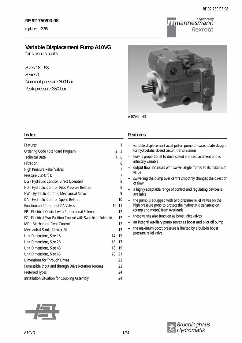
A10VG...HD
RE 92 750/03.98
Features
– variable displacement axial piston pump of swashplate designfor hydrostatic closed circuit transmissions
– flow is proportional to drive speed and displacement and isinfinitely variable
– output flow increases with swivel angle from 0 to its maximumvalue
– swivelling the pump over centre smoothly changes the directionof flow
– a highly adaptable range of control and regulating devices isavailable
– the pump is equipped with two pressure relief valves on thehigh pressure ports to protect the hydrostatic transmission(pump and motor) from overloads
– these valves also function as boost inlet valves
– an integral auxiliary pump serves as boost and pilot oil pump
– the maximum boost pressure is limited by a built-in boostpressure relief valve
RE 92 750/03.98
Brueninghaus Hydromatik 2/24 A10VG
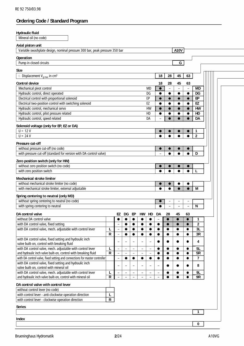
Ordering Code / Standard Program
Hydraulic fluidMineral oil (no code)
Axial piston unitVariable swashplate design, nominal pressure 300 bar, peak pressure 350 bar A10V
OperationPump in closed circuits G
Size Displacement Vg max in cm3 18 28 45 63
Control device 18 28 45 63Mechanical pivot control MD – – – MDHydraulic control, direct operated DG DGElectrical control with proportional solenoid EP EPElectrical two-position control with switching solenoid EZ EZHydraulic control, mechanical servo HW HWHydraulic control, pilot pressure related HD HDHydraulic control, speed related DA – DA
Solenoid voltage (only for EP, EZ or DA)U = 12 V 1U = 24 V 2
Pressure cut-offwithout pressure cut-off (no code)with pressure cut-off (standard for version with DA-control valve) – D
Zero position switch (only for HW)without zero position switch (no code)with zero position switch L
Mechanical stroke limiterwithout mechanical stroke limiter (no code)with mechanical stroke limiter, external adjustable M
Spring centering to neutral (only MD)without spring centering to neutral (no code) – – –with spring centering to neutral – – – N
DA control valve EZ DG EP HW HD DA 28 45 63without DA control valve – 1with DA control valve, fixed setting – 2with DA control valve, mech. adjustable with control lever L – 3L
R – 3Rwith DA control valve, fixed setting and hydraulic inch
– – – – – 4valve built-on, control with breaking fluidwith DA control valve, mech. adjustable with control lever L – – – – – 5Land hydraulic inch valve built-on, control with breaking fluid R – – – – – 5Rwith DA control valve, fixed setting and connections for master controller – 7with DA control valve, fixed setting and hydraulic inch
– – – – – – 8valve built-on, control with mineral oilwith DA control valve, mech. adjustable with control lever L – – – – – – 9Land hydraulic inch valve built-on, control with mineral oil R – – – – – – 9R
DA control valve with control leverwithout control lever (no code)with control lever - anti-clockwise operation direction Lwith control lever - clockwise operation direction R
Series1
Index0
RE 92 750/03.98
A10VG 3/24 Brueninghaus Hydromatik
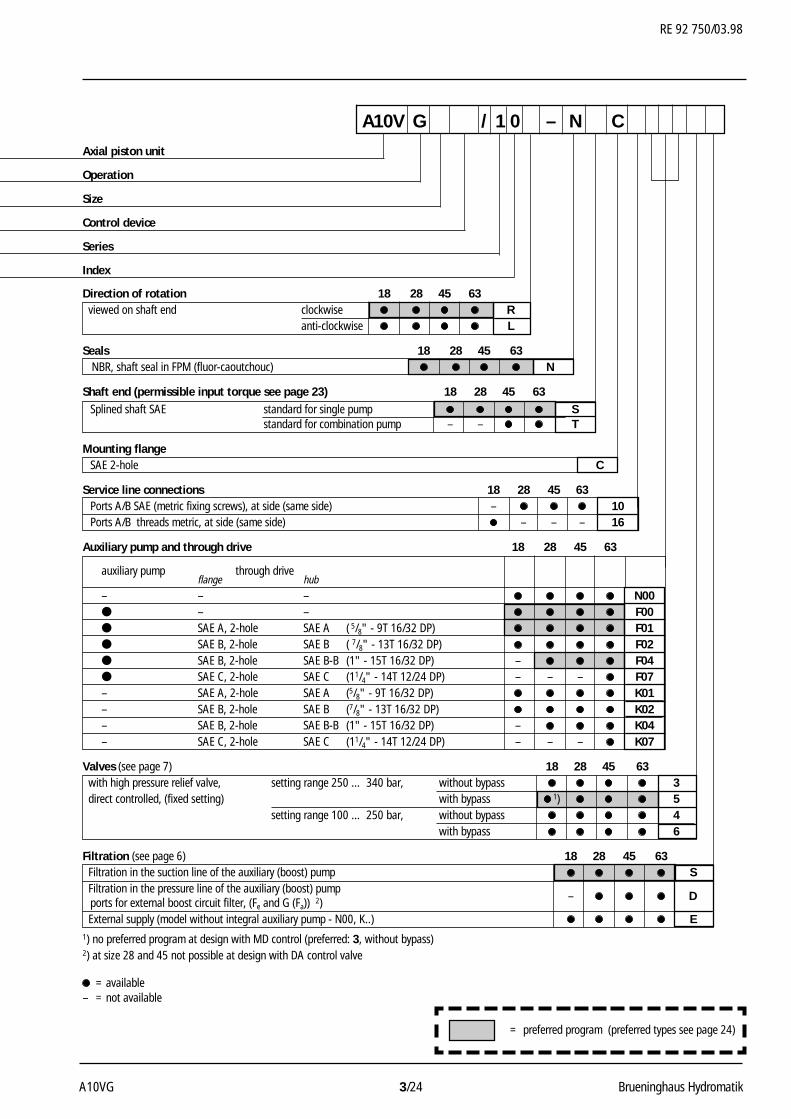
Axial piston unit
Operation
Size
Control device
Series
Index
A10V G / 1 0 – N C
= preferred program (preferred types see page 24)
Direction of rotation 18 28 45 63 viewed on shaft end clockwise R
anti-clockwise L
Seals 18 28 45 63 NBR, shaft seal in FPM (fluor-caoutchouc) N
Shaft end (permissible input torque see page 23) 18 28 45 63Splined shaft SAE standard for single pump S
standard for combination pump – – T
Mounting flangeSAE 2-hole C
Service line connections 18 28 45 63Ports A/B SAE (metric fixing screws), at side (same side) – 10Ports A/B threads metric, at side (same side) – – – 16
Auxiliary pump and through drive 18 28 45 63
auxiliary pump through driveflange hub
– – – N00● – – F00● SAE A, 2-hole SAE A ( 5/8" - 9T 16/32 DP) F01● SAE B, 2-hole SAE B ( 7/8" - 13T 16/32 DP) F02● SAE B, 2-hole SAE B-B (1" - 15T 16/32 DP) – F04● SAE C, 2-hole SAE C (11/4" - 14T 12/24 DP) – – – F07– SAE A, 2-hole SAE A (5/8" - 9T 16/32 DP) K01– SAE B, 2-hole SAE B (7/8" - 13T 16/32 DP) K02– SAE B, 2-hole SAE B-B (1" - 15T 16/32 DP) – K04– SAE C, 2-hole SAE C (11/4" - 14T 12/24 DP) – – – K07
Valves (see page 7) 18 28 45 63 with high pressure relief valve, setting range 250 … 340 bar, without bypass 3 direct controlled, (fixed setting) with bypass 1) 5
setting range 100 … 250 bar, without bypass 4with bypass 6
Filtration (see page 6) 18 28 45 63 Filtration in the suction line of the auxiliary (boost) pump S Filtration in the pressure line of the auxiliary (boost) pump
– Dports for external boost circuit filter, (Fe and G (Fa)) 2) External supply (model without integral auxiliary pump - N00, K..) E1) no preferred program at design with MD control (preferred: 3, without bypass)2) at size 28 and 45 not possible at design with DA control valve
= available– = not available
RE 92 750/03.98
Brueninghaus Hydromatik 4/24 A10VG
Fluid
We request that before starting a project detailed information aboutthe choice of pressure fluids and application conditions are takenfrom our catalogue sheets RE 90220 (mineral oil), RE 90221(environmentally acceptable hydraulic fluids) and RE 90223 (fireresistance fluids, HF).
When using HF- or environmentally acceptable hydraulic fluidspossible limitations for the technical data have to be taken intoconsideration. If necessary please consult our technical department(please indicate type of the hydraulic fluid used for your applicationon the order sheet). The operation with HFA-, HFB- and HFC- hydraulicfluids requires additional special measures.
Operating viscosity range
In order to obtain optimum efficiency and service life, we recommendthat the operating viscosity (at operating tem-perature) be selectedfrom within the range:
νopt = operating viscosity 16...36 mm2/s
referred to the circuit temperature (closed circuit).
Viscosity limits
The limiting values for viscosity are as follows:
νmin = 5 mm2/s,
short term at a max. permissible temp. of tmax = 115°C.
Please note that the max. fluid temperature is also not exceeded incertain areas (for instance bearing area).
νmax = 1600 mm2/s,
short term on cold start (tmin = -40°C).
At temperatures of -25°C up to -40°C special measures are required.Please contact us for further information.
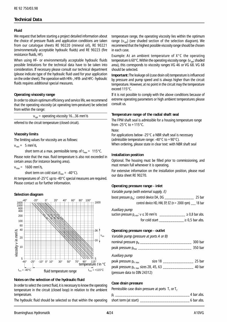
Selection diagram
Notes on the selection of the hydraulic fluidIn order to select the correct fluid, it is necessary to know the operatingtemperature in the circuit (closed loop) in relation to the ambienttemperature.
The hydraulic fluid should be selected so that within the operating
temperature range, the operating viscosity lies within the optimumrange (νopt) (see shaded section of the selection diagram). Werecommend that the highest possible viscosity range should be chosenin each case.
Example: At an ambient temperature of X°C the operatingtemperature is 60°C. Within the operating viscosity range (νopt; shadedarea), this corresponds to viscosity ranges VG 46 or VG 68. VG 68should be selected.
Important: The leakage oil (case drain oil) temperature is influencedby pressure and pump speed and is always higher than the circuittemperature. However, at no point in the circuit may the temperatureexceed 115°C.
If it is not possible to comply with the above conditions because ofextreme operating parameters or high ambient temperatures pleaseconsult us.
Temperature range of the radial shaft seal
The FPM shaft seal is admissible for a housing temperature rangefrom -25°C to +115°C.
Note:For applications below -25°C a NBR shaft seal is necessary(admissible temperature range: -40°C to +90°C).When ordering, please state in clear text: with NBR shaft seal
Installation position
Optional. The housing must be filled prior to commissioning, andmust remain full whenever it is operating.
For extensive information on the installation position, please readour data sheet RE 90270.
Operating pressure range - inlet
Variable pump (with external supply, E)
boost pressure pSp: control device DA, DG _________________ 25 bar
control device HD, HW, EP, EZ (n = 2000 rpm) ___ 18 bar
Auxiliary pumpsuction pressure ps min: ν ≤ 30 mm2/s _______________ ≥ 0,8 bar abs.
for cold start _____________ ≥ 0,5 bar abs.
Operating pressure range - outlet
Variable pump (pressure at ports A or B)
nominal pressure pN ___________________________ 300 bar
peak pressure pmax ____________________________ 350 bar
Auxiliary pump
peak pressure pH max size 18 ________________ 25 bar
peak pressure pH max sizes 28, 45, 63 ________________ 40 bar
(pressure data to DIN 24312)
Case drain pressurePermissible case drain pressure at ports T1 or T2
pL _______________________________________ 4 bar abs.
short term (at start) __________________________ 6 bar abs.
Technical Data
-40°
tmin = -40°C
νopt.
tmax = +115°C
-25° -10° 10° 30° 50° 90° 115°5
10
16
3640
60
20
100
200
400600
100016002500
������������������������������������������������������������
VG 22
VG 32
VG 46
VG 68
70°
0° 20° 40° 60° 80° 100°-40° -20°
5
1600
0°
VG 100
fluid temperature range
temperature t in °C
visc
osity
ν in
mm
2 /s
RE 92 750/03.98
A10VG 5/24 Brueninghaus Hydromatik
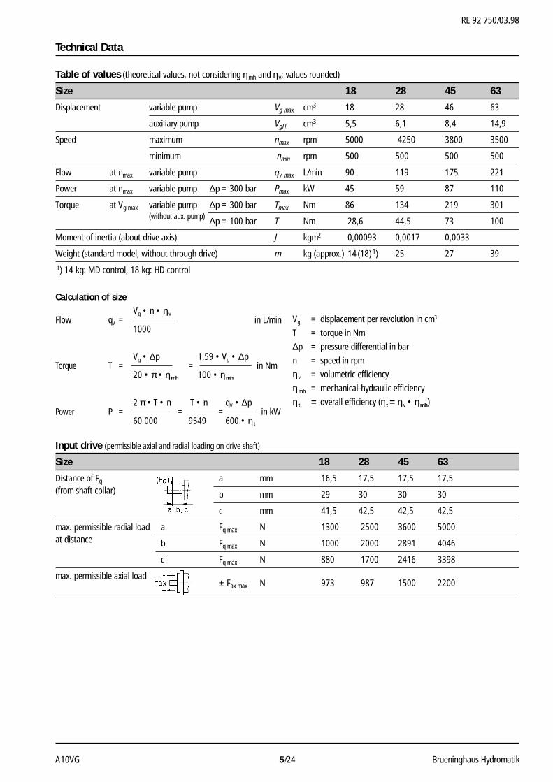
Table of values (theoretical values, not considering ηmh and ηv; values rounded)
Size 18 28 45 63
Displacement variable pump Vg max cm3 18 28 46 63
auxiliary pump VgH cm3 5,5 6,1 8,4 14,9
Speed maximum nmax rpm 5000 4250 3800 3500
minimum nmin rpm 500 500 500 500
Flow at nmax variable pump qV max L/min 90 119 175 221
Power at nmax variable pump ∆p = 300 bar Pmax kW 45 59 87 110
Torque at Vg max variable pump ∆p = 300 bar Tmax Nm 86 134 219 301(without aux. pump) ∆p = 100 bar T Nm 28,6 44,5 73 100
Moment of inertia (about drive axis) J kgm2 0,00093 0,0017 0,0033
Weight (standard model, without through drive) m kg (approx.) 14 (18) 1) 25 27 39
1) 14 kg: MD control, 18 kg: HD control
Technical Data
Calculation of sizeVg • n • ηv
Flow qV = in L/min1000
Vg • ∆p 1,59 • Vg • ∆pTorque T = = in Nm
20 • π • ηmh 100 • ηmh
2 π • T • n T • n qV • ∆pPower P = = = in kW
60 000 9549 600 • ηt
Vg = displacement per revolution in cm3
T = torque in Nm
∆p = pressure differential in bar
n = speed in rpm
ηv = volumetric efficiency
ηmh = mechanical-hydraulic efficiency
ηt = overall efficiency (ηt = ηv • ηmh)
Input drive (permissible axial and radial loading on drive shaft)
Size 18 28 45 63
Distance of Fq a mm 16,5 17,5 17,5 17,5(from shaft collar) b mm 29 30 30 30
c mm 41,5 42,5 42,5 42,5
max. permissible radial load a Fq max N 1300 2500 3600 5000at distance b Fq max N 1000 2000 2891 4046
c Fq max N 880 1700 2416 3398
max. permissible axial load± Fax max N 973 987 1500 2200
RE 92 750/03.98
Brueninghaus Hydromatik 6/24 A10VG
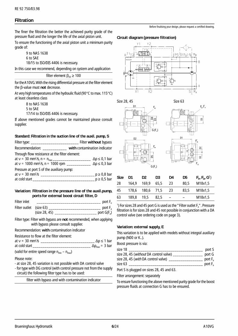
Filtration
Size D1 D2 D3 D4 D5 Fe, Fa, G1)
28 164,9 169,9 65,5 23 80,5 M18x1,5
45 178,6 180,6 71,5 23 83,5 M18x1,5
63 189,8 19,5 82,5 – – M18x1,5
1) For sizes 28 and 45 port G is used as the "Filter outlet Fa". Pressurefiltration is for sizes 28 and 45 not possible in conjunction with a DAcontrol valve (see ordering code on page 3).
Variation: external supply, E
This variation is to be applied with models without integral auxiliarypump (N00 or K..).
Boost pressure is via:
size 18 _____________________________________ port Ssize 28, 45 (without DA control valve) _______________ port Gsize 28, 45 (with DA control valve) _________________ port Fe
size 63 _____________________________________ port Fa
Port S is plugged on sizes 28, 45 and 63.
Filter arrangement: separately
To ensure functioning the above mentioned purity grade for the boostpressure fluids at connection G has to be ensured.
The finer the filtration the better the achieved purity grade of thepressure fluid and the longer the life of the axial piston unit.
To ensure the functioning of the axial piston unit a minimum puritygrade of:
9 to NAS 16386 to SAE18/15 to ISO/DIS 4406 is necessary.
In this case we recommend, depending on system and application
filter element β20 ≥ 100
for the A10VG. With the rising differential pressure at the filter elementthe β-value must not decrease.
At very high temperatures of the hydraulic fluid (90°C to max. 115°C)at least cleanless class
8 to NAS 16385 to SAE17/14 to ISO/DIS 4406 is necessary.
If above mentioned grades cannot be maintained please consultsupplier.
Standard: Filtration in the suction line of the auxil. pump, S
Filter type: ________________________ Filter without bypass
Recommendation: ____________ with contamination indicator
Through flow resistance at the filter element:at ν = 30 mm2/s, n = nmax ___________________ ∆p ≤ 0,1 barat ν = 1000 mm2/s, n = 1000 rpm ____________ ∆p ≤ 0,3 bar
Pressure at port S of the auxiliary pump:at ν = 30 mm2/s ___________________________ p ≥ 0,8 barat cold start _______________________________ p ≥ 0,5 bar
Variation: Filtration in the pressure line of the auxil.pump,ports for external boost circuit filter, D
Filter inlet ________________________________ port Fe
Filter outlet (size 63) __________________________ port Fa
(size 28, 45) _____________________ port G(Fa)
Filter type: Filter with bypass are not recommended, when applyingwith bypass please consult supplier.
Recommendation: with contamination indicator
Resistance to flow at the filter element:at ν = 30 mm2/s ___________________________ ∆p ≤ 1 barat cold start _____________________________ ∆pmax = 3 bar
(valid for entire speed range nmin – nmax)
Please note:- at size 28, 45 variation is not possible with DA control valve- for type with DG control (with control pressure not from the supply
circuit) the following filter type has to be used:
filter with bypass and with contamination indicator
Before finalising your design, please request a certified drawing.
Size 28, 45 Size 63
Circuit diagram (pressure filtration)
D1
D2
D4 D3D5
G(Fa)
G(Fa)
D1
D2D2
D3
RE 92 750/03.98
A10VG 7/24 Brueninghaus Hydromatik
High pressure relief valve, Differential pressuredirect controlled setting ∆pHD
Setting range 340 bar 270 bar∆p = 250…340 bar 320 bar(valve 3 and 5, see ordering code) 300 bar 1)
Setting range 250 bar 150 bar∆p = 100…250 bar 230 bar 100 bar(valve 4 and 6, see ordering code) 200 bar 1)
1) Standard setting of differential pressure, valves set to this value ifno details given on order.
Please state in clear text when ordering:(possible are only the values ∆pHD shown in the table)
High pressure relief valve ADifferential pressure setting: ∆pHD = ... barOpening pressure of the HD-valve (at qV max): pmax = ... bar(pmax = ∆pHD + pSp)
High pressure relief valve BDifferential pressure setting: ∆pHD = ... barOpening pressure of the HD-valve (at qV max): pmax = ... bar(pmax = ∆pHD + pSp)
Please note:- valve setting is done at through flow quantity qV 1 = 6 - 10 L/min- simplification: the bypass function is not shown in the hydraulic
schemes
p Sp
≥20
bar
pSp
pmax
p Sp
≥10 bar
qV 1 qV max
qV 1 qV max
pSp
pmax
High Pressure Relief Valves
Setting diagram
Example (design without pressure cut-off):operating pressure pA,B – boost pressure psp = differential pressure ∆pHD
300 bar – 20 bar = 280 bar
oper
atin
g pr
essu
re p
A, B
at p
orts
A, B
∆p d
rive
desig
npr
essu
resafety margin
boost pressure
set valuepressure cut-off
diffe
rent
ial p
ress
ure ∆
p HD
high
pre
ss. (
HD) v
alve
setti
ng
oper
atin
g pr
essu
re p
A, B
at p
orts
A, B
∆p d
rive
desig
npr
essu
re
safety margin
boost pressure
diffe
rent
ial p
ress
ure ∆
p HD
high
pre
ss. (
HD) v
alve
setti
ng
withoutpressure cut-off
withpressure cut-off
Example (design with pressure cut-off):operating pressure pA,B – boost pressure psp + safety margin = differential pressure ∆pHD
300 bar – 20 bar + 20 bar = 300 bar
The pressure cut-off corresponds to a pressure regulation which, afterreaching the set pressure, adjusts the pump volume of the pump toVg = 0.
This valve prevents the operation of the high pressure relief valveswhen accelerating or decelerating quickly (quick pressure rise).
The pressure peaks occurring when the swashplate is swivelled rapidlyand also the maximum pressure in the system are safeguarded bythe high pressure limit valves.
The setting range of the pressure cut-off may be anywhere withinthe entire working pressure range. However, it must be set 20-30bar lower than the setting of the high pressure safety relief valves(see diagram).
Please state the setting value of the pressure cut-off in clear textwhen ordering.
Circuit diagramHydraulic control, speed related, with pressure cut-off DA.D3
Pressure Cut-Off, D
pressure cut-off
RE 92 750/03.98
Brueninghaus Hydromatik 8/24 A10VG
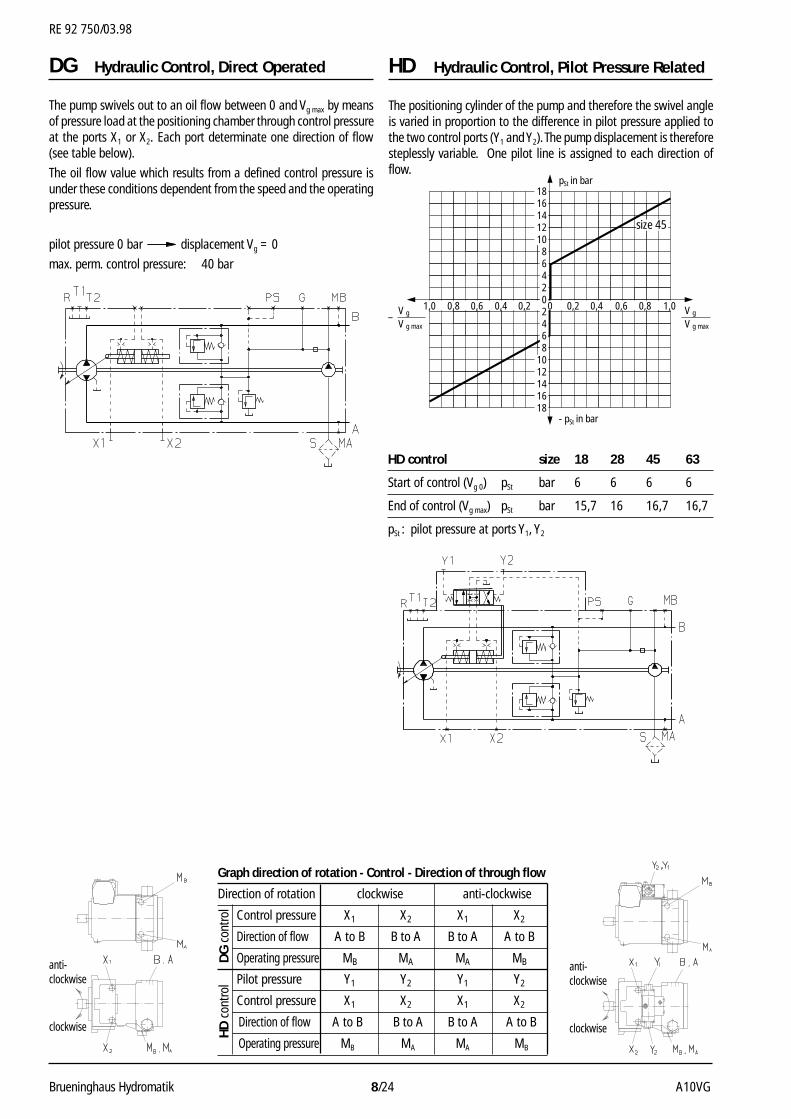
DG Hydraulic Control, Direct Operated
The pump swivels out to an oil flow between 0 and Vg max by meansof pressure load at the positioning chamber through control pressureat the ports X1 or X2. Each port determinate one direction of flow(see table below).
The oil flow value which results from a defined control pressure isunder these conditions dependent from the speed and the operatingpressure.
pilot pressure 0 bar displacement Vg = 0
max. perm. control pressure: 40 bar
Graph direction of rotation - Control - Direction of through flow
Direction of rotation clockwise anti-clockwise
Control pressure X1 X2 X1 X2
Direction of flow A to B B to A B to A A to B
Operating pressure MB MA MA MB
Pilot pressure Y1 Y2 Y1 Y2
Control pressure X1 X2 X1 X2
Direction of flow A to B B to A B to A A to B
Operating pressure MB MA MA MB
The positioning cylinder of the pump and therefore the swivel angleis varied in proportion to the difference in pilot pressure applied tothe two control ports (Y1 and Y2). The pump displacement is thereforesteplessly variable. One pilot line is assigned to each direction offlow.
HD control size 18 28 45 63
Start of control (Vg 0) pSt bar 6 6 6 6
End of control (Vg max) pSt bar 15,7 16 16,7 16,7
pSt : pilot pressure at ports Y1, Y2
anti-clockwise
clockwise
HD Hydraulic Control, Pilot Pressure Related
pSt in bar
- pSt in bar
1816141210864202468
1012141618
0,8 0,80,6 0,60,4 0,40,2 0,201,0 1,0
V g max
V g
V g max
V g–
size 45
anti-clockwise
clockwise HD
con
trol
DG
con
trol
RE 92 750/03.98
A10VG 9/24 Brueninghaus Hydromatik
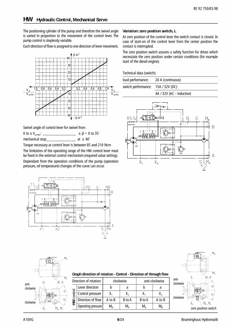
Variation: zero position switch, L
At zero position of the control lever the switch contact is closed. Incase of start-on of the control lever from the center position thecontact is interrupted.
The zero position switch assures a safety function for drives whichnecessiate the zero position under certain conditions (for examplestart of the diesel engine).
Technical data (switch):
load performance: 20 A (continuous)
switch performance: 15A / 32V (DC)
4A / 32V (AC - inductive)
The positioning cylinder of the pump and therefore the swivel angleis varied in proportion to the movement of the control lever. Thepump control is steplessly variable.
Each direction of flow is assigned to one direction of lever movement.
Swivel angle of control lever for swivel from
0 to ± Vg max: _________________ ± β = 0 to 35°
mechanical stop _______________ at ± 40°
Torque necessary at control lever is between 85 and 210 Ncm
The limitation of the operating range of the HW control lever mustbe fixed in the external control mechanism (required value setting).
Dependant from the operation conditions of the pump (operationpressure, oil temperature) changes of the curve can occur.
inβ o
in− β o
40
30
20
10
10
20
30
40
0,8 0,80,6 0,60,4 0,40,2 0,201,0 1,0
V g max
V g
V g max
V g–
zero position switch
HW Hydraulic Control, Mechanical Servo
anti-clockwise
clockwise
anti-clockwise
clockwise
Graph direction of rotation - Control - Direction of through flow
Direction of rotation clockwise anti-clockwise
Lever direction b a b a
Control pressure X1 X2 X1 X2
Direction of flow A to B B to A B to A A to B
Operating pressure MB MA MA MB
HW
con
trol
RE 92 750/03.98
Brueninghaus Hydromatik 10/24 A10VG
DA control valve, fixed setting, (DA..2)
Control pressure is generated in relation to drive speed. Whenordering, please state in clear text: Start of control (set at factory)
In relation to the drive speed, control pressure is applied to thepositioning cylinder of the pump by means of the DA control valvevia a 4/3 way directional valve. Pump displacement is steplessly va-riable in each direction of flow. Each direction of flow is assigned toone of the two solenoids on the directional valve.
Increasing drive speed generates a higher control pressure throughthe DA valve.
Increasing control pressure increases the pump displacement.
Dependent upon the pump operating curve, pressure in the highpressure lines causes the pump to swivel back towards a smallerdisplacement.
Increasing operating pressure gives reduced displacement.
A constant torque input to the pump is achieved by this combinationof de-stroking of the pump as the operating pressure increases andin response to the “pull-down” of the prime mover (leading to areduced control pressure).
The least possible pull down leads to optimum usage of the drivepower. This is achieved by “partial inching”. In this form of the control,the DA valve is mechanically coupled to the accelerator pedal. Thismeans that on reaching a certain speed (movement of the acceleratorpedal), the control curve is offset parallel to the engine speed curve.
Any additional power requirements, e.g. the service hydraulics, maylead to engine pull down occuring. This leads to a reduction in controlpressure and therefore pump displacement. The power thus releasedis then available to supply that demanded. Automatic power divisionand full utilisation of power available is thus achieved for both thevehicle transmission and the service hydraulics.
In an automative transmission, the DA control valve is used inconjunction with the directly controlled hydraulic “DA control”.
However, pumps with HD, HW, EP or DG controls can also be equippedwith a DA control valve. In this way, the automatic transmissionfunction (speed related high pressure/flow increase with load limitingcontrol) may be overridden.
The maximum flow will then be determined by the setting of therelevant control module fitted.
Graph direction of rotation - Control - Direction of through flow
Direction of rotation clockwise anti-clockwise
Solenoid b a b a
Control pressure X1 X2 X1 X2
Direction of flow A to B B to A B to A A to B
Operating pressure MB MA MA MB
DA Hydraulic Control, Speed Related Function and Control of DA Valves
DA control valve, mechanically adjustable with controllever (DA..3)
Control pressure is generated in relation to drive speed. When ordering,please state in clear text: Start of control (set at factory).
Control pressure may be reduced (independently of drive speed) asrequired by operation of the control lever (inch function).
Max. adm. operating torque at the control lever: ___ Tmax= 4 Nm
Max. angle of lever operation 70°. The position of the lever is optional.
A1A2
A3 Size 28 45 63
A1 154 157 154,5
A2 15,5 23 24,5
A3 164,9 178,6 186,3
A1A2
A3
Size 28 45 63
A1 176 176 185
A2 15,5 23 24,5
A3 164,9 178,6 186,3
operating direction"anti-clockwise" (3L)
operating direction"clockwise" (3R)
anti-clockwise
clockwise
switching solenoid a
switching solenoid b
RE 92 750/03.98
A10VG 11/24 Brueninghaus Hydromatik
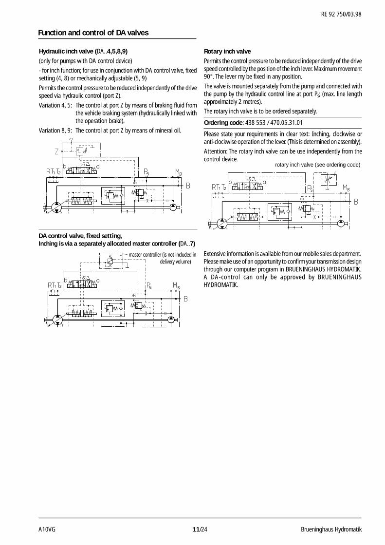
Rotary inch valve
Permits the control pressure to be reduced independently of the drivespeed controlled by the position of the inch lever. Maximum movement90°. The lever my be fixed in any position.
The valve is mounted separately from the pump and connected withthe pump by the hydraulic control line at port PS; (max. line lengthapproximately 2 metres).
The rotary inch valve is to be ordered separately.
Ordering code: 438 553 / 470.05.31.01
Please state your requirements in clear text: Inching, clockwise oranti-clockwise operation of the lever. (This is determined on assembly).
Attention: The rotary inch valve can be use independently from thecontrol device.
Hydraulic inch valve (DA..4,5,8,9)
(only for pumps with DA control device)
- for inch function; for use in conjunction with DA control valve, fixedsetting (4, 8) or mechanically adjustable (5, 9)
Permits the control pressure to be reduced independently of the drivespeed via hydraulic control (port Z).
Variation 4, 5: The control at port Z by means of braking fluid fromthe vehicle braking system (hydraulically linked withthe operation brake).
Variation 8, 9: The control at port Z by means of mineral oil.
DA control valve, fixed setting,Inching is via a separately allocated master controller (DA..7)
Extensive information is available from our mobile sales department.Please make use of an opportunity to confirm your transmission designthrough our computer program in BRUENINGHAUS HYDROMATIK.A DA-control can only be approved by BRUENINGHAUSHYDROMATIK.
Function and control of DA valves
master controller (is not included indelivery volume)
rotary inch valve (see ordering code)
RE 92 750/03.98
Brueninghaus Hydromatik 12/24 A10VG
EZ Electrical Two-Position Control withSwitching Solenoid
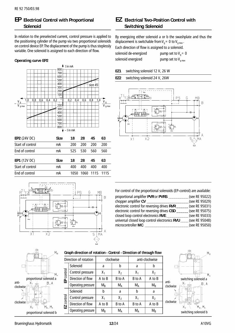
In relation to the preselected current, control pressure is applied tothe positioning cylinder of the pump via two proportional solenoidson control device EP. The displacement of the pump is thus steplesslyvariable. One solenoid is assigned to each direction of flow.
Operating curve EP2
For control of the proportional solenoids (EP-control) are available:
proportional amplifier PVR or PVRS __________ (see RE 95022)chopper amplifier CV _____________________ (see RE 95029)electronic control for reversing drives RVR ______ (see RE 95031)electronic control for reversing drives CSD ______ (see RE 95075)closed loop control electronics RVE ___________ (see RE 95033)universal closed loop control electronics RVU ____ (see RE 95048)microcontroller MC ______________________ (see RE 95050)
EP2 (24V DC) Size 18 28 45 63
Start of control mA 200 200 200 200
End of control mA 525 530 560 560
EP1 (12V DC) Size 18 28 45 63
Start of control mA 400 400 400 400
End of control mA 1050 1060 1115 1115
I in mA
– I in mA
0,8 0,80,6 0,60,4 0,40,2 0,201,0 1,0
800700600500400300200100
0
200300400500600700800
V g max
V g
V g max
V g–
size 45
proportional solenoid a
proportional solenoid b
anti-clockwise
clockwise
switching solenoid a
switching solenoid b
EP Electrical Control with ProportionalSolenoid
By energizing either solenoid a or b the swashplate and thus thedisplacement is switchable from Vg = 0 to Vg max .
Each direction of flow is assigned to a solenoid.
solenoid de-energized pump set to Vg = 0
solenoid energized pump set to Vg max
EZ1 switching solenoid 12 V, 26 W
EZ2 switching solenoid 24 V, 26W
Graph direction of rotation - Control - Direction of through flow
Direction of rotation clockwise anti-clockwise
Solenoid a b a b
Control pressure X1 X2 X1 X2
Direction of flow A to B B to A B to A A to B
Operating pressure MB MA MA MB
Solenoid b a b a
Control pressure X1 X2 X1 X2
Direction of flow A to B B to A B to A A to B
Operating pressure MB MA MA MB
EZ c
ontro
lEP
con
trol
anti-clockwise
clockwise
RE 92 750/03.98
A10VG 13/24 Brueninghaus Hydromatik
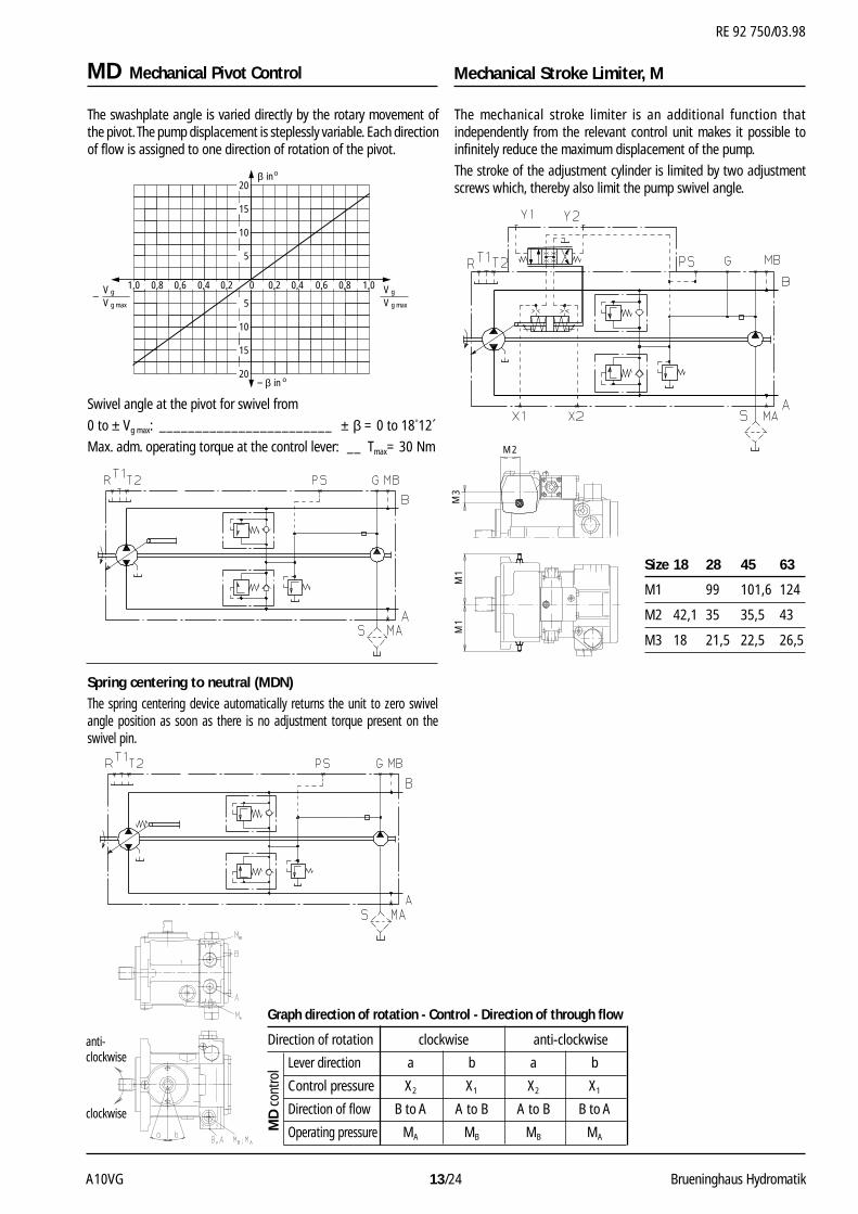
MD Mechanical Pivot Control
The swashplate angle is varied directly by the rotary movement ofthe pivot. The pump displacement is steplessly variable. Each directionof flow is assigned to one direction of rotation of the pivot.
inβ o
in− β o
20
15
10 5 5
10
15
20
0,8 0,80,6 0,60,4 0,40,2 0,201,0 1,0
V g max
V g
V g max
V g–
Swivel angle at the pivot for swivel from
0 to ± Vg max: ________________________ ± β = 0 to 18°12´
Max. adm. operating torque at the control lever: __ Tmax= 30 Nm
Spring centering to neutral (MDN)The spring centering device automatically returns the unit to zero swivelangle position as soon as there is no adjustment torque present on theswivel pin.
Mechanical Stroke Limiter, M
The mechanical stroke limiter is an additional function thatindependently from the relevant control unit makes it possible toinfinitely reduce the maximum displacement of the pump.
The stroke of the adjustment cylinder is limited by two adjustmentscrews which, thereby also limit the pump swivel angle.
Size 18 28 45 63
M1 99 101,6 124
M2 42,1 35 35,5 43
M3 18 21,5 22,5 26,5
M2M
3M
1M
1
Graph direction of rotation - Control - Direction of through flow
Direction of rotation clockwise anti-clockwise
Lever direction a b a b
Control pressure X2 X1 X2 X1
Direction of flow B to A A to B A to B B to A
Operating pressure MA MB MB MA
MD
con
trol
anti-clockwise
clockwise
RE 92 750/03.98
Brueninghaus Hydromatik 14/24 A10VG
83
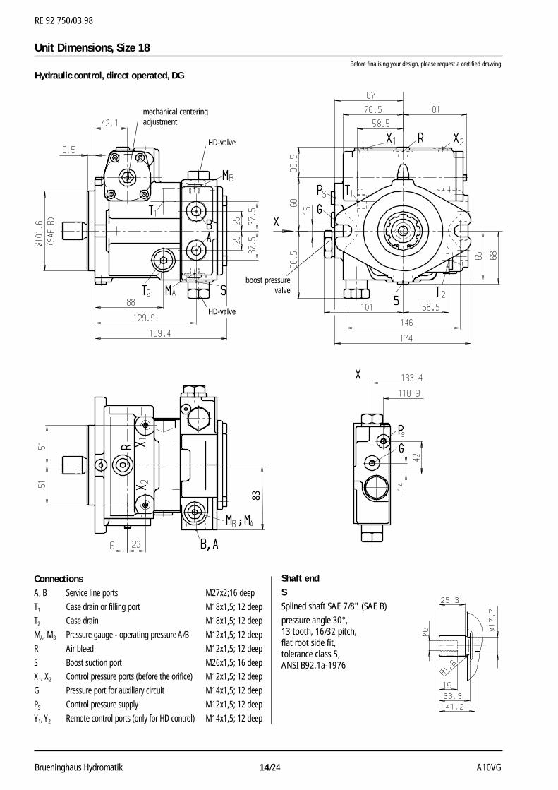
Unit Dimensions, Size 18Before finalising your design, please request a certified drawing.
Hydraulic control, direct operated, DG
Connections
A, B Service line ports M27x2;16 deep
T1 Case drain or filling port M18x1,5; 12 deep
T2 Case drain M18x1,5; 12 deep
MA, MB Pressure gauge - operating pressure A/B M12x1,5; 12 deep
R Air bleed M12x1,5; 12 deep
S Boost suction port M26x1,5; 16 deep
X1, X2 Control pressure ports (before the orifice) M12x1,5; 12 deep
G Pressure port for auxiliary circuit M14x1,5; 12 deep
PS Control pressure supply M12x1,5; 12 deep
Y1, Y2 Remote control ports (only for HD control) M14x1,5; 12 deep
Shaft end
S
Splined shaft SAE 7/8" (SAE B)
pressure angle 30°,13 tooth, 16/32 pitch,flat root side fit,tolerance class 5,ANSI B92.1a-1976
boost pressurevalve
HD-valve
HD-valve
mechanical centeringadjustment
RE 92 750/03.98
A10VG 15/24 Brueninghaus Hydromatik
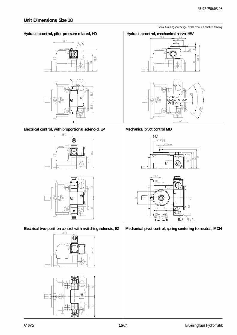
Unit Dimensions, Size 18Before finalising your design, please request a certified drawing.
Mechanical pivot control MD
Hydraulic control, mechanical servo, HWHydraulic control, pilot pressure related, HD
Electrical control, with proportional solenoid, EP
Electrical two-position control with switching solenoid, EZ Mechanical pivot control, spring centering to neutral, MDN
51,1
max max
RE 92 750/03.98
Brueninghaus Hydromatik 16/24 A10VG
65
Fe
71
G (Fa)
G (Fa)
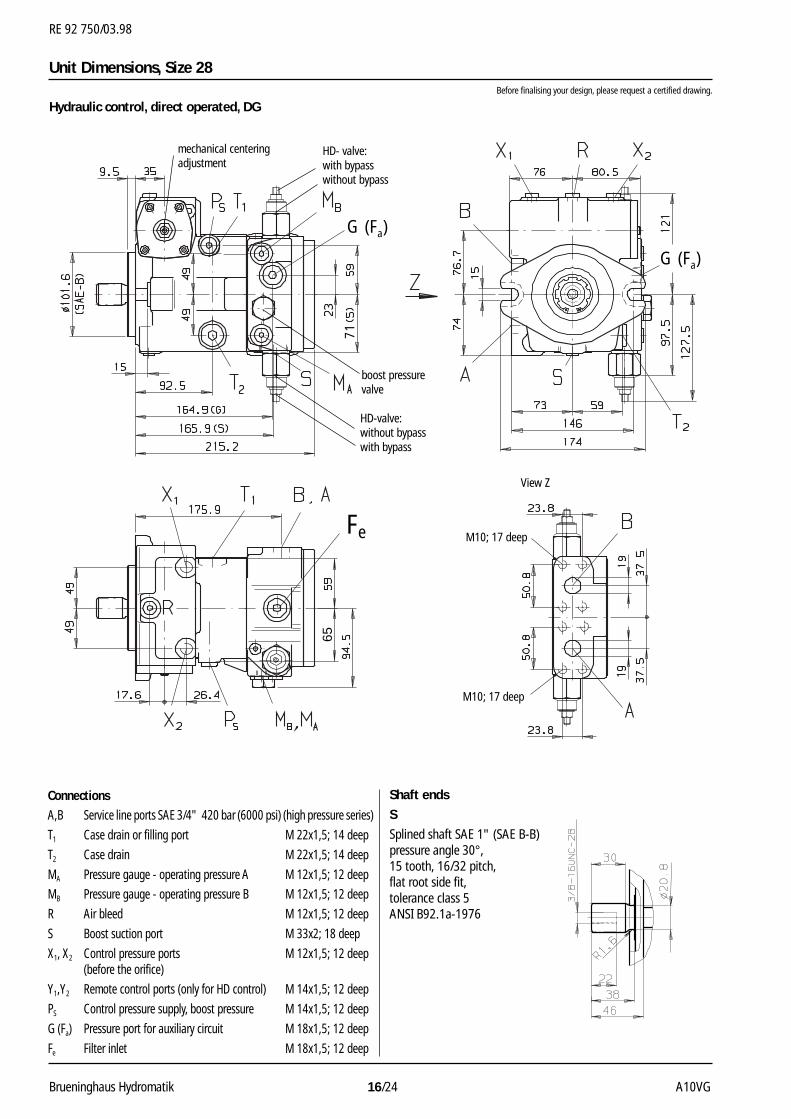
ConnectionsA,B Service line ports SAE 3/4" 420 bar (6000 psi) (high pressure series)
T1 Case drain or filling port M 22x1,5; 14 deep
T2 Case drain M 22x1,5; 14 deep
MA Pressure gauge - operating pressure A M 12x1,5; 12 deep
MB Pressure gauge - operating pressure B M 12x1,5; 12 deep
R Air bleed M 12x1,5; 12 deep
S Boost suction port M 33x2; 18 deep
X1, X2 Control pressure ports M 12x1,5; 12 deep(before the orifice)
Y1,Y2 Remote control ports (only for HD control) M 14x1,5; 12 deep
PS Control pressure supply, boost pressure M 14x1,5; 12 deep
G (Fa) Pressure port for auxiliary circuit M 18x1,5; 12 deep
Fe Filter inlet M 18x1,5; 12 deep
Shaft ends
S
Splined shaft SAE 1" (SAE B-B)pressure angle 30°,15 tooth, 16/32 pitch,flat root side fit,tolerance class 5ANSI B92.1a-1976
boost pressurevalve
HD- valve:with bypasswithout bypass
HD-valve:without bypasswith bypass
View Z
M10; 17 deep
M10; 17 deep
mechanical centeringadjustment
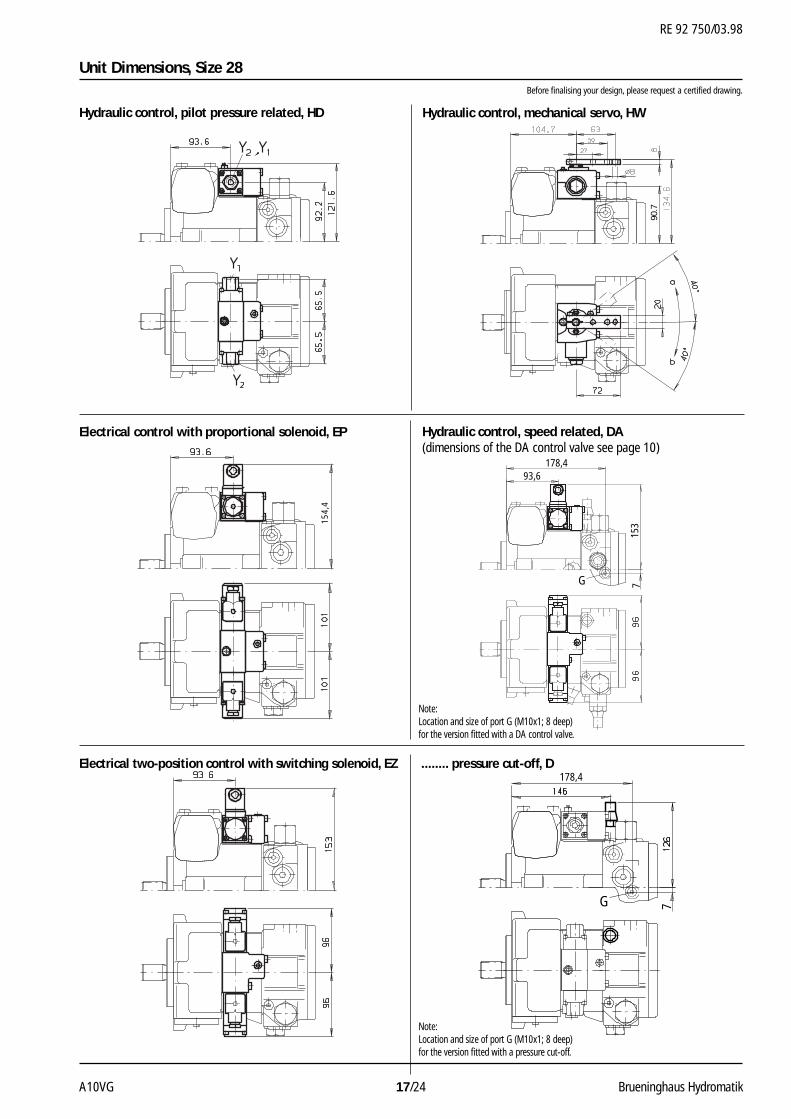
Unit Dimensions, Size 28Before finalising your design, please request a certified drawing.
Hydraulic control, direct operated, DG
RE 92 750/03.98
A10VG 17/24 Brueninghaus Hydromatik
Unit Dimensions, Size 28Before finalising your design, please request a certified drawing.
Hydraulic control, mechanical servo, HWHydraulic control, pilot pressure related, HD
Electrical control with proportional solenoid, EP
Electrical two-position control with switching solenoid, EZ
Hydraulic control, speed related, DA(dimensions of the DA control valve see page 10)
........ pressure cut-off, D
154,
4
90.7
715
3
178,493,6
G
7
178,4
G
Note:Location and size of port G (M10x1; 8 deep)for the version fitted with a DA control valve.
Note:Location and size of port G (M10x1; 8 deep)for the version fitted with a pressure cut-off.

RE 92 750/03.98
Brueninghaus Hydromatik 18/24 A10VG
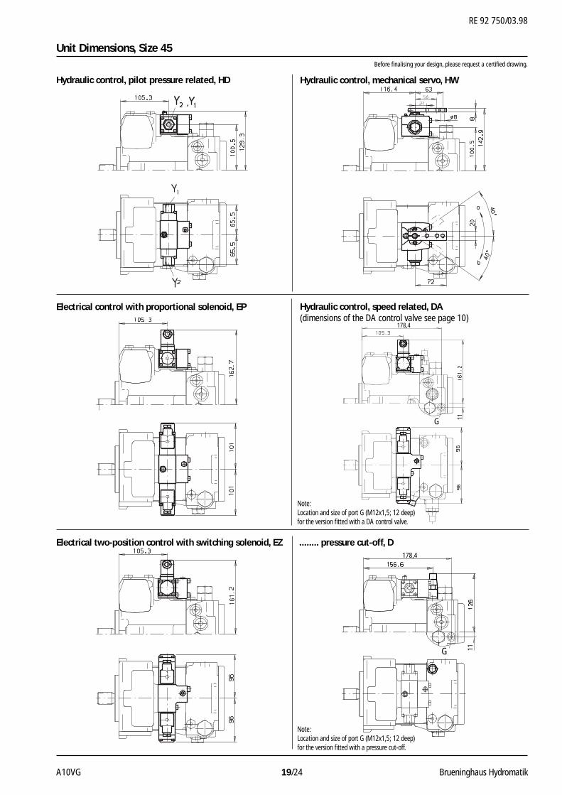
Unit Dimensions, Size 45Before finalising your design, please request a certified drawing.
Hydraulic control, direct operated, DG
Shaft ends
S
Splined shaft SAE 1" (SAE B-B),pressure angle 30°,15 tooth, 16/32 pitch,flat root side fit,tolerance class 5ANSI B92.1a-1976
T
Splined shaft SAE 11/4" (SAE C),pressure angle 30°,14 tooth, 12/24 pitch,flat root side fit,tolerance class 5ANSI B92.1a-1976
Connections
A,B Service line ports SAE 3/4" 420 bar (6000 psi) (high pressure series)
T1 Case drain or filling port M 22x1,5; 14 deep
T2 Case drain M 22x1,5; 14 deep
MA Pressure gauge - operating pressure A M 12x1,5; 12 deep
MB Pressure gauge - operating pressure B M 12x1,5; 12 deep
R Air bleed M 12x1,5; 12 deep
S Boost suction port M 33x2; 18 deep
X1, X2 Control pressure ports (before the orifice) M 12x1,5; 12 deep
Y1,Y2 Remote control ports (only for HD control) M 14x1,5; 12 deep
PS Control pressure supply, boost pressure M 14x1,5; 12 deep
G (Fa) Pressure port for auxiliary circuit M 18x1,5; 12 deep
Fe Filter inlet M 18x1,5; 12 deep
boost pressure valve
68
Fe
G (Fa)
G (Fa)
View Z
HD-valve:without bypasswith bypass
HD-valve:with bypasswithout bypass
M10; 17 deep
M10; 17 deep
mechanical centeringadjustment
RE 92 750/03.98
A10VG 19/24 Brueninghaus Hydromatik
Unit Dimensions, Size 45Before finalising your design, please request a certified drawing.
Hydraulic control, mechanical servo, HWHydraulic control, pilot pressure related, HD
Electrical control with proportional solenoid, EP
Electrical two-position control with switching solenoid, EZ
Hydraulic control, speed related, DA(dimensions of the DA control valve see page 10)
........ pressure cut-off, D
11
178,4
G
11
178,4
G
Note:Location and size of port G (M12x1,5; 12 deep)for the version fitted with a DA control valve.
Note:Location and size of port G (M12x1,5; 12 deep)for the version fitted with a pressure cut-off.
RE 92 750/03.98
Brueninghaus Hydromatik 20/24 A10VG
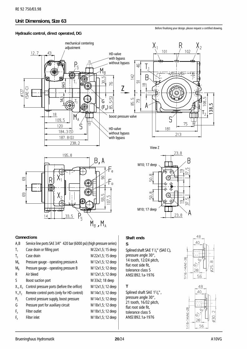
Z
54,5
64,5
G(Fa)
138,
5
Unit Dimensions, Size 63Before finalising your design, please request a certified drawing.
Hydraulic control, direct operated, DG
ConnectionsA,B Service line ports SAE 3/4" 420 bar (6000 psi) (high pressure series)
T1 Case drain or filling port M 22x1,5; 15 deep
T2 Case drain M 22x1,5; 15 deep
MA Pressure gauge - operating pressure A M 12x1,5; 12 deep
MB Pressure gauge - operating pressure B M 12x1,5; 12 deep
R Air bleed M 12x1,5; 12 deep
S Boost suction port M 33x2; 18 deep
X1, X2 Control pressure ports (before the orifice) M 12x1,5; 12 deep
Y1,Y2 Remote control ports (only for HD control) M 14x1,5; 12 deep
PS Control pressure supply, boost pressure M 14x1,5; 12 deep
G Pressure port for auxiliary circuit M 18x1,5; 12 deep
Fa Filter outlet M 18x1,5; 12 deep
Fe Filter inlet M 18x1,5; 12 deep
Shaft ends
S
Splined shaft SAE 11/4" (SAE C),pressure angle 30°,14 tooth, 12/24 pitch,flat root side fit,tolerance class 5ANSI B92.1a-1976
TSplined shaft SAE 13/8",pressure angle 30°,21 tooth, 16/32 pitch,flat root side fit,tolerance class 5ANSI B92.1a-1976
boost pressure valve
View Z
HD-valvewith bypasswithout bypass
M10; 17 deep
M10; 17 deep
mechanical centeringadjustment
HD-valvewithout bypasswith bypass
RE 92 750/03.98
A10VG 21/24 Brueninghaus Hydromatik
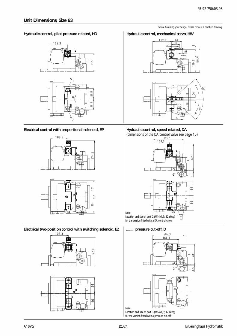
Unit Dimensions, Size 63Before finalising your design, please request a certified drawing.
Hydraulic control, mechanical servo, HWHydraulic control, pilot pressure related, HD
Electrical control with proportional solenoid, EP
Electrical two-position control with switching solenoid, EZ
Hydraulic control, speed related, DA(dimensions of the DA control valve see page 10)
........ pressure cut-off, D
108,3119,3
108,3
G
108,3
9696
108,3
9696
G
166,3
128
Note:Location and size of port G (M14x1,5; 12 deep)for the version fitted with a DA control valve.
Note:Location and size of port G (M14x1,5; 12 deep)for the version fitted with a pressure cut-off.
RE 92 750/03.98
Brueninghaus Hydromatik 22/24 A10VG
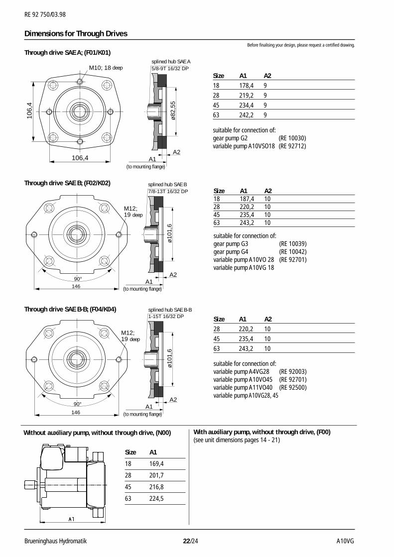
Size A1 A2
18 178,4 9
28 219,2 9
45 234,4 9
63 242,2 9
suitable for connection of:gear pump G2 (RE 10030)variable pump A10VSO18 (RE 92712)
Size A1 A218 187,4 1028 220,2 1045 235,4 1063 243,2 10
suitable for connection of:gear pump G3 (RE 10039)gear pump G4 (RE 10042)variable pump A10VO 28 (RE 92701)variable pump A10VG 18
Size A1 A2
28 220,2 10
45 235,4 10
63 243,2 10
suitable for connection of:variable pump A4VG28 (RE 92003)variable pump A10VO45 (RE 92701)variable pump A11VO40 (RE 92500)variable pump A10VG28, 45
Size A1
18 169,4
28 201,7
45 216,8
63 224,5
A1 A2
(bis Anbauflansch)
ø10
1,6
Keilnabe SAE B-B1-15T 16/32 DP
146
M12;19 tief
90°
A1 A2
(bis Anbauflansch)
ø10
1,6
Keilnabe SAE B7/8-13T 16/32 DP
146
90°
M12;19 tief
106,
4
106,4 A1 A2
(bis Anbauflansch)
ø82
,55
Keilnabe SAE B5/8-9T 16/32 DPM10; 18 tief
Dimensions for Through Drives
Through drive SAE A; (F01/K01)
Through drive SAE B; (F02/K02)
Through drive SAE B-B; (F04/K04)
Without auxiliary pump, without through drive, (N00) With auxiliary pump, without through drive, (F00)(see unit dimensions pages 14 - 21)
Before finalising your design, please request a certified drawing.
splined hub SAE A
splined hub SAE B
splined hub SAE B-B
(to mounting flange)
(to mounting flange)
(to mounting flange)
deep
deep
deep
RE 92 750/03.98
A10VG 23/24 Brueninghaus Hydromatik
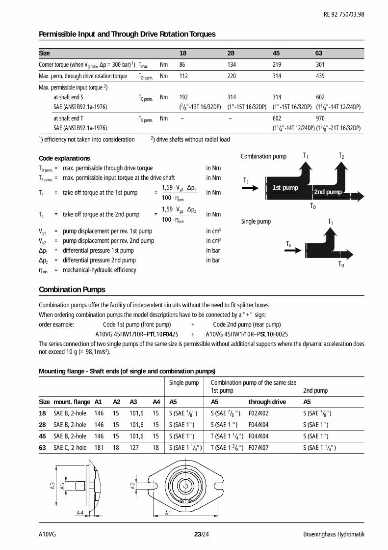
2. Pumpe1. Pumpe
TE
TE
TD
T1
TD
T1
T2
Permissible Input and Through Drive Rotation Torques
Size 18 28 45 63
Corner torque (when Vg max, ∆p = 300 bar) 1) Tmax Nm 86 134 219 301
Max. perm. through drive rotation torque TD perm. Nm 112 220 314 439
Max. permissible input torque 2)
at shaft end S TE perm. Nm 192 314 314 602
SAE (ANSI B92.1a-1976) (7/8"-13T 16/32DP) (1"-15T 16/32DP) (1"-15T 16/32DP) (11/4"-14T 12/24DP)
at shaft end T TE perm. Nm – – 602 970
SAE (ANSI B92.1a-1976) (11/4"-14T 12/24DP) (13/8"-21T 16/32DP)1) efficiency not taken into consideration 2) drive shafts without radial load
Code explanationsTD perm. = max. permissible through drive torque in Nm
TE perm. = max. permissible input torque at the drive shaft in Nm
1,59 . Vg1 . ∆p1T1 = take off torque at the 1st pump = in Nm
100 . ηmh
1,59 . Vg2 . ∆p2T2 = take off torque at the 2nd pump = in Nm
100 . ηmh
Vg1 = pump displacement per rev. 1st pump in cm3
Vg2 = pump displacement per rev. 2nd pump in cm3
∆p1 = differential pressure 1st pump in bar
∆p2 = differential pressure 2nd pump in bar
ηmh = mechanical-hydraulic efficiency
Combination Pumps
Combination pumps offer the facility of independent circuits without the need to fit splitter boxes.
When ordering combination pumps the model descriptions have to be connected by a "+" sign:
order example: Code 1st pump (front pump) + Code 2nd pump (rear pump)
A10VG 45HW1/10R–PTC10F042S + A10VG 45HW1/10R–PSC10F002S
The series connection of two single pumps of the same size is permissible without additional supports where the dynamic acceleration doesnot exceed 10 g (= 98,1m/s2).
Mounting flange - Shaft ends (of single and combination pumps)
Single pump Combination pump of the same size1st pump 2nd pump
Size mount. flange A1 A2 A3 A4 A5 A5 through drive A5
18 SAE B, 2-hole 146 15 101,6 15 S (SAE 7/8") S (SAE 7/8 ") F02/K02 S (SAE 7/8")
28 SAE B, 2-hole 146 15 101,6 15 S (SAE 1") S (SAE 1 ") F04/K04 S (SAE 1")
45 SAE B, 2-hole 146 15 101,6 15 S (SAE 1") T (SAE 1 1/4") F04/K04 S (SAE 1")
63 SAE C, 2-hole 181 18 127 18 S (SAE 1 1/4") T (SAE 1 3/8") F07/K07 S (SAE 1 1/4")
Combination pump
Single pump
1st pump2nd pump
All rights reserved – Subject to revision MF/24 A10VG
RE 92 750/03.98
The specified data is for product descriptionpurposes only and may not be deemed to beguaranteed unless expressly confirmed in thecontract.
Brueninghaus Hydromatik GmbH
Plant ElchingenGlockeraustraße 2 • D–89275 ElchingenPhone +49 (0) 73 08 / 82-0Telefax +49 (0) 73 08 / 72 74
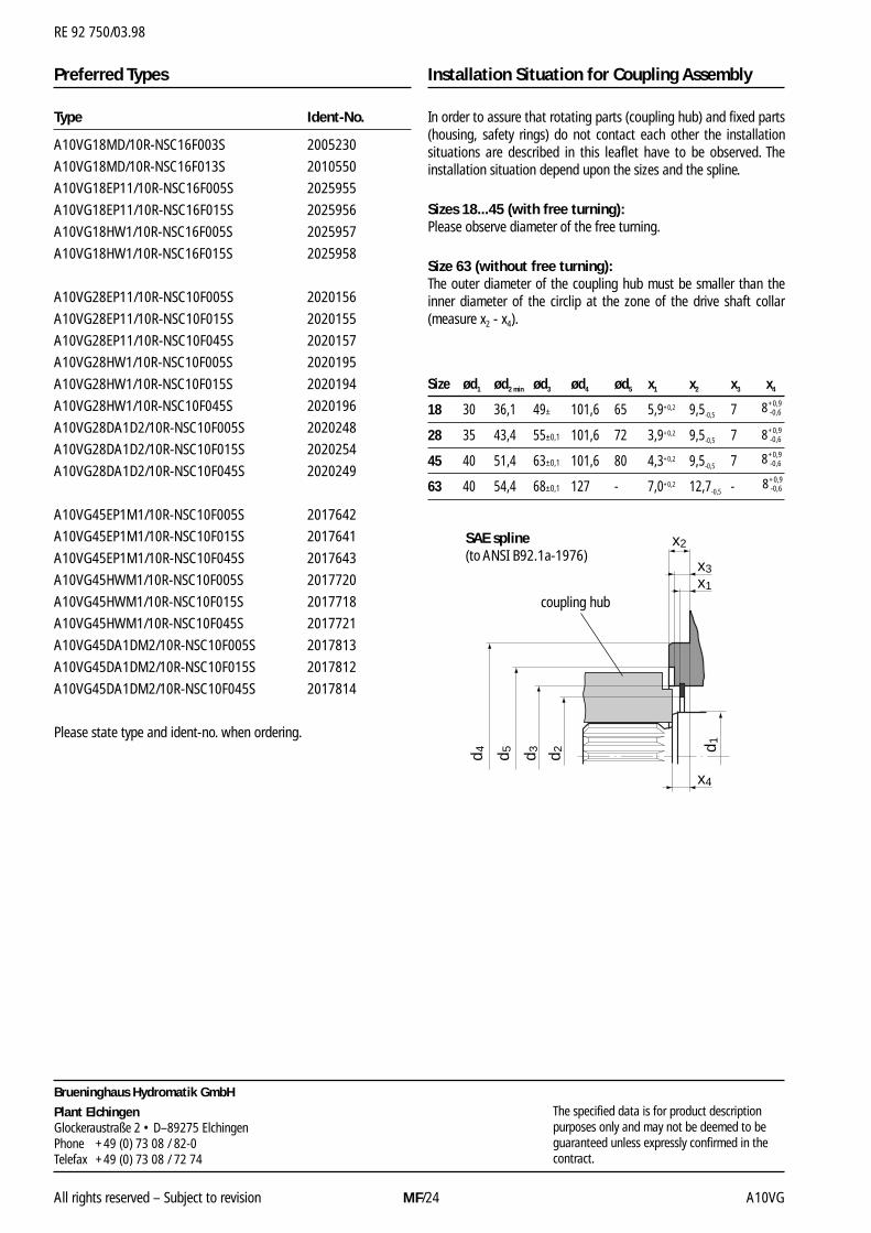
Size ød1 ød2 min ød3 ød4 ød5 x1 x2 x3 x4
18 30 36,1 49± 101,6 65 5,9+0,2 9,5-0,5 7
28 35 43,4 55±0,1 101,6 72 3,9+0,2 9,5-0,5 7
45 40 51,4 63±0,1 101,6 80 4,3+0,2 9,5-0,5 7
63 40 54,4 68±0,1 127 - 7,0+0,2 12,7-0,5 -
Type Ident-No.
A10VG18MD/10R-NSC16F003S 2005230
A10VG18MD/10R-NSC16F013S 2010550
A10VG18EP11/10R-NSC16F005S 2025955
A10VG18EP11/10R-NSC16F015S 2025956
A10VG18HW1/10R-NSC16F005S 2025957
A10VG18HW1/10R-NSC16F015S 2025958
A10VG28EP11/10R-NSC10F005S 2020156
A10VG28EP11/10R-NSC10F015S 2020155
A10VG28EP11/10R-NSC10F045S 2020157
A10VG28HW1/10R-NSC10F005S 2020195
A10VG28HW1/10R-NSC10F015S 2020194
A10VG28HW1/10R-NSC10F045S 2020196
A10VG28DA1D2/10R-NSC10F005S 2020248
A10VG28DA1D2/10R-NSC10F015S 2020254
A10VG28DA1D2/10R-NSC10F045S 2020249
A10VG45EP1M1/10R-NSC10F005S 2017642
A10VG45EP1M1/10R-NSC10F015S 2017641
A10VG45EP1M1/10R-NSC10F045S 2017643
A10VG45HWM1/10R-NSC10F005S 2017720
A10VG45HWM1/10R-NSC10F015S 2017718
A10VG45HWM1/10R-NSC10F045S 2017721
A10VG45DA1DM2/10R-NSC10F005S 2017813
A10VG45DA1DM2/10R-NSC10F015S 2017812
A10VG45DA1DM2/10R-NSC10F045S 2017814
Please state type and ident-no. when ordering.
Preferred Types Installation Situation for Coupling Assembly
x2
x1
x3
x4
d 5d 4 d 3 d 2 d 1
SAE spline(to ANSI B92.1a-1976)
coupling hub
In order to assure that rotating parts (coupling hub) and fixed parts(housing, safety rings) do not contact each other the installationsituations are described in this leaflet have to be observed. Theinstallation situation depend upon the sizes and the spline.
Sizes 18...45 (with free turning):Please observe diameter of the free turning.
Size 63 (without free turning):The outer diameter of the coupling hub must be smaller than theinner diameter of the circlip at the zone of the drive shaft collar(measure x2 - x4).
8 -0,6
+0,9
8 -0,6
+0,9
8 -0,6
+0,9
8 -0,6
+0,9