r&d programme 89
TRANSCRIPT
R&D PROGRAMME 89
Handling and final disposalof nuclear waste.Programme for research developmentand other measures.
September 1989
SVENSK KÄRNBRÄNSLEHANTERING ABSWEDISH NUCLEAR FUEL AND WASTE MANAGEMENT COBOX 5864 S-102 48 STOCKHOLMTEL. 08-665 28 00 TELEX 13108-SKB TELEFAX 08-661 5719
Handling and Final Disposalof Nuclear Waste.
Programme for Research, Developmentand other Measures.
September 1989
Part I GeneralPart II Programme 1990-1995

CONTENTS PARTS I - II
Parti GENERAL
FOREWORD
INTRODUCTION 9
1 PREMISES 11
2 WASTE FROM THE SWEDISH NUCLEARPOWER PROGRAMME 13
3 MANAGEMENT OF RADIOACTIVEWASTE FROM NUCLEAR POWER PLANTS 17
4 FINAL DISPOSAL OF SPENT NUCLEAR FUEL.OVERVIEW OF GOALS, PLAN FOR ACTIVITIESAND STATE OF KNOWLEDGE 25
5 FINAL DISPOSAL OF SPENT NUCLEAR FUEL.SUMMARY OF PLANNED RESEARCH ANDDEVELOPMENT 1990 -1995 39
6 DECOMMISSIONING OF NUCLEAR POWERPLANTS 49
References 53Appendix 55
Part II PROGRAMME 1990-1995
1
2
3
4
5
6
7
8
9
10
11
12
13
GENERAL
SITING OF FINAL REPOSITORY FOR SPENTFUEL AND OTHER LONG-LIVED WASTE
SAFETY ASSESSMENTS
REPOSITORY DESIGN
ENGINEERED BARRIERS
PROPERTIES OF THE ROCK
CHEMISTRY
METHOD AND INSTRUMENT DEVELOPMENT
HARD ROCK LABORATORY
THE STRIPA PROJECT
NATURAL ANALOGUES
BIOSPHERE STUDIES
INTERNATIONAL COOPERATION
References
65
67
73
83
89
103
127
139
151
159
165
169
173
181
BACKGROUND REPORTSI Reviews of R&D-Programmc 86
Summaries and SKB's comments (in Swedish)
II Hard Rock Laboratory
FOREWORD
The Act on Nuclear Activities (SFS 1884:3) prescribesin its Section 12 that a programme shall be prepared forthe comprehensive research and development andother measures that are required to safely handle andfinally dispose of the radioactive waste from the nuclearpower plants. The responsibility lies primarily with theowners of the nuclear power plants. These owners havecommissioned SKB to prepare the prescribed program-me. According to Section 25 of the Ordinance onNuclear Activities (SFS 1984:14), this programme shallbe submitted to the National Board for Spent NuclearFuel during the month of September every third yearbeginning in 1986.
The purpose of this second programme is to fulfilthe above obligations.
Stockholm in September 1989
SVENSK KÄRNBRÄNSLEHANTERING AB
Sten BjurströmManaging Director
II
I Per- Eric AhlströmlResearch Director

CONTENTS PART IPage
11.1
1.21.31.4
2
2.12.22.2.12.2.22.2.32.2.42.32.3.12.3.22.3.32.4
FOREWORD
INTRODUCTION
PREMISESGuidelines for Swedish RadioactiveWaste ManagementApplicable Legislation etcBackgroundR&D-Programme 86 - Expert Review
WASTE FROM THE SWEDISHNUCLEAR POWER PROGRAMMEClassification of Radioactive WasteWaste from the Nuclear Power Plants
Spent Nuclear FuelOperational WasteCore Components and Reactor InternalsDecommissioning Waste
Other Radioactive WasteWaste from CLAB and BSWaste from StudsvikWaste from Reprocessing
Estimated Waste Quantities
9
11
11111112
131313131314141414141515
3 MANAGEMENT OF RADIOACTIVEWASTE FROM NUCLEAR POWERPLANTS 17
3.1 General 173.2 Possible Final Disposal Principles 173.3 Facilities and Systems in Operation 183.3.1 Final Repository for Reactor Waste, SFR 183.3.2 Central Interim Storage Facility
for Spent Nuclear Fuel, CLAB 193.3.3 The Transportation System 193.4 Future Facilities and Systems 203.4.1 Encapsulation Plant for Spent Fuel, BS 203.4.2 Final Repository for Long-lived Waste, SFL 203.5 Timetable 22
4 FINAL DISPOSAL OF SPENT NUCLEARFUEL. OVERVIEW OF GOALS, PLANFOR ACTIVITIES AND STATE OFKNOWLEDGE 25
4.1 Goals of the Research Work - General 254.2 Some Points of Departure for the R&D-Woi k 254.3 Overall Plan for the R&D-Work 264.3.1 R&D-Programme86 264.3.2 Programme for R&D and Other Measures 264..4 Slate of Knowledge Regarding Safety
Assessments 284.4.1 Goals of the Work with Safety Assessments 294.4.2 State of Development for Safety Assessments 29
Page
4.54.5.1
4.5.24.5.34.5.44.5.54.6
4.6.14.6.24.6.34.6.44.6.54.74.7.14.7.24.84.8.14.8.2
5
5.15.25.35.3.15.3.25.3.35.3.45.3.55.3.65.3.75.3.85.3.95.3.105.3.115.4
State of Knowledge Regarding Engineered BarriersGoals of the Research RegardingEngineered BarriersDesign of the Final RepositoryWaste FormsCanisterBuffer and Backfill Material
State of Knowledge within theGcoscicntific Field
Goals of the Gcoscicntific StudiesGroundwa'cr Movements in the RockStability of the RockMethods and Instrument DevelopmentHard Rock Laboratory
ChemistryGoals of R&D in the Chemistry FieldPresent-day State of Knowledge
Biosphere StudiesGoals of Biosphere StudiesPresent-day State of Knowledge
FINAL DISPOSAL OF SPENT NUCLEARFUEL. SUMMARY OF PLANNEDRESEARCH AND DEVELOPMENT1990-1995GeneralResearch Areas and ProjectsResearch Programme 1990-1995
Siting of the Final RepositorySafety AssessmentDesign of the Final Repository
Engineered BarriersProperties of the RockMethod and Instrument DevelopmentHard Rock LaboratoryChemistryNatural AnaloguesBiosphere StudiesInternational Cooperation
Execution of the Programme
30
3030313132
333333343535363636373737
39393939414142424344444546464647
6 DECOMMISSIONING OF NUCLEARPOWER PLANTS 49
6.1 Background 496.2 Goals and Overall Plan 496.3 Ongoing Work 506.3.1 Sweden 506.3.2 Other Countries 506.4 Research Programme 1990-1995 52
REFERENCES 53Appendix 55
INTRODUCTION
The Act on Nuclear Activities (SFS 1984:3) prescribesthe owners of the Swedish nuclear power plants tojointly prepare a comprehensive programme for the re-search and development work and other measures re-quired for the safe management and disposal of thewaste from nuclear power production.
The Swedish Nuclear Fuel and Waste ManagementCompany (SKB) has been commissioned by its owners,the Swedish nuclear utilities, to develop, plan, con-struct and operate facilities and systems for the man-agement and disposal of spent nuclear fuel and radio-active waste from the Swedish nuclear power plants.
SKB is also responsible for the extensive research ac-tivities within the field of nuclear waste which the Swe-dish nuclear power producers arc required to carryout.
SKB is owned by Forsmarks Kraftgrupp AB (FKA),OKG AB, Sydsvenska Värmekraft AB (SVAB, ownedby Sydkraft AB) and Vattenfall (the Swedish StatePower Board).
The above utilities have commissioned SKB to pre-pare the programme for research and developmentprescribed by the Nuclear Activities Act. The pro-gramme, presented in this report, provides an overviewof all measures up to (he implemented final disposal.A more detailed account is given of the research pro-gramme for the period 1990-1995.
SKB's research through 1983 was presented in theKBS-3 Report, which was submitted in support of theapplications for fuelling permits for Fon.mark 3 andOskarshamn 3.
In 1986, SKB submitted the first research program-me pursuant to the Nuclear Activities Act, R&D-Pro-grammc 86. This report provided a brief account of re-search results obtained after the publication of theKBS-3 Report in May 1983.
This research programme, R&D-Programmc 89,provides an account of research results obtained after
September 198<> when R&D-Programme 8<> was pub-lished. A more detailed account of these results is pro-vided in the SKB series of Technical Reports.
The comments made in connection with the expertreview of R&D-Programme 86 have been taken intoaccount in the preparation of R&D-Programmc 89.
For those parts of the waste system that have alreadybeen taken into operation - transportation and hand-ling systems, central interim storage facility for spentnuclear fuel (CLAB) and final repository for reactorwaste (SFR) - the research and development stage hasalready largely been passed. The programme presen-ted here therefore pertains primarily to the treatmentand final disposal of spent fuel and the decommissio-ning of nuclear power plants.
The report is divided into two parts.Part I - General - presents the premises for waste
management in Sweden and the waste types that areproduced in the Swedish nuclear power programme. Abrief description is then provided of the measures re-quired for the handling and final disposal of variouswaste forms. The comments made in the reviews ofR&D-Programme 86 particularly requested an over-view of the present-day state of knowledge within re-search and development. Such an overview is presen-ted a summary of planned research and developmentfor the period 1990-1995 and an account of measuresfor the decommissioning of nuclear power plantsconcludes Part I.
Part II describes the research programme for theyears 1990-1995.
The Act on Nuclear Activities requires that the pro-gramme "present a survey of all measures that may benecessary" and "specify the measures that are intendedto be taken within a period of at least six years". Part Iis intended to fill the first requirement, while Part IIfulfils the requirement on a detailed six-year plan.

1 PREMISES
1.1 GUIDELINES FORSWEDISH RADIOACTIVEWASTE MANAGEMENT
The goal of radioactive waste management in Swedenis to dispose of all radioactive waste products generatedat the Swedish nuclear power plants in a safe manner.
The following general guidelines apply to the wastemanagement system:
— The radioactive waste products shall he disposed olin Sweden.
— The spent nuclear fuel shall be temporarily storedand finally disposed of without reprocessing.
— Technical systems and facilities shall fulfil highstandards of safety and radiation protection andsatisfy the requirements of the Swedish authorities.
— The systems for waste management shall be de-signed so that requirements on the control ol fis-sionable material can be fulfilled.
— In all essential respects, the waste problem shall besolved by the generation that utilizes electricityproduction from the nuclear power stations.
— A decision on the design of the final repository forspent nuclear fuel shall not be taken until aroundthe year 2IMM) so that it can be based on a thoroughunderstanding.
— The necessary technical solutions for the disposal ofSwedish wastes shall be developed within thecountry, at the same time as available foreignknowledge shall be gathered.
— The efforts shall be guided by (he regulatoryauthorities' continuous review and assessment andthe directives issued by them.
— The activities shall be conducted openly and withgood public insight.
1.2 APPLICABLE LEGISLA-TION ETC
The obligations of the owners of nuclear power reactorswith regard to handling and final storage of radioactivewaste are regulated in the Act on Nuclear Activities, inthe Ordinance on Nuclear Activities and in certainlicences and guidelines issued by the (iovernment. Anoverview of the most important provisions is providedin the Appendix.
The provisions and guidelines entail in brief (hat theowners of nuclear power plants shall ensure that:
— the necessary measures are taken in order to safelyhandle and finally dispose ol generated nuclearwaste and to decommission and dismantle nuclearpower plants and appurtenant facilities in a salemanner,
— the comprehensive research and development ac-tivities that are required to carry out these measuresare conducted, including studies of alternativemethods for handling and disposal,
— a programme for research and development andother measures is prepared every third year startingin 1('S<). including an account ol the results of com-pleted research.
1.3 BACKGROUND
Research regarding the handling and final disposal ofradioactive waste started on a large scale in Sweden inconnection with the establishment of the NationalCouncil for Radioactive Waste (TRAV) in I<>7.\ TheCouncil was created on the recommendation of theAKA Committee , 1-1,'. The research was intensified inconnection with the enactment ol the "Stipulation Act"in i'>7(V77, when the KBS (Nuclear Power Safety)Project was started by the nuclear utilities. The projectwas administratively tied to SKI?. The project devel-oped two final disposal methods: KBS-1 for vitrifiedhigh-level reprocessing waste (l')77) 1-2, and KBS-2lor the handling and final storage of unreprocessedspent nuclear fuel (1')7<S) /KV.
The KBS-1 report was submitted in support ol ap-plications for fuel-loading permits foi the Ringhals }and 4 and Forsmark I and 2 reactors. The (iovernmentissued fuel-loading permits in l'>7°and I'WO.
When the Financing Act ,1-4/ entered into force, theNational Council for Radioactive Waste was abolishedand the National Board for Spent Nuclear Fuei (NAK,later SKN) was created. The purpose ol this Boaui is toreview, assess and supervise the activities of the nuclearutilities (SKB) within the waste management field.
In 1983, SKB presented a new report on the final dis-posal ol spent nuclear fuel.The report was based on thesame method as that described in KBS-2, but the newreport, KBS-3, was based on a much broader anddeeper hotly of knowledge /l-.\ '.
The KBS-3 report was presented in support of the ap-plications for fuel-loading permits for I he Forsmark }and Oskarshamn } reactors. The (iovernment giantedthese licences under the new Act on Nueicar Activities/!-(>/ in June I9S4. A research programme ,1-7/
I I
prepared by SKB in February 11>S4 was also submittedas a support lor the licence application.
in Scptcmiicr I'M». SKl> presented the firs! researchprogramme (R<X:D-Programme Sf>) under the Act onNuclear Activities.
The results of SKB"s research work are reported con-tinuously in SKB"s technical reports. Annual summariesare included in the SKB Annual Report 1 -S.l>. I!). 11.12/.
1.4 R&D-PROGRAMME 86 -EXPERT REVIEW
Alter R&D-Programme S<> had been submitted to SKNin September l')8<>. the programme was sent out forreview and comment It» a large number of institutionsand individuals both in and outside Sweden. The review
period expired on February 1, 1*>S7. Some 30 or soSwedish and 10 or so foreign review statements -verereceived by SKN. On the b:»\is ol these and its ownjudgements, SKN prepared a special review report,which was submitted to the (lovernment in May ll)S7.In December, the Government decided that the" SKBprogramme fulfils the requirements of the Act onNuclear Activities, that the programme should serve asa basis for continued work, and that SKN's viewpointsshould be taken into account to as great an extent aspossible.
A summary of SKB comments on the review state-ments received is provided in one of the backgroundreports to this programme. Wherever possible. SKB hastaken heed of the comments on R&D-Programme 86 inthe present research programme.
2 WASTE FROM THE SWEDISH NUCLEAR POWERPROGRAMME
2.1 CLASSIFICATION OFRADIOACTIVE WASTE
Radioactive waste from the Swedish nuclear power pro-gramme varies widely in terms of form and activity con-tent, all the way from virtually inactive trash to spentfuel, which has a very high activity content. Differentwaste forms therefore impose different demands onhandling and final disposal.
From the handling viewpoint, it is practical to distin-guish between low level, intermediate-level and high-level waste. Low-level waste can be handled and storedin simple packages, without any special protectivemeasures. Intermediate-level waste must be radiation-shielded for safe handling. High-level waste requiresnot only radiation .shielding, but also cooling for a cer-tain period of time in order to permit safe storage.
From the viewpoint of final disposal, the half-life ofthe radionuclides contained in the waste is of great im-portance. A distinction is made between short- andlong-lived wastes.
Short-lived waste mainly contains radionuclides witha half-life shorter than M) years, ie it will have decayedto a harmless level within a few hundred years. Thiswaste will be deposited in the Swedish Final Repositoryfor Reactor Waste. SFR, at Forsmark. Some very low-level and short-lived waste can be dumped on a simplelandfill (shallow hind burial).
Long-lived waste remains radioactive for thousandsof years or more and requires a more qualified final dis-posal.
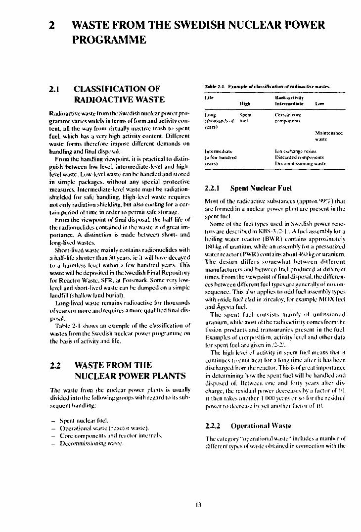
Table 2-1 shows an example of the classification ofwastes from the Swedish nuclear power programme onthe basis of activity and life.
2.2 WASTE FROM THENUCLEAR POWER PLANTS
The waste from ihc nuclear power plants is usuallydivided into (he following groups with regard to its sub-sequent handling:
— Spent nuclear fuel.— Operational waste (reactor waste).— Core components and reactor internals.— Decommissioning waste.
Tablr 2-1. Kuimplr of»lav-ifiialion of rudioai litr »a
I iff
l-"ng(Ihousamisofyears)
Intermediate(a few hundredyears)
High
Spentlucl
RadioactivityInlrrnirdiatr 1.4m
Certain corecomponents
Maintenancewaste
Ion exchange resinsDiscarded componentsDecommissioning waste
2.2.1 Spent Nuclear Fuel
Most of the radioactive substances (approx W'i) thatare formed in a nuclear power plant are present in thespent fuel.
Some of the fuel types used in Swedish power reac-tors are described in KBS-3 ,'2- ],'. A fuel assembly for aboiling water teactor (BWR) contains approximatelyISO kg of uranium, while an assembly for a pressurizedwater reactor (PWR) contains about -V>0 kg or uranium.The design differs somewhat between differentmanufacturers and between fuel produced at differenttimes. From the viewpoint of final disposal, the differen-ces between different fuel types are generally of no con-sequence. This also applies to odd fuel assembly typeswith oxide fuel clad in /ircalov, for example MOX fueland Ågesta fuel.
The spent fuel consists mainly of unfissioneduranium, while most of the radioactivity comes from (hefission products and iransuranics present in the fuel.Examples of composition, activity level and other datafor spent fuel are given in ,'2-2/.
The high level of activity in spent fuel means that itcontinues to emit heal for a long time alter il has beendischarged from ihc reactor. This is of great importancein determining how the spent fuel will be handled anddisposed of. Between one and forty years afler dis-charge, the residual power decreases by a factor of 10.II then takes another 1 000 years or so for the residualpower to decrease by yet another factor of 10.
2.2.2 Operational Waste
The category "operational wasie" includes a number ofdifferent types ofwasle obtained in connection with ihc
operation and maintenance of the reactors. The mainconstituent is ion exchange resins and filters obtainedcontinuously during operation irom cleanup of thereactor water. The operational was!': also includesreplaced components Irom the reactor systems as wellas protective clothing, plastic, paper, insulating mate-rials etc that have been use J in areas where activity ispresent and may theretore be contaminated.
The operational waste is low and intermediate-leveland mainly contains radionuclides with half lives shorterthati 30 years. The concentration of long-livedradionuclides is very low. The activity in the operation-al waste will therefore decay to a harmless level withina lew hundred years or less.
The operational waste is conditioned at the nuclearpower plants to give it a packaging and form that is ap-propriate for its subsequent handling. Different con-ditioning methods are applied at different nuclearpower plants. This is described in greater detail in/2-3/.
Similar waste also comes from the operation of thecentral interim storage facility for spent nuclear fuel,(.'LAB, and from Studsvik.
2.2.3 Core Components and ReactorInternals
Components located in or near the core inside the reac-lor vessel are exposed to a strong neutron flux andthereby obtain a high induced activity. Some of thesecomponents, for example neutron detectors, are suc-cessively replaced at intervals of a few years. Others, forexample the moderator tank, are used for the entirelifetime of the reactor and only become waste when thereactors are dismantled.
Fuel channels and other structural components in thefuel assemblies are included among the core com-ponents here.
The core components and some reactor internalshave a very high radiation level when they are dis-charged from the reactor. This radioactivity is domi-nated by cobalt-60, which has a half-life of yhout fiveyears, which means that the radiation level declines bya factor of 1 000 in 50 years. Core components and reac-tor internals also contain some radionuclideswithalonghalf-life, such as niekel-59 (90 000 years) and niobium-94 (20 000 years). The radiotoxicity of these nuclides islower than that of the transuranics, and requirementson Ihe final disposal of these components are thereforelower than for spent fuel.
induced activity. They also include various parts of thereactor systems that have been radioactively con-taminated. However, most of the plant has not comeinto contact with radioactivity and the waste can there-fore be handled like normal waste from the dismantlingof industrial facilities.
The waste obtained from decommissioning consistsprimarily of components of steel, eg tankr,, pipes andvalves from the reactor's process systems. It also in-cludes large quantities of concrete, 90% of which is in-active. The dismantling and demolition work also givesrise to a certain amount of process waste from water andair cleaning systems that are in operation during thedecommissioning period.
The radioactive decommissioning waste is all low-and intermediate level. However, the activity levelvaries considerably between different parts. A largeportion of the metal scrap can be released for un-restricted reuse. The concrete and some other materialscan be deposited on an ordinary industrial landfill, pos-sibly adjacent to the reactor facility. However, most ofthe active decommissioning waste has an activity levelthat warrants deposition in SFR. As mentioned above,certain highly radioactive reactor internals are also ob-tained from decommissioning and require special treat-ment.
A large portion of the activity consists of surface con-tamination, which can be removed by means of variousdecontamination methods. The quantity of materialthat can be declassified is therefore dependent on howfar the decontamination work is carried.
2.3 OTHER RADIOACTIVEWASTE
Besides the nuclear power plants, the main sources ofradioactive waste in Sweden are the central interimstorage facility for spent nuclear fuel, CLAB, and thecoming treatment plant for spent fuel, BS, as well as theStudsvik Research Facility. Waste from the use ofradioactive materials in industry, medical care and re-search is also collected at Studsvik.
23.1 Waste from CLAB and BS
The waste from CLAB is of the same kind as the opera-tional waste from the reactors. It is also treated in thesame manner. Similar waste will also be obtained fromthe treatment plant for spent fuel, BS.
2.2,4 Decommissioning Waste
When a nuclear power plant is finally shut down, partsof the facility are radioactive and must therefore be dis-posed of in a safe manner. These parts include the reac-tor vessel and reactor internals, as well as the concreteimmediately adjacent to the reactor vessel containing
2.3.2 Waste from Studsvik
Waste from the operation of the R2 research reactor aswell as from the R&D-activitics concerned withradioactive products, such as fuel rods, is generated inStudsvik. The fuel that is used in R2 is sent back to theUSA and therefore does not have to be disposed of in
14
Sweden. Other waste from R2 is similar to the opera-tional waste from the nuclear power plants and istreated in a similar manner.
However, the waste from the ReiD-activitics is of adifferent character. Some of this waste contain.-, con-siderable quantities of long-lived transuranics andtherefore requires a similar final disposal as the spentfuel. Fuel from the Ågesta reactor as well as from theRl research reactor is also stored in Studsvik. A trans-fer of Ågesta fuel and encapsulated fuel residues toCLAB has been going on since 1987.
2.33 Waste from Reprocessing
In the reprocessing of spent nuclear fuel, uranium andplutonium are separated from fission products andother transuranics. This process gives rise to both high-level vitrified waste, which contains most of the radioac-tivity, and low- and intermediate-level waste solidifiedin cement or bitumin.
Most of the waste from reprocessing contains largequantities of transuranics and is therefore long-lived.
The Swedish power industry has reprocessing con-tracts with BNTL in Great Britain and with COGEMAin France. Only the contracts with CXXiEMA call forthe waste to be returned to Sweden. SKB does not cur-rently plan to exercise these contracts but is working in-stead to find someone to take them over. Reprocessingwaste is therefore no longer included in the Swedishplans for the back end of the nuclear fuel cycle.
2.4 ESTIMATED WASTEQUANTITIES
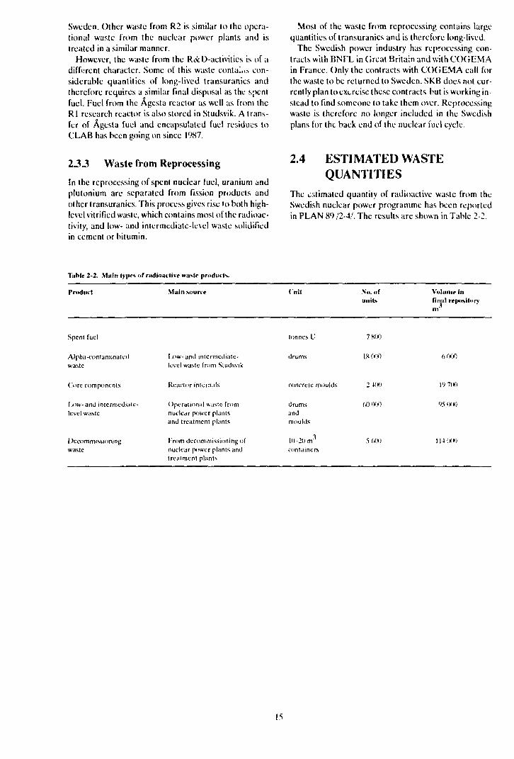
The estimated quantity of radioactive waste from theSwedish nuclear power programme has been reportedin PLAN 89 /2-4/. The results are shown in Table 2-2.
lablr 2-2. Vf siin types of radioactive waste products.
Product
Spent fuel
Alpha-conlaminatcdwaste
Core components
Ixnv-amJ intcrmcdiaie-Icvel waste
Decommissioningwaste
Main source
Ix)w- and intermediate-level waste from Studsvik
Reactor internals
Operational waste fromnuclear power plantsand treatment plants
From decommissioning ofnuclear power plants andtreatment plants
(nil
tonnes U
drums
concrete moulds
drumsandmoulds
l(>—20 n?containers
\o . ofunits
7 800
IK 000
2 400
W) 000
5 MX)
Volume infinal repositorym"
6 000
19 700
95 (KM)
114 000
15


3 MANAGEMENT OF RADIOACTIVE WASTE FROMNUCLEAR POWER PLANTS
3.1 GENERAL
The safe handling and final disposal of the waste fromnuclear power requires planning, construction andoperation of a number of facilities and systems. Figure3-1 illustrates schematically the different parts of theplanned Swedish waste management system. Theseparts are described in detail in the annual report of thecosts for management of the radioactive waste productsof nuclear power, PLAN 89, which the power utilitieshave submitted through SKB /3-1/. Only a brief over-view is given here.
The facilities are also planned to accommodate theradioactive waste in Sweden that docs not come fromelectricity-generating reactors, see Chapter 2.
The design of (he system is based on (he following fun-damental principles:
- Short-lived waste will be disposed oi as soon as pos-sible after it has been generated.
- Spent fuel will be stored for about 40 years before itis placed in a final repository. This will limit heatgeneration in the final repository.
— Other long-lived waste will be disposed of in con-nection with the final disposal of spent fuel.
Essential parts of the waste management system arealready in operation, namely the central interim storagefacility for spent nuclear fuel, CLAB, the final re-pository for reactor waste, SFR, and the transportationsys'em. CLAB and SFR are planned to be expandedduring the latter half of the 1990s so that they can ac-commodate all spent fuel and waste from the Swedishnuclear power programme.
The parts remaining are a treatment plant for spentfuel, BS, and a final repository for long-lived waste, SFL.These facilities will not be built until after 2010, accord-ing to present-day plans. Extensive R&D-work is beingconducted for these parts of the system aimed a; find-ing a suitable design and site, see Chapters 4 and 5.
Management of the radioactive waste products ofnuclear power also includes decommissioning of thenuclear power plants and other facilities when they havebeen taken out of operation and final disposal of thewaste from decommissioning. See Chapter 6.
Nuclear power stations
Central interimstorage facility
CLAB
Encapsulationplant BS
Final repositorySFL
• '
Figure.?- /. T)ie Swedish waste management system.
3.2 POSSIBLE FINALDISPOSAL PRINCIPLES
A number of possible principles for final disposal aredescribed in SKN PLAN 87 and in SKB PLAN 82 Part1 /3-2, 3-3/. A condensed summary of the discussion inthese references is provided below.
The concept "final disposal" entails that the waste isto be isolated without any requirements on surveillanceand in such a manner that it is difficult or impossible toget at. However, a monitored storage is included as anunavoidable link in the handling chain. It can extendover a very long period of time without any major tech-nical or safety-related problems. Sooner or later,however, the waste must be transferred to a repositorywithout supervision and the repository must be sealed.We cannot demand or assume that future generationswill bear the burden of surveillance and maintenance ofthe repository. A repository that is dependent for itssafety on continuous surveillance and maintenancemeasures cannot be regarded as a final repository.
In connection with the final disposal of spent fuel,safeguarding of fissionable material must also be pro-vided for. This means that the final repository must bedesigned and sealed in such a manner that recovery ofthe Fissionable material involves such extensive ;ind
17
well-planned efforts that a covert retrieval can be ruledout.
The following principles for final disposal of radioac-tive waste have been proposed in the international dis-cussion:
— Deep disposal in continental geological formations.— Disposal in shallow soil or rock strata.— Disposal beneath the seabed in deep-sea sediments.— Dumping at sea.— Disposal in or under continental ice sheets (eg An-
tarctica).— Launching into space (or to the sun).
Disposal of long-lived waste at great depth (severalhundred metres or more) in continental geological for-mations is the principle that is prioritized by allcountries conducting extensive research and develop-ment on disposal of radioactive waste. It is also the onlyprinciple that is deemed available and feasible as far asSweden is concerned within the foreseeable future.
Disposal in shallow soil or rock strata (a few tens ofmetres up to 100 metres deep) entails restrictions onland use following disposal. This principle can only beapplied to short lived waste or waste with lowradiotoxicity. The principle is applied in SFR.
Disposal beneath the seabed in deep-sea sedimentsbeyond the continental shelf is being studied by a num-ber of countries, included in international collaborationunder the auspices of OECD/NEA. This principle,which has certain attractive features, would presumab-ly require international agreements or conventions andcannot be applied as an independent Swedish solution.
Sea dumping or disposal in or under continental icesheets is not feasible in Sweden,
Launching into space would certainly be a convincingway to isolate the waste, but the reliability of the launch-ing procedure must be guaranteed. It is also far too ex-pensive to be of interest for Sweden.
Another conceivable final treatment principle wouldinvolve rendering (he long-lived radioactive materials inthe waste harmless by means of nuclear "combustion"(transmutation to stable or short-lived nuclides).However, such a system requires advanced reprocess-ing as well as reactors with a high neutron flux (eg faslbreeder reactors). If this method is to be realized at all,it can only be realized within the framework of a farmore extensive nuclear energy programme than thatwhich has been adopted in Sweden.
Accordingly, the research programme has beenoriented towards the goal that final disposal of the spentnuclear fuel shall be achieved deep down in the Swedishbedrock. The KBS-3 report has described one methodbased on this principle. The method has been approvedfrom the standpoint of safety and radiation protection.
The purpose of SKB's research and development isto provide a broad information base for the final choiceof method. In principle, the work is not bound to anygiven method. It adopts a generic approach, studyingmailers lhal are of imporlance to many alternatives for
final disposal in rock. This means that a number of othermethods are also being studied and evaluated in presentand future research.
The following fundamental requirements have beendiscussed in recent years: a final repository should bedesigned so that it renders surveillance and main-tenance unnecessary for safe function, but does notprevent intervention and corrective measures ("re-pairs") in the future, for example if future knowledgeshould show that the design of the final repository wasunsuitable. "We should not place responsibility for thefinal repository on future generations, but nor shouldwe deny future generations an opportunity to assumeresponsibility"/3-10/. SKB believes that this principle iscorrect. Both of these requirements are satisfied in acrystalline rock repository of, for example, the KBS-3type. Repositories based on some other design prin-ciples do not always meet such requirements.
3.3 FACILITIES AND SYSTEMSIN OPERATION
3.3.1 Final Repository for ReactorWaste, SFR
The final repository for reactor waste, SFR, is situatedat the Forsmark Nuclear Power Station /3-4/. Opera-tional waste from the Swedish nuclear power plants isbeing cmplaccd in SFR, along with similar waste fromCLAB and Studsvik. This Studsvik waste also includeswaste from the use of radioisotopes within research, in-dustry and medicine.
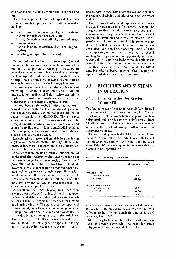
The waste being deposited in SFR is low- and inter-mediate-level and short-lived, which means that it willhave decayed to a harmless level within a few hundredyears. Table 3-1 shows the quantities of wastes that areplanned to be deposited in SFR.
Tahlr .VI. WitMr I» ht drposiird in SI K.
Operational wasteIntermediate-levellx>w-level
Decommissioning wasteIntcrmediatc-lcvclIxtw-lcvcl
StoriiRt volunir ( in )
65 000
25 0QQ
90.000
12 0<X)
ftK 000
100 000
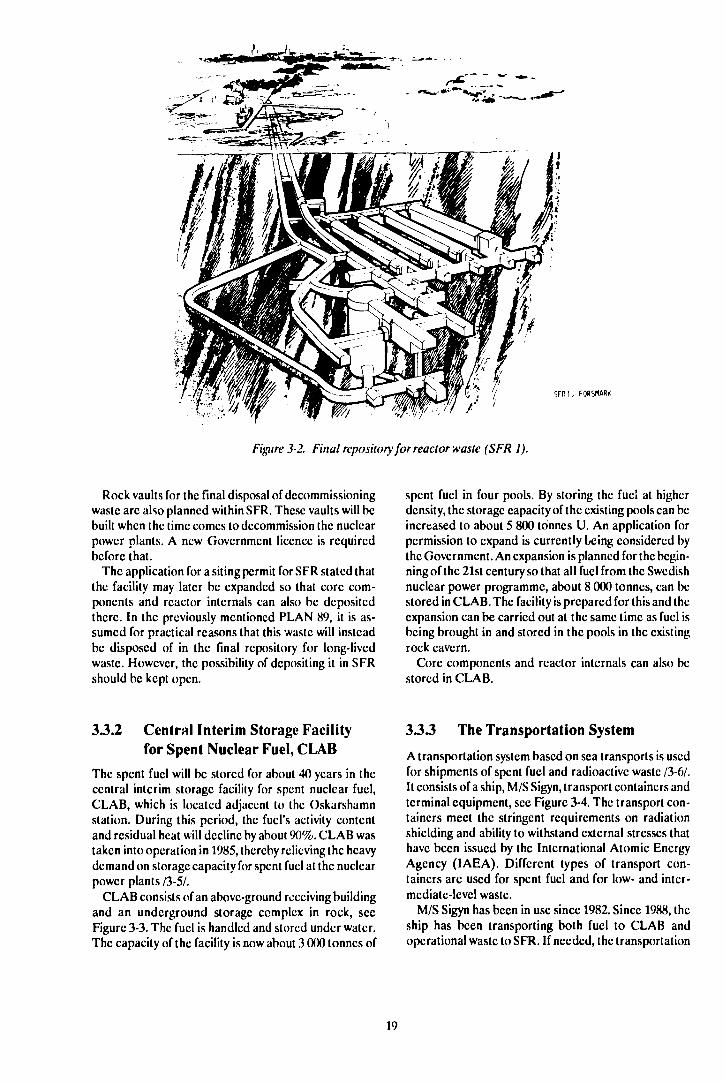
SFR is situated in rock wilh a rock cover of about 50 m.!( consists of different excavated caverns, designed withreference to the activity content in the different kinds ofwaste, see Figure 3-2.
SFR is being built in two phases, the first of which wastaken into service in 1988, while ihe second is plannedlo be commissioned at Ihe end of the 1 WOs.
18
S F R 1 . FO«SMAR<
Figure 3-2. Final repository for reactor waste (SFR I).
Rock vaults for the final disposal of decommissioningwaste are also planned within SFR. These vaults will bebuilt when the time comes to decommission the nuclearpower plants. A new Government licence is requiredbefore that.
The application for a siting permit for SFR stated thatthe facility may later be expanded so that core com-ponents and reactor internals can also be depositedthere. In the previously mentioned PLAN 89, it is as-sumed for practical reasons that this waste will insteadbe disposed of in the final repository for long-livedwaste. However, the possibility of depositing it in SFRshould be kept open.
spent fuel in four pools. By storing the fuel at higherdensity, the storage capacity of the existing pools can beincreased to about 5 800 tonnes U. An application forpermission to expand is currently being considered bythe Government. An expansion is planned for the begin-ning of the 21st century so that all fuel from the Swedishnuclear power programme, about 8 000 tonnes, can bestored in CLAB. The facility is prepared for this and theexpansion can be carried out at the same time as fuel isbeing brought in and stored in the pools in the existingrock cavern.
Core components and reactor internals can also bestored in CLAB.
3.3.2 Central Interim Storage Facilityfor Spent Nuclear Fuel, CLAB
The spent fuel will be stored for about 40 years in thecentral interim storage facility for spent nuclear fuel,CLAB, which is located adjacent to the Oskarshamnstation. During this period, the fuel's activity contentand residual heat will decline by about 90%. CLAB wastaken into operation in 1985, thereby relieving the heavydemand on storage capacity for spent fuel at the nuclearpower plants /3-5A
CLAB consists of an above-ground receiving buildingand an underground storage complex in rock, secFigure 3-3. The fuel is handled and stored under water.The capacity of the facility is now about 3 000 tonnes of
33 J The Transportation System
A transportation system based on sea transports is usedfor shipments of spent fuel and radioactive waste /3-6/.It consists of a ship, M/S Sigyn, transport containers andterminal equipment, see Figure 3-4. The transport con-tainers meet the stringent requirements on radiationshielding and ability to withstand external stresses thathave been issued by the International Atomic EnergyAgency (IAEA). Different types of transport con-tainers are used for spent fuel and for low- and inter-mediate-level waste.
M/S Sigyn has been in use since 1982. Since 1988, theship has been transporting both fuel to CLAB andoperational waste to SFR. If needed, the transportation
19
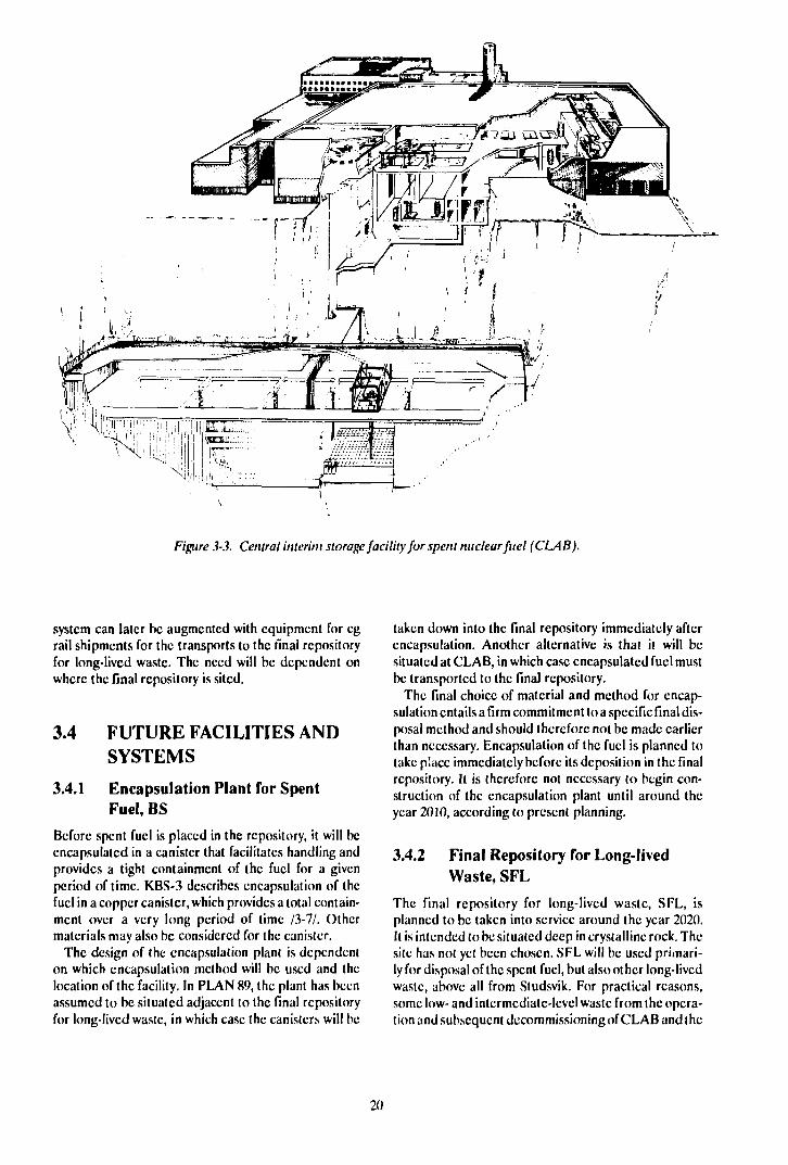
Figure 3-3. Central interim storage facility for spent nuclear fuel (CLAB).
system can later be augmented with equipment for egrail shipments for the transports to the final repositoryfor long-lived waste. The need will be dependent onwhere the final repository is sited.
3.4 FUTURE FACILITIES ANDSYSTEMS
3.4.1 Encapsulation Plant for SpentFuel, BS
Before spent fuel is placed in the repository, it will beencapsulated in a canister that facilitates handling andprovides a tight containment of the fuel for a givenperiod of time. KBS-3 describes encapsulation of thefuel in a copper canister, which provides a total contain-ment over a very long period of time /3-7/. Othermaterials may also be considered for the canister.
The design of the encapsulation plant is dependenton which encapsulation method will be used and thelocation of the facility. In PLAN 89, the plant has beenassumed to be situated adjacent to the final repositoryfor long-lived waste, in which case the canisters will be
taken down into the final repository immediately afterencapsulation. Another alternative is that it will besituated at CLAB, in which case encapsulated fuel mustbe transported to the final repository.
The final choice of material and method for encap-sulation entails a firm commitment to a specific final dis-posal method and should therefore not be made earlierthan necessary. Encapsulation of the fuel is planned totake place immediately before its deposition in the finalrepository. It is therefore not necessary to begin con-struction of the encapsulation plant until around theyear 2010, according to present planning.
3.4.2 Final Repository for Long-livedWaste, SFL
The final repository for long-lived waste, SFL, isplanned to be taken into service around the year 2020.It is intended to be situated deep in crystalline rock. Thesite has not yet been chosen. SFL will be used primari-ly for disposal of the spent fuel, but also other long-livedwaste, above all from Studsvik. For practical reasons,some low- and intermediate-level waste from the opera-tion and subsequent decommissioning of CLAB and the
20

Figure 3-4. Transport vehicle with transport cask leaving the cargo hold of MIS Sigyn.
encapsulation plant is also being planned to be disposedofin connection with SFL.
A possible design of the final repository for spent fuelis described in KBS-3, see Figure 3-5. The method in-volves depositing copper canisters containing spent fuelin holes drilled in the floor of tunnels at a depth of about500 m. In the boreholes, the canisters are embedded incompacted bentonite. When deposition in a tunnel isconcluded, the tunnel is sealed with a sand/bentonitcbackfill.
Until a decision is taken concerning the location anddesign of the facility, alternative designs of the Final re-pository will be studied, as described in Chapters 4 and5 and in Part II.
The repository for other long-lived waste has not yetbeen studied in the same degree of detail as the re-pository for the spent fuel. One possible design, wherethe waste is emplaced in different kinds of rock vaultsat a depth of about 500 m, is described in PLAN 89.
21
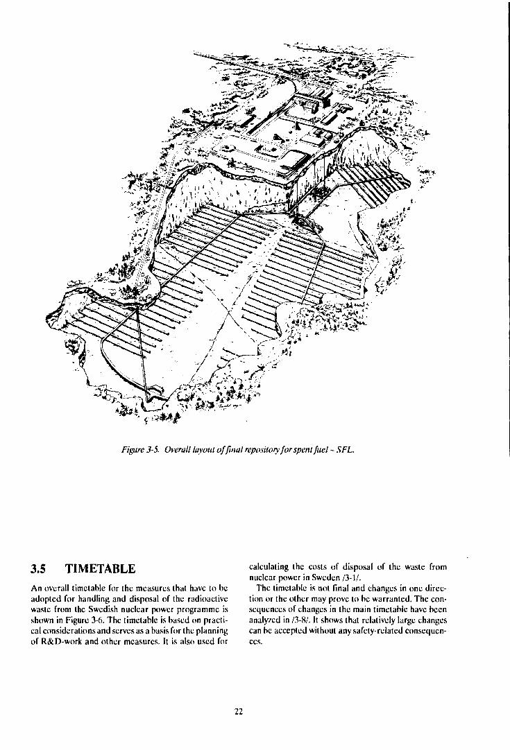
Figure 3-5. Overall layout of final repository for spent fuel - SFL.
3.5 TIMETABLEAn overall timetable for the measures that have to beadopted for handling and disposal of the radioactivewaste from the Swedish nuclear power programme isshown in Figure 3-6. The timetable is based on practi-cal considerations and serves as a basis for the planningof R&D-work and other measures. It is also used for
calculating the costs of disposal of the waste fromnuclear power in Sweden /3-1/.
The timetable is not final and changes in one direc-tion or the other may prove to be warranted. The con-sequences of changes in the main timetable have beenanalyzed in /3-8/. It shows that relatively large changescan be accepted without any safety-related consequen-ces.
22
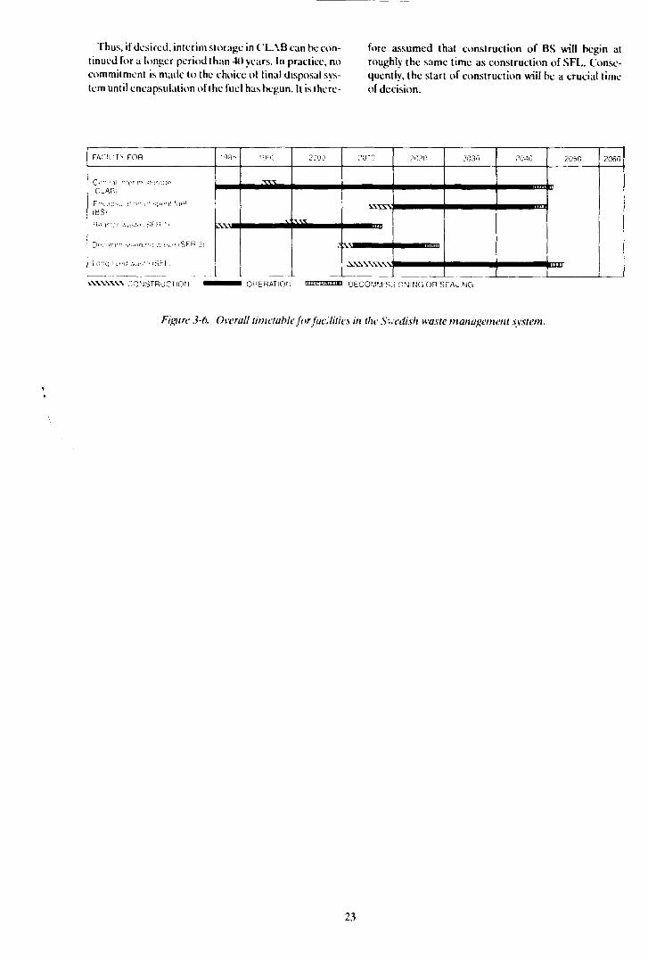
Thus, if desired, interim storage in CLAB can be con-tinued for a longer period than 40 years. In practice, nocommitment is made to the choice ot final disposal sys-tem until encapsulation of the fuel has begun. It is there-
fore assumed that construction of BS will begin atroughly the same time as construction of SFL. Conse-quently, the starl of construction will be a crucial limeof decision.
FACiLITY FOR
Cl-"i:r,ih<i:.TT, S!'.!M!>.
iCLABi
IBSI "
n.\v;:c .-..!•.!•> ,SFH ' i
Qpo.mril.ssOH.-X] .-. . IV-MSFR J]
LO'iq-K-: .•„!>•-:• ISFLJ
!98-
V
2000 ;-'OTO 2020 2030 20-S0 2050 2060
CO^JSTRUCTIOrj OPERATION mmnrajnffliii DECOMMISSIONING On SEALING
Figure 3-6. Overall timetable for facilities in the Swedish waste management system.
23

4 FINAL DISPOSAL OF SPENT NUCLEAR FUEL.OVERVIEW OF GOALS, PLAN FOR ACTIVITIESAND STATE OF KNOWLEDGE
4.1 GOALS OF THE RESEARCHWORK - GENERAL
General goals and guidelines for the management of thewaste from the Swedish nuclear power plants arepresented in Chapter 1. The researeh and developmentwork shall be conducted in such a manner that themeasures described in Chapter 3 can be carried out ac-cording to the stipulated timetable and in such a man-ner that the goals of waste management are achieved.
During the coming 10-year period, the work will beconcentrated on assembling the necessary basis so thata site-specific siting application for a final repository forspent nuclear fuel can be submitted no later than theyear 2(X)3. Prior to that a system optimization is neededto adapt the system design to the selected site.
The research and development work will be con-ducted with due regard to:
— environment and safety,— economy,— comprehensiveness,— flexibility,— relevance,— broad acceptance in society.
The requirement on comprehensiveness means thatdifferent alternative systems will be studied andevaluated. Flexibility should therefore be retained foras long as possible. Effective R&D requires well-defined goals and distinct frames, however. The mostpromising and realistic alternatives should therefore begiven priority and (he research must be related to (hosephenomena and questions that are of relevance to thesafety and economy of the final repository.
Up to 1984, the goal of SKB's research was to dem-onstrate the feasibility of safe final disposal of spentnuclear fuel in Sweden. The work was concentrated ona specific method. This is described in the KBS-3Report/4-1/. The safety account in KBS-3 is based on anumber of pessimistically chosen premises and credithas not been taken for a number of favourable factors.The assessment has been carried out using methods anddata chosen to define an upper limit for the impact ofthe repository on the biosphere. The account in KBS-3therefore contains considerable safely margins lhatwere not possible to quantify at the time.
One important goal of the ongoing and continuedR&D-work is to gain better knowledge of the actual
safety margins. Improved knowledge in this respectprovides a better basis for an optimization and an adap-tation to local conditions, while at the same time allow-ing greater freedom in the siting of the final repository.
The different types of radioactive waste that aregenerated in the Swedish nuclear power programme aredescribed in Chapter 2. Measures to manage and dis-pose of these waste types are described in Chapter 3.Most of the waste forms can be handled and disposedof in the same or a similar manner as the waste that isto be disposed in SFR.
Spent nuclear fuel and certain other waste types re-quire a more qualified final disposal, however. The re-search is primarily aimed at refining this more qualifieddisposal.
The research is thus focussed mainly on final disposalof spent nuclear fuel in the Swedish bedrock.
4.2 SOME POINTS OF DEPAR-TURE FOR THE R&D-VVORK
A final repository for spent nuclear fuel must meetsociety's demands on safety. These demands aim toprotect human beings and nature against harmful ef-fects caused by the waste now and in the ful lire. The goalis that the long-term effects of the repository should notchange the natural radiological conditions in the area inany essential way. During the construction and operat-ing phases, the activities must be carried out in such away that a good working environment is ensured and en-vironmental impact is minimized.
The final repository is designed as a system of en-gineered and natural barriers intended to isolate thewaste for such a long period of time that the radioactivematerials decay to a harmless level. The barriers areboth natural (geological) and engineered (waste matrix,canister, buffer). The research concerns the propertiesand performance of these barriers with the aim of arriv-ing at an optimized choice of barrier system and re-pository site. A general account of the primary factorsinfluencing the choice and design of a final repositorysystem is provided in R&D-Programme 86 Part IIChapter 2/4-2/.
Final disposal of spent nuclear fuel can be effected ina number of different ways. The method described inthe KBS-3 report has been accepted by the SwedishGovernment and regulatory authorities as being accept-able with regard lo safety and radiation protection. This
method is therefore a reference alternative lor furtherstudies of other interesting alternatives. Since the KBS-3 report was published, the research work has beenstudy and obtain a deeper knowledge ol different partsof the final repository sy> tern described in KBS-3 and ingeneral of phenomena ol importance for an under-standing of final disposal in Swedish bedrock. The otherhas been to analyze and evaluate alternative designs ofthe linal repository. This chapter presents an overallplan for the R&D-work and summarizes the present-day state of knowledge on the basis of the experiencethus gained. Chapter 5 summarizes the planned re-search and development for the six-year period 1990-199S.
As already mentioned, the continued research workis aimed at assembling the necessary basis for a site-specific siting application by the year 2(X)3. An overallplan to achieve this goal has been prepared and isdescribed in the following section prior to the summaryof the present-day state of knowledge. In connectionwith the account of the state of knowledge, the differentstage goals that should be achieved in (he different areasin order to fulfil the sub-goals of the main plan aredescribed.
4.3 OVERALL PLAN FOR THER&D-WORK
4.3.1 R&D-Programme 86
The overall research plan presented in R&D-Program-me 86 briefly entailed the following. Up until the mid-1990s, goal-oriented research will be conducted on al-ternative designs of the barrier system and on the fun-damental phenomena of importance for safety, op-timization and choice of system and site. At the sametime, the necessary development of analysis models willbe pursued. In parallel with this, the general charac-terization of study sites that has been going on since theend of the 1970s will be completed. In the early 1990s,a couple of sites will be selected for detailed investiga-tions. These investigations should not be begun laterthan I 993 for all the sites that could be candidates for asiting application in the year 2(XH). In the mid-1990s, thestudies of barrier systems will be summarized and oneor possibly two main alternatives will be chosen as abasis for a site-specific optimization of the final re-pository system. The optimization will be completed by1998, when work will begin on a siting application for aspecific site. Accordingly, this planning entails a finalchoice of system in the mid-1990s and of site in 1998.
In connection with the review of R&D-Programme86, SKN expressed certain viewpoints on the sile selec-tion process in particular. SKN wanted a successive nar-rowing-down of the number of possible sites to takeplace through a screening procedure divided into threephases: test phase, selection phase and licensing phase.During the test phase, roughly speaking the I "80s, a
relatively large number of areas judged to be particular-ly suitable for the siting of a final repository would bescreened out. Affected municipalities and county ad-ministrations would be notified and asked to set asidethe specified identified areas in their general plans onlanduse. Such plans are to be drawn up for all muni-cipalities in the country prior to June 30, 1990. Duringthe subsequent selection phase, in the l'>90s, the fieldstudies would continue and those sites that are bestsuited for a safe final repository would be selected. Onthe basis of proposals received from SKB and after cir-culation of these proposals for comment, SKN wouldthen judge whether a "national interest" exists under theterms ol the Natural Resources Act and would notifythe concerned municipalities and county administra-tions that this is the case. The designation of a "nation-al interest" means that the land areas in question mustbe set aside for a specific type of facility, in this case afinal repository, and may not be utilized for any otherpurposes.
A Government resolution passed in December 1987stated that R&D-Programme 86 meets the require-ments ol the Act on Nuclear Activities and should serveas a basis for the continued work, and than SKN's reviewviewpoints should be taken into account wherever pos-sible.
The work since 1986 has by and large followed theplan laid down in R&D-Programme 86. However, ex-perience gained since then has occasioned certainrefinements of definitions and modifications of the plan.
43.2 Programme for R&D anä OtherMeasures
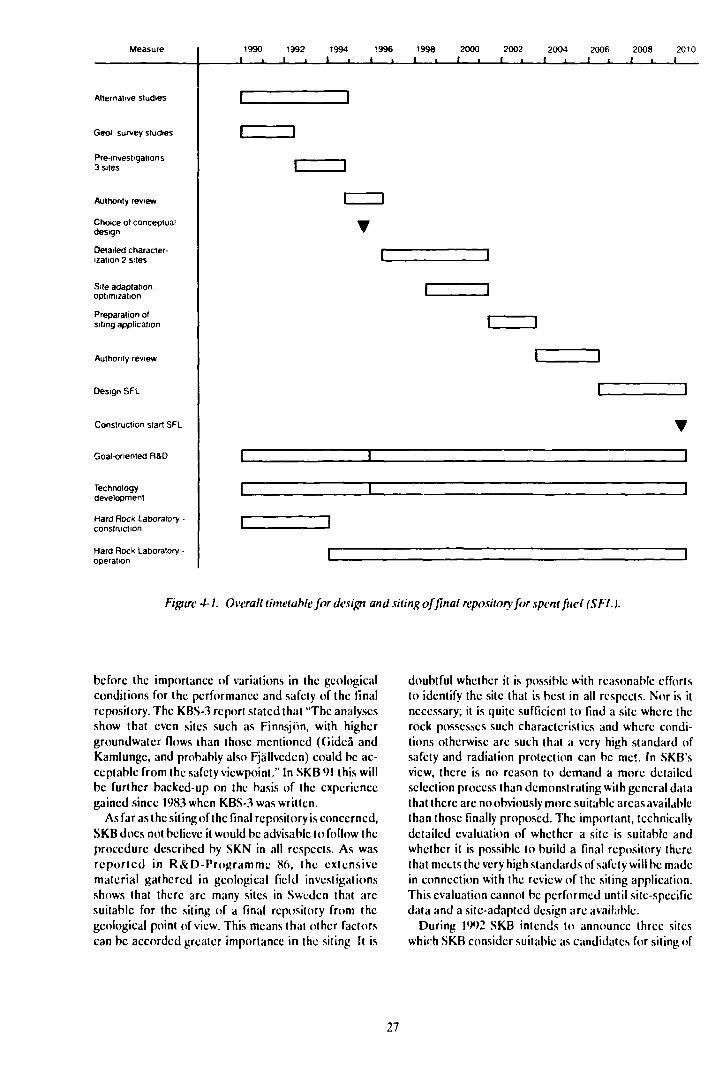
An overall timetable for the measures that have to beadoplad for management and disposal of the radioac-tive waste products from the nuclear power programmeis presented in Chapter 3 Figure 3-6. According to thistimetable, the planned start of construction for the finalrepository for long-lived waste and the encapsulationplant for spent fuel is the year 2010. Figure 4-1 shows anoverall timetable for the R&D, technology develop-ment and other measures thai are required prior to thestart of construction.
The fundamental research in certain key areas andconcerning different alternative designs will continueuntil the mid- 1990s with more or less the current scope.
The inventory of possible sites for the construction ofa final repository that has been going on more or lesscontinuously since the beginning of the 1980s will beconcluded by 1W1. In addition, certain geological sur-vey studies will be carried out on the basis of currentlyexisting geological data. These supplementary studiesare of a general nature and do not require any furtherdrilling or borehole measurements.
A new safety assessment called SKB 91 is planned tobe finished in 1991. One of the purposes of this assess-ment is to evaluate further and more systematically than
26
Measure
Alternative studies
Geol survey studies
Pre-investigations3 sites
Authority review
Choice ot conceptualdesign
Detailed character-ization 2 sites
Site adaptationoptimization
Preparation ofsiting application
Authority review
Design SFL
Construction start SFL
Goal-oriented R&D
Technologydevelopment
Hard Rock Laboratory -construction
Hard Rock Laboratory -operation
1990
1
1
1
1
1
1992 1994 19961 • 1 • 1 •
1
1
1 1
•
1
1
1
1
1
1998 2000 2002 2004 2006 2008 20101 i 1 i 1 i 1 i 1 • 1 i 1
1
1 1
1 1
1 1
| 1
•
1
1
1
Figure 4-1. Overall timetable for design and siting of final repository for spent fuel (SFL).
before the importance of variations in the geologicalconditions for the performance and safety of the finalrepository. The KBS-3 report stated that "The analysesshow that even sites such as Finnsjön, with highergroundwatcr flows lhan those mentioned (Ciidcå andKamlungc, and probably also Fjällvcden) could be ac-ceptable from the safety viewpoint." In SKB 91 this willbe further backed-up on the basis of the experiencegained since 1983 when KBS-3 was written.
As far as the siting of the final repository is concerned,SKB docs not believe it would be advisable to follow theprocedure described by SKN in all respects. As wasreported in R&D-Programmc 86, the extensivematerial gathered in geological field investigationsshows that there arc many sites in Sweden that arcsuitable for the siting of a final repository from thegeological point of view. This means that other factorscan be accorded greater importance in the siting It is
doubtful whether it is possible with reasonable effortsto identify the site that is best in all respects. Nor is itnecessary; it is quite sufficient to find a site where therock possesses such characteristics and where condi-tions otherwise are such that a very high standard ofsafety and radiation protection can be me'.. In SKB'sview, there is no reason to demand a more detailedselection process than demonstrating with general datathat there arc no obviously more suitable areas availablethan those finally proposed. The important, technicallydetailed evaluation of whether a site is suitable andwhether it is possible to build a final repository therethat meets the very high standards of safety will be madein connection with the review of the siting application.This evaluation cannot be performed until site-specificdata and a site-adapted design arc available.
During 1992 SKB intends to announce three siteswhich SKB consider suitable as candidates for siting of
27
the final repository. The body of data on these threesites might at this time be of a general nature and mustthen be augmented through preliminary characteriza-tion. However, the purpose is to be able to concentratesubsequent geologic surveys, licensing questions and in-formation activities to a few (minimum number) pro-mising areas. As a basis for the selection of candidatesites, the results of the aforementioned studies will bepresented simultaneously, along with a summary of ex-isting data on the three sites. In connection with the an-nouncement, SKB's information on matters of specialinterest for the siting of a final repository will be inten-sified.
After permission has been obtained from the land-owner, pre-investigations will be carried out during theyears 1992-1994. At the same time, SKB 91 will be sup-plemented to provide a basis for an initial preliminaryevaluation of the long-term safety of a final repositorylocated at each of the three sites. During 1994, a generalprogramme for subsequent detailed characterization ofthe candidate sites will be drawn up.
Investigation results, programme for detailed charac-terization, preliminary safety assessment and environ-mental impact statements for the detailed characteriza-tion will be submitted to the concerned authorities atthe end of 1994. The concerned authorities are primari-ly SKN, the municipality and the county administration.SKI, SSI and other agencies can be expected to serve asreviewing bodies for the aforementioned authorities.After a review period of about 18months,it is estimatedthat the necessary approvals and permits for detailedcharacterization may be available in early 1996. Suchinvestigations will then start on one site, and on a secondsite in 1997. The detailed characterization will be car-ried out in appropriate stages.
As a basis for starting detailed characterization, arough layout of the area needed for a final repository isrequired. A conceptual design of the final repositorysystem must therefore be selected during 1995. In con-nection with this, a summary of completed studies of dif-ferent alternatives and of then-existing knowledge con-cerning the components in the barrier system will besubmitted. It is assumed that this can be done in con-nection with R&D-Programmc 95. During the years1995-98, the necessary supplementary studies for thecomponents in the selected fundamental design will becarried out, and the models required for an optimiza-tion of the final repository to the site that is finallyselected will be verified. The optimization will be car-ried out in parallel with a second stage of the detailedcharacterization.
These activities are expected to be finished by 2001,when work will begin on preparing a siting applicationunder the Natural Resources Act and under the Act onNuclear Activities. The application, which shouldpreferably be completed by 2003, contains a preliminarysafety report with a detailed assessment of the long-term safety of the final repository. It is assumed that theapplication will take three years to process, which would
mean that a site approved by the Government will existby 2(XK).
After the site has been approved, engineering draw-ings for the final repository and associated faciliti-js willbe prepared and the safety report updated, especiallywith respect to safety during the operating (deposition,surveillance) phase. This report is expected to befinished in 2008 and will comprise the basis for SKl'sand other authorities' approval of start of construelionin 2010.
SKB's goal throughout the siting phase is that ex-perience from the R&D-activities shall be exploited ina systematic fashion and that the safety-related impor-tance of the resultant information shall be successivelyevaluated. On the basis of this evaluation, criticalparameters and conditions will also be identified as abasis for R&D-prioritization.
4.4 STATE OF KNOWLEDGEREGARDING SAFETYASSESSMENTS
The handling and final disposal of the radioactive wastemust be carried out in an acceptable fashion withrespect to safety and radiation protection. The safety ofthe activities is assessed by means of performance andsafety evaluations. The performance analysis constitutestudies of subsystems and their interaction, or of thespecial conditions under which performance is to beguaranteed. The performance studies then serve as abasis for the analysis of total safety that make up thesafety assessment. Besides safety level, a safety assess-ment shall also define the uncertainty with which thejudgements are associated and attempt to quantify thesafety margins as far as is possible.
The purpose of the performance assessment willchange during different phases of the development andlicensing of a final repository. In the introductorypha.se,the performance of the subsystems in the repository willbe evaluated. The uncertainty existing in currentknowledge regarding essential functions will indicatepriorities for research and development.
In a later phase, an attempt will be made to find abalance between the safety barriers, ie the system willbe optimized with respect to performance and cost atan acceptable safety level. During the licensing phase,it must be formally and finally demonstrated that thesystem fulfils the demands made by society on safety.
Performance assessments include the following mainelements:
- review of the external circumstances (scenarios)that can arise and definition of which of thesescenarios the repository shall be able to cope with,
- description of the processes of importance for thesafety of the repository that can occur, and of themodels and databases with whose help the proces-ses can be quantified,
— estimates of the performance of the repository atdifferent relevant points in time for the design-basisscenarios.
A safety assessment must also include the followingelements:
— definition of applied acceptance requirements/criteria for the repository and over the relevant timespans,
- comparisons between estimated consequences/probabilities and the acceptance criteria,
- analysis of uncertainties in the data and models withrespect to their importance for safety.
The degree of detail and completeness in the ele-ments will vary with the state of development and theknowledge base, as well as with the specific purpose ofeach assessment
4.4.1 Goals of the Work with SafetyAssessments
The overall goals of the work of developing methods forsafety assessments are:
— to carry out the safety assessments that arc requiredin different phases to obtain licenses and gain ac-ceptance of the final repository for reactor wastefrom the Swedish nuclear power plants,
— to be able to carry out more realistic assessments soas to better quantify the safety margins.
The stage-specific goals for the safety assessments areclosely linked to the overall plan presented in section4.3 above. Important stage goals are:
— a complete safety assessment" SKB 91" will be car-ried out by 1991 for a design closely related to KBS-3. The assessment will be carried out in such a man-ner that variation analyses can easily be performed,
— coupled to the safety assessment, variation analyseswill also be performed by 1991 of how differentgeological conditions influence the results of thesafety assessment,
— site-specific assessments, complementary to SKB 91will be carried out by 1994 for the candidate sitesidentified in 1992,
— comparative performance evaluations will be car-ried out by 1995 for those barrier alternatives thatcan be of importance for the execution of detailedgeological characterization,
— performance and safety assessments will be carriedout by 2001 as a basis for optimization and site adap-tation of the selected final repository system,
— a safety assessment will be carried out by 2(K)3 of (helong-term performance of the repository as a basisfor a siting application.
Methodological development for uncertainty studies,scenario definition, validation etc, and for presentationof results, is intended to be pursued continuously inclose international cooperation and coupled to thespecific requirements made by the assessments invarious phases of the R&D-programme.
— A systematic review of the scenarios that should beincluded in a safety assessment, based in large parton the work with SKB 91, will be supplemented andreported in R&D-Programme 92.
- During the coming three-year period, QA guide-lines arc intended to be specified for, among otherthings, documentation, handling and storage ofdata, as well as for programming and documenta-tion of computer programs.
4.4.2 State of Development for SafetyAssessments
At an early stage, repository performance assessmentwas divided into scenario analysis and consequenceanalysis.
The scenario analysis includes an identification ofpossible scenarios as well as a description of how dif-ferent scenarios affect repository performance and theprobability that they will occur. The requirement thatno relevant scenarios are to be neglected entails highdemands on the ability of the methodology to identifypossible events and processes in a logical manner. Thefirst part of the work, identification of scenarios relevantto safety, has often been done in a relatively unstruc-tured manner.
Sina* many aspects of scenarios are global, in otherwords independent of site and repository design, SKBhas deemed it essential that the development workwithin this area be carried out in close internationalcooperation. In order to create a consensus on howscenarios arc identified, SKB has, together with SKI,worked actively during 1986/87 to initiate cooperationin scenario work within OECD/NEA. Since 1987, aworking group within NEA's committee for radioactivewaste management has dealt with these questions.Methods used by different groups in the world havebeen collected and systematized. The purpose is tocreate an international overview of available methodsand discuss their advantages and disadvantages in astate-of-the-art report. A preliminary document is ex-pected to be ready in 1990.
A consequence analysis in a broad sense includesstudies, analyses and calculations of the performance ofthe repository within the different scenarios.
Quantified forecasts of repository performance re-quire (hat the processes that arc important for safelycan be modelled. Calculation models for sourcestrength, temperature effects, groundwater flow, can-ister penetration, release of radionuclidcs in the fuel,nuclidc transport in the near field, groundwater path-
29
ways in the rock, groundwater transport of radio-nuclides, interaction of radionuclides with fracturefaces and rock matrix, paths of discharge to the bios-phere and radionuclide dispersal in the biosphere, aswell as resulting doses to man, must be applied in se-quence.
The present-day state of knowledge with regard tomost interesting processes concerned with engineeredbarriers or the rock is described in brief in the follow-ing section and in greater detail in Part II.
In view of the uncertainty existing in the forecasts offuture waste quantities, present-day calculations of thequantity of radionuclides in the spent fuel should beable to be performed with sufficient accuracy using ex-isting calculation models.
A major problem in the safety assessment is to be ableto evaluate how uncertainties in input data translate intouncertainties in calculated consequences. A computerprogramme package called PROPER has beendeveloped within SKB for this purpose. The core of thePROPER package is the monitor that is used to link anumber of submodels, taken from a library during therun, into a total model for the problem at hand, and topropagate the uncertainties in the input data throughthe sequence of submodels. The monitor is now avail-able in a tested version 1.0, which will be utilized forSKB 91.
Data from SKB's field investigations is now being col-lected in a database called GEOTAB on an in-housecomputer. All important data from previous years' in-vestigations arc stored in this database. Routines forOA have been established and are regularly revised.
In 1989, SKB acquired its own computer, CONVEX210, wilh very high performance. This means that allheavy computations for safety and performance assess-ment can be run on the same computer. It also enablesmore comprehensive simulations to be carried out thanhave previously been possible within a given cost frame.Integration of the computer programs also permitsgood quality assurance of the data processing and thecompulations.
4.5 STATE OF KNOWLEDGEREGARDING ENGINEEREDBARRIERS
As is evident from Chapter 3, the purpose of the ongo-ing research work is to establish a method for final dis-posal of the long-lived waste deep down in the Swedishbedrock. A large number of different designs and com-binations of engineered barriers are possible within theframework of this main line. A systematic review of pos-sible alternatives was provided in a background reportto R&D-Programmc 86. The pre;cnt-day state ofknowledge regarding the choice of barrier system issummarized in the following. A more detailed accountis given in Part II.
4.5.1 Goals of the Research RegardingEngineered Barriers
The research and development work regarding the en-gineered barriers is being conducted with the aim ofachieving the following goals, which arc linked to theoverall programme for the work described in Section4.3.2:
- A conceptual main design shall be chosen beforethe detailed characterization of two alternativesiting areas are begun.
- Material, temperature level and other relevantparameters for the canister and buffer material shallbe determined at the same time as a conceptualmain design is chosen. This means that applicablelimits for these essential parameters and for thematerials that can be of interest must be establishedby then.
— The properties and characteristics of the spent fuelin a repository environment shall be clarified suffi-ciently so that they can be taken into account in thechoice of material, temperature level etc. Thismeans that a validated model for fuel corrosion inthe repository environment should be ready by 1995.
— The studies of how the engineered barrier alterna-tives in the near field can be designed and of pos-sibilities for chemical conditioning shall be com-pleted by 1998. This means that data, models andgeneral understanding of the performance of theengineered barriers in the chosen conceptual designshall be developed to a level that permits site adap-tation and optimization of the final repository.
4.5.2 Design of the Final Repository
The means used to isolate the waste from the biosphereare choice of location in the rock, encapsulation andmeasures to give the canisters a suitable environment inthe rock. A good design shall permit the adaptation ofavailable technology for construction of the engineeredbarriers to the isolating characteristics of the rock.
In recent years, two fundamentally different final re-pository alternatives (in comparison with KBS-3) havebeen studied: WP-Cave and very deep boreholes. Thealternatives are described in brief in Part II of this pro-gramme. A comparison between WP-Cave and KBS-3has been completed. The results show that:
— both concepts can provide acceptable safety,— utilization of the potential of WP-Cave requires
considerable development efforts in areas whereunderstanding and data are incomplete today,
— the higher temperatures reached in WP-Cave en-tail, via uncertainties in data and dominant proces-ses, a higher uncertainly in the calculated conse-quences,
30
— both repositories can be constructed with normaladaptation of currently existing technology,
— it cannot be said today whether it is easier to find asuitable site for one or the other design,
— the construction of a WP-Cave repository forSwedish needs would be much more expensive thana KBS-3 repository.
The conclusion is that the studies of WP-Cave as acomplete system will not be continued.
The possibilities of disposing of waste in holes severalkilometres deep have been studied on the basis of theinformation obtained from the drilling of very deepholes, such as the Siljan borehole. Preliminary resultsindicate favourable economics, but sufficient data donot yet exist to permit a clear comparative evaluation ofthis alternative. The studies continue.
4.5.3 Waste Forms
Since Sweden will not reprocess the spent nuclear fuel,the spent fuel is the waste form that will be disposed of.Direct disposal of spent nuclear fuel has been studiedsince the end of the 1970s in Sweden, Canada, the USAand the Federal Republic of Germany. Compared withhigh-level waste from reprocessing., the body of ex-perimental data available on fuel as waste is limited. Atotal of only 30 or so scientific reports on the durabilityof the fuel in water have been published.
Many variables influence this durability, for exampleirradiation history, groundwater chemistry, redox con-ditions and temperature. Despite limited data, how-ever, certain aspects of the dissolution mechanisms arerelatively well known. It is possible today to describe theinfluence of the dominating variables on the kinetics forthe dissolution of fuel. This represents a considerableimprovement over the simplified and conservativemodel that was used in the KBS-3 work. The results ofthe research of recent years indicate that the dissolutiontime for spent fuel is a couple of orders of magnitudelonger than was assumed in the KBS-3 safety assess-ment. The mechanisms of the dissolution are, however,not fully understood as yet.
4.5.4 Canister
In all programmes for final disposal of high-level waste,it is assumed that the waste is encapsulated in an imper-vious container prior to deposition. In most countries,the aim is an absolutely impervious containment with acanister life of at least 1 (XX) years. Sweden and a fewother countries have in addition striven for imperviouscontainment over a much longer lime span, if possibletens of thousands or hundreds of thousands of years.The life of the canister is dependent on such factors asmaterial, manufacturing method, design and repositoryenvironment.
The foreign research programmes that aim at a re-pository environment/geology that is most relevant forSwedish conditions are primarily those in Canada, Fin-Hind, Switzerland ;md the F.F.C
Canada has chosen titanium as a reference materialand copper as an alternative. In both cases, the aim is athin-walled canister with a life of about 1 (XK) years.
Switzerland has chosen a thick-walled steel canisterwith a life of at least 1 (XX) years as the main alternative.The secondary alternative is copper.
The Finnish programme is very similar to the Swedishwith a thick-walled, long-lived copper canister as thereference alternative.
The research work on copper canisters has, in recentyears, concerned pitting corrosion, material creep,studies of welding technology for thick materials andsome testing of material from hot isostatic pressing(HIP). Results obtained to date give no reason to revisethe conclusions in the KBS-3 report that the mostprobable value of the pitting factor is five. An evalua-tion of the corrosion of a bronze cannon (%.3% cop-per) from the warship Kronan has been carried out. Thecannon was buried in the sediment on the bottom of theBaltic Sea for 3IX) years. The results correspond to a cor-rosion of less than 10 mm over a period of UN) (MX) years.
Completed studies reveal considerable differences increep properties of copper between the weld, the heat-affected zone and the parent metal. In addition, prelimi-nary results show that the creep ductility of copper isrelatively low. Further research is therefore required inthis area. Development of welding technology has beenpursued for a couple of years within a EUREKAproject.
A couple of years ago, the highly surprising result wasreported that copper could corrode with the evolutionof hydrogen. The report was based on an experimentconducted at KTH (the Royal Institute of Technology)in Stockholm. Two independent groups have conductedverification experiments and have not been able todetect any hydrogen evolution, despite a much highermeasurement sensitivity than should be required ac-cording to the KTH experiment. No scientific explana-tion of the reported observations has been forthcoming.In view of the results of the verification experiments andthe existing, scientifically well-founded body of data onthe thermodynamics of copper, SKB finds that thereport on copper corrosion with hydrogen evolution canbe disregarded.
For steel as a canister material, the work has focusscdon studies of pitting. The results show that a canister lifeof about 1 (XX) years is possible with a wall thickness of1(X) mm. The Swiss programme is primarily studyingstress corrosion cracking anti hydrogen-generating cor-rosion.
Titanium and titanium alloys exhibit very low generalcorrosion, particularly in chloride-containing water,which may be f resent on certain sites. The Canadianstudies, however, have demonstrated some sensitivityfor crevice corrosion. The research is therefore being
31
focussed particularly on this phenomenon. In Sweden,long-term exposures of up to six years of titanium in con-tact with bentonite have been concluded and the resultsreported.
Ceramics as canister materials have previously at-tracted considerable interest. Considerable work wasdone within the framework of the KBS project. Afterthat work has Seen financed in Sweden by SKN and itspredecessor. The problem with ceramics is first themanufacturing technology for full-si/ed canisters andsecond the risk of delayed fracturing. This phenomenonis not merely a material property, but is also linked tothe manufacturingtechnology. Furthermore, it has beenstatistically demonstrated that the scaling-up of small-scale experiments can in some respects be misleading.Further work on ceramic canisters is therefore current-ly judged not to be of interest for Swedish conditions.
4.5.5 Buffer and Backfill Material
Buffer material in the deposition chambers and backfillmaterial in rock caverns, tunnels and shafts are ex-amples of engineered barriers included in the final re-pository system. The primary function of these barriersis to limit groundwater flow. Buffer material shall alsoconstitute a suitable chemical and mechanical protec-tive /one for canislers in the rock. Sealing measures cantake the form of plugs in excavated areas and sealing ofthe rock's fracture systems by means of injection grout-ing.
The isolating properties that characterize the trans-port conditions in the buffer material are low hydraulicconductivity and low diffusivity. Hydraulic conductivityis determined primarily by the density of the materialand its content of the mineral smectite. A selection ofwell-defined clays has been compared with thereference clay in KBS-3, Mx8(). The comparison showsthat with no reduction in density, hydraulic conductivityis low even if the smectite content decreases. The smec-tite content of the buffer material can decrease as aresult of transformation of smectite to illitc at a rate de-pendent on the temperature. A greater understandingof the relationship between microstrueture and tem-perature, obtained through studies of clays in hy-drolhcrmal tests, has led to a more refined model fortemperature effects. The model has been tested in thestudy of natural bentonites. A very important contri-bution has been the Gotland bentonite located at adepth of about 5(X) m at Hamra. The conclusion is thattemperatures of 105-120C are possible in depositionholes in compact bentonite without mineral changesbeing of importance for barrier function.
An inventory of Swedish buffer material candidateshas been carried out and has not revealed any majorSwedish deposits for buffer material in depositionholes, but it has found material lor backfill.
The buffer material is supposed to interact with therock and the canister to provide a suitable environment
for the canister. Thus, the canister is supposed to beborne up by the material in the deposition hole andprotected from unfavourable loads or possible move-ments deriving from the rock. Sevenil research projectsare being conducted for the purpose of verifying theproperties of the buffer material in this respect anddeveloping validated models.
Bentonite can be deformed and change its volumethrough redistribution, absorption or emission of water.The water in highly compacted bentonite comprises ap-proximately one-fourth of the volume, and the physicalstate of the bentonite varies depending on the claymineral and the microstrueture. The variation in den-sity has been measured over a long period of time anddiscussed, also measurements using several indirectmethods have been used. Examples are NMR (nuclearmagnetic resonance), which has been tried for manyyears in an attempt to reveal the nature of the interac-tion between the clay mineral and the water.
A model for the physical state of water in differentparts of the microstrueture is of importance to obtain atheory for the rheology that can be applied in the for-mulation of the material model and in order to be ableto extrapolate conditions over a very long period oftime, for example for creep.
Rheological properties of bentonites have beenmeasured. The subsidence of a simulated canister in adeposition hole was observed in the laboratory duringthe period April 85 - Dec 86, and observations are beingconducted in Stripa, in both cases with temperaturevariations.
Shear tests with models simulating canisters indeposition holes have been carried out.
Mathematical models have been used for com-parisons. They show that it is possible to model rate andtemperature dependence in more or less dynamicprocesses such as thcrmomcchanically or tectonicallyinduced shear deformations or subsidences of canisters.
Attempts to reduce the water flow in the near field ofthe waste outside the buffer include backfilling with im-pervious materials in rock chambers and sealing of frac-tures in surrounding rock. The lower part of the disposaltunnels can be backfilled using currently known meth-ods and equipment. Experience from Stripa, wherebackfill with 10-20% bentonite mixed with ballastmaterial has been used, has shown that a compactingmethod and equipment for the upper part of the dis-posal tunnels can be developed. The test showed thatwater absorption took place with low water pressures inthe near field in the surrounding rock despite relative-ly high pressures further out in the rock. The backfillfilled out the tunnel completely, but the degree of com-paction can be increased with a refined method for theapplication of fill in the upper part of the tunnel. Plug-ging of shafts, boreholes and tunnels was also tested. Ex-perience from these tests has led to experiments withthe sealing of rock fractures in a third phase at Stripa.The rock sunounding a drift is planned to be sealed instages so that its hydraulic conductivily is reduced in a
measurable fashion. Of particular interest is to obtaindata on the disturbed zone surrounding the tunnel.Sealing measures in the rock surrounding depositionholes are being tested, as well as sealing in a natural frac-ture zone.
The measures being tested at Stripa arc examples ofscaling measures intended to be included in a strategythat redirects the flow of water away from the near fieldof the waste. It presumes knowledge of the pattern ofmore conductive /ones that communicate with the nearfield and the size of more impervious rock volumes inbetween.
The research includes laboratory tests and analysis ofthe long-term stabilities of the sealing materials basedon cement and bentonitc.
4.6 STATE OF KNOWLEDGEWITHIN THE GEOSCIEN-TIFIC FIELD
The investigations during the 1980s have included fieldstudies of a number of study sites, special studies of cer-tain important questions, experiments and investiga-tions at Stripa, development of measuring methods andinstruments, planning for an underground researchlaboratory and development of models forgroundwaterflow in rock. On the eve of the 1990s, the gcoscicntificstudies arc being concentrated on a smaller number ofsubjects in the field than during the 1980s, but these sub-jects will be studied in deeper detail. Of central impor-tance to the continued studies will be the plannedunderground research laboratory- also called the HardRock Laboratory - HRL.
4.6.1 Goals of the Geoscientific Studies
The purposes of the gcoscientific studies within the re-search programme are to:
- identify, quantify and/or set limits on the factors thatcan be of importance for the long-term safety of therepository,
— refine methods for obtaining geodata of importancefor the safely and design of the rcposiiory.
Important subjects within the geoscientific field asregards safe disposal of nuclear waste are:
— groundwater movements and groundwater flow,— groundwater chemistry,— stability of the rock.
The geoscientific research is mainly concerned withthese subjects, (iroundwalcr chemistry is discussedunder the section on chemistry.
The gcoscicntific studies shall be conducted duringthe 1990s with the following stage-specific goals:
— The work to develop a deeper understanding ofgroundwatCi flow in fractured rock will continue.The goal is to have calculation models available foroptimization and site adaptation of the final re-pository by no later than 1998.
— The research work within the Stripa project will becompleted and concluded in 1991. Within the frameof the project, a limited rock volume will be charac-terized on a 1(X) m scale. Models for groundwaterflow and transport of tracers will be validatedagainst measurement data from the characterizedvolume.
— Construction of the underground Hard Rock Labo-ratory will be commenced in 1990 and will havereached a depth of about 500 m by 1993. In connec-tion with the construction of the Hard Rock Labo-ratory, methodology for pre-investigations anddetailed characterization of candidate sites for re-positories will be verified. The prc-invcstigalionmethodology to be used on the candidate sites willbe described by 1991. The methodology for detailedcharacterization of candidate sites will be describedprior to 1995. Data will be collected continuously todevelop and validate models for groundwater Howwith a view towards the goal specified above.
— Oucstions related to the stability of the rock shall bestudied, preferably in connection with the site forthe underground Hard Rock Laboratory and thecandidate sites for the final repository so that zonesof movement can be avoided when laying out the re-pository.
4.6.2 Groundwater Movements in theRock
The central, and at the same time the most difficult,problem in the assessment of the final repository's long-term safety is the flow of groundwaler in the rock's frac-ture systems and the associated transport of substancesdissolved in the groundwater. Great efforts have beenmade and arc being made to shed light on this problem.Important, but by no means exhaustive, examples are:
— Extensive measurements of the hydraulic conduc-tivity of the rock have been carried out in deep bore-holes on all study sites.
— Tracer tests with non-sorbing tracers have been car-ried out at Studsvik, Finnsjon, Stripa and Hylte.
— Mapping of water-bearing fracture zones has beendone through radar measurements and othergeophysical investigations at Slripa and on severalstudy sites.
— Tracer tests with sorhing tracers have been carriedout in laboratories and in situ inSludsvik, Slripa anilFinnsjön.
— Natural analogues, which can provide a picture ofthe behaviour of natural radioactive and chemical-ly related substances on a geological time scale, are
33
being studied at Poqos de Caldas, Cigar Lake andin other projects.
In parallel with these experimental investigations,extensive efforts are being made to develop descriptiveand mathematical models for systematizing and inter-preting the data and results yielded by the field andlaboratory tests.
It is important to give an account of how descriptivemodels of the site can be developed and validated withthe data available in different investigation stages.Models can be based on different premises and can beapplied on different scales. Experiments on differentscales are therefore required for validation of themodels.
Only a few facilities in rock exist today where the en-tire chain investigations - calculations - evaluation ofgroundwatcr flow has been carried out and docu-mented.
Observations and data on the rock and on ground-water movements in the rock need to be processed andanalyzed from different aspects. The most importantarc evaluation with regard to:
— available rock volumes of a given quality,— existence of flow paths/zones,— basis for layout of the repository on different scales,— assessing the groundwater flow on different scales,— assessing the flow paths of the water in the re-
pository area and its environs.
Surface investigations provide the basis for an initialgeological interpretation of a site. It is advantageous ifsurface investigations arc carried out with differentmethods in parallell and if the investigations comparedto successively evaluated in stages. It is difficult today -owing to limited documentation - to evaluate in generalwhat surface investigations give compared to investiga-tions in boreholes. It is essential that all material -geological, geophysical, geohydrological and gcohy-drochemical - be interpreted together in stages. Par-ticular attention must be given to the difficulty of clarify-ing the extent of subhorizontal structures. Surfacedescriptions provide the basis for the setting-out ofboreholes and thereby also for interpretation of t he datathat are later obtained from borehole measurements.
Measurements in boreholes are based on sophisti-cated methods and are resource-demanding. In orderto permit later evaluation, a number of independentmethods must be utilized. It is difficult today to deter-mine the specific usefulness of an individual method.However, borehole measurements and surface inves-tigations together furnish sufficient information tomake a preliminary evaluation of the performance ofthe repository and its geometric layout and to identifysuitable rock volumes for detailed characterization.
Data from tunnels are already being utilized for theevaluation of repository performance and safety. Thedata collection technology needs to be developed so
that the information on, for example, pressure respon-ses obtained during construction can be optimally util-ized in the description of the site. Whether the data ob-tained during tunnel mapping etc are really relevant tothe groundwater's distribution under natural conditionsrequires further elucidation.
The conceptual models available today can describewater flow and flow distribution with sufficient accuracyfor designing a final repository or evaluating the life ofwaste canisters, provided that data on the host rock isobtained. In the safety assessment of a final repository,it is necessary to calculate how radionuclides arctransported with the groundwater. It is not possible todo this with the desired accuracy today. It is not possibleto specify which model or combination of models bestrepresents reality. One is therefore forced in the assess-ment to use pessimistic models that greatly exaggeratethis transport. More realistic and validated models willprovide more certain knowledge of the safety marginsand a better basis for the optimization of the repositoryand adaptation of it to the site.
The conceptual models that are available can becalibrated against experiments,-but they arc not dis-criminating in terms of how the physical flow takes placein the rock. Tracer tests with non-sorbing and weaklysorbing tracers arc one possible way to distinguish theconceptual models. It has not yet been demonstratedthat tracer tests provide a means of discriminating be-tween different conceptual models. In recent years'safety assessments, SKB has used the channelling modelfor calculation of nuclide transport, since it provides themost conservative description of how the rock functionsas a barrier.
4.6.3 Stability of the Rock
It is important to understand to what extent tectonic orclimatic processes affect the performance of the re-pository. A low groundwatcr flow, a favourable chemi-cal environment and the absence of rock movementsthat can damage the waste are guiding principles for thelayout of the repository.
The studies that have been conducted support the no-tion that plate tectonics, together with ongoing landuplift, is of decisive importance for interpretingpresent-day and future movements in the bedrock. It isalso evident that such movements take place preferab-ly or exclusively along major fracture zones of very greatage.
As a basis for design and assessment of the perfor-mance of the repository, it is also of importance todescribe the extent to which a final repository can be af-fected by future ice ages. The study of tectonic andclimatic factors is wide-ranging and in a stale of rapiddevelopment. Large national and international projectsare underway and are constantly improving our pictureof the tectonic processes and their effects on thebedrock.
34
SKB has conducted studies of postglacial movementsat Lansjärv. Among the conclusions are the following:
— the postglacial movements at Lansjärv are assumedfor the most part to have been triggered by reactiva-tion of preexisting fractures and faults,
— the orientation of older /ones of weakness in north-ern Fennoscandia favour the occurrence of postgla-cial faults in the form of thrust faults and reversefaults,
— reactivation of the postglacial fault at Lansjärv hastaken place through tectonic movements that mayhave been set off in connection with the deglacia-tion,
— the hydraulic conductivity in the cored hole at Lans-järv does not deviate significantly from the condi-tions measured in a large number of other boreholesin Swedish bedrock,
— zones of movement of the thickness studied can beavoided in the layout of the final icpository. Despitethe very dramatic course of events when the postglacial fault was formed at Lansjärv, the hydraulicconductivity and geohydrochemistry at typical re-pository levels are in no way remarkable.
(ircater knowledge of the effects of glaciers on therock is important for an assessment of the long-termsafety of the repository.
4.6.4 Methods and InstrumentDevelopment
Ever since the geological field surveys started at the endof the 1970s, systematic work has been conducted todevelop, improve and to render the methods and instru-ments more effective for the collection of geologicaldata in the field. The goal is to have suitable methodsand instruments available for high-quality collection ofsuch data as are required for characterization of a rockvolume for a final repository or for assessment of thesafety of such a repository. The requirements on thequality of the data entail requirements on the accuracyand the reliability of the measuring equipment. A greatemphasis is placed on the importance of being able tocarry out measurements efficiently, since the number ofmeasurements on a given site is very large.
Methods and instruments exist today for measure-ment of fundamental geological, geohydrological,geophysical, geochemical and rock mechanics para-meters from the ground surface and in boreholes downto a depth of 1 (XK) m. However, technological progressis constantly creating new possibilities for the develop-ment of new instruments or data collection systems.Detailed site investigations and investigations from tun-nels make new demands on measuring methods and in-struments that must be met during the 1990s. If the needshould arise for measurements at a much greater depththan 1 000 m, this will require additional instrumenta-tion.
4.6.5 Hard Rock Laboratory
The reasons for building an underground researchlaboratory weie biicfly described in R&D-Piogidiiunc86 and arc given in greater detail in a background reportto this R&D-programme. In summary, the most impor-tant reasons are:
— verification of methods for surface and borehole in-vestigations,
— testing of methods for detailed site characterizationwith shaft sinking or tunnelling,
— opportunity, in a realistic environment and on alarge scale, to investigate conditions of importancefor safety, for example groundwater flow and as-sociated transport of solutes,
— opportunity, in a realistic environment, to carry outdemonstrations and long-term tests of the interac-tion between engineered barriers and rock,
— method development for rock engineering works,waste handling and backfilling.
Investigations of conceivable final repository sitescarried out thus far - on so-called study sites - have onlyinvolved measurements on the ground surface and inboreholes. Investigations have also been carried out inand from tunnels at Stripa and SFR and in connectionwith certain construction work for other purposes.There is a need to directly verify the results of surfaceand borehole investigations with systematic observa-tions from shafts and tunnels down to the depth of a finalrepository.
Some of the technology and methods for carrying outsite investigations have been developed and tested atStripa. However, since Stripa is an abandoned mine, itis not possible to test all aspects of the methods there.Tests in a previously undisturbed area provide addition-al opportunities for developing and refining the meth-ods before they are used "for real".
The future research should above all be devoted to in-tegrate and complete the picture that has been obtainedfrom the previous investigations at different sites. An in-itial integration attempt is being made within Phase 3 ofthe .Stripa project, where a site characterization andvalidation test (SCV) is being carried out with respectto a rock volume on the 100 m scale. Prior to the sitingof the final repository, an integration attempt should bemade on a large scale to obtain more experimental datafor the long-term safety assessment.
The pre-investigations for the siting of the Hard RockLaboratory in the Simpevarp area were begun in theautumn of 1986. Studies have been carried out on dif-ferent scales, both regionally and locally. The resultshave shown that favourable conditions exist on Äsponorth of Simpevarp for constructing the Hard RockLaboratory, of which the following can be mentioned:
— A relatively homogeneous rock block with few, well-defined groundwater-conducting structures existson southern Äspö (where the access tunnel to thelaboratory can be built).
35
— Nearby the above are a regional shear zone andareas with very homogeneous Småland granite.
SKB has thereby found that the different geologicaland hydrological conditions required for the plannedtests exist on southern Äspö.
4.7 CHEMISTRY
4.7.1 Goals of R&D in the ChemistryField
The main goal of the chemistry programme is to knowthe chemical environment in and around the repositoryand to determine the chemical retention of radio-nuclides. Both of these aspects are of importance forthe long-term safety of the final disposal of radioactivewaste.
The ambient chemical environment and how it can bealtered naturally or by components in the repository arecrucial factors for the chemical stability of the barriers.Examples of conditions that arc affected by the com-position of the groundwater are buffer stability, rockporosity (especially in the near field), canister cor-rosion, dissolution and leaching of the waste form and,finally, radionuclide chemistry. The chemical reactionstake place in the aqueous phase and the point of depar-ture for water composition is the undisturbed ground-water. An initial sub-goal is therefore to determine thenormal composition of the groundwatcr by samplingand analysis. The next sub-goal is to determine whatvariations in water composition can arise through natu-ral processes and through the influence of the re-pository and its components. This in turn requires in-vestigations of minerals, and especially fracture mine-rals, that influence the composition of the water. Frac-tures also bear traces of previous changes.
Hydrogeological investigations of flow conditions areof importance for understanding the water composi-tion. Conversely, studies of water chemistry, and in par-ticular the water's content of stable and radioactiveisotopes, actively contribute to supporting conclusionsabout the hydrogeological conditions.
If radionuclidcs from the waste should come into con-tact with the groundwatcr, the barrier provided bychemical retention will be of great importance. Reten-tion takes place through precipitation, sorption and dif-fusion. A radionuclide that is exposed to water can bepoorly soluble, diffuse slowly or precipitate completelyin the near field. It can be held back by sorption onmineral surfaces or penetrate into the micropores in therock and thereby be retarded or completely withheldfrom transport with flowing groundwatcr. An initialsub-goal is therefore to determine these processes andprovide reliable constants and functions that describe(he processes quantitatively.
Phenomena that can short-circuit or otherwiseprevent important retention processes naturallydeserve particular attention. An important second sub-
goal is therefore to analyze and test the transportcharacteristics of certain aggregates such as colloids,natural organic complexes and microbes, which can actas carriers ofrudionuclid.es in the water.
Three different approaches arc used to validate theconclusions and models that are used in the safety as-sessment to describe the chemical environment andradionuclide retention: independent laboratory tests,in-situ tracer tests and studies of natural analogues ofthe final disposal of radioactive waste. Simulations inthe laboratory provide an opportunity for full verifica-tion. In-situ tests offer a realistic environment and scale.Studies of natural analogues are used to support the as-sessments of the chemical environment and radio-nuclide retention that must be valid for very long spansof time.
4.7.2 Present-day State of Knowledge
Hydrochemistry and Geochemistry
The site investigations and the water sampling at Stripaand Forsmark (SFR) have shown that saline ground-watcrsare very common, especially in coastal areas. Thesaline groundwaters arc relatively old, and where theyoccur the groundwater flux is very low. Water underland has proved to be of meteoric origin. Water underthe sea contains traces of sea water.
The deep groundwatcrs arc reducing. They com-pletely lack oxygen and instead contain sulphide andiron(ll). The contents of sulphide and bivalent iron arelow as a rule, in other words the redox buffer capacityof the water is low. This capacity is instead present inthe minerals. Carbon dioxide weathering releases egiron(II), but how great the accessible capacity isremains to be demonstrated. Equipment has beendeveloped for sampling and analyzing gases dissolvedin the groundwatcr.
The use of isotope methods to characterize the "age",origin and flux of the water has been tested. A largenumber of different methods have been tried within theStripa project by prominent experts in the field. Thereis now a selection of methods that are practically usefulfor site investigations and that provide relevant infor-mation.
Analysis of fracture minerals has provided an oppor-tunity for interpreting the chemical evolution of ground-water and verifying models for groundwater movement.
Computer calculations have been carried out with ad-vanced geochemical models to interpret the chemistryof the groundwater and predict the chemical disturban-ces to which a repository will give rise.
Kadionuclide Chemistry
Thcrmodynamic constants that describe the solubilityand hydrochemistry of radionuclides have beenmeasured and compiled, often in cooperation withforeign experts and organizations. Most of the work has
been devoted to aetinides, particularly uranium. The in-fluence of phosphate remains to be shown. Co-preci-pitation has been tested and models developed. Itshould now be possible to include the co-precipitationphenomenon in a safety assessment. Co-precipitation ofradionuclidcs with iron hydroxides and calcite remainsto be investigated.
Sorption and diffusion of radionuclidcs in rock, ben-tonite and concrete have been measured. An extensivebody of data on diffusivitics and sorption coefficientsexists. What remains is above all to explore the effect ofadditives to bentonite and the importance of naturalreducing conditions, and to obtain a deeper theoreticalunderstanding of sorption and diffusion on mineral sur-faces.
The influence of natural organic complexes (humicand fulvic acids) on radionuclidc retention has been in-vestigated. These substances clearly bind radionuclides,and this can reduce sorption somewhat. The presenceand influence of inorganic particles (colloids) andmicrobes in the groundwater has been investigated.Microbes have been found in deep groundwaters. Theoccurrence and stability of groundwater colloids liasbeen investigated. Radionuclide uptake on these ag-gregates largely remains to be investigated.
The possible influence of radiolysis on a repositoryhas been tested in numerous experiments. Theoreticalpredictions and calculations have largely been con-firmed. Hydrogen is formed, as well as oxidants in theform of hydrogen peroxide.
Chemical Transport and Validation
Models for water flow and radionuclidc transport in anindividual fracture with channelling have beendeveloped. Coupled transport-geochemistry modelshave been further developed and applied to describethe interaction between concrete and bentonite and theformation of a redox front.
Laboratory tests have been conducted to validatemodels for transport of redox-sensilive radionuclides innatural rock fractures. So far, the tests have only in-volved tcchnitium.
Tracer tests have been carried out in Finnsjön, Hylteand Stripa. Transport on different scales has beenstudied, from a few centimetres to a couple of hundredmetres, and in different conductive media, from thesound rock to fractured zones. Non-sorbing tracershave been used for the most part. The methodology hasbeen refined and different models for Iransporl havebeen tested, including channelling models. Thetransport in the fracture /one at Finnsjön can bedescribed with a porous continuum model, while thetransport at Stripa shows signs of strong channelling. Ascries of experiments was started at Stripa in l'W2 tovalidate diffusion into the rock matrix. They have nowbeen completed and show that solutes can penetrateinto seemingly quite impervious rock. This is an impor-tant mechanism for radionuclide retention.
Studies of natural analogues have been concentratedto the Poc,os de Caldas project.
Results from the laboratory tests, the tracer tests atFinnsjön and Stripa (3D), as well as the Poc,os de Cal-das project, are also being used to validate transportmodels within the international INTRAVAL project,which is under the direction of SKI.
4.8 BIOSPHERE STUDIES
4.8.1 Goals of Biosphere Studies
The goal of SKB's studies of the properties of the bio-sphere and of the behaviour of radionuclidcs in the bio-sphere is to be able to perform the consequence calcula-tions of the safety assessment in a credible manner. Theefforts will be concentrated on being able to estimatethe consequences of different releases in a timeperspective on the order of 10 (XX) years. Sub-goals inthis process are to:
- attempt to quantify the uncertainties that stem fromthe fact that the biosphere is changing continuous-iy,
- improve the body of data on which the dispersalmodels rest,
- validate the models, for example by studies ofanalogue dispersal processes.
4.8.2 Present-day State of Knowledge
Any activity releases from a final repository will probab-ly take place so far in the future and over a such a longspan of time that considerable changes in the proper-tics of the biosphere can be expected to occur before orduring the release process. This means that analyses ofthe consequences of a release will entail great uncer-tainties.
The greatest uncertainty factor in the biosphere hasto do with the natural evolution of the ecosystems dur-ing the periods of time that can be considered realistic.Examples of processes in a shorter time perspective are:
— eutrophication of lakes and cultivation of old sedi-ments (also due to land uplift),
— erosion of soils by wind and water,— restratification of sediments in lakes and water
courses,— urban settlements, large asphalt surfaces, tunnels
etc.
In a somewhat longer perspective, climatic changesand glaciation must also be taken into account. Thequestion, however, is how meaningful it is to make doseestimates at this stage.
SKB's efforts during the past few years have been con-centrated on the aging of lakes, ie the process wherebythe bottom sediment of lakes is gradually transformedinto farmland. Data from a lake in Södermanland hasbeen collected and evaluated regarding water flow,
37

sedimentation rate, pore water properties, water qualityduring different phases etc. Modelling and variationanalysis showed that the individual doses for somenuclides increased by several orders of magnitude whenthe lake's sediment was used as farmland. For othernuclides, the doses decreased by an order of magnitude.The biggest source of uncertainty is the rate of exchangein the lake's water and sediment. However, this scenariogives lower doses than when a well is assumed to bedrilled close to the disposal area.
()n their way to the surface, groundwater and accom-panying radionuciides will leave the reducing environ-ment in the rock and enter an oxidizing environment.For most relevant chemical compounds, this transitionis associated with a drastic change in solubility. Thetransition often takes place in sediment or soil, but canalso take place directly in free water.
A detailed study of groundwater discharge in lakeswas initiated during 1987 in order to investigate how thechemistry and fauna of the bottom sediments in the dis-charge areas differ from those of the bottom sedimentsin other areas.
Research regarding the dispersal of radionuciides inthe biosphere, and with some relevance for final dis-posal in geological formations, is being conducted by afew departments at the Swedish University of Agricul-tural Sciences, the University of Gothenburg, FOA4and, to some extent, by Studsvik and Kemakta undercontract to SSI and SKI. Risö in Denmark and VTT inFinland are other Nordic institutions where such re-search is being conducted. Other research on chemicalsubstances in the environment may also be relevant tothe disposal of radioactive waste.
5 FINAL DISPOSAL OF SPENT NUCLEAR FUEL.SUMMARY OF PLANNED RESEARCH ANDDEVELOPMENT 1990 -1995
5.1 GENERAL
The preceding Chapter 4 provided an overview of thepresent-day state of knowledge regarding the final dis-posal of spent nuclear fuel. In this connection, overallgoals and secondary goals for different stages of the re-search and development in this field, as well as an over-all plan for the necessary measures, were also pre-sented. On the basis of this plan and the stated goals, adetailed research plan has been drawn up for the 6-yearperiod 1990-1995. This plan is presented in Part II andin the background report on the Hard Rock Laboratory.A brief summary of the most important parts of this planis presented in this chapter. Activities and research per-taining to the decommissioning of nuclear power plantsare dealt with in Chapter 6.
5.2 RESEARCH AREAS ANDPROJECTS
The planned research concerns the central questionsfor the development, design, construction, operationand safety of a final repository for spent nuclear fuel. Inorder to introduce some general systematics, the ques-tions have been broken down into a number of researchareas, and divided into two groups. The first group per-tains to more fundamental areas of knowledge that, incertain respects, arc independent of the design of therepository. The second group is more directly linked tospecific aspects of certain designs. The borderline be-tween the two groups is by no means a sharp one, nor isit particularly meaningful.
Important areas within the first group are:
— properties of the nuclear fuel in the repository en-vironment,
— properties of the canister material in the repositoryenvironment,
— properties of the buffer materials in the repositoryenvironment,
— bedrock movements - bedrock stability,— groundwater movements,— groundwater chemistry,— radionuclide chemistry - the chemical properties of
the radionuclides in the repository and bedrock en-vironments,
— transport of radionuclides with groundwater,
— radionuclide properties and transport in the bio-sphere.
Important areas within the second group are:
— conceptual design of the repository,— siting of the repository,— construction technology,— scaling of rock fissures,— adaptation to rock quality,— manufacture and closure of canisters,— manufacture and application of buffer material,— interaction rock-buffer-canistcr; chcmical/rrecha-
nical,— investigation methods.
The research work is often conducted in the form ofmajor projects, where each project may deal withseveral of the areas enumerated above. The most im-portant projects or project groups within SKB's re-search programme arc the following:
— the Stripa project,— the Hard Rock Laboratory,— a number of projects concerning natural analogues,— other field investigations - Finnsjön, Lansjärv,
Hyltc,— a large number of projects involving measurements
in laboratories,— projects concerning development of theoretical
models,— the SKB 91 safety assessment,— projects concerning design and/or analysis - ie desk
work that is not directly connected with experimentsor any of the above projects/project groups.
Table 5-1 provides an overview of the research areasdealt with by the different projects or project groups.
5.3 RESEARCH PROGRAMME1990-1995
Figures 5-1 and 5-2 show general timetables for thecoming six-year period 1990-1995. The first figure, 5-1,presents activities of importance for siting of the finalrepository and associated R&D. The second, 5-2,presents some of the major research projects. As yet un-defined projects concerning eg validation are expectedto be added during the latter part of the period.
39
Tiihlr 5-1. Important research arras within SKB's R&IX
Project Slripa Rot kla» Naturalanal.
Otherfieldstudies
Labe«p.
Theoryforma-tion
SKB91 Designanaly-sis
I'uel propertiesCanister material propertiesBuffer material propertiesIJcdrock movements(iroundwater movements(iroundwatcr chemistryRad i on uc I id e chemistryTransport of radionuclidcsRadionuclidcs in the biosphere
Design of repositorySiting of repositoryConstruction techniqueAdaptation to rockSealing of rock etcCanister manufacture +closureHuffer manufacture + applicationInteraction rock-buffer-canisterInvestigation methodology
z35
Zu5XD
uDZ<
r
<unur
Measure
Geologicalsurvey studies
Safety assessmentSKB91
Variation analysislong-range safetyevaluations
Pre-investigationsof 3 sites
Authority review
Alternative studies
Construction ofHard Rock Laboratory
Experiments in HardRock Laboratory
Choice of conceptualrepository system
1990 1991 1992 1993 1994 19951 1 1 1 1 1
!
,, ,,|
1 1
1 1
i i
1
l I
1 _ .„ . i
•
Figure 5-7. Timetable for the coming six-year period - siting and research concerning the final repository for spent fuel.
40
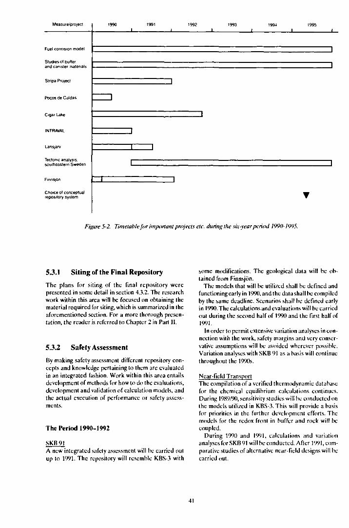
Measure/project 1990 1991 1992 1993 1994 1995
Fuel corrosion model
Studies of butterand canister materials
Stripa Project
Pocos de Caldas
Cigar Lake
INTRAVAL
Lansjärv
Tectonic analysis.southeastern Sweden
FinnS|6n
Choice or conceptualrepository system
Figure 5-2. Timetable for important projects etc. during the six-year period 1990-1995.
5 J.I Siting of the Final Repository
The plans for siting of the final repository werepresented in some detail in section 4.3.2. The researchwork within this area will be focused on obtaining thematerial required for siting, which is summarized in theaforementioned section. For a more thorough presen-tation, the reader is referred to Chapter 2 in Part II.
5.3.2 Safety Assessment
By making safety assessment different repository con-cepts and knowledge pertaining to them are evaluatedin an integrated fashion. Work within this area entailsdevelopment of methods for how to do the evaluations,development and validation of calculation models, andthe actual execution of performance or safety assess-ments.
The Period 1990-1992
SKB91A new integrated safely assessment will be carried outup to 1991. The repository will resemble KBS-3 with
some modifications. The geological data will be ob-tained from Finnsjön.
The models that will be utilized shall be defined andfunctioning early in 1990, and the data shall be compiledby the same deadline. Scenarios shall be defined earlyin 1990. The calculations and evaluations will be carriedout during the second half of 1990 and the first half of1991.
In order to permit extensive variation analyses in con-nection with the work, safety margins and very conser-vative assumptions will be avoided wherever possible.Variation analyses with SKB 91 as a basis will continuethroughout the 1990s.
Near-field TransportThe compilation of a verified thermodynamic databasefor the chemical equilibrium calculations continues.During 1989/90, sensitivity studies will be conducted onthe models utilized in KBS-3. This will provide a basisfor priorities in the further development efforts. Themodels for (he redox front in buffer and rock will becoupled.
During 1990 and 1991, calculations and variationanalyses for SKB 91 will be conducted. After 1991, com-parative studies of alternative near-field designs will becarried out.
41

Far-field TransportThe development of different conceptual models forgroundwater movements and transport of solutes inrock continues, including the buildup of databases.
The concepts in question are:
— channelling,— flow in a two-dimensional stochastic fracture set,— flow in defined discrete fractures.
One or more concepts will be selected during 1990 foruseinSKB91.
PROPERThe development of a new integrated program for post-processing is in progress and is expected to be com-pleted by 1990. During 1990/91, statistical methods willbe refined and variance-reducing methods will bedeveloped.
PROPER will be used as one of the tools for variationand uncertainty analyses for SKB 91. Development ofsubmodels is expected to continue throughout the1990s.
Scenario DevelopmentThe methodological development for scenario analysiswill be coordinated with international efforts, primari-ly within NEA, and will be adapted to the need for safe-ty assessments and variation studies according to thegeneral timetable. The scenarios that will serve as abasis for SKB 91 will be defined during 1990. A sum-ming-up of the situation within the area is planned forR&D-Programme 92.
Quality Requirements and Quality ControlA systematic review of the quality requirements thatmay be stipulated in different phases of the develop-ment work will be performed. (Juidelines for quality as-surance, QA, will be developed for handling, storageand documentation of data as well as for programmingand documentation of computer programs.
The Period 1993-1995
The studies of variability with SKB 91 will continue, withspecial emphasis on geological parameters and can-didate sites. Parameters of importance for safety will beidentified prior to the selection of sites for detailedcharacterization.
Development of the safety assessment methodologywill continue and will be adapted to the research pro-gramme's needs and to the possibilities for furtherdevelopment.
Prior to the start of the detailed geological studies in1995, the safety-related importance of sinking a shaft ora tunnel will be elucidated.
5J.3 Design of the Final Repository
The studies of very deep hole disposal and its safetyaspects will be completed during 1990 with a compara-tive analysis vis-ä-vis KBS-3.
A conceptual study of an alternative with long dis-posal tunnels from the coast out underneath the BalticSea will probably be carried out during 1992/93.
Alternatives of the type
— one or more canisters in each deposition hole,— deposition in long holes drilled between tr^r.S|iort
tunnels,— deposition in tunnels or drilled holes,
will be examined during the programme period to thepoint where properties of importance for the detailedsite characterization have been identified.
53.4 Engineered Barriers
Spent Fuel
The waste form spent fuel is given in the Swedish dis-posal alternative. Studies of spent fuel in the final re-pository environment are therefore an important partof the research programme. The emphasis lies on ex-perimental investigations of the interaction betweenfuel, groundwatcr and other components in the nearfield. This work has been going on in its present scopesince 1982 and is expected to continue for several yearsto come. The research is aimed at examining in greaterdetail the physicochcmical processes that control therelease of radionuclidcs from the fuel, both from theuranium dioxide matrix itself and from the grain boun-daries and cracks within the fuel material. Of particularimportance is to:
— clarify the distribution of fission products within thefuel matrix and at grain boundaries/cracks,
— determine the influence of radiolysis on the redoxconditions at the fuel surface; this determineswhether the dissolution of the matrix is limited bythe solubility or by the oxidation rate,
— obtain reliable thcrmodynamic data for solubility-limited nuclidcs such as technetium and plutonium.
In connection with the experimental work, con-siderable efforts are also being devoted to the develop-ment of theoretical models. The goal is to have a modelthat can describe the process of fuel dissolution and beused for the optimization of the barrier system by themid-1990s. The studies of spent fuel are being pursuedin close contact with similar research in other countries,particularly Canada and the USA. Other major nuclearpower countries have reprocessing as their main alter-native and their research is devoted to vitrified high-level waste from such reprocessing.
42
Canister
The continued work on canister material will be con-centrated on augmenting the existing body of data sothat the engineered barrier system can be selected in themid-1990s.
Additional work is being done on copper, in par-ticular with regard to pitting and techniques for weld-ing of thick metal. Work is also being done to shed fur-ther light on the creep properties of copper at low stresslevels.
The studies of steel will be concentrated during theperiod on hydrogen-producing corrosion. Steel can bean alternative if a canister life of about 1 000 years canbe accepted. However, it can also be an alternative tolead as a filler (pressure-bearing) material in a canisterwhere the corrosion protection consists of copper. Inboth cases, knowledge of hydrogen-producing cor-rosion is important for the performance and safety as-sessment.
Fracture mechanisms for a canister in the repositoryenvironment will be studied during the programmeperiod. Tests intended to verify the theory for designand the necessary level of quality control may be re-quired towards the end of the period.
Buffer and Backfill
The work of clarifying the relationships between themicrostructurc of clays and factors of importance fornuclidc transport in buffer material at differenttemperatures will continue and will be broadened tocover mixtures of natural material and crushed rock.Similarly, the studies of rheological properties of thebuffer and backfill material will continue. The work tovalidate a theoretical model that describes thcr-momcchanics, creep, shear deformation, swelling etcwill continue.
Within the framework of the Stripa project, thestudies of bentonitc and a special cement as sealingmaterial in thin rock fractures will continue. This workalso includes an evaluation of the long-term stability ofthe materials. Collaboration with CEA, France, includ-ing heater tests at Stripa and analyses of gamma-ir-radiated clays will continue and is expected to befinished by the early 1l. H)s.
Tests involving comp; vtion of backfill material in tun-nels may be conductcc during the latter part of theperiod.
53.5 Properties of the Rock
(»roundwater Movements
For the next few years, most of the planned work ongroundwater movements will be carried out within theframework of projects connected to Si ripa, Finnsjönand the Hard Rock Laboratory.
The development of conceptual models on differentscales is of fundamental importance for increasing un-derstanding of how groundwater flow in crystallinebedrock. Model development is planned on differentscales. The Hard Rock Laboratory will work in parallelfrom a regional scale down to volumes of a hundredcubic metres or so. During the pre-investigation phase,regional groundwater models, discrete network modelsand simple transport models will be devised. Thesemodels will be tested and developed during the con-struction phase. The importance of a tracer test duringthe construction phase and the operating phase is spe-cially noted here. The work at Stripa is devoted to vol-umes on a scale of one to about a hundred metres. TheSite Characterization and Validation programme atStripa will yield material permitting several differenttypes of models to be tested. Three different groups areworking with the modelling of the experiments withinthe framework of the project. Great efforts are beingdevoted within the "Sealing of Fractured Rock" test tothe "disturbed" /one around deposition holes and tun-nels. The tests at Finnsjön deal with transport on a far-field scale (several hundred metres).
A thorough evaluation of the extent to which thetracer tests are is applicable is required for the con-tinued experimental planning in order to distinguish be-tween different conceptual models. Such an evaluationis foreseen both for Stripa and the Finnsjön tests. Withan integrated evaluation of these tests, it will be possibleto determine which additional experiments can contri-bute toward an improved analysis of the flow of thegroundwater in rock. An evaluation is planned during1992. This may influence the planning of tracer tests atthe Hard Rock Laboratory.
An important question is to what extent the concep-tual models are based on a complete set of data. Thisset of data includes data collected in surface investiga-tions, in boreholes and in tunnels. As the field investiga-tions progress, the set of data for description of flowpaths will grow. It is difficult to prove that the investiga-tions are ever complete. It is therefore important thatuncertainty analyses be systematically conductedregarding the influence of such factors as overlookedfracture zones on the calculation results. Systematic un-certainty analyses will be carried out in SKB 91.
The work on development of numerical calculationmodels for groundwater flow in fractured rock will con-tinue. Both models based on the "equivalent porousmedium" approximation and network models will betested.
The geometry and properties of vertical and sub-horizontal zones are of great importance. It is urgent totest better equipment and further refined evaluationmethods in order to obtain a description of the frequen-cy and extent of the subhorizontal zones in a early stageof the investigations. The deeper analysis can take placeat the Hard Rock Laboratory.
As mentioned above, the disturbed zone is beingstudied within the Stripa project in the injection-grout-
ing test. Evaluation of this test and of the tests being con-ducted in the Canadian URL at the 240 m level willserve as a basis for possible supplementary tests in theHard Rock Laboratory. Such an evaluation should takeplace in 1992.
Stability of the Kock
It was noted in R&D-Programmc 86 that a deeperanalysis of ice ages and land uplift may be deemednecessary. This proposal was supported by a number ofreviewing bodies, both national and international.
In order to best be able to compile knowledge andevaluate the possible importance of ice ages and landuplift for the assessment of the repository's safety, TVOin Finland and SKB have decided to carry out parts ofthis work jointly. Of particular interest is to examinewhether an ice age is preceded by permafrost to greatdepth, whether the groundwater chemistry is dramati-cally changed under a glacier, whether easily solublefracture minerals can be dissolved and increase thegroundwater flux at the repository level and whetherdeglaciation leads to low effective stresses at greatdepth in the rock and large movements in the bedrock.Most of this work is expected lo be concluded by 1992.The evaluation can lead to specific proposals for sup-plementary data collection.
In the commentaries on R&D-Programme 86, a num-ber of reviewers pointed out the importance of tectonicanalysis. The planned activities around Lansjärv thatare described in Chapter 4 were judged to be ex-emplary, but several reviewing bodies were doubtful asto whether it was possible from these investigations todevise an investigation methodology for identifyingneotectonic phenomena within other areas as well thatdo not exhibit as clear traces as at Lansjärv.
Several reviewing bodies also pointed toward the im-portance of understanding the large-scale structures ina regional context.
SKB deems it advisable to carry out a deeper tectonicanalysis in the regional area that surrounds (he plannedunderground Hard Rock Laboratory at Äspö. The pre-vious regional and local investigations have yielded anexcellent body of data to serve as a point of departure.As in the case of the Lansjärv investigations, it is urgentto describe the presence of possible recent fract ure for-mations, to describe ongoing processes in the area, toclarify the presence of ongoing movements and to lo-cate potential zones of movement. It is deemed valuablethat the tectonic understanding be supported withnumerical modelling.
The investigations at Lansjärv have for the most partbeen carried out according to the plan set forth in R&D-Programmc 86. The results indicates the need for sup-plementary field work during 1990/91 before a final ac-count can be given, however.
In view of the fact (hat the Lansjärv project has notyet been fully concluded, it has been deemed advisableto carry out the planning of the measures for the deeper
tectonic analysis during 1990 so that a coherent andgoal-oriented project can be commenced in 1091. Insuch a project it is also appropriate to formulateguidelines on how a repository should be designed witha view towards possible future movements.
Effects of earthquakes will be further studied in thelight of experiences from other countries where largeearthquakes are common.
5.3.6 Method and InstrumentDevelopment
As has emerged in previous sections, the work withinthis area has primarily been associated wilh surface in-vestigations and borehole investigations. The activitiesduring the coming years will mainly be associated withthe Hard Rock Laboratory and the coming detailed sitecharacterization. The emphasis there will be on meth-ods and equipment that are suitable for investigationsfrom shafts and tunnels as well on instruments for long-term observations. A continued development of meth-ods for tracer tests is foreseen within the framework ofthe projects at Stripa, Finnsjön and the Hard RockLaboratory. Within the Stripa project, planned devcl-opmen( of radar and seismic technique will be carriedout in single boreholes and between boreholes.
5.3.7 Hard Rock Laboratory
The project is divided into three phases - the pre-inves-tigation phase, the construction phase and the operat-ing phase - which are described in general terms below.
The pre-investigation phase includes siting of theHard Rock Laboratory and description of the naturalconditions in the bedrock. The work is being conductedin three stages - siting, site description and prediction- of which two stages have been completed and theresults reported and Ihe third is in progress (September1989). Planning of the project's construction and ope-rating phases is being conducted in parallel with theprc-investigations. The pre-investigation phase will beconcluded in 1990.
During the construction phase 1990-1994, a numberof investigations and tests will be conducted in parallelwith the construction activities. Construction of thelaboratory is planned to take place in two stages. Thefirst stage involves tunnelling to a depth of about 350metres. After this stage, an opportunity will be provided- for up to six months - to make a summary evaluationbefore tunnelling in the second stage continues to the500 m level. At the end of the second stage, some of thetest stations that will be used during the operating phasewill be characterized and built.
The investigations in the construction phase willprovide material for validation of the expectationmodels developed during the pre-investigation phase.Furthermore, data will be obtained permitting theprogressive improvement of previously made predic-
44
lions. The investigations will be conducted along thesurfaces of the access tunnel as well as in boreholes fromthe ground surface and from the tunnel.
It is essential that the degree of detail of the investiga-tions during the construction phase be increased as thework progresses, since the properties of the bedrocknearest the deposition holes and tunnels are of thegreatest importance for the safety of a final repository.Investigations conducted on the future main level, about500 m below the surface, will be more detailed than atthe beginning of the tunnelling work.
If later investigations within the framework of thegeneral research programme should show that the finalrepository ought to be situated deeper than about500 m, expansion of the Hard Rock Laboratory togreater depth may be necessary.
The operating phase will begin in 1994. At the presenttime, it is only possible to indicate the general thrust ofthe investigations and tests planned for the operatingphase. The design and execution of the tests during theoperating phase will be influenced by the results ofother projects and by the outcome of the constructionphase. The planning calls for conducting the followingproposed tests:
— large-scale tracer tests,— block-scale tracer tests,— radionuclide migration,— block-scale redox tests,— methodology for repository construction,— pilot tests, repository systems.
The purpose of the large-scale tracer tests is tocharacterize transport in the far field and yield data forvalidation of models for far-field transport.
Block-scale tracer tests will be performed on an inter-mediate scale. The situation in a final repository withcanisters deposited in rock with low hydraulic conduc-tivity and with a "respect distance" to the nearest majorwater-bearing /one will be simulated. The results willbe evaluated and used to validate transport models ona block scale, ie over distances of 10-100 m.
Radionuclide migration will be carried out to test thedissolution and migration of radionuclides in a realisticenvironment. Previous investigations have shown thatsolubility, sorption on fracture faces and diffusion intothe rock matrix reduce (he transport of radionuclides inthe bedrock. The data and models that describe thechemical properties of the radionuclides in the naturalbedrock environment are, however, based for the mostpart on laboratory tests.
Block-scale redox tests will be conducted lo quantifythe redox capacity of the rock in the flow paths. Reduc-ing conditions at repository depth are a necessary re-quirement for long canister life. The groundwaler thathas been sampled on different occasions and on dif-ferent sites within the study-site investigations is alwaysreducing, proving the reducing properties of the rock.The kinetics of the redox reactions between the bedrock
minerals and the groundwater require further study,however.
Methodology for repository construction is primarilyaimed at demonstrating how the construction of a re-pository is to be accomplished. The investigation can bedivided into the following sub-goals:
— develop a strategy for characterization of the nearfield,
— demonstrate in an appropriately chosen rock vol-ume how the characterization is to be carried out,
— show how flexibility can be achieved in a repositorysystem, ie adaptation of deposition tunnels anddeposition holes to the properties of the rock.
"Pilot tests - repository systems" is a series of pilotand demonstration tests to be carried out after the mainprinciples of repository design and systems have beenfinalized in the mid-90s. The goal is to validate themodels and demonstrate function by clarifying the in-teraction between the rock and the selected buffersunder conditions prevailing in disposal facilities. A fur-ther purpose is to develop and test methods andstrategics for their application.
The programme for the Hard Rock Laboratory isdescribed in detail in a separate background report tothis programme.
53.8 Chemistry
OohydrmhemistryThe research work during the programme period willprimarily be associated with the work at the Hard RockLaboratory. During the second half of the period inves-tigations on proposed repository sites will also be in-cluded. Important investigation objects are:
— identification of different types of saline ground-waters,
— redox buffer capacity of the rock,— isotope studies in water and fracture minerals,— fracture mineral investigations,— geochemical model calculations,— analysis of dissolved gases,— analysis of groundwater in non-transmissive rock
units.
Kiidioniiclide Chemistry
The investigations will continue according to previousguidelines, ie the emphasis is on radionuclide retentionin the repository and surrounding host rock and thechemical conditions that control this. The following ob-jects are important and are included in ongoing orplanned activities:
— Compilation of thcrmodynamic data and augmen-tation with in particular data on phosphates.
45
- Kinetic tests with tcchnctium.— Model for co-precipitation with iron hydroxides
and calcite.— Demonstration of natural reduction.— Model for uptake and mobility of radionuclides on
colloids and in organic complexes.— Influence of microbes on retention.— Importance of multinuclidc mixing, high salinity and
high rock/water ratio for sorption.- Theoretical model for sorption on and diffusion in
rock minerals.- Study of feasibility of adding "getters" to backfill.- Summary of tests with sorption and diffusion in con-
crete.- Review of radiolysis model.
Chemical Transport and Validation ofTransport Models
Development and application of transport models isaimed at the safety assessment for SKB 91. Validationof models for release, transport and retention ofradionuclidcs consists of the application of models toown and others' simulating laboratory tests, in-situtracer tests and results of studies of natural analogues.The following objects are of importance:
— development of transport models that include thechannelling phenomenon,
— development of geochemistry-transport coupledmodels,
— execution and evaluation of laboratory tests con-cerning movement in an individual fracture,
— execution and evaluation of tracer tests,— evaluation of different natural analogue investiga-
tions, primarily the Poc,os dc Caldas analogue.
With regard to tracer tests, the results of the tests atStripa, Finnsjön and Hyltc are currently being eva-luated. Further tracer tests arc planned at Finnsjön andat the Hard Rock Laboratory.
5.3.9 Natural Analogues
Through March of 1990, the research work will be con-centrated to the Poc,os dc Caldas project. Evaluationwill take place partly within the project and partly out-side in a manner agreed upon with the members of theproject. A participation in the Cigar Lake project is cur-rently being discussed with AECL in Canada.
Evaluation and application of the results of naturalanalogue studies is in no way limited to projects whereSKB is, or may become, more directly involved.Through active participation in joint internationalprojects such as INTRAVAL and CHEMVAL,through bilateral exchange and through participation inthe National Analogue Working Group, NAWG (anEC initiative), experience from other similar studies isalso being gathered.
5J.10 Biosphere Studies
The purpose of the biosphere studies is to further refinethe models that describe how radionuclidcs aretransported in the biosphere and how they can reachman.
The study of the transport pathways in the biospherewill continue both to examine more closely howradionuclides reach the biosphere via low-lying dis-charge areas, and to make use of the Chernobyl falloutas a large-scale tracer test on two study sites. The migra-tion of different nuclides in soil and biomass as well asshallow parts of the rock and the groundwater will bemodelled. Greater efforts may be required to establishthe role of sediments as an ultimate sink for theradionuclidcs.
SKB's support of the efforts to validate biospheremodels via international participation in BIOMOVSwill continue.
In connection with the Hard Rock Laboratory, thesurrounding local ecosystem will be explored in a man-ner similar to the studies that need to be done for a finalrepository location. The occurrence of natural radio-nuclides in superficial waters, soils and discharge areaswill be measured, partly to document the undisturbedconditions around the Hard Rock Laboratory, andpartly to further refine the body of data and to testmeasuring methodology.
In connection with the definition of scenarios forSKB 91, certain discussions concerning the change-ability of the biosphere will be documented.
5J.11 International Cooperation
In international cooperation extensive activities arcbeing pursued in the form of experiments, modeldevelopment, site investigations, data collection etcwithin the field of nuclear waste management. Broad in-ternational cooperation takes place within the UN's In-ternational Atomic Energy Agency (IAEA) and withinthe OECD's Nuclear Energy Agency (NEA). In addi-tion, cooperation agreements exist between thosecountries that are actively conducting research anddevelopment within the field.
SKB's Cooperation Agreements with ForeignOrganizations
Through SKB, Sweden has formal cooperation agree-ments with the following organizations in othercountries:
- USA - US DOE (Department of Energy),- Canada - AECL (Atomic Energy of Canada Ltd),- Switzerland - NAGRA (Nationale Gcnossenschaft
fur die Lagcrung Radioaktivcr Abfällc),- France - CEA (Commissariat a l'Energic Ato-
miquc),- EC-EURATOM,
46
- Finland - TVO and IVO,- Soviet Union - SCUAE (State Committee on the
Utilization of Atomic Energy),- Japan-JNFI (Japan Nuclear Fuel Industries Com-
pany, Inc).
In addition, an exchange of information without anyformal agreements exists with West Germany, Belgium,Great Britain and the other Nordic countries.
Within the framework of the agreements generalreviews of the signatories' waste programmes and planstakes place at approximately one-year intervals. Theagreements provide increased opportunities for spe-cialists within the Held of nuclear waste management toexchange up-to-date information.
Cooperation within IAEA
An advisory expert group (the International WasteManagement Advisory Committee, INWAG) wasrecently created. This group arranges opportunities forinformation exchange within different special fieldsthrough Joint Research Programs. SKB has an observerin this expert group.
The reports published by IAEA consist of proceed-ings from international symposia, status reports andmethodology descriptions within important areas un-dergoing rapid development, as well as guidelines andstandards within established Fields of activity. In addi-tion, a catalogue of ongoing research projects in mem-ber states is published annually.
Cooperation within OECD's Nuclear EnergyAgency
One of OECD/NEA's principal areas of cooperation isradioactive waste management in the member count-ries. These questions are dealt with by the RadioactiveWaste Management Committee (RWMC), where SKBis represented. The cooperation takes place within jointinternational projects and working groups formed tofacilitate the exchange ofinformation. SKB participatesin the following groups and projects:
- PAAG - Performance Assessment AdvisoryGroup,
- ISAG - Advisory Group on In Situ Research andInvestigations,
- PSAC - Probabilistic Safety Assessment CodeUsers Group,
- Cooperative Programme for the Exchange of Scien-tific and Technical Information Concerning Nu-clear Installation Decommissioning Projects,
- Expert Group on Geochemical Modelling and Da-ta,
- The Stripa Project,- TDB - Thcrmochemical Data Base.
Other International Projects
International comparisons of different calculationprograms for groundwatcr flow are being conducted inthe HYDROCOIN project. This project is headed bySKI, and SKB has carried out calculations on three ofthe seven test cases included in the project.
For validation of calculation models for radionuclidctransport in the gcosphcrc, SKI has initiated a newproject called INTRAVAL. Five of the 14 test cases arcassociated with SKB.
Within the field of corrosion of spent fuel, a numberof Spent Fuel Workshops have been held on SKB's in-itiative. Since the experimental research work withinthis area is both costly and time-consuming, it is impor-tant that opportunities be provided for an informal ex-change of results and experience.
5.4 EXECUTION OF THEPROGRAMME
The Swedish Nuclear Fuel and Waste ManagementCompany, SKB - has been commissioned by its owners,the Swedish nuclear utilities, to develop, plan, constructand operate facilities and systems for the managementand disposal of spent nuclear fuel and radioactive wastefrom the Swedish nuclear power plants. Within theframework of this commission, SKB will also be respon-sible for the research and development described in thisprogramme.
SKB is organized in two divisions:
- Research and Development.- Systems and Facilities.
In addition there are staff units for Public Affairs andMedia Relations as well as for Finance and Administra-tion. A special group is responsible for coordination ofConsulting Services offered to foreign customers.
Overall responsibility for the execution of the R&D-programme lies with SKB's R&D division. Matters per-taining to the decommissioning of nuclear facilities archandled within Systems and Facilities. The R&Ddivision currently has a director and fourteen academi-cally trained specialists, five of whom arc mainly oc-cupied with safety assessment. In addition, a projectmanager for the Hard Rock Laboratory has been bor-rowed from Systems and Facilities.
In order for the R&D activities to be efficient, it isnecessary to have well-defined goals and delimitedframes. At the same time, the planning must be flexibleenough to enable the programme to be continuouslymodified in response to the results obtained both fromSKB's own research activities and from internationalactivities. This means that SKB is also responsible forperiodically adapting the programme to the currentstate of knowledge at various points in time.
47
The work will be executed primarily through con-tracts awarded to universities, institutes of technology,research institutions, industrial enterprises, engineer-ing firms, consultants and other Swedish and foreigngroups with the necessary qualifications. At present, ap-proximately 250 pci sons outside SKB are involved in theexecution of the current programme. The task for SKB'sown staff is primarily to plan, initiate and coordinate thework and to compile and document the results and takeresponsibility for their application. Another importanttask is to keep track of national and internationaldevelopments within relevant fields of research. This isa prerequisite for being able to direct the contracts andthe work so that appropriate and effective contact net-works are created and maintained.
Larger, more extensive efforts that involve several re-search fields arc organized as separate projects withtheir own project managers and their own project or-ganizations. Examples are the Stripa project, the HardRock Laboratory and the Poc,os de Caldas project.
Special reference groups exist within certain spe-cialist areas. These groups include SKB's ownspecialists as well as specialists from industry, univer-sities, consulting agencies and other bodies. Goals,strategies, contents and results of the R&D-work arereviewed and assessed regularly within these groups.Review and assessment provides a basis for continuousrevision and prioritization of plans and objects.
One goal of the R&D-programmc is to collect thenecessary support material for a site-specific siting ap-plication to be submitted a couple of years after 2000.This requires analysis and evaluation of various alterna-tives for the design and siting of the final repository. In
order to get a proper balance of the R&D-work on dif-ferent alternatives, integrated performance assessmentgroups are organized with representatives for con-cerned areas. The groups define the assessments to bemade and the models that can be used. They alsoevaluate the results and their relevance with respect touncertainties in data and models. Safety, cost assess-ments, technical feasibility, development potential anddevelopment needs play a prominent role in the evalua-tions.
In order to permit scientific review and discussion ofthe research results, the results will, as before, be wide-ly distributed internationally. This is done throughpublication in SKB's own technical reports and in scien-tific journals, through participation in conferences andthrough open, extensive contacts. An annual summaryis published in the SKB Annual Report.
An important and necessary feature of the R&D-pro-grammc is the exchange of information and the oppor-tunities for cooperation that follow from the bilateralagreements signed with counterpart organizations inother countries.
SKB strives for great openness and opportunity forpublic insight into its activities. This applies in par-ticular to the research work. Society and the generalpublic have high demands on information regardingwaste management. In order to satisfy these demands,SKB is expanding its resources to provide easily acces-sible information to interested persons, above andbeyond its normal technical reporting. SKB will regular-ly publish information on plans, work in progress andthe results of the activities associated with the researchprogramme.
48
DECOMMISSIONING OF NUCLEAR POWERPLANTS
6.1 BACKGROUND
When a nuclear power plant is taken out of service,parts of it are contaminated with radioactivity. Thismeans that the decommissioning must be carried out ina controlled manner with due consideration to the needfor radiation protection measures beyond conventionalindustrial safety. Furthermore, certain parts of thedecommissioning waste must be managed and disposedof as radioactive waste, see Section 2.2.4.
A number of small research reactors and a few smallnuclear power plants have already been decommis-sioned at a number of locations in the world. At present,several medium-sized nuclear power plants arc beingdecommissioned, for example in Japan, the USA, West(icrmany and Great Britain. As yet, no full-size plantshave been taken out of service and decommissioned.
Experience of decommissioning in Sweden is limitedto the decommissioning of the Rl research reactor inStockholm and several smaller facilities at Studsvik.
These activities and a number of studies show that then cthods for decommissioning nuclear power plants arcavailable today. Most of the equipment (hat is neededis already available and is used routinely in connectionwith maintenance and modification work at the Swedishnuclear power plants. It is only for dismantling of thereactor vessel and its internal components, and fordemolition of the concrete shield nearest the reactorvessel, that methods are needed that have not yet beenused in Sweden. Experience from the use of such meth-ods is being obtained in connection with the ongoingdecommissioning projects mentioned above. TheSwedish nuclear power industry has good insight intothese projects through a cooperation programme thathas been organized under the auspices of OECD/NEAand where SKB is in charge of the secretariat and pro-gramme coordination.
6.2 GOALS AND OVERALLPLAN
The goal of the decommissioning work after a nuclearpower plant has been taken out of service is that the sitecan be restored and reclaimed after some time so thatit can be used without any radiological restrictions. Thisshall be carried out in such a manner that neither thepersonnel occupied with the decommissioning and dis-mantling work nor the general public arc exposed to un-necessary irradiation. Decommissioning will proceed in
several stages. IAEA has defined three stages in thedecommissioning work /6-lV, which are defined by thephysical status of the plant.
In stage 1, fuel and liquids have been removed fromthe reactor and the control systems disconnected. Ac-cess to the plant is restricted and the plant is kept undersurveillance and inspected periodically.
In stage 2, most of the components containing reac-tivity have been concentrated to a limited volume, whichhas been sealed. Less surveillance is required than instage 1, but continued periodic inspection is desirable.
In stage 3, all radioactive materials (above the deelas-sification limit) have been removed and the area hasbeen released for unrestricted use. Stage 3 is sometimescalled "green field".
It is not necessary that the decommissioning is madein three stages. Stage 2 is mainly applied if decommis-sioning is intended to be delayed beyond the time theplant is taken out of service. It is common to speak of adelay of 30 to 1(X) years. If the decommissioning work isintended to commence within a few years of shutdown,it is natural to proceed directly via stage 1 to stage 3.
It has not yet been decided which schedule will beused for the Swedish nuclear power plants. A numberof different factors will influence this decision. The mostimportant are what other kind of activity is planned onthe site and the availability of personnel familiar withthe plant. Radiation protection aspects and, not least,general political aspects may also influence thedecision.
The procedure for decommissioning the Swedishnuclear power plants has been described in a reportfrom SKB, "Technology and Costs for Decommission-ing of Swedish Nuclear Power Plants" /6-2/. This reportshows that a decommissioning can be commenced ap-proximately one year after the last reactor has been shutdown at a nuclear power plant. Putting the plant inmothballs for 30-50 years before the actual decommis-sioning work is commenced is also shown to be afeasible alternative. The early decommissioning isrecommended mainly in view of the availability of per-sonnel familiar with the plant. A delay of decommis-sioning results in a lower radiation level, permitting cer-tain simplifications of the decommissioning work.
This planning is not affected by the Swedish Parlia-ment's decision in June 1988 on guidelines for the com-mencement of the nuclear power phase-out, see Section6.3.1.
When the decommissioning work is to be carried out,a nationwide planning approach will be the most effi-cient. This will provide advantages in the form of more
efficient utilization of special equipment and speciallytrained personnel, as well as good opportunities for ex-perience feedback.
Thus, the point of departure for the planning of thefuture decommissioning and of the need for R&D isthat no decommissioning will be commenced prior tothe year 2010. Depending on how the nuclear power siteis planned to be used in the future, for example if it willbe used for other power production, there may bereasons for starting the actual decommissioning worklater.
6.3 ONGOING WORK
6 J.I Sweden
Most of the technology required for the future decom-missioning of the nuclear power plants is, as mentionedabove, already available and is used routinely in connec-tion with maintenance, repair and modification work atthe nuclear power plants. Special equipment need onlybe developed for dismantling of the reactor vessel anddemolition of heavy concrete structures. A great deal ofwork is being done within these areas abroad, and it isof great importance that this work be followed up. In-dependent efforts in Sweden arc not warranted at thistime.
A follow-up of repair and modification work takesplace at every nuclear power plant. For certain majorprojects, it is of interest to conduct separate studies ofwhat conclusions can be drawn from this experience forthe future work of decommissioning. One example ofthis is the recently completed steam generator replace-ment at Ringhals 2.
A study was recently conducted to determine how theParliament's 1988 decision on guidelines for the com-mencement of the nuclear power phase-out affects theplanning of decommissioning /6-3/. The two reactorsthat may be candidates for an early phase-out, 1995/%,one at Barsebäck and one at Ringhals, arc both in-tegrated with another reactor that will continue in ser-vice. For safety reasons, it is therefore clearly inap-propriate to begin their decommissioning before theother reactors have been taken out of service.
The planning of R&D within the field of decommis-sioning is therefore based on the assumption that exten-sive decommissioning work will not be commencedbefore the year 2010, at the earliest.
However, completed studies point toward some areaswhere development efforts are warranted now. Onesuch area is the possibility of removing, transportingand disposing of the reactor vessel intact. A study of thisis currently in progress.
down of reactors and other nuclear facilities that havebeen taken out of service. So far, some 20-odd reactorshave been decommissioned to stage .4, ie they have beendismantled and the radioactive components removed.In addition, a large number of plants have been takenout of service and decommissioned to stage 1 or 2. Mostdecommissioning projects have concerned experimen-tal reactors or small power reactors. Only in recentyears have some medium-sized reactors ( MWe) alsobeen taken out of service.
In parallel with actual shutdown projects, somedevelopment of decommissioning methods is also beingconducted. Usually it is connected with a given shut-down project, however. The work is largely being doneon a national basis, but international work is also beingconducted, primarily within the EC.
OECD/NEA's Joint DecommissioningProgramme
A special programme for information and experienceexchange between ongoing shutdown projects has beenorganized within OECD/NEA. Most major shutdownprojects arc included in this programme. At present theprogramme includes a total of 14 projects in eightcountries. A summary of the projects is given in Table6-1. Seven of the projects aim at complete decommis-sioning to stage 3.
The joint programme includes an exchange of ex-perience from day-to-day activities as well as moreextensive discussions and information exchange con-cerning specific technical questions. Examples of suchquestions that have been discussed arc melting of metal-lic waste, measuring methods for low-level waste,removal of asbestos and methodology for cost calcula-tions and cost accounting.
The projects that are of special interest to Sweden areShippingport, JPDR and Niedcraichbach. Most of thedecommissioning work has been completed at Ship-pingport. The reactor vessel has been lifted out intactand transported by barge to the final disposal site.
Within the JPDR project, which involves the decom-missioning of a boiling water reactor, extensive testingand development of different decommissioning meth-ods is being conducted. Of particular interest is theplanned dismantling of the reactor vessel, which will becommenced at the end of 1989.
Dismantling of the reactor vessel is of special interestin Nicdcraichbach as well.
Through Shankar Mcnon of Studsvik, SKB has takenthe responsibility of programme coordination and hasthereby been given an opportunity to follow the dif-ferent projects closely.
6.3.2 Other Countries
The most important work within the decommissioningfield is being done in conjunction with the actual shut-
The EC's Research Programme
The EC has been conducting a joint research program-me within the field of decommissioning since 1979. At
50
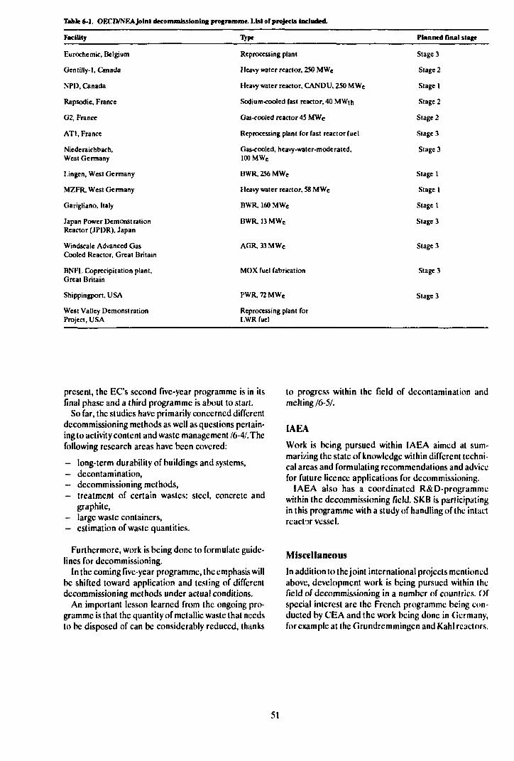
Table 6-1. OECD/NEA Joint decommissioning programme. List of projects Included.
Facility Type Planned flnal stage
Eurochemic, Belgium
Gentilly-1, Canada
NPD, Canada
Rapsodie, France
G2, France
ATI, France
Niederaichbach,West Germany
Lingen, West Germany
MZFR, West Germany
Garigliano, Italy
Japan Power DemonstrationReactor (JPDR), Japan
Windscale Advanced GasCooled Reactor, Great Britain
BNFL Coprecipitation plant,Great Britain
Shippingport, USA
West Valley DemonstrationProject, USA
Reprocessing plant
Heavy water reactor, 250 MWe
Heavy water reactor, CANDU, 250 MWe
Sodium-cooled fast reactor, 40 MWth
Gas-cooled reactor 45 MWC
Reprocessing plant for fast reactor fuel
Gas-cooled, heavy-water-moderated,100 MWe
BWR, 256 MWe
Heavy water reactor, 58 MWe
BWR, 160 MWe
BWR, 13 MWe
AGR, 33 MWe
MOX fuel fabrication
PWR, 72 MWe
Reprocessing plant forLWR fuel
Stage 3
Stage 2
Stage 1
Stage 2
Stage 2
Stage 3
Stage 3
Stage 1
Stage 1
Stage 1
Stage 3
Stage 3
Stage 3
Stage 3
present, the EC's second five-year programme is in itsfinal phase and a third programme is about to start.
So far, the studies have primarily concerned differentdecommissioning methods as well as questions pertain-ing to activity content and waste management 16-41. Thefollowing research areas have been covered:
— long-term durability of buildings and systems,- decontamination,— decommissioning methods,- treatment of certain wastes: steel, concrete and
graphite,- large waste containers,— estimation of waste quantities.
Furthermore, work is being done to formulate guide-lines for decommissioning.
In the coming five-year programme, the emphasis willbe shifted toward application and testing of differentdecommissioning methods under actual conditions.
An important lesson learned from the ongoing pro-gramme is that the quantity of metallic waste that needsto be disposed of can be considerably reduced, thanks
to progress within the field of decontamination andmelting /6-5/.
IAEA
Work is being pursued within IAEA aimed at sum-marizing the state of knowledge within different techni-cal areas and formulating recommendations and advicefor future licence applications for decommissioning.
IAEA also has a coordinated R&D-programmewithin the decommissioning field. SKB is participatingin this programme with a study of handling of the intactreactor vessel.
Miscellaneous
In addition to the joint international projects mentionedabove, development work is being pursued within thefield of decommissioning in a number of countries. Ofspecial interest are the French programme being con-ducted by CEA and the work being done in Germany,for example at the (irundremmingen and Kahl reactors.
51
6.4 RESEARCH PROGRAMME1990-1995
The timetable for carrying out the necessary R&D-work on decommissioning is closely linked to thetimetable for the decommissioning of the nuclear powerplants. As indicated above, the first decommissioningwill not be commenced until a few years after 2010, atthe earliest.
A few years before the planned start of decommis-sioning, a project group will be organized to plan thedecommissioning work in detail. By this time the neces-sary information regarding decommissioning methods,classification of waste, transportation systems etc mustbe available. Most of the methods that are needed arcalready available and arc being used in Sweden. In con-nection with the planning of the decommissioning, theywill be adapted to this work. Development efforts willbe required for some equipment. Since a great deal ofdevelopment work is being done abroad, there is noneed to start any separate Swedish projects during thecoming six-year period.
The completed studies of decommissioning ofSwedish nuclear power plant have indicated some areaswhere early measures are warranted. The most impor-tant arc:
— study of the feasibility of disposing of an intact reac-tor vessel (sec above),
— technology for dismantling of reactor internals,— technology for demolition of the biological shield,— management of asbestos insulation,— methods and equipment for activity measurement
of the waste for dcclassification or simpler disposal,— decontamination for dcclassification,— volume reduction of the waste by compaction or
melting.
During the next few years, most of the work will beconcentrated on the possibility of disposing of an intactreactor vessel. For other areas, efforts will be con-
centrated on following up activities abroad and ex-perience from the operation of the nuclear powerplants. Towards the end of the six-year period, it mayprove necessary to conduct more systematic research inthe other areas. An evaluation should then be made ofthe possibility of conducting tests in the disused Ågestareactor.
The follow-up activities will take place as beforethrough the programme coordination function withinthe OECD/NEA programme and through participationin the work of IAEA etc.
On two occasions, SKB has carried out a completestudy of the technology and costs for decommissioningthe Swedish nuclear power plants. The latest experienceof decommissioning and maintenance work has beentaken into account in these studies. A new decommis-sioning study is planned during the period.
Decommissioning produces a large quantity of slight-ly contaminated material that could be declassified,possibly after decontamination. Some experience existsfrom declassification at the nuclear power plants, whichis done today with permission from SSI for eachseparate occasion. Before decommissioning is com-menced rules and methods for declassification must bedeveloped. The ability to measure low activity levels isof great importance in this connection.
Prior to the decommissioning of the nuclear powerplants, the final repository for decommissioning waste,SFR 3, must also be completed. The time from initialplanning to the finished facility has been estimated tobe about seven years, which means that this work willnot be commenced until a few years into the next cen-tury.
For the decommissioning work to be carried out effi-ciently, certain administrative questions must beresolved, for example what type of licences are neededand what type of accounting to the regulatory autho-rities is required for this purpose. This work lies withinthe sphere of responsibility of the regulatory autho-rities.
52
REFERENCES PART I
Chapter 11-1 Spent fuel and radioactive wasteReport of the AKA committee.SOU 1976:30 Part 1SOU 1976:31 Part 2SOU 1976:41 Appendix(In Swedish)
1-2 Handling of spent nuclear fuel and final storageof vitrified high-level reprocessing wasteNovember 1977
Parts I-VKarnbränslcsakcrhct, KBS, Stockholm
1-3 Handling and final storage of unreprocessedspent nuclear fuelSeptember 1978
Parts I-IIKarnbränslcsakcrhct, KBS, Stockholm
1-4 Act on the financing of future expenses for spentnuclear fuel etc, SFS 1981:669.
(In Swedish)
1-5 Final storage of spent nuclear fuel - KBS-3.May 1983
Parts I-IV.SKBF/KBS, Stockholm
1-6 Act on nuclear activities, SFS 1984:3.(In Swedish)
1-7 Final storage of spent nuclear fuel - KBS-3.February 1984
Programme for research and developmcnlSKBF, Stockholm
1.8 Annual research and developmentReport 1984June 1985
SKB Technical Report TR 85-01, Stockholm
1-9 SKB Annual Report 1985May 1986
SKB Technical Report TR 85-20, Stockholm
1-10 SKB Annual Report 1986May 1987
SKB Technical Report TR 86-31, Stockholm
1-11 SKB Annual Report 1987May 1988
SKB Technical Report TR 87-33, Stockholm
1-12 SKB Annual Report 1988October 1989
SKB Technical Report TR 89-32, Stockholm(In print)
Chapter 22-1 Same as ref 1-5.
2-2 Lönnerberg B et al.May 1983
Encapsulation and handling of spent nuclear fuel forFinal disposal.SKB/KBS Technical Report TR 83-20, Stockholm
2-3 Pettersson S, Hedman TDec 1985
Managing power station wastes.Nuclear Engineering International
2-4 Kärnkraftens slutsteg PLAN 89("Radioactive waste management plan, PLAN89")
(In Swedish)SKB, June 1989, Stockholm
Chapter 33-1 Same as ref 2-4.
3-2 SKN PLAN 87 och förslag till avgift för år 1988("SKN PLAN 87 and recommended fee for1988")
(In Swedish)National Board for Spent Nuclear Fuel, October 1987,Stockholm
3-3 Radioactive waste management plan, PLAN 82June 1982
Parts 1-2SKBF, Stockholm
53
3-4 Slutförvar för reaktoravfallSlutlig säkerhetsrapport("Final repository for reactor waste. Final safe-ty report")
(In Swedish)SKB, September 1987, Stockholm
3-5 Centralt lager för använt bränsleSlutlig säkerhetsrapport.("Central interim storage facility for spentnuclear fuel, final safety report")
(In Swedish)SKB, 1985, Stockholm
3-6 Transportsystem för använt bränsleSlutlig säkerhetsrapport("Transportation system forspent nuclear fuel,final safety report")
(In Swedish)SKBF, March 1982, Stockholm
3-7 Same as ref 1-5
3-8 Kärnkraftens slutstegAlternativa tidplaner för hantering av använtkärnbränsle. Konsekvenser för planering, sä-kerhet och kostnader.("Alternative timetables for management ofspent nuclear fuel. Consequences for planning,safety and costs").
(In Swedish)SKB, December 1985, Stockholm
3-9 Kärnkraftens slutstegTechnology and costs for decommissioning aSwedish nuclear power plant.May 1986
(In Swedish)SKB, Stockholm
3-10 KASAM, Statens Kärnbränslenämnd:Etik och KärnavfallKapport från ett seminarium("KASAM, National Board for Spent NuclearFuel:Ethics and Nuclear Waste, report from a semi-nar")
(In Swedish)SKN Report 28, March 1988, Stockholm
Chapter 4
4-1 Same as ref 1-5.
4-2 Same as ref 1-7.
4-3 Handling and final disposal of nuclear wasteAlternative disposal methods
Background report to R&D Programme 86.SKB, September 1986, Stockholm
Chapter 66-1 Methodology and Technology of Decommis-
sioning Nuclear Facilities1986
IAEA Technical Report Series No. 267 IAEA, Vienna
6-2 Same as ref 3-9.
6-3 Rivning av svenska kärnkraftverk - En analysmot bakgrund av riksdagens beslut om riktlin-jer för inledningen av kärnkraftsawecklingen("Decommissioning of Swedish nuclear powerplants - an analysis against the background ofthe Parliament's decision on guidelines for thecommencement of the nuclear power phase-out")April 1989
(In Swedish)SKB Work Report AR 89-07, Stockholm
6-4 The Community's research and developmentprogramme on decommissioning of nuclear in-stallations1989
Fourth annual progress report 1988, EUR 11715, Com-mission of the European Communities.
6-5 Huber BJuly 1989
EC starts new research programme, Nuclear En-gineering International.
54
APPENDIX
Short Overview of some Legal Requirements on the Nuclear Power Utilities with Respect toNuclear Waste Management
The Government and the Swedish Parliament have, invarious contexts, formulated society's demands on theassignment of responsibility by the nuclear power plantowners for management of the nuclear waste. A briefsummary of the most important provisions of laws, or-dinances etc of relevance for the R&D-programmc isprovided in the following.
The Act on Nuclear Activities (SFS 19<S4:3) regulatesthe obligations of the nuclear power plant owners withrespect to management and disposal of radioactivewaste. These obligations are set forth in Section 10-12of the Act:
"(ienerul obligations of licence-holdersSection 10. The holder of a licence for nuclear activityshall ensure that the necessary measures are taken inorder to
1. maintain safety, with due consideration to the natu-re of the activity and ihc conditions under which it iscarried out;2. safely handle and finally dispose of nuclear waste, ofnon-recycled nuclear material arising in the activity;and3. decommission and dismantle in a safe manner plantsin which the activity is no longer to be carried out.
Section 11. The holder of a licence to possess or ope-rate a nuclear power reactor shall, in addition to therequirements laid down in Section 10, ensure that suchcomprehensive research and development work is con-ducted as is needed in order to meet the requirementsset forth in .Section 10, subsections 2 and 3.
Section 12. The holder of a licence to possess or ope-rate a nuclear power reactor shall, in consultation withother reactor possessors, prepare or have prepared aprogramme for the comprehensive research and deve-lopment work and the other measures stipulated inSection 10, subsections 2 and 3, and in Section 11.Thcprogramme shall present a survey of all measures thatmay be necessary and also specify the measures thatare intended to be taken within a period of at least sixyears. The programme shall, beginning in 1986, be sub-milted to the Government or the authority designatedby ihe Government every third year for examinationand evaluation."
Sections 11-12 state that the research and develop-ment work shall be comprehensive, ie shall pertain toall links in the chain, and shall also i' Hide reportingand follow-up of alternative methods. In the special ar-
gumentation on the Act (Gov bill 1983/84:60), it is sta-ted that the purpose of the provision concerning com-prehensiveness
"is that no commitment shall be made to a given hand-ling and disposal method until sufficient knowledge hasbeen obtained to fully grasp and assess the existingsafety and radiation protection problems. If a new andbetter method emerges during the continued work, thisshould instead be chosen".
In the Ordina.ice on nuclear activities (SFS-1984:14),the following is set forth in Sections 25-26:
"Section 25. The programme referred to in Section 12of the Act (1984:3) on Nuclear Activities shall be sub-mitted to the National Board for Spent Nuclear Fuelfor scrutiny and evaluation no later than Septemberevery third year beginning in 1986.
Section 26. The National Board for Spent Nuclear Fuelshall, no later than six months after the deadline stipu-lated in Section 25, submit to the Government the do-cuments in the matter, together with its own statementof comment on the programme referred to there.
The statement of comment shall include a scrutinyand evaluation of the programme as regards
1. planned research and development activities,2. reported research results,3. alternative handling and disposal methods, and4. the measures intended to be taken."
The research plan reported shall thus also include anaccount of results achieved.
The State's view on the R&D-programmc has beenfuriher expanded on in the "guidelines for the 1986 re-view of the programme of measures with respect to spentnuclear fuel etc ...." issued by the Government on De-cember 12, 1985. These guidelines state, among otherthings: "During the six-year period (1987-1992), thecurrent phase of bedrock investigations- which are ofa fundamental technical-scientific nature and arc notaimed at site selection - shall be completed and prepa-rations made for subsequent phases of field investiga-tions. The current phase, which belongs to the 1980s,must not involve any commitments to specific methodsor sites for future final repositories. It should be evi-dent from the statement of comment which additionalbedrock investigations arc intended to be carried outduring the 1980s and which sites are concerned.
In the next phase, ie mainly during the 1990s, it is tobe expected that further site investigations will also ser-
55
ve as a basis for the gradual narrowing-down of suit-able candidate sites for future final repositories. Thestatement of comment on the research and develop-ment programme in this part should include a propo-sal for a total programme for further test drillings andbroadened site investigations based on the results ob-tained from the current test drillings. The review state-ment should shed light on an appropriate procedurefor how the government authorities will make a deci-sion in site selection questions on the basis of experi-ence gained, results of the bedrock investigations andother parts of the research and development program-me etc. Furthermore, a proposal should be presentedon how information and public relations should behandled at the concerned localities and who should beresponsible for this."
As is evident from the text, the above guidelines arcaimed primarily at the National Board for Spent Nu-clear Fuel, which is responsible for the review of theR&D-programmc. In the preparation of the program-me, however, the Government's guidelines have beentaken into account.
The following is stated in the Government resolutionof November 26,1987, concerning "Programme for re-search etc with regard to the treatment and disposal ofnuclear power waste":
"The Government finds that R&D-Programme 86 ful-fils the requirements made in Section 12 of the Act onNuclear Activities.
The (iovernment finds that the research and devel-opment work should in the main be conducted in ac-cordance with the principles and timetables indicatedin the programme. The viewpoints expressed by theNational Board for Spent Nuclear Fuel in its statementof comment on the programme should be taken into ac-count wherever possible.
As is evident from the drafted memorandum, thereis no support in the constitution for instructing the Na-tional Board for Spent Nuclear Fuel to promulgate re-gulations of a normative nature regarding the R&D-programme. On the other hand, in its capacity as aregulatory authority, the Board may adopt variousmeasures under the provisions of the Act on NuclearActivities and the Act (1981:669) on the financing offuture expenses for spent nuclear fu'jl etc. The Boardcan also issue general advice.
The Government resolves that R&D-Programmc 86be adopted.
The Government declines to act on the NationalBoard for Spent Nuclear Fuel's petition for the right topromulgate regulations."
56
Handling and Final Disposalof Nuclear Waste.
Programme for Research, Developmentand other Measures.
Part II Programme 1990-1995
CONTENTS PART II
1
2
2.12.22.32.3.12.3.22.42.4.12.4.22.4.32.4.42.4.52.4.62.4.72.52.5.12.5.22.5.3
33.13.23.2.1
3.2.23.2.33.33.3.13.3.23.3.33.3.43.3.53.43.4.13.4.2
44.14.24.34.3.14.3.24.3.34.44.4.14.4.24.4.34.5
GENERAL
SITING OF FINAL REPOSITORY FORSPENT FUEL AND OTHER LONG-LIVEDWASTEBackgroundFactors that Influence SitingPlan for Siting
Candidate SitesSite Characterization
Plan for Reporting to the Regulatory AuthoritiesCandidates for Detailed CharacterizationPlan for Prc-investigationsSites for Detailed CharacterizationPlan for Detailed CharacterizationExecution of Detailed CharacterizationSiting ApplicationPermit for Start of Construction
The Geological BasisGeneralPre-invcstigationsDetailed Characterization
SAFETY ASSESSMENTSGeneralGoals
The Overall Timetable and the Role of theSafety AssessmentsMethod DevelopmentGoals for the Period 1990-1995
State of the ArtScenariosModels and CouplingsSite-specific DatabasesCriteria and Regulatory RequirementsConfidence
Programme1990-19921993-1995
REPOSITORY DESIGNGeneralGoalAlternative Designs
WP-Cave DesignDeep Boreholes, DesignConstruction Methods
Comparison of AlternativeWP-CaveDeep HolesMiscellaneous
Research Programme 1990-1995
Page
65
676767686869707070707171717171717272
737374
747575757576787879797981
838384848485868787888888
Page
55.15.1.15.1.25.1.3
5.1.45.25.2.15.2.25.2.3
5.2.45.35.3.15.3.25.3.35.3.3.15.3.3.2
5.3.3.3
5.3.3.45.3.3.5
5.3.3.6
5.3.3.75.3.3.85.3.4
66.16.1.1
6.1.26.26.2.16.2.26.2.2.1
6.2.2.26.2.2.3
6.2.2.46.2.36.36.3.16.3.26.3.2.16.3.2.26.3.2.3
6.3.2.46.3.2.56.3.2.66.3.2.7
ENGINEERED BARRIERSWaste Forms
Goals of the R&D ActivitiesPresent-day State of KnowledgeImportant Review Comments from R&D-Programme 86Research Programme 1990-1995
CanisterGoal of the R&D ActivitiesPresent-day State of KnowledgeImportant Review Comments from R&D-Programme 86Research Programme 1990-1995
Buffer and BackfillBackgroundGoal of the R&D ActivitiesPresent-day State of Knowledge
Long-term Stability of the BcntonitcChemical Conditioning, Mixing withCrushed Rock etcRheology, Water Absorption,Resistance to ErosionEffects of GasSealing Measures in Boreholes andShaftsModel Development for the BarrierFunctionQA ProgrammeSummary of Research Results
Research Programme 1990-1995
PROPERTIES OF THE ROCKGeneral
The Role of the Rock in the FinalRepositoryInvestigation of Rock
Groundwatcr Movements in the RockGoals of the R&D Activities 1990-1995Present-day State of Knowledge
Observation Methods for Ground-watcr in RockConceptual ModelsValidation of Models forGroundwatcr MovementsSome Special Research Areas
Research Programme 1990-1995Stability of the Rock
Goals of the R&D Activities 1990-1995Present-day State of Knowledge
Tectonic ProcessesClimatic ProcessesThe Impact of the Repository onMechanical StabilityPost-glacial MovementsModelling of the Rock MassExperience o.' EarthquakesStudies in Southeastern Sweden
89898989
9292959595
96969797979797
98
9999
100
100100100102
103103
103103104104105
105110
114115116118118118118119
119120122123123
6.3.36.3.3.1
6.3.3.26.3.3.36.3.3.46.3.3.5
77.17.1.17.1.27.1.37.27.2.17.2.27.2.37.3
7.3.17.3.27.3.3
8
8.18.28.2.1
8.2.2
8.2.2.18.2.2.28.2.2.3
8.2.2.4
8.2.2.5
8.2.2.6
8.2.2.7
8.2.3
8.38.3.1
8.3.2
8.3.3
8.3.4
8.3.5
Research Programme 1990-1995State-of-the-art Knowledge Review ofIce Ages and Land UpliftDeepened Tectonic AnalysisConclusion of the Lansjärv ProjectOperation and Analysis of Seismic DataInternational Projects
CHEMISTRYGroundwatcr Chemistry and Geochemistry
Goals of the R&D ActivitiesPresent-day State of KnowledgeResearch Programme 1990-1995
Radionuclide ChemistryGoals of the R&D ActivitiesPresent-day State of KnowledgeResearch Programme 1990-1995
Chemical Transport and Validation ofTransport Models
Goals of the R&D ActivitiesPresent-day State of KnowledgeResearch Programme 1990-1995
METHOD AND INSTRUMENTDEVELOPMENTGoals of the R&D ActivitiesPresent-day State of Knowledge
Measuring Methods and Instruments forSurface InvestigationsMeasuring Methods and Instruments forInvestigations in Boreholes
DrillingMapping of Drill Core and BoreholeGeophysical Measurements inBoreholesGeohydrological Measurements inBoreholesHydrochcmical Measurements inBoreholesRock Stress MeasurementsPosition Determinations inBoreholes
Measuring Methods and Instruments forInvestigations from Tunnels and Shafts
Research Programme 1990-1995Geological Measuring Methods andInstrumentsGeophysical Measuring Methods andInstruments RadarGcohydrological Measuring Methods andInstrumentsChemical Measuring Methods andInstrumentsRock Mechanics Measuring Methods andInstruments
Page
124
124124125125125
127127127127130131131131134
135135135137
139139139
139
140140140
141
142
144144
145
145147
147
147
148
148
149
99.1
9.29.39.4
9.59.5.19.5.29.5.39.69.7
1010.110.1.110.1.210.1.310.2
10.2.110.2.2
10.2.3
1111.111.211.3
1212.1
12.212.312.3.112.3.2
12.3.312.412.4.112.4.212.4.312.4.412.4.5
1313.113.2
13.313.4
13.513.613.713.8
HARD ROCK LABORATORYBackground and Motives for Construction ofthe Hard Rock LaboratorySiting and Layout of the Hard Rock LaboratoryGoal and limctableInvestigations Performed in the Pre-investigationPhaseProgramme for the Construction Phase
Geological InvestigationsGeohydrological InvestigationsGeohydrochemical Investigations
Preliminary Programme for the Operating PhaseFurther Information
THE STRIPA PROJECTGoals and Results Obtained Thus Far
Brief Summary of Results from Phase 1Brief Summary of Results from Phase 2Goals of Phase 3
Present-day State of Project and ResearchProgramme 1990-1992
"Site Characterization and Validation""Improvement of Site Assessment Conceptsand Methods""Scaling of Fracture Rock"
NATURAL ANALOGUESGeneralPocos de CaldasCigar Lake
BIOSPHERE STUDIESThe Importance of the Biosphere Studies for theFinal Disposal of Nuclear WasteGoalsPresent-day State of Knowledge
Evolution of the BiosphereTransport Pathways between Rock andManOther Research on the Biosphere
Research Programme 1990-1995Changes in the BiosphereTransport Pathways in the BiosphereModels and DataSite-specific StudiesAcceptance Criteria
INTERNATIONAL COOPERATIONForeign R&D of Importance for SKB's ProgrammeSKB's Cooperation Agreements with ForeignOrganizationsThe JSS Project - ResultsCooperation with AECL Regarding UndergroundResearch LaboratoryFuel Leaching - WorkshopsHYDROCO1NINTRAVALCooperation with TVO, Finland
Page
151
151152153
154156156157157158158
159159159159160
160161
162163
165165165167
169
169169169169
170170170170170170170171
173173
176176
177177177177177

Page
13.913.9.113.9.213.1013.10.113.10.213.1113.11.113.11.213.12
Cooperation with CEA, FranceClayChemistry
Cooperation with EURATOM, ECCOCOCHEMVAL
Cooperation within OECD Nuclear Energy AgencyRWMCTDB
Cooperation within IAEA
References
178178178178178178178178179179
181

GENERAL
SKB's R&D-Programme 89 constitutes the 1989 planfor research and development as required in Section 12of the Act on Nuclear Activities. The plan describes theR&D activities that are deemed necessary in order tomanage and dispose of the Swedish nuclear waste in asafe manner. This Part II of the programme presents theresearch and development to be carried out over thenext six years. Chapter 2 describes the activities aimedat siting of a final repository for long-lived waste. Thischapter also provides an overview of the total program-me, since many activities arc chronologically linked tothe siting plan. Chapter 3 deals with safety assessments.Activities that relate to the design of the repository andthe engineered barriers are then described. Studies per-taining to the properties of the rock, chemical condi-tions and the method and instrument development thatis required for these studies are dealt with in Chapters6,7 and 8.
The work within the major projects Stripa, Hard RockLaboratory and natural analogues is described inseparate chapters. Then follow chapters concernedwith biosphere studies and international cooperation.A detailed programme for the Hard Rock Laboratoryis presented in a separate background report.
The overall plans for the management of the radioac-tive waste from the Swedish nuclear power plants arepresented in Part I of the programme.
As far as the spent fuel is concerned, the plans are lar-gely the same as presented in R&D-Programme 86,which means that the start of construction of the finalrepository will be in the year 2010. The time schedulefor site investigations and siting application has,however, been delayed a couple a couple of years inorder to synchronize it better with the construction ofthe Hard Rock Laboratory. The start of detailedcharacterization is now planned for 1995/96 and thesiting application for 2003.
The present-day state of knowledge is presentedwithin each subject area, with an emphasis on resultsobtained in recent years since the KBS-3 Report. Thespecific goals of the research within the area are alsodescribed, along with how these goals relate to the stagegoals of the programme. Some of the most importantreview comments on R&D-Programme 86 are pre-sented, along with how they have been taken into ac-count. Finally, the planned research for the period1990-1995 is described. For a detailed presentation of
the review comments on R&D-Programme 86, thereader is referred to a separate background report,which also contains certain comments by SKB.
As a support for the siting of the final repository andfor the continued prioritization of the research work,SKB will carry out a new safety assessment by 1991called SKB 91. The outline of this safely assessment ispresented in Chapter 3.
The studies of different alternative repository systemswill gradually be focussed. Different feasible alterna-tives were described in a background report to R&D-Programme 86. The alternatives with the highestpriority are still being studied within the framework ofthe ongoing programme. Special studies are being ton-ducted on certain basic designs, the results of which willbe reported separately. One example is the study of theWP-Cave design, which is described in brief in Chapter4. Priorities will be assigned to different alternatives onthe basis of such studies. Important grounds for makingthese judgements are:
— radiological safety,— feasibility with reference to existing or easily avail-
able technology,— development potential,— costs,— uncertainties in data and models and confidence in
the quality of the assessment.
Prioritization of the research work will take place in-ternally within SKB after consultation with referencegroups, experts and other concerned persons. This willbe described in reports and in connection with theR&D-programmes every third year.
Execution of R&D-Programmc 89 is described inPart I Chapter 5. In order for the R&D work to beeffective, its planning must be continuously adjusted inresponse to the results obtained. SKB intends to makethe necessary adjustments within the framework of theintentions of the R&D-programme.
Planned activities relating to the decommissioning ofnuclear power plants are described in Part I Chapter 6.Work in this area will be relatively limited during theperiod 1990-1995.
Planned information and public relations effortsaimed at the general public in conjunction with the re-search programme and the siting process are not dealtwith in this report.
65

SITING OF FINAL REPOSITORY FOR SPENT FUELAND OTHER LONG-LIVED WASTE
2.1 BACKGROUND
The siting of the final repository for spent nuclear fueland other long-lived waste is one of the most importantproblems to be solved during the 1990s for the Swedishnuclear waste programme. This question is dealt withsuperficially in R&D-Programme 86 /2-1/. One reasonfor this was that SKN had appointed a "site selectiongroup" with the task of coming up with a proposal onhow the siting question should be dealt with. A reportfrom this group was included as an appendix to SKN'sreview report 12-21 on R&D-Programmc 86 and it con-stituted the basis for SKN's viewpoints on SKB's pro-gramme in this question.
The viewpoints offered by SKN called for a successivenarrowing-down of possible sites through a geological-ly based screening procedure in three phases: Testphase, selection phase and licensing phase. During thetest phase, a relatively large number of areas judgedparticularly suitable for the siting of a final repositorywould be screened out. Concerned municipalities andcounty administrations should be notified and asked toset aside the specific identified areas in their com-prehensive development plans. Such plans arc to bedrawn up for all municipalities in the country prior toJune 30,1990. During the subsequent selection phase,the field studies would continue and those sites that arcbest suited for a safe final repository would be selected.On the basis of proposals received from SKB and aftercirculation of these proposals for comment, SKN wouldthen judge whether a "national interest" exists under theterms of the Natural Resources Act and would notifythe concerned municipalities and county administra-tions that this is the case. The designation of a "nation-al interest" means that the land areas in question mustbe set aside for a specific type of facility, in this case afinal repository, and may not be utilized for any otherpurpose.
A Government resolution passed in December 1987stated that R&D-Programme 86 meets the require-ments of the Act on Nuclear Activities and should serveas a basis for the continued work, and that SKN's reviewcomments should be taken into account wherever pos-sible. SKB has carefully considered the viewpoints putforth by SKN and found that the procedure proposedby SKN cannot be followed in all respects. Successive-ly screening out a diminishing number of sites from alarge number of original candidates requires that a rela-tively large number of municipalities set aside land intheir planning work for the sites that have been screenedout. These areas shall be held in reserve pending the
necessary investigations and siting decisions. Theprocedure can lead unnecessarily to troublesome anddrawn-out political debates in many municipalities.
As was pointed out in R&D-Programme 86, the largebody of material from geological field surveys showsthat there are many sites in Sweden suitable for thesiting of a final repository from the geological point ofview. This means that other factors can be accordedgreater importance in the selection of a site. It is doubt-ful whether the best site in all respects can be identifiedwith reasonable efforts. Nor is this necessary; it is quitesufficient to find a site where the rock possesses suchcharacteristics and where conditions otherwise are suchthat a very high standard of safety and radiation protec-tion can be met. In SKB's view, there is no reason todemand a more detailed selection process than demon-strating with general data that there are no obviouslymore suitable areas than those finally proposed.
The important, technically detailed evaluation ofwhether a site is adequate for constructing a final re-pository that meets the very high demands on safely willbe made in connection with the review of the siting ap-plication. This evaluation cannot be performed untilsite-specific data and a site-adapted design are avail-able.
2.2 FACTORS THATINFLUENCE SITING
The siting of a final repository must take into account alarge number of factors. As already noted, the researchconducted to date shows that there are many sites inSweden that meet the requirements that can be madeon the geology at a final repository. Siting should there-fore also take into account other factors that are not ofdirect safety-related importance. Table 2-1 presentssome of the most important factors.
The parameters in the table have been divided intofour groups. Groups I and II are primarily of impor-tance for the long-term safety of the repository. GroupIII parameters are primarily important for the construc-tion and operation of the repository and for associatedsafety aspects, as well as from the economic and socialviewpoints, while group IV parameters are of social andpolitical importance. In the siting process, priority willbe given to meeting fundamental requirements withregard to the parameters in groups I and II. An optimalbalance of the parameters in groups III and IV will thenbe sought.
67
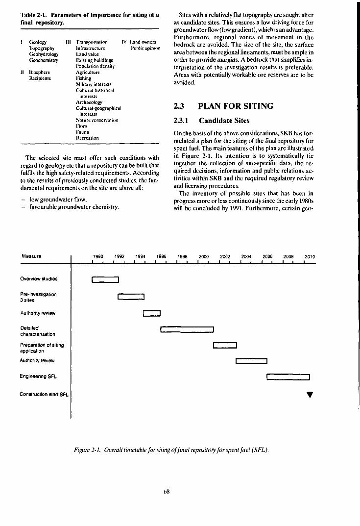
Table 2-1. Parameters of importance for siting of afinal repository.
I GeologyTopographyGcohydrologyGeochemistry
11 BiosphereRecipients
III Transportation IV landownersInfrastructure Public opinionLand valueExisting buildingsPopulation densityAgricultureFishingMilitary interestsCultural-historical
interestsArchaeologyCultural-geographical
interestsNature conservationHoraFaunaRecreation
The selected site must offer such conditions withregard to geology etc that a repository can be built thatfulfils the high safety-related requirements. Accordingto the results of previously conducted studies, the fun-damental requirements on the site arc above all:
- low groundwater flow,- favourable groundwater chemistry.
Sites with a relatively flat topography are sought afteras candidate sites. This ensures a low driving force forgroundwater flow (low gradient), which is an advantage.Furthermore, regional zones of movement in thebedrock are avoided. The size of the site, the surfacearea between the regional lineaments, must be ample inorder to provide margins. A bedrock that simplifies in-terpretation of the investigation results is preferable.Areas with potentially workable ore reserves are to beavoided.
2.3 PLAN FOR SITING
2.3.1 Candidate Sites
On the basis of the above considerations, SKB has for-mulated a plan for the siting of the final repository forspent fuel. The main features of the plan are illustratedin Figure 2-1. Its intention is to systematically tietogether the collection of site-specific data, the re-quired decisions, information and public relations ac-tivities within SKB and the required regulatory reviewand licensing procedures.
The inventory of possible sites that has been inprogress more or less continuously since the early 1980swill be concluded by 1991. Furthermore, certain geo-
Measure
Overview studies
Pre-investigation3 sites
Authority review
Detailedcharacterization
Preparation of sitingapplication
Authority review
Engineering SFL
Construction start SFL
1990 1992 1994 1996 1998 2000 2002 2004 2006 2008 2010
I I
r ..j
i , i
L . . . „ J
•
Figure 2-1. Overall timetable for siting of final repository for spent fuel (SFL).
68
logical overview studies will be carried out on the basisof currently existing geological material. These sup-plementary studies are of a general nature and do notrequire any further drilling or borehole measurements.
A new safety assessment called 8KB 91 is expected tobe finished in 1991. One of the purposes of this assess-ment is to evaluate, more thoroughly and systematical-ly than before, the importance of variations in geologi-cal conditions for the function and safety of the final re-pository. The KBS-3 Report 12-31 claimed that: "Theanalyses show that even sites such as Finnsjön, withhigher groundwater flows than those mentioned (Ciideåand Kamlungc, and probably also Fjällveden), shouldbe acceptable from the safety viewpoint." In SKB 91 thiswill be further backed-up on the basis of experiencegained since 1983 when KBS-3 was written. A moredetailed plan for SKB 91 is provided in Chapter 3.
On the basis of the experience obtained from inves-tigations of study sites, from Stripa and from the workat Simpevarp for the Hard Rock Laboratory, a pro-gramme for pre-investigations of candidate .iites will beprepared. Since knowledge of the geology of (he can-didate sites can vary a great deal, the programme willstipulate which investigations are to be carried out onthe different sites and how they are to be coordinated.The programme will be prepared in the beginning of1991 in order to draw maximum benefit from experiencefrom the Hard Rock Laboratory.
During 1992, SKB intends to announce three siteswhich SKB considers to be suitable candidates for thesiting of the final repository. The candidate sites will bechosen on the basis of the factors mentioned in theabove section 2.2. Site selection should furthermore bemade so that social services, communications and com-petent labour will be available. The fundamental re-quirement qualifying a site as a candidate site is that itshould offer good potential for achieving a repositorywith high safety.
At this point, the site data will be of a general natureand must be augmented by pre-investigations and sub-sequently also detailed characterization. The purpose,however, is to be able to concentrate continued geo-studies, licensing questions and information activities toa few promising areas. As a basis for the selection ofcandidate sites, the results of the above-mentionedstudies and a summary of existing data on the three siteswill be presented at the same time. In connection withthis announcement, SKB's information on matters ofspecial interest for the siting of a final repository will beintensified.
An important part of the work is to plan and executeobjective and open information activities aimed at land-owners, nearby residents, the municipality, authoritiesetc.
2.3.2 Site Characterization
After the candidate sites have been announced, aniterative process of site-specific investigations, compila-tions and evaluations of results and planning of possiblefurther studies will begin. This will lead to a gradual in-crease in the amount of data available for assessing thesuitability of the candidate sites, for positioning the re-pository within a site, for determining possible tunnelroutes and waste emplacement positions, for position-ing of sealing plugs etc. On the finally selected re-pository site, the process will extenu all the way up tosealing of the final repository.
The increasing amount of detailed information willgradually require greater intrusions on the sites in theform of shafts/tunnels to the relevant repository depthand tunnel/boreholes in the available deposition vol-ume. It is therefore essential that the investigations beplanned and executed with a view towards their effectson a repository.
After permission has been obtained from the land-owner, pre-investigations will be conducted during theyears 1992-94 on the three sites according to the aboveprogramme. SKB 91 will be supplemented with site-specific information to provide a basis for a preliminaryassessment of the long-term safety of a final repositorylocated on each of the three sites. At the same time, theanalysis of the parameters of importance for the sitingwill be augmented and deepened.
A general programme for detailed characterizationof the candidate sites will be prepared in 1994. The pro-gramme will be based on the experience gained duringthe construction of the Hard Rock Laboratory and theexperimental programme conducted in conjunctiontherewith. Furthermore, a preliminary environmentalimpact statement will be prepared for each of the threesites. The primary purpose of this environmental impactstatement is to give an account of the effects of conduct -ing detailed characterization. It can only provide a verygeneral description of the impact of a final repositoryon the site in question.
Pre-investigation results, a programme for detailedcharacterization, a preliminary safety assessment andenvironmental impact statements will be submitted tothe concerned authorities at the end of 1994. The con-cerned authorities are primarily SKN, the municipalityand the county administration. SKI, SSI and other agen-cies can be expected to serve as reviewing bodies for theaforementioned authorities. After a review period (ifabout 18 months, it is estimated that the necessary ap-provals and permits for detailed characterization maybe available in early 1996. Such characterization willthen start on one site, and on a second site in 1997. Thedetailed characterization will be carried out in ap-propriate stages. A site-specific programme for the
69
detailed characterization and their subdivision intostages will be prepared during 1995/96. It will be basedon experience from the Hard Rock Laboratory andfrom the pre-investigations of the candidate sites.
A rough layout of the area required for a final re-pository will be needed as a basis for starting detailedcharacterization. A conceptual design of the final re-pository system must therefore be chosen in 1995. Asummary of completed studies of different alternativesand of then-existing knowledge concerning the com-ponents in the barrier system will be submitted in con-nection with this. It is assumed that this can be done inconnection with R&D-Programme 95. During the years1995-98, the necessary supplementary studies for thecomponents in the selected conceptual design will becarried out, and the models required for an optimiza-tion of the final repository to the site that is finallyselected will be further developed and verified. The op-timization will be carried out in parallel with a secondstage of the detailed characterization. These activitiesare expected to be completed by 2001, when work willbegin on preparing a siting application under theNatural Resources Act and under the Act on NuclearActivities. The application, which should preferably befinished by 2003, will contain a preliminary safety reportwith a detailed assessment of the long-term safety of thefinal repository. It is assumed that the application willtake three years to process, which would mean that a(jovcrnment-approved site will exist in 2006.
After the site has been approved, engineering draw-ings will be prepared and an updating of the safetyreport will be carried out, particulary with respect tosafety during the operating (deposition, surveillance)phase. It is estimated that this report will be finished in2008 and will comprise the basis for SKI's and otherauthorities' approval of the start of construction in 2010.
SKB's goal throughout the siting phase is that ex-perience from R&D activities shall be systematically ex-ploited and that the safely-related importance of the ob-tained information shall be successively evaluated. Onthe basis of this evaluation, critical parameters and con-ditions will also be identified as a basis for R&Dprioritization.
2.4 PLAN FOR REPORTING TOTHE REGULATORYAUTHORITIES
The purpose and essential aspects of the safety-relatedreview expected to be conducted by the regulatoryauthorities in conjunction with the siting plan arc dis-cussed below.
2.4.1 Candidates for Detailed Characte-rization
The role of the regulatory authorities in this phase islinked to the general review of the R&D-programmecarried out by SKN. This review is expected to be aimedprimarily at establishing the acceptability of SKB'sjudgement - that a concentration of efforts, as regardsboth geological studies and information, is desirableand possible according to the reported planning,without unnecessarily limitating the potential for suc-cessful siting.
2.4.2 Plan for Pre-investigations
In preparation for the pre-investigations, SKB will, ashas already been mentioned, prepare a plan for their ex-ecution. The plan will also contain a discussion of whatpossible impact the planned investigations might haveon the properties of the rock that are of importance forthe safety of the final repository. The regulatoryauthorities are expected to review this plan.
2.4.3 Sites for Detailed Characterization
Around 1994, the pre-investigations will have yielded anew site-specific database that will permit a deeperevaluation of the potential of the sites as repository sites.
Based on the SKB 91 safety assessment, variationanalyses will be carried out in order to determine thesafety-related importance of differences between thesites. The information from this investigation phase willprimarily be applicable to the safely assessment's far-field description, for example locations of major zones,available space between zones of weakness and thelarge-scale gradient over potential deposition areas.Certain statistical information on the distribution of hy-draulic conductivity on the investigated site will also beavailable, as well as data on groundwater chemistry.
Providing no major unfavourable factors emerge, twoof the studied sites will be designated as sites fordetailed geological characterization. If several sitesshould turn out to be inappropriate for further charac-terization, it may be necessary to designate more can-didates, resulting in a delay in the schedules. SKBjudges the risk of this to be small.
Besides making a preliminary safety assessment andpreparing preliminary layouts, SKB will also assess en-vironmental impact during the detailed characteriza-tion and construction of the final repository. Safety as-sessment, environmental impact studies and planning ofcontinued detailed characterization require that altcr-
70

native repository designs be tried out on the candidatesites. Furthermore, other types of social impact on themunicipalities where the candidate sites are located willbe evaluated.
The regulatory authorities are expected to review thesafety relevance of t he variation analyses and make surethat SKB has made a reasonable interpretation of thesite-specific information. The detailed characterizationwill require considerable financial and human resour-ces, as well as building permission from the municipalityin a certain phase. This means that SKN and other con-cerned central, regional and local authorities must ap-prove the start of the detailed characterization.
2.4.4 Plan for Detailed Characterization
The detailed characterization will be based on site-specific plans stipulating how the investigations are tobe conducted. These plans will in turn be developed onthe basis of the general programme for detailed charac-terization prepared in 1994, on continuously receivedsite-specific information and on experience from theHard Rock Laboratory. The effect of the investigationson a future repository is an important question here,especially the future importance of the location of theshaft or tunnel down to repository depth. Other questions that will be taken up are the strategy for charac-terization of the rock mass, which parameters arc to bemeasured and the measuring methods that are to beused. A large body of experience will have been ob-tained from the Hard Rock Laboratory, for example.The authorities are expected to review this material.
2.4.5 Execution of Detailed Characteriza-tion
The studies will probably be divided into stages, withthe option of interrupting if it should turn out that a siteis unsuitable.
During 1996-1999, the site characterization willgreatly increase the availability of site-specific data. Onthe basis of these data, it should be possible to sketch ina probable repository geometry with levels, tunneldirections and deposition areas. On the basis of the gco-hydrological variability in the potential depositionareas, it should be possible to establish space require-ments and a near-field-specific database.
SKB assumes that an important part of the regulatoryreview will consist of continuous follow-up of this work.
2.4.6 Siting Application
The siting application intended to be submitted in 2003,and primarily intended to cover a single site, will includea preliminary safety report with an emphasis on thelong-term safety of the final repository. The safety as-sessment will be based on the results of the detailed sitecharacterization and the site-optimized final repository
system. This application will be considered under theAct on Nuclear Activities as far as its radiological safe-ty aspects are concerned. The siting application will alsoinclude a description of measuring methods and assess-ment grounds for determining the local quality of therock as the excavation of the deposition tunnels pro-gresses, as well as for positioning the deposition holesin relation to this. The application in its entirety will beconsidered under the Natural Resources Act, the En-vironmental Protection Act, the Planning and BuildingAct etc.
2.4.7 Permit for Start of Construction
The safety report will be updated well in advance of theplanned start of construction. This updating willprimarily be concerned with safety in connection withtransport, handling, encapsulation, deposition etc of thewaste. The report may also update the preliminary as-sessment of long-term safety. This report should also bereviewed under the Act on Nuclear Activities.
The final account of the repository's long-term safetywill in all probability not be submitted before the ap-plication for permission to seal the repository. This docsnot mean that the requirements on the accounts to besubmitted in connection with the siting application andon any subsequent occasions are in any way less rigorousthan for a final account. In other words, the word"preliminary" should not be misinterpreted.
2.5 THE GEOLOGICAL BASIS
2.5.1 General
SKB has carried out extensive surveys and reconnais-sances of possible sites for a final repository at differentperiods. Present-day data from the reconnaissancesconsist mainly of geological parameters of the type men-tioned in section 2.2. The candidate sites shall be of suchquality that it is deemed possible to demonstrate thenecessary long-term safety in a siting application in theyear 2003. Supplementary information such as nationalphysical planning, municipal development plans etc. arcrequired to find candidate sites.
Investigations performed to date have been carriedout on land. However, the possibility of siting a final re-pository underneath the Baltic Sea should still be keptopen, since such a site would have clear safety-relatedadvantages over long spans of time. These advantagesinclude factors such as a defined gradient for ground-water flow, low groundwater flux and postponement ofthe well scenario. In view of the advantages a coastal sitewould appear to offer, SKB plans to compile geologicaldata for coastal candidate sites extending from theshore to about 10 km offshore.
SKB also plans to compile a body of comparativematerial for certain of the study-site investigations pre-viously reported. The variations in data that exist on
these study sites shall be able to be compared with thevariations analyzed in SKB 91. This will provide furthersupport for the conclusion that there are many sites inSweden that are suitable from a geological point of viewfor the location of a final repository.
Since R&D-Programme 86 was presented, certainstudies have been conducted for the purpose ofbroadening the geological material prior to the selec-tion of candidate sites. Sweden's morphology, bedrockand tectonics have been compiled in /2-4/. The report isprimarily based on existing material. The tectonic pic-ture has been obtained with the aid of geological maps,lineament maps based on Landsat images and reliefmaps. Sweden has been divided into tectonic regionsand the orientation, density and length of lineaments ispresented on maps.
A summary of southern Sweden's bedrock and tec-tonics as well as surrounding marine areas is presentedin 12-51. In addition to conventional geological material,data from a large number of prospecting surveys havealso been used. Several seismic profiles from land andout over nearby marine areas arc reported. Thematerial has been compiled in a large number of mapsand profiles.
The question of siting of the final repository in gab-bro instead of gneiss, granite or a similar type of rockwas dealt with in R&D-Programmc 86. It was therebyconcluded that: "Investigations already completed andgeneral experience of gabbro show that it wouldprobably be relatively difficult to find sufficiently largehomogeneous formations among the relatively sparselyoccurring gabbro massifs, in comparison with gneiss orgranite." It was further stated that "The conclusion isthat it is best to concentrate further geological studieson gneiss and granite. These rock types arc sufficientlygood and are the most likely candidates for hosting afinal repository." These statements elicited somecriticism from a few reviewing bodies. This criticismslated that SKB had not considered all availablematerial regarding gabbro massifs in its assessment. Inresponse to this criticism, SKB commissioned S( jU (the(ieological Survey of Sweden) to supplement its inven-tory of gabbro massifs. This supplementary investiga-tion has not occasioned any change in the conclusionsdrawn in R&D-Programmc 86.
2.5.2 Pre-investigations
As is evident from the above, SKB is planning to carryout the investigations for the candidate sites in a pre-in-ve.sl igal ion phase and a detailed characterization phase.SKB is currently conducting several projects with an ex-tremely high level of ambition to develop and test tech-nology for such investigations. These include the HardRock Laboratory and the Stripa Project, see furtherChapters 9 and 10.
Pre-investigations shall provide material for designat-ing which volumes are of interest for continued detailed
characterization, for making a preliminary judgementof whether the site fulfils fundamental requirementswith regard to long-term safety and for alternative,preliminary repository designs.
The pre-investigalions shall also provide a generalcharacterization of the candidate site. Based ongeological and geophysical surface investigations, themain rock type and major tectonic zones on the can-didate site and in its environs will be documented.Boreholes will be drilled, a few to great depths, wherebyrock types and fracture zones will be documented. Rockstresses will be measured to determine mechanicalstability at different depths. The conductivity andgroundwater flux of the rock will be measured.Representative water chemistry will be measured. Mat-ters relating to the geometry and interconnection ofzones and flowpaths will not be studied until thedetailed characterization phase.
The pre-investigations shall also indicate which vol-umes are of interest for continued detailed charac-terization. Volumes judged suitable for hosting a re-pository shall be designated. Furthermore, those vol-umes that subsequently need to be characterized be-tween the repository and discharge areas shall bedefined.
The results from the pre-investigations will be utilizedto plan the continuation of the detailed characteriza-tion.
The programme for pre-investigations shall describewhat measures arc to be carried out on the differentsites by means of what methods. A general programmewill be presented in 1991. For each candidate site, a site-specific programme will then be prepared and ex-ecuted. Coordination with respect to various kinds ofresources will be required.
2.5.3 Detailed Characterization
The detailed characterization shall
— confirm that a suitable repository volume is avail-able,
— yield information for site adaptation of the access tothe repository,
— provide preliminary data to guide the constructionof the repository,
— provide data to permit the repository system to beoptimized with respect to engineered barriers andgeometric configuration,
— characterize the area to the necessary extent so thata very good body of supporting data can bepresented along with the siting application.
It is assumed that detailed characterization will beconducted on two of the candidate sites, suitably stag-gered in time, and that the investigations will be sub-divided into appropriate stages.
A general programme for detailed characterizationwill be presented in 1994.
72
SAFETY ASSESSMENTS
3.1 GENERAL
Nuclear activities must be conducted in an acceptablemanner with respect to safety and radiation protection.The safety of the activities is assessed by means of per-formance and safety assessments. The performance as-sessments constitute studies of subsystems and their in-teraction, or of the special conditions under which per-formance is to be guaranteed. The performance studiesthen serve as a basis for the studies of total safety thatmake up the safety assessment. Besides safety level, asafety assessment shall also define the uncertainty as-sociated with the judgements.
The purpose of the performance assessments will dif-fer during different phases of development and licens-ing of a final repository. In the introductory phase, theperformance of the subsystems in the repository will beevaluated. The uncertainty existing in current know-ledge regarding essential functions will indicatepriorities for further research and development.
In a later phase, attempts will be made to find abalance between the safety barriers, in other words thesystem will be optimized with respect to performanceand cost at an acceptable safety level. During the licens-ing phase, it must be formally and finally demonstratedthat the system fulfils the demands made by society onsafety.
SKB's R&D-Programme is currently in a phase wherethe fundamental feasibility studies have been con-cluded. Review of alternative sitings and repositorydesigns is currently in progress and a progressive cull-ing of alternatives with less development potential isbeing carried out. In this phase, it is essential that thestudies of long term performance and safety provide abasis for variation studies where the safety-related im-portance of the different barriers or the dilferentdesigns can be assessed.
Compared with KBS-3, whose purpose was to provefeasibility, the next major integrated safety assessment,SKB 91, will, as far as is possible, reduce the safety mar-gins in the calculations and avoid highly pessimistic sim-plifications. The idea is, however, still to specify a designand dimensions that meet the acceptance requirementsand provide the necessary safety margins. But thehigher realism will permit a more accurate quantifica-tion of the safety effect that a change in design or dimen-sions will entail.
In order io fulfil the above ambitions, a safety assess-ment must be based on:
— information on waste quantities and radioactivematerials in the repository,
— a description of a reference design with materials,dimensions and quality requirements,
— a characterization of the repository site with respectto factors of importance for safety as well as theirvariation and uncertainty.
The performance assessments include the followingelements:
— review of the external circumstances (scenarios)that can arise, and definition of which of thesescenarios the repository shall be able to cope with,
— description of the processes of importance for thesafety of the repository that can occur, and of themodels and databases with whose help the proces-ses can be quantified,
— estimate of the performance of the repository withrespect to time for the design scenarios.
A safety assessment must also include the followingelements:
— definition of society's acceptance requirements forthe waste and over the relevant time spans,
— comparison between calculated consequences/probabilities and the acceptance criteria,
— analysis of the uncertainty existing in the data andmodels with respect to its importance for accep-tance.
The degree of detail and completeness in the differentelements of the assessment will vary with the state ofdevelopment and the knowledge base, as well as withthe specific purpose of each assessment. (Joals, state ofdevelopment and programmes for essential parts of theperformance and safety assessments are dealt with inthis chapter.
In its review of R&D-Programme 86, SKN recom-mended that SKB should prepare during 1988 a simpleand clarifying description of methods and proceduresfor performance and safety assessments. SKB has un-derestimated the labour involved in preparing such abooklet, and the work has proceeded more slowly thanexpected. The material requires further work before itcan be distributed to a large readership. The goal is firstto compile material that is judged by experts in the fieldto provide a relatively good and complete description,and then to rework it to different levels of simplicity.
73
3.2 GOALS
3.2.1 The Overall Timetable and theRole of the Safety Assessments
R&D-Programme 86 states that the final design of therepository for spent nuelear fuel does not have to besubmitted until around the year 2000. The researchwork shall be oriented towards furnishing adequatesupport material for this purpose. The generaltimetable for aehieving this was presented in Chapter 2.
The safety assessments constitute a part of the back-ground material for the necessary decision-making se-quence within SKB and for the regulatory authorities'assessment of progress in SKB's R&D work anddecisions on licensing matters. At the same time, an in-tegrated safety assessment constitutes an important toolfor judging the relevance of progress within the dif-ferent research fields and for evaluating the need for ad-ditional work.
As is evident from the timetable given in Chapter 2,three sites will be proposed as candidates for a futurefinal repository in early 1992.
The KBS-3 report stated that the bedrock at severallocations in Sweden has the characteristics required fora safe final repository. The report also stated that evenareas with higher groundwater flows than thoseanalyzed in detail in KBS-3 could be acceptable. Fur-ther performance studies of different components andparts of the repository have been able to better quantifythe uncertainties and the required safety margins in anumber of areas. This experience has strengthened thenotion that a safe repository can be built at a number ofsites in the country.
To form a basis that will allow an evaluation of thesafety-related importance of the geology of the re-pository site, an integrated safety assessment will be car-ried out by 1991, SKB 91. The assessment will, for acentral case, be based on the geological conditions atFinnsjön, and be carried out in such a manner that theimportance of changes in geological conditions can bestudied through variation analyses. Compared withKBS-3, SKB 91 will utilize to a lesser extent safety mar-gins and pessimistic simplifications to establish a givensafety level. The intention is to obtain greater realism inth • assessment and thereby obtain a better basis for ac-curate variation analyses.
Investigations will be carried out during the period1992-1994 to determine Ihe suitability of the three can-didate sites. Their purpose is to find two sites suitablefor detailed investigations, in 1994, a sufficient body ofdata is expected to exist to show whether the sites liveup to these expectations.
These pre-investigations will supply material for site-specific variation studies in SKB 91. The variationstudies constitute a part of the basis for determiningwhether the candidate sites are suitable for the detailedinvestigations.
If the authorities accept the choice, a decision can bemade to conduct further detailed investigations on twosites starting in 1995. These investigations will includeshaft sinking or tunnelling to provide a detailed descrip-tion of the rock at repository level. It must thereby bekept in mind that the site investigations can influencethe local conditions on the site. The effect of a shaft ortunnel in different locations on the site in question mustbe clarified, as well as how the access fits in if the siteshould be chosen as the repository site. Here again,much of the data will come from SKB 91 and the pre-investigations.
At the same time as the above, the Hard Rock Labo-ratory will be constructed starting in 1990. From theviewpoint of the safety assessment, the construction ofthe Hard Rock Laboratory constitutes a large-scale testof our ability to predict rock quality in depth and of thequality of our investigation methods. Models of ground-water How will be tested in connection with the con-struction of the laboratory, and a considerable reinfor-cement of the databases for rock at repository depth isexpected.
Other activities at the Hard Rock Laboratory will aimto validate or refine models of importance for the safe-ty of the final repository in a geological environmentjudged to be characteristic for a future final repository.
reevaluation of the factors or processes considered tobe most relevant to safety, tests in the Hard Rock Labo-ratory may have to be adjusted to this.
In parallel with the geoscicntific investigations, alter-native designs of the repository's engineered barriersand the near field will be studied during the first half ofthe 90s. Parameters of importance for siting must beclarified during 1994. Around 1996/1997, the studiesareexpected to have reached such a state of maturity thatone principal design remains for final adaptation to theselected repository site.
The reference design and set of models in SKB 91 willbe chosen so that they are also suitable for variationstudies within the near field. The far-field portion of theassessment will, however, probably have to be modifiedduring (he period 1994/1995 with reference to how dif-ferent models managed to predict the groundwater flowpattern in the Hard Rock Laboratory.
The general research will proceed throughout thisperiod as a support for siting and system selection. Ex-perience and information from the Hard Rock Labo-ratory, field investigations and other research will suc-cessively be fed into the safety assessments in the formof improved models or data.
At the same time as the site-specific optimization ofa final repository is begun around 1999, the analysis se-quence and thrust of the safety assessments must alsobe modified to meet the needs in a siting application in2003.
Following a siting application, a building permit is ex-pected in 2010, an operating licence in 2020 and a seal-
74
ing permit during the 2050s. Similar modifications andupdatings of the safety account are foreseen at thesetimes.
3.2.2 Method Development
In order to simplify systematic safety assessments andvariation analyses, method development is currentlybeing pursued on the national and international levels.
This development work applies to methods for:
- execution of probabilistic assessments,— definition and evaluation of scenarios,- validation of calculation models,— analysis of uncertainties, sensitivity etc.
This work is of such a character that it is very difficultto assign deadlines to quantitative goals. The best avail-able methodology will be used on each occasion. Thestate of the art is described in section 3.3.
In order to strengthen the SKB resources for conduct-ing safety assessments, with associated methoddevelopment, two additional persons have been hired.One focusing on nuclear transport in the near field, oneon nuclear transport in the geosphcrc.
The purpose of SKB's efforts is to progressively refinethe methods with respect to how the safety assessmentswill be utilized at different times. The methods shallfacilitate review and create an understanding of how theanalyses and assessments have been carried out. Theyshall, if possible, be internationally accepted.
3.23 Goals for the Period 1990-1995
In summary, the following goals apply for the workwithin the safety assessment field during the period1990-1995.
The performance and safety assessments shallprovide material for decisions in accordance with SKB'sgeneral timetable.
- A complete safety assessment (SKB 91) will be car-ried out by 1991 for a design closely related to KBS-3. The assessment will be executed in such a man-ner that variation analyses can easily be carried out.
- In connection with the safety assessment, variationanalyses will also be carried out by 1991 of how dif-ferent geological conditions influence the results ofthe safety assessment.
- Site-specific follow-ups of SKB 91 will be carriedout by 1994 for the candidate sites identified at thebeginning of 1992.
- Comparative performance assessments will be car-ried out by 1995 for those barrier alternatives thatcan be of importance for the execution of detailedgeological investigations.
Method development for uncertainty studies, scena-rio definition, validation etc, and for presentation of
results, is intended to be pursued continuously in closeinternational cooperation and coupled to the specificrequirements made by the safety assessments in dif-ferent phases of the R&D-programme.
— A systematic review of the scenarios that should heincluded in the saf-ty assessment, based in largepart on the work with SKB 91, will be supplementedand reported on in R&D- Programme 92.
- During the coming three-year period, OA guide-lines will be prepared for, among other things,documentation, handling and storage of data, aswell as for programming and documentation ofcomputer programs.
3.3 STATE OF TH E ART
3.3.1 Scenarios
Early on, repository performance assessment wasdivided into a scenario analysis and a consequenceanalysis. The scenario analysis includes both identifica-tion of possible scenarios and a description of what dif-ferent scenarios mean for repository performance andthe probability that they will occur. The first part of thework, identification of scenarios relevant to safety, hasoften been done in a relatively unstructured fashion.The goal of not overlooking any relevant scenarios im-poses high demands on the ability of the methodologyto identify possible events and processes in a logicalmanner.
Since many aspects of scenarios are global, ie inde-pendent of location and repository design, SKB hasdeemed it essential that development within this areabe carried out in close international consultation.
In order to create a consensus on how to identifyscenarios, SKB has worked actively together with SKIduring 1986/87 to initiate cooperation in scenario workwithin OECD/NEA. Since 1987, a working group withinNEA's committee for radioactive waste has dealt wilhthese questions. Methods used by different groups inthe world have been collected and systemati/cd. Thepurpose is to create an international overview of avail-able methods and discuss their advantages and disad-vantages in a state-of-the-art report. A preliminarydocument is expected to be ready in 1990.
There arc two basic ways to attack the problem ofidentifying a complete set of scenarios. The first is tostart by defining all events or processes that can in-fluence the safety of the repository, after which they aresystematically grouped on the basis of physicallyreasonable causal chains or coupled phenomena withsufficiently high probability. These groups (hen con-stitute the selected scenarios. The second way is todefine the scenarios directly on the basis of historical orgeological experience, or on the basis of hypotheses forglobal or regional evolution. Then the events or proces-ses of importance for repository performance to whichthe scenario gives rise are defined for each scenario.
75
The first method is said to entail working from the bot-tom up, the second working from the top down.
During 1988 and 198», SKI and SKB have jointlytested the application of a specific bottom-up methodof scenario definition developed by Sandia NationalLab in the USA. The method was originally developedfor salt repositories but has also been applied to a re-pository in basalt. In Sweden, it was applied on a KBS-3-like repository on a fictitious repository site. Ex-perience from this project 73-31/ has shown that it is verydifficult to rely solely on a bottom-up method. Thechoice of what to include and what not to include of theoriginal phenomena is often based on an intuitive feel-ing for the scenarios to be arrived at in a later phase.
In its review of R&D-Programme 1986, SKN recom-mended that SKB should in particular include workwith different types of intrusion, its causes and its con-sequences. During the work with scenarios in general,SKB has found that the handling of intrusion scenariosin the safety assessment is highly dependent on:
— whether the intrusion is regarded as intentional orunintentional,
— the degree of rctrievability or repairability that is re-quired or striven for in the repository,
- society's ability to keep information on the re-pository available over long periods of time,
- society's acceptance criteria for a final repository.
The above question is also influenced by how IAEAsafeguards will be applied to a final repository for spentnuclear fuel. A meeting was held within IAEA on thisquestion in September 1988.
The special status occupied by intrusion scenariosamong other scenarios has also been noted within NEA.An international workshop was arranged in June 1989by NEA on the topic "Assessment of the Risks As-sociated with Human Intrusion at Radioactive WasteDisposal Sites". Furthermore, SKB has proposed thatthe question of what demands arc to be made on infor-mation preservation should be dealt with in a futureNordic collaboration to replace the one previouslyfinanced through the Nordic Council.
In view of the strong international nature of these is-sues and ongoing activities and plans, SKB has deemedit suitable to wait before beginning direct technicalevaluations of different intrusion scenarios.
3.3.2 Models and Couplings
Quantified forecasts of repository performance requirethat the processes of importance for safety can bemodelled. Calculation models for source strength, tem-perature effects, groundwater flux, canister penetra-tion, release of radionuclides in the fuel, nuclidetransport in the near field, groundwater pathways in therock, groundwatcr transport of radionuclides, interac-tion of radionuclides with fracture faces and rockmatrix, transport pathways to the biosphere and radio-
nuclide dispersal in the biosphere, as well as resultingdoses to man, must be applied in sequence.
Development of Calculation Models
SKB has a number of computer models available for dif-ferent calculations required in a safety assessment. Thestatus and availability of these models and their futuredevelopment are shown in a catalogue of calculationmodels /3-2/. The catalogue includes both models towhich SKB has direct access and models which SKB'sconsultants have used in different projects. Thecatalogue will be revised periodically.
In connection with the review procedure for R&D-Programme 86, several reviewers expressed a wish foran explicit strategy for how SKB intends to meet theneed for and have control over the large computationprograms that comprise important tools in the safety as-sessment. They noted that it is important that SKBshould have constant access to the tools that will bedeveloped successively over many years. Furthermore,it is urgent that the tools be collected in one or two com-puters so that the analyses can be performed consistent-ly, with simple transfer of data between programs. Cer-tain analyses and problems already require computerswith immense computing power - so-called supercom-puters. SKB shares the view that it is important to havethe computation programs central to the safety and per-formance assessment collected in one computer. SKBalso considers it important to have full access to theresults of the development work behind the programsand not to be completely dependent on individual con-sultants. From the viewpoint of quality assurance, it isalso important that the data processing be integrated.
Since the mid-1980s, all important data from the geo-scientific investigation programmes have been col-lected in a database - GEOTAB. This database isstored in SKB's VAX 750 computer. This is a relative-ly old model, which is also overloaded at times. It can-not be used for programs that require large computingpower.
In order to meet the need for large computing power,SKB has acquired its own computer, a CONVEX 210.This computer is expected to cover the need for the nextfew years. Its capacity can easily be upgraded if neededwithin the same computer family. All major computa-tion programs will be implemented on this computer,and communication links will be established to consult-ants engaged for large calculations and/or programdevelopment. All programs will be entered under theUNIX operating system hi order to simplify exchangewith other machines. Special importance is attached tothe development of an integrated transfer of data be-tween programs used in series within an analysis.
Having an in-house calculation computer gives SKBthe following advantages:
— all important calculations can be run in the samemachine,
- all important programs are under SKB's control,
76
- SKB can request that consultants use SKB's ma-chine,
- much larger computer simulations can be carriedout within a reasonable cost frame,
- the integration of program systems permits goodquality assurance of the data processing, all the wayfrom measurement results in laboratories and onstudy sites to the final results included in the safetyreport that is to serve as the basis for the necessarypermits and licences from the regulatory autho-rities.
Calculation Models for Source Strength andBarriers
In view of the uncertainty existing in the forecasts of fu-ture waste quantities, present-day calculations ofsource strength in the spent fuel should be able to beperformed with sufficient accuracy via ORIGEN 2 orCASMO/BEGAFIP. When preparing the material onwhich the siting application is to be based, it may benecessary to further validate the calculation models forthe source term for certain transuranics around the turnof the century.
The models for canister corrosion, buffer functionand fuel leaching are discussed in Chapter 5. Modelsfor groundwatcr flux and movements on different scalesare discussed in Chapter 6. The chemical conditions inthe near field and the speciation of the radionuclidesarc discussed in Chapter 7. Models for radionuclidc dis-persal in the biosphere and the dose consequences ofthis are dealt with in Chapter 12.
Calculation Models for Nuclide Transport in theNear Field
In the early 1980s, a number of models were developedto calculate the mass transport in the near field, ie fromthe spent fuel up to and beyond the redox front.
- Model (analytical and numerical) for one-dimen-sional non-steady-statc transport and disintegrationin the buffer.
- Model for steady-state three-dimensional transportthrough the buffer in through fracture openings inthe rock.
- Analytical one-dimensional model for the migrationof the redox front in the buffer.
- Model (analytical and numerical) for the movementof the redox front in a fracture (advective) andsimultaneous diffusion inlo the rock matrix.
- A model for the transport of a nuclide across theredox front, including solubility-limited precipita-tion.
These models are still usable. Some will be furtherdeveloped.
A development of coupled models for geochemistryand transport is deemed desirable. For a good descrip-tion of such factors as the redox fronl, opening/scalingof fractures, evaluation of natural analogues etc, modelsthat deal with more complex chemistry are required.
Such a model should include complexation, dissolu-tion/precipitation, temperature variations and sorption.
The models previously used for eg concrete degrada-tion in SFR and the redox front at Poc,os de Caldas,CHEMTRN and THCC/3-2/, are not very good atdescribing sharp fronts. Moreover, the computationtimes are very long owing to the fact that the programsare based on coupled problem design. Further develop-ment is required here.
(>enchemicul equilibrium models. The goal ofgeochemical modelling is to simulate nuclide releaseand migration out from a repository. A final repositorygives rise to a temperature increase in the near fieldwhich in turn affects the groundwater and surroundingrock. A geochemical model enables these changes andtheir effect on the repository to be calculated, (ieo-chcn'ical models can also calculate how the release ofradionuclidcs from a repository is affected by the com-position of the fuel and the groundwatcr and by the sur-rounding rock.
In geochemical models, physico-chemical principlesare used to interpret the geological processes. Themodels employ mathemathical interpretation of theo-retica' concepts and the calculations proliferate great-ly for systems with many components. It is thereforenecessary to use powerful computers in order to solvethe large number of coupled equations.
The geochemical computer program that is mostgeneral is the EQ3/6 package designed by Wolery /3-3/and further developed in /3-4/. This software package isready for use and is implemented on SKB computers. Ithas been used with success to simulate both field andlaboratory tests on a number of occasions.
Even though today's geochemical models are exten-sive and in general well-validated and verified, there areprocesses of importance in a final repository that can bedealt with in a better way. Development is therefore re-quired within certain areas, such as kinetics, sorptionand thcrmodynamic data.
Calculation Models for Nuclide Transport in theGeosphere
The generation of transport models used for the far fieldin KBS-3 calculated ihe transport of nuclides from thenear field up to the nearest fracture /one. An advection-dispersion model was utilized, supplemented with sur-face .sorption, diffusion into the open microfissures inthe rock and chain decay.
Progress has since been made with, among otherthings, a stronger coupling between the geohydrologicalcalculation models, which give the flowpaths from a re-pository site, and the transport model. Knowledge offracture /ones and their retardation potential has im-proved and is now judged sufficient to permit a model-ling of transport in fractures /ones as well. The chemi-cal data required for modelling have also been im-proved, see further in Chapter 7.
Observations in rock of channelling and rapidtransport pathways of the water How have led to
77
development of special channelling models for calcula-tion of nuclide transport. Such a model has been usedin safety assessments of SFR and WP Cave. For a fur-ther development of the channelling model, more fielddata from tunnels and deep holes arc required. Themodels will be tested in connection with tracer tests.
The network model being developed within the StripaProject can be utilized in both flow and transport cal-culations. However, the models are still in the ex-perimental stage and it will be a long time before theycan be of use in the safety assessment.
The discharge from the geosphere to the biosphere isdiscussed in Chapter 12.
PROPER
A major problem in the safety assessment is that theremay be considerable uncertainty in certain input data,owing to a natural variation or to uncertainties inmeasurement. In order to evaluate how the uncertaintyin the input parameters is translated into uncertaintiesin calculated consequences, a software package calledPROPER has been developed within SKB.
The purpose of the PROPER software package is toprovide the performance assessor with a computerizedmethod for studying how uncertainties in input data arepropagated into the model calculations.
The core of the PROPER package is the monitor,which is used to
— link together a number of submodels, taken from alibrary during the run, into a total model for theproblem at hand, and to
- propagate the uncertainties in the input dataparameters through the sequence of submodels.
This is accomplished without tampering with thesource codes to the monitor or the submodels. The samemonitor can use different sets of submodels.
Each submodel constitutes a separate programmodule, either an internal FORTRAN subroutine orand external FORTRAN program. The monitor checksthe execution of each such module and collects rawstatistics. The modularization is permitted by the factthat communication between the submodels is handledvia an internal database, which is created temporarilyduring the simulation.
The distributions in the input data arc translated intodistributions in the results by means of Monte Carlotechnique through repeated random sampling. Themonitor provides several control mechanisms related tothe random sampling procedure, including optionalvariance-reducing methods and repeated measurementof precision, carried out during the run, and comparisonwith optional criteria for automatic interruption of thesimulation. Correlations between parameters can be in-troduced.
The monitor is now available in a fully tested version1.0 /3-5/, and will be utilized in SKB 91. Since themonitor merely collects raw statistics, separate post-processing programs must also be used. At present,
three different programs are available for sensitivityanalysis and graphic presentation /3-5/.
Submodels have been developed in accordance withthe timetables presented in R&D-Programmc 86 toprovide opportunities for generic assessments and todemonstrate the possibilities of the methodology. Therecently developed first generation of submodels 13-6,11takes into account chain decay and generally lies on alevel of complexity equivalent to that in KBS-3. Thenear-field model regards a copper canister and takesinto account diffusive material transport, canister cor-rosion, solubility limitations and easily accessible ac-tivity (in the clad gap and grain boundaries). The far-field model takes into account advective and dispersivetransport as well as diffusion and sorption in the rockmatrix around a channel.
Close international cooperation for further develop-ment of probabilistic models of the type discussedabove is being pursued within OECD/NEA, see section13.11.1.
33.3 Site-specific Databases
GEOTAB /3-8/ contains data from all of SKB's site in-vestigations. Further surface-based site investigationsor updatings of old investigations will be carried out onthree candidate sites between the years 1992 and 1994.Databases for possible final repository sites will there-by be built up. Certain routines for QA have been es-tablished /3-9,10,ll,12/ and new ones will be added.
Information from the prc-investigations for the HardRock Laboratory at Oskarshamn will be used to predictthe properties of the area at repository depth (cf. Chap-ter 9). The validity of the predictions will then be testedagainst data from excavation of the access tunnel andconstruction of the Hard Rock Laboratory. Experiencefrom these studies will serve as a basis for defining thescope of the necessary investigations on the candidatesites.
With the aid of SKB 91 and site-specific data from thecandidate sites, the importance of possible differenceswill be evaluated and comprise part of the material forplanning of the detailed geological site investigations.
3.3.4 Criteria and Regulatory Require-ments
In its review of the previous R&D-programme, SKNremarked that no direct measures connected todecision-making criteria had been defined in SKB's six-year programme. SKN recommended t hat SKB compilematerial as a basis for the regulatory authorities' workwith decision-making criteria and that an account of thework with decision-making criteria should he includedin R&D-Programme 1989.
Since SKB has only received informal and preliminaryinformation on the ongoing intergovernmental coope-ration between the Nordic countries to issue recom-
78
mcndations for the design of the final repository, it hasnot been possible to plan the R&D measures to satisfyany specific criteria during the past three-year period.The work has therefore been aimed at dealing with im-portant questions within the area in a general fashion.Examples of such questions are:
— scenarios; how can it be demonstrated that the setof scenarios that has been studied is complete? Seesection 3.3.1,
— validity; how is validity established and how shall itbe established that the models used are sufficientlyvalid for their purpose? The question is being con-sidered by several groups, see section 3.3.5,
— probabilistic modelling; how can account be takenof the fact that certain parameters of importance forthe safety of a final repository consist of distribu-tions? See section 3.3.2,
— the ALARA principle; how shall safety require-ments be balanced against national financial resour-ces to influence the overall risk picture to in-dividuals?/3-13/
None of these areas is, however, of such a nature thata deadline can be specified for when the work shouldhave achieved such a level of quality that the work canbe terminated. A progressive focusing of the measuresis necessary as the regulatory system evolves. The scopeof the work must be continuously adapted to the poten-tial for further development, as well as the will of theauthorities to formalize the requirements in concretecriteria.
A discussion of how SKB can best assist theauthorities in developing a system of criteria should beinitiated after the Nordic recommendations have beenpublished.
3.3.5 Confidence
In order for a safety assessment to constitute the groundfor a decision that (he final repository is acceptably safe,an evaluation must be made of how sensitive the resultsare to uncertainties in the assessment or variations indifferent premises. The credibility that can be attachedto an assessment is dependent to a high degree on thepredictability and analyzability of the system.
The methods currently available for evaluating the in-fluence of parameter uncertainty in model calculationscan be roughly divided into stochastic and determinis-tic.
Stochastic simulation is used in computer programssuch as PROPER and the Canadian SYVAC in orderto directly translate distributions for input data into dis-tributions for results. Stochastic simulation is also used,for example in hydrology modelling, to take into ac-count, by means of an estimated spatial variance, thefact that the properties of the rock are not strictly knownin points other than where the measurements are made.
Kriging is a statistical interpolation method deve-loped for ore prospecting and now also used in connec-tion with hydrological modelling. The results are ob-tained without any simulation procedure, however.
A deterministic procedure with which the sensitivityderivative of the equation system can be obtaineddirectly numerically has been developed by a group atOak Ridge National Laboratory in the USA. Themethodology is currently being tested by the SwedishNuclear Inspectorate and will also be evaluated by SKB.It appears, however, to be less suitable in cases wherethere is a large variability in the input parameters.
One of the main purposes of SKB 91 is to analyze indetail a reference case around which variation analysesand sensitivity studies can be carried out. Theseanalyses will be utilized in the early 1990s as a supportfor the siting of the final repository and in the choice ofdesign and system during the mid-90s.
Confidence in how well models can describe reality ischaracterized by the concept of validity. Validity is ingeneral not an absolute concept, but must be related tothe purpose for which the model is used.
Validity is established by comparing the predictionsof the model with tests in different parameter areasfrom well-defined laboratory experiments to naturalanalogues. The concept of validity is currently being dis-cussed in a number of contexts, in connection withvalidation exercises at Stripa (Chapter 10) and at theHard Rock Laboratory (Chapter 9), in connection withthe study of natural analogues (Chapter 11) and in theinternational cooperation in INTRAVAL (Chapter13). The practical implications of the concept of validitymust be further elucidated in these different areas ofuse before an international consensus has been es-tablished on how it is to be used in the context of thefinal repository.
Confidence in the validity of the results is influencedby the validity of the models, but also by the quality ofthe database and the calculation work. SKB intendsduring the coming three-year period to work con-tinuously on quality assurance in preparation for thesiting decisions and the system selections.
3.4 PROGRAMME
3.4.1 1990-1992
SKB 91The detailed description of the background material tobe gathered for SKB 91 is provided in a work report/3-14/, along with the analysis methods intended to beused and the timetables for this. This work report willbe progressively revised as background material emer-ges and its quality can be better evaluated. A generalplan for the work is presented below.
The conceived facility will have roughly the samedesign as the one in KBS-3, ic a 1 km large repository
79
at a depth of about 500 metres where encapsulatedwaste will be deposited in specially drilled depositionholes.
The assessment will be based on geodata from theFinnsjön area, supplemented with certain informationfrom SFR. Site-specific geochemistry and topographywill be utilized. The nuclide inventory will be updatedon the basis of discharged fuel and current forecasts offuture burnout. The temperature will be limited to max.100°C.
The models intended to be used shall in principle bedefined and functioning early in 1990. Supplementarydocumentation and data will be compiled with the sametime horizon. In order to avoid having incompatible cal-culations in different phases of the assessment, pre-mises, models and data will be fixed as of July 1,1990,ie no new model versions will be introduced and thedatabase will not be changed.
The calculation work and the evaluation of the resultswill be performed during the second half of 1990 andthe first half of 1991. A review and definition ofscenarios will be completed by early 1990, after whichinteresting variations can be defined successively dur-ing 1990. In connection with the assessment, tests willbe conducted to systematically quantify various kinds ofuncertainties and evaluate their importance. The workof studying the importance of variations in input datawill continue also after SKB 91 has been submitted. Itwill then constitute a running account of the importanceof the safely-relevant parameters adapted to the otheractivities. During 1992, the variation studies will be con-centrated on material coming from the site studies.
Variation analyses are also expected to be initiated byregulatory authority questions on SKB 91.
A summary report will be published during the fourthquarter of 1991.
Calculation Program for Near-field Transport
Equilibrium models. SKB is collaborating withLawrence Livermorc National Laboratory in thedevelopment of the geochemical code EO3/6. During1990, surface complcxation will be introduced into themodel. The ongoing work of validating the thcr-modynamic database will continue and the goal is tohave evaluated data for U, Pu, Tc, Np, Am and Th intime for SKB 91.
Near-field transport. During 1989-90, sensitivitystudies will be conducted on the near-field models fromKBS-3 to see where further development is necessary.The redox front models will be coupled to permit cal-culation of the migration of the redox front through thebuffer and out inlo (he rock. During 1991, calculationsand variation analyses will be carried out for SKB 91.
Coupled models for geochemistry and transport. Anew model that describes the migration of fronts in thenear field will be developed starting in 1989 and duringa couple of years to come. This model will be used as acomplement to current models.
Alternative near-field design. Comparison studiesbetween different near-field designs will be commencedwhen SKB 91 is concluded.
Calculation Program for Far-field Transport
The database for the channelling model used in the SFRand WP Cave assessments will be further refined.During the period, data on groundwater seepage will becollected from tunnels, shafts and deep holes andanalyzed with respect to information concerning degreeof channelling.
The development of the models used for calculatingnuclide transport in stochastic two-dimensional frac-tures continues. The models will be modified to permitmatrix diffusion to be taken into account. Furtherdevelopment will take place to obtain a channel modelwith stochastic transport characteristics which can beincorporated into three-dimensional network models.In this model, in contrast to the channelling model, itwill be possible for channels to merge, mix water andseparate.
Development of models for calculation of ground-water flow in discrete fractures is taking place within theStripa Project, see section 10.2.2. A simple transportmodel will be incorporated in one of these models,NAPS AC, see section 6.2.3, during 1990/91. In the longrun, these calculation models may be applied within thesafety assessment.
It is as yet impossible to say which of the abovetransport models will be used in SKB 91.
PROPER
Method development within PROPER is difficult toschedule, since the focus of the work will primarily bedefined by experience gained from using the package inconnection with SKB 91. Certain minor measures canbe identified already today, however.
There is quite a bit of overhead in the system's way ofhandling communications between the submodels. Anew version of PROPER's monitor will therefore beproduced. Version 2 is intended to be easier to use andmore flexible. The work is planned to be finished bymid-1990.
The development of a new integrated program forpostprocessing has commenced. A screen handler andmenu control will be introduced for greater user-friendliness. This work will be completed in the mid-1990.
During the second half of 1990 and during 1991, ac-tivities are planned regarding statistical methods forpostprocessing and for development and testing ofvariance-reducing methods.
As an aid to model designers, continued measures areforeseen for development of numerical methods andproduction of service routines. Such methods androutines have thus far mainly been prepared in connec-tion with the development of the demo models. Newdemo models may have to be developed to demonstrate
80
certain types of problem solutions. Work of this typemay have to be pursued continuously and will beadapted to meet needs that arise in connection with theuse or PROPER.
Scenario Development
Method development within the scenario area will beadjusted to the ongoing work within NEA and to theneed for safety assessments and variation studies withinthe R&D-programme as a whole.
The processing of experience gained from differentinternational activities concerning scenarios will serveas a basis for how scenarios are reported in SKB 91 andthe level to which they will be processed. SKB intendsto define a suitable reference scenario for SKB 91, aswell as other design basis scenarios. The latter questionis, however, dependent to some degree on how theSwedish acceptance criteria will be formulated. A sum-ming-up of the situation is planned for R&D-Pro-gramme 92.
Acceptance Criteria
A report on the Nordic regulatory authorities' discus-sion concerning acceptance criteria for facilities for thefinal disposal of radioactive waste is expected to be sub-mitted in 199(). The material must be analyzed withrespect to the consequences it might have on the execu-tion of the safety assessments.
Quality Requirements and Quality Control
A systematic review will be carried out during 1990-1992 to establish (JA guidelines adapted to the state of
development of the activities. This applies primarily tohandling, storage and documentation of data and pro-gramming and documentation of computer programs.
3.4.2 1993-1995
During 1993, and possibly the early part of 1994, addi-tional variation studies will be carried out for the can-didate sites and for culling of the alternatives for re-pository design and barriers. The early efforts (duringthe period 1992-1994) will be concentrated on factorsthat may constitute requirements on a repository site,for example the total space requirement and the as-sociated repository layout. During the period 1995-1997, the remaining background material for the choiceof system design for the near field will be gathered.
During the period, data from the Hard Rock Labo-ratory and other site investigations will permit furtherrefinement of the far-field models. Correspondingdevelopment of the near-field models may be necessaryon account of new barrier types etc.
Methodological development for safety assessmentswill generally take place in response to arising needsand opportunities for further refinement.
Since detailed investigations are planned to com-mence during 1995 of candidate sites for the final re-pository, the safety-related importance of going downto the repository level with a shaft or tunnel in differentparts of the study site will be examined.
81


4 REPOSITORY DESIGN
4.1 GENERAL
The Government's approval of KBS-3 in 1984 meansthat a method exists today for the final disposal of spentnuclear fuel that fulfils society's demands on safety andradiation protection. Ongoing R&D is aimed at obtain-ing adequate background material for siting and select-ing, among possible alternatives, a suitable design as abasis for a siting application. In these alternativestudies, the KBS-3 design constitutes a reference alter-native, see Figure 4-1. Only alternatives that offer ad-vantages within one or more of the following areas willbe studied:
— technical feasibility,— cost-effectiveness,— radiological safety and development potential,— confidence in the safety assessment.
As the repository design evolves, the thrust of theR&D will be adjusted to support the buildup of
databases and development of models that are re-quired. R&D-Programmc 86 discussed alternatives forthe disposal of spent nuclear fuel/4-1/. One of the alter-natives discussed was the possibility of storing wasteunder surveillance and control. CLAB constitutes atemporary storage facility where the storage time couldbe increased if necessary from the 40-year period cur-rently foreseen to 100 years /4-2/.
A possibility for completely dry repositories was alsodiscussed. It was found that this, under present-daySwedish conditions, requires a reliable drainage system,with accompanying long-term surveillance of the func-tion of the drainage system. SKB concluded in 1986 thatit was necessary to clarify society's view of such systemsthat are dependent for their long-term safety on surveil-lance.
In its review report 14-3/, SKN deems that such sys-tems should be given low priority since it is difficult todemonstrate their long-term safety. SKB shares thisview and docs not plan to study systems that are depend-
Figtire 4-1. Final repository according to the KBS-3 method permits good adaptability to varying rock conditions.
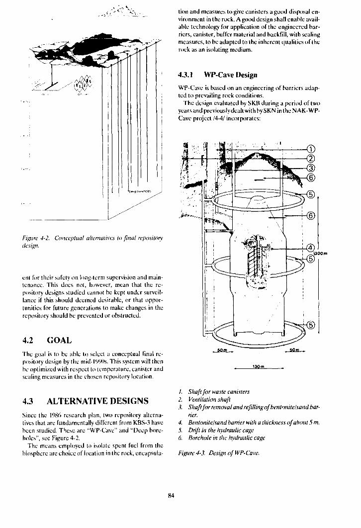
Figure 4-2. Conceptual alternatives to final repositorydesign.
ent for their safety on long-term supervision and main-tenance. This docs not, however, mean that the re-pository designs studied cannot be kept under surveil-lance if this should deemed desirable, or that oppor-tunities for future generations to make changes in therepository should be prevented or obstructed.
4.2 GOAL
The goal is to be able to select a conceptual final re-pository design by the mid-1990s. This system will thenbe optimized with respect to temperature, canister andsealing measures in the chosen repository location.
4.3 ALTERNATIVE DESIGNS
Since the 1986 research plan, two repository alterna-tives that are fundamentally different from KBS-3 havebeen studied. These are "WP-Cave" and "Deep bore-holes", see Figure 4-2.
The means employed to isolate spent fuel from thebiosphere are choice of location in the rock, encapsula-
tion and measures to give canisters a good disposal en-vironment in the rock. A good design shall enable avail-able technology for application of the engineered bar-riers, canister, buffer material and backfill, with sealingmeasures, to be adapted to the inherent qualities of therock as an isolating medium.
4.3.1 WP-Cave Design
WP-Cave is based on an engineering of barriers adap-ted to prevailing rock conditions.
The design evaluated by SKB during a period of twoyears and previously dealt with by SKN in the NAK- WP-Cave project /4-4/ incorporates:
1300 m
, som , 50m ..
130 m
/. Shaft for waste canisters2. Ventilation shaft3. Shaft for removal and refilling ofbentonitelsand bar-
rier.4. Bcntonite/sand barrier with a thickness of about 5 m.5. Drift in the hydraulic cageO. Borehole in the hydraulic cage
Figure 4-3. Design of WP-Cave.
84
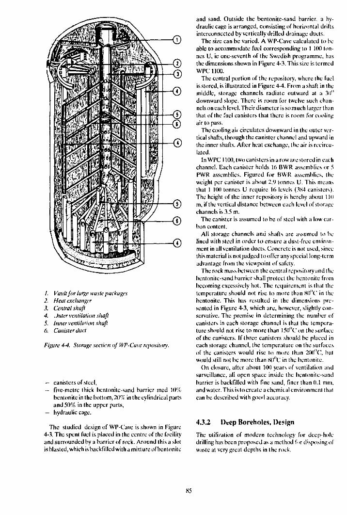
/. Vault for large waste packages2. Heat exchanger.?. Central shaft4. Juter ventilation shaft5. Inner ventilation shaft6. Canister duct
Figure 4-4. Storage section of WP-Cave repository.
— canisters of steel,— five-metre thick bentonite-sand barrier rned 10%
benlonite in the bottom, 2l)% in the cylindrical partsand 50% in the upper parts,
— hydraulic cage.
The studied design of WP-Cave is shown in Figure4-3. The spent fuel is placed in the centre of the facilityand surrounded by a barrier of rock. Around this a slotis blasted, which is backfilled with a mixture of bentonite
and sand. Outside the bentonitc-sand barrier, a hy-draulic cage is arranged, consisting of horizontal driftsinterconnected by vertically drilled drainage ducts.
The size can be varied. A WP-Cave calculated to beable to accommodate fuel corresponding to 1 100 ton-nes U, ie one-seventh of the Swedish programme, hasthe dimensions shown in Figure 4-3. This size is termedWPC 1100.
The central portion of the repository, where the fuelis stored, is illustrated in Figure 4-4. From a shaft in themiddle, storage channels radiate outward at a 30"downward slope. There is room for twelve such chan-nels on each level. Their diameter is so much larger thanthat of the fuel canisters that there is room for coolingair to pass.
The cooling air circulates downward in the outer ver-tical shafts, through the canister channel and upward inthe inner shafts. After heat exchange, the air is recircu-lated.
In WPC 1100, two canisters in a roware stored in eachchannel. Each canister holds 16 BWR assemblies or 5PWR assemblies. Figured for BWR assemblies, theweight per canister is about 2.9 tonnes U. This meansthat 1 UK) tonnes U require 16 levels (384 canisters).The height of the inner repository is hereby about 110m, if the vertical distance between each level of storagechannels is 3.5 m.
The canister is assumed to be of steel with a low car-bon content.
All storage channels and shafts are assumed to belined with steel in order to ensure a dust-free environ-ment in all ventilation ducts. Concrete is not used, sincethis material is not judged to offer any special long-termadvantage from the viewpoint of safety.
The rock mass between the central repository and thebentonite-sand barrier shall protect the bentonite frombecoming excessively hot. The requirement is that thetemperature should not rise to more than 8()"C in thebentonite. This has resulted in the dimensions pre-sented in Figure 4-3, which are, however, slightly con-servative. The premise in determining the number ofcanisters in each storage channel is that the tempera-ture should not rise to more than 15()°C on the surfaceof the canisters. If three canisters should be placed ineach storage channel, the temperature on the surfacesof the canisters would rise to more than 2(X)"C, butwould still not be more than 80°C in the bentonite.
On closure, after about 1(K) years of ventilation aridsurveillance, all open space inside the bentonile-sandbarrier is backfilled with fine sand, finer than 0.1 mm,and water. This is to create a chemical environment thatcan be described with good accuracy.
4.3.2 Deep Boreholes, Design
The utilization of modern technology for deep-holedrilling has been proposed as a method for disposing ofwaste at very great depths in the rock.
85
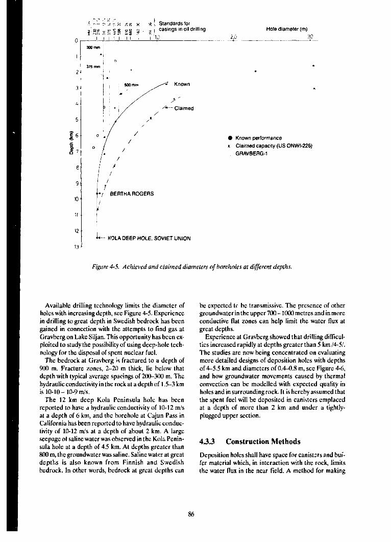
.=:.-... ~ V ss H s ! Standards forsi a* = ••• 5 g ° ° " . -i I casings in oil drilling Hole diameter (m)
2.Ö 3.0
• Known performancex Claimed capacity (US ONWI-226)
GRAVBERG-1
'•*! BERTHA ROGERS
KOLA DEEP HOLE, SOVIET UNION
Figure 4-5. Achieved and claimed diameters of boreholes at different depths.
Available drilling technology limits the diameter ofholes with increasing depth, see Figure 4-5. Experiencein drilling to great depth in Swedish bedrock has beengained in connection with the attempts to find gas atGravberg on Lake Siljan. This opportunity has been ex-ploited to study the possibility of using deep-hole tech-nology for the disposal of spent nuclear fuel.
The bedrock at Gravberg is fractured to a depth of900 m. Fracture zones, 2-20 m thick, lie below thatdepth with typical average spacings of 200-300 m. Thehydraulic conductivity in the rock at a depth of 1.5-3 kmis 10-10 - 10-9 m/s.
The 12 km deep Kola Peninsula hole has beenreported to have a hydraulic conductivity of 10-12 m/sat a depth of 6 km, and the borehole at Cajun Pass inCalifornia has been reported to have hydraulic conduc-tivity of 10-12 m/s at a depth of about 2 km. A largeseepage of saline water was observed in the Kola Penin-sula hole at a depth of 4.5 km. At depths greater than800 m, the groundwater was saline. Saline water at greatdepths is also known from Finnish and Swedishbedrock. In other words, bedrock at great depths can
be expected tr be transmissive. The presence of othergroundwater in the upper 700 -1000 metres and in moreconductive flat zones can help limit the water flux atgreat depths.
Experience at Gravberg showed that drilling difficul-ties increased rapidly at depths greater than 5 km /4-5/.The studies arc now being concentrated on evaluatingmore detailed designs of deposition holes with depthsof 4-5.5 km and diameters of 0.4-0.8 m, see Figure 4-6,and how groundwater movements caused by thermalconvection can be modelled with expected quality inholes and in surrounding rock. It is hereby assumed thatthe spent fuel will be deposited in canisters emplacedat a depth of more than 2 km and under a tightly-plugged upper section.
43.3 Construction Methods
Deposition holes shall have space for canisters and buf-fer material which, in interaction with the rock, limitsthe water flux in the near field. A method for making
86
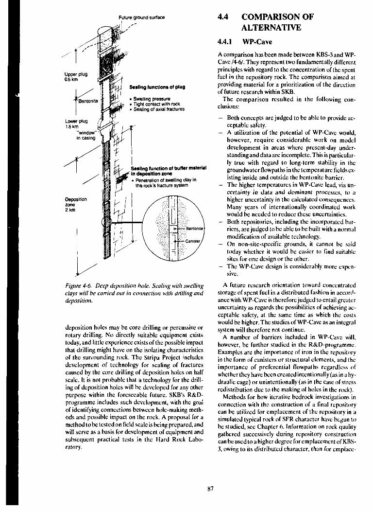
Future ground surface
Lower plug15 km
"window"in casing
Sealing functions of plug
• Swelling pressure• Tight contact with rock• Sealing of axial fractures
Sealing function of buffer materialin deposition zone• Penetration of swelling clay in
the rock's fracture system
Figure 4-6. Deep deposition hole. Sealing with swellingclays will be carried out in connection with drilling anddeposition.
deposition holes may be core drilling or percussive orrotary drilling. No directly suitable equipment existstoday, and little experience exists of the possible impactthat drilling might have on the isolating characteristicsof the sunounding rock. The Stripa Project includesdevelopment of technology for sealing of fracturescaused by the core drilling of deposition holes on halfscale. It is not probable that a technology for the drill-ing of deposition holes will be developed for any otherpurpose within the foreseeable future. SKB's R&D-programme includes such development, with the goalof identifying connections between hole-making meth-ods and possible impact on the rock. A proposal for amethod to be tested on field scale is being prepared, andwill serve as a basis for development of equipment andsubsequent practical tests in the Hard Rock Labo-ratory.
4.4 COMPARISON OFALTERNATIVE
4.4.1 WP-Cave
A comparison has been made between KBS-3 and WP-Cave /4-6/. They represent two fundamentally differentprinciples with regard to the concentration of the spentfuel in the repository rock. The comparison aimed atproviding material for a prioritization of the directionof future research within SKB.
The comparison resulted in the following con-clusions:
- Both concepts are judged to be able to provide ac-ceptable safety.
- A utilization of the potential of WP-Cave would,however, require considerable work on modeldevelopment in areas where present-day under-standing and data arc incomplete. This is particular-ly true with regard to long-term stability in thegroundwatcr flowpaths in the temperature fields ex-isting inside and outside the bentonite barrier.
- The higher temperatures in WP-Cave lead, via un-certainty in data and dominant processes, to uhigher uncertainty in the calculated consequences.Many years of internationally coordinated workwould be needed to reduce these uncertainties.
- Both repositories, including the incorporated bar-riers, arc judged to be able to be built with a normalmodification of available technology.
- On non-sitc-specific grounds, it cannot be saidtoday whether it would be easier to find suitablesites for one design or the other.
- The WP-Cave design is considerably more expen-sive.
A future research orientation toward concentratedstorage of spent fuel in a distributed fashion in accord-ance with WP-Cavc is therefore judged to entail greateruncertainty as regards the possibilities of achieving ac-ceptable safety, at the same time as which the costswould be higher. The studies of WP-Cave as an integralsystem will therefore not continue.
A number of barriers included in WP-Cavc will,however, be further studied in the R&D-programme.Examples arc the importance of iron in the repositoryin the form of canisters or structural elements, and theimportance of preferential flowpaths regardless ofwhether they have been created intentionally (as in a hy-draulic cage) or unintentionally (as in the case of stressredistribution due to the making of holes in the rock).
Methods for how iterative bedrock investigations inconnection with the construction of a final repositorycan be utilized for emplacement of the repository in asimulated typical rock of SFR character have begun tobe studied, see Chapter 6. Information on rock qualitygathered successively during repository constructioncan be used to a higher degree for emplacement of KBS-3, owing to its distributed character, than for cmplace-
87
ment of WP-Cave, which requires a fixed geometry forits different parts.
4.4.2 Deep Holes
The feasibility of disposing of waste in boreholes atgreat depth has been studied on the basis of the infor-mation obtained in connection with deep-hole drilling.The preliminary results indicate favourable economics.However, there is today a lack of material permitting aclear comparative evaluation of the deep-hole conceptas an alternative. The studies will continue.
4.4.3 Miscellaneous
As far as other alternative repository designs are con-cerned, parameters such as canister material, buffermaterial and chemical conditioning of the near Held arebeing studied within the relevant programme area andwith the timetables given there.
Alternative technology for repositories and barrierswill mainly be studied from the end of the 90s and upuntil the time the design work is to commence.
Adaptation of site and engineered barrier system toeach other, as well as a systematic optimization of therepository, will not be commenced until the end of the1990s.
4.5 RESEARCH PROGRAMME1990-1995
The studies of deep-hole deposition and its safetyaspects will be completed during 1990 with a compara-tive analysis with the reference concept KBS-3.
A conceptual study of an alternative design, wherebylong deposition tunnels arc excavated out under theBaltic Sea, will be carried out, possibly based on the in-formation obtained at the Hard Rock Laboratory.However, a sufficient body of material on which to basea judgement is not expected to be available until about1992/93. Certain supportive research concerning prc-investigations of water-covered areas will be carriedout. See Chapter 2.
By 1995, alternatives of the type
— one or more canisters in each deposition hole,— deposition in long drilled holes between transport
tunnels,— deposition in tunnel centre or drilled holes,
must have been examined to such a level that charac-teristics of importance for the detailed geostudies havebeen defined.
88
ENGINEERED BARRIERS
5.1 WASTE FORMS
5.1.1 Goals oftheR&D Activities
The stability of spent fuel in groundwater is beingstudied in order to obtain by 1995 the knowledge of themechanisms and kinetics that is required for being ableto model the dissolution of UO2. This model shall beable to be used as a source term for safety assessment.Better knowledge of how fuel dissolves in groundwaterwill permit optimization of the canister in terms ofdesign and material. It will also permit optimization ofthe near field to the canister and is of great importancefor determining the requirements on rock quality.
5.1.2 Present-day State of Knowledge
Direct disposal of spent fuel was proposed at the end ofthe 1970s /5-1, 11. Since then, the various aspects ofdirect disposal have been examined in varying detail ina number of countries. Sweden, Canada, the USA andthe Federal Rcpublicof Germany have studied this fieldfor almost ten years. The state of knowledge in the worldfor spent fuel as a waste form was recently summari/edby Johnson and Shoesmith /5-."V.
The present-day Swedish programme for studies offuel started in 19S2. It was then based on a preliminaryinvestigation conducted in 1977 as a part of the KBS-2work. The situation for SKB's research within the fieldis summarized in a technical report /5-4/. Only a briefdescription is provided in this chapter.
In all, only some thirty scientific reports have beenpublished dealing with the stability of spent fuel inwater. Many variables influence stability in water, suchas the fuel's irradiation history, groundwater chemistry,redox potential (Eh) and temperature, ll is thereforenot surprising that the mechanisms for fuel dissolutionare not yet completely understood. Despite limiteddata, however, some aspects of the dissolution medianisms are relatively well understood and it is now pos-sible to provide a description of the influence of themost important variableson the kinetics of fuel dissolu-tion.
INFLUENCE OF IRRADIATION HISTORY
(Jap Inventory
The fuel's irradiation history is of great importance forthe release of volatile fission products, for the fuel's
microstructure and for the precipitation of fissionproducts at the grain boundaries. Cesium and iodine,together with the fission gases xenon and krypton, arereleased from the fuel matrix to the empty space insidethe fuel rod. The quantities liberated depend, amongother things, on the temperature of the fuel duringoperation.
drain Boundaries
Certain fission products, such as cesium, seem to con-tinue to be selectively leached even after long exposureto groundwater. This is not surprising, since the firststep in release from the matrix is enrichment at the grainboundaries. This selective leaching is probably limitedto atoms that do not fit into the IJO2 matrix. There areno signs that compatible elements such as lanthanidesand actinides should be leached selectively.
Very little is known about how large a fraction of thefission products is present at the grain boundaries.Studies still in progress indicate that several tens of per-cent of the inventory of 4d metals (Mo, Tc, Ru, Rh, Pd)may be present as separate phases al the grain boun-daries.
GROUNDWATER COMPOSITION
It is well known that carbonate forms strong uranyl com-plexes. This is reflected in a much higher uraniumsolubility in carbonate-containing water compared withdistilled water, see Figure 5-1. The release of fissionproducts does not seem to be affected in the same wayby these changes in water chemistry, see Figure 5-3.
The measured concentrations of uranium agree wellwith calculations based on available thermodynamiedata. Ciood agreement has also been obtained forplutonium. However, further research will be requiredto bring knowledge of other actinides up to the samelevel as for uranium.
Thermodynamic data show that high chloride con-centrations in the water do not i^nificanlly influencethe dissolution of U();>. This is also verified by studiesconducted in Canada. At 25°C, the dissolution ofcaesium, strontium and technetium were largely thesame in 1 M chloride as in chloride-poor carbonate-containing water. At temperatures above 15()"C, how-ever, substantial increases in the rate ol dissolution havebeen reported. The cause of this increase in saline solu-tions at high temperature is unknown. In distilled waterand in carbonate-containing water, the increase is onlymoderate.
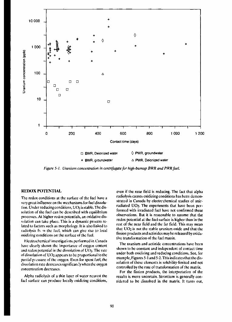
10 000 _
1 000 _aa.a.
IcooE
100 _
10 -
800 1 000 1 200
Contact time (days)
D BWR, Deionized water 0 PWR, groundwater
+ BWR, groundwater A PWR, Deionized water
Figure 5-1. Uranium concentration in centrifugate for high-burnup BWR and PWR fuel.
REDOX POTENTIAL
The redox conditions at the surface of the fuel have avery great influence on the mechanisms for fuel dissolu-tion. Under reducing conditions, UO2 is stable. The dis-solution of the fuel can be described with equilibriumprocesses. At higher redox potentials, an oxidative dis-solution can take place. This is a dynamic process re-lated to factors such as morphology. It is also linked toradiolysis fr< m the fuel, which can give rise to localoxidizing conditions on the surface of the fuel.
Electrochemical investigations performed in Canadahave clearly shown the importance of oxygen contentand redox potential in the dissolution of UO2. The rateof dissolution of UO2 appears to be proportional to thepartial pressure of the oxygen. Even for spent fuel, thedissolution rate decreases significantly when the oxygenconcentration decreases.
Alpha radiolysis of a thin layer of water nearest thefuel surface can produce locally oxidizing conditions,
even if the near field is reducing. The fact that alpharadiolysis causes oxidizing conditions has been demon-strated in Canada by electrcchemical studies of unir-radiatcd UO2. The experiments that have been per-formed with irradiated fuel have not confirmed theseobservations. But it is reasonable to assume that theredox potential at the fuel surface is higher than in therest of the near field and the far field. This may meanthat UO2 is not the stable uranium oxide and that thefission products and actinides may be released by oxida-tive transformation of the fuel matrix.
The uranium and actinide concentrations have beenshown to be constant and independent of contact timeunder both oxidizing and reducing conditions. See, forexample, Figures 5-1 and 5-2. This indicates that the dis-solution of these elements is solubility-limited and notcontrolled by the rate of transformation of the matrix.
For the fission products, the interpretation of theresults is more uncertain. Strontium is generally con-sidered to be dissolved in the matrix. It turns out,
90
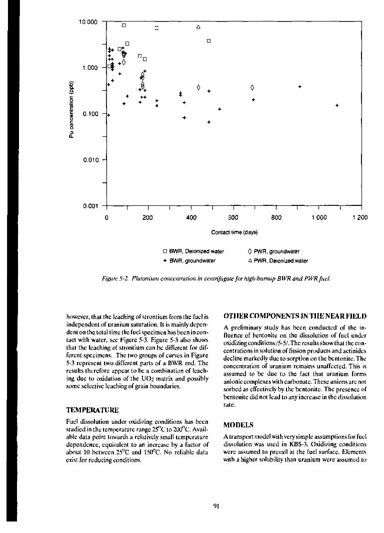
10.000
1.000 -
no.acoii
8Q.
0.100 -
0.010 -
0.001
500
Contact time (days)
1 2 0 0
a BWR, Oeionized water
+ BWR, groundwater
0 PWR, groundwater
A PWR, Deionized water
Figure 5-2. Plutonium concentration in centrifugate for high-bumup BWR and PWR fuel.
however, that the leaching of strontium from the fuel isindependent of uranium saturation. It is mainly depen-dent on the total time the fuel specimen has been in con-tact with water, see Figure 5-3. Figure 5-3 also showsthat the leaching of strontium can be different for dif-ferent specimens. The two groups of curves in Figure5-3 represent two different parts of a BWR rod. Theresults therefore appear to be a combination of leach-ing due to oxidation of the UO2 matrix and possiblysome selective leaching of grain boundaries.
TEMPERATURE
Fuel dissolution under oxidizing conditions has beenstudied in the temperature range 25°C to 200°C. Avail-able data point towards a relatively small temperaturedependence, equivalent to an increase by a factor ofabout 10 between 25°C and 150°C. No reliable dataexist for reducing conditions.
OTHER COMPONENTS IN THE NEAR FIELD
A preliminary study has been conducted of the in-fluence of bentonite on the dissolution of fuel underoxidizing conditions/5-5/. The results show that the con-centrations in solution of fission products and actinidesdecline markedly due to sorption on the bentonite. Theconcentration of uranium remains unaffected. This isassumed to be due to the fact that uranium formsanionic complexes with carbonate. These anions are notsorbed as effectively by the bentonite. The presence ofbentonite did not lead to any increase in the dissolutionrate.
MODELS
A transport model with very simple assumptions for fueldissolution was used in KBS-3. Oxidizing conditionswere assumed to prevail at the fuel surface. Elementswith a higher solubility than uranium were assumed to
91
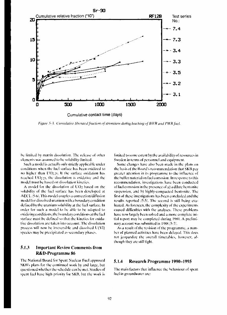
Sr-90Cumulative relative fraction (*104) RF12B Test series
No.:
3.1
2QQ0500 1000 1500
Cumulative contact time (days)
h'igurv >.?. ('uimilathe liberated fraction of strontium during leaching of BWR and PWRfuel.
he limited by matrix dissolution. The release of otherelements was assumed lo he solubility-limited.
Such a model is actually only strictly applicable underconditions when the fuel surface has been oxidi/ed tono higher than U();.:.s. If the surface oxidation hasreached IJO2.11, the dissolution is oxidative and themodel must he based on dissolution kinetics.
A model for the dissolution of UO2 based on thesolubility of the fuel surface has been developed atAEC'I./5-t)/. This model couples a convection/diffusionmodel for dissolved uranium with a boundary conditiondefined by the uranium solubility at the fuel surface. Inorder for such a model lo be able to be adapted tooxidizing conditions, the boundary conditions at the fuelsurface must he defined so that the kinetics for oxida-live dissolution are taken into account. The dissolutionprocess will now be irreversible and dissolved U(VI)species may be precipitated as secondary phases.
5.1.3 Important Review Comments fromR&D-Programme 86
The National Board for Spent Nuclear Fuel approvedSKB's plans for the continued work by and large, butquestioned whether the schedule can he met. Studies ofspent fuel have high priority for SKB, but the work is
limited to some extent by the availability of resources inSweden in terms of personnel and equipment.
Some changes have also been made in the plans onthe basis of the Board's recommendation that SKB paygreater attention in its programme to the influence ofthe buffer material on fuel corrosion. In response to thisrecommendation, investigations have been conductedof fuel corrosion in the presence of a) a dilute bentonitesuspension, and h) highly-compacted bentonile. Thefirst of these investigations has been concluded and theresults reported /5-.V. The second is still being eva-luated. As foreseen, the complexity of the experimentscaused difficulties with the analyses. These problemshave now largely been solved and a more complete ini-tial report may be completed during 19X9. A prelimi-nary account was submitted in 198815-11.
As a result of the revision of the programme, a num-ber of planned activities have been delayed. This doesnot jeopardize the overall timetables, however, al-though they are still tight.
5.1.4 Research Programme 1990-1995
The main factors that influence the behaviour of spentfuel in groundwater are:
92
1) the irradiation history of the fuel, which affects themicrostructiire of the fuel and is of great importan-ce for the precipitation of radionuclides at cracksand grain boundaries,
2) the redox potential and the influence of alpha ra-diolysis on the redox conditions nearest the fuelsurface,
3) the water chemistry, especially in the presence ofother components in the near field,
4) the thermodynamics of the actinides.
Large gaps still exist in knowledge within these areas.The largest lie within the following areas:
— the distribution of fission products and actinides be-tween grain boundaries and the fuel matrix. A grainboundary inventory can be released faster and withother mechanisms than matrix-bound radionu-clides,
— redox conditions at the fuel surface (influence ofradiolysis). This is of importance in determiningwhether a model for solubility-limited dissolution ora model for kinetically controlled dissolution is tobe applied,
— thermodynamic data for certain elements, such asTc, Pu and Np. This applies to both species in solu-tion and any solubility-limited solid phases.
Over the last three-year period, the emphasis in thework has been on studies of corrosion of spent fuel ingroundwater in order to create a database that is statis-tically reliable. Investigations of this type have now beengreatly reduced. At present, only a lew test series withBWR fuel and about a dozen series wilh PWR fuel arebeing conducted. During the coming period, the em-phasis will be on other kinds of experiments where morespecific questions will be studied. These investigationswill be conducted on BWR and PWR fuel, as before.During the latter part of the period, the investigationsmay be broadened to cover gadolinium-doped fuel aswell.
MICROS I RUCTUKi; OF THE FUEL
The release of fission products and actinides from thefuel takes place from three different sources. Duringoperation, Cs and I have been released from the fuelmatrix and are readily accessible for leaching in the gapbetween the cladding and the fuel and in cracks in thefuel. Olhcr fission products, such as Pd, Tc, Ru, Rh andMo, may have formed separate phases in the fuel. In thisway, segregated material can be released faster and viaolher mechanisms than those radionuclides that aretrapped in the U(>2 matrix. It is therefore important thatthe spent fuel be characterized wilh respect (o the dis-tribution of the fission products and aclinides. This in-
formation is of great importance for the work withdevelopment of predictive models.
Experience from the preceding period has shown thatthis work is complex and time-consuming. Experiencefrom the JSS project has shown that analysis of the solidphase is necessary in order to obtain the knowledge ofthe kinetics and mechanisms of corrosion that is re-quired to model the process. This area has high priorityand research efforts will be stepped up compared withthe preceding period. However, resources withinSweden are limited. Close cooperation with foreign re-searchers and institutions will therefore probably benecessary. As before, the main techniques used will beoptical microscopy, SEM, STEM/TEM, microprobeanalysis and Auger spectroscopy. The investigationswill be conducted on existing PWR and BWR fuel, butwill be augmented with investigations of a segment rodsubjected to a controlled power increase in the R2 reac-tor. The power increase produces a different tempera-ture distribution than in a commercial reactor andresults in a redistribution of mobile fission products inthe fuel.
RADIOLYSIS
The available experimental data show that radicalsformed during radiolysis of water cause oxidation ofUO2. While the irradiation fields used in the experi-ments have been much higher than can be expected nearthe fuel surface in a repository environment, it is never-theless reasonable to assume that conditions at the fuelsurface arc oxidizing, even though the si/e of theradiolytic effect is not known. This means that therelease of radionuclides from the fuel will take placethrough oxidative dissolution.
During the preceding period, investigations havebeen conducted of radiolytic oxidation in a gamma field.The part of these experiments being conducted inSweden will be concluded within the next year. A pos-sible continuation of these experiments will take placewithin the framework of an ongoing joint project withAECL of Canada. During the next three years, the em-phasis will be on experimental investigations of the ef-fects of alpha radiolysis, especially in oxygen-free sys-tems.
The experiments that have been conducted underoxidizing conditions, by allowing the leachant to be incontact wilh a volume of air, undoubtedly give an upperlimit for the oxidation rate. But the actual rale in anoxygen-free system is not known. During the period,oxidation through alpha radiolysis will be investigatedboth in model systems and in systems that include spentfuel.
CORROSION OF HIGH-LEVEL FUEL
The corrosion studies of PWR and BWR fuel will con-tinue during the next few years. In comparison wilh thepreceding period, however, fewer but more specific cx-
periments will be carried out. The analysis work will alsobe more extensive for each experiment. As before, par-ticular attention will be given to the following pheno-mena:
— solubility and saturation effects,— type of corrosion on the fuel,— colloid formation,— oxidizing/reducing conditions.
Some of these phenomena have already been dis-cussed in more detail in other sections and will there-fore not be taken up under this heading.
Solubility and saturation effects,the thermodynamics of the actinides
General data on actinide and fission product solubilitiesin groundwater will be determined within the frame-work of SKB's chemistry programme, see Chapter 7.During the past period, the uranium database forhydroxides and carbonates has been updated andvalidated /5-8/. At present, corresponding work is underway for phosphates and silicates. This work is expectedto be concluded within the next three years. In additionto the work with uranium data, an updating of thedatabases for technetium and plutonium has also beenbegun. In both cases, the updating entails both a criti-cal review of literature data and experimental deter-mination of data.
A comparison between experimental equilibriumconcentrations for uranium and calculated solubilitiesfor possible solubility-limiting uranium(VI) phases in-dicate a discrepancy of a factor of between 10 and 50for oxidizing conditions. The discrepancy is not r.urpris-ing in view of the fact that no solubility-limiting secon-dary phase has yet been identified with certainly ex-perimentally. The kinetics for the dissolution of U(>2and the precipitation of the secondary phase are also in-adequately understood. Work on these problems hasbegun and will continue during the next few years. Thiswork also entails determining the oxidation state andspecies for radionuclides in solution to as great an ex-tent as possible.
Water Chemistry
.Since KBS-3, the site investigations have shown thatrelatively high chloride contents can occur, particular-ly in coastal areas. Chloride concentrations of morethan 10 000 ppm have been measured. These levels arcnot so high that they can be expected to have a crucialeffect on the solution chemistry of actinides and fissionproducts. But some experiments arc intended to be car-ried out to confirm this.
The composition of water that comes into contactwith bentonite is also strongly affected. Some increase
in the bicarbonate concentration has been measured forMx 80. For calcium bentonites that have been condi-tioned with soda, the increase in bicarbonate contentcan be considerable. It is not quite clear whether this in-fluence on water composition is permanent or merelytransient, since this excess carbonate can be expectedto be leached out of the bentonite. The influence of car-bonates on the dissolution of UO2 is well known, but inthis case as well a number of specific investigations willbe done.
In addition to the carbonate content, the sulphatecontent also increases to several thousand ppm in con-tact with bentonitc. Sulphate contents in this concentra-tion range are not expected to affect the solutionchemistry of the more important actinides and fissionproducts. Moreover, this increase may also be transient.However, several experiments involving leaching in syn-thetic bentonite interstitial water are intended to Heconducted to confirm this. Experiments in syntheticbentonite interstitial water will also be one step in thestudies of the more complex, realistic repository condi-tions.
Colloids
During the preceding period, the colloid and particlefractions have been characterized solely by means offiltration through membrane filters. This provides anapproximation of the quantity of particulate/colloidalmaterial, but is much too insensitive a method toprovide a good idea of the size distribution. Tests withmore sophisticated methods have been conducted, butthe results have not been encouraging. Development ofmethods and technology is continuing and progress inthis area will be monitored, and further work may bedone during the coming period.
MODEL DEVELOPMENT
The purpose of model development is to devise apredictive model for corrosion of spent fuel over longperiods of time. Such a prediction is only meaningful ifthe dissolution mechanisms in the short and the longtime perspective are known and quantified. The work isproceeding along the same lines as were defined in theprevious research programme. The main goal for thecoming period is to develop a more realistic model forfuel dissolution than the KBS-3 model to use in the safe-ty assessment for SKB 91.
The work is based on the assumption that the fuel dis-solution can be oxidative and controlled by radiolysis.This means that a kinetic model must be used, at leastduring an early phase of fuel dissolution. In a longerperspective, when the alpha activity has decayed, fueldissolution can be described with the aid of a solubility-limiting model. These two models will therefore bedeveloped in parallel during the period.
94
5.2 CANISTER
5.2.1 Goal of the R&D Activities
The goal of the studies of canister materials is to havesufficient knowledge of both copper and alternativematerials by 1995 in order to make a final choice ofcanister material. This applies to both corrosion resis-tance and other material properties of importance forcanister design and for the mechanical stability of thecanister.
5.2.2 Present-day State of Knowledge
In <»' v.)grammcs for final disposal of high-level waste,is 'ssumed that the waste will be encapsulated in an
crvious container prior to deposition. In most•ountrics, the aim is an absolutely impervious contain-ment with a canister life of about 1000 years. In addi-tion, Sweden and several other countries have as an al-ternative, or as the main alternative, long-term contain-ment (about 100 000 years) in canisters.
The foreign research programmes with repositorygeologies that are most relevant for Swedish conditionsare Canada, Switzerland, Finland and the EC.
Canada has chosen titanium as a reference materialand copper as an alternative material. For bothmaterials, the research centres around a relatively thin-walled canister with a life on the order of 1000 years.The purpose of the research is to obtain an under-standing of the possible corrosion processes by usingelectrochemical techniques for studying the mecha-nisms and long-term experiments for confirmation.Owing to the combination of short canister life and thethin-walled material, the research is largely centredaround corrosion under oxidizing conditions. In addi-tion, the Canadian groundwatcr in the projected re-pository areas has a very high chloride content, about1 mol/1. Titanium and titanium alloys arc highly cor-rosion-resistant, especially in chloride-containingwaters. General corrosion is very small, but the mate-rials have proven to be somewhat sensitive to crevicecorrosion. The research is being focusscd on studies ofthe conditions for crevices and the propagation rate ofcrevices. In the case of copper, the research is heavilyconcentrated on investigations of the corrosion kineticsof general corrosion under oxidizing conditions, butknowledge gaps have also been identified with regardto pitting in connection with sulphide corrosion.
In the Swiss programme, the main alternative is athick-walled steel canister, with a copper canister as thesecondary alternative. The steel canister is supposed tohave a life of at least 1000 years. Research during thepast few years has primarily been focussed on hydrogen-producing corrosion and stress corrosion cracking.
The Finnish programme is very similar to the Swedishand the main alternative is a copper canister of rough-ly the same type as the Swedish canister.
As was pointed out in R&D-Programme 86, the re-search work on copper is being conducted in more long-term projects. Most of the work has not yet been con-cluded, but is expected to be concluded during the com-ing period.
The research on copper corrosion is concentrated oninvestigations of pitting under reducing conditions.Phase 1 is concluded and a new phase will begin duringthe latter part of 1989. As yet, nothing has been foundto change the conclusions of KBS-3, ie that the mostprobable value of the pitting factor is 5. The evaluationof the first canon to be salvaged from the warship"Kronan" has been concluded and published 15-91. Thebronze, which has a very high copper content (96.3% ascompared to a normal value of about 90%), showed verylittle corrosion, equivalent to less than 10 mm in 100 000years.
The method development of HIP technology for cop-per was concluded during the period. The results showthat with inert handling of the copper powder, it is pos-sible to produce a sintered material with a ductility andmechanical properties that are comparable to theproperties of ordinary copper metal. Stress corrosiontests showed that the HIPed material did not havehigher sensitivity to stress corrosion cracking thanOFHC copper /5-10/. The development of weldingtechnology is still progressing within the framework ofa EUREKA project. The definition phase was con-cluded during the preceding period. Phase two wasstarted in 1989.
An initial phase of the studies of the creep propertiesof copper has been concluded /5-11/. The study hasrevealed considerable differences in creep propertiesbetween the weld, the heat-affected zone and the parentmetal. In addition, as yet preliminary results indicatethat the creep ductility of copper is relatively low. Fur-ther research is therefore required before the creepproperties of copper under repository conditions arefully understood.
For steel as the canister material, the work has beenconcentrated on studies of pitting during the aerobicperiod in the repository. A statistical study of the pittingprocess has also been carried out /5-12/. With the ex-ception of a few long-term tests, the studies of pittingarc concluded. The results have also been applied in apreliminary evaluation of the life of a steel canister in aKBS-3 repository. With a wall thickness of 100 mm, alife of about 1000 years can be achieved.
The research activities for titanium are concluded.Long-term exposures of up to 6 years with titanium incontact with bentcnite have been evaluated. These testsshow an incipient crystallization of the oxide layer, andin some cases an increase in the growth rate (corrosionrate) has been observed /5-13/.
Two alternative designs of a copper canister with athickness of at least 10 cm were presented in KBS-3.These were fundamentally different with regard toclosure technique and compactness. The welded andlead-filled canister had a lead fill wilh a residual
95
porosity equivalent to no more than 2% of the internalvolume. During use, the copper canister will undergocreep deformation under the external pressure Recentresearch has been devoted to the properties of the cop-per in connection with such creep deformation (seeabove). A description of the creep in a welded coppercanister that takes into account realistic low stresses andpossible fracture mechanisms has not yet been forth-coming, however. Nor is there any basis for an assess-ment of the behaviour of the pressed canister in connec-tion with scenarios with movements in the bedrock thatdirectly affect the canister.
Model development for rock/buffer/canister mecha-nical interaction is in progress, sec section 5.3.3.8. Withthis model, deformation ol the copper can be calculatedif a design basis or a scenario - for example movementin rock with deposition holes due to temperature ef-fects, glaciation or the like - has been denned. Whenthe fracture mechanism has been clarified, this providesa basis for canister design or consequence descriptionwhich in turn provides a basis for the safety assessment.Naturally, it is not meaningful to test other fill materialsin the canister that give greater porosity without thisdesign basis.
A steel canister can be designed with a chosen safelyfactor to fracture. A description of the probable frac-ture mechanism in connection with overload and/orcorrosion is not yet available. A copper canister that issupported internally by a steel canister is an interestingalternative for continued studies.
In the design of welded canisters, special attentionshall be given to the possibilities for quality assurancewith regard to canister integrity and possible materialchanges in the /one surrounding the weld. The R&D-programme shall include such analyses of the relation-ships between quality and design.
5.2.3 Important Review Comments fromR&D-Programme 86
The National Board for Spent Nuclear Fuel said thatcanisters consisting solely of corroding material did nothave to be included in I he SKB programme. SKB doesnot believe steel should be dismissed as a canistermaterial merely because of its shorter expected life.Only if research results and available data do not clear-ly indicate that the desired canister life can be achieved,or if a shorter canister life will have unacceptable con-sequences, can the canister material be dismissed. Itshould be emphasized that copper is still the main alter-native and has top priority. In the continued program-me, steel is to be regarded primarily as an alternative tolead as a load-bearing component in a canister (seebelow). In SKB 91, however, a steel canister will also bestudied in order to examine as fully as possible the con-sequences of early canister penetration.
The sensational observation that copper might cor-rode with hydrogen gas evolution /5-14/ has been check-
ed by two independent studies /5-15,16/. In neither casehas hydrogen been detected, despite the fact that theequipment used was capable of detecting a hydrogenproduction rate only one-thousandth of the ratereported by Hultquist. No scientifically satisfactory ex-planation for Hultquist's observations has been forth-coming.
Naturally, it must be assumed that the encapsulationprocess will not take place with absolute infallibility. Atpresent, SKB has not decided whether defectivecanisters are to be repaired or quite simply enclosed inanother canister. SKB intends to take up this questionin greater detail in connection with the design of the en-capsulation plant.
SKB shares the viewpoint of the Board and thereviewing bodies that so-called "delayed fracturing" ofceramics is not merely to be regarded as a materialproperty, but is highly dependent on the manufacturingtechnology. Moreover, it is a statistically related phe-nomenon, and observations of specimens from small-scale manufacture can to some extent be irrelevant forthe assessment of the probability of delayed fracturingin a full-sized canister. Against this background, TACin Canada has drawn the conclusion that studies of thestability of ceramics in water are only relevant il they arerelated to a full-scale production of canisters of suchmaterials /5-17/. On the same grounds, SKB does notconsider ceramic canisters to be of interest for Swedishconditions.
5.2.4 Research Programme 1990-1995
The most urgent research areas for the period are as fol-lows:
— corrosion assessment for potential canister mate-rials,
— testing/development of technique for non-destruc-tive testing,
— definition of fracture mechanisms and distributionin time of canister failures.
CORROSION STUDIES
For copper, current investigations arc concentrated (insupplementary studies of pitting of copper under reduc-ing conditions. These investigations are being combinedwith further evaluation of archaeological material.
As was discussed above, the studies of pitting on steelare nearly concluded, and only a few long-term ex-posures will be evaluated during the period. Beyondthese, studies are being conducted of the influence ofhydrogen-producing corrosion under reducing condi-tions. These studies arc divided into three parts: (1)Electrochemical measurement of the influence ofhydrogen gas production on reaction kinetics. (2) Inves-tigation of the properties of the corrosion product layer.(3) Long-term testing (up to two years) of the corrosionrate under hydrogen gas pressure. These studies are
96
relevant both for a pure steel canister and for a coppercanister internally supported by steel (see below).
Investigations of the growth of the passive film ontitanium were concluded during the period. The resultsindicate certain changes that can be of importance forthe long-term stability of the passive film. These resultsmust be further evaluated before it is possible to makea decision regarding continued studies. As before, anySwedish measures will be planned so that they comple-ment the more extensive Canadian investigations.
MTERIAL PROPERTIES
The creep properties of copper and welded joints incopper at low stresses arc not yet completely under-stood. Further work in this field will be done during thecoming three-year period.
SEALING TECHNIQUE
Electron beam welding is still considered to be themethod with the greatest development potential forcanister scaling. The research in this area is being donewithin the framework of a EUREKA project in col-laboration with the Welding Institute and other foreigninterests. During the period, work will also be done onnon-destructive testing of clectron-bcam-wcldedmaterial.
CANISTER DESIGN
A canister design without the requirements on heatingentailed by lead fill and HIPing according to KBS-3 re-quires an analysis of the relationships between dimen-sions, external pressure and fracture loads as well as theopportunities for quality control offered by a self-sup-porting canister.
A steel canister designed to relevant portions ofSwedish regulations and codes for pressure vessels willhave, depending on the design of the ends, a wall thick-ness of 7-8 cm with an external pressure of 15 MPa. Itcan be provided with a corrosion protection of copper.
Alternative designs of copper and/or steel canistersarc being considered with respect to manufacture,handling and quality control. In connection herewith,any necessary tests for quality control of seals, welds andthe like arc being identified, along with hydrostatic test-ing or other types of load testing.
Tests are being conducted with the intention of verify-ing theory for designing against failure and rigorousnessof quality control.
5.3 BUFFER AND BACKFILL
5.3.1 Background
Buffer material in deposition chambers and backfillmaterial in rock caverns, tunnels and shafts are ex-amples of engineered barriers included in the final re-
pository system. The primary function of the barriers isto limit groundwater flow. Buffer material shall alsoconstitute a chemical and mechanical /.one of protec-tion around canisters in the rock. Sealing measures canbe adopted in the form of plugs in rock chambers andsealing of the fracture system in the rock by means ofinjection grouting.
53.2 Goal of the R&D Activities
The goal is to be able to select buffer and backfillmaterials by the mid-1990s and specify properties of im-portance for final repository performance. Alternativedeposition methods and final repository designs shall becompared taking into account the geological charac-teristics of the site.
In R&D-Programme 86, it was stated that materialand properties were to be described so that a choice ofdeposition method can be based on
— a clarification of the relationship between differentclays, mixed materials, the repository environmentand the properties of the materials of importancefor the engineered barriers,
— a theoretical model developed for calculations,— developed and tested methods for scaling rock.
Furthermore, a plan was described for a broadeningof knowledge and model development with the goal ofbeing able to choose materials around the year 1995.
The subsequent review and commenting procedureresulted in recommendations for research concerning:
— connection between high temperatures and long-term stability of the bentonite,
— chemical conditioning, admixture of crushed rockeu:,
— rheology, water uptake, erosion resistance,— effects of gas,— sealing measures in boreholes and shafts,— model development for barrier performance,— QA programme.
Research has been conducted more or less intensive-ly within all of these areas. An account is providedbelow, divided into the above areas.
5.3.3 Present-day State of Knowledge
5.3.3.1 Long-term Stability of the Bentonite
As early as December 1983, the second workshop onthe stability of smectite-rich clays under the influenceof such factors as temperature was organized /5-18/.The general opinion of the participants was that smcc-tite/illite alteration took place in stages involving Sirelease, increased charge through substitution of Al,Mg and inward transport of K with irreversible fixation
97
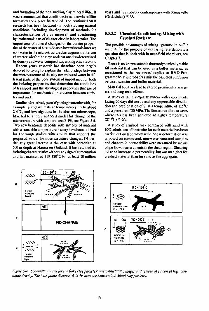
and formation of the non-swelling clay mineral illite. Itwas recommended that conditions in nature where iliiteformation took place be studied. The continued SKBresearch has been focussed on both studying naturalconditions, including development of methods forcharacterization of clay mineral, and conductinghydrothermal tests of cleaner clays in laboratories. Theimportance of mineral changes for the barrier proper-ties of the material has to do with how minerals interactwith water in the microstructured arrangements that arecharacteristic for the clays and that are also determinedby density and water composition, among other factors.
Recent years' research has therefore been largelydevoted to trying to explain the relationships betweenthe microstructure of the clay minerals and water in dif-ferent parts of the pore system of importance for boththe isolating properties that determine the conditionsof transport and the rheological properties that arc ofimportance for mechanical interaction between canis-ter and rock.
Studies of relatively pure Wyoming bentonite with, forexample, autoclave tests at temperatures up to about200°C, and investigations in the electron microscope,have led to a more nuanced model for change of themicrostructure with temperature /5-19/, see Figure 5-4.Two new bentonite deposits with samples of materialwith a traceable temperature history have been utilizedfor thorough studies with results that support theproposed model for microstructure changes. Of par-ticularly great interest is the case with bentonite at500 m depth at Hamra on Gotland. It has retained itsisolating characteristics without any sign of cementationand has maintained 110-120°C for at least 10 million
years and is probably contemporary with Kinnekulle(Ordovician) /5-38A
53.3.2 Chemical Conditioning, Mixing withCrushed Rock etc
The possible advantages of mixing "getters" in buffermaterial for the purpose of increasing retardation is aquestion that is dealt with in near-field chemistry, seeChapter 7.
There is no known suitable thermodynamically stablefill material that can be used as a buffer material, asmentioned in the reviewers' replies to R&D-Pro-grammc 86. It is probably a mistake based on confusionbetween canister and buffer material.
Material additives lead to altered premises for assess-ment of long-term effects.
A study of the clay/quartz system with experimentslasting 70 days did not reveal any appreciable dissolu-tion and precipitation of Si at a temperature of 115°Cand a pressure of 20 MPa. The literature refers to caseswhere this has been achieved at higher temperature(270°C) /5-20/.
A study of crushed rock compared with sand with10% admixture of bentonite for each material has beencarried out on laboratory scale. Shear deformation wasimposed on compacted, non-water-saturated samplesand changes in permeability were measured by meansof gas flow measurements in the shear region. Shearingled to an increase in permeability, but was no higher forcrushed material than for sand as the aggregate.
no water,molecule layer(d - 12.5 A)
130-150 C
Figure 5-4. Schemalic model for the flaky clay particles' microstnictural changes and release of silicon at high ben-lonite density. Vie base plane distance, d, is the distance between individual clay particles.
98
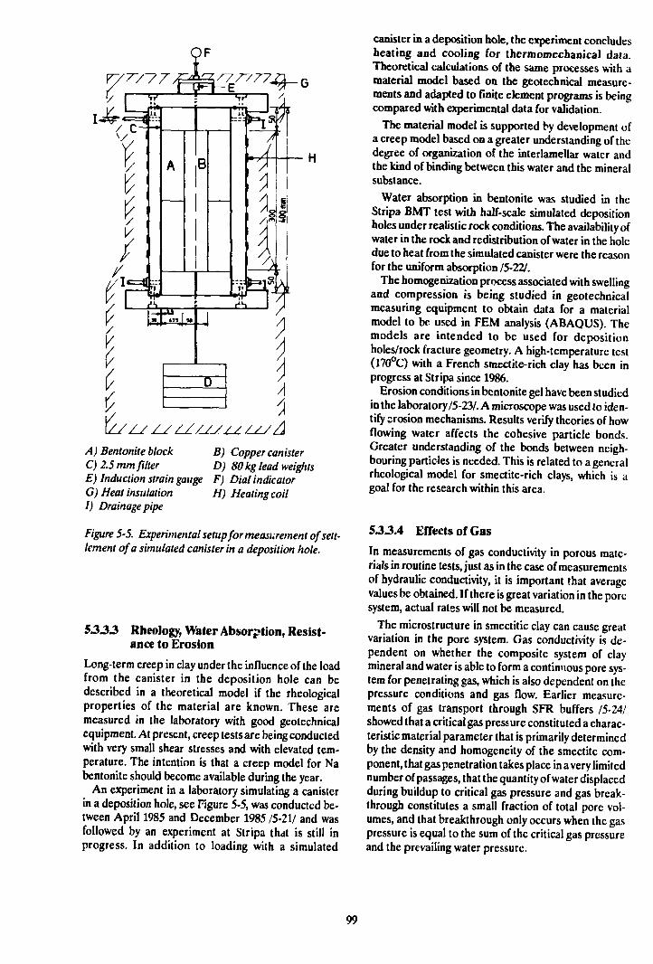
A) Bentonite block B) Copper canisterC) 2.5 mm filter D) 80 kg lead weightsE) Induction strain gauge F) Dial indicatorG) Heat insulation H) Heating coilI) Drainage pipe
Figure 5-5. Experimental setup for measurement of sett-lement of a simulated canister in a deposition hole.
5333 Rheology, Water Absorption, Resist-ance to Erosion
Long-term creep in clay under the influence of the loadfrom the canister in the deposition hole can bedescribed in a theoretical model if the Theologicalproperties of the material are known. These aremeasured in the laboratory with good geotechnicalequipment. At present, creep tests are being conductedwith very small shear stresses and with elevated tem-perature. The intention is that a creep model for Nabentonite should become available during the year.
An experiment in a laboratory simulating a canisterin a deposition hole, see Figure 5-5, was conducted be-tween April 1985 and December 1985 /5-21/ and wasfollowed by an experiment at Stripa that is still inprogress. In addition to loading with a simulated
canister in a deposition hole, the experiment concludesheating and cooling for thcrmomechanical data.Theoretical calculations of the same processes with amaterial model based on the geotechnical measure-ments and adapted to finite element programs is beingcompared with experimental data for validation.
The material model is supported by development ofa creep model based on a greater understanding of thedegree of organization of the interlamellar water andthe kind of binding between this water and the mineralsubstance.
Water absorption in bentonite was studied in theStripa BMT test with half-scale simulated depositionholes under realistic rock conditions. The availability ofwater in the rock and redistribution of water in the holedue to heat from the simulated canister were the reasonfor the uniform absorption /5-22/.
The homogenization process associated with swellingand compression is being studied in geotechnicalmeasuring equipment to obtain data for a materialmodel to be used in FEM analysis (ABAQUS). Themodels are intended to be used for depositionholes/rock fracture geometry. A high-temperature test(170°C) with a French smectite-rich clay has been inprogress at Stripa since 1986.
Erosion conditions in bentonite gel have been studiedin the laboratory 15-23/. A microscope was used to iden-tify erosion mechanisms. Results verify theories of howflowing water affects the cohesive particle bonds.Greater understanding of the bonds between neigh-bouring particles is needed. This is related to a generalrheological model for smectite-rich clays, which is agoal for the research within this area.
533.4 Effects of Gas
In measurements of gas conductivity in porous mate-rials in routine tests,just as in the case of measurementsof hydrauh'c conductivity, it is important that averagevalues be obtained. If there is great variation in the poresystem, actual rates will not be measured.
The microstructure in smectitic clay can cause greatvariation in the pore system. Gas conductivity is de-pendent on whether the composite system of claymineral and water is able to form a continuous pore sys-tem for penetrating gas, which is also dependent on thepressure conditions and gas flow. Earlier measure-ments of gas transport through SFR buffers /5-24/showed that a critical gas pressure constituted a charac-teristic material parameter that is primarily determinedby the density and homogeneity of the smectite com-ponent, that gas penetration takes place in a very limitednumber of passages, that the quantity of water displacedduring buildup to critical gas pressure and gas break-through constitutes a small fraction of total pore vol-umes, and that breakthrough only occurs when the gaspressure is equal to the sum of the critical gas pressureand the prevailing water pressure.
99
j
A model has been proposed 15-251, for the purpose ofdemonstrating the importance of density for gas andwater flow in the density range between highly com-pacted Na bentonitc and the looser state that exists inclay/aggregate mixtures. This model will be verified orrefined in the continued research work.
5-3.3.5 Sealing Measures in Boreholes andShafts
The international collaboration at Stripa has permittedtests in a realistic environment of sealing measures inboreholes and in simulated shafts and tunnels/5-26,27,28/. It has been found that sealing measures inthe rock around deposition holes and plugs in shafts canpossibly be carried out even in relatively imperviousrock with developed technology/5-29/. Tests with suchtechnology are included in Stripa phase 3. In an initialstage /5-30/, both bentonite- and cement-basedmaterials have been chosen for continued tests in theStripa mine.
Borehole and shaft scaling measures require great at-tention in the programme for development of the KBS-3 type disposal method with several shafts to storagecaverns at a depth of about 500 m spread out over anarea of a square kilometre or so. In order to obtain goodsealing results, a developed methodology is also re-quired for quality description of surrounding rock sothat the sealing measures can be carried out with goodstrategy and taking into account the geohydrologicalconditions. It is of great importance to be able to charac-terize conductive conditions in the rock in the near Heldso that its interconnection with other preferential waterpaths in the rock is obtained. An initial analysis has beenmade of a process for quality description of the rock inthe repository's near field and its interconnection withfracture zones of geohydrological importance in therock. Stripa and the Hard Rock Laboratory are poten-tial testing grounds for such method development.
5.3.3.6 Model Development for the BarrierFunction
SKI assumes that development of models describingprocesses of importance during and after depositionwill take place in close cooperation with groups who arestudying different sub-areas. As noted above, mechani-cal model development is being pursued in closecooperation. The same group is devising the materialmodel and calculating and performing validation tests.
For studies of migration of radionuclides, TVO andVTT in Finland are collaborating with SKB and ClayTechnology AB in measuring diffusion and interpretingits premises with the available material model.
As was evident from the section on long-term stability,5.3.3.1, a model for the chemical stability of the bufferis being developed in direct association with the study
of clays. Other chemical aspects of this model develop-ment are being studied in other groups.
The development of a model for radionudide migra-tion coupled with groundwater flow in rock, a model forcanister corrosion and a model for fuel dissolution haveto do with chemical conditions and are described inother sections of the research programme.
533.1 QA Programme
IAEA says that attention must be given to quality as-surance when it comes to buffer and backfill materials,and recommends that higher priority be given to QA inconnection with such research in the future (early1990s).
As was evident from the section on sealing measures,5.3.3.5, confidence in the description of rock quality isimportant, in particular when describing the connectionbetween the sealing materials and the rock in terms thatdefine the premises for how its function can be expectedto be during a long period after emplacement. Atten-tion has been given to the question in connection withthe development of methods for sealing of rock in Stripaphase 3.
5.3.3.8 Summary of Research ResultsDescription of engineered barrier, buf-fer material with respect to transportconditions
The properties that characterize transport conditionsthrough the buffer material are low hydraulic conduc-tivity and low diffusivity.
Hydraulic conductivity is primarily determined bydensity and smectite content, see Figure 5-6. A selec-tion of well-defined clays has been compared with thereference clay in KBS-3, Mx 80, a clay of the Wyomingtype with mainly sodium as the adsorbed ion. The com-parison shows that with no reduction in density, hy-draulic conductivity is low even if the smectite contentdecreases /5-3IA The smectite content of the buffermaterial can decrease as a result of transformation ofsmectite to illite at a rate dependent on the tempera-ture. A greater understanding of the relationship be-tween microstructure and temperature, obtainedthrough studies of clays in hydrothermal tests, has ledto a more nuanced model for temperature effects 15-19/.The model has been tested in the study of natural ben-tonitcs. An important contribution has been the Got-land bentonite located at a depth of about 500 m atHamra. According to the model, a critical temperatureis 150°C. Below 105°C, insignificant changes occur dueto a slow reaction of the Arrhcnius type. In the interval105°C to 150°C, permanent changes can occur of im-portance for microstructure, but illitc/smcclitc mixedlayer formation is insignificant or non-existent. The con-clusion is that temperatures of 105°C to 120°C are pos-
100
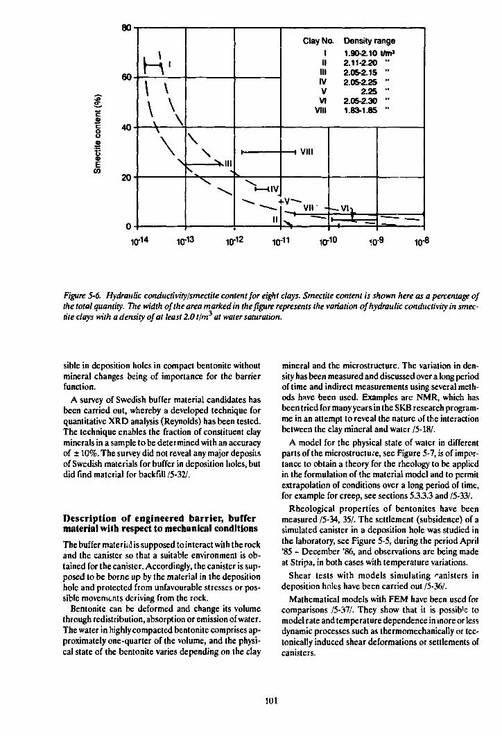
CO
80
60
40
20
\ \
\ \
\\
\
"V-iiv
1 !1
Clay No. Density range1 1.90-2.10 t/m'II 2.11-2.20 "III 2.05-2.15 "IV 2.05-2.25 "V 2.25 "VI 2.05-2.30 "
VIII 1.83-1.85 "
• uiii
—vu
10-14 10-13 10-12 KJ-10 10-9 10-8
Figure 5-6. Hydraulic conductivity/smectite content for eight clays. Smectite content is shown here as a percentage ofthe total quantity. The width of the area marked in the figure represents the variation of hydraulic conductivity in smec-tite clays with a density of at least 2.0 tlm at water saturation.
sible in deposition holes in compact bcntonite withoutmineral changes being of importance for the barrierfunction.
A survey of Swedish buffer material candidates hasbeen carried out, whereby a developed technique forquantitative XRD analysis (Reynolds) has been tested.The technique enables the fraction of constituent clayminerals in a sample to be determined with an accuracyof ± 10%. The survey did not reveal any major depositsof Swedish materials for buffer in deposition holes, butdid find material for backfill /5-32/.
Description of engineered barrier, buffermaterial with respect to mechanical conditions
The buffer material is supposed to interact with the rockand the canister so that a suitable environment is ob-tained for the canister. Accordingly, the canister is sup-posed to be borne up by the material in the depositionhole and protected from unfavourable stresses or pos-sible movements deriving from the rock.
Bentonite can be deformed and change its volumethrough redistribution, absorption or emission of water.The water in highly compacted bentonite comprises ap-proximately one-quarter of the volume, and the physi-cal state of the bentonite varies depending on the clay
mineral and the microstructure. The variation in den-sity has been measured and discussed over a long periodof time and indirect measurements using several meth-ods have been used. Examples arc NMR, which hasbeen tried for many years in the SKB research program-me in an attempt to reveal the nature of the interactionbetween the clay mineral and water /5-18/.
A model for the physical state of water in differentparts of the microstructure, see Figure 5-7, is of impor-tance to obtain a theory for the rheology to be appliedin the formulation of the material model and to permitextrapolation of conditions over a long period of time,for example for creep, see sections 5.3.3.3 and /5-33A
Rheological properties of bentonites have beenmeasured /5-34, 35/. The settlement (subsidence) of asimulated canister in a deposition hole was studied inthe laboratory, see Figure 5-5, during the period April'85 - December '86, and observations are being madeat Stripa, in both cases with temperature variations.
Shear tests with models simulating canisters indeposition holes have been carried out /5-36A
Mathematical models with FEM have been used forcomparisons /5-37A They show that it is possib'e tomodel rate and temperature dependence in more or lessdynamic processes such as thermomechanically or tec-tonically induced shear deformations or settlements ofcanisters.
101
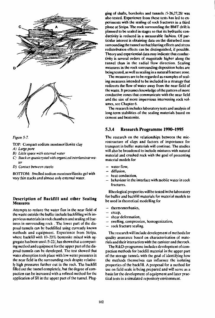
Figure 5-7.
TOP: Compact sodium montmorillonite clayA) LargeporeB) Little space with external waterC} Stack or quasicrystal with organized interlaminar wa-
terD) Contact between stacks
BOTTOM: Swelled sodium montmorillonitc gel withvery thin stacks and almost only external water.
Description of Backfill and other SealingMeasuresAttempts to reduce the water flux in the near field ofthe waste outside the buffer include backfilling with im-pervious materials in rock chambers and sealing of frac-tures in surrounding rock . The lower part of the dis-posal tunnels can be backfilled using currently knownmethods and equipment. Experience from Stripa,where backfill with 10-20% bentonite mixed with ag-gregate has been used 15-22/, has shown that a compact-ing method and equipment for the upper part of the dis-posal tunnels can be developed. The test showed thatwater absorption took place with low water pressures inthe near field in the surrounding rock despite relative-ly high pressures further out in the rock. The backfillfilled out the tunnel completely, but the degree of com-paction can be increased with a refined method for theapplication of fill in the upper part of the tunnel. Plug-
ging of shafts, boreholes and tunnels 15-26,21,,28/ wasalso tested. Experience from these tests has led to ex-periments with the sealing of rock fractures in a thirdphase at Stripa. The rock surrounding the BMT drift isplanned to be sealed in stages so that its hydraulic con-ductivity is reduced in a measurable fashion. Of par-ticular interest is obtaining data on the disturbed zonesurrounding the tunnel so that blasting effects and stressredistribution effects can be distinguished, if possible.Theory and experiential data may indicate that conduc-tivity is several orders of magnitude higher along thetunnel than in the radial flow direction. Sealingmeasures in the rock surrounding deposition holes arebeing tested, as well as sealing in a natural fracture zone.
The measures are to be regarded as examples of seal-ing measures intended to be included in a strategy thatredirects the flow of water away from the near field ofthe waste. It presumes knowledge of the pattern of moreconductive zones that communicate with the near fieldand the size of more impervious intervening rock vol-umes, see Chapter 6.
The research includes laboratory tests and analysis oflong-term stabilities of the sealing materials based oncement and bentonite.
53.4 Research Programme 1990-1995
The research on the relationships between the mic-rostructure of clays and factors of importance fortransport in buffer materials will continue. The studieswill also be broadened to include mixtures with naturalmaterial and crushed rock with the goal of presentingmaterial models for
— water flow,— diffusion,— heat conduction,— behaviour in the interface with mobile water in rock
fractures.
Rheological properties will be tested in the laboratoryfor buffer and backfill materials for material models tobe used in theoretical modelling for
— thcrmomechanics,— creep,— shear deformation,— swelling, compression, homogenization,— rock fracture sealing.
The research will include development of methods forquality assurance based on characterization of mate-rials and their interaction with the canister and the rock.
The R&D-programme includes development of com-paction methods for backfill material in the upper partof the storage tunnels with the goal of identifying howthe methods themselves can influence the isolatingproperties of the backfill. A proposal for a method foruse on field scale is being prepared and will serve as abasis for the development of equipment and later prac-tical tests in a simulated repository environment.
102
6 PROPERTIES OF THE ROCK
6.1 GENERAL
6.1.1 The Role of the Rock in the FinalRepository
The rock is a prerequisite for a safe final disposal ofspent nuclear fuel in accordance with the principledeveloped in Sweden and many other countries. Therock has a number of fundamental properties that areexploited for the long-term safety of the repository.
Important fundamental functions are:
— mechanical protection,— chemically stable environment,— slow and stable water flux.
The rock provides a long-lasting mechanical protec-tion against external forces, including human intrusion.A final repository in rock also provides good protectionagainst changes in climate. Climatic changes can lead toan altered biosphere, a considerable increase in sealevel, or can alternatively give rise to permafrost andglaciation. The impact of such changes will be mini-mized if a final repository is located in deep geologicalformations.
Of fundamental importance is that the chemical en-vironment be stable. The reducing chemistry of thegroundwater is of great importance for the service-lifeof the canister and for the slow dissolution of the fuelmatrix. The chemistry is determined for the most partby the mineral composition of the rock, which is stableover very long periods of time. The chemical environ-ment of the rock is also important in determining howradionuclides can be transported. Here, the interactionbetween nuclidcs and rock is of importance. Theseproperties are largely associated with the rock matrix,which docs not change appreciably through the eons.
The low groundwater flux in the rock is of importanceboth for the stability of the barriers and for the slowtransport of nuclides in the rock. The water flux isgoverned largely by the topography of the ground sur-face, by the fractures of the rock and by prevailing rockstresses. These factors are all stable by nature. Thegroundwater flux around a repository will therefore notchange appreciably with time.
For an assessment of the performance of the final re-pository, it is necessary to describe the components ofthe repository and their interaction over long periods oftime. Since it is difficult to clarify how this long-term in-teraction takes place on a specific site, theoreticalmodels arc used.
The extent to which the models used are valid is offundamental importance for the assessment. Models of
the rock have specific peculiarities, which are discussedin greater detail in section 6.3.2. The rock is opaque andlarge volumes of a complex, heterogeneous mediumhave to be described. The description is often based ona large number of point data from boreholes that arethen generalized to various scales according to thespecific problem to be analyzed.
Certain interactions in a repository are only affectedby a few of the rock's parameters. Calculating thecanisters service-life, for example, requires only data onlocal groundwater flux and chemistry.
Describing how nuclides are fixed and transported inthe rock requires more information. The groundwater'sflow distribution must be described over large volumes.Different models are employed by different groups ofresearchers. Some models describe flow in individualfractures, putting high demands on data collection.Other models assume flow in a porous, partially homo-geneous medium, which is much too rough an ap-proximation in many applications.
It is an urgent task of current research to test thevalidity and limitations of these models.
6.1.2 Investigation of Rock
Investigations of rock for final repositories are carriedout in stages which become progressively more detailedand whose content is progressively adapted to the needsand the information that emerge in the investigations.
It is fruitful to carry out and present the investigationson different scales. A rough classification that is usedhere, see Figure 6-1, is
— regional scale, 1-10 km,- site scale, far field, 100-1000 m,— block scale, far/near field, 10-100 m,- site scale, near field, 0-10 m.
The near field is usually defined as the area nearestthe waste that could conceivably be affected by thewaste or by the excavation of rock; a small temperatureincrease is not included. The size of the near field is de-pendent on the configuration of the final repository. Insome configurations, it is possible to have a near fieldfor each waste package.
The fundamental functions can be studied for eachscale. This involves setting-up of a descriptive model,groundwatcr flow and chemistry, transport of solutesand mechanical stability.
It is urgent that the rock investigations for a final re-pository be conducted in a given sequence:
103

Site investigations of rock for design and assessment of safety
Regional Site Block Detailed
Figure 6-1. Research areas and scales.
- observations (data),- processing of observations to set up a conceptual
model over the area (structures and physicalprocesses),
- calculations,- evaluation.
This sequence is gradually carried toward a higherdegree of detail as the information is improved in eachinvestigation stage.
The different investigation stages are supposed todescribe:
- groundwater flux,- geometry and properties of the groundwater con-
ductors,- groundwater chemistry.
The investigations shall designate which volumes areof interest for continued detailed investigations.Volumes of interest for repository emplacement shallbe specified. Furthermore, those volumes that will laterhave to be characterized between the repository and thedischarge areas shall be defined.
The investigations shall provide background materialfor the geometric layout of the repository. Aims for thelayout of the repository arc:
- low groundwater flux in the repository's near zone,- "respect distance" to potential zones of future t ock
movement.
The final repository should be progressively adaptedand modified, leaving a large potential for flexibility.
6.2 GROUNDWATER MOVE-MENTS IN THE ROCK
6.2.1 Goals of the R&D Activities 1990-1995
The main goals of the research on groundwater move-ments in the rock are to:
- further develop and test methods for location andcharacterization of fracture zones and water-bear-ing fractures,
- broaden the database for water-bearing fracturesand fracture zones with the data needed in models,
- further develop models that describe the ground-water flow pattern in the rock,
- test the usefulness of different models and thereliability of the calculation results.
Much of this research is bciug carried out within theframework of the Hard Rock Laboratory, see fuitherchapter 9. For the period 1990-1995, the following sub-goals can be mentioned:
— to evaluate the results of Phase 3 of the StripaProject in order to specifically decide whether fur-ther experiments are needed to characterize the so-called "disturbed zone", to evaluate tracer techni-que in underground facilities and to evaluate theusefulness of numerical fracture network models,
— to evaluate the tracer tests at Finnsjön to specifical-ly decide to what extent the technique used providesmaterial for calculation of transport of radio-nuclides in fracture zones,
— to set up programmes for the pre-investigations, cal-culations and reports that are t J be carried out onthe candidate sites,
— to set up programmes for the detailed investigationsthat are to be carried out.
622 Present-day State of Knowledge
The movements of the groundwater are of importancefor describing the performance and safety of the finalrepository.
In order to carry out a credible analysis of ground-water movements, a good description is required of thephysical media in which flow takes place. Furthermore,the theories used must relate to the way in which theflow takes place physically in the medium. There arepractical (and economic) limits here on how long thedescription can be carried in the different investigationstages.
It is also important to describe how models can be setup and validated with the data available in different in-vestigation stages. Models are set up with different basicpremises and can be applied on different scales, whichgoverns which data are to be collected and how they areto be evaluated. Validation of the models thereby alsorequires experiments on different scales.
There are only a few facilities in rock today where theentire chain investigations - calculations - evaluation ofgroundwater ilowpaths has been carried out and docu-mented.
Observations and data on the rock and on ground-water movements in the rock need to be processed andanalyzed from different aspects. The most important ofthese are:
— available rock volumes of a certain quality,— presence of flowpaths,— data for repository layout on different scales,— data for analysis of groundwater flux on different
scales,— description of the water's flowpaths in the re-
pository area and its environs.
Observation Methods for Ground-water in Kock
The present-day state of knowledge regarding the col-lection of relevant data in the field to describe ground-water movements is outlined in this section. In order totie in with natural investigation stages, the relevantmethods are described under the headings:
- surface investigations,- borehole investigations,- underground studies.
Investigation methodology and instruments aredescribed in detail in section 8.2.
SURFACE INVESTIGATIONS
Surface investigations include geological mappings, aswell as airborne and ground geophysical surveys. Un-fortunately, it is generally difficult from existing mate-rial from investigations in Swedish bedrock to draw un-equivocal conclusions on the applicability and limita-tions of the methods. Furthermore, the value of dif-ferent methods varies for different sites. In order toevaluate the limitations of different methods on achosen site, predictions must be made. These predic-tions can then be checked by the use of other, inde-pendent surface investigation methods for the purposeof verification. Other ways to check the predictions arcborehole investigations or investigations from tunnels.Surface investigations normally provide a very goodcoverage of the ground surface, but it is difficult to util-ize this surface information for preparing three-dimen-sional descriptions.
The geological mapping that is carried out in Swedenthrough the Geological Survey of Sweden shows eg rocktype distribution and tectonics in the ground surface.For engineering purposes /6-1/, however, it is recom-mended that three-dimensional descriptions of thebedrock be performed in the form uf predictions. Theimportance of making these predictions in stages is alsoemphasized.
This strategy is applied consistently for the investiga-tions in the Hard Rock Laboratory, where predictionsare prepared on a number of scales. This makes it pos-sible to judge the value of the results from surface inves-tigations in the light of continued investigations. Thefirst stage in the investigations has been presented /6-2/.
A large number of surface investigation methods havebeen utilized to provide an aggregate regional pictureof geology, gcohydrology and groundwater chemistry.In the continued investigations, it will be possible tocompare these predictions with results from deep bore-holes and from tunnels.
An important part of a rock description is to indicatethe rock type distribution, since the rock type influen-ces the chemistry of the groundwater, permeability andstructures /6-2/.
105
Geological mapping provides a good description ofthe rock type distribution in the ground surface. Theregional mapping is facilitated by airborne geophysicalsurveys. For the Hard Rock Laboratory, the magneticand electrical properties of the rock, as well as bedrockradiation, were measured. The connection betweengeophysical indications and rock type was then con-firmed by mapping and petrographic investigations.The geological/geophysical interpretation also indi-cated the depth to which the rock types extended(diapirs). Supplementary gravitational measurementswere carried out and interpreted, showing that younger(and lighter) granites were present at a depth of akilometre or so below the ground surface. The geologi-cal mapping and applied geophysics thereby enable athree-dimensional rock type distribution to be describ-ed on a regional scale.
The detailed investigations of southern Äspö showedthat surface investigations arc of limited value fordescribing the rock type distribution in depth. Datafrom the drillings showed an unexpected occurrence ofa quartz-poorer variety of rock - diorite - at a depth ofabout 300 m. It is possible that detailed gravimetry canbe utilized to shed light on possible rock type variationsin three dimensions.
Another important part of the rock description is todescribe the zones of weakness of the bedrock. Map-ping provides a good means of describing the geometricdistribution of steeply-dipping structures in the bed-rock. Mapping is facilitated and can be supplementedby information from eg aerial photography interpreta-tion, geophysics, topographical analysis etc. It is oftendifficult to describe the character of the zones in map-ping if the area is not completely exposed. Of great valueis the opportunity to expose geological profiles, in asimilar manner as was done over Äspö in connectionwith the investigations for the Hard Rock LaboratoryI6-7>I. As far as the subhorizontal structures of thebedrock arc concerned, a careful mapping and inter-pretation can also contribute towards describing these/6-4,5/.
The National Land Survey Administration's digitaldatabase was utilized to perform tectonic interpreta-tions. Study of the topography reveals lineaments, espe-cially vertical structures. The length, width and direc-tion of the lineaments can be utilized to describe zonesof weakness. Zones, however, can have widely differingcharacters that cannot be discovered on maps.
Magnetic and electrical methods arc used routinelyto map the zones in the bedrock. In general, however,their range is limited to a 100 metres. Simultaneous in-terpretation of several methods in parallel provides in-dications of the dip of zones.
Also of interest here is the evaluation of geology andgeophysics that was carried out in conjunction with theconstruction of the 80 km long Bolmcn Tunnel insouthern Sweden 16-61. Mapping carried out in conjunc-tion with the tunnelling work could be compared withthe geological and geophysical description prepared
before and during the construction work. The followingwas found:
- airborne magnetic surveys indicated 80% of allzones over SO m in width, but only 25% of zones lessthan SO m in width,
- ground geophysics (VLF and Slingram) indicated80% of all zones over 50 m and 60% of narrowerzones,
- resistivity measurements indicated 95% of all zonesover 50 m in width and 80% of zones less than 10 min width,
- refraction seismics indicated 60% of the zones over50 m in width and 13% of the most pronouncedzones with widths less than 10 m.
It was found that a combination of geophysical meth-ods is often necessary to prepare a good description.Furthermore, it is difficult - with the chosen distancebetween measuring points in profiles - to detect zonesof less than 10 m and zones that are subhorizontal.Predictions of the presence of water in rock could notbe made merely on the basis of geophysical investiga-tions.
A geophysical method that has had limited applica-tion in Sweden is shallow reflection seismics. Analysesof reflection seismic surveys have been reported in/6-7/ and /6-3/. In order to obtain a good description ofthe uppermost 100 metres, time resolution and ap-paratus need to be better than those used in these sur-veys. In /6-8/, for example, the resolution of 0.25 ms isto be compared with 0.5 ms for the surveys on Äspö.Reflection seismic surveys for URL in Canada soonrevealed Fraction Zone 2. This technique is wellworthwhile for further surface investigations, since itprovides volume information while at the same timepermitting the subhorizontal zones to be detected,which can be difficult to detect with other methods. Inthe approximately 7 km deep boreholes that weredrilled at Siljan to test the deep-gas theory, the reflec-tion seismic surveys were of great value.
With dense reflection seismic profiles, it is deemedpossible to achieve a good geological model in threedimensions. Such surveys can be carried out relativelyeasily even for areas under water.
Summary Evaluation
Surface investigations provide the basts for an initialgeological interpretation of a site.
It is of value that surface investigations be carried outin parallel with different methods and that the investiga-tions be evaluated progressively, in stages. It is difficulttoday-owing to limited documentation - to generallyevaluate what surface investigations yield in relation toborehole investigations. It must also be stressed thatsurface investigations should be site-optimized, sincedifferent methods arc suitable for different sites. It is es-sential that all material - geological, geophysical, geo-
106
hydrological and geohydrochemical - be co-interpretedin stages.
The difficulty of establishing the *rne scope of sub-horizontal structures must be p~.ucularly borne inmind. Surface descriptions constitute the basis for thesctling-out of boreholes and thereby also provide thebasis for interpreting the data that arc later obtainedfrom borehole measurements.
BOREHOLE INVESTIGATIONS
Borehole investigations provide information that sup-plements surface investigations. As far as geology andgeophysics are concerned, basically the same methodsare used for both surface and borehole investigations.The boreholes can also be used for measurements be-tween several holes to obtain a volume description ofthe rock, known as cross-hole measurements. In rela-tion to the repository volume, the number of boreholesis very limited. In the French waste programme /6-9/,for example, it is emphasized that the number of inves-tigation holes from the surface must be limited to a mini-mum.
Cross-hole Measurements
Cross-hole measurements arc carried out in order todetermine the extent of zones of weakness betweenboreholes or to obtain average values for the propertiesof the rock between the boreholes. Different methodsare used. The most common are hydraulic cross-holemeasurements, where hydraulic response (pressurepropagation) is analyzed. These measurements areoften combined with tracer tests, where differenttracers arc injected into a borehole and water samplesare taken from nearby holes. Cross-hole measurementsare also performed using seismic and electrical (radar)methods.
Interference Measurements
Hydraulic cross-hole measurements (interferencemeasurements) arc performed to obtain information onhydraulic interconnections in the rock mass.
Evaluation of the measurements provides values forthe transmissivity of the flowpaths, as well as informa-tion on their geometric extent. Cross-hole measure-ments have been carried out both within the frameworkof SKB's fracture zone project at Finnsjön /6-10/ and forthe Hard Rock Laboratory /6-3/. The measurementtechnique used has performed very satisfactorily, as hasthe evaluation of the results. Interference measure-ments have also been carried out as a part of the inves-tigations for SFR /6-11/, where they made a substantialcontribution toward increasing the understanding ofthe hydraulic interconnections around the final re-pository and toward averaging over large volumes.
Radar Measurements
Borehole radar is described in greater detail in Chap-ter 8. The technique for radar measurements in the typeof rock that exists in Sweden has been further developedwithin the framework of the international Stripa Pro-ject, see Chapter 10. Measurements with radar can becarried out cither as reflection measurements or usingtomographic analysis. Radar tomography requires highmeasurement density so that the area or the measuringplane between the boreholes is criss-crossed by a largenumber of measurement lines. Two types of tomogramscan then be plotted from the data, representing the at-tenuation and the speed of propagation of the radar sig-nal, respectively.
SKB has conducted two special method tests, one ofwhich was a blind test where cross-hole radar, withoutaccess to other information, was supposed to be used todescribe the properties of the rock. The method test wasperformed in connection with the boring of a tunnel inStockholm from which the goodness of the predictioncould be evaluated afterwards id-121. The radarpredicted a large, flat zone that was subsequentlypenetrated by the tunnel. It turns out that the radar alsoidentified a number of minor anomalies that were of noimportance for tunnelling. The study also showed thatthe technique for evaluating tomograms has improvedconsiderably over the course of a few years.
At Stripa, SKB has also tested a method with salinewater injection in connection with radar measurement.This method is deemed to be of great future value. Sinceradar is sensitive to the resistivity of the medium, the dif-ference between tomograms plotted before and aftersaline water injection could be used to identify thoseareas in -he rock that were water-bearing. As a crosscheck, the saline water content in the boreholes was alsorecorded. Since the measurements were carried out inseveral boreholes with a suitable configuration, a 3-dimcnsional picture of the flowpaths was obtained/6-13/.
Cross-hole Seismics
Within the Stripa Project, seismic borehole investiga-tions have been further developed by/6-14,15/. For thismethod as well, the development has concerned cross-hole measurements with tomographic analysis.
Within Phase 2 of the Stripa Project, cross-holemeasurements were performed on two scales: within a200 m block and with up to 1000 metres between theboreholes. Measurements on the large scale, whichwere to be used to test 3-dimcnsional tomographicanalysis, were not very successful. This is partially dueto the fact that the borehole configuration was un-suitable. On the smaller scale, however, the results weremore promising. The method is being further developedwith respect to the transmitter equipment, among otherthings, see also Chapter 8.
107
Vertical Seismic Profiling (VSP) is another seismicmethod where measurements are made from points onthe ground surface at different distances and directionsaround the borehole to a receiver in the borehole. Thismethod has not been tested within the SKB program-me.
Single-hole Measurements
Core Mapping
The drill core can be mapped with great accuracy withrespect to rock type, fracture character, fracture-fillingmaterial etc. Of great importance is the analysis of thefracture mineral, which provides a means of estimatinga relative age for different groundwater periods. It is,for example, possible to describe when calcitc scalingtook place, cf Chapter 7 and /6-3,6-16,17/.
Geophysics
Geophysical loggings of boreholes by means of severalmethods complement each other so that several coinci-dent anomalies are utilized to describe the rock mass.Systematic studies have been performed to correlatelogging results with, for example, hydraulic parameters76-84/ or to study correlations between radar anomaliesand other borehole information /6-18/. Systematic cor-relations have also been carried out for the Hard RockLaboratory /6-3/.
Statistical processing of correlations between dif-ferent types of data has begun. There is no singlegeophysical method that clearly and consistently corre-lates with hydraulic conductivity or hydraulic fracturefrequency. The results in /6-84/ indicate that hydraulicconductivity can be predicted with relatively few datafrom the borehole. Highly conductive zones are indi-cated by a combination of low resistivity (single pointresistance) and long pulse times (sonic). These zonesoften coincide with increased fracturing, crushed rockand iron precipitations in fractures. Within the Klip-perås study site, the subhori/ontal zones appear to bethe most conductive.
In one study /6-18/, the radar signals from measure-ments at Klipperås, Finnsjön, the Saltsjö Tunnel, Ävröand Stripa were evaluated and correlated against otherborehole information. The study shows that there is agood correlation between high radar intensity and frac-turing in the rock mass. The correlation between radarintensity and hydraulic conductivity is good for themeasurements at Stripa, but not for the other sites. It isalso evident that there arc hydraulic units in the rockmass that are not detected by means of the radarmethod. Radar indicates potentially conductive /ones.What is valuable about radar is that it is a volume-descriptive method that shows structural (geometric)characteristics in the rock mass far out from the bore-hole - up to 150 m with present-day equipment. Resolu-tion is dependent on the measuring frequency selected.
Of particular interest is being able to determine theorientation of fractures in the borehole. Here a so-called -televiewer" seems to be appropriate, sec furtherChapter 8.
Hydraulic Measurements
In order to determine the transmissivity of the rock,water injection measurements are performed betweenpacker seals in boreholes. The packers are usuallyspaced at distances of from 20-30 m down to 2-3 m, butin special studies /6-10/ spacings of down to 0.11 m havebeen used. With refined evaluation technique /6-3/, theevaluation limit can be as low as 10' ~ m/s for a 3 m pack-er spacing. It is very important that the evaluation of thehydraulic conductivity should take into account thescale on which the measurements are performed. Mostof the measurements arc performed on a scale that isbelow the Representative Elementary Volume (REV),ie the minimum size for which the approximation witha porous medium assumption can be used. The packerspacing is important, since it is not possible to describethe spacial variation of the logarithm of the conductivityin the borehole on scales smaller than the packer spac-ing /6-19/, unless the transmissivity distribution can belinked to other information from the borehole /6-20/.
Within the framework of the bilateral agreement be-tween US DOE and SKB, data from study-site inves-tigations have been used to provide recommendationsfor optimal packer spacing /6-20/. It is recommendedthat short packer spacings -just a few times greater thanthe average fracture spacing - be used.
In the investigations for the Hard Rock Laboratory,a new type of measurement has been introduced formeasuring hydraulic conductivity /6-3/. Flow logginghas been carried out in deep cored holes in connectionwith test pumping of the holes. The vertical water flowis measured along the entire hole under the pump,enabling the water-bearing sections to be detected.Measurements arc carried out for a 1000 m long bore-hole in a few hours. A measurement is performed foreach metre, and the transmissivity of the most conduc-tive zones is calculated. Furthermore, a unique scries ofmeasurements with different packer spacings has beencarried out to shed light on average conductivity andvariance on different scales.
Flow Measurements
Of great value for an understanding of groundwatermovements is the ability to carry out direct measure-ments of the groundwater flow. A special instrument, adilution probe, has been developed for this purpose.Measurements have been carried out at Finnsjön /6-10/.This type of measurement is deemed to be of great im-portance, since it provides a means for direct com-parison between calculated and measured values ofwater flux.
108
Hydraulic Prrssure
Measurement of groundwater head is essential in orderto understand the driving forces for the groundwater.Pressure measurements were of crucial importance forhow the numerical models were utilized for SFR I6-2V.It is, however, tricky to evaluate pressure when the den-sity of the water varies, and the results have to be ad-justed for this. This is essential if pressure measure-ments are used to validate calculation models forgroundwater.
Rock Stress Measurements
Stress measurements have been carried out to correlatehydraulic conductivity with stress levels and to studywhether the direction of the maximum principal stresscoincides with anisotropies for the groundwater flow/6-3,6-10,6-17/.
Evaluating stress measurements is not a trivial mat-ter. A large quantity of data has been eva1 Jalcd underthe cooperation agreement between AECL and SKBthat was concluded for characterization of the 240 mlevel in URL, /6-22,23/. it turned out that the stressresults were affected by such factors as tectonics,mineral grain size, microfissures and drilling technique.In the high stress field at the 240 m level, the main resultwas that measurements in boreholes with a large angleto the maximum principal stress direction tended toyield results with the maximum obtained principal stressoriented parallel to the borehole. It is believed that theproblems can be identified by geological mapping ofdrill cores and by parameter checks. Geological map-ping is being concentrated on mincralogical in-homogeneitics adjacent to the measuring cell, as well asstructures such as foliation and visible microfissures. AtURL, it was found to be difficult to interpret themeasurement results if the volumetric strain exceeded0.07% /6-22A
Summary Evaluation
Measurements in boreholes are based on advancedtechnology and arc resource-demanding. In order topermit subsequent evaluation, several independentmethods must be used. It is difficult today to determinethe specific benefit of an individual method. It is judgedthat borehole measurements and surface investigationstogether provide sufficient information to carry out apreliminary evaluation of the performance andgeometric layout of the repository and to identifysuitable rock volumes for detailed characterization.
INVESTIGATIONS IN TUNNELS ANDSHAFTS
Detailed investigations and construction of a final re-pository entail the construction of tunnels and shafts. Itis of primary interest to make use of these tunnels andshafts to make observations of the bedrock. In the same
way as for surface investigations, tunnels provide accessto surfaces for observations. The generalized geologicalpicture that is obtained from surface investigations andfrom point information in boreholes can be confirmedand complemented. As far as groundwaler movementsare concerned, the boreholes provide point informationwhile tunnels provide an opportunity for more detailedanalysis of how the water distributes itself ger metrical-ly in the bedrock. In connection with the constructionof tunnels, pressure responses in surrounding boreholescan be successively evaluated and compared with theevaluation previously made on the basis of surface andborehole information. The seepage that takes place intothe tunnel is of interest in evaluating the validity ofmodels for groundwater movements. The total seepagequantity can be utilized to calibrate the total ground-water flux in the area. The geometric distribution of thegroundwater can be used to describe the flowpaths. Itis also possible to collect samples of the chemistry of thegroundwatcr in a tunnel. Comparison between che-mistry results at different points in space and timefacilitates the interpretation of groundwaler move-ments.
A theoretical study describing how a tunnel can beutilized to gather data on the near field during re-pository construction has been published 16-24/.
firoundwater Distribution
Both two- and three dimensional tracer tests have beencarried out within the Stripa Project to shed light on themovement of the groundwatcr in the rock mass. Thefundamental two-dimensional tests in a single fracturedemonstrated the uneven distribution of the water overthe fracture plane. The flow in the fracture plane can bedescribed in simplified terms as taking place in flowchannels formed as a result of the irregular profile ofthe two fracture faces /6-25,26/.
The three-dimensional tests were conducted in a rela-tively large volume of the rock mass. Different types oftracers were injected from boreholes 10-55 metres upfrom the drift to which they were expected to flow. Thequantity of tracer collected in the drift varied from tensof percent of the injected quantity to thousandths of apercent. Four of the nine types of injected tracers werenever recovered in the collection drift / 3-27/. The ex-periments confirmed the channelling phenomenon.The other results have proved to be difficult to inter-pret, however, and no satisfactory explanations havebeen reported.
The results of thv Stripa tests show that for tracer testsin tunnels, it is necessary to characterize the test areathoroughly. Flow takes place in the direction of thegradient only if the conductivity is isotropic. According-ly, it is necessary to take anisotropy into account todescribe the direction of the flow, since there arc in-dividual fracture planes in the near field of a tunnel thatcan control the flow. This experience will be built on inthe design of future tracer tests.
109
Tunnel observations were also of some importancefor the safety assessment of SFR /6-28A The assumptionof a high "channelling" in the bedrock could not beruled out. Input data to the assessment were obtainedby mapping the SFR tunnels with respect to the size ofthe seepage surfaces. It was assumed that the ground-water's behaviour outside the tunnel corresponded towhat was mapped in the form of seepage. Data fromother studies /6-29/ were also utilized to support themodel. Data from SFR, Stripa, Kymmen, the Saltsjötunnel and from other facilities are currently being com-piled. However, it is not yet clear what relevance thesedata have for interpreting the movements of the ground-water under natural conditions.
A tunnel gives rise to stress redistributions. Thesegenerally lead to a change in conductivity in the vicinityof the tunnel. Experience from SFR shows that conduc-tivity across the tunnel decreases. It is a widely acceptedview that axial conductivity increases. This is mportantin view of the fact that if nuclides leak to the "disturbedzone", there is a greater chance of short circuiting be-tween the tunnel and surrounding fracture zones. Fewexperiments have been conducted to study this effect.The buffer test at Stripa /6-30/ supports the view thatthe axial conductivity increases. The ongoing injectionexperiment at Stripa will furnish further data on axialconductivity, see Chapter 10. Besides stress redistribu-tions, conductivity near the tunnel is affected by theblasting procedure, where the tunnel floor in particularis damaged by blasting. Other effects to take into con-sideration arc the potential difference between the roofand the floor of the tunnel, and capillary effects.
Through cooperation with AECL in Canada, it hasbeen possible to analyse one of the more well-docu-mented experiments that shed light on how a tunnel isaffected by the ambient rock mass /6-31/. AECL's rocklaboratory, URL, is situated in the Lac du Bonnetbatholitc, which has very few fractures. However, room209 at the 240 level contains a single, highly conductivefracture that is crossed by a tunnel. Before the tunnelwas built, holes were drilled parallel to it. The holeswere instrumented so that changes in water pressure,transmissivity, rock stresses and rock deformationscould be monitored during the blasting of the tunnel.The results show that the hydraulic conductivity acrossthe tunnel has changed. The change varies over theperiphery of the tunnel in such a manner that conduc-tivity has decreased in the roof and walls, but increasedin the tunnel floor. Since the fracture plane across thetunnel possessed very high stiffness, it has been con-cluded that the reduced conductivity in the roof andwalls stems from the fact that the flow is affected by un-saturated conditions and/or material transport into thefracture. The increased conductivity in the floor of thetunnel is explained as an effect of blasting.
Tunnel tests have also been conducted at Hylte inconnection with the instruction of a hydropowcr plant/6-32/. The studies have taken the form of experiencegathering in preparation for the planning of the Hard
Rock Laboratory. This has included coordination ofdata collection and tunnel production. Geological map-ping at the tunnel face, pilot drilling and hydraulic pres-sure buildup tests have been carried out for this pur-pose. Several different types of tracers have been tested.At present, qualitative tracer tests are in progress aimedat using UV light to test a technique for optical record-ing of tracer breakthrough in tunnels.
Summary Evaluation
Data from tunnels are already being used for assess-ment of the repository's performance and safety. Thedata collection method needs to be refined so that theinformation on eg pressure responses occurring duringconstruction can be optimally exploited in the descrip-tion of the site. The question of whether the data ob-tained during tunnel mapping etc are really repre-sentative of groundwater distribution under naturalconditions requires further examination.
6.2.2.2 Conceptual Models
The observations gathered from Field measurements, insitu tests and laboratories need to be processed andgeneralized in conceptual models.
A conceptual model of, for example, groundwaterflow consists of two submodels. One is the structuralmodel, where the heterogenities of the rock are definedgeometrically. The definition includes volumes and/orsurfaces and/or one-dimensional flow channels. Struc-tural models can be set up on different scales with a rela-tively high accuracy, depending on available data.
The second submodel - the process model - describeswhich physical phenomena are applied to the structuralsubmodel. The flow may, for example, be stochastic,saturated or unsaturated, take into account density con-trasts in the water, thermal convection etc.
Since design and analysis proceed in stages and onvarying scales, it is very helpful to set up these concep-tual models on different scales. At present, there arcseveral alternatives where each conceptual model im-poses different demands on parameters and data.
The conceptual models arc based in principal onlaminar, viscous flow, but seek different ways to simplifythe description of the fractures and cavities in the rockwhere groundwater movement takes place. Dependingon data and needs, the conceptual models may be deter-ministic or stochastic.
The conceptual model also identifies the requireddata. For calculation of eg nuclide transport with thechannel model, essential parameters are water flux, thelength of the channels to the biosphere, diffusion ofnuclides into the rock matrix, sorption of radionuclideson rock faces, the contact area in the flow channels be-tween the flowing water containing radionuclidcs andthe rock, the number of flow channels and the distribu-tion of flow between the channels.
110
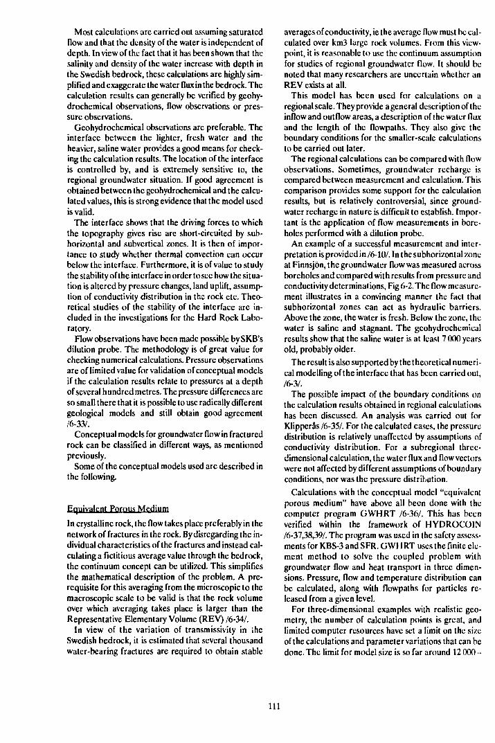
Most calculations are carried out assuming saturatedflow and that the density of the water is independent ofdepth. In view of the fact that it has been shown that thesalinity and density of the water increase with depth inthe Swedish bedrock, these calculations are highly sim-plified and exaggerate the water flux in the bedrock. Thecalculation results can generally be verified by geohy-drochemical observations, flow observations or pres-sure observations.
Geohydrochemical observations are preferable. Theinterface between the lighter, fresh water and theheavier, saline water provides a good means for check-ing the calculation results. The location of the interfaceis controlled by, and is extremely sensitive to, theregional groundwater situation. If good agreement isobtained between the gcohydrochemical and the calcu-lated values, this is strong evidence that the model usedis valid.
The interface shows that the driving forces to whichthe topography gives rise are short-circuited by sub-horizontal and subvertical zones. It is then of impor-tance to study whether thermal convection can occurbelow the interface. Furthermore, it is of value to studythe stability of the interface in order to see how the situa-tion is altered by pressure changes, land uplift, assump-tion of conductivity distribution in the rock etc. Theo-retical studies of the stability of the interface arc in-cluded in the investigations for the Hard Rock Labo-ratory.
Flow observations have been made possible by SKB'sdilution probe. The methodology is of great value forchecking numerical calculations. Pressure observationsare of limited value for validation of conceptual modelsif the calculation results relate to pressures at a depthof several hundred metres. The pressure differences areso small there that it is possible to use radically differentgeological models and still obtain good agreement/6-33Z.
Conceptual models for groundwater flow in fracturedrock can be classified in different ways, as mentionedpreviously.
Some of the conceptual models used are described inthe following.
Equivalent Porous Medium
In crystalline rock, the flow takes place preferably in thenetwork of fractures in the rock. By disregarding the in-dividual characteristics of the fractures and instead cal-culating a fictitious average value through the bedrock,the continuum concept can be utilized. This simplifiesthe mathematical description of the problem. A pre-requisite for this averaging from the microscopic to themacroscopic scale to be valid is that the rock volumeover which averaging takes place is larger than theRepresentative Elementary Volume (REV) /6-34/.
In view of the variation of transmissivity in theSwedish bedrock, it is estimated that several thousandwater-bearing fractures are required to obtain stable
averages of conductivity, ie the average flow must be cal-culated over km3 large rock volumes. From this view-point, it is reasonable to use the continuum assumptionfor studies of regional groundwater flow. It should benoted that many researchers are uncertain whether anREV exists at all.
This model has been used for calculations on aregional scale. They provide a general description of theinflow and outflow areas, a description of the water fluxand the length of the flowpaths. They also give theboundary conditions for the smaller-scale calculationsto be carried out later.
The regional calculations can be compared with flowobservations. Sometimes, groundwater recharge iscompared between measurement and calculation. Thiscomparison provides some support for the calculationresults, but is relatively controversial, since ground-water recharge in nature is difficult to establish. Impor-tant is the application of flow measurements in bore-holes performed with a dilution probe.
An example of a successful measurement and inter-pretation is provided in /6-10/. In the subhorizontal zoneat Finnsjön, the groundwater flow was measured acrossboreholes and compared with results from pressure andconductivity determinations, Fig 6-2. The flow measure-ment illustrates in a convincing manner the fact thatsubhorizontal zones can act as hydraulic barriers.Above the zone, the water is fresh. Below the zone, thewater is saline and stagnant. The geohydrochemicalresults show that the saline water is at least 7 000 yearsold, probably older.
The result is also supported by the theoretical numeri-cal modelling of the interface that has been carried out,
The possible impact of the boundary conditions onthe calculation results obtained in regional calculationshas been discussed. An analysis was carried out forKlipperås /6-35/. For the calculated cases, the pressuredistribution is relatively unaffected by assumptions ofconductivity distribution. For a subregional three-dimensional calculation, the water flux and flow vectorswere not affected by different assumptions of boundaryconditions, nor was the pressure distribution.
Calculations with the conceptual model "equivalentporous medium" have above all been done with thecomputer program GWHRT /6-36/. This has beenverified within the framework of HYDROCOIN/6-37,38,39/. The program was used in the safety assess-ments for KBS-3 and SFR. GWHRT uses the finite cle-ment method to solve the coupled problem withgroundwater flow and heat transport in three dimen-sions. Pressure, flow and temperature distribution canbe calculated, along with flowpaths for particles re-leased from a given level.
For three-dimensional examples with realistic geo-metry, the number of calculation points is great, andlimited computer resources have set a limit on the sizeof the calculations and parameter variations that can bedone. The limit for model size is so far around 12 000 -
111
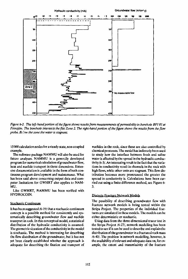
Hydraulic conductivity (m/s)
10-i3 -« -n -io -» - • •? -6 -s
Groundwate: flow (m»/ml y)
•3 ojn 0)0 v» te i » ion
50
100-
1S0
200'
11>n.2j|
^Äuo
»so
- — - — - - — —,1
1—'
~ ] too-
1 1 is»
J I»
_ _ ^ ^ JOO
I ii _ _ ISO
J ^ 40»
, r-"' 4S0
• No measurable flow
2. Tftc left-hand portion of the figure shows results from measurements of permeability in borehole BFI 01 atFinnsjön. The borehole intersects the flat Zone 2. The right-hand portion of the figure shows the results from iheflowprobe. Bilow the zone the water is stagnant.
15 000 calculation nodes for a steady-state, non-coupledexample.
The software package NAMMU will also be used forfuture analyses. NAMMU is a generally developedprogram for numerical calculation of groundwatcr flow,heat and nuclide transport in three dimensions. Exten-sive documentation is available in the form of both con-tinuous program development and maintenance. Whathas been said above concerning output data and com-puter limitations for GWHRT also applies to NAM-MU.
Like GWHRT, NAMMU has been verified withHYDROCOIN.
Stochastic Continuum
It has been suggested 16-19/ that a stochastic continuumconcept is a possible method for consistently and sys-tematically describing groundwatcr flow and nuclidetransport in rock. In this conceptual model, a statisticaldistribution of the hydraulic conductivity is assumed.The geometric situation of the conductivity in the modelis stochastic. The method is interesting for describingthe flow distribution of the groundwatcr, but it has notyet been clearly established whether the approach isadequate for describing the fixation and transport of
nuclides in the rock, since these are also controlled bychemical processes. The model has indirectly been usedto study how the interface between fresh and salinewater is affected by the spread in the hydraulic conduc-tivity/6-3/. An interesting result is the fact that the varia-tions in conductivity result in channels in the rock withhigh flows, while other units arc stagnant. This flow dis-tribution becomes more pronounced the greater thespread in conductivity is. Calculations have been car-ried out using a finite difference method, see Figure 6-3.
Discrete Fracture Network Models
The possibility of describing groundwatcr flow withfracture network models is being tested within theStripa Project. The properties of the individual frac-tures are simulated in these models. The models can beeither deterministic or stochastic.
Using data from the three-dimensional tracer test inthe Stripa Project 16-211, network modelling has beentested to see if it can be used to describe and explain thedistribution of the groundwater in a fractured rock mass/6-40/. The problem in network modelling, however, isthe availability of relevant and adequate data on, for ex-ample, the extent and transmissivity cf the fracture
112
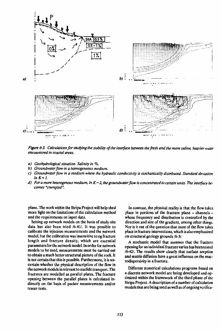
a) ;
FtJKTC <J-J. Calculations for studying the stability of the interface between the fresh and the more saline, heavier waterencountered in coastal areas.
a) Geohydrologkal situation. Salinity in %.b) Groundwaler flow in a homogeneous medium.c) Groundwater flow in a medium where the hydraulic conductivity is stochastically distributed. Standard deviation
lnK=l.d) For a more heterogenous medium, In K=2, the groundwater flow is concentrated to certain units. The interface be-
comes "crumpled".
plane. The work within the Stripa Project will help shedmore light on the limitations of the calculation methodand the requirements on input data.
Setting up network models on the basis of study-sitedata has also been tried /6-41/. It was possible tocalibrate the injection measurements and the networkmodel, but the calibration was insensitive to eg fracturelength and fracture density, which are essentialparameters for the network model. In order for networkmodels to be used, measurements must be carried outto obtain a much better structural picture of the rock. Itis not certain that this is possible. Furthermore, it is un-certain whether the physical description of the flow inthe network models is relevant to nuclide transport. Thefractures are modelled as parallel plates. The fractureopening between the parallel plates is calculated in-directly on the basis of packer measurements and/ortracer tests.
In contrast, the physical reality is that the flow takesplace in portions of the fracture plane - channels -whose frequency and distribution is controlled by thedirection and size of the gradient, among other things.Nor is it out of the question that most of the flow takesplace in fracture intersections, which is also emphasizedon structural geology grounds /6-3/.
A stochastic model that assumes that the fractureopening for an individual fracture varies has been tested/6-42A The results show clearly that surface sorptionand matrix diffusion have a great influence on the mac-rodispersivity in a fracture.
Different numerical calculations programs based ona discrete network model are being developed and op-timized within the framework of the third phase of theStripa Project. A description of a number of calculationmodels that are being used as well as of ongoing vcrifica-
113
tion exercises is provided in 16-43/. Two of the modelsare described in brief below.
NAPSAC is a three-dimensional network model thatcalculates the steady-state flow through a given rec-tilinear block using the finite element method. The flowk assumed to take place exclusively through a networkof fractures, and within these the flow is assumed to belinearly dependent on the pressure gradient. The modelrequires input data consisting of statistical distributionsof the different parameters that describe the network.The calculations have to be repeated a large number oftimes for different realizations of the fracture network.Output data are the steady-state flow as well as thevariation of the flow. The program is being developedfor the Stripa Project by Harwell Laboratory in England/6-44/. Verification and validation will be carried outwithin this project. Limited computer resources set alimit on the utilization of this model today.
JINX stands for "Joints In Networks" and is a collec-tive name of a number of computer programs /6-45,46/.JINX is also being used within Phase 3 of the StripaProject. JINX consists of a PC-based graphic pre-processor for generation of fracture geometries andfinite element networks, FRACMAN. MAFIC then cal-culates the steady-state or transient flow through thefracture network using the finite element method. Flowboth through the fracture plane and through the rockmatrix can be simulated. MAFIC can also be used tocalculate nuclidc transport along the flowpaths of thenetwork. The programs are stil! under development.
Equivalent Discontinuum
The equivalent discontinuum model is something in be-tween a stochastic continuum and a network model/6-43/. The model is being used in Stripa, Phase 3. Spe-cial automatic algorithms arc used to generate a net-work that minimizes the discrepancy between modeland measurement data. It is not possible for the actualnetwork to be recreated. The model is interesting forstudies of groundwatcr flow distribution. The approachis in the basic research stage and it is uncertain to whatextent it can be used in the future for calculating nuclidctransport.
Flow Channel Model
A highly simplified model for groundwatcr flow dis-tribution in the bedrock is the flow channel model/6-28/. The input data for flow distribution comes main-ly from data collected during tunnel mapping. Thegroundwater flow is very unevenly distributed in frac-ture zones and in fractures. The preferential flowpathsare not to be regarded as geometric properties, but arcdependent on the gradient, the direction of the gradientand the local transmissivitics in the fracture network,which has also been treated in numerical models 16-411.Chemical transport is dependent not only on the flowdistribution, but also on the chemical interaction be-tween the solutes in the water and the surroundings. The
channel model is a highly simplified description of thegroundwater's distribution and how nuclides are fixedand transported. The channels are alternatively regar-ded as being either independent or interconnected inpoints. In the latter case, mixing of water occurs.
Data for the flow channel model is obtained from tun-nel mapping and assumes that such mapping gives arelevant statistical distribution of the groundwater'sflowpaths. The extent to which this is the case requiresfurther study.
Summary Evaluation
The conceptual models available today arc able todescribe water flux and flow distribution with sufficientaccuracy to permit the preliminary layout of a final re-pository or the life of waste canisters to be evaluated,provided that data is obtained for the host rock (withexisting methods).
The safety assessment of a final repository should in-clude calculating how radionuclides are transportedwith the groundwater. This cannot be done today withthe desired accuracy. It is impossible to say whichmodels or combination of models best represent reality.It is therefore necessary to make use of pessimisticmodels that greatly exaggerate the transport.
The conceptual models that exist can be calibratedagainst experiments, but they are not particularly dis-criminating in relation to how the physical flow takesplace in the rock. Tracer tests with non-sorbing andweakly sorbing tracers can be one possible way to dis-tinguish the conceptual models. It has not yet been dem-onstrated that tracer tests make it possible to dis-criminate between different conceptual models. Inrecent years' safety assessments, SKB has used the flowchannel model for calculating nuclide transport, sinceit offers the most conservative model for the function ofthe rock as a barrier.
It can be worth noting that UK/DOE has presentedan overview of calculation models for groundwatermovements and nuclide transport /6-48/. This reportcalls for further development of methods for modellingflow in fractured media and gas transport, and of geo-statistical methods.
6.2.2.3 Validation of Models for GroiindwaterMovements
How well models are able to describe reality is charac-terized by the concept of validity. The concept ofvalidity is currently being discussed within severalprojects, see Section 3.3.6.
Within the framework of the Hard Rock Laboratory,work is also being done to define what validation ofgroundwater models entails and requires.
A computer model is a mathematical realization ofthe conceptual model within the framework of a definedand verified computer code. Ideally, the conceptualmodel should coincide with the computer model, but
114
this is not always possible owing to limitations in thecomputer code. To test the validity of the computermodel, it can be calibrated against quantities measuredin the Held. The goal of a calibration is to minimize thediscrepancy between the computer model and mea-surement results by adjusting the parameters of themodel.
When agreement between the computer model andmeasurement results is good, the model is calibratedagainst a given set of data. The calibrated computermodel can then be used to describe quantities in the sys-tem that have not been used in calibration - predictivecalculations. These predictive calculations can later beused for new comparisons with measurements.
Validation includes a number of elements, for ex-ample a systematic comparison between prediction andoutcome and a judgement of whether the agreement isgood.
Validation can be performed against different quan-tities, for example pressure changes, groundwater flow,changes of groundwater chemistry etc. For the long-term safety of the repository, it is valuable to definewhich types of validations arc of the greatest impor-tance. Such judgements can be arrived at through sys-tematic performance and safety assessments. For theHard Rock Laboratory project, work is currently inprogress to systematically determine which statementsare to be predicted and validated and which types ofmeasurements etc are to be utilized to validate the state-ments. This type of work is also going on within theStripa Project.
port over 400 m in a month. A possible interpretationof the high, uniform conductivity is that the zone was ac-tivated in connection with the most recent deglaciation.
The groundwater flow was recorded in the zone witha dilution probe. Although large flows were measured,it turned out that the flows further down in the zonewere small, despite high conductivity. The suppositionthat stagnant conditions prevail is supported by thechemical composition of the groundwater, since thereis a saline interface in the zone. Although the water ismixed and derives from a number of sources, it is clear-ly fossil water. The supposition that the salt water isstagnant is also supported by the theoretical calcula-tions for a fresh/saline water interface, which arcreported in /6-3/.
The concluding phase of the Finnsjön work in.olvcstracer tests. The project is included in INTRAVAL,where a number of groups have submitted predictivecalculations for the tests that have been carried out.
Fracture zone studies have also been initiated at Ävrö/6-50/. The fracture zone is about 120 m thick and dips40°. The strike of the zone has not yet been conclusive-ly determined. In the same way as at Finnsjön, a moresaline water has been encountered in connection withthe zone. It has been deemed advisable to carry out mostof the Finnsjön tests in order to see whether the techni-que used provides answers to the relevant questionsbefore the studies on Ävrö continue.
Fracture zone studies have also been conducted inconnection with tunnelling work, and the results arcbeing compiled.
6.2.2.4 Some Special Research Areas
Fracture Zone Study
In the absence of data to describe groundwater move-ments in fracture zones, it was assumed in the safety as-sessment for KBS-3 that a radionuclide that reaches afracture zone immediately reaches the biosphere. Inorder to broaden the knowledge base, fracture zonestudies have been conducted for several years, amongother places at Finnsjön. The intention is to studynuclide retention in fracture zones, investigation meth-ods and the influence of fracture zones on regionalgroundwater movements.
The first phase of the studies at Finnsjön has pre-viously been reported /6-49/. During 1986-1988, a sub •horizontal, approx. 1G0 m wide fracture zone - Zone 2- was studied in detail /6-10/ to provide a basis for thetracer tests in the concluding phase.
In the detailed characterization, geology, geohy-drology and chemistry have been described. The zonewas formed about 1.6 billion years ago and has sincebeen reactivated on a number of occasions. Zone 2 isdivided into several subzones, where the uppermost inparticular is extremely conductive. A noteworthy fact isthat the conductive properties found in all the boreholesthat intersect the subzone are persistent and of uniformmagnitude. A preliminary tracer test indicated trans-
Suhhorizontal Zones
Low-dipping zones are of importance for the layout ofa repository and for assessment of performance andsafety. Traditional geological investigations providelimited information on the occurrence of subhorizontaizones. It is only through the investigations that havebeen carried out in Sweden, Finland and Canada thatdata have begun to emerge on the frequency andproperties of horizontal zones.
A subhorizontai zone was encountered on the Kam-lunge study site at a depth of 550 m. Its conductivity wasabout 100 times higher than in the surrounding rock. Inthe same manner, high conductivity zones have been en-countered at Gideå, Svartbobcrget, Finnsjön, Klipperåsand SFR. A large number of flat zones were also en-counted during the investigations in the nearly 7 000 mdeep hole drilled at Gravberg for the deep gas project.
Conductive, subhorizontai zones have also been iden-tified on Hästholmen in southern Finland and in con-nection with the investigations for URL in Canada.
The low-dipping structures appear often to be highlyconductive and to short-circuit the driving forces andflowpaths for groundwater movements that are deter-mined by the topography. This is positive for a final re-pository, since the water flux around a repositorybeneath a subhorizontai zone thereby decreases. Theproperties of the zones are of interest for assessment of
115
repository performance, since the presence of sub-horizontal zones facilitates the creation of thermal con-vection cells. For investigation of a site and optimiza-tion of the repository, it is urgent that the distance be-tween subhorizonta! zones be described, which requiresinvestigations to relatively great depths.
Disturbed Zone
The disturbed zone can be denned as "the part of a tun-nel or shaft whose physical or chemical properties arealtered to such a high degree as a consequence of con-struction of the repository or of heat generated by thewaste that the function of the repository is affected".
Theoretical calculations show that stress redistribu-tion around a tunnel causes the axial conductivity to in-crease around the tunnel /6-30A This must be taken intoaccount when calculating the nuclide transport. Ex-perimental data from Stripa, phase 2 /6-30.6-51/, indi-cate that the axial conductivity increases by a factor of1 000 - 10 000 in a zone 0.5 - 1 m around the tunnelperiphery.
Gas Transport
Studies of gas transport arc of importance in caseswhere a repository contains steel that corrodes anae-robically, producing hydrogen. These effects have beenstudied within the framework of the safety assessmentof SFR and the assessment of the WP-Cave project.
For the analysis of gas transport in SFR, both a dis-continuum and a continuum assumption were utilized/6-52,53/.
6.2.3 Research Programme 1990-1995
The research required to attain the goals described in6.2.1 is best carried out in interdisciplinary projectswhere geologists, geophysicists, geohydrologists,chemists and other specialists cooperate.
SKB plans to continue to develop conceptual and cal-culation models in close cooperation with universities,colleges, institutes of technology and other experts.
Over the next few years, most of the planned work willbe carried out within the framework of Finnsjön, theHard Rock Laboratory and Stripa, as described indetail under sections 7.3.3, 9.4, 9.5 and 10.2. The pro-gramme for the Hard Rock Laboratory is presented indetail in a separate background report.
Development of Conceptual Models
Development of conceptual models on different scalesis of fundamental importance for increasing our under-standing of how groundwater flows in crystallinebedrock. The Hard Rock Laboratory will work in paral-lel tracks that range from a regional scale down to vol-umes of a 100 m or so. During the pre-investigationphase, regional groundwater models, discrete networkmodels and simple transport models will be devised.
These models will then be tested and refined during theconstruction phase. The importance of a tracer test dur-ing the construction phase and the operating phase isparticularly stressed here. The work at Stripa is, as men-tioned previously, focussed on the block scale and onthe near field. The "Site Characterization Validation"programme (SCV) will yield material for testing severaldifferent types of models. Three different groups areworking with modelling of the experiments within theproject. In the "Sealing of Fractured Rock" experiment,efforts are being devoted to the "disturbed zone". Thetests at Finnsjön deal with transport on the far-fieldscale.
A full evaluation of the extent to which tracer testtechnique is applicable for distinguishing between dif-ferent conceptual models is required for the furtherplanning of experiments. Such an evaluation is plannedboth for Stripa and the Finnsjön tests. Based on an in-tegrated evaluation of SCV and the injection groutingtests at Stripa and of the tracer tests, it will be possibleto plan which additional experiments can contributetoward an improved analysis of groundwater flow inrock. An evaluation is planned during 1992. This can in-fluence the planning of the tracer tests in the Hard RockLaboratory. Possible methods are:
- a development of the radar tomography/saltwatermethodology. Investigations holes are drilled paral-lel to a conductive zone,
- a conductive unit of a rock mass is injection-groutedand then dismantled into small pieces. The parts ofthe rock that have been in contact with the groutingmaterial arc then mapped,
- castings are made of typical fracture planes usingthe technique described in /6-54/ and arc thenmounted in three-dimensional models.
A question of another character is to what extent theconceptual models arc based on a complete body ofdata. Parameter determinations are based on the datacollected in surface investigations, in boreholes and intunnels. As the field investigations continue, the bodyof material for description of flowpaths will grow. Itwould be difficult to prove that the investigations areever complete. Systematic uncertainty analyses shouldtherefore be carried out concerning what importanceoverlooked fracture zones, for example, have on the cal-culation results for flow.
Uncertainty analyses will be carried out in SKB 91. Itis hereby essential that calculation models able to takeinto account random variation in data arc utilized anddeveloped, see below.
Development of Calculation Models
Equivalent Porous Medium
High-powered computers will eliminate many limita-tions on the finite element models, which require somuch computer capacity. NAMMU will be used for thecalculations when the "equivalent porous medium"
116
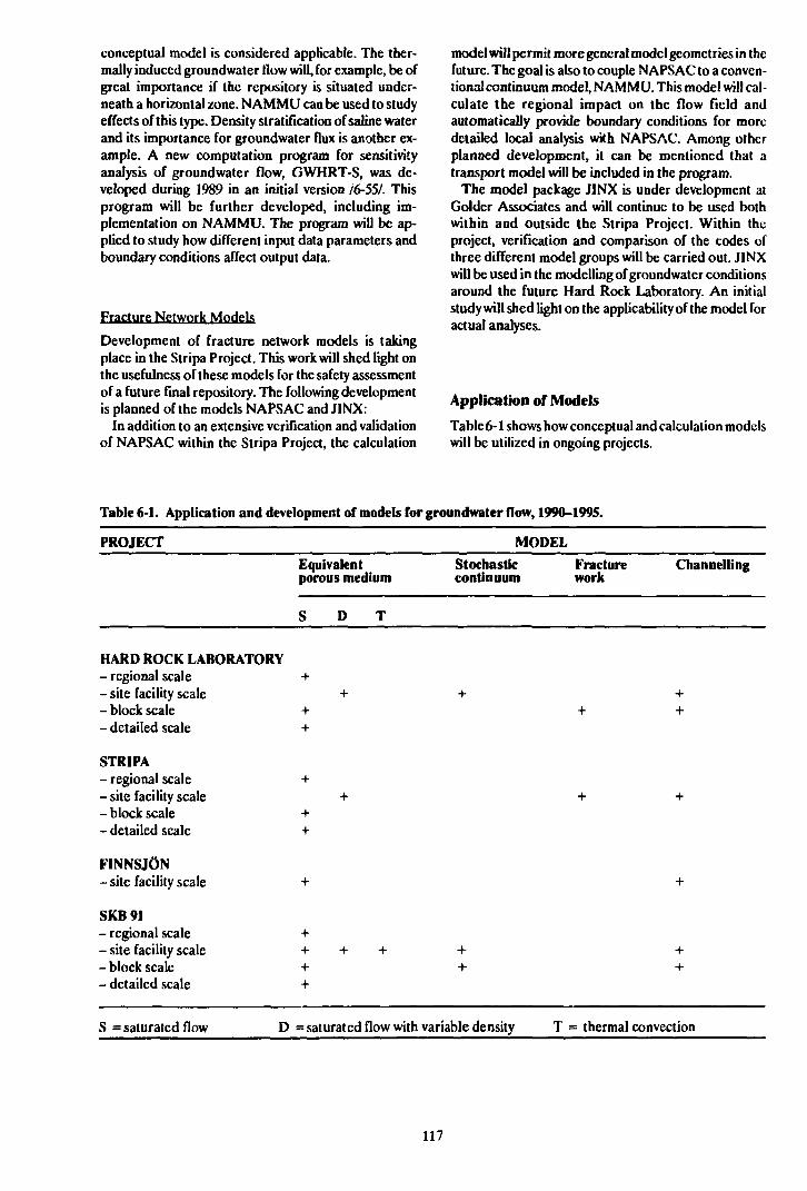
conceptual model is considered applicable. The ther-mally induced groundwater How will, for example, be ofgreat importance if the repository is situated under-neath a horizontal zone. NAMMLJ can be used to studyeffects of this type. Density stratification of saline waterand its importance for groundwater flux is another ex-ample. A new computation program for sensitivityanalysis of groundwater flow, GWHRT-S, was de-veloped during 1989 in an initial version /6-55A Thisprogram will be further developed, including im-plementation on NAMMU. The program will be ap-plied to study how different input data parameters andboundary conditions affect output data.
Fracture Network Models
Development of fracture network models is takingplace in the Stripa Project. This work will shed light onthe usefulness of these models for the safety assessmentof a future final repository. The following developmentis planned of the models NAPSAC and JINX:
In addition to an extensive verification and validationof NAPSAC within the Stripa Project, the calculation
model will permit more general model geometries in thefuture. The goal is also to couple NAPSAC to a conven-tional continuum model, NAMMU. This model will cal-culate the regional impact on the flow field andautomatically provide boundary conditions for moredetailed local analysis with NAPSAC. Among otherplanned development, it can be mentioned that atransport model will be included in the program.
The model package JINX is under development atGolder Associates and will continue to be used bothwithin and outside the Stripa Project. Within theproject, verification and comparison of the codes ofthree different model groups will be carried out. JINXwill be used in the modelling of groundwater conditionsaround the future Hard Rock Laboratory. An initialstudy will shed light on the applicability of the model foractual analyses.
Application of Models
Table 6-1 shows how conceptual and calculation modelswill be utilized in ongoing projects.
Table 6-1. Application and development of models for groundwater flow, 1990-1995.
PROJECT
HARD ROCK LABORATORY- regional scale- site facility scale- block scale- detailed scale
STRIPA- regional scale- site facility scale- block scale- detailed scale
FINNSJÖN- site facility scale
SKB91- regional scale- site facility scale- block scale- detailed scale
S = saturated flow D
MODEL
Equivalent Stochasticporous medium continuum
S D T
* +
+
: + + :
=saturated flow with variable density T
Fracture Channellingwork
:
•
+
:
= thermal convection
117
Subhorizontal Zones
The geometry and properties of vertical and sub-horizontal zones are of great importance. It is urgent totest better equipment and more refined evaluationmethods in order to obtain a description of the frequen-cy and extent of the flat zones at an early phase of theinvestigations. Targeted geological/geophysical studieshave their place in this context. This deeper analysis cantake place within the framework of the Hard RockLaboratory.
The influence of subhorizontal zones on the safety ofthe repository will be elucidated within the frameworkof the safety assessment - SKB 91.
Disturbed Zone
The disturbed zone is being studied within the StripaProject LSI. Evaluation of this experiment and of thetests being conducted in URL at the 240 m level willserve as a basis for possible supplementary tests in theHard Rock Laboratory. Such an evaluation should becarried out during 1992.
As far as the impact of the disturbed zone on the safe-ty of the repository is concerned, this can be assessedwithin the framework of SKB 91.
6.3 STABILITY OF THE ROCK
63.1 Goals of the R&D Activities 1990-1995
The main goals are to:
- quantify or set limits on the effects of earthquakes,ice ages and land uplifts that are of importance forassessing the safety of a final repository for spentnuclear fuel,
- process, evaluate and increase knowledge of thegcodynamic processes in the Baltic Shield.
Sub-goals for the period are to:
- supplement and conclude the study of the post-gla-cial fault at Lansjärv,
- plan and carry out a deeper tectonic analysis insoutheastern Sweden,
- conduct a state-of-the-art review of ice ages andstudy their importance for the long-term safety ofthe final repository.
6.3.2 Present-day State of Knowledge
It is of fundamental importance to understand to whatextent tectonic or climatic processes influence the per-formance of the repository. Low groundwater flux, afavourable chemical environment and the absence ofrock movements that could damage the waste are guid-ing principles for the layout of the repository.
The studies that have been conducted support the no-tion that plate tectonics, together with the ongoing landuplift, following the most recent ice age, are of crucialimportance for interpreting current and future move-ments in the bedrock. It is also evident that these move-ments occur preferably or exclusively along major frac-ture zones of very great age.
As a basis for designing and assessing the perfor-mance of the repository, it is also of importance todescribe the extent to which a final repository can be af-fected by future ice ages.
The study of tectonic and climatic factors is wide-ranging and in a state of rapid development. Large na-tional and international projects are undfway and arecontinuously improving our picture of the tectonicprocesses and effects on the bedrock. General descrip-tions of these phenomena and their possible impact onthe repository are discussed in /6-56,57,58,59/.
The purpose of the following review is net to providea complete overview of knowledge on the developmentof the Baltic Shield, but to describe the work that hasbeen done within the framework of SKB's R&D-pro-gramme.
63.2.1 Tectonic Processes
A general outline of the precambrian evolution of theBaltic Shield is presented in /6-60/. An understandingof this evolution is central to the subdivision of Swedeninto tectonic regions /6-61/.
Of importance in this context is to describe the evolu-tion of the Baltic Shield during the past 58 million years,since the time when Scandinavia separated from Green-land and the Mid-Atlantic Ridge was formed /6-63/.Europe and America are currently moving away fromeach other at a rate of 13 mm per year.
It is this plate-tectonic process which, together withthe ongoing land uplift, controls much of the seismic ac-tivity in the Baltic Shield. The seismic recordings madeduring the 1980s /6-63,64,65/ show that the stressesreleased in earthquakes have a horizontal compressionin the direction N60W, perpendicular to the movementin the Mid-Atlantic ridge. The fact that plate tectonicsand post-glacial rebound arc controlling present-daydeformation processes in the Baltic Shield is also shownin/6-66/.
The worldwide database World Stress Map Projectshows good agreement between the vector of movementfor the plates in the earth's crust and the direction ofhorizontal rock stresses.
The most probable mechanism for generating asurplus of horizontal stresses in the European portionof the Eurasian plate is a pushing force known as "ridgepush" perpendicular to the strike of the Mid-Atlanticridge. The forces are generated by topographical con-ditions and the formation of oceanic crust.
If it is assumed on the basis of present-day knowledgethat the rock stresses are primarily caused by ongoingplate tectonics, a change in the movement of the
118
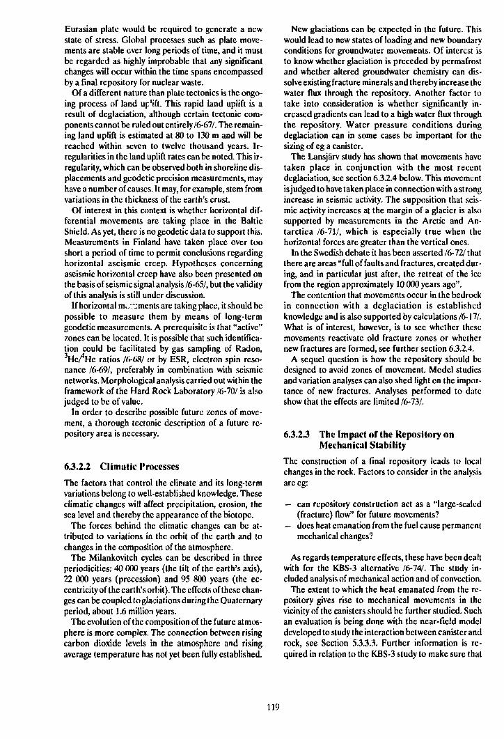
Eurasian plate would be required to generate a newstate of stress. Global processes such as plate move-ments are stable ever long periods of time, and it mustbe regarded as highly improbable that any significantchanges will occur within the time spans encompassedby a Final repository for nuclear waste.
Of a different nature than plate tectonics is the ongo-ing process of land up'ift. This rapid land uplift is aresult of deglaciation, although certain tectonic com-ponents cannot be ruled out entirely 16-611. The remain-ing land uplift is estimated at 80 to 130 m and will bereached within seven to twelve thousand years. Ir-regularities in the land uplift rates can be noted. This ir-regularity, which can be observed both in shoreline dis-placements and geodetic precision measurements, mayhave a number of causes. It may, for example, stem fromvariations in the thickness of the earth's crust.
Of interest in this context is whether horizontal dif-ferential movements are taking place in the BalticShield. As yet, there is no geodetic data to support this.Measurements in Finland have taken place over tooshort a period of time to permit conclusions regardinghorizontal aseismic creep. Hypotheses concerningaseismic horizontal creep have also been presented onthe basis of seismic signal analysis 16-651, but the validityof this analysis is still under discussion.
If horizontal m^/.^ments are taking place, it should bepossible to measure them by means of long-termgeodetic measurements. A prerequisite is that "active"zones can be located. It is possible that such identifica-tion could be facilitated by gas sampling of Radon,3He/*He ratios /6-68/ or by ESR, electron spin reso-nance /6-69/, preferably in combination with seismicnetworks. Morphological analysis carried out within theframework of the Hard Rock Laboratory /6-70/ is alsojudged to be of value.
In order to describe possible future zones of move-ment, a thorough tectonic description of a future re-pository area is necessary.
6.3.2.2 Climatic Processes
The factors that control the climate and its long-termvariations belong to well-established knowledge. Theseclimatic changes will affect precipitation, erosion, thesea level and thereby the appearance of the biotopc.
The forces behind the climatic changes can be at-tributed to variations in the orbit of the earth and tochanges in the composition of the atmosphere.
The Milankovitch cycles can be described in threeperiodicities: 40 000 years (the tilt of the earth's axis),22 000 years (precession) and 95 800 years (the ec-centricity of the earth's orbit). The effects of these chan-ges can be coupled to glaciations during the Quaternaryperiod, about 1.6 million years.
The evolution of the composition of the future atmos-phere is more complex, The connection between risingcarbon dioxide levels in the atmosphere and risingaverage temperature has not yet been fully established.
New glaciations can be expected in the future. Thiswould lead to new states of loading and new boundaryconditions for groundwater movements. Of interest isto know whether glaciation is preceded by permafrostand whether altered groundwater chemistry can dis-solve existing fracture minerals and thereby increase thewater flux through the repository. Another factor totake into consideration is whether significantly in-creased gradients can lead to a high water flux throughthe repository. Water pressure conditions duringdeglaciation can in some cases be important for thesizing of eg a canister.
The Lansjärv study has shown that movements havetaken place in conjunction with the most recentdeglaciation, see section 6.3.2.4 below. This movementis judged to have taken place in connection with a strongincrease in seismic activity. The supposition that seis-mic activity increases at the margin of a glacier is alsosupported by measurements in the Arctic and An-tarctica 16-111, which is especially true when thehorizontal forces are greater than the vertical ones.
In the Swedish debate it has been asserted 16-121 thatthere are areas "full of faults and fractures, created dur-ing, and in particular just after, the retreat of the icefrom the region approximately 10 000 years ago".
The contention that movements occur in the bedrockin connection with a deglaciation is establishedknowledge and is also supported by calculations /6-17/.What is of interest, however, is to see whether thesemovements reactivate old fracture zones or whethernew fractures are formed, see further section 6.3.2.4.
A sequel question is how the repository should bedesigned to avoid zones of movement. Model studiesand variation analyses can also shed light on the impor-tance of new fractures. Analyses performed to dateshow that the effects are limited /6-73A
6.3.2 J The Impact of the Repository onMechanical Stability
The construction of a final repository leads to localchanges in the rock. Factors to consider in the analysisare eg:
— can repository construction act as a "large-scaled(fracture) flow" for future movements?
— docs heat emanation from the fuel cause permanentmechanical changes?
As regards temperature effects, these have been dealtwith for the KBS-3 alternative /6-74/. The study in-cluded analysis of mechanical action and of convection.
The extent to which the heat emanated from the re-pository gives rise to mechanical movements in thevicinity of the canisters should be further studied. Suchan evaluation is being done with the near-field modeldeveloped to study the interaction between canister androck, see Section 5.3.3.3. Further information is re-quired in relation to the KBS-3 study to make sure that
119
the thermal load does not give rise to large-scale move-ments at the borders of the repository, causing (sub-horizontal) ftowpaths to be opened from the repositoryto surrounding zones. Such an analysis is planned.
A number of different finite element models havebeen used by SKB to calculate thermomechanical stres-ses in the rock. These continuum models includeABAQUS, ADINA and HNFEMP. Discontinuitiessuch as fractures and faults are distributed over the en-tire rock mass in these models. An alternative methodis UDEC, where the rock is regarded as a discontinuum,see further Section 6.3.2.6. Preliminary models for tem-perature load in UDEC exist.
6.3.2.4 Post-glacial Movements
In 1986, extensive research was begun on the presumedpost-glacial faults in the Lansjärv area. Lansjärv is lo-cated approximately ISO km north of Luleå. The goalsof the studies at Lansjärv were to:
— assess the mechanisms that have caused present-day scarps,
— clarify the extent of any recent fracturing,— clarify the extent of any ongoing movements.
The investigation was begun with a tectonic analysisof an approx. 150 x 200 km large area around Lansjärv(see Figure 6-4) based on geophysical survey results.
0' 5° 10° 15° 20° 25' 30* 35*
70°
65°
55'
20° 25° EGR.
Figure &4. The Lansjärv area.
Through this analysis, three regional fault systemswere located - two steeply dipping, one with a north-westerly and the other with a northerly strike, and athird weakly dipping towards ESE with a strike towardsNNE. The post-glacial faults in the area are included inthis fault pattern and are deemed mainly to have reac-tivated older low-dipping zones /6-4/. Structural-geo-logy field studies have mainly aimed at examining thekinematics and recent dynamics of the geological defor-mation structures as they appear in the exposed bed-rock in and near presumed post-glacial faults - PGF,(Lansjärv and Pärvie) and in connection with thegeophysically indicated lineaments that strike toward Nand NW. Kinematic arguments suggest that the NNE-and NE-crly striking shear zones, which were reac-tivated in connection with the formation of the post-gla-cial faults, are only the most obvious signs of a moregeneral post-glacial reactivation process 16-151.
Quaternary Geology
Through excavations straight across the approx. 20 mhigh and SO km long NNE-erly oriented post-glacialfault scarps in the Lansjärv area, it has been possible todate the fault movements relative to the quaternarystrati-graphy/6-76A The post-glacial faults were formedin a context shortly after the retreat of the ice sheets ap-proximately 9 000 years ago, and the faults can be as-sociated with earthquakes with a magnitude of M L 6.5-7.0 or greater, judging from the dimensions of the faultsand landslides within the region. Furthermore, thefaults are judged to be reverse and to dip 40-50° orsteeper.
Seismic Networks
During the period 1987-1989, a permanent seismic net-work - under the auspices of FOA (the SwedishDefence Research Institute) - recorded more than 90earthquakes, with signals from three or more stations,in the northern part of Norrbotten County. The magni-tude of the quakes lies between Mi, 0.1 and 3.6, and thefocal depth between 5-15 km. The dominant faultmechanism appears to be strike-slip movements, butnormal and reverse fault movements arc also common.The two largest recorded quakes arc interpreted asreverse faults. This supports the notion that the present-day tectonic activity is similar in character to the activitythat built up the reverse stresses that were released inconnection with the deglaciation in the Lansjärv area/6-65A The results also suggest that it is the horizontalplate movements - and not land uplift - that is theprimary cause of the seismic activity in northernSweden. During the summers of 1987 and 1988, a mo-bile seismic network - operated by the SeismologicalDivision in Uppsala and consisting of six stations - wasdeployed in the Lansjärv area. This network is able torecord weak superficial quakes and has an accuracy forepicentre determination estimated to be within ± 100
120
m. It therefore constitutes a good complement to thepermanent network of stations. More than 20earthquakes were recorded with the mobile networkwithin a distance of 40 km from the measuring stationsduring 1987. Nine of these were pinpointed moreprecisely, and focal depths of 8 and 9 km were calcu-lated for two quakes. Several of the quakes were locatedeast of the post-glacial faults. Approximately 30 quakeswere recorded in the Lansjärv area during the summerof 1988. Eighteen of the quakes were pinpointed moreprecisely, and there are calculations for six of these thatindicate a focal depth of between 5 and 12 km. There isno clear correlation between the quakes and the post-glacial structures. Some quakes can be related to anolder fault that strikes at almost a right angle to the prin-cipal post-glacial direction. Of all the quakes recordedduring the two years, the magnitudes in a few casesamount to a maximum of M L 2.4 16-111. Most quakeshave a much lower magnitude.
Borehole Investigations
On the basis of tectonic and geophysical measurementresults, a number of boreholes were drilled - about 5km north of Lansjärv- within a kilometre or so of a post-glacial fault (PGF) located by excavation. The purposeof the drilling was mainly to investigate whether the rockmass immediately adjacent to a presumed PGF differswith regard to rock stresses, hydrogeology, chemistryand fracture minerals from bedrock in other parts ofSweden. According to the geological tectonic model,three fracture zones low-dipping towards the east oughtto have been drilled through within a depth of 100-200m from the ground surface. A nearly vertical cored holeexhibited a very high fracture frequency in its upperportion, down to about 250 m. Below this level, the frac-ture frequency was normal for the granitic rock typesthat dominate in the borehole. Some presence of am-phibolite, mylonitc and pegmatite was also noted.Within the section 110-265 m in particular, there wereseveral crushed and sometimes clay-altcrcd zones. Dueto a collapse at a depth of 148 m, the borehole had to belined with casing down to a depth of 152 m. For the pur-pose of locating these zones, two percussive boreholeswere collared approx. 400 m west of the cored hole inthe direction towards the excavated post-glacial zone.In both of these boreholes, the drill rod got stuck incrushed zones at a depth of about 90 m.
The groundwater in the cored hole has been sampledand analyzed at depths of 150 and 237 m. The composi-tion of the water from the two levels was largely identi-cal, with a low concentration of solutes, which agreeswith experience from other parts of the basement rockin Norrbotten County, for example Kamlunge.
Rock stress measurements by means of hydraulicfracturing were carried out in the cored hole at 27 dif-ferent levels. Twenty measurements at the 300-500 mlevel yielded useful results. The results showed extreme-
ly low values for the minimum horizontal stress com-pared with measurements from other parts of Sweden.The maximum horizontal stress rotates from NW-SE toENE-WSW within a depth interval of about 200 m.
Mineralogical and geochemical studies of fracture-minerals from the drill core have been carried out in aproject in collaboration with SKI. The sampling of thecore was concentrated to the crushed /ones within thesection about 140-150 m and a number of fracturezones, which were assumed to be water-bearing. Thesamples were examined by means of INA and X-ray dif-fraction analysis as well as by microscoping of thin sec-tions. The results indicate extensive hydrothcrmal ac-tivity, probably combined with circulation of hydrothcr-mal solutions. This has caused formation of haematite,quartz, epidote, zeolites and, in a Final phase, calcite fol-lowed by Fe-oxyhydroxides. Subsequent circulation oflow-temperature groundwater has led to redistributionof elements and minerals, such as dissolution of calciteand release of U and light rare-earth metals in the upperpart of the borehole, followed by sorption of these ele-ments on Fc-oxyhydroxide phases at greater depth. Insummary, it can be said that there are signs of extensivehydrothermal alteration under oxidizing conditions inconnection with intensive fracturing, especially in theupper 300 m of the drill core.
The gcohydrological investigations have includedwater injection tests in the cored hole, observations ofgroundwater pressure levels in cored holes and com-pilation of a map of the groundwatcr levels within thearea. Numerical modelling has also been carried out toinvestigate to what extent measured hydrological datacan be explained by the current geological interpreta-tion for the area. The hydraulic conductivity in the coredhole is greatest - more than 10"6 m/s - in the upper ap-prox. 200 m deep part of the borehole, where the frac-ture frequency is great. Below this level, the conduc-tivity is mostly lower than 10 m/s, except in a few 3-mctre sections that coincide with small fracture-crushed zones. There is, however, no clear-cut correla-tion between hydraulic conductivity and fracture fre-quency (rock type). A comparison between the coredhole at Lansjärv (below 200 m deep) and a large num-ber of boreholes previously drilled in connection withthe KBS-3 investigations reveals fairly similar condi-tions from a conductivity viewpoint. Numerical ground-water modelling of a general nature has been carriedout in order to shed light on what importance the orien-tation oi fracture zones has for groundwater conditions.At Lansjärv, it is the low groundwater pressures in theboreholes that need to be explained. The calculationresults show that a steep post-glacial fracture zone caneasily explain the obtained hydraulic measurements,while a subhorizontal fracture zone, according to the in-terpretation model on which the setting-out of the bore-holes was based, gives poorer agreement. Alternative-ly, there are additional subhorizontal zones at greatdepth.
121
Geophysics and Tectonics
The research group, which will publish the results of thedifferent sub-objects in a joint final report /6-17/ during1989, has compiled the following general conclusions:
General Conclusions
1. Since the majority of the fractures that can be ob-served in the excavated profiles across presumedPGFs are highly chemically altered, it can be as-sumed that they are of pre-Quaternary age. Similarobservations can be made in the upper, approx.300-metrc-longpart of the drill core. Furthermore,large portions of the post-glacial faults coincidewith magnetically indicated oxidation zones. An in-dication of a possible new formation of fractures inconnection with post-glacial movements has onlybeen observed on one excavated rock surface im-mediately adjacent to a PGF. The post-glacial mo-vements at Lansjärv are therefore considered tohave been released primarily through reactivationof already existing fractures and faults.
2. The pattern and kinematics of the post-glacialfaults do not have the radial or tangential extent tobe expected as a result of post-glacial uplift. Theextent of the faults is more commensurate with theeffects of plate-tectonic movements.
3. The post-glacial structures in northern Fenno-scandia are prominent tectonic features that wereformed in recent time in a bedrock characterizedby a relatively large number of regional shear zoneswith an NW-SE and N-S orientation. The relief inthe area is generally low and the present-day rateof land uplift is relatively high.
4. The orientation of older zones of weakness innorthern Fennoscandia favours the occurrence ofPGFs in the form of thrust faults and reverse faults.
5. The reactivation of PGFs in Lansjärv has takenplace through tectonic movements, which may havebeen released in connection to the dcglaciation.
6. The hydraulic conductivity in the cored hole atLansjärv docs not deviate significantly from theconditions measured in a large number of otherboreholes in Swedish basement rock.
7. It is deemed that zones of movement of the thick-ness studied can be avoided by the proper layout ofthe repository. Even if zones are not located in sur-face and borehole investigations, they can later belocated in connection with detailed investigationsand repository construction. Despite the very dra-matic formation of the PGFs at Lansjärv, neitherhydraulic conductivity nor groundwatcr chemistryat typical repository levels is remarkable in anyway.It has, however, not been possible to specificallydistinguish the effects of the last ice age for depthsgreater than 300 m, since the conditions measuredarc the result of accumulated disturbances that
have taken place in the rock over many hundredsof millions of years and a number of glaciations.
63.2.5 Modelling of the Rock Mass
The mechanical properties of the rock mass - strengthand deformations - can in principle be simulated bycontinuous or discontinuous models.
In discontinuous models of the mechanical propertiesof the rock mass, discontinuities with known or assumedparameters are introduced into the models and the in-tervening blocks are treated as completely rigid or elas-tic materials. The distinct element method is one of themethods used to determine whether the rock mass willfail under a given applied load or to calculate the dis-placements that have accumulated when the systemfinally reaches a stable state. As a basis for modelling ofice ages, two computer programs have been testedagainst physical model experiments.
At the Colorado School of Mines' experimental minein Idaho Springs, a block of granitic gneiss sized 2 x 2 x2 m, the CSM block, was tested. The block was sub-jected uniaxially and biaxially to a load of more than 5MPa by means of hydraulic flat-jacks. Displacementsbetween fixed points on the surface, inside the block andacross the entire block, as well as rock stresses, wererecorded for different loading cases. The extensiveprimary results from the block tests were compiled andevaluated to be used in the work of testing the programsHNFEMP and MUDEC. HNFEMP is a finite elementmethod in which the rock is described as a continuum.MUDEC is a finite difference code that describes therock as a discontinuum.
HNFEMP
The magnitude and direction of the calculated defor-mations between different points in the block, as well asfor the entire rock mass in the block, show very goodagreement with measured displacements in the blocktests for the most probable fracture rigidities.
Modelling with continuous models yields stresses inthe block that are in direct proportion to applied loads.The direction of the principal stresses and the averagemeasured stresses in the block have been simulated ina satisfactory manner in the modelling work. /6-78/
MUDEC
In testing of the distinct element method MUDECagainst the CSM block, it has been assumed that theblock consists of four smaller blocks surrounded by dis-crete fractures - a simplification /6-79A
When the loads arc applied to the block, the in-dividual rock blocks move and rotate. The deformationswill thereby vary from point to point in the system, buton the whole directions and magnitudes arc obtainedthat fall within measured values for the CSM block. Par-
122
ticularly good agreement has been obtained with regardto the shear deformations.
Modelling of Ice Age
After testing, the codes HNFEMP and MUDEC wereapplied to studies of the mechanical response of largerock masses to glaciation, the fluid movement of the icesheet and degiaciation. A two-dimensional section of a4 x 4 km portion of a rock mass containing one or twofault groups was loaded with rock stresses of a magni-tude that can be expected to prevail in the Fenno-scandian bedrock.
The modelling is of an introductory character /6-17/.Difficulties exist in making correct estimates of themechanical properties of the faults. Furthermore, allfractures are continuous, which means that the modelswork like a stack of bricks.
In cases where the same input parameters have beenused for faults and for intact rock, good agreement hasbeen achieved between the results of the two modellingcodes.
During a loading cycle, the rock mass is subjected toconsiderable load changes, which in turn result in per-manent deformations. The top surface of the 4 km deeprock mass in the model is pressed down about 4 m as aresult of the ice load. In the models, the bottom is lock-ed against movement in the vertical direction, while inactuality the earth's crust rests on a plastic uppermantle. In the case with two intersecting fault groupswith distances of 200 and 500 m between the faults,respectively, a differential shear deformation takesplace between the blocks on the order of 4-5 cm in thecase with rigid faults and linear MUDEC modelling.Deformations of this order of magnitude also apply ap-proximately 500 m below the ground surface, and thesecan be expected with great probability to alter the hy-draulic properties of the rock mass.
The load of 3 km of ice on the top surface of the modelentails an increase of the vertical stress by about 25 MPaat a depth of 500 m. After the retreat of the ice sheet,the stresses return with small deviations to the initialstate, ie the state determined by prevailing rock stres-ses. The additional stress resulting from the ice loadmust be superimposed on the rock stresses in the designwork for a final repository.
63.2.6 Experience of Earthquakes
R&D-Programme 86 described plans for compiling ex-isting documentation on how underground facilities,mines and wells are affected by seismic events. A col-laboration was initiated with US/DOE. Due to a changein the premises for the American waste programme, theplanned bilateral study has been given another direc-tion. SKB is now in direct contact with the principal con-sultants, who are in charge of the tectonic descriptionof Yucca Mountain.
SKB is also conducting a project aimed at compilingseismic events where underground facilities, mines andboreholes have been affected. Gcohydrological, gcohy-drochemical and mechanical changes are of particularinterest /6-80/. As far as mechanical impact is con-cerned, no damages have been reported for quakes thatproduce ground accelerations below 0.2 g. SKB alsoreviewed Japanese records on a study trip to Japan.Evaluation of these results is included in /6-80/. It wasfound, as expected, that the intensity of earthquakes isconsiderably lower underground than on the surface.
There is no record of tunnels collapsing completelydue to earthquakes. Minor damage has been reportedin cases where a fault intersects the tunnel and verystrong earthquakes occur within a kilometer or so of thetunnel.
Few observations and published data exist on chan-ges in geohydrological conditions, but inflow intounderground facilities has been reported to increase by40-300% for some events.
63.2.7 Studies in Southeastern Sweden
The southeastern part of Sweden - with a bedrockdominated by approx. 1700-1800 million year oldSmåland granites with associated volcanites - appearsto be the most stable part of Sweden. This conclusion isbased on the fact that the precambrian peneplain onlyshows signs of local minor displacements, both where itis covered by Cambro-Silurian sediments and where theprecambrian relief is preserved. It can further be con-cluded from existing records that seismic activity is ex-tremely limited. Southeastern Sweden thus appears toconstitute a delimited area bounded on the west by amajor tectonic zone of regional extent - the Protoginczone.
The Protogine Zone
The Protogine zone extends from Skåne northward toLake Vättern and in through Dalsland. Different faultsbranch out from the main zone towards NNE, for ex-ample through the Almesåkra area and Lake Vänern.SKB is investigating the traces of different fault move-ments along the Protogine zone. Displacements thathave taken place in the past 1000 million years (Ma) ormore can be detected. More recent, brittle structures inthe old crystalline bedrock are more difficult to date,but some structures surround the Vättern Depression(about 850-650 Ma) and constitute evidence of activefaults. Some of the faults intersect the most recent rocktypes in the Visingsö formation and can be related tothe fracture zones that cause displacements in theCambro-Silurian rock types in Östergötland. Faultshave been demonstrated in Cambrian strata in thevicinity of Omberg. Other faults are Permian or morerecent (290 Ma), which is demonstrated by disturban-ces of the diabases in the Västgöta Mountains. Eventhough the Protogine zone appears to have had little ef-
123
feet on the more recent sedimentary layers in Skåne, ithas clearly been active much more recently. A large partof the seismic activity that has been recorded historical-ly has been concentrated at the western edge of thezone. There are local signs of displacements in Quater-nary sediments.
Seismic Networks
During the period 1986-1988, SKB financed a seisuiicnetwork with four stations in southeastern Sweden. Thenetwork was installed and operated by FOA (theSwedish Defence Research Institute). The reportedanalysis of recorded quakes has also included data froma number of other stations operated by FOA in westernand central Sweden /6-64/. During the third quarter of1988, the last for which the network was in operation,the first quake was recorded within the seismically silentcast coast of Småland. It was a magnitude ML = 1.0quake that occurred at a depth of 16-17 km approx. 20km south of Oskarshamn. The analysis of the quakeshowed a relatively high static stress drop in view of thesmall size of the quake. The displacement in the quakefault was estimated to be about 1 mm. The mostprobable quake mechanism is strike-slip with thehorizontal compression direction NW-SE.The two pos-sible fault planes have strikes of N-S or E-W, the planesare nearly vertical.
Geological-tectonic Studies in the Simpevarp Area
In connection with the pre-investigations for the HardRock Laboratory in the Simpevarp region, geological-tectonic analysis has been carried out both on a regionaland a local scale within a large area between Oskars-hamn and Västervik 16-21. The tectonic analysis hasbeen based on a large number of airborne geophysicalsurveys, satellite pictures and lineament studies as wellas petrographic and structural-geological field map-ping. Airborne magnetic aerial surveys, in combinationwith gravimetric ground surveys, indicate a number ofcircular or semicircular structures that are interpretedas diapers of younger (anorogenic) granites in the largemass of Småland granites of different varieties that con-stitute the main rock type in the Simpevarp area. Thecircular structures - especially the Gotcmar massif- arealso clearly visible on satellite pictures. Lineamentstudies of relief maps and structural analysis of differentdigital models have - together with data from the air-borne geophysical surveys, magnetic and electrical -provided a good picture of the superrcgional tectonicpallern. This is especially true of the steep major frac-ture zones which, according to this interpretation, occurin two nearly orthogonal systems - N-S, E-W on the onehand and NW-SE, NE-SW on the other. Attempts to lo-cate possible subhorizontal zones detected within theoverall region by Nordcnskjöld /6-81/ and more locallyby Gustafson et al /6-3/ have mainly been done by meansof seismic reflection surveys. Lineament studies on amore local scale show that the regional tectonic patterns
mentioned above are repeated in the local pattern. Thisis further confirmed by other investigations in the area/6-3/. Fracture zones that strike N-S and NE-SW aresaid to be the most probable water-bearing zones. Thesubhorizontal zones should also be taken into accountin this context. According to 16-31, the oldest structuresin the Simpevarp area coincide with the regional pat-tern of the Småland-Värmland batholith. The basicdykes and the diorite-gabbro rocks encountered in theboreholes on Äspö were formed by continuous "magmamingling and magma mixing processes". The intrusionof the anorogenic granites has had little tectonic effecton older surrounding bedrock.
63.3 Research Programme 1990-1995
6-3.3.1 State-of-the-art Knowledge Review ofIce Ages and Land Uplift
In its research program R&D-Programme 86, SKBstated that a deeper analysis of ice ages and land upliftmay be warranted. This recommendation was sup-ported by a number of reviewing bodies, both nationaland international.
In order to compile knowledge and evaluate what im-portance ice ages and land uplift may have for the as-sessment of the safety of the repository, TVO and SKBhave decided to carry out parts of this assessment joint-ly. Furthermore, a more general joint Nordic study hasbeen proposed.
The goals of TVO's and SKB's review arc to:
- describe conditions before an ice age and how theice sheet grows,
- describe conditions under the ice (groundwatermovements and groundwater chemistry) and underthe pressure of the earth's crust,
- describe the retreat of the ice sheet,- describe land uplift.
Of particular interest is to shed light on whether anice age is preceded by permafrost at great depth,whether groundwatcr chemistry is dramatically alteredunder a glacier, whether easily soluble fracture mineralscan be dissolved and lead to higher groundwatcr flux atthe repository level, whether dcglaciation leads to loweffective stresses at great depth in the rock and largemovements in the bedrock.
The work is being done in stages. It is estimated thatmost of the work will be concluded by 1992. The evalua-tion can lead to specific proposals for supplementarydata collection.
6.3.3.2 Deepened Tectonic Analysis
In the review reports on R&D-Programme 86, a num-ber of reviewing bodies mention the importance of tec-tonic analysis. The planned measures around Lansjärv
124
reported above were judged to be exemplary, but somereviewing bodies were doubtful whether it would bepossible from these studies to devise an investigationmethodology to identify newer tectonic phenomenaeven within other areas that do not exhibit as deartraces as in Lansjärv. Several reviewing bodies alsopointed out the importance of understanding the large-scale structures in a regional context.
SKB also deems it suitable to carry out a deeper tec-tonic analysis in the regional area surrounding theplanned underground Hard Rock Laboratory at Äspö.Thanks to the earlier regional and local investigations/6-2,3/, high-quality data is available for this analysis.
In the same way as for the Lansjärv investigations, itis important to describe the presence of possible recentfracturings, to describe ongoing processes in the area,to clarify the presence of ongoing movements and to lo-cate potential zones of movement.
Valuable contributions to regional understanding canalready be obtained from 16-9,21. It is foreseen that Äspöwill be mapped with respect to possible post-glacialfractures using a methodology described by Mörner16-121.
The tectonic analysis around the Simpcvarp area car-ried out on the basis of digital elevation data /6-70/ canbe the point of departure for deploying a geodetic net-work for long-term monitoring of movements. Datafrom Finnish and Swedish geodetic measurements ofhorizontal creep movements in the Baltic Shield will becompiled. Such a network should be supplemented withgas analysis over a profile /6-68A
Seismic signals are of value for a tectonic interpreta-tion. It is foreseen that such data can be obtained froma Swedish seismic network, see further Section 6.3.3.4.
It is deemed very valuable to support the tectonic un-derstanding with numerical modelling in a mannersimilar to that described above in Section 6.3.2.6, whereeffects of glaciations are also included.
In view cf the fact that the Lansjärv project has notyet been fully concluded, it has been deemed proper toplan the measures for the deeper tectonic analysis dur-ing 1990 so that a collected and goal-oricntcd projectcan be initiated in 1991. In such a project, it is also ap-propriate to formulate guidelines on how the layout ofthe repository is to be determined with a view towardpossible future movements.
6.3.3.3 Conclusion of the Lansjärv Project
A full account of the Lansjärv project has been com-pleted. It has not been possible to resolve all questionsto full satisfaction during the course of the project.
SKB therefore plans supplementary work during1990. A new trench is planned with a longer extent inorder to observe indications of new fracturing adjacentto the zone, short boreholes will be drilled in the zone'shanging wall in order to determine the dip, and a rela-tively short cored hole will be drilled to investigatewhether the hydrothermal transformation is typical forthe area.
The work at Lansjärv will also be reported at an in-ternational seminar.
633.4 Operation and Analysis of SeismicData
SKB expects that an agency will be appointed to takecharge of the operation of an efficient seismic network.SKB will periodically support the analysis of therecorded data.
If no Swedish network is established, it is foreseen thatSKB will establish a network around the site of the finalrepository. Such a network will not become operation-al for at least ten years, however.
633.5 International Projects
A large number of very large international projects arccurrently underway in the gcoscicntific field, for ex-ample the International Lithosphcrc Project, ILP.
The documentation is extensive and is growing rapid-ly. The knowledge that is emerging is relevant for an un-derstanding of the ongoing gcodynamic processes in theBaltic Shield, and for a greater understanding of iceages and of sea level variations in historic time.
SKB is planning to appoint an observer to reportregularly on specific knowledge within internationalprojects that is of use for SKB's geoscientific program-me. This should include reporting interesting newquakes, for example the large earthquakes of magnitudeMs, 6.3,6.4,6.7 that have occurred in a region of low scis-micity/6-83/.
SKB has collected certain data on the effects ofearthquakes etc on underground facilities in Japan.This material will be included in the current compila-tion /6-80/. It is foreseen that compilations of this typewill continue to take place in international collabora-tion.
SKB will also participate in ISRM's (InternationalSociety of Rock Mechanics) Commission on TectonicStability and Site Selection.
125

CHEMISTRY
7.1 GROUNDWATER
CHEMISTRY AND
GEOCHEMISTRY
7.1.1 Goals of the R&D Activities
The geochemical investigations have the following pur-poses:
— to gather sufficient knowledge concerning thechemical properties of the groundwater and min-erals that determine canister dissolution, bufferstability, fuel dissolution and radionuclide migra-tion,
— to determine what chemical changes in the naturalenvironment could be caused by the repository orinflowing water of a different composition,
— to verify the geohydrological model for water flowin a repository area.
7.1.2 Present-day State of Knowledge
GROUNDWATER TYPES
At great depths in the bedrock (> 100 m), two differentmain types of water occur: fresh and saline. Thesewaters either have completely different origins or com-pletely different residence times in the bedrock. It is,however, difficult to deteimine a priori whether resi-dence time or origin is crucial. In many cases, it is pos-sible that the saline waters not only have a differentorigin than the fresh waters, but also a very longresidence time.
Fresh Water
The fresh groundwater has its origin in rain and snowthat, in the form of surface water, penetrates down intothe rock. When the water passes through the soil layer,it absorbs carbon dioxide produced by the biologicalprocesses that take place in this layer. The water thenbecomes acidic and aggressive. Much of the subsequentcomposition of the groundwater is determined by howmuch carbon dioxide is absorbed when the water pas-ses through the soil layer /7-1/.
When the acidic water has come down to the bedrock,a chemical weathering process begins that continuous-ly alters the composition of the groundwater. The car-bon-dioxide-rich water first attacks the highly solublecalcium-containing minerals present in the fracture sys-tems 11-21. Through the dissolution of calcite, thewater's content of calcium and carbonate increases at
the same time as its pH approaches neutral values. Theresult is a water that consists for the most part of cal-cium and carbonate with some magnesium and iron.The variations in concentrations that occur are probab-ly caused by variations in the carbon dioxide content/7-2,3/.
At longer residence times, an exchange takes placebetween calcium and sodium. At the same time as thedissolution of the less soluble sodium minerals in-creases, the pH increases. As a result, some of the cal-cite that was previously dissolved will precipitate again.Often a simultaneous dissolution of calcium from othercalcium-rich minerals takes place, so that the calciumcontent remains constant while the carbonate contentdeclines. These fresh deep groundwatcrs containsimilar contents of sodium and calcium and contain, inaddition to carbonate, also some chloride and sulphateas well as low levels of other anions and cations. TheirpH is around 8.
At longer residence times, the pH and the chloridecontent eventually increase, while the carbonate con-tent decreases. A continuation of the process in thisdirection results in saline water 11-21.
Saline Water
The saline water has two possible origins. Either it is amarine water that has penetrated down into the rock onsome occasion, or it is originally a fresh water that hasbecome saline during a very long residence time in therock through various processes. Water of mctamorphicorigin has not yet been encountered.
During the period since the most recent ice age, theBaltic Sea has passed through various phases from theBaltic Ice Lake to the Yoldia Sea in 8000 B.C., AncylusLake in 7000 B.C., the Littorina Sea in 5000 B.C., whichlater developed into the present-day Baltic Sea. Boththe Yoldia Sea and the Littorina Sea contained brack-ish water. The salinity of the Littorina Sea is consideredto have been at its highest about 3 times higher than inthe Baltic Sea, while the Yoldia Sea had a lower salinity/7-4/. It can be presumed that the ion proportions werethe same in all cases. Groundwater with a salinity higherthan that of the Baltic Sea may thus derive from the Lit-torina Sea or may have its origin in times before theretreat of the most recent continental ice sheet.
At places that lie below the line to which the seareached after the most recent ice age, it can be assumedthat saline waters are of marine origin. At other loca-tions, the saline waters derive from water-mineral reac-tions or sea water from the time previous to the mostrecent glaciation. Processes that have contributed to thewater's becoming saline may, besides being purely
127
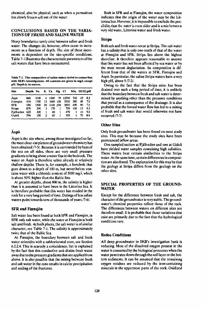
chemical, also be physical, such as when a permafrosthas slowly frozen salt out of the water.
CONCLUSIONS BASED ON THE VARIA-TIONS OF FRESH AND SALINE WATER
Sharp boundaries rarely exist between saline and freshwater. The changes do, however, often occur in incre-ments as a function of depth. The size of these incre-ments is dependent on the site-specific conditions.Table 7-1 illustrates the characteristic parameters of thesalt waters that have been encountered.
Table 7-1. The composition of saline waters tested in connectionwith SKB's investigations. All contents are given in mg/1, exceptpi I. Depth is in metres.
Site Depth Na K Ca Mg Cl SO4 HCO3pH
Äspö 860 3100 6 4300 70 12500 710 10 8.2Finnsjön 439 1700 13 1600 120 5500 380 48 7.0SFR 100 1500 20 1100 250 5000 490 90 7.5Stripa 870 290 3 170 1 700 100 13 9.3Fjällveden 625 300 1 40 1 470 1 16 9.0Gideå 596 150 2 60 1 300 1 70 8.9
Äspö
Äspö is the site where, among those investigated so far,the most clear-cut picture of groundwater chemistry hasbeen obtained 11-51. Because it is surrounded by bays ofthe sea on ail sides, there are very small pressuregradients to bring about a water flux in the bedrock. Thewater on Äspö is therefore saline already at relativelyshallow depths. There is, for example, a borehole thatgoes down to a depth of 100 m, but nevertheless con-tains water with a chloride content of 5000 mg/l, whichis about 50% higher than the Baltic Sea.
At greater depths, about 800 m, the salinity is higherthan it is assumed to have been in the Littorina Sea. Itis therefore probable that this water has resided in therock for a very long period of time. Datings of less salinewaters point towards tens of thousands of years /7-6A
SFR and Finnsjön
Saft water has been found at both SFR and Finnsjön, inSFR only salt water, while the water at Finnsjön is bothsalt and fresh. At both places, the salt water is of similarcharacter, see Table 7-1. The salinity is approximatelytwice that of the Baltic Sea.
At Finnsjön, the boundary between salt and freshwater coincides with a subhorizontal zone, see Section6.2.2.4. This is scarcely a coincidence, but is explainedby the fact that this conductive unit drains fresh wateraway due to the pressure gradients that are applied fromabove. It is also possible that the mixing between freshand salt water in the zone results in calcite precipitationand sealing of the fractures.
Both in SFR and at Finnsjön, the water compositionindicates that the origin of the water may be the Lit-torina Sea. However, it is impossible to exclude the pos-sibility that the \vatcr is even older and is a mix betweenvery old water, Littorina water and fresh water.
Stripa
Both salt and fresh water occur at Stripa. The salt waterhas a salinity that is only one-tenth of that of the waterat Finnsjön and SFR. Stripa lies above the highestshoreline. It therefore appears reasonable to assumethat this water has not been affected by sea water or bythe most recent deglaciation. Its composition is dif-ferent from that of the waters at SFR, Finnsjön andÄspö. In particular, the saline Stripa waters have a veryhigh pH, above 9/7-2/.
Owing to the fact that the Stripa mine has beendrained over such a long period of time, it is unlikelythat the boundary between fresh and salt water is deter-mined by anything other than the pressure conditionsthat prevail as a consequence of the drainage. It is alsoprobable that the forced water flow has led to a mixingof fresh and salt water that would otherwise not haveoccurred 11-11.
Other Sites
Only fresh groundwater has been found on most studysites. This may be because the study sites have beenpronounced inflow areas.
One sampled section at Fjällveden and one at Gideåhave yielded water samples containing high salinities.These waters bear certain similarities to the Stripawater. At the same time, certain differences in composi-tion are also found. The explanation for this may be thatthe geology at Stripa differs from the geology on theother sites.
SPECIAL PROPERTIES OF THE GROUND-WATER
Except for the difference between fresh and salt, thecharacter of the groundwater is very stable. The ground-water's chemical properties reflect those of the rock.The differences between waters on different sites aretherefore small. It is probable that those variations thatexist arc primarily due to the fact that the hydrologicalconditions vary.
Redox Conditions
All deep groundwater in SKB's investigation bank isreducing. Most of the dissolved oxygen present in thewater is consumed by the biological processes when thewater penetrates down through the soil layer or the bot-tom sediments. It can be assumed that the remainingoxygen residues are reduced by the iron-containingminerals in the uppermost parts of the rock. Oxidized
128
fracture faces in the uppermost part of the rock indicatethat this is the case /7-8/.
The carbon-dioxide-rich water that causes calcite dis-solution also raises the concentration of iron in thewater. Within the depth interval 0-100 m, water withiron contents on the order of 1-10 mg/1 has often beensampled. This is probably a consequence of carbondioxide weathering of biotite and other silicate mineralscontaining iron. Since pH and sulphide content increasewith depth, iron content decreases. Iron sulphide is inequilibrium with the groundwater /7-9/.
Measured redox potentials are tightly grouped withina narrow interval. The magnetite-hematite equilibriumand the ratio between bivalent and trivalent iron in sili-cate mineral describe very well the Eh-pH relation inthe measurements. An empirical relationship betweenpH and Eh is
Eh = (200-60xpH)mV
The redox capacity of the water is low. The rock, onthe other hand, has a very high redox capacity in theform of 1-10% iron, most of which is present in thebivalent form. But it is difficult to judge how large a frac-tion of this quantity is available for reactions withoxidants.
Exchange Time
The groundwater does not have any clear-cut exchangetime in the bedrock. It is, however, possible to speak ofa relative "mean exchange time" where the differentwaters can be gradated relative to each other via com-position and contents of radioactive isotopes. The mostimportant parameters and their implications can brief-ly be described as follows:
- Salt water with a chloride content in excess of thatof the Baltic Sea may originate from the LittorinaSea. This means that it has resided in the bedrockfor about 7000 years. In cases where the salt derivesfrom reactions between the bedrock and thegroundwater, its age is much higher, probably up tomillions of years in brines. Salinity can be taken as ameasure of relative age.
- Carbon-14 datings give the water's theoretical age.The half-life of carbon-14 is 5568 years, whichcovers the period of time of greatest interest, about1000-30000 years. There are, however, a number ofprocesses that lead to overestimation of the age ofthe carbonate content in the groundwater. In short,these processes involve an interaction of the car-bonate in the water with carbonate in the bedrock.By combining carbon-14 datings of both inorganicand organic carbon in the water, it is possible to ob-tain a clearer picture of the age distribution.
- Tritium has a half-life of 12.26 years. Measurabletritium contents thus indicate the presence of veryyoung water.
— Oxygen-18 and deuterium show together whetherthe water is of meteoric origin. The oxygen-18 con-tents reflect the climatic conditions that prevailedwhen the water was infiltrated and can thus providesome idea of when this happened.
By weighing in all these "age data", it is possible to getan idea of the age distribution in the water beinganalyzed. The combination of tritium and carbon-14 isoften useful for showing whether the water that has beensampled is representative. Disturbances caused by drill-ing and by the borehole can often result in a combina-tion of high carbon-14 ages together with measurabletritium contents. There are, however, other reasons whywater has both tritium and a high carbon-14 age. A com-bined analysis of all data from several sampling pointsin the same area is necessary to ascertain the exchangetime.
Fracture Minerals and Mineral Equilibria
Analysis of the groundwater provides a clear picture ofthe chemical situation at the present time. By analyzingthe chemical properties of fracture-filling minerals, it ispossible to get an idea of the stability in the picturepresented by the present-day groundwater chemistry. Itis especially possible to find out about variations inredox conditions /7-10/.
The presence of hematite and iron oxyhydroxidc inconductive fracture systems, even at great depths, indi-cates that oxygenated water has existed at these depths.This has occurred under hydrothcrmal conditions andhas resulted in hematite formation. During the finalphase of such an event, oxyhydroxides may have formed,'''here is no evidence that oxygenated water has passedthrough the fracture systems under low-temperatureconditions.
The occurrence and distribution of calcitc-scalcdfractures provides a good opportunity for checking themodels for groundwatcr movements.
Since the carbon-dioxide-rich water dissolves calcitein the uppermost part of the rock, a much lower fre-quency of calcite-scalcd fractures is found down to (hedepth where calcite dissolution ceases. On those siteswhere the water flux is very low, a decrease in calcitefrequency is consequently not found. This is the case onÄspö.
GEOCHEMICAL MODEL CALCULATIONS
Natural Geochemical Conditions
Equilibrium modellings between groundwatcr and dif-ferent minerals show how stable the studied ground-waters are. Since the studied equilibrium systems re-quire different lengths of time to develop, it is possibleto obtain a relative measure of the time during whichthe water and the minerals have been in contact witheach other based on which minerals arc in equilibriumwith the water composition.
129
The PHREEQE and EQ3/6 programs are primarilyused for the modellings. The PHREEQE code is rela-tively simple to use and is suitable for studying possiblegroundwater/mineral interaction. All groundwater dataobtained are checked with respect to solubility for themost important minerals, for example calcite, gypsum,quartz, hematite, magnetite, goethite and pyrtte /7-11,7-6/. The EQ3/6 codes are more suitable for detailedstudies of geohydrochemical processes /7-12,13/.
Conditions in the Near Field
In order to predict the chemical changes that can occurin the near field, gcochemical model calculations arebeing carried out in cooperation with the University ofStrasbourg. Three systems are being dealt with: ben-tonite clay/groundwater, bentonite clay/copper/coppermincral/groundwatcr and the importance of acids andbases for the bentonite clay.
Calculations have been carried out to determine thestability range of smectites and illites as a function oftemperature and chemical composition /7-14/.
The effect of a heating of the rock to 150°C and theeffect of high pH-values due to concrete in the re-pository have also been modelled /7-15/. Heating alonedoes not increase porosity, but heating in conjunctionwith high pH from concrete could bring this about. Theresults have been used in the assessment of the long-term stability of the WP cave repository /7-15/.
7.1.3 Research Programme 1990-1995
During the period 1990-1992, the continued researchprogramme will be carried out primarily within theframework of the Hard Rock Laboratory. Followingthat, during the period 1993-1995, the programme willalso include site investigations. The site investigationswill use the experience from the Hard Rock Laboratory.
A base survey of the geohydrochemical conditionsand a continuous follow-up of any changes that occurduring the investigations or construction activities arcrequired on each study site. Such follow-up is alsotaking place at SFR.
The hydrochemistry group within the Stripa Projecthas put together a proposal for how water andgeochemistry conditions should be investigated /7-16/.
GROUNDWATER TYPES
The occurrence of fresh and salt water will be studiedin all future site investigations. Hydrochcmical inves-tigations will be carried out on every new site in at leasttwo stages: first in shallow percussion boreholes andlater in deep cored holes.
The classification of salt water will be further dif-ferentiated. An attempt will be made to distinguish be-tween preglacial, synglacial and postglacial ground-waters in conjunction with the SKB 91 safety assess-
ment. Hydrochemical data primarily from Äspö,Finnsjön and SFR will be used, but also from other in-vestigations.
REDOX CONDITIONS
The redox level of the deep groundwaters is welldefined and clarified. Their redox buffering capacityand the kinetics of the component reactions arc,however, poorly understood. During the period 1990-1995, experiments will be conducted to measure theredox buffering capacity of the rock, to begin with em-pirically but eventually also aimed at understanding theunderlying reactions.
GROUNDWATER EXCHANGE TIME
Studies of different stable and radioactive isotopes inboth the groundwater and fracture minerals will,together with the classification of the groundwaters,constitute the methods that can be used for the purposeof determining the origin of the water. Appropriatedating technique will hereby be used in the continuedinvestigations. Great benefit can be drawn from theextensive studies of dating technique performed by thehydrochemistry group at Stripa /7-16/.
FRACTURE MINERALS
Sampling and analysis technique will be studied in con-nection with the fracture mineral investigations, for ex-ample contamination by carbon-14 from the air in thecalcite samples.
It is known from, for example, Klipperås that oxygen-containing water that is unsaturated with respect to cal-cite penetrates the upper levels of the bedrock. Thisresults in a reduced frequency of calcite and an in-creased frequency of rust in superficial water-bearingfractures. The depth to which this leaching/oxidationtakes place is dependent on the hydraulic gradient inthe area, the water chemistry, the soil depth, the com-position of the soil layer etc. Hence, ail of these factorsinfluence the redox conditions in the fractures in thebedrock. In this way, the frequency of rust and calcitein the boreholes provides information on the redoxcapacity of the bedrock.
Analyses of redox-sensitive elements such asFe(H)/Fe(III), Ce(IH)/Ce(IV) and Eu(II)/Eu(HI) inthe fracture minerals are utilized to interpret > >e redoxconditions that have existed and currently exist in frac-tures in the bedrock.
The continued work with fracture mineral investiga-tions is being focussed on:
- utilizing the presence and distribution of fractureminerals such as calcite, hematite, rust and pyrite todescribe the hydrogeochemical environment in anarea,
130
— making use of radiometric datings (uranium seriesanalyses and C-14) to determine during which timeperiods different geochemical processes are takingplace or have taken place,
— making use of tracer analyses of fracture mineralsand combined fracture mineral/groundwater samp-les to describe the mobility of elements such as U,Th, rare earth metals, Cs and Sr. The sorption of dif-ferent elements on the fracture minerals variesdepending on varying water chemistry and type ofmineral. This has been investigated in situ only atKlipperås. More areas should be examined in an at-tempt to validate co-precipitation and sorptionstudies performed in the laboratory.
GEOCHEMICAL MODEL CALCULATIONS
Equilibrium models and reaction models will continueto be used to describe the measured chemical condi-tions in the rock-groundwater system. Model calcula-tions of the geochemical evolution in the near field, egwater composition and mineral alteration, will con-tinue. An increase in the use of coupled geochemistry-transport models is foreseen.
A special area where modelling will be done isacidification of precipitation. A low pH in the rain watermaybe of greater importance for the weathering of therock than carbon dioxide absorption.
Further measurements are being made where neces-sary, and modern computer technology is being utilizedfor both storage of data and chemical model calcula-tions.
The second point includes analysis and characteriza-tion of the aggregates, such as colloids, humic substan-ces (humic and fulvic acids) and microbes present in thegroundwater. It also includes experiments with the up-take and mobility of radionuclides in such form. Final-ly, it includes modelling of radionuclide speciation andtransport properties, as far as this is possible.
The third point entails both laboratory experimentsand model studies aimed at understanding the physico-chemical processes for retention in the rock and provid-ing the transport models with retardation constants orsubmodels for surface sorption and diffusion. It is im-portant to show that postulated reactions betweenradionuclides and minerals, eg reduction, actually takeplace.
Regarding the fourth point, good means exist for cal-culating the radiation field outside and inside a wastecanister as a function of time. There is also a radiolysiskinetics model that provides a means of calculating theextent of radiolysis. Experiments are being performedto verify the validity of the model and to permit less con-servative assumptions concerning the consequences ofradiolysis.
7.2 RADIONUCLIDE
CHEMISTRY
7.2.1 Goals of the R&D Activities
The goals of the radionuclide chemistry investigationsarc as follows:
— measure and compile the basic chemical data re-quired to describe solubility, inorganic speciationand co-precipitation of radionuclides in and outsidethe repository,
— determine possible contents, stability and mobilityof dissolved radionuclides in the form of colloids,humic complexes and other aggregates, eg mi-crobes,
— describe the interaction of radionuclides with rockand backfill material in the form of redox reactions,surface sorption and diffusion,
— determine the extent of radiolysis and its influencein the near field.
The first point is being carried out to a great extent ininternational cooperation, with an emphasis on measur-ing solubility constants and compiling the constants ina database. It is essential that the chemical data that areto be included in the safety assessment are internation-ally accepted, well documented and quality-assured tothe required extent.
7.2.2 Present-day State of Knowledge
SOLUBILITY, SPECIATION, CO-PRECIPITA-TION AND KINETICS
The solubility and speciation of radionuclides in thegroundwater can be described with chemical equi-librium models based on thermodynamic constants. Inorder to obtain sufficiently good databases with equi-librium constants for the most important radionuclidcs,supplementary laboratory measurements are being per-formed both in Sweden and elsewhere around theworld. An assessment of the present-day state ofknowledge in the field is presented in Table 7-2.
The laboratory work in Sweden has been concent-rated on uranium, thorium and their compounds withhydroxide and carbonate. The results have been pub-lished for the most part in scientific journals 11-11,18/.For actinides such as neptunium and plutonium, the col-laboration with French CEA has been important /7-19/.They have excellent facilities for conducting experi-ments with radionuclides. Hydrolysis complexes ofuranium(IV) have been studied via thermal lensingspectrophotometry (TLS) in cooperation with the Ispralaboratory in Varese, Italy 11-20/.
Internationally, SKB is supporting the projects forcollection and validation of thcrmodynamic data thaiare being conducted under the leadership of OECD/NEA (TDB) and CEC (CHEMVAL).
131
Table 7-2. An estimate of the general slate of knowledge regard-ing chemical thennodynamk constants for dissolved inorganiccomplexes and solid phases of important elements in ground-water. A five-point rating scale has been used. Specific impor-tance for a safety assessment must be judged from case to case.
ELE-MENT
U
ThPu
Np
AmTeLaCe
VALENCE
VIVIVIVIIIIVVVIVIIIVVVIVIIIIIIVIIIIV
OH"
4a
3b3b43242244251Sa3a
rjrv
4a4a2b2b4a2a3a4a22a3a3a2a3b04a4a
LI«ANDC
;2" HPO42"
Ib
333301001203023
SO42"
4
443333033404244
F"
4
442314142404142
a The measurements were carried out with support from SKB bythe Department of Inorganic Chemistry at the Royal Institute ofTechnology in Stockholm, either alone or in cooperation withCEAorlSPRA.
b Work is currently being done to improve the values, with sup-port from SKB.
c Silicates have not been included but have been found to be ofimportance for eg U(VI).
The work with the thermodynamic database TDB,under the direction of OECD/NEA, has come farthestwith regard to uranium. A special thermodynamicdatabase for uranium, SKBU1 /7-21,22/, has been com-piled for SKB. It is used by the geochemical computerprogram EQ3NR. The compilation and testing ofSKBU1 has benefited from the uranium chemistry ex-periments that have been conducted for a long periodof time, as well as active participation in TDB andCHEMVAL. SKBU1 has been validated against inde-pendent experiments /7-22/. SKB's buildup of its "own"documented database is thereby proceeding accordingto plan.
Co-precipitation of lanthanides and actinides withuranium, and the importance of this phenomenon forthe release and transport of radionuclides in the nearfield, have been investigated experimentally /7-23AThorium, lanthanum and barium were chosen as modelsubstances for actinides and fission products, along withthe main component uranium. Co-precipitation in con-nection with the formation of iron hydroxides and cal-cite has also been dealt with.
ORGANIC COMPLEXES, COLLOIDS ANDMICROBES
Groundwater samples from Stripa, Kamlunge andSvartboberget have been analyzed for their content ofcolloidal inorganic particles. The concentration of par-ticulate material was generally belowO.l mg/1. The high-est value obtained was 0.4 mg/1. Undisturbed ground-waters are expected to have considerably lower con-centrations /7-24/. Filiations of saline groundwaters atForsmark and Simpevarp that have later been carriedout in the field with hollow fibre equipment indicate thatthese waters have very low contents of particulatematerial (considerably lower than 0.1 mg/1).
Formation and stability of inorganic colloids in thegroundwater have been studied in situ at Fjällveden/7-3,7-24/. Oxygenated water was pumped down into awater-bearing section at a depth of 468 metres in bore-hole KFJ02. As expected, this caused a sharp increaseof particles containing iron and sulphur. Pumping res-tored normal conditions in a few days, except for sul-phur particles, which were still present at elevated levelsafter a week. The iron hydroxide particles appear to besorbed on the fracture walls to a higher degree and notto participate in transport over longer distances.
Investigations of the capacity of inorganic particles totransport radionuclides are currently in progress.
Analysis of natural groundwater colloids and theirability to transport radionuclides is included in thestudies of natural analogues, see Chapter 9.
Humic and fulvic acids have been isolated from deepgroundwaters. The material has been concentrated,purified, analyzed and used in radionuclidc chemistryexperiments, see Table 7-3. A calculation model for ionbinding by humic and fulvic acids has been developedat the University of New York in Buffalo /7-25A Humicand fulvic acids are treated as polyelectrolytes in themodel.
The importance of complexation between radionu-clides and natural humic and fulvic acids has also beenstudied in cooperation with French CEA /7-26,27/.
SKB is supporting the participation of a Swedish ex-pert in CEC's international working group COCO. Thegroup's task is to determine the importance of naturalcolloids and complexing agents for the transport ofradionuclides.
Microbes in deep groundwaters have been analyzedby sampling with the mobile field laboratory and specialsampling in situ with the chemistry probe. A so-called"gas sampler" has been used for the latter purpose.Deep groundwater has been found to contain microbesat concentrations of between l(r and W bacteria perml /7-28/. Microbes in groundwater and on minerals andtheir potential importance for radionuclide migrationand geochemistry are also being dealt with within theframe of the P050S de Caldas project, see Chapter 11.The same applies to transport of radionuclides with par-ticulate material and organic complexing agents.
132
Tabk 7-3. Analyses of fulvk acids from superficial and deepgroundwaters.
SiteDepth (m)
BershoSurfacewater
Fjällveden Finnsjön Gldea409 232 107
INORGANIC CHEMISTRY OF THE GROUND-WATERpHEh(mV)HCQ3- (mg/1)SO42' (mg/1)F (mg/1)Q" (mg/1)N a + (mg/1)Caf+ (mg/1)K* (mg/1)MgZ + (mg/1)Age14C
carbonate (years)
5.3-5.536<0.17.25.88.31.88.6
_
7.5•1101700.20.7732212.50.4
4235
7.7-2702601402.315006503208.740
8090
CHEMISTRY OF THE FULVIC ACIDSMolecular weight MW
C(%)H(%)N(%)O(%)S(%)
Ash (%)
Acid capacity inwater (meq/g)
Age14C (years)
265052.53.61.138.81.03.0
4.65
-
170050.83.91.739.70.83.1
5.14
1270
265053.03.80.936.21.15.0
4.98
4610
8.8-101610.82.64.449102.22.6
6450
160053.74.40.537.50.53.4
5.42
5250
SORPTION AND DIFFUSION
Investigations of radionuclide diffusion in bentoniteand diffusion of radionuclides into the micropores ofthe rock have continued. Diffusion of the fissionproducts strontium, technetium and cesium as well asthe actinides thorium, protactinium, uranium, pluto-nium and americium in compacted bentonite has beenmeasured, interpreted and reported 17-29/. The impor-tance of the speciation of the nuclides in the interstitialwater in the clay has been established in the tests. Thus,for example, technctium diffuses ten times more slowlyunder reducing conditions.
Diffusion of radionuclides in sand-bentonite mixturesis being studied experimentally.
Diffusion in rock has been measured with radio-nuclides of strontium, technetium, iodine, cesium, nep-tunium, plutonium and americium 11-301. The pieces ofrock had been taken from drill cores in granitic rock atFinnsjön, Stripa and Studsvik. The measured diffusivityvaried between about 10'13 and 10'15 mV 1 , dependingon the nuclide. How different minerals and fractureminerals sorb different nuclides can also been seen.
Using concrete in existing or future alternative re-pository concepts may prove to be advantageous for dif-
ferent reasons. The chemical experiments with concreteand radionuclides have therefore been continued.Laboratory tests are being conducted with diffusion inconcrete and diffusion from concrete to bentonite. Thechemical alteration of concrete with time will also be in-vestigated.
Bentonite with additives, known as getters, has beeninvestigated experimentally. A series of different com-pounds has been tested. Additives that have a reducingaction have been found to have a favourable retardingeffect on the diffusion of redox-sensitive radionuclides.
Sorption experiments have been conducted with ra-dionuclides of sodium, strontium, cesium and europium/7-31/. Sorption on crushed fracture filling material andcrushed granite was compared with sorption on intactfracture faces. The experiments were conducted to ob-tain supplementary information to augment the labo-ratory investigations of radionuclide migration in over-cored rock fractures. The latter experiments are a partof the validation of transport models for describingradionuclide migration in rock.
Sorption tests are also being conducted to see the ef-fect of different liquid/solid phase ratios and the impor-tance of having a mixture of radionuclides.
The surface complexation theory is being tested as amodel for describing sorption and diffusion of radio-nuclides on mineral surfaces. The method has pre-viously been applied with success to sorption on cleanoxide surfaces. Experiments wi:i be conducted in orderto test sorption on mineral surfaces.
RADIOLYSIS
The production of hydrogen in compacted, wutcr-saturated bentonite as a result of irradiation with alphaparticles has been measured experimentally and com-pared with theoretical calculations that use homo-geneous reaction model for radiolysis /7-32, 33/. Rela-tively good agreement was obtained.
Experiments have also been carried out to determinethe propagation of a redox front in compacted ben-tonite as a result of alpha irradiation /7-34/, see Figure7-1. Here as well, relatively good agreement was ob-tained with calculated values. It was further found thatonly a fraction of the bivalent iron in bentonite is avail-able for reaction with radiolytically produced oxidants.
Experiments and theoretical calculations have alsobeen carried out for the radiolytic production of oxi-dants in connection with alpha radiolysis of simulatedgroundwater /7-35/. The production of hydrogen per-oxide has been analyzed and the influence of ground-water components such as chloride, carbonate and bi-valent iron ions has been determined. Agreement be-tween calculations and experiments has been relativelygood.
133
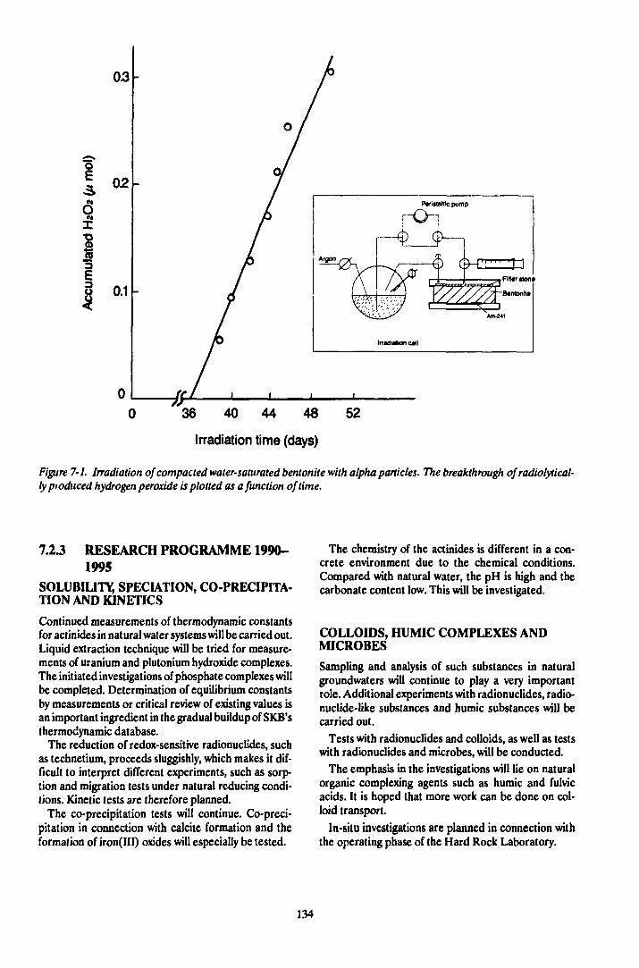
0.1 -
36 40 44 48
Irradiation time (days)
Figure 7-1. Irradiation of compacted water-saturated bentonite with alpha particles. The breakthrough of radiolytical-fypioduced hydrogen peroxide is plotted as a function of time.
7.2.3 RESEARCH PROGRAMME 1990-1995
SOLUBILITY, SPECIATION, CO-PRECIPITA-TION AND KINETICS
Continued measurements of thermodynamic constantsfor actinides in natural water systems will be carried out.Liquid extraction technique will be tried for measure-ments of uranium and plutonium hydroxide complexes.The initiated investigations of phosphate complexes willbe completed. Determination of equilibrium constantsby measurements or critical review of existing values isan important ingredient in the gradual buildup of SKB'sthermodynamic database.
The reduction of redox-sensitive radionuclides, suchas technetium, proceeds sluggishly, which makes it dif-ficult to interpret different experiments, such as sorp-tion and migration tests under natural reducing condi-tions. Kinetic tests are therefore planned.
The co-precipitation tests will continue. Co-preci-pitation in connection with calcite formation and theformation of iron(III) oxides will especially be tested.
The chemistry of the actinides is different in a con-crete environment due to the chemical conditions.Compared with natural water, the pH is high and thecarbonate content low. This will be investigated.
COLLOIDS, HUMIC COMPLEXES ANDMICROBES
Sampling and analysis of such substances in naturalgroundwaters will continue to play a very importantrole. Additional experiments with radionuclides, radio-nuclide-like substances and humic substances will becarried out.
Tests with radionuclides and colloids, as well as testswith radionuclides and microbes, will be conducted.
The emphasis in the investigations will lie on naturalorganic complexing agents such as humic and fulvicacids. It is hoped that more work can be done on col-loid transport.
In-situ investigations are planned in connection withthe operating phase of the Hard Rock Laboratory.
134

SORPTION AND DIFFUSION
Laboratory tests with sorpt ion and diffusion of radionu-clides in rock material will continue. An important taskis to test more advanced models for sorption and dif-fusion that include surface diffusion, surface complexa-tion, surface reactions etc. The aim is to achieve agreater understanding of the phenomena and develop-ment of submodels that can be used in the transportmodels.
The laboratory tests with sorption and diffusion inconcrete will shed light on the possible advantages orconsequences of using concrete in a repository for high-level waste. The tests are intended to determine the im-pact of the concrete on the environment and theconcrete's own chemical and structural alteration withtime.
The tests with additives known as "getters" to a ben-tonite buffer will continue. An initial step has beentaken to find substances which can be shown by experi-ments to have a favourable effect. The next step is tochoose among these substances the ones that arefeasible to use. It then remains to prove that theproposed additives cannot affect the buffer, the canisteror other near-field components negatively during thevery long period of time the barrier function must bemaintained.
RADIOLYSIS
The radiolysis kinetics model needs to be further tested.More fundamental tests and variation analyses mayprove to be necessary. An important point that remainsto be dealt with is the influence of the fuel surface onthe chemical process of radiolysis, see also Chapter 3.
7.3 CHEMICAL TRANSPORTAND VALIDATION OFTRANSPORT MODELS
7 J.I Goals of the R&D Activities
The goal is to develop and validate the models that areused to describe release, dispersal and retention ofradionuclides from a final repository, as well as thechanges in the near field, for example the creation of aredox front due to radiolysis.
Validation of chemical transport models shall be ac-complished by means of:
— laboratory tests,— tracer tests,— study of natural analogues.
73.2 Present-day State of Knowledge
The transport of solutes with the natural groundwaterflow in rock is described with calculation models. This
transport modelling is based on calculations of thewater flow and a description of the distribution of theflow in the rock. The distribution of the water flow be-tween different water-bearing fractures and in the frac-tures themselves is of very great importance for the dis-persal of solutes in the groundwater. The existence ofpreferential flowpaths, known as channels, can reducethe transport times and also diminish the retention ofdissolved radionuclides through a reduction of the con-tact surface area with the rock. This has been describedthoroughly /7-36V and has also been used as a point ofdeparture for conservative hypotheses within safety as-sessments performed for SFR and WP Cave.
TRACER TESTS
Tracer tests can be regarded as larger-scale inter-ference pumping tests. Besides pressure responses, icconnectivities, the length and transport capacity of theflowpaths is obtained. In actuality, tracer tests are theonly method that can be used to determine the traveltimes of the water between two points and thus checkthe validity of the models for water flux devised on thebasis of hydrotests. The extreme cases are that the watermoves in a single channel, and that it flows in a homo-geneous porous medium. On a large scale, the porousmodel is fully acceptable, while on smaller scales chan-nelling must be taken into account.
Tracer tests have been carried out on different scales,at Finnsjön and at Stripa. The tests carried out at Stripahave mainly focussed on transport in the good, low per-meable, rock, while tracer tests at Finnsjön havefocussed on a horizontal fracture zone of high conduc-tivity. The results of the tests have also been different.The transport at Finnsjön can very well be described bya porous continuum model, while the transport at Stripapoints toward strong channelling.
The channelling model for water flow in an individualfracture has been dealt with in /7-37/. A two-dimen-sional statistical model has been used to simulate awater-bearing fracture /7-38A Water flow and solutetransport in the fracture have been modelled for dif-ferent realizations of the model fracture.
Tests at Stripa
Tracer tests with non-interacting tracers are being con-ducted in the Stripa mine within the framework of theinternational OECD/NEA project, see chapter 10. Themigration distance has varied between about 1 andSO m. Longer transport distances have been observed inone case. An important goal has recently been to dem-onstrate the distribution of the water flow over the frac-ture faces and between different fractures.
Radar measurement days have been used successful-ly at Stripa to follow the flow of salt water injected inwater-bearing fractures between boreholes.
A series of experiments at Stripa for the purpose ofvalidating the presence of an interconnected pore sys-tem in low-conductivity rock has now been concluded
135
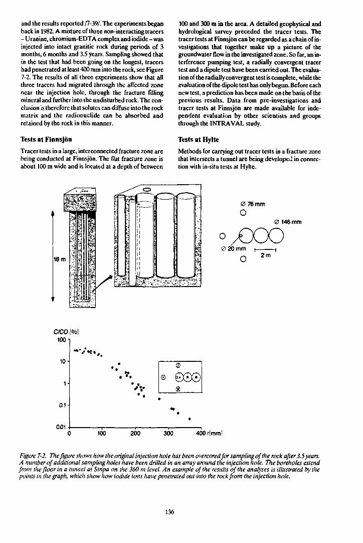
and the results reported /7-39/. The experiments beganback in 1982. A mixture of three non-interacting tracers- Uranine, chromium-EDTA complex and iodide - wasinjected into intact granitic rock during periods of 3months, 6 months and 3.5 years. Sampling showed thatin the test that had been going on the longest, tracershad penetrated at least 400 mm into the rock, see Figure7-2. The results of all three experiments show that allthree tracers had migrated through the affected zonenear the injection hole, through the fracture fillingmineral and further into the undisturbed rock. The con-clusion is therefore that solutes can diffuse into the rockmatrix and the radionuclide can be absorbed andretained by the rock in this manner.
Tests at Finnsjön
Tracer tests in a large, interconnected fracture zone arebeing conducted at Finnsjön. The flat fracture zone isabout 100 m wide and is located at a depth of between
100 and 300 m b the area. A detailed geophysical andhydrological survey preceded the tracer tests. Thetracer tests at Finnsjön can be regarded as a chain of in-vestigations that together make up a picture of thegroundwater flow in the investigated zone. So far, an in-terference pumping test, a radially convergent tracertest and a dipole test have been carried out. The evalua-tion of the radially convergent test is complete, while theevaluation of the dipole test has only begun. Before eachnew test, a prediction has been made on the basis of theprevious results. Data from pre-investigations andtracer tests at Finnsjön are made available for inde-pendent evaluation by other scientists and groupsthrough the INTRAVAL study.
Tests at Hylte
Methods for carrying out tracer tests in a fracture zonethat intersects a tunnel are being developed in connec-tion with in-situ tests at Hylte.
18 m
0 76 mm
0 146 mm
yCOOo0 20 mm
2m
C/CO [%|
10-
1 .t
0.1
0.01
• •
• • • ©
•
©
©0©®
•
100 200 300 400 rfmrnl
Figure 7-2. The figure shows how the original injection hole has been overcoredfor sampling of the rock after 3.5 years.A number of additional sampling holes have been drilled in an array around the injection hole. The boreholes extendfrom the floor in a tunnel at Stripa on the 360 m level. An example of the results of the analyses is illustrated by thepoints in the graph, which show how iodide ions have penetrated out into the rock from the injection hole.
136
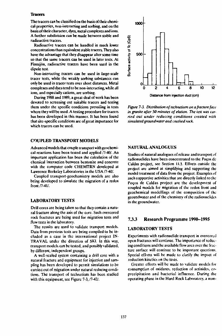
Tracers
The tracers can be classified on the basis of their chemi-cal properties non-interacting and sorbing, and on thebasis of their character, dyes, metal complexes and ions.A further subdivision can be made between stable andradioactive tracers.
Radioactive tracers can be handled in much lowerconcentrations than equivalent stable tracers. They alsohave the advantage that they disappear after some timeso that the same tracers can be used in later tests. AtFinnsjön, radioactive tracers have been used in thedipole test.
Non-interacting tracers can be used in large-scaletracer tests, while the weakly sorbing substances canonly be used in tracer tests over short distances. Metalcomplexes and dyes tend to be non- interact ing, while allions, and especially cations, are sorbing.
During 1988 and 1989, a great deal of work has beendevoted to screening out suitable tracers and testingthem under the specific conditions prevailing in testswhere they will be used. A testing procedure for tracershas been developed in this manner. It has been foundthat site-specific conditions are of great importance forwhich tracers can be used.
1000
o
o2- 500
irCO
0 2 4 6 8 10
Distance from injection duct (cm)
12
Figure 7-3. Distribution nftechnetium on a fracture facein granite after 50 minutes of elution. The test was car-ried out under reducing conditions created withsimulated groundwater and crushed rock.
COUPLED TRANSPORT MODELS
Advanced models that couple transport with geochemi-cal reactions have been tested and applied /7-40/. Animportant application has been the calculation of thechemical interaction between bentonite and concretewith the computer code CHEMTRN developed atLawrence Berkeley Laboratories in the USA /7-40/.
Coupled transport-geochemistry models arc alsobeing developed to simulate the migration of a redoxfront /7-4V.
LABORATORY TESTS
Drill cores are being taken so that they contain a natu-ral fracture along the axis of the core. Such overcorcdrock fractures are being used for migration tests andflow tests in the laboratory.
The results are used to validate transport models.Data from previous tests are being compiled to be in-cluded as a case in the international project IN-TRAVAL under the direction of SKI. In this way,transport models can be tested, and possibly validated,by different, independent groups.
A well-sealed system containing a drill core with anatural fracture and equipment for injection and sam-pling has been developed to permit simulations to becarried out of migration under natural reducing condi-tions. The transport of Icchnclium has been studiedwith this equipment, see Figure 7-3, /7-42/.
NATURAL ANALOGUES
Studies of natural analogues of release and transport ofradionuclides have been concentrated to the Poqos dcCaldas project, sec Section 11.1. Efforts outside theproject arc aimed at simplifying and supporting themodel treatment of data from the project. Examples ofsuch supportive activities that are directly linked to (heP090S de Caldas project are the development ofcoupled models for migration of the rcdox front andgeochemical modellings of the composition of thegroundwater and of the chemistry of the radionuclidcsin the groundwater.
733 Research Programme 1990-1995
LABORATORY TESTSExperiments with radionuclidc transport in ovcrcoredopen fractures will continue. The importance of reduc-ing conditions and the available flow area over the frac-ture surface will continue to be important questions.Special efforts will be made to clarify the impact ofreduction kinetics on the tests.
Greater efforts will be made to validate models forconsumption of oxidants, reduction of actinides, co-precipitation and bacterial influence. During theoperating phase in the Hard Rock Laboratory, a num-
137
ber of in-situ tests are planned to study conditions inconnection with release and migration of radionuclides.Prior to and during the migration tests in the Hard RockLaboratory, laboratory tests will be initiated within thechemistry programme to prepare and support theunderground experiments. This will most likely be amajor activity that will engage a large portion of the1990-1995 chemistry programme.
TRACER TESTS
Additional tracer tests with non-interacting tracers willbe conducted within the Stripa Project and in the HardRock Laboratory. A continuation of the tracer tests atFinnsjön is currently being discussed. For the HardRock Laboratory, the aim is to carry out tests with sorb-ing substances as well, test the reducing properties ofthe rock with respect to oxygen and redox-sensitiveradionuclides, and test the transport of colloidal andcomplex-bound radionuclides.
During the period 1990-1995, tracer tests will mainlybe conducted in the Hard Rock Laboratory. The pur-pose and scope of these tests are described in Chapter9 and are only briefly outlined below.
— A large-scale tracer test during the constructionphase and during the operating phase will shed lighton how the water moves over distances of 100 - 500m. A large number of inflow points and injectionpoints will be utilized.
— A block-scale tracer test during the operating phasewill describe the movement of the water in the good,low permeable, rock and in fracture zones on a scaleof 10-50 m.
As a conclusion of the Site Characterization andValidation Test at Stripa, tracer tests will also be con-
ducted. They will influence the design of the block-scaletracer test in the Hard Rock Laboratory.
TRACERS
During 1990, a tracer manual will be compiled on thebasis of the results obtained from the tests at Finnsjönand Hyltc. Questions to be dealt with include:
- Which tracers can be used in the tests?- When can the different tracers be used?- In what sequence should the tracers be used?- Which tests should be performed before the tests?
An important part of the work involves defining thesorption properties of the weakly sorbing tracers, sincethey can be used to some extent to distinguish the dif-ferent conceptual models.
NATURAL ANALOGUES
In collaboration with England (UK DoE), Switzerland(NAGRA), the USA (US DOE) and Brazil, a study ofnatural analogues is being conducted at Poc.os dc Cal-das in Brazil. The work was begun in May 1986 and isscheduled to continue until March 1990, see also Sec-tion 11.2.
SKB is following the Alligator Rivers project, ARAP(Alligator Rivers Analogue Project), by participation inthe INTRAVAL project, where data from both thePoc.os de Caldas project and the Alligator Riversproject are being processed with broad internationalparticipation. SKB is currently discussing with theCanadian organization AECL the possibility of par-ticipating in the Cigar Lake project in Canada, to beginwith during a three-year period starting in 1989.
138
8 METHOD AND INSTRUMENT DEVELOPMENT
8.1 GOALS OF THE R&DACTIVITIES
By "methods and instruments" is meant in this chaptermeasuring methods for the collection of geological, geo-hydrological, geophysical, geochemical and rock-mechanics parameters for the characterization of a rockvolume, as well as measuring instruments used for thisdata collection. How the methods are applied in SKB'sgeoscientific research has been described in Section6.2.2.1.
The goal of method and instrument development is toensure that suitable methods and instruments are avail-able for high-quality collection of such measurementdata as are required for the characterization of a rockvolume for a final repository and for assessment of thesafety of such a final repository for radioactive waste.
While the principal method development takes placewithin the framework of different projects, the instru-ment development is usually pursued in the form of spe-cial development projects.
8.2 PRESENT-DAY STATE OFKNOWLEDGE
Knowledge of the properties of the rock at depths thatmay be considered for a Swedish final repository forradioactive waste, about 500 m or more, was relativelylimited in the mid-seventies, especially as regards crys-talline bedrock.
Boreholes for oil and gas exploration had mainly beendrilled in sedimentary bedrock. Water prospecting con-stituted a limited source for data collection given thesmall depths, 50 - 150 m. Prospecting for minerals andores extended to greater depths, but had been limitedto a small number of ore fields in Sweden. The data col-lection was usually concentrated for natural r -asons torocks and structures that were of importance h r clarify-ing the origin of the ores.
In response to commercial needs, efficient a. *e drill-ing rigs had been developed so that continuous rocksamples, drill cores, could be retrieved from the pene-trated rock volume for inspection. Geophysical loggingwas relatively well developed for oil prospecting insedimentary bedrock, but was still in its cradle as far ascrystalline bedrock was concerned. Geophysicalmeasurements from the surface, on the other hand, hadbeen developed into relatively useful aids.
Hydrological methods had begun to be used at a rela-tively early stage within groundwater prospecting fordetermination of the water-bearing and water-storage
properties of the rock, but with the limitation that theyapplied for homogeneous aquifers, usually water-bear-ing strata in sedimentary bedrock. These methods werethen further developed in connection with calculationsof the volume content of oil reservoirs etc and sub-sequently came to constitute a basis for the geohy-drological methods in crystalline bedrock as well.
The great proliferation of research on the final dis-posal of radioactive waste that took place during the lat-ter half of the seventies led to great advances within thefield of measuring methods and instruments. Geophysi-cal methods and instruments have come to be importanttools and great progress has therefore been made in thisarea, especially with regard to measurements fromboreholes.
As far as geohydrological methods are concerned,SKB has invested a great deal in developing suitablemethods for the difficult task of characterizing thewater's occurrence and flowpaths in a crystallinebedrock, with its complex pattern of fractures. Methoddevelopment within geohydrology has also led to greatefforts to develop suitable measuring instruments.
8.2.1 Measuring Methods and Instru-ments for Surface Investigations
This summary of the present-day state of knowledgeregarding methods and instruments for surface inves-tigations will not deal with methods for obtaining satel-lite pictures, aerial photographs, topographical andgeological maps, even though such information is ofgreat importance for SKB's georesearch.
As far as airborne geophysics is concerned, methodsexist for the measurement and production of magneticmaps, radiation maps, electromagnetic maps etc of hightechnical quality/8-1/. At the same time, it can be notedthat such surveying activities, which in combination withgeological surveying are of great importance in thenationwide resource planning, have been sharplyreduced in recent years, mainly due to cutbacks ingovernment funding.
A large number of geophysical measurement meth-ods are available for measuring from the ground surface/8-2,3/. Electromagnetic methods (Slingram and VLF)arc also of great importance for determining the loca-tion and extent of rock blocks and fracture zones fromthe ground surface. In the other contexts, electricalmeasuring methods can be decisive. Among acousticmethods, seismic refraction and seismic reflection sur-veys arc best suited for detection of crushed zones atsmall and great depths. The radar method, previouslydeveloped for borehole measurements, should, after
139
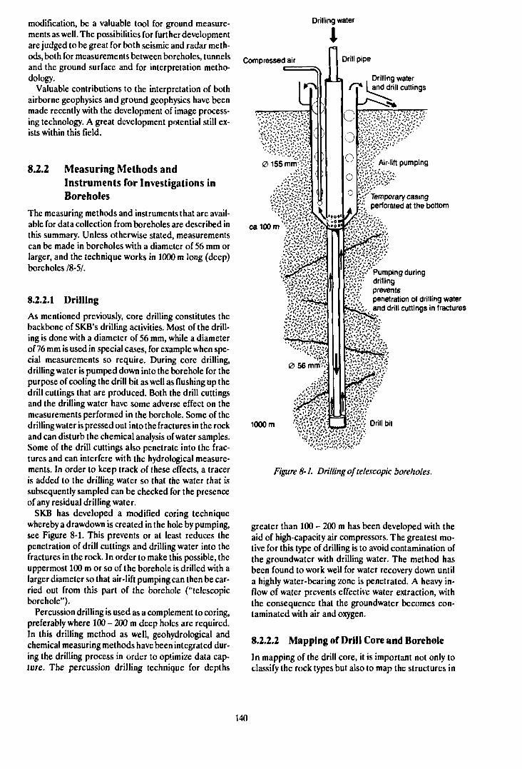
modification, be a valuable tool for ground measure-ments as well. The possibilities for further developmentare judged to be great for both seismic and radar meth-ods, both for measurements between boreholes, tunnelsand the ground surface and for interpretation metho-dology.
Valuable contributions to the interpretation of bothairborne geophysics and ground geophysics have beenmade recently with the development of image process-ing technology. A great development potential still ex-ists within this field.
8.2.2 Measuring Methods andInstruments for Investigations inBoreholes
The measuring methods and instruments that are avail-able for data collection from boreholes are described inthis summary. Unless otherwise stated, measurementscan be made in boreholes with a diameter of 56 mm orlarger, and the technique works in 1000 m long (deep)boreholes /8-5/.
8.2.2.1 Drilling
As mentioned previously, core drilling constitutes thebackbone of SKB's drilling activities. Most of the drill-ing is done with a diameter of 56 mm, white a diameterof 76 mm is used in special cases, for example when spe-cial measurements so require. During core drilling,drilling water is pumped down into the borehole for thepurpose of cooling the drill bit as well as flushing up thedrill cuttings that are produced. Both the drill cuttingsand the drilling water have some adverse effect on themeasurements performed in the borehole. Some of thedrilling water is pressed out into the fractures in the rockand can disturb the chemical analysis of water samples.Some of the drill cuttings also penetrate into the frac-tures and can interfere with the hydrological measure-ments. In order to keep track of these effects, a traceris added to the drilling water so that the water that issubsequently sampled can be checked for the presenceof any residual drilling water.
SKB has developed a modified coring techniquewhereby a drawdown is created in the hole by pumping,see Figure 8-1. This prevents or at least reduces thepenetration of drill cuttings and drilling water into thefractures in the rock. In order to make this possible, theuppermost 100 m or so of the borehole is drilled with alarger diameter so that air-lift pumping can then be car-ried out from this part of the borehole ("telescopicborehole").
Percussion drilling is used as a complement to coring,preferably where 100 - 200 m deep holes are required.In this drilling method as well, geohydrological andchemical measuring methods have been integrated dur-ing the drilling process in order to optimize data cap-ture. The percussion drilling technique for depths
Drilling water
Compressed air
Drilling waterand drill cuttings
v / ' Temporary casingh; perforated at the bottom
'V-'\V«'% Pumping during'>-'i--'" drilling
prevents, penetration of drilling water
js£v,. and drill cuttings in fractures
1000 m
Figure 8-1. Drilling of telescopic boreholes.
greater than 100 - 200 m has been developed with theaid of high-capacity air compressors. The greatest mo-tive for this type of drilling is to avoid contamination ofthe groundwater with drilling water. The method hasbeen found to work well for water recovery down untila highly water-bearing zone is penetrated. A heavy in-flow of water prevents effective water extraction, withthe consequence that the groundwater becomes con-taminated with air and oxygen.
8.2.2.2 Mapping of Drill Core and Borehole
In mapping of the drill core, it is important not only toclassify the rock types but also to map the structures in
140
the bedrock as well as the appearance and direction ofthe fractures. It should be determined whether the frac-tures have formed naturally, whether they have beensealed by fracture minerals or whether they have beencreated in connection with the drilling work. Fractureminerals are mapped and the material is processedstatistically to determine, among other things, correla-tions between fracture directions and fracture minerals/8-6,7/. To assist in this mapping work, a computerizedmapping instrument has been specially devised tofacilitate statistical processing and data presentation.Determining the three-dimensional direction of frac-tures from the drill core is a difficult task. Differentorientation methods are available, but most are time-consuming and/or relatively unreliable.
Borehole TV and televiewer are two methods that canbe used to orient individual fractures directly in theborehole. Borehole TV is currently only available for in-spection down to a depth of 500 m. Orientation is donewith the aid of a built-in compass and inclinometer.With the right illumination, the method has the ad-vantage of providing a visual picture of the boreholewall, but the orientation work requires considerablemanual labour. The method does, however, have greatpotential for development both toward great depthsand toward automatic orientation via image processing.The televiewer is another instrument that is loweredinto the borehole to scan the borehole wall by means ofultrasound. This method has recently been developedso that it can be used in boreholes as small as 56 mm,which was recently tested within the Hard Rock Labo-ratory Project. The method's data presentation is welldeveloped so that the direction of the fractures can bedetermined relatively easily.
8.2.2.3 Geophysical Measurements inBoreholes
Geophysical Borehole Logging
Geophysical borehole logging is a method that is usedroutinely in connection with SKB's site investigations.These measurements supplement core mapping, butcan also be used in percussion boreholes where there isno drill core to study/8-7/. It can be impossible to deter-mine whether a fracture or fracture zone is open andwater-bearing by means of mapping of the drill corealone, but here geophysical logging mcthoJs can indi-cate water content. These methods include measure-ment of the resistivity and temperature of the boreholeliquid, while the two radioactive methods neutron andgamma-gamma (above all in combination) can providean indication of porous units (eg fracture zones) and ofhigh-density rock types (eg greenstone dykes). Mea-surement of natural gamma radiation is especially use-ful for distinguishing different rock types. A number ofelectric logging methods are available and are usedprimarily to detect fractured rock or individual frac-tures. Other measuring methods build on the varying
elasticity and magnetization of the rock. Combining theresults of different measuring methods is an area whereprogress is being made through improvements inprocessing and presentation techniques.
Borehole Radar
Physical methods that have undergone considerabledevelopment recently are borehole radar and boreholeseismic. Radar technology, whose most common andwell-known application has been for the surveillance ofair space as well as air and marine safety, has also beendeveloped over the past couple of decades for measure-ment of soil strata from the ground surface. A great stepforward was made when the radar method was deve-loped for use in rock investigations in boreholes /8-8AThe method entails sending electromagnetic pulseswith frequencies in the range 20 -100 MHz out into therock volume around the borehole. Differences especial-ly in the rock's electrical, but also magnetic, propertiesare manifest in the form of reflection surfaces or at-tenuation of the signal until it returns to the signalreceiver. The method has been refined to a high degreewithin vSKB projects, especially the international StripuProject. It can be performed today in the form of bothsingle-hole measurements and cross-hole measure-ments. The radar instrument is of a high technical leveland the measurement results are presented in the formof images where, for example, fracture zones and rockdykes appear as flat structures or as tomograms wherethe velocity distribution or signal attenuation attest toanomalous bedrock conditions.
The method's resolution is on the order of awavelength, ie 2 - 6 m. Anomalous objects that have thislength in at least one dimension can generally beregarded as detectable 19,-91.
The radar method is still under intensive develop-ment. Directional antennas are being developed to per-mit the direction to a reflecting structure to be deter-mined. One of the big advantages of the radar methodis that it detects structures even outside the immediatevicinity of the borehole, in contrast to the geophysicallogging methods described above. Under favourableconditions, structures can be followed at distances ofmore than 100 m from the borehole.
Radar measurements are sensitive to the resistivity ofthe rock volume. When pores and fractures arc filledwith salt water, the radar signal is greatly attenuated,which means that its range is greatly reduced. However,the highly attenuating properties of salt water can alsobe used to advantage by, for example, injecting saltwater into a fracture zone that is originally filled withfresh water. Differences in the radar images before andduring salt water injection are used to determinewhether, and in which units, a fracture zone is water-bearing. This measuring technique has been tested andconstitutes an example of the development potential ofradar methodology and of how combined testing meth-ods can improve characterizations of rock volumes.
141
Borehole Seismics
Another geophysical method that has been developedto a considerable extent is seismology. Seismic methodsare based on the fact that the propagation and reflec-tion of acoustic waves reflect the elastic properties ofthe medium. The speed of propagation of the seismicwaves is determined in order to obtain a measure of thedegree of fracturing of the rock. Thus, the wave velocityin fracture zones is low, while in sound rock it is high.
Seismic methods have long been used in the form ofrefraction seismic surveys and reflection seismic surveysfrom the ground surface. Another seismic method thathas undergone rapid development recently is boreholeseismics, which, like borehole radar, can be used eitheras a single-hole method or as a cross-hole method withmeasurement results in the form of a reflection diagramor a tomogram, respectively /8-10/. Great efforts havebeen made to improve the seismic transmitter, eg by theintroduction of piezoelectric transmitter elements thatgive the transmitted wave a known frequency spectrum,which in turn simplifies the analysis of the returningwaves. As with radar, most of this development workhas been, and is still being, conducted within theframework of the Stripa Project.
Other applications of seismology are VSP, VerticalSeismic Profiling, and Tube Wave, both of which arebased on wave propagation from the ground surface toboreholes. VSP is mainly used to detect structures thatpenetrate boreholes, and in particular more or lesshorizontal ones, although structures beiow the bottomof the hole can also be identified. The method often con-stitutes a calibration method for reflection seismic sur-veys from the ground surface. Tube Wave measure-ments arc basically conducted in the same manner, butin this case the arrival of so-called tube waves isanalyzed. These waves arise where the borehole inter-sects a water-filled fracture when the fracture is broughtinto oscillation by the primary clastic wave /8-11/. Thetube wave then propagates along the borehole and isdetected with hydrophones. The purpose of the methodis to detect open fractures or fracture zones.
8.2.2.4 Geohydrological Measurements inBoreholes
Gcohydrological measuring methods for use in bore-holes have undergone extensive development. Passivemethods entail measurement of natural conditions(pressure and flow), while active methods involvemeasuring the response of an artificial disturbance inthe groundwater reservoir.
Hydraulic Measurements
An initial hydraulic measurement can be made in con-nection with the drilling operation. This is especiallytrue for percussion drilling, where the rale of recovery(the rate at which the water table returns to its originallevel) is measured when drilling is concluded. The same
type of measurement can also be made in connectionwith core drilling, but then special interruptions aremade when air-lift equipment is lowered and the 100lowermost metres are sealed off by a packer. Recoverymeasurements, which provide a general picture of thehydraulic properties of the borehole in 100 m sections,are an example of combined measurements, since watersamples are taken at the same time.
Hydraulic injection test is a measuring method that isoften used to determine hydraulic conductivity /8-12/.The method involves inflating 2 packer seals to seal offone borehole section at a time and measure how muchwater can be pressed out into the fractures in the rock.Water pressure, the length of the measurement sectionand the measuring time can all vary widely. In SKB's in-vestigations, a section length of 3 and/or 30 m is normal-ly used. In the former case, the measurements are nor-mally performed with an injection time of 15 min, while2 hours is used for 30 m measurements. SKB has madegreat efforts to develop practical instruments with goodaccuracy for these measurements. Thus, for example, anumbilical hose system have been designed that performthe measurements fully automatically under computercontrol /8-5/. With another equipment, called the pipestring system, the water injection is controlled manual-ly while data collection is performed by a computer. Thetests arc usually carried out at an injection pressure of2 bar. Flow values within the range 0.5 ml/min to about201/min can be measured, and pressure changes on theorder of 1 cm H2O should be able to be recorded at adepth of 1000 m. The measuring range for hydraulicconductivity is about 10 - 10* m/s for the pipe stringsystem, but this is dependent on section length andmeasurement time.
When the hole has a large enough diameter to accom-modate a submersible pump, pumping tests can be car-ried out. Like an injection test, a pumping test con-stitutes a hydraulic disturbance whose effect is recor-ded. Usually, however, water is pumped from a wholeborehole, which means higher capacity. It is also usual-ly carried out during a longer period (days-weeks-months). If more boreholes are present in the vicinity,the groundwatcr table is measured in them, and theseholes can also be sectioned off by means of packer seals.Such measurements arc called interference tests orcross-hole measurements and have the great advantageof reflecting the hydraulic conditions within a largerarea. A special type of cross-hole measurement hasbeen tested in the Hard Rock Laboratory Project; waterwas pumped from packer-scaled borehole sections inthe previously described telescopic boreholes with alarge-diameter upper section /8-13/. With this specialtype of measurement, the question of whether fracturezones are hydraulically interconnected between the dif-ferent boreholes can be determined with greater cer-tainty.
A new hydraulic method has been tested for the firsttime within the Hard Rock Laboratory Project /8-12/.Flow meter logging has been carried out during pump-
142
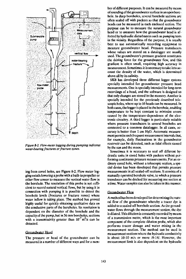
Measurement••: data
depth
Figure 8-2. Flow-meter logging during pumping indicateswater-bearing fractures or fracture zones.
ing from cored holes, see Figure 8-2. Flow meter log-ging entails lowering a probe with a built-in propeller orother flow sensor to measure the vertical water flow inthe borehole. The resolution of this probe is not suffi-cient to record natural vertical flows, but by using it inconnection with pumping it is possible to detect theborehole levels (fractures or fracture zones) wherewater inflow is taking place. The method has provedhighly useful for quickly obtaining qualitative data onthe conductive parts of the boreholes. Its resolution isdependent on the diameter of the borehole and thecapacity of the pump, but in 56 mm boreholes, sectionswith a transmissivity greater than 10"7m2/s can bedetected.
firnundwater Head
The pressure or head of the groundwater can bemeasured in a number of different ways and for a num-
ber of different purposes. It can be measured by meansof sounding of the groundwater surface in an open bore-hole. In deep boreholes, several borehole sections arcoften sealed off with packers so that the groundwaterheads can be measured in each enclosed section. Thepurpose can be to measure the natural groundwaterhead or to measure how the groundwater head is af-fected by hydraulic disturbances such as pumping testsin the vicinity. Regardless of the purpose, it is usuallybest to use automatically recording equipment tomeasure groundwater head. Pressure transducerswhose values are stored on a datalogger are usuallyused. The groundwater's pressure gradient constitutesthe driving force for the groundwater flow, and thisgradient is often small, requiring high accuracy inmeasurement. Sometimes it is necessary to take into ac-count the density of the water, which is determinedabove all by its salinity.
SKB has developed three different logger systemsspecially intended for groundwater pressure headmeasurements. One is specially intended for long-termrecordings of a head, and the software is designed sothat only changes are stored in the memory. Another isspecially intended for the previously described tele-scopic holes, where up to 10 heads can be measured. Inboth cases, the logger is placed in the borehole, enablingtemperature to be kept constant to minimize errorscaused by the temperature-dependence of the elec-tronic circuitry. A third logger is particularly suitablewhere pressure transducers in several boreholes arcconnected to a common datalogger. In all cases, ac-curacy is better than 1 cm H2O. Automatic measure-ment permits such frequent measurement intervals that,for example, daily fluctuations in the groundwaterreservoir can be detected, such as tidal effects causedby the sun and the moon.
Sometimes it is necessary to seal off different hy-draulic units in cored holes with packers without per-forming continuous pressure measurements. For an or-dinary cored hole, without a telescopic section, a spe-cial device has been developed that permits pressuremeasurements in all sealed-off sections. It consists of amanually operated borehole valve, to which a pressuretransducer can be docked for measuring one section ata time. Water samples can also be taken in this manner.
Groundwater Flow
A method has been developed for determining the natu-ral flow of the groundwater whereby a tracer dye isadded to a sealed-off borehole section. As the ground-water flows through the measurement section, the dyeis diluted. This dilution is constantly recorded by meansof a transmission meter, which is the most importantcomponent of the complete dilution probe, which alsoperforms tracer dosage and water mixing in themeasurement section. The method can be used inmeasurement sections where the hydraulic conductivityis about 10-10 m/s or more /8-14/. However, themeasurement limit is also dependent on the hydraulic
143
gradient as well as on borehole diameter and sectionlength. Low water flux results in a long measuring time.
In the Hard Rock Laboratory Project, all boreholesare equipped with packers and the dilution probe can-not be used. Another method for dilution measure-ments will therefore be used. Twin hoses are run upfrom several of the sealed-off sections to the ground sur-face so that the water in the section can circulate. By ad-ding a dye tracer and analyzing its dilution in connec-tion with sampling, it is possible to determine the natu-ral flow of the water. However, this method is notcapable of measuring as low exchange rates as the dilu-tion probe.
8.2.2.5 Hydrochemical Measurements inBoreholes
Water Sampling and Analysis
Water sampling and analysis of the chemical content ofthe water can be performed at different times during adrilling programme /8-15,16/. Different types of sam-pling procedures are suitable for different purposes andyield results with different accuracies.
Sampling can be done during hydraulic air lift pump-ing/recovery measurements in connection with bothpercussion and core drilling. These samples have theadvantage that they provide information on the chemi-cal composition of the water at an early stage, but fromthe quality viewpoint the samples are contaminatedwith oxygen and often contain a high proportion of drill-ing water. Other opportunities for water sampling arein connection with pumping tests.
Special chemical sampling is done with the mobilefield laboratory developed by SKB /8-5/. Sampling isdone by lowering a sampling pump together with pack-er seals down into a borehole. The water pumped upfrom the sealed-off section is conducted through an in-situ measuring cell equipped with electrodes formeasurement of Eh and pH. Up on the surface, thewater passes through a second measuring cell whereoxygen content and electrical conductivity are alsomeasured. The measurement equipment includes achemistry laboratory where most relevant substancesare analyzed. This direct analysis on the sampling sitein combination with recording of pH, Eh and sometimesalso sulphide content down in the hole results in highquality, especially in the determination of the water'sredox conditions and content of redox-sensitivc sub-stances.
Any gases dissolved in the groundwater are normallylost to a large extent due to the pressure reduction whenthe water is pumped to the surface. In order to circum-vent this, a special sampling cylinder has been deve-loped. It is placed down in the borehole next to thepump, and after a period of pumping it fills with waterand is sealed. The sampling cylinder is then lifted up andtaken to the gas laboratory for quantitative analysis ofthe gases that have evaporated from the water.
The sampling pump used for the mobile fieldlaboratory has a low capacity, about 120 ml/s. It is hy-draulically driven and therefore requires a great deal ofperipheral equipment. It should be possible today todevelop a simpler pump system with greater pumpingcapacity.
Tracer Tests
Tracer tests can be used for geometric characterizationof water-bearing fractures and fracture zones and todetermine the transport properties of these structures.The measuring method entails dosing out a tracer at oneor more points (boreholes or borehole sections) andsampling and analyzing the amount of tracer trans-ported to one or more other points. The tests can be car-ried out with the natural gradient as the only drivingforce, but usually the sampling hole is pumped out, andsometimes the tracers are injected under pressure in thedosage hole.
A simple type of tracer test is performed in connec-tion with drilling by adding tracer to the drilling water.If pumping takes place in an adjacent hole, anybreakthrough of tracer can be recorded /8-17/. This canbe a suitable preliminary method in, for example, a tar-geted study of individual fracture zones, and has beenused in SKfi's fracture zone tests at Finnsjön. Moreover,the addition of tracer to the drilling water is valuable forjudging the quality of subsequent water samples.
The methodology for special tracer tests has beendeveloped and tested att Stripa /8-18/ and Finnsjön.
8.2.2.6 Rock Stress Measurements
There are two fundamentally different methods fordetermining rock stresses in boreholes: overcoring andhydrofracturing. Both methods have undergone con-siderable development in recent years.
Overcoring is done as follows: During drilling of ahole, an interruption is made for measurement. Asmaller pilot hole is drilled in which strain gauges areinstalled. Then a sample cylinder is drilled around thepilot hole containing the strain gauges. In this way, it ispossible to determine the stresses in the rock in threedimensions. The most recent development is that aborehole logger continuously records the readings ofthe gauges while overcoring is in progress.
Hydrofracturing is done as follows: A new fracture isinduced in the rock around an existing borehole by hy-draulic overpressure between packer seals. The waterpressure that is required to keep the fracture open andthe direction of the fracture are then measured, seeFigure 8-3. The equipment resembles the hydraulic in-jection equipment in the umbilical hose system de-scribed previously, but higher pressures are required /8-19/. The direction of the fractures is determined with animpression packer and a borehole camera with in-clinometer and compass.
144
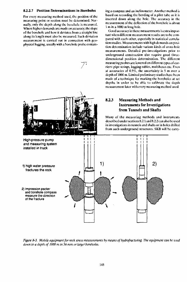
8.2.2.7 Position Determinations in Boreholes
For every measuring method used, the position of themeasuring point or section must be determined. Nor-mally, only the depth along the borehole is measured.Where higher demands are made on accuracy, the slopeof the borehole and how it deviates from a straight linealong its length must also be measured. Such deviationmeasurement is carried out in connection with geo-physical logging, usually with a borehole probe contain-
High-pressure pumpand measuring systeminstalled in truck
1) high water pressurefractures the rock
2) impression packerand borehole compassmeasure the directionof the fracture
ing a compass and an inclinometer. Another method isbased on recording the bending of a pilot tube as it isinserted down along the hole. The accuracy in themeasurement of the deflection of the borehole is about1 m in a 1000 m long hole.
Good accuracy in these measurements is extra impor-tant when different measurement results are to be com-pared with each other, especially in statistical correla-tion studies. Measurements with high demands on posi-tion determination include various kinds of cross-holemeasurements. Detailed pre-investigations prior tounderground construction also require good three-dimensional position determination. The differentmeasuring probes are lowered on different types of car-riers: pipe strings, logging cables, multihoscs etc. Evenat accuracies of 0.5%, the uncertainty is 5 m over adepth of 1000 m. Limited preliminary studies have beenmade of a technique for marking the boreholes at setdepths in order to be able to calibrate the depthmeasurement later with every measuring method used.
8.2 J Measuring Methods andInstruments for Investigationsfrom Tunnels and Shafts
Many of the measuring methods and instrumentsdescribed under sections 8.2.1 and 8.2.2 can also be usedin investigations in tunnels and shafts or in holes drilledfrom such underground structures. SKB will be carry-
I i i iI i i II I I I
trr
2)
Figure 8-3. Mobile equipment for rock stress measurements by means of hydrofracturing. The equipment can be useddown to a depth of 1000 m in 56 mm or larger boreholes.
145

ing out such investigations primarily in connection withthe detailed site investigations. Investigations from tun-nels permit more close-up studies of larger under-ground rock surfaces than boreholes from the groundsurface. At the same time, the usefulness of such rocksurfaces in a larger rock volume is dependent on thethree-dimensional extent of the tunnel system; shaftsalone offer limited accessibility in this respect.
The following summary of the present-day state ofknowledge within this area is limited to methods thatare particularly appropriate for investigations fromunderground structures. The knowledge is based in parton experience from Swedish rock construction andmore directly on the projects which SKB has run or par-ticipated in: CLAB, SFR, Stripa and Hylte.
Geological Mapping
Geological mapping of underground facilities can bedone with different levels of ambition, depending on thepurpose of the mapping. For detailed documentation,it is of the utmost importance that mapping be done assoon as possible after each round of blasting; this is par-ticularly true of the tunnel face, which will be blastedaway by the next round. Mapping at the tunnel face re-quires careful coordination with the tunnelling work.Limited method studies have been conducted in con-nection with the excavation of a power plant tunnel atHylte.
Prediction or Water-bearing Fracture Zones
In connection with tunnelling, it is of urgent importancefor several reasons to be able to predict water seepageinto the tunnel. Depending on the degree of detail in thepre-investigations, an idea has already been obtainedfrom them of presumptive flow zones. Pilot holes can bedrilled from the tunnel face to obtain direct informationon the conditions in the area immediately adjacent tothe face. Predictions can also be made on the basis ofindirect geophysical measurements or a gradually in-creasing body of knowledge on the rock volume in ques-tion. Examples of indirect geophysical methods thatshould be applicable are radar and seismic surveys,which are deemed to have considerable potential.
Geohydrological Investigations
Geohydrological investigations are in many casessimpler to perform underground since it is possible bymeans of passive measures to cause hydraulic distur-bances whose response can be measured and evaluated.The tunnel system is in itself a hydraulic disturbancewhose effects can, however, be difficult to control, espe-cially if the structure has a complex geometric layout.But if it is possible to monitor the process by carefulrecording of parameters such as water pressure, under-ground construction offers a unique opportunity forgeohydrological characterization.
The mapping of water seepage in the tunnel wall haspreviously been mentioned as an important part of over-
all characterization. Different kinds of measurementscan be performed in boreholes from a tunnel, of whichflow measurements accompanied by pressure buildupmeasurements are the most common. All boreholes, in-cluding pilot boreholes if they have not been blastedaway, should be sealed with packers so that the enclosedwater head can be measured /8-20/. This makes simplertypes of cross-hole measurements possible. Carefuldocumentation of all ongoing activities that might dis-turb the hydrological picture also provides good oppor-tunities for performing a detailed hydrogeologicalcharacterization of the rock volume. For special studies,such as different types of cross-hole measurements,more advanced methods and instruments have beendeveloped, for example within the Stripa Project /8-21/.
Measurements of water seeping into the tunnel canbe performed by constructing measuring dykes acrossthe floor of the tunnel at suitable intervals. The seepageinflow within each tunnel section is measured at ameasuring weir at each measuring dyke. It is importantthat these dykes provide a tight seal down through thetunnel floor, which has been loosened by the blastingprocedure. Otherwise, some of the water will pass un-derneath the dykes.
For more accurate measurement of seepage throughtunnel walls and roofs, the latter can be sectioned andlined with plastic sheets, which has been tried in theStripa Project. At low seepages, the ventilation air car-ries off a large portion of the water. This can be check-ed by completely screening off a tunnel section andmeasuring the humidity of the entering and leaving ven-tilation air (ventilation test).
Hydrochemical Investigations
Just as it is important to keep track of how the ground-water head is distributed and changes during under-ground work, it is also important to keep track of thechemistry of the groundwater. Sampling from packer in-stalled boreholes underground is very easy to do and isused both for hydrochemical analysis and tracer tests.In tracer tests, both natural tracers such as salinity andredox conditions and artificially added tracers can beused.
Rock Mechanics Investigations
Rock mechanics parameters must be taken into accountin connection with underground construction work. Alarge number of methods and instruments are availablefor measurement and recording of rock stresses anddeformations. Of particular interest are methods wherethe influence of the rock stresses on the geohydrologicalparameters is investigated. This can be done in largerock blocks that have been completely or partially iso-lated from the rock volume.
When conducting investigations in rock caverns, it isnecessary to bear in mind the fact that the area im-mediately adjacent to the rock wall is heavily disturbeddue to increased fracturing caused by the blasting as
146
well as altered conditions of stress. The special proper-ties of this area, known as the skin zone, can be of greatimportance for the safety assessment and require fur-ther study.
8.3 RESEARCH PROGRAMME1990-1995
The activities that are planned within method and in-strument development for the period 1990-1995 are as-sociated either with SKB's Hard Rock LaboratoryProject or with the coming detailed investigations. Thedevelopment projects are presented under subject areaheadings, in the same way as above for "Present-daystate of knowledge", even though method and instru-ment development, wherever possible, strives for thedevelopment of "multidisciplinary" methods and in-struments. This permits both cost- and time-effective in-vestigations.
Installations and systems for data collection in theHard Rock Laboratory Project must be designed tomeet high demands on accuracy, function and reli-ability, as well as on flexibility in terms of expandability,connection of alternative measuring transducers andvarying measurement intensity.
Unless otherwise stated, the measuring methods andinstruments described are planned for 56 mm bore-holes and use in 1000 m long boreholes. The 56 mmdiameter is usually a minimum diameter, which meansthat boreholes of larger diameter can also be used.
Measurements at depths greater than 1000 m can beperformed in boreholes from tunnels, for example in theHard Rock Laboratory. Development of the measure-ment technology for boreholes longer than 1000 m isjudged to be complicated, but not impossible.
8.3.1 Geological Measuring Methodsand Instruments
DrillingUnder the heading "Present-day state of knowledge",an alternative core drilling method was described thatcan be used to reduce the penetration of drill cuttingsand drilling water into the rock formation. A limitedpreliminary study has been carried out for anothermethod, core drilling with reverse flushing. The pre-mises and difficulties of the method have been defined,and a drilling test with reverse flushing will be carriedout in the next stage. In percussion drilling, and in par-ticular in pilot or probe drilling in tunnels, such drillingparameters as drilling rate, drilling water pressure,drilling water flow etc are important in evaluating rocktypes, fracture systems and the like. Automatic record-ing of such parameters increases the degree of sen-sitivity in such data acquisition and will be tested. Incore drilling as well, similar recording systems shouldgreatly facilitate the documentation of such parameters.
Tunnel Mapping
Tunnel mapping will be carried out on a very large scaleduring the coming programme period in connectionwith the construction of the Hard Rock Laboratory.This mapping will be performed during brief and ex-tended interruptions in the rock work, but also right upat the tunnel face after each blasting round. In order toensure well-executed mapping under the difficult con-ditions that will exist, very good coordination with therock work and the use of the right technical aids are re-quired. Such technical aids include equipment andmethods for simple coordinate measurement andphotodocumentation. Computer aids for tunnel map-ping will be developed, and the possibility of storingmapping results in CAD systems will be explored. Sucha CAD system should be able to be used both as a toolin interpreting fracture zones and other structures andfor the presentation of graphic volume drawings.
Mapping of Drill Core and borehole
A new borehole TV system is being developed that willmake it possible to inspect 1000 m deep boreholes witha diameter of 56 mm. This system can be used for orien-tation of fractures but also for visual examinations of theborehole wall. The possibility of further developmenton the image processing side to simplify fracture orien-tation will thereafter be explored.
Position Determinations in Boreholes
Under the corresponding heading in Section 8.2.2.7, (heproblems involved in making absolute three-dimen-sional position determinations in boreholes weredescribed. The pre-studied method, of placing mark-ings in the boreholes at predetermined depths so thatthey can be detected later in connection with boreholemeasurements for the purpose of calibrating the depthmeasurement systems used in these methods, is beingfurther explored.
8.3.2 Geophysical Measuring Methodsand Instruments Radar
As far as borehole radar is concerned, the developmentof directional antennas is nearly concluded. This work,which has been pursued within the Stripa Project, hasresulted in an antenna prototype with satisfactory func-tion. SKB is currently conducting further work onmaking this type of antenna into a field worthy instru-ment for measurements in deep boreholes from surface.This means that accurate orientation sensors must beintegrated in the borehole probe. Further progress isalso required within processing and presentation tech-nology.
The antennas are the most important component ofthe radar. The frequency can be changed to obtain dif-ferent resolutions and ranges. Furthermore, the anten-nas are specially designed to provide optimum contact
147
with the bedrock. Thus, special antennas will be re-quired for measurements directly in tunnels. Such tun-nel antennas must be particularly unsensitive to distur-bance from different tunnel installations. Developmentof antennas intended for measurements directly fromtunnels has recently been started. The radar system willbe designed so that measurements from tunnels to bore-holes and vice versa can also be done.
In connection with tunnel construction, the radarmethodology should also be able to be used as a tool forpredicting any zones in front of the tunnel face, with theaid of a tunnel radar version of the VSP method.
Seismic Methods
Borehole seismics is a measuring method used by SKBwithin the international Stripa Project. The methodshould also be tested within other projects. Like radar,seismic surveys are suitable for use within the construc-tion phase of the Hard Rock Laboratory Project.
83.3 Geohydrological MeasuringMethods and Instruments
Hydraulic Measurements
The method tested within the Hard Rock LaboratoryProject of carrying out flow meter logging in connectionwith pumping tests will be further refined, particularlywith regard to the measuring resolution of the flow log-ger. Both active and passive hydraulic measurementswill be performed on different scales within the StripaProject. Special equipment for automatic execution ofthese measurements has been developed and will betested. The channelling phenomenon, which deter-mines how the water flow paths are subdivided in a frac-ture system, are studied within the Stripa Project. Spe-cial equipment will be designed to carry out detailedmeasurements along the fracture. Both single-hole andcross-hole measurements will be performed.
Groundwater Head
Within the Hard Rock Laboratory Project, all bore-holes will be provided with a multipacker system afterthe introductory borehole measurements have beencompleted. The purpose is to avoid short circuiting be-tween different hydraulic units and to be able tomeasure heads and take water samples in the screened-off sections. The measuring system for this is speciallyadapted for the telescopic boreholes in the Hard RockLaboratory Project. An equivalent measuring systemhas also been developed for 56 mm cored holes of thestandard type. This system is designed so that someoneliving near the measuring site can be used to make thereadings. This way of conducting long-term recordingswill be tested in several boreholes at eg Finnsjön.
Groundwater Flow
The dilution probe for measurement of the flow rate ofthe groundwater in a borehole section described in Sec-tion 8.2.2.4 can be used in boreholes with a diameter of56 mm or more. Further development of this equipment(for use in 56 mm boreholes, among other things) haslong been planned and will be carried out during thecoming three-year period. Even if the other methodo-logy that has been described, carrying out dilutionmeasurements via a circulation system in the packer-sealed telescopic boreholes, have poorer resolution, itwill be used relatively extensively in the Hard RockLaboratory Project.
Measurements in Tunnels
In connection with hydraulic measurements under-ground (from tunnels), a hydraulic disturbance is nor-mally created by, for example, allowing water to flow outof a borehole. The pressure disturbance is measured viathe system installed in the boreholes.
An underground facility in the form of tunnels and/orshafts, such as the Hard Rock Laboratory, will in itselfconstitute a large-scale disturbance of the naturalgroundwater reservoir. In order to assimilate all the in-formation such a disturbance can provide, a measuringsystem for pressure and flow must be installed duringthe construction phase. Pressure head will mainly bemeasured in boreholes. The disturbance shall also havebeen preceded by a long period of recording of naturalconditions, which is the case in the Hard Rock Labo-ratory Project. Pressure head measurements are sensi-tive to variations in water density, which is in turn de-pendent on salinity and temperature. The temperatureof the bedrock has been regarded as constant in thiscase, while salinity can change due to the disturbancesand water extraction caused by the facility and musttherefore be kept under surveillance. Flow will bemeasured in boreholes. Water seepage into the facilitywill be monitored carefully, primarily through a systemof measuring dykes and weirs. Heavy water seepage intunnel walls and roofs will be measured separately. Inorder to obtain a total picture of the water seepage incertain sections, moisture transport with the ventilationair can also be measured. Suitable instruments will bedeveloped for these measurements.
8.3.4 Chemical Measuring Methods andInstruments
Water Sampling
The routine of taking water samples in connection withother measurements wherever possible will be adaptedto an effective level. The sampling pump used at the mo-bile field laboratory has a low pumping capacity and re-quires considerable peripheral equipment. A new sam-pling pump that has greater capacity and is simpler to
148
use will therefore be developed. A special watersampler is required for long-term sampling in the tele-scopic boreholes.
A number of new chemical investigations will be car-ried out within the Hard Rock Laboratory Project, re-quiring both modification of existing, and developmentof new, measuring methods and instruments. Amongother things, equipment for recording of redox poten-tial and other sensitive parameters will be installed per-manently or connected temporarily to boreholes.
Tracer Tests
Tracer tests will be carried out and further developedduring the coming programme period, eg within theHard Rock Laboratory Project. In the multipackeredboreholes, it shall be possible to carry our dosings withthe same equipment as that developed for dilutionmeasurements.
During the construction phase of the Hard RockLaboratory, the draining effect of the facility on the rockvolume will be utilized as a large-scale tracer test.Through the routine water sampling and the installationof recording measuring cells for Eh, pH etc, naturaltracers such as redox front and salt water front, as wellas artificially added tracers, will be utilized. Specialtracer tests in which sorbing tracers will also be used areplanned around fracture zones and in the rock mass sur-
rounding such zones. The measuring technique will befurther developed for this purpose.
A simple technique for qualitative determinations oftracer leakage into fractures or fracture zones passedby the tunnel is desirable. A preliminary study of thiswill be conducted before the start of the constructionphase for the Hard Rock Laboratory. The goal is to useultraviolet light to detect fluorescing tracers thatpenetrate into roofs and onto walls, and to try outdocumentation technique in the form of photographingand filming.
Different types of tracer tests will also be carried outwithin the Stripa Project. Predictions will be validatedby means of tracer tests, both salt water injection withsampling and radar measurements, and tracer injectionwith sampling of all water flowing into the tunnel.
83.5 Rock Mechanics MeasuringMethods and Instruments
A rock mechanics investigation programme will be car-ried out during the construction of the Hard RockLaboratory. Rock mechanics parameters such as stres-ses and deformations will be recorded. A measuring sys-tem for this purpose will be developed to meet the spe-cial requirements set up in the investigation program-me.
149

9 HARD ROCK LABORATORY
9.1 BACKGROUND ANDMOTIVES FORCONSTRUCTION OF THEHARD ROCK LABORATORY
The scientific investigations within SKB's research pro-gramme are a part of the work of designing a final re-pository and identifying and investigating a suitable site.This requires extensive field studies regarding the inter-action between different engineered barriers and hostrock.
A balances appraisal of the facts, requirements andevaluations presented in connection with the prepara-tion of R&D-Programme 86 led to the proposal to con-struct an underground research laboratory. This pro-posal was presented in the aforementioned researchprogramme and was very positively received by thereviewing bodies.
In the autumn of 1986, SKB initiated field work forthe siting of an underground laboratory, the Hard RockLaboratory, in the Simpcvarp area in the municipalityof Oskarshamn. At the end of 1988, SKB made adecision in principle to site the facility on southern Äspöabout 2 km north of the Oskarshamn station. Construc-tion is planned to start during 1990, provided that ap-proval is obtained from the concerned authorities.
The most important reasons for pertinent the HardRock Laboratory are:
- verification of methods for surface and borehole in-vestigations,
- testing of methods for detailed site investigationswith shaft sinking or tunnelling,
- opportunity, in a realistic environment and on alarge scale, to investigate conditions of importancefor safety, eg groundwater flow and associatedtransport of solutes,
- opportunity, in a realistic environment, to carry outdemonstration tests and long-term tests of the inter-action between engineered barriers and rock,
- method development for rock construction works,waste handling and backfilling.
These motives arc examined in greater detail in thefollowing.
Investigations of conceivable Final repository sitescarried out thus far have only involved measurements
on the ground surface and in boreholes. Investigationshave also been carried out in and from tunnels at Stripaand in connection with certain construction work forother purposes. There is a need to directly verify theresults of surface and borehole investigations with sys-
tematic observations from shaft; and tunnels down tothe depth of a future repository. The construction of t he-Hard Rock Laboratory provides excellent oppor-tunities for such verification.
The detailed investigations of candidate sites that arcplanned for the latter half of the 1990s will includestudies of the rock from shafts and tunnels at repositorylevel. These detailed site investigations include the Heldstudies and analyses that arc supposed to provide thefinal confirmation that a selected site is suitable for thefinal disposal of long-lived and high-level radioactivewaste. These studies are also supposed to provide suf-ficient data for adapting the repository to the selectedsite and for an assessment of the long-term safety of (headapted repository. This assessment shall be includedin a siting application and shall show that the site fulfilsthe requirements in the Act on Nuclear Activities. Someof the technology and methods for carrying out such in-vestigations have been developed and tested at Stripa.However, since Stripa is an abandoned mine, it is notpossible to test all aspects of the methods there.
Tests in a previously undisturbed area provide addi-tional opportunities for developing and refining themethods before they can be used "for real". On the can-didate sites, it is appropriate to carry out the equivalentof what is known in ordinary industrial developmentwork as "destructive" testing. It is therefore importantto have access to a Hard Rock Laboratory where suchtests can be carried out.
The central, and at the same time the most complexproblem in the assessment of the final repository's long-term safety is the flow of groundwater in the rock's frac-ture system and the associated transport of substancesdissolved in the groundwatcr. Extensive efforts havebeen made and are being made to shed light on thisproblem.
The future research should above all be devoted to tictogether and completing the picture that has been ob-tained from the previous investigations at different sites.An initial such tying-together attempt is being madewithin phase 3 of the Stripa Project, where a SiteCharacterization Validation Test (SCV) is being car-i ied out in a rock volume on a 100 m scale. Prior to thesiting of the final repository, a similar tying-togethcr at-tempt will be carried out on a larger scale to obtain moreexperimental data for the long-term safety assessment.Such a large-scale test can be carried out at the HardRock Laboratory.
When a fundamental design for the final repositoryhas been chosen in the mid-1990s, the different parts in-cluded in this system will have to be tested on a realis-tic scale. Of particular importance is testing and dem-onstrating the interaction between engineered barriers
151
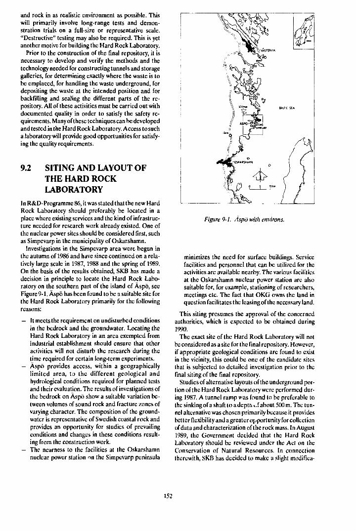
and rock in as realistic environment as possible. Thiswill primarily involve long-range tests and demon-stration trials on a full-size or representative scale."Destructive" testing may also be required. This is yetanother motive for building the Hard Rock Laboratory.
Prior to the construction of the final repository, it isnecessary to develop and verify the methods and thetechnology needed for constructing tunnels and storagegalleries, for determining exactly where the waste is tobe emplaccd, for handling the waste underground, fordepositing the waste at the intended position and forbackfilling and sealing the different parts of the re-pository. All of these activities must be carried out withdocumented quality in order to satisfy the safety re-quirements. Many of these techniques can be developedand tested in the Hard Rock Laboratory. Access to sucha laboratory will provide good opportunities for satisfy-ing the quality requirements.
9.2 SITING AND LAYOUT OFTHE HARD ROCKLABORATORY
In R&D-Programme 86, it was stated that the new HardRock Laboratory should preferably be located in aplace where existing services and the kind of infrastruc-ture needed for research work already existed. One ofthe nuclear power sites should be considered first, suchas Simpcvarp in the municipality of Oskarshamn.
Investigations in the Simpevarp area were begun inthe autumn of 1986 and have since continued on a rela-tively large scale in 1987,1988 and the spring of 1989.On the basis of the results obtained, SKB has made adecision in principle to locate the Hard Rock Labo-ratory on the southern part of the island of Äspö, secFigure 9-1. Äspö has been found to be a suitable site forthe Hard Rock Laboratory primarily for the followingreasons:
- It meets the requirement on undisturbed conditionsin the bedrock and the groundwatcr. Locating theHard Rock Laboratory in an area exempted fromindustrial establishment should ensure that otheractivities will not disturb the research during thetime required for certain long-term experiments.
- Äspö provides access, within a geographicallylimited area, to the different geological andhydrological conditions required for planned testsand their evaluation. The results of investigations ofthe bedrock on Äspö show a suitable variation be-tween volumes of sound rock and fracture zones ofvarying character. The composition of the ground-watcr is representative of Swedish coastal rock andprovides an opportunity for studies of prevailingconditions and changes in these conditions result-ing from the construction work.
- The nearness to the facilities at the Oskarshamnnuclear power station on the Simpcvarp peninsula
Figure 9-1. Äspö with environs.
minimizes the need for surface buildings. Servicefacilities and personnel that can be utilized for theactivities arc available nearby. The various facilitiesat the Oskarshamn nuclear power station are alsosuitable for, for example, stationing of researchers,meetings etc. The fact that OKG owns the land inquestion facilitates the leasing of the necessary land.
This siting presumes the approval of the concernedauthorities, which is expected to be obtained during1990.
The exact site of the Hard Rock Laboratory will notbe considered as a site for the final repository. However,if appropriate geological conditions are found to existin the vicinity, this could be one of the candidate sitesthat is subjected to detailed investigation prior to thefinal siting of the final repository.
Studies of alternative layouts of the underground por-tion of the Hard Rock Laboratory were performed dur-ing 1987. A tunnel ramp was found to be preferable tothe sinking of a shaft to a depth of about 500 m. The tun-nel alternative was chosen primarily because it providesbetter flexibility and a greater opportunity for collectionof data and characterization of the rock mass. In August1989, the Government decided that the Hard RockLaboratory should be reviewed under the Act on theConservation of Natural Resources. In connectiontherewith, SKB has decided to make a slight modifica-
152
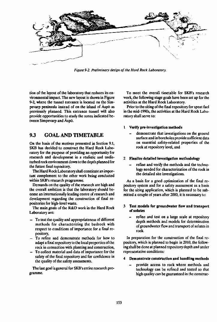
Figure 9-2. Preliminary design of the Hard Rock Laboratory.
tion of the layout of the laboratory that reduces its en-vironmental impact. The new layout is shown in Figure9-2, where the tunnel entrance is located on the Sim-pevarp peninsula instead of on the island of Äspö aspreviously planned. This entrance tunnel will alsoprovide opportunities to study the zones indicated be-tween Simpevarp and Äspö.
9.3 GOAL AND TIMETABLEOn the basis of the motives presented in Section 9.1,SKB has decided to construct the Hard Rock Labo-ratory for the purpose of providing an opportunity forresearch and development in a realistic and undis-turbed rock environment down to the depth planned forthe future final repository.
The Hard Rock Laboratory shall constitute an impor-tant complement to the other work being conductedwithin SKB's research programme.
Demands on the quality of the research are high andthe overall ambition is that the laboratory should be-come an internationally leading centre of research anddevelopment regarding the construction of final re-positories for high-level waste.
The main goals of the R&D work in the Hard RockLaboratory are:
- To test the quality and appropriateness of differentmethods for characterizing the bedrock withrespect to conditions of importance for a final re-pository,
- To refine and demonstrate methods for how toadapt a final repository to the local properties of therock in connection with planning and construction,
- To collect material and data of importance for thesafety of the final repository and for confidence inthe quality of the safety assessments.
The last goal is general for SKB's entire research pro-gramme.
To meet the overall timetable for SKB's researchwork, the following stage goals have been set up for theactivities at the Hard Rock Laboratory.
Prior to the siting of the final repository for spent fuelin the mid-1990s, the activities at the Hard Rock Labo-ratory shall serve to:
1 Verify pre-lnvestigation methods
- demonstrate that investigations on the groundsurface and in boreholes provide sufficient dataon essential safety-related properties of therock at repository level, and
2 Finalize detailed investigation methodology
- refine and verify the methods and the techno-logy needed for characterization of the rock inthe detailed site investigations.
As a basis for a good optimization of the final re-pository system and for a safety assessment as a basisfor the siting application, which is planned to be sub-mitted a couple of years after 2000, it is necessary to:
3 Test models for groundwater flow and transportof solutes
- refine and test on a large scale at repositorydepth methods and models for determinationof groundwater flow and transport of solutes inrock.
In preparation for the construction of the final re-pository, which is planned to begin in 2010, the follow-ing shall be done at planned repository depth and underrepresentative conditions:
4 Demonstrate construction and handling methods
- provide access to rock where methods andtechnology can be refined and tested so thathigh quality can be guaranteed in the conslruc-
153
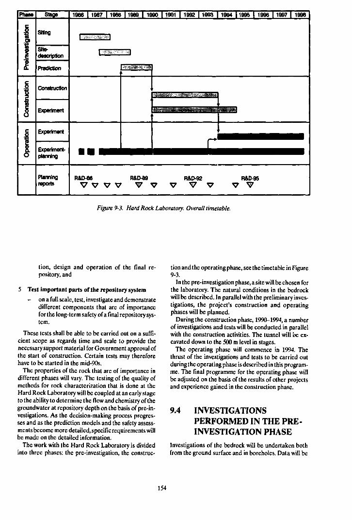
1966 I 1987 | 1988 11969 | 1990 | 1991 | 1992 | 1993 | 1994 11995 | 1996 | 1997 | 1998
SHe-descriptton
Planningreports
R&D-86
V V V V
Figure 9-3. Hard Rock Laboratory. Overall timetable.
tion, design and operation of the final re-pository, and
5 Test important parts of the repository system
- on a full scale, test, investigate and demonstratedifferent components that are of importancefor the long-term safety of a final repository sys-tem.
These tests shall be able to be carried out on a suffi-cient scope as regards time and scale to provide thenecessary support material for Government approval ofthe start of construction. Certain tests may thereforehave to be started in the mid-90s.
The properties of the rock that are of importance indifferent phases will vary. The testing of the quality ofmethods for rock characterization that is done at theHard Rock Laboratory will be coupled at an early stageto the ability to determine the flow and chemistry of thegroundwater at repository depth on the basis of pre-in-vestigations. As the decision-making process progres-ses and as the prediction models and the safety assess-ments become more detailed, specific requirements willbe made on the detailed information.
The work with the Hard Rock Laboratory is dividedinto three phases: the pre-investigation, the construc-
tion and the operating phase, see the timetable in Figure9-3.
In the pre-investigation phase, a site will be chosen forthe laboratory. The natural conditions in the bedrockwill be described. In parallel with the preliminary inves-tigations, the project's construction and operatingphases will be planned.
During the construction phase, 1990-1994, a numberof investigations and tests will be conducted in parallelwith the construction activities. The tunnel will be ex-cavated down to the 500 m level in stages.
The operating phase will commence in 1994. Thethrust of the investigations and tests to be carried outduring the operating phase is described in this program-me. The final programme for the operating phase willbe adjusted on the basis of the results of other projectsand experience gained in the construction phase.
9.4 INVESTIGATIONSPERFORMED IN THE PRE-INVESTIGATION PHASE
Investigations of the bedrock will be undertaken bothfrom the ground surface and in boreholes. Data will be
154
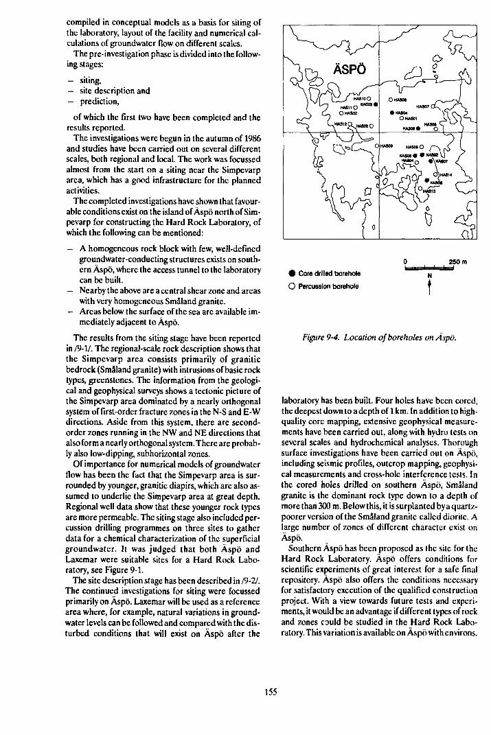
compiled in conceptual models as a basis for siting ofthe laboratory, layout of the facility and numerical cal-culations of groundwater flow on different scales.
The pre-investigation phase is divided into the follow-ing stages:
- siting,- site description and- prediction,
of which the first two have been completed and theresults reported.
The investigations were begun in the autumn of 1986and studies have been carried out on several differentscales, both regional and local. The work was focussedalmost from the start on a siting near the Simpevarparea, which has a good infrastructure for the plannedactivities.
The completed investigations have shown that favour-able conditions exist on the island of Äspö north of Sim-pevarp for constructing the Hard Rock Laboratory, ofwhich the following can be mentioned:
- A homogeneous rock block with few, well-definedgroundwater-conducting structures exists on south-ern Äspö, where the access tunnel to the laboratorycan be built.
- Nearby the above are a central shear zone and areaswith very homogeneous Småland granite.
- Areas below the surface of the sea are available im-mediately adjacent to Äspö.
The results from the siting stage have been reportedin /9-1/. The regional-scale rock description shows thatthe Simpevarp area consists primarily of graniticbedrock (Småland granite) with intrusions of basic rocktypes, greenstones. The information from the geologi-cal and geophysical surveys shows a tectonic picture ofthe Simpevarp area dominated by a nearly orthogonalsystem of first-order fracture zones in the N-S and E-Wdirections. Aside from this system, there are second-order zones running in the NW and NE directions thatalso form a nearly orthogonal system. There are probab-ly also low-dipping, subhorizontal zones.
Of importance for numerical models of groundwaterflow has been the fact that the Simpevarp area is sur-rounded by younger, granitic diapirs, which are also as-sumed to underlie the Simpevarp area at great depth.Regional well data show that these younger rock typesare more permeable. The siting stage also included per-cussion drilling programmes on three sites to gatherdata for a chemical characterization of the superficialgroundwater. It was judged that both Äspö andLaxemar were suitable sites for a Hard Rock Labo-ratory, see Figure 9-1.
The site description stage has been described in 19-21.The continued investigations for siting were focussedprimarily on Äspö. Laxemar will be used as a referencearea where, for example, natural variations in ground-water levels can be followed and compared with the dis-turbed conditions that will exist on Äspö after the
250 m
• Core drilled borehole
O Percussion borehole
Figure 9-4. Location of boreholes on Äspö.
laboratory has been built. Four holes have been cored,the deepest down to a depth of 1 km. In addition to high-quality core mapping, extensive geophysical measure-ments have been carried out, along with hydro tests onseveral scales and hydrochemical analyses. Thoroughsurface investigations have been carried out on Äspö,including seismic profiles, outcrop mapping, geophysi-cal measurements and cross-hole interference tests. Inthe cored holes drilled on southern Äspö, Smålandgranite is the dominant rock type down to a depth ofmore than 300 m. Below this, it is surplantcd by a quartz-poorer version of the Småland granite called dioritc. Alarge number of zones of different character exist onÄspö.
Southern Äspö has been proposed as the site for theHard Rock Laboratory. Äspö offers conditions forscientific experiments of great interest for a safe finalrepository. Äspö also offers the conditions necessaryfor satisfactory execution of the qualified constructionproject. With a view towards future tests and experi-ments, it would be an advantage if different types of rockand zones could be studied in the Hard Rock Labo-ratory. This variation is available on Äspö with environs.
155
Hydrochemical conditions on Äspö are also repre-sentative of the conditions that would prevail in theevent of a coastal siting of an underground facility. Thegroundwater is fresh near the surface and saline atgreater depth. Several types of numerical calculationsof groundwater flow have also been carried out in thesite description stage.
The site description presented in 19-21 has since beensupplemented in the prediction stage with the drillingof an additional four cored holes, see Figure 9-4. Theseresults and the associated numerical calculations will bedescribed in a Technical Report in the spring of 1990.Predictions will be made on different scales, termed theregional scale, > > 1000 m, the site scale 100-1000 m,the block scale, 10-100 m, and the detailed scale, 0-10m. For each scale, the predictions to be made, the ex-pected outcome, the grounds for validation and themeasuring accuracy striven for will be defined. Thepredictions for each scale will be grouped according toresearch fields and will involve testing of conceptualmodels, groundwatcr flux, chemical environment,transport of solutes in groundwater and mechanicalstability of the rock.
Calculations will be carried out on different scalesand compared before the start of the construction phasewith pressure and floor measurements in boreholes andwith gcohydrochcmical data, especially the salinity ofthe water. The geological, gcohydrological and ground-watcr chemistry predictions made during the predictionstage will be evaluated during the construction phase.
In order to check the conceptual model prepared inthe site description phase, a long-range pumping testwill be carried out during the summer of 1989. Themeasurement results will be used to evaluate the predic-tive calculations carried out before the long-termpumping. The results will also be used to prepare thefinal calculation model of the groundwatcr changes thatwill take place when the laboratory is built. A qualifiedradial tracer test will also be carried out before the con-struction phase begins. An evaluation of the long-termpumping will be presented in a Technical Report in1990.
The new layout of the Hard Rock Laboratory that hasbeen decided on (Sept. 1989), sec Figure 9-2, affects thedetailed planning of the conclusion of the pre-investiga-tion phase.
9.5 PROGRAMME FOR THECONSTRUCTION PHASE
During the construction phase, investigations will becarried out to validate expectation models reportedduring the pre-investigation phase. Furthermore, datawill be collected for progressive improvement of pre-vious predictions. The investigations will be carried outboth along the surfaces of the access tunnel and in bore-holes drilled from the ground surface and from the tun-nel. Since favourable properties of the bedrock nearest
the deposition holes and deposition tunnels are of thegreatest importance for the safety of a final repository,it is essential that the degree of detail in the investiga-tions during the construction phase be gradually in-creased.
The investigations carried out during construction ofthe access tunnel will therefore be divided into stages.
The main level of the laboratory will be situated about500 m below the ground surface. If later investigationswithin the framework of the general research program-me should show that the final repositories should besituated deeper than about 500 m, a further extensionof the tunnel to greater depth may be considered.
The work during the construction phase will largelybe focussed on geological, geohydrological and ground-water chemistry aspects.
9.5.1 Geological Investigations
As far as geology is concerned, there are a number ofboth geological and geophysical methods available toassist in describing the composition and structure of therock mass. The relevance of the different methods, bothgenerally and in the local geological environment, isvery incompletely documented, however. This is par-ticularly true of conditions at great depth in crystallinebedrock. The overall goals of the geological documen-tation during the construction phase can therefore besummarized as follows:
— evaluate to what extent the pre-investigation metho-dology has provided an accurate description of thespacial distribution of rock types, large and smallfracture zones and the fracture geometry and min-erals of the rock mass in different geological en-vironments and at different depths,
- establish the relevance of different investigationmethods as regards rock types, structures, stabilityand hydraulic conductivity with respect to geologi-cal environment and depth,
- prepare agood prediction of the geological environ-ment that will be encountered during the secondconstruction stage and during the excavation of the500 m level.
— develop and test methodology for detailed geologi-cal investigations on candidate sites for a Final re-pository.
The geological expectation models will be devisedprimarily with respect to lithology and structures.Predictions will be made on different block scales fordifferent geological environments. An effort will bemade to define different lithological units and todescribe the structure of the rock mass with regard toorientation and character.
Geological documentation of tunnels, shafts andboreholes will be done continuously in connection withthe construction of the facility. The outcome will becompared with the expectation models prepared on thebasis of results from the pre-investigations.
156
9.5.2 Geohydrological Investigations
As far as geohydrology is concerned, only a fewqualified tests have been carried out to test the accuracyof models forgroundwater movements in large rock vol-umes. The overall goals of the geohydrological inves-tigations during the construction phase can be sum-marized as follows:
— evaluate to what extent the pre-investigationmethodology used has provided an accuratedescription of the natural groundwatcr situation indifferent geological environments and at differentdepths,
— document the geohydrological conditions in therock volume from tunnels and rock caverns on dif-ferent scales and make geohydrological operatingpredictions for the blasting work,
— itcrativcly with the documentation, validate the dif-ferent-scale models of the influence of the HardRock Laboratory on the steady-state geohydro-logical logicalconditions,
— with the new data continuously being gathered dur-ing the construction phase, progressively refine andimprove the predictions of gcohydrological condi-tions at deeper levels,
— validate the updated expectation models of gcohy-drological conditions at deeper levels, including the500 m level,
— develop methods for detailed geohydrological in-vestigations on candidate sites.
In order to achieve these goals, it is necessary, as dur-ing the pre-investigation phase, that investigations becarried out in the field, that the data obtained beanalyzed and processed integrally with the geologicaland geohydrochemical investigations, and that theresults be integrated into qualitative and quantitativemodels .The investigations are of crucial importance forthe description of the rock in both the far field and thenear field.
Records will be kept during the construction work ofrock types, fracture content, reinforcing work etc.These records will also include data on water seepagein terms of quantity and location. Water seepage intothe tunnel will be measured by means of measuringdykes and weirs along the access tunnel. The measuringdykes will be designed in such a manner that seepagewater from the tunnel sections between two dykes canbe measured and sampled.
An action programme describing how the geohy-drological observations are to be carried out in connec-tion with injection grouting and extensive reinforcingwork will be drawn up. The programme will also definethe limits for when injection grouting is to be carriedout. It will also include guidelines for when side tunnelsare to be arranged.
To investigate, describe and model conductive zoneswithout disturbing and being disturbed by the construc-tion process, it is planned that side tunnels will be drivenout from the access tunnel. A side tunnel will be blasted
out if rock requiring extensive sealing and reinforcingwork is encountered.
Probe holes will be percussion-drilled from the sidesof the tunnel at the face. Pressure buildup tests and, i!required, packer tests will be carried out in the holes,which will be drilled diagonally forward. These pilot in-vestigations will be used to provide operating forecastsin combination with data from the tunnel and to supple-ment the database with geohydrological Jata collectedunderground. The boreholes will also be used for watersampling.
In addition to the probe holes that are drilled regular-ly at the tunnel face, the observation network under-work will be supplemented to characterize and measurethe pressure in conductive zones. For this purpose, per-cussion boreholes are planned to be drilled with multi-packer systems along the tunnel run.
9.5.3 Geohydrochemical Investigations
Investigations aimed at clarifying geohydrochemicalconditions in the bedrock will be carried out during thepre-investigation phase. This work will be carried out instages that alternate between measurement, evaluationand prediction, where the collected results are used topredict the conditions and the changes expected duringthe construction phase. Since the groundwater is mo-bile, a drainage of shafts and tunnels will bring about ahigh groundwatcr flux. Accordingly, the changes thattake place in water composition will reflect the geohy-drological conditions. The goal of the gcochcmical in-vestigations during the construction phase is to studychanges in water composition and relate them topredictions made during the pre-investigation phase.The goals of the geohydrochemical investigations dur-ing the construction phase therefore include the follow-ing:
— follow changes in the interface between saline andfresh water,
— study the transports of solutes in a large volume ofrock,
— obtain material for validation of groundwatcr flowand transport models on a realistic scale,
— follow changes in the redox conditions in thegroundwater,
— follow changes in the chemical condition of fractureminerals and determine the rcdox kinetics of thegroundwater-fracturc-mineral system,
— develop and test methodologies for detailed geohy-drochemical investigations on candidate sites.
The work includes studies of changes in the chemicalcomposition of the water (natural tracers) as well asnon-interacting tracers injected in surrounding bore-holes and in boreholes drilled from tunnels as well asthrough seepage into the facility. The natural tracersshould be able to describe the flowpaths of the water in
157
the uppermost stratum of the rock, while the injectedtracers shall describe the flowpaths in the deeper-lyingrock.
The fresh-water cushion on Äspö will be used to studythe flowpaths in the near-surface rock (about 100 m).Owing to pressure head drawdowns in the tunnel, freshwater will run down and reach the tunnel in those pointswhere the connection upward is good. In order to studythe flowpaths in the deep rock, tracers will be injectedin conductive zones via the cored holes previouslydrilled from the surface.
Sampling of groundwater will take place in probeholes and drainage ditches as well as with special holesin major flowpaths. The purpose of the sampling in theboreholes is to clarify changes in the chemical composi-tion of the water. In addition, any drilling residues fromdrilling of the deep cored holes and any added tracerswill be detected.
9.6 PRELIMINARY PROGRAM-ME FOR THE OPERATINGPHASE
After the construction phase, the operating phase willbegin. The planning for the operating phase is con-centrated on the following proposed tests:
— large-scale tracer tests,— block-scale tracer tests,— block-scale redox tests,— methodology for repository construction,— pilot tests, repository systems.
The large-scale tracer tests are aimed at characteriz-ing transport in the far field. In order to study the site-specific flowpaths existing in the bedrock around theHard Rock Laboratory, tracer tests will be carried outon different scales. A large-scale tracer test will bestarted in the steady-state phase before the start of con-struction and continue throughout the transient con-struction phase. The results of this test will serve as abasis for planning of large-scale tracer tests during theoperating phase.
Block-scale tracer tests will be conducted on an inter-mediate scale, about 50 x 50 m. The situation in a finalrepository with canisters deposited in rock of low hy-draulic conductivity and with a "respect distance" to thenearest major water-bearing zone will be simulated inthe investigation. The results of this study will beevaluated and used to validate transport models on ablock scale, ie over distances on the order of 10-100 m.The investigation will also demonstrate our ability tocharacterize and select volumes of sound rock for
deposition. Transport models will be used to test thepossibility of predicting the migration of solutes in aselected volume of low-conductivity rock adjacent to afracture zone.
Block-scale redox tests will be carried out to demon-strate that the redox capacity of the rock is sufficient inthe flowpaths. Reducing conditions at repository depthare a necessary requirement for long canister life. Thegroundwater that has been sampled on different oc-casions and on different sites within the study-site inves-tigations has always proved to be reducing. The kineticsof the redox reactions between the minerals in thebedrock and the groundwater require further study,however. During the construction phase, when oxidiz-ing water will get down into the facility, there will be op-portunities to study these reactions. The investigationof the effect of the oxygenated water will be carried outon a block scale (several tens of metres), enabling allrelevant parameters to be checked and provide an op-portunity for an assessment of the rate of the exchangereactions.
Methodology for repository construction is aimed atdemonstrating how the construction of a repository isto be accomplished. In connection with the constructionof a repository, it is necessary to carry out a number ofinvestigations to obtain a final basis for the design andlayout of the repository and sealing of the repository,and to obtain data for the final safety assessment of thecompleted repository. The execution of the investiga-tions is dependent on the choice of system for the finalrepository.
Pilot tests - repository systems is a series of pilot anddemonstration tests to be carried out after the mainprinciples of repository design and systems have beenfinalized in the mid-90s. The goal of the tests is tovalidate the models and demonstrate the function of thesystems by clarifying the interaction between the rockand the selected buffers under conditions prevailing indisposal facilities. A further purpose is to develop andtest methods and strategies for their application.
9.7 FURTHER INFORMATION
This chapter provides only a summary of the researchprogramme for the Hard Rock Laboratory. A muchmore exhaustive account is provided in a special back-ground report to R&D-Programme 89 published simul-taneously with it. The programme will be progressivelyrefined and updated on the basis of the experience andresults obtained during the construction phase. Theprogramme for the operating phase described above ispreliminary and will be refined in greater detail in con-nection with future three-year programmes.
158

10 THE STRIPA PROJECT
10.1 GOALS AND RESULTSOBTAINED THUS FAR
The international Stripa Project started with Phase 1,which was carried out during the period 1980-1985, fol-lowed by Phase 2, which was begun in 1983 and com-pleted for the most part in 1986. Research within thesetwo phases has primarily been conducted within the fol-lowing four subject areas:
— Geohydrological investigations of the Stripa graniteand migration tests with nuclides in simple and com-plex fracture systems.
— Chemical investigations of the groundwater in theStripa granite.
— Technique for detecting and characterizing fracturesystems in granite.
— Study of bentonite clay for use as backfill and seal-ing material in a fracture-filled bedrock.
Current work at Stripa falls within Phase 3, whichstarted in the autumn of 1986 and will be concluded in1991.
10.1.1 Brief Summary of Results fromPhase 1
Phase 1 of the Stripa Project included the developmentof methods and technology for investigation of the rockon a repository site. It also included verifying previouslyobtained laboratory results via field tests.
The results of the geohydrological investigations andthe water chemistry sampling resulted in a recommen-dation that hydrological investigations should be con-ducted at repository depth. It is further observed thatdetailed knowledge of the chemical composition of thewater, and the causes of it, requires a coordinated ef-fort employing a number of investigation techniques.
Greater knowledge was obtained of water flow andnuclide migration in individual fractures. This know-ledge in turn led to greater confidence in previouslymade predictions as regards nuclide retardation. Thetests further showed that diffusion of radioactivenuclides into the rock matrix and sorption on fracturefaces are processes that actively influence the rate ofnuclide migration.
As far as buffer material is concerned, the testsshowed that we can now describe and understand thephysical properties of the bentonite and that we canpredict them for different layouts of the final repository.In this context, the water-absorbing and swellingproperties of the benlonile play a major role. It was fur-
ther shown that we have the technology for preparingand applying the bentonite as a buffer material.
10.1.2 Brief Summary of Results fromPhase 2
Phase 2 of the Stripa Project involved a further refine-ment of methods and technology for investigation of therock on a final repository site.
A cross-hole measurement programme demon-strated that technology is now available that permitscharacterization of fracture zones in crystalline rockwith a degree of certainty and detail that was previouslynot possible. Geophysical investigations showed thatthe flow of groundwater is concentrated to a few majorfracture zones. These fracture zones are regarded forpurposes of simplification as being plane with a varyinghydraulic conductivity alone the fracture plane.
Detailed investigations of water flow and tracermigration in fractures have provided a further increasein knowledge. The work at Stripa has shown thatknowledge exists for collecting and analyzing data onthe structure and hydraulic properties of the rock mass.In this way, as one step in the safety assessment, the con-ditions on a potential final repository site can be com-pared with conditions on another site.
Migration tests, together with tritium measurements,provided support for the theory that a portion of thewater flow in fractures takes place in more or less well-defined channels which have little contact with eachother. However, further research is necessary todevelop numerical models that describe the water flowin a fractured t ock mass.
The sealing and plugging tests at Stripa showed thatthe technology and material exist to redirect the waterflows in a fractured rock mass away from blastcd-outtunnels and shafts. Under repository-like conditions,highly compacted sodium bentonite proved to be asuitable material for plugging boreholes, drifts andshafts. After the bentonite has absorbed water from thesurrounding rock and swelled, the hydraulic conduc-tivity of these plugs is considerably lower than the con-ductivity of the surrounding rock mass. A particularlyimportant property of the bentonite is its ability,together with the rock, to create integral tight plugs lhateffectively prevent water flow in the contact zone be-tween rock and plug. The special physical properties ofthe bentonite arc such that its sealing properties remainundiminished even if the rock mass is subjected to stressredistributions with accompanying rock deformations.
The results of Phases 1 and 2 have shown that sig-nificant advances have been made in the development
159
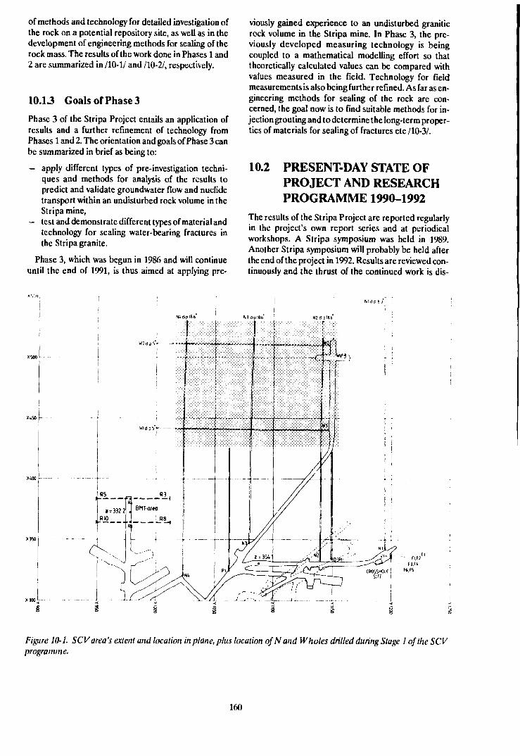
of methods and technology for detailed investigation ofthe rock on a potential repository site, as well as in thedevelopment of engineering methods for sealing of therock mass. The results of the work done in Phases 1 and2 are summarized in /10-1/ and /10-2/, respectively.
10.13 Goals of Phase 3
Phase 3 of the Stripa Project entails an application ofresults and a further refinement of technology fromPhases 1 and 2. The orientation and goals of Phase 3 canbe summarized in brief as being to:
— apply different types of pre-investigation techni-ques and methods for analysis of the results topredict and validate groundwater flow and nuclidetransport within an undisturbed rock volume in theStripa mine,
- test and demonstrate different types of material andtechnology for sealing water-bearing fractures inthe Stripa granite.
Phase 3, which was begun in 1986 and will continueuntil the end of 1991, is thus aimed at applying pre-
viously gained experience to an undisturbed graniticrock volume in the Stripa mine. In Phase 3, the pre-viously developed measuring technology is beingcoupled to a mathematical modelling effort so thattheoretically calculated values can be compared withvalues measured in the field. Technology for fieldmeasurements is also being further refined. As far as en-gineering methods for sealing of the rock are con-cerned, the goal now is to find suitable methods for in-jection grouting and to determine the long-term proper-ties of materials for sealing of fractures etc /10-3/.
10.2 PRESENT-DAY STATE OFPROJECT AND RESEARCHPROGRAMME 1990-1992
The results of the Stripa Project are reported regularlyin the project's own report series and at periodicalworkshops. A Stripa symposium was held in 1989.Another Stripa symposium will probably be held afterthe end of the project in 1992. Results are reviewed con-tinuously and the thrust of the continued work is dis-
H.FlFt,F5
Figure 10-1. SCV area's extent and location in plane, plus location of N and Wholes drilled during Stage 1 of the SCVprogramme.
160
cussed in a Technical Sub Group (TSG) composed ofrepresentatives from the project's member countries.
Research within Phase 3 is divided into the followingthree main areas:
- Site Characterization and Validation; through step-by-step investigations followed by a compilation andprediction phase, a limited rock volume and itsproperties arc characterized and finally validated.
- Improvement of Site Assessment Concepts andMethods; continued development and refinementof the technology and the methods for investigationand characterization of rock that was begun duringPhases 1 and 2.
- Sealing of Fractured Rock testing and evaluatingthe long-term stability of materials that can be usedto seal fractures in the rock and development oftechnology for injecting these materials into thefractures in the rock.
10.2.1 "Site Characterization andValidation"
The SCV programme is divided into five substages:
Stage 1. Introductory investigations. The rock volume(the SCV area) measuring 125 x 125 x 50 metres at the360-metre level in the Stripa mine that is included in theinvestigation programme has been investigated duringStage 1 through six boreholes, the so-called N and Wholes. These boreholes have been situated so that thegeological, hydrological, geophysical, hydrochemicaland rock mechanics investigations performed in theboreholes provide as comprehensive a picture as pos-sible of the properties of the rock mass, see Figure10-1. In addition to the borehole investigations, ad-jacent drifts have been mapped with respect to the fre-quency, orientation and properties of the fractures.Furthermore, a system for measuring the water head inall the boreholes surrounding the SCV area has been in-stalled. It is of great importance in the interpretation ofthe hydrological conditions within the SCV area thatconditions at the boundaries of the area be known. Theresults of all investigations in Stage 1 have beenreported in the Stripa Reports /10-4 - 10-15/. The 180-metre-long access drift that leads up to the border ofthe SCV area was also excavated during Stage 1. Theterminus of this drift will be used in later stages of theprogramme as a starting point for further investigatorydrillings as well as for the "validation drift".
Stage 2. First prediction. Based on the material col-lected during Stage 1, a model has been devised describ-ing the expected geological, hydrological andhydrochemical properties of the SCV area. Thus, anumber of fracture zones that intersect the area havebeen identified. These zones have been verified bymeans of a number of different geophysical measuring
methods. The zones are not all necessarily water-bear-ing; only some of the defined zones have been identifiedas hydraulic zones. The model of the SCV area is com-plemented by the rock stress measurements carried outnearby. This prediction or expectation model of thearea, based on the investigations in Stage 1, is docu-mented in the Stripa Report/10-16/. The report not onlydescribes the final conceptual model based on Stage 1,but also presents the line of reasoning that has led to theproposed model.
Stage 3. Detailed investigation and validation of theprediction made in Stage 2. Based on the expectationmodel produced in Stage 2, a new investigation pro-gramme is being carried out in Stage 3. The program-me contains essentially the same types of investigationsas were carried out in Stage 1, but with the importantdifference that three new boreholes, the C holes drilledin the SCV area during Stage 3, are located to provideinformation that can verify the model of the area com-piled in Stage 2, see Figure 10-2. The measurements inthese boreholes were completed during the first half of1989. Stage 3 also includes drilling of the six D holes.The D holes are about 80 metres long and arc drilledwithin a circle with a diameter of 2.5 metres. The inten-tion is that the validation drift that will be excavated dur-ing Stage 5 of the SCV programme shall have a diameterthat agrees with the circle that circumscribes the Dholes. The D holes will also be utilized to verify themodel from Stage 2 and to gather further informationabout the SCV area. Hydraulic cross-hole measure-ments, as well as measurement of the water flowing infrom the surrounding rock, will also be carried out inthe D holes. These inflow measurements in the D holeswill be used not only in the SCV programme but also inthe numerical modelling programme for calibratingand, for one of the models, for making a preliminaryprediction of the water inflow to the validation drift,which will be excavated in Stage 5. The fracture zonesthat are of importance for water inflow to the D holeswill be characterized by means of radar measurementsafter salt injection in the water-bearing zones.
Stage 4. Detailed prediction. Based on the material col-lected during Stage 3, the model describing the ex-pected geological, hydrological and hydrochemicalproperties of the SCV area that was developed in Stage2 is now being updated. This work is being completedduring the latter part of 1989.
Stage 5. Final evaluation. The model of the SCV areadeveloped in Stage 4 will be evaluated by the excavationof a validation drift with a length of about 75 metres inthe SCV area, see also Figure 10-2. This drift is expectedto intersect one or more of the fracture zones that havebeen identified by means of the different boreholemeasurements. In addition to water inflow and its dis-tribution, fracture distribution and the physical proper-tics of the fracture zones identified by means of
161

XBO
Figure 10-2. The C holes drilled during Stage 3 of the SCV programme and the access drift to the Validation Drift. TheValidation Drift will be excavated during Stage 5 of the SCV programme.
geophysical methods will be determined in the drift.Furthermore, a new radar survey with salt injection willbe carried out in order to evaluate whether the waterpaths identified in Stage 3 are stationary or whether thewater has chosen new paths after excavation of the drift.This will give us some idea of the disturbed zone sur-rounding the validation drift and provide guidelines forinjection of tracers in the concluding tracer tests. Thetracer tests are to be regarded as a follow-up of themigration tests performed in the 3-D drift within thePhase 2 programme. The tracer tests will continuethrough the first half of 1991 and will thereby concludethe field portion of the SCV programme.
10.2.2 "Improvement of Site AssessmentConcepts and Methods"
The programme is divided into five subprogrammes:
- Development of directional antenna for boreholeradar. The new directional antenna system permits
determination of the orientation of a fracture zoneby measurement in a single borehole. The previoustechnique necessitated the utilization of two bore-holes for determining the orientation of a fracturezone. This development considerably approves theusefulness of the borehole radar technique, eventhough the range of the radar is slightly reducedwhen the new antenna is used. Development of thedirectional antenna for the borehole radar has near-ly been completed and will be reported on during1989.
Further refinement of technique for seismic cross-hole measurement. Further refinement of the tech-nique for seismic cross-hole measurement hasprimarily taken place within two areas: Develop-ment of a new type of signal source, and develop-ment of technique for processing and interpretingthe results of the measurements. This new signalsource generates a high-frequency coherent signal.This type of signal provides better resolution in theseismic measurements, facilitating interpretation ofthe results. Processing and interpretation of the
162
measurement results is simplified through im-proved algorithms for evaluation. Furthermore, thecode used for vector analysis has been rewritten.The work of further refinement of the technique forseismic cross-hole measurements will continue untilthe latter part of 1991.Network modelling for water flow in rock. Financedby Stripa funds, the development of a discrete net-work model for simulation of water flow andtransport in rock is under way at Harwell in Eng-land. In parallel with this work, similar models arebeing developed at LBL in California and at Golderin Seattle, USA. This work is being financed direct-ly by US DOE, but benefits all the membercountries of the Stripa Project. All three groups areworking with discrete network modelling, but basedon different concepts as regards fracture generationand representation in the model.A Task Force with experts from the Stripa Project'smember countries has been formed to provide sup-port and viewpoints and to coordinate the work ofthe groups. At the initiative of the group, the dif-ferent codes will be verified by comparing theresults obtained from the processing of identicalstandard problems.
All model development is being applied to inputdata from the SC V area in the Stripa mine. A valida-tion of the models will also be done against datafrom the validation drift. In brief, this validationconsists of having the different groups predict thequantity and distribution of the water expected toflow into the validation drift, after which the predic-tions are compared with measured values.Channelling tests. The fundamental two-dimen-sional tests carried out during Phase 1 showed thatthe water is distributed unevenly over the fractureplane and that the flow in a fracture plane can bedescribed in simplified terms as taking place in"channels" formed as a result of the irregular shapeof the two fracture faces. The fracture faces comeinto contact with each other over large or small sec-tions of the total fracture face, forming channels inwhich the water flows /10-17,18/. Phase 3 includesa continuation of these tests aimed at shedding fur-ther light on the channelling phenomenon.The phenomenon is being studied in two differenttypes of tests: single-hole and double-hole tests. Inthe single-hole tests, which encompass about tenboreholes, the frequency of channels and the dis-tance between the channels in a fracture plane arebeing determined. In the double-hole tests, themanner in which the channels are interlinked andwhether water from different channels is mixed inthe fracture plane is being studied. The results fromthe first two single-hole tests show that two fracturescan have quite different water-conducting proper-ties, even though they look similar when studied onthe wall of the drift. The channelling tests will beconcluded during 1989.
— Hydraulic length and width of fractures. This re-search area, new to Phase 3, is aimed at using single-hole measurements to obtain information on the hy-draulic length of fractures and their connections tofracture systems that do not intersect the boreholebeing used for the measurements. The experimentsare being conducted by performing water lossmeasurements in a borehole while the hole is underconstant water pressure. The evaluation includes adetailed interpretation of the water losses in the en-tire hole as well as the distribution of the water los-ses along regular intervals of the borehole /10-19/.The results of the tests will be reported during 1989.
10.23 "Sealing of Fracture Rock"
Materials and technique for sealing fractures in rockaround the final repository are being studied by meansof a large research effort within Phase 3.
The work is being conducted with the support of aTask Force including experts from the membercountries of the Stripa Project. This task force is notonly offering viewpoints and support to the researcherswho are primarily engaged in the research work, but isalso contributing actively to the work and participatingin the various research projects.
The programme is divided into two subprogrammes:
— Materials for sealing fractured rock. An extensiveinventory has been made of all the differentmaterials that could conceivably be used for injec-tion grouting of fractured rock. The inventory indi-cates two materials, cement and bentonite, whoseproperties make them more suitable for the purposethan other materials /10-20/. An extensive program-me is under way to determine the physical andchemical properties of these selected materials.Furthermore, work has begun on defining the long-term stability of the materials /10-21/. These labo-ratory studies will continue throughout the periodencompassed by the Phase 3 programme.
- Technique for sealing fractured rock. Within theframework of the Stripa Project, a technique hasbeen developed for injecting cement and bentoniteinto very fine fractures with an aperture down to 50microns (0.05 mm). The technique entails superim-posing a static pressure on a dynamic injection pres-sure. It has been tested and found to work very wellon a laboratory scale and in field tests /10-21/. Fourlarge-scale field tests with injection of fracturedrock are currently being conducted in the Stripamine. The tests will show how rock can be sealed ina number of practical situations that arise on a re-pository site 110-221. Figures 10-3 and 10-4 illustratethe tests schematically.Test 1 involves sealing of the rock around twodeposition holes. The intention is to investigate howeffec' ively and to what distance from the deposition
163
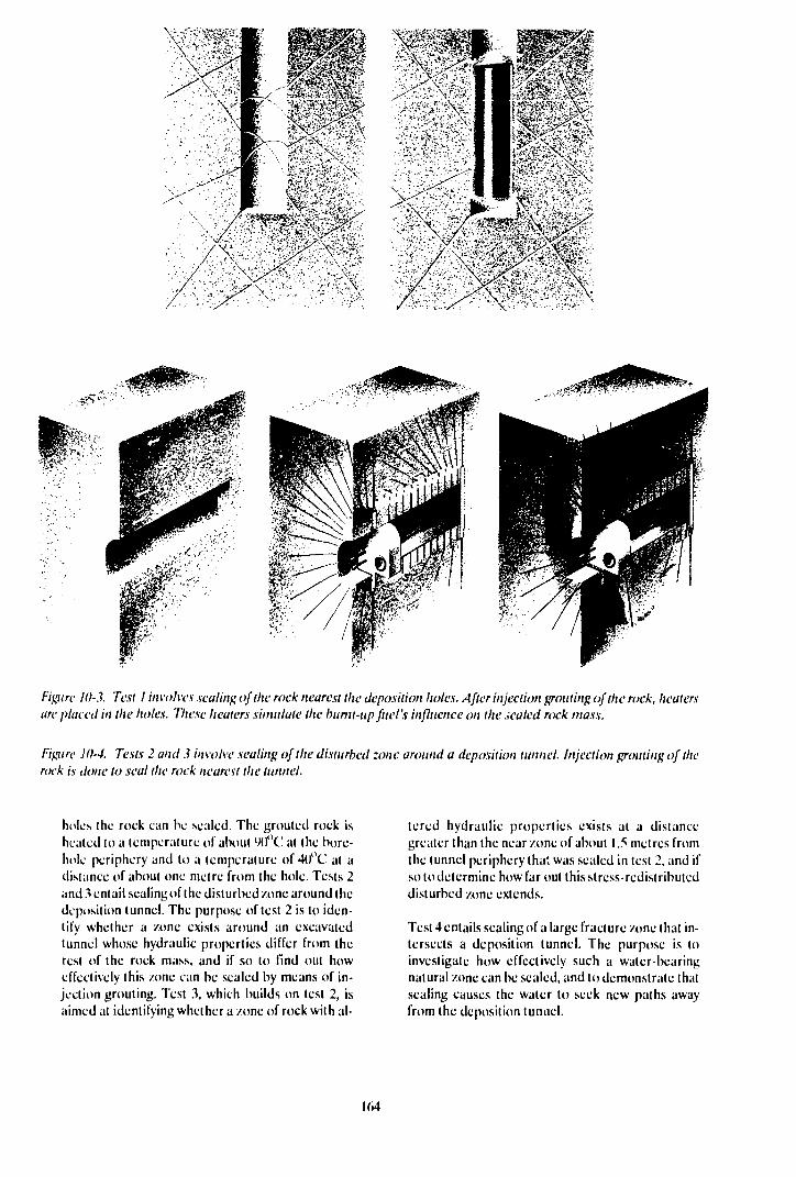
Figure 10-1 Test I involves sealing of the rock nearest the deposition holes. After injection grouting of the rock, heatersare placed in the holes. Tliese heaters simulate the bumt-up fuel's influence on the .sealed rock mass.
Figure 10-4. Tests 2 and.? involve sealing of the disturbed zone around a deposition tunnel. Injection grouting of therock is done to seal the rock nearest the tunnel.
holes the rock can he scaled. The grouted rock ishealed lo a temperature of about yo"C at the bore-hole periphery and to a temperature of 4f)°C at adistance of about one metre from the hole. Tests 2and 3 entail sealing of the disturbed /one around thedeposition tunnel. The purpose of test 2 is to iden-tify whether a /one exists around an excavatedtunnel whose hydraulic properties differ from therest of the rock mass, and if so to find out howeffectively this /one can be sealed by means of in-jection grouting. Test 3, which builds on test 2, isaimed at identifying whether a /one of rock with al-
tered hydraulic properties exists at a distancegreater than the near/one of about 1.5 metres fromthe tunnel periphery that was sealed in test 2, and ifso to determine how far out this stress-redistributeddisturbed /one extends.
Test 4 entails sealing of a large fracture /one that in-tersects a deposition tunnel. The purpose is toinvestigate how effectively such a water-bearingnatural zone can be scaled, and to demonstrate thatsealing causes the water to seek new paths awayfrom the deposition tunnel.
164

11 NATURAL ANALOGUES
11.1 GENERAL
The scope of studies concerned with natural analogueshas increased substantially in recent years. This appliesboth within SKB and internationally. Thanks tocooperation between national programmes and a closelink to the safety assessment and its model deveiopment,the yield of these studies has increased considerably.One example of important international initiatives is theformation of the National Analogue Working Group,NAWG, which works under the oversight of Euratomwithin the EC. A further example is a review of naturalanalogues and their role in the safety assessment car-ried out in 1987 by IAEA /ll-l/ . Natural analogues arealso being dealt with within the international IN-TR A VAL project. SKB is participating actively in all ofthese activities.
NAWG has met annually since its start in 1985. Its for-mation was the result of the workshop on naturalanalogues that was held in Lake Geneva, Wisconsin,USA, in 1984. The meeting had been arranged by SKBin cooperation with US DOE. NAWG has establishedguidelines for selecting and using natural analogueswithin the different national waste programmes. Inselecting an analogue it is important that the geochemi-cal processes be distinct and measurable, that naturalchemical elements exist that are analogues of importantradionuclidcs, that physico-chemical parameters aremeasurable and that the time scale is known and com-parable to that of the repository. The goals of ananalogue study shall be to:
— study the results of the processes or groups ofprocesses that are of importance for the long-termsafety of the repository,
— find limits in the parameter values that will be usedin the safety assessment,
— indicate what phenomena can be of importance,— study the integral results of changes and reactions
in a multicomponent system after a very long periodof time,
— win broader understanding and acceptance for thesafety of the final repository.
A number of large analogue studies arc currently inprogress at different places in the world. Among themore prominent ones are the studies at Pocos dc Cal-das, Brazil; at Cigar Lake, Canada; at Alligator Rivers,Australia; and at Oklo, Gabon. SKB is involved in dif-ferent ways in these studies. The Poc.os dc Caldasproject is managed by SKB. Our participation in theCigar Lake project is currently being discussed withAECL in Canada. The results of the Alligator Rivers
project, ARAP, are being evaluated by experts withsupport from SKB within the INTRAVAL project.
The rock and the hydrology where the large analoguestudies are being conducted can be different from thaton the potential repository sites. This is compensatedfor by the fact that the phenomena and processes of in-terest are particularly pronounced due to, for example,high natural concentrations of radionuclidcs and radio-nuclide-like substances (such as at Poc,os de Caldas.Oklo, Alligator Rivers and Cigar Lake), or due to ex-treme and unique conditions such as the redox front atPoc,os de Caldas, the clay barrier at Cigar Lake and thenatural reactor at Oklo. The emphasis in the analoguestudies can be shifted to more repository-like geologi-cal and hydrogeological conditions at a later phasewhen experience and methods have been developedwithin the aforementioned projects. We therefore planon future analogue studies in more repository-like rock.
11.2 POCOS DE CALDAS
The Poc,os de Caldas project involves studies of naturalanalogues for the release and dispersal of radionuclidesfrom a final repository. The investigations are tied totwo closely-situated sites in the Poc,os de Caldas districtin Minas Gerais, Brazil: the thorium deposit in Morrodo Ferro and the Osamu Utsumi uranium mine, C-09.
Sweden (SKB), Great Britain (UK DoE), Switzer-land (NAGRA), the USA (US DOE) and Brazil (Riode Janeiro University, CNEN and NUCLEBRAS) arcparticipating in the project.
The project will last three years under an agreementdrawn up between SKB, UK DoE, US DOE andNAGRA, who arc the direct sponsors. Brazil is servingas the host and is contributing some equipment andlabour. SKB is in charge of the project management.
The investigations have been divided into three sub-projects:
1 Determination of speciation and chemical trans-port of natural radionuclidcs and rare-earth metalsin a fracture flow system in crystalline rock underoxidizing and reducing conditions.
2 Formation and mobility of colloid-borne radionu-clidcs in natural groundwatcrs (here, humic sub-stances are also included in the Icrm "colloids").
3 Thermal impact on the transport of natural radio-nuclidcs and rare-earth metals.
The most important goals of the subprojects are asfollows:

"i
p
li^itn' 11-1. Sampling at a nulox (runt in the Osamu I'tsumi uranium mine for analysi\ of the minerals.
f-'igu/v 11-2. Rock \ampli'\ (mm the rctiox front. Precipitations of uranium in the Icm of pitchblende can be clearlyl / / ^ f^ ' lC l / / ^ ' / | • [ / ( ;v black
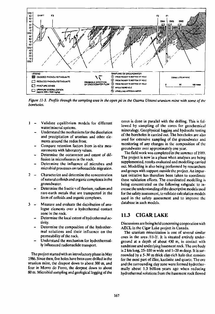
LEGEND
E l OXIDIZED PHONOUTE/TINGUAITE
• REDUCED PHONOUTE/TINGUAITE
O FRACTURE ZONES
I—I URANIUM MINERALIZATION"—' (appro» 200-1500 mg/kg)
SAMPLING OF QROUNDWATER
\ ^ © FROM PACKER TO BOTTOM OF HOLE
^ G ) FROM PACKER TO BOTTOM OF HOLEDDORARI C fURFfTION ^^
OFOROUNDWATERFLOW ® FROM PACKER TO BOTTOM Of HOLE
© WHOLE BOREHOLE
® UPWELLINO ARTESIAN WATER
Figure 11-3. Profile through the sampling area in the open pit in the Osamu Utsumi uranium mine with some of theboreholes.
1 - Validate equilibrium models for differentwater/mineral systems.Understand the mechanisms for the dissolutionand precipitation of uranium and other ele-ments around the redox front.
- Compare retention factors from in-situ mea-surements with laboratory values.
- Determine the occurrence and extent of dif-fusion in microfissures in the rock.
- Determine the influence of microbes andmicrobial processes on radionuclide migration.
2 - Characterize and determine the concentrationof natural colloids and organic complexes in thegroundwater.
- Determine the fractic i of thorium, radium andrare-earth metals that are transported in theform of colloids and organic complexes.
3 - Measure and evaluate the distribution of ana-logue elements over a hydrothermal contactzone in the rock.
- Determine the local extent of hydrothermal ac-tivity.
- Determine the composition of the hydrother-mal solutions and their influence on thepermeability of the rock.
- Understand the mechanism for hydrothermal-ly influenced radionuclide transport.
The project started with an introductory phase in May1986. Since then, five holes have been core drilled in theuranium mine, the deepest down to about 300 m, andfour in Morro do Ferro, the deepest down to about80 m. Microbial sampling and geological logging of the
cores is done in parallel with the drilling. This is fol-lowed by sampling of the cores for geochemicalmineralogy. Geophysical logging and hydraulic testingof the boreholes is carried out. The boreholes are alsoused for extensive sampling of the groundwatcr andmonitoring of any changes in the composition of thegroundwater over approximately one year.
The field work was completed in the summer of 1989.The project is now in a phase when analyses are beingsupplemented, results evaluated and modelling carriedout. Modelling is also being performed by researchersand groups with support outside the project. An impor-tant initiative has therefore been taken to coordinatethese validation efforts. The coordinated modelling isbeing concentrated on the following subgoals: to in-crease the understanding of the descriptive models usedfor the safety assessment, to validate calculation modelsused in the safety assessment and to improve thedatabase in such models.
11.3 CIGAR LAKE
Discussions are being held concerning cooperation withAECL in the Cigar Lake project in Canada.
The uranium minerization is one of several similarones in the area /11-2/. It is situated entirely under-ground at a depth of about 430 m, in contact withsandstone and underlying basement rock. The ore bodyis 2 km long, 25-100 m wide and 1-20 m deep. It is sur-rounded by a 5-30 m thick clay-rich halo that consistsfor the most part of illite, kaolinite and quartz. The oreand the surrounding clay zone were formed hydrother-mally about 1.3 billion years ago when reducinghydrothermal solutions from the basement rock flowed
167
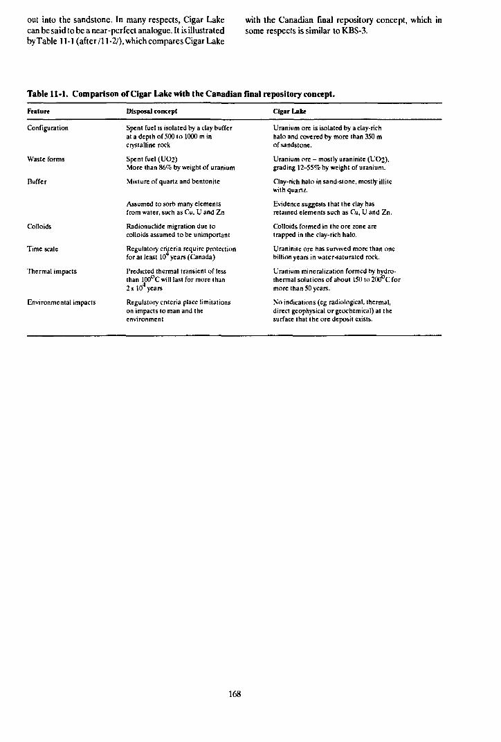
out into the sandstone. In many respects, Cigar Lakecan be said to be a near-perfect analogue. It is illustratedby Table 11-1 (after /11-2/), which compares Cigar Lake
with the Canadian final repository concept, which insome respects is similar to K.BS-3.
Table 11-1. Comparison of Cigar Lake with the Canadian flnal repository concept.
Feature Disposal concept Cigar Lake
Configuration
Waste forms
Buffer
Colloids
Time scale
Thermal impacts
Environmental impacts
Spent fuel is isolated by a clay bufferat a depth of 500 to 1000 m incrystalline rock
Spent fuel (UO2)More than 86% by weight of uranium
Mixture of quartz and bentonite
Assumed to sorb many elementsfrom water, such as Cu, U and Zn
Radionuclide migration due tocolloids assumed to be unimportant
Regulator)' criteria require protectionfor at least 10 years (Canada)
Predicted thermal transient of lessthan 100°C will last for more than2 x 104 years
Regulatory criteria place limitationson impacts to man and theenvironment
Uranium ore is isolated by a clay-richhalo and covered by more than 350 mof sandstone.
Uranium ore - mostly uraninite (UO2),grading 12-55% by weight of uranium.
Clay-rich halo in sand-stone, mostly illitewith quartz.
Evidence suggests that the clay hasretained elements such as Cu, U and Zn.
Colloids formed in the ore zone aretrapped in the clay-rich halo.
Uraninite ore has survived more than onebillion years in water-saturated rock.
Uranium mineralization formed by hydro-thermal solutions of about 150 to 200°C formore than 50 years.
No indications (eg radiological, thermal,direct geophysical orgcochcmical) at thesurface that the ore deposit exists.
168
12 BIOSPHERE STUDIES
12.1 THE IMPORTANCE OF THEBIOSPHERE STUDIES FORTHE FINAL DISPOSAL OFNUCLEAR WASTE
As is evident from previous chapters, the purpose offinal disposal is to isolate the radioactive waste from thebiosphere for such a long period of time that its radioac-tivity decays to a harmless level. To be able to determinethe consequences of abnormal barrier function anddemonstrate that the radiological consequences are in-significant, knowledge is required of how radionuclidesbehave in the biosphere. That portion of our world towhich man normally has access is normally consideredas the biosphere. The studies of the biosphere includethe following processes and calculation steps significantfor the safety assessment.
- Transport from groundwatcr in rock to a localecosystem via different local recipients such as sedi-ment, soil, water etc.
— Transport, dilution, accumulation and deposition inlocal, regional and global ecosystems.
- Calculation of individual doses and collective dosesand comparison with natural conditions.
12.2 GOALS
The goal of SKB's studies of the properties of the bio-sphere and of the behaviour of radionuclides in the bio-sphere is to be able to carry out the consequence cal-culations in the safety assessment in a credible manner.Efforts will be concentrated on estimating the conse-quences of different release scenarios from a final re-pository in a time perspective in the order of 10 tXK)years. Subgoals in this process are to:
— attempt to quantify uncertainties due to the fact thatthe biosphc.; is constantly changing,
— improve the data on which the transport models arcbased,
- validate the models by means of studies of analoguetransport processes.
12.3 PRESENT-DAY STATE OFKNOWLEDGE
12.3.1 Evolution of the Biosphere
Any activity release from a final repository will probab-ly take place so far ahead in time and over such a long
span of time that considerable changes are expected tooccur in the properties of the biosphere before and dur-ing the process of release. This means that analyses ofthe consequences of a release will entail large uncer-tainties.
The greatest uncertainty factor is associated with thenatural evolution of the ecosystems during the timeperiods considered realistic. Examples of processes ina shorter time perspective are:
— cutrophication of lakes and cultivation of old bot-tom sediments (due to land uplift as well),
— erosion of soils by wind and water,— disturbance of sediment layering in lakes and water-
ways,— urbanization, large paved surfaces, tunnels etc.
In a slightly longer perspective, climatic changes andglaciation must also be included in the picture. The bio-sphere then undergoes a very radical change and canre-cmcrge in a large number of ways. The question is,however, how meaningful it is to make dose estimatesat this point.
Mankind utilizes the ecosystems for purposes such asfood production and manipulate these systems to in-crease their yield. This can also be said to constitute akind of evolution. Today's situation exhibits a largenumber of examples of this /12-7/. This impact can beof great importance for the consequence of a postulatedrelease, especially if such phenomena as urbanization,large-scale hydroponics, dam construction or thegreenhouse effect arc included /12-13/. An inventoryof reasonable events of this kind has been discussed inconnection with SKB/SKI's joint scenario definitionwork.
SKB's efforts in recent years have been concentratedon the aging process of lakes, ie the process where (hebottom sediment of the lakes is gradually transformedinto farmland. A collection and processing of data forTrobbofjärden in Södermanland has been carried out/12-1,2,3/ including water flow, sedimentation rate, in-terstitial water characteristics, water quality during dif-ferent phases etc. Modelling /12-4/ and variationanalysis showed that the individual doses for certainnuclidcs increased by several orders of magnitude whenthe lake sediment was used as farmland. For othernuclides, the doses could decrease by a power often orso. The largest source of uncertainty is the rate of ex-change in the lake's water and sediments. However, thisscenario gives lower doses than when a well is assumedto be drilled into the waste disposal area. This projectis expected to be concluded in 1990.
169
12.3.2 Transport Pathways between Rockand Man
On their way to the surface, the groundwater and sub-stances dissolved in it will leave the reducing environ-ment in the rock and enter an oxidizing environment.For most relevant chemical compounds, this transitionis associated with a drastic change in solubility. Thetransition often takes place in sediment or soil, but canalso take place directly in free water. In the box modelsused previously, these processes have been approxi-mated with transfer coefficients. Some studies/12-10,ll/ show that greater consideration should per-haps be paid to this boundary layer, however.
A detailed investigation of outflow in lakes entitled"Nuclide transport in outflow areas" was initiated in1987. In this study, sampling was performed in LakeHillesjön and Lake Långhalsen in Södermanland to ex-amine how the chemistry and fauna of the bottom sedi-ments in outflow areas differ from those of other bot-tom sediments.
Following the Chernobyl accident, a survey of the fall-out in SKB's study sites Gideå and Finnsjön was ini-tiated in 1986 /12-8/. This survey will continue foranother five years. The project includes a sampling andmeasurement programme, studies of migration in soilprofiles, sorption on and migration in rock, water-transported activity and modelling of nuclide turnoverand transport /12-5.6/.
The goal of the sampling and measuring programmeis to be able to utilize the migration of the nuclides inthe fallout for verification and validation of models thatdescribe turnover in the biosphere and geosphere. Forthe ground migration studies, the goal is to describetransport and retardation mechanisms for differentnuclides in different soils so that models for thistransport can be improved.
Binding of actinides and iodine on organic materialin soils can be an essential factor for the exposure path-way via vegetables, meat and milk. The importance ofthe uncertainty in the turnover of the transuranic ele-ments will be evaluated. Some experimental studies mayhave to be carried out.
1233 Other Research on the Biosphere
Research concerning the dispersal of radionuclides inthe biosphere, with some relevance for final disposal ingeological formations, is being conducted by theSwedish University of Agricultural Sciences, the Uni-versity of Gothenburg, FOA4 and to some extent byStudsvik and Kemakta under contract to SSI and SKI.Other Nordic research centres that can be mentionedare Risö in Denmark and VTT in Finland. Other re-search on chemical substances in the environment maybe relevant in certain cases.
12.4 RESEARCH PROGRAMME1990-1995
12.4.1 Changes in the Biosphere
The influence of climatic changes and ice ages, as wellas human intervention, will be studied in connectionwith the work on systematic analysis of scenarios. Seefurther Chapters 3 and 6.
The project concerning the aging of lakes will be con-cluded during the period.
12.4.2 Transport Pathways in theBiosphere
Studies of "Nuclide transpart in outflow areas" will befollowed up with an investigation of the mobility of cer-tain nuclides in sediments (including U, Tc, Cs). Therole of sediments as a long-term and possibly ultimatesink for released radionuclides should be studied ingreater depth.
12.43 Models and Data
Dispersal calculations in KBS-3 were carried out withtraditional box modelling based on available data onpresent-day ecosystems. Dose calculation is carried outwith similar models utilizing radiophysical data andsummarized in internationally accepted recommenda-tions issued by ICRP.
Validation of models will continue to be carried outinternationally within the IAEA/CEC project VAli-dation of Model Predictions, VAMP, or a possible con-tinuation of BIOMO VS /12-12/, and with the aid of datafrom the Chernobyl fallout in Gideå and Finnsjön. Someof the parameters used in the box models have beenpoorly studied for Nordic conditions. Sensitivityanalyses will largely determine which parameters will bestudied further during the coming six-year period.
12.4.4 Site-specific Studies
For cases where releases do not begin until after manytens of thousands of years, when ice ages will probablyhave come and gone, the location of the repository can-not influence the biosphere transport of any nuclidesreleased from the repository.
In scenarios where nuclide release takes place in anearer future, however, the location of the repositorywill play some role in determining how the radionu-clides are transported from the rock to the local ecosys-tems, and the properties of the points of outflow.
In scenarios where release is assumed to take placewithin a few thousand years, for example in the event ofan initial canister damage, the site will be important fordispersal in local ecosystems, since present-day pre-
170
mises for land use can, by and large, be expected to per-sist during this time.
It is therefore of interest to carry out a site-specificmodel study, which should also take into account thelocal impact of the final repository. A suitable place forsuch a study is the Hard Rock Laboratory area. Thisshould then be characterized with respect to thepresence of natural radioactivity in superficial waters,groundwater conditions, outflow areas, soils, land use,biota, population etc so that less generalized models canbeused/12-9/.
Similar investigations are also planned to be con-ducted on candidate sites proposed for the final re-pository.
12.4.5 Acceptance Criteria
The choice of radiological acceptance criteria is of greatimportance for how biosphere analyses are to be car-
ried out. The work of international agencies should becarefully followed (ICRP 46). The Swedish authoritieswill probably specify minimum requirements. In thiscontext, comparisons between modellings and observa-tions of outflows of natural nuclides in human sur-roundings, for example uranium-rich macadam pro-duction, can be of interest.
As in other countries, Swedish safety assessmentshave been based on the principle that "if man as in-dividuals and as a group is protected, other biologicalspecies will not be threatened by radioactive releases".This principle has been applied to all types of releases,not only from waste storage facilities or final re-positories. The principle has been questioned by someresearchers in recent years and should be checked, ifpossible. This is mainly a task for the regulatoryauthorities that stipulate acceptance criteria. SKB in-tends to follow these developments.
171

13 INTERNATIONAL COOPERATION
Development within the field of nuclear waste manage-ment is performed to a great extent in international col-laboration and exchange. Most countries with a nuclearpower programme of any si/c have made plans for themanagement of different forms of radioactive waste andhave begun the research and development that is con-sidered necessary. International activities are thereforebeing conducted today on a large scale in the form ofexperiments, model development, site investigations,data compilations etc within the field of nuclear wastemanagement, of which the Swedish efforts naturallyconstitute only a small part. The extent to which Swedenis able to derive direct benefit from the work being donein other countries is primarily dependent on the follow-ing two factors:
- technical and geological similarities in repositorydesign and site,
- timetables for the execution of research program-mes, large-scale tests and demonstration projects aswell as the construction/operation of final re-positories.
The benefit that Sweden can derive from othercountries' research may lie on several different planes:
— contributions to method and model development,- broadened and strengthened database,— exploration of other altcnativcs for repository and
barrier design, material selection etc,— bolstering public confidence in the system through
eg demonstration trials and large-scale tests.
An important part of SKB's programme is thereforeto follow and profit from the research and developmentthat is being conducted in other countries in a methodi-cal and systematic manner. This task is made easier bythe great interest shown internationally in the workbeing done in Sweden. This chapter contains a summaryof some of the foreign programmes along wilh an over-view of the different joint international projects in whichSKB is directly involved.
13.1
USA
FOREIGN R&D OFIMPORTANCE FOR SKB'sPROGRAMME
The timetables in the USA are governed to a highdegree by the Nuclear Waste Policy Act, which waspassed in 1982. The Acl has undergone far-reaching
changes, the most recent in 1987. The Act states that thefederal government is responsible for the final disposalof high-level waste and spent fuel. US DOE. theDepartment of Energy, is responsible for building afinal repository which, under the Act, must be able toreceive waste no later than January 31, 1998. TheAmerican site has in principle already been selected usthe most recent amendment to the Act, and resourcesare now being focussed on Yucca Mountain in Nevada.The repository is planned here at a depth of 4(M) m inwater-unsaturated rock, providing about 2(K) m of un-saturated tuff as the primary geological barrier abovethe present-day groundwater table. Ciroundwatertransport proceeds extremely slowly, about 0.1 mm/vaccording to calculations. The methodology for charac-terization of Yucca Mountain, model development,studies of waste forms and the safety assessment are ofvalue for Sweden, even if the host medium is differenl.Direct contacts have been established with a number ofspecialists heading different projects in the Americanwaste programme. A person from SKB is currently sta-tioned at US DOE's office in Nevada.
Canada
AECL (Atomic Energy of Canada Ltd) is the federalorganization in charge of Canada's nuclear power pro-gramme. AECL is also responsible for research anddevelopment on the conditioning and disposal ofnuclear fuel waste. The provincially owned power utililyOntario Hydro is responsible for interim storage andtransportation of spent nuclear fuel. The division ofresponsibilities between the federal government andthe provincial governments when it comes to the finalrepository has not yet been defined. Canada's program-me for final disposal consists of three phases:
— concept assessment,— site selection,— demonstration of disposal vault.
The first phase is currently under way. In a ten-yearprogramme, research is being conducted in order to es-tablish a scientific basis for geological disposal and fortechnical criteria for site selection and repositorydesign. A proposal for a disposal method is to bepresented to the authorities for review and assessmentin the autumn of 1989. An extensive review process isforeseen, including public hearings, leadingto a final as-sessment of the proposed concept in 1990-91. Site in-vestigations and site selection are expected to take placeduring the 1990s. Once a site has been selected, a 20-year demonstration period is planned, concluding withexpansion of the demonstration facility to a disposal
173
vault, which will be taken into operation after the year2010.
The bedrock in Canada closely resembles the Scan-dinavian bedrock. Consequently, many of the geologi-cal investigations in Canada are of interest to Sweden.Of particular interest is the URL (UndergroundResearch Laboratory) project where a shaft is beingsunk to a depth of about 450 m in the bedrock. SKB hasan agreement with ACL regarding participation inURL, see Section 13.4. Canada is also advanced inchemistry and in studies of spent fuel.
Finland
According to Finnish law, responsibility for nuclearwaste management in Finland rests with the nuclearpower producers. The two power utilities, IVO andTVO, have formed a joint company, YJT, to coordinatethe necessary research and development activities.
For spent nuclear fuel, the policy is to attempt tosecure agreements whereby the spent fuel can be sentabroad for final disposal. In the case of the Loviisa reac-tors, such an agreement exists with the Soviet Union.Other nuclear fuel is to be stored temporarily and dis-posed of finally in Finland. A facility is being built atOlkiluoto for interim storage. A site for a final re-pository will be selected around the year 2000, and finaldisposal is expected to start around the year 2020.
A list of 101 sites of interest for a final repository ob-tained from an inventory was presented in early 1986.Preliminary investigations on 5-10 of these sites arebeing carried out during the period 1988-1992. Thesewill be followed by detailed investigations on 2-3 sitesup to the year 2000, when the final site will be chosen.Further investigations will be conducted on this site upto the time of a licence application around the year 2010.
Due to close similarities between the Swedish and theFinnish bedrock, an exchange of information is par-ticularly valuable.
For low- and intermediate-level waste, TVO is cur-rently building a final repository at Olkiluoto. The re-pository is being built at a depth of 70-100 m and is ex-pected to be put into service in 1992. At the end of the1990s, IVO will build a similar repository at Loviisa.
France
Responsibility for final disposal of nuclear waste inFrance lies with an independent body, ANDRA, withinCommissariat å l'Energie Atomique, CEA. The re-search and development work is being conductedprimarily by CEA. For high-level waste, the site selec-tion question has been preceded by a reconnaissance ofseveral hundred sites where granite, salt, argillaceousshale and sea sediment have been investigated. Siteselection is very much a political question and recom-mendations for criteria were made in 1987 in the GougelReport.
The site investigations will continue up to 1990. A sitewill then be selected for building an underground
laboratory, where more thorough measurements cansupplement the earlier investigations. Toward the mid-1990s, the French authorities expect to have gatheredsufficient material for the final selection of a system forthe disposal of high-level waste.
Low- and intermediate-level waste has been storedsince 1969 at La Manche. This repository will be full bythe early 1990s. A new repository is therefore being builtat Aube about 200 km south of Paris. This repositorywill be able to receive waste starting in 1991. The Auberepository will be able to accommodate 100 000 m3 ofshort-lived waste, which is equivalent to about 30 yearsof nuclear power production. SKB has concretecooperation with CEA within the fields of radionuclidechemistry and buffer/backfill.
West Germany
West Germany intends to dispose of its high-level wastein a salt formation at Gorleben. No other site is current-ly being considered. An extensive investigation pro-gramme is being conducted at Gorleben, including sink-ing of two shafts down to repository depth. These inves-tigations are expected to be completed by the beginningof the 1990s. It would then be possible to take a re-pository into operation at the end of the 1990s.
The geological studies in salt are of little interest toSweden. However, along with Sweden, West Germanyis the country that has explored the direct disposal al-ternative most systematically. The results of thesestudies were reported in the spring of 1985 in an exten-sive study, PAE, Projekt Andere Entsorgungstech-niken. The PAE project is being carried further, aimedat a full-scale demonstration of certain features, egcanister fabrication and handling of encapsulated fuel.Most of the spent nuclear fuel from the West Germanprogramme will be reprocessed. Direct disposal may beused for certain odd fuel types. SKB is following thework on direct disposal in West Germany through anexchange of information with the PAE project.
Low- and intermediate-level waste will be disposed ofin a former iron ore mine, Konrad. The licensing workfor this final repository is expected to be able to start inthe autumn of 1989. The commissioning date has not yetbeen determined and will depend on the results ofpublic hearings held in 1990.
Switzerland
According the Atomic Energy Act in Switzerland, thenuclear power utilities are obliged to present a plan forfinal disposal of radioactive waste. The Swiss federalgovernment and the Swiss nuclear power utilities havejointly formed NAGRA (Nationale Genossenschaft fiirdie Lager ung Radioaktiver Abfälle) to manage theradioactive waste.
In 1985, NAGRA published its study Project Gewähr,an equivalent of the KBS-3 Report. The report recom-mends that high-level waste be disposed of at greatdepth in crystalline rock. An experimental station in
174
rock, equivalent to the Swedish Stripa mine, has beenbuilt at Grimsel in the Alps.
In June 1988, the Swiss Government approvedProjekt Gewähr. However, they requested supplemen-tary material concerning a concept for tbe storage ofwaste in sediment by 1990, and an evaluation report onall investigations in crystalline rock by the end of 1990.Site selection in Switzerland will take place around theyear 2000, and a final repository is intended to be takeninto service around the year 2020.
For repositories for low- and intermediate-levelwaste, NAGRA conducted investigations on three sitesin the early 1980s. Due to local opposition and politicalimpasses, these are not being considered. lit June 1987,an application was submitted for permission to inves-tigate a new site, Wellenberg. In August 19Ö8, NAGRAreceived an approval from the federal authorities fortunnelling up to 100 m from the intended repository site.The necessary permits from local authorities had stillnot been obtained in May of 1989.
SKB maintains close contact with NAGRA and theSwiss programme. Direction cooperation and coor-dination of research is taking place within the fields ofcanister materials and natural analogues.
Great Britain
During the 1970s, a programme of geological investiga-tions for disposal in granite formations was initiated inGreat Britain. In December 1981, further activitieswithin this programme were postponed for at least 50years on the grounds that it had been demonstrated thatfinal disposal was possible in principle and that high-level waste can be temporarily stored without anyproblems for such a period of time. Consequently, nofurther decisions on Final disposal of HLW are expectedwithin the next few decades. R&D in Great Britain istherefore now being devoted solely to technology forvitrification of high-level waste, storage afld modelstudies. Great Britain is also participating actively in theStripa project, the Poc.os de Caldas project and NEA'sseabed disposal studies.
For low- and intermediate-level waste, plans call foran SFR-Iike repository to be built below the Seabed. Therepository may be situated at a depth of about 1000 m.In March 1989, it was decided that preparatory inves-tigations will be carried out on two sites, Sellaficld andDounreay. The investigations are expected to be com-pleted by 1992. After the final site has been selected,several years of public hearings and commenting roundswill follow. The final repository is expected to be putinto service around 2005.
EC
The EC is conducting an extensive and ^ell-coor-dinated programme within the field of nuclear wastemanagement. The work is being pursued in five-yearprogrammes, and the most recent programme periodextends from 1985 to 1989. The plan for the next pro-
gramme period, 1990-1995, includes the followingpoints:
1. System studies and harmonization of member sta-tes' waste management policies.
2. Conditioning of radioactive waste.
3. Characterization of waste forms, encapsulationmethods and canister materials.
4. Research on "development of underground re-positories".
5. Safety assessments.
The work has thus far been done in the field at under-ground facilities at Asse in West Germany, Mol in Bel-gium and at the French experimental facility at Fanay-Augeres.
During the next programme period, work is alsoplanned to be done at a new French underground ex-perimental facility. Site selection for this facility isplanned in 1991, with commissioning in 1994. A similarfacility is also planned in Great Britain, and the site forthe facility is planned to be selected there around 1993.
Through SKB, Sweden is participating in several ECprojects, for example the COCO Club (colloids andcomplexes), CHEMVAL and NAWG (NationalAnalogue Working Group). See Section 13.10.
Soviet Union
In 1988, a cooperation agreement was concluded withSCUAE (State Committee on the Utilization of AtomicEnergy) in the Soviet Union regarding waste manage-ment. A First seminar with Soviet scientists was held inthe spring of 1989. The Soviet programme appears to befocussed on disposal of reprocessed waste in salt forma-tions. No concrete joint projects currently exist.
Japan
Responsibility for the management of radioactive wastein Japan is shared between two government bodies: theScience and Technology Agency, STA, which is a partof the Government offices, and the Ministry of Interna-tional Trade and Industry, MITI. STA conducts re-search and development in science and technology,while MITI is active on the industrial side of wastemanagement.
The Power Reactor and Nuclear Fuel DevelopmentCo., PNC, and the Japan Atomic Energy Research In-stitute, JAERI, work under STA. PNC has beencharged with the task of presentinga repository conceptfor high-level radioactive waste by 1992 and performinga safety assessment for it, while JAERI is working ongeochemical questions and related safety assessmentwork.
The Central Research Institute of the Electric PowerIndustry, CRIEPI, works under MITI. CRIEPI workson behalf of the power utilities with safety assessment,instrument development and cost calculations.
175

Japan Nuclear Fuel Industries Company, Inc., JNFI,has overall responsibility for the low- and intermediate-level waste. They are currently planning a repository atRohkashomura in the northern parr of the country. Therepository is planned to be commissioned in 1992.
In July 1989, SKB signed a cooperation agreementwith JNFI regarding an exchange of information on themanagement of low- and intermediate-level waste.
International Organizations
Overall international cooperation takes place within theUN's International Atomic Energy Agency, IAEA, andwithin OECD's Nuclear Energy Agency, NEA. Theseorganizations arc natural forums for information ex-change within the field of radioactive waste, see Section13.11.
13.2 SKB's COOPERATIONAGREEMENTS WITHFOREIGN ORGANIZATIONS
SKB strives to utilize relevant results from developmentwork in other countries in a systematic way. To this end,SKB has signed formal bilateral agreements with thefollowing organizations in other countries:
- USA - US DOE (Department of Energy),- Canada - AECL (Atomic Energy of Canada Ltd),- Switzerland - NACJRA (Nationalc Cicnossenschafl
fiir die Lagcrung Radioaktiver Abfällc),- France- CEA (Commissariat å PEnergie Alomi-
quc),- EC-EUROATOM,- linland-TVOandlVO,- Soviet Union - SCUAE (State Committee on the
Utilization of Atomic Energy),- Japan -JNFI (Japan Nuclear Fuel Industries Com-
pany, Inc.).
Information exchange without formal agreementsalso exists with:
- West Germany,- Belgium,- Great Britain,- Olhcr Nordic countries.
The formal agreements arc similar in their construc-tion and cover information exchange and cooperationwithin handling, treatment, storage and final disposal ofradioactive waste. Exchange of up-to-date information(reports), as well as results and methods obtained fromresearch and development, arc main points in the agree-
ments. Arranging joint seminars and short visits ofspecialists to other signatories' facilities are other ex-amples of what is included within the framework of theagreements. General reviews of the signatories' wasteprogrammes and activity planning arc held at ap-proximately one-year intervals.
In the case of exchanges of personnel of long durationor extensive direct project cooperation, special agree-ments are generally concluded within the framework ofthe general agreement.
These agreements give specialists within the field ofnuclear waste management greater opportunities forcontacts and a fruitful exchange of up-to-date informa-tion.
13.3 THE JSS PROJECT -RESULTS
The JSS Project, which started in 1982, was concludedat the end of 1987. It was a joint project betweenCRIEPI (Japan), NAGRA (Switzerland) and SKB forstudies of radioactive glass. In Phases I to III, the goalsof the project were to:
— determine whether radioactive glass displayed dif-ferent behaviour in any respect on contact withwater than a chemically identical non-radioactiveglass,
- build up an independent database for the glass thatwas to be delivered in the future from Cogemaunder existing reprocessing agreements.
The results showed that both the radioactive and thenon-radioactive glasses exhibited, in all essentialrespects, the same behaviour on contact with water. Inaddition, the data obtained were of such high qualitythat they were judged to be able to serve as a basis fordeveloping a predictive model for glass leaching underrepository conditions. The project was therefore ex-tended with Phases IV and V, which lasted from 1984until the end of 1987. Besides model development, thesephases also included supplementary experimentalstudies /13-1,2,3/ and studies of natural analogues113-41.
The results of Phase V show that a glass block of theCogema type at 90°C would not be completely trans-formed within 10 000 years. At a lower temperature, theglass could have a much longer life. At 50°C, the timerequired for complete transformation of the glass ap-proaches a million years. The escape of fission productsand actinides from the glass is not dependent merely onthe rate at which the glass is transformed, however, butalso on the solubilities of secondary phases that can beformed and incorporate these nuclides.
176
13.4 COOPERATION WITHAECL REGARDINGUNDERGROUNDRESEARCH LABORATORY
In the spring of 1987, a three-year cooperation agree-ment was concluded concerning characterization of therock at the 240 m level in AECL's underground re-search laboratory, URL, in Manitoba, Canada.
The exchange has been of mutual benefit for AECLand SKB. To maximize the exchange of information,SKB has had specialists stationed at URL in differentperiods for the purpose of conducting joint projects.Thus far, the follow-up has been focussed on geology,rock mechanics and geohydrology, sec further Section6.2.2.1. Cooperation on groundwater chemistry willbegin during the coming year.
13.5 FUEL LEACHING -WORKSHOPS
Studies of the corrosion of high level fuel are only beingconducted by a few laboratories in the world. The ex-perimental work is both costly and time-consuming,since it has to be carried out in a hot cell. It is thereforeimportant that opportunities be provided for an infor-mal exchange of results and experience. The Spent FuelWorkshops that were started in 1981 at SKB's initiativehave served as such a forum.
A total of eight workshops have been held since thestart. From originallyhaving participants only fromSweden, Canada and the USA, the group has been ex-panded. Participants have also been invited fromcountries that arc interested in direct disposal of spentnuclear fuel but arc not yet conducting any experimen-tal investigations on high-level material.
13.6 HYDROCOIN
This project consists of an international comparisonand verification of different computer programs forgroundwatcr flow. The project's third and last level isplanned to be concluded during 1989. SKI is in chargeof the project, which has been in progress since 1981.
Level 1 of the project, on which a final report has beensubmitted, aimed at verifying the numerical accuracy ofthe different computer programs. SKB has carried outcalculations on three of the seven test cases with theprogram GWHRT /13-5/.
In level 2, which involves validation of models againstfield measurements or laboratory tests, SKB has par-ticipated in one of the test cases /13-6/. (iWHRT hasbeen used here as well.
Within level 3, sensitivity and uncertainty analyses willbe carried out on seven different test cases. A finalreport has been submitted on SKB's participation.
13.7 INTRAVAL
INTRAVAL is an international project whose purposeis to validate calculation models for radionuclidetransport in the geosphcre. The project is a follow-upof the previous projects HYDROCOIN and IN-TRACOIN. All of these projects were initiated by SKB,which also appointed the secretariat that coordinatesthe work within INTRAVAL.
A total of 14 test cases arc included in the project,which involves evaluating the results of selectedlaboratory tests, field tests and studies of naturalanalogues. In many of the cases, it is possible for dif-ferent model groups to perform predictive modellingbefore the measurement results have become available.
Five of the fourteen test cases arc SKB-linked:
- laboratory tests of migration in overcored frac-turcs/KTH,
- tracer tests at Finnsjön within the fracture /.oneprojcct/SGAB,
- Stripa 3D migration/KTH,- Po^os de Caldas Project,- colloid transport/BGS,- redox front/KTH.
INTRAVAL is planned to continue until the end of1990, with an option for extension for an additionalthree years.
13.8 COOPERATION WITH TVO,FINLAND
Cooperation with TVO was initiated in 1988 regardingstudies of the relationship between the microstructurcand diffusion properties of clays. Measurements arebeing made at room temperature and elevated tempera-ture with samples in measuring cells prepared at ClayTechnology in Lund. Measurements with tracers arebeing performed at VTT in Helsinki, while rheology andconductivity arc being studied in Lund.
A regular exchange of experience and technology forsite investigation is taking place. Furthermore, Finnishrepresentatives arc included in the reference groups forthe Lansjärv study and for the Hard Rock Laboratory.
TVO and SKB are jointly compiling existingknowledge on the importance of ice ages and relatedphenomena for the assessment of the repository's safe-ty. Aside from this organized cooperation, informationhas been exchanged regarding deposition methodology,canister design, safety assessment and quality evalua-tions.
177
13.9 COOPERATION WITH CEA,FRANCE
13.9.1 Clay
SKB is currently cooperating with CEA in clay studiesbegun in 1985. The cooperation has included coordina-tion of research projects and information exchangeregarding relationships between the microstructure,mineralogy etc of smectite clays and the influence oftemperature and irradiation. Hvdrolhermaltesls and ir-radiation have been carried out during year-long ex-periments in the laboratory. The irradiation tests havebeen carried out on SKB's reference clay Mx80 andFrench smectite clay in a simulated canister environ-ment in the laboratory at Saclay. Tests arc being con-ducted at Stripa with highly compacted French smec-tite clay in a simulated deposition environment at ap-prox. 17()°C. Studies of rheological properties havebeen carried out in the laboratory in Sweden. Thecooperation has provided good opportunities for com-parisons between the two countries' reference clays forbuffer materials, methods for measurement of proper-ties, swelling pressure, hydraulic conductivity, thermalconductivity etc, and technical methods for deposition.During I'M), an overcoring is planned of a clay-filledborehole at Stripa in which tests have been conductedsince I'AS6.
13.9.2 Chemistry
Within the framework of the bilateral cooperationagreement between CEA and SKB, experiments havebeen conducted to collect basic data on actinides.Similarly, experiments have been conducted regardingcomplcxation between actinides and humic substances.Researchers from the Department of InorganicChemistry at KTH and Tema Vatten ("Theme Water")at the University of Linköping have participated on be-half of SKB. The cooperation has resulted in a numberof publications, see also Chapter 7.
greater insight can be gained through cooperation ofthis kind.
13.10.2 CHEMVAL
CHEMVAL is a CEC project for verification andvalidation of chemical equilibrium calculation pro-grams and coupled models for geochemistry Iransport.
Stage I involved verifying different equilibriumprograms against each other and Stage 2 involvedvalidating the programs against natural groundwaters.
Stage 3 involves verification of coupled models, andStage 4 involves validation of these models. The projectis also developing its thermodynamic database and per-forming sensitivity studies on equilibrium programs.Stages 1 and 2 are finished. Stages 3 and 4 are inprogress. It is estimated that the entire project will beconcluded by early 1990. SKB has had a group par-ticipating in the project from Stage 2 onwards.
13.11 COOPERATION WITHINOECD NUCLEAR ENERGYAGENCY
13.11.1 RWMC
One of OECD/NEA's principal areas of cooperation isradioactive waste management in the member count-ries. These questions are dealt with by the RadioactiveWaste Management Committee (RWMC), where SKBis represented through Tönis Papp. Some work is car-ried out in joint international projects, and work groupsare formed to facilitate information exchange orprepare material as a basis for joint decisions or coor-dination.
Seminars and workshops are arranged within impor-tant areas to document and discuss the state of develop-ment and the direction of future work.
The groups and projects within the area of radioac-tive waste management where SKB is providing person-nel or funding are listed below.
13.10 COOPERATION WITHEURATOM, EC
13.10.1 COCO
The working group COCO (Colloids and Complexes)was formed by CEC to explore the importance of col-loids and organic complexes for the migration of radio-nuclidcs. An important part of the cooperation is com-parative experiments with different methods used at dif-ferent laboratories. SKB is supporting the participationof a Swedish specialist active within the field. Humicsubstances and colloids arc difficult to define, and much
PAAG (Performance Assessment Advisory Group)functions in an advisory capacity to RWMC in matterspertaining to cooperation on means and methods forperformance and safety analyses of final disposal sys-tems.
Member from SKB: Tönis Papp
ISAG (Advisory Group on In Situ Research and Inves-tigations) functions in an advisory capacity to RWMCin matters pertaining to tbc activities of the variousunderground research laboratories.
Member from SKB: Bengt Stillborg
178
PSAC (Probabilistic Safety Assessment Code) UsersGroup is a cooperation group between those whodevelop and those who use mathematical models forprobabilistic analyses of repository systems. The em-phasis lies on coordinating the development and com-paring the quality of the models.
Member from SKB: Nils Kjellbert
Cooperative Programme for the Exchange of Scientificand Technical Information Concerning Nuclear In-stallation Decommissioning Projects is a forum for in-formation exchange and cooperation on various decom-missioning projects all over the world.
Member from SKB: Hans Forsström. SKB is also spon-soring a programme coordinator, Shankar Menon,Studsvik Energiteknik AB.
Expert Group on Geochemical Modelling and Datadeals with matters of common interest within geo-chemistry, including the buildup of a common ther-modynamic database TDB and augmentation of thedatabase for sorption data, SDB. See Section 13.11.2.
Member from SKB: Fred Karlsson
The Stripa Project - see Chapter 10. The projectmanager and head of project administration is BengtStiilborg.
Members from SKB: P-E Ahlström (chairman of JointTechnical Committee), Hans Carlsson, SGAB (mem-ber of Joint Technical Committee) and Bengt Stillborg(Project Manager).
3.11.2 TDB
The TDB Project (Thermochemical Data Base) isunder the direction of OECD/NEA. The goal is todevclopa chemical thermodynamicdatabase fora num-ber of elements that are of importance for the safety as-sessment of the final disposal of radioactive waste. Thedevelopment of the database entails not only collectingand storing published data, but also critical review
/13-8,9,10,ll,12/. Review is carried out by a group of in-ternational experts selected for each element. Atpresent, uranium, neptunium, plutonium, americiumand technicium are being reviewed. There are plans toinclude palladium, iodine, caesium, strontium, radiumand lead as well.
The TDB Project is a very valuable initiative todevelop a well-documented, reviewed and internation-ally accepted database. SKB is supporting the activityand Swedish experts are participating in the reviewwork. For SKB, as well as for other participants, it willnaturally be necessary to have an operational databaseavailable before TDB for different calculation pur-poses. However, the results from TDB will be incor-porated as they become available. A good example ofthis is the Uranium Database at SKB.
13.12 COOPERATION WITHINIAEA
Cooperation is also being conducted within the Inter-national Atomic Energy Agency, IAEA, concerning themanagement of radioactive waste.
The cooperation is being conducted in different ways.including the publication of reports consisting of:
— proceedings from international symposia,— guidelines and standards within established areas of
activity,— status reports and methodology descriptions within
important areas undergoing rapid development.
IAEA recently appointed an expert advisory groupfor its waste management programme (the Internation-al Waste Management Advisory Committee, INWAG)and arranges for information exchanges within differentspecial areas through Joint Research Programmes.IAEA publishes an annual catalogue on current re-search projects within the waste management field inthe member countries.
SKB often participates with experts in the compila-tion or review of the above kinds of reports and has anobserver, Per-Eric Ahlström, in INWAG.
179

REFERENCES PART II
Chapter 22.1 R&D-Programme 86
1986Handling and final disposal of nuclear waste.Programme for research, development and other mea-sures.SKB, Stockholm
2-2 Granskning av Foil-program 861987
"Review of R&D-Programme 86,1987"(In Swedish)SKN, Stockholm
2-3 Final storage of spent nuclear fuel - KBS-3.May 1983
Parts I-IV.SKBF/KBS, Stockholm
2-4 RöshofTK1988
Characterization of the morphology, basement rockand tectonics in Sweden.SKB Technical Report TR 89-03, Stockholm
2-5 Kornfält K-A, Larsson K1987
Geological maps and cross-sections of SouthernSweden.SKB Technical Report TR 87-24, Stockholm
Chapter 33-1 Andersson J, Carlsson T, Eng T, Kautsky F,
Söderman E, Wingefors SThe joint SKI/SKB scenario development project.(In print)
3-2 Sellin P, Ström A1989
Modellkatalogen - Datormodeller inom SKBs forsk-ningsverksamhet."The model catalogue - Computer models withinSKB's research programme."(In Swedish)SKB Work Report AR 89-04, Stockholm
3-3 WoleryTJ1979
Calculation of chemical equilibrium uetween aqueoussoluble minerals: the EQ3/6 software package, Law-rence Livermore National Laboratory.UCRL-52658
3-4 McKenzie W F, Wolery T J, Delany j M,Silva R J, Jackson KJ, Bourcier W L,Emerson D O1986
Geochemical modelling (EQ3/6) plan. Office wastemanagement program, Lawrence Livermore NationalLaboratory.UCID-20864
3-5 Kjellberg N A, Wallin G, Oppelstrup J1989
PROPER - A computer package for uncertaintyanalysis in performance assessment.(In print)
3-6 NormanS, Kjellberg N1989
NEAR 21 - A near-field radionuclide migration codefor use with the PROPER package.(In print)
3-7 Norman S, Söderberg P, Kjellbert N1989
FARF31 - A far-field radionuclide migration code foruse with the PROPER package.(In print)
3-8 The geodatabase, introduction to GEOTABSKB Work Report AR 89-xx, Stockholm(In print)
3-9 Gentzschein B1986
Description of hydrogeological data in SKB's databaseGEOTAB.SKB Technical Report TR 86-22, Stockholm
3-10 SehlstedtS1988
Description of geophysical data in the SKB databaseGEOTAB.SKB Technical Report TR 88-05, Stockholm
181
3-11 Stark T1988
Description of geological data in the SKB databaseGEOTAB.SKB Technical Report TR 88-06, Stockholm
3-12 Eriksson E, Sehlstedt S1989
Description of background data in the SKB databaseGEOTAB.SKB Technics Report TR 89-02, Stockholm
3-13 OECD/NEAMarch 1988
Ad hoc meeting on the Application of Optimization ofProteciion in Regulation and Operational Practice.
3-14 Papp T, Sellin A, Ström ASKB 911990-1991 års säkerhetsanalys.("1990-1991 safety assessment.")(In Swedish)SKB Work Report AR 89-xx, Stockholm(In print)
Chapter 44-1 Underlagsrapport till Foil-program 86
Alternativa slutförvaringsmetoder.("Background report to R&D-Programme 86Alternative final disposal methods.")Sept 1986
(In Swedish)SKB, Stockholm
4-2 Alternativa tidplaner för hantering av använtkärnbränsle("Alternative timetables for management ofspent nuclear fuelConsequences for planning, safety and costs.")Dec 1985
(In Swedish)SKB Work Report AR 85-18, Stockholm
4-3 Granskning av FoU-program 86("Review of R&D-Programme 86")May 1987
(In Swedish)SKN, Stockholm
4-4 NAKWP-Cave ProjectNov 1985
Report on the research and development stage May1984 - 1985, Boliden WP Contech AB.SKN Report 16, Stockholm
4-5 Vattenfall, BEL1988
Storage of nuclear waste in very deep boreholes. Feasi-bility study and assessment of economic potential.Stage 3: Outline design and quality assurance review.SKB Work Report AR 88-56, Stockholm
4-6 WP-Cave - assessment of feasibility, safety anddevelopment potential
SKB Technical Report TR 89-20, Stockholm(In print)
Chapter 55-1 Kärnbränslesäkerhet
1987Handling and final storage of unreprocesscd spentnuclear fuel.KBS, Stockholm
5-2 BoultonJ.ed.1978
Management of radioactive fuel wastes: The Canadiandisposal program, Atomic Energy of Canada Ltd.Report No. AECL-6314
5-3 Johnson L H, Shoesmith D W1988
Radioactive waste form for the future, W Lut/e and RC Ewing, eds, Elsevier Science Publishers B V.
5-4 Werme L O, Forsyth R S1989
The SKB spent fuel corrosion programme. StatusReport 1988.SKB Technical Report TR 89-14, Stockholm
5-5 Forsyth R S , Werme LO, Bruno J1988
J Nucl. Mater. 160 (1988) 218
5-6 Garisto N, Garisto F1988
Atomic Energy of Canada Ltd.Report No. AECL-9562
5-7 Skålberg M, Eliasson L, Skarnemark G,Torstenfelt B, Forsyth R, Hoimér A, Winqvist B,Allard B1988
Sci. Tot. Environment 69 (1988) 347
182
5-8 Puigdoménech I, Bruno J1988
Modelling uranium solubilities in aqueous solutions:Validations of a thcrmodynamic database for theEQ3/6 geochemical codes.SKB Technical Report TR 88-21, Stockholm
5-9 Hallberg RO, östlund P.Wadsten T1988
Appl. Geochem. 3 (1988) 273
5-10 Ekbom L B, Bogegärd S1989
Copper produced from powder by HIP to encapsulatenuclear fuel elements.SKB Technical Report TR 89-10, Stockholm
5-11 Ivarsson B, Österberg J-01988
Creep properties of welded joints in OFHC copper fornuclear waste containment.SKB Technical Report TR 83-20, Stockholm
5-12 Marsh G P, Bland I D, Taylor K J1988
Br. Corros. J. 23 (1988) 157
5-13 Mattsson H, LI C1989
Titanium exposed in water saturated bentonite clay:Exposures ranging up to six years.SKB Technical Report TR 89-xx, Stockholm(In print)
5-14 Hultquist G1986
Corr. Sci. 26 (1986) 173
5-15 Simpson J P, Schenk R1987
Corr. Sci. 27 (1987) 1365
5-16 Eriksen T E, Ndalamba P, Grenthe I1988
On the corrosion of copper in pure water.SKB Technical Report TR 88-17, Stockholm
5-17 Technical Advisory Committee to Atomic Ener-gy of CanadaLimited on Nuclear Fue! Waste ManagementProgram
Seventh Annual Report, Ontario, Canada, 1986.
5-18 Smectite alterationNovember 1984
Proceedings of a workshop convened at the ShorehamHotel, Washington, D.C., December 8-9,1983.Compiled by Duwayne M Anderson, Texas A & MUniversity.SKB Technical Report TR 84-11, Stockholm
5-19 Pusch R, Kärnland OJune 1988
Hydrothermal effects on montmorillonite. A prelimi-nary study.SKB Technical Report TR 88-15, Stockholm
5-20 Erlström MDecember 1986
Pressure solution of minerals in quartz-type buffermaterials.SKB Technical Report TR 86-28, Stockholm
5-21 Pusch RDecember 1986
Settlement of canisters with smectite clay envelopes indeposition holes.SKB Technical Report TR 86-23, Stockholm
5-22 Pusch R, Börgesson L, Ramqvist GAugust 1985
Final report of the buffer mass test - Volume II: Testresults.Stripa Project Technical Report TR 85-12, SKB,Stockholm
5-23 Pusch R, Erlström M, Börgesson LMay 1987
Piping and erosion phenomena in soft clay gels.SKB Technical Report TR 87-09, Stockholm
5-24 Pusch R, Hökmark H1987
Megapermeamcterstudie av gastransport genom SFR-buffertar.("Mcgapermeameter study of gas transport throughSFR buffers.")(In Swedish)SFR Work Report 87-06, Stockholm
5-25 Pusch R, Hökmark H, Börgesson LJune 1987
Outline of models of water and gas flows through smec-tite clay buffers.SKB Technical Report TR 87-10, Stockholm
183
5-26 Pusch R, Börgesson L, Ramqvist GJanuary 1987
Final report of the borehole, shaft and tunnel sealingtest - Volume I: Borehole plugging.Stripa Project Technical Report TR 87-01, SKB,Stockholm
5-27 Pusch R, Börgesson L, Ramqvist GJanuary 1987
Final report of the borehole, shaft and tunnel sealingtest - Volume II: Shaft plugging.Stripa Project Technical Report TR 87-02, SKB,Stockholm
5-28 Pusch R, Börgesson L, Ramqvist GFebruary 1987
Final report of the borehole, shaft and tunnel sealingtest - Volume III: Tunnel plugging.Stripa Project Technical Report TR 87-03, SKB,Stockholm
5-29 Pusch R, Erlström M, Börgesson LDecember 1985
Sealing of rock fractures. A survey of potentially use-ful methods and substances.SKB Technical Report TR 85-17, Stockholm
5-30 State-of-the-art report on potentially usefulmaterials for sealing nuclear waste repositories.June 1987
Stripa Project Technical Report TR 87-12, SKB,Stockholm
5-31 Pusch R, Börgesson L, Erlström MDecember 1987
Alteration of isolating properties of dense smectiteclay in repository environments and exemplified byseven prc-quarternary clays.SKB Technical Report TR 87-29, Stockholm
5-32 Erlström M, Pusch RDecember 1987
Survey of Swedish buffer material candidates andmethods for characterization.SKB Technical Report TR 87-32, Stockholm
5-33 Pusch R, Kärnland ODecember 1986
Aspects of the physical state of smectite-adsorbedwater.SKB Technical Report TR 86-25, Stockholm
5-34 Börgesson L, Pusch RDecember 1987
Rhcological properties of a calcium smectite.SKB Technical Report TR 87-31, Stockholm
5-35 Börgesson L, Hökmark H, Kärnland ODecember 1988
Rheological properties of sodium smectite clay.SKB Technical Report TR 88-30, Stockholm
5-36 Börgesson LDecember 1986
Modern shear tests of canisters with smectite clay en-velopes in deposition holes.SKB Technical Report TR 86-26, Stockholm
5-37 Börgesson LDecember 1988
Modelling of buffer material behaviour.Some examples of material models and performancecalculations.SKB Technical Report TR 88-29, Stockholm
5-38 Pusch R, Kärnland ODecember 1988
Geological evidence of smectite longevity.The Sardinian and Gotland cases.SKB Technical Report TR 88-26, Stockholm
Chapter 66-1 Bergman S G A, Carlsson A
1986Förundersökningar i berg. Rekommendationer förförundersökningar, prognoser och utlåtanden.("Pre-investigations in rock. Recommendations forpre-investigations, predictions and statements.")(In Swedish)BeFo Foundation, Stockholm
6-2 Gustafson G, Stanfors R, Wikberg P1988
The Swedish Hard Rock Laboratory - First evaluationof prc-investigations 1986-1987 and target area cha-racterization.SKB Technical Report TR 88-16, Stockholm
6-3 Gustafson G, Stanfors R, Wikberg P1989
Swedish Hard Rock Laboratory - Evaluation of 1988year pre-investigations and description of the targetarea, the island of Äspö.SKB Technical Report TR 89-16, Stockholm
6-4 Henkel H1988
Tectonic studies in the Lansjärv region.SKB Technical Report TR 88-07, Stockholm
184
6-5 Stone D, Kamineni D C1988
Recognition of low-intermediate-dip fracture zones atsurface; an example from permit area D, Lac Du Bon-net batholith.AECL TR-465. Pinawa, Manitoba
6-13 Andersson P, Andersson P, Gustafsson E,Olsson O1989
Investigation of flow distribution in a fracture zone,using the radar method.SKB Technical Report TR 89-xx, Stockholm(In print)
6-6 Stanfors R1987
The Bolmen tunnel project. Evaluation of geophysicalsite investigation methods.SKB Technical Report TR 87-25, Stockholm
6-7 Dahl-Jensen T, Lindgren J1987
Shallow reflection seismic investigation of fracturezones in the Finnsjö area, method evaluation.SKB Technical Report TR 87-13, Stockholm
6-8 AECL1988
Semi-Annual Status Report of the Canadian nuclearfuel waste management programme 1987 October 1 -1988 March 31.AECL TR-425 - 4, Pinawa, Manitoba
6-14 Pihl J, Hammarström M, Ivansson S, Morén P1986
Crosshole investigations - Result from seismic bore-hole tomography.Stripa Project Technical Report TR 87-06,SKB, Stock-holm
6-15 Cosma, C1987
Crosshole investigations - short and medium rangeseismic tomography.Stripa Project Technical Report TR 87-08, SKB,Stockholm
6-16 Tullborg E-L1986
Fissure fillings from the Klipperås Study Site.SKB Technical Report TR 86-10, Stockholm
6-9 Gougel J1987
Stockage des déchcts radioactifs en formations géo-logique, Criteres techniques de choix de site. Ministerede L'industrie de P & T et du Tourisme, Paris
6-17 Bäckblom G, Stanfors R(eds) 1989
Studies of postglacial faulting in the Lansjärv area,northern Sweden.SKB Technical Report TR 89-xx, Stockholm(In print)
6-10 Ahlbom K, Smellie J (eds)1989
Characterization of fracture zone 2, Finnsjön studysite.SKB Technical Report TR 89-19, Stockholm
6-11 Carlsson L, Winberg A, Arnefors J1986
Hydraulic modelling of tl- • final repository for reactorwaste (SFR). Compilation and conceptualization ofavailable geological and hydrogeological data.SKB Progress Report SFR 86-03, Stockholm
6-12 Olsson O, Palmqvist K1989
Radar investigations at the Saltsjötunnel - predictionsand validation.SKB Technical Report TR 89-18, Stockholm
6-18 Carlsten S, Olsson O1989
Comparison between radar data and geophysical,geological and hydrological borehole purameters bymultivariate analysis of data.SKB Technical Report TR 89-15, Stockholm
6-19 Neuman S H1988
A conceptual framework and methodology for inves-tigating flow and transport in Swedish crystalline rocks.SKB Work Report AR 88-37, Stockholm
6-20 Osnes J D, Winberg A, Andersson J E1989
Analysis of well-test data - application of probalisticmodels of infer hydraulic properties of fractures.SKB Technical Report TR 89-xx, Stockholm(In print)
185
6-21 Carlsson L, Grundfelt B, Winberg A1987
Hydraulic modelling of final repository for reactorwaste (SFR).SKB Progress Report SFR 86-07, Stockholm
6-28 Moreno L, Neretnieks I1988
Channelling in fractured zones and its potential im-pacts on transports of radionuclides. Symp scientificbasis for nuclear waste management, Berlin
6-22 Martin C D, Christiansson R, Kroll D W1989
In-situ measurements in highly stressed granite. Part I- Comparison of USBM and modified CSIR overcoredevices.SKB Work Report AR 88-43, Stockholm
6-23 Christiansson R1989
Bergspänningsmätninggenom överborrning- fördelaroch begränsningar. Bergmekanikdagen 1989,33-56.("Rock stress measurement through overcoring - ad-vantages and limitations. Rock Mechanics Day 1989,33-56.")BeFo Foundation, Stockholm
6-24 Carlsson H, Carlsson L, Pusch R1989
Rock quality designation of the hydraulic properties inthe near field of a final repository for spent nuclearfuel.SKB Technical Report TR 89-21, Stockholm(In print)
6-25 Abelln H, Neretnieks I, Tunbrant S, Moreno L1985
Final report of the migration in a single fracture - Ex-perimental results and evaluation.Stripa Project Technical Report TR 85-03, SKB,Stockholm
6-26 Abelln H1986
Migration in a single fracture. An in-situ experiment ina natural fracture, Ph.D. Thesis.Department of Chemical Engineering, Royal instituteof Technology, Stockholm
6-27 Abelln H, Birgersson L, Gidlund J, Moreno L,Neretnieks I, Widen H, Ågren T1987
Part 13-D migration experiment - Report 3 performedexperiments, results and evaluation.Stripa Project Technical Report TR 87-21, SKB,Stockholm
6-29 Palmqvist K, Stanfors R1987
The Kymmen power station - TBM tunnel. Hydro-geological mapping and analysis.SKB Technical Report TR 87-26, Stockholm
6-30 Pusch R1989
Alteration of the hydraulic conductivity of rock by tun-nel excavation.Int J Rock Mech. Vol 26, No. 1,79,83
6-31 Winberg A, Chan T, Griffiths P, Nakka B1989
Post-excavation analysis ot a revised Room 209 frac-ture. A part of the joint AECL/SKB characterizationof the 240 level at the URL, Manitoba, Canada.SKB Technical Report TR 89-xx, Stockholm(In print)
6-32 Rhen I, Åkesson J Å1988
Hylteprojektet. Geologisk undersökning av sprickzonvid Hylte kraftverk.("The Hylte Project. Geological survey of fracturezone at Hylte power station.")(In Swedish)SKB Work Report AR 88-26, Stockholm
6-33 Larsson N Å, Markström A1988
Groundwater numerical modelling of the Fjiillvcdenstudy site - Evaluation of parameter variations. AHYDROCOIN study - Level 3, case 5 A.SKB Technical Report TR 88-11, Stockholm
6-34 BearJ1979
Hydraulics of groundwater.McGraw-HMl
6-35 Lindbom B, Lundblad K, Winberg A1989
Parameter variations of the groundwatcr flow model-ling at the Klipperås site; Regional and subregionalscale.SKB Work Report AR 89-05, Stockholm
186
6-36 Thunvik R, Braester C1988
GWHRT - A flow model for coupled groundwater andheat flow - version 1.0.SKB Technical Report TR 88-10, Stockholm
6-37 Thunvik R1987
Calculations on HYDROCOIN level 1 using theGWHRT flow model. Cases 1,3 and 4.SKB Technical Report TR 87-03, Stockholm
6-38 Thunvik R1987
Calculations on HYDROCOIN level 2, case 1 using theGWHRT flow model.SKB Technical Report TR 87-04, Stockholm
6-39 OECD/NEA1988
The international HYDROCOIN project - Level 1:Code verification.
6-40 Andersson J, Dverstorp B1987
3-D migration experiment - Report 4 fracture networkmodelling of the Stripa 3-D Site.Stripa Project Technical Report TR 87-22, SKB,Stockholm
6-41 Andersson J1988
Application of discrete fracture network models at sitecharacterization and safety analyses.SKB Work Report AR 88-35, Stockholm
6-42 GelharLW1987
Applications of stochastic models to solute transportin fractured rocks.SKB Technical Report TR 87-05, Stockholm
6-43 Golder Associates Inc1989
Fracture flow code - Cross-verification plan - Revision1.0.Golder Associates, Redmond WA
6-44 Herbert AW1988
NAPSAC stochastic fracture network modelling code:Technical summary.Release 1A AERE Harwell Laboratory
6-45 Golder Associates Inc1988
MAFIC version 1.0:Matrix and fracture interactioncode: User documentation.Golder Associates, Redmond WA
6-46 Golder Associates Inc1988
FracMan version 2.0: Interactive rockfracture geo-metric model: User documentation.Golder Associates, Redmond WA
6-47 Moreno L, Tsang Y, Tsang C F, Neretnieks 11988
Flow and solute transport in a single fracture. A two-dimensional statistical model.SKB Technical Report TR 88-03, Stockholm
6-48 Paige RW, Piper D1988
Capabilities and requirements for modelling radionu-clide transport in the geosphcre.UK/DOE/RW/89/024/, London
6-49 Ahlbom K, Andersson P, Ekman L,Gustafsson E, Smellie J, Tullborg E-L1986
Preliminary investigations of fracture zones in theBrändan area, Finnsjön study site.SKB Technical Report TR 86-05, Stockholm
6-50 Gentzchein B, Nilsson G, Stenberg L1987
Preliminary investigations of fracture zones at Ävrö -results of investigations performed July 1986 - May1987.SKB Progress Report PR 25-87-16, Stockholm
6-51 Pusch R, Börgesson L, Ramqvist G1985
Final report of the buffer mass test - Volume II: testresults.Stripa Project Technical Report TR 85-12, SKB,Stockholm
6-52 Thunvik R, Braester C1987
Calculation of gas migration in fractured rock.SKB Technical Report TR 87-18, Stockholm
6-53 Braester C, Thunvik R1987
Calculation of gas migration in fractured rock - a con-tinuum approach.SKB Technical Report TR 87-19, Stockholm
187
6-54 Hakami E1988
Water flow in single rock joints. Licentiate Thesis1988:11L.Tekniska Högskolan in Luleå, Luleå
6-55 ThunvikR,BaoY-B1989
GWHRT-S - Documentation of computer programfor sensitivity analysis of groundwater flow, Version1.0.SKB Work Report AR 88-55, Stockholm
6-56 Heinrich WF(ed)1984
Proc. workshop on transitional processes. Ottawa1982.AECL-7822. Pinawa, Manitoba
6-63 Slunga R1985
The seismicity of southern Sweden, 1979-1984, finalreport.FOA Report C 20578-T1, ISSN 0347-3694, Stockholm
6-64 Slunga R, Nordgren1987
Earthquake measurements in southern Sweden, Oct 1,1986-March 31,1987.SKB Technical Report TR 87-27, Stockholm
6-65 Slunga R1989
Earthquake measurements in northern Sweden, Oct1987-April 1988.SKB Technical Report TR 89-xx, Stockholm(In print)
6-57 Nurmi P1985
Mahdolliset ympäristölolosuhteiden pitkäaikaismu-utokset Suomessa ja niiden vaikutukset syvällä oleviinkalliopohjavesiin.TVOYJT 85-21, Helsinki
6-58 Gregersen S, Basham P W (eds)1989
Earthquakes at north Atlantic passive margins: Neo-tectonic and glacial rebound.NATO ASI C266, Kluwer, London
6-59 Holmes R (ed)1989
Report on a seminar on natural environmental change,April 1988, London.Technical Report TR-D&M-13, Dames & Moore,London
6-60 Gaål G, Gorbatschev R1987
An outline of the precambrian evolution of the BalticShield.Precambrian Research, Vol 35 15-52.
6-61 RöshofTK1989
Characterization of morphology, basement rock andtectonics in Sweden.SKB Technical Report TR 89-03, Stockholm
6-62 Ziegler P1988
Evolution of the Arctic-North Atlantic AAPG Memoir43.Tulsa, USA
6-66 Stephansson O1987
Modelling of crustal rock mechanics for radioactivewaste storage in Fennoscandia - Problem definition.SKB Technical Report TR 87-11, Stockholm
6-67 KakkuriJ1986
Newest results obtained in studying the Fennoscandianland uplift phenomenon.Techtonophysics 130,327-331
6-68 WakitaH.SanoY.MizoueM1987
High 3He emanations and seismic swarms observed ina non-volcanic, forearc region.Journal Geophysical Res 92, No. B12.12539-12546
6 69 IkeyaM.MikiT.TanakaK1982
Dating of a fault by electron spin resonance on in-trafault material.Science 1982, V 215,1392-1393
6-70 Tirén S, Beckholmen M1989
Block faulting in southeastern Sweden interpretedfrom digital terrain models.GFF Vol III, Pt 2,171-180, Stockholm
6-71 Johnston A C1987
Suppression of earthquakes by large continental icesheets.Nature, 330,467-469.
188
6-72 Mörner N A1988
Kärnavfall i berg är otänkbart.("Nuclear waste in rock is unthinkable.")(In Swedish)Dagens Nyheter DN Debatt. 23 Sept 1988, Stockholm
6-73 Peltonen E, Ryhänen V H, Salu J P, Vieno T K,VuoriSJMarch 1986
Concept and safety assessment for spent fuel disposalin Finland. Int. symp. siting, design and construction ofunderground repositories for radioactive waste.Hanover, IAEA-SM-289/28
6-74 SKBF/KBS1983
Final storage of spent nuclear fuel KBS-3. Volumes I-IV.SKBF/KBS, Stockholm
6-75 Talbot C1986
A preliminary structural analysis of pattern of postgla-cial faults in northern Sweden.SKB Technical Report TR 86-20, Stockholm
6-76 Lagerbäck RPostglacial faulting and paleoseismicity in the Lansjärvarea, northern Sweden.SKB Technical Report TR 88-25, Stockholm
6-77 Wahlström R, Linder S-O, Holmqvist C1988
Near-distance seismological monitoring of the Lans-järv neotectonic fault region.SKB Technical Report TR 88-12, Stockholm
6-78 Stephansson O, Savilahti T1988
Validation of the rock mechanics HNFEMP codeagainst Colorado School of Mines block test data.SKB Technical Report TR 88-13, Stockholm
6-79 Barton N, Chryssanthakis P, Monsen K1988
Validation of MUDEC against Colorado School ofMines block test data.SKB Technical Report TR 88-14, Stockholm
6-80 RöshoffK1989
Seismic effects on underground constructions, ground-water levels and chemistry.SKB Technical Report TR 89-xx, Stockholm(In print)
6-81 Nordenskjöld C E1944
Morfologiska studier inom övergångsområdet mellanKalmar och Tjust.("Morphological studies within the transitional areabetween Kalmar and Tjust.")(In Swedish)Medd Lunds geol. Inst. Avh VIII. Lund
6-82 Svensson N1989
Late weichselian and early holocenc shore displace-ments in the central Baltic, based on stratigraphicaland morphological records from eastern Småland andGotland, Sweden.Lundqua thesis, Vol. 25, Lund University, Lund
6-83 Bowman J R1988
Constraints on locations of large inlraplatc earth-quakes in the northern territory, Australia from ob-servations at the Warramunga seismic array.Geoph Res Letters, Vol 15, No. 13,1475-1478
6-84 Andersson J E, Lindqvist L1989
Prediction of hydraulic conductivity and conductivefracture frequency by multivariatc analysis of datafrom the Klippcrås study site.SKB Technical Report TR 89-11, Stockholm
Chapter 77-1 Stumm W, Morgan J
1981Aquatic Chemistry.2nd ed. (John Wiley & Sons, New York)
7-2 Nordstrom D K (ed), Andrews J, Carlsson L,Fontes J, Fritz P, Moser H, Olsson TJuly 1985
Hydrogeological and hydrogeochemical investigationsin boreholes- Final report of Phase 1: Geochcmical in-vestigations of the Stripa groundwaters.Stripa Project Technical Report TR 85-06, SKB,Stockholm
7-3 WikbergP.AxelsenK, Fredlund F1987
Deep groundwater chcmistiy.SKB Technical Report TR 87-07, Stockholm
189
7-4 Magnusson N, Lundqvist G, Ganlund E1957
Sveriges geologi.("The geology of Sweden.")(In Swedish)3rd ed. Nordstedts förlag, Stockholm
7-5 Gustafson G, Stanfors R, Wikberg P1989
Swedish Hard Rock Laboratory: Evaluation of 1988year pre-investigations and description of the targetarea, the island of Äspö.SKB Technical Report TR 89-16, Stockholm
7-6 Laaksoharju M, Nilsson A-C1989
Models of groundwater comp: .v» and of hydraulicconditions based on chev metrical and chemicalanalyses of deep group.1*;'.or at Äspö and Laxemar.SKB Progress Repov P!; 25-89-04, Stockholm
7-7 Wikberr <: : .iaksoharju M, Bruno J,San»»* >Ser ^jerl988
Site chat ...lerization and validation - Hydrochcmicalinvestigations in Stage I.Stripa Project Internal Report IR 88-09, SKB, Stock-holm
7-8 Neretnieks I1986
"Some uses for natural analogues in assessing the func-tion of a HLW repository" in natural analogues to theconditions around a final repository for high-levelradioactive waste.Chem. Geol. 55,175
7-9 Wikberg P1987
Thesis: The chemistry of deep groundwaters in crystal-line rocks.Royal Institute of Technology, Stockholm
7-10 Tullborg E-L1986
Fissure fillings from Klipperås study site.SKB Technical Report TR 86-10, Stockholm
7-11 Laaksoharju M1988
Shallow groundwater chemistry at Laxemar, Äspö andÄvrö.SKB Progress Report PR 25-88-04, Stockholm
7-12 Nordstrom D K, Puigdoménech IApril 1986
Redox chemistry of deep groundwaters in Sweden.SKB Technical Report TR 86-03, Stockholm
7-13 Puigdoménech I, Nordstrom KAugust 1987
Geochemical interpretation of groundwaters fromFinnsjön, Sweden.SKB Technical Report 87-15, Stockholm
7-14 Tardy Y, Duplay J, Fritz BApril 1987
Stability fields of smectites and illites as a function oftemperature and chemical composition.SKB Technical Report TR 87-20, Stockholm
7-15 Fritz B, Made' B, Tardy FApril 1988
Geochemical modelling of the evolution of a granite-concrete-water system around a repository for spentnuclear fuel.SKB Technical Report TR 88-18, Stockholm
7-16 Andrews J, Fontes J-C, Fritz P, Nordstrom KAugust 1988
Hydrogeochemical assessment of crystalline rock forradioactive waste disposal: The Stripa experience.Stripa Project Technical Report TR 88-05, SKB,Stockholm
7-17 Bruno J, Casas I, Grenthe I, Lagerman B1987
Studies on metal carbonate complexes 19. Complexformation in the Th(IV)-H2O-CO2(g) system.Inorganica Chemica Acta 140 (1987) 299-301
7-18 Bruno J, Grenthe I, Robouch P1988
Studies of metal carbonate equilibria 21. Formation oftetra carbonate uranium(IV)ion, U(CO3)44', in hy-drogen carbonate solutions.Inorganic Chemica Acta (to be published)
7-19 Riglet Ch, Vitorge P, Grenthe I1987
Standard potentials of the (MO22+/MÖ2 + ) systemsfor uranium and other actinides.Inorganica Chimica Acta, 133 (1987) 323-329
7-20 Grenthe I, Bidoglio G, Omenetto N1988
Use of thermal lensing spectrophotometry (TLS) forthe study of mononuclear hydrolysis of uranium(IV).Inorganic Chemistry 28 (1989) 71-74
190
7-21 Puigdoménecb I, Bruno JOctober 1988
Modelling of uranium solubilities in aqueous solutions:Validation of a thermodynamic database for the EQ3/6geochemical codes.SKB Technical Report TR 88-21, Stockholm
7-22 Bruno J, Puigdoménech I1988
Validation of the SKBUI uranium thermodynamicdatabase for its use in geochemical calculations withEQ3/6 in scientific basis for nuclear waste managementXIII; Berlin.
7-23 Bruno J, Sandino ADecember 1987
Radionuclide co-precipitation.SKB Technical Report TR 87-23, Stockholm
7-24 TjusK,WikbergPMarch 1987
Study of groundwater colloids and their ability totransport radionuclidcs.SKB Technical Report TR 87-12, Stockholm
7-25 Marinsky J A, Reddy M M, Ephraim J,Mathuthu AApril 1988
Ion binding by humic and fulvic acids: A computation-al procedure based on functional site heterogeneityand the physical chemistry of polyelectrolyte solutions.SKB Technical Report TR 88-04, Stockholm
7-26 Moulin V, Robouch P, Vitorge P, Allard B1987
Spcctrophotometric study of the interaction betweenamericium(III) and humic materials.Inorganica Chimica Acta 140(1987)303-306
7-27 Allard B, Moulin V, Basso L, Tran M T,Stammose D1987
Americium adsorption on alumina in the presence ofhumic materials.In impact de la Physico-Chimie sur l'Etude, la concep-tion et l'optimisation de procedes en milieu naturel.Presses Universitaires de Nancy, p 277-283
7-28 Pedersen KDecember 1988
Preliminary investigations of deep groundwater micro-biology in Swedish granitic rock.SKB Technical Report TR 88-01, Stockholm
7-29 TorstenfeltBApril 1986
Migration of fission products and actinides in com-pacted bentonite.SKB Technical Report TR 86-14, Stockholm
7-30 Ittner T, Torstenfelt B, Allard BJanuary 1988
Migration of the Fission products strontium tcch-netium, iodine, cesium and the actinides neptunium,plutonium, americium in granitic rock.SKB Technical Report TR 88-02, Stockholm
7-31 Eriksen T, Locklund BNovember 1987
Radionuclide sorption on granitic drill core material.SKB Technical Report TR 87-22, Stockholm
7-32 Eriksen T, Christensen H, Bjergbakke EMarch 1986
Hydrogen production in alfa irradiated bentonitc.SKB Technical Report TR 86-04, Stockholm
7-33 Eriksen T, Christensen H, Bjergbakke E1987
Hydrogen production in alfa irradiated bentonite.Journal of Radiolytical and Nuclear Chemistry, Vol.116 No.l (19817) 13-25
7-34 Eriksen T, Ndalamba PDecember 1988
On the formation of a moving redox front by alfaradiolysis of compacted water saturated bentonite.SKB Technical Report TR 88-27, Stockholm
7-35 Eriksen T, Christensen H, Bjergbakke EDecember 1988
Radiolysis of groundwater: Influence of carbonate andchloride on the hydrogen peroxide production.SKB Technical Report TR 88-22, Stockholm
7-36 Rasmuson A, Neretnieks IMarch 1985
Radicnuclide transport in fast channels in crystallinerock.SKB Technical Report TR 86-13, Stockholm
7-37 TsangYW,Tsang C F, Neretnieks IDecember 1986
Some properties of a channelling model of fractureflow.SKB Technical Report TR 87-06, Stockholm
191
7-38 Moreno L, Tsang Y W, Tsang C F, Neretnieks 1January 1988
Flow and solute transport in a single fracture. A two-dimensional statistical model.SKB Technical Report TR 88-03, Stockholm
7-39 Birgersson L, Neretnieks IApril 1988
Diffusion in the matrix of granitic rock. Field test in theStripa mine. Final report.SKB Technical Report TR 88-08, Stockholm
7-40 Zhu MJanuary 1988
Some aspects of modelling of the migration of chemi-cal species in groundwatcr systems.Licentiate Thesies, Royal Institute of Technology,Stockholm
7-41 Zhu M, Rasmusson A, Neretnieks IJuly 1988
Annual report on chemistry and chemical transport.Report to SKB
7-42 EriksenTDecember 1988
Radionuclide transport in a single fissure. A laboratoryflow system for transport under reducing conditions.SKB Technical Report TR 88-28, Stockholm
8-5 Almén K-E, Andersson O, Fridh B,Johansson B E , Sehlstedt M, Gustafsson E,Hansson K, Olsson O, Nilsson G, Axelsen K,Wikberg P1986
Site investigation - Equipment for geological, geo-physical, hydrogeological and hydrochemical cha-racterization.SKB Technical Report TR 86-16, Stockholm
8-6 SträhleA1988
Drill core investigation in the Simpevarp area, bore-holes KAS 02, KAS 03, KAS 04 and KLX 01.SKB Progress Report PR 25-88-07, Stockholm
8-7 Sehlstedt S, SträhleA1988
Geological core mapping and geophysical boreholelogging in the boreholes KAS 05 - KAS 08 at Äspö.SKB Progress Report PR 25-89-09, Stockholm
8-8 Olsson O, Falk L, Forslund O, Lundmark L,Sandberg E1987
Crosshole investigations - results from borehole radarinvestigations.Stripa Project Technical Report TR 87-11, SKB,Stockholm
Chapter 8
8-1 Gustafsson G, Stanfors R, Wikberg P1988
Swedish Hard Rock Laboratory first evaluation of pre-investigations 1986-87 and target area characteri-zation.SKB Technical Report TR 88-16, Stockholm
8-2 Barmen G, Stanrors R1988
Ground level geophysical measurements on the islandof Äspö.SKB Progress Report PR 25-88-16, Stockholm
8-3 Nisca D, Triumf C-A1989
Detailed geomagnetic and geoelectric mapping ofÄspö.SKB Progress Report PR 25-89-01, Stockholm
8-4 Ploug C, Klitten K1988
SKB Progress Report PR 25-89-02, Stockholm
8-9 Olsson O, Eriksson J, Falk L, Sandberg E1988
Site characterization and validation - Borehole radarinvestigations, Stage 1.Stripa Project Technical Report TR 88-03, SKB,Stockholm
8-10 Cosma C1987
Crosshole investigations - Short and medium rangeseismic tomography.Stripa Project Technical Report TR 87-08, SKB,Stockholm
8-11 Stenberg L1987
Detailed investigations of fracture zones in theBrändan area, Finnsjön study site. Investigations withthe tubewave method in boreholes Fi 6 and BFi 1.SKB Work Report AR 87-27, Stockholm
8-12 Nilsson L1988
Hydraulic tests at Äspö and Laxemar - Evaluation.SKB Progress Report PR 25-88-14, Stockholm
192
8-13 Rhen I1989
Transient interference tests on Äspö.SKB Progress Report PR 25-88-13, Stockholm
8-14 Gustafson E1987
Groundwater flow measurements in fractured crystal-line rock by point dilution.SKB Technical note
8-15 LaaksoharjuM, Nilsson A-C1989
Chemical characterization and modelling of deepgroundwater at Äspö and Laxemar.SKB Progress Report PR 25-89-04, Stockholm
Chapter 99-1 Gustafson G, Stanfors R, Wikberg P
1988Swedish Hard Rock Laboratory - First evaluation ofpre-investigations 1986-87 and target area charac-terization.SKB Technical Report TR 88-16, Stockholm
9-2 Gustafson G, Stanfors R, Wikberg P1989
Swedish Hard Rock Laboratory - Evaluation of 1988pre-investigations and description of the target area,the island of Äspö.SKB Technical Report TR 89-16, Stockholm
8-16 Wikberg P1987
The chemistry of deep groundwaters in crystallinerocks.Royal Institute of Technology, Stockholm
8-17 AhlbomK, Andersson P, Ekman L,TirénS1988
Characterization of fracture zones in the Brändan areaFinnsjön study site, central Sweden.SKB Work Report AR 88-09, Stockholm
8-18 Abelin H, Birgersson L, Gidlund J1987
3-D Migration experiment - Report 2, instrumentationand tracers.Stripa Project Technical Report TR 87-20, SKB,Stockholm
8-19 Bjarnason 8, Torikka A1989
Field instrumentation for hydrofracturing stress mea-surements.SKB Technical Report TR 89-17, Stockholm
Chapter 1010-1 Executive Summary of Phase 1
July 1986Stripa Project Technical Report TR 86-04, SKB,Stockholm
10-2 Executive Summary of Phase 2February 1989
Stripa Project Technical Report TR 89-01, SKB,Stockholm
10-3 Program for the Stripa Project Phase 3 1986-1991May 1987
Stripa Project Technical Report TR 87-09, SKB,Stockholm
10-4 Holmes D, Sehlstedt MMay 1986
Crosshole investigations - Details of the constructionand operation of the hydraulic testing system.Stripa Project Technical Report TR 87-04, SKB,Stockholm
8-20 Carlsten S, Olsson O, Persson O, Sehlstedt M1988
Site characterization and validation - Monitoring ofhead in the Stripa mine during 1987.Stripa Project Internal Report IR 88-02, SKB, Stock-holm
8-21 Holmes 0, Sehlstedt M1987
Crosshole investigations - Details of the constructionand operation of the hydraulic testing system.Stripa Project Technical Report TR 87-04, SKB,Stockholm
10-5 Olsson O, Falk L, Forslund O, Lundmark L,Sandberg EMay 1987
Crosshole investigations - Results from borehole radarinvestigations.Stripa Project Technical Report TR 87-11, SKB,Stockholm
10-6 Bjarnason B, Raillard GJuly 1987
Rock stress measurements in borehole V3.Stripa Project Internal Report IR 87-13, SKB, Stock-holm
193
10-7 Fridh BDecember 1987
Site characterization and validation - Geophysicalsingle hole logging.Stripa Project Technical Report TR 87-17, SKB,Stockholm
10-15 GaleJ,StråhleASeptember 1988
Site characterization and validation - Drift and bore-hole fracture data, Stage I.Stripa Project Internal Report 1R 88-10, SKB, Stock-holm
10-8 Black J, Holmes D, Brightman MDecember 1987
Crosshole investigations - Hydrogeological results andinterpretations.Stripa Project Technical Report TR 87-18, SKB,Stockholm
10-16 Olsson O, Black J, Gale J, Holmes DMay 1989
Site characterization and validation Stage 2 - Prelimi-nary predictions.Stripa Project Technical Report TR 89-03, SKB,Stockholm
10-9 Noy D, Barker J, Black J, Holmes DFebruary 1988
Crosshole investigations - Implementation and frac-tional dimension interpretation of sinusoidal tests.Stripa Project Technical Report TR 88-01, SKB,Stockholm
10-10 Carlsten S, Olsson O, Persson O, Sehlstedt MApril 1988
Site characterization and validation - Monitoring ofhead in the Stripa mine during 1987.Stripa Project Internal Report IR 88-02, SKB, Stock-holm
10-11 Olsson O, Eriksson J, Falk L, Sandberg EApril 1988
Site characterization and validation - Borehole radarinvestigations, Stage I.Stripa Project Technical Report TR 88-03, SKB,Stockholm
10-17 Abelin II, Neretnieks I, Tunbrant S, Moreno LMay 1985
Final report of the migration in a single fracture - Ex-perimental results and evaluation.Stripa Project Technical Report TR 85-03, SKB,Stockholm
10-18 Abelin H1986
Migration in a single fracture. An in-situ experiment ina natural fracture.Ph.D. Thesis, Department of Chemical Engineering,Royal Institute of Technology, Stockholm
10-19 Annual Report 1988May 1989
Stripa Project Technical Report TR 89-05, SKB,Stockholm
10-12 Cosma C, Korhonen R, Hammarström M,Norén P.PihIJSeptember 1988
Site characterization and validation - Results fromseismic crosshole and reflection measurements, Stage1.Stripa Project Internal Report IR 88-07, SKB, Stock-holm
10-13 Vik G, Barton NAugust 1988
Stage 1 Joint characterization and Stage 2 Preliminaryprediction using small core samples.Stripa Project Internal Report IR 88-08, SKB, Stock-holm
10-20 State-of-the-art report on potentially usefulmaterials Tor sealing nuclear waste repositoriesJune 1987
Stripa Project Technical Report TR 87-12, SKB,Stockholm
10-21 Pusch R, Börgesson L, Fredrikson A,Markström I, Edström M, Ramqvist G,Gray M, Coons WSeptember 1988
Rock sealing - Interim report on the rock sealingproject (Stage I).Stripa Project Technical Report TR 88-11, SKB,Stockholm
10-14 Wikberg P, Laaksoharju M, Bruno J,Sandino ASeptember 1988
Site characterization and validation - Hydrochemicalinvestigations in Stage 1.Stripa Project Internal Report IR 88-09, SKB, Stock-holm
10-22 Pusch RMarch 1988
Rock sealing - Large scale field test and accessory in-vestigations.Stripa Project Technical Report TR 88-04, SKB,Stockholm
194
Chapter 11li-i IAEA
1987A review of the use of natural analogues in perfor-mance assessments of deep underground repositoriesfor long-lived radioactive wastes.IAEA Technical Report Series (8000W), Vienna
11-2 Goodwin B W, Cramer J J, McConnell D B1988
The Cigar Lake uranium deposit; An analogue fornuclear fuel waste disposal.In third CEC meeting of the Natural Analogue Work-ing Group (NAWG) Snowbird, Utah, June 15-17
11-3 SmellicJ1988
Swedish natural analogue studies and their applica-tions.In joint Sino-Japanese seminar on the implication ofnatural analogues to the safety of radioactive waste dis-posal. Organized by Taiwan Radwaste Administration- Energy Council. Taipe, Taiwan, December 9.
Chapter 1212-1 Evans S
October 1986Quantitative estimates of sedimentation rates and sedi-ment growth in two Swedish lakes.Studsvik Energiteknik AB, Nyköping.SKB Technical Report TR 86-29, Stockholm
12-2 Sundblad BDecember 1986
Recipient evolution - Transport and distribution ofelements in the lake Sibbo-Trobbofjärden area.Studsvik Energiteknik AB, Nyköping.SKB Technical Report TR 86-30, Stockholm
12-3 Andersson KAugust 1987
Watercomposition in the Lake Sibbofjärden, LakeTrobbofjärden area.Studsvik Energiteknik AB, Nyköping.SKB Technical Report TR 87-30, Stockholm
12-4 Bergström U, Evans S, Puigdomenech I,Sundblad BSeptember 1988
Long-term dynamics of a lake ecosystem and the im-plications for radiation exposure.Studsvik Nuclear, Nyköping.SKB Technical Report TR 88-31, Stockholm
12-5 Carbol P, Eriksson N, Gustafsson E, Ittner T,Karlberg. O, Lampc S. Skålberg M.SundMad B, Tullborg ELDecember 1987
Radionuclide deposition and migration within theGideå and Finnsjön study sites, Sweden: A study of thefallout after the Chernobyl accident. Phase I, initialsurvey.SKB Technical Report TR 87-28, Stockholm
12-6 Ittner T, Gustavsson E1989-03-01
Lägesrapport avseende 1988 års aktiviteter inomprojektet; Nedfallsstudier i Gidcå och Finnsjön-området efter Tjernobylolyckan 1986.("Status report concerning 1988 activities within theproject: Fallout studies in Gideå and the Finnsjön areaafter the Chernobyl accident in 1986.")(In Swedish)Work Report SGAB 89209
12-7 Dames and MooreJanuary 1989
Report of a seminar on "Natural environmentalchange".UKDOE Report No. DOE/RW/89.029
12-8 Carbol P, Ittner T, Skålberg M1988
Radionuclide deposition and migration of the Cher-nobyl fallout in Sweden.Radiochimica Acta 44/45,207-212
12-9 SuoIanenV.VienoTSeptember 1987
Development of biosphere scenarios for safety analysisof spent nuclear fuel disposal.Nuclear Waste Commission of Finnish Power Com-panies.Report YJT-87-13
12-10 Elert M, Argärde A-C1985
Modelling of the interface between the gcosphcre andthe biosphere - Discharge through a sediment layer.Project SSI P295-84.Swedish National Institute of Radiation Protection,Stockholm
12-11 Elert M, Argärde A-C, Ericsson AMDecember 1988
Modelling of the interface between the geosphcrc andthe biosphere: Discharge through a soil layer.Kemakta Konsult AB, Stockholm.KEMAKTA AR 88-23
195
12-12 Häss C, Johansson G1987
BIOMOVS: An international model validation study.SSI Report 87-32
12-13 -P-oroeMCJune 1988
The biosphere: Current status.Electrowatt Engineering Services (UK) LTD, WestSussex.HL89/1085
Chapter 1313-1 JSS Project Phase IV: Final Report
1987Experimental and modelling studies of HLW glass dis-solution in repository environments.JSS Project Technical Report 87-01, SKB, Stockholm
13-2 Grambow B1987
Nuclear waste glass dissolution: Mechanism, modeland application.JSS Project Technical Report 87-02, SKB, Stockholm
13-3 JSS Project Phase V: Final Report1988
Testing and modelling of the corrosion of simulatednuclear waste glass powders in a waste package en-vironment.JSS Project Technical Report 88-02, SKB, Stockholm
13-4 Jercinovic M J, Ewing R C1988
Basaltic glasses from Iceland and the deep sea: Naturalanalogues to borosilicate nuclear waste-form glass.JSS Project Technical Report 88-01, SKB, Stockholm
13-5 Thunvik R, Braester C1988
GWHRT - A flow model for coupled groundwatcr andheat flow version 1.0.SKB Technical Report TR 88-10, Stockholm
13-6 Thunvik R1987
Calculations on HYDROCOIN Level 2, case 1 usingthe GWHRT flow model. Thermal convection andconduction around a field heat transfer experiment.SKB Technical Report TR 87-04, Stockholm
13-7 Larsson N-Å, Markström A1988
Ground'vater numerical modelling of the Fjällvedenstudy site - Evaluation of parameter variations. AHYDROCOIN study - Level 3, Case 5A.SKB Technical Report 88-11, Stockholm
13-8 Wanner H1988
The NEA Thermodynamical Data Base Project.OECD/NEA Report TDB-0
13-9 Wanner H1988
Guidelines for the review procedure and data selec-tion.OECD/NEA Report TDB-1
13-10 Grenthe I, Wanner H1988
Guidelines for the extrapolation to zero ionic strength.OECD/NEA Report TDB-2
13-11 Wanner HGuidelines for the assignment of uncertainties.OECD/NEA Report TDB-3
13-12 Wanner HStandards and conventions for TDB publications.OECD/NEA Report TDB-5
196