rcs series option profinet
TRANSCRIPT

Robostar Robot Controller Manual
Robostar Co., Ltd
RROOBBOOSSTTAARR RROOBBOOTT
RRCCSS SSeerriieess OOppttiioonn
PPRROOFFIINNEETT
Option Module
- PROFINET
√
www.robostar.co.kr

Copyright ⓒ ROBOSTAR Co., Ltd 2015
Copyright of this instruction manual is reserved to Robostar Co., Ltd.
Any part of this manual cannot be used as other forms or other means without permission of Robostar.
The specifications are subject to change without notice in advance.
Product Warranty
i Robostar Co., Ltd
About Product Warranty
Robostar products are manufactured under strict quality control and all Robostar products are warranted for one year from date of manufacture. During the warranty period, free services shall be provided only for : mechanical failure due to the negligence of Robostar, or failure caused by designs and in the manufacturing process during normal operation.
Free services are not provided in the following cases.
(1) After the warranty period expires.
(2) Failure caused by inappropriate repairs, alterations, and shifting that are instructed by your enterprise or the
third party, as well as other mishandling failure.
(3) Failure due to the use of unauthorized products, including parts and grease.
(4) Failure due to incidents involving fire, disasters, earthquakes, damage from storm and flood, and other force
majeure events.
(5) Failure caused by the use of products outside the environment specified in our product specifications, such
as in excretion and flooding.
(6) Wear-out failures for consumables.
(7) Failure due to the negligence of conducting maintenance and inspection work as specified in the operation
manual and the instruction manual.
(8) Damages other than robot repair costs.
Address and Contact Details for Robostar Co., Ltd
Head Office & Factory
700, Suin-ro, Sangnok-gu,
Ansan-City, Gyeonggi-do, Republic of
South Korea (426-220)
2nd Factory
108, Saneop-ro, Gwonseon-gu,
Suwon-City, Gyeonggi-do, Republic of
South Korea (441-813)
Request for service and
Inquiry of products
- Sales inquiry
TEL. 031-400-3600
FAX. 031-419-4249
- Customer service
TEL. 1588-4428
www.robostar.co.kr

Composition of User Manual
ii Robostar Co., Ltd
CCoommppoossiittiioonn ooff UUsseerr MMaannuuaall
The User Manual of this product is composed of the following. If this is the first time to use
this product, fully understand each and every detail in the manual before use.
PROFINET
Explains how to connect a connector to RCS series using PROFINET
communication modules as well as how to use it.
Content
iii Robostar Co., Ltd
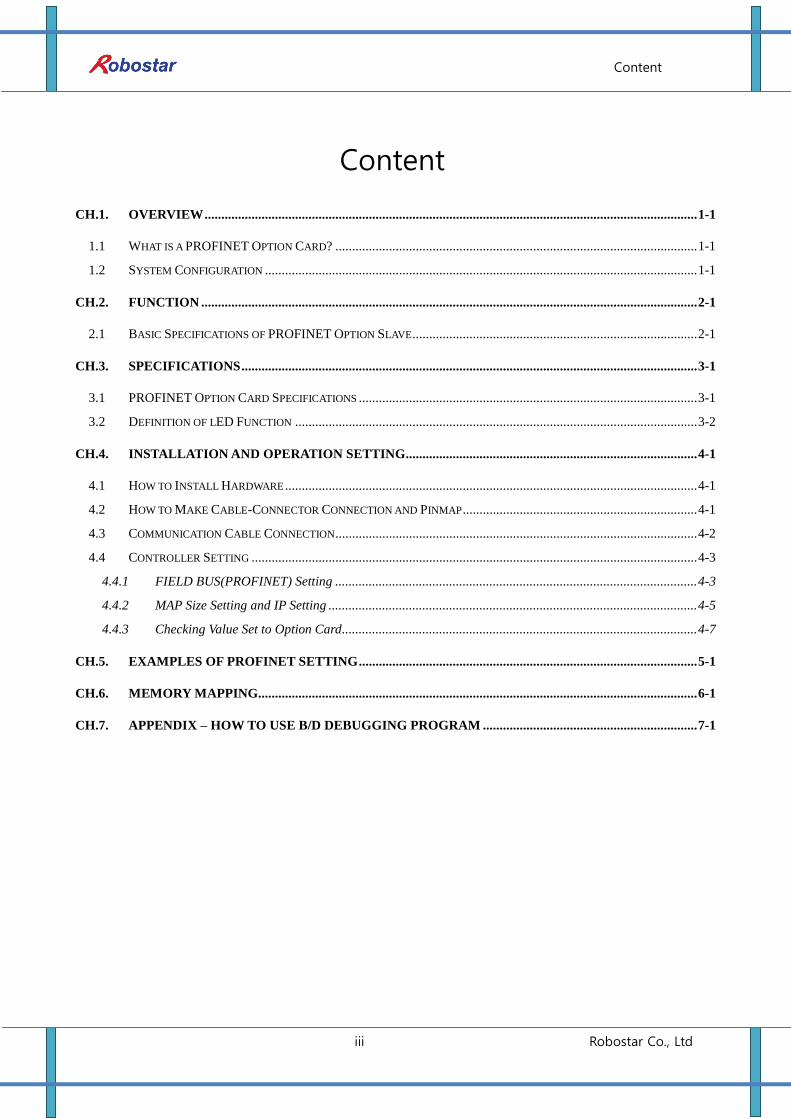
Content
CH.1. OVERVIEW ................................................................................................................................................... 1-1
1.1 WHAT IS A PROFINET OPTION CARD? ............................................................................................................ 1-1
1.2 SYSTEM CONFIGURATION ................................................................................................................................. 1-1
CH.2. FUNCTION .................................................................................................................................................... 2-1
2.1 BASIC SPECIFICATIONS OF PROFINET OPTION SLAVE ..................................................................................... 2-1
CH.3. SPECIFICATIONS ........................................................................................................................................ 3-1
3.1 PROFINET OPTION CARD SPECIFICATIONS ..................................................................................................... 3-1
3.2 DEFINITION OF LED FUNCTION ........................................................................................................................ 3-2
CH.4. INSTALLATION AND OPERATION SETTING ....................................................................................... 4-1
4.1 HOW TO INSTALL HARDWARE ........................................................................................................................... 4-1
4.2 HOW TO MAKE CABLE-CONNECTOR CONNECTION AND PINMAP ...................................................................... 4-1
4.3 COMMUNICATION CABLE CONNECTION ............................................................................................................ 4-2
4.4 CONTROLLER SETTING ..................................................................................................................................... 4-3
4.4.1 FIELD BUS(PROFINET) Setting ............................................................................................................ 4-3
4.4.2 MAP Size Setting and IP Setting .............................................................................................................. 4-5
4.4.3 Checking Value Set to Option Card.......................................................................................................... 4-7
CH.5. EXAMPLES OF PROFINET SETTING ..................................................................................................... 5-1
CH.6. MEMORY MAPPING ................................................................................................................................... 6-1
CH.7. APPENDIX – HOW TO USE B/D DEBUGGING PROGRAM ................................................................ 7-1
Overview
1-1 Robostar Co.,
Ltd
ch.1. Overview
1.1 What is a PROFINET Option Card?
PROFINIT, Ethernet-based communication protocols developed by SIMENS, is public standards
adopted by many companies including Phoenix Contact and Bosch as a next automobile industry
Ethernet solution. PROFINET is protocols designed for communication, configuration and diagnosis
in networks and utilizes Ethernet standards along with TCP, UDP and IP.
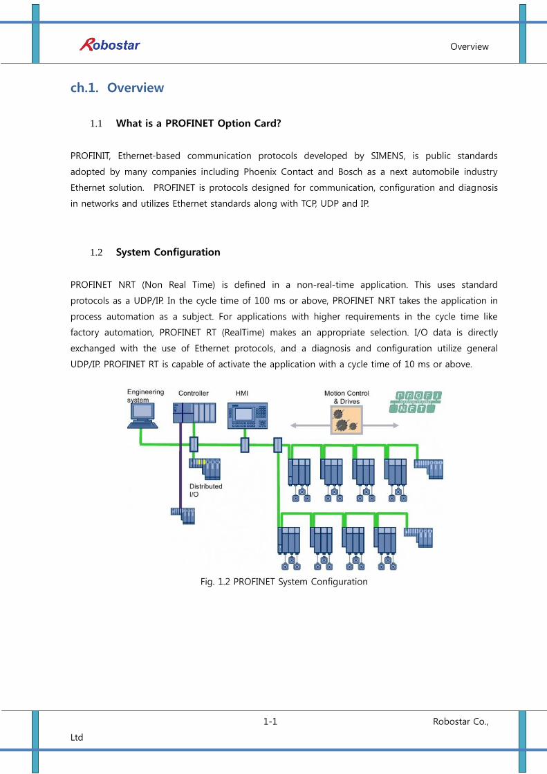
1.2 System Configuration
PROFINET NRT (Non Real Time) is defined in a non-real-time application. This uses standard
protocols as a UDP/IP. In the cycle time of 100 ms or above, PROFINET NRT takes the application in
process automation as a subject. For applications with higher requirements in the cycle time like
factory automation, PROFINET RT (RealTime) makes an appropriate selection. I/O data is directly
exchanged with the use of Ethernet protocols, and a diagnosis and configuration utilize general
UDP/IP. PROFINET RT is capable of activate the application with a cycle time of 10 ms or above.
Fig. 1.2 PROFINET System Configuration
Function
2-1 Robostar Co.,
Ltd
ch.2. Function
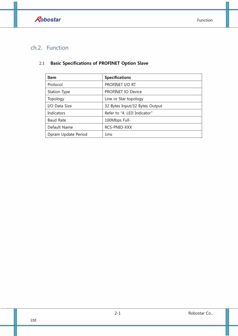
2.1 Basic Specifications of PROFINET Option Slave
Item Specifications
Protocol PROFINET I/O RT
Station Type PROFINET IO Device
Topology Line or Star topology
I/O Data Size 32 Bytes Input/32 Bytes Output
Indicators Refer to “4. LED Indicator”
Baud Rate 100Mbps Full-
Default Name RCS-PNIO-XXX
Dpram Update Period 1ms
Specifications
3-1 Robostar Co.,
Ltd
ch.3. Specifications
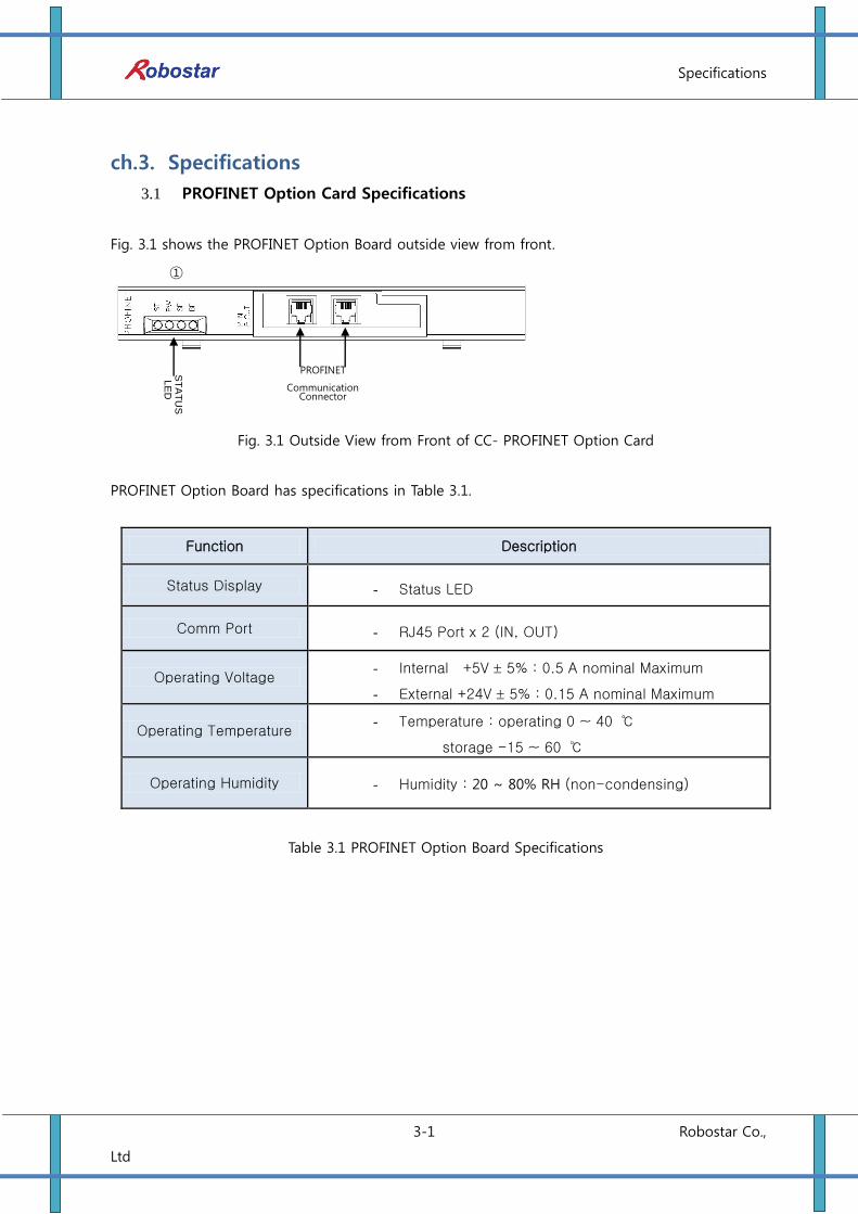
3.1 PROFINET Option Card Specifications
Fig. 3.1 shows the PROFINET Option Board outside view from front.
Fig. 3.1 Outside View from Front of CC- PROFINET Option Card
PROFINET Option Board has specifications in Table 3.1.
Function Description
Status Display - Status LED
Comm Port - RJ45 Port x 2 (IN, OUT)
Operating Voltage - Internal +5V 5% : 0.5 A nominal Maximum
- External +24V 5% : 0.15 A nominal Maximum
Operating Temperature - Temperature : operating 0 ~ 40 ℃
storage -15 ~ 60 ℃
Operating Humidity - Humidity : 20 ~ 80% RH (non-condensing)
Table 3.1 PROFINET Option Board Specifications
①
ST
AT
US
LE
D
PROFINET
Communication Connector
Specifications
3-2 Robostar Co.,
Ltd
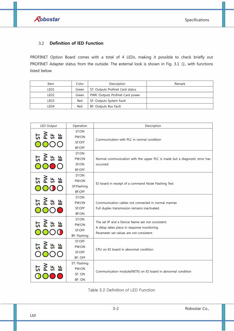
3.2 Definition of lED Function
PROFINET Option Board comes with a total of 4 LEDs, making it possible to check briefly out
PROFINET Adapter status from the outside. The external look is shown in Fig. 3.1 ①, with functions
listed below.
Item Color Description Remark
LED1 Green ST: Outputs Profinet Card status
LED2 Green PWR: Outputs Profinet Card power
LED3 Red SF: Outputs System Fault
LED4 Red BF: Outputs Bus Fault
LED Output Operation Description
ST:ON
PW:ON
SF:OFF
BF:OFF
Communication with PLC in normal condition
ST:ON
PW:ON
SF:ON
BF:OFF
Normal communication with the upper PLC is made but a diagnostic error has
occurred.
ST:ON
PW:ON
SF:Flashing
BF:OFF
IO board in receipt of a command Node Flashing Test
ST:ON
PW:ON
SF:OFF
BF:ON
Communication cables not connected in normal manner.
Full duplex transmission remains inactivated.
ST:ON
PW:ON
SF:OFF
BF: Flashing
The set IP and a Device Name are not consistent.
A delay takes place in response monitoring.
Parameter set values are not consistent.
ST:OFF
PW:ON
SF:OFF
BF: OFF
CPU on IO board in abnormal condition
ST: Flashing
PW:ON
SF: ON
BF: ON
Communication module(NETX) on IO board in abnormal condition
Table 3.2 Definition of LED Function
Installation and Operation Setting
4-1 Robostar Co.,
Ltd
ch.4. Installation and Operation Setting
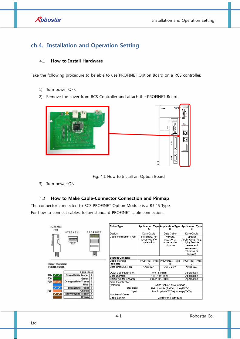
4.1 How to Install Hardware
Take the following procedure to be able to use PROFINET Option Board on a RCS controller.
1) Turn power OFF.
2) Remove the cover from RCS Controller and attach the PROFINET Board.
Fig. 4.1 How to Install an Option Board
3) Turn power ON.
4.2 How to Make Cable-Connector Connection and Pinmap
The connector connected to RCS PROFINET Option Module is a RJ-45 Type.
For how to connect cables, follow standard PROFINET cable connections.
Installation and Operation Setting
4-2 Robostar Co.,
Ltd
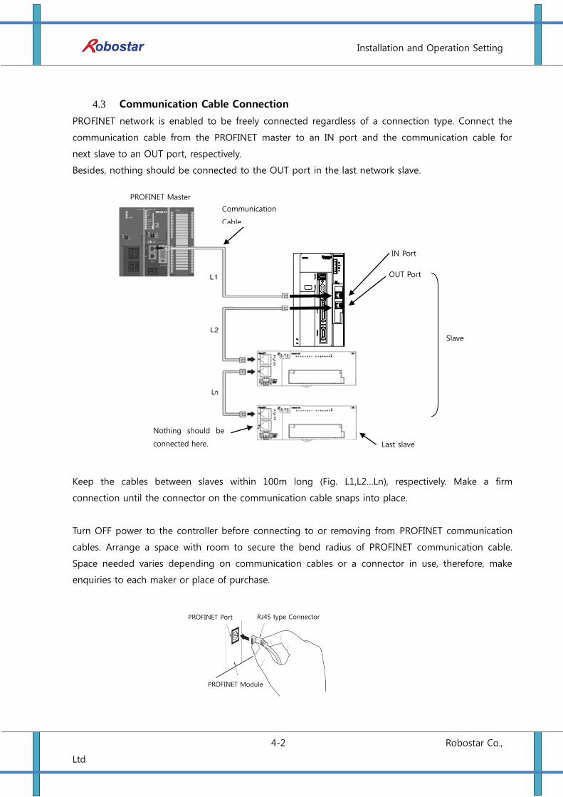
4.3 Communication Cable Connection
PROFINET network is enabled to be freely connected regardless of a connection type. Connect the
communication cable from the PROFINET master to an IN port and the communication cable for
next slave to an OUT port, respectively.
Besides, nothing should be connected to the OUT port in the last network slave.
Keep the cables between slaves within 100m long (Fig. L1,L2…Ln), respectively. Make a firm
connection until the connector on the communication cable snaps into place.
Turn OFF power to the controller before connecting to or removing from PROFINET communication
cables. Arrange a space with room to secure the bend radius of PROFINET communication cable.
Space needed varies depending on communication cables or a connector in use, therefore, make
enquiries to each maker or place of purchase.
PROFINET Port RJ45 type Connector
PROFINET Module
PROFINET Master
Communication
Cable
IN Port
OUT Port
Slave
Nothing should be
connected here.
.
Last slave
Installation and Operation Setting
4-3 Robostar Co.,
Ltd
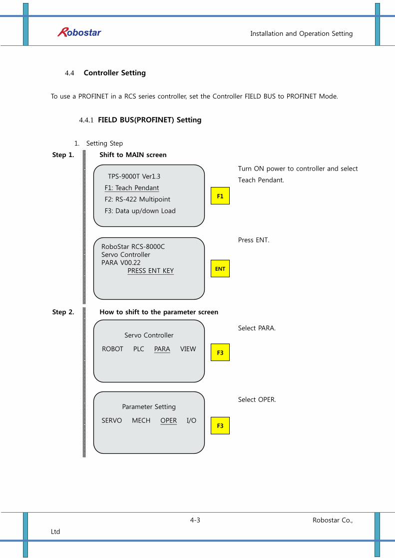
4.4 Controller Setting
To use a PROFINET in a RCS series controller, set the Controller FIELD BUS to PROFINET Mode.
4.4.1 FIELD BUS(PROFINET) Setting
1. Setting Step
Step 1.
Shift to MAIN screen
Turn ON power to controller and select
Teach Pendant.
Press ENT.
Step 2.
How to shift to the parameter screen
Select PARA.
Select OPER.
F3
Parameter Setting
SERVO MECH OPER I/O
F3
Servo Controller
ROBOT PLC PARA VIEW
ENT
RoboStar RCS-8000C Servo Controller PARA V00.22
PRESS ENT KEY
F1
TPS-9000T Ver1.3
F1: Teach Pendant
F2: RS-422 Multipoint
F3: Data up/down Load
Installation and Operation Setting
4-4 Robostar Co.,
Ltd
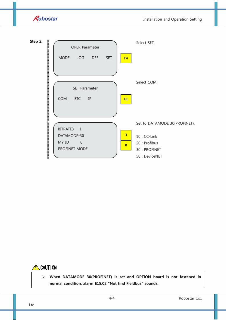
Step 2.
Select SET.
Select COM.
Set to DATAMODE 30(PROFINET).
10 : CC-Link
20 : Profibus
30 : PROFINET
50 : DeviceNET
0
3
BITRATE3 1
DATAMODE*30
MY_ID 0
PROFINET MODE
F1
SET Parameter
COM ETC IP
F4
OPER Parameter
MODE JOG DEF SET
When DATAMODE 30(PROFINET) is set and OPTION board is not fastened in
normal condition, alarm E15.02 “Not find Fieldbus” sounds.
Installation and Operation Setting
4-5 Robostar Co.,
Ltd
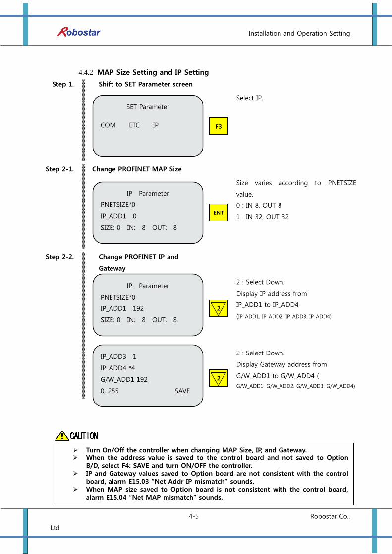
4.4.2 MAP Size Setting and IP Setting
Step 1.
Shift to SET Parameter screen
Select IP.
Step 2-1.
Change PROFINET MAP Size
Size varies according to PNETSIZE
value.
0 : IN 8, OUT 8
1 : IN 32, OUT 32
Step 2-2.
Change PROFINET IP and
Gateway
2 : Select Down.
Display IP address from
IP_ADD1 to IP_ADD4
(IP_ADD1. IP_ADD2. IP_ADD3. IP_ADD4)
2 : Select Down.
Display Gateway address from
G/W_ADD1 to G/W_ADD4 (
G/W_ADD1. G/W_ADD2. G/W_ADD3. G/W_ADD4)
2
IP_ADD3 1
IP_ADD4 *4
G/W_ADD1 192
0, 255 SAVE
2
IP Parameter
PNETSIZE*0
IP_ADD1 192
SIZE: 0 IN: 8 OUT: 8
ENT
IP Parameter
PNETSIZE*0
IP_ADD1 0
SIZE: 0 IN: 8 OUT: 8
F3
SET Parameter
COM ETC IP
Turn On/Off the controller when changing MAP Size, IP, and Gateway. When the address value is saved to the control board and not saved to Option
B/D, select F4: SAVE and turn ON/OFF the controller. IP and Gateway values saved to Option board are not consistent with the control
board, alarm E15.03 “Net Addr IP mismatch” sounds. When MAP size saved to Option board is not consistent with the control board,
alarm E15.04 “Net MAP mismatch” sounds.

Installation and Operation Setting
4-6 Robostar Co.,
Ltd
Step 3-2.
Save PROFINET MAP Size, PROFINET IP and Gateway (When a value changes)
Change the value and select ESC.
Save by selecting F1.
Step 3-2.
Save PROFINET MAP Size, PROFINET IP and Gateway (When value change is not
made)
Save by selecting F4.
Views the currently set value.
Select F1.
SET Parameter
COM ETC IP
F1
Want save? Map : 1
Ip : 192 . 168 . 1 .100
GW : 192 . 168 . 1. 4
YES NO
F4
IP Parameter
PNETSIZE*0
IP_ADD1 192
IN: 8 OUT: 8 SAVE
F1
Do you want to be
Saved IP?
YES NO
ESC
IP Parameter
PNETSIZE*0
IP_ADD1 192
IN: 8 OUT: 8 SAVE

Installation and Operation Setting
4-7 Robostar Co.,
Ltd
4.4.3 Checking Value Set to Option Card
Step 1.
Shift to SET Parameter screen
Select VIEW.
Select SERVO.
Step 2.
Check MAP SIZE, PROFINET IP, Gateway
Press Down button 7.
① MAP SIZE 0,
INPUT : 8bytes, OUTPUT : 8 bytes,
② IP address: 192.168.1.199
③ Gateway: 192.168.1.4
SERVO STATUS <8/9>
SIZE: 0 IN: 8 OUT: 8
IP : 192 . 168 . 1 . 199
G/W : 192 . 168 . 1 . 4
2
SERVO STATUS <1/9>
SPD CMD 300.000 RPM
CUR SPD 0.000 RPM
F2
STATUS VIEW
ALARM SERVO INT
F4
Servo Controller
ROBOT PLC PARA VIEW
①
②
③

Examples of PROFINET Setting
5-1 Robostar Co.,
Ltd
ch.5. Examples of PROFINET Setting
Step1.
Fig. 5.1 SIMENS PLC
Step2.
Fig. 5.2 SIMENS PLC
Step3.
그림 5.3 SIMENS PLC
Run SIMATIC Manager to click Hardware
(Station configuration) as shown in the
figure below.
Run HW Config program to add
PROFINET Slave.
.
Select Options/Install New GSD menu to
select the file provided as shown below.
Examples of PROFINET Setting
5-2 Robostar Co.,
Ltd
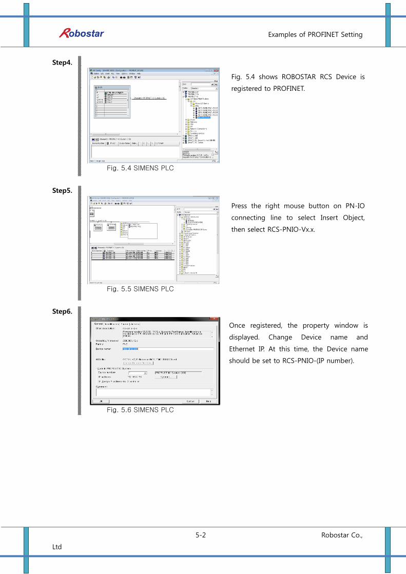
Step4.
Fig. 5.4 SIMENS PLC
Step5.
Fig. 5.5 SIMENS PLC
Step6.
Fig. 5.6 SIMENS PLC
Once registered, the property window is
displayed. Change Device name and
Ethernet IP. At this time, the Device name
should be set to RCS-PNIO-(IP number).
Fig. 5.4 shows ROBOSTAR RCS Device is
registered to PROFINET.
Press the right mouse button on PN-IO
connecting line to select Insert Object,
then select RCS-PNIO-Vx.x.
Examples of PROFINET Setting
5-3 Robostar Co.,
Ltd
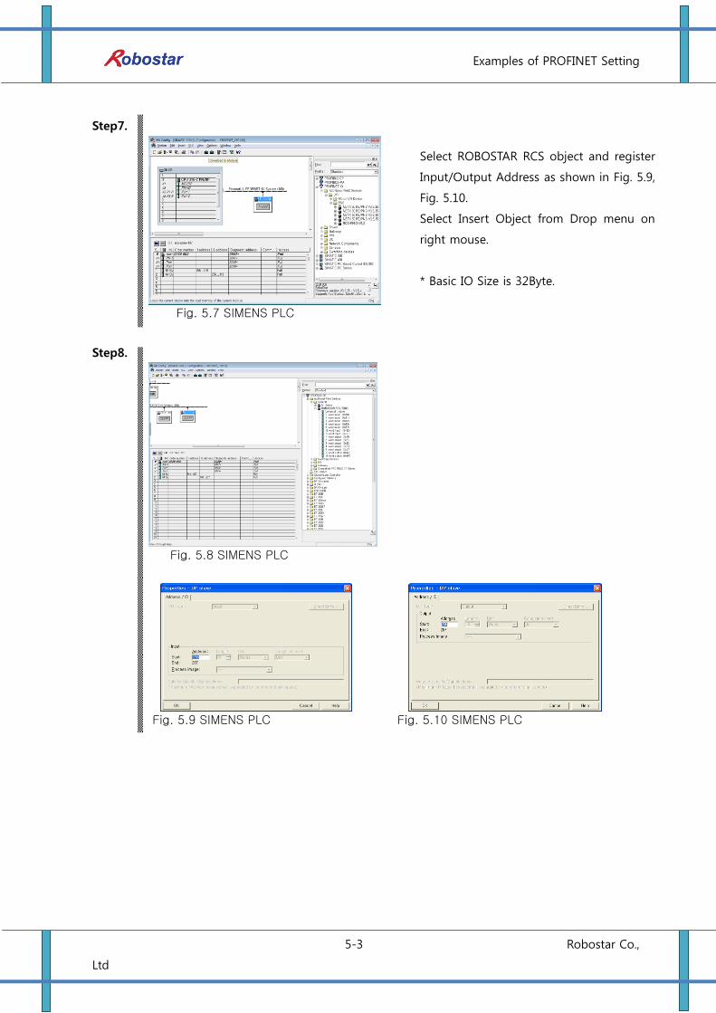
Step7.
Fig. 5.7 SIMENS PLC
Step8.
Fig. 5.8 SIMENS PLC
Fig. 5.9 SIMENS PLC Fig. 5.10 SIMENS PLC
Select ROBOSTAR RCS object and register
Input/Output Address as shown in Fig. 5.9,
Fig. 5.10.
Select Insert Object from Drop menu on
right mouse.
* Basic IO Size is 32Byte.
부록 – Memory Mapping
6-1 Robostar Co.,
Ltd
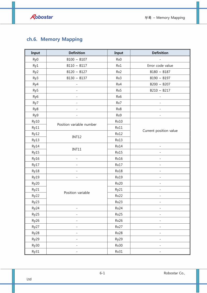
ch.6. Memory Mapping
Input Definition Input Definition
Ry0 B100 ~ B107 Rx0 -
Ry1 B110 ~ B117 Rx1 Error code value
Ry2 B120 ~ B127 Rx2 B180 ~ B187
Ry3 B130 ~ B137 Rx3 B190 ~ B197
Ry4 - Rx4 B200 ~ B207
Ry5 - Rx5 B210 ~ B217
Ry6 - Rx6 -
Ry7 - Rx7 -
Ry8 - Rx8 -
Ry9 - Rx9 -
Ry10 Position variable number
Rx10
Current position value Ry11 Rx11
Ry12 INT12
Rx12
Ry13 Rx13
Ry14 INT11
Rx14 -
Ry15 Rx15 -
Ry16 - Rx16 -
Ry17 - Rx17 -
Ry18 - Rx18 -
Ry19 - Rx19 -
Ry20
Position variable
Rx20 -
Ry21 Ry21 -
Ry22 Rx22 -
Ry23 Rx23 -
Ry24 - Rx24 -
Ry25 - Rx25 -
Ry26 - Rx26 -
Ry27 - Rx27 -
Ry28 - Rx28 -
Ry29 - Ry29 -
Ry30 - Rx30 -
Ry31 - Rx31 -
Appendix – How to Use B/D Debugging Program
7-1 Robostar Co.,
Ltd
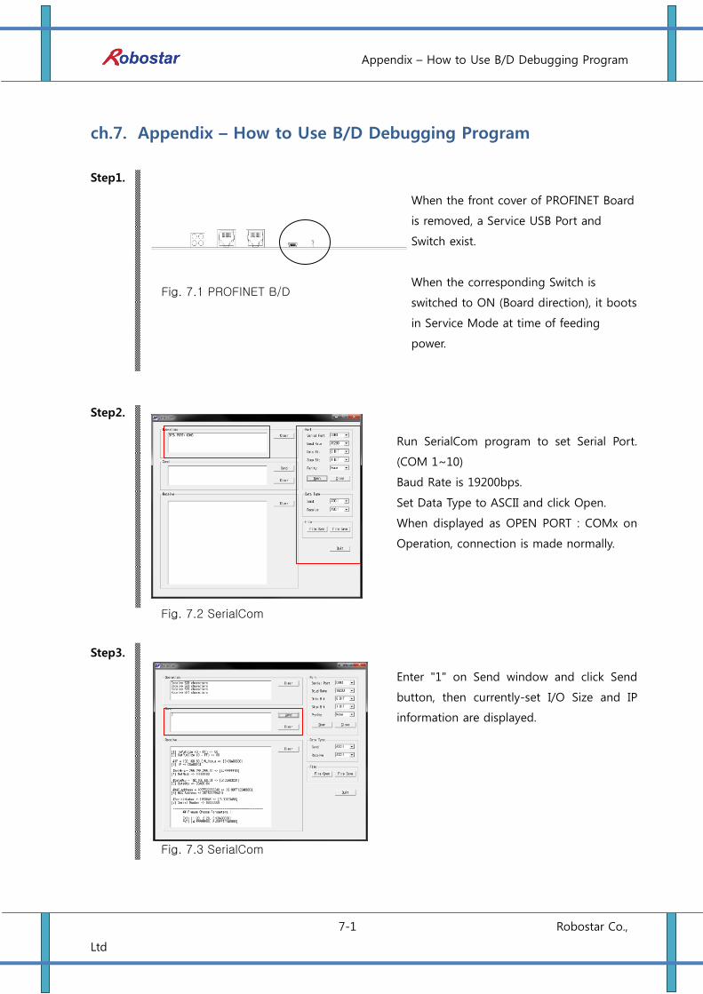
ch.7. Appendix – How to Use B/D Debugging Program
Step1.
Fig. 7.1 PROFINET B/D
Step2.
Fig. 7.2 SerialCom
Step3.
Fig. 7.3 SerialCom
When the front cover of PROFINET Board
is removed, a Service USB Port and
Switch exist.
When the corresponding Switch is
switched to ON (Board direction), it boots
in Service Mode at time of feeding
power.
Run SerialCom program to set Serial Port.
(COM 1~10)
Baud Rate is 19200bps.
Set Data Type to ASCII and click Open.
When displayed as OPEN PORT : COMx on
Operation, connection is made normally.
Enter "1" on Send window and click Send
button, then currently-set I/O Size and IP
information are displayed.
Appendix – How to Use B/D Debugging Program
7-2 Robostar Co.,
Ltd
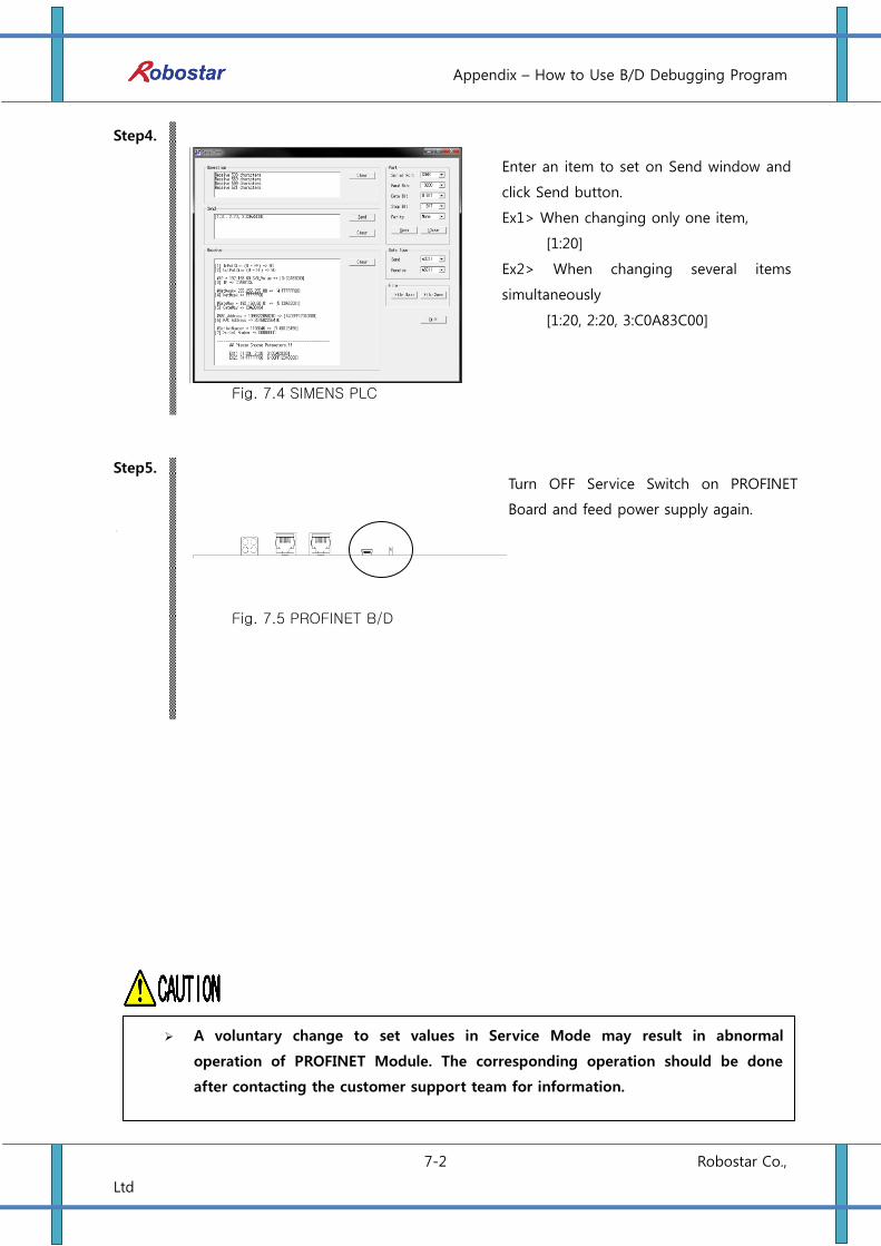
Step4.
Fig. 7.4 SIMENS PLC
Step5.
Fig. 7.5 PROFINET B/D
Enter an item to set on Send window and
click Send button.
Ex1> When changing only one item,
[1:20]
Ex2> When changing several items
simultaneously
[1:20, 2:20, 3:C0A83C00]
Turn OFF Service Switch on PROFINET
Board and feed power supply again.
A voluntary change to set values in Service Mode may result in abnormal
operation of PROFINET Module. The corresponding operation should be done
after contacting the customer support team for information.
Robostar Co., Ltd.
Rev. Date of
Revision Description
Revised
by
S/W
Version
V.1 July 30,
2015
1st Edition Prints
RCS ROBOT CONTROLLER
CONTROLLER MANUAL
FIRST EDITION OCTOBER 2015
ROBOSTAR CO, LTD
ROBOT R&D CENTER