profinet io power hub - pepperl+fuchs
TRANSCRIPT

®
PROFINET IO Power HubWith HD2-GTR-4PA.PN Gateway
PROCESS AUTOMATION
MANUAL

With regard to the supply of products, the current issue of the following document is ap-plicable: The General Terms of Delivery for Products and Services of the Electrical Indus-
try, published by the Central Association of the Electrical Industry (Zentralverband Elektrotechnik und Elektroindustrie (ZVEI) e.V.) in its most recent version as well as the
supplementary clause: "Expanded reservation of proprietorship"
PROFINET IO Power Hub

PROFINET IO Power Hub
1 Introduction................................................................................. 61.1 Contents................................................................................................ 61.2 Target Group, Personnel...................................................................... 61.3 Symbols Used ...................................................................................... 6
2 Product Specifications............................................................... 82.1 Overview and Application ................................................................... 82.2 System Components ........................................................................... 82.3 Recommended System Combinations............................................. 112.4 Component Overview ........................................................................ 132.5 Technical Data .................................................................................... 142.6 Dimensions......................................................................................... 16
3 PROFINET System Integration ................................................ 173.1 PROFINET IO Communication Profile .............................................. 173.2 Gateway Device Model ....................................................................... 173.3 Gateway Management Function........................................................ 183.4 Supported PROFIBUS PA Device Features...................................... 183.5 Cyclic IO Data of the PROFIBUS PA Devices................................... 193.6 PROFIBUS PA Device Diagnostics ................................................... 19
4 Installation and Commissioning ............................................. 204.1 Mounting and Dismounting............................................................... 204.2 Shielding/Grounding ......................................................................... 22
4.2.1 Connection to Equipotential Bonding System .................................. 234.3 Hazardous Area Installation and Use............................................... 24
4.3.1 Installation in Zone 2, Category 3G .................................................. 244.4 Connections ....................................................................................... 254.5 Gateway Addressing .......................................................................... 264.6 PROFIBUS PA Device Addressing.................................................... 264.7 Gateway Configuration....................................................................... 26
3

PROFINET IO Power Hub
4.8 Gateway Device Parameters (DAP Submodules).............................264.9 PROFIBUS PA Master Parameters (FAP Submodules) ...................274.10 Start-Up Behavior ...............................................................................27
5 System Integration ................................................................... 285.1 System Integration in Practice ..........................................................285.2 PROFINET GSD File Generator..........................................................285.3 PROFINET Redundancy Concepts ...................................................30
6 PROFIBUS Commissioning ..................................................... 336.1 Device Type Manager (DTM): Installation and Commissioning .....336.2 PROFINET DTM Project......................................................................336.3 DTM Offline Project Tree ....................................................................346.4 PROFINET Gateway Addressing........................................................366.5 Topology Scan ....................................................................................376.6 PROFINET Identification and Maintenance (I&M) ..........................39
7 Diagnostic Information and Troubleshooting........................ 407.1 PROFIBUS PA Device Diagnostics....................................................407.2 Gateway Diagnostics ..........................................................................407.3 Diagnostics Indicated via LEDs ........................................................42
8 Gateway Web Server................................................................. 459 Gateway Information and Diagnostics.................................... 46
9.1 Device Identification...........................................................................479.2 Device Diagnostics.............................................................................489.3 Device Network Information ..............................................................499.4 Segment Diagnostics.........................................................................509.5 Information on Field Devices of the Segment .................................509.6 Gateway Firmware Update (Web Server Only).................................52
4

PROFINET IO Power Hub
9.7 Gateway Documentation.................................................................... 53
10 References ................................................................................ 55
5

2016
-06
PROFINET IO Power HubIntroduction
1 Introduction1.1 Contents
This document contains information that you need in order to use your product throughout the applicable stages of the product life cycle. These can include the following:
■ Product identification■ Delivery, transport, and storage■ Mounting and installation■ Commissioning and operation■ Maintenance and repair■ Troubleshooting■ Dismounting■ Disposal
The documentation consists of the following parts:■ Present document■ Instruction manual■ Datasheet
Additionally, the following parts may belong to the documentation, if applicable:■ EU-type examination certificate■ EU declaration of conformity■ Attestation of conformity■ Certificates■ Control drawings■ Additional documents
1.2 Target Group, PersonnelResponsibility for planning, assembly, commissioning, operation, maintenance, and dismounting lies with the plant operator.Only appropriately trained and qualified personnel may carry out mounting, installation, commissioning, operation, maintenance, and dismounting of the product. The personnel must have read and understood the instruction manual and the further documentation.Prior to using the product make yourself familiar with it. Read the document carefully.
1.3 Symbols UsedThis document contains symbols for the identification of warning messages and of informative messages.
Note!This document does not substitute the instruction manual.
Note!For full information on the product, refer to the instruction manual and further documentation on the Internet at www.pepperl-fuchs.com.
6

PROFINET IO Power HubIntroduction
2016
-06
Warning MessagesYou will find warning messages, whenever dangers may arise from your actions. It is mandatory that you observe these warning messages for your personal safety and in order to avoid property damage.Depending on the risk level, the warning messages are displayed in descending order as follows:
Informative Symbols
ActionThis symbol indicates a paragraph with instructions. You are prompted to perform an action or a sequence of actions.
Danger!This symbol indicates an imminent danger.Non-observance will result in personal injury or death.
Warning!This symbol indicates a possible fault or danger.Non-observance may cause personal injury or serious property damage.
Caution!This symbol indicates a possible fault.Non-observance could interrupt the device and any connected systems and plants, or result in their complete failure.
Note!This symbol brings important information to your attention.
7
2016
-06
PROFINET IO Power HubProduct Specifications
2 Product Specifications2.1 Overview and Application
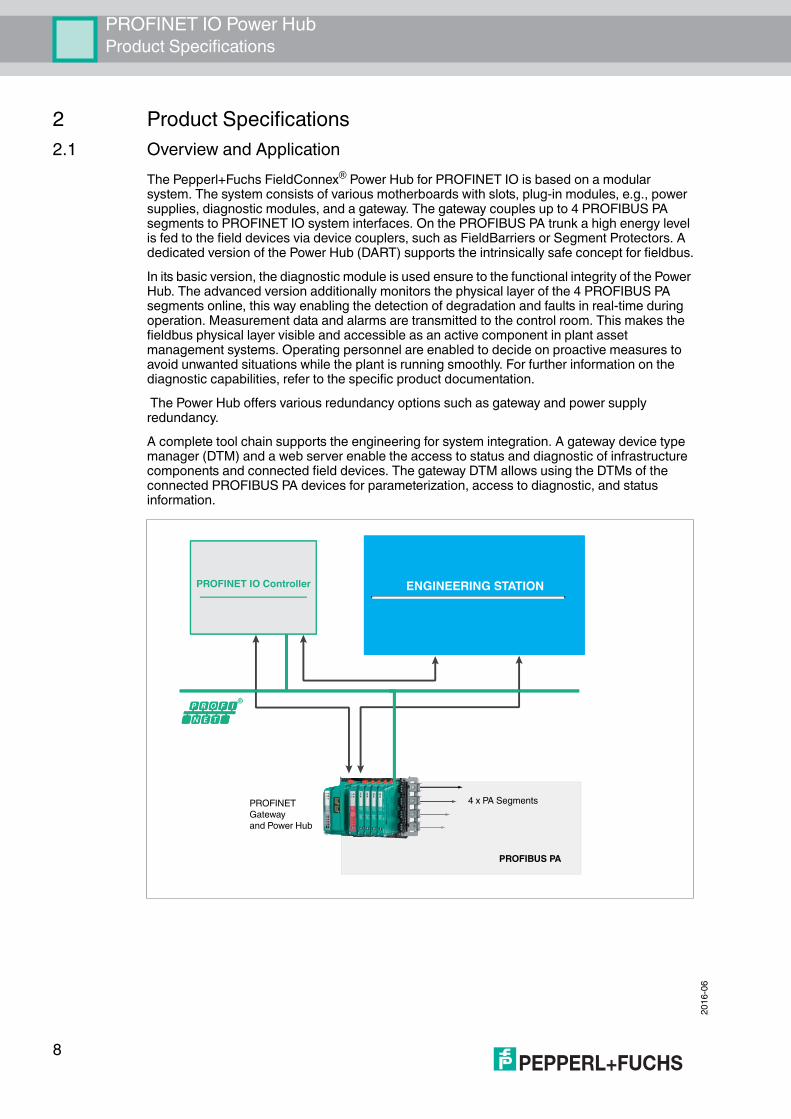
The Pepperl+Fuchs FieldConnex® Power Hub for PROFINET IO is based on a modular system. The system consists of various motherboards with slots, plug-in modules, e.g., power supplies, diagnostic modules, and a gateway. The gateway couples up to 4 PROFIBUS PA segments to PROFINET IO system interfaces. On the PROFIBUS PA trunk a high energy level is fed to the field devices via device couplers, such as FieldBarriers or Segment Protectors. A dedicated version of the Power Hub (DART) supports the intrinsically safe concept for fieldbus.In its basic version, the diagnostic module is used ensure to the functional integrity of the Power Hub. The advanced version additionally monitors the physical layer of the 4 PROFIBUS PA segments online, this way enabling the detection of degradation and faults in real-time during operation. Measurement data and alarms are transmitted to the control room. This makes the fieldbus physical layer visible and accessible as an active component in plant asset management systems. Operating personnel are enabled to decide on proactive measures to avoid unwanted situations while the plant is running smoothly. For further information on the diagnostic capabilities, refer to the specific product documentation. The Power Hub offers various redundancy options such as gateway and power supply redundancy. A complete tool chain supports the engineering for system integration. A gateway device type manager (DTM) and a web server enable the access to status and diagnostic of infrastructure components and connected field devices. The gateway DTM allows using the DTMs of the connected PROFIBUS PA devices for parameterization, access to diagnostic, and status information.
R
FDT/DTMPROFIBUS PA Device Configuration
Web Browser
PROFINET ConfigurationCyclic data - Configuration - IO and statusDiagnostic dataParameter ???
GSDML Generator
ENGINEERING STATION
PROFINET ConfigurationCyclic data - Configuration - IO and statusDiagnostic dataParameter ???
PROFINET IO Controller
4 x PA SegmentsPROFINET Gateway and Power Hub
PROFIBUS PA
R
ENGINEERING STATIONPROFINET IO Controller
8

PROFINET IO Power HubProduct Specifications
2016
-06
2.2 System ComponentsMotherboards The following types of gateway motherboards are available:
■ Compact motherboard MBHC-FB-4.GT: Slots for 1 gateway HD2-GTR-4PA.PN, 4 simplex power supply modules, and 1 diagnostic module. For further information, refer to the documentation for MBHC-FB-4.GT.
■ Gateway motherboard MB-FB-GTR1: 2 slots for up to 2 gateway modules HD2-GTR-4PA.PN. The gateway motherboard is designed for the use with Power Hub motherboards holding power supply modules for the supply of PROFIBUS PA segments. The motherboard can be used with a single gateway for simplex coupling to PROFINET IO or with 2 gateways for redundant coupling. At the point of issue of this manual, redundant coupling is not supported yet. For more information, contact you Pepperl+Fuchs representative. MB-FB-GTR1 can be used with the following Power Hub motherboards:
• MBHC-FB-4.HSC* supports 4 simplex segments, redundant bulk power supply • MBHC-FB-4R.HSC* supports 4 redundant segments, redundant bulk power supply• MBHD-FB-D-4R.GEN supports 4 redundant DART intrinsically safe segments,
redundant bulk power supplyThe motherboards are connected with a customized cable that is included in the delivery of the gateway motherboard.
For further information refer to the respective product documentation at www.pepperl-fuchs.com.GatewayThe PROFINET/PROFIBUS PA gateway module HD2-GTR-4PA.PN connects 4 PROFIBUS PA segments to PROFINET IO on the performance level “real-time RT”. It supports 2 Ethernet-switched ports for PROFINET S2 system redundancy and media ring redundancy based on the media redundancy protocol (MRP). The gateway features LEDs to diagnose the status of the Ethernet ports, gateway hardware, redundancy, and the PROFIBUS PA segments. For system integration the software tool "PROFINET GSD generator" is provided. The generator builds a PROFINET GSD including all gateway and PROFIBUS PA device-specific information required for engineering the PROFINET IO system. As input, the GSD files of the PROFIBUS PA devices used in a specific project are required. The PROFINET GSD is generated out of the individual GSD files. Both, a gateway device type manager (DTM) and a PROFINET communication DTM enable the access and use of the device manufacturer DTMs in oder to parameterize and diagnose the individual PROFIBUS PA devices. A web server provides access to gateway-specific and optional physical layer status read-only information of the 4 segments. Update functionality of gateway firmware is provided.The gateway is compatible with the motherboards of the following Power Hubs:
■ Universal Power Hubs MB–FB–GT, MB–FB–GTR, MBHC–FB-4.GT, MB-FB-GTR1■ Compact Power Hub KT–MB–GTB–2PS■ DART Power Hub KT–MB–GTB–D–2PS
Application documents for the integration of the PROFINET Power Hub into various control systems are available. For more information, contact your Pepperl+Fuchs representative or visit pepperl-fuchs.com.
9

2016
-06
PROFINET IO Power HubProduct Specifications
Fieldbus Power Supply ModulesThe fieldbus power supplies supply the PROFIBUS PA segments with power. For different application requirements, dedicated power supply modules are available:
■ HCD2-FBPS-1.500. Output: 28 V... 30 V at 500 mA with an intrinsically safe limited voltage for Zone 2 of Uo = 30 V
■ HCD2-FBPS-1.23.500. Output: 21 V ...23 V at 500 mA with an intrinsically safe limited voltage for Zone 2 of Uo = 24 V
■ HD2-FBPS-IBD-1.24.360. Output: 24 V at 360 mA for intrinsically safe (DART) segments installed in Zone 1
The power supply modules provide full galvanic isolation between the bulk power supply and the PA segments. The modules offer system reliability for applications where cabling and wiring are routed through critical or harsh electrical environments, with full protection from electromagnetic interference (EMI). Power supply modules are plugged into the motherboard slots and can be exchanged during system operation. In redundant configuration, load is shared between 2 power supply modules. Diagnostic ModulesBasic Diagnostic ModuleThe basic diagnostic module provides basic system diagnostics. It monitors the input voltage of the bulk power supply and each segment for overload and short circuit conditions. Each power supply module is checked for proper function. Power supply modules operating in redundant configuration are checked for compatibility. LEDs indicate both status and fault information. This information can be transmitted via volt-free contact. For further information refer to the manual "Basic Diagnostic Module " at www.pepperl-fuchs.com.
Advanced Diagnostic ModuleThe advanced diagnostic module is a comprehensive measurement tool for the PROFIBUS PA physical layer, and supports commissioning, online monitoring, and maintenance tasks. The module provides the exact segment and individual device data needed for detection of changes in the fieldbus physical layer. Segment measurements include fieldbus voltage and load current. Device-specific measurements are signal level, noise, and jitter. All data is transmitted to the control room via Ethernet. The basic edition of the diagnostic manager displays all data in an easy-to-use user interface. The professional edition of the diagnostic manager offers extended software functions: the commissioning wizard generates automated reports; the software displays clear-text messages for troubleshooting of out-of-specification behavior.For further information refer to the manual "Advanced Diagnostic Module " at www.pepperl-fuchs.com.
10

PROFINET IO Power HubProduct Specifications
2016
-06
2.3 Recommended System CombinationsSimplex Power Feed for 4 Segments with Single Gateway
Figure 2.1 MBHC-FB-4.GT motherboard for the simplex supply of 4 segments and 1 gateway module HD2-GTR-4PA.PN for simplex gateway coupling.
The one-board simplex system with single gateway coupling consists of the following components:
■ Combined Power Hub gateway motherboard MBHC–FB–4.GT■ HD2-GTR-4PA.PN (x 1)■ Power supply modules (x 4)
Optional components:■ Diagnostic module HD2–DM*■ Surge protectors TPH-LBF-IA1.36.DE* (x 4)■ Earth bar for surge protectors ACC–LBF–EB.4
PRO
FIN
ET IO
Power
4 x
PA F
ield
bus T
runk
Coupling Segment Supply
PROFIBUS Power Hub
11

2016
-06
PROFINET IO Power HubProduct Specifications
Redundant Power Feed for 4 Segments with Single Gateway
Figure 2.2 MBHC-FB-4R.HSC motherboard for the redundant supply of 4 segments combined with the MB-FB-GTR1 motherboard and 1 HD2-GTR-4PA.PN gateway module for gateway coupling.
The redundant system with gateway coupling for ring redundancy or S2 redundancy consists of the following components:
■ Combined Power Hub gateway motherboard MBHC–FB–4R.HSC*■ Gateway motherboard MB–FB–GTR1 (x 1)■ HD2-GTR-4PA.PN (x 1)■ Power supply modules (x 8)■ Sub-D cable 9 pins for connecting gateway motherboard and Power Hub motherboard
ACC-MB-HGCOptional components:
■ Diagnostic module HD2–DM*■ Surge protectors TPH-LBF-IA1.36.DE* (x 4)■ Earth bar for surge protectors ACC–LBF–EB.4
PRO
FIN
ET IO
PROFIBUS PAPo
wer
4 x
PA F
ield
bus T
runk
Coupling Segment Supply
PROFIBUS Power Hub
12

PROFINET IO Power HubProduct Specifications
2016
-06
2.4 Component Overview
Figure 2.3 MB-FB-GTR1* component identity
MB-FB-GTR1* Component Overview
1 Motherboard MB-FB-GTR1*2 Gateway HD2-GTR-4PA.PN3 Connections: Volt-free contact alarm and diagnostic bus.
Diagnostic link cable ACC-MB-HDC, optional accessory4 Sub-D interface for the connection of Power Hub motherboards5 Rotary switches for gateway addressing, x1, x10, x1006 Earth connection7 Mounting slot for DIN mounting rail
7
4
5
3
1
2
6
13

2016
-06
PROFINET IO Power HubProduct Specifications
Figure 2.4 HD2-GTR-4PA.PN component identity
2.5 Technical DataSystem Overview
HD2-GTR-4PA.PN Component Overview
1 Ethernet port 12 Ethernet port 1 LED
- Yellow: Communication activity status3 Ethernet port 1 LED
- Green: Link status:4 Ethernet port 2 5 Ethernet port 2 LED
- Yellow: Communication activity status6 Ethernet port 2 LED
- Green: Link status7 LED Seg 1 ... Seg 4:
- Red: PROFIBUS PA segment 1 … 4 status8 LED Red.: Redundancy status9 LED ERR: Error status10 LED PWR: Power status
PN/PALinkingDevice
HD2-GTR-
4PA.PN
Seg4
Seg3
Seg2
Seg1
PWR
Red.
ERR
8
9
10
7
4
6
5
1
3
2
Ambient conditionsAmbient temperature -40 ... 60 °C (-40 ... 140 °F) vertically mounted , -40 ... 70 °C
(-40 ... 158 °F) horizontally mountedStorage temperature -40 ... 85 °C (-40 ... 185 °F)Relative humidity < 95 % non-condensingShock resistance 15 g 11 msVibration resistance 1 g , 10 ... 150 HzPollution degree max. 2, according to IEC 60664Corrosion resistance acc. to ISA-S71.04-1985, severity level G3Mechanical specificationsDegree of protection IP20
14

PROFINET IO Power HubProduct Specifications
2016
-06
HD2-GTR-4PA.PN
MB-FB-GTR1*
Mounting motherboard mountingStandard conformityElectromagnetic compatibility NE 21:2011Degree of protection IEC 60529Fieldbus standard IEC 61158-2Shock resistance EN 60068-2-27Vibration resistance EN 60068-2-6Data for application in connection with Ex-areasStatement of conformity TÜV 15 ATEX 7735 XGroup, category, type of protection, temperature class II 3 G Ex ec IIC T4 GcDirective conformityDirective 2014/30/EU EN 61326-1:2013International approvalsIECEx approval IECEx TUR 16.0007XApproved for Ex ec IIC T4 Gc
SupplyRated voltage 19.2 ... 35 V SELV/PELVRated current typ. 135 mAPower dissipation approx. 3.5 WFieldbus interfaceFieldbus type PROFIBUS PANumber of segments 4Number of devices per segment max. 36, physical connections, depending on the device
couplers usedElectrical isolationCH/PROFIBUS DP functional insulation acc. to IEC 61010, rated insulation
voltage 50 VeffPROFIBUS DP/SupplyCH/CHCH/EthernetAll circuits/FEEthernet/Supply
SupplyRated voltage 19.2 ... 35 V SELV/PELVRated current 2 ... 3 AIndicators/operating meansFault signal VFC alarm output via connectorsRotary switch bus addressing, gateway-specific
15

2016
-06
PROFINET IO Power HubProduct Specifications
2.6 Dimensions
Figure 2.5 All dimensions in millimeters and without tolerance indication.
AccessoriesACC-MB-HDC Diagnostic link cable, length 6 cmACC–MB–HGC Sub-D cable, 9 pins for connecting the gateway
motherboard and Power Hub motherboard. Included in the delivery of gateway motherboards.
Overview of Ordering InformationHD2–GTR–4PA.PN PROFINET to PROFIBUS PA gateway module,
4 PROFIBUS PA segments.MB-FB-GTR1* Motherboard for gateway redundancy, slots for 2 gateway
modules.
Component Dimensions
39 m
m(1
.5")
169
mm
(6.6
")
135 mm (5.3")150 mm (5.9")
16

PROFINET IO Power HubPROFINET System Integration
2016
-06
3 PROFINET System Integration3.1 PROFINET IO Communication Profile
The HD2-GTR-4PA.PN is compatible with PROFINET communication profile CP3/5 according to IEC/EN 61784–2:2015. This communication profile describes the performance characteristics capabilities of a PROFINET device.Important PROFINET/PA Performance Characteristics
3.2 Gateway Device ModelThe PROFINET/PA gateway is based on the PROFINET IO device model and represents a modular device that can be used for process data addressing. The gateway complies with “PROFIBUS Integration in PROFINET IO, Amendment 1 to Fieldbus Integration into PROFINET IO”. According to the PROFINET IO device model, each device has slots for inserting modules. Each module consists of subslots for inserting submodules.
Parameter CharacteristicsConformance class CC B, process automationApplication class Supports process-automation-specific requirementsCommunication class Supports PROFINET RT communicationCommunication relationship Supports 1 IO AR with 1 input CR and 1 output CR with
1440 bytes eachPhysical layer 100Mbit/s, 10Mbit/s full duplex with auto crossover and
auto negotiationBridging internal switch 4 priority queues, cut-through switching is not supportedBridging VLAN Supports virtual local area network (VLAN) priority
handlingPrecision time synchronization Not supportedMedia redundancy Supports loop prevention, ring redundancy, MRP.Device redundancy Single gateway, redundant controller, NAP S2Communication features Fast startup, supervisor AR, implicit ARSNMP Supports SNMPv1, SNMPv2cLLDP Supports neighborhood discoveryConfiguration in run Not supportedSNTP Support of time synchronizationShared device Not supported
17

2016
-06
PROFINET IO Power HubPROFINET System Integration
Mapping PROFIBUS PA Device Data to PROFINETAll information provided by the gateway is accessible using a fixed slot/subslot addressing. Most of the accessible data is handled by system-specific software. Therefore, no detailed knowledge on data mapping is required.
* Addresses 50 … 126 are not used
Slot 0 contains the “device access point” (DAP) with all gateway-specific information, including information on the 2 Ethernet ports.
Slots 1 … 4 contain the “fieldbus access point” (FAP) with all PROFIBUS-PA-specific information, such as, e.g., master parameters.
Slots 053 … 099 contain PROFIBUS PA device data from PA segment 1, device address 3 … 49*
Slots 103 … 149 contain PROFIBUS PA device data from PA segment 2, device address 3 … 49*
Slots 153 … 199 contain PROFIBUS PA device data from PA segment 3, device address 3 … 49*
Slots 203 … 249 contain PROFIBUS PA device data from PA segment 4, device address 3 … 49*
Slot 0, subslot 0x8002, Ethernet port 002
Slot 0, subslot 0x8001, Ethernet port 001
Slot 0, subslot 0x8000, Interface
Slot 0, subslot 0x0001, gateway data
Slot 54, subslot 1 PA device 4 slot 0
...
Slot 53, subslot 2 PA device 3 slot 1
Slot 53, subslot 1 PA device 3 slot 0
...
Slot 3 FAP, PA segment3, PA3
Slot 2 FAP, PA segment2, PA2
Slot 1 FAP, PA segment1, PA1
Slot 0 DAP, gateway-specific slot
Slot 153-199, device data PA3
Slot 103-149, device data PA2
Slot 053-099, device data PA1
Slot 4 FAP, PA segment4, PA4
Slot 203-249, device data PA4
18

PROFINET IO Power HubPROFINET System Integration
2016
-06
3.3 Gateway Management FunctionThe gateway supports SNMPv1 and SNMPv2c to exchange gateway and network-specific management information with dedicated tools. The data content is defined in various specifications and allows mainly to monitor the health status of network components, provided that information is organized in so–called management information bases (MIBs) that various standards define. Supported MIBs are:
■ MIB-II■ LLDP-MIB ■ LLDP-EXT-DOT3-MIB■ LLDP-EXT-PNIO-MIB
The gateway supports mandatory information defined in the specific standard. 3.4 Supported PROFIBUS PA Device Features
PROFIBUS PA devices complying with PROFIBUS DP-V0 and DP-V1 are supported. The gateway supports following PROFIBUS PA communication features:
■ SET_PRM■ SET_CFG■ C2 communication■ Diagnostics, including structured diagnostics■ Module PRM parameters for PROFIBUS PA devices not supporting structured PRM■ PROFIBUS I&M functions■ RD_INPUT■ RD_OUTPUT■ GET_CFG■ Acyclic C1 communication■ Set_Slave_Address
The following PROFIBUS features are not supported because PROFIBUS PA devices cannot support them:
■ Alarms■ EXT_PRM■ Module PRM parameters for PROFIBUS PA devices using structured PRM■ PROFIBUS PA channel diagnostics
3.5 Cyclic IO Data of the PROFIBUS PA DevicesThe PROFIBUS PA device slot data is mapped into gateway subslots. For each PROFIBUS PA segment a maximum of 46 devices can be addressed, each supporting 246 bytes of input and output data. The device address range is defined from 3 … 49. For each PROFIBUS PA segment, a fixed slot cluster is defined with a length of 46 slots. For more information, see chapter 3.2.Example: Device data of PROFIBUS PA device address 5 in segment 3 is available in slot 155.
3.6 PROFIBUS PA Device DiagnosticsPROFIBUS PA SLAVE_DIAG data is mapped to PROFINET diagnostics alarms as defined in the PROFIBUS PA GSD file. Channel-specific diagnostics for PROFIBUS PA devices is not supported.
19

2016
-06
PROFINET IO Power HubInstallation and Commissioning
4 Installation and CommissioningIn the following section you find information on how to install and commission the device in your fieldbus topology.
4.1 Mounting and Dismounting
Danger!Explosion hazard from exposure to potentially explosive gas atmosphereIf the device is installed in Zone 2 without mounting it in a sufficiently suitable enclosure, gas, dust, water or other external interferences can cause the live device to spark. The sparks can ignite the surrounding potentially explosive atmosphere.Only mount the device in an enclosure with degree of protection IP54 according to IEC/EN 60529. The enclosure must have an EU declaration of conformity according to the ATEX Directive for at least equipment category 3G.
Danger!Explosion hazard from exposure to potentially explosive dust atmosphereIf the device is installed in Zone 22 without mounting it in a sufficiently suitable enclosure, dust, water or other external interferences can cause the live device to spark. The sparks can ignite the surrounding potentially explosive atmosphere.Only mount the device in a suitable enclosure. The enclosure must have an EU declaration of conformity according to the ATEX Directive for at least equipment category 3D.
Danger!Explosion hazard from live wiringIf you connect or disconnect energized non-intrinsically safe circuits in a potentially explosive atmosphere, sparks can ignite the surrounding atmosphere.Only connect or disconnect energized non-intrinsically safe circuits in the absence of a potentially explosive atmosphere.
Note!Read the instruction manual first!Before you install and commission this product: Read the instruction manual for this product carefully. Make sure you have understood all information that is relevant for your application.
Danger!Danger to life from wrong mounting and installationIncorrect mounting and installation of the device can compromise its function and its electrical safety.
■ Observe the safety instruction in the instruction manual.■ Observe the information in the manual.
20

PROFINET IO Power HubInstallation and Commissioning
2016
-06
Mounting of Fieldbus Motherboards on DIN Mounting RailIn order to mount a motherboard on a DIN mounting rail, proceed as follows:1. Place the motherboard on the DIN mounting rail.2. Tighten the two fastening screws to attach the motherboard on the DIN mounting rail.
The motherboard has been mounted.Mounting Plug-In Modules on the Motherboard
To install a new plug-in module on the motherboard, proceed as follows:1. Carefully center the polarization holes and mate the 2 connectors, then gently press down
the module.2. Push down the red Quick Lok bars on each side of the module to fix it to the panel. No tools
required.
Danger!Explosion hazard from damaged electronic components Premature wear of electronic components in a device that was previously used in a general electrical installation can cause sparks that can ignite the surrounding potentially explosive atmosphere.Never install devices that have already been operated in general electrical installations in electrical installations used in combination with hazardous areas!
Caution!Property damage from wrong mountingThe Power Hub motherboard includes is a dedicated connection slot for the HD2-DM* diagnostic modules labeled “Diagnostic Module only“. Using this slot for mounting the wrong type of module can cause property damage on the module or the motherboard. Do not try to plug other modules into this connection slot.
21

2016
-06
PROFINET IO Power HubInstallation and Commissioning
The new module has been installed.Dismounting Modules from the MotherboardTo dismount a module from the motherboard, proceed as follows:Pull up the red Quick Lok Bars on each side of the module and carefully lift off the entire module.
The module has been removed from the motherboard.4.2 Shielding/Grounding
Figure 4.1 Stylized composition of the grounding
The Ethernet cable shields are directly connected to the grounding terminal. We recommend to connect the grounding terminal to earth in order to achieve the highest protection against electromagnetic interference (EMI).If the Ethernet cable leads into a hazardous area, the grounding terminal has to be connected to protective earth. It may be necessary to ground all exposed metal parts as a matter of course.
TipEarth ConnectionEnsure that the grounding practice applied is well-planned and consistent. Ensure a clean earth at all times.
22

PROFINET IO Power HubInstallation and Commissioning
2016
-06
4.2.1 Connection to Equipotential Bonding System
All shield connections are internally connected to the "Shield/Screen GND" grounding terminal.Connecting the Ground Connection Cable
1. Connect the ground cable to a cable lug.2. Position the cable lug over the ground connection clamp with the cable pointing downwards.3. Screw the cable lug to the ground connection clamp with 2 toothed lock washers inserted
between screw, lug, and clamp as illustrated:
Figure 4.2 Connecting the ground connection cable
4. Tighten the screw with a torque of 1.5 Nm. The cable lug is properly attached and cannot come loose.
Connect the "Shield/Screen GND" grounding terminal to an equipotential bonding system.
Caution!Risk of electric shock or property damage from inadequate grounding If you fail to connect all metal parts of the device to protective local earth correctly, this could result in potential equalization currents. These currents could hurt operating personnel or cause property damage. The grounding terminal is not a safety earth: Do not use the grounding terminal to ground exposed metal parts. Ground exposed metal parts of the device separately. Ensure that a correct grounding is guaranteed at all times.
Note!Use a cable with a minimum cross core section of 4 mm².
1 Screw2 Toothed lock washer3 Cable lug4 Ground connection clamp on motherboard
1
2
3
4
2
23

2016
-06
PROFINET IO Power HubInstallation and Commissioning
4.3 Hazardous Area Installation and Use4.3.1 Installation in Zone 2, Category 3G
PROFINET Power Hub may be installed in Zone 2, equipment category 3G. The type of protection is Ex ec (increased safety), gas groups IIC, IIB, or IIA. Depending on the type of power supply modules used, different topologies and Zone 2 installations can be implemented. The fieldbus trunk is always rated Ex ec for Zone 2 applications. Connecting the PROFINET Power Hub with the Pepperl+Fuchs Segment Protectors allows for hot swapping of field devices.
Danger!Explosion hazard from exposure to potentially explosive gas atmosphereIf the device is installed in Zone 2 without mounting it in a sufficiently suitable enclosure, gas, dust, water or other external interferences can cause the live device to spark. The sparks can ignite the surrounding potentially explosive atmosphere.Only mount the device in an enclosure with degree of protection IP54 according to IEC/EN 60529. The enclosure must have an EU declaration of conformity according to the ATEX Directive for at least equipment category 3G.
Danger!Explosion hazard from damaged electronic components Premature wear of electronic components in a device that was previously used in a general electrical installation can cause sparks that can ignite the surrounding potentially explosive atmosphere.Never install devices that have already been operated in general electrical installations in electrical installations used in combination with hazardous areas!
Danger!Explosion hazard from exposed conductorsExposed conductors of inadequately attached cables can cause sparks that can ignite the surrounding potentially explosive atmosphere.When installing the device ensure that the cables are adequately attached.
Danger!Explosion hazard from connection damage Manipulating connections outside of the specified ambient temperature range can lead to material damage, resulting in an unwanted failure of the connection. This could result in an increased explosion hazard in potentially explosive atmospheres.Only manipulate connections in the specified ambient temperature range. Temperature range: -5 C° ... +70 C°
24

PROFINET IO Power HubInstallation and Commissioning
2016
-06
4.4 ConnectionsConnections
1 RJ45 Ethernet for PROFINET2 RJ45 Ethernet for PROFINET3 Grounding terminal4 Connections: Volt-free contact alarm and diagnostic bus. Diagnostic link cable ACC-MB-
HDC, optional accessory5 Sub-D connection to Power Hub motherboard MBHC-FB-4*.HSC* using ACC-MB-HDC
link cable
5
4
1 2 3
25

2016
-06
PROFINET IO Power HubInstallation and Commissioning
4.5 Gateway AddressingThe IP address and device name assignment for the gateway is handled automatically by the control system, using standard PROFINET engineering procedures. The address switches on the motherboards are only used for maintenance purposes. For normal operations, the control switch position must be set to "0.0.0".In addition, the IP address can be assigned to the gateway by using a DHCP server or a DHCP tool.
4.6 PROFIBUS PA Device AddressingBefore you connect the devices to the PROFIBUS PA segments, ensure you assign the bus addresses of the PROFIBUS PA devices first. Valid addresses are from 3 … 49 for each of the 4 PROFIBUS PA segments. A PROFIBUS PA device with an address above 49 is not included in cyclic data exchange. Acyclic data exchange is however possible.
Connections of the PROFIBUS Power Hub System
1 RJ45 Ethernet (2 x)2 RJ45 Ethernet (2 x)3 Trunk connections (4 x)4 Primary and secondary bulk power supply connection 5 ACC-MB-HDC diagnostic link cable connecting neighboring Power Hubs (optional) 6 Diagnostic link cable ACC-MB-HDC, optional accessory 7 Final motherboard link (optional)
3
45
7
6
1
2
Note!Different Ways to Transmit Diagnostic InformationBy default, diagnostic information from the diagnostic module HD2-DM* is transmitted via the gateway. It is not necessary to connect neighboring Power Hubs. Alternatively, the gateway can be bypassed and the diagnostic information can be transmitted via a separate bus. In this case, neighboring Power Hubs need to be connected using the ACC-MB-HDC diagnostic link cable. The last Power Hub in a row has to be fitted with a final motherboard link (see picture below).
26

PROFINET IO Power HubInstallation and Commissioning
2016
-06
4.7 Gateway ConfigurationYou can configure the gateway only via the PROFINET IO engineering station. In order to view the parameters in read-only status, use the web server or the gateway device type manager.
4.8 Gateway Device Parameters (DAP Submodules)
4.9 PROFIBUS PA Master Parameters (FAP Submodules)Almost all PROFIBUS PA master parameters are set to default values and cannot be changed. Only the values “maximum retry limit” and “watchdog time” can be changed. We recommend to configure no less than 4 retries when operating the PROFIBUS PA installation, provided that any of the following operation conditions apply:
■ High level of environmental impact■ Vibration or shock■ Field devices connecting or disconnecting regularly during operational conditions
The PA master address for each segment is fixed to "1".4.10 Start-Up Behavior
After powering the Power Hub, the gateway starts to poll for connected PROFIBUS PA devices in order to generate a live list. If a connection to a PROFINET IO controller and the PROFIBUS PA devices are configured in the PROFINET IO system, the gateway starts the IO cycle on the PROFIBUS PA segments.
Parameter Description ValuesADM alarm observer Disables/enables the mapping of the
advanced physical layer alarms to PROFINET IO alarms. Prerequisites: An advanced diagnostic module is used and appropriate alarm limits are defined. See HD2-DM-A documentation.
0: Disabled1: EnabledDefault: Disabled
SNTP mode Setting the “Simple Network Time Protocol” server. Match the configuration of the time server used with this setting. If an SNTP server is activated, the time is synchronized with the advanced diagnostic module to timestamp diagnostic events. Refer to the manual of the SNTP server you are using.
0: Disabled1: Poll2: ListenDefault: Listen
SNTP server IP 1 IP address for SNTP time server 1 Default value 0.0.0.0SNTP server IP 2 IP address for SNTP time server 2 Default value 0.0.0.0
Parameter Description ValuesRetry limit Number of repeated telegrams before a
device is dropped from the life listMin.: 1Max.: 7Default: 4
Watchdog time PA segment watchdog Min.: 100 msMax.: 20 000 msDefault: 3000 ms
27

2016
-06
PROFINET IO Power HubSystem Integration
5 System Integration5.1 System Integration in Practice
The system integration is mostly dependent on the control system in use. For common control systems supporting PROFINET IO, Pepperl+Fuchs provides an integration document.For further information, contact your local Pepperl+Fuchs sales office or refer to www.pepperl-fuchs.com.For system integration, a PROFINET GSD generator is provided. You can use this generator to generate a PROFINET GSD containing all required PROFINET GSD information of the PROFIBUS PA devices used.The PROFINET GSD configures the communication and IO data of the gateway and the underlying PROFIBUS PA devices in the control system.A device and communication device type manager (DTM) is provided together with the PROFINET gateway, in order to parameterize the gateway and PROFIBUS PA devices.A web server serves as read-only access point for information on and diagnostics of the gateway, PROFIBUS PA devices, and physical layer conditions of the PROFIBUS PA segments.
Figure 5.1 PROFINET IO topology
5.2 PROFINET GSD File GeneratorFor integration into PROFINET IO systems, a PROFINET GSD ("GSDML") is required for the gateway. This GSDML file contains gateway-specific information, and GSD file information of the PROFIBUS PA devices used. The PROFINET GSD file generator is a PC-based software that generates the GSDML.Ensure that you have the GSD files of all PROFIBUS PA devices in use.The GSDML file can be changed or updated.The name of the GSDML file is defined by the PROFINET GSD file generator and follows the GSDML specification for PROFINET.
R
FDT/DTMPROFIBUS PA Device Configuration
Web Browser
PROFINET ConfigurationCyclic data - Configuration - IO and statusDiagnostic dataParameter
PROFINET GSD Generator
ENGINEERING STATION
PROFINET ConfigurationCyclic data - Configuration - IO and statusDiagnostic data
PROFINET IO Controller
4 x PA SegmentsPROFINET Gateway and Power Hub
PROFIBUS PA
28

PROFINET IO Power HubSystem Integration
2016
-06
We recommend to use this file name unchanged according to this convention to ensure that all system configuration tools handle the GSDML file name the same way.Example of a GSDML File Name
PROFINET GSD generator
The PROFINET GSD file generator supports language-specific GSD files.
GSDML- V2.31- Pepperl+Fuchs–HD2–GTR–4PA.PN 20151218 100559.xml| | | | |File type Version of
GSDML specification
Device information Date Time
PROFINET GSD Generator
1 "PROFINET GSD file" dialog section: For generating, opening, or deleting GSDML files.
2 New menu item: Generates a new GSDML file.3 Open menu item: Opens an existing GSDML file.4 Save menu item: Saves a GSDML file.5 Remove device menu item: Removes selected GSD file of a device from
the PROFINET GSD file.6 "GSD Browser" dialog section: For listing, viewing, and selecting GSD files
to be added to the PROFINET GSD file.7 Add to PROFINET GSD menu item: Adds a selected GSD file to the
PROFINET GSD file8 Show Details menu item: Shows the content of a selected GSD file9 Search menu item: Used to browse the GSD file list10 Settings menu item: Filter for PROFIBUS PA files and optional GSD file
localization11 Select Folder menu item: Opens the directory for selection of a folder12 Change to Parent Folder menu item: Quick selection option for
the parent folder
1 6
2 3 4 5 7 8 9 11 1210
29

2016
-06
PROFINET IO Power HubSystem Integration
Generating a PROFINET GSD File1. In order to start the PROFINET GSD generator, double-click on ProfinetGsdGenera-
tor.exe.2. In the PROFINET GSD File dialog section: In order to change an existing PROFINET
GSD file, in the menu choose Open and go to the directory where the PROFIBUS PA GSD files are located.
3. In the GSD Browser dialog section: In order to navigate to and open the directory with PROFIBUS PA GSD files you require for your project, use Select Folder and, if needed, Go to Parent Folder.
A list with all the GSD files opens in the GSD Browser dialog section. 4. Optionally, use the Settings menu item to specify which kind of files are supposed to be
selected: Narrow the selection down to specifically localized GSDs or PROFIBUS PA files only.
5. Optionally, use the Details menu item to view the content of a selected GSD file.6. In order to add a specific GSD file to the PROFINET GSD file, choose Add to Profinet
GSD. The added GSD file appears in the PROFINET GSD File dialog section.
7. Repeat the file selection for all PROFIBUS PA GSD files required.8. Save your PROFINET GSD file with the Save menu item.9. Ensure that you transfer the PROFINET GSD file to your system engineering station.
For more information, refer to the specific system integration documentation of your application.
30

PROFINET IO Power HubSystem Integration
2016
-06
5.3 PROFINET Redundancy ConceptsThe HD2-GTR-4PA.PN gateway supports S2 redundancy according to the PROFINET specification. A redundant pair of PROFINET IO controllers is connected to 1 gateway each at 1 port.
Figure 5.2 HD2-GTR-4PA.PN gateway in S2 redundancy according to the PROFINET specification
S2 System Redundancy
PROFINET IO Controller PROFINET IO Controller
31

2016
-06
PROFINET IO Power HubSystem Integration
Redundant PROFINET communication can also be implemented via a socalled media redundancy protocol (MRP) topology. The HD2-GTR-4PA.PN gateway supports MRP in a ring according to the PROFINET specification.For more information, refer to the specific control system documentation of your application.
Figure 5.3 HD2-GTR-4PA.PN gateway in MRP ring redundancy according to the PROFINET specification
MRP Ring Redundancy
PROFINET IO ControllerPROFINET IO Controller
32

PROFINET IO Power HubPROFIBUS Commissioning
2016
-06
6 PROFIBUS Commissioning6.1 Device Type Manager (DTM): Installation and Commissioning
System requirements for installation, commissioning, and operation of the DP/PA gateway device type manager (DTM):
■ Hardware requirements based on your FDT frame application■ FDT frame application (FDT specification 1.2)■ Latest version of the HD2-GTR-4PA.PN DTM■ 40 MB free hard drive storage
Installing the DTM Package with PACTwareTM (Example)In order to install the DTM package on your system, proceed as follows:1. Install the P+F-FieldConnex® DTM package.2. Start the PACTwareTM program.3. Update the device catalog.
The Create new device catalog window appears:
4. Confirm with Yes. The device catalog is installed and ready for operation.
6.2 PROFINET DTM ProjectThis section explains how to generate a project tree, using PACTwareTM as an FDT example.Creating the PROFINET DTM Project TreeIn order to create the PROFINET DTM project tree, proceed as follows:1. Start PACTwareTM.
Note: Make sure the latest DTM version is installed and that the device catalog is updated.2. In order to view the project tree, choose View > Project. Alternatively, press <F2>.3. Open the appropriate project or create a new one via File > New or File > Open.4. Open the Device catalog:View > Device Catalog. Alternatively, press <F3>.5. Open the menu entry PEPPERL+FUCHS GmbH.
Note!Sometimes, the FDT application does not immediately display the address change in the project window, even though the change has been made. If that happens, save the project once to refresh the display.
33

2016
-06
PROFINET IO Power HubPROFIBUS Commissioning
6. Select the entry Driver > PNIO Comm DTM.
7. Add the PNIO Comm DTM to your project window below Host PC. You can do this in any of the following ways: drag and drop the DTM, double-click on the DTM, or click on Host PC, and choose Add device > PNIO Comm DTM.
6.3 DTM Offline Project TreeIn your FDT application you have the option to generate the project tree in different ways. The following section explains the offline generation.Creating the Project Tree OfflineEnsure that you have created the PROFINET DTM project tree, see chapter 6.2. Ensure that the PNIO Comm DTM line remains active, and proceed as follows:1. In the Device catalog, open menu item Pepperl+Fuchs GmbH > Device > HD2-GTR-
4PA.PN.
2. Drag and drop or double-click the HD2-GTR-4PA.PN in order to add it to the PNIO Comm DTM node in the project window.
34

PROFINET IO Power HubPROFIBUS Commissioning
2016
-06
Your project tree now looks like this:
3. With the HD2-GTR-4PA.PN line active, you can now add field devices or diagnostic DTMs in either of the following ways: In the Device catalog, open menu item Pepperl+Fuchs GmbH > Device > ... and select the device you would like to add by double-clicking on it or dragging and dropping it into the project tree. Alternatively, open the context menu and select Add Device.
4. When adding a field device, you are prompted to select the segment that the field device is connected to. Select the appropriate segment, and click OK.
35

2016
-06
PROFINET IO Power HubPROFIBUS Commissioning
The field devices are successfully added to your project tree.
6.4 PROFINET Gateway AddressingYou can address the PROFINET gateway either by entering the assigned tag name or the IP address of the gateway into the DTM. Entering an Assigned Name or IP Address in the DTMProceed as follows:1. Double-click on PNIO Comm DTM in the project tree.
The Parameter dialog opens.2. Set the gateway address via either of the following options.
Note: If you intend to use addressing via tag names, ensure that the IP address field is "{auto}".
HD2-GTR-4PA.PN DTM configuration options for addressing the gateway
If you use PACTware tag names addressing, the DTM checks the device names against the PROFINET naming rules. In case identical device names are found, they are highlighted accordingly. You need to resolve this redundancy accordingly.
1 Tag name assigned to the gateway 2 Gateway IP address
21
36

PROFINET IO Power HubPROFIBUS Commissioning
2016
-06
6.5 Topology ScanThe DTM provides a topology scan wizard to detect and store the device structure of the scanned network in an FDT project. The scan is performed independently on each level for the communication DTM, the PROFINET gateway, and the advanced diagnostic module. Once the scan is complete, the wizard shows the differences between the scanned network and the FDT project. Detected devices are categorized as follows:
■ Configured devices: Devices found on the network as part of the FDT project. ■ New devices: Devices found on the network without being part of the FDT project. For the
devices, DTMs are available in the device catalog.■ Uncataloged devices: Devices found on the network not part of the FDT project. For the
devices, no DTMs are available in the device catalog.■ Missing devices: Devices that are part of the FDT project but are not found on the
network. If required, select or unselect these devices before completing the network configuration.
Click on Next to store the selected network structure in the FDT project or Cancel to leave the FDT project unchanged. The topology scan function on the PROFINET COM DTM level does only support the scan of HD2-GTR-4PA.PN devices.Creating the Project Tree Online (Topology Scan)In order to create the complete project tree online, ensure that you have created the PROFINET DTM project tree, see chapter 6.2. Ensure that the PNIO Comm DTM line remains active, and proceed as follows:1. Right-click on the PNIO Comm DTM, and go to Additional Functions > Topology Scan.
The topology scan wizard opens. 2. Click on Start.
The wizard scans the network and detects the device topology. 3. After the scan is complete, the wizard shows the differences between the scanned network
and the content of the FDT project. Choose whether to select/unselect all missing or new devices etc. and click Next.
37

2016
-06
PROFINET IO Power HubPROFIBUS Commissioning
The wizard finalizes the device topology according to your selection.4. Once the gateway is detected, click on Next and have it added to your project tree. Close
the Topology Scan dialog.5. In the project tree, go to the gateway and double-click to connect it. In order to scan the
topology for the field devices and the advanced diagnostic module (ADM), from the context menu, again select Additional Functions > Topology Scan.
The Topology Scan dialog opens and detects the remaining new or missing devices connected to the PROFINET gateway.
6. Make your settings and click on Next . Close the Topology Scan dialog. The selected field devices and ADMs are added to your project tree.
38

PROFINET IO Power HubPROFIBUS Commissioning
2016
-06
6.6 PROFINET Identification and Maintenance (I&M) You can change the PROFINET I&M information. Setting or Changing PROFINET Identification and Maintenance (I&M) Information in the DTMProceed as follows:1. Double-click on HD2-GTR-4PA.PN in the project tree.
The Parameter dialog opens.2. You can now set or change the tag function, tag location, the date of the tag, and the
descriptor information as required.3. Confirm the parameters with Apply.
39

2016
-06
PROFINET IO Power HubDiagnostic Information and Troubleshooting
7 Diagnostic Information and TroubleshootingDiagnostic information is available for the following components:
■ Field devices■ PROFIBUS PA infrastructure components ■ Gateway■ PROFINET and PROFIBUS PA network
The diagnostic information is made available at different levels of the PROFINET infrastructure. The diagnostic information is propagated throughout the user interface of the web server/device type manager in form of NAMUR icons. NAMUR Icons - Quick Diagnostic Information Reference
7.1 PROFIBUS PA Device DiagnosticsPROFIBUS PA SLAVE_DIAG data is mapped to PROFINET diagnostics alarms as defined in the PROFIBUS PA GSD file. Channel–specific diagnostics for PROFIBUS PA devices is not supported. The diagnostic information is accessible at the PROFINET IO controller and engineering station. Refer to the documentation of the control system used and the control-system specific application document provided by Pepperl+Fuchs. If a device type manager (DTM) is available for a PROFIBUS PA device, diagnostic information is also provided by the gateway DTM.
NAMUR NE107 Icon Diagnostic informationGood:No failure
Maintenance required:Maintenance demanded, Maintenance
Out of specification:Invalid process condition
Failure:Maintenance alarm
40

PROFINET IO Power HubDiagnostic Information and Troubleshooting
2016
-06
7.2 Gateway DiagnosticsPROFINET DAP Module Channel DiagnosticsFor the gateway and the motherboard, diagnostic information is available and mapped to the DAP module channel diagnostics. The information is also available in the gateway device type manager and web server.Diagnostic Message Severity
ChannelDiag ErrorType Possible Root Cause
Remedy/Next Steps
Firmware updatedneed reboot
Maintenance required
0x0103 The firmware version has been updated.
Reboot.
ADM error or module missing
Maintenance demanded
0x0104 The advanced diagnostic module reports an error to the gateway.
For further analysis, access the diagnostic module via the diagnostic manager.ADM system
maintenance required
Maintenance required
0x0105 The diagnostic module reports a "Maintenance required" alarm for the Power Hub hardware.
ADM system out of service
Maintenance demanded
0x0106 The diagnostic module reports an "Out of specification" alarm for the Power Hub hardware.
41

2016
-06
PROFINET IO Power HubDiagnostic Information and Troubleshooting
PROFINET FAP Module Channel DiagnosticsFor each PA segment, diagnostic information is available and mapped to the FAP module channel diagnostics. The information is also available in the gateway device type manager (DTM) and web server.Diagnostic Message Severity
ChannelDiag ErrorType Possible Root Cause Remedy/Next Steps
No slave in life list
Maintenance demanded
0x0006 No PA devices connected to the segment.
Check connections of the PA devices.
No connection to the field infrastructure.
Check connection.
Device couplers are defective.
Check device couplers and replace if needed.
Watchdog time too short
Maintenance required
0x0200 The watchdog time of the specific PA segment master is too short.
Increase the master parameter "Watchdog time [ms]".
PA master not in token ring
Maintenance required
0x0201 Token handling with a second PA master is not correct.
Check token handling.
PA master MAU is defective.
Check gateway hardware and replace if needed.
Segment MAU error
Fault 0x0202 Gateway hardware is defective.
Check gateway hardware and replace if needed.
ADM segment maintenance required
Maintenance required
0x0203 The diagnostic module reports a “Maintenance required” alarm for the specific PA segment.
For further analysis, access the diagnostic module via the diagnostic manager.
ADM segment out of specification
Maintenance demanded
0x0204 The physical layer diagnostic module reports an “Out of specification” alarm for the specific PA segment.
For further analysis, access the diagnostic module via the diagnostic manager.
42

PROFINET IO Power HubDiagnostic Information and Troubleshooting
2016
-06
PROFINET PROFIBUS Slave Channel DiagnosticsFor each PROFIBUS PA slave, diagnostic information is available.
7.3 Diagnostics Indicated via LEDsThe gateway provides LEDs showing status and diagnostic information about the gateway itself, the PROFINET communication and the 4 PROFIBUS PA segments.
Diagnostic Message Severity
ChannelDiag ErrorType Possible Root Cause
Remedy/Next Steps
Communication error
Fault 0x0013 The physical connection between the gateway and the PA slave is lost or loose.
The the wiring of the gateway.
PRM fault Fault 0x0300 Parameter data sent to the PA slave is incorrect.
Check the parameterization of the gateway.
CFG fault Fault 0x0301 Configuration data sent to the PA slave is incorrect.
Check the configuration of the gateway.
PA slave diagnostics error
Maintenance required
0x0304 External diagnostic bit of the PA slave is set.
Check the content of the diagnostic message sent by the PA slave for details.Maintenance
demanded0x0303
Fault 0x0302PROFINET parameterization error
Fault 0x0010 The parameterization data sent by the PROFINET controller is not correct.
Check the contents of the PROFINET GSD file.
Table 7.1 * Depending on the data that the slave reports back. For diagnostic details see PA profile 3 diagnostics
LED Information SymptomPossible Cause/Status Remedy/Next Steps
LED PWR Status of gateway power supply
Green on Power available -Off No power within the
specification available.Gateway defective.
Check power supply.Restart gateway. If problem persists, send gateway to Pepperl+Fuchs.
LED ERR Error status of gateway
Red on Hardware error. Check segment diagnostics for details
LED Red. Status of gateway redundancy
n/a Currently without function. Reserved for future use of gateway redundancy.
-
43

2016
-06
PROFINET IO Power HubDiagnostic Information and Troubleshooting
LED Seg 1 ... 4
Status of the PROFIBUS PA segments
Red 2 Hz flashing
Watchdog time too short.PROFIBUS PA devices communication error.PROFIBUS PA devices configuration or parameterization fault.
Increase the watchdog time.Check the communication settings of the PA devices.Check the GSDs of the PA devices.
Red on PROFIBUS PA medium attachment unit (MAU) error.
Check the MAU hardware for defects.
LED ETH1LINK
Connection status of Ethernet port 1
Green on Ethernet link available. -Off No Ethernet link
available.Check Ethernet connections in the network.
LED ETH1ACT
Communication status of Ethernet port 1
Yellow on/flashing
Ethernet communication activity
-
Off No communication activity.
-
LED ETH2LINK
Connection status of Ethernet port 2
Green on Ethernet link available. -Off No Ethernet link
available.Check Ethernet connections in the network.
LED ETH2ACT
Communication status of Ethernet port 2
Yellow on/flashing
Ethernet communication activity.
-
Off No communication activity.
-
LED Information SymptomPossible Cause/Status Remedy/Next Steps
44

PROFINET IO Power HubGateway Web Server
2016
-06
45
8 Gateway Web ServerThe gateway provides a web server with information and diagnostics on the gateway, the PROFINET IO network, and the PROFIBUS PA segments. Relevant product documentation can be downloaded from the gateway. The web server is intended for read-only access.Accessing the Web ServerFor access to the web server, you need to have a PC with access to the network and a standard web browser installed on it. Ensure you have the IP address of the gateway at hand. In order to open the web server interface, enter the IP address of the gateway into the browser address field.

2016
-06
PROFINET IO Power HubGateway Information and Diagnostics
9 Gateway Information and DiagnosticsFor information purposes, the gateway can either be accessed via the web server or the device type manager. The user interfaces of both programs are almost identical. Deviations are expressly noted where they occur.For information on how to access the web server, see chapter 8.For information on how to access the device type manager, see chapter 6.1.The user interface includes the following options:
HD2-GTR-4PA.PN user interface (web server/DTM)
The following chapters explain the menu items in the left navigation bar.
1 Navigation section: Menu items for navigation to information on the device, the segments 1 ... 4, the firmware update and the documentation.
2 General information on the gateway: Description, order ID, serial number, tag, device status, segment status
3 Contents that can be accessed via selecting a menu item in the navigation.4 Web server only: Icon legend opens a list with all available diagnostic
icons and their explanations.5 Web server only: Contact opens the contact information for
Pepperl+Fuchs worldwide.6 Web server only:
■ Function Firmware Update to update the software of the gateway.■ Documentation: Access to the full gateway documentation.
2
1
3
45
6
46

PROFINET IO Power HubGateway Information and Diagnostics
2016
-06
9.1 Device Identification
Device identification dialog1 Menu item "Device" 2 Identification tab3 Section "General" with general information on the PROFINET gateway,
e.g., order ID, manufacturer, etc.4 Section "PROFINET I&M Data" (read-only in the web server user
interface): Display or change information on: ■ Tag function: Describe the function of the gateway (DTM only) or view
the description (web server)■ Tag location: Define where the device with the tag is located on the
gateway installation (DTM only) or view the location of the device with the tag (web server)
■ Date: Enter a date, when the tag has been defined and placed (DTM only) or view the date (web server)
■ Descriptor: Enter a descriptor of the gateway in the system (DTM only) or view the descriptor information (web server)
5 Section "Device Actions": Button Locate Device to locate the gateway in a system installation. Check whether the device is physically connected and where it is plugged exactly.The deactivation of the Locate Device function works differently:■ In the web server interface: Clicking on the button causes all gateway
LEDs to flash for 10 s time. The LEDs stop flashing automatically after that.
■ In the DTM interface: Clicking on the button causes all gateway LEDs to flash. In order to stop the function, click on the button again.
21 3
5
4
47

2016
-06
PROFINET IO Power HubGateway Information and Diagnostics
9.2 Device Diagnostics
Device diagnostics dialog1 Menu item "Device" 2 Diagnosis tab3 Section "PROFINET": Information on the PROFINET IO connections,
redundancy, etc. For more information on the PROFINET IO communication profile, see chapter 3.1.
4 Section "Advanced Diagnostics Module (ADM)": Status of the advanded diagnostic module
5 Section "Device": Issues status/diagnostic information of the gateway. See chapter 7For more information on the gateway diagnostics, see chapter 7.2.
21 3
5
4
48

PROFINET IO Power HubGateway Information and Diagnostics
2016
-06
9.3 Device Network Information
Device network dialog1 Menu item "Device" 2 Network tab3 Section "IP Configuration": Displays all network details of the gateway. 4 Section "NTP Time Server(s)": Settings of the simple network time protocol
(SNTP). For more onformation on gateway device parameters (DAP submodules), see chapter 4.8.
5 Section "Network Neighborhood (LLDP)": Shows detected neighbors and their ports.For more information on the PROFINET IO communication profile, see chapter 3.1 and for the gateway management function, see chapter 3.3.
21 3
5
4
49

2016
-06
PROFINET IO Power HubGateway Information and Diagnostics
9.4 Segment Diagnostics
Segment diagnostics dialog1 Menu item "Segment 1 ... 4" 2 Diagnosis tab3 Section "General": PROFIBUS PA parameters and number of field devices,
PNIO configured devices, etc.For more information on the PROFIBUS PA parameters (FAP submodules), see chapter 4.9.
4 Section "Detailed Diagnosis": List of diagnostic messages. For more information on the gateway diagnostics,see chapter 7.2.
21 3 4
50

PROFINET IO Power HubGateway Information and Diagnostics
2016
-06
9.5 Information on Field Devices of the SegmentWhile the content of the field device information is identical, they way to access the information slightly differs in the DTM and in the web server user interface. Parameter settings can only be changed in the DTM.
Device type manager dialog Segment 1 ... 4 > Field Devices
Device Type Manager Information Dialog on Field Devices of the Segment
1 Menu item "Segment 1 ... 4" 2 Field Devices tab3 Live list with the field devices: Lists all devices connected to the segment,
their identifiers, and the state of the PA master. Clicking on any heading of the column sorts the active column alphabetically/numerically. Clicking on an entry in this list dynamically provides information on the selected field device in the subsequent sections of this dialogFor more information on the live list, see chapter 4.10.
4 Section "Device Data": 5 Section "Device Diagnosis": Shows the diagnostic status of the selected
device, including the NAMUR icon. This information is added up and propagated as a diagnostic state icon for the segment in the left navigation menu and the general top navigation section. For more information on the NAMUR icons, see chapter 7.
6 Section "Device Status": Shows details on the status of the selected field device.
7 Section "Diagnosis Frame Bytes": Content of the PROFIBUS PA diagnostic telegram. PROFIBUS experts use this information for troubleshooting.
8 Section "PROFIBUS 'Set Slave Address' ": Address assignment for PROFIBUS PA devices. For more information on addressing, see chapter 4.6.
21 3 4 5 6
78
51

2016
-06
PROFINET IO Power HubGateway Information and Diagnostics
Figure 9.1 Web server user interface dialog Segment 1 ... 4 > Field Devices
Click on the Magnifying Glass symbol (1) to access the Device details dialog tab. Use the navigation symbols (2) on the top right of the Device details tab to page through the details of all devices in the list or to close the tab.
Web Server Information Dialog on Field Devices of the Segment
1 Magnifying glass symbol for access to the device details2 Navigation to page through the Device details dialog of all devices in the list or to close
the dialog.
1
2
52

PROFINET IO Power HubGateway Information and Diagnostics
2016
-06
9.6 Gateway Firmware Update (Web Server Only)It may be necessary to update the firmware of the gateway from time to time. This function is exclusively accessible via the gateway web server.Updating the FirmwareIn order to update the gateway firmware, access the web server user interface of the gateway.1. From the left navigation bar, select Firmware Update.
2. Click on Browse and select the new firmware version from the appropriate directory.3. Click on Start Firmware Update.
After the gateway firmware update, you receive a success message that prompts you to reboot the device.
4. Reboot the gateway. The new firmware is installed.
53

2016
-06
PROFINET IO Power HubGateway Information and Diagnostics
9.7 Gateway DocumentationYou can access all gateway documentation via the web server user interface. From the left navigation bar, select Documentation.
The documentation is also available in the DTM:
Figure 9.2 Help menu
1 Help symbol for help on documentation
1
54

PROFINET IO Power HubReferences
2016
-06
55
10 ReferencesFieldbus integration in PROFINET IO. Version 2.0 – Date: May 2011; Order No.: 7.012.PROFIBUS Integration in PROFINET IO Amendment 1 to Fieldbus Integration into PROFINET IO. Version 2.1 – Date: June 2013; Order No.: 7.012.PROFINET Design Guideline.PNO Doc. 8.062.PROFINET Installation Guideline for Cabling and Assembly.PNO Doc. 8.072.PROFINET Installation Guideline for Commissioning.PNO Doc. 8.082.

Subject to modifications Copyright PEPPERL+FUCHS • Printed in Germany
www.pepperl-fuchs.com
Worldwide HeadquartersPepperl+Fuchs GmbH68307 Mannheim · GermanyTel. +49 621 776-0E-mail: [email protected]
For the Pepperl+Fuchs representative closest to you check www.pepperl-fuchs.com/contact
PROCESS AUTOMATION –PROTECTING YOUR PROCESS
/ TDOCT-5050__ENG06/2016