radio craft 1941 04.pdf
TRANSCRIPT
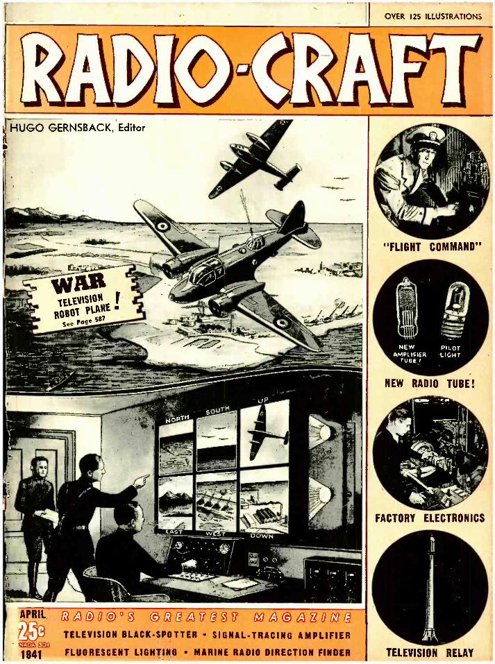
OVER 125 ILLUSTRATIONS
HUGO GERNSBACK, Editor
j r.' -.. t . j) "FLIGHT COMMAND"
NEW RADIO TUBE!
FACTORY ELECTRONICS
APRIL: G3GJD0 @ °ß @G3a ,71M aa@aY069r. TELEVISION BLACK -SPOTTER SIGNAL -TRACING AMPLIFIER
+xa _ 1941 FLUORESCENT LIGHTING MARINE RADIO DIRECTION FINDER TELEVISION RELAY

SAYS EVAN R. RUSHING, SOUND ENGINEER, HOTEL NEW YORKER
A PER E P. G. DYNAMIC BRINGS STUDIO QUALITY
TO ORDINARY P. A. JOBS
UNI -DIRECTIONAL. NEW SUPERIOR ELIPSOID PICKUP PATTERN
* ELIMINATES FEEDBACK TROUBLE BECAUSE IT HAS LOWEST FEEDBACK POINT OF ALL DIAPHRAGM TYPE MICROPHONES
FLAT RESPONSE. FREE FROM ANNOYING PEAKS, GIVING STUDIO -QUALITY REPRODUCTION.
,00 .00
FLAT DI roN8 OF PG DrMAbliC
The P.G. diaphragm follows air particle velocity where Li amplitude is a GRADIENT of the PRESSURE. In ordinary dynamics amplitude is restricted from following air par. .,, . title velocity. 111
The P.G. DYNAMIC is a radical improvement in this type of microphone. You can actually hear the difference. Case is designed
according to modern acoustic principles. Rugged, not affected by temperature, altitude or humidity. HAS UNUSUALLY HIGH
OUTPUT, -55 DB.
MODEL PGH (PGL. 200 ohms). Excellent for high fidelity P.A. installations. broadcast studio, and professional recording. With
switch. cable connector. 25' cable. Chrome finish. LIST 532.00 ( 40- 10000 C.P.S )
GAH (PGAL. 200 ohms). For speech and music 708000 C.P.S. Switch. cable connector. 12' cable. Chrome, LIST S2S.00
,1I illlll It1 '
1
COMBINATION VELOCITY -DYNAMIC ACHIEVED WITH
ACOUSTIC COMPENSATOR An exclusive Amperite feature: By mov- ing up the Acoustic Compensator you change the AMPERITE VELOCITY to a DYNAMIC microphone without peaks. At the same time you reduce the back pick- up, making the microphone practically UNI- DIRECTIONAL.
WITH ACOUSTIC COMPENSATOR: MODEL RBHk; RBMk (200 ohms) with switch, cable connector.
Chrome, LIST $42.00
RSHk; RBSk (200 ohms). Switch, cable connector, Acoustic Compensator.
Chrome or Gunmetal. LIST $32.00
WHITE FOR FREE SALES AIDS ,4MPERITE O.
AMPERITE KONTAK MIKE Puts Musical Instruments Across
So beautiful is the tone produced with the Kontak Mike, that it was used in the Philadelphia Symphony to amplify a mandolin solo. Gives excellent results with any amplifier, radio sets, and record players. MODEL SBH (hi -imp) LIST $12.00 MODEL BRH, with hand volume control LIST 18.00 Plug extra List 1.50
FOOT PEDAL, for making beautiful crescendos LIST 12.00
561 BROADWAY, N. Y. U.S.A.
ilec4fAMPERiTE AMPER /TE
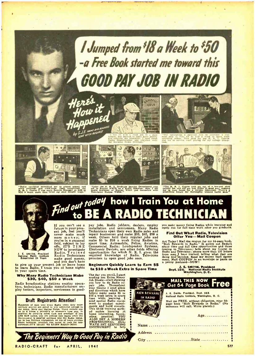
I Jumped from s1áA I eel to ;50 -A free Book started me toward this
L IN RADIO
"I had eek Rah III a 5h0e factory, but desired to make n mom
tl ay
and continue my education. I read about Radio Opportunities m d nr,lled with the National Radio Institute."
"'rie instrurtinm 1 ed Cci l was able to 55 to all1, - wech r, t s tine
avicing radios. rt This paid for a the N. IR. `I I, Course and led to service work paying for my college eduCas thon.
"Radio evenings anpermitted week .ends. Upon completing the
N. R. I. Course I was made Service Manager at Sao to 550 a weeks mom than twice my shoe factory wage."
J. E. SMITH. President Nat Iona' Radio Innitai.
Established 25 Years
"Later the N. R. I. Graduate Service Department sent me to Station KWCR a Radio Operator. Now i am Radio Engineer of Staas WSUI and connected with Television Station WORK."
"The N. R. I. Course took me out [ low -pay shoe factory Job and put me into Radio at good pay: enabled me to a funds for college education. There's a premising future for thoroughly trained Radio men."
today how I Train You at Home
" to BE A RADIO TECHNICIAN If you can't see a future in your pres- ent job, feel you'll never make much more money; if you're in a seasonal field, subject to lay offs, IT'S TIME NOW to investigate Radio. Trained Radio Technicians make good money, and you don't have
to give up your present job or leave home to learn Radio. I train you at home nights in your spare time. Why Many Radio Technicians Make
$30, $40, $50 a Week Radio broadcasting stations employ opera- tors, technicians. Radio manufacturers em- ploy testers, inspectors, servicemen in good-
Draft Registrants Attention! Hundreds of men n who know Radio when they enter military sereieeore going to win specialist ratings In the Army. Navy and Marine Corps. These ratings pay
p to 6 times a private'. or ns
base pay, in addition to carrying extra rank and prestige! If you ARE NOT called, you are getting into Radio when the Government is pouring millions into the Radio Indus- try to buy Defense equipment. on top of boom civilian Radio business. Whether you enlist or wait for Con- scription -IT'S SMART TO LEARN RADIO -NOWI
pay jobs. Radio jobbers, dealers, employ installation and servicemen. Many Radio Technicians open their own Radio sales and repair businesses and make $30, $90, $50 a week. Others hold their regular jobs and make $5 to $10 a week fixing Radios in spare time. Automobile, Police, Aviation, Commercial Radio; Loudspeaker Systems, Electronic Devices, are other fields offering opportunities for which N. R. I. gives the required knowledge of Radio. Television promises to open good jobs soon.
Beginners Quickly Learn to Earn $5 to $10 a Week Extra in Spare Time
The day you enroll, I start sending you Extra Money Job Sheets -start showing you how to do Radio re- pair jobs. Throughout your Course I send plans and directions which have helped many make $6 to $10 a week extra in apare time while learning. I send special Radio equip- ment to conduct experi- ments and build circuits. This 60 -60 training meth- od makes :earning at home interesting, fascin- ating. practical. YOU ALSO GET A MODERN PROFESSIONAL ALL - WAVE SET SERVICING INSTRUMENT to help
%he 23egihaerr" fygy fa &oy Ay íy gdío RADIO -CRAFT for APRIL, 1941
you make money fixing Radios while learning and equip you for full time work after you graduate.
Find Out What Radio, Television Offer You -Mail Coupon
Act Today ! Mail the coupon for my 64 -page book, "Rich Rewards in Radio." It points out Radio's spare time and full time opportunities and those coming in Television ; tells about my Course in Radio and Television ; shows more than 100 letters from men I have trained, telling what they are doing andfearning. Read my money back agree- ment. Mail COUPON in an envelope or paste on a penny postcard-NOW!
J. E. SMITH, President Dept.1DX. National Radio Institute
Washington, D. C.
I. E. Smith. President. Dept. IDX National Radio Institute, Washington. D. C.
Mail me FREE, without obligation, your 64- page book "Rich Rewards in Radio." (No salesman will call. Write plainly.)
Age
Name
Address
City State
577
7-
HUGO GERNSBACK, Editor -in -Chief
N. H. LESSEM
Associate Editor THOS. D. PENTZ
Art Director
R. D. WASHBURNE, Managing Editor
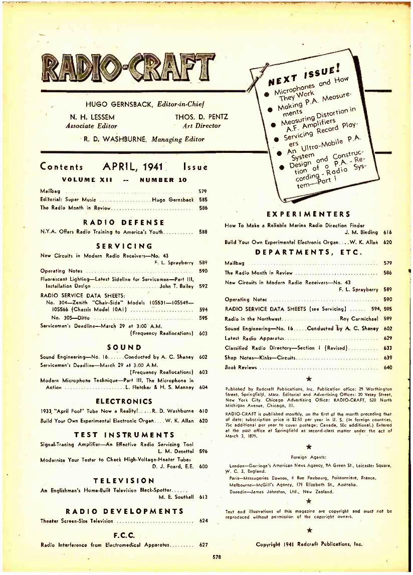
Contents APRIL, 1941 Issue VOLUME XII -- NUMBER 10
Mailbag 579
Editorial: Super Music Hugo Gernsback 585
The Radio Month in Review 586
RADIO DEFENSE N.Y.A. Offers Radio Training to America's Youth 588
SERVICING New Circuits in Modern Radio Receivers -No. 43
F. L. Sprayberry 589
590 Operating Notes
Fluorescent Lighting -Latest Sideline for Servicemen -Part Ill, Installation Design John T. Bailey 592
RADIO SERVICE DATA SHEETS: No. 304 -Zenith "Chair- Side" Models 105531- 105549-
10S566 (Chassis Model 10A1)
No. 305 -Ditto Servicemen's Deadline -March 29 at 3:00 A.M
(Frequency Reallocations) 603
SOUND Sound Engineering -No. 16 Conducted by A. C. Shaney 602
Servicemen's Deadline -March 29 at 3:00 A.M.
594
595
(Frequency Reallocations) 603
Modern Microphone Technique -Part Ill, The Microphone in
Action L Fletcher & H. S. Manney 604
ELECTRONICS 1933. "April Fool" Tube Now a Reality! R D. Washburne 610
Build Your Own Experimental Electronic Organ.... W. K. Allan 620
TEST INSTRUMENTS Signal -Tracing Amplifier -An Effective Radio Servicing Tool
L. M. Dezettel 596
Modernize Your Tester fo Check High -Voltage -Heater Tubes D. J. Foard, E.E. 600
TELEVISION An Englishman's Home -Built Television Black- Spotter
M. E. Southall 613
RADIO DEVELOPMENTS Theater Screen -Size Television 624
F.C.C. Radio Interference from Elecfromedical Apparatus 627
578
N E XT is 5u E
Microphones
pi9 k
Mkn P.A. O SUr e
ments Distortion in
Measuring A F Amplifiers Ploy-
Servicing ers
Ultra -Mobile P.P.
An stem nstru c
Design no PoA' - Re-
cording
s tton
o{ Rodio y -
ort 1 te- -Port
How To Make a Reliable Marine Radio Direction Finder J. M. Binding
Build Your Own Experimental Electronic Organ.... W. K. Allan
DEPARTMENTS, ETC. Mailbag
The Radio Month in Review
616
620
579
586
New Circuits in Modern Radio Receivers -No. 43
F. L. Sprayberry 589
590
594, 595
Roy Carmichael 599
602
629
I (Revised) 633
639
640
Operating Notes
RADIO SERVICE DATA SHEETS (see Servicing)
Radio in the Northwest
Sound Engineering -No. 16 Conducted ly A. C. Shaney
Latest Radio Apparatus
Classified Radio Directory- Section
Shop Notes- Kinks -Circuits
Book Reviews
* Published by Radcreft Publications, Inc. Publication office: 29 Worthington Street, Springfield, Mass. Editorial and Advertising Offices: 20 Vesey Street, New York City. Chicago Advertising Office: RADIO -CRAFT, 520 North Michigan Avenue, Chicago, Ill.
RADIO -CRAFT is published monthly, on the first of the month preceding that of date; subscription price is $2.50 per year in U. S. (In foreign countries, 75c additional per year to cover postage; Canada, Soc additional.) Entered at the post office at Springfield as second -class matter under the act of March 3, 1879. -
* Foreign Agents:
London -Gorringe's American News Agency, 9A Green St., Leicester Square, W. C. 2, England.
Paris- Messageries Dawson, 4 Rue Faubourg, Poissonniere, France.
Melbourne- McGill's Agency, 179 Elizabeth St.. Australia.
Dunedin-James Johnston, Ltd., New Zealand.
Text and illustrations of this magazine are copyright and must not be reproduced without permission of the copyright owners.
*
Copyright 1941 Rederaft Publications, Inc.
ON "WHERE RADIO FAILS" Dear Editor:
I read with unusual interest your editorial in the January issue of Radio -Craft in which you called to the attention of the industry the need for a system of publicizing the radio programs on the air.
This locality was among the first to feel the ax when newspapers and radio stations began falling out. Over 10 years ago, in 1930, I was engineer at one of our local stations. I was also Radio Editor of one of our large daily newspapers. Naturally I was in a position to see both sides of the question. (I set forth these arguments in an article in Parts in 1938.1 In all fairness I must say that the newspapers were imposed upon, and that they received practically no cooperation from the radio stations. The editor of one of our large dailies told me that after he had devoted thousands of dollars of space to radio programs and news he was sent a bill for the radio station an- nouncing a change in location of a public meeting which he had requested. The editor of the other daily said that he quit coop- erating with the radio station because the station's manager refused to instruct his announcers to use the paper's byline when crediting them with news bulletins. In every case it was some silly incident together with selfishness on the part of the station.
However, be this as it may, the need for proper publicity for Radio constitutes an acute problem. The very life line of the industry is the radio audience, and it is only through the spectacular events that have so fortunately occurred that this au-
- dience has been kept alive. All Servicemen will agree that before the outbreak of the war, radio servicing had hit an all -time low.
During the past 10 years I have spent much time and money trying to find a solu- tion to the problem of properly publicizing radio programs. For 3 years I published a radio bulletin. I bought space in the news- papers and time on the air. I printed novel- ties (as you suggest) which I distributed. One was a slide -rule affair with the pro- grams printed on the slide and the time on the cover. The slides could be renewed periodically. I wrote manufacturers and edi- tors in an effort to get some nationally - effective effort started..
And, unless the effort is national, I am thoroughly convinced that it will be useless. From my experience there is only one major way to publicize radio programs, and that is through the daily press. All other sys- tems which I have tried have been more or less failures. People are not going to delib- erately read radio programs. As you say it is too much like reading a dictionary. How- ever, if the programs are listed conveniently in the daily newspapers, they will glance over them and their interest is revived if not aroused.
It is my contention that if a listener be- comes thoroughly interested in only one radio program, he will keep his radio set in good repair; and will buy another when that one becomes worn out. On the other hand, it is the easiest thing in the world for a listener to lose interest in radio. This can be proved by any Serviceman. When a customer brings his set in for a repair he asks almost invariably, "How soon can I get it ? ". This shows h, is interested in some- thing on the air. But let that radio man keep that set for a week, and it is often months before the owner will return. He has lost interest in the programs because of his being unable to hear them.
This condition has been remedied to a certain extent by the fact that most people have more than one radio set. However, the condition is still there and is of primary importance.
RADIO -CRAFT for APRIL,
I think that every phase of radio is to blame for the condition that exists between the newspapers and radio. First, the maga- zines have not done their part in stressing the importance of this phase of the business. Second, the manufacturers have shown a de- cided disregard. With their advertising pow- er, they could have gone to the newspapers and said, "Look here, if you are to get a large portion of our advertising budget, you must run radio program listings." I wrote manufacturers suggesting this and could get no cooperation. I suggested that the manufacturers have their advertising agencies send out a questionnaire asking if the papers carried radiò program listings and making it definite that those which did would be shown partiality. Had this been done years ago, or had the manufacturers had a representative to attend meetings of the newspaper groups and say to them, "You are not hurting the radio stations when you refuse to print their programs, you are hurting us. We are the people who spend money with you. Every bit of ad- vertising that you give to commercial radio programs you are giving to your own cus- tomers, because the radio advertisers are also newspaper advertisers and all they are looking for is results," the problem would have been solved.
And, now let's look at the jobber and dealer. These are the fellows that actually place the advertising. They are the ones from whom the newspaper collects its mon- ey. Years ago had the magazines and manu- facturers started a combined effort to make the jobber and dealer radio program con-
scious, these fellows could and would have jumped straddle the newspaper men's necks. I personally called on every dealer and jobber in this town and suggested that they ask their newspaper advertising solicitor why his paper didn't carry radio programs. Not one time, but every time he came into their store.
I went to the Servicemen and suggested that they ask their customers to call the newspapers and ask why they didn't print radio programs. I even went to large de- partment stores which sold radio receivers and tried to get them to use their influence.
However, all my efforts were in vain. It seems that no one could see enough imme- diate personal gain to participate in such a far -reaching venture. I tried to interest tube manufacturers in devoting part of their advertising budget to materials that would help promote radio listening. They are spending the money anyway, why not make the best of it?
Practically all the advertising that is be- ing done in the radio business is of such a selfish, uninteresting nature that it goes unnoticed. It seems that the industry is like a bunch of automobile salesmen in a small town. They will leave no stone un- turned to sell one of their competitor's cus- tomers, but they will not walk around the corner to try to get a prospect of their own.
If Servicemen would realize that their worst competition is procrastination, and not the man down the street, they would be much better off. There are more radio sets that need work than are working per- fectly. To get this work into their shops requires a concentrated drive to make the owner conscious of the good things he is missing by putting off having his set re- paired.
From a manufacturer's standpoint, prac- tically no space is being devoted to interest the public in higher- priced radio sets. A large part of all radio advertising is devoted to the $9.95 type, on which no one can make any money even after it is sold. In an ef- fort to compete with the chain stores, all
1941
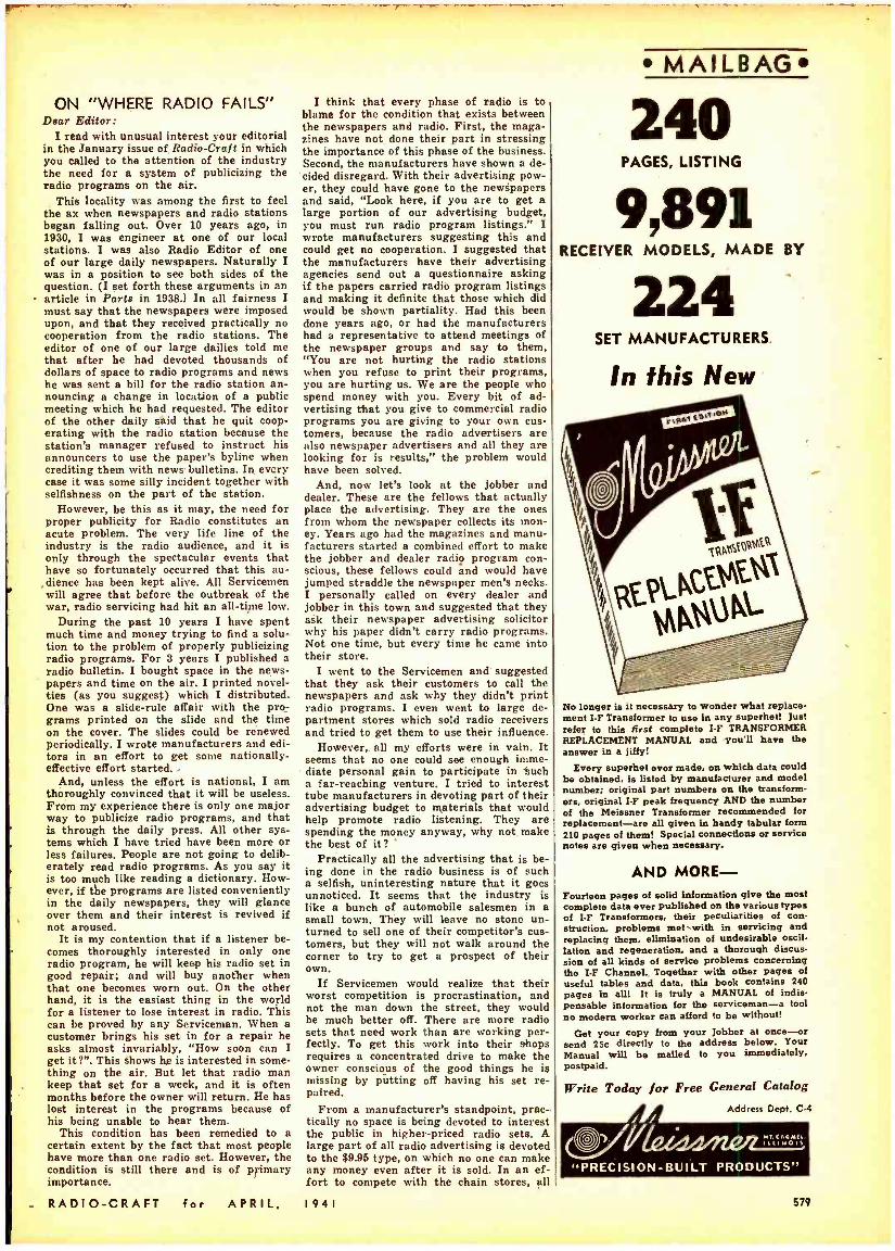
MAILBAG
240 PAGES, LISTING
9,891 RECEIVER MODELS, MADE BY
Z24 SET MANUFACTURERS
In this New
No longer is it necessary to wonder what replace- ment I -F Transformer to use in any superhet! Just refer to this first complete I -F TRANSFORMER REPLACEMENT MANUAL and you'll have the answer in a iffy!
Every superhet ever made, on which data could be obtained. is listed by manufacturer and model number; original part numbers on the transform- ers, original I -F peak frequency AND the number of the Meissner Transformer recommended for replacement -are all given in bandy tabular form 210 pages of them! Special connections or service notes are given when necessary.
AND MORE - Fourteen pages of solid information give the most complete data ever published on the various types of I -F Transformers, their peculiarities of con- struction, problems met with in servicing and replacing them, elimination of undesirable oscil- lation and regeneration, and a thorough discus- sion of all kinds of service problems concerning Use I-F Channel.. Together with other pages of useful tables and data, this book contains 240 pages in all! It is truly a MANUAL of indis- pensable information for the serviceman -a tool no modern worker can afford to be without!
Get your copy from your Jobber at once-or send 25c directly to the address below. Your Manual will be mailed to you immediately. postpaid.
Write Today for Free General Catalog
O , Address Dept. C-4
"PRECISION -BUILT PRODUCTS"
579
Correspondence Courses In
RADIO ira R CTRI(AL £NGIN£ERING
I.F. derived from an oscillator accurate to better than 1 part in 9,000 or 0.0001 -per cent of 455 kc. The 2nd -harmonic of the oscil- lator, an electron -coupled commercial job, is beat against a broadcast station frequency accurate to 20 cycles of the assigned carrier frequency. The oscillator is adjusted, by a trimmer, whenever necessary, and hardly ever shifts, even after warming up. The oscillator is a Philco 088, A.C. job.
More on Mr. Buck next month. WILLARD MOODY. New York, N. Y.
FROM A CHINESE READER Dear Editor:
There are many Chinese readers of your excellent magazine, perhaps I am the only one that writes to you.
The article "Servicing R. F. Coils" (Vol. XI, No. 12) has errors in it. Fig. 7B is Fig. 7C, and vice versa.
This article has been translated into Chinese by me. .and will be published in the July issue of "Popular Radio Magazine," one of the two well -known Chinese radio magazines.
The best of my wishes, K. C. Wu, Shanghai, China
Mr. Wu may be interested to know that Radio -Craft has other correspondents from the Orient, and last week, a visitor, Mr. Fred Shunaman, who operates a radio serv- ice station on Bubbling Well Road in Shang- hai.- Editor
SOUND IS BOOMING!. e
... so Radio -Craft goes to town
The May issue of RADIO -CRAFT will be a "Sound Special." Home Recording and Phono -Radio Combinations have taken the public by storm, so RADIO -CRAFT is going to town! The May Issue will be devoted mainly fo Sound. This, of course, includes public address as well as home recording and phono-radio combinations.
In addition to the usual departments on this topic, there will be special articles and construction projects which will be of con- siderable value to Servicemen, Sound Spe- cialists, and radio men in general; -not the ordinary run of articles but specially -pre- pared material for this issue.
Reserve your copy NOW!
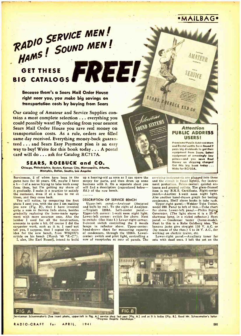
PROGRESS DESPITE HANDICAPS Editor's Note: Last year Mr. R. J. Schoon-
maker sent us a photo (Fig. A.) of the radio service shop he was starting. We did not publish the photo at the time because the shop seemed to be too incomplete. Recently we asked Mr. Schoonmaker how he was get- ting along. His interesting reply follows: Dear Editor:
OK, you asked for it, here it is. I believe I have made fair progress during the past year, all things being considered.
Naturally you do not know what that above expression includes.
However, to be brief, I am a widower, with 6 children to bring up, house work to do, home to look after, am partially deaf (I appreciate what Earl Russell of Colfax, Ill. [Feb. '41 "R.-C.'9, is up against) and I have to put in long hours to accomplish anything. Considering the above handicaps I believe you will agree that I have not done bad. I am up against 3 well -established
MAILBAG
RADIO TRAINING
PORT ARTHUR COLLEGE -not privately owned, not operated for profit, a college
built and endowed by the late cap'talist- philanthrorist, John W. Gates -offers the most thorough practical Radio training in Amer :ea. P. A. C. owns Radio Station KPAC, which is equipped with the very latest type 1000 -Watt high fidelity RCA transmitter, operating on 1220 kc. with di- rectional antenna system. The college is authorized to teach RCA texts.
The Radio training covers thoroughly Air- ways, Press, Announcing, Teletype, Type- writing, Laboratory and practical experience at KPAC transmitter, control room and studios. Announcing is an optional part of this training; nevertheless a number of stu- dents annually make successful announcers. Port Arthur College pioneered the teaching of radio with its first classes in 1909, and for thirty -one years has maintained an ac- tive Employment Bureau that Is successful in placing graduates in airways, broadcast and marine radio industries.
If interested in details about the Radio Course, write for Bulletin R -41
PORT ARTHUR COLLEGE PORT ARTHUR (World -Known Port)
TEXAS
.QRADIO SERVICE EXPERT A. LEARN AT HOME IN WARE TIME
The demand for radio experts grows every day. Learn this paying profession
under personal guidance of qualified en- since: and educator. Clear. fascinating in-
struction and experimental kite make learning easy. Leaders In tho radio industry endorse S.T.A. methods. Spare time profits soon pay for training.
NOW IS A FINE TIME TO START New in radio
Ifa tofriesca program
branch requires radio
dS. Service. men pportunities for advancement almost limitless.
FREE Write today for complete information and radii. book telling what E.T.A. training can do for you.
RADIO TRAINING ASS'N. OF AMERICA 1559 Devon Ave. Dept. RC -41 Chicago, 111.
12.1
ELECTRICAL ENGINEERING °t' wq TA tri.. fl Id. Prepare yourself. at Low Cost, for secure future. Modern, simplified. you can understand qll .
RADIO ENGINEERING Piet éá:ce., °vhám ieeirdlle' ör: Trains y u to be penservtce real v tube technician. Eimer kite furnished. Diploma
payment Tuition. ei [liar course. Deferred payment plan.
R E E cet copies of let, catalogs. student magazines. complete details. SEND NOW!
LINCOLN ENGINEERING SCHOOL, ea 131-18. LINCOLN NESR.
RADIO TECHNOLOGY RCA institutes offer an Intensive course of high standard embracing all phases of Radio and Television. Practical training with modern equipment at New York and Chicago schools. Also specialized courses in Aviation Communi- cations. Radio Servicing and Commercial Oper- ating. Catalog Dept. RC -41.
RCA INSTITUTES, Inc. A Radio Corporation of America Service
75 Veriek St., New York. 1154 Merchandise Mart, Chleago
RADIOTEtEVIS1On Oldest, largest Radio-Television school in West trains you for good pay Job. Complete Instruction Including Radio Construction and Service, Broadcast Operating. Sound. Talking Pi , Television. Public Address, etc. Flexible plan to meet specific needs of those with or without 1 b.. Transportation allowed to L.A. Earn room and board while learning. Request Free Catalog.
NATIONAL SCHOOLS, Los Angeles Dept. 4 -RC
sense of quality and the fine things in life have been forgotten.
Almost daily, every radioman gets calls from his friends asking what make radio should they buy. This alone proves my point. No single manufacturer has put enough thought into his advertising to lift him above the masses in his business. No one has made a bid for the business of the man who is not looking for something cheap -and believe me, there are plenty of these. However, in this day of chiseling he is the forgotten man. Even if he pays a high price for a radio receiver, all that he gets is more junk -more tubes to replace, more condens- ers to short and more knobs to lose the springs out of.
(In view of the fact that radio manufac- turing today is a highly competitive field, we question this contention of Mr. Davis. In other words, there must be a reason for the higher prices charged for certain radio receivers, else no manufacturer could sell his higher -priced products; a radio set must afford certain definite facilities and new im- provements for any given increase in price. In other words the increase in price is more than just a matter of adding com- ponents. What about engineering laboratory expenses, patent costs, increased cost of production, added merchandising costs, etc ,
all to make available and "put over" new conveniences and facilities in receiver oper- ation ?- Editor)
Seriously, it appears to me that what the industry needs is coordination, a combined effort on the part of all concerned to do their part in accomplishing the desired re- sults. If this were done we could lick this and every other problem.
My suggestion is that the industry ap- point some one to go to the newspapers and ask that the rate on radio advertising of all types be increased to a figure that will permit the paper to give space to pro- gram listings. If this were done, every phase of the industry would pay its part. The manufacturer, jobber, dealer, Service- man, radio program sponsor and everyone else who placed advertising pertaining to radio would have to pay this higher rate. This would compensate the newspapers, and without some compensation it is my belief that radio programs will never again be published in all the papers.
HAROLD DAVIS, Jackson, Mies.
ANENT HOMER BUCK'S "ALIGNING SUPERHETS."
Dear Editor: I take exception to the article by Homer
C. Buck, re: "Aligning Superheterodyne Re- ceivers," January Radio -Craft.
"After aligning receivers with recognized aligning equipment we have found that the I.F.s were off as much as 3%. Servicemen who are accustomed to tolerances of 15 and 20% will say that a deviation of 3% is darn near perfect . ."
Where does Mr. Buck derive his figures? Why, they seem to be ridiculous. If we figure 3% of 455 kc., a standard I.F., the answer is 13.65 kc. deviation. If we figure 20 %, the deviation is 91 kc., and I for one do not be- lieve any legitimate Serviceman would align a set with the I.F. that far away from the correct figure.
Furthermore, while his arithmetic is good, his common sense and understanding of service procedure is all cockeyed if he is ready to believe that any busy and success- ful Serviceman has either the time or in- clination to indulge in fancy image hunts and sliderule calculations.
In my own alignment work, for sets not requiring a flat -top I.F. curve, I use the standard method of alignment, with my
580 RADIO -CRAFT for APRIL, 1941
SERVICE MEN SER
I SOUND MEN .
11AM5 I
GET THESE FREE/ BIG CATALOGS
Because there's a Sears Mail Order House right near you, you make big savings on transportation costs by buying from Sears
Our catalog of Amateur and Service Supplies con- tains a most complete selection ... everything you could possibly want! By ordering from your nearest Sears Mail Order House you save real money on transportation costs. As a rule, orders are filled same day received. Everything money -back guaran- teed ... and Sears Easy Payment plan is an easy way to buy! Write for this book today ... A postal card will do ... ask for Catalog RC717A.
SEARS, ROEBUCK and CO. Chicago, Philadelphia, Boston, Kansas City, Minneapolis, Atlanta,
Memphis, Dallas, Seattle, Los Angeles
MAILBAG
Attention PUBLIC ADDRESS
USERS! Prominent Public Address users and Rental outfits havr found It pays big dividends to get their equipment from Sears. Latest equipment at amazingly low prices -and you save Real Money on shipping charges! Get this big book today ... Write for RC732A.
Servicemen, 2 of whom have been in the game here for 20 years. OK, maybe I have a h --1 of a nerve trying to take work away from them, but I'm getting my share of it gradually. I make it a practice to satisfy the customer, even if at a loss to me at times, and they come back.
You will notice, by comparing the first photo I sent you, with the one I am mailing you now (Fig. B), that I have invested quite a sum in Service Info alone, besides gradually replacing the home -made equip- ment with more accurate ones. Also the lumber I used for all the tonstruction, amounts to quite a bit. Of course I did the carpenter work, such as it is. I need' not tell you, I suppose, that I copied the main idea for the new bench, from W8QNU's article on his bench (March '40 "R.-C.").
I, also, like Earl Russell, intend to build
up a hearing -aid as soon as I can spare the money for parts, and then drum up some business with it. On a separate sheet you will find a description (reproduced below - Ed.) of the new bench.
DESCRIPTION OF SERVICE BENCH Upper -left panel. -Analyzer (designed
and built by me). To the right of Analyzer. -Triplett 1200A. Left -center panel. - Upper -left corner: 1 -watt neon night light. Lower -left corner: switch for above. Next to switch: (See Note I.) Lower -right corner: 2- circuit switch controlling the 3 mazda lamps in reflector above. Upper- center: hand -drawn chart for measuring capacity of condensers, through the 1200A. Lower - center: switch and pilot light, controlling a row of receptacles at rear of panels. The
servicing instruments are plugged into these and the circuit is fused lightly, for instru- ment protection. Below- center: quintet an- tenna and ground outlets. The glass- framed item is my R.M.S. Certificate. Right- center panel. -Another 1 -watt neon night light. Also another hand -drawn graph for testing condensers. Shelf above books is tube rack.
Upper -right panel. -Webber Tube Tester, model 200. Panel to left of this. -Tube chart for above. Lower -left panel. -Philco Signal Generator. (The light above it is a 25- showcase lamp, in a nickel reflector.) Next panel. - Condenser tester (home- made). Next to this is a Rube Goldberg idea. The banana jacks give straight 110 V. A.C. or (by means of the rheo.) 6 to 24 V. A.C., for working on electric trains, etc.
Lower -right panel. -Auxiliary tuner for sets with dead ones. I left the set on the
Serviceman Schoonmaker's (See insert photo, upper -left in Fig. A.) service shop last year (Fig. A.) and as it is today (Fig. 8.). Read Mr. Schoonmaker's letter "Progress Despite Handicaps."
RADIO -CRAFT for APRIL, 1941 581
=rr-`C--a-- . . . . ,-
MAILBAG JUST OUT!
EVER. IC Radio Mechanic- Service Man & Student Needs
Audels Radio- mane Guide'
Just Outl The whole subject of Modern Radio - covering the Basic &Operatiov- loe-Repairs-Troubles-all oe- Repairs- Troubles -All Easily Understood. Over 750 Pages. 400 Illustrations. Parts & Diagrams -LATE TELEVISION DATA -Valuable for
REFERENCE AND ROME STUDY. á for youtrsel if lilts in and mall coupon
handy
COMPLETE PAY ONLY $1 A MO. AUDELI Publishers 49 W. 23rd St., N.Y. MdI AUDETS NEW RADIdMANS GUIDE for free eremi
in °moutuly
If priée
will IÑ is Seid. áttherww i wiiil rotons` it.
Name-
Addrda.
Oteaptlon- Referees. Inch
Are You Playing
/woINo
With Your Future? Aro you, I i ko so many other professional radiomen, aimlessly groping for tho door to opportunity? Thou- ' sands of ambitious red !omen have been set on the right nurse with the help of CR E I advanced technical train ing. The well -written text plus the personalized training provides a proven formula for more rapid advancement. CREI graduates as a group are among the highest geld In radio -69% (by actual survey) enjoy salary Increases! Year after year we strive to improve our courses and the results they enable you to enjoy. Why not Investigate what CREI training in Practical Radio Engineering tan do for YOU?
Write for Facts Today - Send for our interesting book- let, together with personal rec- ommendations for your ad- vancement in radio. To help us intelligently answer your in- quiry, please state briefly your education, radio experience and present position; also whether interested in horse study or residence training. CAPITOL RADIO Engineering Institute Dept. RC -4, 3224 16th Street, N.W., Washington, D. C.
FACTORY -TO -YO& VW DM INN 1941
15. TUBE RADIO -PHONO
ION assss ut TOW! PRISM CABINS
ADE -rM TO ZS
TR ¡en Many Model,)
COM PLITf RA010. PHONO
CHASSIS with TUe
and SPEAKER
RICORDER FREE 051.12-Hx MIDWEST uDip eurraunoN. ei.d, á4 pw
582
behch to show you how handy my analyzer is, in spite of Signal Tracing, Signal Sub- stitution, Audolyzing, Veedolyzing, or what have you. I am now working, in my spare time, on the Signal Tracer by Monroe H. Freedman (Sept. '40 "R.-C."). I believe it will be quite a help to speed up my work.
Note I. -This is a little contraption of my own. As I cannot depend on myself to hear the doorbell, I watch this while I am working. I simply connected a second bell transformer to my first one as follows. Where the secondary of the 1st transformer feeds the bell circuit, I connected the sec- ondary of the 2nd transformer, then the primary of the 2nd transformer feeds the 110 -V. neon bulb, which flashes when the bell rings.
If any of you boys are interested in my analyzer (I know thousands of them have been designed and published) I will be glad to send the Ed. the dope on it.
Incidentally, the panels are plywood fin- ished in slate gray, and the striping in between is bright orange.
R. J. SCHOONMAKER, Port Jervis, N. Y.
RE. WILLARD MOODY'S LETTER Dear Editor:
After reading Willard Moody's letter in the Feb. '41 issue, I decided to write, myself. I quite agree with him on some points, not all. I like your editorials and I can't see much wrong with the cover but I don't think that most readers get much out of the Radio Month in Review or the hints and kinks features. I like the Operating Notes and the Data Sheets and think we phould have more of them. And if you are going to have full-page ads to sell Radio -Craft for premiums let's have premiums that are of value or at least change them once in a while.
Of course it is hard to please everyone, I know because I have been a Serviceman for many years and somebody is always displeased with what we do.
I have been a newsstand reader of Radio - Craft for a long time and think it is hard to beat for the Serviceman. (Thank you! - Editor)
CHRIS. NEEDLES, Missoula, Montana.
Dear Editor: I have been a pardner of yours since 'way
back when. Always a silent pardner until now, for you were doing your best to give me what I wanted and that is pretty much what I was getting. There wasn't any need for words, so there were no words. Simple.
But I must now bust out with the plea that you take Willard Moody kinda un- serious.
He has likely just finished a correspond- ence course and has a nice hew diploma showing that he now is a Master of Con- structive Thinking, so he decides to remodel Radio -Craft and show us how much better it is under the sway of his genius.
I don't know his age, but 1 can guess. Only the very young can be so damn sure of themselves. However, he is not so impor- tant, it is his plan that is to be considered. I see it thusly:
(1) The cover. I don't care. I am so ,
anxious to see what is inside that the cover gets scant attention from me.
(2) The tiresome Gernsback editorials. They have broadened the mental horizons for thousands of us and sometimes contain usable ideas. Most of us radionuts would be very unhappy if they were left out.
(3) Radio in Review. He must have
rwMMWW ""1
DATAPRINTS V(11X
TESLA -OUDIN COILS r! 20e Ea. in order for 10 -., (Data and Drawings only.) IIII 4, 86" Sp'k Tesla -Oudin Coil 40e
II (1 K.W. Exc. Trf. Data incl.) 8" Sp'k Tesla -Oudin Coil 40c - =r. (% K.W. Exc. 'rrf. Data incl.) 8" Sp'k Oudin; 110 Vt. _: Kick Coil" type 40c 8" Tesla Works on Ford 'T1 =. Coil 40e
-- - 1 "Sp'kVibratorHi- Freq.Coil40c NEW ! 5 ft. Sp'k. ondin Coil & Exciter
Data 75e
Induction PIPE & ORE LOCATOR
`e Induction Type, Data 40e
Rodio Typo 40e
More DATAPRINTS 40c each! 5 Meter Superhet. Electric Refrigerator % Meter Tr. & Rec. Wheatstone Bridge 20 A.C. Probs. & Ans. Weld. Transf. 2 K.W. 20 Telephone Hook -ups Rewinding Armatures 100 Mech. Movements 20 Motor Hook -ups String Galvanometer Television Hook -up 20 Simple Bell Circuits 20 Elec. Party Tricks Steel Wire Recorder! Solenoids and Magnets Water Wheels
--get list. Water Turbines Fry Eggs on Ice! Photo Cell and Relay Experimental Photo- Ring 4 bells: 2 Wires phone 20 Tesla Tricks Radio Control for
Modals Polarized Relay Diathermy Apparatus Induction Balance Inductor Organ Electric Pipe Thawer
Special Prices: 4 prints $1.00; 10 for $2.00; Single. 40e each. Get New Catalog 100 A.
The DATAPRINT Co. Lock Box 322D, Ramsey, N. J.
ELEMENTARY
MATHEMATICS EASY - SIMPLIFIED - PRACTICAL
HER E Is a book for the business man. the tech- nician and craftsman explaining and answering every operation and meaning with Interpreting
Illustrations and exam pies. It Is the key to a slur ale understand ing of many
perplexing problems In daily I Ito. In clear, positive and detn Ito language. tho author
Depolarizes and clarifies every subject and helps the reader to overcome any apparent difficulty In the study of mathematics.
A real home study - course In mathematics for the student or the man who wants to achieve proficiency or desires to brush- up on his knowledge.
°maire' Chopper n Spec.ni Afafh- "PE
ries for the Radio Technician \i CONTENTS OF BOOK
I. Arithmetlo- Addltioa -Subt setlon- MUltiDll
cHAPTÉRr1- Dalrectoring
and Censttation- Fractions -Doof mals-Ratto -and Proportion. CHAPTER
amm
III. The MtoblMenem. Surfaces and Cawefb
CHAPTER e V.1.Power. and Involution -Roots and rNoto. Lion.
CHAPTER VI. Mathematics for the Man. ual and Tech I I C
er to. - Its a Graphs
her Come Ptotting- Logarithms -Use of the Slide Rule.
CHAPTER VII. special Mathematics for Ne Radio Technician.
CHAPTER VI t. sts - Dlseounta Commercial Calm/
hort tient
Arithmetic. CHAPTER IT.e Weights and Me a
Unef 'PAementore Mathematic" be oa d reed: ais your ',oak.
Send Stamps, Cash or Money Order.
T I:(: N WA X' 1917 S. State St. RC -441 Chicago. III.
ONLY
50c POSTPAID
PATENTS -TRADE MARKS Booklet concerning Inventions & Patents
Form "Evidence of Conception" with instructions for use and "Schedule of Government and Attorneys Fees" -Free
LANCASTER, ALLWINE & ROMMEL Bagtetered Patent Attorneys.
486 Bowen Bldg. Washington, D. C.
RADIO -CRAFT for APRIL, 1941
strained himself thinking that one up. We like it.
(4) Sprayberry OK, not any more OK than your other features, but OK.
(5) Nice large generalities. All right by me- whatever they mean.
(6) Ha! Ha! Remember when "Radio ' News" tried that, about 1937, and how hard they worked to get back their own bunch afterward ?
(7) He recommends no attainable change here.
(8) Hints and kinks mean nothing to me, but a lot of your readers like them. Their money is good too.
(9) Us "dopey" Servicemen are the ones who keep you eating regular as you very well know. You aren't apt to take him seriously on that one. And when he has serv- iced enough thousands of sets, he will be a "dopey" Serviceman too, and will be glad you didn't change.
(10) Seems like you answer that one in most every issue.
I suppose that Letters are a waste of space, but he reads them and adds to some- thing he disapproves of by writing. I read them or I wouldn't have found his letter. It's a sort of meeting place for the gang and probably well liked.
The kid means well. I remember when I, too, felt able to run the World with one hand tied behind me, and do a better job than was being done. But I've growed up since then, even as he will grow.
And if he sees his letter 30 years from now, he will turn the same color that I do when I am reminded of the days of my infallibility.
Ever of thee, CHARLES PILGRIM, Aitkin, Minn.
Dear Editor: I can't agree with Mr. Willard Moody of
New York for his comments in the Feb., 1941, issue of Radio -Craft.
I think he had a bone to pick with some- one and took it out on the Editor and R.-C., I think the Editorials are fine stuff. It gives the radio man something to think about. It's food for thought (even for a Philadelphia lawyer like Mr. Moody). Keep up the good work, Mr. Gernsback.
I see nothing wrong with any of the cov- ers of R.C. It's a radio magazine.
What's the matter with foreign methods? Myself and others like to know what the other fellow is doing. Our foreign friends read R.-C. as well as us in America.
Keep Sprayberry. Yes, keep Sprayberry and keep R. -C. as it is . its service for the radio Serviceman and technician. So keep up the good work in R.-C.--it's a gift at any price!
ALBERT RINGROSE, Windsor, Ont., Canada.
P.S. -It's a wonder Mr. Moody didn't kick nt R.-C. being streamlined.
Thanks very much for your evaluation of Radio -Craft, Mr. Ringrose, and you, Mr. Pilgrim. We hope the magazine will continue to merit such high praise.--Editor
TUNING I.F.s BY EAR Dear Editor:
I received a letter from a fellow by the name of Walker. He said he had an A.C.-D.C. set with an I.F. of 456 kc. and when in Ontario he could receive the Detroit police and WJBK together at 1,500 kc. Both WJBK and the police, WCK, would drift up and down the dial, about 10 kc. either way. I gather there was no distortion when these stations were tuned -in at the new setting, and the rest of the band was OK, WCK be- ing an image of course.
RADIO -CRAFT for APRIt,
MAILBAG
LEARN BY DOING!
Just Published
RADIO LABORATORY
JOB SHEET MANUAL by Sol D. Prensky
The manual contains 24 practical radio projects arranged to explain and illustrate the fundamentals of radio, with definite layout instructions. It con :its of about 83 pa;ea, .wire bound, with over 100 illustrations. It is especially adapted for school laboratory work of a basic course in Practical Radio. An educational discount of 20% $I.80 on orders of six or more. List Price
FREE' Write for Circular RLI. and obtain a compli- mentary copy of a comprehensive RADIO
SYMBOL CHART, including the Continental Code, and Resistor and Condenser Color Codes.
SEND 10c IN COIN for deposit, if you wish a copy of the manual sent to you C.O.D. You pay the balance. plus a small Poet Office collection charge.
AB PUBLISHING CO., 652 Montgomery St., Brooklyn, N..Y
I shall attempt to figure it out. While it is entirely possible to align these cheap receivers by ear -much more accurately, in most cases, than by using equipment -it is also possible to get into a lot of trouble with- out a set of rules to go by and a little practice.
While at 456 kc. the band width of an I.F. transformer may be 8 to 15 kc. -vide, the same transformer when tuned to a lower frequency, with the latitude of the trimmers determining the value, will pass a much wider band of frequencies due to deflation of the response curve. The higher the fre- quency to which a coil is tuned the sharper will be the response.
Therefore, when an I.F. transformer is tuned by ear.it is entirely possible to tune to a frequency other than the correct I.F., or some value which is an even or odd part of the correct value, and as long as the latitude of the oscillator trimmer will per- mit this, some semblance of tracking will occur.
In this particular case, I believe, the I.F. transformers have been tuned to a lower frequency, with the resultant broad re- sponse. Any slight drift of the oscillator will cause a station to move from the correct dial setting, and if the I.F. response is broad enough the station may be tuned -in at the new setting with little or no noticeable side - band cutting.
Also, in case some one should try to cor- rect me on the frequency of WCK, the Detroit police, the correct frequency is 2,414 kc. and they should come in at 1,502 kc. as an image, on cheap receivers.
H. C. BUCK, Detroit, Mich.
ELECTRONIC GUNS Manufacturers have pepped -uT the elec-
tronic shooting range described in this magazine some time ago, so that new elec- tronic "sub- machineguna" lay down a bar- rage of 100 "shots" in 15 seconds. How about using them for preliminary Army target - shooting practice? A lightbeam is lots less ezpeneive than regulation bullets!
1941
LEARN
RADIO SERVICING COURSE -8 WEEKS
OPERAT1NG MONTHS
I'LL FINANCE YOUR TRAINING Mail coupon today for free book howin8 how you can learn Radio
TTel in Television few short seeks in Coyne Shops and also how you can Day tuition in easy monthly payments after graduation.
LEARN BY DOING On real Radio receiving and transmitting equipment at Coyne. Simple. easy method of practical shop tra. ing. You don't need previous experience. Prepare for Radio Ope tor. Government license Exam. and for good lobo in Broadcast. Police Radio. Aircraft Radio. Ships. Commercial Radio stations or in service shops and radio factories. Learn by doing ", the quick, modem way, at Coyne Shops in Chicago.
EARN WHILE LEARNING Job Help After Graduation
We assist you in getting pan -time work to help pay living expenses and give you real employment service cdter you graduate.
SEND COUPON TODAY
H. C. LEWIS Peas.. COYNE RADIO SCHOOL. 500 5o. Paulin St., (Mot. 41.811, Chicago. III.
Pleue end me roar free book and details of cu> Pa>.Atter Graduation rim. NAME
ADDRESS
CITY STATE J RADIO OPERATORS
WANTED The National Defense Program Is creating In-
numerable openings for Commercial Radio Oper- ators -Now is the time to capitalize on your radio training and experience by obtaining a Commercial Radio Operator's License and taking advantage of the many opportunities presented. My recent put l lralton "RADIO OPERATORS' LICENSE GUIDE" has been especially prepared as a Guide for those radio men having the necessary training and ex- perlenco but who are unaware of tho exact require- ments for a Commercial Radio Operator's License - Containing over 1.250 questions and answers to the new type examinations. it will enable you to suc- cessfully pass the examinations. Only $3.00 Postpaid -Send check or Money Order.
WAYNE MILLER 205 West Wacker Drive
Chicago, Illinois
583
Tat ilettee Setv««y -Tot ßig5et Ptatits FOR A WIDER KNOWLEDGE OF TECHNICAL SUBJECTS, READ THE
BOOKS IN THE RADIO-CRAFT LIBRARY SERIES
An accurate simailll led
tochnicai rovlaw of the
fundamentals of this
latest brnnIo of serla'
aer;:t. Includlnt' servie
Ing data on ornent -dD
units. BY Peul
Harrigan. 50e
Book No. 14
POCK GUI RADIO Ñ t.easem.
Etilted by Book Handy Reference
tor
Radio Men -5rA Construction
Articles -
Audlo Amplltlar
.
ad culte UwlutDsta-
short Cuts Honer
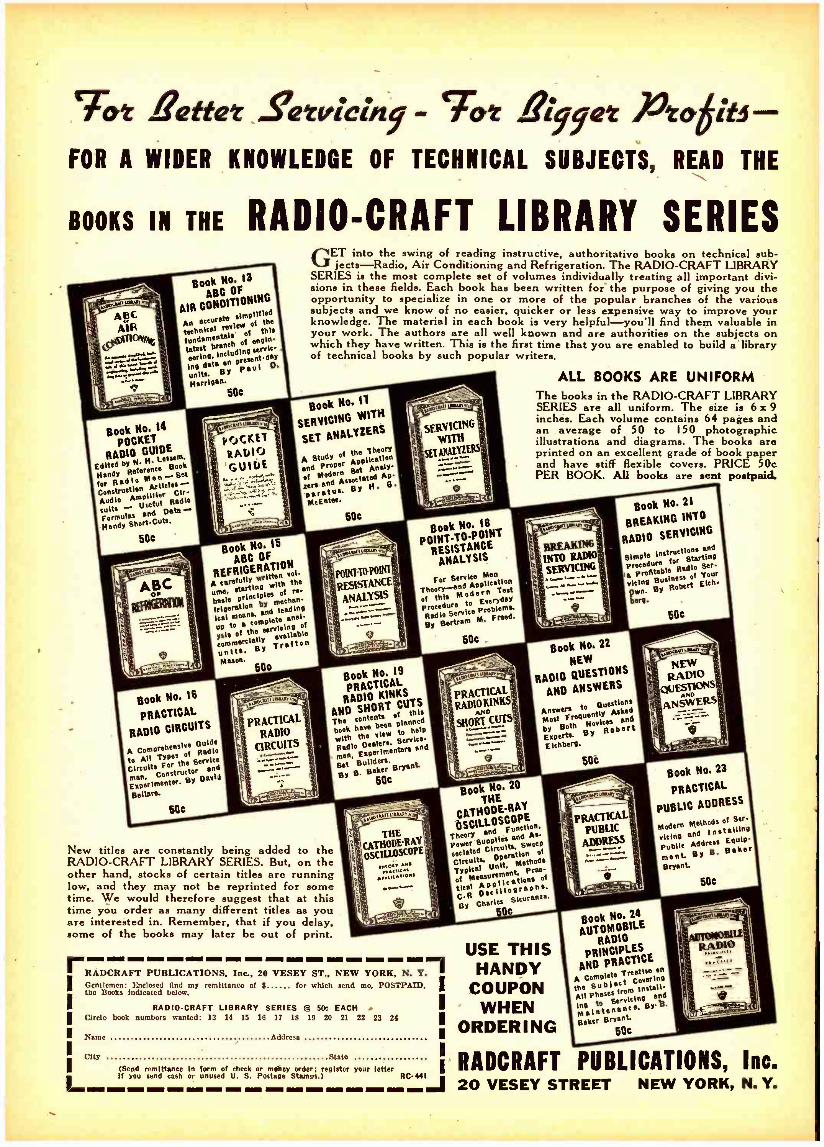
GET into the swing of reading instructive, authoritative books on technical su jects -- Radio, Air Conditioning and Refrigeration. The RADIO -CRAFT LIBRA
SERIES is the most complete set of volumes individually treating all important di lions in these fields. Each book has been written for the purpose of giving you t opportunity to specialize in one or more of the popular branches of the variot
and we know of no easier, quicker or less expensive way to improve you knowledge. The material in each book is very helpful-you'll find them valuable your work. The authors are all well known and are authorities on the subjects o which they have written. This is the first time that you are enabled to build a'libra of technical books by such popular writers.
Book Ho. W17H
SERVICING
SET ANALY7ERS
A Study of the Ilhotlan
and Proper Analy- ot Modernssociated Ap-
r e and Associated H O
p f r flua. McEntee
ALL BOOKS ARE UNIFORM
b-
RY vi- he
tr us
ln
ry
The books in the RADIO -CRAFT LIBRARY SERIES are all uniform. The size is 6 x 9 inches. Each volume contains 64 pages and an average of 50 to I50 photographic illustrations and diagrams. The books are printed on an excellent grade of book paper and have stiff flexible covers. PRICE 50e PER BOOK. All books are sent postpaid.
Book Ho. 15
ABC OF 10N
REFRIGERA I
vol. folly
with the me,
intlples of et'
hot l° ß'0p by mechan- rlvera feedlot' leaf
t moans,
en ate anal -
ysla of the sa 'wettable eommerelellY Tralton units. BY
Muon.
Book Ho. IB
r RENCET AALYSIS
SISTAN
Men
TheorY-e Aoplicetion
of Chia !Ana: deEr rydaY
d re o
600
For Senate
Proce o
By Bertram
MroFeaed.
50e
Book No, 21
BREAKING INTO
RADIO SERVICING
ßlmple Ins forti3 °tnrtn^a
Proceduro e Prodtable Radio Ser-
eIcing Business of Your
Qwn. BY Robert Elch
óarp.
SOC
A Comprehensive Guide
to All Ts of Radio
Glreuw For the Service tru me. Consctor
fad
Expnermenter. BY Darted
Bellare.
Book Ho. 19
PRACTICAL RADIO
RT GUTS AND SHO Chie Tice conte
been poisoned book hove
view to help
with tvealers, Service -
Bedlo and man, Set Builders. BY B. Baker
Bryant
500
Book No. 22
NEW
RADIO QUESTIONS
AND ANSWERS
Answero to BueStlons
Most FreguentlY Asked
by Both Novices and
Erpern. BY Robert
Etch 11
506
New titles are constantly being added to the RADIO -CRAFT LIBRARY SERIES. But, on the other hand, stocks of certain titles are running low, and they may not be reprinted for some time. We would therefore suggest that at this time you order as many different titles as you are interested in. Remember, that if you delay, some of the books may later be out of print.
Book No. 20
THE
CATHODE RAY
OSCILLOSC0 Theory
ana
power 9 Circuits.
p $WeeO
sociatea Opet So t'1
Circuits. Unit, Methods Typical of Measurement
Pro°'
tied Aeplicatfaphs, C.R Oseillog BY Charles
Stcurens .
50e
Book No. 23
PRACTICAL
PUBLIC ADDRESS
Modern Methods of Ser
vie inn and Instellien Publie Address
Baker ment BY Bryant
SOC
rRADCRAFT PUBLICATIONS Inc, 20 VESEY ST NEW YORK N. Yi MGentlemen: I]telonod find my remittance of f for which send me. POSTPAID. the Books indicated below.
RADIO -CRAFT LIBRARY SERIES @ 50e EACH
I Circle book numbers wanted: 13 14 15 16 17 18 19 20 21 22 23
I Name Address
City
24
I (Send remittance in form of check If YOU send cash or unused U. S.
I RADCRAFT PUBLICATIONS, Inca Pmoney order: roister your letter ostase Stamvs.) RCMI J 20 VESEY STREET NEW YORK, N. Y.
USE THIS HANDY
COUPON WHEN
ORDERING
Book Ho. 24
AUTOMOBILE RADIO
PRINCIPLES AND PRACTICE
A Complete the Sub)etroro Install All Phazea and ins to Serviclnp
patente nonce. BY'g
Baker Bryant 50o
. . . . existing means of producing music may one day result in heretofore unheard of musical effects
VERY frequently it is necessary that we humans be reminded that our supposed far -famed technical progress leaves much to be desired.
Ever so often we find that in its evolutionary processes, Nature is not a poor technician; quite the contrary, it often far exceeds our best efforts. Thus, for instance if proof is wanted, our present television efforts are puny compared with real television in full colors, which has been in existence for several billions of years. I refer to the animal eye which so far has not been remotely approached in its abilities by the achievements of any television engineer or physicist.
Coming down to simpler things, we pat ourselves on the backs and really believe that our present loudspeakers, for instance, are the acme of perfection and efficiency. Yet, they are exceedingly crude; and as far as efficiency is concerned, why, that doesn't even exist. If you wish proof, it would not be a bad idea to spend a few evenings, weeks, or months in investigating a really efficient sound reproducing instrument which also has existed for at least 2 billion years. I refer to the lowly cricket which should con- stantly be before our sound engineers as a goal to achieve in efficiency. With a microscopical amount of power, the cricket manages to broadcast sounds which on a quiet evening can be easily heard for more than a mile. Let our acoustical engineers try and duplicate this result with the best loudspeaker using the same amount of power, and they will find that the cricket is far ahead, at least where efficiency is concerned.
Coming down to a more or less modern human achievement, we find the thing called Music. Not that music is anything par- ticularly new on this planet because insects and birds had music ages ago. Modern music as we know it today may be called a rather new achievement on this planet. It is so new, in fact, that we often wonder what music has in store for us in the future. Only very recently, for instance, we discovered electronic music through the medium of the vacuum tube. Before that time, nearly all music was of the mechanical kind and in some cases, of the electrical variety.
There are, however, many other musical developments possible and feasible, a number of which are even now taking shape.
Music may be described as harmonious sound vibrations which impinge on our auditory diaphragm. From that point on, through complex processes, what we know as music, is conveyed to the inner brain. What the brain does then is something we know little about. Thus, it is quite certain that a dog or a cat hears music as well as we do, but the translation of the musical impulses inside of the brain differs in the human being from that of animals, so that whereas the human may derive pleasure from a musical composition, animals usually do not.
Nor is it necessary that musical vibrations strike our ear diaphragms from the outside. It can be done from the inside out just as well. I demonstrated this in the pioneer electrical bone - conduction instrument which I patented many years ago and which I called the "Osophone ". The Osophone, the forerunner of
RADIO -CRAFT for APRIL, 1941
"RADIO'S GREATEST MAGAZINE"
SUPER MUSIC By the Editor - HUGO GERNSBACK
all bone -conduction instruments for the deaf, is taken between the teeth while its electromagnet connects to your radio or microphone. The Osophone fills your entire head with music -if necessary -with terrific volume. Yet a person standing 2 feet away from you will hear nothing. In other words, the music originates within your head and remains there. It does not take a very vivid imagination to picture a special type of Klystron (high -power generator -of energy), by means of which sound vibrations can be set up in the human body without any visible connection at all. In this manner, the entire body, particularly the bony frame, could be vibrated and impart music within us. This could be done by sonorous -sympathetic vibrations which could be set up within the bony frame of the individual.
Those who are doubtful of this should know that it is possible for musical sounds to achieve power of rather large proportions. Thus, a violinist can shatter drinking glasses or window panes at a distance simply by playing the fundamental note of the glass or window pane. It has been said that a violinist could shatter the Empire State Building if he could sound its fundamental note over a period of time. None of these things have been sufficiently exploited as far as modern music is concerned and now that we have it within our reach to generate sounds of almost any desired intensity, it is certain that there will be a tremendous new development in music in the future.
Molecular musk is another subject which as yet has not 'been exploited at all. Years ago, it was discovered that it is possible to make dynamos sing or talk by merely vibrating the dynamo's molecules. In this case, nothing moves. There are no diaphragms, no loudspeakers, but the entire iron frame of the machine gives forth sounds, speech or music.
I can visualize, therefore, a future all -steel auditorium giving forth Super -music by energizing the entire auditoriums id such a manner that the walls, ceiling and floor will have its molecules vibrated. Entirely new effects even undreamed of today will thus be obtained.
Music, as I have shown before, is something that the brain must translate first into music itself. Thus, totally -deaf people can be made aware of music. Years ago, before the New York Institute for the Deaf, I demonstrated the Physiophone, an instrument which I had invented. This instrument used an ordinary carbon microphone, instead of the sound box of a regulation phonograph, in series with batteries and the primary of a step -up transformer. Two handles connected to the transformer, were grasped by the deaf person who could thus feel through his hands, as electrical impulses, the musical vibrations as they originated in the phono- graph record. Of course, the deaf man did not hear music. He only felt the rhythmical pulses, but in a short time it was possible for him to distinguish a waltz from a march, and pick up musical evaluations though the tingling electrical shocks in his hands.
It probably will be possible, in the future, to combine all the methods which I have here enumerated, into Super- music, the total effects of which it is difficult for us to fully appreciate from this vista.
585

THE RADIO MONTH IN REVIEW
The "radio news" paper for busy radio men. An illustrated digest of the important happenings of the month in every branch of the radio field.
air! Batteries of what are virtually tele- vision receivers visualize the reflection, from the planes, of beams from transmitters which operate on the general principle of the altitude clearance indicator described in past issues of Radio -Craft. The principle involved was an accidental discovery of Brit- ish television engineers, who in tracking - down ghost images observed on television screens during periods of non -modulation of television carriers, found that the specks, in geometrical formation, were due to reflec- tions of the television carrier from airplanes.
9 -STAGE MULTIPLIER PHOTOTUBE!
Illustrated here is a new experimental II -prong tube known in the RCA laboratories as the "electron- ically- focused multiplier phototube." Light imping- ing on the wire grid (arrow,) It transformed into electricity and amplified by secondary emission through 9 stages, with an efficiency of 2.5 amperes/ lumen (at 150 V. per stage). The overall voltage Is 1,500 V. Immediate uses: in light -operated relays (garage -door openers, etc.); as a sound -track photo-
cell; for talking -light beams.
ABROAD ACCORDING to information
received at Radio -Craft last month, British plane- spotting
equipment now attains an accuracy of 5% at 200 miles, in locating and analyzing enemy planes as to their number, forma- tion and type, as soon as they take to the
Multitudes of Dutch citizens are reported to be regularly tuning -in B.B.C. broadcasts, and those of the Dutch government in Lon- don, despite the Damascus sword of a fine of 10,000 guilders and 2 to 8 years'- im- prisonment (or even death).
A cablegram to the N. Y. Mirror, from Stockholm, last month, quoted the news- paper Helgens Nyheter to the effect that Norwegian fishermen are holding 30 Ger- mans as hostages for the safe return of a prominent Bergen physician threatened by the Nazis with execution for possessing a radio transmitter.
From Toronto comes the report that a dragnet by Canadian police netted a "phan- tom" radio station operated by the outlawed Cominunist Party of Canada to broadcast subversive propaganda. The 1,000 -mile- radius transmitter was installed in an old automobile, power being derived from a. generator driven by the car's engine.
DEFENSE JUST in Case," we might
title the broadcasts, last month, from the New York
Telephone Building in downtown New York City, of the test of the Army's new "Air Defense Maneuvers." Some 10,000 volunteer civilian observers at 643 posts scattered over a 4 -state area served as the "ears" of the
Army Defense Command in spotting "enemy" planes and telephoning their ob- servations to Headquarters. This informa- tion resulted in the repulse of mock enemy attacks on the Eastern seaboard.
A radio -controlled bomb able to chalk -up a score of 9 hits out of a possible 10 is soon to be tested' by U.- S. Army engineers, INS reported last month.
Slow -speed Piper "Cub" airplanes were demonstrated to a U. S. National Guard unit to be superior to observation balloons or the high -speed planes previously used for reporting on target practice and Army maneuvers. A standard " walkie- talkie" Army portable, of the type illustrated in past issues of Radio- Craft, was put in the seat of the plane for the purpose of the tests and, without need for motor shielding or any special equipment, maintained con- tact with ground radio units.
In a recent broa dcast over the N.B.C. network, Mr. Earl O. Shreve, a vice- Presi- dent of the General Electric Co., disclosed that engineers are designing floating power plants and mobile substations to forestall any interruption of electric power any- where in the U. S.
Demanda of the U. S. Army and Navy are keeping a double shift of employees busy making carbon microphones, Universal Microphone Co., Ltd., reported last month.
Mr. T. R. Kennedy, writing in a recent issue of The New York Times, reports that a "television periscope is being tried out for submarines. A long cable connects the deep- ly submerged submarine with a floating 'eye' which scans the horizon."
TELEVISION THE University of California
is now offering its students an innovation in the curricula. A
short, intensive course in Television Produc- tion and Acting has been inaugurated by the Extension Division of the U. of C. Instructor Catherine Sibley also directs and produces the Don Lee Television Station program "Television University" over W6RAO, Mt.. Lee, Hollywood.
FACTORY ELECTRONICS Balance is all -important in the assembly of a Chrysler Fluid Drive unit with the crankshaft and clutch mechanism. The operator shown above balances these parts carefully by glancing at the chart directly in front of him and can tell instantly just how much weight he must place on each part of the assembly. The degree and Position of unbalance is shown by a pointer revolving, on the face of a dial marked off in degrees of crankshaft rotation; a spark lumps between the periphery of the dial, and the end of the pointer being used as the indicator, when metal parts are correctly associated.
586
2 -COLOR TELEVISION
Dr. Alexanderson and George H. Payne view the General Electric color - television setup demonstrated to the Federal Communications Commission last month. This system of color television is readily applicable to the exterior of any cathode -ray receiver, provided. of course, that the transmitter employs an equivalent arrangement. The 2 -color system exhibits less flicker than does the 3 -color system. The 24-inch disc shown here consists of 2 pieces of cello- phane between which are Eastman orange -red and greenish -blue gelatine
color filters to reproduce the color. It whirls at 1,800 r.p.m.
RADIO -CRAFT for APRIL, 1941

THE RADIO MONTH IN REVIEW The new all- television building being built
in Schenectady, N. Y., by the General Elec- tric Co., to house station W2XB will be illuminated with water- cooled mercury lights that provide 1,000 foot -candles of illumination at any point on the stage. The 125- foot -high antenna is equipped with heating facilities that prevent the forma- tion of ice in winter.
Theatre- screen -size television, using the English "Scophony" system of mechanical television, was demonstrated to Metropolitan audiences, including the F.C.C., last month. The Scophony Laboratories succeeded in perfecting the lower -fidelity English equip- ment to meet the 441 -line high -fidelity stand- ards of the American system, with an image that nearly filled a 10 x 14 ft. screen.
Members of the F.C.C. and of the National Television Systems Committee last month witnessed demonstrations of reception on a 20 -inch cathode -ray receiving tube, of 625 -line images, transmitted 15 frames per second, at station W2XWV, New York City, by Allen B. Du Mont Laboratories of Pas- saic, N. J.
Would you like to know what sort of fare is being offered to televiewers in the Metro- politan area by N.B.C. station W2XBS? Here's the entire program of experimental transmissions during a single week:
Tuesday, Feb. 4 2:00 to 5:00 p.m., test pattern. 7:95 to 8:45 p.m., test pattern. 8:90 p.m., N.B.C. mobile television unit pick
up of hockey from Madison Square Garden: N. Y. Americans vs. N. Y. Rangers.
Friday, Feb. 7 2:00 to 5:00 p.m., test pattern. 7:30 to 8:00 p.m., test pattern. 8:30 p.m., N.B.C. Mobile television unit pick
up of wrestling from Jamaica Arena. Saturday, Feb. 8
2:00 to 5:00 p.m., test pattern. 7:10 to 8:10 p.m., test pattern. 8:10 p.m., N.B.C. mobile television unit pick
up of basketball from Madison Square Garden: Long Island University vs. Duquesne, and C.C.N.Y. vs. Fordham.
ELECTRONICS AREPERCUSSION of the war
situation is an increase in the prices of radio tubes; one
manufacturer last month reported an aver- age increase of fic per tube, "because of higher raw material costs."
In "The Challenge of the Electric Eye" (in a recent issue of Magazine Digest), Ritchie Calder concisely glosses over most of the more than 150 diverse devices which employ the photoelectric eye. Among these is the "Eupathoscope," which reproduces mechanically the way in which the human body responds to heat, to draughts, to humidity, and so -on. Conversely, it may be adapted so that it adjusts a room's atmos- phere to suit an individual's degree of comfort.
Add new terminology: "Klystronics." This was the title selected by Westinghouse's Dr. E. V. Condon for his talk before the I.R.E., last month, on this new super -power gen- erator (of microwave energy) described re- cently in Radio- Craft.
3 -COLOR TELEVISION Inside and outside views of the C.B.S. color telev'sion receiver. The 6 color -segments (shaped to reduce disc diameter) on the disc between cathode -ray tube and cabinet window are: red, green, blue, red green, blue. The disc spins at 1,200 r.p.m., driven'by a motor controlled from a phonic motor powered by the transmitted vertical synchronizing pulse suitably amplified. A pushbutton (arrow) 'helps synchronize
the transmitter and receiver color- discs.
how an "electric ear" is used to control the operation of grinding mills. Briefly, the new technique utilizes a microphone, an amplifier, and 'mill- control equipment. Heretofore trained operators adjusted the feed to suit the degree of grinding (noise); the new setup accomplishes the same result auto- matically by electronic means.
Patent No. 2,228,064, issued to Wilhelm Runge, Hans O. Roosenstein and Werner Fogy (Berlin, Germany) describes how metallic "splinters" floating in air or cer- tain liquids may function as a detector of ultra- shortwave signals. They align and thereby increase the opacity of the air or liquid to the passage of a lightbeam, modu- lated at audio frequency and focused on a photoelectric cell connected to an amplifier and loudspeaker, when 2 electrodes connected to antenna and ground are tuned to a radio station. Patent is assigned to Telefunken.
Last month Dean Joseph W. Barker, Columbia University School of Engineering, told engineers at the Winter convention of the A.I.E.E., that "we do not have to let the imagination run wild" to picture the possibility of a television- equipped recon- naissance plane over battlefields, according to a "Special to the N. Y. Times." The fact of the matter is that Dr. Lee de Forest is now developing just each an airplane along almost exactly the lines laid down by H. Gernsback over 15 years ago. (See illustra- tion, right, from original article; the Cover Feature is a modernized version of this idea.)
"FLIGHT COMMAND" Robert Taylor, left, and Nat Pendleton anxiously watch to see whether the blind -landing radio beam equipment on which they have been working is go- ing to be a colossal suc- cessor a colossal failure with lives the forfeit. Eventually, their beam
equipment lands an en- tire squadron of planes through a "pea- soup" fog, in Metro- Goldwyn- Mayer's latest picture. How they did it will
thrill radio men.
Members of the American Chemical So- ciety learned of one of the newest tricks of the vacuum tube when engineers described
RADIO -CRAFT for APRIL, 1941
WAR TELEVISION ROBOT PLANE! Shown here and (modernized) on the cover of Radio -Craft is a radio-controlled Robot Television Reconnaissance Plane. This plane, only an idea 16 years ago when it was devised by H. Gernsback and described in the Nov. 1924 issue of "The Ex- perimenter,' now is an almost accomplished fact) The idea: A robot plane, equipped with "eyes' (television cameras) that look in 6 directions at once, transmits its views to television receivers where observers note "enemy" activities and oper- ate the Robot Television Reconnaissance Plane
by remote control.
587
RADIO DEFENSE
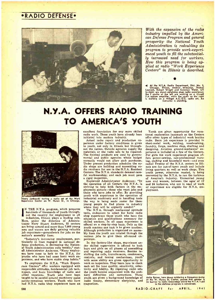
With the expansion of the radio industry impelled by the Ameri- can Defense Program and general prosperity- the National Youth Administration is redoubling its program to provide work- experi- enced youth to fill the substantial- ly increased need for workers. How this program is being ap- plied at radio "Work Experience Centers" in Illinois is described.
4 At the N.Y.A. Radio Department, Dist. No. 3, Chicago, Illinois, Andrew Milauskas, Thomas
Lopresfi, Robert Wright and Coleman Walsh, left fo right, are shown obtaining shop radio experience; the 2 youths at the left are working on a 12 -watt P.A.-system amplifier, while the youth on the right is working on a midget A.C. -D.C. radio set. An
instructor is standing.
N.Y.A. OFFERS RADIO TRAINING TO AMERICA'S YOUTH
Henry Jankowski testing a radio set at the Work Experience Center on W. Huron St., in Chicago.
IN THE N.Y.A. program, which prepares hundreds of thousands of youth through- out the country for employment in all Industries, Illinois plays a leading role.
Here, under the direction of Adminis- trator Mary Stuart Anderson, 33 centers are being opened and more than 7,000 young men and women are daily gaining valuable job experience -groundwork for jobs on the nation's assembly lines.
"Industry's increasing employment, par- ticularly in lines engaged in national de- fense production, is decreasing the Nation- al Youth Administration rolls weekly," stat- e3 Administrator Anderson. "Many employ- ers have come to look to the N.Y.A. for youths who have had some basic work ex- perience, and who have stable shop habits."
To employers the N.Y.A. "Work Experi- ence Centers" offer workers equipped with responsible attitudes, fundamental job tech- niques, and basic knowledge of radio and allied vocations. Youth who have been taught to be careful around machinery make safety -conscious workers. Youth who have had N.Y.A. radio shop experience have an
588
excellent foundation for any more skilled radio work. These youth have already been initiated into modern industry.
Actual radio repair and production ex- perience under factory conditions is given to youth, not only in Illinois but through- out the nation. Outside agencies supply the materials or the radio sets to be repaired. The finished products are used by govern- mental and public agencies whose budget normally would not allow such purchases. Under present production schedules the ra- dio shops are building and assembling ra- dio receivers for use in the.N.Y.A. Resident Centers: The N.Y.A. standards demand care- ful workmanship; and each job must pass a rigid inspection.
Explained Administrator Anderson: "In'
the operation of all Centers the N.Y.A. is striving to help both factors in the em- ployment picture -those who want jobs and those who have jobs to offer. By providing youth with experience in the operation of industrial machinery and in handling tools the way is being made easier for these young people to find places in industry where they will be urgently needed."
The N.Y.A. through mechanical aptitude tests, endeavors to select for basic radio shop experience those youth who have the education and qualifications necessary for skilled workers. In all cases experience is offered on a step -by -step basis. Only as the youth masters one task is he given another. Although production is organized on assem- bly lines the youth are rotated through the various jobs to give them all -round ex- perience.
In the factory -like shops, experience un- der skilled supervision is offered to both boys and girls on all phases of assembling and repairing radio receivers. Besides in- stalling the coils, transformers, condensers, controls, and tuning mechanisms, youth e with more ability are given opportunity to work as inspectors. They learn how to check each set for tone quality, sensitivity, selec- tivity and fidelity. By repairing radio sets the youth become acquainted with the ordi- nary difficulties and corrections. These youth are given a background knowledge of radio theory, elementary electricity, and magnetism.
Youth are given opportunity for voca- tional exploration inasmuch as the Centers offer other types of industrial work besides radio. Basic job experience is provided in sheet -metal work, welding, woodworking, foundry, forge, machine shop, drafting and designing. Aviation ground- mechanics' ex- perience is included at a few of the Centers. For girls the work experience program of- fers power- sewing, sub -professional nurs- ing, cooking and household work -and even radio! Twenty of the N.Y.A. centers in Illi- nois are for out -of -town youth and include living quarters as well as work shops. This youth power, otherwise wasted, is being converted by the N.Y.A. to run the turbines of America's industry. Unmarried young men and women, between the ages' of 17 and 24 inclusive, who are in need of work or experience are eligible for N.Y.A. em- ployment.
í, I
., 4141
Anita Byrnes, here shown soldering a frequency meter at the W. Huron St. Center, proves that gender is no barrier to radio knowledge where the N.Y.A.'s aid
in the defense program is concerned.
RADIO -CRAFT for APRIL, 1941
SERVICING
4.000 Rl F2
lWY I.000
01-045 1500 pp `^^;`/W-
50.000" - OHMS
0.25- M F -,
0.5- MEG.
(EACH)
0.1- MEG
100 v0.1- MME MEG.
0.5 -MEG / \
TO A.F
BALLA CEn /RECTIFIER
IMEG.
i1i111iN`
0.1- MF.
655 EVE
6
1C7 25 MME LIMITER
-Ic-I LIMITER
e B+-
41.000 OHMS
/f 0.1- MF. I
0.5- MF.
1000 OHMS
82.000 OHMS
e
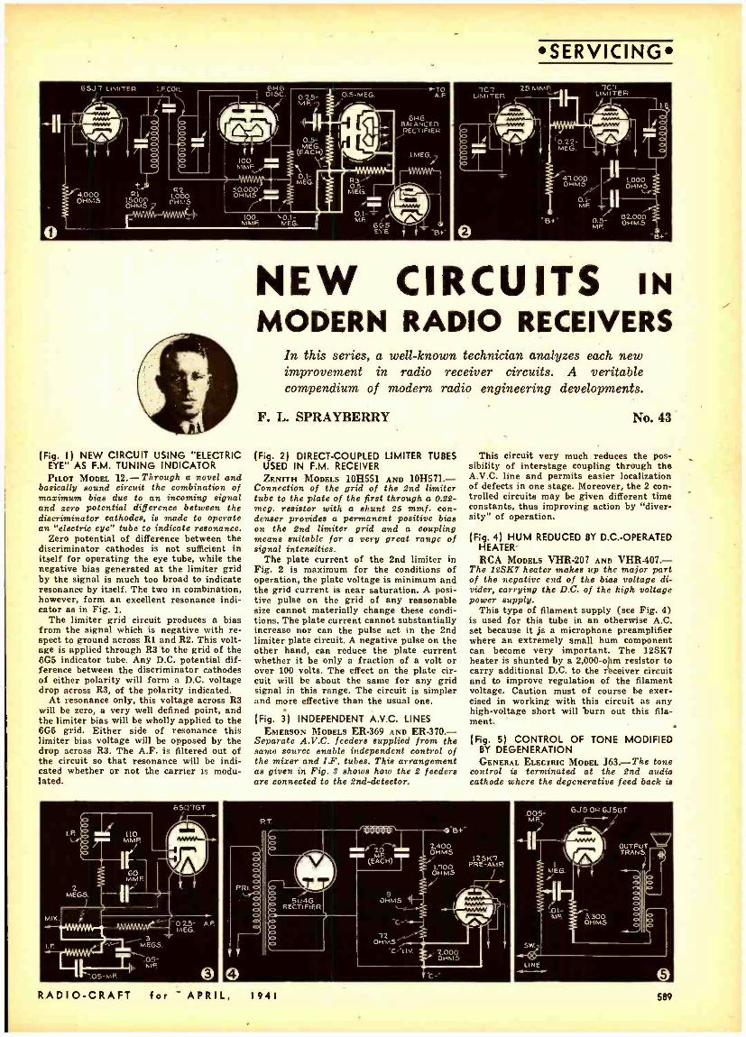
(Fig. I ) NEW CIRCUIT USING "ELECTRIC EYE" AS F.M. TUNING INDICATOR PILOT MODEL 12.- Through a novel and
basically sound circuit the combination of maximum bias due to an incoming signal and zero potential difference between the discriminator cathodes, is made to operate an "electric eye" tubo to indicate resonance.
Zero potential of difference between the discriminator cathodes is not sufficient in itself for operating the eye tube, while the negative bias generated at the limiter grid by the signal is much too broad to indicate resonance by itself. The two in combination, however, form an excellent resonance indi- cator as in Fig. 1.
The limiter grid circuit produces a bias from the signal which is negative with re- spect to ground across Rl and R2. This volt- age is applied through R3 to the grid of the 6G5 indicator tube. Any D.C. potential dif- ference between the discriminator cathodes of either polarity will form a D.C. voltage drop across R3, of the polarity indicated.
At resonance only, this voltage across R3 will be zero, a very well defined point, and the limiter bias will be wholly applied to the 6G6 grid. Either side of resonance this limiter bias voltage will be opposed by the drop across R3. The A.F. is filtered out of the circuit so that resonance will be indi- cated whether or not the carrier is modu- lated.
NEW CIRCUITS IN MODERN RADIO RECEIVERS
In this series, a well -known technician analyzes each new improvement in radio receiver circuits. A veritable compendium of modern radio engineering developments.
F. L. SPRAYBERRY
(Fig. 2) DIRECT- COUPLED LIMITER TUBES USED IN F.M. RECEIVER ZENITH MODELS 10H551 AND 10H571.-
Connection of the grid of the 2nd limiter tube to the plate of the first through a 0.22 - meg. resistor with a shunt 25 mmf. con- denser provides a permanent positive bias on the 2nd limiter grid and a coupling means suitable for a very great range of signal intensities.
The plate current of the 2nd limiter in Fig. 2 is maximum for the conditions of operation, the plate voltage is minimum and the grid current is near saturation. A posi- tive pulse on the grid of any reasonable size cannot materially change these condi- tions. The plate current cannot substantially increase nor can the pulse act in the 2nd limiter plate circuit. A negative pulse on the other hand, can reduce the plate current whether it be only a fraction of a volt or over 100 volts. The effect on the plate cir- cuit will be about the same for any grid signal in this range. The circuit is simpler and more effective than the usual one.
(Fig. 3) INDEPENDENT A.V.C. LINES EMERSON MODELS ER -369 AND ER -370.-
Separate A.V.C. feeders supplied from the same source enable independent control of the mixer and I.F. tubes. This arrangement as given in Fig. 3 shows how the 2 feeders are connected to the 2nd -detector.
No. 43
This circuit very much reduces the pos- sibility of interstage coupling through the A.V.C. line and permits easier localization of defects in one stage. Moreover, the 2 con- trolled circuits may be given different time constants, thus improving action by "diver- sity" of operation.
(Fig. 4) HUM REDUCED BY D.C.-OPERATED HEATER RCA MODELS VHR -207 AND VHR -407.-
The 12SK7 heater makes up the major part of the negative end of the bias voltage di- vider, carrying the D.C. of the high voltage power supply.
This type of filament supply (see Fig. 4) is used for this tube in an otherwise A.C. set because it js a microphone preamplifier where an extremely small hum component can become very important. The 12SK7 heater is shunted by a 2,000 -ohm resistor to carry additional D.C. to the r`eceiver circuit and to improve regulation of the filament voltage. Caution must of course be exer- cised in working with this circuit as any high -voltage short will burn out this fila- ment. .
(Fig. 5) CONTROL OF TONE MODIFIED BY DEGENERATION GENERAL ELECTRIC MODEL 363. -The tone
control is terminated at the 2nd audio cathode where the degenerative feed back is
RADIO -CRAFT for APRIL, I941 509
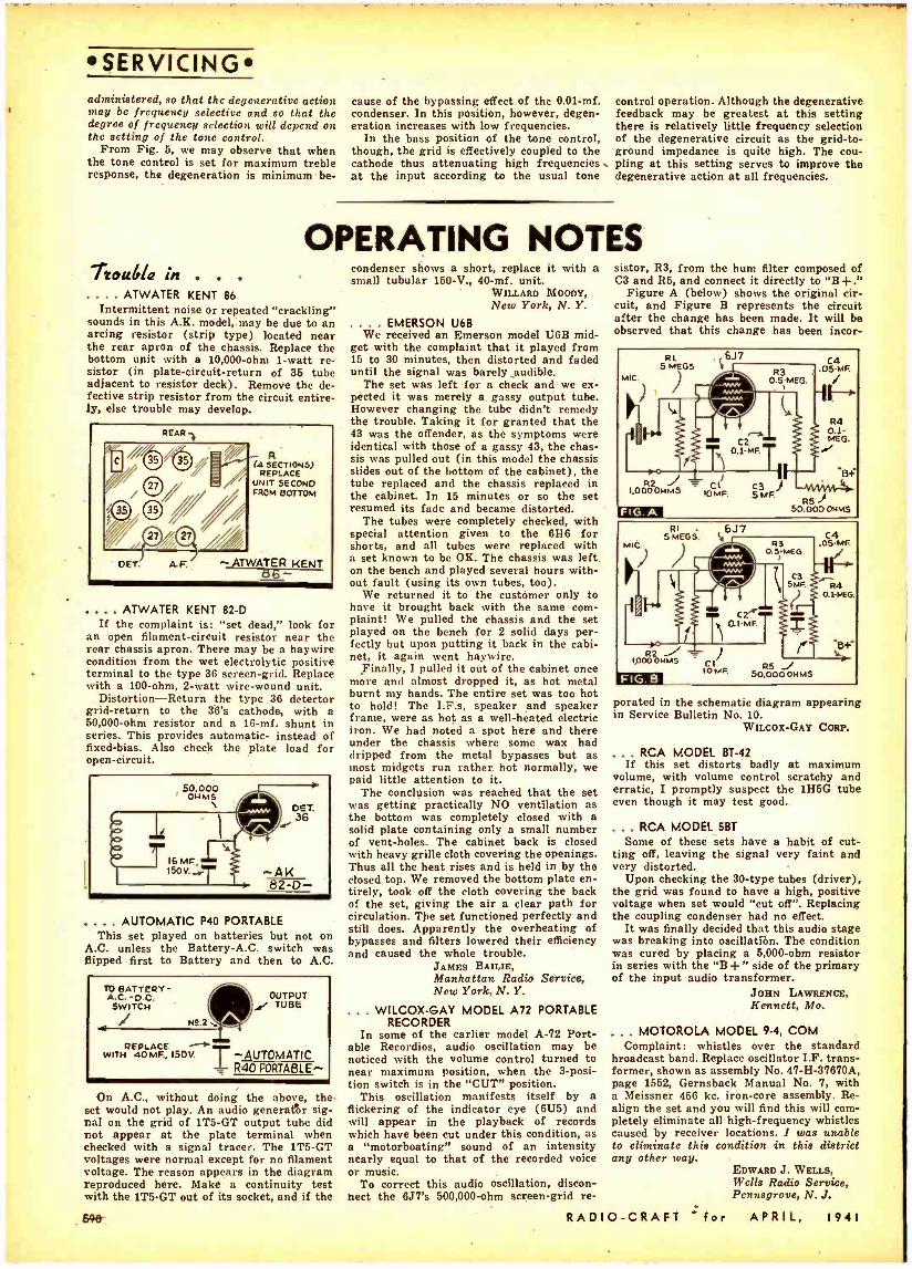
SERVICING administered, so that the degenerative action may be frequency selective and so that the degree of frequency selection will depend on the setting of the tone control.
From Fig. 5, we may observe that when the tone control is set for maximum treble response, the degeneration is minimum be-
cause of the bypassing effect of the 0.01 -mf. condenser. In this position, however, degen- eration increases with low frequencies.
In the bass position of the tone control, though, the grid is effectively coupled to the cathode thus attenuating high frequencies at the input according to the usual tone
control operation. Although the degenerative feedback may be greatest at this setting there is relatively little frequency selection of the degenerative circuit as the grid -to- ground impedance is quite high. The cou- pling at this setting serves to improve the degenerative action at all frequencies.
OPERATING NOTES Itotdia in . . . .... ATWATER KENT 86
Intermittent noise or repeated "crackling" sounds in this A.K. model, may be due to an arcing resistor (strip type) located near the rear apron of the chassis. Replace the bottom unit with a 10,000 -ohm 1 -watt re- sistor (in plate- circuit -return of 36 tube adjacent to resistor deck). Remove the de- fective strip resistor from the circuit entire- ly, else trouble may develop.
R (4 SECTIONS)
REPLACE UNIT SECOND FROM BOTTOM
.... ATWATER KENT 82 -D If the complaint is: "set dead," look for
an open filament- circuit resistor near the rear chassis apron. There may be a haywire condition from the wet electrolytic positive terminal to the type 36 screen -grid. Replace with a 100 -ohm, 2 -watt wire -wound unit.
Distortion- Return the type 36 detector grid -return to the 36's cathode, with a 60,000 -ohm resistor and a 16 -mf. shunt in series. This provides automatic- instead of fixed -bias. Also check the plate load for open- circuit.
.... AUTOMATIC P40 PORTABLE This set played on batteries but not on
A.C. unless the Battery -A.C. switch was flipped first to Battery and then to A.C.
TO BATTERY - A.C. -D.C. SWITCH
N9.2
OUTPUT TUBE
REPLACE WITH 4 0 150V -AUTOMATIC
R40 PORTABLE-
On A.C., without doing the above, the set would not play. An audio generator sig- nal on the grid of 1T5 -GT output tube did not appear at the plate terminal when checked with a signal tracer. The 1T5 -GT voltages were normal except for no filament voltage. The reason appears in the diagram reproduced here. Make a continuity test with the 1T5 -GT out of its socket, and if the
890-
condenser shows a short, replace it with a small tubular 150 -V., 40 -mf. unit.
WILLARD MOODY, New York, N. Y.
. EMERSON U6B We received an Emerson model U6B mid-
get with the complaint that it played from 15 to 30 minutes, then distorted and faded until the signal was barely audible.
The set was left for a check and we ex- pected it was merely a gassy output tube. However changing the tube didn't remedy the trouble. Taking it for granted that the 43 was the offender, as the symptoms were identical with those of a gassy 43, the chas- sis was pulled out (in this model the chassis slides out of the bottom of the cabinet), the tube replaced and the chassis replaced in the cabinet. In 15 minutes or so the set resumed its fade and became distorted.
The tubes were completely checked, with special attention given to the 6146 for shorts, and all tubes were replaced with a set known to be OK. The chassis was left on the bench and played several hours with- out fault (using its own tubes, too).
We returned it to the customer only to have it brought back with the same com- plaint! We pulled the chassis and the set played on the bench for 2 solid days per- fectly but upon putting it back in the cabi- net, it again went haywire.
Finally, I pulled it out of the cabinet once more and almost dropped it, as hot metal burnt my hands. The entire set was too hot to hold! The I.F.s, speaker and speaker frame, were as hot as a well -heated electric iron. We had noted a spot here and there under the chassis where some wax had dripped from the metal bypasses but as most midgets run rather hot normally, we paid little attention to it.
The conclusion was reached that the set was getting practically NO ventilation as the bottom was completely closed with a solid plate containing only a small number of vent -holes. The cabinet back is closed with heavy grille cloth covering the openings. Thus all the heat rises and is held in by the closed top. We removed the bottom plate en- tirely, took off the cloth covering the back of the set, giving the air a clear path for circulation. The set functioned perfectly and still does. Apparently the overheating of bypasses and filters lowered their efficiency and caused the whole trouble.
JAMES BAILIE, Manhattan Radio Service, New York, N. Y.
... WILCOX -GAY MODEL A72 PORTABLE RECORDER
In some of the earlier model A -72 Port- able Recordios, audio oscillation may be noticed with the volume control turned to near maximum position, when the 3 -posi- tion switch is in the "CUT" position.
This oscillation manifests itself by a flickering of the indicator eye (6U5) and will appear in the playback of records which have been cut under this condition, as a "motorboating" sound of an intensity nearly equal to that of the recorded voice or music.
To correct this audio oscillation, discon- nect the 6J7's 500,000 -ohm screen -grid re-
sistor, R3, from the hum filter composed of C3 and R5, and connect it directly to "B+."
Figure A (below) shows the original cir- cuit, and Figure B represents the circuit after the change has been made. It will be observed that this change has been incor-
porated in the schematic diagram appearing in Service Bulletin No. 10.
WILCOx -GAY CORP.
... RCA MODEL BT -42 If this set distorts badly at maximum
volume, with volume control scratchy and erratic, I promptly suspect the 1H5G tube even though it may test good.
... RCA MODEL 5BT
Some of these sets have a habit of cut- ting off, leaving the signal very faint and very distorted.
Upon checking the 30 -type tubes (driver), the grid was found to have a high, positive voltage when set would "cut off ". Replacing the coupling condenser had no effect.
It was finally decided that this audio stage was breaking into oscillation. The condition was cured by placing a 5,000 -ohm resistor in series with the "B -F" side of the primary of the input audio transformer.
JOHN LAWRENCE, Kennett, Mo.
... MOTOROLA MODEL 9 -4, COM Complaint: whistles over the standard
broadcast band. Replace oscillator I.F. trans- former, shown as assembly No. 47- H- 37670A, page 1552, Gernsback Manual No. 7, with a Meissner 456 kc. iron -core assembly. Re- align the set and you will find this will com- pletely eliminate all high- frequency whistles caused by receiver locations. I was unable to eliminate this condition in this district any other way.
EDWARD J. WELLS, Wells Radio Service, Pennsgrove, N. J.
RADIO -CRAFT :for APRIL, 1941
When You "Reset" or
Repair Their "Big Sets"
THESE RADIOLA MODELS
r#set,,,140 / RADIOLA "Extra" Radios
Mean Extra Sales.. . Extra Profits for SERVICEMEN
SUCCESSFUL SERVICEMEN are smart salesmen. That's why we
designed a line of small, fine sets specifically for servicemen to sell.
Look at the RADIOLA 515 above. Suppose you leave it in a custom- er's home while their regular set is in your shop -or even just demonstrate it when you retune their radio push- buttons.
While their set is in your hands, your customers are discovering the added pleasure such an "extra" radio can bring. A radio they can carry easily from room to
"JINX" FALKENBURG, America's Number 1 Model, poses with America's Number 1 profit- opportunity for servicemen ... the new Radiola Model 515. Both
"Models" have plenty of eye -appeal!
room...a radio they can listen to at will. A radio with such top -notch features as foreign reception .. .
R. F. stage for greater sensitivity ... six RCA PreferredTypeTubes ...continental-style wrap- around cabinet of costly woods ... the RADIOLA 515!
Try it -see for yourself. Remem- ber that your best service customers are your best RADIOLA prospects. And that RADIOLA alone is especially de- signed to be sold by servicemen ... by you.
All RADIOLA Models Are Equipped Exclusively with RCA Preferred Type Tubes
RadiolaT Made by RCA Manufacturing Co., Inc., Camden, N. J., U. S. A.
A Service of the Radio Corporation of America In Canada, RCA Victor Company, Ltd., Montreal
RADI O-CRAFT for APRIL, 1941
SUPER -SELLERS, Every One!
RADIOLA Model 510 ... i 10 -volt AC -DC. Striking cabinet of molded plastic, with tear- drop knobs and attractive clock -type dial, Highly efficient chassis embodies superhet- erodyne circuit, built -in tuned loop antenna. full AVC action. 5" Electrodynamic Speaker. 5 RCA Preferred Type Tubes.
RADIOLA Model P -5 . .. A 3 -way portable that's a teal eye -opener. Operates from self - contained batteries. of 110-volt AC or DC line. Durable, washable simulated- leather covering. Built -in tuned loop. 5 RCA Pre - ferred Type Tubes.
PLUS MANY OTHER FAST-SELLING MODELS
591
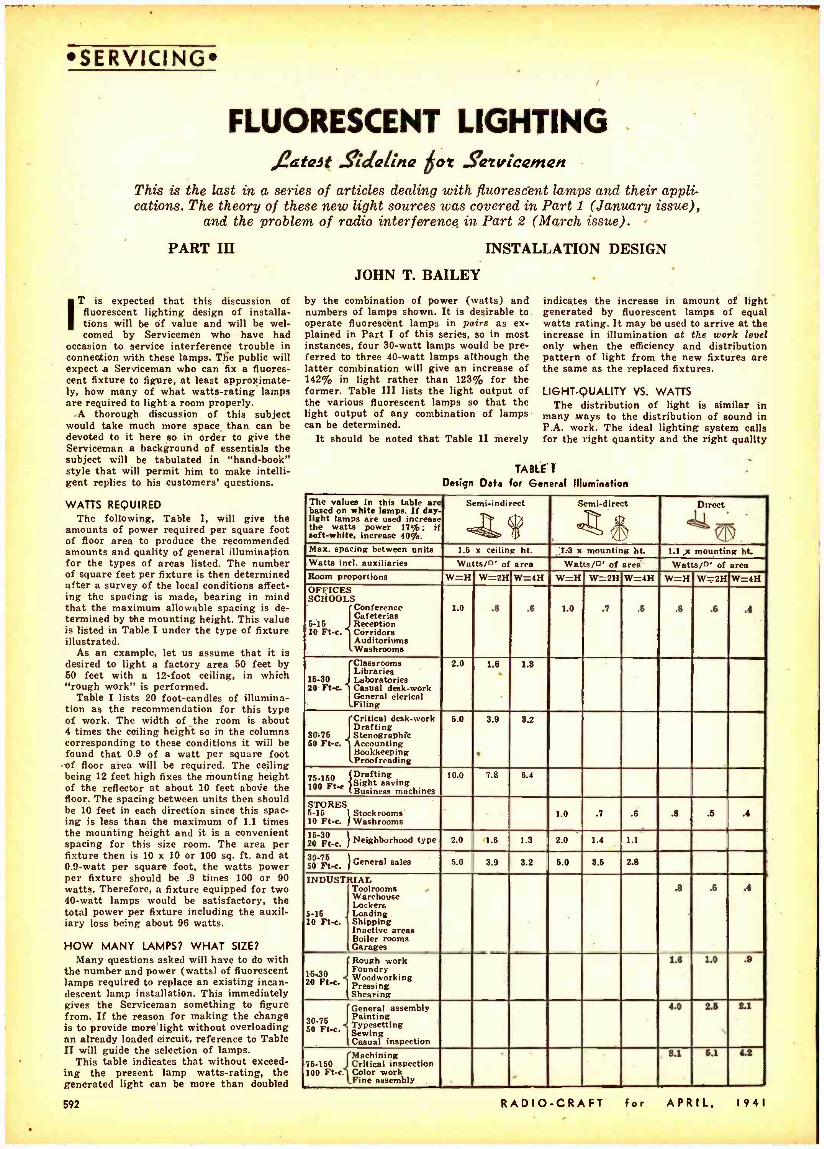
SERVICING
FLUORESCENT LIGHTING J?atait Sidellina bot S'etv[ceinen
This is the last in a series of articles dealing with fluorescent lamps and their appli- cations. The theory of these new light sources was covered in Part 1 (January issue),
and the problem of radio interference in Part 2 (March issue). -
PART III INSTALLATION DESIGN
JOHN T. BAILEY
IT is expected that this discussion of fluorescent lighting design of installa- tions will be of value and will be wel- comed by Servicemen who have had
occasion to service interference trouble in connection with these lamps. The public will expect a Serviceman who can fix a fluores- cent fixture to figure, at least approximate- ly, how many of what watts- rating lamps are required to light a room properly.
.A thorough discussion of this subject would take much more space than can be devoted to it here so in order to give the Serviceman a background of essentials the subject will be tabulated in "hand- book" style that will permit him to make intelli- gent replies to his customers' questions.
WATTS REQUIRED The following, Table 1, will give the
amounts of power required per square foot of floor area to produce the recommended amounts and quality of general illumination for the types of areas listed. The number of square feet per fixture is then determined after a survey of the local conditions affect- ing the spacing is made, bearing in mind that the maximum allowable spacing is de- termined by the mounting height. This value is listed in Table I under the type of fixture illustrated.
As an example, let us assume that it is desired to light a factory area 50 feet by 60 feet with a 12 -foot ceiling, in which "rough work" is performed.
Table I lists 20 foot -candles of illumina- tion as the recommendation for this type of work. The width of the room is about 4 times the ceiling height so in the columns corresponding to these conditions it will be found that 0.9 of a watt per square foot of floor area will be required. The ceiling being 12 feet high fixes the mounting height of the reflector at about 10 feet above the floor. The spacing between units then should be 10 feet in each direction since this spac- ing is less than the maximum of 1.1 times the mounting height and it is a convenient spacing for this size room. The area per fixture then is 10 x 10 or 100 sq. ft. and at 0.9 -watt per square foot, the watts power per fixture should be .9 times 100 or 90 watts. Therefore, a fixture equipped for two 40 -watt lamps would be satisfactory, the total power per fixture including the auxil- iary loss being about 96 watts.
HOW MANY LAMPS? WHAT SIZE? Many questions asked will have to do with
the number and power (watts) of fluorescent lamps required to replace an existing incan- descent lamp installation. This immediately gives the Serviceman something to figure from If the reason for making the change is to provide more light without overloading an already loaded circuit, reference to Table II will guide the selection of lamps.
This table indicates that without exceed- ing the present lamp watts -rating, the generated light can be more than doubled
by the combination of power (watts) and numbers of lamps shown. It is desirable to operate fluorescént lamps in pairs as ex- plained in Part I of this series, so in most instances, four 30 -watt lamps would be pre- ferred to three 40 -watt lamps although the latter combination will give an increase of 142% in light rather than 123% for the former. Table III lists the light output of the various fluorescent lamps so that the light output of any combination of lamps can be determined.
It should be noted that Table II merely
indicates the increase in amount of light generated by fluorescent lamps of equal watts rating. It may be used to arrive at the increase in illumination at the work level only when the efficiency and distribution pattern of light from the new fixtures are the same as the replaced fixtures.
LIGHT -QUALITY VS. WATTS The distribution of light is similar in
many ways to the distribution of sound in P.A. work. The ideal lighting system calls for the right quantity and the right quality
TABLE' T
Design Data for G I Illumination
The values in this table are based on white lamps. If day- light lamps are used increase the watts power 17%; If soft -white, increase 40%.
Semi -indirect Semi -direct
r- ' Direct
\ 177
Max. spacing between units 1.6 x ceiling ht. 1r3 x mounting ht. la x mounting ht. Watts incl. auxiliaries Watts /o' of area Watts /n' of area Watts/o' of area Room proportions W =11 W -2H W =4H W =H W =2H W =4H W =H W=,-2H W -4H OFFICES SCHOOLS
6 -16 10 Ft-c.
Conference Cafeterias Reception Corridors Auditoriums Washrooms
1.0 .8 .6 1.0 .7 .6 .8 .5 .4
15 -30 20 Ft-c.
Classrooms Libraries Laboratories Casual deskwork General clerical Filing
2.0 1.6 1.8
80-75 60 Ft -c.
Critical desk -work Drafting Stenographic Aounting Proofreadincc g Bookkeeping
6.0 3.9 3.2
75.150 100 Ft-e
Drafting Sight saving Business machines
10.0 7.8 6.4
STORES 6 -15 l Stockrooms 10 Ft -c. ¡Washrooms
1.0 .7 .6 .8 .5 .4
16.30 Neighborhood type 20 Ft-e. 2.0 1.6 1.3 2.0 1.4 1.1
80 -75 General sales 50 Ft-e. 5.0 3.9 3.2 6.0 3.5 2.8
INDUSTRIAL
6 -15 10 Ft-c.
Toolrooms Warehouse Lockers Loading Shipping Inactive areas Boiler rooms Garages
.8 .5 .4
IóO 20 Ft e.
Rough work Foundry Woodworking
ssi ShePrearinng g
1.8 1.0 .9
30 -76 50 Ft-c.
General assembly Painting Typesetting Sewing Casual inspection
4.0 2.6 2.1
{Machining 75 -160 Critical inspection 100 Ft -cColor work
Fine assembly
8.1 5.1 4.2
$92 RADIO -CRAFT for APRIL, 1941

of light. The quantity is determined by the power (in watts); and, the quality, by the lighting fixture.
As in P.A. work, where the quantity and quality are determined by power and equip- ment respectively, it is possible to reduce the amount of light if the quality of light is improved. This is a well -known fact to sound engineers who have compared a smaller watts rating of high -fidelity sound to a larger power of just "P.A." It is also appreciated that there are many instances where high- fidelity sound is not required. The same holds for lighting -for instance, the superior quality of indirect lighting is not generally required nor found practicable for industrial plants.
Although not described in detail here, the analogy between the proper application of light and sound will become evident to the Serviceman. Table I has been formulated to guide the selection of proper lighting equip- ment for most types of work requiring light but it should be remembered that therè are many instances where special, individual attention must be given to obtain satisfac- tory results. The solution to such problems usually will be found after a little thought is given and possibly a few trial systems will be required to get the best results.
The slender, tubular, form of the fluores- cent lamp lends itself to continuous rows of lighting equipment mounted, usually, over assembly lines, inspection tables, work- benches and other "in- line" operations where high levels of cool light are especially de- sirable. The radioman's service bench is one of the best locations for him to install a few lamps to experience the benefits of fluorescent lighting.
HEAT VS. COLD A word of caution would not be amiss at
this point regarding the use of fluorescent lamps in cold weather. As discussed in Part
PRESENT INCANDESCENT SYSTEM Lamps per Fixture
I, the light output falls off as the tempera- ture is lowered. Mazda F lamps are recom- mended only for normal indoor use. Their application outdoors or where low tempera- tures are involved must be made at the cus- tomer's risk.
When operated on approved auxiliaries they will give, in general, satisfactory per- formance at temperatures down to as low as 50° F. If the line voltage is in the upper half of the rated range of the auxiliary, if the lamp is enclosed or protected from drafts and if a thermal switch is used, the performance will ordinarily be acceptable down to 32° F. At lower temperatures than 32° F. trouble may be encountered in start- ing, occasional lamps may burn unsteadily and light output and lamp life may be reduced dependent on the degree to which the above precautions are observed. Second- ary sources of heat will improve perform- ance and may be found worthwhile where extreme cold is encountered.
The design and application information given in this article is not intended to pro- vide Servicemen tuitli an extensive back- ground in the lighting profession since to do so would require more space than could be devoted to it here. However, the data given should permit a Serviceman to deter -, mine in a, general way how to figure a fluorescent lighting installation.
It is suggested that, as a check on his design, the Serviceman consult the local utility office or a lighting engineer before proceeding with the expense of relighting his or his customer's stores. As with any
_business, including service work, maximum satisfaction of the customer is assured only after the seller has acquired competency in design based on broad experience in his business.
This article has been prepared from data supplied by courtesy of Westinghouse Lamp Division.
TABLE
Lamp Watts
Number per
Fixture
Generated Light
(Lumens) Lamp
Watts .40 I 470 15 60 1 660 20 60 1 830 15 76 1 1,100 15
20 80
100 1 1.600 15 20 30 40
150 1 2,600 20 30 40
100 200 3,700 30
40 300 1 6,750 30
40 600 10,000 40
100
Includes auxiliary watts ratings. For white lamps.
I I
Number per
Fixture 2 2 3 4
3 2 6 4 3 2 6 4 3 1
5 4 8 6
10 4
NEW FLUORESCENT SYSTEM Lamps per Fixture
Generated Light
(Lumens) 1,170 1.800 1,755 2,340 2,700 2.900 2,925 3,600 4,350 4.200 ;.400 o.800 6.300 4,400 7.250 8,400
11,600 12,600 21.000 17,600
Approx. Fixture Watts*
39 49 59 78 74 75 98 98
115 98
147 160 161 136 190 196 300 294 490 470
Ratio of Generated light (fluorescent to incandescent)
2.50 to 1
2.73 to 1
2.12 to 1
2.12 to 1
2.46 to 1 2.63 to t 1.83 tot 2.26 tot 2.72 tot 2.62 tot 2.08 to 1
2.23 to 1
2.42 to 1
1.69 to-1 -
1.96 to 1 2.27 to 1
2.02 tot 2.19 to 1 2.10 to 1
1.76 to 1
Lamp Watts 15 20 .TO 40 100 Color:
White 585 900 1,450 2,100 4,400 TABLE III Daylight 495 760 1,250 1,800
Approx. initial light Soft White 435 640 1,050 1,500 output in lumens Pink 300 440 750
Green 900 1,300 2,250 Blue 45 60 120 Gold 375 540 930
WEATHERPROOFED ANTENNAS Radio station WHK's new self -supporting
square radio antenna, 223 ft. high, is said to be the tallest of its type in the world. Its purpose is to "shunt" WHK's programs away from station KLRA. The hollow porce- lain "feet" in which the 4 legs of the tower
RADIO -CRAFT for APRIL,
rest are filled with oil, which is maintained at a uniform temperature by thermostatic control to prevent the formation of ice or moisture films on the insulator regardless of the weather conditions, according to technical advisor E. L. Gove.
I941
SERVICING
More Than 25 Proved
Sales Promotion Ser-
vices Help You Sell
WHEN you stock Sylvania Radio Tubes, you get
the most comprehensive and ef- fective merch andising service that ever helped a dealer to big- ger profits. Look over the partial list below. Many are free- Others are avail- able at satisfying savings. All help you sell. Write Hygrade Sylvania Corp., Dept. RC41, Emporium, Pa., for samples of these selling aids and full information about the Syl- vania way to bigger profits. Sylvania Helps ... That Help You Sell
1. Window Dieu'sy 14. Bill heads Material (the TWA 15. Service hints book - Display pictured lets above.dommy tube 16. Technical manual cartons, timely 17. Tube base charts window streamers, 18. Price cards etc.) 19. Sylvania News
2. Counter displays 20. Characteristic. 3. Electric Clock Sheets
signs 21. Interchangeable 4. Electric Window tube charts
signs 22. Tube complement 5. Outdoor metal books
signs 23. Floor model cahi- 6. Window cards net 7. Personalized post- 24. Large and small
al cards service carrying 8. Imprinted match kite
hooks 25. Customer card in- 9. Imprinted t u b e dex files
stickers 26. Service Garments 10. Business cards 27. 3 -in -I business 11. Door Knob Hang- forms
ere 28. Job record cards 12. Newspaper mate (with customer re- 13. Store stationery reipt)
SYLVANIA SET -TESTED RADIO TUBES
Also makers of Hygrade Lamp Bulbs. Hygrade Fluorescent Lamps and Miralume Fluorescent
Light Fixtures
593
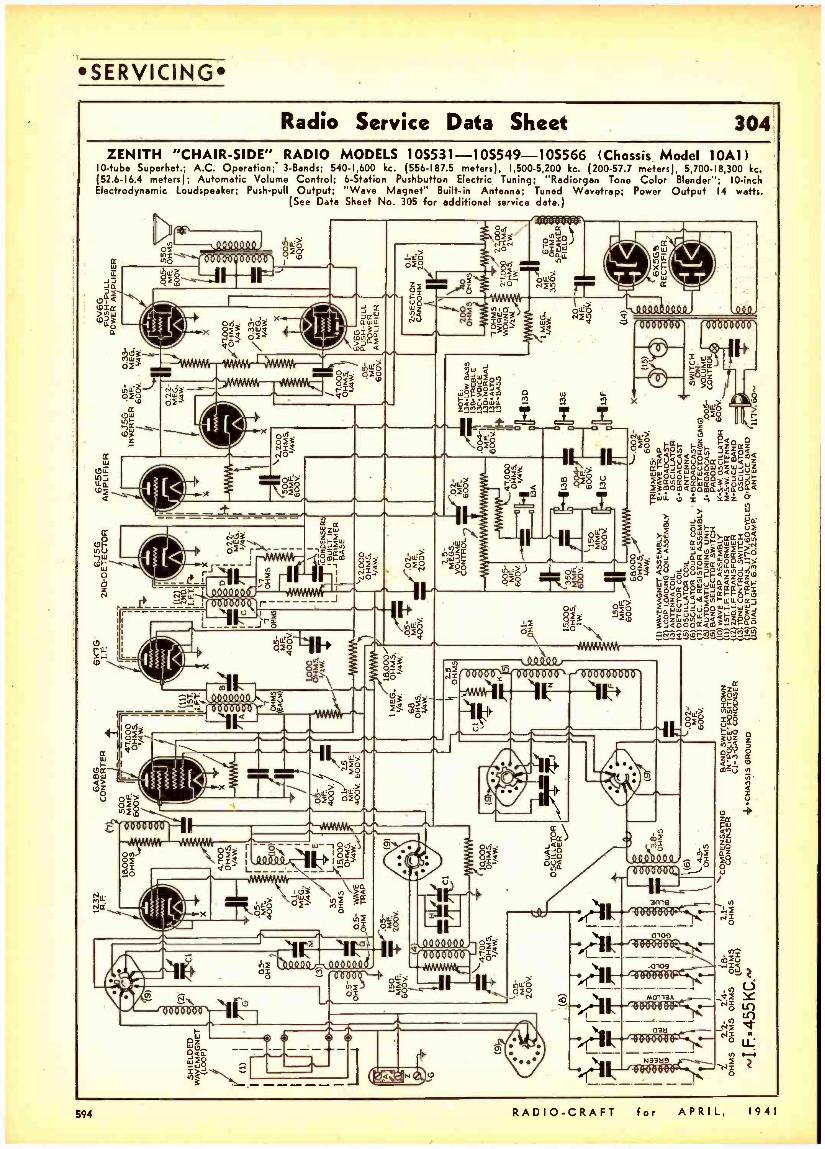
SERVICING
ZENITH "CHAIR- SIDE" RADIO MODELS 105531 -105549- 10S566 (Chassis Model 10A1) 10 -tube Superhet.; A.C. Operation;' 3- Bands; 540 -1,600 kc. (556 -187.5 meters), 1,500 -5,200 kc. (200 -57.7 meters), 5,700 -18,300 kc. (52.6 -16.4 meters); Automatic Volume Control; 6- Station Pushbutton Electric Tuning; "Radiorgan Tone Color Blender "; 10 -inch Electrodynamic Loudspeaker; Push -pull Output; "Wave Magnet" Built -in Antenna; Tuned Wavetrap; Power Output 14 watts.
(See Data Sheet No. 305 for additional service date.)
594 RADIO -CRAFT for APRIL, 1941
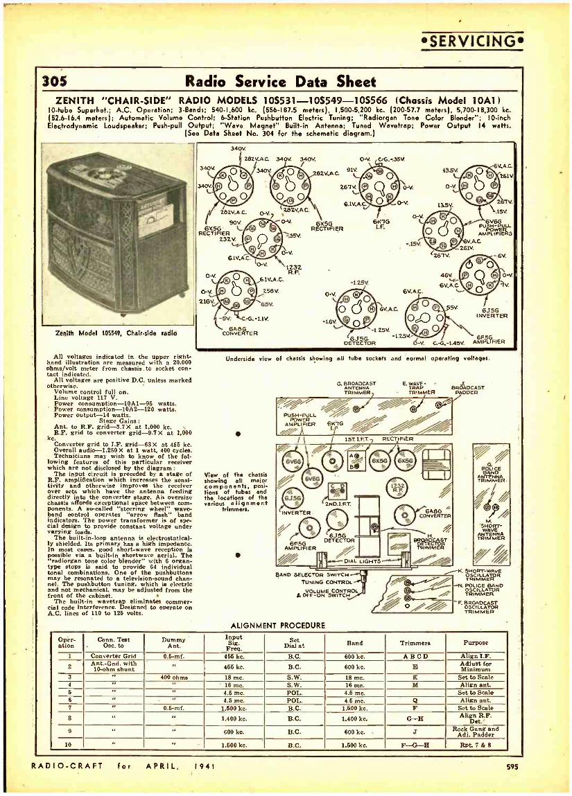
SERVICING
305 Radio Service Data Sheet ZENITH "CHAIR -SIDE" RADIO MODELS 10S531-10S549-10S566 (Chassis Model 10A11
10 -tube Superhet.; A.C. Operation; 3- Bends; 540 -1,600 kc. (556 -187.5 meters), 1,500 -5,200 kc. (200 -57.7 meters), 5,700 -18,300 kc. (52.6 -16.4 meters); Automatic Volume Control; 6- Station Pushbutton Electric Tuning; "Radiorgan Tone Color Blender "; 10 -inch Electrodynamic Loudspeaker; Push -pull Output; "Wave Magnet" Built -in Antenna; Tuned Wavetrap; Power Output 14 watts.
(See Data Sheet No. 304 for the schematic diagram.)
\ \ \ \ \\ . ì, a,
l
z i
"; \ I
`
(
- I
1
3344340V.
6X56 RECTIFIER
O -y
o-v 216V.
340V
N 282V-A.0
O ° b 6
2a2V.A.C.
90V. L 232V. 9
© 61V A.G
©O G,
© v O R
340V.
340V d
o-vi Ls28ZV,A.C.
J '. p e
Ct
° (o-V
6.1V,A.C.
eau.
65V.
340V.
O 92V,A.0 91V.
O L.
6.IV,AG
6X5G R)= CTIFIER
35V
O -V
1232 R.F.
-L2ß
° Q
O-V. C-G..-.35V. . '1') o
.
6141G 1.F.
V.
O \ © 6V,A.C.
6V.A.G 13.5v
Ct
ó-v o-v. ©
© b O
13.5V.
D .15V. l © O 6V6G
PUSH -PUqu. O ° AMPPLLIFL i
.r.- p .V -AC .15V 261V.
:26TV. -.6V.
a O o 46w
O Q
6V,A.0 © 6v.A.c. L- O
.j O V O SV 6J5G
261V.
&
0 -V
7V.
-5V LCD
[c..G. -1.1V. -1.6V. ®O O0,0 O INVERTER
Zenith Model 105549, Chair -side radio' 6A8G '4.25V. O
CONVERTER 6J5G -1.25V- / G
DETECTOR O -V. C.- 0.- 1.45V, AMPLIFIER
All voltages indicated in the upper right- Underside view of chassis showing all tube sockets and normal operating voltages. hand illustration are measured with a 20,000 ohms /volt meter from chassis . to socket con- tact indicated.
All voltages are positive D.C. unless marked otherwise. G BROADCAST E. WAVE- J.
ANTENNA TRAP BROADCAST Volume control full on. TRIMMER TRIMMER PADDER Line 117 V. % voltage Power consumption- 10A1 -96 watts. Power consumption -10A2 -120 watts. Power output -14 watts.
Stage Gains :
_/ .. / 4/
--"e-
I ;,F kc. / I f 1ST. I.F.T. RECTIFIER
Converter grid to T.F. grid -63 X at 465 kc. d 6 uce
TRNMMFR
¡ j j 9 ,4
M. SHORT- WAVE
ANTENNA EE
TRIt MÉR / j
Overall audio -1.250 X at 1 watt, 400 cycles. Technicians may wish to know of the fol.
lowing features of this particular receiver which are not disclosed by the diagram :
The input circuit is preceded by a stage of View of the chassis R.F. amplification which increases the sensi- showing all major tivity and otherwise improves the receiver components, posi- over sets which have the antenna feeding lions of tubes and
.- . 6V6G O
o
6V6G
A Bá
II-II..
6X50 6X56
,_' 52 j c Q 4 I` ®
i 1232 j RR
directly into the converter stage. An oversize the locations of the chassis affords exceptional space between corn- various a I i q n m ent ponents. A so-called "steering wheel" wave- trimmers. band control operates "arrow flash" band
6J5G rl 5-:.
INVERTER i GA6G
e' CONVERTER
indicators. The power transformer is of spa- ciel design to provide constant voltage under
loads. / ®
The built -in -loop antenna is electrostatical- ly shielded. Its primary has a high impedance. In possible
most good short-wave reception is possible via a built-in shortwave aerial. The rediorgan tone color blender" with 6 organ-
?
6F5G AMPLIFIER
DETECTOR 5GG S I y R OpppDCA6T
OETECTOi IMME
DIAL LIGHTS l
type stops is said to provide 64 individual Ill , tonal combinations. One of the pushbuttons K. SHORT-WAVE
BAND SELECTOR OSCILLATOR may be resonated pushbutton
to a tuning. which
Chan- / //O net. The pushbutton tuning, whic is electric TUNING CONTROL / and not mechanical, may be adjusted from the VOLUME CONTROL front of the cabinet. &OFF-ON SWITCH
The built -in wavetrap eliminates commer- / '- cial code interference. Designed to operate on %// O
110 to 126
TRIMMER ,POLICE BAND OSCILLATOR TRIMMER
F. OSCíiLÁTOSTR TRIMMER A.C. lines of volts.
ALIGNMENT PROCEDURE
Oper- atlon
Conn. Test . Osc. to
Dummy Ant.
Input Sig. Set
Dial at Band Trimmers Purpose
1 Converter Grid 0.5 -mf. 466 kc. B.C. 600 kc. A B C D Align I.F.
2 A10-ohm : Gnd. with 10-ohm shunt
.. 466 kc. B.C. 600 kc. Adjust for Minimum
8 400 ohms 18 mc. S.W. 18 mc. K Set to Scale 4 " 16 mc. S.W. 16 mc. M Align ant. 5 " 4.6 mc. POL. 4.6 mc. Set to Scale 6 ' 4.6 mc. POL. 4.6 mc. Q Align ant. 7 " 0.6 -mf. 1.600 kc. B.C. 1,600 kc. F Set to Scale
8 1.400 kc. B.C. 1.400 kc. G-H Align R.F. De-,
9 600 kc. B.C. 600 kc. J Rock Gang and Adj. Padder
10 1.500 kc. B.C. 1,500 kc. F-G -H Rpt. 7 & 8
RADIO -CRAFT for APRIL, 1941 595
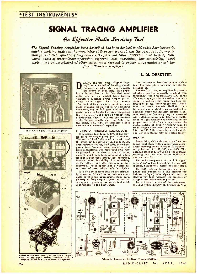
TEST INSTRUMENTS
SIGNAL TRACING AMPLIFIER {An f active Radio Setvicing Tool
The Signal Tracing Amplifier here described has been devised to aid radio Servicemen in quickly spotting faults in the remaining 10% of service problems the average radio repair man fails to clear quickly if only because they are not total "failures." The 10% of "un- usual" cases of intermittent operation, internal noise, instability, low sensitivity, "dead spots ", and an assortment of other cases, must respond to proper stage analysis with the
Signal Tracing Amplifier.
The completed Signal Tracing Amplifier.
Underside and rear views (top and center, respec- ively) of the Signal Tracing Amplifier; and, a
close -up of the coil and trimmer arrangement.
596
DURING the past year, "Signal Trac- ing", as a method of locating circuit failure, especially intermittent cases, has grown in popularity. This popu-
larity is not due to the fact that most units now on the market have built -in voltmeters, measure power output or in- dicate audio signal, but only because (for the first time) an instrument has been made available which will allow operating frequency, relative R.F. gain, and oscillator performance to be checked. Any competent Serviceman does not require a "robot" with a half -dozen "eyes" to locate the receiver fault. He can usually place the failure in the audio, I.F., R.F., or oscillator stages within a few moments' inspection.
THE 10% OR "PROBLEM" SERVICE JOBS Eliminating tube failure, 90% of the serv-
ice cases encountered are total "failures ". The set is "dead," distorted or weak; and the causes lie in shorted or open condensers, open resistors, chokes, field coils, burned -out power transformers, worn insulation and loose connections. The remaining 10% may be grouped into a class of unusual cases, most of which have been serviced at a loss since they represent intermittent operation, internal noise, instability, low sensitivity (with voltages and other parts in perfect condition), "dead spots" and a varied as- sortment of cases which defy description.
It is with these cases that we are primari- ly interested. If we have an instrument ca- pable of checking approximate stage gain, identifying frequency of operation and lo- cating poor bypassing, we have a tool which is invaluable to the Serviceman.
L. M. DEZETTEI.
The instrument described here is such a tool. The principle is not new, but the ap- plication is.
For the first time, an amplifier is present- ed which has approximately constant gain throughout the broadcast sand I.F. bands allowing stage gain to be checked stage -by- stage. In addition, the range has been ex- tended to 17 mc., covering the most impor- tant shortwave channels. Oscillator per- formance may be checked at the higher fre- quencies where the greatest trouble is en- countered; and frequency may be measured with sufficient accuracy to determine wheth- er or not the oscillator is operating on the proper beat; and of more importance, the determination of proper tracking may be made. Intertnittent cases due to R.F., oscil- lator, or I.F. failure may be located quickly and low -gain stages may be located easily.
CIRCUIT Essentially, this unit consists of an un-
tuned input stage with a capacitative atten- uator allowing signal input to be attenuat- ed by factors of 1, 10, 100, and 1,000. This untuned stage is followed by 2 tuned stages working into the input of an infinite -im- pedance detector.
The audio component of the R.F. signal is amplified and made available for use with speaker, headphones, meter, or oscilloscope.
The D.C. rise, due to rectification, is am- plified and applied to a 6E5 electron -ray indicator ( "eye ) tube. Operated thus, the electron -ray tube indicates the presence of a signal whether modulated or not.
To facilitate the use of the instrument, the dial reads directly in frequency. Two
651<, a r r65K,-._._._._
úl
CG 513
L .15)
Ra
4
J \ 1.112;M=IM.
;E:. (1-) 6U5
G TÉ! lLAC ,
Schematic diagram of the Signal Tracing Amplifier.
RADIO -CRAFT for APRIL, 1941
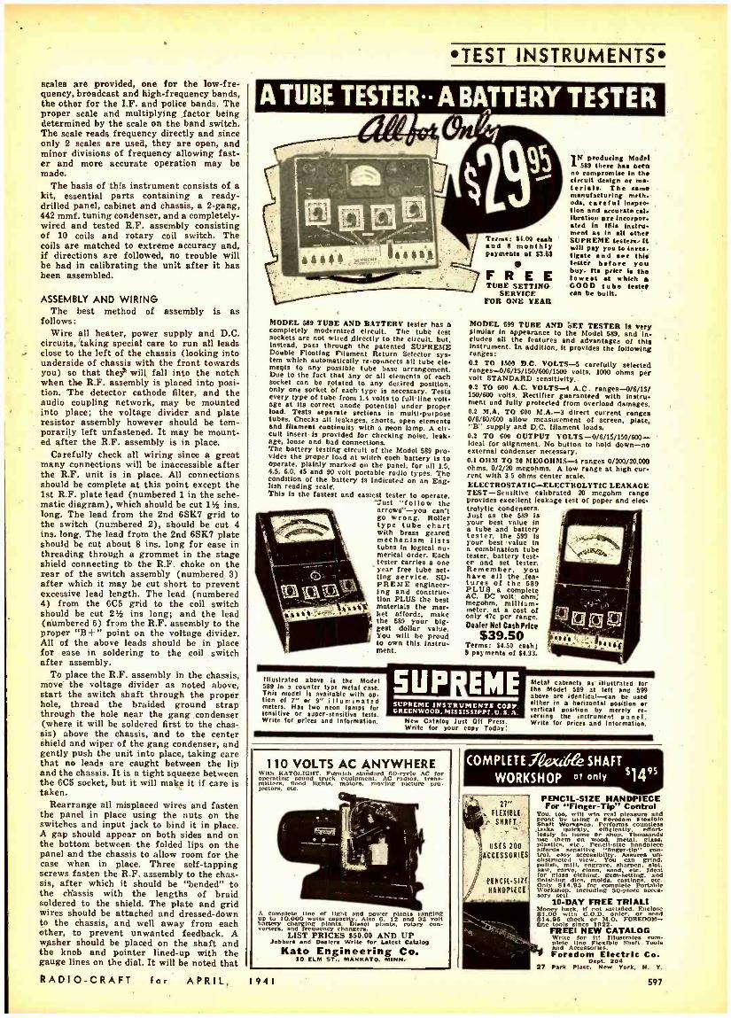
scales are provided, one for the low -fre- quency, broadcast and high- frequency bands, the other for the I.F. and police bands. The proper scale and multiplying factor being determined by the scale on the band switch. The scale reads frequency directly and since only 2 scales are used, they are open, and minor divisions of frequency allowing fast- er and more accurate operation may be made.
The basis of this instrument consists of a kit, essential parts containing a ready - drilled panel, cabinet and chassis, a 2 -gang, 442 mmf. tuning condenser, and a completely - wired and tested R.F. assembly consisting of 10 coils and rotary coil switch. The coils are matched to extreme accuracy and, if directions are followed, no trouble will be had in calibrating the unit after it has been assembled.
ASSEMBLY AND WIRING The best method of assembly is as
follows: Wire all heater, power supply and D.C.
circuits, 'taking special care to run all leads close to the left of the chassis (looking into underside of chassis with the front towards you) so that the will fall into the notch when the R.F. assembly is placed into posi- tion. The detector cathode filter, and the audio coupling network, may be mounted into place; the voltage divider and plate resistor assembly however should be tem- porarily left unfastened. It may be mount- ed after the R.F. assembly is in place.
Carefully check all wiring since a great many connéctions will be inaccessible after the R.F. unit is in place. All connections should be complete at this point except the 1st R.F. plate lead (numbered 1 in the sche- matic diagram), which should be cut 11 ins. long. The lead from the 2nd 6SK7 grid to the switch (numbered 2) should be cut 4 ins. long. The lead from the 2nd 6SK7 plate should be cut about 8 ins. long for ease in threading through a grommet in the stage shield connecting to the R.F. choke on the rear of the switch assembly (numbered 3) after which it may be cut short to prevent excessive lead length. The lead (numbered 4) from the 6C5 grid to the coil switch should be cut 2% ins long; and the lead (numbered 5) from the R.F. assembly to the proper "B +" point on the voltage divider. All of the above leads should be in place for ease in soldering to the coil switch after assembly.
To place the R.F. assembly in the chassis, move the voltage divider as noted above, start the switch shaft through the proper hole, thread the braided ground strap through the hole near the gang condenser (where it will be soldered first to the chas- sis) above the chassis, and to the center shield and wiper of the gang condenser, and gently push the unit into place, taking care that no leads are caught between the lip and the chassis. It is a tight squeeze between the 6C5 socket, but it will make it if care is taken.
Rearrange all misplaced wires and fasten the panel in place using the nuts on the switches and input jack to bind it in place. A gap should appear on both sides and on the bottom between the folded lips on the panel and the chassis to allow room for the case when in place. Three self- tapping screws fasten the R.F. assembly to the chas- sis, after which it should be "bended" to the chassis with the lengths of braid soldered to the shield. The plate and grid wires should be attached and dressed -down to the chassis, and well away from each other, to prevent unwanted feedback. A washer should be placed on the shaft and the knob and pointer lined -up with the gauge lines on the dial. It will be noted that RADIO -CRAFT for APRIL,
TEST INSTRUMENTS
MODEL 589 TUBE AND BATTERY tester has a completely modernized circuit. The tube test sockets are not wired directly to the circuit. but. Instead. pass through the patented SUPREME Double Floating Filament Return Setector sys- tem which automatically re- connects all tube ele- ments to any possible tube base arrangement. Due to the fact that any or all elements of each socket can be rotated to any desired position. Only one socket of each type is necessary. Tests every type of tube from 1.4 volts to full line volt- age at its correct anode potential under proper load. Tests separate sections in multi- purpose tubes. Checks all leakages. shorts. open elements and filament continuity with a neon lamp. A cir- cuit Insert Is provided for checking noise. leak age, loose and bad connections. The battery testing circuit of the Model 589 pro - vIdes the proper load at which each battery Is to operate, plainly marked on the panel, for all 1.5, 4.5. 6.0, 45 and 90 volt portable radio types. The condition of the battery is indicated on an Eng- lish reading scale. This la the fastest and easiest tester to operate.
Just "follow the arrows" -you can't go wrong. Roller type tube chart with brass geared mechanism lists tubes In logical nu- merical order. Each tester carries a one year free tube set- ting service. SU- PREME engineer- ing and construc- tion PLUS the best materials the mar- ket affords. make the 689 your big- gest dollar value. You will be proud to own this Instru- ment.
Illustrated above is the Model 589 In a counter type metal case. This model is available with op fion of 7" or 9" illuminated meters. Hat two neon lamps lot sensitive or supers! nsi tive tests. Write for prices and information.
Terms: 34.00 cash and 8 monthly payments of 33.63
F R E E TUBE SETTING
SERVICE FOR ONE YEAR
IN producing Model
589 there has been no compromise in the circuit design or ma terils. The same manufacturing moth ode, caretul Inapt. Lion and accurate cal. Ibration are lneorper aced In this instru- ment as in all other SUPREME testers. It will pay you to laves Crate and see this
before you buy. Its price is the lowest at which GOOD tube t con be built.
MODEL 699 TUBE AND SET TESTER le Very similar in appearance to the Model 589. and In dudes all the features and advantages of this Instrument. In addition. It protides the following ranges: 0.2 TO 1500 D.C. VOLTS -5 carefully selected ranges -0/6/15/150 /600 /1500 volts. 1000 ohms per volt STANDARD sensitivity. 0.2 TO 600 A.C. VOLTS -4 A.C. ranges -0/6/15/ 150 /600 volts. Rectifier guaranteed with lasers ment and fully protected from overload damages. 0.2 M.A. TO 600 M.A.-3 direct current rangea 0/6/60/600 allow measurement of screen. plate. 'B" supply and D.C. filament loads. 0.2 TO 600 OUTPUT VOLTS-0/6/15/150/600- Ideal for alignment. No button to hold down -no external condenser necessary. 0.1 011M TO 20 MEGOHOIS -4 ranges 0/200/20.000 ohms, 0/2/20 megohms. A low range at high cur- rent with 3.5 ohms center scale. ELECTROSTATIC- ELECTROLYTIC LEAKAGE TEST- Sensitive calibrated 20 megohm range provides excellent leakage test of paper and elec- trolytic condensers. Just as the 589 Is your best value In a tube and battery tester, the 599 is your best value In a combination tube tester. battery test- er and set tester. Remember. you have all the _fea- tures of the 589 PLUS a complete AC, DC volt. ohm; megohm, milliam- meter. at a cost of only 97c per range. Dealer Nel Cash Price
$39.50 Terms: $4.50 cash; 9 payments of $4.33.
SCPREME INSTRUMENTS CORP. GREENWOOD. MISSISSIPPI. U. S. A.
New Catalog lust Off Press. Write for your copy Today:
Metal cabinets at illustrated for the Model 589 at left and 599 above are identical -can he used either in a horizontal position or vertical position by merely re- versing the instrument panel. Write for prices and Information.
110 VOLTS AC ANYWHERE With KATOLICIIT. Furnish sMi,dard 00-creo AC for opeating
sound k equipment.
AC radios, trans.
min ts flood li lights, moving picture pro. lectors. ete.
A m
plete line of light and power plants moping up to 10.000 watts capacity Also 6. 12 and 32 volt battery charging plants. Diesel plants. rotary con- veners. and frequency changera.
LIST PRICES $50.00 AND UP Jobbers and Deniers Write for Latest catalog
Kato Engineering Co. 10 ELM ST.. MANKATO. MINN.
1941
COMPLETE .l?e* ó&e SHAFT 95
WORKSHOP of only j4 Y. 2t
FLEXIBLE
r SRAFT.:
USES 200 ACCESSORIES
PENCIL -SIZE g31fOPIECE
PENCIL -SIZE HANDPIECE For "Finger -Tip" Control
You. too, will win real pleasure and
Shaft Workshop. nPerforms countless tanks effort- Seamy In is home Or shoptl Thousands use them n ood, metal, glass. as' enocn ar lone affords sensitive "finger-tip" con- trol. easy
v salbilty. Assures un-
obstructed iw. You can gran. polish
mill, engrave,
thorpen, slot.
r '. s !clean, sand. etc. Ideal fogl setching. gem -setting. and finishing dies. molds. etc. 0551y 814.95 for complete Portable Workshop. including 50 -piece acces-
FREE TRIAL! Money back. if not satisfied. Enclose 41.00 with CO D. order. or send $14.95 cheek or M.O. FOREDOM- line tools since 1022.
FREE! NEW CATALOG Write for III Tllustntoa »tote line Flexible Shaft Tools and Accessories. F m Electric Co.
Dept. 204 27 Park Plane. New York, N. Y.
597
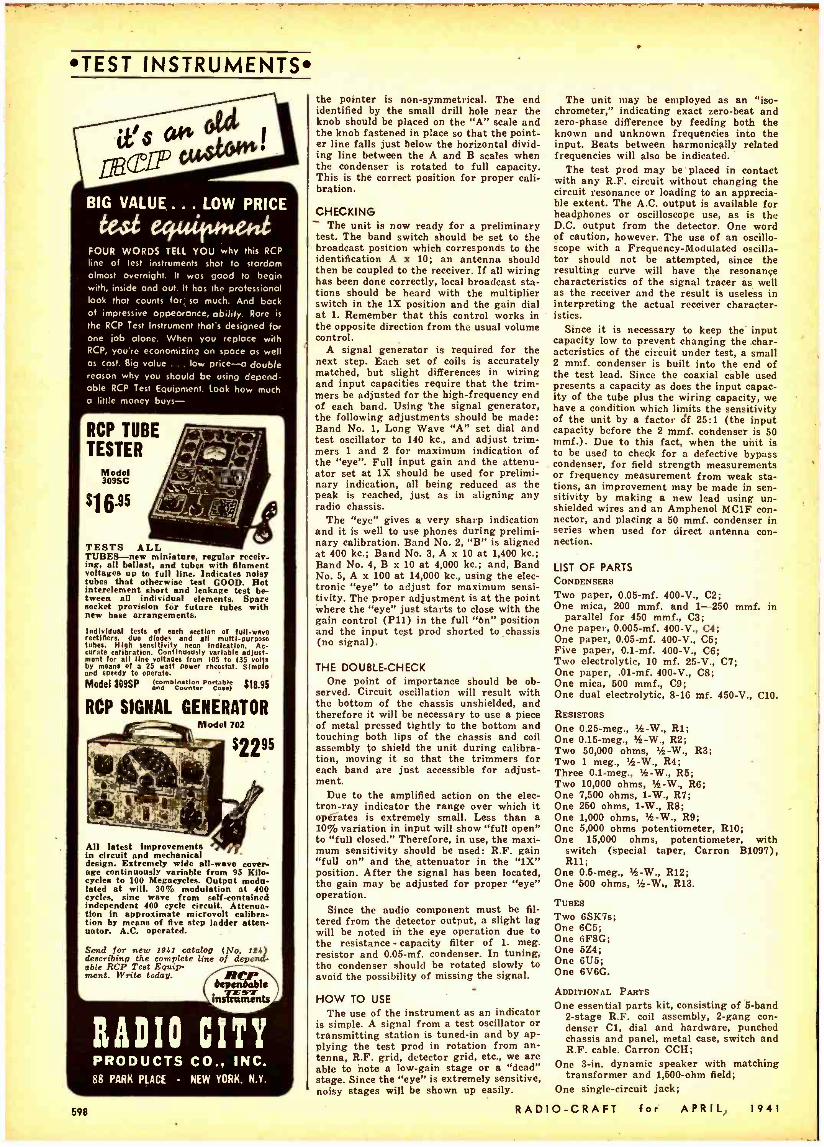
TEST INSTRUMENTS
BIG VALUE ... LOW PRICE
FOUR WORDS TELL YOU why this RCP
line of test instruments shot to stardom almost overnight. It was good to begin with, inside and out. It has the professional look that counts fori so much. And back of impressive appearance, ability. Rare is
the RCP Test Instrument that's designed for one ¡ob alone. When you replace with RCP, you're economizing on space as well as cost. Big value ... love price -a double reason why you should be using depend- able RCP Test Equipment. Look how much a little money buys-
r RCP TUBE TESTER
Model 309SC
S16.95
TESTS ALL TUBES -new miniature, regular receiv- ing, all ballast, and tubes with filament voltages up to full line. Indicates noisy tubes that otherwise test GOOD. Hot interelement short and leakage test be- tween all individual elements. Spare socket provision for future tubes with new base arrangements. Individual tests of each section of full -wave rectifiers, duo diodes and all multi- purpose tubes, High sensitivity neon Indication. Ac- curate calibration. Continuously variable adjust- ment for all lino voltages from 105 to 135 volts by means of a 25 watt power rheostat. Simple and speedy to operate.
Model809SP g,Ver.`ni°47°V,V7 518.95
RCP SIGNAL GENERATOR
All latest Improvements in circuit and mechanical design. Extremely wide all -wave cover- age continuously variable front 95 Kilo- cycles to 100 Megacycles. Output modu- lated at will. 30% modulation at 400 cycles, aine wave from self -contained independent 400 cycle circuit. Attenua- tion in approximate microvolt calibra- tion by means of five step ladder atten- uator. A.C. operated.
Send for new 1941 catalog (No. It l describing the complete line of depend. able RCP Test Equip- ment. Write today. //CA
l.a...rta
RADIO CITY PRODUCTS CO., INC. 88 PARK PLACE NEW YORK, N.Y.
598
the pointer is non -symmetrical. The end identified by the small drill hole near the knob should be placed on the "A" scale and the knob fastened in place so that the point- er line falls just below the horizontal divid- ing line between the A and B scales when the condenser is rotated to full capacity. This is the correct position for proper cali- bration.
CHECKING - The unit is now ready for a preliminary test. The band switch should be set to the broadcast position which corresponds to the identification A x 10; an antenna should then be coupled to the receiver. If all wiring has been done correctly, local broadcast sta- tions should be heard with the multiplier switch in the 1X position and the gain dial at 1. Remember that this control works in the opposite direction from the usual volume control.
A signal generator is required for the next step. Each set of coils is accurately matched, but slight differences in wiring and input capacities require that the trim- mers be adjusted for the high- frequency end of each band. Using the signal generator, the following adjustments should be made: Band No 1, Long Wave "A" set dial and test oscillator to 140 kc., and adjust trim- mers 1 and 2 for maximum indication of the "eye ". Full input gain and the attenu- ator set at 1X should be used for prelimi- nary indication, all being reduced as the peak is reached, just as in aligning any radio chassis.
The "eye" gives a very sharp indication and it is well to use phones during prelimi- nary calibration. Band No. 2, "B" is aligned at 400 kc.; Band No. 3, A x 10 at 1,400 kc.; Band No. 4, B x 10 at 4,000 kc.; and, Band No. 5, A x 100 at 14,000 kc., using the elec- tronic "eye" to adjust for maximum sensi- tivity. The proper adjustment is at the point where the "eye" just starts to close with the gain control (Pli) in the full "On" position and the input tept prod shorted to chassis (no signal).
THE DOUBLE -CHECK One point of importance should be ob-
served. Circuit oscillation will result with the bottom of the chassis unshielded, and therefore it will be necessary to use a piece of metal pressed tightly to the bottom and touching both lips of the chassis and coil assembly to shield the unit during calibra- tion, moving it so that the trimmers for each band are just accessible for adjust- ment.
Due to the amplified action on the elec- tron -ray indicator the range over which it operates is extremely small. Less than a 10% variation in input will show "full open" to "full closed." Therefore, in use, the maxi- mum sensitivity should be used: R.F. gain "full on" and the, attenuator in the "1X" position. After the signal has been located, the gain may be adjusted for proper "eye" operation.
Since the audio component must be fil- tered from the detector output, a slight lag will be noted in the eye operation due to the resistance - capacity filter of 1. meg. resistor and 0.05 -mf. condenser. In tuning, the condenser should be rotated slowly to avoid the possibility of missing the signal.
HOW TO USE
The use of the instrument as an indicator is simple. A signal from a test oscillator or transmitting station is tuned -in and by ap- plying the test prod in rotation from an- tenna, R.F. grid, detector grid, etc., we are able to mote a low -gain stage or a "dead" stage. Since the "eye" is extremely sensitive, noisy stages will be shown up easily.
The unit may be employed as an "iso- chrometer," indicating exact zero -beat and zero -phase difference by feeding both the known and unknown frequencies into the input. Beats between harmonically related frequencies will also be indicated.
The test prod may be placed in contact with any R.F. circuit without changing the circuit resonance or loading to an apprecia- ble extent. The A.C. output is available for headphones or oscilloscope use, as is the D.C. output from the detector. One word of caution, however. The use of an oscillo- scope with a Frequency -Modulated oscilla- tor should not be attempted, since the resulting curve will have the resonance characteristics of the signal tracer as well as the receiver and the result is useless in interpreting the actual receiver character- istics.
Since it is necessary to keep the' input capacity low to prevent changing the char- acteristics of the circuit under test, a small 2 mmf. condenser is built into the end of the test lead. Since the coaxial cable used presents a capacity as does the input capac- ity of the tube plus the wiring capacity, we have a condition which limits the sensitivity of the unit by a factor óf 25:1 (the input capacity before the 2 mmf. condenser is 50 mmf.). Due to this fact, when the unit is to be used to check for a defective bypass condenser, for field strength measurements or frequency measurement from weak sta- tions, an improvement may be made in sen- sitivity by making a new lead using un- shielded wires and an Amphenol MC1F con- nector, and placing a 50 mmf. condenser in series when used for direct antenna con- nection.
LIST OF PARTS CONDENSERS
Two paper, 0.05 -mf. 900 -V., C2; One mica, 200 mmf. and 1 -250 mmf. in
parallel for 450 mmf., C3; One paper, 0.005 -mf. 400 -V., C4; One paper, 0.05 -mf. 400 -V., C5; Five paper, 0.1 -mf. 400 -V., C6; Two electrolytic, 10 mf. 25 -V., C7; One paper, .01 -mf. 400 -V., C8; One mica, 500 mmf., C9; One dual electrolytic, 8 -16 mf. 450 -V., CIO.
RESISTORS
One 0.25 -meg., ifs -W., RI; One 0.15 -meg., Ifs -W., R2; Two 50,000 ohms, Ifs -W., R3; Two I meg., tfz -W., R4; Three 0.1 -meg., tfz -W., R5; Two 10,000 ohms, Ifs -W., R6; One 7,500 ohms, 1 -W., R7; One 250 ohms, 1 -W., R8; One 1,000 ohms, 1 -W., R9; One 5,000 ohms potentiometer, R10; One 15,000 ohms, potentiometer, with
switch (special taper, Carron B1097), R11;
One 0.5 -meg., / -W., R12; One 500 ohms, 11/2-W., R13.
TUBES
Two 6SK7s; One 6C5; One 6F8G; One 5Z4; One 6U5; One 6V6G.
ADDITIONAL PARTS
One essential parts kit, consisting of 5 -band 2 -stage R.F. coil assembly, 2 -gang con- denser Cl, dial and hardware, punched chassis and panel, metal case, switch and R.F. cable. Carron CCH;
One 3 -in. dynamic speaker with matching transformer and 1,500 -ohm field;
One single- circuit jack;
RADIO -CRAFT for APRILS 1941
tealrn RADIO SERVICE WORK with these 2BIG ahham e BOOKS
Learn How with this! Here's the world's most highly praised work - i for you In this one handsome 1300 -page home. Stud book. First, atybiig 420 -page
icing section
neest lenstrumlents -h of they work. how constructed. Dhow to build, how to use them. Then. 900
leppages give you a thorough. .by-atep procedure course In
and repi ring all testing,
akes of iQ°dio
L °est sc e latest ntlnc "factory meth - Od." Learn radio servicing Nis quick, economical S4 and NOW tondo It WHAT
Your copy today. 1300 pp.. 708 Illus.. 730 review quest.
RAD107;r14 -h, a HANDBOOK Save Time with this! 1 TO Here's real help for servicemen- -J 518 big man big pages of valu. SpEE ablei ltlmeeavinR. factory- cheekM tips to help
data right at . UP Ink Job quickly and accurately. It's
slus SECTIONS contain e pages of ttime.svl g"Cane Histories" over 3.300 reedly.
Alignment data for o i5.00Ó a perheta . Servicing d Installation data for all Auto
Radios . TroubleShoatingCharts . Tube. lteaia'or and Condenser
Charts . EVERYTHING! Sneed
Um vital °ser icing datait NOW a3 In this one big book. 518 po.. 134 illus.. 81/2511 size.
r -MAIL COUPON TODAY! -- D Cheek Radio & Tech. Pubi. Co.. Dept. RC4i here I 45 Astor PI.. New York for FREE. Enclosed find payment for: circulars. I D MODERN D RADIO 77101.I. D BOTH books at 1
BLE SHOOT- 10.50 Money I £R9 HAND S Ing Com- BOOK bination Price 1
SERVICING
NAME ADDRESS
.MONEY-BACK IF NOT SÁTÌSFlED!..ÿ
300 WAYS
TO MAKE
MONEY
68 PAGES
lOc PER COPY
MAIL ORDER PLANS
TESTED MONEY MAKERS
BUSINESS SECRETS
SUCCESS SCHEMES
MARVEL BOOK OF
THE YEAR!
40,000 WORDS In TEXTI
In "CASH IN" You get ALL the
real monemak- ers - dozens of
profitable tested mall order plans, condden-
60LD ON A u m tial business secrete.
MONEY -BACK ed or
formulas, successful GUARANTEE tested schemes- actual ex-
periences on a shoestring-with ls than $10 capital. pal. Boyers of This Book Tell Us-
ieesi iggest value l'vC yet
S. BudBook is worth at
L¢pprM,
yn, N. Y.
Selling 'In', 'S""GeorL -áf Brunet. Montnc al, Can the mail ordlerNfeld Lawrence Fox. Fox. Brrooklyn N. Y. "CASH IN" contains only tested ideas covering every type of full -or spare -time enterprise -It's a "master- piece" In business ventures.
BOOK CONTAINS NO ADVERTISING ICs a copy postpaid. Send U.S. stamps or coin.
NATIONAL PLANS INSTITUTE 246 -R Fifth Ave., N.Y.C.
FÍLMGRAPFií lÿ VOICE AND MUSIC RDINGS
Lengthy or continuous recordings now possible with newly patented "FI LMG RAPH." Over 13 hours of indexed voice. radio. code. telephone recording on a single 500 ft. reel Of Sim costing $3.00 and up. No other expense. INSTAN- TANEOUS and PERMANENT play -back. Can easily be synchronized with Motion pictures. Bulletins free.
MILES REPRODUCER CO., INC., Dept. RCB 612 Broadway New York City
RADIO -CRAFT for APRIL.
One 2- circuit jack; Six octal sockets; One Amphenol MEA -10 visual tuning "eye"
assembly; One Amphenol PC -1 -M male chassis con-
nector; One Stancor P -6010 power transformer; One power line cord; Three small bar knobs; Miscellaneous hardware, hookup wire and
braided ground strap wire. This article has been prepared from ma-
terial supplied by courtesy of Allied Radio Corp. in cooperation with Carron Mfg. Co.
RADIO IN THE NORTHWEST ADIO wavelengths are weaving a net-
's work of medical security over the wilds of the Northwest Territories. Aided by 2 -way radio sets, 9 resident doctors em- ployed by the Territorial Council supply the medical needs of about 10,000 Indians, Eski- mos, trappers, traders, miners and mission- aries scattered throughout 1,300,000 square miles of icefields, rock and lake country and barren islands.
Their practice extends from the northern boundaries of the 3 Prairie Provinces and part of British Columbia to the far reaches of the Arctic circle and from the western end of Labrador to the Yukon Territory.
The outpost Physicians previously served only northerners within reach of dog teams or boats and canoes. These restrictions usu- ally held them within a 100 miles radius of their stations except for airplane mercy flights. Now northern ether waves crackle day and night with medical messages from resident doctors at Aklavik, Fort Smith, Norman, Pangnirtung, Resolution, Chester- field, Port Radium, Yellowknife and Simp- son. Trading posts, missions and Royal Ca- nadian Mounted Police stations throughout the silent tundraland pick up and send the mercy messages.
The Hudson's Bay Company, oldest trad- ing firm in the British Empire, has installed 2 -way radio sets in 78 of its 215 northern posts. Each post has at least one employee able to send and receive radio messages and plans are being made to install 25 additional sets next summer.
When aid is required, one of the Govern- ment doctors is called to the radio station. The emergency is described and the physi- cian tells the operator what medicine or treatment is necessary.
AU far -north settlements are stocked with medical supplies. Emergencies ranging front measles to childbirth have been met by radio prescription!
Should weather unfavorable to radio blot out urgent messages in one direction, signals are stretched to far -off sets, sometimes reaching a doctor 1,000 miles off.
ROY CARMICHAEL, Montreal, Que., Canada
ORCHIDS An orchid, Walter, to ]l'OR, for their
swell job of dramatizing the construction of a bomber. Listeners received practically first -hand information on the process, from A to Z, via the following remote pick -upe: designing and planning, and the processing of raw materials, at the Carnegie Illinois Steel Co. and the Revere Copper and Brass Co.; the manufactura of machine tools, Cin- cinnati Milling Machine Co., engine con - etruction, Pratt and Whitney (Hartford, Conn.); plane assembly, Lockheed aircraft plant (Burbank, Calif.); finally, a bomber went aloft over Long Island, N. Y.
1941
TEST INSTRUMENTS
with lfks BIG
1- Volume Radio Training Course
Fit yourself. at home In apare time. for good -paring Radio lob. Yea. roe Can do it -with helpeedrol thoiursandds u'
as others
who got their basic training In Radio from his orld. famous Radio Physle Course. It's y this ay. because Ghirardl has genius for making it all vividly clear and easy to understand. You need no 'bad:ground" to pre - ppre you for this intensive
rsee of technical t
training- not hroourgaTTrdi
will e math!
through' right through Radio. Sound. Television, Cathode -Ray Tubes, etc.. etc. Ica all explained ,
-° ply. mpletely -In this one big 972 -page book thatcosto you only Sa.
USED BY U. S. ARMY and NAVY the rare
of hon0 of excellence,
used o Physics te training text in the radio courses conducted
as the U. 5. Army and Navy. In fact. It io recommended and praised everywhere s tops ". and is used by more din
schoo1sr1aÌdXstudents athan any other radio text in
you learn: 38 Volumes In 1-972 pp. -508 Mus.
1. Radio Broadcasting System. Music, 3. Electron Thheory:Elec?Current 4. Kleee. Units: Ohm'. Jaw: Resistance. S. Elec. Circuits: Batteries. 6. Magnetism. 7. Electromagnetism. B. Electromagnetic Induction. 9. Inductance. 10. Capaci- tance: Condensers. 11. A. C. Circuits. 12. Flltere. rá stilecii iic uTi ' n Broaang. e. Receiving. 17. um ue Pri ailes. 18. Vacuum Tube Charncterin. 19. Vacuum chiles.
Tube Construction. 20. Vacuum Tube Detector and Amplifier Action. 21. Radio Frequency Amplification. 22. Superheta ". 23. H.F. Amplifiers; Tuning Coils. O Audio
ReN ieiiver,. 2725 Power -Suppl 2 Units. Battery-
Operated 8. Elec. eceivers. 29. Automobile and Aircraft Radio. 30. Phono Pickups; Sound Systems. 31. Short-Wave. 32. Photoelectric Cells: Cathode -Ray Tube.. 33. Tel°. ivision.
34. Antennas and Grounds. 35. Testing; Serv. cing. 36. Sound Motion Pictures. . 856 5vN- Review queseionsl Send for this 't book NOW' p -Test it-S DAY TRIAL -MAIL NOW ! -
RADIO 6, TECHNICAL PUBLISHING CO.. 45 Aster Place. New York, Delft. RC -41.
Here RADIO PHYSICS COURSE postpaid.
NAME ADDRESS
CITY STATE D Send me free Illustrated descriptivo litcralure
R MONEY BACK IF NOT SATISFIEDI
d
The Outstanding Tube Tester Value . . Checks all type tubes including Loctals. Bantam Jr., 1.4 volt Miniatures, Gaseous Rectifier, Ballast, High Voltage Series, etc. Filament Voltages from 1.1 to 110 volts. Direct Reading GOOD -BAD Meter Scale. Pro- fessional- appearing case with accessory com- partment large enough for carrying Model 739 AC -DC Pocket Volt- Ohm- Milliammeter, thereby giving the serviceman complete test- ing facilities for calls in the field. . . .
Model 432 -A with compartment, Dealer Net Price . $18.85. Model 432 -A in case less compartment $17.85. Model 739. Dealer Net Price $9.90.
WRITE FOR CATALOG -Section .416 College Drive
READRITE METER WORKS, Bluffton, Ohio
s1
599

TEST INSTRUMENTS
- BUILT IN TYPE - i
r '- __. PILOT
IrG HT c TEST SOCKETS
MODERNIZING TRANSFOMER
ANALYZER ?CABLE TO
TESTER
EWA r I
_
I I
I
PI
SOCKETS
1 I
I i
y
J11
,TIIL
1,
II I
U-alt g/
^ OT
TEST
SEC:
LIGHT
\ a 11 1 111
115V, A.C.
90.07 LIGHT TEST
0 6 0.
a ' e rneMnn sciccroa
T(1 \ SEPARATE MODERNIZING
UNIT
^- THE MODERNIZED
I
a
(/O ó J
a as ea s s ar ae
iii:óc 77935 on
ORIGINAL TESTER
SETUP^
1 1 1 1 1 11
--FILAMENT SELECTOR
SWITCH
f SEC.
`'r - r D.P.S.7.
SWITCH
'` PRI.
-SEPARATE
s.PRI. ín.113 Li- JVJ T 1111 _____
LL UNIT TYPE FILAMENT TRANSFORMER MODERNIZING
OF TESTER TRANSFORMER ('
115V., A.C.
If there's no room to build -in the new transformer and switch (Fig. I, left), in your fest unit' case, try using a separate unit (Figs. 2 and 3, center and right).
MODERNIZE YOUR TESTER o awl #;9h- volta9Q- #Qatet 7'ck
A new filament transformer, a new filament selector switch, and presto!, you are ready with your old tester to test even 117- volt -filament tubes. Read this article and learn how easy it is to do a face- lifting job on otherwise outmoded tube
testers.
D. J. FOARD, E.E.
T WASN'T so very long ago that I pur- chased a tube and set tester that would accommodate only 4- and 5 -prong tubes, this because those were the only tubes in
use at the time. But shortly thereafter it be- came necessary for me to trade this instru- ment in for instruments that would accommo- date 6- and 7 -prong tubes. Then along came metal tubes and I had to purchase testers with provision for octal -base tubes. Not long ago some technicrat invented loctal bases and the modernity of my test equipment was once again subjected to considerable ques- tion. Then came "bantams" and other types of midget tubes and I began to wonder if it wouldn't be wiser to rent test equipment!
.To cap the climax, so to speak, tube man- ufacturers introduced the new high- voltage- heater tubes. Though they are unquestiona- bly a forward stride in improving the ef- ficiency and life of A.C.-D.C. receivers, they do present still another problem for those of us who must service the receivers in which they are used.
At the present time, there are a great many fine tube testers and combination testers which are modern, or which have been rendered modern through the use of adapters, except that there is.no provision for the high- voltage- heater tubes. Though we do not encounter these tubes as yet with alarming frequency, practically all of the new A.C.-D.C. sets employ then and it will not be long until they will be coming in every day. As many of us have had to change test equipment all too frequently' in the last few years, most of us dislike to again have to purchase new equipment. At the present time, modernization of the equipment of most shops requires only provision for the high -voltage- heater tubes. Fortunately, most Servicemen can do such modernization them- selves, easily and inexpensively.
600
BUILT -IN MODERNIZATION Most radio transformer manufacturers
now manufacture tube tester filament trans- formers, with secondaries of from 1 to 117 volts. These transformers can be purchased for $2 or $3 from any large radio supply house. Most tube testers, as well as most combination testers, have sufficient spare room in which to mount the modernizing transformer and, as most of these trans- formers are quite small, installing them in the tester should present no great difficulty. See Fig. 1.
A new filament voltage selector switch is, of course, necessary and one must use a switch with a position for each of the sec- ondary taps of the -modernizing transformer. These switches, together with a suitable fila- ment selector switch plate, can be obtained from any large radio supply house.
PROCEDURE As soon as the modernizing transformer
has been mounted in the tester, the primary (is wired in parallel with the primary of the original transformer, and the filament supply leads of the original transformer are cut -off at the transformer. The old filament selector switch is then removed from the tester and the new switch installed in its place. The secondary leads of the modern- izing transformer are then wired, in proper order, to the various lugs of the new fila- ment selector switch.
The lead which ran from the original transformer's secondary directly to the tube socket is, of course, wired onto the modern- izing transformer. Too, the lead from the tube sockets to the arm of the filament selec- tor switch is wired onto the arm of the new filament selector switch. This will complete the modernization and the tester will now deliver all of the higher filament voltages,
RADI
as well as the lower voltages, through the new transformer and filament selector switch.
INDEPENDENT MODERNIZATION If it is not possible, or desired, to install
a built -in modernization, as described above, a separate unit can very easily be built which will operate well on any tester having the filaments of the various tube sockets wired in parallel. The separate unit can be housed in almost any type of case and has a separate power cord and an "on -off" switch. See Fig. 2.
The modernizing transformer is installed in the case, the Jon -off" switch and filament selector switch then mounted on the panel. The "on -off" switch is then wired in the power cord input to the primary of the mod- ernizing transformer. One wire from the secondary of the modernizing transformer, and a lead from the arm of the filament se- lector switch are then wired to a 2 -wire analyzer cable. The cable should terminate in a 4 -prong analyzer plug with the 2 wires soldered to the 2 filament prongs of the plug. The secondary taps of the modern- izing transformer should then be wired, in proper order, to the various lugs of the new filament selector switch.
The Separate Unit Modernizer will then be complete and, after testing, be ready for use. To use this unit, the tester's filament selector switch is placed (and left) in the "off" position. and the Modernizer cable is plugged into the tester's 4 -prong socket. Then all adjustments are made as before, except that the filament selector switch on the Modernizer is used instead of the fila- ment selector on the tester itself. See Fig. 3.
If the tester has no provision for loctal- or bantam -base tubes, these can easily be installed at this time. All one need do is to obtain the proper sockets and to mount them on the tester panel. Then simply wire the new sockets in parallel with sockets, originally in the tester, having the same .number of terminals.
A very handy feature too is a pilot -light tester. They require very little room and are easily installed. Simply obtain I screw - base socket and 1 bayonet -base socket for flush panel mounting and mount them on the tester panel. Wire them together in parallel and then wire the 2 leads in parallel with the filament terminals of the nearest tube socket. Different voltages will then be applied to each of the pilot -light sockets by the tester's filament selector switch. This tester will, of course, also test flashlight and Xmas -tree lights.
Any competent Serviceman should be able
0-CRAFT for APRIL, 1941
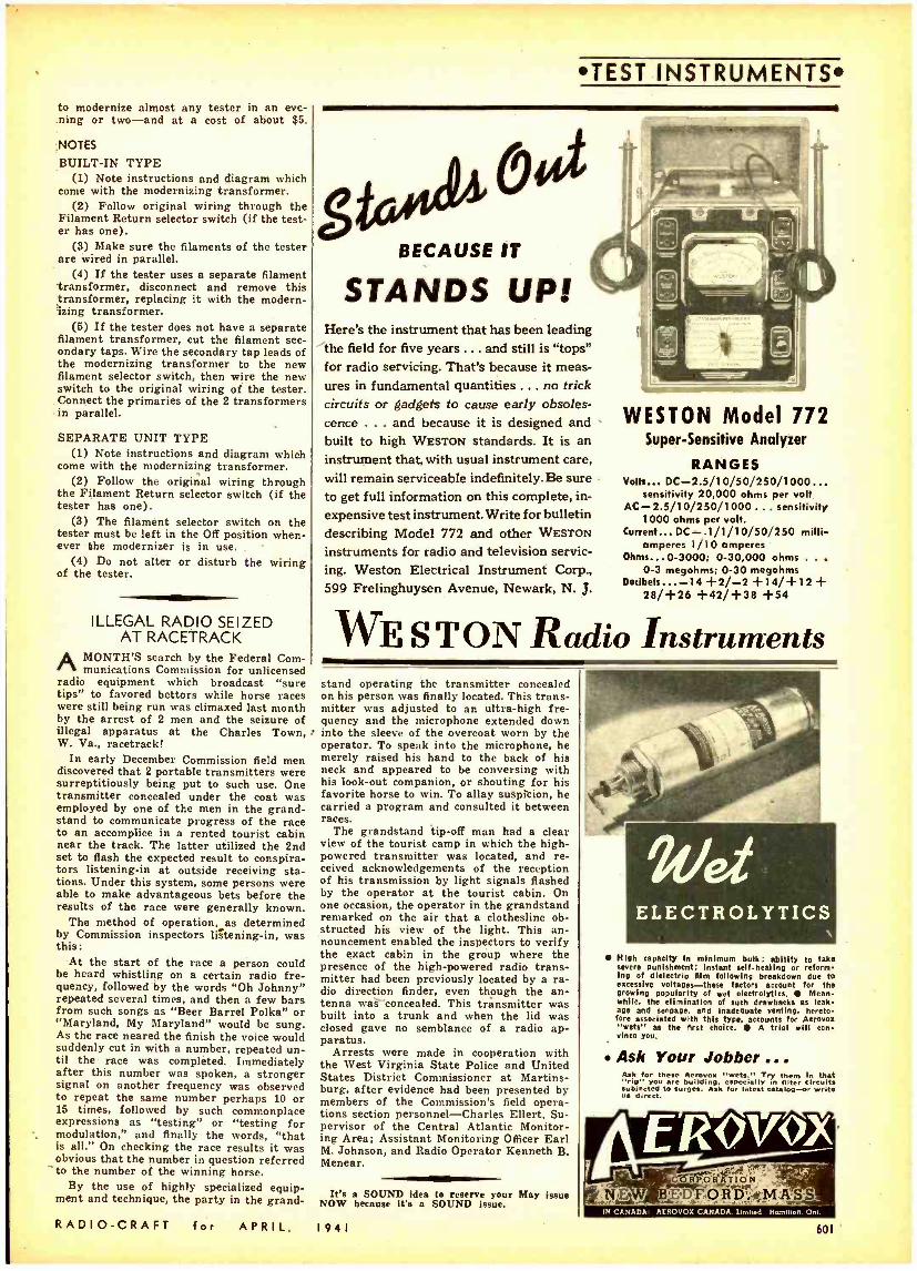
to modernize almost any tester in an evc- ning or two -and at a cost of about $5.
NOTES
BUILT -IN TYPE (1) Note instructions and diagram which
come with the modernizing transformer. (2) Follow original wiring through the
Filament Return selector switch (if the test- er has one).
(3) Make sure the filaments of the tester are wired in parallel.
(4) If the tester uses a separate filament transformer, disconnect and remove this transformer, replacing it with the modern- izing transformer.
(5) If the tester does not have a separate filament transformer, cut the filament sec- ondary taps. Wire the secondary tap leads of the modernizing transformer to the new filament selector switch, then wire the new switch to the original wiring of the tester. Connect the primaries of the 2 transformers in parallel.
SEPARATE UNIT TYPE (1) Note instructions and diagram which
come with the modernizing transformer. (2) Follow the original wiring through
the Filament Return selector switch (if the tester has one).
(3) The filament selector switch on the tester must be left in the Off position when- ever the modernizer is in use.
(4) Do not alter or disturb the wiring of the tester.
ILLEGAL RADIO SEIZED AT RACETRACK
AMONTH'S search by the Federal Corn- munications Commission for unlicensed
radio equipment which broadcast "sure tips" to favored bettors while horse races were still being run was climaxed last month by the arrest of 2 men and the seizure of illegal apparatus at the Charles Town, W. Va., racetrack!
In early December Commission field men discovered that 2 portable transmitters were surreptitiously being put to such use. One transmitter concealed under the coat was employed by one of the men in the grand- stand to communicate progress of the race to an accomplice in a rented tourist cabin near the track. The latter utilized the 2nd set to flash the expected result to conspira- tors listening -in at outside receiving sta- tions. Under this system, some persons were able to make advantageous bets before the results of the race were generally known.
The method of operation, as determined by Commission inspectors listening -in, was this:
At the start of the race a person could be heard whistling on a certain radio fre- quency, followed by the words "Oh Johnny" repeated several times, and then a few bars from such songs as "Beer Barrel Polka" or "Maryland, My Maryland" would be sung. As the race neared the finish the voice would suddenly cut in with a number, repeated un- til the race was completed. Immediately after this number was spoken, a stronger signal on another frequency was observed to repeat the same number perhaps 10 or 15 times, followed by such commonplace expressions as "testing" or "testing for modulation," and finally the words, "that is all." On checking the race results it was obvious that the number in question referred to the number of the winning horse.
By the use of highly specialized equip- ment and technique, the party in the grand-
RADIO -CRAFT for APRIL.
TEST INSTRUMENTS
oot BECAUSE IT
STANDS UP! Here's the instrument that has been leading the field for five years ... and still is "tops" for radio servicing. That's because it meas- ures in fundamental quantities .. . no trick circuits or gadgets to cause early obsoles- cence ... and because it is designed and built to high WESTON standards. It is an instrument that, with usual instrument care, will remain serviceable indefinitely. Be sure to get full information on this complete, in-
expensive test instrument. Write for bulletin describing Model 772 and other WESTON
instruments for radio and television servic- ing. Weston Electrical Instrument Corp., 599 Frelinghuysen Avenue, Newark, N. J.
WESTON Model 772 Super- Sensitive Analyzer
RANGES volts... DC- 2.5/10/50/250/1000...
sensitivity 20,000 ohms per volt AC- 2.5/10/250/1000 ... sensitivity
1000 ohms per volt. Current... DC--.1 /1/10/50/250 milli-
amperes 1/10 amperes Ohms...0 -3000; 0- 30,000 ohms . . .
0 -3 megohms; 0 -30 megohms Decibels... -14 +2/ -2 +14/ + 12 +
28/ +26 +42/ +38 +54
WE S TON Radio Instruments stand operating the transmitter concealed on his person was finally located. This trans- mitter was adjusted to an ultra -high fre- quency and the microphone extended down into the sleeve of the overcoat worn by the operator. To speak into the microphone, he merely raised his hand to the back of his neck and appeared to be conversing with his look -out companion, or shouting for his favorite horse to win. To allay suspicion, he carried a program and consulted it between races.
The grandstand tip -off man had a clear view of the tourist camp in which the high - powered transmitter was located, and re- ceived acknowledgements of the reception of his transmission by light signals flashed by the operator at the tourist cabin. On one occasion, the operator in the grandstand remarked on the air that a clothesline ob- structed his view of the light. This an- nouncement enabled the inspectors to verify the exact cabin in the group where the presence of the high -powered radio trans- mitter had been previously located by a ra- dio direction finder, even though the an- tenna was concealed. This transmitter was built into a trunk and when the lid was closed gave no semblance of a radio ap- paratus.
Arrests were made in cooperation with the West Virginia State Police and United States District Commissioner at Martins- burg, after evidence had been presented by members of the Commission's field opera- tions section personnel- Charles Ellert, Su- pervisor of the Central Atlantic Monitor- ing Area; Assistant Monitoring Officer Earl M. Johnson, and Radio Operator Kenneth B. Menear.
Its a SOUND idea to reserve your May issue NOW because it's a SOUND issue.
1941
ELECTROLYTICS
High capacity In minimum bulk; ability to take severe punishment; Instant self -healing or reform- ing of dleleetrio elm following breakdown due to excessive voltages -these factors account for the growing popularity of wet eleetrolytics. Mean- while, the elimination of such drawbacks as leak- age and seepage. and Inadequate venting. hereto- fore associated with this type, accounts for Aerovox "wets" as the first choice. A trial will con vince you.
Ask Your Jobber ... Ask for these Aerovox "wets." Try them In that "rig" you are building, especially in filter circuits Subjected to surges. Ask for latest catalog -or write us direct.
CbÌ1PÓÁ'ÓN;. E F:O:RDt_M Aw
IN CANADA: AEROVOX CANADA. Limbed Homlllon.Onl.
601
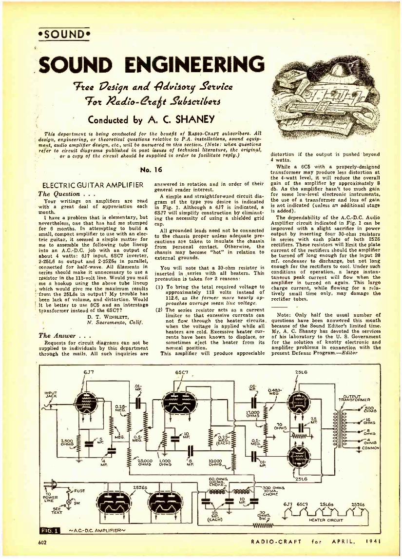
SOUND
SOUND ENGINEERING `Tea l7asiyn and -Pdvilory Sarvica
Tor Radio- era6t S'uGscriGars
Conducted by A. C. SHANEY This department is being conducted for the benefit of RADIO -CRAFT subscribers. All
design, engineering, or theoretical questions relative to P.A. installations, sound equip- ment, audio amplifier design, etc., will be answered in this section. (Note: when questions refer to circuit diagrams published in past issues of technical literature, the original,
or a copy of the circuit should be supplied in order to facilitate reply.)
No. 16
ELECTRIC GUITAR AMPLIFIER The Question .. .
Your writings on amplifiers are read with a great deal of appreciation each month.
I have a problem that is elementary, but nevertheless, one that has had me stumped for 6 months. In attempting to build a small, compact amplifier to use with an elec- tric guitar, it seemed a simple matter for me to assemble the following tube lineup into an A.C.-D.C. job with an output of about 4 watts: 6J7 input, 6SC7 inverter, 2 -26L6 as output and 2 -25Z6s in parallel, connected for half -wave. All filaments in series should make it unnecessary to use a resistor in the 115 -volt line. Would you mail me a hookup using the above tube lineup which would give me the maximum results from the 25L6s in output? My trouble has been lack of volume, and distortion. Would it be better to use 6C5 and an interstage transformer instead of the 6SC7?
D. T. WINSLETT, N. Sacramento, Calif.
The Answer . . .
Requests for circuit diagrams can not be supplied to individuals by this department through the mails. All such inquiries are
answered in rotation and in order of their general reader interest.
A simple and straightforward circuit dia- gram of the type you desire is indicated in Fig. 1. Although a 6J7 is indicated, a 6SJ7 will simplify construction by eliminat- ing the necessity of using a shielded grid cap.
All grounded leads need not be connected to the chassis proper unless adequate pre- cautions are taken to insulate the chassis from personal contact. Otherwise, the chassis may become "hot" in relation to external grounds.
You will note that a 30 -ohm resistor is inserted in ,series with all heaters. This precaution is taken for 2 reasons:
(1) To bring the total required voltage to approximately 118 volts instead of 112.6, as the former more nearly ap- proaches average mean line voltage.
(2) The series resistor acts as a current limiter so that excessive currents can not flow through the heater circuits. when the voltage is applied while all heaters are cold. Excessive heater cur- rents have been known to displace, or sometimes eject the heater from its normal position.
This amplifier will produce appreciable
distortion if the output is pushed beyond 4 watts.
While a 6C5 with a properly- designed transformer may produce less distortion at the 4 -watt level, it will reduce the overall gain of the amplifier by approximately 8 db, As the amplifier hasn't too much gain for some low -level electronic instruments, the use of a transformer and loss of gain is not indicated (unless an additional stage is added).
The dependability of the A.C.-D.C. Audio Amplifier circuit indicated in Fig. 1 can be improved with a slight sacrifice in power output by inserting four 30 -ohm resistors in series with each plate of both 25Z6 rectifiers. These resistors will limit the plate current of the rectifiers should the amplifier be turned off long enough for the input 20 mf. condenser to discharge, but not long enough for the rectifiers to cool. Under such conditions of operation, a large instan- taneous peak current will flow when the amplifier is turned on again. This large charge current, while flowing for a rela- tively small time only, may damage the rectifier tubes.
Note: Only half the usual number of questions have been answered this month because of the Sound Editor's limited time. Mr. A. C. Shaney has devoted the services of his laboratory to the U. S. Government for the solution of knotty electronic and amplifier problems in connection with the present Defense Program.- Editor
INPUT JACK
6J-1
.01- MF
0.5- MEG.
65C7
25.000 1,000 OHMS OHMS
OHMS
10000 OHMS
25265
FIG. 1 "A.C.-O.C. AMPLIFIER",
60 OHMS CHoKÉ
MF.
2.5L6
o O o
25L6 7 F.,
(EAMCH)
-300 OHMa 10 MA..
CHOKE 10
MF - `-' ÓHOMS,
5W.; Y-
TRAN$
JfOliM9 OHM
16 S
re OHMS
r 4 OHMS
COMMON
6.37 65E7 25L65 25765
HEATER CIRCUIT
602 RADIO -CRAFT for APRIL, 1941
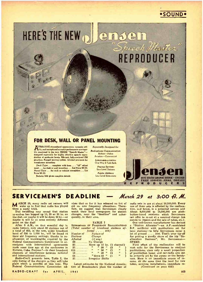
SOUND
HERE'S THE NEW
REPRODUCER
r
Ì FOR DESK, WALL OR PANEL MOUNTING
TTRACTIVE streamlined appearance, versatile urn. ity, and exceptional acoustic performance are capa-
bly combined in the new JENSEN "Speech Master" - designed especially for highly effective speech repro- duction at moderate levels. Efficient, fully -enclosed PM structure. Rugged moving system. Internal provision for transformer mounting.
Desk Type ... complete with base ... 'tilt" adjust ment ... for desk or wall mounting ... List Price $9.95. Panel Type ... for rack or cabinet assemblies ... List Price $8.10.
Bulletin 106 gives complete details.
Especially Designed for
Radiophone Communication Airline - Police
Aviation- Commercial
Intercommunication One.Way & Talk.Beck
Paging Systems Low.Level Stations
Public Address Low.Level Extensions
R
enden 6601 SOU1H LARAMIE tiYEIíUE CHICAGO
CABLE ADDRESS:JERAO, CHICAGO E P R O D U C E R S
SERVICEMEN'S DEADLINE MARCH 29, many radio set owners will
wake up to find that radio has played them a nasty trick.
Dial twiddling may reveal that station so- and -so has hopped up 10, 20 or 30 kc. on the dial -or maybe it will be down 10 kc. -or maybe it will be at some entirely different point on the dial!
After 3 A.M., on that eventful day in radio history, only about 80 stations out of a total of 862, in the new, wider broadcast band of 550 to 1,600 kc., will be found at their old frequency settings, thanks to re- allocation of wavelengths required by the Federal Communications Commission in ac- cordance with international agreements made some time ago at the conference in Havana, Cuba. Purpose ? -to clear broadcast channels of interference between national and international stations.
Radio -Craft presents here, Table I, the only listing of the changes as they will take place which is possible at this time. The Federal Communications Commission ad-
RADIO -CRAFT for APRIL,
/1141Ch 29 at 3:00 lg. ñfe vises that so far it has released no list of old vs. new frequency allocations. There- fore, we suggest that Servicemen closely watch their local newspapers for station changes, near the "deadline" and subse- quently, in their area.
TABLE I SCOREBOARD OF FREQUENCY REALLOCATIONS (Total number of broadcast stations af-
fected . . . . 862) Number of Nature of Stations Change Affected (if any)
80 No Change
radio sets in use at about 50,100,000. Every one of these sets is affected by the realloca- tion, and hence, is a potential service jobl About 9,000,000 to 10,000,000 are push- button -tuned receivers which Servicemen can offer to re -set at a nominal charge (an entrée to repairs and the sale of tubes, etc.).
One well -known manufacturer has devised a "Station Allocator " -an A.F.- modulated R.F. oscillator with pushbuttons set for local stations -to help Servicemen cover a lot of ground .... fast. That's your tip -off for getting a goodly share of the big "Re- allocation Business ", Mr. Serviceman - SPEED.
20 Move up 10 kc. (1 channel) First effect of the reallocation will be 26 " " 20 " (2 ) rush calls for the Serviceman to readjust
619 " " 30 " (3 " ) pushbuttons, since only a small proportion 19 " " 40 " (4 " ) of pushbutton home- and car -radio sets can 64 "down 10 " (1 " ) be properly set by the owner or the handy- 35 Irregular Shifts man. Here is an immediate source of in-
Latest estimates by the National Associa- tion of Broadcasters place the number of
1941
come. At the same time the need for new tubes, antenna installations, immediate re-
(Continued on page 612)
603
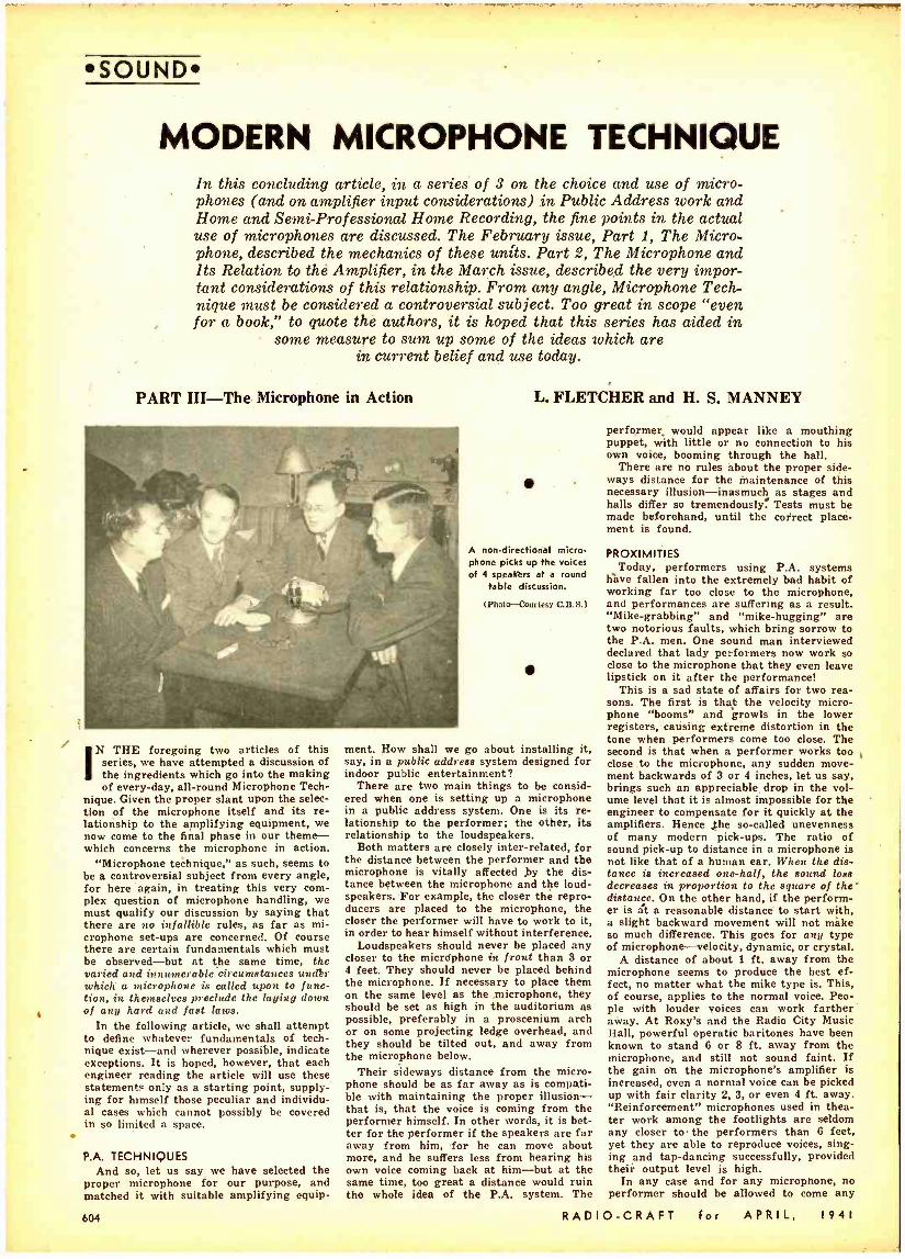
SOUND
MODERN MICROPHONE TECHNIQUE In this concluding article, in a series of 3 on the choice and use of micro- phones (and on amplifier input considerations) in Public Address work and Home and Semi- Professional Home Recording, the fine points in the actual use of microphones are discussed. The February issue, Part 1, The Micro- phone, described the mechanics of these units. Part 2, The Microphone and Its Relation to the Amplifier, in the March issue, described the very impor- tant considerations of this relationship. From any angle, Microphone Tech- nique must be considered a controversial subject. Too great in scope "even for a book," to quote the authors, it is hoped that this series has aided in
some measure to sum up some of the ideas which are in current belief and use today.
PART III -The Microphone in Action
N THE foregoing two articles of this series, we have attempted a discussion of the ingredients which go into the making of every -day, all -round Microphone Tech-
nique. Given the proper slant upon the selec- tion of the microphone itself and its re- lationship to the amplifying equipment, we now come to the final phase in our theme - which concerns the microphone in action.
"Microphone technique," as such, seems to be a controversial subject from every angle, for here again, in treating this very com- plex question of microphone handling, we must qualify our discussion by saying that there are no infallible rules, as far as mi- crophone set -ups are concerned. Of course there are certain fundamentals which must be observed -but at the same time, the varied and itvnunerable.circumatances undr which a microphone is called upon to func- tion, in themselves preclude the laying down of any hard and fast laws.
In the following article, we shall attempt to define whatever fundamentals of tech- nique exist -and wherever possible, indicate exceptions. It is hoped, however, that each engineer reading the article will use these statement only as a starting point, supply- ing for himself those peculiar and individu- al cases which cannot possibly be covered in so limited a space.
P.A. TECHNIQUES And so, let us say we have selected the
proper microphone for our purpose, and matched it with suitable amplifying equip-
604
L. FLETCHER and H. S. MANNEY
A non -directional micro- phone picks up the voices of 4 speakers at a round
table discussion.
(Photo- Courtesy C.B.S.)
ment. How shall we go about installing it, say, in a public address system designed for indoor public entertainment?
There are two main things to be consid- ered when one is setting up a microphone in a public address system. One is its re- lationship to the performer; the other, its relationship to the loudspeakers.
Both matters are closely inter -related, for the distance between the performer and the microphone is vitally affected by the dis- tance between the microphone and the loud- speakers. For example, the closer the repro- ducers are placed to the microphone, the closer the performer will have to work to it, in order to hear himself without interference.
Loudspeakers should never be placed any closer to the microphone in front than 3 or 4 feet. They should never be placed behind the microphone. If necessary to place them on the same level as the microphone, they should be set as high in the auditorium as possible, preferably in a proscenium arch or on some projecting ledge overhead, and they should be tilted out, and away from the microphone below.
Their sideways distance from the micro- phone should be as far away as is compati- ble with maintaining the proper illusion - that is, that the voice is coming from the performer himself. In other words, it is bet- ter for the performer if the speakers are far away from him, for he can move about more, and he suffers less from hearing his own voice coming back at him -but at the same time, too great a distance would ruin the whole idea of the P.A. system. The
performer, would appear like a mouthing puppet, with little or no connection to his own voice, booming through the hall.
There are no rules about the proper side- ways distance for the maintenance of this necessary illusion -inasmuch as stages and halls differ so tremendously. Tests must be made beforehand, until the correct place- ment is found.
PROXIMITIES Today, performers using P.A. systems
have fallen into the extremely bad habit of working far too close to the microphone, and performances are suffering as a result. "Mike- grabbing" and "mike- hugging" are two notorious faults, which bring sorrow to the P.A. men. One sound man interviewed declared that lady performers now work so close to the microphone that they even leave lipstick on it after the performance!
This is a sad state of affairs for two rea- sons. The first is that the velocity micro- phone "booms" and growls in the lower registers, causing extreme distortion in the tone when performers come too close. The second is that when a performer works too close to the microphone, any sudden move- ment backwards of 3 or 4 inches, let us say, brings such an appreciable drop in the vol- ume level that it is almost impossible for the engineer to compensate for it quickly at the amplifiers. Hence the so- called unevenness of many modern pick -ups. The ratio of sound pick -up to distance in a microphone is not like that of a human ear. When the dis- tance is increased one -half, the sound loss decreases in proportion to the square of the distance. On the other hand, if the perform- er is at a reasonable distance to start with, a slight backward movement will not mike so much difference. This goes for any type of microphone -velocity, dynamic, or crystal.
A distance of about 1 ft. away from the microphone seems to produce the best ef- fect, no matter what the mike type is. This, of course, applies to the normal voice. Peo- ple with louder voices can work farther away. At Roxy's and the Radio City Music Hall, powerful operatic baritones have been known to stand 6 or 8 ft. away from the microphone, and still not sound faint. If the gain on the microphone's amplifier is increased, even a normal voice can be picked up with fair clarity 2, 3, or even 4 ft. away. "Reinforcement" microphones used in thea- ter work among the footlights are seldom any closer to the performers than 6 feet, yet they are able to reproduce voices, sing- ing and tap- dancing successfully, provided their output level is high.
In any case and for any microphone, no performer should be allowed to come any
RADIO -CRAFT for APRIL, 1941
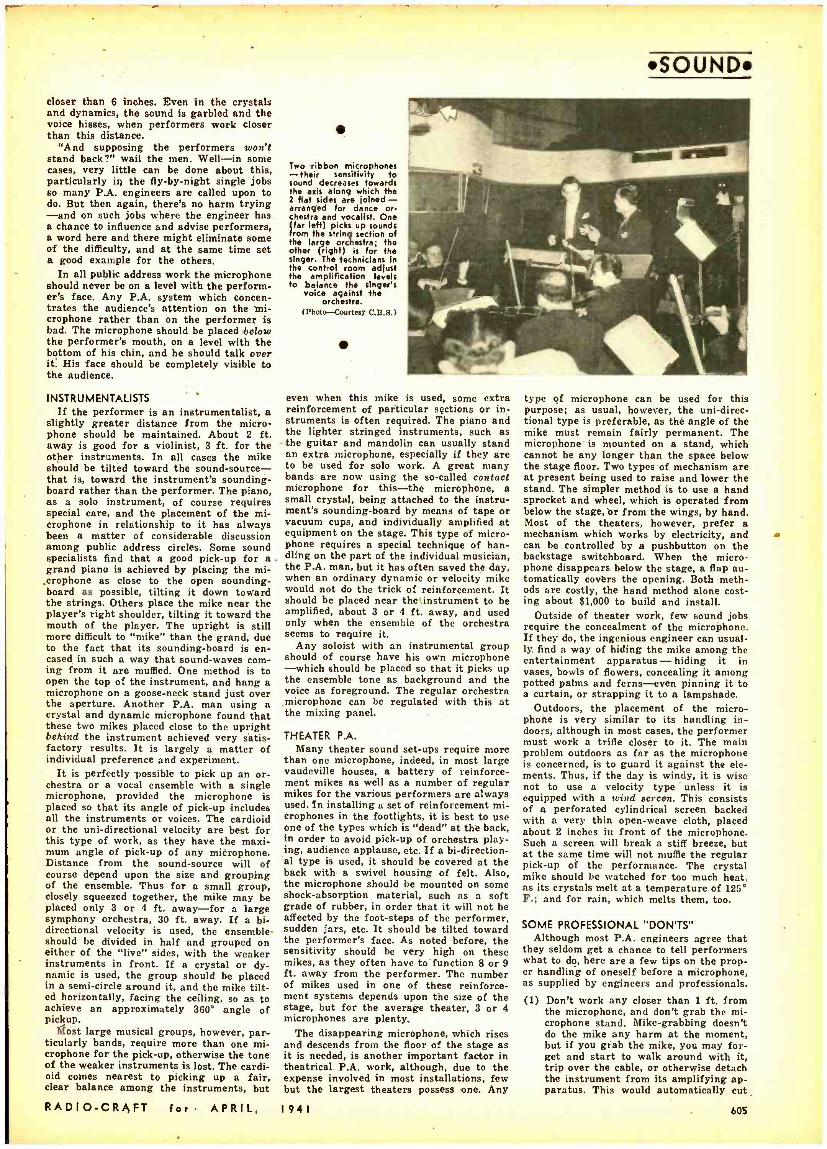
closer than 6 inches. Even in the crystals and dynamics, the sound is garbled and the voice hisses, when performers work closer than this distance.
"And supposing the performers won't stand back ?" wail the men. Well -in some cases, very little can be done about this, particularly in the fly -by -night single jobs so many P.A. engineers are called upon to do. But then again, there's no harm trying -and on such jobs where the engineer has a chance to influence and advise performers, a word here and there might eliminate some of the difficulty, and at the same time set a good example for the others.
In all public address work the microphone should never be on a level with the perform- er's face. Any P.A. system which concen- trates the audience's attention on the mi- crophone rather than on the performer is bad. The microphone should be placed below the performer's mouth, on a level with the bottom of his chin, and he should talk over it: His face should be completely visible to the audience.
INSTRUMENTALISTS If the performer is an instrumentalist, a
slightly greater distance from the micro- phone should be maintained. About 2 ft. away is good for a violinist, 3 ft. for the other instruments. In all cases the mike should be tilted toward the sound- source- that is, toward the instrument's sounding - board rather than the performer. The piano, as a solo instrument, of course requires special care, and the placement of the mi- crophone in relationship to it has always been a matter of considerable discussion among public address circles. Some sound specialists find that a good pick -up for a .
grand piano is achieved by placing the mi- crophone as close to the open sounding - board as possible, tilting it down toward the strings. Others place the mike near the player's right shoulder, tilting it toward the mouth of the player. The upright is still more difficult to "mike" than the grand, due to the fact that its sounding -board is en- cased in such a way that sound -waves corn- ing from it are muffled. One method is to open the top of the instrument, and hang a microphone on a goose -neck stand just over the aperture. Another P.A. man using a crystal and dynamic microphone found that these two mikes placed close to the upright behind the instrument achieved very satis- factory results. It is largely a matter of individual preference and experiment.
It is perfectly possible to pick up an or- chestra or a vocal ensemble with a single microphone, provided the microphone is placed so that its angle of pick -up includes all the instruments or voices. The cardioid or the uni- directional velocity are best for this type of work, as they have the maxi- mum angle of pick -up of any microphone. Distance from the sound -source will of course depend upon the size and grouping of the ensemble. Thus for a small group, closely squeezed together, the mike may be placed only 3 or 4 ft. away -for a large symphony orchestra, 30 ft. away. If a bi- directional velocity is used, the ensemble -
should be divided in half and grouped on either of the "live" sides, with the weaker instruments in front. If a crystal or dy- namic is used, the group should be placed in a semi -circle around it, and the mike tilt- ed horizontally, facing the ceiling, so as to achieve an approximately 360° angle of pickup.
Most large musical groups, however, par- ticularly bands, require more than one mi- crophone for the pick -up, otherwise the tone of the weaker instruments is lost. The cardi- oid comes nearest to picking up a fair, clear balance among the instruments, but
RADIO -CRAFT for . APRIL,
Two ribbon microphones -their sensitivity to sound decreases towards the anis along which the 2 fiat sides are joined - arranged for dance or- chestra and vocalist. One (far left) picks up sounds from the string section of the large orchestra; the other (right) is for the singer. The technicians in the control room adjust the amplification levels to balance the singer's
voice against the orchestra.
(Photo-Courtesy C.B.S.)
SOUND.
even when this mike is used, some extra reinforcement of particular sections or in- struments is often required. The piano and the lighter stringed instruments, such as the guitar and mandolin can usually stand an extra microphone, especially if they are to be used for solo work. A great many bands are now using the so- called contact microphone for this -the microphone, a small crystal, being attached to the instru- ment's sounding -board by means of tape or vacuum cups, and individually amplified at equipment on the stage. This type of micro- phone requires a special technique of han- dling on the part of the individual musician, the P.A. man, but it has often saved the day, when an ordinary dynamic or velocity mike would not do the trick of reinforcement. It should be placed near the instrument to be amplified, about 3 or 4 ft. away, and used only when the ensemble of the orchestra seems to require it.
Any soloist with an instrumental group should of course have his own microphone -which should be placed so that it picks up the ensemble tone as background and the voice as foreground. The regular orchestra microphone can be regulated with this at the mixing panel.
THEATER PA. Many theater sound set -ups require more
than one microphone, indeed, in most large vaudeville houses, a battery of reinforce- ment mikes as well as a number of regular mikes for the various performers are always used. In installing a set of reinforcement mi- crophones in the footlights, it is best to use one of the types which is "dead" at the back, in order to avoid pick -up of orchestra play- ing, audience applause, etc. If a bi- direction- al type is used, it should be covered at the back with a swivel housing of felt. Also, the microphone should be mounted on some shock -absorption material, such as a soft grade of rubber, in order that it will not be affected by the foot -steps of the performer, sudden jars, etc. It should be tilted toward the performer's face. As noted before, the sensitivity should be very high on these mikes, as they often have to function 8 or 9 ft. away from the performer. The number of mikes used in one of these reinforce- ment systems depends upon the size of the stage, but for the average theater, 3 or 4 microphones are plenty.
The disappearing microphone, which rises and descends from the floor of the stage as it is needed, is another important factor in theatrical P.A. work, although, due to the expense involved in most installations, few but the largest theaters possess one. Any
I 9 4 I
type of microphone can be used for this purpose; as usual, however, the uni- direc- tional type is preferable, as the angle of the mike must remain fairly permanent. The microphone is mounted on a stand, which cannot be any longer than the space below the stage floor. Two types of mechanism are at present being used to raise and lower the stand. The simpler method is to use a hand sprocket and wheel, which is operated from below the stage,br from the wings, by hand. Most of the theaters, however, prefer a mechanism which works by electricity, and can be controlled by a pushbutton on the backstage switchboard. When the micro- phone disappears below the stage, a flap au- tomatically covers the opening. Both meth- ods are costly, the hand method alone cost- ing about $1,000 to build and install.
Outside of theater work, few sound jobs require the concealment of the microphone. If they do, the ingenious engineer can usual- ly find a way of hiding the mike among the entertainment apparatus - hiding it in vases, bowls of flowers, concealing it among potted palms and ferns -even pinning it to a curtain, or strapping it to a lampshade.
Outdoors, the placement of the micro- phone is very similar to its handling in- doors, although in most cases, the performer must work a trifle closer to it. The main problem outdoors as far as the microphone is concerned, is to guard it against the ele- ments. Thus, if the day is windy, it is wise not to use a velocity type unless it is equipped with a wind screen. This consists of a perforated cylindrical screen backed with a very thin open -weave cloth, placed about 2 inches in front of the microphone. Such a screen will break a stiff breeze, but at the same time will not muffle the regular pick -up o the performance. The crystal mike should be watched for too much heat, as its crystals melt at a temperature of 125° F.; and for rain, which melts them, too.
SOME PROFESSIONAL "DON'TS" Although most P.A. engineers agree that
they seldom get a chance to tell performers what to do, here are a few tips on the prop- er handling of oneself before a microphone, as supplied by engineers and professionals. (1) Don't work any closer than 1 ft. from
the microphone, and don't grab the mi- crophone stand. Mike- grabbing doesn't do the mike any harm at the moment, but if you grab the mike, you may for- get and start to walk around with it, trip over the cable, or otherwise detach the instrument from its amplifying ap- paratus. This would automatically cut
605
-nos itpO$j óóESK
The
COMBINATION FOR AS LITTLE AS
10c A DAY Bow easy it is to pay for this combination of desk and Remington Deluxe Noiseless Portable Typewriter! Just imagine, a small good will deposit with'terms as low as 10e a day to get this combination at once! You will never miss 10c a day. Yet this small sum can actually make you im- mediately the possessor of this amazing office at home combination. You assume no obligations by sending the coupon.
WITH ANY
REMINGTON PORTABLE TYPEWRITER
A beautiful desk in a neutral blue -green which will fit into the decorations of any home-trimmed in black and silver -and made of sturdy fibre board -is now available for only one dollar ($1.00 extra) to purchasers of a Remington Noiseless Portable Type- writer. The desk is so light that it can be moved anywhere without trouble -it is so strong that it will hold six hundred (600) pounds. With this combination of desk and Noiseless Deluxe Portable Typewriter, you will have a miniature office at home. Learn the complete details of this offer. Mail the coupon today.
LEARN TYPING FREE
To help you even further, you get free with this special offer a 32 -page booklet, prepared by ex- perts, to teach you quickly how to typewrite by the touch method. When you buy a Noiseless you get this free Remington Rand gift that increases the pleasure of using your Remington Noiseless Deluxe Portable. Remember, the touch typing book is sent free while this offer holds.
SPECIAL CARRYING CASE
The Remington Deluxe Noiseless Portable is light in weight, easily carried about. With this offer Remington supplies a sturdy, beautiful carrying case which rivals in beauty and utility the most attractive luggage you can buy.
SPECIFICATIONS ALL ESSENTIAL FEATURES of large stand- ard office machines appear in the Noiseless Portable -standard 4 -row keyboard; back spacer; margin stops and margin release; double shift key and shift lock; two color ribbon and auto- matic ribbon reverse; variable line spacer; paper fingers; makes as many as seven carbons; takes paper 9.5" wide; writes lines 8.2" wide. There are also extra features like the card writing at- tachment, black key cards and white letters, touch regulator, rubber cushioned feet. These make typing on a Remington Deluxe Noiseless Portable a distinct pleasure. Thousands of fam- ilies now using the Remington Deluxe Noiseless Portable know from experience how wonderful it is!
Remington Rand Inc., Dept. 189-4
465 Washington St., Buffalo, N. Y.
Tell me, without obligation, how to get a Free Trial of a new Remington Deluxe Noiseless Portable, including Carrying Case and Free 32 -page Typing Instruction Book- let on terms as low as l0c a day. Send Catalogue.,
Name
Address
City State
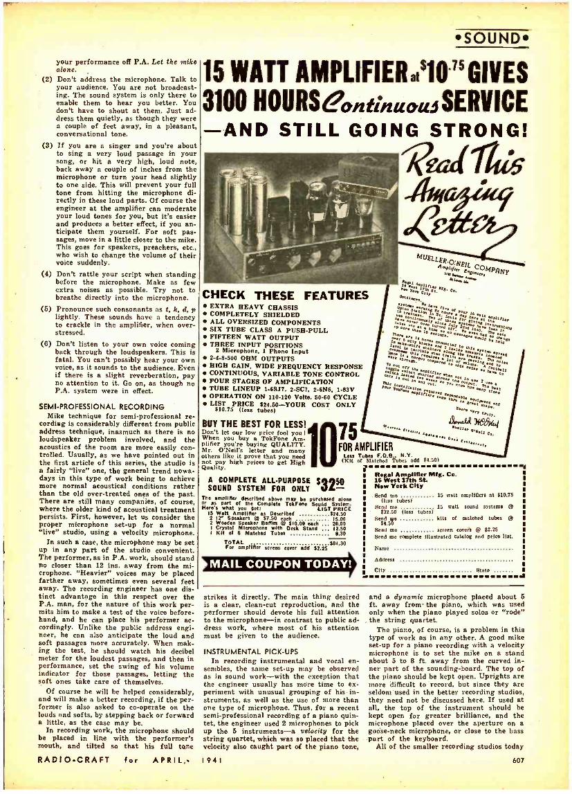
your performance off P.A. Let the rnike alone.
(2) Don't address the microphone. Talk to your audience. You are not broadcast- ing. The sound system is only there to enable them to hear you better. You don't have to shout at them. Just ad- dress them quietly, as though they were a couple of feet away, in a pleasant, conversational tone.
(3) If you are a singer and you're about to sing a very loud passage in your song, or hit a very high, loud note, back away a couple of inches from the microphone or turn your head slightly to one side. This will prevent your full tone from hitting the microphone di- rectly in these loud parts. Of course the engineer at the amplifier can moderate your loud tones for you, but it's easier and produces a better effect, if you an- ticipate them yourself. For soft pas- sages, move in a little closer to the mike. This goes for speakers, preachers, etc., who wish to change the volume of their voice suddenly.
(4) Don't rattle your script when standing before the microphone. Make as few extra noises as possible. Try not to breathe directly into the microphone.
(5) Pronounce such consonants as t, k, d, p lightly. These sounds have a tendency to crackle in the amplifier, when over- stressed.
(6) Don't listen to your own voice coming back through the loudspeakers. This is fatal. You can't possibly hear your own voice, as it sounds to the audience. Even if there is a slight reverberation, pay no attention to it. Go on, as though no P.A. system were in effect.
SEMI -PROFESSIONAL RECORDING Mike technique for semi -professional re-
cording is considerably different from public address technique, inasmuch as there is no loudspeaker problem involved, and the acoustics of the room are more easily con- trolled. Usually, as we have pointed out in the first article of this series, the studio is a fairly "live" one, the general trend nowa- days in this type of work being to achieve more normal acoustical conditions rather than the old over -treated ones of the past. There are still many companies, of course, where the older kind of acoustical treatment persists. First, however, let us consider the proper microphone set -up for a normal "live" studio, using a velocity microphone.
In such a case, the microphone may be set up in any part of the studio convenient. The performer, as in P.A. work, should stand no closer than 12 ins. away from the mi- crophone. "Heavier" voices may be placed farther away, sometimes even several feet away. The recording engineer has one dis- tinct advantage in this respect over the P.A. man, for the nature of this work per- mits him to make a test of the voice before- hand, and he can place his performer ac- cordingly. Unlike the public address engi- neer, he can also anticipate the loud and soft passages more accurately. When mak- ing the test, he should watch his decibel meter for the loudest passages, and then in performance, set the swing of his volume indicator for those passages, letting the soft ones take care of themselves.
Of course he will be helped considerably, and will make a better recording, if the per- former is also asked to co- operate on the louds and softs, by stepping back or forward a little, as the case may be.
In recording work, the microphone should be placed in line with the performer's mouth, and tilted so that his full tone
RADIO -CRAFT for APRIL,.
sourvD
15 WATT AMPUFIERI1O75 GIVES 3100 HOURSeatitinuota SERVICE
AND STILL GOING STRONG!
ea Ales Aif eege
CHECK THESE FEATURES EXTRA HEAVY CHASSIS COMPLETELY SHIELDED ALL OVERSIZED COMPONENTS SIX TUBE CLASS A PUSH -PULL FIFTEEN WATT OUTPUT THREE INPUT POSITIONS
2 Microphone. 1 Phono Input 2 -4 -8 -500 OHM OUTPUTS HIGH GAIN. WIDE FREQUENCY RESPONSE CONTINUOUS, VARIABLE TONE CONTROL FOUR STAGES OF AMPLIFICATION TUBE LINEUP I -6SJ7, 2 -SC7, 2 -6N6, 1-83V OPERATION ON 110 -120 Volts, 50 -60 CYCLE LIST PRICE $24.50 -YOUR COST ONLY
$10.75 (less tubes)
BUY THE BEST FOR LESS! Don't let our low price fool you !
When you buy a TokFone Am- plifier you're buying QUALITY. Mr. O'Neil's letter and many others like it prove that you need not pay high prices to get High Quality.
75
MUELLEg,O.
'olrlp EfL
el
Ç O MpgNy Z» a
p.5y t.a. Co.
y
7 aae2,-pn
D e ,
r : . N
Wn'e:
o ó ,hGrl
~ ; 7(' o4":.é
u
i
é
é t é Z ^ mt
Yrl.tl r
é n S,
pl O .v l's. y 7 e
aaa.e. .141 e hola irú.apei:
"! n:¡' . tiak,.
1T::b`aeN
,;N4s.ha pp to ÿ'ñi e.ëhrp 4al
Hrgt°r; :r'iwW :::-roankon..n
op° nr ¡.lat qie ié
mW 742.;á174a arv
.en 2s sn:i wrt'n r,.. rn tn,lr. A., )69/44
ee21p a..12
FOR AMPLIFIER Less Tubes F.O.B.. N.Y. (Kit of blotched Tubes odd II.501
A COMPLETE ALL- PURPOSE 53250 SOUND SYSTEM FOR ONLY -
The amplifier described above may be purchased alone or as part of the Complete TokFone Sound System. Here's what you get: LIST PRICE
15 Watt Amplifier as Described $24.50 2 IY Speakers @ $7.50 each 15.00 2 Wooden Speaker Barnes @ $10.00 each 20.00 I Crystal Microphone with Desk Stand 12.50 I Kit of 6 Matched Tubes 9.30
TOTAL $91.30 For amplifier screen cover add $2.25
k MAIL COUPON TODAY!
I
Regal Amplifier Mfg. Co. 16 West 17th St New York City Send me
(less tubes) Send one 15 watt sound systems @
$32.50 (lees tubes) Send wo kits of matched tubes @
$4.50 Send me screen corers @ $2.25 Send me complete illustrated catalog and price list.
15 watt amplifiers of $10.75
Nome
Address
city Stato J
strikes it directly. The main thing desired is a clear, clean -cut reproduction, and the performer should devote his full attention to the microphone -in contrast to public ad- dress work, where most of his attention must be given to the audience.
INSTRUMENTAL PICK -UPS In recording instrumental and vocal en-
sembles, the same set -up may be observed as in sound work -with the exception that the engineer usually has more time to ex- periment with unusual grouping of his in- struments, as well as the use of more than one type of microphone. Thus, for a recent semi -professional recording of a piano quin- tet, the engineer used 2 microphones to pick up the 5 instruments -a velocity for the string quartet, which was so placed that the velocity also caught part of the piano tone,
I 9 4 I
and a dynamic microphone placed about 6 ft. away from- the piano, which was used only when the piano played solos or "rode" the string quartet.
The piano, of course, is a problem in this type of work as in any other. A good mike set -up for a piano recording with a velocity microphone is to set the mike on a stand about 5 to 8 ft. away from the curved in- ner part of the sounding- board. The top of the piano should be kept open. Uprights are more difficult to record, but since they are seldom used in the better recording studios, they need not be discussed here. If used at all, the top of the instrument should be kept open for greater brilliance, and the microphone placed over the aperture on a goose -neck microphone, or close to the bass part of the keyboard.
All of the smaller recording studios today
607
THE FINEST RADIO BOOK
FREE WE EVER OFFERED :- the 1940 -41 Radio -Television Reference Annual
With $1.00 sahetiptton to RADIO - CRAFT
WITH our compliments, we want to send a copy of the 1940 RADIO-TELEVISION REFERENCE ANNUAL to you FREE. If you will simply take advantage of RADIO -CRAFT magazine's special
subscription offer NOW. This offer Is being made for a limited time only. The 1940 RADIO-TELEVISION REFERENCE ANNUAL has 68 pages, large sire 8' x 111/4. with over 170 illustrations. The contents of this book has never appeared before In handy book form. Its pages cover practically every branch of radio sound, public address. servicing, television, eonetruction articles for advanced radio men and technicians, time and money- saving kinks, wrinkles, useful circuit Informa. tien, "ham" transmitters and receivers, and a host of other data.
The Annuals have always been regarded as a standard reference work for every practical branch of radio operation and service. This 1940 edition ably sustains this reputation. Every radio man wants a copy of this valuable book. lust as this book will be of unquestionable value to you. so. too, will every monthly Issue of RADIO- CRAFT. This magazine brings you big value every month. It keeps you Intelligently Informed about new developments in radio and television. You went the news, want It fully but concisely, want it first -that is why you should read RADIO -CRAFT regularly.
This very special offer Is made for lust one purpose-we want you as a regular subscriber. The Annual, whose contents appears at the right, is not sold, but a Copy Is FREE to you if you subscribo now.
SAME SIZE AS RADIO -C RAFT
THIS COUPON BRINGS YOU THE ANNUAL RADIO -CRAFT 20 VESEY STREET NEW YORK, N. Y.
Gentlemen: Enclosed you will find One Dollar for which enter my subscription to RADIO -CRAFT, Magazine for Eight Months. Send me ABSOLUTELY FREE and POSTPAID, my copy of 1940 RADIO -TELEVISION REFERENCE ANNUAL.
This is a new order Extend My Present Subscription
NAME ADDRESS
CITY STATE DON'T DELAY - MAIL TODAY! RC- 441
J Read the summary of contents
in this FREE BOOK!
THE 1940 RADIO -TELEVISION REFERENCE ANNUAL contains a collection of the best and most important articles. Covering as they do nearly every branch of radio, they form a handy reference works. In addition, many time and labor- saving kinks, circuits and wrinkles, tried and tested by practicing Servicemen, experimenters and radio fans have been included. This book cannot be bought anywhere at any price. Yet it is yours by merely subscribing. Use the convenient coupon below.
BEGINNER'S SIMPLE INEXPENSIVE CONSTRUCTION ARTICLES Beginner's Breadboard Special - a 1 -Tube High -Cara All - Wave Receiver -Wiring Pointers for Radio Beginners -A Watch Cb,rm Sim 1 -Tube Set -Beginner's Simple Volt - Mllliammeter- Making a 1 -Tubo Broadcast Loop Receiver -A.C.-D.C. Power Supply for Battery Portables -A 1 -Tube Short -Waver with Band Coil Switching.
MORE ADVANCED SET CONSTRUCTION The "High -Seas 4" Broadcast Lamp Radio -flaw to Build e 6 -Tube 1.4 -Volt Short -Wave Superhet for the "Ham" or ShortWave Fan -Build the "Lunch Box 5" Super Set - a Broadcast Battery Portable -How to Build a Plug - Together 8 Tube Broadcast Set -The "5 -In -4" All -Wave Radio for A.C. Operation -An Eaelly-Built 8Tube Midget Broadcast Superheterodyne Receiver.
THE SERVICEMEN'S SECTION Bess Tone Control--Simplified Variable Selectivity-Pne- tical Servicing Pointers -Servicing Universal A.C. -D.C. Re- celvers- Killing the "Intermittent" Bug -A Service Shop A.C.to D.C. Power Supply -Sideline Money for Service- men-Adding A.V.C. to any Screen -Grid T.R.F. Receiver -Iron Particles In Speaker Air Cap.
TEST INSTRUMENTS A Useful Neon Lamp Tester -An Inexpensive Output Meter -Making MRllammeter Multipliers- Home -Made Frequency Modulator -The Busy Servicemen's V.T. Volt- Meter.
PUBLIC ADDRESS AND AMPLIFIERS Build this Combination A.C. -D.C. Radio and Inter -Com- municator- Speaker Placement in P.A. Work -The Design and Construction of an Inexpensive All- Push PuR 10 -Watt Amplifier- Obscure Sources of Horn in High -Gain Ampli- flers -How to Build a High- Fidelity 5 -Watt Versatile Amplifier. "HAM" SECTION UltraHlgh Frequency Antennas -The Beginner's Low -Cat Xmitter- Modulator Meter -Phone Monitor -The Begin- ner's "Ham" Receiver -8i5 Meter Acorn Trsnaceiver.
TELEVISION How to Build a 441 Lino T.A.F. Television Receiver -Use- ful Notes on Tolerlelon Antennae.
MISCELLANEOUS Simple Photo-Cell Relay Bet Up- Making a Burglar Alarm -How to Build A.C. -D.C. Capacity Relay -How to Make s Modern Radio Treasure Locator.
USEFUL KINKS, CIRCUITS AND WRINKLES Making a Flexible Coupler- Two -Timing Chime -A Simple Portable Aerial -An Improvised Non -Slip Screw -Driver. NOTE: The book contains numerous other useful Kinks. Circuits and Wrinkles, not listed here.
(approximately)
45 ARTICLES (approximately)
170 ILLUSTRATIONS
68 BIG PAGES
RADIO -CRAFT 20 VESEY STREET
NEW YORK, N. Y.
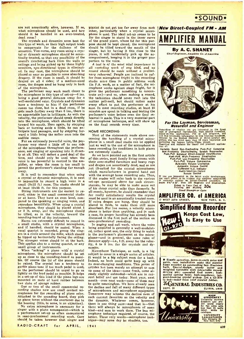
are not acoustically alive, however. If so, what microphone should be used, and how should it be handled in an over -treated, dead room?
The crystals and dynamics seem best for this type of work, as their high output tends to compensate for the dullness of the acoustics. Vice- versa, any room using a crys- tal or dynamic microphone should be acous- tically treated, so that any possibility of the sound's ricocheting back from the walls or ceilings and being picked up by these highly sensitive, non- directional types is eliminat- ed. In any case, the microphone should be placed as near as possible to some absorbing drapery. If the room is small, it should be draped on all 4 sides; if a medium -sized room, the drapes need be hung only in back of the microphone.
The performer may work much closer to ' the microphone in this type of set -up-6 ins. being a good general distance away for a well- modulated voice. Crystals and dynamics have a tendency to hiss if the performer comes too close, but in a dead room, if he gets much farther away than 6 ins., there is
'an appreciable loss in brilliance. As with the velocity, the performer should speak directly into the microphone, which should be tilted toward his mouth. Here again, by stepping back or turning aside a little, he can an- ticipate loud passages, and by stepping for- ward a little bring the softer ones into the audible range.
For an extremely powerful voice, the per- former may stand a little off to one side of the microphone throughout the perform- ance, not singing or speaking into it direct- ly at all. This will deflect a good deal of the tone, and should only be used when the voice is too powerful to control in the am- plifier, or when the room is too small to permit the performer's standing far enough away.
It is well to remember that when using a crystal or dynamic microphone, it is next to impossible to record a high voice in a small (9x12 ft.) room. The studio should be at least 10x15 ft. for this purpose.
String instruments are the easiest to re- cord, either in the small commercial studio or at home. They have an even level, com- pared to the speaking or singing voice, and reproduce beautifully. When using a crystal microphone, they should be placed about 1 or 2 ft. away, and the microphone should be tilted, as in the velocity, toward the sounding -board of the instrument.
Horns are extremely difficult to record in a small studio, with a crystal microphone, and if handled, should be muted. When a vocal quartet is recorded, group the sing- ers in a circle around the mike, which should be tipped up horizontally facing the ceiling. The stronger voices should be at the back. This applies also to a string quartet, or any small group of instruments.
When "miking" a piano with' a crystal microphone, the microphone should be set up as close to the sounding -board as possi- ble. Of course the lid of the piano should be raised. The crystal has a tendency to garble piano tone if too much pedal is used, so the performer should be urged to go as lightly on the loud pedal as possible. It helps in a set -up of this kind if the piano legs are mounted on mats of hard rubber between two slabs of sponge rubber.
One or two of the small commercial re- cording studios now use small contact mi- crophones for the recording of piano solos. Attached to the sounding board, they pick up piano tones without the overtones due to the housing (this, to some, is an objection).
No extra microphone is necessary for a singer with a piano accompanist -which is a performance set -up so often encountered in semi -professional recording work. Care should be taken however that singer and
RADIO -CRAFT for APRIL,
pianist do not get too far away from each other, particularly when a crystal micro- phone is used. The ideal set -up seems to be for the singer to stand in the inner curve of the grand piano, whose lid for this pur- pose should be kept closed; the microphone should be tilted toward the mouth of the singer, but by having it this close to the piano, it will incidentally pick up the ac- companiment, keeping it in the proper pro- portion to the voice.
A test is of the most vital importance in all recording work of any kind, and no record should be mile without a prelimi- nary rehearsal. People are inclined to suf- fer from microphone fright in the recording studio more than in public address work (in P.A. work, as a matter of fact, the mi- crophone works against stage fright, for it gives the performer something to concen- trate on) -and so, when making a record, the technician should never rush into the matter pell -mell, but should rather make every effort to put the performer at his ease. In most recording studios, at least 16 minutes are spent in talking and testing the performer's voice before even the final re- hearsal is made. This is a very essential part of microphone technique, and will show up on the final records every time.
HOME RECORDING Most of the statements made above con-
cerning the handling of a crystal micro- phone in a small dead studio can be applied just as well to the use of the microphone in home recording for conditions in both places are extremely similar.
As we have pointed out in the first article of this series, most family living -rooms with their over- stuffed furniture and heavy rugs and drapes are acoustically dead, and so are not ill- suited for the crystal microphones which manufacturers in general hand out with the average home recording sets. Thus, if the reader will refer back to the various set -ups mentioned above for such circum- stances, he may be able to make more out of his cheap crystal mike than formerly. In all events, however, he should remember that for really satisfactory results the crystal must be used in an acoustically treated room. If extra drapes are hung, they should be placed in folds, to make them still more absorbent. For live rooms, a velocity micro- phone is better than anything, and in such a case, its proper handling has already been discussed in the first part of the section on semi -professional recording.
In paging and call work, where the voice being amplified is generally a well- modulat- ed, rather quiet one, the only thing to watch is the performer's placement at the micro- phone -and in general, the same rules of distance apply -i.e., 1 ft. away for the veloc- ity, 6 to 8 ins. for the crystals and dy- namics.
Microphone Technique, as such, is a big subject to cover in a single series of articles. It would be a big subject even for a book. Indeed, no book could quite keep up with its ever -changing conditions. This series of articles has been merely an attempt to sum up some of the ideas -some fresh, some al- ready slightly outmoded -which are in cur- rent belief and use today. Next year, next month -even next week -some of them may be quite meaningless. We have already seen the decline and fall of many different types of microphones and microphone equipment. Tomorrow may witness the decline even of such current favorites as the velocity and the dynamic. Whatever comes, however, there is one thing sure -and that is -that there will always be microphones of some kind -and men to work them. The less mi- crophone technique required, of course, the better. Those very words - microphone tech- nique -may some day be obsolete, too.
I941
SOUND_ New Direct- Coupled FM - AM
AMPLIFIER MANUAL By A. C. SHANEY
Chief Engineer, Ampli fier Co. of Americo
For the Layman, Serviceman, Recordist and Engineer
Regardless of whether you are interested In the finest type of phonograph reproduction, high fidelity recording, sound -on -fllm applications. FM or AM Programs. YO will lind Invaluable information In this practical handbook. Written by the leading exponent of directcouplod am- plifiers who has spent more than 10 years Improving and Perfecting the famous LortIn- White circuit. Describes and explains the theory and practical applica- tion of: Variable Speed Non- Overoading Push -Pull Expansion
Non Frequency Discriminating Scratch Suppression PushPull Balanced DirectCoupled Amplification
Push -Pull High-Frequency Equalization PuahPulI LowFrequency Equalization
Push -Pull 'Volume Compression Automatic Volume Limitation
Automatic Volume Control Calibrated V.U. Indicator Audio Spectrum Control
Remote Control If you are Interested In the latest audio development,, you can't afford to be without this completo compilation of authentic articles on Direct- Coupled Amplifiers. 82 pages 81/2. 11 ". Over 100 diagrams and illustrations.
Priced to Cover Cost of IA Printing and Mailing
Send Stamps or Coin
AMPLIFIER Co. of AMERICA 17 WEST 20TH STREET. NEW YORK. N. V.
Simplified Home Recorder Keeps Cost Low, Is Easy to Use
Simple operation, down -to -earth price and quick, easy installation make this popular home recorder an outstanding buy. Precision built. Special- design, sturdy motor and weighted turntable with retractable record - driving pin: concealed feed screw; beet- quality cutting head; high -impedance, tan- gent- tracking crystal pickup. Get a GI -R70 to test -order from your regular Jobber.
GENERAL INDUSTRIES CO, DEPT. 20 ELYRIA, OHIO
i r x
nsiepol 14rkg;Tritr
NIGH EFFICIENCY I
University Reflex Speakers will mo- lest sound clearly for two miles with less than 25 watts input. Write for catalogue.
UNIVERSITY LABORATORIES sNew
York C at.
609
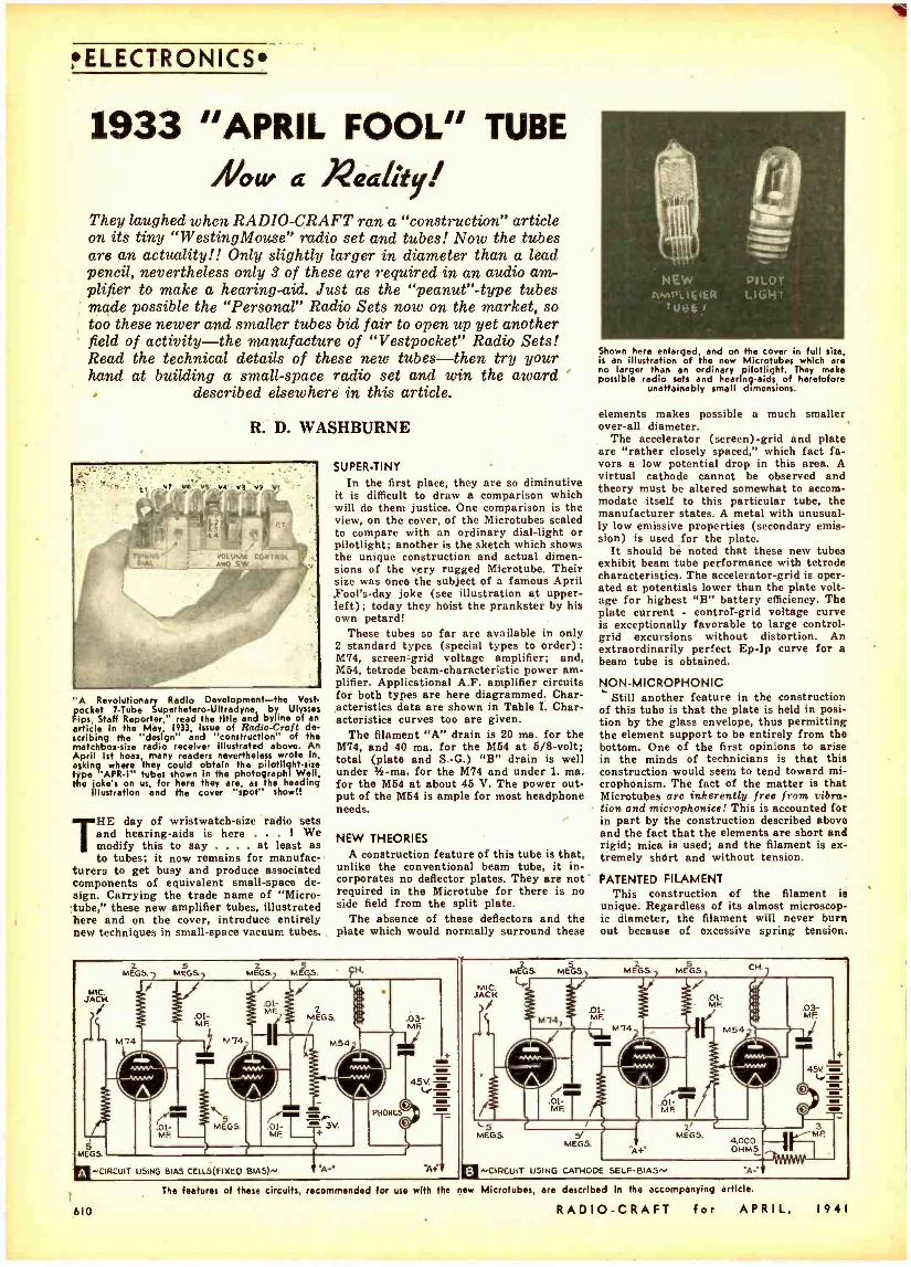
ELECTRONICS
1933 "APRIL FOOL" TUBE
/hour a Xe ty They laughed when RADIO -CRAFT ran a "construction" article on its tiny "WestingMouse" radio set and tubes! Now the tubes are an actuality!! Only slightly larger in diameter than a lead pencil, nevertheless only 3 of these are required in an audio am- plifier to make a hearing -aid. Just as the "peanut" -type tubes made possible the "Personal" Radio Sets now on the market, so too these newer and smaller tubes bid fair to open up yet another field of activity -the manufacture of "Vestpocket" Radio Sets! Read the technical details of these new tubes -then try your hand at building a small -space radio set and win the award '
described elsewhere in this article.
R. D. WASHBURNE
'A Revolutionary Radio Development -the Vest - pocket 7 -Tube Superhetero- Ultradyne by Ulysses
Fips, Staff Reporter," read the title and byline of an article in the May, 1933, Issue of Radio -Craft de- scribing the "design" and "construction" of the matchbox -size radio receiver illustrated above. An April 1st hoax, many readers nevertheless wrote In, asking where they could obtain the pilotlight -size type APR -1" tubes shown in the photographl Well, the jokes on us, for here they are as the heading
illustration and the cover "spot" show!!
THE day of wristwatch -size radio sets and hearing -aids is here . ! We modify this to say . . at least as to tubes; it now remains for manufac-
turers to get busy and produce associated components of equivalent small -space de- sign. Carrying the trade name of "Micro- 'tube," these new amplifier tubes, illustrated here and on the cover, introduce entirely new techniques in small -space vacuum tubes.
SUPER -TINY In the first place, they are so diminutive
it is difficult to draw a comparison which will do them justice. One comparison is the view, on the cover, of the Microtubes scaled to compare with an ordinary dial -light or pilotlight; another is the sketch which shows the unique construction and actual dimen- sions of the very rugged Microtube. Their size was once the subject of a famous April ,Fool's -day joke (see illustration at upper - left); today they hoist the prankster by his own petard!
These tubes so far are available in only 2 standard types (special types to order): M74, screen -grid voltage amplifier; and, M54, tetrode beam- characteristic power am- plifier. Applicational A.F. amplifier circuits for both types are here diagrammed. Char- acteristics data are shown in Table I. Char- acteristics curves too are given.
The filament "A" drain is 20 ma. for the M74, and 40 ma. for the M54 at 5/8-volt; total (plate and S. -G.) "B" drain is well under % -ma. for the M74 and under 1. ma. for the M64 at about 45 V. The power out- put of the M54 is ample for most headphone needs.
NEW THEORIES A construction feature of this tube is that,
unlike the conventional beam tube, it in- corporates no deflector plates. They are not required in the Microtube for there is no side field from the split plate.
The absence of these deflectors and the plate which would normally surround these
Shown here enlarged, and on the cover in full size, is an illustration of the new Microtubes which are no larger than an ordinary pilotlight. They make possible radio sets and hearing -aids of heretofore
unattainably small dimensions.
elements makes possible a much smaller over -all diameter.
The accelerator (screen) -grid and plate are "rather closely spaced," which fact fa- vors a low potential drop in this area. A virtual cathode cannot be observed and theory must be altered somewhat to accom- modate itself to this particular tube, the manufacturer states. A metal with unusual- ly low emissive properties (secondary emis- sion) is used for the plate.
It should be noted that these new tubes exhibit beam tube performance with tetrode characteristics. The accelerator -grid is oper- ated at potentials lower than the plate volt- age for highest "B" battery efficiency. The plate current - contror -grid voltage curve is exceptionally favorable to large control - grid excursions without distortion. An extraordinarily perfect Ep -Ip curve for a beam tube is obtained.
NON- MICROPHONIC Still another feature in the construction
of this tube is that the plate is held in posi- tion by the glass envelope, thus permitting the element support to be entirely from the bottom. One of the first opinions to arise in the minds of technicians is that this construction would seem to tend toward mi- crophonism. The fact of the matter is that Microtubes are inherently free from vibra- tion and microphonics! This is accounted for in part by the construction described above and the fact that the elements are short and rigid; mica is used; and the filament is ex- tremely shórt and without tension.
PATENTED FILAMENT This construction of the filament is
unique. Regardless of its almost microscop- ic diameter, the filament will never burn out because of excessive spring tension.
MIC. JACK
z MEG8 7
/
5 MEG5.7
z MEG/5.7 ME/CS.
f f 01 MF
CH.
.03- MF.
5 MEGS.
-CIRCUIT USING BIAS CELLS(FIXEO BIAS)^ $'A-r
MIC: JACK
z MEGS.
Y 5
MeGSy MEGS 5
MEGS.y
`5 MEGS. y
MEGS. "A+
2 MEGS.
03- MF.
4.5v
4.000 OHMS
MF.
^'CIRCUIT USING CATHODE SELF -BIAS^,
4-
The features of these circuits, recommended for use with the new Microtubes, are described in the accompanying article.
610 RADIO -CRAFT for APRIL, I 9 4 1
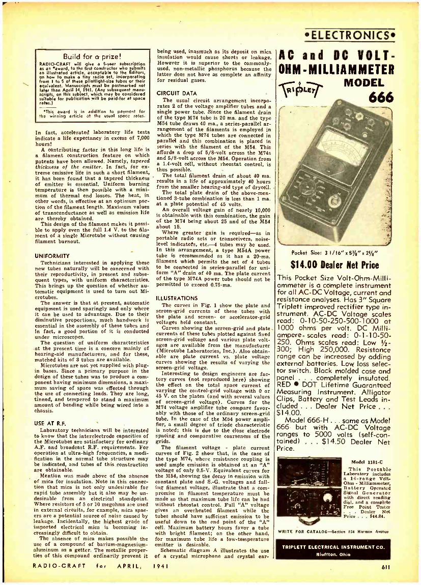
Build for a prize! RADIO -CRAFT will give a 5 -year subscription as an 'award. to the first constructor who submits an illustrated article, acceptable to the Editors, on how to make a tiny radio set, incorporating from I to 5 of these pilotlight-size tubes or their equivalent. Manuscripts must be postmarked not later than April 14r 1941. (Any subsequent manu- scripts, on this subject, which may be considered suitable for publication will be paid -for at space rates.)
'This award is in addition to payment for the winning article at the usual space rates.
In fact, accelerated laboratory life tests indicate a life expectancy in excess of 7,000 hours!
A contributing factor in this long life is a filament construction feature on which patents have been allowed. Namely, tapered thickness of the emitter. In fact, for ex- treme emissive life in such a short filament, it has been found that a tapered thickness of emitter is essential. Uniform burning temperature is then possible with a mini- mum of thermal end losses. The heat, in other words, is effective at an optimum por- tion of the filament length. Maximum values of transconductance as well as emission life are thereby obtained.
This design of the filament makes it possi- ble to apply even the full 1.4 V. to the fila- ment of a single Microtube without causing filament burnout.
UNIFORMITY Technicians interested in applying these
new tubes naturally will be concerned with their reproductivity, in present and subse- quent types, with uniform characteristics. This brings up the question of whether au- tomatic equipment is used to turn out Mi- crotubes.
The answer is that at present, automatic equipment is used sparingly and only where it can be used to advantage. Due to their diminutive proportions, much handwork is essential in the assembly of these tubes and in fact, a good portion of it is conducted under microscopes.
The question of uniform characteristics at the present time is a concern mainly of hearing -aid manufacturers, and for these, matched kits of 3 tubes are available.
Microtubes are not yet supplied with plug - in bases. Since a primary purpose in the design of these tubes was to produce a com- ponent having minimum dimensions, a maxi- mum saving of space was effected through the use of connecting leads. They are long, tinned, and tempered to stand a maximum amount of bending while being wired into a chassis.
USE AT R.F. Laboratory technicians will be interested
to know that the interelectrode capacities of the Microtubes are satisfactory for ordinary A.F. and broadcast R.F. requirements. For operation at ultra -high frequencies, a modi- fication in the normal tube structure may be indicated, and tubes of this construction are obtainable.
Mention was made above of the absence of mica for insulation. Note in this connec- tion that mica is not only undesirable for rapid tube assembly but it also may be un- desirable from an electrical standpoint. Where resistors of 5 or 10 megohms are used in external circuits, for example, mica spac- ers are a potential source of noise caused by leakage. Incidentally, the highest grade of imported electrical mica is becoming in- creasingly difficult to obtain.
The absence of mica makes possible the use of a compound of barium- magnesium- aluminum as a getter. The metallic proper- ties of this compound ordinarily prevent it
RADIO -CRAFT for APRIL,
being used, inasmuch as its deposit on mica insulation would cause shorts or leakage. However it is superior to the commonly - used, non -metallic phosphorus because the latter does not have as complete an affinity for residual gases.
CIRCUIT DATA -
The usual circuit arrangement incorpo- rates 2 of the voltage amplifier tubes and a single power tube. Since the filament drain of the type M74 tube is 20 ma. and the type M54 tube draws 40 ma., a series -parallel ar- rangement of the filaments is employed in which the type M74 tubes are connected in parallel and this combination is placed in series with the filament of the M54. This affords a drop of 5/8 -volt across the M74s and 5/8 -volt across the M54. Operation from a 1.4 -volt cell, without rheostat control, is thus possible. -
The total filament drain of about 40 ma. results in a life of approximately 90 hours from the smaller hearing -aid type of drycell.
The total plate drain of the above -men- tioned 3 -tube combination is less than 1 ma. at a plate potential of 45 volts.
An overall voltage gain of nearly 10,000 is obtainable with this combination, the gain of the M74 being about 25 and of the M64 about 15.
Where greater gain is required -as in portable radio sets or transceivers, noise - level indicatofs, etc. -4 tubes may be used. In this arrangement, a type M54A power tube is recommended as it has a 20 -ma. filament which permits the set of 4 tubes to be connected in series -parallel for uni- form "A" drain of 40 ma. The plate current of the type M74A power tube should not be permitted to exceed 0.75 -ma.
ILLUSTRATIONS The curves in Fig. 1 show the plate and
screen -grid currents of these tubes with the plate and screen- or accelerator -grid voltages held constant.
Curves showing the screen -grid and plate currents of these tubes plotted against fixed screen -grid voltage and various plate volt- ages are available from the manufacturer ( Microtube Laboratories, Inc.). Also obtain- able are plate current vs. plate voltage curves showing the results of varying the screen -grid voltage.
Interesting to design engineers are fac- tory curves (not reproduced here) showing the effect on the total space current of varying the control -grid voltage with O or 45 V. on the plates (and with several values of screen -grid voltage). Curves for the M74 voltage amplifier tube compare favor- ably with those of the ordinary screen -grid tube. In the case of the M54 power ampli- fier, a small degree of triode characteristic is noted; this is due to the close electrode spacing and comparative coarseness of the grids.
The filament voltage - plate current curves of Fig. 2 show that, in the case of the type M74, where resistance coupling is used ample emission is obtained at an "A" voltage of only 0.5 -V. Equivalent curves for the M54, showing the decay in emission with constant plate and S.-G. voltages and fall- ing filament voltage, illustrate that a corn- promise in filament temperature must be made so that maximum tube life can be had without rheostat control. Full "A" voltage gives an overheated filament while the tubes should have sufficient emission to be useful down to the end point of the "A" cell. Maximum battery hours favor a tube with bright filament; on the other hand, for maximum tube life a low- temperature emitter is desirable.
Schematic diagram A illustrates the use of a crystal microphone and crystal ear-
1941
ELECTRONICS
AC and DC VOLT - OHM-MILLIAMMETER
MODEL 666 e _
Pocket Size: 3 I /16" x 51 /err x 21 /e"
$14.00 Dealer Net Price
This Pocket Size Volt- Ohm- Milli- ammeter is o complete instrument for all AC -DC Voltage, current and resistance analyses. Has 3" Square Triplett improved rectifier type in- strument. AC -DC Voltage scales read: 0 -10 -50 -250- 500 -1000 at 1000 ohms per volt. DC Milli- ampere. scales read: 0- 1- 10 -50- 250. Ohms scales read: Low IA- 300; High 250,000. Resistance range can be increased by adding external batteries. Low loss selec- tor switch. Black molded case and panel . completely insulated. RED DOT Lifetime Guaranteed Measuring Instrument. Alligator Clips, Battery and Test Leads in- cluded ... Dealer Net Price . . .
$14.00. Model 666 -H ... same as Model
666 but with AC -DC Voltage ranges to 5000 volts (self -con- tained) . . . $14.50 Dealer Net Price.
Model 1181 -C This Portable
Laboratory includes a 16 -range Volt - Ohm - Milliammeter, Battery Operated Signal Generator with direct reading dial. and a complete Free Point Tester
. Dealer Net Price ... $44.84.
WRITE FOR CATALOG -Section 164 Harmon Avenue
TRIPLETT ELECTRICAL INSTRUMENT CO.
Bluffton, Ohio
611
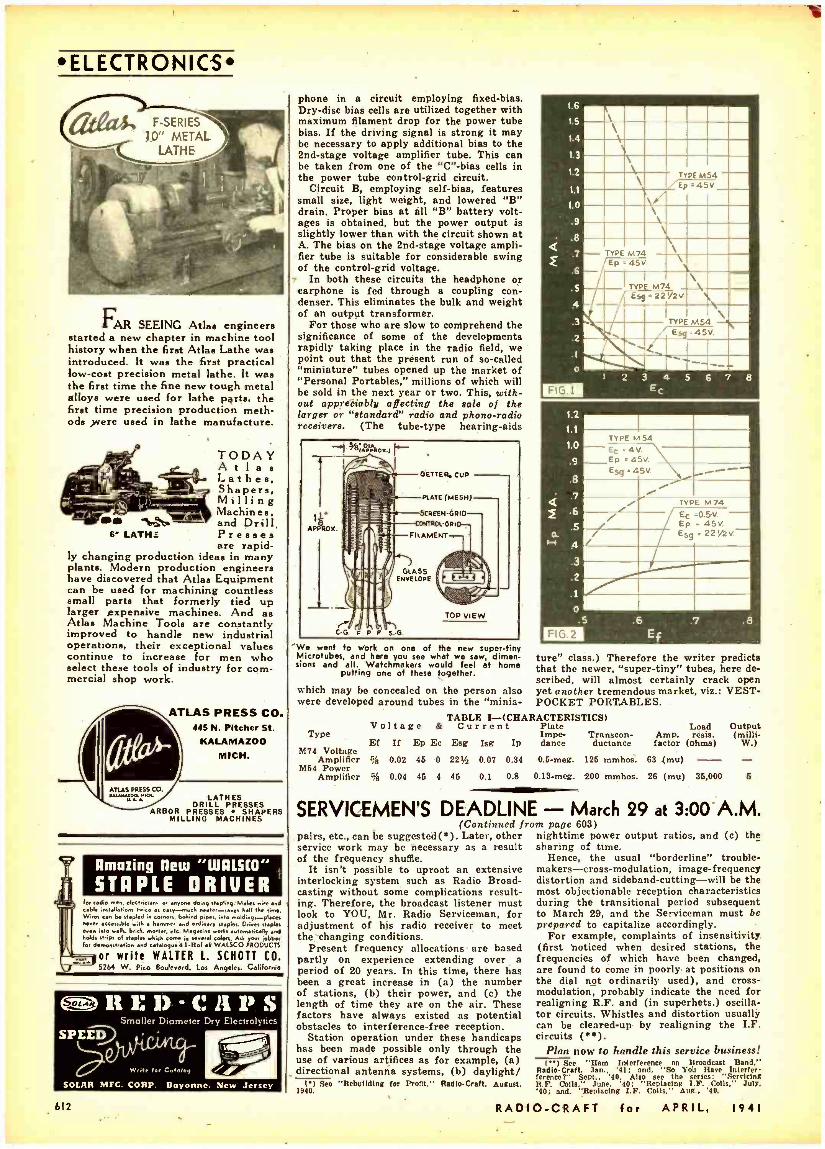
TYPE M54 - EC 4V. Ep e 45V E59 45V. i i i
/
TYPE M74 Ec =0.5v. - Ep _ 45V. En e 22%2V
TYPE M54 ,Ep 045V
ELECTRONICS
FAR SEEING Atlas engineers started a new chapter in machine tool history when the first Atlas Lathe was introduced. It was the first practical low -cost precision metal lathe. It was the first time the fine new tough metal alloys were used for lathe parts, the first time precision production meth- ods were used in lathe manufacture.
TODAY A t l a s Lathes, Shapers, Milling
"= Machines, - and Drill 6" LATH_ Presses
are rapid- ly changing production ideas in many plants. Modern production engineers have discovered that Atlas Equipment can be used for machining countless small parts that formerly tied up larger expensive machines. And as Atlas Machine Tools are constantly improved to handle new industrial operations, their exceptional values continue to increase for men who select these tools of industry for com- mercial shop work.
1
ATLAS PRESS CO. 445 N. Pitcher St.
KALAMAZOO MICH.
ATLAS PRESS CO. n,u,.+oa MO, LATHES
DRILL PRESSES ARBOR PRESSES SHAPERS
MILLING MACHINES
Amazing flew "WALSCO"
STAPLE DRIUER for radio men, eleclr,ci.ns or anyone de ng stapling. Mates airy and cable ' Herons t.ice as easy-reach saves kall Ike lime. Wirer can be stapled .n turne. betted pipes into mold egc -plce,
.i ble with tam sed ordinary staples. Glees staple, eves accessible .ah. hick. mot., eetc. Magnin works a.lem.buly ad
hold Into sN,ps of staple. .bi.A cane in several colo". Aso roer jobber
lot demo ion and mislegw4l -Rof ell WALSCO PRODUCTS
or write WALTER L. SCHOTT CO. 5264 W. Pico Boulevard, Los Angeles, California
emolì}:D-CAPS Smaller Diameter Dry Eleclrolylics
Write ter Catalog
SOLAR MFG. CORP. Bayonne, New Jersey
612
phone in a circuit employing fixed -bias. Dry -disc bias cells are utilized together with maximum filament drop for the power tube bias. If the driving signal is strong it may be necessary to apply additional bias to the 2nd -stage voltage amplifier tube. This can be taken from one of the "C" -bias cells in the power tube control -grid circuit.
Circuit B, employing self -bias, features small size, light weight, and lowered "B" drain. Proper bias at all "B" battery volt- ages is obtained, but the power output is slightly lower than with the circuit shown at A. The bias on the 2nd -stage voltage ampli- fier tube is suitable for considerable swing of the control -grid voltage.
- In both these circuits the headphone or earphone is fed through a coupling con- denser. This eliminates the bulk and weight of an output transformer.
For those who are slow to comprehend the significance of some of the developments rapidly taking place in the radio field, we point out that the présent run of so- called "miniature" tubes opened up the market of "Personal Portables," millions of which will be sold in the next year or two. This, with- out appreciably affecting the sale of the larger or "standard" radio and phono -radio receivers. (The tube -type hearing -aids
1 iveiAOP1:10<.f I .
A P Ox
CG. r P
GETTER. CUP
PLATE (MESH)
SCREEN -GRID
11.051
FILAMENT
11íC GLASS
U1) E G i NVELOPE
TOP VIEW
'we went fo work on one of the new super -tiny Microtubes, and here you see what we saw, dimen lions and all. Watchmakers would feel of home
putting one of these together.
which may be concealed on the person also were developed around tubes in the "minia-
1.6
1.5
1.4
1.3
1.2
1.1
1.0
9
.8
.7
.6
5
4
.3
.2
.1
o
FIG 1
- TYPE M74 Ep 45V.
TYPE M74 559 22'/2V.
TYPE M54 \\ ü77' 45V.
I 2 3 4 5 6 7 8 E
1.2
1.
I.0
.9
.8
.7
.6
s
4 .3
.2
.1
O
FIG .2 .5 .6 .7 .8
Et
ture" class.) Therefore the writer predicts that the newer, "super- tiny" tubes, here de- scribed, will almost certainly crack open yet another tremendous market, viz.: VEST - POCKET PORTABLES.
TABLE I- (CHARACTERISTICS)
Type
M74 Voltage Amplifier
M64 Power Amplifier
Voltage &
Ef If Ep Ec
% 0.02 46 0
% 0.04 45 4
Current Esg Isg Ip
221/2 0.07 0.34
45 0.1 0.8
Plate Impe- dance
0.5 -meg.
0.13 -meg.
Transcon- ductance
126 mmhos.
200 mmhos.
Amp. factor
63 (mu)
26 (mu)
Load resis.
(ohms)
Output (milli -
W.) - 6
- 85,000
SERVICEMEN'S DEADLINE - March 29 at 3:00 A.M. (Continued front pape 603)
nighttime power output ratios, and (c) the sharing of time.
Hence, the usual "borderline" trouble- makers- cross- modulation, image -frequency distortion and sideband- cutting -will be the most objectionable reception characteristics during the transitional period subsequent to March 29, and the Serviceman must be prepared to capitalize accordingly.
For example, complaints of insensitivity (first noticed when desired stations, the frequencies of which have been changed, are found to come in poorly at positions on the dial not ordinarily used), and cross - modulation, probably indicate the need for realigning R.F. and (in superhets.) oscilla- tor circuits. Whistles and distortion usually can be cleared -up by realigning the I.F. circuits ( ).
Plan now to handle this service business! (') See "Ham interference on Broadcast Band."
Radle- Craft. Jan., '41: and. "So You Have Interim.. fercaret" Sept.. '90. Also see the series: "Servicing R.F. Culls." June, '40; Replacing 1.F. Coils," July. '40; and, 'Replacing I.F. Coils." Aug.. '40.
pairs, etc., can be suggested(6). Later, other service work may be necessary as a result of the frequency shuffle.
It isn't possible to uproot an extensive interlocking system such as Radio Broad- casting without some complications result- ing. Therefore, the broadcast listener must look to YOU, Mr. Radio Serviceman, for adjustment of his radio receiver to meet the changing conditions.
Present frequency allocations are based partly on experience extending over a period of 20 years. In this time, there bas been a great increase in (a) the number of stations, (b) their power, and (c) the length of time they are on the air. These factors have always existed as potential obstacles to interference -free reception.
Station operation under these handicaps has been made possible only through the use of various artifices as for example, (a) directional antenna systems, (b) daylight/
() See "Rebuilding for Profit," Radio- Craft. August, 1940.
RADIO -CRAFT for APRIL, 1941
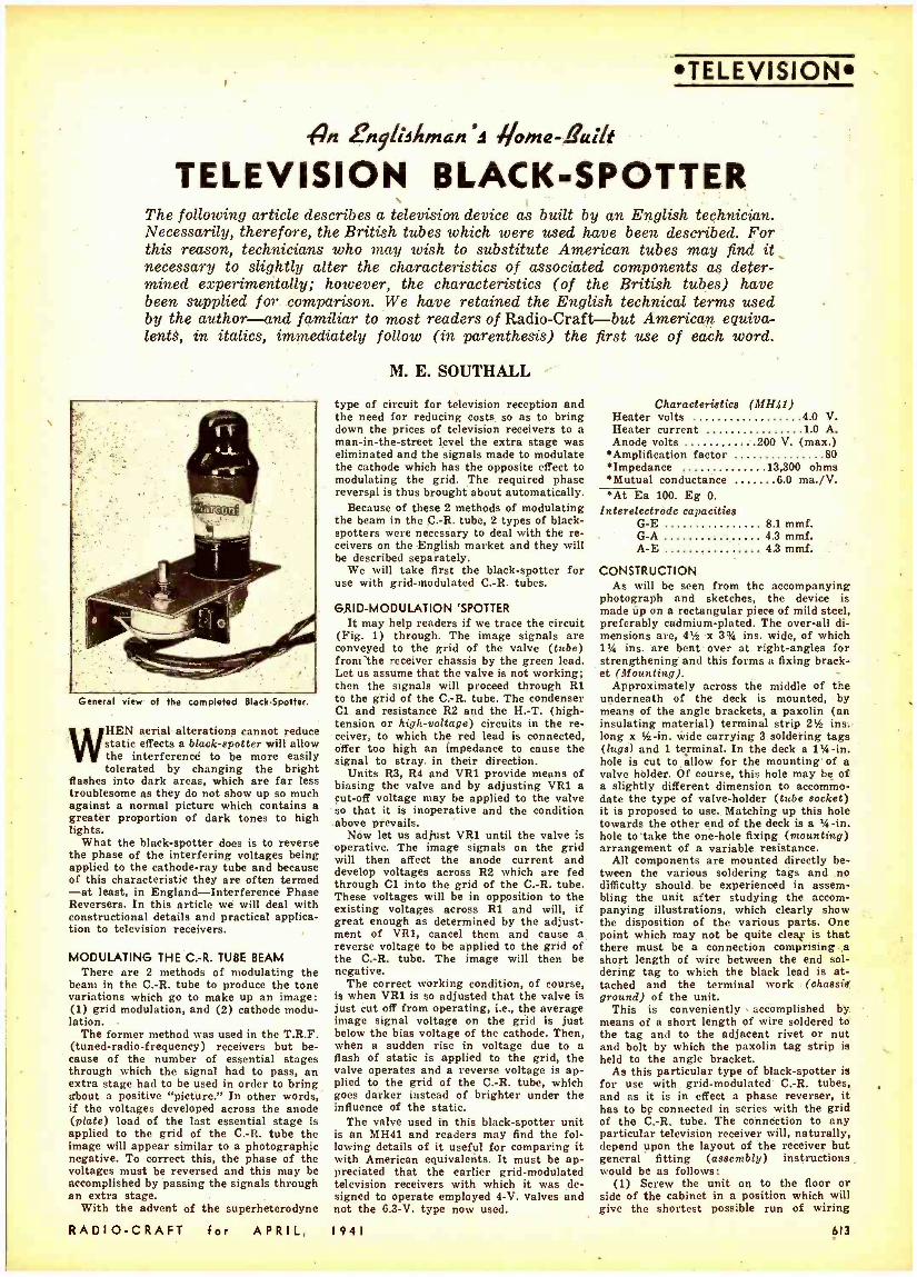
TELEVISION
n en9lisisman'9 fj/oina-Built
TELEVISION BLACK- SPOTTER The following article describes a television device as built by an English technician. Necessarily, therefore, the British tubes which were used have been described. For this reason, technicians who may wish to substitute American tubes may find it necessary to slightly alter the characteristics of associated components as deter- mined experimentally; however, the characteristics (of the British tubes) have been supplied for comparison. We have retained the English technical terms used by the author -and familiar to most readers of Radio -Craft -but American equiva- lentS, in italics, immediately follow (in parenthesis) the first use of each word.
General view of the completed Black -Spotter.
WHEN aerial alterations cannot reduce static effects a black -spotter will allow the interferencé to be more easily tolerated by changing the bright
flashes into dark areas, which are far less troublesome as they do not show up so much against a normal picture which contains a greater proportion of dark tones to high lights.
What the black -spotter does is to reverse the phase of the interfering voltages being applied to the cathode -ray tube and because of this characteristic they are often termed -at least, in England -Interference Phase Reversers. In this article we will deal with constructional details and practical applica- tion to television receivers.
MODULATING THE C.-R. TUBE BEAM There are 2 methods of modulating the
beam in the C.-R. tube to produce the tone variations which go to make up an image: (1) grid modulation, and (2) cathode modu- lation.
The former method was used in the T.R.F. (tuned -radio- frequency) receivers but be- cause of the number of essential stages through which the signal had to pass, an extra stage had to be used in order to bring about a positive "picture." In other words, if the voltages developed across the anode (plate) load of the last essential stage is applied to the grid of the C.-R. tube the image will appear similar to a photographic negative. To correct this, the phase of the voltages must be reversed and this may be accomplished by passing the signals through an extra stage.
With the advent of the superheterodyne
RADIO -CRAFT for APRIL,
M. E. SOUTHALL
type of circuit for television reception and the need for reducing costs so as to bring down the prices of television receivers to a man -in- the -street level the extra stage was eliminated and the signals made to modulate the cathode which has the opposite effect to modulating the grid. The required phase reversal is thus brought about automatically.
Because of these 2 methods of modulating the beam in the C.-R. tube, 2 types of black - spotters were necessary to deal with the re- ceivers on the English market and they will be described separately.
We will take first the black- spotter for use with grid -modulated C.-R. tubes.
GRID -MODULATION 'SPOTTER It may help readers if we trace the circuit
(Fig. 1) through. The image signals are conveyed to the grid of the valve (tube) from the receiver chassis by the green lead. Let us assume that the valve is not working; then the signals will proceed through Rl to the grid of the C.-R. tube. The condenser C1 and resistance R2 and the H. -T. (high - tension or high- voltage) circuits in the re- ceiver, to which the red lead is connected, offer too high an impedance to cause the signal to stray in their direction.
Units R3, R4 and VR1 provide means of biasing the valve and by adjusting VR1 a cut -off voltage may be applied to the valve so that it is inoperative and the condition above prevails.
Now let us adjust VR1 until the valve is operative. The image signals on the grid will then affect the anode current and develop voltages across R2 which are fed through Cl into the grid of the C.-R. tube. These voltages will be in opposition to the existing voltages across Rl and will, if great enough as determined by the adjust- ment of VR1, cancel them and cause a reverse voltage to be applied to the grid of the C.-R. tube. The image will then be negative.
The correct working condition, of course, is when VR1 is so adjusted that the valve is just cut off from operating, i.e., the average image signal voltage on the grid is just below the bias voltage of the cathode. Then, when a sudden rise in voltage due to a flash of static is applied to the grid, the valve operates and a reverse voltage is ap- plied to the grid of the C.-1L tube, which goes darker instead of brighter under the influence of the static.
The valve used in this black- spotter unit is an MH41 and readers may find the fol- lowing details of it useful for comparing it with American equivalents. It must be ap- preciated that the earlier grid -modulated television receivers with which it was de- signed to operate employed 4 -V. valves and not the 6.3 -V. type now used.
I 9 4 I
Characteristics (MH41) Heater volts 4 0 V. Heater current 10 A. Anode volts 200 V. (max.)
Amplification factor 80 Impedance 13,300 ohms *Mutual conductance 6 0 ma. /V. *At Ea 100. Eg 0.
Interelectrodc capacities G -E 8 1 mmf. G -A 4 3 mmf. A -E 4 3 mmf.
CONSTRUCTION As will be seen from the accompanying
photograph and sketches, the device is made up on a rectangular piece of mild steel, preferably cadmium -plated. The over -all di- mensions are, 41/2 x 3% ins. wide, of which 11/4 ins. are bent over at right -angles for strengthening and this forms a fixing brack- et (Mounting). -
Approximately across the middle of the underneath of the deck is mounted, by means of the angle brackets, a paxolin (an insulating material) terminal strip 21 ins. long x 1/2-in. wide carrying 3 soldering tags (lugs) and 1 terminal. In the deck a l'/4 -in. hole is cut to allow for the mounting of a valve hólder. Of course, this hole may be of a slightly different dimension to accommo- date the type of valve -holder (tube socket) it is proposed to use. Matching up this hole towards the other end of the deck is a 1 /4 -in. hole to take the one -hole fixing (mounting) arrangement of a variable resistance.
All components are mounted directly be- tween the various soldering tags and no difficulty should be experienced in assem- bling the unit after studying the accom- panying illustrations, which clearly show the disposition of the various parts. One point which may not be quite clear is that there must be a connection comprising a short length of wire between the end sol- dering tag to which the black lead is at- tached and the terminal work (chassis ground) of the unit.
This is conveniently accomplished by means of a short length of wire soldered to the tag and to the adjacent rivet or nut and bolt by which the paxolin tag strip is held to the angle bracket.
As this particular type of black -spotter is for use with grid- modulated C.-R. tubes, and as it is in effect a phase reverser, it has to be connected in series with the grid of the C.-R. tube. The connection to any particular television receiver will, naturally, depend upon the layout of the receiver but general fitting (assembly) instructions would be as follows:
(1) Screw the unit on to the floor or side of the cabinet in a position which will give the shortest possible run of wiring
613
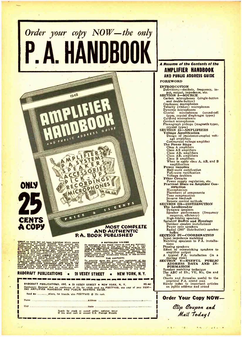
Order your copy NOW the only
P. A. HANDBOOK
ONLY
CENTS A COPY MOST COMPLETE
AND AUTHENTIC P.A. BOOK PUBLISHED
THAT book has yet been published which coven tang,
amplifiers and sound systems (also kindred sye. 1 mólete, thentic volume is almost unalterable. °Yet. it is a fact, there Is book In print ica Public Address from Auto Z. To
ubi brh ÚÌs to guread gap. RADIOCRAPT 111
Andreae of Such meto. gnlfleent le me Puéue
uvathat every mann eo complete and authorlta- ver a engaged Ìn radio have Dom meorettio d ptacticnowledge of
an function and operation of u e systems. The editorial pages
lUSo tilled wit), itruction end r lets with II- strnttons Mat me volume fully justifies its title of 1940 AMPLIFIER HANDBOOK AND PUBLIC AD- DRESS GUIDE. This great HANDBOOK draw on Public Ad. should vdó studies tose svho e n -latently buildoe rice and sell sound equipment.
A MATCHLESS VOLUME At complete as you would expect to find any engineer. Ing handbook --this Is how the radio or P. A. man finds the AMPLIPtE é HAND BOOK AND PUBLIC AD- DRESS GUIDE. With s enttlal technical data compiled from e large
m the
columÌog :h ndred differe ablate ate orinatnrer/
nearly branch or bdivisi°n
of Publie Address. THE CONTENTS
To actually how me cove end magnitude of the AMPLIFIFR nHANDBOOK AND PUBLIC ADDRESS GUIDE, analysis of the contents IS found at the right. showing the breakdown of the material featured
(thin ch particular section. A thorough reading of the contenta shows the completeness of this book.
RADCRAFT PUBLICATIONS 20 VESEY STREET NEW YORK, N. Y. r-----INN -- semi -- ER.-- -. ---- tam el m et - se
RADCRAFT PUBLICATIONS, INC. * 20 VESEY STREET * NEW YORK. N. Y. RC44I Oentlemem Enclosed find my emlttnnce of 25c for which tond me POSTPAID, ono Copy of your NEW - 1940 AMPLIFIER HANDBOOK AND PUBLIC ADDRESS GUIDE.
Send me filbert, for friends, else POSTPAID @ 25c each.
Name Address
City State
Remit by check or money order; register letter If you send cash or unused U.S. Pottage stamps.
A Resume of the Contents of the
AMPLIFIER HANDBOOK AND PUBLIC ADDRESS GUIDE
FOREWORD INTRODUCTION
Defi nitions-decibels, frequency, in- put, output, impedance, etc.
SECTION I- SOURCE Carbon microphones (single- button
and double- button) Condenser microphones Velocity (ribbon) microphones Dynamic microphones Crystal microphones (sound -cell
types, crystal diaphragm types) Cardioid microphones Contact microphones Phonograph pickups (magnetic types,
crystal types) SECTION II- AMPLIFIERS
Voltage Amplification Design . of resistance- coupled volt-
age amplifiers Commercial voltage amplifier
The Power Stage Class A amplifiers Class AB amplifiers
. Class AB1 amplifiers Class AB, amplifiers Clase B amplifiers When to apply class A, AB, and B
amplification Power Supplies
Half -wave rectification Full -wave rectification Voltage doublers
`Filter Circuits Power supply regulation, etc.
Practical Hints on Amplifier Con- struction
Microphonism Placement of components Tone compensation Inverse feedback Remote control methods
SECTION III -DISTRIBUTION The Loudspeaker
Dynamic speakers Speaker performance (frequency
response, efficiency) High- fidelity speakers
Speaker Baffles and Housings Outdoor speaker installations Power cone speakers Radial (360° distribution) speaker
baffles SECTION IV- COORDINATION
Input impedance matching Matching speakers to P.A. installa-
tions Phasing speakers Effect of mismatching speakers to
amplifier output A typical P.A. installation (in a
skating rink) SECTION V- USEFUL PUBLIC
ADDRESS DATA AND IN- FORMATION
Speaker matching technique The ABC of Db., VU, Mu, Gm and
Sm Charts and formulas useful to the
practical P.A. sound man Handy index to important articles
on public address and sound
Order Your Copy NOW - elir &ofcpon and
Mail Today!

between the chassis of the receiver and the grid terminal of the C.-R. tube holder.
(2) Connect the brown lead of the unit to the heater tag of the nearest valve holder or to any convenient supply points, such as the heater tags on the mains (power) trans- former itself.
(3) Join the flexible red lead of the unit to the point on the television chassis which is giving H.T. positive of about 300 V.
(4) Disconnect the lead going from the television receiver chassis to the grid termi- nal on the C.-R. tube holder and re- connect this lead to the one and only terminal marked (G) on the terminal strip of the black- spotter unit. Then join the green lead of the black- spotter to the terminal on the C.-R. tube holder from which the grid lead has just been disconnected.
(5) Earth (ground) the black -spotter unit by connecting an earth wire from under one of the fixing screws on the unit to the earth tag or any convenient bolt on the television receiver chassis.
(6) Switch -on the instrument and test the results by adjusting the variable re- sistance on the black- spotter unit. The cor- rect setting for the control is that which just blacks -out the effect of the electrical interference experienced. If the control is adjusted to maximum the whole image will appear negative, that is, the black appear white, and vice versa.
CATHODE -MODULATION 'SPOTTER For television receivers whose C.-R. tubes
are cathode modulated a different arrange- ment of black- spotter is necessary, as stated earlier in this article.
A black- spotter for this type of circuit is shown in Fig. 2. Its layout is very similar to the black- spotter already described so it is only necessary to go over the circuit arrangements.
At A in Fig. 3 is shown the cathode and grid arrangements of a cathode -modulated C.-R. tube. It will be seen that the picture pulses develop a voltage across the cathode resistance, thus biasing the cathode with regard to the grid which is connected to chassis.
At B the black- spotter is shown connected to the C. -R. tube. It will be seen that the grid of the tube now has Rl between it and chassis while the cathode of the black - spotter valve is directly joined to the cathode of the C. -R. tube. Because of this latter connection the cathode of the black - spotter is mbdulated by the image signals and an amplified version of the voltages would appear across the anode resistor R2.
These voltages would be applied through Cl to Rl which would impress the voltages on to the grid of the C. -R. tube so that the cathode and grid would swing together so that no potential difference would exist be- tween them and no variation of the spot brilliance would occur. If the voltages on the grid were greater than those on the cathode then the "picture" would become negative. (Pictorially, not electrically.)
As in the previous black- spotter, however, the valve can be biased to a cut -off point so that it is inoperative by adjusting VR1 and this is done so that no effect upon the image is noticed during normal conditions but directly a big pulse of static comes along, the valve operates from the excessive volt- age on the cathode and a reversed voltage is impressed upon the grid of the tube, thus turning the bright flash of the static into a dark area.
CONSTRUCTION Constructional details are practically
identical with those of the previous unit. The components are actually less in number and are easily accommodated on the same
Fig. 3 -How the Black - Spotter for cathode - modulated C. -R. tubes
operates.
TELEVISION
(A )
PICTURE
JPULSES '1
CATHODE RAY TUBE
GRID TIED TO CHASSIS
PICTURE PULSES -_ ACROSS RESISTOR MODULATE CATHODE
WPM
CATHODE-, TUBE
RAY
CI
ti RI
R2
TO BIAS CONTROL (VRI)
'a
- How THE BLACKSPOTTER FOR CATI-400E-MODULATED CATHODE -PAY TUBE5 OPERATES ^-
type of L- shaped terminal bracket. The leads are similar to those previously de- scribed and the circuit diagram clearly indi- cates where they are to be connected in the television receiver and to the C.-R. tube base. It will be observed that the terminal marked X on the diagram of the C.-R. tube base is not normally employed in our Eng- lish television receivers and it therefore forms a very useful and convenient anchor- age for the resistance Rl.
As will be seen from the diagram of con- nections the lead from the television re- ceiver to the grid terminal of the C.-R. tube base is disconnected and re- connected to the spare terminal of the tube being employed. If there is not a spare terminal a suitable anchorage must be provided or the resist- ance Rl protected by systoflex (a low -loss tubing insulation) sleeving to strengthen it so that it becomes part of the grid lead. The green lead of the black- spotter is then connected to the grid terminal of the C.-R. tube base and the other connections made as indicated on the diagram.
The installation of the unit into the television receiver cabinet is precisely as for the previous black- spotter just described and the variable control is adjusted to give the most pleasing results.
An English type Z62 valve is used in this black -spotter but is connected to operate as a triode. Its normal pentode characteristics are given elsewhere in this article but as a triode the following data may be helpful to readers finding a suitable substitute.
Characteristics (Z62) Anode volts 300 V. Anode dissipation 2 0 W
*Mutual conductance 8 5 MA. /V. *Amplification factor 38 Impedance 9 960 ohms
At Ea = 150 V. Eg = -2 V.
TO GRID OF C.A. TUBE J
R2. 0.1-MEG. CI L.
.O1-MF. c
TONNAGE SIGNAL OUTPUT ON 5 OF TELEVISION
RECEIVER
RI 2.900 OHMS S
250V.í
VRI 10.000
SAO. OHMS
R3 0.1MEG.
C2 ) 23- MF.
FIG 1
- INTERFERENCE PHASE REVERSER CIRCUIT FOR GRID -MODULATED C.-R. TUBES -
3iií5iM5
_ _
I
1(z62)
i-- ------J GREEN GREEN TO TOUNIT RI CHASSIS
YcSO YE --- TO ú°I i UNIT
SPARE TAB
c c: R.
TUBE BASE
BROWN
MAD<
-.R2 10.000 OHM
Reo 326V+
gE,°,CK 270V.+
1
vai Aµ 0.25-
BM l' MEG
V`
-7,-
I óz
BMCw CHASSIS
BRRw.
BROwN. 6.3V
- INTERFERENCE PHASE REVERSER FOR CATHOOE- M000LATED RECEIVERS
Diagrammed here are the 2 bask types of Black Spotters; the manner in which either type functions is shown In Fig. 3. In Fig. I, tube VI is the English Marconi type MH4I described in the text. Television experimenters will have little difficulty applying to American -type C.-R. tubes the useful circuits shown here as developed with English types. The com- pleted device makes for better enjoyment of tele- vision programs by reducing to a negligible quan- tity the annoying flecks of light due to static
impulses of various kinds.
"THE PEN IS MIGHTIER THAN THE . . . BOMBS!" This article was written 'Midst Bursting Bombs writes the author:
I am sorry I have been so long over the article but we have been so busy one Tray and another that there hardly seems enough time to even sleep. Just as I am dictating these very words the sirens are wailing out their warning, but we are luckier tonight than most nights as it is jest 9 o'clock and this has given us quite a pleasant uninterrupted evening! However, just lately we have had a re- arrangement for working out our evening and night duties in my local A.R.P. division which gives us a few more consecutive evenings off duty and I am thus able to get down to writing again.
We are getting quite hardened or, perhaps, careless over these air raids as I have written pages of this article with the night bombers right overhead, zooming about backward and forward in search of certain objectives in my neighborhood, but apart from making me keep both ears tuned -in for the now familiar 'whistling sound of falling bombs. I don't give Hitler another thought. After all, you know, we can't allow that man to interfere with our lives too much!
In conclusion I would like to say how much of an achievement I consider it to have an article published in a Hugo Gernsback publication. I have many back numbers of "SCIENCE .
AND INVENTION" dating back to 1920. f was only in my 'teens when I bought those inspiring magazines which interested me immensely due to my imaginative nature and I still enjoy studying the very fine artistic covers, especially those depicting the Ferris Wheel. the Overhead Single -Rail Railway, and many others. 1 little thought in those days, that .
an article from my pen would appear in one of H. C.'s publications. M. E. SOUTHALL, Somewhere in England.
RADIO -CRAFT for APRIL 1941 615
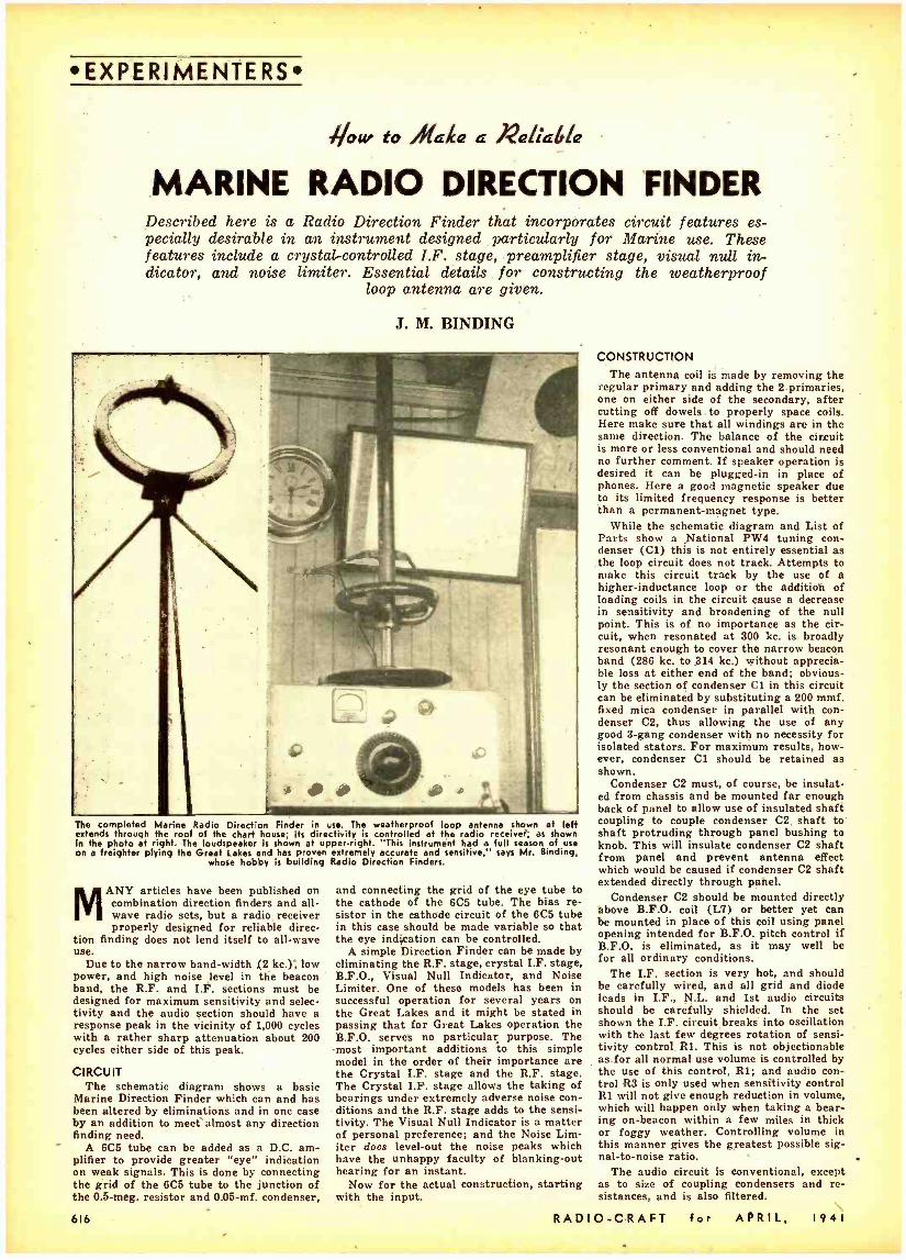
EXPERIMENTERS
/low to Mahe a n¢ia¢
MARINE RADIO DIRECTION FINDER Described here is a Radio Direction Finder that incorporates circuit features es- pecially desirable in an instrument designed particularly for Marine use. These features include a crystal -controlled L.F. stage, preamplifier stage, visual null in- dicator, and noise limiter. Essential details for constructing the weatherproof
loop antenna are given.
J. M. BINDING
The completed Marine Radio Direction Finder in use. The weatherproof loop antenne shown at left extends through the roof of the chart house; its directivity h controlled at the radio receiver. as shown in the photo at right. The loudspeaker is shown at upper -right. "This instrument had a full season of use on a freighter plying the Great Lakes and has proven extremely accurate and sensitive." says Mr. Binding,
whose hobby is building Radio Direction Finders.
MANY articles have been published on combination direction finders and all - wave radio sets, but a radio receiver properly designed for reliable direc-
tion finding does not lend itself to all -wave use.
Due to the narrow band -width (2 kc.); low power, and high noise level in the beacon band, the R.F. and I.>!. sections must be designed for maximum sensitivity and selec- tivity and the audio section should have a response peak in the vicinity of 1,000 cycles with a rather sharp attenuation about 200 cycles either side of this peak.
CIRCUIT The schematic diagram shows a basic
Marine Direction Finder which can and has been altered by eliminations and in one case by an addition to meet'almost any direction finding need.
A 6C5 tube can be added as a D.C. am- plifier to provide greater "eye" indication on weak signals. This is done by connecting the grid of the 6C5 tube to the junction of the 0.5 -meg. resistor and 0.05 -mf. condenser,
616
and connecting the grid of the eye tube to the cathode of the 6C5 tube. The bias re- sistor in the cathode circuit of the 6C5 tube in this case should be made variable so that the eye indication can be controlled.
A simple Direction Finder can be made by eliminating the R.F. stage, crystal I.F. stage, B.F.O., Visual Null Indicator, and Noise Limiter. One of these models has been in successful operation for several years on the Great Lakes and it might be stated in passing that for Great Lakes operation the B.F.O. serves no particular purpose. The -most important additions to this simple model in the order of their importance are the Crystal I.F. stage and the R.F. stage. The Crystal I.F. stage allows the taking of bearings under extremely adverse noise con - ditions and the R.F. stage adds to the sensi- tivity. The Visual Null Indicator is a matter of personal preference; and the Noise Lim- iter doue level -out the noise peaks which have the unhappy faculty of blanking -out hearing for an instant.
Now for the actual construction, starting with the input.
CONSTRUCTION The antenna coil is made by removing the
regular primary and adding the 2 primaries, one on either side of the secondary, after cutting off dowels to properly space coils. Here make sure that all windings are in the same direction. The balance of the circuit is more or less conventional and should need no further comment. If speaker operation is desired it can be plugged -in in place of phones. Here a good magnetic speaker due to its limited frequency response is better than a permanent- magnet type.
While the schematic diagram and List of Parts show a National PW4 tuning con- denser (C1) this is not entirely essential as the loop circuit does not track. Attempts to make this circuit track by the use of a higher- inductance loop or the addition of loading coils in the circuit cause a decrease in sensitivity and broadening of the null point. This is of no importance as the cir- cuit, when resonated at 300 kc. is broadly resonant enough to cover the narrow beacon band (286 kc. to 314 kc.) without apprecia- ble loss at either end of the band; obvious- ly the section of condenser Cl in this circuit can be eliminated by substituting a 200 mmf. fixed mica condenser in parallel with con- denser C2, thus allowing the use of any good 3 -gang condenser with no necessity for isolated stators. For maximum results, how- ever, condenser Cl should be retained as shown.
Condenser C2 must, of course, be insulat- ed from chassis and be mounted far enough back of panel to allow use of insulated shaft coupling to couple condenser C2. shaft to shaft protruding through panel bushing to knob. This will insulate condenser C2 shaft from panel and prevent antenna effect which would be caused if condenser C2 shaft extended directly through panel.
Condenser C2 should be mounted directly above B.F.O. coil (L7) or better yet can be mounted in place of this coil using panel opening intended for B.F.O. pitch control if B.F.O. is eliminated, as it may well be for all ordinary conditions.
The I.F. section is very hot, and should be carefully wired, and all grid and diode leads in I.F., N.L. and 1st audio circuits should be carefully shielded. In the set shown the I.F. circuit breaks into oscillation with the last few degrees rotation of sensi- tivity control Rl. This is not objectionable as for all normal use volume is controlled by the use of this control, R1; and audio con- trol R3 is only used when sensitivity control Rl will not give enough reduction in volume, which will happen only when taking a bear- ing on- beacon within a few miles in thick or foggy weather. Controlling volume in this manner gives the greatest possible sig- nal -to -noise ratio.
The audio circuit is conventional, except as to size of coupling condensers and re- sistances, and is also filtered.
RADIO -CRAFT for APRIL, 1941

EXPERIMENTERS .D.Avu DDW
PI }¡I I ACp`HA
r SCHEMATIC FOR RADIO
I DIRECTION FINDER --
COIL
1b MN1. MF
]]
P.
jjpppp
A-Y'1_71 OneAS OS ÉG.
cAc - PILOT
CO°°NApp'ccEMrrER.
SECTi0N.C1
1 Ö r RT/
w
f 7
020
5ZZ5``
O r/S
éäiENCV OSC ILL Al CC
öá AT- `° - OSCILLATOR .ch f.
2 , ONES
oNrRArissDÁLTir I
000' I
/ c2s R2e- 'C
F.
1- 2a000 .0010E- OHMS MF.
2NóÁ F. 312.F 270'00 MOO l.F ON 5
/CRYSTAL I 1 F
16
ce
Ce
úñ
1 C29 MF
i61J2eFA059G5tw[w 1 fitxc i-
PAC-u 1 I . .MF
e 411 C I ö3 `M?
L
MEG. r -1 SI
'134.200V.J SwT,ansT
.A '_.-44 -- x G- I
+ ------1 wsúSl L
INÓiCl1TDR
O
u.ISÓE ri ölc PPDACKR J
I -TNICK HARDWOOD (ONE OF EACH DEODJ
OUTBOARD LOOP
NS4x 3/4 -R. ND. BRASS WOOD SCREWS
3/9.01.. DOWELS 54 REQ'O. 13/A'LON6. 96 Reab. I ^LONG.
USE 'LITZ" LOOP WIRE
--LOOP --- WINDING AND - MOUNTING DETAILS-
I
INBOARD LOOP
27- 3113"HOLES EQUALLY SPACED IN EACH RING (USE 'FORSTNER BIT)
20Z.COPPER (SOLDER)
RUBBERCrSKET
2x ax Y,' BASS PLATE
- COMPASS CARD-
WAG GA. BRASS
INOLOER)
= LLA . ,O i i,./%/ ̀ K' - ( i
.4401,®_ 111111a B"BRONZE 1 WES Iil-
PLATE iE**
.+A4c.IBlwé xRey
TAO -I/4'x 20
*era Brass ' BASS 1343'0.0. uBIN0.(1'OD) _ x3 /4 -LONG_ D TA
CROSS -SECTION FOR 3/4 No!
THROUGH -A 2 OF EACH REQO. 3 /B PLYW000 (NAROW000)
I PO BORE (SLIP F\T7
72"
7/32'OUu al
HI
ia
Ih
1Y61
1REÓ0
-BRASS BRACHET-
9" l-- q1.
Y4."-2oTAP
rti } t 1
-.POINTER-- I REp.O. (BRASS)
6- 4á~ 5
1 ////////////y1 MARK
. fr I v.P
4-20 1qLES
-- INBOARD LOOP MOUNTING...
1 11O1111
_q
AN
J_
á^
To SUIT
INSTALLATION BRAZE
2'
ADJUSTABLE ÌILLwTION INOEx-
I REQ'D.(BRASS)
SEE LOOP DWG.FOR DETAIL
BRASS Tv81NG- 1"0.0. 3/4'PIPe TAD. TOP. '/2" PIPE TAP, BOTTOM BRASS 15/e"O.D.x 1BORE t -DIA. SLIP FIT COUNTER BORE
13/44. OIA. x Y4 DEEP
BRASS 3 2.2.O.O. x I §íG I.O. SLIPFIT K YB'TNA.
RUBBER GASKET -USE
OOOEN WEDGE FOR SLOPING DECK
BRASS 3'%2 "0.D.x13 /8TQ x %aTRE
BOLTS -4 REÓO.
I' I. P5 BRASS TUBING B USHING ROLLED FROM 1202, COPPER SHEET
9q x3 k^ BRASS HANDwNEEL -TAP
OR 2.I/a' -2o x;4 SocKE T READ SET SCREWS
R COMPASS CARD
ADJUSTABLE INDEX
r.27TID ^' 1 _ r OIA.
t-
-BUSHI NG -1 REGÓ (BRASS)
2
BRACKET
WS1 Q
cf=i;e TOP PANEL
OFRECEIVER
...OUTBOARD LOOP MOUNTING --
CABIN WALL
NE 10 Wrap SCREWS 2 -REDO.
Shown here are fhe complete schematic circuit of the Marine Radio Direction Finder; the construction of e weatherproof loop antenna; and, details of the loop antenna drive mechanism. (Front panel dimensions and markings of the
RADIO -CRAFT for APRIL, I 9 4 I
completed Direction Finder are illustrated elsewhere In this article.) Put Into use on the Great Lakes instruments built in accordance with these instruction received not the "acid" but the "salt- water" test, and were pronounced OK.
617
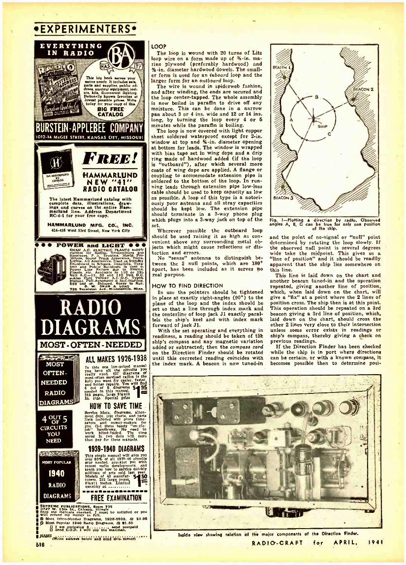
EXPERIMENTERS EVERYTHING
IN RADIO
This big book serves your entire needs. 11 Incles stela
parts and supplies, public ad. dross, amateur equipment, test-
ra, kits, fluorescent lighting. Nationally known favorites at lowest possible paces. Write today for your copy of this
BIG FREE CATALOG
BURSTEIN- APPLEBEE COMPANY 1012 -14 McGEE STREET, KANSAS CITY, MISSOURI
FREE! HAMMARLUND NEW "41"
RADIO CATALOG
The latest Rammarlund catalog with complete data, illustrations, draw- ings and curves on the entire Ham - marlund line. Address Department RC -4 -1 for your free copy.
HAMMARLUND MFG. CO., INC. 424-438 West 33rd Street, New York City
POWER and LIGHT ONAN A.C. ELECTRIC PLANTS Supply current Radios, es MiRecier... Sysiem. o e Pro- tectors. Sound Truck Apparaws Tools. Lights. All Appliances. Used ne Standby Equipment In Schools. Hospitals. Thea- tres and Public Duilding, to ease o. Power Line Failure due to Storms, Floods, etc. Available In 110 or 22t. Volt A.C.-12. 32 and 110 Volt D.C.
.Also Dual Voltage A.C..D.C. Typos. Manual. Full- AUtomatIC & Self - Starting. $99 and up. Shinned. Ready to Run.
0. 720 No latin Avwe.. MinnenppooiIIS. Minn.
RADIO DIAGRAMS MOST - OFTEN - NEEDED
ALL MAKES 1926-1938 MOST
OFTEN -
NEEDED
RADIO
DIAGRAMS
MOST POPULAR
1940
RADiO
DIAGRAMS
In this one low -priced manual Tou have all the circuits you really need. most -often ervi2oed radiosiis the help YOU want for easier, faster. and better repairs. You will find 4 out of 6 diagrams $ 95 needed In this manual. 244 pages, large 864:11 tn. size. special prlco
HOW TO SAVE TIME Service hints. diagrams. align- ment data. test charts. and parte lists included will prove time- saver. and money -makers for you. Oct these handy "tni -the-
work hblindfolded. Th saved in two days will more than pay for these manuals.
1939 -1940 DIAGRAMS This single manual will give Too over 80% of all 1939.40 circuit. ever needed. acquaint you with recent radio developments. and teach you how to service Quickly millions of set. sold last year. Models of 43 manufac- Ihrem 212 large DMRe ß64s11 Inches. Limited Quantity at
FREE EXAMINATION SUPREME PUBLICATIONS, Room 735 3727 W. 13th St., Chimer, Illinels Ship e manuals checked. 1 must be satisfied Or you willth will my money In full. O Moat Ofton -Needed Dlagreme, 1926.1038. fat 51.96 O Most Popular 1940 Radio Diagrams. sal 11.60
O I enclosing S send postpaid O Send C.O.D. I will pay the mailman.
RARE address below and seat{ ibis corner/
618 -
LOOP The loop is wound with 20 turns of Litz
loop wire on a form made up of sib -in. ma- rine plywood (preferably hardwood) and 3 -in. diameter hardwood dowels. The small- er form is used for an inboard loop and the larger form for an outboard loop.
The wire is wound in spiderweb fashion, and after winding, the ends are secured and the loop center -tapped. The whole assembly is now boiled in paraffin to drive off any moisture. This can be done in a narrow pan about 3 or 4 ins. wide and 12 or 14 ins. long, by turning the loop every 4 or 5 minutes while the paraffin is boiling.
The loop is now covered with light copper sheet soldered waterproof except for 2 -in. window at top and % -in. diameter opening at bottom for leads. The window is wrapped with bias tape set in wing dope and a drip ring made of hardwood added (if the loop is "outboard "), after which several more coats of wing dope are applied. A flange or coupling to accommodate extension pipe is soldered to the bottom of the loop. In run- ning leads through extension pipe low -loss cable should be used to keep capacity as low as possible. A loop of this type is a notori- ously poor antenna and all stray capacities should be kept low. The extension pipe should terminate in a 3 -way phone plug which plugs into a 3 -way jack on top of the set.
Wherever possible the outboard loop should be used raising it as high as con- venient above any surrounding metal ob- jects which might cause reflections or dis- tortion and errors. -
No "sense" antenna to distinguish be- tween the 2 null points, which are 180° apart, has been included as it serves no real purpose.
HOW TO FIND DIRECTION In use the pointers should be tightened
in place at exactly right- angles (90 °) to the plane of the loop and the index should be set so that a line through index mark and the centerline of loop jack Jl exactly paral- lels the ship's keel and with index mark forward of jack J1.
With the set operating and everything in readiness, a reading should be taken of thè ship's compass and any magnetic variation added or subtracted; then the compass card on the Direction Finder should be rotated until this corrected reading coincides with the index mark. A beacon is now tuned -in
Fig. I- Plotting a direction by radio. Observed angles A, 8, C can be true for only one position
of the ship.
and the point of no- signal or "null" point determined by rotating the loop slowly. If the observed null point is several degrees wide take the midpoint. This gives us a "line of position" and it should be readily apparent that the ship lies somewhere on this line.
This line is laid down on the chart and another beacon tuned -in and the operation repeated, giving another line of position, which, when laid down on the chart, will give a "fix" at a point where the 2 lines of position cross. The ship then is at this point. This operation should be repeated on a 3rd beacon giving a 3rd line of position, which, laid down on the chart, should cross the other 2 lines very close to their intersection unless some error exists in readings or ship's compass, thereby giving a check on previous readings.
If the Direction Finder has been checked while the ship is in port where directions can be certain, or with a known compass, it becomes possible then to determine posi-
inside view showing relation of the major components of the Direction Finder.
RADIO -CRAFT for APRIL. 1941
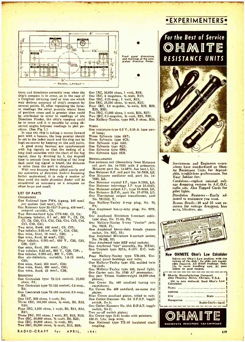
rai r7 61,.
`= " 4
.i. il ht,',. 5%4..
/ \ z
l
cw;.o,; 1
l 7.1i.
7.-7,1... 17-
i1 !t \ / RN 0 IS i1 iT Él .
I ! /
d-
t
- PANEL LAYOUT"'
tions and directions correctly even when the ship's compass is in error, as in the case of a freighter carrying steel or iron ore which may destroy accuracy of ship's compass by several points. If, after repeating the form- er readings the error persists where lines of position cross and is greater than could be attributed to error in readings of the Direction Finder, the ship's compass could be in error and- it is possible by using ob -' served angles between readings to plot po- sition. (See Fig 1.)
In case the ship is taking a course toward port with a beacon, the loop pointer should be set to the index mark and the ship can be kept on- course by keeping on the null point.
A good many beacons are synchronized with fog signals so that the ending of a long dash coincides with the start of the fog signal, thus by dividing by 5, the elapsed time in seconds from the ending of the long dash until fog signal is heard, the distance in miles from the port is obtained.
With new beacons being added yearly and the operation of direction finders becoming better understood, it is only a matter of time until the radio direction finder will be considered as necessary as a compass on ships large and small.
LIST OF PARTS CONDENSERS One National type PW9, 4 -gang, 160 mmf.
per section (see text), Cl; One Meissner type 21 -5217 3 -gang, 410 mmf.,
compact variable, C2; Two Hammarlund type CTS -160, C3, C9; Fourteen tubular, 0.1 mf., 600 V., C5, C6,
C7, C8, C10, C11, C12, C13, CU, C15, C16, C17, C18, C31;
Two mica, fixed, 100 mmf., C9, C21; Two tubular, 0.05 -mf., 600 V., C19, C32; One mica, fixed, 10 mmf., C20; , One mica, fixed, 60 mmf., C22; Four tubular, 0.001 -mf., 600 V., C23, C25,
C26, C27; One mica, fixed, 200 mmf., C24; Two tubular, 0.25 -mf., 600 V., C28, C29; One tubular, 0.005 -mf., 600 V., C30; One air -dielectric, variable, 1.5 -15 mmf.,
C33; One mica, fixed, 250 mmf., C34; One mica, fixed, 400 mmf., C35; One mica, fixed, 25 mmf., C36;
RESISTORS One Centralab type 72 -115 control, 15,000
ohms, RI; One Centralab type 72 -122 control, 0.1 -meg.,
R2; One Centralab type 72 -105 control, 0.6 -meg.,
R3; One IRC, 300 ohms, 1 -watt, R4; Three IRC, 100,000 ohms, % -watt, R5, R13,
R16; Four IRC, 1,000 ohms, 1 watt, R6, R11, R14,
R17; Three IRC, 500 ohms, 1 watt, R7, R12, R15; Two IRC, 50,000 ohms, itz -watt, R8, R20; One IRC, 10,000 ohms, q -watt, R9; Two IRC, 20,000 ohms, q -watt, RIO, R28;
RADIO -CRAFT for APRIL,
Front panel dimensions and markings of the com- pleted Direction Finder.
One IRC, 30,000 ohms, 1 watt, R18; One IRC, 5 megohms, 1h-watt, R19; One IRC, 0.25 -meg., 1 watt, R21; One IRC, 25,000 ohms, tfi -watt, R22; Four IRC, 1.0 megohm, 'fi -watt, R23, R26,
R29, R32; Two IRC, 15,000 ohms, 1 watt, R24, R27; Two IRC, 0.5- megohm, 'fi -watt, R25, R30; One Mallory -Yaxley, type 808, 8 ohms, R31.
TUBES One miniature -type 6.3 V., 0.15 -A. base pan-
el lamp; Three Sylvania type 6K7; Three Sylvania type 6C5; One Sylvania type 6A8; One Sylvania type 6Q7; One Sylvania type 6H6; One Sylvania type 61.15.
MISCELLANEOUS One antenna coil (Secondary from Meissner
coil part No. 14 -763G with 2 primaries. Meissner part No. 14 -6871. See text.), Ll;
One Meissner R.F. coil part No. 14 -7638, L2; One Meissner oscillator coil, part No. 14-
7680, L3; One Meissner crystal I.F., type 9 -1005, L4; One Meissner interstage I.F. type 16 -6643; One Meissner output I.F., type 16 -6645, L6; One Meissner B.F.O., part No. 17 -6779, L7; One Thordarson output transformer, part
No. 781D52, T; One Mallory -Yaxley 3 -way plug, No. 76,
Pl; One Amphenol heavy -duty plug, No. 92M,
P2; One Amphenol Miniature 5- contact cable -
type plug, No. 71 -55, P3; One Mallory -Yaxley 3 -way "Junior" jack,
No. 702B, J1; One Amphenol heavy -duty female chassis
socket, No. 92C, S1; One Amphenol Miniature 5- contact socket,
No. 78 -511, S2; Nine Amphenol type MIP octal sockets; One Amphenol "eye" assembly, No. MEA6; One Triplett type 327A, 0 -10V. D.C. volt-
meter; Four Mallory -Yaxley type UB -241, Uni-
versal panel bushings and nuts; One Mallory -Yaxley type 432, molded twin
tip -jack; One Mallory -Yaxley type 330, panel light; One Carter code No. 1740 AP genemotor; One pair Trimm featherweight 24,000 -ohm
phones; One Crowe No. 440 anodized tuning eye
escutcheon; Six Crowe No. 408 anodized, no -name dial
plates; Nine Crowe anodized plates, titled to suit; One Cutler -Hammer No. 3A S.P.S.T. toggle
switch, Sw.1; One Cutler- Hammer No. l0A D.P.S.T. toggle
switch, Sw.2; Two on -off switch plates; Six Crowe type 6141 knobs with pointers; 100 -ft. Litz. loop wire; One National type TX -10 insulated shaft
coupling.
1941
EXPERIMENTERS
For the Best of Service
RESISTANCE UNITS
Servicemen and Engineers 'every- where have standardized on Ohm - ite Resistance Units for depend- able, trouble -free performance. See Your Jobber for: Cordohms- replace internal volt- age dropping resistor in A.C.-D.C. radio sets. Also Tapped Cords for pilot lights. Dividohm Resistors - Easily ad- justed to resistance you want. Brown Devils -10 and 20 watt re- sistors for voltage dropping, bias units, bleeders, etc.
New OHMITE Ohm's Law Calculator Solves any Ohm's Law problem with one setting of the slide! No slide rule knowl- edge required. All direct readings. Only 10c to cover handling cost. At your
II
jobber or send coupon.
W Ohmite Manufacturing Company 4894 Flournoy Street, Chicago, U.S.A.
10c in coin enclosed. Send Ohm's Law Calculator. Name I
Address I
City State Occupation
L_ Rndio- Craft.-April
©ll=llMUTIE RHEOSTA 5 RESISTORS TAP SWITCHES
619

EXPERIMENTERS
ELECTROSTATIC pick -up, as a means of producing an electronic musical in- strument, can be applied to reeds, strings or rotating waveforms. The
Orgatron uses reeds, the method employed in the Experimental Electronic Organ to be discussed in this article.
APPLICATIONS OF ELECTROSTATIC PICK -UP The Electone produces sustained organ
tone from a struck string by having the key which strikes the string also connect the string to a polarizing voltage through a resistor- condenser delay network, so that as the string's vibrations die away, the vol- tage on the string increases, thus maintain- ing a steady output to the pick -up screw. Screws placed at the end of the string pick up the fundamental; screws placed 1/6 the string's length from the end have more odd -harmonics; and screws located '/e way along have more even -harmonics. The output of these 3 sets of screws can be mixed at will. By reversing the sign of the delayed polarizing voltage which is fed through the key contact to the string, so it kills the voltage initially on the string, the electrical output quickly dies away producing a plucked string or guitar effect.
The Electone of Compton is an organ in which wave -forms are embossed in insulat- ing discs with metal backing, while a rotat- ing arm forms the other plate of the con- denser whose capacity and hence voltage, varies as the changing thickness of the waveform dielectric. A good mathematician should work out the change in capacity pro- duced by say a moving sine waveform past electrodes of various shapes and sizes. J. Mathison made the integration and har- monic analysis for circular electrodes with
This is a description of a type of home -built electric organ which gives the most pipe- organ -like tone in return for the trouble and cost of its construction. Con- sequently it is the best type for
the beginner.
4 Fig. I. Tools and materials required for making an electrostatic reed organ.
Budd rout Own £xpetimental
ELECTRONIC ORGAN W. K. ALLAN
diameter equal to the amplitude of the sine curve and it gave very different results in the higher harmonics as only the wave - length -to- amplitude ratio of the sine curve was altered. The ideal solution would be a workable formula giving the required shapes of the stationary electrodes to form capacity variation curves of any desired harmonic content from a single rotating waveform.
BIBLIOGRAPHY The U. S. patent of F. A. Hoschke, No.
2,016,014, contains 2 pages of diagrams and 21/2 pages of description of the Orgatron. (Send 10c with the inventor's name and patent number to "Commissioner of Patents, Washington, D. C." for any patent desired.) March and April '39 Radio -Craft described the Orgatron. April '40 Electronics con- tained excellent constructional information on this type of organ. November '36 "Pro- ceedings of the Institute of Radio Engi- neers," pages 1427 to 1463, carried B. F. Miessner's classic article "Electron Music and Instruments" (library reference 621: 385.97) .
For electrostatic pick -up from strings obtain B. F. Miessner, et al., 1,915,859 (3, 12) and 2,027,074 (2, 6). Do not include the numbers in brackets when ordering as these are the number of sheets of diagrams, and pages of written description, respectively. January '39 Electronics described the Elec- tone and May '39 Electronics contained a constructional article on electrostatic pick- up from strings. August '40 Electronics & Television and Short Wave World (English magazine) contains an excellent article on the whole subject of electronic organs.
R. H. Ranger 2,018,924 (2, 5) describes an electrostatic chime.
Fig. 4 -Table 1 EQUALLY TEMPERED SCALE FREQUENCIES. A = 440 c.p.e.
From: U. S. Patent, L. Hammond. No. 1.956,350.
196
Semitone ratio 52 ff.= = 1,059463 .. or approximately - 185
C161 C81 C41 C21 Cl' C 32.703 65.406 130.812 261.626 523.251 1046.502 2093.004 C# 34.647 69.295 138.591 277.182 554.365 1108.730 2217.460 D 36.708 73.416 146.832 293.664 587.329 1174.659 2349.318 D# 38.890 77.781 155.563 311.126 622.253 1244.507 2489.014 E 41.203 82.406 164.813 329.627 659.255 1318.510 2637.020 F 43.653 87.307 174.614 349.228 698.456 1396.912 2793.824
46.249 92.498 184.997 369.994 739.988 1479.976 2959.952
C# 48.999 97.998 195.997 391.995 783.991 1667.982 3135.964 51.913 103.826 207.652 415.304 830.609 1661.218 3322.436
A 55.000 110.000 220.000 440.000 880.000 1760.000 3520.000 68.270 116.540 233.081 466.163 932.327 1864.654 3729.308
B 61.735 123.470 246.941 493.883 987.766 1975.532 3951.064
620
PLACING THE PICK -UP SCREWS Now for actual construction. Figure 1
shows the tools and material necessary for an electrostatic reed organ. Obtain a reed organ; C to C is preferred (for reasons given in the first article, Mar. '40 Radio - Craft).
Make a marking tool somewhat like that suggested by F. D. Merrill. Grind one end of an 8 -in. length of 1- x 34 -in. iron to the thickness, width and rounded end of the longest reed. With a hacksaw cut down the middle of the opposite end, and finally, bend into "U" shape so the slotted extremity lies exactly over the rounded end. The completed tool with a marking knife in the slot 'is visible in the center of Fig. 1.
Carefully strip the windchest of swell shutters, etc., which are to be covered with shielding and replaced.
Pull out the bottom reed, insert the round- ed end of the tool and mark the centerline of the reed on the outside top of the reed cell. Also mark across the end of the tool to indicate the position of the tip of the reed. Remove the tool, place the reed on the cell top beside the 'centerline with its tip against the end mark, and with a center - punch mark a point on the centerline about 1/2-in. back from the free end of the reed tongue tnot the reed tip). Choose a brass machine screw about the same diameter as the width of the reed tongue, e.g., 4i-in. No. 14 -20 and with its tap drill make a hole through the top of the reed cell. Turn the screw into the wood; it will cut its own thread as it goes. After blowing out any sawdust replace the reed in its cell.
Repeat this process with each of the other reeds. The top screws can be No. 6 or No. 4. The screw center should be about 1/5 to '/a the length of the reed tongue back from the free end. In one experimental model, the top of the reed cells was removed and the screws were placed in a strip which could be moved from the free end of the reed tongues toward their fixed ends. A very noticeable difference in tone was observed as the position of the screw was moved along the reed. Well back from the tip a more harp -like effect was obtained.
The organ's output may decrease in damp weather so a coat of glyptal insulating varnish was given the parts near the screws. In very damp climates it would be better to mount the screws on a separate strip, sup- ported on non -absorptive insulators. In mak-
RADIO -CRAFT for APRIL, 1941
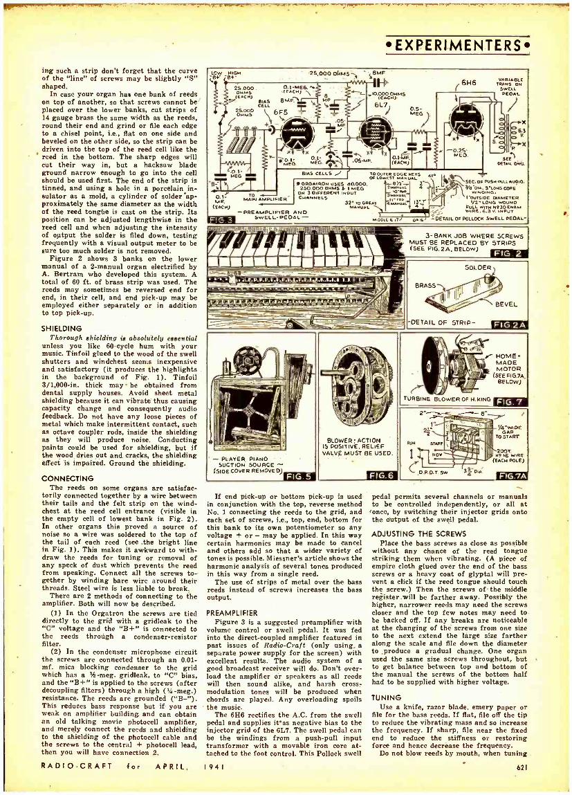
- . . .. ^-vGaw-rvwsF+r-'T .,1.!. : T
ing such a strip don't forget that the curve of the "line" of screws may be slightly "S" shaped.
In case your organ has one bank of reeds on top of another, so that screws cannot be placed over the lower banks, cut strips of 14 gauge brass the same width as the reeds, round their end and grind or file each edge to a chisel point, i.e., flat on one side and beveled on the other side, so the strip can be driven into the top of the reed cell like the reed in the bottom. The sharp edges will cut their way in, but a hacksaw blade ground narrow enough to go into the cell should be used first. The end of the strip is tinned, and using a hole in a porcelain in- sulator as a mold, a cylinder of solder'ap- proximately the same diameter as the width of the reed tongbe is cast on the strip. Its position can be adjusted lengthwise in the reed cell and when adjusting the intensity of output the solder is filed down, testing frequently with a visual output meter to be sure too much solder is not removed.
Figure 2 shows 3 banks on the lower manual of a 2- manual organ electrified by A. Bertram who developed this system. A total of 60 ft. of brass strip was used. The reeds may sometimes be reversed end for end, in their cell, and end pick -up may be employed either separately or in addition to top pick -up.
SHIELDING Thorough shielding is absolutely essential
unless you like 60 -cycle hum with your music. Tinfoil glued to the wood of the swell shutters and windchest seems inexpensive and satisfactory (it produces the highlights in the background of Fig. 1). Tinfoil 3 /1,000 -in, thick may- be obtained from dental supply houses. Avoid sheet metal shielding because it can vibrate thus causing capacity change and consequently audio feedback. Do not have any loose pieces of metal which make intermittent contact, such as octave coupler rods, inside the shielding as they will produce noise. Conducting paints could be used for shielding, but if the wood dries out and cracks, the shielding effect is impaired. Ground the shielding.
CONNECTING The reeds on some organs are satisfac-
torily connected together by a wire between their tails and the felt strip on the wind - chest at the reed cell entrance (visible in the empty cell of lowest bank in Fig. 2). In other organs this proved a source of noise so a wire was soldered to the top of the tail of each reed (see the bright line in Fig. 1). This makes it awkward to with- draw the reeds for tuning or removal of any speck of dust which prevents the reed from speaking. Connect all the screws to- gether by winding bare wire around their threads. Steel wire is less liable to break.
There are 2 methods of connecting to the amplifier. Both will now be described.
(1) In the Orgatron the screws are tied directly to the grid with a gridleak to the "C" voltage and the "B +" is connected to the reeds through a condenser- resistor filter.
(2) In the condenser microphone circuit the screws are connected through an 0.01 - mf. mica blocking condenser to the grid which has a ie -meg. gridleak, to "C" bias, and the "B +" is applied to the screws (after decoupling filters) through a high (14 -meg.) resistance. The reeds are grounded ( "B -"). This reduces bass response but if you are weak on amplifier building and can obtain an old talking movie photocell amplifier, and merely connect the reeds and shielding to the shielding of the photocell cable and the screws to the central + photocell lead, then you will have connection 2.
RADIO -CRAFT for APRIL,
EX PE RI-M ENTERS.
LOW HIGH .B+- ¿B +-
25,OOOOHMS SBMF
FP' 25.000. ,(EACH)
(EACH) 7 BIAS 8 MF1t L CELL
OHM oSO 6F5 ti
Z ,IO.0 OHMS (E00ACH)
6L71 0.5- MEG
.05 MF
1r
6k6 VARIABLE TRANS ON
SWELL PEDAL
eo.L- / MEG
-8-T T x
0.1- iEG MWO,
.L- tir 05-MF
G- O.4MF, (EACH)
xf
-0.25- MEO.
0.1= M F.
(EACH)
To MAIN AMPLIFIER
BIAS CELLS J * OROAracw uSES 40.000.
250.000 OHMS 4 I MEG ON 3 DIFFERENT INPUT CHANNELS
-PREAMPLIFIER ANO FIG.3 SWELL- PEDAL -
TO OUTER EDGE REVS Ale OF LONE T MA UAL
7 gr 4
3Lú o 4MAMIAL I -r' 32MREAT ro GREAT
MIDI) E E 17
IIllIP^h (l.'.':I_ \ rrr mom ; -_- lil y'.-' _P-D-LI_r-P.n-.ia-rr-(.nss..E..r.=I_c(-
E...,71 - ftá -2 H..LJla _ ó _ -
VP
DA16
6.3
x
`SEC. OFRUSNFLLAUDIO. WO. 3 -LONG CORE
WINDING. I LOUTS OE DAMETER
/2'1.ON0 WOUND LULL WITH Mt 30 ENAM .:. W.RE.6.3V. INPUT
- DETAIL OF POLLOCH SWELL PEDAL-
3- BANK JOB WHERE 5CREwS MUST BE REPLACED BY STRIPS (SEE FIG.2A, BELOW) FIG.2
PLAYER PIANO SUCTION SOURCE -
(510E COVER REMOVED)
BLOWER :ACTION 15 POSITIVE. RELIEF VALVE MUST BE USED.
If end pick -up or bottom pick -up is used in conjunction with the top, reverse method No. 1 connecting the reeds to the grid, and each set of screws, i.e., top, end, bottom for this bank to its own potentiometer so any voltage + or - may be applied. In this way certain harmonics may be made to cancel and others add so that a wider variety of tones is possible. Miessner's article shows the harmonic analysis of several tones produced in this way from a single reed.
The use of strips of metal over the bass reeds instead of screws increases the bass output.
PREAMPLIFIER Figure 3 is a suggested preamplifier with
volume control or swell pedal. It was fed into the direct -coupled amplifier featured in past issues of Radio -Craft (only using- a separate power supply for the screen) with excellent results. The audio system of a good broadcast receiver will do. Don't over- load the amplifier or speakers as all reeds will then sound alike, and harsh cross - modulation tones will be produced when chords are played. Any overloading spoils the music.
The 6116 rectifies the A.C. from the swell pedal and supplies Was negative bias to the injector grid of the 6L7. The swell pedal can be the windings from a push -pull input transformer with a movable iron core at- tached to the foot control. This Pollock swell
1941
FIG.6
pedal permits several channels or manuals to be controlled independently, or all at once, by switching their injector grids onto the output of the swell pedal.
ADJUSTING THE SCREWS Place the bass screws as close as possible
without any chance of the reed tongue striking them when vibrating. (A piece of empire cloth glued over the end of the bass screws or a heavy coat of glyptal will pre- vent a click if the reed tongue should touch the screw.) Then the screws of - the middle register.will be farther away. Possibly the higher, narrower reeds may need the screws closer and the top few notes may need to be backed off. If any breaks are noticeable at the changing of the screws from one size to the next extend the large size farther along the scale and file down the diameter to ,produce a gradual change. One organ used the same size screws throughout, but to get balance between top and bottom of the manual the screws of the bottom half had to be supplied with higher voltage.
TUNING Use a knife, razor blade, emery paper or
file for the bass reeds. If flat, file off the tip to reduce the vibrating mass and so increase the frequency. If sharp, file near the fixed end to reduce the stiffness or restoring force and hence decrease the frequency.
Do not blow reeds by mouth, when tuning
621
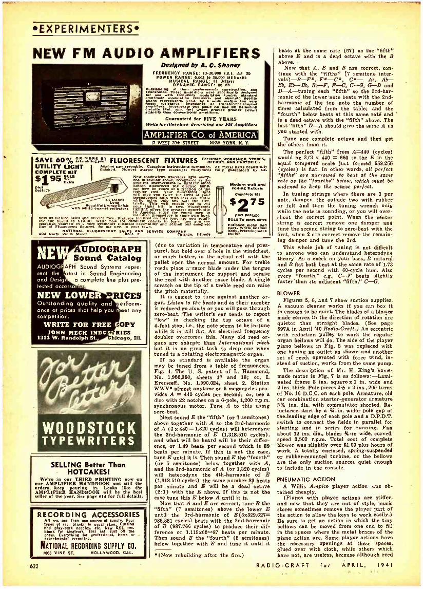
RECORDING ACCESSORIES All ree. ace. from ono source of supply. Four types of rec. blanks in usual sires. Cutting and play -back needles. etc. New QSL ree. blank for amateurs. 1041 cat. just off the press. Everything for professional. home N. experimental recording.
NATIONAL RECORDING SUPPLY CO. 1065 VINE ST. HOLLYWOOD. CAL.
EXPERIMENTERS
NEW FM AUDIO AMPLIFIERS Designed by A. C. Shaney
FREQUENCY RANGE: 13. 30,000 e.p.s. }1 db POWER RANGE: 0.003 to 30,000 Milllwatts
MUSICAL RANGE: I I Octaves DYNAMIC RANGE: 80 db
Outstanding ppearance. Thesehaimpli amplifiers war specifically
with frequency modulation tuners. standard amplitude modulation receivers, and absoluto fidelity V reproducers. Lead. by a wide margin the very finest resistance. impedance o transformer- coupled amplifiers.
r.. Incorporate two basic yrACiaë
and DCC
balancing stability than conventional amplifers. circuit
for FIVE YEARS Write for literature describing our FM Amplifiers
AMPLIFIER CO. of AMERICA 17 WEST 20th STREET NEW YORK. N. Y.
SAVE 60° /D a "emb`ihsEr , FLUORESCENT FIXTURES FO HOME, AND F CTgtá És S.
UTILITY LIGHT I Anyone can assemble. Complete instruction furnished. COMPLETE KIT
BULB New Shadowless, Mettles. fight every - Extra
one is talking about.
Plus / // / Edison l e y
discovered at a fractioÌnt oÌl tthhe
as the
iwill give twice the light n f your
ncandescent bulb with less eye strain while using only one half the elec- tricity. r This will enable you to cut your hill t"eoprtlghing oferhegr greatest opportunity establih
America emselves
for In their
young
tug trained Niles d service men. Fixtures pictured on fhb page a now retail. for 55.50 to $10.00. Write now for complete details to leant
are you establish
noFluoresscentwfixtureñ Be thhel fibusiness our assembling and selling our complete
finished. Newest /tarter type electrical equipment
Is Inchhes Long
Beautiful el rlflt s with wim efecor
All metal parta beautifully fully guaranteed by .
C
Modern wall and Ceiling fixture.
Complete kit
$275 J plus postage
BULB 70 cents extra ponants otel and caps White enamel
NATIONAL FLUORESCENT SALES AND SERVICE COMPANY body price Includes 404 North Wells Street Dent. P Chicago, Illinois switch
NE AUDIOG sent the and Desig tested accesso
AUDIOGRAPH Sound Catalog
APH Sound Systems repre- alest in Sound Engineering -a complete line plus pre-
.
NEW LOWER Outstanding quality and once at prices that help you competition.
RICES
WRITE FOR FREE IOKN MECK INDU
1313 W. Randolph St.
erform- eet any
,OPY RIES
Chicago, IIL
WOODSTOCK TYPEWRITERS
SELLING Better Than HOTCAKES!
We're in our THIRD PRINTING now on our AMPLIFIER HANDBOOK and still the orders keep pouring in. Looks like the AMPLIFIER HANDBOOK will be the best seller of the year. See page 614 for full details.
(due to variation in temperature and pres- sure), but hold over a' hole in the windchest, or much better, in the actual cell with the pallet open the normal amount. For treble reeds place a -razor blade under the tongue of the instrument for support and scrape the reed with another razor blade. A single scratch on the tip of a treble reed can raise the pitch materially.
It is easiest to tune against another or- gan. Listen to the beats and as their number is reduced go slowly or you will pass through zero -beat. The writer's ear tends to report "low" in checking the top octave of a 4 -foot stop, i.e., the note seems to be in -tune while it is still flat. An electrical frequency doubler overcomes this. Many old reed or- gans are sharper than International pitch but it is no great task to drop one when tuned to a rotating electromagnetic organ.
If no standard is available the organ may be tuned from a table of frequencies, Fig. 4. The U. S. patent of L. Hammond, No. 1,956,360, sheets 17 and 18; or, I. Eremeeff, No. 1,990,024, sheet 2. Station W W V e almost anytime on 5 megacycles pro- vides A = 440 cycles per second; or, use a disc with 22 notches on a 6 -pole, 1,200 r.p.m. synchronous motor. Tune A to this using zero -beat.
Next sound E the "fifth" (or 7 semitones) above together with A so the 3rd -harmonic of A (3 x 940= 1,320 cycles) will heterodyne the 2nd -harmonic of E (1,318.510 cycles), and what will be heard will be their differ- ence, or 1.49 beats per second which is 89 beats per minute. If this is not the case, tune E until it is. Then sound E the "fourth" (or 6 semitones) below together with A, and the 3rd -harmonic of A (or 1,320 cycles) will heterodyne the 4th -harmonic of E (1,318.510 cycles) the same number 89 beats per minute and E will be a dead octave (2:1) with the E above. If this is not the case tune this E below A until it is.
Now that A and E are correct, tune B the "fifth" (7 semitones) above the lower E until the 3rd -harmonic of E(3x329.627= 988.881 cycles) beats with the 2nd -harmonic of B (987.766 cycles) to produce their dif- ference or 1.116x60 =67 beats per minute. Then sound B the "fourth" (5 semitones) below together with E and tune it until it
e (Now rebuilding after the fire.)
beats at the same rate (67) as the "fifth" above E and is a dead octave with the B above.
Now tfiat A, E and B are correct, con- tinue with the "fifths" (7 semitone inter - vals) -B -Fz, Ft -CI:, C4- Ab, Ab- Eb, Eb-Bb, Bb-F, F -C, C- G, G-D and D -A- tuning each "fifth" so the 3rd -har- monic of the lower note beats with the 2nd - harmonic of the top note the number of times calculated from the table; and the "fourth" below beats at this same raté and is a dead octave with the "fifth" above. The last "fifth" D -A should give the same A as you started with.
Tune one complete octave and then get the others from it.
The perfect "fifth" from A=440 (cycles) would be 3/2 x 440 = 660 so the E in the equal tempered scale just formed 659.266 (cycles) is flat. In other words, all perfect "fifths" are narrowed to beat at the same rate as the "fourths" below, which must be widened to keep the octave perfect.
In tuning strings where there are 3 per note, dampen the outside two with rubber or felt and turn the tuning wrench only while the note is sounding, or you will over- shoot the correct point. When the center string is correct remove one damper and tune the second string to zero -beat with the first, when 2 are correct remove the remain- ing damper and tune the 3rd.
This whole job of tuning is not difficult to anyone who can understand heterodyne theory. As a check on your bass, B natural and B flat both beat at the same rate of 1.73 cycles per second with 60 -cycle hum. Also every "fourth," e.g., C -F beats slightly faster "than its adjacent "fifth," C -G.
BLOWER Figures 5, 6, and 7 show suction supplies.
A vacuum cleaner works if you can box it in enough to be quiet. The blades of a blower made convex in the direction of rotation are quieter than straight blades. (See page 597A in April '40 Radio -Craft.) An eccentric with reduction pulley to work the regular organ bellows will do. The side of the player piano bellows in Fig. 6 was replaced with one having an outlet as shown and another set of reeds operated with force wind, in- stead of suction, works from the same pump.
The description of Mr. H. King's home- made motor in Fig. 7 is as follows: -Lami- nated frame 8 ins. square x 1 in. wide and 2 ins. thick. Pole pieces 234 x 2 ins., 200 turns of No. 16 D.C.C. on each pole. Armature, old car combination starter- generator armature 3% ins. dia. with commutator shorted. Re- luctance -start by a 3 -in. wider pole gap at the-leading edge of each pole and a D.P.D.T. switch to connect the fields in parallel for starting and in series for running. Fan about 12 ins. dia., blades %-in wide, curved, speed 3,500 r.p.m. Total cost of complete blower was slightly over $1.00 plus hours of work. A totally enclosed, spring- suspended or rubber -mounted turbine, or the bellows are the only suction sources quiet enough to include in the console.
PNEUMATIC ACTION A Willis Ampico player action was ob-
tained cheaply. (Pianos with player actions are stiffer,
and now that they are out of style, music stores sometimes remove the player part of the action to allow the keys to work easily.) Be sure to get an action in which the tiny bellows can be moved from one end to fill in the spaces where the metal braces of the piano action are. Some player actions have the necessary openings at these spaces, glued over with cloth, while others which have not, are useless, because although reed
622 RAD 10-CRAFT for ArKIL, 1V41

11111111,r°...
OODUO0000410PUltO00 tIOCOO C ' 0 0 0 Ö 0 Ó e'0 0 0 O O G o O O
1sÌ,., , ., . ,, ... - ... . I. . .. a . ....:;. _.t. ...
-
.. Mot _ .
Fig. 8. Player action showing how bellows have been moved from ends to fill spaces where piano action braces were. Note that valves have not been moved in as this is unnecessary. Armatures can be attached
to these valves to permit them to be opened by magnets.
organ spacing is the game as the piano, there are no intervals in the spacing of the reeds, as there are in the strings.
This action can be operated from an old pneumatic- action pipe organ keyboard by having the keys admit air to holes in IA
board replacing the paper player roll. Or by fastening iron armatures to the wooden ends of the little valves (Fig. 8) electro- magnets controlled from the keyboard can operate the action. Sometimes in moderniz- ing pneumatic pipe organs, electrically - operated valves are connected to the lead pipes. A set of these would be ideal. Remem- ber the valves of the player action won't work when placed upside down.
The action and reeds could not be oper- ated satisfactorily from the same suction source because the action needs high pres- sure with small volume whereas the reeds required low pressure with large volume. However, the reeds and 1 note at a time of the action (e.g., for a melody or pedal coupler) would work from a single wind source.
It is very difficult to prevent interference from manual contacts being picked up by the electrostatic pick -up screws. One manual wired with No. 30 wire produced much less interference than the manuals wired with the customary (lower resistance) No. 22, so that resistance wires to the contacts seem to aid greatly in suppressing keyclicks. Because of the possibility of keyclick inter- ference pneumatic action would seem pref- erable to magnets placed near the reeds. Moreover pneumatic action enables the organ to be placed some distance from the console. Also it permits sub, super, inter - manual and pedal coupling, without in- creased key resistance; and it produces faster speech in the bass reeds. However with pneumatic action, keyboard touch is lost; i.e., with the keys operating the pal- lets directly, considerable control of the tone can be obtained by pressing the key to different depths with various speeds, while with pneumatic action as soon as the key admits air into the action the pallet is instantly opened to its maximum distance. Thus pneumatic action( is scarcely worth the trouble for notes above the middle of the manual at least.
TREMOLO; INTENSITIES; CONSOLE; OTHER METHODS An aluminum disc, induction -type phono
motor with governor and turntable removed, and a 101/2 -x 12% -in. fibre shutter (which is enlarged or reduced to keep the speed approximately 6 revolutions per second), makes a fine tremolo when placed in front of the loudspeaker. Use a $ -in. square stick
RADIO -CRAFT for APRIL,
about 10 ins. long with a tapered hole in one end to slip over the turntable shaft, and slotted lengthwise at the other end to hold the shutter.
Two or 3 intensities may be set up on each stop by changing the polarizing voltage or amplifier input resistors.
Wrapping the reed action in felt reduces the direct sound and keeps dust out of the treble reeds.
If the reeds are included in a pipe organ console the wider spacing of pipe organ keys may be matched to the reed action by exten- sions placed on the rear of each-key offset toward the center. Leather nuts must be used on threaded rods to the pallets because the vibration will loosen metal nuts.
Steel (accordion) reeds can use electro- magnetic pick -up. Photoelectric pick -up from pedal -controlled dial lamps behind bass reeds being blown continuously overcomes their slow action.
This concludes the description of the Elec- tronic Organ. Only those who are seriously interested in building such a device should undertake what is unquestionably an am- bitious enterprise. True, the results will be worthwhile, but unless the constructor can see his way clear to carrying the project through to completion, it would be wiser not to begin it. Otherwise, we say, "go to it!"
ANALYSIS OF THE ELECTROSTATIC TYPE OF ELECTRONIC ORGAN
ADVANTAGES
(1) Separate reeds produce ensemble or choir effect not found in mechanical electric organs.
(2) Build up of tone or attack in middle and upper registers resembles a pipe. Lovely flute and diapason pipe or- gan tones are produced, in no way resembling the reed organ tone. Reasonably easy to build. Inexpensive to build.
(3)
(4) (b)
DISADVANTAGES
(1) Requires tuning. (2) Bass notes are too slow in attar.:. (3) No trumpet or Vox Humana, etc.,
stops. (4) No fundamentals higher than a
4 -foot stop without excessively small and fragile reeds.
(5) Affected by temperature, pressure, humidity and dust.
I 9 4 I
EXPERIMENTERS
HOW TO SAVE ON
EVERYTHING IN RADIO
r SEND FOR
ALLIED'S NEW
CATALOG
A GREAT BOOK OF RADIO VALUES.
Just off the press! ALLIED'S new Spring Catslog- d mith smashing values from cover to cover!
ALLIED offers you everything new In Radio. roel savings and fast service. Dealer. Serviceman, Soundman, Builder, or Amateur -whatever your Interest In Radio. you'll find the new ALLIED Catalog a necessity! Send for your FREE copy today. Keep It handy for speedy reference!
NEW RADIÓ :SETT' ALI/ ES, IN';P011 Sm them I1- 1941'. Radio 25 New sound Systems? For Hits! Models for every
cation-7 to 75 watt.. Widest pose. Every one a -Personal- throe -way lection! .neat features.
Portable.: latest Recorders: Easy Payment Plan and 15 Phono- COmbinatlons: Plastic Day rial. Complete P.A. Seta: World -wide Models; accessory !!stings for every new FM -AM receivers: Auto purpose. Dollar for dollar. Sed
Farm Radios; Amateur you get more when you buy m ta -all at lowest price. 1941 KNIGHT Sound Equlp- that pelt Real Savings ana t. send for your FREE
Profits for youl catalog l s,e {'g`gR THE BUILDER ä::.i''sA.
If ro build ALLIED for the
latest low -coat Cite and for help ln building any .00
lt radio circuit. Completo isting of the latest build- ers' experimenters' p-
lee. New diagram.. Com- plete Ham gear for the Amateur. Head- quarter. for a o Builders! For Radio Amateurs!
15,000 RADIO PARTS
Suality biggest in 1 lll radio.
Ev ry leading make -corn nleto listings for e
sonic dio replacement and Ing requirement. Ports tool
test equipment, book.. eta. You nere this liable Guide to Elowestlpprices!
reliable Radio
the it! o't trait!
Moll coupon TODAY!
833 W. Jackson Blvd., Dept. 2 -D -1
Chicago, Illinois
Send mo Cour PRIM 180-Page 1941 Spring Catalog.
Name ..
Address
LCity State -J
623
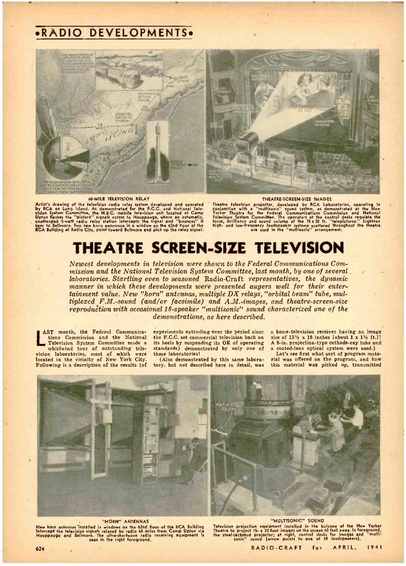
RADIO DEVELOPMENTS
o - UMIr3r'CnLrofitN43 -- --- UM"V"UA_n,.
r51AND AUIL)KEni % ';CITY xAD10LWTA
0.Ñ p8 040
MILES DISTANT
. :_ .Ir,1 ¡t1s1 y
V ev; ecvrAUCS.O.
1,1 RELAY $TAiIOV
68 -MILE TELEVISION RELAY Artist's drawing of the television radio relay system developed and operated by RCA on Long Island. As demonstrated for the F.C.C. and National Tele- vision System Committee, the N.B.C. mobile television unit located at Camp Upton flashes the "picture" signals across to Hauppauge, where an automatic, unattended 5 -watt radio relay station intercepts the signal and "bounces" it over to Bellmore. Two new horn antennae in a window on the 62nd floor of the RCA Building at Radio City, point toward Bellmore and pick up the relay signal.
THEATRE -SCREEN -SIZE IMAGES Theatre television projector, developed by RCA Laboratories, operating in conjunction with a "muitisonic" sound system, as demonstrated at the New Yorker Theatre for the Federal Communications Commission and National Television System Committee. The operators at the control desks regulate the focus, brilliancy and sound volume of the 15 x 20 ft. "telepictures.' Eighteen high- and low- frequency loudspeaker systems scattered throughout the theatre
are used in the "multisonic" arrangement.
THEATRE SCREEN -SIZE TELEVISION Newest developments in television were shown to the Federal Communications Com- mission and the National Television System Committee, last month, by one of several laboratories. Startling even to seasoned Radio -Craft representatives, the dynamic manner in which these developments were presented augers well for their enter- tainment value. New "horn" antennas, multiple DX relays, "orbital beam" tube, mul- tiplexed F.M.-sound (and /or facsimile) and A.M.-images, and theatre- screen -size reproduction with occasional 18- speaker "multisonic" sound characterized one of the
demonstrations, as here described.
AST month, the Federal Communica- tions Commission and the National Television System Committee made a whirlwind tour of outstanding tele-
vision laboratories, most of which were located in the vicinity of New York City. Following is a description of the results (of
experiments extending over the period since the F.C.C. set commercial television back on its heels by suspending its OK of operating standards) demonstrated by only one of these laboratories!
(Also demonstrated by this same labora- tory, but not described here in detail, was
a home -television receiver having an image size of 131 x 18 inches [about 1 x 134 ft.]1 A 5 -in. projection -type cathode -ray tube and a coated -lens optical system were used.)
Let's see first what sort of program mate- rial was offered on the program, and how .
this material was picked up, transmitted
"HORN" ANTENNAS New horn antennas installed in windows on the 62nd floor of the RCA Building Intercept the television signals relayed by radio 68 miles from Camp Upton via Hauppauge end Bellmore. The ultra -shortwave radio receiving equipment is
seen in the right foreground.
624
"MULTISONIC" SOUND Television projection equipment installed in the balcony of the New Yorker Theatre to projetl. IS- x 20 -foot images on the screen 60 feet away. In foreground, the steel -jacketed projector; at right, control desks for images and "multi -
sonic" sound (arrow points to one of 18 loudspeakers).
RADIO -CRAFT for APRIL, 1941
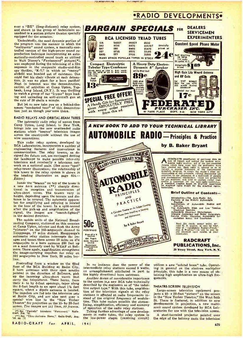
over a "DX" (long- distance) relay system, and shown to the group of technicians as- sembled in a motion picture theatre specially equipped for the occasion.
Undoubtedly, the most dynamic portion of the program was the manner in which the "multisonic" sound system, a manually -con- trolled version of the high -power sound re- production technique incorporating an auto- matically- controlled sound track as utilized in Walt Disney's "Fantasound" picture(*), was employed during the televising of a film sequence in the composite studio- and -film spy thriller, "K -7," in which an "enemy" airfield was bombed out of existence. One could feel his chair vibrate at each detona- tion. It was no place for a born pacifist! Next in interest was the demonstration, earlier, of activities at Camp Upton, Yap - hank, Long Island- (N.Y.). It was thrilling to watch a group of our "1- year" boys load- ing and unloading an anti -aircraft gun at the rate of 30 shells a minute.
But let us now take you on a behind -the- scenes "conducted tour" of this demonstra- tion just as though you-were there.
RADIO RELAYS AND ORBITAL -BEAM TUBES The automatic radio relay of scenes from
Camp Upton, Long Island, to New York, brings into use the new unattended radio stations which "bounce" television images across the countryside without the use of wire connections.
This radio relay system, developed by RCA Laboratories, incorporates a number of engineering features and innovations in communication. The relay towers, as de- signed for future use, are envisaged dotting the landscape to make possible inter -city television and eventually a television net- work on a national scale. (See cover "spot" relay -tower illustration; the relationship of this tower to the relay system is shown in the heading illustration on page 624. - Editor)
Inside the "beacon" on top of the tower is a new horn antenna () sharply direc- tional in reception and transmission of ultra -short waves. The towers vary in height, depending upon the terrain and dis- tance to be covered. The automatic appara- tus for amplifying and relaying is located in the base of the tower. In a split- second after the pick -up and amplification of the signal, the images are "search- lighted" in the desired direction.
The mobile units of the National Broad- casting Company, stationed on this occasion at Camp Upton, televise and flash the Army "pictures" on the 165- megacycle channel to Hauppauge, 17 miles distant. Hauppauge's automatic relay station intercepts the im- ages and tosses them across 23 miles on 474 megacycles to a horn antenna 200 feet up on a mast formerly used by WEAF at Bell- more. There again, amplification strengthens the image- carrying impulses for relay on 506 megacycles to New York, 28 miles bee- line.
Protruding from a window on the 62nd floor of the RCA Building at Radio City, 2 horn antennas with their open mouths pointed in the direction of Bellmore, pick up the incoming ultra -short waves that carry the telepictures. These horns, from their 4- to by 6 -foot openings, taper along the 8 -foot length to an apex about 1% feet square, where a dipole antenna is located. The impulses are fed into the television sets at Radio City, and are also sent over a special' wire line to the "New Yorker Theatre" for projection on the 15- by 20 -foot screen. The images are 441 lines, 80 frames.
(a) See "Fantasia" Introduces "Fantasound." Radio - Craft, Feb. '41.
( ") See "Ultra -shortwave Horne." Radle -Craft, Aug. '40. pg. 72.
RADIO -CRAFT for APRIL,
RADIO DEVELOPMENTS
BAR GAIN SPECIALS RCA LICENSED TRIAD TUBES
12A 6A8GT 6X601 6Ú5G 2A5 6C5G 6K7G 12K7GT Specially 6A7 685 6N6G 25A7G priced at 267 6F5G 607G 25L6G GAIO 6F7 6x50 2526G
MANY OTHER POPULAR TYPES IN STOCK C
FOR DEALERS SERVICEMEN EXPERIMENTERS
Compact Electrolytic Tubular Type Condenser 16 -40 MFD at 150 V. D.C. Work- ing. 20 MFD at 25 V. D.C. Work- ing com- mon neg.
Real Value
13c
SPECIAL FREE OFFER! gpE
Gift. c me BELY e á given
ith e ry order e from f % ad.
A Heavy Duty Electro- Dynamic 8" Speaker while they last
1000 ohm Bold com- plete with
pentodo output trans- former
Constant Speed Phono Motor
Self Starting 78 RPM 110 volts
60 cycles A.C.
Amazingly $189 priced
High Gain Litz Wound Antenna
and RF Coils
far TRF Midget Sets for use with 365 m fd tuning
Condenser
Special per pair
17e i DE R pu.nCRASER D
80 PARK PLACE DEPT. R -41 NEW YORK CITY
A NEW BOOK TO ADD TO YOUR TECHNICAL LIBRARY
AUTOMOBILE RADIO- Principles & Practice
by B. Baker Bryant
ACOMP1,ETF7 compilation of pertinent data en how 16 install and service the modem auto- mobile radio receiver. All of the non -essential
details which have crept Into the profession have been weeded out. Each topic Is treated so as to contain a precise statement of the fundamental principle involved. to assure the reader's clear un- derstanding of this principle, without distracting his attention by the discussion of a multitude of details and mathematical expressions. which are primarily for the engineer. and tend to confuse rather than clarify a statement for the auto -radio -technician. A practical treatise based on practical experience by practical radio people for the practical radio- technician.
Brief Outline of Contents- Introduction -The Auto -Radio Art. Features of the Modern Automobils
Receiver. Installations of Automobile Radios and
Antenna. The Automobile High and Low "Tension
Electrical Systems. Automobile Electrical Disturbances. Vibrator Converters and Motor Generators. Service Hints. Classified Automobile In-
stallation Notes. and Conclusion.
50c POSTPAID
Silo-G x 9 Inches
64 Pages Stiff. flexible
Numerous illuatritiona
dia4nr:ms
Send 50e check, money order, un- used U. S. stamps. or coin for your copy of "Automobile Radio -Prtnh pies d. Pr t lcé' -It will be rent to you postpaid upon receipt of your remittance.
RADCRAFT PUBLICATIONS, Inc. 20 Vesey Street, New York, N. Y.
In no instance does the power of the intermediate relay stations exceed 5 watts, an accomplishment attributed in part to the highly directional horn antennas.
Another device of considerable importance to the system isea new RCA tube technically described by the engineers as of "the induc- tive output type." With this tube, amplifica- tion of the television signals at the relay stations is effected at radio frequencies in- stead of the original frequency of modula- tion. This tube makes possible the stream- lining, simplification, efficiency and economy of operation of the radio relay stations.
Taking further advantage of new develop- ments in radio tubes, the relay system in the low -power stages (receiving circuit)
1941
utilizes a new "orbital beam" tube. Operat- ing in general on the electron multiplier principle, this tube is a new means of ob- ,
taming high amplification on ultra -high fre- quencies.
THEATRE -SCREEN TELEVISION Large- screen television equipment pro-
jects a 15- x 20 -foot "picture" on the screen in the "New Yorker Theatre," 254 West 59th St. There is featured, in addition to new developments in projection, a new multi - sonic sound system developed by RCA Lab- oratories for use with the television screen.
A steel -barreled projector pointed over the edge of the balcony casts the television
625
RADIO DEVELOPMENTS-
GEOPHYSICAL - PROSPECTING OUTFITS
rzerllnrA:
BLUE PRINTS and INSTRUCTIONS
For Building the Following Treasure Finders and Prospecting Outfits
Folder No. 1. The "Radioflecbr Pilot" -con - scats of a 2 -tube transmitter and 8 -tube receiver. Principle: radiated Wave from transmitter loop is reflected back to receiver loop. Emits visual and aural signals. Tubes used two 1A5G -two 1N5G -one 1H5G.
Folder No. 2. The "Harmonic Frequency Lo- cator"- Transmitter radiates low frequency wave to receiver. tuned to one of Harmonics of transmitter. Using regenerative circuit. Emits aural signals. Tubes used: one 1G6G --one 1N5G.
Folder No. 3. The "Beat -Note Indicator" -Two oscillators so adjusted as to produce beat- note. Emits visual and aural signals. Tubes used: Three type '80.
Folder No. 4. The "Radio-Balance Surveyor" -a modulated transmitter and very sensi- tive loop receiver. Principle: Balanced loop. Emits visual and aural signals. By tri- angulation depth of objects in ground can be established. Tubes used: Seven type '80.
Folder No. S. The "Variable Inductance Moni- tor"-a single tube oscillator generating fixed modulated signals and receiver em- ploying two stages R.F. amplification. Works on the inductance principle. Emits aural signals. Tubes used: six type '80.
Folder No. 6. The "Hughes Inductance -Bal- ance Explorer " -a single tube Hartley os- cillator transmitter and sensitive 3 -tube re- ceiver. Principle: Wheatstone bridge. Emits -
aural signals. Tubes used: two type '80- .
one type 12 -one type '33. Folder No. 7. The "Radiodyne Prospector " -
a completely shielded instrument. Principle: Balanced loop. Transmitter, receiver and batteries enclosed in steel box. Very large field of radiation ant depth of penetration. Emits aural signals. Tubes used: two 1N6G -one 1G4G -one 1116G-one 1Q6 -one 1G4.
With any one of the modern geophysical methods described in the Blue -Print patterns. Radio outfits and instruments can be con- structed to locate metal and ore deposits (prospecting) ; finding lost or buried treas- ures; metal war relics: sea and land mines and "duds "; mineral deposits: subterranean water veins; oil deposits (under certain cir- cumstances) ; buried gas and water pipes: tools or other metallic objects sunken in wa- ter. etc.. etc.
Each set of blueprints and Instructions enelosed in heavy envelope (91/4^ x 12Yr'l. aluenrints 22^ x 34'; eight -page Illustrated 844' x I P fold 0 er of Instructions end construction data . , 50
Add Sc for postage
The templets set of seven folders t M shipping weight 2 lbs. (add 25e for ship- $3"
ping anywhere In U.S.A.)
Ì E.í: FI N I l'IiX RC -441
1917 S. STATE ST. CHICAGO. ILL.
TECHNIFAX 1917 So. State, Chicago, III.
Enclosed herewith $ for which mail to address below:
Treasure Finder No. 1. 2, 3. 4. 5. 6. 7.
Complete set of seven folders.
NAME
ADDRESS
CITY STATE RC -441
626
9
images on the stage screen 60 feet distant. Alongside the projector are control desks at which operators manipulate the knobs that regulate the image and sound. These operators exercise the same control over faces and scenes as radio control men do over broadcast music and speech. The "pic- tures," as they come over the wire from an outside point, are received first at the control desk to be fed into the projector. The Camp Upton scenes relayed by radio to the RCA Building are forwarded from Radio City to the "New Yorker Theatre" over special wire circuits.
The sound reproduction system used in connection with the theatre television unit is of the extreme -high -fidelity type, similar in effect and arrangement to the "Fanta- sound" used in the motion picture "Fan- tasia." Differing from Fantasound in that it is manually controlled at the scene of reproduction, the multisonic system permits movement of sound with action on the screen; rotation of sound around the walls of the auditorium; and, emanation of sound from any one desired point in the theatre.
Developed in the RCA 'Laboratories, the large- screen theatre television system oper- ates on signals delivered to it either by coaxial cable or by special wire circuits.
The installation in the theatre consists of 3 main units: (1) control, (2) power sup- ply, and (3) optical system.
An array of knobs and dials on the con- trol panel gives the operator immediate handling of all controlling, metering, and deflecting elements. He can obtain at any time, every possible check on the operation of the system. Sharpness, brightness, con- trast, and size of the image projected may be changed by the turn of a knob. The con - trol,, are is simplified that the average mo- tion picture projectionist could operate the unit with but slight training.
The second unit, the power supply for the optical or projection system, is a con- ventional high -voltage rectifier rated at 70,000 volts. Normally, operation is at 60,000 volts.
The optical, or projection unit, is con- sidered the most important as well as the most complicated of the entire system. For purposes of description, it is possible to divide the unit into 3 principal elements; that is, (1) the kinescope, or projection tube; (2) the reflecting mirror, and (3) the correcting lens, or plate. CO
The kinescope, built to handle high vol- tages, is similar in performance to the kinescope used in RCA's standard home - television receivers. The face or diameter of this Cathode-ray receiving tube is 7 inches; the tube's length is 14 inches. It is mounted in the center of a hollow steel -shielded cylinder 34 inches in diameter and 34 inches long. The face of the tube is pointed away from the stage screen, and the end of its neck pierces a small hole in the center of the correcting plate of the optical system.
The concave reflecting mirror, 30 inches in diameter, is mounted a few inches in front of the tube's face. The image on the face of the tube is picked up on the con- cave surface of the mirror, passed through the correcting lens and onto the screen with a magnification of 45 times. The lens corrects for aberrations and passes the image across the auditorium to the stage screen.
The optical system is unique in that it has a speed rating of f:0.7, which surpasses the fastest known projection lens. It was developed by research engineers in the RCA Laboratories, and is a variation of the Schmidt astronomical camera. Optical ex-
(t) Tlds arrangement Is shown by diagram In "Newest Screen -size Television," Radio- Craft, Aug. '40.
perts viewed the idea in the beginning as impractical, but one of the RCA engineers, whose hobby is optics, figured out a formula, devised special grinding instruments, and successfully developed the optical system! The first unit required 6 months to produce, but the technique of grinding the lens was improved to the point where the one used today was ground in 6 weeks.
The optical unit housing is mounted on u pedestal which contains the video amplifiera and the deflecting output circuits.
Controls for the sound, which accompanies the television projection, are mounted in a separate console, adjacent to the television control desk. They are linked to 18 high - and low- frequency loudspeakers mounted around the auditorium. Wire lines connect the console with the N.B.C. studios and with the central,, radio .receiving point in Radio City. In addition, there are lines which the sound control engineers use for cueing the program.
Three banks of regular RCA Photophone (motion- picture- theatre type) speakers are set up on the stage near the screen. One bank is at the rear of the screen, and the other two are at either side. Beginning at the outer. edge of the proscenium arch, other loudspeakers are located at desired points along the side wall and in the rear of the auditorium. One large loudspeaker is suspended from the ceiling. Thus the sound can be given directivity and height.
MULTIPLEXED FACSIMILE AND "F.M.' SOUND Utilizing a single Frequency Modulated
ultra -short -wave channel to perform 2 serv- ices simultaneously, facsimile and high fidel- ity sound, the RCA Laboratories have de- veloped a new method of radio multiplexing.
Microphones in an N.B.C. studio in the RCA Building feed sound over a wire to the "F.M." transmitter in the Empire State Building, while the facsimile machine op- erates in a laboratory at Radio City. A wire line also links the facsimile scanner with the transmitter. The electrical currents, one carrying sound, the other printed matter or pictures (photographs, drawings, etc.), are combined at the transmitter to modulate a 1- kilowatt F.M. station operating on 45.1 megacycles.
In the demonstration the sound and print signals are detected by a receiver at Radio City. The duty of the receiver is to "un- scramble" the sound from facsimile, and re- produce both to correspond with the origi- nal transmission. Electrical filters do the trick. Then the sound is fed into a high - fidelity loudspeaker. The facsimile signals actuate a carbon -paper recorder capable of reproducing printed matter, drawings, maps, pictures, etc. The machine, performing this double duty, is about the same size as a standard radio -phonograph console.
The F.M. channel is 200 kilocycles wide. For the high fidelity sound (30 to 15,000 cycles) 150 kilocycles of the channel are used; for the facsimile impulses, approx. 30 kilocycles. The remaining 20 kilocycles are utilized as guard bands to keep the sound and facsimile apart.
The facsimile instrument prints on a strip of paper 8 inches wide. Printing speed is 134 inches a minute, making it possible to reproduce a message the size of a busi- ness letterhead or an 8- by 10 -inch picture in less than 10 minutes.
And so, dear reader, we conclude this particular jaunt with the F.C.C., et al. Il- lustrations and brief descriptions of other demonstrations in this series appear in the Radio Month in Review department of this issue.
RADIO -CRAFT for APRIL, 1941
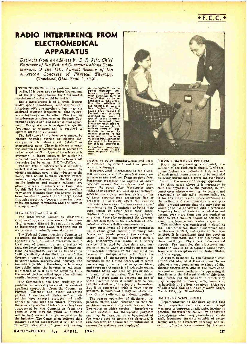
RADIO INTERFERENCE FROM ELECTROMEDICAL
APPARATUS Extracts from an address by E. K. Jett, Chief Engineer of the Federal Communications Com- mission, at the 19th Annual Session of the American Congress of Physical Therapy,
Cleveland, Ohio, Sept. 2, 1940.
INTERFERENCE is the problem child of radio. If it were not for interference, one of the principal reasons for Government
regulation of radio would be lacking. Radio interference is of 3 kinds. Except
under special conditions, radio stations can interfere with one another unless they are assigned separate frequencies -that is, sep- arate highways in the ether. This kind of interference is taken care of through Gov- ernment regulation and international agree- ment. Every station is assigned a specific frequency or channel and is required to operate within this channel.
The 2nd type of interference is caused by Nature -thunder storms or electric dis- charges, which listeners call "static" or atmospheric noise. There is always a vary- ing amount of atmospheric noise present in radio reception. This type of interference is overcome in large measure by assigning sufficient power to radio stations to override the noise (or by using "F.M. "- Editor).
The 3rd type of interference is industrial -electrical or man -made. It is caused by electric machines used in the industry or the home, such as oil burners, electric razors, automatic sign flashers, and the like. Auto- mobile ignition and electric railways are other producers of interference. Fortunate- ly, this 3rd type of interference travels a very short distance from the source. It has been possible to control it to a large extent through cooperation between manufacturers, radio operating companies, and the user of the equipment.
ELECTROMEDICAL STATIC The interference caused by diathermy
equipment appears in a class of its own) (Italics ours. -Editor) It is not only capable of interfering with radio reception but in many cases is actually now doing so.
The Federal Communications Commission recognizes the importance of electromedical apparatus to the medical profession in the treatment of human ills. As a matter of fact, the Inter -American Radio Communica- tions Arrangement, signed at Santiago in 1940, specifically states that the use of dia- thermy apparatus has an important place in therapeutics, surgery, and industry. The immediate problem, therefore, is how may the public enjoy the benefits of radiocoth- munication as well as those resulting from the use of electromedical apparatus without conflict between these services.
The Commission has been studying this problem for several years and has received excellent cooperation from the Council on Physical Therapy and other interested parties. A number of States and munici- palities have enacted statutes and ordi- nances to deal with the subject. However, the general problem of interference has been approached by the Commission from the point of view that the public as a whole will be best served through cooperation in the industry. The Commission believes that through further cooperation it will be able to adopt standards of good engineering
RADIO -CRAFT for APRIL.
As Radio -Craft has re. ported, diathermy inter- ference is perhaps the most pernicious form of "noise that can be ex- perienced in radio recep- tion; the radiations of one machine, set up in a New England hospital, having been received In England (and positively identified by means of special coded interrup- tions of the output)! Even Frequency Modulation re- ceivers, immune to all ordinary forms of inter- ference, in some in- stances succumb to the radiations of diathermy machines installed without due regard to the prob- lem of radio interference. Photo -From a construction article In Radio & Tele- vision Magazine (Feb. '40. issue).
F.C.C.
practice to guide manufacturers and users of electrical equipment and thus prevent radio interference.
However, local interference in the broad- cast services is not the greatest cause for concern in this problem. Transmissions from diathermy machines are capable of being received across the continent and even across the ocean. The frequencies upon which they operate are used by the national defense and safety services. Interruptions of these eeruices may jeopardize life or property, or seriously affect the nation's interests. Communication companies appeal repeatedly to the Commission as being their only source of relief from these inter- ruptions. Municipalities, as many as thirty at a time, have also petitioned the Commis- 8i075 for assistance in the protection of their police services. (Italics ours. -Editor)
Any curtailment of diathermy apparatus would cause great hardship to many suf- ferers and would prevent the saving of many lives. No one would suggest such a step. Diathermy, like Radio, is a safety service. It is used by physicians and sur- geons in many ways to combat disease and for surgical purposes. In the hospital it has become an indispensable tool. There are thousands of therapeutic departments in hospitals in the United States, all of which possess one or more diathermy machines, and there are thousands of privately -owned machines being operated by physicians in this and other countries. The Commission would no more want to prevent the use of these machines than it would seek to cur- tail the activities of the doctors themselves. But it is confronted with a very serious problem. It must find a way in which dia- thermy and radio can get along together.
The reason operation of diathermy ap- paratus affects radio reception is that the machines are essentially radio transmitters. The radiation which results in interference is not essential for therapeutic purposes and may be regarded as a by- product of the means used to attain the objective.' It can, however, be eliminated or minimized if reasonable methods are employed.
1941
SOLVING DIATHERMY PROBLEM From an engineering standpoint, the
solution of the problem is simple. While eco- nomic factors are important, they are not of such great importance as to be regarded as being unreasonable from the standpoint of cost to the users of therapy apparatus.
In those cases where it is necessary to take the apparatus to the patient, in cir- cumstances where screening the room is not practicable or advisable economically, or,, if for any other reason entire screening of the patient and the apparatus is not pos- sible, it would appear that the only solution would be to use apparatus with a restricted frequency band of emission which does not extend over more than one communication channel. This channel should be selected to avoid interference with radio reception.
This problem was considered in detail at the Inter -American Radio Conference held in Havana in 1937, and again at Santiago in 1940. It is significant that the question was an important topic for discussion at these meetings. There are international aspects. For example, the diathermy ma- chines in Mexico or in Canada cause inter- ference with reception in the United States, and vice versa.
A report prepared by the Canadian dele- gation and adopted at Havana gives the re- sults of a very comprehensive study of dia- thermy interference and of the most effec- tive and economic methods of suppressing it. Details as to the different kinds of shielding, their costs, and the manner in which they may be applied to rooms, walls, doors, etc., in hospitals and offices are given. (Also see "Radio's 'Old Man of the Sea'," Radio -Craft, March 1937, pg. 536.-Editor)
DIATHERMY WAVELENGTH Representatives at Santiago agreed that
their respective countries should adopt measures to suppress or alleviate, insofar as possible, interference caused by apparatus or equipment which may generate or radiate radio -frequency Currents capable of inter- fering with, or adversely affecting, the re- ception of radio transmissions. In this con-
627
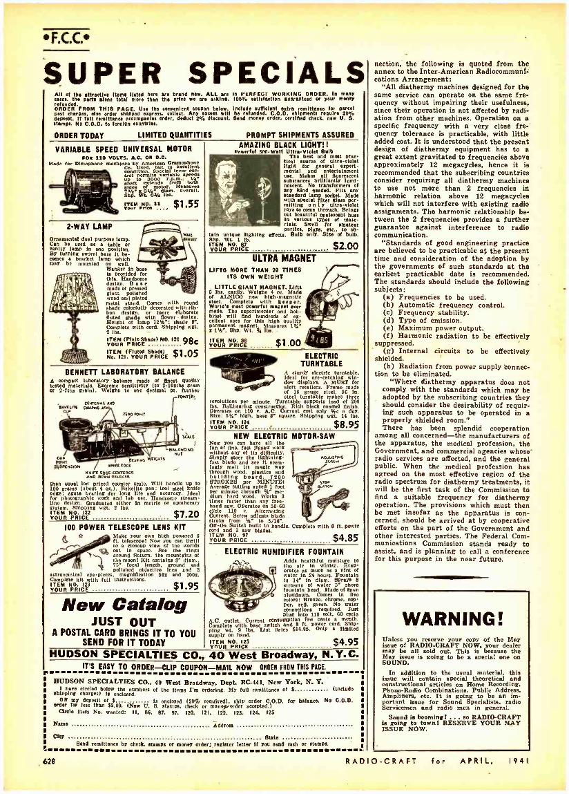
F.C.C.
SUPER SPECIALS All of the attractive Items listed here are brand new. ALL are cases, the parts alone total mere then the price we are asking. refunded. ORDER FROM THIS PAGE. Use the convenient coupon below. Post charge., else arder shipped express, collect. Any excess will deposit. If full remittance accompanies order, deduct 2% discount. stamps. No C.O.D. to foreign Countries.
ORDER TODAY LIMITED QUANTITIES
In PERFECT WORKING ORDER. In many 100V, satisfaction guaranteed or your money
Include sufficient extra remittance for parcel be refunded. C.O.D. shipments require 20% Send money Order. certified check. new U. S.
VARIABLE SPEED UNIVERSAL MOTOR FOR 110 VOLTS, A.C. OR D.C.
Made for Dictaphone matbmee byyUU American Oramophone Co. condition
in condition. Special lever
tont
áo1 ffrrntovariable s peY d , up extends rfm . bog
T[doe of motor. Messures
Na" X 3A/e^ dlam. overall. Shp. W4 q iba.
oakraNÓS11... $1.55
2WAY LAMP
Ornamental dual purpose bran. Can be used as a table or vanity lamp In one position. By turning swivel base It be- comes a bracket lamp which may be mounted on wall.
Hanger in base is provided for this. Handsome design. Base made of pressed glass, polished
cod and plated metal stand. Comes with round shade colorfully decorated with rib- bon design. or more elaborato fluted shade with flower design. Height of lamp 12% "; shade r. Complete with cord. Shipping wgt. 2 lbs. - ITEM (Plain Shade) NO.120 CIO YOUR PRICE ITEM (Fluted Shade) $1 05 No. 121. YOUR PRICE W
WALL nur
r
BENNETT LABORATORY BALANCE A compact laboratory balance made of finest quality tasted materials. Extreme sensitivity (to- 2- 100ths gram or 2 -7th, grain). Weighs to one decimal pt. further
PDINT(R;
cokes., AND 'eaNEtne CANING AA
CUP Ono POINT
Cuo tar
n1PEN5tDN
_.">. % l: r
rix,Sa
SANUTCING
Nenn EDLE
Wore Feet comas% Aste SEAM RELEASE
OATS
SCALE
than usual low priced counter scale. Will handle up to 100 grams (about 4 ox.). Bakelite pan; tool steel knife edge; agate bearing for long life and accuracy. Ideal for photographic work and lab use. Handsome stream- line design. Graduated either to metric or apothecary system. Shipping wgt. 2 lbs. ITEM NO. 122 YOUR PRICE $7.20
100 POWER TELESCOPE LENS KIT Make your own high powered 6 ft. teleecopol Now you can thrill to closeup view of the worlds out in space. See the rings around Saturn, the mountains of Ì the moon! Kit contain. r diem.. 75" focal length. ground and polished objective Lena and 2
astronomical eye- pieces. magnification 50x and 1001. Complete kit with full instructions. ITEM NO. 123 YOUR PRICE $1.95
New Catalog JUST OUT
A POSTAL CARD BRINGS IT TO YOU SEND FOR IT TODAY
PROMPT SHIPMENTS ASSURED
AMAZING BLACK LIGHT! I
Powerful 30(1-Watt UltraVloiet Bulb The best and most pram
ticat source of ultraviolet light for general experi- mental and entertainment use. Makes all fluorescent substances brilliantly lumi- nascent. No transformers of any kind needed. Flu any standard lamp socket. blade with special filter glase per- mitting o n l y ultra -violet rays to come through. Brings out beautiful opalescent hues In various types of mate- rials. Swell for amateur partiu, plays. etc., to ob-
tain unique lighting effects. Bulb only. Site of bulb. Shp. Wt. 1 lb. ITEM NO. 87 YOUR PRICE $2.00
ULTRA MAGNET LIFTS MORE THAN 20 TIMES
ITS OWN WEIGHT
LITTLE GIANT MAGNET. Lifte 5 lbs. easily. Weighs 4 oz. Made of ALNICO new high -magnetic steel. Complete with keeper. World's most powerful magnet ever made. The experimenter and hob- byist will find hundred, of ex- cellent seer for this high quality permanent magnet. Measures 1%" x 1%". Shp. Wt. % lbs.
ITEM NO. 86 YOUR PRICE $1.00
ELECTRIC TURNTABLE
A sturdy electric turntable, ideal for oyecatching win dew displays. A MUST for alert retailers. Frame made of 10 gauge steel. 16 In. steel turntable makes three
revolutions per minute. Turntable supports load of 200 lbs. Ballbearrng construction. Rich black enamel finish. Operates on 110 v. B.C. Current cost only %c n day. Size: 514" high, baso 8" square. Shipping wet. 14 lbs. ITEM NO. 124 YOUR PRICE $8.95
NEW ELECTRIC MOTORSAW Now you can have all the fun of One. tact llgese work without any of Its difficulty. Simply steer the lightning - fast blade and see it seem- ingly melt its magic way through wood. plastics and building board. 7200 STROKES per MINUTE! Average cutting speed 1 foot per minute through %A" me- dium hard wood. Works 3 times faster than any free- hand new. Operates on 50 -60 cycle 110 v. Alternating Current. Screw adjusts blade stroke from 'A" to 5/16 ". Off-On Switch built In handle. Complete with 0 ft. power cord and 3 saw blades.
p ITEM NO. 97 YOUR PRICE $4.85
ELECTRIC HUMIDIFIER FOUNTAIN Adds healthful moisture to the air in winter. Evap- orates as much as a pint of
water in 24 hours. Fountain is 14" in diem. Sprays 8 streams of water 5" above fountain head. Mario of spun aluminum. Comes to Ovo colors: Bronze, chrome, cop. per. red. green. No water connections required. Just plug Into 110 volt. 60 cycle
A.C. outlet. Current consumption few cents a month. Complete with base switch and 8 ft. power cord. Ship- ping wt. 9 lbs. Lint price 514.95. Only a limited supply on hand ITEM NO. 125 YOUR PRICE $4.95
HUDSON SPECIALTIES CO., 40 West Broadway, N.Y.C. IT'S EASY TO ORDER -CLIP COUPON -MAIL NOW ORDER FROM THIS PAGE.
HUDSON SPECIALTIES CO., 40 West Broadway. Dept. RC -441, New York, N. Y. I hare circled below the numbers of the items I'm ordering. My full remittance of S ([ helado
shipping charges) is enclosed. OR my deposit or S la enclosed (20% required), chip order C.O.D. for balance. No C.O.D.
Order for less than 52.00. (New U. S. stamps. cheek or monoy.order accepted.) arelo Item No. wanted: 11. 86, 87. 97. 120, 121. 122, 123, 124, 125
Name Address
City State Bend remittance be cheek. stamps or money order; register letter if you sand cash or atamDJ.
628
nection, the following is quoted from the annex to the Inter -American Radiocommuni2 cations Arrangement:
"All diathermy machines designed for the same service can operate on the same fre- quency without impairing their usefulness, since their operation is not affected by radi- ation from other machines. Operation on a specific frequency with a very close fre- quency tolerance is practicable, with little added cost. It is understood that the present design of diathermy equipment has to a great extent gravitated to frequencies above approximately 12 megacycles, hence it is recommended that the subscribing countries consider requiring all diathermy machines to use not more than 2 frequencies in harmonic relation above 12 megacycles which will not interfere with existing radio assignments. The harmonic relationship be- tween the 2 frequencies provides a further guarantee against interference to radio communication.
"Standards of good engineering practice are believed to be practicable at the present time and consideration of the adoption by the governments of such standards at the earliest practicable date is recommended. The standards should include the following subjects:
(a) Frequencies to be used. (b) Automatic frequency control. (c) Frequency stability. (d) Type of emission. (e) Maximum power output. (f) Harmonic radiation to be effectively
suppressed. (g) Internal circuits to be effectively
shielded. (h) Radiation from power supply connec-
tion to be eliminated. "Where diathermy apparatus does not
comply with the standards which may be adopted by the subscribing countries they should consider the desirability of requir- ing such apparatus to be operated in a properly shielded room." There has been splendid cooperation
among all concerned -the manufacturers of the apparatus, the medical profession, the Government, and commercial agencies whose' radio services are affected, and the general public. When the medical profession has agreed on the most effective region of the radio spectrum for diathermy treatments, it will be the first task of the Commission to find a suitable frequency for diathermy operation. The provisions which must then be met insofar as the apparatus is con- cerned, should be arrived at by cooperative efforts on the part of the Government and other interested parties. The Federal Corn- munications Commission stands ready to assist, and is planning to call a conference for this purpose in the near future.
WARNING! Unless you reserve your copy of the May issue of RADIO -CRAFT NOW, your dealer may be all sold out. This is because the May issue is going to be a special one on SOUND.
In addition to the usual material. this issue will contain special theoretical and constructional articles on Home Recording, Phono -Radio Combinations. Public Address, Amplifiers, etc. It is going to be an im- portant issue for Sound Specialists, radio Servicemen and radio men in general.
Sound is booming! ... so RADIO -CRAFT is going to town! RESERVE YOUR MAY ISSUE NOW.
RADIO -CRAFT for APRIL, 1941

WEIGHT SCALE FOR RECORDERS Universal Microphone Co.
424 Warren Lane, Inglewood, Calif.
NO larger than the size of an ordinary fountain
pen, this scale very quickly, conveniently and accurately measures the weight of any recording head. It is a handy unit to have around since various recorder man- ufacturers recommend their own weight limitations on pickups and cutting heads. Proper cutting head weight
controls depth of cut. -Radio -Craft
LABORATORY OSCILLOSCOPE Allen B. Du Mont Laboratories, Inc.
Passaic, New Jersey
HERE are the features of the new type 208 Du Mont cathode -ray oscilloscope:
Accelerating potential -1,500 volts; 4 easily- accessible deflection -plate terminals; beam switch; removable, calibrated scale for qualitative and quantitative measurements; extended sweep- frequency range -2 to 50,000 cycles; improved amplifier circuits giving symmetrical position- control and de- flection potentials; amplifiers flat -2 to 100,000 sinusoidal cycles per second; 4 -cycle square -wave response; voltage gain of 2,000 times.
Instantaneous position circuits -no "elec- trical backlash "; new power- transformer de- sign- negligible magnetic distortion; mag- netically- shielded cathode -ray tube; nearly 15 -inch time base, with over 21/2 times full - scale deflection; freedom from pattern drift; regulated amplifier -power- supply; regulated position -voltage power- supply; new, func- tionally- designed front panel; compact - small size.-Radio-Craf t
VOLUME -LEVEL INDICATOR General Electric Co. Schenectady, N. Y.
MODEL DO -61 is a VU volume -level indi- cator which essentially is a low- range,
rectifier -type, r.m.s. voltmeter consisting of a d'Arsonval element with an alnico magnet, in series with a stable, full -wave, copper - oxide rectifier designed for performance un- der wide variations of frequency. The in- strument has 2 sets of scale marking, name- ly -20 to O to +3 VU, and the other, 0 -100% volts. Radio -Craft
NEW COMMUNICATIONS RECEIVER
National Co.. Inc. Malden, Mass.
HE new NC -200 Communications Receiver is a 12 -tube superhet, covering 10 ac-
curately- calibrated ranges. Six of these are of the general coverage type tuning continu- ously from 490 to 30,000 kc. The remaining 4 are band -spread ranges for the amateur 10, 20, 40 and 80 meter bands. Other fea- tures include single -dial tuning control, temperature compensation, automatic volt- age stabilization, series valve noise limiter, and flexible crystal filter. -Radio -Craft
RADIO -CRAFT for APRIL,
LATEST RADIO APPARATUS
NEW 6 -8 WATT AMPLIFIER Lafayette Radio Corporation
i00 6th Ave., N. Y. C.
THE Model 406 -T amplifier delivers 6 watts continuous and 8 watts on peaks. One mi-
crophone and one phono channel are provid- ed with gain of 105 and 62 db. respectively. Frequency response is 50 to 8,000 c.p.s. but a tone control is provided to adapt the out- put to the acoustic requirements of each location. Size 61/2x9x7 ins. deep.-Radio- Craft
MARINE RECEIVER & DIRECTION FINDER
Jefferson- Travis Radio Mfg. Corp. 198 Milburn Avenue, Baldwin, N. Y.
THE basic unit of this equipment consists of a compact 3 -band marine radio receiver
which by the addition of the plug -in loop antenna with compass scale can also operate as a direction finder. The receiver is of the superhet. type mounted in a weatherproof metal cabinet measuring 6x9x8 ins. deep. The tuning range covers 3 bands important to boat owners, namely Marine Radio Bea- con Range (200 -400 kc.), Standard Broad- cast Band (550 -1,500 kc.), and Marine Radiotelephone Range (2,000 -3,000 kc.). -Radio -Craft
INTERCOMMUNICATION SYSTEM
Webster- Chicago Corp. 5622 Bloomingdale Ave., Chicago, Ill.
MODEL W -102 is a 2- station system for use in business and other offices where
instant intercommunication is desired. Among its features are latest -type tubes, balanced line, freedom from hum, and new compact loudspeaker - microphone. The sys- tem comprises one master station and one remote station. When the master station calls the remote station, the latter can an- swer back without operating any controls. The master station is equipped with a vol- ume control on the front panel.- Radio- Graft
REFLEX SPEAKER University Laboratories
195 Chrysfie SI., N. Y. C.
MODEL 2112 is a high -power "Baby Bull" reflex speaker designed for 50
watts continuous audio input. The speaker is made completely non- resonant by the use
I 9 4 I
of a rubber tire rim. Driver units consist o4 two 25 -watt high -efficiency units. The units are acoustically connected by means of a "Y" line into the horn which is designed to give uniform loading to the driver combi- nation. Bell diameter 24 ins., impedance 8 or 30 ohms. -Radio -Craft
PLUG -IN ELECTROLYTICS Aerovoz Corporatioi New Bedford, Mass.
ORIGINALLY made to order for mili- tary, aircraft, police radio, and other
special uses, these plug -in electrolytics are now available as standard equipment from various jobbers.
The bases are constructed to fit standard octal sockets and the units are available in standard capacities. -Radio -Craft
POLICE POCKET RECEIVER Tay Bern Equipment Co., Inc.
135 Liberty St., New York City
AMINIATURE 4 -tube superheterodyne receiver for pocket or belt wear. De-
signed especially for patrolmen, but has many other applications where single -way reliable communication is desired. Range of reception up to 500 miles, depending on transmitter and location. Photograph shows shoulder -strap antenna, lightweight phone (miniature hearing -aid phone may be sub- stituted) for head wearing or shoulder strap mounting, and battery pouch which is de- signed for belt mounting or pocket conceal- ment. Tuning is pre -set at desired frequency (any one from 1,550 kc. to 6.5 megacycles), and because of permeability -tuned circuits drifting and readjusting is eliminated. - Radio -Craft
F.M. -A.M. TUNER The Hallicrafters
2611 S. Indiana, Chicago, III.
THE Model S -31 F.M.-A.M. Tuner provides full facilities for F.M. and for standard
broadcast response of unusual quality with- out the necessity for duplication of audio equipment. Its undistorted output of 130 milliwatts is ample for any standard am- plifier, including those in existing broadcast
629
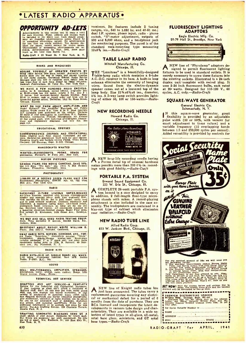
LATEST RADIO APPARATUS
OPPORTUNITY AD-LETS Advertisements in this section cost 15 cents a word for each Insertion. Name, address and initials must be included at the above rate. Cash should occom- Deny all classified advertisements unless placed by an accredited advertising agency. No advertisement for less than ten words accented. Ten percent dis- count six issues, twenty percent for twelve issues. Objectionable or misleading advertisements not tic- corned. Advertisements for May. 1941, Issue must reach us not later than March 7th.
Radlo -Craft 20 Vesey St. New York, N. Y.
BOOKS AND MAGAZINES
ASSURE YOURSELF OF GREATER PROFITS BY doing radio service lobs more quickly. Authentic servire guide. show you the way to locate and correct troubles in any radio receiver. Gernsback Official Radio Service Manuals show you how to complets more repair job. in leu time -how to earn more money by faster servicing. Redcraft Publications. 20 Vesey St.. New York City.
WE HAVE A FEW HUNDRED RADIO ENCYCLO Wins. by S. Genuback, second edition. originally sold at 83.98.Book has 352 paces. weight 3 lbs.. size 9 x
12 inches. Red morocco -keratol flexible binding. Send 82.99 in stamps, cash or money order and book will be forwarded erpress collect. Technifax, 1915 So. State Street, Chicago. Illinois.
WHAT DO YOU KNOW ABOUT AMPLIFIERS AND Sound Systems? The Amplifier Handbook and Public Address Guide covers P.A. from A to Z. Most complete and authentic book published on the subject. Contains 80 Pages of vital information on Amplifiers. P.A. Systems. Speakers. Accessorie.. Pickups. Microphones. etc. Printed on fine coated stock, with numerous photographic Illustra- tions and explanatory diagrams, and only 25e. See pago 614.
EDUCATIONAL COURSES
CORRESPONDENCE COURSES AND EDUCATIONAL books, slightly used. Sold. Rented. Exchanged. All sub- jects. Satisfaction guaranteed. Cash paid for used courses. Complete details and bargain catalog FREE. Write Nelson Company, 500 Sherman. Dept. D -292. Chicago.
MANUSCRIPTS WANTED
WANTED -MANUSCRIPTS. POEMS, SONGS FOR publication. Fortan'., 87 Fifth Are., New York.
MOTION PICTURES
GENERA FILMS FOR MOVIE CAMERAS. SAVE 50%. Got two films "The End," 10c. (Size 7) Big Bargain circulare. ',toreadors, Davenport, Iowa.
PHOTOGRAPHY
1 /100.000 OF A SECOND SPEED FLASH UNIT FOR Stroboscopic Photography. 8200.09. Apt. 63. 782 West End Ave.. New York City.
RADIO
SACRIFICE! 12 -TUBE LINCOLN SUPER -DELUXE All -N'ace ltecelver, complete with 12.inch electrodynamic speaker and separate power pack. Cost originally í14S. Will sacrifice for 825.00. Set is 1933 model. rarely used and in good working condition. Excellent sensitivity and selectivity. A resonance tuning meter, wave -band switch. phonograph input terminals, an Ideal set for the DX fan. Excellent tonal fidelity. All components mounted on a beautiful chromium- finished chassis. Rush! First come. first served! D. Kreisaman, 1930 Ocean Ave., Brooklyn, N. Y.
WE BUY AND SELL USED RADIO TESTING EQUIP mont. Time payment. if desired. Harold Davis, Inc., Jackson. Miss.
QUESTION? ABOUT RADIO? WRITE WILLIAM D. ]layes. Box 1433 -J. Oakland. California.
SWAP RADIO SETS, METERS, CAMERAS, ETC.. FOR: old Tusks "Supordyne," electrolytic detector, "Grant" loudspeaker, AdamsMorgan wooden -case brase plate variable condenser, l' or 2' spark coil: and other radio components dating prior to 1920. R. Bernard. 90 Man- ning Are., No. Plainfield. N. J.
RADIO KITS
RADIO KITS -83.95 UP. SINGLE BAND: ALL WAVE. 5 -10 tubes. Fluorescent lighting. Save 50%. McGee Radio, P -2055, K.C.. Mo.
SOUND
SELL: MULTICHANNEL AMPLIFIER. SPEAKERS, microphones. motor. pickup. cases. cabinet. Beggs, 5321 tt'ayne Menus, Phila.. Penna..
TECHNICAL ART SERVICE
DRAFTING AND ART SERVICE -A COMPLETE Service for the Industrial and Commercial Marketers. If your business or plant can't afford a designing or drafting staff, don't let this stop you from going ahead with that new product you Intend marketing. or that catalog of mechanical or electrical items which needs One detailed drawings and highly retouched photographs. Any mechanical. electrical or radio problem can be solved for you by our associated staff of designers. draftsmen and artists. and technical copywriters. Write for any additional information as to methods and price for this service. Tee -Art Drafting Service. 228 Charlotte Terrace, Roselle Park, N. J.
DRAFTING SCHEMATIC DIAGRAMS SEND US A rough sketch of your circuit. Estimates by return mall. Our prices are moderate: our work guaranteed. No jobs too big or small. Wm. Kadlccek, Jr., 440 East 85th St., New York. N. Y.
630
receivers. Its features include 2 tuning ranges, viz., 540 to 1.650 kc. and 90 -51 mc.; dual I.F. system, phono input, radio - phono switch, "S" -meter adjustment, outputs of 500 and 5,000 ohms, and a headphone jack for monitoring purposes. The panel is of the standard rack- mounting type measuring 19x8% ins.-Radio-Craf t
TABLE LAMP RADIO Mitchell Manufacturing Co.
Chicago, III.
THE "Lumitone" is a beautifully- designed table -lamp radio which contains a 5 -tube
A.C.-D.C. receiver in its base. A built -in loop antenna eliminates the necessity of hanging wires. Sound from the electro- dynamic speaker comes out of a louvered top of the lamp body. Size 21 %x6t/ax6 ins., diameter, 5% ins. A 3 -way lamp switch provides light- ing of either 50, 100 or 150- watts. -Radio- Craft
NEW RECORDING NEEDLE Howard Radio Co.
Chicago, Ill.
61.24 Betle4 é/orae ReaaaAi.ryd
\\1//_ ..HOWARD_
Fidelitonè NOME alta.alaG less tilt nnes
Meu re IMO MEW TIP
ANEW long -life recording needle having a Permo metal tip of unusual hardness
makes possible more than 200 6% -in. record- ings with good fidelity. -Radio -Craft
PORTABLE P.A. SYSTEM Erwood Sound Equipment Co. 223 W. Erie St., Chicago, Ill.
ACOMPLETE 28 -watt portable P.A. sys- tem housed in a case designed to carry
in addition, 2 full -length floor -type micro- phone stands with mikes. A record -playing attachment is also included in the case as- sembly. The loudspeakers are contained in a bias -cut type of cabinet which eliminates rear radiation.- Radio -Craft
NEW RADIO TUBE LINE Allied Radio Corp.
833 W. Jackson Blvd., Chicago, III.
A .üta:uD:d cnroam:o:t
ANEW line of Knight radio tubes has just been announced. The tubes carry a
replacement guarantee covering any electri- cal or mechanical defect for a period of 6 months from the date of purchase. They are RCA licensed and incorporate the latest de- velopments in vacuum tube design and char- acteristics. They are available in a wide se- lection of latest types in all -glass, all -metal, octal base glass, miniature, and GT octal base types. -Radio -Craft
FLUORESCENT LIGHTING ADAPTORS -
Eagle Electric Mfg. Co. 59 -79 Hall St., Brooklyn, New York
ANEW line of "Fluralamp" adaptors de- signed to permit fluorescent lighting
fixtures to be used in standard outlets. It is merely necessary to screw these fixtures into the existing sockets. Illustrated is a 24 -inch duplex unit'complete with swivel plug. It uses 2 -24 inch fluorescent bulbs, each rated at 20 watts. Designed for 110 -120 V., 60 cycles, A.C. only. -Radio -Craft
SQUARE -WAVE GENERATOR General Electric Co. Schenectady, N. Y.
N this square -wave generator, great flexibility is provided by an adjustable
pulse width (10 or 50 %, with vernier for exact adjustment to these values) and a variable frequency (10 overlapping bands between 1.5 and 250,000 cycles per second). Added versatility is provided by controls for
«a Nam (/ivma6! at it
Owls-
For the nominal amount of 35e we wilt send You the following values: I.
Pias eúlseo3x5 IA inchesbwith your Social Security permanently atomised noon It. number and name
2. One aural browntho color. four cotmp rtments.
as i This Pockeillustration bos our free present to You. Abae
lately no strings of any kind. We make you this gift borsa,e w expect you to do s favor by hewing Your me plate to your blends. to interest them In
You will onAforOems themselves. That's all. Help Its and
ACT NOW coins. The fro ze flmo puts ::T oz e Leather Billfold will be forwarded to You at once.
PREMIUM DISTRIBUTING SERVICE U Wrigley Bldg.. Chicago. Dept. RC -441
below toy SodeialSCSecurÌit which to and the
Genuine Loather Billfold without extra cost. as per I your offer. Ply Social Security Number is
NAME
ADDRESS
I I I I I I
CITY STATE I
RADIO -CRAFT for APRIL, 1941
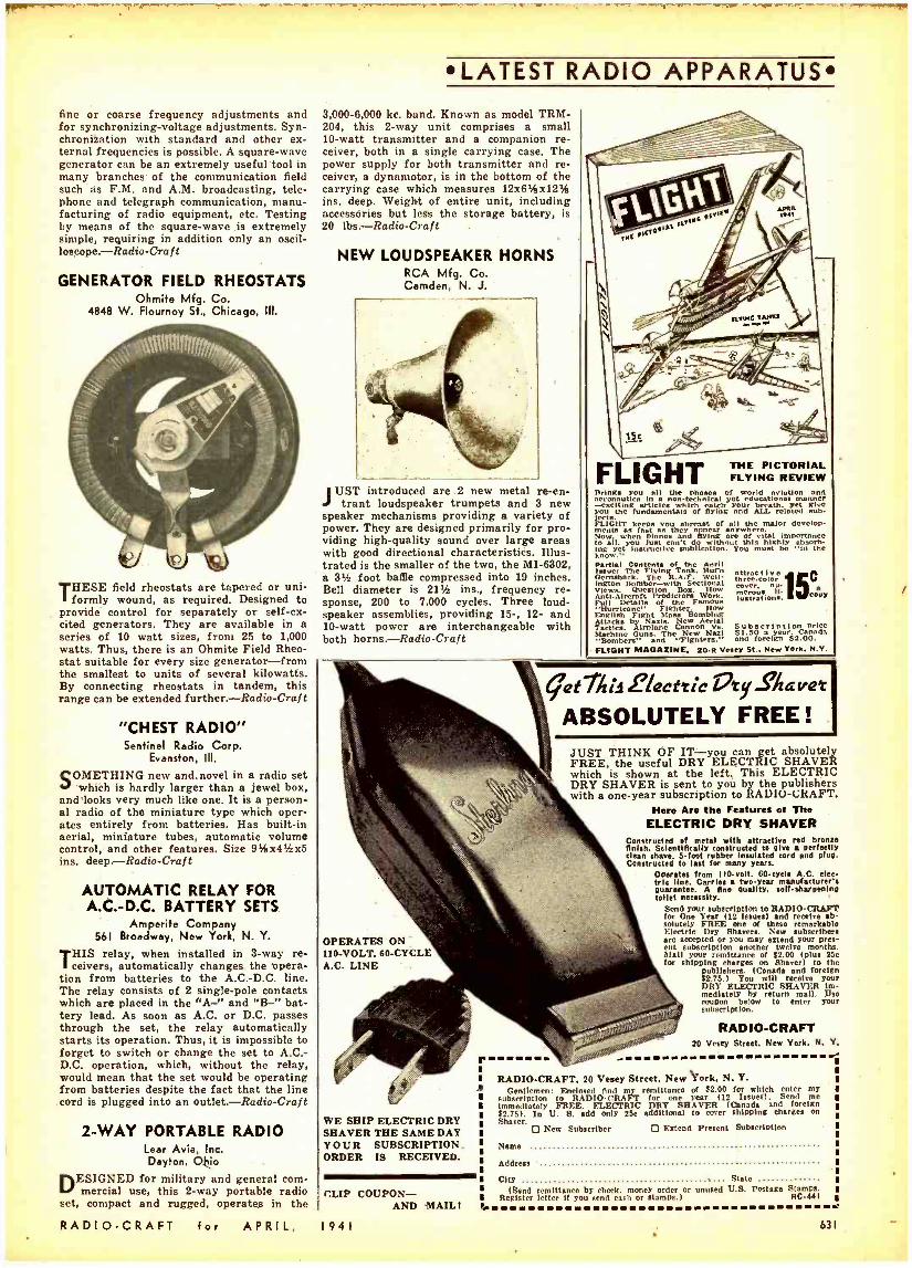
fine or coarse frequency adjustments and for synchronizing -voltage adjustments. Syn- chronization with standard and other ex- ternal frequencies is possible. A square -wave generator can be an extremely useful tool in many branches of the communication field such as F.M. and A.M. broadcasting, tele- phone and telegraph communication, manu- facturing of radio equipment, etc. Testing by means of the square -wave is extremely simple, requiring in addition only an oscil- loscope.-Radio-Craft
GENERATOR FIELD RHEOSTATS Ohmite Mfg. Co.
4848 W. Flournoy St., Chicago, III.
THESE field rheostats are tapered or uni- formly wound, as required. Designed to
provide control for separately or self -ex- cited generators. They are available in a series of 10 watt sizes, from 25 to 1,000 watts. Thus, there is an Ohmite Field Rheo- stat suitable for every size generator -from the smallest to units of several kilowatts. By connecting rheostats in tandem, this range can be extended further.- Radio -Craft
"CHEST RADIO" Sentinel Radio Corp.
Evanston, III.
SOMETHING new and.novel in a radio set which is hardly larger than a jewel box,
and looks very much like one. It is a person- al radio of the miniature type which oper- ates entirely from batteries. Has built -in aerial, miniature tubes, automatic volume control, and other features. Size 9%x4rfzx5 ins. deep. -Radio -Craft
AUTOMATIC RELAY FOR A.C. -D.C. BATTERY SETS
Amperite Company 561 Broadway, New York, N. Y.
HIS relay, when installed in 3 -way re- ceivers, automatically changes the opera-
tion from batteries to the A.C. -D.C. line. The relay consists of 2 single -pole contacts which are placed in the "A " and "B " bat- tery lead. As soon as A.C. or D.C. passes through the set, the relay automatically starts its operation. Thus, it is impossible to forget to switch or change the set to A.C: D.C. operation, which, without the relay, would mean that the set would be operating from batteries despite the fact that the line cord is plugged into an outlet. -Radio -Craft
2 -WAY PORTABLE RADIO Lear Avia, Inc. Dayton, Ohio
DESIGNED for military and general com- mercial use, this 2 -way portable radio
set, compact and rugged, operates in the
RADIO -CRAFT for APRIL,
LATEST RADIO APPARATUS
3,000 -6,000 kc. band. Known as model TRM- 204, this 2 -way unit comprises a small 10 -watt transmitter and a companion re- ceiver, both in a single carrying case. The power supply for both transmitter and re- ceiver, a dynamotor, is in the bottom of the carrying case which measures 12x6'5x12rá ins. deep. Weight of entire unit, including accessories but less the storage battery, is 20 lbs.- Radio -Craf t
NEW LOUDSPEAKER HORNS RCA Mfg. Co. Camden, N. J.
JUST introduced are 2 new metal re -en- trant loudspeaker trumpets and 3 new
speaker mechanisms providing a variety of power. They are designed primarily for pro- viding high -quality sound over large areas with good directional characteristics. Illus- trated is the smaller of the two, the MI -6302, a 3% foot baffle compressed into 19 inches. Bell diameter is 21% ins., frequency re- sponse, 200 to 7.000 cycles. Three loud- speaker assemblies, providing 15 -, 12- and 10 -watt power are interchangeable with both horns. -Radio -Craft
FLIGHT THE PICTORIAL FLYING REVIEW
Brings you all ^ e
phases of world aviation and in a -e
yxciting sarticles e
catch lea yet give ou the fundamentals of fying a ALL rated b.
niai r tam aéou abreast of
all tthe major develop -
Now. when planes and flying arc of vital importance to all. you just can't do without this highly absorb- ing yet instructive publication. You uet be "In the know. Partial Contents of the Peril Issue: The FlyingqR Tnnk, Hurt, HOrRabaCk. The
Bomber -With Sectional Views. Question Box. How Anti.Alrcraft Predictors Work. Full Details Famous
Fichter Hy English Fight Mass HOMblOg Attacks by Nails. New Aerial Tactics. Airplane Cannon Subscription price Machine Guns. The New Nail 51.50 a year. Canada "Bombers" and "Fighters.^ and foreign 32.00. FLIGHT MAGAZINE, 20'S Vesey St.. New York. N.Y.
tnrer-eolor
lustration.: py
get IA 2lecttic Z7ty_' %avet
ABSOLUTELY FREE! JUST THINK OF IT -you can get absolutely FREE, the useful DRY ELECTRIC SHAVER which is shown at the left. This ELECTRIC DRY SHAVER is sent to you by the publishers with a one -year subscription to RADIO- CRAFT.
Here Ara the Features of The ELECTRIC DRY SHAVER
Constructed of metal with attractive red bronze finish. Scientifically constructed to give a perfectly clean shave. 5 -foot rubber insulated cord and plug. Constructed to last for many years.
Operates from 110-volt. 60 -cycle A.C. elee- trie line. Carries a two -year manufacturer's
guarantee. g fine quality, self -sharpenin
Send your subecrlption to RADIO - CRAFT for One Year (12 issue.) and receive ab- solutely FREE one of these remarkable Electric Dry Shaven. New subscribers are accepted or You may extend your pres- ent subscription another twelve months. Mail your remittance of $2.00 (pine 25c for shipping rhargoe on Shaver) to the
publishers. (Canada and foreign 62.75.) You will receive your DRY ELECTRIC SHAVER im- mediately by return mall. Uso coupon below to enlcr your subscription.
RADIO -CRAFT 20 Vesey Street. New York, N. Y. r
OPERATES ON 110 -VOLT. 60 -CYCLE A.C. LINE
WE SHIP ELECTRIC DRY SHAVER THE SAME DAY YOUR SUBSCRIPTION ORDER IS RECEIVED.
CLIP COUPON - AND MAIL 1
1941
RADIO -CRAFT, 20 Vesey Street, New York, N. Y. Gentlemen: Enclosed find my remittance of $2.00 for which enter my
imbmedliately FREE.DELECTRIC DRYouSHAVER )( Canadas) and Send
foreign 62.75). In U. 8. add only 25e additional to cover shipping charge. on
Shaver. D New Subscriber D Extend Present Subscription
Name
Address
City State (Send remittance by check, money order or unused U.S. Postage Stamps
Register letter if you send cash or stamps.) RC -441
631
f
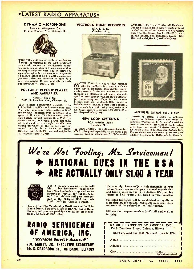
LATEST RADIO APPARATUS
DYNAMIC MICROPHONE American Microphone Co.
1915 S. Western Ave., Chicago, III.
THE VR -2 unit has an easily accessible ex- ternal adjustment of the most important
acoustical reactors in this dynamic micro- phone. A smooth change from a communica- tions -type response, with a cutoff below 500 c.p.a., through a flat response to an augment- ed bass, is attained by a simple positive ad- justment. Greatest diameter of mike is 3 ins.; net weight, 15 ozs. Available in vari- ous impedances.- Radio -Craft
PORTABLE RECORD PLAYER AND AMPLIFIER
Autocrat Radio Co. 3855 N. Hamilton Ave., Chicago, III.
AN electric phonograph complete with built -in amplifier and electric turntable.
The motor is a heavy self -starting unit of the 60 -cycle induction type operating at a speed of 78 r.p.m. The instrument uses a high- fidelity crystal pickup, 8 -in. P.M. dy- namic' speaker, and beam power amplifier. All equipment is in a si tgle portable case having provisions in the lid for carrying several records. It is known as model EPP -11. Size 16x14x81/4 ins., and weighs 16 lbs.; approx. -Radio -Craft
VICTROLA HOME RECORDER RCA Mfg. Co. Camden, N. J.
MODEL V -101 is a 5 -tube (plus rectifier tube and ballast) instrument with an
audio system especially designed' for repro- ducing records. It delivers 6 -watts of power through an efficient 6 -inch electrodynamic speaker. Has built -in "Magic loop antenna" for radio reception. Plays 10- or 12 -inch ecords with the lid closed. Other features include crystal pickup, 2 -point tone control, and superhet. circuit using magnetite -core I.F. transformers. Measures 1234x183/4 x13% ins. deep. -Radio -Craft
NEW LOOP ANTENNA RCA Aviation Radio
Camden, N. J. ANEW aviation loop antenna and adaptor
kit designed'especially as an aural -null direction finding attachment for RCA model
AVR -7D, E, F, G, and H Aircraft Receivers. The loop is available in either remote or local control forms and will operate as a direction finder on the Beacon band (195 -420 kc.) or on the Beacon and Broadcast bands (196 420, and 459 -1,400 kc.).-Radio-Craft
ALEXANDER GRAHAM BELL STAMP
Newest in stamps available to collectors through the Philatelic Agency, Post Office De- partment, Washington, D. C., and of special in- terest to technicians, are those in the Inventore series issued last month. Illustrated here is the 10c stamp dedicated to Alexander Graham Bell. The remaining inventors similarly honored are: Whitney, lc; Morse, 2c; McCormick, 8c; Howe, 5a
Ua':a At `iot;,y, Ale. Sé:v,cena t * NATIONAL DUES IN THE R S A 1 ARE ACTUALLY ONLY 51.00 A YEAR
Yes -it seemed amazing ... incredi- ble ... but Servicemen found it was true. Now hundreds of applications are pouring in from all parts of the coun- try! Just think -a full year member- ship in the National RSA for only $1.00 (that's less than 2c a week).
You get the RSA Membership Certificate and the RSA House Organ. You have access to RSA Technical Helps Bureau, and you can participate in all the other func- tions and benefits RSA offers.
RADIO SERVICEMEN OF AMERICA, INC.
"Reliable Service Assured JOE MARTY, JR., EXECUTIVE SECRETARY 304 S. DEARBORN ST., CHICAGO, ILLINOIS
It's your big chance to join with thousands of your fellow Servicemen in this great national organization and have a voice in your own destiny. It's your big chance to help yourself get ahead in your industry.
Protected territories will be established as rapidly as local chapters are formed. Applicants in present chap. ter areas will be referred to the local chapter.
Fill out the coupon, attach a $1.00 bill and mail it in today.
_, RADIO SERVICEMEN OF AMERICA, INC. 304 S. Dearborn Street, Chicago, Illinois
$1.00 enclosed for 1941 National Dues in RSA.
Name
Address
City State Radio- Craft -Apr,]
632 RADIO -CRAFT for APRIL, 1941
Mete ta 17115 it/ CLASSIFIED RADIO DIRECTORY
CLASSIFIED RADIO DIRECTORY
SECTION I (REVISED)
Handy Buying Guide, by Products and Manufacturers' Names and Addresses, for the Entire Radio Industry
This DIRECTORY is published in sections -1 section per month. This method of publica- tion permits the DIRECTORY to be constantly up-to-date since necessary revisions and corrections can be made monthly. All names preceded by an asterisk (5) indicate that they are trade names.
If you cannot find any item or manufacturer in this section or in previously- published sections, just drop us a line for the information.
Presented here is Section 1 of the completely revised Second Edition of the CLASSIFIED RADIO DIRECTORY.
There Is no charge for regular light -face listings In the Classi- fied Radio Directory.However, if dominant bold -face listings are desired, we make a charge of $2 for concern names and $1 for trade names for each bold -face listing. Please write to the Ad- vertising Dept., Radio-Craft, 20 Vest"; St., New York, N. Y., for
details.
AMPLIFIERS
Amplifier foundation units . A Direct- coupled . D Hearing -aid H Hearing -aid audio components HC Kits (amplifier) KI Mobile MO Power PO Preamplifiers PR Recorders and recording equipment
(see Recording Equipment) Sound motion picture . . . . S Transmitter . T
"AIRLINE " -Montgomery Ward & Co. ALLIED RADIO CORP., 833 W. Jackson Blvd.,
Chicago, III., ''Knight"-KI, PO, PR AMERICAN TRANSFORMER CO., 178 Emmet St.,
Newark, N. J. Amertran -KI AMPERITE COMPANY, 561 Broadway, New York,
N. Y. -PR AMPLIFIER CO. OF AMERICA, 17 W. 20th St.,
New York, N. Y. -A, D, H, HC, KI, MO, PO, PR, S, T
AUDIO DEVELOPMENT CO. 123 Bryant Ave., N., Minneapolis, Minn. -PO, Pk
AUDIOGRAPH SOUND SYSTEMS, 1313 W. Randolph St. Chicago, 111. -PO, PR
BANK'S MANUFACTURING CO., 5019 N. Winthrop Ave. Chicago, III. -PO, PR
BARKER & WILLIAMSON, Ardmore, Pa. -PO. PR BUD RADIO, INC., 5205 Cedar Ave., Cleveland,
Ohio-K1 CANADIAN MARCONI CO., 211 St. Sacrament St.,
Montreal, Que., Can. -PO. PR CHICAGO SOUND SYSTEMS CO., 315 E. Grand
Ave., Chicago, 111. -KI PO PR CINEMA ENGINEERING CO., 1508 W. Verdugo
Ave., Burbank, Calif. -PO, PR CRUMPACKER DISTRIB: CORP., 1801 Fannin St.,
Houston, Tex. -PO, PR HAROLD DAVIS, INC., 428 W. Capitol St., Jackson,
Miss.-PO, PR DE VRY CORPORATION, IIII Armitage Ave., Chi-
cago, 111. -PO, PR DOW RADIO SUPPLY CO., 1759 E. Colorado St.,
Pasadena, Calif. -KI, PO ELECTRONIC APPLICATIONS, Brunswick, Me. -PO,
PR ELECTRONIC SOUND & MUSIC CO., 10 Sfuyvesant -
St., New York, N. Y. -PR ERWOOD SOUND EQUIPMENT CO., 224 W. Huron
St. Chicago III -PO, PR FINCH TELECOMMUNICATIONS, INC., 1819 Broad-
way, New York N. Y.-PO, PR FISCHER DISTRIB. CORP., 222 Fulton St., New York,
N. Y. -KI, PO, PR THE JOHN GABLE MFG. CO., 1200 W. Lake St.,
Chicago, 111. -PO GENERAL COMMUNICATION PRODUCTS
CO., Lexington Ave. at Vine, Hollywood, Calif. -PO, PR
GUIDED RADIO CORP., 118 E. 25íh St., New York, N. Y.-PO, PR
THE HALLDORSON COMPANY, 4500 Ravenswood Ave., Chicago, III -K1
HAMMOND MANUFACTURING CO., Guelph, Ont., Can. -KI
HARRISON RADIO CO., 12 W. Broadway, New York, N. Y. -KI, PO, PR
RADIO -CRAFT for
While every precaution is taken to insure accuracy, Radio -Craft cannot guarantee against the possibility of occasional errors and omissions in the preparation of this Classified Directory. Manufacturers and readers are urged to report all errors and omissions at the
earliest moment to insure corrections in the very next issue.
HARVEY -WELLS COMMUNICATIONS, INC., North St., Southbridge Mass. -PO, T
CHARLES JACK MFG. CORP., 27 E. Philadelphia St., York, Pa. -PO, PR
*KNIGHT- Allied Radio Corp. LAFAYETTE RADIO CORP., 100 6th Ave., New York,
N. Y. -PO, PR LAUREHK RADIO MFG. CO., 3918 Monroe Ave.,
Wayne, Mich.-PO LEOTONE RADIO CO., 63 Dey St., New York, N. Y.
-PO, PR
THE LINCROPHONE CO., INC., 1661 How- ard Ave., Utica, N. Y. -PO, PR
M & H SPORTING GOODS CO., 512 Market St., Phila. Pa.-KI, PO
MARINE RADIO CORP., 117 -17 168th St., Jamaica, N. Y. -PO, PR
MILES REPRODUCER CO., INC., 812 Broadway, New York N. Y. -KI PO, PR
MONTGOMERY WARD & CO., 619 W. Chicago Ave. Chicago, III. "Airline" -PO, PR
MUSIC' MASTER NOG. CO., 508 S. Dearborn St., Chicago, 111. -PO, PR
NATIONAL COMPANY, INC., 61 Sherman St., Malden Mass. -PR
NORTHERN ELECTRIC CO., LTD., 1261 Shearer St., Montreal Que.. Can.-PO, PR
C. OFFENBAH ELECTRIC CO.. 1452 Market St., San Francisco, Calif. -KI PO, PR
OPERADIO MFG. CO., 13th & Indiana Sts., St. Charles, 111. -PO, PR
PACENT ENGINEERING CORP., 79 Madison Ave., New York, N. Y. -PO, PR
PAR -METAL PRODUCTS CORP., 32 -62 49th St., Long Island City, N. Y -A
PHILCO RADIO & TELEVISION CORP., Tioga & "C" Sts., Phila., Pa. -PO PHONOTONE LABORATORIES, INC., S.E. 15th St.,
Washington Ind. -PO PRESTO RECORDING CORP., 242 W. 55th St., New
York, N. Y. -PO, PR
RADIO ELECTRIC SERVICE CO., INC., N. W. Cor. 7th & Arch Sts., Phila., Pa.- KI, PO. PR
RADIO EQUIPMENT CORP., 326 Elm St., Buffalo, N. Y. -KI, PO, PR
THE RADIOTECHNIC LABORATORY, 1328 Sherman Ave., Evanston, III. -PO
RADIOTONE, INC., 7356 Melrose Ave., Hollywood, Calif.-PO, PR
RADOLEK COMPANY, 601 W. Randolph St., Chi- cago 111. -KI PO PR
THE RAYLAND CORPORATION, 3333 Belmont Ave.. Chicago, 111. -PO, PR
RCA MANUFACTURING CO., INC., Camden, N. J. -KI, PO PR
REGAL AMPLIFIER MFG. CORP., 14 W. 17th St.. New York N. Y. -PO PR
ROTOPHOÑE CORPORATION, 26 Journal Sq., Jer- sey City, N. J. -HC
ROWE INDUSTRIES, INC., 3120 Monroe St., Teledo, Ohio -PR
ROWE RADIO RESEARCH LAB. CO., 4201 Irving Park Blvd., Chicago, 111. -PR
MAURICE SCHWRRT & SON, 710 -712 Broadway, Schenectady, N. Y. -KI PO, PR
SETCHELL CARLSON, INC., 2233 University Ave., St. Paul, Minn. -PO, PR
SHELLEY RADIO CO., 1841 S. Flower St., Los Angeles Calif. -KI
MARK SILMPSON DISTRIB. CO., INC., 16 Hudson St., New York, N. Y. -KI PO
S.O.S. CINEMA SUPPLY CbRP., 636 Ilth Ave., New York N. Y. -PO, PR, S
SOUNb APPARATUS CO., ISO W. 46th St., New York, N. Y. -PO, PR
SUNDT ENGINEERING CO., 4787 Ravens- wood Ave., Chicago, III. -PO
SUN RADIO CO., 212 Fulton St., New York. N. Y.- Kl. PO, PR
TALK -A -PHONE MFG. CO., 1847 S. Millard Ave., Chicago 111. -PO
TECHNICAL PRODUCTS INTERNATIONAL, 135 Lib - erty St., New York, N. Y. -PO, PR
TELEVISO COMPANY, 341 N. Pulaski Rd., Chicago, 111.-PO, PR
THORDARSON ELECTRIC MFG. CO., 500 W. Huron St., Chicago 111. -KI, PO, PR
TRANSFORMER CORP. OF AMERICA, 69 Wooster St. New York, N. Y.-PO, PR
TRY.IIO RADIO CO., INC., 85 INC., St., New York, N. Y. -KI, P PR
UNITED TRANSFORMER CORP., 150 Varick St., New York, N. Y. -KI, PO, PR
VICTOR ANIMATOGRAPH CORP., Davenport, Iowa -PO, PR
WEBER MACHINE CORP., 59 Rutter St., Rochester, N. Y. -S
THE WEBSTERCHICAGO CORP., 5622 W. Bloom- ingdale Ave., Chicago, Ill., "Webster- Chicago"
WEB-PO STER ELECTRIC CO., Clark & DeKanen Ave., Resine, Wis. -PO, PR
WESTERN SOUND & ELEC. LABS., INC., 311 W. Kilbourn Ave., Milwaukee, Wis. -PO, PR
ANTENNAS & ACCESSORIES
Aircraft Al All -wave (home) A Antenna eliminators AE Auto antennas AA Built -in line antennas . . B Coaxial (concentric) cables CC Frequency Modulation . .
clamps GC Insulators. IN Kits KI Kits (Aircraft) KA Lightning arresters LA Loop antennas L Multiple (master) antenna systems M Multiple (master) systems (sup-
ports) MS Noise -reducing . . . . . NR Outlets . OU Rhombic antennas & resistors . RR Rotary beam R Television T Television, F.M. & A.M. comb. TC Towers & supports (commercial) TSC Towers & supports (home) . . TS Transmitter (& equipment) . TR Ultra -H.F. antennas UA Ultra -H.F. (fixed freq'y.) coaxial UC
ABC RADIO LABS., 3334 N. New Jersey St., Indianapolis. Ind. -AA
AEROVOX CORPORATION, New Bedford, Mass. - NR
AIRLINE -Montgomery Ward & Co. ALLIED ENGINEERING INSTITUTE, 85 Warren St.,
New York N. Y. -KI ALLIED RADIO CORP., 833 W. Jackson Blvd.. Chi -.
cago Ill., ' Kni ht " -A AE. AA, B, CC, F, GC, IN, 1 1, LA, L, M, NR, 1`, TC, TS, UA, UC
Please eay you saw it in the Radio -Craft "Classified Radio Directory"
APRIL, .1941 633
CLASSIFIED RADIO DIRECTORY'
ALLIGATOR- Porcelain Products, Inc. ALPHA WIRE CORP. 50 Howard St. New York,
N. Y. -A, AA, CC, k, GC, IN, KI, LA, L, TC, UC ALSIMAG-American Lava Corp. AMERICAN COMMUNICATIONS CORP. 123 Lib.
erty St., New York, N. Y. -A, 8, GCS, IN, M, NR OU
AMERICAN LAVA CORP., Cherokee Blvd. & Manu- facturers Rd., Chattanooga, Tenn., "AISiMag," "Leva " -IN
AMERICAN PHENOLIC CORP., 1250 Van Buren St., Chicago 111.-CC, IN UC
AMERICAN RADIO HARDWARE CO., INC., 476 Broadway, New York N. Y. -IN, OU
AMY, ACEVES & KING, INC., II W. 42nd St., New York, N. Y.-A, M NR, OU
VICTOR J. ANDEW CO., 6429 S. Lavergne Ave., Chicago, 111. -CC, TR, UA, UC, TSC
"ANTENEX -M. M. Fleron & Son. REX BASSETT INC., 214 Star Bldg., Niles, Mich. -
F,T, UA, TSC
BELDEN MFG. CO., 4647 W. Van Buren St., Chicago, 111. -A, GC, IN, KI, LA, M, NR
BENDIX RADIO CORP., 920 E. Fort Ave., Baltimore, Md. -L
BIRNBACH -Birnbach Radio Co., Inc. BIRNBACH RADIO CO., INC., 145 Hudson St., New -
York, N. Y. "Birnbach " -A, AE, F, GC, IN, KI LA, T, TC UA
BOND PRODUCTS CO., 13139 Hamilton Ave., De- troit, Mich. -AA, GC
L S. BRACH MFG. CORP., 55 Dickerson St., Newark, N. J. -A, AA, B, F, GC, IN KI, LA, L, M, NR, OU, TS
* BROWN DEVILS- Ohmite Manufacturing Co. BROWNIE- Porcelain Products, Inc. BROWN MFG. CO., 403 W. Baltimore, Detroit,
Mich -F KI BUD RADIO, INC., 5205 Ceder Ave., Cleveland,
Ohio -B, IN, OU
BURTON -ROGERS CO., Sales Div. for Hoyt Elec. Inst. Works, 857 Boylston St., Boston, Mass. -A, AA, F
CANADIAN MARCONI CO., 211 St. Sacrament St., Montreal, Can. -A, AA CC, F, GC, IN, KI, LA, L, RR, TC, TS, UA UC CANADIAN RADIO CORP., LTD., 622 Fleet St. W., Toronto, Ont., Can. -A, AA, B, GC, IN, Kf, LA
THE CARBORUNDUM CO., GLOBAR DIVISION, Niagara Fells N. Y.-RR
WIRE & ASSOCIATED CORPS., 512 S. Peoria St., Chicago 111. -A, AA, B, F, GC, IN, KI LA L, M, MB, OU -
CORNING 6`LASS WORKS, Corning, N. Y. -IN CORNISH WIRE CO., IS Park Row New York,
N. Y.-A, AE, GC, IN, KI, LA, NR, Row,
THE TC
CORPORATION, Cincinnati, Ohio - A, AA, B
CRUMPACKER DISTRIB. CORP. 1801 Fannin St., Houston, Tex. -A, AA, GC, ir1, KI, LA, NR
HAROLD DAVIS, INC., 428 W. Capital St., Jackson, Miss. -GC IN LA
DETERMOI4M- bhmite Mfg Co. DOOLITILE RADIO INC., 7421 Loomis Blvd., Chi-
cago 111. -AA, CC UC DOW RADIO SUPPLY CO., 1759 E. Colorado, Pas-
adena, Calif. -A, AA, B, F, GC, IN, KI, LA, OU, TSC
EAGLE ELECTRIC MFG. CO., INC., 59 Hall St., Brooklyn, N. Y. -A , GC, IN KI, LA, OU
EFFARS7EE- Fishwick Radio Co. FARNSWORTH TELEVISION & RADIO CORP., 3700
E. Pontiac St., Ft. Wayne Ind. -T, TC FEDERATED PURCHASER, INC., 80 Park Place, New
York N. Y. -A, M, AA, B, F, GC, IN, KI, LA, NR, T TC UA
FISCHER DISTRIB. CORP. 222 Fulton St., New York, N. Y. -A, AA, 8, F, GC, IN, KI, LA, L, M, NR, OU, TS
FISHWICK RADIO CO., 139 W. 4th St., Cincinnati, Ohio, "Effarsee " -A, AA, B, L, NR
*FLERON-M. M. Fleron & Son. M. M. FLERON & SON, INC., 113 N. Broad St.
Trenton, N. J. -A, F GC IN, KI LA, NR, Oli ' Antenex," "Fleron." Saitest," Signaler"
FONDA CORPORATION, 29 W. 57th St., New York, N. Y. -F, RR T. TC
FOWLER MFG. CO., 9 Rutger St., St. Louis, Mo. -A GENERAL CEMENT MFG. CO., 919 Taylor Ave.,
Rockford, III -AE GENERAL CERAMICS CO., Plant No. 3, Keasbey,
N. J. -F, IN GENERAL ELECTRIC CO. Schenectady, N. Y. &
Bridgeport, Conn. -F. T. 'SC GOLDEÑTONE RADIO CO. 15123 Warren Ave.,
Dearborn, Mich.-A, AA, KI NR EDWIN I. GUTHMAN & CO., INC., 400 S. Peoria
St., Chicago, 111. -L D. H. HARRELL, 1527 E. 74th Place, Chicago, 111:
MS HARRISON RADIO CO. 12 W. Broadway New York,
N. Y. -CC, F, GC, IN, KI, RR T UA, UC HARVEY -WELLS COMMUNICATIONS, INC., North
St., Southbridge, Mass.-UA, UC HOME RADIO SERVICE, INC., 521 W. 48th St.,
New York, N. Y. -M HOPE WEBBING CO., P.O. Box 1495, Providence,
R. I. -A HERBERT H. HORN, 1201 S. Olive St. Los Angeles,
Calif. -A, AA, B IN, KI LA, L, St.,
OU, TS HOWARD RADIO CO., 1731 W. Belmont Ave.,
Chicago, III. -F, L
634
INSULINE CORP. OF AMERICA 30 -30 Northern Blvd. Long Island City, N. Y. -A, AA, 8, F, GC, IN, Ill, LA L, TS
JAMES WIRE & CABLE CO., 1014 Madison Ave., Toledo, Ohio -A KI
J.F.D. MANUFACTURING CO., 4111 Ft. Hamilton Pkwy. Brooklyn, N. Y. -A AA, F, KI, TS
E. F. JOHNSON COMPANY, Waseca, Minn. -F, IN KNIGHT- Allied Radio Corp. LAFAYETTE RADIO CORP., 100 6th Ave., New York,
N. Y. -A, AA, F, GC, IN, Kl, LA, L, M, NR, OU TS
LAVA- American Lava Corp. LEARADIO -Lear Avia, Inc. LEAR AVIA INC. 30 Rockefeller Plaza, New York,
N. Y., "Learadi, o " -AI, UA JOHN E. LINGO & SON, INC., 28th St. & Van
Buren Ave. Camden, N. J. -F FRED M. LINK, 125 W. 17th St., New York, N. Y.-
AA, UC M. & H. SPORTING GOODS CO., 512 Market St.,
Phila. Pa.-A, AA, GC IN, LA M, NR, OU MAC.AbAMS EUIPMENT INC., 507 W. 56th
St., New York N. Y. -AA, F, CO.,
, TC MAJESTIC RADIO & TELEVISION CORP., 2600
W. 50th St., Chicago, III. -L MIDWEST RADIO CORP., 909 Broadway, Cincinnati,
Ohio, "Midwest " -A JAMES MILLEN MFG. CO., INC., 150 Exchange
St., Malden, Mass. -IN MIMS RADIO CO., P. O. Box 504, Texarkana, Ark. -f R
MONTGOMERY WARD & CO., 619 W. Chicago Ave., Chicago, III., 'Airline' -A, AA, B, CC, GC, IN, KI LA
MUELLER ELECTRIC CO., 1583 E. 31st St., Cleve- land Ohio-GC
MULTIVOLTS- Ohmite Manufacturing Co. MUSIC MASTER MFG. CO., 508 S. Dearborn St.,
Chicago, 111 -KI, NR THE MUTER COMPANY, 1255 S. Michigan Ave.,
Chicago, 111. -L NOBLITT- SPARKS INDUSTRIES, INC., Columbus,
Ind. -AA NORTHERN ELEC. CO., LTD. 1261 Shearer St., Mon.
tree!, Que., Can.-A, B, GC, IN, KI, M, NR, OU OFFENBACH ELECTRI CO. 1452 Market St., San
Francisco, Calif. -A, AA, r', GC, IN, KI, LA, L, NR, OU
OHMITE- Ohmite Manufacturing Co. OHMITE MANUFACTURING CO., 4835 W. Flournoy
St. Chicago, III., Ohmite," "Brown Devils," "tiultivolts " "Determohm," "Riteohm " -RR
PACENT ENGINEERING CORP., 79 Madison Aye., New York, N. Y. -A F, NR
PHILCO RADIO & TELEVISION CORP., Tioga & "C" Sts., Phila., Pa. -A, AA, B, GC, IN, KI, LA, L, M NR, TS
PHILMORE MANUFACTURING CO., 13 University PI., New York, N. Y. -GC, IN, KI,
INC., L, NR
PHILSON MANUFACTURING CO., INC., 156 Cham- bers St., New York, N. Y.-AA, F, T
PILOT RADIO CORP., 37 -06 36th St., Long Island City N. Y.-A, F
PIONEER SPECILTY CO., 5100 St. Jean Ave., De- troit Mich. -AA
PORCELAIN PRODUCTS INC., P. O. Box 300, Find- lay. Ohio, Brownie's 'AIl,gator " -GC IN, LA
PREMAX PRODUCTS DIV., CHISHOLM -RYÔER CO.,
Drawer F, Bridge Sta., Niagara Falls, N. Y. -IN,
TS QUAM- NICHOLS CO., 33rd Pl. & Cottage Grove,
Chicago 111 -K1 LA RADEX CORPORATION, 1733 (Milwaukee Ave., Chi.
cago, 111. -CC, F, M
RADIO ELECTRIC SERVICE CO., INC., N. W. Cor. 7th & Arch Sts., Phila., Pa. -A, AA, B, F, GC, IN, KI, LA, L, M, NR, OU, TS
RADIO EQUIPMENT CORP., 316 Elm St., Buffalo, N. Y. -A AA GC, IN KI, LA, M, NR, OU
RADIO RECEPTOR CO., INC., 251 W. 19th St., New York N. Y.-CC UA, UC
RADOLEK COMPANY 601 W. Randolph St., Chi-
cago, 111. AU AE AA,
B, CC, F, GC, IN, KI,
RCA MANUFACTURING CO. INC., Camden N. J. -A AA, B F, GC, IN, Kl, LA, L, M, NR, OU RITEÒHM- bhmite Manufacturing Co. ROGERS -MAJESTIC CORP., LTD., 622 Fleet St.,
Toronto, Can. -A, KI *SAFTEST -M. M. Fleron & Son. MAURICE SCHWARTZ & SON, 710.712 Broadway,
Schenectady. N. Y. -A, AA, B, F, GC, IN, KI, LA, L, M, NR OU, TS
SEATTLE RADIO SUPPLY CO., INC., 2117 2nd Ave. Seattle Wash. -A, CC, GC IN, LA, RR, UA, UC
SHELLEY' RADIO CO., 1841 S. Flower St., Los An- geles Calif. -A AA
H. B.
An- geles,
MFG. CO., 22 Barney St., Battle Creek, Mich. -GC
SIGNALER -M. M. Fleron & Son. SNYDER, INC., Noble & Darien Sts., Phila., Pa.-
A, AA, GC STROMBERG- CARLSON TELEPHONE MFG. CO.. 100
Carlson Rd., Rochester, N. Y. -A, B, F, KI, NR SUN RADIO CO., 212 Fulton St., New York, N. Y.-
A AA, B F, GC, IN KI, LA L, MS, NR, OU, TS TAYLOR AIRPHONE PRODUCTS Hangar 15, Long
Beach Airport, Long Beach, Calif. -KA TECHNICAL-APPLIANCE CORP., 17 E. 16th St., New
York N. Y. -A, B, F, GC, IN, K1, LA, M, NR, T, TC, UA
TELERADIO ENGINEERING CORP. 484 Broome St., New York, N. Y. -B, F, KI, L, NR
TILTON ELECTRIC CORP., 15 E. 26th St., New York, N. Y. -F NR
TREBOR RADIO CO., Pasadena, Calif. -L TRICO FUSE MFG. CO., 2948 N. 5th St., Milwaukee,
Wis. -GC TRY -MO RADIO CO., INC., 85 Cortlandt St., New
York, N. Y. -A, AE, AA, B CC, F, GC, IN, KI, KA, LA, L, M, NR, OU, RR, T, TC, TS, UA, UC
VERTI -FLEX ILLINOIS SEATING CO., 2138 N. Racine Ave. Chicago, 111. -A, F, M, NR
VERTROD MANUFACTURING 132 Nassau St., New York, N. Y. -A F KI, NR
CO., TC, UA
WARD PRODUCTS CORP., 1523 E. 45th St., Cleve- land, Ohio -A
WESTINGHOUSE ELEC. & MFG. CO., E. Pittsburgh, Pa. -F, TSC
WINCHARGER CORPORATION, Sioux City, Iowa - TS
WIRT COMPANY, 5221.27 Greene St., Phila., Pa. -LA
AUTOMATIC TUNERS & PARTS
Inductance trimmer units . . . I
Mechanical selectors . . . . M Pushbutton identification tabs . PT Pushbutton knobs . . . P
Pushbutton motor -operated units (complete) PB
Pushbutton switches PS
Pushbutton trimmer units (complete) PU
Remote controls RC Station name cards S
Temperature- compensating condensers . . . . . . T
Trimmer condenser units . . . TC Tuning motors TM
ADVANCE ELECTRIC CO., 1260 W. 2nd St., Los Angeles, Calif. -RC
AEROVOX CORPORATION, New Bedford, Mass. - TC
AIRLINE -Montgomery Ward & Co. ALLIANCE MANUFACTURING CO., Alliance, Ohio
-TM ALLIED RADIO CORP., 833 W. Jackson Blvd., Chi-
cago, III., "Knight' -M P PS, RC, TC AMERICAN\ RADIO HARDWARE CO., INC., 476
Broadway, New York, N. Y. -P, PS ANSLEY RADIO CORP., 4377 Bronx Blvd., New York,
N. Y.-RC ATOMS -Sprague Products Co. BARKER & WILLIAMSON, Ardmore, Pa. -1, M, RC,
TC BIRNBACH- Birnbach Radio Co., Inc. BIRNBACH RADIO CO., INC., 145 Hudson Sf., New
York, N. Y., "Birnbach " -PS DAVID BOGEN CO., 663 Broadway, New York, N. Y.
-RC CENTRALAB, DIV. OF GLOBE UNION, INC.,
900 E. Keefe Ave., Milwaukee, Wis. -T, TC CRUMPACKER DISTRIB. CORP., 1801 Fannin St.,
Houston, Tex -I, M P, PB PS, PU, TC, TM DOW RADIO SUPPLY CO., 1759 E. Colorado,
Pasadena Calif. -P PS, RC THE ELECtRO MOTIVE MFG. CO., INC., Willi-
mantic, Conn. -PU TC EMPIRE NOTION Cb., 105 E. 29th St., New York,
N. Y. -P ERIE RESISTOR CORP., 644 W. 12th St., Erie, Pa.-
I, P, T TC FEDERATED PURCHASER, INC., 80 Park Place, New
York, N. Y -P PS, TC FISCHER DISTRIB. CORP., 222 Fulton St. New York,
N. Y.-1, M, P, PB PS, PU, RC T, TC, TM FONDA CORPORATION, 29 W. 57th St. New York,
N. Y.-1, M, PT, P, PB PS PU, RC, tM GENERAL CEMENT MFG. LO., 919 Taylor. Ave., Rockford, 111. -PT, S
GENERAL CERAMICS CO., Plant No. 3, Keasbey, N. J. -TC (bases only)
GENERAL INSTRUMENT CORP., 829 New- ark Ave., Elizabeth, N. J. -M
GORDON SPECIALTIES CO., 1104 S. Wabash Ave., Chicago, 111. -S
CARL GORR PRINTING CO., 2615 N. Ash- land Ave., Chicago, III. -PT
L. F. GRAMMES & SONS, INC., 361 Union St., Allen- town, Pa. -PT
GUARDIAN ELECTRIC MFG. CO., 1621.27 W. Wal- nut St. Chicago, 111. -RC
EDWIN I. GUTHMAN & CO., INC., 400 S. Peoria St., Chicago, 111. -I, T TC
HARRISON RADIO CO., 12 W. Broadway, New York, N. Y.-I, I
INSULINE CORP. OF AMERICA, 30-30 Northern Blvd. Long Island City, N. Y. -P, TC
KNIGI4T- Allied Radio Corp. KOOLOHMS- Sprague Products Co. KURZ -KASCH, INC., 1421 S. Broadway, Dayton,
Ohio -P Pisase say you saw it in the Radio -Craft "Classified Radio Directory"
RADIO -CRAFT for APRIL, 1941
1111."V-°.'
LAFAYETTE RADIO CORP., 100 6th Ave. New York, N. Y. -I, M, P. PB PS, PU, RC, T TC, TM
MAC -ADAMS EQUIPIv1ENT CO., INC., 507 W. 56th St., New York, N. Y. -RC
MAJESTIC RADIO & TELEVISION CO!!P., 2600 W. 50th St. Chicago, 111.-I
P. R. MALLORY & CO., INC., 3029 E. Washington St., Indianapolis Ind -PS
MEISSNER MANUFACTURING CO., Mt. Carmel, III. -I , P
JAMES MILLEN MFG. CO., INC., 150 Exchange St. Malden, Mass. -TC
ELMER E. MILLS CORP., 812 W. Van Buren St., Chicago 111. -P
MONTGOMERY WARD & CO. 619 W. Chicago Ave., Chicago III., "Airline'1 -TC
THE MUTER COMPANY, S. Michigan Ave., Chicago, III. -PS, T TC
OAK MANUFACTURING CO. 1260 Clybourn Ave., Chicago 111. -M PB, PS, PU
OFFENBACH ELECTRIC CO., 1452 Market St., San Francisco, Calif. -I. M, P, PS, PU, RC, T, TC
PACENT ENGINEERING CORP., 79 Madison Ave., New York N. Y. -RC
PARISIAN NOVELTY CO., 3510 S. Western Ave., Chicago 111. -PT S
PHILCO RADIO L TELEVISION CORP., Tioga & "C" Sts., Phila., Pa. -I, M, P, PB, PS, PU, RC, T, TC
PIONEER GEN -E -MOTOR CORP., 466 W. Superior St., Chicago, 111. -TM
RADIO ELECTRIC SERVICE CO., INC., N.W. Cor. 7th & Arch Ste., Phila., Pa. -I, M, P,
PB, PS, PU, RC, T, TC, TM RADIO EQUIPMENT CORP., 326 Elm St., Buffalo,
N. Y. -I, M, P, PS, PU, RC, T TC TM RADIO KNOB CO., 43 E. Ohio St., Chicago, III. -
P
RADOLEK COMPANY 601 W. Randolph St., Chica- go, 111. -1 M P, PS, PU, TC
RCA MANUFACTURING CO., INC., Camden, N. J. -PU RC, T TC
THE RICHARDSON COMPANY, 27th & Lake Sts., Melrose Park, III. -P
ROGERS- MAJESTIC CORP., LTD., 622 Fleet St., Toronto, Can. -M, P
MAURICE SCHWARTZ & SON, 710 -712- Broadway, Schenectady, N. Y. -I, M, P, PB, PS, PU, RC, T, TC, TM
SEATTLE RADIO SUPPLY CO., INC., 2117 2nd Ave., Seattle, Wash. -PS, T, TC
600 LINE -Sprague Products Co. SORENG- MANEGOLD CO., 1901 Clybourn Ave.,
Chicago, 111. -PS SPRAGUE PRODUCTS CO. N. Adams Mass., "600
Line ", "Atoms ", "Koolohms ", "Telohmite " -T, TC
F. W. STEWART MFG. CORP., 340 W. Huron St., Chicago, 111. -RC
SUN RADIO CO., 212 Fulton St., New York, N. Y. -I, M, P, PB, PS, PU, RC T, TC, TM
TELERADIO ENGINEERING 484 Broome St., New York, N. Y -1, PU, RC, T
CORP. C TELOHMITE- Sprague Products Co.
WESTINGHOUSE ELEC. & MFG. CO., E. Pittsburgh, Pa. -PS
AUTO -RADIO CONTROLS
Cable replacement fools . CT Control fittings CF Control heads C Controls (complete) . . . . CC Flexible shafts F
ALLIED RADIO CORP., 833 W. Jackson Blvd., Chi- cago, Ill., ""Knight"-CT, CF, C, CC. F
AMERICAN RADIO HARDWARE CO., INC., 476 Broadway, New York, N. Y.-CT, CF
CANADIAN RADIO CORP., LTD., 622 Fleet St., W Toronto Ont., Can. -C, F
CROWE NAME PLATE & MFG. CO., 3701 Ravens- wood Ave.. Chicago, 111. -F, C, CC, F
CRUMPACKER DISTRIB. CORP. 1801 Fannin St., Houston, Tex. -CT, CF. C, CC, F
HAROLD DAVIS, 428 W. Capital St., Jackson, Miss. -CT, CF, C,
INC., C F
DOW RADIO SUPPLY CO., 1759 E. Colorado, Pasa- dena. Calif. -CT, CF C. CC, F
C DUAL REMOTE ONTROL CO.. INC., 31776 W. Warren Ave., Wayne, Mich. -CF, C CC, F
ERIE RESISTOR CORP., 644 W. 12th St., Erie, Pa.- FEDERATED PURCHASER, INC., 80 Park Place, New
York, N. Y. -CF, C, F FISCHER DISTRIB. CORP., 222 Fulton St.. New York,
N. Y.-CT, CF, C. CC, F
GALVIN MANUFACTURING CORP., 4545 W. Au- gusta Blvd., Chicago, III., "Motorola " -CF, C, F
J. F. D. MANUFACTURING CO., 4111 Ft. Hamilton Pkwy., Brooklyn, N. Y.-CT, CF, F
KNIGHT- Allied Radio Corp. LAFAYETTE RADIO CORP., 100 6th Ave., New York,
N. Y.-CT, CF, C, CC, F
RADIO -CRAFT for
CLASSIFIED RADIO DIRECTORY
MAC -ADAMS EQUIPMENT CO., INC., 507 W. 56th St., New York, N. Y.-CF, C, CC, F
P. R. MALLORY & CO., INC., 3029 E. Washington St. Indianapolis Ind -F
MOYOROLA- Galvin Manufacturing Corp. OFFENBACH ELECTRIC CO., 1452 Market St., San
Francisco, Calif. -F PHILCO RADIO & TELEVISION CORP., Tioga & "C"
Sts., Phila., Pa. -CF, C, CC, F
RADIO ELECTRIC SERVICE CO., INC., N. W. Co. 7th & Arch Sts., Phila., Pe. -CT, CF, C, CC, F
RADIO EQUIPMENT CORP., 326 Elm St., Buffalo, N. Y. --CT, CF, C, CC, F
RADOLEK COMPANY, 601 W. Randolph St., Chica- go, 111. -CT, CF, C, CC F
RCA MANUFACTURING CO., INC., Camden, N. J. -CT, CF, C, CC, F (these products for car mfrs. only)
MAURICE SCHWARTZ & SON 710 -712 Broadway, Schenectady, N. Y. -CT, CF, O, CC, F
SHELLEY RADIO CO., 1841 S. Flower St., Los Angeles, Calif. -C, F
F. W. STEWART MFG. CORP. 340 W. Huron St., Chicago, III. -CT, CF, C. CO, F
SUN RADIO CO., 212 Fulton St., New York, N. Y.- CT, CF, C, CC, F
AIRCRAFT RADIO (see Receiving Sets [including Adapters
& Converters])
BATTERY CHARGERS (& PARTS)
Automatic switches . . . . AS Battery -charging tubes . . . BT Gas -engine chargers . GC Powerline chargers (home) . PH Powerline chargers (service
station) V Vibrator chargers . V Wind- driven chargers . . . WC
"AIRLINE -Montgomery Ward & Co. ALLEN ELEC. & EQUIP. CO., 2101 N. Pitcher St.,
Kalamazoo, Mich. -BT, PS
ALLIED RADIO CORP., 833 W. Jackson Blvd., Chica- go, III., "Knight " -BT, GC, PH, V, WC
AMERICAN COMMUNICATIONS CORP., 123 Liber - ty St., New York, N. Y. -BT, PH
AMERICAN TELEVISION & RADIO CO., 300 E. 4th St. St. Paul Minn. -PH, V
AUTOMATIC ELECTRICAL DEVICES CO., 324 E. 3rd St., Cincinnati, Ohio -PH V
THE BENWOOD -LINZE CO. 1870 Washington Ave., St. Louis, Mo. -BT, PH, PS
CANADIAN MARCONI CO., 211 St. Sacrament St., Montreal, Can. -BT, GC, PH, PS, V, WC
CHARGIT -Chargit Corporation CHARGIT CORPORATION, Citizens Bank Bldg., An-
derson, Ind. "Chargit " -PH CINEMA ENGINEERING CO., 1508 W. Verdugo
Ave., Burbank, Calif. -PH CONTINENTAL ELECTRIC CO. Geneva 111. -BT CRUMPACKER DISTRIB. CORP., 1801 Fannin St.,
Houston, Tau. -GC PH, PS, V, WC HAROLD DAVIS, INC., 428 W. Capital St., Jackson,
Miss. -GC WC DOW RADIO SUPPLY CO., 1759 E. Colorado, Pasa-
dena, Calif. -BT V EICOR, INC., 515 S. Laflin St., Chicago, III. -GC,
ELECTRONIC PRODUCTS CO., St. Charles, 111. -PS FEDERAL TELEGRAPH CO., 200 Mt. Pleasant Ave.,
Newark, N. J. -BT, PS FEDERATED PURCHASER, INC., 80 Park Place, New
York, N. Y. -BT, GC, PH, V WC FISCHER DISTRIB, CORP. 222 Fulton St., New York,
N. Y. -FC, PH, PS, WC GENERAL ELECTRIC CO., Schenectady, N. Y. &
Bridgeport, Conn.-BT, PH, PS HARRISON RADIO CO., 12 W. Broadway, New York,
N. Y. -BT GC, PH V HARTMAN ELECTRICAL MFG. CO., Mansfield,
Ohio -AS, PH HETRO -Hetro Electrical Industries, Inc. RETRO ELECTRICAL INDUSTRIES, INC., 5819 N.
Drake Ave. Chicago. III., "Hetro "-GC JANETTE MANUFACTURING CO., 556 W. Monroe
St. Chicago, III. -GC KATO ENGINEERING CO., INC., 530 N. Front St.,
Mankato, Minn. -GC "KNIGHT -Allied Radio Corp. LAFAYETTE RADIO CORP., 100 6th Ave., New York,
N. Y. -BT, GC, PH, PS, V, WC
LAUREHK RADIO MFG. CO., 3918 Monroe Ave., Wayne, Mich. -PH
THE LAUSON COMPANY, New Holstein, Wis. -GC LeJAY MANUFACTURING CO., 1406 W. Lake St.,
Minneapolis, Minn. -GC, PH P. R. MALLORY & CO., 3029 E. Washington
St., Indianapolis, Ind. -PH, INC.,
MEISSNER MANUFACTURING CO., Mt. Carmel, III. -V
MIDCO MFG. & DISTRIB. CO., INC., S. 13th & Ken - tucky Ave., Sheboygan, Wis. -GC
MONTGOMERY WARD & CO., 619 W. Chicago Ave. Chicago, Ill., "Airline " -BT, GC, PH, WC
NATIONAL COMPANY, INC., 61 Sherman St., Mel - den, Mass. -V
OAK MANUFACTURING CO., 1260 Clybourn Ave., Chicago, 111. -V
OFFENBACH ELECTRIC CO., 1452 Market St., San Francisco, Calif. -BT, GC, PH, PS, V
PIONEER GEN -E -MOTOR CORP., 466 W. Superior St., Chicago III. -GC
ONAN -D. W. Onan & Sons D. W. ONAN & SONS 43 Royalston Ave., Minneap-
olis, Minn., "Onant' -GC RADIO ELECTRIC SERVICE CO., INC., N. W.
Cor. 7th & Arch Sts., Phila., Pa. -BT, GC, PH, WC
RADIO EQUIPMENT CORP., 326 Elm St., Buffalo, N. Y. -BT PH, V
RADOLEK COMPANY, 601 W. Randolph St., Chica- go 111.-BT. PH
MAURICE SCHWARTZ & SON, 710 -712 Broadway, Schenectady, N. Y.-BT, GC, PH, PS, V, WC
SEATTLE RADIO SUPPLY CO., 2117 2nd Ave., Seattle, Wash. -8T GC PH, PS,
INC.,
SHELLEY RADIO CO., 1841 S. Flower St., Los An- geles, Calif. -BT
S.O.S. CINEMA SUPPLY CORP., 636 Ilth Ave., New York, N. Y.-BT, PH
SUN RADIO CO., 212 Fulton St., New York, N. Y.- 8T, GC, PH, V, WC
TECHNICAL PRODUCTS INTERNATIONAL, 135 Liberty St., New York, N. Y.-GC, PH, PS, WC
UNITED TRANSFORMER CORP., 150 Verick St., New York, N. Y. -BT, PH
WARD LEONARD ELECTRIC CO., 31 South St., Mt. r(ernon N. Y. -PS
EARL WEBBER CO., 4348 W. Roosevelt Rd., Chicago, 111 -BT, PS
JOS. WEIDENHOFF, INC., 4344 W. Roosevelt Rd., Chicago, III. -BT, PS
WILLARD STORAGE BATTERY CO., 246 E. 131st St., Cleveland, Ohio -BT PS
WINCHARGER CORPORATION, Sioux City, lowe- GC, WC
BATTERIES (& CELLS) DRY & WET (STORAGE)
"A" dry -batteries "B" dry- batteries "C" dry -batteries Bias cells (oxide) Drycells Flashlight drycells Flashlight storage cells . . . FS Hearing -aid dry -batteries . . HA Miniature portable dry -batteries MP Storage batteries SB
AB BB CB BC
D
FD
AIR- ELECTRIC MACHINE CO., INC., Lohrville, Iowa -SB
'AIRLINE-Montgomery Ward & Co. ALLIED RADIO CORP. 833 W. Jackson Blvd., Chi-
cago, Ill., "Knight'1 -AB, BB, CB, BC, D, FD, MP, SB
BOND ELECTRIC CORP., DIV. OF WESTERN CAR- TRIDGE CO., 275 Winchester Ave., New Haven, Conn. -AB, BB CB, BC, D, FD, MP
BRIGHT STAR-bright Star Battery Co. BRIGHT STAR BATTERY CO., Clifton, N. J., "Bri ht
Star" "Uneedit" "Eclipse ", "Mars " -AB, BB, CB, BC, D FD, MP
BURGESS BATTERY CO., Freeport, 611. -AB, BB, CB, BC D, FD, HA, MP (dry)
CANADIAN MARCONI CO., 211 St. Sacrament St., Montreal, Can. -AB, BB, CB, BC, D, MP, SB
CANADIAN RADIO CORP., LTD., 622 Fleet St., W., Toronto, Ont., Can. -AB, BB, CB, D, FD, MP, SB
"CHARGIT -Chargit Corporation CHARGIT CORPORATION Henderson, Ind.,
"Chargit " -FD, FS, MP SB THE CROSLEY CORPORATION, Cincinnati, Ohio - AB, BB
CRUMPACKER DISTRIB. CORP., 1801 Fannin St., Houston, Tex-AB, BB CB, D, FD MP
DOW RADIO SUPPLY CO., 1759 E. Colorado, Pasa- dena, Calif. -AB, BB, CB, D FD, MP
ECLIPSE -Bright Star Battery_ Co. FEDERATED PURCHASER, INC., 80 Park Place, New
York, N. Y. -AB, BB, CB, BC, D, FD, MP
Please say you saw it in the Radio -Craft "Classified Radio Directory"
APRIL, 1941 .635
C LASSIFIED RADIO DIRECTORY FISCHER DISTRIB. CORP., 222 Fulton St., New York,
N. Y. -AB, B8, CB, D FD, MP GENERAL DRY BATTERIES, INC., 13000 Athens Ave.,
Cleveland Ohio -AB, BB CB, D, FD, MP GLOBE PHONE MFG. COkP., Reeding, Mess. -AB,
GOLDENTONE RADIO CO., 15123 Warren Ave., Dearborn, Mich. -AB, BB, MP
HARRISON RADIO CO., 12 W. Broadway, New York, N. Y. -AB, BB, CB, BC, D, MP
HERBERT H. HORN. 1201 S. Olive St., Los Angeles, Calif. -AB, BB, CB, D, FD MP
IDEAL COMMUTATOR DRESSER CO., Sycamore, III. -FS
KELLOGG SWITCHBOARD & SUPPLY CO., 6650 S. Cicero Ave., Chicago 111. -AB, BB, CB, D, FD
"KNIGHT " -Allied Radio Corp. LAFAYETTE RADIO CORP. 100 6th Ave., New York,
LeJAY MANUFACTURING OCO.P, l4Ó6 W. Lake St., Minneapolis, Minn. -AB
M. & G. HEARING AIDS CO. 30 N. Michigan Ave., Chicago, I11. -AB, BB, CB, D, FD, MP
M & H SPORTING GOODS CO., 512 Market St., Phila., Pe. -AB BB CB, D FD, MP
MARS -Bright ht Star Battery Co. MONTGOMERY. WARD & CO. 619 W. Chicago Ave., Chicago, III., "Airline'1 -AB, BB, CB, D, MP, SB
NATIONAL CARBON CO., INC., 30 E. 92nd St., New York, N. Y. -AB, BB, CB, 0, FD, MP
NATIONAL UNION RADIO CORP., 57 State St., Newark, N. J. -AB, BB, CB, MP
NORTHERN ELECTRIC CO., LTD. 1261 Sheerer St. Montreal Que. Can. -AB, BB, CB D, FO, MP, SEl
OFFENBACH ELECTRIC C451 I.4arket St., San Francisco, Calif. -AB, BB,
CO., CB D FD, MP
PHILCO RADIO & TELEVISION CORP., Tioga & Sts., Phila., Pa. -AB, BB, CB, 0, FD, MP, SB
RADIO ELECTRIC SERVICE CO., INC., N. W. Cor. 7th & Arch Sts., Phila., Pe. -AB, BB, CB, D, FD, MP, SB
RADIO EQUIPMENT CORP., 326 Elm St., Buffalo, N. Y. -AB BB, CB, D, FD MP
RADOLEK COMPANY, 601 W. Randolph St. Chi- cago, 111. -AB, BB CB, BC, D, FD, MP, Sé
RAY-0-VAC COMPANY, Madison, Wis. -A8, BB, CB, D, FD, MP
MAURICE SCHWARTZ & SON 710 -712 Broadway, Schenectady, N. Y. -AB, 88 CB D, FD, MP
SEATTLE RADIO SUPPLY CO., INC., 2117 2nd Ave. Seattle Wash.-AB, BB, CB, BC, D, FD, MP, SI<
SENTINEL RADIO CORP., 2020 Ridge Ave.. Evans- ton. 111. -AB, BB, MP
SHELLEY RADIO 1841 S. Flower St., Los Angeles, Calif.-AB,
CO., B, CB, D, FD, MP, SB
SUN RADIO CO., 212 Fulton St., New York, N. Y.- AB, BB, CB, D, FD MP
TAYLOR AIRPHONE PRODUCTS Hangar IS, Long Beach Airport, Long Beach, Calif. -AB, BB, CB, D, MP
TRY -MO RADIO CO., INC., 85 Corflandt St., New York, N. Y. -AB, BB, CB. BC, D, FD, MP, SB
UNEEDIT- Bright Star Battery Co. WESTINGHOUSE ELEC. & MFG. CO., E. Pittsburgh,
Pa. -BT, PH, PS WILLARD STORAGE BATTERY CO., 246 E. 131st St.,
Cleveland, Ohio -AB, BB CB, 0, FD, SB WINCHARGER CORPORATION, Sioux City, lowa-
SB
BOOKS (see Service Manuals, Books &
Magazines)
CABINETS, CASES, PARTS & SERVICES
Cabinet re- covering (leather, etc.) . CR
Cabinet refinishing kits & materials CK
Console (wood) CC Leather L Metal MC Mirror M Plastic PC Portable cases P
Speaker housings S Table (wood) TC
"AIRLINE- Montgomery Ward & Co. ALLIED RADIO CORP., 833 W. Jackson Blvd., Chi.
cago, III.,"Knight " -CK, MC VICTOR J. ANDREW CO., 6429 S. Lavergne Ave.,
Chicago, 111. -MC ANSLEY RADIO CORP., 4377 Bronx Blvd., New York,
N. Y. -CC, TC ATLAS SOUND CORP., 1451 39th St., Brooklyn,
N. Y.-CC AUBURN BUTTON WORKS, INC., Auburn, N. Y.-
PC
636
BOONTON MOLDING CO., 326 Myrtle Ave., Boon- ton, N. J.-PC
BUD RADIO, INC., 5205 Cedar Ave., Cleveland, Ohio -MC
CANADIAN MARCONI CO., 211 St. Sacrament St., Montreal Can. -MC
CASTLEWOOD MANUFACTURING CO., 12th & Burnett Sts., Louisville, Ky. -CC, TC
THE CASWELLRUNYAN CO., Huntington, Ind. -CC CHICAGO MOLDED PRODUCTS CORP., 1020 N.
Kolmar Ave., Chicago, 111. -PC CHICAGO SOUND SYSTEMS CO., 315 E. Grand
Ave., Chicago, 111. -MC (record cases) CHURCHILL CABINET CO., 2119 Churchill St., Chi -
cago, III. -CC, TC DOW RADIO SUPPLY CO., 1759 E. Colorado, Pasa-
dena, Calif. -MC, TC FEDERATED PURCHASER, INC., 80 Park Place, New
York N. Y. -CK GENERAL CEMENT MFG. CO., 919 Taylor Ave.,
Rockford, III. -CK GENERAL ELECTRIC CO., Schenectady, N. Y. &
Bridgeport, Conn.-PC L. F. GRAMMES & SONS, INC., 364 Union St.,
Allentown, Pa.-MC ROBERT M. HADLEY CO., 709 E. 61st St., Los An-
geles, Calif -MC HAMMOND MANUFACTURING CO., Guelph, Ont.,
Can. -MC HARPTONE MANUFACTURING CORP., 127.33 S.
15th St., Newark, N. J. -L, P
HARRISON RADIO CO., 12 W. Broadway, New York, N. Y. -MC
HAWLEY PRODUCTS CO., 201 N. First Ave., St. Charles, 111.-PC
ILLINOIS CABINET CO., 2525 I Ith St., Rockford, 111. -CC, TC
INSULINE CORP. OF AMERICA 30.30 Northern Blvd., Long Island City, N. Y. -MC
KARP METAL PRODUCTS CO., 129 30th St., Brook. lyn, N. Y. -MC
KNIGHT -Allied Radio Corp. LAFAYETTE RADIO CORP. 100 6th Ave., New York,
N. Y. -CC, MC, PC TC LeFEBURE CORPORATION, Cedar Rapids, Iowa -
MC
THE LINCROPHONE CO., INC., 1661 How. and Ave., Utica, N. Y. -CC
MAJESTIC RADIO & TELEVISION CORP., 2600 W. 50th St., Chicago, III. -TC
T. R. McELROY, 100 Brookline Ave., Boston, Mass. - PC
MEISSNER MANUFACTURING CO., Mt. Carmel, 111. -MC
MIDWEST RADIO CORP., 909 Broadway, Cincin- nati, Ohio. "Midwest " -CC, TC
JAMES MILLEN MFG. .CO., INC., 150 Exchange St., Malden, Mass -MC
J. W. MILLER CO., 5917 S. Main St., Los Angeles, Calif. -MC
MONTGOMERY WARD & CO., 619 W. Chicago Ave., Chicago, Ill., "Airline " -MC
NATIONAL COMPANY, INC., 61 Sherman St., Malden, Mass. -MC
NORTHERN ELECTRIC CO., LTD., 1261 Shearer St., Montreal, Que., Can. -MC
OFFENBACH ELECTRIC CO., 1452 Market St., San Francisco, Calif. -MC
PACENT ENGINEERING CORP., 79 Madison Ave., New York, N. Y.-CC, TC
PAR -METAL PRODUCTS CORP., 32 -62 49th St., Long Island City, N. Y. -MC
PAUL & BEEKMAN. Div. of PHILA. LAWN MOWER & MFG. CO., 4250 Wissahickon Ave., Phila., Pa.- MC
PHILCO RADIO & TELEVISION CORP., Tioga & "C" Sts., Phila., Pa. -CC, MC, PC, TC
HOWARD A. PRATT, 665 5th Ave., New York, N. Y. -CR, L, M
RADOLEK COMPANY, 601 W. Randolph St., Chi. cago, III. -CK, CC, MC, PC, TC
RCA MANUFACTURING CO., INC., Camden, N. J. -CC, MC, PC, TC
THP - EE RICHARDSON COMPANY, Melrose Park, III
RQCK -OLA MANUFACTURING CORP., 800 N. Ked zie Ave., Chicago, 111. -CC, TC
ROGERS- MAJESTIC CORP., LTD., 622 Fleet St., Toronto, Can. -CC, PC, TC
WALTER L. SCHOTT CO., 5266 W. Pico Blvd., Los Angeles, Calif., "Walsco "-CK
MAURICE SCHWARTZ á SON 710 -712 Broadway, Schenectady, N. Y. -CC, MC, PC, TC
SHELLEY RADIO CO., 1841 S. Flower St., Los An- geles, Calif. -PC
MARK SIMPSON DISTRIB. CO., INC., 16 Hudson St., New York, N. Y. -S
STEGER FURNITURE MFG. CO., 34th St. & C. & E.I.R.R., Steger, 111. -CC, TC
STEVENS- WALDEN, INC., 475 Shrewsbury St., Worcester, Mass. -MC
SUN RADIO CO., 212 Fulton St., New York, N. Y. -CC, MC
SYRACUSE ORNAMENTAL CO., Syracuse, N. Y. -PC E. TOMAN & CO., 2621 W. 21st PL, Chicago, Ill-
CC. MC. PC, TC UNION STEEL CHEST CORP., S4 Church St., LeRoy,
N. Y -MC THE VEGA COMPANY, 155 Columbus Ave., Boston,
Mass., "Vega" "Vicar " -TC
'VEGA-The Vega Company . .
VITAR -The Vega Company WALSCO- Welter L. Schott Co. THE WATERBURY BUTTON CO., Waterbury, Conn.
-PC WATTERSON RADIO MFG. CO., Box 54, Dallas,
Tex. -CC S, TC WILCOX ELECTRIC CO., INC., 40th & State Line,
Kansas City, o. -MC THE WINNEBAGO MANUFACTURING CO., 1109
Seminary St., Rockford, III. -CC
CHEMICALS FOR RADIO
Cabinet touch -up chemicals . C Dial oil D Phosphors P
Record (disc) lubricant . . R Turntable lubricant T
EIMER & AMEND, 3rd Ave. & 18th St., New York, N. Y. -P
GENERAL CEMENT MFG. CO., 1041 Kilburn Ave., Rockford, III. -C, D, P, R, T
COILS & TRANSFORMERS (R.F. & I.F.) & ACCESSORIES t !r :
Coil forms . CF Coil- winding equipment . . CE I.F. coils IFC Iron -core types ICT R.F. chokes (receiving) . RC R.F. chokes (transmitting) . . TC R.F. coils (receiving) . . . RFC Transmitting coils TR
'AIRLINE -Montgomery Ward & Co. ALLIED RADIO CORP., 833 W. Jackson Blvd. Chi-
cagRFCo, III., "Knight " -CF, CE, IFC, ICT, RC, TC, TR
ALSIMAG- American Lava Corp. AMERICAN LAVA CORP., Cherokee Blvd. & Manu.
facturers Rd., Chattanooga, Tenn., "AISiMag ", "Lava " -CF
AMERICAN PHENOLIC CORP., 1250 Van Buren St., Chicago, III. -CF
AUBURN BUTTON WORKS, INC., Auburn, N. Y.- CF
BARBER & HOWARD, INC., East Ave., Westerly, -R. 1. -IFC, RC, RFC
BARKER & WILLIAMSON, Ardmore, Pa. -CF, CE, TR
BOND PRODUCTS CO., 13139 Hamilton Ave., De- troit, Mich. -CF IFC, RC
BROWNING LABORATORIES, INC., 750 Main St., Winchester, Mass. -IFC, RFC, TR
BUD RADIO, INC., 5205 Cedar Ave., Cleveland, Ohio -CF, RC, TR
WM. W. L. BURNETT RADIO LAB., 4814 Idaho St., San Diego, Calif. -RC, TC, RFC
CANADIAN MARCONI CO., 211 St. Sacrament St., Montreal, Can. -IFC, ICT RC TC, RFC, TR
CARRON MANUFACTURING CO., 415 S. Aberdeen St., Chicago, 111.-CF, IFC, ICT, RC, RFC, TC, TR
CONSOLIDATED WIRE & ASSOCIATED CORPS., 512 Peoria St., Chicago, 111. -CF, CE, IFC, RC, RFC, TR
CONTINENTAL. DIAMOND FIBRE CO., Newark, Gela. -CF
CRUMPACKER DISTRIB. CORP. 1801 Fannin St., Houston Tex. -CF, CE, IFC, RC, RFC TR
HAROLD DAVIS, INC., 428 W. Capital St Jackson, Miss. -CF, CE, IFC, RC, RFC, TR
DELTA RADIO CORP. 115 Worth St., New York, N. Y. -IFC, RC, RFC, TR
DOOLITTLE RADIO, INC.. 7421 Loomis Blvd., Chi- cago, 111. -TR
DOW RADIO SUPPLY CO., 1759 E. Colorado, Pasa- dena, Calif. -CF, IFC RC , RFC, TR
EISLER ENGINEERING LO., 750 S. 13th St., Newark, N. J.-CE
ELECTRONIC APPLICATIONS, Brunswick, Me. -IFC, RC, RFC, TR
JOHN E. FAST & CO., 3123 N. Pulaski Ave., Chica- go, 111.-RC
FEDERATED PURCHASER, INC. 80 Park Place, New York, N. Y.-CF, CE, IFC, ICT RC RFC, TC, TR
FISCHER DISTRIB. CORP. 222 Fulton St., New York, N. Y.-CF CE, IFC, RC, RFC, TR
GENERAL CERAMICS CO., Plant No. 3, Keasbey, N. J.-CF (ceramic only)
GENERAL TRANSFORMER CORP., 1250 W. Van Buren St., Chicago, III. -ICT
Please say you saw it in the Radio -Craft "Classified Radio Directory"
RAD10-CRAFT s. r APRII_- 1Ot1
CLASSIFIED RADIO DIRECTORY
EDWIN I. GUTHMAN & CO., INC., 400 S. Peoria St., Chicago, III. -CE, IFC, ICI, RC, TC, RFC
HAMMARLI/ND MFG. CO., INC., 424 W. 33rd St., New York, N. Y.-CF, IFC, RC, RFC, TR
HAMMOND MANUFATURING CO., Guelph, Ont., Can.-TR
HARRISON RADIO CO., 12 W. Broadway New York, N. Y.-CF, IFC, KCT, RC, TC, RFC,
Broadway,
HERBERT H. HORN 1201 S. Olive St., Los Angeles, Calif.-IFC, RC, RFD INSULINE CORP. OF AMERICA, 30 -30 Northern Blvd., Long Island City, N. Y. -CF, IFC, RC, RFC, TR
E. F. JOHNSON CO., Waseca, Minn. -RC, TR 'KNIGHT -Allied Radio Corp. LAFAYETTE RADIO CORP. 100 6th Ave., New York, N. Y. -CF, CE, IFC, RC, RFC, TR
LAVA -American Lava Corp MAJESTIC RADIO & TELEVISION CORP., 2600 W.
50th St., Chicago, III. -IFC, RC, RFC MEISSNER MANUFACTURING CO., Mt. Carmel,
III. -CF, CE IFC, ICI RC TC, RFC M & H SPORTING GOODS CO., 512 Market St.,
Phila., Pa. -IFC, RC, RFC, TR MILES REPRODUCER CO. INC., 812 Broadway,
New York, N. Y.-CF, CE, IFC, RC RFC, TR JAMES MILLEN MFG.-CO., INC., ISO Exchange
St., Maiden, Mass. -CF, IFC, ICT, RC, TC, RFC, TR
J. W. MILLER CO., 5917 S. Main St., Los Angeles, Calif. -IFC RC, RFC
MONTGOMERY WARD & CO., 619 W. Chicago Ave., Chicago III., "Airline " -CF, TC, RFC, TR
THE MUTER COMPANY, 1255 S. Michigan Ave., Chicago, III. -IFC, RC, RFC
NATIONAL COMPANY, INC., 61 Sherman St., Mal- den Mass.-CF, IFC RC RFC. TR
OFFENBACH ELECTRIC CO., 1452 Market St., San Francisco, Calif.-CF CE, IFC RC, RFC, TR
PHILCO RADIO & TELEVISION CORP., Tioga & "C" Sts., Phila., Pa. -IFC, RC, RFC
RADEX CORPORATION 1733 Milwaukee Ave., Chi- cago, III. -CF, CE, IFC, ICT, RC, IC. RFC, TR
RADIO ELECTRIC SERVICE CO., INC., N. W. Cor. 7th & Arch Sts., Phila., Pe. -CF, CE, IFC, RC, RFC, TR
RADIO ENGINEERING LABS., INC., 35 -54 36th St., Long Island City N. Y. -TR
RADIO EQUIPMENT CORP., 326 Elm St., Buffalo, -N. Y.-CF, /IFC, RC, RFC, TR
RADIO RECEPTOR CO., INC., 251 W. 19th St., New York N. Y. -TR
RADOLEK COMPANY, 601 W. Randoph St., Chica- go, III.CF, CE, IFC ICT RC, TC RFC, TR
RCA MANUFACTURING` CO., INC., Camden. N. J. -IFC RC, RFC
ROGERS- MAJESTIC CORP., LTD. 622 Fleet St., Toronto, Can. -CF, IFC, RC RFC
MAURICE SCHWARTZ & SON, 710 -712 Broadway, Schenectady N. Y.-CF, CE, IFC RC, RFC, TR
SEATTLE RADIO SUPPLY CO., INC., 2117 2nd Ave., Seattle, Wash.-IFC, RCT, RC, TC, RFC, TR
SHELLEY RADIO CO., 1841 S. Flower St., Los An- geles, Calif. -IFC, RC, RFC
SUN RADIO CO., 212 Fulton St., New York, N. Y.- CF, CE IFC, RC, RFC, TR
TAYLOR FIBRE CO., Norristown, Pa.-CF TELERADIO ENGINEERING CORP., 484 Broome St.,
New York, N. Y.-CF, CE, IFC, RC, RFC, TR TILTON ELECTRIC CORP., IS E. 26th St., New York,
N. Y.-RC TRY -MO RADIO CO., INC., 85 Cortlendt St. New
York N. Y.-CF CE, IFC ICT RC, TC RFrC TR UNITEb STATES T'ELEVISION MFG. CORO., 220 E.
51st St., New York N. Y. -IFC WESTINGHOUSE ELEC. & MFG. CO., E. Pittsburgh,
Pa -TR WILCOX ELECTRIC CO., INC., 40th & State Line,
Kansas City, Mo. -IFC, RFC
COIN CONTROLS (see Records & Record -Playing Equipment;
also, Receiving Sets)
CONDENSERS, FIXED
Ceramic CE Compensatin CC Electrolytic dry) E Electrolytic wet) EL Industrial IN Padding (mica) MP Polystyrene P
Power factor correction PC Receiving (mica) MR Receiving (paper) . . PR Television . TC Transmitting . . . . . . TR
AEROVOX CORPORATION New Bedford, Mass. -E, EL, IN, MP, MR, PR, PC TC TR
*AIRLINE- Montgomery Weird & Co.
ALLIED RADIO CORP., 833 W. Jackson Blvd., Chi- cago, Ill., ""Knight"-CE, CC, E, EL, IN, MP, MR, PR, PC, TC, TR
* AMCON- American Condenser Corp. AMERICAN CONDENSER CORP., 2508 S.
Michigan Ave., Chicago, Ill., "Amcon"- E, IN, PC, PR, TC, TR
ATLAS CONDENSER PRODUCTS CO. 548 West- chester Ave., New York, N. Y. -E, Pk
* ATOMS- Sprague Products Co. BARKER & WILLIAMSON, Ardmore, Pe. -IN, TR
BUD RADIO, INC., 5205 Cedar Ave., Cleveland, Ohio -TR
CANADIAN MARCONI CO., 211 St. Sacrament St., Montreal, Can.-CC, E, EL, IN, TR
Preceding Listings in RADIO- CRAFT'S
CLASSIFIED RADIO DIRECTORY Sec. I, Oct. '40: Antennas & Accessories Automatic Tuners & Parts Auto -Radio Controls Battery Chargers, Eliminators & Rectifiers Batteries, Dry & Wet Cabinets Coils & Transformers (R.F. & I.F.), & Accessories Condensers (Fixed)
Sec. I I, Nov. '40: Condensers (Variable) Crystals (Quartz) Dials & Parts Electric Fence Controllers Electric- Generating Machines Electronics Electronic Musical Instruments & Parts Frequency Modulation Equipment Hardware- Connectors & Misc. Parts Headphones Hearing -Aids Hearing -Aid Parts Insulation Intercommunicating Systems Line Filters
Sec. III, Dec. '40: Magnets Metal & Special Fittings (for Radio) Metal, Ore & Oil Locators Microphones Noise Elimin'etion Equipment Paint, Cement & Wax Products Plastics Plastic Molders Radio Logs Maps & Globes Receiving Sets (including Adapten & Converters) Records & Record Playing Equipment
Sec. IV, Jan. '41: Recording Equipment Resistors & Volume Controls (Attenuators & Net-
works) Schools Service Manuals, Books & Magazines Servicing Equipment Sound Systems, Amplifiers & Accessoriei
Sec. V, Feb. '41: Speakers (& Parts) Switches & Relays Television Test Equipment -Laboratory & Production Tools Transformers & Chokes Transmitters (& Equipment)
Sec. VI, March '41: Tubes (& Parts) Vibrators Wire Literature
The above back -issues of Radio -Craft are avail- able at the regular price of 25c per copy.
Next month: Section II of the Classified Radio Directory, revised, with new classifications, and new names and addresses added; and with obsolete listings removed. Reserve your copy, today, from your regular newsdealer.
CANADIAN RADIO CORP., LTD., 622 Fleet St., W., Toronto, Ont., Can. -E, EL, MR, PR
THE ALLEN D. CARDWELL MFG. CORP., 81 Pros- pect St., Brooklyn, N. Y. -TR (air & coil)
CENTRALAB, DIV. OF GLOBE UNION, INC., 900 E. Keefe Ave., Milwaukee, Wis. -CE, CC
CONDENSER PRODUCTS CO., 1375 N. Branch St., Chicago, 111. -E, IN PR, TC
CONSOLIDATED WIRE & ASSOCIATED CORPS., 512 S. Peoria St.,, Chicago, 111.-E, EL
CONTINENTAL CARBON, INC.,' 13900 Lorain Ave., Cleveland, Ohio -PR, PC, TC, TR
CORNELL -DUBILIER ELEC. CORP. S. Plainfield, N. J.-CC E, EL IN, MP, MR, 'R, TC, TR
CRUMPACKER DISTRIB. CORP., 1801 Fannin St., Houston, Tex.-CC, E, EL, IN, MP, MR PR, TR
HAROLD DAVIS, INC., 428 W. Capital St., Jack- son, Miss.-CC, E, EL, IN, MP MR PR, TC TR
TOBE DEUTSCHMANN CORPORATION, Clanton, Mass. -E, IN, PR PC, TR
DOW RADIO SUPPLY CO., 1759 E. Colorado Pasa- dena, Calif. -CC E, EL, IN, MP, MR PR, TC, TR THE ELECTRO MOTIVE MFG.CO., INC., Williman- tic, Conn. -MR
ERIE RESISTOR CORP., 644 W. 12th St., Erie, Pa.- CC, MP, MR, TC
JOHN E. FAST & CO. 3123 N. Pulaski Ave., Chi - cago, 111. -IN, PR, TC, TR
FEDERATED PURCHASER, INC., 80 Park Place New York, N. Y. -CE CC, E, EL, MP MR PR P, TC TR
FISCHER DISTRIB. CORP., 222 Fulton St., }dew York, N. Y.-CC, E, El IN, MP, MR, PR, TC, TR
FONDA CORPORATION, 29 W. 57th St., New York, N. Y. -E, EL, IN, PC, TC
GENERAL ELECTRIC CO. Schenectady, N. Y. & . Bridgeport, Conn. -IN, 11C, TC, TR
EDWIN I. GUTHMAN & CO., INC., 400 S. Peoria St., Chicago 111. -MP MR
HAMMOND MANUFACTURING CO., Guelph, Ont., Can. -TR
HARRISON RADIO 2' W. Broadway, New York N. Y.-CE, CC,
CO., E, EL, IN, MP, MR, PR, P,
TC TR HERBERT H. HORN, 1201 S. Olive St., Los Angeles,
Calif. -CC E, EL, MP, MR, PR ILLINOIS CONDENSER CO., 1160 N. Howe St., Chi.
cogo III. -E IN PR INDUStRIAL CONbENSER CORP. 4049 Diversey
Ave., Chicago, 111.-E, IN PR TC, TR INSULINE CORP. OF AMERICA, 30 -30 Northern
Blvd., Long Island City, N. Y.-CC, MP
E. F. JOHNSON CO., Waseca, Minn. -TC KNIGHT- Allied Radio Corp. !KOOLOHMS- Sprague Products Co. LAFAYETTE RADIO CORP., 100 6th ew York,
N. Y. CC, E, EL, IN, MP, MR, PR, Ave.,
fC, TR M & H SPORTING GOODS CO., 512 Market St.,
Phila., Pa. -CC, E, EL, IN, MP, MR, PR, TC, TR THE MAGNAVOX COMPANY, INC., 2131 Bueter
Rd. Ft. Wayne, Ind -E MAJESTIC RADIO & TELEVISION CORP., 2600 W.
50th St., Chicago, III -PM PR P. R. MALLORY & CO., INC., 3029 E. Washington
St., Indianapolis, Ind. -CC, E, EL, IN, MP, MR, PR, TC, TR
MEISSNER MANUFACTURING CO., Mt. Carmel, 111.-MP
MICAMOLD RAD1O CORP., 1087 Flushing Ave., Brooklyn, N. Y. -E, EL, MR PR, TR
JAMES MILLEN MFG. CO., INC., 150 Exchange St., Malden, Mass. -MP
MIMS RADIO CO., P. O. Box 504, Texarkana, Ark. - IN
MONTGOMERY WARD & CO. 619 W. Chicago hicago, III., "Airline't -E, EL, MP, MR,
PR, Ave.,
TR THE MUTER COMPANY, 1255 S. Michigan Ave., Chi -
cago, 111. -CC NATIONAL COMPANY, INC., 61 Sherman St.,
Malden, Mass. -TR NATIONAL UNION RADIO CORP., 57 State
St., Newark, N. J. -E, EL, PR, TR OFFENBACH ELECTRIC CO. 1452 Market St., San
Francisco, Calif.-CC, E, EL, IN, MP, MR, PR, TC, TR
PHILCO RADIO & TELEVISION CORP., Tioga & "C" Sts., Phila., Pa.-CC, E, EL, IN, MP, MR, PR, TC
RADIO ELECTRIC SERVICE CO., INC., N. W. Cor. 7th & Arch Sts., Phila., Pa. -CC, E,
EL, IN, MP, MR, PR. TC, TR RADIO EQUIPMENT CORP., 326 Elm St., Buffalo,
N. Y.-CC, E, EL, IN, MP, MR, PR, TC, TR RADOLEK COMPANY, 601 W. Randolph St. , Chica-
go, 111. -CE, CC, E, EL, IN, MP, MR, PR, PCTR
RCA MANUFACTURING CO., INC., Camden, N. J. -CC, MP, MR, PR TR
SANGAMO ELECTRIC CO., Springfield, 111. -MR, TR MAURICE SCHWARTZ & SON 710.712 Broadway,
Schenectady, N. Y.-CC, E, EL, IN, MP, MR, PR, TC, TR
SEATTLE RADIO SUPPLY CO., INC. 2117 2nd Ave., Seattle, Wash.-CE, E, EL, IN, tlP, MR, PR, TR
600 LINE-Sprague Products Co. SOLAR MANUFACTURING CORP., Ave. A & 25th
St. Bayonne, N. J.-CC, E, EL, 1N, MP, MR, P, PR, TC, TR
SPRAGUE PRODUCTS CO., N. Adams, Mass., "600 Line', 'Atoms", ' Koolohms ", 'Telohmite "CC, E, EL IN, MP MR PR, PC, TC, TR
STROMBERG-CARLSON TELEPHONE MFG. CO., 100 Carlson Rd., Rochester, N. Y. -PR
SUN RADIO CO., 212 Fulton St., New York, N. Y.- CC, E, EL IN, MP, MR, PR, TC, TR
TELERADIO ENGINEERING CORP., 484 Broome St., New York N. Y.-CC, MP, MR TC
TELOHMITE- Sprague Products Co. TILTON ELECTRIC CORP., 15 E. 26th St., New York,
N. Y. -E, EL, PR TRY -MO RADIO CO., 5 Cortland} St., New
York N. Y. -CE, CC, E, INC.,
EL, IN, MP, MR, PR, P,
PC, 'IC, TR WESTINGHOUSE ELEC. & MFG. CO., E. Pittsburgh,
Pa. -PC, TR
Please say you saw it in the Radio -Craft " Classified Radio Directory"
RADIO -CRAFT for APRIL, 1 941 637
CLASSIFIED RADIO DIRECTORY
FREE- RE?%L
fLfCTROPMTING OvT77r
Now You Can ELECTROPLATE
EASILY WITH A BRUSH
SOMETHING new for radio men - something which gives you the
opportunity to make additional prof - its-or to improve your type of serv- ice. Here's an ELECTROPLATING KIT amazingly simple to operate - you just Electroplate with a Brush!
NOT A TOY! teounehold- - aehtraye tif iixtures hundreds things
c In turn
brackets). door knobs. musical instruments. Jewelry and allverware and other articles. its an Indie- pertmenta .
piece of medical and In hotels.
flees. factories. schools. laboratories. etc. Exactly by electricians.
radio taseerrvicel
s used , automobile
re-
pair hope. etc. radio
one single dry cell 1L - It battery to operate.
Ytcheons. contacts. worrnnrnradiod parts land aces.
escutcheons. and disnlaY hassle. Put this REAL ELEC- T ELEC-
TROPLATING RIT to se Immediately -nuke it the most useful article In your hop o laboratory. And. You en get it absolutely FREE
or for slight
Subscribe today. to RADIO.CRAFT for One Year (18 issues, and ive absolutely FREE t Is ELEC- TROPLATING
yoouur present itou subscribers twelaccented e hs.
Mail remittance of 82.00 (nlus 10e (fCoarp'hinnin
f!urge kit) to te Publishers. F6EË aRFan ore)lgil
$2.85). you 911 etve your
pon below toTING enter é bscrió e turn mau. Úco eou-
RADIO -CRAFT 20 Veser Street New York, N. Y
i RADIO -CRAFT RC -441 20 Vesey Street, New York, N. Y.
Gentlemen: Enclosed find my remittance of 62.00 for which enter ubscrintlon to RADIO -CRAFT for One Yea (12 'Issues). Send FREE. ELEC.
TR Ú. ST áÉá OUTFIT IT (Canada
nsln to me
shipping 0ónÿ charges on kit n cover
New Subscriber O Extend Present Subscription
Name
Address
City State
mews o os p elser l tr iousdU. SPúé tm. Ret letter f you m
CONDENSERS, VARIABLE
Trimmer (air) AT Trimmer (ceramic) . CT Trimmer (mica) MT Tuning (receiver) . R Tuning (transmitter) . . T Padding . . P
"AIRLINE" -Montgomery Ward & Co. ALLIED RADIO CORP., 833 W. Jackson Blvd., Chi-
cago, III.. "Knight " -AT, MT, P, R, T AMERICAN RADIO HARDWARE CO., INC., 476
Broadway New York, N. Y.-AT BARKER & WILLIAMSON, Ardmore, Pa. -T BUD RADIO, INC., 5205 Cedar Ave., Cleveland,
Ohio -AT, R, T
CANADIAN MARCONI CO., 211 St. Sacrament St., Montreal. Can. -T
THE ALLEN D. CARDWELL MFG. CORP., 81 Pros- pect St., Brooklyn, N. Y. -AT, R, T
CARRON MANUFACTURING CO., 415 S. Aberdeen St., Chicago, 111. -AI, MI, P, K
CENTRALAB, DIV. OF GLOBE UNION, INC., 900 E. Keefe Ave., Milwaukee, Wis. -CT, P
CRUMPACKER DISTRIB. CORP., 1801 Fannin St., Houston, Tex.-MT, R
HAROLD DAVIS, !NC. 428 W. Capital St., Jackson, Miss. -AT, MT, R, 1"
DOW RADIO SUPPLY CO.. 1759 E. Colorado, Pasa- dena, Calif. -AT, MT, R, T
THE ELECTRO MOTIVE MFG. CO., INC., Williman- tic, Conn. -AT, MT
ERIE RESISTOR CORP., 644 W. 12th St., Erie, Pa.- MT
FEDERATED PURCHASER, INC., 80 Park Place, New York, N. Y. -AT, MT, R, T
FISCHER DISTRIB. CORP., 222 Fulton St., New York, .
N. Y. -AT, MT, R, T
GENERAL INSTRUMENT CORP., 829 Newark Ave., Elizabeth, N. J. -R
EDWIN I. GUTHMAN & CO., INC., 400 S. Peoria St., Chicago, 111. -MT
HAMMARLIJND MFG. CO., INC., 424 W. 33rd St., New York, N. Y. -AT MI, P, R, I
HAMMOND MANUFACTURING CO., Guelph, Ont., Can. -T
HARRISON RADIO CO., 12 W. Broadway, New York, N. Y.-AT, MT, R, T
HEINTZ & KAUFMAN, LTD., So. San Francisco, Calif. -T
INSULINE CORP. OF AMERICA, 30.30 Northern Blvd. Long Island City, N. Y.-MT, R, T
E. F. JOHNSON CO., Waseca, Minn. -T KNIGHT- Allied Radio Corp. LAFAYETTE RADIO CORP., 100 6th Ave., New York,
N. Y. -AT, MT P, R T M & H SPORTING GOODS CO., 512 Market St.,
Phila. Pa.-AT, MT, R T MAJESTIC RADIO &TELEVISION CORP., 2600 W.
50th St. Chicago 111. -MT MEISSNER MANUFACTURING CO., Mt. Carmel, Pa.
-AT MT, P R
JAMES MILLEN MFG. CO., INC., 150 Exchange St., Malden, .Mess. -AT, MT, R, T
J. W. MILLER CO., 5917 S. Main St., Los Angeles, Calif.-MT
MONTGOMERY WARD & CO., 619 W. Chicago Ave., Chicago, Ill., "Airline " -AT, MT, R, T
NATIONAL COMPANY, INC., 61 Sherman St., Mal- den Mass -AT MT, R, T
OAK ' MANUFACTURING CO., 1260 Clybourn Ave., Chicago III. -R
OFFENBACH ELECTRIC 452 Market St., San Francisco, Calif. -AT MT,
CO., á T PHILCO RADIO & TELEVISION CORP., Tioga &
"C" Sts. Phila. Pa. -AT, MT, P, R
RADIO CONDENSER CO., Camden, N. J. -AT, R
RADIO ELECTRIC SERVICE CO., INC., N. W. Cor. 7th & Arch Sts., Phila., Pa. -AT, MT, R, T
RADIO ENGINEERING LABS., INC., 35 -54 36th St., Long Island City, N. Y. -T
RADIO EQUIPMENT CORP., 326 Elm St., Buffalo, N. Y. -AT MT, R, T
RADOLEK COMPANY, 601 W. Randolph St., Chi- cago, 111. -AT, MT, P, R, T
RCA MANUFACTURING CO., INC., Camden, N. J. MT, P, R '
ROGERS -MAJESTIC CORP., LTD., 622 Fleet St., Toronto Can. -MT
MAURICE: SCHWARTZ & SON, 710 -712 Broadway, Schenectady, N. Y. -AT, MT, R, T
SEATTLE RADIO SUPPLY CO., INC., 2117 2nd Ave., Seattle, Wash. -AT, MT, R, T
SOLAR MANUFACTURING CORP., Ave. A & 25th St., Bayonne N. J. -MT, P
SUN RADIO CO., 212 Fulton St., New York, N. Y.- AT, MT, R, T
TELERADIO ENGINEERING CORP., 484 Broome St., New York, N. Y. -AT, MT
TRY -MO RADIO CO., INC., 85 Cortlandt St.. New York, N. Y. -AT, MT, R, T
UNITED SCIENTIFIC LAB., INC., 440 Lafayette St., New York N. Y.-AT
ELEC. & MFG. CO., E. Pittsburgh, Pa. -T
CRYSTALS (Quartz)
Amateur A Blanks B
Broadcast BC Frequency standard FS
Holders H I.F. filter IF Supersonic S
Temperature -control ovens TO
AIRLINE -Montgomery Ward & Co. ALLIED RADIO CORP., 833 W. Jackson Blvd., Chi-
cago, Ill., "Knight " -A, B, H
ALSIMAG- American Lava Corp. AMERICAN LAVA CORP., Cherokee Blvd. & Manu-
facturers Rd., Chattanooga, Tenn., "AISiMag ", "Lava " -H
AMERICAN RADIO HARDWARE CO., INC., 476 Broadway, New York, N. Y. -H
BLILEY- Bliley Electric Co. BLILEY ELECTRIC CO., 200 Union Sta. Bldg., Erie,
Pa., "Bliley " -A, BC, FS, H, IF S, TO WM. W. L. BURNETT RADIO LAB.
'
4814 Idaho St., San Diego, Calif. -BC, F5, H, TO
CANADIAN MARCONI CO., 211 St. Sacrament St., Montreal, Can. -BC, FS, H, IF TO
HAROLD DAVIS, INC., 428 W. Capital St., Jackson, Miss. -A, BC
DOOLITTLE RADIO, INC., 7421 Loomis Blvd., Chi- cago 111. -TO
DOW RADIO SUPPLY CO., 1759 E. Colorado, Pasa- dena, Calif. -A, BC
FEDERATED PURCHASER, INC., 80 Park Place, New York, N. Y.-A, B BC FS H, IF, TO
GENERAL ELECRIC OSchenectady N. Y. & Bridgeport, Conn. -A CO.
BC, FS, H, IF, 'TO HARRISON RADIO CO., 12 W. Broadway, New
York, N. Y.-A, BC FS H, IF, TO 'HARVEY RADI LABS., INC., 25 Thornfiike St.,
Cambridge, Mass.-A, BC HARVEY -WELLS COMMUNICATIONS, INC., North
St. Southbridge Mass. -A, BC, FS, H, TO H B INSTRUMENT CO., INC., 2518 N. Broad St.,
Phila., Pa. -TO HIPOWER CRYSTAL CO., SALES DIV., 2020 Engi-
neering Bldg., Chicago, 111. -A, BC KAAR ENGINEERING CO., 619 Emerson St., Palo
Alto, Calif. -A, BC KNIGHT -Allied Radio Corp. LAFAYETTE RADIO CORP., 100 6th Ave., New York,
N. Y. -A, BC "LAVA- American Lava Corp. FRED M. LINK, 125 W. 17th St., New York, N. Y.-
A BC M B H SPORTING GOODS CO., 512 Market St.,
Phila., Pa. -A, BC MEISSNER MANUFACTURING CO., Mt. Carmel,
111.-TO AUGUST E. MILLER, 9226 Dudson Blvd., North Ber -
gen, N. J. -A, B BC FS, H, IF, TO ELMER E. MILLS CORP., 812 W. Van Buren St..
Chicago 111.-BC MONTGOMERY WARD & CO., 619 W. Chicago
Ave., Chicago, Ill., "Airline " -A, H, IF NORTHERN ELECTRIC CO., LTD., 1261 Shearer St.,
Montreal, Que., Can.-A, BC OFFENBACH ELECTRIC C., 1452 Market St., San
Francisco, Calif.-A,' BC
PETERSEN RADIO CO., 205 N. 17th St., Council Bluffs, lows -A, BC, H
PRECISION CRYSTAL LABS. Springfield Airport, Springfield, Mass. -A, 8, BC FS, H, TO
PRECISION PIEZO SERVICE, 427 Asia St., Baton Rouge, La. -A, B, BC FS H TO
PREMIER CRYSTAL LABS., NC., 53 Park Row, New York, N. Y -A, B, BC, F5, H, IF, TO
RADIO ELECTRIC SERVICE CO., INC., N. W. Cor. 7th & Arch Sts., Phila., Pa. -A, BC
RADIO EQUIPMENT CORP., 326 Elm St., Buffalo, N. Y. -A, BC
RADOLEK COMPANY, 601 W. Randolph St., Chi- cago 111.-A, H
RCA MANUFACTURING CO., INC., Camden, N. J. -A BC, FS H MAURICE SCHWARTZ & SON, 710 -712 Broadway,
Schenectady, N. Y. -A BC SCIENTIFIC RADIO SERVICE 124 Jackson Ave.,
University Pk., Hyattsville, Md. -A, B, BC, FS, H, IF
SEATTLE RADIO SUPPLY CO., INC. 2117 2nd Ave., Seattle, Wash.-A, BC, FS, H, It!, TO TO
STANDARD PIEZO O., Cedar & Louther Sts., Car- lisle, Pa. -A, BC
SUN RADIO CO., 212 Fulton St., New York, N. Y.- A, BC
TAYLOR AIRPHONE PRODUCTS, Hangar IS, Long Beach Airport, Long Beach, Calif. -A, BC
TRY -MO RADIO INC., 85 Cortlandt St., New York, N. Y. -A, B,
CO., C, FS, H, IF, TO
VALPEY CRYSTALS, P. O. Box 321, Holliston, Mass. - A, B, BC FS H, IF TO
WILCOX ELECTRIC CO., INC., 40th & State Line, Kansas City, Mo. -A, BC
638 RADIO -CRAFT for APRIL, 1941
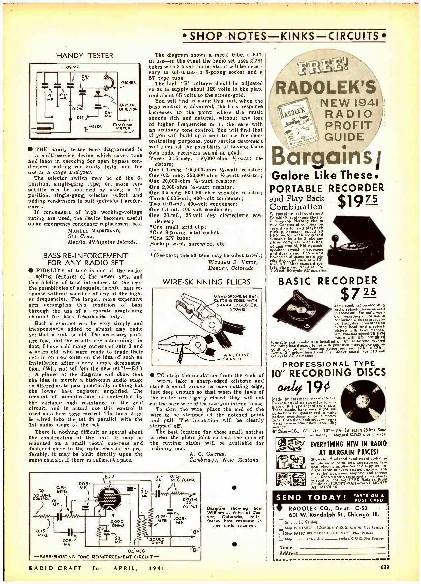
HANDY TESTER
THE handy tester here diagrammed is a multi -service device which saves time
and labor in checking for open bypass con- densera, making continuity tests, and for use as a stage analyzer.
The selector switch may be of the 6- position, single -gang type; or, more ver- satility can be obtained by using a 12- position, single -gang, selector switch and adding condensers to suit individual prefer- ences.
If condensers of high working -voltage rating are used, the device becomes useful as an emergency condenser replacement box.
MANUEL MADRIDANO, Sta. Cruz, Manila, Philippine Mande.
BASS RE- INFORCEMENT FOR ANY RADIO SET
FIDELITY of tone is one of the major selling features of the newer sets, and
this fidelity of tone introduces to the user the possibilities of adequate, faithful bass re sponse without sacrifice of any of the high- er frequencies. The larger, more expensive sets accomplish this rendition of bass through the use of a separate amplifying channel for bass frequencies only.
Such a channel can be very simply and inexpensively added to almost any radio set that is not too old. The necessary parts are few, and the results are astounding; in fact, I have sold many owners of sets 3 and 4 years old, who were ready to trade their sets in on new ones, on the idea of such an installation after a very simple demonstra- tion. (Why not sell 'em the new set ?! -Ed.)
A glance at the diagram will show that the idea is merely a high -gain audio stage so filtered as to pass practically nothing but the lower bass register, amplified. The amount of amplification is controlled by the variable high resistance in the grid circuit, and in actual use this control is used as a bass tone control. The bass stage is wired into the set in parallel with the 1st audio stage of the set.
There is nothing difficult or special about the construction of the unit. It may be mounted on a small metal sub -base and fastened close to the radio chassis, or pre- ferably, it may be built directly upon the radio chassis, if there is sufficient space.
SHOP NOTES KINKS -CIRCUITS The diagram shows a metal tube, a 6J7,
in use-in the event the radio set uses glass tubes with 2.5 volt filaments, it will be neces- sary to substitute a 6 -prong socket and a 57 type tube.
The high "B" voltage should be adjusted so as to supply about 120 volts to the plate and about 66 volts to the screen -grid.
You will find in using this unit, when the bass control is advanced, the bass response increases to the point where the music sounds rich and natural, without any loss of higher frequencies as is the case with an ordinary tone control. You will find that if you will build up a unit to use for dem- onstrating purposes, your service customers will jump at the possibility of having their own radio receivers sound as good. Three 0.16 -meg. 150,000 -ohm 'F. -watt re-
sistors; One 0.1 -meg. 100,000 -ohm 2 -watt resistor; One 0.25 -meg. 250,000 -ohm 1/2-watt resistor; One 20,000 -ohm 1/2-watt resistor; One 2,000 -ohm 1/2-watt resistor; One 0.5 -meg. 500,000 -ohm variable resistor; Three 0.005 -mf., 400 -volt condenser; Two 0.01 -mf., 400 -volt condenser; One 0.1 -mf. 400 -volt condenser; One 20 -mf., 25 -volt dry electrolytic con-
denser; One small grid clip;
One 8 -prong octal socket; *One 6J7 tube; Hookup wire, hardware, etc.
(See text; these 3 items may be substituted.) WILLIAM J. VETTE, Denver, Colorado
WIRE- SKINNING PLIERS
MANE-GROOVE IN EACH CUTTING EDGE WITH SHARP.EOGEO OIL
STONE
WIRE BEING SKINNED
TO strip the insulation from the ends of wires, take a sharp -edged oilstone and
stone a small groove in each cutting edge, just deep enough so that when the jaws of the cutter are tightly closed, they will not cut the bare wire of the size you intend to use.
To skin the wire, place the end of the wire to be stripped at the notched point and pull. The insulation will be cleanly stripped off.
The best location for these small notches is near the pliers joint so that the ends of the cutting blades will be available for ordinary use.
A. C. CARTER, Cambridge, New Zealand
TO VOLUME
CONTROL
.005 MF.
MEG.
/ MF.
0.15- MEG.
6J7 MF MEEGG.((EEACH)) f''- "'e'er,
DRIVER OR
OUTPUT
.005 - MF
O.25- MEG.
.005- MF.
O.1MEG -BASS- B005TING TONE REINFORCEMENT CIRCUIT-
RADIO -CRAFT for APRIL, 1941
Diagram showing how William J. Vette of Den- ver, Colorado, re -In- forces bass response in
any radio receiver.
i
RADOLEK'S NEW 1941
100 \ RADIO \ PROFIT
GUIDE
arg.ains Galore Like These. PORTABLE RECORDER
$1975 and Play Back Combination A complete ell- contained Portable Recorder and Electric Phonograph, Nothing else to buy. Consists of combination
cord cuver and playback pickup,
with constant sed 78
RPM motor h turntable. built in 3 tube am- pill `cbtÏ nameooP
with yÁ c speaker. crystal miclophone and desk stand. Entire unit housed in alligator grain lab. rfkoid coveted case, size 13" ,i13" a 7". Uses standard ace- tate discs and needles. For ;110volt 60 cycle AC opetation.
BASIC RECORDER $7a an Same
layback ches recording
ed. and above unit. For buad.your
own recorders or for use In confliction with radio receiv-
ceIncludes combination
cutting head and playback pickup with feed mechan. ism, constant speed 78 RPM motor with 815 weighted
turntable and needle cup installed on 8" leatherette covered mounting board ready to use with your own microphone and re. cording a pblier. Mounting spa. required 12 k" x 128". Depth.
cycle A below
low board and 3 Ns" above board. For 110 volt
PROFESSIONAL TYPE ICY' RECORDING DISCS
190 Made by foremost m nulacturer. Pro equal or superior teeny
of this type roger of These blanks have very slight im. pedections but guaranteed to make perfect codm r your money
`abaen both rae mtl base- llammble. Big ev gs!
' Disc -10c; 8 14c: 10 " -19c: lc less in 25 lots. Send no money - shipped C.O.D plus postage
h9f1 .rl
EVERYTHING NEW IN RADIO
AT BARGAIN PRICES! Shows hundreds and hundreds of up.to.the. minute radio parts, sets, accessories. ham gear, electric appliances and supplice. In. dispensable
e , every engine, experiment-
er. e
man. Keep up with radio and all its phases rad for the big FREE Radolek Prollt
Guide now DON'T WAIT -SAVE MONEY AT RADOLEK.
SEND TODAY! POST CARD
RADOLEK CO., Dept. C -53
601 W. Randolph St., Chicago, III.
Send FREE Catalog.
Ship PORTABLE RECORDER C D. SIR 75 Plus Postage.
Slop BASIC RECORDER C O D. 37.25 Plos Postage
Ship Disa,; Sue _ I hn "C O D. Plus Postage.
Name Address
639
BOOK REVIEWS
90de.x. ,tom aciveiziava
PUBLISHERS
Amplifier Co. of America 609 Audel, Publishers 662 Data Print Co - 682 Miller, Wayne 583 National Plans Inst 599 Radcraft Publications, Inc. 584, 614 Radio & Technical Pub. Co 699 Radiolab Publishing Co. 583 Supreme Publications 618 Technifax 682, 626
RADIO PARTS
Aerovox Corporation 601 Amperite Co. Inside Front Cover Hammarlund Mfg. Co 618 Meissner Mfg. Company 679 National Union Radio Corp Back Cover Ohmite Mfg. Company 619 Solar Mfg. Corp 612
RADIO SETS
Midwest Radio Corp 682 RCA Manufacturing Co., Inc 691
RADIO SUPPLY HOUSES
Allied Radio Corp 623 Burstein- Applebee Co 618 Federated Purchaser, Inc 626 Hudson Specialties Co 628 Radolek Co 639 Sears, Roebuck & Company 581
SCHOOLS
Capitol Radio Eng. Inst. Coyne Radio School Lincoln Engineering School National Radio Institute National Schools Port Arthur College Radio .Training Assoc. RCA Institutes Sprayberry Academy of Radio
Inside Back Cover
682 688 680 677 680 680 680 580
SOUND & RECORDING EQUIPMENT
Amplifier Co. of America 622 General Industries Co 609 Jensen Radio Mfg. Co 603 John Meck Industries 622 Miles Reproducer Co 599 National Recording Supply Co 622 Regal Amplifier Mfg. Corp 607 University Laboratories 609
TEST EQUIPMENT
Radio City Products Co 698 Readrite Meter Works 699 Supreme Instruments Corp. 697 Triplett Electrical Instrument Co 611 Weston Elec. Instrument Corp 601
TUBES Hygrade Sylvania Corp 593
MISCELLANEOUS
Atlas Press Co 612
Classified Section 630
Flight Magazine 631 Foredom Electric Co 697 Kato Engineering Co.. Inc 597 Lancaster. Allwine & Rommel 682 National Fluorescent Sales & Service Co 622 Onan. D. W., & Sons 618 Premium Distributing Service 630
Radio Servicemen of America. Inc 632
Remington Rand, Inc 606
Walter L. Schott Co. 612
Woodstock Typewriter Co. 622
(While every precaution is taken to insure accuracy, we cannot guarantee against the possibility of an occasional change or omis- sion in the preparation of this index.)
640 Printed In the U.S.A.
THE RADIO AMATEUR'S HANDBOOK -1941, 18th Edition (Revised). Published by American Radio Relay League. Paper covers, size 9% x 6% ins., profusely illustrated, 552 pages. Price $1.
The 18th Edition of this standard manual of amateur ham -radio communications includes a new book -edge indexing system and a special catalog section. Both are .of interest to tech- nicians who wish to locate articles or products in minimum time.
The Handbook continues to be the best book value in the radio field. A wealth of material is contained in 32 chapters, grouped as follows: Introduction. Principles and Design, Construc- tion and Adjustment, Antennas, Ultra -High Fre- quencies, Operating and Traffic Handling. The most modern practices of amateur radio com- munication are described in detail.
FUN WITH A RECORDER. Published by Audio Devices, Inc. Paper covers, size 8 x 5% ins., 167 pages. Price $1.
This book contains 30 amusing skits in radio- script form. Covering a variety of human sub- jects, they appeal to most embryo "actors young and old, who may wish to take a hand at disc recording.
Each skit is cued for sound effects with com- plete instructions on how to produce them. Servicemen -dealers might do well to include "Fun With a Recorder" as a premium on the purchase of a radio set having sound recording facilities. This book will help you make your disc sound- recorder the life of the party.
HOW TO MAKE GOOD RECORDINGS. Pub- lished by Audio Devices, Inc. Hard paper covers, size 5% x 8 ins., profusely illustrated, 128 pages. Price $1.00.
This book may well be called "The Complete Handbook for the Every -Day Recordist."
Home recordists, teachers, musicians. even sound engineers who already have a wide ac- quaintance with (disc) recording will find that the information this book contains fills gaps in their knowledge.
Written in non -technical style, the subject matter covers a wide range of subjects as for example, how to choose a recorder, cutting and playing needles, mike technique, putting to- gether a show, recording sound effects, recording for home movies, common difficulties and their remedies, and many others.
THE CALCULATION AND DESIGN OF ELEC- TRICAL APPARATUS, 2nd Edition (Revised), by W. Wilson. Published by Chapman & Hall. London, England: available from Sherwood Press, Edgewater Branch, Cleveland, Ohio. Cloth covers, size 5 x 7% ins.. 220 pages. Price $2.50.
This book forms a comprehensive treatise on the physical principles and mathematical formu- las of electromagnets, meters, instruments. The numerous tables are worth the price of the book.
This book is of particular value to student en- gineers. It should be noted that the treatment is mainly mathematical, and is prepared in school textbook style (problems and answers, etc.).
ELECTRICAL MEASUREMENTS IN PRIN- CIPLE AND PRACTICE, by H. Cobden Turner and E. H. W. Banner. Published by Chapman & Hall, London, England. Cloth covers, size 5% x 8% ins., 350 pages, well illustrated. Price $1.50.
This book has been written primarily for tech- nicians who want applicational information con- cerning electrical measurement devices but who do not require a textbook involving the mathe- matical treatments which might be required by students and research workers.
The subject matter deals in detail with the common measurements of current, voltage. power and resistance, and with the application of elec- trical devices to the measurement of speed. tem- perature, illumination, etc.. and to many mis- cellaneous measurements.
Radio men will be interested to note that this book also gives attention to the more specialized types of measurement involving the use of D.C. and A.C. potentiometers, A.C. bridges, vacuum tubes, and the oscilloscope.
RADIO TRAILBLAZING, by B. H. Darrow. Published by College Book *Company. Cloth covers, size 5% x 7% ins., 137 pages. Price $2.
The founder of the "Little Red Schoolhouse of Radio " -WLS, Chicago, verbally paints the picture of this program in a brief history of
the Ohio School of the Air and its implications for educational broadcasting.
Chapter headings: Chapter I, Origin and Es- tablishment ; Chapter II, The Period of Sub - stantial Developmedt ; Chapter III, The Depres- sion Makes Itself Felt ; Chapter IV, The Gradual Extension of Services; Chapter V, New Diffi- culties Arise: Chapter VI, Some Personal Con- clusions About Educational Broadcasting.
RADIO AND THE PRINTED PAGE, by Paul F. Lazarsfeld. Published by Duell, Sloan & Pearce, Inc. Cloth covers, size 5% x 8% ins., 354 pages. Price $4.
The Director of the Office of Radio Research here presents a thorough -going study of Radio and the Press.
This book is intended for the use of persons in commercial broadcasting but it also has lay interest in its dramatically presented survey of radio broadcasting as a new factor in the life of America. The book contains, among other contributions, the following: "The Importance of Being Earnest, Why Do People Like a Pro- gram?, The Future of Serious Listening, To Read or Not to Read, Radio and the Printed Page as Sources of News, For Further De- tails ... 48 MILLION HORSES: by Humphrey B. Neill. Published by J. B. Lippincott & Co. Cloth covers, size 6 x 9% ins., 241 pages, well illus- trated. Price $2.50.
Here is a book of non -technical and semi -tech- nical interest, divided into 6 parts- Energy. Light and Comfort, Industry. Tele- Magic, Trans- portation, and Looking Ahead.
It tells in romantic fashion of the progress of Electricity since Thomas Edison in 1882 opened the Pearl Street Central Station in New York City.
The title is a reference to the present -day capacity of America in terms of the produc- tion of electrical horsepower. The part, "Look- ing Ahead" contains an interesting chapter. "You and I and the Electron" by Dr. Willis R. Whitney, vice -President in charge of Re- search. C.E. Co.
RCA SERVICE NOTES FOR 1939 -RADIO RECEIVERS, VICTROLAS, TELEVISION. TEST EQUIPMENT. Published by RCA Mfg. Co. Cloth covers, size 8'.4 x 11 ins.. 406 pages. Price $1.50.
This is the largest and most complete bound volume of "Service Notes" ever issued by RCA Victor. It covers not only 1939 radio and radio- phonograph instruments, but also makes avail- able to dealers and Servicemen technical data on a number of 1940 models. The book contains over 150 circuits together with servicing data.
A master index contains reference to service data in this and all the preceding issues of "Service Notes" in this series. It is of interest to note that the book includes instruction - service notes on RCA test equipment. Also bound into the volume is the 48 -page Chanalyst instruction book.
RADIO LABORATORY JOB SHEET MANUAL. Radiolab Publishing Company, Brooklyn, New York. Composition covers, size 11% x 8% ins., profusely illustrated, 78 pages. Price $1.80.
This new spiral -bound publication is a 'basin course " -an instruction manual for practical radio projects. It contains information of interest to nearly every radio technician. in addition to its direct value to students.
The thousands of instructors throughout the U.S. who have recently been given the job of teaching Radio under the National Defense plan will welcome this working outline by an author who writes from the dual vantage points of teacher and technician.
This book employs the time -proven technique of "building to learn." Construction experiments lead the student from the elements of electricity to the construction and operation of a complete radio receiver.
The plan may be divided roughly as follows: Electrical Fundamentals -Exps. 1 -4 ; Electricity and Sound -Exps. 5-7 ; Radio-Frequency Phe- nomena -Exps. 8 -9; Simple Vacuum -Tube Opera- tion -Exps. 10-13 ; A.C. Power Apparatus -Exps. 14 -17 ; A.C. Receivers -Exps. 18 -20; Additional Construction Projects-Exps. 21 -24.
The latter chapter includes constructidn in- formation on a T.R.F. Receiver. R.F. and A.F. Signal Generators. and a Superhet. Receiver. Of interest to those who wish to learn telegraphy are the Morse Code table and Radio Symbols chart.
RADIO -CRAFT for APRIL, 1941,
1nòIudedw-" 7 Experience Easily Acquired at Hemel
OVER 100 EXPERIMENTS plus Many Other Special Features
ALL DESIGNED TO HELP YOU MAKE FAST PROGRESS! SPRAYRERRY Training starts right at the beginning of Radio . unfolds each
subject in a simplified, logical, understandable style. You easily learn Television Frequency Modulation, Signal Tracing. Mobile Radio (Auto -Tank), Aviation Radio, Electronics, Facsimile Radio, Radio Set Repair and Installation Work. You learn quickly in your spare hours ... AT HOME OR AT CAMP.
Training Prepares You for a Business of Your Own
Or Good Radio Jobs at Excellent Pay! The great, fascinating and progressive field of Radio and Television offers malty
opportunities to the man who wants to get ahead. There is good money to be mide. My Training is designed to give you quick access to these opportunities. SPRAY - BERRY Methods are thorough and practical. Your Training will not interfere with your present work.
You Get Professional Test Equipment '
plus Experimental Outfits! . Includes 146 RADIO PARTS for building a complete Receiver. RADIO TOOLS
and a modern TESTER -ANALYZER. You also receive 8 BIG SHIPMENTS OF RADIO EQUIPMENT for conducting actual experiments with your own hands. I show you
how to create Radio defects ... how to correct them. This practical "beforehand" experience will come in handy again and again when you are called on to do actual Radio repair work later on.
READ WHAT THESE FELLOWS SAY ABOUT THE NEW
PRACTICAL SPRAYBERRY TRAINING
"GROSSED BETWEEN $150 AND $200" "Since finishing your training I've started In the Radio
repair business. 1 Lane about all the work 1 can take core of. I haro grossed between $150 and $200 in the last few months in my spare time. I think your Course Is 'topa'." W. Francis W'aseko, Fountain City, Wisconsin.
"SALARY HAS INCREASED" "Your Radio training has made it possible for me to make more money. My salary has Increased from $40.00 to around $30.00 per week. I now have about all the Radio repair vork I can handle." Asa Smith. P. 0. Box 528, Fort Leavenworth. KY.
"MADE AS MUCH AS $8 A DAY" "The Instruments you have sent me helped me in solving Radio problems. I am building up my business by using all your methods. have made as much as $8 in one day. L. It. Lamle. 316 Dudley Street. Providence. It. I.
Cash In on Radio's Rich Opportunities No matter If you desire to BE YOUR OWN BOSS in your own business or
hold dawn a good job in Radio, my Training will give you the useful inform. lion and knowledge to win success. Days of delay mean orecious timo wasted. Start training for a money -making Radio career -right now.
-THE SPRAYBERRY COU
EARN W
No Previous Experience Needed
It make. difference what your education has
be s i can fit you quickly
I make t good-paying for Radio
you ata grasp Radio principles and remember them. Your s cess my fuu ns
E YOU LEARN ,
All
Equipment
Becomes
Your
Personal
Property
tl
My BUSINESS BUILDERS show you how to put your equipment to actual use in handling oney- making Radio Service Jobs shortly after you begin training.
Learn More About the SPRAYBERRY Method
And How Easy It Is to Start The romplcte details of my funda-
mental Course and Advanced Training Course . ail features are fully de- scribed in my new, valuable 52.page FREE Book. Send for your copy. No obligation.
RSE IS SOLD REMEMBER UNDER A MONEY -BACK AGREEMENT
D O O J
DON'T DELAY! ACT MOW! SPRAYBERRY ACADEMY OF RADIO
F. L. Sprayberry, Pres. 420 -D University Place, N. W. Washington, D. C.
Please send my FREE copy of "HOW To MAKE MONEY IN RADIO."
Name Age
Address
l' i l y State
Tear off this coupon, mail in envelope or paste on penny postcard.
1nniver
Gwit 50,000 piece2 ere.;ri,rre,d
-:tie-it FREE
oit LOUIS E. COMNEn. Radio
410/tor - - - - Sen. . Piper l Taft.
Seattle, Wash - After a.ing .._
Iheisands el N. U. tests der. Mt In, past into years me And that we have had fewer replacements than on any other ante. Most If eu epe.prnent has been seemed end N. U. way. 1
K N. NOLICK. Bolin t. lite., Neosho. Ni.
no had 20 coalreant Gents Poring the past
1. I late to t. Dulness N. U. for I find
M. U. moduli and prD- wDtloe helps etotandipiy.
e
e E. 1. MIiINOT. Mk: In my split... and le ten of many tbe tarin .,murs
r whom I aurtlatml, N. I/ n). restive whlth aids qtr Na. radio NM Inmano Noe.
. N. U "spur. O. COONEY, Goan Raits
St tools, Mo.- Thant. N. U. Egaipreent Deals shop Is one of the most
mileldy epelpaed testiq laboratories In the city. 1
and N. U. preslects are the guilty codes% In the In. Pastry and entineally recommend them ta .nn del,,.
desk ore the hunt n%Ibntlo sanetut 'cer ham na ell rad. sent. profession. In threat tewpetit ion I sill at l b I un OW mon ta
15
VERNON N. NOOK. tans, Vamo.t -N. U. bu ghmathiq I. Ers Eg.ipmut Deals that Pe IOW l aaafaetaa w. Nor -One el the larplt Not of &pare ta the dealer h pto data tnt ene pment- What WAN toit be suie than "Ilia, N. U. ride %1
e
29 e0
MATMEW 1. OENLSWITI, leneae Naga. Shop, Mllhu, WlsuuID -f NN is chenille my "cal 1 titled 29 entrails. Then Is as heeler way for unless,. to patelessly antelre pad untie sent. 1. my 10 yeas of aeleslve dealing with N. U. (heir predeals Sue .toys been utlefute y.
1. E. STAGE, langelew Nulls Salsa Slink. Ce., Lenplew, Wash. -T Slit
e Erelpment Plan peat -Nave u 23 N. U. EpUment Deals -lm No N. U. 'cotas 9 yeah. N. U. (1111 all eked alike- -aaely have te mate te. Ilseements,
®.1O.LL N,9.ß,_C,OHI,'i
?'also 4311 ca41 !atie ate "/3e4tt 4r.cippeCQ sItap isi `loin "-see vo444 N. V. 2, iit21Asc1oz oz 2t/zite
NATIONAL UNION RADIO CORP 57 STATE STREET, NEWARK, NEW JERSEY