radiation forces on an absorbing micrometer-sized sphere in an evanescent field
TRANSCRIPT
arX
iv:p
hysi
cs/0
1111
32v2
[ph
ysic
s.op
tics]
11
Apr
200
3
Radiation forces on an absorbing micrometer-sized sphere in an evanescent field
I. Brevik∗ and T. A. Sivertsen†
Department of Energy and Process Engineering,
Norwegian University of Science and Technology,
N-7491 Trondheim, Norway
E. Almaas‡
Department of Physics,
University of Notre Dame, Notre Dame, Indiana 46556
The vertical radiation force on an absorbing micrometer-sized dielectric sphere situated in anevanescent field is calculated, using electromagnetic wave theory. The present work is a continuationof an earlier paper [E. Almaas and I. Brevik, J. Opt. Soc. Am. B 12, 2429 (1995)], in which both thehorizontal and the vertical radiation forces were calculated with the constraint that the sphere wasnon-absorbing. Whereas the horizontal force can be well accounted for within this constraint, thereis no possibility to describe the repulsiveness of the vertical force, so distinctly demonstrated in theKawata-Sugiura experiment [Opt. Lett. 17, 772 (1992)], unless a departure from the theory of purenon-dispersive dielectrics is made in some way. Introduction of absorption, i.e. a complex refractiveindex, is one natural way of generalizing the previous theory. We work out general expressions forthe vertical force for this case and illustrate the calculations by numerical computations. It turns outthat, when applied to the Kawata-Sugiura case, the repulsive radiation force caused by absorptionis not strong enough to account for the actual lifting of the polystyrene latex or glass spheres.The physical reason for the experimental outcome is, in this case, most probably the presence ofsurfactants making the surface of the spheres partially conducting.
PACS numbers: 03.50.De, 42.25.-p, 42.50.Vk, 42.55.-f
I. INTRODUCTION
The outcome of the Kawata-Sugiura levitation exper-iment from 1992 [1] is in some ways still surprising. Theauthors examined the radiation force on a micrometer-sized spherical dielectric particle in the evanescent fieldproduced by a laser beam of moderate power, P = 150mW. As one would expect, the particle moved along thehorizontal plate at a speed of a few micrometers per sec-ond, as a result of the tunneled photons in the evanescentfield. The surprising point is, however: why does the par-ticle lift from the surface? As reported in Ref. [1], “theparticle is forced to float from the substrate surface andto slide along the surface.” For a non-magnetic and non-absorbing dielectric particle, it is well known that theelectromagnetic volume force density f is
f = −1
2E2∇ǫ, (1)
ǫ being the permittivity such that f = 0 in the homoge-neous and isotropic interior, and different from zero onlyin the particle’s boundary layer. The evanescent field isknown to vary as exp[−β(x+h)] in the vertical direction(see Eq. (14) below), and is significant only very close tothe substrate. In practice, this field interacts with those
∗Electronic address: [email protected]†Electronic address: [email protected]‡Electronic address: [email protected]
parts of the particle that are situated closest to the sub-strate, and it gives rise to a surface force that, accordingto Eq. (1), has to act in the downward direction (assum-ing that ǫ > ǫ0). It is simply impossible to account fora lift force on the particle, using Eq. (1). This discrep-ancy between electromagnetic theory for dielectrics andthe Kawata-Sugiura experiment [1] is therefore, as men-tioned above, somewhat surprising at first sight, sinceEq. (1) has generally been proven to be invaluable in amultitude of cases in electromagnetism and optics.
Consequently, we have to conclude that the explana-tion for the observed lift of the particle has to lie in thepresence of an additional force, different from the onegiven by Eq. (1). The following two possibilities come tomind:
(1) The particle has a complex permittivity ǫ, and istherefore exposed to a repulsive (or positive lift) forcecaused by the absorption of radiation in the interior.
(2) Another natural possibility is that surface effects
may have played a significant role in the experiments.The presence of impurities on the surface, or the pres-ence of a liquid of a film of adsorbed material, may havea considerable influence on the electrical conductivity ofthe surface region, and can thus enhance multiple scat-tering effects. This allows for an analysis of the problemin terms of a multiple scattering formalism. Adoptingsuch a picture, the vertical force on the particle neces-sarily has to be repulsive; the photons are bouncing offthe spherical surface and are, accordingly, transferring animpulse in the upward direction.
In the present paper, we will be studying option (1)
2
above, thus allowing for a complex ǫ, which in turn im-plies a non-vanishing effective conductivity σ in the inte-rior of the particle. As far as we know, such a study hasnot previously been undertaken. This study is a continu-ation of the work of Almaas and Brevik [2], dealing withthe case of a pure dielectric (real ǫ). Whereas the analysisin [2] gave satisfactory results for the horizontal radiationforce observed in the Kawata-Sugiura experiment, it wasimpossible, as mentioned above, on the basis of Eq. (1)to account for an upward directed vertical force. Fromnow on, we will assume that the particle is a sphere ofradius a, and regard the effective conductivity σ as aninput parameter.
Before embarking on the mathematical formalism, letus however make some further remarks related to option(2) above. There is a variety of surface effects that onecan envisage: multiple reflections, as mentioned; more-over capillary forces (the order of magnitude of the cap-illary forces may be up to 10−7 N), surface tension (be-cause of the capillary forces), viscous retarding forces ifthe sphere and the surface are immersed in a liquid, elec-trostatic forces, and finally the role of evaporation. Cf.in this context the survey given by Vilfan et al. [3]. Espe-cially the role of the size of the spherical particle seems tobe important. If the particle is large, multiple scatteringbetween the sphere and the substrate distorts the evanes-cent wave structure that one would have in the absenceof the particle. Lester and Nieto-Vesperinas [4] recentlyanalyzed the problem using multiple scattering methods,and were able to account for a positive lift force. An ad-vantage of this kind of method is that the proximity of thesphere-substrate two-body system is addressed explicitly.In contrast, our formalism is built on the model of scat-tering of an evanescent wave by an isolated sphere, andis therefore not expected to be very accurate for smallseparations between the sphere and the substrate. It isnecessary to point out that the adoption of a multiplescattering method does not in itself imply that the liftforce is positive, as long as the material in the sphere isa pure dielectric. Regardless of whether the electromag-netic boundary conditions at the surface of the substrateare taken into account or not, for a pure dielectric, theforce on the sphere is given by Eq. (1), and, as we haveargued above, is necessarily downward directed. To ac-count for a positive lift force, we must allow for deviationsfrom the simple theory of pure dielectrics, meaning thatabsorption, and consequently conductivity, are importanteffects in the theory, explicitly or implicitly.
As already mentioned, we will not attempt to give aquantitative description of a possible adsorbed film onthe surface; the physical reason for such a film may bequite complex. Problems of this sort belong to the vastfield of physicochemical hydrodynamics. [A good sourceof information in this area is the book of Levich [5]; abriefer treatment is found in Landau and Lifshitz [6]].It is noticeable that the experiment of Vilfan et al. [3]similarly measured a repulsive force. They obtained aforce 300 pN on a dielectric sphere of radius 5 µm in the
evanescent field of a 500 mW laser focused to a diame-ter of 5 µm. These spheres are relatively large, and aretherefore likely to distort the evanescent field structureconsiderably.
In the next section, we summarize the wave theoreticalformalism describing the interaction between the evanes-cent field and the sphere. In Section 3, we show how thesurface force F
surf – i.e. the part of the total radiationforce F which is associated with the boundary and in-dependent of the absorptive properties in the interior –can be written as a double sum over complex expansioncoefficients. Section 4, the main section of our paper,contains the calculation of the absorptive part F
abs ofthe radiation force. The results are illustrated in Figs. 2- 5. Our calculations incorporate both the two polariza-tion states of the incident beam (p and s polarization).
Our main analytical result is given in Eq. (66), forthe non-dimensional vertical absorptive force componentQabs
x . As one would expect physically, the result be-comes proportional to the effective conductivity σ. Forthe polystyrene latex spheres, or glass spheres, used inthe Kawata-Sugiura experiment, the values of σ are low.Hence, it turns out that Qabs
x becomes too weak to ac-count for the floating of the sphere in the gravitationalfield. Now, our formalism has, of course, a much widerscope than the Kawata-Sugiura experiment. In optics,there are numerous cases where radiation forces interactwith absorbing media. For instance, the current develop-ment of microelectromagnetical systems, which are usedin a variety of applications including even measurementsof the Casimir force, accentuates the usefulness of thepresent theory.
II. BASIC FORMALISM
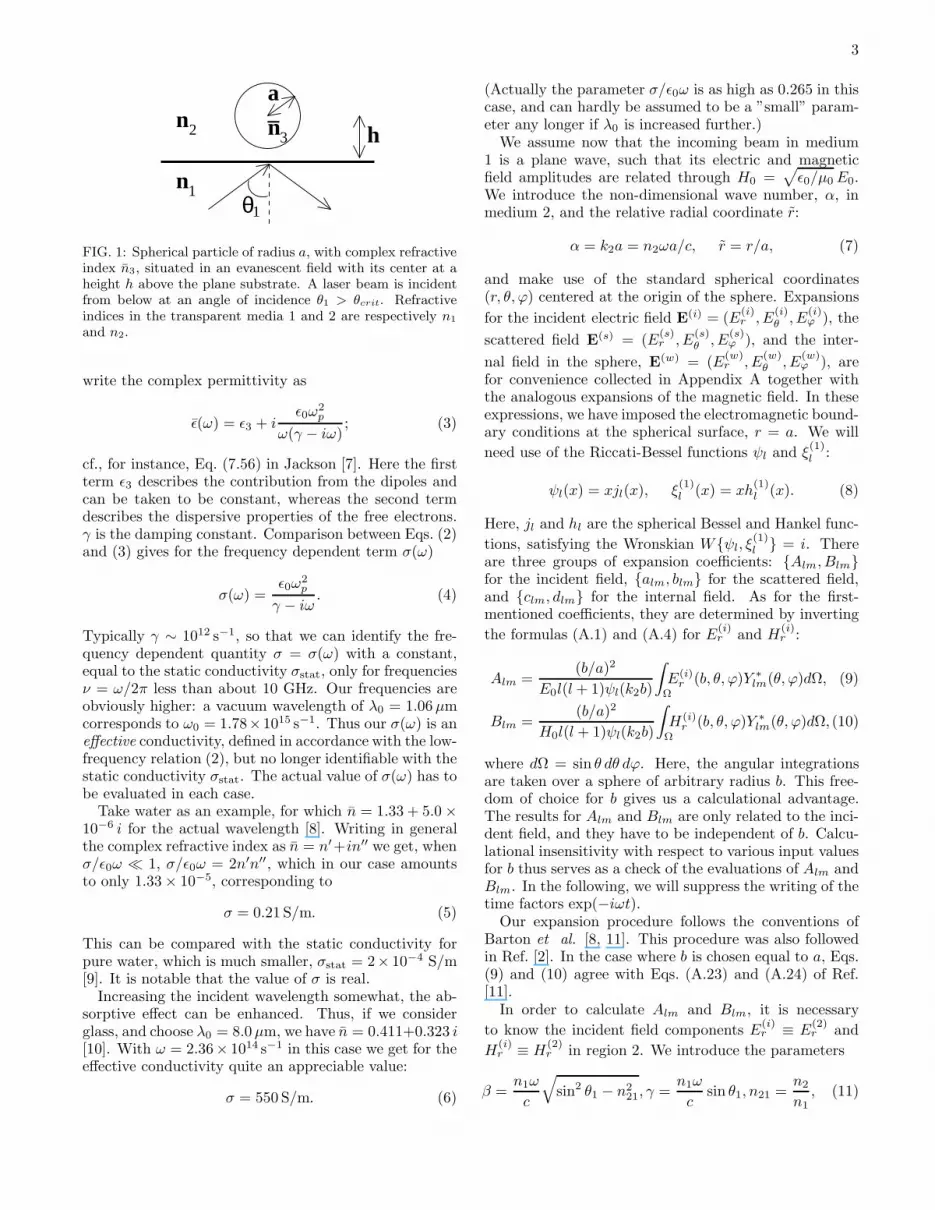
A sketch of the geometry is shown in Fig. 1: Alaser beam is incident from below through a transparentmedium, called medium 1, and hits the plane, horizontalsurface towards the transparent medium 2 at an angleof incidence, θ1, which is greater than the critical angle,θcrit = arcsin(n2/n1), for total reflection. This estab-lishes an evanescent field above the plane surface, which,in turn, is regarded as the incident field falling upon acompact sphere of radius a and complex refractive indexn3. The sphere is centered at the origin with the x axispointing vertically upwards. If ǫ3 is the complex permit-tivity of the (non-magnetic) sphere, we will require it tobe related to the effective conductivity, σ, through theequation
ǫ3 = ǫ3 + iσ/ω, (2)
hence n3 =√
ǫ3/ǫ0.
Here, a remark is called for as regards our formal useof the dispersion relation. For simplicity, taking themedium to have only one resonance frequency, we can
3
n
n
_a
h
θ11
2 3n
FIG. 1: Spherical particle of radius a, with complex refractiveindex n3, situated in an evanescent field with its center at aheight h above the plane substrate. A laser beam is incidentfrom below at an angle of incidence θ1 > θcrit. Refractiveindices in the transparent media 1 and 2 are respectively n1
and n2.
write the complex permittivity as
ǫ(ω) = ǫ3 + iǫ0ω
2p
ω(γ − iω); (3)
cf., for instance, Eq. (7.56) in Jackson [7]. Here the firstterm ǫ3 describes the contribution from the dipoles andcan be taken to be constant, whereas the second termdescribes the dispersive properties of the free electrons.γ is the damping constant. Comparison between Eqs. (2)and (3) gives for the frequency dependent term σ(ω)
σ(ω) =ǫ0ω
2p
γ − iω. (4)
Typically γ ∼ 1012 s−1, so that we can identify the fre-quency dependent quantity σ = σ(ω) with a constant,equal to the static conductivity σstat, only for frequenciesν = ω/2π less than about 10 GHz. Our frequencies areobviously higher: a vacuum wavelength of λ0 = 1.06µmcorresponds to ω0 = 1.78×10¹⁵ s−1. Thus our σ(ω) is aneffective conductivity, defined in accordance with the low-frequency relation (2), but no longer identifiable with thestatic conductivity σstat. The actual value of σ(ω) has tobe evaluated in each case.
Take water as an example, for which n = 1.33 + 5.0 ×10⁻⁶ i for the actual wavelength [8]. Writing in generalthe complex refractive index as n = n′+in′′ we get, whenσ/ǫ0ω ≪ 1, σ/ǫ0ω = 2n′n′′, which in our case amountsto only 1.33 × 10⁻⁵, corresponding to
σ = 0.21 S/m. (5)
This can be compared with the static conductivity forpure water, which is much smaller, σstat = 2× 10⁻⁴ S/m[9]. It is notable that the value of σ is real.
Increasing the incident wavelength somewhat, the ab-sorptive effect can be enhanced. Thus, if we considerglass, and choose λ0 = 8.0µm, we have n = 0.411+0.323 i[10]. With ω = 2.36× 10¹⁴ s−1 in this case we get for theeffective conductivity quite an appreciable value:
σ = 550 S/m. (6)
(Actually the parameter σ/ǫ0ω is as high as 0.265 in thiscase, and can hardly be assumed to be a ”small” param-eter any longer if λ0 is increased further.)
We assume now that the incoming beam in medium1 is a plane wave, such that its electric and magneticfield amplitudes are related through H0 =
√
ǫ0/µ0E0.We introduce the non-dimensional wave number, α, inmedium 2, and the relative radial coordinate r:
α = k2a = n2ωa/c, r = r/a, (7)
and make use of the standard spherical coordinates(r, θ, ϕ) centered at the origin of the sphere. Expansions
for the incident electric field E(i) = (E
(i)r , E
(i)θ , E
(i)ϕ ), the
scattered field E(s) = (E
(s)r , E
(s)θ , E
(s)ϕ ), and the inter-
nal field in the sphere, E(w) = (E
(w)r , E
(w)θ , E
(w)ϕ ), are
for convenience collected in Appendix A together withthe analogous expansions of the magnetic field. In theseexpressions, we have imposed the electromagnetic bound-ary conditions at the spherical surface, r = a. We will
need use of the Riccati-Bessel functions ψl and ξ(1)l :
ψl(x) = xjl(x), ξ(1)l (x) = xh
(1)l (x). (8)
Here, jl and hl are the spherical Bessel and Hankel func-
tions, satisfying the Wronskian Wψl, ξ(1)l = i. There
are three groups of expansion coefficients: Alm, Blmfor the incident field, alm, blm for the scattered field,and clm, dlm for the internal field. As for the first-mentioned coefficients, they are determined by inverting
the formulas (A.1) and (A.4) for E(i)r and H
(i)r :
Alm =(b/a)2
E0l(l+ 1)ψl(k2b)
∫
Ω
E(i)r (b, θ, ϕ)Y ∗
lm(θ, ϕ)dΩ, (9)
Blm =(b/a)2
H0l(l + 1)ψl(k2b)
∫
Ω
H(i)r (b, θ, ϕ)Y ∗
lm(θ, ϕ)dΩ, (10)
where dΩ = sin θ dθ dϕ. Here, the angular integrationsare taken over a sphere of arbitrary radius b. This free-dom of choice for b gives us a calculational advantage.The results for Alm and Blm are only related to the inci-dent field, and they have to be independent of b. Calcu-lational insensitivity with respect to various input valuesfor b thus serves as a check of the evaluations of Alm andBlm. In the following, we will suppress the writing of thetime factors exp(−iωt).
Our expansion procedure follows the conventions ofBarton et al. [8, 11]. This procedure was also followedin Ref. [2]. In the case where b is chosen equal to a, Eqs.(9) and (10) agree with Eqs. (A.23) and (A.24) of Ref.[11].
In order to calculate Alm and Blm, it is necessary
to know the incident field components E(i)r ≡ E
(2)r and
H(i)r ≡ H
(2)r in region 2. We introduce the parameters
β =n1ω
c
√
sin2 θ1 − n221, γ =
n1ω
csin θ1, n21 =
n2
n1, (11)
4
and take the following expressions for the amplitude ra-
tios, T‖ = E(2)‖ /E
(1)‖ , and T⊥ = E
(2)⊥ /E
(1)⊥ at the surface
of the substrate into account:
T‖ =2n21 cos θ1
n221 cos θ1 + i
√
sin2 θ1 − n221
, (12)
T⊥ =2 cos θ1
cos θ1 + i√
sin2 θ1 − n221
. (13)
Here, E‖ refers to the field component in the plane ofincidence (p polarization), and E⊥ to the field orthogonalto it (s polarization). For the radial field components, wefind
E(i)r =
1
n21T‖E
(1)‖ [sin θ1 sin θ cosϕ− i
√
sin2 θ1 − n221 cos θ] + T⊥E
(1)⊥ sin θ sinϕ
× exp[−β(x+ h) + iγz], (14)
H(i)r =
T⊥H(1)‖ [− sin θ1 sin θ cosϕ+ i
√
sin2 θ1 − n221 cos θ] + n21T‖H
(1)⊥ sin θ sinϕ
× exp[−β(x+ h) + iγz],(15)
where
H(2)‖ /H
(1)‖ = n21T⊥, H
(2)⊥ /H
(1)⊥ = n21T‖, (16)
at the surface of the substrate. (Readers interested inbackground material for our developments can e.g. con-sult the articles [2, 8, 11, 12], as well as the standardtexts [9, 13, 14].) Upon insertion into Eqs. (9) and (10),we find that the coefficients Alm and Blm for the case ofs (⊥) and p (‖) polarization are related through
A⊥lm =
T⊥n2T‖
B‖lm, (17)
B⊥lm = −
n2T⊥T‖
A‖lm, (18)
hence, it is sufficient to only consider one polarization di-rection in the calculations of the expansion coefficients,and in the following, we will choose the case of p polariza-tion. By inserting the expressions for the incident fieldinto Eqs. (9) and (10), we obtain the following expres-sions for the expansion coefficients:
A‖lm =
α1(l,m)
n21T‖e
−βh
[
sin θ1Q1(l,m)
−i
√
sin2 θ1 − n221Q2(l,m)
]
, (19)
B‖lm = n2α1(l,m)T‖ e
−βhQ3(l,m), (20)
where we have defined
α1(l,m) =
[
2l+ 1
4π
(l −m)!
(l +m)!
]1/2(b/a)2
l(l + 1)ψl(k2b), (21)
Q1(l,m) = 2π(−1)m−1
∫ π/2
0
sin2 θ
cosi sin
(γb cos θ)
×Pml (cos θ)
[
I|m−1|(u) + I|m+1|(u)]
dθ, (22)
Q2(l,m) = 4π(−1)m
∫ π/2
0
sin θ cos θ
i sincos
(γb cos θ)
×Pml (cos θ)I|m|(u)dθ, (23)
Q3(l,m) = 4πi(−1)m m
βb
∫ π/2
0
sin θ
cosi sin
(γb cos θ)
×Pml (cos θ)I|m|(u)dθ, (24)
where u = βb sin θ, l + m is
evenodd
, and Im(z) =
i−mJm(iz) is a modified Bessel function. (In Ref. [2],Eqs. (46) and (49), were missing factors of 2.) Again,
the calculated values of A‖lm and B
‖lm have to be numer-
ically independent of the value chosen for the radius b.Once Alm and Blm are known, the other sets of coef-
ficients, alm, blm and clm, dlm, can readily be calcu-lated using Eqs. (A.19)–(A.22). In appendix B, we givea table of Alm and Blm up to lmax = 7 for p polarization.
III. THE SURFACE FORCE
Let us, as indicated above, write the total radiationforce F on the sphere as a sum of two contributions:
F = Fsurf + F
abs, (25)
where Fsurf is the result of the force density f acting
in the surface layer, i.e. Eq. (1), and Fabs is caused
by the absorption in the sphere. By integrating acrossthe surface layer, the components F surf
i of Fsurf can be
related to the surface integral of Maxwell’s stress tensorSik on the outside of the sphere:
F surfi = −
∫
SiknkdS, (26)
n being the outward normal (cf. for instance, Refs.[11, 15]). [This expression assumes that the effect from
5
absorption is negligible, in other words that the sizeof the particle is much smaller than the skin depthδ = (2/µ0ωσ)1/2.] If a≪ λ0, and the susceptibility of theparticle is small, the formula for the total force F goesover to the conventional expression for dilute particles:
F = 6πa3 ǫ′′
(ǫ+ 2ǫ0)2ǫ0k|E
(i)|2; (27)
cf., for instance, Refs. [16, 17, 18].It should be stressed that we are calculating the force
on the sphere in two steps: First, the surface integral(26) is evaluated assuming the refractive index to be real.That means, the coefficients Alm and Blm below are cal-culated on the basis of a real n3. Thereafter, the ab-sorptive part F
absis calculated separately, via the forcedensity J × B.
Using the general expressions for the incident and thescattered field, Eqs. (A.1) – (A.12), we can re-write thissurface integral in terms of the complex expansion coef-ficients Alm, Blm, alm and blm:
F surfx + iF surf
y
ǫ0E20a
2=
iα2
4
∞∑
l=1
l∑
m=−l
[
(l +m+ 2)(l+m+ 1)
(2l + 1)(2l+ 3)
]1/2
l(l+ 2)
(
2n22alma
∗l+1,m+1 + n2
2almA∗l+1,m+1
+ n22Alma
∗l+1,m+1 + 2blmb
∗l+1,m+1 + blmB
∗l+1,m+1 +Blmb
∗l+1,m+1
)
+
[
(l −m+ 1)(l −m+ 2)
(2l + 1)(2l+ 3)
]1/2
× l(l+ 2)
(
2n22al+1,m−1a
∗lm + n2
2al+1,m−1A∗lm + n2
2Al+1,m−1a∗lm + 2bl+1,m−1b
∗lm + bl+1,m−1B
∗lm
+ Bl+1,m−1b∗lm
)
−
[
(l +m+ 1)(l −m)
]1/2
n2
(
− 2almb∗l,m+1 + 2blma
∗l,m+1 − almB
∗l,m+1
+ blmA∗l,m+1 +Blma
∗l,m+1 −Almb
∗l,m+1
)
, (28)
F surfz
ǫ0E20a
2= −
α2
2
∞∑
l=1
l∑
m=−l
[
(l −m+ 1)(l +m+ 1)
(2l+ 1)(2l + 3)
]1/2
l(l + 2)ℑ[
2n22al+1,ma
∗lm + n2
2al+1,mA∗lm + n2
2Al+1,ma∗lm
+ 2bl+1,mb∗lm + bl+1,mB
∗lm +Bl+1,mb
∗lm + n2m
(
2almb∗lm + almB
∗lm +Almb
∗lm
)
]
. (29)
We shall not dwell much on these expressions, since ourmain interest, as mentioned above, is the vertical forceF abs
x associated with the absorption. Consider, however,the horizontal surface force component F surf
z . With anincident beam power (in vacuum) of P = 150 mW, dis-tributed over a circular cross-sectional area of diameter10 µm, we find the magnitude of the Poynting vectorto be (c/2)ǫ0E
20 = 19.0 MW/m2. Taking the radius of
the sphere a = 1 µm, we find the denominator in Eq.(29) to be ǫ0E
20a
2 = 0.13 pN. If the sphere is madeof glass (n3 = 1.50) and the surrounding medium 2 iswater (n2 = 1.33), we then have α = 2πa/λ2 = 7.9,since the wavelength in water for Nd:YAG laser light isλ2 = 1.06/1.33 = 0.80 µm. Using Fig. 5 in Ref. [2], wefind that F surf
z is positive, as it should be, and is approx-imately equal to 0.010 pN in the case of p polarization.Since the Reynolds number is very low, the Stokes dragformulaD = 6πµav is applicable, using µ = 1.0×10⁻³ Pas as the dynamic viscosity of water. Putting F surf
z = D,we obtain the drift velocity of the sphere to be v = 0.53 µm/s. This is an order of magnitude agreement with the
observations of Kawata and Sugiura [1]; from their Fig.4, one infers that v ∼ 1 − 2 µm/s. This agreement issatisfactory; there is no need to carry out a complicatedcalculation to find the absorptive correction to the hori-zontal radiation force. In the following, we focus atten-tion on the vertical absorptive part of the force.
IV. THE VERTICAL ABSORPTIVE FORCE
To calculate the absorptive force, we first replace Eq.(1) by the general expression
f = ρE + J× B −1
2E2∇ǫ, (30)
where ρ and J are the external charge and current den-sities in the medium. A general derivation of this forceexpression can be found, for instance, in Stratton’s book[9]. Also, in the review article of one of the present au-thors [15], it was found that the force expression is able to
6
describe the outcome of known experiments. We assumeno external charges to be present, so that ρ = 0. WritingJ = σE where σ is the frequency-dependent conductiv-ity, assumed to be real (cf. Eq. (5)), we get in complexrepresentation the following expression for the absorptiveforce:
Fabs =
1
2ℜ
∫
J × B∗dV =
σµ0
2ℜ
∫
E× H∗ dV, (31)
where the integral is evaluated over the volume of thesphere.
In cases of current interest, we can simplify our cal-culation: In view of the assumed smallness of σ/ǫ0ω, wereplace the fields inside the sphere with those calculatedwhen assuming the material to be a perfect dielectric.That is, we can replace the complex refractive index n3
by its real part n3. This facilitates the calculation of thevolume integrals. The expressions for the internal fieldsare given by Eqs. (A.13)–(A.18), in spherical coordinates.For notational convenience, we will omit the superscripts(w).
With r = r/a we can write the vertical absorptive forceas
F absx =
σµ0
2a3 ℜ
∫ 2π
0
dϕ
∫ π
0
sin θdθ
∫ 1
0
r2dr
[
(E× H∗)r
× sin θ cosϕ+(E× H∗)θ cos θ cosϕ−(E× H
∗)ϕ sinϕ
]
,
=σµ0
2a3 ℜ
6∑
i=1
Ii, (32)
where we have defined
I1 =
∫ 2π
0
cosϕdϕ
∫ π
0
sin2 θdθ
∫ 1
0
r2drEθH∗ϕ, (33)
I2 = −
∫ 2π
0
cosϕdϕ
∫ π
0
sin2 θdθ
∫ 1
0
r2drEϕH∗θ , (34)
I3 =
∫ 2π
0
cosϕdϕ
∫ π
0
cos θ sin θdθ
∫ 1
0
r2drEϕH∗r , (35)
I4 = −
∫ 2π
0
cosϕdϕ
∫ π
0
cos θ sin θdθ
∫ 1
0
r2drErH∗ϕ, (36)
I5 = −
∫ 2π
0
sinϕdϕ
∫ π
0
sin θdθ
∫ 1
0
r2drErH∗θ , (37)
I6 =
∫ 2π
0
sinϕdϕ
∫ π
0
sin θdθ
∫ 1
0
r2drEθH∗r . (38)
It is now convenient to introduce the operators
L =
∞∑
l=1
∞∑
j=1
∫ n32α
0
du, (39)
M(±)lj =
l∑
m=−l
j∑
k=−j
(δm,k−1 ± δm,k+1) . (40)
We write the two first of the Ii’s as a sum of four terms:
Ii = iπαn1cǫ0E20
4∑
k=1
Iik, i = 1, 2. (41)
and remaining Ii’s, which are simpler since they are eachcomposed of only two terms:
Ii = iπαn1cǫ0E20
2∑
k=1
Iik, i = 3, 4, 5, 6. (42)
where (in the following, l, m, j and k denote summationindices as defined in Eqs. (39) and (40))
I11 = −n32L
[
ψ′l(u)ψ
′j(u)M
(+)lj
kclmd∗jkClmCjkR1(l,m, j, k)
]
, (43)
I12 = −n232n2L
[
ψ′l(u)ψj(u)M
(+)lj
clmc∗jkClmCjkR2(l,m, j, k)
]
, (44)
I13 =1
n2L
[
ψl(u)ψ′j(u)M
(+)lj
mkdlmd∗jkClmCjkR3(l,m, j, k)
]
, (45)
I14 = n32L
[
ψl(u)ψj(u)M(+)lj
mdlmc∗jkClmCjkR1(j, k, l,m)
]
, (46)
I21 = −n32L
[
ψ′l(u)ψ
′j(u)M
(+)lj
mclmd∗jkClmCjkR1(j, k, l,m)
]
, (47)
I22 = −n232L
[
ψ′l(u)ψj(u)M
(+)lj
mkclmc∗jkClmCjkR3(l,m, j, k)
]
, (48)
7
I23 =1
n2L
[
ψl(u)ψ′j(u)M
(+)lj
dlmd∗jkClmCjkR2(l,m, j, k)
]
, (49)
I24 = n32L
[
ψl(u)ψj(u)M(+)lj
kdlmc∗jkClmCjkR1(l,m, j, k)
]
, (50)
I31 = n32L
[
ψ′l(u)
uψj(u)j(j + 1)M
(+)lj
mclmd∗jkClmCjkR4(l,m, j, k)
]
, (51)
I32 = −1
n2L
[
ψl(u)
uψj(u)j(j + 1)M
(+)lj
dlmd∗jkClmCjkR5(l,m, j, k)
]
, (52)
I41 = n32L
[
ψl(u)
uψ′
j(u)l(l + 1)M(+)lj
kclmd∗jkClmCjkR4(l,m, j, k)
]
, (53)
I42 = n232n2L
[
ψl(u)
uψj(u)l(l + 1)M
(+)lj
clmc∗jkClmCjkR5(j, k, l,m)
]
, (54)
I51 = −n32L
[
ψl(u)
uψ′
j(u)l(l+ 1)M(−)lj
clmd∗jkClmCjkR1(j, k, l,m)
]
, (55)
I52 = −n232n2L
[
ψl(u)
uψj(u)l(l+ 1)M
(−)lj
kclmc∗jkClmCjkR3(l,m, j, k)
]
, (56)
I61 = n32L
[
ψ′l(u)
uψj(u)j(j + 1)M
(−)lj
clmd∗jkClmCjkR1(l,m, j, k)
]
, (57)
I62 = −1
n2L
[
ψl(u)
uψj(u)j(j + 1)M
(−)lj
mdlmd∗jkClmCjkR3(l,m, j, k)
]
, (58)
with
R1(l,m, j, k) =
∫ π
0
sin θdPm
l (cos θ)
dθP k
j (cos θ) dθ, (59)
R2(l,m, j, k) =
∫ π
0
sin2 θdPm
l (cos θ)
dθ
dP kj (cos θ)
dθdθ, (60)
R3(l,m, j, k) =
∫ π
0
Pml (cos θ) P k
j (cos θ) dθ, (61)
R4(l,m, j, k) =
∫ π
0
cos θ Pml (cos θ) P k
j (cos θ) dθ, (62)
R5(l,m, j, k)=
∫ π
0
cos θ sin θdPm
l (cos θ)
dθP k
j (cos θ) dθ, (63)
and the definition
Clm =
√
(2l + 1)(l −m)!
4π(l +m)!. (64)
Altogether, writing the non-dimensional vertical absorp-tive force as Qabs
x , where
Qabsx =
F absx
ǫ0E20a
2, (65)
we get
Qabsx = −σµ0cλ
n12α2
4ℑ
[
2∑
i=1
4∑
k=1
Iik +
6∑
i=3
2∑
k=1
Iik
]
. (66)
Note that the prefactor in the above equations, as well asthe terms Iik, are non-dimensional. The expression (66)is our main result.
V. RESULTS
A. Numerics
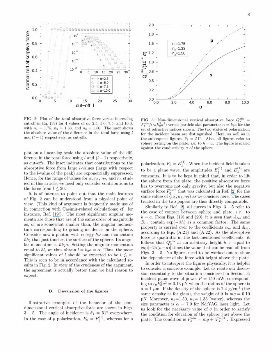
We implemented an adaptive Gauss-Kronrod rule tocalculate the integrals in Eqs. (22) – (24) and (43) –(58). By employing the symmetry properties of the inte-grals over the Legendre polynomials (Eqs. (59) – (63)),we were able to greatly reduce the number of integrals tobe computed. To make sure that the sum over l and j inEq. (39) converged properly for our chosen cut-off value,we plotted the total absorptive force on the sphere versusincreasing cut-off, lmax, in l (we used the same cut-off forl and j). In Fig. 2, we give an example for p polarizationusing several values of α. The total force is normalizedto the lmax = 30 result; all other parameters are givenin the figure caption. This figure clearly suggests that,for a given value of α, there is a narrow range in l whichaccounts for most of the absorptive force. Moreover, itis seen that this range of important l-values moves tohigher l and broadens with increasing α. In the inset, we
8
0 5 10 15 20 25 3010
−12
10−9
10−6
10−3
100
0 5 10 15 20 25 30cut−off l
0.0
0.2
0.4
0.6
0.8
1.0N
orm
aliz
ed a
bsor
ptiv
e fo
rce
α=2.5α=5.0α=7.5α=10.0
FIG. 2: Plot of the total absorptive force versus increasingcut-off in Eq. (39) for 4 values of α: 2.5, 5.0, 7.5, and 10.0,with n1 = 1.75, n2 = 1.33, and n3 = 1.50. The inset showsthe absolute value of the difference in the total force using land (l − 1) respectively, as cut-offs.
plot on a linear-log scale the absolute value of the dif-ference in the total force using l and (l− 1) respectively,as cut-offs. The inset indicates that contributions to theabsorptive force from large l-values (large with respectto the l-value of the peak) are exponentially suppressed.Hence, for the range of values for α, n1, n2, and n3 stud-ied in this article, we need only consider contributions tothe force from l ≤ 30.
It is of interest to point out that the main featuresof Fig. 2 can be understood from a physical point ofview. (This kind of argument is frequently made use ofin connection with Casimir-related calculations; cf. forinstance, Ref. [19]). The most significant angular mo-menta are those that are of the same order of magnitudeas, or are somewhat smaller than, the angular momen-tum corresponding to grazing incidence on the sphere.Consider now a photon with energy ~ω and momentum~k2 that just touches the surface of the sphere. Its angu-lar momentum is ~k2a. Setting the angular momentumequal to ~l, we thus obtain l = k2a = α. Thus, the mostsignificant values of l should be expected to be l . α.This is seen to be in accordance with the calculated re-sults in Fig. 2. In view of the crudeness of the argument,the agreement is actually better than we had reason toexpect.
B. Discussion of the figures
Illustrative examples of the behavior of the non-dimensional vertical absorptive force are shown in Figs.3 – 5. The angle of incidence is θ1 = 51 everywhere.
In the case of p polarization, E0 = E(1)‖ , whereas for s
0.0 2.0 4.0 6.0 8.0 10.0α
0.0
0.2
0.5
0.8
1.0
1.2
1.5
1.8
2.0
Qxab
s /(10
−4 σ
)
n1=1.75n2=1.33n3=1.50
p
s
FIG. 3: Non-dimensional vertical absorptive force Qabs
x =F abs
x /(ǫ0E2
0a2) versus particle size parameter α = k2a for theset of refractive indices shown. The two states of polarizationfor the incident beam are distinguished. Here, as well as inthe subsequent figures, θ1 = 51. Also, all figures refer tosphere resting on the plate, i.e. to h = a. The figure is scaledagainst the conductivity σ of the sphere.
polarization, E0 = E(1)⊥ . When the incident field is taken
to be a plane wave, the amplitudes E(1)‖ and E
(1)⊥ are
constants. It is to be kept in mind that, in order to liftthe sphere from the plate, the positive absorptive forcehas to overcome not only gravity, but also the negativesurface force F surf
x that was calculated in Ref. [2] for thesame values of n1, n2, n3 as we consider here. The casestreated in the two papers are thus directly comparable.
Similarly to Ref. [2], all curves in Figs. 3 – 5 refer tothe case of contact between sphere and plate, i.e. toh = a. From Eqs. (19) and (20), it is seen that Alm andBlm contain exp(−βh) as a common factor. The sameproperty is carried over to the coefficients clm and dlm,according to Eqs. (A.21) and (A.22). As the absorptiveforce is quadratic in the last-mentioned coefficients, itfollows that Qabs
x at an arbitrary height h is equal toexp[−2β(h−a)] times the value that can be read off fromFigs. 3 – 5. No figures need to be worked out to showthe dependence of the force with height above the plate.
In order to interpret the figures physically, it is helpfulto consider a concrete example. Let us relate our discus-sion essentially to the situation considered in Section 3:incident plane wave of power P = 150 mW, correspond-ing to ǫ0E
20a
2 = 0.13 pN when the radius of the sphere isa = 1 µm. If the density of the sphere is 2.4 g/cm3 (thesame density as for glass), the weight of it is mg = 0.10pN. Moreover, n3=1.50, n2= 1.33 (water), whereas thesize parameter is α = 7.9 for Nd:YAG laser light. Letus look for the necessary value of σ in order to satisfythe condition for elevation of the sphere, just above theplate. The condition is F abs
x = mg + |F surfx |. Expressed

9
0.0 2.0 4.0 6.0 8.0 10.0α
0.0
0.5
1.0
1.5
2.0
2.5
3.0
3.5
4.0Q
xabs /(
10−
4 σ)
n1=1.75n2=1.33n3=1.60
p
s
FIG. 4: Same as for Fig. 3, but with a higher (dominant realpart of) refractive index (n3 = 1.60) in the sphere.
non-dimensionally,
Qabsx =
mg
ǫ0E20a
2+ |Qsurf
x |. (67)
From Fig. 3 we read off, when choosing for definitenessthe case of p polarization, Qabs
x /(10−4σ) = 1.7, whereasfrom Fig. 4 in [2] we read off Qsurf
x = −0.35 for the samevalue of α. This leads to a relatively high value of σ,about 6600 S/m (S≡ Ω−1). In our example, the influenceof the weight of the sphere is relatively large because theincident power is so moderate. If we increase P to 1 watt,we get ǫ0E
20a
2 = 0.87 pN, resulting in a somewhat lowervalue, σ ≈ 2700 S/m.
For glass, at optical wavelengths, the effective con-ductivity σ is very small. (The static conductivity isextremely small, σstat ∼ 10−12 S/m.) Even for higherwavelengths such as λ0 = 8.0µm, the value σ = 550 S/mgiven in Eq. (6) is insufficient to account for the lift-ing force. For water, at optical wavelengths, as we haveseen in Eq. (5), the effective conductivity is even smaller.We can thus immediately conclude that absorption is not
the physical reason for the elevation of the sphere in theKawata-Sugiura experiment. It is likely that there weresurfactants on the spheres in this experiment, and hence,that a theoretical description of the kind given in Ref.[4] is most appropriate in this case. For other materialswhere the conductivities are higher, for instance for car-bon (σstat = 0.77 × 10⁵ S/m), the absorption-generatedelevation of microspheres should be quite possible physi-cally. One must however be aware of the algebraic restric-tion made in the present paper to simplify calculations:our calculation relied on the property that σ/ǫ0ω ≪ 1(cf. Eq. (2)). This restriction made it possible to takethe refractive index n3 to be real, inside the integrals inSection 4. Since ǫ0ω ≈ 105 S/m, we can no longer expecthigh accuracy from the formalism when σ ≫ 104 S/m,
0.0 2.0 4.0 6.0 8.0α
0.0
0.5
1.0
1.5
2.0
2.5
3.0
3.5
4.0
Qxab
s /(10
−4 σ
)
n1=1.75n2=1.00n3=1.50
p
s
FIG. 5: Same as for Fig. 3, but with vacuum (n2 = 1) sur-rounding the sphere.
at optical frequencies.Consider finally the remaining figures: Fig. 4 shows
that when the refractive index in the sphere increasesfrom 1.50 to 1.60, the absorptive force increases. This isas we would expect. Moreover, if the difference betweeninterior and exterior indices increases, the Riccati-Besselfunctions cause the force to become more oscillatory incharacter. The changes are clearly shown, if we com-pare Fig. 3 with Fig. 5. Increasing differences betweenthe refractive indices effectively mean enhancing the thegeometrical-optics properties of the system. There is alsoa dependence of the force upon the two different polariza-tion states of the beam. No simple physical explanationof this dependence seems to exist.
VI. CONCLUSIONS
We can summarize as follows:1. The strategy of the above calculation has been to
identify the evanescent field with the incident field onthe sphere. The theory makes use of wave optics, and isthus applicable even when the wavelength is of the samemagnitude as the sphere diameter.
2. The main novel development of the present paperin comparison with Ref. [2] is the calculation in Section4 of the vertical absorptive force, assuming the refractiveindex n3 in the sphere to be complex. The calculationrests upon the approximation that σ/ǫ0ω ≪ 1, so thatthe fields inside the sphere can be evaluated as if thematerial were a perfect dielectric. The surface force isthus calculated from Eq. (26) assuming n3 = n3 to bereal. The absorptive force is calculated from Eq. (30).
3. The results of Figs. 3 – 5 show that in order toaccount for elevation of the micrometer-sphere, the con-
10
ductivity σ must be at least as large as about 103 S/m.This applies, for instance, to media like carbon.
4. For latex or glass spheres, used in the Kawata-Sugiura experiment [1], the absorptive force seems to betoo weak to account for the elevation force. Most prob-ably, the observed elevation force was due largely to im-purities or a film on the surface of the sphere, making itpartly conducting. Cf. also Ref. [4]. The absorption issensitive with respect to impurities, and it is at presentdifficult to estimate to which degree the absorption isimportant in practice.
5. As a final general remark: the subject of radiationpressure on particles in the evanescent field is a many-facetted phenomenon which is not yet fully understood,and it is a very active subject. In addition to the ref-erences given above, the reader is referred also to recentpapers in which the dipole method is made use of, inorder to calculate the force of an evanescent wave overdielectric and metallic surfaces [20, 21].
VII. ACKNOWLEDGEMENTS
E.A. was supported by NSF through grants DMR97-31511 and DMR01-04987. Computational support
was provided by the Ohio Supercomputer Center andthe Norwegian University of Science and Technology(NTNU).
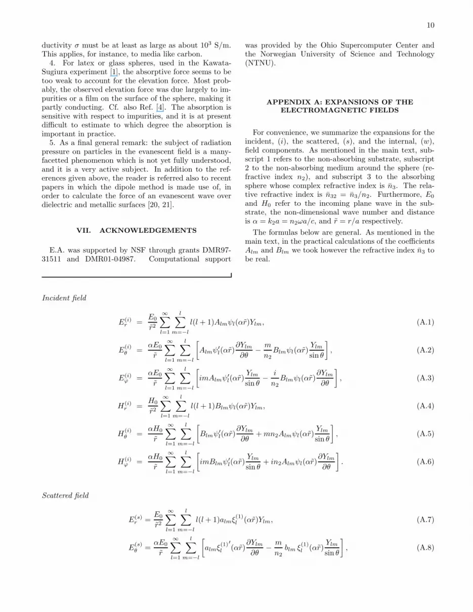
APPENDIX A: EXPANSIONS OF THE
ELECTROMAGNETIC FIELDS
For convenience, we summarize the expansions for theincident, (i), the scattered, (s), and the internal, (w),field components. As mentioned in the main text, sub-script 1 refers to the non-absorbing substrate, subscript2 to the non-absorbing medium around the sphere (re-fractive index n2), and subscript 3 to the absorbingsphere whose complex refractive index is n3. The rela-tive refractive index is n32 = n3/n2. Furthermore, E0
and H0 refer to the incoming plane wave in the sub-strate, the non-dimensional wave number and distanceis α = k2a = n2ωa/c, and r = r/a respectively.
The formulas below are general. As mentioned in themain text, in the practical calculations of the coefficientsAlm and Blm we took however the refractive index n3 tobe real.
Incident field
E(i)r =
E0
r2
∞∑
l=1
l∑
m=−l
l(l + 1)Almψl(αr)Ylm, (A.1)
E(i)θ =
αE0
r
∞∑
l=1
l∑
m=−l
[
Almψ′l(αr)
∂Ylm
∂θ−m
n2Blmψl(αr)
Ylm
sin θ
]
, (A.2)
E(i)ϕ =
αE0
r
∞∑
l=1
l∑
m=−l
[
imAlmψ′l(αr)
Ylm
sin θ−
i
n2Blmψl(αr)
∂Ylm
∂θ
]
, (A.3)
H(i)r =
H0
r2
∞∑
l=1
l∑
m=−l
l(l + 1)Blmψl(αr)Ylm, (A.4)
H(i)θ =
αH0
r
∞∑
l=1
l∑
m=−l
[
Blmψ′l(αr)
∂Ylm
∂θ+mn2Almψl(αr)
Ylm
sin θ
]
, (A.5)
H(i)ϕ =
αH0
r
∞∑
l=1
l∑
m=−l
[
imBlmψ′l(αr)
Ylm
sin θ+ in2Almψl(αr)
∂Ylm
∂θ
]
. (A.6)
Scattered field
E(s)r =
E0
r2
∞∑
l=1
l∑
m=−l
l(l+ 1)almξ(1)l (αr)Ylm, (A.7)
E(s)θ =
αE0
r
∞∑
l=1
l∑
m=−l
[
almξ(1)l
′(αr)
∂Ylm
∂θ−m
n2blm ξ
(1)l (αr)
Ylm
sin θ
]
, (A.8)
11
E(s)ϕ =
αE0
r
∞∑
l=1
l∑
m=−l
[
imalmξ(1)l
′(αr)
Ylm
sin θ−
i
n2blm ξ
(1)l (αr)
∂Ylm
∂θ
]
, (A.9)
H(s)r =
H0
r2
∞∑
l=1
l∑
m=−l
l(l+ 1) blm ξ(1)l (αr)Ylm, (A.10)
H(s)θ =
αH0
r
∞∑
l=1
l∑
m=−l
[
blmξ(1)l
′(αr)
∂Ylm
∂θ+mn2almξ
(1)l (αr)
Ylm
sin θ
]
, (A.11)
H(s)ϕ =
αH0
r
∞∑
l=1
l∑
m=−l
[
im blm ξ(1)l
′(αr)
Ylm
sin θ+ in2 alm ξ
(1)l (αr)
∂Ylm
∂θ
]
. (A.12)
Internal field
E(w)r =
E0
r2
∞∑
l=1
l∑
m=−l
l(l+ 1)clmψl(n32αr)Ylm, (A.13)
E(w)θ =
αE0
r
∞∑
l=1
l∑
m=−l
[
n32 clm ψ′l(n32αr)
∂Ylm
∂θ−m
n2dlm ψl(n32αr)
Ylm
sin θ
]
, (A.14)
E(w)ϕ =
αE0
r
∞∑
l=1
l∑
m=−l
[
imn32clmψ′l(n32αr)
Ylm
sin θ−i
n2dlmψl(n32αr)
∂Ylm
∂θ
]
, (A.15)
H(w)r =
H0
r2
∞∑
l=1
l∑
m=−l
l(l + 1)dlmψl(n32αr)Ylm, (A.16)
H(w)θ =
αH0
r
∞∑
l=1
l∑
m=−l
[
n32dlmψ′l(n32αr)
∂Ylm
∂θ+mn2n
232clmψl(n32αr)
Ylm
sin θ
]
, (A.17)
H(w)ϕ =
αH0
r
∞∑
l=1
l∑
m=−l
[
imn32dlmψ′l(n32αr)
Ylm
sin θ+in2n
232clmψl(n32αr)
∂Ylm
∂θ
]
. (A.18)
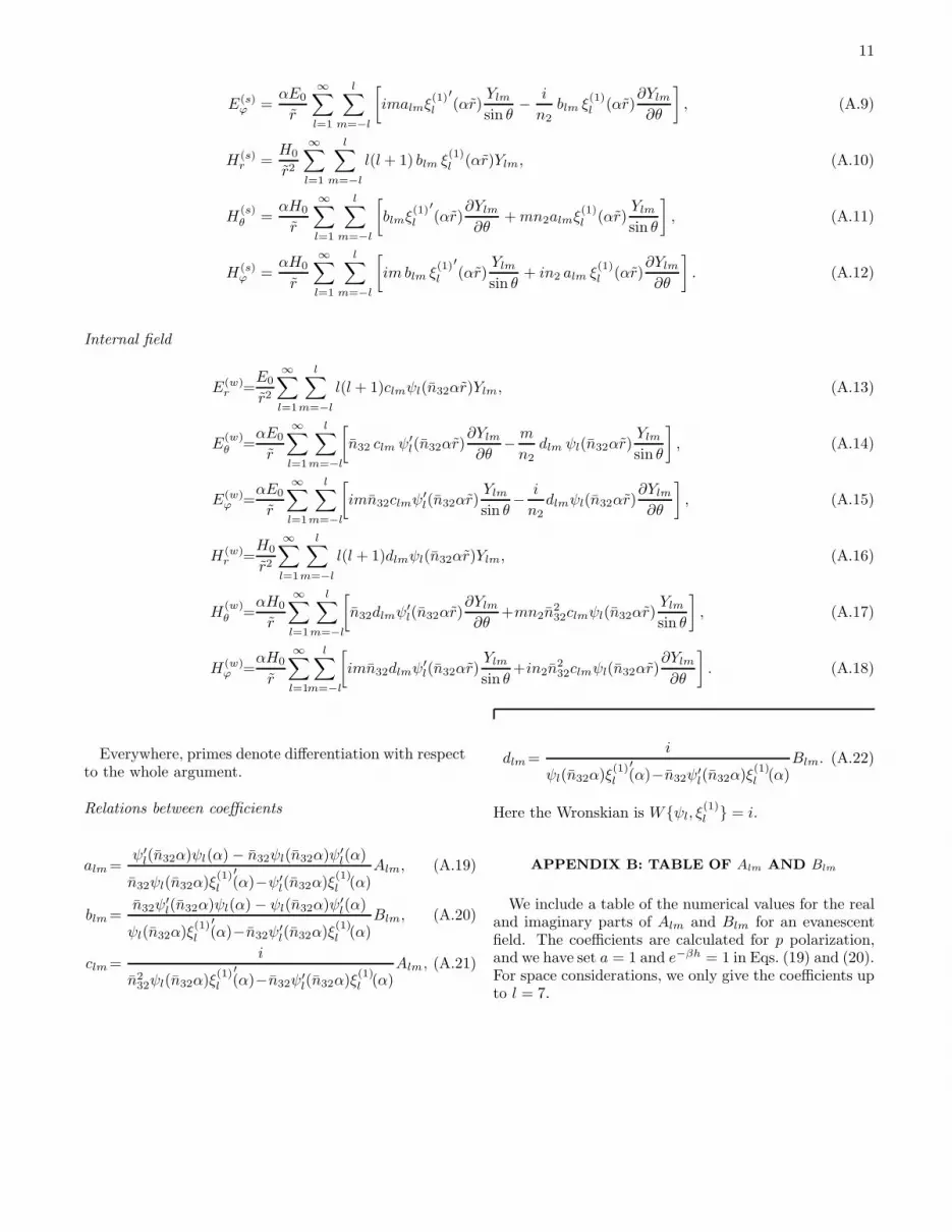
Everywhere, primes denote differentiation with respectto the whole argument.
Relations between coefficients
alm =ψ′
l(n32α)ψl(α) − n32ψl(n32α)ψ′l(α)
n32ψl(n32α)ξ(1)l
′(α)−ψ′
l(n32α)ξ(1)l (α)
Alm, (A.19)
blm =n32ψ
′l(n32α)ψl(α) − ψl(n32α)ψ′
l(α)
ψl(n32α)ξ(1)l
′(α)−n32ψ′
l(n32α)ξ(1)l (α)
Blm, (A.20)
clm =i
n232ψl(n32α)ξ
(1)l
′(α)−n32ψ′
l(n32α)ξ(1)l (α)
Alm, (A.21)
dlm =i
ψl(n32α)ξ(1)l
′(α)−n32ψ′
l(n32α)ξ(1)l (α)
Blm. (A.22)
Here the Wronskian is Wψl, ξ(1)l = i.
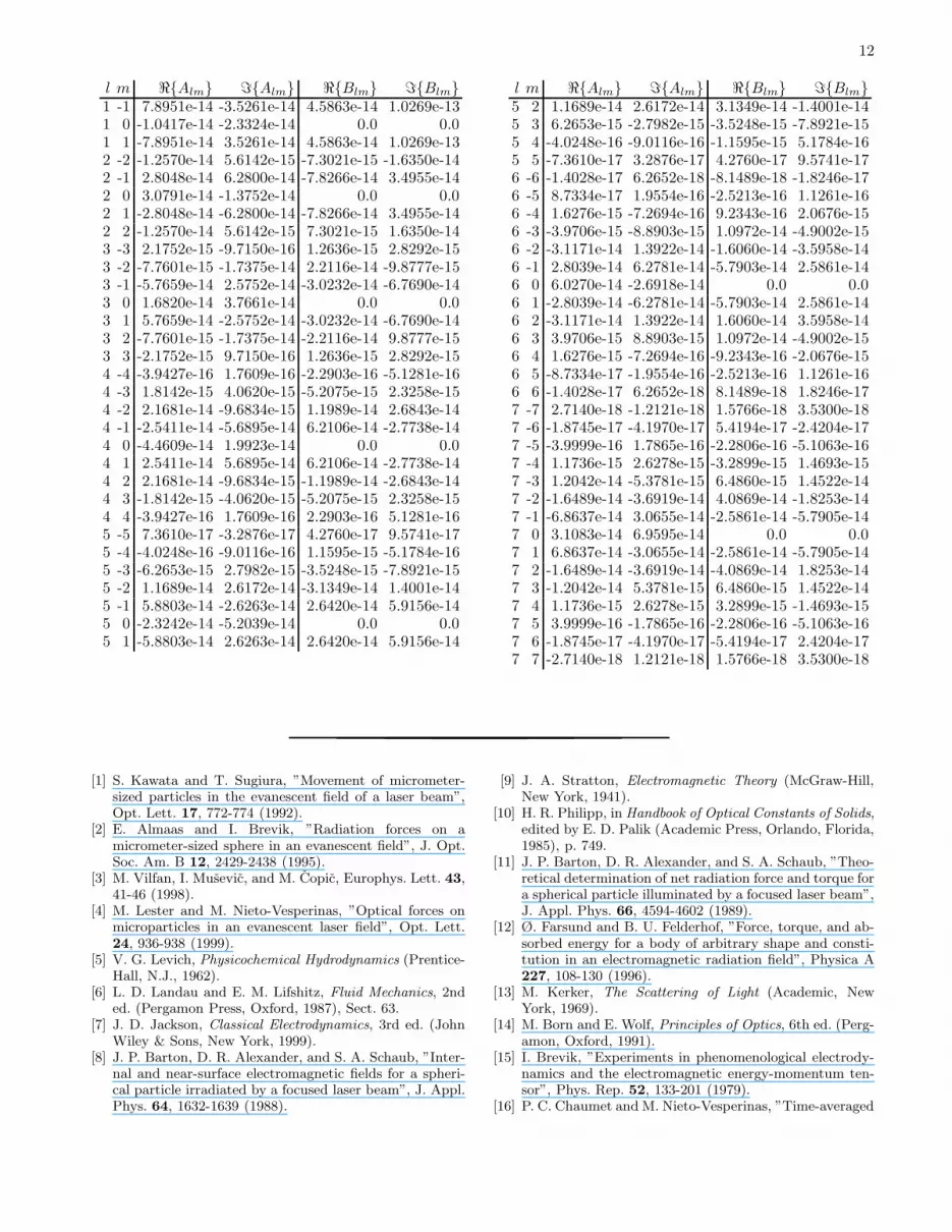
APPENDIX B: TABLE OF Alm AND Blm
We include a table of the numerical values for the realand imaginary parts of Alm and Blm for an evanescentfield. The coefficients are calculated for p polarization,and we have set a = 1 and e−βh = 1 in Eqs. (19) and (20).For space considerations, we only give the coefficients upto l = 7.
12
l m ℜAlm ℑAlm ℜBlm ℑBlm1 -1 7.8951e-14 -3.5261e-14 4.5863e-14 1.0269e-131 0 -1.0417e-14 -2.3324e-14 0.0 0.01 1 -7.8951e-14 3.5261e-14 4.5863e-14 1.0269e-132 -2 -1.2570e-14 5.6142e-15 -7.3021e-15 -1.6350e-142 -1 2.8048e-14 6.2800e-14 -7.8266e-14 3.4955e-142 0 3.0791e-14 -1.3752e-14 0.0 0.02 1 -2.8048e-14 -6.2800e-14 -7.8266e-14 3.4955e-142 2 -1.2570e-14 5.6142e-15 7.3021e-15 1.6350e-143 -3 2.1752e-15 -9.7150e-16 1.2636e-15 2.8292e-153 -2 -7.7601e-15 -1.7375e-14 2.2116e-14 -9.8777e-153 -1 -5.7659e-14 2.5752e-14 -3.0232e-14 -6.7690e-143 0 1.6820e-14 3.7661e-14 0.0 0.03 1 5.7659e-14 -2.5752e-14 -3.0232e-14 -6.7690e-143 2 -7.7601e-15 -1.7375e-14 -2.2116e-14 9.8777e-153 3 -2.1752e-15 9.7150e-16 1.2636e-15 2.8292e-154 -4 -3.9427e-16 1.7609e-16 -2.2903e-16 -5.1281e-164 -3 1.8142e-15 4.0620e-15 -5.2075e-15 2.3258e-154 -2 2.1681e-14 -9.6834e-15 1.1989e-14 2.6843e-144 -1 -2.5411e-14 -5.6895e-14 6.2106e-14 -2.7738e-144 0 -4.4609e-14 1.9923e-14 0.0 0.04 1 2.5411e-14 5.6895e-14 6.2106e-14 -2.7738e-144 2 2.1681e-14 -9.6834e-15 -1.1989e-14 -2.6843e-144 3 -1.8142e-15 -4.0620e-15 -5.2075e-15 2.3258e-154 4 -3.9427e-16 1.7609e-16 2.2903e-16 5.1281e-165 -5 7.3610e-17 -3.2876e-17 4.2760e-17 9.5741e-175 -4 -4.0248e-16 -9.0116e-16 1.1595e-15 -5.1784e-165 -3 -6.2653e-15 2.7982e-15 -3.5248e-15 -7.8921e-155 -2 1.1689e-14 2.6172e-14 -3.1349e-14 1.4001e-145 -1 5.8803e-14 -2.6263e-14 2.6420e-14 5.9156e-145 0 -2.3242e-14 -5.2039e-14 0.0 0.05 1 -5.8803e-14 2.6263e-14 2.6420e-14 5.9156e-14
l m ℜAlm ℑAlm ℜBlm ℑBlm5 2 1.1689e-14 2.6172e-14 3.1349e-14 -1.4001e-145 3 6.2653e-15 -2.7982e-15 -3.5248e-15 -7.8921e-155 4 -4.0248e-16 -9.0116e-16 -1.1595e-15 5.1784e-165 5 -7.3610e-17 3.2876e-17 4.2760e-17 9.5741e-176 -6 -1.4028e-17 6.2652e-18 -8.1489e-18 -1.8246e-176 -5 8.7334e-17 1.9554e-16 -2.5213e-16 1.1261e-166 -4 1.6276e-15 -7.2694e-16 9.2343e-16 2.0676e-156 -3 -3.9706e-15 -8.8903e-15 1.0972e-14 -4.9002e-156 -2 -3.1171e-14 1.3922e-14 -1.6060e-14 -3.5958e-146 -1 2.8039e-14 6.2781e-14 -5.7903e-14 2.5861e-146 0 6.0270e-14 -2.6918e-14 0.0 0.06 1 -2.8039e-14 -6.2781e-14 -5.7903e-14 2.5861e-146 2 -3.1171e-14 1.3922e-14 1.6060e-14 3.5958e-146 3 3.9706e-15 8.8903e-15 1.0972e-14 -4.9002e-156 4 1.6276e-15 -7.2694e-16 -9.2343e-16 -2.0676e-156 5 -8.7334e-17 -1.9554e-16 -2.5213e-16 1.1261e-166 6 -1.4028e-17 6.2652e-18 8.1489e-18 1.8246e-177 -7 2.7140e-18 -1.2121e-18 1.5766e-18 3.5300e-187 -6 -1.8745e-17 -4.1970e-17 5.4194e-17 -2.4204e-177 -5 -3.9999e-16 1.7865e-16 -2.2806e-16 -5.1063e-167 -4 1.1736e-15 2.6278e-15 -3.2899e-15 1.4693e-157 -3 1.2042e-14 -5.3781e-15 6.4860e-15 1.4522e-147 -2 -1.6489e-14 -3.6919e-14 4.0869e-14 -1.8253e-147 -1 -6.8637e-14 3.0655e-14 -2.5861e-14 -5.7905e-147 0 3.1083e-14 6.9595e-14 0.0 0.07 1 6.8637e-14 -3.0655e-14 -2.5861e-14 -5.7905e-147 2 -1.6489e-14 -3.6919e-14 -4.0869e-14 1.8253e-147 3 -1.2042e-14 5.3781e-15 6.4860e-15 1.4522e-147 4 1.1736e-15 2.6278e-15 3.2899e-15 -1.4693e-157 5 3.9999e-16 -1.7865e-16 -2.2806e-16 -5.1063e-167 6 -1.8745e-17 -4.1970e-17 -5.4194e-17 2.4204e-177 7 -2.7140e-18 1.2121e-18 1.5766e-18 3.5300e-18
[1] S. Kawata and T. Sugiura, ”Movement of micrometer-sized particles in the evanescent field of a laser beam”,Opt. Lett. 17, 772-774 (1992).
[2] E. Almaas and I. Brevik, ”Radiation forces on amicrometer-sized sphere in an evanescent field”, J. Opt.Soc. Am. B 12, 2429-2438 (1995).
[3] M. Vilfan, I. Musevic, and M. Copic, Europhys. Lett. 43,41-46 (1998).
[4] M. Lester and M. Nieto-Vesperinas, ”Optical forces onmicroparticles in an evanescent laser field”, Opt. Lett.24, 936-938 (1999).
[5] V. G. Levich, Physicochemical Hydrodynamics (Prentice-Hall, N.J., 1962).
[6] L. D. Landau and E. M. Lifshitz, Fluid Mechanics, 2nded. (Pergamon Press, Oxford, 1987), Sect. 63.
[7] J. D. Jackson, Classical Electrodynamics, 3rd ed. (JohnWiley & Sons, New York, 1999).
[8] J. P. Barton, D. R. Alexander, and S. A. Schaub, ”Inter-nal and near-surface electromagnetic fields for a spheri-cal particle irradiated by a focused laser beam”, J. Appl.Phys. 64, 1632-1639 (1988).
[9] J. A. Stratton, Electromagnetic Theory (McGraw-Hill,New York, 1941).
[10] H. R. Philipp, in Handbook of Optical Constants of Solids,edited by E. D. Palik (Academic Press, Orlando, Florida,1985), p. 749.
[11] J. P. Barton, D. R. Alexander, and S. A. Schaub, ”Theo-retical determination of net radiation force and torque fora spherical particle illuminated by a focused laser beam”,J. Appl. Phys. 66, 4594-4602 (1989).
[12] Ø. Farsund and B. U. Felderhof, ”Force, torque, and ab-sorbed energy for a body of arbitrary shape and consti-tution in an electromagnetic radiation field”, Physica A227, 108-130 (1996).
[13] M. Kerker, The Scattering of Light (Academic, NewYork, 1969).
[14] M. Born and E. Wolf, Principles of Optics, 6th ed. (Perg-amon, Oxford, 1991).
[15] I. Brevik, ”Experiments in phenomenological electrody-namics and the electromagnetic energy-momentum ten-sor”, Phys. Rep. 52, 133-201 (1979).
[16] P. C. Chaumet and M. Nieto-Vesperinas, ”Time-averaged
13
total force on a dipolar sphere in an electromagneticfield”, Opt. Lett. 25, 1065-1067 (2000).
[17] A. Ashkin, J. M. Dziedzic, J. E. Bjorkholm, and S. Chu,”Observation of a single-beam gradient force optical trapfor dielectric particles”, Opt. Lett. 11, 288-290 (1986).
[18] L. D. Landau and E. M. Lifshitz, Electrodynamics of
Continuous Media, 2nd ed. (Pergamon, Oxford, 1984),Sect. 93.
[19] I. Brevik and V. N. Marachevsky, ”Casimir surface forceon a dilute dielectric ball”, Phys. Rev. D 60, 085006 (12
pages) (1999).[20] P. C. Chaumet and M. Nieto-Vesperinas, ”Coupled
dipole method determination of the electromagnetic forceon a particle over a flat dielectric substrate”, Phys. Rev.B 61, 14119-14127 (2000).
[21] P. C. Chaumet and M. Nieto-Vesperinas, ”Electromag-netic force on a metallic particle in the presence of a di-electric surface”, Phys. Rev. B 62, 11185-11191 (2000).