pwm speed control of dc motor based on singular perturbation technique
TRANSCRIPT
978-1-4799-5291-5/14/$31.00 ©2014 IEEE
PWM Speed Control of DC Motor based on Singular Perturbation Technique
Valery D. Yurkevich Automation Department
Novosibirsk State Technical University Novosibirsk, Russia
Nikita A. Stepanov Automation Department
Novosibirsk State Technical University Novosibirsk, Russia
Abstract – The problem of regulation for a DC motor with autonomous voltage inverter is discussed. The considered control system consists of two feedback loops. In the first one, the armature current control for a DC motor is provided by means of pulse-width modulated control of such autonomous voltage inverter as the H-bridge. In the second one, DC motor speed control is maintained. Proportional-integral (PI) controllers are designed for armature current and motor speed control based on singular perturbation technique such that multi-time-scale motions are artificially induced in the closed-loop system. Multi-time-scale motions analysis allows getting analytical expressions for selection of controller parameters. Simulation results are presented as well.
Keywords – DC motor speed control, DC-DC converters, pulse-width modulation, PI controller, multi-time-scale motions.
I. INTRODUCTION
DC motor is the key element of mobile robots and autonomous systems [1-3]. There is a set of various robotics applications where it is necessary to control the speed of the DC motor subject to the DC motor load variations over a speed range and demand of high-speed control accuracy and good dynamic responses. It is well known, the speed of the DC motor can be controlled by the using a variable resistor in series with the motor. However, this approach to a problem of speed control leads to a lot of energy waste and one generates a great deal of heat in the resistor. From point of view of energy efficiency and flexibility of practical implementation using a microcontroller, the most widely used approach at present to control the speed of the DC motor is based on Pulse-Width Modulation (PWM) [4-6]. By using PWM the average power delivered to a load can be easily controlled and by that the desired speed of the DC motor can be effectively provided. In order to implement the PWM technique, the DC motor should be equipped by voltage converter, for example, such as the H-bridge. Particular features caused by pulse-width modulated control for DC-DC voltage converter (H-bridge) should be taken into account during the control system design.
Despite that PWM controllers for DC motors are widely used in industry, the most part of the recent publications in this area is related with issues of practical hardwire implementation, computer simulations and experimental results [7-10].
There is a set of research works devoted to control design methodologies such as DC motor sliding mode control [11], DC motor control based on optimization technique [12], fuzzy logic controllers design methodology [13], Ziegler-Nichols method [14]. However, theoretical issues of control law structure justification, controller design methodology, tuning of controller parameters contain the great number of still open problems.
In this paper the cascaded control system structure is discussed [7], where in the first control loop the armature current control for DC motor is provided. In the second one the DC motor speed control is maintained. Another example of the cascaded control system structure can be found in [11] where sliding mode control design methodology to control the speed of the DC motor was presented.
The switching control strategy for the armature current control loop is provided in this paper based on pulse-width modulation and the existence of equivalence between sliding modes of variable structure control and PWM control responses under the high frequency sampling is taken into account [15,16], where it is assumed that PWM controller is not saturated and the sampling frequency is high enough, such that the response of discontinuously controlled system coincides with average model [17] where control variable is represented by continuous-time duty ratio function.
In this paper, the parameters of proportional-integral (PI) controllers of inner and outer control loops are selected based on singular perturbation technique [18,19] where two-time-scale motions are artificially induced in the closed-loop system. The analysis of the closed-loop system properties is provided via the method of singular perturbations [20,21]. The advantage of time-scale separation technique for closed-loop system analysis is that analytical expressions for parameters of controller can be easily derived.
The paper is organized as follows. First, the cascaded control system structure with PWM in control loop is discussed. Second, the Filippov's average model of the armature circuit equipped by the H-bridge voltage converter is introduced and PI armature current controller with an additional low-pass filtering is designed via singular perturbation technique. Third, the outer DC motor speed controller is designed based on the discussed two-time-scale design methodology. Finally, simulation results of the designed control system are included from which it follow that the desired transients performance specifications are provided for the motor speed.
II. CONTROL PROBLEM STATEMENT
The discussed control system consists of two feedback loops as shown on Fig.1. In the first one the armature current control for DC motor is provided by means of pulse-width modulated control of the H-bridge voltage converter. In the second one the DC motor speed control is maintained. Both of controllers for armature current and motor speed are designed based on singular perturbation technique such that multi-time-scale motions are artificially induced in the closed-loop system. The DC motor is connected with H-bridge convertor and PWM as shown on Fig.2, where control signal of the each
2014 6th International Congress on Ultra Modern Telecommunications and Control Systems and Workshops (ICUMT)
978-1-4799-5291-5/14/$31.00 ©2014 IEEE 534

switch on Fig.2 is defined by symbol푆. If the switch is turned on, then 푆 = 1. If the switch is turned off, then 푆 = 0.
Fig. 1. Block diagram of control system
Fig. 2. Block diagram of DC motor connected with H-bridge convertor and PWM
The current controller is being designed so that to maintain the desired average value of the DC motor armature current푖 , that is
lim → 퐼 (푡) = 푖 , (1)
where 푖 is the desired value (reference input) of the armature current, 퐼 is the average current in the armature circuit.
The speed controller is being designed so that to maintain the desired value of the DC-DC motor speed ω, that is
lim → 휔(푡) = 휔 , (2)
where 휔 is the desired value (reference input) of the DC motor speed. Moreover, the controlled transients of ω and 푖 should have the desired settling time without overshoot.
III. ARMATURE CURRENT CIRCUIT
The load on the output of the H-bridge voltage converter consists of series connection inductance퐿 , the total active resistance푅 , and the total reverse electromotive force (back EMF) 퐸 in the armature circuit
푈 = 퐿 푖( ) + 푅 푖 + 퐸 ,
where 퐸 = 푘 휔 and푖푎 is instantaneous current in the armature circuit, 푈 = 퐸푈, the signal 푈 is the output of the pulse-width modulator, 퐸 is the voltage source.
Electrical part of the system will be described by the following equation:
푖 = − 푖 − + 푈.
A discontinuous control strategy is provided by the pulse-width modulator, where the input signal of the modulator is defined as the scalar variable 휒 which takes values in the interval (-1, 1). The magnitude of 휒 is the duty ratio function. The output signal of the modulator is defined as the switching function U. The switching function U and control signals of the switches on Fig.2 are generated in accordance with the following rules:
푈 = 1, 푆 = 푆 = 1, 푆 = 푆 = 0,
푖푓푡 < 푡 ≤ 푡 + |휒(푡 )|푇 , 휒(푡 ) > 0;
푈 = 0, 푆 = 푆 = 1, 푆 = 푆 = 0,푖푓푡 + |휒(푡 )|푇 < 푡 ≤ 푡 + 푇 , 휒(푡 ) > 0;
푈 = 0, 푆 = 푆 = 1, 푆 = 푆 = 0,푖푓푡 < 푡 ≤ 푡 + 푇 , 휒(푡 ) = 0;
푈 = −1, 푆 = 푆 = 0, 푆 = 푆 = 1,푖푓푡 < 푡 ≤ 푡 + |휒(푡 )|푇 , 휒(푡 ) < 0;
푈 = 0, 푆 = 푆 = 0, 푆 = 푆 = 1,푖푓푡 + |휒(푡 )|푇 < 푡 ≤ 푡 + 푇 , 휒(푡 ) < 0.
By definition, 푇 is the PWM sampling period, 휒(푡 ) is the value of the function 휒(푡) in the time instant 푡 = 푡 , , where 푡 = 푘푇 and k=0,1,2,3...
Assumption 1: The pulse-width modulator is not saturated, that is the following inequality −1 < 휒 < 1 holds.
Assumption 2: The sampling period 푇 is assumed to be sufficiently small in compare with time constants associated with the dynamics of the DC motor.
From Assumptions 1 and 2, following that, the response of discontinuously controlled armature circuit coincides with average model
퐼 = − 퐼 − + 휒. (4)
IV. CURRENT CONTROLLER
The current regulator is being designed for the discussed inner control loop equipped by the H-bridge voltage converter so that to maintain the desired average value of the armature current푖 that is (1). Consider the continuous-time current controller given by the following differential equation
휇 휒( ) + 푑 휇 휒( ) = 푘 (푖 − 푖 ) − 푖( ) , (5)
where 휇 is a small positive parameter of the controller, 휇 > 0, 푑 > 0, and 휏 > 0. The control law (5) can be expressed in terms of the Laplace transform that is the structure of the PI controller with an additional low-pass filtering given by
휒(푠) =( ∙ )
[ [푖 (푠) − 푖 (푠)] − 푖 (푠)].
The closed-loop system analysis is provided below based on the consideration of the average model (4) with controller (5) where the instantaneous current 푖 is replaced by 퐼 .
2014 6th International Congress on Ultra Modern Telecommunications and Control Systems and Workshops (ICUMT)
535

The replacement of 푖( ) in (5), where we take 푖 = 퐼푎 and 푖( ) = 퐼푎
(1), by the right member of the equation (4) yields the averaged closed-loop system in the form
퐼( ) = −푅퐿 퐼 −
퐸퐿 +
퐸퐿 휒,
휇 휒( ) + 푑 휇 휒( ) =
푘 휏 (푖 − 퐼 ) + 퐼 − 휒 + . (6)
Since 휇 is the small parameter, the above equations (6) are the singularly perturbed differential equations. Hence, fast and slow modes are artificially forced in the closed-loop system (6) as휇 → 0.
Denote 휒 = 휒, 휒 = 휇 휒( ).
The degree of time-scale separation between these modes depends on the parameter 휇 . From (6), the averaged fast-motion subsystem (FMS)
휇 휒( ) = 휒
휇 휒( ) = −퐸퐿 푘 휒 − 푑 휒
+푘 휏 (푖 − 퐼 ) + 퐼 + . (7)
results, where 퐸, 퐼 ,퐸 are treated as the frozen variables during. Remark 1: The stability of FMS transients of (7) is provided by
selection of the gain 푘 such that the condition 푘 퐸 > 0 holds given that 휇 > 0 and 푑 > 0.
Assume that the control law parameters 푘 , 휇 , and 푑 have been selected such that the FMS (7) is stable as well as time-scale decomposition is maintained in the closed-loop system (6). Take, for example,
푘 = 퐿 /퐸,
then the FMS (7) characteristic polynomial is given by
2 2 1a a as d s . (8)
From (6), the averaged slow-motion subsystem (SMS) given by
퐼( ) = (푖 − 퐼 ). (9)
results, where the parameter 휏 is selected in accordance with the desired settling time 푡 for the average armature current 퐼 such that 휏 ≈ 푡 /3. The time-scale decomposition is maintained in the system (6) by selection of the parameter 휇 such that the condition 휇 ≈휏 /휂 holds, where 휂 is the degree of time-scale separation between fast and slow modes, for instance, 휂 ≥ 10. The desired damping of the FMS transients is provided by selection of the parameter 푑 , for example, 푑 = 2.
V. DC MOTOR SPEED CONTROLLER
The average model of the armature circuit and mechanical part of the DC motor are described by the system of differential equations
퐼 = 휒 − 퐼 − 휔,
휔 = 퐼 − − ,� (10)
where 퐽 is the moment of inertia, 푇 is an external load torque and 푇 = 푘 휔. So, the load torque 푇 is considered to vary with the motor speed.
Let us assume that the transients of the armature current 퐼 in system (4) with controller (5) are much faster than the transients of the speed ω such that the requirement (1) holds. Hence, take 퐼 = 푖 , and on purpose of motor speed controller design, instead of (10), the following reduced model of DC motor will be treated
휔 = 푖 − − , (11)
where 푖 is considered as the new control variable of the motor speed feedback loop.
The DC motor speed controller is being designed so that to maintain the desired value of the motor speed ω, that is (2). Consider the continuous-time motor speed controller given by the following differential equation
휇 푖 ( ) = 푘 (휔 −휔) −휔( ) , (12)
where 휇 is a small positive parameter of the controller, 휇 > 0, 휏 > 0. The control law (12) can be expressed in terms of the Laplace transform that is the structure of the conventional PI controller given by
푖 (푠) = [ [휔 (푠) − 휔(푠)] − 휔(푠)].
The closed-loop system analysis is provided below based on the consideration of the reduced model (11) with controller (12). The replacement of 휔( ) in (12) by the right member of (11) yields the closed-loop system
휔( ) =푘퐽 푖 −
푇퐽 −
푇퐽 ,
휇 푖 ( ) = 푘 (휔 −휔) − 푖 + + . (13)
The systems of equations (13) are the singularly perturbed differential equations where fast and slow modes are artificially forced as휇 → 0. The degree of time-scale separation between these modes depends on the parameter휇 .
From (13), the fast-motion subsystem (FMS)
휇 푖 ( ) = − 푘 푖 + 푘 (휔 −휔) + + (14)
results, where is treated as the frozen variable. Assume that the control law parameter 푘 has been selected
such that 푘 = 퐽/푘 ,then the FMS (14) characteristic polynomial
2014 6th International Congress on Ultra Modern Telecommunications and Control Systems and Workshops (ICUMT)
536

is given by 휇 푠 + 1. (15) From (13) it follows that the averaged slow-motion subsystem
(SMS) is given by 휔 = (휔 −휔). (16) So, after damping of fast transients of (14), we get from (13),
the slow-motion subsystem (16). As the result, the behavior of the motor speed ω is prescribed by the stable reference equation (16) and by that, the requirement (2) is maintained.
Note, time-scale decomposition between the both control loops is maintained by selection of controller parameters such that the conditions
휇 ≪ 휏 ≪ 휇 ≪ 휏 hold.
VI. SIMULATION OF CLOSED-LOOP SYSTEM
Let the DC motor parameters are as the following ones: E=1500V, La=0.0015, Ra=0,16Ω,
J=150kg∙m2, kL=0,002. The sampling period of the pulse-width modulator is selected
as Ts=0,0001s. In accordance with the presented above design methodology, the following controller parameters were selected:
휇 =0,001s, 푑 =2, τa=0,01s, 푘 =10-6,
휇 =0,1s, τω=1s, kω = 5,44. k1 = 5, k2 = 27,56
So, we have 휇 = τa /10, τa=휇 /10, 휇 = τω /10.
The results of simulation are displayed on Figs. 3-8, where the simulation results confirm the analytical calculations.
Fig. 3 Simulation results: Plots of and 휔 ( rad/s)
Fig. 4 Simulation results: Plot of ai (A)
Fig. 5 Simulation results: Plot of 푖 (A)
Fig. 6 Simulation results: Plot of 휒
Fig. 7 Simulation results: Plot of 푈
Fig. 8 Simulation results: Plot of 푇
In order to show the effect of time-scale separation degree reduction on the closed-loop system behavior, the results of simulation are represented on Figs. 9 – 14, where the controller parameters were selected as following ones:
2014 6th International Congress on Ultra Modern Telecommunications and Control Systems and Workshops (ICUMT)
537

휇 =0,008s, 푑 =2, τa=0,04s, 푘 =10-6, 휇 =0,2s, τω=1s, kω = 5,44.
So, we have 휇 = τa /5, τa=휇 /5, 휇 = τω /5.
Fig. 9 Simulation results: Plots of and 휔 ( rad/s)
Fig. 10 Simulation results: Plot of ai (A)
Fig. 11 Simulation results: Plot of 푖 (A)
Fig. 12 Simulation results: Plot of 휒
Fig. 13 Simulation results: Plot of 푈
Fig. 14 Simulation results: Plot of 푇
From comparison of Fig. 3 with Fig. 9, it is easy to see that the time-scale separation degree reduction leads to effect of performance degradation in the output transients behavior.
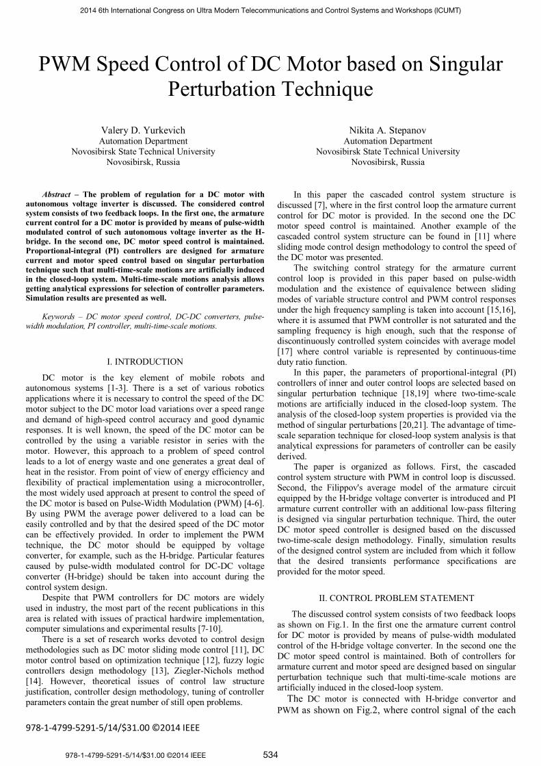
Additional simulation results are shown on the Figs. 15 – 20 where the desired value of motor speed has step change from 70 rad/s to -70 rad/s and the controller parameters were selected as the following ones (the same values as in case of Figs. 3-8):
휇 =0,001s, 푑 =2, τa=0,01s, 푘 =10-6,
휇 =0,1s, τω=1s, kω = 5,44. k1 = 5, k2 = 27,56
So, we have 휇 = τa /10, τa=휇 /10, 휇 = τω /10.
2014 6th International Congress on Ultra Modern Telecommunications and Control Systems and Workshops (ICUMT)
538
Fig. 15 Simulation results: Plots of and 휔 ( rad/s)
Fig. 16 Simulation results: Plot of ai (A)
Fig. 17 Simulation results: Plot of 푖 (A)
Fig. 18 Simulation results: Plot of 휒
Fig. 19 Simulation results: Plot of 푈
Fig. 20 Simulation results: Plot of 푇
VII. CONCLUSION
The advantage of the presented singular perturbation technique of controller design for the discussed DC motor equipped by the H-bridge voltage converter is that the desired transients of the motor speed are provided. The increase of the time-scale separation degree allows providing the desired output transients specifications with more high accuracy.
The other advantage is that analytical expressions for selection of controller parameters are derived, where controller parameters depend explicitly on the specifications of the desired behavior of motor speed.
VIII. ACKNOWLEDGEMENT
This work was supported by Russian Foundation for Basic Research (RFBR) under grant no.14-08-01004а and by Novosibirsk State Technical University under academic mobility grant of the strategic development program.
REFERENCES [1] Power Electronics Handbook, Ed. by Muhammad H. Rashid, Academic
Press, 2001. [2] R.W. Erikson, M. Dragan, Fundamentals of Power Electronics, Springer, 2-
nd ed, 2001. [3] J. Lovine, Robots, androids, and animations, McGraw-Hill, 2001. [4] J. Holtz, “Pulsewidth modulation: a survey,” IEEE Trans. Industrial
Electronics, 1992, vol. IE-39, no.5 pp.410-420. [5] S.D. Barman, A. Hussain, T. Ahmed, Speed Control of DC Motor Using
PWM Technique: Pulse Width Modulated DC Motor Control, LAP Lambert Academic Publishing, 2012.
2014 6th International Congress on Ultra Modern Telecommunications and Control Systems and Workshops (ICUMT)
539

[6] A.K. Dewangan, N. Chakraborty, S. Shukla, and V. Yadu, “PWM Based Automatic Closed Loop Speed Control of DC Motor,” Int. J. of Engineering Trends and Technology, 2012, vol.3I, issue 2, pp.110-112.
[7] L.S. Patel and K.C. Dave, “Cascade control Technique for D.C. Motor Speed Control,” Proc. of the Int. Conf. on Science and Engineering (ICSE 2011), 2011, pp.599-603.
[8] A. K. Yadav and A.K. Chaubey, “Speed control of DC motor using PWM,” Int. J. of Advance Research in Science and Engineering, March 2013, vol.2, issue 3, March, 2013.
[9] Vinod KR Singh Patel and A.K.Pandey, “Modeling and Simulation of Brushless DC Motor Using PWM Control Technique,” Int. J. of Engineering Research and Applications, May-Jun 2013, vol.3, issue 3, pp.612-620.
[10] M.K.Parai, D. Misra, and B. Das, “CPLD Based Speed Controller of a DC Motor Operated Through Cellphone,” Int. J. of Soft Computing and Engineering (IJSCE), September 2012, vol.2, issue 4, pp.190-193.
[11] V.I. Utkin, J. Guldner and J.X. Shi, Sliding Mode Control in Electromechanical Systems, Taylor and Francis, London, 1999.
[12] H. Shayeghi, A. Akbarimajd, A. Mohammadian, and G. Shokri, “Speed and Current Controllers Design of BLDC Motor Using SNR Optimization Technique,” Int. Research Journal of Applied and Basic Sciences, 2013, vol.4 (1), pp.99-106.
[13] P. Kannan, S.K. Natarajan, and S.S. Dash, “Design of fuzzy logic controller for online speed regulation of DC motor using PWM technique based on laboratory virtual instrument engineering workbench,” Journal of Computer Science, 2013, vol.9 (8), pp.990-997.
[14] Vinod KR Singh Patel and A.K.Pandey, “Modeling and Performance Analysis of PID Controlled BLDC Motor and Different Schemes of PWM Controlled BLDC Motor,” Int. J. of Scientific and Research Publications, April 2013, vol.3, issue 4, pp.1-14.
[15] H. Sira-Ramirez, “A geometric approach to pulse-width-modulated control in nonlinear dynamical systems,” IEEE Trans. Automatic Control, 1989, vol. 34, no.2, pp.184-187.
[16] H. Sira-Ramirez, P. Lischinsky-Arenas, “Dynamical discontinuous feedback control of nonlinear systems,” IEEE Trans. Automatic Control, 1990, vol. 35, no.12, pp. 1373-1378.
[17] A.F. Filippov, Differential equations with discontinuous right hand sides, Am. Math. Soc. Transl., 1964, vol. 42, pp.199-231.
[18] V.D. Yurkevich, “PWM controller design based on singular perturbation technique: a case study of buck-boost dc-dc converter,” Proc. of the 18-th IFAC World Congress, Milan, Italy, August 28-September 2, 2011, pp. 9739-9744.
[19] V.D. Yurkevich, G.S. Zinoviev, and A.A. Gordeev “PWM Current Controller Design for Multi-level DC-DC Converter via Singular Perturbation Technique,” Proc. of International Conference and Seminar of Young Specialists on Micro/Nanotechnologies and Electron Devices EDM 2011. 12-th Annual. Erlagol, Altai-June 30-July 4, 2011, pp. 390-398.
[20] P.V. Kokotovic, H. K. Khalil, and J. O'Reilly, Singular Perturbation Methods in Control: Analysis and Design, Philadelphia, PA: SIAM, 1999.
[21] D.S. Naidu “Singular perturbations and time scales in control theory and applications: an overview,” Dynamics of Continuous, Discrete & Impulsive Systems (DCDIS), Series B: Applications & Algorithms, 2002, vol. 9, no. 2, pp. 233-278.
2014 6th International Congress on Ultra Modern Telecommunications and Control Systems and Workshops (ICUMT)
540