purpose control: did you process the data for the intended purpose?
TRANSCRIPT
Purpose Control: did you process the data for theintended purpose??
Milan Petkovic13, Davide Prandi2, and Nicola Zannone3
1 Philips Research [email protected]
2 Centre for Integrative Biology, University of [email protected]
3 Eindhoven University of [email protected]
Abstract. Data protection legislation requires personal data to be collected andprocessed only for lawful and legitimate purposes. Unfortunately, existing pro-tection mechanisms are not appropriate for purpose control: they only preventunauthorized actions from occurring and do not guarantee that the data are actu-ally used for the intended purpose. In this paper, we present a flexible frameworkfor purpose control, which connects the intended purpose of data to the busi-ness model of an organization and detects privacy infringements by determiningwhether the data have been processed only for the intended purpose.
1 Introduction
In recent decades, many countries have enacted privacy laws and regulations that im-pose very stringent requirements on the collection and processing of personal data (e.g.,EU Directive 95/46/EC, HIPAA). Purpose control plays a central role in such legisla-tion [1]: personal data shall be collected for specified, lawful and legitimate purposesand not processed in ways that are incompatible with the purposes for which data havebeen collected. Purpose control requires the deployment of mechanisms that hold usersaccountable for their actions by verifying how data have actually been processed.
In contrast, current security and data protection mechanisms do not provide appro-priate support for purpose control. They are preventive and, more importantly, they donot check for which purpose data are processed after access to data has been granted.Protection of personal information is often implemented by augmenting access controlsystems with the concept of purpose [2–5] (hereafter, we call access control policiesaugmented with purpose data protection policies). Here, protecting data implies guar-anteeing that data are disclosed solely to authorized users with the additional conditionthat data are requested for the intended purpose. The access purpose is usually specifiedby the requester [4], implying complete trust on users. This poses risks of re-purposingthe data [6, 7] as users might process the data for purposes other than those for whichthe data were originally obtained. Therefore, to ensure compliance to data protection
? This work has been partially funded by the EU-IST-IP-216287 TAS3 project.
and purpose control, it is necessary to extend the current preventive approach by imple-menting mechanisms for verifying the actual use of data.
Some privacy enhancing technologies (e.g., [2, 8]) partially address this issue. Theycollect and maintain audit trails, which record the actual user behavior, for external pri-vacy audits. These auditing activities, however, are usually manual; the auditors sampleand inspect the audit trails recorded by the system. The lack of systematic methods fordetermining how data are used makes auditing activities time-consuming and costly.For instance, at the Geneva University Hospitals, more than 20,000 records are openedevery day [9]. In this setting, it would be infeasible to verify every data usage manually,leading to situations in which privacy breaches remain undetected.
In this paper, we present a framework for purpose control which detects privacyinfringements by determining whether data are processed in ways that are incompatiblewith the intended purpose of data. To this end, we need a purpose representation modelthat connects the intended purpose of data to the business activities performed by anorganization and methods able to determine whether the data are actually processed inaccordance with purpose specifications.
Organizations often make use of business processes to define how organizationalgoals should be fulfilled. These organizational processes define the expected user be-havior for achieving a certain organizational goal. The idea underlying our approachis to link the purposes specified in data protection policies to organizational goals and,therefore, to the business processes used to achieve such goals. Thus, the problem ofverifying the compliance of data usage with the intended purpose consists in determin-ing whether the audit trail is a valid execution of the organizational processes repre-senting the purposes for which data are meant to be used. Intuitively, if the audit traildoes not correspond to a valid execution of those processes, the actual data usage is notcompliant with the purpose specification.
To enable automated analysis, we use the Calculus of Orchestration of Web Ser-vices (COWS) [10] for the representation of organizational processes. COWS is a foun-dational calculus strongly inspired by WS-BPEL [11]. It is based on a very small set ofprimitives associated with a formal operational semantics that can be exploited for theautomated derivation of the dynamic evolution of the process. The COWS semanticsmakes it possible to construct a labeled transition system that generates the set of tracesequivalent to the set produced by all possible executions of the process.
A naıve approach for purpose control would be to generate the transition system ofthe COWS process model and then verify if the audit trail corresponds to a valid traceof the transition system. Unfortunately, the number of possible traces can be infinite,for instance when the process has a loop, making this approach not feasible. Therefore,in this paper we propose an algorithm that replays the audit trail in the process modelto detect deviations from the expected behavior. We demonstrate that the algorithmterminates and is sound and complete.
The structure of the paper is as follows. Next section presents our running exam-ple. (§2). Then, we introduce the building blocks of our framework and analyze theiralignment (§3). We present an algorithm for purpose control (§4) and demonstrate thetermination, soundness and completeness of the algorithm (§5). Finally, we discuss re-lated work (§6) and conclude the paper, providing directions for future work (§7).
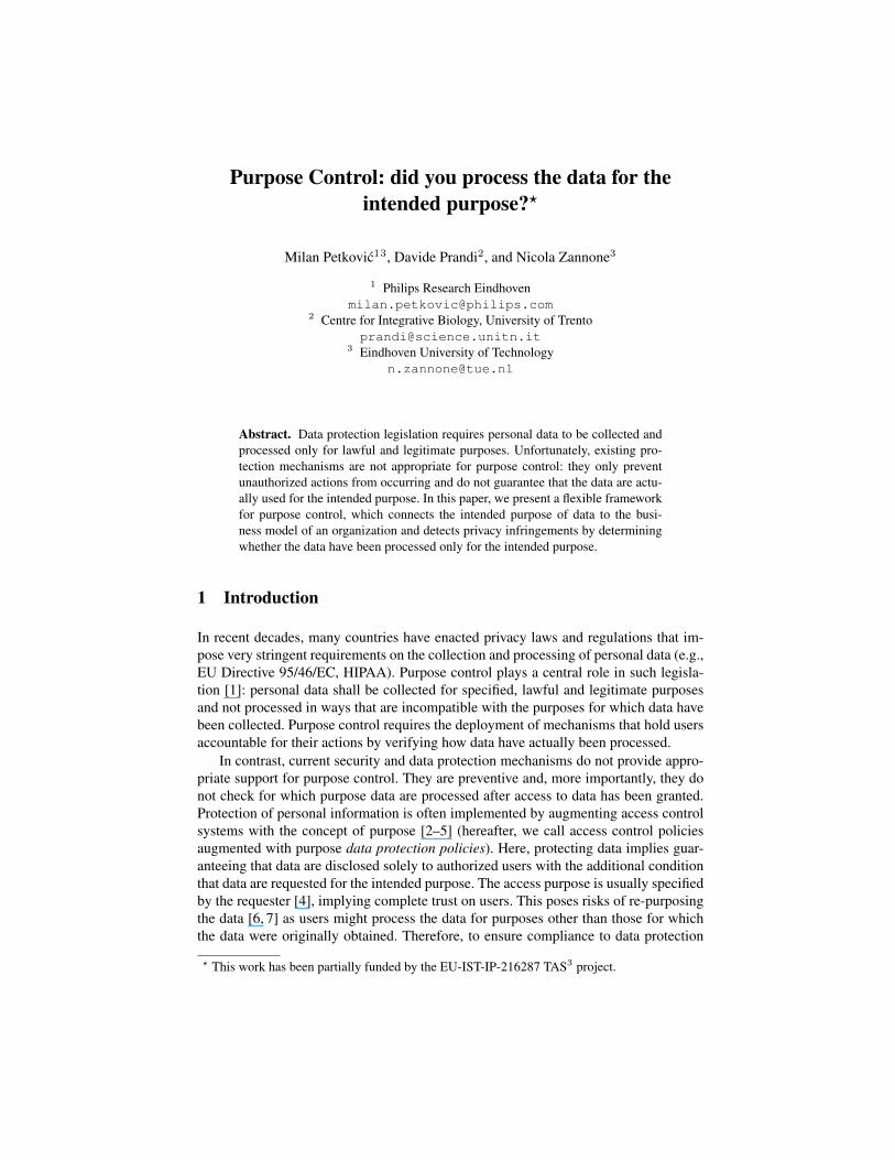
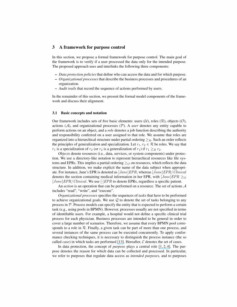
Fig. 1. Healthcare Treatment Process
2 Running example
This section presents a simple scenario in the healthcare domain to illustrate our ap-proach. Consider a patient who goes to a hospital to see a doctor. The hospital isequipped with its own Hospital Information System (HIS) to manage the administrative,financial, and clinical aspects of patient information. In particular, patient informationare stored in an electronic patient record (EPR); here, we assume that EPRs are orga-nized in sections; each of them contains a certain type of information. Members of thehospital staff can access specific sections of the EPR (or parts of them) depending ontheir position within the hospital and for well defined purposes. Suppose that a patient,Jane, did not give the hospital consent to process her information for research purposes.Then, the hospital staff cannot access Jane’s information for clinical trials.
The provision of healthcare treatments can be seen as a process that involves severalparties. Fig. 1 describes an example of a healthcare treatment process specified in theBusiness Process Modeling Notation (BPMN) [12]. Here, every BPMN pool4 repre-sents the visit of the patient to a member of the clinical staff at the local hospital. Theprocess starts when a patient visits the general practitioner (GP) at the hospital (S1).The GP accesses the HIS to retrieve the patient’s EPR and makes a physical exami-nation to collect the symptoms (T01). Based on the gathered information, the GP maysuspect that the patient is affected by a certain disease. He can either make a diagnosis(T02) or refer to a specialist if the case is more complex (T05). For instance, in case theGP suspects a cardio-vascular disease, he can refer the patient to a cardiologist.
4 In BPMN a pool is used to specify the boundaries of the activities to be performed by a partic-ipant in the process and is graphically represented as a container enclosing those activities.
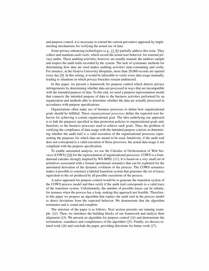
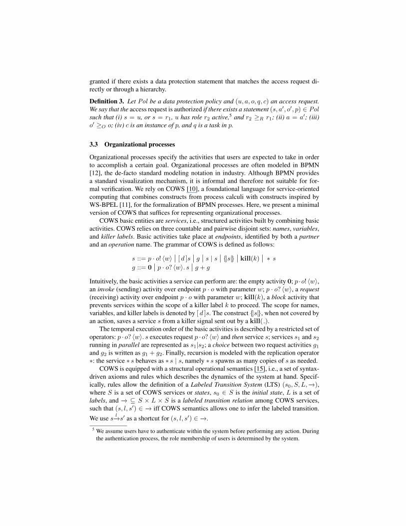
Fig. 2. Clinical Trial Process
If the patient is referred to a cardiologist (S3), the cardiologist accesses patient med-ical history in the HIS and makes a medical examination to collect the symptoms (T06).Based on this information, the cardiologist can either make a diagnosis directly (T07),or request lab tests or radiology scans (T08 and T09, respectively). If the resulting testsand scans are not good or a diagnosis cannot be made based on them, further testscan be required. When the lab or the radiology department receive the request for testsfrom the cardiologist (S5 and S6, respectively), they check the EPR for allergies orother counter-indications (T10 and T03, respectively). Then, they do the lab exam (T11and T14) and export the results to the HIS (T12 and T15). A notification is sent to thecardiologist when the tests or the scans have been completed (E6 and E7).
When the cardiologist receives a notification for all the ordered tests and scans (S4),he retrieves the test results or the scans from the HIS (T06) and, based on them, makesa diagnosis (T07). After the cardiologist enters the diagnosis into the HIS, a notificationis sent to the GP (E4). Upon the notification (S2), the GP extracts the diagnosis madeby the cardiologist, scans and tests from the patient’s EPR (T01). Based on them, theGP prescribes medical treatments to the patient (T03) and discharges her (T04).
Suppose now that the same cardiologist mentioned above is involved in a clinicaltrial. Fig. 2 shows the part of the clinical trial process in which a physician is involved.The physician has to define eligibility criteria for the trial (T91). Then, he accessesEPRs to find patients with a specific condition that meet the eligibility criteria (T92).In the next step, the physician asks the selected candidates whether they want to partic-ipate in the trial (T93). The trial is then performed (T94) and the results are analyzed(T95). Note that the cardiologist can get access to patient information for the legiti-mate purpose (i.e., claiming that it is for healthcare treatment) and then use the datafor research purposes (i.e., clinical trial). Preventive mechanisms are not able to copewith these situations. In particular, they cannot prevent a user to process data for otherpurposes after the same user has legitimately got access to them.
To address this issue, we need mechanisms that make users accountable for theiractions by determining how data were actually used. In this paper, we propose an ap-proach that enables purpose control by determining if an audit trail is a valid executionof the process used by the organization to implement the intended purposes. In ourscenario, this implies verifying that every usage of patient information is part of thesequence of tasks that the cardiologist and the other parties involved in the provision ofhealthcare treatments have to perform in order to accomplish the goal.
3 A framework for purpose control
In this section, we propose a formal framework for purpose control. The main goal ofthe framework is to verify if a user processed the data only for the intended purpose.The proposed approach uses and interlinks the following three components:
– Data protection policies that define who can access the data and for which purpose.– Organizational processes that describe the business processes and procedures of an
organization.– Audit trails that record the sequence of actions performed by users.
In the remainder of this section, we present the formal model components of the frame-work and discuss their alignment.
3.1 Basic concepts and notation
Our framework includes sets of five basic elements: users (U), roles (R), objects (O),actions (A), and organizational processes (P). A user denotes any entity capable toperform actions on an object, and a role denotes a job function describing the authorityand responsibility conferred on a user assigned to that role. We assume that roles areorganized into a hierarchical structure under partial ordering≥R. Such an order reflectsthe principles of generalization and specialization. Let r1, r2 ∈ R be roles. We say thatr1 is a specialization of r2 (or r2 is a generalization of r1) if r1 ≥R r2.
Objects denote resources (i.e., data, services, or system components) under protec-tion. We use a directory-like notation to represent hierarchical resources like file sys-tems and EPRs. This implies a partial ordering≥O on resources, which reflects the datastructure. In addition, we make explicit the name of the data subject when appropri-ate. For instance, Jane’s EPR is denoted as [Jane]EPR, whereas [Jane]EPR/Clinicaldenotes the section containing medical information in her EPR, with [Jane]EPR ≥O
[Jane]EPR/Clinical . We use [·]EPR to denote EPRs, regardless a specific patient.An action is an operation that can be performed on a resource. The set of actions A
includes “read”, “write”, and “execute”.Organizational processes specifies the sequences of tasks that have to be performed
to achieve organizational goals. We use Q to denote the set of tasks belonging to anyprocess in P . Process models can specify the entity that is expected to perform a certaintask (e.g., using pools in BPMN). However, processes usually are not specified in termsof identifiable users. For example, a hospital would not define a specific clinical trialprocess for each physician. Business processes are intended to be general in order tocover a large number of scenarios. Therefore, we assume that every BPMN pool corre-sponds to a role in R. Finally, a given task can be part of more than one process, andseveral instances of the same process can be executed concurrently. To apply confor-mance checking techniques, it is necessary to distinguish the process instance (the socalled case) in which tasks are performed [13]. Hereafter, C denotes the set of cases.
In data protection, the concept of purpose plays a central role [1, 2, 4]. The pur-pose denotes the reason for which data can be collected and processed. In particular,we refer to purposes that regulate data access as intended purposes, and to purposes

(Physician, read, [·]EPR/Clinical, treatment)(Physician,write, [·]EPR/Clinical, treatment)(Physician, read, [·]EPR/Demographics, treatment)(MedicalTech, read, [·]EPR/Clinical, treatment)(MedicalTech, read, [·]EPR/Demographics, treatment)(MedicalLabTech,write, [·]EPR/Clinical/Tests, treatment)(Physician, read, [X]EPR, clinicaltrial)
Fig. 3. Sample Data Protection Policy
for which data access is requested as access purposed. Purposes are related to the busi-ness activities of an organization and can be identified with organizational goals. Forinstance, [14] defines a list of purposes for healthcare, which includes healthcare treat-ment, payment, research and marketing. Thus, in this paper, we represent purposes bythe organizational process implemented by an organization to achieve the correspond-ing organizational goal.
3.2 Data protection policies
The aim of data protection policies is to protect an individual’s right to privacy bykeeping personal data secure and by regulating its processing. Several languages forthe specification of data protection policies have been proposed in literature [3, 4]. Theobjective of this paper is not to propose yet another policy specification language. Thus,here we present a simple language that suffices for the purpose of this paper.
A data protection policy specifies the access rights: who is authorized to access thesystem, what actions he is allowed to perform on a resource, and for which purpose.
Definition 1. A data protection statement is a tuple (s, a, o, p) where s ∈ U∪R, a ∈ A,o ∈ O, and p ∈ P . A data protection policy Pol is a set of data protection statements.
Fig. 3 presents the data protection policy governing our scenario. The first block ofFig. 3 states that physicians can read and write patient medical information in EPRs fortreatment. Moreover, physicians can also read patient demographics for treatment. Notethat roles GP, radiologist, and cardiologist are specializations of role physician. Thesecond block of statements targets medical technicians. They can read patient medicalinformation for treatment. Moreover, medical lab technicians (which is a specializationof medical technicians) have write permission on the EPR section concerning test re-sults. The last block of Fig. 3 represents the hospital policy that allows physicians toaccess the EPR of those patients (X) who give consent to use their data for clinical trial.
Users can request access to system’s resources by means of access request.
Definition 2. An access request is a tuple (u, a, o, q, c) where u ∈ U , a ∈ A, o ∈ O,q ∈ Q, and c ∈ C.
An access request specifies the user who makes the request, the object to be accessed,and the action to be performed on the object along with information about the purposefor which the request is made. In particular, the access purpose is represented by thetask for which the access to the object is requested and by the process instance.
When a user requests permission to execute an action on an object for a certainpurpose, the access request is evaluated against the data protection policy. Access is
granted if there exists a data protection statement that matches the access request di-rectly or through a hierarchy.
Definition 3. Let Pol be a data protection policy and (u, a, o, q, c) an access request.We say that the access request is authorized if there exists a statement (s, a′, o′, p) ∈ Polsuch that (i) s = u, or s = r1, u has role r2 active,5 and r2 ≥R r1; (ii) a = a′; (iii)o′ ≥O o; (iv) c is an instance of p, and q is a task in p.
3.3 Organizational processes
Organizational processes specify the activities that users are expected to take in orderto accomplish a certain goal. Organizational processes are often modeled in BPMN[12], the de-facto standard modeling notation in industry. Although BPMN providesa standard visualization mechanism, it is informal and therefore not suitable for for-mal verification. We rely on COWS [10], a foundational language for service-orientedcomputing that combines constructs from process calculi with constructs inspired byWS-BPEL [11], for the formalization of BPMN processes. Here, we present a minimalversion of COWS that suffices for representing organizational processes.
COWS basic entities are services, i.e., structured activities built by combining basicactivities. COWS relies on three countable and pairwise disjoint sets: names, variables,and killer labels. Basic activities take place at endpoints, identified by both a partnerand an operation name. The grammar of COWS is defined as follows:
s ::= p · o! 〈w〉 | [ d ]s | g | s | s | |s| | kill(k) | ∗ sg ::= 0 | p · o? 〈w〉. s | g + g
Intuitively, the basic activities a service can perform are: the empty activity 0; p ·o! 〈w〉,an invoke (sending) activity over endpoint p · o with parameter w; p · o? 〈w〉, a request(receiving) activity over endpoint p · o with parameter w; kill(k), a block activity thatprevents services within the scope of a killer label k to proceed. The scope for names,variables, and killer labels is denoted by [ d ]s. The construct |s|, when not covered byan action, saves a service s from a killer signal sent out by a kill( ).
The temporal execution order of the basic activities is described by a restricted set ofoperators: p · o? 〈w〉. s executes request p · o? 〈w〉 and then service s; services s1 and s2running in parallel are represented as s1|s2; a choice between two request activities g1and g2 is written as g1 + g2. Finally, recursion is modeled with the replication operator∗: the service ∗ s behaves as ∗ s | s, namely ∗ s spawns as many copies of s as needed.
COWS is equipped with a structural operational semantics [15], i.e., a set of syntax-driven axioms and rules which describes the dynamics of the system at hand. Specif-ically, rules allow the definition of a Labeled Transition System (LTS) (s0, S, L,−→),where S is a set of COWS services or states, s0 ∈ S is the initial state, L is a set oflabels, and −→ ⊆ S × L × S is a labeled transition relation among COWS services,such that (s, l, s′) ∈ −→ iff COWS semantics allows one to infer the labeled transition.We use s l−→s′ as a shortcut for (s, l, s′) ∈ −→.
5 We assume users have to authenticate within the system before performing any action. Duringthe authentication process, the role membership of users is determined by the system.
Labels in L are generated by the following grammar:
l ::= (p · o) / w | (p · o) . w | p · o (v) | †k | †
Invoke label (p ·o)/ w and request label (p ·o). w are for invoke and request activities,respectively. Label p·o (v) represents a communication between an invoke label (p·o)/ vand a request label (p · o) . w. If the communication is indeed a synchronization, thelabel is simplified as p · o. Finally, labels †k and † manage, respectively, ongoing andalready executed killing activities. We refer to [10] for a detailed description of theCOWS structural operational semantics.
The encoding of BPMN processes into COWS specifications founds on the idea ofrepresenting every BPMN element as a distinct COWS service. For the lack of space,here we only present the intuition of the encoding; examples of the encoding are givenin Appendix A. In [16], we have defined elementary and parametric COWS services fora core set of BPMN elements. For example, a start event (e.g., S1 in Fig. 1) is modeledin COWS as x ·y! 〈〉where x ·y is the endpoint triggering the next BPMN element in theflow (x is the pool that contains the element and y is the name of the element); a task(e.g., T01 in Fig. 1) is modeled as x · y? 〈〉.Act , where x · y is the endpoint to triggerthe execution of the task, and Act is the activity performed by the task (Act eventuallyspecifies the next BPMN element). Parameters are instantiated to connect the BPMNelements forming the BPMN process. The COWS service implementing S1 and T01,denoted by [[S1]] and [[T01]] respectively, are [[S1]] = GP · T01! 〈〉 and [[T01]] =GP · T01? 〈〉. [[Act ]], where [[Act ]] is the COWS service implementing activity Actand GP stands for general practitioner. The overall organizational process results fromthe parallel composition of the elementary services implementing the single BPMNelements. The process composed by services [[S1]] and [[T01]] is [[S1]] | [[T01]].
The sequence flow, which describes the execution order of process activities bytracking the path(s) of a token through the process, is rendered as a sequence of com-munications between two services. For instance, the sequence flow between event S1and task T01 is defined by the labeled transition
[[S1]] | [[T01]] GP ·T01−−−−−→ 0 | [[Act ]]
Intuitively, the label GP · T01 allows one to “observe” on the COWS transition sys-tem that the task received the token. The same idea applies to message flow as well asto other BPMN elements like event handlers and gateways. However, in case of eventhandlers and gateways, some “internal computation” is required to determine the nextBPMN element to be triggered. For instance, exclusive gateway G1 in Fig. 1 is con-nected to T02 and T05; from G1, the token can flow either to T02 or T05, but not toboth. The act of deciding which task should be triggered does not represent a flow ofthe token. In this case we use the private name sys as the partner in the label. Similarly,label sys · Err is used to represent error signals. In general, it is not known in advancehow many times a service is invoked during the execution of a process. An example ofthis is given by cycles (e.g., T01, G1 and T02 in Fig. 1). To this end, we prefix COWSservices with the replication operator ∗ . This operator makes multiple copies of theCOWS service; each copy corresponds to an invocation of the service.
3.4 Audit trails
Auditing involves observing the actions performed by users to ensure that policies andprocedures are working as intended or to identify violations that might have occurred.Audit trails are used to capture the history of system activities by representing eventsreferring to the actions performed by users. Every event is recorded in a log entry.
Definition 4. A log entry is a tuple (u, r, a, o, q, c, t, s) where u ∈ U , r ∈ R, a ∈ A,o ∈ O, q ∈ Q, c ∈ C, t ties an event to a specific time, and s is the task status indicator.
The field user represents the user who performed the action on the object. Role rep-resents the role held by the user at the time the action was performed. The task statusindicator specifies whether the task succeeded or not (i.e., s ∈ success, failure).We assume that the failure of a task makes the task completed; therefore, no actionswithin the task are possible after the task has failed. In addition, the process can pro-ceed only if there is in place a mechanism to handle the failure. Log entries also containinformation about the purpose for which the action was performed. In particular, thepurpose is described by the task in which the action was performed and the case thatidentifies the process instance in which the action took place.
An audit trail consists of the chronological sequence of events that happen withinthe system.
Definition 5. A audit trail is an ordered sequence of log entries where given two entriesei = (ui, ri, ai, oi, qi, ci, ti, si) and ej = (uj , rj , aj , oj , qj , cj , tj , sj) we say that ei isbefore ej (denoted by ei < ej) if ti < tj .
Recent data protection regulations in the US (see [17]) impose healthcare providersto record all actions related to health information. Accordingly, we assume that audittrails record every action performed by users, and these logs are collected from all ap-plications in a single database with the structure given in Def. 4. In addition, audit trailsneed to be protected from breaches of their integrity. A discussion on secure loggingis orthogonal to the scope of this paper. Here, we just mention that there exist well-established techniques [18, 19], which guarantee the integrity of logs.
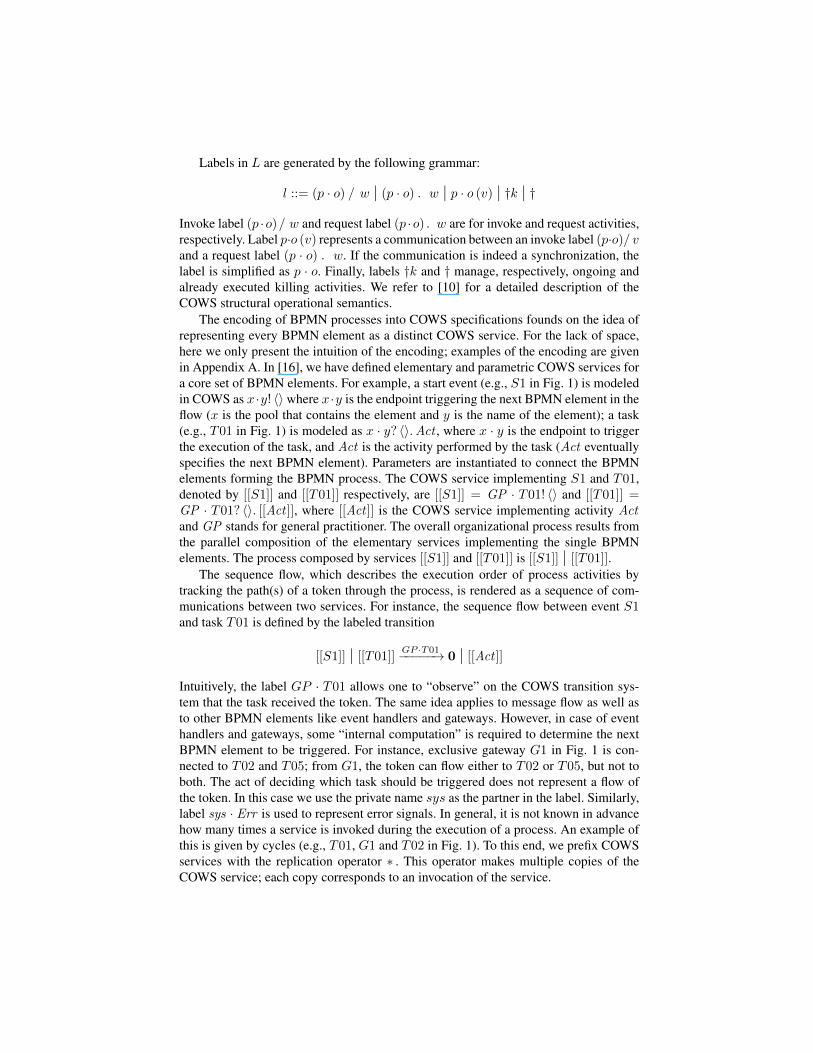
Fig. 4 presents a possible audit trail for the scenario of Section 2. The audit traildescribes the accesses to Jane’s EPR made by the GP (John), the cardiologist (Bob),and the radiologist (Charlie) in the process of providing her medical treatments (weassume that Bob did not order lab tests). It also shows that a number of instances of theprocess can be executed concurrently. Time is in the form year-month-day-hour-minute.Tasks are denoted by a code as defined in Fig. 1. Case HT-1 represents the instance ofthe process being executed. In particular, HT stands for the healthcare treatment processand the number indicates the instance of the process.
The last part of Fig. 4 presents the log entries generated during the execution of theclinical trial (CT) process. Here, Bob specified healthcare treatment as the purpose inorder to retrieve a larger number of EPRs.6 Note that preventive mechanisms cannotdetect the infringement. Only the patients selected for the trial might suspect a privacybreach. Certainly, the infringement remains covered for those patients who were notselected for the trial and did not allow the usage of their data for research purposes.
6 Note that, if the physician specifies clinical trial as purpose, the HIS would only return theEPRs of those patients who gave their consent to use their information for research purposes.

user role action object task case time statusJohn GP read [Jane]EPR/Clinical T01 HT-1 201003121210 successJohn GP write [Jane]EPR/Clinical T02 HT-1 201003121212 successJohn GP cancel N/A T02 HT-1 201003121216 failureJohn GP read [Jane]EPR/Clinical T01 HT-1 201003121218 successJohn GP write [Jane]EPR/Clinical T05 HT-1 201003121220 successJohn GP read [David]EPR/Demographics T01 HT-2 201003121230 success
· · ·Bob Cardiologist read [Jane]EPR/Clinical T06 HT-1 201003141010 successBob Cardiologist write [Jane]EPR/Clinical T09 HT-1 201003141025 successCharlie Radiologist read [Jane]EPR/Clinical T10 HT-1 201003201640 successCharlie Radiologist execute ScanSoftware T11 HT-1 201003201645 successCharlie Radiologist write [Jane]EPR/Clinical/Scan T12 HT-1 201003201730 successBob Cardiologist read [Jane]EPR/Clinical T06 HT-1 201003301010 successBob Cardiologist write [Jane]EPR/Clinical T07 HT-1 201003301020 successJohn GP read [Jane]EPR/Clinical T01 HT-1 201004151210 successJohn GP write [Jane]EPR/Clinical T02 HT-1 201004151210 successJohn GP write [Jane]EPR/Clinical T03 HT-1 201004151215 successJohn GP write [Jane]EPR/Clinical T04 HT-1 201004151220 successBob Cardiologist write ClinicalTrial/Criteria T91 CT-1 201004151450 successBob Cardiologist read [Alice]EPR/Clinical T06 HT-10 201004151500 successBob Cardiologist read [Jane]EPR/Clinical T06 HT-11 201004151501 success
· · ·Bob Cardiologist read [David]EPR/Clinical T06 HT-20 201004151515 successBob Cardiologist write ClinicalTrial/ListOfSelCand T92 CT-1 201004151520 successBob Cardiologist read [Alice]EPR/Demographics T06 HT-21 201004151530 success
· · ·Bob Cardiologist read [David]EPR/Demographics T06 HT-30 201004151550 successBob Cardiologist write ClinicalTrial/ListOfEnrCand T93 CT-1 201004201200 successBob Cardiologist write ClinicalTrial/Measurements T94 CT-1 201004221600 success
· · ·Bob Cardiologist write ClinicalTrial/Measurements T94 CT-1 201004291600 successBob Cardiologist write ClinicalTrial/Results T95 CT-1 201004301200 success
Fig. 4. Audit Trail
3.5 Alignment
In the previous sections, we introduced data protection policies, organizational pro-cesses, and audit trails. Although these components make use of the same concepts,such concepts are often specified at a different level of abstraction. In this section, wediscuss how they are related to each other.
Audit trails usually capture and store information at a lower level of abstraction thanorganizational processes. While the basic components of organizational processes aretasks, the basic components of audit trails are actions. Accomplishing a task may requirea user to execute a number of actions. Thereby, there is a 1-to-n mapping between tasksand log entries: one task can be associated with multiple log entries. One can think tobring organizational processes and audit trails at a comparable level of abstraction, forinstance, by specifying a process in terms of actions or by annotating each task in theprocess with the actions that can be executed within the task. However, these approacheswould require several efforts in the specification of organizational processes as well asaffect their readability and understanding. To address this issue, we allow for everyaction executed within the tasks active at a certain time (when checking the complianceof the actual data usage with the intended purpose as described in Section 4). However,this leaves risks of unauthorized access to data. To prevent unauthorized access whilekeeping the management of organizational processes simple, a mechanism for purpose
control should be complemented with a preventive enforcement mechanism that verifiesaccess requests in isolation (i.e., independently from other requests).
Languages for representing business processes often rely on information that is notavailable in audit trails. For instance, the COWS representation of organizational pro-cesses founds on the idea that the evolution of the transition system completely char-acterizes the evolution of the process. Accordingly, transition systems contain informa-tion about the management of gateways and the occurrence of non-observable events,which is not recorded in audit trails. To define a suitable mapping between log entriesand COWS labels, we distinguish the information that is IT observable by defining theset of observable labels L as a subset of the set of labels L, i.e., L ⊂ L. In particular,labels in L specify labels representing the execution of a task q by a partner r (i.e.,synchronization labels of the form r · q) and labels representing errors (i.e., sys ·Err).Summing up, the set of observable labels is
L = r · q | r ∈ R and q ∈ Q ∪ sys · Err.
Our definition of observable labels reflects the fact that we assume that only the execu-tion of tasks and error events are IT observable. In case other activities can be loggedby the system (e.g., message flows), the definition above should be extended to includethe corresponding labels.
How the system determines the purpose for which an action was performed (i.e.,the task and case in a log entry) is a critical issue as it is necessary to link the actionsto the appropriate process instance. We assume that information about the purpose isavailable. Different solutions can be adopted to collect this information. For instance,most IT systems based on transactional systems such as WFM, ERP, CRM and B2Bsystems are able to record the task and the instance of the process [13]. Here, the systemitself is responsible to determine the context of an action and store it in the log entry. Adifferent approach is proposed in [2–4] where users are required to specify the purposealong with the access request. This approach is also adopted in existing EPR systemslike DocuLive which require users to provide the reason for the access and record thatreason in audit trails [20]. We assume that the purpose specified in the access request(i.e., q and c in Def. 2), which can be determined either by the user or by the system,is recorded in the corresponding log entry. In the next section, we present an algorithmfor verifying if data have actually been processed for that purpose.
4 Compliance with purpose specification
The aim of purpose control is to guarantee that personal data are not processed in waysthat are incompatible with the intended purpose of data. We identify two main issues tobe addressed in order to ensure compliance to purpose control: (a) data access should beauthorized, and (b) access purposes should be specified correctly and legally. The firstissue is addressed by Def. 3 which provides a way to evaluate access request againstdata protection policies. In particular, this definition guarantees that the data requesterhas the permission necessary to access the data.
However, the real challenge in ensuring purpose control is to validate the accesspurpose specified in the access request, i.e. determining whether data were in fact pro-cessed for that purpose. In our scenario, the cardiologist legitimately accessed patient
Algorithm 1: Compliance procedureinput : a state s, an audit trail loutput: bool
let conf set = (s, empty,WeakNext(s));1let next conf set = null;2while l 6= null do3
let l = e ∗ l′;4let r ∈ R s.t. e.role ≤R r;5let found = false;6forall conf ∈ conf set do7
if ((r , e.task) /∈ conf .active tasks) ∨ (e.status = failure)) then8forall (label, state, active task) ∈ conf.next do9
if ((label = r · e.task) ∧ (e.status = success)) ∨ ((label = sys · Err) ∧10(e.status = failure)) then
found = true;11next conf set+ = (state, active task ,WeakNext(state));12
end13else14
found = true;15next conf set+ = conf ;16
let l = l′;17conf set = next conf set ;18next conf set = null ;19
end20if ¬found then return false;21
end22return true;23
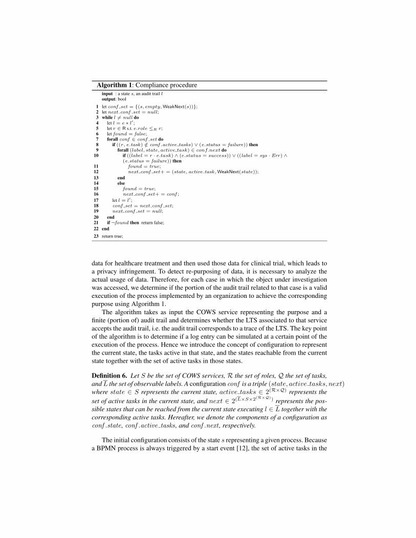
data for healthcare treatment and then used those data for clinical trial, which leads toa privacy infringement. To detect re-purposing of data, it is necessary to analyze theactual usage of data. Therefore, for each case in which the object under investigationwas accessed, we determine if the portion of the audit trail related to that case is a validexecution of the process implemented by an organization to achieve the correspondingpurpose using Algorithm 1.
The algorithm takes as input the COWS service representing the purpose and afinite (portion of) audit trail and determines whether the LTS associated to that serviceaccepts the audit trail, i.e. the audit trail corresponds to a trace of the LTS. The key pointof the algorithm is to determine if a log entry can be simulated at a certain point of theexecution of the process. Hence we introduce the concept of configuration to representthe current state, the tasks active in that state, and the states reachable from the currentstate together with the set of active tasks in those states.
Definition 6. Let S be the set of COWS services, R the set of roles, Q the set of tasks,andL the set of observable labels. A configuration conf is a triple (state, active tasks, next)where state ∈ S represents the current state, active tasks ∈ 2(R×Q) represents theset of active tasks in the current state, and next ∈ 2(L×S×2
(R×Q)) represents the pos-sible states that can be reached from the current state executing l ∈ L together with thecorresponding active tasks. Hereafter, we denote the components of a configuration asconf .state , conf .active tasks , and conf .next , respectively.
The initial configuration consists of the state s representing a given process. Becausea BPMN process is always triggered by a start event [12], the set of active tasks in the
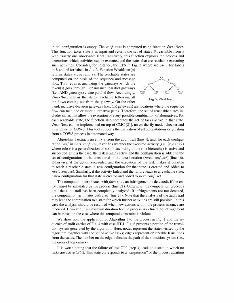
initial configuration is empty. The conf .next is computed using function WeakNext.This function takes state s as input and returns the set of states S reachable from swith exactly one observable label. Intuitively, this function explores the process anddetermines which activities can be executed and the states that are reachable executingsuch activities. Consider, for instance, the LTS in Fig. 5 where we use l for labels
s¬l
wwpppppp l
''NNNNNN
'&%$ !"#s0l
l
>>> '&%$ !"#s1¬l l
>>>
'&%$ !"#s2 '&%$ !"#s3 '&%$ !"#s4 '&%$ !"#s5
Fig. 5. WeakNext
in L and ¬l for labels in L \ L. Function WeakNext(s)returns states s1, s2, and s3. The reachable states arecomputed on the basis of the sequence and messageflow. This requires analyzing the gateways which thetoken(s) goes through. For instance, parallel gateways(i.e., AND gateways) create parallel flow. Accordingly,WeakNext returns the states reachable following allthe flows coming out from the gateway. On the otherhand, inclusive decision gateways (i.e., OR gateways) are locations where the sequenceflow can take one or more alternative paths. Therefore, the set of reachable states in-cludes states that allow the execution of every possible combination of alternatives. Foreach reachable state, the function also computes the set of tasks active in that state.WeakNext can be implemented on top of CMC [21], an on-the-fly model checker andinterpreter for COWS. This tool supports the derivation of all computations originatingfrom a COWS process in automated way.
Algorithm 1 extracts an entry e from the audit trail (line 4), and, for each configu-ration conf in next conf set , it verifies whether the executed activity (i.e., (r, e.task)where role r is a generalization of e.role according to the role hierarchy) is active andsucceeded. If it is the case, the task remains active and the configuration is added to theset of configurations to be considered in the next iteration (next conf set) (line 16).Otherwise, if the action succeeded and the execution of the task makes it possibleto reach a reachable state, a new configuration for that state is created and added tonext conf set . Similarly, if the activity failed and the failure leads to a reachable state,a new configuration for that state is created and added to next conf set .
The computation terminates with false (i.e., an infringement is detected), if the en-try cannot be simulated by the process (line 21). Otherwise, the computation proceedsuntil the audit trail has been completely analyzed. If infringements are not detected,the computation terminates with true (line 23). Note that the analysis of the audit trailmay lead the computation to a state for which further activities are still possible. In thiscase the analysis should be resumed when new actions within the process instance arerecorded. However, if a maximum duration for the process is defined, an infringementcan be raised in the case where this temporal constraint is violated.
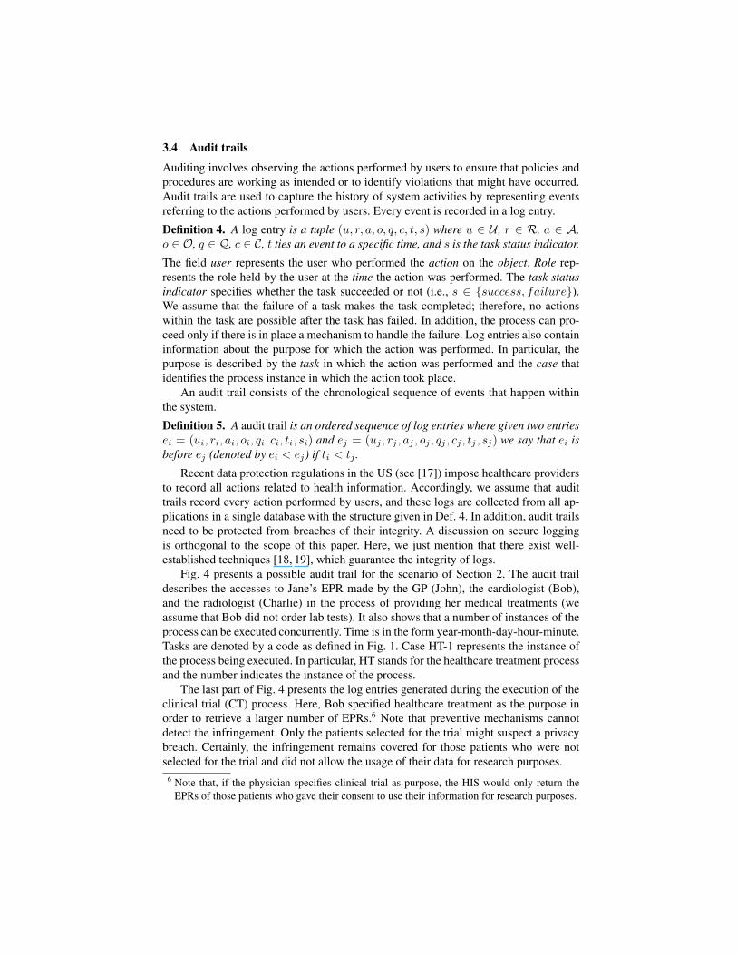
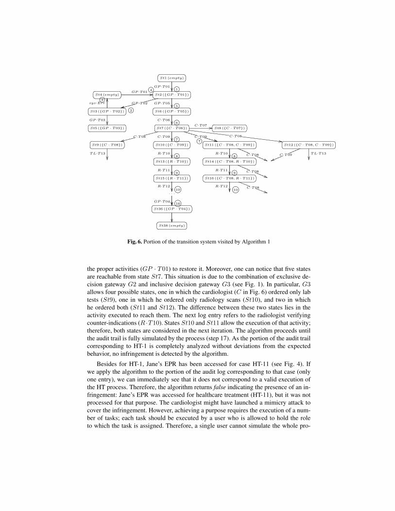
We show now the application of Algorithm 1 to the process in Fig. 1 and the se-quence of audit entries of Fig. 4 with case HT-1. Fig. 6 presents a portion of the transi-tion system generated by the algorithm. Here, nodes represent the states visited by thealgorithm together with the set of active tasks; edges represent observable transitionsfrom the states. The number on the edge indicates the path of the transition system (i.e.,the order of log entries).
It is worth noting that the failure of task T02 (step 3) leads to a state in which notasks are active (St4). This state corresponds to a “suspension” of the process awaiting
St1 (empty)
GP ·T01 1 St4 (empty)
GP ·T01 //4 St2 (GP · T01)
GP ·T02ggggg
ssggggg GP ·T052
ss 5 St3 (GP · T02)
sys·Err
OO
GP ·T03
3
St6 (GP · T05)
C·T06 6 St5 (GP · T03)
St7 (C · T06)C·T07 //
C·T08ggggg
ssggggg C·T09
C·T09VVVVV
**VVVVV C·T08[[[[[[[[[[[[[
--[[[[[[[[[[[[[7 7 **
St8 (C · T07)
St9 (C · T08)
TL·T13
St10 (C · T09)
R·T10 8
St11 (C · T08, C · T09)
R·T10 C·T08
RRRRR
((RRRRR8
St12 (C · T08, C · T09)
TL·T13
C·T09
mmmmm
vvmmmmm St13 (R · T10)
R·T11 9
St14 (C · T08, R · T10)
R·T11 C·T08
RRRRR
((RRRRR9 St15 (R · T11)
R·T12
'&%$ !"#10
St16 (C · T08, R · T11)
R·T12
'&%$ !"#10C·T08
SSSS
))SSSS. . .
GP ·T04 '&%$ !"#16 St36 (GP · T04)
St38 (empty)
Fig. 6. Portion of the transition system visited by Algorithm 1
the proper activities (GP · T01) to restore it. Moreover, one can notice that five statesare reachable from state St7. This situation is due to the combination of exclusive de-cision gateway G2 and inclusive decision gateway G3 (see Fig. 1). In particular, G3allows four possible states, one in which the cardiologist (C in Fig. 6) ordered only labtests (St9), one in which he ordered only radiology scans (St10), and two in whichhe ordered both (St11 and St12). The difference between these two states lies in theactivity executed to reach them. The next log entry refers to the radiologist verifyingcounter-indications (R ·T10). States St10 and St11 allow the execution of that activity;therefore, both states are considered in the next iteration. The algorithm proceeds untilthe audit trail is fully simulated by the process (step 17). As the portion of the audit trailcorresponding to HT-1 is completely analyzed without deviations from the expectedbehavior, no infringement is detected by the algorithm.
Besides for HT-1, Jane’s EPR has been accessed for case HT-11 (see Fig. 4). Ifwe apply the algorithm to the portion of the audit log corresponding to that case (onlyone entry), we can immediately see that it does not correspond to a valid execution ofthe HT process. Therefore, the algorithm returns false indicating the presence of an in-fringement: Jane’s EPR was accessed for healthcare treatment (HT-11), but it was notprocessed for that purpose. The cardiologist might have launched a mimicry attack tocover the infringement. However, achieving a purpose requires the execution of a num-ber of tasks; each task should be executed by a user who is allowed to hold the roleto which the task is assigned. Therefore, a single user cannot simulate the whole pro-
cess alone, but he has to collude with other users to make a mimicry attack successful.Moreover, if the cardiologist reuses a previous case as the reason for the request (i.e.,HT1 instead of HT11), the attack would succeed only in very restricted time windows:the unlawful access has to be in conjunction with a legitimate access, otherwise Al-gorithm 1 recognizes that the audit trace is not a valid execution of the process. Thisthreat can be partially mitigated by limiting multi-tasking, i.e. a user have to completean activity before starting a new activity.
5 Properties of the Algorithm
In the previous section, we have proposed an algorithm that can either confirm thatthe data were processed for the intended purpose or detect privacy infringements. Inthis section, we discuss the termination, soundness and completeness of the algorithm.Proofs are presented in Appendix B.
The critical part of Algorithm 1 is function WeakNext, because, given a COWSservice s, it has to generate and explore (part of) the possibly infinite transition systemLTS(s) associated to s; thereby, we have to guarantee the termination of WeakNext.We start by giving some basic definitions.
Given a LTSΩ = (s, S, L,−→), a trace is a possibly infinite sequence of S×L pairsσ ≡ (s, l0), (s0, l1) . . . (sn, ln+1) . . . describing a trajectory of the LTS, also denoted as
sl0−→s0
l1−→ . . . snln+1−−−→ . . .. The possibly infinite set of traces of Ω is Σ(Ω).
A formal definition of the set of states computed by function WeakNext follows.
Definition 7. Let s be a COWS service and L the set of observable labels for s. Then,WeakNext(s) = s′ | ∃k <∞.s l0−→ . . .
lk−→skl−→s′ ∧ ∀i ≤ k . li /∈ L ∧ l ∈ L.
Given a COWS service s, function WeakNext(s) is decidable w.r.t. the set of ob-servable labelsL if, for each trace from s, it is not possible to perform an infinite numberof transitions with label in L \ L. The following generalizes this concept.
Definition 8. Let Ω = (s, S, L,−→) be a LTS and M ⊆ L a set of labels. A traceσ ≡ (s, l0), (s0, l1) . . . (sn, ln+1) . . . in Σ(Ω) is finitely observable w.r.t M iff ∃n <∞ . ln ∈ M and ∀j > n . (lj ∈ M ⇒ ∃k < ∞ . lj+k ∈ M). The set of finitelyobservable traces of Ω is denoted as ΣFO(Ω). If Σ(Ω) = ΣFO(Ω), Ω is a finitelyobservable LTS w.r.t M .
A finitely observable transition system w.r.t. a set of labels M could express infinitebehaviors, but, within a finite time period it is possible to observe a label in M . This isthe idea underlying Algorithm 1. In particular, given a task active at a certain step of theexecution of the process, the algorithm determines what are the possible sets of activetasks in the next step. The definition of finitely observable transition system allows usto state a first important result.
Proposition 1. Given a COWS service s and the set of observable labels L for s, ifLTS(s) is finitely observable w.r.t. L, then WeakNext(s) is decidable on L.
Although COWS is expressive enough to represent BPMN processes, in order toguarantee the decidability of WeakNext we have to restrict our target to the set ofBPMN processes whose transition system is finitely observable w.r.t. the set of ob-servable labels. Hereafter, we say that a BPMN process p is well-founded w.r.t. a setof labels M if LTS(s) is finitely observable w.r.t. M , where s is the COWS encod-ing of p. Intuitively, a BPMN process p is well-founded if every cycle in p has at leastone activity which is observable. Given the definition of observable labels L in Sec-tion 3.5, a BPMN process is therefore well-founded if every sequence flow path endingin a cycle contains at least a task or an event handling errors. Restricting the analysis towell-founded processes does not impose a serious limitation in practice. It avoids thosedegenerate cases where the process could get stuck because no task or event handler isperformed but the process is not ended. An example is a BPMN process with a cycleformed only by gates. Note that non well-founded processes can be detected directly onthe diagram describing the process.
From the above considerations, we can state the following corollary.
Corollary 1. Let p be a well-founded BPMN process, s the COWS service encoding p,LTS(s) = (s, S, L,−→), and L ⊆ L the set of observable labels for s. Then, WeakNextterminates for all s′ ∈ S.
We now prove that Algorithm 1 terminates for every COWS service s encoding awell-founded BPMN process. If we consider an audit trail l of length k, Algorithm 1explores only a finite portion of the transition system of s to verify if an entry e of l isaccepted, because of Corollary 1. The idea is that, being k finite, Algorithm 1 exploresa finite portion of LTS(s), and therefore terminates.
Theorem 1. Let p be a well-founded BPMN process, s the COWS service encoding p,L the set of observable labels for s, and l an audit trail of length k. Then, Algorithm 1on (s, l) terminates.
The following result demonstrates the correctness of Algorithm 1.
Theorem 2. Let s be a COWS service encoding a well-founded BPMN process and lan audit trail. Algorithm 1 on (s, l) returns true iff there exists a trace σ ∈ Σ(LTS (s))such that σ accepts l.
The results presented in this section allow us to conclude that, within the boundariesdefined by a well-founded BPMN process, Algorithm 1 can always decide if a finiteaudit trail raises concerns about infringement of purpose specification.
6 Related Work
It is largely recognized that traditional access control is insufficient to cope with pri-vacy issues [1, 2, 22]. Karjoth et al. [23] identify the need of three additional elements(i.e., purpose, condition, and obligation), beside the basic authorization elements (i.e.,subject, object, and action). Based on this observation, a number of models, languagesand standards tailored to specify data protection policies have been proposed in thelast decade [2, 4, 5, 8, 24–26]. In this section, we discuss existing proposals based on

the concept of purpose. Works on obligations are complementary to our work as obli-gations are intended to address different data protection requirements (e.g., retentionperiod).
Existing purpose-based frameworks [2, 4, 5, 24] treat the intended purpose as a la-bel attached to data. Upon receiving an access request, they match the access purposeagainst the label attached to the requested data. However, they rely on the fact that therequester specifies the purpose legally, implying complete trust on the requester. Fewresearchers have addressed the problem of validating the access purpose. For instance,Byun and Li [4] specify the roles that can make a request for a given purpose. However,this approach is preventive and does not solve the problem of re-purposing the data. Incontrast, we propose to specify the operational behavior of purposes, which makes itpossible to analyze the actual usage of data with respect to purpose specifications.
To best of our knowledge, there is only another framework, the Chain method [27],that attempts to define an operational model for purposes. Here, a privacy policy speci-fies the “chains of acts” that users are allowed to perform where each act is some formof information handling (i.e., creating, collecting, processing, disclosing); purposes areimplicitly defined by the sequences of acts on personal information. Compared to ourapproach, this corresponds to specifying business processes in terms of actions, intro-ducing an undesirable complexity into process models. Conversely, our solution pro-vides a flexible way to align business processes, data protection policies and audit trailsand allows an organization to reuse its business process models for purpose control. Inaddition, the Chain method has a preventive nature and lacks capability to reconstructthe sequence of acts (when chains are executed concurrently).
Some approaches propose methods for a-posteriori policy compliance [28, 29]. Forinstance, Cederquist et al. [29] present a framework that allows users to justify theiractions. However, these frameworks can only deal with a limited range of access con-trol policies and do not consider the purpose. Agrawal et al. [30] propose an auditingframework to verify whether a database system is compliant with data protection poli-cies. However, their focus is mainly on minimizing the information to be disclosed andidentifying suspicious queries rather than verifying data usage.
Techniques for detecting system behaviors that do not conform to an expectedmodel have been proposed in process mining and intrusion detection. In intrusion detec-tion, logs of system calls are analyzed either to detect deviations from normal behavior(anomaly detection) [31] or to identify precise sequences of events that damage thesystem (misuse detection) [32]. Accordingly, our method can be seen as an anomalydetection technique. Process mining [33] and, in particular, conformance checking [13]have been proposed to quantify the “fit” between an audit trail and a business pro-cess model. These techniques, however, work with logs in which events only refer toactivities specified in the business process model. Consequently, they are not able toanalyze the compliance with fine-grained data protection policies. Moreover, they areoften based on Petri Nets. This formalism does not make it possible to capture the fullcomplexity of business process modeling languages such as BPMN. Existing solutionsbased on Petri Nets either impose some restrictions on the syntax of BPMN (e.g., avoid-ing cycles), or define a formal semantics that deviate from the informal one. Conversely,we have adopted COWS [10] for the representation of organizational processes. This
language has been proved to be suitable for representing a large set of BPMN constructsand analyzing business processes quantitatively [16].
7 Conclusions
Organizations often make use of business process models to define how organizationalgoals should be achieved. In this paper, we proposed to associate the purpose definedin data protection policies to such process models. This representation makes it pos-sible to verify the compliance of the actual data usage with purpose specifications bydetermining whether the audit trail represents a valid execution of the processes definedby the organization to achieve a certain purpose. We expect that the audit process istractable and scales to real applications. Intuitively, the complexity of the approach isbound to the complexity of Algorithm 1. Indeed, Algorithm 1 is independent from theparticular object under investigation so that it is not necessary to repeat the analysisof same process instance for different objects. In addition, the analysis of process in-stances is independent from each other, allowing for massive parallelization. A detailedcomplexity analysis of the algorithm is left for future work, but our first experimentsshow encouraging performances.
The work presented in this paper suggests some interesting directions for the futurework. The proposed approach alone may not be sufficient when we consider the hu-man component in organizational processes. Process specifications may contain humanactivities that cannot be logged by the IT system (e.g., a physician discussing patientdata over the phone for second opinion). These silent activities make it not possible todetermine if an audit trail corresponds to a valid execution of the organization process.Therefore, we need a method for analyzing user behavior and the purpose of data us-age when audit trails are partial. In addition, many application domains like healthcarerequire dealing with exceptions. For instance, a physician can take actions that divergefrom the procedures defined by a hospital to face emergency situations. On one side,preventing such actions may be critical for the life of patients. On the other side, check-ing every occurrence of emergency situations can be costly and time consuming. Tonarrow down the number of situations to be investigated, we are complementing thepresented mechanism with metrics for measuring the severity of privacy infringements.
References
1. P. Guarda and N. Zannone, “Towards the Development of Privacy-Aware Systems,” Infor-mation and Software Technology, vol. 51, no. 2, pp. 337–350, 2009.
2. R. Agrawal, J. Kiernan, R. Srikant, and Y. Xu, “Hippocratic Databases,” in Proceedings ofthe 28th International Conference on Very Large Data Bases. Morgan Kaufmann, 2002,pp. 143–154.
3. P. Ashley, S. Hada, G. Karjoth, and M. Schunter, “E-P3P privacy policies and privacy autho-rization,” in Proceedings of the 2002 ACM Workshop on Privacy in the Electronic Society.ACM, 2002, pp. 103–109.
4. J.-W. Byun and N. Li, “Purpose based access control for privacy protection in relationaldatabase systems,” VLDB J., vol. 17, no. 4, pp. 603–619, 2008.

5. F. Massacci, J. Mylopoulos, and N. Zannone, “Hierarchical Hippocratic Databases with Min-imal Disclosure for Virtual Organizations,” VLDB J., vol. 15, no. 4, pp. 370–387, 2006.
6. D. Catteddu and G. Hogben, “Cloud Computing – Benefits, risks and recommendations forinformation security,” European Network and Information Security Agency (ENISA), Re-port, 2009.
7. B. Daskala, “Being diabetic in 2011 – Identifying Emerging and Future Risks in RemoteHealth Monitoring and Treatment,” European Network and Information Security Agency(ENISA), Report, 2009.
8. G. Karjoth, M. Schunter, and M. Waidner, “Platform for Enterprise Privacy Practices:Privacy-enabled Management of Customer Data,” in Proceedings of the 2nd InternationalConference on Privacy Enhancing Technologies, ser. LNCS, vol. 2482. Springer, 2002, pp.69–84.
9. C. Lovis, S. Spahni, N. Cassoni, and A. Geissbuhler, “Comprehensive management of the ac-cess to the electronic patient record: Towards trans-institutional networks,” Int. J. of MedicalInformatics, vol. 76, no. 5-6, pp. 466–470, 2007.
10. A. Lapadula, R. Pugliese, and F. Tiezzi, “Calculus for Orchestration of Web Services,”in Proceedings of the 16th European Symposium on Programming, ser. LNCS, vol. 4421.Springer, 2007, pp. 33–47.
11. OASIS, “Web Services Business Process Execution Language – Version 2.0,” OASISStandard, 2007. [Online]. Available: http://docs.oasis-open.org/wsbpel/2.0/OS/wsbpel-v2.0-OS.html
12. Object Management Group, “Business Process Modeling Notation (BPMN) Specification(version 1.2),” OMG document, 2009. [Online]. Available: http://www.omg.org/spec/BPMN/1.2/
13. A. Rozinat and W. M. P. van der Aalst, “Conformance checking of processes based on mon-itoring real behavior,” Inf. Syst., vol. 33, no. 1, pp. 64–95, 2008.
14. “Enterprise Security and Privacy Authorization (XSPA) Profile of XACML v2.0 forHealthcare,” Committee Draft, 2008. [Online]. Available: http://xml.coverpages.org/xspa-xacml-profile-CD01-29664.pdf
15. G. Plotkin, “The origins of structural operational semantics,” J. Log. Algebr. Program,vol. 60, pp. 3–15, 2004.
16. D. Prandi, P. Quaglia, and N. Zannone, “Formal analysis of BPMN via a translation intoCOWS,” in Proceedings of the 10th International Conference on Coordination Models andLanguages, ser. LNCS, vol. 5052. Springer, 2008, pp. 249–263.
17. Office of the National Coordinator for Health Information Technology, “Electronic HealthRecords and Meaningful Use,” 2010. [Online]. Available: http://healthit.hhs.gov/portal/server.pt/community/healthit hhs gov meaningful use announcement/2996
18. D. Ma and G. Tsudik, “A new approach to secure logging,” ACM Trans. Storage, vol. 5,no. 1, pp. 1–21, 2009.
19. B. Schneier and J. Kelsey, “Secure audit logs to support computer forensics,” ACM Trans.Inf. Syst. Secur., vol. 2, no. 2, pp. 159–176, 1999.
20. L. Rostad and O. Edsberg, “A study of access control requirements for healthcare systemsbased on audit trails from access logs,” in Proceedings of the 22nd Annual Computer SecurityApplications Conference. IEEE Computer Society, 2006, pp. 175–186.
21. A. Fantechi, S. Gnesi, A. Lapadula, F. Mazzanti, R. Pugliese, and F. Tiezzi, “A model check-ing approach for verifying COWS specifications,” in Proceedings of the 11th InternationalConference on Fundamental Approaches to Software Engineering, ser. LNCS, vol. 4961.Springer, 2008, pp. 230–245.
22. Q. He and A. I. Anton, “A Framework for Modeling Privacy Requirements in Role Engi-neering,” in Proceedings of the 9th International Workshop on Requirements Engineering:Foundation for Software Quality, 2003, pp. 137–146.
23. G. Karjoth and M. Schunter, “A Privacy Policy Model for Enterprises,” in Proceedings of the15th IEEE Workshop on Computer Security Foundations. IEEE Computer Society, 2002,pp. 271–281.
24. M. Backes, G. Karjoth, W. Bagga, and M. Schunter, “Efficient comparison of enterprise pri-vacy policies,” in Proceedings of the 2004 ACM Symposium on Applied Computing. ACM,2004, pp. 375–382.
25. M. Hilty, D. A. Basin, and A. Pretschner, “On Obligations,” in Proceedings of the 10thEuropean Symposium on Research in Computer Security, ser. LNCS, vol. 3679. Springer,2005, pp. 98–117.
26. OASIS, “eXtensible Access Control Markup Language (XACML) Version 2.0,”OASIS Standard, 2005. [Online]. Available: http://docs.oasis-open.org/xacml/2.0/accesscontrol-xacml-2.0-core-spec-os.pdf
27. S. S. Al-Fedaghi, “Beyond purpose-based privacy access control,” in Proceedings of the 8thConference on Australasian Database. Australian Computer Society, Inc., 2007, pp. 23–32.
28. C. Fournet, N. Guts, and F. Z. Nardelli, “A formal implementation of value commitment,”in Proceedings of the 17th European Symposium on Programming, ser. LNCS, vol. 4960.Springer, 2008, pp. 383–397.
29. J. G. Cederquist, R. J. Corin, M. A. C. Dekker, S. Etalle, J. I. den Hartog, and G. Lenzini,“Audit-based compliance control,” Int. J. Inf. Sec., vol. 6, no. 2-3, pp. 133–151, 2007.
30. R. Agrawal, R. Bayardo, C. Faloutsos, J. Kiernan, R. Rantzau, and R. Srikant, “AuditingCompliance with a Hippocratic Database,” in Proceedings of the 30th International Confer-ence on Very Large Data Bases. VLDB Endowment, 2004, pp. 516–527.
31. H. H. Feng, O. M. Kolesnikov, P. Fogla, W. Lee, and W. Gong, “Anomaly detection using callstack information,” in Proceedings of the IEEE Symposium on Security and Privacy. IEEEComputer Society, 2003, pp. 62–75.
32. S. Kumar and E. H. Spafford, “A Pattern Matching Model for Misuse Intrusion Detection,”in Proceedings of the 17th National Computer Security Conference, 1994, pp. 11–21.
33. W. M. P. van der Aalst, T. Weijters, and L. Maruster, “Workflow Mining: Discovering ProcessModels from Event Logs,” IEEE Trans. Knowl. Data Eng., vol. 16, no. 9, pp. 1128–1142,2004.
A Encoding of BPMN in COWS
In this section we present some examples that provide the intuition underlying theCOWS semantics and the encoding of BPMN processes into COWS specification.
Consider the simple process in Fig. 7(a); it is composed by a start event S, a taskT , and an end event E within a pool P . The corresponding COWS service is Serv =[[S]] | [[T ]] | [[E]], where services [[S]], [[T ]], and [[E]] are defined in Fig. 7(b). Service[[S]] gives the control to task T in pool P , written as P ·T ! 〈〉. Service [[T ]] receives thecontrol (P · T? 〈〉) and then (represented as infix dot “. ”) gives the control to the endevent E within pool P (P ·E! 〈〉). Finally, [[E]] closes the flow receiving the control P ·E? 〈〉. The LTS associated with service Serv (Fig. 7(c)) gives a compact representationof the possible paths of tokens within the process of Fig. 7(a). In this simple case, onlya single path is possible.
An example involving a gateway is presented in Fig. 8(a). Here, when reaching theexclusive gateway G, the token can follow only one flow, either through T1 or throughT2. Fig. 8(b) shows the encoding of the process in COWS. Note that the encoding ofG, [[G]], makes use of kill(k): when an alternative is selected, a killer signal is sent

(a) BPMN Process
[[S]] := P · T ! 〈〉[[T ]] := P · T? 〈〉. P · E! 〈〉[[E]] := P · E? 〈〉
(b) COWS Serv
/.-,()*+St1P ·T // /.-,()*+St2
P ·E // /.-,()*+St3
(c) COWS LTS
Fig. 7. A Simple BPMN process in COWS
to prevent the other alternative to be executed. This is evident in Fig. 8(c) where stateSt6 is reached by running either T1 or T2, but there is no path where both T1 and T2are executed. We use the private name sys to avoid interference between services orbetween different executions of the same service.
(a) BPMN Process
[[S]] := P · T ! 〈〉[[T ]] := P · T? 〈〉. P ·G! 〈〉[[G]] := P ·G? 〈〉. [ k ][ sys ](
sys · T1! 〈〉 | sys · T2! 〈〉|sys · T1? 〈〉.(kill(k) ||P · T1! 〈〉|)|sys · T2? 〈〉.(kill(k) ||P · T2! 〈〉|))
[[T1]] := P · T1? 〈〉. P · E1! 〈〉[[E1]] := P · E1? 〈〉[[T2]] := P · T2? 〈〉. P · E2! 〈〉[[E2]] := P · E2? 〈〉
(b) COWS Serv
/.-,()*+St1
P ·T/.-,()*+St2
P ·G/.-,()*+St3sys·T1
~~ sys·T2
AAAA
/.-,()*+St4
P ·T1
/.-,()*+St7
P ·T2/.-,()*+St5
P ·E1 AAAA /.-,()*+St8
P ·E2~~/.-,()*+St6
(c) COWS LTS
Fig. 8. A BPMN Process with Exclusive Gateway
Tasks with an associated error event are another example of sequence flow. Theexample in Fig. 9(a) models a task T that can either proceed “correctly” to task T2 orincur an error Err managed by task T1. The encoding of the COWS services is reportedin Fig. 9(b). Note that the encoding of the BPMN elements S, T1, E1, T2, and E2 arethe same of the previous example (Fig. 8(b)). We only change the definition of [[T ]]:when T takes the token, it can either proceed normally invoking T2 (P ·T2! 〈〉) or aftersignaling an error (label “sys · Err”) proceed invoking T1 (P · T1! 〈〉). The LTS ofFig. 9(c) shows these two possible paths.
The three examples above give some hints about the representation of an organiza-tional process through COWS. To have a complete insight in the COWS services usedto model the process in Fig. 1 we have to discuss two further topics, namely messageflows and service replication.
Message flows are represented as communications over endpoints belonging to dif-ferent pools. An example is given in Fig. 10. Here, events S2 and S3 are message startevents, i.e. events that trigger the start of the process upon the receipt of a message, andE1 and E2 are message end events, i.e. events that send a message to a participant atthe conclusion of the process. When the end event E1 is triggered, it sends a message
(a) BPMN Process
[[S]] := P · T ! 〈〉[[T ]] := P ·G? 〈〉. [ k ][ sys ](
sys · Err! 〈〉 | sys · T2! 〈〉|sys · Err? 〈〉.(kill(k) ||P · T1! 〈〉|)|sys · T2? 〈〉.(kill(k) ||P · T2! 〈〉|))
[[T1]] := P · T1? 〈〉. P · E1! 〈〉[[E1]] := P · E1? 〈〉[[T2]] := P · T2? 〈〉. P · E2! 〈〉[[E2]] := P · E2? 〈〉
(b) COWS Serv
/.-,()*+St1
P ·T /.-,()*+St2
sys·T2 sys·Err
&&MMMMMM
/.-,()*+St3
P ·T2
/.-,()*+St6
P ·T1/.-,()*+St4
P ·E2
/.-,()*+St7
P ·E1xxqqqqqq
/.-,()*+St5
(c) COWS LTS
Fig. 9. A BPMN Process with Error Event
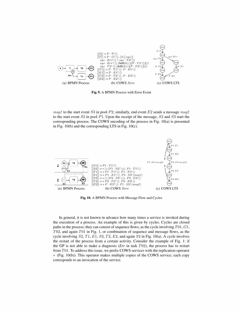
msg1 to the start event S3 in pool P2; similarly, end event E2 sends a message msg2to the start event S2 in pool P1. Upon the receipt of the message, S2 and S3 start thecorresponding process. The COWS encoding of the process in Fig. 10(a) is presentedin Fig. 10(b) and the corresponding LTS in Fig. 10(c).
(a) BPMN Process
[[S1]] := P1 · T1! 〈〉[[S2]] := ∗ [ z ]P1 · S2? 〈z〉. P1 · T1! 〈〉[[T1]] := ∗P1 · T1? 〈〉. P1 · E1! 〈〉[[E1]] := ∗P1 · E1? 〈〉. P2 · S3! 〈msg1〉[[S3]] := ∗ [ z ]P2 · S3? 〈z〉. P2 · T2! 〈〉[[T2]] := ∗P2 · T2? 〈〉. P2 · E2! 〈〉[[E2]] := ∗P · E2? 〈〉. P1 · S2! 〈msg2〉
(b) COWS Serv
/.-,()*+St1
P1·T1/.-,()*+St2
P1·E2/.-,()*+St3
P2·S3 (msg1)/.-,()*+St4
P2·T2/.-,()*+St5
P2·E2/.-,()*+St6
P1·S2 (msg2)
HH
(c) COWS LTS
Fig. 10. A BPMN Process with Message Flow and Cycles
In general, it is not known in advance how many times a service is invoked duringthe execution of a process. An example of this is given by cycles. Cycles are closedpaths in the process; they can consist of sequence flows, as the cycle involving T01,G1,T02, and again T01 in Fig. 1, or combination of sequence and message flows, as thecycle involving S2, T1, E1, S3, T2, E2, and again S2 in Fig. 10(a). A cycle involvesthe restart of the process from a certain activity. Consider the example of Fig. 1: ifthe GP is not able to make a diagnosis (Err in task T02), the process has to restartfrom T01. To address this issue, we prefix COWS services with the replication operator∗ (Fig. 10(b)). This operator makes multiple copies of the COWS service; each copycorresponds to an invocation of the service.
B Proofs
Proof of Proposition 1 If LTS(s) is finitely observable w.r.t. L, then for each trace
sl0−→s0
l1−→s1 . . . snln+1−−−→sn+1 . . .
there exists a value k < ∞ such that lk ∈ L, by Def. 8. This implies that the set ofstates that can be reached from s with exactly one label in L can be computed in a finitenumber of steps, namely WeakNext(s) is decidable on L.
Proof of Theorem 1 The proof is by induction on the length k of l = e1e2 . . . ek.
Base Step: Let l = e1. A BPMN process is always triggered by a start event [12].Therefore, the initial configuration has the form conf = (s, empty,WeakNext(s)).By definition LTS(s) is a finitely observable LTS. Therefore, each trace σ ≡(s, l0), (s0, l1) . . . (sn, ln) . . . in Σ(LTS(s)) is such that ∃j < ∞ . lj ∈ L. IfΣ(LTS(s)) is empty, WeakNext(s) returns an empty set. In this case, the algo-rithm does not enter into the forall of line 7 and the variable found remains false.Thereby, the algorithm exits at line 22 with false. If there exists (lj , s′, active tasks) ∈WeakNext(s) such that lj = r · e1.task with e1.role ≤R r, or lj = sys · Err ande1.status = failure, Algorithm 1 returns true at line 24. Otherwise, Algorithm 1returns false at line 22.
Inductive Step: Let l = e1 . . . ek with k > 1. By the inductive hypothesis, Algo-rithm 1 terminates on the audit trail l(k−1) = e1e2 . . . ek−1. Let conf set be theset of actual configurations. If conf set = ∅, the variable found remains false, andAlgorithm 1 returns false at line 22. If there exists a configuration conf ∈ conf setsuch that (r, ek.task) ∈ conf .active tasks with ek.role ≤R r and ek.status =success, the configuration is added to the set of configurations to be consideredin the next iteration (line 16). As l is completely analyzed and found is equal totrue (line 15), Algorithm 1 returns true at line 24. If there exists a configurationconf ∈ conf set such that (r · ek.task, s′, at) ∈ conf .next with ek.role ≤R ror (sys · Err, s′, at) ∈ conf .next and ek.status = failure, variable found be-comes true at line 11. Then, Algorithm 1 returns true at line 24. Otherwise, ifthe entry ek does not correspond either to any task in conf .active tasks or to anylabel in conf .next , Algorithm 1 returns false on line 22. Therefore, by induction,Algorithm 1 terminates for l.
Proof of Theorem 2 The correctness is essentially given in term of soundness (forwardsproof) and completeness (backwards proof). We show the implications separately. Weonly sketch the proof of the theorem, which requires a double induction on the lengthof l and on the structure of s.(=⇒) Let l = e1e2 . . . ek be of length k. Algorithm 1 on (s,l) returns true only ifthe while cycle of line 3 ends and line 24 is executed. By Theorem 1, we know that thealgorithm and, consequently, the cycle always terminates. Line 24 is executed only if foreach ei ∈ l either condition on line 8 is not verified (i.e., ei .task is active and ei .status

is not failure) or, by line 10, there exists a configuration conf ∈ conf set that acceptsei (i.e., (r · ei.task, s′, at) ∈ conf .next with ei.role ≤R r or (sys · Err, s′, at) ∈conf .next and ek.status = failure). This consideration makes it possible to provethat, at each iteration i ∈ [1, k] of the while cycle, Algorithm 1 computes the set oftraces of LTS(s) that accept the prefix e1 . . . ei. Therefore, if line 24 is executed, thereexists at least one trace σ in Σ(LTS(s)) that accepts l.(⇐=) To prove the completeness of Algorithm 1, we have to prove that if there is a tracefrom s that accepts l, then Algorithm 1 on (s, l) gives true. Below, we demonstrate thecontra-positive of the previous sentence, i.e. if Algorithm 1 on (s, l) returns false, thenthere is not a trace from s that accepts l. Given l = e1e2 . . . ek, Algorithm 1 on (s, l)returns false if there exists an iteration i ∈ [1, k] of the while cycle in line 3 such that thecondition on line 21 is true. This is possible if during iteration i both line 11 and line 15are not executed. The first condition is verified if, given a conf ∈ conf set such that eidoes not correspond to any task in conf .active tasks or it is a failure (i.e., condition online 8 is true), there is not a triple (lm , sm , at) ∈ conf .next that accepts ei (condition online 10 is false). In this case, by Proposition 1, there does not exist a finitely observabletrace (sj , lj+1) . . . (sm−1, lm) from the current state sj to sm such that ei correspondsto lm. Line 15 is executed only if ei corresponds to a task in conf .active tasks and itis not a failure (i.e., condition on line 8 is false). No execution of this line implies thatthere does not exist a conf ∈ conf set where e1 is active. This means that ei does notcorrespond to an active task in the current state sj . Suppose that at the i-th iterationof the while cycle, Algorithm 1 has already built all the traces accepting e1 . . . ei−1. IfAlgorithm 1 cannot replay ei in the process, we can conclude that there is not a trace inΣ(LTS(s)) accepting e1 . . . ei, and so l.