project of svbr-75/100 reactor plant with improved safety for
TRANSCRIPT
5th International Conference on Nuclear Option in Countries with Small and Medium Electricity GridsDubrovnik, Croatia, May 16-20, 2004.
PROJECT OF SVBR-75/100 REACTOR PLANT WITH IMPROVED SAFETY FOR NUCLER SOURCES
OF SMALL AND MEDIUM POWER
Yu.G.Dragunov, V.S.Stepanov, N.N.Klimov, A.V.Dedul, S.N.BolvanchikovFSUE OKB “Gidropress”
Russia, 142103, Podolsk, Moscow region, Ordzhonikidze, 21 E-mail: grpress@ grpress.podolsk.ru
A.V.Zrodnikov, G.I.Toshinsky, O.G.KomlevSNC RF-IPPE
Russia, 249020, Obninsk, Kaluga region, Bondarenko square, 1 E-mail: [email protected]
ABSTRACTAs a result of the joint work performed recently by FSUE OKB “Gidropress”, SNC RF-IPPE and other organizations the technical feasibility is shown for creation and usage in nuclear power engineering of the unified reactor plant (RP) SVBR-75/100 with fast neutron reactor core and lead-bismuth coolant (LBC) in the primary circuit.
Technical design of SVBR-75/100 reactor plant is based on the following:
- 50-year operation experience in development and operation of RP with LBC for nuclear submarines;
- experience in development and operation of fast reactor with sodium coolant;
- experience in optimization of LBC technology at nuclear submarines and ground-based test benches;
- conceptual design of SVBR-75 reactor plant (for renovation of Units 2, 3 and 4 of Novovoronezh NPP).
Technical solutions laid down in the basis of SVBR-75/100 reactor plant design are oriented towards the industrial basis, structural materials existing in Russia, as well as the unique LBC technology with experimental and practical support.
The concept of SVBR-75/100 reactor plant safety assurance is based on the following provisions:
- maximum usage of inherent safety supported by physical features of fast neutron reactor, chemically inert LBC in the primary circuit, integral layout and special design solutions;
- maximum possible combination of normal operation and safety functions in RP systems.
Small power of SVBR-75/100 RP makes it possible to manufacture the complete set of RP main equipment at the factory and delivery it to NPP site as-finished practically using any transport including railway.
Possible fields of application of SVBR-75/100 reactor plants:
- modular NPPs of different power;
- renovation of NPPs with light water reactors exhausted their service life;
- independent nuclear power sources for different applications (ground-based nuclear water-desalinating plants, etc.).
1
5th International Conference on Nuclear Option in Countries with Small and Medium Electricity GridsDubrovnik, Croatia, May 16-20, 2004.
1 INTRODUCTIONMany developing countries do not possess cheap resource of organic fuel and would like to use the nuclear power sources.At the same time in the modern market of nuclear technologies the NPP Units of large power are proposed that can not be used in the developing countries with small electricity grids.Besides, such NPPs require presence of well-developed infrastructure and high-skilled operating personnel, that is also not available in the developing countries.
When the type of NPP is chosen in these countries one shall take into account that many of them are situated in the regions with unstable policy and high probability of sabotage and acts of terrorism.
In selection of electric power of NPP Unit it is necessary to takes into account diversity in demands of potential customer in source power and, consequently, NPPs of different power shall be developed.
A number of requirements proceed from the above-mentioned conditions that shall be met by the reactor plants of NPPs:
• reactor plant shall be of small electric power within the range of 10... 100 MW-el. For development of NPP Units of different power to suit the most wide possible circle of potential customers the modular principle of NPP Unit construction shall be used with similar reactor plants operating to one or several turbine plants;
• reactor plant shall possess the inherent safety preventing deterministically a possibility of severe accidents requiring evacuation of population living outside NPP territory, under simultaneous multiple failures of equipment, superimposing of personnel errors or people’s ill-intentioned actions;
• as the fuel the uranium shall be used with enrichment below 20% in uranium-235 that corresponds to IAEA recommendations under non-proliferation;
• reactor plant shall be manufactured completely in the Country-Supplier and provide for a possibility of its safe transportation as-finished to the Country-Utility and back, with this, the reactor plant is a property of the Country-Supplier and will be let on lease to the Country-Utility for the term governed by the core fuel cycle;
• reactor plant core fuel cycle shall be at least 7.10 years;
The whole set of the mentioned requirements is met by the unified reactor plant of multi-purpose application SVBR-75/100 (Fast Lead-Bismuth Reactor with equivalent electric power of 75...100 MW-el depending on steam parameters) developed by FSUE OKB “Gidropress” and SNC RF-IPPE, named after A.I.Leipunsky, on the basis of the unique experience in development and operation of reactors with lead-bismuth coolant (LBC) for Russian submarines. Nowadays the SVBR-10 RP with equivalent electric power of 10 MW-el is under development.
The reports gives a brief presentation of the operation experience of reactors with LBC at nuclear submarines, as well as of the basic design provisions of SVBR-75/100 RP and inherent safety properties, layout, structure of SVBR-75/100 and its performance.
2 BRIEF DESCRIPTION OF EXPERIENCE IN USING LEAD-BISMUTH COOLANT
At the beginning of 50-ties the USA and USSR started development of RP for nuclear submarines almost simultaneously. In both countries the work was being carried out on two types of RP - with water-cooled water-moderated power reactors and with reactors using liquid metal coolants.
In the USA the sodium was chosen as the liquid metal coolant possessing the best thermophysical properties. The ground-based test bench - RP prototype - and pilot submarine “Sea Wolf” were constructed.
However operation experience showed that selection of the coolant being fire- and explosive in contact with air and water did not prove its value in practice. After a number of RP accidents at this nuclear submarine the RP was demounted together with the compartment and replaced with water-cooled water-moderated RP.
2
5th International Conference on Nuclear Option in Countries with Small and Medium Electricity GridsDubrovnik, Croatia, May 16-20, 2004.
Besides, the R&D were carried out in the USA on LBC mastering. But the way they chose for solution of the problem concerning corrosion resistance of structural materials did not result in positive results and these activities were stopped.
In the USSR the LBC - eutectic ally of lead and bismuth - was chosen as the liquid metal coolant. Eight nuclear submarines were constructed in the USSR in total with RP using LBC. The rest seven nuclear submarines of 705 design (“Alpha” as to NATO terminology) were one-reactor plant. Besides, two full-scale ground-based reactor test benches with LBC were constructed and operated in FEI (Obninsk) and NITI (Sosnovy Bor). The total operating life of RP with LBC was about 80 reactor-years. At the early stage they did not avoid some failures that are inevitable unfortunately in mastering any new technology as shown by the history of engineering.
This it referred, first of all, to lack of studying the LBC technology. To overcome the difficulties occurred the intensive long-term activities of many organizations in the country was required. As a result, the problem was solved successfully that is confirmed by long-term exe in the following operation of RP at nuclear submarines. Within the period of operation of RP with LBC of the second generation no problems occurred neither in corrosion of structural materials in the primary circuit, nor in deviations from the standards of the circuit cleanness.
Another LBC specific feature is formation of polonium-210 alpha-active radionuclide with half-life of -138 days under irradiation with bismuth neutrons. However the individual and collective protective means developed for the personnel, methods of equipment decontamination and recording of activity on surfaces, as well as procedures of repair-restoration work resulted in the situation when no cases of overexposure of the maintenance personnel with this radionuclide above the permissible levels were observed within the whole period of operation of RP with LBC, including the conditions of the primary circuit repair.
Among other problems the problem of multiple “freezing-unfreezing” of equipment with LBC was solved with keeping the serviceability of this equipment.
On the industrial scale the new nuclear power technology was demonstrated that has no analogs in the worldwide practice. Nowadays there favourable conditions for implementation of this technology in civil nuclear power engineering.
3 BASIC DESIGN PROVISIONS OF SVBR-75/100 RPAs to the scale factor the reactor plant SVBR-75/100 is close to reactor plants with LBC for nuclear submarines. This circumstance, as well as the desire to reduce considerably the technical and financial risks, reduce a probability of errors and failures, typical during implementation of innovation nuclear technologies, the desire to reduce considerably the scope, terms of fulfilment and expenses for R&D, resulted in the idea to use the conservative approach in development of design and layout-process solutions for SVBR-75/100 RP.
Main ideas of conservative approach in designing SVBR-75/100 RP:
• application of borrowed or scaled with small factors design and layout-process solutions approved by operation experience of RP of nuclear submarines and other RPs. This is referred to practically all RP components: fuel pellets, fuel rod clads, fuel assemblies, absorbing rods, internals, actuators of absorbing rods, devices of LBC technology, steam generator modules, separator, condenser of independent cooling, condenser of gas system, seismic resistant supporting structure of passive heat removal system tank wherein the reactor monoblock is installed, equipment of refuelling system;
• using the optimized primary and secondary mode parameters;
• orientation to the existing fuel infrastructure and manufacturing capabilities of machine building plants.However application of conservative approach does not mean full rejection of application of new technical solutions because it would lead to stagnation and slowing down the scientific and technological progress. Further on, in the course of evolutionary improvement of RP design after performance of the appropriate R&D the progressive technical solutions will be introduced into RP design with the aim of improving its technical-economic indices.
3
5th International Conference on Nuclear Option in Countries with Small and Medium Electricity GridsDubrovnik, Croatia, May 16-20, 2004.
Considering the above-mentioned the following basic design provisions are implemented in the design ofSVBR-75/100 RP:
• SVBR-75/100 RP is developed as the unified reactor plant with power from 75 to 100 MW (el.) depending on the parameters of steam generated for multi-purpose application in a set of modular nuclear power plants of as the independent power sources;
• the fast neutron reactor with chemically inert LBC (eutectic alloy of lead and bismuth) in the primary circuit is used. LBC boiling temperature is 16700C, LBC melting temperature is 123,50C;
• reactor integral layout is used with the core, primary equipment and steam generators arranged in a common solid vessel of the reactor monoblock without any valves and pipelines containing LBC;
• reactor monoblock with the safeguard housing is arranged in the tank of passive heat removal system (PHRS). The tank filled with water fulfils also the function of neutron protection;
• two-loop system of heat removal and steam generator with repeated natural circulation over the secondary side are used;
• in the reactor monoblock heat removal loops the natural circulation of coolants is provided sufficient for the reactor cooling down without hazardous core overheating;
• the number of special safety systems is reduced considerably, with this, safety functions are fulfilled by the systems of normal operation;
• main components of the reactor monoblock and reactor plant are made in the form of separate modules, with this, a possibility of their replacement and repair is provided;
• fuel withdrawal is provided by assemblies at a time on completion of the core cycle, as well as loading the fresh fuel in the form of a complete cartridge (new core);
• a possibility of using different kinds of fuel (UO2, MOX-fuel with warhead or reactor PU, mixed oxide fuel with junior actinides - TRUOX-fuel, nitride fuel) is provided without change in the reactor design and with meeting the safety requirements;
• mass and overall dimensions of the reactor monoblock are such that allow to manufacture it at the factory and deliver to NPP site or remove from NPP site using sea, car or railway transport.
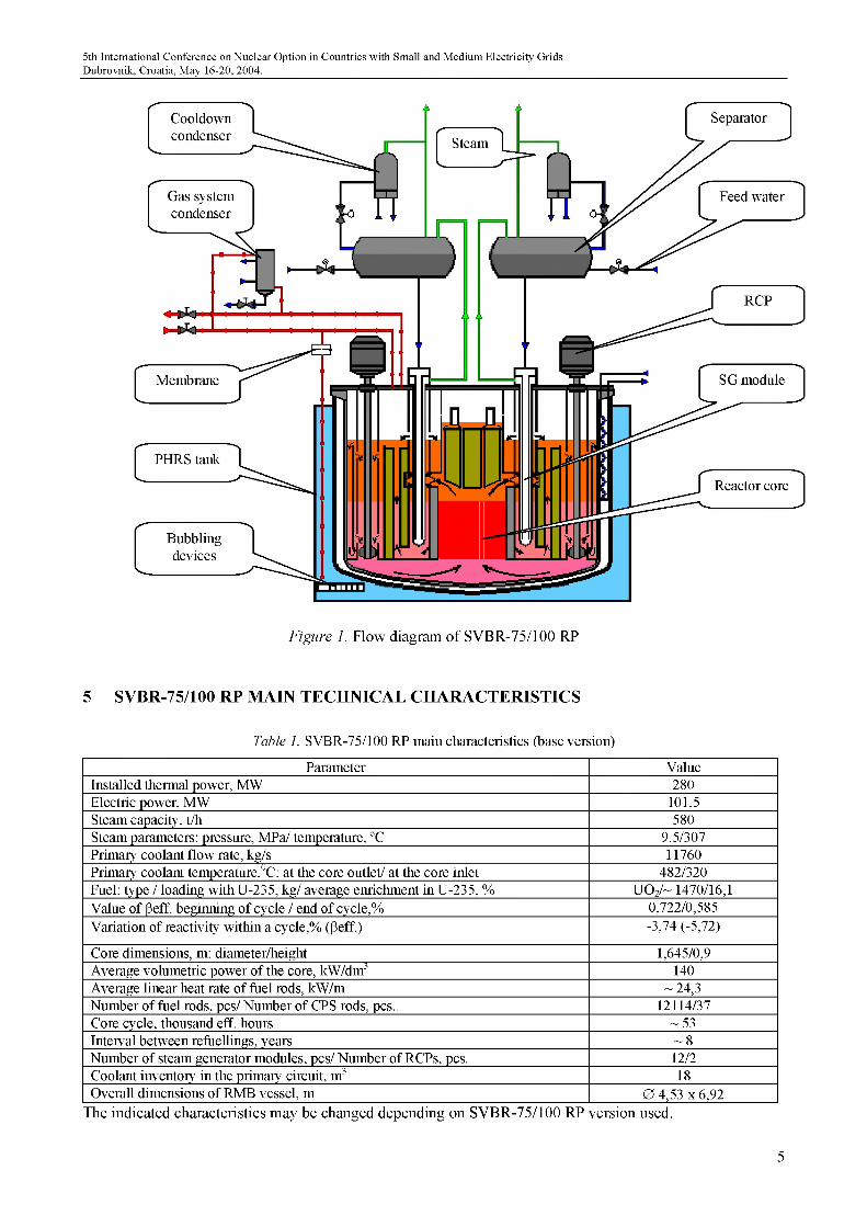
4 FLOW DIAGRAM OF SVBR-75/100 RPFigure 1 presents the flow diagram of SVBR-75/100 RP.
RP main components:
• reactor monoblock (RMB);
• equipment and pipelines of the primary circuit gas system, including the gas system condensers, safety rupture discs, bubbling devices in PHRS tank and pipelines with valves;
• secondary circuit equipment and pipelines including separators, condensers of RP cooling down without connection to turbine plant, water and steam lines;
• equipment and pipelines of passive heat removal system (PHRS) including the PHRS tank with supporting structures for installing the RMB, heat exchangers integrated into PHRS tank;
• fuel handling system equipment including a set of equipment (transition box with a gate, refuelling suits for withdrawal of protective plug and the core basket, refuelling container) for withdrawal of spent fuel assemblies (FA) into bottles filled with lead, and for installing the new core basket with fresh fuel.
For power Units constructed by modular principle it is sufficient to have one set of the mentioned equipmentirrespective of the number of SVBR-75/100 RP (in a set of power Unit).
4
5th International Conference on Nuclear Option in Countries with Small and Medium Electricity GridsDubrovnik, Croatia, May 16-20, 2004.
SeparatorCooldowncondenser Steam
Gas system condenser
Feed water
SG moduleMembrane
PHRS tank
Reactor core
Bubblingdevices
Figure 1. Flow diagram of SVBR-75/100 RP
5 SVBR-75/100 RP MAIN TECHNICAL CHARACTERISTICS
Table 1. SVBR-75/100 RP main characteristics (base version)
Parameter ValueInstalled thermal power, MW 280Electric power, MW 101,5Steam capacity, t/h 580Steam parameters: pressure, MPa/ temperature, °C 9.5/307Primary coolant flow rate, kg/s 11760Primary coolant temperature. "C: at the core outlet/ at the core inlet 482/320Fuel: type / loading with U-235, kg/ average enrichment in U-235, % U02/~ 1470/16,1Value of Peff. beginning of cycle / end of cycle.% 0,722/0,585Variation of reactivity within a cycle,% (Peff.) -3,74 (-5,72)
Core dimensions, m: diameter/height 1,645/0,9Average volumetric power of the core, kW/dm3 140Average linear heat rate of fuel rods, kW/m -24.3Number of fuel rods, pcs/ Number of CPS rods, pcs.. 12114/37Core cycle, thousand eff. hours -53Interval between refuellings, years ~ 8Number of steam generator modules, pcs/ Number of RCPs, pcs. 12/2Coolant inventory in the primary circuit, m3 18Overall dimensions of RMB vessel, m 0 4.53 x 6.92
The indicated characteristics may be changed depending on SVBR-75/100 RP version used.
5
5th International Conference on Nuclear Option in Countries with Small and Medium Electricity GridsDubrovnik, Croatia, May 16-20, 2004.
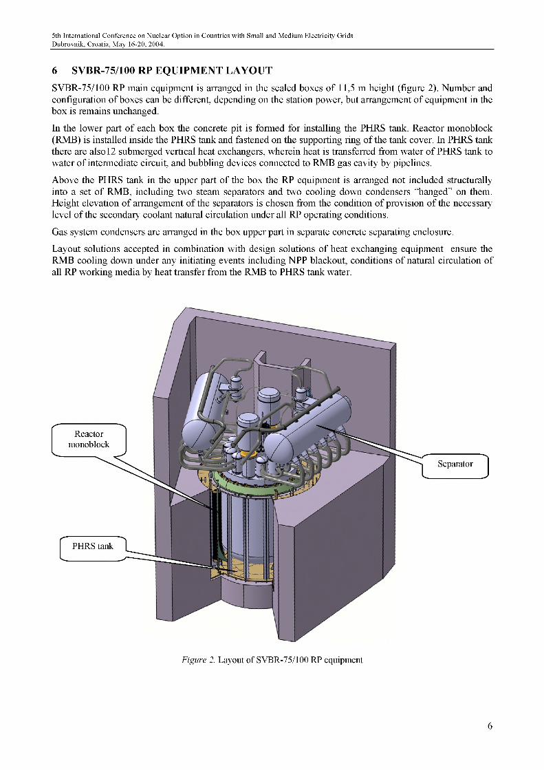
6 SVBR-75/100 RP EQUIPMENT LAYOUTSVBR-75/100 RP main equipment is arranged in the sealed boxes of 11,5 m height (figure 2). Number and configuration of boxes can be different, depending on the station power, but arrangement of equipment in the box is remains unchanged.
In the lower part of each box the concrete pit is formed for installing the PHRS tank. Reactor monoblock (RMB) is installed inside the PHRS tank and fastened on the supporting ring of the tank cover. In PHRS tank there are also 12 submerged vertical heat exchangers, wherein heat is transferred from water of PHRS tank to water of intermediate circuit, and bubbling devices connected to RMB gas cavity by pipelines.
Above the PHRS tank in the upper part of the box the RP equipment is arranged not included structurally into a set of RMB, including two steam separators and two cooling down condensers “hanged'’ on them. Height elevation of arrangement of the separators is chosen from the condition of provision of the necessary level of the secondary coolant natural circulation under all RP operating conditions.
Gas system condensers are arranged in the box upper part in separate concrete separating enclosure.
Layout solutions accepted in combination with design solutions of heat exchanging equipment ensure the RMB cooling down under any initiating events including NPP blackout, conditions of natural circulation of all RP working media by heat transfer from the RMB to PHRS tank water.
Figure 2. Layout of SVBR-75/100 RP equipment
6
5th International Conference on Nuclear Option in Countries with Small and Medium Electricity GridsDubrovnik, Croatia, May 16-20, 2004.
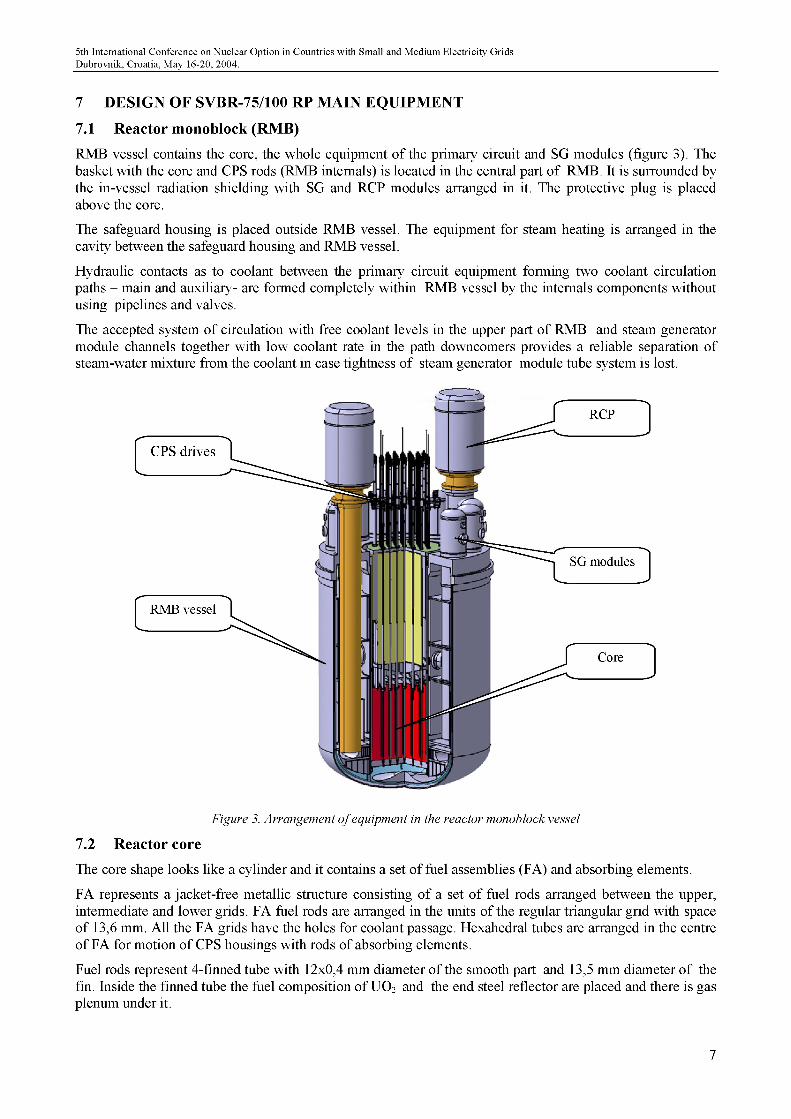
7 DESIGN OF SVBR-75/100 RP MAIN EQUIPMENT
7.1 Reactor monoblock (RMB)RMB vessel contains the core, the whole equipment of the primary circuit and SG modules (figure 3). The basket with the core and CPS rods (RMB internals) is located in the central part of RMB. It is surrounded by the in-vessel radiation shielding with SG and RCP modules arranged in it. The protective plug is placed above the core.
The safeguard housing is placed outside RMB vessel. The equipment for steam heating is arranged in the cavity between the safeguard housing and RMB vessel.
Hydraulic contacts as to coolant between the primary circuit equipment forming two coolant circulation paths - main and auxiliary- are formed completely within RMB vessel by the internals components without using pipelines and valves.
The accepted system of circulation with free coolant levels in the upper part of RMB and steam generator module channels together with low coolant rate in the path downcomers provides a reliable separation of steam-water mixture from the coolant in case tightness of steam generator module tube system is lost.
SG modules
Core
RMB vessel
CPS drives
Figure 3. Arrangement of equipment in the reactor monoblock vessel
7.2 Reactor coreThe core shape looks like a cylinder and it contains a set of fuel assemblies (FA) and absorbing elements.
FA represents a jacket-free metallic structure consisting of a set of fuel rods arranged between the upper, intermediate and lower grids. FA fuel rods are arranged in the units of the regular triangular grid with space of 13,6 mm. All the FA grids have the holes for coolant passage. Hexahedral tubes are arranged in the centre of FA for motion of CPS housings with rods of absorbing elements.
Fuel rods represent 4-finned tube with 12x0,4 mm diameter of the smooth part and 13,5 mm diameter of the fin. Inside the finned tube the fuel composition of U02 and the end steel reflector are placed and there is gas plenum under it.
7
5th International Conference on Nuclear Option in Countries with Small and Medium Electricity GridsDubrovnik, Croatia, May 16-20, 2004.
CPS rods are fastened by means of extension to CPS actuating mechanism extension shafts. When CPS actuating mechanisms are dismantled, CPS rods are kept in the lower position against lifting in LBC by a special weight increaser.
The developed structure of the core provides a possibility of applying different types of fuel. It is a good potential for improving reactor characteristics in the future.
7.3 Reactor coolant pumpReactor coolant pump represents a pump set consisting of axial submerged pump and uncontrolled sealed electric motor. Their shafts are connected by a slotted sleeve. The internal free cavities of the pump and electric motor are filled with inert gas.
7.4 Steam generator moduleSteam generator module represents a recuperative heat exchanger of submerged type. Steam generator module tubing, forming a heat transfer surface, was made in the form of 301 Fild channels. Each Fild channel consists of the external tube of 26x1,5 mm diameter with the bottom and coaxial central tube with diameter of 12x1,0 mm. Arrangement of channels in the tube bundle was made by a triangular grid with space of 30 mm. The working length of Fild channel equals to about 3,7 m.
8 SAFETY CONCEPTSafety concept of SVBR-75/100 RP is based on the following principles:
• selection of the reactor type, the primary coolant and design solutions permitting to use properties of inherent safety as much as possible;
• improvement of reliability and safety of the reactor plant at the expense of considerable reduction and simplification of safety systems and transfer of safety functions to normal operation systems.
8.1 Selection of the reactor type, the primary coolant and design solutionsSuch peculiarities of fast reactor as absence of poisoning effect, small value of negative temperature coefficient of reactivity, compensation of fuel burn-up processes by plutonium breeding permit to have an operative reactivity margin in the operating reactor less than a fraction of delayed neutrons, thus a possibility of prompt reactor runaway is excluded.Prevention of prompt reactor from runaway in case of unauthorized insertion of positive reactivity under postulated failure of all the actuating mechanisms of emergency protection is provided by special algorithm of control of compensating rods, which is put into the automatic control system, when during reactor operation at nominal power within the certain period of time (about four months) reactivity margin, which can be controlled by an operator, is considerably less than peff.. In this case the rest of the compensating rods are disconnected from the control system. Besides, worth of any rod is greatly lower than peff, and velocity of motion of absorbing rods withdrawn sequentially is limited technically. So, the inserted positive reactivity has time to be compensated by feedbacks without dangerous increase in core temperature.
It is necessary to mention that as calculations show the low (25...30%) values of LBC volume fraction in the core (fuel rods «tight» grid) and LBC specific mass don’t worsen safety characteristics of SVBR-75/100 RP both in case of RCP trip and interloop untightness of SG pipe system and under nonauthorized insertion of positive reactivity. The last event is connected with sufficient strong negative feedback being typical for small power reactor and small lag time of its component of coooant temperature at the core inlet (expansion of lower grid) in combination with sufficient thermal storage capacity of RMB.
Full void effect of reactivity of the reactor for the considered fuel cycles is negative and local positive void effect of reactivity of the core is less than peff and it can’t be realized because of a very high coolant boiling point and impossibility of appearing a large number of gas or steam bubbles.
A choice of LBC for the primary circuit of SVBR-75/100 RP is caused by nature properties of this coolant:
8
5th International Conference on Nuclear Option in Countries with Small and Medium Electricity GridsDubrovnik, Croatia, May 16-20, 2004.
• high boiling temperature and therefore, impossibility of LBC boiling improves reliability of heat transfer from the core and safety because of absence of heat removal crisis. Besides, there is no need to maintain high pressure in the primary circuit. This leads to the following: simplification of RP structure, improvement of its reliability, the primary circuit overpressurization as well as heat explosion of the reactor under emergency coolant overheat can’t practically occur. Besides, low pressure in the primary circuit decreases risk of loss of its sealing and permits to reduce thickness of RMB vessel walls and to reduce restrictions for the rate of temperature variation by the conditions of thermocycle strength;
• LBC interacts with water and air weakly. Accidents connected with loss of sealing of the primary circuit and SG inter-loop leaks take place without hydrogen release and any exothermic reactions. Besides, RP and reactor core have no materials releasing hydrogen as a result of thermal and radiation effect and chemical reactions with coolant. This prevents from occurring chemical explosions and fires because of internal causes;
Prevention of water and steam from getting into the core under large break in SG and the resulting possible overpressurization of RMB vessel, designed for maximum possible pressure in this case, is provided by LBC circulation system with which steam bubbles are thrown to its free level by the upward LBC flow, wherefrom steam enters the condensers of gas system and under their failure - through rupture disk into the bubbling devices of PHRS tank.
Prevention of the reactor core from damage under action of residual heat and keeping integrity of RMB vessel in case of failure of all RP cooldown systems and complete NPP loss of power is provided completely by passive way at the expense of heat removal through RMB vessel to PHRS tank water and heat accumulation by the in-pile structures and LBC. In this case the non-intervention period to be determined by the time of water evaporation from PHRS tank amounts to about five days.
Safety potential of SVBR-75/100 RP, as calculations showed, are characterised by the fact that even with combination of such postulated initiating events as damage of protective envelope, reinforced concrete ceiling above the reactor and loss of sealing of the primary circuit gas system with direct contact of LBC surface in the monoblock vessel with atmospheric air, complete NPP loss of power, neither reactor runway, nor explosion and fire take place, and radioactivity release into the environment doesn’t reach the values at which evacuation of population living outside NPP territory is required. Probability of severe damage of the reactor core is considerably lower than the value established by regulatory documentation.
8.2 Safety functions of SVBR -75/100 RP systems
8.2.1 Reactor emergency shutdown systemThe system consists of six emergency protection (EP) rods in dry channels. The rods are equipped with springs and electromagnet locks. The rods are inserted into the core in response to signals arrived from the control system or in case of loss of power, and also during emergency overheating due to gravitation forces owing to the fusible locks.
Besides, 13 reactivity compensating rods (RCR) are equipped with the springs and electromagnet locks (the so-called RCR group). These rods are inserted into the core by the control system signals or in case of loss of power, and also they are fitted with the weight increasing materials of tungsten or uranium to prevent their lifting in LBC. Such solution makes it possible to consider RCR system as the second system of emergency protection.
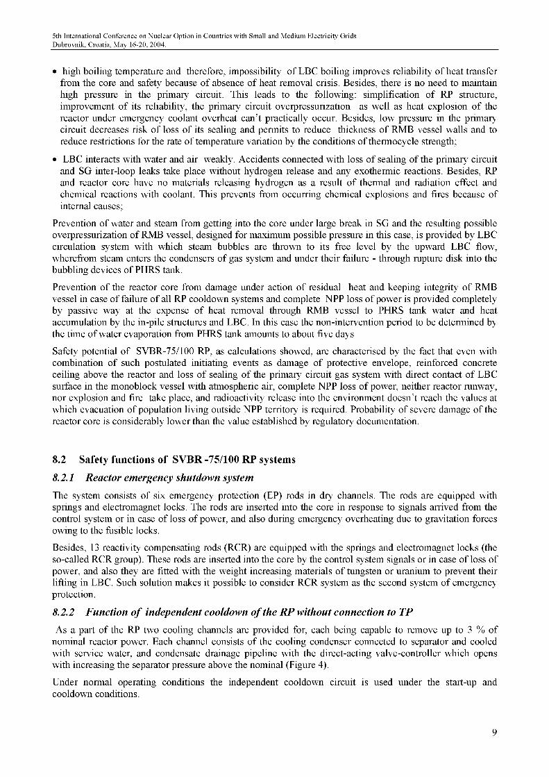
8.2.2 Function of independent cooldown of the RP without connection to TPAs a part of the RP two cooling channels are provided for, each being capable to remove up to 3 % of
nominal reactor power. Each channel consists of the cooling condenser connected to separator and cooled with service water, and condensate drainage pipeline with the direct-acting valve-controller which opens with increasing the separator pressure above the nominal (Figure 4).
Under normal operating conditions the independent cooldown circuit is used under the start-up and cooldown conditions.
9
5th International Conference on Nuclear Option in Countries with Small and Medium Electricity GridsDubrovnik, Croatia, May 16-20, 2004.
lipII II
Cooldown ^ condenser
Figure 4. Independent cooldown of the RP without connection to turbine
During the standby mode the condensers are flooded with water, and there are no heat losses practically. When the steam pressure increases, by some cause, up to a certain value, the valves open and condensate is drained into separator. It makes the heat exchange surface free and the steam condensation is started until the steam pressure decreases to the level set beforehand.
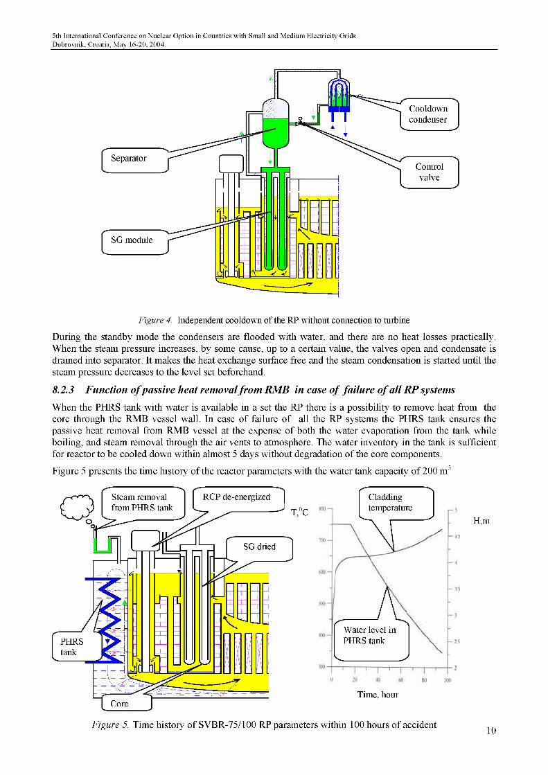
8.2.3 Function ofpassive heat removal from RMB in case of failure of all RP systemsWhen the PHRS tank with water is available in a set the RP there is a possibility to remove heat from the core through the RMB vessel wall. In case of failure of all the RP systems the PHRS tank ensures the passive heat removal from RMB vessel at the expense of both the water evaporation from the tank while boiling, and steam removal through the air vents to atmosphere. The water inventory in the tank is sufficient for reactor to be cooled down within almost 5 days without degradation of the core components.
Figure 5 presents the time history of the reactor parameters with the water tank capacity of 200 nr
Claddingtemperature
Water level in PHRS tank
Time, hour
RCP de-energizedSteam removal from PHRS tank
SG dried
PHRStank
H.m
Figure 5. Time history of SVBR-75/100 RP parameters within 100 hours of accident 10
5th International Conference on Nuclear Option in Countries with Small and Medium Electricity GridsDubrovnik, Croatia, May 16-20, 2004.
During RP operation under normal conditions not more than 0,2 % of nominal reactor power is removed through the PHRtank. In this case the tank fulfils the neutron protection functions.
The water tank allows for decay heat removal during the scheduled and repair work.
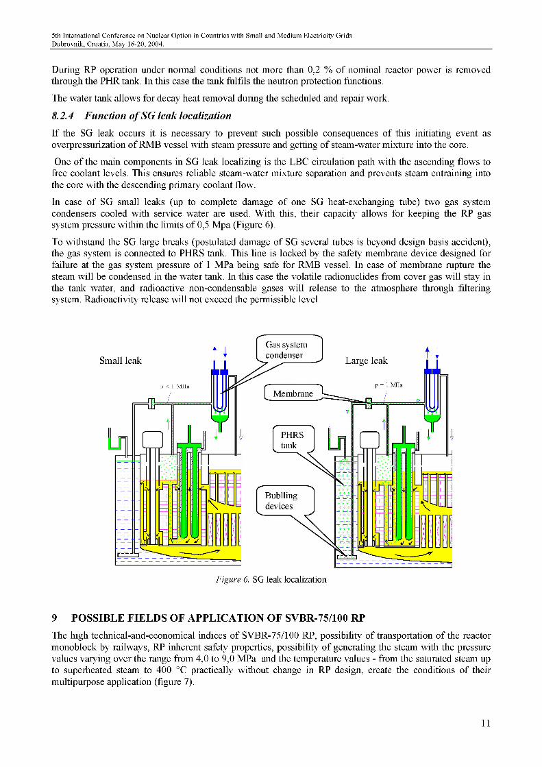
8.2.4 Function of SG leak localizationIf the SG leak occurs it is necessary to prevent such possible consequences of this initiating event as overpressurization of RMB vessel with steam pressure and getting of steam-water mixture into the core.
One of the main components in SG leak localizing is the LBC circulation path with the ascending flows to free coolant levels. This ensures reliable steam-water mixture separation and prevents steam entraining into the core with the descending primary coolant flow.
In case of SG small leaks (up to complete damage of one SG heat-exchanging tube) two gas system condensers cooled with service water are used. With this, their capacity allows for keeping the RP gas system pressure within the limits of 0,5 Mpa (Figure 6).
To withstand the SG large breaks (postulated damage of SG several tubes is beyond design basis accident), the gas system is connected to PHRS tank. This line is locked by the safety membrane device designed for failure at the gas system pressure of 1 MPa being safe for RMB vessel. In case of membrane rupture the steam will be condensed in the water tank. In this case the volatile radionuclides from cover gas will stay in the tank water, and radioactive non-condensable gases will release to the atmosphere through filtering system. Radioactivity release will not exceed the permissible level.
Gas system condenserSmall leak Large leak
p = 1 MTIap < 1 MilaMembrane
PHRStank
Bubllingdevices
Figure 6. SG leak localization
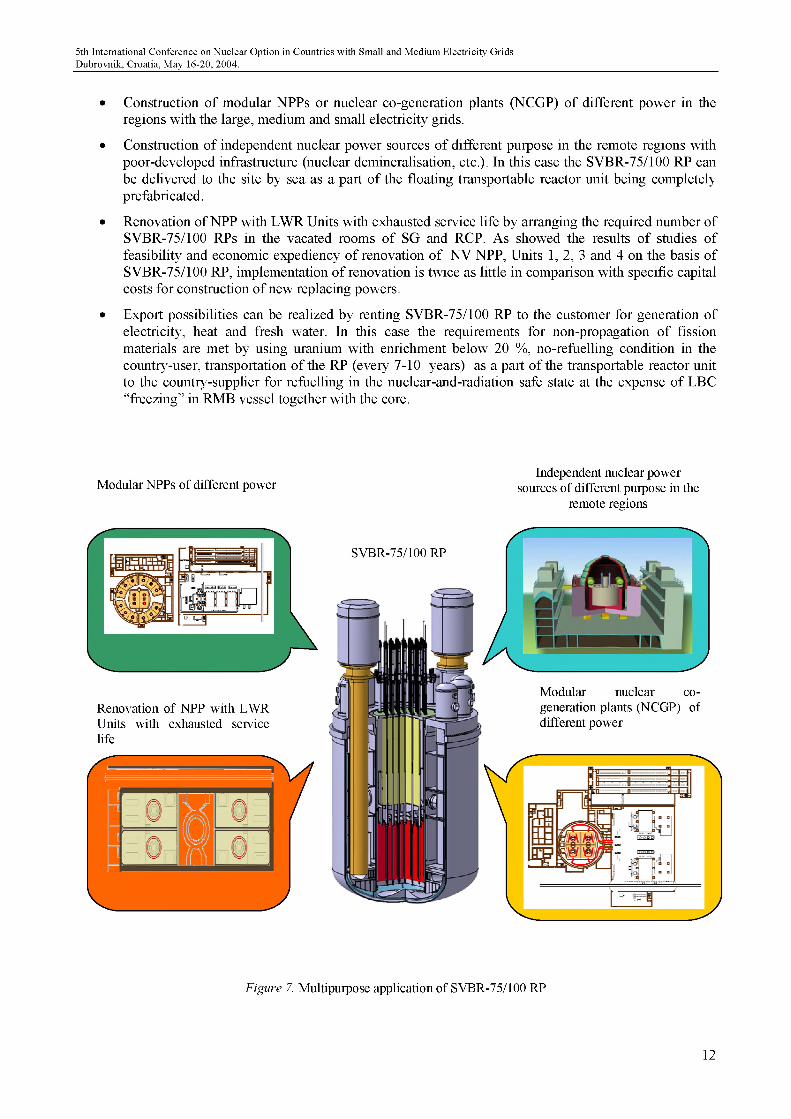
9 POSSIBLE FIELDS OF APPLICATION OF SVBR-75/100 RPThe high technical-and-economical indices of SVBR-75/100 RP, possibility of transportation of the reactor monoblock by railways, RP inherent safety properties, possibility of generating the steam with the pressure values varying over the range from 4,0 to 9,0 MPa and the temperature values - from the saturated steam up to superheated steam to 400 °C practically without change in RP design, create the conditions of their multipurpose application (figure 7).
11
5th International Conference on Nuclear Option in Countries with Small and Medium Electricity GridsDubrovnik, Croatia, May 16-20, 2004.
• Construction of modular NPPs or nuclear co-generation plants (NCGP) of different power in the regions with the large, medium and small electricity grids.
• Construction of independent nuclear power sources of different purpose in the remote regions with poor-developed infrastructure (nuclear demineralisation, etc ). In this case the SVBR-75/100 RP can be delivered to the site by sea as a part of the floating transportable reactor unit being completely prefabricated.
• Renovation of NPP with LWR Units with exhausted service life by arranging the required number of SVBR-75/100 RPs in the vacated rooms of SG and RCP. As showed the results of studies of feasibility and economic expediency of renovation of NV NPP, Units 1, 2, 3 and 4 on the basis of SVBR-75/100 RP, implementation of renovation is twice as little in comparison with specific capital costs for construction of new replacing powers.
• Export possibilities can be realized by renting SVBR-75/100 RP to the customer for generation of electricity, heat and fresh water. In this case the requirements for non-propagation of fission materials are met by using uranium with enrichment below 20 %, no-refuelling condition in the country-user, transportation of the RP (every 7-10 years) as a part of the transportable reactor unit to the country-supplier for refuelling in the nuclear-and-radiation safe state at the expense of LBC “freezing” in RMB vessel together with the core.
Independent nuclear powerModular NPPs of different power sources of different purpose in the
remote regions
Renovation of NPP with LWR Units with exhausted service life
Figure 7. Multipurpose application of SVBR-75/100 RP
12
5th International Conference on Nuclear Option in Countries with Small and Medium Electricity GridsDubrovnik, Croatia, May 16-20, 2004.
10 CONCLUSION
• The performed work shows that for solution of nuclear power engineering problems it is technically feasible and economically expedient to use the unified multipurpose SVBR-75/100 RP possessing the new quality of safety level (inherent safety) and meeting the up-to-date approaches to designing RPs of new generation.
• Technical solutions, laid down in the basis of SVBR-75/100 RP design are oriented towards industrial basis, structural materials existing in Russia, as well as the unique LBC technology experimentally and practically justified.
• Mass and overall dimensions of RP equipment, including RMB, allow to manufacture it at the factory and deliver to NPP site using any transport including railway.
• Modular structure of power Unit makes it possible to reduce the time of NPP construction and transfer in future to standard designing of Units with different power on the basis of commercial production of standard reactor modules possessing all properties of inherent safety that will provide for NPP competitiveness not only at the electricity market but also at the market of investments. Such power Units can be applicable not only in developed but also in developing countries.
• Reactor plant SVBR-75/100 can use different types of fuel and operate in different fuel cycles being the most economically reasonable for the given stage of nuclear power development. During operation in closed fuel cycle the SVBR-75/100 RP can operate in the mode of fuel self-sufficiency or with small breeding. As the makeup fuel, similar to DUPIC-technology, the spent nuclear fuel of thermal reactors (both of WWER, and RBMK) can be directly utilized.
REFERENCES1. Zrodnikov A.V., Chitaikin V.I., Toshinsky G.I., Grigoriev O.G., Dragunov Yu.G., Stepanov V.S., Klimov N.N., Malyshev A.B.,
Krushelnitsky V.N., Takh S.M. “NPP on the basis of SVBR-75/100 reactor modules” Atomnaya energia, vol. 91, issue 6, December 2001.
13