progress update on failure mechanisms of advanced thermal barrier coatings: a review
TRANSCRIPT

R
Pc
VD
a
ARR1A
KTIMTCC
C
h0
Progress in Organic Coatings 90 (2016) 54–82
Contents lists available at ScienceDirect
Progress in Organic Coatings
j o ur nal ho me pag e: www.elsev ier .com/ locate /porgcoat
eview
rogress update on failure mechanisms of advanced thermal barrieroatings: A review
ijay Kumar, K. Balasubramanian ∗
epartment of Materials Engineering, Defence Institute of Advanced Technology, Girinagar, Pune 411025, India
r t i c l e i n f o
rticle history:eceived 25 March 2015eceived in revised form4 September 2015ccepted 21 September 2015
eywords:BC
a b s t r a c t
Thermal barrier coatings (TBCs) have proved to be a key technology in thermal stability and their use toachieve surface temperature reduction of the underlying super alloys surpass all other achievements inthe field of material technologies that have taken place in last three decades. The technological advancesin TBCs also make them suitable for wider engineering and defense applications. The performance of thesemulti-layered and multi-material systems, tailored for high temperature applications is closely linkedto their microstructure evolution. The article presents a comprehensive review of various degradationmechanisms to which the TBC system is subjected during service life viz. hot corrosion, CMAS attack,
nterfacial delaminationicrostructure
hermal conductivityorrosionMAS
oxidation, erosion, foreign object damage, sintering and phase transformations. Strategies to mitigatethe adverse impact of the degradation mechanisms and the recent advances toward reduction in thethermal conductivity of TBCs have also been discussed. The emphasis of this review is on the relationshipbetween the properties and the microstructure of TBCs for better understanding of their life limitingmechanisms to assist developments in advanced and novel TBCs for engineering applications.
© 2015 Elsevier B.V. All rights reserved.
ontents
1. Introduction . . . . . . . . . . . . . . . . . . . . . . . . . . . . . . . . . . . . . . . . . . . . . . . . . . . . . . . . . . . . . . . . . . . . . . . . . . . . . . . . . . . . . . . . . . . . . . . . . . . . . . . . . . . . . . . . . . . . . . . . . . . . . . . . . . . . . . . . . . . . . 551.1. Scope of review. . . . . . . . . . . . . . . . . . . . . . . . . . . . . . . . . . . . . . . . . . . . . . . . . . . . . . . . . . . . . . . . . . . . . . . . . . . . . . . . . . . . . . . . . . . . . . . . . . . . . . . . . . . . . . . . . . . . . . . . . . . . . . . . . .55
2. Sintering effects and residual stresses . . . . . . . . . . . . . . . . . . . . . . . . . . . . . . . . . . . . . . . . . . . . . . . . . . . . . . . . . . . . . . . . . . . . . . . . . . . . . . . . . . . . . . . . . . . . . . . . . . . . . . . . . . . . . . . . . . 552.1. Sintering effects on coating properties and microstructure . . . . . . . . . . . . . . . . . . . . . . . . . . . . . . . . . . . . . . . . . . . . . . . . . . . . . . . . . . . . . . . . . . . . . . . . . . . . . . . . . . . . 552.2. Nanostructured coatings to counter sintering . . . . . . . . . . . . . . . . . . . . . . . . . . . . . . . . . . . . . . . . . . . . . . . . . . . . . . . . . . . . . . . . . . . . . . . . . . . . . . . . . . . . . . . . . . . . . . . . . . 562.3. Effect of residual stresses on mechanical properties and lifetime . . . . . . . . . . . . . . . . . . . . . . . . . . . . . . . . . . . . . . . . . . . . . . . . . . . . . . . . . . . . . . . . . . . . . . . . . . . . . 57
3. Oxidation behavior. . . . . . . . . . . . . . . . . . . . . . . . . . . . . . . . . . . . . . . . . . . . . . . . . . . . . . . . . . . . . . . . . . . . . . . . . . . . . . . . . . . . . . . . . . . . . . . . . . . . . . . . . . . . . . . . . . . . . . . . . . . . . . . . . . . . . .583.1. High temperature oxidation behavior . . . . . . . . . . . . . . . . . . . . . . . . . . . . . . . . . . . . . . . . . . . . . . . . . . . . . . . . . . . . . . . . . . . . . . . . . . . . . . . . . . . . . . . . . . . . . . . . . . . . . . . . . . 583.2. Influence of water vapor on oxidation behavior . . . . . . . . . . . . . . . . . . . . . . . . . . . . . . . . . . . . . . . . . . . . . . . . . . . . . . . . . . . . . . . . . . . . . . . . . . . . . . . . . . . . . . . . . . . . . . . . 583.3. Graphene protective coatings to counter oxidation . . . . . . . . . . . . . . . . . . . . . . . . . . . . . . . . . . . . . . . . . . . . . . . . . . . . . . . . . . . . . . . . . . . . . . . . . . . . . . . . . . . . . . . . . . . . 60
4. Hot corrosion. . . . . . . . . . . . . . . . . . . . . . . . . . . . . . . . . . . . . . . . . . . . . . . . . . . . . . . . . . . . . . . . . . . . . . . . . . . . . . . . . . . . . . . . . . . . . . . . . . . . . . . . . . . . . . . . . . . . . . . . . . . . . . . . . . . . . . . . . . . .614.1. YSZ-Al2O3 coatings . . . . . . . . . . . . . . . . . . . . . . . . . . . . . . . . . . . . . . . . . . . . . . . . . . . . . . . . . . . . . . . . . . . . . . . . . . . . . . . . . . . . . . . . . . . . . . . . . . . . . . . . . . . . . . . . . . . . . . . . . . . . . . 624.2. LTA and lanthanum zirconate coating . . . . . . . . . . . . . . . . . . . . . . . . . . . . . . . . . . . . . . . . . . . . . . . . . . . . . . . . . . . . . . . . . . . . . . . . . . . . . . . . . . . . . . . . . . . . . . . . . . . . . . . . . . 624.3. Evaluation of hot corrosion behavior . . . . . . . . . . . . . . . . . . . . . . . . . . . . . . . . . . . . . . . . . . . . . . . . . . . . . . . . . . . . . . . . . . . . . . . . . . . . . . . . . . . . . . . . . . . . . . . . . . . . . . . . . . . 64
5. CMAS attack, erosion, impact damage and countermeasures. . . . . . . . . . . . . . . . . . . . . . . . . . . . . . . . . . . . . . . . . . . . . . . . . . . . . . . . . . . . . . . . . . . . . . . . . . . . . . . . . . . . . . . . . .645.1. CMAS resistant coatings . . . . . . . . . . . . . . . . . . . . . . . . . . . . . . . . . . . . . . . . . . . . . . . . . . . . . . . . . . . . . . . . . . . . . . . . . . . . . . . . . . . . . . . . . . . . . . . . . . . . . . . . . . . . . . . . . . . . . . . . . 645.2. Coating composition effects on CMAS resistance . . . . . . . . . . . . . . . . . . . . . . . . . . . . . . . . . . . . . . . . . . . . . . . . . . . . . . . . . . . . . . . . . . . . . . . . . . . . . . . . . . . . . . . . . . . . . . . 665.3. Coating degradation by CMAS deposits . . . . . . . . . . . . . . . . . . . . . . . . . . . . . . . . . . . . . . . . . . . . . . . . . . . . . . . . . . . . . . . . . . . . . . . . . . . . . . . . . . . . . . . . . . . . . . . . . . . . . . . . . 67
5.4. Evaluation of coatings with CMAS deposit infiltration . . . . . . . . . . . . .5.5. Foreign object damage and surface erosion . . . . . . . . . . . . . . . . . . . . . . . .5.6. Modulated TBC structures and ablative coatings . . . . . . . . . . . . . . . . . .∗ Corresponding author.E-mail address: [email protected] (K. Balasubramanian).
ttp://dx.doi.org/10.1016/j.porgcoat.2015.09.019300-9440/© 2015 Elsevier B.V. All rights reserved.
. . . . . . . . . . . . . . . . . . . . . . . . . . . . . . . . . . . . . . . . . . . . . . . . . . . . . . . . . . . . . . . . . . . . . . . . . . . . 67 . . . . . . . . . . . . . . . . . . . . . . . . . . . . . . . . . . . . . . . . . . . . . . . . . . . . . . . . . . . . . . . . . . . . . . . . . . . . 68. . . . . . . . . . . . . . . . . . . . . . . . . . . . . . . . . . . . . . . . . . . . . . . . . . . . . . . . . . . . . . . . . . . . . . . . . . . . . 68

V. Kumar, K. Balasubramanian / Progress in Organic Coatings 90 (2016) 54–82 55
6. Interfacial degradation and failure mechanism . . . . . . . . . . . . . . . . . . . . . . . . . . . . . . . . . . . . . . . . . . . . . . . . . . . . . . . . . . . . . . . . . . . . . . . . . . . . . . . . . . . . . . . . . . . . . . . . . . . . . . . . 696.1. Bond coat and interfacial delamination . . . . . . . . . . . . . . . . . . . . . . . . . . . . . . . . . . . . . . . . . . . . . . . . . . . . . . . . . . . . . . . . . . . . . . . . . . . . . . . . . . . . . . . . . . . . . . . . . . . . . . . . . 696.2. Thermo-mechanical fatigue (TMF) behavior and failure modes in APS coatings . . . . . . . . . . . . . . . . . . . . . . . . . . . . . . . . . . . . . . . . . . . . . . . . . . . . . . . . . . . . . . 706.3. Thermal cycling and failure mechanism in EB-PVD coatings . . . . . . . . . . . . . . . . . . . . . . . . . . . . . . . . . . . . . . . . . . . . . . . . . . . . . . . . . . . . . . . . . . . . . . . . . . . . . . . . . . .726.4. Life time model: APS coatings. . . . . . . . . . . . . . . . . . . . . . . . . . . . . . . . . . . . . . . . . . . . . . . . . . . . . . . . . . . . . . . . . . . . . . . . . . . . . . . . . . . . . . . . . . . . . . . . . . . . . . . . . . . . . . . . . . .726.5. Interfacial damage based life model: EB-PVD coatings . . . . . . . . . . . . . . . . . . . . . . . . . . . . . . . . . . . . . . . . . . . . . . . . . . . . . . . . . . . . . . . . . . . . . . . . . . . . . . . . . . . . . . . . . 74
7. Challenges and future directions . . . . . . . . . . . . . . . . . . . . . . . . . . . . . . . . . . . . . . . . . . . . . . . . . . . . . . . . . . . . . . . . . . . . . . . . . . . . . . . . . . . . . . . . . . . . . . . . . . . . . . . . . . . . . . . . . . . . . . . 76 . . . . . .
1
mgoclacbezrr
esuosdlhtmoisngic
balmtauoibaioao
1
lt
References . . . . . . . . . . . . . . . . . . . . . . . . . . . . . . . . . . . . . . . . . . . . . . . . . . . . . . . . . . . .
. Introduction
Thermal barrier coatings (TBCs) are multi-layered and multi-aterial coating system, used to lend thermal protection from hot
ases in turbines and engines, hence lower the surface temperaturef the substrate components [1,2]. The conventional TBC systemonsists of three layers over the super alloy substrate; the metal-ic bond coat (BC), the intermediate thermally grown oxide (TGO)nd the ceramic top coat (TP). All these layers have distinct physi-al, mechanical and thermal properties, which are strongly affectedy the processing conditions [3]. TBCs are being used on turbinengine components such as combustors, turbine blades and noz-les to achieve higher operating temperatures which consequentlyesult into improved efficiency, increase in thrust to weight ratio,educed emissions and reduction in air cooling needs.
TBCs have proven to be a crucial technology in thermalndurance and their use along with the internal air cooling for theuper alloy substrates can provide surface temperature reductionp to 300 ◦C [4]. These temperature benefits using TBCs surpass allther achievements in the field of material technologies, includingingle crystal Ni base super alloys that have taken place in last threeecades. Over the years, the TBCs have evolved from just insulating
ayers to complex designs. A number of factors such as heat flux,eat transfer coefficients, backside cooling, part geometry and loca-ion, coating thickness and its thermal conductivity, determine the
agnitude of temperature reduction of the substrate. The continu-us efforts to improve the efficiency of a gas turbine, have resultednto the operating temperatures to above 1300 ◦C, which neces-itate thicker TBCs with its chemistry modification, along with aew cooling system [5–7]. The thickness of the top coat has pro-ressively increased (in the range 600–2000 �m). With the increasen top ceramic coat thickness, the surface temperature of the TBCooled components reduces at a rate of 4–9 ◦C per 25 �m [8–14].
Higher thermal efficiency is achieved in advanced diesel enginesy insulating combustion system components. In SI engines, TBCsre typically deposited at the piston top surface near the crevice toower knocking. TBCs are also used in the braking systems of auto-
obiles to insulate the hydraulic components from heat. Though,he TBCs are typically applied to the metallic substrates, they canlso be coated on composites, which has further stepped up theirse for diverse defense applications. The extensive research workn TBCs undertaken for aerospace and defense applications alsonclude the design of the rocket nozzles, nosecones, wings and sta-ilizers of hypersonic missiles. TBCs are also capable of playing
decisive role in enhancing the technological superiority of mil-tary tanks. They enable improvements in the cooling effectivenessf the components, which result in increased specific power andllow combustion at higher operating conditions, without the usef conventional cooling system in the turbine engine of a tank.
.1. Scope of review
The article is aimed to review and summarize the techno-ogical advances on the vital aspects of TBCs, with emphasis onhe relationship between their properties and the microstructure.
. . . . . . . . . . . . . . . . . . . . . . . . . . . . . . . . . . . . . . . . . . . . . . . . . . . . . . . . . . . . . . . . . . . . . . . . . . . . 77
The research work in this field is directed to improve the TBCatomic level properties to extend their survival under the hos-tile high temperature environment, to make them suitable forwider engineering applications. Various degradation mechanismsto which the TBC system is subjected during service life, in agas turbine have been reviewed. The fallout of sintering withrespect to the coating microstructure as well its properties athigher temperatures and the efficacy of nano-structured coatings tocounter sintering has been discussed. Another degradation mech-anism of TBCs is chemical attack such as oxidation, for whichthe selection of bond coat material plays a vital role. Oxidationbehavior in the absence and presence of moisture and also theuse of ultra-thin graphene protective coatings to counter oxida-tion has been discussed. Hot corrosion degradation mechanism andvarious approaches to enhance hot corrosion resistance of TBC sys-tem have been presented. Calcium–magnesium–alumina–silicate(CMAS) attack, wherein at temperatures greater than 1200 ◦C, themolten CMAS glass infiltrates into the porous TBC surface, is amajor challenge to the material scientists. CMAS attack mechanicsand the uses of alternative compositions to mitigate the damagesare discussed. Evaluation of coatings with CMAS deposits infiltra-tion and damage by impact and erosion have also been discussed.These degradation issues are examined independently in most ofthe research works, whereas during service life of TBCs, a numberof degradation mechanisms occur simultaneously. The use of mod-ulated TBC structures and ablative coatings for high temperatureapplications has been commented upon.
Failure modes of TBCs such as multiple surface cracking andinterfacial delamination are discussed. Thermo-mechanical fatigue(TMF) methods for evaluation of service lifetime of TBC system,failure mechanism and lifetime modules of TBCs have also beendiscussed. Finally, the present challenges and the future researchtrends in this field are presented.
2. Sintering effects and residual stresses
2.1. Sintering effects on coating properties and microstructure
At high temperatures (>1000–1200 ◦C), additional mechanismssuch as sintering and phase transformation, contribute to TBC fail-ure. When deposited, the TBCs are porous. However, during theirservice life at higher temperatures, TBCs are subjected to sintering,thereby leading to densification and a rise in thermal conductivity[15]. At higher temperatures, sintering causes additional stressesin the coating due to mismatch of sintering rate and thermalexpansion coefficient for the coating and the super alloy substrate.Appreciable microstructural changes accompany sintering, leadingto changes in the coating properties [16–18]. Sintering of EB-PVDcoatings occur in a manner similar to Rayleigh instability prob-lem. However, the distance between the necks is shorter than the
expected from Rayleigh theory [19]. The sintering of free standingZrO2 plasma sprayed coating has been characterized by measuringthe shrinkage [20,21] and variations in the microstructural depend-ent properties like elastic modulus and bend strength [22].
5 ress in Organic Coatings 90 (2016) 54–82
tTiTsrard[
cwcpaa(ibZrlco
C[attpc
2
scTpptstsrpi1r2c
ivtrsobtdlr
Fig. 1. Higher magnification view of the nanostructured YSZ coating, heat treatedat 1400 ◦C for 20 h [38].
Fig. 2. Graph showing the variation of the thermal diffusivity from as-sprayed to
6 V. Kumar, K. Balasubramanian / Prog
Creep deformation as well as the shrinkage of the coating dueo sintering mark the high temperature deformations observed inBCs. A pseudo-plastic stretching of the TBCs due to crack bordernteractions between microcracks is found at room temperature.he thermo-elastic tensile stresses in the coatings relax withineven minutes during higher temperature testing, as revealed byelaxation tests [23]. A combination of different deformation mech-nisms act at the same time in the coating during its service lifeesulting into aging of the coating. Sintering behavior of TBCsepend strongly on the powder used during plasma spray process24].
At temperatures above 1200 ◦C, YSZ is subjected to a diffusionontrolled partitioning to the tetragonal (t) and cubic (c) phases,ith t phase experiencing the deleterious transformation to mono-
linic (m) phase on cooling [25–28]. To overcome sintering andhase stability problems of YSZ at higher temperatures, search forlternative materials has been going on in the two directions viz.lternative materials (other than ZrO2) and alternative stabilizersother than Y2O3 for ZrO2 based coating systems). Rahaman [29]nvestigated the use of Gd2O3 as an alternative to Y2O3 in ZrO3ased TBC materials. Plasma sprayed powders of Gd2O3 stabilizedrO2, sintered slowly as compared to YSZ and it also had a loweresistance to destabilization of the metastable (t1) phase. Also,ower thermal conductivity for gadolina stabilized ZrO2 observed,ompared to YSZ. Lowering of sintering and t1 phase stability alsobserved.
Studies have investigated the use of other stabilizers such aseO2, which have some advantages over Y2O3 stabilized ZrO230,31]. Zirconium doped with oxides such as Y2O3, CeO2, MgOnd CaO exhibit better thermal and mechanical properties viz. lowhermal conductivity and phase stability up to higher operatingemperature [32]. Sintering at higher temperatures influences theorous microstructure thereby causing structure changes at theoating surface [33].
.2. Nanostructured coatings to counter sintering
A number of works have been undertaken to engineer nano-tructured YSZ TBCs to counteract sintering effects. Nanostructuredoatings offer significant advances in the service performance ofBCs as a result of reduced grain size, enabling improvements inhysical and mechanical properties. To obtain nanostructured airlasma sprayed YSZ coatings, it is important to carefully controlhe spray parameters to avoid the complete melting of nano-tructured YSZ agglomerates in the plasma jet so as to preservehe nanostructure of the agglomerates into the coating micro-tructure. It is possible to considerably change the mechanicalesponse of the coating by controlling the amount of molten andorous semi-molten particles previously embedded in the coat-
ng microstructure [34–36]. The thermal shock tests carried out at000–1300 ◦C for air plasma sprayed nanostructured YSZ coatingseveal that the number of cycles to failure was approximately–3 times higher for non-YSZ coatings than that of conventionaloatings [37].
Lima and Marple [38] worked to engineer air plasma spray coat-ng microstructure from nano agglomerated YSZ powders with aiew to counter sintering (densification) effects. The results showedhat the coarse porosity levels of the nanostructured coating areaised on heat treatment. The coarse porosity level of the nano-tructured coating was 3.5 times above that of the conventionalne, after 20 h at 1400 ◦C. At high temperature exposure, a distinctehavior occurred due to the difference in the sintering rates of
he matrix and nano-zones in the nanostructured coating. A higherriving force for sintering was exhibited by nano-zones due to theirarger surface area. As a result, the nano-zones shrank at a fasterate than that of the matrix, thereby creating coarse pores (voids)
heat-treated nanostructured and conventional YSZ coatings at 1400 ◦C with time,for 1, 5 and 20 h [38].
within the coating structure. Thus differential sintering rates do notallow steep and continuous increase in thermal diffusivity and elas-tic modulus over time. Fig. 1 exhibits the effects of higher sinteringrate of nano-zones as compared to that of the matrix. The evolu-tion of the thermal diffusivity value of nanostructured coatings as aresult of purity of the powder as well as its nano structure is shownin Fig. 2.
Thermal cycling resistance and oxidation resistance of BC as wellas the thermal expansion mismatch strains are important factorsthat are closely related to the service life of plasma sprayed TBCs[39]. Due to the nanostructure, the thermal cycling life time ofplasma sprayed nanostructured TBCs more than the conventionalcoatings [40–45]. Zhou et al. [46] employed an analytical model toanalyze the stress distribution in nanostructured and traditionalTBCs prepared using plasma spray on NiCrAlY coated super alloysubstrate. The stress within the nanostructure YSZ ceramic layer inaxial direction was about 67% that of conventional YSZ. The stressin the radial direction near the interface between TGO and YSZ topcoat at the edge of the sample was about 37% that of the conven-tional YSZ. It is concluded from these results that higher thermalcycling lifetime in respect of the nanostructured TBCs was due to
the decrease of the stresses in the nanostructured ceramic layer.The challenge with respect to nanostructured coatings at highertemperatures is the coarsening of the nano particles and also

ress in Organic Coatings 90 (2016) 54–82 57
scwccmoahtct
2l
faOtsdtdrsc
emtrficthti
tatrITacsttrhpt
saucTazt
Fig. 3. Coating segment used for analytical modeling [62].
V. Kumar, K. Balasubramanian / Prog
intering due to their higher surface area [47]. The changes inoating structure as a result of sintering effects are irreversible,hich result into a fall in thermal conductivity [48]. Lower thermal
onductivity due to higher porosity is observed in nanostructuredoating. The microstructure changes appreciably with heat treat-ent time because of sintering of the coating and the grain size
f the nanostructured zirconium coating increases drastically withnnealing time [49]. This indicates that the coating sintering makeigher contribution to the thermal conductivity of the nanostruc-ured coating vis a vis the conventional coating. In nanostructuredoating, the thermal barrier effects are more sensitive to the heatreatment time as compared to the conventional coatings.
.3. Effect of residual stresses on mechanical properties andifetime
The combination of residual stresses and service stresses causeailure of YSZ TBCs. The residual stresses generated in the coatingsre the driving force for cracking and delamination of YSZ coatings.ften, segmentation cracks are observed just after deposition of
hick coatings [50,51]. Quenching, which is caused due to rapidhrinkage and contraction of the molten splats during coatingeposition process [52,53] and thermal stresses generated due tohermo-mechanical mismatch between substrate and the coatinguring post-deposition cooling stage, are the two major sources ofesidual stresses in plasma sprayed coatings. Grit blasting the sub-trate prior to bond coat deposition and phase transformation alsoause residual stresses [54,55].
In situ curvature monitoring techniques to measure the stressvolution in the plasma sprayed coatings are used [56,57], since theisfit strains generated in the coating result in bending deforma-
ion of the substrate [58]. TBC adhesion property (viz. delaminationesistance and interfacial fracture toughness) and TBC itself (viz.racture toughness, fracture energy and strength of sprayed coat-ng) are the two types of fracture properties which need to beonsidered. Among various mechanical testing methods to charac-erize the fracture properties of coatings, the four-point bend testas a number of advantages over other testing methods [59]. Thisest is also used to evaluate the interfacial crack extension energyn the coating system containing pre-cracks [60,61].
Zhang et al. [62] investigated the effects of residual stresses onhe fracture properties of YSZ TBCs by using an analytical modelnd experimental data obtained from four point bend tests. Inhis analytical model, the effect of thickness, elastic modulus andesidual stresses on coating fracture properties can be reflected.nvestigation of the fracture properties of plasma sprayed YSZBCs on stainless steels, deposited at different deposition temper-tures revealed that the critical strain, at which the first transverserack generated, was lower for the coatings with low compres-ive stress and porous microstructure deposited at low depositionemperature. The fracture properties of TBCs were influenced byhe deposition temperature. The coatings that exhibited high crackesistance, were the coating deposited at high temperature withigh compressive residual stresses. With the rise in the com-ressive residual stress, the fracture energy and mode of fractureoughness of the coating generally increased.
For a coating based system subjected to the four point bend, thetress distribution in one segment, used as a representative in thenalytical model is indicated in Fig. 3. The variation of the resid-al stresses at the coating surface and the elastic modulus of theoating along with the deposition temperature are shown in Fig. 4.
he final residual stress in the coating is controlled by quenchingnd thermal stresses. The residual stress in the coating was almostero, when the deposition temperature was lower than 200 ◦C. Inhis case, the final residual stress is contributed primarily by theFig. 4. Variations of (a) residual stress at the coating surface and (b) elastic modulusof the coatings along with the deposition temperature [62].
quenching stress. The compressive residual stress increased withincrease in the deposition temperature.
Widjaja et al. [55] and Bengtsson and Persson [54] describedthe residual stresses occurring during spraying of zirconium basedTBCs by finite element analysis. There was a good agreementbetween their results and the experimental data. The temperature

58 V. Kumar, K. Balasubramanian / Progress in Organic Coatings 90 (2016) 54–82
l, finite
drightnmssTcocfm
tit[asie
3
3
Eosdcicps
Fig. 5. A thermal barrier coating system mode
istribution was assumed as homogenous in all these works, theesidual stresses appearing at the plasma spraying of the coat-ng were not considered and in some of these works, the lateralrowth of TGO was neglected. Ranjbar-Far et al. [63] used a non-omogeneous temperature model with ABAQUS to describe thehermo-mechanical behavior of TBC system. The distribution ofon-homogeneous temperature in the model caters for the ther-al transfer between different layers by conduction while to the
urrounding environment by convection. The TBC system model ishown in Fig. 5. The result shows that the overall residual stress inBC peak region of the asperity is in the compressive state. Micro-racks are seen near the peak of TBC–TGO interface due to bucklingf the coating. These micro-cracks are observed to propagate andoalesce with cracks that already propagated at the TGO–TBC inter-ace and through the TGO. The resultant linking of micro-cracks
ay lead to delamination of thermal barrier coating layers [64–69].While the micro-crack propagation and their coalesce are sys-
em specific, there are some common aspects. The micro-cracksnitiations commence at multiple sites, which may be at or abovehe interface with TGO and extend laterally as the system cycles70–72]. Consequently some adjacent micro-cracks coalesce into
crack, which when large enough exhibits higher buckling andpall. Chen et al. [73] described cyclic crack growth rate in a coat-ng system using an analytical model that correlated well withxperimental observations.
. Oxidation behavior
.1. High temperature oxidation behavior
Li et al. [74] worked on the oxidation kinetics and degradation ofB-PVD coatings having NiCrAlY bond coat, with focus on the effectf intrinsic weight increase at bond coat–TGO interface, which con-equently leads to failure initiated by spall. Yttrium and halniumopants enhance the adhesion of the substrate-bond coat and alsoan join up with sulfur, thus providing improved coating life period
n case of sulfur bearing fuels commonly observed in turbine appli-ations [75–78]. Cheruvu et al. [79] worked on the effects of longereriod isothermal oxidation of a CoNiCrAlY bond coats on an IN738ubstrate and YSZ as top coat, without the addition of Hf in theelement mesh and boundary conditions [63].
bond coat. The study indicated that the accelerating effect of TGOformation eventually caused delamination cracks as well as spall.
Guo et al. [80], in another study explored the higher temper-ature oxidation behavior of hafnium modified NiAl bond coat inEB-PVD coating system. Hf doped NiAl coating was prepared byevaporation of 0.5 at% Hf doped NiAl coating, which significantlyimproved cyclic oxidation resistance of NiAl coatings. Straight TGOwas formed on 1.5 at% Hf doped NiAl coatings. As compared to un-doped TBCs, the doped NiAl coatings exhibited far better results interms of thermal cycling life time, at 1423 K.
The roles of pre-oxidation surface treatment using Pt-modifiedNiAl BC have been studied to analyze TBC performance [81,82]. ForEB-PVD ceramic coatings, smooth surfaces/oxide layer formationgive enhanced performance of TBC system at higher temperature.Soboyejo et al. [83] studied the standard and vertically cracked APSmicrostructured coating with Hf doped BC to highlight the highertemperature impact on the coating oxidation. The results focusedon the parabolic relationship of the TGO growth kinetics is in thetemperature range between 900 and 1000 ◦C. The variations in theoxidation behavior of the vertically cracked and standard structuresare attributable to the impact of microstructural morphology andporosity due to the oxygen ingression into zirconium and also TGOlayer. Up to 1200 ◦C, the isothermal oxidation resistance offered bythe standard as well as the vertically controlled microstructuresis similar. However, the increased ingress of oxygen through thegrain boundary of the vertically cracked microstructures lead tothicker TGO layer and slightly increased oxidation rate. The initialmicrostructure of the standard and vertically cracked structures isshown in Fig. 6(a) and (b) respectively. The waviness and thicknessof the TGO and BC layers increase with increase in oxidation dura-tion at 1100 ◦C, as shown in Figs. 7 and 8. The results suggest thatthe TGO growth process may be slowed with the addition of oxy-gen reactive elements (such as Hf) to the sprayed coating structure,since the oxide of reactive elements generally have higher stabilitywithin TGO.
3.2. Influence of water vapor on oxidation behavior
The function of bond coat is to stop oxidation of the substrate,apart from providing a matching thermal expansion between thetop coat and the substrate. Zhou et al. [84] studied the influence of

V. Kumar, K. Balasubramanian / Progress in Organic Coatings 90 (2016) 54–82 59
Fig. 6. TBC Microstructures, prior oxidation of APS YSZ coatings (a) standard coating and (b) VC coating [83].
Fig. 7. TBC Microstructures, annealed at 1100 ◦C for: (a) 25 h (standard microstructures); (b) 25 h (VC microstructures); (c) 100 h (standard microstructures) and (d) 100 h(VC microstructures) [83].
Fig. 8. (a) Graph showing dependence of TGO BC thickness of TBC annealed at 1100 ◦C (standard TGO and VC TGO). (b) Dependence of TGO BC thickness of coating annealedat 1100 ◦C (standard BC and VC BC) [83].

60 V. Kumar, K. Balasubramanian / Progress in Organic Coatings 90 (2016) 54–82
Fa
wadbomutoiidwOlMiaofamdt
stat1tteb
NiietNo1et
ig. 9. Isothermal oxidation kinetics of thermal barrier coatings at 1050 ◦C in oxygens well as mixture of O2 + 5%H2O [84].
ater vapor on the oxidation behavior of TBCs at higher temper-tures. Bond coat with composition Ni–28Cr–6Al–0.4Y (wt%) waseposited on a nickel-base super alloy using LPPS process, followedy air plasma spray of top coat (7.5 wt% Y2O3–ZrO2). At 1050 ◦C, thexidation tests were performed in a flow of pure O2 as well as inixture of O2 and H2O. After oxidation, the samples were analyzed
sing XRD, optical microscopy and SEM. The isothermal oxidationest performed for the investigation of the influence of water vaporn the oxidation behavior is as shown in Fig. 9. The coatings exhib-ted low oxidation rate in pure O2 at 1050 ◦C and the oxidation rates parabolic. However, water vapor had a distinct effect on the oxi-ation of TBCs as seen in the figure, there is a rise in the weight gainhen the exposure to O2 is replaced with exposure by mixture of2 + 5% H2O. The oxidation kinetics of the coating becomes almost
inear, after long exposure time period. XRD was used to analyzeiCrAlY surfaces to identity the phases developed along the BC–TC
nterface, for isothermal oxidation in flow of O2 and mixture of O2nd H2O at 1050 ◦C for 400 h. In pure O2, XRD gives a strong peakf Al2O3 and a very weak peak of Cr2O3, which indicates the oxideormation at the NiCrAlY–YSZ interface, which is Al2O3 with a smallmount of Cr2O3. Post-oxidation in a mixture of O2 and H2O, theorphologies were porous. The impact of water vapors on the oxi-
ation of NiCrAlY coatings is mainly attributed to the increase inhe transport of Ni and Cr ions.
In marine environments, the turbine engines are subjected toalt, in addition to the water vapor. Salt and water vapor get intohe turbine engines from the atmosphere and cause high temper-ture corrosion. Wang [85] studied the influence of NaCl vapor onhe cyclic oxidation of NiCrAlY/YSZ TBC at temperatures 1050 ◦C to150 ◦C in air. The cyclic oxidation life of NiCrAlY + YSZ coatings inhe presence of NaCl was shorter vis a vis that in air. Higher theemperature, shorter was the cyclic oxidation life of the TBC. Thexperimental procedure for cyclic oxidation is reported in the worky Hiramatsu et al. [86].
Song et al. [87] studied the cyclic oxidation behavior ofiCrAlY–YSZ TBC in NaCl–water vapor. Fig. 10 shows the kinet-
cs curve for corrosion of NiCrAlY + YSZ coating at 1050 ◦C. Theres a very slow mass increase in the first 20 cycles, followed by anxpected mass loss at 50 cycles, when the coatings were exposedo NaCl vapor. However, the corrosion of NiCrAlY + YSZ coating inaCl + water vapor is sterner as seen in Fig. 10. The careful scrutiny
f the surface morphologies of coatings after cyclic oxidation at050 ◦C indicate a large number of cracks on the coating surfacexposed to NaCl + water vapor after 39 cycles, which implies thathe corrosion here is more obvious as compared to the TBC exposedFig. 10. Corrosion kinetics of TBC at 1050 ◦C in NaCl vapor and NaCl + water vapor[87].
to NaCl vapor. Fig. 11 shows SEM of cross-section of TBC after cyclichot corrosion under NaCl + water vapor, with TGO about 10 �mthick under NaCl, while the TGO thickness under NaCl + watervapor was 10–20 �m. The failure of the coatings primarily occurrednearer to the interface between BC and YSZ.
Rudolphi et al. [88] investigated the correlation between watercontact and top coat spall to verify the moisture induced delayedfailure of TBCs. Recording of acoustic emission data to detect micro-cracking and video filming of the optically visible effects was carriedout. The results showed that the crack path traveled both sidesof the TGO layer. The observed failure of TGO layer is consistentwith the other works on the moisture-induced alumina scale spall[89,90], which proposed that the alumina scale is prone to hydro-gen embrittlement as a result of the formation of Al(OH)3 and H+.The acoustic emission was not present in the as–sprayed sample,which was in agreement with earlier reports on the generation ofhydrogen by the reaction of �-Al2O3 modified Al powders, by Denget al. [91].
3.3. Graphene protective coatings to counter oxidation
Refined metals widely used in the academic and industrial sec-tors, are chemically reactive and hence require a protective coatingto prevent their interaction with the reactive environment. Thereare a number of approaches employed to protect the refined metalsviz. coating with organic layers [92,93], polymers [94], coatingswith other metals and alloys [95], anodization [96], chemical mod-ification [97] and paints or varnishes [98]. These conventionalmethods of protection also introduce certain negative effects on theproperties of the substrate metal viz. changes in the optical, ther-mal and electrical properties of the metal as well as the increase inthickness. Use of an ultra-thin protective coating is desired for suchapplications.
Graphene with its single layer of carbon atoms bonded into2-D hexagonal network hold promise for wide variety of appli-cations [99–101]. Lot of work has been undertaken worldwideto find improved methods for growing graphene on metal sub-strates [102–105]. However, chemical vapor deposition (CVD) isan attractive low cost method of graphene synthesis and it hasbeen used to grow high quality single or multilayers of grapheneonto various metal substrates [106–110]. Graphene is stable at
◦
much higher temperatures (>1500 C) and exhibit remarkablethermal and chemical stability [111,112]. These properties makeGraphene suitable for protective coatings. Other positive attributesof graphene include high electrical and thermal conductivity, high
V. Kumar, K. Balasubramanian / Progress in Organic Coatings 90 (2016) 54–82 61
Fig. 11. Cross-section morphologies of NiCrAlY + YSZ coating, post-cyclic hot corrosion at 1050 ◦C in: (a) NaCl vapor and (b) NaCl + water vapor [87].
ut air
oG[
goposurgaifi
Fig. 12. Optical micrograph image of Ni and Ni + G samples witho
ptical transparency and ultra thin layer (0.34 mm per layer).raphene has been used as a protective layer on metal surfaces
113].Nayak et al. [114] demonstrated the coatings of graphene films
rown by CVD on the surface of Ni substrate to protect it from airxidation. Two sets of samples were used. The first set of sam-les was pure Ni foils of 0.1 mm thickness while the second setf samples was graphene coated Ni foils with same dimensions,ynthesized at low temperature (800 ◦C) using CVD [115]. Thencoated and coated Ni samples were designated as Ni and Ni + Gespectively. The performance of graphene coatings was investi-ated by heating the coated films in air for longer time periods
nd also by immerging it into a solution of 31% hydrogen perox-de (H2O2). The results indicated that the surface is well protectedrom oxidation up to maximum temperature of 500 ◦C. The coat-ng disappears when the substrate subjected to air annealing atannealing (a, c) and annealed at 500 ◦C in air for 3 h (b, d) [114].
600 ◦C. However, with more advances in the graphene growth andcareful control of metal catalyst, the upper limit of coatings pro-tection temperature is likely to significantly improve. An effectiveanti-corrosive coating formulation has also been prepared usingwaste rubber, waste plastics, graphite and bitumen [116]. Fig. 12shows the optical micrograph image of both graphene coated anduncoated Ni surface, post-annealing in air at 500 ◦C for 3 h. Thegraphene coated Ni surfaces show little changes visually vis avis uncoated Ni, where its surface changes significantly. Also, thegraphene coated Ni foils show nil changes post-air annealing, whilethe uncoated foils exhibit substantial contrast of color.
4. Hot corrosion
Salt vapors (Na2SO4, V2O5, NaCl) deposit into the surfaceof turbine blades of gas turbine engines operating in marine

6 ress in Organic Coatings 90 (2016) 54–82
ebfcacrl
4
ibmcsAtistal[
icbb[tcnsntia
tYtowfZmtYetY
lscwoisitaY
2 V. Kumar, K. Balasubramanian / Prog
nvironment. Also, due to the low quality fuels, often used in tur-ine engines, the impurities in the contaminated fuels merge toorm molten salts and get deposited on the coating surface in theombustive environment, thereby causing hot corrosion associ-ted issues [117]. Thermal cyclic lifetime of hot corrosion exposedoatings is much shorter than that in air [118]. Thus, high hot cor-osion resistance of coating materials is an important factor for itsong term life and performance.
.1. YSZ-Al2O3 coatings
The impurities (mainly Na and V), contained in the low qual-ty fuels, form Na2SO4 and V2O5 salt on the surface of the turbinelades, which react with YSZ top coat and cause phase transfor-ation of zirconium from tetragonal or cubic to monoclinic during
ooling [119–121]. This phase transformation leads to cracking andpall of TBC since it is followed by 3–5% volume increase [122,123].
number of different methods to boost the hot corrosion resis-ance of TBCs have been proposed, as an outcome of various worksn this field. Some of these methods are – the use of more resistanttabilizers such as In2O3, Sc2O3 and CeO2 [119,124,125], deposi-ion of denser alumina overlay on the surface of YSZ coating [126]nd laser glazing and re-melting of coating which gives a denseayer without pores, to prevent salt infiltration into the coating127–130].
The YSZ top coat is adversely affected from the problem of peel-ng off from the substrate due to oxidation of intermediate bondoat [131–134]. The thermal cycle life of SZ coating is improvedy interposing 2–5 �m thick steady continued diffusion barrieretween the BC and TC, which eliminate the oxidation of bond coat135]. Ramaswamy et al. [136] carried out experimental investiga-ion of hot corrosion resistance of the composite coatings (Al2O3oating with an over layer of 8% Y2O3–ZrO2 in double layer, alter-ate multi-layer and mixed coating configuration) with moltenodium chloride (NaCl) as corrodant. The results show that alter-ate multilayer configurations of Al2O3 and 8YSZ exhibit superiorhermal properties as compared to pure Al2O3 coatings. The sever-ty of molten corrodant (NaCl) at 1273 K on Al2O3 coating was lesss compared to 8PSZ coatings.
Afrasiabi et al. [137] carried out a comparative study of threeypes of plasma sprayed coatings viz. YSZ, particle composite ofSZ + Al2O3 and layer composite of YSZ/Al2O3. It was observed thathe hot corrosion of YSZ coating was mainly due to the reactionf molten salt containing Y2O3 and V2O5, which was associatedith the formation of monoclinic ZrO4 and YVO4 crystals. The
ailure of TBCs and the crack formation was led by monoclinicrO2 and YVO4 crystals. YSZ + Al2O3 coating had lower fraction ofonoclinic ZrO2 as compared to YSZ coating. The degradation of
he composite coating was caused by the formation of dendriticVO4. Also, the reduction in the infiltration of molten salt andnhanced resistance of TBC against hot corrosion in YSZ/Al2O3 sys-em observed was due to the presence of dense Al2O3 top layer onSZ.
Fig. 13 shows the cross-section of the three types of TBCs withamellar structure, that is prominent characteristic of a plasmaprayed coating. Fig. 14 shows the SEM surface morphology of theoating after 40 h of corrosion testing. YSZ and YSZ + Al2O3 coatingsith porous surface have few cracks and many crystals deposited
n the surface is seen in Fig. 14(a) and (b). The shape of the crystalss rod type in YSZ and dentritic in YSZ + Al2O3. Fig. 14(c) shows theurface of YSZ as an inner layer and small rods with low number
n YSZ/Al2O3 coating. The spall of usual YSZ coating is from BC dueo an increase in the stress at the bond coat–YSZ interface whilelthough the YSZ/Al2O3 coating exhibit the spall of Al2O3 layer, yetSZ as inner layer did not indicate any cracks or delimitation.Fig. 13. SEM images (cross-sectional view) of the as sprayed thermal barriercoatings: (a) YSZ; (b) YSZ + Al2O3; and (c) YSZ–Al2O3 [137].
4.2. LTA and lanthanum zirconate coating
A number of works illustrate hot corrosion behavior ofconventional YSZ coatings against common corrosive elementsviz. vanadium pentoxide (V2O5) and sodium sulfate (Na2SO4)[138–141]. Also, few works illustrate the hot corrosion behaviorof lanthanum zirconate (La2Zr2O7), which is a rising TBC mate-rial especially for corrosive environments [142–144]. These worksreveal that the durability of YSZ coating is quite good againstNa2SO4 environment but poor against V2O5 environment. How-ever, La2Zr2O7 coatings exhibit superior hot corrosion resistanceagainst V2O5 while performs poorly against Na2SO4 environment.Both type of coatings exhibit limited hot corrosion resistanceagainst mixture of Na2SO4 and V2O5 corrosive environment.
Yugeshwaran et al. [145] worked to understand hot corrosion
mechanism of 8YSZ, La2ZrO7 and equal weight percentage of itscomposite (50% 8YSZ + 50% La2Zr2O7) coating, deposited using gastunnel type plasma spray torch at optimum spraying condition.Effect of processing parameters on the ceramic coating formation
V. Kumar, K. Balasubramanian / Progress in Organic Coatings 90 (2016) 54–82 63
Fig. 14. SEM images of YVO4 crystals on the surface of coating: (a) YSZ; (b) YSZ + Al2O3; and (c) YSZ–Al2O3 [137].
50%La
ada5cYcc
Fig. 15. Surface micrograph for hot corroded 50%8YSZ +
nd the unique feature of gas tunnel type plasma spraying are wellocumented [146,147]. The coatings underwent hot corrosion testgainst 40 wt% V2O5–60 wt% Na2SO4 corrosive ash at 1173 K for
h. The results indicated that the large corrosive products in the
oatings are flake-like structured LaVO4 and needle-like structuredVO4, which cause severe damage in the coating microstructuresompared to the individual coatings (i.e. 8YSZ and La2Zr2O7), theomposite coating (i.e. 50% 8YSZ + 50% La2Zr2O7) showed the least2Zr2O7 coating surface along with EDS spectrum [145].
degradation against the corrosive environments. Fig. 15 shows thesurface micrograph of hot corroded 50% 8YSZ + 50% La2ZrO7 coatingalong with EDS spectrum.
LaTi2Al9O19 (LTA) is another novel TBC material as it has excel-
lent high temperature (up to 1773 K) stability, lower thermalconductivity and higher thermal expansion coefficient [148,149].A double ceramic layer (LTA–YSZ) coating survives thousands ofcycles at a coating surface temperature higher than 1573 K, in a
64 V. Kumar, K. Balasubramanian / Progress in
F7
bbp
seochrtcaf(
4
uTtIaommpb
i1sorHdtYcFt
resistant to CMAS attack at 1200 ◦C. The molten CMAS front could
ig. 16. Resistance of YSZ top coat, post-exposure to the mixture of 25 wt% NaCl and5 wt% Na2SO4, as a function of corrosion time [162].
urner rig testing. Xiaoyun et al. [150] investigated hot corrosionehavior LTA–YSZ TBC sprayed onto Ni-based super alloy K3 by APSrocess against molten salt of Na2SO4 and NaCl at 1373 K.
The results showed that LTA–YSZ TBC survive 1458 hot corro-ion cycles while LTA–YSZ TBC without molten salt remains intactven after 3033 thermal cycles. Decomposition of LTA does notccur after hot corrosion test, which indicates that LTA has goodhemical stability in molten salt. DSC curve of the coating afterot corrosion, showed no endothermic or exothermic peaks fromoom temperature to 1573 K, which indicates that there is no reac-ion between LTA and the molten salt. LTA also showed goodhemical stability in the molten salt. The interfaces of LTA–YSZnd YSZ–BC remained intact while TGO thickness was fairly uni-orm (approximately 3 �m) in spite of high thermal exposure>500 h).
.3. Evaluation of hot corrosion behavior
Several non-destructive evaluation techniques are used for eval-ation of hot corrosion behavior. Photoluminescence determinesGO residual stress and TGO phase constituents [151,152]. Acous-ic emission is used to identify cracking characterization [153,154].mpendence spectroscope is used for evaluation of the thicknessnd compositional variations in TGO during oxidation and effectsf cracks within YSZ ceramic top coat [155–158]. As the failureechanism of a TBC depends on the nature of the interface andicrostructures of the bi-material system (viz. TGO growth, crack
ropagation and thermal expansion mismatch) [159–161], a num-er of research works relate to the study of TBC microstructure.
Liu et al. [162] evaluated the microstructure of TBC system usingmpendence spectroscopy, in a cyclic hot corrosion environment (at173 K with a mixture of 25 wt% NaCl and 75 wt% Na2SO4 corrosivealt). The results gave the relationship between the microstructuresf TBCs and their electrical properties. For cycles less than 110, theesistance of TGO layer rises due to the increase of TGO thickness.owever, for cycles more than 110, the resistance of TGO layerrops due to rise in the porosity of TGO layers, irrespective ofhe increase in TGO thickness. Increase in electrical resistance ofSZ due to the nucleation and propagation of cracks within YSZ
oat was observed, which characterize the degradation of TBCs.ig. 16 shows the resistance of YSZ coat as a function of corrosionime.Organic Coatings 90 (2016) 54–82
5. CMAS attack, erosion, impact damage andcountermeasures
The thermal barrier coatings employed in turbine bladesof aero-engines are exposed to hostile combustive environ-ment in conjunction with air-infested foreign particles (viz.air borne/volcanic/concrete dust, sand fly ash, fuel residue,etc.). The particles sediment on the hot TBC surface as moltencalcium–magnesium–alumina–silicate (CMAS) glass, whichingress into the porous surface of the TBC [163–168]. Theseenvironmental deposits crystallize as the temperature drops andthe thermal expansion disparity between CMAS and the coatingthus caused results into TBC degradation. A number of researchworks have been undertaken in the recent years to understandthis kind of failure of TBCs.
5.1. CMAS resistant coatings
Efforts to diminish CMAS attack on the TBCs have attracted lot ofattention of late. The approaches reported in the literature includeapplication of a sealant or de-wetting the outer layer of the coatings[169] and introduction of sacrificial layer or particles of crystallineAl2O3 into 7YSZ coatings [169,170]. The first approach suffers fromthe drawback of cracking/erosion of the outer layers during ther-mal cycling and operation while the rationale behind the secondapproach of additional sacrificial layers is to check the propagationof CMAS front, making use of Al2O3. However, the limitations of thisapproach are the addition of thermal expansion disparity stressesbetween 7YSZ and the second phase (Al2O3) and also a rise in theoverall thermal conductivity of the coatings.
Aygun et al. [171], so as to blunt the CMAS attack on TBCs, incor-porated 20 mol% La2O3 and 5 mol% TiO2 in YSZ TBC in the solidsolution form (and not as a discreet second phase as describedin some other works). The coating was developed using solutionprecursor plasma spray (SPPS) process, wherein a liquid precursorsolution (instead of powder feedstock) is injected straight into theplasma jet. SPPS process enables some unique microstructural fea-tures viz. controlled porosity, through thickness vertical cracks anddecreased large scale “splat” boundaries [172–174]. The throughthickness cracks provide strain tolerance while the effective tough-ness increases due to fall in large scale “splat” boundaries [175].SPPS process is used to deposit ZrO2 containing solid solution(10 mol% Al2O3) and also this process may be used to integrateup to 20 mol% Al2O3 solid solute in ZrO2 containing 3.6 mol% Y2O3[176,177]. The higher temperature interaction of simulated CMASglass in contact with five separate types of coatings viz. APS 7YSZ,SPPS 7YSZ, SPPAS YSZ with Al2O3, SPPS YSZ with TiO2 and SPPSYSZ with Al2O3 + TiO2 was studied [171]. The result shows that theSSPS YSZ coating with Al2O3 + TiO2 is effective against CMAS attackby total degradation of the CMAS glass penetrating front. A cross-section SEM image of APS 7YSZ, post its interaction with CMAS glassat 1121 ◦C for 24 h, is seen in Fig. 17(a). Fig. 17(b), (c) and (d) arecorresponding elemental maps of Zr (L� line), Si (K� line) and Ca(K� line) respectively. Fig. 18 is the SEM image wherein CMAS glassinteraction with SPPS (YSZ + Al + Ti) TBC is shown. CMAS glass pen-etrated into SPPS (YSZ + Al + Ti) coating only about 60 �m from thetop, as seen in Fig. 18(a). Absence of strong Si and Ca signal belowthickness confirms this, as evident from Fig. 18(c) and d.
Drexler et al. [178] used the more amendable APS method,instead of SPPS to deposit solid solution of YSZ + 20Al + 5Ti TBCfor investigation of thermal stability and CMAS resistance proper-ties. The results exhibited that YSZ + 20Al + 5Ti APS TBC was highly
penetrate only about one third of the coating thickness before itwas defeated due to the formation of crystalline anorthite at theleading edge. The CMAS attack mitigation mechanism using APS

V. Kumar, K. Balasubramanian / Progress in Organic Coatings 90 (2016) 54–82 65
Fig. 17. (a) SEM micrograph (cross-sectional view) of APS (7YSZ) coating which has interacted with CMAS glass (1121 ◦C, 24 h), and its corresponding elemental maps: (b)Zr, (c) Si and (d) Ca. The horizontal dashed line in (a) corresponds to top of the original TBC [171].
Fig. 18. (a) SEM micrograph (cross-sectional view) of SPPS (YSZ + Al + Ti) TBC which has interacted with CMAS glass (1121 ◦C, 24 h), and corresponding elemental maps: (b)Zr, (c) Si and (d) Ca. The horizontal dashed line in (a) corresponds to top of the original coating. The vertical line in (a) denotes the approximate path of the EDS X–Y line scan.Z denotes the region wherein the CMAS-glass front appears to have mitigated [171].

66 V. Kumar, K. Balasubramanian / Progress in Organic Coatings 90 (2016) 54–82
Fap
pmcp
5
tdcg
eTpv(tmndfmwmTs
tiTTtcgattaidtF
Fig. 20. Graph of CMAS penetration depth for the 7YSZ pellets as a function ofthe heat-treatment time period (1200 ◦C). Error bars smaller than the symbol sizeomitted. The dashed lines used for visual guidance [184].
Fig. 21. (a) TEM micrograph (cross-section view), bright-field of a 7YSZ + Al + Ti pel-let infiltrated with molten CMAS (1200 ◦C, 24 h) from the lower region. IndexedSAEDPs from the regions are indicated by the corresponding letter showing thepresence of: (b) m-ZrO2 (ss) and (c) anorthite (CaAl2Si2O8). The white circles denote
ig. 19. Schematic diagram of APS thermal barrier coatings (cross-sectional view),ccompanying lignite fly ash deposits, prior and post-heat exposure, depicting theossible interactions: (a) 7YSZ and (b) Gd2Zr2O7. Diagram not to the scale [183].
rocess was similar to that of YSZ + 20Al + 5Ti TBC deposited by SPPSethod in the earlier studies. However, the success of APS process
oating has advantages in terms of the process versatility, ease ofrocessing and lower cost.
.2. Coating composition effects on CMAS resistance
The use of alternative composition TBCs (YSZ + Al + Ti) to arresthe damages to the coatings from molten CMAS and volcanic asheposit, is one of the more rewarding approaches. Another TBComposition, which is resistant to the strike by molten CMAS, isadolinium Zirconate (Gd2Zr2O7) [179–182].
Gledhill et al. [183] showed that APS TBC made of Gd2 Zr2O7 isxtremely effective against the damage by molten fly ash deposits.he results show that lignite fly ash, which was a representativearticulate impurity expected in syngas, when it contacts con-entional APS 7YSZ TBCs at 1200 ◦C, penetrates the full thickness200 �m) of TBC and destroys it completely. However, under iden-ical conditions, APS Gd2Zr2O7 TBCs are highly resistant as the
olten lignite fly ash infiltrates only up to 25% of the coating thick-ess. The reduction in the damages to the TBC is attributed to theevelopment of a stable impervious crystalline layer at the inter-ace between the TBC and molten fly ash, thereby stops the piercing
olten fly ash front. Fig. 19(b) shows the general mechanisms videhich APS Gd2ZrO7 TBCs counter the molten ash attack. The broadechanism through which molten lignite fly ash attack 7YSZ APS
BCs is identical to the CMAS sand and volcanic ash case as depictedchematically in Fig. 19(a).
Drexler et al. [184] investigated the composition effects (theype and concentration of solute) in ZrO2 centered TBCs, on theirnteraction with molten CMAS glass. Porous pellets of ceramicsBCs were used in place of actual TBCs to perform the model studies.he results showed that the magnitude of molten CMAS infiltra-ion into the pellets is influenced by the type of solute as well itsoncentration. The degree of CMAS penetration into the pellets isoverned by the development of crystalline silicate phases (suchs apatite and anorthite) by the incorporation of the solute duringhe ceramic–CMAS interaction. In order to defeat the CMAS attack,he ceramic TBC should interfere strongly with the molten glassnd lead to its rapid crystallization. Fig. 20 shows a plot of CMAS
nfiltration depth for 7YSZ pellet in terms of the heat treatmenturation, at 1200 ◦C. For duration of about a week, it shows consis-ent infiltration of molten glass in 7YSZ. The TEM results shown inig. 21 are consistent with the past studies on APS coatings of samethe transmitted beam and B denotes the zone axis. The phases marked in (a) wereconfirmed by SAEDPs [184].

ress in Organic Coatings 90 (2016) 54–82 67
cotptpittp
5
tcviebpsesis
tdmTYpttlBtmba[eaMr[
YasTcat1ysctatTETt
V. Kumar, K. Balasubramanian / Prog
ompositions [185]. As seen, the absence of an appreciable amountf CMAS glass in the arrest region indicates the near-complete crys-allization of anorthite. The Al2O3 concentration in 7YSZ + Al + Tiellets was 20 mol%, for maintaining a full solid solution in line withhe past studies. However, the precipitation of Al2O3 second phasearticles does not affect the mechanical properties of TBC adversely
f they are sufficiently small. Thus, by increasing Al3+ concentra-ion (up till it can be readily incorporated into the CMAS glass),he performance of 7YSZ + Al + Ti ceramics in defeating the CMASenetration can be improved.
.3. Coating degradation by CMAS deposits
The sand or ash particles adhere on the hot TBC surface whereinhese particle deposits change into molten CMAS glass and causeoating degradation. The melting point of CMAS differs with theariation in their composition. At temperatures less than the melt-ng point, the particles rebound off the surface and may lead torosive damages [186]. However, the molten CMAS pierce the TBCy capillary action as a consequence of the microstructure and mor-hology of the TBCs [187]. EB-PVD coatings are more liable to CMAStrike due to their columnar microstructure. This microstructurenables TBC to tolerate stresses developed due to thermal expan-ion disparity. However, the strain tolerance capability of EB-PVDs reduced due to the infiltration of molten CMAS and hence thetructure is no longer able to reduce stresses [188,189].
The interaction between YSZ TBCs and CMAS have been inves-igated, which show that the coating exposed to CMAS becomesepleted in yttrium, allowing tetragonal to monoclinic transfor-ations and flow of zirconium in the CMAS melt [168,186]. The
BC degradation is attributed to the wetting of the TBC by CMAS;SZ dissolves in CMAS and re-precipitates with a varying com-osition and morphology. It was observed that the CMAS attackakes place at a very fast speed [168,186,190]. A critical infiltrationhickness has been identified, above which the penetrated layer isiable to delamination and the delamination occurred just aboveC and at the base of the CMAS infiltrated layer, for a failed sta-ionary aero-engine component [191,192]. A set of delamination
aps developed by Evans and Hutchinson [188] are implementedy superimposing cooling trajectories. A minimum level of CMASttack to cause damage has been estimated for EB-PVD coatings190]. YSZ coatings undergo significant porosity reduction andnhanced sintering shrinkages due to CMAS infiltration, whichdversely affects the thermal insulation property of the TBCs [193].ost of the works have been undertaken to examine the deterio-
ation of the coatings on the real turbine blades, post their service191,192,194].
Peng et al. [195] investigated the microstructure evolution ofSZ TBC, produced by EB-PVD, under simulated CMAS conditionnd thermo-chemical interactions between CMAS deposits and YSZo as to understand the failure mechanism of TBC by CMAS attack.he results showed that the accelerated degradation of EB-PVD YSZoatings occurred due to CMAS glass penetration into the YSZ layerlong the inter-columnar gaps. An interaction zone of about 20 �mhickness was found in YSZ surface layer, post-heat treatment at250 ◦C for 4 h. The interaction zone was sufficiently depleted inttrium and it was the mixture of CMAS and YSZ with equiaxedtructure. Degradation of YSZ coating occurred by delaminationracking of YSZ layer, after 8 h heat treatment. This was attributedo the thermal expansion disparity between undamaged YSZ layernd the interaction zone, the phase transformation being unlikehe traditional interfacial cracking at the YSZ/metallic bond coat.
he vertical cracks as a result of tensile stresses due to sintering ofB-PVD TBCs, occurring during heat treatment are shown in Fig. 22.hough columnar microstructure provides high strain tolerance buthe columnar grain boundaries are also path for CMAS infiltration,Fig. 22. SEM micrograph (cross-section view) of YSZ thermal barrier coating, posttheir interaction with CMAS deposits; vertical cracks seen. Samples heat-treated at1250 ◦C for (a) 4 h and (b) 8 h [195].
which accelerate exfoliation of the coatings. The sharp increase inCa, Mg, Al contents across a vertical crack implies that the crackwas filled with CMAS glassy deposit as evident from Fig. 22(a).Fig. 22(b) shows that when the transverse cracks propagate to theedge of the vertical cracks, spall/wrinkle occurs. The TBC system isdivided into three layers viz. CMAS–YSZ interaction zone, undam-aged YSZ layer and the bond coat. The phase transformation isanother possible mechanism of CMAS attack. Phase transformationof ZrO2 (tetragonal to monoclinic) is martenstic transformation,very quick, uncontrolled and accompanied by volume expansion(3–5%). Thus stress is generated in the ceramic coat and as and whenthis stress is large enough, micro-cracks are generated. The placesnear the surface and vertical cracks are subjected to extensive CMAScorrosion and thus more phase transformation occurred in theseregions, which cause micro-cracks. YSZ structure gets disruptedthereby deteriorating the integrity of TBCs due to the propagationof micro-cracks.
5.4. Evaluation of coatings with CMAS deposit infiltration
Impedance spectroscopy, a non-destructive evaluation tech-nique, is employed for quality control, balance lifetime evaluationand forecast for coatings [196–201]. Wu et al. [202] used impedancespectroscopy to investigate the APS coating with CMAS infiltration.The result of the AC equivalent circuit reveal that the resistancecapacitance change rate of the semi-molten part is more than thatof the molten part, which implies that the two parts in the coat-ing with CMAS deposits have different sintering behavior. Stressinstability failure of the coating occurs due to different sinteringrates.
From the relationship between the sintering behavior andelectrical properties, the capacitance can be achieved using the
equation: C = R(1−n)/nA1/n, the variation tendencies of resistance andcapacitance with different heating period in the early stage can beshown in graph wherein the resistance of YSZ monolith and poresin YSZ decrease with the heat treatment times and the capacitance
6 ress in Organic Coatings 90 (2016) 54–82
ific
5
bt[t
e1vworttrphbwtapiwiiter[tTtdtdtc
5
adiaaric
earttpic
Fig. 23. (a) The yield strength of YSZ as a function of temperature [208,209]. (b) Across-section of a columnar 7YSZ, post-testing at 1150 ◦C [208], shows the densifi-
8 V. Kumar, K. Balasubramanian / Prog
ncreases. There is an increase in the resistance of YSZ bulk in theree standing coating with CMAS infiltration. The phenomenon isntimately connected with the infiltration of CMAS into the YSZoating that results in microstructural changes in the coating.
.5. Foreign object damage and surface erosion
Damage by foreign objects as a result of the impact of TBCsy hard projectiles at higher temperatures (above 1200 ◦C) andhe gradual erosion of the surface are of particular importance203–206]. At these high temperatures YSZ TBCs are susceptibleo plastic deformations.
Chen et al. [207] investigated the mechanisms governing for-ign object damage and erosion at the surface temperatures above200 ◦C during turbine operation. Dynamic simulations of a highelocity object penetrating the TBC deposited by EB-PVD processere performed and determination of displacements as a result
f plastic deformation and the resultant induced stresses was car-ied out. Three different domains based on particle size, velocity,emperature and coating composition were explored by quan-itative modeling of the erosion and wear processes. Domain Iepresented impact conditions in which the projectile creates deeplastic/dense zones, while the impacting particles are sizable andave higher velocity. A threshold condition must be surpassedefore bigger cracks are induced, when plastic zone is confinedithin the oxide. The typical impacts at 1150 ◦C do not go beyond
he threshold and a denser layer is created in the absence ofny delaminations. Domains II refers to the impact condition thatroduces comparatively shallow denser zones, by the impact of
ntermediate size particles. Domain III represents the conditionhen the coating reacts in an elastic manner, for small particle
mpact at lower temperatures. Thus this model identified domainsn which three different mechanisms govern erosion and ascer-ained the microstructure and property variations that influencerosion rates within each domain. Multiple mechanism of materialemoval guided by particle size, velocity, temperature and material203–206] have been suggested based on the study of cross sec-ions of EB-PVD materials, eroded at higher temperatures (1150 ◦C).he mechanisms differentiated by time scales for the stress waveransits with respect to those for plastic deformation for the threeomains. The high temperature yield strength of YSZ determineshe depth of the dense layer [208,209] as shown in Fig. 23(a). Theensifications and plastic deformations that go with the penetra-ion as well as the development of kink bands are illustrated in theross sections at Fig. 23(b).
.6. Modulated TBC structures and ablative coatings
Darolia et al. [210] evaluated the field returned turbine bladesnd observed that a modulated TBC structure can withstand impactamage better when compared to straight TBC columns, as shown
n Fig. 24. The superior performance of modulated TBC structure isttributed to the layers between each zone of orientation, whichct as sites for deflection of the impact stress. This results in theemoval of only the outer layer, instead of the entire coating. Thus,n the case of modulated structure, instead of the loss of entireoating thickness, only a thin single layer (<25 �m) is sacrificed.
Another approach toward the advent of thermal barrier coatingsmployed in supersonic vehicles is ablative coatings. Ablation is
thermo-physical process of erosion and degradation of a mate-ial, which undergoes sacrificial pyrolysis, forming insulation withurbostratic char and a gas flux which isolates the materials from
he extreme environment [211,212]. The effective use of the com-osite materials for higher thermal zone applications in aerospacendustry has paved the way for large-scale research work to exploreheaper materials for effective ablative coatings. Heat shielding at
cation and the kink bands and plastic deformations of the columns [207].
higher temperatures, for external as well as internal applicationsin the space vehicles is crucial for their survival and safety. By heatshielding, the substrate material is guarded against outer kineticheating as well as the sub-systems are protected through internalinsulation, thereby keeping the coefficient of thermal expansionlow. The temperature prevailing in the combustion chambers ofrockets and missiles engines are in the range of 2000–3000 ◦C [213].
Conventionally phenol formaldehyde resins and C–C compos-ites are exploited for such kind of thermal protection coatingsystems. Formaldehyde is modified with atoms having higherbond energy (boron, molybdenum, titanium and phosphorous)[214–219], nano-sized inorganic cage structure such as OP-POSS(octa phenol polyhedral oligomeric silsesquioxane) [220], ther-mally resistant hyper branched 10 polyborate (HBPB) [221],silicone resin-based anti-ablation coatings [222], nano clay addi-tives in phenolic resin [222–224] or change in the weave patternsof carbon-fabric or silica fiber [225] to enhance ablation resis-tance. A new resin has emerged among phenolic resins, resorcinolformaldehyde which is a dihydric phenol system, and is extensivelyused as an adhesive, has faster curing rates and requires lowertemperatures. It has proven to be better than phenol formalde-hyde in terms of char yield and ablation rates as evident fromthe work by Balasubramanian et al. [226,227]. Balasubramanianet al. have recently synthesized layered composites as thermalprotection coatings of resorcinol formaldehyde resins with silicabased systems like polyhedral oligomeric silsesquioxane (POSS)
and molybdenum disilicide, via a cost effective processing tech-nique of compression molding modified with ultrasonication horns[228]. This method yields blister free composites, with char yieldingadditives and find applications as thermal protection coatings.
V. Kumar, K. Balasubramanian / Progress in Organic Coatings 90 (2016) 54–82 69
ice show that modulated TBC structure is resistant to particle impact damage [210].
6
6
tctibtmda
[e[THmomtnniettf
ocssKtTtop
romnd
Fig. 24. Observations on field returned HPT blades from the same engine serv
. Interfacial degradation and failure mechanism
.1. Bond coat and interfacial delamination
Multifold surface cracking and interfacial delamination are thewo major categories of failure modes of TBCs. The delamination ofoating is caused by the in service stresses arising primarily due towo reasons viz. thermal mismatch and lateral growth and thicken-ng of TGO. These thermal stresses lead to crack initiation, followedy crack growth. The coalescence of the cracks cause delamina-ion of TBCs, which finally leads to large area spall and failure. The
ultiple surface cracks that occur first, are succeeded by interfacialelamination which is introduced from the root of a surface cracknd occurs mostly at TC–BC interface [229].
The TBC substrate failure mechanism and TBC structure failure230,231] have been the focus of intense research work so as tonhance the strength and safety of the materials and structures232–235]. Rizk [236] investigated the periodic surface cracking ofBC by taking into account the surface heating. Zhang et al. [237],uang et al. [238] and Fan et al. [239,240] followed finite elementethod to study the surface failure of coatings. The singular nature
f the crack-tip stress field in case of bonded non-homogeneousaterials under shear loading was studied by Erdogan [241] while
he periodic cracking of an elastic coating bonded to a homoge-eous substrate was analyzed by Schulze and Erdogan [242]. Aumber of studies have focused on the fracture behavior of the
nterface cracks caused by thermal cycling stress, residual stress,tc. These studies include that of Suo and Hutchison [243], Cot-erell and Rice [244,245] and He et al. [246]. These works indicatehat the interfacial delamination of TBC is the most catastrophicailure mode of TBC–substrate system.
Zhou and Kokini [247,248] and some other recent works focusn the interactions of interfacial delaminations and the surfaceracks. An analytical model to understand the effects of preseturface crack morphologies on the interfacial fracture of coatingubjected to thermal shock loading was presented by Zhou andokini. The effect of fracture toughness and cohesive strength on
he deflection of surface cracks has been studied by Parmigiani andhouless [249]. Mei et al. [250] used a semi-infinite model to gethe driving force of an interface crack, emanating from the rootsf a surface crack while Fan et al. [251] investigated the effects oferiodic surface cracks on the interfacial fracture of the coatings.
Xu et al. [252] investigated the effect of geometrical and mate-ial parameters of the TC and BC on the initiation and propagation
f interfacial delamination and also the related interfacial fractureechanisms of the coatings. The results indicated that the thick-ess of ceramic top coat has greater influence on the delaminationriving forces than that of the BC. Also, for relatively thicker TC,
Fig. 25. Geometry and local coordinates of an interface crack, it initiates from theroots of a surface crack [252].
the interfacial delamination can easily initiate and propagate asthe strain energy release rate rises appreciably as the thickness ofthe top coat increases. Thus, a comparatively thin TC layer and goodinterfacial shear strength are more suitable for the structural designof a coating so as to contain or delay the interfacial failures of TBC.The interfacial delamination also gets significantly affected by thematerial parameters of the TC and BC. The interfacial delaminationextends more easily if a stiffer TC is deposited on a comparativelycomplaint BC. This is because the interfacial delamination drivingforces approach to a large value while it emanates from the rootsof a channel surface crack. Softening of the TC or hardening of theBC slows down the propagation of delamination. Since the drivingforce of delamination is highly responsive to the young’s modu-lus of the TC, it is simpler to delay or contain the initiation andpropagation of interfacial delamination by softening the TC vis avis hardening the BC.
The interfacial delaminations appear at the root of channelcracks. The spall failure of the coating commences with multiplesurface cracking, thereafter channel surface cracks are formed, fol-lowed by interfacial delamination. Fig. 25 shows a unit cell modelwhich can be made using periodic boundary conditions, so as toconsider the commencement of interface cracks from the roots ofsurface cracks [253,254]. Fig. 26 shows that the effect of materialproperties of TC and BC on the stable driving force (GSS) of delam-ination may be combined and compared to ˛, which is a unifiedparameter.
The influence of mechanical properties and interface roughnesson the stresses in TBC system has been investigated by a num-
ber of researchers including Rosler et al. [255] and Bednarz [256].They reduced the system to 2D and a periodic interface roughnessprofile, to decrease the calculation time. Their work showed that
70 V. Kumar, K. Balasubramanian / Progress in Organic Coatings 90 (2016) 54–82
Ff
fs
cFAOotstas
amPtpmfi
ecrama
patiwicsu[
ttp
Fig. 27. Crack patterns and TGO morphologies, as observed post 200, 400 and 800thermal cycles for a sample with larger TGO irregularities. The experimental andnumerical observations are given at the left and right sides, respectively. For numer-ical response, the cracks are indicated by thicker lines and the boundaries of the TGOlayer by thinner lines [266].
heating equipment used for conduct of TMF tests include radiation
ig. 26. Relationship for the stable values of interfacial delamination SERR GSS as aunction of material mismatch parameter [252].
aster creep of BC and TGO causes significantly lower stresses in theystem and hence a delayed crack formation and enhanced lifetime.
Beck et al. [257,258] investigated the influence of BC, TGOreep strength and interface roughness on TBC lifetime. CylindricaleCrAlY substrates with different creep strength were coated withl2O3 layers of variable grain size to vary the oxide creep strength.n the BC, a YSZ TC was applied by APS and the specimens sobtained were thermally cycled to determine their lifetime. A clearrend of higher lifetime corresponding to low creep strength sub-trate was observed. The influence of oxide creep was less pouncedhan that of substrate creep. The highest lifetime was observed for
combination of low creep strength oxide layer and low creeptrength substrate.
Wu et al. [259] observed that various failure mechanismsre actively associated with variation in the higher temperatureechanical properties of the BC. In the study, the coatings with
t diffusion BC did not rumple and the adhesion of interfaces inhe coatings did not degrade while the TBCs with the low tem-eratures higher activity Pt–Al (LT Pt–Al) BC failed by a rumplingechanism which created isolated cracks at the YSZ–TGO inter-
ace, which lowered adhesion at the interfaces thereby resultingnto coating delamination.
Ranjbar-Far et al. [260] worked on the effects of material prop-rties and interface roughness on the stress distribution in theoatings, by simulation employing finite element method. Theesults indicated that for determining the stress state, stress relax-tion during dwell-time by creep and plastic deformations wasain factor. An appreciably large lifetime of the coating resulted
s the process strongly impacts the stresses after cooling.The effects of the BC–TC interface roughness on the adhesion
roperties and hence the life of the TBCs has received significantttention of the researchers [261,262]. Some works indicate that byhe introduction of irregularities in the profile of TGO, the delam-nation can be delayed. By doing this, an interlocking mechanism
ith the adjacent BC and TC is created which enhances the overallnterfacial toughness [263,264]. However, some other works indi-ate the opposing viewpoint that the irregularities generate highertress concentrations that cause more cracks and hence the irreg-larities adversely affect the performance of the coating systems265].
Hille et al. [266] analyzed the effects of TGO irregularities on
he damage growth by studying samples with distinct inden-ations. The results indicate that the bond coat surface to beolished deliberately prior to the deposit of YSZ TC and the TGOFig. 28. Relationship of computed total crack length versus number of thermalcycles, for samples wherein the TGO has a large (dash-dotted line), medium (dashedline) and small (solid line) irregularities [266].
irregularities can be strong adverse effects on the coating life.Fig. 27 shows the crack generation and TGO growth after 200,400 and 800 thermal cycles for a sample which has larger TGOirregularities. The extent of cracking process in TGO is restrictedafter 200 thermal cycles, it however increase with the number ofcycles. More cracking observed at 800 thermal cycles. TGO thick-ness increases to double during the period from 200 to 800 thermalcycles. Fig. 28 indicates the extent of damages on thermal cycling,by the use of total crack length as a function of thermal cycles.
6.2. Thermo-mechanical fatigue (TMF) behavior and failuremodes in APS coatings
During service life, severe cyclic mechanical loads and tem-perature gradient are experienced by the hot section componentsin a turbine. Thermo-mechanical fatigue (TMF) is a method forthe evaluation of service life time of a TBC system by identify-ing damage mechanism. TMF gives a handy simulation for the realstrain-temperature cycle in a turbine, a limiting factor for the lifeof turbine blades [267].
There are a number of limitations in the conduct of TMF testsviz. need for adequately strong heating and cooling techniques,associated with low conductivity and heat absorption of ZrO2 (topcoat) in a coating system [271,273] and need for establishment ofa service-like temperature gradient across TBC system thickness.Hence, comparatively limited research work and publications onTMF tests of TBC systems are available [268–277]. Different types of
furnaces, lamps furnaces and direct/indirect induction heating.Chen et al. [278] presented experimental results concerning TMF
life time and failure behavior of a Ni-based super alloy substrate,

ress in Organic Coatings 90 (2016) 54–82 71
acbouTlIodtwtltitosoafis
ltm
V. Kumar, K. Balasubramanian / Prog
NiCrAlY bond and YSZ top coat TBC system, wherein both topoat as well as bond coat were prepared by APS process. The failureehavior of the TBC was investigated under in-phase (IP) and out-f-phase (OP) TMF test in the temperature range of 450–850 ◦C,nder mechanical strain control for a given time period of 300 s.he results showed that the IP TMF life was higher than OP TMFife, under the similar mechanical strain amplitude since underP condition, lower axial stress is experienced. The morphologybservations of the failed specimens revealed that the interfaceamage and cracking behavior were different in two phase condi-ions. Under IP condition, the specimens failed at the gauge lengthithout delamination whereas the coating cracked and spalled due
o higher circumferential stress in OP tests. Fig. 29 shows the fatigueifetime for IP and OP TMF as the function of mechanical ampli-ude. The fatigue life decreases as the mechanical strain amplitudencrease. OP TMF exhibits a shorter fatigue life than IP TMF, underhe same mechanical strain amplitude. Fig. 30 shows a digital photof a failed specimen wherein different failure behaviors for the twopecimens are seen. Fig. 31(a) shows a representative fractographf the failed specimens under IP TMF condition wherein no cracksre seen and the interfaces are intact whereas Fig. 31(b) shows theracture surface of the specimen failed in the OP TMF test, wheren a different failure behavior the BC widely detached from theubstrate is seen.
Apart from TMF, other methods used for the evaluation of TBCife are low cycle fatigue (LCF) and high cycle fatigue (HCF). Jinnes-rand et al. [279] studied the failure mechanism in APS TBCs by FE
odeling and fractographic.
Fig. 30. Photo showing failed specimen at (a) IP TMF and (b)
Fig. 31. Fractograph of broken down/failed specimen at (
Fig. 29. Relationship of mechanical strain amplitude with the cycles to failure [278].
Investigations of LCF tested specimen. The results of both theapproaches indicated that an increased thickness of TGO decreasesthe LCF life of a TBC coated specimen. The fatigue cracks in theoxidized TBC emanate either from TC/BC interface or from the BCoxide network. Both the modeling as well as fractographic inves-
tigations indicated that the delamination cracks form within theTGO layer, above the bond coat and these cracks change directioninto the bond coat because of the presence of high axial stresses atOP TMF, inset of (b) showing spall of the coating [278].
a) IP TMF and (b) OP TMF (TC, BC, substrate) [278].

72 V. Kumar, K. Balasubramanian / Progress in
Fd[
tt
gta
ustwrTtwaio
TtiTmct1ge[wBfi
6
T
ig. 32. Nucleation and growth of fatigue cracks in TGO. (a) Nucleation of smallefects in TGO; (b) growth of small defects in TGO; (c) formation of radial crack279].
he material interface as well as low delamination stresses presenthere.
Fig. 32 schematically illustrates the initiation of small crackrowth that result from the stress fields as predicted by FE simula-ions. Fig. 33 shows the fractographic study of the same initiationnd crack growth behavior as predicted through modeling.
Schlichting et al. [280] investigated APS TBCs to study the fail-re modes during thermal cycling. Using photoluminescence piezopectroscopy (PLPS) method [281–283], the residual stresses inhe TGO were measured and the microstructure of the coatingsas characterized with respect to the thermal cycles. The results
evealed that an average residual stress of 1 GPa was present inGO and the average life of the TBCs was 348 cycles. The microstruc-ure observations revealed that the BC–TGO and TGO–TC interfacesere highly undulated, cracking occurred at the BC–TGO interface
t the crests of BC undulations, the primary failure mode was crack-ng of the BC–TGO interface, the cracking within the TC and linkingf these by the fracture of the TGO.
Bargraser et al. [284] examined microstructural features of APSBCs based on thermal cycle tests at 1100 ◦C to assess their lifeime. The failure resulted due to the entire spall of the YSZ TC, thats typical characteristic failure mode in APS coatings [285–291].he specimens were thermally cycled for various intervals of theeasurable average lifetime to understand their microstructure
hanges, ultimately causing YSZ spall. The failure occurred at TGOhickness of 5.82 ± 0.66 �m, 6.08 ± 1.82 �m and 6.63 ± 1.18 �m for-h, 10-h and 50-h dwell periods respectively, with the parabolicrowth constant being 0.238 �m/h½, which was in line with thearlier reported values of the parabolic growth rate constant285–291]. Fig. 34 shows the failed specimens with CoNiCrAlY BCherein two phase microstructure (� + �) existing initially in theC, were observed to consist of only single phase (�) as seen ingure.
.3. Thermal cycling and failure mechanism in EB-PVD coatings
EB-PVD coatings often break down by the spall of the ceramicC at or near the TGO–BC interface or in the oxide layer [293–296].
Organic Coatings 90 (2016) 54–82
A number of failure mechanisms, internal and external factors havebeen studied, which are specific to EB-PVD coatings [10,297,298].
Sridharan et al. [299] studied the effects of cycle time andtemperature on the breakdown mechanism of EB-PVD coatings. Asingle crystal super alloy substrate was bond coated by EB-PVD pro-cess, after its grit blasting and thereafter cyclic oxidation tests wereperformed in air at 1100 ◦C, 1121 ◦C and 1151 ◦C in a thermal cyclingfurnace. The results revealed that the spall life of EB-PVD (Pt–Al)coating rose by four times with the decrease in cycle temperaturefrom 1151 ◦C to 1100 ◦C. There is also a change in the failure modewhen the hold time changed from 1 h to 24 h at 1121 ◦C. All thesamples tested in 1 h cycle failed near TBC/TGO interface whereasthe 24 h cyclic test samples failed at the TGO/bond coat interface.The failure cause for 1 h tests was progressive TBC cracking as aresult of rumpling while the 24 h samples tolerated more rumplingwith minimal or zero cracking since they experienced greater totalrumpling due to longer test duration. Fig. 35 illustrates the trans-formation of TBC–TGO and TGO–BC interfaces with cycling for 24 hcycled samples. From the rumpling amplitude plotted against TGOthickness, it is seen that the rumpling amplitude is a nearly linearfunction of TGO thickness. The TBC restricts rumpling as the rum-pling seen on the rear side of the bond coat of the sample was 2–2.5times higher in amplitude than that of top coat. Fig. 36 shows aschematic diagram indicating the relationship of cycle rates on thetwo failure modes.
Bhatnagar et al. [300] investigated the characteristics of failuremodes to include buckling instability and interfacial delaminationof EB-PVD TBCs using FEM. The highlights of their work indicatedthat the large scale buckling and spall mainly originate from theBC–TGO interface, which eventually cause catastrophic failure ofTBCs. A contest between buckling and interfacial delamination,which is stimulated by waviness of the interface, precedes the spallof the TBCs. The buckling instability is a dominant mode of failureat flat interfaces/near the locations of least cross-section in a wavyinterface whereas crack extension is the leading failure mecha-nism in the vicinity of waviness. The natures of loading as wellas geometric and material parameters dictate as to which failuremechanism takes precedence over the other. The results indicatedthat the life of the coatings could be enhanced by an optimum mixof material and geometric parameters that suppress the predomi-nant mechanism. Fig. 37 shows a schematic representation of therival damage modes due to the already existing delamination at theTGO–BC interface.
Katsareas et al. [301] carried out a relative comparison studyabout the failure resistance of TBCs. Using finite element analysis,a single layer TBC, represented by a bi-material structure, with aninterfacial crack was made to undergo a cooling shock. The effectsof the material properties disparity between the substrate and thecoating with respect to failure resistance of the cracked structure,represented by the strain energy release rate was studied usingnumerical tests. The computational result indicated that the strainenergy release rate peak depends on the thermal expansion coef-ficient mismatch as well as the thermal conductivity of TBC, but itis independent of young’s modulus mismatch of the two materials.As the insulation capability of the TBC and its thermal expansioncoefficient rises with respect to the substrate, the failure resistanceof the TBC decreases.
6.4. Life time model: APS coatings
It is difficult to predict the lifetime of TBCs due to the changes inlocal stresses, which are responsible for their failure. These changes
are caused due to oxidation, sintering and creep. A number of stud-ies on the stress analysis and life period estimate of the coatingsystems have been undertaken [302–304]. Broadly, these stud-ies follow two approaches viz. analytical approach and numerical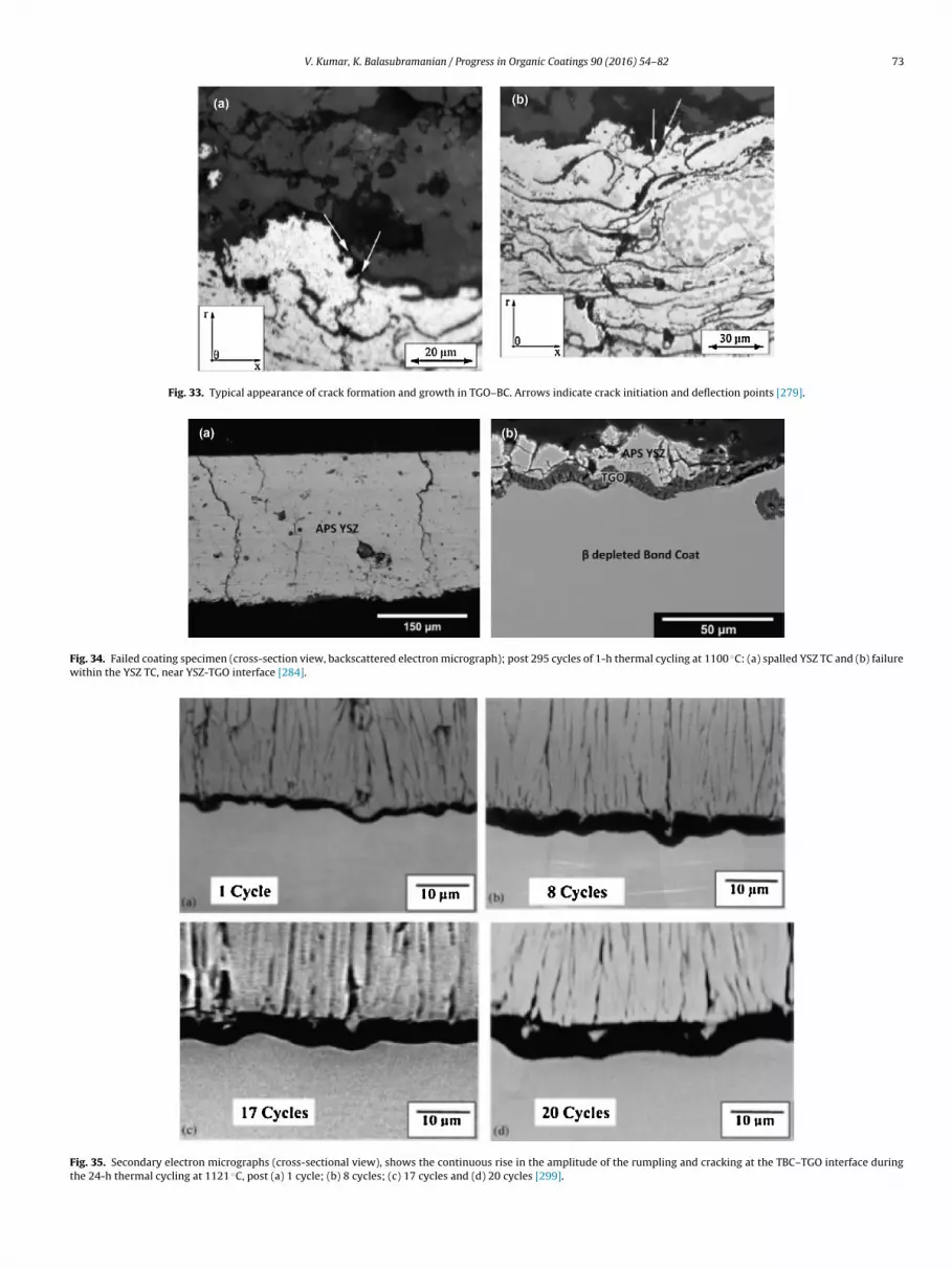
V. Kumar, K. Balasubramanian / Progress in Organic Coatings 90 (2016) 54–82 73
Fig. 33. Typical appearance of crack formation and growth in TGO–BC. Arrows indicate crack initiation and deflection points [279].
Fig. 34. Failed coating specimen (cross-section view, backscattered electron micrograph); post 295 cycles of 1-h thermal cycling at 1100 ◦C: (a) spalled YSZ TC and (b) failurewithin the YSZ TC, near YSZ-TGO interface [284].
Fig. 35. Secondary electron micrographs (cross-sectional view), shows the continuous rise in the amplitude of the rumpling and cracking at the TBC–TGO interface duringthe 24-h thermal cycling at 1121 ◦C, post (a) 1 cycle; (b) 8 cycles; (c) 17 cycles and (d) 20 cycles [299].

74 V. Kumar, K. Balasubramanian / Progress in
Fm
appc[tam[waitpiatHi
ct
ig. 36. The cyclic response of the thermal barrier coating system undergoing ther-al cycling for the 1-h and 24-h tests. [299].
pproach. In the analytical approach [305,306], it is difficult toredict the stresses developed in the TBC system. Recent works pro-osed a model based on micro-mechanical mechanisms to describerack growth and failure of thermally cycled plasma coatings307,308]. However, this model did not consider aspects such ashe interactive effect of interface morphology, top coat sinteringnd thermal mismatch, TGO growth and TBC creep. Comparatively,ore studies are based on numerical approach especially FEM
309,310]. Using this approach, Baker and co-workers [311–313]hile considering creep relaxation and cooling stresses, proposed
parametric study of the state of stresses in a TBC system by tak-ng into consideration the cooling stresses, creep relaxation andhe effect of interface geometry on the stress. Busso et al. [314]redicted the lifetime of TBC by FEM, using a software tool, which
nterpolates the finite element results with respect to time, temper-ture and geometry. As some factors have not been considered inhese works, the predicted local TBC stresses are somewhat larger.owever, in spite of these limitations, these works play vital role
n the estimate and prediction of TBC life.
Wei et al. [315] predicted the lifetime of plasma sprayed TBCs byonsidering interface morphology, TGO growth, creep effects andop coat sintering; the stress developed during thermal cycling was
Fig. 37. Schematic diagram representing the rivalry/competing failure mec
Organic Coatings 90 (2016) 54–82
calculated using FEM. The growth of the TGO is an important fac-tor responsible for the spall failure of TBC; the normal reliance ofthe TGO thickness h on the absolute maximum cycle temperaturewas described using a phenomenological relation H = B · (n · thold)m
where B is a proportionality constant, n and thold are thermal cyclesand dwell period respectively while m is a growth exponent. Failureof TBC system is due to many reasons viz. TGO growth, roughen-ing of TC–TGO–BC interfaces, TBC creep, TC sintering, the thermalexpansion disparity between BC, TGO, TC, etc. All these reasonswere considered in application of FEM to model TBC stresses andpredict the lifetime of plasma sprayed TBC system. TBC failure isprimarily caused due to the stress concentrating in the rougheninginterface during thermal cycling. Fig. 38 shows the morphologicalcharacteristics of the interface as represented by series of undula-tions. A number of unit cells, which are characterized by the halfperiod (a) and amplitude (b) [311], separate the random nature ofthe interface morphology. b/a represents an important roughnessparameter and the damage occurs where the value of b/a is largest[314]. The cumulative probability of the morphological character-istics of the interface r(i), was obtained from the series of selectedSEM images from the specimens while the stress �Tmax and strainεTmax of TBC during hold periods at Tmax, by taking into consider-ation oxidation, creep and sintering. Fig. 39 shows the cumulativeprobability of the measured values r(i), which represent differentb/a, r(i) = b(i)/a(i). Based on the statistical model, b/a = 0.8 is built torepresent the overall coating. Wei et al. [315] experimental studyconcluded that the function of the TGO growth during thermalcycling is quantified; the failure occurs by spall of the top coat at ornear TC–TGO interface and 860 cycles is the TBC average lifetime.By taking into consideration the oxidation, sintering and creep forlifetime prediction, the peaks of the maximum principal stressesincrease rapidly till 900 cycles (TGO thickness being 0–6.6 �m).However, the peaks of the maximum principal stresses declineslightly from 900 to 1100 cycles (TGO thickness being 6.6–7.0 �m).By comparing the failure stress in top coat, the lifetime of plasmasprayed TBCs using FEM worked out to be 810–900 cycles withthe TGO thickness being 6.4–6.6 �m, which was in line with theexperimental average lifetime results (860 cycles).
6.5. Interfacial damage based life model: EB-PVD coatings
Due to aging, the macroscopic spall is initiated by maximumin-plane compressive stress and fall in ceramic–metal inter-face toughness [316]. Large scale buckling is triggered mostly in
hanisms in the coating systems having flat and wavy interfaces [300].

V. Kumar, K. Balasubramanian / Progress in Organic Coatings 90 (2016) 54–82 75
Fig. 38. Sketch representation to illustrate geometric parameters
tTntk[lcuaoodoiscagm
oe[booaltt
system life, temperature was taken as the first order parameter.
Fig. 39. Relationship graph for cumulative probability of r(i) [315].
he lower temperature juncture of the loading path [317–319].he interfacial damages on the other hand, are the combi-ation of microstructure evolutions linked to the growth ofhermally activated alumina scale and roughness evolution (alsonown as rumpling effect), which is induced by thermal cycling318,320,321]. Thus, the damages linked to the roughness evo-ution grow with cyclic frequency while the damage mechanismonnected to oxide growth is a direct function of the time usedp at higher temperatures [316,322]. According to the currentlyccepted scenario which relies on the experimental studies of cyclicxidation, the spall happens in four stages [316,321] viz. damagef metal–ceramic interface, delamination initiated on the existentefects, buckling of TC and microscopic spall. However, since thebservations are based on post-mortem of the failed coatings, its harder to evaluate the relative importance of buckling, dynamicpall and induced delaminations. The damage and failure of theoating systems involve multiple time scales for the degradationnd delamination of the system interfaces, over a time period ran-ing from hundreds of hours to few minutes while the final spallay take fractions of a seconds.A number of works on the interfacial roughness are based
n simulated analytical and finite element analysis of interfaciallementary pattern assuming a perfect periodicity of interfaces323–326]. Some works assess the lifetime of TBC systems on theasis of the evaluation of a local state, a binary evaluation (safer spalled). Such models rely on a critical oxide thickness [327]r oxide net mass increase [328–330], which is taken as a dam-ge parameter function of the peak stress intensity factor (SIF) in a
inear elastic fracture mechanics scheme [317,331–334] as well ashe maximum local stress [326]. However, the experiments exhibithat the top coat layer can stay adherent in spite of the cracksa and b of the interface morphology characteristics [315].
being present locally, which is not in line with some approachesand hence difficult to defend and validate such approaches. Also,the cracks in the TGO layer can be healed at higher temperatures.A greater oxide thickness as compared to the critical thicknessassessed for isothermal loading could result from specific thermo-mechanical fatigue (TMF) loading condition, without macroscopicbreakdown [335,336]. The in-service components are exposed tohigher as well as lower temperature stages with frequency vari-ations and thus the thermo-mechanical fatigue (TMF) tests arethe most appropriate to enact in-service load conditions i.e. com-bine mechanical and thermal loading along with phase effects[320,335,337–340].
Some works assess localized mechanical states for eachlayer based on microstructure morphology and local behavior[324,341,342]. However, microstructure evolution and the cor-responding behavior determination are difficult tasks because ofextreme thinness and complexity of the materials [10,245–344].Cyclic oxidation database and correlated models prepared on thebasis of balance chemical potential in the BC layer has been usedin many works to assess microstructure evolution, in order to esti-mate TBC lifetime [345]. However, such models do not describemechanical interaction and are often confined to a given cycle fre-quency [329]. An alternate approach to the proposed local models isto evaluate a regular interfacial properties evolution and a final test-ing procedure for the critical event met during loading. The worksof Miller [346] and Cruse et al. [347], for plasma sprayed TBCs arebased on this approach.
In EB-PVD coating systems, the final spalling is not stable andit is mainly supported by lower temperatures part of the loading.Courcier et al. [348] focused on the estimate of the damages thatoccur due to higher temperature exposure under oxidizing con-ditions and during thermal transients. Cyclic oxidation data areused for the TBC spall tests. Oxidation also depends on temper-ature cycle (isothermal, cyclic or with superimposed mechanicalstrain) [335,349]. The resistance to TBC spall, prior to failure, wasmeasured with respect to the number of oxidation cycles, usingsimple compression tests [349,350]. The components undergothermo-mechanical fatigue loading during in-service conditions,which needs to be accounted for, in the design. For a aero-turbineblade substrate, a typical loading path is shown in Fig. 40(a)for stress/temperature function while Fig. 40(b) is for tempera-ture/time function. Loading in the TC layer was estimated andplotted as shown in Fig. 40(a).
For interfacial damages based life model for EB-PVD TBCs byCourcier et al. [348], nickel based single crystal super alloy AMI with(Ni,Pt)Al BC was used. Analysis of interfacial damage of ceramicTC–metallic BC, causing macroscopic failure of the ceramic layerwas carried out. For both spatial scales involved in the coating
The higher temperature stage promotes oxide–BC interfacial dam-age at the lower scale, as a result of the segregation effects whilecyclic loading down to lower temperature stage activates plastic

76 V. Kumar, K. Balasubramanian / Progress in Organic Coatings 90 (2016) 54–82
F e in sc 48].
riumatoTiTustpHats
7
bi
Fo[
ig. 40. Thermal cum mechanical fatigue loading path in respect of a turbine bladhanges base on the location on the blade surface. (b) Thermal loads versus time [3
atcheting resulting into rumpling effect. The macroscopic spalls reached in the lowest temperature range or on cooling, at thepper scale. The interrupted tests enable identification of damageechanism kinetics and the life model parameters. This damage
pproach takes into account the effects of the thermal parame-ers and also the frequency effect. Thus a qualitative descriptionf the hike in the spalled area for blade computation is obtained forMF loading. The results of Courcier et al. [348] work are shownn Fig. 41. The damage location is shown in Fig. 41(a) and (b).he spalled area fraction evolution observed for in-service bladender TMF loading for propagation stage and stabilization of thepalled area fraction in the second stage is ably described qualita-ively by the model, as seen in Fig. 41(c). This life model is useful toredict the location of spall and assess the life of turbine blades.owever, model is rather conservative and needs to take intoccount diffusion, creep and phase transformations, which affecthe BC behavior, morphology and hence the local stress–straintate.
. Challenges and future directions
TBCs enable desired thermal protection from hot gases in tur-ines and engines and hence have proved to be a key technology
n lowering the surface temperature of the substrate components.
ig. 41. Post-processing for a 3D blade simulation under TMF loading. (a) Sketch showingf relative number of cycles at failure Nf . For Nf/N0 = 1; no failure expected to occur. (c) Rel348].
ervice. (a) Stress loads versus temperature. Vertical arrows point out the loading
However, they are susceptible to various life limiting issues asso-ciated with their harsh high temperature operating environment.These issues include corrosion, oxidation, erosion, foreign objectdamage, sintering and phase transformations. The failure of YSZcoatings is caused due to the stresses developed as a result ofvolumetric changes accompanying the material phase transforma-tions [351]. Zirconium undergoes three crystallographic phases atdifferent temperatures on cooling/heating. The sintering of freestanding ZrO2 plasma sprayed coating is characterized by shrink-age [20,21] and the changes in properties like elastic modulus andthe bend strength, which hinge on the microstructure [22]. TheTBC system itself is a dynamic system while in service. The con-stituents of the TBC system (top coat, TGO, bond coat and superalloy substrate) undergo continuous changes in their composition,microstructure and crystalline phases during service life. Thesechanges result into the changes in mechanical and physical prop-erties of the TBCs during various stages of their service life. Duringservice life, the impurities such as sulphur originating due to diffu-sion from the substrate or from the raw material contaminate thebond coat surface, which has a adverse effect on the TBC lifetime.
Better raw material, cleaner heat treat furnaces and evolving sensi-tive screening tests to simulate exact engine operating conditionscan overcome this problem [352]. There is a need for developmentof effective diffusion barriers.the blade cross-sectional view. (b) Details of a blade surface along with iso-valuesationship of the spalled area fraction, obtained as a function of the number of cycles

ress in
npputBiT[soaaaTow
aiiicodlgtssgticet
uttcivnmGBdddusestmecsbtpoei
V. Kumar, K. Balasubramanian / Prog
The understanding of material behavior at high temperatureeeds to be augmented by accurate measurement techniques forroperties such as fracture toughness and hardness at these tem-eratures. Also, for a reliable life-time prediction model of TBCsnder complex operation loads, a need exists to measure theemperature precisely on the surface and also at the interfaces.etter process controls with online sensors to enhance reliabil-
ty are also desired. For 50 ◦C increase in temperature at theBC/substrate interface, the TBC service life decreases by six times353]. This reiterates the significance of accurate temperature mea-urements at the interfaces to evolve workable life enhancingptions. Thermal barrier sensor coatings facilitate remote temper-ture measurements inside the coatings by integrating opticallyctive material into the TBC [354–356]. Use of embedded sensorsnd non-destructive evaluation techniques to access the residualBC life and also for quality control of TBC manufacture process aren the increase. For critical applications such as temperature andear sensing, embedded thermo-graphic phosphors are used.
Efforts to diminish the CMAS onslaught onto the TBCs havettracted lots of research attention of late. The main approachesn this regard have been the application of a sealant [169] andntroducing sacrificial layers within 7YSZ TBCs [169,170]. Mit-gation of CMAS damage at higher temperatures necessitatesompositional and process modifications at affordable cost. Usef rare earth zirconates has shown promise in this regard. Impactamage caused by impinging particles may be addressed by multi-
ayered architecture with tailored microstructure. The functionallyraded coating design consists of multi-phase composites that areailored to exhibit a smooth spatial variation of the material con-tituents. This is achieved by depositing a bond coat on the metalubstrate, followed by cermet layers and a ceramic top layer. Theradient so engineered enables smoothening of the stress distribu-ion across layers and minimizes the stress concentration at thenterface [357–361]. The direction of future research for appli-ations such as mitigation of CMAS/impact damage is to furthervolve processing techniques and effective compositions of TBCso address the specific needs.
The TBCs are porous when deposited but while in use, theyndergo accelerated sintering and phase transformations at higheremperatures thereby causing denseness and consequent escala-ion in thermal conductivity [15]. The thermal conductivity of theoating materials is limited by the phonon scattering mechan-cs, which is associated with the intrinsic properties of materialsiz. architecture, structure and atomic bonds [362]. Among theew generation of advanced ceramic TBCs with much lower ther-al conductivity, there are several interesting zirconates such asd2Zr2O7, Sm2Zr2O7, Nd2Zr2O7, La2ZrO7, Dy2Zr2O7, Ln2ZrO7 andaY2O4, SrY2O4 materials [363]. Further reduction in thermal con-uctivity at a given layer thickness is still a challenge. Efforts in thisirection are directed to make use of ceramics by modifying theirensity, components and microstructure [364,365]. TBCs preparedsing nanostructured feedstock are found to indicate that the nano-tructured coatings exhibit low thermal conductivity due to thexistence of unmelted and porous nano-domains in their micro-tructure [366]. The use of the resins like the oligomers, PMR-15,he bismaleimides (BMI), etc. with fillers of carbon allotropes of
icro/nano sizes for high temperature applications has also beenxplored [367]. However, the underlying physical mechanism con-erning thermal protection effects of the nano-structured ceramicystems and their use to enhance insulation temperature needs toe further explored for engineering applications as well as for bet-er scientific understandings. The conventional coating methods of
rotection also introduce certain negative effects on the propertiesf the substrate metal, such as changes in the optical, thermal andlectrical properties as well as the increase in thickness of the coat-ng. Hence, the use of an ultra-thin protective coating is desired forOrganic Coatings 90 (2016) 54–82 77
such applications. Graphene with its single layer of carbon atomsbonded into 2-D hexagonal network holds promise for protectivecoating applications [99–101]. It is stable at higher temperatures(>1500 ◦C) and exhibits exceptional thermal and chemical stabil-ity [111,112]. Graphene has been used as a protective layer onrefined metal surfaces [113] and the prospects of its use as ultra-thin coatings at higher temperatures will improve with furtheradvances in the graphene growth and careful control of the metalcatalyst.
References
[1] A. Feuerstein, J. Knapp, T. Taylor, V. Ashary, A. Bolcavage, N. Hitchman,Technical and economical aspects of current thermal barrier coatingsystems for gas turbine engines by thermal spray and EB-PVD: a review, J.Therm. Spray Technol. 17 (2008) 199–213.
[2] S. Bose, High Temperature Coatings, Butterworth-Heinemann, Elsevier,2007, ISBN-13: 978-0-7506-8252-7.
[3] A.C. Karaoglanli, et al., Thermal shock and cycling behavior of thermalbarrier coatings (TBCs) used in gas turbines, in: E. Benini (Ed.), Progress inGas Turbine Performance, InTech, 2013, ISBN 978-953-51-1166-5, http://dx.doi.org/10.5772/2797 (Chapter 10), 268 pp.
[4] S.W. Myoung, et al., Effect of post heat treatment on thermal durability ofthermal barrier coatings in thermal fatigue tests, Surf. Coat. Technol. 215(2013) 46–51.
[5] S. Ahmaniemia, P. Vuoristo, T. Mäntylä, C. Gualco, A. Bonadei, R. Di Maggio,Surf. Coat. Technol. 190 (2005) 378.
[6] S. Amagasa, K. Shimomura, M. Kadowaki, K. Takeishi, H. Kawai, S. Aoki, K.Aoyema, J. Eng. Gas Turbines Power 116 (1994) 597.
[7] D. Schwingel, C. Persson, R. Taylor, T. Johanesson, J. Wigren, High Temp.High Press. 27–28 (1995) 273.
[8] A.N. Khan, J. Lu, Surf. Coat. Technol. 166 (2003) 37.[9] http://www.gepower.com/prod serv/products/tech docs/en/downloads/
ger3569g.pdf.[10] N.P. Padture, M. Gell, E.H. Jordan, Science 296 (2002) 280.[11] T. Bhatia, A. Ozturk, L. Xie, E.H. Jordan, B.M. Cetegen, M. Gell, X. Ma, N.P.
Padture, J. Mater. Res. 17 (2002) 2363.[12] L. Xie, X. Ma, E.H. Jordan, N.P. Padture, T.D. Xiao, M. Gell, Mater. Sci. Eng. A
362 (2003) 204.[13] K.W. Schlichting, N.P. Padture, E.H. Jordan, M. Gell, Mater. Sci. Eng. A 342
(2003) 120.[14] A. Rabiei, A.G. Evans, Acta Mater. 48 (2000) 3963.[15] D.R. Clarke, C.G. Levi, Annu. Rev. Mater. Res. 33 (2003) 383.[16] V. Lughi, V.K. Tolpygo, D.R. Clarke, Mater. Sci. Eng. A368 (2004) 212.[17] J.A. Thompson, T.W. Clyne, Acta Mater. 49 (2002) 1565.[18] S.A. Tsipas, I.O. Golosnoy, R. Damani, T.W. Clyne, J. Therm. Spray Technol. 13
(2004) 370.[19] L. Rayleigh, Proc. Lond. Math. Soc. 10 (1879) 4.[20] D. Zhu, R.A. Miller, Ceram. Eng. Sci. Proc. 23 (2002) 457.[21] D. Zhu, R.A. Miller, Surf. Coat. Technol. 108–109 (1998) 114.[22] P.A. Langjahr, R. Oberacker, M.J. Hoffmann, J. Am. Ceram. Soc. 84 (2001)
1301.[23] G. Thurn, et al., High-temperature deformation of plasma-sprayed ZrO2,
thermal barrier coatings, Mater. Sci. Eng. A 233 (1997) 176–182.[24] B. Siebert, et al., Changes in porosity and Young’s modulus due to sintering
of plasma sprayed thermal barrier coatings, J. Mater. Process. Technol. 92(93) (1999) 217–223.
[25] R.A. Miller, J.L. Smialek, R.G. Garlick, Phase stability in plasma-sprayedpartially stabilized zirconia-yttria, in: A.H. Heuer, L.W. Hobbs (Eds.),Advances in Ceramics. Science and Technology of Zirconia, vol. 3, AmericanCeramic Society, Columbus, OH, 1981, p. 241.
[26] R.A. Miller, R.G. Garlick, J.L. Smialek, Am. Ceram. Soc. Bull. 62 (1983) 1355.[27] R. Chaim, D.G. Brandon, A.H. Heuer, Acta Metall. 34 (1986) 1933.[28] U. Schulz, J. Am. Ceram. Soc. 83 (2000) 904.[29] M.N. Rahaman, et al., Phase stability, sintering, and thermal conductivity of
plasma-sprayed ZrO2-Gd2O3 compositions for potential thermal barriercoating applications, Acta Mater. 54 (2006) 1615–1621.
[30] W. Holmes, B.H. Pilsner, in: D.L. Houck (Ed.), Thermal Spray: Advances inCoatings Technology, ASM International, Materials Park, OH, 1998, p. 259.
[31] P.A. Langjahr, R. Oberacker, M.J. Hoffmann, J. Am. Ceram. Soc. 84 (2001)1301.
[32] S. Sodeoka, M. Suzuki, T. Inoue, K. Ueno, S. Oki, in: C.C. Berndt (Ed.),Proceedings of the 9th National Thermal Spray Conference: Thermal-Spray,Practical Solutions for Engineering Problems, Cincinnati USA, October 96,ASM International, Materials Park, OH, 1996, p. 295.
[33] B. Cortese, et al., Micro-chemical and -morphological features of heattreated plasma sprayed zirconia based thermal barrier coatings, Thin Solid
Films 549 (2013) 321–329.[34] R.S. Lima, A. Kucuk, C.C. Berndt, Surf. Coat. Technol. 135 (2001) 166–172.[35] R.S. Lima, A. Kucuk, C.C. Berndt, Mater. Sci. Eng. A 313 (2001) 75–82.[36] R.S. Lima, A. Kucuk, C.C. Berndt, Mater. Sci. Eng. A 327 (2002) 224–232.[37] B. Liang, C. Ding, Surf. Coat. Technol. 197 (2005) 185–192.

7 ress in
8 V. Kumar, K. Balasubramanian / Prog[38] R.S. Lima, B.R. Marple, Nanostructured YSZ thermal barrier coatingsengineered to counteract sintering effects, Mater. Sci. Eng. A 485 (2008)182–193.
[39] R.A. Miller, J. Am. Ceram. Soc. 67 (1984) 517.[40] H. Chen, X. Zhou, C. Ding, J. Eur. Ceram. Soc. 23 (2003) 1449–1455.[41] Y. Zeng, S.W. Lee, L. Gao, C.X. Ding, J. Eur. Ceram. Soc. 22 (2002) 347–351.[42] C. Zhou, N. Wang, Z. Wang, Scr. Mater. 51 (2004) 945–948.[43] J. He, J.M. Schoenung, Mater. Sci. Eng. A336 (2002) 274–319.[44] J. Karthikeyan, C.C. Berndt, J. Tikkanen, et al., Mater. Sci. Eng. A238 (1997)
275–296.[45] B. Liang, C. Ding, Surf. Coat. Technol. 197 (2005) 185.[46] C. Zhou, et al., Comparison of thermal cycling behavior of plasma-sprayed
nanostructured and traditional thermal barrier coatings, Mater. Sci. Eng. A452–453 (2007) 569–574.
[47] O. Racek, C.C. Berndt, Nanostructured and conventional YSZ coatingsdeposited using APS and TTPR techniques, Surf. Coat. Technol. 201 (1–2)(2006) 338–346.
[48] S.K. Gong, L. Deng, Thermal barrier effect of ceramic thermal barriercoatings, Acta Aeronaut. Astronaut. Sin. 21 (1) (2000) 75–79 (in Chinese).
[49] K. Wang, et al., Effect of sintering on thermal conductivity and thermalbarrier effects of thermal barrier coatings, Chin. J. Aeronaut. 25 (2012)811–816.
[50] H.B. Guo, S. Kuroda, H. Murakami, Microstructures and properties ofplasma-sprayed segmented thermal barrier coatings, J. Am. Ceram. Soc. 89(2006) 1432–1439.
[51] X. Zhang, et al., Effects of processing conditions on the mechanicalproperties and deformation behaviors of plasma-sprayed thermal barriercoatings: evaluation of residual stresses and mechanical properties ofthermal barrier coatings on the basis of in situ curvature measurementunder a wide range of spray parameters, Acta Mater. 61 (2013) 1037–1047.
[52] S. Kuroda, T.W. Clyne, The quenching stress in thermally sprayed coatings,Thin Solid Films 200 (1991) 49–66.
[53] S. Kuroda, T. Fukushima, S. Kitahara, Generation mechanisms ofresidual-stresses in plasma-sprayed coatings, Vacuum 41 (1990)1297–1299.
[54] P. Bengtsson, C. Persson, Modelled and measured residual stresses in plasmasprayed thermal barrier coatings, Surf. Coat. Technol. 92 (1997) 78–86.
[55] S. Widjaja, A.M. Limaraga, T. Hon Yip, Modeling of residual stresses in aplasma sprayed zirconia/alumina functionally graded-thermal barriercoating, Thin Solid Films 434 (2003) 216–227.
[56] J. Matejicek, S. Sampath, D. Gilmore, R. Neiser, In situ measurement ofresidual stresses and elastic moduli in thermal sprayed coatings – Part 2:processing effects on properties of Mo coatings, Acta Mater. 51 (2003)873–885.
[57] A. Vaidya, T. Streibl, L. Li, S. Sampath, O. Kovarik, R. Greenlaw, An integratedstudy of thermal spray process-structure-property correlations: a casestudy for plasma sprayed molybdenum coatings, Mater. Sci. Eng. A: Struct.403 (2005) 191–204.
[58] X.C. Zhang, B.S. Xu, H.D. Wang, Y.X. Wu, Error analyses on some typicallyapproximate solutions of residual stress within a thin film on a substrate, J.Appl. Phys. 98 (2005).
[59] P. Kadolkar, N.B. Dahotre, Effect of processing parameters on the cohesivestrength of laser surface engineered ceramic coatings on aluminum alloys,Mater. Sci. Eng. A: Struct. 342 (2003) 183–191.
[60] Z.Y. Huang, Z. Suo, G.H. Xu, J. He, J.H. Prevost, N. Sukumar, Initiation andarrest of an interfacial crack in a four-point bend test, Eng. Fract. Mech. 72(2005) 2584–2601.
[61] I. Hofinger, M. Oechsner, H.A. Bahr, M.V. Swain, Modified four-point bendingspecimen for determining the interface fracture energy for thin, brittlelayers, Int. J. Fract. 92 (1998) 213–220.
[62] X. Zhang, et al., Effects of residual stress on the mechanical properties ofplasma-sprayed thermal barrier coatings, Eng. Fract. Mech. 110 (2013)314–327.
[63] M. Ranjbar-Far, et al., Impact of the non-homogenous temperaturedistribution and the coatings process modeling on the thermal barriercoatings system’, Mater. Des. 32 (2011) 728–735.
[64] A.G. Evans, D.R. Mumm, J.W. Hutchinson, G.H. Meier, F.S. Pettit, Prog. Mater.Sci. 46 (2001) 505.
[65] N.P. Padture, M.E.H. Gell, E.H. Jordan, Science 296 (2002) 280.[66] A.M. Karlsson, A.G. Evans, Acta Mater. 49 (2001) 1793.[67] D.R. Mumm, A.G. Evans, I.T. Spitsberg, Acta Mater. 49 (2001) 2329.[68] J.A. Ruud, A. Bartz, M.P. Borom, C.A. Johnson, J. Am. Ceram. Soc. 84 (2001)
1545.[69] A.M. Karlsson, J.W. Hutchinson, A.G. Evans, J. Mech. Phys. Solids 50 (2002)
1565.[70] M.J. Stiger, N.M. Yanar, M.G. Topping, F.S. Pettit, G.H. Meier, Z. Metallkd. 90
(1999) 1069.[71] A. Rabiei, A.G. Evans, Acta Mater. 48 (2000) 3963.[72] M. Baker, Influence of material models on the stress state in thermal barrier
coating simulations, Surf. Coat. Technol. 240 (2014) 301–310.[73] X. Chen, et al., On the propagation and coalescence of delamination cracks in
compressed coatings: with application to thermal barrier systems, ActaMater. 51 (2003) 2017–2030.
[74] M.H. Li, Z.Y. Zhang, X.F. Sun, H.R. Guan, W.Y. Hu, Z.Q. Hu, Oxid. Met. 58 (5/6)(2002) 499–512.
[75] T. Besmann, J. Mater. Sci. 44 (2009) 1661–1663.
Organic Coatings 90 (2016) 54–82
[76] A.G. Evans, D.R. Clarke, C.G. Levi, J. Eur. Ceram. Soc. 28 (2008) 1405–1419.[77] J.A. Haynes, B.A. Pint, K.L. More, Y. Zhang, I.G. Wright, Oxid. Met. 58 (5/6)
(2002) 513–544.[78] N.P. Padture, M. Gell, E.H. Jordan, Science 296 (2002) 280–284.[79] N.S. Cheruvu, K.S. Chan, D.W. Gandy, J. Eng. Gas Turbines Power 131 (2009)
1–7.[80] H. Guo, et al., High temperature oxidation behavior of hafnium modified
NiAl bond coat in EB-PVD thermal barrier coating system, Thin Solid Films516 (2008) 5732–5735.
[81] J. Schwarzer, D. Lohe, O. Vohringer, Mater. Sci. Eng. A387–389 (2004)692–695.
[82] I. Spitsberg, K. More, Mater. Sci. Eng. A417 (2006) 322–333.[83] W.O. Soboyejo, et al., High temperature oxidation interfacial growth kinetics
in YSZ thermal barrier coatings with bond coatings of NiCoCrAlY with 0.25%Hf, Mater. Sci. Eng. A 528 (2011) 2223–2230.
[84] C. Zhou, et al., Influence of water vapor on the high temperature oxidationbehavior of thermal barrier coatings, Mater. Sci. Eng. A 348 (2003) 327–332.
[85] C. Wang, Cyclic Oxidation Behavior of Thermal Barrier Coating Exposed toNaCl Vapor (Master degree thesis), Beijing University of Aeronautics andAstronautics, 2006.
[86] N. Hiramatsu, Y. Uematsu, T. Tanaka, M. Kinugasa, Mater. Sci. Eng. A: Struct.Mater. Prop. Microstruct. Process. 120 (1998) 319.
[87] Y. Song, et al., Corrosion behavior of thermal barrier coatings exposed toNaCl plus water vapor at 1050 ◦C, Thin Solid Films 516 (2008) 5686–5689.
[88] M. Rudolphi, et al., Verification of moisture-induced delayed failure ofthermal barrier coatings, Scr. Mater. 59 (2008) 255–257.
[89] J.L. Smialek, G.N. Morscher, Mater. Sci. Eng. A332 (2002) 11–24.[90] J.L. Smialek, JOM 1 (2006) 29–36.[91] Z.-Y. Deng, Y.-F. Liu, Y. Tanaka, H.-W. Zhang, J. Ye, Y. Kagawa, J. Am. Ceram.
Soc. 88 (2005) 2975–2977.[92] M. Stratmann, R. Feser, A. Leng, Electrochim. Acta 39 (1994) 1207.[93] B.V.A. Rao, M.Y. Iqbal, B. Sreedhar, Corros. Sci. 51 (2009) 1441.[94] M.I. Redondo, C.B. Breslin, Corros. Sci. 49 (2007) 1765.[95] M. Segarra, L. Miralles, J. Diaz, H. Xuriguera, J.M. Chimenos, F. Espiell, S.
Pinol, Mater. Sci. Forum 426 (4) (2003) 3511.[96] P.J. Kinlen, V. Menon, Y.W. Ding, J. Electrochem. Soc. 146 (1999) 3690.[97] G. Grundmeier, C. Reinartz, M. Rohwerder, M. Stratmann, Electrochim. Acta
43 (1998) 165.[98] D.M. Merkula, P.D. Novikov, V.N. Ivanenkov, V.V. Sapozhnikov, Y.I. Lyakhin,
Oceanology 14 (1974) 299.[99] K.S. Novoselov, A.K. Geim, S.V. Morozov, D. Jiang, Y. Zhang, S.V. Dubonos, I.V.
Grigorieva, A.A. Firsov, Science 306 (2004) 666.[100] K.S. Novoselov, A.K. Geim, S.V. Morozov, D. Jiang, M.I. Katsnelson, I.V.
Grigorieva, S.V. Dubonos, A.A. Firsov, Nature 438 (2005) 197.[101] C. Gómez-Navarro, M. Burghard, K. Kern, Nano Lett. 8 (7) (2008) 2045.[102] Q.K. Yu, J. Lian, S. Siriponglert, H. Li, Y.P. Chen, S.S. Pei, Appl. Phys. Lett. 93
(2008) 113103.[103] A. Reina, X.T. Jia, J. Ho, D. Nezich, H.B. Son, V. Bulovic, M.S. Dresselhaus, J.
Kong, Nano Lett. 9 (2009) 30.[104] X.S. Li, W.W. Cai, J.H. An, S. Kim, J. Nah, D.X. Yang, R. Piner, A. Velamakanni, I.
Jung, E. Tutuc, S.K. Banerjee, L. Colombo, R.S. Ruoff, Science 324 (2009) 1312.[105] X.S. Li, W.W. Cai, L. Colombo, R.S. Ruoff, Nano Lett. 9 (2009) 4268.[106] K.S. Kim, Y. Zhao, H. Jang, S.Y. Lee, J.M. Kim, J.H. Ahn, P. Kim, J.Y. Choi, B.H.
Hong, Nature 457 (2009) 706.[107] W.W. Cai, Y.W. Zhu, X.S. Li, R.D. Piner, R.S. Ruoff, Appl. Phys. Lett. 95 (2009)
123115.[108] L. Gao, W. Ren, J. Zhao, L.P. Ma, Z. Chen, H.M. Cheng, Appl. Phys. Lett. 97
(2010) 183109.[109] T. Fujita, W. Kobayashi, C. Oshima, Surf. Interface Anal. 37 (2005) 120.[110] P.W. Sutter, J.I. Flege, E.A. Sutter, Nat. Mater. 7 (2008) 406.[111] W.A. de Heer, C. Berger, X.S. Wu, P.N. First, E.H. Conrad, X.B. Li, T.B. Li, M.
Sprinkle, J. Hass, M.L. Sadowski, M. Potemski, G. Martinez, Solid StateCommun. 143 (2007) 92.
[112] J. Hass, F. Varchon, J.E. Millan-Otoya, M. Sprinkle, N. Sharma, W.A. De Heer, C.Berger, P.N. First, L. Magaud, E.H. Conrad, Phys. Rev. Lett. 100 (2008) 125504.
[113] S. Chen, L. Brown, M. Levendorf, W. Cai, S.Y. Ju, J. Edgeworth, X. Li, C.W.Mangnuson, A. Velamakanni, R.D. Piner, J. Kang, J. Park, R.S. Rouff, ACS Nano5 (2) (2011) 1321.
[114] P.K. Nayak, et al., Graphene coated Ni films: a protective coating, Thin SolidFilms 529 (2013) 312–316.
[115] C.J. Hsu, P.K. Nayak, S.C. Wang, J.C. Sung, C.L. Wang, C.L. Wu, J.L. Huang,Spinodal decomposition of mono- to few-layer graphene on Ni substrates atlow temperature, J. Nanosci. Nanotechnol. 12 (3) (2012) 2442–2447, http://dx.doi.org/10.1166/jnn.2012.5799.
[116] K. Balasubramanian, et al., Anti Corrosive Coating Based on WasteThermoplastic Materials, Indian Patent 1113/MUM/2012.
[117] R.A. Miller, Surf. Coat. Technol. 30 (1) (1987) 1–11.[118] C.G. Zhou, C.L. Wang, Y.X. Song, Evaluation of cyclic oxidation of thermal
barrier coatings exposed to NaCl vapor by finite element method, Mater. Sci.Eng. A 490 (1–2) (2008) 351–358.
[119] I. Gurrappa, J. Mater. Sci. Lett. 17 (1998) 1267.
[120] R.L. Jones, J. Therm. Spray Technol. 6 (1) (1997) 77.[121] S.Y. Park, J.H. Kim, M.C. Kim, H.S. Song, C.G. Park, Surf. Coat. Technol. 190(2005) 357.[122] M.P. Borom, C.A. Johnson, L.A. Peluso, Surf. Coat. Technol. 87–89 (1996) 116.[123] C. Leyens, I.G. Wright, B.A. Pint, Oxid. Met. 54 (2000) 40l.

ress in
[[
[[[[
[[
[
[
[
[
[
[
[[
[[
[
[
[
[
[[[
[
[
[
[
[
[
[
[
[
[
[
[
[
V. Kumar, K. Balasubramanian / Prog
124] R.L. Jones, J. Am. Ceram. Soc. 75 (7) (1992) 1818.125] R.L. Jones, R.E. Tressler, M. Mcnallan, Ceramic Transactions, vol. 10,
American Ceramic Society, Westerville, OH, 1990, pp. 291.126] Z. Chen, N.Q. Wu, J. Singh, S.X. Mao, Thin Solid Films 443 (2003) 46.127] I. Zplatynsky, Thin Solid Films 95 (1982) 275.128] T. Mantyla, P. Vuoristo, P. Kettunen, Thin Solid Films 118 (1984) 437.129] C. Batista, A. Portinha, R.M. Ribeiro, V. Teixeira, C.R. Oliveira, Surf. Coat.
Technol. 200 (2006) 6783.130] P.-C. Tsai, C.-S. Hsu, Surf. Coat. Technol. 183 (2004) 29.131] A. Bennett, Properties of thermal barrier coatings, Mater. Sci. Technol. 2
(1986) 257–261.132] B.C. Wu, E. Chang, C.H. Chao, M.L. Tsai, The oxide pegging spalling
mechanism and spalling modes of ZrO2 8 wt% Y2O3/Ni-22Cr-10Al-1Ythermal barrier coatings under various operating conditions, J. Mater. Sci. 25(1990) 1112–1119.
133] Kh.G. Schmitt-Thomas, U. Dietl, Thermal barrier coatings with improvedoxidation resistance, Surf Coat. Technol. 68/69 (1994) 113–115.
134] H.L. Tsai, P.C. Tsai, Performance of laser-glazed plasma-sprayed(ZrO2-12 wt% Y2O3)/(Ni-22 wt% Cr-10 wt% Al-1 wt% Y) thermal barriercoatings in cyclic oxidation tests, Surf Coat. Technol. 71 (1995) 53–59.
135] J.H. Sun, E. Chang, C.H. Chao, M.J. Cheng, ZrO2-8 wt% Y2O3
CVD-AI2O3/Ni-22Cr-10Al-1Y thermal barrier coatings, Oxid. Met. 40 (1993)465–481.
136] P. Ramaswamy, et al., A12O3–ZrO2 composite coatings for thermal barrierapplications, Compos. Sci. Technol. 57 (1997) 81–89.
137] A. Afrasiabi, et al., A comparative study on hot corrosion resistance of threetypes of thermal barrier coatings: YSZ, YSZ + Al2O3 and YSZ/Al2O3, Mater.Sci. Eng. A 478 (2008) 264–269.
138] P.E. Hodge, R.A. Miller, M.A. Gedwill, Thin Solid Films 73 (2) (1980) 447–453.139] D.W. Sustitzky, W. Hertl, C.B. Carter, J. Am. Ceram. Soc. 71 (11) (1988)
992–1004.140] W. Hertl, J. Appl. Phys. 63 (11) (1988) 5514–5520.141] P. Mohan, B. Yuan, T. Patterson, V.H. Desai, Y.H. Sohn, Am. Ceram. Soc. 90
(11) (2007) 3601–3607.142] R. Vassen, X. Cao, F. Tietz, D. Basu, D. Stover, J. Am. Ceram. Soc. 83 (3) (1999)
2023–2028.143] B.R. Marple, J. Voyer, M. Thibodeau, D.R. Nagy, R. Vassen, J. Eng. Gas Turbines
Power 128 (2006) 144–152.144] Z. Xu, L. He, R. Mu, S. He, G. Huang, X. Cao, J. Alloys Compd. 504 (2) (2010)
382–385.145] S. Yugeswaran, et al., Initial phase hot corrosion mechanism of gas tunnel
type plasma sprayed thermal barrier coatings, Mater. Sci. Eng. B 177 (2012)536–542.
146] A. Yoshiaki, A. Kobayashi, Y. Habara, J. Appl. Phys. 62 (1987) 4884–4890.147] A. Kobayashi, Surf. Coat. Technol. 90 (3) (1997) 197–202.148] H.B. Guo, X.Y. Xie, H.B. Xu, et al., The Manufacturing of Thermal Barrier
Coating with Columnar Grain Structure, China Patent 200710118236.5(2007).
149] X.Y. Xie, H.B. Guo, S.K. Gong, Mechanical properties of LaTi2Al9O19 andthermal cycling behaviors of plasmasprayed LaTi2Al9O19/YSZ thermalbarrier coatings, J. Therm. Spray Technol. 19 (6) (2010) 1179–1185.
150] X.I.E. Xiaoyun, et al., Hot corrosion behavior of double-ceramic-layerLaTi2Al9O19/YSZ thermal barrier coatings, Chin. J. Aeronaut. 25 (2012)137–142.
151] A. Selcuk, A. Atkinson, The evolution of residual stress in the thermallygrown oxide on Pt diffusion bond coats in TBCs, Acta Mater. 51 (2) (2003)535–549.
152] J.A. Nychka, D.R. Clark, S. Sridharan, NDE assessment of TBCs: an interimreport of a photo-stimulated luminescence ‘round-robin’ test, Surf. Coat.Technol. 163–164 (2003) 87–94.
153] X.Q. Ma, M. Takemoto, Quantitative acoustic emission analysis of plasmasprayed thermal barrier coatings subjected to thermal shock tests, Mater.Sci. Eng. A 308 (1–2) (2001) 101–110.
154] A. Kucuk, C.C. Berndt, U. Senturk, et al., Influence of plasma sprayparameters on mechanical properties of yttria stabilized zirconia coatings.II: acoustic emission response, Mater. Sci. Eng. A 284 (1–2) (2000) 41–50.
155] K. Ogawa, D. Minkov, T. Shoji, et al., NDE of degradation of thermal barriercoating by means of impedance spectroscopy, NDE E Int. 32 (3) (1999)177–185.
156] S.H. Song, P. Xiao, L.Q. Weng, Evaluation of microstructural evolution inthermal barrier coatings during thermal cycling using impedancespectroscopy, J. Eur. Ceram. Soc. 25 (7) (2005) 1167–1173.
157] X. Wang, J.F. Mei, P. Xiao, Non-destructive evaluation of thermal barriercoatings using impedance spectroscopy, J. Eur. Ceram. Soc. 21 (7) (2001)855–859.
158] N.Q. Wu, K. Ogawa, M. Chyu, et al., Failure detection of thermal barriercoatings using impedance spectroscopy, Thin Solid Films 457 (2) (2004)301–306.
159] E.P. Busso, J. Lin, S. Sakurai, et al., A mechanistic study of oxidation-induceddegradation in a plasma-sprayed thermal barrier coating system. Part I:model formulation, Acta Mater. 49 (9) (2001) 1515–1528.
160] A.G. Evans, D.R. Mumm, J.W. Hutchinson, et al., Mechanisms controlling thedurability of thermal barrier coatings, Prog. Mater. Sci. 46 (5) (2001)505–553.
161] J. Gomez-Garia, A. Rico, M.A. Garrido-Maneiro, et al., Correlation ofmechanical properties and electrochemical impedance spectroscopy
Organic Coatings 90 (2016) 54–82 79
analysis of thermal barrier coatings, Surf. Coat. Technol. 204 (6–7) (2009)812–815.
[162] C. Liu, et al., Evaluation of thermal barrier coatings exposed to hot corrosionenvironment by impedance spectroscopy, Chin. J. Aeronaut. 24 (2011)514–519.
[163] J. Kim, M.G. Dunn, A.J. Baran, et al., Deposition of volcanic materials in thehot sections of two gas turbine engines, J. Eng. Gas Turbines Power 7 (1993)641.
[164] D.J. DeWet, R. Taylor, F.H. Stott, J. Phys. IV 3 (1993) 655.[165] J.L. Smialek, F.A. Archer, R.G. Garlick, Turbine airfoil degradation in the
Persian Gulf war, JOM J. Miner. Met. Mater. Soc. 46 (1994) 39.[166] F.H. Stott, D.J. Wet, R. Taylor, Degradation of thermal-barrier coatings at very
high temperatures, MRS Bull. 10 (1994) 46.[167] M.P. Borom, C.A. Johnson, L.A. Peluso, Role of environmental deposits and
operating surface temperature in spallation of air plasma sprayed thermalbarrier coatings, Surf. Coat. Technol. 86–87 (1996) 116.
[168] S. Kramer, J. Yang, C.G. Levi, et al., Thermochemical interaction of thermalbarrier coatings with molten CaO–MgO–Al2O3–SiO2 (CMAS) deposits, J. Am.Ceram. Soc. 89 (2006) 3167.
[169] R. Darolia, B.A. Nagaraj, US Patent No. 6,720,038 (2004).[170] W.C. Hasz, C.A. Johnson, M.P. Borom, US Patent No. 5,660,885 (1997).[171] A. Aygun, et al., Novel thermal barrier coatings that are resistant to
high-temperature attack by glassy deposits, Acta Mater. 55 (2007)6734–6745.
[172] T. Bhatia, A. Ozturk, L. Xie, E.H. Jordan, B.M. Cetegen, M. Gell, et al., J. Mater.Res. 17 (2002) 2363.
[173] M. Gell, L. Xie, X. Ma, E.H. Jordan, N.P. Padture, Surf. Coat. Technol. 177–178(2004) 97.
[174] E.H. Jordan, L. Xie, X. Ma, M. Gell, N.P. Padture, B.M. Cetegen, et al., J. Therm.Spray Technol. 13 (2004) 57.
[175] A. Jadhav, N.P. Padture, F. Wu, E.H. Jordan, M. Gell, Mater. Sci. Eng. A 405(2005) 313.
[176] A.L. Vasiliev, N.P. Padture, X. Ma, Acta Mater. 54 (2006) 4913.[177] A.L. Vasiliev, N.P. Padture, Acta Mater. 54 (2006) 4921.[178] J.M. Drexler, et al., Air-plasma-sprayed thermal barrier coatings that are
resistant to high-temperature attack by glassy deposits, Acta Mater. 58(2010) 6835–6844.
[179] S. Krämer, J. Yang, C.G. Levi, J. Am. Ceram. Soc. 91 (2008) 576–583.[180] D.A. Litton, K.W. Schlichting, M. Freling, J.G. Smeggil, D.B. Snow, M.J.
Maloney, U.S. Patent No. 7,662,489 (2010).[181] M. Freling, K.W. Schlichting, M.J. Maloney, D.A. Litton, J.G. Smeggil, D.B.
Snow, U.S. Patent No. 7,785,722 (2010).[182] J.M. Drexler, A.D. Gledhill, K. Shinoda, A.L. Vasiliev, K.M. Reddy, S. Sampath,
N.P. Padture, Adv. Mater. 23 (2011) 2419–2424.[183] A.D. Gledhill, et al., Mitigation of damage from molten fly ash to
air-plasma-sprayed thermal barrier coatings, Mater. Sci. Eng. A 528 (2011)7214–7221.
[184] J.M. Drexler, et al., Composition effects of thermal barrier coating ceramicson their interaction with molten Ca–Mg–Al–silicate (CMAS) glass, ActaMater. 60 (2012) 5437–5447.
[185] J.M. Drexler, A. Aygun, D. Li, R. Vaßen, T. Steinke, N.P. Padture, Surf. Coat.Technol. 204 (2010) 2683.
[186] A.G. Evans, N.A. Fleck, S. Faulhaber, et al., Scaling laws governing the erosionand impact resistance of thermal barrier coatings, Wear 260 (2006)886–894.
[187] F.H. Stott, D.J. Dewet, R. Taylor, Degradation of thermal-barrier coatings atvery high temperatures, MRS Bull. 19 (1994) 46–49.
[188] A.G. Evans, J.W. Hutchinson, The mechanics of coating delamination inthermal gradients, Surf. Coat. Technol. 201 (2007) 7905–7916.
[189] R.G. Wellman, J.R. Nicholls, Erosion, corrosion and erosion–corrosion of EBPVD thermal barrier coatings, Tribol. Int. 41 (2008) 657–662.
[190] R. Wellman, G. Whitman, J.R. Nicholls, CMAS corrosion of EB PVD TBCs:identifying the minimum level to initiate damage, Int. J. Refract. Met. HardMater. 28 (2010) 124–132.
[191] C. Mercer, S. Faulhaber, A.G. Evans, et al., A delamination mechanism forthermal barrier coatings subject to calcium–magnesium–alumino–silicate(CMAS) infiltration, Acta Mater. 53 (2005) 1029–1039.
[192] S. Kramer, S. Faulhaber, M. Chambers, et al., Mechanisms of cracking anddelamination within thick thermal barrier systems in aero-engines subjectto calcium–magnesium–alumino–silicate (CMAS) penetration, Mater. Sci.Eng. A 490 (2008) 26–35.
[193] J. Wu, H.B. Guo, Y.Z. Gao, et al., Microstructure and thermo-physicalproperties of yttria stabilized zirconia coatings with CMAS deposits, J. Eur.Ceram. Soc. 31 (2011) 1881–1888.
[194] A.G. Evans, D.R. Clarke, C.G. Levi, The influence of oxides on the performanceof advanced gas turbines, J. Eur. Ceram. Soc. 28 (2008) 1405–1419.
[195] H. Peng, et al., Degradation of EB-PVD thermal barrier coatings caused byCMAS deposits, Prog. Nat. Sci.: Mater. Int. 22 (5) (2012) 461–467.
[196] J. Zhang, V. Desai, Evaluation of thickness, porosity and pore shape of plasmasprayed TBC by electrochemical impedance spectroscopy, Surf. Coat.Technol. 190 (2005) 98.
[197] M.D. Shawkat, S.H. Song, P. Xiao, Evaluation of degradation of thermalbarrier coatings using impedance spectroscopy, J. Eur. Ceram. Soc. 22 (2002)101.
[198] X. Wang, J. Mei, P. Xiao, Non-destructive evaluation of thermal barriercoatings using impedance spectroscopy, J. Eur. Ceram. Soc. 21 (2001) 855.

8 ress in
0 V. Kumar, K. Balasubramanian / Prog[199] S.H. Song, P. Xiao, An impedance spectroscopy study of high-temperatureoxidation of thermal barrier coatings, Mater. Sci. Eng. B 97 (2003) 46.
[200] L.F. Deng, Y.S. Xiong, P. Xiao, Modeling and experimental study ofimpedance spectra of electron beam physical vapour deposition thermalbarrier coatings, Surf. Coat. Technol. 201 (2007) 7775.
[201] L.F. Deng, P. Xiao, Characterisation of alumina scales on FeCr alloy usingimpedance spectroscopy, Thin Solid Films 516 (15) (2008) 5027.
[202] J. Wu, et al., Evaluation of plasma sprayed YSZ thermal barrier coatings withthe CMAS deposits infiltration using impedance spectroscopy, Prog. Nat.Sci.: Mater. Int. 22 (1) (2012) 40–47.
[203] X. Chen, R. Wang, N. Yao, A.G. Evans, J.W. Hutchinson, R.W. Bruce, Mater. Sci.Eng. A 352 (2003) 221–231.
[204] J.R. Nicholls, M.J. Deakin, D.S. Rickerby, Wear 233–235 (1999) 352–361.[205] R.G. Wellman, J.R. Nicholls, Wear 242 (2000) 89–96.[206] R.W. Bruce, Tribol. Trans. 41 (1998) 399–410.[207] X. Chen, et al., Mechanisms governing the high temperature erosion of
thermal barrier coatings, Wear 256 (2004) 735–746.[208] M. Watanabe, A.G. Evans, Unpublished.[209] B.D. Kernan, A. He, A.H. Heuer, Microstructural evolution and microhardness
in zirconia-based thermal barrier EB-PVD coatings, J. Am. Ceram. Soc. 86 (6)(2003) 959–968.
[210] R. Darolia, B. Boutwell, B.T. Hazel, B.A. Nagaraj, J.D. Rigney, R.D. Wustman,Thermal Barrier Coating with Modulated Grain Structure and MethodTherefore, US Patent 7,318,955 (2008).
[211] L. Torre, J.M. Kenny, A.M. Maffezzoli, J. Mater. Sci. 33 (10) (1998) 3137.[212] D.W.K. Ho, J.H. Koo, O.A. Ezekoye, J. Spacecr. Rockets 46 (2009) 526.[213] R. Palaninathan, S. Bindu, J. Spacecr. Rockets 42 (2005) 971.[214] M.O. Abdalla, A. Ludwick, T. Mitchell, Polymer 44 (24) (2003) 7353.[215] A.M. Kawamoto, L.C. Pardini, M.F. Diniz, V.L. Lourenco, M.F.K. Takahashi, J.
Aerosp. Technol. Manage. 2 (2) (2010) 169.[216] H. Yu, J. Liu, X. Wen, Z. Jiang, Y. Wang, L. Wang, J. Zheng, Polymer 52 (21)
(2011) 4891.[217] Y. Zhang, S. Shen, Y. Liu, Polym. Degrad. Stab. 98 (2) (2013) 514.[218] D. Cho, Phenolic, J. Mater. Sci. Lett. 15 (1996) 1786.[219] T.L. Dhami, O.P. Bahl, B.R. Awasthy, Carbon 33 (4) (1995) 479.[220] S. Kuo, C. Huang, F. Chang, Macromol. Rapid Commun. (2006) 537.[221] P. Xu, X. Jing, Polym. Eng. Sci. 50 (7) (2010) 1382.[222] J. Xiao, J.-M. Chen, H.-D. Zhou, Q. Zhang, Mater. Sci. Eng. A 452–453 (2007)
23.[223] R.D. Patton, C.U. Pittman, Composites A 33 (2002) 243.[224] J.H. Koo, L.A. Pilato, 41st AIAA–ASME–SAE–ASEE, Joint Propulsion
Conference & Exhibit, Tucson, AZ, 2005.[225] J.K. Park, D. Cho, T.J. Kang, Carbon 42 (2004) 795.[226] B. Yutika, K. Balasubramanian, RSC Adv. 4 (2014) 28956–28963.[227] K. Balasubramanian, B. Yutika, Cost Effective Processing of Defect/Blister
Free Ablative Composites of Functionally Tailored Resins of Ultra HighTemperature Ceramics (UHTC) for Layered Composite, Indian Patent641/MUM/2014.
[228] K. Balasubramanian, Sonication Method and Apparatus, International PatentWO/2011/086354.
[229] L. Yang, Y. Zhou, W. Mao, C. Lu, Real-time acoustic emission testing based onwavelet transform for the failure process of thermal barrier coatings, Appl.Phys. Lett. 93 (2008) 231906.
[230] M. Hu, A.G. Evans, The cracking and decohesion of thin films on ductilesubstrates, Acta Metall. 37 (1989) 917–925.
[231] T.Q. Lu, W.X. Zhang, T.J. Wang, The surface effect on the strain energy releaserate of buckling delamination in thin film-substrate systems, Int. J. Eng. Sci.49 (9) (2011) 967–975.
[232] T.J. Wang, Z. Lou, A continuum damage model for weld heat affected zoneunder low cycle fatigue loading, Eng. Fract. Mech. 37 (1990) 825–829.
[233] T.J. Wang, Further investigation of a new continuum damage mechanicscriterion for ductile fracture: experimental verification and applications,Eng. Fract. Mech. 48 (1994) 217–230.
[234] Y. Bai, Z. Han, H. Li, C. Xu, Y. Xu, Z. Wang, et al., High performancenanostructured ZrO2 based thermal barrier coatings deposited by highefficiency supersonic plasma spraying, Appl. Surf. Sci. 257 (16) (2011)7210–7216.
[235] M. Ranjbar-Far, J. Absi, G. Mariaux, D.S. Smith, Crack propagation modelingon the interfaces of thermal barrier coating system with different thicknessof the oxide layer and different interface morphologies, Mater. Des. 32(2011) 4961–4969.
[236] A.E.F.A. Rizk, Periodic array of cracks in a strip subjected to surface heating,Int. J. Solids Struct. 41 (2004) 4685–4696.
[237] W.X. Zhang, X.L. Fan, T.J. Wang, The surface cracking behavior in air plasmasprayed thermal barrier coating system incorporating interface roughnesseffect, Appl. Surf. Sci. 258 (2) (2011) 811–817.
[238] R. Huang, J. Prevost, Z. Huang, Z. Suo, Channel-cracking of thin films with theextended finite element method, Eng. Fract. Mech. 70 (2003) 2513–2526.
[239] X.L. Fan, W.X. Zhang, T.J. Wang, G. Liu, J. Zhang, Investigation on periodiccracking of elastic film/substrate system by the extended finite elementmethod, Appl. Surf. Sci. 257 (2011) 6718–6724.
[240] X.L. Fan, W.X. Zhang, T.J. Wang, Q. Sun, The effect of thermally grown oxideon multiple surface cracking in air plasma sprayed thermal barrier coatingsystem, Surf. Coat. Technol. 208 (2012) 7–13.
[241] F. Erdogan, The crack problem for bonded nonhomogeneous materialsunder antiplane shear loading, J. Appl. Mech. 52 (1985) 823.
Organic Coatings 90 (2016) 54–82
[242] G.W. Schulze, F. Erdogan, Periodic cracking of elastic coatings, Int. J. SolidsStruct. 35 (1998) 3615–3634.
[243] Z. Suo, J.W. Hutchinson, Interface crack between two elastic layers, Int. J.Fract. 43 (1990) 1–18.
[244] B. Cotterell, J.R. Rice, Slightly curved or kinked cracks, Int J. Fract. 16 (1980)155–169.
[245] J.R. Rice, Elastic fracture mechanics concepts for interfacial cracks, J. Appl.Mech. 55 (1988) 98–103.
[246] M.Y. He, A.G. Evans, J.W. Hutchinson, Crack deflection at an interfacebetween dissimilar elastic materials: role of residual stresses, Int. J. SolidsStruct. 31 (1994) 3443–3456.
[247] B. Zhou, K. Kokini, Effect of pre-existing surface crack morphology on theinterfacial thermal fracture of thermal barrier coatings: a numerical study,Mater. Sci. Eng. A 348 (2003) 271–279.
[248] B. Zhou, K. Kokini, Effect of surface pre-crack morphology on the fracture ofthermal barrier coatings under thermal shock, Acta Mater. 52 (2004)4189–4197.
[249] J. Parmigiani, M. Thouless, The roles of toughness and cohesive strength oncrack deflection at interfaces, J. Mech. Phys. Solids 54 (2006) 266–287.
[250] H. Mei, Y. Pang, R. Huang, Influence of interfacial delamination on channelcracking of elastic thin films, Int. J. Fract. 148 (2007) 331–342.
[251] X.L. Fan, R. Xu, W.X. Zhang, T.J. Wang, Effect of periodic surface cracks on theinterfacial fracture of thermal barrier coating system, Appl. Surf. Sci. 258(2012) 9816–9823.
[252] R. Xu, et al., Effects of geometrical and material parameters of top and bondcoats on the interfacial fracture in thermal barrier coating system, Mater.Des. 47 (2013) 566–574.
[253] W.X. Zhang, T.J. Wang, L. Li, Numerical analysis of the transversestrengthening behavior of fiber-reinforced metal matrix composites,Comput. Mater. Sci. 39 (2007) 684–696.
[254] Z.M. Xu, W.X. Zhang, T.J. Wang, Deformation of closed-cell foamsincorporating the effect of inner gas pressure, Int. J. Appl. Mech. 2 (2010)489–513.
[255] J. Rosler, M. Baker, K. Aufzug, A parametric study of the stress state ofthermal barrier coatings. Part I: creep relaxation, Acta Mater. 52 (2004)4809–4817.
[256] P. Bednarz, Finite Element Simulation of Stress Evolution in Thermal BarrierCoating Systems, Forschungszentrum Jülich GmbH, Julich, 2006.
[257] T. Beck, et al., Influence of interface roughness, substrate and oxide-creep ondamage evolution and lifetime of plasma sprayed zirconia-based thermalbarrier coatings, Procedia Eng. 55 (2013) 191–198.
[258] T. Beck, R. Herzog, O. Trunova, M. Offermann, R.W. Steinbrech, L. Singheiser,Damage mechanisms and lifetime behavior of plasma sprayed thermalbarrier coating systems for gas turbines – Part II: Modeling, Surf. Coat.Technol. 202 (2008) 5901–5908.
[259] R.T. Wu, et al., On the interfacial degradation mechanisms of thermal barriercoating systems: effects of bond coat composition, Acta Mater. 58 (2010)5578–5585.
[260] M. Ranjbar-Far, et al., Simulation of the effect of material properties andinterface roughness on the stress distribution in thermal barrier coatingsusing finite element method, Mater. Des. 31 (2010) 772–781.
[261] M.-J. Pindera, J. Aboudi, S.M. Arnold, The effect of interface roughness andoxide film thickness on the inelastic response of thermal barrier coatings tothermal cycling, Mater. Sci. Eng. A: Struct. Mater. Prop. Microstruct. Process.284 (2000) 158–175.
[262] J. Aktaa, K. Sfar, D. Munz, Assessment of TBC systems failure mechanismsusing a fracture mechanics approach, Acta Mater. 53 (2005)4399–4413.
[263] H.X. Zhu, N.A. Fleck, A.C.F. Cocks, A.G. Evans, Numerical simulations of crackformation from pegs in thermal barrier systems with NiCoCrAlY bond coats,Mater. Sci. Eng. A: Struct. Mater. Prop. Microstruct. Process. 404 (2005)26–32.
[264] S.Q. Guo, Y. Tanaka, Y. Kagawa, Effect of interface roughness and coatingthickness on interfacial shear mechanical properties of EB-PVDyttria-partially stabilized zirconia thermal barrier coating systems, J. Eur.Ceram. Soc. 27 (2007) 3425–3431.
[265] E.P. Busso, L. Wright, H.E. Evans, L.N. McCartney, S.R.J. Saunders, S. Osgerby,et al., A physics-based life prediction methodology for thermal barriercoating systems, Acta Mater. 55 (2007) 1491–1503.
[266] T.S. Hille, et al., Damage growth triggered by interface irregularities inthermal barrier coatings, Acta Mater. 57 (2009) 2624–2630.
[267] T.C. Totemeier, W.F. Gale, J.E. King, Metall. Mater. Trans. A 27 (1996)363–369.
[268] P.K. Wright, Mater. Sci. Eng. A 245 (1998) 191–200.[269] M. Bartsch, G. Marci, K. Mull, C. Sick, Adv. Eng. Mater. 1 (1999) 127–129.[270] Y.H. Zhang, P.J. Withers, M.D. Fox, D.M. Knowles, Mater. Sci. Technol. Lond.
15 (1999) 1031–1036.[271] E. Tzimas, H. Müllejans, S.D. Peteves, J. Bressers, W. Stamm, Acta Mater. 48
(2000) 4699–4707.[272] B. Baufeld, E. Tzimas, P. Hähner, H. Müllejans, S.D. Peteves, P. Moretto, Scr.
Mater. 45 (2001) 859–865.
[273] B. Baufeld, E. Tzimas, H. Müllejans, S. Peteves, J. Bressers, W. Stamm, Mater.Sci. Eng. A 315 (2001) 231–239.[274] A. Peichl, T. Beck, O. Vöhringer, Surf. Coat. Technol. 162 (2003) 113–118.[275] B. Baufeld, M. Bartsch, S. Dalkilic , M. Heinzelmann, Surf. Coat. Technol. 200
(2005) 1282–1286.

ress in
[
[
[
[
[
[[
[
[
[
[
[
[[[
[
[[
[
[[
[
[
[
[
[
[[[[
[[[[[[[[[
[
[
[
[
[
[
V. Kumar, K. Balasubramanian / Prog
276] J. Shi, A.M. Karlsson, B. Baufeld, M. Bartsch, Mater. Sci. Eng. A 434 (2006)39–52.
277] M. Bartsch, B. Baufeld, S. Dalkilic , L. Chernova, M. Heinzelmann, Int. J.Fatigue 30 (2008) 211–218.
278] Z.B. Chen, et al., Thermo-mechanical fatigue behavior of an air plasmasprayed thermal barrier coating system, Mater. Sci. Eng. A 528 (2011)8396–8401.
279] M. Jinnestrand, et al., Crack initiation and propagation in air plasma sprayedthermal barrier coatings, testing and mathematical modeling of low cyclefatigue behavior, Mater. Sci. Eng. A 379 (2004) 45–57.
280] K.W. Schlichting, et al., Failure modes in plasma-sprayed thermal barriercoatings, Mater. Sci. Eng. A 342 (2003) 120–130.
281] E.A.G. Shillington, D.R. Clarke, Acta Mater. 47 (1999) 1297.282] J.R. Christensen, D.M. Lipkin, D.R. Clarke, K. Murphy, Appl. Phys. Lett. 69
(1996) 3754.283] K.W. Schlichting, K. Vaidyanathan, Y.H. Sohn, E.H. Jordan, M. Gell, N.P.
Padture, Mater. Sci. Eng. A291 (2000) 68.284] C. Bargraser, et al., Life approximation of thermal barrier coatings via
quantitative microstructural analysis, Mater. Sci. Eng. A 549 (2012) 76–81.285] A.G. Evans, D.R. Mumm, J.W. Hutchinson, G.H. Meier, F.S. Pettit, Prog. Mater.
Sci. 46 (2001) 505–553.286] P.K. Wright, A.G. Evans, Curr. Opin. Solid-State Mater. Sci. 4 (1999)
255–265.287] K.W. Schlichting, N.P. Padture, E.H. Jordan, M. Gell, Mater. Sci. Eng. A342
(2003) 120–130.288] A. Rabiei, A.G. Evans, Acta Mater. 48 (2000) 3963–3976.289] D. Zhu, S.R. Choi, R.A. Miller, Surf. Coat. Technol. 146–152 (2004) 188–189.290] O. Trunova, T. Beck, R. Herzog, R.W. Steinbrech, L. Singheiser, Surf. Coat.
Technol. 202 (2008) 5027–5032.291] E.P. Busso, J. Lin, S. Sakurai, M. Nakayama, Acta Mater. 49 (2001)
1515–1528.292] M. Madhwal, E.H. Jordan, M. Gell, Mater. Sci. Eng. A384 (2004) 151–161.293] S. Bose, J. Demasi-Marcin, Thermal barrier coating experience in gas turbine
engines at Pratt & Whitney, in: Proceedings of Thermal Barrier CoatingWorkshop, vol. 3312, NASA CP, 1995, p. 63.
294] D.J. Wortman, B.A. Nagaraj, E.C. Duderstadt, Mater. Sci. Eng. A A121 (1989)433.
295] R.A. Miller, Surf. Coat. Technol. 30 (1987) 1.296] S.M. Meier, D.M. Nissley, K.D. Sheffler, S. Bose, J. Eng. Gas Turbines Power
114 (1992) 259.297] A.G. Evans, D.R. Mumm, J.W. Hutchinson, G.H. Meier, F.S. Petitt, Prog. Mater.
Sci. 46 (2001) 505.298] J.T. DeMasi-Marcin, K.D. Sheffler, S. Bose, J. Eng. Gas Turbines Power 112
(1990) 521.299] S. Sridharan, et al., Damage evolution in an electron beam physical vapor
deposited thermal barrier coating as a function of cycle temperature andtime, Mater. Sci. Eng. A 393 (2005) 51–62.
300] H. Bhatnagar, et al., Parametric studies of failure mechanisms in elasticEB-PVD thermal barrier coatings using FEM, Int. J. Solids Struct. 43 (2006)4384–4406.
301] D.E. Katsareas, et al., A comparative study on the failure resistance ofthermal barrier coatings, Comput. Struct. 84 (2006) 1958–1964.
302] F. Traeger, M. Ahrens, R. Va�en, D. Stover, Mater. Sci. Eng. A 358 (2003) 255.303] M. Caliez, J.-L. Chaboche, F. Feyel, S. Kruch, Acta Mater. 51 (2003) 1133.304] R.A. Miller, C.E. Lowell, Thin Solid Films 95 (1982) 265.305] O. Trunova, T. Beck, R. Herzog, L. Singheiser, Surf. Coat. Technol. 202 (2008)
5027.306] C.H. Hsueh, E.R. Fuller, Scr. Mater. 42 (2000) 781.307] V. Robert, G. Stephan, D. Stover, J. Therm. Spray Technol. 18 (2009) 835.308] R. Va�en, G. Kerkhoff, D. Stover, Mater. Sci. Eng. A 303 (2001) 100.309] E.P. Busso, Z.Q. Qian, M.P. Taylor, H.E. Evans, Acta Mater. 57 (2009) 2349.310] E.P. Busso, J. Lin, S. Sakurai, Acta Mater. 49 (2001) 1529.311] J. Rosler, M. Baker, K. Aufzug, Acta Mater. 52 (2004) 4809.312] J. Rosler, M. Baker, M. Volgmann, Acta Mater. 49 (2001) 3659.313] M. Baker, J. Rosler, G. Heinze, Acta Mater. 53 (2005) 469.314] E.P. Busso, H.E. Evans, L. Wright, L.N. McCartney, J. Nunn, S. Osgerby, Mater.
Corros. 59 (2008) 556.315] S. Wei, et al., Lifetime prediction of plasma-sprayed thermal barrier coating
systems, Surf. Coat. Technol. 217 (2013) 39–45.316] A.G. Evans, D.R. Mumm, J.W. Hutchinson, G.H. Meier, F.S. Pettit, Prog. Mater.
Sci. 46 (5) (2001) 505, http://dx.doi.org/10.1016/S0079-6425(00)00020-78http://www.sciencedirect.com/science/article/B6TX1-4372WDK-2/2/528639fddb36aca05a09a653d333d3b2.
317] S.R. Choi, J.W. Hutchinson, A.G. Evans, Mech. Mater. 31 (7) (1999) 431,http://dx.doi.org/10.1016/S0167-6636(99)00016-28 http://www.sciencedirect.com/science/article/B6TX6-48CPFV5-N/2/fc077f0e1646800e396aafcedad1639a.
318] I. Spitsberg, D. Mumm, A. Evans, Mater. Sci. Eng. A 394 (1–2) (2005) 176,http://dx.doi.org/10.1016/j.msea.2004.11.0388 http://www.sciencedirect.com/science/article/B6TXD-4F7H57S-4/2/281c10841b390c75d6f32320f828a3f9.
319] M. Harvey, C. Courcier, V. Maurel, L. Rémy, Proceedings of the 35thInternational Conference on Metallurgical Coatings and Thin Films, Surf.Coat. Technol. 203 (5–7) (2008) 432.
320] L. Rémy, Thermal–mechanical fatigue (including thermal shock), in: I. Milne,R.O. Ritchie, B. Karihaloo (Eds.), Comprehensive Structural Integrity, Oxford,
Organic Coatings 90 (2016) 54–82 81
Pergamon, 2003, p. 113, http://dx.doi.org/10.1016/B0-08-043749-4/05021-78, http://www.sciencedirect.com/science/article/B782T-4B4Y70W-2J/2/b2de4a7fa801e69309237f4dae58f8a4.
[321] N. Yanar, F. Pettit, G. Meier, Metall. Mater. Trans. A 37 (5) (2006) 1563–1580,http://dx.doi.org/10.1007/s11661-006-0100-4.
[322] V. Tolpygo, D. Clarke, Scr. Mater. 57 (7) (2007) 563, http://dx.doi.org/10.1016/j.scriptamat. 2007.06.0318 http://www.sciencedirect.com/science/article/B6TY2-4P6MC4C-4/2/c9ba86f742af4e72985fee6f18ee902a.
[323] D.S. Balint, J.W. Hutchinson, Acta Mater. 51 (13) (2003) 3965, http://dx.doi.org/10.1016/S1359-6454(03)002211-08 http://www.sciencedirect.com/science/article/B6TW8-48S2Y7S-3/2/d761c5f3eafab8a77dbbaf62d473ac21.
[324] M. Caliez, J. Chaboche, F. Feyel, S. Kruch, Acta Mater. 51 (4) (2003) 1133,http://dx.doi.org/10.1016/S1359-6454(02)00518-9.
[325] E. Busso, J. Lin, S. Sakurai, Acta Mater. 49 (2001) 1529.[326] E. Busso, L. Wright, H. Evans, L. McCartney, S. Saunders, S. Osgerby, J. Nunn,
Acta Mater. 55 (5) (2007) 1491, http://dx.doi.org/10.1016/j.actamat.2006.10.0238 http://www.sciencedirect.com/science/article/B6TW8-4MV71TK-1/2/f18431edfd5dff84129033654965e5f6.
[327] V. Tolpygo, D. Clarke, K. Murphy, Surf. Coat. Technol. 146–147 (2001) 124.[328] C.A. Barrett, C.E. Lowell, NASA TM 81773 (1981).[329] J.L. Smialek, M.A. Gedwill, P.K. Brindley, Scr. Metall. Mater. 24 (7) (1990)
1291, http://dx.doi.org/10.1016/0956-716X(90)90344-G8 http://www.sciencedirect.com/science/article/B6TY3-48F6GPP-JJ/2/e7c6272bb976a8ca4b8ee614904005df.
[330] M.P. Bacos, P. Josso, N. Vialas, D. Poquillon, B. Pieraggi, D. Monceau, J.R.Nicholls, N. Simms, A. Encinas-Oropesa, T. Ericsson, S. Stekovic, Appl. Therm.Eng. 24 (11–12) (2004) 1745, http://dx.doi.org/10.1016/j.applthermaleng.2003.11.0188 http://www.sciencedirect.com/science/article/B6V1Y-4BG3J7D-1/2/75929859074578aeb3857cd9efcc10b3.
[331] A.G. Evans, G.B. Crumley, R.E. Demaray, Oxid. Met. 20 (5) (1983) 1938,http://dx.doi.org/10.1007/BF00656841.
[332] A.G. Evans, M.Y. He, J.W. Hutchinson, Prog. Mater. Sci. 46 (3–4) (2001) 249,http://dx.doi.org/10.1016/S0079-6425(00)00007-48 http://www.sciencedirect.com/science/article/B6TX1-42JYVPK-6/2/9d71a2833ad9dc3a5e2bc69a4e4c1ee0.
[333] S. Choi, D. Zhu, R. Miller, Eng. Fract. Mech. 72 (13) (2005) 2144, http://dx.doi.org/10.1016/j.engfracmech.2005.01.0108 http://www.sciencedirect.com/science/article/B6V2R-4FV9MN0-1/2/77fe453b015d686e1636230674fb2ae5.
[334] T. Beck, R. Herzog, O. Trunova, M. Offermann, R.W. Steinbrech, L. Singheiser,Surf. Coat. Technol. 202 (24) (2008) 5901, http://dx.doi.org/10.1016/j.surfcoat.2008.06.1328 http://www.sciencedirect.com/science/article/B6TVV-4STB090-H/2/8cc8f5e04d2e270aeb79a734034be229.
[335] A. Bickard, L. Rémy, High Temperature Fatigue Behaviour of a ThermalBarrier Coating on a Single Crystal Superalloy. High Temperature SurfaceEngineering, Institute of Materials, ENSM, Paris, 2000, pp. 183.
[336] B. Baufeld, E. Tzimas, P. Hahner, H. Mullejeans, S. Peteves, P. Moretto, Scr.Mater. 45 (2001) 859.
[337] P.K. Wright, Mater. Sci. Eng. A 245 (2) (1998) 191, http://dx.doi.org/10.1016/S0921-5093(97)00850-28 http://www.sciencedirect.com/science/article/B6TXD-3SY3VP8-1H/2/969394fa440bf8add6a702b1eed8ab88.
[338] E. Tzimas, H. Mullejans, S.D. Peteves, J. Bressers, W. Stamm, Acta Mater. 48(18–19) (2000) 4699, http://dx.doi.org/10.1016/S1359-6454(00)00260-38http://www.sciencedirect.com/science/article/B6TW8-41SK82X-1C/2/6a89e89f1014dcf20c4f454f1f3cd049.
[339] A. Peichl, T. Beck, O. Vohringer, Surf. Coat. Technol. 162 (2–3) (2003) 113,http://dx.doi.org/10.1016/S0257-8972(02)00698-98 http://www.sciencedirect.com/science/article/B6TVV-4771BDH-1/2/13dda186c839eb792abb508b21584228.
[340] L. Rémy, A. Alam, A. Bickard, ASTM STP 1428 (2003) 98.[341] A. Karlsson, J. Hutchinson, A. Evans, Mater. Sci. Eng. A351 (2003) 244.[342] T.S. Hille, T.J. Nijdam, A.S. Suiker, S. Turteltaub, W.G. Sloof, Acta Mater. 57 (9)
(2009) 2624, http://dx.doi.org/10.1016/j.actamat.2009.01.0228 http://www.sciencedirect.com/science/article/B6TW8-4VWKPVB-1/2/f28b4f615178a7866747a4cec7ffa145.
[343] M. Taylor, H. Evans, C. Ponton, J. Nicholls, Surf. Coat. Technol. 124 (2000) 13.[344] A. Volinsky, N. Moody, W. Gerberich, Acta Mater. 50 (2002) 441.[345] K. Chan, N. Cheruvu, G. Leverant, 42nd International Gas Turbine and
Aeroengine Congress and Exhibition, Orlando, Florida, Jun 02–05, 1997, J.Eng. Gas Turbines Power 120 (3) (1998) 609.
[346] R. Miller, J. Am. Ceram. Soc. 67 (8) (1984) 517.[347] T. Cruse, S. Stewart, M. Ortiz, Trans. ASME (1988) 610.[348] C. Courcier, et al., Interfacial damage based life model for EB-PVD thermal
barrier coating, Surf. Coat. Technol. 205 (2011) 3763–3773.[349] A. Bickard, Endommagement sous sollicitations thermiques et mécaniques
d’une barriere thermique et d’un aluminiure de nickel déposés sur unsuperalliage monocristallin (Ph.D. thesis), Ecole des Mines de Paris, France,1998 (in French).
[350] C. Guerre, Etude des mécanismes d’endommagement d’un systeme barrierethermique déposé sur un superalliage base nickel (Ph.D. thesis), Ecole desMines de Paris, France, 2002 (in French).
[351] Vijay Kumar, K. Balasubramanian, Thermal barrier coatings for defenceapplications, Paper No. MJ8, MILIT J. (2014), ISSN 2278-6872.
[352] R. Darolia, Thermal barrier coatings technology: critical review, progressupdate, remaining challenges and prospects, Int. Mater. Rev. 58 (6) (2013)315–348.

8 ress in
2 V. Kumar, K. Balasubramanian / Prog[353] M. Madhwal, E.H. Jordan, M. Gell, Failure mechanisms of dense verticallycracked thermal barrier coatings, Mater. Sci. Eng. A 384 (2004) 151–161.
[354] K.L. Choy, A. Heyes, J. Feist, Thermal Barrier Coating withThermoluminescent Indicator Material Embedded Therein, WO PatentWO/2000/006,796 (2000).
[355] R. Steenbakker, J. Feist, R. Wellman, J. Nicholls, Sensor thermal barriercoatings: remote in situ condition monitoring of EB-PVD coatings atelevated temperatures, J. Eng. Gas Turbines Power 131 (2009) 041301.
[356] J.I. Eldridge, T.J. Bencic, S.W. Allison, D.L. Beshears, Depth-penetratingtemperature measurements of thermal barrier coatings incorporatingthermographic phosphors, J. Therm. Spray Technol. 13 (2004) 44–50.
[357] A. Mimaroglu, E. Celik, E. Avci, Fracture analysis for ZrO2–GG ceramiccoatings using finite element technique, in: Proceedings of the FifthCombustion Symposium, Bursa, Turkey, July 21–23, 1997, pp. 526–534.
[358] E. Celik, Y. Islamoglu, Y. Akin, C. Parmaksizoglu, Y.S. Hascicek, Thermal
analysis of high temperature ZrO2 insulation ceramic coatings on Ag tapesused as sheath of Bi-2212 superconducting materials using finite elementmethod, in: IEEE Transactions on Applied Superconductivity. 17thInternational Conference on Magnet Technology, Geneva, Switzerland,September 24–28, 2001.Organic Coatings 90 (2016) 54–82
[359] H.D. Steffens, B. Wielage, J. Drozak, Interface phenomena and debondingmechanics of thermally sprayed metal and ceramic composites, Surf. Coat.Technol. 45 (1991) 291–308.
[360] K.L. Hoang, D.P. Roehling, T.M. Yonushonis, B.E. Dulin, ASME Paper No.88-KE-20, 1988.
[361] K. Kokini, R.W. Perkins, Thermal stresses in annular glass-to-metal sealsunder thermal shock, AIAA J. 22 (1984) 1472–1477.
[362] P.G. Klemens, M. Gell, Mater. Sci. Eng. A: Struct. 245 (1998) 143.[363] X. Qiang, et al., Preparation and thermophysical properties of Dy2Zr2O7
ceramic for thermal barrier coatings, Mater. Lett. 59 (2005) 2804–2807.[364] R.E. Taylor, High Temp. High Press. 15 (1983) 299.[365] Y. Wang, et al., Relationship between the microstructure and thermal
conductivity of plasma-sprayed ZrO2 coatings, J. Therm. Spray Technol. 20(2011) 1177–1182.
[366] C. Amaya, et al., A non-destructive method for determination of thermal
conductivity of YSZ coatings deposited on Si substrates, Mater. Chem. Phys.136 (2012) 917–924.[367] K. Balasubramanian, T. Manoj, in: J. Njuguna (Ed.), StructuralNanocomposites: Perspectives for Future Applications, Springer, UK, 2013,pp. 165–186, http://dx.doi.org/10.1007/978-3-642-40322-4 (chapter 7).