programming paradigms for scientific problem solving environments
TRANSCRIPT

Programming Paradigms for Scientific ProblemSolving Environments
Dennis Gannon, Marcus Christie, Suresh Marru, Satoshi Shirasuna,Aleksander Slominski
Department of Compute Science, School of Informatics,Indiana University,Bloomington, IN [email protected]
Summary. Scientific problem solving environments (PSEs) are software platformsthat allow a community of scientific users the ability to easily solve computationalproblems within a specific domain. They are designed to hide the details of generalpurpose programming by allowing the problem to be expressed, as much as possible,in the scientific language of the discipline. In many areas of science, the nature ofcomputational problems has evolved from simple desktop calculations to complex,multidisciplinary activities that require the monitoring and analysis of remote datastreams, database and web search and large ensembles of supercomputer-hostedsimulations. In this paper we will look at the class of PSE that have evolved for these“Grid based” systems and we will consider the associated programming models theysupport. It will be argued that a hybrid of three standard models provides the rightprogramming support to handle the majority of the applications of these PSEs.
1 Introduction
Domain specific problem solving environments have a long history in computing andthere are several examples of widely used tools that are also commercial successes.For example Mathematica [1] provides a platform for doing symbolic mathematicsand related visualization tasks using a programming language that is designed withmathematical primitives as a basic component of the type system. Another exampleis Matlab [2], which is widely used in the scientific community to study problemsrequiring matrix manipulations or other linear algebra operations. In the area ofcomputer graphics PSE like AVS and Explorer [3] pioneered the use of programmingby component composition to build visualization pipelines. This same approach isused in SciRun [4] and many of the other systems described below.
In recent years, we have seen a shift in the nature of the problems scientistsare trying to solve and this is changing the way we think about the design of PSEs.Specifically, many contemporary computational science applications require the inte-gration of resources that go beyond the desktop. Remote data sources including on-line instruments and databases and high-end supercomputing platforms are among
Grid-Based Problem Solving Environments 3

the standard tools of modern science. In addition multidisciplinary collaborationsinvolving a distributed team of researchers are becoming a very common model ofscientific discovery. Grid computing was invented to make it easier for applicationsand research teams to pool resources to do science in such a distributed setting.Grids are defined as a service oriented architecture that allows a group of collabo-rators, known as a virtual organization (VO), to share access to a set of distributedresources. There are three primary classes of core services that Grids provide thatmake it easier to build PSEs that use distributed systems. These services are:
• Security - authentication and authorization• Virtualization of Data Storage• Virtualization of Computation
The PSE that is built on top of a Grid service framework is often called ascience gateway, because it provides a portal for a community to access a collectionof resources without requiring them to be trained in the distributed systems andsecurity technology that the Grid is built upon. As illustrated in Figure 1, theuser’s desktop interaction is through a browser and other tools which can be startedwith a mouse click in the browser. A remote server mediates the user’s interactionwith the Grid security services, the virtual data storage and metadata catalogs andapplication resources. The user’s programs are represented as workflows that areexecuted by a remote execution engine.
Figure 1. The organization of top level services in a science gateway PSE.
In this paper we will look at the problem solving programming model that isevolving for these Grid science gateway PSEs and suggest ways in which it can beextended in the future.
4 Grid-Based Problem Solving Environments

2 Programming in a Science Gateway PSE
The access point to a science gateway is usually based on a web portal that allowsusers access to the collective computational and data management resources of theunderlying Grid. There are many examples of these gateway portals currently inuse. The TeraGrid web site (http://www.teragrid.org) has links to many of these.They include
• The National Virtual Observatory (NVO), a gateway for astronomical sciences.• Linked Environments for Atmospheric Discovery (LEAD), a PSE portal for
mesoscale weather prediction.• Network for Earthquake Engineering Simulation (NEES), a gateway for earth-
quake hazard mitigation.• The GEOsciences Network (GEON), a geophysics gateway.• Network for Computational Nanotechnology and nanoHUB, a PSE for access to
nanotechnology tools.• The Earth System Grid (ESG), a portal for global atmospheric research.• The National Biomedical Computation Resource (NBCR), a gateway focused on
integrative biology and neuroscience• The Virtual Laboratory for Earth and Planetary Materials (VLAB), which fo-
cuses on materials research.• The Biology and Biomedicine Science Gateway (The Renci Bioportal) which
provides resources and tools for molecular biosciences.• The Telescience Project, a gateway for neuroscience biology.
This is only a small sample. There are many other significant gateway projectsin the U.S., Europe and Japan. While there are many unique features supportedby these gateways, they also share many common attributes. Perhaps the mostimportant feature they all share are mechanisms that provide access to communitydata. Science has become more data driven. The Scientists and engineers need to beable to search for, discover, analyze and visualize the data produced by instrumentsand computational experiments. They need to have mechanisms to discover newdata based on searchers of metadata catalogs and they need tools to extract thisdata and save it in a gateway workspace for later use.
Once a scientist has collected the data (or identified the required data sources),he or she must begin the process of analyzing it. The data is frequently used as theinput to a large simulation, a data mining computation or other analysis tool. Asimple approach to the design of a PSE is to wrap up all the important applicationcomponents and present a web portal user-interface page to the user for each one.For example, a simulation program may require one or two standard input files anda desired name for the output file or files. These may be exactly what is requiredto run the simulation program from the command line. The advantage of providingthe input parameters in a portal web page is that we can transfer the complexity ofselecting the best computer to run the application and establishing all the neededlibraries and environment variables to the back-end Grid system. The user need onlyidentify the input and output data set names.
While a simple web interface to individual applications is useful, life is seldomthis simple. Specifically, the data is seldom in exactly the form that the analysis toolsexpect, so transformations must be applied to make it fit. These transformationsmay be format conversions, data sub-sampling, or interpolation. The task may also
Grid-Based Problem Solving Environments 5
involve data assimilation, where multiple data sources must be merged or alignedin a particular way to meet the requirements of the simulation task. There may bemany such preprocessing tasks and the analysis/simulation part of the activity mayrequire the use of more than one package. Finally, there may be post-processing tocreate visualizations or other reports. And, as with most scientific experiments, thesequence of transformations, data analysis, mining, simulation, and post processingmust be repeated in exactly the same way for many different input data samples.Programming the sequence of steps required to do such an analysis scenario is knownas workflow design and this term is now in common use in the e-Science community.
The second most important feature of any science gateway PSE is to provide amechanism for users to create workflow scripts that can be saved and later boundto input files and executed automatically using the remote grid resources. A recentstudy [5] has identified a dozen popular workflow tools used by these PSEs. The fourmost commonly used tools are Kepler [6], which is used in a variety of applicationdomains, Taverna [7], a common tool for life-science workflows, Pegasus [8], usedby many large physics applications, and BPEL [9], the industry standard for webservice orchestration. In a later section of this paper we describe how BPEL hasbeen integrated into the LEAD science gateway.
3 Compositional Programming Models in e-Science
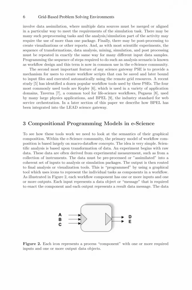
To see how these tools work we need to look at the semantics of their graphicalcomposition. Within the e-Science community, the primary model of workflow com-position is based largely on macro-dataflow concepts. The idea is very simple. Scien-tific analysis is based upon transformation of data. An experiment begins with rawdata. These data are often derived from experimental measurement, such as from acollection of instruments. The data must be pre-processed or ”assimilated” into acoherent set of inputs to analysis or simulation packages. The output is then routedto final analysis or visualization tools. This is “programmed” by using a graphicaltool which uses icons to represent the individual tasks as components in a workflow.As illustrated in Figure 2, each workflow component has one or more inputs and oneor more outputs. Each input represents a data object or “message” that is requiredto enact the component and each output represents a result data message. The data
Figure 2. Each icon represents a process “component” with one or more requiredinputs and one or more output data objects.
6 Grid-Based Problem Solving Environments

object may be a numerical value, a string or the URI of a file. In some systems thedata object may be a continuous stream of data to be processed. As illustrated inFigure 3, two components may be composed if the output of one component canserve as a valid input to another component. ”Unbound” inputs represent the datasources for the workflow and the unbound outputs are the final data products.
Figure 3. The components may be composed. In this case one result from compo-nent X is used as an input to component Y. A, B, and C are unbound inputs whichmust be supplied by the user at runtime.
In the typical system based on this model, the programmer drags icons onto apallet and wires together the dataflow for the experiment. Figure 4 illustrates theinterface to the XBaya system used in the Linked Environments for AtmosphericDiscovery (LEAD) project [10, 11].
Figure 4. The XBaya workflow composition tool used to build a storm forecastingworkflow.
Grid-Based Problem Solving Environments 7

Unfortunately, there are several problems with this basic model of dataflowdriven workflow as described above. The first problem relates to the way compo-nents are connected. When is the output of one component suitable as an input toanother component? Clearly, if they have conflicting simple types, such as providinga String as an input to something that is expecting a Float, then it is easy for arudimentary type system to detect the error. But most problems are due to subtlesemantic differences between the content of the message that is passed. For example,in large systems, the message often only contains the URI of a data file that is storedon a remote resource. How do we know if the data file has the right format or con-tent to be used by the destination component? The solution to this problem lies inproviding complete information about the exact semantics and format of each inputand output. This metadata needs to be attached to the component and some formof metadata analysis would be required to check compatibility. Without a commonmetadata schema, a component provided by one group of researchers cannot be usedby another group. Consequently, it is up to the scientist composing the workflow tounderstand this issue.
The second problem with this simple model is that it does not take into accountthe control dependencies that a typical computer program uses. For example, condi-tionals and iteration are difficult to express in a language where the only operationis the composition of directed acyclic graphs. However, it is not difficult to overlayadditional control operations over the dataflow. For example, a conditional can beexpressed by a component (Figure 5) that takes two inputs, a value message, and aconditional predicate that the message must satisfy. There are two outputs. If thepredicate evaluates to true, then the value is forwarded out one output. If the valueis false, the other message is generated.
Figure 5. A simple conditional element with two inputs: a value and a predicate.Based on the predicate value one of the output messages is generated.
Another essential component of any complete e-science workflow programmingtool is the expression of iteration. There are two cases to consider. The first is theclassical case of a “while” loop. As illustrated in Figure 6, the input is a predicate, aninitial iterate value and a set of data values. The predicate is applied to the iteratevalue and if the result is true, the iterate value and data values are passed to asubgraph. The subgraph transforms both the data values and applies some functionto the iterate value. These are fed back to the while control node and the test isrepeated.
The second form is a parallel “for each” that can be used when you wish toexecute a subgraph for each element of a set of data values. In this case the subgraph
8 Grid-Based Problem Solving Environments

Figure 6. A “while” loop and a parallel “for each” element.
is also supplied with an additional “iteration” index so the different invocations ofthe subgraph can be uniquely identified. This additional index is important when thesubgraph must create a side-effect outside the body of the workflow. For example,when an element of the workflow creates a file, it must be distinguished from thefile generated by the other instances. However, the exact semantics of how such aniteration index is propagated to the body of a “for each” loop is non-trivial and nota topic for this paper.
There are other standard features of workflow composition tools in this category.For example, it is important to be able to encapsulate any valid composed workflowas a component which can be used in other workflows.
Finally a topic that is always overlooked by e-Science workflow systems is thatof exceptions. An exception occurs when a specific component realizes that it cannotcorrectly process an incoming message. As with any modern programming language,it is essential that the system have a mechanism to capture these runtime exceptionsand deal with them. The model often used in programming languages, where ablock of code is encapsulated in a “try” block which is followed by a “catch” blockwhich is responsible for handling the exceptional conditions, can be used in graphicaldataflow-based systems. In the graphical case we can simply identify a subgraphthat may throw an exception and provide a description for a replacement “catch”subgraph. The exceptions that are the most frequent are those that are relatedto access to remote resources. For example, a remote service that fails to respondbecause of a network or other resource failure. In these cases it is often better tohandle the problem at a lower, resource allocation level than at the abstract workflowgraph level. A situation that may be handled at the graph level could be one wherea request to an application component is simply too large or, for some other reason,too difficult to process. In these cases, the workflow designer may know that analternative service exists that can be used in special cases like this.
Grid-Based Problem Solving Environments 9

4 The Service Architecture of a Science Gateway PSE.
The science gateway PSE programming model we have described so far is based onbuilding applications by composing application services. The LEAD gateway is likemany others in that the components services are implemented as Web services. Thisallows us to use standard robust middleware concepts and tooling that is widelyused in the commercial sector. However, large-scale computational science is stillthe domain of big Fortran applications that run from the command line. To usethese applications in a Web service based workflow we need to encapsulate themas services. To accomplish this we use an Application Factory Service [12], whichwhen given a description of an application deployment and execution shell script,automatically generates a web service that can run the application. As illustratedin Figure 7, the service takes as input command-line parameters and the URLsof any needed input files. The service automatically fetches the files and stages
Figure 7. The application services provide a mechanism to execute applications onbehalf of the user on remote resources.
them in a subdirectory on the machine where the application is to run. It thenuses a remote job execution tool (Globus GRAM [13]) to run and monitor theapplication. Finally the output files are pushed to the data storage facilities. Duringthe invocation of the service the progress of the data transfers and the monitoringof the application are published as “events” to a message notification bus. The busrelays the messages to listening processes including the user’s private applicationmetadata catalog. This allows the user to consult the catalog from the portal to seethe status of the execution.
To tie this all together we need to fill out a more complete service oriented archi-tecture (SOA). The portal and workflow composer are only one piece of the system.One important component is the workflow engine. While most e-Science workflowtools also double as the execution engine, the XBaya system is actually a compiler.It can either directly execute the workflow or it can compile a python programwhich, when run, does the execution, or it can generate a BPEL document. BPEL is
10 Grid-Based Problem Solving Environments
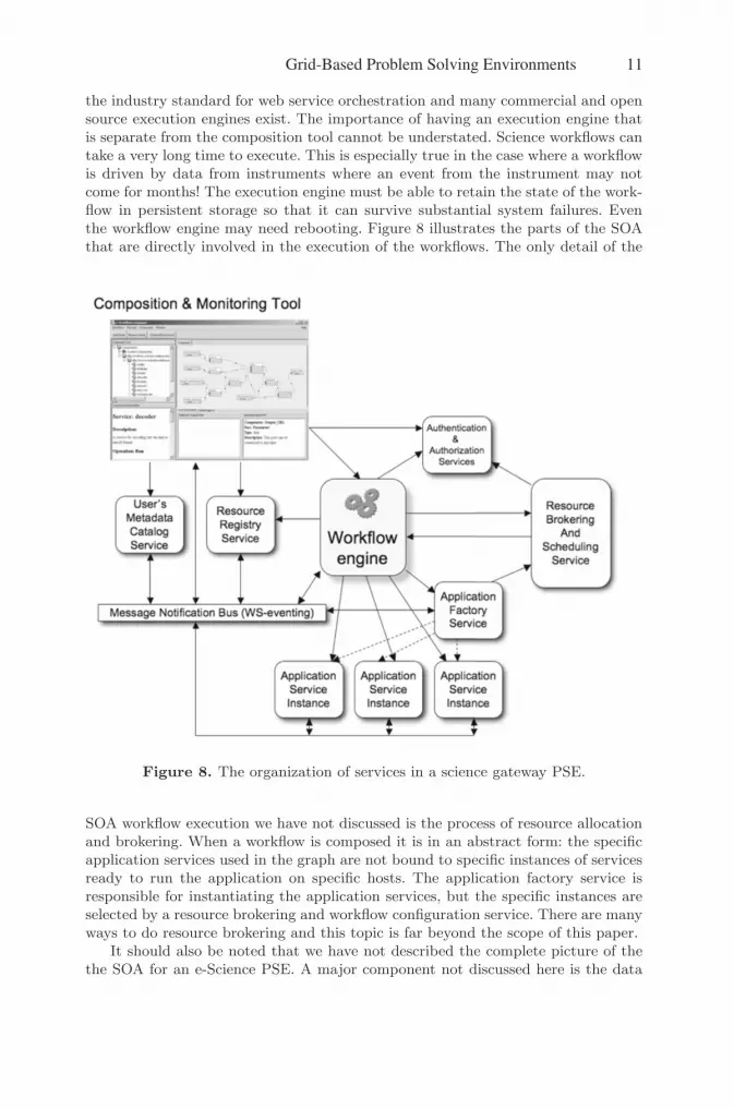
the industry standard for web service orchestration and many commercial and opensource execution engines exist. The importance of having an execution engine thatis separate from the composition tool cannot be understated. Science workflows cantake a very long time to execute. This is especially true in the case where a workflowis driven by data from instruments where an event from the instrument may notcome for months! The execution engine must be able to retain the state of the work-flow in persistent storage so that it can survive substantial system failures. Eventhe workflow engine may need rebooting. Figure 8 illustrates the parts of the SOAthat are directly involved in the execution of the workflows. The only detail of the
Figure 8. The organization of services in a science gateway PSE.
SOA workflow execution we have not discussed is the process of resource allocationand brokering. When a workflow is composed it is in an abstract form: the specificapplication services used in the graph are not bound to specific instances of servicesready to run the application on specific hosts. The application factory service isresponsible for instantiating the application services, but the specific instances areselected by a resource brokering and workflow configuration service. There are manyways to do resource brokering and this topic is far beyond the scope of this paper.
It should also be noted that we have not described the complete picture of thethe SOA for an e-Science PSE. A major component not discussed here is the data
Grid-Based Problem Solving Environments 11

subsystem. e-Science revolves around data. The workflow system only transformsthe data. This topic is treated in another paper in this workshop and elsewhere[14, 15].
5 Event Bus based PSE organization.
There are other approaches to building a PSE programming system that are oftenoverlooked because the dataflow graph model is so intuitive for scientists. Ratherthan thinking in terms of composing applications as explicit dataflow/control flowgraphs, we can consider the possibility of program components that respond to theirown environment in productive ways. The concept is based on an information busas illustrated in Figure 9. In this model a component “subscribes” to messages ofsome type or “topic” or containing certain content. Any component may “publish”messages on some topics for others to hear. To understand this, we should consideran example. Data from an instrument is gathered and published by an instrumentcomponent sitting on the bus. The user inserts data filters onto the bus whichcaptures the data events and transforms them and republishes them. These eventsare captured by a data analysis component, which publishes results. The resultsare captured by different rendering tools. This type of system, which resembles ablackboard model [11], is extremely flexible and dynamic.
Figure 9. The message bus architecture allow a more dynamic organization thanthe fixed dataflow model of execution.
This information bus model is the most flexible for integrating user interactioninto the system. Future systems will likely contain a combination of bus-based anddataflow approaches.
6 Discussion.
As part of this workshop a series of questions were posed to the authors from otherparticipants. In the spirit of the workshop we will devote our conclusion to a discus-sion of the points they raised.
• Q1: Anne Trefethen. You mentioned MATLAB as one of the classic PSEs. Haveyou looked at MATLAB Simulink, SimBiology, or SimEvents, which seem tohave the same kind of graphical interface? Have they solved any of the issuesyou raise?
12 Grid-Based Problem Solving Environments

Yes. These tools all use a graphical interface similar to the ones we have discussedhere. There are many more examples. This model of programming is certainly notnew. Many domain specific composition tools are able to reduce the complexity ofthe problem by simplifying the semantic space. SImBiology is an excellent example.However, most of these systems are not designed to operate in the wide area asweb service workflow engines. However MATLAB does have support for Web ser-vice integration, so it is possible to integrate web services into a MATLAB-basedapplication framework.
• Q2: Tom Jackson. How do you deal with the problem of integrating legacy usercode into portals (which are typically non-Java), particularly for visualization?
As discussed in Section 4 of this paper, legacy application integration is accomplishedby wrapping the application as a web service. This is a semi-automatic process. Inthe case of visualization, it is possible to wrap an off-line rendering system as aweb service and we have done that. A more complex problem is to invoke a “live”desktop application as part of a workflow. This is a general problem many systemshave with inserting a human action into the workflow. The best solution is to combinethe dataflow model with the event-bus model described above.
• Q3: Gabrielle Allen. How do you deal with resource allocation and/or resourcescheduling in these scenarios?
As mentioned in section 5, resource allocation and scheduling is handled by a “call-out” to a resource allocation service from the workflow configuration service. Thisuse of late binding of the resources with the workflow script allows for very greatflexibility. If the workflow engine is also able to catch exceptions and listen to theevent notification bus, it is possible to change the resource allocation while theworkflow execution is continuing.
• Q4: Tom Jackson. Where you referring to Enterprise Service Bus architectureswhen you discussed message bus solutions?
Yes. Although Enterprise Service Bus is often associated with a specific technologysuch as an EJB/JMS solution. However the concept is identical.
• Q5: Gabrielle Allen. What is the difference between event-driven and data-drivenarchitectures, and can you integrate these with a centralized component whichallows decision making and control to only need to be implemented in one place?
A workflow or computation can be data-driven and implemented with an event-driven bus framework or with a dataflow framework. There is a big difference be-tween dataflow (as described here) and an event-driven bus. In the case of dataflowthe workflow designer implements control based on a graph of dependencies thatmust be satisfied. Messages from one service are explicitly routed to the graphicallyconnected services. In the even-driven bus case each service can hear all messagesand respond to any of them. We control chaos by selecting services that only respondto messages that are of the appropriate topic.
• Q6: Bill Gropp. Have formal methods for verifying correctness been applied tographical workflows?
Yes and No. There is ample work in the theoretical literature about the semanticsand correctness of these graphical models, but we know of no system in use thatimplements any of these idea in practice.
Grid-Based Problem Solving Environments 13

• Q7. Richard Hanson. Libraries of software routines are well established as aprogramming model and tool. What do you visualize as an execution model forgrid computing and workflows?
In many ways, what we have described here is a way to deploy application softwarelibraries in a distributed context. But there is an important and subtle difference be-tween software components and traditional software libraries. Most software librariesare not well encapsulated: they rely on the runtime environment of the program in-voking them and they often operate by side-effecting common data structures. Thebehavior of component systems is completely defined by the interfaces they presentto their clients.
• Q8: (Mo Mu) What do you think is the role of APIs in the composition ofworkflows as a mechanism/standards to ensure the proper fitting of compo-nents/services?
In a Web service oriented system, interfaces are defined by the Web Service Defini-tion Language. This provides a programming language neutral way to describe themessages sent to a service and the types of messages that are returned. Also, Webservice systems have evolved considerably from the days of remote procedure calls.The stand now is message oriented, where the message is an XML document de-fined by an XML schema. The reply is defined similarly. By using WSDL and XMLschemas, the services become completely programming language neutral. Servicesbuilt from Java or C++ or .Net or Perl or Python can all interoperate. This wasnot possible with programming language based APIs because they all have differenttype systems.
• Q9 : (Keith Jackson) What role dows semantic information play in a componentarchitecture? What kinds of semantic information should a service expose?
Semantics are critical. Current service models do not provide enough semanticsabout the content of messages and responses. As discussed above this is one of thegreatest challenges to making a truly interoperable system of service components.
• Q10: (Anne Trefethen) How do we get community agreement on the semantics?
This is perhaps the most important question. The first step is to get a community toagree upon an ontology. This is starting to happen in many scientific domains. Oncethere is a common ontology, one can start defining common scientific metadata.Again this is happening in atmospheric science, oceanography, physics, geology, andmany more areas. But there is a long way to go. Once you have a common ontologyand common scientific metadata, then wrapping community codes to work as servicesin general e-Science PSE frameworks is relatively easy.
References
1. S. Wolfram, Mathematica: a system for doing mathematics by computer, 1991,Adison Wesley Co.
2. D. Hanselman, B. Littlefield, Mastering MATLAB 5: A Comprehensive Tutorialand Reference, 1997 - Prentice Hall PTR Upper Saddle River, NJ, USA
14 Grid-Based Problem Solving Environments
3. C. Upson , T. Faulhaber, Jr. , D. Kamins , D. H. Laidlaw, D. Schlegel, J. Vroom,R. Gurwitz, A. van Dam, The Application Visualization System: A Computa-tional Environment for Scientific Visualization, IEEE Computer Graphics andApplications archive Vol. 9 , no. 4, July 1989, pp. 30 - 42
4. S. Parker, C. Johnson, SCIRun: a scientific programming environment for com-putational steering, Proceedings of the 1995 ACM/IEEE conference on Super-computing, San Diego, California, United States Article No. 52, 1995.
5. I. Taylor, E. Deelman, D. Gannon, M. Shields (Eds.) , Workflows for e-ScienceScientific Workflows for Grids, Springer, 2007.
6. D. Pennington, D. Higgins, A. Townsend Peterson, M. Jones, B. Ludascher,S. Bowers, Ecological Niche Modeling Using the Kepler Workflow System. inWorkflows for e-Science Scientific Workflows for Grids, Springer, 2007.
7. T. Oinn, P. Li, D. Kel l, C. Goble, A. Goderis, M. Greenwood, D. Hul l, R.Stevens, D. Turi and J. Z hao, Taverna / myGrid: aligning a workflow systemwith the life sciences community, in Workflows for e-Science Scientific Workflowsfor Grids, Springer, 2007.
8. E. Deelman, G. Mehta, G. Singh, M-H. Su, K. Vahi, Pegasus: Mapping Large-Scale Workflows to Distributed Resources, in Workflows for e-Science ScientificWorkflows for Grids, Springer, 2007.
9. A.Slominski, Adapting BPEL to Scientific Workflows, in Workflows for e-Science Scientific Workflows for Grids, Springer, 2007.
10. K. Droegemeier, D. Gannon, D. Reed, B. Plale, J. Alameda, T. Baltzer, K.Brewster, R. Clark, B. Domenico, S. Graves, E. Joseph, D. Murray, R. Ra-machandran, M. Ramamurthy, L. Ramakkrisshnan, J. Rushing, D. Webeer, R.Wilhelmson, A. Wilson, M. Xue, S. Yalda, Service-Oriented Environments forDynamically Interacting with Mesoscale Weather, CiSE, Computing in Science& Engineering – November 2005, vol. 7, no. 6, pp. 12-29.
11. B. Plale, D. Gannon, J. Brotzge, K. Droegemeier, J. Kurose, D. McLaughlin,R. Wilhelmson, S. Graves, M. Ramamurthy, R. Clark, S. Yalda, D. Reed, E.Joseph, V. Chandrasekar, CASA and LEAD: Adaptive Cyberinfrastructure forReal-Time Multiscale Weather Forecasting, IEEE Computer, November 2006(Vol. 39, No. 11) pp. 56-64
12. Gopi Kandaswamy, Dennis Gannon, Liang Fang, Yi Huang, Satoshi Shirasuna,Suresh Marru, Building Web Services for Scientific Applications, IBM Journalof Research and Development, Vol 50, No. 2/3 March/May 2006.
13. I Foster, C Kesselman, Globus: A metacomputing infrastructure toolkit, Inter-national Journal of Supercomputer Applications, 1997
14. Y. Simmhan, S. Lee Pallickara, N. Vijayakumar, and B. Plale, Data Manage-ment in Dynamic Environment-driven Computational Science, IFIP WorkingConference on Grid-Based Problem Solving Environments (WoCo9) August2006, to appear as Springer-Verlag Lecture Notes in Computer Science (LNCS).
15. Beth Plale, Dennis Gannon, Yi Huang, Gopi Kandaswamy, Sangmi Lee Pal-lickara, and Aleksander Slominski, Cooperating Services for Data-Driven Com-putational Experimentation”, CiSE, Computing in Science & Engineering –September 2005 vol. 7 issue 5, pp. 34-43
Grid-Based Problem Solving Environments 15

Q&A – Dennis Gannon
Questioner: Anne Trefethen You mentioned MATLAB as one of the classic PSEs. Have you looked at MATLAB Simulink, SimBiology, or SimEvents, which seem to have the same kind of graphical interface? Have they solved any of the issues you raise?
Dennis Gannon: For our application domains, MATLAB is not a primary tool, but we do get requests to support it. Part of the problem is MATLAB is not completely Grid friendly. However, it does now support Web Services. Hence it should be possible to integrate MATLAB based tools into Grid workflows.
Questioner: Tom Jackson How do you deal with the problem of integrating user code into portals (which are typically non-Java), particularly for visualization?
Dennis Gannon: We have an application service factory that is capable of "wrapping" a command line application and turning it into a Web service. This is described in the talk. However, a big challenge is integrating legacy desktop tools. In some cases it is possible to create a service which listens for an event of a specific type. This service runs on the user's desktop. When the service gets the event, it can fetch data and then launch the legacy application with the data. This allows the tool to exist at the end points of the workflow. The difficulty is putting the legacy desktop application in the critical loops of a workflow. More work needs to be done in this area. It is very important.
Questioner: Tom Jackson Were you referring to Enterprise Service Bus architectures when you discussed message bus solutions?
Dennis Gannon: ESB is one solution. However, we prefer a Web services solution and find ws-notification and ws-eventing to be very powerful and general solutions to the message bus.
Questioner: Gabrielle Allen How do you deal with resource allocation and/or resource scheduling in these scenarios?
Dennis Gannon: Poorly. However, we are working with the VGrADS project which is focused on scheduling and resource allocation. In general, this is a service that the

workflow engine and other services can invoke in advance of execution or on-the-fly.
Questioner: Gabrielle Allen What is the difference between event-driven and data-driven architectures, and can you integrate these with a centralized component which allows decision making and control to only need to be implemented in one place?
Dennis Gannon: Event-driven is based on a bus organization where components subscribe to event by type, and publish other events back to the bus. Data-driven are worklfows that behave like dataflow graphs. Data arrives at the source components and the work propagates through the graph. It can be pipelined. Purely event-driven workflows are harder to manage with a central control, while data-driven is manageable by a centralized workflow engine.
Questioner: Bill Gropp Have formal methods for verifying correctness been applied to graphical workflows?
Dennis Gannon: There is not much work that I know about on this for e-science workflows but there may be lots of work I am unaware of. One natural place to look is the work that has been done on circuit simulation.
Questioner: Bill Gropp How do you handle relationships between elements or hierarchy in representation?
Dennis Gannon: This is a big problem. Many of the legacy applications have complex, interdependent input files. Often a change in one input file to an upstream service may require a change to a downstream service. The only want to handle this is to propagate change information downstream with the other data. It is a hard problem in general.