programming guide - helpdesk communications ltd
TRANSCRIPT
Model No. KX-TD612E
Digital Super Hybrid System
Programming Guide
Version 3Thank you for purchasing a Panasonic Digital Super Hybrid System, Model KX-TD612.Please read this manual before connecting the Digital Super Hybrid System and save this manual for future reference.

Introduction
IntroductionThis Programming Guide provides programming instruction for a digital proprietary telephone (DPT).
2 Programming Guide
Table of Contents
Table of Contents1 General System Programming ........................................................ 91.1 General Programming Instructions............................................................................101.2 Using the Digital Proprietary Telephone....................................................................111.3 Programming Ways......................................................................................................151.4 Entering Characters.....................................................................................................171.5 Example of Programming............................................................................................22
2 Manager Programming.................................................................. 252.1 Manager Programming................................................................................................26[000] Date and Time Set.......................................................................................................26[001] System Speed Dialling and Intelligent Call Handling Number Set............................28[002] System Speed Dialling and Intelligent Call Handling Name Set ...............................31[003] Extension Number Set ................................................................................................33[004] Extension Name Set....................................................................................................35[005] Flexible CO Button/PF Key Assignment....................................................................37[006] Operator/Manager Extension Assignment — Day/Night...........................................40[007] Console Port and Paired Telephone Assignment ........................................................42[008] Absent Messages.........................................................................................................44[009] Quick Dial Number Set...............................................................................................46[010] Budget Management ...................................................................................................47[012] ISDN Extension Number Set......................................................................................49[013] ISDN Extension Name Set .........................................................................................51[014] Budget Management on ISDN Port ............................................................................52[015] Charge Rate Fractional Point Assignment..................................................................54[016] Charge Rate Assignment ............................................................................................55[021-022] Doorphone Call Forwarding — Day/Night .........................................................57[024] Intelligent Call Handling Table...................................................................................58[025] Intelligent Call Handling for Fax and Modem............................................................60[026] ISDN Remote Maintenance Access Number..............................................................62[027] ISDN Remote Maintenance Access Name .................................................................63[028] ISDN Remote Alarm Notification Dial Number ........................................................64
3 System Programming..................................................................... 653.1 System Programming...................................................................................................66[100] Flexible Numbering ....................................................................................................66[102] Day/Night Service Starting Time................................................................................71[103] Automatic Access CO Port Assignment.....................................................................73[104] Quick Dial Assignment...............................................................................................74[105] Account Codes............................................................................................................75[106] Station Hunting Type ..................................................................................................77[107] System Password ........................................................................................................79[108] One-Touch Transfer by DSS Button...........................................................................81[110] Network Type Assignment .........................................................................................82[113] Voice Mail Status DTMF Set ......................................................................................83[114] Voice Mail Command DTMF Set ...............................................................................85[116] Software Version Display ...........................................................................................87
Programming Guide 3
Table of Contents
[117] Charge Display Selection........................................................................................... 88[118] Charge Verification Assignment ................................................................................ 89[119] Charge Verification ID Code Set................................................................................ 90[120] User Password............................................................................................................ 91[121] Pulse Dial Reception Assignment.............................................................................. 92[122] Automatic Door Open Assignment............................................................................ 93[125] Currency Assignment................................................................................................. 94[126] Voice Mail Number Assignment................................................................................ 95[127] Voice Mail Extension Number Assignment............................................................... 97[128] Voice Mail Extension Group Assignment.................................................................. 99[129] Operator Queue........................................................................................................ 101[130] Phantom Extension Number Assignment ................................................................ 102[131] Hunting Group Assignment ..................................................................................... 104[132] Hunting Group Name Assignment........................................................................... 106[133] Hunting Overflow .................................................................................................... 107[134-135] Hunting Intercept — Day/Night ....................................................................... 109[137-138] Time Table Assignment — Day/Night ............................................................. 110[139] Time Table................................................................................................................ 111[140] Phantom Extension Name........................................................................................ 113[141] Off-Hook Monitor.................................................................................................... 114[143] CCBS Feature .......................................................................................................... 115[144] Hunting Group Busy on Busy.................................................................................. 116[145] Second Ringer For Doorphone Assignment ............................................................ 117
4 Timer Programming..................................................................... 1194.1 Timer Programming.................................................................................................. 120[200] Hold Recall Time ..................................................................................................... 120[201] Transfer Recall Time................................................................................................ 121[202] Call Forwarding — No Answer Time...................................................................... 122[203] Intercept Time .......................................................................................................... 123[204] Pickup Dial Waiting Time........................................................................................ 124[205] Extension-to-Outside Line Call Duration Time....................................................... 125[206] Outside-to-Outside Line Call Duration Time .......................................................... 126[207] First Digit Time........................................................................................................ 127[208] Inter Digit Time ....................................................................................................... 128[209] Automatic Redial Repeat Times .............................................................................. 129[210] Automatic Redial Interval Time............................................................................... 130[211] Dial Start Time......................................................................................................... 131[212] Call Duration Count Start Time ............................................................................... 132[213] External Relay Connecting Time ............................................................................. 133[214] Message Waiting Ring Interval Time....................................................................... 134[215] Ring Off Detection Time ......................................................................................... 135[217] Timed Reminder Alarm Ring Time ......................................................................... 136[218] Doorphone-to-CO Line Call Duration Time............................................................ 137[220] DISA Prolong Time ................................................................................................. 138[221] DISA Automated Attendant (AA) Wait Time.......................................................... 139[222] OGM Recording Time ............................................................................................. 140[223] Built-in Voice Message Recording Time ................................................................. 141
4 Programming Guide
Table of Contents
5 TRS Programming ....................................................................... 1435.1 TRS Programming .....................................................................................................144[301-305] TRS Denied Code Entry for Levels 2 through 6 ...............................................144[306-310] TRS Excepted Code Entry for Levels 2 through 6 ............................................146[311] Emergency Dial Number Set ....................................................................................148
6 CO Line Programming ................................................................ 1516.1 CO Line Programming ..............................................................................................152[400] CO Port Connection Assignment..............................................................................152[402] Dial Mode Selection .................................................................................................153[403] Pulse Speed Selection ...............................................................................................155[404] DTMF Time ..............................................................................................................156[411] Host PBX Access Codes...........................................................................................157[412] Pause Time................................................................................................................159[413] Flash Time ................................................................................................................160[414] Disconnect Time .......................................................................................................161[418] Second Ringer Assignment.......................................................................................162[421] CO Port Name...........................................................................................................163[422] ISDN Port Type.........................................................................................................165[423] ISDN Layer 1 Active Mode......................................................................................166[424] ISDN Configuration..................................................................................................167[425] ISDN Data Link Mode..............................................................................................168[426] ISDN TEI Mode........................................................................................................169[427] ISDN Extension Multiple Subscriber Number .........................................................171[428] ISDN Extension Progress Tone ................................................................................172[452] Extension Ringing Assignment ................................................................................173[453] Other Extension Ringing Assignment ......................................................................175[454] ISDN Extension Ringing Assignment ......................................................................177[455] Built-in Voice Message for Call Handling................................................................179[456] Call Handling When All Busy ..................................................................................180[457] Intercept Extension ...................................................................................................181[458] Intelligent Call Handling Table for Analogue CO....................................................183[460] ISDN Call Hold ........................................................................................................184[461] ISDN Call Transfer ...................................................................................................185[462] ISDN Conference......................................................................................................186[463] ISDN Call Forwarding..............................................................................................187[464] ISDN Call Deflection................................................................................................188
7 COS Programming....................................................................... 1897.1 COS Programming .....................................................................................................190[500-501] Toll Restriction Level — Day/Night .................................................................190[502] Extension-to-CO Call Duration Limit ......................................................................192[503] Call Transfer to CO Line ..........................................................................................193[504] Call Forwarding to CO Line .....................................................................................194[505] Executive Busy Override ..........................................................................................195[506] Executive Busy Override Deny.................................................................................196[507] Do Not Disturb Override ..........................................................................................197[508] Account Code Entry Mode .......................................................................................198[509-510] Toll Restriction Level for System Speed Dialling – Day/Night ........................200
Programming Guide 5
Table of Contents
[511] Door Opener Access ................................................................................................ 201[512] External Relay Access ............................................................................................. 202[513] Night Service Access ............................................................................................... 203[514] Do Not Disturb (DND) for Intelligent Call Handling 1:1 Call ................................ 204[516] Calling Line Identification Restriction .................................................................... 205[517] Connected Line Identification Restriction ............................................................... 206[518] CFU/CFB/CFNR Assignment ................................................................................. 207[519] Off-Hook Call Announcement (OHCA).................................................................. 208[520] Call Forwarding from Hunting Group ..................................................................... 209[521] Doorphone Call Forwarding to CO Line ................................................................. 210
8 Extension Programming .............................................................. 2118.1 Extension Programming ........................................................................................... 212[600] EXtra Device Port .................................................................................................... 212[601] Class of Service........................................................................................................ 213[602] Extension Group Assignment .................................................................................. 215[605-606] Outgoing Permitted CO Line Assignment — Day/Night................................. 217[607-608] Doorphone Ringing Assignment — Day/Night ............................................... 219[609] Voice Mail Access Codes......................................................................................... 221[610] Department Codes.................................................................................................... 223[611] Extension Connection Assignment .......................................................................... 225[612] Data Line Security ................................................................................................... 226[613] ISDN Class of Service ............................................................................................. 227[614] Department Codes of ISDN Port ............................................................................. 229[615-616] Outgoing Permitted CO Line Assignment – Day/Night for ISDN Extension.. 230[617] Live Call Screening Recording Mode Assignment.................................................. 232[622] Incoming Call Display ............................................................................................. 234[623] CLIP/COLP Number Assignment for Extension..................................................... 235[624] CLIP/COLP Number Assignment for ISDN Extension .......................................... 237[625-626] Built-in Voice Message for Extension — Day/Night ....................................... 239[627] Voice Message Resource Assignment...................................................................... 240[628] Built-in Voice Message Access Code through CO Line .......................................... 242[629] Telephone Answering Machine (TAM) Connection Assignment............................ 244[630] ISDN Bearer Mode .................................................................................................. 245[631] CLIP/COLP Number Assignment for ISDN Port.................................................... 246[632] Caller ID................................................................................................................... 248[633] Caller ID Line Access Number................................................................................ 249[634] Caller ID Type.......................................................................................................... 250[635] Caller ID Parameter ................................................................................................. 251[636] Single Line Telephone Bell Cadence ....................................................................... 252[637] Single Line Telephone Bell Pattern ......................................................................... 253
9 LCR Programming....................................................................... 2559.1 LCR Programming.................................................................................................... 256[7000] LCR Mode ............................................................................................................. 256[7002] BTL Access Code .................................................................................................. 257[7003] Itemised Code Set .................................................................................................. 258[7004] ISDN Itemised Code Set ........................................................................................ 259[7X0Y] LCR Leading Digit Entry for Plan 1-8................................................................. 260
6 Programming Guide
Table of Contents
[7X1Y] LCR Time and Fee for Plan 1-8 ............................................................................262[7X20] LCR Exceptional Code ..........................................................................................264[7X21] LCR Carrier Code..................................................................................................266[7X22] LCR Carrier Modify Command.............................................................................267[7X23] LCR CO Port Assignment .....................................................................................269[7X24] LCR Authorisation Code .......................................................................................270
10 Resource Programming ............................................................. 27110.1 Resource Programming ...........................................................................................272[800] SMDR Incoming/Outgoing Call Log Printout .........................................................272[801] SMDR Format...........................................................................................................273[802] System Data Printout ................................................................................................275[803] Music Source Use .....................................................................................................276[804] External Pager BGM.................................................................................................277[805] External Pager Confirmation Tone ...........................................................................278[806] RS-232C Parameters.................................................................................................279[809] DISA Security Type..................................................................................................281[810] DISA Tone Detection................................................................................................282[811] DISA User Codes......................................................................................................283[813] Floating Number Assignment...................................................................................285[815] DISA Automated Attendant (AA) ............................................................................287[820] OGM Recording .......................................................................................................289[822] Built-in Voice Message Total Recording Time .........................................................290[895] OGM and Voice Message Clear................................................................................291
11 Optional Programming .............................................................. 29311.1 Optional Programming ............................................................................................294[990] System Additional Information ................................................................................294[991] COS Additional Information ....................................................................................308
12 Default Values ............................................................................. 311
Programming Guide 7

Table of Contents
8 Programming Guide
General System Programming
Section 1
General System Programming
Programming Guide 9
General System Programming
1.1 General Programming Instructions
Default SettingThis system has a default factory setting. If any of the programming needs to be changed, you will find the necessary information in "Features Guide." This makes the system very simple to install and customise as required by the customer.
Required Telephone SetOne of the following telephone sets is required for System Programming:
• Digital Proprietary Telephone (DPT):KX-T7431, KX-T7433, KX-T7436, KX-T7230, KX-T7235
Extensions Used for ProgrammingConnect one of the above-mentioned telephone sets to either of the following:
• Jack number 1
• Jack programmed as a manager extensionTo assign the manager extension, see Section [006] Operator/Manager Extension Assignment — Day/Night"
• All jacks for Manager Programming [000] Date and Time Set through [014] Budget Management on ISDN Port
10 Programming Guide

General System Programming
1.2 Using the Digital Proprietary Telephone
Soft Buttons and SHIFT Button on the Display DPTThree soft buttons are provided just below the display on the Digital Proprietary Telephones with Display (DPT); KX-T7433, KX-T7436, KX-T7230, KX-T7235. The functions of these soft buttons vary as the programming procedures advance from step to step. Those functions that are currently assigned to the buttons are shown on the lower line of the display. (See "Viewing the Display" on Page 13 for more information on the display lines.)If the SHIFT button indicator is on, 2 functions are available with each soft button. To alternate between the 2 functions, press the SHIFT button on the right side of the display.
Soft button variations
CLR NEXT
Soft 1 Soft 2 Soft 3 SHIFT
Type 1Example:KX-T7433 Display
Buttons
SKP+ CLR NEXT
Soft 1 Soft 2 Soft 3 SHIFT SHIFT
SKP- PREV
Soft 1 Soft 2 Soft 3
Type 2Press SHIFTto alternate
—> SEL NEXT
Soft 1 Soft 2 Soft 3 SHIFT SHIFT
<— SEL PREV
Soft 1 Soft 2 Soft 3
Type 3Press SHIFTto alternate
A B C
Soft 1 Soft 2 Soft 3 SHIFT SHIFT
a b c
Soft 1 Soft 2 Soft 3
Type 4Press SHIFTto alternate
SKP+ SEL NEXT
Soft 1 Soft 2 Soft 3 SHIFT
SKP- CLR PREV
Soft 1 Soft 2 Soft 3 SHIFT
Type 5 Press SHIFT to alternate
Programming Guide 11
General System Programming
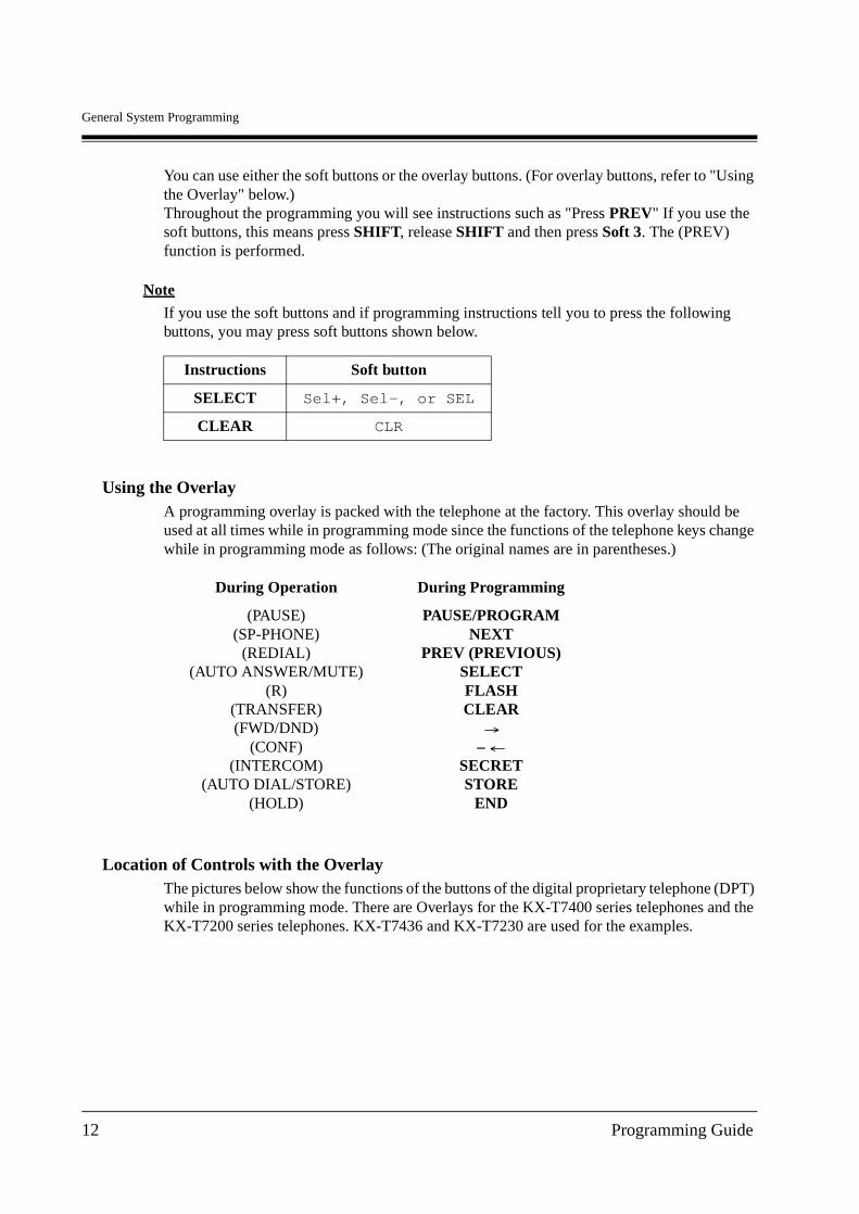
You can use either the soft buttons or the overlay buttons. (For overlay buttons, refer to "Using the Overlay" below.)Throughout the programming you will see instructions such as "Press PREV" If you use the soft buttons, this means press SHIFT, release SHIFT and then press Soft 3. The (PREV) function is performed.
Note
If you use the soft buttons and if programming instructions tell you to press the following buttons, you may press soft buttons shown below.
Using the OverlayA programming overlay is packed with the telephone at the factory. This overlay should be used at all times while in programming mode since the functions of the telephone keys change while in programming mode as follows: (The original names are in parentheses.)
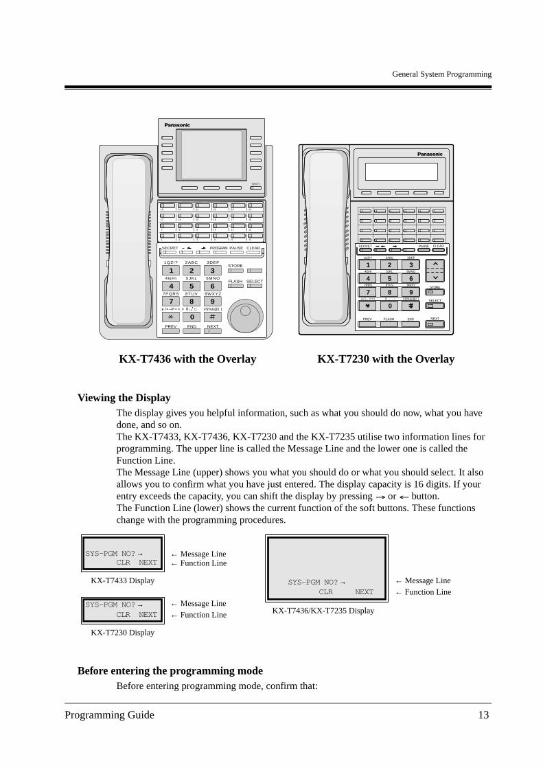
Location of Controls with the OverlayThe pictures below show the functions of the buttons of the digital proprietary telephone (DPT) while in programming mode. There are Overlays for the KX-T7400 series telephones and the KX-T7200 series telephones. KX-T7436 and KX-T7230 are used for the examples.
Instructions Soft button
SELECT Sel+, Sel-, or SEL
CLEAR CLR
During Operation During Programming
(PAUSE)(SP-PHONE)
(REDIAL)(AUTO ANSWER/MUTE)
(R)(TRANSFER)(FWD/DND)
(CONF)(INTERCOM)
(AUTO DIAL/STORE)(HOLD)
PAUSE/PROGRAMNEXT
PREV (PREVIOUS)SELECTFLASHCLEAR
– SECRETSTORE
END
12 Programming Guide
General System Programming
Viewing the DisplayThe display gives you helpful information, such as what you should do now, what you have done, and so on.The KX-T7433, KX-T7436, KX-T7230 and the KX-T7235 utilise two information lines for programming. The upper line is called the Message Line and the lower one is called the Function Line.The Message Line (upper) shows you what you should do or what you should select. It also allows you to confirm what you have just entered. The display capacity is 16 digits. If your entry exceeds the capacity, you can shift the display by pressing or button.The Function Line (lower) shows the current function of the soft buttons. These functions change with the programming procedures.
Before entering the programming modeBefore entering programming mode, confirm that:
KX-T7230 with the Overlay
1
4
7
5
8
0
2
6
9
34GHI
7PRS
5JKL
8TUV
2ABC
6MNO
9WXY
3DEF
FLASHPREV
CLEAR
SELECT
NEXT
SECRET PAUSE
END
1QZ!?
/+– =<> 0 . , ’ : ; #$%&@( )
STORE
*
KX-T7436 with the Overlay
FLASH
AUTO DIAL
STOREAUTO ANSWER
MUTE
MESSAGE
SP-PHONEHOLDREDIAL
1 2 3 4 5 6
7 8 9 10 11 12
13 14 15 16 17 18
19 20 21 22 23 24
PROGRAM TRANSFERPAUSEFWD/DNDINTERCOM CONF
ABC DEF
JKL MNOGHI
TUV WXYZPQRS
SHIFT
MIC
5
8
0
22ABC
5JKL
8TUV
0 ., :;
3DEF
6MNO
9WXYZ
#$%&@( )
6
9
3
,
SECRET PROGRAM PAUSE CLEAR
1
4
7
1QZ!?
4GHI
7PQRS
/+–P= < >
ENDPREV NEXT
SELECTFLASH
STORE
SYS-PGM NO? →CLR NEXT
KX-T7230 Display
← Message Line← Function Line
SYS-PGM NO?→CLR NEXT
KX-T7433 Display
← Message Line← Function Line
SYS-PGM NO? →CLR NEXT
KX-T7436/KX-T7235 Display
← Message Line← Function Line
Programming Guide 13

General System Programming
• Your telephone is on-hook.
• No calls are on hold at your telephone.
Entering the programming modeTo enter the System Programming mode from a Jack 1 DPT:
• The display shows the Initial Message: SYS-PGM NO?
To enter the Manager Programming mode from any DPT:
• The display shows the Initial Message: MNG-PGM NO?
Note
• If your telephone set has no PROG. button, substitute with the PAUSE button.
• If nothing is entered in 5 seconds after the PROG. button is pressed, it is cancelled.
• The System or User Password entered is not shown on the display. The System or User Password can be changed by System Programming. Refer to [107] System Password or [120] User Password.
• During the programming mode, your extension is treated as a busy extension.
• Only 1 DPT can be in programming mode at any one time.
Press PROG. + + # and enter your System Password(default=1234).
Press PROG. + + and enter your User Password(default=1234).
14 Programming Guide
General System Programming
1.3 Programming Ways
Advancing to the next stageWhen "SYS-PGM NO? " is displayed, you can select one of the following:
• To go to programme [000], press the NEXT button.
• To go to another programme, enter the 3-digit programme address.
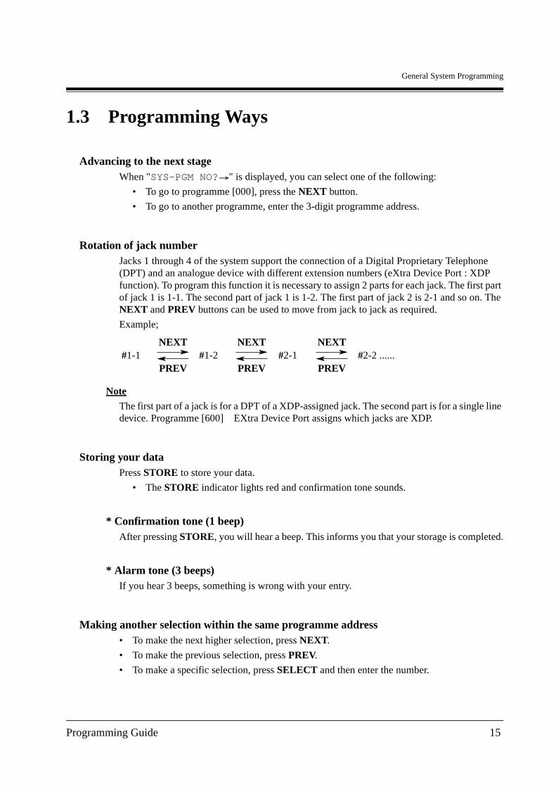
Rotation of jack numberJacks 1 through 4 of the system support the connection of a Digital Proprietary Telephone (DPT) and an analogue device with different extension numbers (eXtra Device Port : XDP function). To program this function it is necessary to assign 2 parts for each jack. The first part of jack 1 is 1-1. The second part of jack 1 is 1-2. The first part of jack 2 is 2-1 and so on. The NEXT and PREV buttons can be used to move from jack to jack as required.
Example;
Note
The first part of a jack is for a DPT of a XDP-assigned jack. The second part is for a single line device. Programme [600] EXtra Device Port assigns which jacks are XDP.
Storing your dataPress STORE to store your data.
• The STORE indicator lights red and confirmation tone sounds.
* Confirmation tone (1 beep)After pressing STORE, you will hear a beep. This informs you that your storage is completed.
* Alarm tone (3 beeps)If you hear 3 beeps, something is wrong with your entry.
Making another selection within the same programme address• To make the next higher selection, press NEXT.
• To make the previous selection, press PREV.
• To make a specific selection, press SELECT and then enter the number.
NEXT NEXTNEXT#1-1 #1-2 #2-1 #2-2 ......
PREV PREVPREV
Programming Guide 15

General System Programming
Going to another programme addressAfter pressing STORE, you can go to another programme with either of the following two methods:
a) To go to the next higher programme address:Press Soft 1 (SKP+) or VOLUME (DOWN).
To go to the next lower programme address:Press SHIFT + Soft 1 (SKP-) or VOLUME (UP).
b) To go to a specific programme address:Press END, then enter the programme address.
Method 1 is useful when you want to perform a series of programmes consecutively. For example, to change the programming in addresses [0XX], use this method. You can move from [000] to [001], from [001] to [002], and so on by pressing the SKP+ or VOLUME . You can move in reverse order from [008] to [007], etc. by pressing the SKP- or VOLUME .This method can also be used to move between neighboring programme groups: For example, you can move between the programme addresses of the largest [0XX] and [100], the largest [1XX] and [200], and so on. Also, you can move between the smallest programme address [000] and the largest one [9XX].Method 2 is useful when you wish to jump to another programme address. For example, you have just finished with programme [006] and now you want to go to programme [301]. Neither SKP+/ VOLUME nor SKP- or VOLUME is convenient in this case. So you should press END and enter 301.
Note
The following programming instructions suppose that you have already entered programming mode and that you will use Method 2.
Confirming the entriesYou may review the stored programming without making any changes.
Going back to the operation modeTwo ways are available to go back to the operation mode:
a) Lift the handset while in programming mode.
b) When the Initial Message "SYS-PGM NO? " is displayed, press the PROG. button.(To display the Initial Message, press END.)
16 Programming Guide
General System Programming
1.4 Entering Characters
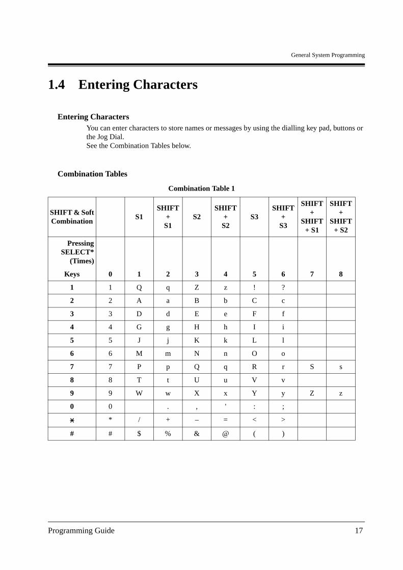
Entering CharactersYou can enter characters to store names or messages by using the dialling key pad, buttons or the Jog Dial.See the Combination Tables below.
Combination Tables
Combination Table 1
SHIFT & SoftCombination
S1SHIFT
+ S1
S2SHIFT
+ S2
S3SHIFT
+ S3
SHIFT +
SHIFT + S1
SHIFT +
SHIFT + S2
PressingSELECT*
(Times)
0 1 2 3 4 5 6 7 8Keys
1 1 Q q Z z ! ?
2 2 A a B b C c
3 3 D d E e F f
4 4 G g H h I i
5 5 J j K k L l
6 6 M m N n O o
7 7 P p Q q R r S s
8 8 T t U u V v
9 9 W w X x Y y Z z
0 0 . , ' : ;
* / + – = < >
# # $ % & @ ( )
Programming Guide 17
General System Programming
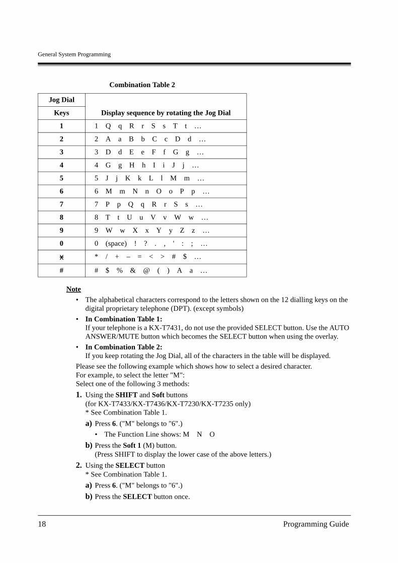
Note
• The alphabetical characters correspond to the letters shown on the 12 dialling keys on the digital proprietary telephone (DPT). (except symbols)
• In Combination Table 1:If your telephone is a KX-T7431, do not use the provided SELECT button. Use the AUTO ANSWER/MUTE button which becomes the SELECT button when using the overlay.
• In Combination Table 2:If you keep rotating the Jog Dial, all of the characters in the table will be displayed.
Please see the following example which shows how to select a desired character.For example, to select the letter "M":Select one of the following 3 methods:
1. Using the SHIFT and Soft buttons(for KX-T7433/KX-T7436/KX-T7230/KX-T7235 only)* See Combination Table 1.
a) Press 6. ("M" belongs to "6".)
• The Function Line shows: M N O
b) Press the Soft 1 (M) button.(Press SHIFT to display the lower case of the above letters.)
2. Using the SELECT button* See Combination Table 1.
a) Press 6. ("M" belongs to "6".)
b) Press the SELECT button once.
Combination Table 2
Jog Dial
Display sequence by rotating the Jog DialKeys
1 1 Q q R r S s T t …
2 2 A a B b C c D d …
3 3 D d E e F f G g …
4 4 G g H h I i J j …
5 5 J j K k L l M m …
6 6 M m N n O o P p …
7 7 P p Q q R r S s …
8 8 T t U u V v W w …
9 9 W w X x Y y Z z …
0 0 (space) ! ? . , ' : ; …
* / + – = < > # $ …
# # $ % & @ ( ) A a …
18 Programming Guide
General System Programming
• Pressing the SELECT button an appropriate number of times gives you the desired letter. Pressing SELECT twice gives the letter "m", pressing 3 times gives "N", and so on.
3. Using the Jog Dial(for KX-T7431/KX-T7433/KX-T7436 only)* See Combination Table 2.
a) Press 6. ("M" belongs to "6".)
b) Rotate the Jog Dial 1 pulse.
• Rotating the Jog Dial an appropriate number of pulses gives you the desired letter. Rotating the Jog Dial 2 pulses gives the letter "m", rotating 3 pulses gives "N", and so on.
OR
a) Press any dialling keypad.
b) Rotate the Jog Dial until the desired character appears.
• If you keep rotating the Jog Dial, eventually all of the characters will be displayed. For example, If you rotate the Jog Dial after pressing 2, characters will appear in the following order:A a B b … Z z (space) ! ? . , ' : ; * / + - = < > # $ % & @ ( ) A a B b …
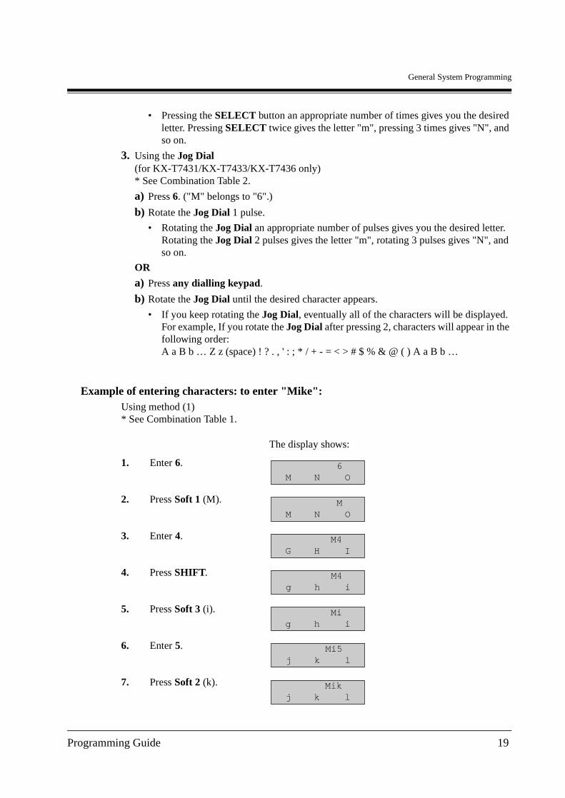
Example of entering characters: to enter "Mike":Using method (1)* See Combination Table 1.
The display shows:
1. Enter 6.
2. Press Soft 1 (M).
3. Enter 4.
4. Press SHIFT.
5. Press Soft 3 (i).
6. Enter 5.
7. Press Soft 2 (k).
6M N O
MM N O
M4G H I
M4g h i
Mig h i
Mi5j k l
Mikj k l
Programming Guide 19
General System Programming
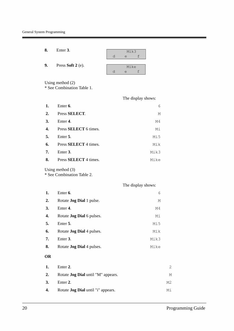
Using method (2)* See Combination Table 1.
Using method (3)* See Combination Table 2.
OR
8. Enter 3.
9. Press Soft 2 (e).
The display shows:
1. Enter 6. 6
2. Press SELECT. M
3. Enter 4. M4
4. Press SELECT 6 times. Mi
5. Enter 5. Mi5
6. Press SELECT 4 times. Mik
7. Enter 3. Mik3
8. Press SELECT 4 times. Mike
The display shows:
1. Enter 6. 6
2. Rotate Jog Dial 1 pulse. M
3. Enter 4. M4
4. Rotate Jog Dial 6 pulses. Mi
5. Enter 5. Mi5
6. Rotate Jog Dial 4 pulses. Mik
7. Enter 3. Mik3
8. Rotate Jog Dial 4 pulses. Mike
1. Enter 2. 2
2. Rotate Jog Dial until "M" appears. M
3. Enter 2. M2
4. Rotate Jog Dial until "i" appears. Mi
Mik3d e f
Miked e f
20 Programming Guide
General System Programming
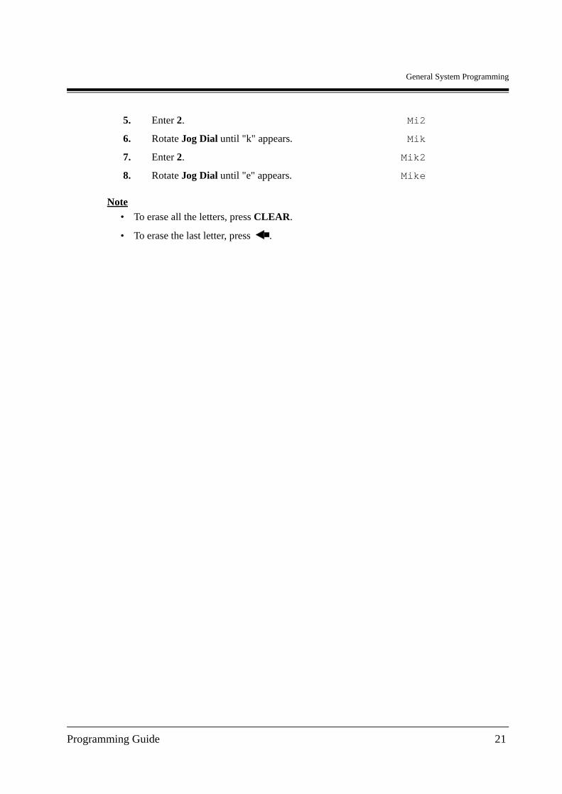
Note• To erase all the letters, press CLEAR.
• To erase the last letter, press .
5. Enter 2. Mi2
6. Rotate Jog Dial until "k" appears. Mik
7. Enter 2. Mik2
8. Rotate Jog Dial until "e" appears. Mike
Programming Guide 21
General System Programming
1.5 Example of Programming
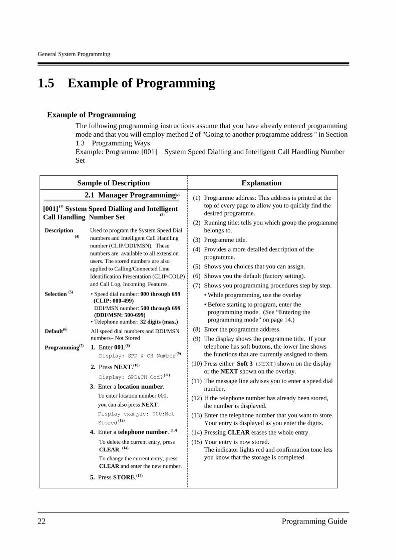
Example of ProgrammingThe following programming instructions assume that you have already entered programming mode and that you will employ method 2 of "Going to another programme address " in Section 1.3 Programming Ways.Example: Programme [001] System Speed Dialling and Intelligent Call Handling Number Set
Description(4)
Used to program the System Speed Dialnumbers and Intelligent Call Handling number (CLIP/DDI/MSN). These numbers are available to all extension users. The stored numbers are also applied to Calling/Connected Line Identification Presentation (CLIP/COLP) and Call Log, Incoming Features.
Selection (5) • Speed dial number: 000 through 699 (CLIP: 000-499)
• Telephone number: 32 digits (max.)
Default(6) All speed dial numbers and DDI/MSN numbers– Not Stored
Programming(7) 1. Enter 001.(8)
Display: SPD & CH Number (9)
2. Press NEXT.(10)
Display: SPD&CH Cod? (11)
3. Enter a location number.
To enter location number 000,
you can also press NEXT.
Display example: 000:Not
Stored (12)
4. Enter a telephone number. (13)
To delete the current entry, pressCLEAR. (14)
To change the current entry, pressCLEAR and enter the new number.
5. Press STORE.(15)
2.1 Manager Programming(2)
(3)[001] System Speed Dialling and Intelligent Call Handling Number Set
(1)
(1) Programme address: This address is printed at the top of every page to allow you to quickly find thedesired programme.
(2) Running title: tells you which group the programmebelongs to.
(3) Programme title.
(4) Provides a more detailed description of theprogramme.
(5) Shows you choices that you can assign.
(6) Shows you the default (factory setting).
(7) Shows you programming procedures step by step.
• While programming, use the overlay
.• Before starting to program, enter the
programming mode. (See “Entering theprogramming mode” on page 14.)
(8) Enter the programme address.
(9) The display shows the programme title. If yourtelephone has soft buttons, the lower line showsthe functions that are currently assigned to them.
(10) Press either Soft 3 (NEXT)shown on the displayor the NEXT shown on the overlay.
(11) The message line advises you to enter a speed dialnumber.
(12) If the telephone number has already been stored,the number is displayed.
(13) Enter the telephone number that you want to store.Your entry is displayed as you enter the digits.
(14) Pressing CLEAR erases the whole entry.
(15) Your entry is now stored.The indicator lights red and confirmation tone letsyou know that the storage is completed.
Sample of Description Explanation
DDI/MSN number: 500 through 699 (DDI/MSN: 500-699)
22 Programming Guide
General System Programming
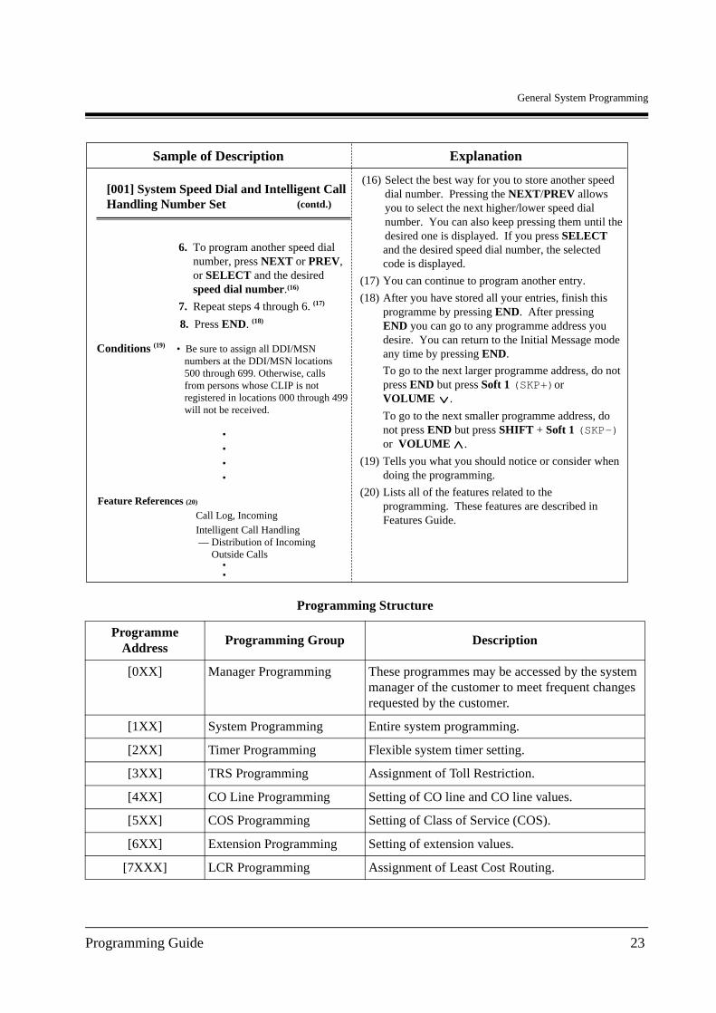
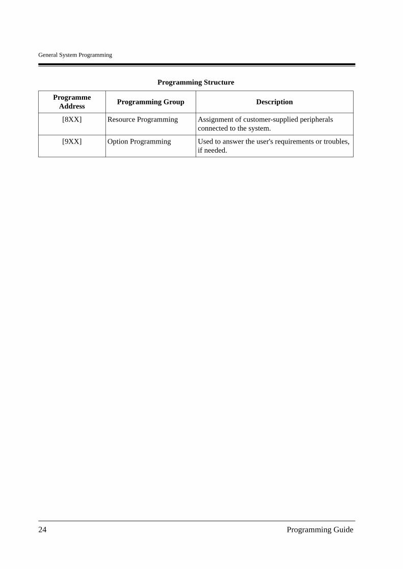
Programming Structure
Programme Address
Programming Group Description
[0XX] Manager Programming These programmes may be accessed by the system manager of the customer to meet frequent changes requested by the customer.
[1XX] System Programming Entire system programming.
[2XX] Timer Programming Flexible system timer setting.
[3XX] TRS Programming Assignment of Toll Restriction.
[4XX] CO Line Programming Setting of CO line and CO line values.
[5XX] COS Programming Setting of Class of Service (COS).
[6XX] Extension Programming Setting of extension values.
[7XXX] LCR Programming Assignment of Least Cost Routing.
Sample of Description Explanation
[001] System Speed Dial and Intelligent CallHandling Number Set (contd.)
7. Repeat steps 4 through 6. (17)
8. Press END. (18)
Conditions (19) • Be sure to assign all DDI/MSN numbers at the DDI/MSN locations 500 through 699. Otherwise, calls from persons whose CLIP is not registered in locations 000 through 499 will not be received.
6. To program another speed dialnumber, press NEXT or PREV,or SELECT and the desiredspeed dial number. (16)
••••
Feature References (20)
Call Log, IncomingIntelligent Call Handling — Distribution of Incoming Outside Calls •
(16) Select the best way for you to store another speeddial number. Pressing the NEXT/PREV allowsyou to select the next higher/lower speed dialnumber. You can also keep pressing them until thedesired one is displayed. If you press SELECTand the desired speed dial number, the selectedcode is displayed.
(17) You can continue to program another entry.
(18) After you have stored all your entries, finish thisprogramme by pressing END. After pressingEND you can go to any programme address youdesire. You can return to the Initial Message modeany time by pressing END.
To go to the next larger programme address, do notpress END but press Soft 1 (SKP+)orVOLUME .
To go to the next smaller programme address, do not press END but press SHIFT + Soft 1 (SKP-)or VOLUME .
(19) Tells you what you should notice or consider whendoing the programming.
(20) Lists all of the features related to theprogramming. These features are described inFeatures Guide.
•
Programming Guide 23
General System Programming
[8XX] Resource Programming Assignment of customer-supplied peripherals connected to the system.
[9XX] Option Programming Used to answer the user's requirements or troubles, if needed.
Programming Structure
Programme Address
Programming Group Description
24 Programming Guide

Manager Programming
Section 2
Manager Programming
Programming Guide 25
Manager Programming
2.1 Manager Programming
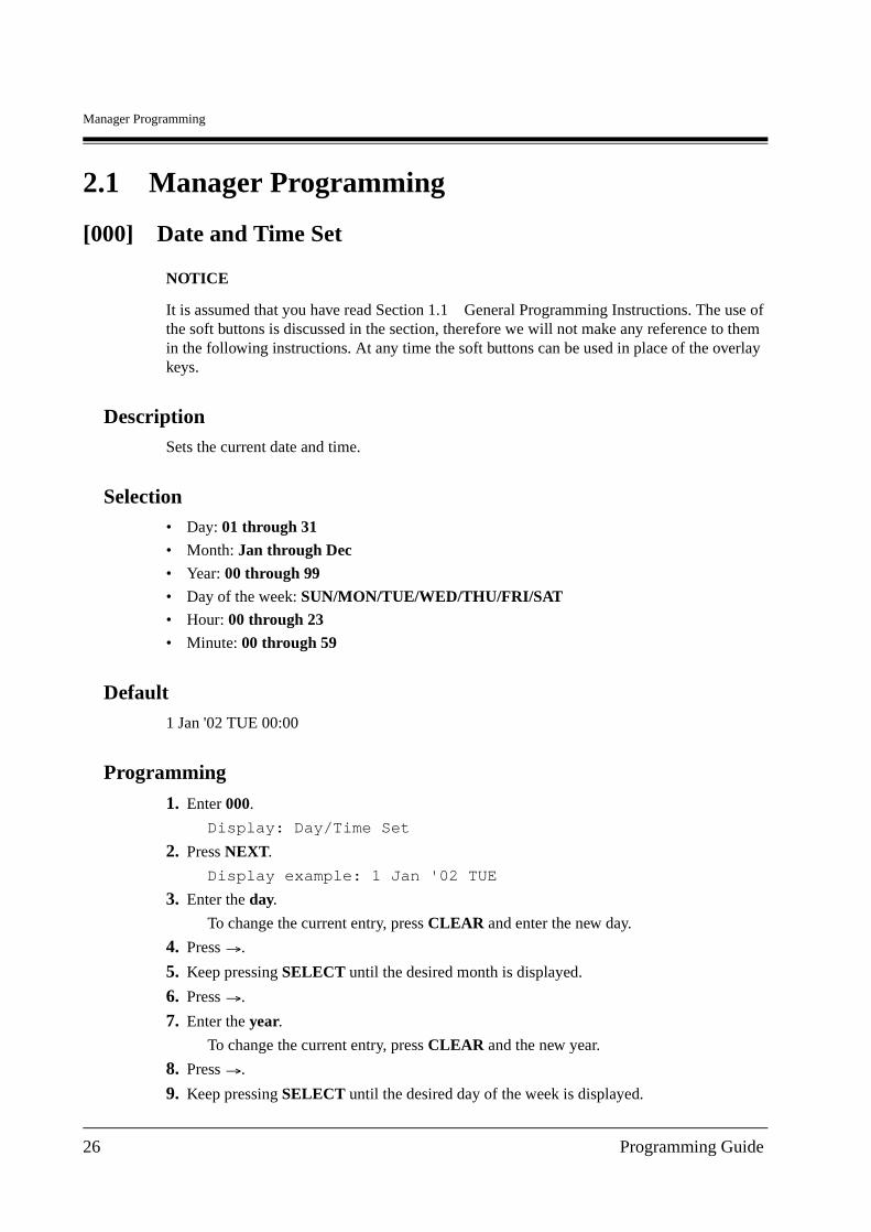
[000] Date and Time Set
NOTICE
It is assumed that you have read Section 1.1 General Programming Instructions. The use of the soft buttons is discussed in the section, therefore we will not make any reference to them in the following instructions. At any time the soft buttons can be used in place of the overlay keys.
DescriptionSets the current date and time.
Selection• Day: 01 through 31
• Month: Jan through Dec
• Year: 00 through 99
• Day of the week: SUN/MON/TUE/WED/THU/FRI/SAT• Hour: 00 through 23
• Minute: 00 through 59
Default1 Jan '02 TUE 00:00
Programming
1. Enter 000.
Display: Day/Time Set
2. Press NEXT.
Display example: 1 Jan '02 TUE
3. Enter the day.
To change the current entry, press CLEAR and enter the new day.
4. Press .
5. Keep pressing SELECT until the desired month is displayed.
6. Press .
7. Enter the year.
To change the current entry, press CLEAR and the new year.
8. Press .
9. Keep pressing SELECT until the desired day of the week is displayed.
26 Programming Guide
Manager Programming
10.Press STORE.
11.Press NEXT.
Display example: 00:00
12.Enter the hour.
To change the current entry, press CLEAR and the new hour.
13.Press .
14.Enter the minute.
To change the current entry, press CLEAR and new minute.
15.Press STORE.
16.Press END.
Conditions• After changing an entry, you can press STORE. You do not have to perform all of the rest
of the steps.
• To go back to the previous field, press at steps 4 through 9 and steps 13 through 14.
• If you hear an alarm after pressing STORE, check that the date is valid.
• The clock starts immediately after the STORE button is pressed.
• You cannot leave the entry empty.
• The date and time are adjusted automatically, when the first outgoing call is made through ISDN line after 3 o'clock each morning.
Features Guide ReferencesAutomatic Adjust Time
Display, Time and Date
Programming Guide 27
Manager Programming
[001] System Speed Dialling and Intelligent Call Handling Number Set
DescriptionUsed to program the System Speed Dial numbers and Intelligent Call Handling number (CLIP /DDI/MSN). These numbers are available to all extension users. The stored numbers are also applied to Calling/Connected Line Identification Presentation (CLIP/COLP) and Call Log, Incoming Features.
Selection• Speed dial number: 000 through 499 (CLIP: 000-499)
DDI/MSN number: 500 through 699 (DDI/MSN: 500-699)
• Telephone number: 32 digits (max.)
DefaultAll speed dial numbers and DDI/MSN numbers — Not Stored
Programming
1. Enter 001.
Display: SPD & CH Number
2. Press NEXT.
Display: SPD&CH Cod?
3. Enter a location number.
To enter location number 000, you can also press NEXT.
Display example: 000:Not Stored
4. Enter a telephone number.
To delete the current entry, press CLEAR.To change the current entry, press CLEAR and enter the new number.
5. Press STORE.
6. To program another speed dial number, press NEXT or PREV, or SELECT and the desired speed dial number.
7. Repeat steps 4 through 6.
8. Press END.
Conditions• Be sure to assign all DDI/MSN numbers at the DDI/MSN locations 500 through 699.
Otherwise, calls from persons whose CLIP is not registered in locations 000 through 499 will not be received.
28 Programming Guide
Manager Programming
• There is a maximum of 700 (000 – 699) System Speed Dialling and Intelligent Call Handling numbers. Each number has a maximum of 32 digits. System Speed Dialling numbers must be assigned at 000 through 499. The valid characters are 0 through 9, , and # keys, PAUSE, SECRET and — (hyphen) buttons.
— To store a hyphen, press the "–" button.
— To store a pause, press PAUSE.
— To prevent the display of all or part of the number, press SECRET before and after confidential parts of the number. The SECRET button must always be entered in a pair. Or your entry is not stored. (Refer to "Secret Dialling" in Features Guide.)
• The name assigned in programme [002] System Speed Dialling and Intelligent Call Handling Name Set will not be displayed when receiving the call if you store 1) PAUSE; 2) SECERT; 3) – (hyphen) twice.
• If you are storing an external CLIP number, include the line access code (default=9, 81 through 84) before the number. For CLIP/COLP and Call Log, Incoming feature; Include – (hyphen) before a phone number, because the telephone number check starts after the hyphen. Example: 9-12345678
• Be sure not to store your DDI/MSN number including the line access code. If the line access code is included, the incoming call with that DDI/MSN number cannot be handled properly because the system analyses the line access code as a part of your DDI/MSN number.
• If you are storing an account code, enter the account code before the line access code. Example: 4912345#9-12345678(Refer to "Account Code Entry" in Features Guide.)
• It is possible to store a number consisting of 33 digits or more by storing it in 2 speed dial numbers. A line access code should not be stored in the second speed dial number.
• To display parts of the number which have scrolled off the display, press or .
• Programme [002] System Speed Dialling and Intelligent Call Handling Name Set is used to give names to speed dial numbers and DDI/MSN numbers.
• You can use as the wild card characters to separate ringing destinations by area codes etc. Be sure to assign the number so that the total number of digits (including wild card characters) will be the same as the one of the originating telephone numbers.
• If you assign a wild card number at the locations 000-499, the name assigned at [002] System Speed Dialling and Intelligent Call Handling Name Set will not be displayed when receiving the call.
• You can assign CLIP and DDI/MSN numbers at locations 000-699. CLIP numbers can be assigned at the location 000-499. DDI/MSN numbers can be assigned at locations 500-699. We recommend that wild card numbers for CLIP be stored starting at location 499, and then 498, 497, etc. That is, go backwards starting at number 499. We recommend the preceding because if you assign the wild card number "9-012 " at location 000, then all calls that start with "012" will be processed according to that routing – even though you assign "9-0123456789" at another location. This is because the CLIP or your DDI/MSN number is analysed sequentially from 000 to 699.
Features Guide ReferencesCall Log, Incoming
Programming Guide 29
Manager Programming
Intelligent Call Handling — Distribution of Incoming Outside Calls
Special Display Features (System Speed Dialling)
System Speed Dialling
Toll Restriction Override for System Speed Dialling
30 Programming Guide
Manager Programming
[002] System Speed Dialling and Intelligent Call Handling Name Set
DescriptionAssigns names to the system speed dial numbers and DDI/MSN numbers assigned in programme [001] System Speed Dialling and Intelligent Call Handling Number Set. The KX-T7431, KX-T7433, KX-T7436 and KX-T7235 telephone show the stored name when performing System Speed Dialling or Intelligent Call Handling. The stored names are applied to the Call Log — Incoming features.
Selection• Speed dial number: 000 through 499 (CLIP: 000-499)
DDI/MSN number: 500 through 699 (DDI/MSN: 500-699)
• Name: Speed dial number — 16 characters (max.)DDI/MSN number — 10 characters (max.)
DefaultAll speed dial and DDI/MSN numbers — Not Stored
Programming
1. Enter 002.
Display: SPD & CH Name
2. Press NEXT.
Display: SPD&CH Cod?
3. Enter a location number.
To enter location number 000, you can also press NEXT.
Display example: 000:Not Stored
4. Enter a name.
For entering characters, see 1.4 Entering Characters.To delete the current entry, press CLEAR.To change the current entry, press CLEAR and the new name.
5. Press STORE.
6. To program another location number, press NEXT or PREV, and the desired location number.
7. Repeat steps 4 through 6.
8. Press END.
Programming Guide 31
Manager Programming
Conditions• Speed dial and DDI/MSN numbers are programmed in programme [001] System Speed
Dialling and Intelligent Call Handling Number Set.
• There is a maximum of 700 names. Each name has a maximum of 16 characters for speed dial numbers and 10 characters for DDI/MSN numbers.
• If you assign a wild card number at the locations 000-499, the name assigned in this programming will not be displayed when receiving a call.
Features Guide ReferencesCall Log, Incoming
Special Display Features (System Speed Dialling)
System Speed Dialling
32 Programming Guide
Manager Programming
[003] Extension Number Set
DescriptionAssigns an extension number to each jack.
Note
This programming should be performed before you connect a Panasonic Voice Processing System (VPS) because the VPS can create mailboxes automatically based on your extension plan (extension number set).
Selection• Jack number: 1-4 (-1/-2), 5-8 (-1)
(-1 = first part, -2 = second part)
• Extension Number: 2 through 4 digits
DefaultDPT extensions :
Jack 1-1 : 201/Jack 2-1 : 202/Jack 3-1 : 203/Jack 4-1 : 204/Jack 5-1 : 205/Jack 6-1 : 206 /Jack 7-1 : 207/Jack 8-1 : 208
XDP extensions :
Jack 1-2 : 301/Jack 2-2 : 302/Jack 3-2 : 303/Jack 4-2 : 304
Programming
1. Enter 003.
Display: EXT Number Set
2. Press NEXT.
Display: Jack NO?
3. Enter a jack number.
To enter jack number 1, you can also press NEXT.To select the second part (-2), press NEXT after entering the jack number.
Display: #1-1:EXT201
4. Enter an extension number.
To change the current entry, press CLEAR and the new number.
5. Press STORE.
6. To program another jack, press NEXT or PREV, or SELECT and the desired jack number.
7. Repeat steps 4 through 6.
8. Press END.
Programming Guide 33
Manager Programming
Conditions• There is a maximum of 12 extension numbers. Each extension number can be 2, 3, or 4
digits, consisting of 0 through 9. The and # keys cannot be used.
• An extension number is invalid if the leading first or second digits disagree with the setting of the programme [100] Flexible Numbering, 1st through 16th hundred extension blocks. If 1 digit is assigned as the leading digit, some extensions have 2 digits and some have 3 digits. If 2 digits are assigned, some have 3 digits and some have 4 digits.
• For Jacks 1 through 4, 2 extension numbers can be assigned per jack. If XDP is disabled for the jack in programme [600] EXtra Device Port, the extension number of the second part (X-2) is not available. (X=jack number)
• For an explanation of jack numbering, see "Rotation of jack number" in Section 1.3 Programming Ways.
• Double entry or incompatible entry is invalid including the assignment of programmes [012] ISDN Extension Number Set, [127] Voice Mail Extension Number Assignment, [130] Phantom Extension Number Assignment and [813] Floating Number Assignment. Valid entry examples: 10 and 11; 10 and 110. Invalid entry examples: 10 and 106; 210 and 21.
• Programme [004] Extension Name Set is used to give names to extension numbers.
Features Guide ReferencesEXtra Device Port (XDP)
Intercom Calling
Special Display Features (Extension Dialling)
34 Programming Guide
Manager Programming
[004] Extension Name Set
DescriptionAssigns names to the extension numbers programmed in programme [003] Extension Number Set.
Selection• Jack number: 1-4 (-1/-2), 5-8 (-1)
(-1 = first part, -2 = second part)
• Name: 16 characters (max.)
DefaultAll jacks — Not Stored
Programming
1. Enter 004.
Display: EXT Name Set
2. Press NEXT.
Display: Jack NO?
3. Enter a jack number.
To enter jack number 1-1, you can also press NEXT.To select the second part (-2), press NEXT after entering a jack number.
Display: #1-1:Not Stored
4. Enter a name.
For entering characters, see Section 1.4 Entering Characters.To delete the current entry, press CLEAR.To change the current entry, press CLEAR and the new name.
5. Press STORE.
6. To program another jack, press NEXT or PREV, or SELECT and the desired jack number.
7. Repeat steps 4 through 6.
8. Press END.
Conditions• There is a maximum of 12 names. Each name has a maximum of 16 characters.
• Programme [003] Extension Number Set is used to assign extension numbers.
• For an explanation of jack numbering, see "Rotation of jack number" in Section 1.3 Programming Ways.
Programming Guide 35
Manager Programming
Features Guide ReferencesIntercom Calling
Special Display Features (Extension Dialling)
36 Programming Guide
Manager Programming
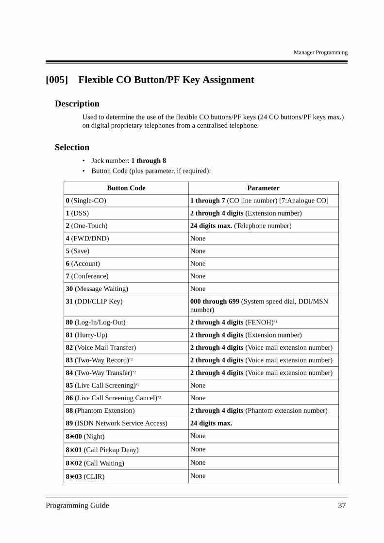
[005] Flexible CO Button/PF Key Assignment
DescriptionUsed to determine the use of the flexible CO buttons/PF keys (24 CO buttons/PF keys max.) on digital proprietary telephones from a centralised telephone.
Selection• Jack number: 1 through 8
• Button Code (plus parameter, if required):
Button Code Parameter
0 (Single-CO) 1 through 7 (CO line number) [7:Analogue CO]
1 (DSS) 2 through 4 digits (Extension number)
2 (One-Touch) 24 digits max. (Telephone number)
4 (FWD/DND) None
5 (Save) None
6 (Account) None
7 (Conference) None
30 (Message Waiting) None
31 (DDI/CLIP Key) 000 through 699 (System speed dial, DDI/MSN number)
80 (Log-In/Log-Out) 2 through 4 digits (FENOH)*1
81 (Hurry-Up) 2 through 4 digits (Extension number)
82 (Voice Mail Transfer) 2 through 4 digits (Voice mail extension number)
83 (Two-Way Record)*2 2 through 4 digits (Voice mail extension number)
84 (Two-Way Transfer)*2 2 through 4 digits (Voice mail extension number)
85 (Live Call Screening)*2 None
86 (Live Call Screening Cancel)*2 None
88 (Phantom Extension) 2 through 4 digits (Phantom extension number)
89 (ISDN Network Service Access) 24 digits max.
8 00 (Night) None
8 01 (Call Pickup Deny) None
8 02 (Call Waiting) None
8 03 (CLIR) None
Programming Guide 37
Manager Programming
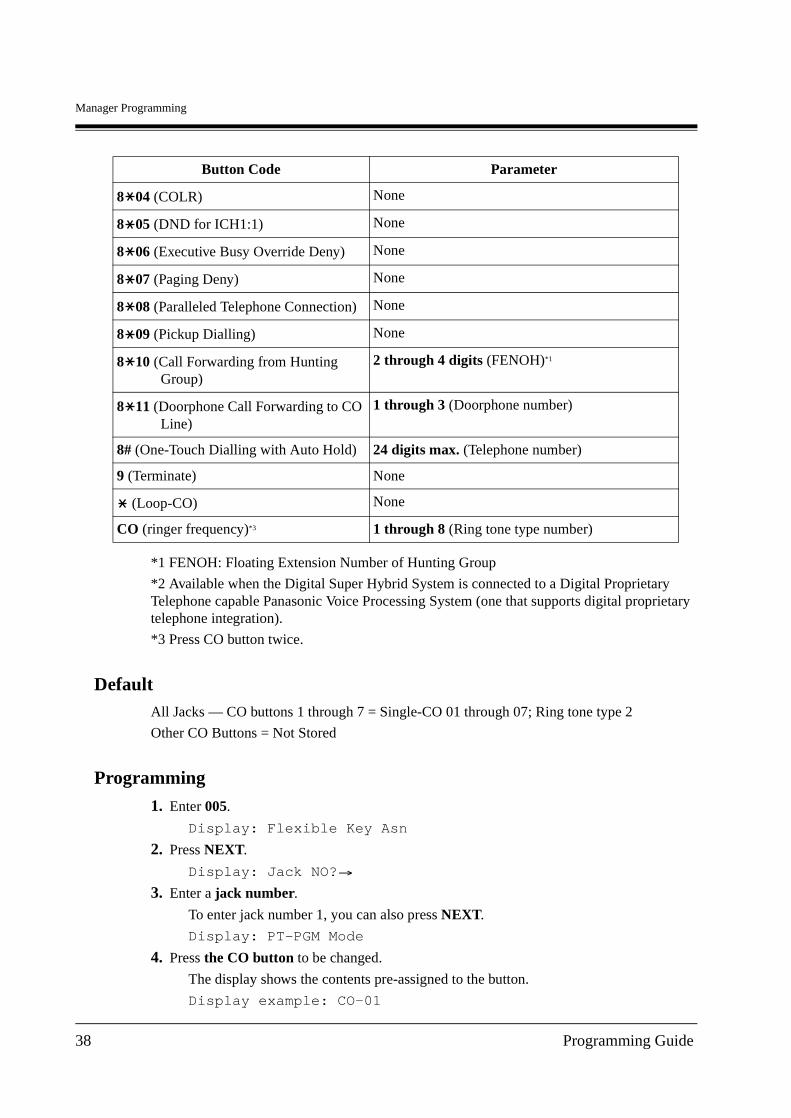
*1 FENOH: Floating Extension Number of Hunting Group
*2 Available when the Digital Super Hybrid System is connected to a Digital Proprietary Telephone capable Panasonic Voice Processing System (one that supports digital proprietary telephone integration).
*3 Press CO button twice.
DefaultAll Jacks — CO buttons 1 through 7 = Single-CO 01 through 07; Ring tone type 2
Other CO Buttons = Not Stored
Programming
1. Enter 005.
Display: Flexible Key Asn
2. Press NEXT.
Display: Jack NO?
3. Enter a jack number.
To enter jack number 1, you can also press NEXT.
Display: PT-PGM Mode
4. Press the CO button to be changed.
The display shows the contents pre-assigned to the button.
Display example: CO-01
8 04 (COLR) None
8 05 (DND for ICH1:1) None
8 06 (Executive Busy Override Deny) None
8 07 (Paging Deny) None
8 08 (Paralleled Telephone Connection) None
8 09 (Pickup Dialling) None
8 10 (Call Forwarding from Hunting Group)
2 through 4 digits (FENOH)*1
8 11 (Doorphone Call Forwarding to CO Line)
1 through 3 (Doorphone number)
8# (One-Touch Dialling with Auto Hold) 24 digits max. (Telephone number)
9 (Terminate) None
(Loop-CO) None
CO (ringer frequency)*3 1 through 8 (Ring tone type number)
Button Code Parameter
38 Programming Guide
Manager Programming
5. Enter a button code (plus parameter, if required).
To change the parameter, press CLEAR and enter the new parameter.
6. Press STORE.
7. To program another CO button of the same jack, repeat steps 4 through 6.To program another jack, press SELECT and repeat steps 3 through 6.
8. Press END.
Cancelling1. Perform the same procedures as steps 1 through 4 above.
2. Enter 2.
3. Press STORE.
4. Press END.
Conditions• A maximum of 24 CO buttons/PF keys can be assigned.
• A centralised telephone is a telephone connected to jack 1 or a jack programmed as a manager extension in programme [006] Operator/Manager Extension Assignment — Day/Night.
• If you press the same CO button again at step 5, you can select a desired ringer frequency for the CO button from 8 types of ring tone. When you enter the tone type number (1 through 8), you will hear the selected tone type before STORE is pressed. This selection is possible only for the CO buttons that have been assigned to Single-CO, Loop-CO or DDI/CLIP key.
Features Guide ReferencesButton, Flexible
Buttons on Digital Proprietary Telephones
Programming Guide 39
Manager Programming
[006] Operator/Manager Extension Assignment — Day/Night
DescriptionAssigns the jack number for a manager and/or operators. The manager extension can perform System Programming. An operator has the ability to perform operator services.
Selection• Operator 1 (Day/Night)/Operator 2 (Day/Night)/Manager
• Jack number: 1-8
DefaultOperator 1 (Day/Night) — Jack 1
Operator 2 (Day/Night) — Not Stored
Manager — Jack 1
Programming
1. Enter 006.
Display: Operator/Manager
2. Press NEXT to program operator 1 in Day mode.
Display: OP-1-Day:Jack1
To program another item, you can also keep pressing NEXT or PREV until the desired one is displayed.
3. Enter a jack number.
To delete the current entry, press CLEAR.
To change the current entry, press CLEAR and the new jack number.
4. Press STORE.
5. To program another item, press NEXT or PREV.
6. Repeat steps 3 through 5.
7. Press END.
Conditions• Up to 2 operators and a manager can be programmed.
• The manager cannot be assigned the jack number of the Console Port set in programme [007] Console Port and Paired Telephone Assignment.
• If the assigned jack is in eXtra Device Port mode, the digital proprietary telephone jack is treated as the manager/operator extension.
• If there is no operator or manager, press CLEAR at step 3.
40 Programming Guide

Manager Programming
Features Guide ReferencesManager Extension
Operator
Programming Guide 41
Manager Programming
[007] Console Port and Paired Telephone Assignment
DescriptionAssigns the jack numbers for the Digital DSS Console/Digital Attendant Console (Console) and the paired extension.
Selection• Console number: 01-04
• Jack number for Console: 2-8
• Jack number for paired extension: 1-8
DefaultAll Consoles — Not Stored
Programming
1. Enter 007.
Display: DSS Console Asn
2. Press NEXT.
Display: DSS NO?
3. Enter a Console number.
To enter Console number 1, you can also press NEXT.
Display example: DSS-01:# P:#
4. Enter a jack number for the console.
To delete the current entry, press CLEAR.
To change the current entry, press CLEAR and the new jack number.
5. Press .
6. Enter a jack number for the paired extension.
To change the current entry, press CLEAR and enter the new jack number.
Display example: DSS-01:#2 P:#3
7. Press STORE.
8. To program another Console, press NEXT or PREV, or SELECT and the desired Console number.
9. Repeat steps 4 through 8.
10.Press END.
Conditions• The jack number for the Console and that for the paired extension must be entered together.
• Multiple Consoles cannot be assigned to the same Console jack.
42 Programming Guide
Manager Programming
• Multiple Consoles can be paired with the same digital proprietary telephone jack.
• A Console jack cannot be assigned the jack 1 and the jack number of Manager set in programme [006] Operator/Manager Extension Assignment — Day/Night.
• If all incoming outside calls are set to ring at the operator extension telephone in programme <[452] Extension Ringing Assignment>, assigning the Consoles to the operator extension makes the operator's job much easier.
• If a Console-assigned jack is programmed for eXtra Device Port, an SLT can be connected to the jack in parallel with the console.
• If an SLT is assigned as the pair extension, the paired Console will not function.
Features Guide ReferencesConsole
Programming Guide 43
Manager Programming
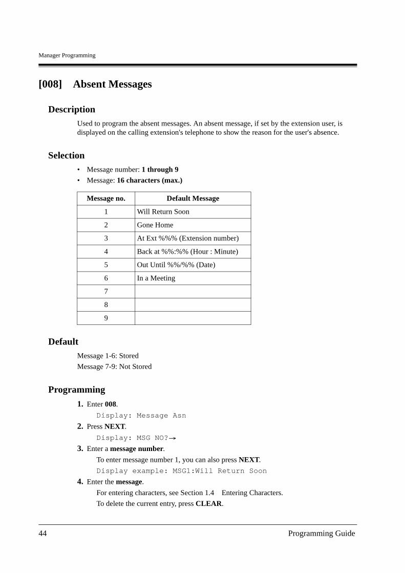
[008] Absent Messages
DescriptionUsed to program the absent messages. An absent message, if set by the extension user, is displayed on the calling extension's telephone to show the reason for the user's absence.
Selection• Message number: 1 through 9
• Message: 16 characters (max.)
DefaultMessage 1-6: Stored
Message 7-9: Not Stored
Programming
1. Enter 008.
Display: Message Asn
2. Press NEXT.
Display: MSG NO?
3. Enter a message number.
To enter message number 1, you can also press NEXT.
Display example: MSG1:Will Return Soon
4. Enter the message.
For entering characters, see Section 1.4 Entering Characters.
To delete the current entry, press CLEAR.
Message no. Default Message
1 Will Return Soon
2 Gone Home
3 At Ext %%% (Extension number)
4 Back at %%:%% (Hour : Minute)
5 Out Until %%/%% (Date)
6 In a Meeting
7
8
9
44 Programming Guide
Manager Programming
To change the current entry, press CLEAR and enter the new message.
5. Press STORE.
6. To program another message, press NEXT or PREV, or SELECT and the desired message number.
7. Repeat steps 4 through 6.
8. Press END.
Conditions• There is a maximum of 9 messages. Messages 1 through 6 are programmed at the factory
but can be changed. Each message has a maximum of 16 characters.
• You can enter a maximum of 7 "%" characters per message which can be programmed at each user's station. The station user can enter 0 through 9, and # for the "%" characters. If the user enters digits less than the number of "%" characters, it is recommended to fill the remaining "%" characters with "#" or " ".
• If there are 4-digit extension numbers available in your system, add 1 % to Message 3.
• To display parts of the message which have scrolled off the display, press or .
Features Guide ReferencesAbsent Message Capability
Programming Guide 45
Manager Programming
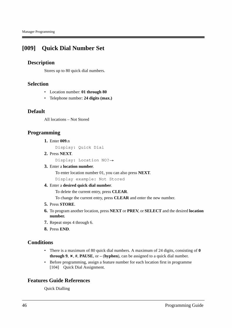
[009] Quick Dial Number Set
DescriptionStores up to 80 quick dial numbers.
Selection• Location number: 01 through 80
• Telephone number: 24 digits (max.)
DefaultAll locations – Not Stored
Programming
1. Enter 009.n
Display: Quick Dial
2. Press NEXT.
Display: Location NO?
3. Enter a location number.
To enter location number 01, you can also press NEXT.
Display example: Not Stored
4. Enter a desired quick dial number.
To delete the current entry, press CLEAR.
To change the current entry, press CLEAR and enter the new number.
5. Press STORE.
6. To program another location, press NEXT or PREV, or SELECT and the desired location number.
7. Repeat steps 4 through 6.
8. Press END.
Conditions• There is a maximum of 80 quick dial numbers. A maximum of 24 digits, consisting of 0
through 9, , #, PAUSE, or – (hyphen), can be assigned to a quick dial number.
• Before programming, assign a feature number for each location first in programme [104] Quick Dial Assignment.
Features Guide ReferencesQuick Dialling
46 Programming Guide
Manager Programming
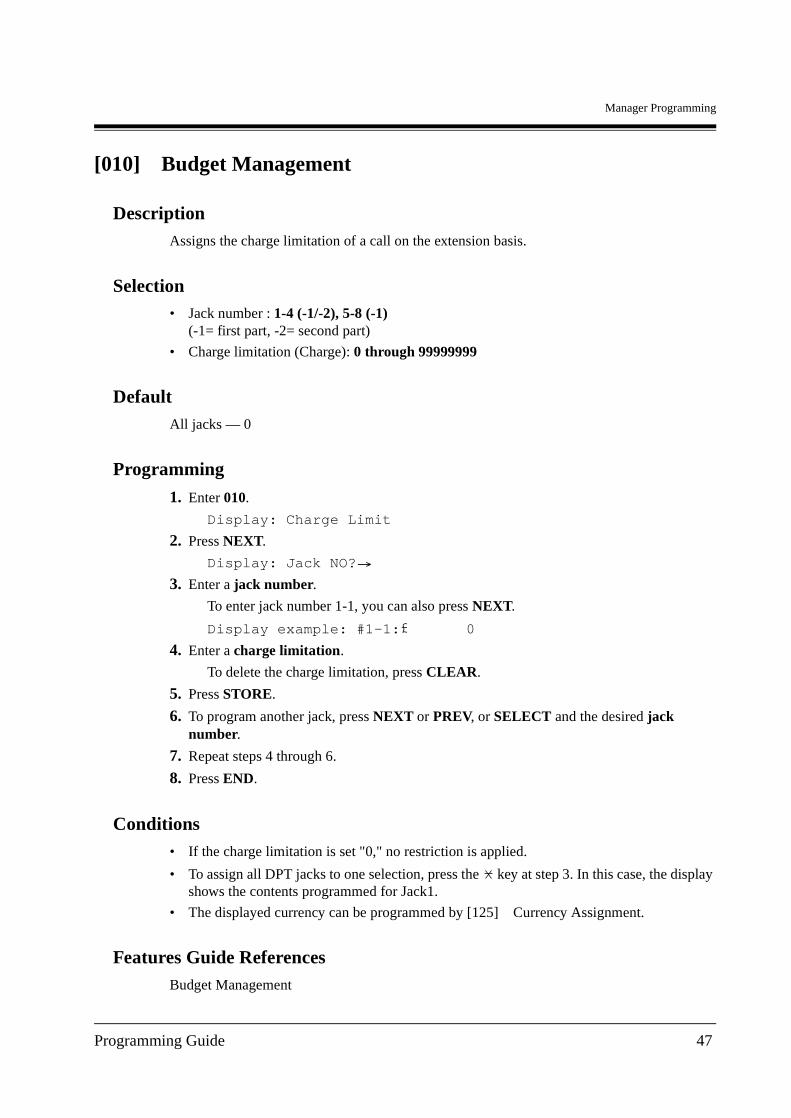
[010] Budget Management
DescriptionAssigns the charge limitation of a call on the extension basis.
Selection• Jack number : 1-4 (-1/-2), 5-8 (-1)
(-1= first part, -2= second part)
• Charge limitation (Charge): 0 through 99999999
DefaultAll jacks — 0
Programming
1. Enter 010.
Display: Charge Limit
2. Press NEXT.
Display: Jack NO?
3. Enter a jack number.
To enter jack number 1-1, you can also press NEXT.
Display example: #1-1: 0
4. Enter a charge limitation.
To delete the charge limitation, press CLEAR.
5. Press STORE.
6. To program another jack, press NEXT or PREV, or SELECT and the desired jack number.
7. Repeat steps 4 through 6.
8. Press END.
Conditions• If the charge limitation is set "0," no restriction is applied.
• To assign all DPT jacks to one selection, press the key at step 3. In this case, the display shows the contents programmed for Jack1.
• The displayed currency can be programmed by [125] Currency Assignment.
Features Guide ReferencesBudget Management
Programming Guide 47

Manager Programming
Charge Fee Reference
48 Programming Guide
Manager Programming
[012] ISDN Extension Number Set
DescriptionAssigns an extension number to each ISDN port which is connected to the system.
Selection• ISDN port number: 2, 3
• Extension Number: 1 through 3 digits
DefaultAll ports — Not Stored
Programming
1. Enter 012.
Display: ISDN EXT.Num Set
2. Press NEXT.
Display: Port NO?
3. Enter a port number.
To enter a first port number, you can also press NEXT.
Display example: #2 :Not Stored
4. Enter an extension number.
To change the current entry, press CLEAR and the new number.
5. Press STORE.
6. To program another port, press NEXT or PREV, or SELECT and the desired port number.
7. Repeat steps 4 through 6.
8. Press END.
Conditions
• Each extension number can be 1, 2 or 3 digits, consisting of 0 through 9. The and # keys cannot be used.
• A multiple subscriber number (MSN) is determined regarding to this assignment. The MSN must be up to 4 digits, consisting of the assigned extension number and an additional number (1 or 2 digits). The MSN additional number digit can be selected in programme [427] ISDN Extension Multiple Subscriber Number.Example) In case that the ISDN extension number is assigned "3";30 through 39 are effective as MSN's. The extension user can call any terminal equipment on the ISDN Extension bus with MSN individually. Pressing "30" calls all extensions on the ISDN Extension bus simultaneously.
Programming Guide 49
Manager Programming
• An extension number is invalid if the leading first or second digits disagree with the setting of the programme [100] Flexible Numbering, 1st through 16th hundred extension blocks. If 1 digit is assigned as the leading digit, some extensions have 2 digits and some have 3 digits. If 2 digits are assigned, some have 3 digits and some have 4 digits.
• Double entry or incompatible entry is invalid including the assignment of programmes [003] Extension Number Set, [127] Voice Mail Extension Number Assignment, [130] Phantom Extension Number Assignment and [813] Floating Number Assignment. Valid entry examples: 10 and 11; 10 and 110. Invalid entry examples: 10 and 106; 210 and 21.
• Programme [013] ISDN Extension Name Set is used to give names to the extension numbers.
Features Guide ReferencesIntegrated Services Digital Network (ISDN) Extension
50 Programming Guide
Manager Programming
[013] ISDN Extension Name Set
DescriptionAssigns names to the ISDN extension numbers programmed in programme [012] ISDN Extension Number Set.
Selection• ISDN port number: 2, 3
• Name: 16 characters (max.)
DefaultAll ports — Not Stored
Programming
1. Enter 013.
Display: ISDN EXT. Name
2. Press NEXT.
Display: Port NO?
3. Enter a port number.
To enter the first port number, you can also press NEXT.
Display example: #2 :Not Stored
4. Enter a name.
For entering characters, see Section 1.4 Entering Characters.
To delete the current entry, press CLEAR.
To change the current entry, press CLEAR and the new name.
5. Press STORE.
6. To program another port, press NEXT or PREV, or SELECT and the desired port number.
7. Repeat steps 4 through 6.
8. Press END.
ConditionsNone
Features Guide ReferencesIntegrated Services Digital Network (ISDN) Extension
Programming Guide 51
Manager Programming
[014] Budget Management on ISDN Port
DescriptionAssigns the charge limitation of a call on the ISDN port basis.
Selection• ISDN port number: 2, 3
• Charge limitation (Charge): 0 through 99999999
DefaultAll ports — 0
Programming
1. Enter 014.
Display: ISDN Charge Lim.
2. Press NEXT.
Display: Port NO?
3. Enter a port number.
To enter a first port number, you can also press NEXT.
Display example: #2 : 0
4. Enter a charge limitation.
To delete the charge limitation, press CLEAR.
5. Press STORE.
6. To program another port, press NEXT or PREV, or SELECT and the desired port number.
7. Repeat steps 4 through 6.
8. Press END.
Conditions• If the charge limitation is set "0," no restriction is applied.
• To assign all port to one selection, press the key at step 3.In this case, the display shows the contents programmed for a first port.
• The displayed currency can be programmed by [125] Currency Assignment.
Features Guide ReferencesBudget Management
Charge Fee Reference
52 Programming Guide

Manager Programming
Integrated Services Digital Network (ISDN) Extension
Programming Guide 53
Manager Programming
[015] Charge Rate Fractional Point Assignment
DescriptionAssigns how many decimal places to set for the charge rate.
SelectionNumber of decimal places: 0 through 8
Default2
Programming
1. Enter 015.
Display: Decimal Point
2. Press NEXT.
Display example: Fraction place 2
3. Enter the number of decimal place.
To delete the current entry, press CLEAR.
4. Press STORE.
5. Press END.
Conditions• This programme is used when the rate is assigned in programme [016] Charge Rate
Assignment.
• According to this assignment, the charge is displayed during the conversation and shown on the SMDR print out.
• This assignment is used for the charge fee reference.
• You cannot leave the entry empty.
Features Guide ReferencesCharge Fee Reference
54 Programming Guide
Manager Programming
[016] Charge Rate Assignment
DescriptionAssigns the rate to each CO port. This rate is multiplied with the meter charge to generate a charge in currency.
Selection• CO port number: 1 through 3
• Charge rate: 10 digits max. (including the decimal point)
Default0.01
Programming
1. Enter 016.
Display: Charge Rate Asn
2. Press NEXT.
Display: Port NO?
3. Enter a CO port number.
To enter CO port number 1, you can also press NEXT.
Display example: #1 : 0.01
4. Enter a charge rate (to the left of the decimal point).
To delete the current entry, press CLEAR.
5. Press .
6. Enter a charge rate (to the right of the decimal point).
To delete the current entry, press CLEAR.
7. Press STORE.
8. To program another CO port, press NEXT or PREV, or SELECT and the desired CO port number.
9. Repeat steps 4 through 7.
10.Press END.
Conditions• A maximum of 10 digits, consisting of 0 through 9, can be assigned as the rate. The number
of decimal places depends on the assignment in programme [015] Charge Rate Fractional Point Assignment.
Programming Guide 55

Manager Programming
• The charge for ISDN Port 1 applies to CO 1 and CO 2. The charge for ISDN Port 2 applies to CO 3 and CO 4. The charge for ISDN Port 3 applies to CO 5 and CO 6.
Features Guide ReferencesCharge Fee Reference
56 Programming Guide
Manager Programming
[021-022] Doorphone Call Forwarding — Day/Night
DescriptionAssigns the phone number where doorphone calls are forwarded. This feature is one of the ISDN service.
Selection• Doorphone number: 1 through 3
• Line access code: 9 or 81 through 83
• Telephone number: 24 digits (max.) (including a line access code)/Not Stored
DefaultAll doorphone numbers — Not Stored
Programming
1. Enter a programme address (021 for day or 022 for night).
Display example: D-phone FWD Day
2. Press NEXT.
Display: D-phone NO.?
3. Enter a doorphone number.
Display example: #1:Disable
4. Enter a line access code and a phone number.
To assign no forwarding, press CLEAR.
5. Press STORE.
6. To program the other doorphone, press NEXT.
7. Repeat steps 4 and 5.
8. Press END.
Conditions• When "Disable" is selected, the call is received by the extension programmed in [607-
608] Doorphone Ringing Assignment — Day/Night.
Features Guide ReferencesDoorphone Call Forwarding to CO Line
Day/Night Service
Programming Guide 57

Manager Programming
[024] Intelligent Call Handling Table
DescriptionAssigns the intelligent call handling table.
IMPORTANTPlease enable this feature as the first step. Otherwise, an outside call cannot be handled properly.
Selection• System Speed Dialling and Intelligent Call Handling table number: 000 through 699
(CLIP: 000-499, DDI/MSN: 500-699)
• Intelligent Call Handling table number; Day: 01 through 60, Night: 01 through 60
DefaultSystem Speed Dialling number: 000 through 499 — Not stored;
500 through 699 — Day: 01, Night: 01
Programming
1. Enter 024.
Display: Handling Table
2. Press NEXT.
Display: SPD&CH Cod?
3. Enter a System Speed Dialling and Intelligent Call Handling table.
To enter System Speed Dialling number 000, you can also press NEXT.
Display example: 000:Day Nit
4. Enter a table number.
To delete the current entry, press CLEAR.
To change the current entry, press CLEAR and enter the new number.
5. Press STORE.
6. To program another System Speed Dialling number, press NEXT or PREV, or SELECT and the desired System Speed Dialling number.
7. Repeat steps 4 through 6.
8. Press END.
Conditions• Each System Speed Dialling and Intelligent Call Handling table number consists of 3 digits,
from 0 through 9.
58 Programming Guide
Manager Programming
• One table is reserved for analogue CO calls (default: table 1 — Day/Night). Refer to [458] Intelligent Call Handling Table for Analogue CO.
Features Guide ReferencesIntelligent Call Handling — Distribution of Incoming Outside Calls
Programming Guide 59
Manager Programming
[025] Intelligent Call Handling for Fax and Modem
DescriptionAssigns DDI/MSN numbers for a fax and a modem.
Selection• Location number: 1 through 8
• DDI/MSN number (System Speed Dialling and Intelligent Call Handling location number): 500 through 699
DefaultAll locations — Not stored
Programming
1. Enter 025.
Display: ICH FAX/MODEM NO
2. Press NEXT.
Display: Location NO?
3. Enter a location number.
To enter location number 01, you can also press NEXT.
Display example: 01 :Not Stored
4. Enter a DDI/MSN number (System Speed Dialling and Intelligent Call Handling location number).
To delete the current entry, press CLEAR.
To change the current entry, press CLEAR and enter the new number.
5. Press STORE.
6. To program another location, press NEXT or PREV, or SELECT and the desired location number.
7. Repeat steps 4 through 6.
8. Press END.
Conditions• When an outside call arrives from ISDN line, its CLIP and DDI/MSN number will be
analysed in the following order.
1. [026] ISDN Remote Maintenance Access Number
2. [025] Intelligent Call Handling for Fax and Modem
3. [001] System Speed Dialling and Intelligent Call Handling Number Set — CLIP number
60 Programming Guide
Manager Programming
4. [001] System Speed Dialling and Intelligent Call Handling Number Set — DDI/MSN number
• Even though a fax or a modem is not hooked up to the destination while an incoming call is received and analysed according to this programme, the call will be handled in any event.
Features Guide ReferencesIntelligent Call Handling — Distribution of Incoming Outside Calls
Programming Guide 61
Manager Programming
[026] ISDN Remote Maintenance Access Number
DescriptionUsed to program a DDI/MSN number for remote maintenance by using a personal computer.
SelectionDDI/MSN number: 32 digits (max.)
DefaultNot stored
Programming
1. Enter 026.
Display: ISDN RMT.MNT.NO
2. Press NEXT.
Display example: Code:Not Stored
3. Enter a DDI/MSN number.
To change the current entry, press CLEAR and the new number.
4. Press STORE.
5. Press END.
Conditions
• The number has a maximum of 32 digits, consisting of 0 through 9, and #.
• When an outside call arrives from ISDN line, its CLIP and DDI/MSN number will be analysed in the following order.
1. [026] ISDN Remote Maintenance Access Number
2. [025] Intelligent Call Handling for Fax and Modem
3. [001] System Speed Dialling and Intelligent Call Handling Number Set — CLIP number
4. [001] System Speed Dialling and Intelligent Call Handling Number Set — DDI/MSN number
Features Guide ReferencesIntelligent Call Handling — Distribution of Incoming Outside Calls
System Programming and Diagnosis with Personal Computer
62 Programming Guide
Manager Programming
[027] ISDN Remote Maintenance Access Name
DescriptionAssigns a name to the DDI/MSN number for remote maintenance assigned in programme [026] ISDN Remote Maintenance Access Number.
SelectionName: 16 characters (max.)
DefaultNot stored
Programming
1. Enter 027.
Display: ISDN RMT.MNT.NM
2. Press NEXT.
Display example: Name:Not Stored
3. Enter a name.
To change the current entry, press CLEAR and the new name.
4. Press STORE.
5. Press END.
ConditionsNone
Features Guide ReferencesIntelligent Call Handling — Distribution of Incoming Outside Calls
System Programming and Diagnosis with Personal Computer
Programming Guide 63
Manager Programming
[028] ISDN Remote Alarm Notification Dial Number
DescriptionAssigns the phone number of a dealer to send an alarm notice when a major alarm occurs.
SelectionTelephone number: 32 digits (max.)
DefaultTelephone number — Not stored
Programming
1. Enter 028.
Display: ISDN RMT.ARM NO
2. Press NEXT.
Display example: No:Not Stored
3. Enter a phone number.
To change the current entry, press CLEAR and the new number.
4. Press STORE.
5. Press END.
Conditions
• The number has a maximum of 32 digits, consisting of 0 through 9, and #.
Features Guide ReferencesSystem Programming and Diagnosis with Personal Computer
64 Programming Guide
System Programming
Section 3
System Programming
Programming Guide 65
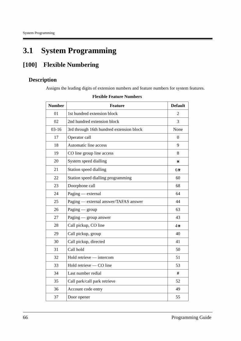
System Programming
3.1 System Programming
[100] Flexible Numbering
DescriptionAssigns the leading digits of extension numbers and feature numbers for system features.
Flexible Feature Numbers
Number Feature Default
01 1st hundred extension block 2
02 2nd hundred extension block 3
03-16 3rd through 16th hundred extension block None
17 Operator call 0
18 Automatic line access 9
19 CO line group line access 8
20 System speed dialling
21 Station speed dialling 6
22 Station speed dialling programming 60
23 Doorphone call 68
24 Paging — external 64
25 Paging — external answer/TAFAS answer 44
26 Paging — group 63
27 Paging — group answer 43
28 Call pickup, CO line 4
29 Call pickup, group 40
30 Call pickup, directed 41
31 Call hold 50
32 Hold retrieve — intercom 51
33 Hold retrieve — CO line 53
34 Last number redial #
35 Call park/call park retrieve 52
36 Account code entry 49
37 Door opener 55
66 Programming Guide
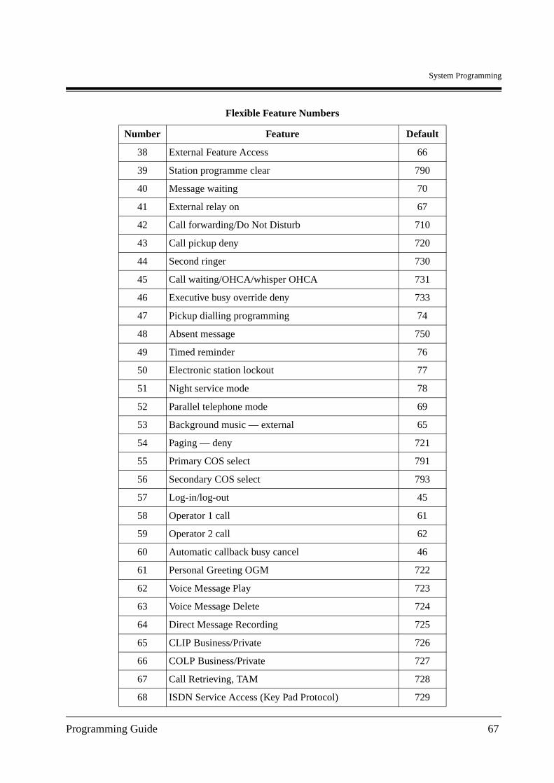
System Programming
38 External Feature Access 66
39 Station programme clear 790
40 Message waiting 70
41 External relay on 67
42 Call forwarding/Do Not Disturb 710
43 Call pickup deny 720
44 Second ringer 730
45 Call waiting/OHCA/whisper OHCA 731
46 Executive busy override deny 733
47 Pickup dialling programming 74
48 Absent message 750
49 Timed reminder 76
50 Electronic station lockout 77
51 Night service mode 78
52 Parallel telephone mode 69
53 Background music — external 65
54 Paging — deny 721
55 Primary COS select 791
56 Secondary COS select 793
57 Log-in/log-out 45
58 Operator 1 call 61
59 Operator 2 call 62
60 Automatic callback busy cancel 46
61 Personal Greeting OGM 722
62 Voice Message Play 723
63 Voice Message Delete 724
64 Direct Message Recording 725
65 CLIP Business/Private 726
66 COLP Business/Private 727
67 Call Retrieving, TAM 728
68 ISDN Service Access (Key Pad Protocol) 729
Flexible Feature Numbers
Number Feature Default
Programming Guide 67
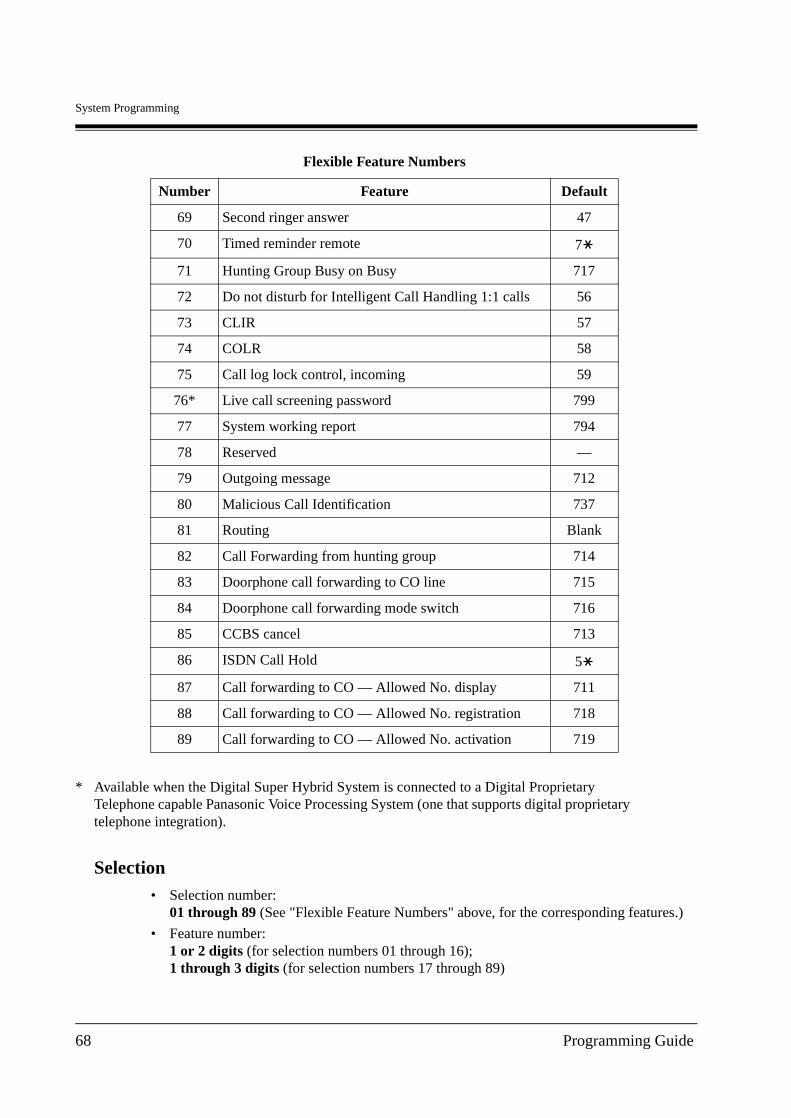
System Programming
Selection• Selection number:
01 through 89 (See "Flexible Feature Numbers" above, for the corresponding features.)
• Feature number:1 or 2 digits (for selection numbers 01 through 16);1 through 3 digits (for selection numbers 17 through 89)
69 Second ringer answer 47
70 Timed reminder remote 7
71 Hunting Group Busy on Busy 717
72 Do not disturb for Intelligent Call Handling 1:1 calls 56
73 CLIR 57
74 COLR 58
75 Call log lock control, incoming 59
76* Live call screening password 799
77 System working report 794
78 Reserved —
79 Outgoing message 712
80 Malicious Call Identification 737
81 Routing Blank
82 Call Forwarding from hunting group 714
83 Doorphone call forwarding to CO line 715
84 Doorphone call forwarding mode switch 716
85 CCBS cancel 713
86 ISDN Call Hold 5
87 Call forwarding to CO — Allowed No. display 711
88 Call forwarding to CO — Allowed No. registration 718
89 Call forwarding to CO — Allowed No. activation 719
* Available when the Digital Super Hybrid System is connected to a Digital Proprietary Telephone capable Panasonic Voice Processing System (one that supports digital proprietary telephone integration).
Flexible Feature Numbers
Number Feature Default
68 Programming Guide
System Programming
DefaultSee "Flexible Feature Numbers" above.
Programming
1. Enter 100.
Display: FLX Numbering
2. Press NEXT.
Display: Select NO?
3. Enter a selection number.
To enter selection number 01, you can also press NEXT.
Display example: 01. 1-EXT BL:2
4. Enter the feature number.
To delete the feature number, press CLEAR.
To change the current entry, press CLEAR and enter the new number.
5. Press STORE.
6. To program another selection, press NEXT or PREV, or SELECT and the desired selection number.
7. Repeat steps 4 through 6.
8. Press END.
To remove all the feature numbers except selection numbers (01) through (16) 1st through 16th extension blocks;
1. Enter 100.
2. Press NEXT.
3. Enter 00.
Display: All Feature CLR?
4. Press STORE.
5. Press END.
Conditions• Each extension block has 1 or 2 digits, consisting of 0 through 9. Assign the leading digits
for extension numbers of the respective blocks.
• Assignment of extension blocks defines the limits for programmes [003] Extension Number Set, [012] ISDN Extension Number Set, [127] Voice Mail Extension Number Assignment, [130] Phantom Extension Number Assignment and [813] Floating Number Assignment.
• To clear an extension block (01) through (16), it is required to change the corresponding numbers assigned in programmes [003] Extension Number Set, [012] ISDN Extension Number Set, [127] Voice Mail Extension Number Assignment, [130] Phantom Extension Number Assignment and [813] Floating Number Assignment.
Programming Guide 69
System Programming
• Each feature number has 1 through 3 digits, consisting of 0 through 9, , and #.
• If or # is included in a feature number, dial pulse telephone users cannot access the feature.
• Double entry and incompatible combinations are invalid. Valid entry example: 30 and 31, 210 and 211. Invalid entry example: 5 and 5, 30 and 301.
• If you delete a feature number, the feature cannot be used by dialling operation.
• You can remove all the feature numbers except selections (01) through (16).
Features Guide ReferencesFlexible Numbering
70 Programming Guide

System Programming
[102] Day/Night Service Starting Time
DescriptionSets the starting time of day service and the starting time of night service for each day of the week, when automatic day/night switching is enabled.
Selection• Day of the week selection number:
1 (Sunday)/2 (Monday)/3 (Tuesday)/4 (Wednesday)/5 (Thursday)/6 (Friday)/7 (Saturday)/ (every day of the week)
• Hour: 0 through 23/Disable (no switching)
• Minute: 0 through 59
DefaultEvery day of the week — Day — 9:00/Night — 17:00
Programming
1. Enter 102.
Display: Day/Night Time
2. Press NEXT.
Display: Day of Week?
3. Enter the day of the week selection number.
To select Sunday, you can also press NEXT.
Display example: Sun-Day : 9:00
To select night mode, press NEXT one more time.
Display example: Sun-Night: 17:00
4. Enter the hour.
To set no switching, keep pressing SELECT until "Disable" is displayed and go to step 7.If SELECT is pressed, the display shows the previous entry. If the previous setting was "Disable", press SELECT to enter the starting time.To change the current entry, press CLEAR and the new time.
5. Press .
6. Enter the minute.
To change the current entry, press CLEAR and the new minutes.
7. Press STORE.
8. To program another day/night mode or day of the week, press NEXT or PREV, or SELECT and the day of the week selection number.
9. Repeat steps 4 through 10.
Programming Guide 71
System Programming
10.Press END.
Conditions• To select the desired day, you may keep pressing NEXT at step 3. To assign every day of
the week to one selection, press the key at step 3. In this case, the display shows the contents programmed for Sunday.
• If day/night switching is unwanted, select "Disable" at step 4.
• You cannot leave the entry empty.
Features Guide ReferencesDay/Night Service
72 Programming Guide
System Programming
[103] Automatic Access CO Port Assignment
DescriptionAssigns the sequence in which CO ports will be accessed when in Automatic Line Access mode. When a user dials the feature number for automatic line access (default=9) or presses the L-CO button, an idle line is hunted in the programmed CO ports order.
SelectionCO port number: 1 through 4, (4: Analogue CO) 4 entries (max.) in desired order
Default1234
Programming
1. Enter 103.
Display: Auto Line Access
2. Press NEXT.
Display example: Access:1234
3. Enter the CO port numbers in priority from top to bottom.
To delete the current entry, press CLEAR.
To change the current entry, press CLEAR and the new order.
4. Press STORE.
5. Press END.
ConditionsThere is a maximum of 4 CO ports. Up to 4 CO port numbers can be entered.
Features Guide ReferencesLine Access, Automatic
Line Access, Direct
Line Preference — Outgoing (Idle Line/No Line/ Prime Line)
Programming Guide 73
System Programming
[104] Quick Dial Assignment
DescriptionAssigns a feature number for each quick dial location number.
Selection• Location number: 01 through 80
• Feature number: 4 digits (max.)
DefaultAll locations — Not Stored
Programming
1. Enter 104.
Display: FLX Quick Dial
2. Press NEXT.
Display: Location NO?
3. Enter a location number.
To enter location number 01, you can also press NEXT.
Display example: Not Stored
4. Enter a feature number.
To delete the current entry, press CLEAR.
To change the current entry, press CLEAR and enter the new number.
5. Press STORE.
6. To program another location, press NEXT or PREV, or SELECT and the desired location number.
7. Repeat steps 4 through 6.
8. Press END.
Conditions• There is a maximum of 80 quick dial numbers. A maximum of 4 digits, consisting of 0
through 9, , and # can be assigned as a feature number.
Features Guide ReferencesQuick Dialling
74 Programming Guide

System Programming
[105] Account Codes
DescriptionAssigns the account codes for Account Code Entry, Verified – All Calls and Verified – Toll Restriction Override modes. If Verified – All Calls is assigned in programme [508] Account Code Entry Mode, an account code is required to make an outside call. If Verified – Toll Restriction Override is assigned, an account code is only required for a toll call and overrides toll restriction.
Selection• Location number: 01 through 64
• Account code: 10 digits (max.)
DefaultAll locations — Not Stored
Programming
1. Enter 105.
Display: Account Code
2. Press NEXT.
Display: Location NO?
3. Enter a location number.
To enter location number 01, you can also press NEXT
Display example: 01 :Not Stored
4. Enter an account code.
To delete the current entry, press CLEAR.
To change the current entry, press CLEAR and the new account code.
5. Press STORE.
6. To program another location, press NEXT or PREV, or SELECT and the desired location number.
7. Repeat steps 4 through 6.
8. Press END.
Conditions• There is a maximum of 64 verifiable account codes. Each code has a maximum of 10 digits,
consisting of 0 through 9.
• Programme [508] Account Code Entry Mode is used to select the Account Code Entry mode.
Programming Guide 75
System Programming
• Account codes having "99" in any part or ending with "9" are invalid, as "99" is used as a delimiter when entering an account code.
• The location 01 of the entries is used as the account code for Private Call.
Features Guide ReferencesAccount Code Entry
Private Call
Toll Restriction Override by Account Code Entry
76 Programming Guide
System Programming
[106] Station Hunting Type
DescriptionUsed to enable or disable hunting and set the Station Hunting type for each hunting group. There are 6 Station Hunting types available: Circular, Uniform Call Distribution (UCD), Voice Mail (VM), Automated Attendant (AA), Ring, and No Reply. If circular hunting is assigned for a group, all of the extensions in the group are hunted until an idle one is found. If VM hunting is assigned, all of the VM ports of an extension group are hunted until an idle one is found to allow Voice Mail Service. If AA hunting is assigned, all of the AA ports of an extension group are hunted until an idle one is found to allow AA Service. If UCD is assigned, group members are hunted in circular way, starting at the extension following the last one called. If Ring hunting is assigned, all of the extensions in the group ring simultaneously. If No Reply hunting is assigned, the extensions in the group are hunted in order of registration for a programmed interval of time.
Selection• Hunting group number: 01-32
• Disable/Circular/VM/AA/UCD/RING/No Reply
DefaultAll hunting groups — Disable
Programming
1. Enter 106.
Display: Hunt Type
2. Press NEXT.
Display: Group NO?
3. Enter a hunting group number.
To enter hunting group number 1, you can also press NEXT.
Display example: 01:Disable
4. Keep pressing SELECT until the desired selection is displayed.
5. Press STORE.
6. To program another hunting group, press NEXT or PREV, or SELECT and the desired hunting group number.
7. Repeat steps 4 through 6.
8. Press END.
Conditions• If you want to receive a call at ISDN extensions, you have to assign No Reply hunting,
otherwise you cannot receive the call.
Programming Guide 77

System Programming
• The system supports a maximum of 2 jacks for connection to a Voice Processing System as VM or AA ports.
Features Guide ReferencesHunting Group
Ring Group
No Reply Group
Station Hunting
Uniform Call Distribution (UCD)
Voice Mail Integration
78 Programming Guide
System Programming
[107] System Password
DescriptionAssigns the password required for entering System Programming mode and for maintenance from a personal computer.
WarningWarning to the dealer regarding the system password.
a) Please thoroughly inform the importance of the password and the dangers involved to the customer.
b) Please maintain the secrecy of the password. Because a person who knows the password can easily take over the control of any PBX system in the market and he may proceed to commit toll fraud.
c) Please change the password periodically.
d) We strongly recommend that you set the system password to 7 digits for maximum protection against "hackers".
e) You have to take the following measures to find the system password, when you forget the password. Therefore, please never forget the password.— If you have the backup system data, you can find the password by loading the backup system data to your PC and check the password with programming screen.— If you don't have the backup system data, you have to program again.
SelectionPassword: 4 through 7 digits
Default1234
Programming
1. Enter 107.
Display: System Password
2. Press NEXT.
Display: Password:1234
3. Enter a password.
To change the current entry, press CLEAR and the new password.
4. Press STORE.
5. Press END.
Conditions• The password can be from 4 to 7 digits long. The valid numbers are from 0 through 9.
Programming Guide 79

System Programming
• You cannot leave the entry empty.
Features Guide ReferencesSystem Programming and Diagnosis with Personal Computer
System Programming with Digital Proprietary Telephone
80 Programming Guide
System Programming
[108] One-Touch Transfer by DSS Button
DescriptionEnables or disables the function of automatically holding the outside call when a DSS button on the digital DSS console/digital attendant console or digital proprietary telephone is pressed.
SelectionEnable/Disable
DefaultEnable
Programming
1. Enter 108.
Display: DSS Auto Hold
2. Press NEXT.
Display example: Auto HLD:Enable
3. Keep pressing SELECT until the desired selection is displayed.
4. Press STORE.
5. Press END.
ConditionsNone
Features Guide ReferencesOne-Touch Transfer by DSS Button
Programming Guide 81
System Programming
[110] Network Type Assignment
DescriptionAssigns the type of ISDN network.
SelectionBT / EURO-BT
DefaultBT
Programming
1. Enter 110.
Display: Network Type
2. Press NEXT.
Display example: BT
3. Keep pressing SELECT until the desired selection is displayed.
4. Press STORE.
5. Press END.
Conditions• After this assignment, you should reset the system so that this assignment is effective.
Features Guide ReferencesIntegrated Services Digital Network (ISDN)
Integrated Services Digital Network (ISDN) Extension
82 Programming Guide
System Programming
[113] Voice Mail Status DTMF Set
Description
Note
Disregard this programming if you have digital proprietary telephone (DPT) integration between your PBX and Voice Processing System (VPS).
Sets the DTMF signals transmitted to your Voice Processing System (VPS) to inform the VPS of the VPS ports states quickly.The following signals are sent to the VPS with the assigned DTMF signals:
Selection• RBT/BT/ROT/DND/Answer/Disconnect/Confirm/FWD VM RBT/FWD VM BT/
FWD EXT RBT
• DTMF signal number: 3 digits (max.)
DefaultRBT — 1; BT — 2; ROT — 3; DND — 4;
Answer — 5; Disconnect — #9; Confirm — 9; FWD VM RBT — 6;
RBT (ringback tone) : This signal is sent when calling anextension.
BT (busy tone) : This is sent when the called extensionis busy.
ROT (reorder tone) : This is sent when the dialled number isinvalid.
DND (DND tone) : This is sent when the other extensionhas DND assigned.
Answer : This is sent when the other extensionanswers the call.
Disconnect : This is sent when the other extensionhangs up.
Confirm (confirmation tone) : This is sent when the feature number for "Message Waiting Lamp" is valid.
FWD VM RBT (FWD to Voice Mail (VM) ringback tone)
: Not available (reserved).
FWD VM BT (FWD to VM busy tone) : This is sent when the called extension has set Call Forwarding to VPS.
FWD EXT RBT (FWD to extension ringback tone)
: Not available (reserved).
Programming Guide 83
System Programming
FWD VM BT — 7; FWD EXT RBT — 8
Programming
1. Enter 113.
Display: VM Status Set
2. Press NEXT to program ringback tone status.
To program another status, keep pressing NEXT or PREV until the desired status is displayed.
Display example: RBT :1
3. Enter a DTMF signal number.
To delete the current entry, press CLEAR.To change the current entry, press CLEAR and the new number.
4. Press STORE.
5. To program another selection, keep pressing NEXT or PREV until the desired selection is displayed.
6. Repeat steps 3 through 5.
7. Press END.
Conditions
• A DTMF signal number can have a maximum of 3 digits, consisting of 0 through 9, , # and PAUSE.
• The DTMF signals are sent to the extensions in the extension groups that are assigned as "Voice Mail" or "Automated Attendant" in programme [106] Station Hunting Type.
Features Guide ReferencesVoice Mail Integration
84 Programming Guide

System Programming
[114] Voice Mail Command DTMF Set
Description
Note
Disregard this programming if you have digital proprietary telephone (DPT) integration between your PBX and Voice Processing System (VPS).
Sets the DTMF command signals transmitted to your Voice Processing System (VPS). There are 4 commands available: Leave Message; Get Message; Automated Attendant (AA) Service; Voice Mail Service. These commands are used in the following ways:
(A) If your VPS is used for Voice Mail (VM) Service
1. Call Forwarding/Intercept Routing to Voice MailIf a call is forwarded to the VPS, your system will send a mailbox number to the VM port. This allows the caller to leave a message without knowing the mailbox number.
• Required entries (selections):LV-MSG (Leave Message): This command is transmitted to a VM port if a call is forwarded or intercepted and rerouted to the port.AA-SVC (Automated Attendant Service): If AA Service is effective in programme [990] System Additional Information, Area 05 – bits 2 and 3, the "AA-SVC" command is sent to a VM port if an incoming outside call is answered by the VM port.
• Other programming required (programme addresses): [106] Station Hunting Type; [602] Extension Group Assignment; [609] Voice Mail Access Codes; [990] System Additional Information, Area 05 — bits 2 and 3; [990] System Additional Information, Area 02 — bit 8
2. Hearing the message at the extensionIf the VPS receives a message and lights the MESSAGE button indicator of the concerned telephone, the telephone user can hear the message by pressing the MESSAGE button.
• Required entries (selections):GETMSG (Get Message): This command is transmitted to a VM port when the message receiver presses the MESSAGE button.VM-SVC (Voice Mail Service): The "VM-SVC" command is a code transmitted preceding the "GETMSG" command above. This is effective to switch to VM port when an AA port lights the MESSAGE indicator.
• Other programming required (programme addresses): [609] Voice Mail Access Codes; [990] System Additional Information, Area 02 — bit 8
(B) If your VPS is used for Automated Attendant (AA) ServiceAn AA port answers an incoming outside call to provide AA services, such as call transfer, receiving a message.
• Required entries (selections):VM-SVC (Voice Mail Service): The "VM-SVC" command is a code transmitted before "LV-MSG" code if Operator transfers a call to an extension and then it is forwarded to an AA port so that the AA port can be switched to VM port temporarily.
• Other programming required (programme addresses): [106] Station Hunting Type, [602] Extension Group Assignment
Programming Guide 85
System Programming
Selection• LV-MSG/GETMSG/AA-SVC/VM-SVC
• DTMF signal number: 16 digits (max.)
DefaultLV-MSG — H; GETMSG — *H; AA-SVC — #8 ; VM-SVC — #6
Programming
1. Enter 114.
Display: VM Command Set
2. Press NEXT to program the "LV-MSG" command.
To program another command, keep pressing NEXT until the desired command is displayed.
Display example: LV-MSG:H
3. Enter a DTMF signal number.
To delete the current entry, press CLEAR.
To change the current entry, press CLEAR and the new number.
4. Press STORE.
5. To program another selection, keep pressing NEXT or PREV until the desired selection is displayed.
6. Repeat steps 3 through 5.
7. Press END.
Conditions
• A command signal number can have a maximum of 16 digits, consisting of 0 through 9, , #, FLASH and PAUSE.
• The FLASH button is available only for "LV-MSG" and "GETMSG" commands to store "H" which means "Home Position".
• If "H" is stored for "LV-MSG", a mailbox number programmed in programme [609] Voice Mail Access Codes or an extension number will be sent to the VM port (Follow On ID function). If certain codes are required before and after the ID code, insert "H" between the codes, as "aaaHbbb". If nothing is stored, it will operate as "H".
• If " H" is stored for "GETMSG", a mailbox number programmed in programme [609] Voice Mail Access Codes or an extension number will be sent to the port succeeding the .
• To display parts of the number which have scrolled off the display, press or .
Features Guide ReferencesVoice Mail Integration
86 Programming Guide
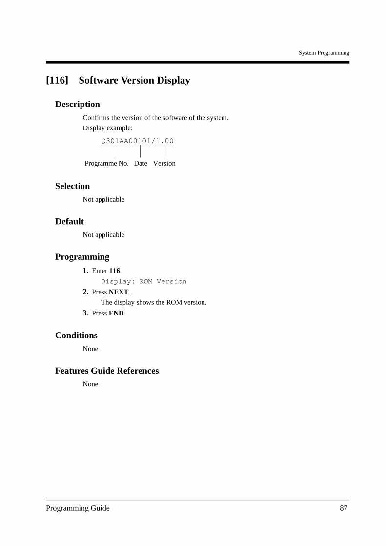
System Programming
[116] Software Version Display
DescriptionConfirms the version of the software of the system.
Display example:
SelectionNot applicable
DefaultNot applicable
Programming
1. Enter 116.
Display: ROM Version
2. Press NEXT.
The display shows the ROM version.
3. Press END.
ConditionsNone
Features Guide ReferencesNone
Q301AA00101/1.00
Date Programme No. Version
Programming Guide 87
System Programming
[117] Charge Display Selection
DescriptionAssigns the initial display format of charge fee.
SelectionMeter/Currency
DefaultCurrency
Programming
1. Enter 117.
Display: Charge Meter
2. Press NEXT.
Display example:
3. Keep pressing SELECT until the desired selection is displayed.
4. Press STORE.
5. Press END.
Conditions• The currency is assigned in programme [125] Currency Assignment.
Features Guide ReferencesCharge Fee Reference
Display, Call Information
88 Programming Guide
System Programming
[118] Charge Verification Assignment
DescriptionAssigns the extension which can refer to or clear the call information on an extension basis, CO line basis, department code basis, account code basis, or total basis. This feature is not available for XDP extensions.
Selection• Jack number: 1-8
• Enable/Disable
DefaultAll jacks — Enable
Programming
1. Enter 118.
Display: Charge Refer EXT
2. Press NEXT.
Display: Jack NO?
3. Enter a jack number.
To enter jack number 1, you can also press NEXT.
Display example: #1:Enable
4. Keep pressing SELECT until the desired selection is displayed.
5. Press STORE.
6. To program another jack, press NEXT or PREV, or SELECT and the desired jack number.
7. Press END.
Conditions
• To assign all jack numbers to one selection, press the key at step 3.In this case, the display shows the contents programmed for Jack1.
Features Guide ReferencesCharge Fee Reference
Programming Guide 89
System Programming
[119] Charge Verification ID Code Set
DescriptionAssigns an ID code required to refer the charge information. Please see User Manual, 4.1.4 Charge Fee Management [Pre-assigned extension only] for actual use of this ID code.
Selection4 digits (0000 through 9999)
Default1234
Programming
1. Enter 119.
Display: Charge ID Code
2. Press NEXT.
Display example: Code:1234
3. Enter an ID code.
To delete the current entry, press CLEAR.
4. Press STORE.
5. Press END.
ConditionsNone
Features Guide ReferencesCharge Fee Reference
90 Programming Guide
System Programming
[120] User Password
DescriptionAssigns the password required for entering the Manager Programming mode.In the Manager Programming Mode, programming [000] through [024] can be set at any digital proprietary telephone with display.
SelectionPassword: 4 through 7 digits
Default1234
Programming
1. Enter 120.
Display: User Password
2. Press NEXT.
Display example: Password:1234
3. Enter a password.
To change the current entry, press CLEAR and the new password.
4. Press STORE.
5. Press END.
Conditions• The password can be from 4 to 7 digits long. Valid numbers are from 0 through 9.
• If less than 4 digits are entered, they are not stored.
• You cannot leave the entry empty.
Features Guide ReferencesNone
Programming Guide 91
System Programming
[121] Pulse Dial Reception Assignment
DescriptionAssigns whether the pulse dial from the extension can be received or not by the system.
SelectionEnable/Disable
DefaultEnable
Programming
1. Enter 121.
Display: Ext Pulse Dial
2. Press NEXT.
Display example: Ext Puls:Enable
3. Keep pressing SELECT until the desired selection is displayed.
4. Press STORE.
5. Press END.
ConditionsNone
Features Guide ReferencesMixed Station Capability
92 Programming Guide

System Programming
[122] Automatic Door Open Assignment
DescriptionAssigns whether the door is automatically unlocked or not, when pressing Call button.
Selection• Doorphone number: 1 through 3
• Enable/Disable
DefaultAll doorphone numbers—Disable—Day/Night
Programming
1. Enter 122.
Display: Auto Door Open
2. Press NEXT to program D1–Day.
To program another status, keep pressing NEXT until the desired one is displayed.
Display example: D1- Day :Disable
3. Keep pressing SELECT until the desired selection is displayed.
4. Press STORE.
5. To program another selection press NEXT or PREV until the desired selection is displayed.
6. Repeat steps 3 and 4.
7. Press END.
ConditionsThis programming is applied to the doorphone which provides the door opener.
Features Guide ReferencesDoor Opener
Programming Guide 93
System Programming
[125] Currency Assignment
DescriptionAssigns the currency required for your country.
Selection3 characters (max.)
DefaultPound*
Programming
1. Enter 125.
Display: Currency
2. Press NEXT.
Display example: Currency:
3. Enter a currency.
To delete the current entry, press CLEAR.To change the current entry, press CLEAR and enter the new currency.To enter characters, see Section 1.4 Entering Characters.
4. Press STORE.
5. Press END.
Conditions• You can display a currency unit before or after the number. Refer to [990] System
Additional Information, Area 09 — Bit 12.
Note
* The actual display of the default currency is " ". It is not spelled out as "Pound".
Features Guide ReferencesDisplay, Call Information
94 Programming Guide
System Programming
[126] Voice Mail Number Assignment
DescriptionThis programme is available when you connect your KX-TD612 to a Digital Proprietary Telephone capable Panasonic Voice Processing System (one that supports DPT Integration). This programme assigns the PBX jack that will carry data to and from the VPS.
Note
This programme should be used before connecting the VPS. After this programme, [127] Voice Mail Extension Number Assignment and [003] Extension Number Set have been performed, start programming the VPS. If you are connecting a VPS for the first time, system reset is recommended (DIP switch position 5). Then to create mailboxes for AA service, use DIP switch position 2. Or to create mailboxes for VM service, use DIP switch position 3. DPT Integration is very simple.
Selection• Jack number: 2-4 (max. 2)
DefaultAll jacks — Blank
Programming
1. Enter 126.
Display: VPS Port Asn
2. Press NEXT.
Display example: JackNo # #
3. Enter a jack number.
To delete the current entry, press CLEAR.
To change the current entry, press CLEAR and enter the new jack number.
4. Press to enter another jack number.
5. Repeat steps 3 through 4 to enter another jack number.
6. Press STORE.
7. Press END.
Conditions• A maximum of 2 jacks can be assigned; and each jack supports 2 voice mail channels.
• Neither Jack number 1 nor the manager extension can be assigned as a voice mail port jack.
Programming Guide 95

System Programming
• The jack numbers correspond to the voice mail port in numerical order. Example: Stored jack numbers: Jacks 2, 3Jack 2=Voice mail numbers 01, 02; Jack 3=Voice mail numbers 03, 04
Features Guide ReferencesVoice Mail Integration for Digital Proprietary Telephones
96 Programming Guide
System Programming
[127] Voice Mail Extension Number Assignment
DescriptionThis programme is available when you connect your KX-TD612 to a Digital Proprietary Telephone capable Panasonic Voice Processing System (one that supports DPT Integration). This programme assigns the extension numbers for the voice mail numbers (channels). These numbers can be used in the same way extension numbers are used for station access.
Selection• Voice mail number (VM): 01 through 04• Extension Number: 2 through 4 digits
DefaultVM-01=265, VM-02=266,
VM-03=267, VM-04=268,
Programming
1. Enter 127.
Display: VM EXT NO. Set
2. Press NEXT.
Display: VM NO?
3. Enter a voice mail number.
To enter voice mail number 01, you can also press NEXT.
Display: VM-01:#02-1:265
4. Enter an extension number.
To change the current entry, press CLEAR and enter the new number.
5. Press STORE.
6. To program another voice mail number, press NEXT or PREV, or SELECT and the desired voice mail number.
7. Repeat steps 4 through 6.
8. Press END.
Conditions• You cannot leave an entry empty.
• Double entries and incompatible entries for extension numbers are invalid.To avoid making an invalid entry, check the other extension numbers in programmes [003] Extension Number Set, [012] ISDN Extension Number Set, [130] Phantom Extension Number Assignment and [813] Floating Number Assignment.
Programming Guide 97
System Programming
• The display shows "VM-XX:#YY-1:ZZZ" in step 3."XX" means the voice mail number. "YY" means the jack number of the voice mail port programmed in [126] Voice Mail Number Assignment."-1" of YY-1 means the first part of jack number in digital line.YY-2 means the second number of the jack number in digital line.
Features Guide ReferencesVoice Mail Integration for Digital Proprietary Telephones
98 Programming Guide
System Programming
[128] Voice Mail Extension Group Assignment
DescriptionThis programme is available when you connect your KX-TD612 to a Digital Proprietary Telephone capable Panasonic Voice Processing System (one that supports DPT Integration). This programme assigns each operational voice mail number to a voice mail extension group.
Note
You should first perform [126] Voice Mail Number Assignment.
Selection• Voice mail number (VM): 01 through 04
• Voice mail extension group number (EXG): 1 through 4
DefaultAll voice mail numbers — EXG 1
Programming
1. Enter 128
Display: VM EXT Group Asn
2. Press NEXT.
Display: VM NO?
3. Enter a voice mail number.
To enter voice mail number 01, you can also press NEXT.
Display example: VM-01:#02-1:EXG1
4. Enter the voice mail extension group number.
To delete the current entry, press CLEAR.
To change the current entry, enter the new number.
5. Press STORE.
6. To program another voice mail number, press NEXT or PREV, or SELECT and the desired voice mail number.
7. Repeat steps 4 through 6.
8. Press END.
Conditions• The display shows "VM-XX:#YY-1:EXG Z" in step 3.
"XX" means a voice mail number. "YY" means the jack number of the voice mail port programmed in [126] Voice Mail Number Assignment.
Programming Guide 99
System Programming
"-1" of YY-1 means the first part of jack number in digital line."YY-2" means the second part of the jack number in digital line.
• To assign all voice mail numbers to one selection, press the key in step 3. In this case, the display shows the contents programmed for voice mail number 01.
Features Guide ReferencesVoice Mail Integration for Digital Proprietary Telephones
100 Programming Guide
System Programming
[129] Operator Queue
DescriptionAssigns the limited number of the queue and the number of the Hurry-Up.
Selection• Queue: 0 through 6
• Number of Hurry-Up: 0 through 6
DefaultQueue: 6, Hurry-Up No.: 3
Programming
1. Enter 129.
Display: Operator Queue
2. Press NEXT.
Display example: Queue:6,H-UP :3
3. Enter a queue.
To change the current entry, press CLEAR and the new number.
4. Press .
5. Enter a number of Hurry-Up.
To change the current entry, press CLEAR and the new number.
6. Press STORE.
7. Press END.
Conditions• The number of Hurry-Up should not be more than the number of the queue.
Features Guide ReferencesAutomatic Overflow and Hurry-Up Transfer
Programming Guide 101
System Programming
[130] Phantom Extension Number Assignment
DescriptionAssigns the phantom extension number.
Selection• Location number: 01 through 16
• Phantom extension number: 2 to 4 digits
DefaultAll locations — Not Stored
Programming
1. Enter 130.
Display: Phantom NO.
2. Press NEXT.
Display: Location NO?
3. Enter a location number.
To enter location number 01, you can also press NEXT.
Display example: 01 :Not Stored
4. Enter a phantom extension number.
To delete the current entry, press CLEAR
To change the current entry, press CLEAR and the new number.
5. Press STORE.
6. To program another location, press NEXT or PREV, or SELECT and the desired location number.
7. Repeat steps 4 through 6.
8. Press END.
Conditions• There is a maximum of 16 phantom numbers. Each number has 2 to 4 digits, consisting of
numbers 0 through 9.
• The first 1 or 2 digits of the phantom extension numbers are subject to program [100] Flexible Numbering, (01) through (16) 1st through 16th hundred extension blocks.
• Phantom extension numbers and other extension numbers should be unique. Double entry and incompatible entry for these numbers are invalid. Valid entry examples are: 10 and 11, 10 and 110. Invalid entry examples are: 10 and 106, 210 and 21.
102 Programming Guide

System Programming
• To avoid making an invalid entry, check the other extension numbers in programmes [003] Extension Number Set, [012] ISDN Extension Number Set, [127] Voice Mail Extension Number Assignment, and [813] Floating Number Assignment.
Features Guide ReferencesPhantom Extension
Programming Guide 103
System Programming
[131] Hunting Group Assignment
DescriptionAssigns extensions to hunting groups. An incoming call is hunted in the order of registration except for Ring hunting.
Selection• Hunting group number: 01 through 32
• Extension number: 2 through 4 digits, 12 numbers (max.)/Disable (No entry)
DefaultAll hunting groups — Disable
Programming
1. Enter 131.
Display: Hunt Group Asn
2. Press NEXT.
Display: Group NO?
3. Enter a hunting group number.
To enter hunting group number 01, you can also press NEXT.
Display example: 01:01:Disable
4. Enter an extension number.
To delete the current entry, press CLEAR.
To change the current entry, press CLEAR and the new number.
5. Press STORE.
6. To program another extension to the same group, press NEXT and repeat steps 4 and 5.
7. To program another hunting group, press SELECT and repeat steps 3 through 6.
8. Press END.
Conditions• One extension can belong to more than 1 hunting group simultaneously.
• You can assign extension numbers assigned in the following programmes to a hunting group:[003] Extension Number Set[012] ISDN Extension Number Set
• You can assign the floating number of the Ring hunting group for No Reply hunting.
• In other cases, floating numbers cannot be assigned.
104 Programming Guide
System Programming
• It is possible to assign the ISDN extension numbers. In this case, the MSN additional number can be added. The MSN must be up to 4 digits, consisting of an ISDN extension number and an additional number (1 or 2 digits). The MSN additional number digit can be selected in programmes [427] ISDN Extension Multiple Subscriber Number.
• An ISDN extension in a hunting group will only ring if the type of the hunting group is No Reply.
Features Guide ReferencesHunting Group
Station Hunting
Programming Guide 105
System Programming
[132] Hunting Group Name Assignment
DescriptionAssigns a hunting group name to the hunting group. When an incoming outside call is received, the assigned name and the extension number of the group are displayed on the LCD.
Selection• Hunting group number: 01 through 32
• Name: 16 characters (max.)
DefaultAll hunting groups — Not Stored
Programming
1. Enter 132.
Display: Hunt Group Name
2. Press NEXT.
Display: Group NO?
3. Enter a hunting group number.
To enter hunting group number 01, you can also press NEXT.
Display example: 01:Not Stored
4. Enter a name.
For entering characters, see Section 1.4 Entering Characters.
To delete the current entry, press CLEAR.
To change the current entry, press CLEAR and the new name.
5. Press STORE.
6. To program another group, press NEXT or PREV, or SELECT and the desired hunting group number.
7. Repeat steps 4 through 6.
8. Press END.
ConditionsNone
Features Guide ReferencesHunting Group
Station Hunting
106 Programming Guide
System Programming
[133] Hunting Overflow
DescriptionAssigns the length of a queue and the management of an incoming call when the queue is full. There are 3 types of management mentioned below:
Selection• Hunting group number: 01 through 32
• Call management: OVF (Overflow)/Busy (Busy Tone)/No
• The length of the queue: 0 through 8, 1 digit
DefaultAll hunting groups — Busy, 0
Programming
1. Enter 133.
Display: Hunt Overflow
2. Press NEXT.
Display: Group NO?
3. Enter a hunting group number.
To enter hunting group number 01, you can also press NEXT.
Display example: 01:Busy ,0
4. Keep pressing SELECT until the desired selection is displayed.
5. Press .
6. Enter the length of the queue.
To change the current entry, press CLEAR and the new number.
Overflow: When the queue is full, a new incoming call is transferred to the Intercept destination for the group. If the length of the queue is assigned as "0" and all extensions are busy or logged out, the call is transferred to the Intercept destination for the group.
Busy Tone: This assignment is available only when the call is made through an ISDN line or intercom call. If the queue is full, a busy tone is sent to a caller. If the length of the queue is assigned as "0" and all extensions are busy or logged out, a busy tone is sent to the caller.
No: As the queue is treated as infinite, overflow will not occur and a busy tone will not be sent. The call will be kept waiting until an extension in the group becomes idle (or logs in) or until the intercept timer expires (the intercept destination will then ring). IRNA starts.
Programming Guide 107
System Programming
7. Press STORE.
8. To program another group, press NEXT or PREV, or SELECT and the desired hunting group number.
9. Repeat steps 4 through 6.
10.Press END.
ConditionsNone
Features Guide ReferencesHunting Group
Intercept Routing
Station Hunting
108 Programming Guide
System Programming
[134-135] Hunting Intercept — Day/Night
DescriptionSets the Intercept destination in both day and night modes for each hunting group.
Selection• Hunting group number: 01 through 32
• Extension number: 2 through 4 digits/Disable (no Intercept Routing)
DefaultAll hunting groups – Disable — Day/Night
Programming
1. Enter a programme address (134 for day or 135 for night).
Display example: Hunt Intercp Day
2. Press NEXT.
Display: Group NO?
3. Enter the hunting group number.
To enter hunting group number 01, you can also press NEXT.
Display example: 01:Disable
4. Enter an extension number.
To change the current entry, press CLEAR and the new number.
To disable Intercept Routing, press CLEAR.
5. Press STORE.
6. To program another hunting group, press NEXT or PREV, or SELECT and the desired hunting group number.
7. Repeat steps 4 through 6.
8. Press END.
Conditions• You can set the extension numbers in programmes [003] Extension Number Set,
[012] ISDN Extension Number Set, [127] Voice Mail Extension Number Assignment, [130] Phantom Extension Number Assignment and also floating numbers of the second ringer, hunting groups, and pagers in programme [813] Floating Number Assignment.
Features Guide ReferencesIntercept Routing
Programming Guide 109
System Programming
[137-138] Time Table Assignment — Day/Night
DescriptionAssigns the Time Table to be used when all extensions are busy in the Hunting Group (Ring, No Reply, UCD).
Selection• Hunting Group number: 01 through 32
• Time Table number: 1 through 4
DefaultAll Hunting Groups — Not Stored
Programming
1. Enter a programme address (137 for day or 138 for night).
Display example: UCD T.Table Day
2. Press NEXT.
Display: Group NO?
3. Enter a Hunting Group number.
To enter Hunting Group number 1, you can also press NEXT.
Display example: UCD01:Not Stored
4. Enter a Time Table number.
Display example: UCD01:1
5. Press STORE.
6. Press END.
Conditions• If the Time Table is not assigned, the system will not answer the call and waits for an
extension to become idle. When an extension becomes free, rings, but is not answered. Intercept Routing — No Answer (IRNA) will be employed.
Features Guide ReferencesNo Reply Group
Ring Group
Uniform Call Distribution (UCD)
110 Programming Guide
System Programming
[139] Time Table
DescriptionAssigns the queuing sequence in the Time Table for Ring, No Reply, and UCD hunting groups. The queuing sequences are as follows:
Selection• Time Table number: 1 to 4
• S1/S2/S3/S4/S5/S6/S7/S8/S9 TR/RT/1T/2T/3T/4T/Blank
DefaultAll time tables — Blank
Programming
1. Enter 139.
Display: UCD T.Table
2. Press NEXT.
S1 : Sends the outgoing message Built-in Voice Message (BV) 1.
S2 : Sends the outgoing message BV2.
S3 : Sends the outgoing message BV3.
S4 : Sends the outgoing message BV4.
S5 : Sends the outgoing message BV5.
S6 : Sends the outgoing message BV6.
S7 : Sends the outgoing message BV7.
S8 : Sends the outgoing message BV8.
S9 : Sends the outgoing message BV9.
TR : Transfers to the overflow extension.
RT : Returns to the top of the sequence.
1T : Timer — 16 seconds
2T : Timer — 32 seconds
3T : Timer — 48 seconds
4T : Timer — 64 seconds
Blank : Disconnects.
Programming Guide 111
System Programming
Display: Table NO?
3. Enter a Time Table number.
To enter Time Table number 1, you can also press NEXT.
Display example: 1:
4. Keep pressing SELECT until the desired selection is displayed.
Display example: 1:S4
5. Press .
6. Repeat steps 4 and 5.
7. Press STORE.
8. Press END.
Conditions• "Sx" can be assigned in the second to the fifth positions only when "Sx" is assigned in the
first position.
• An assignment after "TR," "RT" or "Blank" is not available.
• You can change the returning point when selecting RT from top to second in programme [990] System Additional Information — Area 09, bit 3 through 6.
• If you want to send a BV message (S1, S2, etc.), you need to set the following:[133] Hunting Overflow (Relevant hunting group to "No" or "More than One Queuing".)[134-135] Hunting Intercept — Day/Night (Relevant handling table to some extensions.)[456] Call Handling When All Busy (Relevant handling table to "Queuing".)
• When a call arrives through the analogue CO line and is handled by the UCD Time Table, even though the calling party hangs up, the call will not be disconnected, but will keep on ringing. To avoid this, be sure to assign "Blank" (or "Unused" when programming by PC programming software) to the corresponding sequence of the UCD Time Table.
Features Guide ReferencesNo Reply Group
Ring Group
Uniform Call Distribution (UCD)
112 Programming Guide
System Programming
[140] Phantom Extension Name
DescriptionAssigns the phantom extension names.
Selection• Location number: 01 through 16
• Phantom extension name: 16 characters (max.)
DefaultAll locations — Not stored
Programming
1. Enter 140.
Display: Phantom Name
2. Press NEXT.
Display: Location NO?
3. Enter a location number.
To enter location number 01, you can also press NEXT.
Display example: 01:Not Stored
4. Enter a phantom extension name.
To enter characters, see Section 1.4 Entering Characters.
To delete the current entry, press CLEAR.
To change the current entry, press CLEAR and enter the new name.
5. Press STORE.
6. To program another location, press NEXT or PREV, or SELECT and the desired location number.
7. Repeat steps 4 through 6.
8. Press END.
Conditions• There is a maximum of 16 phantom extension names. Each name can have a maximum of
16 characters.
Features Guide ReferencesPhantom Extension
Programming Guide 113
System Programming
[141] Off-Hook Monitor
DescriptionEnables or disables the ability to perform the off-hook monitor.
SelectionEnable/Disable
DefaultEnable
Programming
1. Enter 141.
Display: Off-Hook Monitor
2. Press NEXT.
Display example: Monitor:Enable
3. Keep pressing SELECT until the desired selection is displayed.
4. Press STORE.
5. Press END.
Conditions• This feature is only available for KX-T7431, KX-T7433 and KX-T7436.
Features Guide ReferencesOff-Hook Monitor
114 Programming Guide
System Programming
[143] CCBS Feature
DescriptionEnables or disables the Completion of Calls to Busy Subscriber (CCBS) function.
SelectionDisable
DefaultDisable
Programming
1. Enter 143.
Display: CCBS
2. Press NEXT.
Display: CCBS :Disable
3. Keep pressing SELECT until the desired selection is displayed.
4. Press STORE.
5. Press END.
ConditionsNone
Features Guide ReferencesCompletion of Calls to Busy Subscriber (CCBS)
Programming Guide 115
System Programming
[144] Hunting Group Busy on Busy
DescriptionDecides the maximum number of busy extension for Busy on Busy feature.
SelectionHunting group number: 01 through 32
The maximum number of busy extension: 0 through 8
DefaultAll hunting group — 0
Programming
1. Enter 144.
Display: H/G Busy on Busy
2. Press NEXT.
Display: Group NO?
3. Enter a hunting group number.
To enter a hunting group number 01, you can also press NEXT.
Display: 01:0
4. Enter the maximum number of busy extension.
Display: 01:1
5. Press STORE.
6. Press END.
ConditionsIf you set 0 as the number of busy extension, this function will be disabled. The calls will reach to an idle extension in the hunting group.
Features Guide ReferencesHunting Group
116 Programming Guide
System Programming
[145] Second Ringer For Doorphone Assignment
DescriptionThis selection (when enabled) allows the Second Ringer to ring only when a Doorphone call arrives.
Selection• Doorphone number: 1 through 3
• Enable/Disable
DefaultAll doorphone numbers—Enable—Day/Night
Programming
1. Enter 145.
Display: 2nd Ringer DPH
2. Press NEXT to program DPH1 Day.
To program another status, keep pressing NEXT until the desired one is displayed.
Display example: DPH1 Day :Enabl
3. Keep pressing SELECT until the desired selection is displayed.
4. Press STORE.
5. To program another selection press NEXT or PREV until the desired selection is displayed.
6. Repeat steps 3 and 4.
7. Press END.
ConditionsIf "Disable" is selected in this programme while an extension sets to ring a Second Ringer, the Second Ringer will not ring when a call from a doorphone is made.
Features Guide ReferencesDoorphone Call
Second Ringer
Programming Guide 117

System Programming
118 Programming Guide

Timer Programming
Section 4
Timer Programming
Programming Guide 119
Timer Programming
4.1 Timer Programming
[200] Hold Recall Time
DescriptionAssigns the length of the hold recall timer. This timer is used to alert an extension that a call has been held for an extended period of time.
SelectionTime (seconds): 0 through 240
Default60 s
Programming
1. Enter 200.
Display: Hold Recall Time
2. Press NEXT.
Display example: Time: 60 sec
3. Enter the time.
To change the current entry, press CLEAR and the new time.
4. Press STORE.
5. Press END.
Conditions• Select "0" if Hold Recall is not required.
• You cannot leave the entry empty.
Features Guide ReferencesHold Recall
120 Programming Guide
Timer Programming
[201] Transfer Recall Time
DescriptionSets the number of rings before the transfer recall occurs. If a transferred call is not answered before the programmed number of rings, the call returns to the original caller or to an operator.
SelectionNumber of rings: 3 through 48
Default12 rings
Programming
1. Enter 201.
Display: Transfer Recall
2. Press NEXT.
Display example: Time:12 rings
3. Enter the number of rings.
To change the current entry, press CLEAR and the new number of rings.
4. Press STORE.
5. Press END.
Conditions• One ring is equivalent to 5 seconds.
• You cannot leave the entry empty.
Features Guide ReferencesCall Transfer, Unscreened — to Extension
Programming Guide 121
Timer Programming
[202] Call Forwarding — No Answer Time
DescriptionSets the number of rings for the Call Forwarding — No Answer feature. If a call is not answered before the programmed number of rings, the call is forwarded to the destination.This timer is also used for the "No Reply Group" feature; if an extension is not answered within the specified time, the call goes to the next extension.
SelectionNumber of rings: 1 through 12
Default3 rings
Programming
1. Enter 202.
Display: No Answer Time
2. Press NEXT.
Display example: Time: 3 rings
3. Enter the number of rings.
To change the current entry, press CLEAR and the new number of rings.
4. Press STORE.
5. Press END.
Conditions• One ring is equivalent to 5 seconds.
• You cannot leave the entry empty.
Features Guide ReferencesCall Forwarding — Busy/No Answer
Call Forwarding — No Answer
No Reply Group
122 Programming Guide
Timer Programming
[203] Intercept Time
DescriptionSets the number of rings for the Intercept Routing – No Answer (IRNA) feature. If a call is not answered before the programmed number of rings, the call is redirected to the programmed station.
SelectionNumber of rings: 1 through 48
Default12 rings
Programming
1. Enter 203.
Display: Intercept Time
2. Press NEXT.
Display example: Time: 12 rings
3. Enter the number of rings.
To change the current entry, press CLEAR and the new number of rings.
4. Press STORE.
5. Press END.
Conditions• One ring is equivalent to 5 seconds.
• Intercept destinations are set on a handling table number basis in [457] Intercept Extension.
• If the original extension has set Call Forwarding – No Answer, Intercept Timer starts after the Call Forwarding.
• You cannot leave the entry empty.
Features Guide ReferencesIntercept Routing
Programming Guide 123

Timer Programming
[204] Pickup Dial Waiting Time
DescriptionSets the number of seconds for Pickup Dialling. If the telephone user lifts the handset, the programmed party is called when the time expires.
SelectionTime (seconds): 0 through 8
Default1 s
Programming
1. Enter 204.
Display: Pickup Dial Time
2. Press NEXT.
Display example: Time: 1 sec
3. Enter the time.
To change the current entry, enter the new time.
4. Press STORE.
5. Press END.
ConditionsThis time gives the user an opportunity to dial digits before the automatic dialling process occurs.
Features Guide ReferencesPickup Dialling
124 Programming Guide
Timer Programming
[205] Extension-to-Outside Line Call Duration Time
DescriptionSets the maximum time allowed for a conversation with an outside party. If an outside call is originated or answered by a programmed extension user and the timer expires, the call is disconnected.
SelectionTime (minutes): 1 through 64
Default10 min
Programming
1. Enter 205.
Display: CO Dur. Time
2. Press NEXT.
Display example: Time:10 min
3. Enter the time.
To change the current entry, press CLEAR and enter the new time.
4. Press STORE.
5. Press END.
Conditions• This time-out applies to extensions to which limited call duration is assigned by programme
[502] Extension-to-CO Call Duration Limit.
• This time cannot be set to zero or be left empty.
Features Guide ReferencesNone
Programming Guide 125
Timer Programming
[206] Outside-to-Outside Line Call Duration Time
DescriptionSets the maximum time allowed for a conversation between two outside parties. When the timer expires, the outside-to-outside line call is disconnected.
SelectionTime (minutes): 1 through 64
Default10 min
Programming
1. Enter 206.
Display: CO-CO Dur. Time
2. Press NEXT.
Display example: Time:10 min
3. Enter the time.
To change the current entry, press CLEAR and enter the new time.
4. Press STORE.
5. Press END.
Conditions• You cannot leave the entry empty.
Features Guide ReferencesCall Forwarding — to CO Line, All Calls
Call Transfer, Screened — to CO Line
Call Log, Incoming
Direct Inward System Access (DISA)
126 Programming Guide
Timer Programming
[207] First Digit Time
DescriptionSets the maximum time allowed between the start of outside dial tone and the first digit dialled on an outgoing outside call. If an extension user fails to dial any digits during this time, the DTMF receiver is released.
SelectionTime (seconds): 5 through 120
Default10 s
Programming
1. Enter 207.
Display: 1st Digit Time
2. Press NEXT.
Display example: Time: 10 sec
3. Enter the time.
To change the current entry, press CLEAR and the new time.
4. Press STORE.
5. Press END.
Conditions• This timer is used for toll restriction checking.
• You cannot leave the entry empty.
Features Guide ReferencesToll Restriction
Programming Guide 127
Timer Programming
[208] Inter Digit Time
DescriptionAssigns the maximum time allowed between digits on an outgoing toll call. If an extension user fails to dial any digits during this time, the DTMF receiver is released. This timer applies until the Toll Restriction check is completed.
SelectionTime (seconds): 5 through 30
Default10 s
Programming
1. Enter 208.
Display: Inter Digit Time
2. Press NEXT.
Display example: Time: 10sec
3. Enter the time.
To change the current entry, press CLEAR and the new time.
4. Press STORE.
5. Press END.
Conditions• This timer is used for toll restriction checking.
• You cannot leave the entry empty.
Features Guide ReferencesToll Restriction
128 Programming Guide
Timer Programming
[209] Automatic Redial Repeat Times
DescriptionSets the number of times Automatic Redial is tried. Automatic redialling of the last dialled or saved number is done up to the specified number of times.
SelectionNumber of times: 1 time through 12 times
Default4 times
Programming
1. Enter 209.
Display: Redial Times
2. Press NEXT.
Display example: Attempt:4
3. Enter the number of times.
To change the current entry, press CLEAR and the new number of times.
4. Press STORE.
5. Press END.
Conditions• Programme [210] Automatic Redial Interval Time is used to set the interval time between
Automatic Redial attempts.
• You cannot leave the entry empty.
Features Guide ReferencesRedial, Automatic
Programming Guide 129
Timer Programming
[210] Automatic Redial Interval Time
DescriptionSets the interval time between Automatic Redial attempts.
SelectionTime (seconds): 30 through 1200
Default120 s
Programming
1. Enter 210.
Display: Interval Time
2. Press NEXT.
Display example: Time: 120 sec
3. Enter the time.
To change the current entry, press CLEAR and the new time.
4. Press STORE.
5. Press END.
Conditions• Programme [209] Automatic Redial Repeat Times is used to set the number of times
Automatic Redial is tried.
• You cannot leave the entry empty.
Features Guide ReferencesRedial, Automatic
130 Programming Guide
Timer Programming
[211] Dial Start Time
DescriptionSets the number of milliseconds the system waits before dialling after an outside line is seised.
Selection
Time (milliseconds): 0 through 40 ( 100 is the actual time)
Default0 ms
Programming
1. Enter 211.
Display: CO Dial Start
2. Press NEXT.
Display example: Time: 0 msec
3. Enter the time.
To change the current entry, press CLEAR and enter the new time.
4. Press STORE.
5. Press END.
Conditions• You enter a number from 0 through 40. The actual time is a 100 times your input.
• You cannot leave the entry empty.
Features Guide ReferencesNone
Programming Guide 131
Timer Programming
[212] Call Duration Count Start Time
DescriptionSets the number of seconds the system waits between the end of dialling and the start of the SMDR timer for outgoing toll calls when the system is installed behind a host PBX. When the system has sent out all the digits to the central office and this timer expires, the system starts counting the call. A display telephone shows the elapsed time of the call. The starting time and the total duration of a call are recorded in the SMDR record.
SelectionTime (seconds): 0 through 60
Default0 s
Programming
1. Enter 212.
Display: SMDR Durat Time
2. Press NEXT.
Display example: Time: 0sec
3. Enter the time.
To change the current entry, press CLEAR and the new time.
4. Press STORE.
5. Press END.
Conditions• The timer starts counting after all the digits are dialled. This timer is not applied to incoming
calls. The timer for incoming calls starts immediately.
• You cannot leave the entry empty.
Features Guide ReferencesStation Message Detail Recording (SMDR)
132 Programming Guide
Timer Programming
[213] External Relay Connecting Time
DescriptionSet the connecting time to hold the external relay on.
SelectionTime (seconds): 0 through 99
Default5 s
Programming
1. Enter 213.
Display: Ext Relay Time
2. Press NEXT.
To program "Slave," press NEXT twice.
Display example: Time : 5 sec
3. Enter the time.
To change the current entry, enter the new time.
4. Press STORE.
5. Press END.
Conditions• If "0" is assigned, the system will hold the external relay on until the controlling telephone
is on-hooked.
Features Guide ReferencesExternal Relay
Programming Guide 133
Timer Programming
[214] Message Waiting Ring Interval Time
DescriptionSet the interval time of Message Waiting ring for a single line telephone.
SelectionTime (minutes): 0 through 64
Default10 min
Programming
1. Enter 214.
Display: MW Ring Time
2. Press NEXT.
Display example: Interval: 0 min
3. Enter the time.
To change the current entry, press CLEAR and enter the new time.
4. Press STORE.
5. Press END.
ConditionsWhen the internal time is set "0," the telephone does not ring for Message Waiting notification.
Features Guide ReferencesMessage Waiting
134 Programming Guide
Timer Programming
[215] Ring Off Detection Time
DescriptionSets the ring-off time so that the system can detect that the central office stops ringing.
Selection• Time (seconds): 4/5/12
Default5 s
Programming
1. Enter 215.
Display: Ring Detect Time
2. Press NEXT.
Display example: Time: 5sec
3. Keep pressing SELECT until the desired selection is displayed.
4. Press STORE.
5. Press END.
ConditionsNone
Features Guide ReferencesNone
Programming Guide 135
Timer Programming
[217] Timed Reminder Alarm Ring Time
DescriptionSets the number of seconds the Timed Reminder alarm rings.
SelectionTime (seconds): 30 through 240
Default30 s
Programming
1. Enter 217.
Display: Timed Remind
2. Press NEXT.
Display example: Reminder: 30sec
3. Enter the time.
To change the current entry, enter the new time.
4. Press STORE.
5. Press END.
ConditionsNone
Features Guide ReferencesTimed Reminder
136 Programming Guide
Timer Programming
[218] Doorphone-to-CO Line Call Duration Time
DescriptionSets the maximum time allowed for a conversation between a caller at a doorphone and an outside party. When the timer expires, the call is disconnected.
Selection
Time (seconds): 0 through 30 ( 10 is the actual time)
Default0 s
Programming
1. Enter 218.
Display: Door-CO Dur.Time
2. Press NEXT.
Display example: Time: 0 sec
3. Enter the time.
To change the current entry, press CLEAR and enter the new time.
4. Press STORE.
5. Press END.
Conditions• You can enter a number from 0 through 30. The actual time is 10 times your input.
• If the duration time is set to "0", there will be no time limit.
Features Guide ReferencesDoorphone Call Forwarding to CO Line
Programming Guide 137
Timer Programming
[220] DISA Prolong Time
DescriptionSets the maximum allowable prolonged time for an outside-to-outside line call via the Direct Inward System Access (DISA) feature. An outside-to-outside line call is initially limited by the "Outside-to-Outside Line Call Duration Time" (Programme [206]). However, the DISA caller can prolong the call after hearing the warning tones by pressing any key (except the key). The DISA prolong time sets the duration of these extended periods.
SelectionTime (minutes): 0 through 7 (0=no prolonging)
Default3 min
Programming
1. Enter 220.
Display: DISA Prolng Time
2. Press NEXT.
Display example: Time:3 min
3. Enter the time.
To change the current entry, enter the new time.
4. Press STORE.
5. Press END.
Conditions• Do not confuse this parameter with the "Outside-to-Outside Line Call Duration Time"
(Programme [206]) parameter. Programme [206] is used to set the duration time allowed for an outside-to-outside line call.
• You cannot leave the entry empty.
Features Guide ReferencesDirect Inward System Access (DISA)
138 Programming Guide
Timer Programming
[221] DISA Automated Attendant (AA) Wait Time
DescriptionSets the number of seconds the system waits for a second digit entry. If the timer expires, the system assumes that the first digit is a DISA (Direct Inward System Access) Automated Attendant (AA) number, if assigned in programme [815] DISA Automated Attendant (AA).
SelectionTime (seconds): 1 through 5
Default1 s
Programming
1. Enter 221.
Display: DISA AA WaitTime
2. Press NEXT.
Display: Time: 1 sec
3. Enter the time.
To change the current entry, press CLEAR and enter the new time.
4. Press STORE.
5. Press END.
ConditionsNone
Features Guide ReferencesIntelligent Call Handling — Distribution of Incoming Outside Calls
Programming Guide 139
Timer Programming
[222] OGM Recording Time
DescriptionSets the maximum allowable recording time for outgoing messages (OGM).
SelectionOGM recording time (minutes): 1 through 15
Default3 min
Programming
1. Enter 222.
Display: OGM Rec Time
2. Press NEXT.
Display: Time: 3 min
3. Enter the time.
To change the current entry, press CLEAR and enter the new time.
4. Press STORE.
5. Press END.
Conditions• A maximum of 9 OGMs can be recorded for company message box.
• You can choose the total recording time for Built-in Voice Message feature (including OGM) out of 60 minutes/30 minutes/20 minutes. (See [822] Built-in Voice Message Total Recording Time)
Features Guide ReferencesBuilt-in Voice Message
Outgoing Message (OGM)
Timed Reminder
Uniform Call Distribution (UCD)
140 Programming Guide
Timer Programming
[223] Built-in Voice Message Recording Time
DescriptionSets the maximum recording time of a voice message to the Built-in Voice Message (BV) box.
SelectionBV recording time (minutes): 1 through 60
Default5 min
Programming
1. Enter 223.
Display: BV Rec Time
2. Press NEXT.
Display: Time: 5 min
3. Enter the time.
To change the current entry, press CLEAR and enter the new time.
4. Press STORE.
5. Press END.
Conditions• You can choose the total recording time for Built-in Voice Message feature (including
OGM) out of 60 minutes/30 minutes/20 minutes. (See [822] Built-in Voice Message Total Recording Time)
Features Guide ReferencesBuilt-in Voice Message
Programming Guide 141

Timer Programming
142 Programming Guide

TRS Programming
Section 5
TRS Programming
Programming Guide 143
TRS Programming
5.1 TRS Programming
[301-305] TRS Denied Code Entry for Levels 2 through 6
DescriptionThese allow you to specify the numbers which are toll-restricted for each toll restriction level as follows:
Programme [301]: restricts levels 2 through 6Programme [302]: restricts levels 3 through 6Programme [303]: restricts levels 4 through 6Programme [304]: restricts levels 5 through 6Programme [305]: restricts levels 6
Selection• Location number: 01 through 20
• Toll call number: 7 digits (max.)
DefaultAll locations — Not Stored
Programming
1. Enter a programme address (301 through 305).
Display example: TRS Deny LVL-2
2. Press NEXT.
Display: Location NO?
3. Enter a location number.
To enter location number 01, you can also press NEXT.
Display example: 01: Not Stored
4. Enter a toll call number.
To delete the current entry, press CLEAR.
To change the current entry, press CLEAR and the new number.
5. Press STORE.
6. To program another location, press NEXT or PREV, or SELECT and the desired location number.
7. Repeat steps 4 through 6.
8. Press END.
144 Programming Guide
TRS Programming
Conditions• There is a maximum of 20 toll call numbers which can be restricted for each programme.
Each number has a maximum of 7 digits, consisting of 0 through 9, and . The character can be used as a wild card character.
• Programmes [306-310] TRS Excepted Code Entry for Levels 2 through 6 are used to assign exceptions to these numbers. Programmes [500-501] Toll Restriction Level — Day/Night are used to set the toll restriction value for each COS.
Features Guide ReferencesToll Restriction
Programming Guide 145
TRS Programming
[306-310] TRS Excepted Code Entry for Levels 2 through 6
DescriptionThese allow you to assign numbers which are exceptions to the toll restriction specified in programmes [301] through [305] as follows:
Programme [306]: applies to level 2Programme [307]: applies to levels 2 through 3Programme [308]: applies to levels 2 through 4Programme [309]: applies to levels 2 through 5Programme [310]: applies to levels 2 through 6
Selection• Location number: 01 through 20
• Exceptional number: 7 digits (max.)
DefaultAll locations — Not Stored
Programming
1. Enter a programme address (306 through 310).
Display example: TRS Excp LVL-2
2. Press NEXT.
Display: Location NO?
3. Enter a location number.
To enter location number 01, you can also press NEXT.
Display example: 01:Not Stored
4. Enter an exceptional number.
To delete the current entry, press CLEAR.
To change the current entry, press CLEAR and the new number.
5. Press STORE.
6. To program another location, press NEXT or PREV, or SELECT and the desired location number.
7. Repeat steps 4 through 6.
8. Press END.
146 Programming Guide

TRS Programming
ConditionsThere is a maximum of 20 numbers for each programme. Each number has a maximum of 7 digits, consisting of 0 through 9, and . The character " " can be used as a wild card character.
Features Guide ReferencesToll Restriction
Programming Guide 147
TRS Programming
[311] Emergency Dial Number Set
DescriptionStores up to 10 emergency call numbers.Emergency numbers are not subject to toll restriction, Account Code – Verified or Electronic Station Lockout.
Selection• Location number: 01 through 10
• Emergency number: 16 digits (max.)
DefaultLocation 01 — 999; 02 — 112; 03 through 10 — Not Stored
Programming
1. Enter 311.
Display: Emergency Dial
2. Press NEXT.
Display: Location NO?
3. Enter a location number.
To enter location number 01, you can also press NEXT.
Display example: 01:999
4. Enter an emergency number.
To delete the current entry, press CLEAR.
To change the current entry, press CLEAR and the new number.
5. Press STORE.
6. To program another location, press NEXT or PREV, or SELECT and the desired location number.
7. Repeat steps 4 through 6.
8. Press END.
ConditionsThere is a maximum of 10 emergency numbers. Each number has a maximum of 16 digits, consisting of 0 through 9.
Features Guide ReferencesElectronic Station Lockout
Emergency Call
148 Programming Guide

TRS Programming
Toll Restriction
Programming Guide 149

TRS Programming
150 Programming Guide

CO Line Programming
Section 6
CO Line Programming
Programming Guide 151
CO Line Programming
6.1 CO Line Programming
[400] CO Port Connection Assignment
DescriptionUsed to identify the CO ports which are connected to the system. This prevents users from originating a call to a line which is not connected.
Selection• CO port number: 1 through 4 (4: Analogue CO)
• Connect/No Connect
DefaultAll CO ports — Connect
Programming
1. Enter 400.
Display: CO Connection
2. Press NEXT.
Display: Port NO?
3. Enter a CO port number.
To enter CO port number 1, you can also press NEXT.
Display example: #1 :Connect
4. Keep pressing SELECT until the desired selection is displayed.
5. Press STORE.
6. To program another CO port, press NEXT or PREV, or SELECT and the desired CO port number.
7. Repeat steps 4 through 6.
8. Press END.
Conditions
• To assign all CO port to one selection, press the key at step 3. In this case, the display shows the contents programmed for CO1.
Features Guide ReferencesNone
152 Programming Guide
CO Line Programming
[402] Dial Mode Selection
DescriptionA CO line can be programmed for DTMF (Dual Tone Multi-Frequency), pulse (rotary) or call blocking. This programme assigns your choice to each line.DTMF:The dialling signals from an extension, either tone or pulse, are converted to tone signals and transmitted to the CO line.Pulse:The dialling signals from an extension, either tone or pulse, are converted to pulse signals and transmitted to the CO line.Call blocking:If your central office can receive both DTMF and pulse signals but you are contracted for pulse, select this mode. When dialling on the line with a touch tone telephone, only the pulse signals are sent to the CO line.
Selection• CO port number: 4
• DTMF/Pulse/Call blocking
DefaultDTMF
Programming
1. Enter 402.
Display: CO Dial Mode
2. Press NEXT.
Display: Port NO?
3. Enter an CO port number.
To enter CO port number 4, you can also press NEXT.
Display example: #4 :DTMF
4. Keep pressing SELECT until the desired selection is displayed.
5. Press STORE.
6. Press END.
Conditions• If DTMF is assigned, set the DTMF time of the line in programme [404] DTMF Time.
• If pulse or call blocking is assigned, set the pulse speed of the line in programme [403] Pulse Speed Selection, and set the pulse break ratio and inter-digit pause in
Programming Guide 153

CO Line Programming
programme [990] System Additional Information, Area 02 - bit 7, and bits 12 and 11, if necessary.
Features Guide ReferencesNone
154 Programming Guide
CO Line Programming
[403] Pulse Speed Selection
DescriptionA CO line set for pulse or call blocking mode in programme [402] Dial Mode Selection can have two pulse rates, 10 pps (low) and 20 pps (high). This programme sets the pulse speed for each outside line set to pulse or call blocking mode.
Selection• CO port number: 4
• 10 pps / 20 pps
Default10 pps
Programming
1. Enter 403.
Display: Pulse Speed
2. Press NEXT.
Display: Port NO?
3. Enter an CO port number.
To enter CO port number 4, you can also press NEXT.
Display example: #4 :10pps
4. Keep pressing SELECT until the desired selection is displayed.
5. Press STORE.
6. Press END.
Conditions• The pulse speed required is determined by the CO line or PBX line.
• Programme [990] System Additional Information, Area 02 - bit 7, and bits 12 and 11 are used to select a pulse break ratio and inter-digit pause, if needed.
Features Guide ReferencesNone
Programming Guide 155
CO Line Programming
[404] DTMF Time
DescriptionA CO line set to DTMF (Dual Tone Multi-Frequency) mode in programme [402] Dial Mode Selection can have two settings. This programme sets the duration of the DTMF signals sent to a CO line to DTMF mode.
Selection• CO port number: 4
• Time (milliseconds): 80/160
Default80 ms
Programming
1. Enter 404.
Display: DTMF Time
2. Press NEXT.
Display: Port NO?
3. Enter an CO port number.
To enter CO port number 4, you can also press NEXT.Display example: #4 : 80msec
4. Keep pressing SELECT until the desired selection is displayed.
5. Press STORE.
6. Press END.
Conditions• The DTMF time required is determined by the outside line or PBX line.
Features Guide ReferencesNone
156 Programming Guide
CO Line Programming
[411] Host PBX Access Codes
DescriptionAssigns Host PBX access codes. If the system is installed behind a host PBX, an access code is required to make an outside call. Up to 4 codes can be stored for a CO port.
Selection• CO port number: 1 through 4 (4: Analogue CO)
• Access code: 1 or 2 digits, 4 different entries (max.)
DefaultAll CO ports — Not Stored
Programming
1. Enter 411.
Display : TRG Host PBX NO.
2. Press NEXT.
Display: Port NO?
3. Enter a CO port number.
To enter CO port number 1, you can also press NEXT.
Display example: #1 : , , ,
4. Enter an access code.
To delete the current entry, press CLEAR.
To change the current entry, press CLEAR and the new access code.
Display example: #1 :01 , , ,
5. To enter more access codes for the same CO port group, press and enter the access codes until all the required entries are completed.
Display example: #1 :01,08,10,22
6. Press STORE.
7. To program another CO port, press NEXT or PREV, or SELECT and the desired CO port number.
8. Repeat steps 4 through 7.
9. Press END.
Conditions• This programme is only required if a host PBX is connected to the system.
• The access code has 1 or 2 digits, consisting of 0 through 9, and .
Programming Guide 157

CO Line Programming
• If conflicting access codes (such as 8 and 81) are stored for the same CO port, the 1-digit code (8) only will be in effect.
• When the programmed codes are dialled, Toll Restriction is applied to the calls.
• To assign all CO ports to one selection, press the key at step 3. In this case, the display shows the contents programmed for CO port 1.
Features Guide ReferencesNone
158 Programming Guide
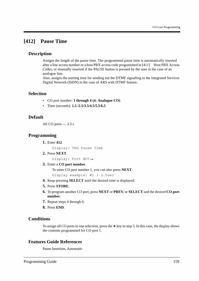
CO Line Programming
[412] Pause Time
DescriptionAssigns the length of the pause time. The programmed pause time is automatically inserted after a line access number or a host PBX access code programmed in [411] Host PBX Access Codes, or manually inserted if the PAUSE button is pressed by the user in the case of an analogue line.Also, assigns the starting time for sending out the DTMF signalling to the Integrated Services Digital Network (ISDN) in the case of ARS with DTMF feature.
Selection• CO port number: 1 through 4 (4: Analogue CO)
• Time (seconds): 1.5 /2.5/3.5/4.5/5.5/6.5
DefaultAll CO ports — 3.5 s
Programming
1. Enter 412.
Display: TRG Pause Time
2. Press NEXT.
Display: Port NO?
3. Enter a CO port number.
To enter CO port number 1, you can also press NEXT.
Display example: #1 : 3.5sec
4. Keep pressing SELECT until the desired time is displayed.
5. Press STORE.
6. To program another CO port, press NEXT or PREV, or SELECT and the desired CO port number.
7. Repeat steps 4 through 6.
8. Press END.
Conditions
To assign all CO ports to one selection, press the key in step 3. In this case, the display shows the contents programmed for CO port 1.
Features Guide ReferencesPause Insertion, Automatic
Programming Guide 159
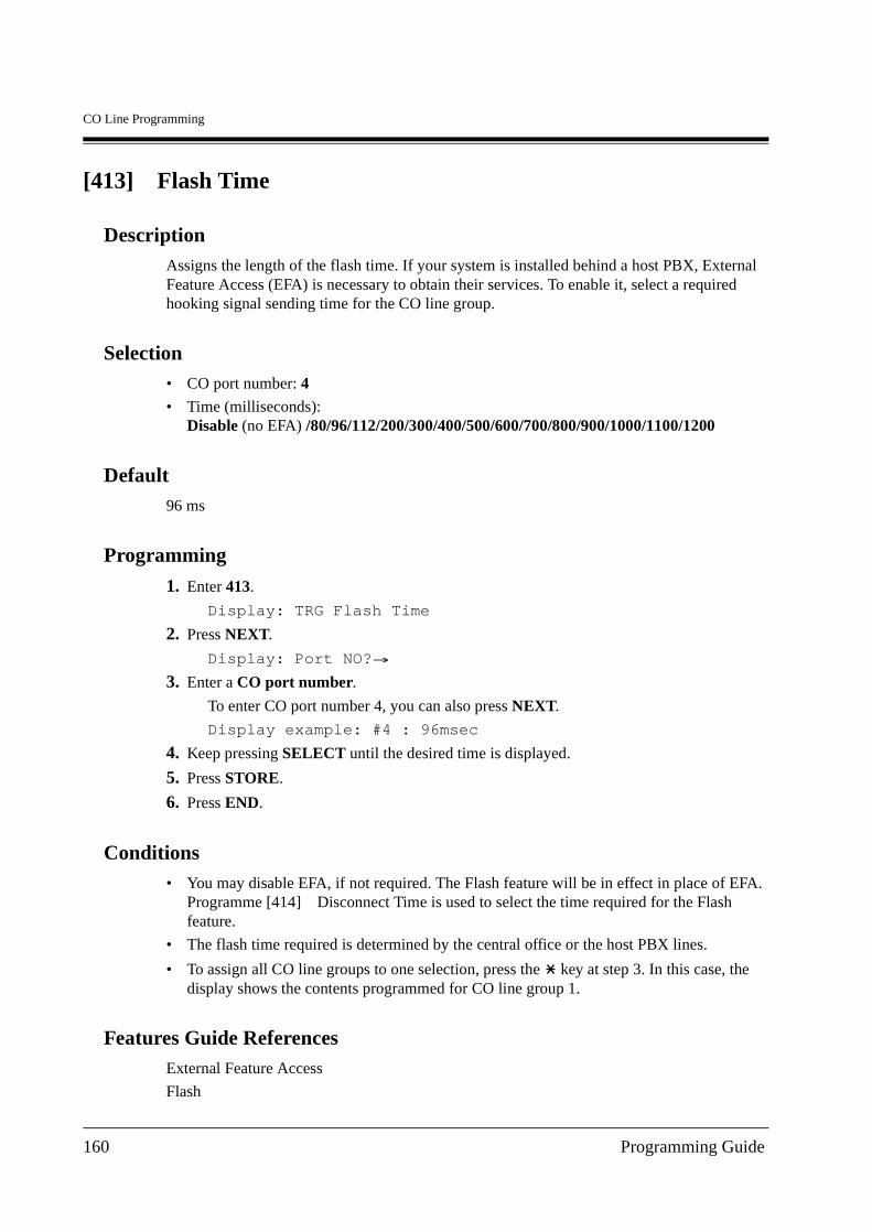
CO Line Programming
[413] Flash Time
DescriptionAssigns the length of the flash time. If your system is installed behind a host PBX, External Feature Access (EFA) is necessary to obtain their services. To enable it, select a required hooking signal sending time for the CO line group.
Selection• CO port number: 4
• Time (milliseconds): Disable (no EFA) /80/96/112/200/300/400/500/600/700/800/900/1000/1100/1200
Default96 ms
Programming
1. Enter 413.
Display: TRG Flash Time
2. Press NEXT.
Display: Port NO?
3. Enter a CO port number.
To enter CO port number 4, you can also press NEXT.
Display example: #4 : 96msec
4. Keep pressing SELECT until the desired time is displayed.
5. Press STORE.
6. Press END.
Conditions• You may disable EFA, if not required. The Flash feature will be in effect in place of EFA.
Programme [414] Disconnect Time is used to select the time required for the Flash feature.
• The flash time required is determined by the central office or the host PBX lines.
• To assign all CO line groups to one selection, press the key at step 3. In this case, the display shows the contents programmed for CO line group 1.
Features Guide ReferencesExternal Feature Access
Flash
160 Programming Guide
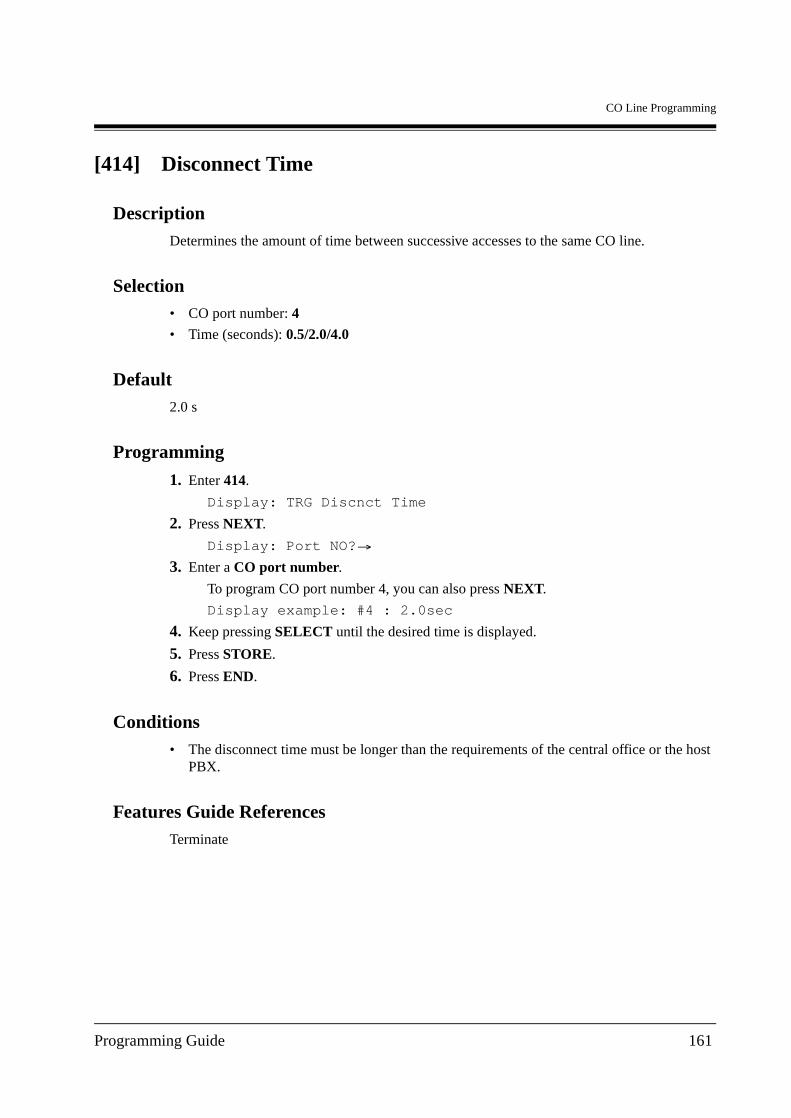
CO Line Programming
[414] Disconnect Time
DescriptionDetermines the amount of time between successive accesses to the same CO line.
Selection• CO port number: 4
• Time (seconds): 0.5/2.0/4.0
Default2.0 s
Programming
1. Enter 414.
Display: TRG Discnct Time
2. Press NEXT.
Display: Port NO?
3. Enter a CO port number.
To program CO port number 4, you can also press NEXT.
Display example: #4 : 2.0sec
4. Keep pressing SELECT until the desired time is displayed.
5. Press STORE.
6. Press END.
Conditions• The disconnect time must be longer than the requirements of the central office or the host
PBX.
Features Guide ReferencesTerminate
Programming Guide 161
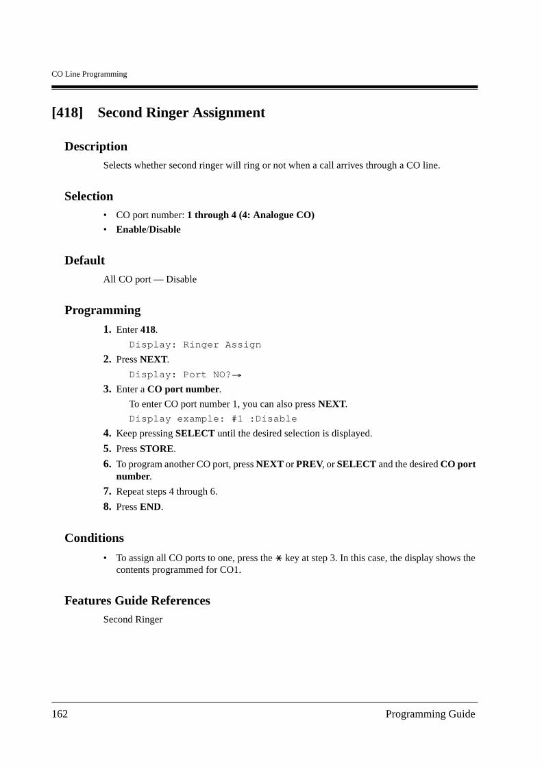
CO Line Programming
[418] Second Ringer Assignment
DescriptionSelects whether second ringer will ring or not when a call arrives through a CO line.
Selection• CO port number: 1 through 4 (4: Analogue CO)
• Enable/Disable
DefaultAll CO port — Disable
Programming
1. Enter 418.
Display: Ringer Assign
2. Press NEXT.
Display: Port NO?
3. Enter a CO port number.
To enter CO port number 1, you can also press NEXT.
Display example: #1 :Disable
4. Keep pressing SELECT until the desired selection is displayed.
5. Press STORE.
6. To program another CO port, press NEXT or PREV, or SELECT and the desired CO port number.
7. Repeat steps 4 through 6.
8. Press END.
Conditions
• To assign all CO ports to one, press the key at step 3. In this case, the display shows the contents programmed for CO1.
Features Guide ReferencesSecond Ringer
162 Programming Guide
CO Line Programming
[421] CO Port Name
DescriptionAssigns company or customer names to each outside line so that the operator or extension user can view the destination which the caller is trying to reach before answering.
Selection• CO port number: 1 through 4 (4: Analogue CO)
• CO port name: 10 characters (max.)
DefaultAll ports — Not stored
Programming
1. Enter 421.
Display: CO Line Name
2. Press NEXT.
Display: Port NO?
3. Enter a CO port number.
To enter characters, see 1.4 Entering Characters
To enter CO port number 1, you can also press NEXT.
Display example: #1:Not Stored
4. Enter the desired name.
To delete the current entry, press CLEAR.
To change the current entry, press CLEAR and enter the new name.
5. Press STORE.
6. To program another port, press NEXT or PREV, or SELECT and the desired CO port number.
7. Repeat steps 4 through 6.
8. Press END.
Conditions• Each name can have a maximum of 10 characters.
• To assign all outside lines to one selection, press in step 3. In this case, the display will show the contents programmed for CO1.
Programming Guide 163
CO Line Programming
Features Guide ReferencesNone
164 Programming Guide
CO Line Programming
[422] ISDN Port Type
DescriptionAssigns the type of each port as either CO line or extension line on ISDN port basis.
Selection• Port number: 2, 3
• CO/Extension
DefaultPort 2 — CO
Port 3 — Extension
Programming
1. Enter 422.
Display: ISDN Line Type
2. Press NEXT.
Display: Port NO?
3. Enter a port number.
To enter a first port number, you can also press NEXT.
Display example: #2 :CO
4. Keep pressing SELECT until the desired selection is displayed.
5. Press STORE.
6. To program another port, press NEXT or PREV, or SELECT and the desired port number.
7. Repeat steps 4 through 6.
8. Press END.
Conditions
• To assign all ports to one selection, press the key at step 3. In this case, the display shows the contents programmed for a first port.
• After this assignment, you should reset the system so that this assignment is effective.
• Port 1 is only for CO line.
Features Guide ReferencesIntegrated Services Digital Network (ISDN) Extension
Programming Guide 165
CO Line Programming
[423] ISDN Layer 1 Active Mode
DescriptionAssigns the active mode of Layer 1 on ISDN port basis.
Selection• Port number: 1-3
• Permanent/Call
DefaultPort 1, 2 — Permanent
Port 3 — Call
Programming
1. Enter 423.
Display: L1 Active Mode
2. Press NEXT.
Display: Port NO?
3. Enter a port number.
To enter a first port number, you can also press NEXT.
Display example: #1 :Permanent
4. Keep pressing SELECT until the desired selection is displayed.
5. Press STORE.
6. To program another port number, press NEXT or PREV, or SELECT and the desired port number.
7. Repeat steps 4 through 6.
8. Press END.
Conditions
• To assign all ports to one selection, press the key at step 3. In this case, the display shows the contents programmed for a first port.
• After this assignment, you should reset the system so that this assignment is effective.
Features Guide ReferencesIntegrated Services Digital Network (ISDN) Extension
166 Programming Guide

CO Line Programming
[424] ISDN Configuration
DescriptionAssigns the configuration on ISDN port basis.
Selection• Port number: 1 through 3
• Point/Multipoint
DefaultPort 1, 2 — Point
Port 3 — Multipoint
Programming
1. Enter 424.
Display: Access Mode
2. Press NEXT.
Display: Port NO?
3. Enter a port number.
To enter a first port number, you can also press NEXT.
Display example: #1 :Point
4. Keep pressing SELECT until the desired selection is displayed.
5. Press STORE.
6. To program another port, press NEXT or PREV, or SELECT and the desired port number.
7. Repeat steps 4 through 6.
8. Press END.
Conditions• If 1 equipment is connected to the ISDN port, select "Point." If multiple equipment are
connected, select "Multipoint."
• To assign all ports to one selection, press the key at step 3. In this case, the display shows the contents programmed for a first port.
• After this assignment, you should reset the system so that this assignment is effective.
Features Guide ReferencesIntegrated Services Digital Network (ISDN) Extension
Programming Guide 167
CO Line Programming
[425] ISDN Data Link Mode
DescriptionAssigns the data link mode on ISDN port basis.
Selection• Port number: 1-3
• Permanent/Call
DefaultPort 1, 2 — Permanent
Port 3 — Call
Programming
1. Enter 425.
Display: Data Link Mode
2. Press NEXT.
Display: Port NO?
3. Enter a port number.
To enter a first port number, you can also press NEXT.
Display example: #1 :Permanent
4. Keep pressing SELECT until the desired selection is displayed.
5. Press STORE.
6. To program another port number, press NEXT or PREV, or SELECT and the desired port number.
7. Repeat steps 4 through 6.
8. Press END.
Conditions
• To assign all ports to one selection, press the key at step 3. In this case, the display shows the contents programmed for a first port.
• After this assignment, you should reset the system so that this assignment is effective.
Features Guide ReferencesIntegrated Services Digital Network (ISDN) Extension
168 Programming Guide

CO Line Programming
[426] ISDN TEI Mode
DescriptionAssigns the Terminal Endpoint Identifier (TEI) mode on ISDN port basis.
Selection• Port number: 1-3
• Fix 0 through 63/Automatic
DefaultPort 1, 2 — Fix 0
Port 3 — Automatic
Programming
1. Enter 426.
Display: TEI Assign
2. Press NEXT.
Display: Port NO?
3. Enter a port number.
To enter a Port 01, you can also press NEXT.
Display example: #1 :Fix 0
4. Enter TEI.
To change the current entry, press CLEAR and enter the new number.
To assign "Automatic", press CLEAR and do not enter the new number.
5. Press STORE.
6. To program another port, press NEXT or PREV, or SELECT and the desired port number.
7. Repeat steps 4 through 6.
8. Press END.
Conditions• If the "Point" is selected in programme [424] ISDN Configuration are selected, assign the
fixed TEI. If the "Multipoint" is selected, assign "Automatic". After this assignment, you should reset the system so that this assignment is effective.
• To assign all ports to one selection, press the key at step 3. In this case, the display shows the contents programmed for Port 1.
Programming Guide 169

CO Line Programming
Features Guide ReferencesIntegrated Services Digital Network (ISDN) Extension
170 Programming Guide
CO Line Programming
[427] ISDN Extension Multiple Subscriber Number
DescriptionSelects whether the Multiple Subscriber Number (MSN) is allocated to each terminal equipment on ISDN Extension bus or not on ISDN port basis. Additional number for MSN can be 1 or 2 digits.
Selection• Port number: 2, 3
• 1 Digit/2 Digits/Disable
DefaultAll ports — Disable
Programming
1. Enter 427.
Display: MSN Service
2. Press NEXT.
Display: Port NO?
3. Enter a port number.
To enter a first port number, you can also press NEXT.
Display example: #2 :Disable
4. Keep pressing SELECT until the desired selection is displayed.
5. Press STORE.
6. To program another port, press NEXT or PREV, or SELECT and the desired port number.
7. Repeat steps 4 through 6.
8. Press END.
Conditions
• To assign all ports to one selection, press the key in step 3. In this case, the display shows the contents programmed for a first port.
• After this assignment, you should reset the system so that this assignment is effective.
Features Guide ReferencesIntegrated Services Digital Network (ISDN) Extension
Programming Guide 171
CO Line Programming
[428] ISDN Extension Progress Tone
DescriptionEnables or disables to send the progress tone to ISDN extension on ISDN port basis.
Selection• Port number: 2-3
• Enable/Disable
DefaultAll ports — Enable
Programming
1. Enter 428.
Display: ISDN EXT Tone
2. Press NEXT.
Display: Port NO?
3. Enter a port number.
To enter a first port number, you can also press NEXT.
Display example: #2 :Enable
4. Keep pressing SELECT until the desired selection is displayed.
5. Press STORE.
6. To program another port, press NEXT or PREV, or SELECT and the desired port number.
7. Repeat steps 4 through 6.
8. Press END.
Conditions
• To assign all ports to one selection, press the key at step 3. In this case, the display shows the contents programmed for a first port.
Features Guide ReferencesIntegrated Services Digital Network (ISDN) Extension
172 Programming Guide
CO Line Programming
[452] Extension Ringing Assignment
DescriptionSelects the extension ringing pattern on an handling table number basis when an outside call is received.
Note
When an outside call arrives and makes no hit on the System Speed Dialling and Intelligent Call Handling table (because, for example, the table is totally blank), the call will be routed through Extension Ringing Assignment for handling tables 61 (day) and 62 (night). Ringing patterns are assigned in this programme.
Selection• Jack number: 1-4 (-1/-2), 5-8 (-1)
(-1: first part, -2: second part)
• Handling table number (HND): 1 through 62
• Immdt (Immediate)/2RNG (2 Rings)/4RNG (4 Rings)/6RNG (6 Rings)/8RNG (8 Rings)/NoRNG (No Ring)/Disab (Disable)
DefaultHND 01, 61, 62: All jacks – Immediate
HND 02 through 60: All jacks – Disable
Programming
1. Enter 452.
Display: Ext Ring Assign
2. Press NEXT.
Display: Jack NO?
3. Enter a jack number.
To enter jack number 1, you can also press NEXT.
To select the second part (-2), press NEXT after entering the jack number.
Display: #1-1:HND01:Immdt
4. Enter a handling table number.
5. Keep pressing SELECT until the desired selection is displayed.
6. Press STORE.
7. To program another jack, press NEXT or PREV, or SELECT and the desired table number.
8. Repeat steps 4 through 7.
9. Press END.
Programming Guide 173
CO Line Programming
Conditions• To assign one part (first part or second part) of all jack numbers to one selection, press the
key at step 3. In this case, the display shows the contents programmed for jack number 1.
• If you select "DISA" or "BV" in programme [455] Built-in Voice Message for Call Handling, you cannot select "Disable" for all jacks in this programme. Reason: There must be a backup extension in case all DISA or BV resources are busy.
• You cannot select "Disable" for all jacks for the handling table number (HND) 61 and 62.
• If only 1 extension is assigned to ring while others are set as "Disable", the extension starts ringing immediately regardless of its setting of delayed ringing.
Features Guide ReferencesRinging, Discriminating
174 Programming Guide
CO Line Programming
[453] Other Extension Ringing Assignment
DescriptionDetermines which "other" extensions receive calls. See "Conditions" for applicable extensions. For normal extensions, see [452] Extension Ringing Assignment.
Selection• Handling table number: 01 through 60
• Extension number: 2 through 4 digits/Disable
DefaultAll handling tables — Not Stored
Programming
1. Enter 453.
Display: Other Ext Ring
2. Press NEXT.
Display: Hand tbl NO?
3. Enter a handling table number.
To enter handling table number 01, you can also press NEXT.
Display example: 01:Disable
4. Enter the desired extension number.
To delete the current entry, press CLEAR.
To change the current entry, press CLEAR and enter the new number.
5. Press STORE.
6. To program another table, press NEXT or PREV, or SELECT and the desired handling table number.
7. Repeat steps 4 through 6.
8. Press END.
Conditions• You can set the extension number in the following programming: [127] Voice Mail
Extension Number Assignment, [130] Phantom Extension Number Assignment and [813] Floating Number Assignment.
Features Guide ReferencesVoice Mail Integration
Floating Number
Programming Guide 175

CO Line Programming
Phantom Extension
176 Programming Guide
CO Line Programming
[454] ISDN Extension Ringing Assignment
DescriptionDetermines which of the extensions receives a call on an Intelligent Call Handling 1:1 or 1:N basis of the ISDN port.
Selection• Handling table number: 01 through 60
• ISDN extension number: 2 through 4 digits/Disable
DefaultAll handling tables — Not Stored
Programming
1. Enter 454.
Display: ISDN Ext Ring
2. Press NEXT.
Display: Hand tbl NO?
3. Enter a handling table number.
To enter handling table number 01, you can also press NEXT.
Display example: 01:Disable
4. Enter the desired ISDN extension number.
To delete the current entry, press CLEAR.
To change the current entry, press CLEAR and enter the new number.
5. Press STORE.
6. To program another table, press NEXT or PREV, or SELECT and the desired table number.
7. Repeat steps 4 through 6.
8. Press END.
Conditions• Assignable extension numbers are programmed by the following programming.
[012] ISDN Extension Number Set
[427] ISDN Extension Multiple Subscriber Number
• The corresponding handling table setting in [453] Other Extension Ringing Assignment must be "disable". "Other" extensions and ISDN extensions cannot ring simultaneously.
Programming Guide 177
CO Line Programming
Features Guide ReferencesIntegrated Services Digital Network (ISDN) Extension
178 Programming Guide
CO Line Programming
[455] Built-in Voice Message for Call Handling
DescriptionDirects an incoming call to the built-in voice message box in accordance with the Intelligent Call Handling table.
Selection• Handling table number: 01 through 60
• Disable/BV (Built-in Voice Message) 1 through 9/DISA BV 1 through 9
DefaultAll handling tables — Disable
Programming
1. Enter 455.
Display: Voice Mess.
2. Press NEXT.
Display: Hand tbl NO?
3. Enter a handling table number.
To enter handling table number 01, you can also press NEXT.
Display example: 01:Disable
4. Keep pressing SELECT until the desired selection is displayed.
5. Press STORE.
6. To program another table, press NEXT or PREV, or SELECT and the desired handling table number.
7. Repeat steps 4 through 6.
8. Press END.
Conditions• Optional Voice Message Card is required.
• If you select "DISA" or "BV" in this programming, you cannot select "Disable" for all jacks in programme [452] Extension Ringing Assignment.
• If you select "BV" or "Queuing" in programme [456] Call Handling When All Busy, you cannot select "DISA" or "BV" in this programming.
Features Guide ReferencesBuilt-in Voice Message
Intelligent Call Handling — Distribution of Incoming Outside Calls
Programming Guide 179
CO Line Programming
[456] Call Handling When All Busy
DescriptionSets the ringing pattern if an incoming call cannot be received because all destinations are busy.
Selection• Handling table number: 01 through 60
• Recovery/Busy/BUSY BV 1 through 9/Queuing
DefaultAll handling tables — Recovery
Programming
1. Enter 456.
Display: Busy BV
2. Press NEXT.
Display: Hand tbl NO?
3. Enter a handling table number.
To enter handling table number 01, you can also press NEXT.
Display example: 01:Recovery
4. Keep pressing SELECT until the desired selection is displayed.
5. Press STORE.
6. To program another table, press NEXT or PREV, or SELECT and the desired handling table number.
7. Repeat steps 4 through 6.
8. Press END.
Conditions• If you select "DISA" or "BV", in programme [455] Built-in Voice Message for Call
Handling, you cannot select "BV" or "Queuing" in this programming.
• If you assign an ISDN extension as the destination of 1:1 calls, be sure to select Busy or Busy BV in this programme. Other selections are not applicable.
• If you assign an ISDN extension as one of the destinations of 1:N calls, be sure to select Recovery in this programme. Other selections are not applicable.
Features Guide ReferencesIntelligent Call Handling — Distribution of Incoming Outside Calls
180 Programming Guide
CO Line Programming
[457] Intercept Extension
DescriptionIntercept Routing provides an automatic re-direction of calls which cannot or have not been answered (IRNA: Intercept Routing — No Answer). This programme sets the destination for the handling table number.
Selection• Handling table number: 01 through 60
• EXT (Extension number) : 2 through 4 digits/BV (Built-in Voice Message) 1 through 9
DefaultAll handling tables — Not Stored
Programming
1. Enter 457.
Display: Intercpt Ext
2. Press NEXT.
Display: Hand tbl NO?
3. Enter a handling table number.
To enter handling table number 01, you can also press NEXT.
Display example: 01:EXT
4. Keep pressing SELECT until the desired selection is displayed.
5. Enter a desired extension or BV number. To delete the current entry, press CLEAR. To change the current entry, press CLEAR and enter the new number.
6. Press STORE.
7. To program another table, press NEXT or PREV, or SELECT and the desired handling table number.
8. Repeat steps 4 through 7.
9. Press END.
Conditions
• To assign all tables to one selection, press in step 3. In this case, the display will show the contents programmed for table number 1.
• Assignable extension numbers are programmed by the following programming.
[003] Extension Number Set
[012] ISDN Extension Number Set
[127] Voice Mail Extension Number Assignment
Programming Guide 181
CO Line Programming
[130] Phantom Extension Number Assignment
[813] Floating Number Assignment
Features Guide ReferencesIntercept Routing
182 Programming Guide
CO Line Programming
[458] Intelligent Call Handling Table for Analogue CO
DescriptionAssigns Intelligent Call Handing table to analogue CO port in both day and night modes.
Selection• Intelligent Call Handing table number; Day: 01 through 60, Night: 01 through 60
Default01
Programming
1. Enter 458.
Display: Analog hnd Table
2. Press NEXT.
Display: Day1 Nit1
3. Enter a table number for day mode.
To delete the current entry, press CLEAR.
To change the current entry, press CLEAR and the new code.
4. Press .
5. Enter a table number for night mode.
6. Press STORE.
7. Press END.
Conditions• It is impossible to make no assignment.
• One of the Intelligent Call Handing tables (default: table 1 — Day/Night) is used for analogue CO port calls.
Features Guide ReferencesNone
Programming Guide 183
CO Line Programming
[460] ISDN Call Hold
DescriptionEnables or disables to allow the ISDN Call Hold service.
Selection• Port number: 1 through 3
• Enable/Disable
DefaultAll ports — Disable
Programming
1. Enter 460.
Display: ISDN Call Hold
2. Press NEXT.
Display: Port NO?
3. Enter a port number.
To enter a first port number, you can also press NEXT.
Display example: #1 :Disable
4. Keep pressing SELECT until the desired selection is displayed.
5. Press STORE.
6. To program another port, press NEXT or PREV, or SELECT and enter the desired port number.
7. Repeat steps 4 through 6.
8. Press END.
Conditions• Unless this setting is enabled, you can enjoy neither the ISDN Call Transfer service nor
ISDN Conference service.
• If you change this setting, be sure to restart the system. Refer to 2.10.1 System Restart in Installation Manual.
Features Guide ReferencesIntegrated Services Digital Network (ISDN) Call Hold
Integrated Services Digital Network (ISDN) Call Transfer
Integrated Services Digital Network (ISDN) Conference
184 Programming Guide

CO Line Programming
[461] ISDN Call Transfer
DescriptionEnables or disables to allow the ISDN Call Transfer service.
Selection• Port number: 1 through 3
• Enable/Disable
DefaultAll ports — Disable
Programming
1. Enter 461.
Display: ISDN Call Trans.
2. Press NEXT.
Display: Port NO?
3. Enter a port number.
To enter a first port number, you can also press NEXT.
Display example: #1 :Disable
4. Keep pressing SELECT until the desired selection is displayed.
5. Press STORE.
6. To program another port, press NEXT or PREV, or SELECT and enter the desired port number.
7. Repeat steps 4 through 6.
8. Press END.
Conditions• If you change this setting, be sure to restart the system. Refer to 2.10.1 System Restart in
Installation Manual.
Features Guide ReferencesIntegrated Services Digital Network (ISDN) Call Hold
Integrated Services Digital Network (ISDN) Call Transfer
Programming Guide 185
CO Line Programming
[462] ISDN Conference
DescriptionSelects the type of ISDN Conference.
Selection• Port number: 1 through 3
• 3PTY (three-party)/CONF (conference)/Disable
DefaultAll ports — Disable
Programming
1. Enter 462.
Display: ISDN Conference
2. Press NEXT.
Display: Port NO?
3. Enter a port number.
To enter a first port number, you can also press NEXT.
Display example: #1 :Disable
4. Keep pressing SELECT until the desired selection is displayed.
5. Press STORE.
6. To program another port, press NEXT or PREV, or SELECT and enter the desired port number.
7. Repeat steps 4 through 6.
8. Press END.
Conditions• If you change this setting, be sure to restart the system. Refer to 2.10.1 System Restart in
Installation Manual.
Features Guide ReferencesIntegrated Services Digital Network (ISDN) Call Hold
Integrated Services Digital Network (ISDN) Conference
186 Programming Guide
CO Line Programming
[463] ISDN Call Forwarding
DescriptionEnables or disables to allow the ISDN Call Forwarding service.
Selection• Port number: 1 through 3
• Enable/Disable
DefaultAll ports — Disable
Programming
1. Enter 463.
Display: ISDN Call FWD
2. Press NEXT.
Display: Port NO?
3. Enter a port number.
To enter a first port number, you can also press NEXT.
Display example: #1 :Disable
4. Keep pressing SELECT until the desired selection is displayed.
5. Press STORE.
6. To program another port, press NEXT or PREV, or SELECT and enter the desired port number.
7. Repeat steps 4 through 6.
8. Press END.
Conditions• When forwarding the incoming calls through CO port which has been assigned to enable in
this programme, ISDN Call Forwarding is operated prior to the usual Call Forwarding to Outside Line feature.
Features Guide ReferencesIntegrated Services Digital Network (ISDN) Call Forwarding
Programming Guide 187
CO Line Programming
[464] ISDN Call Deflection
DescriptionEnables or disables the ability to allow the ISDN Deflection service.
Selection• Port number: 1 through 3
• Enable/Disable
DefaultAll ports — Disable
Programming
1. Enter 464.
Display: ISDN Call DEF.
2. Press NEXT.
Display: Port NO?
3. Enter a port number.
To enter a first port number, you can also press NEXT.
Display example: #1 :Disable
4. Keep pressing SELECT until the desired selection is displayed.
5. Press STORE.
6. To program another port, press NEXT or PREV, or SELECT and the desired port number.
7. Repeat steps 4 through 6.
8. Press END.
ConditionsNone
Features Guide ReferencesCall Deflection
188 Programming Guide

COS Programming
Section 7
COS Programming
Programming Guide 189
COS Programming
7.1 COS Programming
[500-501] Toll Restriction Level — Day/Night
DescriptionEach extension must be assigned a Class of Service (COS). These programmes set the toll restriction value for each COS in day or night mode.
Selection• COS number: 1 through 8
• Level number: 1 through 8
DefaultAll COS — Level 1 — Day/Night
Programming
1. Enter a programme address (500 for day or 501 for night).
Display example: TRS Level Day
2. Press NEXT.
Display : COS NO?
3. Enter a COS number.
To enter COS number 1, you can also press NEXT.
Display example: COS1:1
4. Enter a level number.
To change the current entry, press CLEAR and the new number.
5. Press STORE.
6. To program another COS, press NEXT or PREV, or SELECT and the desired COS number.
7. Repeat steps 4 through 6.
8. Press END.
Conditions
To assign all COS to one selection, press the key at step 3. In this case, the display shows the contents programmed for COS 1.
Features Guide ReferencesDay/Night Service
190 Programming Guide

COS Programming
Toll Restriction
Programming Guide 191
COS Programming
[502] Extension-to-CO Call Duration Limit
DescriptionEnables or disables to allow for a conversation between an extension and an external party.
Selection• COS number: 1 through 8
• Enable/Disable
DefaultAll COS — Disable
Programming
1. Enter 502.
Display: CO Durat. Limit
2. Press NEXT.
Display: COS NO?
3. Enter a COS number.
To enter COS number 1, you can also press NEXT.
Display example: COS1:Disable
4. Keep pressing SELECT until the desired selection is displayed.
5. Press STORE.
6. To program another COS, press NEXT or PREV, or SELECT and the desired COS number.
7. Repeat steps 4 through 6.
8. Press END.
Conditions• A CO call originated or answered by the programmed extension user is disconnected when
the time specified in programme [205] Extension-to-Outside Line Call Duration Time expires.
• Extensions in limited classes cannot establish a CO-to-CO call, this is, cannot transfer/forward a CO call to another CO line or perform an Unattended Conference.
• To assign all COS to one selection, press the key in step 3. In this case, the display shows the currents programmed for COS 1.
Features Guide ReferencesAccount Code Entry
192 Programming Guide
COS Programming
[503] Call Transfer to CO Line
DescriptionThis programme determines which Classes of Services (COS) are allowed to perform the Call Transfer to CO Line function.
Selection• COS number: 1 through 8
• Enable/Disable
DefaultAll COS — Enable
Programming
1. Enter 503.
Display: Transfer to CO
2. Press NEXT.
Display : COS NO?
3. Enter a COS number.
To enter COS number 1, you can also press NEXT.
Display example: COS1:Enable
4. Keep pressing SELECT until the desired selection is displayed.
5. Press STORE.
6. To program another COS, press NEXT or PREV, or SELECT and the desired COS number.
7. Repeat steps 4 through 6.
8. Press END.
Conditions
To assign all COS to one selection, press the key at step 3. In this case, the display shows the contents programmed for COS 1.
Features Guide ReferencesCall Transfer, Screened — to CO Line
Programming Guide 193
COS Programming
[504] Call Forwarding to CO Line
DescriptionThis programme determines which Classes of Services (COS) are allowed to perform the Call Forwarding to CO Line function.
Selection• COS number: 1 through 8
• Enable/Disable
DefaultAll COS — Disable
Programming
1. Enter 504.
Display: Call FWD to CO
2. Press NEXT.
Display: COS NO?
3. Enter a COS number.
To enter COS number 1, you can also press NEXT.
Display example: COS1:Disable
4. Keep pressing SELECT until the desired selection is displayed.
5. Press STORE.
6. To program another COS, press NEXT or PREV, or SELECT and the desired COS number.
7. Repeat steps 4 through 6.
8. Press END.
Conditions
To assign all COS to one selection, press the key at step 3. In this case, the display shows the contents programmed for COS 1.
Features Guide ReferencesCall Forwarding — to CO Line, All Calls
194 Programming Guide
COS Programming
[505] Executive Busy Override
DescriptionDetermines which Classes of Services (COS) are allowed to perform Executive Busy Override – CO Line/Extension. Executive Busy Override allows the user to intrude into an established call.
Selection• COS number: 1 through 8
• Enable/Disable
DefaultAll COS — Disable
Programming
1. Enter 505.
Display: Busy Override
2. Press NEXT.
Display: COS NO?
3. Enter a COS number.
To enter COS number 1, you can also press NEXT.
Display example: COS1:Disable
4. Keep pressing SELECT until the desired selection is displayed.
5. Press STORE.
6. To program another COS, press NEXT or PREV, or SELECT and the desired COS number.
7. Repeat steps 4 through 6.
8. Press END.
Conditions
To assign all COS to one selection, press the key at step 3. In this case, the display shows the contents programmed for COS 1.
Features Guide ReferencesExecutive Busy Override — CO Line
Executive Busy Override — Extension
Programming Guide 195

COS Programming
[506] Executive Busy Override Deny
DescriptionThis programme is used to determine which Classes of Services (COS) are allowed to deny Executive Busy Override. Executive Busy Override Deny allows the user to prevent Executive Busy Override – CO Line/Extension from being executed by another extension user.
Selection• COS number: 1 through 8
• Enable/Disable
DefaultAll COS — Enable
Programming
1. Enter 506.
Display: Busy Over. Deny
2. Press NEXT.
Display: COS NO?
3. Enter a COS number.
To enter COS number 1, you can also press NEXT.
Display example: COS1:Enable
4. Keep pressing SELECT until the desired selection is displayed.
5. Press STORE.
6. To program another COS, press NEXT or PREV, or SELECT and the desired COS number.
7. Repeat steps 4 through 6.
8. Press END.
Conditions
To assign all COS to one selection, press the key at step 3. In this case, the display shows the contents programmed for COS 1.
Features Guide ReferencesExecutive Busy Override — CO Line
Executive Busy Override — Extension
196 Programming Guide
COS Programming
[507] Do Not Disturb Override
DescriptionThis programme determines which Classes of Services (COS) are allowed to perform Do Not Disturb (DND) Override.
Selection• COS number: 1 through 8
• Enable/Disable
DefaultAll COS — Disable
Programming
1. Enter 507.
Display: DND Override
2. Press NEXT.
Display: COS NO?
3. Enter a COS number.
To enter COS number 1, you can also press NEXT.
Display example: COS1:Disable
4. Keep pressing SELECT until the desired selection is displayed.
5. Press STORE.
6. To program another COS, press NEXT or PREV, or SELECT and the desired COS number.
7. Repeat steps 4 through 6.
8. Press END.
Conditions
To assign all COS to one selection, press the key at step 3. In this case, the display shows the contents programmed for COS 1.
Features Guide ReferencesDo Not Disturb (DND) Override
Programming Guide 197
COS Programming
[508] Account Code Entry Mode
DescriptionThere are 3 account code modes: Option, Verified — All Calls and Verified — Toll Restriction Override. This programme determines the mode to be used by each Class of Service (COS).
Optional mode:The user can enter any account code, if needed.
Verified — All Calls mode:The user must always enter a pre-assigned account code to make an outside call.
Verified — Toll Restriction Override mode:The user must enter a pre-assigned account code when the user needs to override toll restriction.
Selection• COS number: 1 through 8
• Option/Verify — All/Verify — Toll
DefaultAll COS – Option
Programming
1. Enter 508.
Display: Call Accounting
2. Press NEXT.
Display: COS NO?
3. Enter a COS number.
To enter COS number 1, you can also press NEXT.
Display example: COS1:Option
4. Keep pressing SELECT until the desired selection is displayed.
5. Press STORE.
6. To program another COS, press NEXT or PREV, or SELECT and the desired COS number.
7. Repeat steps 4 through 6.
8. Press END.
Conditions
• To assign all COS to one selection, press the key at step 3. In this case, the display shows the contents programmed for COS 1.
198 Programming Guide
COS Programming
• Programme [105] Account Codes is used to define the Account Codes for the Verified modes.
Features Guide ReferencesAccount Code Entry
Toll Restriction Override by Account Code Entry
Programming Guide 199

COS Programming
[509-510] Toll Restriction Level for System Speed Dialling – Day/Night
DescriptionThese programmes set the toll restriction value used in System Speed Dialling for each Class of Service (COS) in day or night mode.When the user makes a call with System Speed Dialling, the system will check the phone number with this level.
Selection• COS number: 1 through 8• Level number: 1 through 8
DefaultAll COS — Level 1 — Day/Night
Programming
1. Enter a programme address (509 for day or 510 for night).
Display: SPD TRS LVL Day
2. Press NEXT.
Display: COS NO?
3. Enter a COS number.
To enter COS number 1, you can also press NEXT.
Display example: COS1:1
4. Enter a level number.
To change the current entry, press CLEAR and the new number.
5. Press STORE.
6. To program another COS, press NEXT or PREV, or SELECT and the desired COS number.
7. Repeat steps 4 through 6.
8. Press END.
Conditions
To assign all COS to one selection, press the key at step 3. In this case, the display shows the contents programmed for COS 1.
Features Guide ReferencesToll Restriction Override for System Speed Dialling
200 Programming Guide
COS Programming
[511] Door Opener Access
DescriptionEnables or disables the ability to unlock the door opener on a Class of Service (COS) basis.
Selection• COS number: 1 through 8
• Enable/Disable
DefaultAll COS — Enable
Programming
1. Enter 511.
Display: Door Opener
2. Press NEXT.
Display: COS NO?
3. Enter a COS number.
To enter COS number 1, you can also press NEXT.
Display example: COS1: Enable
4. Keep pressing SELECT until the desired selection is displayed.
5. Press STORE.
6. To program another COS, press NEXT or PREV, or SELECT and the desired COS number.
7. Repeat steps 4 through 6.
8. Press END.
Conditions
To assign all COS to one selection, press the key at step 3. In this case, the display shows the contents programmed for COS 1.
Features Guide ReferencesDoor Opener
Programming Guide 201
COS Programming
[512] External Relay Access
DescriptionEnables or disables to turn on the external relay on a Class of Service (COS) basis.
Selection• COS number: 1 through 8
• Enable/Disable
DefaultAll COS — Enable
Programming
1. Enter 512.
Display: External Relay
2. Press NEXT.
Display: COS NO?
3. Enter a COS number.
To enter COS number 1, you can also press NEXT.
Display example: COS1:Enable
4. Keep pressing SELECT until the desired selection is displayed.
5. Press STORE.
6. To program another COS, press NEXT or PREV, or SELECT and the desired COS number.
7. Repeat steps 4 through 6.
8. Press END.
Conditions
To assign all COS to one selection, press the key at step 3. In this case, the display shows the contents programmed for COS 1.
Features Guide ReferencesExternal Relay
202 Programming Guide

COS Programming
[513] Night Service Access
DescriptionEnables or disables to switch the Day/Night service on a Class of Service (COS) basis.
Selection• COS number: 1 through 8
• Enable/Disable
DefaultAll COS — Enable
Programming
1. Enter 513.
Display: Night Service
2. Press NEXT.
Display: COS NO?
3. Enter a COS number.
To enter COS number 1, you can also press NEXT.
Display example: COS1:Enable
4. Keep pressing SELECT until the desired selection is displayed.
5. Press STORE.
6. To program another COS, press NEXT or PREV, or SELECT and the desired COS number.
7. Repeat steps 4 through 6.
8. Press END.
Conditions
• To assign all COS to one selection, press the key at step 3. In this case, the display shows the contents programmed for COS 1.
• The operator extension can switch the mode regardless of setting.
Features Guide ReferencesDay/Night Service
Programming Guide 203
COS Programming
[514] Do Not Disturb (DND) for Intelligent Call Handling 1:1 Call
DescriptionEnables or disables to reject DND for Intelligent Call Handling 1:1 call on a Class of Service (COS) basis.
Selection• COS number: 1 through 8
• Enable/Disable
DefaultAll COS — Disable
Programming
1. Enter 514.
Display: DND for ICH1:1
2. Press NEXT.
Display: COS NO?
3. Enter a COS number.
To enter COS number 1, you can also press NEXT.
Display example: COS1:Disable
4. Keep pressing SELECT until the desired selection is displayed.
5. Press STORE.
6. To program another COS, press NEXT or PREV, or SELECT and the desired COS number.
7. Repeat steps 4 through 6.
8. Press END.
Conditions
• To assign all COS to one selection, press the key at step 3. In this case, the display shows the contents programmed for COS 1.
• The operator extension can switch the mode regardless of setting.
Features Guide ReferencesDo Not Disturb (DND) for Intelligent Call Handling 1:1 Call
204 Programming Guide
COS Programming
[516] Calling Line Identification Restriction
DescriptionEnables or disables the Calling Line Identification Restriction (CLIR) Service on a Class of Service (COS) basis.
Selection• COS number: 1 through 8
• Enable/Disable
DefaultAll COS — Disable
Programming
1. Enter 516.
Display: CLIR
2. Press NEXT.
Display: COS NO?
3. Enter a COS number.
To enter COS number 1, you can also press NEXT.
Display example: COS1:Disable
4. Keep pressing SELECT until the desired selection is displayed.
5. Press STORE.
6. To program another COS, press NEXT or PREV, or SELECT and the desired COS number.
7. Repeat steps 4 through 6.
8. Press END.
Conditions
To assign all COS to one selection, press the key at step 3. In this case, the display shows the contents programmed for COS 1.
Features Guide ReferencesCalling/Connected Line Identification Restriction (CLIR/COLR)
Programming Guide 205
COS Programming
[517] Connected Line Identification Restriction
DescriptionEnables or disables the Connected Line Identification Restriction (COLR) Service.
Selection• COS number: 1 through 8
• Enable/Disable
DefaultAll COS — Disable
Programming
1. Enter 517.
Display: COLR
2. Press NEXT.
Display: COS NO?
3. Enter a COS number.
To enter COS number 1, you can also press NEXT.
Display example: COS1:Disable
4. Keep pressing SELECT until the desired selection is displayed.
5. Press STORE.
6. To program another COS, press NEXT or PREV, or SELECT and the desired COS number.
7. Repeat steps 4 through 6.
8. Press END.
Conditions
To assign all COS to one selection, press the key at step 3. In this case, the display shows the contents programmed for COS 1.
Features Guide ReferencesCalling/Connected Line Identification Restriction (CLIR/COLR)
206 Programming Guide
COS Programming
[518] CFU/CFB/CFNR Assignment
DescriptionThis programme determines which Class of Service (COS) can perform CFU, CFB and CFNR features.
Selection• COS number: 1 through 8
• Enable/Disable
DefaultAll COS — Disable
Programming
1. Enter 518.
Display: CFU/CFB/CFNR
2. Press NEXT.
Display: COS NO?
3. Enter a COS number.
To enter COS number 1, you can also press NEXT.
Display example: COS1:Disable
4. Keep pressing SELECT until the desired selection is displayed.
5. Press STORE.
6. To program another COS, press NEXT or PREV, or SELECT and the desired COS number.
7. Repeat steps 4 through 6.
8. Press END.
Conditions
To assign all COS to one selection, press the key at step 3. In this case, the display shows the contents programmed for COS 1.
Features Guide ReferencesCall Forwarding — by ISDN Line (CFU/CFB/CFNR)
Programming Guide 207

COS Programming
[519] Off-Hook Call Announcement (OHCA)
DescriptionEnables or disables to perform the Off-Hook Call Announcement (OHCA) and Whisper OHCA on a Class of Service (COS) basis.
Selection• COS number: 1 through 8
• Enable/Disable
DefaultAll COS — Enable
Programming
1. Enter 519.
Display: OHCA
2. Press NEXT.
Display: COS NO?
3. Enter a COS number.
To enter COS number 1, you can also press NEXT.
Display example: COS1:Enable
4. Keep pressing SELECT until the desired selection is displayed.
5. Press STORE.
6. To program another COS, press NEXT or PREV, or SELECT and the desired COS number.
7. Repeat steps 4 through 6.
8. Press END.
Conditions
To assign all COS to one selection, press the key at step 3. In this case, the display shows the contents programmed for COS 1.
Features Guide ReferencesOff-Hook Call Announcement (OHCA)
Whisper OHCA
208 Programming Guide
COS Programming
[520] Call Forwarding from Hunting Group
DescriptionEnables or disables to perform the Call Forwarding from Hunting Group on a Class of Service (COS) basis. Calls arriving at any Hunting Groups ("All") or just calls arriving at your Hunting Group ("Connected") can be forwarded to your extension.
Selection• COS number: 1 through 8
• Disable/Connect/All
DefaultAll COS — Disable
Programming
1. Enter 520.
Display: Hunt Group FWD
2. Press NEXT.
Display: COS NO?
3. Enter a COS number.
To enter COS number 1, you can also press NEXT.
Display example: COS1:Disable
4. Keep pressing SELECT until the desired selection is displayed.
5. Press STORE.
6. To program another COS, press NEXT or PREV, or SELECT and the desired COS number.
7. Repeat steps 4 through 6.
8. Press END.
Conditions
To assign all COS to one selection, press the key at step 3. In this case, the display shows the contents programmed for COS 1.
Features Guide ReferencesCall Forwarding — from Hunting Group
Programming Guide 209
COS Programming
[521] Doorphone Call Forwarding to CO Line
DescriptionEnables or disables to perform the Doorphone Call Forwarding to CO Line on a Class of Service (COS) basis.
Selection• COS number: 1 through 8
• Enable/Disable
DefaultAll COS — Disable
Programming
1. Enter 521.
Display: Door Phone FWD
2. Press NEXT.
Display: COS NO?
3. Enter a COS number.
To enter COS number 1, you can also press NEXT.
Display example: COS1:Disable
4. Keep pressing SELECT until the desired selection is displayed.
5. Press STORE.
6. To program another COS, press NEXT or PREV, or SELECT and the desired COS number.
7. Repeat steps 4 through 6.
8. Press END.
Conditions
To assign all COS to one selection, press the key at step 3. In this case, the display shows the contents programmed for COS 1.
Features Guide ReferencesDoorphone Call Forwarding to CO Line
210 Programming Guide

Extension Programming
Section 8
Extension Programming
Programming Guide 211
Extension Programming
8.1 Extension Programming
[600] EXtra Device Port
DescriptionEXtra Device Port (XDP) allows a single line telephone (SLT) to be connected to the same jack as a digital proprietary telephone (DPT) or digital DSS console/digital attendant console (console). This programme assigns which jacks are XDP. The SLT and the DPT/console of the programmed jack work as independent extensions.
Selection• Jack number: 1-4
• Enable/Disable
DefaultAll jacks — Enable
Programming
1. Enter 600.
Display: XDP Assign
2. Press NEXT.
Display: Jack NO?
3. Enter a jack number.
To enter jack number 1, you can also press NEXT.
Display example: #1:Enable
4. Keep pressing SELECT until the desired selection is displayed.
5. Press STORE.
6. To program another jack, press NEXT or PREV, or SELECT and the desired jack number.
7. Repeat steps 4 through 6.
8. Press END.
Conditions
• To assign all jacks to one selection, press the key at step 3. In this case, the display shows the contents programmed for Jack 1.
Features Guide ReferencesEXtra Device Port (XDP)
212 Programming Guide
Extension Programming
[601] Class of Service
DescriptionPrograms each extension for a Class of Service (COS). The COS determines the call handling abilities of each extension.A primary and a secondary COS numbers can be assigned per extension.
Selection• Jack number: 1-4 (-1/-2), 5-8 (-1)
(-1= first part, -2 = second part)
• COS number: 1 through 8
DefaultAll jacks-1/2 — COS 1
Programming
1. Enter 601.
Display: COS Assign
2. Press NEXT.
Display: Jack NO?
3. Enter a jack number.
To enter jack number 1, you can also press NEXT.
To select the second part (-2), press NEXT after entering a jack number.
Display example: #1-1:COS1, COS1
4. Enter a COS number for primary number.
To change the current entry, enter the new number.
5. Press .
6. Enter a COS number for secondary number.
To change the current entry, enter the new number.
7. Press STORE.
8. To program another jack, press NEXT or PREV, or SELECT and the desired jack number.
9. Repeat steps 4 through 8.
10.Press END.
Programming Guide 213
Extension Programming
Conditions• There is a maximum of 8 Classes of Services. Every extension must be assigned to a Class
of Service and is subject to the COS Programming of programmes [5XX] and [991] COS Additional Information.
• For an explanation of jack numbering, see "Rotation of jack number" in Section 1.3 Programming Ways.
• To assign all DPT jacks to one COS, press the key at step 3. In this case, the display shows the contents programmed for Jack 1.
Features Guide ReferencesClass of Service (COS)
214 Programming Guide
Extension Programming
[602] Extension Group Assignment
DescriptionAssigns each extension to an extension group. Extension groups are used for Group Call Pickup and Paging – Group.
Selection• Jack number: 1-4 (-1/-2), 5-8 (-1)
(-1 = first part, -2 = second part)
• Extension group number: 01 through 08, ( =all groups)
• Enable/Disable
DefaultAll jacks-1/2 — Extension group 1: Enable
Programming
1. Enter 602.
Display: EXT Group Asn
2. Press NEXT.
Display: Jack NO?
3. Enter a jack number.
To enter jack number 1, you can also press NEXT.
To select the second part (-2), press NEXT after entering a jack number.
Display example: #1-1:EG01:Enabl
4. Enter the extension group number.
You can also keep pressing or until the desired extension group number is displayed.
5. Keep pressing SELECT until the desired selection is displayed.
6. Press STORE.
7. To program another jack, press NEXT or PREV, or SELECT and the desired jack number.
8. Repeat steps 4 through 7.
9. Press END.
Conditions• There is a maximum of 8 extension groups. Each extension can belong to more than 1
group.
Programming Guide 215
Extension Programming
• For an explanation of jack numbering, see "Rotation of jack number" in Section 1.3 Programming Ways.
• To assign all jacks to the same extension group, press the key in step 3. In this case, the display shows the contents programmed for Jack 1.
Features Guide ReferencesCall Pickup, Group
Extension Group
Paging — Group
216 Programming Guide
Extension Programming
[605-606] Outgoing Permitted CO Line Assignment — Day/Night
DescriptionDetermines the CO lines which can be accessed by an extension in both day and night modes. The extension users can make outgoing outside calls using the assigned CO lines.
Selection• Jack number: 1-4 (-1/-2), 5-8 (-1)
(-1 = first part, -2 = second part)
• CO port number: 1 through 4 (4: Analogue CO)
• Enable/Disable
DefaultAll jacks-1/2 — all CO ports — Enable — Day/Night
Programming
1. Enter a programme address (605 for day or 606 for night).
Display example: CO Out Day
2. Press NEXT.
Display: Jack NO?
3. Enter a jack number.
To enter jack number 1, you can also press NEXT.
To select the second part (-2), press NEXT after entering a jack number.
Display example: #1-1:PRT1:Enabl
4. Enter the CO port number, or keep pressing or until the desired CO port is displayed.
To change the current entry, enter the new number.
5. Keep pressing SELECT until the desired selection is displayed.
6. Press STORE.
7. To program another jack, press NEXT or PREV, or SELECT and the desired jack number.
8. Repeat steps 4 through 7.
9. Press END.
Conditions• For an explanation of jack numbering, see "Rotation of jack number" in Section
1.3 Programming Ways.
• To assign all jacks or all CO ports to one selection, press the key at step 3 or 4. In these cases, the display shows the contents programmed for Jack 1 or PRT1.
Programming Guide 217
Extension Programming
Features Guide ReferencesCO Line Connection Assignment — Outgoing
Day/Night Service
218 Programming Guide
Extension Programming
[607-608] Doorphone Ringing Assignment — Day/Night
DescriptionThese programmes assign the extensions which will ring when a doorphone call is received during the day and night modes.
Selection• Jack number: 1-4 (-1/-2), 5-8 (-1)
(-1 = first part, -2 = second part)
• Doorphone number: 1 through 3 (Enable)/Disable
DefaultJack 1-1 —123; Other jacks — Disable— Day/Night
Programming
1. Enter a programme address (607 for day or 608 for night).
Display example: Doorphone in Day
2. Press NEXT.
Display: Jack NO?
3. Enter a jack number.
To enter jack number 1, you can also press NEXT.
To select the second part (-2), press NEXT after entering a jack number.
Display example: #1-1:123
4. Enter the doorphone numbers.
To assign no doorphone, press CLEAR.
To change the current entry, press CLEAR and the new doorphone numbers.
5. Press STORE.
6. To program another jack, press NEXT or PREV, or SELECT and the desired jack number.
7. Repeat steps 4 through 6.
8. Press END.
Conditions• For an explanation of jack numbering, see "Rotation of jack number" in Section
1.3 Programming Ways.
• To assign all jacks to one selection, press the key at step 3 or 4. In these cases, the display shows the contents programmed for Jack 1.
• A maximum of 3 doorphones can be installed.
Programming Guide 219

Extension Programming
Features Guide ReferencesDoorphone Call
Day/Night Service
220 Programming Guide
Extension Programming
[609] Voice Mail Access Codes
DescriptionAssigns a mailbox number for each extension, only if programme [990] System Additional Information, Area 02 – bit 8 is set to "1: free."
Selection• Jack number: 1-4 (-1/-2), 5-8 (-1)
(-1 = first part, -2 = second part)
• Mailbox number: 16 digits (max.)
DefaultAll jacks — Not Stored
Programming
1. Enter 609.
Display: Mailbox ID Code
2. Press NEXT.
Display: Jack NO?
3. Enter a jack number.
To enter jack number 1, you can also press NEXT.
To select the second part (-2), press NEXT after entering a jack number.
Display example: #1-1:Not Stored
4. Enter the mailbox number.
To delete the current entry, press CLEAR.
To change the current entry, press CLEAR and the new number.
5. Press STORE.
6. To program another jack, press NEXT or PREV, or SELECT and the desired jack number.
7. Repeat steps 4 through 6.
8. Press END.
Conditions• For an explanation of jack numbering, see "Rotation of jack number" in Section
1.3 Programming Ways.
• The system supports a maximum of 2 jacks for connection to a Voice Processing System as the Voice Mail or Automated Attendant ports.
Programming Guide 221

Extension Programming
• Each mailbox number has a maximum of 16 digits, consisting of 0 through 9, , # and PAUSE.
• To display parts of the code which have scrolled off the display, press or .
Features Guide ReferencesVoice Mail Integration
222 Programming Guide
Extension Programming
[610] Department Codes
DescriptionAssigns the department codes.
Selection• Jack number: 1-4 (-1/-2), 5-8 (-1)
(-1 = first part, -2 = second part)
• Department code: 5 digits (max.)
DefaultAll jacks — Not Stored
Programming
1. Enter 610.
Display: Department Code
2. Press NEXT.
Display: Jack NO?
3. Enter a jack number.
To enter jack number 1, you can also press NEXT.
To select the second part (-2), press NEXT after entering a jack number.
Display example: #1-1:Not Stored
4. Enter a department code.
To delete the current entry, press CLEAR.
To change the current entry, press CLEAR and the new department code.
5. Press STORE.
6. To program another jack, press NEXT or PREV, or SELECT and the desired jack number.
7. Repeat steps 4 through 6.
8. Press END.
Conditions• Each extension has 1 department code. Each code has a maximum of 5 digits, consisting of
0 through 9.
• For an explanation of jack numbering, see "Rotation of jack number" in Section 1.3 Programming Ways.
• To assign all jacks to one selection, press the key at step 3. In this case, the display shows the contents programmed for Jack 1.
Programming Guide 223
Extension Programming
Features Guide ReferencesDepartment Codes
224 Programming Guide
Extension Programming
[611] Extension Connection Assignment
DescriptionAssigns whether the extension can perform all accesses or not.
Selection• Jack number: 1-4 (-1/-2), 5-8 (-1)
(-1 = first part, -2 = second part)
• Connect/No Connect
DefaultAll jacks — Connect
Programming
1. Enter 611.
Display: Ext Connection
2. Press NEXT.
Display: Jack NO?
3. Enter a jack number.
To enter jack number 1, you can also press NEXT.
To select the second part (-2), press NEXT after entering a jack number.
Display example: #1-1:Connect
4. Keep pressing SELECT until the desired selection is displayed.
5. Press STORE.
6. To program another jack, press NEXT or PREV, or SELECT and the desired jack number.
7. Repeat steps 4 through 6.
8. Press END.
Conditions• The extension of the jack number 1 should be set to "Connect".
• For an explanation of jack numbering, see "Rotation of jack number" in Section 1.3 Programming Ways.
• To assign one part (first part or second part) of all jack numbers to one selection, press the key at step 3. In this case, the display shows the contents programmed for Jack 1.
Features Guide ReferencesExtension Connection Assignment
Programming Guide 225
Extension Programming
[612] Data Line Security
DescriptionSets or cancels the Data Line Security mode on an extension basis.
Selection• Jack number: 1-4 (-1/-2), 5-8 (-1)
(-1 = first part, -2 = second part)
• On/Off
DefaultAll jacks — Off
Programming
1. Enter 612.
Display: Data Mode
2. Press NEXT.
Display: Jack NO?
3. Enter a jack number.
To enter jack number 1, you can also press NEXT.
To select the second part (-2), press NEXT after entering a jack number.
Display example: #1-1:Off
4. Keep pressing SELECT until the desired selection is displayed.
5. Press STORE.
6. To program another jack, press NEXT or PREV, or SELECT and the desired jack number.
7. Repeat steps 4 through 6.
8. Press END.
Conditions• For an explanation of jack numbering, see "Rotation of jack number" in Section
1.3 Programming Ways.
• To assign one part (first part or second part) of all jack numbers to one selection, press the key at step 3. In this case, the display shows the contents programmed for Jack 1.
Features Guide ReferencesData Line Security
226 Programming Guide
Extension Programming
[613] ISDN Class of Service
DescriptionPrograms each ISDN port for a Class of Service (COS). The COS determines the call handling abilities of each port.
A primary and a secondary COS number can be assigned per port.
Selection• Port number: 2, 3
• COS number: 1 through 8
DefaultAll ports — COS 1
Programming
1. Enter 613.
Display: ISDN COS Assign
2. Press NEXT.
Display: Port NO?
3. Enter a port number.
To enter a first number, you can also press NEXT.
Display example: #2 :COS1, COS1
4. Enter a COS number for primary number.
To change the current entry, enter the new number.
5. Press .
6. Enter a COS number for secondary number.
To change the current entry, enter the new number.
7. Press STORE.
8. To program another jack, press NEXT or PREV, or SELECT and the desired port number.
9. Repeat steps 4 through 8.
10.Press END.
Conditions• There is a maximum of 8 Classes of Services. Every ISDN extension must be assigned to a
Class of Service and is subject to the COS Programming of programmes [5XX] and [991] COS Additional Information.
Programming Guide 227

Extension Programming
• To assign all ports to one selection, press the key at step 3. In this case, the display shows the contents programmed for the first port.
Features Guide ReferencesClass of Service (COS)
Integrated Services Digital Network (ISDN) Extension
228 Programming Guide
Extension Programming
[614] Department Codes of ISDN Port
DescriptionAssigns the department code of the ISDN port.
Selection• Port number: 2, 3
• Department code: 5 digits (max.)
DefaultAll ports — Not Stored
Programming
1. Enter 614.
Display: ISDN Dept Code
2. Press NEXT.
Display: Port NO?
3. Enter a port number.
To enter a first number, you can also press NEXT.
Display example: #2 :Not Stored
4. Enter a department code.
To delete the current entry, press CLEAR.
To change the current entry, press CLEAR and the new code.
5. Press STORE.
6. To program another port, press NEXT or PREV, or SELECT and the desired port number.
7. Repeat steps 4 through 6.
8. Press END.
Conditions• Each port has 1 department code. Each code has a maximum of 5 digits, consisting of 0
through 9.
• To assign all ports to one selection, press the key at step 3. In this case, the display shows the contents programmed for the first port.
Features Guide ReferencesDepartment Codes
Integrated Services Digital Network (ISDN) Extension
Programming Guide 229
Extension Programming
[615-616] Outgoing Permitted CO Line Assignment – Day/Night for ISDN Extension
DescriptionDetermines the CO lines which can be accessed by an ISDN extension in both day and night modes. The extension users can make outgoing outside calls using the assigned CO lines.
Selection• ISDN extension port number: 2, 3
• CO port number: 1 through 3
• Enable/Disable
DefaultAll ports — all CO lines — Enable — Day/Night
Programming
1. Enter a programme address (615 for day or 616 for night).
Display example: CO Out(ISDN) Day
2. Press NEXT.
Display: Port NO?
3. Enter a port number.
To enter a first number, you can also press NEXT.
Display example: #2 :PRT1:Enabl
4. Enter the desired CO port number, or keep pressing or until the desired CO port number is displayed.
To change the current entry, press the number.
5. Keep pressing SELECT until the desired selection is displayed.
6. Press STORE.
7. To program another jack, press NEXT or PREV, or SELECT and the desired port number.
8. Repeat steps 4 through 7.
9. Press END.
Conditions
• To assign all ports to one selection, press the key at step 3. In this case, the display shows the contents programmed for the first port.
• To assign all CO ports to one selection, press the key at step 4. In this case, the display shows the contents programmed for PRT 1.
230 Programming Guide

Extension Programming
• When you change a port number by pressing NEXT or PREV, the CO line number is not changed.Example #2:PRT2.......Pressing NEXT....#3:PRT2
Features Guide ReferencesCO Line Connection Assignment — Outgoing
Integrated Services Digital Network (ISDN) Extension
Day/Night Service
Programming Guide 231

Extension Programming
[617] Live Call Screening Recording Mode Assignment
DescriptionAssigns whether to close the mailbox or to keep recording the conversation after the call is intercepted.
Note
Available when the Digital Super Hybrid System is connected to a Digital Proprietary Telephone capable Panasonic Voice Processing System (one that supports digital proprietary telephone (DPT) integration).
Selection• Jack number: 1-8
• Stop Record/Keep Record
DefaultAll jacks — Stop Record
Programming
1. Enter 617.
Display: LCS Rec. Mode
2. Press NEXT.
Display: Jack NO?
3. Enter a jack number.
To enter jack number 1, you can also press NEXT.
Display example: #1:Stop Record
4. Keep pressing SELECT until the desired selection is displayed.
5. Press STORE.
6. To program another jack numbers, press NEXT or PREV, or SELECT and the desired jack number.
7. Repeat steps 4 through 6.
8. Press END.
Conditions• For an explanation of jack numbering, see "Rotation of jack number" in Section
1.3 Programming Ways.
• To assign all jacks to one selection, press the key in step 3. In this case, the display shows the contents programmed for jack 1.
232 Programming Guide

Extension Programming
Features Guide ReferencesLive Call Screening (LCS)
Voice Mail Integration for Digital Proprietary Telephones
Programming Guide 233

Extension Programming
[622] Incoming Call Display
DescriptionAllows you to choose between 3 display types when an incoming call is received.If you select the display type "Caller", the incoming caller's telephone number and name are displayed. "CO line" means the CO port name assigned in the programme [421] CO Port Name are displayed. If you select the display type "Called Party", the called party's (DDI/MSN) number and extension name are displayed.
Selection• Jack number: 1 through 8
• Display Types: Caller/CO Line/Called Party
DefaultAll jacks — Caller
Programming
1. Enter 622.
Display: Incoming Display
2. Press NEXT.
Display: Jack NO?
3. Enter a jack number.
To enter jack number 1, you can also press NEXT.
Display example: #1:Caller
4. Keep pressing SELECT until the desired selection is displayed.
5. Press STORE.
6. To program another jack, press NEXT or PREV, or SELECT and the desired jack number.
7. Repeat steps 4 through 6.
8. Press END.
Conditions
• To assign all jacks to one selection, press the key in step 3. In this case, the display shows the contents programmed for jack 1.
Features Guide ReferencesCO Incoming Call Information Display
Display, Call Information
234 Programming Guide
Extension Programming
[623] CLIP/COLP Number Assignment for Extension
DescriptionAssigns a CLIP/COLP number for each extension.
Selection• Jack number: 1-4 (-1/-2), 5-8 (-1)
(-1 = first part, -2 = second part)
• System Speed Dialling/Intelligent Call Handling group number: CLIP: 0 through 4; COLP: 0 through 6
• BI (Business, CLIP)/PI (Private, CLIP)/BP (Business, COLP)/PP (Private, COLP)/AL (All)
• CLIP/COLP number: 32 digits (max.)
DefaultAll jacks — Not Stored
Programming
1. Enter 623.
Display: CLIP/COLP NO.
2. Press NEXT.
Display: Jack NO?
3. Enter a jack number.
To enter jack number 1, you can also press NEXT.
To select the second part (-2), press NEXT after entering the jack number.
Display example: #1-1:0:BI:
4. Enter a group number.
To change the current entry, press CLEAR and enter the new number.
5. Press .
6. Keep pressing SELECT until the desired selection is displayed.
7. Press .
8. Enter a CLIP/COLP number.
To change the current entry, press CLEAR and enter the new number.
9. Press STORE.
10.To program another jack, press NEXT or PREV, or SELECT and the desired jack number.
11.Repeat steps 4 through 6.
12.Press END.
Programming Guide 235
Extension Programming
Conditions• Each CLIP/COLP number consists of digits 0 through 9.
• To assign the same CLIP/COLP number to BI, PI, BP and PP, select "AL" in step 6.
• To assign all jacks to one selection, press the key in step 3. In this case, the display will show the contents programmed for jack 1.
Features Guide ReferencesCalling/Connected Line Identification Presentation (CLIP/COLP)
236 Programming Guide
Extension Programming
[624] CLIP/COLP Number Assignment for ISDN Extension
DescriptionAssigns a CLIP/COLP number for each ISDN extension port.
Selection• ISDN Port number: 2, 3
• System Speed Dialling/Intelligent Call Handling group number: CLIP: 0 through 4; COLP: 0 through 6
• BI (Business, CLIP)/PI (Private, CLIP)/BP (Business, COLP)/PP (Private, COLP)/AL (All)
• CLIP/COLP number: 32 digits (max.)
DefaultAll ports — Not Stored
Programming
1. Enter 624.
Display: ISDN CLIP/COLP
2. Press NEXT.
Display: Port NO?
3. Enter a port number.
To enter port number 2 or 3, you can also press NEXT.
Display example: #2:0:BI:
4. Enter a group number.
To change the current entry, press CLEAR and enter the new number.
5. Press .
6. Keep pressing SELECT until the desired selection is displayed.
7. Press .
8. Enter a CLIP/COLP number.
To change the current entry, press CLEAR and enter the new number.
9. Press STORE.
10.To program another port, press NEXT or PREV, or SELECT and the desired port number.
11.Repeat steps 4 through 6.
12.Press END.
Programming Guide 237
Extension Programming
Conditions• Each CLIP/COLP number consists of digits 0 through 9.
• To assign the same CLIP/COLP number to BI, PI, BP and PP, select "AL" in step 6.
• To assign all ports to one selection, press the key in step 3. In this case, the display will show the contents programmed for the first port.
Features Guide ReferencesCalling/Connected Line Identification Presentation (CLIP/COLP)
238 Programming Guide
Extension Programming
[625-626] Built-in Voice Message for Extension — Day/Night
DescriptionSets the Built-in Voice Message (BV) feature to each extension in both day and night mode.
Selection• Jack number: 1-4 (-1/-2), 5-8 (-1)
(-1 = first part, -2 = second part)
• BV/Disable
DefaultAll jacks — BV
Programming
1. Enter the programme address (625 for day or 626 for night).
Display: Ext BV Day
2. Press NEXT.
Display: Jack NO?
3. Enter a jack number.
To enter jack number 1, you can also press NEXT.
To select the second part (-2), press NEXT after entering a jack number.
Display example: #1-1:BV
4. Keep pressing SELECT until the desired selection is displayed.
5. Press STORE.
6. To program another jack, press NEXT or PREV, or SELECT and the desired jack number.
7. Repeat steps 4 through 6.
8. Press END.
Conditions• Optional Voice Message Card (KX-TD61291) is required.
Features Guide ReferencesBuilt-in Voice Message
Programming Guide 239
Extension Programming
[627] Voice Message Resource Assignment
DescriptionAssigns a personal voice message box to either resource.
Selection• Jack number: 1-4 (-1/-2), 5-8 (-1)
(-1 = first part, -2 = second part)
• BV resource number: BV1/BV2
DefaultJack 1-1: BV1
Jack 2-1: BV1
Other jacks: BV2
Programming
1. Enter 627.
Display: BV Resource
2. Press NEXT.
Display: Jack NO?
3. Enter a jack number.
To enter jack number 1, you can also press NEXT.
To select the second part (-2), press NEXT after entering a jack number.
Display example: #1-1:BV1
4. Keep pressing SELECT until the desired selection is displayed.
5. Press STORE.
6. To program another jack, press NEXT or PREV, or SELECT and the desired jack number.
7. Repeat steps 4 through 6.
8. Press END.
Conditions• Optional Voice Message Card (KX-TD61291) is required.
• When you re-assign the personal voice message box of an extension to a different resource, keep in mind that all voice messages that have been stored prior to re-assignment will be deleted.
240 Programming Guide

Extension Programming
Features Guide ReferencesBuilt-in Voice Message
Programming Guide 241
Extension Programming
[628] Built-in Voice Message Access Code through CO Line
DescriptionAssigns the Built-in Voice Message (BV) access code through a CO line to each jack.
Note
Every access code must be unique.
Selection• Jack number: 1-4 (-1/-2), 5-8 (-1)
(-1 = first part, -2 = second part)
• Access code: 4 through 10 digits (0 through 9)
DefaultDPT extensions :
Jack 1-1 : 0201/Jack 2-1 : 0202/Jack 3-1 : 0203/Jack 4-1 : 0204/Jack 5-1 : 0205/Jack 6-1 : 0206 /Jack 7-1 : 0207/Jack 8-1 : 0208
XDP extensions :
Jack 1-2 : 0301/Jack 2-2 : 0302/Jack 3-2 : 0303/Jack 4-2 : 0304
Programming
1. Enter 628.
Display: BV Access Code
2. Press NEXT.
Display: Jack NO?
3. Enter a jack number.
To enter jack number 1, you can also press NEXT.
To select the second part (-2), press NEXT after entering a jack number.
Display example: #1-1:0201
4. Enter the desired code.
To delete the current entry, press CLEAR.
To change the current entry, press CLEAR and enter the new code.
5. Press STORE.
6. To program another jack, press NEXT or PREV, or SELECT and the desired jack number.
7. Repeat steps 4 through 6.
8. Press END.
242 Programming Guide
Extension Programming
Conditions• Optional Voice Message Card (KX-TD61291) is required.
• Must be 4 through 10 digits, from 0 through 9.
• You cannot leave the entry empty.
• A code which starts with redundant digits to another BV Access Code is invalid. For example, if you assign the codes "1234" and "12345", "12345" cannot be selected since "1234" is selected prior to "12345".
Features Guide ReferencesBuilt-in Voice Message
Direct Inward System Access (DISA)
Programming Guide 243
Extension Programming
[629] Telephone Answering Machine (TAM) Connection Assignment
DescriptionEnables or disables a TAM connection.
Selection• Jack number: 1-4 (-1/-2), 5-8 (-1)
(-1 = first part, -2 = second part)
• Enable/Disable
DefaultAll jacks — Disable
Programming
1. Enter 629.
Display: TAM Connect Ass.
2. Press NEXT.
Display: Jack NO?
3. Enter a jack number.
To enter jack number 1, you can also press NEXT.
To select the second part (-2), press NEXT after entering a jack number.
Display example: #1-1:Disable
4. Keep pressing SELECT until the desired selection is displayed.
5. Press STORE.
6. To program another jack, press NEXT or PREV, or SELECT and the desired jack number.
7. Repeat steps 4 through 6.
8. Press END.
Conditions• Normally, a TAM should be connected as an XDP extension. There is no such thing as a
DPT extension.
Features Guide ReferencesCall Retrieving, Telephone Answering Machine (TAM)
244 Programming Guide
Extension Programming
[630] ISDN Bearer Mode
DescriptionAssigns the ISDN bearer mode.
Selection• Jack number: 1-4 (-1/-2), 5-8 (-1)
(-1 = first part, -2 = second part)
• Automatic/Speech/Audio (3.1 kHz Audio)
DefaultAll jacks — Automatic
Programming
1. Enter 634.
Display: Bearer Mode
2. Press NEXT.
Display: Jack NO?
3. Enter a jack number.
To enter jack number 1, you can also press NEXT.
To select the second part (-2), press NEXT after entering a jack number.
Display: #1-1:Automatic
4. Keep pressing SELECT until the desired selection is displayed.
5. Press STORE.
6. To program another jack, press NEXT or PREV, or SELECT and the desired jack number.
7. Repeat steps 4 through 6.
8. Press END.
ConditionsNone
Features Guide ReferencesNone
Programming Guide 245
Extension Programming
[631] CLIP/COLP Number Assignment for ISDN Port
DescriptionAssigns a CLIP/COLP number for each ISDN (BRI) port.
Selection• Port number: 1 through 3
• BI (Business, CLIP)/PI (Private, CLIP)/BP (Business, COLP)/PP (Private, COLP)/AL (All)
• CLIP/COLP number: 32 digits (max.)
DefaultAll ports — Not Stored
Programming
1. Enter 631.
Display: CO CLIP/COLP
2. Press NEXT.
Display: Port NO?
3. Enter a port number.
To enter a first port number, you can also press NEXT.
Display example: #1:BI:
4. Keep pressing SELECT until the desired selection is displayed.
5. Press .
6. Enter a CLIP/COLP number.
To change the current entry, press CLEAR and enter the new number.
7. Press STORE.
8. To program another port, press NEXT or PREV, or SELECT and enter the desired port number.
9. Repeat steps 4 through 8.
10.Press END.
Conditions• Each CLIP/COLP number consists of digits 0 through 9.
• To assign the same CLIP/COLP number to BI, PI, BP and PP, select "AL" in step 4.
• To assign all ports to one selection, press the key in step 3. In this case, the display will show the contents programmed for the first port.
246 Programming Guide

Extension Programming
• If DDI/MSN number not in the contract has been assigned as CLIP/COLP, the number might not be displayed properly.
• Class of Service will be applied. Refer to [601] Class of Service in this manual.
• After setting this programme, please perform System Data Default Set.
Features Guide ReferencesCalling/Connected Line Identification Presentation (CLIP/COLP)
System Data Default Set
Programming Guide 247
Extension Programming
[632] Caller ID
DescriptionEnables or disables the ability to send Caller ID information to a single line telephone (SLT).
Selection• Jack number: 1 through 4
• Enable/Disable
DefaultAll jacks — Disable
Programming
1. Enter 632.
Display: Caller ID Asn
2. Press NEXT.
Display: Jack NO?
3. Enter a jack number.
To enter jack number 1, you can also press NEXT.
Display example: #1:Disable
4. Keep pressing SELECT until the desired selection is displayed.
5. Press STORE.
6. To program another jack, press NEXT or PREV, or SELECT and the desired jack number.
7. Repeat steps 4 through 6.
8. Press END.
ConditionsAn optional Caller ID Sending Card with 1 CO I/F, KX-TD61283, is required.
Features Guide ReferencesCaller ID
248 Programming Guide

Extension Programming
[633] Caller ID Line Access Number
DescriptionEnables or disables the ability to add and show a line access number before a telephone number of a calling party when presenting Caller ID information.
SelectionEnable/Disable
DefaultEnable
Programming
1. Enter 633.
Display: CID Line Acs NO.
2. Press NEXT.
Display example: Line Acs :Enabl
3. Keep pressing SELECT until the desired selection is displayed.
4. Press STORE.
5. Press END.
ConditionsAn optional Caller ID Sending Card with 1 CO I/F, KX-TD61283, is required.
Features Guide ReferencesCaller ID
Programming Guide 249
Extension Programming
[634] Caller ID Type
DescriptionSelects the type of Caller ID.
SelectionDuring Ring/Pre-Ring
DefaultDuring Ring
Programming
1. Enter 634.
Display: Caller ID Type
2. Press NEXT.
Display example: Type:During Ring
3. Keep pressing SELECT until the desired selection is displayed.
4. Press STORE.
5. Press END.
Conditions• An optional Caller ID Sending Card with 1 CO I/F, KX-TD61283, is required.
• To enable Caller ID feature, it may be required to set the type of Caller ID identical with the one of the public exchange.
Features Guide ReferencesCaller ID
250 Programming Guide
Extension Programming
[635] Caller ID Parameter
DescriptionSelects Caller ID parameter to send to a single line telephone.
SelectionDate and Time/Name: Enable/Disable
DefaultDate and Time/Name — Enable
Programming
1. Enter 635.
Display: CID Parameter
2. Press NEXT to program Date.
Display example: Date:Enable
3. Keep pressing SELECT until the desired selection is displayed.
4. Press STORE.
5. To program Name, press NEXT or PREV.
Display example: Name:Enable
6. Keep pressing SELECT until the desired selection is displayed.
7. Press STORE.
8. Press END.
ConditionsAn optional Caller ID Sending Card with 1 CO I/F, KX-TD61283, is required.
Features Guide ReferencesCaller ID
Programming Guide 251
Extension Programming
[636] Single Line Telephone Bell Cadence
DescriptionDetermines bell cadence of single line telephones.
Selection• Bell on (milliseconds): 1000 through 2000
• Bell off (milliseconds): 1000 through 5000
DefaultBell on: 1200 ms/Bell off: 3800 ms
Programming
1. Enter 636.
Display: SLT Bell Cadence
2. Press NEXT to program Bell On time
Display example: Bell On :1200ms
3. Enter the Bell On time.
To change the current entry, press CLEAR and enter the new Bell On time.
4. Press STORE.
5. To program Bell Off time, press NEXT or PREV.
Display example: Bell Off :3800ms
6. Enter the Bell Off time.
To change the current entry, press CLEAR and enter the new Bell Off time.
7. Press STORE.
8. Press END.
Conditions• This programming is available in units of 100 ms.
• This assignment is available regardless of programme [632] Caller ID.
• To enable Caller ID feature, it may be required to set the bell cadence identical with the one of the public exchange.
Features Guide ReferencesCaller ID
252 Programming Guide
Extension Programming
[637] Single Line Telephone Bell Pattern
DescriptionSets the ringing pattern of each single line telephone to the pattern of one long bell (single bell) or two short bells (double bell) when receiving an outside or intercom call.
Selection• Jack number: 1 through 4
• Single/Double/Automatic
DefaultAutomatic
Programming
1. Enter 637.
Display: SLT Bell Type
2. Press NEXT.
Display: Jack NO?
3. Enter a jack number.
To enter jack number 1, you can also press NEXT.
Display example: #1:Automatic
4. Keep pressing SELECT until the desired selection is displayed.
5. Press STORE.
6. To program another jack, press NEXT or PREV, or SELECT and the desired jack number.
7. Repeat steps 4 through 6.
8. Press END.
Conditions• When "Automatic" is selected, it allows SLT users to draw a distinction between outside
calls and intercom calls.
• This assignment is available regardless of programme [632] Caller ID.
• To enable Caller ID feature, it may be required to set the bell pattern identical with the one of the public exchange.
Features Guide ReferencesCaller ID
Programming Guide 253

Extension Programming
254 Programming Guide

LCR Programming
Section 9
LCR Programming
Programming Guide 255
LCR Programming
9.1 LCR Programming
[7000] LCR Mode
DescriptionAllows you to turn on or off the Least Cost Routing (LCR) mode. LCR, if enabled, selects the least expensive route to be used for an outside call.
Selection• On/Off
DefaultOff
Programming
1. Enter 7000.
Display: LCR Mode
2. Press NEXT.
Display example: LCR:Off
3. Keep pressing SELECT until the desired selection is displayed.
4. Press STORE.
5. Press END.
Conditions• If "Off" is selected, the Automatic Line Access feature functions in place of LCR.
Features Guide ReferencesLeast Cost Routing (LCR)
Line Access, Automatic
256 Programming Guide
LCR Programming
[7002] BTL Access Code
DescriptionStores the BTL (British Telecom Line) access code.
Selection• BTL access code: 10 digits (max.)
Default121
Programming
1. Enter 7002.
Display: BTL Access Code
2. Press NEXT.
Display example: 121
3. Enter a BTL access code.
To delete the current entry, press CLEAR.
To change the current entry, press CLEAR and the new code.
4. Press STORE.
5. Press END.
Conditions• The BTL access code can be a maximum of 10 digits, consisting of 0 through 9.
Features Guide ReferencesLeast Cost Routing (LCR)
Programming Guide 257
LCR Programming
[7003] Itemised Code Set
DescriptionRegisters an itemised code applied to an extension. The registered code is inserted into the "I" command position stored in program [7X22] "LCR Carrier Modify Command."
Selection• Jack number: 1-4(-1/-2), 5-8(-1)
(-1 = first part, -2 = second part)
• Itemised code: 4 digits (max.)
DefaultAll jacks – Not Stored
Programming
1. Enter 7003.
Display: Itemised Code
2. Press NEXT.
Display: Jack NO?->
3. Enter a jack number.
To enter jack number 1, you can also press NEXT. To select the second part (-2), press NEXT after entering a jack number.
Display example: #1-1: Not Stored
4. Enter an itemised code.
To delete the current entry, press CLEAR.
To change the current entry, press CLEAR and the new code.
5. Press STORE.
6. To program another jack, press NEXT or PREV, or SELECT and the desired jack number.
7. Repeat steps 4 through 6.
8. Press END.
Conditions• There is a maximum of 12 itemised codes. Each code has a maximum of 4 digits, consisting
of 0 through 9.
Features Guide ReferencesLeast Cost Routing (LCR)
258 Programming Guide
LCR Programming
[7004] ISDN Itemised Code Set
DescriptionRegisters an itemised code applied to an ISDN extension. The registered code is inserted into the "I" command position stored in program [7X22] "LCR Carrier Modify Command."
Selection• Port number: 2 and 3
• Itemised code: 4 digits (max.)
DefaultAll ports – Not Stored
Programming
1. Enter 7004.
Display: ISDN Itemised CD
2. Press NEXT.
Display: Port NO?->
3. Enter a port number.
To enter port number 3, you can also press NEXT.
Display example: #3: Not Stored
4. Enter an itemised code.
To delete the current entry, press CLEAR.
To change the current entry, press CLEAR and the new code.
5. Press STORE.
6. To program another port, press NEXT or PREV, or SELECT and the desired port number.
7. Repeat steps 4 through 6.
8. Press END.
Conditions• There is a maximum of 2 itemised codes. Each code has a maximum of 4 digits, consisting
of 0 through 9.
Features Guide ReferencesLeast Cost Routing (LCR)
Programming Guide 259
LCR Programming
[7X0Y] LCR Leading Digit Entry for Plan 1-8
DescriptionBy entering numbers into leading digit plan for a maximum of eight carriers, you are starting the process to determine which CO port will be used to route the call.
Selection• Program address: 7X0Y, X:1-8 (carrier number), Y:1-8 (table number)
• Location number: 01 through 80
• Leading digit number: 7 digits (max.)
DefaultCarrier/Table 1: Location 01 – *****
All other locations – Not stored
Programming
1. Enter a program address (7X0Y).
Display example: LCR L-Digit C1-1
2. Press NEXT.
Display: Location NO?->
3. Enter a location number.
To enter location number 01, you can also press NEXT.
Display example: 01:Not Stored
4. Enter a leading digit number.
To delete the current entry, press CLEAR.
To change the current entry, press CLEAR and the new number.
5. Press STORE.
6. To program another location, press NEXT or PREV, or SELECT and the desired location number.
7. Repeat steps 4 through 6.
8. Press END.
Conditions• There is a maximum of 80 leading digit numbers. Each number has a maximum of 7 digits,
consisting of 0 through 9, and . The character " " can be used as a wild card character.
• The same code with different digits may be assigned in this program or in program [7X20] "LCR Exceptional Code." In this case, the code which has smaller digits takes the more expensive route is priority. To prevent this, enter " " (wild card) after the code with the
260 Programming Guide
LCR Programming
smaller digits. Examples are shown below:<Examples>
a) The code priority is as follows:"44" in programme [7201] > "444" in programme [7101] In this case, "44 " should be assigned in programme [7201].
b) The code priority is as follows:"332" in programme [7120] > "3323" in programme [7120] In this case, "32 should be assigned in programme [7120].
Features Guide ReferencesLeast Cost Routing (LCR)
Programming Guide 261
LCR Programming
[7X1Y] LCR Time and Fee for Plan 1-8
DescriptionAssigns time schedules and charged fees for a maximum of 8 carriers. It is possible to split a day into 4 time zones max so that the least expensive line is selected for that time. According to the service hours and charges offered by your carriers, enter the starting time of each zone.
Selection• Program address: 7X1Y, X:1-8 (carrier number), Y:1-8 (table number)
• Day of the week selection number: 1 through 7
1: Sunday 2: Monday 3: Tuesday 4: Wednesday5: Thursday6: Friday7: Saturday
• Time schedule: 1-4
• Starting time: 00-23 (hours), 00-59 (minutes)
• Fee: 00-99 (pounds), 00-99 (pence)
DefaultNot stored
Programming
1. Enter a program address (7X1Y).
Display: Time & Fee C1-1
2. Press NEXT.
Display: Week NO?->
3. Enter a day of the week selection number.
To program Monday, you can also press NEXT.
Display example: mo1:12:00 10.10
To program another time schedule of the day, keep pressing NEXT orPREV until the desired time schedule is displayed.
4. Enter the starting time (hours and minutes), moving the cursor with and buttons.
To delete the current entry, press CLEAR.
To change the current entry, press CLEAR and the new number.
5. Press to enter the fee.
6. Enter the fee (pounds and pence), moving the cursor with or buttons.
262 Programming Guide
LCR Programming
To delete the current entry, press CLEAR.
To change the current entry, press CLEAR and the new number.
7. Press STORE.
8. To program another time schedule, press NEXT or PREV.
9. Repeat steps 4 through 10.
10.Press END.
Conditions• The times must be programmed in sequence from Time-1 to Time-4.
Features Guide ReferencesLeast Cost Routing (LCR)
Programming Guide 263
LCR Programming
[7X20] LCR Exceptional Code
DescriptionAssigns dialling numbers that are excepted from LCR routing plans of the specified carrier. They are sent out to a CO selected from automatic access CO line groups.
Selection• Program address: 7X20, X: 1-8 (carrier number)
• Location number: 01 through 80
• Exceptional code: 7 digits (max.)
DefaultAll locations – Not stored
Programming
1. Enter a program address (7X20).
Display example: EXCP Digit C1
2. Press NEXT.
Display: Location NO?->
3. Enter a location number.
To enter location number 01, you can also press NEXT.
Display example: 01:Not Stored
4. Enter an exceptional code.
To delete the current entry, press CLEAR.
To change the current entry, press CLEAR and the new number.
5. Press STORE.
6. To program another location, press NEXT or PREV, orSELECT and the desired location number.
7. Repeat steps 4 through 6.
8. Press END.
Conditions• There is a maximum of 80 exceptional codes for each carrier. Each code has a maximum of
7 digits, consisting of 0 through 9, and . The character " " can be used as a wild card character.
• The same code with different digits may be assigned in this program or in program [7X0Y] "LCR Leading Digit Entry for Plan 1-8." In this case, the code which has smaller digits takes the more expensive route is priority. To prevent this, enter " " (wild card) after the
264 Programming Guide
LCR Programming
code with the smaller digits. Examples are shown below:<Examples>
a) The code priority is as follows:"44" in program [7201] > "444" in program [7101]In this case, "44 " should be assigned in program [7201].
b) The code priority is as follows:"332" in program [7120] > "3323" in program [7120]In this case, "332 " should be assigned in program [7120].
Features Guide ReferencesLeast Cost Routing (LCR)
Programming Guide 265
LCR Programming
[7X21] LCR Carrier Code
DescriptionAssigns carrier access codes used for LCR feature.
Selection• Program address: 7X21, X:1-8 (carrier number)
• Carrier code: 10 digits (max.)
DefaultProgram 7121 (carrier 1) – 131;
Other programs (carriers 2-8) – Not stored
Programming
1. Enter a program address (7X21).
Display example: Carrier Code C1
2. Press NEXT.
Display example: 131
3. Enter the carrier code.
To delete the current entry, press CLEAR.
To change the current entry, press CLEAR and the new number.
4. Press STORE.
5. Press END.
Conditions• There is a maximum of 8 carrier codes. Each code has a maximum of 10 digits, consisting
of 0 through 9.
Features Guide ReferencesLeast Cost Routing (LCR)
266 Programming Guide
LCR Programming
[7X22] LCR Carrier Modify Command
DescriptionAssigns modification commands applied to carrier numbers. Dialled numbers are modified according to the programmed commands. Available commands are as follows:
C : Insert carrier codeP : Send pauseT : Change to tone (DTMF) modeA : Insert Authorisation codeI : Insert Itemised codeH : Home Position
Selection• Program address: 7X22, X:1-8 (carrier number)
• C/P/T/A/I/H, 16 entries (max.)
DefaultProgram 7122 (carrier 1) – CPTAIH;
Other programs (carriers 2-8) – Not stored
Programming
1. Enter a program address (7X22).
Display example: Modify Command C1
2. Press NEXT.
Display example: CPTAIH
3. Keep pressing SELECT until the desired selection is displayed.
4. To select other commands for the same carrier, press and press SELECT for the desired command until all the required entries are completed.
To delete the current entry, press CLEAR.
To change the current entry, press CLEAR and the new number.
5. Press STORE.
6. Press END.
Conditions• There is a maximum of 8 carriers, each of which can be given a maximum of 16 commands.
Programming Guide 267

LCR Programming
Features Guide ReferencesLeast Cost Routing (LCR)
268 Programming Guide
LCR Programming
[7X23] LCR CO Port Assignment
DescriptionAssigns CO ports that correspond to an LCR carrier.
Selection• Program address: 7X23, X:1-8 (carrier number)
• CO port number: 1 through 4 (4: Analogue CO), 4 entries (max.)
DefaultProgram 7123 (carrier 1) – 1234
Other programs (carriers 2-3) – Not stored
Programming
1. Enter a program address (7X23).
Display example: Port No Assign C1
2. Press NEXT.
Display example: 1234
3. Enter CO port numbers in succession.
To delete the current entry, press CLEAR.
To change the current entry, press CLEAR and the new number.
4. Press STORE.
5. Press END.
Conditions• There is a maximum of 8 carriers, each of which can be given a maximum of 4 CO port.
Features Guide ReferencesLeast Cost Routing (LCR)
Programming Guide 269
LCR Programming
[7X24] LCR Authorisation Code
DescriptionRegisters an authorisation code applied to a CO port. The registered code is inserted into the "A" command position stored in programme [7X22] "LCR Carrier Modify Command."
Selection• Program address: 7X24, X:1-8 (carrier number)
• CO port number: 1 through 4 (4: Analogue CO), ( =all CO ports)
• Authorization code: 20 digits (max.)
DefaultAll programs – Not stored
Programming
1. Enter a program address (7X24).
Display example: Authorise Code C1
2. Press NEXT.
Display example: Port NO?->
3. Enter CO port number.
To enter CO port number 1, you can also press NEXT.
Display example: #1: Not Stored
4. Enter an authorisation code.
To delete the current entry, press CLEAR.
To change the current entry, press CLEAR and the new code.
5. Press STORE.
6. To program another CO port, press NEXT or PREV, orSELECT and the desired CO port number.
7. Repeat steps 4 through 6.
8. Press END.
Conditions• There is a maximum of 4 CO ports, each of which can be given an authorisation code.
Features Guide ReferencesLeast Cost Routing (LCR)
270 Programming Guide

Resource Programming
Section 10
Resource Programming
Programming Guide 271
Resource Programming
10.1 Resource Programming
[800] SMDR Incoming/Outgoing Call Log Printout
DescriptionUsed to determine which calls will produce an SMDR printout.
Selection• Outgoing calls: All (All calls)/Toll (Toll calls only)/Off (No printing)
• Incoming calls: On (All calls)/Off (No printing)
DefaultOutgoing calls — Off; Incoming calls — Off
Programming
1. Enter 800.
Display: Duration Log
2. Press NEXT to program outgoing calls.
Display: Outgoing:Off
3. Keep pressing SELECT until the desired selection is displayed.
4. Press STORE.
5. Press NEXT to program incoming calls.
Display: Incoming:Off
6. Keep pressing SELECT until the desired selection is displayed.
7. Press STORE.
8. Press END.
Conditions• It is necessary to connect a printer to the Serial Interface (RS-232C) port provided on the
system.
• After connecting a printer, printout will be started in 10 seconds.
• If "Toll" is selected, the system will print out all the calls starting from the numbers stored in programmes [301-305] TRS Denied Code Entry for Levels 2 through 6.
Features Guide ReferencesStation Message Detail Recording (SMDR)
272 Programming Guide
Resource Programming
[801] SMDR Format
DescriptionUsed to match the SMDR output to the paper size being used in the printer. Page length determines the number of lines per page. Skip perforation determines the number of lines to be skipped at the end of every page. Page width determines the number of characters per line.
Selection• Page length (lines): 4 through 99
• Skip perforation (lines): 0 through 95
• Page width (characters): 80/100
DefaultPage length — 66; Skip perforation — 0; Page width — 80
Programming
1. Enter 801.
Display: SMDR Format
2. Press NEXT to program page length.
Display example: Page Length:66
3. Enter the page length.
To change the current entry, press CLEAR and enter the new page length.
4. Press STORE.
5. Press NEXT to program skip perforation.
Display example: Skip Perf: 0
6. Enter the skip perforation.
To change the current entry, press CLEAR and enter the new skip perforation.
7. Press STORE.
8. Press NEXT to program page width.
Display example: Page Width:80
9. Keep pressing SELECT until the desired selection is displayed.
10.Press STORE.
11.Press END.
Conditions• The page length should be at least 4 lines longer than the skip perforation length.
• If 80 characters for page width is selected, the last 5 digits of account codes are not printed out.
Programming Guide 273
Resource Programming
• A title is positioned on the first 3 lines of every page.
• The programmed format becomes valid only if the Serial Interface (RS-232C) cable is connected. If a printer is already connected, disconnect it and connect again. Otherwise the former format becomes valid.
Features Guide ReferencesStation Message Detail Recording (SMDR)
274 Programming Guide
Resource Programming
[802] System Data Printout
DescriptionStarts or stops printing of the system data. All the current system-programmed data is printed out.
SelectionStart/Stop
DefaultNot applicable.
Programming
1. Enter 802.
Display: System Data Dump
2. Press NEXT.
Display: Print-Out:Start
3. Press STORE to start printing.
Printing starts.To stop printing in the middle of printing, press SELECT and go to step 4.
When printing is completed, the display shows:
Display: Print-Out:Finish
4. Press STORE.
Display: Print-Out:Stop
5. Press END.
ConditionsYou may stop printing by pressing the END button, while records are being printed out.
Features Guide ReferencesStation Message Detail Recording (SMDR)
Programming Guide 275
Resource Programming
[803] Music Source Use
DescriptionAssigns the music source to be used for Music on Hold and Background Music (BGM).
Selection• Hold: Music (External Music)/No Use
• BGM: Music (External Music)/No Use
DefaultHold: Music (External Music)
BGM: Music (External Music)
Programming
1. Enter 803.
Display: Music Source Use
2. Press NEXT to program Music on Hold.
Display example: Hold:Music
3. Keep pressing SELECT until the desired selection is displayed.
4. Press STORE.
5. Press NEXT to program BGM.
Display example: BGM: Music
6. Keep pressing SELECT until the desired selection is displayed.
7. Press STORE.
8. Press END.
Conditions• Programme [804] External Pager BGM is used to enable/disable BGM.
• To send music during on hold, you have to assign [990] System Additional Information, Area 07 — Bit 7 as Selection 1: Music, otherwise tone will be heard.
Features Guide ReferencesBackground Music (BGM)
Background Music (BGM) — External
Music on Hold
276 Programming Guide
Resource Programming
[804] External Pager BGM
DescriptionUsed to determine whether external pagers will receive Background Music (BGM). BGM — External is turned on and off by an operator.
SelectionEnable/Disable
DefaultDisable
Programming
1. Enter 804.
Display: Ext-Pag BGM
2. Press NEXT.
Display example: Pager :Disable
3. Keep pressing SELECT until the desired selection is displayed.
4. Press STORE.
5. Press END.
Conditions• Programme [803] Music Source Use is used to select the music source to be used for
BGM.
Features Guide ReferencesBackground Music (BGM) — External
Programming Guide 277
Resource Programming
[805] External Pager Confirmation Tone
DescriptionUsed to remove the confirmation tone for the external pager. The default setting sends confirmation tone 2 to the external pager before paging is broadcast.
SelectionOn/Off
DefaultOn
Programming
1. Enter 805.
Display: Ext-Pag Ack-Tone
2. Press NEXT.
Display example: Tone:On
3. Keep pressing SELECT until the desired selection is displayed.
4. Press STORE.
5. Press END.
ConditionsNone
Features Guide ReferencesConfirmation Tone
Paging — All
Paging — External
278 Programming Guide
Resource Programming
[806] RS-232C Parameters
DescriptionAssigns the communication parameters for the Serial Interface (RS-232C) for Port 1.
New Line Code: Select the code for your printer or personal computer. If your printer or personal computer automatically feeds lines with carriage return, select "CR." If not, select "CR+LF."
Baud Rate: A baud rate code indicates the data transmission speed from the system to the printer or personal computer.
Word Length: A word length code indicates how many bits compose a character.
Parity Bit: A parity code indicates what type of parity is used to detect an error in the string of bits composing a character. Make an appropriate selection depending on the requirements of your printer or personal computer.
Stop Bit Length: A stop bit code indicates the end of a bit string which composes a character. Select an appropriate value depending on the requirements of your printer or personal computer.
Selection• New line code: CR+LF/CR (CR=Carriage Return, LF=Line Feed)
• Baud rate (baud): 150/300/600/1200/2400/4800/9600
• Word length (bits): 7/8
• Parity bit: None/Mark/Space/Even/Odd
• Stop bit length (bits): 1/2
DefaultNew line code = CR+LF; Baud rate = 9600; Word length = 8;
Parity bit = None; Stop bit length = 1 — Port 1
Programming
1. Enter 806.
Display example: RS232C Paramet.1
2. Press NEXT to program new line code.
Display example: NL-Code:CR+LF
3. Keep pressing SELECT until the desired selection is displayed.
4. Press STORE.
5. Press NEXT to program baud rate.
Display example: Baud Rate:9600
6. Keep pressing SELECT until the desired selection is displayed.
7. Press STORE.
Programming Guide 279
Resource Programming
8. Press NEXT to program word length.
Display example: Word Lengt:8bits
9. Keep pressing SELECT until the desired selection is displayed.
10.Press STORE.
11.Press NEXT to program parity bit.
Display example: Parity:None
12.Keep pressing SELECT until the desired selection is displayed.
13.Press STORE.
14.Press NEXT to program stop bit.
Display example: Stop Bit:1bit
15.Keep pressing SELECT until the desired selection is displayed.
16.Press STORE.
17.Press END.
Conditions• The following combinations are invalid.
• The programme address of the out-of-service system port is unacceptable.
Features Guide ReferencesStation Message Detail Recording (SMDR)
Parity Word Length Stop Bit
Mark 8 2
Space 8 1
Space 8 2
280 Programming Guide
Resource Programming
[809] DISA Security Type
DescriptionAssigns the security mode for outside calls attempted by the DISA (Direct Inward System Access) caller. There are 3 modes: Non Security, Trunk Security (outside line security) and All Security. Non Security mode allows the caller to access an outside line or make an intercom call without dialling a DISA user code. Trunk Security mode requires the caller to enter a DISA user code before making an outside call. All Security mode requires the caller to enter a DISA user code before making an outside call or an intercom call.
Selection• Trunk/All/Non
DefaultTrunk
Programming
1. Enter 809.
Display example: DISA Security
2. Press NEXT.
Display: Security:Trunk
3. Keep pressing SELECT until the desired selection is displayed.
4. Press STORE.
5. Press END.
ConditionsNone
Features Guide ReferencesDirect Inward System Access (DISA)
Programming Guide 281
Resource Programming
[810] DISA Tone Detection
DescriptionEnables or disables Tone Detection for the Direct Inward System Access (DISA) feature or the Built-in Voice Message feature when receiving a call from an analogue CO line. Enabling tone detection allows the system to detect the end of the call.
SelectionEnable/Disable
DefaultEnable
Programming
1. Enter 810.
Display: DISA Tone Detect
2. Press NEXT.
Display: Tone DTC:Enable
3. Keep pressing SELECT until the desired selection is displayed.
4. Press STORE.
5. Press END.
ConditionsNone
Features Guide ReferencesDirect Inward System Access (DISA)
282 Programming Guide
Resource Programming
[811] DISA User Codes
DescriptionAssigns the DISA (Direct Inward System Access) and a Class of Service (COS) to each code. The code COS determines the toll restriction level of the DISA caller.
WarningWhen you enable the Outside – Outside Line Call feature of DISA function, if a third party discovers the password (a DISA User Code) of the system, you have a risk that they will make illegal phone calls using your telephone line, and the cost may be charged to your account.In order to avoid this problem, we strongly recommend the following points:
a) Carefully maintain the secrecy of the password.
b) Specify a complicated password with several digits.
c) Change the password frequently (at least once per month).
Selection• User code (01-32): 4 through 10 digits
• COS number: 1 through 8
DefaultAll COS number – 8
All user codes – Not stored
Programming
1. Enter 811.
Display: DISA User Code
2. Press NEXT.
Display: User Code NO?
3. Enter a user code number.
To enter user code number 01, you can also press NEXT.
Display example: 01: C:8
4. Enter the desired user code (4-10 digits).
To delete the current entry, press CLEAR.
To change the current entry, press CLEAR and enter the desired user code.
5. Press .
6. Enter a COS number.
To change the current entry, press CLEAR and enter the new number.
7. Press STORE.
8. To program another user code number, press NEXT or PREV, or SELECT and the desired user code.
Programming Guide 283
Resource Programming
9. Repeat steps 4 through 8.
10.Press END.
Conditions
• Each code should be different and composed of 4 to 10 digits, from 0 through 9. The and # keys cannot be used.
• A code which starts with redundant digits to another DISA User Code is invalid. For example, if you assign the codes "1234" and "12345", "12345" cannot be selected since "1234" is selected prior to "12345".
• This setting is required if Trunk (Outside line) Security mode or All Security mode is selected in programme [809] DISA Security Type.
Features Guide ReferencesDirect Inward System Access (DISA)
284 Programming Guide
Resource Programming
[813] Floating Number Assignment
DescriptionAssigns the floating numbers for the External Pager, Digital Test Access (DTA), Second Ringer and Hunting Groups. These numbers can be used the same way extension numbers are used for station access.
Selection• Floating station:
Pager (External Pager)/DTA/2nd Ringer (Second Ringer)/Hunt Grp (Hunting Group) 01 through 32
• Floating number:2 to 4 digits/No floating number
DefaultPager = 296, Ringer = 298, Hunting Group = Not Stored, DTA = 399
Programming
1. Enter 813.
Display: FLT EXT NO.
2. Press NEXT to program Pager.
Display example: Pager :296
To program another floating station, keep pressing NEXT or PREV until the desired floating station is displayed.
3. Enter a floating number.
To program no floating number, press CLEAR.
To change the current entry, press CLEAR and the new floating number.
4. Press STORE.
5. To program another floating station, keep pressing NEXT or PREV until the desired floating station is displayed.
6. Repeat steps 3 through 5.
7. Press END.
Conditions• A floating number is composed of 2 to 4 numerical digits, 0 through 9.
• The leading 1 or 2 digits of the floating numbers are subject to program [100] Flexible Numbering, (01) through (16) 1st through 16th hundred extension blocks.
Programming Guide 285
Resource Programming
• Floating numbers and extension numbers should be unique. Double entry and incompatible entry for these numbers are invalid. Valid entry example: 10 and 11, 10 and 110. Invalid entry example: 10 and 106, 210 and 21.
• You can leave the entry empty.
• To avoid making an invalid entry, check the other extension number in programmes [003] Extension Number Set, [012] ISDN Extension Number Set, [127] Voice Mail Extension Number Assignment and [130] Phantom Extension Number Assignment. The default of each extension number is as follows:
[003] Extension Number Set
201 through 208, 301 through 304
[012] ISDN Extension Number Set
Not stored
[127] Voice Mail Extension Number Assignment
265 through 268
[130] Phantom Extension Number Assignment
Not stored
Features Guide ReferencesFloating Number
286 Programming Guide
Resource Programming
[815] DISA Automated Attendant (AA)
DescriptionAssigns the DISA (Direct Inward System Access) Automated Attendant (AA) number. The extension, ISDN extension, floating extension, Phantom extension, Voice Mail extension number can be assigned as a one digit number and be used as a DISA AA number.
Selection• DISA AA number: 0 through 9
• Extension/ISDN extension/floating extension/Phantom extension/Voice Mail extension number: 2 through 4 digits/Not Stored
DefaultAll numbers — Not Stored
Programming
1. Enter 815.
Display: DISA AA
2. Press NEXT.
Display: Dial NO?
3. Enter a DISA AA number.
To enter DISA AA number 0, you can also press NEXT.
Display example: Dial 0:Disable
4. Enter an extension number.
To delete the current entry, press CLEAR.
To change the current entry, press CLEAR and enter the new number.
5. Press STORE.
6. To program another DISA AA number, press NEXT or PREV, or SELECT and the desired DISA AA number.
7. Repeat steps 4 through 6.
8. Press END.
Conditions• This system can store up to 10 programmable DISA AA numbers.
• Extension numbers can be assigned in programmes:— [003] Extension Number Set— [012] ISDN Extension Number Set— [127] Voice Mail Extension Number Assignment
Programming Guide 287

Resource Programming
— [130] Phantom Extension Number Assignment— [813] Floating Number Assignment
Features Guide ReferencesDirect Inward System Access (DISA)
288 Programming Guide
Resource Programming
[820] OGM Recording
DescriptionAssigns the OGM recording source.
Selection• Hand Set/Ext BGM (External Music jack)
DefaultHand Set (SP-Phone)
Programming
1. Enter 820.
Display: OGM Recording
2. Press NEXT.
Display: OGM:Hand Set
3. Keep pressing SELECT until the desired selection is displayed.
4. Press STORE.
5. Press END.
ConditionsNone
Features Guide ReferencesOutgoing Message (OGM)
Programming Guide 289
Resource Programming
[822] Built-in Voice Message Total Recording Time
DescriptionAssigns the total recording time for each Built-in Voice Message (BV) resource (including Outgoing Message).
Note
The total recording time for resource 1 and 2 cannot be programmed separately.
Selection60 minutes (Low quality)/30 minutes (Normal quality)/20 minutes (High quality)
Default30 min
Programming
1. Enter 822.
Display: BV Total Time
2. Press NEXT.
Display: Time:30 min
3. Keep pressing SELECT until the desired selection is displayed.
4. Press STORE.
5. Press END.
Conditions• An optional voice message card (KX-TD61291) is required.
• The longer the recording time is, the poorer the sound quality may be.
Features Guide ReferencesBuilt-in Voice Message
Outgoing Message (OGM)
290 Programming Guide
Resource Programming
[895] OGM and Voice Message Clear
DescriptionErases all outgoing messages (OGM) and voice messages.
SelectionOGM ALL Clear
DefaultNot applicable.
Programming
1. Press 895.
Display: OGM MSG Clear
2. Press NEXT.
Display: OGM ALL Clear
3. Press STORE.
4. Press END.
Conditions• Before performing this programme, disconnect CO lines and extension lines, except the one
accessing to System Programming, from your system so that no one can make/receive calls. Otherwise, the system may not work properly.
• You can perform this programme only when no one else is using the Built-in voice Message feature such as replaying/recording/deleting a voice message or an OGM.
Features Guide ReferencesBuilt-in Voice Message
Outgoing Message (OGM)
Programming Guide 291

Resource Programming
292 Programming Guide

Optional Programming
Section 11
Optional Programming
Programming Guide 293
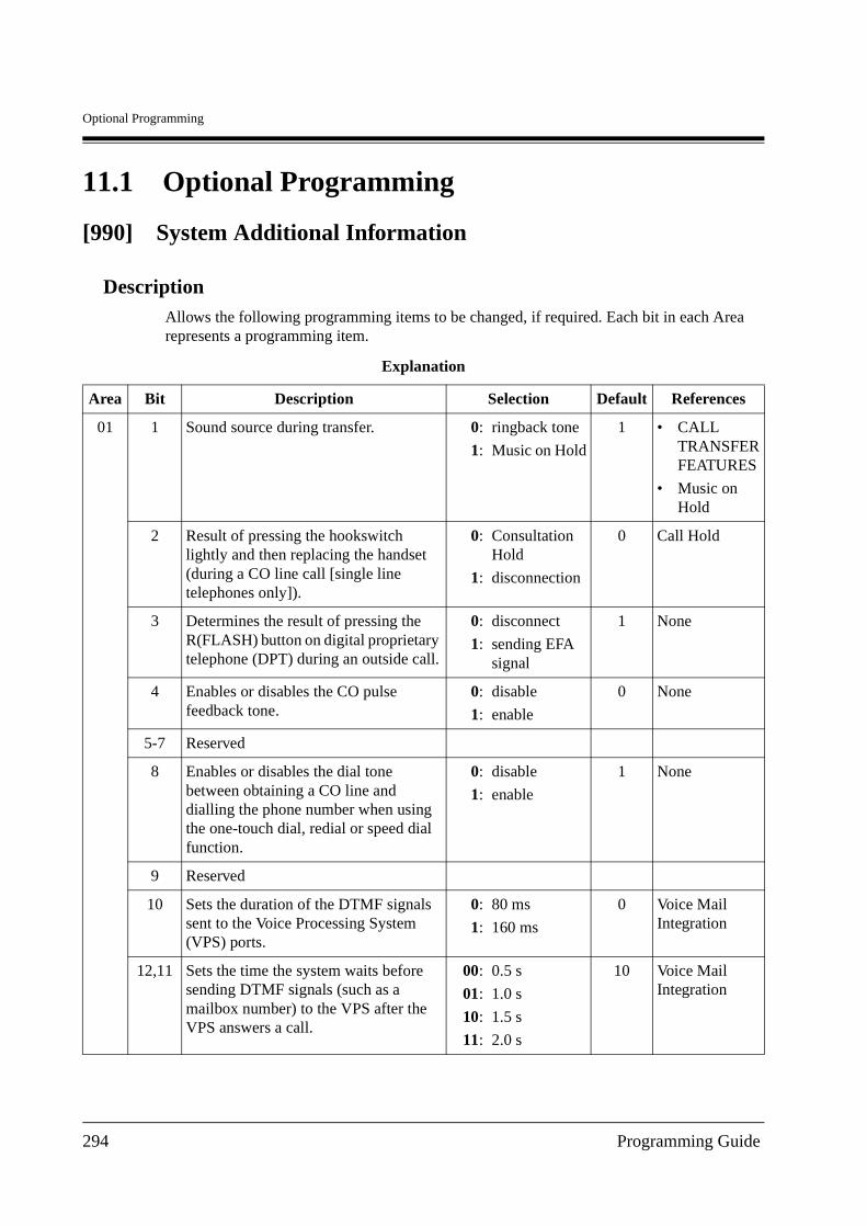
Optional Programming
11.1 Optional Programming
[990] System Additional Information
DescriptionAllows the following programming items to be changed, if required. Each bit in each Area represents a programming item.
Explanation
Area Bit Description Selection Default References
01 1 Sound source during transfer. 0:
1:
ringback tone
Music on Hold
1 • CALLTRANSFERFEATURES
• Music on Hold
2 Result of pressing the hookswitch lightly and then replacing the handset (during a CO line call [single line telephones only]).
0:
1:
ConsultationHold
disconnection
0 Call Hold
3 Determines the result of pressing the R(FLASH) button on digital proprietary telephone (DPT) during an outside call.
0:
1:
disconnect
sending EFA signal
1 None
4 Enables or disables the CO pulse feedback tone.
0:
1:
disable
enable
0 None
5-7 Reserved
8 Enables or disables the dial tone between obtaining a CO line and dialling the phone number when using the one-touch dial, redial or speed dial function.
0:
1:
disable
enable
1 None
9 Reserved
10 Sets the duration of the DTMF signals sent to the Voice Processing System (VPS) ports.
0:
1:
80 ms
160 ms
0 Voice Mail Integration
12,11 Sets the time the system waits before sending DTMF signals (such as a mailbox number) to the VPS after the VPS answers a call.
00:
01:
10:
11:
0.5 s
1.0 s
1.5 s
2.0 s
10 Voice Mail Integration
294 Programming Guide
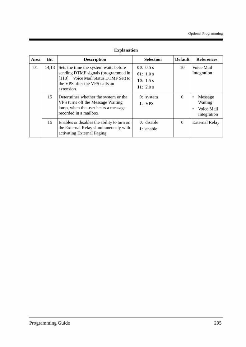
Optional Programming
01 14,13 Sets the time the system waits before sending DTMF signals (programmed in [113] Voice Mail Status DTMF Set) to the VPS after the VPS calls an extension.
00:
01:
10:
11:
0.5 s
1.0 s
1.5 s
2.0 s
10 Voice Mail Integration
15 Determines whether the system or the VPS turns off the Message Waiting lamp, when the user hears a message recorded in a mailbox.
0:
1:
system
VPS
0 • Message Waiting
• Voice Mail Integration
16 Enables or disables the ability to turn on the External Relay simultaneously with activating External Paging.
0:
1:
disable
enable
0 External Relay
Explanation
Area Bit Description Selection Default References
Programming Guide 295
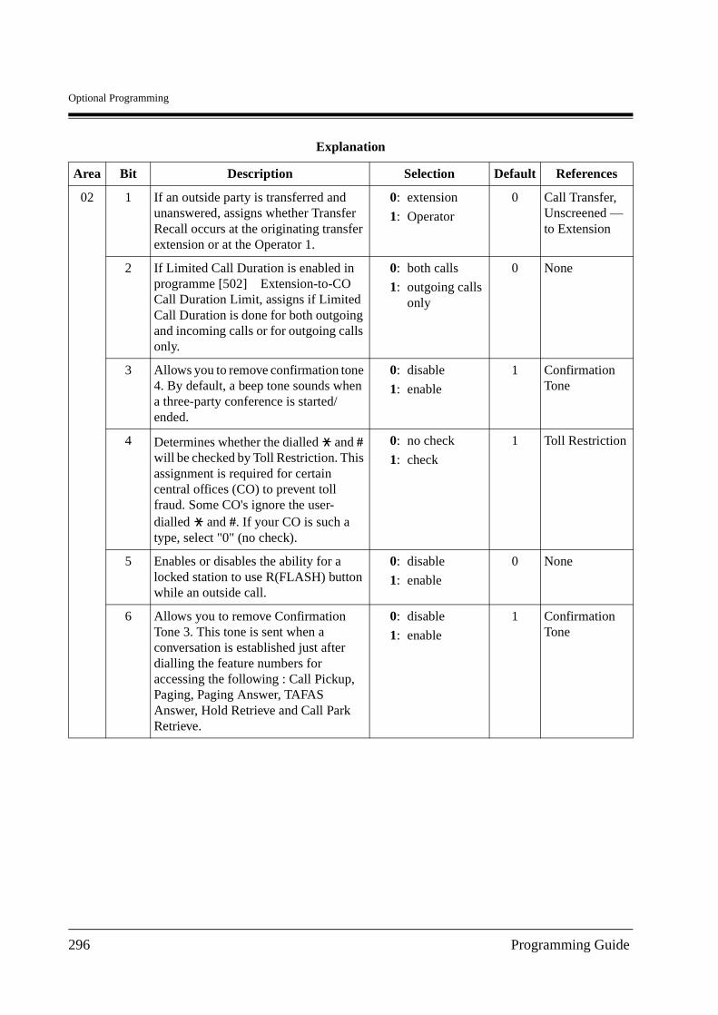
Optional Programming
02 1 If an outside party is transferred and unanswered, assigns whether Transfer Recall occurs at the originating transfer extension or at the Operator 1.
0:
1:
extension
Operator
0 Call Transfer, Unscreened — to Extension
2 If Limited Call Duration is enabled in programme [502] Extension-to-CO Call Duration Limit, assigns if Limited Call Duration is done for both outgoing and incoming calls or for outgoing calls only.
0:
1:
both calls
outgoing calls only
0 None
3 Allows you to remove confirmation tone 4. By default, a beep tone sounds when a three-party conference is started/ended.
0:
1:
disable
enable
1 Confirmation Tone
4 Determines whether the dialled and # will be checked by Toll Restriction. This assignment is required for certain central offices (CO) to prevent toll fraud. Some CO's ignore the user-dialled and #. If your CO is such a type, select "0" (no check).
0:
1:
no check
check
1 Toll Restriction
5 Enables or disables the ability for a locked station to use R(FLASH) button while an outside call.
0:
1:
disable
enable
0 None
6 Allows you to remove Confirmation Tone 3. This tone is sent when a conversation is established just after dialling the feature numbers for accessing the following : Call Pickup, Paging, Paging Answer, TAFAS Answer, Hold Retrieve and Call Park Retrieve.
0:
1:
disable
enable
1 Confirmation Tone
Explanation
Area Bit Description Selection Default References
296 Programming Guide
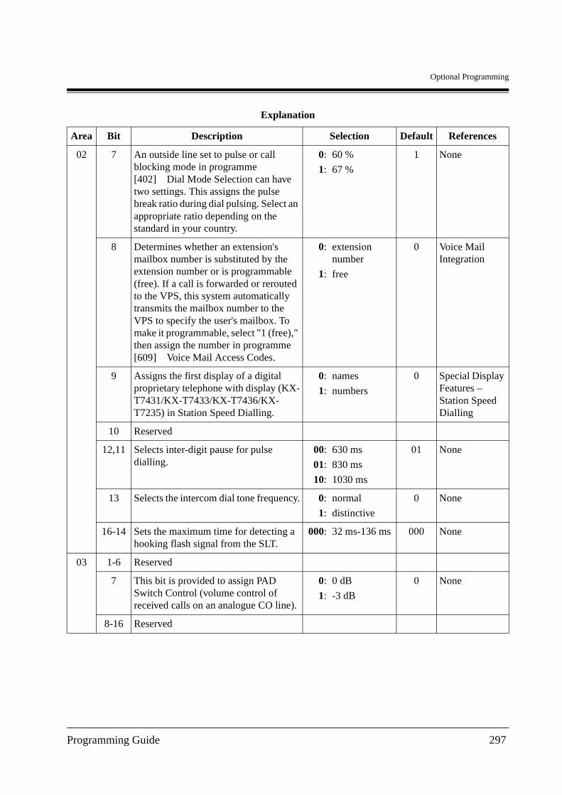
Optional Programming
02 7 An outside line set to pulse or call blocking mode in programme [402] Dial Mode Selection can have two settings. This assigns the pulse break ratio during dial pulsing. Select an appropriate ratio depending on the standard in your country.
0:
1:
60 %
67 %
1 None
8 Determines whether an extension's mailbox number is substituted by the extension number or is programmable (free). If a call is forwarded or rerouted to the VPS, this system automatically transmits the mailbox number to the VPS to specify the user's mailbox. To make it programmable, select "1 (free)," then assign the number in programme [609] Voice Mail Access Codes.
0:
1:
extension number
free
0 Voice Mail Integration
9 Assigns the first display of a digital proprietary telephone with display (KX-T7431/KX-T7433/KX-T7436/KX-T7235) in Station Speed Dialling.
0:
1:
names
numbers
0 Special Display Features – Station Speed Dialling
10 Reserved
12,11 Selects inter-digit pause for pulse dialling.
00:
01:
10:
630 ms
830 ms
1030 ms
01 None
13 Selects the intercom dial tone frequency. 0:
1:
normal
distinctive
0 None
16-14 Sets the maximum time for detecting a hooking flash signal from the SLT.
000: 32 ms-136 ms 000 None
03 1-6 Reserved
7 This bit is provided to assign PAD Switch Control (volume control of received calls on an analogue CO line).
0:
1:
0 dB
-3 dB
0 None
8-16 Reserved
Explanation
Area Bit Description Selection Default References
Programming Guide 297
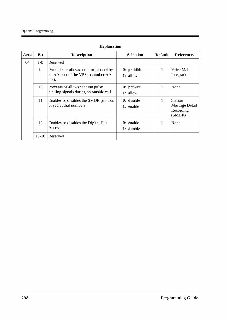
Optional Programming
04 1-8 Reserved
9 Prohibits or allows a call originated by an AA port of the VPS to another AA port.
0:
1:
prohibit
allow
1 Voice Mail Integration
10 Prevents or allows sending pulse dialling signals during an outside call.
0:
1:
prevent
allow
1 None
11 Enables or disables the SMDR printout of secret dial numbers.
0:
1:
disable
enable
1 Station Message Detail Recording (SMDR)
12 Enables or disables the Digital Test Access.
0:
1:
enable
disable
1 None
13-16 Reserved
Explanation
Area Bit Description Selection Default References
298 Programming Guide
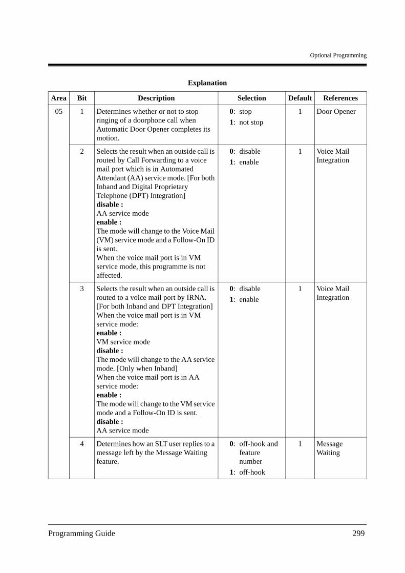
Optional Programming
05 1 Determines whether or not to stop ringing of a doorphone call when Automatic Door Opener completes its motion.
0:
1:
stop
not stop
1 Door Opener
2 Selects the result when an outside call is routed by Call Forwarding to a voice mail port which is in Automated Attendant (AA) service mode. [For both Inband and Digital Proprietary Telephone (DPT) Integration]disable : AA service modeenable : The mode will change to the Voice Mail (VM) service mode and a Follow-On ID is sent.When the voice mail port is in VM service mode, this programme is not affected.
0:
1:
disable
enable
1 Voice Mail Integration
3 Selects the result when an outside call is routed to a voice mail port by IRNA.[For both Inband and DPT Integration]When the voice mail port is in VM service mode:enable : VM service modedisable : The mode will change to the AA service mode. [Only when Inband]When the voice mail port is in AA service mode:enable : The mode will change to the VM service mode and a Follow-On ID is sent.disable : AA service mode
0:
1:
disable
enable
1 Voice Mail Integration
4 Determines how an SLT user replies to a message left by the Message Waiting feature.
0:
1:
off-hook and feature number
off-hook
1 Message Waiting
Explanation
Area Bit Description Selection Default References
Programming Guide 299
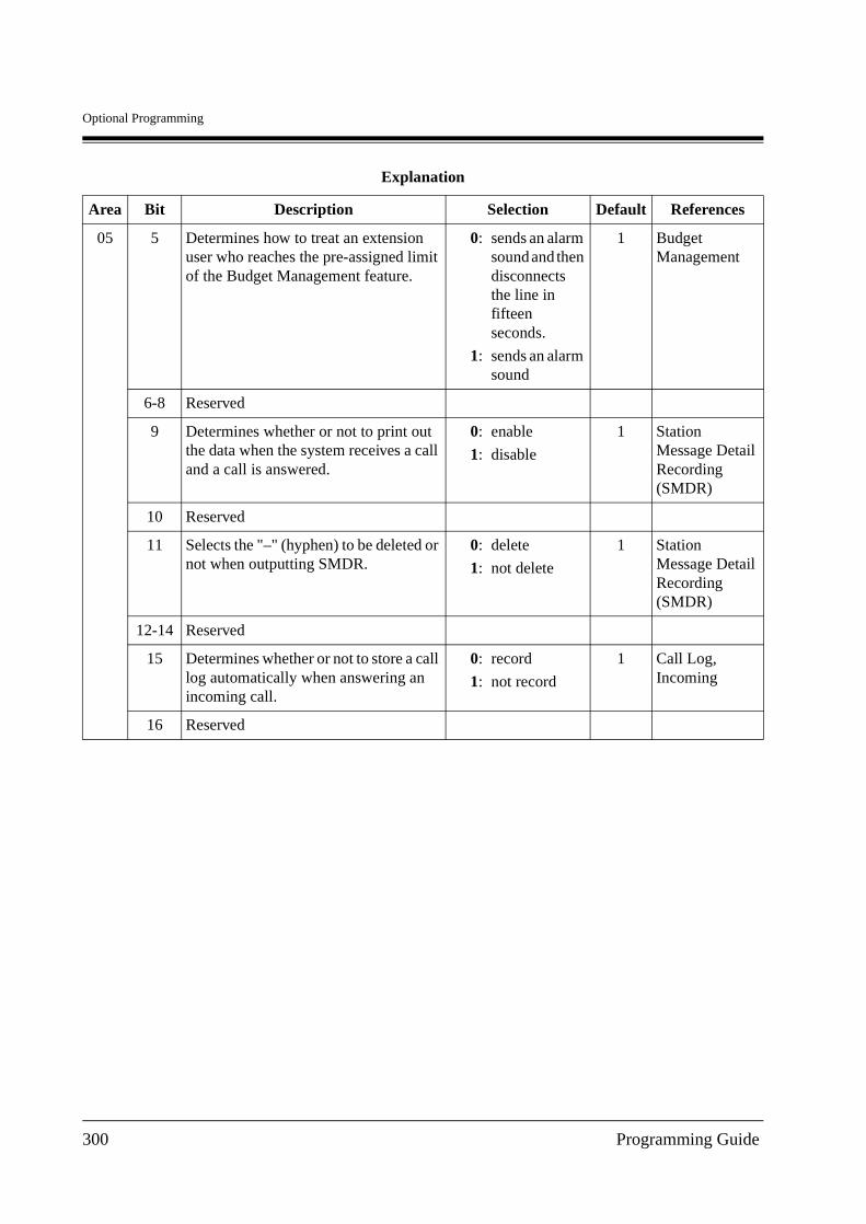
Optional Programming
05 5 Determines how to treat an extension user who reaches the pre-assigned limit of the Budget Management feature.
0:
1:
sends an alarm sound and then disconnects the line in fifteen seconds.
sends an alarm sound
1 Budget Management
6-8 Reserved
9 Determines whether or not to print out the data when the system receives a call and a call is answered.
0:
1:
enable
disable
1 Station Message Detail Recording (SMDR)
10 Reserved
11 Selects the "–" (hyphen) to be deleted or not when outputting SMDR.
0:
1:
delete
not delete
1 Station Message Detail Recording (SMDR)
12-14 Reserved
15 Determines whether or not to store a call log automatically when answering an incoming call.
0:
1:
record
not record
1 Call Log, Incoming
16 Reserved
Explanation
Area Bit Description Selection Default References
300 Programming Guide
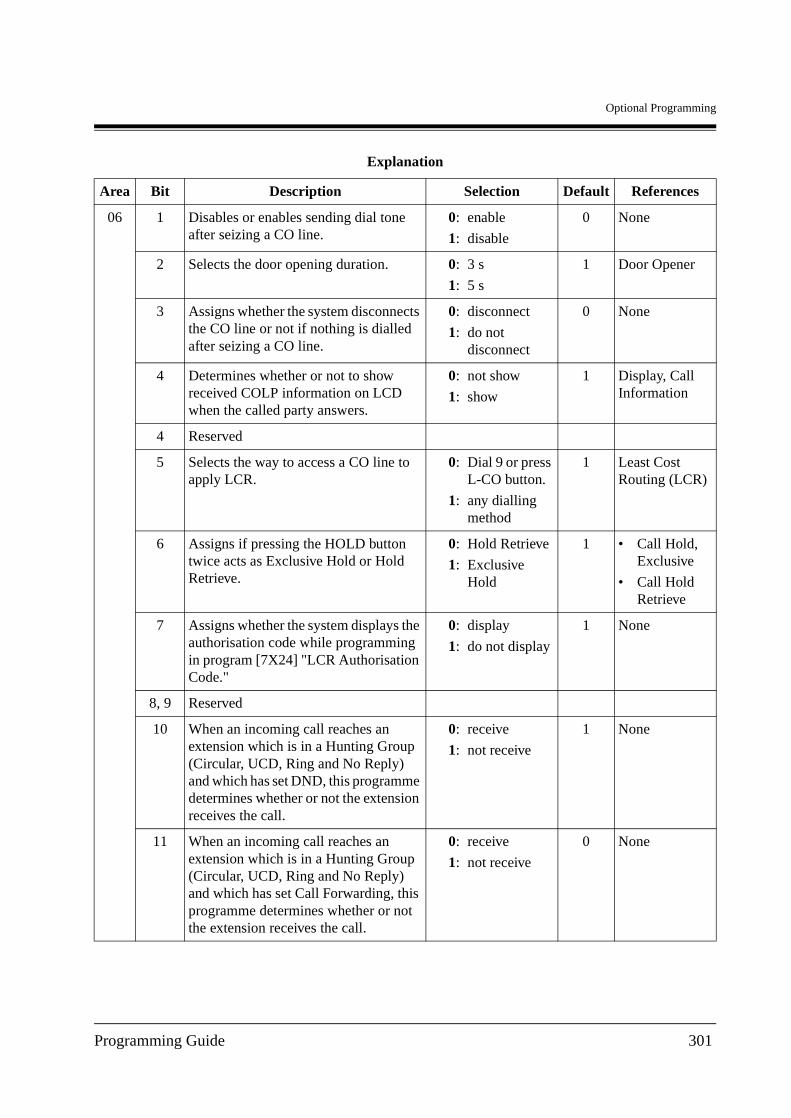
Optional Programming
06 1 Disables or enables sending dial tone after seizing a CO line.
0:
1:
enable
disable
0 None
2 Selects the door opening duration. 0:
1:
3 s
5 s
1 Door Opener
3 Assigns whether the system disconnects the CO line or not if nothing is dialled after seizing a CO line.
0:
1:
disconnect
do not disconnect
0 None
4 Determines whether or not to show received COLP information on LCD when the called party answers.
0:
1:
not show
show
1 Display, Call Information
4 Reserved
5 Selects the way to access a CO line to apply LCR.
0:
1:
Dial 9 or press L-CO button.
any dialling method
1 Least Cost Routing (LCR)
6 Assigns if pressing the HOLD button twice acts as Exclusive Hold or Hold Retrieve.
0:
1:
Hold Retrieve
Exclusive Hold
1 • Call Hold, Exclusive
• Call Hold Retrieve
7 Assigns whether the system displays the authorisation code while programming in program [7X24] "LCR Authorisation Code."
0:
1:
display
do not display
1 None
8, 9 Reserved
10 When an incoming call reaches an extension which is in a Hunting Group (Circular, UCD, Ring and No Reply) and which has set DND, this programme determines whether or not the extension receives the call.
0:
1:
receive
not receive
1 None
11 When an incoming call reaches an extension which is in a Hunting Group (Circular, UCD, Ring and No Reply) and which has set Call Forwarding, this programme determines whether or not the extension receives the call.
0:
1:
receive
not receive
0 None
Explanation
Area Bit Description Selection Default References
Programming Guide 301
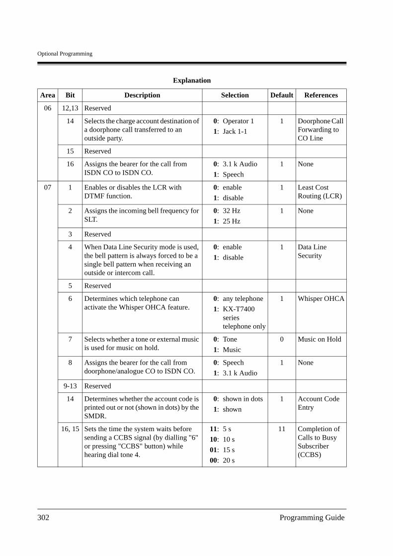
Optional Programming
06 12,13 Reserved
14 Selects the charge account destination of a doorphone call transferred to an outside party.
0:
1:
Operator 1
Jack 1-1
1 Doorphone Call Forwarding to CO Line
15 Reserved
16 Assigns the bearer for the call from ISDN CO to ISDN CO.
0:
1:
3.1 k Audio
Speech
1 None
07 1 Enables or disables the LCR with DTMF function.
0:
1:
enable
disable
1 Least Cost Routing (LCR)
2 Assigns the incoming bell frequency for SLT.
0:
1:
32 Hz
25 Hz
1 None
3 Reserved
4 When Data Line Security mode is used, the bell pattern is always forced to be a single bell pattern when receiving an outside or intercom call.
0:
1:
enable
disable
1 Data Line Security
5 Reserved
6 Determines which telephone can activate the Whisper OHCA feature.
0:
1:
any telephone
KX-T7400 series telephone only
1 Whisper OHCA
7 Selects whether a tone or external music is used for music on hold.
0:
1:
Tone
Music
0 Music on Hold
8 Assigns the bearer for the call from doorphone/analogue CO to ISDN CO.
0:
1:
Speech
3.1 k Audio
1 None
9-13 Reserved
14 Determines whether the account code is printed out or not (shown in dots) by the SMDR.
0:
1:
shown in dots
shown
1 Account Code Entry
16, 15 Sets the time the system waits before sending a CCBS signal (by dialling "6" or pressing "CCBS" button) while hearing dial tone 4.
11:
10:
01:
00:
5 s
10 s
15 s
20 s
11 Completion of Calls to Busy Subscriber (CCBS)
Explanation
Area Bit Description Selection Default References
302 Programming Guide

Optional Programming
09 1 When all DISA resources are busy, decides whether to let a caller reach to extensions determined by the Intelligent Call Handling (ICH) table, or to have a caller kept waiting until one of the resources becomes idle.
0:
1:
a caller reaches to extensions determined by ICH table
a caller waits
1 Direct Inward System Access (DISA)
2 Sets to release the DISA resource when the destination is determined (before the destination answers). If you select "not release", the caller can recall by pressing
.
0:
1:
not release (recallable)
release
1 Direct Inward System Access (DISA)
3 Selects the returning point of sequence of the UCD time table 1.
0:
1:
returns to the 2nd of the sequence
returns to the top of the sequence
1 Uniform Call Distribution (UCD)
4 Selects the returning point of sequence of the UCD time table 2.
0:
1:
returns to the 2nd of the sequence
returns to the top of the sequence
1 Uniform Call Distribution (UCD)
5 Selects the returning point of sequence of the UCD time table 3.
0:
1:
returns to the 2nd of the sequence
returns to the top of the sequence
1 Uniform Call Distribution (UCD)
6 Selects the returning point of sequence of the UCD time table 4.
0:
1:
returns to the 2nd of the sequence
returns to the top of the sequence
1 Uniform Call Distribution (UCD)
Explanation
Area Bit Description Selection Default References
Programming Guide 303
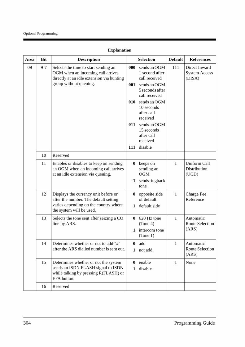
Optional Programming
09 9-7 Selects the time to start sending an OGM when an incoming call arrives directly at an idle extension via hunting group without queuing.
000:
001:
010:
011:
111:
sends an OGM 1 second after call received
sends an OGM 5 seconds after call received
sends an OGM 10 seconds after call received
sends an OGM 15 seconds after call received
disable
111 Direct Inward System Access (DISA)
10 Reserved
11 Enables or disables to keep on sending an OGM when an incoming call arrives at an idle extension via queuing.
0:
1:
keeps on sending an OGM
sends ringback tone
1 Uniform Call Distribution (UCD)
12 Displays the currency unit before or after the number. The default setting varies depending on the country where the system will be used.
0:
1:
opposite side of default
default side
1 Charge Fee Reference
13 Selects the tone sent after seizing a CO line by ARS.
0:
1:
620 Hz tone(Tone 4)
intercom tone(Tone 1)
1 Automatic Route Selection (ARS)
14 Determines whether or not to add "#" after the ARS dialled number is sent out.
0:
1:
add
not add
1 Automatic Route Selection (ARS)
15 Determines whether or not the system sends an ISDN FLASH signal to ISDN while talking by pressing R(FLASH) or EFA button.
0:
1:
enable
disable
1 None
16 Reserved
Explanation
Area Bit Description Selection Default References
304 Programming Guide
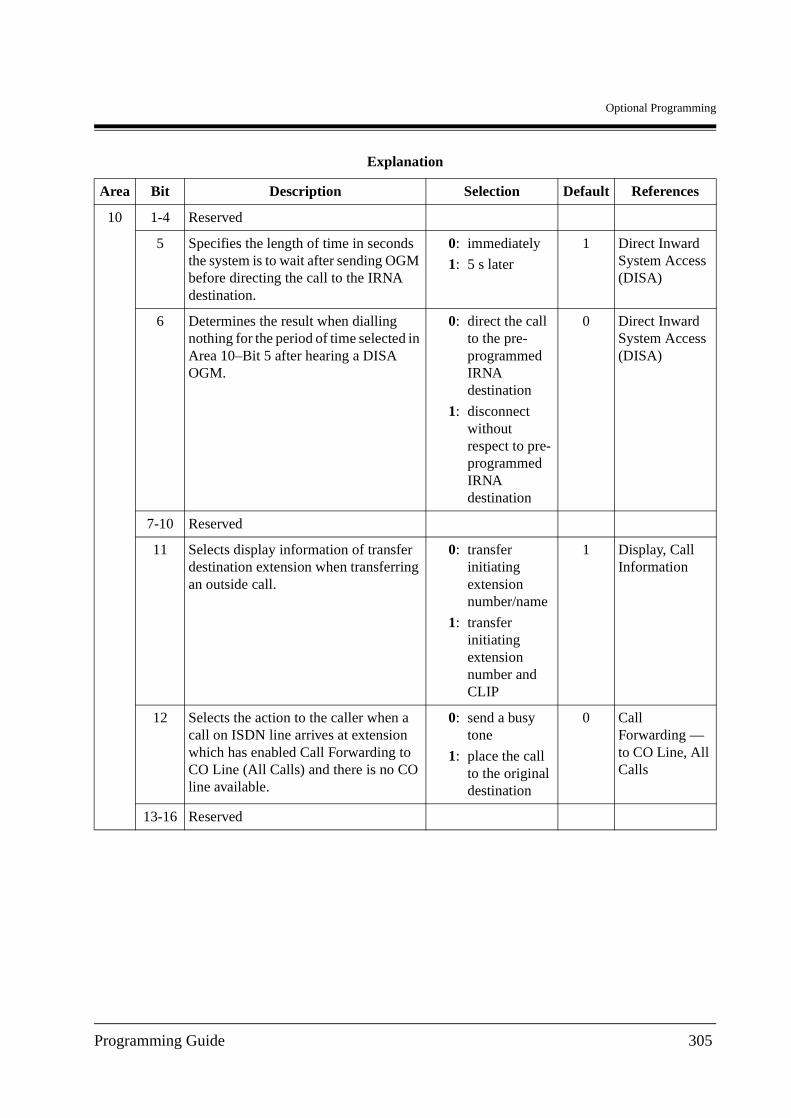
Optional Programming
10 1-4 Reserved
5 Specifies the length of time in seconds the system is to wait after sending OGM before directing the call to the IRNA destination.
0:
1:
immediately
5 s later
1 Direct Inward System Access (DISA)
6 Determines the result when dialling nothing for the period of time selected in Area 10–Bit 5 after hearing a DISA OGM.
0:
1:
direct the call to the pre-programmed IRNA destination
disconnect without respect to pre-programmed IRNA destination
0 Direct Inward System Access (DISA)
7-10 Reserved
11 Selects display information of transfer destination extension when transferring an outside call.
0:
1:
transfer initiating extension number/name
transfer initiating extension number and CLIP
1 Display, Call Information
12 Selects the action to the caller when a call on ISDN line arrives at extension which has enabled Call Forwarding to CO Line (All Calls) and there is no CO line available.
0:
1:
send a busy tone
place the call to the original destination
0 Call Forwarding — to CO Line, All Calls
13-16 Reserved
Explanation
Area Bit Description Selection Default References
Programming Guide 305
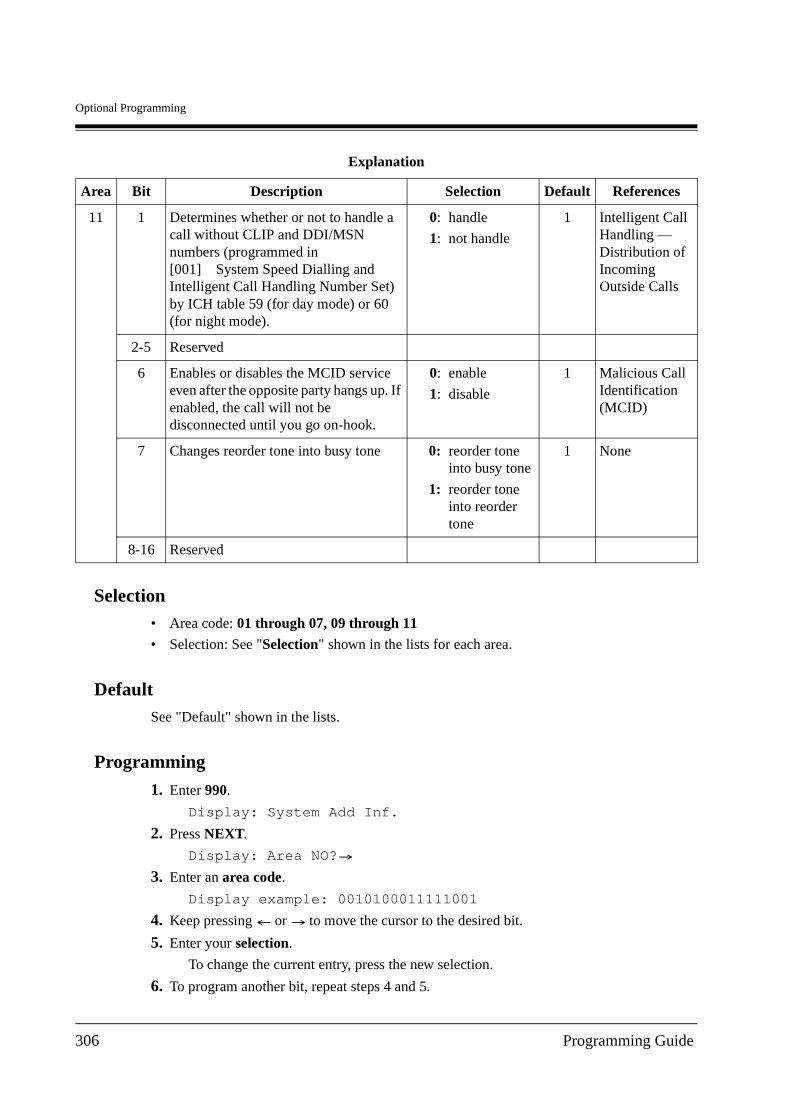
Optional Programming
Selection• Area code: 01 through 07, 09 through 11
• Selection: See "Selection" shown in the lists for each area.
DefaultSee "Default" shown in the lists.
Programming
1. Enter 990.
Display: System Add Inf.
2. Press NEXT.
Display: Area NO?
3. Enter an area code.
Display example: 0010100011111001
4. Keep pressing or to move the cursor to the desired bit.
5. Enter your selection.
To change the current entry, press the new selection.
6. To program another bit, repeat steps 4 and 5.
11 1 Determines whether or not to handle a call without CLIP and DDI/MSN numbers (programmed in [001] System Speed Dialling and Intelligent Call Handling Number Set) by ICH table 59 (for day mode) or 60 (for night mode).
0:
1:
handle
not handle
1 Intelligent Call Handling — Distribution of Incoming Outside Calls
2-5 Reserved
6 Enables or disables the MCID service even after the opposite party hangs up. If enabled, the call will not be disconnected until you go on-hook.
0:
1:
enable
disable
1 Malicious Call Identification (MCID)
7 Changes reorder tone into busy tone 0:
1:
reorder tone into busy tone
reorder tone into reorder tone
1 None
8-16 Reserved
Explanation
Area Bit Description Selection Default References
306 Programming Guide
Optional Programming
7. Press STORE.
8. To program another area, press SELECT and the desired area code.
9. Repeat steps 4 through 8.
10.Press END.
ConditionsNone
Features Guide ReferencesNone
Programming Guide 307
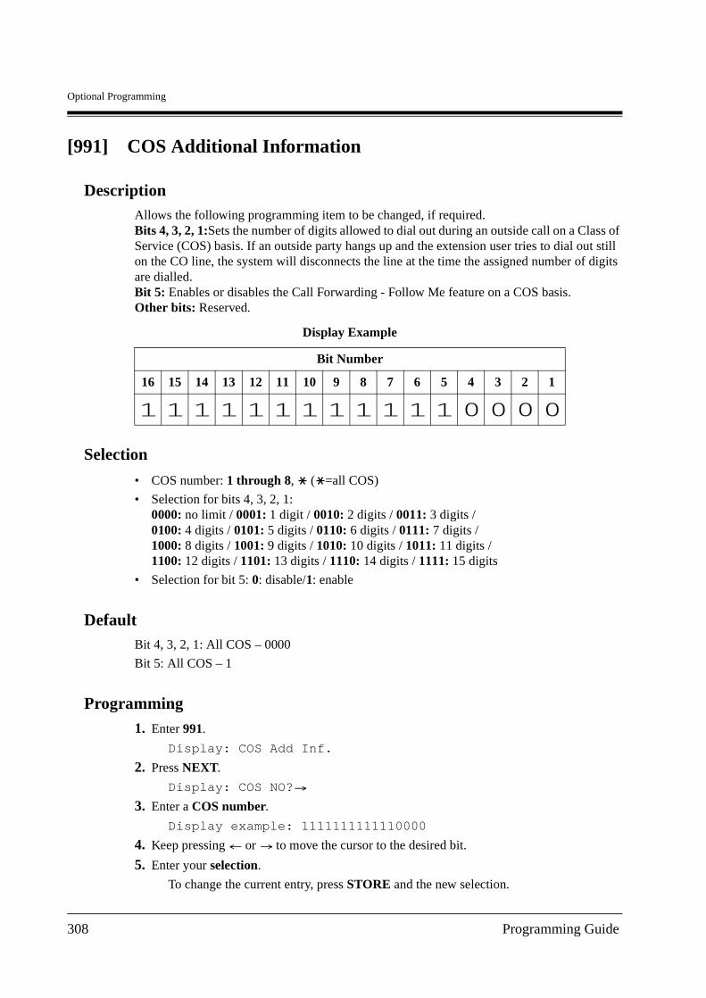
Optional Programming
[991] COS Additional Information
DescriptionAllows the following programming item to be changed, if required.Bits 4, 3, 2, 1:Sets the number of digits allowed to dial out during an outside call on a Class of Service (COS) basis. If an outside party hangs up and the extension user tries to dial out still on the CO line, the system will disconnects the line at the time the assigned number of digits are dialled.Bit 5: Enables or disables the Call Forwarding - Follow Me feature on a COS basis.Other bits: Reserved.
Selection
• COS number: 1 through 8, ( =all COS)
• Selection for bits 4, 3, 2, 1:0000: no limit / 0001: 1 digit / 0010: 2 digits / 0011: 3 digits /0100: 4 digits / 0101: 5 digits / 0110: 6 digits / 0111: 7 digits /1000: 8 digits / 1001: 9 digits / 1010: 10 digits / 1011: 11 digits /1100: 12 digits / 1101: 13 digits / 1110: 14 digits / 1111: 15 digits
• Selection for bit 5: 0: disable/1: enable
DefaultBit 4, 3, 2, 1: All COS – 0000
Bit 5: All COS – 1
Programming
1. Enter 991.
Display: COS Add Inf.
2. Press NEXT.
Display: COS NO?
3. Enter a COS number.
Display example: 1111111111110000
4. Keep pressing or to move the cursor to the desired bit.
5. Enter your selection.
To change the current entry, press STORE and the new selection.
Display Example
Bit Number
16 15 14 13 12 11 10 9 8 7 6 5 4 3 2 1
308 Programming Guide
Optional Programming
6. To program another bit, repeat steps 4 and 5.
7. Press STORE.
8. To program another COS, press SELECT and the desired COS number.
9. Repeat steps 4 through 8.
10.Press END.
Conditions
To assign all COS numbers to one selection, press the key at step 3.
Features Guide ReferencesCall Forwarding — Follow Me
Class of Service (COS)
Programming Guide 309

Optional Programming
310 Programming Guide
Default Values
Section 12
Default Values
Programming Guide 311
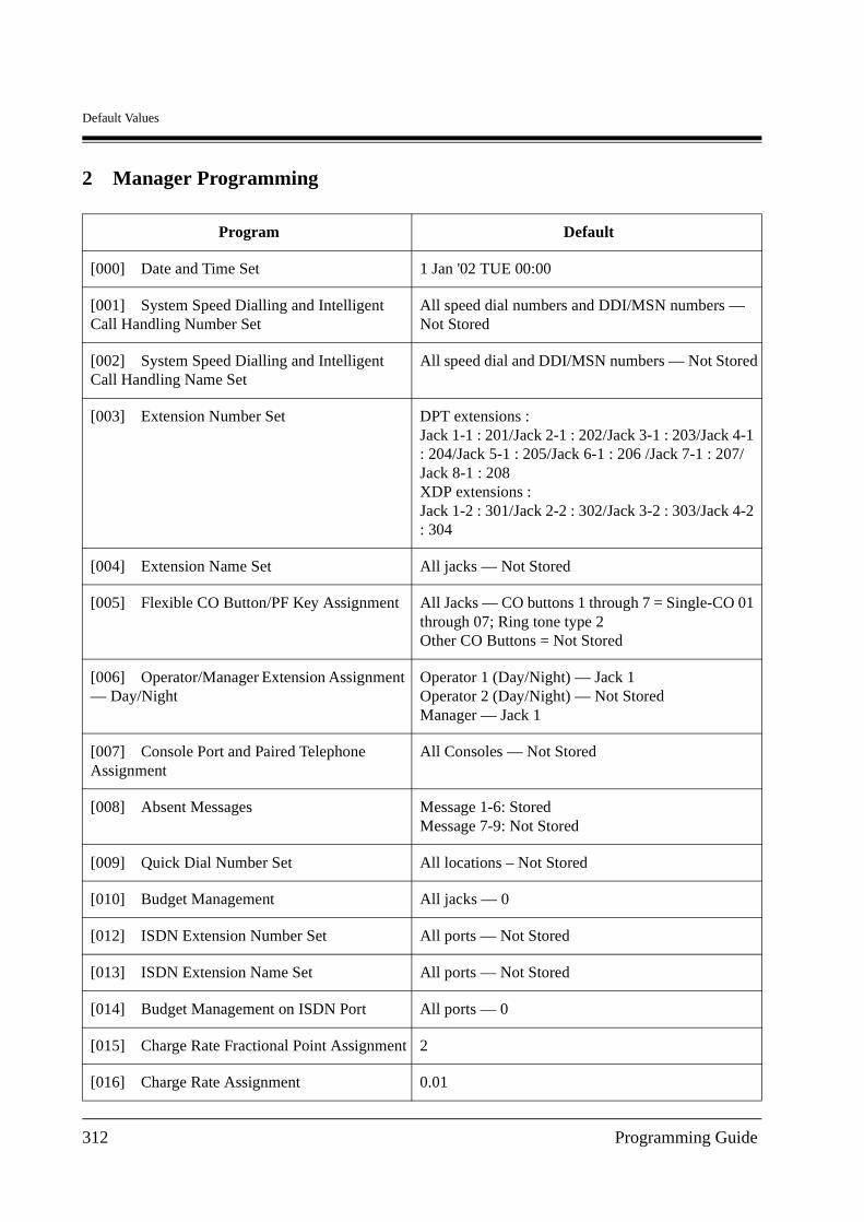
Default Values
2 Manager Programming
Program Default
[000] Date and Time Set 1 Jan '02 TUE 00:00
[001] System Speed Dialling and Intelligent Call Handling Number Set
All speed dial numbers and DDI/MSN numbers — Not Stored
[002] System Speed Dialling and Intelligent Call Handling Name Set
All speed dial and DDI/MSN numbers — Not Stored
[003] Extension Number Set DPT extensions : Jack 1-1 : 201/Jack 2-1 : 202/Jack 3-1 : 203/Jack 4-1 : 204/Jack 5-1 : 205/Jack 6-1 : 206 /Jack 7-1 : 207/Jack 8-1 : 208XDP extensions :Jack 1-2 : 301/Jack 2-2 : 302/Jack 3-2 : 303/Jack 4-2 : 304
[004] Extension Name Set All jacks — Not Stored
[005] Flexible CO Button/PF Key Assignment All Jacks — CO buttons 1 through 7 = Single-CO 01 through 07; Ring tone type 2Other CO Buttons = Not Stored
[006] Operator/Manager Extension Assignment — Day/Night
Operator 1 (Day/Night) — Jack 1Operator 2 (Day/Night) — Not StoredManager — Jack 1
[007] Console Port and Paired Telephone Assignment
All Consoles — Not Stored
[008] Absent Messages Message 1-6: StoredMessage 7-9: Not Stored
[009] Quick Dial Number Set All locations – Not Stored
[010] Budget Management All jacks — 0
[012] ISDN Extension Number Set All ports — Not Stored
[013] ISDN Extension Name Set All ports — Not Stored
[014] Budget Management on ISDN Port All ports — 0
[015] Charge Rate Fractional Point Assignment 2
[016] Charge Rate Assignment 0.01
312 Programming Guide
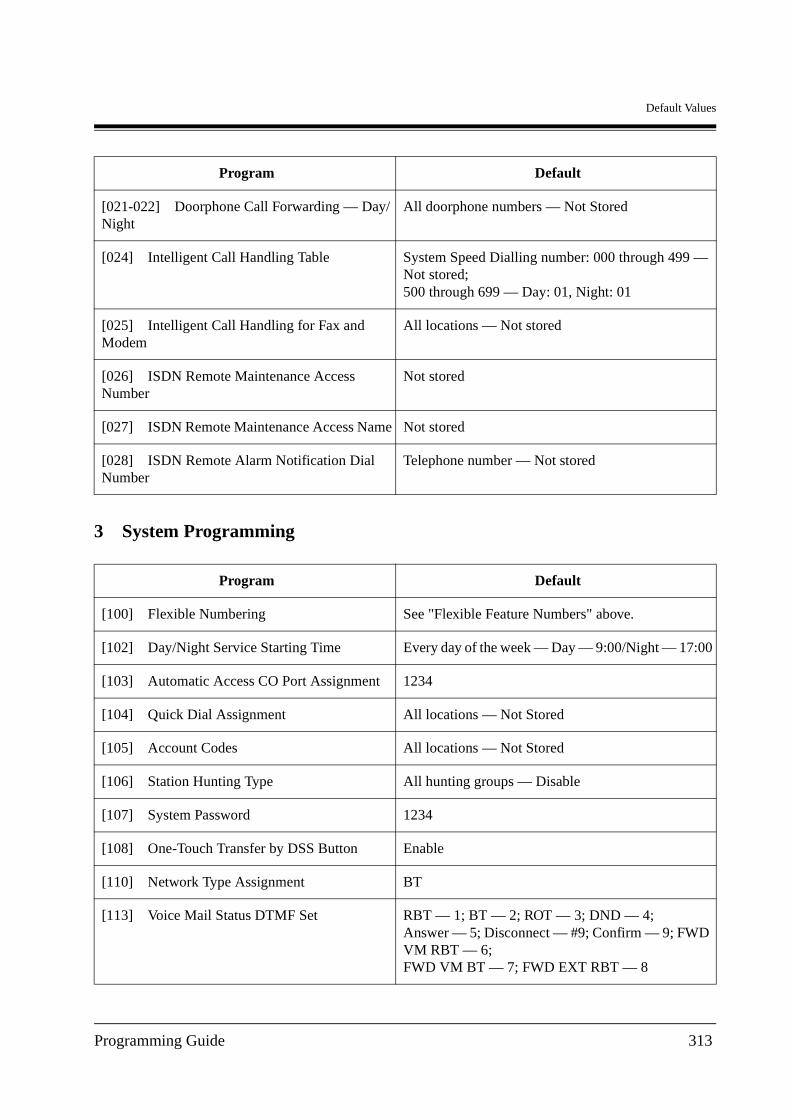
Default Values
3 System Programming
[021-022] Doorphone Call Forwarding — Day/Night
All doorphone numbers — Not Stored
[024] Intelligent Call Handling Table System Speed Dialling number: 000 through 499 — Not stored;500 through 699 — Day: 01, Night: 01
[025] Intelligent Call Handling for Fax and Modem
All locations — Not stored
[026] ISDN Remote Maintenance Access Number
Not stored
[027] ISDN Remote Maintenance Access Name Not stored
[028] ISDN Remote Alarm Notification Dial Number
Telephone number — Not stored
Program Default
[100] Flexible Numbering See "Flexible Feature Numbers" above.
[102] Day/Night Service Starting Time Every day of the week — Day — 9:00/Night — 17:00
[103] Automatic Access CO Port Assignment 1234
[104] Quick Dial Assignment All locations — Not Stored
[105] Account Codes All locations — Not Stored
[106] Station Hunting Type All hunting groups — Disable
[107] System Password 1234
[108] One-Touch Transfer by DSS Button Enable
[110] Network Type Assignment BT
[113] Voice Mail Status DTMF Set RBT — 1; BT — 2; ROT — 3; DND — 4;Answer — 5; Disconnect — #9; Confirm — 9; FWD VM RBT — 6;FWD VM BT — 7; FWD EXT RBT — 8
Program Default
Programming Guide 313
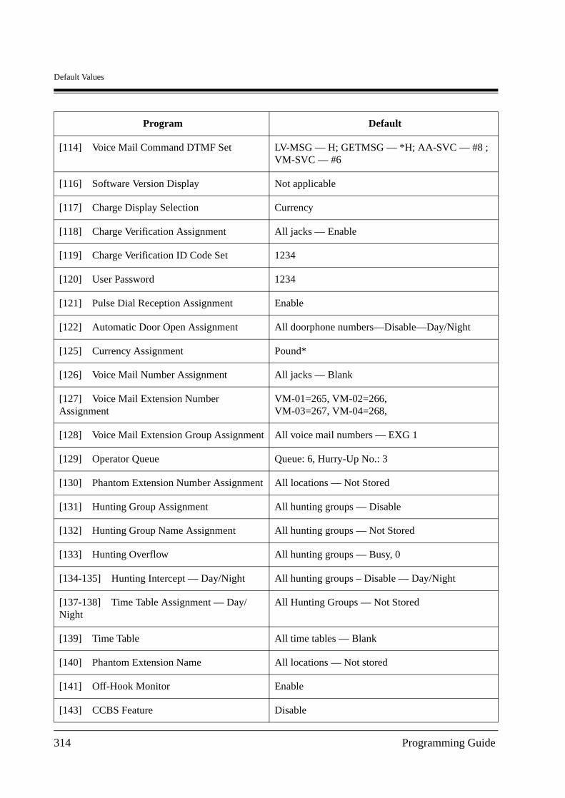
Default Values
[114] Voice Mail Command DTMF Set LV-MSG — H; GETMSG — *H; AA-SVC — #8 ; VM-SVC — #6
[116] Software Version Display Not applicable
[117] Charge Display Selection Currency
[118] Charge Verification Assignment All jacks — Enable
[119] Charge Verification ID Code Set 1234
[120] User Password 1234
[121] Pulse Dial Reception Assignment Enable
[122] Automatic Door Open Assignment All doorphone numbers—Disable—Day/Night
[125] Currency Assignment Pound*
[126] Voice Mail Number Assignment All jacks — Blank
[127] Voice Mail Extension Number Assignment
VM-01=265, VM-02=266, VM-03=267, VM-04=268,
[128] Voice Mail Extension Group Assignment All voice mail numbers — EXG 1
[129] Operator Queue Queue: 6, Hurry-Up No.: 3
[130] Phantom Extension Number Assignment All locations — Not Stored
[131] Hunting Group Assignment All hunting groups — Disable
[132] Hunting Group Name Assignment All hunting groups — Not Stored
[133] Hunting Overflow All hunting groups — Busy, 0
[134-135] Hunting Intercept — Day/Night All hunting groups – Disable — Day/Night
[137-138] Time Table Assignment — Day/Night
All Hunting Groups — Not Stored
[139] Time Table All time tables — Blank
[140] Phantom Extension Name All locations — Not stored
[141] Off-Hook Monitor Enable
[143] CCBS Feature Disable
Program Default
314 Programming Guide
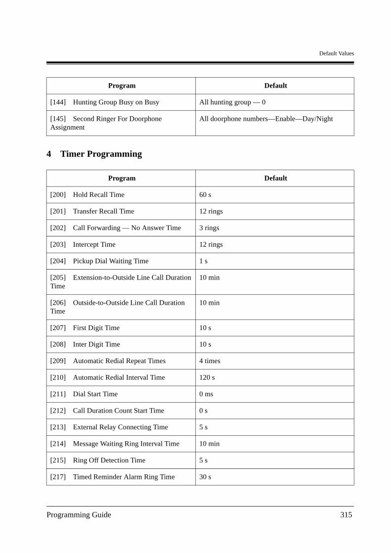
Default Values
4 Timer Programming
[144] Hunting Group Busy on Busy All hunting group — 0
[145] Second Ringer For Doorphone Assignment
All doorphone numbers—Enable—Day/Night
Program Default
[200] Hold Recall Time 60 s
[201] Transfer Recall Time 12 rings
[202] Call Forwarding — No Answer Time 3 rings
[203] Intercept Time 12 rings
[204] Pickup Dial Waiting Time 1 s
[205] Extension-to-Outside Line Call Duration Time
10 min
[206] Outside-to-Outside Line Call Duration Time
10 min
[207] First Digit Time 10 s
[208] Inter Digit Time 10 s
[209] Automatic Redial Repeat Times 4 times
[210] Automatic Redial Interval Time 120 s
[211] Dial Start Time 0 ms
[212] Call Duration Count Start Time 0 s
[213] External Relay Connecting Time 5 s
[214] Message Waiting Ring Interval Time 10 min
[215] Ring Off Detection Time 5 s
[217] Timed Reminder Alarm Ring Time 30 s
Program Default
Programming Guide 315
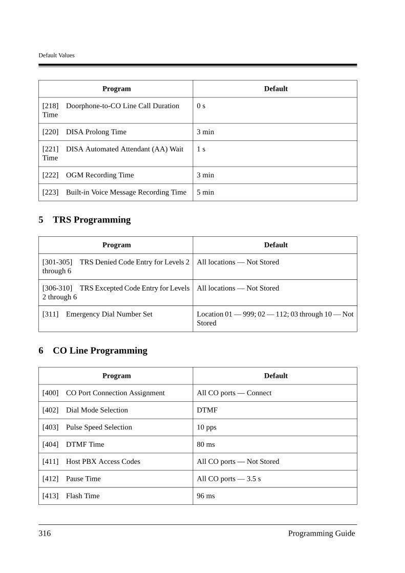
Default Values
5 TRS Programming
6 CO Line Programming
[218] Doorphone-to-CO Line Call Duration Time
0 s
[220] DISA Prolong Time 3 min
[221] DISA Automated Attendant (AA) Wait Time
1 s
[222] OGM Recording Time 3 min
[223] Built-in Voice Message Recording Time 5 min
Program Default
[301-305] TRS Denied Code Entry for Levels 2 through 6
All locations — Not Stored
[306-310] TRS Excepted Code Entry for Levels 2 through 6
All locations — Not Stored
[311] Emergency Dial Number Set Location 01 — 999; 02 — 112; 03 through 10 — Not Stored
Program Default
[400] CO Port Connection Assignment All CO ports — Connect
[402] Dial Mode Selection DTMF
[403] Pulse Speed Selection 10 pps
[404] DTMF Time 80 ms
[411] Host PBX Access Codes All CO ports — Not Stored
[412] Pause Time All CO ports — 3.5 s
[413] Flash Time 96 ms
Program Default
316 Programming Guide

Default Values
[414] Disconnect Time 2.0 s
[418] Second Ringer Assignment All CO port — Disable
[421] CO Port Name All ports — Not stored
[422] ISDN Port Type Port 2 — COPort 3 — Extension
[423] ISDN Layer 1 Active Mode Port 1, 2 — PermanentPort 3 — Call
[424] ISDN Configuration Port 1, 2 — PointPort 3 — Multipoint
[425] ISDN Data Link Mode Port 1, 2 — PermanentPort 3 — Call
[426] ISDN TEI Mode Port 1, 2 — Fix 0Port 3 — Automatic
[427] ISDN Extension Multiple Subscriber Number
All ports — Disable
[428] ISDN Extension Progress Tone All ports — Enable
[452] Extension Ringing Assignment HND 01, 61, 62: All jacks – ImmediateHND 02 through 60: All jacks – Disable
[453] Other Extension Ringing Assignment All handling tables — Not Stored
[454] ISDN Extension Ringing Assignment All handling tables — Not Stored
[455] Built-in Voice Message for Call Handling All handling tables — Disable
[456] Call Handling When All Busy All handling tables — Recovery
[457] Intercept Extension All handling tables — Not Stored
[458] Intelligent Call Handling Table for Analogue CO
01
[460] ISDN Call Hold All ports — Disable
[461] ISDN Call Transfer All ports — Disable
[462] ISDN Conference All ports — Disable
Program Default
Programming Guide 317

Default Values
7 COS Programming
[463] ISDN Call Forwarding All ports — Disable
[464] ISDN Call Deflection All ports — Disable
Program Default
[500-501] Toll Restriction Level — Day/Night All COS — Level 1 — Day/Night
[502] Extension-to-CO Call Duration Limit All COS — Disable
[503] Call Transfer to CO Line All COS — Enable
[504] Call Forwarding to CO Line All COS — Disable
[505] Executive Busy Override All COS — Disable
[506] Executive Busy Override Deny All COS — Enable
[507] Do Not Disturb Override All COS — Disable
[508] Account Code Entry Mode All COS – Option
[509-510] Toll Restriction Level for System Speed Dialling – Day/Night
All COS — Level 1 — Day/Night
[511] Door Opener Access All COS — Enable
[512] External Relay Access All COS — Enable
[513] Night Service Access All COS — Enable
[514] Do Not Disturb (DND) for Intelligent Call Handling 1:1 Call
All COS — Disable
[516] Calling Line Identification Restriction All COS — Disable
[517] Connected Line Identification Restriction All COS — Disable
[518] CFU/CFB/CFNR Assignment All COS — Disable
[519] Off-Hook Call Announcement (OHCA) All COS — Enable
[520] Call Forwarding from Hunting Group All COS — Disable
Program Default
318 Programming Guide
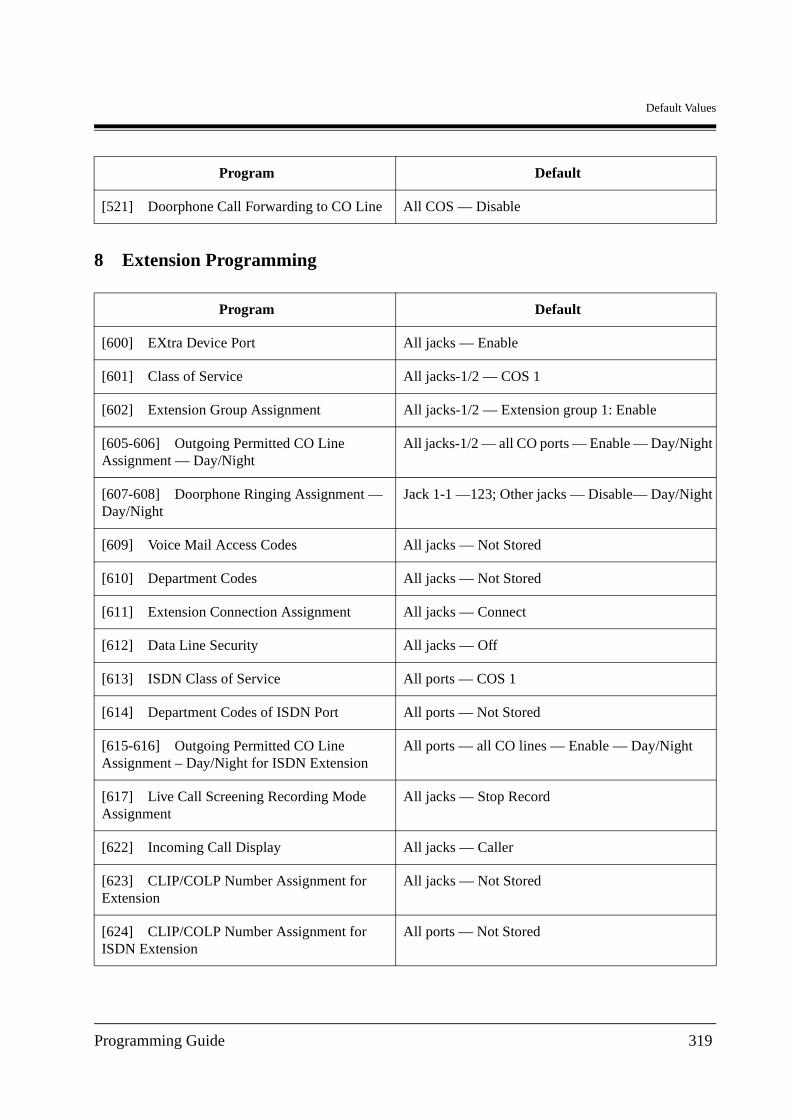
Default Values
8 Extension Programming
[521] Doorphone Call Forwarding to CO Line All COS — Disable
Program Default
[600] EXtra Device Port All jacks — Enable
[601] Class of Service All jacks-1/2 — COS 1
[602] Extension Group Assignment All jacks-1/2 — Extension group 1: Enable
[605-606] Outgoing Permitted CO Line Assignment — Day/Night
All jacks-1/2 — all CO ports — Enable — Day/Night
[607-608] Doorphone Ringing Assignment — Day/Night
Jack 1-1 —123; Other jacks — Disable— Day/Night
[609] Voice Mail Access Codes All jacks — Not Stored
[610] Department Codes All jacks — Not Stored
[611] Extension Connection Assignment All jacks — Connect
[612] Data Line Security All jacks — Off
[613] ISDN Class of Service All ports — COS 1
[614] Department Codes of ISDN Port All ports — Not Stored
[615-616] Outgoing Permitted CO Line Assignment – Day/Night for ISDN Extension
All ports — all CO lines — Enable — Day/Night
[617] Live Call Screening Recording Mode Assignment
All jacks — Stop Record
[622] Incoming Call Display All jacks — Caller
[623] CLIP/COLP Number Assignment for Extension
All jacks — Not Stored
[624] CLIP/COLP Number Assignment for ISDN Extension
All ports — Not Stored
Program Default
Programming Guide 319
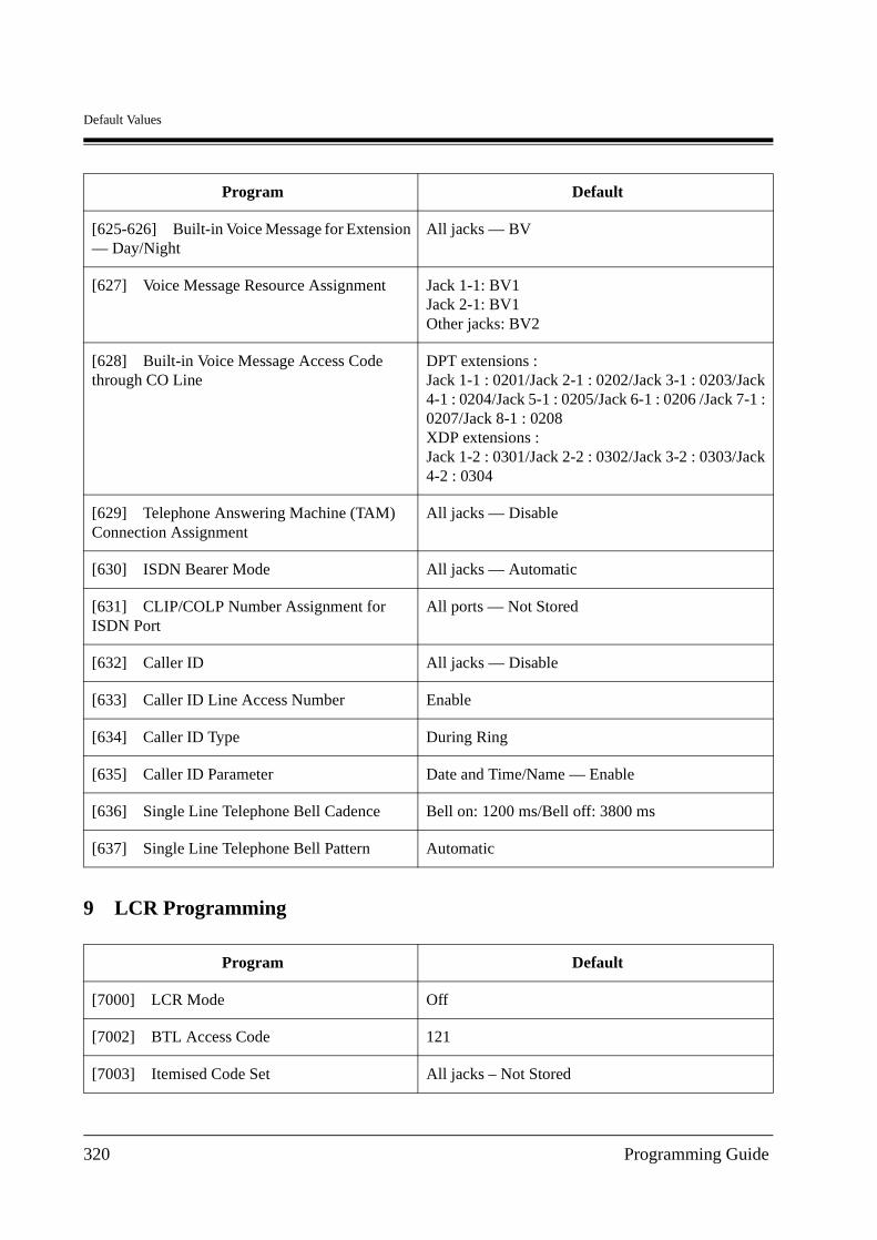
Default Values
9 LCR Programming
[625-626] Built-in Voice Message for Extension — Day/Night
All jacks — BV
[627] Voice Message Resource Assignment Jack 1-1: BV1Jack 2-1: BV1Other jacks: BV2
[628] Built-in Voice Message Access Code through CO Line
DPT extensions : Jack 1-1 : 0201/Jack 2-1 : 0202/Jack 3-1 : 0203/Jack 4-1 : 0204/Jack 5-1 : 0205/Jack 6-1 : 0206 /Jack 7-1 : 0207/Jack 8-1 : 0208XDP extensions :Jack 1-2 : 0301/Jack 2-2 : 0302/Jack 3-2 : 0303/Jack 4-2 : 0304
[629] Telephone Answering Machine (TAM) Connection Assignment
All jacks — Disable
[630] ISDN Bearer Mode All jacks — Automatic
[631] CLIP/COLP Number Assignment for ISDN Port
All ports — Not Stored
[632] Caller ID All jacks — Disable
[633] Caller ID Line Access Number Enable
[634] Caller ID Type During Ring
[635] Caller ID Parameter Date and Time/Name — Enable
[636] Single Line Telephone Bell Cadence Bell on: 1200 ms/Bell off: 3800 ms
[637] Single Line Telephone Bell Pattern Automatic
Program Default
[7000] LCR Mode Off
[7002] BTL Access Code 121
[7003] Itemised Code Set All jacks – Not Stored
Program Default
320 Programming Guide
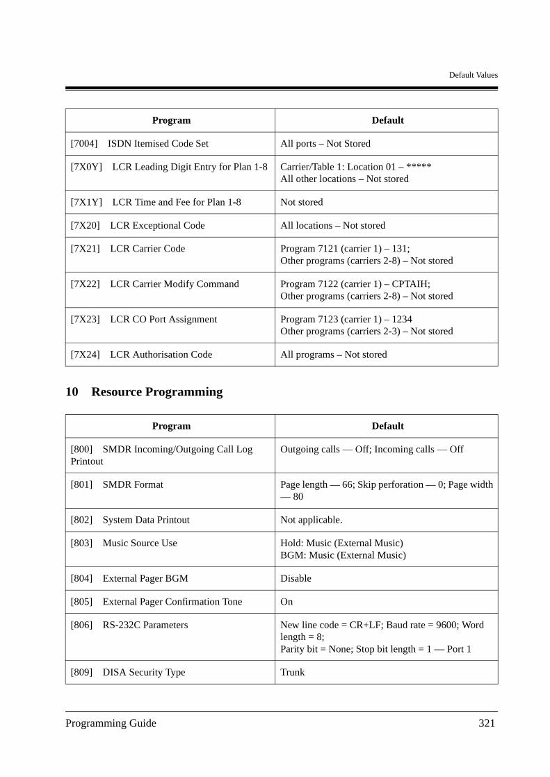
Default Values
10 Resource Programming
[7004] ISDN Itemised Code Set All ports – Not Stored
[7X0Y] LCR Leading Digit Entry for Plan 1-8 Carrier/Table 1: Location 01 – *****All other locations – Not stored
[7X1Y] LCR Time and Fee for Plan 1-8 Not stored
[7X20] LCR Exceptional Code All locations – Not stored
[7X21] LCR Carrier Code Program 7121 (carrier 1) – 131; Other programs (carriers 2-8) – Not stored
[7X22] LCR Carrier Modify Command Program 7122 (carrier 1) – CPTAIH;Other programs (carriers 2-8) – Not stored
[7X23] LCR CO Port Assignment Program 7123 (carrier 1) – 1234Other programs (carriers 2-3) – Not stored
[7X24] LCR Authorisation Code All programs – Not stored
Program Default
[800] SMDR Incoming/Outgoing Call Log Printout
Outgoing calls — Off; Incoming calls — Off
[801] SMDR Format Page length — 66; Skip perforation — 0; Page width — 80
[802] System Data Printout Not applicable.
[803] Music Source Use Hold: Music (External Music)BGM: Music (External Music)
[804] External Pager BGM Disable
[805] External Pager Confirmation Tone On
[806] RS-232C Parameters New line code = CR+LF; Baud rate = 9600; Word length = 8;Parity bit = None; Stop bit length = 1 — Port 1
[809] DISA Security Type Trunk
Program Default
Programming Guide 321
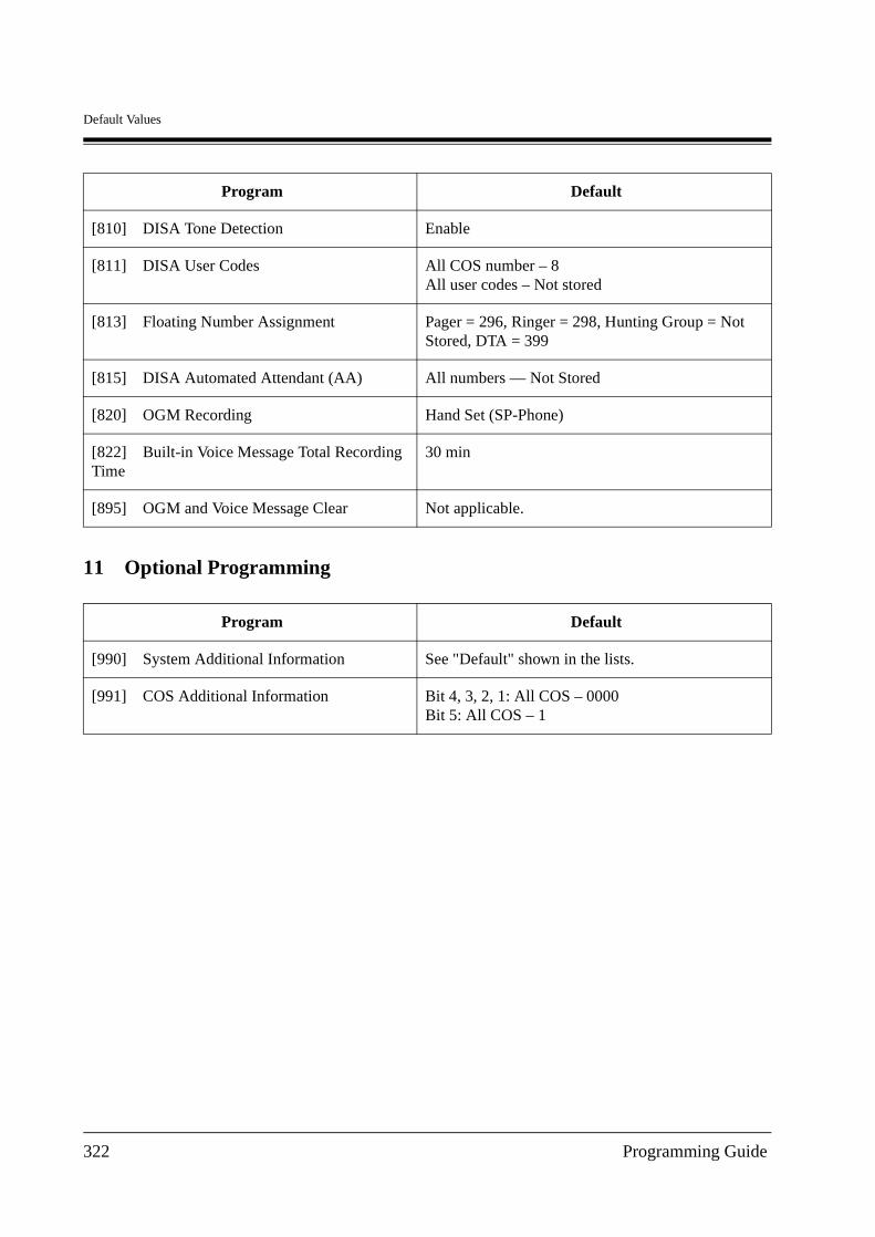
Default Values
11 Optional Programming
[810] DISA Tone Detection Enable
[811] DISA User Codes All COS number – 8All user codes – Not stored
[813] Floating Number Assignment Pager = 296, Ringer = 298, Hunting Group = Not Stored, DTA = 399
[815] DISA Automated Attendant (AA) All numbers — Not Stored
[820] OGM Recording Hand Set (SP-Phone)
[822] Built-in Voice Message Total Recording Time
30 min
[895] OGM and Voice Message Clear Not applicable.
Program Default
[990] System Additional Information See "Default" shown in the lists.
[991] COS Additional Information Bit 4, 3, 2, 1: All COS – 0000Bit 5: All COS – 1
Program Default
322 Programming Guide

Default Values
Programming Guide 323

Printed in Japan PSQX2069XA
This Equipment complies with the essential requirements of the Directive 1999/5/EC Radio and telecommunications terminal equipment directive.
KK1100EP2032
Copyright:This manual is copyrighted by Kyushu Matsushita Electric Co., Ltd. (KME). You may print out this manual solely for internal use with this model. Except above, you may not reproduce this manual in any form, in whole or part, without the prior written consent of KME and its licensee.
2000 Kyushu Matsushita Electric Co., Ltd. All Rights Reserved.
Panasonic Business Systems U.K.Panasonic House, Willoughby Road, Bracknell,Berkshire RG12 8FP