programmable ph controller - lakewood instruments
TRANSCRIPT
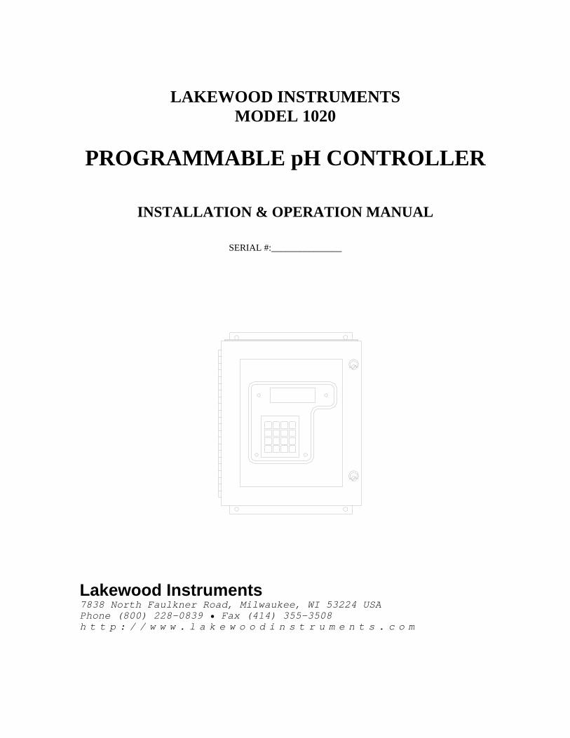
LAKEWOOD INSTRUMENTS MODEL 1020
PROGRAMMABLE pH CONTROLLER
INSTALLATION & OPERATION MANUAL
SERIAL #:_______________
Lakewood Instruments 7838 North Faulkner Road, Milwaukee, WI 53224 USA Phone (800) 228-0839 • Fax (414) 355-3508 h t t p : / / w w w . l a k e w o o d i n s t r u m e n t s . c o m
Lakewood Instruments
Congratulations on your purchase of a Lakewood Instruments product. We would like to take this opportunity to welcome you to the Lakewood Instruments product family. With proper care and maintenance, your product should give you trouble-free service. Please take the time to read and understand the operation manual, paying special attention to the sections on INSTALLATION and MAINTENANCE. If, in the future, any parts or repairs are required, we strongly recommend that only original replacement parts be used. Our Customer Service Department would be happy to assist you with your parts or service requests. We thank you for your selection and purchase of an Lakewood Instruments product.
1

2
MODEL 1020
Table of Contents GENERAL DESCRIPTION 5
START UP 6
DISPLAY MENUS 7 Main Menu ............................................................................................................. 7 Display Process .................................................................................................... 8 Manual Operation .................................................................................................. 10 Review Calibrations .............................................................................................. 11 Change Set Point ................................................................................................... 12 Set Alarm ............................................................................................................... 13 Calibrate One Point ............................................................................................... 14 Calibrate Two Points ............................................................................................. 15 Run Auto-Retract .................................................................................................. 16 Diagnostics ............................................................................................................ 17 Verify RAM/EEPROM .............................................................................. 17 Test Inputs .................................................................................................. 18 Test Outputs ............................................................................................... 19 System Set Up ....................................................................................................... 22 Output Control ........................................................................................... 23 Initialization ............................................................................................... 27 Retract ....................................................................................................... 28 Recorder .................................................................................................... 32 TECHNICAL DESCRIPTION 34 MAINTENANCE 35 TROUBLESHOOTING 36 DRAWINGS 38
3

4
GENERAL DESCRIPTION The model 1020 is a programmable pH Controller that drives relay outputs and 4-20 mA outputs to adjust the pH according to one of the following control schemes: • Acid/Caustic Output Use this configuration when the system retention time is from 1 to 30 minutes. • PID Output
Use this configuration when a varying input must be adjusted with very low retention time. A unique dual proportional band arrangement permits lower controller gain when the chemical reagent feed gain is high. Use the BANDWIDTH setup to adjust the region of lower gain. PID control consists of three parts: Proportional, Integral, and Derivative.
In addition, the Controller provides automatic cleaning and calibration features. It recognizes the following digital input signals: • Low Cleaner This signal is active when the cleaner solution drum level is low. • Low 4 pH Buffer
This signal is active when the 4 pH buffer solution drum level is low. • Low 7 pH Buffer This signal is active when the 7 pH buffer solution drum level is low. The Controller also outputs the following digital signals: • Low Tank Alarm The Controller asserts this signal when any one (or all) of the Low Cleaner, Low 4 pH Buffer, and Low 7 pH Buffer input signals are active. • Slope Deviation Alarm The Controller asserts this signal following an auto-calibration error. • pH Alarms The Controller asserts up to 3 different signals based on user-programmable high pH and low pH conditions. NOTE: THIS VERSION OF THE 1020 pH CONTROLLER DOES NOT SUPPORT THE FLOW METER OPTION DESCRIBED IN THE PREVIOUS MODEL 1020/1050 COMPUTING pH CONTROLLER INSTRUCTION MANUAL.
5
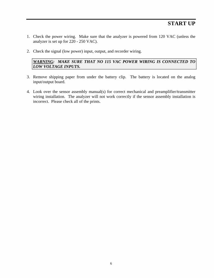
START UP 1. Check the power wiring. Make sure that the analyzer is powered from 120 VAC (unless the
analyzer is set up for 220 - 250 VAC). 2. Check the signal (low power) input, output, and recorder wiring.
WARNING: MAKE SURE THAT NO 115 VAC POWER WIRING IS CONNECTED TO LOW VOLTAGE INPUTS.
3. Remove shipping paper from under the battery clip. The battery is located on the analog
input/output board. 4. Look over the sensor assembly manual(s) for correct mechanical and preamplifier/transmitter
wiring installation. The analyzer will not work correctly if the sensor assembly installation is incorrect. Please check all of the prints.
6
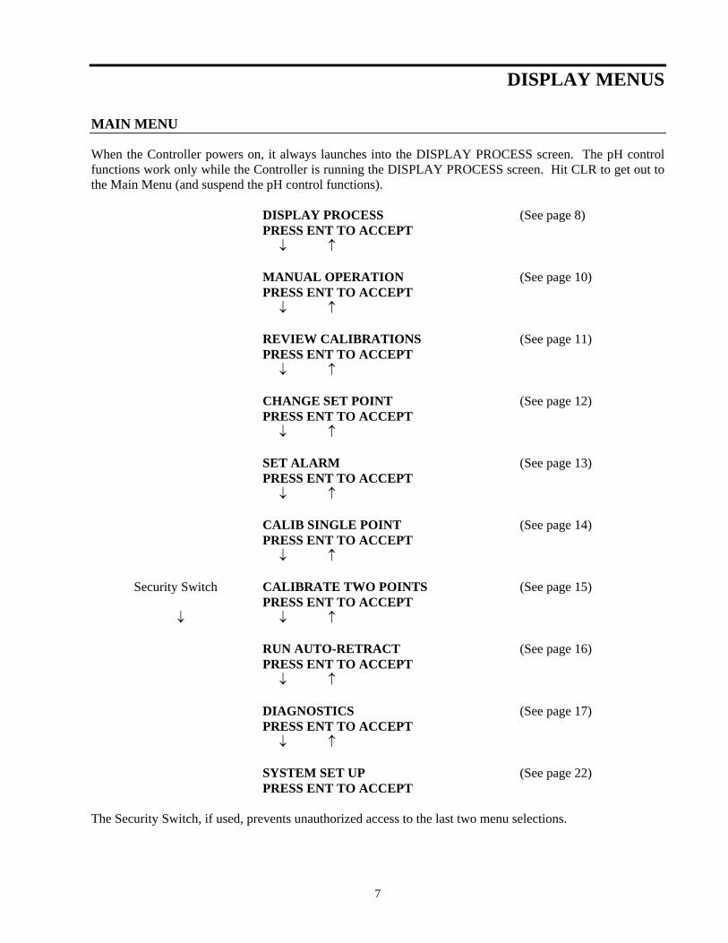
DISPLAY MENUS MAIN MENU When the Controller powers on, it always launches into the DISPLAY PROCESS screen. The pH control functions work only while the Controller is running the DISPLAY PROCESS screen. Hit CLR to get out to the Main Menu (and suspend the pH control functions). DISPLAY PROCESS (See page 8) PRESS ENT TO ACCEPT ↓ ↑ MANUAL OPERATION (See page 10) PRESS ENT TO ACCEPT ↓ ↑ REVIEW CALIBRATIONS (See page 11) PRESS ENT TO ACCEPT ↓ ↑ CHANGE SET POINT (See page 12) PRESS ENT TO ACCEPT ↓ ↑ SET ALARM (See page 13) PRESS ENT TO ACCEPT ↓ ↑ CALIB SINGLE POINT (See page 14) PRESS ENT TO ACCEPT ↓ ↑ Security Switch CALIBRATE TWO POINTS (See page 15) PRESS ENT TO ACCEPT ↓ ↓ ↑ RUN AUTO-RETRACT (See page 16) PRESS ENT TO ACCEPT ↓ ↑ DIAGNOSTICS (See page 17) PRESS ENT TO ACCEPT ↓ ↑ SYSTEM SET UP (See page 22) PRESS ENT TO ACCEPT The Security Switch, if used, prevents unauthorized access to the last two menu selections.
7
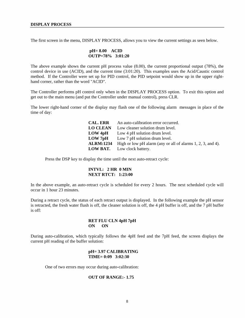
DISPLAY PROCESS The first screen in the menu, DISPLAY PROCESS, allows you to view the current settings as seen below. pH= 8.00 ACID OUTP=78% 3:01:20 The above example shows the current pH process value (8.00), the current proportional output (78%), the control device in use (ACID), and the current time (3:01:20). This examples uses the Acid/Caustic control method. If the Controller were set up for PID control, the PID setpoint would show up in the upper right-hand corner, rather than the word "ACID". The Controller performs pH control only when in the DISPLAY PROCESS option. To exit this option and get out to the main menu (and put the Controller under manual control), press CLR. The lower right-hand corner of the display may flash one of the following alarm messages in place of the time of day: CAL. ERR An auto-calibration error occurred. LO CLEAN Low cleaner solution drum level. LOW 4pH Low 4 pH solution drum level. LOW 7pH Low 7 pH solution drum level. ALRM:1234 High or low pH alarm (any or all of alarms 1, 2, 3, and 4). LOW BAT. Low clock battery. Press the DSP key to display the time until the next auto-retract cycle: INTVL: 2 HR 0 MIN NEXT RTCT: 1:23:00 In the above example, an auto-retract cycle is scheduled for every 2 hours. The next scheduled cycle will occur in 1 hour 23 minutes. During a retract cycle, the status of each retract output is displayed. In the following example the pH sensor is retracted, the fresh water flush is off, the cleaner solution is off, the 4 pH buffer is off, and the 7 pH buffer is off: RET FLU CLN 4pH 7pH ON ON During auto-calibration, which typically follows the 4pH feed and the 7pH feed, the screen displays the current pH reading of the buffer solution: pH= 3.97 CALIBRATING TIME= 0:09 3:02:30 One of two errors may occur during auto-calibration: OUT OF RANGE:- 1.75
8
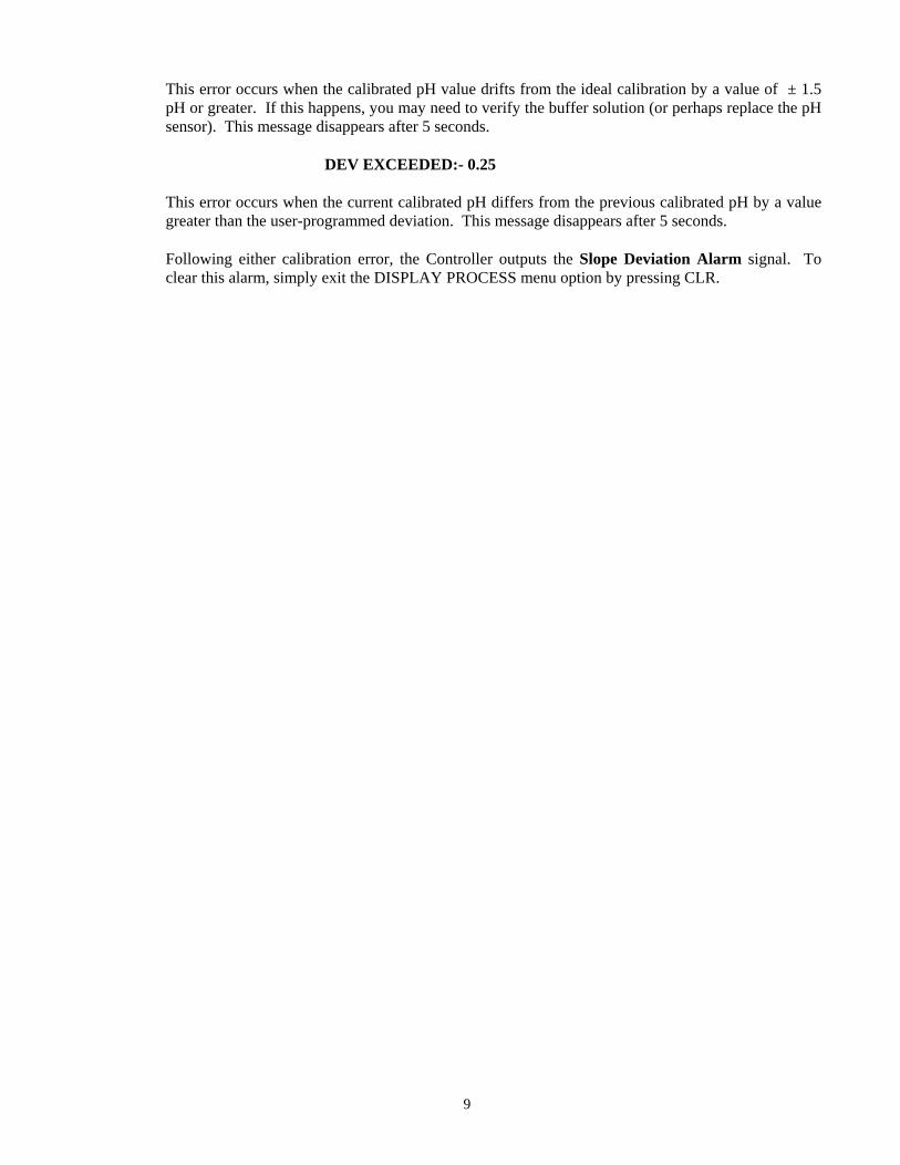
This error occurs when the calibrated pH value drifts from the ideal calibration by a value of ± 1.5 pH or greater. If this happens, you may need to verify the buffer solution (or perhaps replace the pH sensor). This message disappears after 5 seconds.
DEV EXCEEDED:- 0.25
This error occurs when the current calibrated pH differs from the previous calibrated pH by a value greater than the user-programmed deviation. This message disappears after 5 seconds.
Following either calibration error, the Controller outputs the Slope Deviation Alarm signal. To clear this alarm, simply exit the DISPLAY PROCESS menu option by pressing CLR.
9
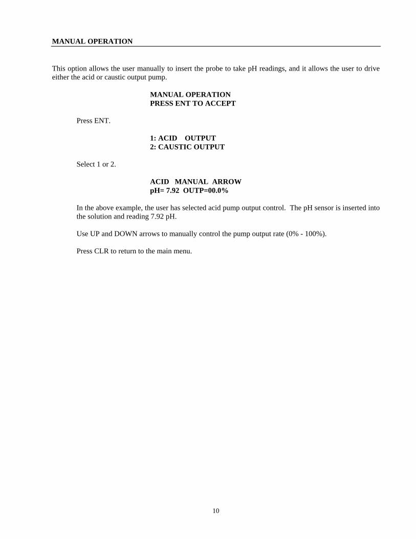
MANUAL OPERATION This option allows the user manually to insert the probe to take pH readings, and it allows the user to drive either the acid or caustic output pump. MANUAL OPERATION PRESS ENT TO ACCEPT Press ENT. 1: ACID OUTPUT 2: CAUSTIC OUTPUT Select 1 or 2. ACID MANUAL ARROW pH= 7.92 OUTP=00.0%
In the above example, the user has selected acid pump output control. The pH sensor is inserted into the solution and reading 7.92 pH.
Use UP and DOWN arrows to manually control the pump output rate (0% - 100%). Press CLR to return to the main menu.
10
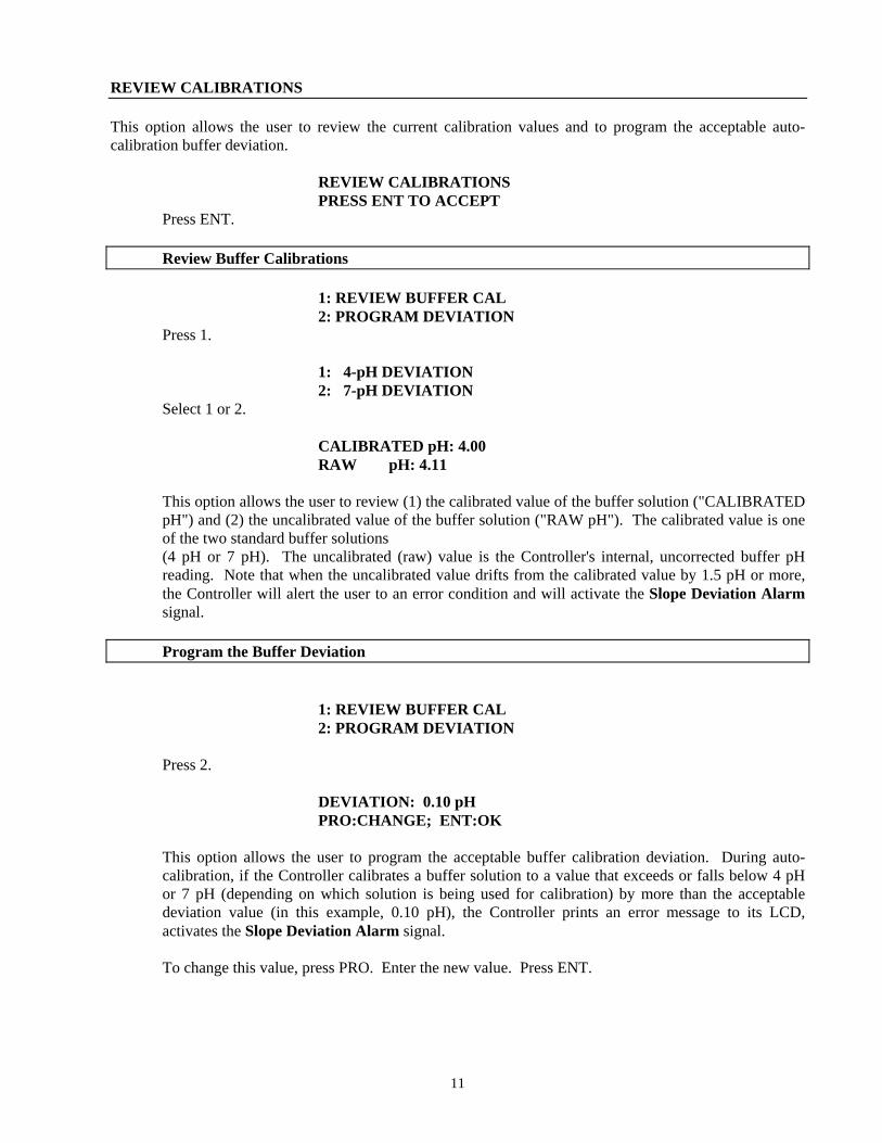
REVIEW CALIBRATIONS This option allows the user to review the current calibration values and to program the acceptable auto-calibration buffer deviation. REVIEW CALIBRATIONS PRESS ENT TO ACCEPT Press ENT. Review Buffer Calibrations 1: REVIEW BUFFER CAL 2: PROGRAM DEVIATION Press 1. 1: 4-pH DEVIATION 2: 7-pH DEVIATION Select 1 or 2. CALIBRATED pH: 4.00 RAW pH: 4.11
This option allows the user to review (1) the calibrated value of the buffer solution ("CALIBRATED pH") and (2) the uncalibrated value of the buffer solution ("RAW pH"). The calibrated value is one of the two standard buffer solutions (4 pH or 7 pH). The uncalibrated (raw) value is the Controller's internal, uncorrected buffer pH reading. Note that when the uncalibrated value drifts from the calibrated value by 1.5 pH or more, the Controller will alert the user to an error condition and will activate the Slope Deviation Alarm signal.
Program the Buffer Deviation 1: REVIEW BUFFER CAL 2: PROGRAM DEVIATION Press 2. DEVIATION: 0.10 pH PRO:CHANGE; ENT:OK
This option allows the user to program the acceptable buffer calibration deviation. During auto-calibration, if the Controller calibrates a buffer solution to a value that exceeds or falls below 4 pH or 7 pH (depending on which solution is being used for calibration) by more than the acceptable deviation value (in this example, 0.10 pH), the Controller prints an error message to its LCD, activates the Slope Deviation Alarm signal.
To change this value, press PRO. Enter the new value. Press ENT.
11
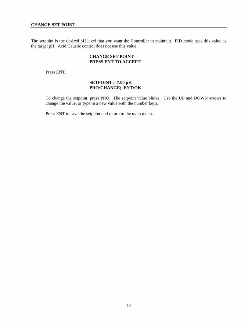
CHANGE SET POINT The setpoint is the desired pH level that you want the Controller to maintain. PID mode uses this value as the target pH. Acid/Caustic control does not use this value. CHANGE SET POINT PRESS ENT TO ACCEPT Press ENT. SETPOINT : 7.00 pH PRO:CHANGE; ENT:OK
To change the setpoint, press PRO. The setpoint value blinks. Use the UP and DOWN arrows to change the value, or type in a new value with the number keys.
Press ENT to save the setpoint and return to the main menu.
12
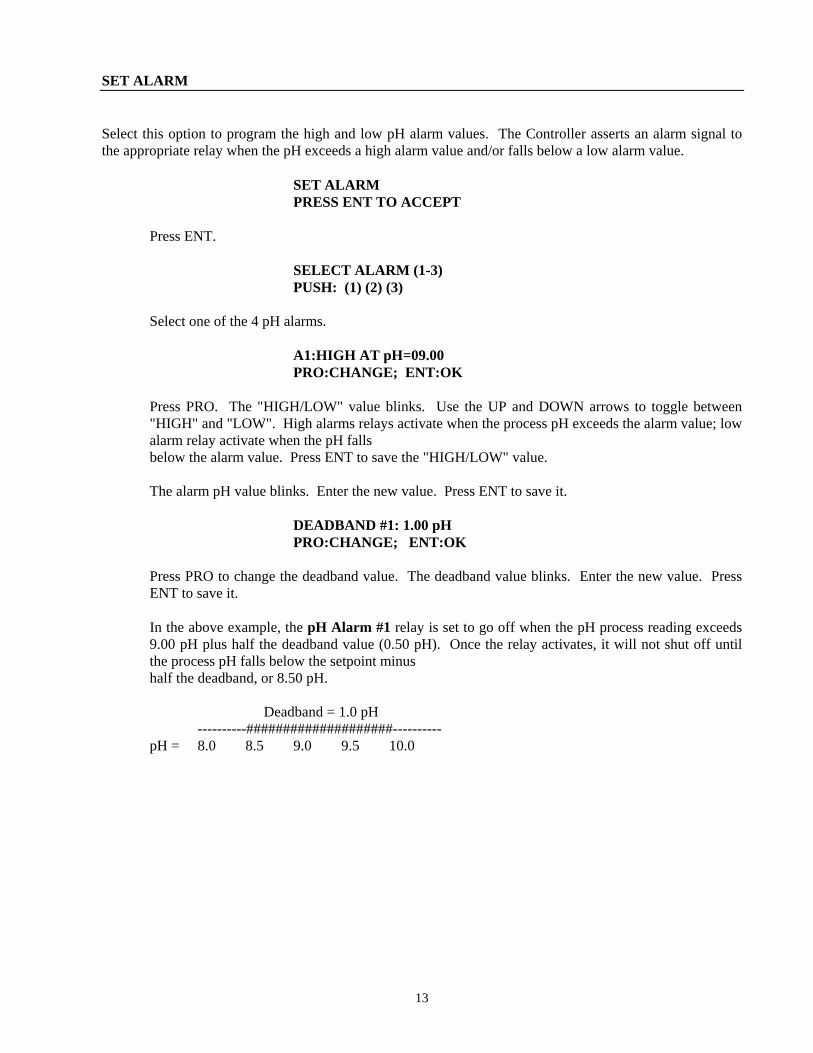
SET ALARM Select this option to program the high and low pH alarm values. The Controller asserts an alarm signal to the appropriate relay when the pH exceeds a high alarm value and/or falls below a low alarm value. SET ALARM PRESS ENT TO ACCEPT Press ENT. SELECT ALARM (1-3) PUSH: (1) (2) (3) Select one of the 4 pH alarms. A1:HIGH AT pH=09.00 PRO:CHANGE; ENT:OK
Press PRO. The "HIGH/LOW" value blinks. Use the UP and DOWN arrows to toggle between "HIGH" and "LOW". High alarms relays activate when the process pH exceeds the alarm value; low alarm relay activate when the pH falls
below the alarm value. Press ENT to save the "HIGH/LOW" value. The alarm pH value blinks. Enter the new value. Press ENT to save it. DEADBAND #1: 1.00 pH PRO:CHANGE; ENT:OK
Press PRO to change the deadband value. The deadband value blinks. Enter the new value. Press ENT to save it.
In the above example, the pH Alarm #1 relay is set to go off when the pH process reading exceeds 9.00 pH plus half the deadband value (0.50 pH). Once the relay activates, it will not shut off until the process pH falls below the setpoint minus
half the deadband, or 8.50 pH. Deadband = 1.0 pH ----------####################---------- pH = 8.0 8.5 9.0 9.5 10.0
13
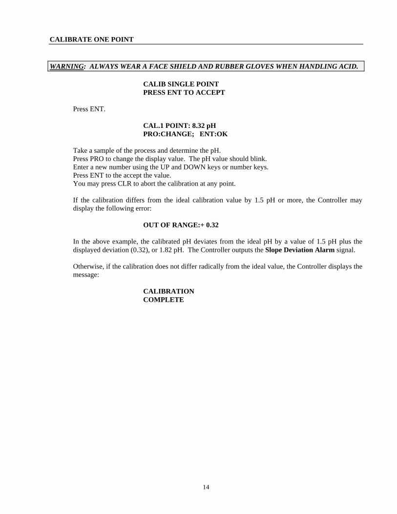
CALIBRATE ONE POINT WARNING: ALWAYS WEAR A FACE SHIELD AND RUBBER GLOVES WHEN HANDLING ACID. CALIB SINGLE POINT PRESS ENT TO ACCEPT Press ENT. CAL.1 POINT: 8.32 pH PRO:CHANGE; ENT:OK Take a sample of the process and determine the pH. Press PRO to change the display value. The pH value should blink. Enter a new number using the UP and DOWN keys or number keys. Press ENT to the accept the value. You may press CLR to abort the calibration at any point.
If the calibration differs from the ideal calibration value by 1.5 pH or more, the Controller may display the following error:
OUT OF RANGE:+ 0.32
In the above example, the calibrated pH deviates from the ideal pH by a value of 1.5 pH plus the displayed deviation (0.32), or 1.82 pH. The Controller outputs the Slope Deviation Alarm signal.
Otherwise, if the calibration does not differ radically from the ideal value, the Controller displays the message:
CALIBRATION COMPLETE
14
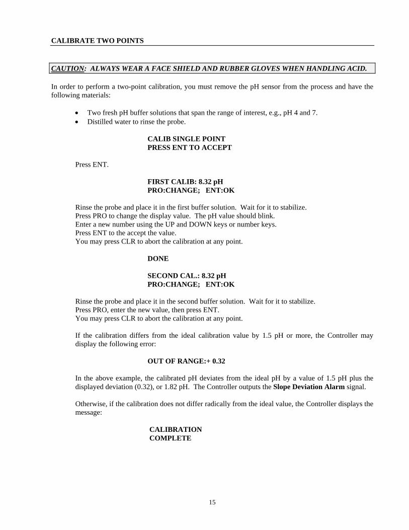
CALIBRATE TWO POINTS CAUTION: ALWAYS WEAR A FACE SHIELD AND RUBBER GLOVES WHEN HANDLING ACID. In order to perform a two-point calibration, you must remove the pH sensor from the process and have the following materials:
• Two fresh pH buffer solutions that span the range of interest, e.g., pH 4 and 7. • Distilled water to rinse the probe.
CALIB SINGLE POINT PRESS ENT TO ACCEPT Press ENT. FIRST CALIB: 8.32 pH PRO:CHANGE; ENT:OK Rinse the probe and place it in the first buffer solution. Wait for it to stabilize. Press PRO to change the display value. The pH value should blink. Enter a new number using the UP and DOWN keys or number keys. Press ENT to the accept the value. You may press CLR to abort the calibration at any point. DONE SECOND CAL.: 8.32 pH PRO:CHANGE; ENT:OK Rinse the probe and place it in the second buffer solution. Wait for it to stabilize. Press PRO, enter the new value, then press ENT. You may press CLR to abort the calibration at any point.
If the calibration differs from the ideal calibration value by 1.5 pH or more, the Controller may display the following error:
OUT OF RANGE:+ 0.32
In the above example, the calibrated pH deviates from the ideal pH by a value of 1.5 pH plus the displayed deviation (0.32), or 1.82 pH. The Controller outputs the Slope Deviation Alarm signal.
Otherwise, if the calibration does not differ radically from the ideal value, the Controller displays the message:
CALIBRATION COMPLETE
15
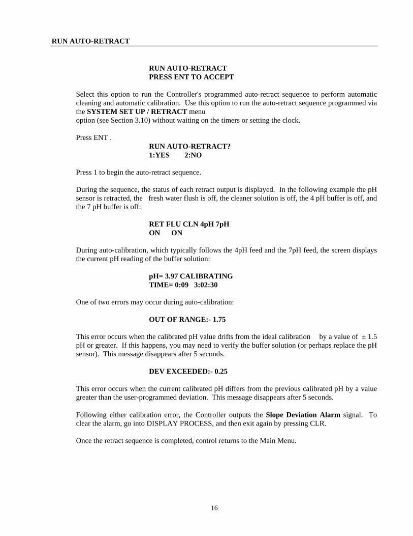
RUN AUTO-RETRACT RUN AUTO-RETRACT PRESS ENT TO ACCEPT
Select this option to run the Controller's programmed auto-retract sequence to perform automatic cleaning and automatic calibration. Use this option to run the auto-retract sequence programmed via the SYSTEM SET UP / RETRACT menu
option (see Section 3.10) without waiting on the timers or setting the clock. Press ENT . RUN AUTO-RETRACT? 1:YES 2:NO Press 1 to begin the auto-retract sequence.
During the sequence, the status of each retract output is displayed. In the following example the pH sensor is retracted, the fresh water flush is off, the cleaner solution is off, the 4 pH buffer is off, and the 7 pH buffer is off:
RET FLU CLN 4pH 7pH ON ON
During auto-calibration, which typically follows the 4pH feed and the 7pH feed, the screen displays the current pH reading of the buffer solution:
pH= 3.97 CALIBRATING TIME= 0:09 3:02:30 One of two errors may occur during auto-calibration: OUT OF RANGE:- 1.75
This error occurs when the calibrated pH value drifts from the ideal calibration by a value of ± 1.5 pH or greater. If this happens, you may need to verify the buffer solution (or perhaps replace the pH sensor). This message disappears after 5 seconds.
DEV EXCEEDED:- 0.25
This error occurs when the current calibrated pH differs from the previous calibrated pH by a value greater than the user-programmed deviation. This message disappears after 5 seconds.
Following either calibration error, the Controller outputs the Slope Deviation Alarm signal. To clear the alarm, go into DISPLAY PROCESS, and then exit again by pressing CLR.
Once the retract sequence is completed, control returns to the Main Menu.
16
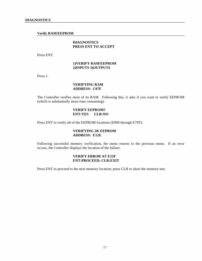
DIAGNOSTICS
Verify RAM/EEPROM DIAGNOSTICS PRESS ENT TO ACCEPT Press ENT. 1)VERIFY RAM/EEPROM 2)INPUTS 3)OUTPUTS Press 1. VERIFYING RAM ADDRESS: C07F
The Controller verifies most of its RAM. Following this, it asks if you want to verify EEPROM (which is substantially more time consuming):
VERIFY EEPROM? ENT:YES CLR:NO Press ENT to verify all of the EEPROM locations (E000 through E7FF): VERIFYING 2K EEPROM ADDRESS: E12E
Following successful memory verification, the menu returns to the previous menu. If an error occurs, the Controller displays the location of the failure:
VERIFY ERROR AT E12F ENT:PROCEED; CLR:EXIT Press ENT to proceed to the next memory location; press CLR to abort the memory test.
17
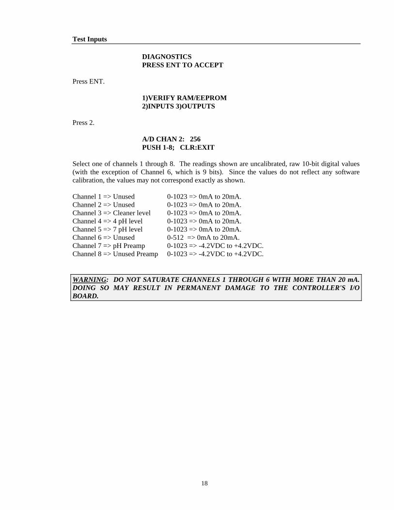
Test Inputs DIAGNOSTICS PRESS ENT TO ACCEPT Press ENT. 1)VERIFY RAM/EEPROM 2)INPUTS 3)OUTPUTS Press 2. A/D CHAN 2: 256 PUSH 1-8; CLR:EXIT
Select one of channels 1 through 8. The readings shown are uncalibrated, raw 10-bit digital values (with the exception of Channel 6, which is 9 bits). Since the values do not reflect any software calibration, the values may not correspond exactly as shown.
Channel 1 => Unused 0-1023 => 0mA to 20mA. Channel 2 => Unused 0-1023 => 0mA to 20mA. Channel 3 => Cleaner level 0-1023 => 0mA to 20mA. Channel 4 => 4 pH level 0-1023 => 0mA to 20mA. Channel 5 => 7 pH level 0-1023 => 0mA to 20mA. Channel 6 => Unused 0-512 => 0mA to 20mA. Channel 7 => pH Preamp 0-1023 => -4.2VDC to +4.2VDC. Channel 8 => Unused Preamp 0-1023 => -4.2VDC to +4.2VDC.
WARNING: DO NOT SATURATE CHANNELS 1 THROUGH 6 WITH MORE THAN 20 mA. DOING SO MAY RESULT IN PERMANENT DAMAGE TO THE CONTROLLER'S I/O BOARD.
18
Test Outputs
Test Relay Outputs
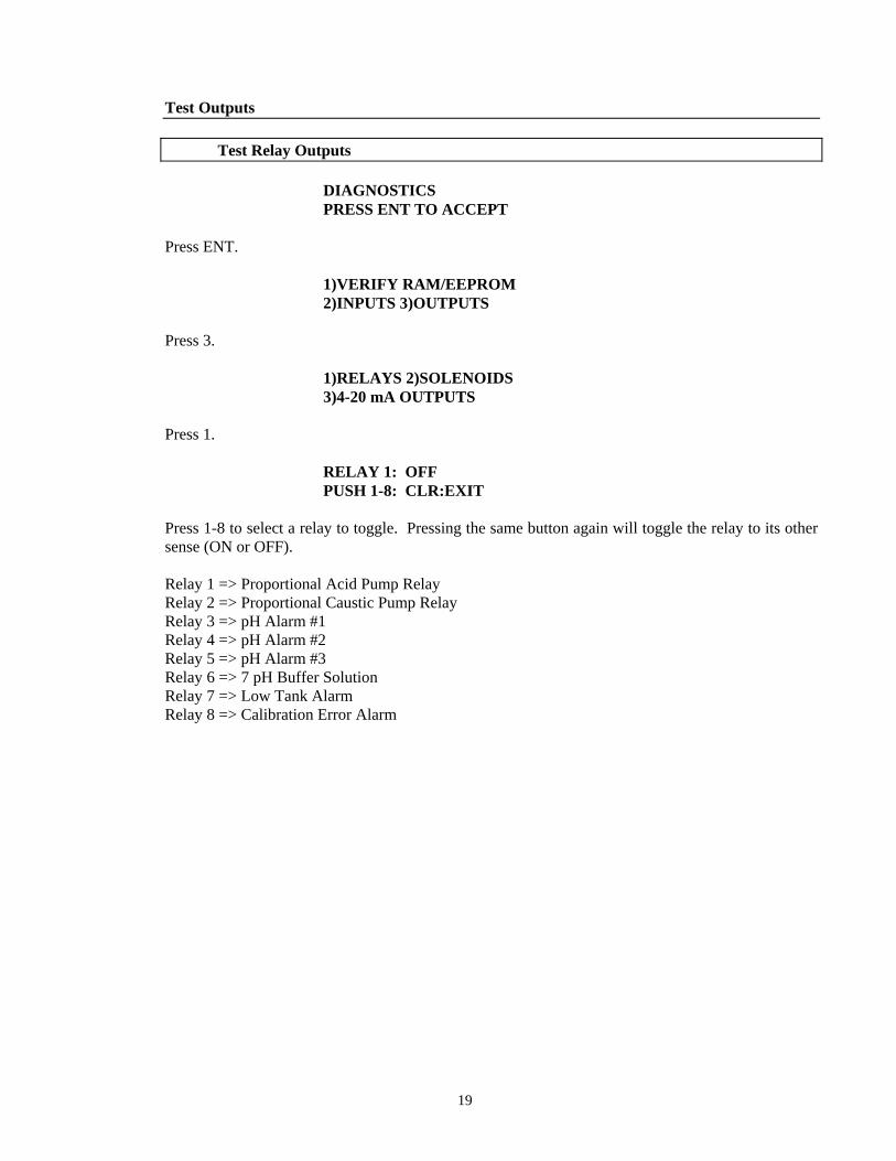
DIAGNOSTICS PRESS ENT TO ACCEPT Press ENT. 1)VERIFY RAM/EEPROM 2)INPUTS 3)OUTPUTS Press 3. 1)RELAYS 2)SOLENOIDS 3)4-20 mA OUTPUTS Press 1. RELAY 1: OFF PUSH 1-8: CLR:EXIT
Press 1-8 to select a relay to toggle. Pressing the same button again will toggle the relay to its other sense (ON or OFF).
Relay 1 => Proportional Acid Pump Relay Relay 2 => Proportional Caustic Pump Relay Relay 3 => pH Alarm #1 Relay 4 => pH Alarm #2 Relay 5 => pH Alarm #3 Relay 6 => 7 pH Buffer Solution Relay 7 => Low Tank Alarm Relay 8 => Calibration Error Alarm
19
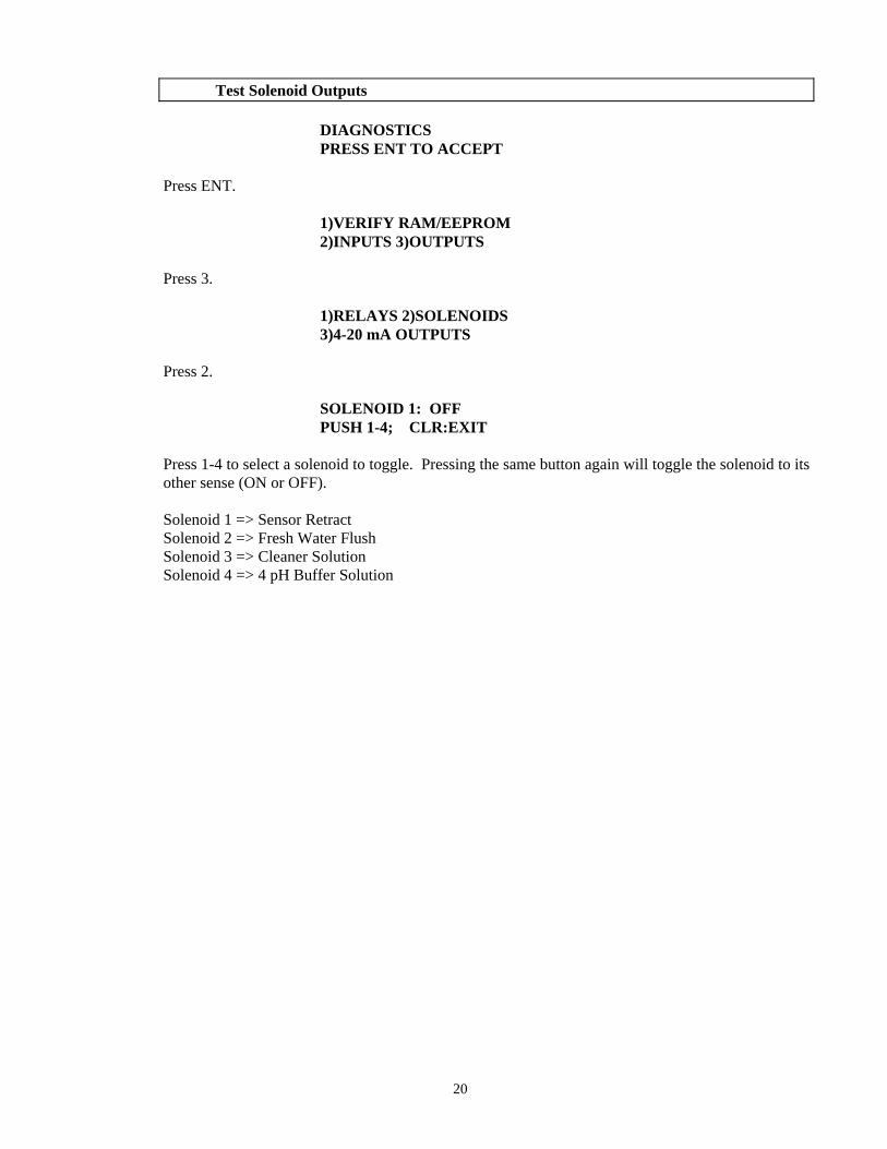
Test Solenoid Outputs DIAGNOSTICS PRESS ENT TO ACCEPT Press ENT. 1)VERIFY RAM/EEPROM 2)INPUTS 3)OUTPUTS Press 3. 1)RELAYS 2)SOLENOIDS 3)4-20 mA OUTPUTS Press 2. SOLENOID 1: OFF PUSH 1-4; CLR:EXIT
Press 1-4 to select a solenoid to toggle. Pressing the same button again will toggle the solenoid to its other sense (ON or OFF).
Solenoid 1 => Sensor Retract Solenoid 2 => Fresh Water Flush Solenoid 3 => Cleaner Solution Solenoid 4 => 4 pH Buffer Solution
20
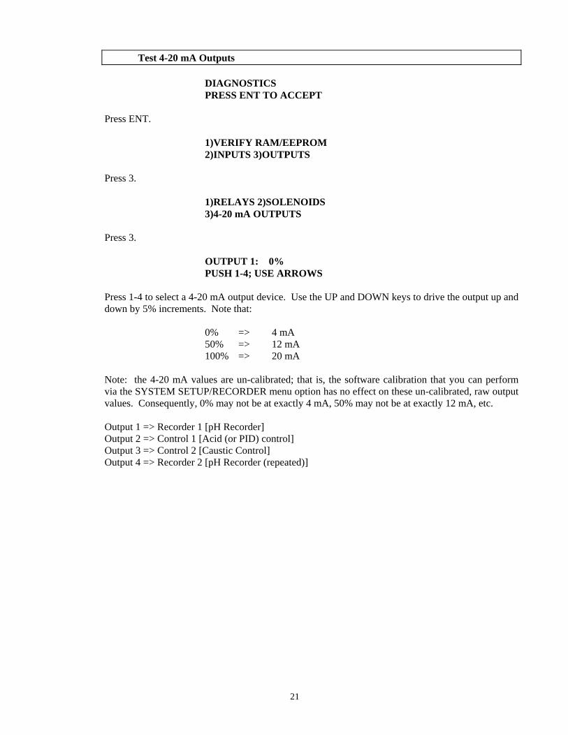
Test 4-20 mA Outputs DIAGNOSTICS PRESS ENT TO ACCEPT Press ENT. 1)VERIFY RAM/EEPROM 2)INPUTS 3)OUTPUTS Press 3. 1)RELAYS 2)SOLENOIDS 3)4-20 mA OUTPUTS Press 3. OUTPUT 1: 0% PUSH 1-4; USE ARROWS
Press 1-4 to select a 4-20 mA output device. Use the UP and DOWN keys to drive the output up and down by 5% increments. Note that:
0% => 4 mA 50% => 12 mA 100% => 20 mA
Note: the 4-20 mA values are un-calibrated; that is, the software calibration that you can perform via the SYSTEM SETUP/RECORDER menu option has no effect on these un-calibrated, raw output values. Consequently, 0% may not be at exactly 4 mA, 50% may not be at exactly 12 mA, etc.
Output 1 => Recorder 1 [pH Recorder] Output 2 => Control 1 [Acid (or PID) control] Output 3 => Control 2 [Caustic Control] Output 4 => Recorder 2 [pH Recorder (repeated)]
21
SYSTEM SET UP SYSTEM SET UP PRESS ENT TO ACCEPT Press ENT. 1)OUTP CONTRL 2)INIT 3)RETRACT 4)RECORDER This option allows the user to initialize various system parameters; namely:
• The acid/caustic and PID proportional feed parameters.
• Initialization of calibrations to factory-set values.
• Setting the clock.
• The automatic cleaning/calibrating retract program.
• The 4-20 mA pH recorder range.
22
Output Control
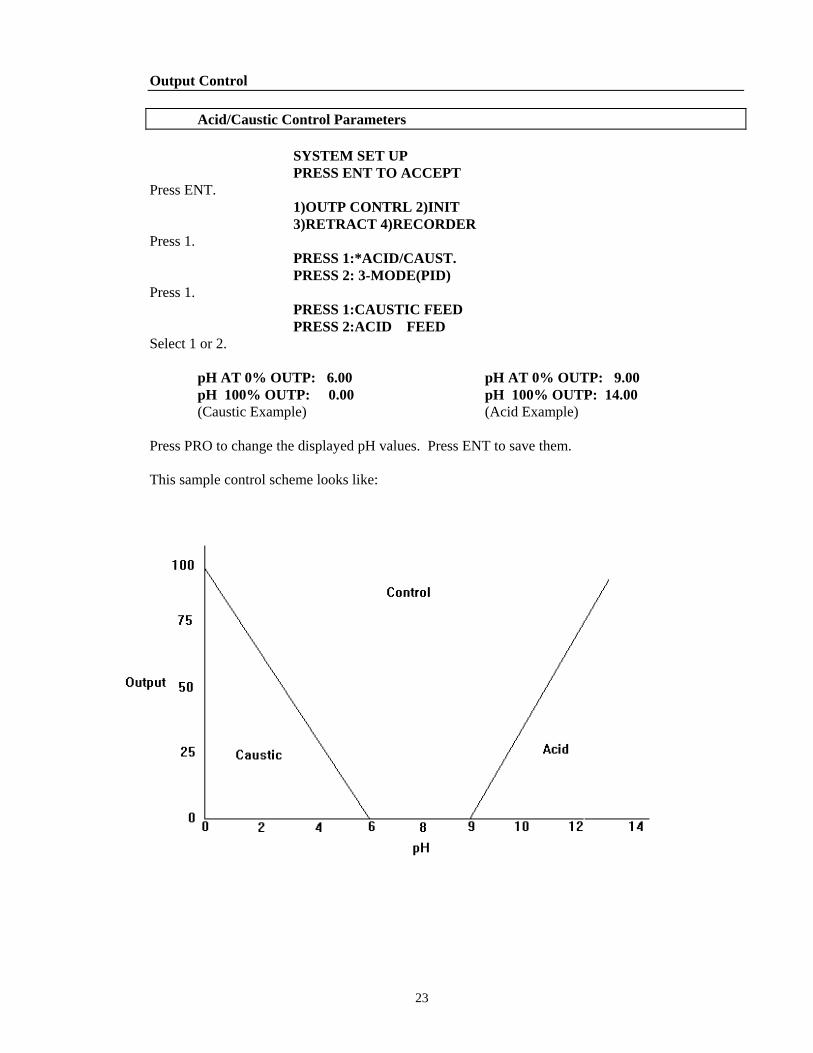
Acid/Caustic Control Parameters SYSTEM SET UP PRESS ENT TO ACCEPT Press ENT. 1)OUTP CONTRL 2)INIT 3)RETRACT 4)RECORDER Press 1. PRESS 1:*ACID/CAUST. PRESS 2: 3-MODE(PID) Press 1. PRESS 1:CAUSTIC FEED PRESS 2:ACID FEED Select 1 or 2. pH AT 0% OUTP: 6.00 pH AT 0% OUTP: 9.00 pH 100% OUTP: 0.00 pH 100% OUTP: 14.00 (Caustic Example) (Acid Example) Press PRO to change the displayed pH values. Press ENT to save them. This sample control scheme looks like:
23
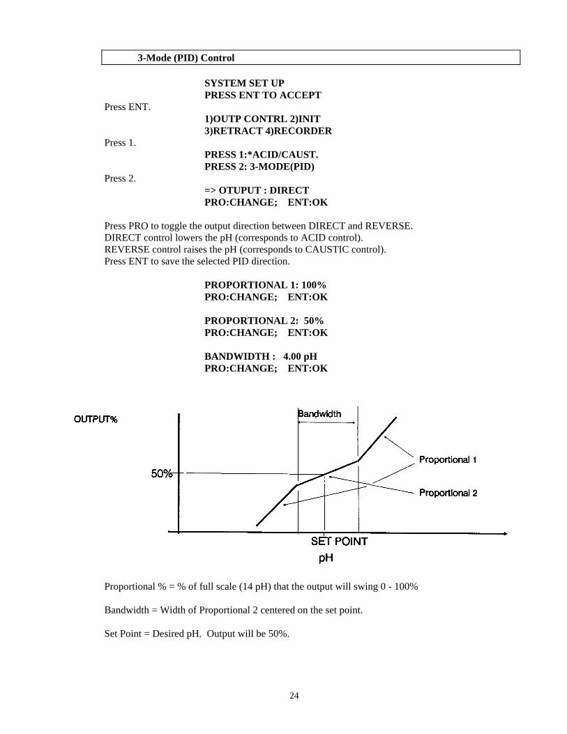
3-Mode (PID) Control SYSTEM SET UP PRESS ENT TO ACCEPT Press ENT. 1)OUTP CONTRL 2)INIT 3)RETRACT 4)RECORDER Press 1. PRESS 1:*ACID/CAUST. PRESS 2: 3-MODE(PID) Press 2. => OTUPUT : DIRECT PRO:CHANGE; ENT:OK Press PRO to toggle the output direction between DIRECT and REVERSE. DIRECT control lowers the pH (corresponds to ACID control). REVERSE control raises the pH (corresponds to CAUSTIC control). Press ENT to save the selected PID direction. PROPORTIONAL 1: 100% PRO:CHANGE; ENT:OK PROPORTIONAL 2: 50% PRO:CHANGE; ENT:OK BANDWIDTH : 4.00 pH PRO:CHANGE; ENT:OK
Proportional % = % of full scale (14 pH) that the output will swing 0 - 100% Bandwidth = Width of Proportional 2 centered on the set point. Set Point = Desired pH. Output will be 50%.
24
USE OF INTEGRAL PRESS 1:*YES 2: NO To use the Integral Term, select 1. RESET TIME: 5 SEC PRO:CHANGE; ENT:OK
The Reset Time (Integral Time) is the time required for the Integral portion to contribute an amount equal to the proportional portion. Press PRO to change the Reset Time. Press ENT to save it.
USE OF DERIVATIVE PRESS 1: YES 2:*NO
We do not recommend using the derivative time for most process control applications. Use this term to compensate for very rapid changes in the process.
25
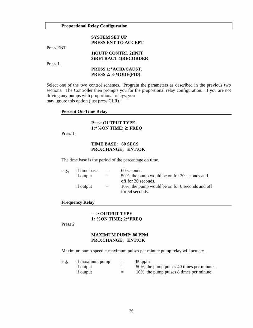
Proportional Relay Configuration SYSTEM SET UP PRESS ENT TO ACCEPT Press ENT. 1)OUTP CONTRL 2)INIT 3)RETRACT 4)RECORDER Press 1. PRESS 1:*ACID/CAUST. PRESS 2: 3-MODE(PID)
Select one of the two control schemes. Program the parameters as described in the previous two sections. The Controller then prompts you for the proportional relay configuration. If you are not driving any pumps with proportional relays, you
may ignore this option (just press CLR).
Percent On-Time Relay P==> OUTPUT TYPE 1:*%ON TIME; 2: FREQ Press 1. TIME BASE: 60 SECS PRO:CHANGE; ENT:OK The time base is the period of the percentage on time. e.g., if time base = 60 seconds if output = 50%, the pump would be on for 30 seconds and off for 30 seconds. if output = 10%, the pump would be on for 6 seconds and off for 54 seconds.
Frequency Relay ==> OUTPUT TYPE 1: %ON TIME; 2:*FREQ Press 2. MAXIMUM PUMP: 80 PPM PRO:CHANGE; ENT:OK Maximum pump speed = maximum pulses per minute pump relay will actuate. e.g, if maximum pump = 80 ppm if output = 50%, the pump pulses 40 times per minute. if output = 10%, the pump pulses 8 times per minute.
26
Initialization
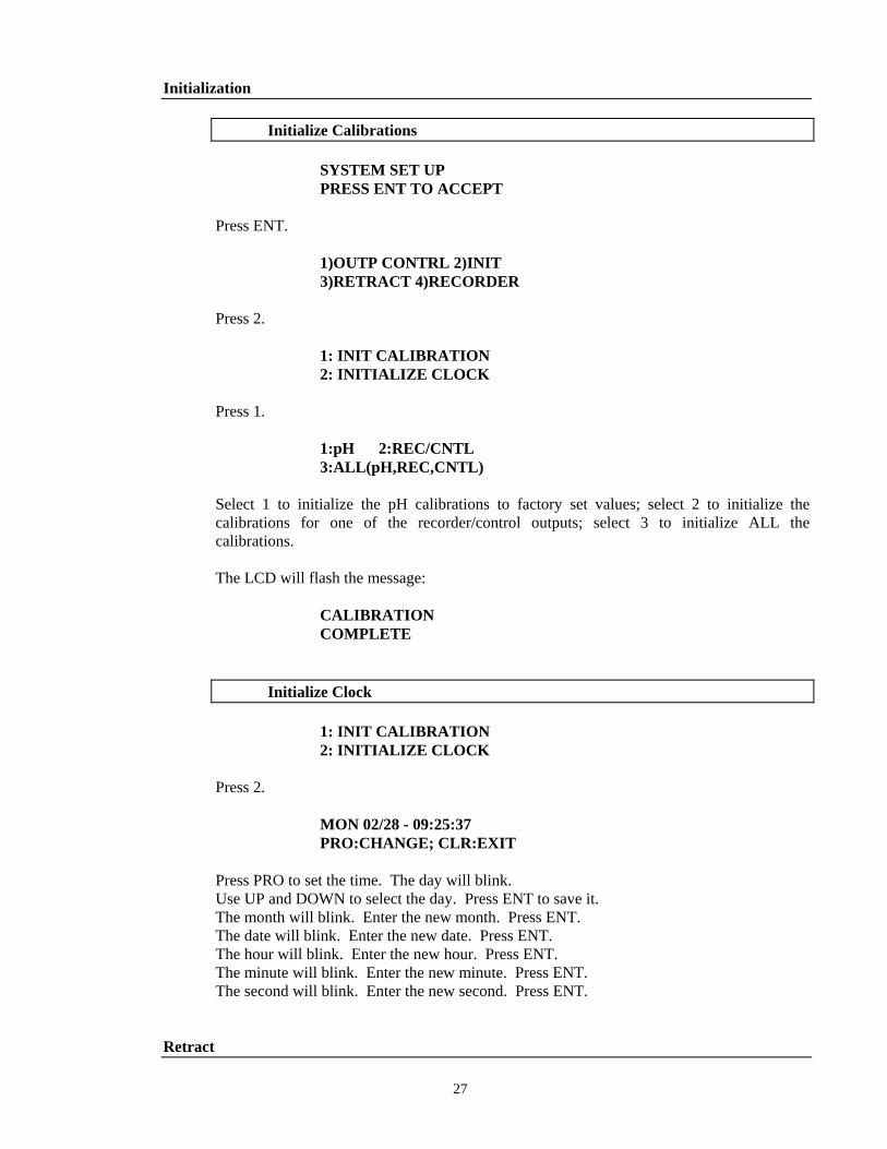
Initialize Calibrations SYSTEM SET UP PRESS ENT TO ACCEPT Press ENT. 1)OUTP CONTRL 2)INIT 3)RETRACT 4)RECORDER Press 2. 1: INIT CALIBRATION 2: INITIALIZE CLOCK Press 1. 1:pH 2:REC/CNTL 3:ALL(pH,REC,CNTL)
Select 1 to initialize the pH calibrations to factory set values; select 2 to initialize the calibrations for one of the recorder/control outputs; select 3 to initialize ALL the calibrations.
The LCD will flash the message: CALIBRATION COMPLETE
Initialize Clock 1: INIT CALIBRATION 2: INITIALIZE CLOCK Press 2. MON 02/28 - 09:25:37 PRO:CHANGE; CLR:EXIT
Press PRO to set the time. The day will blink. Use UP and DOWN to select the day. Press ENT to save it.
The month will blink. Enter the new month. Press ENT. The date will blink. Enter the new date. Press ENT. The hour will blink. Enter the new hour. Press ENT. The minute will blink. Enter the new minute. Press ENT. The second will blink. Enter the new second. Press ENT.
Retract
27
Automatic Retract Features
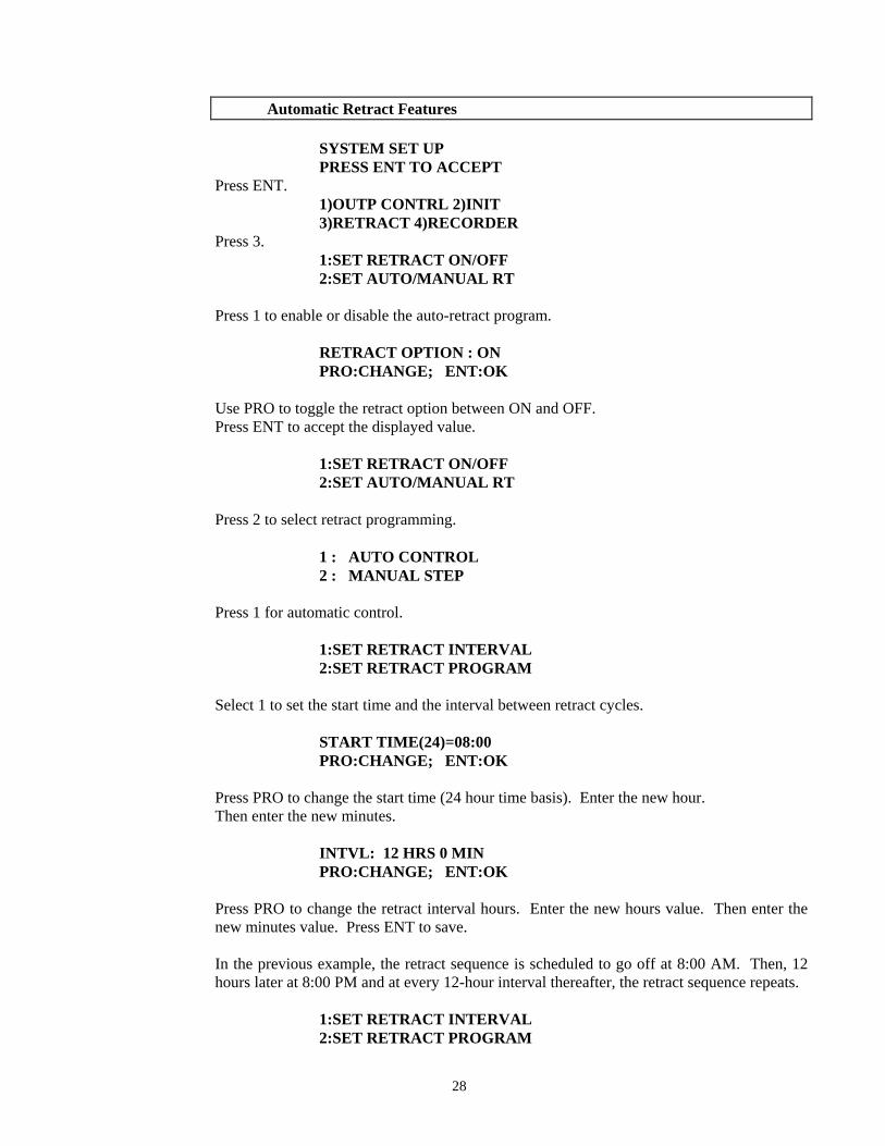
SYSTEM SET UP PRESS ENT TO ACCEPT Press ENT. 1)OUTP CONTRL 2)INIT 3)RETRACT 4)RECORDER Press 3. 1:SET RETRACT ON/OFF 2:SET AUTO/MANUAL RT Press 1 to enable or disable the auto-retract program. RETRACT OPTION : ON PRO:CHANGE; ENT:OK Use PRO to toggle the retract option between ON and OFF. Press ENT to accept the displayed value. 1:SET RETRACT ON/OFF 2:SET AUTO/MANUAL RT Press 2 to select retract programming. 1 : AUTO CONTROL 2 : MANUAL STEP Press 1 for automatic control. 1:SET RETRACT INTERVAL 2:SET RETRACT PROGRAM Select 1 to set the start time and the interval between retract cycles. START TIME(24)=08:00 PRO:CHANGE; ENT:OK Press PRO to change the start time (24 hour time basis). Enter the new hour. Then enter the new minutes. INTVL: 12 HRS 0 MIN PRO:CHANGE; ENT:OK
Press PRO to change the retract interval hours. Enter the new hours value. Then enter the new minutes value. Press ENT to save.
In the previous example, the retract sequence is scheduled to go off at 8:00 AM. Then, 12 hours later at 8:00 PM and at every 12-hour interval thereafter, the retract sequence repeats.
1:SET RETRACT INTERVAL 2:SET RETRACT PROGRAM
28
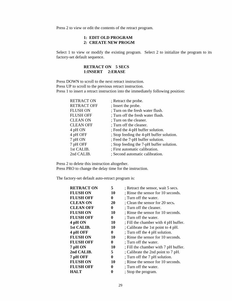
Press 2 to view or edit the contents of the retract program. 1: EDIT OLD PROGRAM 2: CREATE NEW PROGM
Select 1 to view or modify the existing program. Select 2 to initialize the program to its factory-set default sequence.
RETRACT ON 5 SECS 1:INSERT 2:ERASE Press DOWN to scroll to the next retract instruction. Press UP to scroll to the previous retract instruction. Press 1 to insert a retract instruction into the immediately following position:
RETRACT ON ; Retract the probe. RETRACT OFF ; Insert the probe. FLUSH ON ; Turn on the fresh water flush. FLUSH OFF ; Turn off the fresh water flush. CLEAN ON ; Turn on the cleaner. CLEAN OFF ; Turn off the cleaner. 4 pH ON ; Feed the 4-pH buffer solution. 4 pH OFF ; Stop feeding the 4-pH buffer solution. 7 pH ON ; Feed the 7-pH buffer solution. 7 pH OFF ; Stop feeding the 7-pH buffer solution. 1st CALIB. ; First automatic calibration. 2nd CALIB. ; Second automatic calibration.
Press 2 to delete this instruction altogether. Press PRO to change the delay time for the instruction. The factory-set default auto-retract program is: RETRACT ON 5 ; Retract the sensor, wait 5 secs. FLUSH ON 10 ; Rinse the sensor for 10 seconds. FLUSH OFF 0 ; Turn off the water. CLEAN ON 20 ; Clean the sensor for 20 secs. CLEAN OFF 0 ; Turn off the cleaner. FLUSH ON 10 ; Rinse the sensor for 10 seconds. FLUSH OFF 0 ; Turn off the water. 4 pH ON 10 ; Fill the chamber with 4 pH buffer. 1st CALIB. 10 ; Calibrate the 1st point to 4 pH. 4 pH OFF 0 ; Turn off the 4 pH solution. FLUSH ON 10 ; Rinse the sensor for 10 seconds. FLUSH OFF 0 ; Turn off the water. 7 pH ON 10 ; Fill the chamber with 7 pH buffer. 2nd CALIB. 5 ; Calibrate the 2nd point to 7 pH. 7 pH OFF 0 ; Turn off the 7 pH solution. FLUSH ON 10 ; Rinse the sensor for 10 seconds. FLUSH OFF 0 ; Turn off the water. HALT 0 ; Stop the program.
29
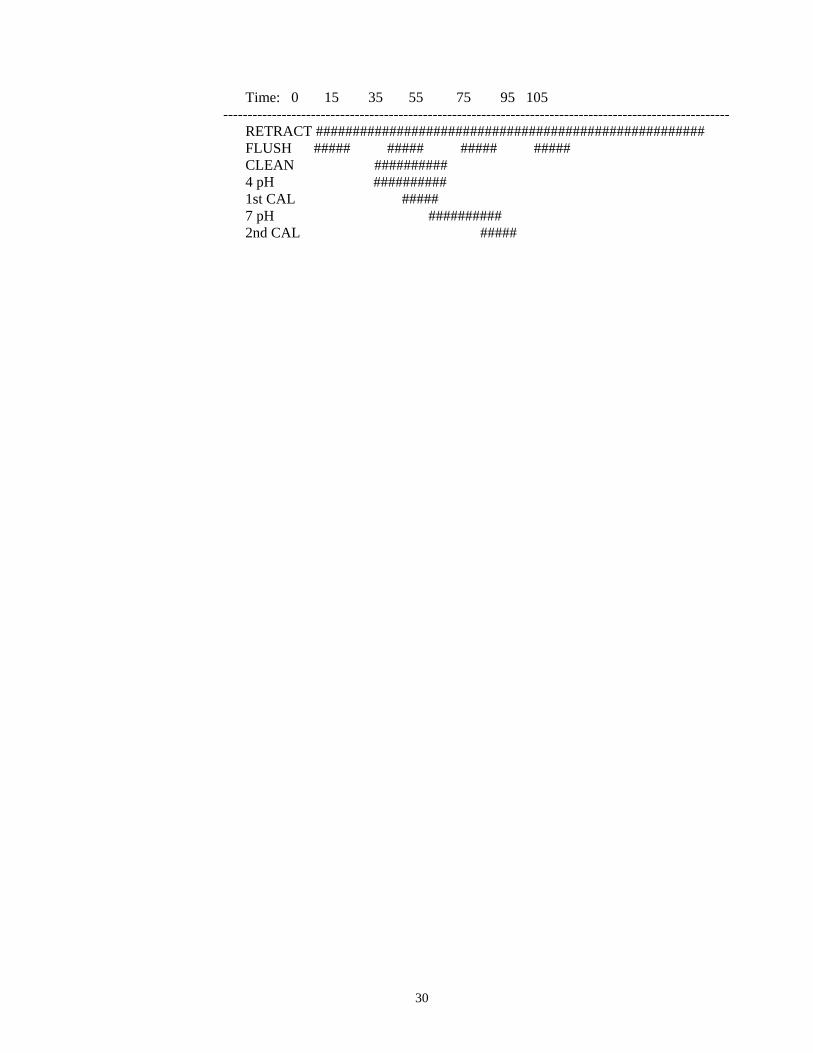
Time: 0 15 35 55 75 95 105 -------------------------------------------------------------------------------------------------------- RETRACT ##################################################### FLUSH ##### ##### ##### ##### CLEAN ########## 4 pH ########## 1st CAL ##### 7 pH ########## 2nd CAL #####
30
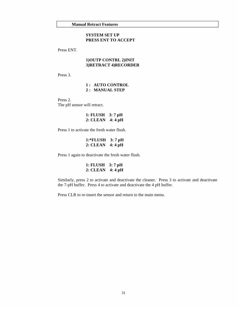
Manual Retract Features SYSTEM SET UP PRESS ENT TO ACCEPT Press ENT. 1)OUTP CONTRL 2)INIT 3)RETRACT 4)RECORDER Press 3. 1 : AUTO CONTROL 2 : MANUAL STEP Press 2. The pH sensor will retract. 1: FLUSH 3: 7 pH 2: CLEAN 4: 4 pH Press 1 to activate the fresh water flush. 1:*FLUSH 3: 7 pH 2: CLEAN 4: 4 pH Press 1 again to deactivate the fresh water flush. 1: FLUSH 3: 7 pH 2: CLEAN 4: 4 pH
Similarly, press 2 to activate and deactivate the cleaner. Press 3 to activate and deactivate the 7-pH buffer. Press 4 to activate and deactivate the 4 pH buffer.
Press CLR to re-insert the sensor and return to the main menu.
31
Recorder
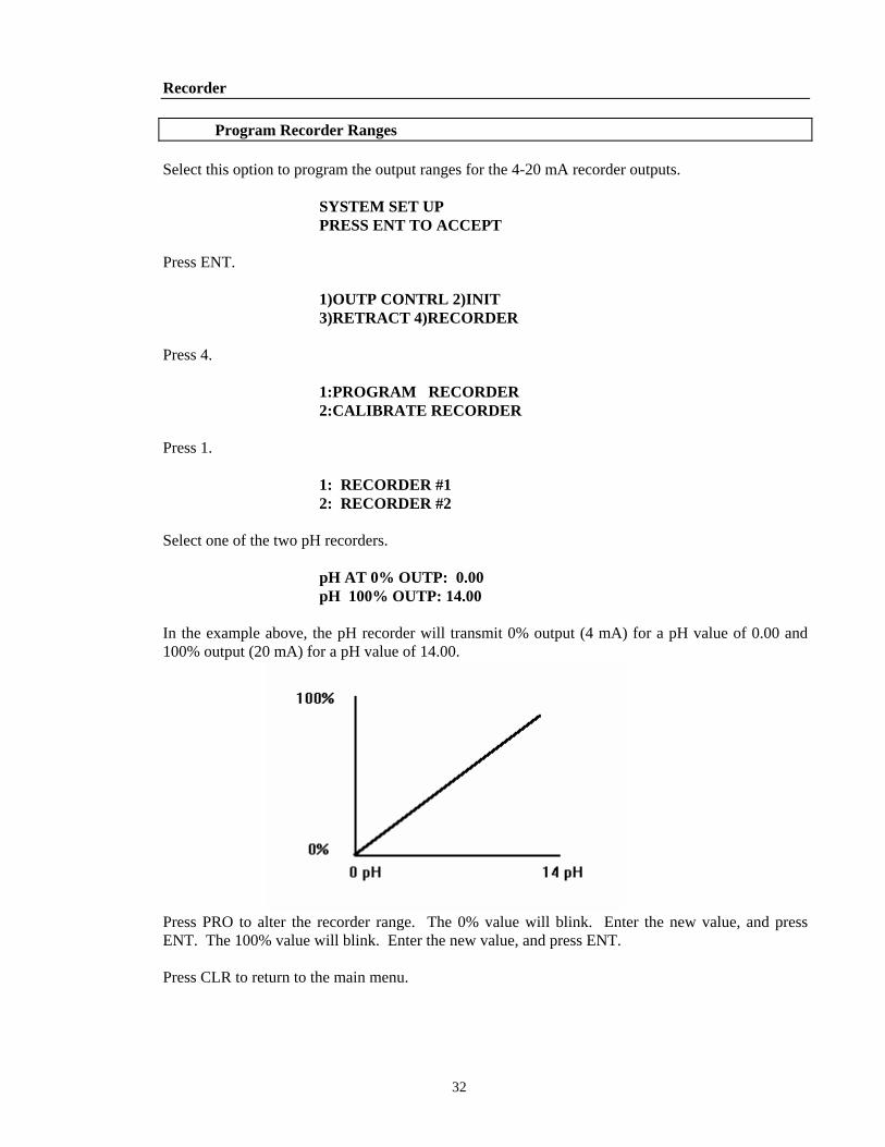
Program Recorder Ranges Select this option to program the output ranges for the 4-20 mA recorder outputs. SYSTEM SET UP PRESS ENT TO ACCEPT Press ENT. 1)OUTP CONTRL 2)INIT 3)RETRACT 4)RECORDER Press 4. 1:PROGRAM RECORDER 2:CALIBRATE RECORDER Press 1. 1: RECORDER #1 2: RECORDER #2 Select one of the two pH recorders. pH AT 0% OUTP: 0.00 pH 100% OUTP: 14.00
In the example above, the pH recorder will transmit 0% output (4 mA) for a pH value of 0.00 and 100% output (20 mA) for a pH value of 14.00.
Press PRO to alter the recorder range. The 0% value will blink. Enter the new value, and press ENT. The 100% value will blink. Enter the new value, and press ENT.
Press CLR to return to the main menu.
32
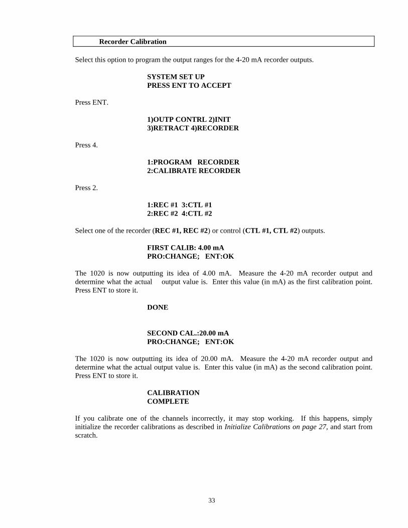
Recorder Calibration Select this option to program the output ranges for the 4-20 mA recorder outputs. SYSTEM SET UP PRESS ENT TO ACCEPT Press ENT. 1)OUTP CONTRL 2)INIT 3)RETRACT 4)RECORDER Press 4. 1:PROGRAM RECORDER 2:CALIBRATE RECORDER Press 2. 1:REC #1 3:CTL #1 2:REC #2 4:CTL #2 Select one of the recorder (REC #1, REC #2) or control (CTL #1, CTL #2) outputs. FIRST CALIB: 4.00 mA PRO:CHANGE; ENT:OK
The 1020 is now outputting its idea of 4.00 mA. Measure the 4-20 mA recorder output and determine what the actual output value is. Enter this value (in mA) as the first calibration point. Press ENT to store it.
DONE SECOND CAL.:20.00 mA PRO:CHANGE; ENT:OK
The 1020 is now outputting its idea of 20.00 mA. Measure the 4-20 mA recorder output and determine what the actual output value is. Enter this value (in mA) as the second calibration point. Press ENT to store it.
CALIBRATION COMPLETE
If you calibrate one of the channels incorrectly, it may stop working. If this happens, simply initialize the recorder calibrations as described in Initialize Calibrations on page 27, and start from scratch.
33
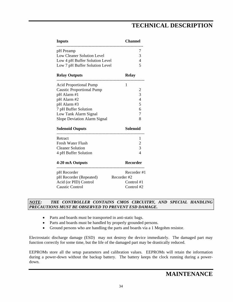
TECHNICAL DESCRIPTION Inputs Channel -------------------------------------------------------------- pH Preamp 7 Low Cleaner Solution Level 3 Low 4 pH Buffer Solution Level 4 Low 7 pH Buffer Solution Level 5 Relay Outputs Relay --------------------------------------------------------------- Acid Proportional Pump 1 Caustic Proportional Pump 2 pH Alarm #1 3 pH Alarm #2 4 pH Alarm #3 5 7 pH Buffer Solution 6 Low Tank Alarm Signal 7 Slope Deviation Alarm Signal 8 Solenoid Ouputs Solenoid --------------------------------------------------------------- Retract 1 Fresh Water Flush 2 Cleaner Solution 3 4 pH Buffer Solution 4 4-20 mA Outputs Recorder --------------------------------------------------------------- pH Recorder Recorder #1 pH Recorder (Repeated) Recorder #2 Acid (or PID) Control Control #1 Caustic Control Control #2 NOTE: THE CONTROLLER CONTAINS CMOS CIRCUITRY, AND SPECIAL HANDLING PRECAUTIONS MUST BE OBSERVED TO PREVENT ESD DAMAGE.
• Parts and boards must be transported in anti-static bags. • Parts and boards must be handled by properly grounded persons. • Ground persons who are handling the parts and boards via a 1 Megohm resistor.
Electrostatic discharge damage (ESD) may not destroy the device immediately. The damaged part may function correctly for some time, but the life of the damaged part may be drastically reduced. EEPROMs store all the setup parameters and calibration values. EEPROMs will retain the information during a power-down without the backup battery. The battery keeps the clock running during a power-down.
MAINTENANCE
34
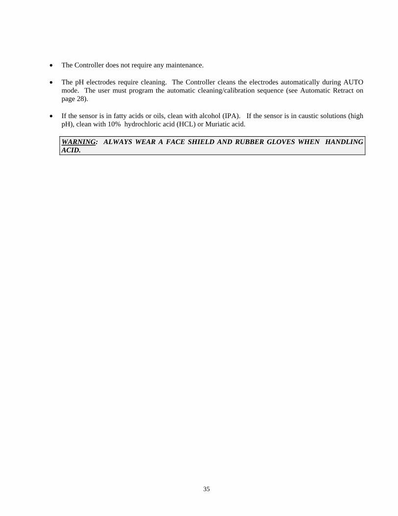
• The Controller does not require any maintenance. • The pH electrodes require cleaning. The Controller cleans the electrodes automatically during AUTO
mode. The user must program the automatic cleaning/calibration sequence (see Automatic Retract on page 28).
• If the sensor is in fatty acids or oils, clean with alcohol (IPA). If the sensor is in caustic solutions (high
pH), clean with 10% hydrochloric acid (HCL) or Muriatic acid.
WARNING: ALWAYS WEAR A FACE SHIELD AND RUBBER GLOVES WHEN HANDLING ACID.
35
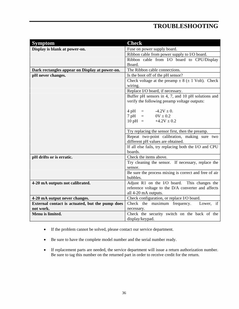
TROUBLESHOOTING Symptom Check Display is blank at power-on. Fuse on power supply board. Ribbon cable from power supply to I/O board. Ribbon cable from I/O board to CPU/Display
Board. Dark rectangles appear on Display at power-on. The Ribbon cable connections. pH never changes. Is the boot off of the pH sensor? Check voltage at the preamp ± 8 (± 1 Volt). Check
wiring. Replace I/O board, if necessary. Buffer pH sensors in 4, 7, and 10 pH solutions and
verify the following preamp voltage outputs: 4 pH = -4.2V ± 0. 7 pH = 0V ± 0.2 10 pH = +4.2V ± 0.2
Try replacing the sensor first, then the preamp. Repeat two-point calibration, making sure two
different pH values are obtained. If all else fails, try replacing both the I/O and CPU
boards. pH drifts or is erratic. Check the items above. Try cleaning the sensor. If necessary, replace the
sensor. Be sure the process mixing is correct and free of air
bubbles. 4-20 mA outputs not calibrated. Adjust R1 on the I/O board. This changes the
reference voltage to the D/A converter and affects all 4-20 mA outputs.
4-20 mA output never changes. Check configuration, or replace I/O board. External contact is actuated, but the pump does not work.
Check the maximum frequency. Lower, if necessary.
Menu is limited. Check the security switch on the back of the display/keypad.
• If the problem cannot be solved, please contact our service department.
• Be sure to have the complete model number and the serial number ready.
• If replacement parts are needed, the service department will issue a return authorization number.
Be sure to tag this number on the returned part in order to receive credit for the return.
36

37

DRAWINGS


© Copyright 2006 Lakewood Instruments, LLC. Printed in USA, P/N 68923 Rev. 1
© Copyright 2006 Lakewood Instruments, LLC. Printed in USA, P/N 68923 Rev. 1
For more information call toll free in the USA (800) 228-0839 Manufactured in the USA
Lakewood Instruments 7838 North Faulkner Road, Milwaukee, WI 53224 USA Phone (800) 228-0839 • Fax (414) 355-3508 h t t p : / / w w w . l a k e w o o d i n s t r u m e n t s . c o m