principles of remote sensing: the photon and radiometric quantities
TRANSCRIPT
Principles of Remote Sensing: The Photon andRadiometric Quantities
Most remote sensing texts begin by giving a survey of the main principles, to build a theoretical background, mainly in the physics of radiation. While it is important to have such a framework to pursue many aspects of remote sensing, we do not delve into this complex subject in much detail at this point. Instead, we offer on this and the next several pages an outline survey of the basics of relevant electromagnetic concepts. On this page, the nature of the photon is the prime topic. Photons of different energy values are distributed through what is called the Electromagnetic Spectrum. A full discussion of the electromagnetic spectrum (EMS) is deferred to page I-4.
Hereafter in this Introduction and in the Sections that follow, we limit the discussion and scenes examined to remote sensing products obtained almost exclusively by measurements within the Electromagnetic Spectrum (force field and acoustic remote sensing are briefly covered elsewhere in the Tutorial). Our emphasis is on pictures (photos) and images (either TV-like displays on screens or "photos" made from data initially acquired as electronic signals, rather than recorded directly on film). We concentrate mainly on images produced by sensors operating in the visible and near-IR segments of the electromagnetic spectrum (see the spectrum map on page I-4), but also inspect a fair number of images obtained by radar and thermal sensors.
The next several pages strive to summarize much of the underlying theory - mainly in terms of Physics - appropriateto Remote Sensing. The reader can gain most of the essentialknowledge just through those pages. The writer's (NMS) original, but now unavailable, "Landsat Tutorial Workbook", the information source from which this Remote Sensing Tutorial is an updated extension and expansion, contains a more detailed treatment of many aspects of the theory,
including a different treatment of quantum theory and an examination of how spectroscopy helped to develop that theory. So, optionally you can choose to read a reproductionof extracts from the Landsat T W version to extend your basic understanding by clicking onto the hidden page I-2a. Or, if you choose not to, read this next inserted paragraph which synopsizes key ideas from both the present and the I-2a pages:
Synoptic Statement: The underlying basis for most remote sensing methods and systems is simply that of measuring the varying energy levels of a single entity, the fundamental unit in the electromagnetic (which may be abbreviated "EM") force field known as the photon. As you will see later on this page, variations in photon energies (expressed in Joules or ergs) are tied to the parameter wavelength or its inverse, frequency. EM radiation that varies from high to lowenergy levels comprises the ElectroMagnetic spectrum (EMS). Radiation from specific parts of the EM spectrum contain photons of different wavelengths whose energy levels fall within a discrete range of values. When any target material is excited by internal processes or by interaction with incoming EM radiation, it will emit or reflect photons of varying wavelengths whose radiometric quantities differ at different wavelengths in a way diagnostic of the material. Photon energy received at detectors is commonly stated in power units such as Watts per square meter per wavelength unit. The plot of variation of power with wavelength gives rise to a specific pattern or curve that is the spectral signature for the substance or feature being sensed (discussed on page I-5).
Now, in more detail: The photon is the physical form of a quantum, the basic particle studied in quantum mechanics (which deals with the physics of the very small, that is, particles and their behavior at atomic and subatomic
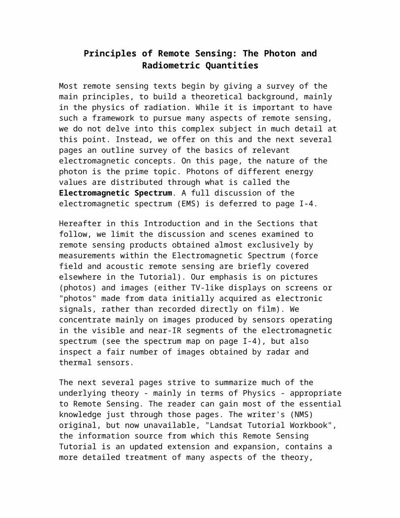
levels). The photon is also described as the messenger particle for EM force or as the smallest bundle of light. This subatomic massless particle comprises radiation emitted by matter when it is excited thermally, or by nuclear processes (fusion, fission), or by bombardment with other radiation. It also can become involved as reflected or absorbedradiation. Photons move at the speed of light: 299,792.46 km/sec (commonly rounded off to 300,000 km/sec or ~186,000 miles/sec). These particles also move as waves and hence, have a "dual" nature. These waves follow a pattern that can be described in terms of a sine (trigonometric) function, asshown in two dimensions in the figure below.
The distance between two adjacent peaks on a wave is its wavelength. The total number of peaks (top of the individualup-down curve) that pass by a reference lookpoint in a second is that wave's frequency (in units of cycles per second, whose SI version [SI stands for System International] is known as a Hertz [1 Hertz = 1/s-1]).
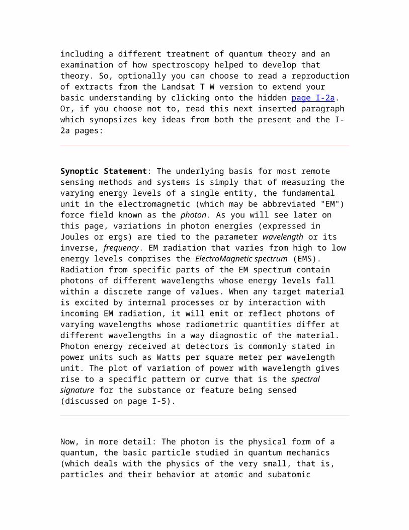
A photon travels as an EM wave having two components, oscillating as sine waves mutually at right angles, one consisting of the varying electric field, the other the varying magnetic field. Both have the same amplitudes (strengths) which reach their maxima-minima at the same time. Unlike other wave types which require a carrier (e.g.,water waves), photon waves can transmit through a vacuum (such as in space). When photons pass from one medium to
another, e.g., air to glass, their wave pathways are bent (follow new directions) and thus experience refraction.
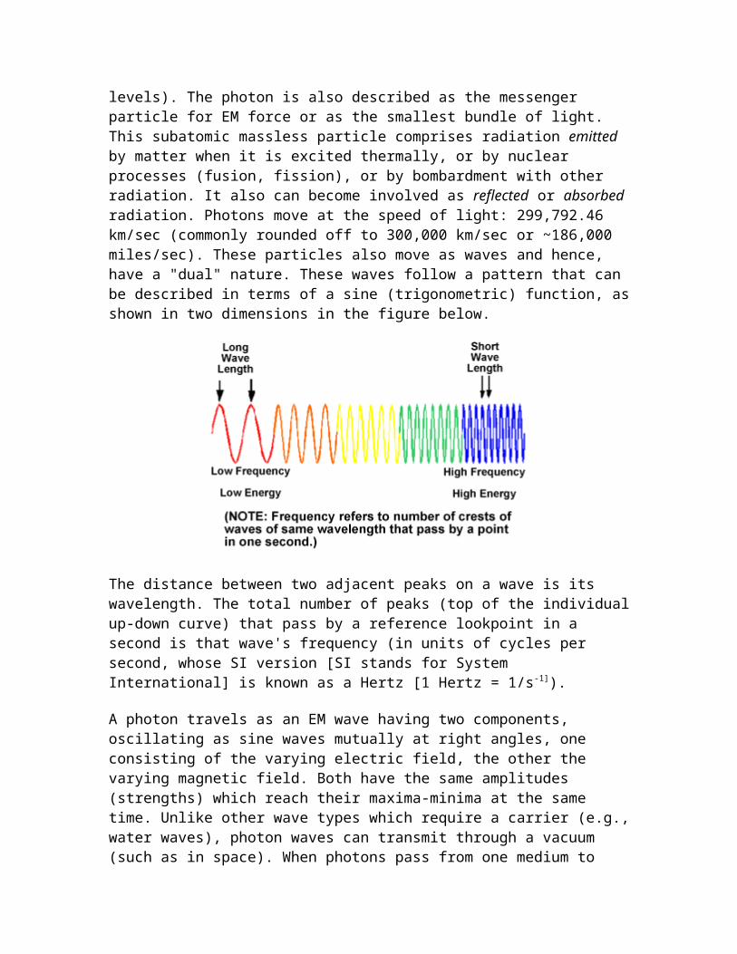
A photon is said to be quantized, in that any given one possesses a certain quantity of energy. Some other photon can have a different energy value. Photons as quanta thus show a wide range of discrete energies. The amount of energycharacterizing a photon is determined using Planck's generalequation:
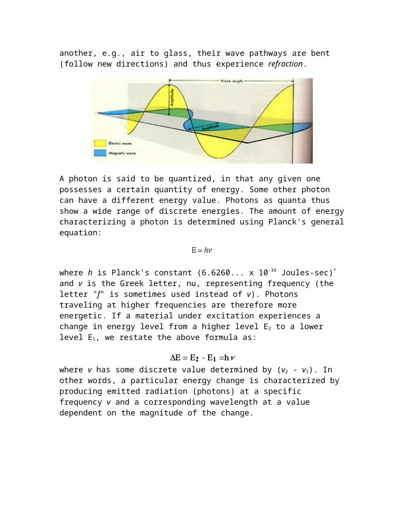
where h is Planck's constant (6.6260... x 10-34 Joules-sec)* and v is the Greek letter, nu, representing frequency (the letter "f" is sometimes used instead of v). Photons traveling at higher frequencies are therefore more energetic. If a material under excitation experiences a change in energy level from a higher level E2 to a lower level E1, we restate the above formula as:
where v has some discrete value determined by (v2 - v1). In other words, a particular energy change is characterized by producing emitted radiation (photons) at a specific frequency v and a corresponding wavelength at a value dependent on the magnitude of the change.
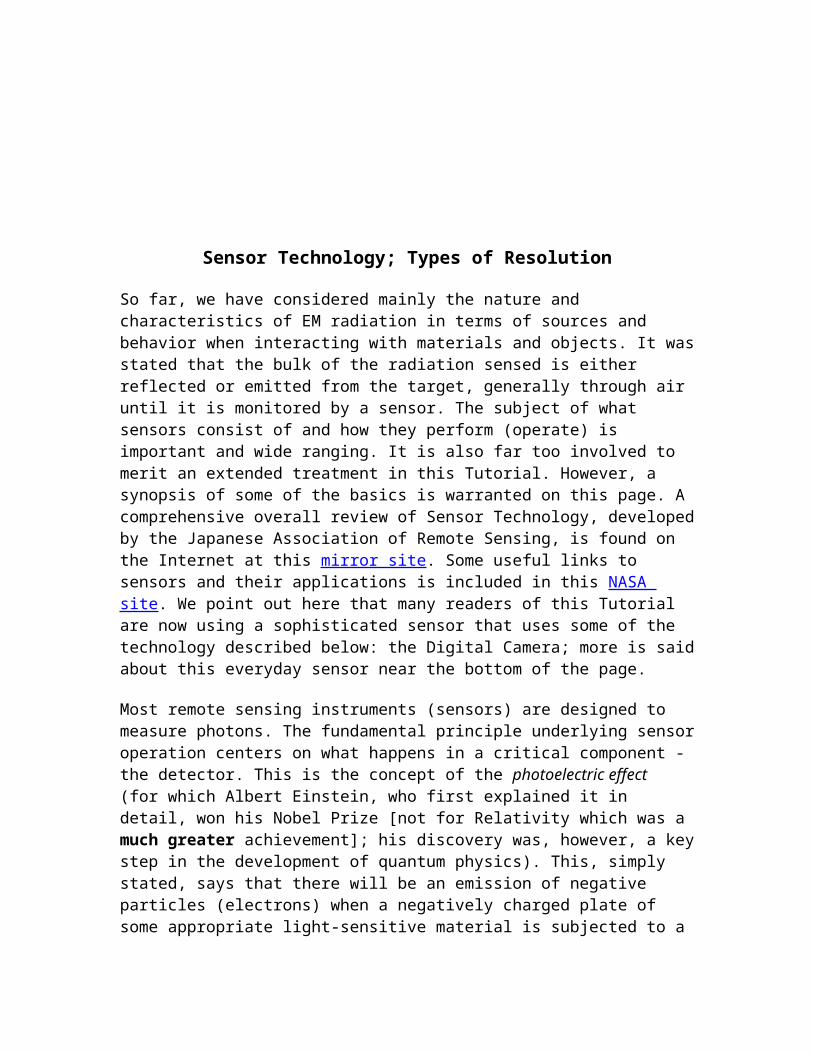
Sensor Technology; Types of Resolution
So far, we have considered mainly the nature and characteristics of EM radiation in terms of sources and behavior when interacting with materials and objects. It wasstated that the bulk of the radiation sensed is either reflected or emitted from the target, generally through air until it is monitored by a sensor. The subject of what sensors consist of and how they perform (operate) is important and wide ranging. It is also far too involved to merit an extended treatment in this Tutorial. However, a synopsis of some of the basics is warranted on this page. A comprehensive overall review of Sensor Technology, developedby the Japanese Association of Remote Sensing, is found on the Internet at this mirror site. Some useful links to sensors and their applications is included in this NASA site. We point out here that many readers of this Tutorial are now using a sophisticated sensor that uses some of the technology described below: the Digital Camera; more is saidabout this everyday sensor near the bottom of the page.
Most remote sensing instruments (sensors) are designed to measure photons. The fundamental principle underlying sensoroperation centers on what happens in a critical component - the detector. This is the concept of the photoelectric effect (for which Albert Einstein, who first explained it in detail, won his Nobel Prize [not for Relativity which was a much greater achievement]; his discovery was, however, a keystep in the development of quantum physics). This, simply stated, says that there will be an emission of negative particles (electrons) when a negatively charged plate of some appropriate light-sensitive material is subjected to a
beam of photons. The electrons can then be made to flow as acurrent from the plate, are collected, and then counted as asignal. A key point: The magnitude of the electric current produced (number of photoelectrons per unit time) is directly proportional to the light intensity. Thus, changes in the electric current can be used to measure changes in the photons (numbers; intensity) that strike the plate (detector) during a given time interval. The kinetic energy of the released photoelectrons varies with frequency (or wavelength) of the impinging radiation. But, different materials undergo photoelectric effect release of electrons over different wavelength intervals; each has a threshold wavelength at which the phenomenon begins and a longer wavelength at which it ceases.
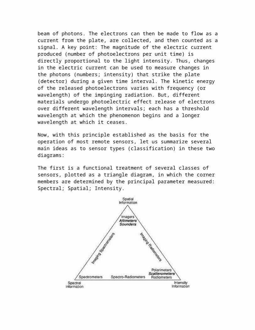
Now, with this principle established as the basis for the operation of most remote sensors, let us summarize several main ideas as to sensor types (classification) in these two diagrams:
The first is a functional treatment of several classes of sensors, plotted as a triangle diagram, in which the corner members are determined by the principal parameter measured: Spectral; Spatial; Intensity.
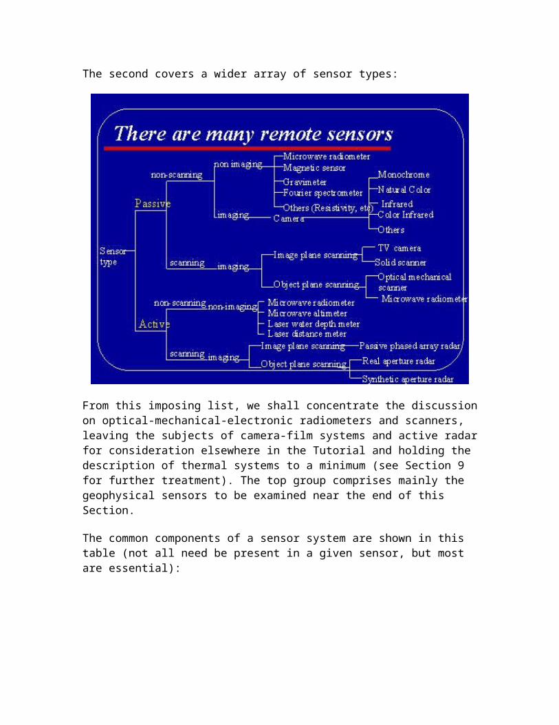
The second covers a wider array of sensor types:
From this imposing list, we shall concentrate the discussionon optical-mechanical-electronic radiometers and scanners, leaving the subjects of camera-film systems and active radarfor consideration elsewhere in the Tutorial and holding the description of thermal systems to a minimum (see Section 9 for further treatment). The top group comprises mainly the geophysical sensors to be examined near the end of this Section.
The common components of a sensor system are shown in this table (not all need be present in a given sensor, but most are essential):
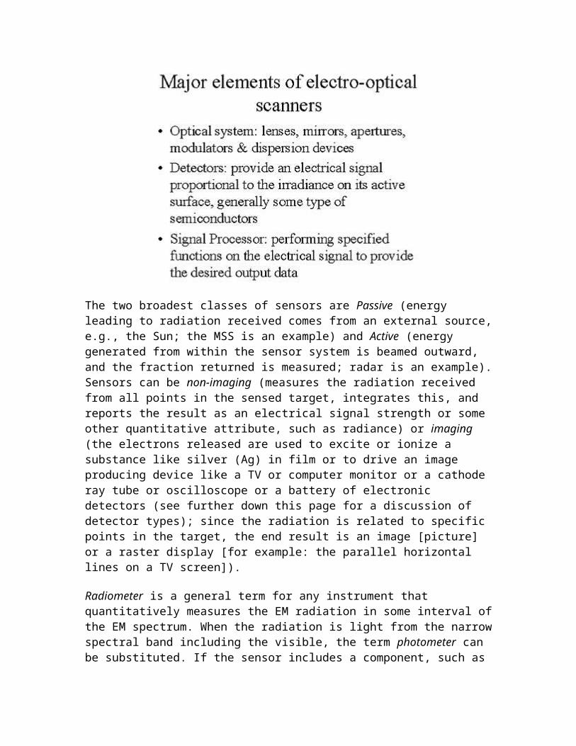
The two broadest classes of sensors are Passive (energy leading to radiation received comes from an external source,e.g., the Sun; the MSS is an example) and Active (energy generated from within the sensor system is beamed outward, and the fraction returned is measured; radar is an example).Sensors can be non-imaging (measures the radiation received from all points in the sensed target, integrates this, and reports the result as an electrical signal strength or some other quantitative attribute, such as radiance) or imaging (the electrons released are used to excite or ionize a substance like silver (Ag) in film or to drive an image producing device like a TV or computer monitor or a cathode ray tube or oscilloscope or a battery of electronic detectors (see further down this page for a discussion of detector types); since the radiation is related to specific points in the target, the end result is an image [picture] or a raster display [for example: the parallel horizontal lines on a TV screen]).
Radiometer is a general term for any instrument that quantitatively measures the EM radiation in some interval ofthe EM spectrum. When the radiation is light from the narrowspectral band including the visible, the term photometer can be substituted. If the sensor includes a component, such as
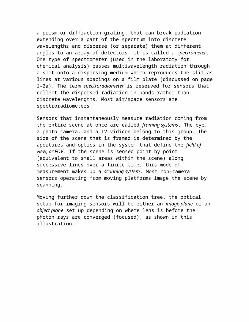
a prism or diffraction grating, that can break radiation extending over a part of the spectrum into discrete wavelengths and disperse (or separate) them at different angles to an array of detectors, it is called a spectrometer. One type of spectrometer (used in the laboratory for chemical analysis) passes multiwavelength radiation through a slit onto a dispersing medium which reproduces the slit aslines at various spacings on a film plate (discussed on pageI-2a). The term spectroradiometer is reserved for sensors that collect the dispersed radiation in bands rather than discrete wavelengths. Most air/space sensors are spectroradiometers.
Sensors that instantaneously measure radiation coming from the entire scene at once are called framing systems. The eye, a photo camera, and a TV vidicon belong to this group. The size of the scene that is framed is determined by the apertures and optics in the system that define the field of view, or FOV. If the scene is sensed point by point (equivalent to small areas within the scene) along successive lines over a finite time, this mode of measurement makes up a scanning system. Most non-camera sensors operating from moving platforms image the scene by scanning.
Moving further down the classification tree, the optical setup for imaging sensors will be either an image plane or anobject plane set up depending on where lens is before the photon rays are converged (focused), as shown in this illustration.
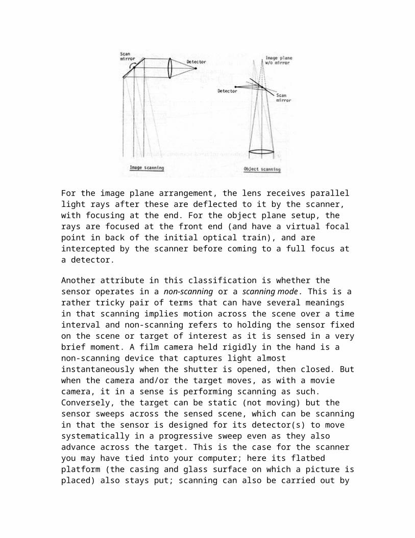
For the image plane arrangement, the lens receives parallel light rays after these are deflected to it by the scanner, with focusing at the end. For the object plane setup, the rays are focused at the front end (and have a virtual focal point in back of the initial optical train), and are intercepted by the scanner before coming to a full focus at a detector.
Another attribute in this classification is whether the sensor operates in a non-scanning or a scanning mode. This is arather tricky pair of terms that can have several meanings in that scanning implies motion across the scene over a timeinterval and non-scanning refers to holding the sensor fixedon the scene or target of interest as it is sensed in a verybrief moment. A film camera held rigidly in the hand is a non-scanning device that captures light almost instantaneously when the shutter is opened, then closed. Butwhen the camera and/or the target moves, as with a movie camera, it in a sense is performing scanning as such. Conversely, the target can be static (not moving) but the sensor sweeps across the sensed scene, which can be scanningin that the sensor is designed for its detector(s) to move systematically in a progressive sweep even as they also advance across the target. This is the case for the scanner you may have tied into your computer; here its flatbed platform (the casing and glass surface on which a picture isplaced) also stays put; scanning can also be carried out by
put a picture or paper document on a rotating drum (two motions: circular and progressive shift in the direction of the drum's axis) in which the scanning illumination is a fixed beam.
Two other related examples: A TV (picture-taking) camera containing a vidicon in which light hitting that photon-sensitive surface produces electrons that are removed in succession (lines per inch is a measure of the TV's performance) can either stay fixed or can swivel to sweep over a scene (itself a spatial scanning operation) and can scan in time as it continues to monitor the scene. A digitalcamera contains an X-Y array of detectors that are discharged of their photon-induced electrons in a continuoussuccession that translate into a signal of varying voltage. The discharge occurs by scanning the detectors systematically. That camera itself can remain fixed or can move.
The gist of all this (to some extent obvious) is that the term scanning can be applied both to movement of the entire sensor and, in its more common meaning, to the process by which one or more components in the detection system either move the light gathering, scene viewing apparatus or the light or radiation detectors are read one by one to produce the signal. Two broad categories of most scanners are defined by the terms "optical-mechanical" and "optical-electronic", distinguished by the former containing an essential mechanical component (e.g., a moving mirror) that participates in scanning the scene and by the latter having the sensed radiation move directly through the optics onto alinear or two-dimensional array of detectors.
Another attribute of remote sensors, not shown in the classification, relates to the modes in which those that follow some forward-moving track (referred to as the orbit or flight path) gather their data. In doing so, they are said to monitor the path over an area out to the sides of the path; this is known as the swath width. The width is determined by that part of the scene encompassed by the
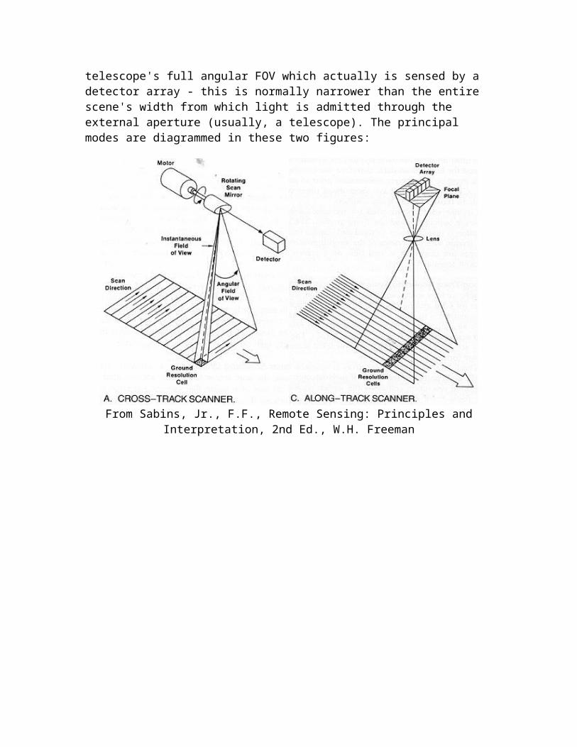
telescope's full angular FOV which actually is sensed by a detector array - this is normally narrower than the entire scene's width from which light is admitted through the external aperture (usually, a telescope). The principal modes are diagrammed in these two figures:
From Sabins, Jr., F.F., Remote Sensing: Principles andInterpretation, 2nd Ed., W.H. Freeman