preparation of chitosan-containing nanofibres by electrospinning of chitosan/poly(ethylene oxide)...
TRANSCRIPT

e-Polymers 2004, no. 056. ISSN 1618-7229
http://www.e-polymers.org
Preparation of chitosan-containing nanofibres by electrospinning of chitosan/poly(ethylene oxide) blend solutions Maria Spasova, Nevena Manolova, Dilyana Paneva, Iliya Rashkov * Laboratory of Bioactive Polymers, Institute of Polymers, Bulgarian Academy of Sciences, Acad. G. Bonchev Str., bl. 103 A, Sofia 1113, Bulgaria; Fax +359 (0)2 870 75 23; [email protected] (Received: June 10, 2004; published: September 3, 2004)
Abstract: The first successful preparation of chitosan-containing nanofibres was achieved by electrospinning of chitosan/poly(ethylene oxide) (PEO) blend aqueous solutions. The diameters of the nanofibres were in the range 40 - 290 nm and decreased with increasing chitosan content and decreasing total concentration. An increase of the applied field strength leads to an increase of the diameter of the nanofibres and to a broadening of the size distribution. The possibility to prepare nanofibres containing a model drug – potassium 5-nitro-8-quinolinolate (K5N8Q), a broad-spectrum antimicrobial and antimycotic agent – was shown. The incorpora-tion of K5N8Q in the nanofibres resulted in a decrease of the nanofibre diameters and the appearance of bead-shaped defects. Non-woven mats from the drug-loaded nanofibres with composition chitosan : PEO = 1:1 (w/w) and 1% K5N8Q showed antibacterial and antimycotic activity against E. coli, S. aureus and C. albicans.
Introduction Polymer fibres are applied in a wide variety of industrial fields [1]. Diameters of fibres made by conventional methods like spinning from melt or solution are in the range of 5 - 500 µm. The interest in electrospinning has much increased in the past few years because it allows producing polymer fibres with diameters in the nanoscale range. Because of the small pore size and the large specific surface area inherent in electro-spun textiles [2,3] these products might find different applications: e.g., in military protective clothing and filter applications, for non-traumatic wound dressing, in drug delivery carriers, haemostatic devices, as tubular shapes for blood vessels and nerve regeneration, 3D-scaffolds for bone and cartilage regeneration, in cosmetics, in optics like nano-sensors (thermal, piezoelectric, biochemical and fluorescence optical chemical sensors), or in electronics [4-7]. The electrospinning process involves the application of a strong electrostatic field to a capillary connected with a reservoir containing the polymer solution. The electrostatic field deforms the pendant droplet of the polymer solution at the capillary tip into a conical shape (Taylor cone) [8]. If the applied field strength exceeds a threshold value, the electrostatic forces overcome the surface tension, and a fine charged jet is ejected to move towards a ground plate acting as a counter electrode. Due to the
1 - 10.1515/epoly.2004.4.1.624
Downloaded from PubFactory at 08/02/2016 07:22:15AMvia free access

high viscosity of the polymer solution and the presence of entanglements, the jet remains stable and is not transformed into spherical droplets. The solvent begins to evaporate immediately after the jet is formed. As a result thin polymer fibres are deposited on the counter electrode [9]. In spite of the great number of variables that affect the process, some models describing the electrospinning process have been put forward [10-12]. The electrospinning of biocompatible and degradable polymers is of great interest because it is supposed that biomimetic fibrous scaffolds for tissue engineering might be constructed from these materials. The possibility to obtain different shapes and to control the fibre orientation, its composition and dimensions is a prerequisite of preparing ideal tissue engineering scaffolds [13]. A suitable polymer for devices contacting with living organisms is poly(ethylene oxide) (PEO) because of its low toxicity [14]. PEO has been electrospun from aqueous solution and fibres with diameters in the range of 500 - 5000 nm have been obtained [15]. Ordering has been observed by atomic force microscopy in the surface layer in PEO fibres [16]. The natural polyaminosaccharide chitosan is recommended as a suitable functional material for the preparation of medical devices because of its excellent properties such as biocompatibility, biodegradability, and non-toxicity [17,18]. Combining chitosan with PEO might lead to novel materials suitable for diverse applications in the biomedical field. Previously we have proposed chitosan/PEO blend films as a suitable system for drug dosage forms [19]. In the present work, the possibility to prepare chitosan-containing nanofibres by electrospinning from chitosan/PEO blend solutions is shown. The effect of solution concentration and applied field strength on the diameters and morphology of the fibres has been studied. The effect of adding potassium 5-nitro-8-quinolinolate - a broad-spectrum antimicrobial and antimycotic agent - has been studied. Results and discussion Until now, all attempts to electrospin solutions of chitosan of various molecular weights dissolved in its common solvents have been unsuccessful [5,20]. Any explanation of these findings has not been given. Our preliminary experiments to electrospin chitosan aqueous solutions also failed. Previously, we have found that the rheological behaviour of chitosan/PEO blend solutions is determined by chitosan macromolecules, the PEO chains being orientated to a certain extent along chitosan chains thus facilitating their flow [21]. This stimulated us to perform electrospinning of chitosan solutions containing PEO. Our results showed that chitosan-containing nanofibres were successfully electrospun from chitosan/PEO blend solutions at weight ratios chitosan : PEO equal to or less than 1. Higher chitosan : PEO ratios led to the formation of spherically shaped nanoparticles. Effect of the processing variables on nanofibre morphology It has been reported that the morphology of individual electrospun nanofibres and electrospun non-woven mats is strongly influenced by the applied field strength and solution concentration. The number of bead defects along electrospun PEO fibres has been found to increase on increasing the applied field strength (AFS), and the fibre diameter increases with increasing concentration [2]. Data for the dependence of the diameter and the morphology of the prepared chitosan-containing nanofibres
2 - 10.1515/epoly.2004.4.1.624
Downloaded from PubFactory at 08/02/2016 07:22:15AMvia free access

on the composition of the spun chitosan/PEO solution, its concentration, and on the AFS are summarised in Tab. 1. Tab. 1. Composition of the spun chitosan/PEO blend solutions, applied field strength (AFS), average fibre diameter (d), mean quadratic error (s) and divergence (R) of d, length (L) and width (W) of defects. Total polymer concentration 5%
Chitosan : POE (w/w)
AFS in kV/cm
d in nm
s R in nm
W/L in nm/nm
1.00 a) 1.0 40 7 15 410/750 1.00 a) 2.0 60 17 40 460/880 0.67 b) 1.0 140 24 80 370/1050 0.33 1.0 200 26 100 no 0.33 1.5 210 27 70 no 0.33 2.8 220 31 100 no 0.33 c) 2.8 70 21 70 310/580 0.25 1.0 200 18 70 no 0.25 2.8 210 42 130 no 0.18 1.0 230 43 120 no 0.18 2.8 230 34 90 no 0.11 1.0 240 36 100 no 0.11 2.8 290 71 220 no 0.11 d) 2.8 270 72 200 no 0.05 1.0 250 27 80 no 0.05 1.5 290 76 200 no 0.05 2.8 280 82 240 no
a) Total polymer concentration 3%. b) Total polymer concentration 4%. c) With 0.2% potassium 5-nitro-8-quinolinolate. d) With 0.1% potassium 5-nitro-8-quinolinolate. In the case of electrospinning from chitosan/PEO blend solutions we found that at ratios chitosan : PEO from 0.05 to 4 the optimal AFS values were in the range from 1.0 to 2.8 kV/cm. The scanning electron micrographs (SEM) of the obtained nano-fibres by applying electric field of 1 kV/cm at different weight ratios chitosan : PEO (5% solution) are shown in Fig. 1a - e. The nanofibres electrospun from these blend solutions were cylindrical and the average fibre diameters were in the range from 200 to 250 nm. On increasing the chitosan amount the fibre diameters decreased from 250 nm at weight ratio chitosan : PEO = 0.05 to 200 nm at chitosan : PEO = 0.33. In these cases, neither bead- or spindle-shaped defects along the fibres, nor micro-droplets non-connected with the fibres were found. The fibres electrospun at AFS 2.8 kV/cm (5% solution) had diameters from 220 to 290 nm. In this case the increasing chitosan amount also led to decreasing average fibre diameters. 3
- 10.1515/epoly.2004.4.1.624Downloaded from PubFactory at 08/02/2016 07:22:15AM
via free access

а b
c d
e
Fig. 1. SEM micrographs of nanofibres electrospun from chitosan/PEO blend solutions (total conc. 5%), obtained at chitosan : PEO weight ratios: 0.33; ×1 000 and ×10 000 (а); 0.25; ×1 000 and ×10 000 (b); 0.18; ×1 000 and ×10 000 (c); 0.11; ×1 000 and ×10 000 (d); 0.05; ×10 000 (e); AFS 1 kV/cm
A small number of defects began to appear at AFS 2.8 kV/cm at a weight ratio chitosan : PEO = 0.33 (Fig. 2a). Defects were not detected in the nanofibres obtained at lower weight ratio chitosan : PEO using the same AFS (Fig. 2b). The distributions of the average diameters of nanofibres obtained at two different AFS values from one and the same polymer blend solution (chitosan : PEO = 0.11) are shown in Fig. 3a and 3b. As seen, at the lower applied field strength (1 kV/cm) the distribution is narrower (in the range 200 - 300 nm). On increasing the AFS to 2.8 kV/cm, fibre diameters increased and the fibre diameter distribution broadened (200 - 420 nm). A similar increase in the fibre diameter at higher AFS has been reported for the case of polyurethane electrospinning [22]. The broadening of the diameter distribution is probably related to some instability of the process at higher applied field strength. The solution viscosity became too high at ratios higher than 0.33; that was the reason
4 - 10.1515/epoly.2004.4.1.624
Downloaded from PubFactory at 08/02/2016 07:22:15AMvia free access

to use spinning solutions with lower total concentrations (4% or 3%) in experiments where the chitosan : PEO ratio was higher than 0.33. At these lower concentrations at high weight fraction of chitosan (0.67 and 1), nanofibres of smaller diameter were obtained (e.g., 140 nm at chitosan : PEO = 0.67). However some defects began to appear.
a b Fig. 2. SEM micrographs of chitosan/PEO fibres electrospun with weight ratios chitosan : PEO = 0.33, ×1 000 and ×10 000 (a), chitosan : PEO = 0.11, ×1 000 and x10 000 (b); total polymer concentration 5%; AFS 2.8 kV/cm
0
0.05
0.1
0.15
0.2
0.25
0.3
Dis
trib
utio
n
200 220 250 280 300Diameter, nm
a
Dis
trib
utio
n
200 220 250 280 350 380 420Diameter, nm
b
Fig. 3. Diameter distribution of chitosan/PEO nanofibres, weight ratio chitosan : PEO = 0.11 at AFS 1 kV/cm (a) and 2.8 kV/cm (b); total solution concentration 5%
00.040.080.120.16
0.2
5 - 10.1515/epoly.2004.4.1.624
Downloaded from PubFactory at 08/02/2016 07:22:15AMvia free access

Fig. 4. SEM micrographs of fibres electrospun at the weight ratio chitosan : PEO = 0.67 (total polymer conc. 4%) at AFS 1 kV/cm, ×5 000 and ×10 000
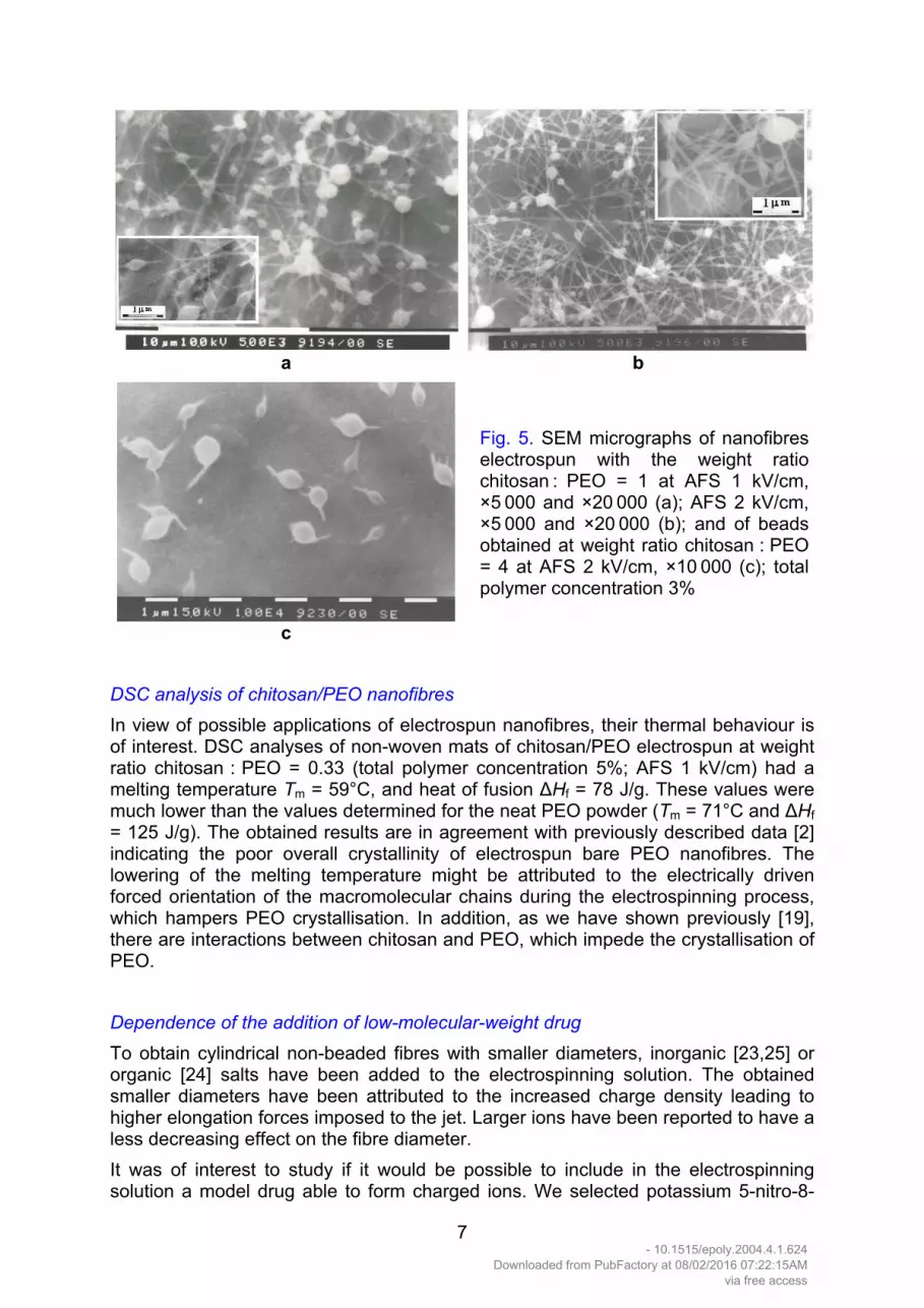
It is known that the electrospun fibres often have beads or spindle-like defects. The concentration of the spinning solution is one of the main processing parameters influencing their occurrence. For bare PEO nanofibres it has been shown that bead formation depends on solution viscosity, a higher viscosity decreasing the number of beads [23]. In our case of chitosan/PEO blend solutions the nanofibres electrospun from a solution of total polymer conc. 5% were not beaded. Beads or spindles began to appear at concentrations lower than 5%. Beaded nanofibres obtained on electro-spinning chitosan/PEO blend solution with concentration 4% are shown in Fig. 4. The average length along the fibre axis and the average width perpendicular to the fibre axis of the defects of fibres electrospun at weight ratio chitosan : PEO = 0.67 and total polymer concentration 4% at AFS 1 kV/cm were 1050 and 370 nm, respectively. Attempts were made to prepare fibres with higher chitosan content (chitosan : PEO = 1) at total polymer concentration 5%. It was found that the solution viscosity was rather high for a successful electrospinning of fibres. The measured values of the solution viscosity increased on increasing the chitosan amount and for the weight ratios chitosan : PEO = 0.05, 0.11, 0.18, 0.25 and 0.33 at total polymer concentration 5% they were 12 400, 18 400, 24 500, 28 000 and 34 500 сР, respectively. That was the reason to use solutions with lower total polymer concentration (4 or 3%). In these cases the viscosities at total polymer concentration 3% for chitosan : PEO = 1 and 4 were 6 500 and 14 600 cP, respectively, and at a ratio of 0.67 and total polymer conc. of 4% the viscosity was 2 100 cP. SEM micrographs of nanofibres, obtained from chitosan/PEO blend solutions at total polymer concentration 3% are shown in Fig. 5. A significant decrease in the fibre diameter was observed compared to those obtained at a concentration of 5% and lower weight ratios of chitosan : PEO. The average bead length along the fibre axis (L) was 750 nm and the average bead width (W) perpendicular to the fibre axis was 410 nm in the case of fibres electrospun at weight ratio chitosan : PEO = 1 and total polymer conc. 3% at AFS 1 kV (Fig. 5a). The L and W values were 880 and 460 nm, respectively, in the case of fibres electrospun at weight ratio chitosan : PEO = 1 and total polymer concentration 3% at AFS 2 kV at the same solution concentration (Fig. 5b). On further increasing the chitosan content (chitosan : PEO = 4) fibres did not spun and only ‘tailed’ beads were formed. In the latter case the L and W values were 950 and 670 nm, respectively (Fig. 5c). These findings are in agreement with the results obtained by other authors, who have observed similar effects of concentration and viscosity on the diameter and the morphology of fibres obtained by electrospinning of bare PEO solutions [2,23] and of PLA solutions [24].
6 - 10.1515/epoly.2004.4.1.624
Downloaded from PubFactory at 08/02/2016 07:22:15AMvia free access
a b
c
Fig. 5. SEM micrographs of nanofibres electrospun with the weight ratio chitosan : PEO = 1 at AFS 1 kV/cm, ×5 000 and ×20 000 (a); AFS 2 kV/cm, ×5 000 and ×20 000 (b); and of beads obtained at weight ratio chitosan : PEO = 4 at AFS 2 kV/cm, ×10 000 (с); total polymer concentration 3%
DSC analysis of chitosan/PEO nanofibres In view of possible applications of electrospun nanofibres, their thermal behaviour is of interest. DSC analyses of non-woven mats of chitosan/PEO electrospun at weight ratio chitosan : PEO = 0.33 (total polymer concentration 5%; AFS 1 kV/cm) had a melting temperature Tm = 59°C, and heat of fusion ∆Hf = 78 J/g. These values were much lower than the values determined for the neat PEO powder (Tm = 71°C and ∆Hf = 125 J/g). The obtained results are in agreement with previously described data [2] indicating the poor overall crystallinity of electrospun bare PEO nanofibres. The lowering of the melting temperature might be attributed to the electrically driven forced orientation of the macromolecular chains during the electrospinning process, which hampers PEO crystallisation. In addition, as we have shown previously [19], there are interactions between chitosan and PEO, which impede the crystallisation of PEO. Dependence of the addition of low-molecular-weight drug To obtain cylindrical non-beaded fibres with smaller diameters, inorganic [23,25] or organic [24] salts have been added to the electrospinning solution. The obtained smaller diameters have been attributed to the increased charge density leading to higher elongation forces imposed to the jet. Larger ions have been reported to have a less decreasing effect on the fibre diameter. It was of interest to study if it would be possible to include in the electrospinning solution a model drug able to form charged ions. We selected potassium 5-nitro-8-
7 - 10.1515/epoly.2004.4.1.624
Downloaded from PubFactory at 08/02/2016 07:22:15AMvia free access

quinolinolate (K5N8Q) because of its wide-spectrum antimicrobial and antimycotic effect and its ability to form charged ions in aqueous solutions. It was found that K5N8Q amounts from 0.1 to 1 wt.-% did not impede the normal spinning process and the formation of nanofibres. A considerable decrease in the average fibre diameter was observed for 0.2% K5N8Q. The results are presented in Fig. 6. The average fibre diameter was 70 nm.
NO
NO2
K +
K5N8Q
The production of fibres with smaller diameters is accompanied by formation of bead-type defects (Fig. 7b). Such kinds of defects were not detected at a K5N8Q concen-tration of 0.1% in the spinning solution (Fig. 7a). The average bead length along the fibre axis was 580 nm and the average bead width perpendicular to the fibre axis was 310 nm in the case of fibres electrospun at weight ratio chitosan : PEO = 0.33, total polymer concentration 5%, 0.2% K5N8Q, AFS 2.8 kV/cm.
0
0.05
0.1
0.15
0.2
0.25
Dis
trib
utio
n
30 50 60 70 80 100Diameter, nm
Fig. 6. Diameter distribution of fibres, electrospun from solution with weight ratio chitosan : PEO = 0.33, total polymer concentration 5%, K5N8Q conc. 0.2%, AFS 2.8 kV/cm
a b Fig. 7. SEM micrographs of fibres electrospun from 5% solution, at AFS 2.8 kV/cm; chitosan : PEO = 0.11, 0.1% K5N8Q, ×10 000 (а); and chitosan : PОЕ = 0.33, 0.2% K5N8Q, ×10 000 (b)
8
- 10.1515/epoly.2004.4.1.624Downloaded from PubFactory at 08/02/2016 07:22:15AM
via free access
Microbiological screening of non-woven mats electrospun from chitosan/PEO blend solutions containing K5N8Q The antibacterial and antimycotic activity of mats electrospun from chitosan/PEO blend solutions prepared with the weight ratio chitosan : PEO = 1 and K5N8Q at a concentration of 1% was tested against Gram-negative bacteria (E. coli), Gram-positive bacteria (S. aureus) and the fungus C. albicans. The activity was estimated by measuring the width of the sterile zone around the nanofibre-coated disks. For comparison, the biological activity of blank controls of chitosan/PEO non-woven mats was evaluated. Well-defined wide sterile zones around the disks with non-woven mats were observed. The diameters of the sterile zones were 3 cm, 2 cm and 3 cm for S. aureus, E. coli and C. albicans, respectively. Sterile zones did not appear in the case of the blank controls. In contrast to the case of low-molecular weight electrolytes, the effect of polyelectro-lytes on the morphology of electrospun nanofibres has not been studied up to now. No successful preparation of nanofibres without defects by electrospinning of poly-electrolytes has been reported. The macromolecules of natural (chitosan and other ionisable polysaccharides) and synthetic polyelectrolytes become more stretched with increasing charge density. It might be assumed that one of the prerequisites of successful electrospinning is the ability of the coiled macromolecules of the synthetic non-ionogenic polymers to be transformed by the flow of the jet into oriented entangled structures, which are retained in the solidified nanofibres. This explains the decreased overall crystallinity of the nanofibres, as well as some observations of the orientation in their surface layer (PEO nanofibres [16]). In the case of solutions of polymers with extended chains this possibility is strongly decreased or is lacking. The other authors’ as well as our own unsuccessful attempts to electrospin nanofibres from chitosan (chitosan acetate) solutions, under conditions providing electrospun nanofibres from non-ionogenic polymers, imply that this failure is probably related to the poor flexibility of the polyelectrolyte chains. In order to successfully electrospin polyelectrolyte solutions probably it is necessary to add non-ionogenic polymers having flexible chains, which will play the role of a plastifier facilitating the orientation and the flow of the polyelectrolyte macromolecules. The necessity of adding an excess of PEO to the chitosan acetate solution (PEO in an amount higher than equimolar) might be attributed to the possibility of formation of a complex between PEO and chitosan acetate resulting in an uncoiling of the PEO macromolecules and their orientation along the chitosan chains. Our previous studies [19] have shown the possibility of formation of a chitosan/PEO complex with composition close to the stoichiometric one. It might be assumed that this is the reason that the spinning of fibres is not possible at mole ratios [chitosan] : [PEO] > 1. This hypothesis is supported by our experiments resulting in ‘tailed’ nanobeads. Because of the great interest in nanofibres and nanobeads from ionogenic polymers we intend to search for other ways of their successful preparation by electrospinning. Experimental part Materials High-molecular-weight chitosan from crab shell (Sigma) and poly(ethylene oxide) (Badimol® Dimitrovgrad, Bulgaria) were used. The viscosity-average molecular weight (Mv) of chitosan was calculated from the intrinsic viscosity (in dl/g), determined in 0.3 M CH3COOH/0.2 M CH3COONa (1:1 9
- 10.1515/epoly.2004.4.1.624Downloaded from PubFactory at 08/02/2016 07:22:15AM
via free access

v/v) with an Ubbelohde viscometer using Mark-Houwink constants K = 1.38·10-4 and α = 0.85 at 25°С [26]. Mv of PEO was 800 000 as determined in distilled water at 30°C, using an Ubbelohde viscometer, by the equation: [η] = 1.25·10-4 Mv
0.78 [27]. Spinning solutions The solutions used in the electrospinning experiments were prepared at weight ratios chitosan : PEO = 0.05, 0.11, 0.18, 0.25, 0.33, 0.67, 1 and 4, respectively. PEO was dissolved in distilled water. Chitosan was dissolved in 0.3 М acetic acid (2% w/v). The total polymer concentration at weight ratios 0.05, 0.11, 0.18, 0.25 and 0.33 was 5%. The total polymer concentration for chitosan : PEO = 0.67 was 4% and for chitosan : PEO = 1 and 4 it was 3%. The rheological measurements were performed using a Brookfield LVT viscometer equipped with a small sample thermostating adapter, spindle SC 4-18/13 R and SC 4-31/13 R at 25°С. Experimental set up for electrospinning The blend solution (1 ml) was placed in a 2 ml syringe with a conical nozzle. The electrode, connected with a high-voltage supply capable to generate positive DC voltages from 10 to 28.5 kV, was immersed in the syringe. A grounded copper plate was used to collect the electrospun material. The distance between the capillary tip and the collector was 10 cm. Analyses The nanofibre samples were vacuum-covered with carbon. The SEM analyses of the nanofibres were performed with a scanning electron microscope Philips 515. Differ-ential scanning calorimetry (DSC) thermograms were obtained using a DSC-4 Perkin-Elmer calorimeter at a heating and cooling rate of 10°C/min. Fibre size distribution characteristics The divergence (R) was calculated by R = xmax - xmin (1) where xmax is the maximum and xmin the minimum value. The dispersion s2 was calculated by s2 = Σi = 1... n (xi - X)2/(n - 1) (2) where X is the average (arithmetic mean) of all xi. The mean quadratic error (s) is the square root of the dispersion s2. Microbiological studies Nanofibres were electrospun from solutions containing 1% K5N8Q on aluminium disks with 14 mm diameter (weight ratio chitosan : PEO = 1). Control blank mats were prepared at the same ratio chitosan : PEO. A solid agar medium composed of 4% glucose, 2% pectin, 0.1% yeast extract and 1.2% Sabouraud agar was used for the
10 - 10.1515/epoly.2004.4.1.624
Downloaded from PubFactory at 08/02/2016 07:22:15AMvia free access

studies. The flat surface of the medium was inoculated with a suspension of 24 h-cultures of E. coli, S. aureus or C. albicans. Within 5 - 10 min after inoculation nine disks of each sample were put on the inoculated surface (three disks in one Petri dish). The Petri dishes were incubated at 37°С for 24 h and the width of the sterile zone around the disk was measured.
Acknowledgement: The authors thank Dr. N. Markova from the Institute of Microbio-logy, Bulgarian Academy of Sciences, for the microbiological tests.
[1] Lee, K. H.; Kim, H. Y.; Khil, M. S.; Ra, Y. M.; Lee, D. R.; Polymer 2003, 44, 1287. [2] Deitzel, J. M.; Kleinmeyer, J.; Harris, D.; Beck Tan, N. C.; Polymer 2001, 42, 261. [3] Reneker, D. H.; Chun, I.; Nanotechnology 1996, 7, 216. [4] Gibson, P.; Shreuder-Gibson, H.; e-Polymers 2003, no. T_002. [5] Huang, Z.-M.; Zhang, Y.-Z.; Kotaki, M.; Ramakrishna, S.; Composites Sci. Techn. 2003, 63, 2223. [6] Norris, I. D.; Shaker, M. M.; Ko, F. K.; MacDiarmid, A. G.; Synth. Met. 2000, 114, 109. [7] Burgshoef, M. M.; Vancso, G. J.; Adv. Mater. 1999, 16, 1362. [8] Taylor, G. I.; Proc. R. Soc. A 1969, 313, 453. [9] Bognitzki, M.; Czado, W.; Frese, T.; Schaper, A.; Hellwig, M.; Steinhart, M.; Greiner, A.; Wendorff, J. H.; Adv. Mater. 2001, 13, 70. [10] Reneker, D. H.; Yarin, A. L.; Fong, H.; Koombhongse, S. J.; Appl. Phys. 2000, 87, 4531. [11] Hohman, M. M.; Shin, M.; Rutledge, G.; Brenner, M. P.; Phys. Fluids 2001, 13, 2221. [12] Shin, Y. M.; Hohman, M. M.; Brenner, M. P.; Rutledge, G. C.; Polymer 2001, 42, 9955. [13] Lewandrowski, K.-U.; Wise, D. L.; Trantolo, D. J.; Gresser, J. D.; Yaszemski, M. J.; Altobelli, D. E; editors; Marcel Dekker, Inc., N.Y. 2002, chapter 9, pp. 165 - 178. [14] Herold, D. A.; Keil, K.; Burns, D. E.; Biochem. Pharmacol. 1989, 38, 73. [15] Doshi, J.; Reneker, D. H.; J. Electrostatics 1995, 35, 151. [16] Jaeger, R.; Schönherr, H.; Vancso, G. J.; Macromolecules 1996, 29, 7634. [17] Ravi Kumar, M.; React. Funct. Polym. 2000, 46, 1. [18] Rao, S.; Sharma, C.; J. Biomed. Mater. Res. 1997, 34, 21. [19] Angelova, N.; Manolova, N.; Rashkov, I.; Maximova, V.; Bogdanova, S.; Domard, A.; J. Bioactive Compat. Polymers 1995, 10, 285. [20] Schiffman, J.; Frey, M.; Cornell Polymer Outreach Program Poster Session, 2004. [21] Nikolova, A.; Manolova, N.; Rashkov, I.; Polym. Bull. 1998, 41, 115. [22] Demir, M. M.; Yilgor, I.; Yilgor, E.; Erman, B.; Polymer 2002, 43, 3303. [23] Fong, H.; Chun, I.; Reneker, D. H.; Polymer 1999, 40, 4585. 11
- 10.1515/epoly.2004.4.1.624Downloaded from PubFactory at 08/02/2016 07:22:15AM
via free access

[24] Jun, Z.; Hou, H.; Schaper, A.; Wendorff, J.; Greiner, A.; e-Polymers 2003, no. 009. [25] Zong, X.; Kim, K.; Fang, D.; Ran, S.; Hsiao, B. S.; Chu, B.; Polymer 2002, 43, 4403. [26] Gamzazade, A. I.; Sheimac, V. M.; Skljar, A. M.; Stykova, E. V.; Pavlova, S. A.; Rogozin, S. V.; Acta Polym. 1985, 36, 421. [27] ‘Polymer Handbook’, Brandrup, J.; Immergut, E. H.; editors; John Wiley & Sons, NY 1989, 3rd edition, ch. 7.
12 - 10.1515/epoly.2004.4.1.624
Downloaded from PubFactory at 08/02/2016 07:22:15AMvia free access