preparation and characterization of phosphine oxide containing organosilica hybrid coatings by...
TRANSCRIPT
This article appeared in a journal published by Elsevier. The attachedcopy is furnished to the author for internal non-commercial researchand education use, including for instruction at the authors institution
and sharing with colleagues.
Other uses, including reproduction and distribution, or selling orlicensing copies, or posting to personal, institutional or third party
websites are prohibited.
In most cases authors are permitted to post their version of thearticle (e.g. in Word or Tex form) to their personal website orinstitutional repository. Authors requiring further information
regarding Elsevier’s archiving and manuscript policies areencouraged to visit:
http://www.elsevier.com/copyright

Author's personal copy
Progress in Organic Coatings 69 (2010) 366–375
Contents lists available at ScienceDirect
Progress in Organic Coatings
journa l homepage: www.e lsev ier .com/ locate /porgcoat
Preparation and characterization of phosphine oxide based polyurethane/silicananocomposite via non-isocyanate route
Zuhal Hosgöra,b, Nılhan Kayaman-Apohana,∗, Sevim Karatas a, Yusuf Mencelogluc, Atilla Güngöra
a Department of Chemistry, Faculty of Art and Science, Marmara University, Goztepe 34722, Istanbul, Turkeyb Department of Chemistry, Faculty of Art and Science, Trakya University, Edirne, Turkeyc Faculty of Engineering and Natural Sciences, Sabancı University, Tuzla 34956, Istanbul, Turkey
a r t i c l e i n f o
Article history:Received 3 December 2009Received in revised form 16 July 2010Accepted 26 July 2010
Keywords:NanocompositesPolyurethanesStructure–property relationsNanoparticles
a b s t r a c t
A novel carbonate-modified bis(4-glycidyloxy phenyl) phenyl phosphine oxide (CBGPPO) was synthe-sized to prepare phosphine oxide based polyurethane/silica nanocomposites. Spherical silica particleswere prepared according to Stöber method and modified with cyclic carbonate functional silane couplingagent (CPS) to improve the compatibility of silica particles and organic phase. The cyclic carbonate-modified epoxy resins and silica particles were used to prepare hybrid coatings using hexamethylenediamine as a curing agent. The cupping, impact and gloss measurements were performed on aluminumpanels, and the tensile test, gel content, thermal and morphological analyses were conducted on the freefilms. No damage was observed in the impact strength of the coatings. Incorporation of silica and CBGPPOinto formulations increased modulus and hardness of the coating making the material more brittle. Itwas also observed that, the thermal stability of hybrid coatings enhanced with the addition of silica andCBGPPO.
© 2010 Elsevier B.V. All rights reserved.
1. Introduction
Silica precursor particles occupy a prominent position in sci-entific research, because of their easy preparation and theirwide uses in various industrial applications, such as stabiliz-ers, coatings, emulsifiers, strengtheners, binders. The quality ofsome of these products is highly dependent on the size and sizedistribution of these particles [1,2]. Stöber et al. [3], in 1968,reported a innovative method for the synthesis of spherical andmonodisperse silica nanoparticles that range in size from 50 nmto 1 �m, based on a hydrolysis and condensation reactions of sil-icon alkoxides in the presence of ammonia as a catalyst. Last 10years, the research activities have been immensely focused onthe synthesis and characterization of polymeric nanocompositesbecause of their excellent performances compared to conven-tional composite materials [4]. The early works on nanocompositematerials demonstrated that the enhancement of mechanical andthermomechanical properties is definitely higher in the case ofnanosized particles with respect to micron-sized dispersed [5]. Asthe nano-scale morphology plays an important role in achievingdesired macroscopic properties, to obtain a better compatibilitybetween the particles and the host polymeric material is nec-
∗ Corresponding author. Tel.: +90 216 3479641; fax: +90 216 3478783.E-mail address: [email protected] (N. Kayaman-Apohan).
essary. The surface modification of the inorganic nanoparticlesusing acrylic/vinylic or epoxy functional trialkoxysilanes is recom-mended. The formation of chemical bonds between the inorganicand organic components is expected to be of great importance toguarantee a durable chemical junction between the two incompat-ible phases [6].
Applications of polyurethane (PU) materials have significantlyincreased in comparison with some other thermosetting poly-mer materials. Conventional polyurethanes have good mechanicalproperties but they are porous and possess poor hydrolytic stabilityand insufficient permeability. The involvement of toxic compo-nents, such as isocyanates, in their fabrication process makesthe production extremely toxic and dangerous. In this sense,a pioneering method, which depends on the reaction betweencyclocarbonate oligomers and primary amine oligomers, has beendeveloped for environmental friendly PU manufacturing [7]. Cyclo-carbonates that can be synthesized from corresponding epoxyprecursors are attracting research interest due to their potentialuse in the preparation of green, porous free and moisture insen-sitive polyurethanes. In non-isocyanate route an intra-molecularhydrogen bond through the hydroxy group at the �-carbon atom ofthe polyurethane chain is formed. The blockage of carbonyl oxygenconsiderably lowers the susceptibility of the whole urethane groupto hydrolysis. Moreover, materials containing intra-molecularhydrogen bonds display chemical resistance 1.5–2 times more ascompared to materials of the similar chemical structure without
0300-9440/$ – see front matter © 2010 Elsevier B.V. All rights reserved.doi:10.1016/j.porgcoat.2010.07.010

Author's personal copy
Z. Hosgör et al. / Progress in Organic Coatings 69 (2010) 366–375 367
such bonds. Production of non-volatile by-products makes thisreaction environmental friendly [8–13].
A feasible approach for improving flame retardation ofpolyurethanes involves the synthesis of phosphorus containingpolyurethanes. Since traditional halogen-based flame-retardantshave disadvantages such as the potentiality of corroding metalcomponents and toxic corrosive fumes of hydrogen halide dur-ing the combustion, halogen-free flame-retardants for polymershave attracted more attention from scientists in recent years.Phosphorus compounds are well established as components offlame-retardant additives. The action of phosphorus containingflame-retardant can occur predominantly through a condensedphase mechanism in which combustion of the outer layers of thepolymeric material containing the flame-retardant leads to intu-mescent carbonaceous char. This acts as a physical and thermalbarrier to further combustion, by impeding heat transfer to theunderlying layers of polymer and therefore, impeding the releaseof further flammable volatiles. Other interesting features of envi-ronmentally friendly phosphorus polymers are good adhesion tosubstrates, metal ion binding characteristics and increased polar-ity. Among these, the phosphine oxide groups have the advantageof containing the hydrolytically stable P–C bond (compared toP–O–C) and the oxidatively stable P O bond (compared to phos-phine). Polymers containing phosphine oxide moieties typicallydisplay good flame-retardant property, high thermal oxidative sta-bility, enhanced solubility, and improved miscibility and adhesion[14–22].
The main objective of this work is to develop environmentallyfriendly and flame-retardant polyurethane–silica nanocompos-ite coatings. Therefore, two different series of nanocompositeswere prepared to investigate the effects of silica nanoparti-cles and phosphine oxide based cyclocarbonate oligomer on thecoating properties. In the first series, the amount of (4-((3-(trimethoxysilyl)propoxy)methyl)-1,3-dioxolan-2-one CPS) mod-ified silica particles were changed gradually in the nanocompositecomposition. In the second series, carbonate-modified commercialepoxy oligomers were steadily replaced with carbonate-modifiedbis(4-glycidyloxy phenyl) phenyl phosphine oxide (CBGPPO) resinin the nanocomposite formulations bearing 4 wt% CPS modified sil-ica content. Nanocomposite coatings were prepared by curing theseformulations with diamine thermally and their characterizationwas performed by analyses of various properties such as impact,cupping, gel content and stress–strain tests. Thermal behaviors andmorphologic properties of the coatings were also investigated.
2. Experimental
2.1. Materials
Dichlorophenylphosphine oxide, p-bromo fluoro benzene,magnesium, epichlorohydrin and hexamethylene diamine werepurchased from Fluka. Cycloaliphatic diepoxy (Cyracure UV-6107,epoxy group content: 131–140 mmol/kg) was kindly suppliedby Dow Chemical. (Polypropyleneglycol) diglycidyl ether (PPG-DGE) with a molecular weight of 640 g/mol, (3-glycidyloxypropyl)trimethoxysilane (GPTMS) and tetrabutylammonium bromide(TBAB) were purchased from Sigma–Aldrich. Tetramethylorthosil-icate (TMOS), hexamethylene diamine (HMDA) and triphenylphosphine were purchased from Merck AG. BYK 333 as wettingagent was obtained from BYK Chemie. Common solvents suchas tetrahydrofurane, methanol, acetone and all materials wereused as received. All other chemicals were of analytical grade andwere purchased from Merck AG. Anode oxidized aluminum panels(75 mm × 150 mm × 0.82 mm) were used as substrates in all coat-ing applications.
2.2. Characterization
The chemical structures of synthesized resins were identifiedby FT-IR (Shimadzu 8300 FT-IR). The solid state cross-polarization(CP)/magic-angle spinning (MAS) 29Si NMR spectrum was recordedusing a Bruker Avance Superconducting FT NMR Spectrometeroperated at 300 MHz. 13C spectrum was recorded using Mercury-VX 400 BB model NMR operated at 400 MHz.
SEM (scanning electron microscope) imaging was performed ona JEOL-JSM-5919LV. SEM micrographs were taken by dropping sil-ica nanoparticles dispersed in methanol on carbon platform anddrying under vacuum before gold sputtering. Measurement of themean particle diameter of the carbonate functional silica particleswas conducted with the use of a dynamic light scattering parti-cle size analyzer that had a measuring range of 0.6 nm to 6 mm(Zetasizer Nano ZS, Malvern Instruments Ltd., Worcestershire, UK).Refractive indices of 1.46 for silica and 1.328 for methanol wereused to calculate the particle size. The temperature was 20 ◦C. Thefinal particle diameter was calculated from the average of at leastthree measurements.
For TEM investigation, the silica particles dispersed inpoly(ethyleneglycol diacrylate) was diluted with pure acetone andsprayed on Cu grids. Wet formulation is cured with UV irradiation.TEM-work was performed using a JEOL 1011B operated at 80 kV inorder to enhance the contrast between the polymer matrices andthe silica particles.
Thermogravimetric analyses (TGA) were conducted with Net-zsch STA 409 CD in air atmosphere using a heating rate of 10 ◦C/minover the temperature range of ca. ambient to 900 ◦C. Differentialscanning calorimetry (DSC) analyses of the films were obtainedusing Perkin Elmer DSC Pyris Diamond model device. Samples wererun under a nitrogen atmosphere from −80 to +80 ◦C with a heatingrate of 10 ◦C/min.
The coating properties were measured in accordance with thecorresponding standard test methods as indicated; gloss (ASTM D-523-80), impact (ASTM D-2794-82) and cupping test (DIN 53156).
The gel contents of the hybrid films were determined by Soxhletextraction method for 4 h employing acetone.
Mechanical properties of the free films were determined bystandard tensile stress–strain tests in order to measure the mod-ulus (E), ultimate tensile strength (�) and elongation at break (ε).Stress–strain measurements were carried out at room temperatureusing a universal test machine (Zwick Rolle, 500N) with a crossheadspeed of 10 mm/min. The measurements represent the average ofat least five runs.
2.3. Synthesis of the materials
2.3.1. Synthesis of silica nanoparticlesSilica particles were prepared by hydrolysis and condensation of
tetramethylorthosilicate (TMOS) in methanol (MeOH) with ammo-nia (NH3) as the base catalyst causing the formation of sphericalparticles according to Stöber method [3]. 10 mmol TMOS and halfvolume of the methanol (5 ml) were charged into three-neckedflask, equipped with a mechanical stirrer, a dropping funnel and acondenser, heated to 50 ◦C. Then the solution of 1 mmol ammonia,40 mmol water and residual half of the methanol (5 ml) was slowlydropped into the flask and stirred at 50 ◦C for 19 h to obtain silicaparticles. The silica particles were washed with dichloromethaneseveral times to remove ammonia and dried in vacuum at 80 ◦C[23,24].
2.3.2. Synthesis of carbonate functional silica particles (Si-CPS)In order to prepare non-isocyanate polyurethane/silica
nanocomposites, surface of the silica particles required carbonatemodification. For that purpose, initially, carbonate modification
Author's personal copy
368 Z. Hosgör et al. / Progress in Organic Coatings 69 (2010) 366–375
Scheme 1. Synthesis reaction of carbonate-modified silica (Si-CPS).
Scheme 2. Synthesis reaction of BGPPO.
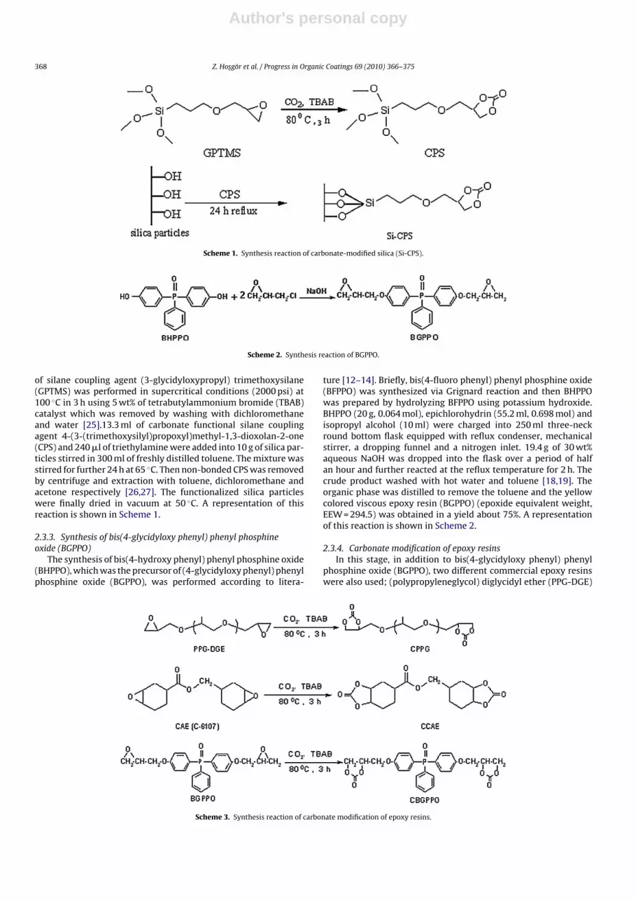
of silane coupling agent (3-glycidyloxypropyl) trimethoxysilane(GPTMS) was performed in supercritical conditions (2000 psi) at100 ◦C in 3 h using 5 wt% of tetrabutylammonium bromide (TBAB)catalyst which was removed by washing with dichloromethaneand water [25].13.3 ml of carbonate functional silane couplingagent 4-(3-(trimethoxysilyl)propoxyl)methyl-1,3-dioxolan-2-one(CPS) and 240 �l of triethylamine were added into 10 g of silica par-ticles stirred in 300 ml of freshly distilled toluene. The mixture wasstirred for further 24 h at 65 ◦C. Then non-bonded CPS was removedby centrifuge and extraction with toluene, dichloromethane andacetone respectively [26,27]. The functionalized silica particleswere finally dried in vacuum at 50 ◦C. A representation of thisreaction is shown in Scheme 1.
2.3.3. Synthesis of bis(4-glycidyloxy phenyl) phenyl phosphineoxide (BGPPO)
The synthesis of bis(4-hydroxy phenyl) phenyl phosphine oxide(BHPPO), which was the precursor of (4-glycidyloxy phenyl) phenylphosphine oxide (BGPPO), was performed according to litera-
ture [12–14]. Briefly, bis(4-fluoro phenyl) phenyl phosphine oxide(BFPPO) was synthesized via Grignard reaction and then BHPPOwas prepared by hydrolyzing BFPPO using potassium hydroxide.BHPPO (20 g, 0.064 mol), epichlorohydrin (55.2 ml, 0.698 mol) andisopropyl alcohol (10 ml) were charged into 250 ml three-neckround bottom flask equipped with reflux condenser, mechanicalstirrer, a dropping funnel and a nitrogen inlet. 19.4 g of 30 wt%aqueous NaOH was dropped into the flask over a period of halfan hour and further reacted at the reflux temperature for 2 h. Thecrude product washed with hot water and toluene [18,19]. Theorganic phase was distilled to remove the toluene and the yellowcolored viscous epoxy resin (BGPPO) (epoxide equivalent weight,EEW = 294.5) was obtained in a yield about 75%. A representationof this reaction is shown in Scheme 2.
2.3.4. Carbonate modification of epoxy resinsIn this stage, in addition to bis(4-glycidyloxy phenyl) phenyl
phosphine oxide (BGPPO), two different commercial epoxy resinswere also used; (polypropyleneglycol) diglycidyl ether (PPG-DGE)
Scheme 3. Synthesis reaction of carbonate modification of epoxy resins.

Author's personal copy
Z. Hosgör et al. / Progress in Organic Coatings 69 (2010) 366–375 369
Table 1Polyurethane–silica nanocomposite coating formulations.
Sample % Silica Si-CPS (g) EtOHa (g) CCAE (g) CPPG (g) CBGPPO (g) HMDA (g) PPh3 (g)
1 CCAE-PPG-0 0 – 4 5 5 – 3.005 0.0752 CCAE-PPG-1 1 0.05 4 5 5 – 3.015 0.0753 CCAE-PPG-1.5 1.5 0.1 4 5 5 – 3.025 0.0754 CCAE-PPG-2 2 0.2 4 5 5 – 3.035 0.0755 CCAE-PPG-4 4 0.4 4 5 5 – 3.045 0.0756 CCAE-PPG-6 6 0.6 4 5 5 – 3.055 0.0757 CCAE-PPG-CBGPPO-10-4 4 0.4 4 4.5 4.5 1 2.98 0.0758 CCAE-PPG-CBGPPO-20-4 4 0.4 4 4 4 2 2.95 0.0759 CCAE-PPG-CBGPPO-30-4 4 0.4 4 3.5 3.5 3 2.92 0.075
10 CCAE-PPG-CBGPPO-20-0 0 0 4 4 4 2 2.95 0.075
a BYK/ethanol solution (2 wt%).
Fig. 1. SEM images of silica particles (a) ×32.20 KX (b) ×104.97 KX.
and Cyracure UV-6107 (cyclic aliphatic epoxy resin). Modifica-tion of all epoxy resins was performed in supercritical conditions(1500 psi CO2) at 80 ◦C in 3 h using tetrabutylammonium bro-mide (TBAB) as a catalyst. After extraction with dichloromethaneand evaporation, viscous carbonate-modified epoxy resins wereobtained in a yield about 90%. A representation of reaction is shownin Scheme 3.
2.3.5. Preparation of phosphine oxide based polyurethane–silicananocomposite coatings and free films by non-isocyanate route
Firstly, various amounts of modified silica particles were dis-persed in ethanol solution that contains BYK as wetting agent andtriphenylphosphine (TPP) as a catalyst over a period of 2 h in asonication bath. After the addition of carbonate-modified epoxyresins, ethanol was removed in vacuum oven at 75 ◦C. Finally hex-
amethylene diamine (HMDA) as a curing agent was added to theformulation. The compositions of all coating formulations weregiven in Table 1. In order to remove air bubbles formed duringmixing; formulations heated to 35 ◦C then kept under gentle vac-uum for 10 min without upsetting composition. After removal of airbubbles the prepared formulations were applied on to aluminumpanels using a wire gauged bar applicator in order to obtain uniformthickness of 30 �m and left at 100 ◦C for 24 h to cure. Moreover,hybrid free films were prepared by pouring the liquid formulationson to a Teflon® mold (10 mm × 50 mm × 1 mm) and cured at 100 ◦Cfor 24 h.
3. Results and discussion
Silica nanoparticles was synthesized according to Stöbermethod. Morphologic characterization of particles was carried outby SEM analyses. The morphology of silica particles was shown inFig. 1a and b. SEM images indicate that silica particles were agglom-erated while they were drying. Their particle size was around100 nm. The morphology of particles was also investigated by TEM.TEM picture shows that although there are lots off small parti-cles less than 50 nm, particles around 100–150 nm sizes can alsobe detected due to combination of smaller ones (Fig. 2)
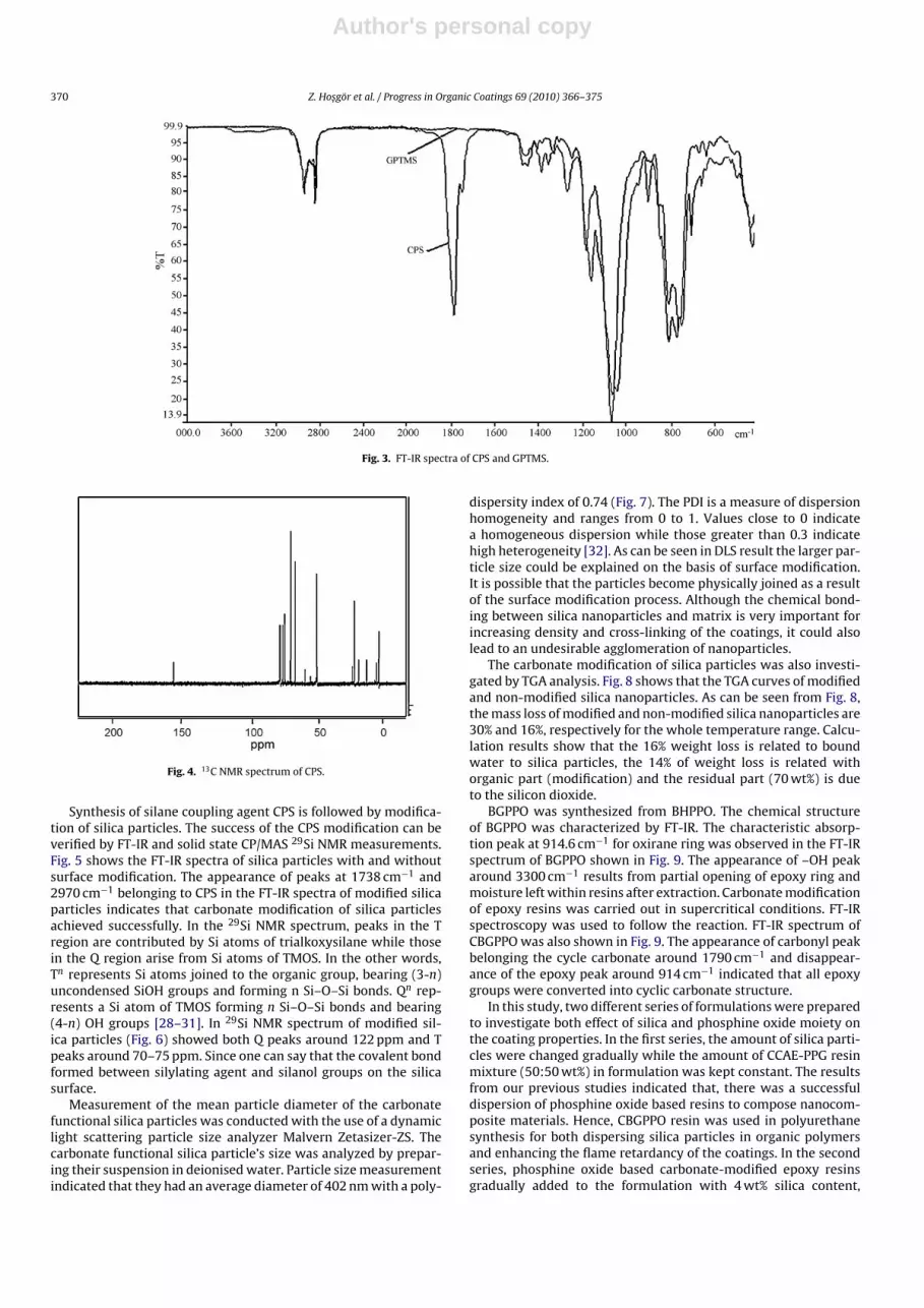
Carbonate modification reaction of GPTMS was followed by FT-IR and 13C NMR. The success of reaction was understood by theformation of carbonyl of cyclic carbonate peak that occurred at1790 cm−1 and disappearance of epoxy peak at 909 cm−1, in the FT-IR spectrum (Fig. 3). The appearance of intensive peak at 155 ppmthat attributed to carbonyl of cyclic carbonate structure in 13C NMRspectrum of CPS (Fig. 4) was another proof of the successful reac-tion.
Fig. 2. TEM image of silica particles.
Author's personal copy
370 Z. Hosgör et al. / Progress in Organic Coatings 69 (2010) 366–375
Fig. 3. FT-IR spectra of CPS and GPTMS.
Fig. 4. 13C NMR spectrum of CPS.
Synthesis of silane coupling agent CPS is followed by modifica-tion of silica particles. The success of the CPS modification can beverified by FT-IR and solid state CP/MAS 29Si NMR measurements.Fig. 5 shows the FT-IR spectra of silica particles with and withoutsurface modification. The appearance of peaks at 1738 cm−1 and2970 cm−1 belonging to CPS in the FT-IR spectra of modified silicaparticles indicates that carbonate modification of silica particlesachieved successfully. In the 29Si NMR spectrum, peaks in the Tregion are contributed by Si atoms of trialkoxysilane while thosein the Q region arise from Si atoms of TMOS. In the other words,Tn represents Si atoms joined to the organic group, bearing (3-n)uncondensed SiOH groups and forming n Si–O–Si bonds. Qn rep-resents a Si atom of TMOS forming n Si–O–Si bonds and bearing(4-n) OH groups [28–31]. In 29Si NMR spectrum of modified sil-ica particles (Fig. 6) showed both Q peaks around 122 ppm and Tpeaks around 70–75 ppm. Since one can say that the covalent bondformed between silylating agent and silanol groups on the silicasurface.
Measurement of the mean particle diameter of the carbonatefunctional silica particles was conducted with the use of a dynamiclight scattering particle size analyzer Malvern Zetasizer-ZS. Thecarbonate functional silica particle’s size was analyzed by prepar-ing their suspension in deionised water. Particle size measurementindicated that they had an average diameter of 402 nm with a poly-
dispersity index of 0.74 (Fig. 7). The PDI is a measure of dispersionhomogeneity and ranges from 0 to 1. Values close to 0 indicatea homogeneous dispersion while those greater than 0.3 indicatehigh heterogeneity [32]. As can be seen in DLS result the larger par-ticle size could be explained on the basis of surface modification.It is possible that the particles become physically joined as a resultof the surface modification process. Although the chemical bond-ing between silica nanoparticles and matrix is very important forincreasing density and cross-linking of the coatings, it could alsolead to an undesirable agglomeration of nanoparticles.
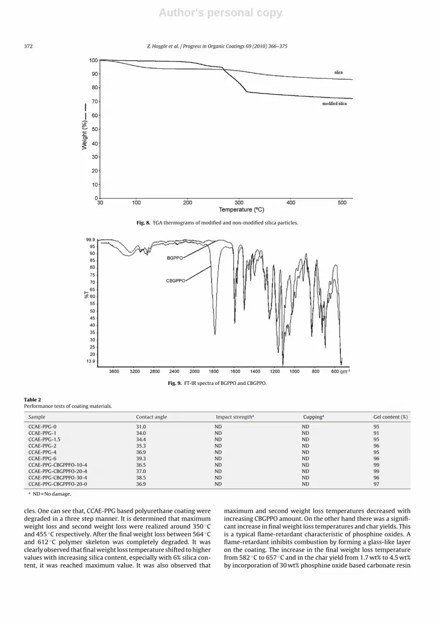
The carbonate modification of silica particles was also investi-gated by TGA analysis. Fig. 8 shows that the TGA curves of modifiedand non-modified silica nanoparticles. As can be seen from Fig. 8,the mass loss of modified and non-modified silica nanoparticles are30% and 16%, respectively for the whole temperature range. Calcu-lation results show that the 16% weight loss is related to boundwater to silica particles, the 14% of weight loss is related withorganic part (modification) and the residual part (70 wt%) is dueto the silicon dioxide.
BGPPO was synthesized from BHPPO. The chemical structureof BGPPO was characterized by FT-IR. The characteristic absorp-tion peak at 914.6 cm−1 for oxirane ring was observed in the FT-IRspectrum of BGPPO shown in Fig. 9. The appearance of –OH peakaround 3300 cm−1 results from partial opening of epoxy ring andmoisture left within resins after extraction. Carbonate modificationof epoxy resins was carried out in supercritical conditions. FT-IRspectroscopy was used to follow the reaction. FT-IR spectrum ofCBGPPO was also shown in Fig. 9. The appearance of carbonyl peakbelonging the cycle carbonate around 1790 cm−1 and disappear-ance of the epoxy peak around 914 cm−1 indicated that all epoxygroups were converted into cyclic carbonate structure.
In this study, two different series of formulations were preparedto investigate both effect of silica and phosphine oxide moiety onthe coating properties. In the first series, the amount of silica parti-cles were changed gradually while the amount of CCAE-PPG resinmixture (50:50 wt%) in formulation was kept constant. The resultsfrom our previous studies indicated that, there was a successfuldispersion of phosphine oxide based resins to compose nanocom-posite materials. Hence, CBGPPO resin was used in polyurethanesynthesis for both dispersing silica particles in organic polymersand enhancing the flame retardancy of the coatings. In the secondseries, phosphine oxide based carbonate-modified epoxy resinsgradually added to the formulation with 4 wt% silica content,

Author's personal copy
Z. Hosgör et al. / Progress in Organic Coatings 69 (2010) 366–375 371
Fig. 5. FT-IR spectra of silica particles without and with surface modification.
Fig. 6. 29Si NMR spectrum of modified silica particles (Si-CPS).
decreasing the amount of organic matrix (CPPG and CCAE). Inall formulations hexamethylene diamine was used to preparenon-isocyanate polyurethane nanocomposites by thermal curingmethod. Feed compositions that used to prepare aluminum coat-ings and free films were shown in Table 1.
Fig. 7. Particle size of the modified silica particles (Si-CPS).
The coated aluminum panels were subjected to performancetests such as impact and cupping. After impact and cupping testswere applied to aluminum coating no damage was seen.
In order to investigate the surface property of hybrid materialswater contact angle measurements were performed. Each contactangle value given in Table 2 represents an average of 8–10 readings.As shown in Table 2, contact angle values increase with incorpora-tion of silica particles and phosphine oxide based resin.
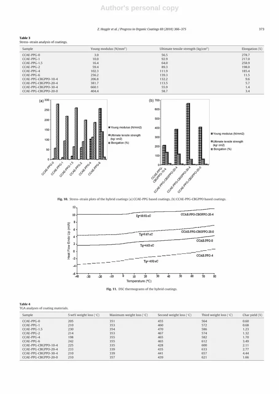
Mechanic properties of polyurethane nanocomposites wereinvestigated with universal tensile test machine. Evaluatedstress–strain data of hybrid coatings as Young’s modulus, ultimatetensile strength and elongation at break were listed in Table 3 andgraphics of them were shown in Fig. 10a and b. As show in thetable, in the first series value of modulus and ultimate strength val-ues increased from 3.0 N/mm2 to 256.2 N/mm2 and 56.5 kg/cm2 to139.3 kg/cm2 respectively by increasing the silica amount in thecoating. While incorporation of silica makes the coating strongerbut also makes brittle. Elongation at break is decreasing sharply at6 wt% silica content because at higher silica concentrations, silicaaggregates making the coating more brittle. In the second series,addition of phosphine oxide makes remarkable increase in mod-ule values. But at concentration 10 wt% phospine oxide based resin,the ultimate strength reached maximum value since aromatic rigidgroups increased the hardness of the coating making the materialmore brittle.
The thermal properties of the hybrid coatings were character-ized by DSC and TGA analyses. The DSC thermograms of the filmswere shown in Fig. 11. One can say that the incorporation of sil-ica particles does not make significant effect on Tg values but withincorporation of phosphine oxide based resin, Tg values increasedfrom 5 ◦C to 10 ◦C. And also all formulations show only a single Tg,which demonstrates the compatibility of three resins.
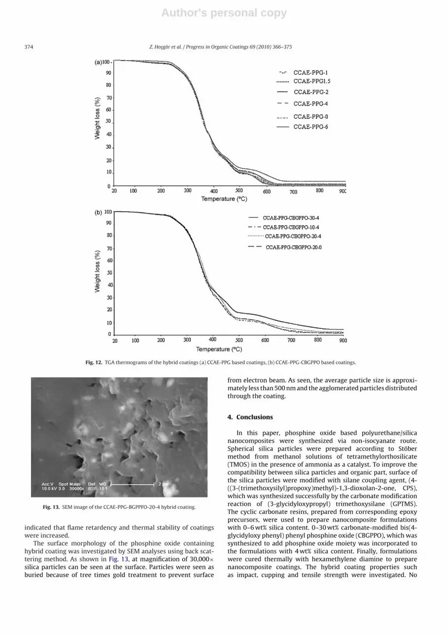
Fig. 12a and b shows the thermal degradation behaviors ofhybrid coatings. TGA measurements were carried out under airatmosphere at heating rate 10 ◦C/min from room temperature to900 ◦C and the test data are summarized in Table 4. All samplesshowed 5 wt% weight loss between 198 ◦C and 242 ◦C implyingthe release of volatile degradation products such as methanol,the excess amount of HMDA and the moisture of silica parti-
Author's personal copy
372 Z. Hosgör et al. / Progress in Organic Coatings 69 (2010) 366–375
Fig. 8. TGA thermograms of modified and non-modified silica particles.
Fig. 9. FT-IR spectra of BGPPO and CBGPPO.
Table 2Performance tests of coating materials.
Sample Contact angle Impact strengtha Cuppinga Gel content (%)
CCAE-PPG-0 31.0 ND ND 95CCAE-PPG-1 34.0 ND ND 91CCAE-PPG-1.5 34.4 ND ND 95CCAE-PPG-2 35.3 ND ND 96CCAE-PPG-4 36.9 ND ND 95CCAE-PPG-6 39.3 ND ND 96CCAE-PPG-CBGPPFO-10-4 36.5 ND ND 99CCAE-PPG-CBGPPFO-20-4 37.0 ND ND 99CCAE-PPG-CBGPPFO-30-4 38.5 ND ND 96CCAE-PPG-CBGPPFO-20-0 36.9 ND ND 97
a ND = No damage.
cles. One can see that, CCAE-PPG based polyurethane coating weredegraded in a three step manner. It is determined that maximumweight loss and second weight loss were realized around 350 ◦Cand 455 ◦C respectively. After the final weight loss between 564 ◦Cand 612 ◦C polymer skeleton was completely degraded. It wasclearly observed that final weight loss temperature shifted to highervalues with increasing silica content, especially with 6% silica con-tent, it was reached maximum value. It was also observed that
maximum and second weight loss temperatures decreased withincreasing CBGPPO amount. On the other hand there was a signifi-cant increase in final weight loss temperatures and char yields. Thisis a typical flame-retardant characteristic of phosphine oxides. Aflame-retardant inhibits combustion by forming a glass-like layeron the coating. The increase in the final weight loss temperaturefrom 582 ◦C to 657 ◦C and in the char yield from 1.7 wt% to 4.5 wt%by incorporation of 30 wt% phosphine oxide based carbonate resin
Author's personal copy
Z. Hosgör et al. / Progress in Organic Coatings 69 (2010) 366–375 373
Table 3Stress–strain analysis of coatings.
Sample Young modulus (N/mm2) Ultimate tensile strength (kg/cm2) Elongation (%)
CCAE-PPG-0 3.0 56.5 278.7CCAE-PPG-1 10.0 92.9 217.0CCAE-PPG-1.5 16.4 64.0 258.9CCAE-PPG-2 59.4 89.3 198.0CCAE-PPG-4 102.3 111.9 185.4CCAE-PPG-6 256.2 139.3 11.5CCAE-PPG-CBGPPO-10-4 206.8 132.2 9.6CCAE-PPG-CBGPPO-20-4 381.7 113.5 5.7CCAE-PPG-CBGPPO-30-4 660.1 55.9 1.4CCAE-PPG-CBGPPO-20-0 404.4 58.7 3.4
Fig. 10. Stress–strain plots of the hybrid coatings (a) CCAE-PPG based coatings, (b) CCAE-PPG-CBGPPO based coatings.
Fig. 11. DSC thermograms of the hybrid coatings.
Table 4TGA analyses of coating materials.
Sample 5 wt% weight loss (◦C) Maximum weight loss (◦C) Second weight loss (◦C) Third weight loss (◦C) Char yield (%)
CCAE-PPG-0 205 351 455 564 0.60CCAE-PPG-1 210 353 460 572 0.68CCAE-PPG-1.5 230 354 470 586 1.23CCAE-PPG-2 214 353 467 574 1.32CCAE-PPG-4 198 355 465 582 1.70CCAE-PPG-6 242 355 465 612 3.49CCAE-PPG-CBGPPO-10-4 225 335 428 600 2.11CCAE-PPG-CBGPPO-20-4 233 339 435 633 2.77CCAE-PPG-CBGPPO-30-4 210 339 441 657 4.44CCAE-PPG-CBGPPO-20-0 210 357 439 621 1.66
Author's personal copy
374 Z. Hosgör et al. / Progress in Organic Coatings 69 (2010) 366–375
Fig. 12. TGA thermograms of the hybrid coatings (a) CCAE-PPG based coatings, (b) CCAE-PPG-CBGPPO based coatings.
Fig. 13. SEM image of the CCAE-PPG-BGPPFO-20-4 hybrid coating.
indicated that flame retardency and thermal stability of coatingswere increased.
The surface morphology of the phosphine oxide containinghybrid coating was investigated by SEM analyses using back scat-tering method. As shown in Fig. 13, at magnification of 30,000×silica particles can be seen at the surface. Particles were seen asburied because of tree times gold treatment to prevent surface
from electron beam. As seen, the average particle size is approxi-mately less than 500 nm and the agglomerated particles distributedthrough the coating.
4. Conclusions
In this paper, phosphine oxide based polyurethane/silicananocomposites were synthesized via non-isocyanate route.Spherical silica particles were prepared according to Stöbermethod from methanol solutions of tetramethylorthosilicate(TMOS) in the presence of ammonia as a catalyst. To improve thecompatibility between silica particles and organic part, surface ofthe silica particles were modified with silane coupling agent, (4-((3-(trimethoxysilyl)propoxy)methyl)-1,3-dioxolan-2-one, CPS),which was synthesized successfully by the carbonate modificationreaction of (3-glycidyloxypropyl) trimethoxysilane (GPTMS).The cyclic carbonate resins, prepared from corresponding epoxyprecursors, were used to prepare nanocomposite formulationswith 0–6 wt% silica content. 0–30 wt% carbonate-modified bis(4-glycidyloxy phenyl) phenyl phosphine oxide (CBGPPO), which wassynthesized to add phosphine oxide moiety was incorporated tothe formulations with 4 wt% silica content. Finally, formulationswere cured thermally with hexamethylene diamine to preparenanocomposite coatings. The hybrid coating properties suchas impact, cupping and tensile strength were investigated. No

Author's personal copy
Z. Hosgör et al. / Progress in Organic Coatings 69 (2010) 366–375 375
damage was observed in the impact strength of the coatings.Incorporation of silica and CBGPPO into formulations increasedmodulus and hardness of the coating making the material morebrittle. It was also observed that, the thermal stability of hybridcoatings enhanced with the addition of silica and CBGPPO. Thermalgravimetric analysis of CBGPPO containing polymeric films gavehigher char yield compared with CCAE-PPG only.
Acknowledgements
This work was supported by TUBITAK (The Scientific & Techno-logical Research Council of Turkey) Research Project under grantproject number: 106T083.
References
[1] K.S. Rao, K. El-Hami, T. Kodaki, K. Matsushige, K. Makino, J. Colloid Interface Sci.289 (1995) 125.
[2] D.L. Green, J.S. Lin, Y.F. Lam, M.Z. Hu, D.W. Schaefer, M.T. Harris, J. ColloidInterface Sci. 266 (2003) 346.
[3] W. Stöber, A. Fink, E. Bohn, J. Colloid Interface Sci. 26 (1968) 62.[4] G. Kickelbick, Prog. Polym. Sci. 28 (2003) 83.[5] R. Bongiovanni, M. Sangermano, S. Ronchetti, A. Priola, G. Malucelli, Polymer
48 (2007) 7000.[6] O. Türünc, N. Kayaman-Apohan, M.V. Kahraman, Y. Menceloglu, A. Gungor, J.
Sol–Gel Sci. Technol. 47 (2008) 290.[7] S. Sarkar, Paintindia 57 (2007) 99.[8] O.L. Figovsky, L. Shapovalov, Nonisocyanate Polyurethanes for Adhesives and
Coatings First International IEEE Conference on Polymers and Adhesives inElectronics, Potsdam, Germany, October 21–24, 2001, p. 257.
[9] O.L. Figovsky, L. Shapovalov, F. Buslov, Surf. Coat. Int. B: Coat. Trans. 88B (2004)167.
[10] C.D. Diakoumakos, D.L. Kotzev, Macromol. Symp. 216 (2004) 46.[11] O.L. Figovsky, L. Shapovalov, Macromol. Symp. 187 (2002) 325.[12] I.V. Stroganov, V.F. Stroganov, Polym. Sci. C 49 (2007) 263.[13] Y. Du, J.Q. Wang, J.Y. Chen, F. Cai, J.S. Tian, D.L. Kong, L.N. He, Tetrahedron Lett.
47 (2006) 1271.[14] S. Karatas, Z. Hosgör, Y. Menceloglu, N. Kayaman-Apohan, A. Gungor, J. Appl.
Polym. Sci. 102 (2006) 1906.[15] C.D. Smith, H. Gurbbs, H.F. Webster, A. Gungor, J.P. Wightman, J.E. McGrath,
High Perform. Polym. 3 (1991) 211.[16] D.J.J. Riley, Ph.D. Thesis, Virginia Polytechnic Institute, 1997.[17] N. Mann, S.K. Mendon, J.W. Rawlins, S.F. Thames, J. Am. Oil Chem. Soc. 85 (2008)
791.[18] H. Ren, J. Sun, B. Wu, Q. Zhou, Polym. Degrad. Stab. 92 (2007)
956–961.[19] M.S. Lakshmi, B.S.R. Reddy, Eur. Polym. J. 38 (2002) 795.[20] M.V. Kahraman, N. Kayaman-Apohan, N. Arsu, A. Gungor, Prog. Org. Coat. 51
(2004) 213.[21] M.J. Alcon, G. Ribera, M. Galia, V. Cadiz, Polymer 44 (2003) 7291.[22] Y.L. Liu, J. Appl. Polym. Sci. 83 (2002) 1697.[23] Y. Chen, S. Zhou, G. Chen, L. Wu, Prog. Org. Coat. 54 (2005) 120.[24] Y. Chen, S. Zhou, H. Yang, G. Gu, L. Wu, J. Colloid Interface Sci. 279 (2004)
370.[25] D.L. Tomasko, H. Li, D. Liu, X.Han, M. Wingert, L.J. Lee, K.W. Koelling, Ind. Eng.
Chem. Res. 42 (2003) 6431.[26] S. Radi, A. Ramdani, Y. Lekchiri, M. Morcellet, G. Crini, L. Janus, M. Bacquet, New
J. Chem. 27 (2003) 1224.[27] A. Ponchel, S. Abramson, J. Quartararo, D. Bormann, Y. Barbaux, E. Monflier,
Microporous Mesoporous Mater. 75 (2004) 261.[28] D.P. Fasce, I.E. Erba, R.J.J. Williams, Polymer 46 (2005) 6649.[29] X. Zhang, N. Zhao, W. Wei, Y. Sun, Catal. Today 115 (2006) 102.[30] S.R. Davis, A.R. Brough, A. Atkinson, J. Non-Cryst. Solids 315 (2003) 197.[31] H. Kao, Y. Tsai, S. Chao, Solid State Ionics 176 (2005) 1261.[32] F. Guo, Q. Zhang, B. Zhang, H. Zhang, L. Zhang, Polymer 50 (2009) 1887.