premolded screened separable cable connectors
TRANSCRIPT

26
Premolded screened separable cable connectors
CSE-A 12 – 24 kV, 250 A, CSS-A 12 – 24 kV, 250 A
Application areas
Standard
Design
Note:
Always select products by Insulation diameter.
Voltage Insulation diameter
Conductor cross section
Designation Weight
kV mm mm2 kg/unit
Elbow cable connector
12 10–12 10–16 2.2
12 13–22 25–95 2.2
24 13–22 10–16 2.2
24 17–25.5 25–95 2.2
Straight cable connector
12 10–12 10–16 2.2
12 13–22 25–95 2.2
24 13–22 10–16 2.2
24 17–25.5 25–95 2.2
Elbow cable connector complete with screen separation kit
12 10–12 10–16 5.5
12 13–22 25–95 5.5
24 13–22 10–16 5.5
24 50–95 6.1
R3R1C 2 x 45°
Ø 4
3.5
Ø 4
8.5
Ø 9
0
Ø 3
1
1
Ø 3
2.5
9 48
Ø 63
124
211
Ø 58
29
263
Ø 65
66

27
Premolded screened separable connectorfor cables with Cu-tape screen
CSE-A 12 – 24 kV, 250 A
Application areas
Standard
Design
Always select products by Insulation diameter.
Voltage Insulation diameter
Conductor cross section
Designation Outer sheathdiameter
Weight
kV mm mm2 mm kg/unit
Elbow cable connector, 3 x 1-core
12 13–22 25–95 – 2.7
24 19–25.5 35–95 – 2.7
Elbow cable connector, 3-core
12 13–22 25–50 31–50 2.9
12 13–22 70–95 44–70 2.9
24 19–25.5 35–95 47–70 2.9
R3R1C 2 x 45°
Ø 4
3.5
Ø 4
8.5
Ø 9
0
Ø 3
1
1
Ø 3
2.5
9 48
Ø 63
124
211
Ø 58
29

28
Designation Description Qty. Weight See page
per kit kg/kit
3 2.3 28
1 28
1 1.0–1.1 54
1 0.3–1.0 55
3 3.0 28
1 2.7 28
1 0.2 28
1 0.3 28
Accessories, to be ordered separatelyCSE-A and CSS-A 12 – 24 kV, 250 A
MA 250
IH-A 24250
IP 250 CU 250
JP 250
250 A.
PSSK
PC 630/250
TSH

29
Premolded screened separable cable connector
CSE-A 12 – 42 kV, 400 A
Application areas
Standard
Design
Note:
Always select products by Insulation diameter.
Voltage Insulation diameter
Conductor cross section
Designation Ratedcurrent
Weight
kV mm mm2 A kg/unit
12 13–20 25–70 400 6.1
12 18.5–30.5 95–300 400 6.6
24 17–24 25–70 400 6.1
24 22.5–35 95–300 400 6.6
36 24.5–34 400 6.1
36 27.5–42 400 6.6
42 24.5–34 50–70 400 6.1
42 27.5–42 95–300 400 6.6
R3
Ø 4
6
Ø 7
0Ø
102
115.5
40R3R3
Ø 5
6
90
Ø 80
173
256
Ø 72
34
Ø 80
195
284
Ø 74
34
30
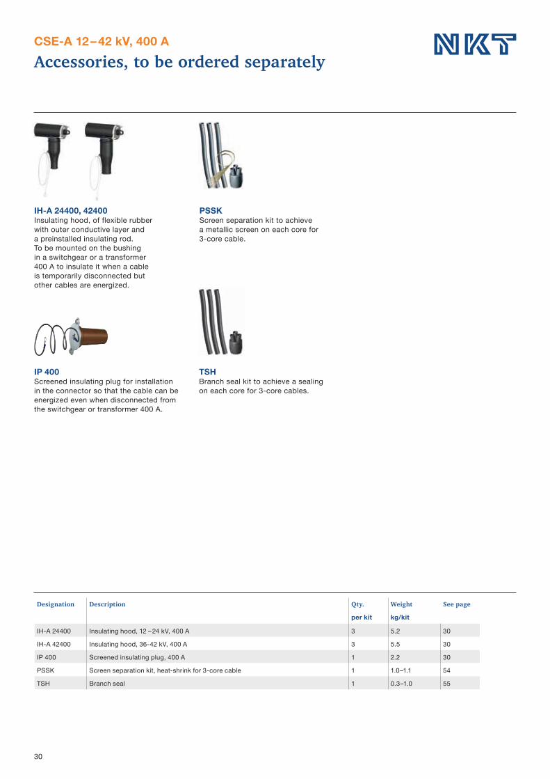
Designation Description Qty. Weight See page
per kit kg/kit
3 5.2 30
3 5.5 30
1 2.2 30
1 1.0–1.1 54
1 0.3–1.0 55
Accessories, to be ordered separatelyCSE-A 12 – 42 kV, 400 A
IH-A 24400, 42400
IP 400
PSSK
TSH

31
Premolded screened separable cable connector
CSE-A 12 – 42 kV, 630 A
Application areas
Standard
Design
Note:
Always select products by Insulation diameter.
Voltage Insulation diameter
Conductor cross section
Designation Weight
kV mm mm2 kg/unit
12 13–20 25–70 5.112 18.5–30.5 95–300 5.512 30.5–45 400–630 7.724 17–24 25–70 5.124 22.5–35 95–300 5.524 30.5–45 400–630 7.736 24.5–34 6.136 27.5–42 6.636 38.0–55 8.742 24.5–34 50–70 6.142 27.5–42 95–300 6.642 38–55 400–630 8.7
Cable connector complete with screen separation kit
12 13–20 25–70 8.412 18.5–30.5 95–300 9.424 50–70 924 22.5–35 95–300 9.436 23–34 50–95 1036 27.5–42 95–300 1.4
Ø 81
194
283
Ø 74
9
Ø 85
180
31490
9
Ø 81
172
256
Ø 72
9
9Ø 85
202
31490
Ø 4
6Ø
56
R3R3
Ø 7
0
11 90
R3 1.529

32
Premolded screened separable cable connectorfor cables with copper tape screen
CSE-A 12 – 36 kV, 630 A
Application areas
Standard
Design
Always select products by Insulation diameter.
Voltage Insulation diameter
Conductor cross section
Outer sheathdiameter
Designation Weight
kV mm mm2 mm kg/unit
Elbow cble connectors, 3 x 1-core cables
12 13–20 25–70 – 5.612 19–29 95–300 – 6.012 30.5–37 400 – 8.224 19–24 35–70 – 5.624 25–35 95–300 – 6.024 30.5–37 400 – 8.236 19–29 50–70 – 6.836 27.5–37 95–300 – 7.336 38–50 400 – 9.4
Elbow cable connectors, 3-core cables
12 13–20 25–70 31–50 5.812 19–29 95–185 47–70 6.212 25–30.5 240–300 58–94 6.212 30.5–37 400 58–94 8.424 19–24 35–70 47–70 5.824 25–35 95–300 58–94 6.224 30.5–37 400 65–110 8.436 19–29 50–95 58–94 6.836 27.5–37 95–300 65–110 7.3
Ø 81
194
283
Ø 74
9
Ø 85
180
31490
9
Ø 81
172
256
Ø 72
9
9Ø 85
202
31490

33
Designation Description Qty. Weight See page
per kit kg/kit
3 5.2 333 5.5 331 2.2 333 3.0 331 1.0–1.1 541 0.3–1.0 553 0.2 331 3.6–5.0 35
PG 630 1 1.5 331 2.0 331 5.7–9.8 341 5.0 331 1.8 33
Accessories, to be ordered separatelyCSE-A 12 – 42 kV, 630 A
IH-A 24630, IH 42630
MA-A 630
PC 630/250
PG 630IP 630
630 A.
PG-A 630
36 – 42 kV.
JPB 630
JPA V
CSAP-A CSEP-APSSK
TSH

34
Parallel separable connector CSEP-A 12 – 42 kV
Application area
12 – 42 kV.
Standard
Design
Note:
Always select products by Insulation diameter.
Voltage Conductor cross section
Insulation diameter
Designation Weight
kV mm2 mm kg/kit
12 25–70 13–20 5.712 95–300 18.5–30.5 6.112 400–630 30.5–45 8.624 25–70 17–24 5.724 95–300 22.5–35 6.124 400–630 30.5–45 8.636 50–95 24.5–34 6.736 95–300 27.5–42 7.136 400–630 38–55 9.842 50–70 24.5–34 6.742 95–300 27.5–42 7.142 400–630 38–55 9.8
Parallel connector complete with screen separation kit
12 13–20 25–70 912 18.5–30.5 95–300 1024 17–24 50–70 9.624 22.5–35 95–300 1036 23–34 50–95 10.636 27.5–42 95–300 11.9
256
72
85100 9
314
90
85114 9
283
74
81122 9
314
90
85136 9

35
Parallel screened separable connectorCSEP-A 12 – 42 kV
Application area
Standard
Design
Note:
Always select products by Insulation diameter.
Voltage Insulation diameter
Conductor cross section
Designation Weight
kV mm mm2 kg/kit
Parallel connector for 3 x 1-core cables
12 13–20 25–70 5.812 18.5–30.5 95–300 6.212 30.5–45 400 8.724 17–24 35–70 5.824 22.5–35 95–300 6.224 30.5–45 400 8.736 24.5–34 50–70 6.836 27.5–42 95–300 7.236 38–55 400 9.9
Parallel connector for 3-core cables
12 13–20 25–70 5.812 18.5–30.5 95–185 6.212 18.5–30.5 240–300 6.212 30.5–45 400 8.724 17–24 35–70 5.824 22.5–35 95–300 6.224 30.5–45 400 8.736 24.5–34 50–95 6.836 27.5–42 95–300 7.2
256
72
81100 9
314
90
85114 9
283
74
81122 9
314
90
85136 9

36
Dimensional drawings
Parallel connection of CSE-A and CSEP-A 12 – 42 kVParallel connection of two CSE-A 12 – 42 kV
Connection of parallel connector type CSEP-A to cable connector type
353 369 397 413
36 –
4 2 k
V12
– 24
kV
278
97
289
105
286
101 109
298
339
128
324
117
330
124
316
113
202194180
172
Accessories, to be ordered separately
Designation Description See page
55
54
37
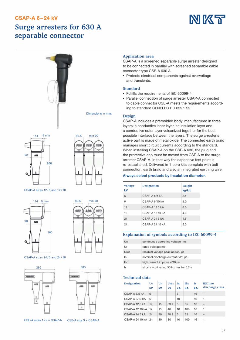
separable connector
CSAP-A 6 – 24 kV
Application area
Standard
Design
Always select products by Insulation diameter.
Voltage Designation WeightkV kg/kit
6 2.6
6 3.0
12 3.6
12 4.0
24 4.6
24 5.0
295 303
114
90
89.5
266
114
90
89.5
360
Technical dataDesignation Uc Ur Ures In Ihc Is IEC line
discharge classkV kV kV kA kA kA
6 5 16 –6 10 16 112 15 39.1 5 65 16 –12 15 40 10 100 16 124 30 78.2 5 65 16 –24 30 80 10 100 16 1