connectors - schaltbau
TRANSCRIPT

Connect - Contact - Control
1
InhaltRundsteckverbinder für Spezialanwendungen, Baureihe SB 2
Besondere Merkmale 2
Applikationen 2
Baureihenübersicht 2
Kompetenz 2
Normen 2
Technische Daten 3
Bestellschlüssel 4
5-polig + PE Flanschstecker, Kabeldose 4
6-polig Flanschdose, Kabelstecker 5
14-polig Flanschstecker, Kabeldose 5
Montage 6
Werkzeuge Ausdrückwerkzeuge AWZ-A und AWZ-C/H, Crimpzange CWZ-600 6
Montagebohrungen 6
Kontakte Stecker: Crimpkontakte, Dosen: Lötkontakte 7
Deratingkurven 7
Sicherheitshinweise 7
M Series
Circular Modular Connectors
Manual A10-M.en
Connectors
2 2017-12-21 / V1.3Connectors Series M – Installation and Maintenance Instructions
Content
1. Important Basic Information ......................................................................................... 31.1 Legal Notes .............................................................................................................................. 31.2 Conventions for this Installation and Maintenance Instructions ......................... 3
2. General and Security Information ................................................................................ 32.1 Observing the Installation and Maintenance Instructions .................................... 32.2 User Obligations .................................................................................................................... 32.3 Intended Use........................................................................................................................... 42.4 Ambient Conditions ............................................................................................................. 4
3. Dangers and Security Measures ................................................................................... 53.1 Electrical Dangers ................................................................................................................. 53.2 Other Hazards ......................................................................................................................... 53.3 Measures for Avoiding Damages..................................................................................... 63.4 Measures for Avoiding Malfunctions ............................................................................. 6
4. Description ........................................................................................................................ 74.1 Features .................................................................................................................................... 74.2 Varieties of Con�guration .................................................................................................. 74.3 Survey of the Components ................................................................................................ 8
5. Installation ......................................................................................................................105.1 Check Parts for Transport Damage ...............................................................................105.2 Assembly of Receptacles / Plugs into a Mounting Wall .........................................10
6. Cable Assembly and Processing .................................................................................126.1 Required Tools ......................................................................................................................126.2 Crimp Contacts (Pin / Socket) and Filler Plugs ..........................................................136.3 Ordering Code for Contacts ............................................................................................146.4 Threading Parts on Cables ...............................................................................................146.5 Make Crimp Connections .................................................................................................166.6 Assemble Contacts into Contact Inserts .....................................................................176.7 Assemble Filler Plugs .........................................................................................................186.8 Assemble Contact Inserts into Receptacle / Plug shells ........................................186.9 Final Assembly of the Connectors.................................................................................20
7. Plugging Procedure.......................................................................................................227.1 Plugging .................................................................................................................................227.2 Unplugging ...........................................................................................................................237.3 Attach Protection Caps .....................................................................................................23
8. Regular Visual Checks / Functional Checks ...............................................................258.1 Checking Intervals ..............................................................................................................258.2 Visual and Functional Check with Every Plugging Procedure ............................25
9. Special Tools and Spare Parts ......................................................................................27
10. Technical Data ................................................................................................................27
32017-12-21 / V1.3 Connectors Series M – Installation and Maintenance Instructions
Important Basic Information
1. Important Basic Information
1.1 Legal NotesWithout prior written consent of Schaltbau GmbH, the installation and maintenance instructions is not al-lowed to be electronically or mechanically reproduced – as a whole or in parts – be distributed, changed, trans-mitted, translated into another language or used in any other way.Schaltbau GmbH cannot be held liable for damage caused by not observing (or only partly observing) the Installation and maintenance instructions.
1.2 Conventions for this Installation and Maintenance Instructions
This instructions describe the installation and mainte-nance of the M series connectors.Cross references are presented in bold italics.To highlight particularly important safety instructions and other information, the following symbols are used in this instructions:
DANGERIndicates a hazardous situation with a high level of risk which, if not avoided, will result in death or seri-ous injury.
WARNINGIndicates a hazardous situation with a medium level of risk which, if not avoided, could result in death or serious injury.
CAUTIONIndicates a hazardous situation with a low level of risk which, if not avoided, may result in minor or moderate injury.
NOTICEIndicates a hazardous situation which, if not avoided, may result in property damage, such as service inter-ruption or damage to equipment or other materials.
Refers to technical features and methods aimed at facilitating work or to particu-larly important information.
2. General and Security InformationThe circular industrial connectors dealt with in this doc-ument are intended for use with low-voltage systems for special applications. They are designed and tested in compliance with the generally recognised state of the art. However, the improper use, operation, handling, maintenance of or tampering with electric equipment can cause serious or fatal injury to the user or others, and the appliance or other property can be damaged.The operation, maintenance and installation instructions for the connectors must therefore be strictly followed.Any uncertainties must be clari�ed and all queries must include details of the type of device and the serial num-ber. Only authorized and trained personnel are allowed to plan and carry out all mechanical and electrical installa-tions, transport, commissioning, as well as maintenance and repair work. This applies to the observation of the general installation and safety regulations for low-volt-age systems as well as the proper use of tools approved for this purpose. Electric equipment requires protection from moisture and dust during installation and storage.
2.1 Observing the Installation and Maintenance Instructions
X All sta� must read and understand the instruc-tions and adhere to them when working with the device.
X Always carefully observe all safety warnings!
2.2 User Obligations
X Observe the respective national instructions and the other applicable safety regulations for the use and cable assembly of connectors and connector systems.
X Observe all applicable national provisions, all safety, accident prevention and environmental regulations as well as the recognized technical rules for safe and proper working.
X Carry out regular inspections of all protection and safety devices to see if they work properly.

4 2017-12-21 / V1.3Connectors Series M – Installation and Maintenance Instructions
General and Security Information
X Work on electric equipment may only be performed by an expert or trained personnel working under the direction and supervision of an expert accord-ing to the applicable rules of electrical engineering.
X An expert is a person who can judge and recognise the possible dangers of the jobs commended to him based on his training, knowledge and experi-ence and by knowledge of the appropriate regula-tions.
X Sta� must be informed clearly about who is re-sponsible for the maintenance of the connectors.
2.3 Intended Use
X The connectors supply power and signals. They are intended for plugin and detachable connec-tions of components, devices and systems only.
X In order to comply with DIN EN IEC 61984 make sure that always the live side of the connector – no matter whether plug or receptacle – is �tted with socket contacts.
X A symmetrical assembly of the contact insert is not permitted. Please refer to the chapter „6. Cable Assembly and Processing“.
X None of the operating conditions de�ned in our catalogue “A10.en” in section “Speci�cations”, such as voltages, currents, ambient conditions, etc. may be changed.
X Work on the connectors must only be carried out by sta� who meets the requirements set out in these installation and maintenance instructions.
X According to DIN EN IEC 61984 connectors used as intended must not be engaged or disengaged when live or under load.
X A connector that does not engage easily requires special attention:Check for the correct orientation, pollution or if contacts got bent. Remedy the cause without de-lay. Never use force! The connector should always engage easily.
X In order to meet the requirements of the protec-tion class and to prevent the connectors against the entry of dirt or moisture, make sure that plugs and receptacles, when not mated, are always closed with protection caps.
X When disengaging a connector, pull the plug and never the cable.
X Use the connector only according to its intended use. Replace or repair damaged parts exclusively with original parts. Any other usage of or tamper-ing with the connector is considered contrary to its intended use. No liability is assumed for damages and accidents caused due to non-compliance with the instructions or improper use of the connector.
2.4 Ambient Conditions
NOTICEThe connectors are constructed for speci�c ambient conditions.
X Operate the connectors only under the ambi-ent conditions, like temperature ranges and IP protection classes as de�ned in our catalogue A10.en in section “Speci�cations“ (schaltbau.info/download1en).
Note:In case of a very low or very high ambient temperature which approximates the limits of the allowable oper-ating temperature range speci�ed in our catalogue A10.en in section “Speci�cations”, - a higher e�ort may be needed for the plugging and
unplugging and - the operational life span of plug and coupling recep-
tacle may thus be reduced due to increased wear and tear.
52017-12-21 / V1.3 Connectors Series M – Installation and Maintenance Instructions
Dangers and Security Measures
3. Dangers and Security Measures
3.1 Electrical Dangers
DANGERThe connectors contain components that carry voltage. Deadly hazard!Always observe the following safety regulations before beginning any work on electrical constructions:
X Disconnect X Ensure that it is not possible to reconnect unintentionally X Clearly mark your work area X Make sure that there is no voltage present X Earth and short circuit the installation X Insulate or cover adjacent energized parts X Only an electrically skilled person may determine if there is no voltage present
WARNINGA wrong pin con�guration of the contact inserts may cause a deathly electric shock.
X Make sure that associated pin contacts and socket contacts are always inserted in the corre-sponding contact cavities with identical pin con�guration!
X Make sure that contacts with phase assignment are not mounted into contact cavities which are destined for the protective earthing (PE) contact!
X Refer to chapter „6. Cable Assembly and Processing“.
3.2 Other Hazards
WARNINGExclusively use the connectors for purposes as indicated in the speci�cations and data sheets. A wrong application can cause accidents and severe damages to persons.
X The manufacturer doesn‘t take the responsibility for accidents which were caused by improper use of the product.
X We recommend the use of fault current safety systems in constructions with voltages higher than safety extra-low voltage.
WARNINGThe plugging and disconnecting of the connectors on-load can cause electric arcs. When explosive substances or ignition sources of any kind are nearby, there is a risk of �re and explosion!
X Never plug and disconnect the connectors on-load.
6 2017-12-21 / V1.3Connectors Series M – Installation and Maintenance Instructions
Dangers and Security Measures
3.3 Measures for Avoiding Damages
NOTICEImproper handling of the connector, e.g. when hitting the �oor with some impact, can result in breakage, visible cracks and deformation.
X Make sure that the connectors are handled appropriately. X Carry out regular visual checks to detect possible damages. X Replace damaged parts immediately.
3.4 Measures for Avoiding Malfunctions
NOTICEIn the case of damage, wear and tear and/or soiling of the connector components - in the form of a partial break, sharp edges and discoloured surfaces - the functional safety of the connectors is no longer guaranteed.
X Carry out regular visual checks to detect wear and tear and dirt. X Immediately replace damaged parts. X Immediately remove dirt without leaving any residues. X Immediately replace parts with stubborn dirt.
NOTICEInappropriate handling when plugging or disconnecting may damage the connectors. The functional safety of the connectors is no longer guaranteed when parts are damaged.
X Make sure that the guideways and slots of plug and receptacle always interlock when plugging! X Take care that plug and receptacle do not tilt and that they are plugged without force. X Make sure before the plugging procedure that plug and receptacle as well as the protection caps are not
soiled. Remove existent dirt without leaving any residues. X Make sure that in the not mated condition the protection caps are always attached according to regulations.
72017-12-21 / V1.3 Connectors Series M – Installation and Maintenance Instructions
Description
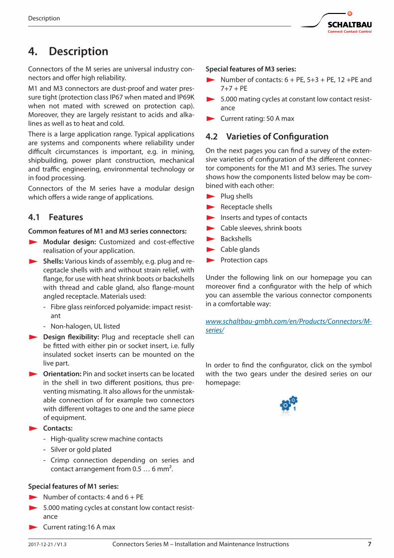
4. DescriptionConnectors of the M series are universal industry con-nectors and o�er high reliability.M1 and M3 connectors are dust-proof and water pres-sure tight (protection class IP67 when mated and IP69K when not mated with screwed on protection cap). Moreover, they are largely resistant to acids and alka-lines as well as to heat and cold.There is a large application range. Typical applications are systems and components where reliability under di�cult circumstances is important, e.g. in mining, shipbuilding, power plant construction, mechanical and tra�c engineering, environmental technology or in food processing.Connectors of the M series have a modular design which o�ers a wide range of applications.
4.1 FeaturesCommon features of M1 and M3 series connectors:
X Modular design: Customized and cost-e�ective realisation of your application.
X Shells: Various kinds of assembly, e.g. plug and re-ceptacle shells with and without strain relief, with �ange, for use with heat shrink boots or backshells with thread and cable gland, also �ange-mount angled receptacle. Materials used: - Fibre glass reinforced polyamide: impact resist-
ant - Non-halogen, UL listed
X Design �exibility: Plug and receptacle shell can be �tted with either pin or socket insert, i.e. fully insulated socket inserts can be mounted on the live part.
X Orientation: Pin and socket inserts can be located in the shell in two di�erent positions, thus pre-venting mismating. It also allows for the unmistak-able connection of for example two connectors with di�erent voltages to one and the same piece of equipment.
X Contacts: - High-quality screw machine contacts - Silver or gold plated - Crimp connection depending on series and
contact arrangement from 0.5 … 6 mm².
Special features of M1 series: X Number of contacts: 4 and 6 + PE X 5.000 mating cycles at constant low contact resist-
ance X Current rating:16 A max
Special features of M3 series: X Number of contacts: 6 + PE, 5+3 + PE, 12 +PE and
7+7 + PE X 5.000 mating cycles at constant low contact resist-
ance X Current rating: 50 A max
4.2 Varieties of Con�gurationOn the next pages you can �nd a survey of the exten-sive varieties of con�guration of the di�erent connec-tor components for the M1 and M3 series. The survey shows how the components listed below may be com-bined with each other:
X Plug shells X Receptacle shells X Inserts and types of contacts X Cable sleeves, shrink boots X Backshells X Cable glands X Protection caps
Under the following link on our homepage you can moreover �nd a con�gurator with the help of which you can assemble the various connector components in a comfortable way:
www.schaltbau-gmbh.com/en/Products/Connectors/M-series/
In order to �nd the con�gurator, click on the symbol with the two gears under the desired series on our homepage:
8 2017-12-21 / V1.3Connectors Series M – Installation and Maintenance Instructions
Description
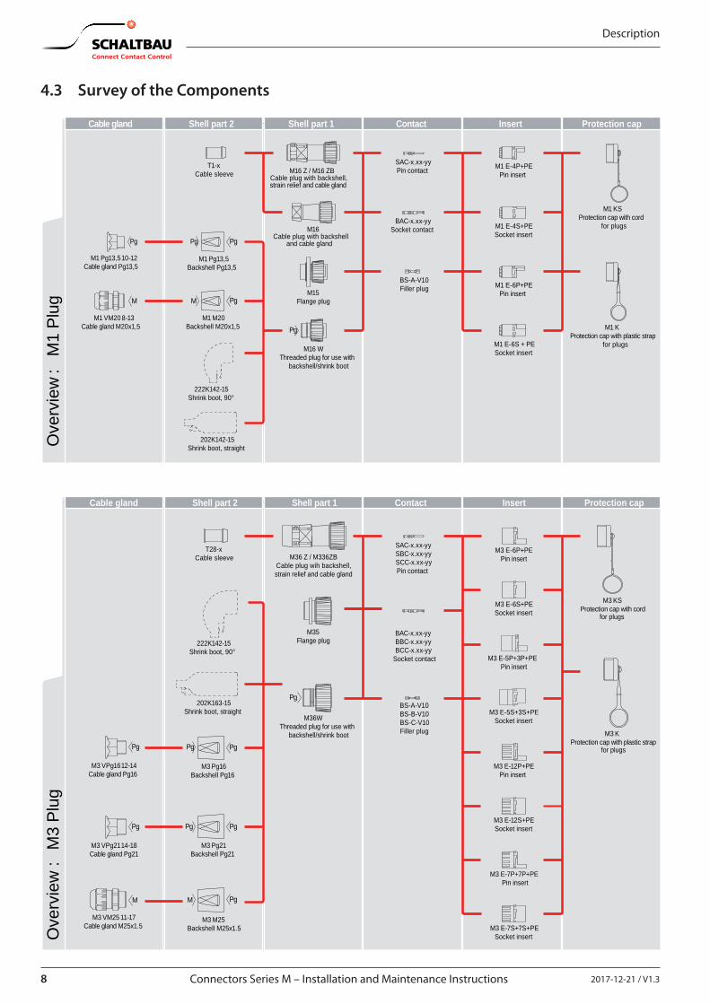
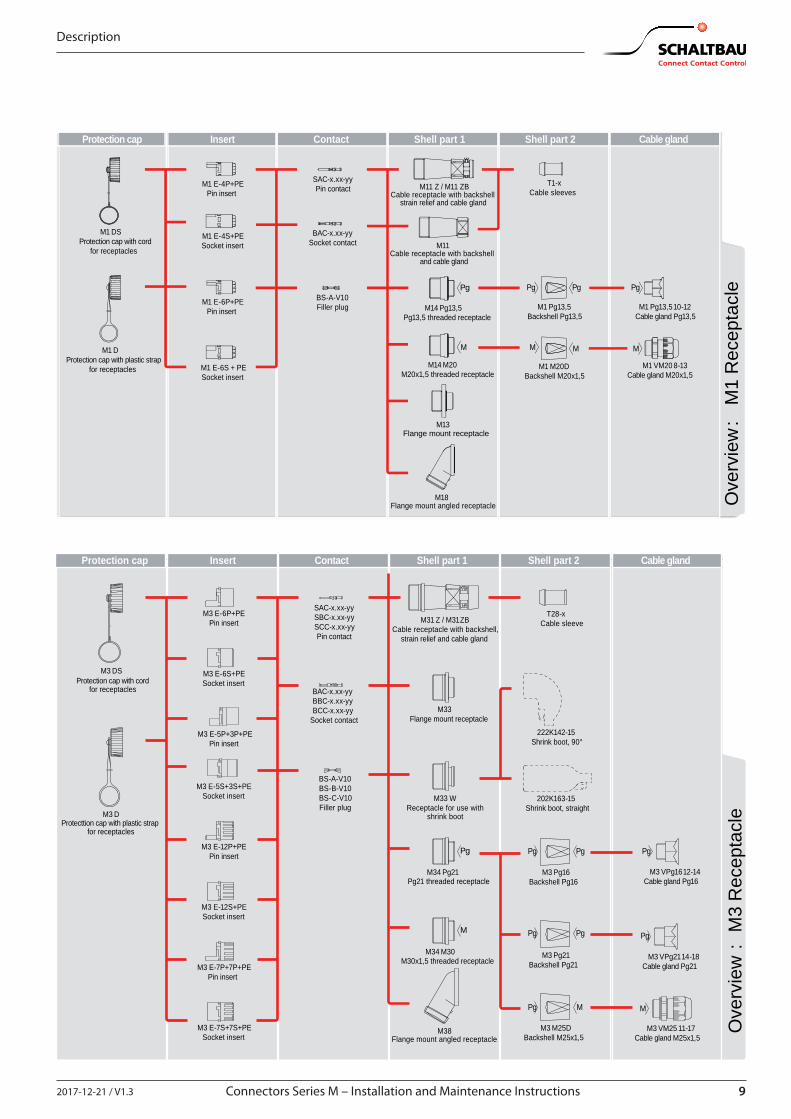
4.3 Survey of the Components
Pg
M
Pg
Pg
Pg
M
Pg
Ove
rvie
w
:
M1
Plug
Protection capInsertContactShell part 1Shell part 2Cable gland
M1 KS Protection cap with cord
for plugs
M1 K Protection cap with plastic strap
for plugs
M16 Z / M16 ZB Cable plug with backshell, strain relief and cable gland
M16 Cable plug with backshell
and cable gland
M16 W Threaded plug for use with
backshell/shrink boot
M15 Flange plug
202K142-15 Shrink boot, straight
T1-x Cable sleeve
222K142-15 Shrink boot, 90°
M1 E-4P+PE Pin insert
M1 E-4S+PE Socket insert
M1 E-6P+PE Pin insert
M1 E-6S + PE Socket insert
SAC-x.xx-yy Pin contact
BAC-x.xx-yy Socket contact
BS-A-V10 Filler plug
M1 M20 Backshell M20x1,5
M1 VM20 8-13 Cable gland M20x1,5
M1 Pg13,5 Backshell Pg13,5
M1 Pg13,5 10-12 Cable gland Pg13,5
Protection capInsertContactShell part 1Shell part 2Cable gland
Pg
Pg
M M
PgPg
Pg
Pg
Pg
Pg
Ove
rvie
w :
M3
Plug
M3 E-6P+PE Pin insert
M3 E-6S+PE Socket insert
M3 E-5P+3P+PE Pin insert
M3 E-5S+3S+PE Socket insert
SAC-x.xx-yy SBC-x.xx-yy SCC-x.xx-yy Pin contact
BAC-x.xx-yy BBC-x.xx-yy BCC-x.xx-yy
Socket contact
BS-A-V10 BS-B-V10 BS-C-V10 Filler plug
M36 Z / M3 36ZB Cable plug wih backshell,strain relief and cable gland
M35 Flange plug
M36W Threaded plug for use with
backshell/shrink boot
M3 E-12P+PE Pin insert
M3 E-7P+7P+PE Pin insert
M3 E-12S+PE Socket insert
M3 E-7S+7S+PE Socket insert
202K163-15 Shrink boot, straight
T28-x Cable sleeve
222K142-15 Shrink boot, 90°
M3 M25 Backshell M25x1.5
M3 VM25 11-17 Cable gland M25x1.5
M3 VPg16 12-14 Cable gland Pg16
M3 VPg21 14-18 Cable gland Pg21
M3 Pg16 Backshell Pg16
M3 Pg21 Backshell Pg21
M3 KS Protection cap with cord
for plugs
M3 K
Protection cap with plastic strap
for plugs
92017-12-21 / V1.3 Connectors Series M – Installation and Maintenance Instructions
Description
M
Pg PgPg
M M
Pg
M
Ove
rvie
w
:
M1
Rec
epta
cle
Protection cap Insert Contact Shell part 1 Shell part 2 Cable gland
M11 Z / M11 ZB Cable receptacle with backshell
strain relief and cable gland
M11 Cable receptacle with backshell
and cable gland
M14 Pg13,5 Pg13,5 threaded receptacle
M14 M20 M20x1,5 threaded receptacle
M13 Flange mount receptacle
M18 Flange mount angled receptacle
M1 DS Protection cap with cord
for receptacles
M1 D
M1 E-4P+PE Pin insert
M1 E-4S+PE Socket insert
M1 E-6P+PE Pin insert
M1 E-6S + PE Socket insert
T1-x Cable sleeves
SAC-x.xx-yy Pin contact
BAC-x.xx-yy Socket contact
BS-A-V10 Filler plug
M1 M20DBackshell M20x1,5
M1 VM20 8-13
Cable gland M20x1,5
M1 Pg13,5 Backshell Pg13,5
M1 Pg13,5 10-12
Cable gland Pg13,5
Protection cap with plastic strapfor receptacles
Protection cap Insert Contact Shell part 1 Shell part 2 Cable gland
Pg
Pg
MPg
PgPg
PgPg
M
Pg
M
Ove
rvie
w :
M3
Rec
epta
cle
M3 E-6P+PE Pin insert
M3 E-6S+PE Socket insert
M3 E-5P+3P+PE Pin insert
M3 E-5S+3S+PE Socket insert
SAC-x.xx-yy SBC-x.xx-yy SCC-x.xx-yy Pin contact
BAC-x.xx-yy
BBC-x.xx-yy
BCC-x.xx-yy
Socket contact
BS-A-V10 BS-B-V10 BS-C-V10 Filler plug
M3 E-12P+PE Pin insert
M3 E-7P+7P+PE Pin insert
M3 E-12S+PE Socket insert
M3 E-7S+7S+PE Socket insert
M31 Z / M31 ZB Cable receptacle with backshell,
strain relief and cable gland
M33 W Receptacle for use with
shrink boot
M38 Flange mount angled receptacle
M33 Flange mount receptacle
M34 Pg21 Pg21 threaded receptacle
M34 M30 M30x1,5 threaded receptacle
M3 M25D Backshell M25x1,5
M3 VM25 11-17 Cable gland M25x1,5
M3 VPg16 12-14 Cable gland Pg16
M3 VPg21 14-18 Cable gland Pg21
M3 Pg16 Backshell Pg16
M3 Pg21 Backshell Pg21
M3 DS
M3 D
202K163-15 Shrink boot, straight
T28-x Cable sleeve
222K142-15 Shrink boot, 90°
Protection cap with cordfor receptacles
Protecttion cap with plastic strap for receptacles
10 2017-12-21 / V1.3Connectors Series M – Installation and Maintenance Instructions
Installation
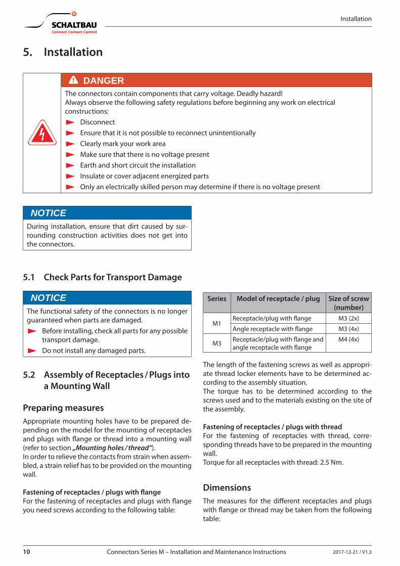
5. Installation
DANGERThe connectors contain components that carry voltage. Deadly hazard!Always observe the following safety regulations before beginning any work on electrical constructions:
X Disconnect X Ensure that it is not possible to reconnect unintentionally X Clearly mark your work area X Make sure that there is no voltage present X Earth and short circuit the installation X Insulate or cover adjacent energized parts X Only an electrically skilled person may determine if there is no voltage present
NOTICEDuring installation, ensure that dirt caused by sur-rounding construction activities does not get into the connectors.
5.1 Check Parts for Transport Damage
NOTICEThe functional safety of the connectors is no longer guaranteed when parts are damaged.
X Before installing, check all parts for any possible transport damage.
X Do not install any damaged parts.
5.2 Assembly of Receptacles / Plugs into a Mounting Wall
Preparing measuresAppropriate mounting holes have to be prepared de-pending on the model for the mounting of receptacles and plugs with �ange or thread into a mounting wall (refer to section „Mounting holes / thread“).In order to relieve the contacts from strain when assem-bled, a strain relief has to be provided on the mounting wall.
Fastening of receptacles / plugs with �angeFor the fastening of receptacles and plugs with �ange you need screws according to the following table:
Series Model of receptacle / plug Size of screw (number)
M1Receptacle/plug with �ange M3 (2x)
Angle receptacle with �ange M3 (4x)
M3 Receptacle/plug with �ange and angle receptacle with �ange
M4 (4x)
The length of the fastening screws as well as appropri-ate thread locker elements have to be determined ac-cording to the assembly situation.The torque has to be determined according to the screws used and to the materials existing on the site of the assembly.
Fastening of receptacles / plugs with threadFor the fastening of receptacles with thread, corre-sponding threads have to be prepared in the mounting wall.Torque for all receptacles with thread: 2.5 Nm.
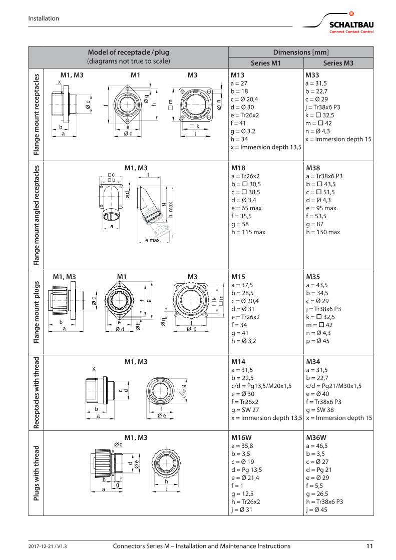
Dimensions The measures for the di�erent receptacles and plugs with �ange or thread may be taken from the following table:
112017-12-21 / V1.3 Connectors Series M – Installation and Maintenance Instructions
Installation
Model of receptacle / plug(diagrams not true to scale)
Dimensions [mm]Series M1 Series M3
Flan
ge m
ount
rece
ptac
les M1, M3 M1 M3
x
ab
Ø d
Ø c f h
e
Ø g
m
Ø n
k j
M13a = 27b = 18c = Ø 20,4d = Ø 30e = Tr26x2f = 41g = Ø 3,2h = 34x = Immersion depth 13,5
M33a = 31,5b = 22,7c = Ø 29j = Tr38x6 P3k = o 32,5m = o 42n = Ø 4,3x = Immersion depth 15
Flan
ge m
ount
ang
led
rece
ptac
les M1, M3
� c f
a
e max.
h m
ax.
g
� b
Ø d
M18a = Tr26x2b = o 30,5c = o 38,5d = Ø 3,4e = 65 max.f = 35,5g = 58h = 115 max
M38a = Tr38x6 P3b = o 43,5c = o 51,5d = Ø 4,3e = 95 max.f = 53,5g = 87h = 150 max
Flan
ge m
ount
plu
gs
M1, M3 M1 M3
Ø n
k
pj
Ø
m
eØ d
f g
ba
Øc
Øh
M15a = 37,5b = 28,5c = Ø 20,4d = Ø 31e = Tr26x2f = 34g = 41h = Ø 3,2
M35a = 43,5b = 34,5c = Ø 29j = Tr38x6 P3k = o 32,5m = o 42n = Ø 4,3 p = Ø 45
Rece
ptac
les w
ith th
read M1, M3
x
ba Ø e
f
c d
g
M14a = 31,5b = 22,5c/d = Pg13,5/M20x1,5e = Ø 30f = Tr26x2g = SW 27x = Immersion depth 13,5
M34a = 31,5b = 22,7c/d = Pg21/M30x1,5e = Ø 40f = Tr38x6 P3g = SW 38x = Immersion depth 15
Plug
s w
ith th
read
M1, M3
Ø
ed
gb
Ø c
a
f hj
M16Wa = 35,8b = 3,5c = Ø 19d = Pg 13,5e = Ø 21,4f = 1g = 12,5h = Tr26x2j = Ø 31
M36Wa = 46,5b = 3,5c = Ø 27d = Pg 21e = Ø 29f = 5,5g = 26,5h = Tr38x6 P3j = Ø 45

12 2017-12-21 / V1.3Connectors Series M – Installation and Maintenance Instructions
Cable Assembly and Processing
Mounting holes / threadYou may take the measures for the mounting holes for the assembly of the di�erent receptacles and plugs
with �ange or thread into a mounting wall from the fol-lowing diagram.
Flange mount receptacles and plugs Flange mount angled receptacles Receptacles with thread
34Ø 21
Ø 3.2 Ø 4.3
□ 32.
5
Ø 29.5
□ 30.
5
Ø 27
Ø 3.2
□ 43.
5
Ø 37
Ø 4.3Pg13.5
M20x1.5Pg21
M30x1.5
M13, M15 M33, M33 W, M35 M18 M38 M14 M34
Fig. 1: Dimensions and arrangements of the mounting holes and threads (measures in mm)
6. Cable Assembly and Processing
6.1 Required Tools
X Insertion tools for socket inserts
Fig. 2: Insertion tools for socket inserts
Ordering code Insertion tools forVW-M1 E-4S Contact insert M1 E-4S+PEVW-M1 E-6S Contact insert M1 E-6S+PEVW-M3 E-6S Contact insert M3 E-6S+PEVW-M3 E-5S+3S Contact insert M3 E-5S+3S+PEVW-M3 E-12S Contact insert M3 E-12S+PE, M3 7+7S+PE
X Insertion tools for pin inserts
Fig. 3: Insertion tools for pin inserts
Ordering code Insertion tools forVW-M1 E-4P Contact insert M1 E-4P+PEVW-M1 E-6P Contact insert M1 E-6P+PEVW-M3 E-6P Contact insert M3 E-6P+PEVW-M3 E-5P+3P Contact insert M3 E-5P+3P+PEVW-M3 E-12P Contact insert M3 E-12P+PE, M3 7+7P+PE
X Extraction tools for disassembly of contacts
Fig. 4: Extraction tool
Ordering code Extraction tools forAWZ-A Contacts type SAC-x
AWZ-B Contacts type SBC-x, BBC-x
AWZ-C/H Contact type SCC-x, BCC-x
X Crimping pliers
Fig. 5: Crimping pliers
Ordering code Crimping pliers forCWZ-600-1 SAC-x, BAC-x, SBC-x, BBC-x, SCC-x and BCC-x, (not ap-
propriate for contacts SAC-2.50-xx and BAC-2.50-xx)Tool frame M22520/1-01 and Turret M22520/1-02 (without illustration)
For contacts SAC-2.50-xx and BAC-2.50-xx only.Crimping pliers and turret from the company DMC or the company Buchanan. Order directly from the manufacturer.
X Wire stripping tools, commercially available
X Tweezers, commercially available (for inserting �ller plugs)
132017-12-21 / V1.3 Connectors Series M – Installation and Maintenance Instructions
Cable Assembly and Processing
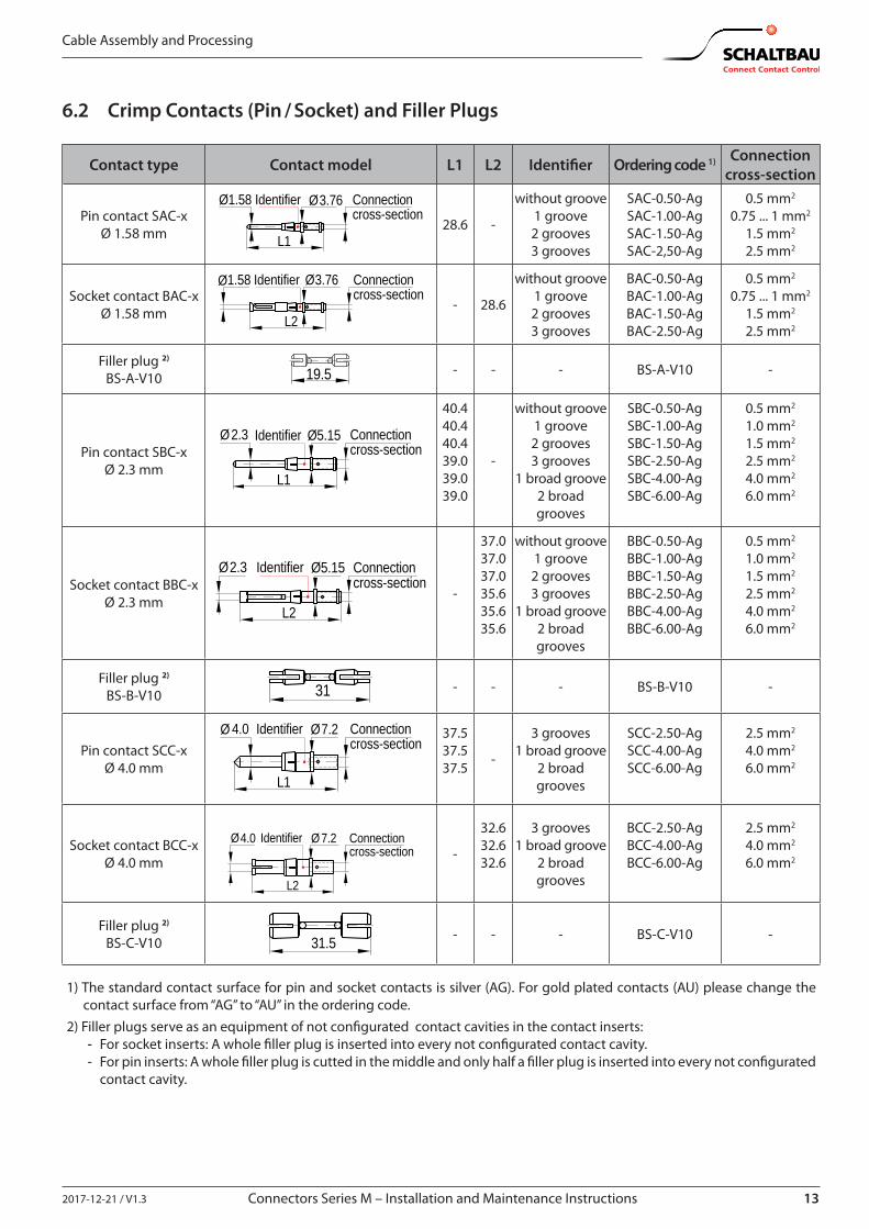
6.2 Crimp Contacts (Pin / Socket) and Filler Plugs
Contact type Contact model L1 L2 Identi�er Ordering code 1) Connection cross-section
Pin contact SAC-xØ 1.58 mm
Connectioncross-section
IdentifierØ1.58
L1
Ø3.76
28.6 -
without groove1 groove2 grooves3 grooves
SAC-0.50-AgSAC-1.00-AgSAC-1.50-AgSAC-2,50-Ag
0.5 mm2
0.75 ... 1 mm2
1.5 mm2
2.5 mm2
Socket contact BAC-xØ 1.58 mm
Connectioncross-section
Identifier
L2
Ø1.58 Ø3.76
- 28.6
without groove1 groove2 grooves3 grooves
BAC-0.50-AgBAC-1.00-AgBAC-1.50-AgBAC-2.50-Ag
0.5 mm2
0.75 ... 1 mm2
1.5 mm2
2.5 mm2
Filler plug 2) BS-A-V10 19.5 - - - BS-A-V10 -
Pin contact SBC-xØ 2.3 mm
Connectioncross-section
Identifier
L1
Ø2.3 Ø5.15
40.440.440.439.039.039.0
-
without groove1 groove2 grooves3 grooves
1 broad groove2 broad grooves
SBC-0.50-AgSBC-1.00-AgSBC-1.50-AgSBC-2.50-AgSBC-4.00-AgSBC-6.00-Ag
0.5 mm2
1.0 mm2
1.5 mm2
2.5 mm2
4.0 mm2
6.0 mm2
Socket contact BBC-xØ 2.3 mm
Connectioncross-section
Identifier
L2
Ø2.3 Ø5.15
-
37.037.037.035.635.635.6
without groove1 groove2 grooves3 grooves
1 broad groove2 broad grooves
BBC-0.50-AgBBC-1.00-AgBBC-1.50-AgBBC-2.50-AgBBC-4.00-AgBBC-6.00-Ag
0.5 mm2
1.0 mm2
1.5 mm2
2.5 mm2
4.0 mm2
6.0 mm2
Filler plug 2) BS-B-V10 31 - - - BS-B-V10 -
Pin contact SCC-xØ 4.0 mm
Connectioncross-section
Identifier
L1
Ø 4.0 Ø7.2 37.537.537.5 -
3 grooves1 broad groove
2 broad grooves
SCC-2.50-AgSCC-4.00-AgSCC-6.00-Ag
2.5 mm2
4.0 mm2
6.0 mm2
Socket contact BCC-xØ 4.0 mm
Connectioncross-section
Identifier
L2
Ø4.0 Ø7.2-
32.632.632.6
3 grooves1 broad groove
2 broad grooves
BCC-2.50-AgBCC-4.00-AgBCC-6.00-Ag
2.5 mm2
4.0 mm2
6.0 mm2
Filler plug 2) BS-C-V10 31.5 - - - BS-C-V10 -
1) The standard contact surface for pin and socket contacts is silver (AG). For gold plated contacts (AU) please change the contact surface from “AG” to “AU” in the ordering code.
2) Filler plugs serve as an equipment of not con�gurated contact cavities in the contact inserts: - For socket inserts: A whole �ller plug is inserted into every not con�gurated contact cavity. - For pin inserts: A whole �ller plug is cutted in the middle and only half a �ller plug is inserted into every not con�gurated
contact cavity.
14 2017-12-21 / V1.3Connectors Series M – Installation and Maintenance Instructions
Cable Assembly and Processing
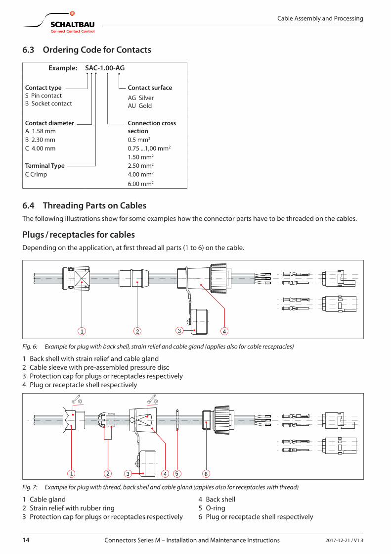
6.3 Ordering Code for Contacts
Example: SAC-1.00-AG
Contact type S Pin contact B Socket contact
Contact surface
AG Silver AU Gold
Contact diameterA 1.58 mm
Connection cross section
B 2.30 mm 0.5 mm2
C 4.00 mm 0.75 ...1,00 mm2
1.50 mm2
Terminal Type 2.50 mm2
C Crimp 4.00 mm2
6.00 mm2
6.4 Threading Parts on CablesThe following illustrations show for some examples how the connector parts have to be threaded on the cables.
Plugs / receptacles for cablesDepending on the application, at �rst thread all parts (1 to 6) on the cable.
1 2 43
Fig. 6: Example for plug with back shell, strain relief and cable gland (applies also for cable receptacles)
1 Back shell with strain relief and cable gland2 Cable sleeve with pre-assembled pressure disc3 Protection cap for plugs or receptacles respectively4 Plug or receptacle shell respectively
1 52 643
Fig. 7: Example for plug with thread, back shell and cable gland (applies also for receptacles with thread)
1 Cable gland2 Strain relief with rubber ring3 Protection cap for plugs or receptacles respectively
4 Back shell5 O-ring6 Plug or receptacle shell respectively
152017-12-21 / V1.3 Connectors Series M – Installation and Maintenance Instructions
Cable Assembly and Processing
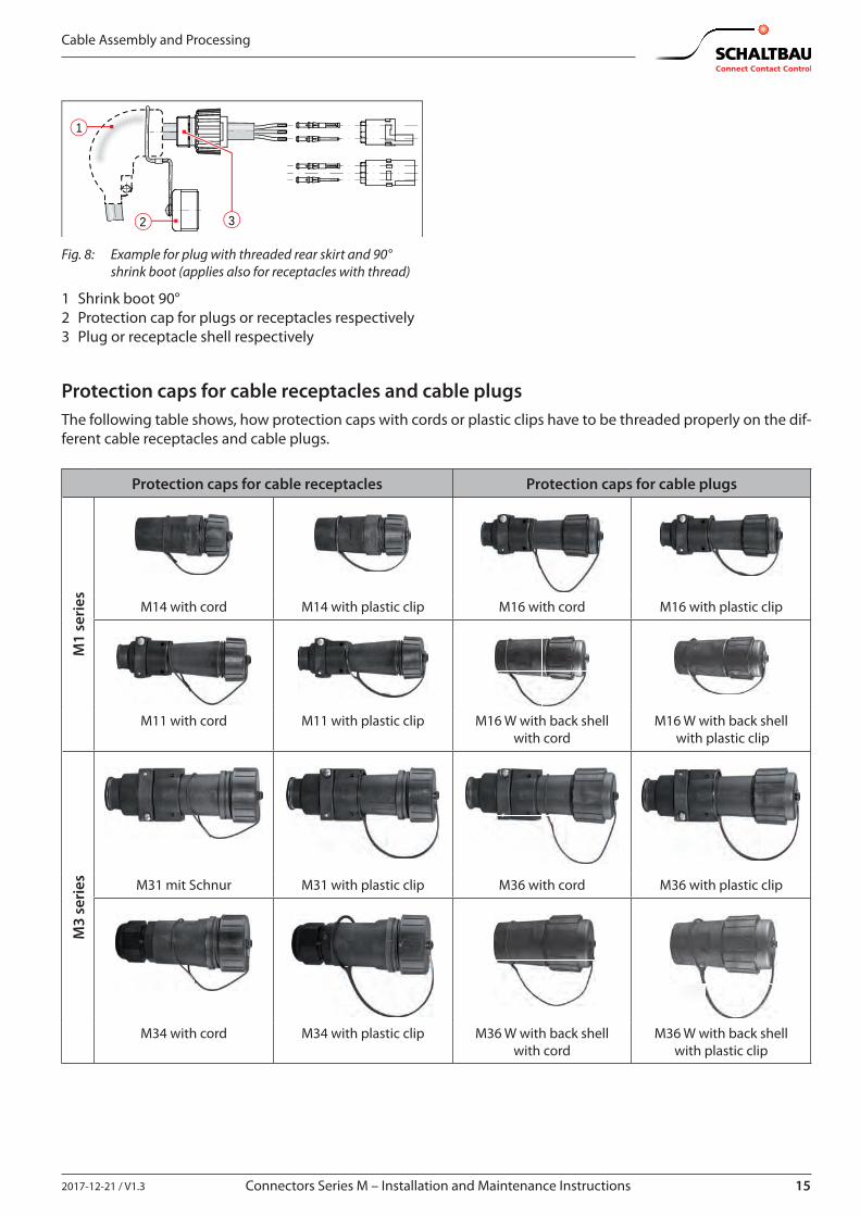
2 3
1
Fig. 8: Example for plug with threaded rear skirt and 90° shrink boot (applies also for receptacles with thread)
1 Shrink boot 90°2 Protection cap for plugs or receptacles respectively3 Plug or receptacle shell respectively
Protection caps for cable receptacles and cable plugsThe following table shows, how protection caps with cords or plastic clips have to be threaded properly on the dif-ferent cable receptacles and cable plugs.
Protection caps for cable receptacles Protection caps for cable plugs
M1
seri
es M14 with cord M14 with plastic clip M16 with cord M16 with plastic clip
M11 with cord M11 with plastic clip M16 W with back shellwith cord
M16 W with back shell with plastic clip
M3
seri
es M31 mit Schnur M31 with plastic clip M36 with cord M36 with plastic clip
M34 with cord M34 with plastic clip M36 W with back shellwith cord
M36 W with back shellwith plastic clip
16 2017-12-21 / V1.3Connectors Series M – Installation and Maintenance Instructions
Cable Assembly and Processing
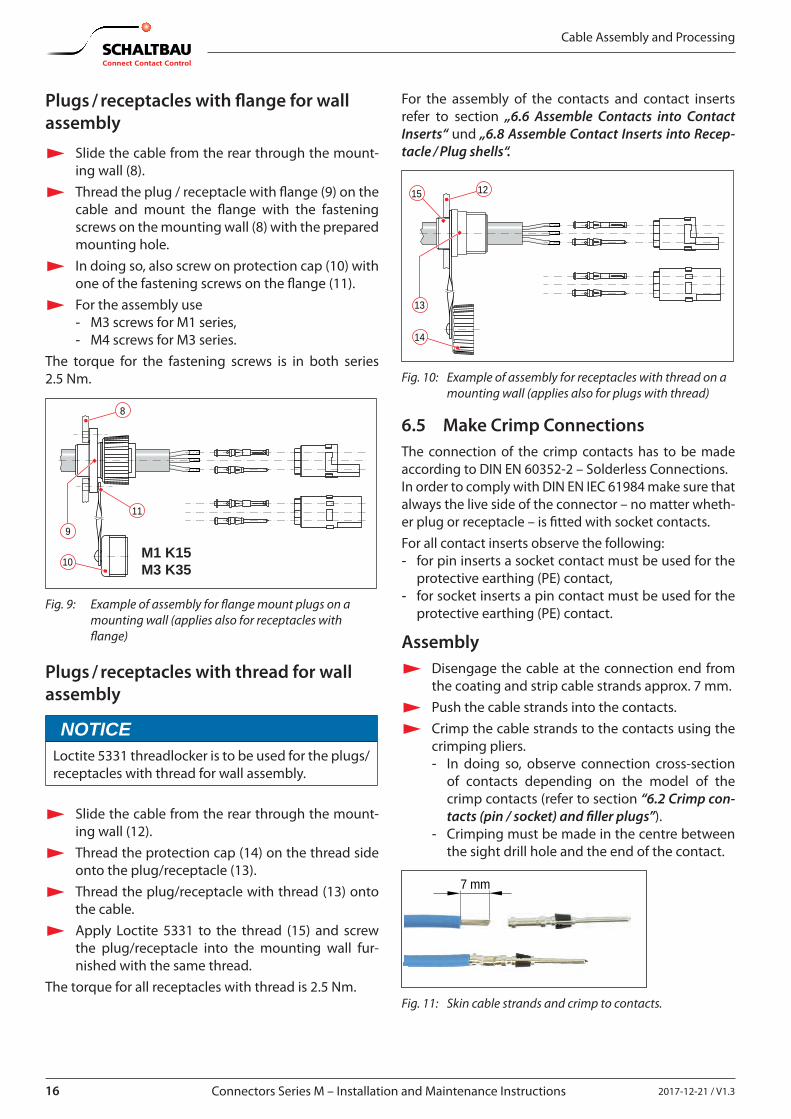
Plugs / receptacles with �ange for wall assembly
X Slide the cable from the rear through the mount-ing wall (8).
X Thread the plug / receptacle with �ange (9) on the cable and mount the �ange with the fastening screws on the mounting wall (8) with the prepared mounting hole.
X In doing so, also screw on protection cap (10) with one of the fastening screws on the �ange (11).
X For the assembly use - M3 screws for M1 series, - M4 screws for M3 series.
The torque for the fastening screws is in both series 2.5 Nm.
M1 K15 M3 K35
9
10
8
11
Fig. 9: Example of assembly for �ange mount plugs on a mounting wall (applies also for receptacles with �ange)
Plugs / receptacles with thread for wall assembly
NOTICELoctite 5331 threadlocker is to be used for the plugs/receptacles with thread for wall assembly.
X Slide the cable from the rear through the mount-ing wall (12).
X Thread the protection cap (14) on the thread side onto the plug/receptacle (13).
X Thread the plug/receptacle with thread (13) onto the cable.
X Apply Loctite 5331 to the thread (15) and screw the plug/receptacle into the mounting wall fur-nished with the same thread.
The torque for all receptacles with thread is 2.5 Nm.
For the assembly of the contacts and contact inserts refer to section „6.6 Assemble Contacts into Contact Inserts“ und „6.8 Assemble Contact Inserts into Recep-tacle / Plug shells“.
13
14
1215
Fig. 10: Example of assembly for receptacles with thread on a mounting wall (applies also for plugs with thread)
6.5 Make Crimp ConnectionsThe connection of the crimp contacts has to be made according to DIN EN 60352-2 – Solderless Connections.In order to comply with DIN EN IEC 61984 make sure that always the live side of the connector – no matter wheth-er plug or receptacle – is �tted with socket contacts.For all contact inserts observe the following: - for pin inserts a socket contact must be used for the
protective earthing (PE) contact, - for socket inserts a pin contact must be used for the
protective earthing (PE) contact.
Assembly X Disengage the cable at the connection end from
the coating and strip cable strands approx. 7 mm. X Push the cable strands into the contacts. X Crimp the cable strands to the contacts using the
crimping pliers. - In doing so, observe connection cross-section
of contacts depending on the model of the crimp contacts (refer to section “6.2 Crimp con-tacts (pin / socket) and �ller plugs”).
- Crimping must be made in the centre between the sight drill hole and the end of the contact.
7 mm
Fig. 11: Skin cable strands and crimp to contacts.
172017-12-21 / V1.3 Connectors Series M – Installation and Maintenance Instructions
Cable Assembly and Processing
Check
X Check if crimp contacts are �rmly and correctly connected. - Make sure that no single wires stick out.
Check extraction forces according to DIN EN 61238-1.
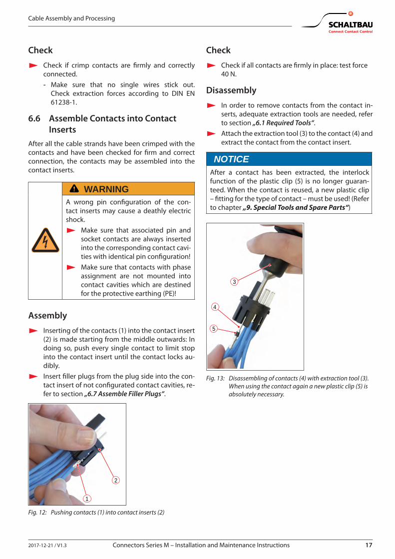
6.6 Assemble Contacts into Contact Inserts
After all the cable strands have been crimped with the contacts and have been checked for �rm and correct connection, the contacts may be assembled into the contact inserts.
WARNINGA wrong pin con�guration of the con-tact inserts may cause a deathly electric shock.
X Make sure that associated pin and socket contacts are always inserted into the corresponding contact cavi-ties with identical pin con�guration!
X Make sure that contacts with phase assignment are not mounted into contact cavities which are destined for the protective earthing (PE)!
Assembly
X Inserting of the contacts (1) into the contact insert (2) is made starting from the middle outwards: In doing so, push every single contact to limit stop into the contact insert until the contact locks au-dibly.
X Insert �ller plugs from the plug side into the con-tact insert of not con�gurated contact cavities, re-fer to section „6.7 Assemble Filler Plugs“.
1
2
Fig. 12: Pushing contacts (1) into contact inserts (2)
Check
X Check if all contacts are �rmly in place: test force 40 N.
Disassembly
X In order to remove contacts from the contact in-serts, adequate extraction tools are needed, refer to section „6.1 Required Tools“.
X Attach the extraction tool (3) to the contact (4) and extract the contact from the contact insert.
NOTICEAfter a contact has been extracted, the interlock function of the plastic clip (5) is no longer guaran-teed. When the contact is reused, a new plastic clip – �tting for the type of contact – must be used! (Refer to chapter „9. Special Tools and Spare Parts“)
3
4
5
Fig. 13: Disassembling of contacts (4) with extraction tool (3). When using the contact again a new plastic clip (5) is absolutely necessary.

18 2017-12-21 / V1.3Connectors Series M – Installation and Maintenance Instructions
Cable Assembly and Processing
6.7 Assemble Filler PlugsFiller plugs have to be inserted into not con�gurated contact cavities of the contact inserts. Depending on the contact insert, �ller plugs of di�erent models and with corresponding diameters are available, refer to section „6.2 Crimp Contacts (Pin / Socket) and Filler Plugs“. The following illustrations show for di�erent examples of application how �ller plugs have to be assembled into the contact inserts.
X Use tweezers (2) for easier insert of small �ller plugs (1).
1
2
Fig. 14: Insert of small �ller plugs (1) (e. g. BS-A/BS-B) with tweezers (2)
For socket inserts: X Insert one whole �ller plug (1/3) per not con�gu-
rated contact cavity.
3
Fig. 15: Assembly of whole �ller plugs (3) for socket inserts
For pin inserts: X Cut through one whole �ller plug in the middle
and only insert half a �ller plug (4) per not con�gu-rated contact cavity.
4
Fig. 16: Assembly of half �ller plugs (4) for pin inserts
X Insert the �ller plug from the plug side into the contact insert and push until the end stop.
5
Fig. 17: Final position (5) of the assembled �ller plug
6.8 Assemble Contact Inserts into Receptacle / Plug shells
After all the contacts have been made and the contacts and the �ller plugs, if necessary, have been assembled into the contact insert, the contact insert must be in-serted into the shell and locked with the help of ad-equate insertion tools (refer to section „6.1 Required Tools“).
CodingsThe receptacle and plug shells as well as the corre-sponding contact inserts are equipped with codings in the form of grooves and guideways.
M1 M3
Fig. 18: Examples for codings: Grooves on the contact inserts, guideways on the inner sides of the shells
All contact inserts have 2 coding posi-tions (A, B). This allows for the unmis-takable connection of for example two connectors with di�erent voltages to one and the same piece of equipment.
192017-12-21 / V1.3 Connectors Series M – Installation and Maintenance Instructions
Cable Assembly and Processing
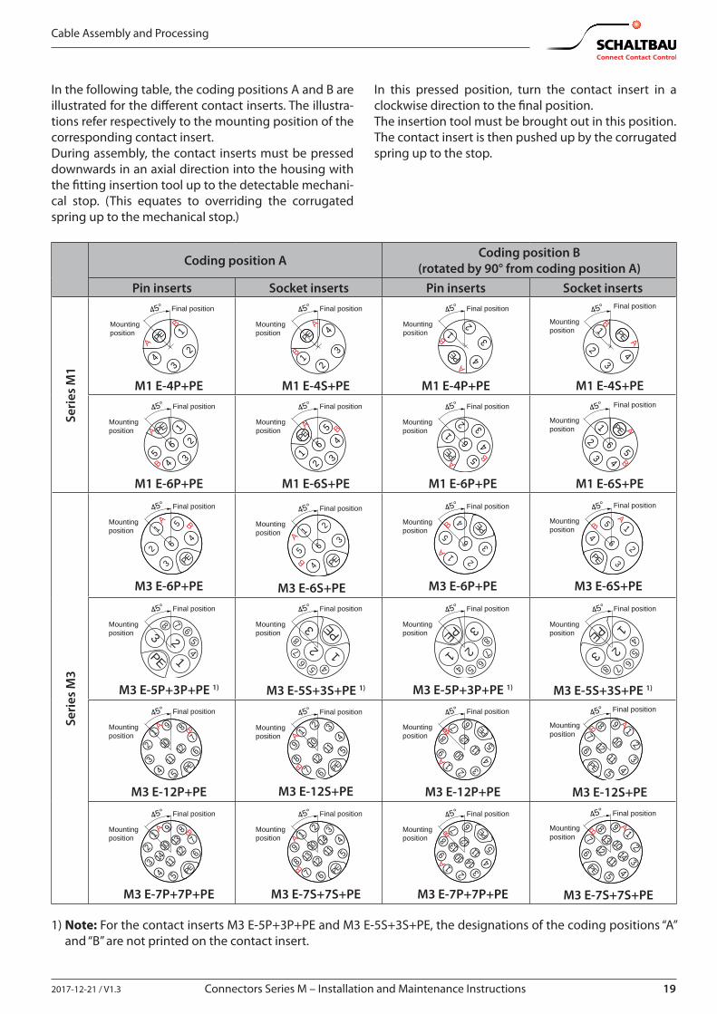
In the following table, the coding positions A and B are illustrated for the di�erent contact inserts. The illustra-tions refer respectively to the mounting position of the corresponding contact insert. During assembly, the contact inserts must be pressed downwards in an axial direction into the housing with the �tting insertion tool up to the detectable mechani-cal stop. (This equates to overriding the corrugated spring up to the mechanical stop.)
In this pressed position, turn the contact insert in a clockwise direction to the �nal position.The insertion tool must be brought out in this position.The contact insert is then pushed up by the corrugated spring up to the stop.
Coding position A Coding position B (rotated by 90° from coding position A)
Pin inserts Socket inserts Pin inserts Socket inserts
Seri
es M
1
A
B1
23
4
PE
45°
Mountingposition
Final position
M1 E-4P+PE
12
3
4PE
45°
Mountingposition
Final position
A
B
M1 E-4S+PE
A
B1
23
4PE
45°
Mountingposition
Final position
M1 E-4P+PE
45°
Mountingposition
Final position
1
23
4
PEA
B
M1 E-4S+PE
1
56 2
34
PE
45°
Mountingposition
Final position
A
B
M1 E-6P+PE
1
5
6
2 3
4PE
45°
Mountingposition
Final position
A B
M1 E-6S+PE
1
5
6
2 3
4PE
45°
Mountingposition
Final position
AB
M1 E-6P+PE
45°
Mountingposition
Final position
1
562
3 4
PE A
B
M1 E-6S+PE
Seri
es M
3
2
3
1 5
6 4
PE
45°
Mountingposition
Final position
A B
M3 E-6P+PE
2
31
5 6
4 PE
45°
Mountingposition
Final position
A
B
M3 E-6S+PE
2
31
5 6
4PE
45°
Mountingposition
Final position
A
B
M3 E-6P+PE
45°
Mountingposition
Final position
2
3
15
64
PE
AB
M3 E-6S+PE
45°
Mountingposition
Final position
12
678
54PE
3
M3 E-5P+3P+PE 1)
45°
Mountingposition
Final position
126
78
5 4
PE3
M3 E-5S+3S+PE 1)
45°
Mountingposition
Final position
1 26
78
54
PE 3
M3 E-5P+3P+PE 1)
45°
Mountingposition
Final position
1
26
78
54
PE
3
M3 E-5S+3S+PE 1)
1
5
6
4
710
1112
9
2
3
8
PE
45°
Mountingposition
Final position
A B
M3 E-12P+PE
1
5
6
4
7
10 1112
9
2 3
8PE
45°
Mountingposition
Final position
A
B
M3 E-12S+PE
1
5
6
4
7
10 1112
9
2 3
8 PE
45°
Mountingposition
Final position
A
B
M3 E-12P+PE
45°
Mountingposition
Final position
1
5
6
4
7 1011
12
9
2
3
8
PE
AB
M3 E-12S+PE
1
5
6
4
710
1114 1213
9
2
3
8
PE
45°
Mountingposition
Final position
A B
M3 E-7P+7P+PE
1
5
6
4
7
10 1114
12139
2 3
8PE
45°
Mountingposition
Final position
A
B
M3 E-7S+7S+PE
1
5
6
4
7
10 1114
12139
2 3
8 PE
45°
Mountingposition
Final position
A
B
M3 E-7P+7P+PE
45°
Mountingposition
Final position
1
5
6
4
7 1011
1412
139
2
3
8
PE
AB
M3 E-7S+7S+PE
1) Note: For the contact inserts M3 E-5P+3P+PE and M3 E-5S+3S+PE, the designations of the coding positions “A” and “B” are not printed on the contact insert.
20 2017-12-21 / V1.3Connectors Series M – Installation and Maintenance Instructions
Cable Assembly and Processing
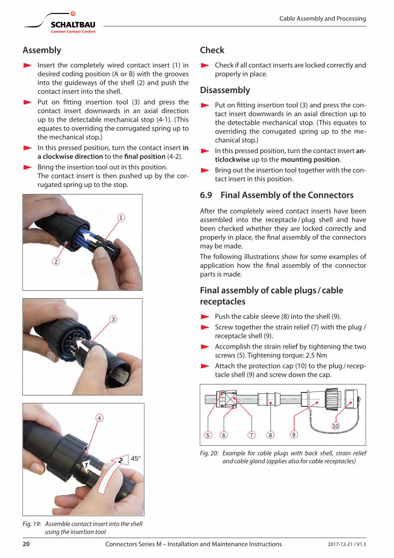
Assembly
X Insert the completely wired contact insert (1) in desired coding position (A or B) with the grooves into the guideways of the shell (2) and push the contact insert into the shell.
X Put on �tting insertion tool (3) and press the contact insert downwards in an axial direction up to the detectable mechanical stop (4-1). (This equates to overriding the corrugated spring up to the mechanical stop.)
X In this pressed position, turn the contact insert in a clockwise direction to the �nal position (4-2).
X Bring the insertion tool out in this position.The contact insert is then pushed up by the cor-rugated spring up to the stop.
1
2
3
4
45°
Fig. 19: Assemble contact insert into the shell using the insertion tool
Check
X Check if all contact inserts are locked correctly and properly in place.
Disassembly
X Put on �tting insertion tool (3) and press the con-tact insert downwards in an axial direction up to the detectable mechanical stop. (This equates to overriding the corrugated spring up to the me-chanical stop.)
X In this pressed position, turn the contact insert an-ticlockwise up to the mounting position.
X Bring out the insertion tool together with the con-tact insert in this position.
6.9 Final Assembly of the Connectors
After the completely wired contact inserts have been assembled into the receptacle / plug shell and have been checked whether they are locked correctly and properly in place, the �nal assembly of the connectors may be made.The following illustrations show for some examples of application how the �nal assembly of the connector parts is made.
Final assembly of cable plugs / cable receptacles
X Push the cable sleeve (8) into the shell (9). X Screw together the strain relief (7) with the plug /
receptacle shell (9). X Accomplish the strain relief by tightening the two
screws (5). Tightening torque: 2.5 Nm X Attach the protection cap (10) to the plug / recep-
tacle shell (9) and screw down the cap.
5 910
6 7 8
Fig. 20: Example for cable plugs with back shell, strain relief and cable gland (applies also for cable receptacles)
212017-12-21 / V1.3 Connectors Series M – Installation and Maintenance Instructions
Cable Assembly and Processing
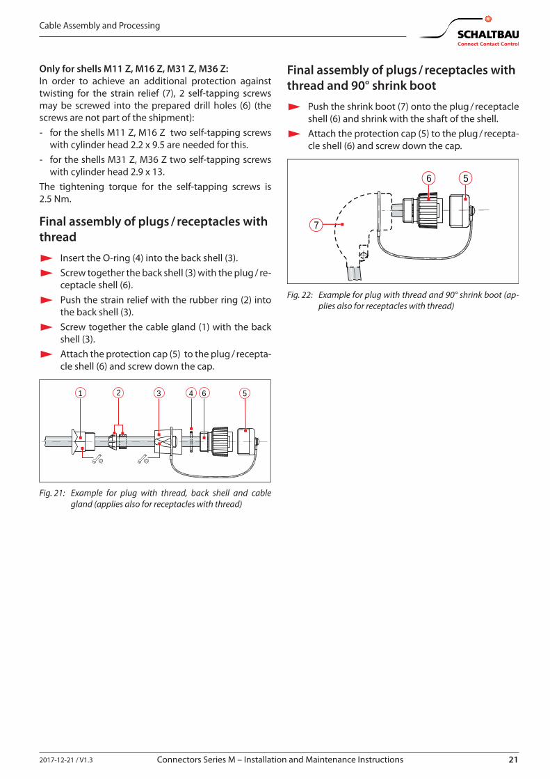
Only for shells M11 Z, M16 Z, M31 Z, M36 Z:In order to achieve an additional protection against twisting for the strain relief (7), 2 self-tapping screws may be screwed into the prepared drill holes (6) (the screws are not part of the shipment): - for the shells M11 Z, M16 Z two self-tapping screws
with cylinder head 2.2 x 9.5 are needed for this. - for the shells M31 Z, M36 Z two self-tapping screws
with cylinder head 2.9 x 13.The tightening torque for the self-tapping screws is 2.5 Nm.
Final assembly of plugs / receptacles with thread
X Insert the O-ring (4) into the back shell (3). X Screw together the back shell (3) with the plug / re-
ceptacle shell (6). X Push the strain relief with the rubber ring (2) into
the back shell (3). X Screw together the cable gland (1) with the back
shell (3). X Attach the protection cap (5) to the plug / recepta-
cle shell (6) and screw down the cap.
21 3 4 6 5
Fig. 21: Example for plug with thread, back shell and cable gland (applies also for receptacles with thread)
Final assembly of plugs / receptacles with thread and 90° shrink boot
X Push the shrink boot (7) onto the plug / receptacle shell (6) and shrink with the shaft of the shell.
X Attach the protection cap (5) to the plug / recepta-cle shell (6) and screw down the cap.
7
6 5
Fig. 22: Example for plug with thread and 90° shrink boot (ap-plies also for receptacles with thread)
22 2017-12-21 / V1.3Connectors Series M – Installation and Maintenance Instructions
Plugging Procedure
7. Plugging Procedure
NOTICEInappropriate handling when plugging or discon-necting may damage the connectors. The functional safety of the connectors is no longer guaranteed when parts are damaged.
X Make sure when plugging that grooves (1) and guideways (2) of plug and receptacle always in-terlock!
X Take care that plug and receptacle do not tilt and that they are plugged without force.
X Make sure before the plugging procedure that plug and receptacle as well as the protection caps are not soiled. Remove existent dirt with-out leaving any residue.
X Make sure that in the not mated condition the protection caps are always attached according to regulations.
Note:In case of a very low or very high ambi-ent temperature which approximates the limits of the allowable operating tem-perature range speci�ed in our catalogue A10.en in section “Speci�cations”, - a higher e�ort may be needed for the
plugging and unplugging and - the operational life span of plug and
coupling receptacle may thus be re-duced due to increased wear and tear.
21
1
2
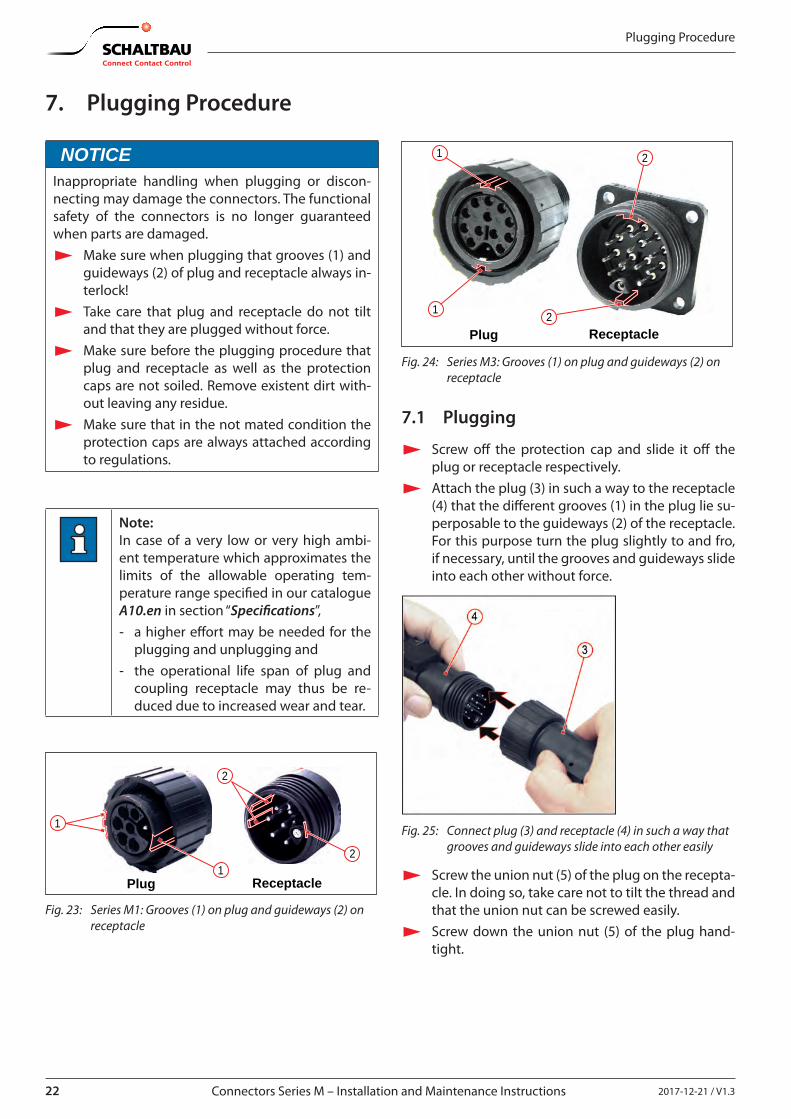
ReceptaclePlug
Fig. 23: Series M1: Grooves (1) on plug and guideways (2) on receptacle
1
2
2
1
ReceptaclePlug
Fig. 24: Series M3: Grooves (1) on plug and guideways (2) on receptacle
7.1 Plugging
X Screw o� the protection cap and slide it o� the plug or receptacle respectively.
X Attach the plug (3) in such a way to the receptacle (4) that the di�erent grooves (1) in the plug lie su-perposable to the guideways (2) of the receptacle.For this purpose turn the plug slightly to and fro, if necessary, until the grooves and guideways slide into each other without force.
Fig. 25: Connect plug (3) and receptacle (4) in such a way that grooves and guideways slide into each other easily
X Screw the union nut (5) of the plug on the recepta-cle. In doing so, take care not to tilt the thread and that the union nut can be screwed easily.
X Screw down the union nut (5) of the plug hand-tight.
232017-12-21 / V1.3 Connectors Series M – Installation and Maintenance Instructions
Plugging Procedure
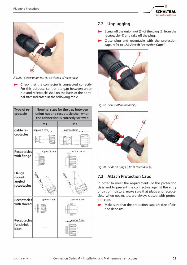
Fig. 26: Screw union nut (5) on thread of receptacle
X Check that the connector is connected correctly. For this purpose, control the gap between union nut and receptacle shell on the basis of the nomi-nal sizes indicated in the following table.
Type of re-ceptacle
Nominal sizes for the gap between union nut and receptacle shell when the connection is correctly screwed
M1 M3
Cable re-ceptacles
approx. 3 mm approx. 3 mm
Receptacles with �ange
approx. 3 mm approx. 3 mm
Flange mount angled receptacles
approx. 15 mm
approx. 10 mm
Receptacles with thread
approx. 4 mm approx. 3 mm
Receptacles for shrink boot ---
approx. 3 mm
7.2 Unplugging
X Screw o� the union nut (5) of the plug (3) from the receptacle (4) and take o� the plug.
X Close plug and receptacle with the protection caps, refer to „7.3 Attach Protection Caps“.
Fig. 27: Screw o� union nut (5)
Fig. 28: Slide o� plug (3) from receptacle (4)
7.3 Attach Protection CapsIn order to meet the requirements of the protection class and to prevent the connectors against the entry of dirt or moisture, make sure that plugs and recepta-cles, when not mated, are always closed with protec-tion caps.
X Make sure that the protection caps are free of dirt and deposits.
24 2017-12-21 / V1.3Connectors Series M – Installation and Maintenance Instructions
Plugging Procedure
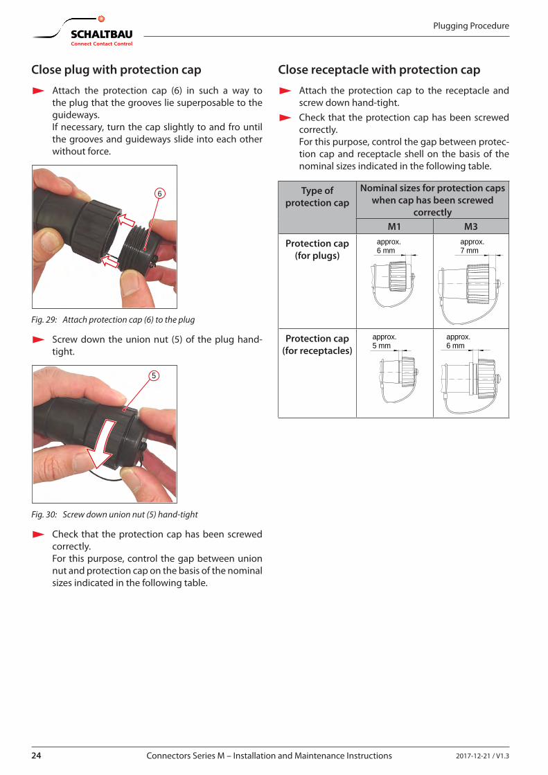
Close plug with protection cap
X Attach the protection cap (6) in such a way to the plug that the grooves lie superposable to the guideways. If necessary, turn the cap slightly to and fro until the grooves and guideways slide into each other without force.
6
Fig. 29: Attach protection cap (6) to the plug
X Screw down the union nut (5) of the plug hand-tight.
5
Fig. 30: Screw down union nut (5) hand-tight
X Check that the protection cap has been screwed correctly. For this purpose, control the gap between union nut and protection cap on the basis of the nominal sizes indicated in the following table.
Close receptacle with protection cap
X Attach the protection cap to the receptacle and screw down hand-tight.
X Check that the protection cap has been screwed correctly. For this purpose, control the gap between protec-tion cap and receptacle shell on the basis of the nominal sizes indicated in the following table.
Type of protection cap
Nominal sizes for protection caps when cap has been screwed
correctlyM1 M3
Protection cap (for plugs)
approx.6 mm
approx.7 mm
Protection cap (for receptacles)
approx.5 mm
approx.6 mm
252017-12-21 / V1.3 Connectors Series M – Installation and Maintenance Instructions
Regular Visual Checks / Functional Checks
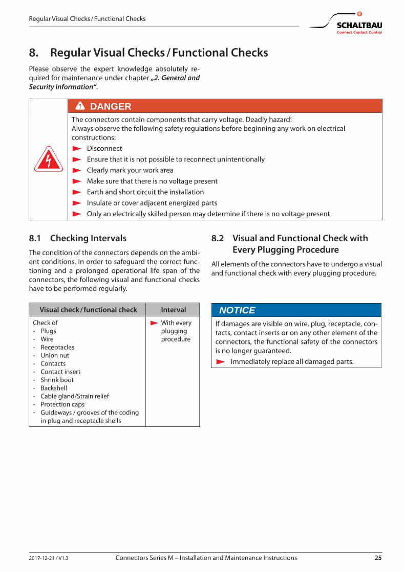
8. Regular Visual Checks / Functional ChecksPlease observe the expert knowledge absolutely re-quired for maintenance under chapter „2. General and Security Information“.
DANGERThe connectors contain components that carry voltage. Deadly hazard!Always observe the following safety regulations before beginning any work on electrical constructions:
X Disconnect X Ensure that it is not possible to reconnect unintentionally X Clearly mark your work area X Make sure that there is no voltage present X Earth and short circuit the installation X Insulate or cover adjacent energized parts X Only an electrically skilled person may determine if there is no voltage present
8.1 Checking IntervalsThe condition of the connectors depends on the ambi-ent conditions. In order to safeguard the correct func-tioning and a prolonged operational life span of the connectors, the following visual and functional checks have to be performed regularly.
Visual check / functional check Interval
Check of - Plugs - Wire - Receptacles - Union nut - Contacts - Contact insert - Shrink boot - Backshell - Cable gland/Strain relief - Protection caps - Guideways / grooves of the coding
in plug and receptacle shells
X With every plugging procedure
8.2 Visual and Functional Check with Every Plugging Procedure
All elements of the connectors have to undergo a visual and functional check with every plugging procedure.
NOTICEIf damages are visible on wire, plug, receptacle, con-tacts, contact inserts or on any other element of the connectors, the functional safety of the connectors is no longer guaranteed.
X Immediately replace all damaged parts.
26 2017-12-21 / V1.3Connectors Series M – Installation and Maintenance Instructions
Regular Visual Checks / Functional Checks
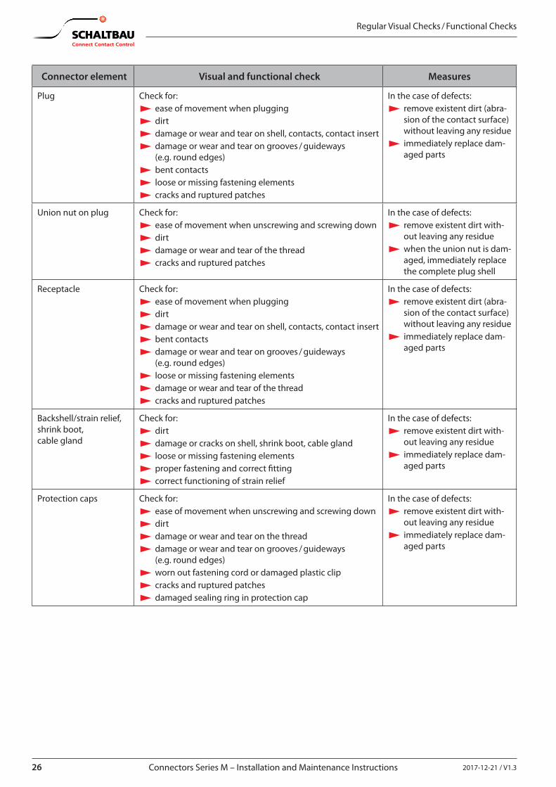
Connector element Visual and functional check Measures
Plug Check for: X ease of movement when plugging X dirt X damage or wear and tear on shell, contacts, contact insert X damage or wear and tear on grooves / guideways (e.g. round edges) X bent contacts X loose or missing fastening elements X cracks and ruptured patches
In the case of defects: X remove existent dirt (abra-sion of the contact surface) without leaving any residue X immediately replace dam-aged parts
Union nut on plug Check for: X ease of movement when unscrewing and screwing down X dirt X damage or wear and tear of the thread X cracks and ruptured patches
In the case of defects: X remove existent dirt with-out leaving any residue X when the union nut is dam-aged, immediately replace the complete plug shell
Receptacle Check for: X ease of movement when plugging X dirt X damage or wear and tear on shell, contacts, contact insert X bent contacts X damage or wear and tear on grooves / guideways (e.g. round edges) X loose or missing fastening elements X damage or wear and tear of the thread X cracks and ruptured patches
In the case of defects: X remove existent dirt (abra-sion of the contact surface) without leaving any residue X immediately replace dam-aged parts
Backshell/strain relief, shrink boot, cable gland
Check for: X dirt X damage or cracks on shell, shrink boot, cable gland X loose or missing fastening elements X proper fastening and correct �tting X correct functioning of strain relief
In the case of defects: X remove existent dirt with-out leaving any residue X immediately replace dam-aged parts
Protection caps Check for: X ease of movement when unscrewing and screwing down X dirt X damage or wear and tear on the thread X damage or wear and tear on grooves / guideways (e.g. round edges) X worn out fastening cord or damaged plastic clip X cracks and ruptured patches X damaged sealing ring in protection cap
In the case of defects: X remove existent dirt with-out leaving any residue X immediately replace dam-aged parts
272017-12-21 / V1.3 Connectors Series M – Installation and Maintenance Instructions
Special Tools and Spare Parts
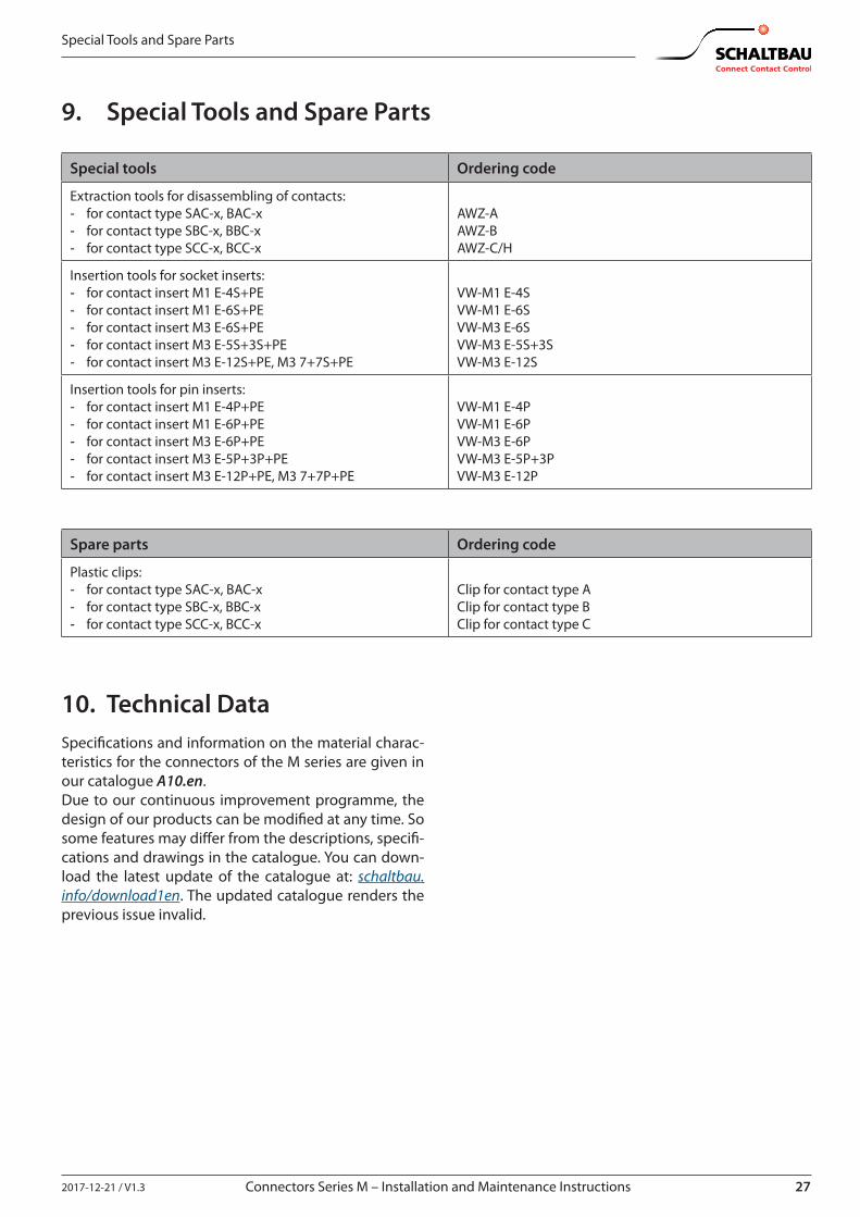
9. Special Tools and Spare Parts
Special tools Ordering code
Extraction tools for disassembling of contacts: - for contact type SAC-x, BAC-x - for contact type SBC-x, BBC-x - for contact type SCC-x, BCC-x
AWZ-AAWZ-BAWZ-C/H
Insertion tools for socket inserts: - for contact insert M1 E-4S+PE - for contact insert M1 E-6S+PE - for contact insert M3 E-6S+PE - for contact insert M3 E-5S+3S+PE - for contact insert M3 E-12S+PE, M3 7+7S+PE
VW-M1 E-4SVW-M1 E-6SVW-M3 E-6SVW-M3 E-5S+3SVW-M3 E-12S
Insertion tools for pin inserts: - for contact insert M1 E-4P+PE - for contact insert M1 E-6P+PE - for contact insert M3 E-6P+PE - for contact insert M3 E-5P+3P+PE - for contact insert M3 E-12P+PE, M3 7+7P+PE
VW-M1 E-4PVW-M1 E-6PVW-M3 E-6PVW-M3 E-5P+3PVW-M3 E-12P
Spare parts Ordering code
Plastic clips: - for contact type SAC-x, BAC-x - for contact type SBC-x, BBC-x - for contact type SCC-x, BCC-x
Clip for contact type AClip for contact type BClip for contact type C
10. Technical DataSpeci�cations and information on the material charac-teristics for the connectors of the M series are given in our catalogue A10.en.Due to our continuous improvement programme, the design of our products can be modi�ed at any time. So some features may di�er from the descriptions, speci�-cations and drawings in the catalogue. You can down-load the latest update of the catalogue at: schaltbau.info/download1en. The updated catalogue renders the previous issue invalid.
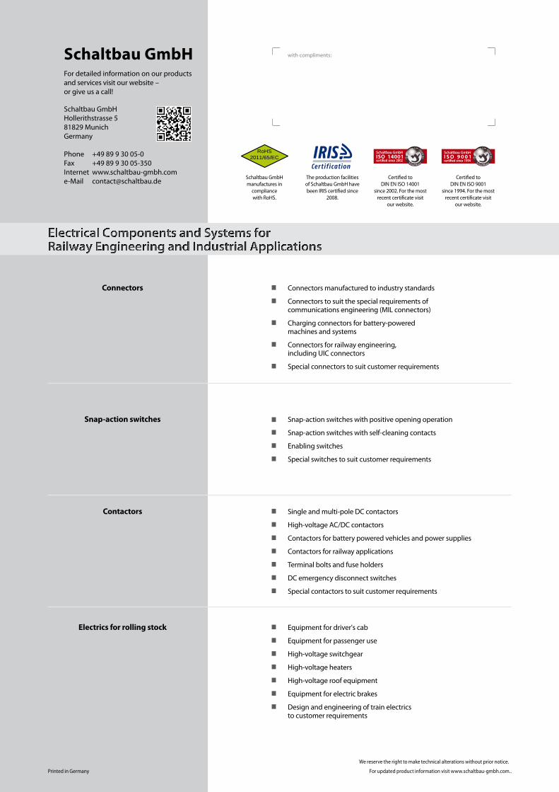
Schaltbau GmbHFor detailed information on our products and services visit our website – or give us a call!
Schaltbau GmbH Hollerithstrasse 5 81829 Munich Germany
Phone +49 89 9 30 05-0 Fax +49 89 9 30 05-350 Internet www.schaltbau-gmbh.com e-Mail [email protected]
Connectors
Connectors manufactured to industry standards
Connectors to suit the special requirements of communications engineering (MIL connectors)
Charging connectors for battery-powered machines and systems
Connectors for railway engineering, including UIC connectors
Special connectors to suit customer requirements
Snap-action switches Snap-action switches with positive opening operation
Snap-action switches with self-cleaning contacts
Enabling switches
Special switches to suit customer requirements
Contactors Single and multi-pole DC contactors
High-voltage AC/DC contactors
Contactors for battery powered vehicles and power supplies
Contactors for railway applications
Terminal bolts and fuse holders
DC emergency disconnect switches
Special contactors to suit customer requirements
Electrics for rolling stock
Equipment for driver's cab
Equipment for passenger use
High-voltage switchgear
High-voltage heaters
High-voltage roof equipment
Equipment for electric brakes
Design and engineering of train electrics to customer requirements
Electrical Components and Systems for Railway Engineering and Industrial Applications
with compliments:
RoHS2011/65/EC
Schaltbau
Qua
lity y
ou can count on
Schaltbau
Qua
lity y
ou can count on
Schaltbau GmbH manufactures in
compliance with RoHS.
The production facilities of Schaltbau GmbH have been IRIS certified since
2008.
Certified to DIN EN ISO 14001
since 2002. For the most recent certificate visit
our website.
Certified to DIN EN ISO 9001
since 1994. For the most recent certificate visit
our website.
Printed in Germany
We reserve the right to make technical alterations without prior notice.
For updated product information visit www.schaltbau-gmbh.com..