prefab-mep-guidebook-v2.pdf - bca
TRANSCRIPT
Design for Manufacturingand Assembly (DfMA)
PREFABRICATED MECHANICAL, ELECTRICAL AND PLUMBING (MEP) SYSTEMS
DisclaimerThis guide may be used for reference purposes only. The contents of this guide are protected by copyright and other forms of proprietary rights owned by, licensed to or controlled by BCA and STAS and shall
not be reproduced, republished, uploaded, posted, transmitted or otherwise distributed in any way, without the prior written permission
of BCA and STAS. Modification of any of the contents or use of the contents for any other purpose will be a violation of BCA’s and STAS’ copyright and other intellectual property rights. Any reference herein
to any specific commercial products, process, or service by trade name, trademark, manufacturer, or otherwise does not constitute or imply BCA’s or STAS’ endorsement or recommendation. BCA, STAS or any agency stated in this guide shall not be liable for any reliance on or misinterpretation of any information contained in this guide by any party. All content used herein is for non-profit educational purposes. Where possible, all credit has been given to the respective owners or
creators of the content.
PREFABRICATED MECHANICAL, ELECTRICAL AND PLUMBING (MEP) SYSTEMS Guidebook
is produced by Specialists Trade Alliance of Singapore (STAS) in collaboration with
Building and Construction Authority (BCA). The purposeful content resonates with professionals
of the construction industry in an easy to read illustrative style. This joint effort by STAS
and BCA is to help developers, consultants, builders, specialist trade subcontractors and prefabricated MEP specialists have a better
understanding of the benefits and good industry practices in Prefabricated
MEP systems.
01
Foreword
FOREWORD
THOMAS ANGPresidentSpecialists Trade Alliance of Singapore
NEO CHOON KEONGDeputy Chief Executive Officer (Industry Development)Building and Construction Authority
The Construction Industry Transformation Map (ITM) envisions an advanced and integrated sector with widespread adoption of leading technologies, led by progressive and collaborative firms well-poised to capture business opportunities, and supported by a skilled and competent workforce. Key global trends which impact the sector, includes Integrated Digital Delivery (IDD), Design for Manufacturing and Assembly (DfMA) which includes the Prefabricated Mechanical, Electrical and Plumbing (MEP) systems as well as green building as transformation areas to address the challenges faced by the sector.
Construction involves many parties at different stages of a project, and good co-ordination is critical in preventing unnecessary reworks along the way. The requirement to adopt prefabricated MEP modules cannot be an afterthought and needs to be incorporated upfront, starting from the project brief. The early decision to adopt MEP modules in a project allows greater continuity of design and maximises productivity gains.
This guidebook aims to push the wider use of Prefabricated MEP modules within the DfMA continuum, with best industry practices and knowledge for industry practitioners to fully embrace the Prefabricated MEP technology. In this book, learning curves from case studies on successful projects in Singapore that adopted prefabricated MEP system allow better understanding on how prefabricated MEP system could be designed, fabricated and installed to achieve its functional requirements and high workmanship standards.
With the support of Building and Construction Authority (BCA), we hope to see leading firms investing in capability building to undertake DfMA projects. Collaboration across the entire value chain is key to meeting the demands of the future, where we expect buildings to become more complex, high-density yet liveable and sustainable. The DfMA approach when adopted correctly, achieves higher quality, productivity and sustainability in a traditionally manpower-intensive industry.
Our appreciations to contributions from key technical agencies and industry practitioners in the production of this guidebook. We trust the industry will find this guidebook useful and we welcome feedback to further improve on the prefabricated MEP system.
A strategic focus of the Construction Industry Transformation Map (ITM) is to champion widespread adoption of Design for Manufacturing and Assembly (DfMA) technologies. DfMA transforms construction into a manufacturing process. It involves moving construction activities from worksites into a controlled factory environment. Building components are prefabricated off-site before being brought on site for assembly. This allows construction projects to be completed faster with better quality, and in a cleaner and quieter manner. Prefabricated Mechanical, Electrical and Plumbing (MEP) systems is one of the game-changing technologies under the DfMA continuum. This MEP Good Industry Practices (GIP) Guidebook (2nd edition) is a joint collaboration between Specialists Trade Alliance of Singapore (STAS) and the Building and Construction Authority (BCA). It seeks to provide simple and useful guidance to practitioners on how prefabricated MEP systems could be designed, fabricated and installed to achieve its functional requirements and workmanship standards, as well as facilitate downstream maintainability. The first edition, which was published in April 2018, introduced the concept of prefabricated MEP systems to industry professionals. Since then, the number of projects adopting prefabricated MEP systems has grown to 34 in 2020. It is hence timely to update this guidebook to build on the learning from these projects to address any knowledge gaps and clarify existing misconceptions, to better support industry professionals in the implementation of prefabricated MEP systems in their projects. In this second edition, we have included additional good practices and case studies of projects in Singapore that have adopted prefabricated MEP systems successfully.
This guide is not meant to be a definitive publication on how prefabricated MEP systems must be designed, fabricated and installed. Industry practitioners are encouraged to innovate and improve further on prefabricated MEP systems. Professional advice should always be sought from designers and suppliers when adopting prefabricated MEP systems. We gratefully acknowledge the contributions of key technical agencies and practitioners in the production of this guide and trust that the industry will find this publication useful. We welcome any contributions from readers to improve subsequent editions of this guide.
01
Championing Widespread Adoption of DfMA
Benefits of Prefabricated MEP Modules
Types of Prefabricated MEP Modules/ Systems and Their Applications
Early Involvement of Contractors and MEP Specialists Tender Requirements and Specifications
Allow Sufficient Time to ConsiderDesign Options
Have Co-ordinated ServicesDrawings (CSD) Endorsed by All RelevantProject Parties
Approve Materials and Mock-ups Prior toMass Production of MEP modules
Ensure Workers are Trained and Defectsare Rectified at the Factory
Improve Co-ordination on Site and inthe Factory
Include Appropriate Contract Clauses forPayment of Completed MEP Modules Summary of Information to be Provided to Tenderers
Key Considerations
Requirements for Different Module Types
Establish a Workflow to Develop Co-ordinated Services Drawing (CSD)
for Prefabrication
Integrated Digital Delivery (IDD) Approach
19
22
27
28
05
06
0811
14
15
15
15
15
16
16
16
31
31
32
32
32
33
33
33
Adopt Good Management Practices to Improve Productivity
Ensure Quality Control
Align MEP Modules Properly Before Delivery to Site
Protect Modules Against Weather Elements
Facilitate Transport, Handling and Installation
Allow Sufficient Temporary Storage Space for Completed Modules
Refer to Inspection Checklist for Deliveryof Modules
Safety Measures in Factory
Written and produced by Specialists Trade Alliance of Singapore (STAS) in collaboration with Building and Construction Authority (BCA). Creative direction by Darby Media Pte Ltd.
CONTENTS 58 APPENDIX
FOREWORD
02 ACKNOWLEDGEMENT
13
2
4
DESIGN
INTRODUCTION
44
48
52
56
Global Switch Singapore Woodlands SMU Connexion Light Factory Development at Woodlands North Coast Rivervale Community Club
7CASE STUDIES
PROCUREMENT
PRODUCTION AT FACTORY
35
35
36
36
39
Adopt Just-In-Time (JIT) Concept Plan for Logistics in Advance Mark and Set Out Modules’ Position
Install and Connect Modules and to the Mains
Testing and Commissioning
5INSTALLATION
40
41
42
43
43
Procurement
Design
Production of Prefabricated MEP Modules Offsite in a Factory
Construction Site
Overall Testing and Commissioning of Services
6ROLES & RESPONSIBILITIES
PREFABRICATED MECHANICAL, ELECTRICAL AND PLUMBING (MEP) SYSTEMS

ACKNOWLEDGEMENT
TECHNICAL COMMITTEE
WORKING COMMITTEE
This second edition of Prefabricated Mechanical, Electrical and Plumbing (MEP) Systems Guidebook was developed by the working committee in close collaboration with key technical agencies and industry representatives comprising developers, architects, builders, consultants, specialist consultants and industry associations.
A technical committee, comprising members from various industry associations and organisations, was formed to review the content.
We wish to thank all members of the technical agencies as well as the technical and working committees for their valuable contributions:
Er Rose NguanEr Denis WongEr Winston HoEr Joseph TohEr Yeo Ser ChongMr Tan HuiMr Tan Ann KiongAr Yeo Eng ChoonMr Lee Keng SengMr Affandi BernawiMr William Lim
Mr Eddy LauMr Jonanthan OoiMs Gloria HeMs Go Hui JingMr Tee Liang SongEr Darren WooMr Stephen AdamsMr Desmond KwekMr Bochan ShinMr Brant Bogyoung JuMr Goutham VijayEr Jannet AngMr Liew Yong SeongMs Kamalika KunduMr Wang See Chenn
Building and Construction Authority (BCA) (Chair)Housing & Development Board (HDB)Jurong Town Corporation (JTC)MOH Holdings (MOHH)Association of Consulting Engineers Singapore (ACES)Real Estate Developers’ Association of Singapore (REDAS)Singapore Contractors Association Ltd (SCAL)Singapore Institute of Architects (SIA)Singapore Institute of Surveyors and Valuers (SISV)Singapore Institute of Surveyors and Valuers (SISV)Society of Project Managers (SPM)
Specialists Trade Alliance of Singapore (STAS) (Co-Chair)Squire Mech Pte Ltd (Co-Chair)Building and Construction AuthorityBuilding and Construction AuthorityBuilding and Construction AuthoritySurbana Jurong Private LimitedGammon Construction Pte LtdLum Chang Building Contractors Pte LtdBintai Kindenko Pte LtdBintai Kindenko Pte LtdTech Onshore MEP Prefabricators Pte LtdTrans Equatorial Engineering Pte LtdHilti Far East Pte LtdHilti Asia Pacific Pte LtdGeorge Fischer Pte Ltd
PREFABRICATED MECHANICAL, ELECTRICAL AND PLUMBING (MEP) SYSTEMS
02Ac
know
ledg
emen
t

CASE STUDIES
TECHNICAL AGENCIES
Global Switch Singapore Woodlands
SMU Connexion
Light Factory Development at Woodlands North Coast
Rivervale Community Club
Global Switch (Property) Singapore Gammon Pte Ltd
Singapore Management UniversityMKPL Architects Pte LtdMeinhardt (Singapore) Pte LtdRider Levett Bucknall LLPLian Ho Lee Construction (Private) Ltd
Jurong Town Corporation (JTC)Lum Chang Building Contractors Pte LtdPowen Engineering Pte Ltd
People’s AssociationKim Seng Heng Engineering Construction (Pte) Ltd
Housing & Development Board (HDB)Jurong Town Corporation (JTC)Land Transport Authority (LTA)Singapore Civil Defence Force (SCDF)
PREFABRICATED MECHANICAL, ELECTRICAL AND PLUMBING (MEP) SYSTEMS 03
Acknowledgem
ent

01 I
ntro
duct
ion
PREFABRICATED MECHANICAL, ELECTRICAL AND PLUMBING (MEP) SYSTEMS
04
INTRODUCTION1.1 The construction industry has been moving towards the adoption of Design for Manufacturing and Assembly (DfMA) where most of the work is done off-site in a controlled manufacturing environment, and then transported and assembled on site. With more prefabrication, manpower and time needed to construct buildings are reduced, worksites are safer and more conducive, and there is less impact on the surrounding environment.
1.2 Prefabricated Mechanical, Electrical and Plumbing (MEP) systems are one of the game-changing technologies that can significantly improve productivity. It adopts the DfMA concept where components in MEP services and equipment are integrated into a subassembly off-site, for easy installation on site.
1.3 This guidebook helps developers, consultants, builders, subcontractors and prefabricated MEP specialists to have a better understanding on prefabricated MEP modules, its benefits and good industry practices on such systems.
intro-duction
04
chapter
05
01 Introduction
PREFABRICATED MECHANICAL, ELECTRICAL AND PLUMBING (MEP) SYSTEMS
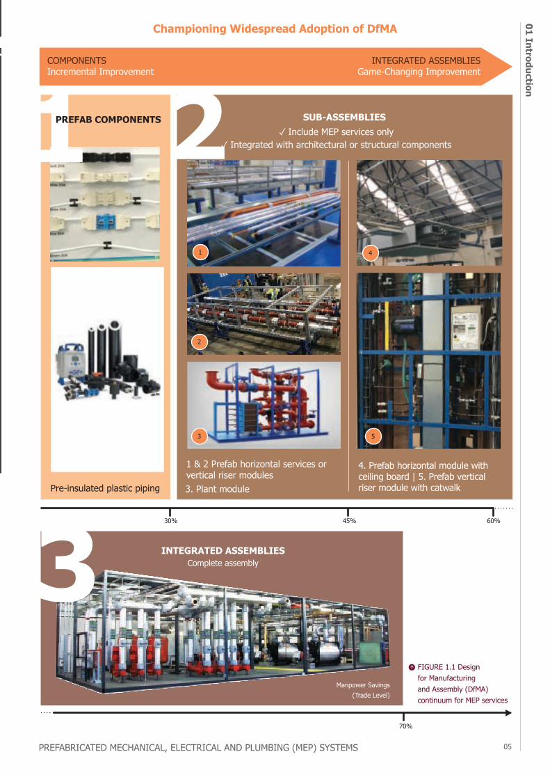
COMPONENTSIncremental Improvement
INTEGRATED ASSEMBLIESGame-Changing Improvement
SUB-ASSEMBLIES✓ Include MEP services only
✓ Integrated with architectural or structural components
30% 45% 60%
70%
Manpower Savings (Trade Level)
INTEGRATED ASSEMBLIESComplete assembly
Pre-insulated plastic piping
4. Prefab horizontal module with ceiling board | 5. Prefab vertical riser module with catwalk
1 & 2 Prefab horizontal services or vertical riser modules3. Plant module
Championing Widespread Adoption of DfMA
1
2
3 5
4
FIGURE 1.1 Design for Manufacturing and Assembly (DfMA) continuum for MEP services
PREFAB COMPONENTS
intro-duction
chapter
01 I
ntro
duct
ion
PREFABRICATED MECHANICAL, ELECTRICAL AND PLUMBING (MEP) SYSTEMS
06
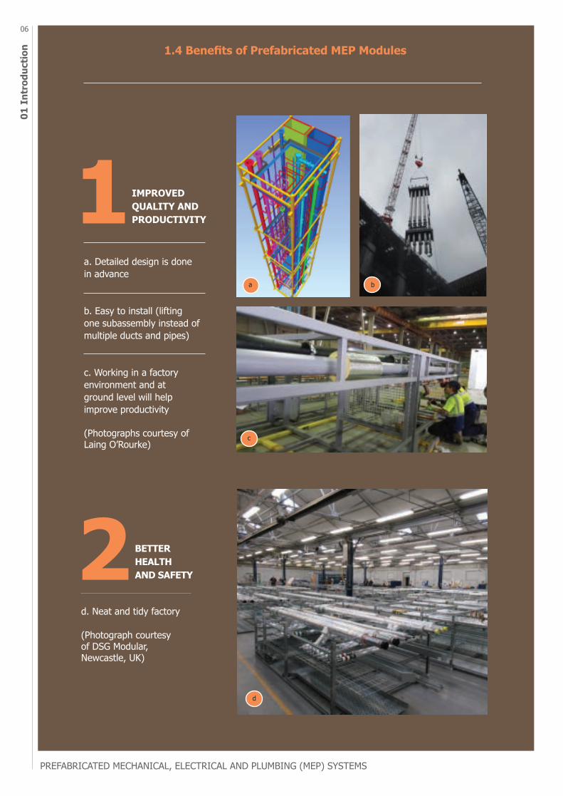
1.4 Benefits of Prefabricated MEP Modules
BETTER HEALTH AND SAFETY
IMPROVED QUALITY AND PRODUCTIVITY
a
c
d
b
a. Detailed design is done in advance
b. Easy to install (lifting one subassembly instead of multiple ducts and pipes)
c. Working in a factory environment and at ground level will helpimprove productivity
(Photographs courtesy of Laing O’Rourke)
d. Neat and tidy factory
(Photograph courtesy of DSG Modular, Newcastle, UK)
07
01 Introduction
PREFABRICATED MECHANICAL, ELECTRICAL AND PLUMBING (MEP) SYSTEMS
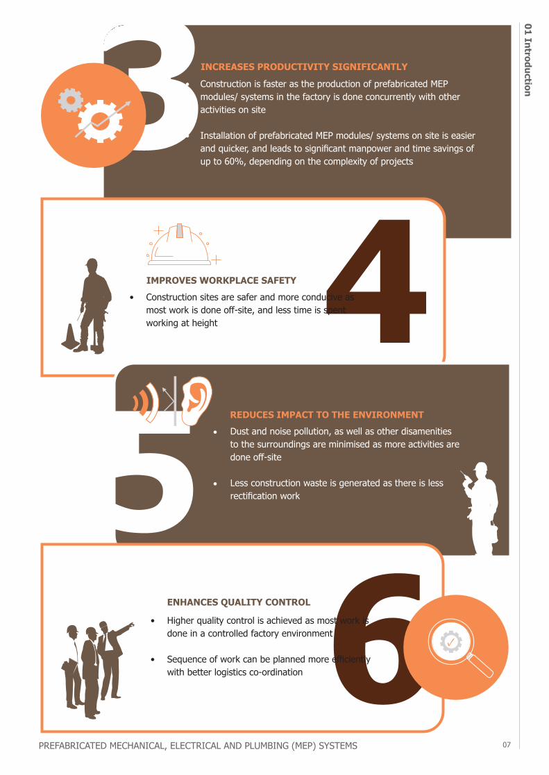
Construction is faster as the production of prefabricated MEP modules/ systems in the factory is done concurrently with other activities on site
Installation of prefabricated MEP modules/ systems on site is easier and quicker, and leads to significant manpower and time savings of up to 60%, depending on the complexity of projects
•
•
•
•
• Higher quality control is achieved as most work is done in a controlled factory environment
• Sequence of work can be planned more efficiently with better logistics co-ordination
INCREASES PRODUCTIVITY SIGNIFICANTLY
IMPROVES WORKPLACE SAFETY• Construction sites are safer and more conducive as
most work is done off-site, and less time is spent working at height
Dust and noise pollution, as well as other disamenities to the surroundings are minimised as more activities are done off-site
Less construction waste is generated as there is less rectification work
REDUCES IMPACT TO THE ENVIRONMENT
ENHANCES QUALITY CONTROL
01 I
ntro
duct
ion
PREFABRICATED MECHANICAL, ELECTRICAL AND PLUMBING (MEP) SYSTEMS
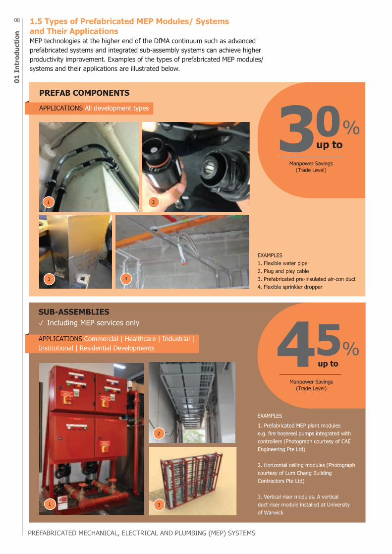
08 1.5 Types of Prefabricated MEP Modules/ Systems and Their ApplicationsMEP technologies at the higher end of the DfMA continuum such as advanced prefabricated systems and integrated sub-assembly systems can achieve higher productivity improvement. Examples of the types of prefabricated MEP modules/ systems and their applications are illustrated below.
EXAMPLES1. Flexible water pipe 2. Plug and play cable3. Prefabricated pre-insulated air-con duct4. Flexible sprinkler dropper
EXAMPLES
APPLICATIONS Commercial | Healthcare | Industrial | Institutional | Residential Developments
Manpower Savings (Trade Level)
Manpower Savings (Trade Level)
APPLICATIONS All development types
PREFAB COMPONENTS
SUB-ASSEMBLIES✓ Including MEP services only
1 2
3 4
2
31
1. Prefabricated MEP plant modules e.g. fire hosereel pumps integrated with controllers (Photograph courtesy of CAE Engineering Pte Ltd)
2. Horizontal ceiling modules (Photograph courtesy of Lum Chang Building Contractors Pte Ltd)
3. Vertical riser modules. A vertical duct riser module installed at University of Warwick
09
01 Introduction
PREFABRICATED MECHANICAL, ELECTRICAL AND PLUMBING (MEP) SYSTEMS
1. MEP system integrated into Prefabricated Prefinished Volumetric Construction systems
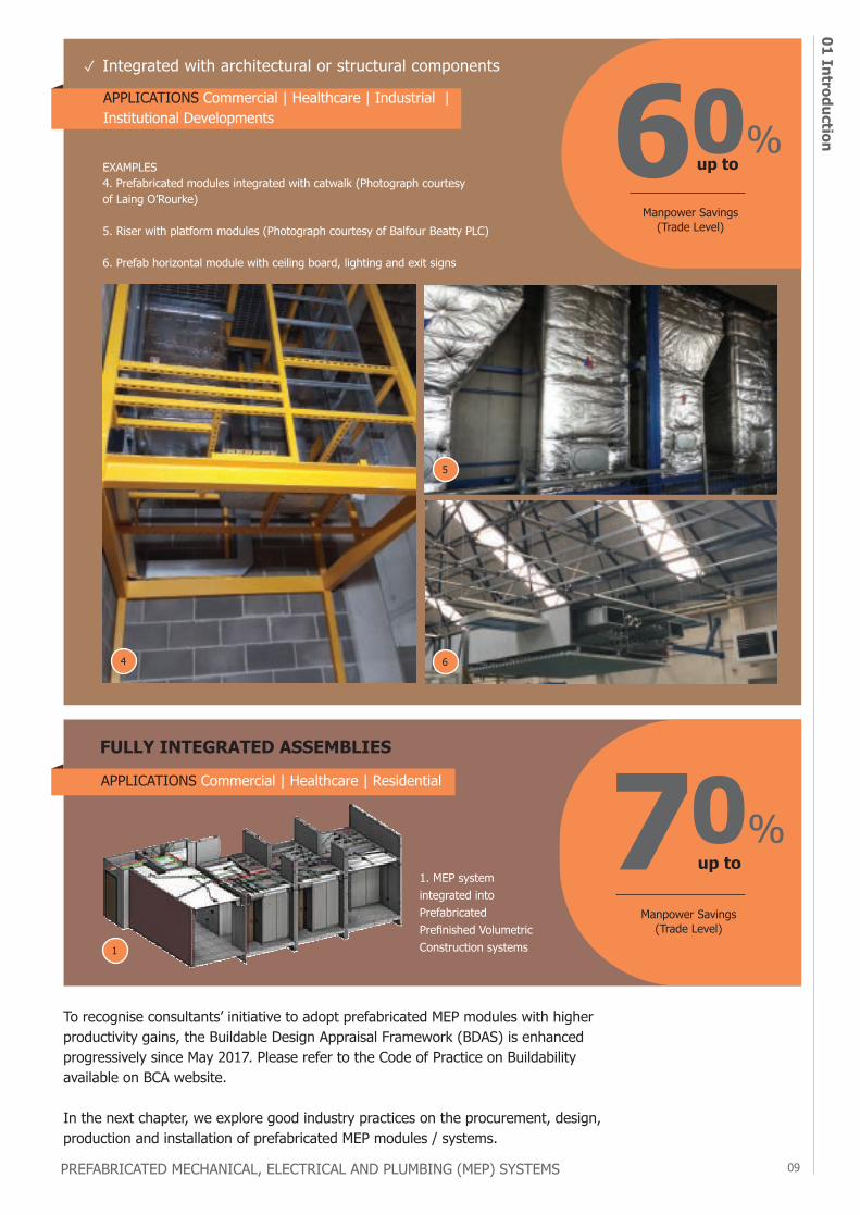
EXAMPLES4. Prefabricated modules integrated with catwalk (Photograph courtesy of Laing O’Rourke)
5. Riser with platform modules (Photograph courtesy of Balfour Beatty PLC)
6. Prefab horizontal module with ceiling board, lighting and exit signs
Manpower Savings (Trade Level)
APPLICATIONS Commercial | Healthcare | Residential
APPLICATIONS Commercial | Healthcare | Industrial | Institutional Developments
✓ Integrated with architectural or structural components
FULLY INTEGRATED ASSEMBLIES
1
4
5
6
Manpower Savings (Trade Level)
To recognise consultants’ initiative to adopt prefabricated MEP modules with higher productivity gains, the Buildable Design Appraisal Framework (BDAS) is enhanced progressively since May 2017. Please refer to the Code of Practice on Buildability available on BCA website.
In the next chapter, we explore good industry practices on the procurement, design, production and installation of prefabricated MEP modules / systems.

02 P
rocu
rem
ent
10
procurement
chapter
10
OVERVIEWEarly Involvement of Contractors and MEP Specialists
Tender Requirements and Specifications
Allow Sufficient Time to Consider Design Options
Have Co-ordinated Services Drawings (CSD) Endorsed by All Relevant Project Parties
Approve Materials and Mock-ups Prior to Mass Production of MEP modules
Ensure Workers are Trained and Defects are Rectified at the Factory
Improve Co-ordination on Site and in the Factory
Include Appropriate Contract Clauses for Payment of Completed MEP Modules
Summary of Information to be Provided to Tenderers
2.1
2.2
PREFABRICATED MECHANICAL, ELECTRICAL AND PLUMBING (MEP) SYSTEMS
2.2.1
2.2.2
2.2.3
2.2.4
2.2.5
2.2.6
2.3
11
02 Procurement
PREFABRICATED MECHANICAL, ELECTRICAL AND PLUMBING (MEP) SYSTEMS
PROCUREMENT2.1 Early Involvement of Contractors and MEP SpecialistsIt is important to engage the builder, MEP trade specialists and prefabricated MEP specialists as early as possible in the design development of the project. By incorporating their inputs into the design, a more effective technical and buildable solution can be achieved. Some key considerations that require early involvement of contractors and MEP specialists are as follows:
1. Scope of prefabricated MEP modules 2. Contractors and prefabricated MEP specialists can help identify areas where
prefabricated MEP modules can be applied, such as typical risers, common corridors, plantroom skids, and raised floor systems. By establishing the scope of prefabricated MEP modules early, relevant requirements can be incorporated into the tender specifications, allowing contractors to plan the necessary logistics in advance and price their tender correctly and sufficiently to cover all their obligations.
3. 4. Early co-ordination and space planning in consideration of modules upfront will
also allow more services to be co-located within each prefabricated assembly, improving efficiency in fabrication and installation of modules.
5. 6. Buildability and constructability of the prefabricated MEP design 7. Contractors can conduct a preliminary assessment on the buildability and
constructability of the prefabricated MEP design based on site conditions including the availability of access to and around the site, and delivery routes of modules to their designated positions. This will provide a more holistic review of project requirements such as provisions of lifting equipment and temporary openings in walls and slabs, that are necessary for the transportation and installation of modules on site. In addition, working access should be catered in the prefabricated MEP design to allow further connections of individual services, after the modules are installed on site. The buildability and constructability of the prefabricated MEP design is essential in defining the scope of prefabricated MEP modules.
8. 9. Potential design clashes and structural safety concerns 10. during installation 11. The co-ordination and overall clash detection processes can start earlier,
eliminating the risks of reworks downstream. Contractors will also provide inputs on the structural requirements of the MEP modules including the weight of the modules and their dynamic loading, access openings in structural wall and floor for installation of modules. These inputs should be provided to the Qualified Person (QP) Structural to design the building structural requirements.
12. 13. Ease and accessibility of future maintenance, replacement and
upgrading of MEP system14. Design for maintenance is important to integrate operations and maintenance
considerations into project planning and design to achieve effectiveness, safety, and economy of maintenance tasks during the lifespan of a facility. Providing safe and easy access for the inspection and maintenance of MEP installations should be considered upfront in the design of prefabricated MEP system. Besides guidelines from relevant publications such as the Design for Maintainability Guide issued by BCA, facilities management team and contractors can provide early inputs for consideration.
a.
b.
c.
d.
02 P
rocu
rem
ent
PREFABRICATED MECHANICAL, ELECTRICAL AND PLUMBING (MEP) SYSTEMS
12
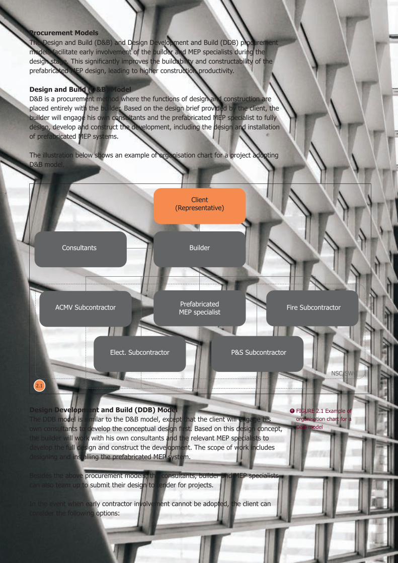
FIGURE 2.1 Example of organisation chart for a D&B model
Client(Representative)
Builder
PrefabricatedMEP specialist Fire Subcontractor
Consultants
ACMV Subcontractor
Elect. Subcontractor P&S Subcontractor
NSC/SWC
The Design and Build (D&B) and Design Development and Build (DDB) procurement models facilitate early involvement of the builder and MEP specialists during the design stage. This significantly improves the buildability and constructability of the prefabricated MEP design, leading to higher construction productivity.
Design and Build (D&B) ModelD&B is a procurement method where the functions of design and construction are placed entirely with the builder. Based on the design brief provided by the client, the builder will engage his own consultants and the prefabricated MEP specialist to fully design, develop and construct the development, including the design and installation of prefabricated MEP systems.
The illustration below shows an example of organisation chart for a project adopting D&B model.
Design Development and Build (DDB) ModelThe DDB model is similar to the D&B model, except that the client will engage his own consultants to develop the conceptual design first. Based on this design concept, the builder will work with his own consultants and the relevant MEP specialists to develop the full design and construct the development. The scope of work includes designing and installing the prefabricated MEP system.
Besides the above procurement models, the consultants, builder and MEP specialists can also team up to submit their design to tender for projects.
In the event when early contractor involvement cannot be adopted, the client can consider the following options:
Procurement Models
2.1
13
02 Procurement
PREFABRICATED MECHANICAL, ELECTRICAL AND PLUMBING (MEP) SYSTEMS
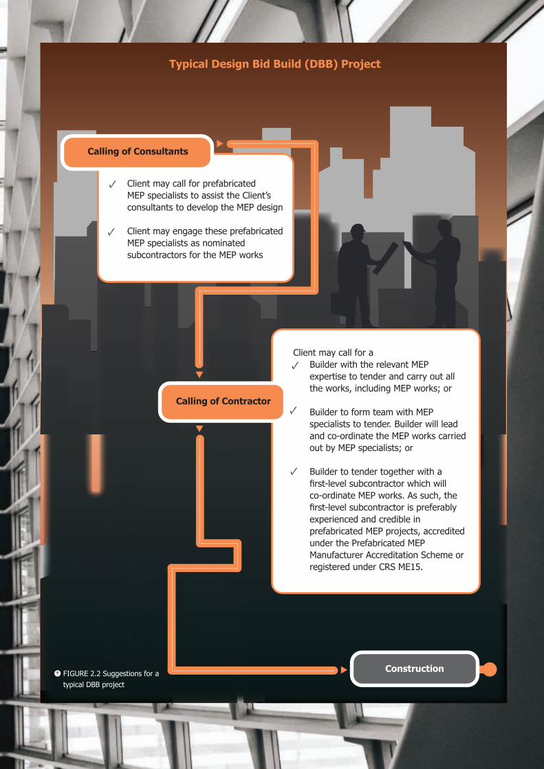
Typical Design Bid Build (DBB) Project
Construction
Calling of Consultants
• Client may call for prefabricated MEP specialists to assist the Client’s consultants to develop the MEP design
• • Client may engage these prefabricated
MEP specialists as nominated subcontractors for the MEP works
Client may call for a• Builder with the relevant MEP
expertise to tender and carry out all the works, including MEP works; or
• • Builder to form team with MEP
specialists to tender. Builder will lead and co-ordinate the MEP works carried out by MEP specialists; or
• • Builder to tender together with a
first-level subcontractor which will co-ordinate MEP works. As such, the first-level subcontractor is preferably experienced and credible in prefabricated MEP projects, accredited under the Prefabricated MEP Manufacturer Accreditation Scheme or registered under CRS ME15.
Calling of Contractor
FIGURE 2.2 Suggestions for a typical DBB project
02 P
rocu
rem
ent
PREFABRICATED MECHANICAL, ELECTRICAL AND PLUMBING (MEP) SYSTEMS
14
2.2 Tender Requirements and SpecificationsThe requirement to adopt prefabricated MEP modules cannot be an afterthought and must be incorporated upfront in the tender documents, starting from the project brief. The early decision to adopt MEP modules in the project allows greater continuity of design and maximises productivity gains.
Project milestones are different when prefabricated MEP modules are adopted in a project. As such, the contract provisions of a project adopting prefabricated MEP modules should take into account the following considerations:
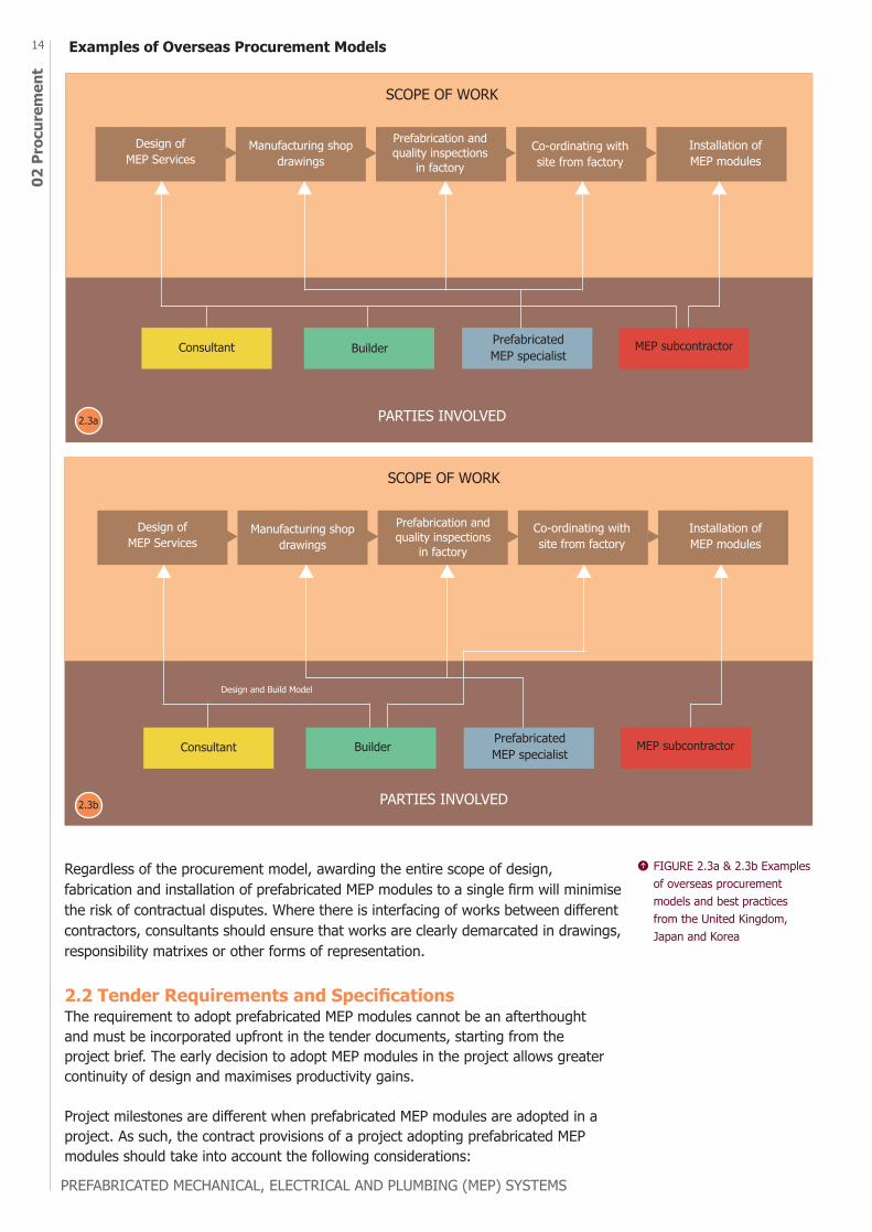
Regardless of the procurement model, awarding the entire scope of design, fabrication and installation of prefabricated MEP modules to a single firm will minimise the risk of contractual disputes. Where there is interfacing of works between different contractors, consultants should ensure that works are clearly demarcated in drawings, responsibility matrixes or other forms of representation.
SCOPE OF WORK
PARTIES INVOLVED
SCOPE OF WORK
PARTIES INVOLVED
Design and Build Model
FIGURE 2.3a & 2.3b Examples of overseas procurement models and best practices from the United Kingdom, Japan and Korea
Examples of Overseas Procurement Models
Prefabrication and quality inspections
in factory
Prefabrication and quality inspections
in factory
2.3a
2.3b
15
02 Procurement
PREFABRICATED MECHANICAL, ELECTRICAL AND PLUMBING (MEP) SYSTEMS
2.2.1 Allow Sufficient Time to Consider Design OptionsDuring planning, it is important to allocate sufficient time to consider a range of design options for prefabricated MEP modules with the help of BIM software, and avoid rushing into details which can limit the design options.
For example, a detailed design of a building’s services may pre-determine the construction sequence or limit the scope for preassembly. The use of a vertical riser in a frame passing through multiple floors may be more efficient than having a smaller assembly for each floor or fitting components in a traditional in-situ manner. However, lifting restrictions on the site may prevent this option from being used.
As various design options require inputs across the construction value chain, the client should allow adequate time for design and space planning in BIM software as well as collaboration among the consultants, builder and MEP specialists, before construction starts.
2.2.2 Have Co-ordinated Services Drawings (CSD) Endorsed by All Relevant Project PartiesOnce prefabrication is completed, only minor changes are allowed. Any design changes or re-routing causes a lot of disruption. Hence, it is important that the designs of the MEP services including structural requirements of modules are confirmed early by all relevant project parties including the client, consultants, builder and relevant MEP trade specialists. Since all modules are manufactured based on BIM co-ordinated models, the process of approving the shop drawings is critical and must be robust.
The CSD needs to be endorsed by all relevant project parties according to a pre-agreed schedule.
Clients are also encouraged to require the builder and MEP specialists to provide more detailed BIM drawings to facilitate off-site prefabrication of MEP systems as well as ensure rigor in quality inspections.
2.2.3 Approve Materials and Mock-ups Prior to Mass Production of MEP modulesUnlike cast in-situ works where there is a sequence for materials to arrive on site, upfront material planning is critical for prefabricated MEP modules as all materials are needed at the same time for prefabrication. Consultants are required to approve the materials used early, so that prefabrication of modules can proceed on schedule. Mock-ups of the most typical prefabricated MEP modules used in the development should also be produced for the consultants’ approval, prior to mass production of the modules in the factory.
Contractors or prefabricated MEP specialists can also use the mock-ups to train their workers on installation of modules and connections of individual services on site, thereby enhancing site safety and productivity.
2.2.4 Ensure Workers are Trained and Defects are Rectified at the FactoryThe skills of the trade workers deployed at the factory play a critical role in ensuring the smooth installation of modules on site. Where possible, defects should be identified and rectified before the modules are delivered to site. To avoid potential disputes, the tender can include requirements for MEP trade specialists to provide training for workers in the factory, and to rectify defects found in the modules installed on site.
To improve and verify the workmanship of the modules, the works done in the factory should be inspected periodically by the builder’s Quality Assurance/Quality Control (QA/QC) personnel or an engineer’s representative engaged by the consultants.
02 P
rocu
rem
ent
PREFABRICATED MECHANICAL, ELECTRICAL AND PLUMBING (MEP) SYSTEMS
16 2.2.5 Improve Co-ordination on Site and in the FactoryClients can specify to engage firms under the CRS ME15 workhead or Prefabricated MEP Manufacturer Accreditation Scheme as the first-level subcontractor to co-ordinate the installation of prefabricated MEP works. The firm should have a relevant track record in the co-ordination and installation of prefabricated MEP modules.
In addition, the tender should specify a dedicated firm or personnel to lead and direct the co-ordination among various trades on site and in the factory. The lead co-ordinator is preferably the builder that is well placed to co-ordinate logistics and activities of all trades on site. It is recommended that the organisation chart include co-ordinators from prefabricated MEP specialists as well as builder and sub-contractors involved and they must ensure that adequate resources are dedicated to the installation of the prefabricated MEP modules.
2.2.6 Include Appropriate Contract Clauses for Payment of Completed MEP ModulesWith a different work sequence, the contractor’s methodology for claiming for work done will change and the appropriate particular conditions of contract clauses will need to be inserted to address and to facilitate these payments accordingly. For example, the prefabricated MEP specialist can claim part of the contract amount for the modules completed in the factory, before the installation of these modules on site.
2.3 Summary of Information to be Provided to Tenderers Consultants can consider providing the following additional information to tenderers, to facilitate the design, fabrication and installation of prefabricated MEP modules in the project:a. Preliminaries including the following: i. Structural design load of building, accessibility and site constraints that might affect the design and installation of modules on site ii. Collaborative practices such as requiring the builder to engage prefabricated MEP specialists early, that will demonstrate their competencies, preferably through a Manufacturer Accreditation Scheme or relevant track record
b. Detailed scope of works consisting the following: i. Drawings should clearly indicate zones identified to be suitable for prefabricated MEP modules ii. Roles and responsibilities including demarcation of works on site requiring interfacing of works by different contractors iii. Deliverables of individual contractors
c. Detailed technical specifications consisting the following: i. Design and material specifications of support system of modules ii. Acceptable quality standards and criteria for factory acceptance tests, testing and commissioning of modules on site
d. Attributes relating to prefabricated MEP modules under Price Quality Method (PQM)
17
02 Procurement
PREFABRICATED MECHANICAL, ELECTRICAL AND PLUMBING (MEP) SYSTEMS
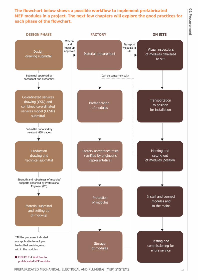
The flowchart below shows a possible workflow to implement prefabricated MEP modules in a project. The next few chapters will explore the good practices for each phase of the flowchart.
Material procurementVisual inspections
of modules delivered to site
Prefabrication of modules
Factory acceptance tests (verified by engineer’s
representative)
Protection of modules
Storage of modules
Transportation to position
for installation
Marking and setting out
of modules’ position
Install and connect modules and to the mains
Testing and commissioning for
entire service
Design drawing submittal
DESIGN PHASE FACTORY ON SITE
Submittal approved by consultant and authorities
Material and
mock-up approved
Transport modules to
site
Can be concurrent with
Submittal endorsed by relevant MEP trades
Strength and robustness of modules’ supports endorsed by Professional
Engineer (PE)
Co-ordinated services drawing (CSD) and
combined co-ordinated services model (CCSM)
submittal
Production drawing and
technical submittal
Material submittal and setting up
of mock-up
FIGURE 2.4 Workflow for prefabricated MEP modules
*All the processes indicated are applicable to multiple trades that are integrated within the modules.

PREFABRICATED MECHANICAL, ELECTRICAL AND PLUMBING (MEP) SYSTEMS
18
design
chapterOVERVIEWKey Considerations
Requirements for Different Module Types
Establish a Workflow to Develop Co-ordinated Services Drawing (CSD) for Prefabrication
Integrated Digital Delivery (IDD) Approach
3.1
3.2
3.3
3.4
3.1.1
3.1.2
3.1.3
3.1.4
3.1.5
3.1.6
Transportation
Lifting and Handling
Availability of Confirmed Detailed Design
Ease of Maintenance
Structural System
Material Wastage
03 Design
19
DESIGN
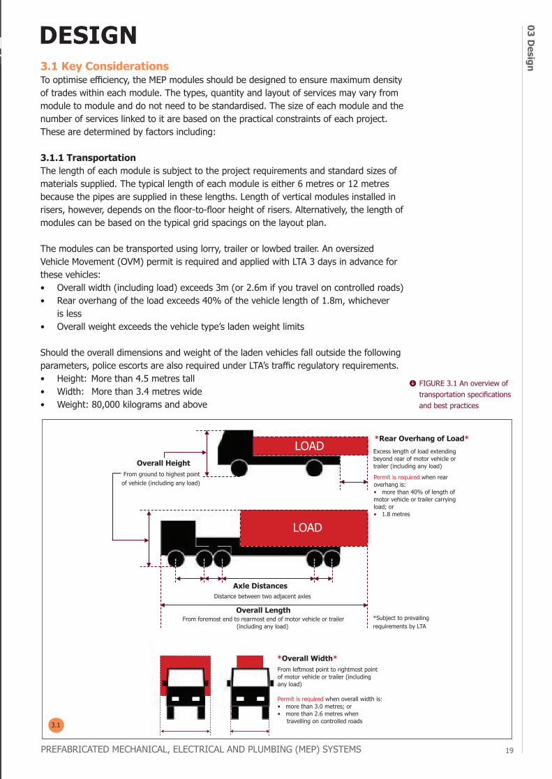
Axle DistancesDistance between two adjacent axles.
*Rear Overhang of Load*Excess length of load extending beyond rear of motor vehicle or trailer (including any load).
Permit is required when rear overhang is:• more than 40% of length of motor vehicle or trailer carrying load; or• 1.8 metres
3.1 Key ConsiderationsTo optimise efficiency, the MEP modules should be designed to ensure maximum density of trades within each module. The types, quantity and layout of services may vary from module to module and do not need to be standardised. The size of each module and the number of services linked to it are based on the practical constraints of each project. These are determined by factors including:
3.1.1 TransportationThe length of each module is subject to the project requirements and standard sizes of materials supplied. The typical length of each module is either 6 metres or 12 metres because the pipes are supplied in these lengths. Length of vertical modules installed in risers, however, depends on the floor-to-floor height of risers. Alternatively, the length of modules can be based on the typical grid spacings on the layout plan.
The modules can be transported using lorry, trailer or lowbed trailer. An oversized Vehicle Movement (OVM) permit is required and applied with LTA 3 days in advance for these vehicles:• Overall width (including load) exceeds 3m (or 2.6m if you travel on controlled roads)• Rear overhang of the load exceeds 40% of the vehicle length of 1.8m, whichever
is less• Overall weight exceeds the vehicle type’s laden weight limits
Should the overall dimensions and weight of the laden vehicles fall outside the following parameters, police escorts are also required under LTA’s traffic regulatory requirements.• Height: More than 4.5 metres tall• Width: More than 3.4 metres wide• Weight: 80,000 kilograms and above
*Subject to prevailing requirements by LTA.
FIGURE 3.1 An overview of transportation specifications and best practices
chapter
PREFABRICATED MECHANICAL, ELECTRICAL AND PLUMBING (MEP) SYSTEMS
3.1
PREFABRICATED MECHANICAL, ELECTRICAL AND PLUMBING (MEP) SYSTEMS
03 D
esig
n20
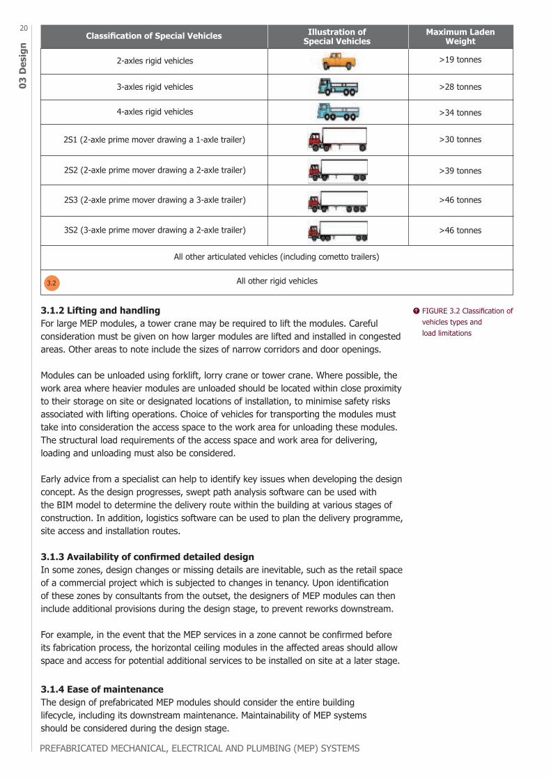
Classification of Special Vehicles Illustration of Special Vehicles
Maximum Laden Weight
2-axles rigid vehicles >19 tonnes
>28 tonnes
>34 tonnes
>30 tonnes
>39 tonnes
>46 tonnes
>46 tonnes
3-axles rigid vehicles
4-axles rigid vehicles
2S1 (2-axle prime mover drawing a 1-axle trailer)
2S2 (2-axle prime mover drawing a 2-axle trailer)
2S3 (2-axle prime mover drawing a 3-axle trailer)
3S2 (3-axle prime mover drawing a 2-axle trailer)
All other articulated vehicles (including cometto trailers)
All other rigid vehicles
3.1.2 Lifting and handlingFor large MEP modules, a tower crane may be required to lift the modules. Careful consideration must be given on how larger modules are lifted and installed in congested areas. Other areas to note include the sizes of narrow corridors and door openings.
Modules can be unloaded using forklift, lorry crane or tower crane. Where possible, the work area where heavier modules are unloaded should be located within close proximity to their storage on site or designated locations of installation, to minimise safety risks associated with lifting operations. Choice of vehicles for transporting the modules must take into consideration the access space to the work area for unloading these modules. The structural load requirements of the access space and work area for delivering, loading and unloading must also be considered.
Early advice from a specialist can help to identify key issues when developing the design concept. As the design progresses, swept path analysis software can be used with the BIM model to determine the delivery route within the building at various stages of construction. In addition, logistics software can be used to plan the delivery programme, site access and installation routes.
3.1.3 Availability of confirmed detailed designIn some zones, design changes or missing details are inevitable, such as the retail space of a commercial project which is subjected to changes in tenancy. Upon identification of these zones by consultants from the outset, the designers of MEP modules can then include additional provisions during the design stage, to prevent reworks downstream.
For example, in the event that the MEP services in a zone cannot be confirmed before its fabrication process, the horizontal ceiling modules in the affected areas should allow space and access for potential additional services to be installed on site at a later stage.
3.1.4 Ease of maintenanceThe design of prefabricated MEP modules should consider the entire buildinglifecycle, including its downstream maintenance. Maintainability of MEP systemsshould be considered during the design stage.
FIGURE 3.2 Classification of vehicles types and load limitations
3.2
PREFABRICATED MECHANICAL, ELECTRICAL AND PLUMBING (MEP) SYSTEMS
03 Design
21
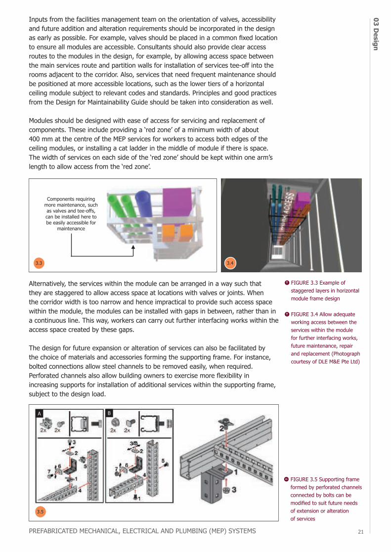
Alternatively, the services within the module can be arranged in a way such that they are staggered to allow access space at locations with valves or joints. When the corridor width is too narrow and hence impractical to provide such access space within the module, the modules can be installed with gaps in between, rather than in a continuous line. This way, workers can carry out further interfacing works within the access space created by these gaps.
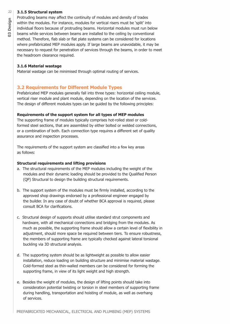
The design for future expansion or alteration of services can also be facilitated by the choice of materials and accessories forming the supporting frame. For instance, bolted connections allow steel channels to be removed easily, when required. Perforated channels also allow building owners to exercise more flexibility in increasing supports for installation of additional services within the supporting frame, subject to the design load.
A B
Components requiring more maintenance, such as valves and tee-offs, can be installed here to be easily accessible for
maintenance
FIGURE 3.3 Example of staggered layers in horizontal module frame design
FIGURE 3.4 Allow adequate working access between the services within the module for further interfacing works, future maintenance, repair and replacement (Photograph courtesy of DLE M&E Pte Ltd)
Inputs from the facilities management team on the orientation of valves, accessibility and future addition and alteration requirements should be incorporated in the design as early as possible. For example, valves should be placed in a common fixed location to ensure all modules are accessible. Consultants should also provide clear access routes to the modules in the design, for example, by allowing access space between the main services route and partition walls for installation of services tee-off into the rooms adjacent to the corridor. Also, services that need frequent maintenance should be positioned at more accessible locations, such as the lower tiers of a horizontal ceiling module subject to relevant codes and standards. Principles and good practices from the Design for Maintainability Guide should be taken into consideration as well.
Modules should be designed with ease of access for servicing and replacement of components. These include providing a ‘red zone’ of a minimum width of about 400 mm at the centre of the MEP services for workers to access both edges of the ceiling modules, or installing a cat ladder in the middle of module if there is space. The width of services on each side of the ‘red zone’ should be kept within one arm’s length to allow access from the ‘red zone’.
FIGURE 3.5 Supporting frame formed by perforated channels connected by bolts can be modified to suit future needs of extension or alteration of services
3.3 3.4
3.5
PREFABRICATED MECHANICAL, ELECTRICAL AND PLUMBING (MEP) SYSTEMS
03 D
esig
n22 3.1.5 Structural system
Protruding beams may affect the continuity of modules and density of trades within the modules. For instance, modules for vertical risers must be ‘split’ into individual floors because of protruding beams. Horizontal modules must run below beams while services between beams are installed to the ceiling by conventional method. Therefore, flab slab or flat plate systems can be considered for locations where prefabricated MEP modules apply. If large beams are unavoidable, it may be necessary to request for penetration of services through the beams, in order to meet the headroom clearance required.
3.1.6 Material wastageMaterial wastage can be minimised through optimal routing of services.
3.2 Requirements for Different Module TypesPrefabricated MEP modules generally fall into three types: horizontal ceiling module, vertical riser module and plant module, depending on the location of the services. The design of different modules types can be guided by the following principles:
Requirements of the support system for all types of MEP modulesThe supporting frame of modules typically comprises hot-rolled steel or cold-formed steel sections, that are assembled by either bolted or welded connections, or a combination of both. Each connection type requires a different set of quality assurance and inspection processes.
The requirements of the support system are classified into a few key areas as follows: Structural requirements and lifting provisionsa. The structural requirements of the MEP modules including the weight of the modules and their dynamic loading should be provided to the Qualified Person (QP) Structural to design the building structural requirements.
b. The support system of the modules must be firmly installed, according to the approved shop drawings endorsed by a professional engineer engaged by the builder. In any case of doubt of whether BCA approval is required, please consult BCA for clarifications.
c. Structural design of supports should utilise standard strut components and hardware, with all mechanical connections and bridging from the modules. As much as possible, the supporting frame should allow a certain level of flexibility in adjustment, should more space be required between tiers. To ensure robustness, the members of supporting frame are typically checked against lateral torsional buckling via 3D structural analysis.
d. The supporting system should be as lightweight as possible to allow easier installation, reduce loading on building structure and minimise material wastage. Cold-formed steel as thin-walled members can be considered for forming the supporting frame, in view of its light weight and high strength.
e. Besides the weight of modules, the design of lifting points should take into consideration potential twisting or torsion in steel members of supporting frame during handling, transportation and hoisting of module, as well as overhang of services.
PREFABRICATED MECHANICAL, ELECTRICAL AND PLUMBING (MEP) SYSTEMS
03 Design
23
f. Modules can be linked in tandem for a continuous service run.
g. The overhead components should be independently supported.
h. To ensure the reliability of steel members used in the support system of the modules, project team could consider selecting steel based on its manufactured capabilities to successfully meet design requirements.
i. The reliability of structural steel members and thin-walled channel frame in resisting ultimate loads also depends on their accompanying accessories, e.g. channels, connectors, pipe clamps and threaded rods used. Factory Production Control certificate and mill test report should be considered as one of the relevant reports and documentary proofs required.
Corrosion resistance of support systemj. Depending on the exposure conditions and intended service lifetime, the supporting frame should comprise steel sections and fasteners of appropriate grades, and be adequately protected with hot-dip galvanising, coats of painting or other measures to prevent corrosion.
k. If welded connections are used in the assembly of the support system, measures to prevent corrosion to the welded connections are required, e.g. painting with cold galvanizing zinc.
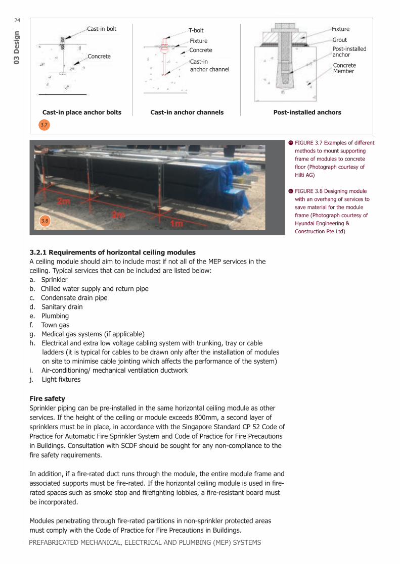
Method to fasten the supporting frame in placel. Supporting frame of modules is generally fastened to the building structure using cast-in-place anchor bolts, cast-in-place anchor channels or post-installed anchors. While cast-in-place anchor bolts or channels eliminate the need for drilling on site, post-installed anchors offer more flexibility in positioning.
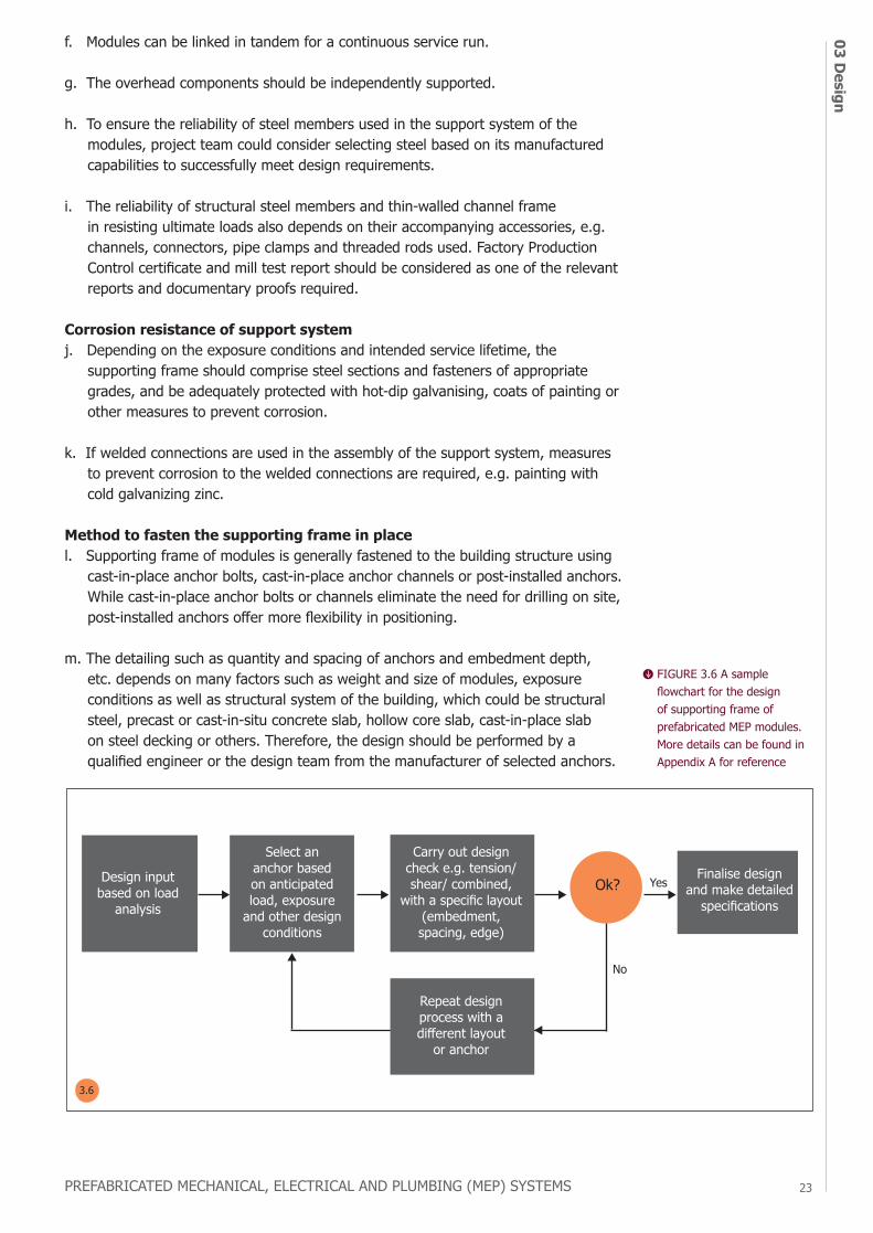
m. The detailing such as quantity and spacing of anchors and embedment depth, etc. depends on many factors such as weight and size of modules, exposure conditions as well as structural system of the building, which could be structural steel, precast or cast-in-situ concrete slab, hollow core slab, cast-in-place slab on steel decking or others. Therefore, the design should be performed by a qualified engineer or the design team from the manufacturer of selected anchors.
Design input based on load
analysis
Select an anchor based on anticipated load, exposure
and other design conditions
Carry out design check e.g. tension/shear/ combined,
with a specific layout (embedment, spacing, edge)
Finalise design and make detailed
specificationsOk? Yes
No
Repeat design process with a different layout
or anchor
FIGURE 3.6 A sample flowchart for the design of supporting frame of prefabricated MEP modules. More details can be found in Appendix A for reference
3.6
PREFABRICATED MECHANICAL, ELECTRICAL AND PLUMBING (MEP) SYSTEMS
03 D
esig
n24
3.2.1 Requirements of horizontal ceiling modulesA ceiling module should aim to include most if not all of the MEP services in the ceiling. Typical services that can be included are listed below: a. Sprinkler b. Chilled water supply and return pipec. Condensate drain piped. Sanitary draine. Plumbingf. Town gasg. Medical gas systems (if applicable)h. Electrical and extra low voltage cabling system with trunking, tray or cable ladders (it is typical for cables to be drawn only after the installation of modules on site to minimise cable jointing which affects the performance of the system)i. Air-conditioning/ mechanical ventilation ductworkj. Light fixtures
Fire safety Sprinkler piping can be pre-installed in the same horizontal ceiling module as other services. If the height of the ceiling or module exceeds 800mm, a second layer of sprinklers must be in place, in accordance with the Singapore Standard CP 52 Code of Practice for Automatic Fire Sprinkler System and Code of Practice for Fire Precautions in Buildings. Consultation with SCDF should be sought for any non-compliance to the fire safety requirements.
In addition, if a fire-rated duct runs through the module, the entire module frame and associated supports must be fire-rated. If the horizontal ceiling module is used in fire-rated spaces such as smoke stop and firefighting lobbies, a fire-resistant board must be incorporated.
Modules penetrating through fire-rated partitions in non-sprinkler protected areas must comply with the Code of Practice for Fire Precautions in Buildings.
Cast-in place anchor bolts Cast-in anchor channels Post-installed anchors
Cast-in bolt
Concrete
T-boltFixture
Fixture
GroutPost-installed anchor
Concrete Member
Concrete
Cast-in anchor channel
FIGURE 3.7 Examples of different methods to mount supporting frame of modules to concrete floor (Photograph courtesy of Hilti AG)
FIGURE 3.8 Designing module with an overhang of services to save material for the module frame (Photograph courtesy of Hyundai Engineering & Construction Pte Ltd)
3.7
3.8
PREFABRICATED MECHANICAL, ELECTRICAL AND PLUMBING (MEP) SYSTEMS
03 Design
25
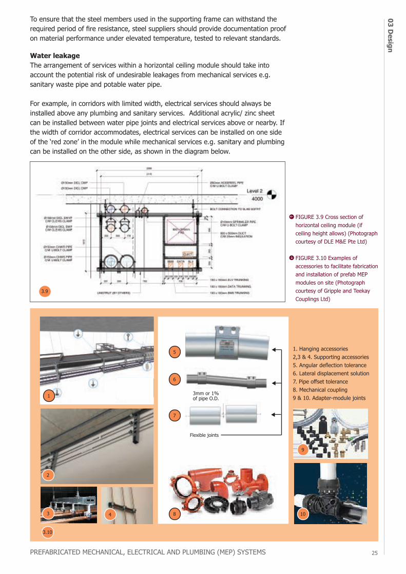
Water leakage The arrangement of services within a horizontal ceiling module should take into account the potential risk of undesirable leakages from mechanical services e.g. sanitary waste pipe and potable water pipe.
For example, in corridors with limited width, electrical services should always be installed above any plumbing and sanitary services. Additional acrylic/ zinc sheet can be installed between water pipe joints and electrical services above or nearby. If the width of corridor accommodates, electrical services can be installed on one side of the ‘red zone’ in the module while mechanical services e.g. sanitary and plumbing can be installed on the other side, as shown in the diagram below.
FIGURE 3.9 Cross section of horizontal ceiling module (if ceiling height allows) (Photograph courtesy of DLE M&E Pte Ltd)
FIGURE 3.10 Examples of accessories to facilitate fabrication and installation of prefab MEP modules on site (Photograph courtesy of Gripple and Teekay Couplings Ltd)
1
5
6
7
8 10
9
2
3 4
3mm or 1%of pipe O.D.
Flexible joints
1. Hanging accessories2,3 & 4. Supporting accessories5. Angular deflection tolerance6. Lateral displacement solution7. Pipe offset tolerance8. Mechanical coupling9 & 10. Adapter-module joints
To ensure that the steel members used in the supporting frame can withstand the required period of fire resistance, steel suppliers should provide documentation proof on material performance under elevated temperature, tested to relevant standards.
3.10
3.9
PREFABRICATED MECHANICAL, ELECTRICAL AND PLUMBING (MEP) SYSTEMS
03 D
esig
n26 Access provisions
The distance between vertical tiers of the module should be at least 100 mm to allow access for further works such as drawing cables and interfacing between modules, and future maintenance. If welding works for pipe jointing are to be carried out, more clearance around the pipes will be required.
The horizontal ceiling modules should comprise components that allow adjustment to the height of services to compensate any offset due to unevenness of the structural ceiling. Examples of such components are vertical threaded rod and flexible coupling which accommodates misalignment of jointing pipes as seen in Figure 3.10.
3.2.2 Requirements of vertical riser modulesA typical riser module comprises some vertical riser ducts and pipes. The vertical services in each riser module can be installed horizontally at ground level in the factory, and branch out to multiple floors.
The riser module can be installed prior to, and independently of, the erection of block walls of the riser shaft. Another method of installation is to lower the riser modules into the riser shaft through designated openings in the top floor. Therefore, lifting lugs and bracketry should be incorporated in the design of vertical riser modules.
3.2.3 Requirements of plant modules Prefabricated MEP plant modules are fully pre-assembled with control panels, and instruments mounted on skids with lifting eyes for piping connections, valves, cable termination for power supply, and interfaces for building automation system and fire alarm system, where applicable.
The pre-assembled and pre-wired equipment with control panels may include: a. Water services pump sets for boosting and transfer including hydro-pneumatic tankb. Fire hosereel and fire sprinkler pumps with controllers, test assembly, valves and strainers on suction and discharge pipe works c. Vacuum pump setsd. Air compressor including air receivere. Cooling towersf. Chillersg. Chilled water and condensing water pumpsh. Air-condensing uniti. Air handling units (AHUs)j. Fan coil units (FCUs)
Two or more modules can be combined using flexible connections on site to complete the installation in a plant room. All the valves/ pipework connections to the equipment can be pre-installed in the factory including the control panels and internal wiring. When the equipment is delivered to site, contractors will only need to connect the pipework and the incoming power supply, then the system is ready for testing and commissioning. As compared to the conventional way of installing plant and equipment, prefabricated MEP plant modules save time on site, and reduce the number of hoists and trips to deliver individual materials/ components such as valves, pipes, and control panels to the plantroom for assembly. The site will also be neater and material waste can be minimised.
PREFABRICATED MECHANICAL, ELECTRICAL AND PLUMBING (MEP) SYSTEMS
03 Design
27
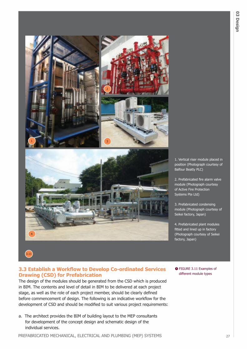
1. Vertical riser module placed in position (Photograph courtesy of Balfour Beatty PLC)
2. Prefabricated fire alarm valve module (Photograph courtesy of Active Fire Protection Systems Pte Ltd)
3. Prefabricated condensing module (Photograph courtesy of Seikei factory, Japan)
4. Prefabricated plant modules fitted and lined up in factory (Photograph courtesy of Seikei factory, Japan)
3.3 Establish a Workflow to Develop Co-ordinated Services Drawing (CSD) for PrefabricationThe design of the modules should be generated from the CSD which is produced in BIM. The contents and level of detail in BIM to be delivered at each project stage, as well as the role of each project member, should be clearly defined before commencement of design. The following is an indicative workflow for the development of CSD and should be modified to suit various project requirements:
a. The architect provides the BIM of building layout to the MEP consultants for development of the concept design and schematic design of the individual services.
4
1
2
3
FIGURE 3.11 Examples of different module types
3.11
b. The builder, respective MEP trade specialist contractors and prefabricated MEP specialist collaborate to develop the CSD in BIM with detailed design where elements are defined with specific assemblies, precise quantity, size, shape, location and orientation. The deliverables at this stage should include elevation views at selected locations including common corridors, turning points in the routing of services, and incoming of new services, etc. The appointed lead co-ordinator may be most suitable among the project members to integrate the BIM models from various disciplines to form the final CSD.
c. The CSD is reviewed and endorsed by relevant project members, including consultants, builder and respective MEP specialist contractors.
d. The endorsed CSD is further developed with more details for fabrication and assembly, including elements of the modules’ supporting frame, flanges, corners, etc. The CSD should be developed with a minimum LOD of 350 in BIM, or to project requirements. Information on fasteners will not be captured in the drawings if the BIM LOD is below 350.
3.4 Integrated Digital Delivery (IDD) ApproachTo speed up the process of design development while meeting all design considerations, limitations and compliance to rules, industry practitioners are strongly encouraged to adopt the Integrated Digital Delivery (IDD) approach which builds on the use of BIM and Virtual Design and Construction (VDC) [1] . IDD uses digital technologies to connect stakeholders working on the same project throughout the construction and building lifecycle, making it more efficient for stakeholders to generate various design options and arrive at the most optimal and holistic design solution sooner.
In fact, manufacturers of materials including steel sections and accessories are already providing high-fidelity BIM models to support their clients in creating construction models in BIM, enhancing design accuracy and saving time in developing details for supporting frame of modules in the process of digital modelling.
To reap full benefits of the IDD approach, digital software and tool should be carefully selected based on their software capabilities, which might significantly reduce the time needed for design iterations. Some useful software capabilities are as follows:
1. Ease the process of modularisation by generating different configurations of parts2. Integrated modelling and data input environment3. Built-in database of structural steel section, thinned-wall channel and connector 4. Interoperability (via seamless data exchange) with other software and
BIM systems5. Built-in structural analysis and design to relevant design standards6. Automated design report generation7. Automated CAD-drawing generation8. Automated billing of material for quantity take-off
[1] In essence, VDC is to “Build Twice”, first virtual, and then real. It is a framework that requires all stakeholders to commit to work collaboratively towards achieving a common set of goals, through systematically modelling what is to be built, and through constantly measuring and narrowing deviations between what was built (real) and what was modelled and rehearsed (virtual). One of the methodologies under VDC is Integrated Concurrent Engineering (ICE) sessions that aim to resolve design challenges in a multi-disciplinary meeting.
PREFABRICATED MECHANICAL, ELECTRICAL AND PLUMBING (MEP) SYSTEMS
03 D
esig
n28
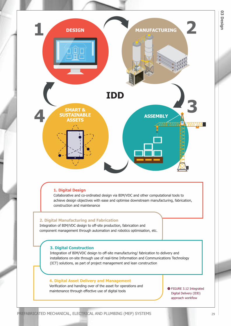
1. Digital DesignCollaborative and co-ordinated design via BIM/VDC and other computational tools to achieve design objectives with ease and optimise downstream manufacturing, fabrication, construction and maintenance
IDDSMART &
SUSTAINABLEASSETS
ASSEMBLY
MANUFACTURINGDESIGN
2. Digital Manufacturing and FabricationIntegration of BIM/VDC design to off-site production, fabrication and component management through automation and robotics optimisation, etc.
4. Digital Asset Delivery and ManagementVerification and handing over of the asset for operations and maintenance through effective use of digital tools
3. Digital ConstructionIntegration of BIM/VDC design to off-site manufacturing/ fabrication to delivery and installations on-site through use of real-time Information and Communications Technology (ICT) solutions, as part of project management and lean construction
FIGURE 3.12 Integrated Digital Delivery (IDD) approach workflow
PREFABRICATED MECHANICAL, ELECTRICAL AND PLUMBING (MEP) SYSTEMS
03 Design
29
04 P
rodu
ctio
n at
Fac
tory
PREFABRICATED MECHANICAL, ELECTRICAL AND PLUMBING (MEP) SYSTEMS
30
production at factory
chapterOVERVIEWAdopt Good Management Practices to Improve Productivity
Ensure Quality Control
Align MEP Modules Properly Before Delivery to Site
Protect Modules Against Weather Elements
Facilitate Transport, Handling and Installation
Allow Sufficient Temporary Storage Space for Completed Modules
Refer to Inspection Checklist for Delivery of Modules
Safety Measures in Factory
4.1
4.2
4.3
4.4
4.5
4.6
4.7
4.8
PREFABRICATED MECHANICAL, ELECTRICAL AND PLUMBING (MEP) SYSTEMS 31
04 Production at FactoryPRODUCTION AT FACTORY4.1 Adopt Good Management Practices to Improve Productivity Before production commences, detailed manufacturing drawings for each module should be produced and finalised by all key parties. After the MEP modules have been produced in the factory, the manufacturing drawing should be pasted on the respective modules and the services labelled* accordingly for reference by other trades.
To improve productivity of fabrication and quality of products, the IDD approach can be adopted by introducing more digital tools and solutions in factory management. Currently, radio frequency identification (RFID) or a barcode system is already commonly used to track the modules in the factory and facilitate installation on site. With more advanced digital tool or software, real-time and data-driven tracking and monitoring of modules can be achieved, aiding various processes such as scheduling of production, manpower deployment, transmitting manufacturing drawings to relevant parties, documenting process checks and quality inspections, logistics planning and procurement of materials used in fabrication when supplies are running low.
The production schedule and manpower planning are also critical. The adoption of automation and mechanisation e.g. robotic welding machine and Computer Numerical Control (CNC) pipe cutting machine in a factory can help improve productivity and reduce reliance on manpower. All machinery and powered tools must be maintained and calibrated, if applicable, periodically to manufacturer’s specifications. Maintenance records should be kept properly for regular reviews.
To ensure a smooth and efficient workflow, the factory layout should facilitate the flow of materials, locations and movement of equipment such as an overhead crane, and suitable space to check alignment of modules. Workstations should also be equipped with dedicated hand tools such as measurement tape, spirit level, pipe cutters and markers.
Prefabricated MEP specialists with factories should consider to apply for assessment and audit under the Prefabricated MEP Manufacturer Accreditation Scheme (MAS) administered by Specialists Trade Alliance of Singapore (STAS), which validates the effectiveness of quality management system and production processes to produce high quality products consistently.
4.2 Ensure Quality ControlA mock-up should be produced for inspection and approval by the Qualified Person (QP) prior to mass production.
Material inspection should commence once the materials to be used for production are delivered to the factory. Such inspections shall be recorded and verified by QA/QC personnel. Production can only begin after verifying the materials delivered.
For every task in production, a checklist stating all necessary steps should be developed to ensure that the task is completed in order.
Inspection test plans should be developed for all modules by the prefabricated MEP specialist and endorsed by MEP trade specialists and consultants to ensure that they are applicable for the project.
* The labels should be positioned at the location of ceiling access panels or maintenance panels, according to the ceiling plan.
PREFABRICATED MECHANICAL, ELECTRICAL AND PLUMBING (MEP) SYSTEMS
3204
Pro
duct
ion
at F
acto
ryTests and inspections of all individual services and support system e.g. steel frames of the modules should be conducted according to the respective technical specifications and codes of practice. These include the material’s compliance with regulatory requirements, project specifications, pipe pressure test, air tightness test for ductwork, and gradient of condensate drain pipe, sanitary waste pipe and kitchen waste pipe. The scope of tests and inspections in the factory would vary with project requirements.
Factory acceptance tests should be verified by an engineer’s representative to ensure that the modules have achieved their performance requirements. Should the modules fail to meet the performance requirements, rectifications should be carried out accordingly, prior to the delivery of the modules.
Any non-compliance or defect found in the modules should be rectified according to the Quality Assurance/Quality Control (QA/QC) plans for the project. MEP modules may contain loose items such as cable ties. As such, the QA/QC plans must ensure that all loose items are secured firmly to the modules to prevent them from getting dislodged at height during hoisting on site.
4.3 Align MEP Modules Properly Before Delivery to SiteTo ensure a smooth installation on site, the alignment of services from module to module must be checked in the factory and documented to avoid disputes. A template or jig could be used when lining up the modules in the factory to check for proper alignment.
4.4 Protect Modules Against Weather ElementsModules should be covered with shrink wrap, tarp etc. to protect them against exposure to weather, prior to delivery to site. Alternatively, the modules can be kept in a sheltered condition at all times.
4.5 Facilitate Transport, Handling and InstallationTo ease transport and handling, modules can be pre-installed with castor wheels that can be taken off after installation. Equipment such as pallet jacks and forklifts also facilitate the manoeuvring and lifting of modules in the factory and on site.
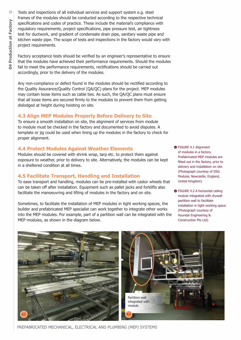
Sometimes, to facilitate the installation of MEP modules in tight working spaces, the builder and prefabricated MEP specialist can work together to integrate other works into the MEP modules. For example, part of a partition wall can be integrated with the MEP modules, as shown in the diagram below.
Partition wall integrated with module
FIGURE 4.1 Alignment of modules in a factory. Prefabricated MEP modules are fitted out in the factory, prior to delivery and installation on site (Photograph courtesy of DSG Modular, Newcastle, England, United Kingdom)
FIGURE 4.2 A horizontal ceiling module integrated with drywall partition wall to facilitate installation in tight working space (Photograph courtesy of Hyundai Engineering & Construction Pte Ltd)
4.1 4.2
PREFABRICATED MECHANICAL, ELECTRICAL AND PLUMBING (MEP) SYSTEMS 33
04 Production at Factory4.7 Refer to Inspection Checklist for Delivery of ModulesA checklist should be used to verify the condition of modules before they are delivered to site, minimising unnecessary waste and time. An example of the checklist is as shown in Appendix B.
4.8 Safety Measures in FactorySome examples of measures to ensure workplace safety and health in the factory of prefabricated MEP modules are listed below.
Lifting activitiesa. Identify clear designated lifting pathwaysb. Use overhead crane or other machinery or equipment for lifting of modules and materialsc. Use forklifts for lifting of heavier or odd-shaped modules
Handling of material and modulea. Adopt a wide range of equipment, especially semi-automated and automated equipment and systems, for efficient handling of materialsb. Optimise the factory layout to ensure an efficient workflow, e.g. minimum travel distance for transfer of materials or products, and separate storage of materials and tools used by different trades, etc.
Ergonomics and design for safetya. Enhance workplace ergonomics and minimise working at heightb. Use equipment or accessories such as castor wheel to aid the manoeuvring of modules
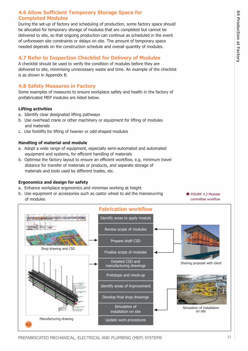
Identify areas to apply module
Fabrication workflow
Review scope of modules
Prepare draft CSD
Finalise scope of modules
Detailed CSD and manufacturing drawings
Prototype and mock-up
Identify areas of improvement
Develop final shop drawings
Simulation of installation on site
Update work procedures
Shop drawing and CSD
Sharing proposal with client
Simulation of installation on site
Manufacturing drawing4.3
4.6 Allow Sufficient Temporary Storage Space for Completed Modules During the set-up of factory and scheduling of production, some factory space should be allocated for temporary storage of modules that are completed but cannot be delivered to site, so that ongoing production can continue as scheduled in the event of unforeseen site constraints or delays on site. The amount of temporary space needed depends on the construction schedule and overall quantity of modules.
FIGURE 4.3 Modular committee workflow

PREFABRICATED MECHANICAL, ELECTRICAL AND PLUMBING (MEP) SYSTEMS
3405
Ins
talla
tion
34
PREFABRICATED MECHANICAL, ELECTRICAL AND PLUMBING (MEP) SYSTEMS
installation
chapter
OVERVIEWAdopt Just-In-Time (JIT) Concept
Plan for Logistics in Advance
Mark and Set Out Modules’ Position
Install and Connect Modules and to the Mains
Testing and Commissioning
5.1
5.2
5.3
5.4
5.5
PREFABRICATED MECHANICAL, ELECTRICAL AND PLUMBING (MEP) SYSTEMS 35
05 Installation
INSTALLATION5.1 Adopt Just-In-Time (JIT) ConceptAdopting a just-in-time (JIT) concept, where MEP modules are delivered according to the construction sequence, eliminates congestion in the factory and minimises damages to the modules on site. BIM can be used to simulate the actual on-site installation to identify potential problems in the access route.
Close co-ordination between parties at the project site and factory is critical to ensure a smooth supply of modules to the site and minimise downtime due to missing modules on site.
5.2 Plan for Logistics in AdvanceThe method statements and risk assessments for lifting, installing and storing (if applicable) the modules on site require the builder’s inputs on the capacity of cranes, availability of access platforms on each floor for landing of modules, delivery routes of modules to their designated positions, and other logistics constraints.
As such, prefabricated MEP specialist must co-ordinate closely with the builder on the availability of crane for hoisting of modules to a designated floor. The IDD approach can be considered to aid the co-ordination process, for instance, in simulating the construction sequence to optimise the utilisation of tower crane or other lifting equipment.
Before arranging for transportation of any module to site, the following items should be achieved to ensure that the delivery process is smooth and efficient:
Architectural a. The delivery route of module to its designated location is free of obstacles.b. The project model in BIM is accurate as per actual site installation for critical areas.
Structurala. The structural construction follows the latest drawings and the dimensions are accurate.
MEPa. All services within the module are installed according to project specifications and the module has cleared the necessary quality inspections in the factory (including factory acceptance tests and other tests on individual services as required).
chapter
PREFABRICATED MECHANICAL, ELECTRICAL AND PLUMBING (MEP) SYSTEMS
3605
Ins
talla
tion
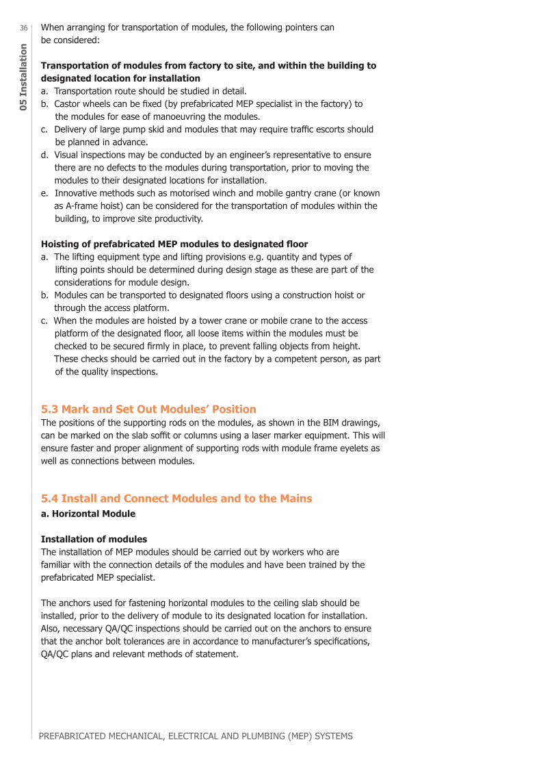
When arranging for transportation of modules, the following pointers can be considered:
Transportation of modules from factory to site, and within the building to designated location for installationa. Transportation route should be studied in detail.b. Castor wheels can be fixed (by prefabricated MEP specialist in the factory) to the modules for ease of manoeuvring the modules.c. Delivery of large pump skid and modules that may require traffic escorts should be planned in advance.d. Visual inspections may be conducted by an engineer’s representative to ensure there are no defects to the modules during transportation, prior to moving the modules to their designated locations for installation.e. Innovative methods such as motorised winch and mobile gantry crane (or known as A-frame hoist) can be considered for the transportation of modules within the building, to improve site productivity.
Hoisting of prefabricated MEP modules to designated floora. The lifting equipment type and lifting provisions e.g. quantity and types of lifting points should be determined during design stage as these are part of the considerations for module design.b. Modules can be transported to designated floors using a construction hoist or through the access platform. c. When the modules are hoisted by a tower crane or mobile crane to the access platform of the designated floor, all loose items within the modules must be checked to be secured firmly in place, to prevent falling objects from height. These checks should be carried out in the factory by a competent person, as part of the quality inspections.
5.3 Mark and Set Out Modules’ PositionThe positions of the supporting rods on the modules, as shown in the BIM drawings, can be marked on the slab soffit or columns using a laser marker equipment. This will ensure faster and proper alignment of supporting rods with module frame eyelets as well as connections between modules.
5.4 Install and Connect Modules and to the Mainsa. Horizontal Module
Installation of modulesThe installation of MEP modules should be carried out by workers who are familiar with the connection details of the modules and have been trained by the prefabricated MEP specialist.
The anchors used for fastening horizontal modules to the ceiling slab should be installed, prior to the delivery of module to its designated location for installation. Also, necessary QA/QC inspections should be carried out on the anchors to ensure that the anchor bolt tolerances are in accordance to manufacturer’s specifications, QA/QC plans and relevant methods of statement.
PREFABRICATED MECHANICAL, ELECTRICAL AND PLUMBING (MEP) SYSTEMS 37
05 Installation
Connections of individual services between modules and to the mainsIndividual services of adjacent modules are connected after installation of modules.
If a synchronised lifting equipment is used, the horizontal ceiling modules can also be pre-assembled on the floor on site, before being lifted to the required height to be fastened to the ceiling slab.
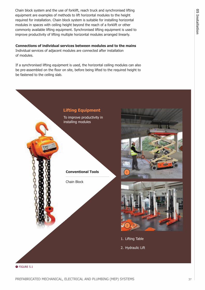
To improve productivity in installing modules
Lifting Equipment
Conventional Tools
Chain Block
2
1.
2.
Lifting Table
Hydraulic Lift
Chain block system and the use of forklift, reach truck and synchronised lifting equipment are examples of methods to lift horizontal modules to the height required for installation. Chain block system is suitable for installing horizontal modules in spaces with ceiling height beyond the reach of a forklift or other commonly available lifting equipment. Synchronised lifting equipment is used to improve productivity of lifting multiple horizontal modules arranged linearly.
1
FIGURE 5.1
PREFABRICATED MECHANICAL, ELECTRICAL AND PLUMBING (MEP) SYSTEMS
3805
Ins
talla
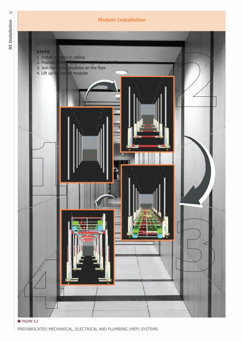
tion Module Installation
STEPS1. Install anchors in ceiling2. Position lifting equipment e.g. hydraulic lift3. Join horizontal modules on the floor4. Lift up horizontal modules
FIGURE 5.2
PREFABRICATED MECHANICAL, ELECTRICAL AND PLUMBING (MEP) SYSTEMS 39
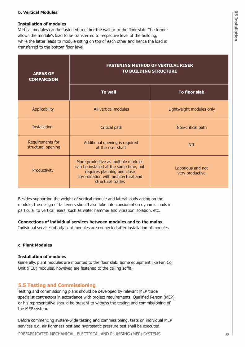
05 Installationb. Vertical Modules
Installation of modulesVertical modules can be fastened to either the wall or to the floor slab. The former allows the module’s load to be transferred to respective level of the building, while the latter leads to module sitting on top of each other and hence the load is transferred to the bottom floor level.
AREAS OF COMPARISON
More productive as multiple modules can be installed at the same time, but
requires planning and close co-ordination with architectural and
structural trades
Laborious and not very productive
Applicability All vertical modules
Critical path
Additional opening is required at the riser shaft
Lightweight modules only
Non-critical path
NIL
Installation
Requirements for structural opening
Productivity
FASTENING METHOD OF VERTICAL RISER TO BUILDING STRUCTURE
To wall To floor slab
Besides supporting the weight of vertical module and lateral loads acting on the module, the design of fasteners should also take into consideration dynamic loads in particular to vertical risers, such as water hammer and vibration isolation, etc.
Connections of individual services between modules and to the mainsIndividual services of adjacent modules are connected after installation of modules.
c. Plant Modules
Installation of modulesGenerally, plant modules are mounted to the floor slab. Some equipment like Fan Coil Unit (FCU) modules, however, are fastened to the ceiling soffit.
5.5 Testing and CommissioningTesting and commissioning plans should be developed by relevant MEP trade specialist contractors in accordance with project requirements. Qualified Person (MEP) or his representative should be present to witness the testing and commissioning of the MEP system.
Before commencing system-wide testing and commissioning, tests on individual MEP services e.g. air tightness test and hydrostatic pressure test shall be executed.
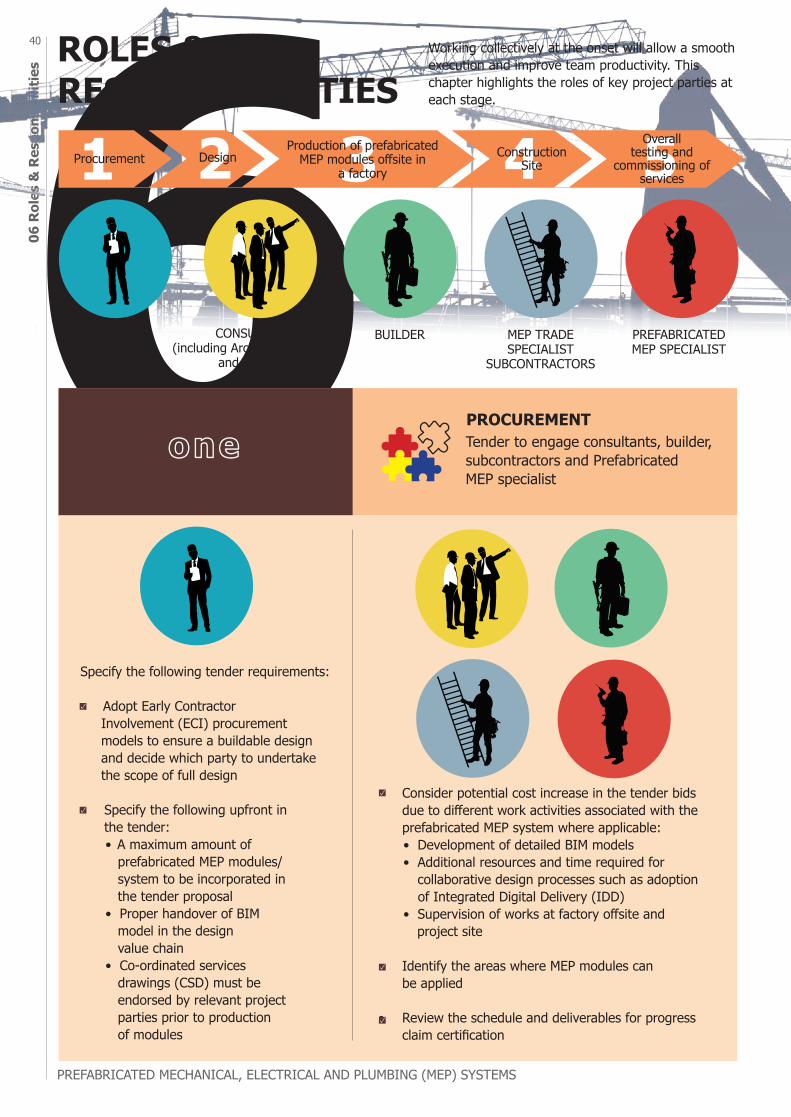
PREFABRICATED MECHANICAL, ELECTRICAL AND PLUMBING (MEP) SYSTEMS
4006
Rol
es &
Res
pons
ibili
ties ROLES &
RESPONSIBILITIES
PROCUREMENTTender to engage consultants, builder, subcontractors and Prefabricated MEP specialist
Specify the following tender requirements:
• Adopt Early Contractor Involvement (ECI) procurement models to ensure a buildable design and decide which party to undertake the scope of full design • Specify the following upfront in
the tender: • A maximum amount of prefabricated MEP modules/ system to be incorporated in the tender proposal • Proper handover of BIM model in the design value chain • Co-ordinated services drawings (CSD) must be endorsed by relevant project parties prior to production of modules
Working collectively at the onset will allow a smooth execution and improve team productivity. This chapter highlights the roles of key project parties at each stage.
DEVELOPER BUILDER MEP TRADE SPECIALIST
SUBCONTRACTORS
PREFABRICATED MEP SPECIALIST
CONSULTANTS (including Architect, Structural
and MEP etc.)
• Consider potential cost increase in the tender bids due to different work activities associated with the prefabricated MEP system where applicable:
• Development of detailed BIM models • Additional resources and time required for collaborative design processes such as adoption of Integrated Digital Delivery (IDD) • Supervision of works at factory offsite and project site • Identify the areas where MEP modules can
be applied
• Review the schedule and deliverables for progress claim certification
one
1 2 3 4 5Procurement DesignProduction of prefabricated
MEP modules offsite in a factory
Overall testing and
commissioning of services
Construction Site
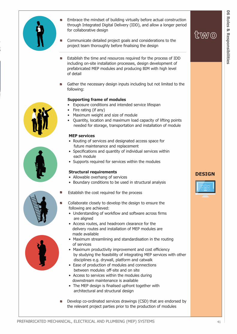
PREFABRICATED MECHANICAL, ELECTRICAL AND PLUMBING (MEP) SYSTEMS 41
06 Roles & Responsibilities
DESIGN
• Embrace the mindset of building virtually before actual construction through Integrated Digital Delivery (IDD), and allow a longer period for collaborative design
• Communicate detailed project goals and considerations to the project team thoroughly before finalising the design
• Establish the time and resources required for the process of IDD including on-site installation processes, design development of prefabricated MEP modules and producing BIM with high level of detail
• Gather the necessary design inputs including but not limited to the following:
Supporting frame of modules • Exposure conditions and intended service lifespan • Fire rating (if any) • Maximum weight and size of module • Quantity, location and maximum load capacity of lifting points needed for storage, transportation and installation of module
MEP services • Routing of services and designated access space for future maintenance and replacement • Specifications and quantity of individual services within each module • Supports required for services within the modules
Structural requirements • Allowable overhang of services • Boundary conditions to be used in structural analysis
• Establish the cost required for the process
• Collaborate closely to develop the design to ensure the following are achieved: • Understanding of workflow and software across firms are aligned • Access routes, and headroom clearance for the delivery routes and installation of MEP modules are made available • Maximum streamlining and standardisation in the routing of services • Maximum productivity improvement and cost efficiency by studying the feasibility of integrating MEP services with other disciplines e.g. drywall, platform and catwalk • Ease of production of modules and connections between modules off-site and on site • Access to services within the modules during downstream maintenance is available • The MEP design is finalised upfront together with architectural and structural design
• Develop co-ordinated services drawings (CSD) that are endorsed by the relevant project parties prior to the production of modules
two
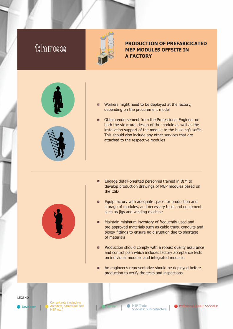
PREFABRICATED MECHANICAL, ELECTRICAL AND PLUMBING (MEP) SYSTEMS
4206
Rol
es &
Res
pons
ibili
ties
• Workers might need to be deployed at the factory, depending on the procurement model
• Obtain endorsement from the Professional Engineer on both the structural design of the module as well as the installation support of the module to the building’s soffit. This should also include any other services that are attached to the respective modules
DeveloperConsultants (including Architect, Structural and MEP etc.)
Builder MEP Trade Specialist Subcontractors
Prefabricated MEP Specialist
• Engage detail-oriented personnel trained in BIM to develop production drawings of MEP modules based on the CSD
• Equip factory with adequate space for production and storage of modules, and necessary tools and equipment such as jigs and welding machine
• Maintain minimum inventory of frequently-used and pre-approved materials such as cable trays, conduits and pipes/ fittings to ensure no disruption due to shortage of materials
• Production should comply with a robust quality assurance and control plan which includes factory acceptance tests on individual modules and integrated modules
• An engineer’s representative should be deployed before production to verify the tests and inspections
PRODUCTION OF PREFABRICATED MEP MODULES OFFSITE IN A FACTORY
three
LEGEND
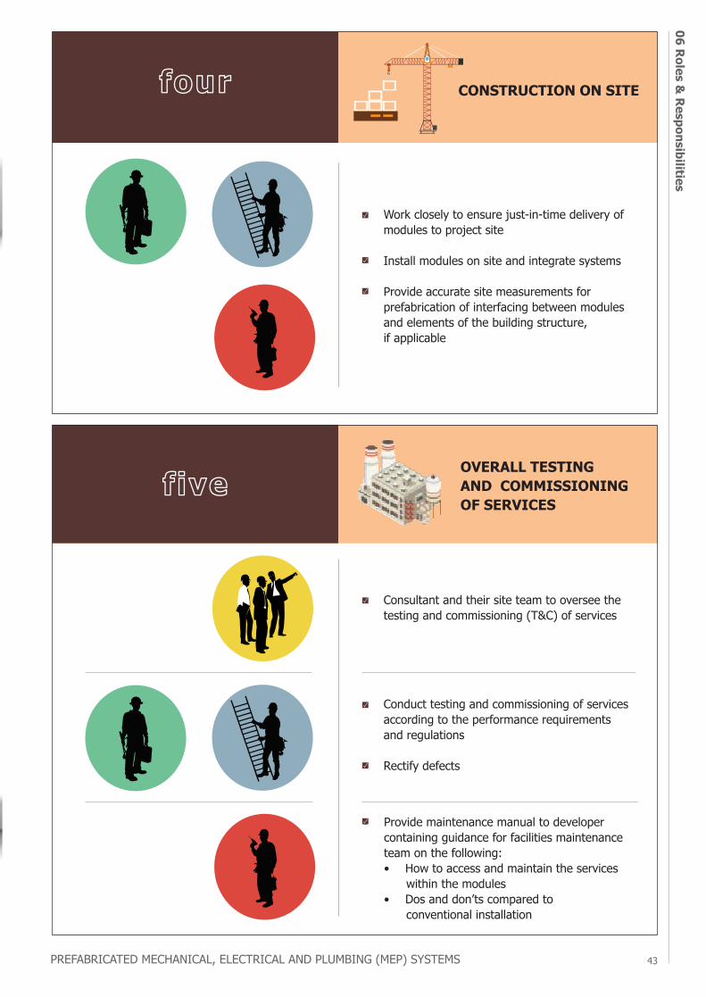
PREFABRICATED MECHANICAL, ELECTRICAL AND PLUMBING (MEP) SYSTEMS 43
06 Roles & Responsibilities
Prefabricated MEP Specialist
• Work closely to ensure just-in-time delivery of modules to project site
• Install modules on site and integrate systems
• Provide accurate site measurements for prefabrication of interfacing between modules and elements of the building structure, if applicable
• Provide maintenance manual to developer containing guidance for facilities maintenance team on the following:
• • How to access and maintain the services • within the modules• • Dos and don’ts compared to • conventional installation
• Conduct testing and commissioning of services according to the performance requirements and regulations
• Rectify defects
CONSTRUCTION ON SITE
OVERALL TESTING AND COMMISSIONING OF SERVICES
four
five
• Consultant and their site team to oversee the testing and commissioning (T&C) of services
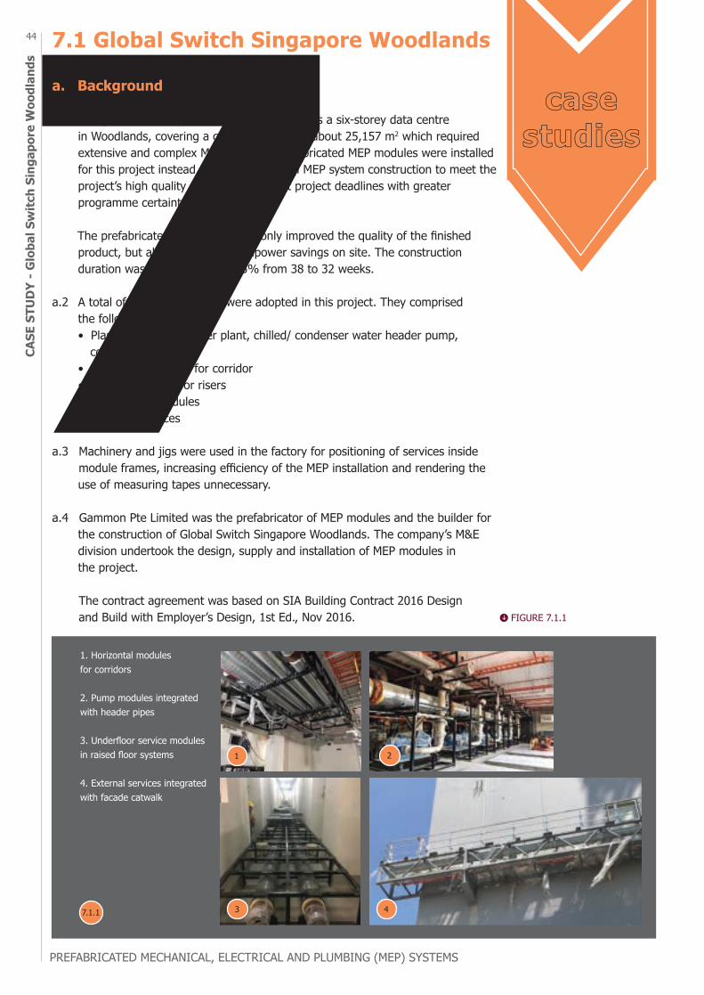
PREFABRICATED MECHANICAL, ELECTRICAL AND PLUMBING (MEP) SYSTEMS
44CA
SE S
TUD
Y - G
loba
l Sw
itch
Sing
apor
e W
oodl
ands
7.1 Global Switch Singapore Woodlands
a. Background
a.1 Completed in 2018, Global Switch Singapore is a six-storey data centre in Woodlands, covering a gross floor area of about 25,157 m2 which required extensive and complex MEP systems. Prefabricated MEP modules were installed for this project instead of the conventional MEP system construction to meet the project’s high quality standards and tight project deadlines with greater programme certainty. The prefabricated MEP system not only improved the quality of the finished product, but also led to 40% manpower savings on site. The construction duration was also reduced by 15% from 38 to 32 weeks.
a.2 A total of 337 MEP modules were adopted in this project. They comprised the following: • Plant modules for chiller plant, chilled/ condenser water header pump, cooling tower • Horizontal modules for corridor • Vertical modules for risers • Raised floor modules • Roof top services
a.3 Machinery and jigs were used in the factory for positioning of services inside module frames, increasing efficiency of the MEP installation and rendering the use of measuring tapes unnecessary.
a.4 Gammon Pte Limited was the prefabricator of MEP modules and the builder for the construction of Global Switch Singapore Woodlands. The company’s M&E division undertook the design, supply and installation of MEP modules in the project. The contract agreement was based on SIA Building Contract 2016 Design and Build with Employer’s Design, 1st Ed., Nov 2016.
1. Horizontal modules for corridors
2. Pump modules integrated with header pipes
3. Underfloor service modules in raised floor systems
4. External services integrated with facade catwalk
1 2
43
casestudies
FIGURE 7.1.1
7.1.1
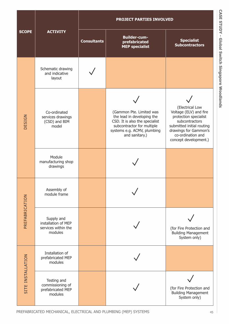
PREFABRICATED MECHANICAL, ELECTRICAL AND PLUMBING (MEP) SYSTEMS 45
CASE STUD
Y - Global Sw
itch Singapore Woodlands
DES
IGN
PREF
ABRI
CATI
ON
SITE
IN
STAL
LATI
ON
SCOPE ACTIVITY
ConsultantsBuilder-cum-prefabricated MEP specialist
Specialist Subcontractors
PROJECT PARTIES INVOLVED
Schematic drawing and indicative
layout
Co-ordinated services drawings (CSD) and BIM
model
(Gammon Pte. Limited was the lead in developing the
CSD. It is also the specialist subcontractor for multiple
systems e.g. ACMV, plumbing and sanitary.)
(Electrical Low Voltage (ELV) and fire protection specialist
subcontractors submitted initial routing drawings for Gammon’s
co-ordination and concept development.)
(for Fire Protection and Building Management
System only)
(for Fire Protection and Building Management
System only)
Module manufacturing shop
drawings
Assembly of module frame
Supply and installation of MEP services within the
modules
Testing and commissioning of prefabricated MEP
modules
Installation of prefabricated MEP
modules

PREFABRICATED MECHANICAL, ELECTRICAL AND PLUMBING (MEP) SYSTEMS
46CA
SE S
TUD
Y - G
loba
l Sw
itch
Sing
apor
e W
oodl
ands
b. Design Processes and Considerations
b.1 Gammon Pte. Limited identified the locations and scope of MEP modules in their tender submission for Global Switch Singapore Woodlands. Upon the award of tender, Gammon Pte. Limited further developed the design. Services were modelled for different areas and provided to another team for module design. Next, parametric module family was created inside BIM using virtual programming. Detailing for different types of modules for respective locations were created in BIM, providing information on modules’ dimensions. QR code was generated for each module for monitoring of progress in fabrication and installation. BIM design of different modules was then converted from 3D to 2D views for the purpose of fabrication. The design was developed in BIM with a high level of detail (LOD) of 500. The design co-ordination of MEP modules took about the same time as conventional MEP installation, although the former involved additional detailing of modules and the development of fabrication drawings.
b.2 To maximise quality and productivity gains, some of the MEP modules were integrated with structural and architectural components. Along the facade, a catwalk was pre-assembled with external MEP services in the workshop of the structural steel specialist, reducing crane hoists as well as works at height. The raised floor pedestals were also pre-assembled with MEP services inside the raised floor system, improving site productivity and avoiding clashes.
b.3 MEP modules were also designed for ease of installation on site as well as access for future maintenance, among many design considerations. In the case of horizontal modules, working access space of about 400mm wide was provided within the horizontal modules for cable pulling and future maintenance. To facilitate connections of chilled water pipes across horizontal modules, mechanical couplings were used instead of welding. As compared to traditional method of installing the services component by component in the ceiling, the additional headroom required by horizontal modules was less than 50 mm, which was negligible.
c. Prefabrication and Installation
c.1 To allow a smooth production of modules, mock-ups for each module type were approved by relevant project parties including developers and consultants before the commencement of mass production in the factory. A mock-up of the corridor containing the horizontal modules was set up to simulate the actual on-site installation to identify spatial constraints in carrying out downstream activities such as cable pulling and painting following the installation of module. Repetitive work processes in the factory were carried out using machinery such as automatic welding machine, automatic band saw machine and puncher, increasing work efficiency and improving quality of finished products.
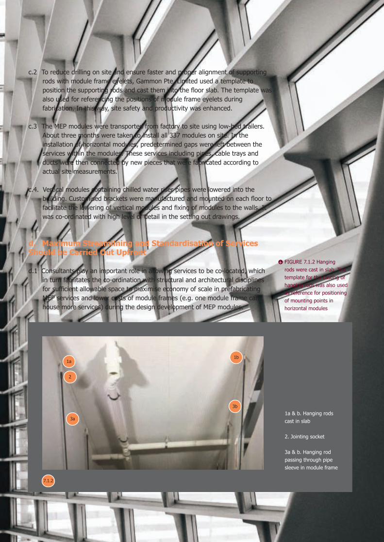
PREFABRICATED MECHANICAL, ELECTRICAL AND PLUMBING (MEP) SYSTEMS 47
CASE STUD
Y - Global Sw
itch Singapore Woodlands
FIGURE 7.1.2 Hanging rods were cast in slab. The template for the casting of hanging rods was also used as reference for positioning of mounting points in horizontal modules
c.2 To reduce drilling on site and ensure faster and proper alignment of supporting rods with module frame eyelets, Gammon Pte. Limited used a template to position the supporting rods and cast them into the floor slab. The template was also used for referencing the positions of module frame eyelets during fabrication. In this way, site safety and productivity was enhanced.
c.3 The MEP modules were transported from factory to site using low-bed trailers. About three months were taken to install all 337 modules on site. In the installation of horizontal modules, predetermined gaps were left between the services within the modules. These services including pipes, cable trays and ducts were then connected by new pieces that were fabricated according to actual site measurements.
c.4. Vertical modules containing chilled water riser pipes were lowered into the building. Customised brackets were manufactured and mounted on each floor to facilitate the lowering of vertical modules and fixing of modules to the walls. It was co-ordinated with high level of detail in the setting out drawings.
d. Maximum Streamlining and Standardisation of Services Should be Carried Out Upfront
d.1 Consultants play an important role in allowing services to be co-located, which in turn facilitates the co-ordination with structural and architectural disciplines for sufficient allowable space to maximise economy of scale in prefabricating MEP services and lower costs of module frames (e.g. one module frame can house more services) during the design development of MEP modules.
1a & b. Hanging rods cast in slab
2. Jointing socket
3a & b. Hanging rod passing through pipe sleeve in module frame
1a
7.1.2
2
3a
3b
1b

PREFABRICATED MECHANICAL, ELECTRICAL AND PLUMBING (MEP) SYSTEMS
48CA
SE S
TUD
Y - S
MU
Con
nexi
on7.2 SMU Connexiona. Background
a.1 SMU Connexion is an institutional development completed in October 2019, comprising one 5-storey teaching block with link building on Fort Canning Link/ Stamford Road. The building structure consists of Cross Laminated Timber (CLT) floor slabs and structural steel beams and columns. Singapore Management University initiated the use of prefabricated MEP systems in this project, leading to more than 50% manpower savings in the installation of MEP services. Safety on site and workmanship of MEP installation was also improved as a result.
a.2 MEP modules adopted are: • Horizontal modules (for ceiling services along main corridors and in rooms) • Vertical modules (for electrical and mechanical risers e.g. hose reel and dry rising mains) • Plant modules (for sprinkler pumps and domestic water pumps)
a.3 The contract specified the use of prefabricated MEP modules comprising horizontal, vertical and plant modules during the tender stage. In the tender drawings, the MEP Consultant, Meinhardt (Singapore) Pte Ltd, identified applicable areas of MEP modules and marked them out with the intended concept design. The contract agreement was a lump sum contract based on SIA Articles and Conditions of Building Contract (Lump Sum Contract) Ninth Edition.
a.4 The builder of the project, Lian Ho Lee Construction (Private) Limited, was also the prefabricator of MEP modules. Based on the tender drawings, Lian Ho Lee Construction (Private) Limited’s M&E department co-ordinated the services and further developed the concept design of MEP modules in close consultation with Meinhardt (Singapore) Pte Ltd. The roles of project parties are detailed below:
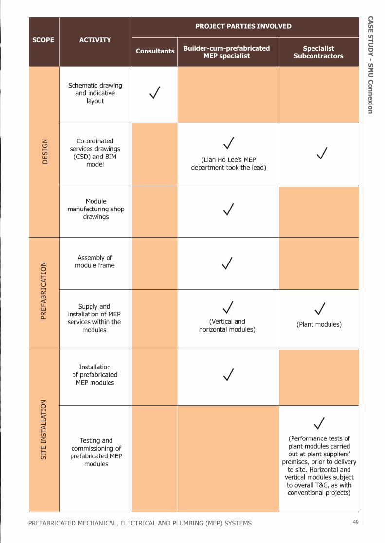
PREFABRICATED MECHANICAL, ELECTRICAL AND PLUMBING (MEP) SYSTEMS 49
CASE STUD
Y - SMU
Connexion
PREF
ABRI
CATI
ON
SITE
INST
ALLA
TIO
NSCOPE ACTIVITY
Consultants Builder-cum-prefabricated MEP specialist
Specialist Subcontractors
PROJECT PARTIES INVOLVED
(Vertical and horizontal modules)
(Plant modules)
(Performance tests of plant modules carried out at plant suppliers’
premises, prior to delivery to site. Horizontal and
vertical modules subject to overall T&C, as withconventional projects)
Assembly of module frame
Module manufacturing shop
drawings
Supply and installation of MEP services within the
modules
Testing and commissioning of prefabricated MEP
modules
Installation of prefabricated MEP modules
DES
IGN
Schematic drawing and indicative
layout
Co-ordinated services drawings (CSD) and BIM
model (Lian Ho Lee’s MEP department took the lead)
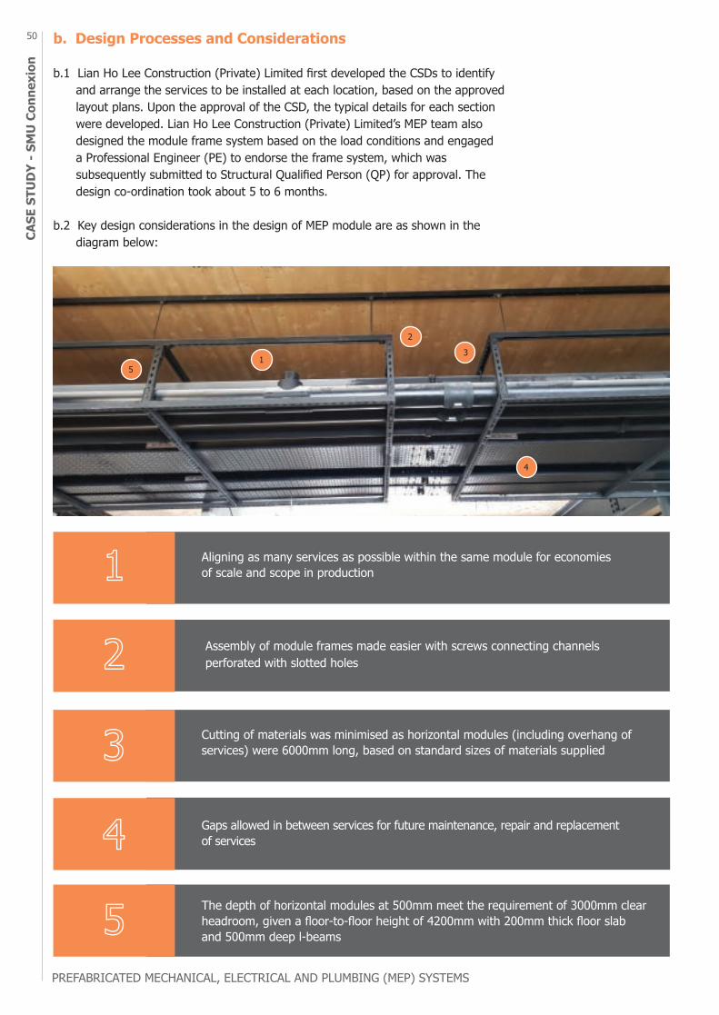
PREFABRICATED MECHANICAL, ELECTRICAL AND PLUMBING (MEP) SYSTEMS
50CA
SE S
TUD
Y - S
MU
Con
nexi
onb. Design Processes and Considerations
b.1 Lian Ho Lee Construction (Private) Limited first developed the CSDs to identify and arrange the services to be installed at each location, based on the approved layout plans. Upon the approval of the CSD, the typical details for each section were developed. Lian Ho Lee Construction (Private) Limited’s MEP team also designed the module frame system based on the load conditions and engaged a Professional Engineer (PE) to endorse the frame system, which was subsequently submitted to Structural Qualified Person (QP) for approval. The design co-ordination took about 5 to 6 months.
b.2 Key design considerations in the design of MEP module are as shown in the diagram below:
Aligning as many services as possible within the same module for economiesof scale and scope in production
Assembly of module frames made easier with screws connecting channels perforated with slotted holes
Cutting of materials was minimised as horizontal modules (including overhang of services) were 6000mm long, based on standard sizes of materials supplied
Gaps allowed in between services for future maintenance, repair and replacement of services
The depth of horizontal modules at 500mm meet the requirement of 3000mm clear headroom, given a floor-to-floor height of 4200mm with 200mm thick floor slab and 500mm deep l-beams
1
2
3
4
5
4
3
2
15

PREFABRICATED MECHANICAL, ELECTRICAL AND PLUMBING (MEP) SYSTEMS 51
CASE STUD
Y - SMU
Connexionc. Prefabrication and Installation
c.1 The production of horizontal and vertical modules was at Lian Ho Lee Construction (Private) Limited’s factory, located in Tuas and was about 900m2 large, while the plant modules were fabricated and supplied by another pump and plant module supplier, CAE Engineering Pte Ltd. The production at Lian Ho Lee Construction (Private) Limited’s factory took about 4 months from May 2019 to September 2019, with mass production taking place in July 2019 to August 2019.
c.2 To ensure consistent quality of MEP modules produced at the factory, workers were specialised in specific tasks so that they would be skilful and less likely to make errors during fabrication. Productivity and safety in factory were also improved as a result. Also, fabrication shopdrawings were made as detailed as possible to eliminate guesswork during fabrication. Before delivery of MEP modules to site, QA/QC checks were carried out on the MEP modules in the factory. Resident Technical Officer (RTO) also inspected the completed horizontal and vertical modules in the factory, ensuring that the services were installed according to the approved drawings.
c.3 For plant modules, performance tests were carried out by CAE Engineering Pte Ltd. To ease transportation and handling, plant equipment like the sprinkler pumpset was prefabricated in two separate modules (i.e. separate skids).
c.4 Just-in-time concept was implemented for the installation of the MEP modules on site. The MEP modules were hoisted onto access platforms on respective floors, before being transported using forklifts or other equipment to their designated locations for installation. As such, external facade panels were installed after the delivery of the MEP modules. Similarly, plant room walls were erected after the installation of plant modules, to allow access to the plant room. Before installing the MEP modules, site personnel scanned the barcodes affixed on the modules to verify the locations of installation.
d. Changes in Project Milestones
d.1 Singapore Management University (SMU) allowed Lian Ho Lee Construction (Private) Limited to claim advance payments for MEP modules that were completed offsite in the factory albeit yet to be delivered to site. Consultants had to identify zones suitable for prefabrication of services and evaluate the design of MEP modules.
d.2 Lian Ho Lee Construction (Private) Limited’s MEP team learnt that it was critical to ensure timely supply of materials required for prefabrication and assembly of MEP modules. It was also important to factor more time for optimising the routing of services and developing the concept design of MEP modules.
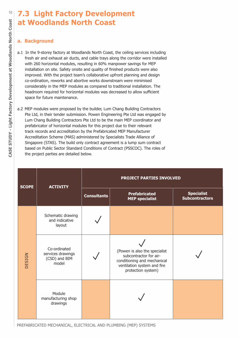
PREFABRICATED MECHANICAL, ELECTRICAL AND PLUMBING (MEP) SYSTEMS
52CA
SE S
TUD
Y - L
ight
Fac
tory
Dev
elop
men
t at W
oodl
ands
Nor
th C
oast
7.3 Light Factory Development at Woodlands North Coast
a. Background
a.1 In the 9-storey factory at Woodlands North Coast, the ceiling services including fresh air and exhaust air ducts, and cable trays along the corridor were installed with 260 horizontal modules, resulting in 60% manpower savings for MEP installation on site. Safety onsite and quality of finished products were also improved. With the project team’s collaborative upfront planning and design co-ordination, reworks and abortive works downstream were minimised considerably in the MEP modules as compared to traditional installation. The headroom required for horizontal modules was decreased to allow sufficient space for future maintenance.
a.2 MEP modules were proposed by the builder, Lum Chang Building Contractors Pte Ltd, in their tender submission. Powen Engineering Pte Ltd was engaged by Lum Chang Building Contractors Pte Ltd to be the main MEP coordinator and prefabricator of horizontal modules for this project due to their relevant track records and accreditation by the Prefabricated MEP Manufacturer Accreditation Scheme (MAS) administered by Specialists Trade Alliance of Singapore (STAS). The build only contract agreement is a lump sum contract based on Public Sector Standard Conditions of Contract (PSSCOC). The roles of the project parties are detailed below.
DES
IGN
Schematic drawing and indicative
layout
Co-ordinated services drawings (CSD) and BIM
model
(Powen is also the specialistsubcontractor for air-
conditioning and mechanical ventilation system and fire
protection system)
Module manufacturing shop
drawings
SCOPE ACTIVITY
Consultants Prefabricated MEP specialist
Specialist Subcontractors
PROJECT PARTIES INVOLVED
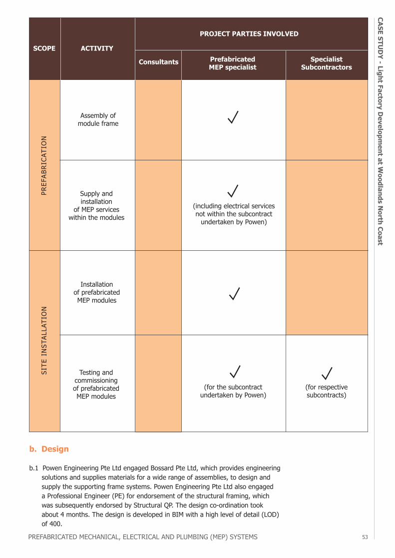
PREFABRICATED MECHANICAL, ELECTRICAL AND PLUMBING (MEP) SYSTEMS 53
CASE STUD
Y - Light Factory Developm
ent at Woodlands N
orth Coast
SITE
IN
STAL
LATI
ON
SCOPE ACTIVITY
Consultants Prefabricated MEP specialist
Specialist Subcontractors
PROJECT PARTIES INVOLVED
(for respective subcontracts)
(for the subcontract undertaken by Powen)
Testing and commissioning of prefabricated MEP modules
Installation of prefabricated MEP modules
PREF
ABRI
CATI
ON
(including electrical services not within the subcontract
undertaken by Powen)
Supply and installation
of MEP services within the modules
Assembly of module frame
b. Design
b.1 Powen Engineering Pte Ltd engaged Bossard Pte Ltd, which provides engineering solutions and supplies materials for a wide range of assemblies, to design and supply the supporting frame systems. Powen Engineering Pte Ltd also engaged a Professional Engineer (PE) for endorsement of the structural framing, which was subsequently endorsed by Structural QP. The design co-ordination took about 4 months. The design is developed in BIM with a high level of detail (LOD) of 400.
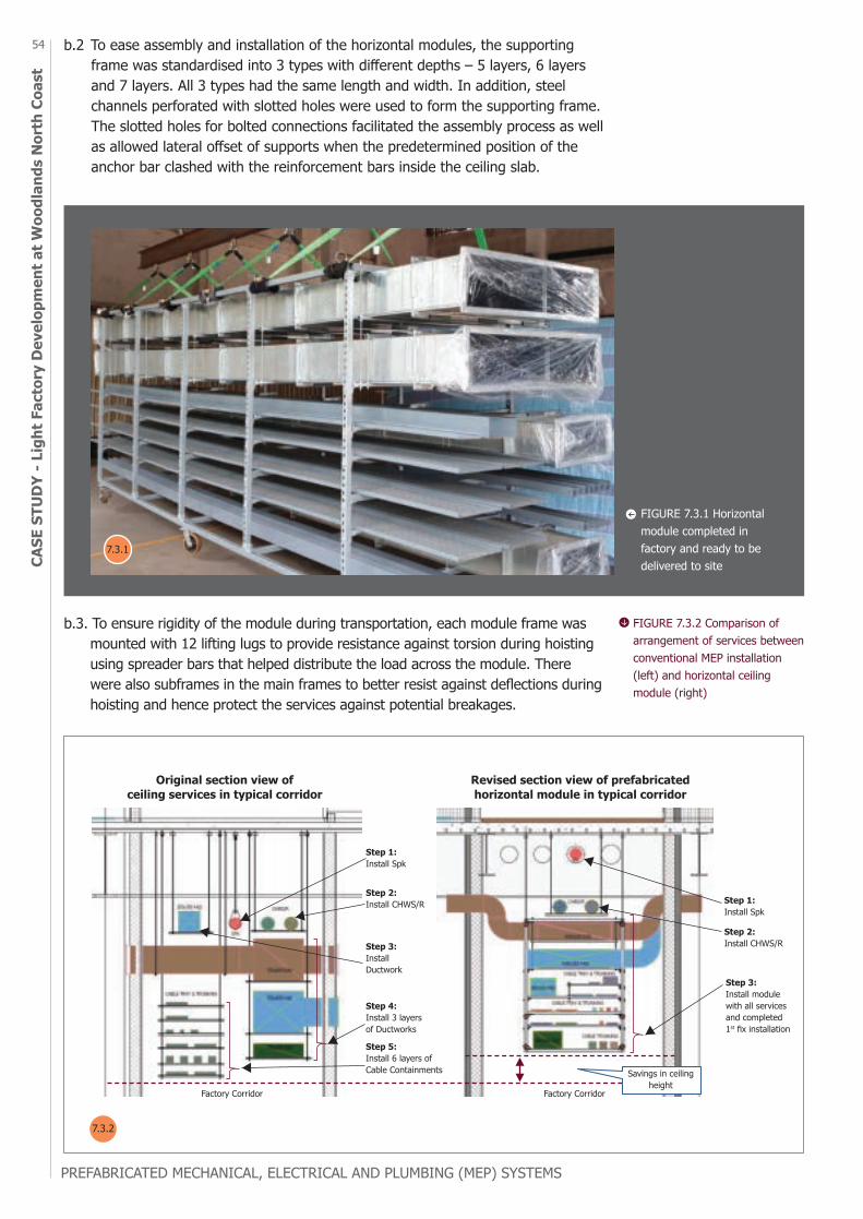
PREFABRICATED MECHANICAL, ELECTRICAL AND PLUMBING (MEP) SYSTEMS
54CA
SE S
TUD
Y - L
ight
Fac
tory
Dev
elop
men
t at W
oodl
ands
Nor
th C
oast
Factory Corridor
Step 1: Install Spk
Step 1: Install Spk
Step 2: Install CHWS/R
Step 2: Install CHWS/R
Step 3: Install modulewith all servicesand completed 1st fix installation
Step 3: Install Ductwork
Step 4: Install 3 layers of Ductworks
Step 5: Install 6 layers of Cable Containments
Factory Corridor
Saving in ceiling height
Original section view of ceiling services in typical corridor
Revised section view of prefabricated horizontal module in typical corridor
FIGURE 7.3.2 Comparison of arrangement of services between conventional MEP installation (left) and horizontal ceiling module (right)
Savings in ceiling height
b.3. To ensure rigidity of the module during transportation, each module frame was mounted with 12 lifting lugs to provide resistance against torsion during hoisting using spreader bars that helped distribute the load across the module. There were also subframes in the main frames to better resist against deflections during hoisting and hence protect the services against potential breakages.
FIGURE 7.3.1 Horizontal module completed in factory and ready to be delivered to site
b.2 To ease assembly and installation of the horizontal modules, the supporting frame was standardised into 3 types with different depths – 5 layers, 6 layers and 7 layers. All 3 types had the same length and width. In addition, steel channels perforated with slotted holes were used to form the supporting frame. The slotted holes for bolted connections facilitated the assembly process as well as allowed lateral offset of supports when the predetermined position of the anchor bar clashed with the reinforcement bars inside the ceiling slab.
7.3.1
7.3.2
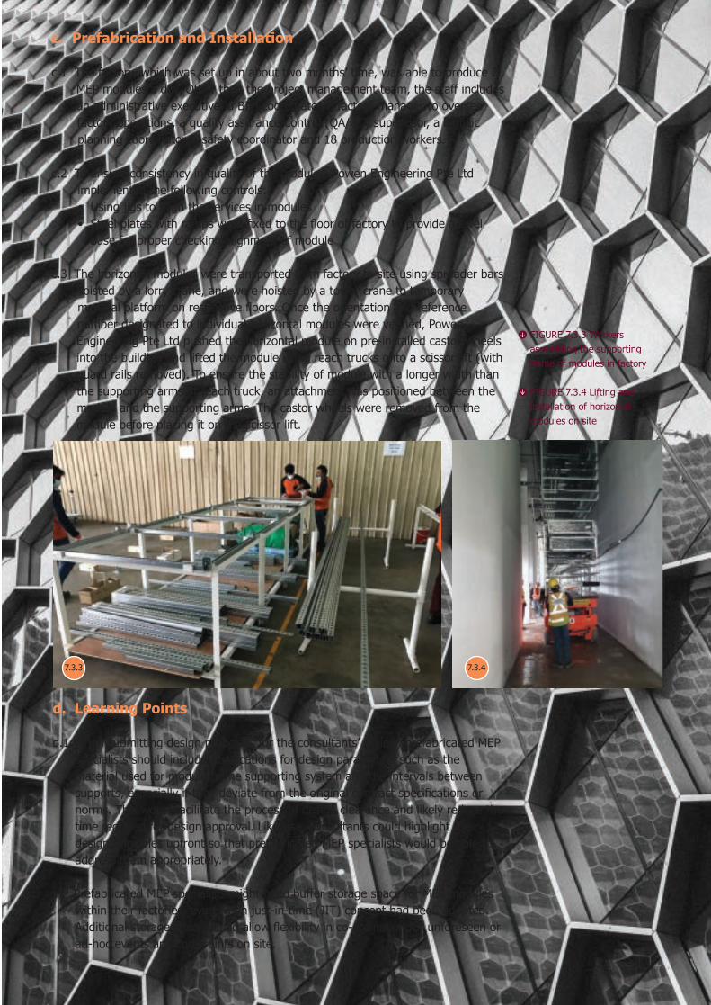
PREFABRICATED MECHANICAL, ELECTRICAL AND PLUMBING (MEP) SYSTEMS 55
CASE STUD
Y - Light Factory Developm
ent at Woodlands N
orth Coastc. Prefabrication and Installation
c.1 The factory, which was set up in about two months’ time, was able to produce 2 MEP modules a day. Other than the project management team, the staff includes an administrative executive, a BIM coordinator, a factory manager to oversee factory operations, a quality assurance/control (QA/QC) supervisor, a logistic planning coordinator, a safety coordinator and 18 production workers.
c.2 To ensure consistency in quality of the modules, Powen Engineering Pte Ltd implemented the following controls: • Using jigs to align the services in modules • Steel plates with ramps were fixed to the floor of factory to provide a level base for proper checking alignment of module
c.3 The horizontal modules were transported from factory to site using spreader bars hoisted by a lorry crane, and were hoisted by a tower crane to temporary material platform on respective floors. Once the orientation and reference number designated to individual horizontal modules were verified, Powen Engineering Pte Ltd pushed the horizontal module on pre-installed castor wheels into the building and lifted the module using reach trucks onto a scissor lift (with guard rails removed). To ensure the stability of module with a longer width than the supporting arms of reach truck, an attachment was positioned between the module and the supporting arms. The castor wheels were removed from the module before placing it on the scissor lift.
FIGURE 7.3.3 Workers assembling the supporting frame of modules in factory
FIGURE 7.3.4 Lifting and installation of horizontal modules on site
7.3.3 7.3.4
d. Learning Points
d.1 When submitting design proposals for the consultants’ review, prefabricated MEP specialists should include justifications for design parameters such as the material used for module frame supporting system and the intervals between supports, especially if they deviate from the original contract specifications or norms. This would facilitate the process of design clearance and likely reduce the time required for design approval. Likewise, consultants could highlight their design principles upfront so that prefabricated MEP specialists would be able to address them appropriately.
d.2 Prefabricated MEP specialists might need buffer storage space for MEP modules within their factories, even when just-in-time (JIT) concept had been adopted. Additional storage space would allow flexibility in co-ordination for unforeseen or ad-hoc events and constraints on site.
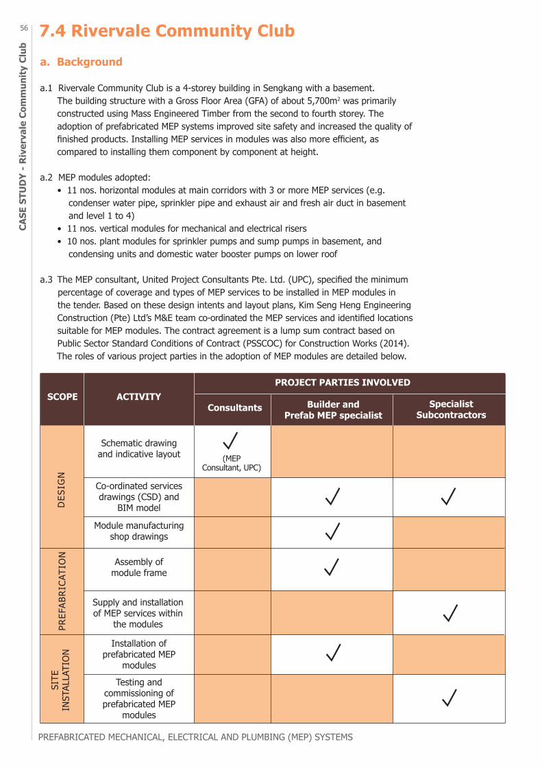
PREFABRICATED MECHANICAL, ELECTRICAL AND PLUMBING (MEP) SYSTEMS
56CA
SE S
TUD
Y - R
iver
vale
Com
mun
ity C
lub
7.4 Rivervale Community Cluba. Background
a.1 Rivervale Community Club is a 4-storey building in Sengkang with a basement. The building structure with a Gross Floor Area (GFA) of about 5,700m2 was primarily constructed using Mass Engineered Timber from the second to fourth storey. The adoption of prefabricated MEP systems improved site safety and increased the quality of finished products. Installing MEP services in modules was also more efficient, as compared to installing them component by component at height.
a.2 MEP modules adopted: • 11 nos. horizontal modules at main corridors with 3 or more MEP services (e.g. condenser water pipe, sprinkler pipe and exhaust air and fresh air duct in basement and level 1 to 4) • 11 nos. vertical modules for mechanical and electrical risers • 10 nos. plant modules for sprinkler pumps and sump pumps in basement, and condensing units and domestic water booster pumps on lower roof
a.3 The MEP consultant, United Project Consultants Pte. Ltd. (UPC), specified the minimum percentage of coverage and types of MEP services to be installed in MEP modules in the tender. Based on these design intents and layout plans, Kim Seng Heng Engineering Construction (Pte) Ltd’s M&E team co-ordinated the MEP services and identified locations suitable for MEP modules. The contract agreement is a lump sum contract based on Public Sector Standard Conditions of Contract (PSSCOC) for Construction Works (2014). The roles of various project parties in the adoption of MEP modules are detailed below.
DES
IGN
PREF
ABRI
CATI
ON
SITE
IN
STAL
LATI
ON
SCOPE ACTIVITYConsultants Builder and
Prefab MEP specialistSpecialist
Subcontractors
PROJECT PARTIES INVOLVED
Schematic drawing and indicative layout
Co-ordinated services drawings (CSD) and
BIM model
(MEP Consultant, UPC)
Module manufacturing shop drawings
Assembly of module frame
Supply and installation of MEP services within
the modules
Testing and commissioning of prefabricated MEP
modules
Installation of prefabricated MEP
modules

PREFABRICATED MECHANICAL, ELECTRICAL AND PLUMBING (MEP) SYSTEMS 57
CASE STUD
Y - Rivervale Comm
unity Club
b. Design
b.1 The design process took about five months to complete. The first two months were used for preliminary case study and exploring different options, 1.5 months for design development and 1.5 months for design co-ordination. The design is developed in BIM with a high level of detail (LOD) of 400.
b.2 To ease assembly of modules, the supporting frames were assembled using screw connections. The length of horizontal modules was set at 6000 mm, because the pipes and cable trays were supplied at that length.
b.3 The dimensions of the modules took into account the ceiling height required and sizes of structural openings on site. In order to meet the project requirement of typical ceiling height at 3100mm, some ductworks were left out because of limited headroom available for horizontal modules. After incorporating as many services as possible within the horizontal modules, the depth of horizontal modules ranged from 466mm to 1030mm, that contained either two or three layers of services. In the case of vertical modules, the height of vertical modules was limited to 3500mm to avoid being obstructed at door openings along its delivery route in the building. The width of vertical modules was 75mm smaller than the floor opening of riser in order to provide sufficient access space for mounting of vertical module to the wall by drilling.
b.4 Diagonal braces formed by L-shaped brackets were added to the supporting frames of modules to better resist against torsion and deflections during transportation, hoisting and lifting. To prevent corrosion, the supporting frame system comprising steel channels, angle bars and diagonal braces was hot-dipped galvanised and painted.
c. Prefabrication and Installation
c.1 To ensure consistent quality of the modules produced, one of the measures taken by Kim Seng Heng Engineering Construction (Pte) Ltd was to conduct magnetic particle inspection (MPI) test on the steel supporting frames of MEP modules, which helped detect surface or near-surface flaws such as cracks, laps, seams and inclusions. In the factory, approximately 6 mandays (a gang size of 3 workers for about 2 days) could produce the frame for each module. The 3 workers comprised 1 foreman, 1 general worker and 1 welder.
c.2 Upfront planning was used in overcoming logistics constraints. For example, in the installation of plant modules located at the basement, access openings were provided in the first storey slab to allow hoisting of plant modules into the basement. After the installation of plant modules, the walls around the plant modules were cast.
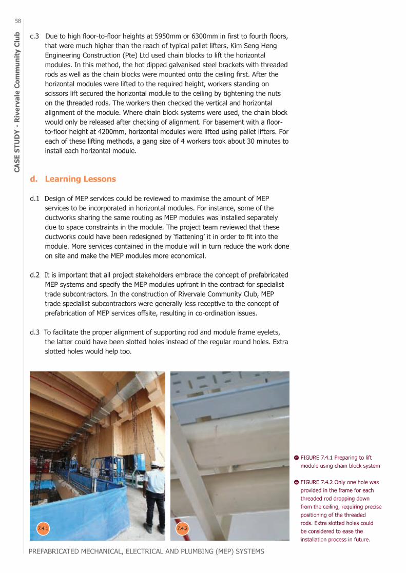
PREFABRICATED MECHANICAL, ELECTRICAL AND PLUMBING (MEP) SYSTEMS
58CA
SE S
TUD
Y - R
iver
vale
Com
mun
ity C
lub
FIGURE 7.4.1 Preparing to lift module using chain block system
FIGURE 7.4.2 Only one hole was provided in the frame for each threaded rod dropping down from the ceiling, requiring precise positioning of the threaded rods. Extra slotted holes could be considered to ease the installation process in future.
c.3 Due to high floor-to-floor heights at 5950mm or 6300mm in first to fourth floors, that were much higher than the reach of typical pallet lifters, Kim Seng Heng Engineering Construction (Pte) Ltd used chain blocks to lift the horizontal modules. In this method, the hot dipped galvanised steel brackets with threaded rods as well as the chain blocks were mounted onto the ceiling first. After the horizontal modules were lifted to the required height, workers standing on scissors lift secured the horizontal module to the ceiling by tightening the nuts on the threaded rods. The workers then checked the vertical and horizontal alignment of the module. Where chain block systems were used, the chain block would only be released after checking of alignment. For basement with a floor- to-floor height at 4200mm, horizontal modules were lifted using pallet lifters. For each of these lifting methods, a gang size of 4 workers took about 30 minutes to install each horizontal module.
d. Learning Lessons
d.1 Design of MEP services could be reviewed to maximise the amount of MEP services to be incorporated in horizontal modules. For instance, some of the ductworks sharing the same routing as MEP modules was installed separately due to space constraints in the module. The project team reviewed that these ductworks could have been redesigned by ‘flattening’ it in order to fit into the module. More services contained in the module will in turn reduce the work done on site and make the MEP modules more economical.
d.2 It is important that all project stakeholders embrace the concept of prefabricated MEP systems and specify the MEP modules upfront in the contract for specialist trade subcontractors. In the construction of Rivervale Community Club, MEP trade specialist subcontractors were generally less receptive to the concept of prefabrication of MEP services offsite, resulting in co-ordination issues.
d.3 To facilitate the proper alignment of supporting rod and module frame eyelets, the latter could have been slotted holes instead of the regular round holes. Extra slotted holes would help too.
7.4.1 7.4.2
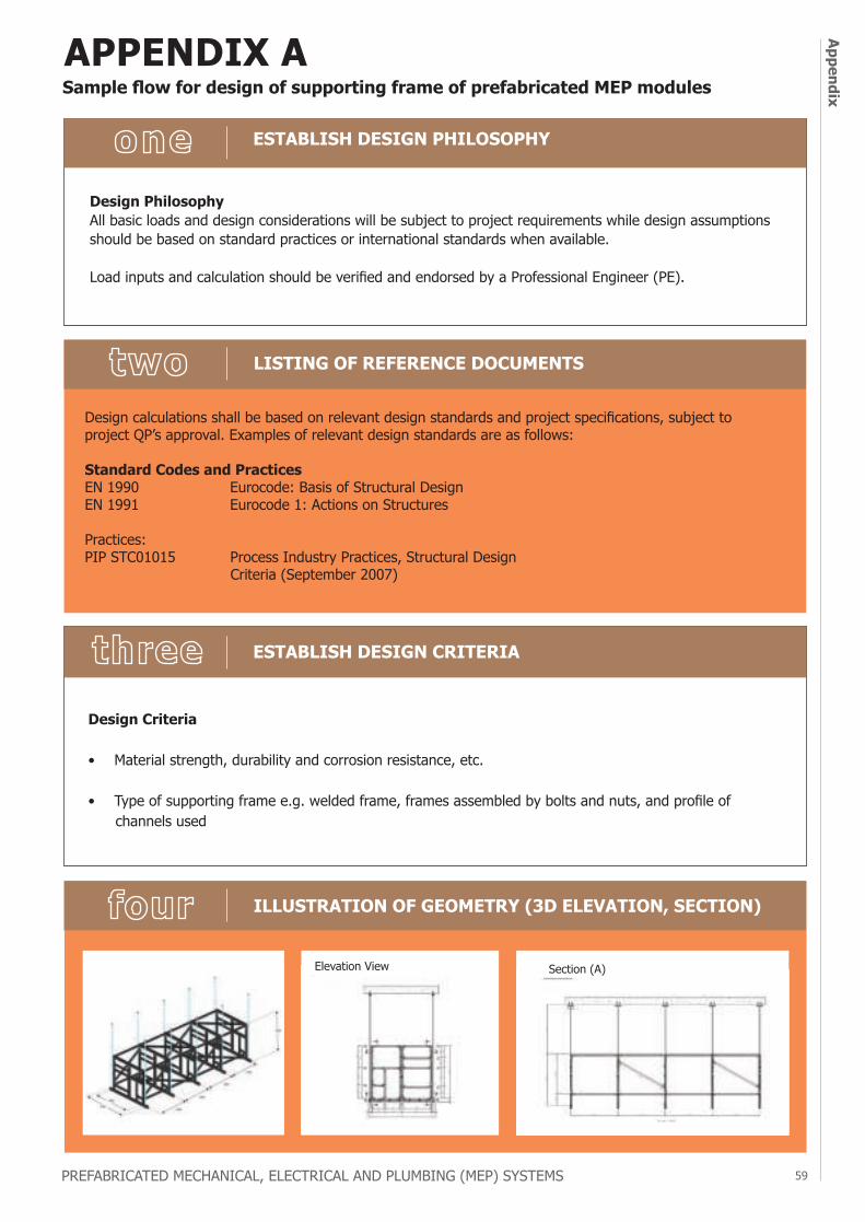
PREFABRICATED MECHANICAL, ELECTRICAL AND PLUMBING (MEP) SYSTEMS 59
Appendix
APPENDIX A
Design PhilosophyAll basic loads and design considerations will be subject to project requirements while design assumptions should be based on standard practices or international standards when available.
Load inputs and calculation should be verified and endorsed by a Professional Engineer (PE).
ESTABLISH DESIGN PHILOSOPHY
LISTING OF REFERENCE DOCUMENTS
ILLUSTRATION OF GEOMETRY (3D ELEVATION, SECTION)
ESTABLISH DESIGN CRITERIA
Design Criteria
• Material strength, durability and corrosion resistance, etc.
• Type of supporting frame e.g. welded frame, frames assembled by bolts and nuts, and profile of channels used
Design calculations shall be based on relevant design standards and project specifications, subject to project QP’s approval. Examples of relevant design standards are as follows:
Standard Codes and PracticesEN 1990 Eurocode: Basis of Structural DesignEN 1991 Eurocode 1: Actions on Structures
Practices:PIP STC01015 Process Industry Practices, Structural Design Criteria (September 2007)
Sample flow for design of supporting frame of prefabricated MEP modules
Elevation View Section (A)
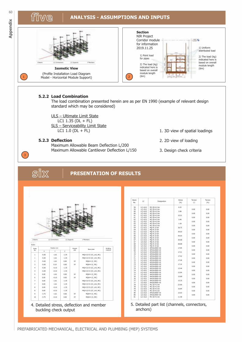
PREFABRICATED MECHANICAL, ELECTRICAL AND PLUMBING (MEP) SYSTEMS
60Ap
pend
ix
ANALYSIS - ASSUMPTIONS AND INPUTS
PRESENTATION OF RESULTS
5.2.2 Load Combination The load combination presented herein are as per EN 1990 (example of relevant design standard which may be considered)
ULS – Ultimate Limit State LC1 1.35 (DL + FL) SLS – Serviceability Limit State LC1 1.0 (DL + FL)
5.2.3 Deflection Maximum Allowable Beam Deflection L/200 Maximum Allowable Cantilever Deflection L/150
SectionNIR Project Corridor module for information 2019.11.25 1) Uniform
distributed load
2) The load (kg) indicated here is based on overall module length (6m)
1 Beams (1) Connections (1) Supports 1*Members
1) Point load for pipes
2) The load (kg) indicated here is based on overall module length (6m)
Isometic View(Profile Installation Load Diagram
Model - Horizontal Module Support)1 2
3
1. 3D view of spatial loadings
2. 2D view of loading
3. Design check criteria
4. Detailed stress, deflection and member buckling check output
1 Beams (1) Connections (1) Supports 1*Members
Nodes
1
1
2
3
4
4
5
6
7
7
8
8
9
10
-5.00
-5.00
-5.00
-5.00
-5.00
-5.00
0.00
0.00
0.00
0.00
0.00
0.00
-3.75
-3.75
-1.35
-1.35
0.00
0.00
-1.35
-1.35
0.00
0.00
-1.35
-1.35
-1.35
-1.35
0.00
0.00
XY
XY
XY
XY
XY
XY
MQV-3/3 D (CC_ch2_MC)
MQV-3/3 D (CC_ch3_MC)
MQW-4 (C_MC)
MQW-4 (C_MC)
MQV-3/3 D (CC_ch3_MC)
MQV-3/3 D (CC_ch2_MC)
MQW-4 (C_MC)
MQW-4 (C_MC)
MQV-3/3 D (CC_ch3_MC)
MQV-3/3 D (CC_ch2_MC)
MQV-3/3 D (CC_ch2_MC)
MQV-3/3 D (CC_ch3_MC)
MQW-4 (C_MC)
MQW-4 (C_MC)
Node No.
Position (m)
X Y Z
Hinged axis Base plate Building
material
-1.61
-1.61
-1.61
0.10
-0.10
-0.10
-1.61
-0.10
-1.61
-1.61
-0.10
-0.10
-1.61
-0.10
595960606161626263636464656566666767686869697070717172727373747475757676777778787979808081
Beam No.
LC DesignationStress(%)
Torsion(o)
Torsion(%)
LC1-ULSLC1-SLSLC1-ULSLC1-SLSLC1-ULSLC1-SLSLC1-ULSLC1-SLSLC1-ULSLC1-SLSLC1-ULSLC1-SLSLC1-ULSLC1-SLSLC1-ULSLC1-SLSLC1-ULSLC1-SLSLC1-ULSLC1-SLSLC1-ULSLC1-SLSLC1-ULSLC1-SLSLC1-ULSLC1-SLSLC1-ULSLC1-SLSLC1-ULSLC1-SLSLC1-ULSLC1-SLSLC1-ULSLC1-SLSLC1-ULSLC1-SLSLC1-ULSLC1-SLSLC1-ULSLC1-SLSLC1-ULSLC1-SLSLC1-ULSLC1-SLSLC1-ULS
MC-3D-41 6mMC-3D-41 6mMC-3D-41 6mMC-3D-41 6mMC-3D-41 6mMC-3D-41 6mMC-3D-41 6mMC-3D-41 6mMC-3D-41 6mMC-3D-41 6mMQ-41 D 6mMQ-41 D 6mMQ-41 D 6mMQ-41 D 6mMQ-41 D 6mMQ-41 D 6mMQ-41 D 6mMQ-41 D 6mMQ-41 D 6mMQ-41 D 6mAM10x3000 4.8AM10x3000 4.8AM10x3000 4.8AM10x3000 4.8AM10x3000 4.8AM10x3000 4.8AM10x3000 4.8AM10x3000 4.8AM10x3000 4.8AM10x3000 4.8AM10x3000 4.8AM10x3000 4.8AM10x3000 4.8AM10x3000 4.8AM10x3000 4.8AM10x3000 4.8AM10x3000 4.8AM10x3000 4.8MC-3D-41 6mMC-3D-41 6mMC-3D-41 6mMC-3D-41 6mAM10x3000 4.8AM10x3000 4.8MC-3D-41 6m
0.32
2.86
10.01
3.46
1.59
38.75
39.03
39.03
39.08
38.88
17.05
17.21
17.42
17.28
17.14
15.44
15.84
15.89
15.35
23.66
16.84
15.63
11.58
0.00
0.00
0.00
0.00
0.00
0.00
0.00
0.00
0.00
0.00
0.00
0.00
0.00
0.00
0.00
0.00
0.00
0.00
0.00
0.00
0.00
0.00
0.00
0.00
0.00
0.00
0.00
0.00
0.00
0.00
0.00
0.00
0.00
0.00
0.00
0.00
0.00
0.00
0.00
0.00
0.00
0.00
0.00
0.00
5. Detailed part list (channels, connectors, anchors)
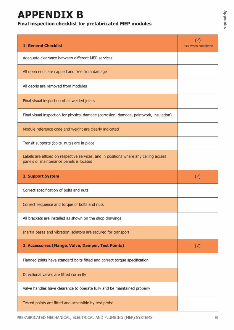
PREFABRICATED MECHANICAL, ELECTRICAL AND PLUMBING (MEP) SYSTEMS 61
Appendix
ANALYSIS - ASSUMPTIONS AND INPUTS
PRESENTATION OF RESULTS
APPENDIX BFinal inspection checklist for prefabricated MEP modules
1. General Checklist
2. Support System
3. Accessories (Flange, Valve, Damper, Test Points)
Adequate clearance between different MEP services
All open ends are capped and free from damage
All debris are removed from modules
Final visual inspection of all welded joints
Final visual inspection for physical damage (corrosion, damage, paintwork, insulation)
Module reference code and weight are clearly indicated
Transit supports (bolts, nuts) are in place
Labels are affixed on respective services, and in positions where any ceiling access panels or maintenance panels is located
Correct specification of bolts and nuts
Correct sequence and torque of bolts and nuts
All brackets are installed as shown on the shop drawings
Inertia bases and vibration isolators are secured for transport
Flanged joints have standard bolts fitted and correct torque specification
Directional valves are fitted correctly
Valve handles have clearance to operate fully and be maintained properly
Tested points are fitted and accessible by test probe
tick when completed(✓)
(✓)
(✓)
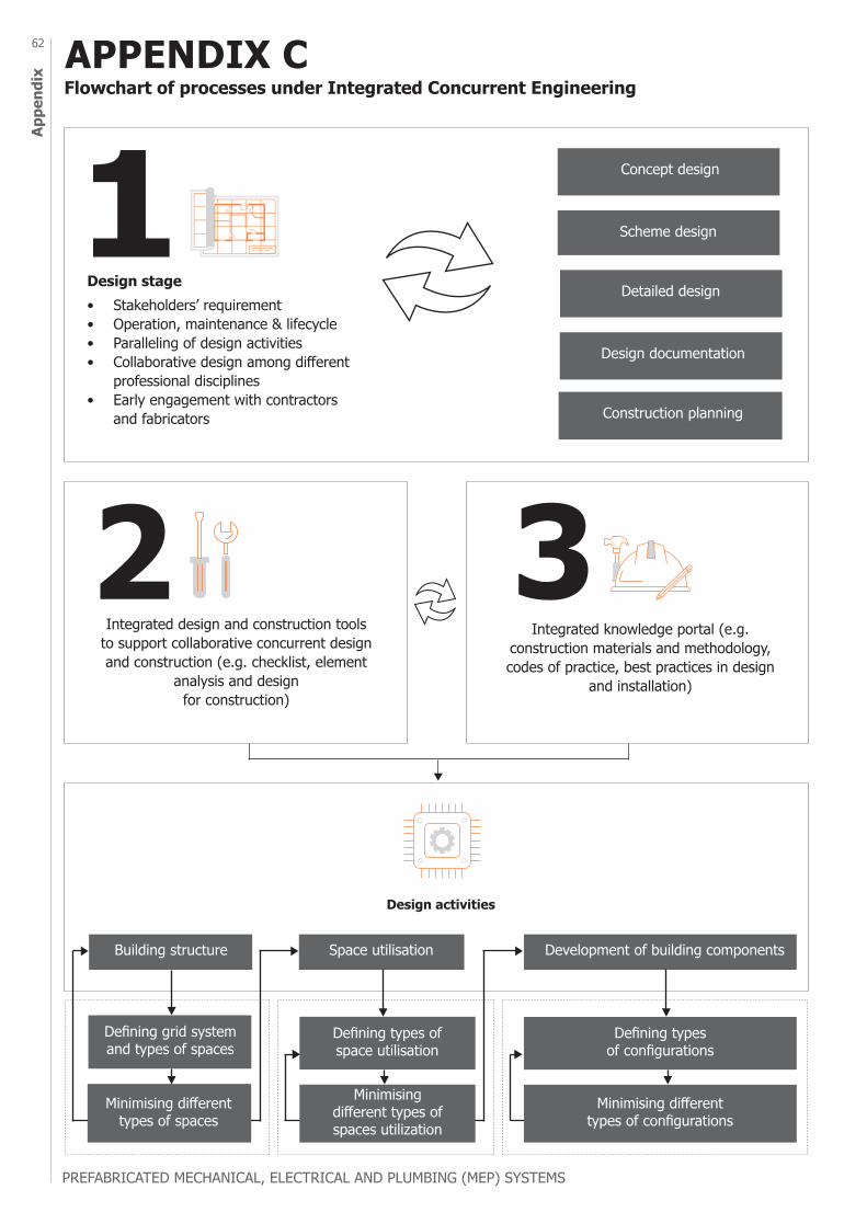
PREFABRICATED MECHANICAL, ELECTRICAL AND PLUMBING (MEP) SYSTEMS
62Ap
pend
ix
APPENDIX CFlowchart of processes under Integrated Concurrent Engineering
Design stage
Design activities
Construction planning
Design documentation
Detailed design
Scheme design
Concept design
Building structure
Defining grid system and types of spaces
Defining types of space utilisation
Defining types of configurations
Minimising different types of spaces
Minimising different types of spaces utilization
Minimising different types of configurations
Space utilisation Development of building components
• Stakeholders’ requirement• Operation, maintenance & lifecycle• Paralleling of design activities• Collaborative design among different
professional disciplines• Early engagement with contractors
and fabricators
Integrated design and construction tools to support collaborative concurrent design and construction (e.g. checklist, element
analysis and design for construction)
Integrated knowledge portal (e.g. construction materials and methodology, codes of practice, best practices in design
and installation)
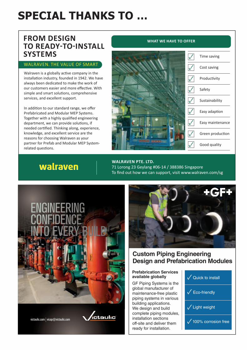
SPECIAL THANKS TO …
victaulic.com | [email protected]
ENGINEERING CONFIDENCE INTO EVERY BUILD
Walraven is a globally active company in the installation industry, founded in 1942. We have always been dedicated to make the work of our customers easier and more effective. With simple and smart solutions, comprehensive services, and excellent support.
In addition to our standard range, we offer Prefabricated and Modular MEP Systems. Together with a highly qualified engineering department, we can provide solutions, if needed certified. Thinking along, experience, knowledge, and excellent service are the reasons for choosing Walraven as your partner for Prefab and Modular MEP System-related questions.
WHAT WE HAVE TO OFFER
Time saving
Cost saving
Productivity
Safety
Sustainability
Easy adaption
Easy maintenance
Green production
Good quality
WALRAVEN PTE. LTD.71 Lorong 23 Geylang #06-14 / 388386 SingaporeTo find out how we can support, visit www.walraven.com/sg
WALRAVEN. THE VALUE OF SMART
FROM DESIGN TO READY-TO-INSTALL SYSTEMS
Custom Piping Engineering Design and Prefabrication Modules
GF Piping Systems is the global manufacturer of maintenance-free plastic piping systems in various building applications. We design and build complete piping modules, installation sections off-site and deliver them ready for installation.
100% corrosion free
Eco-friendly
Quick to install
Light weight
Prefabrication Services available globally
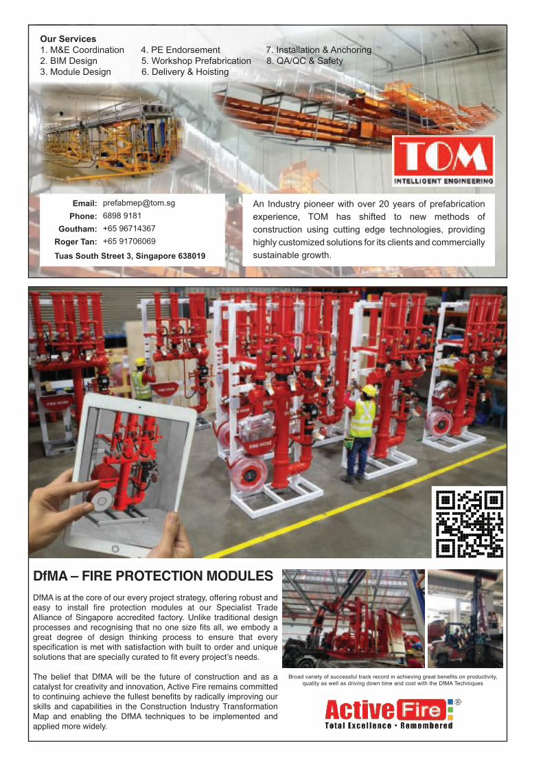
Our Services1. M&E Coordination 4. PE Endorsement 7. Installation & Anchoring2. BIM Design 5. Workshop Prefabrication 8. QA/QC & Safety3. Module Design 6. Delivery & Hoisting
An Industry pioneer with over 20 years of prefabrication experience, TOM has shifted to new methods of construction using cutting edge technologies, providing highly customized solutions for its clients and commercially sustainable growth.Tuas South Street 3, Singapore 638019
Email:Phone:
Goutham:Roger Tan:
[email protected] 9181+65 96714367+65 91706069
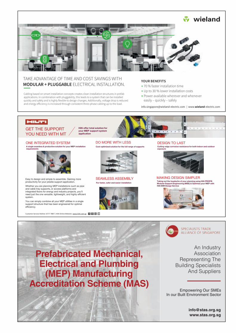
TAKE ADVANTAGE OF TIME AND COST SAVINGS WITH MODULAR + PLUGGABLE ELECTRICAL INSTALLATION.
Cabling based on smart installation concepts creates clean installation structures in prefab applications. In combination with pluggability, this leads to a system that can be installed quickly and safely and is highly flexible to design changes. Additionally, voltage drop is reduced and energy efficiency is increased through consistent three-phase cabling up to the load.
[email protected] | www.wieland-electric.com
YOUR BENEFITS + 70 % faster installation time+ Up to 30 % lower installation costs+ Power available wherever and whenever
easily – quickly – safely
ANZ_2021_01_Singapur_Sinnecker_Building_v3.indd 1ANZ_2021_01_Singapur_Sinnecker_Building_v3.indd 1 28.04.2021 10:25:1128.04.2021 10:25:11
GET THE SUPPORT YOU NEED WITH MT
Easy to design and simple to assemble. Gaining more productivity for your jobsite support application.
Whether you are planning MEP installations such as pipe and cable tray supports, or access platforms and integrated floors for energy and industry projects, you’ll need just the one versatile, lightweight, and highly efficient system.
You can simply combine all your MEP utilities in a single support structure that has been engineered for optimal efficiency.
ONE INTEGRATED SYSTEM DO MORE WITH LESSCost-optimized solution for the full range of supports
SEAMLESS ASSEMBLYFor faster, safer and easier installation
MAKING DESIGN SIMPLERTaking out the headache of your planning using Hilti PROFIS Modular Support Engineering (MSE) & Optimize your MEP with Hilti BIM Design Service
DESIGN TO LASTCutting-edge corrosion resistance for both indoor and outdoor exposure
Customer Service Hotline: 6777 7887 | Hil� Online Website: www.hil�.com.sg
A single seamless & productive solution for your MEP installation requirements
Hilti offer total solution for your MEP support system application
An Industry Association
Representing The Building Specialists
And Suppliers
Empowering Our SMEs In our Built Environment Sector
www.stas.org.sg [email protected]
Prefabricated Mechanical,Electrical and Plumbing
(MEP) ManufacturingAccreditation Scheme (MAS)