predicting skull loading: applying multibody dynamics analysis to a macaque skull
TRANSCRIPT
Predicting Skull Loading: ApplyingMultibody Dynamics Analysis to a
Macaque SkullNEIL CURTIS,1* KORNELIUS KUPCZIK,2 PAUL O’HIGGINS,3
MEHRAN MOAZEN,1 AND MICHAEL FAGAN1
1Centre for Medical Engineering and Technology, University of Hull, Hull, United Kingdom2Department of Human Evolution, Max Planck Institute for Evolutionary Anthropology,
Leipzig, Germany3Hull-York Medical School, University of York, York, United Kingdom
ABSTRACTEvaluating stress and strain fields in anatomical structures is a way
to test hypotheses that relate specific features of facial and skeletal mor-phology to mechanical loading. Engineering techniques such as finite ele-ment analysis are now commonly used to calculate stress and strainfields, but if we are to fully accept these methods we must be confidentthat the applied loading regimens are reasonable. Multibody dynamicsanalysis (MDA) is a relatively new three dimensional computer modelingtechnique that can be used to apply varying muscle forces to predict jointand bite forces during static and dynamic motions. The method ensuresthat equilibrium of the structure is maintained at all times, even for com-plex statically indeterminate problems, eliminating nonphysiological con-straint conditions often seen with other approaches. This study describesthe novel use of MDA to investigate the influence of different musclerepresentations on a macaque skull model (Macaca fascicularis), wheremuscle groups were represented by either a single, multiple, or wrappedmuscle fibers. The impact of varying muscle representation on stressfields was assessed through additional finite element simulations. TheMDA models highlighted that muscle forces varied with gape and thatforces within individual muscle groups also varied; for example, the ante-rior strands of the superficial masseter were loaded to a greater extentthan the posterior strands. The direction of the muscle force was alteredwhen temporalis muscle wrapping was modeled, and was coupled withcompressive contact forces applied to the frontal, parietal and temporalbones of the cranium during biting. Anat Rec, 291:491–501,2008. � 2008 Wiley-Liss, Inc.
Key words: multibody dynamics analysis; finite element anal-ysis; Macaque; bite force; muscle force
Analysis of motion and the stress/strain fields of themasticatory apparatus are of interest for many reasons.We may wish to explain or predict masticatory functionin extinct or extant animals, or understand how stressesthat contribute to the development and evolution ofskull form are created, or examine which structures arerelated to stress alleviation and which are associatedwith display or protection of sensory organs. Bone is adynamic structure that can modify its geometry inresponse to applied loads, and even though our under-standing has increased in recent years (e.g., Huiskes,
*Correspondence to: Neil Curtis, Department of Engineeringand Centre for Medical Engineering and Technology (CMET),University of Hull, Hull, HU67RX UK. Fax: 44(0)1482 466664.E-mail: [email protected]
Grant sponsor: the Leverhulme Trust; Grant sponsor: TheBiotechnology and Biological Sciences Research Council(BBSRC).
Received 11 December 2007; Accepted 30 January 2008
DOI 10.1002/ar.20689Published online 31 March 2008 in Wiley InterScience (www.interscience.wiley.com).
� 2008 WILEY-LISS, INC.
THE ANATOMICAL RECORD 291:491–501 (2008)
2000; see, e.g., reviews in Pearson and Lieberman, 2004;Ruff et al., 2006), we have known about the relationshipbetween bone loading and the development of bone mor-phology since the late 1800s (i.e., Wolff ’s Law; Wolff,1892). In the facial skeletons of diverse New and OldWorld monkeys growth remodeling fields show consider-able and, as yet unexplained, ontogenetic and interspe-cific variability between primate groups (Bromage, 1986;O’Higgins et al., 1991, 2001; Enlow and Hans, 1996;Walters and O’Higgins, 1992). While it is likely that,during growth, some depository fields and, potentially,aspects of condylar, nasal septal, and sutural (Morriss-Kay and Wilkie, 2005) growth are intrinsically regu-lated, one strong candidate for the extrinsic modulationof remodeling fields is the local mechanical environment(Moss and Salentijn, 1969).The development of high specification computer sys-
tems has paved the way for detailed investigations intothe effect of skull loading. Muscle force generation, bonytranslations, and subsequent stress/strain distributionsthroughout the skull can all be analyzed using techni-ques such as finite element analysis (FEA) and multi-body dynamics analysis (MDA). These technologies, andin particular the former, have been used for decades inthe automotive and aerospace industries to reliably pre-dict structural performance of mechanical systems.Applying FEA and MDA to biological systems seems alogical progression, and indeed mechanical modeling inrelation to the masticatory apparatus of humans andother nonhuman primates has previously been con-ducted (Koolstra and van Eijden, 1995; Daegling andHylander, 2000; Koolstra, 2003; Sellers and Crompton,2004; Ross et al., 2005; Strait et al., 2005; Ichim et al.,2006; Kupczik et al., 2007). A common way of estimatingloading conditions is to compute physiological cross-sectional areas (PCSA) to approximate the peak forcesthat can be generated by muscles and, where availableto further refine loadings using data from experimentalanalyses of muscle activation (e.g., Ross et al., 2005).This approach is not applicable in the many circumstan-ces where such data are not available, for examplewhere experimentation and recording of muscle activa-tion or anatomy is not feasible as in fossils. In these cir-cumstances MDA offers an opportunity to estimate mus-cle forces and facilitates experimentation with musclearchitecture and activation patterns. Where experimen-tal data from EMG studies are available, these can beincorporated into MDA models to improve the estimationof loading scenarios.Most studies load anatomically accurate models and
assess the resulting deformations in what is termed an in-ductive approach; however, an alternative deductivemethod is described in work by Witzel and Preuschoft (e.g.,Preuschoft and Witzel, 2004; Witzel et al., 2004; Witzel andPreuschoft, 2005). In this deductive approach extremelysimplified general skull forms are created and then loadedwith muscle and bite forces. Compressive stresses drivethe ‘‘synthesis’’ of the skull, which ends when compressivestresses equilibrate to within set tolerance limits. Both theinductive and deductive finite element techniques provideimportant data with respect to skull form and mechanicalfunction, and are described more comprehensively in arecent publication by Rayfield (2007).To accurately predict the mechanical environment of a
skull, not only must the loads (and constraints) be repro-
duced as faithfully as possible, but the material proper-ties throughout the structure must also be incorporatedin the model. However, bone is anisotropic, or at bestorthotropic, and its properties vary not only betweenindividuals but also throughout each specimen, thereforedefining accurate material properties in a specific skullmodel is problematic. Strait et al. (2005) conducted asensitivity study into the effects of using isotropic andanisotropic material properties in a Macaca fasciculariscranium and found that even though the more definedmodels produced greater accuracy in relation to experi-mental strain results, isotropic material definition pro-duced comparable results. Indeed, a validation study byKupczik et al. (2007) showed good correlation to experi-mental data using isotropic material properties, and it isalso true that most investigations into complex three-dimensional structures apply isotropic material proper-ties with successful results (e.g., Witzel and Preuschoft,1999; Rayfield et al., 2001; Cattaneo et al., 2003; Cruzet al., 2003).The aim of the present study is to investigate the
MDA method in predicting the loading conditions of theskull. The main part of the study will describe the noveluse of MDA to model skull mechanics of a Macaca fasci-cularis, where muscle forces will drive biting simula-tions in which bite forces and joint forces will be pre-dicted. We will investigate the role of masticatorymuscles in terms of their force application, as well asthe importance of geometry and simulating musclewrapping. In addition to this, the loading derived fromthe MDA will be applied directly to FEA to assess differ-ences, if any, in the stress distributions between differ-ent muscle modeling and loading conditions.
MATERIALS AND METHODS
Micro-computed tomography (CT) skull data from amale crab-eating macaque (Macaca fascicularis) wereobtained using an X-Tek HMX 160 micro-CT scanner (X-Tek Systems Ltd, Tring, Herts., UK). A 123-kV voltageand 87-mA current were applied in conjunction with a0.2-mm Cu filter. Voxel resolution was 0.23 mm in the x,y, and z directions. The same CT data were used in aprevious study (Kupczik et al., 2007; MAC-14).
MDA
MDA is a technique by which rigid-body motion isdefined for an object or group of objects, from whichforces can be derived. In relation to the presentresearch, a macaque skull with representative mastica-tory muscles was modeled. The jaw was subsequentlyopened to a predefined gape, and in doing so, the musclegroups were extended. From this open position, a simu-lated food substance was placed between the teeth andthen muscle forces were applied to produce biting, wherebite and joint reaction forces were recorded.To produce the MDA model, the micro-CT data were
segmented into separate mandibular and cranial por-tions using AMIRA image segmentation software (Mer-cury Computer Systems Inc, USA), and three-dimen-sional surface models were created and exported aswavefront (.obj) files. The surface models were thenimported into MSC ADAMS multibody dynamics model-
492 CURTIS ET AL.
ing software (MSC Software Corp, USA), where theywere treated as rigid-bodies. Multibody dynamics model-ing requires the definition of the mass properties of themoving bodies, the forces or movements applied to them,and the constraints on their movement. The only movingpart in this simulation was the mandible, whose masswas calculated from its volume and estimated density.The volume was calculated directly from the AMIRAsegmentation software (1.79 3 1025 m3), which withan assumed tissue density of 1,050 kg/m3 (Sellers andCrompton, 2004) gave a mandibular mass of 0.019 kg.The cranium was fixed and the mandible rotated withinthe temporomandibular joint (TMJ), which was modeledas a bicompartmental joint that could translate in thesagittal plane and rotate about the coronal axis. Theskull was initially scanned with the jaw open, whichrequired it to be repositioned into a closed position dur-ing the model setup so that the corresponding teeth inthe upper and lower teeth rows were aligned. The repo-sitioning from an open to closed state resulted in a pos-terior translation of 5 mm and an axial rotation of 558.The anterior/posterior temporalis, deep/superficial
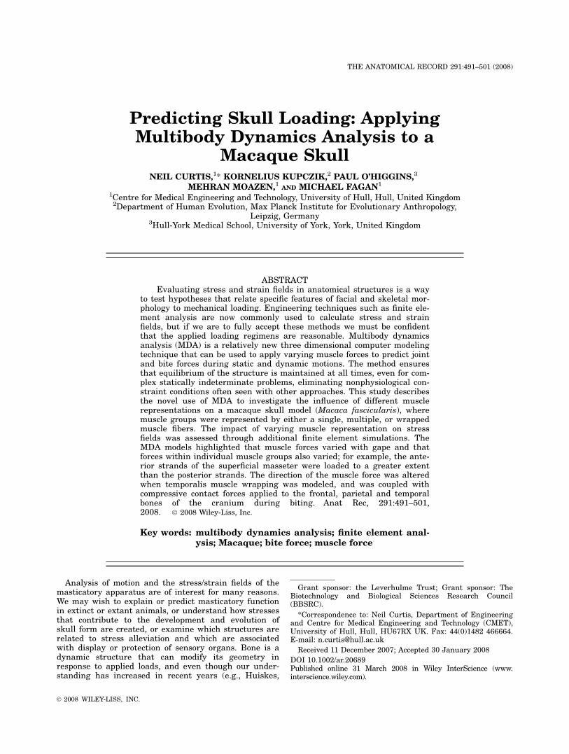
masseter, and medial/lateral pterygoid muscle groupswere represented in the model. Initially, the musclegroups were represented by spring elements (‘‘strands’’),which were later modified to behave according to realis-tic force–length characteristics, as defined in equation 1.Three methods of representing the muscle groups wereassessed, as shown in Fig. 1: (1) most simply, using sin-gle muscle strands for each muscle group directed in astraight line from origin to insertion and positioned cen-trally within the muscle attachment area; (2) in a moreanatomical configuration, using multiple strands foreach muscle group directed in a straight line from originto insertion and applied over the entire muscle area;and (3) as anatomically as possible, using multiple mus-cle strands for each group combined with muscle wrap-ping of the anterior and posterior temporalis. For themultiple muscle strand and muscle wrapping models,the anterior and posterior temporalis were split intothree sections each, the deep masseter four sections, su-perficial masseter five sections, and the medial and lat-eral pterygoids were split into four sections each (seeFig. 1). The three simulations were designed to evaluatethe effects of different modeling approaches in providingrelevant information to guide future applications. Devel-opment of the MDA model to incorporate muscle wrap-
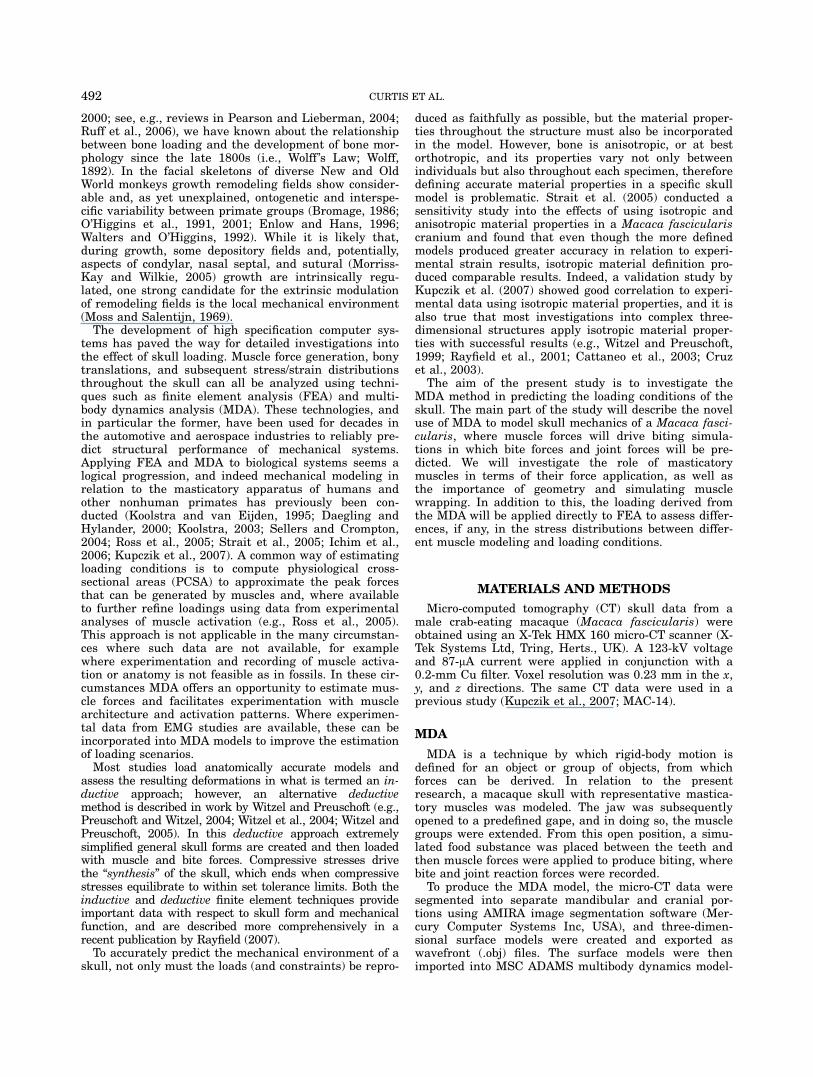
ping of the temporalis muscle groups involved splittingeach of the individual muscle strands into four sections,and laying these sections around the cranium. To allowcontact between the muscle and the skull contactspheres were placed at the junctions between the musclesections, as shown in Fig. 2. These contact spheres couldslide over the cranium, and for the purposes of the pres-ent study, their motion was frictionless.To open the mandible, the TMJ was moved in such a
way that it both rotated and translated (where transla-tion 5 [5 mm/558] 3 gape angle). As the mandibleopened the muscle strands elongated and shifted in rela-tion to the underlying structures, except at the points oforigin and insertion. The strand force–length character-istics were used to estimate the muscle forces that wouldgenerate the opposite motion. Biting simulations werethen carried out at a gape of 158 in all muscle models bysimulating a stiff, incompressible spring between theteeth and allowing the muscle forces to be applied. Astiff spring (2,000 N/mm stiffness) was positioned bilat-erally at the second molar position to represent a rigidfood particle. To assess the effect of gape angle and bitepoint, biting simulations were carried out at 58, 108, 158,208, 258, and 308 at the M2 position, and at 158 gape atthe first premolar, first molar, and second molar posi-tions with the multiple muscle strand model.The muscles were modeled according to Van Ruijven
and Weijs (van Ruijven and Weijs, 1990), which were inturn based on a Hill-type model (Hill, 1938):
F ¼ Fmax 3 ðFA 3 FV 3 FQþ FPÞ ð1Þ
where Fmax is maximal tetanic force (25 N.cm22 of cross-section; see for instance Herzog, 1994; Cleuren et al.,1995), FA is a force/length factor, FV is a force/velocityfactor, FQ is an activation factor and FP a passive mus-cle element. The physiological cross-sectional area of themuscles used to calculate Fmax were taken from the lit-erature (Anton, 1999, 2000; Ross et al., 2005). Equation1 was simplified to equation 2 because only static bitingwas simulated (FV 5 1 when change in muscle length 50), FQ was assumed to be 100% (5 1), and FP wasexcluded for simplicity. The passive element (FP) is at-tributable to the tendinous structures of the muscle, andcontributes to muscle forces beyond a specific gape. Thegapes assessed in the present study did not require therepresentation of the passive element.
Fig. 1. A–C: Multibody dynamics analysis (MDA) models showing single (A), multiple (B), and wrapped(C) muscle groups. Blue, red, and yellow represent the temporalis, masseter, and pterygoid musclegroups, respectively.
493PREDICTING SKULL LOADING
F ¼ Fmax 3 FA ð2Þ
The force length factor (FA) has been estimated using asecond order polynomial, and defines a force–lengthcurve that follows that of experimentally measured skel-etal muscle (equation 3; Epstein and Herzog, 1998).
FA ¼ �6:25 3 ðL=LoÞ2 þ 12:5 3 ðL=LoÞ � 5:25 ð3Þ
Where L is the muscle length and Lo is the optimallength, that is, the length at which the muscle can applyits maximum force. For each individual muscle strand,the optimum was specified as its length (Lo) when themodel had a gape of 158. Lo was determined before thebiting simulations and was applied as a constant inequation 3. Based on the experience of the authorsand what is stated in the literature (Turkawski and vanEijden, 2001), a gape of 158 was deemed reasonable for amacaque. The calculated Lo values are of course approx-imations, and when more comprehensive data becomeavailable this value can be modified.
FEA
In brief, the finite element method works by dividingthe geometry of the problem under investigation (e.g., askull) into a finite number of subregions, called ele-ments, which are connected together at their corners(and sometimes along their mid-sides). These points ofconnection are called nodes. For stress analysis, a varia-tion in displacement (e.g., linear or quadratic) is thenassumed through each element, and equations describ-ing the behavior of each element are derived in terms of
the (initially unknown) nodal displacements. These ele-ment equations are then combined to give a set of sys-tem equations that describe the behavior of the wholeproblem. After modifying the equations to account forthe loading and constraints applied to the problem,these system equations are solved. The output is a list ofall the nodal displacements. The element strains canthen be calculated from the displacements, and thestresses from the strains. More detailed descriptions ofFEA principles and its applications to craniofacialmechanics are available (e.g., Fagan, 1992; Rayfield,2007; Strait et al., 2007).ANSYS 11 FEA software (ANSYS Inc, USA) was used
in the present study, and like most commercially avail-able FEA software allows stress analyses to be con-ducted relatively simply. Using AMIRA image segmenta-tion software the cranium surface model (previously cre-ated for the MDA analyses) was transformed into a solidmodel and meshed into approximately 120,000 elements.In ANSYS, isotropic properties were defined with aYoung’s modulus of 17GPa and Poisson’s ratio of 0.3.The Young’s modulus and Poisson’s ratio values are com-parable to those used in other studies (e.g., Strait et al.,2005; Witzel and Preuschoft, 2005); however, the specificvalues were not critical to the present research, becausedirectly comparable models were being assessed relativeto each other and not with anatomical specimens. Theloading data were taken directly from the MDA simula-tions and included bite forces, joint forces, muscle forces,and in the case of muscle wrapping, temporal musclecontact forces. ANSYS then automatically calculated thesystem equations, incorporated the boundary conditions,performed the solution and calculated the strains andstresses. Because all the loading data was taken directly
Fig. 2. Temporalis muscle wrapping. A: Individual muscle strands are split into four segments and laidaround the cranium. B: View without the muscle strands showing the contact spheres that connecteach of the muscle strand segments. The dotted line represents the attachment point of the muscle onthe cranium.
494 CURTIS ET AL.
from the MDA simulations, a state of equilibrium wasreached, allowing the FE models to be solved with mini-mal constraints. This resulted in zero reaction forces,with the added benefit of eliminating unrealisticallystressed regions at the constraints, which are observedin models that are not in equilibrium.
RESULTS
MDA
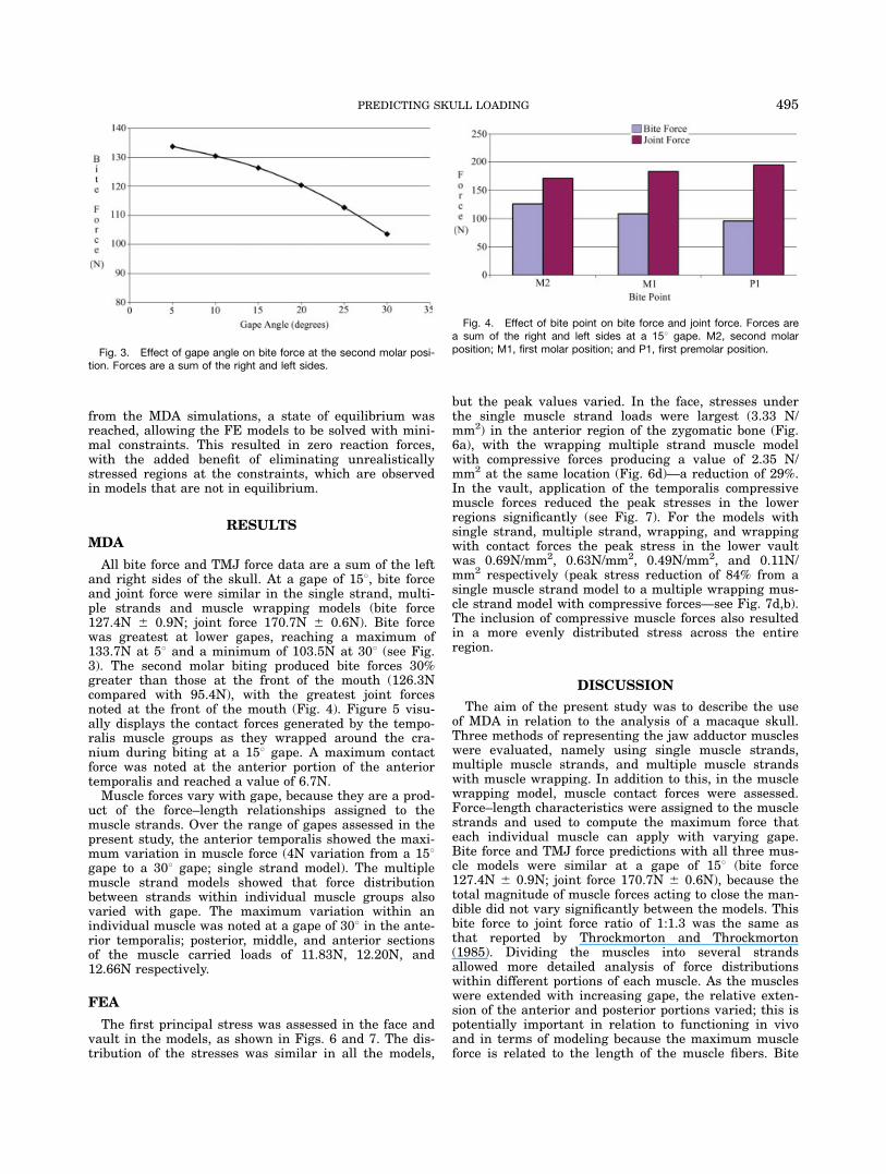
All bite force and TMJ force data are a sum of the leftand right sides of the skull. At a gape of 158, bite forceand joint force were similar in the single strand, multi-ple strands and muscle wrapping models (bite force127.4N 6 0.9N; joint force 170.7N 6 0.6N). Bite forcewas greatest at lower gapes, reaching a maximum of133.7N at 58 and a minimum of 103.5N at 308 (see Fig.3). The second molar biting produced bite forces 30%greater than those at the front of the mouth (126.3Ncompared with 95.4N), with the greatest joint forcesnoted at the front of the mouth (Fig. 4). Figure 5 visu-ally displays the contact forces generated by the tempo-ralis muscle groups as they wrapped around the cra-nium during biting at a 158 gape. A maximum contactforce was noted at the anterior portion of the anteriortemporalis and reached a value of 6.7N.Muscle forces vary with gape, because they are a prod-
uct of the force–length relationships assigned to themuscle strands. Over the range of gapes assessed in thepresent study, the anterior temporalis showed the maxi-mum variation in muscle force (4N variation from a 158gape to a 308 gape; single strand model). The multiplemuscle strand models showed that force distributionbetween strands within individual muscle groups alsovaried with gape. The maximum variation within anindividual muscle was noted at a gape of 308 in the ante-rior temporalis; posterior, middle, and anterior sectionsof the muscle carried loads of 11.83N, 12.20N, and12.66N respectively.
FEA
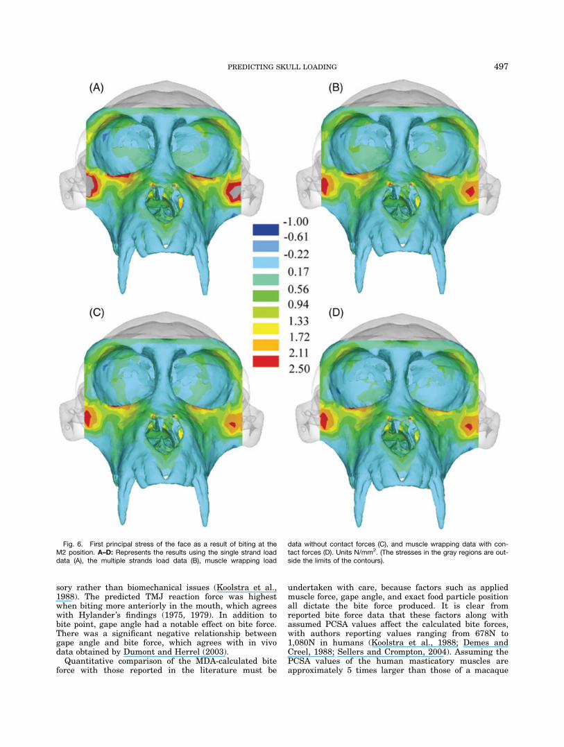
The first principal stress was assessed in the face andvault in the models, as shown in Figs. 6 and 7. The dis-tribution of the stresses was similar in all the models,
but the peak values varied. In the face, stresses underthe single muscle strand loads were largest (3.33 N/mm2) in the anterior region of the zygomatic bone (Fig.6a), with the wrapping multiple strand muscle modelwith compressive forces producing a value of 2.35 N/mm2 at the same location (Fig. 6d)—a reduction of 29%.In the vault, application of the temporalis compressivemuscle forces reduced the peak stresses in the lowerregions significantly (see Fig. 7). For the models withsingle strand, multiple strand, wrapping, and wrappingwith contact forces the peak stress in the lower vaultwas 0.69N/mm2, 0.63N/mm2, 0.49N/mm2, and 0.11N/mm2 respectively (peak stress reduction of 84% from asingle muscle strand model to a multiple wrapping mus-cle strand model with compressive forces—see Fig. 7d,b).The inclusion of compressive muscle forces also resultedin a more evenly distributed stress across the entireregion.
DISCUSSION
The aim of the present study was to describe the useof MDA in relation to the analysis of a macaque skull.Three methods of representing the jaw adductor muscleswere evaluated, namely using single muscle strands,multiple muscle strands, and multiple muscle strandswith muscle wrapping. In addition to this, in the musclewrapping model, muscle contact forces were assessed.Force–length characteristics were assigned to the musclestrands and used to compute the maximum force thateach individual muscle can apply with varying gape.Bite force and TMJ force predictions with all three mus-cle models were similar at a gape of 158 (bite force127.4N 6 0.9N; joint force 170.7N 6 0.6N), because thetotal magnitude of muscle forces acting to close the man-dible did not vary significantly between the models. Thisbite force to joint force ratio of 1:1.3 was the same asthat reported by Throckmorton and Throckmorton(1985). Dividing the muscles into several strandsallowed more detailed analysis of force distributionswithin different portions of each muscle. As the muscleswere extended with increasing gape, the relative exten-sion of the anterior and posterior portions varied; this ispotentially important in relation to functioning in vivoand in terms of modeling because the maximum muscleforce is related to the length of the muscle fibers. Bite
Fig. 3. Effect of gape angle on bite force at the second molar posi-tion. Forces are a sum of the right and left sides.
Fig. 4. Effect of bite point on bite force and joint force. Forces area sum of the right and left sides at a 158 gape. M2, second molarposition; M1, first molar position; and P1, first premolar position.
495PREDICTING SKULL LOADING
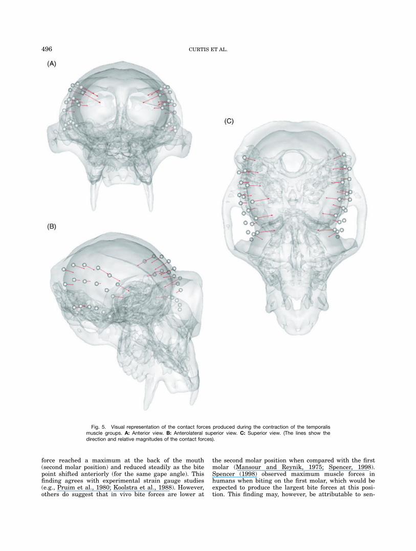
force reached a maximum at the back of the mouth(second molar position) and reduced steadily as the bitepoint shifted anteriorly (for the same gape angle). Thisfinding agrees with experimental strain gauge studies(e.g., Pruim et al., 1980; Koolstra et al., 1988). However,others do suggest that in vivo bite forces are lower at
the second molar position when compared with the firstmolar (Mansour and Reynik, 1975; Spencer, 1998).Spencer (1998) observed maximum muscle forces inhumans when biting on the first molar, which would beexpected to produce the largest bite forces at this posi-tion. This finding may, however, be attributable to sen-
Fig. 5. Visual representation of the contact forces produced during the contraction of the temporalismuscle groups. A: Anterior view. B: Anterolateral superior view. C: Superior view. (The lines show thedirection and relative magnitudes of the contact forces).
496 CURTIS ET AL.
sory rather than biomechanical issues (Koolstra et al.,1988). The predicted TMJ reaction force was highestwhen biting more anteriorly in the mouth, which agreeswith Hylander’s findings (1975, 1979). In addition tobite point, gape angle had a notable effect on bite force.There was a significant negative relationship betweengape angle and bite force, which agrees with in vivodata obtained by Dumont and Herrel (2003).Quantitative comparison of the MDA-calculated bite
force with those reported in the literature must be
undertaken with care, because factors such as appliedmuscle force, gape angle, and exact food particle positionall dictate the bite force produced. It is clear fromreported bite force data that these factors along withassumed PCSA values affect the calculated bite forces,with authors reporting values ranging from 678N to1,080N in humans (Koolstra et al., 1988; Demes andCreel, 1988; Sellers and Crompton, 2004). Assuming thePCSA values of the human masticatory muscles areapproximately 5 times larger than those of a macaque
Fig. 6. First principal stress of the face as a result of biting at theM2 position. A–D: Represents the results using the single strand loaddata (A), the multiple strands load data (B), muscle wrapping load
data without contact forces (C), and muscle wrapping data with con-tact forces (D). Units N/mm2. (The stresses in the gray regions are out-side the limits of the contours).
497PREDICTING SKULL LOADING
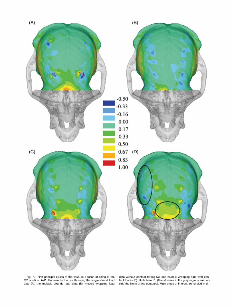
Fig. 7. First principal stress of the vault as a result of biting at theM2 position. A–D: Represents the results using the single strand loaddata (A), the multiple strands load data (B), muscle wrapping load
data without contact forces (C), and muscle wrapping data with con-tact forces (D). Units N/mm2. (The stresses in the gray regions are out-side the limits of the contours). Main areas of interest are circled in d.
(Ross et al., 2005; van Eijden et al., 1997), then by scal-ing, macaque bite forces might be expected to be 136 Nto 216 N. The MDA model in this current study pre-dicted bite forces of 104N to 134N between a gape of 58and 308 (multiple muscle strand model at the secondmolar position), and from 95N to 126N between the firstpremolar and second molar position (multiple musclestrand model at a 158 gape). These results are closer tothe values reported by Hylander (1979) who used trans-ducer plates to experimentally record bite forces ofbetween 70N and 120N in macaques.In FEA of the cranium in which masticatory function
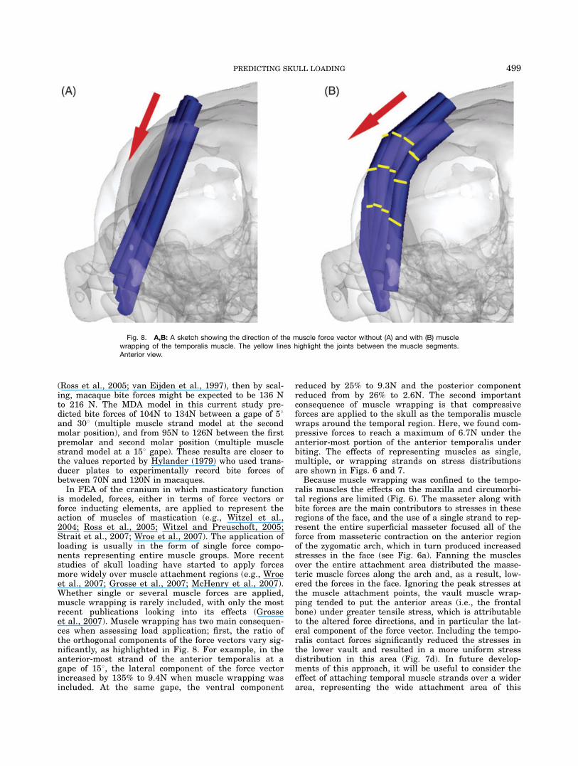
is modeled, forces, either in terms of force vectors orforce inducting elements, are applied to represent theaction of muscles of mastication (e.g., Witzel et al.,2004; Ross et al., 2005; Witzel and Preuschoft, 2005;Strait et al., 2007; Wroe et al., 2007). The application ofloading is usually in the form of single force compo-nents representing entire muscle groups. More recentstudies of skull loading have started to apply forcesmore widely over muscle attachment regions (e.g., Wroeet al., 2007; Grosse et al., 2007; McHenry et al., 2007).Whether single or several muscle forces are applied,muscle wrapping is rarely included, with only the mostrecent publications looking into its effects (Grosseet al., 2007). Muscle wrapping has two main consequen-ces when assessing load application; first, the ratio ofthe orthogonal components of the force vectors vary sig-nificantly, as highlighted in Fig. 8. For example, in theanterior-most strand of the anterior temporalis at agape of 158, the lateral component of the force vectorincreased by 135% to 9.4N when muscle wrapping wasincluded. At the same gape, the ventral component
reduced by 25% to 9.3N and the posterior componentreduced from by 26% to 2.6N. The second importantconsequence of muscle wrapping is that compressiveforces are applied to the skull as the temporalis musclewraps around the temporal region. Here, we found com-pressive forces to reach a maximum of 6.7N under theanterior-most portion of the anterior temporalis underbiting. The effects of representing muscles as single,multiple, or wrapping strands on stress distributionsare shown in Figs. 6 and 7.Because muscle wrapping was confined to the tempo-
ralis muscles the effects on the maxilla and circumorbi-tal regions are limited (Fig. 6). The masseter along withbite forces are the main contributors to stresses in theseregions of the face, and the use of a single strand to rep-resent the entire superficial masseter focused all of theforce from masseteric contraction on the anterior regionof the zygomatic arch, which in turn produced increasedstresses in the face (see Fig. 6a). Fanning the musclesover the entire attachment area distributed the masse-teric muscle forces along the arch and, as a result, low-ered the forces in the face. Ignoring the peak stresses atthe muscle attachment points, the vault muscle wrap-ping tended to put the anterior areas (i.e., the frontalbone) under greater tensile stress, which is attributableto the altered force directions, and in particular the lat-eral component of the force vector. Including the tempo-ralis contact forces significantly reduced the stresses inthe lower vault and resulted in a more uniform stressdistribution in this area (Fig. 7d). In future develop-ments of this approach, it will be useful to consider theeffect of attaching temporal muscle strands over a widerarea, representing the wide attachment area of this
Fig. 8. A,B: A sketch showing the direction of the muscle force vector without (A) and with (B) musclewrapping of the temporalis muscle. The yellow lines highlight the joints between the muscle segments.Anterior view.
499PREDICTING SKULL LOADING
muscle. In the present model, the temporal muscle wasonly attached to the upper temporal region. If theattachment was distributed over the whole temporalarea, its compressive effect in the lower vault may becounteracted, to some extent, by the tensile force pro-duced by the lower muscle strands.The complexity of skull models is continually increas-
ing, with some models now including a degree of varia-tion in material properties across the skull, musclegroups divided into different segments and the effects ofdifferent loading conditions being assessed (e.g., Rosset al., 2005; Strait et al., 2005; Witzel and Preuschoft,2005; Wroe et al., 2007). MDA offers an opportunity fora further improvement in the biofidelity of these simula-tions. This study has demonstrated how we can calcu-late the loading conditions of several muscle groups,joint reaction forces, and bite forces during a single bitesimulation, ensuring the skull remains in equilibrium.There are still several assumptions and approximationsin the equations used to define the muscles’ behavior,which need further development and refinement.Future application of MDA to model increasingly com-
plex situations should provide novel insights into theoptimization of muscle and skull form. For example,Macaca fascicularis has a wide and varied diet thatincludes plants, fruits, seeds, and several small animals(e.g., bird chicks, lizards, frogs). This alone tells us thatsimulating one loading condition is not enough to fullyunderstand the form of the macaque skull. Variations inbite point, food stiffness, chewing cycles (including possi-ble grinding, shearing, snapping, and so on), as well asforces not arising from mastication such as those arisingfrom expression, head motion, and so on, should also betaken into account in attempting to evaluate craniofacialform in terms of mechanical optimization. In addition,sexual dimorphism clearly plays a pivotal role in shap-ing the skull, and these differences must lead to differ-ences in skull loading between male and female prima-tes. Beyond obvious variations such as the large caninesin the male, other, perhaps less obvious sexually dimor-phic variations in muscle attachment zones (e.g., tempo-ralis) and in skeletal form such as the shape of the TMJbearing surfaces point to differences in loading betweenthe male and female skulls. All these situations can berealized by means of MDA to provide ever more realisticloading data for FEAs.
LITERATURE CITED
Anton SC. 1999. Macaque masseter muscle: internal architecture,fiber length, and cross-sectional area. Int J Prim 20:441–462.
Anton SC. 2000. Macaque pterygoid muscles: internal architecture,fiber length, and cross-sectional area. Int J Prim 21:131–156.
Bromage TG. 1986. A comparative scanning electron microscopestudy of facial growth remodelling in early hominids. PhD Thesis:University of Toronto.
Cattaneo PM, Dalstra M, Melsen B. 2003. The transfer of occlusalforces through the maxillary molars: a finite-element study. Am JOrthod Dentofacial Orthop 123:367–373.
Cleuren J, Aerts P, De Vree F. 1995. Bite and joint force analysis incaiman crocodilus. Belg J Zool 125:79–94.
Cruz M, Wassall T, Toledo EM, Barra LP, Lemonge AC. 2003.Three-dimensional finite-element stress analysis of a cuneiform-geometry implant. Int J Oral Maxillofac Implants 18:675–684.
Daegling DJ, Hylander WL. 2000. Experimental observation, theo-retical models, and biomechanical inference in the study of man-dibular form. Am Jf Phys Anth 112:541–551.
Demes B, Creel N. 1988. Bite force, diet and cranial morphology offossil hominids. J Hum Evol 17:657–670.
Dumont ER, Herrel A. 2003. The effect of gape angle and bite pointon bite force in bats. J Exp Biol 206:2117–2123.
Enlow DH, Hans MG. 1996. Essentials of facial growth. Philadelphia:WB Saunders Company.
Epstein M, Herzog W. 1998. Theoretical models of skeletal mus-cle biological and mathematical considerations. Chichester:John Wiley and Sons. p 23–69.
Fagan MJ. 1992. Finite element analysis: theory and practice.Longmans.
Grosse IR, Dumont ER, Coletta C, Tolleson A. 2007. Techniques formodeling muscle-induced forces on finite element models of skele-tal structures. Anat Rec 290:1069–1088.
Herzog W. 1994. Muscle. In: Nigg BM, Herzog W, editors. Biome-chanics of the musculoskeletal system. Chichester: John Wileyand Sons. p 154–187.
Hill AV. 1938. The heat of shortening and the dynamic constants ofmuscle. Proc R Soc B 126:136–195.
Huiskes R. 2000. If bone is the answer, then what is the question?J Anat 197:145–156.
Hylander WL. 1975. The human mandible: lever or link? Am J PhysAnthropol 43:227–242.
Hylander WL. 1979. An experimental analysis of temporomandibu-lar joint reaction force in macaques. Am J Phys Anthropol 51:433–456.
Ichim I, Swain M, Kieser JA. 2006. Mandibular biomechanics anddevelopment of the human chin. J Dent Res 85:638–642.
Koolstra JH. 2003. Number crunching with the human masticatorysystem. J Dent Res 82:672–676.
Koolstra JH, van Eijden TMGJ. 1995. Biomechanical analysis ofjaw-closing movements. J Dent Res 74:1564–1570.
Koolstra JH, van Eijden TMGJ, Weijs WA, Naeije M. 1988. A three-dimensional mathematical model of the human masticatory sys-tem predicting maximum possible bite forces. J Biomech 21:563–576.
Kupczik K, Dobson CA, Fagan MJ, Crompton RH, Oxnard CE,O’Higgins P. 2007. Assessing mechanical function of the zygo-matic region in macaques: validation and sensitivity testing offinite element models. J Anat 210:41–53.
Mansour RM, Reynik RJ. 1975. In vivo occlusal forces andmoments: I. Forces measured in terminal hinge position and asso-ciated moments. J Dent Res 54:114–120.
McHenry CR, Wroe S, Clausen PD, Moreno K, Cunningham E.2007. Super-modeled sabercat, predatory behaviour in Smilodonfatalis revealed by high-resolution 3-D computer simulation. ProcNatl Acad Sci U S A 104:16010–16015.
Morriss-Kay GM, Wilkie AO. 2005. Growth of the normal skullvault and its alteration in craniosynostosis: insights from humangenetics and experimental studies. J Anat 207:637–653.
Moss M, Salentijn L. 1969. The primary role of functional matricesin facial growth. Am J Orthop 55:566–577.
O’Higgins P, Johnson DR, Bromage TG, Moore WJ, McPhie P. 1991.A study of craniofacial growth in the sooty Mangabey cercocebusatys. Folia Primatol 56:86–95.
O’Higgins P, Chadfield P, Jones N. 2001. Facial growth and the on-togeny of morphological variation within and between cebusapella and cercocebus torquatus. J Zoo 254:337–357.
Pearson OM, Lieberman DE. 2004. The aging of Wolff ’s ‘‘Law’’: on-togeny and responses to mechanical loading in cortical bone.Yearb Phys Anthropol 47:63–99.
Preuschoft H, Witzel U. 2004. Functional structure of the skull inhominoidea. Folia Primatol 75:219–252.
Pruim GJ, de Jongh HJ, ten Bosch JJ. 1980. Forces acting on the mandi-ble during bilateral static bite at different bite force levels. J Biomech13:755–763.
Rayfield EJ. 2007. Finite element analysis and understanding thebiomechanics of evolution of living and fossil organisms. AnnuRev Earth Planet Sci 35:541–576.
Rayfield EJ, Norman DB, Horner CC, Horner JR, Smith PM,Thomason JJ, Upchurch P. 2001. Cranial design and function in alarge theropod dinosaur. Nature 409:1033–1037.
500 CURTIS ET AL.
Ross CF, Patel BA, Slice DE, Strait DS, Dechow PC, RichmondBG, Spencer MA. 2005. Modeling masticatory muscle force in fi-nite element analysis: sensitivity analysis using principal coor-dinates analysis. Anat Rec A Discov Mol Cell Evol Biol 283:288–299.
Ruff CB, Holt BH, Trinkaus E. 2006. Who’s afraid of the big badWolff? ‘‘Wolff ’s law’’ and bone functional adaptation. Am J PhysAnthropol 129:484–498.
Sellers WI, Crompton RH. 2004. Using sensitivity analysis to vali-date the predictions of a biomechanical model of bite forces. AnnAnat 186:89–95.
Spencer MA. 1998. Force oroduction in the primate masticatory system:electromyographic tests of biomechanical hypothesis. J Hum Evol34:25–54.
Strait DS, Wang Q, Dechow PC, Ross CF, Richmond BG, SpencerMA, Patel BA. 2005. Modeling elastic properties in finite elementanalysis: how much precision is needed to produce an accuratemodel? Anat Rec 283A:275–287.
Strait DS, Richmond BG, Spencer MA, Ross CF, Dechow PC, WoodBA. 2007. Masticatory biomechanics and its relevance to earlyhominid phylogeny: an examination of palatal thickness usingfinite-element analysis. J Hum Evol 52:585–599.
Throckmorton GS, Throckmorton LS. 1985. Quantitative calcula-tions of temporomandibular joint reaction forces: I. The impor-tance of the magnitude of the jaw muscle forces. J Biomech18:445–452.
Turkawaski SJJ, van Eijden TMGJ. 2001. Mechanical properties ofsingle motor units in the rabbit masseter muscle as a function ofjaw position. Exp Brain Res 138:153–162.
van Eijden TMGJ, Korfage JAM, Brugman P. 1997. Architecture ofthe human jaw-closing and jaw-opening muscles. Anat Rec 248:464–474.
van Ruijven LJ, Weijs WA. 1990. A new model for calculating mus-cle forces from electromyograms. Eur J Appl Physiol Occup Phys-iol 61:479–485.
Walters MJ, O’Higgins P. 1992. Factors influencing craniofacialgrowth: a scanning electron microscope study of high resolutionfacial replicas. Proc Australas Soc Hum Biol 5:391–403.
Witzel U, Preuschoft H. 1999. The bony roof of the nose in humansand other primates. Zool Anz 238:103–115.
Witzel U, Preuschoft. 2005. Finite element model construction forthe virtual synthesis of the skulls in vertebrates: case study ofdiplodocus. Anat Rec 283A:391–401.
Witzel U, Preuschoft H, Sick H. 2004. The role of the zygomaticarch in the statics of the skull and its adaptive shape. Folia Pri-matol (Basel) 75:202–218.
Wolff J. 1892. Das Gesetz der Transformation der Knochen (Transl.The law of bone remodelling). Berlin: Springer-Verlag.
Wroe S, Clausen P, McHenry C, Moreno K, Cunningham E. 2007.Computer simulation of feeding behaviour in the thylacine anddingo as a novel test for convergence and niche overlap. Proc RSoc B 274:2819–2828.
501PREDICTING SKULL LOADING