practical repair &renovation of colourtv's - world radio
TRANSCRIPT
Practical Repair
& Renovation
of Colour TV’si
CHAS. E. MILLER

fclBUOTHEEK
N.V.H.R* A •
PRACTICAL REPAIR AND RENOVATION OF
COLOUR TVs
v \
*
ALSO BY THE SAME AUTHORNo BP31 PRACTICAL ELECTRICAL RE WIRING AND REPAIRS
i
\
glBUOTHEEK^ RV.H.R/
PRACTICAL REPAIR AND RENOVATION OF
COLOUR TVs
byCHAS. E. MILLER
BABANI PRESS The Publishing Division of
Babani Trading and Finance Co. Ltd. The Grampians
Shepherds Bush Road London W6 7NF
England.
I
Although every care is taken with the preparation of this book, the publishers or author will not be responsible in any way for any errors that might occur.
©1976 BABAN1 PRESS
I.S.B.N. 0 85934 037 6
First Published — December 1976
Printed and Manufactured in Great Britain by C. Nicholls & Co. Ltd.
:i
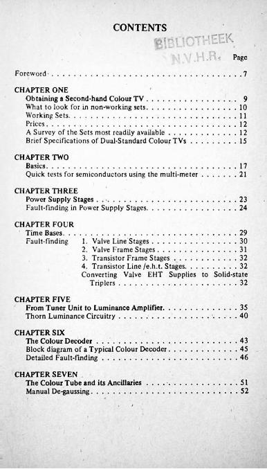
CONTENTS
Page
Foreword 7
CHAPTER ONEObtaining a Second-hand Colour TV...................What to look for in non-working sets...................Working Sets........................................................Prices...................................................................A Survey of the Sets most readily available . . . . Brief Specifications of Dual-Standard Colour TVs
91011121215
CHAPTER TWOBasics..........................................................................Quick tests for semiconductors using the multi-meter
1721
CHAPTER THREEPower Supply Stages . ......................Fault-finding in Power Supply Stages.
2324
CHAPTER FOUR Time Bases. . . Fault-finding
291. Valve Line Stages................2. Valve Frame Stages.............3. Transistor Frame Stages . . .4. Transistor Line /e.h.t. Stages,Converting Valve EHT Supplies to Solid-state
Triplers
30313232
32
CHAPTER FIVEFrom Tuner Unit to Luminance Amplifier. Thorn Luminance Circuitry.....................
3540
CHAPTER SIXThe Colour Decoder................................Block diagram of a Typical Colour Decoder Detailed Fault-finding..............................
434546
CHAPTER SEVENThe Colour Tube and its Ancillaries Manual De-gaussing........................
5152
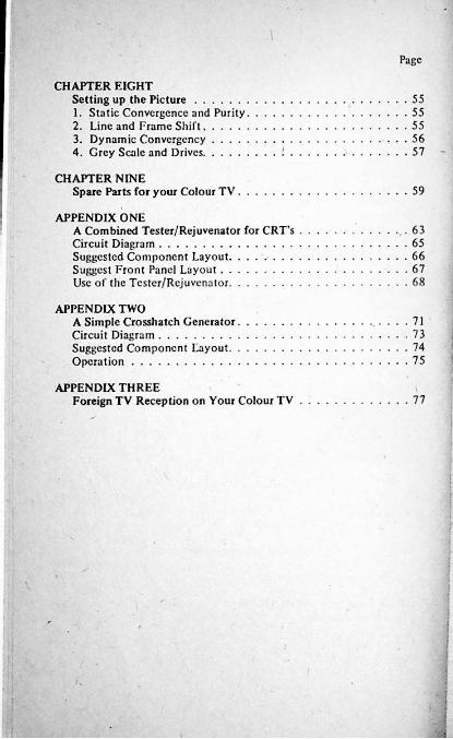
Page
CHAPTER EIGHTSetting up the Picture.............1. Static Convergence and Purity2. Line and Frame Shift...........3. Dynamic Convergcncy ....4. Grey Scale and Drives...........
5555555657
CHAPTER NINESparc Parts for your Colour TV 59
APPENDIX ONEA Combined Tester/Rejuvenator for CRT'sCircuit Diagram........................................Suggested Component Layout...................Suggest Front Panel Layout.....................Use of the Tester/Rejuvenator...................
6365666768
APPENDIX TWOA Simple Crosshatch GeneratorCircuit Diagram......................Suggested Component Layout. Operation..............................
71737475
APPENDIX THREEForeign TV Reception on Your Colour TV 77
;:!
FOREWORD
There is little doubt that many enthusiasts would love to be able to build their own colour television receivers, and to experience the thrill and satisfaction that this enterprise would bring. Unfortunately, if we arc honest, it has to be admitted that it is just not a practical proposition. The few designs w'hich have appeared in the last few years have relied to a large extent upon commercially produced circuit boards, which must be fitted with components and soldered at home. This is of necessity an expensive and time-consuming job, with the ever present risk of making a mistake which could take an awful long time to be discovered. It is immeasurably more difficult to find a fault on a previously untried piece of equipment than it is with the commercial equivalent which must have been working when it left the factory! It is not surprising, therefore, that there has no boom in home- constructed colour sets, as there was with black-and-white back in the 50s. At that time many different component firms offered kits of parts to constructors; the fact that this has not happened in the eight years or so since colour TV was established is significant.
Recently, however, a state of affairs has arisen which is of considerable interest to enthusiasts. The ever rising costs of repairs to the older colour TVs has resulted in large numbers becoming available on the second-hand market. The price of a set in working condition can be anything from £50-£ 150, but non-workers may be obtained for as little as tens of pounds. Very often such sets have been written off by dealers as "B.E.R.” — Beyond Economical Repair. This is fully understandable when one takes into account the cost of a technician’s time alone, without the price of spare parts. A day’s work on a set could easily result in a bill to the customer (who can be the dealer himself if it is a rented-out set) of £30 or more, plus VAT, which at present adds another 12'/i%. But for the enthusiast it is a very different story. He does not have to think that “time is money”. Indeed, he will thoroughly enjoy the hours of spare time he will spend on renovating a potentially useful set.
Tire object of this book is to assist firstly in the choice and acquisition of a second-hand colour TV; and secondly to deal step by step with common faults and their cures in order to get it in good order. If you are inclined to doubt your ability, take heart. Colour TV has been around in the United States for many years. A well-known American service engineer, Jack Darr, wrote long ago that in his experience a very large proportion of colour TV faults were attributable to the same causes as with monochrome sets; namely failed resistors, capacitors, and valves. This statement is still valid today, except that semi-conductors must now be added to the list.
7
!As to equipment, although it would be nice to have transistor testers, oscilloscopes, pattern generators and so on to hand, it is by no means essential. A good multi-meter will serve to trace all but the most obscure faults. The transmitted testcard will enable convergence to be adjusted to an acceptable standard. Provided that you can adopt a logical approach to problems you should be quite capable of solving them. And once you have gained a little experience, confidence will follow.
What this book is not intended to be is a detailed guide to the PAL colour system. This would require a volume in itself. Obviously the basic functions must be understood if renovation is undertaken, and a general outline is given in Chapter Two. Later on in the book the decoder is discussed in more depth, as this part of the set is by far the most complex. Nevertheless, most of the faults you are likely to encounter will yield to systematic use of the test meter.
There is an enormous satisfaction to be had in restoring a colour TV to active life, and to sec pictures appear on the screen.It has certainly not palled for the author, after many years of doing it professionally!
!8
CHAPTER ONEObtaining a Second-hand Colour TV
From (he enthusiast’s point of view, the sets which will be of most interest as regards availability and price are those dual standard models produced between around 1967 and 1970. It will be recalled that colour, and indeed UHF in general, was restricted to BBC2 until the autumn of 1969, thus making it necessary for the early model sets to be also capable of receiving BBC1 and 1TV on 405 lines, VHF. It is this first generation of colour TVs that is now coming onto the market at as low as tens of pounds.
Where do they come from? One suggestion, made in the foreword, is that some sets are “beyond economic repair”, and are consigned to store-rooms. They are likely to be joined by others taken in part- exchange against new sets. It is not really a commercial proposition for dealers to renovate and sell these sets because of the need to guarantee them for a reasonable time in accordance with consumer protection laws. It is far better for sets to be disposed of once and for all, even though the prices have to be lowered drastically. In a lot of cases this means entering them at small local auction sales, and it is always worth having a look around these in search of bargains. (But do take care; whilst preparing this chapter the author examined a modern-looking colour TV offered for sale under the hammer, only to find that the tube had been replaced with a monochrome type!) Any sets not actually described as in working order seldom make much money in auctions. Depending upon the age and condition, a maximum of around £35 is reasonable. Sets which have scruffy cabinets can be had for much less than this. It muy be worth your while enquiring at local dealers to see if they will sell an old set to you directly. You must, of course make it clear that you are prepared to accept it “as seen”, and will not expect any kind of guarantee. Purchasing in this manner will probably cost you more than from an auction, but on the credit side the dealer or one of his engineers will most likely be able to outline what work is needed to get the set into working order.
A high proportion of sets are rented out, and as the rental firms’ profits are directly related to the reliability of their sets, it makes sense for them to sell off the older ones before they start to give trouble. Because of the large quantities involved they normally go to trade disposal concerns who in turn pass them on to the second-hand dealers and sometimes directly to the public. If there is such a firm operating near you it will pay to make enquiries. Very often they too will be only too pleased to find a customer for non-working sets.
9
From time to time you will find second-hand sets offered in the small-ad columns of your local papers. It may be worth y6ur while following these up, with the following reservations. The price should be attractive, even when dealing with sets allegedly in working order, since it would be difficult to get any legal redress if serious faults were later discovered. Try to discover in a discreet manner, the reason for the sale. Genuine people are unlikely to resent your asking. And above all, don’t buy what appears to be a recent model at a bargain price without seeing proof of ownership on the vendor’s part. This request again will only upset those with something to hide; better that than finding yourself in possession of a set which is the property of an H.P. company!
What to look for in non-working sets
In the absence of any reliable information as to age and condition, a systematic scries of checks should be carried out. Quite candidly, the actual age of the set is not likely to be too important, except as a bargaining point when fixing a price. It can often be ascertained merely by having a good look around the inside of the cabinet with a torch, as makers frequently stamp the date of manufacture on the woodwork. Alternatively the larger electrolytic capacitors are usually dated; although there will have been a time lag between their manufacture and subsequent use, it will give a good enough idea for our purpose.
Again, the outward appearance of the set will have a bearing on the price asked, and it is reasonable to expect that a set having an unmarked cabinet will have spent little time being taken in and out of the workshop. Check if all the back screws arc fitted, and if they arc all of the same type. Discrepancies here point to frequent servicing. It’s always a good omen when the ventilation holes in the back are bunged up with dust, and the “works” also liberally coated, indicating no recent need of repairs.
If you are able to test the c.r.t. with an instrument like that to be described later in this book, you will know its conditions swiftly and accurately. When this is not possible, play safe and assume that you may have to fit a replacement when haggling.
The next most expensive item in the set is the line output transformer. This is normally enclosed in a metal shield (in the case of those using valve EHT rectifiers and stabilisers this prevents harmful X- radiation, and must be in place). If the shielding is wholly- or partly- missing, or appears to have been recently disturbed, trouble in the LOPT may have been suspected and/or investigated. Mentally deduct about £10 from the price to cover this eventuality.
10
In the case of sets having separate panels for the various stages, make sure that all are present. This may sound rather obvious, but even an old hand can be fooled when glancing around an unfamiliar set.
Note if any valves arc missing. Even if you arc certain of obtaining cheap replacements, think in terms of the full price for bargaining purposes.
Working Sets
Wo will, of course, assume that the set demonstrated to you does not exhibit perfect sound and picture, which would make further comment superfluous! But it is all too easy to be convinced that a picture is “perfect” when in the grip of enthusiasm. It is far better to check a set on a test card rather than on a moving picture, as any serious faults show up immediately. Severe misconvergcncc will make the vertical lines look like medal ribbons, for instance. The little girl pictured in the centre circle should have a natural complexion; the teddy-bear should be green, and the upper background blue. Incorrect colours suggest that there are faults on the decoder section. An overall bias to one colour may merely be the result ot bad “grey scale” adjustment, or it could be due to the failure of one or more of the guns tn the c.r.t.
The noughts and crosses on the black-board are in the centre of the screen, and will show up incorrect static convergence and poor focus. This latter condition can be due to something more than just a wrong setting of the control. In sets using an EHT tripler this itself could be at fault. Or it could be that the c.r.t. is weak. As in black- and-white sets, turning up the brightness control will cause a weak tube to give a fuzzy picture. In some cases the colours will alter radically, too.
The tube tester will soon confirm or eliminate any doubts about the c.r.t., but boosting should not be attempted until after the set has been purchased, for obvious reasons!
Lack of picture height is not likely to cause serious problems, nor is a slight lack of width. Only when the picture is very narrow, with perhaps some bright vertical lines, need you suspect the line output transformer.
Faults on the sound are seldom very serious, and any shortcomings in this respect need cause no worries.
11
Prices:
The following are roughly appropriate to the classes of set described, when the cabinet is in good condition. Badly marked cabinets should attract £5-10 less.
Non-workers, nothing known, c.r.t. not tested: £20-25. Same, but c.r.t. reasonable: £25-30.Same, but c.r.t. poor: £15-20.Workers, c.r.t. reasonable, but other faults: £35-40.Same, but c.r.t poor: £25-30.
These should be taken as a guide only. Obviously there will be ocassions when prices can be raised or lowered. Don’t be misled into snapping up the first set you see if you have doubts about it. Secondhand colour TV is now a buyer’s market, and you can afford to be a little selective.
A Survey of the Sets most readily Available
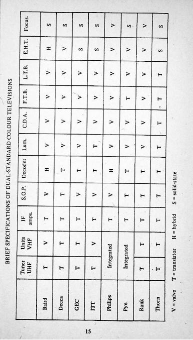
Dual-standard sets were produced under around two dozen brand names, but the number of manufacturers was only eight. This makes it relatively easy to briefly discuss the various types and to evaluate their appeal to the enthusiast. In more general terms, the majority of sets were ’’hybrids”, i.e., they employed a mixture of valves and transistors. This usually meant that the lightly-loaded parts of the set (tuners, IF panels, decoders) employed transistors, with valves doing the hard work, especially in the line time base. This is an arrangement ideally suited to the enthusiast. Low-power transistors arc cheap and freely obtainable, whilst the valves are to be had at economical prices from “surplus” dealers. This is not always so with the high-posver transistors which would otherwise be used; a PL509 line output valve can cost as little as 30p, with the equivalent transistor at around £2-3. The valve, obviously, is much easier to install, whilst it usually gives some visual warning, by glowing red-hot, of trouble in the line output stage. Perhaps this accounts in part for some of the best-known makers sticking to hybrids right up to the present.
The exception was, and is the Thorn Group. Right from the start their sets were fully transistorised. This entailed the use of a very large number of semi-conductors, and considerable complication of design. For this reason, in the body of this book, Thorn chassis arc dealt with separately from the hybrids, in most of the chapters.
The following descriptions arc in alphabetical order of the Groups producing the relevant Brand names.
1. Baird/Radio Rentals. Most sets rented out; now filtering through to the second-hand market Serviceability good. Only snag- on earlier models the use of a rotary, rather than push-button UHF tuner, but this could be modified. Spares situation could be complicated by the Thorn take-over.
12
2. Decca. Also produced for Granada rental concern under that name. One of the best sets for enthusiasts. Most of the works on large horizontal chassis with access from below. The Service Department is most efficient, and unfailingly helpful.
3. GEC/Mastcradio/SobelL Another well-set out chassis, with swing-up facility for tracing faults on underside of print. One snag: they are the only group to use printed panels with "wiring" on both sides. This makes changing components, etc., more difficult than with conventional types. Nevertheless, recommended, as it is generally very reliable.
4. I.T.T. (K.B. & R.G.D.) What a lot of initials! These sets are probably the least likely to be found on the second-hand market, presumably because they are so very good. Forget recent adverse reports in "Which” - these sets are extremely reliable, and well worth buying.
5. Philips Group (Alba*, Philips, Stella) Very large, heavy, and cumbersome sets. Used rather more valves than most. The upright chassis allows only limited access for servicing, and the design is what one expects of Pliilips-technically excellent, but very complicated in practice. Reluctantly not really recommended.
6. Pye Group (Dynatron, Ekco, Ferranti, Invicta, Pyc) A good design, using easily removed sub-chassis. Highly recommended.
7. Rank (Hush, Defiant*, Murphy) The earlier hybrids were far better for servicing than the later “all-solid-state", due to the spacious layout of the former. Sub-panels not quite so easy to detach as some, but still warmly recommended.
8. Thorn (Ferguson, HMV, Marconi, Ultra) The odd man out. Fully transistorised, which gives reasonable reliability at the expense of complication, especially in the power supply unit and line tiinebase/ EHT oscillator. Some of the semi-conductors could be difficult/ expensive to obtain. O.K. apart from these reservations.
* Independent concern using chassis made by this manufacturer.
General
Most of these sets had large, spacious cabinets which allow good access, particularly in the case of 25” models. Tltis also gave them plenty of ventilation space, which is probably one factor in their reliability.A tribute to this is supplied by the longevity of some of the designs; the Pye group chassis in single standard form, and with slight modifications, has been produced for many years, as an instance.
13
!
By looking around you should be able to acquire a pretty good example at a maximum of £40. Above this figure you might as well buy a good worker and miss all the fun of renovation!
:
■■
P.S. Just as this book was nearing completion, a 25” Decca colour set, in a magnificent console cabinet, was sold at the author’s local auction for just £7.50!
14I
<A38 Vi >Vi Vi >Vi Vi Viu.
X X > > >Vi >Vi Viui
CO> > > > > > > H-iVi
Z2 si£ H > > > > > f- >> HW-J
f- <ec d > > > > > > > HUo-Jou
Ec > > > H >J3 > >cc H<QZ 5< ■gH X H H H X Hv? u H H 2-J a 3< v)
QSU. 2 > H > > > H H E*O llVi
V) ViZOH ak. f— H< H H H H H H- E .o2
j=
u iiXu .«■<*!
c X 3 >
o_ > H H > H HVi ■8 ■8u. oSw&8*C5 2 Cu u.
§ X £ 3eo
£ 2H H H H H • HH
>Q. 73§
wcT3 ■S
ca>a±3 oo> llm £ £ £a o >
15

1I
CHAPTER TWOBasics
Before one even attempts to repair a colour TV, there are certain safety precautions which must be committed to memory so thoroughly that they become second nature. Only thus can one be sure of avoiding painful, and possibly dangerous, shocks.
Since this book is intended for enthusiasts who have "cut their teeth" on monochrome sets, it will be presumed that the reader will already be familiar with the live-chassis technique favoured by UK manufacturers. Although all colour TVs are for AC supplies only, the AC/DC type of HT supply lives on, for reasons of economy. Therefore the neutral main must be connected to the chassis of the set, normally via the black or blue conductor in the mains lead. But don’t trust to luck here. Someone may have reversed the connections at the switch, or elsewhere, during maintenance work. The humble neon screwdriver will establish whether or not the chassis is live immediately, but since it is not a fail-safe device, always touch it on a known to be live part of the set (e.g., the mains fuse) to prove that it is indeed in working order.
Even with the chassis proven to be "dead” one cannot relax one's guard. All the HT points in the set will be live both to chassis and to earth- i.e., that bit of our planet that you happen to be standing upon at the time! This is why it is so much safer to work on a wooden floor, or if this is impossible, upon a wooden frame, such as a strong old door, placed on the stone or concrete.
Never work with both hands at a time, but keep one firmly in a pocket. This obviates the possibility of getting a shock from one arm to another, via the heart, which is the most dangerous kind.
Treat the EHT supply with respect. 25kV is not to be trifled with. An arc from this onto the person would almost certainly result in some nasty electrical burns, if not worse. Bear in mind, too, that the focus voltage on colour tubes is in the order of 4-5kV. The focus pin on the c.r.t. base is recognised — and avoided - by its vee-shaped insulating surround.
When the final anode connector has to be removed from a tube, always discharge the residual voltage to chassis with an insulated tool. Tins must be done repeatedly, as the charge builds itself up over and over again.
Reference was made in the previous chapter to valve EHT rectifiers and/or stabilisers, and to the danger of X-radiation. The makers screening around the EHT stage gives full protection, and for this reason a set must not be operated with it removed. Some firms
17
(e.g. Philips) fitted interlock switches to positively prevent operation when the line can was dismantled. This does make life hard when searching for line time base faults, and for this reason alone sets with solid-state rectifiers are to be preferred. In a later chapter the possibility of changing from valves to solid-state will be discussed.
For fault-finding on colour sets the only absolutely essential piece of lest gear is the multi-meter. It's by no means necessary to
\ invest in transistor testers and oscilloscopes. You will already, it is presumed, have the normal range of small tools and a soldering iron or gun. The latter is excellent for heavy work (e.g., soldering direct to the chassis), but may be a little too powerful lor printed panels, so it’s a good plan to get hold of a fine-tipped 15 watt type as well. You will also find that an “Anglepoise” lamp is invaluable.
An item which is vitally necessary, but which may be overlooked, is a good aerial. All too often the enthusiast, relegated to a spare room or shed, relies upon a makeshift indoor type. This may have given some kind of picture on a black-and-white TV, but it just won’t do for colour! You must equip yourself with either a second outdoor aerial, or alternatively use a small distribution amplifier with the aerial used for the main domestic set. The Labgear 6034/DA, for instance, will drive up to four sets from a single aerial. Loft or set-top aerials are unlikely to be much use unless you live in an exceptionally good reception area. The knowledge that you have a decent signal going into the set removes one doubt when fault-finding.
fYour first glance into the works of a colour TV can be very
daunting. There seems to be about three times as much in it than in a mono set, with a bewildering network of interconnecting leads between panels. It helps to remember that once upon a time even the mono set appeared complicated, too! On closer examination you will find that whatever the make, the set is made up of a number of sub-assemblies. The usual arrangement is as follows:
1. Tuner unit. 2. Vision and sound IF strip and Luminance amplifier. 3. Decoder. 4. Colour difference amplifiers. 5. Timebases and EHT unit. 6. Power Supply. 7. Convergence unit. 8. C.R.T. and its ancillartes.
It is beyond the scope of this book to give a detailed technical description of the PAL colour system. However, as it is essential that the broad principles are understood to enable fault-finding to take place, there follows a very brief guide.
A colour television picture is built up from three primary colours - red, green and blue. The picture tube has three “gun” assemblies, one for each colour, and on the inside of the viewing screen are groups of phosphor dots, again in threes. To ensure that
18
the red gun, for instance, illuminates only the red dots, and so on, just behind the dots is a device called the shadow-mask. This has over 400,000 holes, through which the stream of electrons from each gun has to pass; by careful design and subsequent adjustment of certain controls the registration of the colours can be made almost perfect. But how do we get these three colours from the transmitted signal?
The tuner unit and llr amplifier stages of the colour TV are very similar to those in a mono set, especially as regards the sound. But instead of there being a "video” output as in the black-and-white set, we have a luminance amplifier at the end. This works in much the same way as a video amplifier by varying the brightness of the image on the three screens.
Contained within the luminance signal is the chrominance, or colour information, transmitted in the supressed sideband mode. Readers who arc keen short-wave fans will know how a local oscillator (BFO) has to be used in a radio receiver to decode the otherwise meaningless singlc-side-band transmissions. A similar system operates in a colour TV, but here the local oscillator has a very precise frequency - 4.43361875 mHz to be exact - so a crystal control is used. Liven this is not sufficient to maintain accuracy, so it is locked to the incoming signal by what is called the burst gate. Extracting the burst of colour information which follows the line sync pulses, it operates as does the familiar flywheel sync in a mono TV. The burst gate has to have a switching pulse applied to it, normally derived from a winding on the line output transformer.
We must now return to the chroma signal, which is amplified by usually two transistor stages. The input to the second stage is controlled by the saturation or “colour" control. The chroma signal passes on to a delay line, in which it is separated into two distinct channels, U and V. These two each have their own synchronous detector, but they operate in different ways. To understand this we have to consider the reference oscillator once more. Its output is taken virtually directly to the D detector, but it has to be continuously phase-reversed before being coupled to the V stage. It is this phase reversal which distinguishes the PAL (Phase Alternate Line) system from the original American N.T.S.C., and which gives it its immunity from changes of hue. The phase reversal is accomplished by a pair of diodes driven by a form of multi-vibrator known as a bi-stable.This in turn is controlled by a 7.8 kHz signal (half line frequency) again derived from the line output transformer.
The U and V detectors produce, respectively, the blue and red colour difference signals, which are passed on to the colour difference amplifiers. The green signal is derived from the other two signals, cither before or after amplification. The luminance information may be injected into either the amplifiers or directly into the picture tube.
19
, Another feature of all colour sets is the “colour killer". This detects the presence or otherwise of colour information; when it is absent the killer disables the chroma amplifiers, thus preventing spurious colours appearing on monochrome transmissions.
The sync seperator and time bases of the colour set arc similar in most respects to those used for mono, but the higher powers required to scan the colour tube necessitates larger output transformers. Various waveforms derived from the line and frame time bases are used to,provide control of convergence, i.c., to ensure that registration of the three colours on the tube face are indeed perfect, as was mentioned earlier. This process will be described in more detail later in the book.
Power supplies are provided, in most hybrid sets, by conventional use of silicon rectifiers and rcsistance/capacity or inductancc/capacity smoothing, for both high and low voltage. It is this relative simplicity which makes them more attractive to the amateur than the highly stabilised - and complicated - units employed in all-transistor sets.
The above is a highly simplified description of colour TV workings, particularly as regards the decoder stage. As we deal with this, and the rest of the stages in the step-by-step fault finding guide, a more detailed examination of the circuitry will be given. Chapters three, four, and five will deal with power supplies; Line and frame time bases; and tuncr/I.F./luminancc panels respectively. Their object will be to restore picture and sound to a previously “dead" set, even if this results only in a monochrome picture for the time being. Chapter six will deal with tracing loss of colour, and subsequent chapters will cover adjustments such as purity and convergence, and obtaining spare parts. Hopefully, this will eventually lead to your having very acceptable colour pictures which arc (nearly) "all your own work"!
Service Sheets. These are, of course, essential for fault-finding and setting up the convergence, etc. Manufacturers’ own publications arc usually restricted to the trade, but various specialist firms offer their own manuals for around 50p each. The names of these firms are to be found in the advertisement columns of relevant magazines.
Spare Parts. The various sources of supply are dealt with in detail later on in this book.
20
Poa. leod
Pos. lead Neg. lead
Meg. lead Pos. lead
Low Xi
High ii
Neg. lead
Meg. lead
High
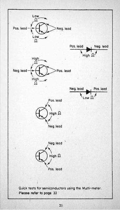
Quick tests for semiconductors using the Multi-meter. Please refer to page 22
21
Using the Quick Check Chart for Semiconductors
Diodes und transistors may be tested very simply by measuring the internal resistances with a test-inetcr. The principle is that between certain connections there should be a high resistance when the meter leads are applied in one way, and a low resistance in another. Additionally, transistors should also exhibit a high resistance between collector and emitter, irrespective of the meter connections. The chart shows the tests for diodes and N-P-N transistors, l-'or P-N-P types the meter leads are applied in the opposite polarity, c.g., positive to collector, negative to base.
An extension of these tests is to determine the polarity of unmarked diodes and transistors.
Important Note. Hie tests hold good for meters in which the positive of the internal battery is connected to the positive test lead. This is not always so, and this should be determined either by tracing through or the use of another meter on a low d.c. range. When the polarity is found to be reversed it is a good plan to stick a label onto the meter saying something like “Reverse meter leads tor transistor checks”, in order to remind yourself.
No actual resistance values are quoted, as these are dependent to a large extent on the device under test and the meter in use. Always switch to the lowest range, as typical values lie within the 5-200 ohm range. Dead shorts instead of low resistances will show up readily if the meter has a low range of say 0-1000 ohms.
If;
*22
CHAPTER THREE
Power Supply Stages
li is a curious fact that the radio industry of this country seems to unlearn a lot of experience each time it creates a new product for the domestic market. In the early days of mains radios the h.t. voltage was dropped by power resistors to several various levels, each being decoupled by its own smoothing capacitor. Al ter many years it became clear that these elaborate arrangements were unnecessary, and the number of capacitors reduced to perhaps one double or treble unit. But as soon as television receivers appeared, the industry went straight back to the complex smoothing circuits again. In due course television h.t. supplies were simplified, until colour TV came on the scene, when once again history was repealednumerous h.t lines - for instance the Philips G6 had no fewer than 9 positive rails, plus one - 24v supply! Fortunately not all sets were quite as well-endowed, but in any event even the G6 could not be as complex as the Thorn 2000 and later 3000 chassis, which had very elaborate stabilising circuits needed for transistor line output stages.
Which explains why some of the early sets had
The typical power stage for a hybrid set has a small mains transformer which supplies 6.3 volts for the tube heater, and 20-30v for the low voltage line. The latter may have either full-wave or bridge rectification, with quite large values ol smoothing capacitors, commonly up to 4000uf. The associated smoothing resistors are not likely to exceed 100 ohms.
The high voltage line is usually derived from the mains via a low value (5-10 ohms) limiting resistor and silicon rectifier, such as the BY127. Certain makers, such as Philips, again in their G6, preferred to split the load between two rectifiers, each with its own limiting resistor. In the case of the G6, the latter resistors were associated with thermal fuses, which opened up if excess current caused them to overheat.GEC, on the other hand, fitted a thermistor in series with the fixed limiting resistor, to prevent a large surge of voltage when the set was switched on from cold. There was no HT fuse as such; the entire set was protected by just one 3 amp. fuse in the mains supply lead to the on/off switch. In later models, however, an overload cut-out was fitted in the line output stage to protect the transformer and valves. The outward sign of its presence is a small red button protruding through a hole in the chassis at its extreme bottom right, looking at the rear view. Obviously it is a good plan to try to determine what was the cause of its operating before re-setting.
The valve heaters are invariably series-run, often, but not always, with a silicon rectifier as part of the voltage-dropping circuit. Sets with tapped primary mains transformers (e.g., Baird, Decca) generally take
23
the heater supply from the 200v tapping, to reduce the amount of power wasted in the dropper. The use of thermistors to prevent switching-on surges is again not universal, even though it would appear to be a desirable feature.
Another item associated with the power unit is the degaussing coils which are fitted around the c.r.t. They are fed with a.c. from the mains via a positivc-co-efficient thermistor - i.e., one whose resistance increases when hot. In practice this takes place very quickly indeed, so that current flows through the coils for just a few seconds when the set is switched on, either from cold, or after a rest of about five minutes or more. The B.R.C.2000 chassis also automatically degaussed when changing from 405 to 625 lines, and vice versa, provided that this was not done at intervals of less than 3-5 minutes.
Fault-finding in Power Supply Stages
The first step must be to check the following:1. Is the set completely dead, i.e. no valve or tube heaters alight,
no sound. (In the case of sets with transistor audio stages)2. Tube heaters alight, but no valves. Otherwise as above.3. Valves and tube lit, no sound or picture.4. Sound absent, or picture absent.Or, of course, a combination of some of the above.
If you have managed to obtain a service sheet for your set you will be able to see at once if the sound is produced by a valve or transistors. Otherwise refer to the table on page 15. Transistorised
• sound is very handy here, as it provides an audible check on whether or not the low-voltage line is functioning. Fairly obviously, the presence of low voltage indicates that the mams are reaching the set, and the transformer. In this case the tube heaters should be lit, but failure to do so may be due merely to bad contacts on the base, or on the wiring to it. You would be very unlikely to have the bad luck to find the heaters open circuit. Cross-check by reading the a.c. voltage across pins 1 and 14 of the tube base. If only the tube heaters are unlit, the rest of the set should be starting to work, so beware of high voltages on the focus pin!
Utter silence and lack of heaters is quite possibly due to a blown mains fuse, but have a good look at a faulty one before throwing it in the bin. A small break in the wire, with no discolouration of the glass, is often the result of a gradual overload, such as would be caused by the line output stage drawing heavy current under fault conditions. Should the inside of the fuse be completely blackened, however, it points to a sudden and catastrophic overload. Common causes are the failure of the mains suppression capacitor, or the h.t. rectifier. Always check the resistance from the fuseholder to chassis before fitting another fuse. The minimum resistance recorded should be that of the mains
24
transformer primary, and/or degaussing coils. Even though these will read very low, they will be distinguished from a dead short on (say) the ohms divided by 100 range of an AVO 8, or its equivalent. Be warned that the plastic-sealed capacitors commonly used from mains to chassis frequently heal themselves after a flash-over, and may read quite o.k. on a meter. This can happen several times before the final self- destruction. The only real test to be made domestically is to connect a suspected capacitor across the mains in series with a lOOw light bulb, and to wait for the latter to light up!
There is always a temptation to merely snip out a failed capacitor, and not to replace it; this is not really recommended, as any curious spiky pulses which may appear on the mains will be free to enter the set and upset the rectifiers.
Testing from fuse to earth may not reveal an h.t. short, so test directly across the rectifier. It should have a low resistance one way, and quite high the other. Exactly similar readings point to failure here. Reading from the h.t. line to earth in the usual manner, i.e., with the negative meter lead clipped on the chassis, is also misleading; a short will probably be registered due to a path through the rectifier and mains transformer. Reversing the meter leads should give the familiar needle- hard-over, backing-off-slowly effect. Again, similar readings indicate trouble. Experience suggests that the main smoothing capacitors seldom go dead short, and that this type of fault is mostly due to a smaller- value component further down the line. This has to be traced by methodically disconnecting leads to the h.t. supply until the short disappears, or in some cases reading across various points from h.t. to earth with the meter to determine the place at which the resistance is lowest. In practice this often boils down to high-voltage capacitors in the line circuit, in particular those of around 150-200 pF which are frequently to be found connected between the cathode of the boost diode and earth. The second favourite is the plastic-sealed type of capacitor of 0.1-0.47 uF, also to be found in and around the line stage.
Tracing h.t. shorts is aided in sets with an h.t. fuse, as this can be removed to isolate part of the circuitry.
A fault which is fairly common is the failure of the thermistor supplying a.c. to the rectifier. The disc types come adrift where the connecting wires are fastened, causing sparks to fly when the set is switched on. The rod variety tend to split near one end, occasionally arcing across, but more often springing far enough apart to completely deaden the set.
The fixed value surge-limiting resistors used in other sets are also vulnerable; when replacing a faulty one make sure that you use one of sufficient wattage, as even with the low values commonly employed the amount of power dissipated is quite large.
25
Turning to the low-tension supply, the transformer itself is not likely to give trouble. The rectifier(s) arc probably the chief candidates for inspection here; the ohmeter will soon tell you if a short has taken place, or if part of a bridge has gone open circuit. Decca, by the way, used a separate rectifier for the 26 volt supply to the audio stage, in later versions of their dual-standard sets. This component, a BY234, seems to have a fairly large failure rate. It generally goes dead short, announcing this by causing a powerful hum in the loud-speaker. If you don’t happen to have a low-voltage rectifier handy to replace the BY234, a BY 100 will work well enough.
It will be appreciated that the smoothing of the l.t. line is vitally important, but again over the years the capacitors employed have proved to be remarkably reliable, even when subjected to a.c. following a rectifier failure. Incidentally, the supply is frequently arranged to be both positive and negative as regards earth, with the latter the mid point. This entails having two lots of smoothing, with some of the capacitors’ positive terminals connected to earth. You need to bear this in mind if you do have to replace one, and be sure either to use an insulated type, or alternatively wrap a layer ol tape around a plain metal can.
The heater chain starts in the power stage with its droppers and/ or thermistors. The former seldom give trouble, as they are not so highly stressed as in mono. sets. (They have fewer volts to drop and consequently dissipate less power), but the latter arc subject to the same kind of failure experienced in the h.t. supply. Strictly speaking, most heater faults do not lie in the power pack at all, but it is more convenient to deal with them here. High on the list is valve failure, cither by open circuiting, or by shorting from heater to cathode. An undetected h/k short lasting more than a few minutes can lead to trouble in other valves, as they arc forced to take more than their fair share of heater volts. Always check to sec if all the valves are lit if some seem extremely bright. It's common practice to insert small decoupling capacitors at various parts of the heater chain, and these too can fail, giving the same effect as a hcater/cathode short.
Other causes of over-bright healers are (a) a short on the heater rectifier, where used, and (b) a wrong value of dropping resistor having been fitted. It’s definitely a good idea to check replacements, as some engineers are not always too fussy in this respect.
Degaussing coils just don’t fail! They arc robustly constructed and, after all, arc actively employed for only minutes in.a year. It is possible to have them out of action for quite a long time without noticing any ill-effect on the screen, until and unless someone inadvertantly brings a magnet into close contact with it! Should the odd- coloured patches produced not disappear next time the set is switched on from cold, the most likely explanation is an open-circuit thermistor. These closely resemble the familiar ones in the heater and h.t. line, but possess, of course, a positive temperature co-efficient. The replacement must be of the same type, or the de-gaussing coils will go out in a blaze of giorv!
26
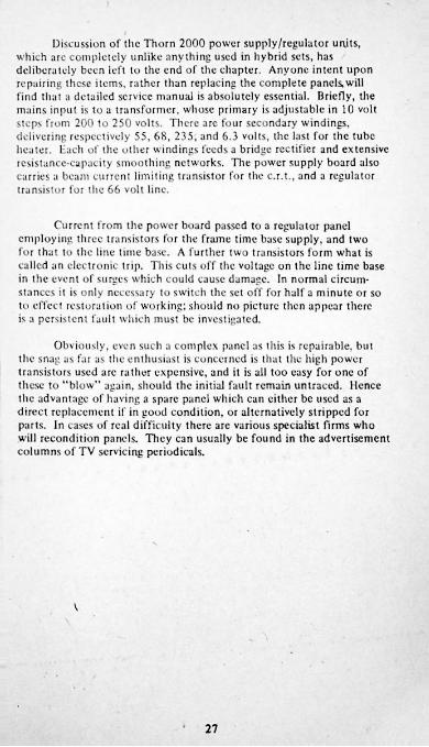
Discussion of the Thorn 2000 power supply/rcgulator units, which arc completely unlike anything used in hybrid sets, has deliberately been left to the end of the chapter. Anyone intent upon repairing these items, rather than replacing the complete panels, will find that a detailed service manual is absolutely essential. Briefly, the mains input is to a transformer, whose primary is adjustable in 10 volt steps from 200 to 250 volts. There are four secondary windings, delivering respectively 55, 68, 235, and 6.3 volts, the last for the tube heater. Hach of the other windings feeds a bridge rectifier and extensive resistance-capacity smoothing networks. The power supply board also carries a beam current limiting transistor for the c.r.t., and a regulator transistor lot the 66 volt line.
Current from the power board passed to a regulator panel employing three transistors for the frame time base supply, and two for that to the line time base. A further two transistors form what is called an electronic trip. This cuts off the voltage on the line time base in the event of surges which could cause damage. In normal circumstances it is only necessary to switch the set off for half a minute or so to effect restoration of working: should no picture then appear there is a persistent fault which must be investigated.
Obviously, even such a complex panel as this is repairable, but the snag as far as the enthusiast is concerned is that the high power transistors used arc rather expensive, and it is all too easy for one of these to "blow" again, should the initial fault remain untraced. Hence the advantage of having a spare panel which can either be used as a direct replacement if in good condition, or alternatively stripped for parts. In cases of real difficulty there are various specialist firms who will recondition panels. They can usually be found in the advertisement columns of TV servicing periodicals.
V
27

\ •
V t
!• •
/
Pi 5-
/
\: '1 '
28
CHAPTER FOURTime Bases
It was remarked earlier in this book that the time bases of a colour TV differ but little from those of mono. sets. In the case of the frame time base the main difference is that most manufacturers abandoned the single valve oscillator/output arrangement in favour of a separate oscillator driving a PL508 output pentode. This has a power rating more suitable for the work of scanning a colour tube. The oscillator is nearly always an ECC82, the exceptions bcine Baird(i’CF80) and Philips (ECC81).
Pyc group sets use a transistorised oscillator and output stage.It is a small panel which has the twin virtues of simplicity and reliability. The circuitry is very similar to that of the Thorn 2000, but in this latter case the frame time base shares a panel with the audio amplifier and output transistors.
Line time bases have three valves common to all hybrids, namely, PCI 802 oscillator, PL509 output, PY500 boost diode. Sets employing valve LHT rectifiers and/or stabilers employ the CY501 and PD500.The focus potential of around 5kV can be obtained by various means.It may be bled from the main e.h.t. by a network of high-value resistors, or rectified separately, either by a silicon type, or a valve. Bush used a DY87 for the job, while Philips went so far as to resurrect the EY51, veteran of mono. TV since the early post-war days! Sets with solid- state triplcrs invariably have a tapping on this unit to give the focus voltage. :
Another feature of the pioneer black-and-white sets had to be reintroduced after a long period of disuse. This is the electronic shift control system for picture centreing. The magnetic shift controls used on the neck of mono, tubes cannot be used for colour, as it would interfere with the purity magnets to be found in this position, so it was back to the old method! This entails having a small amount of d.c. passing through the scan coils, controlled by a low-value variable resistor, commonly 50-100 ohms. A means is normally provided of reversing the polarity of the current in case the picture should be too far over one way even at maximum on the control.
In addition to actually scanning the c.r.t. the time bases provide the combinations of waveforms necessary to “converge" the three guns. As it is a unit in its own right, the convergence panel will be dealt with in a later chapter.
29 J
Fault-finding, 1. Valve Line Stages
The first thing to be tried when the line output fails is, of course, the valves. When the PY500 is seen to be glowing red hot on its anode it could be due to an internal short, or more likely to the breaking-down of a capacitor. (Sec under power supplies for details.) These valves arc also prone to suddenly giving up all emission, resulting in zero volts on the PL509 anode. If this latter is overheating one naturally hopes that it is due to lack of drive from the oscillator, but there is always the fear that the line output transformer could have gone. The preliminary check is to see if there is a good negative voltage on the control grid, absence of which would certainly point to the oscillator stage. Again, replacement of the PCF802 valve is the favourite.
Having pinned the fault down to either oscillator or output, you can now start detailed checks. Assuming that drive is present at the grid of'the PL509, try the old trick of running the set with the PY500 top cap removed. This will restore partial operation where the boost capacitor has gone dead short, or will alternatively prevent the PL509 from overheating by removing its anode voltage, a useful consideration when testing is likely to take a fair time. The snag here is that lack of anode voltage causes the screen grid to be greedy, and to run its supply resistor hot, so keep an eye on it. It must be mentioned here that this component can stop the line output stage dead should it go open circuit. Also examine all the ancillary components mounted on and around the line transformer, especially those subjected to high peak voltages. Remove the lead from the transformer to the voltage triplet, as this component has been known to develop internal shorts. Replace the top cap on the PY500 and check with a neon tester on the PL509 anode for flyback volts. If there is still no life, it’s just possible that there could be a fault on the scan coils or the convergence network. These are normally connected by plugs and sockets, so it is reasonably easy to exonerate them or otherwise. If all else fails to provide the answer then, reluctantly, the transformer must be blamed. Over tire years service engineers have always had to face up to this problem of replacing what is the most expensive item in a set after the tube, since this is thejOne certain way of proving that die original one is faulty.As replacements tend to be quite costly - around £ 10 - this is another instance in which having a spare set handy is invaluable.
Whilst on the subject, it must be noted that line transformers can cause other problems even when they are operating correctly as far as scanning the tube is concerned. The numbers of subsidiary windings producing pulses for the decoder, etc., can go open circuit, giving the effect of no colour, or perhaps incorrect colours. This is a very annoying state of affairs, since the “expensive” part of the transformer is quite o.k. and it could be well worth the enthusiast’s time to attempt rewinding bad sections.
30
Replacement transformers are obtainable from the manufacturers service departments only through authorised dealers. There arc, however, specialist firms who wind their own spares, and supply them to the public via the advertisements in TV journals. Before purchasing from such firms it is strongly recommended that you ascertain that theirs is an exact replacement. Some need to have parts from the old transformer transferred over, and this can be a tedious and lengthy proceeding. It may also be found that the fixing lugs, etc., do not match up properly, and that it is impossible to remount the tripicr, for instance. A genuine spare is then worth the small extra cost!
Returning to the oscillator stage, it's probably fair to say that about 90% of failures are due to valve trouble. The remainder will be resistor and capacitor faults, with shorted turns on the oscillator transformer as the outside chance. Voltage checks on the valve should soon enable you to trace component failures.
From time to time you may encounter loss of sync., with the picture either running in lines, or "floating" across the screen. The discriminator diodes are the likely cause of this, and as colour TVs are bristling with diodes, do make sure you have the right ones before replacing! In many cases there will be one of the small dual units which have been a familiar sight in mono, sets for a number of years. These may be replaced by a couple of good silicon diodes, such as the I N914.
2. Valve Frame Stages
When initially testing a set, and confronted by a single line across the screen you should not automatically start fault-finding on the frame time base. Some sets were fitted with a switch which collapses the frame for grey-scale adjustments; it’s possible that this may inadvertently have been operated. Moving on from this, the PL508 is your next item on the check list. When a replacement restores frame scan, cast your eyes around the panel in its vicinity in case any component appears to have sutTered when the original valve failed. The bias resistor in particular should be measured to ensure that it retains its correct value.
A fault on the oscillator stage may result in either complete loss of scan, or reduced height, or a false lock (wrong speed). All three arc often attributable to resistors which have changed their value. Ones to look out for are high-resistance types feeding h.t. from the boost line to the driver part of the oscillator, and those in scries with the hold control. The multi-vibrator is employed in most sets, with the exception of Baird; the anode of the first section is fed by a resistor of 22k-100k ohms, another component worth testing. When fitting a replacement here it will pay to use a rather higher wattage type than the original.
When loss of frame sync, is experienced, suspect the inverter or limiter which is usually interposed between the sync, seperator and the oscillator. It may be either a diode or triodc, in the latter case one section of a valve such as a PCF80 or ECC82.
31
3. Transistor Frame Stages
Both examples of this, Pye and Thorn, employ a blocking oscillator/driver/output sequence, the last being a pair of BD124s. The general design is extremely straightforward and unlikely to give much trouble. The output transistors do sometimes burn out, possibly the victims of the “domino” effect common to many transistor oscillator/ amplifier arrangements. (When the first in the chain fails, the others follow). You will probably end up changing all four transistors. Electrolytic capacitors can be the cause of loss of height or linearity when aging reduces their values. Check by connecting a good one in parallel. The 250 uf which couples the output pair to the scan coils is always worth trying if the raster is badly cramped.
4. Transistor Line/e.h.t. Stages
By which, of course, we refer to tile Thorn group products. The line time base has a reactance stage (BC107) controlling a blocking oscillator employing the same type of transistor. A 2S035 driver is transformer coupled to the output pair, twin R 1039s. The e.h.t. is not derived from the line output stage, but from another unit having no fewer than 7 transistors, culminating in a single R1038 for output. The tripler delivers 24kV and 4-5kV for the tube anode and focus electrode respectively. Here are two more examples of rather complex design, for which spare transistors and transformers would be costly. Once again the best plan is to substitute complete panels when trouble arises.
Converting Valve EHT Supplies to Solid-state Triplers
Not only is die circuitry for an EHT tripler simpler than for the valve supply, it is also completely free from the X-radiation hazard which is associated with the latter. It is thus obviously desirable whenever possible to convert to a tripler. Since all tubes operate at the same nominal anode and focus potentials, the selection of a unit is not critical. The ITT-made replacement for the later single-standard GEC sets is a good choice, because of its small physical size.
Your first step will be to remove die overwind on the line output transformer which supplies the GY501 rectifier. This valve, the associated PD500, and their holders, may be removed altogether. To maintain the heater circuit at its correct current, the connecting leads to pins 4 and 5 of the PDS00 should be taken to a 25 ohm 3 watt resistor, mounted on a conveniendy sited tag strip.
The original focus supply will have to go, as well. This may be a small high voltage silicon rectifier or a standard EHT valve, e.g., DY86. In the latter case, the holder again is taken out. The new supply comes from a tapping on the tripler.
32
The tripler should be mounted in such a way that none of its leads is unduly close to windings on the transformer, save where connection has to be made. To let the 25kV output lead rest on the tranny is to ask for trouble, namely, a lutz and a flash, followed by the demise of both components.
There are always four leads on triplers. One goes to the anode of the PL509, one to the focus control, one to the tube anode, and the last to earth. In some instances the original focus control system will be unsuitable. If a metrosil type is not available, a substitute can be made up very easily from the contents of the average workshop junk box. All you need is a square of paxolin measuring around 6”, a preset pot. of 1 2 megohms, and about eight 1 watt resistors, value1 - 4.7 megohms. Any combination that gives a total of about 20 megs is o.k. Initially, string all the fixed resistors end to end, from focus supply to earth. Hook the wire from the tube to a joint about a quarter of the total resistance from earth. Switch the set on, and check the focus. You will readily find a tapping which gives reasonable results. Switch off, break the chain at the optimum point, and insert the preset. Take the centre contact to the tube. It should now be possible to vary the voltage sufficiently to get the focus exact.
Having determined the above, make a note of how the resistors were wired, and unsolder them. Lay them on the sheet of paxolin and mark with a pencil positions which will allow them a good clearance from each other. Drill small holes to accept the end wires two at a time. They must be pushed through, twisted together for a couple of turns, and “blobbed" with solder to prevent corona discharge.The preset is mounted in the appropriate place, and connected as before. If you happen to have some EHT sealer spray handy, give the whole a couple of coats. Fasten the completed unit somewhere in the cabinet where it may be adjusted, but not easily touched accidentally.
Most sets have a set EHT control, and if you have means of measuring 25kV, it is as well to check that the anode volts are near to the norm. Sometimes the control has a marked effect upon the width, so the safest thing to do is to settle for a sharp picture/correct width combination. If sufficient width is absolutely unobtainable otherwise, you could experiment with connecting a high voltage “pulse” capacitor of 50 - 150 pf. between the top cap of the PY500 and earth. In extreme cases you could even try from the PL509 anode to earth.In both cases be sure that the capacitor is rated at minimum 12kV.
Having removed the source of X-radiation, you may if necessary remove or modify part of the line output can to accomodate the tripler. Nevertheless, sufficient protection around the transformer itself should be left, to minimise radiation of the line time base, and to prevent contact with high voltage points.
33
CHAPTER FIVEFrom Tuner Unit to Luminance Amplifier
All but one of the sets we have to consider was fitted with a pushbutton UHF tuner unit. The exception was the Baird 700 series. At the time of its production, there was of course only the one station available on UHF, and so the disadvantages of the rotary tuner were probably not immediately obvious. It would be possible to modify the set to take a push-button unit without having to drill the cabinet. In cases like this the new unit may be screwed to the top rear of the cabinet so that just the knobs appear above it. Almost any make of tuner is suitable, the only consideration being whether it was intended for positive HT line, as was the original.
Decca, Bush, Philips, Pve, and Thorn all had 6-button integrated tuners covering VHP and UHF. In most cases these may be adjusted to operate on UHF only. GEC and ITT had four-button UHF tuners, and in the former case mechanical wear can cause erratic operation after years of use. The usual symptoms are failure to tune accurately when switched from one station to another, and drift when left on one particular channel. Geantng the contact springs which earth the variable capacitor in the unit, and subsequent smearing with silicon grease can mitigate this trouble, but in the long term replacement is the only real answer. The GEC tuner unit bears a strong resemblance to that used in the Philips TGI 70 series of black-and-white sets, suggesting a fruitful and inexpensive source of spares.
All types of tuners are at risk during electrical storms, even when actual lightning strikes may occur quite long distances away. The RF amplifier transistor is the usual victim, which can be checked by. connecting the aerial, via a small capacitor, to a point somewhere near the second transistor’s base. The exact spot is not crucial, and you should soon discover a place where the signal is received reasonably well. If the resulting picture is better than that received through the aerial socket, first measure the voltages on the RF transistor before attempting to replace it - just in case another component should have failed. Note that manufacturers sometimes changed the type of tuner unit during production runs, so select a replacement transistor equivalent to the one removed, rather than by relying on the circuit diagram to be correct. (The most likely difference is the use of silicon in place of germanium transistors.) Take extreme care when unsoldering the faulty transistor not to bend the wiring or tuning bars, as this could lead to difficulties in getting all three channels to tune in properly. The same applies, of course, when fitting the new transistor, and in addition it is suggested that the lead wires should be held with a pair of fine-nosed pliers to act as a heat sink during soldering.
35
Much of the above applies also to the oscillator transistor, blit in this case it is not possible to treat by the aerial method, only by metering and/or substitution.
The small disc capacitors widely used in tuner units can split apart, but so slightly as to not be immediately noticed. These are well worth checking when the transistors appear to be blameless.
The three or four trimming capacitors mounted on the side of many units should not be adjusted unless absolutely essential. This would mainly occur when (a) the fitting of a new component has upset the alignment, or (b) it the trimmers have previously been disturbed.As may be imagined, to re-align a tuner unit properly, very accurate signal generators have to be used. However, a very fair attempt may be made, as follows:
Tune to the middle channel of your local group, which in most cases is 1TV. Adjust the trimmer nearest to the oscillator section tor sound and vision to appear together. Peak up the rest of the trimmers, not favouring vision at the expense of sound, or vice-versa. Then tunc to the other channels to see it they too come in correctly. Re-adjust the trimmers very slightly if necessary to achieve balance, finally, the II7 output coil should be gently adjusted, again for a good balance of sound and picture. This is best done whilst watching a test card, to obtain the best bandwidth, as registered by the vertical gratings on either side of the centre circle. Ideally, even the finest should be sharp, but in practice this is not always possible.
Although the IF strip will be of the dual-standard type, for our purpose we can ignore the 405-line components. Indeed, in some cases it may be possible to solder the system switch in its 625 position, thus eliminating any potential trouble due to bad contacts.
The intercarrier sound system, whereby the latter’s IF is tapped off just before or after the vision detector, gives a useful cross-checking facility. If sound is present, but not vision, the fault must lie after the take-off point. Alternatively, when both have disappeared, the fault will lie in the IF strip itself (or the tuner unit, of course).
To check the sound IF amplifiers, normally all that is needed is to put a meter prod on the input. This acts as an aerial and will pick up short-wave station on the 49 metre band, if all is well. If no sound at all results, try the effect of lightly tapping the meter prod, switched to ohms, on the centre tap of the volume control. This should produce loud clicks in the speaker. Having narrowed down the field in this way, you can procede with checking individual stages.
Measure the voltages on suspect transistors. Even if the correct values are not quoted on the service sheet, the conventional arrangement of the base having slightly more voltage than the emitter, and the
36
collector not fax off that of the HT rail, will normally hold good as a basis for tests. Unusual voltage readings should be followed up by the standard base-emitter, base collector resistance checks. BF194 transistors in particular seem prone to failure due to internal shorts. The BF1 I 5, an excellent multi-purpose RF transistor, acts as a replacement here, as in many other applications. In some cases it will be found that the printed board is drilled to take the fourth (earthing) lead of the BF115; otherwise it may be bent up out of the way and left unconnected.
Some engineers seem to have a fair amount of trouble with small capacitors, notably the semi-transparent plastic variety, but this has not been the author’s experience. Nevertheless, these may be suspected in the event of unstability, or radical lack of gain even with new transistors.
The mere replacement of a transistor in the vision or sound IF strip should not have any marked effect upon the alignment, provided that surrounding components are disturbed as little as possible.
Whilst on this subject, a few words of caution concerning realignment. It should not, in fact, be necessary throughout the working life of the set in normal circumstances, due to the inherent stability of transistor IF amplifiers, it follows the mis-alignment should be suspected only when all other causes of poor performance have been discounted, or, as with the tuner, it is obvious that it has been interfered with. A "smeary" picture, for instance can be the result of a component failure around the luminance amplifier, such as the anode and cathode resistors and by-pass capacitors. Grainy pictures are seldom due to faults on the IF stages - the tuner unit is a much more likely suspect. Separation of sound and vision, with both weak, can also be traced to this. Low signal strength can give the same effect.
On the sound side, a background buzz can be due to misalignment, but might well be caused by poor smoothing of the HT or LT supply. Another prime suspect is the 50Hz frame pulses being picked up by a badly routed or unscreened AF lead.
A small balancing pot. is usually included in the sound detector circuit, and it has been known for the centre tap to cease contacting the track. This will cause quite loud buzzing, particularly on certain camera shots.
N.B. This above mentioned effect, known as “caption buzz” is very difficult to eradicate in some sets, even when perfectly aligned. The balancing control should be set for minimum buzz, preferably when there is a caption on the screen, but no sound, as sometimes occurs during a break between programmes or commercials.
37
If after all this, realignment proves to be called for, you should aim to beg, borrow, or otherwise obtain a signal generator and to follow the manufacturers recommended procedure. Unfortunately this latter is not always to be found in service manuals, and some kind of compromise has to be achieved. One constant is the alignment of the sound IFs to 6.0mHz, so this should be your first task. There are commonly five cores to be adjusted - one on the take-off coil near the vision detector, and four on the actual transformers. The signal generator input is to the base of the last transistor prior to the sound take-off.
Two precautions must be taken at this point. Firstly, you must equip yourself with a correctly fitting tool with which to adjust the cores. Failure to do this will almost certainly result in splitting one or more of them, entailing hours of tedious and painstaking work in removing the broken bits. The correct tool for most small cores is a moulded hard plastic handle having non-ferrous blades of two different sizes set into its ends. The blades will pass through the length of the core, greatly reducing the tendency to split. Larger cores often have a hexagonal hole down the centre instead of a screwdriver slot. The proper tool has one end fashioned part hexagonal, part round, so that it may be slipped through the top core of a pair to adjust the lower.
Whichever type you need should be available for a few pence at components dealers.
Secondly, the signal generator must be isolated from the transistors by capacitors of about 0.01 uf, lOOOvw. This is to positively prevent any stray voltages from entering the set and causing damage. Mains operated generators frequently have capacitors connected from both sides of the mains lead to chassis, to by-pass any unwanted RF, and should one of these “leak” enough voltage could pass through it to ruin a transistor. In addition there may in fact be a slight potential difference between the neutral main and earth, so that even with the set connected correctly to the mains, there could again be that nasty little voltage between it and the generator. Better be safe than sorry!
=
Having connected the generator to the TV, set it to give 6.0mHz, modulated, and tune the sound IF transformers for maximum. The final core tunes the ratio detector, and this must subsequently be reset on a signal for minimum distortion and buzz.
Once the sound channel is known to be reasonably on tune, the generator output should be taken to the point where the tuner input enters the set. The tuning should be swung slowly over the range 30-38 mHz, through most of which bars should be seen on the screen. It is unlikely that the alignment would be so far out to prevent some sort of signal passing through. If maker’s instructions are available follow them closely. This often involves the use of damping resistors across certain coils, batteries to simulate the effects of AGC, and so on; it is virtually
10
impossible to give any sort of standard procedure. The best that can be done is to wait until one of the channels is transmitting test card "F”, and to work from that. Since the sound must be on tune now, the tuner can be set to give this. The vision should come into tune automatically, but if it is out, as shown by poor responce of the vertical gratings, the vision cores may be gently altered, keeping a close eye on the screen. Settings should be found where the best bandwidth, consistent with good sound, is available. This means that at least the first live of the six gratings should be sharply defined. Under good conditions the sixth should also be visible.
At this stage the colour information ought to be received satisfactorily, and provided that everything else is in order the colours should spring up in the centre circle. Final slight readjustments must be made to eliminate objectionable patterning on the colours.
Sometimes the bandwidth gratings will exhibit a kind of herring- bone.effcct, but this is not of any consequence and may be ignored.
Sound-on-vision interference is far less likely to occur than with 405-line IF strips, but any slight trouble here may normally be dealt with quite easily. The 6.0mllz sound take off coil frequently doubles as a rejector for the vision detector, and should be set to give the minimum patterning on screen, rather than maximum sound.
It must be emphasised that this “rule of thumb” method of alignment must be regarded as for emergency use only, when all else fails. If satisfactory results just cannot be obtained it will pay you to return the IF panel to the makers, or a specialist repairer, with instructions that it be realigned or replaced, whichever would be more economical.
The detector stage of the vision IF strip is similar to that of a mono. TV, with added filtering to remove the chrominance information, which would otherwise cause a dot pattern to appear on the screen.
There will probably be two luminance pre-amplifiers after the detector, one of which may be an emitter-follower. The contrast control normally operates in this area. Mere too will be found the luminance delay line. This particular component is necessary to compensate for the delay to the chrominance signal inherent in the PAL design. Without a corresponding delay in the luminance information, it would reach the screen slightly in advance of the colour, and cause strange effects. Physically the luminance delay line resembles a ferrite aerial, wound from end to end. They seldom give trouble, but it has been known for there to be a bad soldered joint where the windings are attached to the conductor wires. Its position in circuit varies from make to make, but is generally between the first and final luminance amplifiers.
39
The initial amplification of the luminance signal is carried out by a transistor of the BF115 or similar type. There may be a phase splitter or emitter follower between this and the output stage, which ~ in hybrids is nearly always a I*L802. The circuitry is much the same as that of a monochrome set, but extra precautions are taken to blank out the line and frame flyback lines, usually involving a 1)C108 fed with pulses front the two timebascs.
Gradual changes in the level of brightness can sometimes be traced to the PL802’s emission falling as it heats up. The same is true of the PFL200, the alternative used by Baird and Philips.
A major difference front black-and-white TV lies in the method commonly used to control the picture brightness. In monochrome sets the standard arrangement for many years has been to have the c.r.t. cathode at around 100-150 volts positive by coupling it closely to the video amplifier anode, and to vary the bias on the c.r.t. grid by means of a potentiometer connected into the I IT line. This would not be practicable with the triple gun assembly of a colour tube, so another means has to be found. That generally adopted is to vary the anode current, and thus the voltage, of the luminance output valve by controlling the bias on its grid. Since there arc negative low tension lines in most sets, the brightness control is often a low value pot. with an effective range of only a few volts. This explains why these controls appear to have a limited effect compared with those of a monochrome set. In addition, the DC component is likely to be well dc-coupled to chassis by an electrolytic capacitor, resulting in a curious delayed action in certain sets whereby there is a noticeable time lag between operation of the control and alteration of the picture.
Since the range of the brightness control is so limited, it is common to find a preset added to the circuitry to give extra adjustment. Nevertheless, when the main control fails to give sufficient control it is better to look for a cause, rather than to immediately alter the preset.
Another feature associated with the luminance amplifier is the provision of variation of drive to the three guns. Tills may be achieved by the use of preset contrbls, or by a series of fixed tapping points (GEC). The red gun normally receives full drive, but may in some sets have an optional adjustment, (e.g. Baird). The settings for the drive controls are best found by reference to the relevant service manual, but later in this book a general guide to the procedure will be given.
Thorn Luminance Circuitry
This is actually split between two printed boards. The vision and sound IF amplifiers and detectors being on one, and the luminance amplifier and emitter follower on another, with the three colour difference amplifiers, etc. In addition the sound output stage shares a board with the frame time base. The design is pretty straight-forward,
40
with conventional transistors. The output, for instance, is the ubiquitous BC1 07, and the emitter follower a BF115.
Both panels are extremely reliable, and servicing should present few problems. One point to bear in mind is that due to the large number of plug and socket interconnections the prospect of a bad joint or two is always there. The most likely offenders are the multi-way types of moulded nylon, in the female half of which are numbers of small connector sleeves, semi-flouting. They are intended to press home over the male pins when the plug is inserted, but due to the construction it is possible for the sleeves to push back and to make minimal contact. The answer is to push each one gently but firmly with a fine-bladed screwdriver, until it is well seated. It can be rather surprising on occasion to sec just how far the sleeves can be moved!
Tlie edge connectors also used extensively in Thorn sets do not give much trouble, at least as far as low-voltage applications are involved. Where there is a considerable potential difference between adjacent contacts it is advisable to keep them clean. Dust etc., could conduct and eventually cause a carbon track to develop.
I
41

-
\
\ •42
CHAPTER SIXThe Colour Decoder
The decoder is by far the most complicated section of the colour receiver, as even a cursory inspection will reveal. Nevertheless, a logical approach will enable you to localise and trace most faults without too much trouble.
To understand how a fault can be pinned down to a particular part of the decoder, it is necessary to take a rather more detailed look at its operation than in Chapter Two. Otherwise many of the terms which have to be used will be meaningless. On page 45 appears a block diagram of a typical decoder. Study this in conjunction with the following technical description. It may well appear bewildering at first, with the various signal paths criss-crossing, and sometimes apparently doubling back upon themselves. So initially let us consider just that part of the diagram within the red box.
The first Chroma, amplifier receives the composite video signal, i.e., the colour information and the "burst” which follows each line sync, pulse. The burst is not required to pass through the complete chroma, circuit, and so a blanking pulse from the line transformer is applied to eliminate it. Between the first and second chroma amps, is the saturation or “colour" control, which is in essence just a gain control for the second amp. The signal passes to the delay line via a driver transistor which is likely to be a BC108. The delay line splits the colour information into the "U” and “V" components, which when demodulated will provide, respectively, the blue and red drives to the colour amplifiers. The green will be obtained by subtraction or addition of the other two colours. Demodulation of the colour signals requires the aid of a local oscillator, running at exactly the same frequency as the chroma signal (4.43361875mHz) and in the correct phase. To achieve this sort of accuracy is difficult enough in itself, but this is not the end of the story.
The main feature of the "PAL" system is its resistance to phase changes in the transmitted signal, which in the American NTSC system can give rise to annoying changes of hue. This is especially apparent when long-distance link-ups are involved. For instance, when the “splash-down” of an American space ship was televised live some years ago, the sailors on the mother ship appeared to have green uniforms!In the PAL system the phase of the line is reversed constantly, hence Phase Alternate Line, which provides the initials. Errors can still enter the signal, but due to the rapid phase reversal they are not detected by the viewer’s eye, and present no problem.
Having said earlier that the reference oscillator has to be in the correct phase as the incoming signal, it is now clear that the former has
43
:.iIto have its phase reversed in step with the latter. So now we move on
to the circuitry within the preen box.
The reference oscillator has its frequency controlled by a quartz crystal. The output is taken more or less directly to the U channel, and via a phase switch to the V channel. The phase switch is a pair of diodes which are made to conduct alternatively and oppositely by the application of a square waveform of the appropriate polarity. The square waves are generated by what is termed a bi-stable multivibrator - i.c., one that can be switched from one stable state of oscillation to another. The change of phase takes place during the line fly-back period, which means that the bi-stable can very conveniently be switched by a pulse from the line output transformer. Thus: the LOPT switches the bistable, the bistable switches the phase changer, and the phase chancer switches the phase of the reference oscillator input to the V channel. It is not difficult to imagine that unless all these operations are 100% accurate, the result will be chaos on the screen! Fortunately means are available to lock everything to the incoming signal, and for this we have to return to the burst pulse, which you will remember was excluded from the chroma amplifiers by a blanking pulse, again drawn from the LOPT.
The first item in the black box is the Burst Gate. A pulse in opposite phase to that which blanks the burst from the chroma amps, admits it through the gate to a phase discrimator. Ilerc it is compared with a sample from the reference oscillator. Any discrepancy in frequency or phase produces an error voltage, which can be used to pull the reference oscillator back into tune.
At the same time, the level of burst is directly related to the signal input, so by rectifying it with a small diode a bias voltage can be obtained which will control the chroma, amps, in a similar way to the familiar AGC found in mono. TVs. The full name of Automatic Chrominance Control is usually abbreviated to ACC.
The phase discriminator is meanwhile producing more than a control voltage for the reference oscillator. It also sends out what is now normally referred to as an “ident.” (Identifying) pulse. This is a derivative of the burst, and has the same frequency and phase. When amplified it is applied to the bi-stable via a so-called steering diode, to ensure that the line by line switching is in fact locked to that of the transmitter.
There is yet one more duty for this versatile stage to perform. When a monochrome transmission is being received it is necessary to disable the chroma, amplifiers to prevent their producing spurious colours. (The effects produced are shown graphically when a programme containing both colour and monochrome material is transmitted.Certain aspects of the latter, particularly small areas of fine detail, can fool the chroma circuits into producing patches of blue.)
44
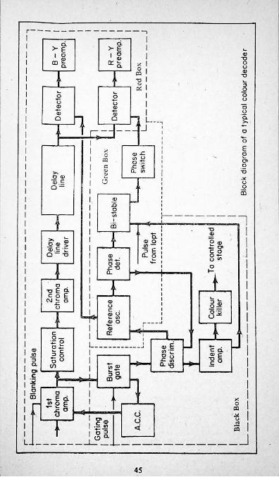
I
1
45
Since the presence or otherwise of the burst is the certain indicator of colour or mono, transmission, the means of switching the chroma, channel on and off as required presents itself. An output from the Ident. amplifier is rectified to give a control voltage by the “colour killer". The normal system is for the controlled stage, which may be the first or second chroma amps, or the delay line driver, to be held in a biassed-off state until the necessary voltage arrives from the killer and switches it on.
It is customary to provide a preset level at which the colour killer starts to operate. A setting-up procedure for this is given later.
Detailed Fault-finding
When you are presented with a monochrome picture, which should be in colour and is not due to something as simple as mis-tuning, your first action must be to over-ride the colour killer. The precise method of doing this is usually to be found in the service manual, but generally consists of introducing bias to the controlled stage by connecting a resistor between it and the transistor HT line. This will produce one of the following three results:
A. Correct colour.B. Incorrect or unsynchronised colour.C. Still no colour at all.
In the case of A, the fault will lie in the killer itself. Now is the time to check if the level control is out of adjustment by turning it to cither end of its travel in turn. Should this produce colour, the correct point may be found as follows:
Turn the manual colour control to maximum. Switch the set to a blank channel and remove the aerial. Look closely at the screen for the presence of colour “noise”. Turn the preset to the setting where the noise just disappears. Don’t go past this position.
If this is not the reason for the killer being permanently on, check all around it with the meter. The coupling to the ident amp. may be amiss, or alternatively the diode(s) in the killer rectifier could be faulty. Sometimes a d.c. amplifier transistor follows the killer to increase the bias voltage.' Check that this is in order, and if so, that the coupling to the controlled stage is also ok. A systematic approach should soon reveal the cause of the trouble.
Result B calls for some deductive work. Absence of burst is the one fault which will simultaneously cause the killer to be operating continuously, and the reference oscillator and bi-stable to be out of synchronism. This condition is of course not visible on the screen until the killer is over-ridden. We must therefore look for trouble in the burst processing network and/or the reference oscillator tuning.
46
The first link in the chain is of course the burst gate. This is typically a pair of diodes turned "on" at the right time by the pulse from the l.o.p.t. Note that it the latter is missing the gate will be inoperative. Something as simple as a displaced plug-and-sockct connection front l.o.p.t. to decoder could be responsible, but it has been known for the pulse windings to go open circuit. Check the latter with the ohm meter if in doubt. Also bear in mind the possibility of the connections on the l.o.p.t. having been made incorrectly, if this * appears to have received the attention of a soldering iron recently.It is all too easy to slip up when replacing the dozen or so wires commonly attached to this component.
Another design uses a gate generator transistor which turns the burst amplifier on and off as required.
Whatever the type, check all semiconductors and small components thoroughly. Remember that unless the gate and amplifier are in order the reference oscillator and the bi-stable cannot work correctly.
If the foregoing check out correctly, move on to the phase discriminator. Here again the diodes are probably the most likely suspects. The control voltage for the reference oscillator originates here, and as with the colour killer there may be a d.e. amplifier to be investigated. Control of the oscillator is by a varactor diode, which do appear to be very reliable in service. A preset adjustment for frequency may be effected by manually varying the varactor voltage, or by a conventional small trimmer capacitor. Consult the manual before altering either type.
Faults on the oscillator stage will produce some differing effects, but at the moment we are concerned only with its not being synchronised. This will result in “rainbows” - colours swirling around, possibly in thick horizontal bars. It will not cause people to have green faces, nor the alternate bright and dark pairs of lines known as Hanover Blinds. These are due to (he PAL switch operating, respectively, in the wrong phase or not at alL From this you should be able to narrow down the search a little more.
More thought shows that the green face syndrome reveals that the bi-stable must be running, even if the phasing is wrong, so the cause must lie in the steering circuit. By the same token the PAL switch is exonerated.
Exactly the opposite applies when Hanover Blinds arc encountered. Now both the bi-stable and the switch are suspect. Once again there are lots of semi-conductors to check, but my favourites here are the actual bi-stable transistors.
Here too a line pulse going astray can upset matters, so make sure of its presence.
47
There remains another possibility when considering incorrect colour; i.e., a synchronised picture with one primary colour obviously missing or subdued. We will assume that you have already eliminated the c.r.t. from your list of suspects! Predominate red/cyan indicates a fault in the U demodulator, the B-Y pre-amp., or the colour output valve. Excessive blue/yellow points to the V and K-Y channel.
Loss of green can be traced to the G-Y stages. Bear in mind that green is derived from the other two colours.
When dealing with the U and V demodulators, ensure that both signal and reference information is present. Bridge detectors employing four diodes each are used, in which the failure of just one will effectively stop the proceedings.
We now have to consider C-still no colour, with the killer overridden. The chroma amplifiers must be investigated, and if all seems to be well here, check the burst blanking. You will recall that one of those handy l.o.p.t. pulses eliminates the burst from the chroma channel by switching off a couple of diodes at the correct time. It follows that if the diodes should pack up, or if the pulse should be absent, then the chrominance can be lost along with the burst.
The chroma, amp. transistors can be checked conventionally. Bear in mind that a very “noisy” colour control could stop the signal from passing from one to another.
As stated earlier, the delay line driver is often a BC1 08 - and by now you will probably have learned to distrust these little fellows on sight, as I have!
Our next check takes us back to the reference oscillator, this time to consider its not working at alL If the transistor(s) arc found to be faulty, do try to get exact replacements, as shown in the service manual. When capacitors have to be replaced, use good quality types. In the case of small capacities, close tolerance silver micas axe best. Crystals have been known to fail on occasion, too.
It is to be hoped that from the above, the easily obtained impression that the decoder is a house of cards with every part interdependent, will be dispelled. A careful study of the fault condition, and a logical approach to pinning it down will in most cases result in success.
There is, of course, one very nasty eventuality which can be encountered - that a previous engineer or owner has despaired and twiddled every control and tuning core in sight. Your one great hope here is that the manufacturer marked the original settings with a dash of paint, //you can return everything to normal, and if this results in some kind of colour pictures, it is then permissible to tune for optimum
48
performance on Test Card F. Otherwise you are on a decidedly sticky wicket. To realign a decoder “by ear” requires an enormous amount of patience and good fortune. A glance at the service manual will show just how complicated the procedure is even with the aid of sophisticated test gear. So your best bet in these circumstances is to acquire either a reconditioned or good second-hand paneL
There are now a number of independent firms offering a repair service on panels at reasonable rates. You can usually phone for a quote before comitting yourself.
In the decoder, as in most other parts of a set, there is always the chance of printed circuit faults-cracks, bad joints and the like.The double sided (GEO panels arc especially susceptible to trouble where the sole connection between one side and the other may be just one soldered joint. This appears to be most troublesome where the sub-panels (prefixed M) join the main part of the decoder.
49 \

1I
I
\
I
i
»50
CHAPTER SEVEN
The Colour Tube and its Ancillaries
The majority of dual-standard colour sets use the 19 or 25 inch size of tube. In either case the e.h.t. potential is 25kV., and that for the focus electrode around 4-5kV. These voltages are obtained from the line output transformer (as mentioned earlier) by the use of valve or solid- state rectifiers. In the case of valves shunt stabilisation of the e.h.t. is employed, using the 1*0500 which was specially developed for the job.It is this valve and the associated rectifier (GY501) that are responsible for the X-radiation which makes it essential for them to be enclosed in heavy-duty screening. The solid-state e.h.t. rectifier, often referred to as a tripler needs no stabiliser, and thus sets employing them do not have the X-ray problem.
The focus voltage is sometimes obtained, in valve stages, by the use of a bleeder network of high valve resistors from the main e.h.t. supply. An alternative is a separate valve or solid-state rectifier fed from the fly-back voltage appearing at the anode of the line output valve. It is then possible to effect control of the focus by varying the fly-back voltage by means of a pre-set potentiometer.
Sets using triplets frequently have the latter lapped to provide the necessary focus potential. This is normally applied to a metrosil resistor forming part of a high-voltage pot. The whole is enclosed in a plastic case to prevent flash-overs, etc.
Colour tubes are provided with means of varying the A1 potential in order that the three colour gunes may be balanced to give the correct range of colours. These controls are commonly fitted on the convergence panel, and fitted with switches to enable just a single colour to be displayed for setting-up purposes. However, one or two firms did not adhere to this practice and used either one switch for the blue gun alone (GEC) or none at all (Decca). This is sometimes a little inconvenient when adjusting colour purity, for which individual colours are called for. More of this later.
The scan coils used with the shadow-mask c.r.t. are larger versions of those for monochrome sets. They look a lot more complicated because they an: in unit with the convergence coils, which latter have rather a lot of connections. They are in the shape of a broad inverted Y, with the windings on its legs. At the extremes are small circular magnets, rotatable about their axes. The coils effect dynamic convergence, the magnets static. Behind the convergence yoke, as it is called, are two disc magnets similar to the shift controls on a mono. tube. These are for achieving purity - i.c., to ensure that only electrons front the red gun fall on red dots on the screen, and so on.
51
There is one more assembly on the neck of the tube. This lies between the purity magnets and the base, and is called the blue lateral control. It is simply two coiJs with adjustable cores fed from the convergence network, and its function is to move the blue beam in the horizontal plane. Vertical movement is effected by the static magnet at the top of the yoke. Those on the other two arms are for red and green, working around clockwise.
The next item is the degaussing coils, discussed in Chapter Three. They are attached to a metal shield which fits around the body of the tube. They require no attention and arc extremely reliable.
Finally we have the drive controls, with which the amount of colour drive from the colour difference amplifiers to the guns may be pre-set. They may consist of small pots., or of a system of flying leads to a group of sockets.
It is not usual to provide adjustment for all three guns, the red normally receiving full drive. To cater for the odd occasion when the latter may need to be altered some makers provide a means of transposing (say) the blue and red drives.
Once again not all manufacturers have adopted the common practice of mounting the drive controls on the tube base. Decca for instance, have them on the decoder board.
In the next chapter the order and methods of setting the various controls will be discussed.
Manual De-gaussing. As a preliminary to any adjustments concerning the c.r.t., many service manuals refer to manually demagnetising it by the use of a de-gaussing coil. In practice this action is only called for when the tube has been subjected to a really strong magnetic field, such as would occur if a loudspeaker were left close to it for some time. A suitable coil can be made by winding about 1000 turns of 31 guage enamelled copper wire on a 15 inch diameter former; but if you pause to consider this, you will realise that it entails over half a mile of wire! This is rather daunting in terms of effort and expense, so if manual degaussing is absolutely essential, it would certainly be easier to borrow a coil for the occasion.
To use it correctly, switch it on and move it over the front, top, and sides of the set (not the rear) ending with it parallel to the screen and some inches distant. Draw it away from the screen steadily to at least 8 feet distant, turn it vertically through 90 degrees, and switch off.
Note that de-gaussing coils are meant to be switched on only for short periods - not more than a few minutes in any hour. Longer running will cause them to overheat rapidly, with possible damage to the insulation. For this reason they are normally fitted with a type of mains switch which has to be held in the “on” position by the operator.
52
At one time it was thought that de-gaussing would be needed if the colour TV was so much as moved across a room. As with some other notions, possibly based on experience in the U.S., this proved a groundless fear.
.i
I
53

I
I
/
\
54
CHAPTER EIGHTSetting up the Picture
(1) Static Convergence and Purity
Start by running the set for about a quarter of an hour to ensure that it is fully warmed up, and that everything has “settled down”. Then work with either Test Card “F" or a cross-hatch pattern on the screen.
For static convergence only the central part of the screen is important. When using the test card this is represented by the noughts and crosses on the blackboard. These, or the centre squares of the cross hatch should be white. If there is considerable colour fringing, adjust as follows:
Switch off the blue gun to leave the red and green only visible. Turn the appropriate static magnets slowly to overlay the two colours exactly. Switch on the blue gun and bring it into alignment by means of the static magnet and the blue lateral control.
Repeat as necessary to achieve optimum results.
Switch off or turn down both the blue and green guns. With a blank raster, advance the red screen control for moderate brightness. Inspect the raster for purity, i.c., for patches of other colours, or of a weaker shade of red. If these are present, partly release the wing nuts which secure the scan coils in their housing and slide them back towards the base of the tube. Rotate the purity rings individually, or as a pair, until you get a ball of red in the centre of the screen. Then slide the scan coils forward again until the screen is uniformly red. This may require some small readjustment of the rings. Once it has been achieved, tighten the wing nuts and switch in turn to the green and blue rasters. Slightly readjust the rings to move any small discrepancies. Finally check the red once more.
(2) Line and Frame Shift
This is best carried out using the test card. The shift controls are commonly located in or around the line transformer can. Adjust them to centralise the test card on the screen. Should the range of adjustment be insufficient, you may find that means are provided to reverse the sense of the controls. This takes the form of reversible plugs or flying leads and sockets.
The castcllations around the edge of the test card should all be visible, fully so on the sides, but only half at the top and bottom. Reset the height and width controls, or the frame linearity if need be.
55
(3) Dynamic Convergence
Whilst the basic ideas are similar, each maker’s practical layout and instructions for adjustment of dynamic convergence arc quite unique, it is therefore not possible to quote a general method as with static convergence, and the service manual must be closely followed during the procedure. Note, however, that the instructions for the 405 system no longer apply, and may be ignored. In many instances the switching for the two convergence networks will have been fixed in the 625 position, often by the switch contacts having been soldered together. If this has not been done, it could pay you to delay carrying it out until you have had a try at convergence. On odd occasions the 405 network may give better results than the 625!
When it is completely redundant, parts from the 405 network (especially preset pots.) may be used to replace faulty items on the 625. The values of pots, are seldom greatly different. Speaking of these, it quite frequently happens that the optimum point of adjustment lies just outside the range of a pot, giving the impression that if only one could turn it a little more perfection could be achieved, in this case it may help to replace the control in question by one with a slightly higher resistance, e.g., from 200 ohms to 250. 1 have tried this dodge several times with success.
Not all the dynamic convergence controls will be pots. Some will be coils with variable cores. As always, the correct tool must be used for adjustment. In some sets, notably GEC. trimming tools were permanently attached to the cores.
Do not be too surprised to find that some of the controls do not do exactly as they should, according to the manual. In fact some may do the opposite! Hence the need sometimes to compromise.
There is also considerable discrepancy in the case with which different sets may be converged, even to examples of the same model. One may seem to “click” into position, whilst another may take hours of patient work. One thing is certain, the need to realise when enough is enough. A desire to improve matters beyond an acceptable stage may lead to an awful lot of wasted time and effort. Remember that what may appear to be serious errors on a stationary test pattern viewed at close quarters can be virtually un-noticeable on a moving picture at a normal distance. If overall convergence is absolutely impossible to achieve, ensure that the middle of the screen, rather than the outer edges, has the best of the bargain. The action of most films and plays is concentrated within the centre section, and often the only time poor convergence outside it is noticed is when the credits are shown.
56
(4) Grey Scale and Drives
Now that you have a viewable picture on the screen, it may become apparent that there is a bias towards one colour, and that a background intended to be dark is not the neutral tint that it should be. The remedy for this condition is to set the Grey Scale, as it is called.
Darken the room by drawing the curtains or switching off artificial lighting. Turn the colour control to minimum, so that the set displays a black and white picture. (In certain sets some colour is present even at the lowest setting; slightly detune the set to remove this.) If a generator giving a stepped grey scale, or test card “F” is viewed, the various steps should be distinct and ol the correct shade. If not, set the brightness control to about the three-quarter mark, and adjust the red, green and blue screen controls to obtain u picture that has the correct grey, and a normal level of brightness.
Examine the sections of the screen having the highest white tones. If these still show slight discolouration, the c.r.t. drive controls must be reset. These are frequently located on the tube base itself, taking the form of small preset pots, or alternatively plugs and sockets. Sometimes only the green and blue drives are adjustable, the red being permanently at maximum. Gradually reduce the dominant drive until the white is free of tinting; but if this happens to be red, and there is no control to alter, you may find that increasing the other two drives will do the trick.
As each drive control is altered, the screen controls will probably have to be readjusted to maintain the correct black level.
Finally, turn up the colour control to its normal setting, whereupon you should have well balanced, natural picture. If you are unfortunate enough to still have incorrect colours, it may be that one or more of the guns in the c.r.t. is low-emission. This condition produces an effect easily distinguished from that caused by a decoder fault-for instance, turning the brightness up and down on a poor tube will cause marked colour changes. The tube tester will readily confirm or allay your suspicions here.
Focussing is best carried out on the test card, since the setting which gives the most defined horizontal lines is not necessarily that which will produce the best definition on an actual picture. As with convergence, the centre portion of the screen is more important than the outer edges.
57

\
*
/ i'
•:
>iV
1/ / .
(
. *I
1 ■I.
' » 'U
»
* ' fI
i 58
CHAPTER NINESpare Parts for your Colour TV
1. Valves. The most common types to be found in hybrid colour sets are as follows:
Type Used AsFrame oscillator.Colour difference amplifier. Frame osc/output.Sound amp/output.Frame output.Line output.Booster diode Sync, separator.Line oscillator.
ECC82PCL84PCL8SPCL86PL508PL509PY500PCF80PCF802Others are: DY86/87/802 GYS01 PDSOO
Focus rectifier. EHT rectifier. EHT stabiliser.
All these are obtainable from “surplus” stores at very reasonable prices. In addition, any non-working sets you may be able to buy cheaply should have their valves removed and tested in a good set, then stored for future use. Throw the bad ones away immediately, because if they hang around your bench for a long time you may forget that they were faulty, and give yourself unnecessary work when using them as replacements. Worse, valves with heater to cathode shorts can cause others to burn out, so take no chances!
2. Transistors. Although there are a fair number of different types to be found in the various makes of sets, in a lot of cases the BF115 or the BC108 are effective replacements. It’s a good plan to keep half-a-dozen or so of each by you, and obtain the more expensive special types as and when needed. This applies in particular to frame and (in the Thorn 2000) line output transistors. The video amplifier transistors, too, in this chassis are a little more costly as they have to work with quite high collector voltages.
There must be literally dozens of firms advertising surplus transistors, as a glance through any TV magazine will confirm. My advice is to find a reliable supplier, and stick to him, even if his prices are slightly higher. Only recently I bought a quantity of BF115s at an attractive price, only to find later that most of them were shorted internally collector to emitter. The financial loss was small, but the cost in wasted time is another matter altogether! Since then 1 have taken to doing the simple base-collcctor-emitter test with the Avometer on every transistor before fitting them.
59
Returning to the subject of high power transistors, always search for any cause of the original’s failure. Very often a driver transistor (again likely to be a BC108) which goes open circuit is responsible for the larger device drawing high collector current until the inevitable burn-out. Bias resistors should also be tested in case the heavy current has either made them change in value, or go completely open.
3. Line output transformers. Reference has already been made in Chapter 4 to the possible short-comings of non-standard replacements. In certain cases, of course, it may prove impossible to obtain transformers from the set maker, either because of obsolescence or due to a policy of not supplying anyone but an authorised dealer. If you experience the latter, it may be possible to order a spare through a local agent. Costs vary quite amazingly from one manufacturer to another; whilst preparing this book I had cause to buy two differing types, the dearer of which cost over £8 more than the other. This was in the trade price, so the cost to a retail customer would show an even more marked disparity.
If the maker has declared a certain model to be obsolescent, and cannot supply a replacement, it may pay you nut to turn immediately to the specialist suppliers. First browse through all the finely printed adverts in “Television'’, “Wireless World", etc. It would appear that job lots of older spares must be sold off to various “surplus” dealers, and you may be lucky enough to locate a brand new transformer for a fraction of its original price.
Should a fellow-enthusiast own a similar model set to yours, and is amenable to the idea, it is a tremendous help to swop over the line transformers as a cross check. Having to unsolder and remake a large number of joints is tedious, true, but worthwhile if it saves you from spending £10 or more on an unnecessary replacement.
4. Miscellaneous components. Where resistors or capacitors have failed due to their working tolerances having been rather loo low for their job, use higher-rated replacements. This is seldom difficult, since modern components tend to have better wattage-dissipation or voltage-working specifications for a given size than their predecessors. In most instances figures are quoted in service manuals, especially where close-tolerances arc involved. It is also a good idea to refer to modification lists, where these are included, in case the value or rating of components has been altered to enhance reliability or performance.
Once again the choice of suppliers is extremely wide; and once again the old adage of not spoiling the ship for a ha’porth of tar is apt.
EHT triplers show almost as wide a variation in price as do lino output transformers. Here too, a study of the surplus market can be rewarding. As an example, one very well known maker's genuine article can be had for less than one third of the trade price of a “special” replacement!
60
Scan coils, frame output transformers, mains droppers and transformers seem to be very durable indeed, and seldom need attention. In the rare cases where trouble is experienced, replacements should present no problem, as these items are pretty well standard.
61

’I
i
V'
.i
I
\
/
* \
62
APPENDIX ONE
A Combined Tester/Rejuvenator for CRTs
Simple rejuvenators for monochrome tubes huve been around for some time. The basis of most is to apply a positive voltage to the grid of the tube with respect to the cathode - i.e., the opposite way to normal. This tends to remove impurities from the cathode and to restore its emission, often with a remarkable effect on the pictures produced.
Tlie voltage required is about 200, plus of course 6.3 a.c. for the tube heaters. Common practice is to derive the h.t. directly from the mains using a silicon rectifier, followed by a current limiting resistor, which can conveniently be a 10 or 15 watt mains bulb. When the rejuvenation process is complete enough current (lows through the bulb to light it, thus giving visual indication. The heater volts may be supplied by a small transformer or by dropping the mains by a rectifier/resistor combination.
The drawback of this otherwise useful little unit is its inability to actually test tubes; and since those with fairly good emission may suffer rather than benefit from the treatment, this can be a serious defect. A means of measuring the emission would enlarge the scope of the device enormously.
With this in mind I set about finding a way of testing tubes which would not involve a lot of complication and expense. At the same time it was clear that extending the capability to include colour tubes was also desirable, so this too was an aim from the start.
The emission of a tube, just as a valve, can be found by supplying it with a certain h.t. voltage via a meter. The current drawn will be related to the "goodness" of the tube. Unfortunately this would require the use of some 15kV for a black-and-white tube, and no less than 25kV for a colour type, to simulate working conditions! A less hazardous method had to be discovered!
All modern tubes have a number of electrodes in addition to the cathode, grid, and final anode. The extra ones are referred to as Al,A2, A3, and so on. Al normally operates with upwards of 300v applied, derived from the boost h.t. line. The current consumed is small, but still proportional to the tube’s emission. The manufacturers are curiously shy about quoting figures for A2 currents, so after ploughing through a large number of data books I conceded defeat and to determine it empirically. More of this later.
63
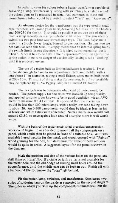
In order to cater for colour tubes a heater transformer capable of delivering 1 amp. was necessary, along with switching to enable each of the colour guns to be measured in turn. And common to these and monochrome tubes would be a switch to select “Test" and "Rejuvenate”.
■
An obvious choice for the transformer was the type used in small tape recorders, etc., some years back, delivering 6.3. v.a.c. for the heaters and 200-250 for the h.t. It should be possible to acquire one of these from a scrap recorder or a surplus dealer at little cost. The gun selector switch is a two-pole four-way wavechange type. The Test/Rejuvenate switch is a 2-pole 2-way toggle, biassed to one position. (In case you are not familiar with this term, it simply means that an internal spring holds the switch firmly in one direction.) It is wired so its normal setting is “Test”. Since it has to be held in the "Rejuvenate" position against the spring action there is no danger of accidentally leaving a tube “cooking" until it is rendered useless.
The use of a mains bulb as limiter/indicator is retained. 1 was fortunate enough to have by me a panel-mounted lamp holder with a lens about 1” in diameter, taking a small Edison screw mains bulb rated at 200v lOw. This sort of thing makes for neatness, but if not available may be replaced by a 15w Pygmy lamp in a standard BC holder.
The next job was to determine what kind of meter would be needed. The power supply for the tester was hooked up temporarily, and applied to some tubes known to be in good condition, via an AVO meter to measure the A1 current. It appeared that the maximum would be less than 500 micro-amps, with a really low tube taking down to about 20. An 0-500 uump meter would thus be ideal, at least as far as black-and-white tubes were concerned. Such a meter new would cost around £3.50, so once again a look around a surplus store is well worth while.
With the basis of the tester established practical construction work could begin. It was decided to mount all the components on a panel, which could then be placed in front of a suitable box. As it was available I used paxolin for the panel, and wood, covered with "Fablon” wood graining for the box, but aluminium for either or both sections would be quite in order. A suggested layout for the panel is shown in the diagram.
Mark the position and size of the various holes on the panel and drill them out carefully. If a circle or tank cutter is not available for the meter hole, use the old dodge of drilling small holes around the circumference, until the middle part can be broken out. Finish off with a half-round File to remove the “cogs” left behind.
Fit the meter, lamp, switches, and transformer, then screw two strips of soldering tags on the inside as suggested in the second diagram. The order in which you wire up the components is immaterial, but do
64
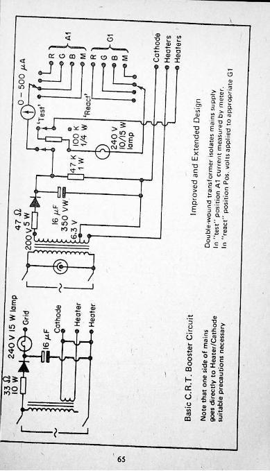
oa;
> fc ■»€ 2 a c ago ,5> 3 E 5s £££
Q 5 ? S
| SSig "22t; o c ™X !2 “ U>
LU " C - _ u £ o ■3 c >- > C E 3 • "3 O ° S
" rfa; c < - o 2 C o 2 ~ 2 ~ a S.:5 C C o S g ° oa:
« i? s i s sQ££
<D
It3a £ ~ S._ (TJ /»«J O «>E t 80 “ c <u a> cSI| " 051 ;s ° ~ sS 8 a £ £ • £ • m
O
2oo
CO
CEd«% HiCO
65
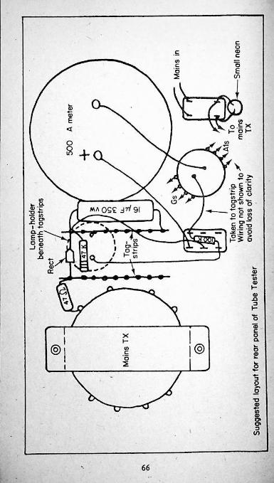
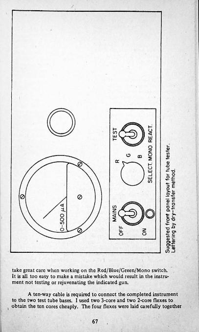
take great care when working on the Rcd/Blue/Green/Mono switch. It is all too easy to make a mistake which would result in the instrument not testing or rejuvenating the indicated gun.
A ten-way cable is required to connect the completed instrument to the two test tube bases. I used two 3-core and two 2-core flexes to obtain the ten cores cheaply. Tire four flexes were laid carefully together
67
and bound with cloth tape, giving a neat and durable appearance. The 3-core cables will have either red/black/grcen or brown/bluc/green colouring according to age; either presents a convenient coding for the three colour guns. Connect the R/B/G grids and Als to their respective switches with these cables. The three colour cathodes, and that of the mono base are all connected to each other and the earthy side of the heaters. The latter are supplied by one of the 2-core flexes, using the red or brown core as live. The remaining 2-core has its red or brown and black or blue cores connected respectively to the mono. A1 and grid.
The test buses are obtained from scrap sets. In both cases Bush/ Murphy types are very suitable, as they have rather large paxolin surrounds fitted with useful soldering points. Remove all the original components before attaching the test cables. The two bases may then be fitted back to back, using metal or paxolin stand-offs about l'/i” long. Secure the cables to one of the fixing bolts so that the soldered joints do not take any strain.
When a metal panel and/or box is used, employ three-core flex for the mains lead, and ensure that there is a reliable connection to the earth core in the instrument. Hie small neon indicator is a precaution against the mains being left switched on accidentally.
Use of the Tester/Rejuvenator
1. Mono, tubes. Fit the appropriate base and switch on, with the gun switch in the mono, position. The meter should start to read within about two minutes, unless the tube is exceptionally “lazy”. A reading of over 150 uamps will normally mean that the emission is enough to produce a reasonable picture. It must be stressed, however, that variations in HT voltage will affect the A1 current, and it is advisable to employ the method mentioned earlier, with some good tubes, to get a norm for your particular instrument. Very low readings indicate that the rejuvenation treatment is called for.
Hold the switch in the “Rejuvenate" position. The meter is automatically switched out of circuit, and will read zero. If the tube responds well the 10 or 15 watt indicator lamp will soon start to glow, and perhaps achieve almost full brilliance. As soon as this occurs release the switch into the test position, and check the meter reading. If it exceeds your norm, leave well alone. Attempting to increase the emission still further may have the reverse effect. An exception to this is when the meter reading drops back after a few seconds. When this happens an alternative method of rejuvenation often works well. Instead of holding the switch down, flick it very quickly, so that a sharp pulse of voltage is delivered to the grid. This may have to be repeated many times before an acceptable and steady reading is obtained.
68
Tubes treated by the instrument have their useful life extended significantly in most cases. Generally speaking, the worse a tube is to start with, the better the results.
Now and again you may get hold of a tube which just will not improve. This is more than likely because the treatment has been applied previously, and tube cathodes just don’t seem to like a second spring cleaning!
2. Colour Tubes. Wien evaluating the A1 current of good and bad colour tubes to obtain working averages, I found that the readings differed much more than with mono, tubes. Low emission c.r.t.s. could register as little as 25ua., whilst new one would send the meter right off scale. Since the majority of tubes tested were hardly likely to be in the latter category, this was not a major problem.
One of the most useful aspects of being able to check the emission of the three guns separately is the case with which one can decide if the lack of a colour or colours is due to a decoder fault or the tube itself. Each gun should draw substantially similar Ai current, whether or not the level of emission is high or low. The discovery that one or other is very low will save hours of trying to achieve a satisfactory grey scale.
In most instances it has been my experience that the “quick flick” method works best when rejuvenating. This sometimes has a most remarkable effect, with a reading shooting up from little or nothing to right off scale. Usually 1 ant content to get anything above 200ua. This will provide good watehable pictures. British and European tubes seem to be amenable to treatment, but I must confess that the few Japanese types I have tried have been none too successful Maybe the Orientals have found a way of building in obsolescence!
69
/
*A
/
V70
APPENDIX TWO
A Simple Crosshatch Generator
When this book was first conceived BBC2 transmitters were operating throughout the working day, radiating Test Card F between the few public programmes and the series of trade test films. There was, thus, ample opportunity for the enthusiast to converge a colour TV on the test card, without having to obtain a costly crosshateh generator. Unfortunately the need for economy has forced the BBC to close the second network between programmes, and the amount of lime that the test card is to be seen on BBC1 and 1TV is limited by the increased number of daytime programmes. In any case, the person able to work only in the evenings would be severely handicapped by the lack of a test card, or a generator. For these reasons the need for a simple type of instrument lias become very urgent.
Professional generators are expensive items. Their small physical size belies the complexity of the circuitry inside. There has to be an oscillator covering Bands 4/S (and sometimes Band 3 as well) with either continuous or pre-set tuning. This is modulated by the crosshateh wave-form for injection into the aerial socket of the set under test. The signal must include sync, pulses to lock the pattern on the screen. In addition to the crosshatch, most generators provide a dot pattern and some kind of grey scale. To construct such an instrument in the home workshop would be very difficult and costly.
In practice, however, a straightforward crosshatch pattern alone would be sufficient for the enthusiast. The dots are intended for setting up static convergence, but this is seldom difficult without this facility. Similarly, grey scale is easily achieved by the means described in Chapter tight of this book. The omission of these functions from the generator would simplify it immediately. Further economies can be made by injecting the signal not as modulated r.f., but as a video waveform directly into the luminance amplifier; and by finding another method of synchronising.
Firstly, suitable pulses for triggering and synchronising a test pattern are available from the line output transformer of a colour TV, via the same windings which supply the decoder panel. Secondly semi-conductors are cheaply and easily obtained, with which a physically small and inexpensive generator may be constructed. In the last year or so some examples have appeared commercially using integrated circuits of the TTL (transistor-transistor logic) type. In these the line pulses are sampled, divided and sub-divided to give the necessary waveforms. This certainly makes for a very small unit, but for various reasons a different approach, using discrete components, is a more attractive proposition for the enthusiast.
I
71;;
I believe that one of the foremost considerations in preparing a design for the home constructor is that the component parts should be readily at hand, so that there should be a minimum of delay in completing the project. Again, these parts should be easily tested and replaced should a fault occur. Integrated circuits, excellent though they might be, present a serious problem in this respect. Unless a check list of voltages is provided for correct operating conditions it is not possible to test an integrated circuit; the only sure method is to replace it with another. This may be acceptable in workshops where spares are available "off the shelf’; but not so good for the enthusiast who may have to wait a considerable time for delivery by post.
It would not be practicable to build a generator using i.e.s. without a printed circuit board, but the most elementary bread-board layout can be employed for the discrete component type. My prototype was, in fact, constructed on a piece of scrap wood approximately 7” x 4” x Vi”, in a matter of three hours, tvery part was taken from the "junk” box. The cost was minimal, and obviously replacements will not cause any anguish!
Circuit Description
To present a crosshatch pattern on the screen of the set we have to apply two suitable waveforms to the luminance amplifier grid (or base). These may be easily generated by multivibrators closely resembling the bi-stable used in the colour decoder panel. The output from the multivibrators is taken to twin amplifiers which sharpen it into a sawtooth shape. The signals are then combined and fed to the set via a short length of co-ax cable. The only other connection is the sync, input feed, which goes to the burst gate pulse on the decoder panel.
Constructional Notes
The layout shown in the diagram is merely suggested, and may be modified to suit individual ideas. The transistors used (2SB75) were to hand in large quantities from a dismantled computer, but any general purpose device should be satisfactory. N-P-N transistors will require the battery supply leads to be reversed. Likewise, the diodes are by no means critical, and any of the 0A81 equivalent types may be used. The resistors were all of the 10% tolerance type, as were the capacitors in the verticals generator. (470 and 680 pf.) The corresponding components in the horizontals generator are best found by selection. The tolerance of capacitors of these values seems to leave a lot to be desired! The wide variation of actual capacity in those marked identically results in marked difference in the number of lines displayed.
The battery supply can be between 4.5 and 9 volts, without alteration of circuit values or performance.
72
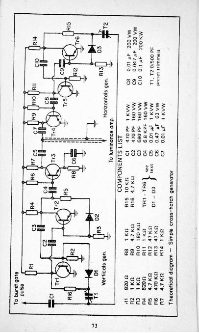
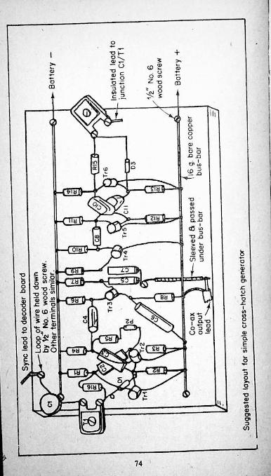
74
Operation. Many sets already have test points at the luminance amplifier input and on the decoder, to which the generator connections may be made. If these are not present, however, it is suggested that short lengths of fairly thick wire be soldered to the printed board at the appropriate places to receive crocodile clips.
With the video input and line pulse connections made, switch the TV on and allow it to warm up. Switch on the crosshatch generator, whereupon some sort of pattern should appear on the screen. Adjust the verticals sync, trimmer for stable lines, then that for the horizontals. Best results will probably be obtained by having the set tuned to a station, and reducing the contrast until the pattern over-rides the picture. Finding the correct adjustment for the second trimmer can sometimes be a little tricky, but with practice you will soon be able to master it.
Convergence may then be carried out in accordance with the general remarks earlier in this book, and with the manufacturers instructions.
Note. Values given for components are not especially critical. Individual experiment is permissible, and indeed may result in interesting variations of the vertical/horizontals ratio.
75

V
\t
1
r
/ '
-\•f
>
/ t
. ■
t
v76v;• ..
APPENDIX THREEForeign TV Reception on Your Colour TV
Many readers will be aware that under certain conditions reception of continental TV stations becomes possible. The normal line- of-siglu restrictions on range arc suspended, due to a number of various causes. The most familiar manifestation of this is the heavy patterning on British Hand 1 stations in hot weather. Sometimes this is so severe as to obliterate the pictures altogether, and whilst the ordinary viewer is cursing heartily, the DX enthusiasts are having a ball!
For many years the "standard'' receiver for long distance TV was the good old Bush TV53 series. The line time base of this 405 only set could be induced to scan at 625 lines merely by fiddling with the line hold control. (Continental stations mostly use this standard.) The change from negative to positive modulation which is also required is very easily accomplished by reversing the connections to the vision detector. But the most useful feature was the tuner unit. This resembled a conventional 13-channel type from a casual glance at the knobs, but was in fact completely different. Tuning was by moving brass cores within long narrow coil formers. A single wafer switch gave selection of Bands 1 or 3. Movement of the cores was effected by a scries of cams on the rear of the channel-change knob, whilst the fine tuner simply varied the cores by a small amount. Thus the coverage of the two Bands was continuous, unlike the preselected frequencies of the turret type, and ideal for tuning in Continental stations. (Their vision channel E2 is pretty well the same as our Channel 2 sound. A turret “biscuit” could hardly be expected to tune this successfully.)
Now that colour is being radiated by a large number of Continental Band 1/3 stations, it is quite possible to receive them successfully in this country. Owners of sets imported from Germany and Austria often have nothing else to do but to switch their tuners from UHF to VHF and connect a Band 1, or even a Band 2 aerial to the set to get foreign pictures in colour. The author has a friend who has received many programmes this year in this way, and who has photographs and colour slides to prove it!
Should you wish to have a go at this fascinating hobby - be warned, it’s a real time-waster! - you can convert your dual-standard colour TV with very little effort.
It should not be difficult to acquire a Bush tuner unit from a scrap set. Countless thousands must now be lying idle around workshops and junkrooms. The object is to wire it into the set in such a way that it is in circuit in place of the UHF tuner when the set is working on 625 lines. The power requirements are simple enough, 16v at 0.3a for the heaters and around 200v for the h.t. TTte former may be obtained by tapping into the heater chain at a convenient point, or by the use of a
'’l
small transformer. There are numerous points from which the h.t. voltage may be drawn, but probably the best is one with a fair amount of decoupling. In sets using a valve sound output the “hot” end of the output transformer is an ideal source. The i.f. output lead from the new tuner takes the place of that from the original.
Don’t expect to switch on and get pictures instantly. This can happen, of course, but very often a great deal of patience is required before the first alien test card flashes up on your screen. If the line and frame hold controls are left as they were for L'HF reception, little or no adjustment should be necessary on VHF. Signals strong enough to provide a viewable picture will lock it in automatically.
As mentioned earlier, a Band 1 or 2 aerial will often give good results. To achieve good pick up in most directions, a Channel 1 or 2 X aerial mounted horizontally works well. Naturally very sophisticated systems are available should you wish to go to extremes. I must confess to feeling that some of the fun goes out of a hobby when it is taken too seriously!
You will probably want to make a record of your “catches” by photographing them. The best camera for the purpose is the single lens reflex, with the twin lens version second. With both of these one can focus the image accurately upon the viewing screen, thus ensuring sharp pictures. Simpler cameras with means of focusing may also be used, provided that the distance between the film (i.e. the rear of the camera, not the lens) is measured carefully. Since you will be at or near the shortest focal length to fill the viewfinder with the image of the TV screen, it is better to use a tape measure rather than depend upon a range-finder. Remember also that the phenomenon of parallax error occurs at close quarters, meaning in simple terms that the image in the viewfinder may be some inches disposed from that on the film. This may be avoided by ensuring that the centre of the camera lens is directly opposite to that of the TV screen.
In all cases a tripod should be used to support the camera. Once the correct position for this is found some means of finding it quickly again is advisable if it is not possible for it to remain untouched. Use a fairly long cable release to operate the shutter. This will not only avoid camera shake, but also allow you to sit back from the screen in comfort.
As for film and shutter speeds, and apertures, the choice is pretty straightforward. In the days when I used to take a lot of shots in black and white, I'P3 film, rated at 200 ASA and exposed for 1/25 sec. at f.4.5 gave me excellent negatives. Tire processing' was done at home and under my control. Now that colour rules, and slides and prints are done commercially, I use 100 ASA film shot at 1/25 or 1/30 sec at f2.8. It is permissible to use longer exposures, say 1/15 or even 1/10 sec. if the picture is steady enough, but never go above 1/30. At faster speeds the camera will perceive what your eye cannot and reproduce split images and other weird effects.
i
78
The golden rule is to shoot whenever an acceptable picture arrives. Don’t wait for it to improve, as the chances are that it might disappear! And you can always take a second exposure if there is a marked improvement.
Set the brightness and contrast controls to give a not-too contrasty picture. Try to avoid ambient lighting falling upon the screen by having the set in a shaded place and drawing the curtains when there is strong sunlight.
With a little luck and perseverance you should be able to log and photograph a number of stations. Not all will be receivable in colour, but, as stated earlier, you will probably find yourself devoting an awful lot of time to the attempt!
Please note overleaf is a list of other titles that are available in our range of Radio and Electronic Books.
These should be available from all good Booksellers, Radio Component Dealers and Mail Order Companies.
However, should you experience difficulty in obtaining any title in your area, then please write directly to the publisher enclosing payment to cover the cost of the book plus adequate postage.
BABANI PRESS & BERNARDS (PUBLISHERS) LTD THE GRAMPIANS
SHEPHERDS BUSH ROAD LONDON W6 7NF
ENGLAND
19
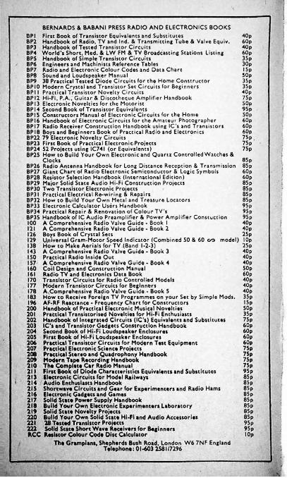
!BERNARDS & BABANI PRESS RADIO AND ELECTRONICS BOOKS
DPI First Book of Transistor Equivalents and Substitutes 8P2 Handbook of Radio, TV and Ind. & Transmitting Tube & Valve Equiv.BP3 Handbook of Tested Transistor CircuitsBP4 World’s Short. Med. & LW FM & TV Broadcasting Stations Listing BPS Handbook of Simple Transistor Circuits BP6 Engineers and Machinists Reference Tables BP7 Radio and Electronic Colour Codes and Data Chart BP8 Sound and Loudspeaker Manual8P9 38 Practical Tested Diode Circuits for the Home Constructor BPIO Modern Crystal and Transistor Set Circuits for Beginners BPII Practical Transistor Novelty Circuits BPI2 Hi-Fi, P.A., Guitar & Discotheque Amplifier Handbook BPI3 Electronic Novelties for the Motorist BPI4 Second Book of Transistor Equivalents BPIS Constructors Manual of Electronic Circuits for the Home BPI6 Handbook of Electronic Circuits for the Amateur Photographer BPI7 Radio Receiver Construction Handbook using IC's and Transistors BPI8 Boys and Beginners Book of Practical Radio and Electronics BP22 79 Electronic Novelty Circuits BP23 First Book of Practical Electronic Projects BP24 52 Projects using IC74I (or Equivalents)BP25 How to Build Your Own Electronic and Quartz Controlled Watchos &
ClocksBP26 Radio Antenna Handbook for Long Distance Reception & Transmission 85p BP27 Giant Chart of Radio Electronic Semiconductor & Logic Symbols BP28 Resistor Soloction Handbook (International Edition)BP29 Major Solid State Audio Hi-Fi Construction Proiecis BP30 TwoTransistor Electronic Projects BP3I Practical Electrical Re-wiring & Repairs BP32 How to Build Your Own Metal and Treasure Locators BP33 Electronic Calculator Users Handbook BP34 Practical Repair & Renovation of Colour TV'sBP3S Handbook of 1C Audio Preamplifier & Power Amplifier Constuction 100 A Comprehensive Radio Valve Guide - Book I 121 A Comprehensive Radio Valve Guide - Book 2
Boys Book of Crystal Sets 129 Universal Gram-Motor Speed Indicator (Combined 50 & 60 c/d model) lOp 138 How to Make Aerials for TV.(Band 1-2-3)143 A Comprehensive Radio Valve Guide - Book 3 150 Practical Radio Inside Out 157 A Comprehensive Radio Valve Guide - Book 4160 Coil Design and Construction Manual161 Radio TV and Electronics Data Book 170 Transistor Circuits for Radio Controlled Models177 Modern Transistor Circuits for Beginners178 A.Comprehensive Radio Valve Guide - Book 5 183 How to Receive Foreign TV Programmes on your Set by Simple Mods. 35p 196 AF-RF Reactance - Frequency Chart for Constructors200 Handbook of Practical Electronic Musical Novelties201 Practical Transistorised Novelties for Hi-Fi Enthusiasts202 Handbook of Integrated Circuits (IC's) Equivalents and Substitutes203 IC's and Transistor Gadgets Construction Handbook204 Second Book of Hi-Fi Loudspeaker Enclosures205 First Book of Hi-Fi Loudspeaker Enclosures206 Practical Transistor Circuits for Modern Test Equipment207 Practical Elactronic Science Projects208 Practical Stereo and Quadrophony Handbook209 Modern Tape Recording Handbook210 The Complete Car Radio Manual211 First Book of Diode Characteristics Equivalents and Substitutes 21) Electronic Circuits for Model Railways214 Audio Enthusiasts Handbook215 Shortwave Circuits and Gear for Experimenters and Radio Hams216 Electronic Gadgets and Games217 Solid State Power Supply Handbook218 Build Your Own Electronic Experimenters Laboratory219 Solid State Novelty Projects220 Build Your Own Solid State Hi-Fi and Audio Accessories221 28 Tested Transistor Projects222 Solid State Short Wave Receivers for Beginners RCC Resistor Colour Code Disc Calculator
The Grampians, Shepherds Bush Road. London W6 7NF England Telephone: 01-603 258117296
40p60p40p60p35p30pI5p50p35p3Sp40p75pSOp9Sp50p60p60pfeOp75p75p75p !85p60 p60 p85p85p85 p85p95p95p95p40p40p25p1262Sp40p40p40pSOp60p40p40p40pI5p50p35p75p60p60p60p60p75p75p7Sp75p95p85p8 5 p85p85p85p85p85p85p95p95pI Op
%

fiJBLlOTHEEK
Practical Repair
& Renovation
of Colour TV’sShows how to obtain a working colour TV for
relatively little outlay by repairing and renovating a set that has been "written off" by a dealer as "B E R" (Beyond economical Repair).
Gives advice on obtaining suitable sets and then deals with the various stages of the colour TV chapter by chapter.
Includes the circuitry and practical details for building your own C RI TestedRejuvenator and Cross Hatch Generator.
This book is written by Mr. Chas Miller who is a highly experienced TV service engineer and also a regular contributor to the magazine 'Television" with his articles "Millers Miscellany':
Die NittH>ilsDes*(jn Unit
BABANIPRESS The Grampians Shepherds Bush Road London W6 7NF England
oliotheek Ned. Ver. v;