ppi-2 model e & pe series - tinley tech
TRANSCRIPT
November, 2014 IMPCO Technologies Inc. PPI-2 REV. J 3030 South Susan St. Page 1 of 16
Santa Ana, CA 92704 www.impcotechnologies.com
3030 S Susan Street, Santa Ana, CA 92704 Ph: +1 714 656 1200 Fax: +1 714 656 1400
MODEL E & PE SERIES
TWO-STAGE REGULATOR REPAIR KIT INSTRUCTIONS Important: Any maintenance, service or repair should be performed by trained and experienced service technicians. Proper tools and equipment should be used to prevent injury to the servicing technician, property or system components. Service repairs should always be performed in a safe environment and the technician should always wear protective clothing to prevent injury. The IMPCO PPI-2 repair kit instructions will provide the technician information to successfully repair the model E and PE regulators. Always inspect the major casting pieces for damage, corrosion or cracks before attempting a service repair. Be sure the repair kit part number you are using is correct for the regulator being serviced. Diaphragms are color coded and have different performance characteristics: BLACK: Hydrin diaphragm material is the standard material and is well suited for the most common applications. YELLOW: Silicone diaphragm material is the optional upgrade material that provides excellent flexibility in cold weather climates and is more resistant to chemical contamination. BLUE: Fluorosilicone diaphragm material provides excellent high and low temperature durability with increased chemical resistance. This material is recommended for turbo applications.
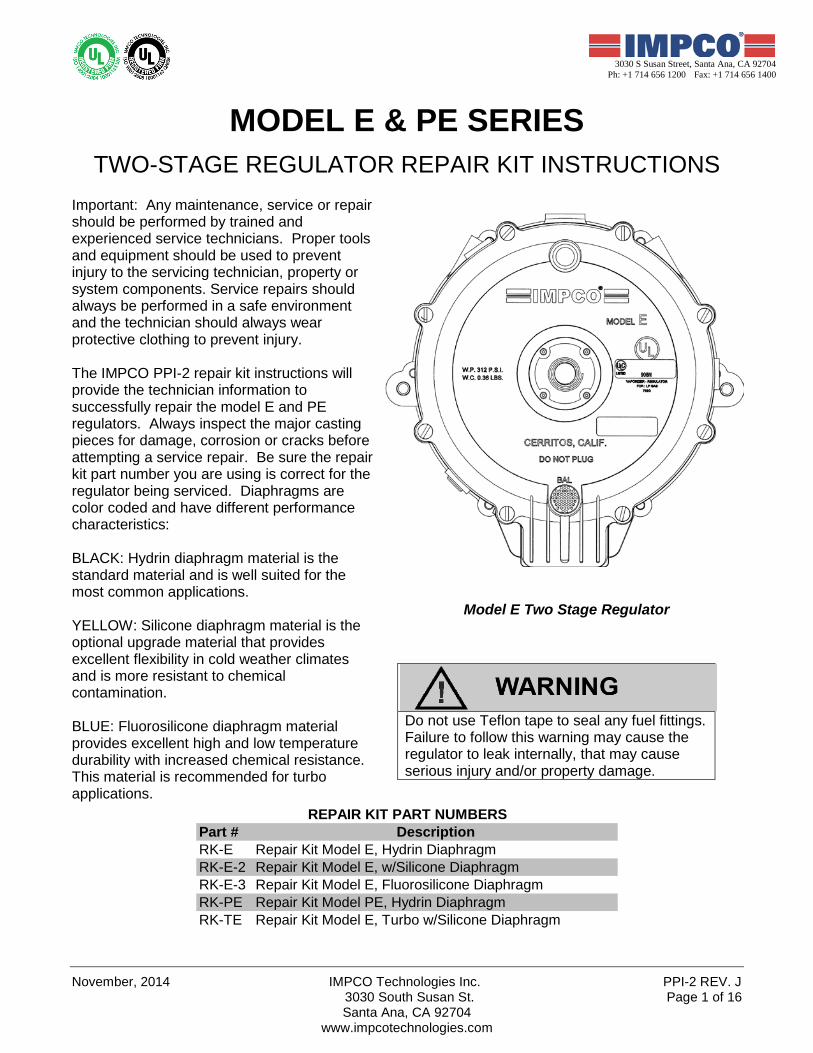
Model E Two Stage Regulator
Do not use Teflon tape to seal any fuel fittings. Failure to follow this warning may cause the regulator to leak internally, that may cause serious injury and/or property damage.
Part # DescriptionRK-E Repair Kit Model E, Hydrin DiaphragmRK-E-2 Repair Kit Model E, w/Silicone DiaphragmRK-E-3 Repair Kit Model E, Fluorosilicone DiaphragmRK-PE Repair Kit Model PE, Hydrin DiaphragmRK-TE Repair Kit Model E, Turbo w/Silicone Diaphragm
REPAIR KIT PART NUMBERS
PPI-2 REV. J IMPCO Technologies Inc November, 2014 3030 South Susan St. Page 2 of 16
Santa Ana, CA 92704 www.impcotechnologies.com
3030 S Susan Street, Santa Ana, CA 92704 Ph: +1 714 656 1200 Fax: +1 714 656 1400
MODEL E & PE SERIES REGULATORS
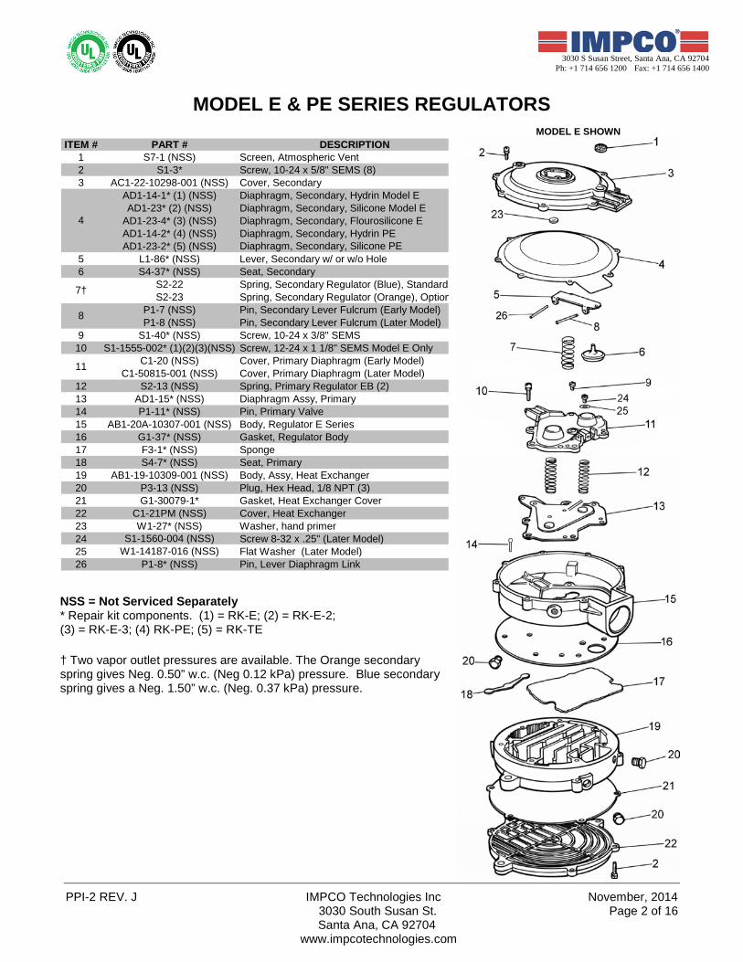
MODEL E SHOWN ITEM # PART # DESCRIPTION
1 S7-1 (NSS) Screen, Atmospheric Vent2 S1-3* Screw, 10-24 x 5/8" SEMS (8)3 AC1-22-10298-001 (NSS) Cover, Secondary
AD1-14-1* (1) (NSS) Diaphragm, Secondary, Hydrin Model EAD1-23* (2) (NSS) Diaphragm, Secondary, Silicone Model E
AD1-23-4* (3) (NSS) Diaphragm, Secondary, Flourosilicone EAD1-14-2* (4) (NSS) Diaphragm, Secondary, Hydrin PEAD1-23-2* (5) (NSS) Diaphragm, Secondary, Silicone PE
5 L1-86* (NSS) Lever, Secondary w/ or w/o Hole6 S4-37* (NSS) Seat, Secondary
S2-22 Spring, Secondary Regulator (Blue), StandardS2-23 Spring, Secondary Regulator (Orange), Option
P1-7 (NSS) Pin, Secondary Lever Fulcrum (Early Model)P1-8 (NSS) Pin, Secondary Lever Fulcrum (Later Model)
9 S1-40* (NSS) Screw, 10-24 x 3/8" SEMS10 S1-1555-002* (1)(2)(3)(NSS) Screw, 12-24 x 1 1/8" SEMS Model E Only
C1-20 (NSS) Cover, Primary Diaphragm (Early Model)C1-50815-001 (NSS) Cover, Primary Diaphragm (Later Model)
12 S2-13 (NSS) Spring, Primary Regulator EB (2)13 AD1-15* (NSS) Diaphragm Assy, Primary14 P1-11* (NSS) Pin, Primary Valve15 AB1-20A-10307-001 (NSS) Body, Regulator E Series16 G1-37* (NSS) Gasket, Regulator Body17 F3-1* (NSS) Sponge18 S4-7* (NSS) Seat, Primary19 AB1-19-10309-001 (NSS) Body, Assy, Heat Exchanger20 P3-13 (NSS) Plug, Hex Head, 1/8 NPT (3)21 G1-30079-1* Gasket, Heat Exchanger Cover22 C1-21PM (NSS) Cover, Heat Exchanger23 W1-27* (NSS) Washer, hand primer24 S1-1560-004 (NSS) Screw 8-32 x .25" (Later Model)25 W1-14187-016 (NSS) Flat Washer (Later Model)26 P1-8* (NSS) Pin, Lever Diaphragm Link
4
7†
8
11
NSS = Not Serviced Separately * Repair kit components. (1) = RK-E; (2) = RK-E-2; (3) = RK-E-3; (4) RK-PE; (5) = RK-TE † Two vapor outlet pressures are available. The Orange secondary spring gives Neg. 0.50” w.c. (Neg 0.12 kPa) pressure. Blue secondary spring gives a Neg. 1.50” w.c. (Neg. 0.37 kPa) pressure.
November, 2014 IMPCO Technologies Inc. PPI-2 REV. J 3030 South Susan St. Page 3 of 16
Santa Ana, CA 92704 www.impcotechnologies.com
3030 S Susan Street, Santa Ana, CA 92704 Ph: +1 714 656 1200 Fax: +1 714 656 1400
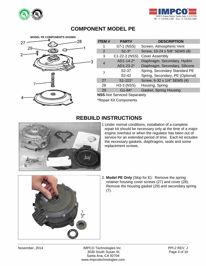
COMPONENT MODEL PE
MODEL PE COMPONENTS SHOWN
ITEM # PART# DESCRIPTION1 S7-1 (NSS) Screen, Atmospheric Vent2 S1-3* Screw, 10-24 x 5/8" SEMS (8)3 C1-22-2 (NSS) Cover Assembly
AD1-14-2* Diaphragm, Secondary, HydrinAD1-23-2* Diaphragm, Secondary, Silicone
S2-37 Spring, Secondary Standard PES2-42 Spring, Secondary, PE (Optional)
27 S1-101* Screw, 6-32 x 1/4" SEMS (4)28 H3-3 (NSS) Housing, Spring29 G1-84* Gasket, Spring Housing
NSS-Not Serviced Separately*Repair Kit Components
7
4
REBUILD INSTRUCTIONS
1.Under normal conditions, installation of a complete repair kit should be necessary only at the time of a major engine overhaul or when the regulator has been out of service for an extended period of time. Each kit includes the necessary gaskets, diaphragms, seals and some replacement screws.
2. Model PE Only (Skip for E): Remove the spring retainer housing cover screws (27) and cover (28). Remove the housing gasket (29) and secondary spring (7).
PPI-2 REV. J IMPCO Technologies Inc November, 2014 3030 South Susan St. Page 4 of 16
Santa Ana, CA 92704 www.impcotechnologies.com
3030 S Susan Street, Santa Ana, CA 92704 Ph: +1 714 656 1200 Fax: +1 714 656 1400
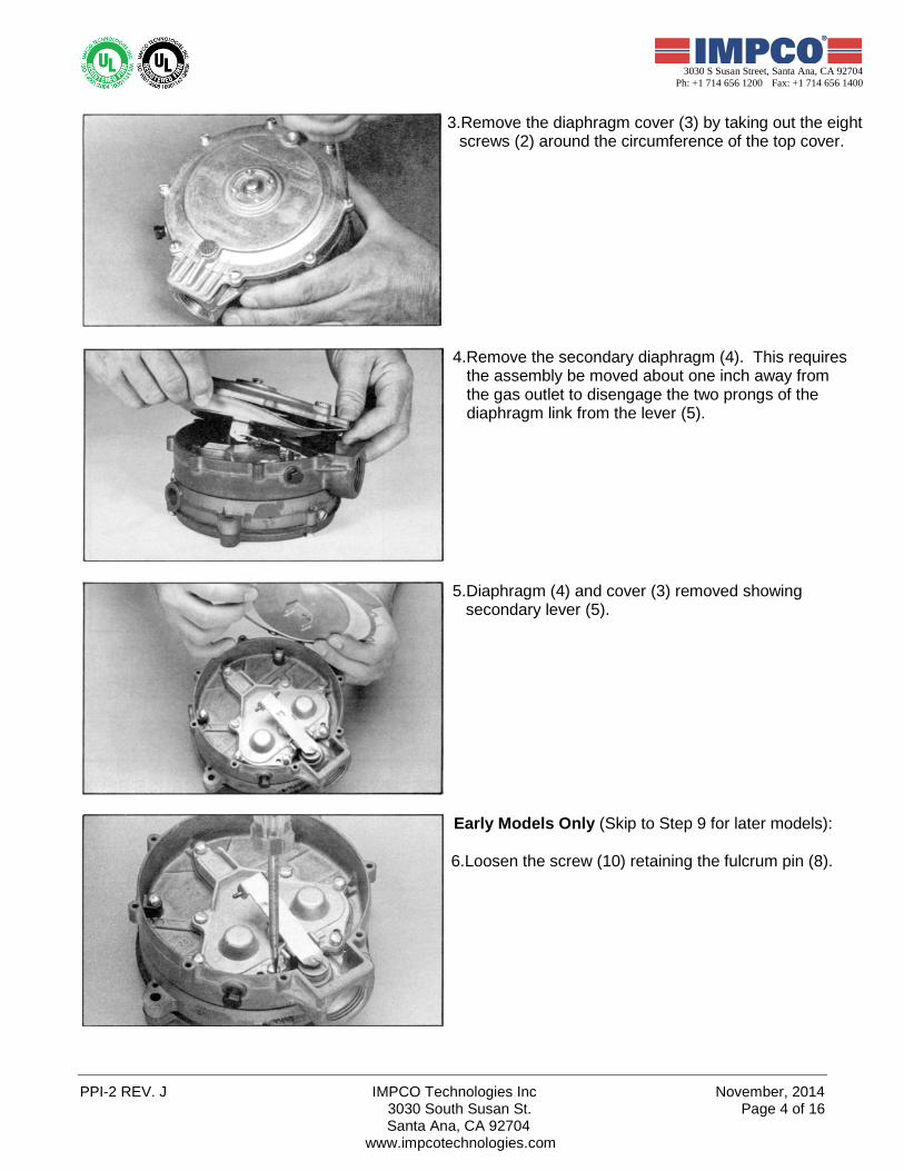
3.Remove the diaphragm cover (3) by taking out the eight screws (2) around the circumference of the top cover.
4.Remove the secondary diaphragm (4). This requires the assembly be moved about one inch away from the gas outlet to disengage the two prongs of the diaphragm link from the lever (5).
5.Diaphragm (4) and cover (3) removed showing secondary lever (5).
Early Models Only (Skip to Step 9 for later models): 6.Loosen the screw (10) retaining the fulcrum pin (8).
November, 2014 IMPCO Technologies Inc. PPI-2 REV. J 3030 South Susan St. Page 5 of 16
Santa Ana, CA 92704 www.impcotechnologies.com
3030 S Susan Street, Santa Ana, CA 92704 Ph: +1 714 656 1200 Fax: +1 714 656 1400
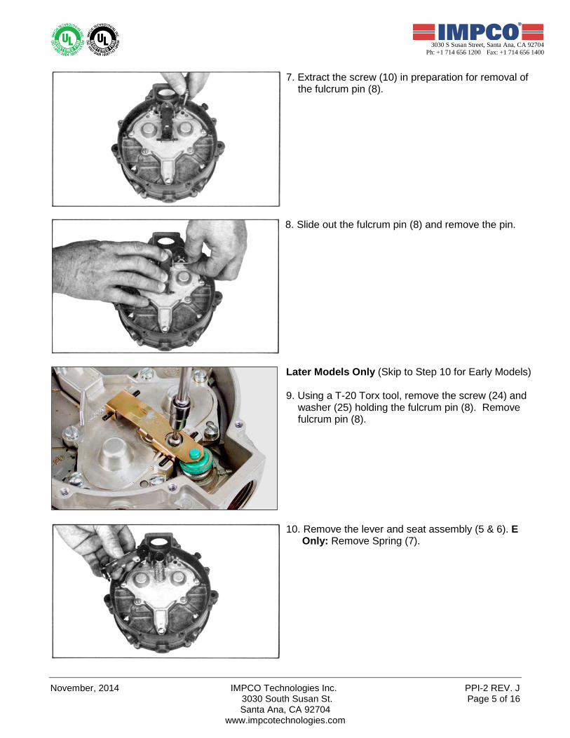
7. Extract the screw (10) in preparation for removal of the fulcrum pin (8).
8. Slide out the fulcrum pin (8) and remove the pin.
Later Models Only (Skip to Step 10 for Early Models) 9. Using a T-20 Torx tool, remove the screw (24) and
washer (25) holding the fulcrum pin (8). Remove fulcrum pin (8).
10. Remove the lever and seat assembly (5 & 6). E Only: Remove Spring (7).
PPI-2 REV. J IMPCO Technologies Inc November, 2014 3030 South Susan St. Page 6 of 16
Santa Ana, CA 92704 www.impcotechnologies.com
3030 S Susan Street, Santa Ana, CA 92704 Ph: +1 714 656 1200 Fax: +1 714 656 1400
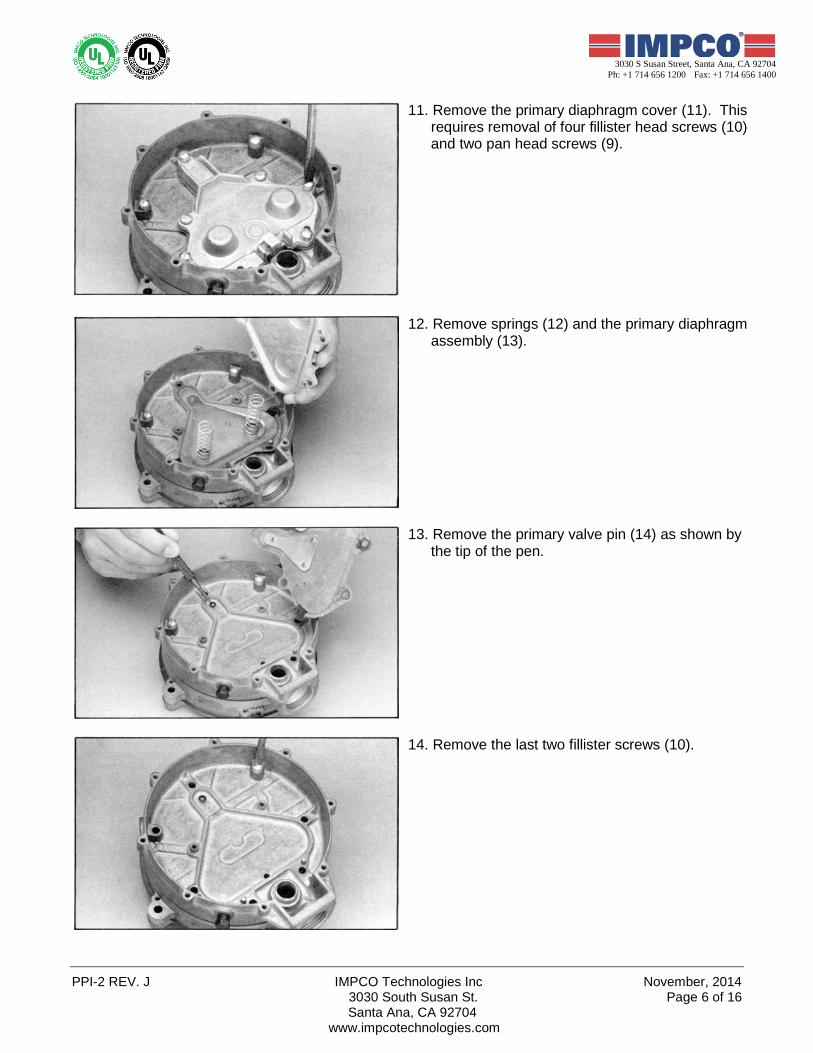
11. Remove the primary diaphragm cover (11). This requires removal of four fillister head screws (10) and two pan head screws (9).
12. Remove springs (12) and the primary diaphragm assembly (13).
13. Remove the primary valve pin (14) as shown by the tip of the pen.
14. Remove the last two fillister screws (10).
November, 2014 IMPCO Technologies Inc. PPI-2 REV. J 3030 South Susan St. Page 7 of 16
Santa Ana, CA 92704 www.impcotechnologies.com
3030 S Susan Street, Santa Ana, CA 92704 Ph: +1 714 656 1200 Fax: +1 714 656 1400
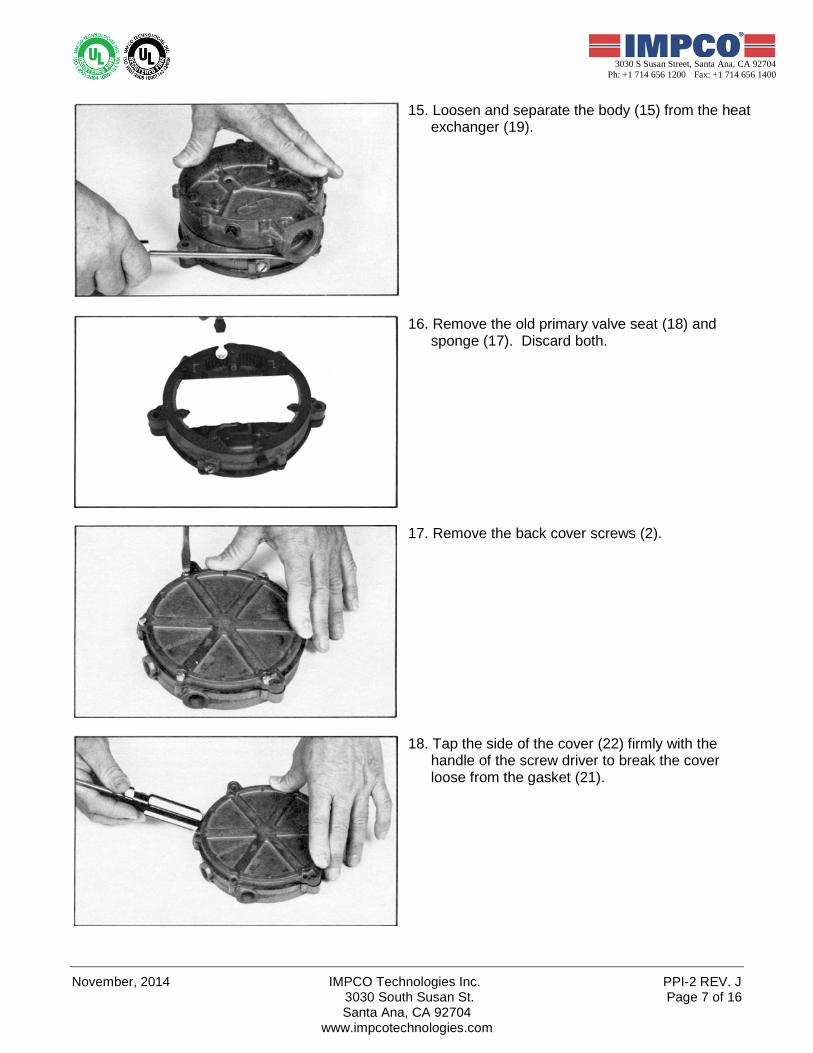
15. Loosen and separate the body (15) from the heat exchanger (19).
16. Remove the old primary valve seat (18) and sponge (17). Discard both.
17. Remove the back cover screws (2).
18. Tap the side of the cover (22) firmly with the handle of the screw driver to break the cover loose from the gasket (21).
PPI-2 REV. J IMPCO Technologies Inc November, 2014 3030 South Susan St. Page 8 of 16
Santa Ana, CA 92704 www.impcotechnologies.com
3030 S Susan Street, Santa Ana, CA 92704 Ph: +1 714 656 1200 Fax: +1 714 656 1400
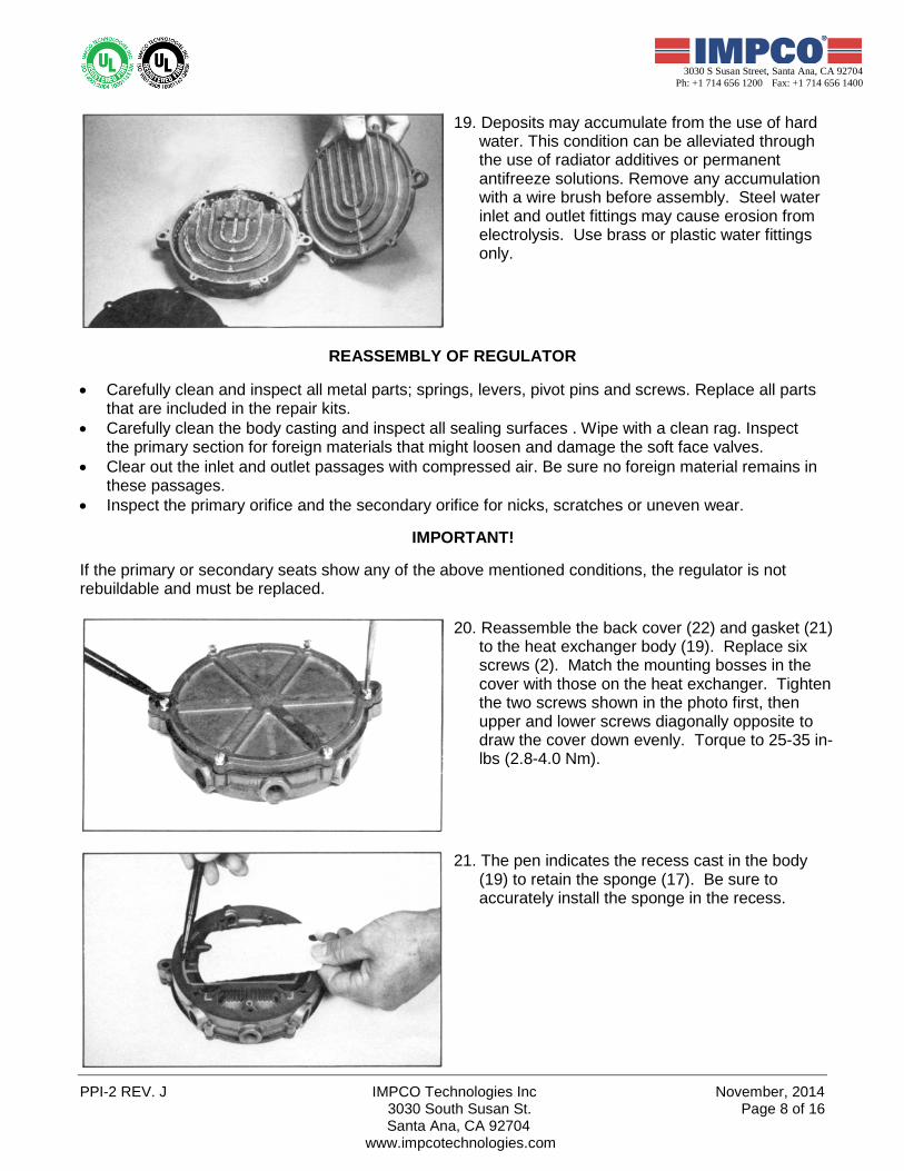
19. Deposits may accumulate from the use of hard water. This condition can be alleviated through the use of radiator additives or permanent antifreeze solutions. Remove any accumulation with a wire brush before assembly. Steel water inlet and outlet fittings may cause erosion from electrolysis. Use brass or plastic water fittings only.
REASSEMBLY OF REGULATOR
• Carefully clean and inspect all metal parts; springs, levers, pivot pins and screws. Replace all parts
that are included in the repair kits. • Carefully clean the body casting and inspect all sealing surfaces . Wipe with a clean rag. Inspect
the primary section for foreign materials that might loosen and damage the soft face valves. • Clear out the inlet and outlet passages with compressed air. Be sure no foreign material remains in
these passages. • Inspect the primary orifice and the secondary orifice for nicks, scratches or uneven wear.
IMPORTANT! If the primary or secondary seats show any of the above mentioned conditions, the regulator is not rebuildable and must be replaced.
20. Reassemble the back cover (22) and gasket (21) to the heat exchanger body (19). Replace six screws (2). Match the mounting bosses in the cover with those on the heat exchanger. Tighten the two screws shown in the photo first, then upper and lower screws diagonally opposite to draw the cover down evenly. Torque to 25-35 in-lbs (2.8-4.0 Nm).
21. The pen indicates the recess cast in the body (19) to retain the sponge (17). Be sure to accurately install the sponge in the recess.
November, 2014 IMPCO Technologies Inc. PPI-2 REV. J 3030 South Susan St. Page 9 of 16
Santa Ana, CA 92704 www.impcotechnologies.com
3030 S Susan Street, Santa Ana, CA 92704 Ph: +1 714 656 1200 Fax: +1 714 656 1400
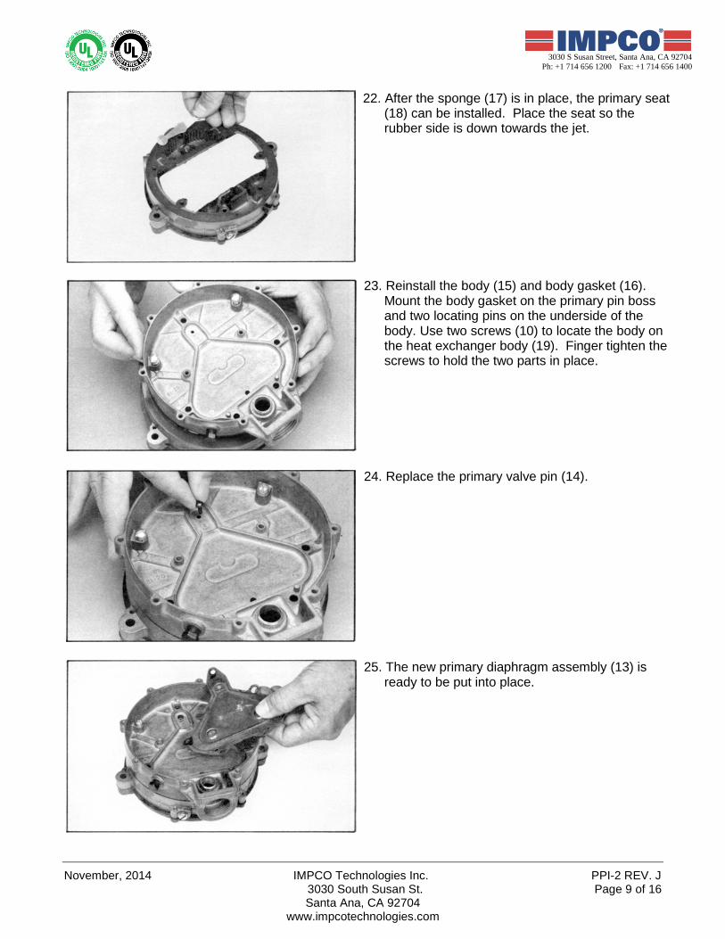
22. After the sponge (17) is in place, the primary seat (18) can be installed. Place the seat so the rubber side is down towards the jet.
23. Reinstall the body (15) and body gasket (16). Mount the body gasket on the primary pin boss and two locating pins on the underside of the body. Use two screws (10) to locate the body on the heat exchanger body (19). Finger tighten the screws to hold the two parts in place.
24. Replace the primary valve pin (14).
25. The new primary diaphragm assembly (13) is ready to be put into place.
PPI-2 REV. J IMPCO Technologies Inc November, 2014 3030 South Susan St. Page 10 of 16
Santa Ana, CA 92704 www.impcotechnologies.com
3030 S Susan Street, Santa Ana, CA 92704 Ph: +1 714 656 1200 Fax: +1 714 656 1400
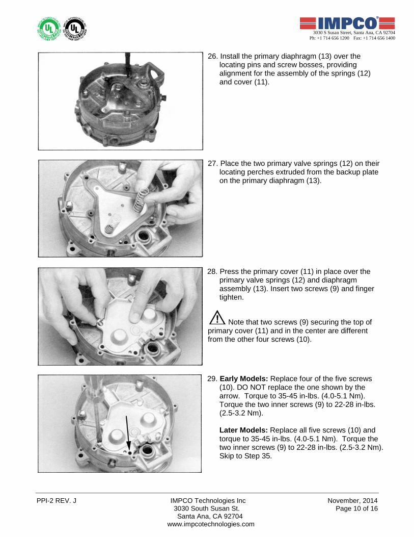
26. Install the primary diaphragm (13) over the locating pins and screw bosses, providing alignment for the assembly of the springs (12) and cover (11).
27. Place the two primary valve springs (12) on their locating perches extruded from the backup plate on the primary diaphragm (13).
28. Press the primary cover (11) in place over the primary valve springs (12) and diaphragm assembly (13). Insert two screws (9) and finger tighten.
Note that two screws (9) securing the top of primary cover (11) and in the center are different from the other four screws (10).
29. Early Models: Replace four of the five screws (10). DO NOT replace the one shown by the arrow. Torque to 35-45 in-lbs. (4.0-5.1 Nm). Torque the two inner screws (9) to 22-28 in-lbs. (2.5-3.2 Nm).
Later Models: Replace all five screws (10) and torque to 35-45 in-lbs. (4.0-5.1 Nm). Torque the two inner screws (9) to 22-28 in-lbs. (2.5-3.2 Nm). Skip to Step 35.
November, 2014 IMPCO Technologies Inc. PPI-2 REV. J 3030 South Susan St. Page 11 of 16
Santa Ana, CA 92704 www.impcotechnologies.com
3030 S Susan Street, Santa Ana, CA 92704 Ph: +1 714 656 1200 Fax: +1 714 656 1400
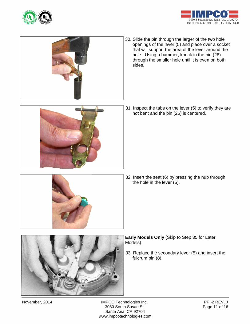
30. Slide the pin through the larger of the two hole openings of the lever (5) and place over a socket that will support the area of the lever around the hole. Using a hammer, knock in the pin (26) through the smaller hole until it is even on both sides.
31. Inspect the tabs on the lever (5) to verify they are not bent and the pin (26) is centered.
32. Insert the seat (6) by pressing the nub through the hole in the lever (5).
Early Models Only (Skip to Step 35 for Later Models)
33. Replace the secondary lever (5) and insert the
fulcrum pin (8).
PPI-2 REV. J IMPCO Technologies Inc November, 2014 3030 South Susan St. Page 12 of 16
Santa Ana, CA 92704 www.impcotechnologies.com
3030 S Susan Street, Santa Ana, CA 92704 Ph: +1 714 656 1200 Fax: +1 714 656 1400
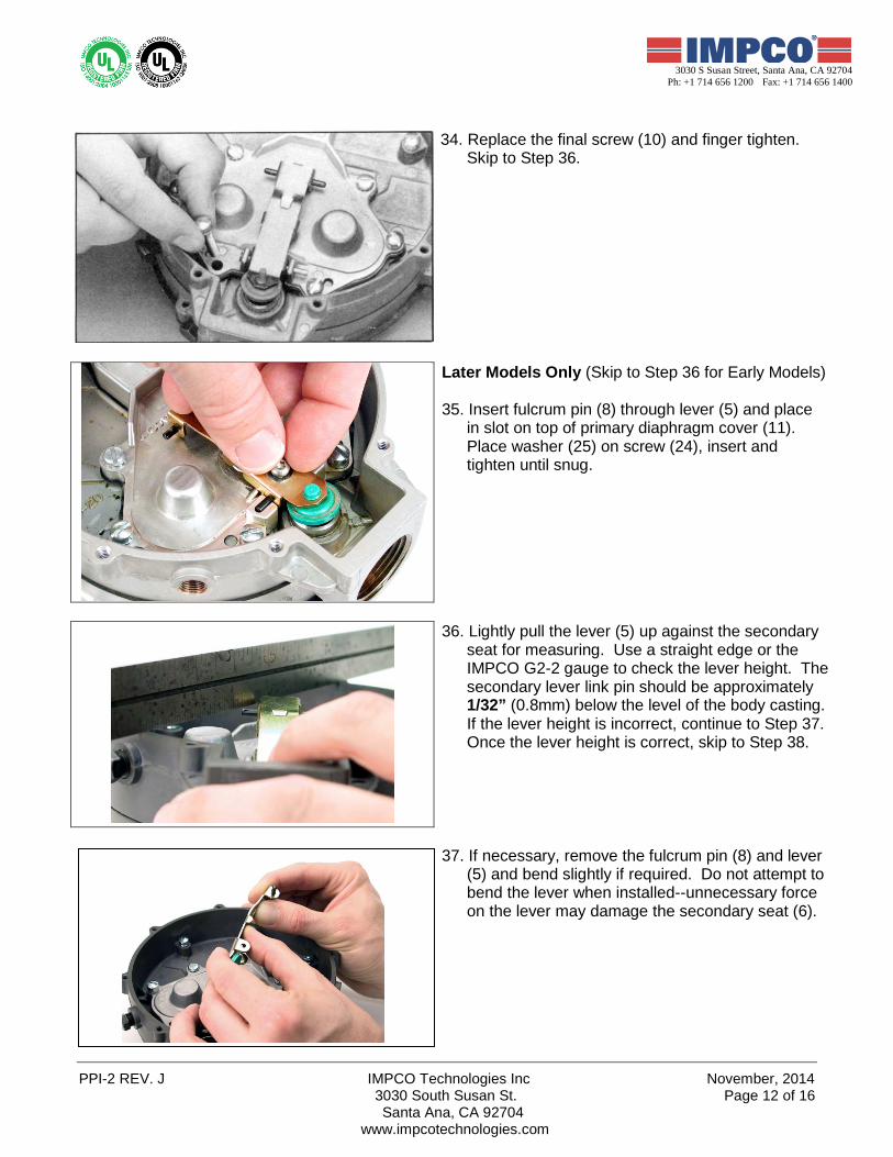
34. Replace the final screw (10) and finger tighten. Skip to Step 36.
Later Models Only (Skip to Step 36 for Early Models) 35. Insert fulcrum pin (8) through lever (5) and place
in slot on top of primary diaphragm cover (11). Place washer (25) on screw (24), insert and tighten until snug.
36. Lightly pull the lever (5) up against the secondary seat for measuring. Use a straight edge or the IMPCO G2-2 gauge to check the lever height. The secondary lever link pin should be approximately 1/32” (0.8mm) below the level of the body casting. If the lever height is incorrect, continue to Step 37. Once the lever height is correct, skip to Step 38.
37. If necessary, remove the fulcrum pin (8) and lever (5) and bend slightly if required. Do not attempt to bend the lever when installed--unnecessary force on the lever may damage the secondary seat (6).
November, 2014 IMPCO Technologies Inc. PPI-2 REV. J 3030 South Susan St. Page 13 of 16
Santa Ana, CA 92704 www.impcotechnologies.com
3030 S Susan Street, Santa Ana, CA 92704 Ph: +1 714 656 1200 Fax: +1 714 656 1400
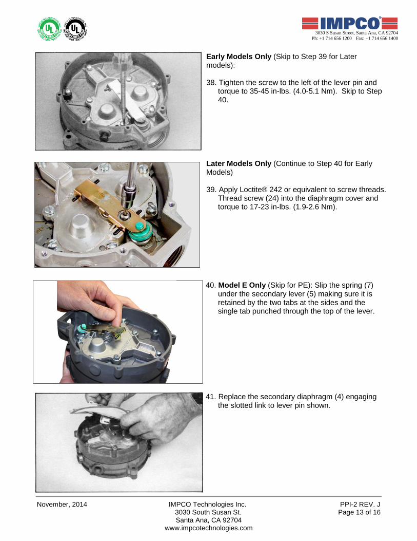
Early Models Only (Skip to Step 39 for Later models): 38. Tighten the screw to the left of the lever pin and
torque to 35-45 in-lbs. (4.0-5.1 Nm). Skip to Step 40.
Later Models Only (Continue to Step 40 for Early Models) 39. Apply Loctite® 242 or equivalent to screw threads.
Thread screw (24) into the diaphragm cover and torque to 17-23 in-lbs. (1.9-2.6 Nm).
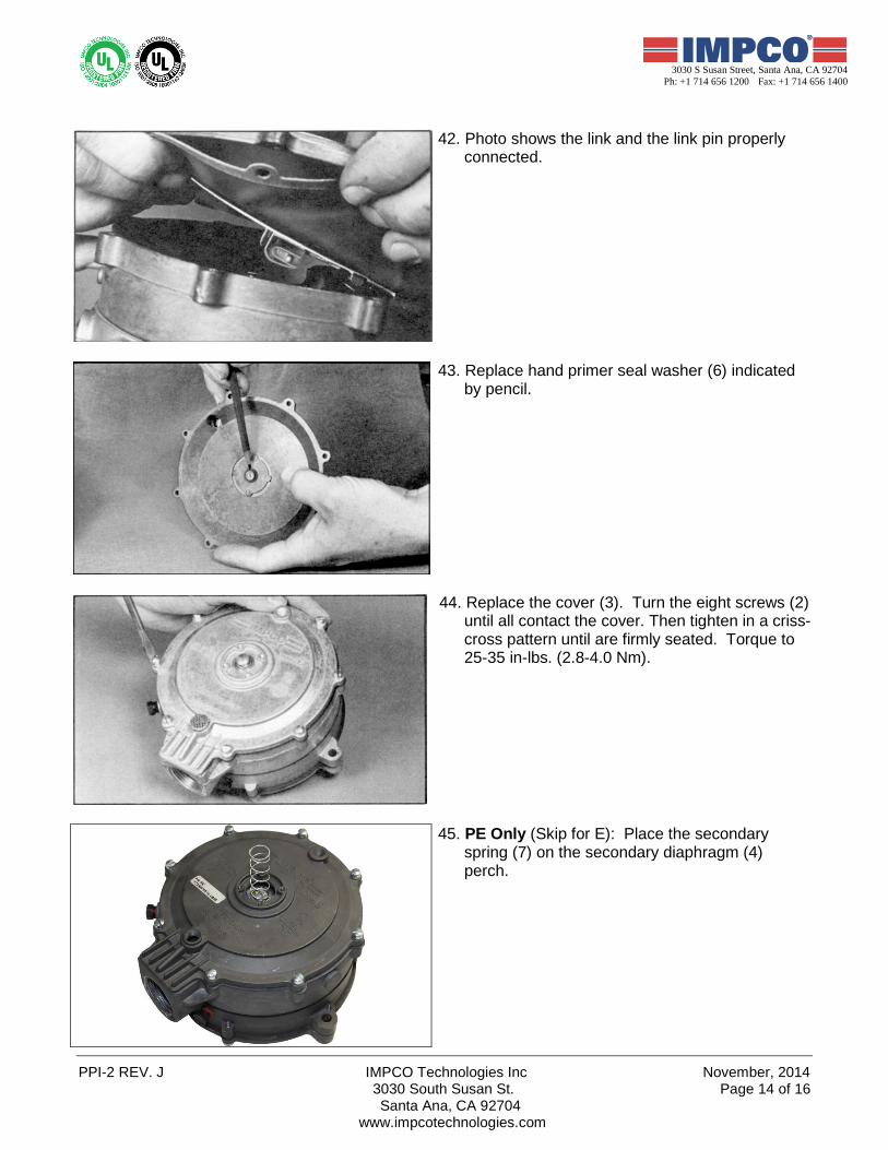
40. Model E Only (Skip for PE): Slip the spring (7) under the secondary lever (5) making sure it is retained by the two tabs at the sides and the single tab punched through the top of the lever.
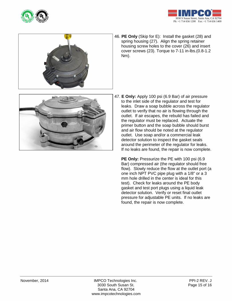
41. Replace the secondary diaphragm (4) engaging the slotted link to lever pin shown.
PPI-2 REV. J IMPCO Technologies Inc November, 2014 3030 South Susan St. Page 14 of 16
Santa Ana, CA 92704 www.impcotechnologies.com
3030 S Susan Street, Santa Ana, CA 92704 Ph: +1 714 656 1200 Fax: +1 714 656 1400
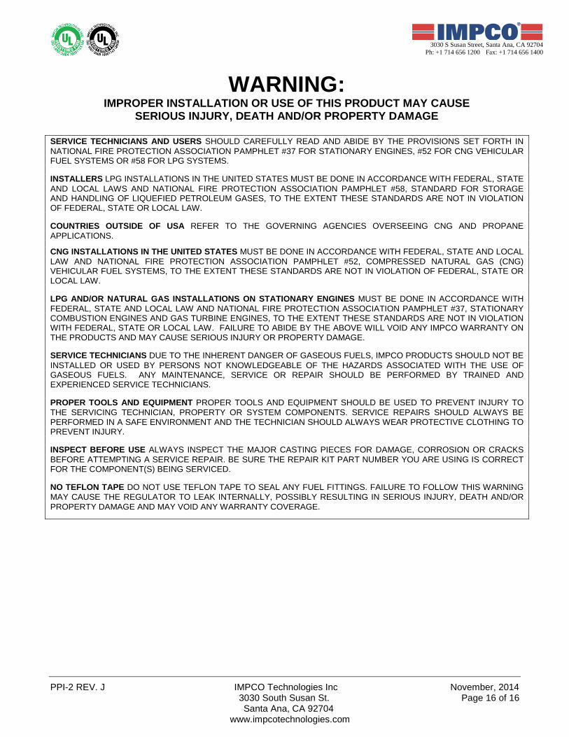
42. Photo shows the link and the link pin properly connected.
43. Replace hand primer seal washer (6) indicated by pencil.
44. Replace the cover (3). Turn the eight screws (2) until all contact the cover. Then tighten in a criss-cross pattern until are firmly seated. Torque to 25-35 in-lbs. (2.8-4.0 Nm).
45. PE Only (Skip for E): Place the secondary spring (7) on the secondary diaphragm (4) perch.
November, 2014 IMPCO Technologies Inc. PPI-2 REV. J 3030 South Susan St. Page 15 of 16
Santa Ana, CA 92704 www.impcotechnologies.com
3030 S Susan Street, Santa Ana, CA 92704 Ph: +1 714 656 1200 Fax: +1 714 656 1400
46. PE Only (Skip for E): Install the gasket (28) and spring housing (27). Align the spring retainer housing screw holes to the cover (26) and insert cover screws (23). Torque to 7-11 in-lbs.(0.8-1.2 Nm).
47. E Only: Apply 100 psi (6.9 Bar) of air pressure to the inlet side of the regulator and test for leaks. Draw a soap bubble across the regulator outlet to verify that no air is flowing through the outlet. If air escapes, the rebuild has failed and the regulator must be replaced. Actuate the primer button and the soap bubble should burst and air flow should be noted at the regulator outlet. Use soap and/or a commercial leak detector solution to inspect the gasket seals around the perimeter of the regulator for leaks. If no leaks are found, the repair is now complete.
PE Only: Pressurize the PE with 100 psi (6.9 Bar) compressed air (the regulator should free flow). Slowly reduce the flow at the outlet port (a one inch NPT PVC pipe plug with a 1/8” or a 3 mm hole drilled in the center is ideal for this test). Check for leaks around the PE body gasket and test port plugs using a liquid leak detector solution. Verify or reset final outlet pressure for adjustable PE units. If no leaks are found, the repair is now complete.
PPI-2 REV. J IMPCO Technologies Inc November, 2014 3030 South Susan St. Page 16 of 16
Santa Ana, CA 92704 www.impcotechnologies.com
3030 S Susan Street, Santa Ana, CA 92704 Ph: +1 714 656 1200 Fax: +1 714 656 1400
WARNING: IMPROPER INSTALLATION OR USE OF THIS PRODUCT MAY CAUSE
SERIOUS INJURY, DEATH AND/OR PROPERTY DAMAGE
SERVICE TECHNICIANS AND USERS SHOULD CAREFULLY READ AND ABIDE BY THE PROVISIONS SET FORTH IN NATIONAL FIRE PROTECTION ASSOCIATION PAMPHLET #37 FOR STATIONARY ENGINES, #52 FOR CNG VEHICULAR FUEL SYSTEMS OR #58 FOR LPG SYSTEMS. INSTALLERS LPG INSTALLATIONS IN THE UNITED STATES MUST BE DONE IN ACCORDANCE WITH FEDERAL, STATE AND LOCAL LAWS AND NATIONAL FIRE PROTECTION ASSOCIATION PAMPHLET #58, STANDARD FOR STORAGE AND HANDLING OF LIQUEFIED PETROLEUM GASES, TO THE EXTENT THESE STANDARDS ARE NOT IN VIOLATION OF FEDERAL, STATE OR LOCAL LAW. COUNTRIES OUTSIDE OF USA REFER TO THE GOVERNING AGENCIES OVERSEEING CNG AND PROPANE APPLICATIONS. CNG INSTALLATIONS IN THE UNITED STATES MUST BE DONE IN ACCORDANCE WITH FEDERAL, STATE AND LOCAL LAW AND NATIONAL FIRE PROTECTION ASSOCIATION PAMPHLET #52, COMPRESSED NATURAL GAS (CNG) VEHICULAR FUEL SYSTEMS, TO THE EXTENT THESE STANDARDS ARE NOT IN VIOLATION OF FEDERAL, STATE OR LOCAL LAW. LPG AND/OR NATURAL GAS INSTALLATIONS ON STATIONARY ENGINES MUST BE DONE IN ACCORDANCE WITH FEDERAL, STATE AND LOCAL LAW AND NATIONAL FIRE PROTECTION ASSOCIATION PAMPHLET #37, STATIONARY COMBUSTION ENGINES AND GAS TURBINE ENGINES, TO THE EXTENT THESE STANDARDS ARE NOT IN VIOLATION WITH FEDERAL, STATE OR LOCAL LAW. FAILURE TO ABIDE BY THE ABOVE WILL VOID ANY IMPCO WARRANTY ON THE PRODUCTS AND MAY CAUSE SERIOUS INJURY OR PROPERTY DAMAGE. SERVICE TECHNICIANS DUE TO THE INHERENT DANGER OF GASEOUS FUELS, IMPCO PRODUCTS SHOULD NOT BE INSTALLED OR USED BY PERSONS NOT KNOWLEDGEABLE OF THE HAZARDS ASSOCIATED WITH THE USE OF GASEOUS FUELS. ANY MAINTENANCE, SERVICE OR REPAIR SHOULD BE PERFORMED BY TRAINED AND EXPERIENCED SERVICE TECHNICIANS. PROPER TOOLS AND EQUIPMENT PROPER TOOLS AND EQUIPMENT SHOULD BE USED TO PREVENT INJURY TO THE SERVICING TECHNICIAN, PROPERTY OR SYSTEM COMPONENTS. SERVICE REPAIRS SHOULD ALWAYS BE PERFORMED IN A SAFE ENVIRONMENT AND THE TECHNICIAN SHOULD ALWAYS WEAR PROTECTIVE CLOTHING TO PREVENT INJURY. INSPECT BEFORE USE ALWAYS INSPECT THE MAJOR CASTING PIECES FOR DAMAGE, CORROSION OR CRACKS BEFORE ATTEMPTING A SERVICE REPAIR. BE SURE THE REPAIR KIT PART NUMBER YOU ARE USING IS CORRECT FOR THE COMPONENT(S) BEING SERVICED. NO TEFLON TAPE DO NOT USE TEFLON TAPE TO SEAL ANY FUEL FITTINGS. FAILURE TO FOLLOW THIS WARNING MAY CAUSE THE REGULATOR TO LEAK INTERNALLY, POSSIBLY RESULTING IN SERIOUS INJURY, DEATH AND/OR PROPERTY DAMAGE AND MAY VOID ANY WARRANTY COVERAGE.