post-processing opportunities of professional and consumer grade 3d printing equipment: a...
TRANSCRIPT
Seediscussions,stats,andauthorprofilesforthispublicationat:https://www.researchgate.net/publication/285583534
Post-processingopportunitiesofprofessionalandconsumergrade3Dprintingequipment:acomparativestudy
ARTICLEinINTERNATIONALJOURNALOFRAPIDMANUFACTURING·DECEMBER2015
DOI:10.1504/IJRAPIDM.2015.073548
READS
34
5AUTHORS,INCLUDING:
IñigoFloresItuarte
AaltoUniversity
7PUBLICATIONS0CITATIONS
SEEPROFILE
MikaSalmi
AaltoUniversity
25PUBLICATIONS98CITATIONS
SEEPROFILE
JukkaTuomi
AaltoUniversity
29PUBLICATIONS173CITATIONS
SEEPROFILE
JouniPartanen
AaltoUniversity
70PUBLICATIONS463CITATIONS
SEEPROFILE
Allin-textreferencesunderlinedinbluearelinkedtopublicationsonResearchGate,
lettingyouaccessandreadthemimmediately.
Availablefrom:IñigoFloresItuarte
Retrievedon:19January2016

58 Int. J. Rapid Manufacturing, Vol. 5, No. 1, 2015
Copyright © 2015 Inderscience Enterprises Ltd.
Post-processing opportunities of professional and consumer grade 3D printing equipment: a comparative study
Iñigo Flores Ituarte*, Sergei Chekurov, Mika Salmi, Jukka Tuomi and Jouni Partanen Department of Engineering Design and Production, Aalto University School of Engineering, Espoo, Finland Email: [email protected] Email: [email protected] Email: [email protected] Email: [email protected] Email: [email protected] *Corresponding author
Abstract: The paper describes to the machine user community how to improve surface quality and dimensional stability of additively produced parts. A case geometry is designed to compare the subtractive finishing process of FDM parts. Two different machines are used to produce a sample to be post-processed with a CNC milling machine. Geometrical and dimensional features are analysed with a 3D scanner to assess the reliability and repeatability of the post-processing for engineering applications. In addition, causal relationships of the hybrid approaches and final part geometric accuracy can be understood. Results show that the reliability of consumer grade machines needs to be improved substantially to implement them into engineering applications. Geometry distortions, due to thermal warping and delamination problems and due to lack of shear strength, are the obstacles to overcome in the development of hybrid subtractive processes. Nevertheless, machine users can benefit from the methodology presented in order to plan hybrid processes and improve final manufacturing quality.
Keywords: additive manufacturing; 3D printing; hybrid manufacturing; post-processing; tolerance analysis.
Reference to this paper should be made as follows: Ituarte, I.F., Chekurov, S., Salmi, M., Tuomi, J. and Partanen, J. (2015) ‘Post-processing opportunities of professional and consumer grade 3D printing equipment: a comparative study’, Int. J. Rapid Manufacturing, Vol. 5, No. 1, pp.58–75.
Biographical notes: Iñigo Flores Ituarte is a PhD candidate at the Aalto University in the Department of Engineering Design and Production, Finland. He studied Product Development and Mechanical Engineering and received his diploma in 2013. Currently works as a Research Scientist in the field of advance manufacturing systems in national and European research projects. His research focuses on mapping integration opportunities as well as challenges in the global industrial context.
Sergei Chekurov is a PhD candidate of Production Engineering at the Aalto University in Espoo, Finland. He studied production engineering and industrial

Post-processing opportunities of professional 59
management at Aalto University, Finland, and received his master’s degree in 2014. Currently works as a Research Scientist in European and Finnish national projects to research AM integration in manufacturing operations.
Mika Salmi works as post-doctoral research at the Aalto University in the Department of Engineering Design and Production, Finland. He made his PhD in 2013 focusing in medical applications of additive manufacturing in surgery and dental care. He has published more than 15 scientific and technical papers from industrial and medical applications of additive manufacturing. Currently he is involved in projects related to commercialising novel manufacturing method and researching industrial applications of additive manufacturing.
Jukka Tuomi is a Research Director at the Aalto University, Finland. He is President of Finnish Rapid Prototyping Association, FIRPA, and representative of Finland in Global Alliance of Additive Manufacturing Associations, GAAMA. He has written over 50 scientific papers about Additive Manufacturing, 3D Modelling and Product and Production Development. He has been international scientific committee member in over 20 conferenced and he has been presenting in over 50 international conferences and seminars in about 20 different countries worldwide.
Jouni Partanen is Professor of Future Production Technologies at the Aalto University, Finland. He has industrial and academic background mostly in the USA, but also in Finland and the UK. For his academic degree, he studied laser physics, but his later career for more than two decades has evolved around new production technique called additive manufacturing.
1 Introduction
Additive Manufacturing (AM) or 3D printing has been presented as a game-changing technology (Holmström and Partanen, 2014). It is predicted that in the near future new applications will become mainstream in the industry; research road maps indicated an untapped potential to replace and/or coexist with conventional manufacturing in cases where significant gain can be obtained in the life cycle of products in terms of cost, functionality and environmental impact (Ahn et al., 2013).
AM can also contribute to the realisation of distributed manufacturing and mass-customisation (Kinnunen et al., 2014), since the personal ownership of AM hardware is becoming feasible due to reduced price of consumer grade 3D printers. The commercialisation and usage of Consumer Grade Additive Manufacturing (CGAM) systems have increased vastly over the past years; CGAM systems are defined as the group of personal 3D printing equipment that sell for less than $5000 (Wohlers, 2015). However, the quality of the produced parts is generally poor in engineering terms; therefore, its use is limited in engineering applications (Pei et al., 2011). Direct part production with CGAM can hardly compete against Professional Grade Additive Manufacturing (PGAM) equipment. This is due to several factors, such as lack of reliability of the manufacturing process, geometrical distortions on parts, poor surface quality and weak mechanical properties (Gibson et al., 2010).
60 I.F. Ituarte et al.
When speaking about CGAM machines, most of the available commercial equipment belongs to the process category called material extrusion (ASTM International, 2013). The technology is also described with the trademark ‘Fused Deposition Modelling’ (FDM). The principles of the technology involve a thermoplastic material filament, which is fed and melted in a controlled manner in an extruder. Afterwards, this material is deposited selectively using the same extruder, which is moved along X- and Y-coordinates. Once a layer is finished, the build platform moves down the Z-axis to continue with the following layer in a sequential process, which allows creating 3D geometries (Turner et al., 2014).
Regardless of the final quality of CGAM-produced parts, the capabilities and competitiveness of the equipment should not be underestimated. CGAM machines are one of the drivers of what is called ‘personal manufacturing’ (Bogue, 2013). One of the most relevant parameters to democratise manufacturing is that the average selling price of CGAM equipment was around $1208 in 2013 (Wohlers, 2015), which is 70 times lower than the average price of PGAM industrial systems and representing 9% of the direct revenue of AM equipment sales. Low cost has allowed the technology to reach a wide audience, including independent users, design studios, inventors and the engineering community. In addition, many educational institutes globally are embracing the possibilities of the additive manufacturing by purchasing CGAM equipment. Currently, ‘3D printing hubs’ are coexisting with conventional manufacturing facilities in universities and technical schools.
However, steps towards integrating additive manufacturing systems into engineering applications often require combining the technology with other finishing or post-processing techniques (Francis et al., 2014). As introduced by Pham and Gault (1998), Stucker and Qu (2003), as well as Townsend and Urbanic (2011), dimensional stability control of additively manufactured parts can be obtained by finishing the parts with subtractive manufacturing processes. Additively manufacturing can be used to generate the rough geometry, and then a machining strategy can be implemented to finish the geometry in order to obtain the required dimensional specifications. This process is analogous to foundries with cast parts, in which the initial geometry is obtained by forming methods, and then functional geometrical features are machined in a sequential manufacturing process.
1.1 Background to research
Short-run production or technical prototyping of engineering technical parts with additive systems has several downsides: the parts are rarely ready for end-use even when produced with the most advanced AM systems, and therefore need to be finished or post-processed (Mellor et al., 2014). Coating, infiltration and surface refining processes are feasible solutions to achieve desired properties. However, during the additive manufacturing process, machine and process parameters (e.g. machine architecture, build orientation, layer thickness, shell thickness, raster path and others) have a fundamental impact on macro- and micro-level geometrical accuracy (Thrimurthulu et al., 2004). These initial parameters also have an impact when combined with subtractive post-processing techniques (Ahn et al., 2007).
During additive and subtractive hybrid manufacturing processes, the geometrical properties, such as surface quality and dimensional accuracy, cannot be optimised only by adjusting independently machining parameters from additive process parameters or by

Post-processing opportunities of professional 61
software modifications only (Pandey et al., 2003). The optimisation process requires considering input factors from both processes. As the demand for more accurate geometries has increased, hardware frameworks, which include deposition and machining in a single station, have been developed to research the system architecture and process planning of the additive–subtractive hybrid methods (Hur et al., 2002). In the context of CGAM systems, scientific literature addresses the problem of improving dimensional stability and surface quality, and research suggests that manufacturing stations integrating additive and subtractive methods could help to improve the part quality using CGAM systems.
However, most of the research on CGAM systems has focused on understanding macro- and micro-level geometrical limitations during direct manufacturing (Pei et al., 2011; Johnson et al., 2014). The common aim of these studies was to make a quality evaluation of parts produced with open source FDM systems. These studies were limited to understanding the production of parts using inexpensive equipment, without considering the possibility of post-processing them with a machining strategy.
To fill this gap, this research paper has explored the differences between CGAM and PGAM equipment when combined with subtractive methods in a sequential manufacturing process. The initial intuition was that the relative dimensional error of the produced geometries could also be minimised by post-processing the CGAM part in a machining process. Outcomes could be independent from the type machine used during the manufacturing; therefore, dimensional accuracy and surface quality problems, which have limited the use of the technology in technical engineering applications, can be minimised in a hybrid subtractive process (Lee et al., 2014). Dimensional errors of CGAM or PGAM parts could be potentially solved by post-processing them using a Computer Numerically Control (CNC) milling machine.
In contrast to the approach presented in previous research (Hur et al., 2002), this experimental research adopts the machining strategy as a tool for the finishing operation of the produced part, similar to the process presented in previous research (Kulkarni and Dutta, 2000). To do so, a limited batch of parts is produced with CGAM and PGAM, to be combined with subtractive processes. The aim of this research is to add comprehension to the causal relationships between additive and subtractive manufacturing methods and final manufacturing accuracy by experimenting with commercially available CGAM systems, PGAM systems and conventional subtractive equipment to evaluate the use of the AM in engineering plastic applications.
2 Experimental work
2.1 Geometry for the case study
A benchmarking geometry was designed to evaluate the suitability of the additive–subtractive hybrid process. The geometry includes a variety of macro-level geometrical features machinable in a three-axis milling process, such as curved surfaces, holes, pockets, sharp edges, as well as perpendicular, parallel and inclined planes at different angles. The geometry was designed to minimise the need for support structures by eliminating possible overhanging features, and the functional geometry was located only in the XY plane in order to simplify the milling process, which was completed with a three-axis milling machine with the same tool in a single set-up.
62 I.F. Ituarte et al.
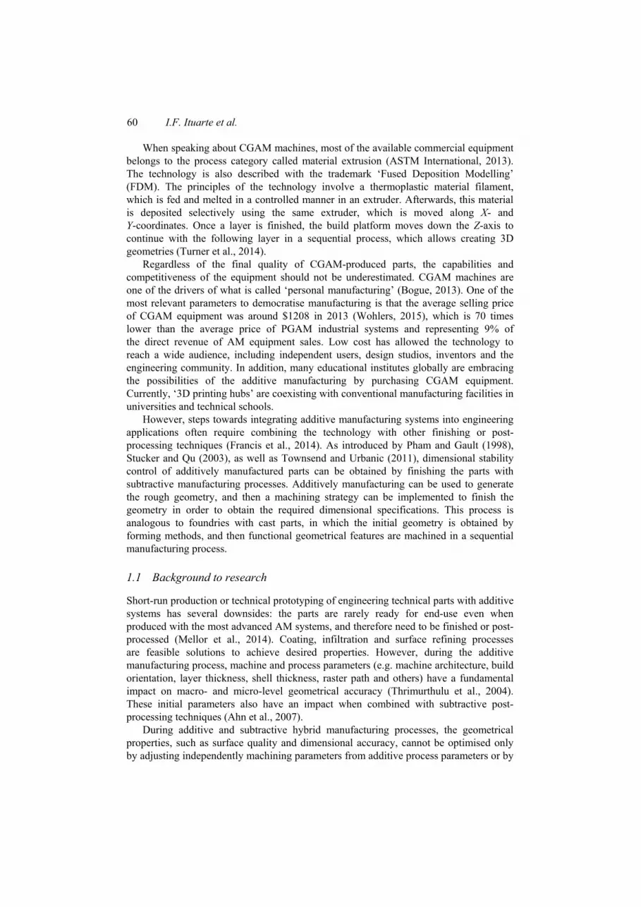
Figure 1 Geometry of the case study: top, side, front and perspective view
Figure 1 shows the geometry used in this experiment. The part in grey shows the nominal geometry. Overlapped in the same figure, a translucent offset geometry is displayed. The nominal geometry has been offset in all faces and geometrical features to compensate for the overall distortions of the additive process. By doing so, the parts produced will have enough stock material to be removed during the post-processing; therefore, inaccuracies of the AM parts can be compensated for during the finishing process. The general dimensions of the part are 65 mm in the Y-, 68.5 mm in the X- and 15 mm in the Z-axis, and its theoretical volume is approximately 49,300 mm3. The offset factors were calculated to obtain approximately 1 mm of machining stock on the part after the additive process.
2.2 Hybrid manufacturing process
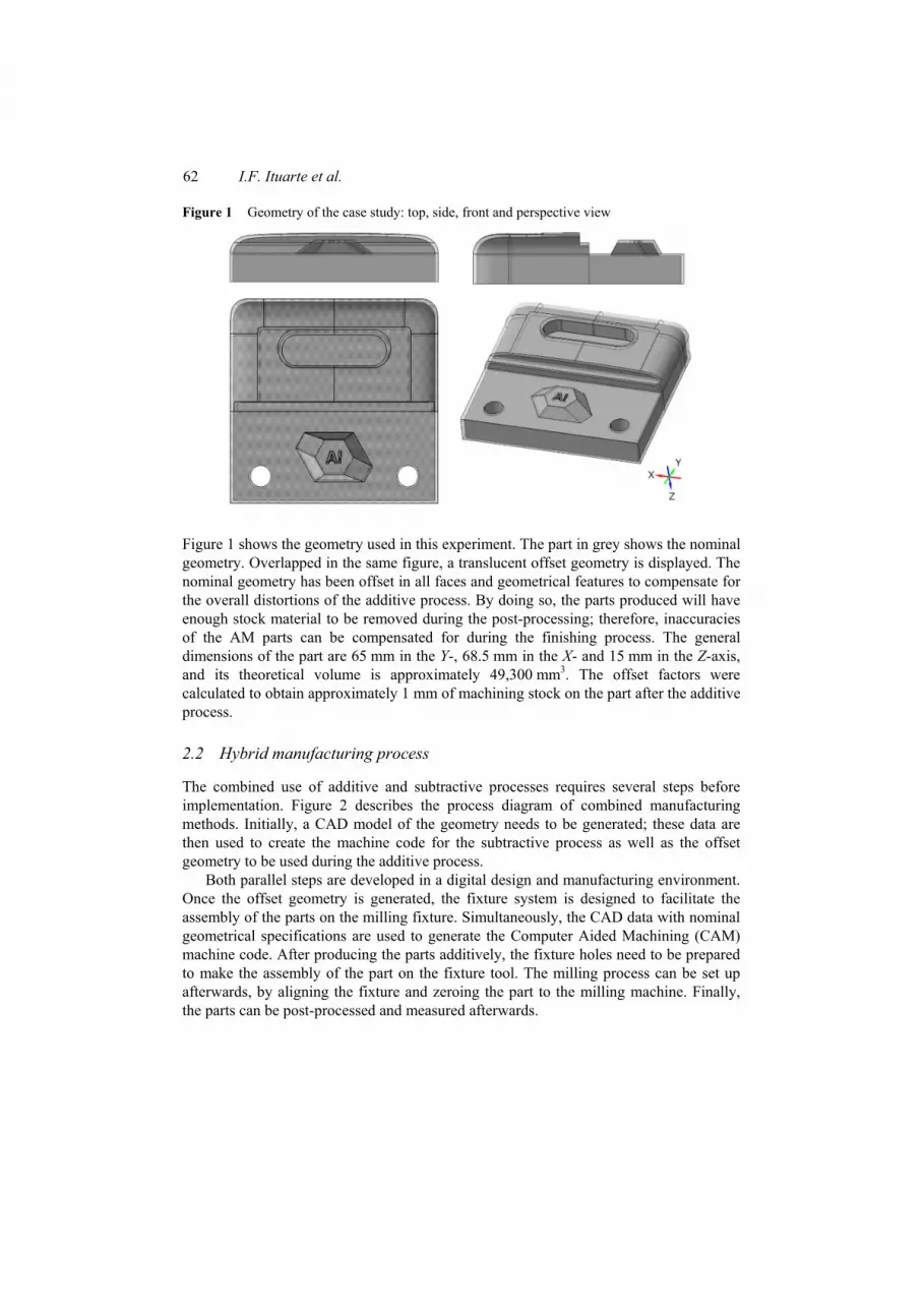
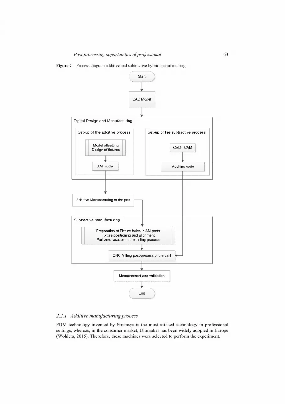
The combined use of additive and subtractive processes requires several steps before implementation. Figure 2 describes the process diagram of combined manufacturing methods. Initially, a CAD model of the geometry needs to be generated; these data are then used to create the machine code for the subtractive process as well as the offset geometry to be used during the additive process.
Both parallel steps are developed in a digital design and manufacturing environment. Once the offset geometry is generated, the fixture system is designed to facilitate the assembly of the parts on the milling fixture. Simultaneously, the CAD data with nominal geometrical specifications are used to generate the Computer Aided Machining (CAM) machine code. After producing the parts additively, the fixture holes need to be prepared to make the assembly of the part on the fixture tool. The milling process can be set up afterwards, by aligning the fixture and zeroing the part to the milling machine. Finally, the parts can be post-processed and measured afterwards.
Post-processing opportunities of professional 63
Figure 2 Process diagram additive and subtractive hybrid manufacturing
2.2.1 Additive manufacturing process
FDM technology invented by Stratasys is the most utilised technology in professional settings, whereas, in the consumer market, Ultimaker has been widely adopted in Europe (Wohlers, 2015). Therefore, these machines were selected to perform the experiment.

64 I.F. Ituarte et al.
Typically, general features of both machines show differences in terms of machine architecture. The CGAM systems are typically built using a heated plate and a single extruder construction; on the other hand, PGAM systems are equipped with a heated build chamber and a double extruder. Build volume, layer thickness and material processing capabilities of both machines are comparable. Nevertheless, CGAM equipment process variables can be controlled and adjusted freely. For instance, shell thickness and model interior density are fully configurable as well as other process variables. In contrast, the PGAM system has a set of established process variables, which are not possible to modify. The additive systems and process variables used in this experiment are described in Table 1.
Table 1 Additive manufacturing systems specifications and experimental process parameters
CGAM PGAM
Machine Ultimaker 2 (Ultimaker) uPrint SE plus (Stratasys)
Year 2013 2010
Approximate price 1800 € 17,000 €
Build chamber Heated plate Heated build chamber
Type of extruder Single extruder Double extruder
Build volume 230 225 205 mm 203 203 152 mm
Material White ABS White ABS plus
Manufacturing time 3 h 20 min 2 h 1 min
Model material 50 g 49 g
Support material N/A 4.02 g
Layer thickness 0.2 mm 0.254 mm
Shell thickness 1.6 mm Default
Model interior 55% fill density Sparse high density
Process temp. 50C (heated plate) Default
Extruder temp. 250 ºC Default
Feed speed 35 mm/s Default
Retraction 3 mm Default
Material flow 107% Default
Raft Included Default
During the additive process, only horizontal orientation has been tested, and the material used in both machines was proprietary white ABS plastic filament. This type of material is used extensively in FDM equipment, and therefore was selected for the manufacturing experiment. During the experiment, the interior densities of the model, as well as the additive process variables, were adjusted so that the approximate weights of the produced parts were similar in both processes. This was performed in order to obtain parts with similar mechanical properties and to gather comparable results after the subtractive process.
The CGAM system set-up required an initial process parameter optimisation to minimise the effect of warping, as well as to assure that the initial layers were attached properly to the base plate. This optimisation was based on trial and error and tacit knowledge of the machine user. It is important to mention that during this process, more

Post-processing opportunities of professional 65
than 20 samples where produced, and 40% of the prints failed until the warping effect was minimised to an acceptable range; only the best three samples were included for analysis. In addition, the low reliability of the CGAM did not allow for fabricating more sample parts with varying build and process parameter (e.g. part orientation, part location, layer thickness, etc.) in order to improve the experimental quality.
2.2.2 Subtractive manufacturing process
In the presented hybrid manufacturing, the machining process also has an impact on the final quality of the produced parts. Milling process parameters as well as selection of milling machine have an impact on variables, such as surface quality, dimensional stability and process efficiency. In this experiment, a three-axis CNC high-speed milling machine was used to post-process the additively manufactured parts and the machine code was created using commercially available CAD to CAM software.
The simulation of milling process was performed using a MasterCam X5 license. The same milling process variables and machine tool path were used during the milling operation to post-process the CGAM and the PGAM produced parts. Table 2 shows a summary of the most relevant process parameters used during the milling process.
Table 2 Milling process parameters during the experiment
Milling process parameters
Tool-path Top surface contour machining
Machine Modig MD7200 CNC-mill (three-axis machine)
Spindle Speed (S) 14,000 rpm
Feed Speed (Ft) 1100 mm/min
Step-down 0.15 mm
Side-step 0.25 mm
Profile step-down (pocket, holes and vertical walls)
6 mm
Tool Fraisa end mill Ø6 mm – 2z
Corner radius 1 mm
Cooling Low power pressurised air to clean chips
Tolerance Max allowed 0.025 mm
Machine control Heidenhain TNC 415
Tool path programming MasterCam X5
Milling time 19 min 59 sec
The nominal CAD top surface was used to compute the machine tool path; the bottom plane of the geometry was not machined, and its function was limited to integrate the fixture solution. Potentially, the bottom plane of the geometry can also be machined by turning the part 180 and designing the fixture for this operation. However, this experiment was limited to manufacturing the geometry in a single machine set-up with a three-axis machine.
To bridge the gap between the additive and the subtractive process, a zero positioning fixture was used. The produced parts were assembled to a MecaTool C220400 system for a 90 angle reference, which was aligned once to the milling machine and then

66 I.F. Ituarte et al.
used as a fixture tool. This type of tool is typically used as a fixture solution for repetitive manufacturing processes, such as grinding, milling and drilling processes. In this experiment, the fixture allowed for an increase in the part repeatability as well as for a decrease in the manufacturing cycle time.
Before assembling the additively manufactured parts to the fixture, the positioning of the part in the tool was achieved by preparing two of the fixture holes with a manual reamer to improve the positioning of the part over the fixture. At the same time, four threads were created to assemble the parts on the fixture. Figure 3 shows the assembly of the case geometry on the fixture. The CNC process was performed by using a single tool to machine all the geometrical features (e.g. holes, pocket, curved surfaces and angles). Other tools can be implemented to improve the quality of the machine process and gain accuracy on the process.
Figure 3 Fixture solution for AM parts during the machining process
2.3 Measurements and process validation
Three parts per machine were produced to evaluate the repeatability of the hybrid manufacturing process. The fabricated samples were scanned using a 3D camera scanning system (ATOS Compact scan system). The accuracy of the 3D scanning system allowed gathering of geometrical information with a point accuracy of 0.002 mm, and was therefore suitable for the inspection of the geometrical features of the case geometry.
Based on the results of the scan data, approximately 687,200 vertices and 1,368,080 facets were obtained per ‘stl’ file. Each sample was scanned using the same process, and one ‘stl’ file was created per each sample. After obtaining the scan data, the next step was to make the CAD to the part digital comparison to determine the deviation of the produced part to the nominal CAD model (i.e. deviation is defined as the shortest distance in space from the scanned data to the closest point on the nominal CAD model). To do so, GOM Inspect V7.5 SR2 software was used, and the alignment of the ‘stl’ file and the CAD model was created by using the best fit approach.
During the inspection, the planes, cylinders and required geometrical data were created by approximating the solution by the Gaussian best-fit method (i.e. the obtained geometry is computed using all the points which belong to the geometry under study). The results displayed in this experiment measure the impact of using CGAM versus PGAM systems in the hybrid process. To do so, several linear dimensions, angular

Post-processing opportunities of professional 67
dimensions and general tolerances for form (GD&T) were analysed (e.g. XYZ linear dimensions, distance between holes, diameter, cylindricity, roundness, flatness, perpendicularity and parallelism).
In addition, due to the uncertainty of the manufactured sample, a correction factor has been applied to study the uncertainty of the experiment as proposed in the ISO standard (ISO, 2005). The following equation (1) has been used to compute the standard uncertainty or corrected standard deviation:
1
1 / N
N i iS Correction t k x xN . (1)
In this regard, the authors considered it appropriate to weigh the estimated standard deviation by multiplying it with a sensitivity coefficient. The results of this are known as standard uncertainty (SN), which is the contribution to the calculated standard deviation multiplied by the student t-factor of t = 2.27 for the original N = 3 observations per measurement and with coverage factor of k = 2 for a confidence level of 95% (Birch, 2001).
3 Results
Table 3 shows the overall linear and angular dimensions of the produced sample. The figure of standard uncertainty is also presented per dimension and per machine.
Table 3 Overall studied dimensions and deviation of the manufactured parts
0,0
0,2
0,4
0,6
0,8
1,0
1,2
1,4
1 2 3 4 5 6 7 8 9 10 11 12 13 14 15 16
SN
Linear Dimensions #
PGAM CGAM
PGAM CGAM
# Feature Nom Ave. SN Ave. SN
1 Hole 1 8 7.980 0.023 7.977 0.013
2 Hole 2 8 7.983 0.013 7.977 0.013
3 Nominal X 68.5 68.528 0.020 68.511 0.011
4 Nominal Y 65 65.003 0.031 65.013 0.013
5 Nominal Z to centre (max) 15 14.953 0.089 14.977 0.122
6 Nominal Z to corner (min) 15 14.541 0.161 12.755 1.005
7 Nominal Z to bottom plane 15 14.781 0.067 14.375 0.309
8 Logo to top plane (Z-axis) 4 3.975 0.013 3.900 0.032

68 I.F. Ituarte et al.
Table 3 Overall studied dimensions and deviation of the manufactured parts (continued)
9 Pocket to top plane (Z-axis ) 0.83 0.840 0.025 0.663 0.210
10 Front plane to middle plane (Y-axis) 29.25 29.264 0.215 29.291 0.241
11 Hole to hole distance (X-axis) 50 49.981 0.029 49.932 0.011
12 Pocket diameter 12.1 12.045 0.034 12.051 0.018
13 Pocket width (X-axis) 25.3 25.250 0.049 24.903 0.031
14 Angle 60 60 59.980 0.120 60.043 0.080
15 Angle 45 45 44.903 0.125 44.827 0.232
16 Angle 30 30 29.887 0.052 29.970 0.420
Consistent with the results displayed in Table 3, all the dimensional features in the Z-axis (i.e. dimensions related with the bottom plane of the produced parts) have shown a much higher deviation. In this regard, the average error value of dimension 6 in the CGAM produced parts has grown to 2.245 mm and is not displayed in the figure.
Figure 4 shows the average linear dimensional error of the parts after the hybrid manufacturing process. The errors have been calculated by computing the difference between the average dimensions of the produced sample and the nominal value. Results show that the dimensional errors related with the bottom plane of the part (i.e. attaching plane on the additive machine) suffer from much higher deviations due to the warping effect typically present in material extrusion processes.
Figure 4 Average linear dimensional error of CGAM and PGAM samples after the hybrid process
The results displayed in Figure 4 and Table 3 demonstrate that linear dimensions and angular dimensions on the horizontal plane (XY plane) have very low deviations and the performance is similar in both machines. According to the general tolerance standard (ISO, 2000), the tolerance class designation of the PGAM sample has fallen under the category of ‘fine’. In the case of the CGAM sample, average results fall under the same tolerance category. However, standard uncertainty is higher and certain dimensions, such as numbers 9 and 11, show poor results falling under the category of ‘medium’.

Post-processing opportunities of professional 69
Figure 5 Surface comparison PGAM: sample 3
Figures 5 and 6 show the CAD to part surface comparison of PGAM sample 3 and CGAM sample 2, respectively. Red areas represent the dimensions which are above the nominal CAD model and blue areas represent dimensions which are below the nominal CAD model.
Deviation to nominal CAD model is in the range of –0.40 mm to 0.40 mm for PGAM produced parts and –2 mm to 2 mm for CGAM produced parts. At the same time, the bottom view of the figures shows that warping is much more severe in CGAM produced parts, thus having a deviation maximum up to 3.4 mm. Consistently, with the trends previously displayed in Figure 4 and Table 3, the top view of the visualised samples demonstrates that dimensional deviations are much lower in all the post-processed surfaces (i.e. XY plane), hence subtractive processes are increasing the dimensional stability.
Figure 6 Surface comparison CGAM: sample 2
Figure 7 shows the General Dimensions and Tolerances (GD&T) studied during this experiment, and the data displayed correspond to sample 3, manufactured with CGAM equipment. Average DG&T values and corrected standard deviations for small samples are shown in Table 4.

70 I.F. Ituarte et al.
Figure 7 CGAM sample 3: studied geometrical tolerances GD&T
Table 4 GD&T results for the selected geometrical features and deviation
PGAM CGAM
# Feature description GD&T Feature Ave. SN Ave. SN
1 Hole 1 Cylindricity 0.08 0.073 0.09 0.057
2 Hole 2 Cylindricity 0.05 0.026 0.09 0.183
3 Hole 1 Roundness 0.07 0.052 0.07 0.060
4 Hole 2 Roundness 0.04 0.013 0.09 0.230
5 Top plane – front plane Perpendicularity 0.12 0.186 0.32 0.328
6 Front plane – middle plane Parallelism 0.16 0.170 0.34 0.444
7 Top plane Flatness 0.11 0.035 0.20 2.799
8 Bottom plane – top plane Parallelism 0.62 0.126 3.18 2.391
9 Bottom plane – front plane Perpendicularity 0.55 0.144 2.90 1.833
10 Bottom plane Flatness 0.52 0.104 2.64 0.069
Post-processing opportunities of professional 71
The cylindricity and roundness tolerances in holes 1 and 2 (GD&T 1, 2, 3 and 4) show equivalent results for CGAM and PGAM parts. The top plane and front plane perpendicularity (GD&T 5), the front plane and middle plane parallelism (GD&T 6) and the top plane flatness (GD&T 7) show better results for PGAM parts. The majority of these GD&T features fall under the tolerance class K, according to standards, not depending on the type of machine used. Table 4 also shows that thermal warping had a negative effect on GD&T features, such as the bottom plane and top plane parallelism (GD&T 8), the bottom plane and front plane perpendicularity (GD&T 9) and the bottom plane flatness (GD&T 10). They have been computed using the best fit plane of the bottom plane of the produced sample, and therefore its deviation is much higher.
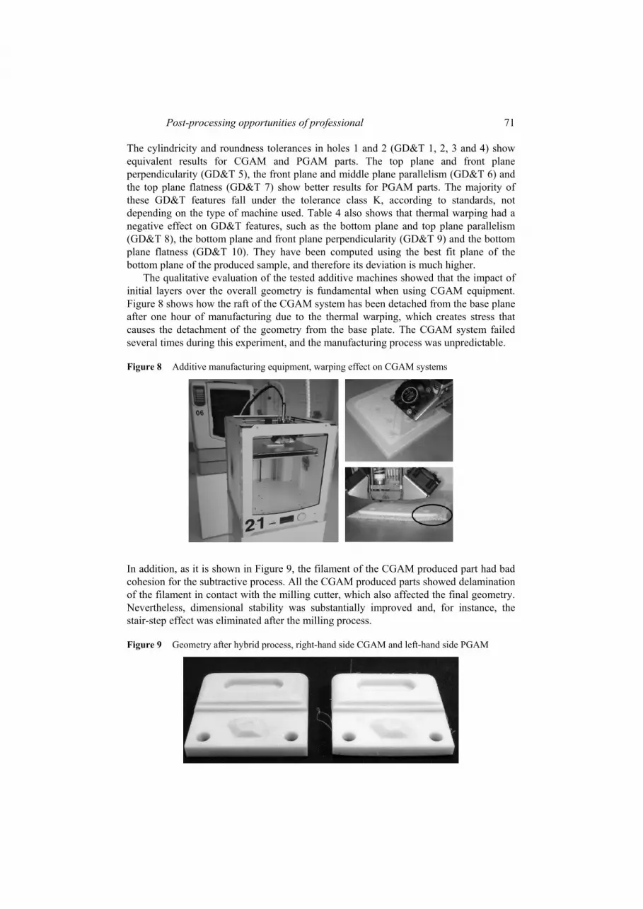
The qualitative evaluation of the tested additive machines showed that the impact of initial layers over the overall geometry is fundamental when using CGAM equipment. Figure 8 shows how the raft of the CGAM system has been detached from the base plane after one hour of manufacturing due to the thermal warping, which creates stress that causes the detachment of the geometry from the base plate. The CGAM system failed several times during this experiment, and the manufacturing process was unpredictable.
Figure 8 Additive manufacturing equipment, warping effect on CGAM systems
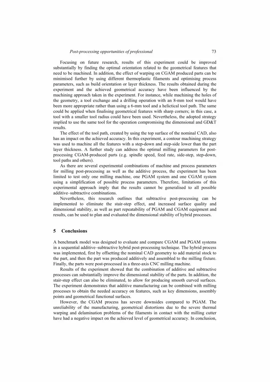
In addition, as it is shown in Figure 9, the filament of the CGAM produced part had bad cohesion for the subtractive process. All the CGAM produced parts showed delamination of the filament in contact with the milling cutter, which also affected the final geometry. Nevertheless, dimensional stability was substantially improved and, for instance, the stair-step effect was eliminated after the milling process.
Figure 9 Geometry after hybrid process, right-hand side CGAM and left-hand side PGAM

72 I.F. Ituarte et al.
4 Discussion
This research has underlined how subtractive methods, such as milling, grinding, or turning processes, can be an option for post-processing CGAM produced parts. The research has used an established process methodology in which parts are produced by additive systems and then a surface finishing strategy is implemented by subtractive methods. The obtained experimental results increase the understanding of the relationships between the additive and subtractive manufacturing process and final manufacturing accuracy, especially when studying commercially available CGAM systems.
The results of this research show that the combination of additive and subtractive hybrid processes is feasible and its implementation possible as a post-processing alternative. Dimensional and GD&T results demonstrate that additive and subtractive processes can be combined to create geometries with tight geometrical requirement for low production volumes. However, there are disadvantages when using CGAM equipment, mainly in terms of reliability of the process, build speed and final dimensional accuracy of the produced parts. More than 20 samples were produced, and 40% of the prints failed until the warping effect was minimised to an acceptable range; only the best three samples were included for analysis
The low reliability of CGAM equipment makes the production process uncertain, and therefore unsuitable for technical engineering applications. In general, dimensional and GD&T results showed that corrected standard deviation is higher in comparison to PGAM, mainly due to problems with thermal warping. The CGAM sample showed delamination problems on surface filaments in contact with the milling cutter, internal layers of the part did not show major distortions. The PGAM part did not suffer from major filament delamination during the milling process.
The authors understand that the sample size is critical to ensure more robust studies. Nevertheless, due to the difficulties in obtaining a bigger sample of reliable parts from the CGAM equipment, the standard deviation of the manufactured samples has been corrected following the instruction provided by ISO standard for measuring dimensional uncertainty when dealing with a limited sample size.
After this correction, the results of the PGAM sample showed that the subtractive finishing process can be more reliable and repeatable. The benefits of using the PGAM system are obvious: dimensional deviation and warping effects have been minimised by incorporating a heated build chamber in the machine and pre-establishing optimised process parameters to simplify the manufacturing, making the process more robust to variation. In addition, the produced sample had better mechanical performance for subtractive post-processing due to higher shear strength of the parts.
By analysing the results of Figure 4, the dimensions 6, 7, 8 and 9 showed a significant discrepancy between CGAM and PGAM. All these dimensional features have been measured in the Z-axis (i.e. dimensions related with the bottom plane of the produced parts). While using PGAM systems, the thermal warping is minimised by controlling the temperature gradient of the build chamber, and results are much closer to nominal; however, the CGAM system only included a heated plate having greater temperature gradients during the manufacturing processes, and therefore inaccuracies are much higher.
Post-processing opportunities of professional 73
Focusing on future research, results of this experiment could be improved substantially by finding the optimal orientation related to the geometrical features that need to be machined. In addition, the effect of warping on CGAM produced parts can be minimised further by using different thermoplastic filaments and optimising process parameters, such as build orientation or layer thickness. The results obtained during the experiment and the achieved geometrical accuracy have been influenced by the machining approach taken in the experiment. For instance, while machining the holes of the geometry, a tool exchange and a drilling operation with an 8-mm tool would have been more appropriate rather than using a 6-mm tool and a helictical tool path. The same could be applied when finalising geometrical features with sharp corners; in this case, a tool with a smaller tool radius could have been used. Nevertheless, the adopted strategy implied to use the same tool for the operation compromising the dimensional and GD&T results.
The effect of the tool path, created by using the top surface of the nominal CAD, also has an impact on the achieved accuracy. In this experiment, a contour machining strategy was used to machine all the features with a step-down and step-side lower than the part layer thickness. A further study can address the optimal milling parameters for post-processing CGAM-produced parts (e.g. spindle speed, feed rate, side-step, step-down, tool paths and others).
As there are several experimental combinations of machine and process parameters for milling post-processing as well as the additive process, the experiment has been limited to test only one milling machine, one PGAM system and one CGAM system using a simplification of possible process parameters. Therefore, limitations of this experimental approach imply that the results cannot be generalised to all possible additive–subtractive combinations.
Nevertheless, this research outlines that subtractive post-processing can be implemented to eliminate the stair-step effect, and increased surface quality and dimensional stability, as well as part repeatability of PGAM and CGAM equipment and results, can be used to plan and evaluated the dimensional stability of hybrid processes.
5 Conclusions
A benchmark model was designed to evaluate and compare CGAM and PGAM systems in a sequential additive–subtractive hybrid post-processing technique. The hybrid process was implemented, first by offsetting the nominal CAD geometry to add material stock to the part, and then the part was produced additively and assembled to the milling fixture. Finally, the parts were post-processed in a three-axis CNC milling machine.
Results of the experiment showed that the combination of additive and subtractive processes can substantially improve the dimensional stability of the parts. In addition, the stair-step effect can also be eliminated, to allow for producing smooth curved surfaces. The experiment demonstrates that additive manufacturing can be combined with milling processes to obtain the needed accuracy on features, such as key dimensions, assembly points and geometrical functional surfaces.
However, the CGAM process has severe downsides compared to PGAM. The unreliability of the manufacturing, geometrical distortions due to the severe thermal warping and delamination problems of the filaments in contact with the milling cutter have had a negative impact on the achieved level of geometrical accuracy. In conclusion,

74 I.F. Ituarte et al.
sequential additive and subtractive processes, as well as one-build hybrid systems, will need to consider these issues to produce quality FDM parts to be used in technical prototyping or short-run production for end use.
In this regard, future research is planned to address the limitations presented in this research, as well as to implement five-axis milling to post-process additively manufactured parts, and finalise complex geometries with curved or sculptured surfaces in a single set-up. In addition, rapid manufacturing and design rules of integrated fixture solutions, manufacturing process automation using multi-axis robots, material characterisation for cutting processes and optimisation of cutting parameters to ensure stress-free machining of additively manufactured parts is planned to be researched further.
Acknowledgements
This research project has been funded by the Agency for Technology and Innovation, ‘TEKES’ from Finland (grant number 3055/31/2012), together with a consortium of Finnish industry partners including DeskArtes, Genimate, Multiprint, Microsoft (Former Nokia Devices and Services), Nokian Renkaat, Relicomp, TP-Tools and Wärtsilä.
References
Ahn, D., Kim, H. and Lee, S. (2007) ‘Fabrication direction optimization to minimize post-machining in layered manufacturing’, International Journal of Machine Tools and Manufacture, Vol. 47, Nos. 3–4, pp.593–606.
Ahn, S-H., Chun, D-M. and Chu, W-S. (2013) ‘Perspective to green manufacturing and applications’, International Journal of Precision Engineering and Manufacturing, Vol. 14, No. 6, pp.873–874.
ASTM International (2013) F2792-12a – Standard Terminology for Additive Manufacturing Technologies. Available online at: www.astm.org/Standards/F2792
Birch, K. (2001) Estimating Uncertainties in Testing, Measurement Good Practice Guide No. 36, National Physical Laboratory, Teddington, UK.
Bogue, R. (2013) ‘3D printing: the dawn of a new era in manufacturing?’, Assembly Automation, Vol. 33, No. 4, pp.307–311.
Francis, J., Sparks, T.E., Ruan, J. and Frank, L. (2014) ‘Multi-axis tool path generation for surface finish machining of a rapid manufacturing process’, International Journal of Rapid Manufacturing, Vol. 4, No. 1, pp.66–80.
Gibson, I., Rosen, D.W. and Stucker, B. (2010) Additive Manufacturing Technologies: Rapid Prototyping to Direct Digital Manufacturing, Springer, New York.
Holmström, J. and Partanen, J. (2014) ‘Digital manufacturing-driven transformations of service supply chains for complex products’, Supply Chain Management: An International Journal, Vol. 19, No. 4, pp.421–430.
Hur, J., Lee, K., Zhu-hu and Kim, J. (2002) ‘Hybrid rapid prototyping system using machining and deposition’, CAD Computer Aided Design, Vol. 34, No. 10, pp.741–754.
ISO (2000) General Tolerances for Linear and Angular Dimensions, Linear Dimensions, DIN/ISO 2768T1, ISO.
ISO (2005) General Requirements for the Competence of Testing and Calibration Laboratories, ISO/IEC17025:2005, ISO.

Post-processing opportunities of professional 75
Johnson, W.M., Rowell, M., Deason, B. and Eubanks, M. (2014) ‘Comparative evaluation of an open-source FDM system’, Rapid Prototyping Journal, Vol. 20, No. 3, pp.205–214.
Kinnunen, T., Hanninen, K., Haapasalo, H. and Kropsu-Vehkapera, H. (2014) ‘Business case analysis in rapid productisation’, International Journal of Rapid Manufacturing, Vol. 4, No. 1, pp.14–27.
Kulkarni, P. and Dutta, D. (2000) ‘On the integration of layered manufacturing and material removal processes’, Journal of Manufacturing Science and Engineering, Vol. 122, No. 1, pp.100–108.
Lee, W.C., Wei, C.C. and Chung, S.C. (2014) ‘Development of a hybrid rapid prototyping system using low-cost fused deposition modeling and five-axis machining’, Journal of Materials Processing Technology, Vol. 214, No. 11, pp.2366–2374.
Mellor, S., Hao, L. and Zhang, D. (2014) ‘Additive manufacturing: a framework for implementation’, International Journal of Production Economics, Vol. 149, pp.194–201.
Pandey, P.M., Reddy, N.V. and Dhande, S.G. (2003) ‘Improvement of surface finish by staircase machining in fused deposition modeling’, Journal of Materials Processing Technology, Vol. 132, Nos. 1–3, pp.323–331.
Pei, E., Campbell, R.I. and de Beer, D. (2011) ‘Entry level RP machines: how well can they cope with geometric complexity?’, Journal of Assembly Automation, Vol. 31, No. 2, pp.153–160.
Pham, D. and Gault, R. (1998) ‘A comparison of rapid prototyping technologies’, International Journal of Machine Tools and Manufacture, Vol. 38, Nos. 10–11, pp.1257–1287.
Stucker, B. and Qu, X. (2003) ‘A finish machining strategy for rapid manufactured parts and tools’, Rapid Prototyping Journal, Vol. 9, No. 4, pp.194–200.
Thrimurthulu, K., Pulak, M. and Pandey, N.V.R. (2004) ‘Optimum part deposition orientation in fused deposition modeling’, Computer-Aided Design and Applications, Vol. 2, Nos. 1–4, pp.585–594.
Townsend, V. and Urbanic, R.J. (2011) ‘A systems approach to hybrid design: fused deposition modeling and CNC machining’, in Bernard, A. (Ed.): Global Product Development, Springer, Berlin, pp.373–383.
Turner, B.N., Strong, R. and Gold, S.A. (2014) ‘A review of melt extrusion additive manufacturing processes: I – process design and modeling’, Rapid Prototyping Journal, Vol. 20, No. 3, pp.192–204.
Wohlers, T. (2015) Additive Manufacturing and 3D Printing State of the Industry, Annual Worldwide Progress Report, Wohlers Associates Inc, USA.