policyl procedure - grenfell tower inquiry
TRANSCRIPT
Policyl Procedure
LONDON FIRE BRIGADE
Entel HT981 fireground radio and savox interface
equipment (BARIE)-training note
Official
New policy number: 516
Old instruction number: TRN:EO15:a1
Issue date: 12 July 2007
Reviewed as current: 22 November 2016
Owner: Head of Operational Policy
Responsible work team: Incident Communications
Contents
1 Aims ....................................................................................................................................................................... 2
2 Objectives ............................................................................................................................................................. 2
3 Introduction .......................................................................................................................................................... 2
4 The entel HT981 intrinsically safe fireground radio ......................................................................................
5 Description of entel HT981 intrinsically safe radio ....................................................................................... :3
6 The savox interface equipment connected toentel HT981 in yellow case .............................................. 6
7 Fitting B.A.R.I.E. to a breathing apparatus set ............................................................................................... 6
8 Operational use .................................................................................................................................................. 12
9 Channels .............................................................................................................................................................. 12
10 Battery fitting, removal and charging ............................................................................................................ 13
11 Cleaning, testing and recording ..................................................................................................................... 14
12 Testing ................................................................................................................................................................. 14
Document history .............................................................................................................................. 16
Review date: 22 November 2019
516 Issue date: 12 July 2007
Last amended date:
1 of 16
LFBO0105450 0001 LFB00105450/1
1
1.2
2
3
3.2
3.3
3.4
3.5
Aims
To introduce and familiarise SDBA and EDBAwearerswith the Entel HT981 intrinsically safe
rad io and Savox interface eq uipment (B.A.R.I.E).
Memorandum to all users of this policy
Before read ingthis policy all personnel are asked to ram iliarise them selves with the contents of
the following policies:
¯ Policy Number 593 - Entel HT981 Intrinsically Safe Fireground Radio. ¯ Policy Num ber 592 - Breathing Apparatus Rad io Interface Eq uipm ent (B_A_RI E)_
Objectives
By using this policy you will be able to:
¯ Identify the Entel rad io and Savox interface eq uipment (B.AR.I.E.) and where it is allocated. ¯ Fitthe radioand B.A.R.I.E. to an SDBA and EDBAset. ¯ Operatethe B.A.R.I.E. ¯ Remove and fit a battery to the radio and charge spare batteries. ¯ Be ram iliar with the testing of the Entel rad io and Savox interface eq uipm ent (B.A.R.I.E).
Introduction
The Entel HT981 is an intrinsically safe rad io that replaces the Motorola G P900 and Niros
TRX1012 currently carried on PumpingAppliances and Fire Rescue Units (FRU).These
appliances will now carry two sets of B.A.R.I.E. per appliance.
The radio and B.A.R.I.E. conform to all current requirementsofthe European ATEX Directive.
Eq uipment and Protective Systems intended for use in Potentially Explosive Atmospheres
(ATEX).
The radio is fully splash proof and SUBMERSIBLE, exceedingall aspects of the European ATEX
Directive. (Please note that this is a quality of the radio in its manufacture and not an intended
use when connected to a B.AR.I.E).
Safety precautions
Never attempt to remove a battery in a flammable or explosive atmosphere.
If dedicated B.A.R.I.E. sets are not available a minimum ofa handheld radio must be carried.
Ente1480/1 personal issue handheld radios are not intrinsically safe (IS), and m ust not be used
in flammable or explosive atmospheresand should only be used where BARIE sets are
unavailable, and only after a risk assessment has been undertaken. (Please refer to Policy Number 4.58 - Entel HX-480/1 Hand held Incident ground radio for further information).
516 Issue date: 12 July 2007 2of16
LFBO0105450 0002 LFB00105450/2
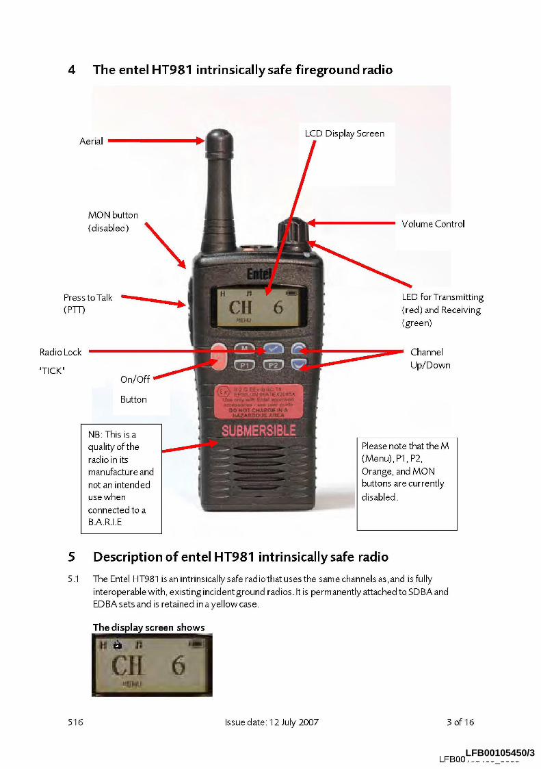
4 The entel HT981 intrinsically safe fireground radio
Aerial
MON button
(disabled)
Press to Talk
(P-I-F)
Radio Lock
’TICK’ On/Off
Button
NB: This is a
quality of the
radioin its
manufacture and
not an intended
use when
connected to a
B.A.R.I.E
LCD Display Screen
Volume Control
LED for Transmitting
(red) and Receiving
(green)
Channel Up/Down
Please note that the M
(Menu), P1, P2,
Orange, and MON
buttons are currently
disabled.
5 Description of entel HT981 intrinsically safe radio
The Entel HT981 is an intrinsically safe radiothat uses the same channels as, and is fully
interoperable with, existing incident ground radios. It is permanently attached to SDBA and
EDBA sets and is retained in a yellow case.
The display screen shows
516 Issue date: 12 July 2007 3 of 16
LFBO0105450 0003 LFB00105450/3
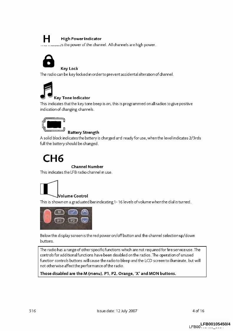
H Power Indicator High
............. ~,s the power of the channel. All channels are high power.
Key Lock
The radio can be key locked in order to prevent accidental alteration of channel.
l~r~ Key Tone Indicator
This indicates that the key tone beep is on; this is programmed on all radios to give positive
ind ication of changing channels.
Battery Strength
A solid block indicates the battery is charged and ready for use, when the level indicates 2/3rds
full the battery should be changed.
CH6 Channel Number
This indicates the LFB radio channel in use.
[~]Volume Control
This is shown on a grad uated bar indicating 1- 16 levels ofvolume when the dial is turned.
Belowthe display screen is the red power on/off button and the channel selection up/down
buttons.
The radio has a range of other specific functions which are not required for fire service use.The
controls for additional functions have been disabled on the radios. The operation of unused
function controls buttons will cause the radioto bleep and the LCD screen to illuminate, but will
not otherwise affect the performance of the radio.
Those disabled are the M (menu), P1, P2, Orange, ’X’ and MON buttons.
516 Issue date: 12 July 2007 4of16
LFB00105450 0004 LFB00105450/4
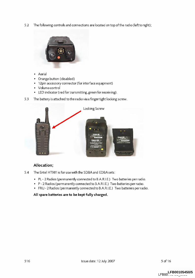
5.2 The following controls and connections are located on top of the rad io (left to right);
¯ Aerial ¯ Orange button (disabled) ¯ 12pin accessory connector (for interface equipment) ¯ Volume control ¯ LED indicator (red fortransmitting, green for receiving).
5.3 The battery is attached tothe radioviaa finger tight locking screw.
Locking Screw
5.4
Allocation;
The Entel HT981 is for usewiththe SDBAand EDBAsets:
¯ PL- 2 Radios (permanently connected to B.A.R.I.E.) Two batteries per radio. ¯ P - 2 Radios (permanently connected to B.A.R.I.E.) Two batteries per radio. ¯ FRU - 2 Radios (permanently connected to B.A.R.I.E.) Two batteries per radio.
All spare batteries are to be kept fully charged.
516 Issue date: 12 July 2007 5 of 16
LFB00105450 0005 LFB00105450/5
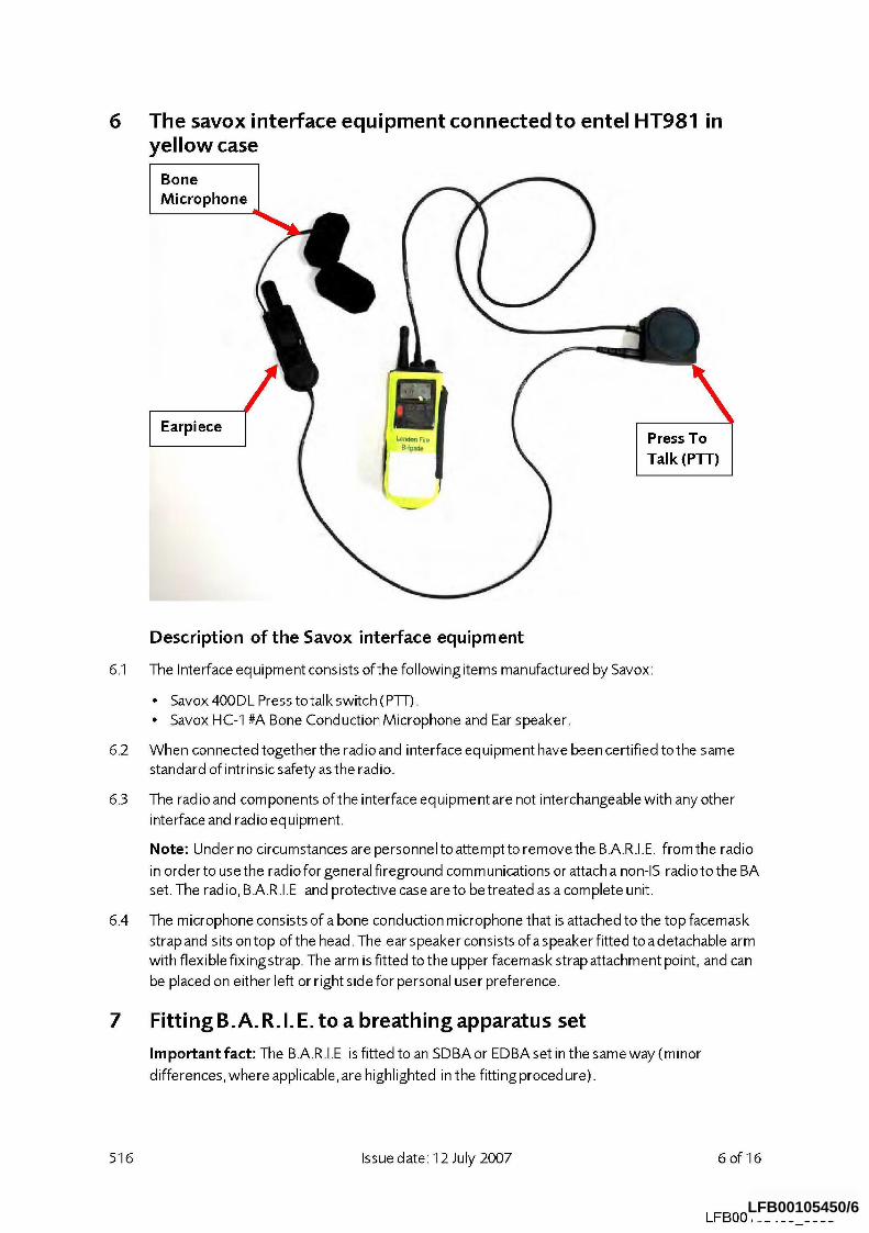
6 The savox interface equipment connected to entel HT981 in yellow case
Bone Microphone
,, Press To
Talk (PTT)
Description of the Savox interface equipment
6.1 The Interface eq uipment consists ofthe following items manufactured by Savox:
¯ Savox 400DL Press totalk switch (P-I-I-). ¯ Savox HC-1 #A Bone Conduction Microphone and Ear speaker.
5.2 When connected together the radio and interface eq uipment have been certified to the same
standard of intrinsic safety as the radio.
5.3 The radio and components of the interface equipment are not interchangeable with any other
interface and radio equipment.
Note: Under no circumstances are personnel to attempt to remove the B.A.R.I.E. from the radio
in order to use the radio for general fireground corn munications or attach a non-IS radio to the BA
set. The rad io, B.A.R.I.E and protective case are to be treated as a com plete unit.
5.4 The microphone consists of a bone cond uction microphone that is attached to the top facemask
strap and sits on top of the head. The ear speaker consists of a speaker fitted to a detachable arm
with flexible fixingstrap. The arm is fitted to the upper facemask strap attachment point, and can
be placed on either left or right side for personal user preference.
7 Fitting B.A.R.I.E. to a breathing apparatus set
Important fact: The B.A.R.I.E is fitted to an SDBA or EDBA set in the same way (minor
differences, where applicable, are highlighted in the fitting proced ure).
516 Issue date: 12 July 2007 6of16
LFB00105450 0006 LFB00105450/6
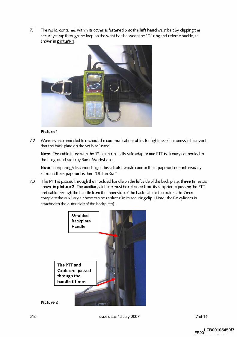
7.1 The radio, contained within its cover, is fastened onto the left hand waist belt by clipping the
security strap through the loop on the waist belt between the "D" ri ng and release buckle, as
shown in picture 1.
Picture I
7.2 Wearers are reminded to recheck the comm unication cables for tightness/looseness in the event
that the back plate on the set is adjusted.
Note: The cable fitted with the 12 pin intrinsically safe adaptor and P-I-I- is already connected to
the fireground radio by RadioWorkshops.
Note: Tampering/disconnecting of this adaptor would render the equipment non-intrinsically
safe and the equipment isthen "Offthe Run".
7.3 The PTTis passed throughthe moulded handle onthe left side ofthe back plate, three times,as
shown in picture 2. The auxiliary air hose m ust be released from its clip prior to passingthe P-I-I-
and cable through the handle from the inner side of the backplate to the outer side. Once
complete the auxiliary air hose can be replaced in its securingclip. (Note! the BA cylinder is
attached to the outer side of the backplate).
Moulded Backplate
Handle
The P~-r and Cable are passed through the handle 3 times
Picture 2
516 Issue date: 12 July 2007 7of16
LFBO0105450 0007 LFB00105450/7
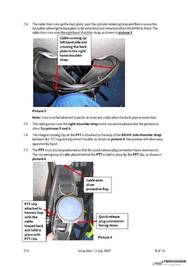
7.4 The cable then runs up the back plate, past the cylinder retaining strap and then crosses the
backplate allowingthe backplate to be extended and retracted whilst the BARIE is fitted.The
cable then runs over the right hand shoulder strap, as shown in picture :3.
Cable running up left hand side and
crossing the back "z--.~ll
hand shoulder
strap.
7.5
Picture 3
Note: Care m ust be taken not to pinch or strain any cable when the back plate is extended.
The cable passes overthe right shoulder strap and is secured in place under the protective
silver flap pictures 3 and 4.
7.6 The integral rotating clip on the PTT is attached to the loop ofthe RIGHT side shoulder strap
between the "D" ring and adjustment buckle, as shown in picture 4; this position will allow easy
operation by hand.
7.7 The PTT must also be positioned sothat the quick release plugconnection faces downwards.
The remaining loop of cable placed behind the PTT is held in place by the PTT clip, as shown in
p i ctu re 4.
Cable exits silver protective fl ap
PTT clip attached to harness with the cable looped back and held in place with PTT clip.
Quick release plug connection faci ng down
Picture 4
516 Issue date: 12 July 2007 8of16
LFBO0105450 0008 LFB00105450/8
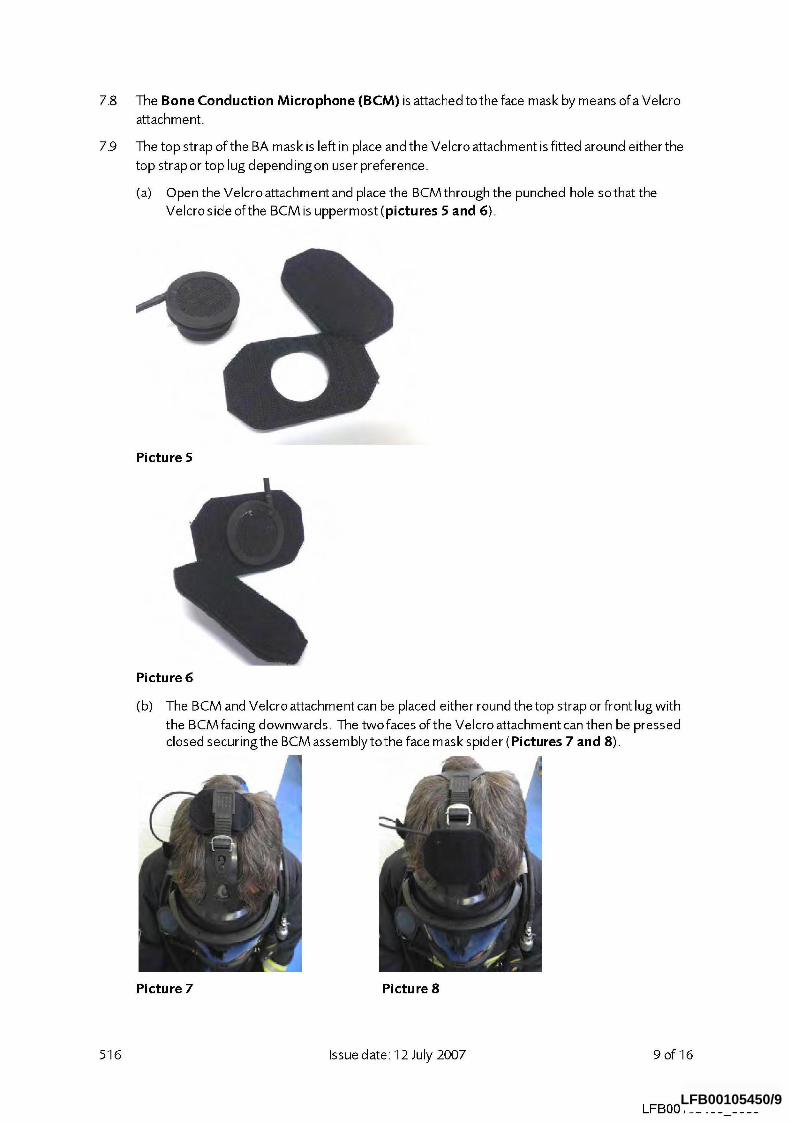
7.8
7_9
The Bone Conduction Microphone (BCM) is attached tothe face mask by means ofa Velcro
attachment.
The top strap of the BA mask is left in place and the Velcro attachment is fitted around either the
top strap or top lug depending on user preference.
(a) Open the Velcro attachment and place the BCM through the punched hole sothat the
Velcro side of the BCM is uppermost (pictures 5 and 6).
Picture 5
Picture 6
(b) The BCM and Velcro attachment can be placed either round the top strap or front lug with
the BCM facing downwards. The two faces of the Velcro attachment can then be pressed closed securingthe BCM assembly tothe face mask spider (Pictures 7 and 8).
Picture 7 Picture 8
516 Issue date: 12 July 2007 9of16
LFB00105450 0009 LFB00105450/9
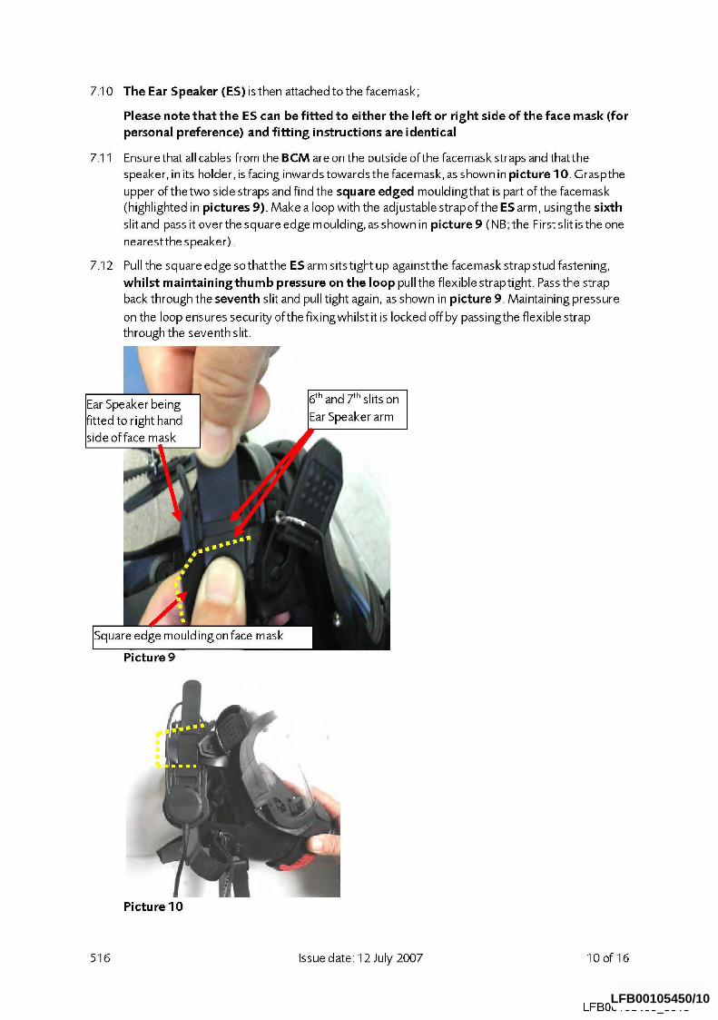
7.10 The Ear Speaker (ES) is then attached to the facemask;
7.11
7.12
Please note that the ES can be fitted to either the left or right side of the face mask (for personal preference) and fitting instructions are identical
Ensure that all cables from the BCM are on the outside of the facemask straps and thatthe
speaker, in its holder, is facing inwards towards the facemask, as shown in picture 10. Graspthe
upper of the two side straps and find the square edged mouldingthat is part of the facemask
(highlighted in pictures 9}. Make a loop with the adjustable strapofthe ES arm, usingthe sixth
slit and pass it over the square edge moulding, as shown in picture 9 (NB; the First slit is the one
nearestthe speaker)_
Pull the square edge so that the ES arm sits tight up against the facemask strap stud fastening,
whilst maintainingthumb pressure on the loop pull the flexible straptight. Pass the strap
back through the seventh slit and pull tight again, as shown in picture 9. Maintaining pressure
on the loop ensures security of the fixingwhilst it is locked offby passingthe flexible strap
through the seventh slit.
5th and 7th slits on
Ear Speaker arm
Square edge mouldingon face mask
Picture 9
Picture 10
516 Issue date: 12 July 2007 10of16
LFBO0105450 0010 LFB00105450/10

7.13
The quick release plug will be disconnected when the set is stowed on the appliance. The connection will only be made when it is necessary to test the B.A.R.I.E. and when the BA set is donned and started.
When wearing B.A.R.I.E. with fire hoods, donthe hood, passingthe face hole over the head so
that it sits around the wearer’s neck. Don the face mask in the normal manner ensuringthe bone
conduction microphone locates onto the head in a comfortable position. Pass the cable and quick
release plugfrom the speaker down through the face hole and out through the neck hole as
shown in picture 11. The plug will then hang from the top of the fire coat zip. The cable is then
hidden behind velcro fasteningof the fire coat leaving sufficient cable protrudingand enabling
connection to be made with the PTT, as shown in pictures 12 and 13. When the hood is pulled
back over the head and the fire tunic collar fastened (above the protrud ing cable), the hood will
provide an effective and continuous seal around the face mask and between the face mask and the tunic collar as shown in picture 14.
Picture 11 Picture 12
Ear Speaker and BCM] qidden undertheflash I mood J
Picture 13 Picture 14
516 Issue date: 12 July 2007 11 of 16
LFB00105450 0011 LFB00105450/11
8 Operational use
The procedures below areto be undertaken at ’A and B’ tests and don and start
Prior to rigging in BA it is recommended that B.A.R.I.E. wearers turn the radio on and key lock it to the appropriate channel.
To turn on the radio press the power switch,the radiowill bleep to indicate a selftest, ’London
Fire’ and the radio serial num her will appear in the LCD screen. The radio will then default to the
last channel selected and displaythis onthe LCD screen.
8.2 Channel 6 must be selected by the wearer for BA communications, or Channel 5 or8 ifbase
station and leaky feeder equipment are installed_
To prevent accidental changing ofthe channels the radio has been provided with a key lock
facility. The appropriate channel is key locked by pressingand holdingthe TICK button for 3
seconds, and a padlock symbolwill appear in the LCD screen. When in lock mode the radio
cannot be accidentally turned off. To unlock the channel press and hold the TICK button for 3
seconds, the radio can then be turned off by press ingthe power key.
8.4 Adjust the volumeto a comfortable listening level by rotatingthe volume knob. Clockwise will
increase volume and anticlockwise will decreasevolume,the volume level indicated on the LED
screen is in a series of 1 to 16 bars. There is NO limit stop on the rotating switch.
8.5 Rig in BA and carry out d on and start proced ure
8.6 To talk usingthe Press toTalk (PTT); connect the quick release plugintothe Press to Talk switch
then press the PTT with your hand.
8.7 Before transmitting, monitor the desired channel to ensure it is clear. When receivinga signal,
wait until the signal stops before transmitting.The radio cannot transmit and receive
sire ultaneously. Pressingthe transm it switch (PTT) on the B.A.R.I.E. begins transm ission, to
confirm transmission the LED on top of the radio will illuminate RED.
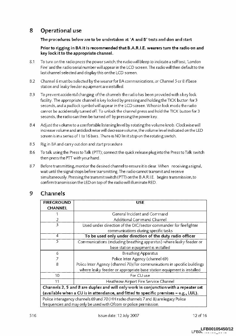
9 Channels
516
FIREGROUND USE
CHANNEL
1 General Incident and Command
2 Additional Command Channel 3 Used under direction of the OIC/sector commander for firefighter
communications during specific tasks 4 To be used only under direction of the duty radio officer 5 Communications (including breathing apparatus) where leaky feeder or
base station equipment is installed
6 Breathing Apparatus
7 Police Inter Agency (channel 69)
8 Police Inter Agency (channel 70)/for communications in specific buildings
where leaky feeder or appropriate base station equipment is installed
10 For CU use
11 Heathrow Airport Fire Service Channel
Channels 2, 5 and 8 are duplex and will only work in conjunction with a repeater set
(available when a CU is in attendance, and fitted to specific premises - e.g., LUL).
Police interagency channels 69 and 70 (H H radio channels 7 and 8) are legacy Police
frequencies and may only be used with Ofcom or police permission.
Issue date: 12 July 2007 12of16
LFBO0105450 0012 LFB00105450/12
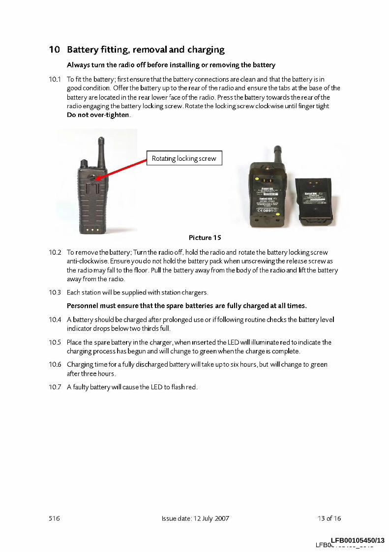
10
10.1
Battery fitting, removal and charging
Always turn the radio off before installing or removing the battery
To fit the battery; first ensure that the battery connections are clean and that the battery is in
good condition. Offer the battery up to the rear of the radio and ensure the tabs at the base of the
battery are located in the rear lower face of the radio. Press the battery towards the rear ofthe
radio engaging the battery locking screw. Rotate the locking screw clockwise until finger tight.
Do not over-tighten
Rotating locking screw
10.2
Picture 15
To remove the battery; Turn the radio off, hold the radio and rotate the battery Iockingscrew
anti-clockwise. Ensure you do not hold the battery pack when unscrewingthe release screw as
the radio may fall to the floor. Pull the battery away from the body of the radio and lift the battery
away from the radio.
10.3 Each station will be supplied with station chargers.
10.4
10.5
10.6
Personnel must ensure that the spare batteries are fully charged at all times.
A battery should be charged after prolonged use or if following routine checks the battery level
indicator drops belowtwo thirds full.
Place the spare battery in the charger, when inserted the LED will illuminate red to indicate the
charging process has begun and will change to green when the charge is corn plete.
Charging time for a fully discharged battery will take upto six hours, but will change to green
after three hours.
10.7 A faulty battery will cause the LED to flash red.
516 Issue date: 12 July 2007 13of16
LFBO0105450 0013 LFB00105450/13
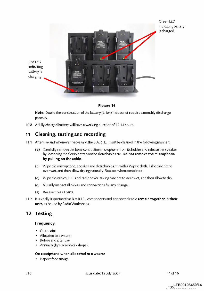
Red LED
indicating
battery is
charging
Green LED
indicating battery
is charged
10.8
11
11.1
11.2
12
Picture 16
Note: Dueto the construction of the battery (Li Ion) it does not require a monthly discharge
process.
A fully charged battery will have a workingduration of 12-14 hours.
Cleaning, testingand recording
After use and whenever necessary, the B.A.R.I.E. m ust be cleaned in the following manner:
(a) Carefully rem ove the bone cond uction m icrophone from its hold er and release the s peaker by Iooseningthe flexible strap on the detachable arm. Do not remove the microphone
by pulling on the cable.
(b) Wipe the m icrophone, speaker and d etachable arm with a Wipex cloth. Take care not to
over wet, and then allow d rying naturally. Replace when corn pleted.
(c) Wipe the cables, P~I- and radio cover,takingcare not to overwet, and then allowto dry.
(d) Visually inspect all cables and connections for any change.
(e) Reassemble all parts.
It is vitally importantthat B.A.R.I.E. components and connected radio remain together in their
unit, as issued by RadioWorkshops.
Testing
Frequency
¯ On receipt ¯ Allocated to awearer ¯ Beforeand after use ¯ Annually (by Radio Workshops).
On receipt and when allocated to a wearer
¯ Inspect fordamage.
516 Issue date: 12 July 2007 14of16
LFB00105450 0014 LFB00105450/14
Attach or check the existingfitting of both the fireground radio and the B.AR.I.E. to the allocated BA set. Testthe B.AR.I.E. with another hand held radio.
Before use
Testthe BAR.I.E. with the Communications Operator.
After use ¯ Clean as necessary ¯ Inspect fordamage ¯ Ensurethat the B.AR.I.E. is roved correctly ¯ Testwith another hand held radio ¯ Re-stowthe BA set on the appliance with the quick release plugdisconnected ¯ Ensurethe radio isturned offwhen not in use.
Annually
¯ The B_ARI_E is intrinsically safe and will be withd rawn annually for an intrinsic safety test by RadioWorkshops.
Recording of tests and inspections
An entry is to be made in colum n 9 - Remarks, ofthe BA log book to which the B.A.R.I.E. is
attached, after all inspections and tests.
516 Issue date: 12 July 2007 15 of 16
LFBO0105450 0015 LFB00105450/15
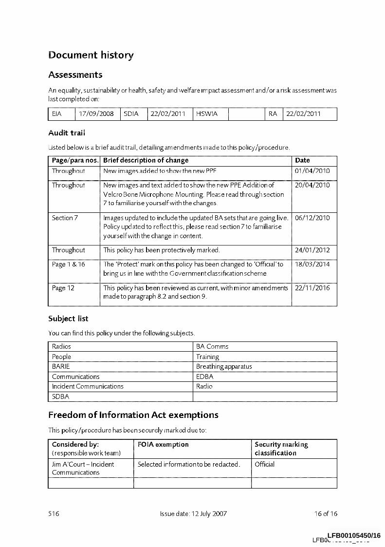
Document history
Assessme nts
An equality, sustainability or health, safety and welfare impact assessment and/or a risk assessment was
last completed on:
I I I
Audit trail
Listed below is a brief audit trail, detailingamendments madetothis policy/procedure.
Page/para nos. Brief description of change Date
Throughout New images added to showthe new PPE 01/04/2010
Throughout New images and text added to showthe new PPE Addition of 20/04/2010
Velcro Bone Microphone Mounting. Please read through section 7 to familiarise yourself with the changes.
Section 7 Images updated to include the updated BA sets that are going live. 06/12/2010
Policy updated to reflect this, please read section 7to familiarise
yourself with the change in content.
Throughout This policy has been protectively marked. 24/01/2012
Page 1 & 16 The ’Protect’ mark onthis policy has been changed to ’Official’ to 18/03/2014
bring us in line withthe Government classification scheme
Page 12 This po[icyhas been reviewed ascurrent, withminoramendments 22/11/2016
made to paragraph 8.2 and section 9.
Subject list
You can find this policy underthe followingsubjects.
Radios BA Comms
People Training
BARI E Breat hi ng apparatus
Corn munications EDBA
Incident Communications Radio
SDBA
Freedom of Information Act exemptions
This policy!procedure has been securely marked due to:
Considered by: FOIA exemption (responsible work team)
Jim A’Court-Incident Selected information to be redacted. Communications
Security marking classification
Official
516 Issue date: 12 July 2007 16of16
LFBO0105450 0016 LFB00105450/16