pjm generator interconnection #i11 new freedom – cardiff
TRANSCRIPT
PJM Generator Interconnection #I11 New Freedom – Cardiff 500MW
Impact Study
September 2003 DMS# 215125
2
General Project #I11 is a Commonwealth Shore, LLC 500 MW (summer capacity) generation project consisting of three simple cycle combustion turbine generators. The new generation will be located in Hamilton Township, Atlantic County, New Jersey. Project #I11 is scheduled for commercial operation by June 2006.
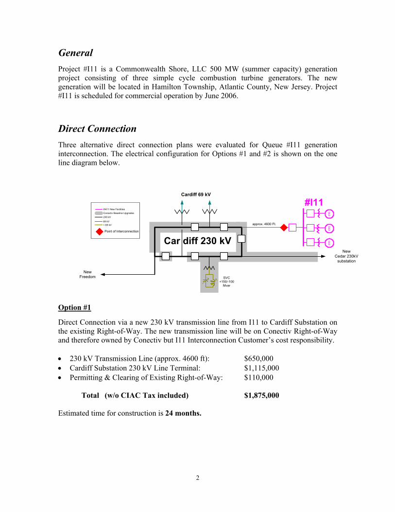
Direct Connection Three alternative direct connection plans were evaluated for Queue #I11 generation interconnection. The electrical configuration for Options #1 and #2 is shown on the one line diagram below.
Option #1 Direct Connection via a new 230 kV transmission line from I11 to Cardiff Substation on the existing Right-of-Way. The new transmission line will be on Conectiv Right-of-Way and therefore owned by Conectiv but I11 Interconnection Customer’s cost responsibility. • 230 kV Transmission Line (approx. 4600 ft): $650,000 • Cardiff Substation 230 kV Line Terminal: $1,115,000 • Permitting & Clearing of Existing Right-of-Way: $110,000
Total (w/o CIAC Tax included) $1,875,000 Estimated time for construction is 24 months.
CT1
CT3
CT2
#I11
Car diff 230 kV
NewFreedom
Cardiff 69 kV
SVC+150/-100
Mvar
NewCedar 230kV
substation
Conectiv Baseline Upgrades#H11 New Facilities
230 kV
69 kV< 69 kV approx. 4600 Ft.
Point of Interconnection
3
Option #2 Direct Connection via a new 230 kV transmission line from I11 to Cardiff Substation using the open position on the New Freedom to Cardiff 230 kV double circuit transmission line structures. The new transmission line would be on existing Conectiv structures and therefore owned by Conectiv but Queue I11 Interconnection Customer’s cost responsibility. The estimated cost and construction time is as follows:
• 230 kV Transmission Line (approx. 4600 ft) $ 600,000* • Cardiff Substation 230 kV Line Terminal $1,115,000 • Permitting & Clearing of Right-of-Way $ 40,000 • Value to Conectiv of open Position $ 110,000
Total (w/o CIAC Tax included) $1,865,000
Estimated time for construction is 24 months. * Assumes enough clearance exists to go under existing 230 kV New Freedom-Cardiff
line aerially to get to the open position on the structures. Planned outages on the existing New Freedom to Cardiff 230 kV line will be required in order to add the additional circuit. These planned outages may cause congestion and there may be limitations to the time of year when these planned outages can be scheduled.
Option #3 Direct Connection via cutting into the existing New Freedom – Cardiff 230 kV transmission line and establishing a 230 kV Ring Bus substation at the Queue I11 site. The 230 kV cut-in and 230 kV substation will be owned by Conectiv but Queue I11 Interconnection Customer’s cost responsibility. • 230 kV Transmission Line $1,100,000 • Cardiff Substation 230 kV Line Terminal $ 50,000 • Transmission Line Permitting $ 20,000 • 3 breaker 230 kV Ring Bus at Generator Site $4,100,000 Total (w/o CIAC Tax included) $5,270,000 Estimated time for construction is 30 months. Notes:
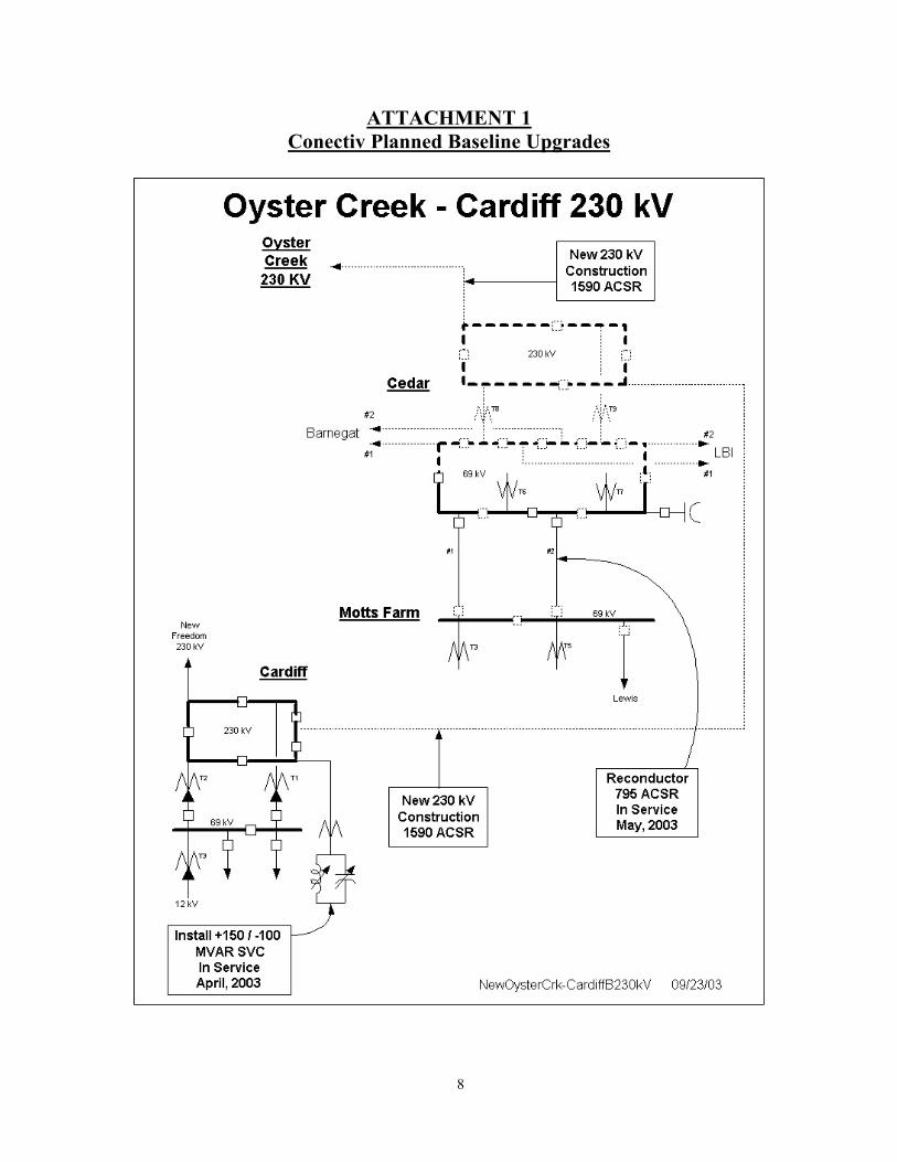
1. The one line diagram for options 1 and 2 includes upgrades identified for Conectiv baseline transmission expansion plans proposed at Cardiff. The total baseline transmission expansion plan is shown on Attachment #1. The Queue I11 Direct Connection and Network Upgrade requirements in this report are based on
4
the assumption that all Conectiv baseline upgrades are already completed. The baseline upgrades are scheduled for May, 2004.
2. #I11 Interconnection Customer will be responsible for installation of the generator
collector bus, Direct Connection line terminals, step-up transformers, and all switching equipment which will be located at the Generating Facility site.
3. All three options assume Pinelands Approval can be obtained to support a
commercial operation date of June 2006. Network Impacts The I11 project was studied as a 500MW capacity injection into the Cardiff 230kV substation. I11 was evaluated for compliance with reliability criteria for summer peak conditions in 2007. Potential network impacts were as follows: (Note: The following Impacts apply for either of the three Direct Connection options.) Normal System
No identified problems.
Single Contingency (MAAC Criteria IIA) No identified problems.
Second Contingency (MAAC Criteria IIB)
No identified problems. Multiple Facility Contingency (MAAC Criteria IIC)
No identified problems. Generator Deliverability 1. The Cardiff #2 230/69kV transformer is contingency overloaded at 115% of the
emergency rating (259 MVA) for the outage of the Cardiff #1 230/69kV transformer. The I11 project contributes approximately 68 MVA to the loading of this transformer. 2. The Cardiff #1 230/69kV transformer is contingency overloaded at 115% of the
emergency rating (259 MVA) for the outage of the Cardiff #2 230/69kV transformer. The I11 project contributes approximately 69 MVA to the loading of this transformer. 3. The Cardiff - Mill 69kV circuit is contingency overloaded at 129% of the emergency
rating (241MVA) for the outage of the Cardiff-Lewis 69kV circuit. The I11 project contributes approximately 80 MVA to the loading on this circuit.
4. The Cardiff – Lewis 69kV circuit is contingency overloaded at 110% of the emergency rating (241MVA) for the outage of the Cardiff-Mill 69kV circuit. The I11 project contributes approximately 65 MVA to the loading on this circuit.
5
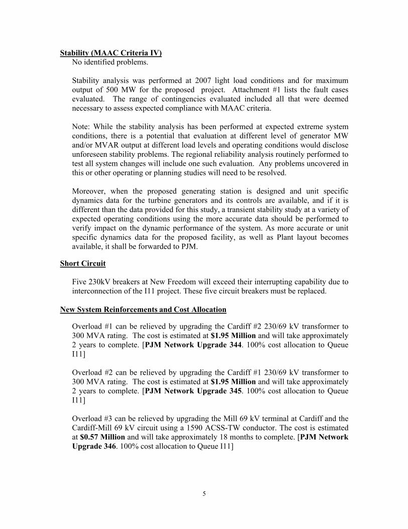
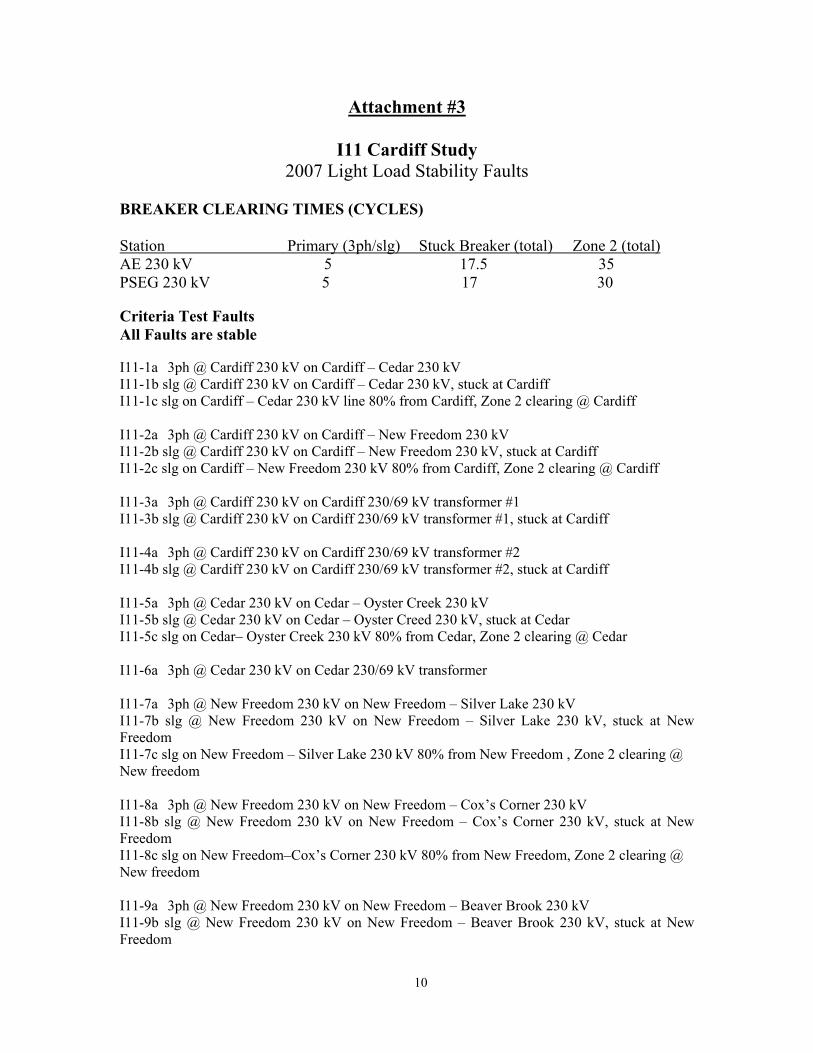
Stability (MAAC Criteria IV) No identified problems. Stability analysis was performed at 2007 light load conditions and for maximum output of 500 MW for the proposed project. Attachment #1 lists the fault cases evaluated. The range of contingencies evaluated included all that were deemed necessary to assess expected compliance with MAAC criteria.
Note: While the stability analysis has been performed at expected extreme system conditions, there is a potential that evaluation at different level of generator MW and/or MVAR output at different load levels and operating conditions would disclose unforeseen stability problems. The regional reliability analysis routinely performed to test all system changes will include one such evaluation. Any problems uncovered in this or other operating or planning studies will need to be resolved.
Moreover, when the proposed generating station is designed and unit specific dynamics data for the turbine generators and its controls are available, and if it is different than the data provided for this study, a transient stability study at a variety of expected operating conditions using the more accurate data should be performed to verify impact on the dynamic performance of the system. As more accurate or unit specific dynamics data for the proposed facility, as well as Plant layout becomes available, it shall be forwarded to PJM.
Short Circuit
Five 230kV breakers at New Freedom will exceed their interrupting capability due to interconnection of the I11 project. These five circuit breakers must be replaced.
New System Reinforcements and Cost Allocation
Overload #1 can be relieved by upgrading the Cardiff #2 230/69 kV transformer to 300 MVA rating. The cost is estimated at $1.95 Million and will take approximately 2 years to complete. [PJM Network Upgrade 344. 100% cost allocation to Queue I11] Overload #2 can be relieved by upgrading the Cardiff #1 230/69 kV transformer to 300 MVA rating. The cost is estimated at $1.95 Million and will take approximately 2 years to complete. [PJM Network Upgrade 345. 100% cost allocation to Queue I11] Overload #3 can be relieved by upgrading the Mill 69 kV terminal at Cardiff and the Cardiff-Mill 69 kV circuit using a 1590 ACSS-TW conductor. The cost is estimated at $0.57 Million and will take approximately 18 months to complete. [PJM Network Upgrade 346. 100% cost allocation to Queue I11]
6
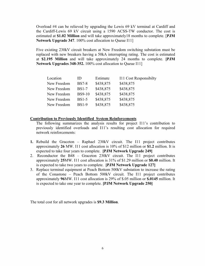
Overload #4 can be relieved by upgrading the Lewis 69 kV terminal at Cardiff and the Cardiff-Lewis 69 kV circuit using a 1590 ACSS-TW conductor. The cost is estimated at $1.02 Million and will take approximately18 months to complete. [PJM Network Upgrade 347. 100% cost allocation to Queue I11] Five existing 230kV circuit breakers at New Freedom switching substation must be replaced with new breakers having a 50kA interrupting rating. The cost is estimated at $2.195 Million and will take approximately 24 months to complete. [PJM Network Upgrades 348-352. 100% cost allocation to Queue I11]
Location ID Estimate I11 Cost Responsibilty New Freedom BS7-8 $438,875 $438,875 New Freedom BS1-7 $438,875 $438,875 New Freedom BS9-10 $438,875 $438,875 New Freedom BS1-5 $438,875 $438,875 New Freedom BS1-9 $438,875 $438,875
Contribution to Previously Identified System Reinforcements The following summarizes the analysis results for project I11’s contribution to previously identified overloads and I11’s resulting cost allocation for required network reinforcements:
1. Rebuild the Graceton – Raphael 230kV circuit. The I11 project contributes approximately 26 MW. I11 cost allocation is 10% of $12 million or $1.2 million. It is expected to take four years to complete. [PJM Network Upgrade 249]
2. Reconductor the B48 – Graceton 230kV circuit. The I11 project contributes approximately 25MW. I11 cost allocation is 31% of $1.29 million or $0.40 million. It is expected to take two years to complete. [PJM Network Upgrade 127]
3. Replace terminal equipment at Peach Bottom 500kV substation to increase the rating of the Conastone – Peach Bottom 500kV circuit. The I11 project contributes approximately 96MW. I11 cost allocation is 29% of $.05 million or $.0145 million. It is expected to take one year to complete. [PJM Network Upgrade 250]
The total cost for all network upgrades is $9.3 Million.
7
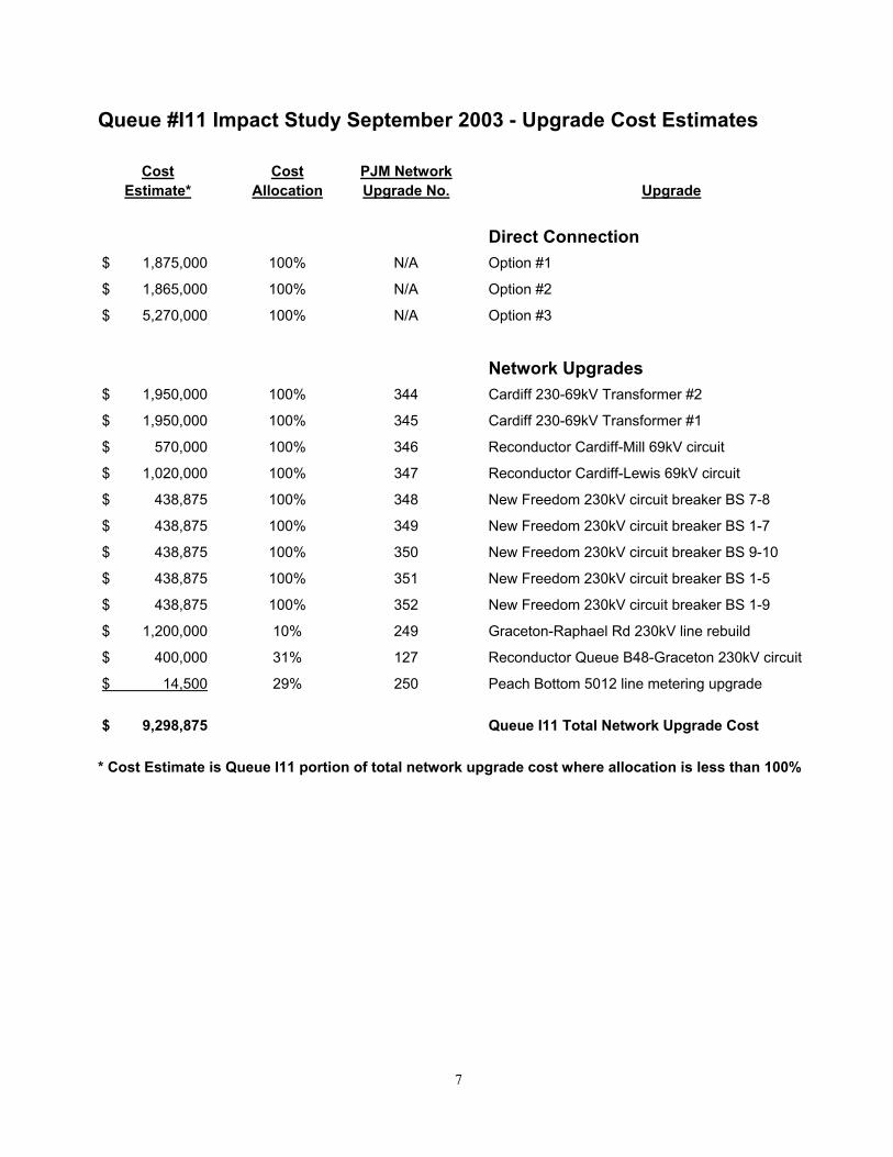
Queue #I11 Impact Study September 2003 - Upgrade Cost Estimates
Cost Cost PJM Network Estimate* Allocation Upgrade No. Upgrade
Direct Connection $ 1,875,000 100% N/A Option #1
$ 1,865,000 100% N/A Option #2
$ 5,270,000 100% N/A Option #3
Network Upgrades $ 1,950,000 100% 344 Cardiff 230-69kV Transformer #2
$ 1,950,000 100% 345 Cardiff 230-69kV Transformer #1
$ 570,000 100% 346 Reconductor Cardiff-Mill 69kV circuit
$ 1,020,000 100% 347 Reconductor Cardiff-Lewis 69kV circuit
$ 438,875 100% 348 New Freedom 230kV circuit breaker BS 7-8
$ 438,875 100% 349 New Freedom 230kV circuit breaker BS 1-7
$ 438,875 100% 350 New Freedom 230kV circuit breaker BS 9-10
$ 438,875 100% 351 New Freedom 230kV circuit breaker BS 1-5
$ 438,875 100% 352 New Freedom 230kV circuit breaker BS 1-9
$ 1,200,000 10% 249 Graceton-Raphael Rd 230kV line rebuild
$ 400,000 31% 127 Reconductor Queue B48-Graceton 230kV circuit
$ 14,500 29% 250 Peach Bottom 5012 line metering upgrade $ 9,298,875 Queue I11 Total Network Upgrade Cost * Cost Estimate is Queue I11 portion of total network upgrade cost where allocation is less than 100%
8
ATTACHMENT 1 Conectiv Planned Baseline Upgrades
9
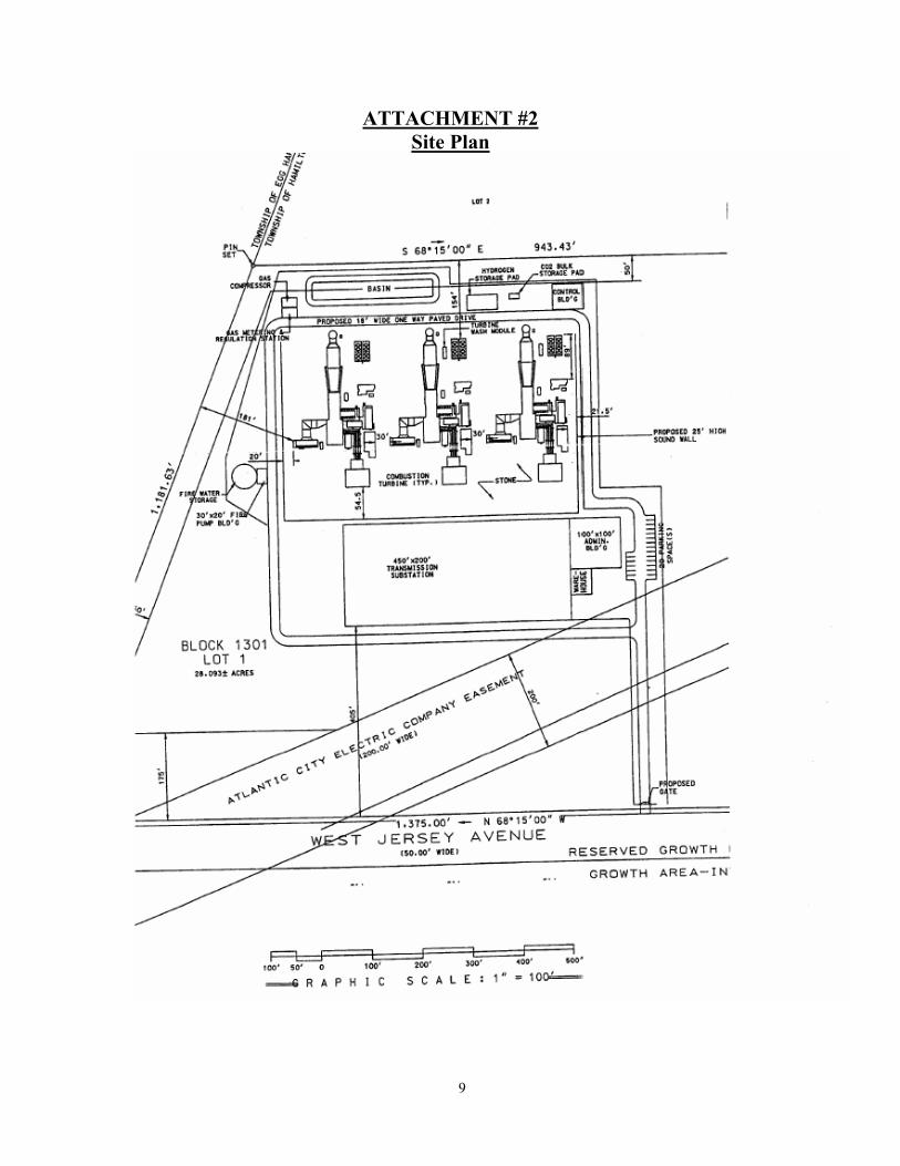
ATTACHMENT #2 Site Plan
10
Attachment #3
I11 Cardiff Study 2007 Light Load Stability Faults
BREAKER CLEARING TIMES (CYCLES) Station Primary (3ph/slg) Stuck Breaker (total) Zone 2 (total) AE 230 kV 5 17.5 35 PSEG 230 kV 5 17 30 Criteria Test Faults All Faults are stable I11-1a 3ph @ Cardiff 230 kV on Cardiff – Cedar 230 kV I11-1b slg @ Cardiff 230 kV on Cardiff – Cedar 230 kV, stuck at Cardiff I11-1c slg on Cardiff – Cedar 230 kV line 80% from Cardiff, Zone 2 clearing @ Cardiff I11-2a 3ph @ Cardiff 230 kV on Cardiff – New Freedom 230 kV I11-2b slg @ Cardiff 230 kV on Cardiff – New Freedom 230 kV, stuck at Cardiff I11-2c slg on Cardiff – New Freedom 230 kV 80% from Cardiff, Zone 2 clearing @ Cardiff I11-3a 3ph @ Cardiff 230 kV on Cardiff 230/69 kV transformer #1 I11-3b slg @ Cardiff 230 kV on Cardiff 230/69 kV transformer #1, stuck at Cardiff I11-4a 3ph @ Cardiff 230 kV on Cardiff 230/69 kV transformer #2 I11-4b slg @ Cardiff 230 kV on Cardiff 230/69 kV transformer #2, stuck at Cardiff I11-5a 3ph @ Cedar 230 kV on Cedar – Oyster Creek 230 kV I11-5b slg @ Cedar 230 kV on Cedar – Oyster Creed 230 kV, stuck at Cedar I11-5c slg on Cedar– Oyster Creek 230 kV 80% from Cedar, Zone 2 clearing @ Cedar I11-6a 3ph @ Cedar 230 kV on Cedar 230/69 kV transformer I11-7a 3ph @ New Freedom 230 kV on New Freedom – Silver Lake 230 kV I11-7b slg @ New Freedom 230 kV on New Freedom – Silver Lake 230 kV, stuck at New Freedom I11-7c slg on New Freedom – Silver Lake 230 kV 80% from New Freedom , Zone 2 clearing @ New freedom I11-8a 3ph @ New Freedom 230 kV on New Freedom – Cox’s Corner 230 kV I11-8b slg @ New Freedom 230 kV on New Freedom – Cox’s Corner 230 kV, stuck at New Freedom I11-8c slg on New Freedom–Cox’s Corner 230 kV 80% from New Freedom, Zone 2 clearing @ New freedom I11-9a 3ph @ New Freedom 230 kV on New Freedom – Beaver Brook 230 kV I11-9b slg @ New Freedom 230 kV on New Freedom – Beaver Brook 230 kV, stuck at New Freedom

11
I11-9c slg on New Freedom–Beaver Brook 230 kV 80% from New Freedom, Zone 2 clearing @ New freedom I11-10a 3ph @ New Freedom 230 kV on New Freedom – Sickler 230 kV I11-10b slg @ New Freedom 230 kV on New Freedom – Sickler 230 kV, stuck at New Freedom I11-10c slg on New Freedom – Sickler 230 kV 80% from New Freedom , Zone 2 clearing @ New freedom
12
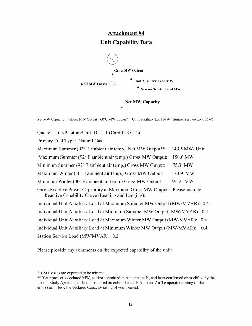
Attachment #4 Unit Capability Data
Net MW Capacity = (Gross MW Output - GSU MW Losses* – Unit Auxiliary Load MW - Station Service Load MW)
Queue Letter/Position/Unit ID: I11 (Cardiff-3 CTs)
Primary Fuel Type: Natural Gas
Maximum Summer (92º F ambient air temp.) Net MW Output**: 149.5 MW/ Unit
Maximum Summer (92º F ambient air temp.) Gross MW Output: 150.6 MW
Minimum Summer (92º F ambient air temp.) Gross MW Output: 75.3 MW
Maximum Winter (30º F ambient air temp.) Gross MW Output: 183.9 MW
Minimum Winter (30º F ambient air temp.) Gross MW Output: 91.9 MW
Gross Reactive Power Capability at Maximum Gross MW Output – Please include Reactive Capability Curve (Leading and Lagging):
Individual Unit Auxiliary Load at Maximum Summer MW Output (MW/MVAR): 0.4
Individual Unit Auxiliary Load at Minimum Summer MW Output (MW/MVAR): 0.4
Individual Unit Auxiliary Load at Maximum Winter MW Output (MW/MVAR): 0.4
Individual Unit Auxiliary Load at Minimum Winter MW Output (MW/MVAR): 0.4
Station Service Load (MW/MVAR): 0.2
Please provide any comments on the expected capability of the unit: * GSU losses are expected to be minimal. ** Your project’s declared MW, as first submitted in Attachment N, and later confirmed or modified by the Impact Study Agreement, should be based on either the 92 oF Ambient Air Temperature rating of the unit(s) or, if less, the declared Capacity rating of your project.
Station Service Load MW
Net MW Capacity
Gross MW Output
GSU MW LossesUnit Auxiliary Load MW
13
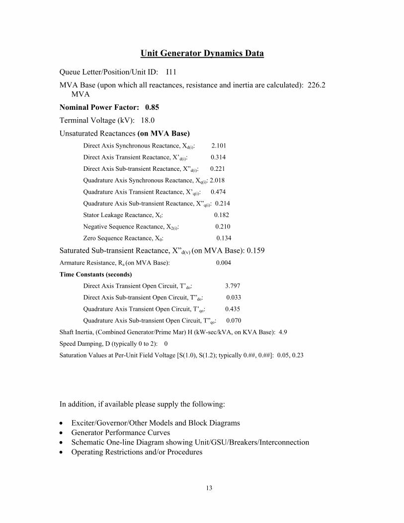
Unit Generator Dynamics Data Queue Letter/Position/Unit ID: I11
MVA Base (upon which all reactances, resistance and inertia are calculated): 226.2 MVA
Nominal Power Factor: 0.85 Terminal Voltage (kV): 18.0
Unsaturated Reactances (on MVA Base) Direct Axis Synchronous Reactance, Xd(i): 2.101
Direct Axis Transient Reactance, X’d(i): 0.314
Direct Axis Sub-transient Reactance, X”d(i): 0.221
Quadrature Axis Synchronous Reactance, Xq(i): 2.018
Quadrature Axis Transient Reactance, X’q(i): 0.474
Quadrature Axis Sub-transient Reactance, X”q(i): 0.214
Stator Leakage Reactance, Xl: 0.182
Negative Sequence Reactance, X2(i): 0.210
Zero Sequence Reactance, X0: 0.134
Saturated Sub-transient Reactance, X”d(v) (on MVA Base): 0.159 Armature Resistance, Ra (on MVA Base): 0.004
Time Constants (seconds)
Direct Axis Transient Open Circuit, T’do: 3.797
Direct Axis Sub-transient Open Circuit, T”do: 0.033
Quadrature Axis Transient Open Circuit, T’qo: 0.435
Quadrature Axis Sub-transient Open Circuit, T”qo: 0.070
Shaft Inertia, (Combined Generator/Prime Mar) H (kW-sec/kVA, on KVA Base): 4.9
Speed Damping, D (typically 0 to 2): 0
Saturation Values at Per-Unit Field Voltage [S(1.0), S(1.2); typically 0.##, 0.##]: 0.05, 0.23
In addition, if available please supply the following: • Exciter/Governor/Other Models and Block Diagrams • Generator Performance Curves • Schematic One-line Diagram showing Unit/GSU/Breakers/Interconnection • Operating Restrictions and/or Procedures
14
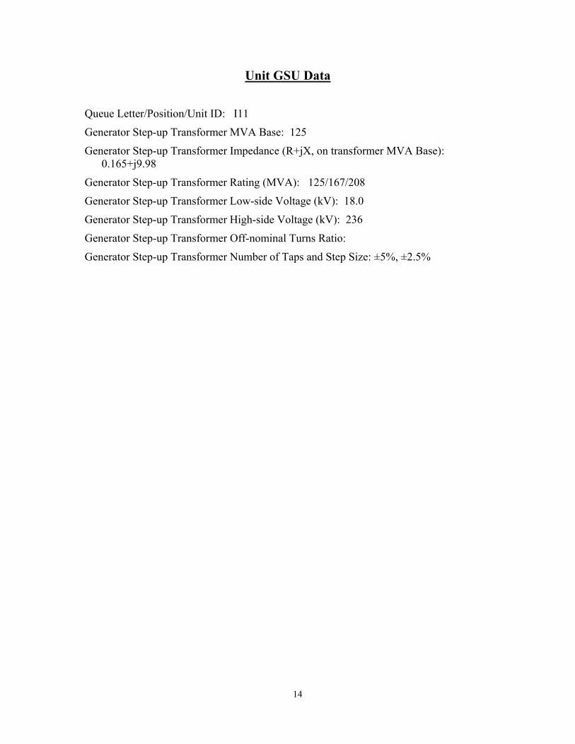
Unit GSU Data
Queue Letter/Position/Unit ID: I11
Generator Step-up Transformer MVA Base: 125
Generator Step-up Transformer Impedance (R+jX, on transformer MVA Base): 0.165+j9.98
Generator Step-up Transformer Rating (MVA): 125/167/208
Generator Step-up Transformer Low-side Voltage (kV): 18.0
Generator Step-up Transformer High-side Voltage (kV): 236
Generator Step-up Transformer Off-nominal Turns Ratio:
Generator Step-up Transformer Number of Taps and Step Size: ±5%, ±2.5%