phoenix digger uncovers ice in martian soil
TRANSCRIPT
JWST-PLAN-000872 Revision -
Effective Date: January 5, 2004 Expiration Date: January 5, 2009
James Webb Space Telescope Project
Systems Engineering Management Plan
November 21, 2003
CHECK WITH JWST DATABASE AT:https://ngst1.hst.nasa.gov/
TO VERIFY THAT THIS IS THE CORRECT VERSION PRIOR TO USE.
Goddard Space FlightCenter
Greenbelt, Maryland National Aeronauticsand
Space Administration
JWST GSFC CMO
January 5, 2004
RELEASED
JWST Systems Engineering Management Plan JWST-PLAN-000872Revision-
CM FOREWORD
This document is a James Webb Space Telescope (JWST) Project Configuration Management (CM)-controlled document. Changes to this
document require prior approval of the JWST Project Manager. Proposed changes shall be submitted to the JWST CM Office (CMO), along with
supportive material justifying the proposed change. Changes to this document will be made by complete revision.
Questions or comments concerning this document should be addressed to:
JWST Configuration Manager JWST Configuration Management Office Mail Stop 443
Goddard Space Flight Center Greenbelt, Maryland 20771
CHECK WITH JWST DATABASE AT:https://ngst1.hst.nasa.gov/
TO VERIFY THAT THIS IS THE CORRECT VERSION PRIOR TO USE.

JWST Systems Engineering Management Plan JWST-PLAN-000872Revision-
James Webb Space Telescope Project
Systems Engineering Management Plan (SEMP)
Signature Page
Prepared by:
Original signed by 1/5/04 Richard Lynch Systems Engineer
Approved by:
Original signed by 1/5/04 Joe Burt
JWST Mission Systems Engineer NASA GSFC, Code 530
CHECK WITH JWST DATABASE AT:https://ngst1.hst.nasa.gov/
TO VERIFY THAT THIS IS THE CORRECT VERSION PRIOR TO USE.
JWST Systems Engineering Management Plan JWST-PLAN-000872Revision-
JAMES WEBB SPACE TELESCOPE PROJECT
DOCUMENT CHANGE RECORD...................... Sheet: 1 of 1REVLEVEL DESCRIPTION OF CHANGE APPROVED
BYDATE
APPROVED
CHECK WITH JWST DATABASE AT:https://ngst1.hst.nasa.gov/
TO VERIFY THAT THIS IS THE CORRECT VERSION PRIOR TO USE.
JWST Systems Engineering Management Plan JWST-PLAN-000872Revision-
Basic
Released per JWST-CCR-000102 P.Sabelhaus
12/11/03
CHECK WITH JWST DATABASE AT:https://ngst1.hst.nasa.gov/
TO VERIFY THAT THIS IS THE CORRECT VERSION PRIOR TO USE.

JWST Systems Engineering Management Plan JWST-PLAN-000872Revision-
List of TBDs/TBRs
Item No. Location Summary Resp.Party
DueDate
1 Appendix C Engineering MemoFormat
R. Lynch/443
3/1/04
2 3.5.4.3.2 Institutional Systems R.Lynch/443
3/1/04
3 3.5.4.3.3 Common Systems R.Lynch/443
3/1/04
CHECK WITH JWST DATABASE AT:https://ngst1.hst.nasa.gov/
TO VERIFY THAT THIS IS THE CORRECT VERSION PRIOR TO USE.
JWST Systems Engineering Management Plan JWST-PLAN-000872Revision-
TABLE OF CONTENTSPage
1.0 Scope....................................................1-1
1.1 Purpose.............................................1-11.2 Mission Overview....................................1-1
2.0 Reference Documents......................................2-1
2.1 Goddard Space Flight Center Documents.................2-12.2 Non-Goddard Space Flight Center Documents.............2-1
3.0 Systems Engineering Management............................3-1
3.1 Definition and Scope.................................3-13.2 Objective and Approach...............................3-13.3 Unique Factors......................................3-13.4 Lessons Learned.....................................3-23.5 JWST Systems Engineering Team Approach................3-2
3.5.1............ Discipline and Product Systems Engineers3-3
3.5.2............................... Integrated Modeling3-4
3.5.3.................................... Working Groups3-4
3.5.4......................... Roles and Responsibilities3-7
3.6 Systems Engineering Communication...................3-143.7 Systems Engineering Schedule........................3-15
4.0 Key Systems Engineering Functions.........................4-1ii
CHECK WITH JWST DATABASE AT:https://ngst1.hst.nasa.gov/
TO VERIFY THAT THIS IS THE CORRECT VERSION PRIOR TO USE.
JWST Systems Engineering Management Plan JWST-PLAN-000872Revision-
4.1 Systems Engineering Life Cycle, Gates and Reviews......4-2
4.1.1................ Pre-Phase A: Conceptual Design Phase4-2
4.1.2........................ Phase A: Preliminary Design4-3
4.1.3............ Phase B/C: Detail Design and Development4-3
4.1.4..... Phase D: Production, Integration, and Test Phase4-3
4.1.5......... Phase E: Operational Use and Systems Support4-4
4.2 Requirements Identification and Analysis.............4-8
4.2.1......................... Requirements Traceability4-9
TABLE OF CONTENTS (CONTINUED)Page
4.2.2 Requirement Verification......................4-10
4.3 Functional Analysis and Allocation..................4-114.4 Design Synthesis...................................4-124.5 Verification.......................................4-134.6 System Analysis and Control.........................4-15
4.6.1........................... Requirements Management4-16
4.6.2.................. Trade Studies/Engineering Studies4-16
4.6.3............................... Design Optimization4-17
4.6.4............................ Design Standardization4-17
iii
CHECK WITH JWST DATABASE AT:https://ngst1.hst.nasa.gov/
TO VERIFY THAT THIS IS THE CORRECT VERSION PRIOR TO USE.
JWST Systems Engineering Management Plan JWST-PLAN-000872Revision-
4.6.5.......................Survivability/Vulnerability4-17
4.6.6....................................Produceability4-17
4.6.7............................... Equipment Databases4-17
4.6.8............ Fault Detection, Isolation, and Recovery4-18
4.6.9................................... Risk Management4-18
4.6.10...... Mission/Product Assurance and Quality Control4-18
4.7 Technical Performance Metrics.......................4-194.8 Technical Reviews..................................4-19
4.8.1......................... System Engineering Reviews4-21
4.8.2.............................. Project Level Reviews4-22
4.9 Configuration Management...........................4-224.10 Integration and Test................................4-23
5.0 Systems Engineering Tools.................................5-1
5.1 Statement of Work....................................5-15.2 Work Breakdown Structure.............................5-15.3 Technical Plans.....................................5-15.4 Project Schedule/Milestones.........................5-15.5 Technical Performance Measures ......................5-15.6 Resource Margin.....................................5-35.7 Contingency Criteria................................5-3
5.7.1........................................Propellant5-4
iv
CHECK WITH JWST DATABASE AT:https://ngst1.hst.nasa.gov/
TO VERIFY THAT THIS IS THE CORRECT VERSION PRIOR TO USE.
JWST Systems Engineering Management Plan JWST-PLAN-000872Revision-
5.7.2.............................. Pointing (Alignment)5-5
5.7.3.................. Command and Telemetry Allocations5-5
5.7.4............................. Link Margin Allocation5-5
TABLE OF CONTENTS (CONTINUED)Page
5.7.5.........................................Processor5-5
5.7.6.............................. Reliability Analysis5-5
5.7.7........................... Orbital Debris Analysis5-6
Appendix A. Abbreviations and Acronyms.........................A-1 Appendix B. Technical Problem/Resolution.......................B-1 Appendix C. Engineering Memo Forma.............................C-1
LIST OF FIGURES Figure...........................................................
Page
1-1 The JWST System Level Block Diagram........................1-1 3-1 The JWST System Engineering Team (SET).....................3-3
3-2 The JWST System...........................................3-83-3 JWST Communications Enterprise...........................3-143-4 SET Communication Process................................3-153-5 JWST SE Schedules........................................3-164-1 The System Engineering Process............................4-14-2 SET Products.............................................4-24-3 JWST Project Life Cycle...................................4-24-4 JWST Requirements Flow....................................4-84-5 Requirements Development Process.........................4-114-6 JWST Verification.......................................4-14
v
CHECK WITH JWST DATABASE AT:https://ngst1.hst.nasa.gov/
TO VERIFY THAT THIS IS THE CORRECT VERSION PRIOR TO USE.
JWST Systems Engineering Management Plan JWST-PLAN-000872Revision-
4-7 Requirements Management Process..........................4-164-8 System Engineering Reviews...............................4-20
LIST OF TABLESTable............................................................
Page
3-1 JWST Working Groups.......................................3-63-2 JWST Systems Engineering Responsibility Matrix.............3-84-1 Products by Phase.........................................4-54-2 Control Gates by Phase....................................4-64-3 Information Base-lined by Phase...........................4-74-4 Verification Methods....................................4-154-5 Project Reviews.........................................4-215-1 Contingency Release Schedule..............................5-3
vi
CHECK WITH JWST DATABASE AT:https://ngst1.hst.nasa.gov/
TO VERIFY THAT THIS IS THE CORRECT VERSION PRIOR TO USE.
JWST Systems Engineering Management Plan JWST-PLAN-000872Revision-
1.0 SCOPE
1.1 PURPOSE The Systems Engineering Management Plan (SEMP) defines the systems
engineering approach for the James Webb Space Telescope (JWST). The full range of systems engineering activities on the Project, the
organizations involved and the methods of coordinating and integrating these activities are presented in this document.
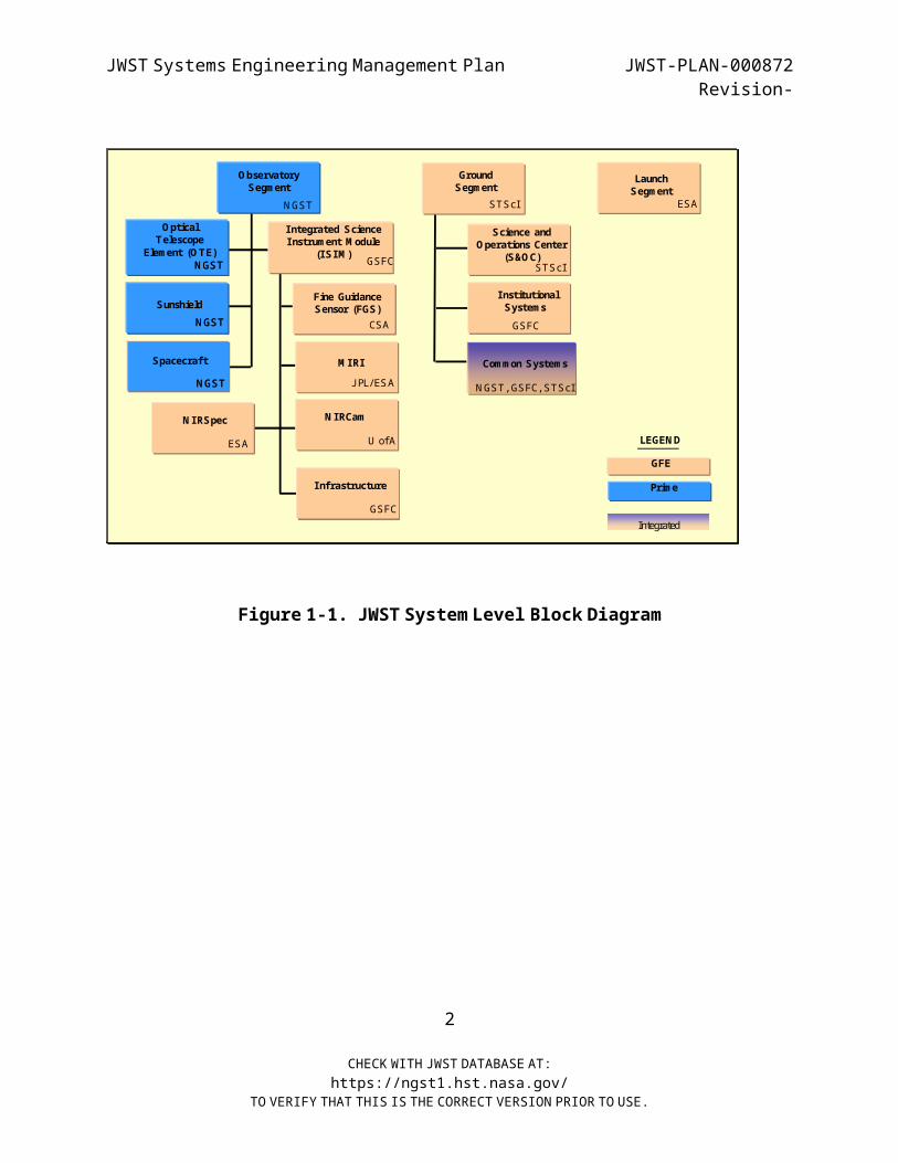
1.2 MISSION OVERVIEW JWST is a large-scale National Aeronautics and Space Administration
(NASA) Goddard Space Flight Center (GSFC) Project with an architecture that is divided into three segments as shown in Figure 1-1. The
Observatory Segment is the responsibility of the Prime Contractor. The Prime is responsible for the design, development, Integration and
Test (I&T), and on-orbit performance of the Observatory. Significant portions of the Observatory are provided as Government- Furnished
Equipment (GFE) for reasons of cost sharing, resident expertise, community involvement, etc. Additionally, the Ground and Launch
segments are provided as GFE.
1
CHECK WITH JWST DATABASE AT:https://ngst1.hst.nasa.gov/
TO VERIFY THAT THIS IS THE CORRECT VERSION PRIOR TO USE.
JWST Systems Engineering Management Plan JWST-PLAN-000872Revision-
Figure 1- 1. JWST System Level Block Diagram
2
CHECK WITH JWST DATABASE AT:https://ngst1.hst.nasa.gov/
TO VERIFY THAT THIS IS THE CORRECT VERSION PRIOR TO USE.
Launch Segm ent
KSCGround Segm ent
STScI
Science and O perations Center
(S&O C)STScI
Com m unications Elem ent
STScI
W ave Front SensingAnd Control
(W FS&C) ExecutiveJPL
O bservatory
Prim e
Prim e
Sunshield
Prim e
Integrated Science Instrum ent M odule
(ISIM ) GSFC
Fine Guidance Sensor (FGS)
CSA
N IRCam
USAN IRSpec
ESA
M IRIJPL/ESA
GFE
LEGEN D
O ptical Telescope
Elem ent (O TE)
Spacecraft
ESA
ISIMCom m on C&DH
GSFC
Shared Services
GSFC
Prim e
Launch Segm ent
ESA
Ground Segm ent
STScI
Science and O perations Center
(S&O C)STScI
InstitutionalServicesDSN , GSFC
Com m on System s
N GST
O bservatory Segm ent
N GST
Sunshield
Integrated Science Instrum ent M odule
(ISIM ) GSFC
Fine Guidance Sensor (FGS)
CSA
N IRCam
U ofAN IRSpec
ESA
M IRIJPL/ESA
GFE
LEGEN D
O ptical Telescope
Elem ent (O TE)
Spacecraft
ISIMC&DH
GSFC
Infrastructure
GSFC
Prim e
N GST
N GST
N GST
Launch Segm ent
KSCGround Segm ent
STScI
Science and O perations Center
(S&O C)STScI
Com m unications Elem ent
STScI
W ave Front SensingAnd Control
(W FS&C) ExecutiveJPL
O bservatory
Prim e
Prim e
Sunshield
Prim e
Integrated Science Instrum ent M odule
(ISIM ) GSFC
Fine Guidance Sensor (FGS)
CSA
N IRCam
USAN IRSpec
ESA
M IRIJPL/ESA
GFE
LEGEN D
O ptical Telescope
Elem ent (O TE)
Spacecraft
ESA
ISIMCom m on C&DH
GSFC
Shared Services
GSFC
Prim e
Launch Segm ent
ESA
Ground Segm ent
STScI
Science and O perations Center
(S&O C)STScI
InstitutionalSystem sGSFC
Com m on System s
N GST, GSFC, STScI
O bservatory Segm ent
N GST
Sunshield
Integrated Science Instrum ent M odule
(ISIM ) GSFC
Fine Guidance Sensor (FGS)
CSA
N IRCam
U ofAN IRSpec
ESA
M IRIJPL/ESA
GFE
LEGEN D
O ptical Telescope
Elem ent (O TE)
Spacecraft
Infrastructure
GSFC
Prim e
N GST
N GST
N GST
Integrated
Launch Segm ent
KSCGround Segm ent
STScI
Science and O perations Center
(S&O C)STScI
Com m unications Elem ent
STScI
W ave Front SensingAnd Control
(W FS&C) ExecutiveJPL
O bservatory
Prim e
Prim e
Sunshield
Prim e
Integrated Science Instrum ent M odule
(ISIM ) GSFC
Fine Guidance Sensor (FGS)
CSA
N IRCam
USAN IRSpec
ESA
M IRIJPL/ESA
GFE
LEGEN D
O ptical Telescope
Elem ent (O TE)
Spacecraft
ESA
ISIMCom m on C&DH
GSFC
Shared Services
GSFC
Prim e
Launch Segm ent
ESA
Ground Segm ent
STScI
Science and O perations Center
(S&O C)STScI
InstitutionalServicesDSN , GSFC
Com m on System s
N GST
O bservatory Segm ent
N GST
Sunshield
Integrated Science Instrum ent M odule
(ISIM ) GSFC
Fine Guidance Sensor (FGS)
CSA
N IRCam
U ofAN IRSpec
ESA
M IRIJPL/ESA
GFE
LEGEN D
O ptical Telescope
Elem ent (O TE)
Spacecraft
ISIMC&DH
GSFC
Infrastructure
GSFC
Prim e
N GST
N GST
N GST
Launch Segm ent
KSCGround Segm ent
STScI
Science and O perations Center
(S&O C)STScI
Com m unications Elem ent
STScI
W ave Front SensingAnd Control
(W FS&C) ExecutiveJPL
O bservatory
Prim e
Prim e
Sunshield
Prim e
Integrated Science Instrum ent M odule
(ISIM ) GSFC
Fine Guidance Sensor (FGS)
CSA
N IRCam
USAN IRSpec
ESA
M IRIJPL/ESA
GFE
LEGEN D
O ptical Telescope
Elem ent (O TE)
Spacecraft
ESA
ISIMCom m on C&DH
GSFC
Shared Services
GSFC
Prim e
Launch Segm ent
ESA
Ground Segm ent
STScI
Science and O perations Center
(S&O C)STScI
InstitutionalSystem sGSFC
Com m on System s
N GST, GSFC, STScI
O bservatory Segm ent
N GST
Sunshield
Integrated Science Instrum ent M odule
(ISIM ) GSFC
Fine Guidance Sensor (FGS)
CSA
N IRCam
U ofAN IRSpec
ESA
M IRIJPL/ESA
GFE
LEGEN D
O ptical Telescope
Elem ent (O TE)
Spacecraft
Infrastructure
GSFC
Prim e
N GST
N GST
N GST
Infrastructure
GSFC
Prim e
N GST
N GST
N GST
Integrated
JWST Systems Engineering Management Plan JWST-PLAN-000872Revision-
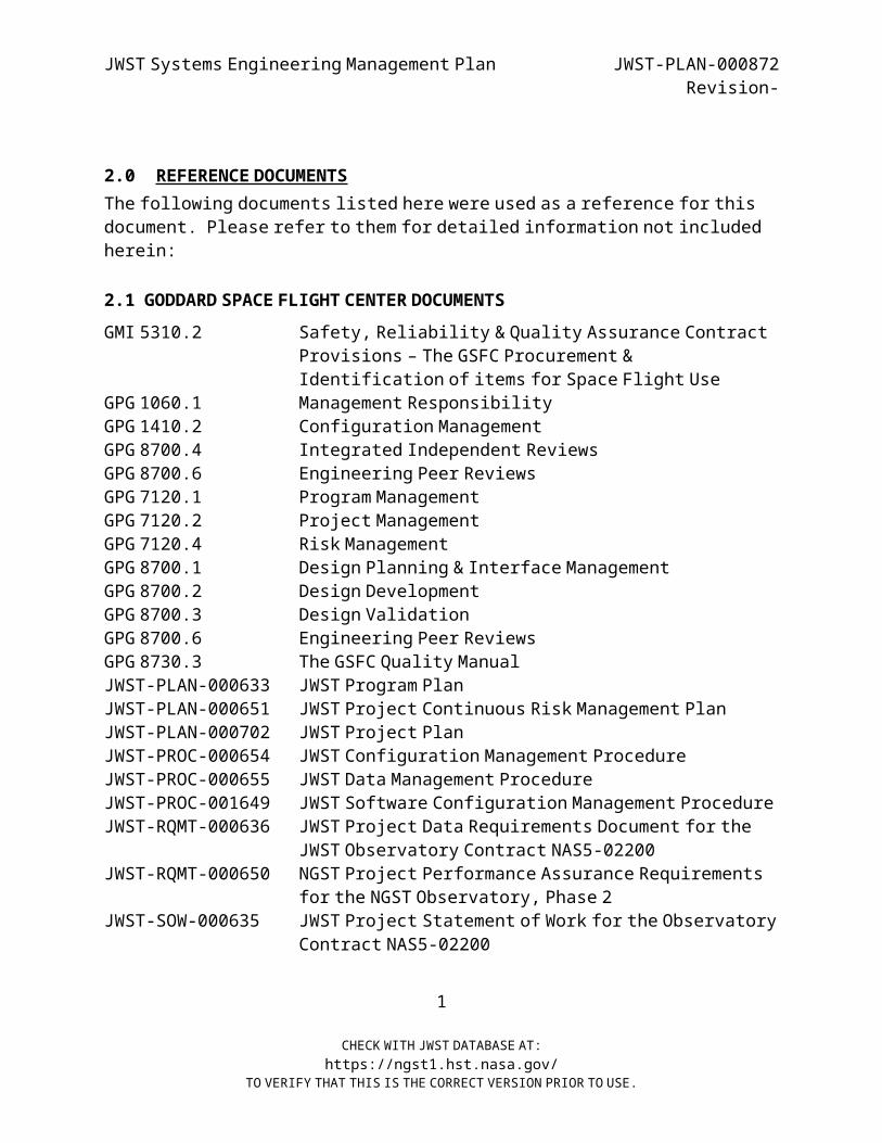
2.0 REFERENCE DOCUMENTS
The following documents listed here were used as a reference for this document. Please refer to them for detailed information not included
herein:
2.1 GODDARD SPACE FLIGHT CENTER DOCUMENTS GMI 5310.2 Safety, Reliability & Quality Assurance Contract
Provisions – The GSFC Procurement & Identification of items for Space Flight Use
GPG 1060.1 Management Responsibility GPG 1410.2 Configuration Management GPG 8700.4 Integrated Independent Reviews GPG 8700.6 Engineering Peer Reviews GPG 7120.1 Program Management GPG 7120.2 Project Management GPG 7120.4 Risk Management GPG 8700.1 Design Planning & Interface Management GPG 8700.2 Design Development GPG 8700.3 Design Validation GPG 8700.6 Engineering Peer Reviews GPG 8730.3 The GSFC Quality Manual
JWST-PLAN-000633 JWST Program PlanJWST-PLAN-000651 JWST Project Continuous Risk Management PlanJWST-PLAN-000702 JWST Project Plan
JWST-PROC-000654 JWST Configuration Management ProcedureJWST-PROC-000655 JWST Data Management ProcedureJWST-PROC-001649 JWST Software Configuration Management ProcedureJWST-RQMT-000636 JWST Project Data Requirements Document for the
JWST Observatory Contract NAS5-02200 JWST-RQMT-000650 NGST Project Performance Assurance Requirements
for the NGST Observatory, Phase 2 JWST-SOW-000635 JWST Project Statement of Work for the Observatory
Contract NAS5-02200
1
CHECK WITH JWST DATABASE AT:https://ngst1.hst.nasa.gov/
TO VERIFY THAT THIS IS THE CORRECT VERSION PRIOR TO USE.
JWST Systems Engineering Management Plan JWST-PLAN-000872Revision-
JWST-SOW-000725 JWST Project Science and Operations Statement ofWork
JWST-TREE-000659 JWST Document TreeJWST-HDBK-000668 JWST Project Configuration Management-
Controlled Document Style
2.2 NON-GODDARD SPACE FLIGHT CENTER DOCUMENTS NPG 7120.5B NASA Project and Project Processes and
RequirementsSP-6105 NASA System Engineering Handbook
DoD Systems Engineering Fundamentals Handbook
2
CHECK WITH JWST DATABASE AT:https://ngst1.hst.nasa.gov/
TO VERIFY THAT THIS IS THE CORRECT VERSION PRIOR TO USE.
JWST Systems Engineering Management Plan JWST-PLAN-000872Revision-
3.0 SYSTEMS ENGINEERING MANAGEMENT
The Systems Engineering approach described in the following paragraphs is a tailored approach that attempts to maximize ownership
and responsibility among all JWST partners. This approach incorporates the result of 4 years of joint study with our Space
Telescope Science Institute (STScI), International and Industry Contractor Partners. Additionally, we have incorporated many lessons
learned from past NASA Projects.3.1 DEFINITION AND SCOPE
Systems Engineering is defined as an interdisciplinary approach that encompasses the entire technical effort, and evolves into and verifies
an integrated and life cycle balanced set of system personnel, products, and process solutions that satisfy customer needs.1 JWST
Systems Engineering is involved in all phases of the JWST Project including, but not limited to the following:
Understanding project definitions, requirements and concepts Analysis, trade studies and planning Systems requirements definition Project integration Requirements coordination Design integration and support Change Assessment Verification of requirements Compliance Operations Support Mission Evaluation
3.2 OBJECTIVE AND APPROACH The principal objective of Systems engineering on JWST is to achieve
mission success. The JWST approach to system engineering is optimized
1 Electronic Industries Alliance (EIA) Standard IS-632, Systems Engineering, December 1994 – should be listed in reference document list – not here.
1
CHECK WITH JWST DATABASE AT:https://ngst1.hst.nasa.gov/
TO VERIFY THAT THIS IS THE CORRECT VERSION PRIOR TO USE.
JWST Systems Engineering Management Plan JWST-PLAN-000872Revision-
in accordance with the following objectives outlined by the JWST Project Manager:
Achievement of the science mission objectives (minimum mission success criteria)
Lowest implementation phase cost Simplification of the system where feasible Engagement of the best minds (most experienced staff) Appropriate weighting of factors critical to mission success Frequent, free-flowing, bi-directional communications
between all elements3.3 UNIQUE FACTORS
There are several ways to successfully implement the systems engineering process for JWST. The approach is driven by several
factors unique to JWST: One-of-a-kind nature of JWST and the fact that no one in the
aerospace industry has yet attempted to field such a complex electro-optical space system.
Unique multi-national partnering arrangements that leverage a significant financial contribution from our international
partners. Ability to draw from a large pool of astrophysicists,
astronomers, and physicists at the STScI, GSFC, and the Science Working Group (SWG) to provide a unique oversight that has come to
be known as science systems engineering. A Wavefront control subsystem that determines and controls the
telescope image quality performance. This is a NASA-led technology development effort that is to be transitioned to the
Prime at the JWST Preliminary Design Review (PDR). A NASA-led lightweight mirror technology development project
to be transitioned to the Prime early in Phase B.
2
CHECK WITH JWST DATABASE AT:https://ngst1.hst.nasa.gov/
TO VERIFY THAT THIS IS THE CORRECT VERSION PRIOR TO USE.
JWST Systems Engineering Management Plan JWST-PLAN-000872Revision-
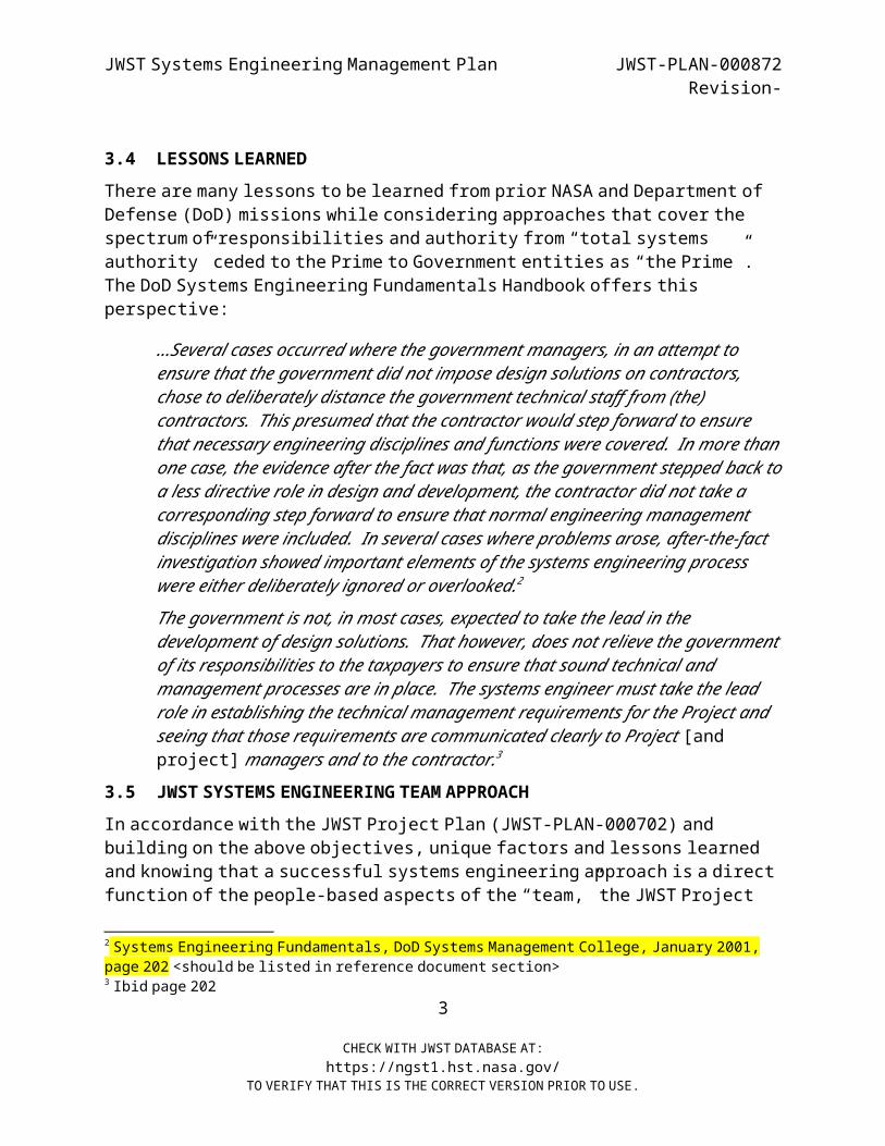
3.4 LESSONS LEARNED There are many lessons to be learned from prior NASA and Department of
Defense (DoD) missions while considering approaches that cover the spectrum of responsibilities and authority from “total systems
authority” ceded to the Prime to Government entities as “the Prime”. The DoD Systems Engineering Fundamentals Handbook offers this
perspective:
…Several cases occurred where the government managers, in an attempt to ensure that the government did not impose design solutions on contractors,
chose to deliberately distance the government technical staff from (the) contractors. This presumed that the contractor would step forward to ensure
that necessary engineering disciplines and functions were covered. In more than one case, the evidence after the fact was that, as the government stepped back to
a less directive role in design and development, the contractor did not take a corresponding step forward to ensure that normal engineering management
disciplines were included. In several cases where problems arose, after-the-fact investigation showed important elements of the systems engineering process
were either deliberately ignored or overlooked.2
The government is not, in most cases, expected to take the lead in the development of design solutions. That however, does not relieve the government
of its responsibilities to the taxpayers to ensure that sound technical and management processes are in place. The systems engineer must take the lead
role in establishing the technical management requirements for the Project and seeing that those requirements are communicated clearly to Project [and
project] managers and to the contractor.3
3.5 JWST SYSTEMS ENGINEERING TEAM APPROACH In accordance with the JWST Project Plan (JWST-PLAN-000702) and
building on the above objectives, unique factors and lessons learned and knowing that a successful systems engineering approach is a direct
function of the people-based aspects of the “team,” the JWST Project
2 Systems Engineering Fundamentals, DoD Systems Management College, January 2001, page 202 <should be listed in reference document section>
3 Ibid page 2023
CHECK WITH JWST DATABASE AT:https://ngst1.hst.nasa.gov/
TO VERIFY THAT THIS IS THE CORRECT VERSION PRIOR TO USE.
JWST Systems Engineering Management Plan JWST-PLAN-000872Revision-
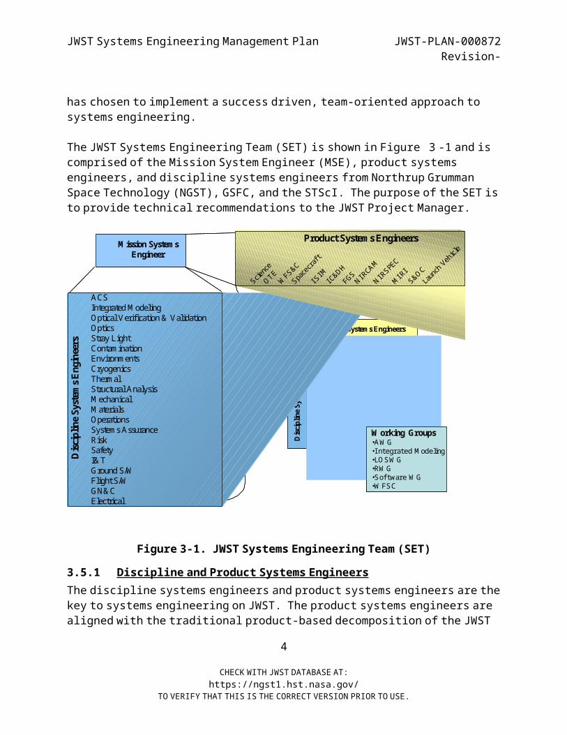
has chosen to implement a success driven, team-oriented approach to systems engineering.
The JWST Systems Engineering Team (SET) is shown in Figure 3 -1 and is comprised of the Mission System Engineer (MSE), product systems
engineers, and discipline systems engineers from Northrup Grumman Space Technology (NGST), GSFC, and the STScI. The purpose of the SET is
to provide technical recommendations to the JWST Project Manager.
Figure 3-1 . JWST Systems Engineering Team (SET)
3.5.1 Discipline and Product Systems Engineers
The discipline systems engineers and product systems engineers are the key to systems engineering on JWST. The product systems engineers are
aligned with the traditional product-based decomposition of the JWST
4
CHECK WITH JWST DATABASE AT:https://ngst1.hst.nasa.gov/
TO VERIFY THAT THIS IS THE CORRECT VERSION PRIOR TO USE.
M ission System s Engineer
Product System s Engineers
Discipline S
ystem
s Engineers
W orking Groups•AW G•Integrated M odeling•LO SW G•RW G•Software W G•W FSC
Discipline S
ystem
s Engineers
Product System s Engineers
FGS
S&O C
ISIM
Launch Vehicle
O TE
N IRCAM
Spacecraft
W FS&C
IC&DH
N IRSPEC
M IRI
Science
ACSIntegrated M odelingOptical Verification & ValidationOptics Stray LightContaminationEnvironmentsCryogenicsThermalStructural AnalysisM echanicalM aterialsOperationsSystems AssuranceRiskSafetyI& TGround S/WFlight S/WGN&CElectrical

JWST Systems Engineering Management Plan JWST-PLAN-000872Revision-
system. They provide systems engineering support associated directly with the production of the product. Product systems engineers work with each of the discipline engineers to obtain the best product
possible. The discipline systems engineers work for each of the product systems engineers and product managers. The discipline systems engineers strive to integrate their discipline across all
products to achieve an optimal system. In order to ensure engagement of the discipline system engineers and
product systems engineers, they will meet on a weekly basis with the MSE to discuss system-wide issues. This ensures that the entire SET is
fully engaged.
The MSE looks to the discipline and product systems engineers as the “gate keepers” for their discipline or product. The discipline and
product systems engineers are responsible for auditing, via peer reviews, their discipline or product and for making pass/fail
recommendations to the MSE. Recommendations from discipline systems engineers, and product systems engineers provide the MSE with a
balanced technical view of the JWST Project. The MSE can then provide optimized recommendations, based on the principles outlined
previously, to the JWST Project Manager.
3.5.2 Integrated Modeling
Integrated Modeling (IM) is listed as a Discipline and a working group in Figure 3-1, this is because IM is unique in that it cuts across both
disciplines and products. The function of IM is best viewed as one of integrating models across disciplines. The primary responsibility of
IM is to create, validate, verify and exercise multi-disciplinary models. Additionally, IM will coordinate processes, tools, methods,
practices, definitions, etc. across product lines such that integrated modeling as practiced by product leads/teams will have a consistent look and feel. The goal is to optimize resources (no need to
invent multiple solutions, leverage discipline expertise, etc.). Further, IM maintains, via configuration control, all of the
observatory-level analytical tools, models, input data and
5
CHECK WITH JWST DATABASE AT:https://ngst1.hst.nasa.gov/
TO VERIFY THAT THIS IS THE CORRECT VERSION PRIOR TO USE.

JWST Systems Engineering Management Plan JWST-PLAN-000872Revision-
associated documentation. IM coordinates the configuration management of important documents with the Project CM Office (CMO).
Lastly, IM provides inputs to the I&T plans and requirements. In particular, IM provides inputs to the requirements and plans of test-
beds. These hardware oriented activities represent an opportunity for IM to validate and verify their models.
There are several steps involved in IM. The first step is single- discipline model integration across product lines by discipline
leads. Integration of element-level discipline models into Observatory-Level discipline models will be performed by the
respective disciplines The second step is to assemble the integrated system model by combining the observatory-level models across the
discipline lines: structures, thermal, optics, stray light, controls, detectors, electrical, etc. Integration of the
Observatory-Level discipline models into an end-to-end integrated model will be performed by the systems modeling team with technical
assistance from the discipline modeling teams as needed. The third step is to update the integrated models based on actual test data as it
becomes available. An IM plan will be written by the IM Lead that document procedures and schedules for what IM will be done. The plan
will address how modeling is used in requirements analysis and verification, and how it is used to support trade studies. The IM plan
will address the schedule for modeling deliverables and products over the entire Project lifecycle. The plan will specify the role
integrated modeling plays in estimating Technical Performance Measures (TPMs) such as Encircled Energy, Point Spread Function (PSF)
Stability, Sensitivity, etc. The plan will explicitly establish the connection between the analysis tools and the error budgets. The IM
plan will describe how configuration control is maintained over math models, drawings and documentation.
3.5.3 Working Groups
Working groups are used for products that cut across disciplines where multiple products are integrated by the working group product. Each
working group has a unique charter from the MSE. Working groups are for
6
CHECK WITH JWST DATABASE AT:https://ngst1.hst.nasa.gov/
TO VERIFY THAT THIS IS THE CORRECT VERSION PRIOR TO USE.
JWST Systems Engineering Management Plan JWST-PLAN-000872Revision-
technical interchange. They study options and potential issues. An example is the Wavefront Sensing and Control (WFS&C) working group
that integrates the development of WFS&C algorithms, the control mechanisms for the Optical Telescope Element (OTE), and the Near-
Infrared Camera (NIRCam) instrument as the Wavefront sensor. This working group facilitates communication at a more technical level than
the weekly meetings with the MSE. The working groups are chaired, as appropriate, by systems engineers from the Prime, GSFC, or STScI.
Working groups do not possess any additional authority than the individual members possess. Working groups can only r ecommended
changes. All changes must be worked through appropriate channels to address cost, schedule, performance, risk, and contractual issues.
For example, the WFSC working group can only recommend changes to any of the affected subsystems. The current working groups and their
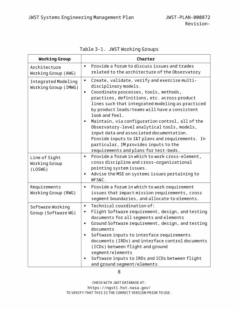
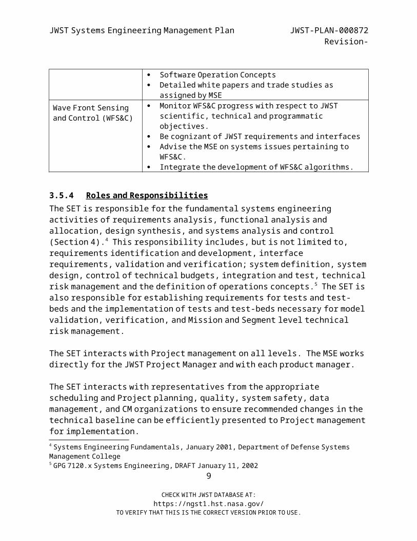
charters are shown in Table 3-1.
7
CHECK WITH JWST DATABASE AT:https://ngst1.hst.nasa.gov/
TO VERIFY THAT THIS IS THE CORRECT VERSION PRIOR TO USE.
JWST Systems Engineering Management Plan JWST-PLAN-000872Revision-
Table 3-1. JWST Working Groups
Working Group Charter Architecture
Working Group (AWG) Provide a forum to discuss issues and trades
related to the architecture of the Observatory
Integrated Modeling Working Group (IMWG)
Create, validate, verify and exercise multi- disciplinary models.
Coordinate processes, tools, methods, practices, definitions, etc. across product
lines such that integrated modeling as practiced by product leads/teams will have a consistent
look and feel. Maintain, via configuration control, all of the
Observatory-level analytical tools, models, input data and associated documentation.
Provide inputs to I&T plans and requirements. In particular, IM provides inputs to the
requirements and plans for test-beds. Line of Sight
Working Group(LOSWG)
Provide a forum in which to work cross-element, cross discipline and cross-organizational
pointing system issues. Advise the MSE on systems issues pertaining to
WFS&C. Requirements
Working Group (RWG) Provide a forum in which to work requirement
issues that impact mission requirements, cross segment boundaries, and allocate to elements.
Software Working Group (Software WG)
Technical coordination of: Flight Software requirement, design, and testing
documents for all segments and elements Ground Software requirement, design, and testing
documents Software inputs to interface requirements
documents (IRDs) and interface control documents (ICDs) between flight and ground
segment/elements Software inputs to IRDs and ICDs between flight
and ground segment/elements8
CHECK WITH JWST DATABASE AT:https://ngst1.hst.nasa.gov/
TO VERIFY THAT THIS IS THE CORRECT VERSION PRIOR TO USE.
JWST Systems Engineering Management Plan JWST-PLAN-000872Revision-
Software Operation Concepts Detailed white papers and trade studies as
assigned by MSE Wave Front Sensing
and Control (WFS&C) Monitor WFS&C progress with respect to JWST
scientific, technical and programmatic objectives.
Be cognizant of JWST requirements and interfaces Advise the MSE on systems issues pertaining to
WFS&C. Integrate the development of WFS&C algorithms.
3.5.4 Roles and Responsibilities
The SET is responsible for the fundamental systems engineering activities of requirements analysis, functional analysis and
allocation, design synthesis, and systems analysis and control (Section 4).4 This responsibility includes, but is not limited to,
requirements identification and development, interface requirements, validation and verification; system definition, system
design, control of technical budgets, integration and test, technical risk management and the definition of operations concepts.5 The SET is also responsible for establishing requirements for tests and test- beds and the implementation of tests and test-beds necessary for model
validation, verification, and Mission and Segment level technical risk management.
The SET interacts with Project management on all levels. The MSE works directly for the JWST Project Manager and with each product manager.
The SET interacts with representatives from the appropriate scheduling and Project planning, quality, system safety, data
management, and CM organizations to ensure recommended changes in the technical baseline can be efficiently presented to Project management
for implementation.4 Systems Engineering Fundamentals, January 2001, Department of Defense Systems
Management College5 GPG 7120.x Systems Engineering, DRAFT January 11, 2002
9
CHECK WITH JWST DATABASE AT:https://ngst1.hst.nasa.gov/
TO VERIFY THAT THIS IS THE CORRECT VERSION PRIOR TO USE.
JWST Systems Engineering Management Plan JWST-PLAN-000872Revision-
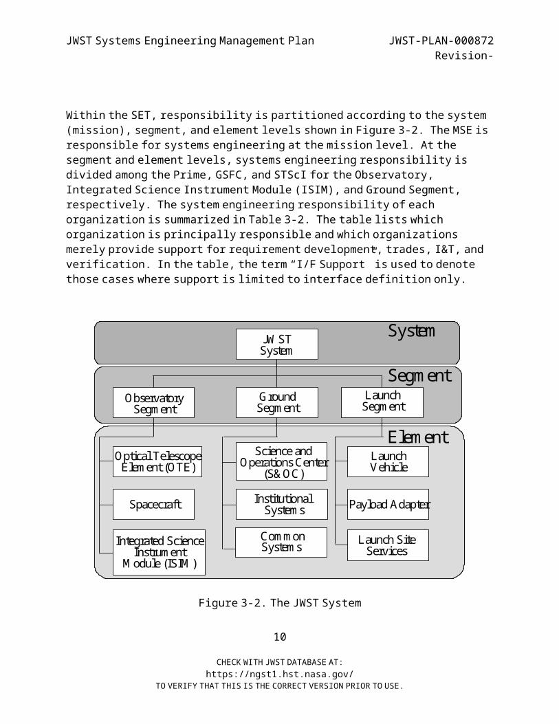
Within the SET, responsibility is partitioned according to the system (mission), segment, and element levels shown in Figure 3-2. The MSE is
responsible for systems engineering at the mission level. At the segment and element levels, systems engineering responsibility is divided among the Prime, GSFC, and STScI for the Observatory,
Integrated Science Instrument Module (ISIM), and Ground Segment, respectively. The system engineering responsibility of each
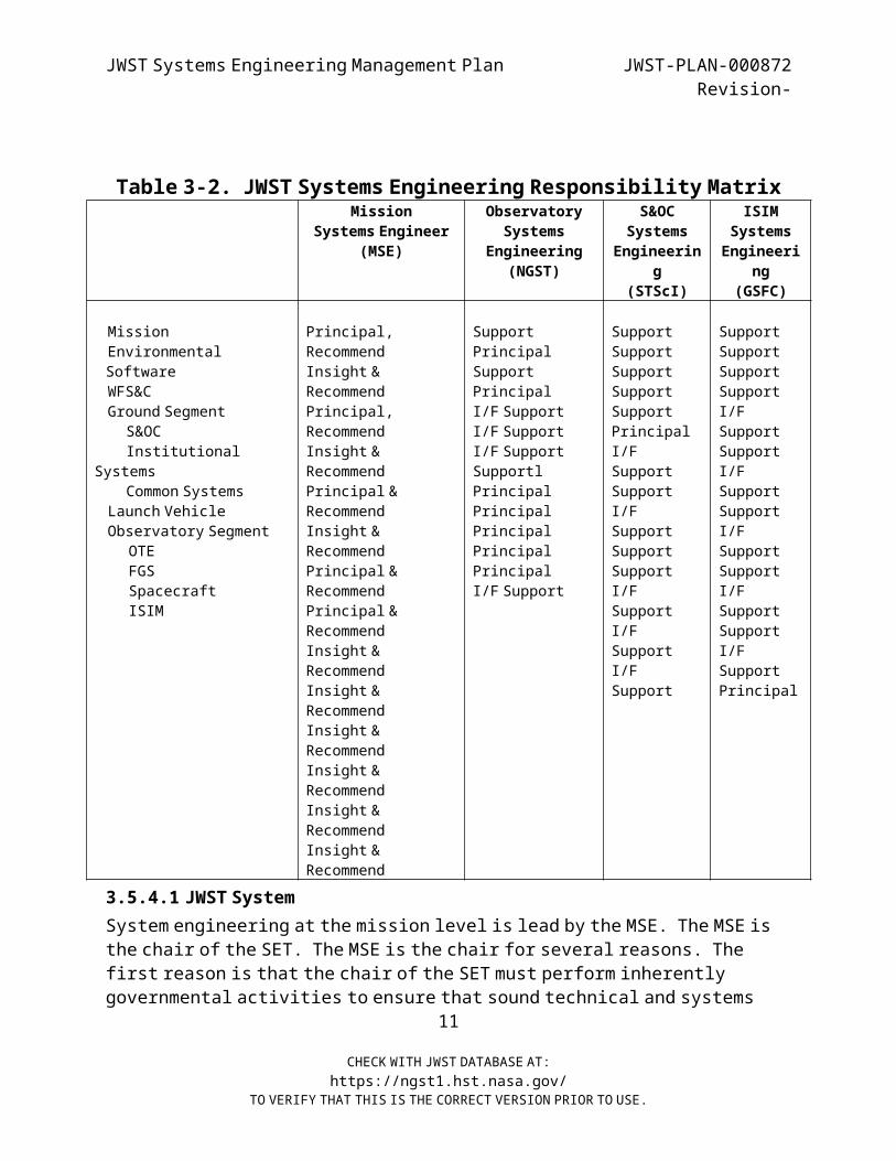
organization is summarized in Table 3-2. The table lists which organization is principally responsible and which organizations
merely provide support for requirement development, trades, I&T, and verification. In the table, the term “I/F Support” is used to denote
those cases where support is limited to interface definition only.
System
Segment
Element
JW ST System
Ground Segment
Observatory Segment
Launch Segment
Launch Vehicle
Optical Telescope Element (OTE)
Spacecraft
Integrated Science Instrument
M odule (ISIM )
Payload Adapter
Launch Site Services
IRD IRD
IRDIRDIRD
Science and Operations Center
(S&OC)
Institutional Services
Common Command and
Telemetry System
System
Segment
Element
JW ST System
Ground Segment
Observatory Segment
Launch Segment
Launch Vehicle
Optical Telescope Element (OTE)
Spacecraft
Integrated Science Instrument
M odule (ISIM )
Payload Adapter
Launch Site Services
Science and Operations Center
(S&OC)
Institutional Systems
Common Systems
System
Segment
Element
JW ST System
Ground Segment
Observatory Segment
Launch Segment
Launch Vehicle
Optical Telescope Element (OTE)
Spacecraft
Integrated Science Instrument
M odule (ISIM )
Payload Adapter
Launch Site Services
IRD IRD
IRDIRDIRD
Science and Operations Center
(S&OC)
Institutional Services
Common Command and
Telemetry System
System
Segment
Element
JW ST System
Ground Segment
Observatory Segment
Launch Segment
Launch Vehicle
Optical Telescope Element (OTE)
Spacecraft
Integrated Science Instrument
M odule (ISIM )
Payload Adapter
Launch Site Services
Science and Operations Center
(S&OC)
Institutional Systems
Common Systems
Figure 3-2. The JWST System
10
CHECK WITH JWST DATABASE AT:https://ngst1.hst.nasa.gov/
TO VERIFY THAT THIS IS THE CORRECT VERSION PRIOR TO USE.
JWST Systems Engineering Management Plan JWST-PLAN-000872Revision-
Table 3- 2. JWST Systems Engineering Responsibility Matrix Mission
Systems Engineer(MSE)
ObservatorySystems
Engineering(NGST)
S&OCSystems
Engineering
(STScI)
ISIMSystemsEngineeri
ng(GSFC)
MissionEnvironmentalSoftwareWFS&C
Ground SegmentS&OC
InstitutionalSystems
Common Systems Launch Vehicle
Observatory SegmentOTEFGSSpacecraftISIM
Principal,Recommend
Insight &Recommend
Principal,Recommend
Insight &Recommend
Principal &Recommend
Insight &Recommend
Principal &Recommend
Principal &Recommend
Insight &Recommend
Insight &Recommend
Insight &Recommend
Insight &Recommend
Insight &Recommend
Insight &Recommend
SupportPrincipalSupportPrincipal
I/F Support I/F Support I/F Support
Supportl Principal
PrincipalPrincipalPrincipalPrincipal
I/F Support
SupportSupportSupportSupportSupportPrincipal
I/FSupportSupport
I/F Support
SupportSupport
I/FSupport
I/FSupport
I/FSupport
SupportSupportSupportSupport
I/FSupportSupport
I/FSupportSupport
I/F Support
Support I/F
SupportSupport
I/FSupportPrincipal
3.5.4.1 JWST System System engineering at the mission level is lead by the MSE. The MSE is
the chair of the SET. The MSE is the chair for several reasons. The first reason is that the chair of the SET must perform inherently
governmental activities to ensure that sound technical and systems11
CHECK WITH JWST DATABASE AT:https://ngst1.hst.nasa.gov/
TO VERIFY THAT THIS IS THE CORRECT VERSION PRIOR TO USE.

JWST Systems Engineering Management Plan JWST-PLAN-000872Revision-
engineering management processes are in place. Another reason for having the SET chair be the MSE is that as a civil servant he will have an
appreciation for Project budget, risk and schedule issues due to his attendance at all of the weekly internal Project meetings. From the
knowledge he gains at the project meeting he will best be able to chart a course for the SET that addresses project needs.
3.5.4.1.1 Mission Systems Engineer The responsibilities of the MSE are those inherently governmental
activities. These activities include, but are not limited to: Ensuring mission success Ensuring traceability from mission requirement to science and
level 1 requirements Insight into the Prime and STScI designs Insight into the Prime and STScI implementation approaches Providing recommendations to the JWST Project Manager Assisting in inter-agency (International) technical conflictresolution Leading key inter-segment and inter-element trade studies Mission requirements development and verification tracking Review of segment and element requirements and their
associated verification Inputs into the performance evaluation on the Prime’s and
STScI’s engineering
The MSE has the responsibility to ensure mission success per NASA Standard 7120-A, Project and Project Management Process and
Requirements. The MSE has the responsibility and authority to monitor, analyze, identify, and recommend plans to assist all SET
members to assure the functionality and quality of all systems engineering processes, activities and interrelationships.
The MSE has a unique relationship with the systems engineering organizations of the European Space Agency (ESA) and Canadian Space
Agency (CSA). CSA and ESA involvement in JWST is documented within the context of Memorandum of Understanding (MOU), and respective project
12
CHECK WITH JWST DATABASE AT:https://ngst1.hst.nasa.gov/
TO VERIFY THAT THIS IS THE CORRECT VERSION PRIOR TO USE.
JWST Systems Engineering Management Plan JWST-PLAN-000872Revision-
and individual collaboration implementation plans. The United States International Traffic in Arms Regulations (ITAR) can restrict the
exchange of ITAR sensitive technical data and hardware with the international agencies. The ITAR restrictions require that any flow
of ITAR sensitive technical information to international agencies be controlled. To accommodate this restriction, the MSE must ensure that
requirements documents, specifications, interface documents, and meetings involving international partners are narrow in scope and do
not exceed the bounds of the standing international agreement (i.e. MOU) and the ITAR. Note that the United States (U.S.) does not restrict
the flow of information from the International government and contractors into the U.S. The three space agencies (NASA, ESA, and
CSA) have stipulated that the JWST Prime will work directly with ESA and CSA contractors within the bounds of the ITAR regulations, and
associated industry Technical Assistance Agreements, to obtain the necessary insight into the ESA CSA designs.
The MSE reviews, approves, and periodically monitors the Prime, STScI, and ISIM systems engineering approaches. The primary focus is on
mission requirements, interfaces, specifications, verification, and integration and test plans and procedures. In addition, the
derivation of segment and element requirements, interfaces, specifications, verification and integration and test plans and
procedures produced by the Prime, ISIM and STScI are reviewed3.5.4.1.2 Software Systems Engineering
Due to the unique relationship between mission success and software system engineering the project has established a Software Systems
Engineer (SWSE) who is responsible at the mission level for all Software system engineering (flight and ground). This includes the
requirements identification, architecture definition, interface definition, integration and test, and the operations of all Software.
The SWSE has the responsibility and authority to monitor, analyze, identify, and initiate plans to assure the functionality and quality
of software systems engineering processes, activities, and interrelationships, as delegated by the MSE. This is of particular
13
CHECK WITH JWST DATABASE AT:https://ngst1.hst.nasa.gov/
TO VERIFY THAT THIS IS THE CORRECT VERSION PRIOR TO USE.
JWST Systems Engineering Management Plan JWST-PLAN-000872Revision-
importance given the complex software interfaces on JWST. The SWSE works through the MSE for interfaces with the ESA and CSA. The SWSE is
responsible for tracking and reporting software status. The SWSE is provided by GSFC.
The SWSE reviews and approves the Observatory Prime, STScI, ISIM FSW systems architectures and interfaces. The list of architectures and
interfaces are documented via the individual contract deliverables lists. As such, the SWSE is the sponsor in the CM process for the
identified documents.
The SWSE is the chair of the Software Working Group (Software WG), which is chartered by the MSE to resolve JWST software related
interface issues. Membership of the Software WG includes Leads and team members from the Prime Flight Software (FSW) Team, ISIM Command
and Data Handling (ICDH) FSW Team, Science Instrument (SI) FSW Teams, Ground Software Leads, Test System Leads, and STScI.
3.5.4.2 Observatory Segment The Prime is responsible for JWST Observatory Segment systems
engineering per the JWST Project Statement of Work for the Observatory ContractNAS5-02200 (JWST-SOW-000635). GSFC through the MSE maintains
oversight of Observatory Segment systems engineering.
The Prime defines, implements, and maintains a Systems Engineering Plan(SEP), which is in compliance with this JWST Project System Engineering
Management Plan (SEMP), JWST-PLAN-000872, that documents their specific approach to performing JWST Observatory systems engineering.6 Where
assistance to the Prime is needed from other organizations the Project System Engineering Office will help to ensure that the assistance is
provided.
6 Statement of Work for the Phase 2 Observatory Contract, JWST-SOW-000635, Section 2.1 page 13
14
CHECK WITH JWST DATABASE AT:https://ngst1.hst.nasa.gov/
TO VERIFY THAT THIS IS THE CORRECT VERSION PRIOR TO USE.
JWST Systems Engineering Management Plan JWST-PLAN-000872Revision-
The Prime is responsible for all Observatory verification, including the verification plan for all JWST subsystems, elements, and
segments.7
The Prime will define and implement a process that continually assesses the risks to the Observatory, determines the relative threat
of risks, implements strategies to mitigate significant risks, and measures the effectiveness of these strategies.
The Prime will establish, implement, manage, and maintain a Configuration Management Plan , in conformance with the JWST Project
Configuration Management Procedure , JWST-PROC-000654, and apply it to all operational systems.8
The Prime’s Lead Systems Engineer is the deputy chair for the principal reason that the Prime is responsible for on-orbit performance of the
Observatory and must be involved in all aspects of systems engineering in order to meet their responsibility.
3.5.4.2.1 Optical Telescope Element The prime contractor is responsible for OTE systems engineering as
documented in the Prime’s Systems Engineering Plan (SEP) . The GSFC OTE product system engineer provides oversight of the prime’s OTE system
engineering. The OTE product system engineer has the followingresponsibilities:
Provide systems engineering oversight for validating OTErequirements
Provide the MSE with assessments of the OTE and timely notification of problems and/or major successes
Review all documents, requirements and specification and provide a summary to the MSE
Provide systems engineering to ensure that requirements verification is consistent with project objectives and best
practices
7 Section L of 03768/352 page 110 paragraph 78 Paragraph C 1.6
15
CHECK WITH JWST DATABASE AT:https://ngst1.hst.nasa.gov/
TO VERIFY THAT THIS IS THE CORRECT VERSION PRIOR TO USE.

JWST Systems Engineering Management Plan JWST-PLAN-000872Revision-
Perform as an integral part of the OTE Integrated Product Team (IPT) for requirement development, design, analysis, and trades
Perform independent systems analyses as needed Facilitate communications of interfaces, design issues, test
plans, and other information between the various government agencies, contractors and subcontractors
Serve as the technical lead for project-specific OTE technology development efforts
Participate in the development of the WFS&C system Coordinate all OTE modeling activities, tools, and processes
among the various government agencies, contractors andsubcontractors
3.5.4.2.2 Spacecraft Element The Prime contractor is responsible for spacecraft systems
engineering as documented in the Prime’s Systems Engineering Plan (SEP) . In addition, GSFC provides a spacecraft product system engineer to
provide oversight of the Prime’s spacecraft system engineering. The spacecraft product system engineer has the following
responsibilities:3.5.4.2.3 Integrated Science Instrument Module
ISIM Systems Engineering is performed by the ISIM product system engineer. The ISIM product system engineer is provided by GSFC and he
represents the ISIM to the SET. ISIM Systems Engineering responsibilities include the definition and negotiation of ISIM
interfaces (IRDs and ICDs) to the SIs and to the Observatory, the flow down of level 2 requirements to the ISIM, and overseeing ISIM trade
studies and system design, integration, and testing. Additional responsibilities include overseeing the ISIM verification program,
managing technical risks, supporting the CM system, and supporting reviews.
ISIM systems engineering analyzes the mission requirements and other applicable documents to derive and allocate Observatory requirements
to the ISIM, with concurrence from the Prime and the Project. This
16
CHECK WITH JWST DATABASE AT:https://ngst1.hst.nasa.gov/
TO VERIFY THAT THIS IS THE CORRECT VERSION PRIOR TO USE.
JWST Systems Engineering Management Plan JWST-PLAN-000872Revision-
includes flow-down of system requirements into software functions and hardware implementations.
ISIM systems engineering will be the lead for the development and test of the SI/Fine Guidance Sensor (FGS)/ISIM system. The ISIM SE supports
the ISIM I&T Manager in the development of an ISIM I&T Plan (JWST-PLAN-TBD ) that describes how overall I&T activity will be executed. ISIM
systems engineering provides all the systems engineering necessary to accomplish ISIM I&T, creates documentation for the integration, test,
and verification Project (including on-orbit verification), and identifies, negotiates, and defines requirements for I&T interfaces
with the Observatory and the Ground Segment.
ISIM systems engineering is responsible for all ISIM verification activities. This activity begins with the identification of the
verification method for each requirement as it is defined, and follows with the Verification Plan(s). These plans will be submitted to the
Prime and the Project for approval prior to implementation. They will establish the end-to-end testing Projects that support system
verification and validation testing of all requirements for all ISIM components. ISIM systems engineering will also support verification
efforts at the Observatory level, as well as on-orbit verification.3.5.4.3 Ground Segment
System engineering at the Ground Segment level is performed by the Ground Segment product system engineer. The Ground Segment product system engineer is supplied by GSFC.
3.5.4.3.1 Science and Operations Center System engineering for the Science and Operations Center (S&OC)
element is performed by the S&OC product system engineer. The STScI provides the S&OC product system engineer. The STScI is responsible
for the development of science operations requirements and science systems engineering.
17
CHECK WITH JWST DATABASE AT:https://ngst1.hst.nasa.gov/
TO VERIFY THAT THIS IS THE CORRECT VERSION PRIOR TO USE.

JWST Systems Engineering Management Plan JWST-PLAN-000872Revision-
The STScI will provide science and operations systems engineering to the JWST Project. STScI is responsible for maintaining the Design
Reference Mission (DRM) for JWST.9
The STScI will provide requirements development support to the Prime, ISIM, and SI providers. The STScI will use their participation to gain
insight into the operation of the hardware, influence its design and implementation for low-cost operations and science optimization, and
help assure the quality of its interfaces to the ground system.10 The STScI will support the development of requirements for the SIs, OTE,
WFS&C, FGS, and the ISIM.11 The STScI will support the development of the FSW requirements.12 The STScI will perform the engineering tasks
required to integrate ground system requirements with flight system requirements.
The STScI supports the Prime, ISIM developer, and SI and FGS developers in defining ground system to Observatory interfaces.13 STScI is
responsible for the final end-to-end data flow test for the JWSTsystem.14
The STScI attends and participates in major JWST reviews by providing and presenting STScI-related work, providing analysis and technical
assessments regarding operations and science impacts, reviewing architectures and designs, and providing other pertinent information
as appropriate and determined by the JWST Project.
The STScI supports the Prime, ISIM developer, and SI and FGS developers in defining ground system to Observatory interfaces. STScI is
responsible for the final end-to-end data flow test for the JWST system.
9 JWST Ground System Statement of Work (SOW), Paragraph C 2.110 JWST Science and Operations SOW, JWST-SOW-000725 Paragraph C 3.2.311 JWST Science and Operations SOW, JWST-SOW-000725 Paragraph C 3.3.1, 3.4.112 JWST Science and Operations SOW, JWST-SOW-000725 Paragraph C 3.2.2 and 3.6.113 JWST Science and Operations SOW, JWST-SOW-000725 Paragraph C 3.2.2 and 3.5.314 IBID, Paragraph C 3.2.3
18
CHECK WITH JWST DATABASE AT:https://ngst1.hst.nasa.gov/
TO VERIFY THAT THIS IS THE CORRECT VERSION PRIOR TO USE.
JWST Systems Engineering Management Plan JWST-PLAN-000872Revision-
STScI is also responsible for Ground Segment V&V.
3.5.4.3.2 Institutional SystemsTBD
3.5.4.3.3 Common Systems TBD
19
CHECK WITH JWST DATABASE AT:https://ngst1.hst.nasa.gov/
TO VERIFY THAT THIS IS THE CORRECT VERSION PRIOR TO USE.
JWST Systems Engineering Management Plan JWST-PLAN-000872Revision-
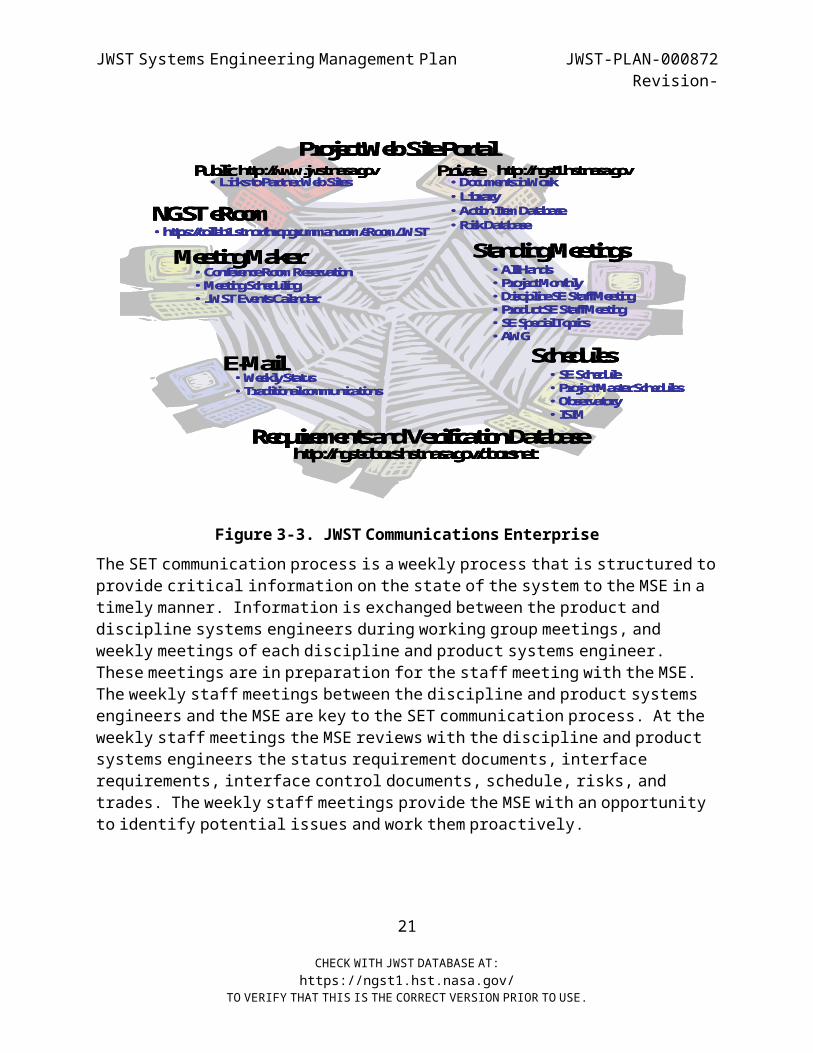
3.6 SYSTEMS ENGINEERING COMMUNICATION Systems engineering ensures proper flow of information across the various activities and team members by using existing Project
communication channels. The JWST Communications Enterprise is shown in Figure 3-2. There are two key components to the JWST Communications
Enterprise. The first key component is the JWST Project website. The Project website contains a library of all the officially released project documentation, an action item database, and the risk database
for the project. The second key component is the Project website, NGST maintains a website to facilitate communication between the Project
and NGST. This website holds all of the documentation produced by NGST including meeting minutes for all of the product teams and working
groups.
The JWST Communications Enterprise also consists of several tools that the SET uses to facilitate its activities. The first is a meeting
scheduling tool called Meeting Maker. Meeting Maker is used to schedule conference rooms, reserve overhead projectors, and invite
attendees to meetings. Another tool is the email system, which allows messages to be distributed to the SET. A third tool is the requirements
and verification database Dynamic Object Oriented Requirements System (DOORS). DOORS provides a centralized location containing all
of the requirements for the Project. Finally, there are several schedules that the SET team uses to manage its activities. Key among
these is the Systems Engineering Schedule that is discussed in Section 3.7. Other schedules of interest are the Project Master schedule, the
Observatory schedule and the ISIM schedule.
20
CHECK WITH JWST DATABASE AT:https://ngst1.hst.nasa.gov/
TO VERIFY THAT THIS IS THE CORRECT VERSION PRIOR TO USE.
JWST Systems Engineering Management Plan JWST-PLAN-000872Revision-
Schedules
Meeting Maker
Project Web Site Portal
•Action Item Database•Risk Database
Requirements and Verification Database
Public Private•Library•Documents in Work
http://www.jwst.nasa.gov http://ngst1.hst.nasa.gov
http://ngst-doors.hst.nasa.gov/doorsnet
E-Mail•Weekly Status•Traditional communications
Standing Meetings
•Links to Partner Web Sites
•Conference Room Reservation•Meeting Scheduling•JWST Events Calendar
•All Hands•Project Monthly•Discipline SE Staff Meeting•Product SE Staff Meeting•SE Special Topics•AWG
•SE Schedule•Project Master Schedules•Observatory•ISIM
NGST eRoom•https://collab1.st.northropgrumman.com/eRoom/JWST
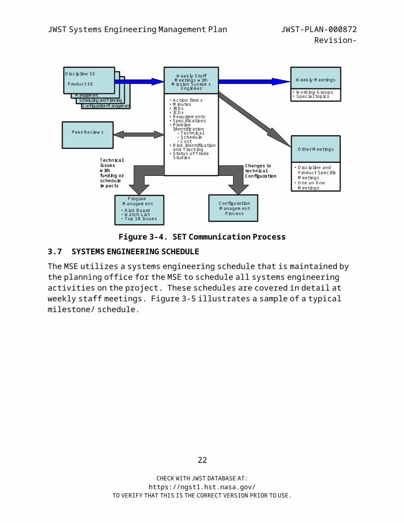
Figure 3- 3. JWST Communications Enterprise The SET communication process is a weekly process that is structured to
provide critical information on the state of the system to the MSE in a timely manner. Information is exchanged between the product and
discipline systems engineers during working group meetings, and weekly meetings of each discipline and product systems engineer.
These meetings are in preparation for the staff meeting with the MSE. The weekly staff meetings between the discipline and product systems
engineers and the MSE are key to the SET communication process. At the weekly staff meetings the MSE reviews with the discipline and product
systems engineers the status requirement documents, interface requirements, interface control documents, schedule, risks, and
trades. The weekly staff meetings provide the MSE with an opportunity to identify potential issues and work them proactively.
21
CHECK WITH JWST DATABASE AT:https://ngst1.hst.nasa.gov/
TO VERIFY THAT THIS IS THE CORRECT VERSION PRIOR TO USE.
JWST Systems Engineering Management Plan JWST-PLAN-000872Revision-
Configuration M anagementScheduling and Planning
Configuration M anagem ent
Process
Changes to technical Configuration
W eekly M eetings
Peer Review s
M anagement
Program M anagem ent
O ther M eetings
Technical Issues w ith funding or schedule im pacts
Discipline SE
Product SEW eekly Staff M eetings w ith
M ission System s Engineer
• Action Item s• M inutes• IRDs• ICDs• Requirem ents• Specifications• Problem Identification– Technical– Schedule– Cost
• Risk Identification and Tracking
• Status of Trade Studies
• Discipline and Product Specific M eetings
• O ne on O ne M eetings
• W orking G roups• Special topics
• Risk Board• W atch List• Top 10 Issues
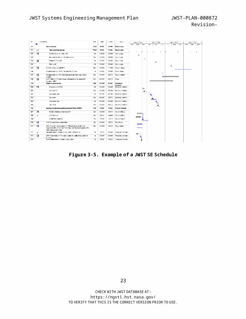
Figure 3-4. SET Communication Process3.7 SYSTEMS ENGINEERING SCHEDULE
The MSE utilizes a systems engineering schedule that is maintained by the planning office for the MSE to schedule all systems engineering
activities on the project. These schedules are covered in detail at weekly staff meetings. Figure 3-5 illustrates a sample of a typical
milestone/ schedule.
22
CHECK WITH JWST DATABASE AT:https://ngst1.hst.nasa.gov/
TO VERIFY THAT THIS IS THE CORRECT VERSION PRIOR TO USE.
JWST Systems Engineering Management Plan JWST-PLAN-000872Revision-
Figure 3- 5. Example of a JWST SE Schedule
23
CHECK WITH JWST DATABASE AT:https://ngst1.hst.nasa.gov/
TO VERIFY THAT THIS IS THE CORRECT VERSION PRIOR TO USE.
JWST Systems Engineering Management Plan JWST-PLAN-000872Revision-
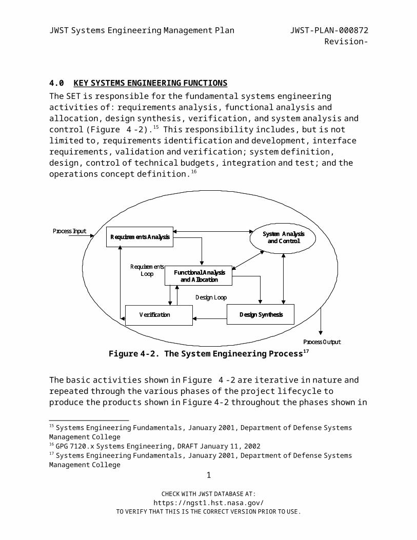
4.0 KEY SYSTEMS ENGINEERING FUNCTIONS
The SET is responsible for the fundamental systems engineering activities of: requirements analysis, functional analysis and
allocation, design synthesis, verification, and system analysis and control ( Figure 4 -2).15 This responsibility includes, but is not limited to, requirements identification and development, interface
requirements, validation and verification; system definition, design, control of technical budgets, integration and test; and the
operations concept definition.16
Figure 4-2 . The System Engineering Process17
The basic activities shown in Figure 4 -2 are iterative in nature and repeated through the various phases of the project lifecycle to
produce the products shown in Figure 4-2 throughout the phases shown in
15 Systems Engineering Fundamentals, January 2001, Department of Defense Systems Management College
16 GPG 7120.x Systems Engineering, DRAFT January 11, 200217 Systems Engineering Fundamentals, January 2001, Department of Defense Systems
Management College1
CHECK WITH JWST DATABASE AT:https://ngst1.hst.nasa.gov/
TO VERIFY THAT THIS IS THE CORRECT VERSION PRIOR TO USE.
Process Input
Process Output
Requirem ents Analysis
Requirem ents Loop
System Analysis and Control
Functional Analysis and Allocation
Design Loop
Design SynthesisVerification
Process Input
Process Output
Requirem ents Analysis
Requirem ents Loop
System Analysis and Control
Functional Analysis and Allocation
Design Loop
Design SynthesisVerification
JWST Systems Engineering Management Plan JWST-PLAN-000872Revision-
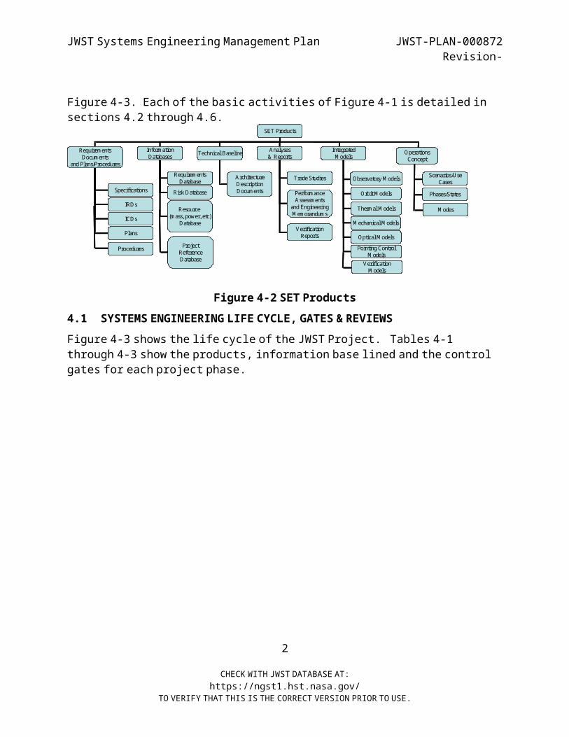
Figure 4-3. Each of the basic activities of Figure 4-1 is detailed in sections 4.2 through 4.6.
Figure 4-2 SET Products4.1 SYSTEMS ENGINEERING LIFE CYCLE, GATES & REVIEWS
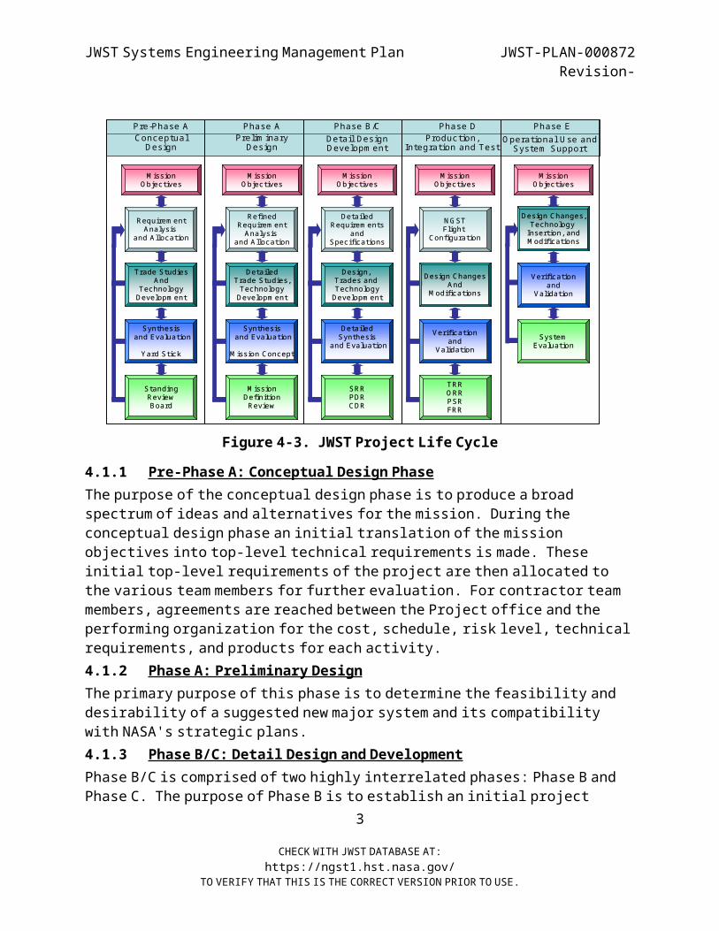
Figure 4-3 shows the life cycle of the JWST Project. Tables 4-1 through 4-3 show the products, information base lined and the control
gates for each project phase.
2
CHECK WITH JWST DATABASE AT:https://ngst1.hst.nasa.gov/
TO VERIFY THAT THIS IS THE CORRECT VERSION PRIOR TO USE.
SET Products
RequirementsDocuments
and Plans/Procedures
InformationDatabases Technical Baseline Analyses
& ReportsIntegratedM odels
Specifications
IRDs
ICDs
Plans
RequirementsDatabase
Risk Database
ArchitectureDescriptionDocuments
Trade Studies
PerformanceAssessments
and EngineeringM emorandums
VerificationReports
Operations Concept
Thermal M odels
M echanical M odels
Optical M odelsPointing Control
M odels
Observatory M odels
Orbit M odels
VerificationM odels
Resource (mass, power, etc)
Database
Project Reference Database
Scenarios/Use Cases
Phases/States
M odes
Procedures
JWST Systems Engineering Management Plan JWST-PLAN-000872Revision-
Detail Design D evelopm ent
Production, Integration and Test
Phase B /C Phase DConceptual
D esignPrelim inary
D esign
Pre-Phase A Phase A
Requirem entAnalysis
and Allocation
RefinedRequirem entAnalysis
and Allocation
Trade StudiesAnd
TechnologyDevelopm ent
DetailedTrade Studies,TechnologyDevelopm ent
Synthesisand Evaluation
Yard Stick
Synthesisand Evaluation
M ission Concept
Design, Trades and TechnologyDevelopm ent
StandingReviewBoard
M issionDefinitionReview
DetailedSynthesis
and Evaluation
DetailedRequirem ents
andSpecifications
SRRPDRCDR
M issionO bjectives
O perational U se and System Support
Phase E
M issionO bjectives
M issionO bjectives
SystemEvaluation
Verificationand
Validation
Design Changes,Technology Insertion, andM odifications
M issionO bjectives
TRRO RRPSRFRR
Verificationand
Validation
Design ChangesAnd
M odifications
N G STFlight
Configuration
M issionO bjectives
Figure 4- 3. JWST Project Life Cycle
4.1.1 Pre-Phase A: Conceptual Design Phase
The purpose of the conceptual design phase is to produce a broad spectrum of ideas and alternatives for the mission. During the
conceptual design phase an initial translation of the mission objectives into top-level technical requirements is made. These
initial top-level requirements of the project are then allocated to the various team members for further evaluation. For contractor team
members, agreements are reached between the Project office and the performing organization for the cost, schedule, risk level, technical
requirements, and products for each activity.4.1.2 Phase A: Preliminary Design
The primary purpose of this phase is to determine the feasibility and desirability of a suggested new major system and its compatibility
with NASA's strategic plans.4.1.3 Phase B/C: Detail Design and Development
Phase B/C is comprised of two highly interrelated phases: Phase B and Phase C. The purpose of Phase B is to establish an initial project
3
CHECK WITH JWST DATABASE AT:https://ngst1.hst.nasa.gov/
TO VERIFY THAT THIS IS THE CORRECT VERSION PRIOR TO USE.

JWST Systems Engineering Management Plan JWST-PLAN-000872Revision-
baseline, which (according to NHB 7120.5) includes "a formal flow-down of the project-level performance requirements to a complete set of
system and subsystem design specifications for both “flight and ground elements" and "corresponding preliminary designs." The technical
requirements should be sufficiently detailed to establish firm schedule and cost estimates for the project.
The purpose of Phase C is to establish a complete design (“build-to" baseline) that is ready to fabricate (or code), integrate, and verify.
Trade studies continue throughout Phase B/C. Engineering test units are built that more closely resembling actual hardware are built and
tested so as to establish confidence that the design will function in the expected environments. Engineering specialty analysis results are integrated into the design, and the manufacturing process and
controls are defined and validated. Configuration management continues to track and control design changes as detailed interfaces
are defined. At each step in the successive refinement of the final design, corresponding integration and verification activities are planned in greater detail. During this phase, technical parameters,
schedules, and budgets are closely tracked to ensure that undesirable trends (such as an unexpected growth in spacecraft mass or increase in
its cost) are recognized early enough to take corrective action. Phase B/C culminates in a series of C ritical Design Reviews (CDRs) containing the
system-level CDR and CDRs corresponding to the different levels of the system hierarchy. The CDR is held prior to the start of
fabrication/production of end items for hardware and prior to the start of coding of deliverable software products. Typically, the
sequence of CDRs reflects the integration process that will occur in the next phase— that is, from lower-level CDRs to the system-level CDR.
4.1.4 Phase D: Production, Integration, and Test Phase
The purpose of this phase is to build and verify the system designed in the previous phase, deploy it, and prepare for operations. During the
Phase D, technical requirements are translated into hardware and software Assemblies, Subsystems, Elements, and Segments, and tests of
the final products are performed to validate that the performance meets the Project requirements. The System Engineer uses a milestone
4
CHECK WITH JWST DATABASE AT:https://ngst1.hst.nasa.gov/
TO VERIFY THAT THIS IS THE CORRECT VERSION PRIOR TO USE.
JWST Systems Engineering Management Plan JWST-PLAN-000872Revision-
process to track technical performance, in which milestones can either be design reviews, readiness reviews, or test reviews. Each of these
major technical reviews has criteria that must be accomplished prior to the review. Systems engineering defines these criteria, allocates
responsibility to the performing organization, and reviews the products of these efforts. The Systems Engineer uses the criteria and schedule to determine if the Project execution is progressing
according to plan.
Activities include fabrication of hardware and coding of software, integration, and verification of the system. Other activities include
the initial training of operating personnel and implementation of the Integrated Logistics Support Plan. For flight projects, the focus of activities then shifts to pre-launch integration and launch. For
large flight projects, there may be an extended period of orbit insertion, assembly, and initial shakedown operations. The major
product is a system that has been shown to be capable of accomplishing the purpose for which it was created.
4.1.5 Phase E: Operational Use and Systems Support
The purpose of this phase is to meet the initially identified need or to grasp the initially identified opportunity. The products of the phase
are the results of the mission. This phase encompasses evolution of the system only insofar as that evolution does not involve major
changes to the system architecture; changes of that scope constitutes new “needs and the project life cycle starts over.
5
CHECK WITH JWST DATABASE AT:https://ngst1.hst.nasa.gov/
TO VERIFY THAT THIS IS THE CORRECT VERSION PRIOR TO USE.
JWST Systems Engineering Management Plan JWST-PLAN-000872Revision-
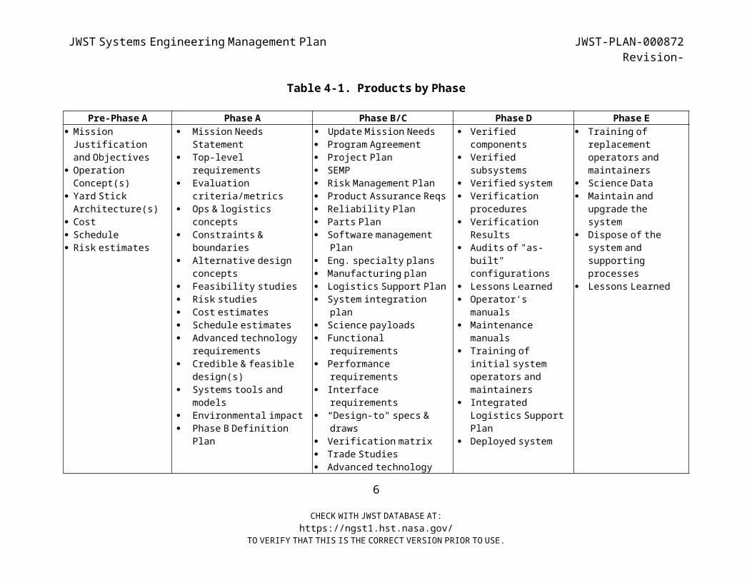
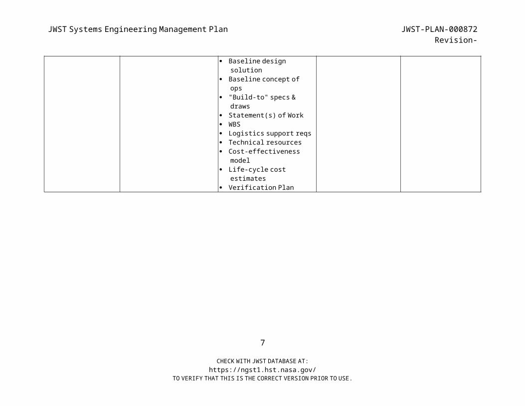
Table 4-1 . Products by Phase
Pre-Phase A Phase A Phase B/C Phase D Phase E Mission
Justification and Objectives
OperationConcept(s)
Yard StickArchitecture(s)
Cost Schedule Risk estimates
Mission NeedsStatement
Top-levelrequirements
Evaluationcriteria/metrics
Ops & logisticsconcepts
Constraints &boundaries
Alternative designconcepts
Feasibility studies Risk studies Cost estimates Schedule estimates Advanced technology
requirements Credible & feasible
design(s) Systems tools and
models Environmental impact Phase B Definition
Plan
Update Mission Needs Program Agreement Project Plan SEMP Risk Management Plan Product Assurance Reqs Reliability Plan Parts Plan Software management
Plan Eng. specialty plans Manufacturing plan Logistics Support Plan System integration
plan Science payloads Functional
requirements Performance
requirements Interface
requirements “Design-to" specs &
draws Verification matrix Trade Studies Advanced technology
Verifiedcomponents
Verifiedsubsystems
Verified system Verification
procedures Verification
Results Audits of "as-
built"configurations
Lessons Learned Operator's
manuals Maintenance
manuals Training of
initial system operators and
maintainers Integrated
Logistics SupportPlan
Deployed system
Training of replacement
operators andmaintainers
Science Data Maintain and
upgrade thesystem
Dispose of the system and
supportingprocesses
Lessons Learned
6
CHECK WITH JWST DATABASE AT:https://ngst1.hst.nasa.gov/
TO VERIFY THAT THIS IS THE CORRECT VERSION PRIOR TO USE.
JWST Systems Engineering Management Plan JWST-PLAN-000872Revision-
Baseline designsolution
Baseline concept ofops
"Build-to" specs &draws
Statement(s) of Work WBS Logistics support reqs Technical resources Cost-effectiveness
model Life-cycle cost
estimates Verification Plan
7
CHECK WITH JWST DATABASE AT:https://ngst1.hst.nasa.gov/
TO VERIFY THAT THIS IS THE CORRECT VERSION PRIOR TO USE.
JWST Systems Engineering Management Plan JWST-PLAN-000872Revision-
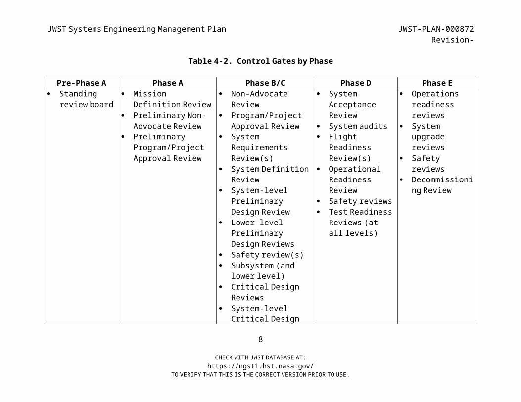
Table 4-2 . Control Gates by Phase
Pre-Phase A Phase A Phase B/C Phase D Phase E Standing
review board Mission
Definition Review Preliminary Non-
Advocate Review Preliminary
Program/Project Approval Review
Non-AdvocateReview
Program/Project Approval Review
System Requirements
Review(s) System Definition
Review System-level
Preliminary Design Review
Lower-level Preliminary
Design Reviews Safety review(s) Subsystem (and
lower level) Critical Design
Reviews System-level
Critical Design
System Acceptance
Review System audits Flight
ReadinessReview(s)
Operational Readiness
Review Safety reviews Test Readiness
Reviews (at all levels)
Operations readiness
reviews System
upgradereviews
Safetyreviews
Decommissioni ng Review
8
CHECK WITH JWST DATABASE AT:https://ngst1.hst.nasa.gov/
TO VERIFY THAT THIS IS THE CORRECT VERSION PRIOR TO USE.
JWST Systems Engineering Management Plan JWST-PLAN-000872Revision-
Review
9
CHECK WITH JWST DATABASE AT:https://ngst1.hst.nasa.gov/
TO VERIFY THAT THIS IS THE CORRECT VERSION PRIOR TO USE.
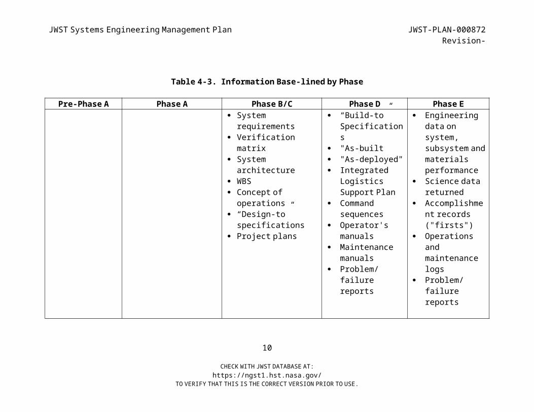
JWST Systems Engineering Management Plan JWST-PLAN-000872Revision-
Table 4-3 . Information Base-lined by Phase
Pre-Phase A Phase A Phase B/C Phase D Phase E Systemrequirements
Verificationmatrix
System architecture
WBS Concept ofoperations
“Design-to”specifications
Project plans
“Build-to”Specifications
"As-built "As-deployed" Integrated
Logistics Support Plan
Command sequences
Operator'smanuals
Maintenancemanuals
Problem/ failure
reports
Engineering data on
system, subsystem and materials
performance Science data
returned Accomplishme
nt records("firsts")
Operations and
maintenancelogs
Problem/ failure
reports
10
CHECK WITH JWST DATABASE AT:https://ngst1.hst.nasa.gov/
TO VERIFY THAT THIS IS THE CORRECT VERSION PRIOR TO USE.

JWST Systems Engineering Management Plan JWST-PLAN-000872Revision-
4.2 REQUIREMENTS IDENTIFICATION AND ANALYSIS The first step in the System Engineering Process ( Figure 4 -2 ) is
Requirements Identification & Analysis. The objective of requirements analysis is to describe requirements at each level in the
system hierarchy (i.e. to describe the “what” not the “how”). The “how” will ultimately evolve from the functional analysis and
allocation process. As shown in Figure 4-4, the JWST mission requirements and hierarchy are
derived from the requirements and goals documented in the NASA Headquarters Program Plan (JWST-PLAN-000633), the requirements
contained in the Science Requirements Document (JWST-RQMT-XXXX), and the operation concepts documented in the Mission Operations Concept
Document (JWST-OPS-002018). The mission requirements are documented in the Mission Requirements Document (JWST-RQMT-000634).
Figure 4-4 JWST Requirement Flow11
CHECK WITH JWST DATABASE AT:https://ngst1.hst.nasa.gov/
TO VERIFY THAT THIS IS THE CORRECT VERSION PRIOR TO USE.
NIRCam SRDNIRSpec SRDM IRI SRD
FG S SRD
JW ST-ICD-002001JW ST-ICD-001998
JW ST Program PlanJW ST-PLAN-000633Program
System
JW ST Perform anceAssurance Requirem entsJW ST-RQ M T-000650
JW ST ScienceRequirem ents Docum entJW ST-RQM T-002558
JW ST M ission O perationsConcept Docum entJW ST-OPS-002018
Segment
Perform ance Q ualityAssurance Plan
JW ST-PLAN-002412
Contam ination ControlPlan
JW ST-PLAN-002028
JW ST O bservatorySpecification
JW ST-SPEC-002020
Environm ental Req’sfor the JW ST O bservatory
EV1-0074
EM C Control PlanJW ST-PLAN-002449
W FS&C Requirem entsAllocation Docum entJW ST-RQ M T-002017
JW ST SystemVerification Plan
JW ST-PLAN-002027
Launch Segm entSpecification
JW ST-SPEC-001999
Flight Observatory toGround Segm ent IRDJW ST-IRD-000696
O bservatory to LaunchSegm ent IRD
JW ST-IRD-002000
NIRCam OCDNIRSpec O CDM IRI O CD
FGS O CD
Radiation Requirem entsAllocation SpecificationJW ST-SPEC-000871
ISIM to O TE and
JW ST-ICD-001831
Fault ProtectionRequirem ents Docum entJW ST-RQ M T-002450
ISIM to O TE and Spacecraft IRD
JW ST-IRD-000640O TE Specification
JW ST-RQM T-002021SC Requirem ents Docum ent
JW ST-RQM T-002039ISIM Requirem ents
Docum entJW ST-RQM T-000835
E lement
Spacecraft to OTE ICD
D35231
L1
SR
JW ST M issionRequirem ents
JW ST-RQ M T-000634M R M OC PA
GS OBS
ISIM
EVRD
W FSCCPPQEM C
OL
OLCLS
FP
FGFGC
IOS-IRIOSC
OTESOICSC
BudgetsW FE Rev Q 03-JW ST-0405
EfficiencyPointing
D36128
O bservatory to GSE IRDD36127 OG
OGC
O bservatory I&T PlanJW ST-PLAN-002030
JWST Systems Engineering Management Plan JWST-PLAN-000872Revision-
Our goal is to create a comprehensive and traceable set of technical requirements specifying all aspects of the mission design. To assist
us we are using a commercial requirements management tool called DOORS(http://ngst-doors-hst.nasa.gov/DOORSnet ) to document and track all
JWST requirements. We are utilizing a classical Requirement Development Process that is illustrated in Figure 4-5. The process is
“Vee Shaped” with user needs on the upper left and a verified and validated system on the upper right. On the left side of the “Vee”, are
the requirements decomposition and definition activities. In general, requirements are derived from upper level requirements and
allocated to lower levels. At each level control gates such as the System Requirement Reviews (SRR) will be conducted to ensure
completeness. Requirements are analyzed for the following qualitycharacteristics:
Need The requirement must be expressed in terms of the need, not the solution. It should address the “what” and the
“why” not the “how”. Realistic The requirement must be achievable. It must allow a
solution that is technically achievable at costs considered affordable.
Unambiguous The requirement must be clearly stated and are not likely to be subjected to different interpretations.
Appropriate The requirement must be appropriate for the level of the system hierarchy in which it appears. Detailed
requirements should not appear at high levels of the system documentation.
Consistent – The requirement must use uniform notation, symbols, terminology, and structure and not
contradict themselves technically. Complete The requirement must be at a level of detail that
provides for translation of the requirement into design.
12
CHECK WITH JWST DATABASE AT:https://ngst1.hst.nasa.gov/
TO VERIFY THAT THIS IS THE CORRECT VERSION PRIOR TO USE.
JWST Systems Engineering Management Plan JWST-PLAN-000872Revision-
Testable The requirement must be expressed in a manner that allows the requirement to be verified by test,
demonstration, and/or analysis. Traceable The requirements must be traceable to some higher
level requirements/specifications. Requirements are categorized in several ways. JWST has chosen the
following categories of requirements: Allocated A requirement that is established by dividing or
otherwise allocating a high level requirement into multiple lower level requirements.
Design The “build-to”, “code-to”, and “buy-to” requirements for products and “how to execute” requirements for processes.
Derived Requirements that are implied or transformed from higher level requirements.
Environmental. Requirements that are a result of the environment in which the item must operate and/or survive
Functional The necessary task, action or activity that must be accomplished. Used as the starting point for
functional analysis and allocation. Interface Those requirements that describe the interface
between two items Operational Where, how, when, for what, for how long, and how
efficient must the system be in performing itsmission.
Performance The extent to which a mission or function must be executed, generally measured in terms of quantity,
quality, coverage, timeliness or readiness. Verification..... Those requirements placed on the verification
process.4.2.1 Requirements Traceability
Requirements traceability is crucial to determining that all Project requirements are addressed in the design. Requirements will be traced
from the JWST Level 1 Requirements down to the component level (Figure 4-4). A goal of this analysis is to identify all non-linking
13
CHECK WITH JWST DATABASE AT:https://ngst1.hst.nasa.gov/
TO VERIFY THAT THIS IS THE CORRECT VERSION PRIOR TO USE.
JWST Systems Engineering Management Plan JWST-PLAN-000872Revision-
requirements, which fall into two categories: lower-level requirements that do not trace directly to a higher-level requirement
and high-level requirements that are not allocated to a lower level. Non-linking, lower-level requirements often indicate that higher
level requirements have not been fully defined or are missing. Derived requirements must be checked, making sure that they do not conflict
with higher-level requirements or result in out-of-scope design work. Top-level requirements that do not flow down to lower levels may
indicate required system performance that has not been factored into the design specifications. In this case, the lower-level
specifications are reviewed to see that they are responsive. If not, they are appropriately revised.
The JWST Project will use the Dynamic Object Oriented Requirements System (DOORS) to document JWST requirements and provide traceability
between requirements. Once the database has been loaded with each document, links are established between individual requirements in
the various documents. These links allow the database user to determine how each requirement tracks between documents. Top-level
requirements will be traced to the Element and Subsystem level requirements using this database. Derived requirements will be traced
to their source documentation, if other than the next-highest level of specifications. Source documents may be design notes or internal
memos, and must link the derived requirements to higher-level requirements, even if that causes changing or the creation of a new
high-level requirement. In addition to the above documents, subsystem lead engineers are responsible for tracing their assembly
specification requirements to higher-level documents, and justifying any derived requirements.
4.2.2 Requirement Verification
For each requirement the verification method(s) is/are identified. The early identification of how each requirement will be verified will
reduce total system cost since the technical demands of integration and verification can drive cost and schedule. A Requirements Analysis
Report is also generated describing any operations concept or14
CHECK WITH JWST DATABASE AT:https://ngst1.hst.nasa.gov/
TO VERIFY THAT THIS IS THE CORRECT VERSION PRIOR TO USE.
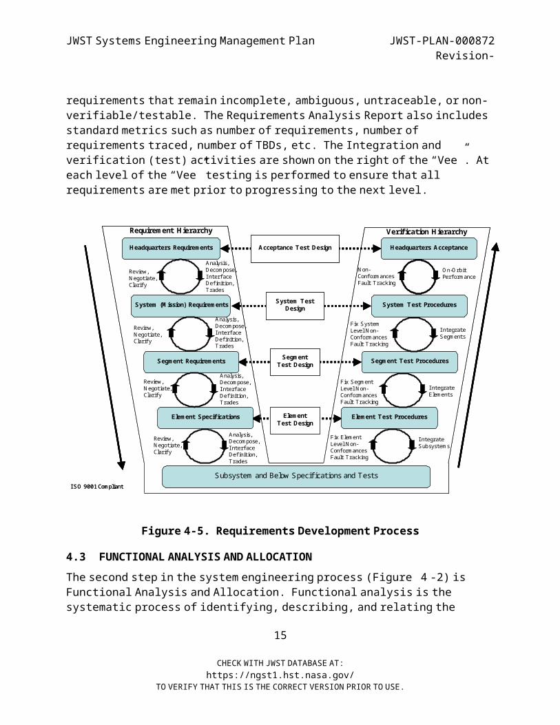
JWST Systems Engineering Management Plan JWST-PLAN-000872Revision-
requirements that remain incomplete, ambiguous, untraceable, or non- verifiable/testable. The Requirements Analysis Report also includes
standard metrics such as number of requirements, number of requirements traced, number of TBDs, etc. The Integration and verification (test) activities are shown on the right of the “Vee”. At
each level of the “Vee” testing is performed to ensure that all requirements are met prior to progressing to the next level.
Requirement Hierarchy Verification Hierarchy
Element Specifications Element Test ProceduresElement Test Design
Segment Requirements Segment Test ProceduresSegment Test Design
System (M ission) Requirements System Test ProceduresSystem Test Design
Headquarters Requirements Headquarters AcceptanceAcceptance Test Design
Subsystem and Below Specifications and Tests
Review, N egotiate, Clarify
Analysis, Decompose, Interface Definition, Trades
Analysis, Decom pose, Interface Definition, Trades
Analysis, Decom pose, Interface Definition, Trades
Analysis, Decompose, Interface Definition, Trades
O n-O rbit Performance
Integrate Segm ents
Fix System Level N on-Conform ancesFault Tracking
N on-ConformancesFault Tracking
Integrate Elements
Fix Segm ent Level N on-ConformancesFault Tracking
Integrate Subsystem s
Fix Element Level N on-ConformancesFault Tracking
ISO 9001 Com pliant
Review, N egotiate, Clarify
Review, N egotiate, Clarify
Review, N egotiate, Clarify
Figure 4- 5. Requirements Development Process
4.3 FUNCTIONAL ANALYSIS AND ALLOCATION The second step in the system engineering process ( Figure 4 -2 ) is
Functional Analysis and Allocation. Functional analysis is the systematic process of identifying, describing, and relating the
15
CHECK WITH JWST DATABASE AT:https://ngst1.hst.nasa.gov/
TO VERIFY THAT THIS IS THE CORRECT VERSION PRIOR TO USE.
JWST Systems Engineering Management Plan JWST-PLAN-000872Revision-
functions a system must perform in order to fulfill its goals and objectives. Functional analysis is the process of translating system
requirements into detailed design criteria, along with the identification of specific resource requirements. Functional
analysis is logically structured as a top-down hierarchical decomposition. In the early phases of the project life cycle (pre-
phase A and phase A), the functional analysis deals with the top-level functions that need to be performed by the system, where they need to be
performed, how often, under what operational concept and environmental conditions, and so on. The functional analysis needs
only to proceed to a level of decomposition that enables the system engineer to understand the full implications of the goals, objectives,
and constraints in order to formulate an appropriate system solution.
Several tools are available for performing functional analysis. The primary tool is the functional flow block diagram (FFBD). The FFBD
shows the network of actions that lead to the fulfillment of a function. Although the FFBD network shows the logical sequence of
“what” must happen, it does not ascribe a time duration to functions or between functions. To understand time-critical requirements, a time
line analysis (TLA) is used. The TLA can be applied to such diverse operational functions as spacecraft command sequencing and launch
vehicle processing. A third tool is the N2 diagram, which is a matrix display of functional interactions, or data flows, at a particular
hierarchical level.
Requirements are allocated according to the following systemhierarchy:System
SegmentElement
SubsystemComponent
AssemblySubassembly
16
CHECK WITH JWST DATABASE AT:https://ngst1.hst.nasa.gov/
TO VERIFY THAT THIS IS THE CORRECT VERSION PRIOR TO USE.

JWST Systems Engineering Management Plan JWST-PLAN-000872Revision-
Part
Figure 3-2 shows the System through Element portion of the JWST hierarchy. At the system level the Level 1 requirements, Science
Requirements and mission operations concept are decomposed into the Mission Requirements. The mission requirements are then allocated to
the three main Segments: Observatory, Ground and Launch.
Within each Segment requirements are further allocated to each Element. The Element level allocations are then used to generate
Subsystem allocations, which are documented in the Subsystem specifications. Subsystem engineers further allocate requirements
to their components and assemblies.
Since all allocations can change with design maturity, Systems Engineering assesses the allocations against "bottom-up" engineering
estimates and recommends allocation changes when justified. These changes require formal approval.
4.4 DESIGN SYNTHESIS The third step in the system engineering process ( Figure 4 -2 ) is
Design Synthesis. Design synthesis is the process of defining the product or item in terms of the physical and software elements that
make up and define the item and how the item will be used in such a way as to represent a feasible system configuration.18 Inputs to this process
are a functional architecture and any previously determined constraints or study results. The result is a physical definition that
is often referred to as the physical architecture and an operational concept. The goal is to develop a physical architecture that has
simple testable interfaces, supports a maximum parallel development effort and provides early recognition of problems through an
integrated test program. The result of design synthesis is continually feed back as an input to requirements analysis (section
18 Blanchard and Fabrycky , Systems Engineering and Analysis Third Edition, Prentice Hall, Inc., Upper Saddle River, NJ, 1998
17
CHECK WITH JWST DATABASE AT:https://ngst1.hst.nasa.gov/
TO VERIFY THAT THIS IS THE CORRECT VERSION PRIOR TO USE.
JWST Systems Engineering Management Plan JWST-PLAN-000872Revision-
4.3) until all design goals are achieved. The following tasks are performed to help define the overall physical architecture and
operational concept: Synthesize system element alternatives Integrated modeling of the alternatives Assess technology alternatives Define physical interfaces Define the system WBS Identification of mission phases Identification of operating modes Trade studies Select preferred concept/design
4.5 VERIFICATION Verification refers to the process of ensuring that all requirements
can be satisfied. Further, verification of all requirements will be conducted via analysis, inspection or test during integration and test
of the system. The JWST Verification Plan (JWST-PLAN-002027) identifies the overall approach to accomplishing verification,
establish requirements for each level of verification, establish verification methods, describe the verification process, and dictate
what shall be included in the Verification Test Procedures. Included in the plan is the overall approach of the verification program,
descriptions of the configuration of the test item, test objectives, facilities, safety considerations, organization responsibilities,
as well as descriptions of what will be contained in each Verification Test Procedure document.
System Engineering is responsible for ensuring that the Validation and Verification Program addresses all technical requirements stated in
all requirement documents, specifications, IRDs and ICDs. Figure 4-6 shows the verification process that culminates in the Verification
Matrix. The verification process must be in compliance with project plans such as the PAR, Contamination Control, Calibration, Modeling,
18
CHECK WITH JWST DATABASE AT:https://ngst1.hst.nasa.gov/
TO VERIFY THAT THIS IS THE CORRECT VERSION PRIOR TO USE.
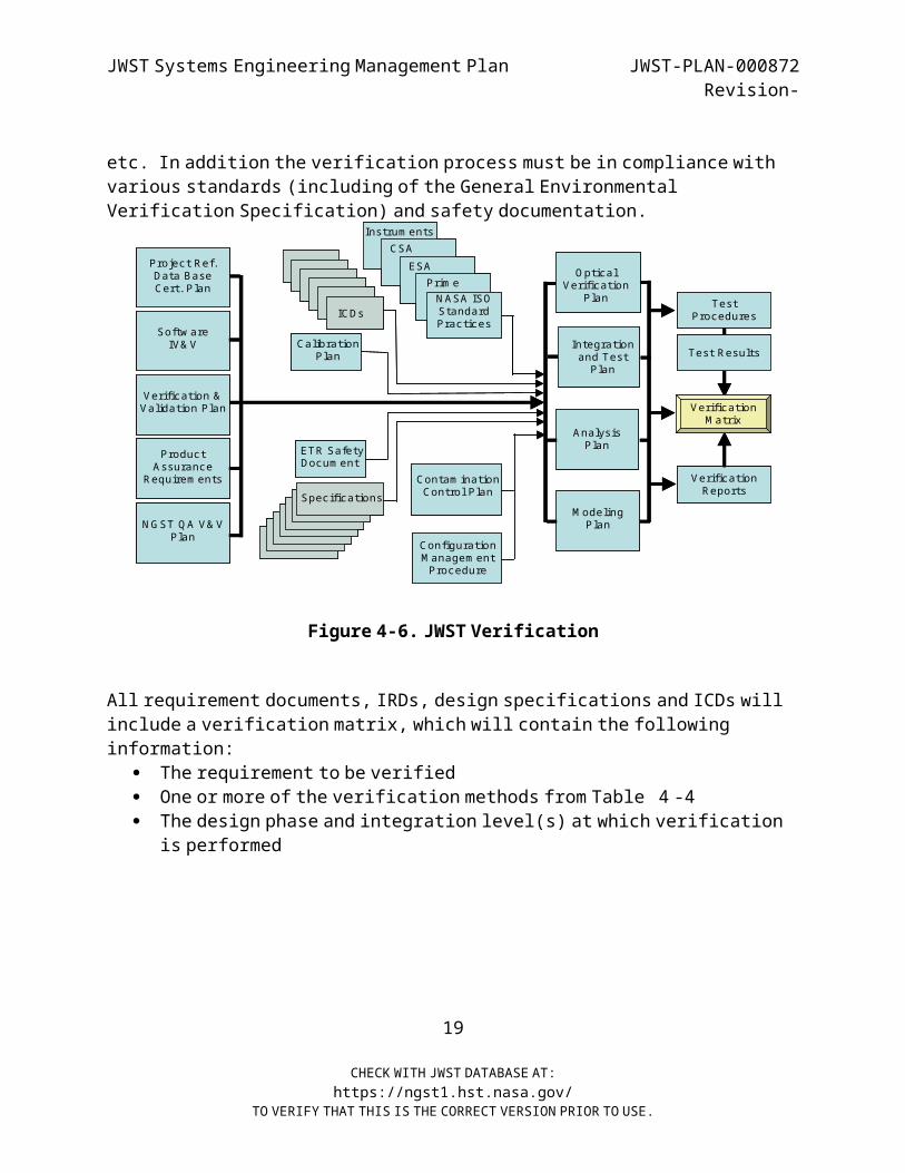
JWST Systems Engineering Management Plan JWST-PLAN-000872Revision-
etc. In addition the verification process must be in compliance with various standards (including of the General Environmental
Verification Specification) and safety documentation.
Verification &Validation Plan
ICDs
Calibration Plan
ETR SafetyDocum ent
Specifications
Integration and Test Plan
Contam ination Control Plan
Prim eN ASA ISO Standard Practices
ESACSA
Instrum ents
M odeling Plan
Analysis Plan
N G ST Q A V& V Plan
Product Assurance
Requirem ents
Configuration M anagem ent Procedure
O ptical Verification
Plan Test Procedures
Test Results
Verification Reports
Verification M atrix
Softw areIV& V
Project Ref. Data Base Cert. Plan
Figure 4- 6. JWST Verification
All requirement documents, IRDs, design specifications and ICDs will include a verification matrix, which will contain the following
information: The requirement to be verified One or more of the verification methods from Table 4 -4 The design phase and integration level(s) at which verification
is performed
19
CHECK WITH JWST DATABASE AT:https://ngst1.hst.nasa.gov/
TO VERIFY THAT THIS IS THE CORRECT VERSION PRIOR TO USE.
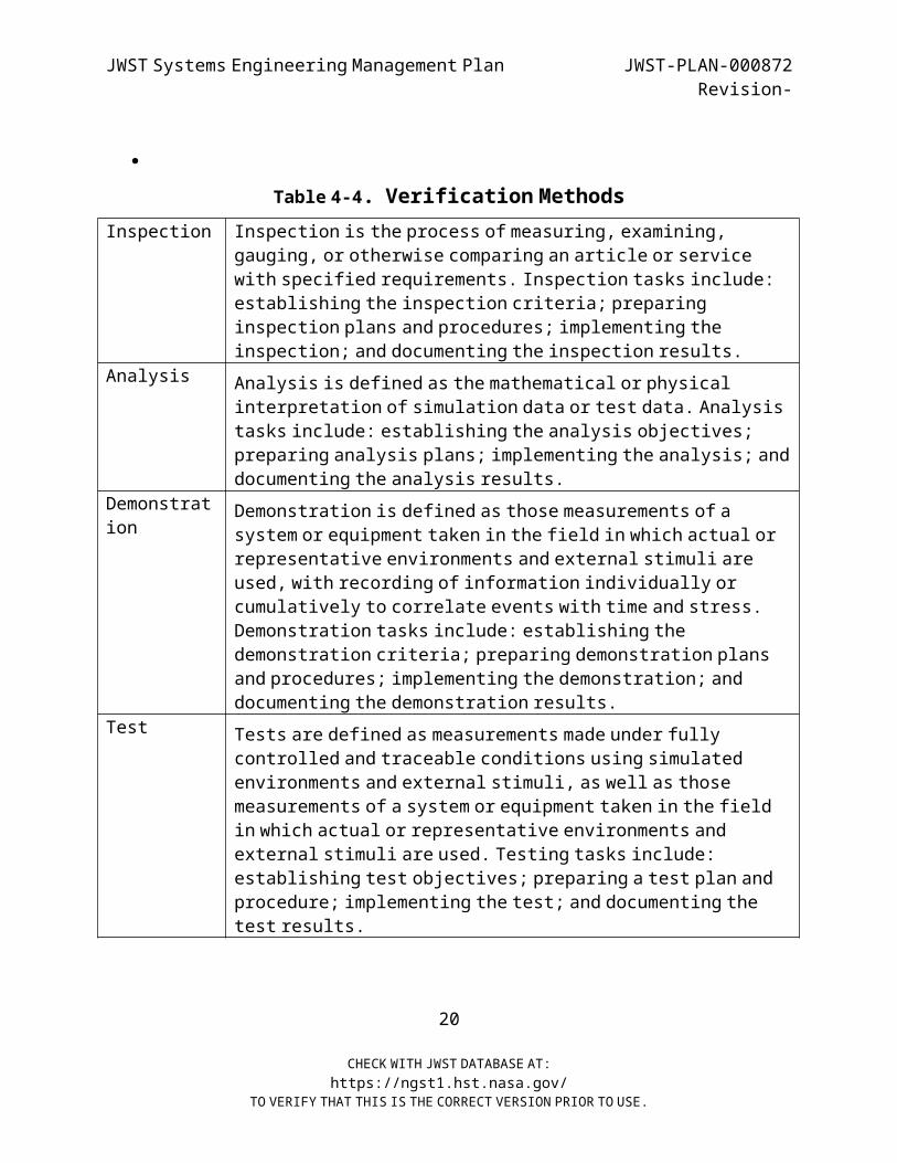
JWST Systems Engineering Management Plan JWST-PLAN-000872Revision-
Table 4-4 . Verification MethodsInspection Inspection is the process of measuring, examining,
gauging, or otherwise comparing an article or service with specified requirements. Inspection tasks include:
establishing the inspection criteria; preparing inspection plans and procedures; implementing the
inspection; and documenting the inspection results.Analysis Analysis is defined as the mathematical or physical
interpretation of simulation data or test data. Analysis tasks include: establishing the analysis objectives;
preparing analysis plans; implementing the analysis; and documenting the analysis results.
Demonstration
Demonstration is defined as those measurements of a system or equipment taken in the field in which actual or
representative environments and external stimuli are used, with recording of information individually or
cumulatively to correlate events with time and stress. Demonstration tasks include: establishing the demonstration criteria; preparing demonstration plans
and procedures; implementing the demonstration; and documenting the demonstration results.
Test Tests are defined as measurements made under fully controlled and traceable conditions using simulated
environments and external stimuli, as well as those measurements of a system or equipment taken in the field
in which actual or representative environments and external stimuli are used. Testing tasks include:
establishing test objectives; preparing a test plan and procedure; implementing the test; and documenting the
test results.
20
CHECK WITH JWST DATABASE AT:https://ngst1.hst.nasa.gov/
TO VERIFY THAT THIS IS THE CORRECT VERSION PRIOR TO USE.
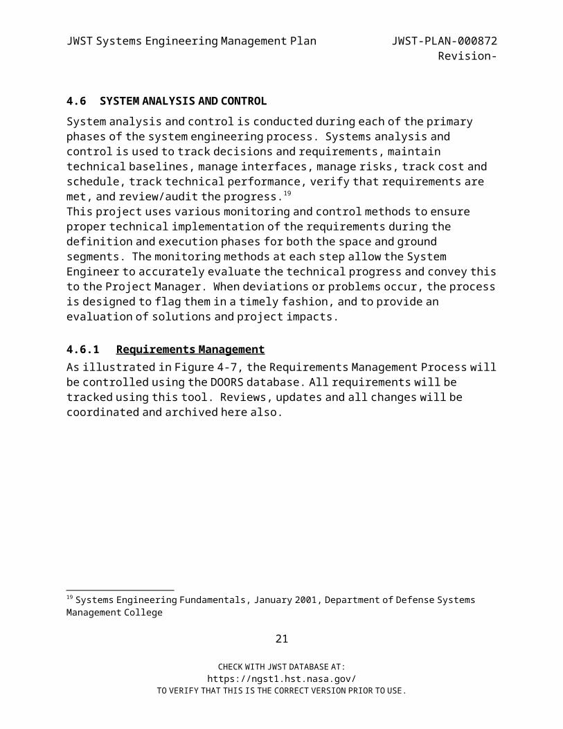
JWST Systems Engineering Management Plan JWST-PLAN-000872Revision-
4.6 SYSTEM ANALYSIS AND CONTROL System analysis and control is conducted during each of the primary phases of the system engineering process. Systems analysis and
control is used to track decisions and requirements, maintain technical baselines, manage interfaces, manage risks, track cost and schedule, track technical performance, verify that requirements are
met, and review/audit the progress.19 This project uses various monitoring and control methods to ensure
proper technical implementation of the requirements during the definition and execution phases for both the space and ground
segments. The monitoring methods at each step allow the System Engineer to accurately evaluate the technical progress and convey this
to the Project Manager. When deviations or problems occur, the process is designed to flag them in a timely fashion, and to provide an
evaluation of solutions and project impacts.
4.6.1 Requirements Management
As illustrated in Figure 4-7, the Requirements Management Process will be controlled using the DOORS database. All requirements will be
tracked using this tool. Reviews, updates and all changes will be coordinated and archived here also.
19 Systems Engineering Fundamentals, January 2001, Department of Defense Systems Management College
21
CHECK WITH JWST DATABASE AT:https://ngst1.hst.nasa.gov/
TO VERIFY THAT THIS IS THE CORRECT VERSION PRIOR TO USE.
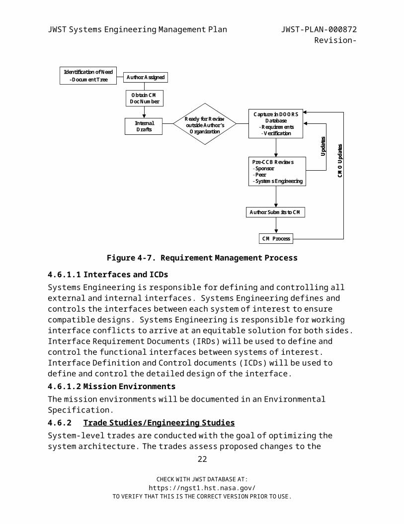
JWST Systems Engineering Management Plan JWST-PLAN-000872Revision-
Identification of Need-Docum ent Tree Author Assigned
Pre-CCB Reviews-Sponsor-Peer-System s Engineering
Capture in DO ORS Database
-Requirem ents-Verification
Author Subm its to CM
CM Process
Internal Drafts
Updates
CMO Up
dates
Ready for Review outside Author’s O rganization
Obtain CM Doc Num ber
Identification of Need-Docum ent Tree Author Assigned
Pre-CCB Reviews-Sponsor-Peer-System s Engineering
Capture in DO ORS Database
-Requirem ents-Verification
Author Subm its to CM
CM Process
Internal Drafts
Updates
CMO Up
dates
Ready for Review outside Author’s O rganization
Obtain CM Doc Num ber
Figure 4- 7. Requirement Management Process
4.6.1.1 Interfaces and ICDs Systems Engineering is responsible for defining and controlling all
external and internal interfaces. Systems Engineering defines and controls the interfaces between each system of interest to ensure
compatible designs. Systems Engineering is responsible for working interface conflicts to arrive at an equitable solution for both sides. Interface Requirement Documents (IRDs) will be used to define and
control the functional interfaces between systems of interest. Interface Definition and Control documents (ICDs) will be used to
define and control the detailed design of the interface.4.6.1.2 Mission Environments
The mission environments will be documented in an Environmental Specification.
4.6.2 Trade Studies/Engineering Studies
System-level trades are conducted with the goal of optimizing the system architecture. The trades assess proposed changes to the
22
CHECK WITH JWST DATABASE AT:https://ngst1.hst.nasa.gov/
TO VERIFY THAT THIS IS THE CORRECT VERSION PRIOR TO USE.
JWST Systems Engineering Management Plan JWST-PLAN-000872Revision-
System/Subsystem configuration or architecture, and to the requirements. Results will be used to update and detail system
performance and design requirements allocations as necessary. In addition, analyses will be performed on COTS hardware and software
recommended by team members to determine compatibility with system requirements. All trades will consider:
Alternative architectures Alternative operation scenarios or requirements Assessment of technical and development risks Effects on operations Impact on verification Programmatic concerns (e.g. cost and schedule) Predicted performance Reliability
Each trade study will be documented in an Engineering Memo (EM), which will identify the subject, tradeoff considerations, and results. The
format specified in Appendix C will be used for each EM. At a minimum each trade study EM should identify: The system issue under analysis System requirements and/or goals, objectives, andconstraints The measures and measurement methods (models) used All data sources Alternatives chosen for analysis Computational results, including uncertainty ranges, andsensitivities Selection rule used Recommended alternative
4.6.3 Design Optimization
The JWST team conducted several design optimization activities right after prime contractor selection. A selection was made of Option 4 by
the NHQ and the PMO. As identified in SP-6105, Para. 3.7, a Synthesis/Select Optimal Option is the final path of the Systems
Definition. All validated requirements for end items have been23
CHECK WITH JWST DATABASE AT:https://ngst1.hst.nasa.gov/
TO VERIFY THAT THIS IS THE CORRECT VERSION PRIOR TO USE.
JWST Systems Engineering Management Plan JWST-PLAN-000872Revision-
baselined, top-level architecture alternatives optimized and risk mitigation documented and in place. A demonstration is ready that the
system can be built within cost, schedule and performance constraints. A specification of requirements is planned early in the conceptual
phase to define the functionality of the products.4.6.4 Design Standardization
General NASA Engineering practices apply in addition the use of FED STDs, DOD, IEEE 1220, ANSI, EIA 632, and specifications listed herein, where applicable, provides for standardization throughout the JWST
Project.4.6.5 Survivability/Vulnerability
JWST requires the generation of a Systems Safety Plan and various studies such as contamination, FRI/EMI, and various engineering
simulations conducted early in the design process.4.6.6 Produceability
The JWST Design Team must consider all aspects of the spacecraft life cycle especially the labor intensive I&T stage. In order to provide
ease of assembly/disassembly and element to component ease of access for troubleshooting, testing and sub-assembly/component rework and
or replacement modularity and works-in-a-drawer design is highly recommended. BITE design features are also encouraged down to the
component level. Diagnostic testing techniques that provide self- test health checks and full-up performance testing are standard
engineering practices.4.6.7 Equipment Databases
Systems Engineering is responsible for developing and maintaining the Equipment Database(s) to track assembly resource requirements and
properties and assess subsystem margins and contingencies. It is used to track engineering changes, compare the engineering estimates with
allocated quantities, assess resource margins and contingencies, and provide a baseline assembly description for engineering analysis. For
each Space Segment assembly, the following data are reported: Quantity, unit and total mass estimates, allocated total mass, number
of units operating in each mode, estimated Beginning-of-Life (BOL).24
CHECK WITH JWST DATABASE AT:https://ngst1.hst.nasa.gov/
TO VERIFY THAT THIS IS THE CORRECT VERSION PRIOR TO USE.
JWST Systems Engineering Management Plan JWST-PLAN-000872Revision-
And EOL total orbit average power, allocated total orbit average power, number of units dissipating heat in each mode, estimated total
heat dissipation and accuracy class. The database is updated periodically as engineering changes are approved by issuing ECNs and
represents the latest engineering estimates of assembly resources. This information can be grouped by Subsystem or Element, which is used
for tracking higher-level resources, margins and contingencies. Different databases can be maintained by each Element or Segment, as
needed.
A separate Instrument Database shall be maintained, containing instrument scientific goals, instrument operating modes, mechanical
configuration, command and data handling requirements, thermal requirements, power requirements, pointing and navigation requirements, EMC/EMI and contamination constraints, and special
Integration and Test requirements. This database is used by Systems Engineering to assess compatibility of spacecraft bus-to-payload
interfaces and is configuration controlled.4.6.8 Fault Detection, Isolation, and Recovery
Systems Engineering will define the Fault Detection, Isolation, and Recovery strategy and requirements, using heritage designs as much as
possible. These will become the bases for development and implementation of Element and Subsystem Fault Detection, Isolation,
and Recovery (FDIR). The FDIR system concept will be documented andcontrolled.4.6.9 Risk Management
Systems Engineering is responsible for the implementation of the Risk Management process, reporting to the Project Office the status of the mitigation efforts and any problems that are discovered during the
Project. Risk Management is performed according to the JWST Risk Management Plan (JWST-PLAN-000651) to identify the risk areas early in
the Project, and to develop plans to reduce risk and implement these plans.
25
CHECK WITH JWST DATABASE AT:https://ngst1.hst.nasa.gov/
TO VERIFY THAT THIS IS THE CORRECT VERSION PRIOR TO USE.
JWST Systems Engineering Management Plan JWST-PLAN-000872Revision-
4.6.10 Mission/Product Assurance and Quality Control
Part of the Systems Engineering function is assuring that the final product performs as required. The role of day-to-day monitoring of
this function is delegated to the Product Assurance/Quality Control (PA/QC) Engineers. PA/QC monitors and reviews all activities to
identify technical design concerns or problems of implementation (e.g., testing, operations, etc.) which could impair the scientific
performance of the project, or which could otherwise jeopardize the mission. PA/QC is responsible for the overall management, planning,
reporting, and auditing of the performance assurance activities, which include both hardware and software quality assurance, and
auditing the efforts of EEE parts control, materials and process control, safety, and reliability.
4.7 TECHNICAL PERFORMANCE METRICS The following project metrics are collected and analyzed, as a
minimum, in order to determine trends, performance strengths, weaknesses and probability of mission success.
Mission Metrics: Schedule Compliance: Time allotted and taken, variance Performance: Requirements met, not met, or deferred Risks: number and severity Critical Path: Number of Items along, Performance along Divergence from historical programs: Novelty, State-of-the-Art External Dependencies Observatory Mass Observatory Power Observatory Thermal Performance
Product Metrics: Measures of Effectiveness (MOEs) Achievement Achievement of Key Performance Parameters (KPPs) Technical Performance Measures (TPMs) Complexity/Producibility
26
CHECK WITH JWST DATABASE AT:https://ngst1.hst.nasa.gov/
TO VERIFY THAT THIS IS THE CORRECT VERSION PRIOR TO USE.
JWST Systems Engineering Management Plan JWST-PLAN-000872Revision-
Requirements Traceability Requirements and Design Changes: Change Requests pending Quality and Stability: System Trouble Reports pending, Trend
Analysis, Rework Computer Resource Utilization Software Metrics: AVDEP-HDBK-7, Rev.1, dated 1 Feb 1996 –
Software Metrics Program Testing Metrics: Requirements identified, tested and passed
4.8 TECHNICAL REVIEWS Technical reviews are divided into two major categories: project
reviews and peer reviews. Major project reviews are the key technical milestones of the Project, conducted by Systems Engineering and
covering a major segment of the project such as the spacecraft bus design.
The major technical reviews are significant milestones in the project and are conducted by Systems Engineering. The Systems
Engineer/Manager approves the technical criteria for each review and establishes an agenda, with approval from Project Management.
Technical meetings shall be conducted by Systems Engineering on an as- needed basis with coordination through the Project office.
27
CHECK WITH JWST DATABASE AT:https://ngst1.hst.nasa.gov/
TO VERIFY THAT THIS IS THE CORRECT VERSION PRIOR TO USE.

JWST Systems Engineering Management Plan JWST-PLAN-000872Revision-
Figure 4- 8 System Engineering Reviews
4.8.1 Systems Engineering Reviews The technical progress of the Project must be assessed at key
milestones to ascertain readiness to transition into the next Project phase. As illustrated in Figure 4-8, these reviews are event driven
activities, that is, the technical progress milestones require that certain specific tasks must be completed prior to conducting the review. System Engineering collects and reviews the documentation
that demonstrates the technical progress planned for the milestone, and submits the materials as a data package to the review team prior to the review. This allows adequate review by the selected technical
representatives to identify problems and issues that can be discussed at the review. Systems Engineering is responsible for the agenda,
organization, and conduct of the review as well as obtaining closure on any action items and corrective actions. Systems Engineering acts as
recorder, noting all comments and questions that are not adequately
28
CHECK WITH JWST DATABASE AT:https://ngst1.hst.nasa.gov/
TO VERIFY THAT THIS IS THE CORRECT VERSION PRIOR TO USE.
Phase B/C Detail Design Development Phase D Production and Integration and Test
NGST Program Reviews
ISIM Project Reviews
Observatory Project Reviews
Launch Reviews
External Reviews
SRR PDR
IA
ISIM and Instruments PDR
NAR
CDR
PM C
M OR TRRORR
PSRFRR
LaunchSafety Review
Safety Review
Safety Review
Safety Review
Red Team Review(s) as appropriate
IARs called annually
Optics Review
W eekly System Engineering Tagups and Hot Synchs
JSEB as needed
ISIM and Instruments CDR ISIM PSRFlight Software Reviews (every 3 months)
Instruments PSR
S/C and OTE PDR
S/C and OTE CDR
ISIM SRR
S/C and OTE SRR
Subsystem Reviews as appropriate
Subsystem Reviews as appropriate
Observatory Reviews
ISIM Reviews
Phase B/C Detail Design Development Phase D Production and Integration and Test
NGST Program Reviews
ISIM Project Reviews
Observatory Project Reviews
Launch Reviews
External Reviews
SRR PDR
IA
ISIM and Instruments PDR
NAR
CDR
PM C
M OR TRRORR
PSRFRR
LaunchSafety Review
Safety Review
Safety Review
Safety Review
Red Team Review(s) as appropriate
IARs called annually
Optics Review
W eekly System Engineering Tagups and Hot Synchs
JSEB as needed
ISIM and Instruments CDR ISIM PSRFlight Software Reviews (every 3 months)
Instruments PSR
S/C and OTE PDR
S/C and OTE CDR
ISIM SRR
S/C and OTE SRR
Subsystem Reviews as appropriate
Subsystem Reviews as appropriate
Observatory Reviews
ISIM Reviews
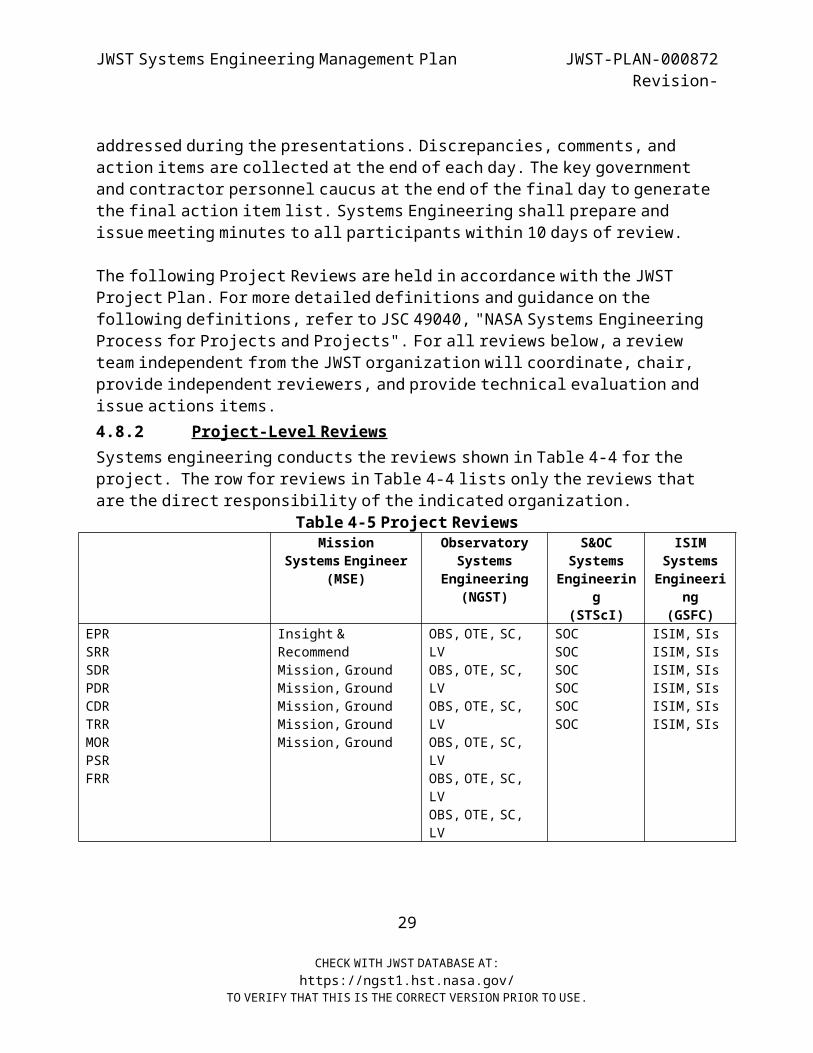
JWST Systems Engineering Management Plan JWST-PLAN-000872Revision-
addressed during the presentations. Discrepancies, comments, and action items are collected at the end of each day. The key government
and contractor personnel caucus at the end of the final day to generate the final action item list. Systems Engineering shall prepare and
issue meeting minutes to all par ticipants within 10 days of review.
The following Project Reviews are held in accordance with the JWST Project Plan. For more detailed definitions and guidance on the
following definitions, refer to JSC 49040, "NASA Systems Engineering Process for Projects and Projects". For all reviews below, a review
team independent from the JWST organization will coordinate, chair, provide independent reviewers, and provide technical evaluation and
issue actions items.4.8.2 Project-Level Reviews
Systems engineering conducts the reviews shown in Table 4-4 for the project. The row for reviews in Table 4-4 lists only the reviews that
are the direct responsibility of the indicated organization. Table 4-5 Project Reviews
Mission Systems Engineer
(MSE)
ObservatorySystems
Engineering(NGST)
S&OCSystems
Engineering
(STScI)
ISIMSystemsEngineeri
ng(GSFC)
EPRSRRSDRPDRCDRTRRMORPSRFRR
Insight &Recommend
Mission, Ground Mission, Ground Mission, Ground Mission, Ground Mission, Ground
OBS, OTE, SC,LV
OBS, OTE, SC,LV
OBS, OTE, SC,LV
OBS, OTE, SC,LV
OBS, OTE, SC,LV
OBS, OTE, SC,LV
SOCSOCSOCSOCSOCSOC
ISIM, SIs ISIM, SIs ISIM, SIs ISIM, SIs ISIM, SIs ISIM, SIs
29
CHECK WITH JWST DATABASE AT:https://ngst1.hst.nasa.gov/
TO VERIFY THAT THIS IS THE CORRECT VERSION PRIOR TO USE.
JWST Systems Engineering Management Plan JWST-PLAN-000872Revision-
4.8.2.1 Engineering Peer Reviews (EPR) Engineering Peer Review (EPR) are focused, in-depth technical reviews
that add value and reduces risk through expert knowledge infusion, confirmation of approach, and specific recommendations.
An EPR Plan that lists the items to be reviewed and the associated life- cycle milestones for the reviews will be produced.
The EPR teams shall be comprised of technical experts with significant practical experience relevant to the technology and requirements of
the subsystem, component to be reviewed. The EPR presentation materials shall be placed in the project library and maintained throughout the project/product lifecycle.
A summary of results from each EPR conducted since the last Integrated Independent Review (IIR) shall be presented at the next IIR.
The Product Manager (Project Manager, Project Formulation Manager, Instrument Manager, or Principal Investigator) shall define and
implement a set of Engineering Peer Reviews (EPRs) for hardware/software subsystems of the product commensurate with the
scope, complexity, and acceptable risk of the product in accordance with GPG 8700.6.
A variety of reviews are held by each team member and their staff. These reviews are the primary mechanism for internal technical Project
control. The following peer reviews are held regularly.
4.8.2.2 System Requirements Review (SRR) A technical review of the mission requirements, as well as
requirements at the system level, to demonstrate that the requirements at the system level meet the mission objectives, and that the system
specifications are sufficient to meet the project objectives.
30
CHECK WITH JWST DATABASE AT:https://ngst1.hst.nasa.gov/
TO VERIFY THAT THIS IS THE CORRECT VERSION PRIOR TO USE.
JWST Systems Engineering Management Plan JWST-PLAN-000872Revision-
4.8.2.3 System Definition Review (SDR) A technical review of the system architecture, with regards to
requirements, specifications, operational concepts, plans, and cost and schedule estimates, established as a result of the definition
effort.4.8.2.4 Preliminary Design Reviews (PDR)
A comprehensive, technical review of the preliminary design showing that it meets all system and interface requirements with acceptable
risk, is adequately defined, and can be verified. All elements are covered in this series of reviews, which cover Assembly or Subsystems,
Elements, and Segment PDRs.4.8.2.5 Critical Design Reviews (CDR)
A comprehensive, technical review of the complete system design in full detail, showing that all problems have been resolved, and that the
design is sufficiently mature to proceed to manufacturing. Provides a comprehensive review of all verification plans to ensure that all
performance and interface requirements can be verified. All elements are covered in this series of reviews, which cover Assembly or
Subsystems, Elements, and Segment CDRs.4.8.2.6 Test Readiness Review (TRR)
A formal technical review of the system that establishes functional compliance with all technical requirements prior to exposure to
environmental testing.4.8.2.7 Mission Operations Review (MOR)
A formal review of ground segment plans for operations, verification, and readiness for Observatory integration and test.
4.8.2.8 Pre-Ship Review (PSR) A technical and Projectmatic review prior to shipment of the Space
Segment to the launch site to demonstrate the system has verified all requirements. The technical review will concentrate on past system
performance during functional and environmental testing. The Projectmatic review will emphasize preflight activities planned for
the launch site and other support areas.
31
CHECK WITH JWST DATABASE AT:https://ngst1.hst.nasa.gov/
TO VERIFY THAT THIS IS THE CORRECT VERSION PRIOR TO USE.
JWST Systems Engineering Management Plan JWST-PLAN-000872Revision-
Flight Readiness Review (FRR) A formal review to determine the overall readiness of the system for
launch.4.9 CONFIGURATION MANAGEMENT
System Engineering controls the technical baselines of the project and ensures efficient and logical progression through the baselines.
Typically, these baselines are the: “functional," ''design to,” "build-to'' (or "code-to"), "as-built" (or "as-coded"), and ''as-
deployed." These baselines are established after completion of the appropriate review.
The CM process, utilizing DOORS software tools, ensures that all proposed and approved technical and programmatic changes to JWST
hardware, software, GSE, ground system, SOC, Science, LV interfaces, testing verification and associated documents and drawings shall be
systematically evaluated for validity, merit, need, and impact. This is to ensure all preventive and corrective actions affecting the
quality of these JWST resources are fully documented and archived over the project life cycle. In addition, the James Webb Space Telescope
Project Configuration Management Procedure (JWST-PROC-000654 ) satisfies the CM requirements of GPG 1410.2 and 400-PG-1410.2.1.
The CM review process includes the Systems Engineering Organization review of all changes to ensure they are compatible in terms of
technical performance and schedule. Technical review performed by the Systems Engineering Organization will be done with the support of the
Discipline and Product engineers from across the organization.4.10 INTEGRATION AND TEST
The Integration and Test Plan (JWST-PLAN-XXXXX) describe who is responsible for the physical integration and testing of the Space
Segment and for the planning of all launch-site activities.
32
CHECK WITH JWST DATABASE AT:https://ngst1.hst.nasa.gov/
TO VERIFY THAT THIS IS THE CORRECT VERSION PRIOR TO USE.
JWST Systems Engineering Management Plan JWST-PLAN-000872Revision-
5.0 SYSTEMS ENGINEERING TOOLS
5.1 STATEMENT OF WORK (SOW) The contract SOW describes the effort required to develop, design,
fabricate, integrate, and test the JWST mission Segments; deliver the completed Segments to their respective operational locations, and
perform operations as described in the Project Plan. This is a contractual document controlled and maintained by the JWST Project.
5.2 WORK BREAKDOWN STRUCTURE (WBS) The contract Work Breakdown Structure (WBS) and Dictionary divides the
tasks, as broken down in the SOW, into discrete and manageable segments. The WBS is documented in (TBD ), maintained by Resource
Management, and used to organize and assign technical responsibilities and tasks.
Systems Engineering will use the WBS to evaluate the work within each partner’s responsibility and across interfaces for a comprehensive,
systems-level assessment of the status and adjustments required during the JWST lifecycle.
5.3 TECHNICAL PLANS Project technical plans provide detailed technical direction to
specific areas of the project to ensure that the products comply with the project requirements. These plans are extensions of this SEMP and are reviewed and approved by Systems Engineering through the CM
process.5.4 PROJECT SCHEDULE/MILESTONES
One of the key management tools required in the accomplishment of any project is that of scheduling. An accurate portrayal of the sequence
of events and the pinpoint date or time for events helps all participants in the accomplishment of their task. Project Management
will maintain the master schedule, and will provide to Systems Engineering the schedule and milestones associated with all Systems
1
CHECK WITH JWST DATABASE AT:https://ngst1.hst.nasa.gov/
TO VERIFY THAT THIS IS THE CORRECT VERSION PRIOR TO USE.
JWST Systems Engineering Management Plan JWST-PLAN-000872Revision-
Engineering activities. This schedule will be updated at regular intervals or as needed by Project Management.
System Engineering participates in establishing a realistic JWST schedule baseline, including the development of critical product and
interface documentation. Systems Engineering monitors schedule progress, supports the forecast of completion trends, and utilize this
information to make recommendations on trades or adjustments to the JWST Project Manager.
5.5 TECHNICAL PERFORMANCE MEASURES (TPMs) Technical Performance Measures (TPM) are used in concert with cost and
schedule performance measurement to provide an overall picture of Project status. The TPM tracking Project will tie together several
basic systems engineering activities (i.e., systems analysis, functional and performance requirements definition, and verification
and validation activities).
Systems analysis activities and trade studies will help identify and quantify system effectiveness and performance requirements.
Functional and performance requirements definition help identify verification and validation requirements, which in turn result in quantitative evaluation of TPMs.
When TPM thresholds are exceeded, it is a signal to replan cost, schedule, and human resources. In addition, this may trigger new
systems analysis activities.
TPM development and tracking will begin with the establishment of the design baseline, planned for early in Phase B. Additional TPMs will be
developed throughout the lifecycle of the Project as tracking data isdeveloped.
TPM data will be developed that is relevant to each system element, power, mass, etc. The systems engineering group will determine which
metrics are appropriate for each element and establish a tracking system to measure performance. TPMs will be established that can be
2
CHECK WITH JWST DATABASE AT:https://ngst1.hst.nasa.gov/
TO VERIFY THAT THIS IS THE CORRECT VERSION PRIOR TO USE.

JWST Systems Engineering Management Plan JWST-PLAN-000872Revision-
measured objectively by direct or indirect testing and analysis. TPMs that are tracked through analysis will be based on demonstrated values
to the maximum extent possible, and performed using the same measurement methods or models used during the trade studies. The
models will continue to replace estimated data with demonstrated data as the Project matures and measured data becomes available.
Selected TPMs will fall well within defined system limits, which reflect a hard boundary that can not be exceeded. An example would be
the high-level TPM of the LV mass limit. Tracking at this high level will ensure that the capability of the LV is not exceeded.
TPMs will be established on a time-phased planned profile, continuously monitoring demonstrated values against the profile. The
planed profile will take into account a number of factors, including system technological maturity. For example, greater margins or
reserves are required for a less mature system. The established margins and reserves will be based on lessons learned from other NASA
missions.
Parameter selection is based on the measures of system effectiveness, impact to system performance, and appropriate technical attributes of
the Project. Systems Engineering selects the parameters, and with the Subsystem Leads, and defines the control method for each parameter.
Definition of the input data types, formats, and schedules required to support these analyses will be established by agreement with the team members as appropriate.
Once the final critical parameters have been established at SRR, the subsystems report the status of each parameter that has been allocated
to their area on a regular basis. Systems Engineering maintains constant monitoring of the performance status, defines alternatives
and mitigation plans for areas falling short of full performance, and assesses impacts of potential risks. The JWST Project Office has full
visibility into this process through the technical metrics used to assess progress. System impact of any change is determined, trends are
3
CHECK WITH JWST DATABASE AT:https://ngst1.hst.nasa.gov/
TO VERIFY THAT THIS IS THE CORRECT VERSION PRIOR TO USE.
JWST Systems Engineering Management Plan JWST-PLAN-000872Revision-
generated and corrective action, where required, is implemented in a Mitigation Plan.
5.6 RESOURCE MARGIN Resource margin is defined as the amount of resource remaining when an estimate plus the associated contingencies and reserves are
subtracted from the available quantity. Margin is calculated at the Element level. For mass margin, the LV lift capability is used as the
available resource, and for power margin the Observatory End-of-Life (EOL) solar array capability is used. Margin can be represented by the
equation:
Margin = Available Resource -(Design Estimate + Contingency + Manager Reserve)
Small or negative margins will trigger a review of the design, resulting in either reallocation of resources, release of design
contingency, or modification to the proposed hardware design.5.7 CONTINGENCY CRITERIA
Contingency is defined as a percentage of resource (e.g., mass or power) added to an estimate as a provision for uncertainty.
Contingency accounts for the tendency of resource usage to increase as the design progresses. Up through the PDR phase of the Project, 20
percent contingency is applied to a resource usage estimates for the purposes of design and analysis work, including subsystem sizing.
After PDR, contingency is based on the "accuracy class" (i.e., stage of development) of each hardware assembly. Each assembly is assigned one
of the following accuracy class numbers: Just like an existing flown unit Qualified by similarity - existing technology New development - existing technology To be developed - new technology
As the design converges and uncertainty and risk are retired, contingency is reduced. This helps to avoid oversizing of subsystems,
which can occur if contingencies are too high. For example, if power4
CHECK WITH JWST DATABASE AT:https://ngst1.hst.nasa.gov/
TO VERIFY THAT THIS IS THE CORRECT VERSION PRIOR TO USE.
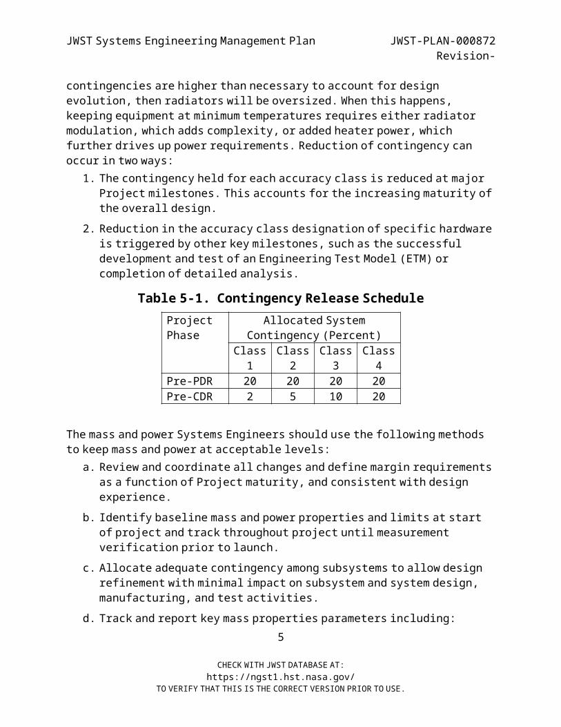
JWST Systems Engineering Management Plan JWST-PLAN-000872Revision-
contingencies are higher than necessary to account for design evolution, then radiators will be oversized. When this happens,
keeping equipment at minimum temperatures requires either radiator modulation, which adds complexity, or added heater power, which
further drives up power requirements. Reduction of contingency can occur in two ways:
1. The contingency held for each accuracy class is reduced at major Project milestones. This accounts for the increasing maturity of
the overall design.2. Reduction in the accuracy class designation of specific hardware
is triggered by other key milestones, such as the successful development and test of an Engineering Test Model (ETM) or
completion of detailed analysis.
Table 5-1. Contingency Release Schedule Project
Phase Allocated System
Contingency (Percent)Class1
Class2
Class3
Class4
Pre-PDR 20 20 20 20Pre-CDR 2 5 10 20
The mass and power Systems Engineers should use the following methods to keep mass and power at acceptable levels:a. Review and coordinate all changes and define margin requirements
as a function of Project maturity, and consistent with designexperience.
b. Identify baseline mass and power properties and limits at start of project and track throughout project until measurement
verification prior to launch.c. Allocate adequate contingency among subsystems to allow design
refinement with minimal impact on subsystem and system design, manufacturing, and test activities.
d. Track and report key mass properties parameters including:5
CHECK WITH JWST DATABASE AT:https://ngst1.hst.nasa.gov/
TO VERIFY THAT THIS IS THE CORRECT VERSION PRIOR TO USE.
JWST Systems Engineering Management Plan JWST-PLAN-000872Revision-
1. Unit and subsystem weights2. Centers of gravity of all components3. Dynamic and/or static imbalance (stowed)4. Spin-to-transverse moment of inertia ratio (stowed)5. Maximum-to-minimum transverse moment-of-inertia variation
(stowed)6. Deployed moments of inertia7. Moment on LV adapter8. Weight margin for selected LV
b. Power source levels and usage is summarized for all operating modes by unit and subsystem (including battery charging and
distribution losses). This will include:1. Equinox and solstice operations2. BOL and EOL3. Eclipse and sunlight operations4. Nominal and worst case operating conditions5. Transfer orbit and operational orbit6. Peak and steady-state load operation7. Safe-hold operations
c. Provide an alert of any unfavorable trends or design concepts that could degrade performance.
d. If the margins fall below minimum, perform tradeoffs to recovermargin
5.7.1 Propellant
Systems Engineering works with Space Segment subsystem engineers to support the development and maintenance of the Space Segment
propellant budget. Systems Engineering maintains propellant budgets to reflect changes in satellite mass properties, thruster
performance, and/or mission requirements. A weight-versus-life exchange ratio is calculated and used to estimate the impacts of
6
CHECK WITH JWST DATABASE AT:https://ngst1.hst.nasa.gov/
TO VERIFY THAT THIS IS THE CORRECT VERSION PRIOR TO USE.

JWST Systems Engineering Management Plan JWST-PLAN-000872Revision-
hardware changes or weight growth on projected excess life capability. The propulsion subsystem configuration is reviewed, and operational
strategies are developed that minimize propellant usage. The propellant budget is then input to the mass allocation process.
5.7.2 Pointing (Alignment)
The allowable contribution of the Spacecraft Bus to instrument pointing error, any antenna pointing errors, (i.e., gimbal accuracy,
performance changes over time, and attitude sensor error) and solar array pointing error is allocated by Systems Engineering. Systems
Engineering also works with mechanical and thermal subsystem engineers to develop and maintain the Space Segment alignment plan, to
assess the effect of attitude disturbances (e.g., thermal transients, thrusters, mechanisms, solar and magnetic torques) on the Space
Segment system, and develop strategies to minimize their impacts. The instrument(s) contribution(s) to instrument pointing error and
attitude disturbances is assessed cooperatively between the Spacecraft Bus and Instrument Element leads.
5.7.3 Command and Telemetry Allocations
Systems Engineering analyzes the Space Segment requirements for commands and telemetry in order to allocate commands and telemetry to Elements and Subsystems. The allocations are maintained in the Command
and Telemetry Lists. These lists must include all information for each command/telemetry, such as:
a. Mnemonic, title, description, channel number, format [e.g. Consultative Committee for Space Data Systems (CCSDS]
b. Telemetry channel type (analog, bilevel, and serial)c. Command type (low-level pulse, high-level pulse, serial)d. Command pulse width required for function activatione. Indication of hazardous and critical commandsf. Sorts of command and telemetry information by subsystem and unit
5.7.4 Link Margin and Allocation
Systems Engineering maintains link margin calculations for both command and telemetry, with margin allocated based on project
7
CHECK WITH JWST DATABASE AT:https://ngst1.hst.nasa.gov/
TO VERIFY THAT THIS IS THE CORRECT VERSION PRIOR TO USE.
JWST Systems Engineering Management Plan JWST-PLAN-000872Revision-
maturity. As the design matures, replace margins with measured/actual values, and increase fidelity of analysis to reflect details of the
Space and Ground Segments respective properties.5.7.5 Processor
Key tracking parameters of the processor(s) include memory, throughput, and bus bandwidth utilization. Processor resource
management involves maintenance of adequate spare Random Access Memory (RAM) and Programmable Reads Only Memory (PROM).
Key tracking parameters of the Ground Segment include estimates of timelines for various operations scenarios
5.7.6 Reliability Analysis
Systems Engineering reliability analysts calculate the mission lifetime probability of success. If calculated reliability falls
below the specified levels, Systems Engineering suggests design changes that improve the reliability at minimum cost. Tradeoffs also suggest means of reliability improvement for modest use of weight,
power, schedule, or other resources. Systems Engineering should follow the reliability evaluation process shown here:
1. Establish reliability criteria for the System2. Gather reliability data for parts/subassemblies/assemblies3. Specify Space Segment operating modes for the purposes of
reliability modeling4. Support Subsystem/Reliability Engineers in calculating and
evaluating reliabilities based on design complexity, operational use, parts count, parts type, and parts failure
rates. This effort can involve:a. Electronic parts stress-derating analysesb. Worst-case circuit analysesc. Mechanical device stress analysesd. Thermal analyses
8
CHECK WITH JWST DATABASE AT:https://ngst1.hst.nasa.gov/
TO VERIFY THAT THIS IS THE CORRECT VERSION PRIOR TO USE.
JWST Systems Engineering Management Plan JWST-PLAN-000872Revision-
e. Life limiting wearout analyses defining operational constraints for each unit and evaluating margins
f. Test failure (if applicable) identification, investigation, documentation, reporting, and corrective action definition
5. Perform initial Failure Modes and Effects Analyses (FMEAs) by determining critical unit failures at interfaces between each
unit (their input/output) and determining existing levels of function redundancy.
6. Complete system level analyses, identify the lowest reliability parts/assemblies, and define means of eliminating
susceptibility.7. Evaluate and select design changes with the lowest system impact
to increase reliability, if needed8. Perform Probabilistic Risk Assessment (PRA) and with Project
concurrence make decision on design change.9. If Yes, modify the design to account for low-reliability areas.10. Perform tests to verify design (e.g., mechanism life cycle
testing).11. Finalize FMEA results, showing current design meets the
criteria.12. Identify telemetry to monitor low-reliability areas.13. For Ground Segment equipment, incorporate results into the
sparing requirements and maintenance facility requirements.5.7.7 Orbital Debris Analysis
Systems Engineering will perform an orbital debris analysis and generate a report to fulfill the requirements of NASA Safety Standard
1740.14.
9
CHECK WITH JWST DATABASE AT:https://ngst1.hst.nasa.gov/
TO VERIFY THAT THIS IS THE CORRECT VERSION PRIOR TO USE.
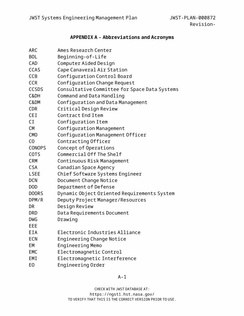
JWST Systems Engineering Management Plan JWST-PLAN-000872Revision-
APPENDIX A - Abbreviations and Acronyms
ARC Ames Research CenterBOL Beginning-of-LifeCAD Computer Aided DesignCCAS Cape Canaveral Air StationCCB Configuration Control BoardCCR Configuration Change RequestCCSDS Consultative Committee for Space Data SystemsC&DH Command and Data HandlingC&DM Configuration and Data ManagementCDR Critical Design ReviewCEI Contract End ItemCI Configuration ItemCM Configuration ManagementCMO Configuration Management OfficerCO Contracting OfficerCONOPS Concept of OperationsCOTS Commercial Off The ShelfCRM Continuous Risk ManagementCSA Canadian Space AgencyLSEE Chief Software Systems EngineerDCN Document Change NoticeDOD Department of DefenseDOORS Dynamic Object Oriented Requirements SystemDPM/R Deputy Project Manager/ResourcesDR Design ReviewDRD Data Requirements DocumentDWG DrawingEEEEIA Electronic Industries AllianceECN Engineering Change NoticeEM Engineering MemoEMC Electromagnetic ControlEMI Electromagnetic InterferenceEO Engineering Order
A-1
CHECK WITH JWST DATABASE AT:https://ngst1.hst.nasa.gov/
TO VERIFY THAT THIS IS THE CORRECT VERSION PRIOR TO USE.
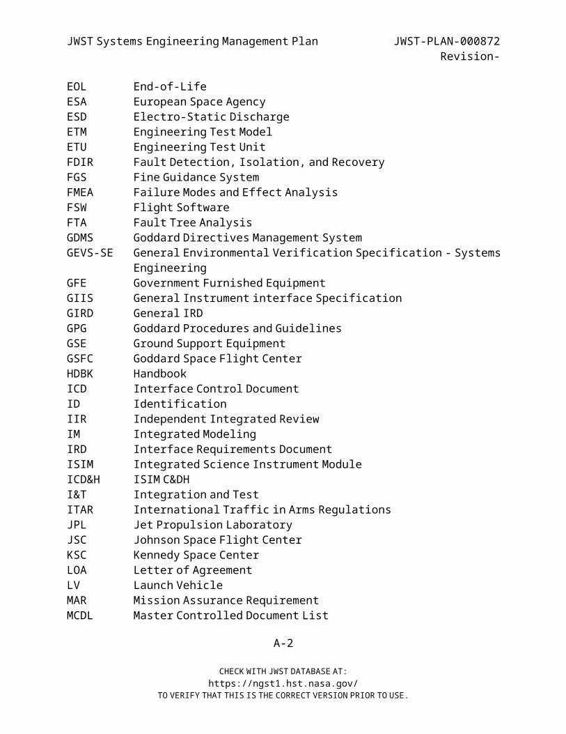
JWST Systems Engineering Management Plan JWST-PLAN-000872Revision-
EOL End-of-LifeESA European Space AgencyESD Electro-Static DischargeETM Engineering Test ModelETU Engineering Test UnitFDIR Fault Detection, Isolation, and RecoveryFGS Fine Guidance SystemFMEA Failure Modes and Effect AnalysisFSW Flight SoftwareFTA Fault Tree AnalysisGDMS Goddard Directives Management SystemGEVS-SE General Environmental Verification Specification - Systems
EngineeringGFE Government Furnished EquipmentGIIS General Instrument interface SpecificationGIRD General IRDGPG Goddard Procedures and GuidelinesGSE Ground Support EquipmentGSFC Goddard Space Flight CenterHDBK HandbookICD Interface Control DocumentID IdentificationIIR Independent Integrated ReviewIM Integrated ModelingIRD Interface Requirements DocumentISIM Integrated Science Instrument ModuleICD&H ISIM C&DHI&T Integration and TestITAR International Traffic in Arms RegulationsJPL Jet Propulsion LaboratoryJSC Johnson Space Flight CenterKSC Kennedy Space CenterLOA Letter of AgreementLV Launch VehicleMAR Mission Assurance RequirementMCDL Master Controlled Document List
A-2
CHECK WITH JWST DATABASE AT:https://ngst1.hst.nasa.gov/
TO VERIFY THAT THIS IS THE CORRECT VERSION PRIOR TO USE.
JWST Systems Engineering Management Plan JWST-PLAN-000872Revision-
MIRI Mid-Infrared InstrumentMOA Memorandum of AgreementMOU Memorandum of UnderstandingMSE Mission Systems EngineerNAR Non-Advocate ReviewNASA National Aeronautics and Space AdministrationNCR/CA Non-Conformance Report/Corrective ActionJWST James Webb Space TelescopeNIRCAM Near-Infrared CameraNIRSPEC Near-Infrared SpectrographNSTS National Space Telescope SystemNTE Not to exceedOTE Optical Telescope ElementPA Product AssurancePAR Product Assurance RequirementsPDF Portable Document FilePDL Product Design LeadPDR Preliminary Design ReviewPG Procedures and GuidelinesPIP Payload Integration PlanPL Parts ListsPLF Payload FairingPMO Project Management OfficePR Procurement RequestPRA Probabilistic Risk AssessmentPROM Programmable Read Only MemoryPSM Project Support ManagerQA Quality AssuranceQC Quality ControlQMS Quality Management SystemRAM Random Access MemoryRF Radio FrequencyRFP Request for ProposalROM Rough Order of MagnitudeSAM System Assurance ManagerSDR Systems Design Review
A-3
CHECK WITH JWST DATABASE AT:https://ngst1.hst.nasa.gov/
TO VERIFY THAT THIS IS THE CORRECT VERSION PRIOR TO USE.
JWST Systems Engineering Management Plan JWST-PLAN-000872Revision-
SEMP Systems Engineering Management PlanSEP Systems Engineering PlanSET Systems Engineering TeamSI Science InstrumentSLT Senior Leadership TeamSOC Science and Operations CenterSOW Statement of WorkSOWG Software and Operations Working GroupSRR Systems Requirement ReviewSTScI Space Telescope Science InstituteSWG Science Working GroupTAA Technical Assistance AgreementTC Telemetry and CommandTIM Technical Interchange MeetingTM Technical MemoTPM Technical Performance MeasureUIRD Unique IRDWBS Work Breakdown StructureWFS Wave Front SensingWFS&C Wave Front Sensing and ControlWOA Work Order Authorization
A-4
CHECK WITH JWST DATABASE AT:https://ngst1.hst.nasa.gov/
TO VERIFY THAT THIS IS THE CORRECT VERSION PRIOR TO USE.
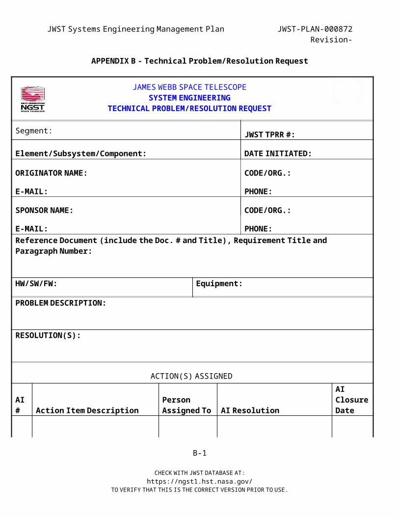
JWST Systems Engineering Management Plan JWST-PLAN-000872Revision-
APPENDIX B - Technical Problem/Resolution Request
JAMES WEBB SPACE TELESCOPE SYSTEM ENGINEERING
TECHNICAL PROBLEM/RESOLUTION REQUEST
Segment: JWST TPRR #:
Element/Subsystem/Component: DATE INITIATED:
ORIGINATOR NAME: CODE/ORG.:
E-MAIL: PHONE:
SPONSOR NAME: CODE/ORG.:
E-MAIL: PHONE: Reference Document (include the Doc. # and Title), Requirement Title and Paragraph Number:
HW/SW/FW: Equipment:
PROBLEM DESCRIPTION:
RESOLUTION(S):
ACTION(S) ASSIGNED
AI# Action Item Description
Person Assigned To AI Resolution
AIClosureDate
B-1
CHECK WITH JWST DATABASE AT:https://ngst1.hst.nasa.gov/
TO VERIFY THAT THIS IS THE CORRECT VERSION PRIOR TO USE.

JWST Systems Engineering Management Plan JWST-PLAN-000872Revision-
Comments
TPRB CHAIRPERSON TPRR CLOSURE DATE: JWST-FORM-000XXX, Rev –
January 16, 2002
B-2
CHECK WITH JWST DATABASE AT:https://ngst1.hst.nasa.gov/
TO VERIFY THAT THIS IS THE CORRECT VERSION PRIOR TO USE.
JWST Systems Engineering Management Plan JWST-PLAN-000872Revision-
APPENDIX C - Engineering Memo FormatTBD
C-1
CHECK WITH JWST DATABASE AT:https://ngst1.hst.nasa.gov/
TO VERIFY THAT THIS IS THE CORRECT VERSION PRIOR TO USE.