phius 2021 passive building standard - certification guidebook
TRANSCRIPT

i
Phius 2021 Passive Building Standard
Certification Guidebook
Version 3.02
July 14, 2021
Phius
53 W. Jackson Blvd. Suite 1462
Chicago, IL 60604
(312) 561-4588
www.Phius.org
© Phius | Phius Certification Guidebook
ii
Contents
1. ABOUT PHIUS 2021 5
1.1 INTRODUCTION .............................................................................................................................................................................................................. 5
1.2 WHY CERTIFY? ................................................................................................................................................................................................................ 7
1.3 ABOUT THIS GUIDE ....................................................................................................................................................................................................... 7
1.4 THE PROJECT TEAM ..................................................................................................................................................................................................... 8
1.5 TYPES OF PROJECTS ..................................................................................................................................................................................................... 9
1.6 PROGRAM VERSION ELIGIBILITY ............................................................................................................................................................................. 15
2. GENERAL NOTES/GUIDANCE 16
2.1 GENERAL CHALLENGES ASSOCIATED WITH ENERGY EFFICIENT BUILDINGS .......................................................................................... 16
2.2 “YELLOW FLAG” ITEMS ............................................................................................................................................................................................... 16
3. BUILDING CERTIFICATION REQUIREMENTS 17
3.1 OVERVIEW OF REQUIREMENTS ............................................................................................................................................................................... 17
3.2 RENEWABLE ENERGY REQUIREMENTS ................................................................................................................................................................ 22
3.3 MOISTURE DESIGN CRITERIA FOR ASSEMBLIES AND DETAILS ................................................................................................................... 22
3.4 WINDOW COMFORT REQUIREMENTS ................................................................................................................................................................. 23
3.5 MANDATORY DESIGN REQUIREMENTS ............................................................................................................................................................... 23
3.6 MANDATORY ON-SITE REQUIREMENTS AND RATER/VERIFIER INFORMATION .................................................................................... 35
4. PROCESS 41
4.1 GENERAL TIPS DURING THE PROCESS ................................................................................................................................................................ 43
4.2 PHIUS PROJECT DATABASE ACCESS .....................................................................................................................................................................44
4.3 DATABASE/DROPBOX INSTRUCTIONS AND TIPS ............................................................................................................................................ 45
4.4 REQUIRED SUBMISSION DOCUMENTATION .................................................................................................................................................... 46
4.5 PHIUS CERTIFICATION FEEDBACK DOCUMENT ................................................................................................................................................. 51
5. PHIUS PROJECT CERTIFICATION FEE SCHEDULE 52
5.1 PERFORMANCE PATH CERTIFICATION FEE ......................................................................................................................................................... 52
5.2 PRESCRIPTIVE PATH CERTIFICATION FEE ............................................................................................................................................................ 52
5.3 EXPEDITE FEES ............................................................................................................................................................................................................. 53
5.4 ADDITIONAL CONSULTING ...................................................................................................................................................................................... 53
5.5 CERTIFICATION PLAQUE ........................................................................................................................................................................................... 54
6. WUFI® PASSIVE ENERGY MODELING PROTOCOL 55
6.1 GETTING STARTED ...................................................................................................................................................................................................... 55
6.2 LOCALIZATION/CLIMATE .......................................................................................................................................................................................... 57
6.3 PH CASE ....................................................................................................................................................................................................................... 60
6.4 ZONE 1 .......................................................................................................................................................................................................................... 64

iii
6.5 VISUALIZED COMPONENTS .....................................................................................................................................................................................65
6.6 INTERNAL LOADS/OCCUPANCY ............................................................................................................................................................................ 70
6.7 VENTILATION/ROOMS.............................................................................................................................................................................................. 80
6.8 THERMAL BRIDGES .....................................................................................................................................................................................................84
6.9 ATTACHED ZONES & REMAINING ELEMENTS .................................................................................................................................................. 85
6.10 SYSTEMS ...................................................................................................................................................................................................................... 85
6.11 WUFI PASSIVE REPORTS .................................................................................................................................................................................... 102
7. MONITORING 103
7.1 MONITORING PROTOCOL...................................................................................................................................................................................... 103
7.2 MONITORING YOUR PROJECT .............................................................................................................................................................................. 103
8. ADDITIONAL CERTIFICATION BADGES 104
8.1 SUPPLY AIR HEATING AND COOLING SUFFICIENT ........................................................................................................................................ 104
APPENDIX A – RENEWABLE ENERGY 105
A-1 RENEWABLE ENERGY SYSTEMS ........................................................................................................................................................................... 105
A-2 ADJUSTED RENEWABLE ENERGY ......................................................................................................................................................................... 105
A-3 OFF-SITE RENEWABLE ENERGY REQUIREMENTS .......................................................................................................................................... 107
A-4 RENEWABLE ENERGY CERTIFICATE TRACKING ............................................................................................................................................... 108
A-5 RENEWABLE ENERGY ALLOCATION TO MULTIPLE BUILDINGS................................................................................................................109
APPENDIX B – MOISTURE CONTROL GUIDELINES FOR OPAQUE ASSEMBLIES 110
B-1 GENERAL MOISTURE CONTROL GUIDELINES ................................................................................................................................................. 110
B-2 MOISTURE CONTROL GUIDELINES FOR WALLS ............................................................................................................................................... 111
B-3 MOISTURE CONTROL GUIDELINES FOR ROOFS ............................................................................................................................................. 115
B-4 MOISTURE CONTROL GUIDELINES FOR FLOORS ........................................................................................................................................... 118
APPENDIX C – METHOD FOR EVALUATING WHEN A COOLING SYSTEM IS RECOMMENDED 120
APPENDIX D - ASHRAE FUNDAMENTALS 2017 NON-RESIDENTIAL EQUIPMENT TABLES 122
APPENDIX E – PHIUS CERTIFIED RATER/VERIFIER MANUAL: VERSION 1.1 126
E-1.0 DEFINITION & ELIGIBILITY................................................................................................................................................................................. 126
E-2.0 CERTIFICATION REQUIREMENTS AND MAINTENANCE ............................................................................................................................ 126
E-2.1 PHIUS CERTIFIED RATER INFORMATION ...................................................................................................................................................... 126
E-2.2 PHIUS CERTIFIED VERIFIER INFORMATION .................................................................................................................................................. 128
E-3.0 PRE-CONSTRUCTION REQUIREMENTS .......................................................................................................................................................... 131
E-4.0 TECHNICAL INSPECTION AND FIELD REQUIREMENTS ............................................................................................................................. 132
E-5.0 POST-CONSTRUCTION REQUIREMENTS....................................................................................................................................................... 137
E-6.0 RESOURCES ............................................................................................................................................................................................................ 138
APPENDIX F –PROCEDURE TO PREPARE THE BUILDING FOR AIRTIGHTNESS TESTING 139
iv
F-1 ANSI/RESNET/ICC 380-2016 ....................................................................................................................................................................... 139
F-2 NON-THREATENING AIR LEAKAGE ...................................................................................................................................................................... 141
APPENDIX G - PHIUS MULTIFAMILY CERTIFICATION PERFORMANCE REQUIREMENTS V2.2 144
G-1.0 BUILDING CERTIFICATION ................................................................................................................................................................................ 144
G-2.0 ON-SITE VERIFIED PERFORMANCE CRITERIA ............................................................................................................................................ 145
G-3.0 ENERGY MODEL-BASED PERFORMANCE REQUIREMENTS ................................................................................................................... 153
APPENDIX H – PHIUS 2021 TARGET-SETTING UPDATES 154
H-1 TINY HOUSE STUDY ................................................................................................................................................................................................ 154
H-2 REVISED CURVE-FITS FOR SPACE CONDITIONING TARGETS .................................................................................................................... 155
H-3 PRESCRIPTIVE PATH AIRTIGHTNESS LIMIT ...................................................................................................................................................... 157
APPENDIX I – INFORMATIVE 158
I-1 TIPS FOR PASSIVE BUILDING DESIGN ................................................................................................................................................................. 158
I-2 SOURCE ENERGY ........................................................................................................................................................................................................160
I-3 RATERS AND VERIFIERS ............................................................................................................................................................................................160
I-4 FIREPLACES .................................................................................................................................................................................................................... 161
APPENDIX J - CO-GENERATION 162
APPENDIX K - ELECTRIC VEHICLE CHARGING INFRASTRUCTURE 164
K-1 REQUIREMENTS ......................................................................................................................................................................................................... 164
K-2 DEFINITIONS .............................................................................................................................................................................................................. 164
APPENDIX L - ELECTRIFICATION READINESS FOR COMBUSTION EQUIPMENT 166
APPENDIX N - NORMATIVE 168
N-1 DHW DISTRIBUTION PIPE MATERIALS AND SIZES ..................................................................................................................................... 168
N-2 MEDIAN ENERGY STAR APPLIANCES (EXPANDED) ................................................................................................................................. 170
N-3 MINIMUM INTERIOR SURFACE TEMPERATURE FOR THERMALLY BRIDGED CONSTRUCTION DETAILS .......................................171
N-4 WINDOW COMFORT ............................................................................................................................................................................................... 172
N-5 RECIRCULATION DEFROST .................................................................................................................................................................................... 173
N-6 NON-RESIDENTIAL BUILDING PROCESS LOADS .......................................................................................................................................... 173
N-7 PRESCRIPTIVE PATH ................................................................................................................................................................................................ 174
N-8 BLINDS ........................................................................................................................................................................................................................ 180
N-9 MULTI-UNIT LIGHTING & MEL CALCULATIONS ........................................................................................................................................... 180
N-10 NON-RESIDENTIAL UTILIZATION PATTERNS............................................................................................................................................... 186
REFERENCES 187
Phius Certification Guidebook v3.02 | 5
1. About Phius 2021
1.1 Introduction
Thank you for your interest in the Phius Passive Building Standard.
The Phius standard is a “high-performance building standard” – it challenges the building
industry to construct buildings that can maintain a comfortable indoor environment with
very low operating energy. Historically, the operating energy of a building over its lifetime
far exceeded the embodied energy required to construct and maintain the building, thus
the Phius standard focuses on reducing operating energy and does not specifically address
the environmental impacts of the building materials and construction process. Low energy
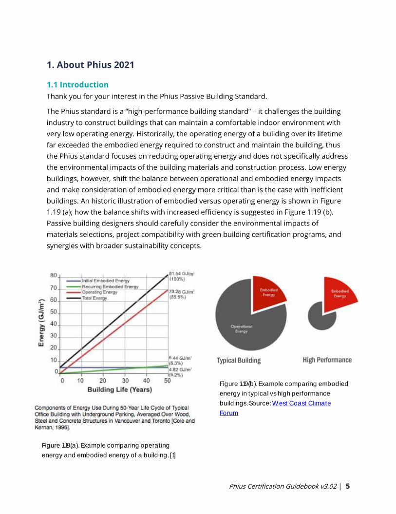
buildings, however, shift the balance between operational and embodied energy impacts
and make consideration of embodied energy more critical than is the case with inefficient
buildings. An historic illustration of embodied versus operating energy is shown in Figure
1.19 (a); how the balance shifts with increased efficiency is suggested in Figure 1.19 (b).
Passive building designers should carefully consider the environmental impacts of
materials selections, project compatibility with green building certification programs, and
synergies with broader sustainability concepts.
Figure 1.19(b). Example comparing embodied
energy in typical vs high performance
buildings. Source: West Coast Climate
Forum
Figure 1.19(a). Example comparing operating
energy and embodied energy of a building. [1]
Phius Certification Guidebook v3.02 | 6
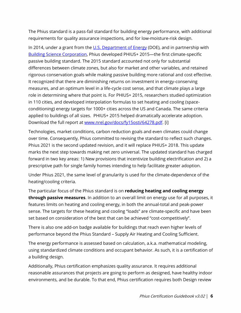
The Phius standard is a pass-fail standard for building energy performance, with additional
requirements for quality assurance inspections, and for low-moisture-risk design.
In 2014, under a grant from the U.S. Department of Energy (DOE), and in partnership with
Building Science Corporation, Phius developed PHIUS+ 2015—the first climate-specific
passive building standard. The 2015 standard accounted not only for substantial
differences between climate zones, but also for market and other variables, and retained
rigorous conservation goals while making passive building more rational and cost effective.
It recognized that there are diminishing returns on investment in energy-conserving
measures, and an optimum level in a life-cycle cost sense, and that climate plays a large
role in determining where that point is. For PHIUS+ 2015, researchers studied optimization
in 110 cities, and developed interpolation formulas to set heating and cooling (space-
conditioning) energy targets for 1000+ cities across the US and Canada. The same criteria
applied to buildings of all sizes. PHIUS+ 2015 helped dramatically accelerate adoption.
Download the full report at www.nrel.gov/docs/fy15osti/64278.pdf. [i]
Technologies, market conditions, carbon reduction goals and even climates could change
over time. Consequently, Phius committed to revising the standard to reflect such changes.
Phius 2021 is the second updated revision, and it will replace PHIUS+ 2018. This update
marks the next step towards making net zero universal. The updated standard has charged
forward in two key areas: 1) New provisions that incentivize building electrification and 2) a
prescriptive path for single family homes intending to help facilitate greater adoption.
Under Phius 2021, the same level of granularity is used for the climate-dependence of the
heating/cooling criteria.
The particular focus of the Phius standard is on reducing heating and cooling energy
through passive measures. In addition to an overall limit on energy use for all purposes, it
features limits on heating and cooling energy, in both the annual-total and peak-power
sense. The targets for these heating and cooling “loads” are climate-specific and have been
set based on consideration of the best that can be achieved “cost-competitively”.
There is also one add-on badge available for buildings that reach even higher levels of
performance beyond the Phius Standard – Supply Air Heating and Cooling Sufficient.
The energy performance is assessed based on calculation, a.k.a. mathematical modeling,
using standardized climate conditions and occupant behavior. As such, it is a certification of
a building design.
Additionally, Phius certification emphasizes quality assurance. It requires additional
reasonable assurances that projects are going to perform as designed, have healthy indoor
environments, and be durable. To that end, Phius certification requires both Design review

Phius Certification Guidebook v3.02 | 7
as well as third-party on-site quality assurance checks. Design review is performed by Phius
staff, and final certification involves the participation of Phius-certified independent Raters
or Verifiers who carry out on-site quality inspections (see Section 3.6).
Certification proceeds through two stages:
• Design Certification verifies that the energy model matches the plans and
specifications.
• Final Certification verifies that the finished building matches the plans and
specifications.
1.2 Why Certify?
The Phius certification process is the best way to build any project, from single-family
homes to apartment buildings and commercial applications. Certification brings seasoned
Phius reviewers onto your team who provide guidance and support for all project
submitters. The Phius Certification process:
1. Includes third-party verification—This ensures the building is designed and
constructed to meet the high-performance standards for energy use and that critical
systems are commissioned into proper operation. Third-party verification is also
typically required by the incentive programs of utilities and governments.
2. Introduces risk management—passive building requires special attention to
moisture control and ventilation. Phius Certification staff and third-party QA/QC
professionals can identify problem areas at the design stage before they become
real-world problems.
3. Builds and shares knowledge —As more scenarios, project types and solutions
pass through the certification process, Phius pays it forward to future project teams
through direct feedback, building the public Certified Project Database and ongoing
updates to this Guidebook.
1.3 About this Guide
The main goal is to help your project team design and execute high-performance, high-
quality buildings and avoid as many pitfalls as possible.
This Guidebook contains the following kinds of information, roughly in the order for which
they are relevant in the building delivery process.
• General hints and tips for success.
Simplicity is a popular idea in the abstract, but in practice a simple rule often meets objections that it is lacking
some desired nuance in certain cases; as a result, certification protocol tends to become more elaborate over
time.
Phius Certification Guidebook v3.02 | 8
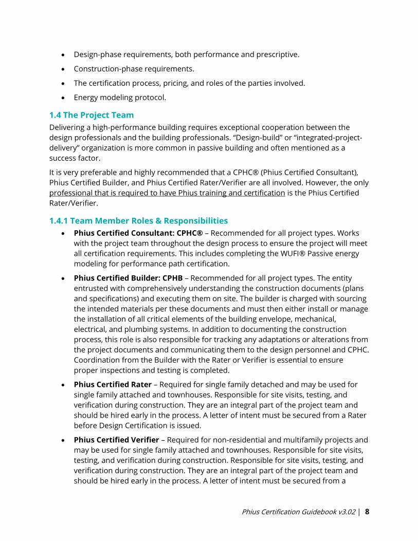
• Design-phase requirements, both performance and prescriptive.
• Construction-phase requirements.
• The certification process, pricing, and roles of the parties involved.
• Energy modeling protocol.
1.4 The Project Team
Delivering a high-performance building requires exceptional cooperation between the
design professionals and the building professionals. “Design-build” or “integrated-project-
delivery” organization is more common in passive building and often mentioned as a
success factor.
It is very preferable and highly recommended that a CPHC® (Phius Certified Consultant),
Phius Certified Builder, and Phius Certified Rater/Verifier are all involved. However, the only
professional that is required to have Phius training and certification is the Phius Certified
Rater/Verifier.
1.4.1 Team Member Roles & Responsibilities
• Phius Certified Consultant: CPHC® – Recommended for all project types. Works
with the project team throughout the design process to ensure the project will meet
all certification requirements. This includes completing the WUFI® Passive energy
modeling for performance path certification.
• Phius Certified Builder: CPHB – Recommended for all project types. The entity
entrusted with comprehensively understanding the construction documents (plans
and specifications) and executing them on site. The builder is charged with sourcing
the intended materials per these documents and must then either install or manage
the installation of all critical elements of the building envelope, mechanical,
electrical, and plumbing systems. In addition to documenting the construction
process, this role is also responsible for tracking any adaptations or alterations from
the project documents and communicating them to the design personnel and CPHC.
Coordination from the Builder with the Rater or Verifier is essential to ensure
proper inspections and testing is completed.
• Phius Certified Rater – Required for single family detached and may be used for
single family attached and townhouses. Responsible for site visits, testing, and
verification during construction. They are an integral part of the project team and
should be hired early in the process. A letter of intent must be secured from a Rater
before Design Certification is issued.
• Phius Certified Verifier – Required for non-residential and multifamily projects and
may be used for single family attached and townhouses. Responsible for site visits,
testing, and verification during construction. Responsible for site visits, testing, and
verification during construction. They are an integral part of the project team and
should be hired early in the process. A letter of intent must be secured from a
Phius Certification Guidebook v3.02 | 9
Verifier before Design Certification is issued.
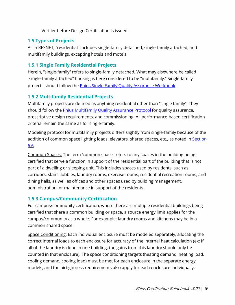
1.5 Types of Projects
As in RESNET, “residential” includes single-family detached, single-family attached, and
multifamily buildings, excepting hotels and motels.
1.5.1 Single Family Residential Projects
Herein, “single-family” refers to single-family detached. What may elsewhere be called
“single-family attached” housing is here considered to be “multifamily.” Single-family
projects should follow the Phius Single Family Quality Assurance Workbook.
1.5.2 Multifamily Residential Projects
Multifamily projects are defined as anything residential other than “single family”. They
should follow the Phius Multifamily Quality Assurance Protocol for quality assurance,
prescriptive design requirements, and commissioning. All performance-based certification
criteria remain the same as for single-family.
Modeling protocol for multifamily projects differs slightly from single-family because of the
addition of common space lighting loads, elevators, shared spaces, etc., as noted in Section
6.6.
Common Spaces: The term ‘common space’ refers to any spaces in the building being
certified that serve a function in support of the residential part of the building that is not
part of a dwelling or sleeping unit. This includes spaces used by residents, such as
corridors, stairs, lobbies, laundry rooms, exercise rooms, residential recreation rooms, and
dining halls, as well as offices and other spaces used by building management,
administration, or maintenance in support of the residents.
1.5.3 Campus/Community Certification
For campus/community certification, where there are multiple residential buildings being
certified that share a common building or space, a source energy limit applies for the
campus/community as a whole. For example: laundry rooms and kitchens may be in a
common shared space.
Space Conditioning: Each individual enclosure must be modeled separately, allocating the
correct internal loads to each enclosure for accuracy of the internal heat calculation (ex: if
all of the laundry is done in one building, the gains from this laundry should only be
counted in that enclosure). The space conditioning targets (heating demand, heating load,
cooling demand, cooling load) must be met for each enclosure in the separate energy
models, and the airtightness requirements also apply for each enclosure individually.

Phius Certification Guidebook v3.02 | 10
Net Source Energy Allowance: If the campus/community is strongly/mainly residential in
character the source energy allowance is proportional to the design occupancy. For non-
residential day schools, commuter campuses and the like, the source energy allowance is
per square foot of interior conditioned floor area (iCFA). See Section 3.1.4 for specific target
values.
1.5.4 Commercial/Non-Residential Projects
The criteria for non-residential projects are the same as for residential projects, apart from
the Source Energy requirement. The Source Energy limit for commercial buildings is
proportional to floor area, rather than occupancy. There may be additional differences that
require additional documentation for Phius Certification.
Compared to residential projects, the energy models for non-residential projects need
more detailed information on lighting systems, usage patterns, plug loads, and custom
internal heat gains. For commercial buildings with process loads, Phius will determine the
Source Energy allowance on a case-by-case basis. See Appendix N-5 for process load
definition.
For unique non-residential/commercial buildings with significant process loads, very high
internal loads, or highly variable occupancy, custom optimization may need to be
completed to determine the appropriate targets for Heating Demand, Cooling Demand,
Heating Load & Cooling Load. Custom targets can be completed by Phius on a case-by-case
basis using BEopt for an additional fee.
Non-Residential QA/QC Commissioning is required.
Download the Phius Non-Residential Quality Assurance Workbook. Non-residential
certification protocol will continue to be updated as more information becomes available
on these types of projects.
1.5.4.1 Dorms & Hotels/Motels
The IBC/IECC codes draw the line between residential and commercial based on number of
stories and whether the occupancy is primarily “transient”, which means < 30 days.
Transient occupancy is considered commercial.
Dorms:
Transient occupancy (< 30 days) = Commercial
Long term occupancy (> 30 days) = Residential
On-site prescriptive requirements: Phius Multifamily Protocol
Hotel/Motel: Commercial
On-site prescriptive requirements: Phius Commercial Protocol
Phius Certification Guidebook v3.02 | 11
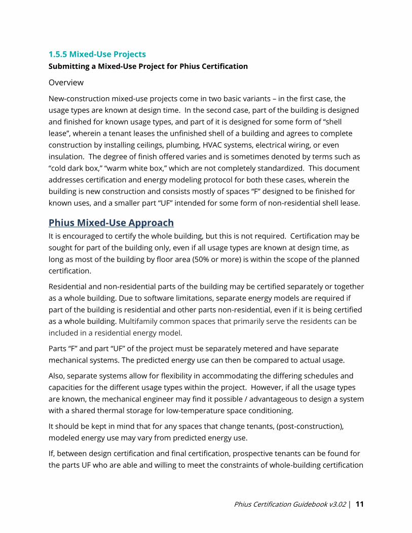
1.5.5 Mixed-Use Projects
Submitting a Mixed-Use Project for Phius Certification
Overview
New-construction mixed-use projects come in two basic variants – in the first case, the
usage types are known at design time. In the second case, part of the building is designed
and finished for known usage types, and part of it is designed for some form of “shell
lease”, wherein a tenant leases the unfinished shell of a building and agrees to complete
construction by installing ceilings, plumbing, HVAC systems, electrical wiring, or even
insulation. The degree of finish offered varies and is sometimes denoted by terms such as
“cold dark box,” “warm white box,” which are not completely standardized. This document
addresses certification and energy modeling protocol for both these cases, wherein the
building is new construction and consists mostly of spaces “F” designed to be finished for
known uses, and a smaller part “UF” intended for some form of non-residential shell lease.
Phius Mixed-Use Approach
It is encouraged to certify the whole building, but this is not required. Certification may be
sought for part of the building only, even if all usage types are known at design time, as
long as most of the building by floor area (50% or more) is within the scope of the planned
certification.
Residential and non-residential parts of the building may be certified separately or together
as a whole building. Due to software limitations, separate energy models are required if
part of the building is residential and other parts non-residential, even if it is being certified
as a whole building. Multifamily common spaces that primarily serve the residents can be
included in a residential energy model.
Parts “F” and part “UF” of the project must be separately metered and have separate
mechanical systems. The predicted energy use can then be compared to actual usage.
Also, separate systems allow for flexibility in accommodating the differing schedules and
capacities for the different usage types within the project. However, if all the usage types
are known, the mechanical engineer may find it possible / advantageous to design a system
with a shared thermal storage for low-temperature space conditioning.
It should be kept in mind that for any spaces that change tenants, (post-construction),
modeled energy use may vary from predicted energy use.
If, between design certification and final certification, prospective tenants can be found for
the parts UF who are able and willing to meet the constraints of whole-building certification
Phius Certification Guidebook v3.02 | 12
in their build-out plans, the tenant fit-out may be certified under its planned function
rather than as unfinished space.
The source energy allowance for residential spaces is calculated on a per person basis, and
for nonresidential spaces on a per square foot basis (3.1.4).
Office and retail spaces do not qualify for an additional source energy allowance for
process loads, but restaurants and groceries do. Contact Phius about process load
allowances for other usage types.
General recommended practices include:
• Thermally isolating residential spaces from a nonresidential portion to some extent
(for soundproofing and other considerations).
• Air sealing to separate the two parts to prevent odor transference.
Phius Protocol for modeling Unfinished spaces (UF):
• Building Type: Non-residential
• Occupancy Type: Undefined/unfinished
• Internal gains: 1 BTU/hr.ft2
• Continuous ventilation rate of 0.3 ACH (air changes per hour)
• Ventilation heat recovery efficiency matching the average for the rest of the building
The foregoing points pertain to calculating the heating and cooling loads and demands – it
is necessary to assume a scenario to apply the certification criteria. For the source energy
criterion that is not necessary – there is no additional source energy allowance for
unfinished spaces and therefore no assumption about their energy use.
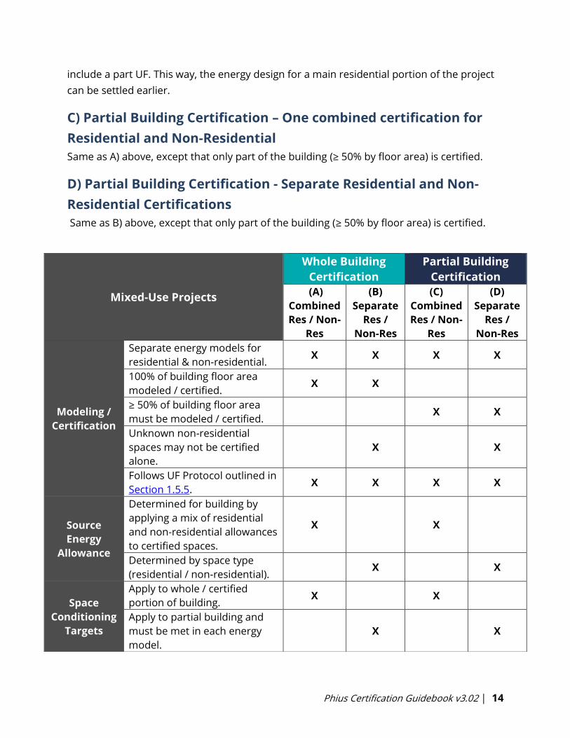
In general, there are 4 unique paths, listed below.
A) Whole Building Certification– One combined certification for
Residential and Non-Residential
Separate energy models must be constructed for residential and nonresidential parts.
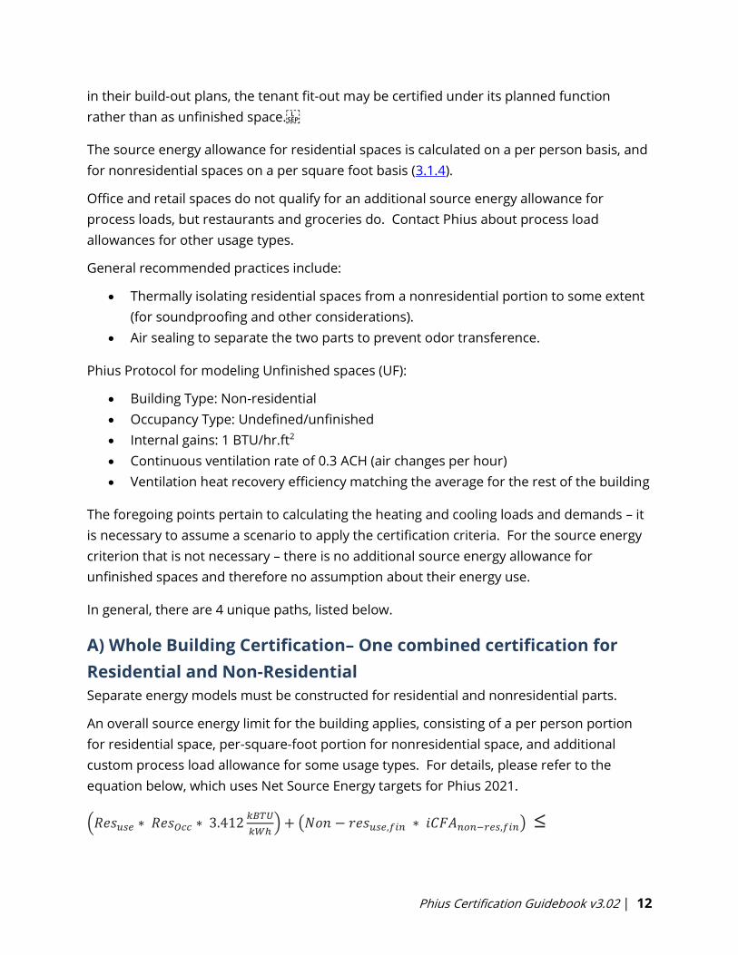
An overall source energy limit for the building applies, consisting of a per person portion
for residential space, per-square-foot portion for nonresidential space, and additional
custom process load allowance for some usage types. For details, please refer to the
equation below, which uses Net Source Energy targets for Phius 2021.
(𝑅𝑒𝑠𝑢𝑠𝑒 ∗ 𝑅𝑒𝑠𝑂𝑐𝑐 ∗ 3.412𝑘𝐵𝑇𝑈
𝑘𝑊ℎ) + (𝑁𝑜𝑛 − 𝑟𝑒𝑠𝑢𝑠𝑒,𝑓𝑖𝑛 ∗ 𝑖𝐶𝐹𝐴𝑛𝑜𝑛−𝑟𝑒𝑠,𝑓𝑖𝑛) ≤
Phius Certification Guidebook v3.02 | 13
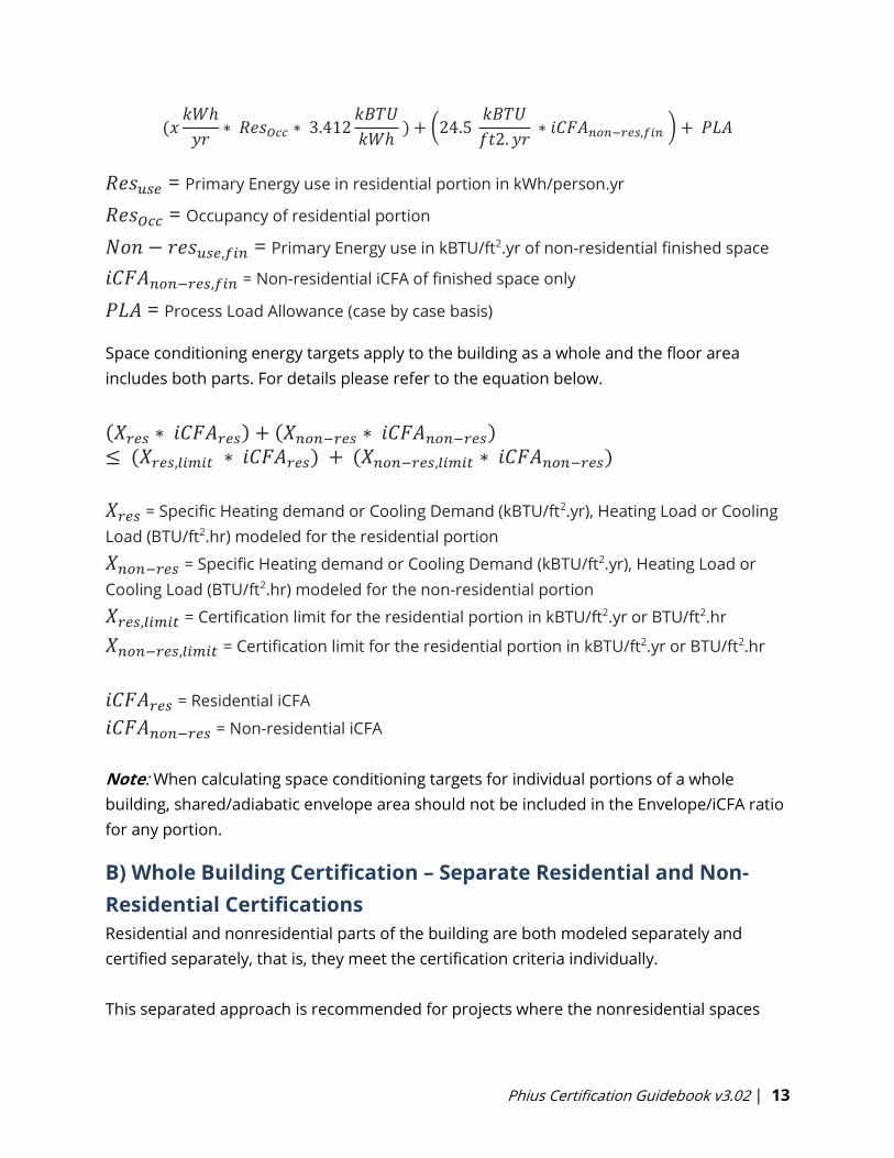
(𝑥𝑘𝑊ℎ
𝑦𝑟∗ 𝑅𝑒𝑠𝑂𝑐𝑐 ∗ 3.412
𝑘𝐵𝑇𝑈
𝑘𝑊ℎ ) + (24.5
𝑘𝐵𝑇𝑈
𝑓𝑡2. 𝑦𝑟 ∗ 𝑖𝐶𝐹𝐴𝑛𝑜𝑛−𝑟𝑒𝑠,𝑓𝑖𝑛 ) + 𝑃𝐿𝐴
𝑅𝑒𝑠𝑢𝑠𝑒 = Primary Energy use in residential portion in kWh/person.yr
𝑅𝑒𝑠𝑂𝑐𝑐 = Occupancy of residential portion
𝑁𝑜𝑛 − 𝑟𝑒𝑠𝑢𝑠𝑒,𝑓𝑖𝑛 = Primary Energy use in kBTU/ft2.yr of non-residential finished space
𝑖𝐶𝐹𝐴𝑛𝑜𝑛−𝑟𝑒𝑠,𝑓𝑖𝑛 = Non-residential iCFA of finished space only
𝑃𝐿𝐴 = Process Load Allowance (case by case basis)
Space conditioning energy targets apply to the building as a whole and the floor area
includes both parts. For details please refer to the equation below.
(𝑋𝑟𝑒𝑠 ∗ 𝑖𝐶𝐹𝐴𝑟𝑒𝑠) + (𝑋𝑛𝑜𝑛−𝑟𝑒𝑠 ∗ 𝑖𝐶𝐹𝐴𝑛𝑜𝑛−𝑟𝑒𝑠)≤ (𝑋𝑟𝑒𝑠,𝑙𝑖𝑚𝑖𝑡 ∗ 𝑖𝐶𝐹𝐴𝑟𝑒𝑠) + (𝑋𝑛𝑜𝑛−𝑟𝑒𝑠,𝑙𝑖𝑚𝑖𝑡 ∗ 𝑖𝐶𝐹𝐴𝑛𝑜𝑛−𝑟𝑒𝑠)
𝑋𝑟𝑒𝑠 = Specific Heating demand or Cooling Demand (kBTU/ft2.yr), Heating Load or Cooling
Load (BTU/ft2.hr) modeled for the residential portion
𝑋𝑛𝑜𝑛−𝑟𝑒𝑠 = Specific Heating demand or Cooling Demand (kBTU/ft2.yr), Heating Load or
Cooling Load (BTU/ft2.hr) modeled for the non-residential portion
𝑋𝑟𝑒𝑠,𝑙𝑖𝑚𝑖𝑡 = Certification limit for the residential portion in kBTU/ft2.yr or BTU/ft2.hr
𝑋𝑛𝑜𝑛−𝑟𝑒𝑠,𝑙𝑖𝑚𝑖𝑡 = Certification limit for the residential portion in kBTU/ft2.yr or BTU/ft2.hr
𝑖𝐶𝐹𝐴𝑟𝑒𝑠 = Residential iCFA
𝑖𝐶𝐹𝐴𝑛𝑜𝑛−𝑟𝑒𝑠 = Non-residential iCFA
Note: When calculating space conditioning targets for individual portions of a whole
building, shared/adiabatic envelope area should not be included in the Envelope/iCFA ratio
for any portion.
B) Whole Building Certification – Separate Residential and Non-
Residential Certifications
Residential and nonresidential parts of the building are both modeled separately and
certified separately, that is, they meet the certification criteria individually.
This separated approach is recommended for projects where the nonresidential spaces
Phius Certification Guidebook v3.02 | 14
include a part UF. This way, the energy design for a main residential portion of the project
can be settled earlier.
C) Partial Building Certification – One combined certification for
Residential and Non-Residential
Same as A) above, except that only part of the building (≥ 50% by floor area) is certified.
D) Partial Building Certification - Separate Residential and Non-
Residential Certifications
Same as B) above, except that only part of the building (≥ 50% by floor area) is certified.
Mixed-Use Projects
Whole Building
Certification
Partial Building
Certification
(A)
Combined
Res / Non-
Res
(B)
Separate
Res /
Non-Res
(C)
Combined
Res / Non-
Res
(D)
Separate
Res /
Non-Res
Modeling /
Certification
Separate energy models for
residential & non-residential. X X X X
100% of building floor area
modeled / certified. X X
≥ 50% of building floor area
must be modeled / certified. X X
Unknown non-residential
spaces may not be certified
alone.
X X
Follows UF Protocol outlined in
Section 1.5.5. X X X X
Source
Energy
Allowance
Determined for building by
applying a mix of residential
and non-residential allowances
to certified spaces.
X X
Determined by space type
(residential / non-residential). X X
Space
Conditioning
Targets
Apply to whole / certified
portion of building. X X
Apply to partial building and
must be met in each energy
model.
X X
Phius Certification Guidebook v3.02 | 15
1.5.6 Retrofit Projects
The criteria for retrofit projects are the same as for new construction, except that a case-by-
case energy allowance may be made for a foundation perimeter thermal bridge or other such
hard-to-fix structural thermal bridges - provided that the design is also “damage-free,” that is,
low risk from a moisture point of view.
The allowance noted above may also apply to uninsulated slab-on-grade conditions. To
determine the allowance in WUFI Passive, the prescriptive path R-value under the slab should
be modeled. The difference in modeled performance results is equivalent to the allowance that
may be applied.
As with new construction projects, there is a moisture criterion that requires less than 80% RH
on interior surfaces. Any critical areas that need surface temperature calculation will be noted
in design certification. The calculation will be performed in accordance with ISO 13788.
Airtightness requirements are the same as for new construction (see 3.1.3).
Some ZERH requirements are not applicable to retrofit projects.
1.5.7 Buildings with Seasonal Use
Certification of seasonal-use buildings is discouraged, for two reasons.
1. First, if a building can be used year-round, it may tend to gravitate to year-round use
over time - the intentions of the current or initial users notwithstanding.
2. Second, it is not fully supported by the current energy modeling software and requires
significant workarounds.
Certification staff may allow it if there are other factors indicating that the seasonal use pattern
will persist during the life of the building, e.g., "remote location on a seasonal road" and if the
season of use encompasses at least half the year.
1.6 Program Version Eligibility
The date that the Phius Certification Contract is executed determines the program versions
required for that project. Projects may voluntarily choose to comply with a newer version than
required by contract date.
Please see the Program Version Dates page for the matrix of program version effective dates.
Phius Certification Guidebook v3.02 | 16
2. General Notes/Guidance
2.1 General Challenges Associated with Energy Efficient Buildings
Please be aware of these general issues with “super-insulated,” “low-load” buildings:
• Better insulation leads to colder exterior surfaces and less heat available to evaporate
water in the assemblies. [2] See also Appendix B.
• The “sensible heat ratio problem”, that is, HVAC dehumidification capacity at part load
conditions. Sensible cooling demands and loads are reduced, while dehumidification
demands and loads still exist. [3] [4]
2.2 “Yellow Flag” Items
Please contact Phius early for more information if the project entails any of these items:
• Retrofit projects with foundation thermal bridges.
• Non-residential projects with “process loads” or unusual heating/cooling set point
temperatures.
• Site altitude very different from the nearest climate dataset location. See Section 6.1.2
for more details.
• Thermal bridge calculations: contact [email protected] for assistance, or refer to
Phius’ Intro to THERM Training.
• No Phius Rater/Verifier within 100 miles of the project location. (See Appendix E)
Please study the referenced information if the project entails any of these items:
• Spray foam, flash-and-fill assemblies: see Appendix B.
• Double-stud walls: see Appendix B.
• Floors with air-permeable insulation: see Appendix B.
• Thermal mass, or anything more than “light construction”: see Section 6.4.5.
• Heat pumps of any kind: Review the Heat Pump related calculators here.
Phius Certification Guidebook v3.02 | 17
3. Building Certification Requirements
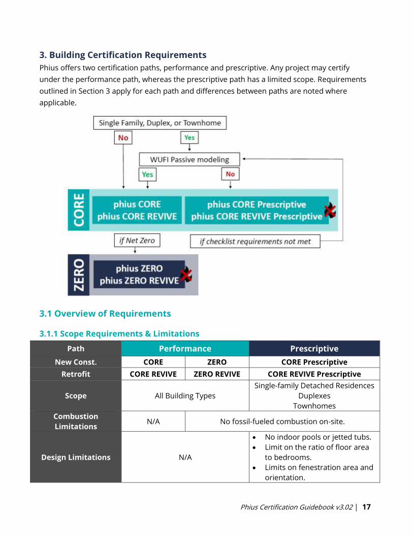
Phius offers two certification paths, performance and prescriptive. Any project may certify
under the performance path, whereas the prescriptive path has a limited scope. Requirements
outlined in Section 3 apply for each path and differences between paths are noted where
applicable.
3.1 Overview of Requirements
3.1.1 Scope Requirements & Limitations
Path Performance Prescriptive
New Const. CORE ZERO CORE Prescriptive
Retrofit CORE REVIVE ZERO REVIVE CORE REVIVE Prescriptive
Scope All Building Types
Single-family Detached Residences
Duplexes
Townhomes
Combustion
Limitations N/A No fossil-fueled combustion on-site.
Design Limitations N/A
• No indoor pools or jetted tubs.
• Limit on the ratio of floor area
to bedrooms.
• Limits on fenestration area and
orientation.

Phius Certification Guidebook v3.02 | 18
3.1.2 Passive Conservation Requirements
Each path guides the designer to use passive conservation strategies to limit heating and
cooling demands on an annual and peak basis.
Performance PrescriptiveThe performance path uses specific heating
and cooling energy limits1 for the project to
guide investment in passive conservation
strategies.
The prescriptive path outlines
requirements for individual passive
conservation measures that must be
implemented in the design.
Space Conditioning Performance Criteria for
Certification:
Annual Heating Demand ≤ A (kBTU/ft2.yr)
Annual Cooling Demand,2 ≤ B (kBTU/ft2.yr)
Peak Heating Load ≤ C (BTU/ft2.hr)
Peak Cooling Load2 ≤ D (BTU/ft2.hr)
Limits are determined by the envelope area,
floor area, occupant density, unit density
(residential only), and location of the project.
Relevant sections of the Prescriptive
Checklist:
3. Compactness3
4. Solar Protection3
5. Thermal Enclosure3
Fenestration U-value limits
Opaque R-value requirements
7. Mechanical Ventilation
Sensible & Total Recovery Efficiency
limits
Refer to the Phius 2021 Criteria Calculator to
determine criteria for the project.
Refer to the Phius CORE Prescriptive
Checklist to determine criteria for the
project.
1 The space conditioning criteria are all per square foot of interior Conditioned Floor Area (iCFA). See
Appendix H for details on the development of Phius 2021. 2 Annual Cooling Demand is total cooling, latent plus sensible. Peak Cooling Load target is sensible only.
• Cooling criteria apply regardless of whether a cooling system is planned or not.
• See Appendix C for method to evaluate when a cooling system is recommended. It is
recommended in most climates especially for residential projects.
• Certification staff may require that occupant-installed cooling, e.g. window A/C, is included in the
energy model, even if it is not designed into the building as-delivered, so that the impact on source
energy use is accounted for.3 Review Appendix N-7
Phius Certification Guidebook v3.02 | 19
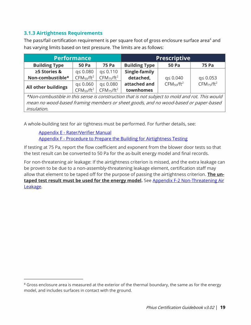
3.1.3 Airtightness Requirements
The pass/fail certification requirement is per square foot of gross enclosure surface area4 and
has varying limits based on test pressure. The limits are as follows:
Performance Prescriptive Building Type 50 Pa 75 Pa Building Type 50 Pa 75 Pa
≥5 Stories &
Non-combustible*
q≤ 0.080
CFM50/ft2
q≤ 0.110
CFM75/ft2
Single-family
detached,
attached and
townhomes
q≤ 0.040
CFM50/ft2
q≤ 0.053
CFM75/ft2 All other buildings
q≤ 0.060
CFM50/ft2
q≤ 0.080
CFM75/ft2
*Non-combustible in this sense is construction that is not subject to mold and rot. This would
mean no wood-based framing members or sheet goods, and no wood-based or paper-based
insulation.
A whole-building test for air tightness must be performed. For further details, see:
Appendix E - Rater/Verifier Manual
Appendix F - Procedure to Prepare the Building for Airtightness Testing
If testing at 75 Pa, report the flow coefficient and exponent from the blower door tests so that
the test result can be converted to 50 Pa for the as-built energy model and final records.
For non-threatening air leakage: If the airtightness criterion is missed, and the extra leakage can
be proven to be due to a non-assembly-threatening leakage element, certification staff may
allow that element to be taped off for the purpose of passing the airtightness criterion. The un-
taped test result must be used for the energy model. See Appendix F-2 Non-Threatening Air
Leakage.
4 Gross enclosure area is measured at the exterior of the thermal boundary, the same as for the energy
model, and includes surfaces in contact with the ground.
Phius Certification Guidebook v3.02 | 20
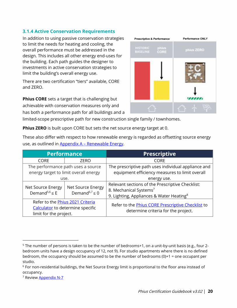
3.1.4 Active Conservation Requirements
In addition to using passive conservation strategies
to limit the needs for heating and cooling, the
overall performance must be addressed in the
design. This includes all other energy end-uses for
the building. Each path guides the designer to
investments in active conservation strategies to
limit the building’s overall energy use.
There are two certification “tiers” available, CORE
and ZERO.
Phius CORE sets a target that is challenging but
achievable with conservation measures only and
has both a performance path for all buildings and a
limited-scope prescriptive path for new construction single family / townhomes.
Phius ZERO is built upon CORE but sets the net source energy target at 0.
These also differ with respect to how renewable energy is regarded as offsetting source energy
use, as outlined in Appendix A – Renewable Energy.
Performance PrescriptiveCORE ZERO CORE
The performance path uses a source
energy target to limit overall energy
use.
The prescriptive path uses individual appliance and
equipment efficiency measures to limit overall
energy use.
Net Source Energy
Demand5,6 ≤ E
Net Source Energy
Demand6,7 ≤ 0
Relevant sections of the Prescriptive Checklist:
8. Mechanical Systems7
9. Lighting, Appliances & Water Heating8
Refer to the Phius 2021 Criteria
Calculator to determine specific
limit for the project.
Refer to the Phius CORE Prescriptive Checklist to
determine criteria for the project.
5 The number of persons is taken to be the number of bedrooms+1, on a unit-by-unit basis (e.g., four 2-
bedroom units have a design occupancy of 12, not 9). For studio apartments where there is no defined
bedroom, the occupancy should be assumed to be the number of bedrooms (0)+1 = one occupant per
studio. 6 For non-residential buildings, the Net Source Energy limit is proportional to the floor area instead of
occupancy. 7 Review Appendix N-7
Phius Certification Guidebook v3.02 | 21
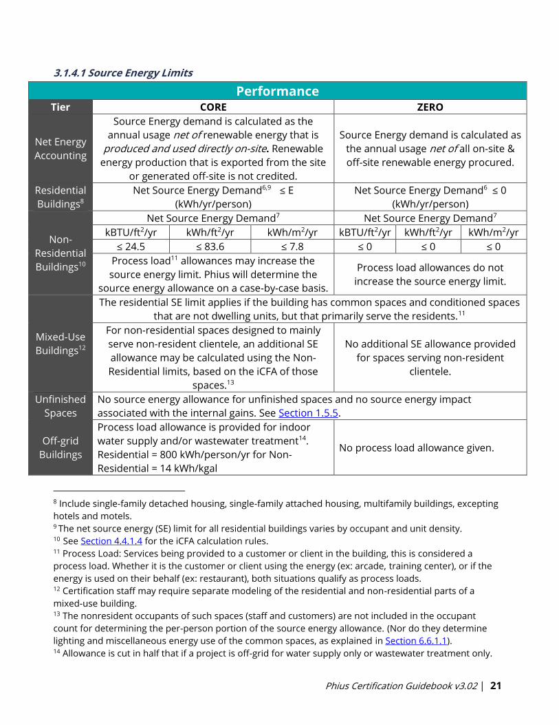
3.1.4.1 Source Energy Limits
Performance Tier CORE ZERO
Net Energy
Accounting
Source Energy demand is calculated as the
annual usage net of renewable energy that is
produced and used directly on-site. Renewable
energy production that is exported from the site
or generated off-site is not credited.
Source Energy demand is calculated as
the annual usage net of all on-site &
off-site renewable energy procured.
Residential
Buildings8
Net Source Energy Demand6,9 ≤ E
(kWh/yr/person)
Net Source Energy Demand6 ≤ 0
(kWh/yr/person)
Non-
Residential
Buildings10
Net Source Energy Demand7 Net Source Energy Demand7
kBTU/ft2/yr kWh/ft2/yr kWh/m2/yr kBTU/ft2/yr kWh/ft2/yr kWh/m2/yr
≤ 24.5 ≤ 83.6 ≤ 7.8 ≤ 0 ≤ 0 ≤ 0
Process load11 allowances may increase the
source energy limit. Phius will determine the
source energy allowance on a case-by-case basis.
Process load allowances do not
increase the source energy limit.
Mixed-Use
Buildings12
The residential SE limit applies if the building has common spaces and conditioned spaces
that are not dwelling units, but that primarily serve the residents.11
For non-residential spaces designed to mainly
serve non-resident clientele, an additional SE
allowance may be calculated using the Non-
Residential limits, based on the iCFA of those
spaces.13
No additional SE allowance provided
for spaces serving non-resident
clientele.
Unfinished
Spaces
No source energy allowance for unfinished spaces and no source energy impact
associated with the internal gains. See Section 1.5.5.
Off-grid
Buildings
Process load allowance is provided for indoor
water supply and/or wastewater treatment14.
Residential = 800 kWh/person/yr for Non-
Residential = 14 kWh/kgal
No process load allowance given.
8 Include single-family detached housing, single-family attached housing, multifamily buildings, excepting
hotels and motels. 9 The net source energy (SE) limit for all residential buildings varies by occupant and unit density. 10 See Section 4.4.1.4 for the iCFA calculation rules. 11 Process Load: Services being provided to a customer or client in the building, this is considered a
process load. Whether it is the customer or client using the energy (ex: arcade, training center), or if the
energy is used on their behalf (ex: restaurant), both situations qualify as process loads. 12 Certification staff may require separate modeling of the residential and non-residential parts of a
mixed-use building. 13 The nonresident occupants of such spaces (staff and customers) are not included in the occupant
count for determining the per-person portion of the source energy allowance. (Nor do they determine
lighting and miscellaneous energy use of the common spaces, as explained in Section 6.6.1.1). 14 Allowance is cut in half that if a project is off-grid for water supply only or wastewater treatment only.
Phius Certification Guidebook v3.02 | 22
3.1.4.2 Lighting, Appliance, & Equipment Efficiencies
See relevant requirements in Section 3.5.
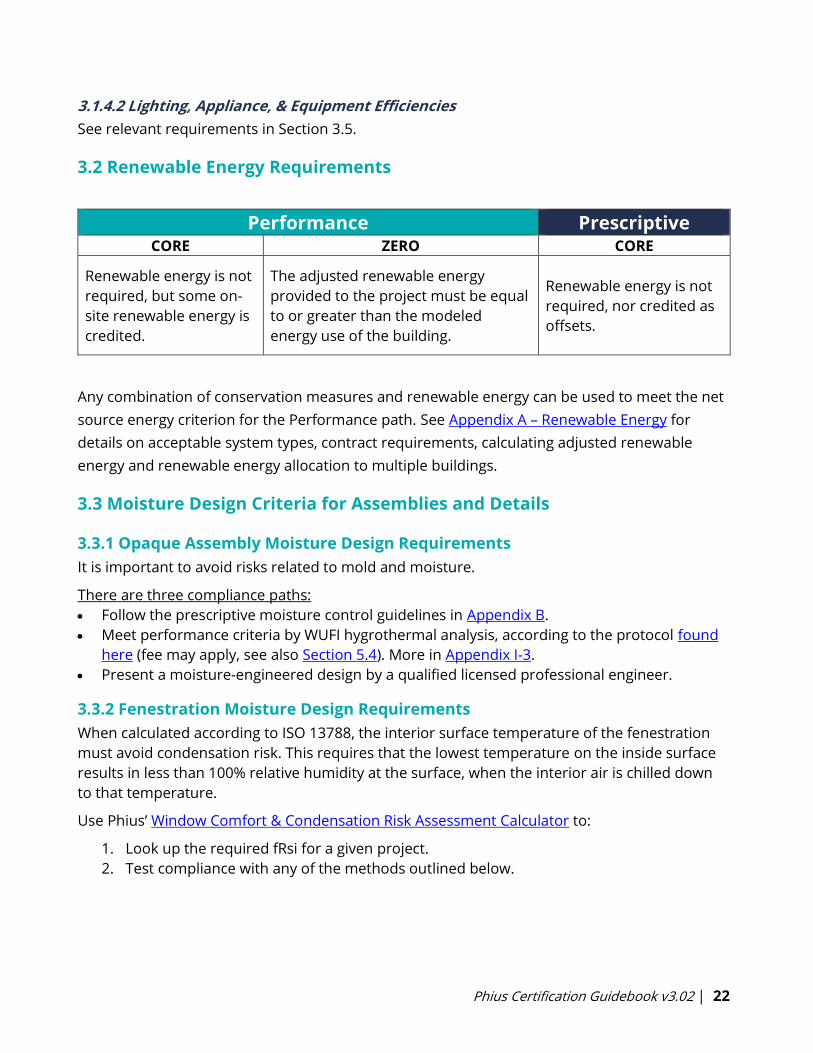
3.2 Renewable Energy Requirements
Performance PrescriptiveCORE ZERO CORE
Renewable energy is not
required, but some on-
site renewable energy is
credited.
The adjusted renewable energy
provided to the project must be equal
to or greater than the modeled
energy use of the building.
Renewable energy is not
required, nor credited as
offsets.
Any combination of conservation measures and renewable energy can be used to meet the net
source energy criterion for the Performance path. See Appendix A – Renewable Energy for
details on acceptable system types, contract requirements, calculating adjusted renewable
energy and renewable energy allocation to multiple buildings.
3.3 Moisture Design Criteria for Assemblies and Details
3.3.1 Opaque Assembly Moisture Design Requirements
It is important to avoid risks related to mold and moisture.
There are three compliance paths:
• Follow the prescriptive moisture control guidelines in Appendix B.
• Meet performance criteria by WUFI hygrothermal analysis, according to the protocol found
here (fee may apply, see also Section 5.4). More in Appendix I-3.
• Present a moisture-engineered design by a qualified licensed professional engineer.
3.3.2 Fenestration Moisture Design Requirements
When calculated according to ISO 13788, the interior surface temperature of the fenestration
must avoid condensation risk. This requires that the lowest temperature on the inside surface
results in less than 100% relative humidity at the surface, when the interior air is chilled down
to that temperature.
Use Phius’ Window Comfort & Condensation Risk Assessment Calculator to:
1. Look up the required fRsi for a given project.
2. Test compliance with any of the methods outlined below.
Phius Certification Guidebook v3.02 | 23
The Fenestration Condensation Resistance requirement, fRsi, must be met by one of the
following methods:
1. General Frame Type U-value
2. U-Frame (Uf) inferred from U-Window (Uw) and U-Center of Glass (Ucog)
3. AAMA 1503 Condensation Resistance Factor (CRF)
4. NFRC 500-2020 Condensation Resistance
5. CAN/CSA A440.2 Temperature Index
6. fRSI Method15
Exception 1: Dog doors are not required to pass the condensation resistance test.
Exception 2: The whole door U-value may be used for the condensation risk assessment for
exterior doors that are required to be ADA compliant, egress rated, fire rated, etc., instead of
requiring that each of the individual elements pass (glazing and frame).
3.3.3 Thermally Bridged Construction Detail Requirements
When calculated according to ISO 13788, the interior surface temperature of thermally bridged
construction details must avoid mold growth. This requires that the lowest temperature on the
inside surface results in less than 80% relative humidity at the surface, when the interior air is
chilled down to that temperature.
More details and calculation compliance tools can be found in Appendix N-3.
3.4 Window Comfort Requirements
The maximum whole-window U-value that may be used in a building pursuing Phius
certification is set based on the window height and ASHRAE 99% design temperature for that
location.
The window comfort criterion applies to all projects, regardless of size. The U-value required
scales by window height – the taller the window, the lower the required U-value, and can be
calculated here: Phius Window Comfort & Condensation Risk Assessment
More details and exceptions can be found in Appendix N-4.
3.5 Mandatory Design Requirements
Many of the following requirements are outlined in the Phius Single Family Quality Assurance
Workbook. Most are the responsibility of the builder but there are some items that concern the
designer as well. Those items are collected in this section for emphasis, along with some other
prescribed items. Please refer to the Workbook linked above for additional information and
adhere to these guidelines. If there are any inconsistencies with what appears in the Workbook
and this Guidebook, please email [email protected] for clarification.
15 Passivhaus Institut (PHI) Certified Component Data
Phius Certification Guidebook v3.02 | 24
The requirements below are listed according to tabs, section headings, and numbering in the
quality assurance workbook. References to Sections below may be referring to external
documents rather than this Guidebook.
3.5.1 Building Envelope
3.1a: Air Barrier Integrity: Air barrier is contiguous, including behind stairs, porch roofs,
fireplaces, showers/tubs, attic knee walls, walls/ceilings adjacent to vented attics, and floors
over unconditioned basements and vented crawlspaces. See ENERGY STAR Rater Field Checklist
Section 2 for further details and criteria.
3.1b: Air Sealing: All penetrations (wire/pipe/HVAC/etc.) between conditioned and
unconditioned space sealed, service chases capped at exterior, exterior/doors to garages
weather-stripped, rough opening of doors/windows sealed, multifamily drywall shaft walls
sealed at exterior, recessed lights ICAT and gasketed, etc. See ENERGY STAR Rater Field
Checklist Section 4 for further details and criteria.
3.2: Insulation Quality Check: All insulated assemblies have achieved a RESNET Grade I cavity
insulation level, or alternatively GII with continuous insulation. Per ENERGY STAR Rater Field
Checklist 1.3. Please see RESNET Standards Appendix A for information on insulation Grading.
3.3: Window Performance: Windows are ENERGY STAR certified, and/or triple-glazed with
thermally broken frames/spacers, and meets project the design specs.
Per ENERGY STAR National Rater Design Checklist (Rev 11) Footnote 4: Fenestration shall
meet the applicable ENERGY STAR Windows Eligibility Criteria for U and SHGC, with the
following exceptions:
a. An area-weighted average of fenestration products shall be permitted to satisfy the U-
factor requirements;
b. An area-weighted average of fenestration products ≥ 50% glazed shall be permitted to
satisfy the SHGC requirements;
c. 15 square feet of glazed fenestration per dwelling unit shall be exempt from the U-factor
and SHGC requirements, and shall be excluded from area-weighted averages calculated
using a) and b), above;
d. One side-hinged opaque door assembly up to 24 square feet in area shall be exempt
from the U-factor requirements and shall be excluded from area-weighted averages
calculated using a) and b), above;
e. Fenestration utilized as part of a passive solar design shall be exempt from the U-factor
and SHGC requirements and shall be excluded from area-weighted averages calculated
using a) and b), above. Exempt windows shall be facing within 45 degrees of true South
and directly coupled to thermal storage mass that has a heat capacity > 20 btu / ft3x◦F
Phius Certification Guidebook v3.02 | 25
and provided in a ratio of at least 3 sq. ft. per sq. ft. of South facing fenestration.
Generally, thermal mass materials will be at least 2 in. thick.
3.4: Vented Attic Reduced Thermal Bridging: Vent baffles installed in bays with soffit vents to
prevent wind-washing; Insulation over top plates and under attic walkways/platforms ≥ R-21in
CZ 1-5; ≥ R-30in CZ 6-8
3.5: Slab Edge Insulation: For slabs on-grade in CZ 4-8, 100% of slab edge insulated to ≥ R-5 at
the depth specified by the 2009 IECC
Per ENERGY STAR Rev 11 Rater Checklist footnotes 15 & 16:
a. Consistent with the 2009 IECC, slab edge insulation is only required for slab-on-grade
floors with a floor surface less than 12 inches below grade. Slab insulation shall extend
to the top of the slab to provide a complete thermal break. If the top edge of the
insulation is installed between the exterior wall and the edge of the interior slab, it shall
be permitted to be cut at a 45-degree angle away from the exterior wall. Alternatively,
the thermal break is permitted to be created using ≥ R-3 rigid insulation on top of an
existing slab (e.g., in a home undergoing a gut rehabilitation). In such cases, up to 10% of
the slab surface is permitted to not be insulated (e.g., for sleepers, for sill plates).
Insulation installed on top of slab shall be covered by a durable floor surface (e.g.,
hardwood, tile, carpet).
b. Where an insulated wall separates a garage, patio, porch, or other unconditioned space
from the conditioned space of the house, slab insulation shall also be installed at this
interface to provide a thermal break between the conditioned and unconditioned slab.
Where specific details cannot meet this requirement, partners shall provide the detail to
EPA to request an exemption prior to the home’s certification. EPA will compile
exempted details and work with industry to develop feasible details for use in future
revisions to the program. A list of currently exempted details is available at:
energystar.gov/slabedge.
3.6: Above-Grade Wall Reduced Thermal Bridging: AGWs achieve at least one of the
strategies for Reduced Thermal Bridging listed in Section 3 of the ENERGY STAR Rater Field
Checklist (Rev 11)
• Most Phius Projects will easily meet this requirement. Where any doubt or question
exists about the strategy to meet this requirement, see the ENERGY STAR Rater Field
Checklist (Rev 11) footnotes relating to section 3
3.7: Other Thermal Bridging/mitigation strategy identification: Note any other meaningful
thermal bridges observed on the project, as well as thermal bridging mitigation strategy
Phius Certification Guidebook v3.02 | 26
identification. Special effort should be made to clearly document such bridging and mitigation
strategies, or where such details are missed.
• The Phius Rater shall discuss the presence of known thermal bridges with CPHC prior to
inspection, as well as specific mitigation strategies. Any significant bridging observed on
a project not accounted for by the CPHC must be brought to the attention of Phius
immediately.
3.5.2 Ventilation
3.5.2.1 Balanced Ventilation
• A whole-building mechanical ventilation system is required to be installed.
• The system shall have at least one supply or exhaust fan with associated ducts and
controls. Local exhaust fans can be part of a whole-house ventilation system.
• For Phius certification, regardless of type, the ventilation system must meet one
of the following requirements for balance:
1. Total measured supply and exhaust airflows are within 10% of each other. (Use the
higher number as the basis of the percentage difference.)
2. The total net pressurization or depressurization from the un-balanced ventilation
system does not exceed 5 Pa. The net pressurization/depressurization that the
ventilation system imbalance causes on the building is determined using the multi-
point air-tightness test results graph.
• In the case of ventilation ductwork integrated with heating/cooling ducts, ERV
should remain in balance under all fan speeds of the heating/cooling air handler.
In the Energy Star framework, the ventilation system type is characterized as either “Supply”,
“Exhaust”, or “Balanced”.
In the case of “Supply” or “Exhaust” systems:
A ventilation system design with supply fans only or exhaust fans only will generally require
dedicated openings in the envelope (with dampers) for make-up air to meet the balance
requirements, because of the air-tightness requirement on the building overall. Such make-up
air inlets or outlets must appear in the design documentation for Design Certification.
In the case of “Balanced” systems with heat or energy recovery devices:
If the exhaust or supply air flow exceeds the exhaust air flow by more than 10%, the energy
penalty must be accounted for per Section 6, Energy Modeling Protocol.
Phius Certification Guidebook v3.02 | 27
3.5.2.2 Ventilator Defrost
A pre-heater defrost (or ground loop pre-heater) is required for ERVs where the ASHRAE 99.6%
design temperature is below the manufacturer’s claimed minimum operating temperature,
rather than relying on re-circulation defrost.
If the unit can maintain the required fresh air ventilation rates on average with the unit
intermittently in recirculation mode, then this is acceptable. The unit needs to have enough
boost to maintain the same time-average fresh air ventilation rate as it would at higher
temperatures. See Appendix N-5 Recirculation Defrost for requirements.
3.5.2.3 Quality Assurance Workbook Requirements
1.3a: All ventilation air inlets located at least 10' ("stretched-string distance") from known
contamination sources
1.3b: All ventilation air inlets located minimum 5' from ventilation exhaust outlet,
recommended 10'
1.4: Ventilation air comes directly from outdoors, not from adjacent dwelling units, common
spaces, garages, crawlspaces, or attics.
1.5: Ventilation air comes directly from outdoors, not from adjacent dwelling units, common
spaces, garages, crawlspaces, or attics
1.6: Outside air passes through a minimum MERV 8 filter prior to distribution, is changed at
final and home is ventilated prior to occupancy
1.7: Outside air filter is located to facilitate regular service by the occupant and/or building
superintendent
1.8: Air-sealed, class 1 vapor retarder shall be installed over all air-permeable insulation (such
as fiberglass duct wrap) on ventilation ducts connected to outside
1.10: Dedicated Fresh Air supply to all bedrooms
Fresh air (OA) supply to bedrooms is required in all dwelling units:
• In the case of ventilation ductwork integrated with heating/cooling ducts, the
heating/cooling air handler fan must be designed to run continuously by default.
1.11: Rater-measured bathroom exhaust rates meets one of the following: ≥20cfm continuous
or 50 cfm intermittent
Phius Certification Guidebook v3.02 | 28
1.13: Rater-measured kitchen exhaust rates meets one of the following: ≥25cfm continuous,
100cfm intermittent for range hoods, or 5ACH based on kitchen volume
1.13a: Note future update to align with EPA Indoor airPLUS v2 (permit date 01/01/2022
and later)– Direct, intermittent kitchen exhaust is required in only single family, duplex,
and townhomes.
1.14: If kitchen exhaust connected to ERV/HRV, register is min. 6' from cooktop, MERV 3 or
washable mesh filter for trapping grease, and recirc hood over range
2.9: Total supply and exhaust are within 10% of each other
2.10: Net pressure across envelope no greater than +/-5 Pascals
3.5.3 Heating, Cooling & Domestic Hot Water
Heating/Cooling Equipment
1.7: If a combustion equipment for space heating, the building has provided a designated
exterior location(s) in accordance with the following:
Exception: Where an electrical circuit in compliance with IRC Section E3702.11 exists for space
cooling equipment.
1.7A: Natural drainage for condensate from cooling equipment operation or a
condensate drain located within 3 feet
1.7B: A dedicated branch circuit in compliance with IRC Section E3702.11 based on heat
pump space heating equipment sized in accordance with R403.7 and terminating within
3 feet of the location with no obstructions. Both ends of the branch circuit shall be
labeled “For Future Heat Pump Space Heater.”
Heating/Cooling Distribution – Ducted systems only
2.4: All return air passes through a min. MERV 8 filter which is located to facilitate regular
service by the occupant and/or building superintendent.
2.6: Equipment selected to keep relative humidity < 60% in “Warm-Humid” climates OR install
additional dehumidification. Exception: Climate Zones 4-8 3B, 3C and the portions of 3A and 2B
above the white line as shown by IECC Figure 3012009
2.7: Bedrooms are pressure balanced to achieve a Rater-measured pressure difference of no
more than 3Pa with respect to the main body of the house when all bedroom doors are closed,
all heating/cooling air handlers are operating at full speed and ventilation system is operating
at design speed.
2.8: Ducts and air handlers located entirely within building thermal envelope.
Phius Certification Guidebook v3.02 | 29
Combustion Safety and Condensation Management
4.1: Combustion heating/water heating systems located within the buildings' pressure
boundary are sealed combustion, direct-vent appliances.
4.2: Natural draft fireplaces are not installed.
4.3: Installed fireplaces and woodstoves have a combustion air inlet connected to the firebox.
4.4: No unvented combustion fireplaces installed in home.
Domestic Hot Water Systems
6.4: Continuous, time, or temperature-based hot water recirculation systems not installed.
6.5: Hot water temperature-rise test.
For more information, see the EPA Watersense Guide for Efficient Hot Water Delivery Systems.
[5] Download the associated design-aid calculator here.
WUFI Passive hot water distribution entries also support this calculation.
6.8: If combustion water heating and water heater capacity is less than or equal to 300,000
Btu/h (88 kW) the following are met:
6.8A: A dedicated 240-volt branch circuit with a minimum capacity of 30 amps shall
terminate within 3 feet from the water heater and be accessible to the water heater with
no obstructions. Both ends of the branch circuit shall be labeled with the words "For
Future Heat Pump Water Heater" and be electrically isolated.
6.8B: A condensate drain is installed within 3 feet of the water heater. It is no more than
2 inches higher than the base of the installed water heater and allows natural draining
without pump assistance.
6.8C: The water heater is installed in a space with minimum dimensions of 3 feet x 3 feet
x 7 feet high.
6.8D: The water heater is installed in a space with a minimum volume of 700 cubic feet
or the equivalent of one 16-inch x 24-inch grill to a heated space and one 8-inch duct of
no more than 10 feet in length for cool exhaust air.
3.5.4 Lights, Appliances, & Renewables
Lighting
1.1: 80% of lighting fixtures are ENERGY STAR qualified or ENERGY STAR lamps (bulbs) in
minimum 80% of sockets.
Appliances
Phius Certification Guidebook v3.02 | 30
All installed refrigerators, dishwashers, and clothes washers are ENERGY STAR qualified.
For products in categories which are not covered by ENERGY STAR product criteria, such
as combination all-in-one clothes washer-dryers, these products are exempt.
2.4C: If combustion clothes drying. A dedicated 240-volt branch circuit with a minimum capacity
of 30 amps shall terminate within 6 feet of natural gas clothes dryers and shall be accessible
with no obstructions. Both ends of the branch circuit shall be labeled with the words “For
Future Electric Clothes Drying” and be electrically isolated.
2.5B: If combustion cooking. A dedicated 240-Volt, 40A branch circuit shall terminate within 6
feet of natural gas ranges, cooktops and ovens and be accessible with no obstructions. Both
ends of the branch circuit shall be labeled with the words “For Future Electric Range'' and be
electrically isolated.
2.7: All combustion equipment shall be provided with a branch circuit sized for an electric
appliance, equipment or end use with an equivalent capacity that terminates within 6 feet of
the appliance or equipment.
Renewable Energy Systems
Phius requires homes to be solar PV-ready regardless of average daily solar radiation
(kWh/m2/day). Phius projects are not exempt even if daily average solar radiation for the site is
less than 5 kWh/m2/day. This rule is in effect as of April 2016.
4.3: If solar photovoltaic (PV) system not installed, document home's compliance with the DOE
ZERH Home PV-ready checklist:
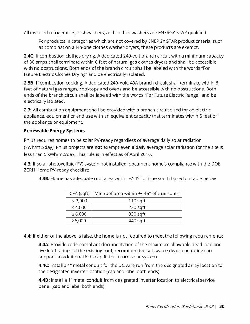
4.3B: Home has adequate roof area within +/-45° of true south based on table below
iCFA (sqft) Min roof area within +/-45° of true south
≤ 2,000 110 sqft
≤ 4,000 220 sqft
≤ 6,000 330 sqft
>6,000 440 sqft
4.4: If either of the above is false, the home is not required to meet the following requirements:
4.4A: Provide code-compliant documentation of the maximum allowable dead load and
live load ratings of the existing roof; recommended: allowable dead load rating can
support an additional 6 lbs/sq. ft. for future solar system.
4.4C: Install a 1” metal conduit for the DC wire run from the designated array location to
the designated inverter location (cap and label both ends)
4.4D: Install a 1” metal conduit from designated inverter location to electrical service
panel (cap and label both ends)
Phius Certification Guidebook v3.02 | 31
4.4E: Install and label a 4’ x 4’ plywood panel (or alternatively blocking) area for mounting
an inverter and balance of system components.
4.4F: Install a 70-amp dual pole circuit breaker in the electrical service panel for use by
the PV system (label the service panel)
Electric Vehicle Charging Infrastructure
5.1: One EV-Ready space shall be provided for each dwelling unit where parking is required, or
if there are attached or detached garages, on-site parking spaces and new detached garages.
5.2: The branch circuit has wiring capable of supporting a 40-amp, 208/240-volt circuit
5.3: The branch circuit terminates at a junction box or receptacle located within 3 feet of the
parking space
5.4: The electrical panel directory has designated the branch circuit as “For electric vehicle
charging” and the junction box or receptacle shall be labeled “For electric vehicle charging”.
3.5.5 Water Management and Indoor Air Quality
Water/Moisture Managed Site/Foundation
1.1: Patio/porch slabs/walks/driveways sloped ≥ 0.25"/ft from home to edge of surface or 10 ft;
back-fill tamped and graded ≥ 0.5"/ft from home for 10'. See ENERGY STAR Water Management
System Builder Requirements Rev. 11
1.2: Layer of aggregate or sand (4 in.) with geotextile matting & capillary break beneath all slabs
using either: ≥ 6 mil polyethylene sheeting, lapped 6-12 in., or ≥ 1 in. extruded polystyrene
insulation with taped joints. Exceptions to the aggregate OR sand requirement: (Not applicable
in EPA Radon Zone 1)
• Dry climates, as defined by 2009 IECC Figure 301.1. (Also exempt from capillary break
requirement)
• Areas with free-draining soils – identified as Group 1 (Table R405.1, 2009 IRC) by a
certified hydrologist, soil scientist, or engineer through a site visit.
• Slab-on-grade foundations
1.3: Basements/crawlspaces insulated, sealed, dampproofed and conditioned.
Exceptions:
• Homes built in areas designated as flood zones (conditioned crawlspaces not
recommended for use in flood zones).
• Raised pier foundations with no walls.
• Dry climates, as defined by 2009 IECC Figure 301.1.
Phius Certification Guidebook v3.02 | 32
• Marine climates, as defined by 2009 IECC Figure 301.1, if no air handler or return ducts
are installed in the crawlspace.
1.4: Class 1 vapor retarder not installed on interior side of air permeable insulation in exterior
below-grade walls. See footnote 8 of ENERGY STAR Water Management requirements
1.5: Drain or sump pump installed in basements and crawlspaces; sump pump covers
mechanically attached with full gasket seal or equivalent. See item 1.1 of IAP specs.
1.6: Drain tile installed at basement/crawlspace walls, with the top of the drain tile pipe below
the bottom of the concrete slab or crawlspace floor. See footnote 9 of ENERGY STAR Water
Management requirements
Water Managed Walls/Roofs
2.1: Flashing at bottom of exterior walls with weep holes included for masonry veneer and
weep screed for stucco cladding systems or equivalent systems.
2.2: Fully sealed continuous drainage plane behind exterior cladding that laps over flashing in
Item 2.1 and fully sealed at all penetrations. Additional bond-break drainage plane layer
provided behind all stucco and non-structural masonry cladding wall assemblies.
• See footnote 10 & 11 of ENERGY STAR Water Management requirements
2.3: Window and door openings fully flashed. Apply pan flashing over the rough sill framing,
inclusive of the corners of the sill framing; side flashing that extends over pan flashing; and top
flashing that extends over side flashing or equivalent details for structural masonry walls.
2.4: Step and kick-out flashing at all roof-wall intersections, extending ≥ 4” on wall surface
above roof deck and integrated shingle-style with drainage plane above; boot / collar flashing at
all roof penetrations." Intersecting wall siding shall terminate 1 in. above the roof or higher, per
manufacturer recommendations. Continuous flashing shall be installed in place of step flashing
for metal and rubber membrane roofs.
2.5: Non-slab on-grade homes shall have gutters/downspouts with discharge on sloping final
grade ≥ 5 ft. from foundation. See footnotes and additional details from ENERGY STAR and IAP
for other circumstances. See item 1.7 of IAP specs and footnotes 4, 14 & 15 from ENERGY STAR
Water Management requirements
2.6: Self-adhering polymer-modified bituminous membrane at all valleys & roof deck
penetrations AND in CZ 5+, over sheathing at eaves from the edge of the roof line to > 2 ft. up
roof deck from the interior plane of the exterior wall. See footnote 4 & 16 of ENERGY STAR
Water Management requirements
2.7: Piping in exterior walls insulated with pipe wrap.
Phius Certification Guidebook v3.02 | 33
Water Managed and Low-Emitting Building Materials
3.1: Hard-surface flooring in kitchens, baths, entry, laundry and utility rooms AND carpet not
installed within 2.5 ft. of toilets, tubs, and showers.
3.2: Cement board or equivalent moisture-resistant backing material installed on all walls
behind tub and shower enclosures composed of tile or panel assemblies with caulked joints.
Paper-faced backerboard shall not be used. See footnote 17 of ENERGY STAR Water
Management requirements.
3.3: In Warm-Humid climates, Class 1 vapor retarders not installed on the interior side of air
permeable insulation in above-grade walls. Except at shower and tub walls. See footnote 8 of
ENERGY STAR Water Management Requirements.
3.4: Materials w/ visible signs of water damage/mold not installed; framing members/insulation
products w/ high moisture content not enclosed. See footnotes 18 &19 of ENERGY STAR Water
Management Requirements
3.5: All composite wood products, interior paints/finishes, carpet/carpet adhesive/padding
certified low-emission. See IAP construction specs for Section 6.
Radon, Pest & Combustion Pollutant Mitigation
4.1: Radon-resistant features installed in Radon Zone 1 homes in accordance with IAP
Construction Specification 2.1.
*Passive radon systems are highly recommended in Radon Zones 2 & 3.
See EPA Consumers Guide to Radon Reduction for more details.
4.2: Corrosion-proof rodent/bird screens installed at all openings that cannot be fully sealed
(Exception: dryer vents)
4.3: Emissions standards met for fuel-burning and space-heating appliances; CO alarms
installed in each sleeping zone (e.g., common hallway) according to NFPA 720. Except at shower
and tub walls. See ENERGY STAR Water Management Requirements.
4.4: Multifamily buildings: Smoking restrictions implemented AND ETS transfer pathways
minimized. See item 1.7 of IAP specs and ENERGY STAR Water Management requirements.
3.5.6 Electric Vehicle (EV) Charging Infrastructure
Infrastructure for the current and future charging of electric vehicles (EVs) is required for all
residential buildings where parking spaces are required.
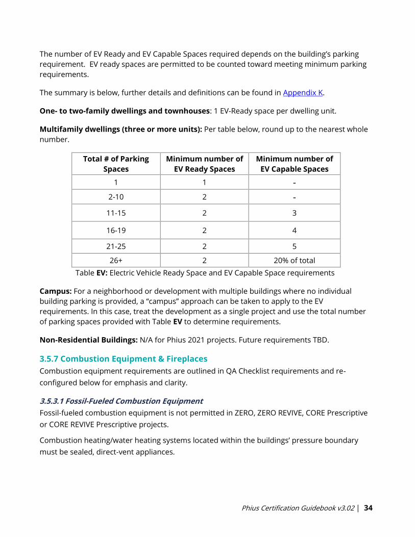
Phius Certification Guidebook v3.02 | 34
The number of EV Ready and EV Capable Spaces required depends on the building’s parking
requirement. EV ready spaces are permitted to be counted toward meeting minimum parking
requirements.
The summary is below, further details and definitions can be found in Appendix K.
One- to two-family dwellings and townhouses: 1 EV-Ready space per dwelling unit.
Multifamily dwellings (three or more units): Per table below, round up to the nearest whole
number.
Total # of Parking
Spaces Minimum number of
EV Ready Spaces Minimum number of
EV Capable Spaces
1 1 -
2-10 2 -
11-15 2 3
16-19 2 4
21-25 2 5
26+ 2 20% of total
Table EV: Electric Vehicle Ready Space and EV Capable Space requirements
Campus: For a neighborhood or development with multiple buildings where no individual
building parking is provided, a “campus” approach can be taken to apply to the EV
requirements. In this case, treat the development as a single project and use the total number
of parking spaces provided with Table EV to determine requirements.
Non-Residential Buildings: N/A for Phius 2021 projects. Future requirements TBD.
3.5.7 Combustion Equipment & Fireplaces
Combustion equipment requirements are outlined in QA Checklist requirements and re-
configured below for emphasis and clarity.
3.5.3.1 Fossil-Fueled Combustion Equipment
Fossil-fueled combustion equipment is not permitted in ZERO, ZERO REVIVE, CORE Prescriptive
or CORE REVIVE Prescriptive projects.
Combustion heating/water heating systems located within the buildings’ pressure boundary
must be sealed, direct-vent appliances.
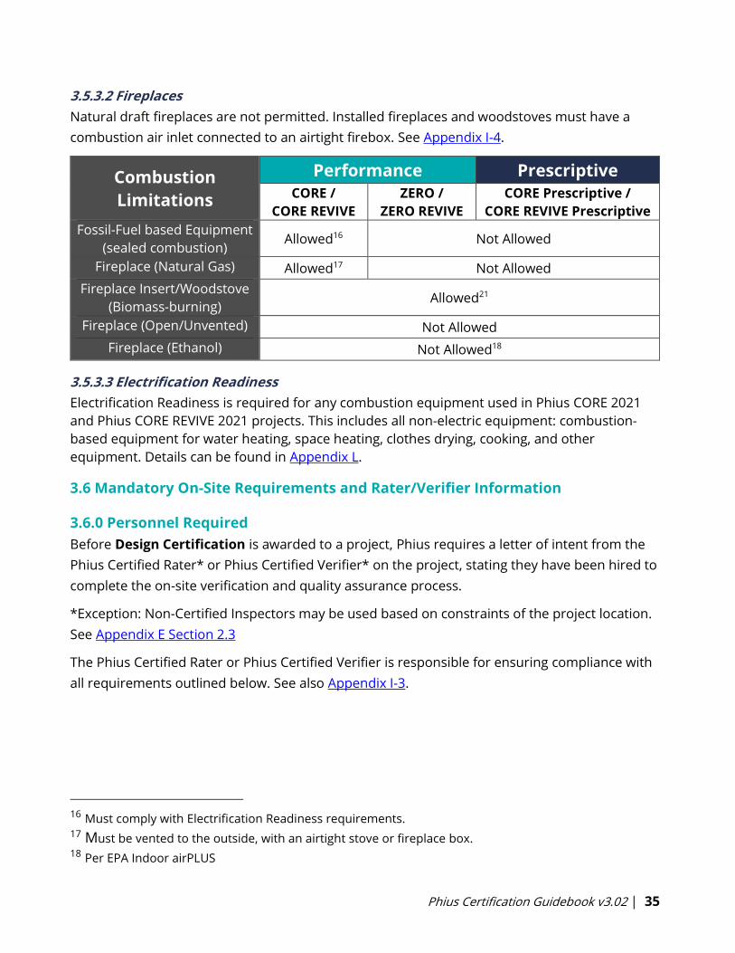
Phius Certification Guidebook v3.02 | 35
3.5.3.2 Fireplaces
Natural draft fireplaces are not permitted. Installed fireplaces and woodstoves must have a
combustion air inlet connected to an airtight firebox. See Appendix I-4.
Combustion
Limitations
Performance Prescriptive
CORE /
CORE REVIVE
ZERO /
ZERO REVIVE
CORE Prescriptive /
CORE REVIVE Prescriptive
Fossil-Fuel based Equipment
(sealed combustion) Allowed16 Not Allowed
Fireplace (Natural Gas) Allowed17 Not Allowed
Fireplace Insert/Woodstove
(Biomass-burning) Allowed21
Fireplace (Open/Unvented) Not Allowed
Fireplace (Ethanol) Not Allowed18
3.5.3.3 Electrification Readiness
Electrification Readiness is required for any combustion equipment used in Phius CORE 2021
and Phius CORE REVIVE 2021 projects. This includes all non-electric equipment: combustion-
based equipment for water heating, space heating, clothes drying, cooking, and other
equipment. Details can be found in Appendix L.
3.6 Mandatory On-Site Requirements and Rater/Verifier Information
3.6.0 Personnel Required
Before Design Certification is awarded to a project, Phius requires a letter of intent from the
Phius Certified Rater* or Phius Certified Verifier* on the project, stating they have been hired to
complete the on-site verification and quality assurance process.
*Exception: Non-Certified Inspectors may be used based on constraints of the project location.
See Appendix E Section 2.3
The Phius Certified Rater or Phius Certified Verifier is responsible for ensuring compliance with
all requirements outlined below. See also Appendix I-3.
16 Must comply with Electrification Readiness requirements. 17 Must be vented to the outside, with an airtight stove or fireplace box. 18 Per EPA Indoor airPLUS
Phius Certification Guidebook v3.02 | 36
3.6.1 Residential
3.6.1.1 Co-Requisite Program19 Requirements
The following are required for all single-family projects and all other eligible residential projects.
• EPA ENERGY STAR New Homes (ESTAR) / Multifamily New Construction (MFNC)
• DOE Zero Energy Ready Home (ZERH)
• EPA Indoor airPLUS (IAP)
The Phius Single Family Quality Assurance Workbook incorporates all of the co-requisite
requirements into a single document. The single-family workbook shall be used for all Phius
projects encompassing single family homes and small attached residential developments
(duplexes, townhomes, etc). All individual program checklists are required to be completed and
submitted along with the QA Workbook.
The Phius Multifamily Quality Assurance Workbook should be used for multifamily projects. See
Section 1.5.2 for definition of multifamily.
Projects that meet the eligibility criteria for the EPA ENERGY STAR New Homes (ESTAR) or EPA
ENERGY STAR Multifamily New Construction (MFNC) Program and DOE Zero Energy Ready
Homes (ZERH) programs shall be certified under the appropriate programs. Projects that do not
meet eligibility criteria for certification under these programs shall be exempt from certification
for both ESTAR and ZERH. However, the certification checklist criteria for these programs shall
still be applied to ensure that multifamily projects seeking Phius Certification are not only
energy efficient, but also durable, comfortable, and healthy buildings.
The EPA has released the EPA ENERGY STAR Multifamily New Construction Program (ES MFNC)
which includes all multifamily buildings with more than 2 units, and less than 50% commercial
space. Until July 1, 2021, Phius will support two paths for Phius Multifamily Quality Assurance,
with requirements outlined in two separate workbooks:
Version 2.2: Supports EPA ENERGY STAR for Homes
Version 2.3: Supports EPA ENERGY STAR Multifamily New Construction (MFNC) Program
Projects with a Building Permit date on or after July 1, 2021 requires use of Phius QA Workbook
v2.3, and mandatory certification under the EPA ENERGY STAR Multifamily New Construction
(MFNC) Program. This excludes single family detached, 1-2 family homes, townhomes and 100%
commercial projects.
19 Check the policy record for each program as to the current version and applicability to the project’s
location.

Phius Certification Guidebook v3.02 | 37
Townhome projects can be certified under either the Energy Star Certified Homes or the
Multifamily New Construction Program. For mixed use projects, the residential portions shall be
certified, provided the residential portion qualifies and is recognized by the EPA Energy Star
MFNC as an eligible project. Residential spaces on projects that would not be accepted into the
Energy Star MFNC shall meet all the Energy Star MFNC requirements “as if it were being
certified”.
Note: Phius tracks program version requirements by project contract date. Phius does not track
project building permit dates and is not responsible for a project team’s selection of the QA
program version above. Teams must select the appropriate program version based on
expected permit date. Even if a Phius contract date is before July 1, 2021, if the permit date will
be after that, version 2.3 must be followed.
For full program requirements, please see Appendix G: Phius Certification for Multifamily
Performance Requirements (v2.2).
Download the Phius Multifamily Quality Assurance Workbooks.
3.6.1.2 Residential Exceptions
Generally, the only cases where an eligible residential Phius project may not earn ESTAR or DOE
ZERH certifications are:
1. Existing Buildings: Some retrofits, gut rehabilitations, partial renovations, or
unforeseen circumstances that may arise. In such cases, a written submission should be
sent to Phius for review during design certification.
2. Project Location not Eligible for Certification: Projects in California, Alaska, Canada, or
other International Locations. While earning the actual certification is not required, the
project must still meet all certification criteria.
3.6.2 Non-Residential
3.6.2.1 Co-Requisite Program Requirements20
Non-Residential projects shall use the eligibility criteria and follow checklist requirements
for:
• EPA ENERGY STAR Multifamily New Construction (MFNC) Program21
• DOE Zero Energy Ready Homes (ZERH)
• EPA Indoor airPLUS (IAP)
20 Projects located outside of the United States, or in California or Alaska, will need to meet the same
criteria, regardless of their configuration. 21 Nonresidential projects with a building permit date after July 1, 2021 will be required to follow the EPA
Energy Star Multifamily New Construction Program Certification Criteria.

Phius Certification Guidebook v3.02 | 38
Mixed-Use Buildings: Dwelling and sleeping units must be certified to the co-requisite
programs above.
Non-residential buildings (and non-residential spaces within mixed-use buildings): Exempt
from certifying under those programs however, the certification checklist criteria for these
programs shall still be achieved to help ensure that Nonresidential projects seeking Phius
Certification are not only energy efficient, but also durable, comfortable, and healthy
buildings.
General concepts below – details are outlined in the Phius Nonresidential Quality
Assurance Workbook.
The initial scope of requirements for commissioning of nonresidential buildings is focused on
energy use impacts.
• Systems manual for building operators.
• Infiltration testing.
• Ventilation balancing and wattage measurement.
• Ducted heating/cooling balancing.
• Verification of envelope, air barrier, thermal bridge mitigation, and shading – that these
are built to plans.
• Verification of lighting, mechanical, and process load systems per plans/energy model.
• Photo documentation, per ENERGY STAR MFNC Photo Documentation Guidance.
The process will be based upon and comprehensive of USGBC’s LEED requirements for
basic level commissioning to support dual certification.
Provider requirements:
• Two projects experience, or
• Certification from CPMP, BCxP, ACG.
Commissioning procedures follow either:
• ASHRAE Standard 202 – 2013
• NEBB Procedural Standards for Whole Building Systems Commissioning for New
Construction
3.6.3 Phius Certified Rater/Verifier Manual
Full document can be found in Appendix E, below.
The manual contains:
1. Description of Phius Certified Rater and Verifier
2. Certification Eligibility, Requirements & Maintenance
3. Pre-Construction Requirements
4. Technical Inspection and Field Requirements

Phius Certification Guidebook v3.02 | 39
5. Post-Construction Requirements
3.6.4 Contractor Declaration
The intent of the Contractor Declaration is to have a written statement of proof that the as built
building conforms to the provided documentation and outlines any as-built variations from
construction documents. This information will be verified through the site tests as performed
by the Phius Certified Rater or Verifier.
Here are some sample wordings:
I, ______________, as general contractor of the _______________ (project) located at
____________________ (address), confirm that the documents supplied to Phius on
____________ (date) are identical to the finished project.
Any discrepancies or changes are listed here: ______________________.
This declaration certifies that the _______________ (project) located at ____________________
(address), has been constructed according to the technical specifications in the
___________ energy model, which has been populated based on the drawings submitted
on ______________ (date).
There are no deviances from the file or any of the supporting documentations that
have previously been submitted to Phius.
These declarations should be placed on an official letterhead and signed by the construction
supervisor or general contractor. These wordings can be adjusted, but these are good
examples to start from.

Phius Certification Guidebook v3.02 | 40

Phius Certification Guidebook v3.02 | 41
4. Process
4.0.1 Feasibility Study (Optional)
To help decide if Phius Certification is a worthwhile pursuit, project teams may request Phius to
conduct a feasibility study.
• To review what is included and required to request such a study, visit this page:
Feasibility Study
• Payment: Fee structure outlined in Section 5.4.2. Make payment by check or request an
invoice for online payment. All credit card transactions incur a 3% fee.
4.0.2 Pre-Process Paperwork
Review this Guidebook, which summarizes all requirements, covers energy modeling protocol,
and includes vapor control recommendations and other technical details.
• Visit the Submitting a Project for Certification page on the Phius website to find a
step-by-step outline of the certification process.
• Contract: Review and sign the Phius Certification Contract. This contract must
be requested using the form in Step 1 of the ‘Submitting a Project’ page linked
above.
• Email executed contract to [email protected].
• Payment: Make payment by check or request an invoice for online payment. All
credit card transactions incur a 3% fee.
4.0.3 Create a Project
• Log on to the Phius Certified Projects Database.
• If necessary, Phius will create account or give access to submit projects.
• For CPHCs, this should not be necessary.
• Create a project by adding at minimum a project name, interior Conditioned Floor
Area (iCFA), number of units (if residential) and location. Other information can be
added after the project has been Design Certified.
• Once a project is created, Phius certifiers will be informed by the database. At this
time, Phius will create a DropBox folder for the project and invite the Submitter to
the folder. The Submitter may invite other members of the project team.
• When all documents have been prepared, uploaded to the DropBox and the
project is ready for review, the team must use the form on the Project
Certification Review Queue page to add the project into the queue.
• The project will be added into the Phius review queue as of the forms submit date.
This is a manual process, so please allow one business day before the project status
is updated on the public queue.
• Email notifications will be re-directed to use the submission form.
• We recommend keeping a record of your submissions.
• The project review will not begin until both the contract and payment are received.

Phius Certification Guidebook v3.02 | 42
4.0.4 Quality Assurance and Quality Control (QA/QC)
• The QA/QC components of Phius Certification performed by Phius Certified Raters or
Verifiers are an essential part of the Phius process.
• That Phius Certification component is covered under a separate contract between
the project team and the Rater or Verifier.
• Before Design Certification is awarded to a project, Phius requires a letter of intent
from the Phius Certified Rater or Verifier on the project, stating they have been hired
to complete the on-site verification process.
• Phius encourages project CPHCs to clearly communicate the following to the Rater or
Verifier as early as possible so that on-site verification can be performed as efficiently
and effectively as possible:
• Foundation condition and insulation strategy.
• Primary whole-building air barrier/infiltration control strategy.
• Intended insulation materials, installed thicknesses and R-values for all
building enclosure assemblies.
• HVAC and hot water system strategies, equipment and design drawings.
• Intended labeled window performance values.
• Known project thermal bridges and associated mitigation strategies/products.
• Window install and sealing strategies.
• Window shading strategies, including adjacent site shading, overhangs and/or
external movable shading.
• Intended tested whole-building infiltration values, including intended mid-
construction infiltration testing values.
• For more information about the Phius Certified Rater or Verifier process, see
Appendix E.
4.0.5 Phius Certification (Final Stages)
• The Phius Certified Rater or Verifier must upload all on-site documentation to the
project DropBox.
• The CPHC should update the WUFI Passive energy model to match any known as-
built changes as well as final test results. All changes should be tracked in the Phius
Certification Feedback form used during Design Certification.
• Once ready, submit the project for final review using the form on the Project
Certification Review Queue page.
• Phius Certification Staff will review the submission and provide feedback requesting
further documentation, or comments for clarification.
• If not adjusted by the CPHC, before final certification is awarded, Phius will adjust the
final WUFI Passive energy model to match the verified results for:
• Air-tightness test results

Phius Certification Guidebook v3.02 | 43
• Average continuous ventilation rate
• Measured ventilation fan wattage.
• Project team to upload final drawings, documents, pictures, etc. to the DropBox.
• Once all documentation is reviewed and approved, Phius issues a formal email
notification and mail (3) copies of the Phius Certified Project Certificate to the CPHC.
• Purchase Phius Certified Project Plaque
• One included per project, additional available for purchase for $75
• If a project qualifies for Phius Zero, an additional plaque is available for
purchase for $75.
4.0.6 Incentives
Updated local and national incentives can be found on Phius’ Incentives webpage.
• With the addition of a QA/QC process, Phius projects are now able to gain more
performance-based incentives.
• Since 2013, Phius has partnered with the DOE’s Zero Energy Ready Home program as
well as ENERGY STAR for Homes. These programs are pre-requisites for Phius
Certification. Your Phius Certified Rater or Verifier will complete documentation for
all these programs during their on-site visits, and the project will be awarded
recognition from all three.
• Most projects will automatically receive a RESNET HERS Index score as part of
certification. The RESNET HERS Index is the leading industry standard by which a
home’s energy efficiency is measured. Many local, state, and federal financial
incentive programs require a HERS Index to demonstrate compliance.
4.1 General Tips During the Process
• When uploading new information, please also update the feedback form, so that we
know what has changed. The feedback form is the primary communication channel. It
covers all the bases, that is, it serves also as a checklist. It is a written record and keeps
everything in one place to keep track of what was said by whom and when on each
point.
• Communication by phone or email can be used from time to time, but these outside
discussions should be captured in the feedback form.
• Likewise, when uploading new feedback, please give it a final run through to make sure
that if you refer to new information, that those documents are in fact uploaded to the
DropBox - and, that the noted adjustments to the energy model were implemented.
• Include dates in the file naming conventions, and name the files in a logical manner (i.e.
v1, v2, etc.). Please also avoid uploading a file that was arbitrarily assigned a file name
that is un-readable/non-descriptive of the file content. Rename files when necessary,
before uploading.
Phius Certification Guidebook v3.02 | 44
• Ex: original file downloaded from online, file name ‘k35fd8463yfh.pdf’. Rename to
‘Dishwasher ES Rating.pdf’
From time to time, we may ask for changes to the energy model even if it looks like the change
will probably have a small impact, or in cases where there are two mistakes, but net result is a
wash. There are two reasons for this:
1. Educational—on the next project it may make more of a difference and we do not want
people to repeat mistakes.
2. Accuracy—improve the chances that the model will match actual energy use if the
comparison is ever made.
4.1.1 Review Timeline
Generally, projects can expect the following review timeframes. These estimates are applicable
to the Prescriptive & Performance paths.
Design Certification
• Round 1: 6-8 weeks
• Round 2: 4-6 weeks
• Round 3: 2-4 weeks
• Round 4+: 1-2 weeks
Final Certification
• First Full Review: 2-4 weeks
• Revision Review: 2-4 weeks
The overall certification process timeline is highly variable and depends on the response time
from both the reviewer and the submitter. It also depends on the completeness and accuracy
of the first submission.
Expedite Review: An expedited review path may be available for an additional fee (See Section
5). The expedited path provides each round of review within 5 to 8 business days, rather than
the timeline listed above. Whether or not this option is available is up to the discretion of Phius
and the volume of expedited reviews in the certification queue at the time of submission.
4.2 Phius Project Database Access
Go to the Phius Certified Projects Database
The login link is located at the top right of the page.
A current Phius CPHC may log into their CPHC database account. To create a new a project, click
on the "New Project" button and following the instructions in Section 4.3.
4.2.1 Logging in
If you have any questions about logging into your account, contact [email protected].

Phius Certification Guidebook v3.02 | 45
If you are not currently a CPHC, please request login information to log into the system as a
Project Submitter. This will be created once the certification fee is paid, and the certification
contract is signed. Once in the system, a Submitter can fill in project information to the Phius
Projects Database.
4.3 Database/DropBox Instructions and Tips
Creating a New Project in the Database
To begin a new project, log into the system then:
Click the “New project” button near the top of the page. A comprehensive form of project detail
fields will appear.
Note: Most of these fields will be completed later in the process, and many cannot be
completed until the project proceeds. (Once the project reaches design certification or final
certification, many of these fields will be viewable to the public.)
To create a new project in the Phius Project Database, you initially need only complete the
following fields:
• Project Name (e.g. Dublin Project)
• Project Location
o City
o State/Province
• Building Function
• Units – Especially important for multifamily or mixed-use projects.
o Refers to the number of living quarters (not measurement units).
• Treated Floor Area (Sq. Ft.) – Input the interior Conditioned Floor Area (iCFA)
Click the “Add Project” button.
After your project is created, Phius will create a DropBox folder for the project and invite the
Submitter to the folder. If other members of the project team need to be invited to the
DropBox folder, please inform Phius’ Certification Manager.
A few important notes:
• We strongly encourage you to click the “Add Project” button as soon as you have added
the key pieces of project information listed above. That creates the record and puts the
project in the system.
• The database “times out” often, so if you are inputting the project details, be sure
to save often or the information will be lost.
• Uploading can take some time depending on the size of your file(s). Do not click “Add
project” again or attempt to make any changes during the upload. Doing so can create
duplicate projects, in which case you will need to email [email protected] so that
we can delete duplicates.

Phius Certification Guidebook v3.02 | 46
• Upon successful upload, you will see a screen that indicates the project has been
created.
• Important: To review or edit your project, click the “Edit” button at the end (right side) of
the project listing. Do not use the “Back” button on your browser. In general, use the
“Edit” button, or to return to the basic project listing, click “Projects” in the upper right of
your screen.
As the project submitter you will be able to add to or modify the project until the project is
marked as Certified by Phius.
Notes on Project Details Fields
• Projects that reach Design Certification status will be accessible by public search of the
Phius Certification Database. Please note that not all information supplied for
certification will be visible. In fact, only a subset of the Project Details fields will be listed,
as well as photographs.
• Cost fields will only accept digits. Do not include commas or dollar signs.
• Once the project listing is public (design certified), it is highly recommended to fill out all
details. This helps promote the project and provides a resource to the passive building
community.
4.4 Required Submission Documentation
Project Documentation:
For Phius to begin a Project Review, the following documents need to be added to the DropBox:
1. Compliance Tool (See 4.4.0)
2. Drawings
For Phius to award Design Certification to a project, the following documents must be added to
the DropBox and approved by the Phius Certification team:
1. Compliance Tool (See 4.4.0)
2. Drawings
3. Datasheets (or basis of design documents)
a. Fenestration
b. Systems (Ventilation, Heating/Cooling, Water Heating)
All other documentation must be added to the folders before Final Certification can be
awarded.
The following does not need to be completed for Design Certification (though any additional
information available should be uploaded):
• Airtightness Reports
• Ventilation Commissioning
• Contractor Declaration
• Photos
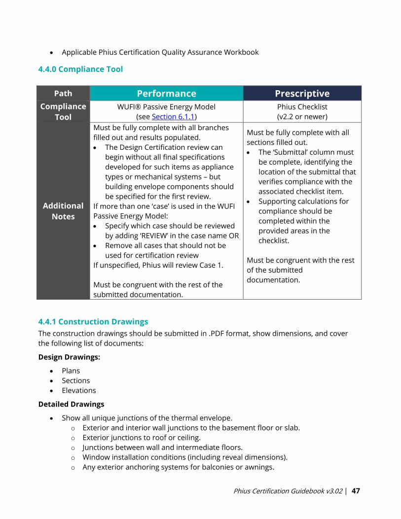
Phius Certification Guidebook v3.02 | 47
• Applicable Phius Certification Quality Assurance Workbook
4.4.0 Compliance Tool
Path Performance Prescriptive
Compliance
Tool
WUFI® Passive Energy Model
(see Section 6.1.1)
Phius Checklist
(v2.2 or newer)
Additional
Notes
Must be fully complete with all branches
filled out and results populated.
• The Design Certification review can
begin without all final specifications
developed for such items as appliance
types or mechanical systems – but
building envelope components should
be specified for the first review.
If more than one ‘case’ is used in the WUFI
Passive Energy Model:
• Specify which case should be reviewed
by adding ‘REVIEW’ in the case name OR
• Remove all cases that should not be
used for certification review
If unspecified, Phius will review Case 1.
Must be congruent with the rest of the
submitted documentation.
Must be fully complete with all
sections filled out.
• The ‘Submittal’ column must
be complete, identifying the
location of the submittal that
verifies compliance with the
associated checklist item.
• Supporting calculations for
compliance should be
completed within the
provided areas in the
checklist.
Must be congruent with the rest
of the submitted
documentation.
4.4.1 Construction Drawings
The construction drawings should be submitted in .PDF format, show dimensions, and cover
the following list of documents:
Design Drawings:
• Plans
• Sections
• Elevations
Detailed Drawings
• Show all unique junctions of the thermal envelope.
o Exterior and interior wall junctions to the basement floor or slab.
o Exterior junctions to roof or ceiling.
o Junctions between wall and intermediate floors.
o Window installation conditions (including reveal dimensions).
o Any exterior anchoring systems for balconies or awnings.
Phius Certification Guidebook v3.02 | 48
Airtight details
o Window installations
o Building component connections
o Penetrations
• All details must be fully annotated with dimensions and callouts for specific materials.
o e.g. call out insulation type rather than noting ‘rigid’ so the insulation type can be
matched with the insulation specifications provided, and thermal resistance can
be verified.
• Airtight details must be comprehensible and show a continuous uninterrupted barrier
that forms from the different materials and components at all junctions.
Thermal Envelope
• Must be clearly identified. Best accomplished using section or elevation drawings with
exterior dimensions
• Thermal bridges need to be called out and calculated when applicable.
o The PHIUS reviewer will look for continuous and consistent insulation in all details
and flag any details that need to be calculated.
o Submit both THERM files and psi-value calculation for any thermal bridge details
calculated.
Mechanical Drawings
Mechanical drawings need to show:
• Ventilation
o Duct layout and sizes
o Supply and extract airflow rates at each diffuser and the diffuser location
o Soundproofing, filters, pressure overflows
o Outdoor penetrations for exhaust and supply ducts
o Duct insulation thickness and type
o Supply and exhaust duct length from the inside of the exterior wall to the
ventilation unit
• Heating and Cooling
o Location of elements - both point source and supply air
o Size/capacity of elements
o For incentives Manual J/D calculations or dynamic simulation may become
necessary.
• DHW System
o Type of tank(s) and system
o Comprehensive length of the DHW pipe length calculation as described in the
energy modeling protocol section of this Guidebook (see Section 6.10.1).
• Additional systems (solar thermal, defroster, ground loop, earth tube, etc.)
Phius Certification Guidebook v3.02 | 49
4.4.1.1 Ventilation Calculations
• Gross Building Volume
o Total enclosed volume of the building.
o Uses exterior dimensions, to the edge of the thermal boundary to calculate.
• Net Volume
o The real interior building volume
o Total volume within the building envelope - drywall to drywall, floor to ceiling
o Same as ventilation volume.
4.4.1.2 Site Plan
Needs to show:
• The building’s orientation.
• Changes in topography (if applicable).
• The location and height of neighboring buildings or structures.
• The location and height of trees or ground levels that cast lateral shadows.
The site plan and site shading photos together must show the complete shading situation. If
necessary, other drawings should be included.
4.4.1.3 Site Shading
Phius requires a shading study on the project site. We will need sky-dome or sky-panorama
images for each façade, with overlaid measurement grids. Solar Pathfinder images are
preferred. However, other methods such as Solmetric are acceptable. No special programs
need to be purchased to analyze the Solar Pathfinder images. A free analyzer is included in the
Phius Shading Protocol Package, downloadable from the Calculators and Protocols page.
4.4.1.4 Interior Conditioned Floor Area (iCFA)
iCFA is the interior-dimension (drywall-to-drywall) projected floor area of the conditioned
spaces with at least seven feet ceiling height. It includes stairs, cabinets, interior walls,
mechanical spaces, storage, but excludes open-to-below.
More specifically:
• Include the floor area of interior spaces at least 7’ in height, measured from the interior
finished surfaces that comprise the thermal boundary of the building. Spaces that are
open-to-below shall not be counted. (The general concept is “walkable”).
• Other than open-to-below, the projected floor area of all spaces within this shall count
toward the iCFA measurement, including walls, cabinets, mechanical spaces, storage,
etc.
• Projected floor area of the stair treads counts toward iCFA on all floors, that is, once per
floor. (By the 7’ height rule, some floor area under the stairs on the 1st floor would be
excluded. This conflict is resolved by including it).
Phius Certification Guidebook v3.02 | 50
Naming Conventions
Phius has not dictated strict naming conventions. However, naming conventions should be
included for all windows and areas. These should be clearly labeled and easily understood by a
reviewer unfamiliar with the project. The best way to do this is to label the drawing and have
the labels in the drawings match the labels used in the Energy Model. There should be enough
overlap in the names such that each window and door can be positively identified. Often,
following a logical rotation (such as clockwise) is helpful. A copy of the drawing set that is
annotated specifically for Phius Certification is extremely helpful and preferred. All penetrations
should be listed.
Formats and Sizes
Phius does not dictate drawing scales though they should be large enough to be
comprehensive and readable. PDF is the preferred drawing file format. Phius respects the
intellectual property right you have for your details and drawings. This concern should not
inhibit the sending of drawings, specifications, or other documentation. Remember that
comprehension of a project by an outside party (Phius) is the goal. The easier it is to
understand a project the quicker and less costly the certification will be for all parties involved.
4.4.2 Technical Specifications
• Data sheets and performance specifications are necessary for all values input into the
energy model.
• Generally, these should be provided by the product manufacturer. For some
components and equipment, third party ratings are provided. More details on each
component/system found under Section 6: Energy Modeling Protocols.
• This should include documentation from third party agents including shading
calculations, appliance energy usage, earth tube efficiencies, and any other exteriorly
derived values.
• It is best to have this information available and formatted ahead of the Design
Certification process.
The following Sections: 4.4.3-4.4.8 must be submitted for final certification along with any
updates to Sections 4.4.1 and 4.4.2.
See Appendix E: Phius Certified Rater/Verifier Manual for full details.
4.4.3 Pressure Test Verification
• Must be performed by an approved Phius Certified Rater/Verifier.
• Must be a multipoint test of both pressurization and depressurization.
• The final result is the average of pressurization and depressurization.
• See Appendix F for test protocol details.
4.4.4 Ventilation Commissioning
Will be completed by an approved Phius Certified Rater/Verifier and should include the
following information:

Phius Certification Guidebook v3.02 | 51
• Description and location of the project.
• Name and address of the Rater/Verifier.
• Time and date of commissioning.
• Manufacturer and model number of ventilation unit.
• Adjusted volumetric flows per diffuser - both supply and exhaust.
• Flow comparison between supply and exhaust airstreams as measured between the unit
and the exterior, or the interior before any branch ducts (imbalance <10%).
• Power draw of the ventilation unit at nominal speed.
4.4.5 Declaration of the Construction Supervisor
• See Section 3.6.4 for an example.
4.4.6 Public Database Photographs
• 1 main photo, 6 additional for public project database.
• At least 3 photos of the final project.
• Exterior photos of each façade and surrounding site.
• Representative photos of the various insulated assemblies, window and door installs.
• Representative infrared photos, inside and outside.
• Documentation for the construction is also acceptable.
4.4.7 Additional Documentation
• Examples could be shading studies, extra calculations, system sizing, ground loop
calculations, etc.
• See Section 6.1.5.
4.4.8 QA/QC Reports
• Supplied by the Phius Certified Rater/Verifier, see Appendix E, Section 4.3 for more
details.
• Available to both the project submitter and Phius.
• Submitter is able to update energy model and documentation based on reports.
4.5 Phius Certification Feedback Document
The Phius Certification Feedback Document is one of the main channels of communication
between Phius and the project submitter. The document is used to track the design certification
progress and includes feedback on the energy model, the drawings submitted, and
specifications submitted. This document must be uploaded to your project’s designated
DropBox Folder for each round of review. When the submitter makes changes to the Phius
Certification Feedback Document, the updated energy model should also be uploaded.
Any external communication via email, phone call, etc. must be copied into this feedback form
so the project reviewer is aware.
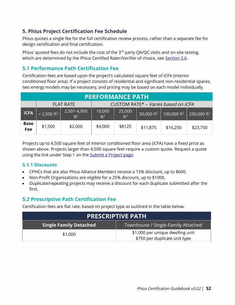
Phius Certification Guidebook v3.02 | 52
5. Phius Project Certification Fee Schedule
Phius quotes a single fee for the full certification review process, rather than a separate fee for
design certification and final certification.
Phius’ quoted fees do not include the cost of the 3rd party QA/QC visits and on-site testing,
which are determined by the Phius Certified Rater/Verifier of choice, see Section 3.6.
5.1 Performance Path Certification Fee
Certification fees are based upon the project’s calculated square feet of iCFA (interior
conditioned floor area). If a project consists of residential and significant non-residential spaces,
two energy models may be necessary, and pricing may be based on each model individually.
PERFORMANCE PATHFLAT RATE CUSTOM RATE* – Varies based on iCFA
iCFA < 2,500 ft2 2,501-4,500
ft2
10,000
ft2
25,000
ft2 50,000 ft2 100,000 ft2 250,000 ft2
Base
Fee $1,500 $2,000 $4,000 $8125 $11,875 $16,250 $23,750
Projects up to 4,500 square feet of interior conditioned floor area (iCFA) have a fixed price as
shown above. Projects larger than 4,500 square feet require a custom quote. Request a quote
using the link under Step 1 on the Submit a Project page.
5.1.1 Discounts
• CPHCs that are also Phius Alliance Members receive a 15% discount, up to $600.
• Non-Profit Organizations are eligible for a 25% discount, up to $1000.
• Duplicate/repeating projects may receive a discount for each duplicate submitted after the
first.
5.2 Prescriptive Path Certification Fee
Certification fees are flat rate, based on project type as outlined in the table below.
PRESCRIPTIVE PATH
Single Family Detached Townhouse / Single-Family Attached
$1,000 $1,000 per unique dwelling unit
$750 per duplicate unit type

Phius Certification Guidebook v3.02 | 53
5.3 Expedite Fees
An expedited review may be available for an additional 50% up-front cost on the base fee (i.e. a
3,500 ft2 home with a base fee of $2,000 would have an expedite fee of $1,000, totaling to
$3,000 for the full fee). See details in Section 4.1.1 Review Timeline.
5.4 Additional Consulting
Phius can provide additional services, such as opaque assembly hygrothermal analysis, thermal
bridge moisture risk analysis, thermal bridge calculations, red-flag reviews, and feasibility
studies. Performing this type of analysis is not included in the project certification fee and is
available for an additional fee as needed. Typical consulting rates are noted below, but specific
services may have different pricing.
Base Consulting Rate: $175/hr
Phius Alliance Member Consulting Rate: $150/hr
5.4.1 Red-Flag Review
Phius offers red-flag reviews to provide preliminary feedback on projects interested in Phius
Certification. This service is primarily geared towards project teams that have created a WUFI-
Passive energy model and are seeking high-level review of documentation available to get a
sense of if the project is on the right track to move forward with design. Feedback for red-flag
reviews is provided in an excel document that follows the same format as the typical Phius
Certification feedback form.
• Timeframe: Generally completed in two hours of review time and only cover high-level
information. Feedback is provided to the client within 5-10 business days of submission.
• Goal: Provide project teams with feedback related to the most important design
elements that may affect a project early in the design process.
• Review Items: Red-flag reviews concentrate on feedback related to the documentation
outlined below (if available).
o Climate, Phius space conditioning targets, building altitude, and building
orientation are reviewed.
o Foundation type is reviewed.
o Opaque assemblies
▪ Hygrothermal risk reviewed with Phius' prescriptive moisture
requirements.
o Transparent assemblies
▪ Comfort & Condensation risk reviewed with Phius' prescriptive
requirements.
o Thermal Bridges
▪ Potential thermal bridges are identified.
o Internal Loads / Occupancy
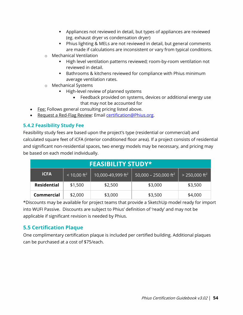
Phius Certification Guidebook v3.02 | 54
▪ Appliances not reviewed in detail, but types of appliances are reviewed
(eg. exhaust dryer vs condensation dryer)
▪ Phius lighting & MELs are not reviewed in detail, but general comments
are made if calculations are inconsistent or vary from typical conditions.
o Mechanical Ventilation
▪ High level ventilation patterns reviewed; room-by-room ventilation not
reviewed in detail.
▪ Bathrooms & kitchens reviewed for compliance with Phius minimum
average ventilation rates.
o Mechanical Systems
▪ High-level review of planned systems
• Feedback provided on systems, devices or additional energy use
that may not be accounted for
• Fee: Follows general consulting pricing listed above.
• Request a Red-Flag Review: Email [email protected].
5.4.2 Feasibility Study Fee
Feasibility study fees are based upon the project’s type (residential or commercial) and
calculated square feet of iCFA (interior conditioned floor area). If a project consists of residential
and significant non-residential spaces, two energy models may be necessary, and pricing may
be based on each model individually.
FEASIBILITY STUDY*
iCFA < 10,00 ft2 10,000-49,999 ft2 50,000 – 250,000 ft2 > 250,000 ft2
Residential $1,500 $2,500 $3,000 $3,500
Commercial $2,000 $3,000 $3,500 $4,000
*Discounts may be available for project teams that provide a SketchUp model ready for import
into WUFI Passive. Discounts are subject to Phius’ definition of ‘ready’ and may not be
applicable if significant revision is needed by Phius.
5.5 Certification Plaque
One complimentary certification plaque is included per certified building. Additional plaques
can be purchased at a cost of $75/each.
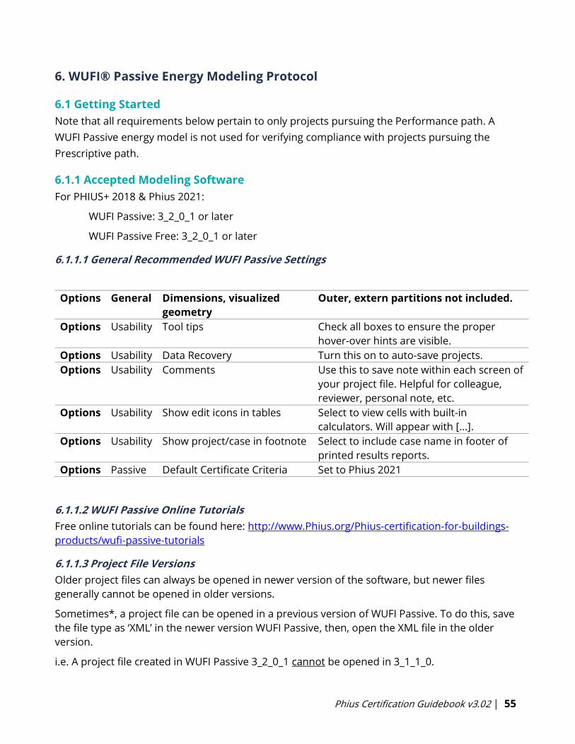
Phius Certification Guidebook v3.02 | 55
6. WUFI® Passive Energy Modeling Protocol
6.1 Getting Started
Note that all requirements below pertain to only projects pursuing the Performance path. A
WUFI Passive energy model is not used for verifying compliance with projects pursuing the
Prescriptive path.
6.1.1 Accepted Modeling Software
For PHIUS+ 2018 & Phius 2021:
WUFI Passive: 3_2_0_1 or later
WUFI Passive Free: 3_2_0_1 or later
6.1.1.1 General Recommended WUFI Passive Settings
Options General Dimensions, visualized
geometry
Outer, extern partitions not included.
Options Usability Tool tips Check all boxes to ensure the proper
hover-over hints are visible.
Options Usability Data Recovery Turn this on to auto-save projects.
Options Usability Comments Use this to save note within each screen of
your project file. Helpful for colleague,
reviewer, personal note, etc.
Options Usability Show edit icons in tables Select to view cells with built-in
calculators. Will appear with […].
Options Usability Show project/case in footnote Select to include case name in footer of
printed results reports.
Options Passive Default Certificate Criteria Set to Phius 2021
6.1.1.2 WUFI Passive Online Tutorials
Free online tutorials can be found here: http://www.Phius.org/Phius-certification-for-buildings-
products/wufi-passive-tutorials
6.1.1.3 Project File Versions
Older project files can always be opened in newer version of the software, but newer files
generally cannot be opened in older versions.
Sometimes*, a project file can be opened in a previous version of WUFI Passive. To do this, save
the file type as ‘XML’ in the newer version WUFI Passive, then, open the XML file in the older
version.
i.e. A project file created in WUFI Passive 3_2_0_1 cannot be opened in 3_1_1_0.
Phius Certification Guidebook v3.02 | 56
A project file created in WUFI Passive 3_1_1_0 can be opened in 3_2_0_1.
*It is not guaranteed that files created in “intermediate” or test versions of WUFI Passive can be
opened in future release versions.
6.1.1.4 Dynamic modeling in WUFIplus
Though not required for certification, consider also doing dynamic modeling (WUFI Plus) when:
• Cooling and/or moisture loads are high.
• Heating is discontinuous (during the heating period).
• Occupancy and indoor conditions vary considerably.
• Comfort and overheating should be assessed.
If dynamic modeling seems called for, Phius suggests running a 3-zone dynamic model as a
comfort analysis using WUFI Plus (WUFI Passive dynamic side), or another dynamic energy
model. The 3 zones would be coldest room, warmest room, rest-of-building. There are two
possible approaches – one is to set the heating and cooling system capacities very high and
look for the per-square-foot differences in the heating and cooling loads among the zones. The
other is to limit the system capacities and look for failure to maintain the desired interior
temperature set-points.
6.1.2 Climate Data
• Must be approved by Phius for each project.
• It is important to choose the correct dataset, especially given that a project’s space-
conditioning performance targets vary by location.
• Phius has generated 1000+ climate datasets for locations around the United States; they
are available as individual XML database import files for each state, as well as a single
XML file for the entire United States. These datasets are available free to Phius Alliance
members and can be downloaded from the Phius Alliance Member Resources page.
• A custom data set is required for a project location when the closest existing data set is
more than 50 linear miles and >400’ different in elevation from the project location.
o Project locations even within the parameters above might benefit from custom
climate data.
o Please refer to the Phius blog posts “Climate Data – When to Request a Custom
Dataset” and “Climate Data and PHIUS+ 2015" for more information.
o The cost of a custom climate data set is $75 and may be purchased here:
http://www.Phius.org/software-resources/wufi-passive-and-other-modeling-
tools/climate-data-sets
• If project is within 50 linear miles and within 400 feet difference in elevation of an
existing climate data set, you must use the Phius space conditioning targets associated
with the existing data set. However, you can order custom climate data if you would like
to.
Phius Certification Guidebook v3.02 | 57
6.1.3 Energy Model Defaults
The accepted software versions agree on default input values for several input parameters.
Unless otherwise noted below, these values should be used in the energy model for
certification. These values (and the way they are calculated) may be updated in the future to
coincide with research and best practices.
6.1.4 Energy Model Inputs Requiring Additional Documentation
• Ground Thermal Resistivity > 0.1 hr.ft2.F/BTU.in.
• Window frame-to-wall psi value < 0.015 BTU/hr.ft.F
• Subsoil heat exchanger efficiency > 60%.
• Air change rate for window ventilation; see Section 6.7.3.
• Solar fraction for hot water – expert/specialist calculation recommended if greater than
65% estimated to be covered by solar in WUFI Passive model.
6.1.5 External Calculators & Protocol Documents
Many external calculation methods and protocol documents are developed as new modeling
situations arise. Eventually, these calculation methods and protocol are built in or implemented
into the WUFI Passive energy modeling tool. External calculators may be used in the interim.
• Always download the latest version of the protocol documents on the Calculators &
Protocols page.
6.1.6 WUFI Passive Cases
WUFI Passive allows for quick creation of multiple ‘cases’ within a single project file. Cases are
generally created by duplicating a previous case. This can be used to compare alternate designs
and provides direct result comparison. Cases can contain varying geometry, and a new
geometry file can be imported into a duplicate case.
For Mixed-Use projects, it is helpful to import the whole building as two zones (residential and
non-residential). Then, one case can cover the residential portion as the ‘active’ or ‘simulated
zone’, and the second case can cover the non-residential portion as the ‘simulated zone’. This
keeps the entire building in one WUFI Passive model.
6.1.7 Using SketchUp with WUFI Passive
For guidance, tips and tricks on using WUFI Passive in tandem with SketchUp and for other
general modeling guidance review the Guidelines for using Sketchup with WUFI Passive here.
6.2 Localization/Climate
Selecting a Climate Data Set - See Section 6.1.2.
Download and save a Phius Climate File or Phius Climate XML Database - See Section 6.1.2.
6.2.1 Localization
To Upload a Phius Climate File into WUFI Passive

Phius Certification Guidebook v3.02 | 58
Select “User Defined” from the dropdown list, click the “Browse” button, and search for the
saved climate file. Change the file type in the bottom right hand corner to “Excel (.xls)” if need
be. Or, complete a one-time download of the climate database XML file to your WUFI Passive
database. This can be done by selecting “Database”, then selecting the drop down menu to
“Import from XML File”. These files are also available on the Phius Alliance Member Resources
page. After this import, you will be able to browse your WUFI Passive database to select a
climate dataset for your new project.
*Please note climate data import is not available in the free version of WUFI Passive; in this
version the climate data must be input manually. See guidance below, Section 6.2.1.1.
About the Design Temperatures in the Climate Data
A super-insulated structure responds more slowly to outside conditions, so the peak loads are
moderated. The static mode calculation does also assume a slightly wider comfort range on the
inside, 68-77 F instead of for example the Building America default 71-76 F, and similarly, the
reason for this is that the inside surface temperatures should be more stable, so the air
temperature can vary a bit more and still be comfortable, because the radiant temperature of
the surfaces varies less.
We recommend against taking the passive mode design temperatures and using them in an
ACCA manual J calculation, but rather run each method on its own terms and compare the
bottom line Btu/h results.
Altitude Building: The altitude of the project site must be input. Site altitude may be verified
using Google Earth.
Phius recommends locating the project site on Google Earth, placing a ‘marker’ on the site at
ground level, and providing a screenshot verifying site altitude. This should be uploaded in the
Site Plan/Shading folder.
Time Zone: This entry is required for the dynamic shading calculation. Use standard time, not
daylight.
• Eastern Standard Time: UTC -5
• Central Standard Time: UTC -6
• Mountain Standard Time: UTC -7
• Pacific Standard Time: UTC -8
• Alaskan Standard Time: UTC -9
Ground Thermal Conductivity: In heating dominated climates, this value may not be lower
than 0.833 (BTU/hr.ft.F), and should usually be left at the default of 1.1558 (BTU/hr.ft2.F).
For thermal resistance, this is equivalent to no more than 0.1 R/in (hr.ft2.F/BTU.in).
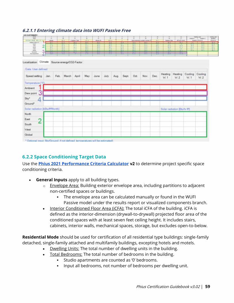
Phius Certification Guidebook v3.02 | 59
6.2.1.1 Entering climate data into WUFI Passive Free
6.2.2 Space Conditioning Target Data
Use the Phius 2021 Performance Criteria Calculator v2 to determine project specific space
conditioning criteria.
• General Inputs apply to all building types.
o Envelope Area: Building exterior envelope area, including partitions to adjacent
non-certified spaces or buildings.
▪ The envelope area can be calculated manually or found in the WUFI
Passive model under the results report or visualized components branch.
• Interior Conditioned Floor Area (iCFA): The total iCFA of the building. iCFA is
defined as the interior-dimension (drywall-to-drywall) projected floor area of the
conditioned spaces with at least seven feet ceiling height. It includes stairs,
cabinets, interior walls, mechanical spaces, storage, but excludes open-to-below.
Residential Mode should be used for certification of all residential type buildings: single-family
detached, single-family attached and multifamily buildings, excepting hotels and motels.
• Dwelling Units: The total number of dwelling units in the building.
• Total Bedrooms: The total number of bedrooms in the building.
▪ Studio apartments are counted as ‘0’ bedrooms.
▪ Input all bedrooms, not number of bedrooms per dwelling unit.
Phius Certification Guidebook v3.02 | 60
Non-Residential Mode should be used for certification of all non-residential building types.
• Design Occupancy: Maximum occupancy of the building.
• Custom Optimization: For unique non-residential buildings with very high
internal loads, ventilation loads, or highly variable occupancy, custom
optimization may be needed to determine the appropriate targets. This will be
done on a case-by-case basis. An additional certification fee will apply.
Mixed-Use building types currently require two separate calculations to represent different
use types.
6.2.3 Source Energy/CO2-Factor
Source Energy Factor for Grid Electricity
Use the national average value for certification, regardless of regional differences.
• USA: 1.822
• Canada: 1.96
• Japan: 2.77
This policy forestalls the tendency for “rebound effect” - of building designers taking advantage
of locally “cleaner” grids to use more energy, and instead, in effect, shares that benefit with
designers in “dirty grid” regions. This is consistent with the idea that with the current fossil-
dominated primary fuel mix, energy impact translates into atmosphere impact.
6.3 PH Case
6.3.1 PH Case - General
The interior temperature thresholds for Phius Certification are 68F and 77F. Please contact
Phius if the program of the project requires a different temperature set point.
Indoor Temperature defined on this tab is the ‘heating setpoint’, 68F should be used.
6.3.1.1 Occupancy and Internal Heat Gains
For residential projects, model occupancy as the # of bedrooms + 1. This is per unit if there are
multiple units.
A bedroom is defined as per RESNET: [6]
A room or space 70 square feet or greater, with egress window and closet, used or
intended to be used for sleeping. A "den." "library," "home office" with a closet, egress
window, and 70 square feet or greater or other similar rooms shall count as a bedroom,
but living rooms and foyers shall not.
22 This value is reflecting a 2050 outlook, see Appendix I-2.1.
Phius Certification Guidebook v3.02 | 61
Exception: For dormitory buildings, occupancy is determined by the number of beds. Where
number of beds is equivalent to the number of occupants.
Internal heat gains are set “calculated”, rather than using a default value by building type.
6.3.1.2 Non-permanent occupants in multifamily buildings: Visitors and Workers
Source Energy Allowance:
Workers: Non-Resident workers such as office workers, senior/medical service workers, etc. will
add to the planned occupancy load of the building. Schedules and number of workers should
be summed and equated to full time occupants. For example, 3 workers that work 8 hours/day
each can equate to 1 full time occupant. The number of equivalent full-time workers can be
added to the residential occupancy and given the residential source energy allowance per
person.
Visitors: If the building includes designated spaces that serve the residents as well as outside
visitors, the commercial building source energy allowance per square foot should be applied to
those spaces.
Internal Heat Gains + Energy Use:
Workers: By adding full time equivalent occupancy for workers into the total occupancy count,
internal heat gains and other energy use is appropriately accounted for with no additional
input.
Visitors: Depending on the nature of the typical visits (games, dinner, etc), the appropriate
energy use of the visitors should be estimated and documented for design certification review
6.3.1.3 Number of Units and Floors
Number of Units: This is used to calculate the reference quantity for refrigerator and freezer
entries, as well as calculating the DHW tap openings per year.
Residential: The total number of residential units should be used. At minimum, a ‘unit’ includes
a kitchen, bedroom/living space, and bathroom.
Non-Residential: Enter 1.
Number of floors: The number of floors should be entered. This is used to determine:
1. Air-tightness allowance adjustment, if applicable.
2. Number of floors to be used for the DHW distribution losses when using ‘floor method’.
6.3.2 PH Case - Additional Data
Overheating temperature threshold: This entry is the cooling setpoint. For most cases, 77F
should be used for certification.
Fresh Air Per Person: 18 cfm for residential, 9-12 cfm for school and daycare, 35 cfm for sports
halls.

Phius Certification Guidebook v3.02 | 62
Hot water tap-openings per person per day: Defines how many times each DHW tap is opened
per person, per day. Used to calculate DHW distribution losses only when using ‘Simplified
Individual pipes’ method for DHW individual pipes.
Residential: This entry will not apply for Phius 2021 projects. DHW Distribution
calculation method cannot be ‘Simplified Individual pipes’ for design certification.
Non-Residential: A user defined value may be input here based on total occupants
assumed on an average day in the building, the total number of tap openings, and
Infiltration/Airtightness: Per Section 3.1.3
For buildings of five stories and above that are also of noncombustible construction:
q50 <= 0.080 CFM50/ft2 of gross envelope area
For all other buildings:
q50 <= 0.060 CFM50/ft2 of gross envelope area
Gross envelope is measured at the exterior of the thermal boundary, the same as for the
energy model, and includes surfaces in contact with the ground.
Envelope airtightness at 50 Pa: Phius recommends entering the maximum limit for the building
here. A lower value may be used to meet space conditioning targets, but the designer must
acknowledge that the lower value must be met in the field for the project to pass at final
certification.
Note: For some large buildings with elements that are considered non-threatening leakage
(Review Appendix F-2), modeling with a higher airtightness value than the durability
requirement noted above may be beneficial to ensure that the project passes the space-
conditioning and source energy requirements with the un-taped blower door test value.
Non-Combustible Materials: Check this box if the building is of non-combustible construction. If
this box is checked, and the building is 5 stories or greater (input on PH Case>General), the
‘target’ air-tightness will be adjusted in the model and report.
Example project conversion from cfm50/ft2 to ACH50:
Total envelope area = 6,958 ft2 & Net volume = 19,387 ft3
6,958 ft2 * (0.05 ft3/min)/ft2) * (60 min/hr.) * (1/19,387 ft3) = 1.08 ACH50
Maximum Humidity Ratio (if dehumidification is planned)
The default value of 0.012 lbw/lba should not be changed for Phius Certification. It is the upper
limit for humidity levels according to the comfort standard ASHRAE 55-2004. This is essentially a
humidity set-point. At 77 F this value corresponds to approximately 60% relative humidity.
Domestic Hot Water Use Per Person
• Residential: 6.6 gal/person/day
o Default is used for residential certification regardless of entry in WUFI Passive.
Phius Certification Guidebook v3.02 | 63
• Non-residential: 3.2 gal/person/day
o The default above will not fit for all non-residential projects. The entry may vary
from the default if supporting documentation/calculation is provided and
approved by Phius.
This input pertains to showers, hand-washing, and shaving. Laundry and dishwashing is
separate from that, and calculated with the appliance entries. If there is no dishwasher,
consider adding extra gallons to this daily value.
Remember, these are “hot gallons” (140 F). It calculates the energy to raise the water from the
incoming water temperature (default 50 F) to 140 F, a 90 F rise. When mixed down to a
temperature a person would want to shower under, it goes almost twice as far in terms of
volume.
Cold Water Supply/Incoming Temperature
If this input is left blank in WUFI Passive, it will calculate using an average annual ground
temperature.
A user defined entry may be used if supporting documentation is submitted to confirm the
new groundwater temperature. The adjusted groundwater temperature generally should not
exceed the average ambient air temperature for the project’s climate.
Mechanical Room Temperature
The default value here is 68F. If the mechanical ventilation device (ERV or HRV) is located within
the thermal envelope, this default should remain. If the ERV or HRV is located outside of the
thermal envelope (eg. the roof), this value should be calculated use the ‘ERV_HRV Outside’
calculator which can be downloaded from the Calculators & Protocols page.
6.3.3 PH Case - Foundation Interface
Up to 3 different foundation interface connections can be defined. These determine reduction
factors to be applied to components with ‘Ground’ assigned on the Outer Side.
Floor Slab / Floor Ceiling Area
For heated basements, only include the interior floor area. For all other ground conditions,
include the entire floor area calculated to the exterior of the thermal boundary.
Floor Slab Perimeter
For heated basements, only include the interior perimeter. For all other ground conditions,
include the entire (exterior-adjacent portion of the) floor slab perimeter measured at the
exterior of the thermal boundary.
Phius Certification Guidebook v3.02 | 64
6.4 Zone 1
6.4.1 Visualized Volume
This value is not used for the “Passive House Verification” calculation; it refers to the volume of
the visualized 3D model. This will be equal to the gross volume in most cases (when the model
is drawn to the exterior dimensions).
6.4.2 Gross Volume
This volume represents the volume of the building measured from the exterior boundary of the
thermal envelope. Generally, this is the same as the visualized volume. However, if objects are
included in the 3D geometry that are not part of the thermal boundary, for shading, etc., the
visualized volume may not represent the gross volume. In this case, the gross volume should be
calculated.
6.4.3 Net Volume
To determine the net volume, calculate the home’s interior volume (drywall to drywall floor to
ceiling, wall to wall) minus volume taken up by interior walls and floor systems. A calculation
must be submitted for certification.
6.4.4 Interior Conditioned Floor Area (iCFA)
The reference floor area. The space conditioning criteria (heating and cooling annual demands
and peak loads) are per square foot of iCFA. See Section 4.4.1.4 for the definition of iCFA.
6.4.5 Specific Heat Capacity/Thermal Mass
Regarding thermal mass, it is not just the total mass that matters but the distribution, so that it
can interact with the infrared radiation bouncing around the room. The way of figuring this is
based on the number of heavy surfaces (0 to six) per room, in an average sense. For example, a
two-story building with a first-floor concrete slab would have 1/2 of a heavy surface per room
on average.
Thermal mass is determined by the equation = [60+n(heavy)*24]*0.176 (BTU/ft2.F).
Guidelines for Accounting Heavy Surfaces
• Drywall = 0 heavy surfaces - (first ½” included in the baseline)
• 5/8" drywall = 0.34 heavy surfaces
• Double or high-density drywall = 0.5 heavy surfaces
• Two-inch-thick concrete or more, phase-change materials = 1 heavy surface
• Flagstone/tile = 0.5 heavy surfaces
o Example:
Concrete floor = 1 heavy surface
Other 5 surfaces = 0.34 each = 1.7 heavy surfaces
Phius Certification Guidebook v3.02 | 65
Total n (heavy surfaces) = 2.7
Specific capacity = (60+2.7*24) *0.176 = 21.96 BTU/ft2F
6.5 Visualized Components
6.5.1 Wall Components
Framing
Framing must be included. For walls, vertical and horizontal framing must be included. Typical
assemblies are built out in 3D.
For wall assemblies with exterior continuous insulation, actual spacing of vertical framing
should be used to define the ‘width’ of the typical assembly created, i.e. 16” o.c., and framing
added in as horizontal subdivisions.
For wall assemblies with no exterior continuous insulation, framing factors of 25% should be
used for 16” o.c. and 15% may be used for advanced framing (24” o.c.”).
The ‘height’ of the assembly created should be defined by a typical floor to floor height. The top
and bottom plates must be added into the assembly as vertical subdivisions.
Insulation Specifications
Some insulation is temperature-dependent; use the R-value at 75 F for the energy model. Some
insulation is thickness-dependent; use the R-value at the appropriate thickness for the
assembly.
In WUFI Passive, please note that default conductivity values are used from the existing
database.
• Conductivity or thermal resistance values should be updated in the project file to match
the insulation specification.
• This can be done under the Edit Assembly screen by clicking into the “Conductivity”
input, for the specific assembly layer, selecting the [R/in] button, and inputting the
accurate R per inch.
Surface / Radiation Balances / Solar Absorption/Emission
The radiation balances need to be input for every opaque surface above grade. This includes
values for: emissivity, absorptivity, and shading. Rough values are acceptable.
6.5.2 Window Components
Phius has verified data for a number of windows and manufacturers; these are listed on the
Find & Compare Windows page of the Phius website.
If the project is using windows included in the Phius Verified Data for Window Performance
Program, Phius’ data must be used.

Phius Certification Guidebook v3.02 | 66
Window Components in 3D visualization: In the energy model, each individual ‘lite’ or individual
‘piece of glazing’ should be its own clickable component. This ensures that the proper solar gain
and frame to glazing ratio is accounted for.
Window Groups in 3D visualization: In WUFI Passive, windows may be grouped/ungrouped and
through the 'Assign Data' option given common properties.
• To add 'Basic Data' and 'Frame Data' and ‘reveal’ shading, they can be grouped by
"Window Type".
• To add 'General Parameters' for site shading (fractions of solar exposure), you could
group them by 'orientation' or by 'floor level'.
• WUFI Mean Monthly shading factors are calculated per window, regardless of grouping.
Window Sizes: The windows are entered into the building energy model in their actual size and
configuration (every lite), with the performance of the framing members and the glass broken
out separately (as opposed to using whole-window properties at a standard size.)
Window Performance Entries: Specification data is needed for:
• Center-of-glass (cog) U-value
• Solar Heat Gain Coefficient (SHGC) (cog)
• Frame width
• Frame U-value
• Linear heat loss coefficient at the edge of the glass (“psi-spacer”)
Phius’ window program calculates all these. But the project certification program is flexible as
to the source of that data, that is, it is not “hostage” to the window rating program. Usually,
center-of-glass properties can be obtained from the glazing system manufacturer. For the
frame, rating data per CEN standards or NFRC's CMAST can be used, or a conservative default
based on frame material type can be used. The linear coefficient at the edge is the hardest to
come by, but a conservative default can be used for that (0.023 BTU/hr.ft.F). Similarly, a default
value can be used for the linear heat loss coefficient at the outer edge of the frame (“psi-
install”).
Psi-Installation / Frame-to-wall psi-value
The frame-to-wall psi-installation value is dependent on how the window is installed within the
wall. Please do not use values from manufacturers’ data sheets unless they have completed a
project specific calculation for you.
• A default value of 0.030 BTU/hr.ft.F can be used for most installation details.
• Improved detailed can use the values below:
o As low as 0.020 (Btu/hr.ft.F) for a mid-wall mounted window that is not

Phius Certification Guidebook v3.02 | 67
over-insulated.
o As low as 0.015 (Btu/hr.ft.F) for a mid-wall mounted window that is over-
insulated.
• If a THERM calculation is provided, psi-installation values below these thresholds
are acceptable.
6.5.3 Solar Protection/Shading
6.5.3.1 Reveal Shading
Often windows are not installed flush with the exterior of the building façade which causes
reveal shading to the left and right sides of the window from the window in-set in the wall.
• Depth of window reveal: Measured from the outside of the leading shading edge to the
glazing.
• Distance from edge of glazing to reveal: Measured from the edge of glazing to the
shading edge.
Reveal shading must be input for all windows.
• In WUFI Passive, this can be done quickly with the [Assign Data] function.
o The 3D geometry will visualize the window in-set into the wall when entries
are adjusted.
• All reveal entries are calculated as if on both sides of the window.
o If the reveal depths are significantly different on the left and right, due to a
vertical shading fin or similar, it is recommended that the irregular shading
device is drawn into the 3D geometry rather than input numerically.
o See ‘Shading due to building geometry’ below.
Phius Certification Guidebook v3.02 | 68
6.5.3.2 Shading Devices
Sunscreen/shading devices in WUFI Passive are assumed to be used only during the cooling
season. If year-round blinds are used, please input as an “other shading fraction of solar
exposure”.
External blinds offer better thermal protection than internal blinds because the solar radiation
is partially absorbed by the fabric before reaching the glazing and reflected outwards.
The effectiveness of window blinds needs to be de-rated if they are manually operated, to
account for occupant behavior. Phius has created the ‘Blinds’ calculator located on the
Calculators & Protocols page that follows the deration method noted in Appendix N-8.
Blind Ratings: Should be provided by manufacturers. Solar transmittance is used in the
equations above. Solar radiation is always partially transmitted through, absorbed, or reflected
by the fabric.
Ts = Solar Transmittance – Proportion of solar energy transmitted through the fabric.
Low percentage means the fabric performs well at reducing solar energy.
Rs = Solar Reflectance – Proportion of solar radiation reflected by the fabric.
High percentage means the fabric performs well at reflecting solar energy.
As = Solar Absorptance – Proportion of solar radiation absorbed by the fabric.
Low percentage means the fabric absorbs little solar energy.
Ts + Rs + As = 100% of solar energy
OF = Openness Factor - Percentage of blind fabric/material that is open (between the
threads)
Insulated Interior Blinds
Unless the blind is air sealed to the window opening and is airtight, much of the insulating value
of the blind can be bypassed. Because of this, we are giving credit for essentially, the R-value of
the two air films on either side of the blind and not the blind itself. We generally round this to R-
2 in IP units. We also assume that user behavior impacts the use of the blinds and that
somewhere around half the time, the blinds are not in the right spot, or are removed.
Therefore, we currently allow an R-1 adjustment to be made directly to the glass R-value and
the Frame R-value. One word of caution is that if they do work as intended/advertised, there is
a significant risk of condensation on the window in cold climates, which over time could lead to
problems and durability issues. This must be checked and managed.
6.5.3.3 Overhangs
Overhangs may be included in the 3D geometry or entered numerically into WUFI Passive.
If including in 3D geometry, angled or complex overhangs may be modeled.
If entering numerically, an overhang parallel to the window head will be simulated. Three
parameters must be defined:
• Depth of overhang: Measured horizontally out from the glazing to the shading
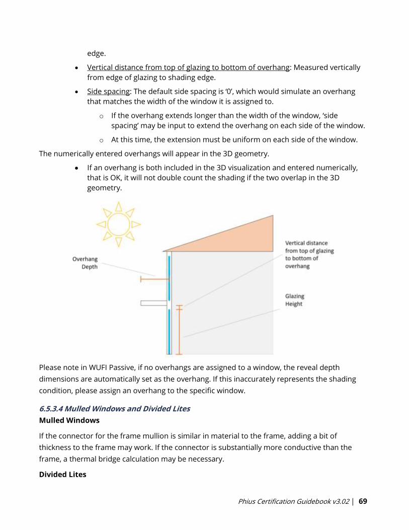
Phius Certification Guidebook v3.02 | 69
edge.
• Vertical distance from top of glazing to bottom of overhang: Measured vertically
from edge of glazing to shading edge.
• Side spacing: The default side spacing is ‘0’, which would simulate an overhang
that matches the width of the window it is assigned to.
o If the overhang extends longer than the width of the window, ‘side
spacing’ may be input to extend the overhang on each side of the window.
o At this time, the extension must be uniform on each side of the window.
The numerically entered overhangs will appear in the 3D geometry.
• If an overhang is both included in the 3D visualization and entered numerically,
that is OK, it will not double count the shading if the two overlap in the 3D
geometry.
Please note in WUFI Passive, if no overhangs are assigned to a window, the reveal depth
dimensions are automatically set as the overhang. If this inaccurately represents the shading
condition, please assign an overhang to the specific window.
6.5.3.4 Mulled Windows and Divided Lites
Mulled Windows
If the connector for the frame mullion is similar in material to the frame, adding a bit of
thickness to the frame may work. If the connector is substantially more conductive than the
frame, a thermal bridge calculation may be necessary.
Divided Lites
Phius Certification Guidebook v3.02 | 70
There are some different ways to deal with true divided lites that bridge the gas cavity. The
SHGC could be adjusted to account for the blocked light, and linear thermal bridges added to
account for the extra conduction loss.
Simulated Divided Lites
If these are a kind of divided lites such that the gas cavity is not actually bridged, we will still
reduce the SHGC, but no additional thermal bridging need be accounted for.
6.5.3.5 WUFI Mean Month Shading Factors
Shading due to building geometry
Shading from building geometry such as overhangs, bump-outs, complicated geometry,
surrounding buildings etc. will be considered.
• Any elements that should be considered for shading can be included in the 3D
geometry imported into WUFI Passive. This includes overhangs, surrounding
buildings, etc.
• These elements should be assigned as ‘opaque’ and ‘Outer Air’ should be
assigned on both the Inner Side and Outer Side of the components.
• The ‘Calculate WUFI shading’ button should be used.
• If an entry changes that affects the shading calculation, a warning will appear
stating “Shading factors are not up-to-date…”. When this appears, the shading
calculation must be re-run.
• Monthly shading factors are calculated and shown on the ‘WUFI Mean Month
Shading Factors’ tab.
• Correction/reduction factor per month can be applied in the row above the
results, or
• Default correction factor input can be used to apply a uniform reduction
factor for all months.
• Results are calculated per window, even when windows are grouped.
• Note: Unique shading properties such as reveals, numerically entered
overhangs, blinds, etc. will not be retained per window if grouping and
ungrouping. When windows are grouped, they are given uniform numerical
entries based on the first window selected when grouping.
• More information can be found in this presentation from NAPHC2018.
6.6 Internal Loads/Occupancy
6.6.1 Residential
Occupant Quantity: See Section 6.3.1.
Number of Bedrooms: Based on the total number of bedrooms in the building.
Phius Certification Guidebook v3.02 | 71
Humidity Sources:
Internal sources due to respiration or evaporation. Default value of 0.00041 [lb/(ft2hr)].
Per ASHRAE standard 160, clause 4.3.2.1.1, if there is a jetted [whirlpool] tub installed in a room
without an automatically controlled (e.g. humidistat) exhaust fan, it would be appropriate to
add 1.3 liters/day or 0.12 lb/h to the moisture generation rate.
6.6.1.1 Calculation Methods
The energy use for most appliances is proportionate to the number of occupants. This holds
true for dishwashers, clothes washers, dryers, and cooktops.
o Generally, do not adjust the quantity of these appliances.
o Default: If only 1 zone in the project, select “PH Case Occupants” as the “Reference
Quantity”.
o If multiple zones in the project, select “Zone Occupants” as the “Reference Quantity”.
For refrigerators and freezers, consumption is not dependent on occupancy, it is proportional
to the number of devices.
o Default: Select “PH Case Units” as the “Reference Quantity”.
o The quantity may be adjusted as needed.
6.6.1.2 Devices/Appliances
Pre-defined devices are built into the software. Choose ‘Set Standard Dataset’ to insert one of
each typical appliance. If a garage is present, this should be added by choosing ‘New’ and
selecting ‘PHIUS+ Garage lighting’.
Below is a list of typical devices. Median Energy Star (ES) values as of 2021 are listed for each
device. This may be used for projects early in design, or in some cases for design certification
until the appliance is selected.
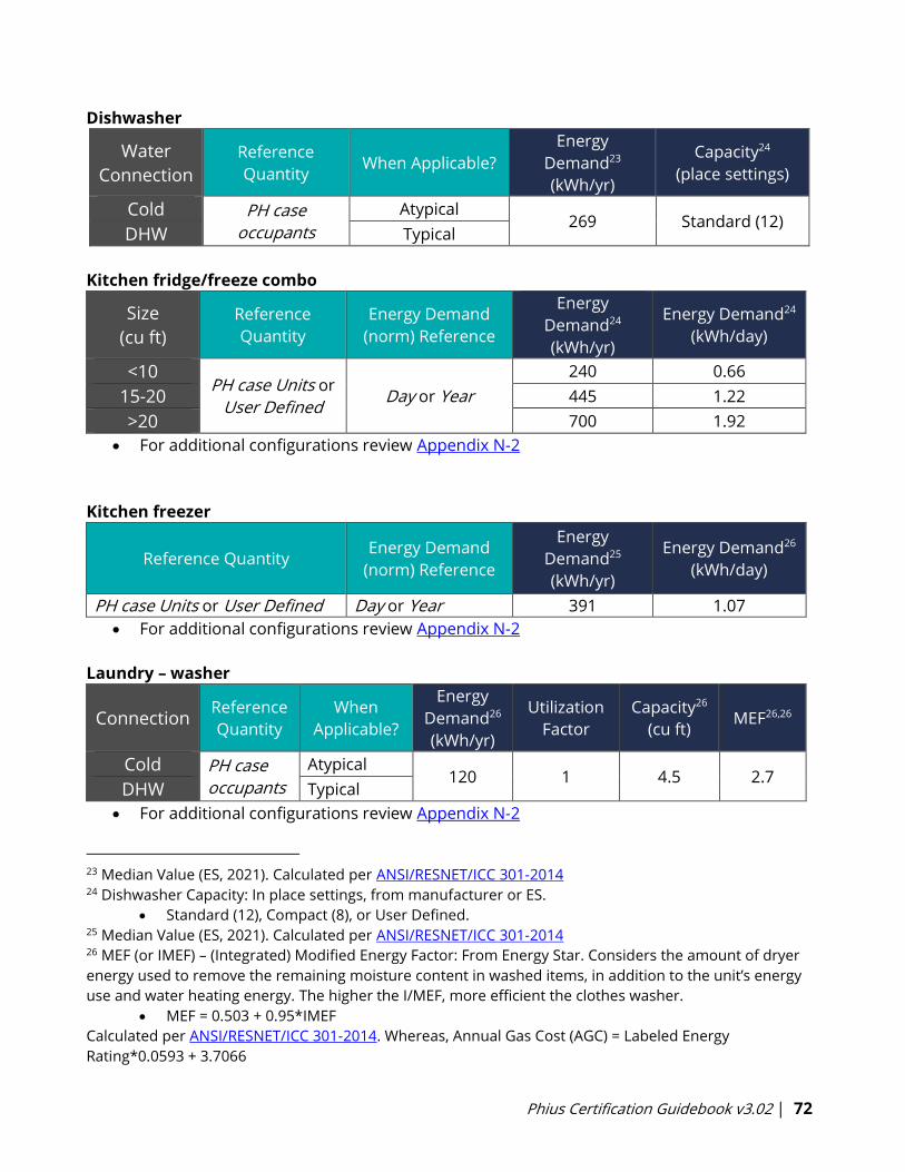
Phius Certification Guidebook v3.02 | 72
Dishwasher
Water
Connection
Reference
Quantity When Applicable?
Energy
Demand23
(kWh/yr)
Capacity24
(place settings)
Cold PH case
occupants
Atypical 269 Standard (12)
DHW Typical
Kitchen fridge/freeze combo
Size
(cu ft)
Reference
Quantity
Energy Demand
(norm) Reference
Energy
Demand24
(kWh/yr)
Energy Demand24
(kWh/day)
<10 PH case Units or
User Defined Day or Year
240 0.66
15-20 445 1.22
>20 700 1.92
• For additional configurations review Appendix N-2
Kitchen freezer
Reference Quantity Energy Demand
(norm) Reference
Energy
Demand25
(kWh/yr)
Energy Demand26
(kWh/day)
PH case Units or User Defined Day or Year 391 1.07
• For additional configurations review Appendix N-2
Laundry – washer
Connection Reference
Quantity
When
Applicable?
Energy
Demand26
(kWh/yr)
Utilization
Factor
Capacity26
(cu ft) MEF26,26
Cold PH case
occupants
Atypical 120 1 4.5 2.7
DHW Typical
• For additional configurations review Appendix N-2
23 Median Value (ES, 2021). Calculated per ANSI/RESNET/ICC 301-2014 24 Dishwasher Capacity: In place settings, from manufacturer or ES.
• Standard (12), Compact (8), or User Defined.25 Median Value (ES, 2021). Calculated per ANSI/RESNET/ICC 301-2014 26 MEF (or IMEF) – (Integrated) Modified Energy Factor: From Energy Star. Considers the amount of dryer
energy used to remove the remaining moisture content in washed items, in addition to the unit’s energy
use and water heating energy. The higher the I/MEF, more efficient the clothes washer.
• MEF = 0.503 + 0.95*IMEF
Calculated per ANSI/RESNET/ICC 301-2014. Whereas, Annual Gas Cost (AGC) = Labeled Energy
Rating*0.0593 + 3.7066
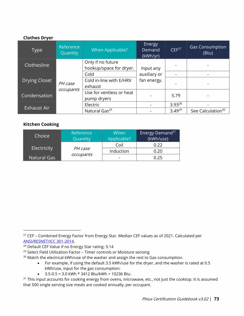
Phius Certification Guidebook v3.02 | 73
Clothes Dryer
Type Reference
Quantity When Applicable?
Energy
Demand
(kWh/yr)
CEF27 Gas Consumption
(Btu)
Clothesline
PH case
occupants
Only if no future
hookup/space for dryer. Input any
auxiliary or
fan energy.
- -
Drying Closet
Cold - -
Cold in-line with E/HRV
exhaust - -
Condensation Use for ventless or heat
pump dryers - 5.79 -
Exhaust Air Electric - 3.9328 -
Natural Gas29 - 3.4929 See Calculation30
Kitchen Cooking
Choice Reference
Quantity
When
Applicable?
Energy Demand31
(kWh/use)
Electricity PH case
occupants
Coil 0.22
Induction 0.20
Natural Gas - 0.25
27 CEF – Combined Energy Factor from Energy Star. Median CEF values as of 2021. Calculated per
ANSI/RESNET/ICC 301-2014. 28 Default CEF Value if no Energy Star rating: 3.14 29 Select Field Utilization Factor – Timer controls or Moisture sensing 30 Match the electrical kWh/use of the washer and assign the rest to Gas consumption.
• For example, if using the default 3.5 kWh/use for the dryer, and the washer is rated at 0.5
kWh/use, input for the gas consumption:
• 3.5-0.5 = 3.0 kWh * 3412 Btu/kWh = 10236 Btu.31 This input accounts for cooking energy from ovens, microwave, etc., not just the cooktop. It is assumed
that 500 single serving size meals are cooked annually, per occupant.
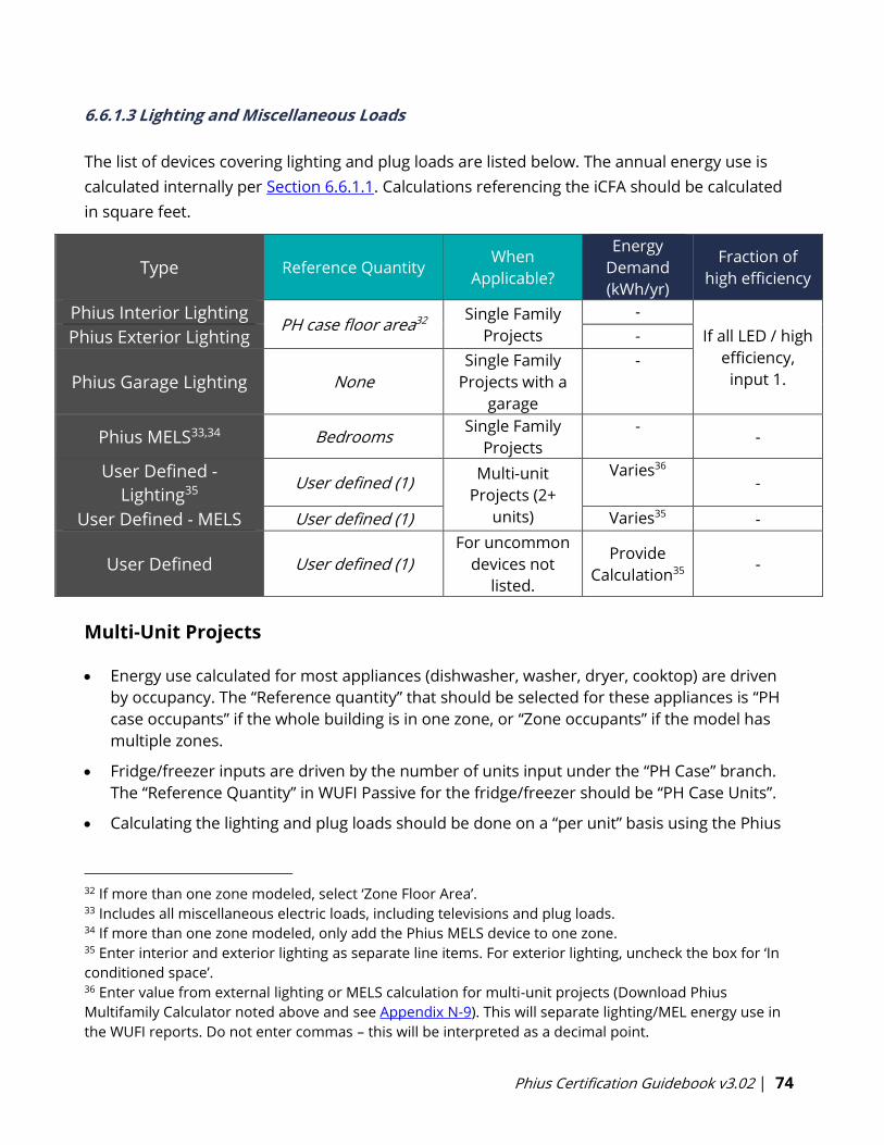
Phius Certification Guidebook v3.02 | 74
6.6.1.3 Lighting and Miscellaneous Loads
The list of devices covering lighting and plug loads are listed below. The annual energy use is
calculated internally per Section 6.6.1.1. Calculations referencing the iCFA should be calculated
in square feet.
Type Reference Quantity When
Applicable?
Energy
Demand
(kWh/yr)
Fraction of
high efficiency
Phius Interior Lighting PH case floor area32
Single Family
Projects
-
If all LED / high
efficiency,
input 1.
Phius Exterior Lighting -
Phius Garage Lighting None
Single Family
Projects with a
garage
-
Phius MELS33,34 Bedrooms Single Family
Projects
- -
User Defined -
Lighting35 User defined (1)
Multi-unit
Projects (2+
units)
Varies36 -
User Defined - MELS User defined (1) Varies35 -
User Defined User defined (1)
For uncommon
devices not
listed.
Provide
Calculation35 -
Multi-Unit Projects
• Energy use calculated for most appliances (dishwasher, washer, dryer, cooktop) are driven
by occupancy. The “Reference quantity” that should be selected for these appliances is “PH
case occupants” if the whole building is in one zone, or “Zone occupants” if the model has
multiple zones.
• Fridge/freezer inputs are driven by the number of units input under the “PH Case” branch.
The “Reference Quantity” in WUFI Passive for the fridge/freezer should be “PH Case Units”.
• Calculating the lighting and plug loads should be done on a “per unit” basis using the Phius
32 If more than one zone modeled, select ‘Zone Floor Area’. 33 Includes all miscellaneous electric loads, including televisions and plug loads. 34 If more than one zone modeled, only add the Phius MELS device to one zone. 35 Enter interior and exterior lighting as separate line items. For exterior lighting, uncheck the box for ‘In
conditioned space’. 36 Enter value from external lighting or MELS calculation for multi-unit projects (Download Phius
Multifamily Calculator noted above and see Appendix N-9). This will separate lighting/MEL energy use in
the WUFI reports. Do not enter commas – this will be interpreted as a decimal point.
Phius Certification Guidebook v3.02 | 75
Multifamily Calculator.
• User Defined inputs are not applied to any internal patterns, and inputs are simply in
kWh/yr. Therefore, when inputting lighting and plug loads as User Defined inputs, this
should be for the whole building. (Or, if there are identical units, input per unit and adjust
the quantity as needed).
Download the Phius Multifamily Calculator from the Calculators and Protocols page, which has
all of the protocol noted in Appendix N-9.
6.6.2 Non-Residential
Utilization Pattern
The internal loads and occupancy calculation for non-residential projects begins with the
definition of utilization patterns. These patterns are used for two purposes: lighting energy
calculation and internal gains due to people and the equipment they use.
A utilization pattern consists of a set of several parameters:
• Beginning hour
• Ending hour
• Days/year
• Illumination level
• Height of utilization (0 or 2.62 ft)
• Relative absence
o 1 = Occupants always absent
o 0 = Occupants never absent
• Part use factor of building period for lighting
o 1 = No reduction in lighting energy
o 0 = Full reduction in lighting energy
A set of standard default patterns (per DIN V 18599-10:2007-02, Table 4) is shown in the table in
Appendix N-10 below. [7]
The illumination level, height of utilization, and part-use factor for lighting enter only into the
lighting calculation.
The average occupancy (in ft2/person) can be entered. It factors into the total occupancy
associated with a utilization pattern if the mode of planning for occupancy is floor-area-based
rather than direct entry. It influences the calculation of gains from people and the equipment
they use if any equipment is assigned to that Utilization Pattern.
The other parameters enter both the lighting and internal gains calculations.
Often, more utilization patterns will be needed for lighting purposes than for internal gains. For
example, in an office building with single-shift operation and everyone typically sitting at desks,
a single pattern could suffice for internal gains due to people, but if there are space types that
require a few different illumination levels, more patterns would be needed for lighting. That is,

Phius Certification Guidebook v3.02 | 76
it may be necessary / appropriate to define utilization patterns that “overlap” to support the
calculations for internal gains, lighting, and equipment electricity use.
In the table in Appendix N-10, the patterns are grouped by required illumination level. The first
step in the analysis is to identify the different space types that are present, from the floorplan.
In the lighting calculation, the patterns can be applied room-by-room. Grouping of rooms may
be appropriate if they share a pattern (or ones with similar required illumination) and have
similar access to daylight.
6.6.2.1 Occupancy
• Occupant Quantity: The top-level occupancy entry should reflect the average day
occupancy. This value influences total DHW consumption, daily tap openings for DHW
distribution losses, and the ‘Supply air due to persons’ ventilation requirement shown
under Ventilation/Rooms>Utilization Pattern.
o This entry does not influence the internal heat gains related to occupants.
• Occupant Groups: Occupant groups should be entered in the lines below.
o Generally, each unique space type should have a new line entry.
o Planned occupancy for the space should be entered.
▪ Keep in mind that the relative absence on the ‘Utilization Pattern’ tab is
relative to this occupancy.
o Be careful not to double count occupants.
▪ For example, if there is an office with 20 desks, that should be input with
the 20 occupants. If there are also two conference rooms that serve the
same occupants that occupy the desks, do not also add the conference
room with 20 occupants, or that will double count the occupants. The
conference room can be a separate line item for lighting, but not for
occupancy.
o Not all space types need designated occupants or entries on this tab.
▪ Transient spaces such as, stairwells, restrooms, storage spaces, etc. may
have occupants at certain times, but those occupants should be included
in the space types where they will reside the majority of the time they
occupy the space.
• Heat loss due to evaporation (per person): Default value of 51.2 BTU/hr
• Number of flush toilets: Enter the total number of toilets in the entire building.
• Toilet Utilization Pattern: The utilization pattern with the most ‘Annual utilization days’
should be selected.
6.6.2.2 Office Equipment
Planned equipment for the building should be input here.
• Pre-defined equipment types are built in.
• Power Rating [W] must be input for all equipment.
Phius Certification Guidebook v3.02 | 77
See Appendix D – ASHRAE Fundamentals Non-Residential Equipment Tables below for guidance
on office equipment power ratings.
PC, Monitor:
o A utilization pattern must be assigned to each of these equipment types.
o The amount of time in operational mode vs power saving mode is built in.
Copier, Printer:
o A utilization pattern must be assigned to each of these equipment types.
o The number of hours in energy savings mode will be calculated automatically. Or
you may define this number. The number of hours input here is out of the total
hours in the Utilization Pattern – not out of all 8760 hours in a year.
Telephone system:
o The quantity should be input, and the energy use is not dependent on the
number of occupants.
User Defined:
o Enter the Power Rating [W] and the Utilization Hours per year.
o May be used for any miscellaneous items that do not fit the built-in options.
o External calculation for equipment energy use may be completed to determine
kWh/yr. To input these external results:
▪ Enter the resulting kWh/yr as the Power Rating [W]
▪ Enter 1000 hrs/yr for the utilization
▪ The result will be [W] * 1 khr/yr = kWh/yr.
6.6.2.3 Kitchen Equipment
Planned kitchen equipment for the non-residential building should be input here.
• Pre-defined equipment types are built in.
Cooktop:
o Utilization pattern must be defined to define the utilization days per year.
o Number of meals per utilization day refers to the total number of meals cooked
in that zone, per day.
▪ By default, the model will assume 0.25 kWh/meal for cooking energy.
o Quantity can also be input. Be sure not to double count the meals by adjusting
the quantity. If quantity is adjusted, meals per individual cooktop should be input.
Phius Certification Guidebook v3.02 | 78
Dishwasher
o Utilization pattern must be defined to define the utilization days per year.
o Number of meals per utilization day refers to the total number of meals cooked
(place settings washed) in that zone, per day.
▪ By default, the model will assume 0.055 kWh/meal for dishwashing
energy.
Refrigerator
o Norm demand [kWh/day] must be input.
o This data is available from Energy Star for residential fridges and some
commercial fridges.
o To estimate energy use for walk-in fridges/freezers, an external calculator is
available for download here.
User Defined
o May be used for any miscellaneous items that do not fit the built-in options.
o External calculation for equipment energy use may be completed to determine
kWh/yr. To input these external results:
▪ Enter the kWh/yr calculated into the ‘kWh/day’ field
▪ Enter 1 day/yr
▪ The result will be kWh/day * 1 day/yr = kWh/yr
6.6.2.4 Lighting
Space types should be split out into individual line items here.
If multiple Utilization Patterns are used to define the full usage hours for a single space, that
space must be entered multiple times on this sheet and assigned to the appropriate
Utilization Patterns to cover all hours of usage.
Fraction of conditioned floor area:
o This should generally add up to 1 for any given Utilization Pattern.
Daylighting: WUFI Passive will estimate daylighting potential by requiring the following inputs:
• Derivation from North: 0=North, 180=South
• Glazing Visible Transmittance: Select a pre-defined option, or enter User Defined if
known. This value is generally provided by window manufacturers.
• Room Depth: Enter the room depth starting from a window on the wall defined in the
Derivation from North.
Phius Certification Guidebook v3.02 | 79
o For example, if you input 180, select a ‘typical’ window on the south wall and
measure to the north wall enclosing that space.
• Room Width: Measure in the opposite direction of the Room Depth described above.
• Room Height: Floor to ceiling height.
• Façade has windows: Check this box if applicable. If not applicable, do not check the
box and no daylighting potential will be assumed.
• Lintel height: Height of the typical window head from the floor.
• Window width: Sum of all the window widths on the wall specified above for ‘Derivation
from North’.
Installed Lighting Power: Value should be input in W/ft2 . Phius requires lighting plans and
documentation to verify these values.
• Values entered here will override ‘illuminance [lux]’ entries from the Utilization Pattern.
Lighting full load hours: This entry will over-ride all entries utilized for the daylighting
calculation built into the software.
• The daylighting calculation utilizes the Derivation from North, Glazing Visible
Transmittance, Room Width/Depth/Height, Façade with windows checkbox, lintel height,
and window width.
6.6.2.5 Process Loads
As mentioned in Section 3.1.4.1, process load allowances may be defined for commercial
projects. Each unique process load should be input as an individual line item.
• Total energy in kWh/use may be input, or
• Power Rating [W] and Annual use hours [hr] may be used with the built in […] calculator
Include in Source Energy Total: This checkbox allows the modeler to include/remove this
process load in the calculated source energy total for the purposes of verifying compliance with
the base source energy target before process loads and allowances are included.
Increase Source Energy Allowance: This checkbox allows the modeler to adjust the source
energy target by including the process load allowance in the model. This will auto-adjust the
Source Energy target in the results to include this allowance
• Note: Process load allowances must be reviewed and approved by Phius.
Phius Certification Guidebook v3.02 | 80
6.7 Ventilation/Rooms
6.7.1 Utilization Pattern
The design airflow is determined by the largest of 2 factors:
1. Supply air requirement (based on occupancy)
2. Exhaust air requirement (based on kitchens, baths, etc.)
The capacity of the ventilation system installed needs to exceed whichever rate is greatest37
(see Section 3.5).
The average air flow rate (cfm) and average air change rate (1/hr) is calculated as a reduction
from the “design air flow rate”. It is determined by the daily operation schedule and “fraction of
design” airflow at the scheduled hours.
For non-residential projects, multiple utilization patterns may be set up to reflect varying levels
of ventilation rates for different days (i.e. weekday vs weekend). Alternatively, one utilization
pattern may be used and the ‘daily operation schedule’ can be revised to reflect the appropriate
ratios of design airflow rates during occupied and unoccupied hours.
6.7.2 Rooms Ventilation
In WUFI Passive, it is best practice to enter both exhaust rooms and supply rooms, though only
exhaust room entries are required if the model is setup with ‘Balanced Ventilation’ (under PH
Case>Additional Data).
• Entering all rooms ensures the ventilation design is balanced.
• “Supply rooms” must be entered if there is to be more than one H/ERV device entered.
• When adding exhaust rooms, input 0 cfm supply. When adding supply rooms, input 0
cfm exhaust.
For multi-unit buildings with repeated exhaust rooms, the room may be input once, and the
quantity adjusted appropriately. For example, a 50-unit MF building with 50 kitchens may have
a single line entry for the kitchen, quantity 50, if the exhaust flow rate is planned to be the same
for all kitchens.
Phius recommends starting with the following exhaust rates as rules of thumb:
Kitchen: 35 cfm
Bathroom: 24 cfm
Half Bath: 12 cfm
37 For design certification, it is recommended (but not required) that residential projects model with a
ventilation rate of 0.3 ACH or higher.
Phius Certification Guidebook v3.02 | 81
6.7.3 Summer Ventilation
Summer ventilation may be notionally either natural, via windows, or mechanical automatically
controlled (e.g. whole house exhaust fan.)
Summer Mechanical Ventilation by the HRV/ERV Average mechanical ventilation air change rate [1/hr]:
By default, this value should be left empty if the E/HRV runs year-round. This value should
match the year-round average ACH from the E/HRV.
If the climate allows for summer ventilation to be taken care of through windows and other
passive features, and the HRV/ERV will be shut off, input 0 here.
*Note: Occupants must provide other means of ventilation if turning off continuous ventilation
system.
Summer Bypass
Summer/HRV Humidity Recovery:
Most heat recovery ventilation units (Both ERVs and HRVs) can bypass heat recovery in the
summer condition when outdoor temperatures are more favorable than indoor. Also referred
to as ‘economizer mode’ or ‘free cooling’. Typically, this is temperature-controlled bypass.
• None: If there is no heat/moisture recovery ventilation during the summer. (Only
applicable if the E/HRV is shut off during the summer)
• Temperature-controlled bypass: If the bypass mode is activated based temperature.
• Enthalpy-controlled bypass: If the bypass mode is activated based on both temperature
and humidity/moisture.
• Always: If there is no bypass mode and recovery mode is always active.
Summer Natural Ventilation (day)
ACH via natural ventilation (day):
If a cooling system is planned, no natural ventilation may be included in the model. An entry of
‘0’ is required for PHIUS+ 2018 certification.
o If no cooling is planned, up to 0.3 ACH may be used.
Phius Certification Guidebook v3.02 | 82
Additional Summer Ventilation (night)
ACH via natural ventilation (night):
If a cooling system is planned, no natural ventilation may be included in the model. An entry of
‘0’ is required for PHIUS+ 2018 or Phius 2021 certification.
o If no cooling system is planned:
▪ Be cautious and realistic with the amount of natural ventilation being counted on
for cooling. There are two main concerns with the amount of cooling.
1. Humidity - look for dew point temperature in the Climate Data. In many
climates in the United States, there are high levels of humidity in the cooling
situations.
2. The built-in summer ventilation calculator can generate quite high air change
rates, but during the night usually interior doors are closed so that cross
ventilation is cut off.
▪ For Phius Certification, either:
1. Account for no higher than 0.3 ACH for nighttime ventilation; or
2. Follow Building America House Simulation Protocol, which states: 33% of the
open-able windows are opened. This can happen 3 days a week (M, W, F),
which would translate, to a fraction of opening duration of 43%, Or 10.3
hrs/day.
Use the additional calculator found under Summer Ventilation in WUFI Passive Model each
window in one column. A second window group is allowed for stack effect and cross ventilation
only for day, not night (unless there are no intervening doors.)
Additional Summer Mechanical Ventilation
Use these inputs when implementing a mechanical exhaust system in addition to the ERV. Ex:
whole house fan. Use [Mechanical automatic controlled ventilation] if the system is tied to
sensors for either temperature or humidity difference and define the control system in WUFI
Passive.
o ACH via mechanical ventilation exhaust air.
o Mechanical automatic controlled ventilation
a. Specific Power Consumption
6.7.4 Exhaust Ventilation
Exhaust Air Appliances:
• In WUFI Passive, account for the exhaust appliances on the Ventilation/Rooms > Exhaust
Appliances tab.
Exhaust Dryers and Exhaust Range Hoods
• There are pre-defined devices for exhaust dryers and exhaust range hoods over kitchen
Phius Certification Guidebook v3.02 | 83
cooktops, which are tied to the annual usage patterns of the dryer and cooktop.
Bathrooms with direct exhaust fans: There are two acceptable methods to account for this:
• Assume 60 min/bathroom/day per BAHSP protocol
o Exhaust volume flow rate [cfm]: Sum total bathroom exhaust fans in the building
and enter that here.
o Run time per year [min]: Use (365 days/yr * 60 min/day) = 21,900 minutes/yr
• Alternate: Assume 30 min/person/day
o Exhaust volume flow rate [cfm]: Average exhaust flow rate of all bathroom
exhaust fans in the building. Enter that exhaust rate for the average bathroom
here.
o Run time per year [min]: (30 min/occ/day * Occupants * 365 days/yr) = minutes/yr
Unbalanced Airflow: If at final commissioning, the exhaust or supply air flow exceeds the
exhaust air flow by more than 10%, the energy penalty must be accounted for. This can be
done by modeling the associated additional infiltration or exfiltration, assumed that this
unconditioned airflow will be continuous at the same rate as the difference between the supply
and exhaust air flows. See alternate method in Section 6.10.7 Mechanical Ventilation Devices.
Multiple Exhaust Dryer Protocol:
If a community building or similar shared building is serving multiple buildings with a laundry
room, multiple exhaust dryers with high usage patterns put a lot of load on the space
conditioning system. If the makeup air is either fully ducted to the dryer case, or even near /
behind it, then the makeup air may be regarded as not mixing with the room air and therefore
does not increase the load/demand on the space heating/cooling system, because the room
thermostat will not ever feel it. The extra energy must be accounted for, but it is considered to
be moved from the space-conditioning category to the source energy category. That accounting
may be done as follows:
• Duplicate the existing case, create a new ‘test’ case.
• Add the dryers to the Exhaust Appliances tab in WUFI Passive .
• Take the difference between the added heat demand and the added cooling
demand. (On the theory that cold air makes the dryer work harder, warm air
makes it work easier, than it does under its rated conditions.)
• Convert that to a source energy using the COP and SE factor of the dryer. Divide
by the source energy factor for electricity and enter the result as an auxiliary
electric load outside the thermal envelope.

Phius Certification Guidebook v3.02 | 84
• Furthermore, it is recommended to install an electric heater in the makeup air
duct (near the point of entry) capable of raising the air temperature to at least 49
F (dew point of 68 F air at 50% RH.)
• If the dryer is not electric resistance, the SE factor in the above energy calculation
should be adjusted with a seasonal weighting based on the percentage of the
year that the makeup air heater would be expected to operate. This would
prevent the makeup air from causing a frost or condensation problem.
Notice that, if the space heating system is efficient or has a low source energy factor, a heated
makeup air duct may use more energy overall in a site or source energy sense. Therefore, this
is not necessarily the best strategy in all cases. The multiple exhaust dryer protocol is offered as
an option that may help some smaller buildings meet the certification criteria for space
conditioning.
6.8 Thermal Bridges
To learn how to use THERM software developed by Lawrence Berkeley National Laboratory
(LBNL) to calculate thermal bridges, an introductory training course may be purchased from the
Intro to THERM Workshop page on the Phius website.
Phius has created a Psi-Value Calculator Template for consultants to use to document and
calculate a project’s thermal bridges.
Negative Thermal Bridges: If accounting for any negative thermal bridges, all thermal bridges in
the project must be calculated, no matter how small. In general, Phius strongly recommends
against taking negative thermal bridges in the design phase, and only using these as a “last line
of defense”.
Temperature Zone Assignments in WUFI Passive
WUFI Passive
Attachment
Temperature conditions in psi-value calculation
Interior (68F) Exterior (14F) Ground (41F)
Ambient x x
Perimeter x x x
Basement Floor x x
• Ambient: Use this selection for thermal bridges occurring above grade. Only two
temperatures will be used in the THERM/psi value calculation – interior and exterior.
• Perimeter: Use this selection for thermal bridges occurring at grade. In this case, there
will be three temperature zones used in the THERM calculation – interior, exterior, and
ground.
• Ground Floor: Use this selection for thermal bridges below grade. Only two
temperatures will be used in the THERM calculation – interior and ground.
Phius Certification Guidebook v3.02 | 85
6.9 Attached Zones & Remaining Elements
6.9.1 Attached Zones
Reduction Factors for Tempered Spaces
In passive house verification mode, the lowest reduction factor currently allowed for Phius
Certification is ≥0.95. One example of this is a garage. Garages may be warmer in the winter
and afford a reduction to the assemblies that come into contact with it. However, it also could
be warmer in the summer. The exact reduction factor cannot be calculated in passive house
verification mode and a conservative approach is being taken.
If there is an infill project built directly adjacent to existing buildings, the walls neighboring the
existing building can be assumed adiabatic if the space is occupied and residential or if the
space is non-residential and always conditioned. The neighboring walls should be set to 'Space
with same inner conditions'. (This will result in a slightly higher heating load than setting up the
neighboring building as an 'Attached Zone w/a temperature reduction factor of 0'). Review the
Guidelines for using SketchUp with WUFI Passive pdf from the Calculators & Protocols page.
6.9.2 Remaining Elements
Any components with ‘Outer Air’ or ‘Ground’ assigned to both the ‘Inner side’ and ‘Outer side’
will appear as remaining elements. This may include shading elements that are outside of the
thermal boundary, a roof over a vented attic, etc.
The remaining elements only influence the calculation via the dynamic shading calculation. No
heat transfer is considered through these components.
6.10 Systems
In WUFI Passive, systems consist of a set of devices. Often, only one ‘System’ is needed per
building. There are cases where multiple systems must be used, such as to add system capacity,
or due to a limitation in the WUFI Passive software. More details below.
Devices must be added to cover Space Heating, Space Cooling (if applicable), Mechanical
Ventilation and Domestic Hot Water (DHW).
System Coverage: If more than one ‘device’ serves the same purpose, all devices should be
added, and the appropriate coverage should be assigned for each. Coverage can be determined
based on the capacity of each piece of equipment used (i.e. if multiple different heat pumps are
used with different performance ratings), or priority (i.e. heat pump for heating with backup
electric resistance heaters). Coverage is assigned below the device list.
Phius Certification Guidebook v3.02 | 86
6.10.1 DHW Distribution
Domestic Hot Water (DHW)
Make sure the reviewer can verify the hot water distribution technology from the mechanical
drawings. Document the actual pipe lengths used for the applicable entries described below.
Design Flow Temperature: This is used to calculate the circulation pipe losses. Phius will accept
between 120-140oF. It is recommended, and common, to insulate plumbing. This is mostly to
improve efficiency and slow the heat transfer from the pipe to the interior environment.
Although this is recommended, it is not required.
6.10.1.1 Circulation Pipes
• Length of Circulation Pipes: A true circulation loop has hot water running through it for a
certain period each day. Referred to below as ‘Continuous or time-based recirculation’. The
full length of these pipes should be entered here.
o Recirculation systems are found most often in large or commercial buildings.
o Neither time-based nor continuous recirculation systems are allowed in single
family homes.
o For this entry, determine the length of the circulation loop.
The default calculation for the recirc pumping energy auto-sizes a pump based on
the gross enclosed volume of the building, and conservatively assumes 24 hour a day
operation. This can be overridden.
• On-Demand Recirculation: When recirculation is triggered by a demand-based system,
rather than continuous/time-based, do NOT enter this as circulation pipes.
o Use the ‘Individual pipes’ entry, select ‘Hot water piping calculator’. See below.
▪ The cautious view is that an on-demand system saves water, but it does not
save much water heating energy, because the pipes cool off between uses like
the individual branch pipes.
• Daily running hours of the circulation: 24 hours for continuous, or lower for time-based.
o Phius strongly discourages, but shall not prevent, the use of continuous or time-
based hot water circulation systems in multifamily or non-residential projects.
6.1.10.2 Individual Pipes – Calculation Methods
1. Simplified Individual Pipes
This method should be used for all non-residential projects.
o Length of individual pipes:
▪ To determine this, determine the distance from the HW tank/tankless
heater to each individual hot water tap. Sum these distances to find the
total length of individual pipes.
Phius Certification Guidebook v3.02 | 87
▪ For hot water pipes to the clothes washer and dishwasher, exclude the
length of these pipes, or more conservatively, apply a reduction factor of
0.06 to the length.
▪ If the project is using a continuous or time-based circulation loop,
determine the distance from the recirc loop to each individual hot water
tap. Sum these distances to find the total length of individual pipes. (Note
that a supporting drawing / diagram is part of the required
documentation.)
o Exterior Pipe Diameter: Typically add ⅛” inch to the nominal pipe dimension to
determine the exterior dimension. Projects using a variety of HW pipe
thicknesses may use a weighted average for this value.
2. Simplified hot water piping calculator
o May be used early in design. Not accepted for design nor final certification.
o Pipe material: Select the pipe material used. More information can be found in
Appendix N-1.
o Pipe diameter: Nominal pipe diameter in inches.
o Number of bathrooms: Sum of all bathrooms in building covered by the DHW
device in this ‘System’.
▪ If multiple ‘Systems’ with DHW devices are defined in WUFI Passive, do not
double count bathrooms.
3. Hot water piping calculator (unit/floor method)
o This calculation method is required for all residential PHIUS+ 2018 & Phius 2021
projects.
o This calculator estimates hot water distribution losses, as well as ‘time to hot’
used to aid in the design of a DHW distribution network that will meet the EPA
WaterSense Hot Water Delivery requirements.
o The length of Demand-based recirculation pipes SHOULD be entered here. The
length of time-based or continuous hot water recirculation pipes SHOULD NOT
be entered in this section, but rather above under Circulation Pipes.
o Hint: When considering how to enter the DHW distribution network,
consider the source of the ‘hot’ water, as well as the full path from the
source of the hot water to each individual tap.
o For the purposes of this calculation, hot water lines to dishwashers and clothes
washers can be ignored.
o Sample DHW Distribution takeoff and WUFI Passive entry screen inputs can be
found on the Calculators and Protocols page.
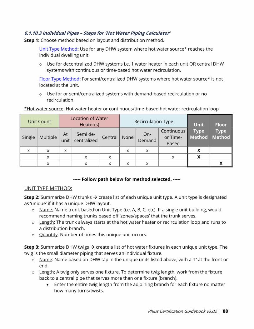
Phius Certification Guidebook v3.02 | 88
6.1.10.3 Individual Pipes – Steps for ‘Hot Water Piping Calculator’
Step 1: Choose method based on layout and distribution method.
Unit Type Method: Use for any DHW system where hot water source* reaches the
individual dwelling unit.
o Use for decentralized DHW systems i.e. 1 water heater in each unit OR central DHW
systems with continuous or time-based hot water recirculation.
Floor Type Method: For semi/centralized DHW systems where hot water source* is not
located at the unit.
o Use for or semi/centralized systems with demand-based recirculation or no
recirculation.
*Hot water source: Hot water heater or continuous/time-based hot water recirculation loop
Unit Count Location of Water
Heater(s) Recirculation Type
Unit
Type
Method
Floor
Type
Method Single Multiple At
unit
Semi de-
centralized Central None
On-
Demand
Continuous
or Time-
Based
x x x x x X
x x x x X
x x x x x X
----- Follow path below for method selected. -----
UNIT TYPE METHOD:
Step 2: Summarize DHW trunks → create list of each unique unit type. A unit type is designated
as ‘unique’ if it has a unique DHW layout.
o Name: Name trunk based on Unit Type (i.e. A, B, C, etc). If a single unit building, would
recommend naming trunks based off ‘zones/spaces’ that the trunk serves.
o Length: The trunk always starts at the hot water heater or recirculation loop and runs to
a distribution branch.
o Quantity: Number of times this unique unit occurs.
Step 3: Summarize DHW twigs → create a list of hot water fixtures in each unique unit type. The
twig is the small diameter piping that serves an individual fixture.
o Name: Name based on DHW tap in the unique units listed above, with a ‘T’ at the front or
end.
o Length: A twig only serves one fixture. To determine twig length, work from the fixture
back to a central pipe that serves more than one fixture (branch).
• Enter the entire twig length from the adjoining branch for each fixture no matter
how many turns/twists.

Phius Certification Guidebook v3.02 | 89
Step 4: Summarize DHW branches → create list of branches connecting trunk to twig. Each twig
will have its own branch, running from the trunk to the twig.
o Name: Name based on DHW tap in the unique units listed above (same as twig but
without ‘T’)
o Length: Total length between twigs and trunks above.
o If a twig connects directly to a trunk, enter a branch with a length of ‘0’ and connect the
twig to that branch.
o Sometimes a branch off the trunk may only serve one fixture. In that case, it could all be
considered a twig, or could be split into a branch and a twig. If the pipe dimension and
material are the same, either method will yield the same results.
Step 5: Enter information from spreadsheet above into WUFI Passive.
o A segment must be entered first with the trunk, then connecting branch, then
connecting twig.
o To ‘connect’ a branch to a trunk, you must first click on the trunk, then add that branch.
o To ‘connect’ a twig to a branch, you must first click on the branch, then add that twig.
o Be careful to ensure you are always connecting the appropriate segments.
Step 6: Use the ‘Watersense met?’ column built into the twig entries to estimate whether all
fixtures will pass the EPA WaterSense Hot Water Delivery requirement.
o This is an on-site test that applies to most residential projects.
o This tool is used to aid in design of a DHW distribution network that will pass on-site
testing, but does not guarantee it.
o If a twig is not passing in the model, it is recommended to revise the tap location or
circulation strategy for that tap.
Step 7: Double check entries:
o All trunks must have branch entries
o All branches must have twigs connected.
o Quantities must appropriately represent the building distribution network.
FLOOR TYPE METHOD:
Step 2: Summarize DHW trunks → create list of unique floors, and then list each unit number
on those unique floors. A floor is designated as unique if the count or configuration of dwelling
units varies from another floor.
o Name: Name trunk based on unit number (i.e. 401, 402, 403). If vertical risers, select an
‘average’ floor for unit numbers (about half-way up, see more below).
o Length: Trunk always starts at semi/central water heater and ends at the dwelling unit.
• On-demand recirculation loops:
▪ Enter only the Supply side of the loop, omit Return portion (downstream
Phius Certification Guidebook v3.02 | 90
of last fixture and recirc pump temperature sensor.)
▪ Check the box for ‘demand-recirculation’. This will reset the ‘up-stream
volume’ for any branch connected to that trunk, i.e. it will assume the
branch will always be served with hot water and the trunk length should
not be considered when estimating the ‘time to hot’ for the EPA
WasterSense Hot Water Delivery test.
• The on-demand recirculation pipes must still be entered to
accurately account for DHW pipe distribution losses, even though it
resets the volume in the trunk for the ‘time to hot’ calculation.
• Vertical Risers:
▪ Determining the average vertical distance from the water heater to each
unit.
▪ If all residential building:
Calculating average vertical run: (# Floors * Floor-to-floor height)/2
# Floors: Includes the floor the water heater is located on, even if there
are no residences on that floor.
• Ex 1: If there are 8 identical residential floors, the water heater is in
a mechanical penthouse on the 9th floor, and floor-to-floor heights
are 12’, then use (9*12)/2 = 54 ft.
▪ If mixed-use building:
Calculating average vertical run: ((Distance from water heater to
residential floor + (# Floors * Floor-to-floor height))/2
# Floors: Do not include floor water heater is located on.
• Ex 2: Mixed use (floors 1-2), 8 residential floors (floors 3-11), all
floors 12’ in height and water heater in basement, then use ((36’ +
(8*12))/2 = 66 ft.
o Quantity: This is number of times this unique floor occurs.
Step 3: Summarize DHW twigs → create a list of hot water fixtures in each unique unit type. The
twig is the small diameter piping that serves an individual fixture.
o Name: Name based on DHW tap in the unique units listed above, with a ‘T’ at the end.
o Length: A twig only serves one fixture. To determine twig length, work from the fixture
back to a central pipe that serves more than one fixture (branch).
• Enter the entire twig length from the adjoining branch for each fixture no matter
how many turns/twists.
Step 4: Summarize DHW branches → create list of branches connecting trunk to twig. Each twig
will have its own branch, running from the trunk to the twig.
o Name: Name based on DHW tap in the unique units listed above (same as twig but

Phius Certification Guidebook v3.02 | 91
without ‘T’)
o Length: Total length between twig and trunk above.
o If a twig connects directly to a trunk, enter a branch with a length of ‘0’ and connect the
twig to that branch.
o Sometimes a branch off the trunk may only serve one fixture. In that case, it could all be
considered a twig, or could be split into a branch and a twig. If the pipe dimension and
material are the same, either method will yield the same results.
Step 5: Enter information from spreadsheet above into WUFI Passive.
o A segment must be entered first with the trunk, then connecting branch, then
connecting twig.
o To ‘connect’ a branch to a trunk, you must first click on the trunk, then add that branch.
o To ‘connect’ a twig to a branch, you must first click on the branch, then add that twig.
o Be careful to ensure you are always connecting the appropriate segments.
o Note that pipe material, diameter, and length must be added for each new segment.
Step 6: Use the ‘Watersense met?’ column built into the twig entries to estimate whether all
fixtures will pass the EPA WaterSense Hot Water Delivery requirement.
o This is an on-site test that applies to most residential projects.
o This tool is used to aid in design of a DHW distribution network that will pass on-site
testing, but does not guarantee it.
o If a twig is not passing in the model, it is recommended to revise the tap location or
circulation strategy for that tap.
Step 7: Double check entries:
o All trunks must have branch entries
o All branches must have twigs connected.
o Quantities must appropriately represent the building distribution network.
Four example layouts are described below:
Units Location of Water Heater Recirculation Method
A Single At unit On demand Unit Type
B Multiple Units Semi de-centralized or Central Continuous/Time-Based Unit Type
C Multiple Units Semi de-centralized or Central On demand Floor Type
D Multiple Units Semi de-centralized or Central None Floor Type
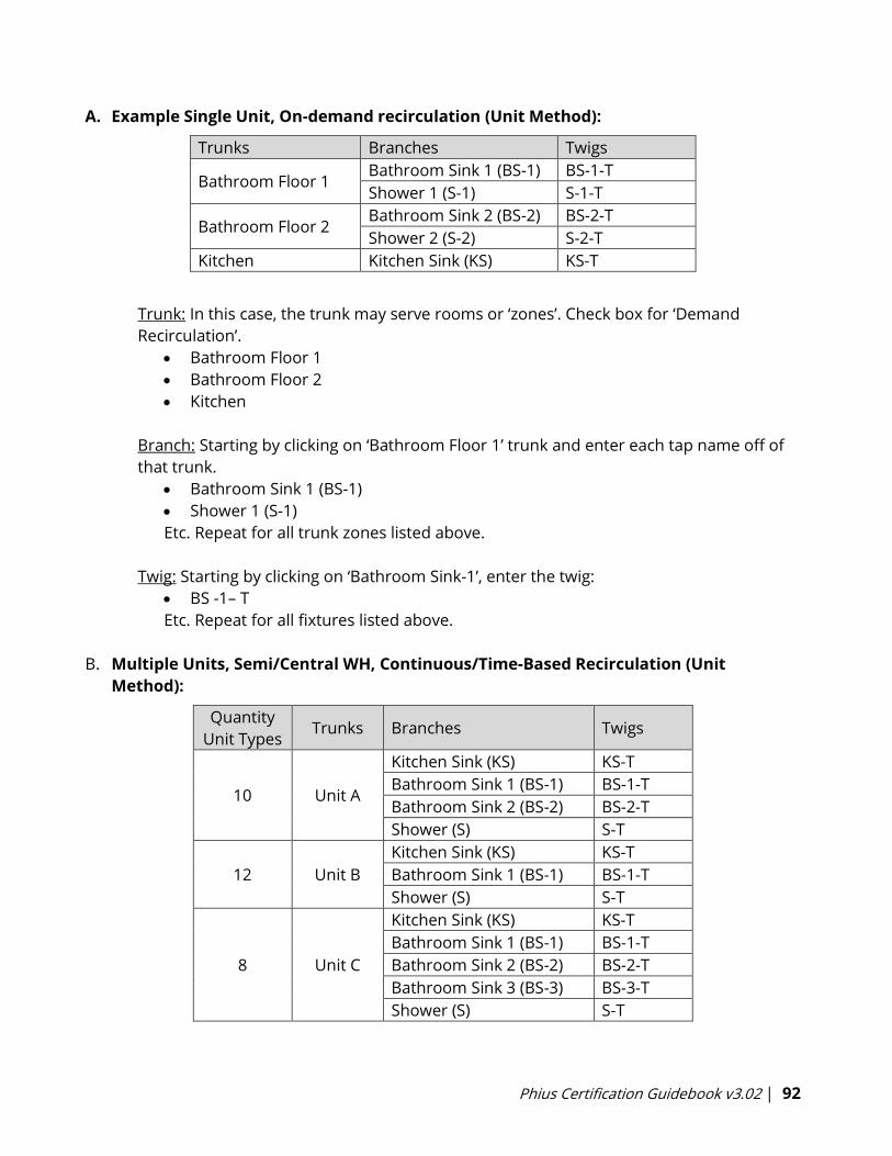
Phius Certification Guidebook v3.02 | 92
A. Example Single Unit, On-demand recirculation (Unit Method):
Trunks Branches Twigs
Bathroom Floor 1 Bathroom Sink 1 (BS-1) BS-1-T
Shower 1 (S-1) S-1-T
Bathroom Floor 2 Bathroom Sink 2 (BS-2) BS-2-T
Shower 2 (S-2) S-2-T
Kitchen Kitchen Sink (KS) KS-T
Trunk: In this case, the trunk may serve rooms or ‘zones’. Check box for ‘Demand
Recirculation’.
• Bathroom Floor 1
• Bathroom Floor 2
• Kitchen
Branch: Starting by clicking on ‘Bathroom Floor 1’ trunk and enter each tap name off of
that trunk.
• Bathroom Sink 1 (BS-1)
• Shower 1 (S-1)
Etc. Repeat for all trunk zones listed above.
Twig: Starting by clicking on ‘Bathroom Sink-1’, enter the twig:
• BS -1– T
Etc. Repeat for all fixtures listed above.
B. Multiple Units, Semi/Central WH, Continuous/Time-Based Recirculation (Unit
Method):
Quantity
Unit Types Trunks Branches Twigs
10 Unit A
Kitchen Sink (KS) KS-T
Bathroom Sink 1 (BS-1) BS-1-T
Bathroom Sink 2 (BS-2) BS-2-T
Shower (S) S-T
12 Unit B
Kitchen Sink (KS) KS-T
Bathroom Sink 1 (BS-1) BS-1-T
Shower (S) S-T
8 Unit C
Kitchen Sink (KS) KS-T
Bathroom Sink 1 (BS-1) BS-1-T
Bathroom Sink 2 (BS-2) BS-2-T
Bathroom Sink 3 (BS-3) BS-3-T
Shower (S) S-T

Phius Certification Guidebook v3.02 | 93
Trunk:
• Unit A
• Unit B
• Unit C
Branch: Enter each unique fixture type as a branch for each trunk. Example for Unit A.
• Kitchen Sink (KS)
• Bathroom Sink - 1 (BS-1)
• Bathroom Sink - 2 (BS-2)
• Shower (S)
Twig: Click on ‘Kitchen Sink (KS) branch’, then add the KS twig (KS-T).
• Kitchen Sink (KS)
o KS-T
Click on ‘Bathroom Sink (BS-1) branch’, then add the BS twig (BS-1-T).
• Bathroom Sink - 1 (BS-1)
o BS-1-T
Etc. Repeat for all fixtures listed above.
C. Multiple Units, Semi/Central WH, On-Demand Recirculation (Floor Method):
Floor Type Trunks Branches Twigs
1
Unit 401
Kitchen Sink (KS) KS-T
Bathroom Sink 1 (BS-1) BS-1-T
Bathroom Sink 2 (BS-2) BS-2-T
Shower (S) S-T
Unit 402
Kitchen Sink (KS) KS-T
Bathroom Sink - 1 (BS-1) BS-1-T
Shower (S) S-T
Unit 403
Kitchen Sink (KS) KS-T
Bathroom Sink 1 (BS-1) BS-1-T
Bathroom Sink 2 (BS-2) BS-2-T
Shower (S) S-T
Trunk: Check box for ‘Demand Recirculation’ if applicable. Length includes vertical pipe
length when applicable.
• Unit 401
• Unit 402
• Unit 403
Branch & Twig: Follow Example B.
Phius Certification Guidebook v3.02 | 94
D. Multiple Units, Semi/Central WH, No Recirculation (Floor Method):
Same as method ‘C’, but un-check ‘Demand-Recirculation’ for trunk.
6.1.10.4 Distribution Pipe Materials and Sizes
See Appendix N-1 for a table on DHW distribution pipe materials and sizes.
6.10.2 Cooling
Cooling system properties are entered under System>Distribution>Cooling, rather than in
individual cooling devices. If you are specifying varying cooling systems, add a new ‘System’, and
a new device for cooling in that new system. It is not currently possible to enter varying cooling
performance specifications when two cooling devices are included in the same ‘System’.
• Coverage: WUFI Passive will estimate the available cooling coverage based on system
entries. If the cooling demand is not covered, this will appear as a warning under the
‘Data state/results’ box. If the cooling demand is not covered, capacity must be increased
either by changing the numerical entries or adding an additional cooling system.
• Cooling via ventilation air:
o Use this for cooling systems that cool incoming fresh air/outdoor air supply, in-
line with the ventilation, and are not using additional airflow to satisfy the cooling
needs.
o Supply air cooling capacity: From manufacturer, based on available ventilation
airflow and cooling coil.
o Supply air cooling COP: Use EER/3.412
• Recirculation Cooling:
o Use for heat pump systems that cool indoor, recirculated air.
a. Recirculation air flow rate: Rated values provided by manufacturer, or estimate
between 250-400 cfm/ton of cooling
b. Recirculation air cooling capacity: Rated value from manufacturer.
c. Recirculation Cooling COP: Use ((SEER + EER)/2) / 3.412.
i. If only EER is provided, SEER = (1.12-√(1.2544-0.08*EER)) / 0.04
ii. For commercial cooling units, the cooling COP may be estimated using the
IEER rating. Use (IEER/3.412 = COP)
iii. IEER = (0 .02 * A) + (0 .617 * B) + (0 .238 * C) + (0 .125 * D)
Whereas:
A = EER at 100% net capacity at AHRI standard cond. (95 deg F)
B = EER at 75% net capacity and reduced ambient (81 .5 deg F)
C = EER at 50% net capacity and reduced ambient (68 deg F)
D = EER at 25% net capacity and reduced ambient (65 deg F)
Phius Certification Guidebook v3.02 | 95
• Dehumidification COP use dehumidifier rating in Liter/kWh
o 1 Liter/kWh = 0.625 COP
o OR, use a COP of ‘1.2’ for cooling systems that provide latent cooling as a product
of sensible cooling. (air source heat pump, mini-split, VRF etc..)
• Panel Cooling
o Only used for radiant cooling systems. External calculation needed to determine
Panel Cooling COP.
6.10.3 Ventilation Distribution
Duct Length and Duct Separation
Supply and exhaust duct lengths should be measured from the inside of the exterior wall to the
outside of the ventilation unit. Often, these lengths are different.
If there are multiple H/ERVs in the project covered by a single ERV device, do not increase the
quantity of duct lengths input here. For example, if there are 50 identical ERVs in the project,
the ERV device will have a quantity of 50. Determine the average supply/exhaust duct length for
those 50 ERVs, and input only one entry for a supply duct, and one for exhaust. Then, check the
box to assign those two average-length ducts to the appropriate ERV type. This will accurately
assign those ducts to the 50 ERVs.
On the outside of the building the supply and exhaust diffusers should be located at least 10
feet apart to keep from short circuiting exhaust air back into the house.
Note: If the ventilation unit is running at a very low airflow, manufacturers may allow for less
separation. This will be reviewed on a case-by-case basis.
Taking the supply air from above the roof is generally not recommended, because of the
possibility of excessive heat and hot-roof odor.
6.10.4 Auxiliary Energy
This should include any additional fans, pumps, air-handling units, space conditioning
distribution systems, etc.
There is an option to ‘Use Default values’, which applies to many projects.
• When this box is un-checked, only the Ventilation fan energy and defrost energy are
retained. Any pump entries for DHW recirculation, storage load pump, or heating
system circulation pump are removed. (Note: The devices that remain are shown in the
WUFI Passive reports under Auxiliary Energy).
DHW recirculation system: Add the DHW pump energy here or use the default value.
On-demand recirculation system for DHW: Please input the pump energy here. There is a quick
workaround to determine an average estimate for this value for your project:
1. Go to Distribution>DHW. Input a value of '1' under length of circulation pipes.
Phius Certification Guidebook v3.02 | 96
2. Then, go back to Distribution>Aux Electricity. Note the value that auto-populates for the
'Norm Demand [W]' of the DHW circulating pump.
3. Then, go back to Distribution>DHW, remove the '1' from the length of circulation pipes.
4. Go back to Auxiliary Energy, un-check the box for 'Use default values', and add a new
pump with the ‘Norm Demand’ power rating noted from the DHW recirculating system in
Step 2.
Air-Handling Units/Space Conditioning Distribution: Energy associated with space conditioning
distribution networks/fans should be estimated and input here.
• If fresh air supply is connected to an air handling unit for distribution into bedrooms,
the air handling unit fan energy must be input here and assumed to run 8760 hrs/yr.
See Section 3.5.3.
Direct Exhaust Bathroom Fans & Makeup Air Fans: Energy associated with fans should be input
here as an ‘Other’ device.
• Energy Demand (norm) [W]: Use fan energy data when available. If no fan energy data is
available, use 0.3 W/cfm as a default.
o Multiply total airflow (cfm) found on Ventilation/Rooms>Exhaust ventilation by
0.3 W/cfm for [W] entry.
• Run times are based on the assumed run times found under Ventilation/Rooms>Exhaust
Ventilation
o Convert minutes/yr to khr/yr: (minutes/yr)/60/1000 = khr/yr.
6.10.5 Heating Devices
Heat Pumps
If any heat pump technology is used for space heating, use the ‘Heat Pump’ device type. Within
this device type, there are two options for modeling heat pumps used for space conditioning:
1. Heat Pump Rated Monthly COP: When COP data for two rated ambient temperatures
can be found, use this device type. This takes the monthly heating demand and
climate data into consideration to calculate a more accurate COP.
• Generally, air source heat pumps are rated at 17°F and 47°F. By entering the
rated performance at both temperatures, WUFI Passive can calculate an annual
average heating COP based on the monthly heating demand and climate. This
follows Phius’ heat pump protocol.
• If multiple types of heat pumps are provided for single building, Phius has
created a calculator that calculates the weighted efficiency. Download this
calculator from the Calculators & Protocols page.
2. Heat Pump: Use when given a single COP (coefficient of performance) is provided for
the heating system and for ground/water source heat pumps. Note that when a
Phius Certification Guidebook v3.02 | 97
single value is given for air source heat pumps, often this is rated at an ambient
temperature of 47F, and the entry should be de-rated if the climate often reaches
temperatures below that.
• If only the HSPF given
o Climate Zones 4 and colder: Phius’ HSPF de-rating calculator must be used.
Download Heat Pump Protocol kit from Phius’ Calculators and Protocols
page.
o Climate Zones 3 and warmer: COP may be estimated as HSPF/3.412.
Boiler or Furnace
It is acceptable, and quicker, to enter this as a “User Defined” device in the system.
Find the Energy Factor (EF) or thermal efficiency of the model you are using.
• If using an EF, Phius recommends de-rating the EF by a factor of 0.92 (as in RESNET
protocol), to account for the discrepancies between the heavy draws used in the DOE
water heater testing protocol and the real world. This de-rated value can be thought of
as a % efficiency for the boiler.
Performance Ratio of Heat Generator: Input the inverse of the efficiency (or Energy Factor)
Source Energy Factor: For natural gas, 1.1
If a specification sheet is available containing information to support the detailed entries for the
Boiler device, feel free to use the Boiler option. The part-load efficiency curves in LBNL report
42175 may be used as defaults (See Figure 1 in the report for old boilers and Figure 6 for sealed
combustion.) [8]
Wood Stove
A typical “off the shelf” wood stove is likely oversized for single family passive buildings. If using
this system for a portion of heating, as a default, assign 25% heating coverage. For the
efficiency, an estimate of 60% will suffice. The PE factor will be 0.2 for biomass. On the other
hand, if using a system designed for a lower heat load or a more low-steady heating system,
such as a masonry heater or pellet stove, it may be plausible to increase the % coverage.
6.10.6 Domestic Hot Water Devices
Heat Pump Water Heaters
• With Indoor Compressors:
o In the Systems branch, add a ‘Heat Pump’ device.
o Select ‘Heat Pump water heater (HPWH) inside’ as the device type. This will de-rate
the efficiency of the HPWH heater to account for the heating systems working
against each other in the heating season.
▪ Enter the heating system COP or efficiency

Phius Certification Guidebook v3.02 | 98
▪ Total System Performance Ratio: Enter 1
𝐻𝑒𝑎𝑡𝑖𝑛𝑔 𝑆𝑦𝑠𝑡𝑒𝑚 𝐶𝑂𝑃 as a decimal.
▪ HPWH EF: Enter the rated Energy Factor (EF) for the Heat Pump Water Heater
• If Uniform Energy Factor (UEF) is provided
o HPWH EF = 1.201 * UEF – 0.6052
• With Outdoor Compressors:
o In the Systems branch, add a “Heat Pump” device.
o Select ‘Heat Pump’ as the device type.
o Supplemental calculators that take the local climate into effect can be found on the
Calculators & Protocols page.
o The climate-adjusted Energy Factor (EF) of the specified model should be used
▪ Total System Performance Ratio: Enter 1
𝐴𝑑𝑗𝑢𝑠𝑡𝑒𝑑 𝐸𝑛𝑒𝑟𝑔𝑦 𝐹𝑎𝑐𝑡𝑜𝑟 as a decimal.
• Sanden CO2 Heat Pump Water Heater or other HPWH with outdoor compressor and indoor
water storage.
o In the Systems branch, add a ‘Heat Pump’ device in WUFI Passive
o Select ‘Heat Pump’ as the device type.
o Supplemental calculators that take the local climate into effect can be found on the
Calculators & Protocols page.
o The climate-adjusted Energy Factor (EF) of the specified model should be used
▪ Total System Performance Ratio: Enter 1
𝐴𝑑𝑗𝑢𝑠𝑡𝑒𝑑 𝐸𝑛𝑒𝑟𝑔𝑦 𝐹𝑎𝑐𝑡𝑜𝑟 as a decimal.
Water Heaters with Tank
• Gas-Fired: Input the same as a Boiler & include water storage as a system.
o If UEF provided, convert to EF using the calculation below.
▪ EF = 0.9066 * UEF + 0.0711
• Electric:
o If UEF is provided, input as a ‘User Defined’ device, convert to EF using the calculation
below, use Phius’ electric source energy factor & do not include water storage as a
system.
▪ EF = 2.4029 * UEF – 1.2844
o If no UEF or EF provided, choose electric and add water storage as a system.
Water Storage
• Enter as a ‘Water Storage’ device and check the box for ‘DHW’.
• Input Options: Choose option based on documentation available.
o Specific total losses (Btu/hr.F): If AHRI standby loss (F/hr) data available, calculate
using the formula below.
▪ 8.3454 ∗ 𝑇𝑎𝑛𝑘 𝑆𝑖𝑧𝑒 (𝑔𝑎𝑙) ∗ 𝑆𝑡𝑎𝑛𝑑𝑏𝑦 𝐿𝑜𝑠𝑠(𝐹/ℎ𝑟)
Phius Certification Guidebook v3.02 | 99
o Specific losses standby part only (Btu/hr.F): Least common options and requires part-
load standby loss data.
o Total losses (Btu/hr): If AHRI standby Loss (F/hr) data available, calculate using the
formula below.
▪[8.3454∗𝑇𝑎𝑛𝑘 𝑆𝑖𝑧𝑒 (𝑔𝑎𝑙)∗𝑆𝑡𝑎𝑛𝑑𝑏𝑦 𝐿𝑜𝑠𝑠 (𝐹/ℎ𝑟)]
[𝑇𝑦𝑝𝑖𝑐𝑎𝑙 𝑊𝑎𝑡𝑒𝑟 𝑆𝑡𝑜𝑟𝑎𝑔𝑒 𝑇𝑒𝑚𝑝𝑒𝑟𝑎𝑡𝑢𝑟𝑒 (𝐹) – 68 (𝐹)]
Tankless Water Heaters
• Gas-Fired: Enter the same as Gas-Fired Water Heater, but UEF = EF; do not add water
storage as a system.
• Electric: Enter the same as Electric Water Heater, but UEF = EF or choose electric heating; do
not add water storage as a system.
Solar Collector
• In cases where the energy model report shows a solar fraction above 65%, we require a
predicted annual output from the solar inspector as to the kBTU/yr energy production; OR
o A BEopt model run according to the Phius Solar DHW Fraction BEopt Protocol. This
protocol can be downloaded here.
Ground Source Heat Pump
• Enter as a ‘Heat Pump’ device and use the rated COP at the appropriate entering and exiting
water temperatures.
• Any pump energy that are not included in the COP of the system should be added as an
auxiliary energy device.
6.10.7 Mechanical Ventilation Devices
Sensible Recovery Efficiency, Humidity Recovery Efficiency, Electric Efficiency:
• Phius projects should model ventilation efficiency according to the protocol described by
the Phius Technical Committee, which can be found on the Calculators and Protocols
page.
• Ventilation ratings from Phius Certified Ventilator program take priority over 3rd party
ratings.
• Refer to the HVI Winter Ratings modified for Phius modeling for common ventilation
units, also found on the Calculators and Protocols page.
• AHRI ratings for commercial units do not include electrical efficiency data. For design
certification calculations, estimate electrical consumption from manufacturer’s
specifications.
• At final certification, if the exhaust or supply air flow exceeds the exhaust air flow by
more than 10%, the energy penalty must be accounted for by de-rating the recovery
efficiency of the ventilation equipment based on the unbalanced airflow.

Phius Certification Guidebook v3.02 | 100
Latent/Humidity Recovery Efficiency: If this value is not specified for the ERV, 40% may be
entered as a default. For an HRV, enter 0%. When a project falls under the summer test
conditions (Climate zones 1A,2A,2B,3B), then request the HRV manufacturer provide their CSA
439 summer test point data. You can use this to break out ASE and LR. You will see that most
projects should use the HVI’s winter test point data. Only the 2B and 3B zones will use different
test data for the ASE and LR inputs.
CERV from Build Equinox:
Default values may be used for performance of refrigerant-based heat recovery devices. Or,
Phius-approved calculation methodology may be used to determine performance entries.
• Default accepted values:
o Sensible Heat Recovery: 75%
o Latent Heat Recovery: 40%
o Electric Efficiency: 1 W/cfm
PentaCare V12 from MINOTAIR:
This system requires dynamic (hourly) climate data and project specific calculations to
determine the performance values for WUFI Passive modeling. Email Phius at
[email protected] to receive the Phius calculator needed for project certification.
Assigning ‘rooms ventilated by this unit’: If multiple ERVs are used, the rooms assigned to each
unit need to appropriately be assigned to their corresponding ERV. The list of rooms shown
here is populated based on the entries on the Ventilation/Rooms branch. For the example
below, ERV Type X would check the boxes for all the residential exhaust rooms. ERV Type Y
would check the boxes for all common space exhaust rooms.
Quantity: When using multiple identical ERVs in one building, a single ‘Mechanical ventilation’
device in WUFI Passive can cover all of them. For example, if the project is a 50-unit MF building
with 50 identical ERVs “Type X”, this can be modeled as a single device, ERV Type X, and the
quantity would be adjusted to 50.
• This applies when the identical ERVs are scheduled to run at roughly the same airflow
rates, and therefore would have similar rated efficiencies (refer to HVI Winter Ratings
document above for more information on rated efficiencies at different airflows).
• Because you have increased the quantity of ventilation units under the device, do not
increase the quantity of ventilation ducts under Systems>Distribution (see Section
6.10.3).
• New mechanical ventilation devices only need to be added when a new unique ERV/HRV
type is used in the project. For example, in a MF building, the residential units are being
served by ERV Type X, and the common spaces are served by ERV Type Y.
HRV/ERV in conditioned space: If the ventilation unit is located outside of the thermal envelope
in an unconditioned space (ie. Rooftop), uncheck this box and amend the Mechanical Room
Temperature under PH Case: Additional Data using the E/HRV Outside calculator found on the
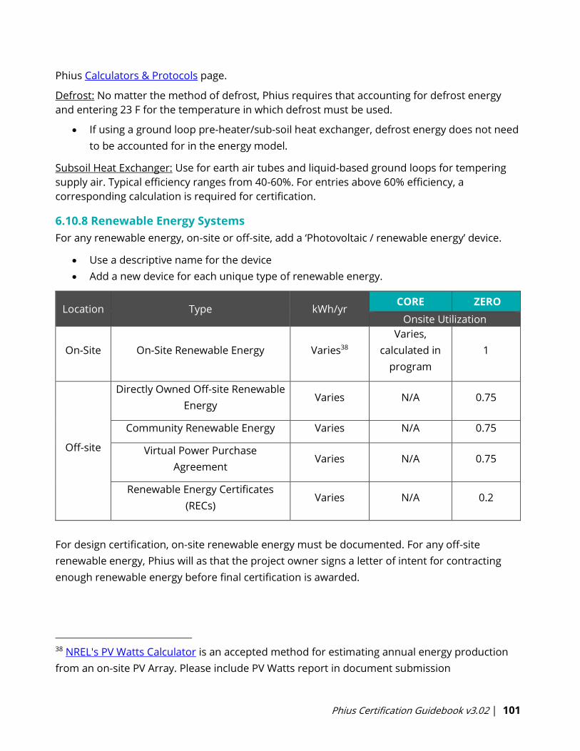
Phius Certification Guidebook v3.02 | 101
Phius Calculators & Protocols page.
Defrost: No matter the method of defrost, Phius requires that accounting for defrost energy
and entering 23 F for the temperature in which defrost must be used.
• If using a ground loop pre-heater/sub-soil heat exchanger, defrost energy does not need
to be accounted for in the energy model.
Subsoil Heat Exchanger: Use for earth air tubes and liquid-based ground loops for tempering
supply air. Typical efficiency ranges from 40-60%. For entries above 60% efficiency, a
corresponding calculation is required for certification.
6.10.8 Renewable Energy Systems
For any renewable energy, on-site or off-site, add a ‘Photovoltaic / renewable energy’ device.
• Use a descriptive name for the device
• Add a new device for each unique type of renewable energy.
Location Type kWh/yr CORE ZERO
Onsite Utilization
On-Site On-Site Renewable Energy Varies38
Varies,
calculated in
program
1
Off-site
Directly Owned Off-site Renewable
Energy Varies N/A 0.75
Community Renewable Energy Varies N/A 0.75
Virtual Power Purchase
Agreement Varies N/A 0.75
Renewable Energy Certificates
(RECs) Varies N/A 0.2
For design certification, on-site renewable energy must be documented. For any off-site
renewable energy, Phius will as that the project owner signs a letter of intent for contracting
enough renewable energy before final certification is awarded.
38 NREL's PV Watts Calculator is an accepted method for estimating annual energy production
from an on-site PV Array. Please include PV Watts report in document submission
Phius Certification Guidebook v3.02 | 102
6.10.9 Drain Water Heat Recovery
The drain water heat recovery device is used to adjust the temperature of the incoming water
supply by recovering warm drain water and pre-heating the incoming cold freshwater.
Note: DWHR device does not work in combination with the ‘Simplified individual pipes’ hot
water distribution calculation method.
DW heat recovery unit indoor temp: Default 97F
DW Heat Recovery Unit Efficiency: As rated and labeled in accordance with CSA 55.1
Pipe Length: Measured length of hot water piping from the hot water heater to the farthest hot
water fixture. Measured longitudinally from plans, assuming the hot water piping does not run
diagonally. Plus 10 feet of piping for each floor level, plus 5 feet of piping for unconditioned
basements (if any).
Supplies pre-heated water to: Select if the system supplies both hot and cold water, or just one
of the two.
6.10.10 Electric Vehicle Charging
It is not required to include the EV charging station in the WUFI Passive energy model used for
certification compliance. The energy use from the car charger is categorized as transportation
energy and not included in the source energy limit for Phius Certification.
6.11 WUFI Passive Reports
Reports are automatically generated upon completion of a WUFI Passive model. If results are
present, the reports are available. Reports can be printed to PDF or exported into Microsoft
Word. If exported into MS Word, charts can easily be copied into Excel if needed.
Scope:
▪ Passive House Verification: Comprehensive summary of results and verification of
compliance for all performance-based certification requirements, verification of
compliance with Phius’ add-on badges, breakdown of losses and gains for calculation of
annual demands and peak loads, electricity c& DHW consumption, etc.
▪ REM-Rate Report: Summary report for Phius Certified Rater/Verifier to view for
coordination with REM/Rate model.
▪ Site Energy Report: Breakdown of site energy by end use.
▪ Source Energy Report: Breakdown of source energy by end use.
▪ Site Energy Monthly Report: Breakdown of monthly site energy by end use. Supports
comparison of energy model results to monthly utility bills. New in PHIUS+ 2018 mode.
Currently only available in residential mode.
▪ User Defined: Combines all reports into one, long report.

Phius Certification Guidebook v3.02 | 103
View Settings
▪ Normal: Used for viewing within WUFI Passive. Does not have headers or page numbers.
▪ Print/Export Layout: Includes a header, page numbers, and a footer which includes the
case name on each page of the report.
Note: Select WUFI Passive Options> >Usability> ‘Show project/case in footnote’
7. Monitoring
Post occupancy energy monitoring is highly recommended, however, Phius does not require it
for certification. A main reason for this is because it is highly dependent on occupant behavior.
Phius certifies projects based on values that assume how an occupants would behave, but most
times occupant behavior cannot be controlled by the designer.
By gathering actual performance data – in the form of utility bills or from monitoring systems –
Phius can improve modeling protocols and refine the practices used by all parties involved in
the certified project, including component manufacturers. This may also provide insight into the
intricacies of climate specific design and its financial implications for the passive building
owner.
7.1 Monitoring Protocol
Phius has released draft monitoring protocol which defines background information on:
• The purpose of monitoring
• Research questions that guide selection of datapoints to monitor
• Various tiers of equipment to use based on project budget
• Roles and responsibilities of planning and executing a successful monitoring plan from
design through construction to post occupancy.
The monitoring protocol will continue to develop as Phius gains more insight and experience on
collecting data from certified projects.
7.2 Monitoring Your Project
Reach out to [email protected] if:
1. You have a project in design-phase that is interested in participating in Phius’ monitoring
program.
2. You are willing to share monitored data for a Phius Certified project.
• If 1+ years of utility bills are available, Phius will provide a free analysis of the predicted
vs. actual performance based on the WUFI Passive energy model.

Phius Certification Guidebook v3.02 | 104
8. Additional Certification Badges
Additional recognition will be given to project designs that meet the regular requirements and
achieve any of the following performance goals.
8.1 Supply Air Heating and Cooling Sufficient
The design allows for adequate delivery of heating and cooling via ventilation supply air only
per WUFI Passive static calculation, with average design ventilation rate no more 0.4 ACH. This
is accomplished with low peak load design.
The ‘Passive House Verification’ Report in WUFI Passive can verify compliance with this add-on
badge.
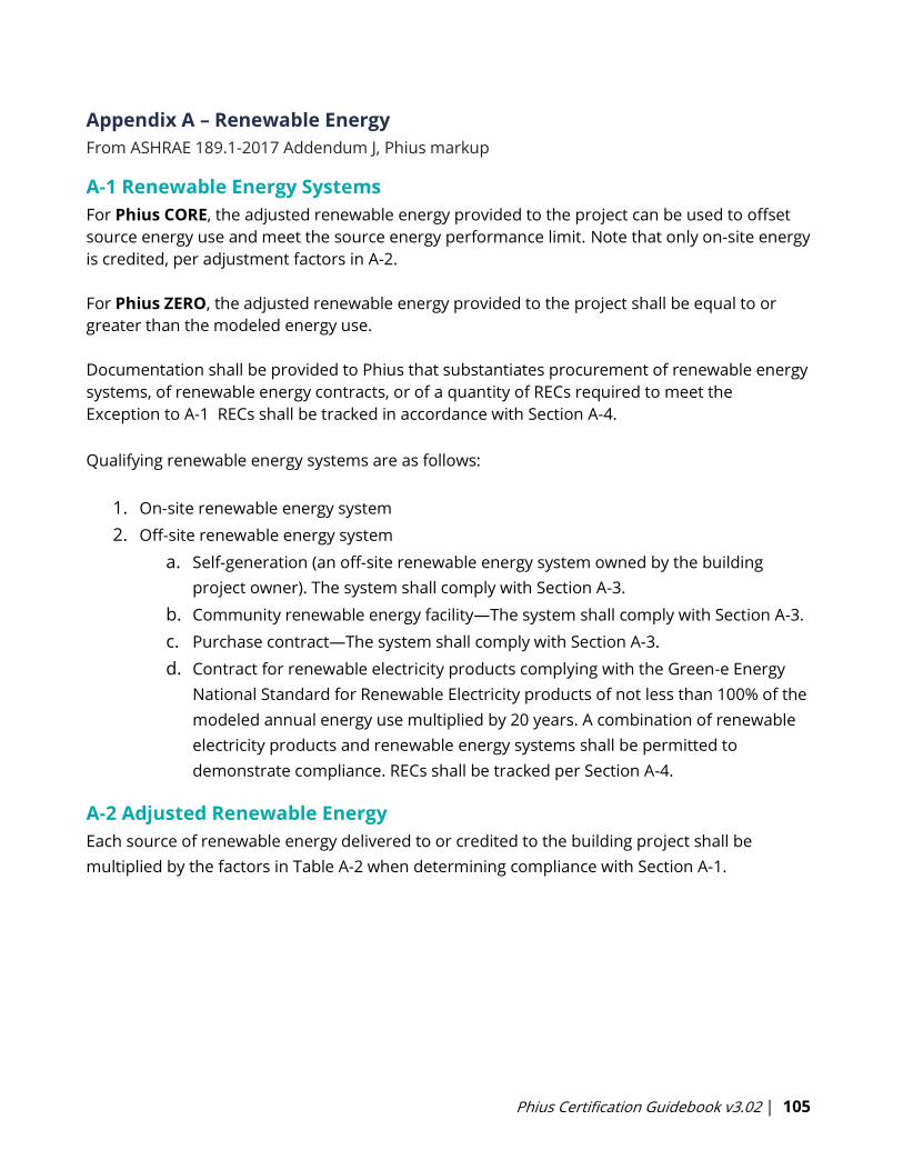
Phius Certification Guidebook v3.02 | 105
Appendix A – Renewable Energy
From ASHRAE 189.1-2017 Addendum J, Phius markup
A-1 Renewable Energy Systems
For Phius CORE, the adjusted renewable energy provided to the project can be used to offset
source energy use and meet the source energy performance limit. Note that only on-site energy
is credited, per adjustment factors in A-2.
For Phius ZERO, the adjusted renewable energy provided to the project shall be equal to or
greater than the modeled energy use.
Documentation shall be provided to Phius that substantiates procurement of renewable energy
systems, of renewable energy contracts, or of a quantity of RECs required to meet the
Exception to A-1 RECs shall be tracked in accordance with Section A-4.
Qualifying renewable energy systems are as follows:
1. On-site renewable energy system
2. Off-site renewable energy system
a. Self-generation (an off-site renewable energy system owned by the building
project owner). The system shall comply with Section A-3.
b. Community renewable energy facility—The system shall comply with Section A-3.
c. Purchase contract—The system shall comply with Section A-3.
d. Contract for renewable electricity products complying with the Green-e Energy
National Standard for Renewable Electricity products of not less than 100% of the
modeled annual energy use multiplied by 20 years. A combination of renewable
electricity products and renewable energy systems shall be permitted to
demonstrate compliance. RECs shall be tracked per Section A-4.
A-2 Adjusted Renewable Energy
Each source of renewable energy delivered to or credited to the building project shall be
multiplied by the factors in Table A-2 when determining compliance with Section A-1.
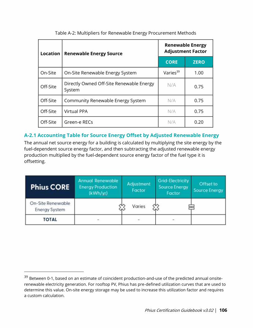
Phius Certification Guidebook v3.02 | 106
Table A-2: Multipliers for Renewable Energy Procurement Methods
Location Renewable Energy Source
Renewable Energy
Adjustment Factor
CORE ZERO
On-Site On-Site Renewable Energy System Varies39 1.00
Off-Site Directly Owned Off-Site Renewable Energy
System N/A 0.75
Off-Site Community Renewable Energy System N/A 0.75
Off-Site Virtual PPA N/A 0.75
Off-Site Green-e RECs N/A 0.20
A-2.1 Accounting Table for Source Energy Offset by Adjusted Renewable Energy
The annual net source energy for a building is calculated by multiplying the site energy by the
fuel-dependent source energy factor, and then subtracting the adjusted renewable energy
production multiplied by the fuel-dependent source energy factor of the fuel type it is
offsetting.
39 Between 0-1, based on an estimate of coincident production-and-use of the predicted annual onsite-
renewable electricity generation. For rooftop PV, Phius has pre-defined utilization curves that are used to
determine this value. On-site energy storage may be used to increase this utilization factor and requires
a custom calculation.
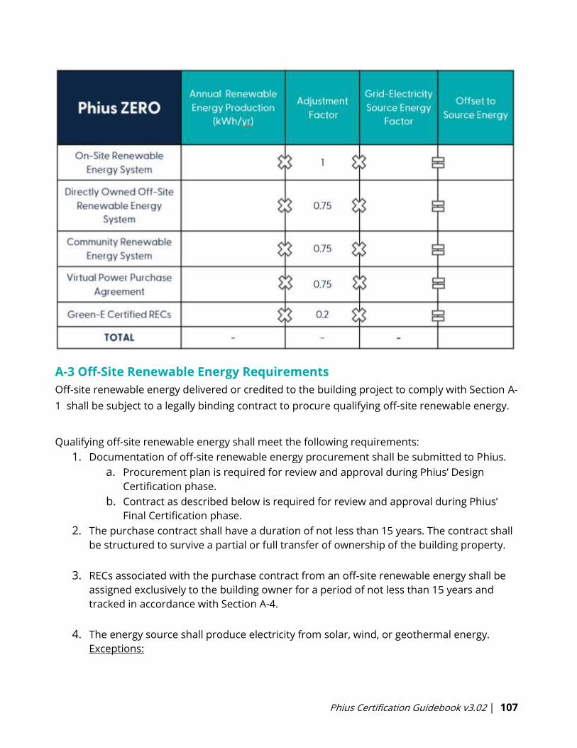
Phius Certification Guidebook v3.02 | 107
A-3 Off-Site Renewable Energy Requirements
Off-site renewable energy delivered or credited to the building project to comply with Section A-
1 shall be subject to a legally binding contract to procure qualifying off-site renewable energy.
Qualifying off-site renewable energy shall meet the following requirements:
1. Documentation of off-site renewable energy procurement shall be submitted to Phius.
a. Procurement plan is required for review and approval during Phius’ Design
Certification phase.
b. Contract as described below is required for review and approval during Phius’
Final Certification phase.
2. The purchase contract shall have a duration of not less than 15 years. The contract shall
be structured to survive a partial or full transfer of ownership of the building property.
3. RECs associated with the purchase contract from an off-site renewable energy shall be
assigned exclusively to the building owner for a period of not less than 15 years and
tracked in accordance with Section A-4.
4. The energy source shall produce electricity from solar, wind, or geothermal energy.
Exceptions:
Phius Certification Guidebook v3.02 | 108
a. Captured methane from feed-lots and landfills are permitted to be used to
generate electricity for the purposes of this section.
b. Hydropower from new generation capacity on a non-impoundment or new
generation capacity on an existing impoundment that meets one of the following
conditions:
i. The hydropower facility complies with the Low Impact Hydropower
Certification Handbook and is certified by a nationally recognized
accreditation organization.
ii. The hydropower facility complies with UL 2854 and is certified by an
organization that has the standard in its ISO 17065 scope of accreditation.
iii. The hydropower facility consists of a turbine in a pipeline or a turbine in
an irrigation canal. For facilities falling under either Exception, only output
generated during the period of certification is eligible for RECs sale in
accordance with the provisions of this section. Renewables from new
impoundments of water are not eligible.
5. The generation source shall be located where the energy can be delivered to the
building site by any of the following:
a. By direct connection to the off-site renewable energy facility
b. By the local utility or distribution entity
c. By an interconnected electrical network where energy delivery capacity between
the generator and the building site is available (Informative Note: Examples of
interconnected electrical networks include regional power pools and regions
served by Independent System Operators or Regional Transmission
Organizations.)
6. Records on renewable power purchased by the building owner from the off-site
renewable energy generator that specifically assign the RECs to the building owner shall
be retained or retired by the building owner on behalf of the entity demonstrating
financial or operational control over the building seeking compliance to this standard
and made available for inspection by Phius upon request. (Informative Note: Refer to
Sections A-4 and A-5 for tracking and allocation requirements.)
7. Where multiple buildings in a building project are allocated energy procured by a
contract subject to this section, the owner shall allocate for not less than 15 years the
energy procured by the contract to the buildings in the building project. (Informative
Note: Refer to Section A-5 for allocation requirements.)
A-4 Renewable Energy Certificate Tracking
The plan shall include provisions to use a REC tracking system that meets the requirements of
Section V.B of the Green-e Framework for Renewable Energy Certification. The plan shall
Phius Certification Guidebook v3.02 | 109
describe how the building owner will procure alternative qualifying renewable energy in the
case that the renewable energy producer ceases operation.
A-5 Renewable Energy Allocation to Multiple Buildings
Where renewable energy is allocated to multiple buildings in compliance with Section A-3 (7),
the plan shall indicate how renewable energy produced from on-site or off-site systems that is
not allocated before issuance of the certificate of occupancy will be allocated to new or existing
buildings included in the building project. The plan shall indicate who will be responsible for
retaining the documentation for allocations and where it will be stored so that it can be made
available for inspection by Phius upon request.
Where multiple buildings in a building project share a common utility interconnection and are
served by the same on-site renewable energy system, the building owner shall allocate for not
less than 15 years the annual REC generation of the on-site renewable energy system to the
buildings served by the system. The annual generation vintage date of delivered RECs shall be
allocated to the same 12-month reporting year, up to six months prior, or up to three months
after the calendar year in which the electricity is used in the building. The annual allocation of
RECs shall be documented as part of the plan. The plan shall indicate who will be responsible
for retaining the documentation and where it will be stored so that it can be made available for
inspection by Phius upon request.
Phius Certification Guidebook v3.02 | 110
Appendix B – Moisture Control Guidelines for Opaque Assemblies
Excerpted from Straube (2012), Section 3.4.1, with some revisions.
Different types of assemblies have different vapor control requirements. Although the
requirements can be developed through rational engineering analysis, a simplified summary of
recommendations, many from the “I” codes, is presented below.
B-1 General Moisture Control Guidelines
There are three compliance paths:
• Follow the prescriptive moisture control guidelines listed in this Appendix B.
• Meet performance criteria by WUFI hygrothermal analysis, according to the protocol found
here (fee may apply, see also Section 5.4). More in Appendix I-3.
• Present a moisture-engineered design by a qualified licensed professional engineer.
Assemblies that do not fit the prescriptive category descriptions do not have a prescriptive
path.
Exterior load-bearing double-stud walls do not have a prescriptive path.
Floors with more than 2.5 inches (5 cm) of air-permeable insulation or acoustic material do not
have a prescriptive path, unless they are suspended floors accessible from below for repair,
and are not subject to bulk water events per plumbing plans, in which case the vapor control
requirements for walls apply.
B-1.1 Things to Avoid
In general, Phius recommends against using wet spray cellulose.
“Vapor-sandwiched” or “double vapor barrier” assemblies: These should generally be
avoided and can make a project uncertifiable. There are some subtleties, e.g., it may be
acceptable in compact roof assemblies. See these articles for a more detailed discussion [BSI-
073] [BSI-092]. That discussion starts with "For the record, it makes no sense to have a vapor
barrier on both sides of an assembly. If the assembly gets wet or starts out wet, we are pretty
much doomed…except if we are perfect and we start out dry.”
Building Science Corporation BSI-073: Macbeth Does Vapor Barriers
Building Science Corporation BSI-092: Doubling Down-How Come Double Vapor Barriers Work?
Phius Certification Guidebook v3.02 | 111
B-2 Moisture Control Guidelines for Walls
B-2.1 Above-Grade Wall Assemblies
Four categories of above-grade wall assemblies include most of the possible
enclosures:
a) Framed assemblies with all or most of the insulation inside of the sheathing and
between the framing members,
b) Framed assemblies with some insulation outboard of the framing and some
insulation between the framing members,
c) Assemblies with all or most of the insulation outboard of the structure (framed or
solid), and
d) Assemblies with insulation comprised only of air-impermeable and Class II vapor
control insulation between, within, or outside of the structure.
a) Framed wall assemblies with all or most of the insulation value installed
between the framing or structure (e.g. wood or steel stud) as vapor permeable
(more than 10 perm) insulation (e.g., fiberglass, rockwool, cellulose, or open cell
foam).
The goal of the vapor control design is to prevent vapor diffusing easily and condensing on
either the cold sheathing in cold weather or the cold interior finish during warm weather.
• No vapor control layer is needed in climate zones 1,2,3,4a or 4b.
o Smart membranes such as Membrain & Intello are not recommended in
hot/humid40 and mixed/humid40 climates.
• A Class I or Class II vapor control layer is required on the interior side of framed walls in
zones 4c, 5, 6, 7, and 8, with the exceptions of basement walls, below-grade portion of
any wall, and wall construction that is not sensitive to moisture or freezing (e.g.,
concrete).
• Class I vapor control layers including non-perforated vinyl wallpaper, reflective foil, glass,
epoxy paint, white boards, melamine, etc. are not recommended and should be avoided
on the interior of air-conditioned building occupancies in climates with humid summers
in zones 1-6. The dividing line between dry (B) and moist (A) can be found in ASHRAE
90.1. Enclosures clad with unvented water absorbent claddings (e.g., stucco, masonry,
40 The climate zones noted here are defined by the Building America Zoning system.
Phius Certification Guidebook v3.02 | 112
fiber cement, wood) are at especially high risk of summer condensation.
• A Class III vapor retarder can be used instead of a Class I or Class II when:
o In zones 4c, or 5, vented cladding is used over sheathing with a perm rating of
more than 1 (wet-cup), i.e., OSB, plywood, or exterior gypsum sheathing; or
o In zone 6, vented cladding is used over high permeance (more than 10 perm)
sheathings such as fiberboard and exterior gypsum.
Vented claddings include vinyl siding, metal panels, terra cotta, wood or fiber cement sidings on
air gaps, and masonry veneers with clear airspaces and vent openings top and bottom. A clear
gap of around ⅜” (10mm) will generally provide sufficient airflow to allow for ventilation, but at
least 1” (25mm) should be specified for masonry walls.
_______________________________________________________________________
Exterior Load Bearing Double-Stud Walls
This wall type is discouraged in climate zones 3 and higher. They tend to be too vapor-closed on
the outside for those climates and put the air barrier on the exterior where it will be less
durable than a mid-wall air barrier.
These will generally incur additional certification cost for hygrothermal analysis (WUFI).
If they are of the “flash and fill” type and insulation with a high global warming potential is used
(some closed cell spray foam or XPS), PHIUS may ask the project team to complete a global
warming potential calculation to assess the overall impact of the insulation.
In heating dominated climates, double stud walls should be of the interior load-bearing type,
either Larsen truss (standoff truss) or the kind described in [9], [10].
_______________________________________________________________________
b) Framed assemblies with some insulation value outside of the framing or
structure.
The use of insulation on the exterior of the sheathing increases its temperature in cold weather,
thereby relaxing the need to control cold-weather vapor diffusion. Exterior insulation made of
foamed plastic has the benefit that it also tends to reduce inward vapor drives during warm
weather. MFI insulation work different in that they allow more outward drying. 24
A Class III vapor control layer shall be used on the interior of framed walls in zone 4c and
higher, and any of the following criteria met: 25
• Zone 4c (e.g., Vancouver, Seattle, or Portland)
o Sheathing-to-cavity R-value ratio of >0.20
Phius Certification Guidebook v3.02 | 113
o Insulated sheathing with an R-value >2.5 on a 2x4 framed wall
o Insulated sheathing with an R-value >3.75 on a 2x6 framed wall
• Zone 5 (e.g., Chicago, Windsor, Boston)
o Sheathing-to-cavity R-value ratio of >0.35
o Insulated sheathing with an R-value >= 5 (e.g., 1” XPS) on a 2x4 framed wall
o Insulated sheathing with an R-value >= 7.5 (e.g., 1.5” XPS) on a 2x6 framed wall
• Zone 6 (e.g., Toronto, Ottawa, Helena, Montreal, Halifax, Minneapolis)
o Sheathing-to-cavity R-value ratio of >0.50
o Insulated sheathing with an R-value >= 7.5 (e.g., 1.5” XPS) on a 2x4 framed wall
o Insulated sheathing with an R-value >= 11.25 (e.g. 2” PIC) on a 2x6 framed wall
• Zones 7 and 8 (e.g., Calgary, Edmonton, Whitehorse, Anchorage, Fairbanks)
o Sheathing-to-cavity R-value ratio of >0.70
o Insulated sheathing with an R-value >=10 (e.g., 2” XPS) on a 2x4 framed wall
o Insulated sheathing with an R-value >=15 (e.g., 3” XPS) on a 2x6 framed wall
Insulated sheathing can be installed in the form of expanded polystyrene (EPS) or semi-rigid
glass fiber and rockwool with approximately R-4 per inch, extruded polystyrene (XPS) with R-5
per inch, polyisocyanurate (PIC) with approximately R-6 per inch or closed-cell spray foam
(usually around R-6/inch).
Note: For walls, the sheathing-to-cavity R-value ratio is specified. This is different from the roof, which
specifies a sheathing R-value as a percentage of the total assembly R-value.
c) Assemblies with all or most (more than 75% of the total) of the insulation value
located outboard of the structure (framing or solid).
This is the simplest and most robust wall to design with respect to vapor control. Such walls
should ideally have all moisture sensitive components and materials located on the inside of
the insulation. In this location, a Class I or II layer on the inside of all or most of the insulation
value is acceptable and recommended if all outboard components are moisture tolerant.26 A
Class III layer on the interface of a high permeance (more than 10 perms) insulation layer
outboard of a moisture-sensitive structure should only be used if warm weather and inward
vapor drive condensation are not an issue or are controlled by other means.
d) Assemblies comprised of only air-impermeable and Class II vapor control
insulation between, within, or outside the structure.
The EPS and urethane foam cores of wood or metal SIPS, board foams, and medium density
closed cell spray foam (between wood or steel studs), if installed as continuous layers, all
provide their own vapor control layers and require no additional vapor-diffusion control in any
climate. Wood studs and small cracks between steel or wood studs do not allow significant
vapor to flow by diffusion. Their use does not change the recommendations.
Phius Certification Guidebook v3.02 | 114
Cracks between framing members and insulation boards are often significant for airflow
control and must be addressed in all the systems described in the previous paragraph.
B-2.2 Below-Grade Wall Assemblies
Below-grade spaces, such as basements, are of particular concern with respect to improperly
located Class I vapor control layers. Because the moisture drive in below-grade walls is always
from the exterior to the interior in zones 6 and lower, installing a low-permeance layer on the
interior side of insulation wall will cause moisture related durability issues by trapping moisture
in the enclosure. A Class I vapor control layer outside a concrete or masonry basement wall is
recommended to control the flow of vapor from damp soil into the assembly. Installing a Class
II vapor control layer on the inside of below-grade framed assemblies is recommended for
zones 7 and higher.
In cold climates (zone 5 and higher), condensation may occur on the interior side of
concrete/masonry structure of a below-grade wall assembly if insulated on the inside with an
air and vapor permeable (Class II or more, e.g., fibrous insulation) layer. To control both inward
and outward drives, it is recommended that a Class II or III insulation product (e.g. most foams)
be used in contact with the interior face of the concrete/masonry, and any insulation installed
between interior framing follow the rules of “Framed assemblies with some insulation value
outside of the framing or structure.”
B-2.3 Masonry Walls and Freeze-Thaw
Interior insulation retrofits of masonry walls in cold climates can cause durability problems.
Please review the information in these articles: [11] [12] [13] Certification staff may require a
“hold harmless” agreement.
Phius Certification Guidebook v3.02 | 115
B-3 Moisture Control Guidelines for Roofs
Roofing behaves differently than walls from a vapor control point of view for several reasons:
most roof membranes are located on the exterior and provide Class I vapor control. Roof
membranes, shingles, metal roofing are all vapor impermeable. Only back-ventilated roofing
such as concrete ties perform in a similar manner to walls.
Assuming a vapor impermeable roofing membrane, four categories of roof assemblies will
include most practical roofing systems:
a) Unvented roof assemblies with all or most of the insulation outboard of the structure
(framed or solid),
b) Vented, framed roof assemblies with all or most of the insulation inside of the sheathing
and between the framing members,
c) Unvented, framed roof assemblies with either some insulation outboard of the framing
and some insulation between the framing members, or some air-impermeable
insulation outboard of air-impermeable insulation, and
d) Unvented roof assemblies with insulation comprised of air-impermeable and Class II
vapor control between, within, or outside the structure.
a) Unvented roof assemblies with all or most (>75%) of the insulation outboard of
the structure (framed or solid).
These types of roofs comprise most of the low-slope, rigid board insulated; commercial roof
systems installed over metal and concrete decks. However, there is no technical difference
between a low-slope roof built in this manner and a sloped roof. This type of roof has very little
need for additional vapor control as all the common board foam roofing insulations (PIC, EPS,
XPS) provide sufficient vapor control for most climate zones.
• No additional vapor control layer is needed if a Class II vapor control insulation layer is
used (>2” of XPS, PIC, >3” of EPS).
• To control diffusion at joints in board foam, all board insulation should be installed in
two layers or more, with joints offset vertically and horizontally. This is especially
important in zones 5 and higher.
Such roofs should ideally have all moisture sensitive components and materials located to the
inside of the insulation. In this location a Class I or II layer on the inside of all or most of the
insulation value (e.g., 75%) is acceptable but will restrict desirable and effective inward drying.
For zones 5 and lower, a vapor control layer of Class III or higher is recommended to allow for
inward drying of incidental moisture due to solar heating to roof membranes (e.g., gypsum
board on metal deck).
Phius Certification Guidebook v3.02 | 116
b) Vented, framed roof assemblies with all or most of the insulation value
installed between the framing (e.g., wood/steel stud, metal buildings) as vapor
permeable (more than 10 perm) insulation (e.g., fiberglass, rockwool, cellulose, or
open cell foam).
If a compact roof is well-vented above the insulation (i.e., with soffit and ridge vents connected
by an open air-space of 1.5”/38mm or more):
• No vapor control layer is required in zones 1 through 3
o Smart membranes such as Membrain & Intello are not recommended in
hot/humid41 and mixed/humid41 climates.
• Class III vapor control in zones 4 through 6
• Class II vapor control in zones 7 and higher
If a roof is sloped over a well-vented attic (i.e., with soffit and ridge vents connected by an open-
air volume of at least 12” (300mm) average height, and no less than 1.5”/38mm anywhere):
• No vapor control layer is required in zones 1 through 4.
• Class III vapor control layer is recommended for zones 5 through 6.
• Class II vapor control layer is recommended in zones 7 and higher.
Unvented, framed assemblies with all the insulation value comprised of air permeable
insulation (fiberglass, rockwool, cellulose) between the framing are not recommended due to
the potential for air leakage condensation.
c) Unvented framed roof assemblies with some insulation provided by air
impermeable insulation.
Roofs need not be vented if diffusion and air leakage related wetting can be strictly limited. To
accomplish this, some air impermeable, some Class II insulation can be located outside of air
and vapor permeable (more than 10 perm) insulation (e.g., fiberglass, rockwool, and cellulose
are both).
The ratio of the insulation value of the exterior air- and vapor-control insulation to the
insulation value of the interior air- and vapor-permeable insulation increases as the climate
becomes colder, and the interior more humid. For normal commercial and residential
occupancies, the following recommendations can be made.
41 The climate zones noted here are defined by the Building America Zoning system.
Phius Certification Guidebook v3.02 | 117
(Note: painted drywall or more than about 150mm/6” of open cell foam are Class III retarder)
• For zones 1 through 3A, 3B
o Outer air-impermeable insulation value >15% of total
o No vapor control layer required.
• For zones 3c/4c (e.g. Vancouver, Seattle, Portland, San Francisco)
o Outer air-impermeable insulation value >25% of total
o Class III vapor control
• Zone 4A, 4B, 5 (e.g. Windsor, Kansas City, Boston)
o Outer air-impermeable insulation value >35% of total
o Class III vapor control in zone 5
• Zone 6 (e.g. Toronto, Ottawa, Montreal, Halifax, St Johns, Minneapolis)
o Outer, air-impermeable insulation value >50% of total
o Class III vapor control
• Zones 7 and 8 (e.g. Edmonton, Calgary, Winnipeg, Whitehorse, Fairbanks)
o Outer, air-impermeable insulation value >65% of total
• Class III vapor control
Note: For roofs, a sheathing R-value as a percentage of the total assembly R-value is specified. This is
different from walls which prescribe the sheathing-to-cavity R-value ratios.
Air-impermeable insulation can be in the form of expanded polystyrene (EPS) with
approximately R-4 per inch, extruded polystyrene (XPS) with R-5 per inch, polyisocyanurate (PIC)
with approximately R-6 per inch, 2 pcf (32 kg/m3) closed-cell spray foam (usually around R-6 per
inch) or 0.5 pcf (8 kg/m3) open cell spray foam (usually around R-4 per inch). All of these
products, other than open-cell spray foam and EPS, provide a Class II vapor control layer in
thicknesses of 1.5” or more. EPS and 1 pcf density (16 kg/m3) which requires between 3” and 5”
(depending on density) to reach Class II performance, and open cell foam requires a special
vapor control coating.
d) Unvented roof assemblies with insulation comprised of only air-impermeable
and Class II vapor control insulation between, within, or outside the structure.
The EPS and urethane foam cores of wood or metal SIPS, board foams, and medium density
closed cell spray foam (between wood or steel studs), if installed as continuous layers, all
provide their own vapor control layers and require no additional vapor diffusion control in any
climate with normal residential and commercial interior humidity conditions. Wood studs and
cracks between steel or wood studs do not allow significant vapor to flow by diffusion and
hence do not change the recommendations.
Cracks between framing members and panels are significant for airflow control and must be
addressed in all the systems described above. A very effective airflow control layer is required
on the inside of the insulation and/or framing for all unvented roof assemblies.

Phius Certification Guidebook v3.02 | 118
B-4 Moisture Control Guidelines for Floors
Floors that are subject to “bulk water events42” from above have trouble drying out.
B-4.1 Floors with Air Permeable Insulation
The use of fluffy (air permeable) insulation in floors is preferably limited to a thin layer near the
inside for sound deadening purposes.
• Floors with fluffy insulation and with plumbing fixtures or hot water tanks in a room
above must have a water resisting layer above the fluffy insulation, such as a vapor
permeable weather resistive membrane or an impermeable waterproofing.
• Floors with more than 2.5 inches (5 cm) of air-permeable insulation or acoustic material
must pass the hygrothermal performance test according to the protocol in Moisture Risk
Analysis & Assessment using WUFI (v1.0 or later). Floor that are subject to bulk water
events from above due to the plumbing plan, are evaluated with an initial condition
representing a post-water-leak condition.
• For suspended floors that are accessible from below for repair, and that are not subject
to bulk water events from above per plumbing plans, the vapor control requirements for
walls apply.
Advisory notes on particular situations:
One situation that will usually fail the performance test is the case of a fluffy floor directly on a
slab in a cold climate, or only a thin layer of rigid on the bottom and slab or ground directly
below. These might pass in hot climates, but in cold climates there is a high risk that the floor
would never dry out from a bulk water event, and repair could be expensive, requiring removal
of interior walls.
Another situation of concern is the case of a crawlspace in a mixed climate with humid
summers. In the summer these benefit from air-impermeable insulation on the bottom, as
noted in (Lstiburek 2010). But with fluffy cavity insulation, this creates a tradeoff with moisture
accumulation on the cold side of the cavity in the winter, and with the ability to dry from a
indoor wetting event, unless the air-impermeable insulation is thick enough.
For floors without air-impermeable insulation, over a crawlspace or garage, or cantilevered over
outdoor ambient conditions, hydrophobic insulation such as fiberglass or most preferably
mineral wool, is preferable to cellulose (drain-down strategy instead of buffering.)
42 Bulk water events include water heater failure, floods from dishwashers, clothes washers,
sink/tub/toilet overflows, wet-pipe or dry-pipe sprinkler systems, but not incidental beverage spills or
water lines to residential freezer ice-makers.
Phius Certification Guidebook v3.02 | 119
B-4.2 Below-Grade Floor Assemblies
Locating all the insulation below the structure (concrete slab or framed) with a Class I vapor
control layer between the structure and the insulation is the practical and economical
manifestation of the perfect enclosure. Some insulations provide the same level of vapor
control (foil-faced polyiso or EPS, plastic-faced XPS) but many products will require a special
low-permeance layer (polyethylene sheet is commonly used, inexpensive, and effective).
If no impermeable floor finishes are likely to be used during the life of the structure, the vapor
control class requirement can be relaxed to a Class II. See also BSI-003: Concrete Floor
Problems and BSI-009: New Light in Crawlspaces online at buildingscience.com for more
discussion of vapor control and flooring.
Phius Certification Guidebook v3.02 | 120
Appendix C – Method for Evaluating when a Cooling System is
Recommended
Some designers are quite set against the use of cooling systems, and indeed, with
regard to the building code, the “cooling-is-a-luxury” perspective survived the introduction of
air-conditioning. North American building codes do not require a cooling system in any climate,
nor do the U.S. Energy Star requirements which are part of the Phius certification program.
The question of when to design in a cooling system could be decided with reference to ASHRAE
55. Clause 5.4 lays out the procedure for determining Acceptable Thermal Conditions in
Occupant-Controlled Naturally Conditioned Spaces, based on the climate.
Reviewing the daily mean outside temperatures in the hottest part of the year, calculates a
running average, and then from a graph/formulas determines the acceptable range of indoor
operative temperature, which cannot be any higher than 89 F regardless of climate. The
formula for the upper limit is:
0.31 * Tpma-out + 60.5 F
where Tpma-out is the “prevailing mean outdoor temperature”.
Tpma-out must be less than 92.3 F. (There is also a lower limit which is 12.6 F cooler.)
• Up to another 4.0 F can be added to the upper limit if increased air speed of 236 fpm
can be provided (with fans).
For the Tpma-out calculation the language of ASHRAE 55 prefers TMY3 or actual daily weather
data, but monthlies are allowed if those are not available. Seven to thirty days of averaging is
acceptable. For example, in Dubuque, Iowa, picking in the middle at 18 days (432 hours) and
running the average, Tpma-out tops out at 73.9 F which is a little warmer than the 70.2
maximum in the monthly file.
This makes the upper operative temperature limit (Top):
Top = 0.31 * 70.2 + 60.5 = 82.2 F, by monthly data maximum
Top = 0.31 * 73.9 + 60.5 = 83.4 F, by TMY3 18-day running average
Going by the monthly, then with the air speed adjustment the limits are
Top = 82.2 + 2.2 = 84.4 F, for air speed 118 fpm
Top = 82.2 + 3.2 = 85.4 F, for air speed 177 fpm
Top = 82.2 + 4.0 = 86.2 F, for air speed 236 fpm
It may be fair to credit the 118 fpm if there are any ceiling. U.S. Energy Star ratings for ceiling
fans report air flow in cubic feet per minute, which can be converted to fpm directly under the
fan using the fact that the test duct is a cylinder eight inches larger in diameter than the fan. Air
Phius Certification Guidebook v3.02 | 121
speed in the room could be then estimated from consideration of the room cross section
compared to the fan.
Phius’ protocol is outlined as follows:
A cooling system may reasonably be foregone if:
• Representative occupants have metabolic rates ranging from 1.0 to 1.3 met.
• Representative occupants are free to adapt their clothing to the indoor and/or outdoor
conditions within a range at least as wide as 0.5 to 1.0 Clo.
• The prevailing mean outdoor temperature Tpma-out (monthly max) is greater than 50 F and
less than 92.3 F.
• WUFI Passive model calculates no cooling load with a cooling set point of 0.31 * Tpma-out +
60.5 F (plus 2.2 F if there are ceiling fans).
o Input the upper-limit temperature into the building’s WUFI Passive energy model as a
cooling set-point.
o Natural ventilation for day/night may be modeled, but no higher than B.A. protocol
allows as outlined in section 6.7.3 Summer Ventilation.
The conditions on the representative occupants might always be assumed true for residential
but might not be for nonresidential. However, as noted above, residential occupancies are
demographically more likely to be occupied by sensitive people than workplaces, so a cooling
system is more strongly advisable for residential.
Phius Certification Guidebook v3.02 | 122
Appendix D - ASHRAE Fundamentals 2017 Non-Residential Equipment
Tables
Table 8A: Recommended Heat Gain for Typical Desktop Computers
Table 8B: Recommended Heat Gain for Typical Laptops and Laptop Docking Stations
Table 8C: Recommended Heat Gain for Typical Tablet PC
Table 8D: Recommended Heat Gain for Typical Monitors
Table 9: Recommended Heat Gain for Typical Printers
Table 10: Recommended Heat Gain for Miscellaneous Equipment
Table 11: Recommended Load Factors for Various Types of Offices
Table 12: Diversity Factor for Different Equipment
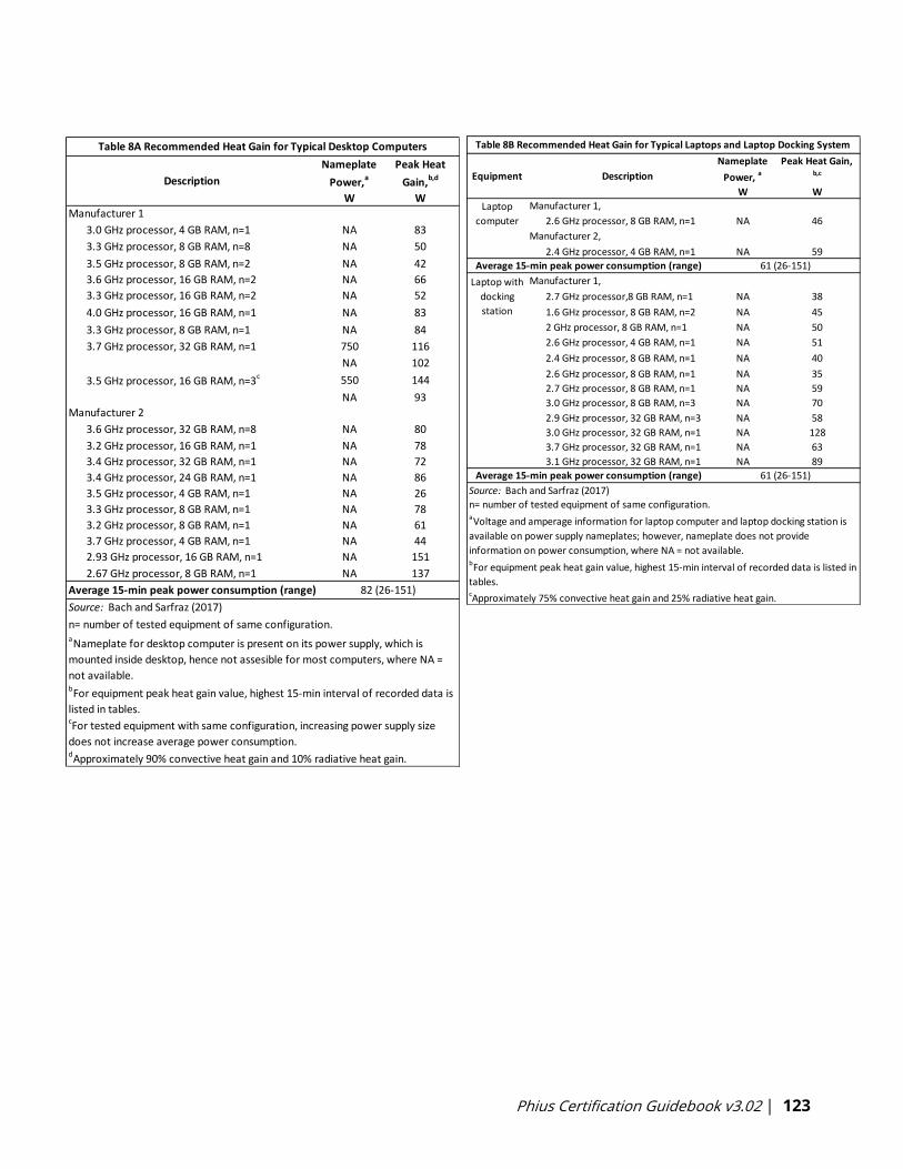
Phius Certification Guidebook v3.02 | 123
Equipment Description
Nameplate
Power, a
W
Peak Heat Gain, b,c
W
2.6 GHz processor, 8 GB RAM, n=1 NA 46
2.4 GHz processor, 4 GB RAM, n=1 NA 59
2.7 GHz processor,8 GB RAM, n=1 NA 38
1.6 GHz processor, 8 GB RAM, n=2 NA 45
2 GHz processor, 8 GB RAM, n=1 NA 50
2.6 GHz processor, 4 GB RAM, n=1 NA 51
2.4 GHz processor, 8 GB RAM, n=1 NA 40
2.6 GHz processor, 8 GB RAM, n=1 NA 35
2.7 GHz processor, 8 GB RAM, n=1 NA 59
3.0 GHz processor, 8 GB RAM, n=3 NA 70
2.9 GHz processor, 32 GB RAM, n=3 NA 58
3.0 GHz processor, 32 GB RAM, n=1 NA 128
3.7 GHz processor, 32 GB RAM, n=1 NA 63
3.1 GHz processor, 32 GB RAM, n=1 NA 89
Source: Bach and Sarfraz (2017)
aVoltage and amperage information for laptop computer and laptop docking station is
available on power supply nameplates; however, nameplate does not provide
information on power consumption, where NA = not available.
Table 8B Recommended Heat Gain for Typical Laptops and Laptop Docking System
Laptop
computer
Average 15-min peak power consumption (range) 61 (26-151)
Average 15-min peak power consumption (range) 61 (26-151)
Laptop with
docking
station
bFor equipment peak heat gain value, highest 15-min interval of recorded data is listed in
tables.cApproximately 75% convective heat gain and 25% radiative heat gain.
Manufacturer 1,
Manufacturer 2,
Manufacturer 1,
n= number of tested equipment of same configuration.
Nameplate
Power,a
W
Peak Heat
Gain,b,d
W
3.0 GHz processor, 4 GB RAM, n=1 NA 83
3.3 GHz processor, 8 GB RAM, n=8 NA 50
3.5 GHz processor, 8 GB RAM, n=2 NA 42
3.6 GHz processor, 16 GB RAM, n=2 NA 66
3.3 GHz processor, 16 GB RAM, n=2 NA 52
4.0 GHz processor, 16 GB RAM, n=1 NA 83
3.3 GHz processor, 8 GB RAM, n=1 NA 84
3.7 GHz processor, 32 GB RAM, n=1 750 116
NA 102
3.5 GHz processor, 16 GB RAM, n=3c 550 144
NA 93
3.6 GHz processor, 32 GB RAM, n=8 NA 80
3.2 GHz processor, 16 GB RAM, n=1 NA 78
3.4 GHz processor, 32 GB RAM, n=1 NA 72
3.4 GHz processor, 24 GB RAM, n=1 NA 86
3.5 GHz processor, 4 GB RAM, n=1 NA 26
3.3 GHz processor, 8 GB RAM, n=1 NA 78
3.2 GHz processor, 8 GB RAM, n=1 NA 61
3.7 GHz processor, 4 GB RAM, n=1 NA 44
2.93 GHz processor, 16 GB RAM, n=1 NA 151
2.67 GHz processor, 8 GB RAM, n=1 NA 137
Table 8A Recommended Heat Gain for Typical Desktop Computers
Description
Manufacturer 1
Manufacturer 2
Average 15-min peak power consumption (range)
Source: Bach and Sarfraz (2017)
bFor equipment peak heat gain value, highest 15-min interval of recorded data is
listed in tables.cFor tested equipment with same configuration, increasing power supply size
does not increase average power consumption.dApproximately 90% convective heat gain and 10% radiative heat gain.
aNameplate for desktop computer is present on its power supply, which is
mounted inside desktop, hence not assesible for most computers, where NA =
not available.
82 (26-151)
n= number of tested equipment of same configuration.
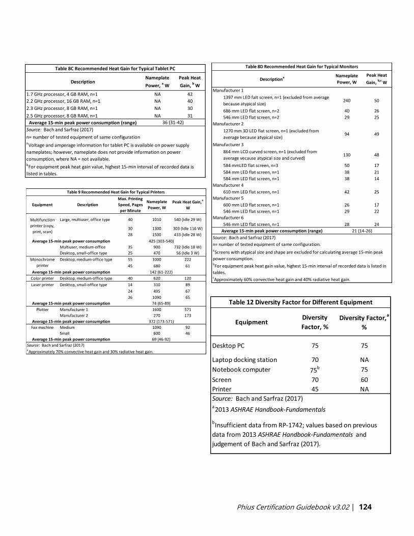
Phius Certification Guidebook v3.02 | 124
DescriptionNameplate
Power, a W
Peak Heat
Gain, b W
1.7 GHz processor, 4 GB RAM, n=1 NA 42
2.2 GHz processor, 16 GB RAM, n=1 NA 40
2.3 GHz processor, 8 GB RAM, n=1 NA 30
2.5 GHz processor, 8 GB RAM, n=1 NA 31
Average 15-min peak power consumption (range)
Table 8C Recommended Heat Gain for Typical Tablet PC
36 (31-42)
aVoltage and amperage information for tablet PC is available on power supply
nameplates; however, nameplate does not provide information on power
consumption, where NA = not available.bFor equipment peak heat gain value, highest 15-min interval of recorded data is
listed in tables.
n= number of tested equipment of same configuration
Source: Bach and Sarfraz (2017)
Nameplate
Power, W
Peak Heat
Gain, b,c W
686 mm LED flat screen, n=2 40 26
546 mm LED flat screen, n=2 29 25
584 mmLED flat screen, n=3 50 17
584 mm LED flat screen, n=1 38 21
584 mm LED flat screen, n=1 38 14
610 mm LED flat screen, n=1 42 25
600 mm LED flat screen, n=1 26 17
546 mm LED flat screen, n=1 29 22
546 mm LED flat screen, n=1 28 24
21 (14-26)
1397 mm LED falt screen, n=1 (excluded from average
because atypical size)240 50
1270 mm 3D LED flat screen, n=1 (excluded from
average because atypical size)
864 mm LCD curved screen, n=1 (excluded from
average vecause atypical size and curved)
94
Manufacturer 4
Manufacturer 5
Manufacturer 6
Average 15-min peak power consumption (range)
130 48
49
Descriptiona
Table 8D Recommended Heat Gain for Typical Monitors
Manufacturer 1
Manufacturer 2
Manufacturer 3
aScreens with atypical size and shape are excluded for calculating average 15-min peak
power consumption.bFor equipment peak heat gain value, highest 15-min interval of recorded data is listed in
tables.cApproximately 60% convective heat gain and 40% radiative heat gain.
Source: Bach and Sarfraz (2017)
n= number of tested equipment of same configuration.
EquipmentDiversity
Factor, %
Diversity Factor,a
%
Desktop PC 75 75
Laptop docking station 70 NA
Notebook computer 75b 75
Screen 70 60
Printer 45 NA
Table 12 Diversity Factor for Different Equipment
Source: Bach and Sarfraz (2017)a2013 ASHRAE Handbook-Fundamentals
bInsufficient data from RP-1742; values based on previous
data from 2013 ASHRAE Handbook-Fundamentals and
judgement of Bach and Sarfraz (2017).
Equipment Description
Max. Printing
Speed, Pages
per Minute
Nameplate
Power, W
Peak Heat Gain,a
W
Large, multiuser, office type 40 1010 540 (Idle 29 W)
30 1300 303 (Idle 116 W)
28 1500 433 (Idle 28 W)
Multiuser, medium-office 35 900 732 (Idle 18 W)
Desktop, small-office type 25 470 56 (Idle 3 W)
Desktop, medium-office type 55 1000 222
45 680 61
Color printer Desktop, medium-office type 40 620 120
Laser printer Desktop, small-office type 14 310 89
24 495 67
26 1090 65
Plotter Manufacturer 1 1600 571
Manufacturer 2 270 173
Fax machine Medium 1090 92
Small 600 46
Average 15-min peak power consumption 74 (65-89)
Average 15-min peak power consumption 372 (173-571)
Table 9 Recommended Heat Gain for Typical Printers
Multifunction
printer (copy,
print, scan)
Average 15-min peak power consumption 425 (303-540)
Monochrome
printer
Average 15-min peak power consumption 142 (61-222)
Source: Bach and Sarfraz (2017)aApproximately 70% convective heat gain and 30% radiative heat gain.
69 (46-92)Average 15-min peak power consumption

Phius Certification Guidebook v3.02 | 125
Nameplate
Power,a W
Peak Heat
Gain,b W
Drinks, 280 to 400 items NA 940
Snakcs NA 54
Food (e.g., for sandwiches) NA 465
340 308
1415 265
NA 1.5
220 15
NA 5
40 V NA 19
AA NA 5.5
1000 to 1550 713 to 822
Single cup 1400 385
Up to 12 cups 950 780
With grinder 1350 376
NA 73
1200 1200
NA 57
130 125
NA 387 to 430
NA 658
NA 114 to 350
25 9
NA 15
Table 10 Recommended Heat Gain for Miscellaneous Equipment
Equipment
Vending machine
Thermal building machine, 2 single documents
up to 340 pages
Projector, resolution 1024 x 768
Paper shredder, up to 28 sheets
Dorm fridge, 3.1 ft3
Freezer, 18 ft3
Fridge, 18 to 28 ft3
Electric stapler, up to 45 sheets
Speakers
Cell phone station
Microwave oven, 7 to 9 gal
Temperature-controlled electronics soldering
station
Source: Bach and Sarfraz (2017)aFor some equipment, nameplate power consumption is not availbale,
where NA= not available.bFor equipment peak heat gain value, highest 15-min interval of recorded
data is listed in tables.
350
95 16
28.5
NA 58
Ice maker and dispenser, 20 lb. bin capacity
Top mounted bottled water cooler
Cash register
Self-checkout machine
Battery charger
Coffee maker
Touch screen computer, 15 in. standard LCD
and 2.2 GHz processor
Coffee grinder, up to 12 cups
Tea kettle, up to 6 cups
Load Factor*,
W/ft2 Description
light 0.34
medium 0.46
light 0.44
medium 0.59
light 0.54
medium 0.72
2 screens 0.69
2 screens 0.84
3 screens 0.96
heavy, 2 screens 1.02
heavy, 3 screens 1.16
full on, 2 screens 1.14
full on, 2 screens 1.33
full on, 3 screens 1.53
167 ft2/workstation, 50% laptop docking
station use/50% desktop, 1 printer per 10
125 ft2/workstation, 50% laptop docking
station use/50% desktop, 1 printer per 10
167 ft2/workstation, all desktop use, 1 printer
per 10
125 ft2/workstation, all desktop use, 1 printer
per 10
167 ft2/workstation, all laptop docking station
use, 1 printer per 10
125 ft2/workstation, all laptop docking station
use, 1 printer per 10
*Medium-office type monochrome printer is used for load factor calculator with 15-
min peak power consumption of 142 W.
100% laptop, docking station
100% desktop
100% desktop
100% laptop, docking station
100% desktop
Source: Bach and Sarfraz (2017)
85 ft2/workstation, all laptop docking use, 2
screens, 1 printer per 8, no diversity
85 ft2/workstation, all desktop use, 3 screens,
1 printer per 8, no diversity
Table 11 Recommended Load Factors for Various Types of Offices
Type of Use
100% laptop, docking station
50% laptop, docking station
100% desktop
85 ft2/workstation, all desktop use, 3 screens,
1 printer per 8
85 ft2/workstation, all desktop use, 2 screens,
1 printer per 8, no diversity
125 ft2/workstation, all laptop docking station
use, 2 screens, 1 printer per 10
125 ft2/workstation, all desktop use, 2
screens, 1 printer per 10
125 ft2/workstation, all desktop use, 3
screens, 1 printer per 10
85 ft2/workstation, all desktop use, 2 screens,
1 printer per 8
Phius Certification Guidebook v3.02 | 126
Appendix E – Phius Certified Rater/Verifier Manual: Version 1.1
This section outlines the prerequisites and process of becoming a Phius Certified Rater or
Verifier, eligibility to inspect and verify Phius projects, and the responsibilities of the
Rater/Verifier in the certification of Phius projects.
E-1.0 Definition & Eligibility
Phius Certified Raters and Phius Certified Verifiers are certified professionals eligible to perform
the on-site inspections and performance testing requirements for verification of all aspects of
Phius Certification. The eligibility of each professional to inspect and verify a given project type
depends on the designation.
E-1.1 Phius Certified Rater
Eligible to inspect and verify single-family homes, duplexes and Townhomes for Phius
certification.
E-1.2 Phius Certified Verifier
Eligible to inspect and verify multifamily projects (including Townhomes) or non-residential
projects for Phius certification.
E-1.3 Third Party Status
Phius Certified Rater/Verifiers cannot serve as the CPHC or builder on a project in which they
are performing verification. However, another member of the Rater/Verifier’s company may
perform this scope with prior written approval from Phius certification staff.
E-2.0 Certification Requirements and Maintenance
E-2.1 Phius Certified Rater Information
The Phius Certified Rater training course is geared toward single-family building professionals.
The course will be open to any potential candidates. Certification and earning the professional
title of Phius Certified Rater will be contingent upon applying for and passing the Phius Certified
Rater Exam.
E-2.1.1 Phius Certified Rater Exam Eligibility
To be eligible to take the Phius Certified Rater Exam the following documentation must be
provided when applying for the exam:
In the United States:
1. Provide proof of all the following:
a. Current EPA Energy Star Rater Partnership Agreement
b. Current EPA Indoor airPLUS Partnership Agreement

Phius Certification Guidebook v3.02 | 127
c. Current Dept. of Energy (DOE) Zero Energy Ready Homes Rater Partnership
d. Successful completion of EPA Energy Star Certified Homes v3.0 Training
e. Successful completion of Phius Certified Rater Training, OR already Certified as a
Phius Certified Verifier
f. Alignment with recognized programs per below:
1. All states except California and Alaska:
1. Fully Certified as a RESNET HERS Rater
2. Currently aligned with a RESNET QA Provider and in good standing
with RESNET
2. In California
a. Be certified as a HERS Rater and be in good standing with either a
RESNET QA Provider or a California Energy Commission Approved-
Provider
3. In Alaska
a. Be certified as a HERS Rater and be in good standing with either a
RESNET QA Provider or a certified Energy Rater through the Alaska
Housing Finance Corporation.
In Canada:
1. Be a certified rater in good standing with either CRESNET or Natural Resources Canada.
2. Attest to knowledge and understanding of the EPA ENERGY STAR Certified Homes, EPA
Indoor airPLUS Certified Homes, and a DOE Zero Energy Ready Homes programs.
In other international locations:
1. Credentials will be verified on a case-by-case basis. Candidates should have a background in
residential energy inspections and testing.
2. Attest to knowledge and understanding of the EPA ENERGY STAR Certified Homes, EPA
Indoor airPLUS Certified Homes, and a DOE Zero Energy Ready Homes programs.
E-2.1.2 Phius Certified Rater Certification
To become a Phius Certified Rater and serve as a Phius Certified Rater on a project, one must:
a. Pass the Phius Certified Rater Exam
b. Sign the Phius Certified Rater Agreement
c. Remain an active Phius Certified Rater.

Phius Certification Guidebook v3.02 | 128
For projects where no Phius Certified Verifier is within 200 miles of project, but a Phius Certified
Rater is within 200 miles of the project, a Phius Certified Rater may serve as the Phius Certified
Verifier on the project so long as they are approved by Phius for the project in question.
E-2.1.3 Phius Certified Rater Renewal
Phius Certified Raters must renew their status every year on January 15th. To maintain/extend
their standing another year, a Rater must:
1. Maintain their status as a Certified HERS Rater in good standing with RESNET and a Quality
Assurance Provider. (Exception: CA and AK Raters must maintain status with their state-
sponsored ratings systems and providers).
2. Report any changes in status to Partnership Agreements to Phius.
3. Complete 1 of 4 activities below:
a. Fulfill the Phius Certified Rater role on a Phius Certified Passive Building Project.
b. Attend and complete the Phius Certified Rater/Verifier Webinar and online quiz
offered in December.
c. Attend the 2-Day Phius annual conference.
d. Complete the full CPHC Training, Phase I and Phase II.
E-2.1.4 Phius Certified Rater Expiration
Phius Certified Rater status expires every year on January 15th. A Rater who fails to meet the
requirements outlined in E-2.1.2 above will be removed from the professional’s database.
E-2.1.5 Phius Certified Rater Re-Activation
A professional whose Rater status has expired can reactivate certification by applying for and
passing the current Rater exam.
E-2.2 Phius Certified Verifier Information
The Phius Certified Verifier training course is geared toward non-residential and multifamily
building professionals. The course will be open to any potential candidates. Actual certification
and earning the professional title of Phius Certified Verifier will be contingent upon applying for
and passing the Phius Certified Verifier Exam.
As a baseline, earning the Phius Certified Verifier designation will qualify the professional to
verify non-residential buildings. In order to also verify multifamily buildings, more prerequisites
must be met. Phius will review these prerequisites before the student takes the exam to
become certified. There is a distinguisher between these two in the professional’s database.

Phius Certification Guidebook v3.02 | 129
E-2.2.1 Phius Certified Verifier Exam Eligibility
The Phius Certified Verifier exam is offered in two versions: Baseline and Baseline + Multifamily
Designation. The following documentation must be provided when applying for the exam:
Prerequisite to take Phius Certified Verifier Exam (baseline):
a. Completion of Phius Certified Verifier Course
b. Proof of verification and/or commissioning experience for commercial, non-
residential, or multifamily buildings
Prerequisite to add the Multifamily Designation:
c. Proof all prerequisites for Phius Certified Rater (Outlined in Section E-2.1.1)
d. Proof of completion of RESNET Multifamily High Rise Training Modules
e. Proof of completion of Energy Star Multifamily New Construction V 1/1.1 Rater
Training Course
E-2.2.2 Phius Certified Verifier Certification
To become a Phius Certified Verifier and serve as a Phius Certified Verifier on a non-residential
project, one must:
a. Pass the Phius Certified Verifier Exam
b. Sign the Phius Certified Verifier Agreement
c. Remain an active Phius Certified Verifier
To become certified as a Phius Certified Verifier and serve as a Phius Certified Verifier on a
multifamily project, one must:
a. Pass the Phius Certified Verifier Exam, with Multifamily Designation
b. Sign the Phius Certified Verifier Agreement
c. Remain an active Phius Certified Verifier
If a Phius Certified Verifier without the multifamily designation wishes to verify multifamily
projects, they can apply to take the Multifamily Designation portion of the Phius Certified
Verifier Exam and must meet all pre-requisites for that as outlined above.
E-2.2.3 Phius Certified Verifier Renewal
Phius Certified Verifiers must renew their status every year on January 15th. To maintain/extend
their standing another year, a Verifier must:
1. All Verifiers must complete 1 of 4 activities below:
a. Fulfill the Phius Certified Verifier role on a Phius Certified Passive Building Project.

Phius Certification Guidebook v3.02 | 130
b. Attend and complete the Phius Certified Rater/Verifier Webinar and online quiz
offered in December.
c. Attend the 2-Day Phius annual conference.
d. Complete the full CPHC Training, Phase I and Phase II.
2. Verifiers with a Multifamily Designation who wish to keep the designation must do all of the
following:
a. Maintain their status as a Certified HERS Rater in good standing with RESNET and a
Quality Assurance Provider. (Exception: CA and AK Raters must maintain status with
their state-sponsored ratings systems and providers).
b. Report any changes in status to Partnership Agreements to Phius.
E-2.2.4 Phius Certified Verifier Expiration
Phius Certified Verifier status expires every year on January 15th. A Verifier who fails to meet the
requirements outlined in E-2.2.2 above will be removed from the professional’s database.
E-2.2.5 Phius Certified Verifier Re-Activation
A professional whose Verifier status has expired can reactivate certification by applying for and
passing the current Verifier exam (baseline or multifamily designation).
E-2.3 Non-Certified Inspectors
Where no Phius certified professional is within 200 miles of a project, a project may elect to use
a non-Phius certified professional to perform site inspections and testing if approved by Phius
Staff.
Requirements are outlined below:
1. Non-certified inspectors shall meet the eligibility requirements for either Phius Certified
Rater or Verifier, other than having attended the training.
2. Non-certified inspectors shall contract with and work directly under the supervision of an
existing certified Phius Certified Rater or Verifier.
a. This relationship shall require at a minimum that the Phius Certified certified
professional conducts virtual training on the Phius Workbook and testing standards,
and reviews all documentation issued by the Phius Certified Verifier/Rater detailing
their inspection and testing protocol.
b. The Phius certified professional shall complete a letter of attestation to this
training/mentorship. Letter of Attestation can be downloaded here.
Phius Certification Guidebook v3.02 | 131
Alternatively, where a Phius Certified Rater or Verifier has other verification staff who are
otherwise qualified but are not yet Phius certified professionals, they may be permitted to
perform verification so long as:
1. The Phius Certified Rater/Verifier takes full responsibility for their verification work.
2. The Phius Certified Rater/Verifier completes a letter of attestation of training/mentorship on
Phius-specific verification scopes of work.
3. The candidate otherwise meets all the other eligibility criteria. At a minimum, the not yet
Phius certified professionals should at least be certified as RESNET HERS Rater.
E-3.0 Pre-Construction Requirements
E-3.1 Contracting with a Project
A project team attempting Phius certification for a project will contract with a Phius Certified
Rater or Verifier prior to construction, and ideally while the project is in design phase. Phius
recommends the project team will contract with a Phius Certified Rater or Verifier as early in
the design process as possible.
Contracts can be entered into between the Rater/Verifier and any member of the project team.
Preferably, but not a requirement, the contract will be with the project owner so that the
Rater/Verifier can remain fully independent of the construction and design teams.
Phius Certified Rater/Verifiers cannot serve as the CPHC or builder on a project in which they
are performing verification. However, another member of the Rater/Verifier’s company may
perform this scope with prior written approval from Phius certification staff.
E-3.2 Project Team Training
While it is ultimately the responsibility of the project team to ensure a project is fully compliant
with Phius certification requirements, it is the Rater/Verifier’s responsibility to ensure that all
critical project team members understand the Phius Certification process, program
requirements, and individual requirements from partner programs such as the EPA ENERGY
STAR Certified Homes, EPA ENERGY STAR Multifamily New Construction Program, EPA Indoor
airPLUS and DOE Zero Energy Ready Homes programs.
It is not the responsibility of the Rater/Verifier to train builders, building subcontractors,
designers, or any other project team member on specific scopes of work to construct Phius
compliant projects, other than to make them aware of the requirements listed in the Phius
Workbook or allied documents. The Rater/Verifier may choose to provide such guidance at their
own discretion.

Phius Certification Guidebook v3.02 | 132
E-3.3 Design Review
It is encouraged that the Phius Certified Rater/Verifier be present at design review meetings
with the project team where possible.
While it is not the responsibility that the Rater/Verifier provide guidance or feedback on the
design, it may be helpful where the Rater/Verifier has valuable experience to offer project team
members.
▪ Any guidance on design/implementation strategies shall be given at their own
discretion.
▪ It is encouraged that Phius Certified Rater/Verifiers carry a minimum of $500,000
professional liability insurance if giving specific design or construction guidance.
E-4.0 Technical Inspection and Field Requirements
E-4.1 Mid-Construction Inspections
A minimum of two mid-construction inspections shall be required; one at foundation phase to
verify foundation insulation systems, and another pre-drywall. Photo documentation is
required.
▪ RESENT Standards and program requirements for Energy Star Certified Homes and Energy
Star Multifamily New Construction Program requires a minimum number of inspections to
verify projects. Please ensure the work scope for services includes the minimum number of
required inspection visits.
▪ More frequent inspections and testing may be required or requested by project team
depending on project scope, and if agreed upon by Rater/Verifier.
1. Foundation Inspection - the following shall be observed at this phase:
a. Slab (both edge and under) and foundation wall insulation materials and
thicknesses and R-values
b. Radon mitigation system piping (where applicable)
c. Foundation drainage systems (where applicable)
d. Presence of any known or unintended thermal bridges and associated mitigation
strategies
e. General site slope/grading
2. Pre-drywall Inspection - the following shall be observed at this phase:
a. Foundation and above grade wall cavity insulation and R-values (where
applicable)
b. Foundation and above grade wall continuous insulation and R-values
Phius Certification Guidebook v3.02 | 133
c. Air sealing/air barrier details
d. Insulation inspections to verify material type, R-value and installation grade. If
insulation material is not marked such as with blown in or spray applied
materials, ESR reports shall be collected and used to validate the installed R-
value. Insulation Grading and evaluation shall be in compliance with
ANSI/RESNET/ICC Standard 301-2019 Appendix A “Insulation Grading”
e. Presence of any known or unintended thermal bridges and associated mitigation
strategies
f. Window specification, NFRC data or equivalent data, rough opening sizes,
location, overhangs, shading and install condition. Verification of window
performance shall be collected and can consists of published NFRC data, photos
of NFRC labels, Shop Drawings, Manufacturer’s Data, or other evidence of the
installed window(s).
g. Mid-construction air tightness test (optional). Note Phius CORE 2021 Prescriptive
path for SF homes REQUIRES a mid-construction air tightness test. Refer to the
Phius 2021 Program requirements for more details.
E-4.2 Final Inspection and Testing
Once final construction is substantially complete, the Rater/Verifier shall perform the following
measures.
E-4.2.1 Verification
The following shall be verified at final:
a. Ceiling R-values and any other insulation not previously verified
b. Distance and R-value of ventilation ducts to exterior
c. Window overhang, external and adjacent shading attributes
d. Final site grading
e. Radon mitigation system final installation (where applicable)
f. Mechanical system make/models
g. Appliance make/models
h. Lighting efficiency percentages
i. Major process loads or other electrical loads (where applicable)
j. On-site renewable energy systems
k. Infrared Inspection of interior and exterior of building
l. All other mandatory ENERGY STAR, Indoor airPLUS, Zero Energy Ready Home or
Phius requirements.
Phius Certification Guidebook v3.02 | 134
E-4.2.2 Testing
All testing required per the applicable Phius Workbook shall be used, including:
E-4.2.2.1 Whole-building airtightness
a. Conducted in both pressurization and depressurization modes
b. Using multipoint testing that meets either the provisions of:
1. ANSI/RESNET/ICC 380-2019, or The Air Barrier Association of America Standard
Method for Building Enclosure Airtightness Compliance Testing
2. Measured Infiltration air flow test results shall indicate a standard level of accuracy
test result or have an accuracy within 10%.
3. The Test Reports shall indicate a Correlation Coefficient of 0.95 or greater.
E-4.2.2.2 Duct leakage testing (where applicable)
a. Only required for dwelling unit heating and cooling ducts >10’ total system length. It is
encouraged that duct testing be conducted at rough-in stage before concealment.
Note: RESNET MINHERS Standards requires duct Leakage to Outside to be measured.
b. Testing to be conducted in accordance with ANSI/RESNET/ICC 380-2019
c. For ventilation systems, common space systems, and non-residential systems, duct
testing may be required by the Energy Star Multifamily New Construction Program.
Phius recommends this as a valuable diagnostic tool to ensure proper airflow and
balancing can be achieved.
E-4.2.2.3 Ventilation system testing
a. Room-by-room balancing
1. Testing can be performed using devices such as the Retrotec Flow Finder, Energy
Conservatory Flowblaster, Energy Conservatory Exhaust Fan Flow Meter (for flows
under 35 CFM), Testo 417 (for flows under 100 CFM) with flow straightener and capture
hood, CFM-range appropriate non-powered flow hood, and duct tester device with
custom capture hood attachment.
i. Any other device or methodology must be preapproved by Phius and listed in
ANSI/RESENT/ICC Standard 380-2019.
2. Alternatively, a certified third-party air balancer or product commissioning agent can
provide a detailed air balancing report in lieu of the Rater performing this task. A
minimum number of airflows are to be verified by the Rater or Verifier per the QA
Workbook requirements.
i. For MF verification of 3rd party air-balancer work, see the most current version of
the Energy Star Multifamily New Construction Program documents.
b. Total ventilation system airflow at unit (supply & exhaust) at maximum speed
setting/capacity.
Phius Certification Guidebook v3.02 | 135
1. Used to determine if recommended 0.3 ACH can be achieved.
c. Total ventilation system airflow at unit (supply & exhaust) at typical operation
1. Total supply and exhaust shall be least 100% of the design values and within 10% of
each other.
2. Individual room supply and exhaust airflows shall be at least 100% of the design
values and no more than 10% greater than design values.
i. Note minimum exhaust airflows are mandated per Ventilation
requirements outlined in Section 3 of the Guidebook.
3. Alternatively, measurements of the outdoor air inlet and exhaust outlet of the
ventilation system can be made on the exterior of a building using a pressure
matching tool such as a duct tester or powered flow hood, so long as:
i. Measurements can be made safely
ii. The ducts connecting the system to outside are well sealed
iii. Environmental conditions (wind) will not adulterate the test results.
iv. Ventilation in/outlets are possible to test without building products or
architectural features interfering.
d. Power consumption measurement recorded in watts for ventilation units in typical 24/7
mode using of the following methods:
1. Using a power-factor adjusted wattage clamp meter, such as the Amprobe NAV-51,
tested at the electrical panel or other accessible location
2. Using a plug-in watt meter such as the Kill-a-Watt, so long as the system has an
electrical plug
3. Using measured total system airflow or external static pressure and a manufacturer’s
fan curve table
4. Alternatively, this may be tested by a third-party balancing firm, HVAC contractor or
electrician.
E-4.2.2.4 Heating and cooling system airflow testing
a. Room-by-room balancing, see ventilation provisions above
b. Total system airflow, see ventilation provisions above
E-4.2.2.5 Bedroom pressure balancing
a. Ducted heating and cooling systems
1. Bedrooms shall be pressure balanced to +/- 3 Pa with respect to (WRT) the main body
of the house with all other bedroom doors closed and the system running
b. Ventilation systems
1. Bedrooms shall be pressure balanced to +/- 1 Pa with respect to (WRT) the main body
of the house with all other bedroom doors closed and the ventilation system running.
Phius Certification Guidebook v3.02 | 136
E-4.2.2.6 Hot water distribution system testing
Hot Water Temperature Rise Test shall be conducted for all single family projects and at a
minimum sampled for dwelling units in all multifamily projects per the DOE ZERH Mandatory
Requirements for Water Efficiency.
DOE ZERH Water Efficiency Requirements has 2 compliance options.
1. Measuring the temperature of the hot water stream, no more than 0.6 gallons (or 1.4
gallons under the Alternative Compliance Option) shall be emitted before the hot
water temperature increases by 10 deg. F.
I. Without priming the hot water pipes (i.e., do not turn on the hot water tap for a
minimum of 2 hours ahead of time), measure the temperature of the hot water
stream at the hot water fixture that contains the highest volumetric water
content from water heater. This is often, but not always, the longest hot water
plumbing run from the water heater.
II. Hot water shall be captured using a bucket, pitcher, or plastic bag with 0.6 gallons
(1.4 gallons for Alternative Compliance Option) marked.
III. It is recommended to use either an infrared camera or a digital thermometer to
check the temperature rise of the water.
2. The DOE ZERH Water Efficiency Alternative Compliance Option, wherein the Rater or
Verifier shall confirm and provide documentation that the water heater and fixtures
meet the criteria listed.
E-4.3 Documentation
All inspections and testing shall be documented using the most current version of the Phius
Workbook that was available when the project was initially registered with Phius (based on
contract date, see ‘Program Version Dates’ section above).
Additional documentation that shall be provided include:
1. Multi-point automated testing software reports or digital files
2. Ventilation and heating/cooling balancing reports (if not in Workbook)
3. HERS energy modeling software files or Building Summary/Building File Report pdfs.
Exceptions - not required for:
a) CA, AK, or international projects
b) MF 6+ stories and non-residential projects
4. Clearly labeled photos, including a minimum of:
a) Foundation insulation
b) Air sealing details
c) Above-grade insulated assemblies
Phius Certification Guidebook v3.02 | 137
d) Known thermal-bridges and/or mitigation strategies
e) Surrounding site and window shading systems
f) Representative thermal images demonstrating no unexpected thermal
bypasses
g) Appliance tags clearly showing model and serial number
h) All HVAC equipment nameplates clearly showing model and serial numbers;
i. Ventilation equipment
ii. Hot water heater
iii. Air handlers and coils
iv. Ductless heads
v. Condensers
i) All other mechanical equipment such as for central systems and process
equipment
5. Indoor airPLUS low-emitting products documentation
i. While it is not necessarily the responsibility of the Rater/Verifier to verify
compliance with all the IAP low emitting products requirements, it is
necessary for the builder to provide documentation and attestation that all
products are compliant.
ii. It is recommended that the Rater/Verifier work with the builder to develop a
list of affected products, and to educate them on verifying compliance with
these program requirements.
E-5.0 Post-Construction Requirements
All projects shall be documented as described above. This documentation shall be
communicated to the project team so that any appropriate adjustments can be made to the
Phius energy model.
a. For Single family and multi-family projects that include a formal HERS Rating, it is
recommended that specific building characteristics be reviewed and coordinated with the
Certified Passive House Consultant (CPHC).
a. Overall iCFA
b. Net Volume
c. Building Envelope area
d. Window areas & NFRC performance data
b. After communicating documentation to the project team and final updates made to the
Phius energy model, either the Rater/verifier or a member of the project team shall notify
Phius certification staff that the proje ct is ready for final review.

Phius Certification Guidebook v3.02 | 138
c. Documentation shall be submitted to the shared Dropbox folder established by Phius for
the project. Phius may request additional documentation where necessary.
d. Phius certification staff shall review final documentation of project and compare to the
WUFI Passive energy model and intended project specifications.
1. Where questions arise, or changes are necessary to be made for consistency,
Phius certification staff shall communicate this information to the Rater/Verifier, and
or the project team where applicable to make updates.
2. The Rater/Verifier shall use this information to make any necessary adjustments
and shall resubmit all project documentation to Phius certification staff for final
approval.
E-6.0 Resources
Download the latest documents from this page:
1. Phius Multi Family Quality Assurance Workbook
2. Phius Single Family Quality Assurance Workbook
3. Phius Non-Residential Quality Assurance Workbook
4. Phius Certification Guidebook
5. Phius Multifamily Quality Assurance Protocol
6. Phius Certified Rater/Verifier Mentorship Letter of Attestation
Phius Certification Guidebook v3.02 | 139
Appendix F –Procedure to Prepare the Building for Airtightness
Testing
F-1 ANSI/RESNET/ICC 380-2016
Standard for Testing Airtightness of Building Enclosures, Airtightness of Heating and
Cooling Air Distribution Systems, and Airflow of Mechanical Ventilation Systems
3.2.1. Fenestration. Exterior doors and windows shall be closed and latched.
3.2.2. Attached garages. All exterior garage doors and windows shall be closed and latched
unless the blower door is installed between the house and the garage, in which case the garage
shall be opened to outside by opening at least one exterior garage door.
3.2.3. Crawlspaces. If a crawlspace is unvented, interior access doors and hatches between the
house and the crawlspace shall be opened and exterior crawlspace access doors, vents, and
hatches shall be closed. If a crawlspace is vented the interior access doors and hatches shall be
closed and crawlspace vents shall be left in their as-found position and their position shall be
recorded on the test report.
3.2.4. Attics. Attic access doors and hatches shall be closed unless the attic is air sealed and
insulated at the roof deck, in which case the access doors and hatches shall be opened. The
position of the attic access doors and hatches shall be recorded. Exterior access doors,
dampers, or vents shall be left in their as-found position and their position shall be recorded on
the test report.
3.2.5. Basements. All doors between basements and Conditioned Space Volume shall be
opened unless the house floor above the basement is air sealed and insulated, in which case
the door between the basement and Conditioned Space Volume shall be closed. The position of
the basement doors shall be recorded. Where the door to the basement is required to be
closed, the basement shall be excluded from Infiltration Volume and Conditioned Floor Area.
3.2.6. Interior doors. All doors between rooms inside the Conditioned Space Volume shall be
opened.
3.2.7. Chimney dampers and combustion-air inlets on solid fuel appliances. Chimney
dampers and combustion-air inlets on solid fuel appliances shall be closed. Precautions shall be
taken to prevent ashes or soot from entering the house during testing.
3.2.8. Combustion appliance flue gas vents. Combustion appliance flue gas vents shall be left
in their as-found position.
3.2.9. Fans. Any fan or appliance capable of inducing airflow across the building enclosure shall
be turned off including, but not limited to, clothes dryers, attic fans, kitchen and bathroom
Phius Certification Guidebook v3.02 | 140
exhaust fans, air handlers, ventilation fans used in a whole-house mechanical ventilation
system1 , and crawlspace and attic ventilation fans. This requirement to turn fans off includes
accessible fans in adjacent attached dwelling units.
3.2.10. Dampers
3.2.10.1. Non-motorized dampers that connect the Conditioned Space Volume to the
exterior or to Unconditioned Space Volumes shall be left in their as-found positions.
3.2.10.2. Motorized dampers that connect the conditioned space volume to the exterior
or to unconditioned spaces shall be placed in their closed positions and shall not be
further sealed.
See also Section F-3.1
3.2.11. Non-dampered openings for ventilation, combustion air and make-up air
3.2.11.1. Non-dampered ventilation openings of intermittently operating local exhaust
ventilation systems that connect the Conditioned Space Volume to the exterior or to
Unconditioned Space Volume shall be left open.
3.2.11.2. Non-dampered ventilation openings of intermittently operating whole-house
ventilation systems, including HVAC fan-integrated outdoor air inlets, that connect the
Conditioned Space Volume to the exterior or to Unconditioned Space Volume shall not
be sealed.
3.2.11.3. Non-dampered ventilation openings of continuously operating local exhaust
ventilation systems that connect the Conditioned Space Volume to the exterior or to
Unconditioned Space Volume shall be sealed at the exterior of the enclosure where
conditions allow.
3.2.11.4. Non-dampered ventilation openings of continuously operating whole-house
ventilation systems that connect the Conditioned Space Volume to the exterior or to
Unconditioned Space Volume shall be sealed at the exterior of the enclosure where
conditions allow.
3.2.11.5. All other Non-dampered intentional openings between Conditioned Space
Volume and the exterior or Unconditioned Space Volume shall be left open.
3.2.12. Whole-building fan louvers/shutters. Whole-building fan louvers and shutters shall be
closed. In addition, if there is a seasonal cover present, it shall be installed.
3.2.13. Evaporative coolers. The opening to the exterior of evaporative coolers shall be placed
in its off position. In addition, if there is a seasonal cover present, it shall be installed.
Phius Certification Guidebook v3.02 | 141
3.2.14. Operable window trickle-vents and through-the-wall vents. Operable window
trickle-vents and through-the-wall vents shall be closed.
3.2.15. Supply registers and return grilles. Supply registers and return grilles shall be left in
their as-found position and left uncovered.
3.2.16. Plumbing drains with p-traps. Plumbing drains with empty p-traps shall be sealed or
filled with water.
3.2.17. Vented combustion appliances. Vented combustion appliances shall remain off or in
“pilot only” mode for the duration of the test.
F-1.1 Large Building Infiltration Testing
Verifiers are encouraged to test the building as a whole, and if needed, to reach out to and
attempt to contract a more experienced testing professional. Phius is open to alternative
methods of testing as long as a proposed work scope is provided by the Verifier and sent in
advance of testing to [email protected].
The building should be prepared for the test in accordance with F-1, ANSI Standard 380-2016.
F-2 Non-Threatening Air Leakage
Exception, for non-threatening air leakage:
• If the airtightness criterion is missed, and the extra leakage can be proven to be due to a
non-assembly-threatening leakage element, certification staff may allow that element to
be taped off for the purpose of passing the airtightness criterion.
• Projects with openings not listed below may request approval (via email to
[email protected]) to tape such items off prior to the air-tightness test.
• The un-taped test result must be used for the energy model.
Further details are subject to staff interpretation as detailed below.
Non-threatening leakage elements that may be taped upon Phius approval:
▪ Fire rated entry doors - leakage through operable components
▪ Entry doors with panic hardware requirements - leakage through operable
components
▪ Entry door thresholds with universal accessibility requirements - leakage at
threshold/sweep
▪ Elevator doors - leakage through operable components into shaft
▪ Dampers - leakage at seal
▪ Trash chutes and compactor systems, code required dampened openings like elevator
shaft vents, gas meter room vents, coiling doors
▪ Direct vent gas fireplace – leakage through firebox

Phius Certification Guidebook v3.02 | 142
▪ Window mounted space conditioning unit – leakage through unit itself or through
gasket inset in window glazing or window frame (some frames present durability risk
and certifier has discretion to decline request for taping)
Non-threatening leakage elements already accounted for in the cfm/ft2 gross
envelope limit. May not be taped:
▪ Standard casement/TT/awning windows - leakage through operable components
▪ Standard lift and slide doors - leakage through operable components
▪ Standard Balcony/French doors – leakage through operable components
▪ Duct/vent leakage if fully exposed and in conditioned space
Threatening leakage sources. May not be taped.
▪ Window or door installation - leakage at rough opening
▪ Duct/vent/wiring - leakage at penetration of exterior wall
▪ Duct or vent - leakage inside assembly
▪ Exterior wall mounted space conditioning unit installation– leakage through rough
opening
Phius Variance: Barometric/spring loaded dampers could be sealed for the direction of
the test that they will be force-failed open by the test. Thus, fresh air intake dampers could
be sealed during depressurization, while exhaust dampers could be sealed during
pressurization.
The idea here is that whatever small amount of damper gasket leakage will be captured in
the opposite direct in which the damper is forced open, so it is at least somewhat
accounted for.
Note: It is important to route an additional pressure tap to the exterior for the reference
pressure on channel B during the pressurization test. In some cases, when this is not
done, the pressurization results are worse than the depressurization.
Related Documents
1. Acceptable Air Tightness of Walls in Passive Houses – Salonvaara and Karagiozis 2015
2. Phius Technical Committee Airtightness Comparison
Background
The Phius Technical Committee goal was a clear standardized building enclosure metric for all
buildings, large and small. ACH50 is not an equitable metric since the volume of a building does
not scale at the same rate as surface area. Phius views the primary purpose of the airtightness
threshold as the reduction the risk of building assembly damage due to air-leakage driven

Phius Certification Guidebook v3.02 | 143
moisture in super insulated assemblies with minimized mechanical systems, and energy
efficiency as the secondary purpose.
Testing at 75 Pa aligns with commercial code (IBC, IECC) and U.S. Army Corps of Engineers (as
well as U.S. General Services Administration Facilities Standards, ASTM E779, ASHRAE 90.1, and
the National Building Code of Canada.)

Phius Certification Guidebook v3.02 | 144
Appendix G - Phius Multifamily Certification Performance
Requirements v2.2
G-1.0 Building Certification
All Phius Certified projects must meet the certification criteria of the current revision of the
Energy Star and ZERH programs at the time that the project is permitted, as well as additional
on-site verification criteria as contained in the Phius Multifamily Quality Assurance Workbook
and associated checklists. Any building as part of a project that meets the eligibility criteria for
Energy Star and ZERH shall additionally be fully certified under both programs, with the
exception of projects in California, Alaska, and outside the USA.
The eligibility criteria for these programs include:
• Any multifamily building with 4 units or fewer; OR
• Multifamily buildings with 3 stories or fewer above-grade OR
• Multifamily buildings with 4 or 5 stories above-grade where dwelling units have their
own heating, cooling, and hot water systems, separate from other units, and where
dwelling units occupy 80% or more of the occupiable square footage of the building.
When evaluating mixed–use buildings for eligibility, exclude commercial / retail space
when assessing whether the 80% threshold has been met.
• Multifamily buildings with 4 or 5 stories above-grade that meet the above criteria, but
that have central water heating system for domestic hot water are eligible for
certification if solar energy provides at least 50% of the domestic hot water needs for the
residential units.
Additional footnotes regarding eligibility for multifamily buildings is contained in the footnotes
of the ENERGY STAR Version 3 National Program Guidelines.
Multifamily buildings that are not eligible for certification based on these criteria cannot be
certified under ESv3 and ZERH, and therefore shall not be required to do so for Phius
certification. However, the certification checklist criteria for these programs shall still be
achieved and documented through the Phius Multifamily Quality Assurance Workbook and
associated checklists. Specifically:
• Building envelope construction checklist items for air sealing, thermal bridging
reduction, and water management strategies as specified by the ESv3 program shall be
met for the entire project.
• HVAC design, installation, testing and commissioning checklist items shall be met for all
dwelling units within the project, while HVAC systems for common spaces shall meet the
design and commissioning requirements specified by this Standard.

Phius Certification Guidebook v3.02 | 145
• DOE ZERH requirements that affect dwelling units (the use of ENERGY STAR appliances,
efficient lighting, hot water temperature rise testing) shall be implemented for all
dwelling units. All other program criteria (heating/cooling ducts within conditioned
space, high-efficacy lighting, ENERGY STAR appliances, solar-ready construction, and EPA
Indoor airPLUS certification criteria) shall be met for the entire project.
All certified buildings must meet the ENERGY STAR Multifamily High Rise requirements for
lighting and pump motor efficiency shall be met for the entire project. Phius encourages, but
does not require, that such ineligible projects also meet the criteria of and certify under the EPA
ENERGY STAR Multifamily High Rise, LEED Multifamily, and/or National Green Building Standard
Multifamily programs.
Program Versions: See Phius Certification Guidebook Section 3.6.1
G-1.1 Effective Date
The effective date of this v2.2 standard for certification of multifamily buildings shall be for any
projects contracted with PHIUS on or after April 1, 2019. Any projects with a PHIUS contract
date prior to this shall be encouraged but not required to follow this version’s protocol and
shall achieve certification based on the certification criteria agreed upon by the project and
Phius upon original registration of project.
G-1.2 Phius Certified Rater/Verifier
See Appendix E: Phius Certified Rater/Verifier Manual
G-2.0 On-Site Verified Performance Criteria
G-2.1 Sampling
Phius accepts Sampling as a method for streamlining on-site verification by Phius Certified
Rater/ Verifier. If the project is being verified by a Phius Certified Rater/ Verifier who is in good
standing with a RESNET Sampling Provider, they shall have their plan for implementing
Sampling approved by their Provider prior to Sampling being implemented. Where the
Rater/Verifier is not a RESNET Rater working with a Sampling Provider, project Sampling plan
must be submitted to Phius’ QA/QC Manager for approval prior to implementation of Sampling
Approved Sampling plan shall be no less stringent than the Sampling policies and procedures
specified by the RESNET Chapter 6 Standards. Documentation of execution of Sampling plan
shall be submitted to Phius’ QA/QC Manager as part of the final submission package of on-site
project documentation.

Phius Certification Guidebook v3.02 | 146
The following dwelling unit-level on-site verification measures are likely candidates for
implementation of Sampling controls:
• Compartmentalization testing.
• Duct system tightness testing.
• Ducted heating, cooling and ventilation air volume measurement and balancing.
o If project has hired third-party air volume measurement and balancing
professional other than the Rater/MF Verifier to conduct air volume
measurement and balancing, Rater/MF Verifier shall be responsible for repeating
the air volume measurement testing on 10% of dwelling units (maximum of 10,
minimum of 3), whichever is greater. Any failures identified by the Rater/MF
Verifier shall be corrected, and an additional unit shall be added to Rater/MF
Verifier verified tally to ensure project failures are either isolated occurrences or
are appropriately fixed.
o If project has hired third-party professional as described above, Rater/MF Verifier
shall not be responsible for repeating common space ducted HVAC system air
volume measurements. However, testing professional shall submit
documentation of this test to Rater/MF Verifier as described below.
• ZERH hot water distribution efficiency test.
• Bedroom pressure balancing for units with ducted HVAC systems
o Per ESv3 standards, bedrooms shall be pressure balanced to +/- 3 Pa for dwelling
units with ducted heating and cooling systems.
o Per Phius standards, bedrooms shall also be pressure balanced to +/- 1 Pa for
dwelling units with ducted ventilation systems.
• External static pressure testing of forced air heating and cooling systems.
• Spot ventilation air volume measurements to comply with ESv3 standards.
• Verification of insulated assemblies, mechanical systems, lighting and appliances.
• All other ESv3 and ZERH Rater-verifiable checklist requirements.
In addition to dwelling-unit-level measures, the Rater/MF Verifier may also implement a
customized sampling plan for common space building envelope and mechanical system
verification. A written plan of for sampling of these additional measures must be submitted to
Phius’ QA/QC Manager for review prior to execution.
G-2.2 Whole-building air tightness Testing
Whole-building infiltration testing shall be performed by the Phius Certified Rater/Verifier for
each detached building in certification project. Testing shall be conducted using multi-point
infiltration procedures as specified in Appendix F, as well as additional guidance specific to
Phius Certification Guidebook v3.02 | 147
multifamily building testing included in the RESNET Guidelines for Multifamily Energy Ratings
document.
If a single blower door fan is utilized for testing, the Rater/MF Verifier shall use an automated
multi-point testing software such as The Energy Conservatory TECTITE or Retrotec Fantestic
software. If multiple fans are used, it is recommended that the test be performed using a multi-
fan control testing software such as The Energy Conservatory TECLOG software. Alternative
testing methodologies proposed by the Rater/MF Verifier must be presented in writing to the
Phius QA/QC Manager and will be considered on a case-by-case basis.
Details on air-tightness criterion can be found in Section 3.1.
For attached multifamily housing developments without common access point to perform
testing of all building common spaces and dwelling units, achieving uniform test pressure from
a single testing location will likely be impossible. This will often be the case for attached
townhouse developments, or apartment buildings without common enclosed hallways with
doorways connecting the dwelling units to the common space. In such cases, multi-zone whole
building testing shall be required, which will necessitate the use of multiple fans set up in
multiple testing locations to achieve uniform testing pressure throughout all building zones,
and either a multi-fan control testing software must be utilized, or sufficient fan operators must
be employed to achieve accurate testing results.
If the nature of the development is such that the number of fans and/or fan operators needed
to achieve uniform multi-zone testing conditions to assess whole-building infiltration result is
beyond the ability of the project to reasonably coordinate (example: a 20-unit attached
townhouse development, which would require 20 simultaneously running blower door tests to
create a uniform result), the project shall use the following testing protocol:
2.2.1 Individual zone, “unguarded” testing
• Each unique building zone shall be tested individually, without adjusting the pressure of
adjacent zones.
• The test results shall be adjusted using the coefficients provided in the Guidance for
modeling infiltration results for dwelling units in multifamily residential buildings section
of the RESNET Guidelines for Multifamily Energy Ratings document.
• All coefficient-adjusted test results for each individual zone shall be added together. The
total sum of all project zone test results shall comply with the whole-building infiltration
threshold.
2.2.2 Individual zone, “guarded” testing
• In general, “guarded” blower door testing of individual dwelling units is undesirable due
to a lack of confidence in the isolation of individual dwelling unit infiltration to outdoor
Phius Certification Guidebook v3.02 | 148
results. However, certain cases may require implementation of such a strategy to isolate
the infiltration to outdoors of an individual dwelling unit.
• The strategy below shall only be allowed if an appropriate whole-building test is unable
to be performed, and where dwelling units achieve the following prescriptive measures:
• All penetrations in dwelling unit enclosure shell shall be sealed, including pipes, wires,
light fixtures, vent fans, duct/ventilation boots, light switches, electrical outlets, etc. so as
to prevent leakage between the dwelling unit and other adjacent spaces.
• If electrical conduit is used to connect electrical fixtures or junction boxes, the conduit
shall be sealed at each fixture or junction box to prevent air leakage within the conduit.
Additionally, if each dwelling-unit contains an electrical service panel, the conduit leading
from the service panel to outside of the dwelling unit shall be sealed.
• Dwelling unit bottom and top plates shall be sealed using appropriate sealing product,
such as high-quality caulk, air sealing tape, foam gasket product, etc.
• Partition walls between dwelling units shall be capped at the top of the wall so as to
prevent air leakage into the interstitial ceiling cavity space. In addition, solid blocking
material shall be installed above partition walls for the entire perimeter of the dwelling
unit so as to create a sealed ceiling cavity space directly above the dwelling unit. Any
wires, pipes, ducts or other penetrations running through this blocking shall be sealed
so as to prevent leakage into adjacent building chase spaces.
• For dwelling units with attic space above, ideally a fully sealed partition wall would
extend from the attic floor to the roofline so as to isolate the attic space of each dwelling
unit. Where this is not possible or practical, Rater/MF Verifier measured zonal pressure
testing shall be conducted while performing individual unit blower door test to
determine unit pressure connection to the attic space. The attic zonal pressure reading
shall be 49 Pa or higher (more isolated) in comparison to the pressure within the
dwelling unit while the dwelling unit is depressurized to -50 Pa.
• If the above criterion is met, the “guarded” testing strategy described below shall be
accepted.
• Blower door is installed in individual dwelling unit to be tested. Blower door is also
installed in each directly adjacent building zone surrounding the dwelling unit. (Example
1: A middle floor, interior apartment has 4 directly adjacent building zones – the unit
above, the unit below, and the units on either side of the tested dwelling unit. Example
2: a townhouse end-unit has one directly adjacent building zone.)
• All fans are set to depressurize their respective zones to uniform test pressures. Multi-
point testing shall be required and repeated for pressurization. The pressurization and
depressurization results shall be averaged.
Phius Certification Guidebook v3.02 | 149
• This testing protocol shall be completed for all individual zones of the building. The
averaged zone leakage rate for each individual zone shall be added together. The total
sum of all project zone test results shall comply with the whole-building infiltration
threshold.
2.2.3 Zone linking method
• An additional alternative may be employed whereby attached multifamily dwellings
without common corridors to link them together may be linked through an approved
“zone linking” method.
• Zone linking refers to connecting attached dwelling units together from a pressure
perspective with some form of conduit connecting the zone of the building where the
testing fan is installed and adjacent zones that will not have a testing fan installed.
• Examples of zone linking methods include using well sealed flex duct and taped
transitions into windows of adjacent spaces, or using duct work of central ventilation
systems. Using these methods, several zones can be linked together from a pressure
perspective, allowing whole-building testing to be performed.
Any method of zone linking used will be required to documented with Phius prior to field
execution. Once approved, the method may be used, but care must be taken during the test to
ensure that all linked zones achieve the minimum testing pressure (i.e., a linked zone is
depressurized to -50 Pa the same as the location of the testing fan). If consistent pressure
cannot be maintained between zones (5 Pa) then either the conduit size must be increased in
size, or additional fans may be required for testing to achieve consistent pressure.
G-2.3 Dwelling unit compartmentalization
Requirement: ≤0.30 CFM@50 Pa/sqft of dwelling unit shell
Individual dwelling unit compartmentalization testing shall be performed to test the air barrier
integrity of each dwelling unit. Testing shall be performed as an “unguarded” test as described
under the section Procedures for Multifamily Dwelling unit/Building Air Tightness Testing, Test 1
from the RESNET Guidelines for Multifamily Energy Ratings document, and shall not be
adjusted by any multifamily infiltration correction coefficient.
Dwelling unit compartmentalization testing shall be performed in single-point depressurization
mode following RESNET Chapter 8 protocol unless the testing condition at the time of the test
qualifies as a Reduced Level of Accuracy testing condition per RESNET Chapter 8. Any
adjustments for temperature, altitude or reduced accuracy as specified by Chapter 8 shall be
applied to the measured CFM@50 Pa leakage rate.
Phius Certification Guidebook v3.02 | 150
This adjusted compartmentalization value shall be divided by the square footage of the
dwelling unit enclosure shell area to demonstrate compliance with this requirement. For
apartment-style dwelling units, “band joist” surface area accounted for as the perimeter of the
ceiling cavity space of the dwelling unit shall be applied to the lower dwelling unit, and shall
only be added if the entire perimeter of the ceiling cavity space is blocked and sealed (i.e., an
open floor truss that is not blocked for the ceiling cavity spaces between building zones cannot
have the “band joist” surface area included in this calculation.)
G-2.4 Heating and cooling air distribution system tightness testing
All heating, cooling and ventilation air distribution systems shall comply with the following:
• Located inside conditioned space (heating and cooling ducts only)
• Dwelling units
o Comply with all HVAC design, installation and testing requirements of ESv3 Checklists
• Common spaces
o Be designed, sized and installed according to all local and municipal code
requirements by the project engineer or HVAC contractor,
o Be constructed, installed and sealed per SMACNA Duct Construction Standards
based on Class rating of duct system or the municipal mechanical code requirement
where the project is permitted, whichever is more stringent.
o Common space load calculations and duct designs submitted to the Phius Certified
Rater/MF Verifier for documentation.
o Duct tightness testing performed by either the Rater/MF Verifier, HVAC contractor or
third-party air balancing firm to demonstrate compliance with SMACNA HVAC Air
Duct Leakage Test Manual thresholds or the municipal mechanical code requirement
where the project is permitted, whichever is more stringent.
o Tests completed by a party other than the Rater/MF Verifier shall be documented
and sent to Rater/MF Verifier for documentation.
G-2.5 Heating, cooling and ventilation air distribution system measurement and
balancing
HVAC air volume measurement and balancing shall be performed for all ducted heating,
cooling and ventilation systems. All measurements shall be performed by the Phius Certified
Rater/MF Verifier unless a certified third-party air balancing contractor has been hired by the
project team to perform air volume measurements and balancing. If no third-party air
balancing contractor has been hired and Rater/MF Verifier is not experienced or qualified to
perform system balancing, the project HVAC installing contractor shall be responsible for
system air volume balancing, and the Rater/MF Verifier shall perform air volume measurements
Phius Certification Guidebook v3.02 | 151
to confirm that air volume balancing has been performed and measurements are within design
specifications.
Systems shall comply with the following:
• Air balancing reports produced listing the design airflows, tested airflows, locations
of registers and grilles for all systems. Submitted to the Phius Certified Rater/MF
Verifier for review and documentation.
• Dwelling units
o Comply with all air volume measurement and balancing requirements of ESv3
program and Phius On-site Quality Control Workbook for Multifamily Projects.
• Common spaces
o Comply with all air volume measurement and balancing requirements of local
and municipal codes.
o Exhaust ventilation systems that exert greater than -5 Pa of depressurization
shall have make-up air systems with mechanical dampers that open while the
exhaust system is operating installed that are sized to relieve
depressurization effect.
o The Rater/MF Verifier shall document through zonal pressure testing that
each zone containing an exhaust system does not depressurize the zone by
more than -5 Pa.
G-2.6 Hydronic heating, cooling, and hot water systems appropriately tested and
balanced
Hydronic heating and cooling systems fall outside of the scope of ESv3 and ZERH standards.
Nevertheless, their design, installation and performance are critical to building performance.
All hydronic heating and cooling systems shall be designed, sized and installed per local or
municipal code requirements. Additionally, systems shall be balanced by installing contractor or
third-party balancing professional. It is recommended that balancing be performed following
either National Environmental Balancing Bureau (NEBB) PROCEDURAL STANDARDS FOR
TESTING ADJUSTING AND BALANCING OF ENVIRONMENTAL SYSTEMS - SEVENTH EDITION, ACCA
Manual B, or another professional industry-accepted testing and balancing standard.
Documentation of balancing shall be provided to Rater/MF Verifier with design flows, tested
flows, and locations of all terminal devices.
Rater/MF Verifier shall test hot water distribution effectiveness for each dwelling unit by
measuring the temperature-rise of highest volume fixture per ZERH standards. Phius
encourages, but does not require, project teams to install demand-based controls for central
Phius Certification Guidebook v3.02 | 152
hot water distribution systems to meet this requirement. Additionally, Phius strongly
discourages, but shall not prevent, the use of continuous or time-based hot water circulation
systems.
G-2.7 Installed HVAC, pump, motor, and lighting verification and electrical
measurement
The Rater/MF Verifier shall perform visual verification that all installed HVAC, pump, motor and
lighting equipment meet the specifications of the building design. Where deviations occur, the
Rater/MF Verifier shall report findings to the project energy modeler to revise the Phius energy
model. Additionally, the Rater/MF Verifier shall perform electrical wattage measurement on
installed ventilation systems, or alternatively shall shadow an electrical/mechanical contractor
in their measurement of such systems.
G-2.8 Demonstration of compliance with all ESv3 and DOE checklist certification
criteria
For projects where ESv3 and ZERH certification are required, as described in Footnote 4, the
project team shall choose to comply with either the Performance or Prescriptive Path of each
program. Choosing the Performance Path of these programs will require that the Phius
Certified Rater complete additional HERS-based energy modeling in addition to the Phius
energy model. Choosing the Prescriptive Path will eliminate the need for modeling, but may
only be chosen for projects where all dwelling units meet all Prescriptive Path eligibility criteria.
Additionally, many utility and state energy efficiency programs offer incentives for HERS-based
performance verification, and thus projects may benefit overall from using the Performance
Path.
The appropriate version of the ESv3 and ZERH standards shall be based on the permit date of
the project. ZERH also requires certification under the EPA Indoor airPLUS program as part of
its certification criteria. Phius also encourages, but does not require, certification under the EPA
WaterSense New Homes program. For more information on these programs, please see the
following links:
ESv3: http://www.energystar.gov/index.cfm?c=bldrs_lenders_raters.nh_v3_guidelines
ZERH: http://energy.gov/eere/buildings/zero-energy-ready-home
IAP: http://www.epa.gov/indoorairplus/index.html
WaterSense: http://www.epa.gov/watersense/new_homes/index.html

Phius Certification Guidebook v3.02 | 153
G-2.9 Verification of Renewable Energy System Installation, or Renewable Ready
All projects shall either have renewable energy systems installed or shall comply with the DOE
Zero Energy Ready Home PV-Ready Checklist, regardless of how much average daily solar
radiation the site receives. Sites with significant adjacent shading or insufficient roof area facing
true south per the program checklist shall not be required to comply with this requirement.
G-3.0 Energy Model-Based Performance Requirements
See Section 3.
Phius Certification Guidebook v3.02 | 154
Appendix H – Phius 2021 Target-Setting Updates
Building size and occupant density influence the optimal path to a low energy building.
Therefore, the criteria implement continuous adjustments for a range of different building
sizes, occupant and unit densities (the adjustments are continuous within a limited range). The
sensitivities to building size, occupant density, and unit density are different for each of the four
criteria, and change depending on climate.
The space conditioning criteria result from optimizing based on upgrade costs vs. savings in
operational energy, and guide building energy planners accordingly.
For PHIUS+ 2018, the basic process for setting the heating and cooling criteria was:
1. Life-cycle cost optimization: Model study buildings in BEopt, giving its optimizer various
energy-saving upgrades to weigh.
2. Crossover: Model the study buildings again in WUFI® Passive, with the chosen upgrade
packages. This is necessary to tune the criteria to the calculation methods actually used
in project certification.
3. Statistical smoothing: Note the resulting annual demands and peak loads for heating
and cooling and do curve-fitting on that data to find interpolation formulas. Those
formulas then determine the criteria for all cases.
The BEopt study cases from 2018 were also used for 2021, but there were additional
optimization cases run on a Tiny house design, and some corrections were made to the
Crossover models of the 2018 cases. Therefore, the curve-fitting was also redone.
H-1 Tiny House Study
While the PHIUS+ 2018 study buildings covered a wide range of envelope to floor area ratios,
some of the smaller projects submitted for certification ran into difficulty with very tight space
conditioning criteria. For phius 2021, a ‘tiny house’ case was created and run to extend the
envelope to floor area ratio of studied buildings from the previous ratio of 3.07 up to 9.20. Forty
cases were run (using BEopt 2.8) comprising two different occupancy levels (one or two people),
each in twenty climate locations. Fixed parameters of the ‘tiny house’ are noted below. It was
inspired by the “Bodega” design from Tumbleweed Tiny House Company.
• iCFA: 146 to 229 square feet, depending on the wall package chosen by BEOpt. (Base
iCFA was 192 ft2.)
• 18 ft (long) x 14 ft (wide)
• 16’ tall with 12:12 gable roof
• 14% Window-to-wall ratio
• Oriented facade-south
• Foundation: Assumed pier-and-beam – floor was considered in contact with outer air.

Phius Certification Guidebook v3.02 | 155
Design inspiration for the Tiny house study cases.
Unlike for some of the 2018 study buildings, the window sizes and locations remained static.
Otherwise the variables and constraints for the optimization were set as for the 2018 study,
including IECC code minimums. In the crossover models, the exterior dimensions were kept
fixed but the floor area was adjusted depending on the wall thickness.
H-2 Revised Curve-fits for Space Conditioning Targets
In the fitting of regression formulas for the heating/cooling performance to functions of the
climate factors, the Tiny houses did not fall into the same pattern as the 2018 study buildings.
Therefore, a separate set of formulas was fitted to the Tiny house results. The phius 2021
criteria calculator interpolates between the two sets of criteria formulas based on the building
floor area. For buildings with over 1000 ft², it just uses the updated 2018 criteria, and limits the
envelope-to-floor area adjustment to the range studied in 2018 (0.71 to 3.07). For buildings
between 200 and 1000 ft², it interpolates linearly, and below 200 ft² it uses the Tiny house
formulas.
The following changes were made in refitting the regression formulas for the 300 case studies
from 2018:
• The WUFI Passive Crossover models were recalculated using the new shading algorithm.
• Window areas in the Crossover models were corrected (lower) for some of the cases.
• Unit density was tested as a predictor along with the occupant density. For the Annual
Heating and Cooling Demands, unit density was found to be a better predictor than
occupant density. The peak loads were sensitive to both, but not strongly.
• The formula for the Peak Heating Load limit now uses the heating design-day
temperature of the clear-cold day (THD-1), as one of its predictor variables, instead of
the average of the two design-day temperatures. For most projects the clear-cold day
condition calculates a higher heating load than the cloudy, warmer day (THD-2).
Therefore, using THD-1 in the curve-fitting slightly improved the fit and raised the peak
heating load limit in the warm climates.
Phius Certification Guidebook v3.02 | 156
The best-fit climate-sensitive regression formulas for the heating and cooling criteria are shown
in Appendix A, for both the Tiny homes and the Non-Tiny. As was done for the 2018 mid-cycle
update, the Criteria calculator actually uses inclusive-fit formulas for all the criteria except the
annual heat demand. The inclusive fit adds an additional allowance of 120% of the RMS error.
On average, for the study buildings and for 52 recent projects, these changes resulted in about
an 11% loosening of the annual heating demand target and about a 14% tightening of the
annual cooling and peak cooling targets, with little average change in the heating load target,
compared to 2018.
Climate factors included:
(1) HDD65: Heating Degree Days, base 65F
Source: ASHRAE Fundamentals 2017
(2) CDD50: Cooling Degree Days, base 50F
Source: ASHRAE Fundamentals 2017
(3) IGA [kWh/m2.yr]: Solar Irradiance, Global, Annual
Source: Meteonorm
(4) DDD [lb/lb.days]: Dehumidification Degree Days, base 0.10 lb/lb
Source: Meteonorm
(5) THD [F]: Peak Heating Design Temperature
Source: Meteonorm
(6) TCD [F]: Peak Heating Design Temperature
Source: Meteonorm
(7) DDHR [grains/lb]: Dehumidification Design Humidity Ratio 0.4%
Source: ASHRAE Fundamentals 2017
(8) IGHL [BTU/hr.ft2]: Peak Heating Solar Radiation
Source: Meteonorm
(9) IGCL [BTU/hr.ft2]: Peak Cooling Solar Radiation
Source: Meteonorm
(10) Pelec [$/kWh]: Marginal cost of electricity
The marginal cost of electricity, in $/kWh, was used as an independent factor in the experiment,
to determine its impact on the resulting space conditioning targets. That is, its value was not
tied to the city used, but rather test values were used to explore a full range of options.
To choose the upgrade package, the optimal, minimum life-cycle cost point was chosen for all
cases, rather than manually choosing a point of diminishing returns on the cost curve as before
in 2015.
Crossover to WUFI Passive
In the crossover study, the 300 optimized buildings were re-modeled in WUFI® Passive, adding
only a few effects from Phius protocol that BEopt neglects, such as window installation thermal
Phius Certification Guidebook v3.02 | 157
bridge coefficients, and corridor ventilation. It was challenging to match the ground contact
modeling procedures between the two software, so workaround measures were taken to
simulate uninsulated slabs with only perimeter insulation.
Curve-Fitting
In the curve-fitting, each of the four criteria was fitted to a “response-surface” type of function
in terms of envelope-to-floor-area-ratio (EnvFlr), occupant density (Occ) and three to five of the
relevant climate factors. For example, Annual Heat Demand was fitted to a function of EnvFlr,
Occ, HDD65, IGA, and Pelec. Such functions consist of a sum of several terms or “effects”: a
constant, terms linearly proportional to each of the factors, terms proportional to the squares
of the factors, (quadratics) and terms proportional to the two-way cross products of the factors
(interactions). The constants of proportionality are adjusted by least-squares regression for the
best fit. Effects that were not statistically significant were dropped from the fitted formula. The
software used for this statistical analysis was JMP 13.
For the most part, the climate dependence in the resulting formulae for the heating/cooling
targets behaves in an intuitive way – places with hotter design days are allowed more peak
cooling load and so on. However, this is not always the case. Keep in mind that there has been
an optimizer at work that is “trying” to compensate for climate variation; it chooses different
upgrade packages for different conditions, so it may go against expectations based on “other
things being equal” type of thinking. This is particularly so for the Annual Heat Demand,
because that is typically where most of the energy savings comes from; therefore it interacts
with the cost-optimization more strongly than the other heating/cooling metrics.
H-3 Prescriptive Path Airtightness Limit
This is tighter than the limit set for projects taking the performance route because:
1. Air-tightness was shown to be a cost-effective measure in the cost-optimization studies
used to set the performance targets. Therefore, the study buildings used for the target-
setting process often used better than required air-tightness. So, this tighter limit helps
provide more consistent results with the performance path.
2. Project teams have also found over-performing on air-tightness to be a good strategy
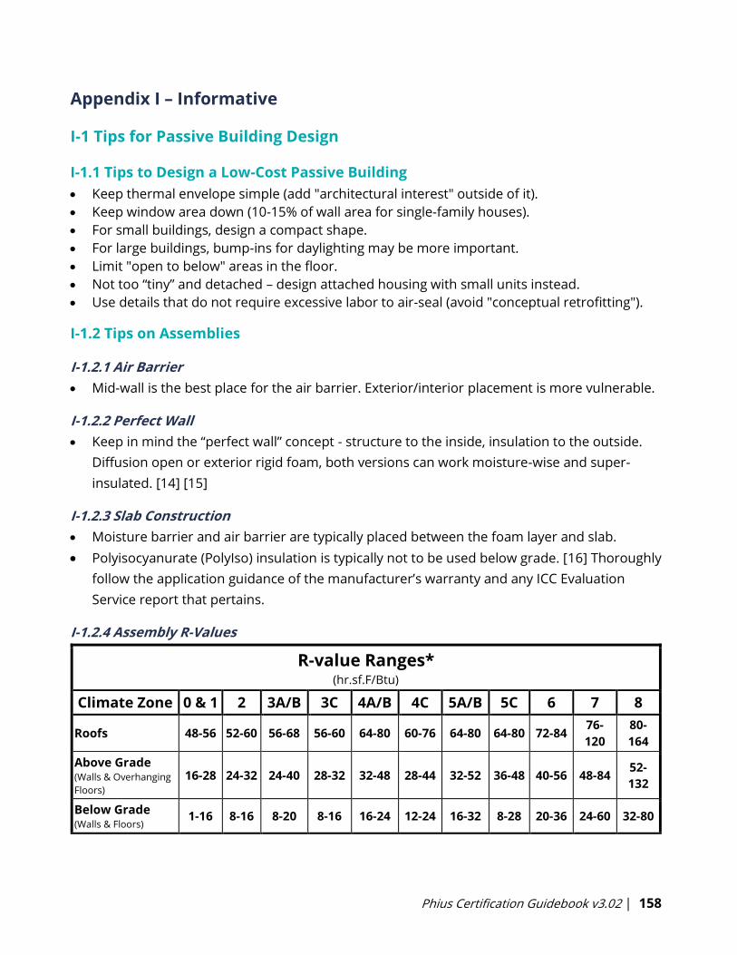
Phius Certification Guidebook v3.02 | 158
Appendix I – Informative
I-1 Tips for Passive Building Design
I-1.1 Tips to Design a Low-Cost Passive Building
• Keep thermal envelope simple (add "architectural interest" outside of it).
• Keep window area down (10-15% of wall area for single-family houses).
• For small buildings, design a compact shape.
• For large buildings, bump-ins for daylighting may be more important.
• Limit "open to below" areas in the floor.
• Not too “tiny” and detached – design attached housing with small units instead.
• Use details that do not require excessive labor to air-seal (avoid "conceptual retrofitting").
I-1.2 Tips on Assemblies
I-1.2.1 Air Barrier
• Mid-wall is the best place for the air barrier. Exterior/interior placement is more vulnerable.
I-1.2.2 Perfect Wall
• Keep in mind the “perfect wall” concept - structure to the inside, insulation to the outside.
Diffusion open or exterior rigid foam, both versions can work moisture-wise and super-
insulated. [14] [15]
I-1.2.3 Slab Construction
• Moisture barrier and air barrier are typically placed between the foam layer and slab.
• Polyisocyanurate (PolyIso) insulation is typically not to be used below grade. [16] Thoroughly
follow the application guidance of the manufacturer’s warranty and any ICC Evaluation
Service report that pertains.
I-1.2.4 Assembly R-Values
R-value Ranges*(hr.sf.F/Btu)
Climate Zone 0 & 1 2 3A/B 3C 4A/B 4C 5A/B 5C 6 7 8
Roofs 48-56 52-60 56-68 56-60 64-80 60-76 64-80 64-80 72-8476-
120
80-
164
Above Grade (Walls & Overhanging
Floors) 16-28 24-32 24-40 28-32 32-48 28-44 32-52 36-48 40-56 48-84
52-
132
Below Grade (Walls & Floors)
1-16 8-16 8-20 8-16 16-24 12-24 16-32 8-28 20-36 24-60 32-80
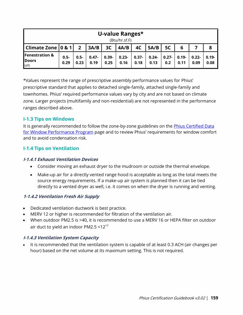
Phius Certification Guidebook v3.02 | 159
U-value Ranges*(Btu/hr.sf.F)
Climate Zone 0 & 1 2 3A/B 3C 4A/B 4C 5A/B 5C 6 7 8
Fenestration &
Doors (all)
0.5-
0.29
0.5-
0.23
0.47-
0.19
0.39-
0.25
0.23-
0.16
0.37-
0.18
0.24-
0.13
0.27-
0.2
0.19-
0.11
0.22-
0.09
0.19-
0.08
*Values represent the range of prescriptive assembly performance values for Phius’
prescriptive standard that applies to detached single-family, attached single-family and
townhomes. Phius’ required performance values vary by city and are not based on climate
zone. Larger projects (multifamily and non-residential) are not represented in the performance
ranges described above.
I-1.3 Tips on Windows
It is generally recommended to follow the zone-by-zone guidelines on the Phius Certified Data
for Window Performance Program page and to review Phius’ requirements for window comfort
and to avoid condensation risk.
I-1.4 Tips on Ventilation
I-1.4.1 Exhaust Ventilation Devices
• Consider moving an exhaust dryer to the mudroom or outside the thermal envelope.
• Make-up air for a directly vented range hood is acceptable as long as the total meets the
source energy requirements. If a make-up air system is planned then it can be tied
directly to a vented dryer as well, i.e. it comes on when the dryer is running and venting.
1-1.4.2 Ventilation Fresh Air Supply
• Dedicated ventilation ductwork is best practice.
• MERV 12 or higher is recommended for filtration of the ventilation air.
• When outdoor PM2.5 is >40, it is recommended to use a MERV 16 or HEPA filter on outdoor
air duct to yield an indoor PM2.5 <1217
I-1.4.3 Ventilation System Capacity
• It is recommended that the ventilation system is capable of at least 0.3 ACH (air changes per
hour) based on the net volume at its maximum setting. This is not required.
Phius Certification Guidebook v3.02 | 160
I-2 Source Energy
The metric used for this criterion is net source energy use. The overall energy limit is based on
source energy because that is a good measure of the impact the building’s operation has on
society. That impact consists mostly of CO2 emissions, but the source energy metric differs from
carbon-scoring in that it includes the impact of nuclear power as well.
I-2.1 Source Energy Factors for Grid Electricity
In past versions of the Phius certification program, the source-site ratio for grid electricity was
defined by the Energy Star Portfolio Manager and was determined based on past generation
and consumption data from the EIA (Energy Information Administration).
Moving forward, Phius will use a source energy factor for grid electricity that reflects a future
outlook. The intent is to reflect future conditions more appropriately and to better weigh the
impact of using electricity versus natural gas on-site. For projects in the US, Phius 2021 uses a
source energy factor based on a projected 2050 electricity generation mix. This future source
energy factor was calculated from NREL’s MidCase scenario in 2050, as reported in their 2020
Standard Scenario Report. This report details the future grid generation resource mix based on
policies that were in place as of June 30, 2020. A full calculation methodology report can be
found here. 2050 is the furthest year out that the data is projected to and is roughly a midpoint
on the anticipated life of a building built today.
I-2.2 Net Zero Source Energy
For an all- electric building, the same on-site PV array (or PPA, etc) that gives site zero also gives
source zero. It is different if the building uses other fuels - for example if the building made
heavy use of biomass for heating, the overall source/site ratio of its usage might be only 1.5,
while the source/site ratio of the PV is 1.8. Therefore, on that building the PV array size for
source zero would be smaller than the array size for site zero, because of the additional source-
reduction strategy.
Note: In setting the source energy limit to zero, it is unproductive to put the entire burden on
the building and its on-site production potential. Doing so may push past the point of
diminishing returns in energy conservation or prohibit projects with constrained sites from ever
achieving this goal. At some point, the building has conserved and generated all it can, and the
focus will shift to cleaning up the energy supply.
I-3 Raters and Verifiers
We recommend contacting a Phius Certified Rater/Verifier as soon as certification becomes a
goal for the project and incorporate them into the project team early on. Phius asks that you
hire a Rater/Verifier when you submit a project contract to Phius at the start of Certification.

Phius Certification Guidebook v3.02 | 161
Phius acknowledges that the addition of this component to our certification does raise fees.
However, we also feel strongly that it helps create higher quality buildings.
Phius has not set a fee structure for the Phius Certified Raters/Verifiers to charge for their
services. For a single-family home, expect 20 hours of work (plus travel time) at the Phius
Certified Rater/Verifier’s hourly rate (typically $100-$200 per hour depending on market). This
does assume a relatively straightforward process. Significant problems could result in more
time needed, but simple homes may expect less time for completion.
Be aware that travel can significantly affect the quote the project team receives from a Phius
Certified Rater/Verifier.
Find a Phius Certified Rater | Find a Phius Certified Verifier
I-3.1 Overview of Typical Site Visits for the Rater/Verifier:
1. Sub-slab insulation check.
2. Preliminary blower door test.
3. Insulation quality check.
4. Final blower door, ventilation commissioning, final Quality Assurance Workbook.
Coordination of the site visits and design review by the Phius Certified Rater/Verifier should
occur between the Rater/Verifier and the project team. The number of site visits is up to the
Rater/Verifier. Phius encourages in-person sub-slab insulation inspection, but procurement of
onsite photos is allowed. Preliminary blower door testing is optional, but strongly encouraged.
More details can be found in Appendix E Sections 3-5.
I-4 Fireplaces
In an airtight house there is great danger of back drafting or for the fireplace/stove using the
interior air for combustion. The combustion intake air must be directly from the outdoors and
independent of the interior air supply. Warning systems should be considered such as carbon
monoxide detectors or depressurization sensors. If the building gets depressurized for some
reason (one of the ventilator fans fails and the defect goes unnoticed) then, despite of all the
precaution of airtight fire box and dedicated combustion air, back drafting could still occur and
draw potentially life-threatening gases into the interior of the building.
Fireplace Disclaimer: The use of a fireplace/woodstove in a home can be dangerous due to the
risk of carbon monoxide poisoning. The fireplace/woodstove specified for this home must be
completely airtight to the room air. Combustion air must be provided by a dedicated pipe
connecting to the outside. If smoke is seen to be leaking from the stove into the living area,
immediately open all the windows, and discontinue using the stove. DO NOT LEAVE A FIRE
BURNING UNATTENDED especially when going to sleep at night. Carbon monoxide detectors
should be installed in locations so that they can be heard throughout the house. Phius (the
Passive House Institute US) or any of its employees are not responsible for any damage, injury
or death caused.
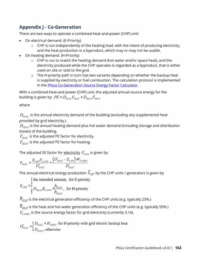
Phius Certification Guidebook v3.02 | 162
Appendix J - Co-Generation
There are two ways to operate a combined-heat-and-power (CHP) unit:
• On electrical demand. (E-Priority)
o CHP is run independently of the heating load, with the intent of producing electricity,
and the heat production is a byproduct, which may or may not be usable.
• On heating demand. (H-Priority)
o CHP is run to match the heating demand (hot water and/or space heat), and the
electricity produced while the CHP operates is regarded as a byproduct, that is either
used on site or sold to the grid.
o The H-priority path in turn has two variants depending on whether the backup heat
is supplied by electricity or fuel combustion. The calculation protocol is implemented
in the Phius Co-Generation Source Energy Factor Calculator.
With a combined-heat-and power (CHP) unit, the adjusted annual source energy for the
building is given by:
where
is the annual electricity demand of the building (excluding any supplemental heat
provided by grid electricity.)
is the annual heating demand plus hot water demand (including storage and distribution
losses) of the building.
is the adjusted PE factor for electricity.
is the adjusted PE factor for heating.
The adjusted SE factor for electricity is given by
The annual electrical energy production ECHP by the CHP units / generators is given by
ECHP =
the intended amount, for E-priority
DHEATKCOVG ×hELEChHEAT
, for H-priority
ì
íï
îï
hELEC is the electrical generation efficiency of the CHP units (e.g. typically 25%.)
hHEAT is the heat and hot water generation efficiency of the CHP units (e.g. typically 50%.)
is the source energy factor for grid electricity (currently 3.16).
PE =DELECFELEC +DHEATFHEAT
DELEC
DHEAT
FELEC
FHEAT
FELEC
FELEC =ECHPFE,CHP
D*
ELEC
+D*
ELEC -ECHP( ) ×FE,GRID
D*
ELEC
FE,GRID
DELEC* =
DELEC +HGRID, for H-priority with grid electric backup heat
DELEC, otherwise
ìíî
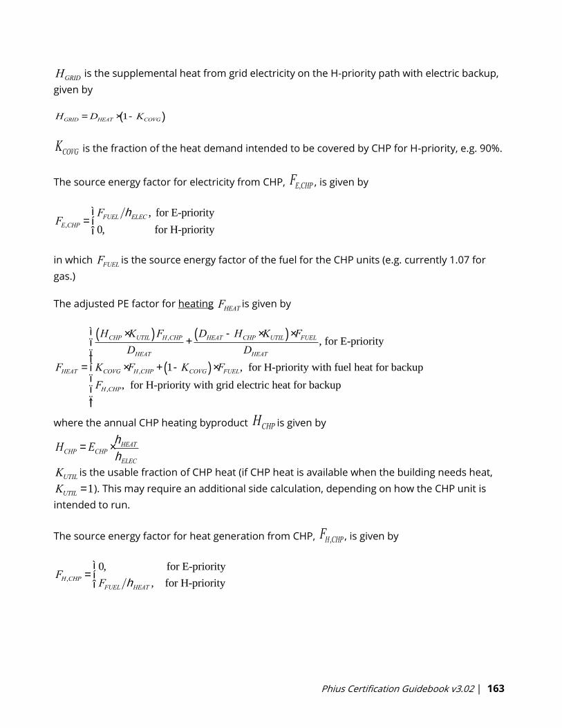
Phius Certification Guidebook v3.02 | 163
is the supplemental heat from grid electricity on the H-priority path with electric backup,
given by
HGRID =DHEAT × 1-KCOVG( )
KCOVG is the fraction of the heat demand intended to be covered by CHP for H-priority, e.g. 90%.
The source energy factor for electricity from CHP, FE,CHP , is given by
in which is the source energy factor of the fuel for the CHP units (e.g. currently 1.07 for
gas.)
The adjusted PE factor for heating is given by
FHEAT =
HCHP ×KUTIL( )FH ,CHP
DHEAT+DHEAT -HCHP ×KUTIL( ) ×FFUEL
DHEAT, for E-priority
KCOVG ×FH ,CHP + 1-KCOVG( ) ×FFUEL, for H-priority with fuel heat for backup
FH ,CHP, for H-priority with grid electric heat for backup
ì
í
ïïï
î
ïïï
where the annual CHP heating byproduct HCHP is given by
HCHP = ECHP ×hHEAThELEC
is the usable fraction of CHP heat (if CHP heat is available when the building needs heat,
). This may require an additional side calculation, depending on how the CHP unit is
intended to run.
The source energy factor for heat generation from CHP, FH ,CHP , is given by
FH ,CHP =0, for E-priority
FFUEL hHEAT , for H-priority
ìíî
HGRID
FE,CHP =FFUEL hELEC , for E-priority
0, for H-priority
ìíî
FFUEL
FHEAT
KUTILKUTIL =1
Phius Certification Guidebook v3.02 | 164
Appendix K - Electric Vehicle Charging Infrastructure
K-1 Requirements
One- to two-family dwellings and townhouses. One- and two-family dwellings and
townhouses with a dedicated attached or detached garage or on-site parking spaces and
new detached garages shall be provided with one EV-Ready space per dwelling unit. The
branch circuit for the EV-Ready space shall have a minimum capacity of 9.6 kVA.
Exception: EV-Ready Spaces are not required where no parking spaces are provided.
Multifamily dwellings (three or more units). EV Ready Spaces and EV Capable Spaces shall
be provided in accordance with Table EV. Where the calculation of percent served results in
a fractional parking space, it shall round up to the next whole number. The service panel or
subpanel circuit directory shall identify the spaces reserved to support EV charging as “EV
Capable” or “EV Ready”. The raceway location shall be permanently and visibly marked as
“EV Capable”.
Campus EV Requirements: For a neighborhood or development with multiple buildings where
no individual building parking is provided, a “campus” approach can be taken to apply to the
EV requirements. In this case, treat the development as a single project and use the total
number of parking spaces provided with Table EV to determine requirements.
Non-Residential Buildings: TBD
K-2 Definitions
ELECTRIC VEHICLE (EV). An automotive-type vehicle for on-road use, such as passenger
automobiles, buses, trucks, vans, neighborhood electric vehicles, electric motorcycles, and
the like, primarily powered by an electric motor that draws current from a rechargeable
storage battery, a fuel cell, a photovoltaic array, or another source of electric current. Plug-in
hybrid electric vehicles are electric vehicles having a second source of motive power. Off-
road, self-propelled electric mobile equipment, such as industrial trucks, hoists, lifts,
transports, golf carts, airline ground support equipment, tractors, boats and the like, are not
considered electric vehicles.
ELECTRIC VEHICLE SUPPLY EQUIPMENT (EVSE). The conductors, including the ungrounded,
grounded, and equipment grounding conductors, and the electric vehicle connectors,
attachment plugs, and all other fittings, devices, power outlets, or apparatus installed
specifically for the purpose of transferring energy between the premise’s wiring and the
electric vehicle.
ELECTRIC VEHICLE SUPPLY EQUIPMENT (EVSE) SPACE. A designated parking space with
dedicated electric vehicle supply equipment capable of supplying not less than 6.2 kW to an
electric vehicle located within 3 feet of the parking space.

Phius Certification Guidebook v3.02 | 165
EV-CAPABLE SPACE. A parking space that is provided with conduit that meets the following
requirements:
1. The conduit shall be continuous between a junction box or receptacle located within 3
feet of the parking space and an electrical panel serving the area of the parking
space with sufficient dedicated physical space for a dual-pole, 40-amp breaker
2. The conduit shall be sized and rated to accommodate a 40-amp, 208/240-volt branch
circuit and have a minimum nominal trade size of 1 inch
3. The electrical junction box and the electrical panel directory entry for the dedicated
space in the electrical panel shall have labels stating “For future electric vehicle
charging”.
EV-READY SPACE. A parking space that is provided with dedicated branch circuit that meets the
following requirements:
1. Wiring capable of supporting a 40-amp, 208/240-volt circuit,
2. Terminates at a junction box or receptacle located within 3 feet of the parking space,
and
3. The electrical panel directory shall designate the branch circuit as “For electric vehicle
charging” and the junction box or receptacle shall be labeled “For electric vehicle
charging”.
ELECTRIC VEHICLE LOAD MANAGEMENT SYSTEM. A system designed to allocate charging
capacity among multiple electric vehicle supply equipment.
Identification. Construction documents shall indicate the raceway termination point and
proposed location of future EV spaces and EV chargers. Construction documents shall also
provide information on amperage of future EVSE, raceway methods, wiring schematics and
electrical load calculations to verify that the electrical panel service capacity and electrical
system, including any on-site distribution transformers, have sufficient capacity to
simultaneously charge all EVs at all required EV spaces at the full rated amperage of the EVSE.
Phius Certification Guidebook v3.02 | 166
Appendix L - Electrification Readiness for Combustion Equipment
Combustion equipment serving multiple dwelling units shall comply with the section below.
Combustion water heating: (with a capacity less than or equal to 300 kBtu/h) shall be installed
in accordance with the following:
1. A dedicated 240-volt branch circuit with a minimum capacity of 30 amps shall terminate
within 3 feet from the water heater and be accessible to the water heater with no
obstructions. Both ends of the branch circuit shall be labeled with the words "For Future
Heat Pump Water Heater" and be electrically isolated.
2. A condensate drain that is no more than 2 inches higher than the base of the installed
water heater and allows natural draining without pump assistance shall be installed
within 3 feet of the water heater.
3. The water heater shall be installed in a space with minimum dimensions of 3 feet by 3
feet by 7 feet high.
4. The water heater shall be installed in a space with a minimum volume of 700 cubic feet
or the equivalent of one 16-inch by 24-inch grill to a heated space and one 8-inch duct of
no more than 10 feet in length for cool exhaust air.
Combustion space heating: The building shall be provided with a designated exterior
location(s) in accordance with the following:
1. Natural drainage for condensate from cooling equipment operation or a condensate
drain located within 3 feet, and
2. A dedicated branch circuit in compliance with IRC Section E3702.11 based on heat pump
space heating equipment sized in accordance with R403.7 and terminating within 3 feet
of the location with no obstructions. Both ends of the branch circuit shall be labeled “For
Future Heat Pump Space Heater.”
Exception: Where an electrical circuit in compliance with IRC Section E3702.11 exists for space
cooling equipment.
Combustion clothes drying. A dedicated 240-volt branch circuit with a minimum capacity of 30
amps shall terminate within 6 feet of natural gas clothes dryers and shall be accessible with no
obstructions. Both ends of the branch circuit shall be labeled with the words “For Future Electric
Clothes Drying” and be electrically isolated.
Combustion cooking. A dedicated 240-Volt, 40A branch circuit shall terminate within 6 feet of
natural gas ranges, cooktops and ovens and be accessible with no obstructions. Both ends of
the branch circuit shall be labeled with the words “For Future Electric Range'' and be electrically
isolated.

Phius Certification Guidebook v3.02 | 167
Other combustion equipment. Combustion equipment and end-uses not covered by Sections
above shall be provided with a branch circuit sized for an electric appliance, equipment or end
use with an equivalent capacity that terminates within 6 feet of the appliance or equipment.
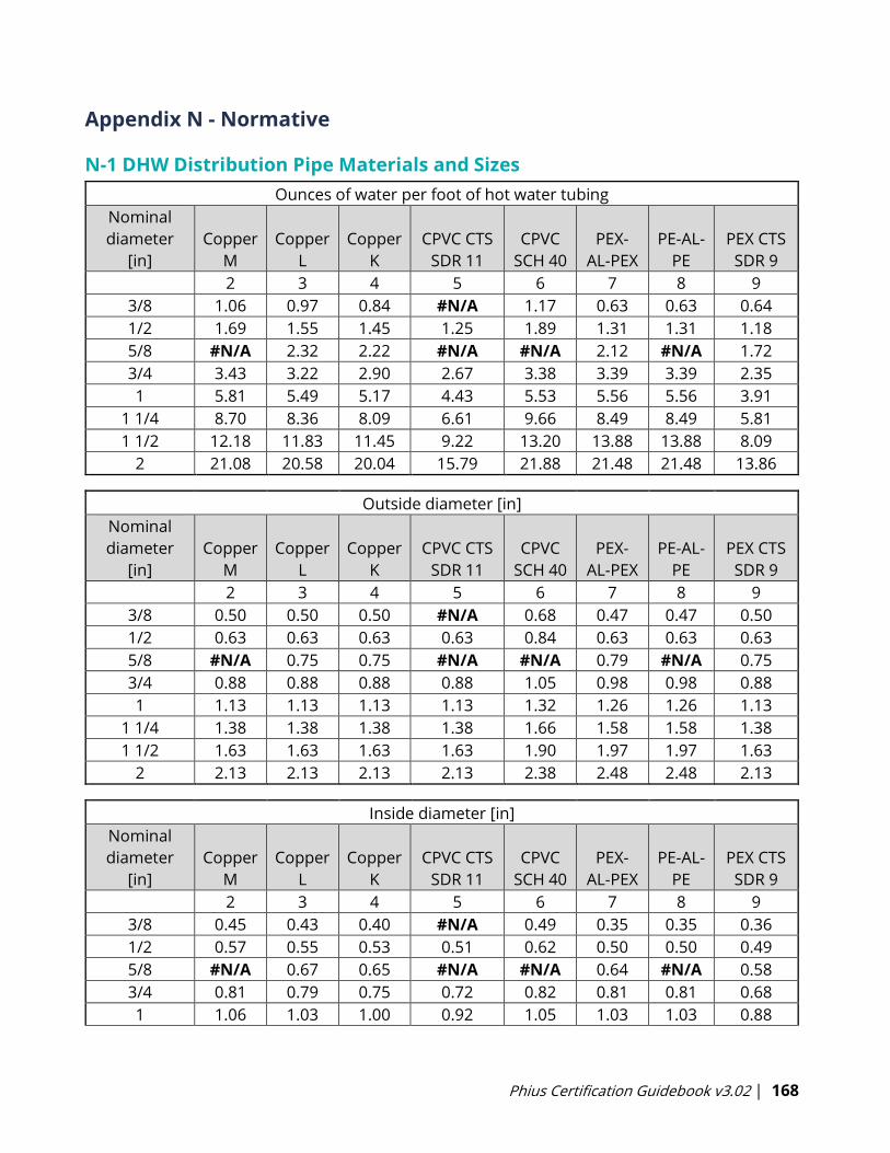
Phius Certification Guidebook v3.02 | 168
Appendix N - Normative
N-1 DHW Distribution Pipe Materials and Sizes
Ounces of water per foot of hot water tubing
Nominal
diameter
[in]
Copper
M
Copper
L
Copper
K
CPVC CTS
SDR 11
CPVC
SCH 40
PEX-
AL-PEX
PE-AL-
PE
PEX CTS
SDR 9
2 3 4 5 6 7 8 9
3/8 1.06 0.97 0.84 #N/A 1.17 0.63 0.63 0.64
1/2 1.69 1.55 1.45 1.25 1.89 1.31 1.31 1.18
5/8 #N/A 2.32 2.22 #N/A #N/A 2.12 #N/A 1.72
3/4 3.43 3.22 2.90 2.67 3.38 3.39 3.39 2.35
1 5.81 5.49 5.17 4.43 5.53 5.56 5.56 3.91
1 1/4 8.70 8.36 8.09 6.61 9.66 8.49 8.49 5.81
1 1/2 12.18 11.83 11.45 9.22 13.20 13.88 13.88 8.09
2 21.08 20.58 20.04 15.79 21.88 21.48 21.48 13.86
Outside diameter [in]
Nominal
diameter
[in]
Copper
M
Copper
L
Copper
K
CPVC CTS
SDR 11
CPVC
SCH 40
PEX-
AL-PEX
PE-AL-
PE
PEX CTS
SDR 9
2 3 4 5 6 7 8 9
3/8 0.50 0.50 0.50 #N/A 0.68 0.47 0.47 0.50
1/2 0.63 0.63 0.63 0.63 0.84 0.63 0.63 0.63
5/8 #N/A 0.75 0.75 #N/A #N/A 0.79 #N/A 0.75
3/4 0.88 0.88 0.88 0.88 1.05 0.98 0.98 0.88
1 1.13 1.13 1.13 1.13 1.32 1.26 1.26 1.13
1 1/4 1.38 1.38 1.38 1.38 1.66 1.58 1.58 1.38
1 1/2 1.63 1.63 1.63 1.63 1.90 1.97 1.97 1.63
2 2.13 2.13 2.13 2.13 2.38 2.48 2.48 2.13
Inside diameter [in]
Nominal
diameter
[in]
Copper
M
Copper
L
Copper
K
CPVC CTS
SDR 11
CPVC
SCH 40
PEX-
AL-PEX
PE-AL-
PE
PEX CTS
SDR 9
2 3 4 5 6 7 8 9
3/8 0.45 0.43 0.40 #N/A 0.49 0.35 0.35 0.36
1/2 0.57 0.55 0.53 0.51 0.62 0.50 0.50 0.49
5/8 #N/A 0.67 0.65 #N/A #N/A 0.64 #N/A 0.58
3/4 0.81 0.79 0.75 0.72 0.82 0.81 0.81 0.68
1 1.06 1.03 1.00 0.92 1.05 1.03 1.03 0.88
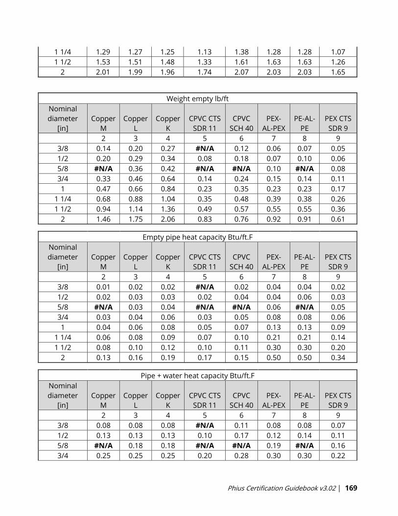
Phius Certification Guidebook v3.02 | 169
1 1/4 1.29 1.27 1.25 1.13 1.38 1.28 1.28 1.07
1 1/2 1.53 1.51 1.48 1.33 1.61 1.63 1.63 1.26
2 2.01 1.99 1.96 1.74 2.07 2.03 2.03 1.65
Weight empty lb/ft
Nominal
diameter
[in]
Copper
M
Copper
L
Copper
K
CPVC CTS
SDR 11
CPVC
SCH 40
PEX-
AL-PEX
PE-AL-
PE
PEX CTS
SDR 9
2 3 4 5 6 7 8 9
3/8 0.14 0.20 0.27 #N/A 0.12 0.06 0.07 0.05
1/2 0.20 0.29 0.34 0.08 0.18 0.07 0.10 0.06
5/8 #N/A 0.36 0.42 #N/A #N/A 0.10 #N/A 0.08
3/4 0.33 0.46 0.64 0.14 0.24 0.15 0.14 0.11
1 0.47 0.66 0.84 0.23 0.35 0.23 0.23 0.17
1 1/4 0.68 0.88 1.04 0.35 0.48 0.39 0.38 0.26
1 1/2 0.94 1.14 1.36 0.49 0.57 0.55 0.55 0.36
2 1.46 1.75 2.06 0.83 0.76 0.92 0.91 0.61
Empty pipe heat capacity Btu/ft.F
Nominal
diameter
[in]
Copper
M
Copper
L
Copper
K
CPVC CTS
SDR 11
CPVC
SCH 40
PEX-
AL-PEX
PE-AL-
PE
PEX CTS
SDR 9
2 3 4 5 6 7 8 9
3/8 0.01 0.02 0.02 #N/A 0.02 0.04 0.04 0.02
1/2 0.02 0.03 0.03 0.02 0.04 0.04 0.06 0.03
5/8 #N/A 0.03 0.04 #N/A #N/A 0.06 #N/A 0.05
3/4 0.03 0.04 0.06 0.03 0.05 0.08 0.08 0.06
1 0.04 0.06 0.08 0.05 0.07 0.13 0.13 0.09
1 1/4 0.06 0.08 0.09 0.07 0.10 0.21 0.21 0.14
1 1/2 0.08 0.10 0.12 0.10 0.11 0.30 0.30 0.20
2 0.13 0.16 0.19 0.17 0.15 0.50 0.50 0.34
Pipe + water heat capacity Btu/ft.F
Nominal
diameter
[in]
Copper
M
Copper
L
Copper
K
CPVC CTS
SDR 11
CPVC
SCH 40
PEX-
AL-PEX
PE-AL-
PE
PEX CTS
SDR 9
2 3 4 5 6 7 8 9
3/8 0.08 0.08 0.08 #N/A 0.11 0.08 0.08 0.07
1/2 0.13 0.13 0.13 0.10 0.17 0.12 0.14 0.11
5/8 #N/A 0.18 0.18 #N/A #N/A 0.19 #N/A 0.16
3/4 0.25 0.25 0.25 0.20 0.28 0.30 0.30 0.22
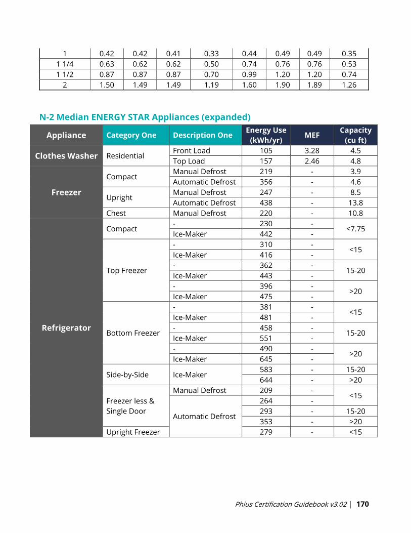
Phius Certification Guidebook v3.02 | 170
1 0.42 0.42 0.41 0.33 0.44 0.49 0.49 0.35
1 1/4 0.63 0.62 0.62 0.50 0.74 0.76 0.76 0.53
1 1/2 0.87 0.87 0.87 0.70 0.99 1.20 1.20 0.74
2 1.50 1.49 1.49 1.19 1.60 1.90 1.89 1.26
N-2 Median ENERGY STAR Appliances (expanded)
Appliance Category One Description One Energy Use
(kWh/yr) MEF
Capacity
(cu ft)
Clothes Washer Residential Front Load 105 3.28 4.5
Top Load 157 2.46 4.8
Freezer
Compact Manual Defrost 219 - 3.9
Automatic Defrost 356 - 4.6
Upright Manual Defrost 247 - 8.5
Automatic Defrost 438 - 13.8
Chest Manual Defrost 220 - 10.8
Refrigerator
Compact - 230 -
<7.75 Ice-Maker 442 -
Top Freezer
- 310 - <15
Ice-Maker 416 -
- 362 - 15-20
Ice-Maker 443 -
- 396 - >20
Ice-Maker 475 -
Bottom Freezer
- 381 - <15
Ice-Maker 481 -
- 458 - 15-20
Ice-Maker 551 -
- 490 - >20
Ice-Maker 645 -
Side-by-Side Ice-Maker 583 - 15-20
644 - >20
Freezer less &
Single Door
Manual Defrost 209 - <15
Automatic Defrost
264 -
293 - 15-20
353 - >20
Upright Freezer 279 - <15
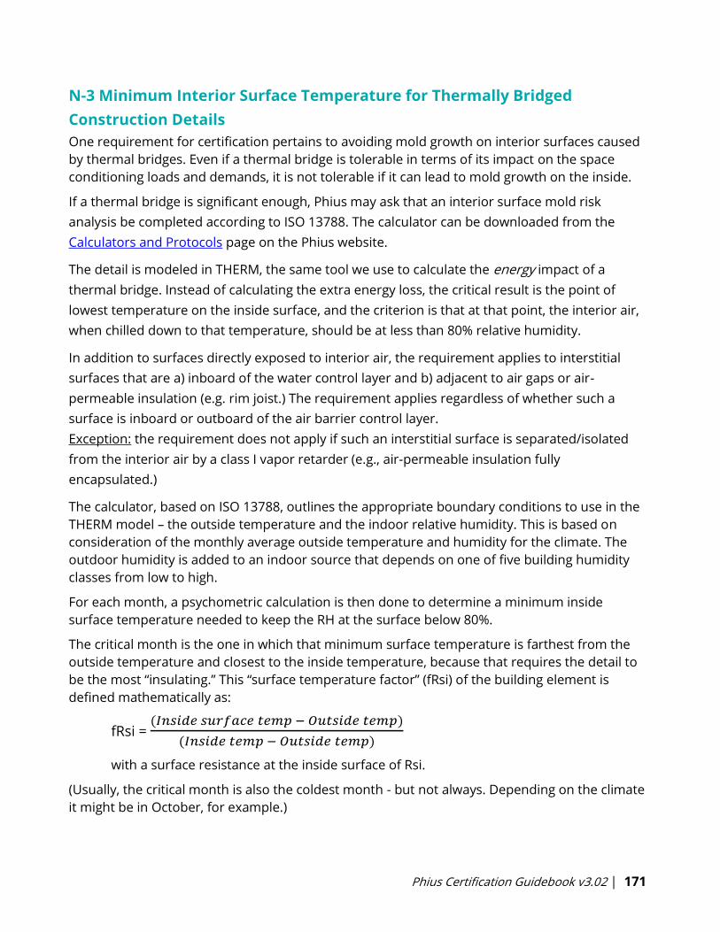
Phius Certification Guidebook v3.02 | 171
N-3 Minimum Interior Surface Temperature for Thermally Bridged
Construction Details
One requirement for certification pertains to avoiding mold growth on interior surfaces caused
by thermal bridges. Even if a thermal bridge is tolerable in terms of its impact on the space
conditioning loads and demands, it is not tolerable if it can lead to mold growth on the inside.
If a thermal bridge is significant enough, Phius may ask that an interior surface mold risk
analysis be completed according to ISO 13788. The calculator can be downloaded from the
Calculators and Protocols page on the Phius website.
The detail is modeled in THERM, the same tool we use to calculate the energy impact of a
thermal bridge. Instead of calculating the extra energy loss, the critical result is the point of
lowest temperature on the inside surface, and the criterion is that at that point, the interior air,
when chilled down to that temperature, should be at less than 80% relative humidity.
In addition to surfaces directly exposed to interior air, the requirement applies to interstitial
surfaces that are a) inboard of the water control layer and b) adjacent to air gaps or air-
permeable insulation (e.g. rim joist.) The requirement applies regardless of whether such a
surface is inboard or outboard of the air barrier control layer.
Exception: the requirement does not apply if such an interstitial surface is separated/isolated
from the interior air by a class I vapor retarder (e.g., air-permeable insulation fully
encapsulated.)
The calculator, based on ISO 13788, outlines the appropriate boundary conditions to use in the
THERM model – the outside temperature and the indoor relative humidity. This is based on
consideration of the monthly average outside temperature and humidity for the climate. The
outdoor humidity is added to an indoor source that depends on one of five building humidity
classes from low to high.
For each month, a psychometric calculation is then done to determine a minimum inside
surface temperature needed to keep the RH at the surface below 80%.
The critical month is the one in which that minimum surface temperature is farthest from the
outside temperature and closest to the inside temperature, because that requires the detail to
be the most “insulating.” This “surface temperature factor” (fRsi) of the building element is
defined mathematically as:
fRsi = (𝐼𝑛𝑠𝑖𝑑𝑒 𝑠𝑢𝑟𝑓𝑎𝑐𝑒 𝑡𝑒𝑚𝑝 − 𝑂𝑢𝑡𝑠𝑖𝑑𝑒 𝑡𝑒𝑚𝑝)
(𝐼𝑛𝑠𝑖𝑑𝑒 𝑡𝑒𝑚𝑝 − 𝑂𝑢𝑡𝑠𝑖𝑑𝑒 𝑡𝑒𝑚𝑝)
with a surface resistance at the inside surface of Rsi.
(Usually, the critical month is also the coldest month - but not always. Depending on the climate
it might be in October, for example.)
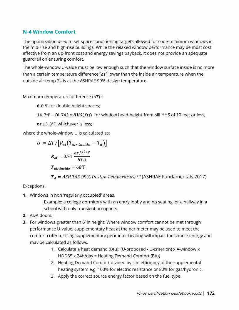
Phius Certification Guidebook v3.02 | 172
N-4 Window Comfort
The optimization used to set space conditioning targets allowed for code-minimum windows in
the mid-rise and high-rise buildings. While the relaxed window performance may be most cost
effective from an up-front cost and energy savings payback, it does not provide an adequate
guardrail on ensuring comfort.
The whole-window U-value must be low enough such that the window surface inside is no more
than a certain temperature difference (∆𝑻) lower than the inside air temperature when the
outside air temp 𝑻𝒅 is at the ASHRAE 99% design temperature.
Maximum temperature difference (∆𝑻) =
𝟔. 𝟎 ℉ for double-height spaces;
𝟏𝟒. 𝟕℉ − (𝟎. 𝟕𝟒𝟐 𝒙 𝑯𝑯𝑺(𝒇𝒕)) for window head-height-from-sill HHS of 10 feet or less,
or 𝟏𝟑. 𝟑℉, whichever is less;
where the whole-window U is calculated as:
𝑈 = ∆𝑇 [𝑅𝑠𝑖(𝑇𝑎𝑖𝑟,𝑖𝑛𝑠𝑖𝑑𝑒 − 𝑇𝑑)]⁄
𝑹𝒔𝒊 = 0.74 ℎ𝑟𝑓𝑡2℉
𝐵𝑇𝑈
𝑻𝒂𝒊𝒓,𝒊𝒏𝒔𝒊𝒅𝒆 = 68℉
𝑻𝒅 = 𝐴𝑆𝐻𝑅𝐴𝐸 99% 𝐷𝑒𝑠𝑖𝑔𝑛 𝑇𝑒𝑚𝑝𝑒𝑟𝑎𝑡𝑢𝑟𝑒 ℉ (ASHRAE Fundamentals 2017)
Exceptions:
1. Windows in non 'regularly occupied' areas.
Example: a college dormitory with an entry lobby and no seating, or a hallway in a
school with only transient occupants.
2. ADA doors.
3. For windows greater than 6’ in height: Where window comfort cannot be met through
performance U-value, supplementary heat at the perimeter may be used to meet the
comfort criteria. Using supplementary perimeter heating will impact the source energy and
may be calculated as follows.
1. Calculate a heat demand (Btu): (U-proposed - U-criterion) x A-window x
HDD65 x 24h/day = Heating Demand Comfort (Btu)
2. Heating Demand Comfort divided by site efficiency of the supplemental
heating system e.g. 100% for electric resistance or 80% for gas/hydronic.
3. Apply the correct source energy factor based on the fuel type.
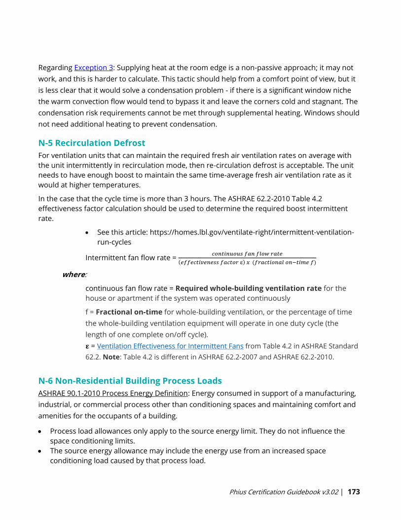
Phius Certification Guidebook v3.02 | 173
Regarding Exception 3: Supplying heat at the room edge is a non-passive approach; it may not
work, and this is harder to calculate. This tactic should help from a comfort point of view, but it
is less clear that it would solve a condensation problem - if there is a significant window niche
the warm convection flow would tend to bypass it and leave the corners cold and stagnant. The
condensation risk requirements cannot be met through supplemental heating. Windows should
not need additional heating to prevent condensation.
N-5 Recirculation Defrost
For ventilation units that can maintain the required fresh air ventilation rates on average with
the unit intermittently in recirculation mode, then re-circulation defrost is acceptable. The unit
needs to have enough boost to maintain the same time-average fresh air ventilation rate as it
would at higher temperatures.
In the case that the cycle time is more than 3 hours. The ASHRAE 62.2-2010 Table 4.2
effectiveness factor calculation should be used to determine the required boost intermittent
rate.
• See this article: https://homes.lbl.gov/ventilate-right/intermittent-ventilation-
run-cycles
Intermittent fan flow rate = 𝑐𝑜𝑛𝑡𝑖𝑛𝑢𝑜𝑢𝑠 𝑓𝑎𝑛 𝑓𝑙𝑜𝑤 𝑟𝑎𝑡𝑒
(𝑒𝑓𝑓𝑒𝑐𝑡𝑖𝑣𝑒𝑛𝑒𝑠𝑠 𝑓𝑎𝑐𝑡𝑜𝑟 ε) 𝑥 (𝑓𝑟𝑎𝑐𝑡𝑖𝑜𝑛𝑎𝑙 𝑜𝑛−𝑡𝑖𝑚𝑒 𝑓)
where:
continuous fan flow rate = Required whole-building ventilation rate for the
house or apartment if the system was operated continuously
f = Fractional on-time for whole-building ventilation, or the percentage of time
the whole-building ventilation equipment will operate in one duty cycle (the
length of one complete on/off cycle).
𝛆 = Ventilation Effectiveness for Intermittent Fans from Table 4.2 in ASHRAE Standard
62.2. Note: Table 4.2 is different in ASHRAE 62.2-2007 and ASHRAE 62.2-2010.
N-6 Non-Residential Building Process Loads
ASHRAE 90.1-2010 Process Energy Definition: Energy consumed in support of a manufacturing,
industrial, or commercial process other than conditioning spaces and maintaining comfort and
amenities for the occupants of a building.
• Process load allowances only apply to the source energy limit. They do not influence the
space conditioning limits.
• The source energy allowance may include the energy use from an increased space
conditioning load caused by that process load.

Phius Certification Guidebook v3.02 | 174
o For example: A commercial kitchen requiring direct exhaust range hoods. The source
energy allowance is calculated as a combination of the increased heating energy
consumption caused by the exhaust and makeup air and the fan energy associated
with operating the range hoods.
• Custom optimization targets may be used when process loads influence the space
conditioning so much that they no longer fit within the typical internal gain profiles used
during Phius’ target setting optimization study. Review Section 1.5.4 for more information.
N-7 Prescriptive Path
N-7.1 Compactness Criteria
The compactness requirement is intended not to force an ideal or optimal level of compactness, but
rather to prevent particularly non-compact designs. The enclosure area AE must not exceed that of a
notional rectangular building with the proposed interior conditioned floor area iCFA and number of
walkable levels Ns, calculated as follows:
𝐴𝐸 ≤ 𝐴𝐸𝑚𝑎𝑥 = 2 ∗ (𝑤 ∗ 𝑑 + 𝑑 ∗ ℎ + 𝑤 ∗ ℎ)
𝑇ℎ𝑒 ℎ𝑒𝑖𝑔ℎ𝑡 ℎ = 𝐻𝑠 ∗ 𝑁𝑠
𝑇ℎ𝑒 𝑑𝑒𝑝𝑡ℎ 𝑑 =
𝑖𝐶𝐹𝐴𝑁𝑠
𝑤 − 0.6𝑚+ 0.6𝑚
𝑇ℎ𝑒 𝑤𝑖𝑑𝑡ℎ 𝑤 = 𝑠𝑞𝑟𝑡 (𝑎𝑤𝑑 ∗𝑖𝐶𝐹𝐴
𝑁𝑠) + 2 𝑓𝑒𝑒𝑡 (0.6𝑚)
𝑇ℎ𝑒 𝑤𝑖𝑑𝑡ℎ 𝑡𝑜 𝑑𝑒𝑝𝑡ℎ 𝑎𝑠𝑝𝑒𝑐𝑡 𝑟𝑎𝑡𝑖𝑜 𝑎𝑤𝑑 = 3
𝑇ℎ𝑒 ℎ𝑒𝑖𝑔ℎ𝑡 𝑝𝑒𝑟 𝑠𝑡𝑜𝑟𝑦 𝐻𝑠 = 12 𝑓𝑒𝑒𝑡 (3.7𝑚)
N-7.2 Solar Protection Criteria
Glazed fenestration solar heat gain coefficient: Requirements vary by climate zone and align
with DOE Zero Energy Ready Home.
Fixed overhangs: Required for south windows in hot climate zones, with a depth that depends
on the latitude and window height.
N-7.2.1 Fenestration Orientation (for detached houses only)
There are two rules pertaining to fenestration orientation, that is, the distribution of windows
and glazed doors facing different directions.
1. Limit high peaks in cooling load in summer and shoulder seasons.
2. Limit net heat loss from the windows in winter.
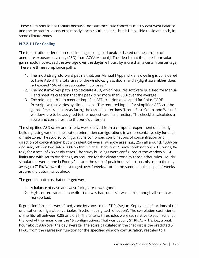
Phius Certification Guidebook v3.02 | 175
These rules should not conflict because the “summer” rule concerns mostly east-west balance
and the “winter” rule concerns mostly north-south balance, but it is possible to violate both, in
some climate zones.
N-7.2.1.1 For Cooling
The fenestration orientation rule limiting cooling load peaks is based on the concept of
adequate exposure diversity (AED) from ACCA Manual J. The idea is that the peak hour solar
gain should not exceed the average over the daytime hours by more than a certain percentage.
There are three compliance paths:
1. The most straightforward path is that, per Manual J Appendix 3, a dwelling is considered
to have AED if “the total area of the windows, glass doors, and skylight assemblies does
not exceed 15% of the associated floor area.”
2. The most involved path is to calculate AED, which requires software qualified for Manual
J, and meet its criterion that the peak is no more than 30% over the average.
3. The middle path is to meet a simplified AED criterion developed for Phius CORE
Prescriptive that varies by climate zone. The required inputs for simplified AED are the
glazed fenestration areas facing the cardinal directions (North, East, South, and West). All
windows are to be assigned to the nearest cardinal direction. The checklist calculates a
score and compares it to the zone’s criterion.
The simplified AED score and criteria were derived from a computer experiment on a study
building, using various fenestration orientation configurations in a representative city for each
climate zone. The studied configurations comprised combinations of concentration and
direction of concentration but with identical overall window area, e.g., 25% all around, 100% on
one side, 50% on two sides, 33% on three sides. There are 15 such combinations x 19 zones, 0A
to 8, for a total of 285 study cases. The study buildings were configured at the window SHGC
limits and with south overhangs, as required for the climate zone by those other rules. Hourly
simulations were done in EnergyPlus and the ratio of peak hour solar transmission to the day
average (ST Pk/Av) was then averaged over 4 weeks around the summer solstice plus 4 weeks
around the autumnal equinox.
The general patterns that emerged were:
1. A balance of east- and west-facing areas was good.
2. High concentration in one direction was bad, unless it was north, though all-south was
not too bad.
Regression formulas were fitted, zone by zone, to the ST Pk/Av Jun+Sep data as functions of the
orientation configuration variables (fraction facing each direction). The correlation coefficients
of the fits fell between 0.85 and 0.95. The criteria thresholds were set relative to each zone, at
the level of the mean over the 15 configurations. That was usually ST Pk/Av ~ 1.9, i.e., a peak
hour about 90% over the day average. The score calculated in the checklist is the predicted ST
Pk/Av from the regression function for the specified window configuration, rescaled to a
Phius Certification Guidebook v3.02 | 176
percentage of the way towards the zone limit. This levels the passing criterion to ≤ 100% for all
zones (lower is better). 43
N-7.2.1.2 For Heating
The fenestration orientation rule for winter is based on the idea that the windows should
preferably be oriented to have a net gain over the worst-case month (coldest/dimmest), or at
least not too great a net loss. The same model buildings and representative cities were used as
for the simplified AED cooling load study. The heat transmission loss from the windows was
calculated with the windows at the U-value limit for the zone.
The results indicated that in zones 4C, 5C, and 8, net heat gain in the worst month was not
possible with any window orientation, thus there is no orientation requirement for these zones.
Also, in zones 0-3 the “winter” gain is either unavoidable, or again mostly unavailable due to the
cooling season solar protection measures in place as required, thus there is no orientation
requirement for zones 0-3.
For zones 4-7 except C, winter gain is desirable and fenestration orientation did make a big
difference, so criteria were set: Regression functions of the orientation variables were fitted to
the worst-month net heat gain data. The correlation coefficients of the fits were all over 0.98.
The general pattern was that some North windows are tolerable if there are south-facing ones
to compensate. The criteria thresholds were set relative to each zone, at the level of the median
net gain over the 15 orientation configurations. The score calculated in the checklist is the
difference between the predicted net gain from the regression function for the specified
window orientation configuration, minus the zone target, then rescaled by the range of net gain
over all the study cases. This makes for a levelized net gain score in the range of about ± 100,
where zero is passing and higher is better.
The “summer” and “winter” orientation rules were tested together in combination with the
compactness rule on 33 certified projects and some randomly generated fenestration
orientations and they appeared to give good guidance.44
N-7.3 Thermal Enclosure
The maximum U-value for fenestration is derived from the idea of maintaining the inside
surface temperature high enough to prevent cold air from pooling under the window and
43 An attempt was made to find a correlation between this simplified AED and Manual J AED, by
calculating both on a subset of 30 of the 285 study cases, but this did not work - the correlation
coefficient was only 0.4. This may be due to differences in the Manual J design-day data compared to the
TMY type weather data used to develop the simplified AED, or other Manual J AED calculation details we
are not aware of as of this writing. 44 The original idea was to have uniform criteria on the raw metrics, e.g. net gain > 0 for winter and ST
Pk/Av Jun+Sep < 1.XX for summer, but the zone-to-zone differences were large enough that testing
suggested zone-by-zone criteria would be a better idea. As noted above, the final scoring methods shift
all zones to a uniform “≤ 1” and “≥ 0”basis
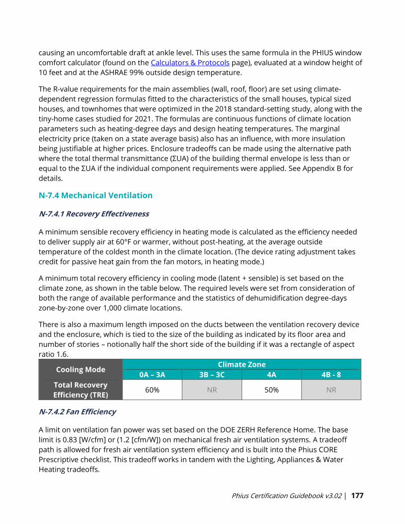
Phius Certification Guidebook v3.02 | 177
causing an uncomfortable draft at ankle level. This uses the same formula in the PHIUS window
comfort calculator (found on the Calculators & Protocols page), evaluated at a window height of
10 feet and at the ASHRAE 99% outside design temperature.
The R-value requirements for the main assemblies (wall, roof, floor) are set using climate-
dependent regression formulas fitted to the characteristics of the small houses, typical sized
houses, and townhomes that were optimized in the 2018 standard-setting study, along with the
tiny-home cases studied for 2021. The formulas are continuous functions of climate location
parameters such as heating-degree days and design heating temperatures. The marginal
electricity price (taken on a state average basis) also has an influence, with more insulation
being justifiable at higher prices. Enclosure tradeoffs can be made using the alternative path
where the total thermal transmittance (ΣUA) of the building thermal envelope is less than or
equal to the ΣUA if the individual component requirements were applied. See Appendix B for
details.
N-7.4 Mechanical Ventilation
N-7.4.1 Recovery Effectiveness
A minimum sensible recovery efficiency in heating mode is calculated as the efficiency needed
to deliver supply air at 60°F or warmer, without post-heating, at the average outside
temperature of the coldest month in the climate location. (The device rating adjustment takes
credit for passive heat gain from the fan motors, in heating mode.)
A minimum total recovery efficiency in cooling mode (latent + sensible) is set based on the
climate zone, as shown in the table below. The required levels were set from consideration of
both the range of available performance and the statistics of dehumidification degree-days
zone-by-zone over 1,000 climate locations.
There is also a maximum length imposed on the ducts between the ventilation recovery device
and the enclosure, which is tied to the size of the building as indicated by its floor area and
number of stories – notionally half the short side of the building if it was a rectangle of aspect
ratio 1.6.
Cooling Mode Climate Zone
0A – 3A 3B – 3C 4A 4B - 8
Total Recovery
Efficiency (TRE) 60% NR 50% NR
N-7.4.2 Fan Efficiency
A limit on ventilation fan power was set based on the DOE ZERH Reference Home. The base
limit is 0.83 [W/cfm] or (1.2 [cfm/W]) on mechanical fresh air ventilation systems. A tradeoff
path is allowed for fresh air ventilation system efficiency and is built into the Phius CORE
Prescriptive checklist. This tradeoff works in tandem with the Lighting, Appliances & Water
Heating tradeoffs.
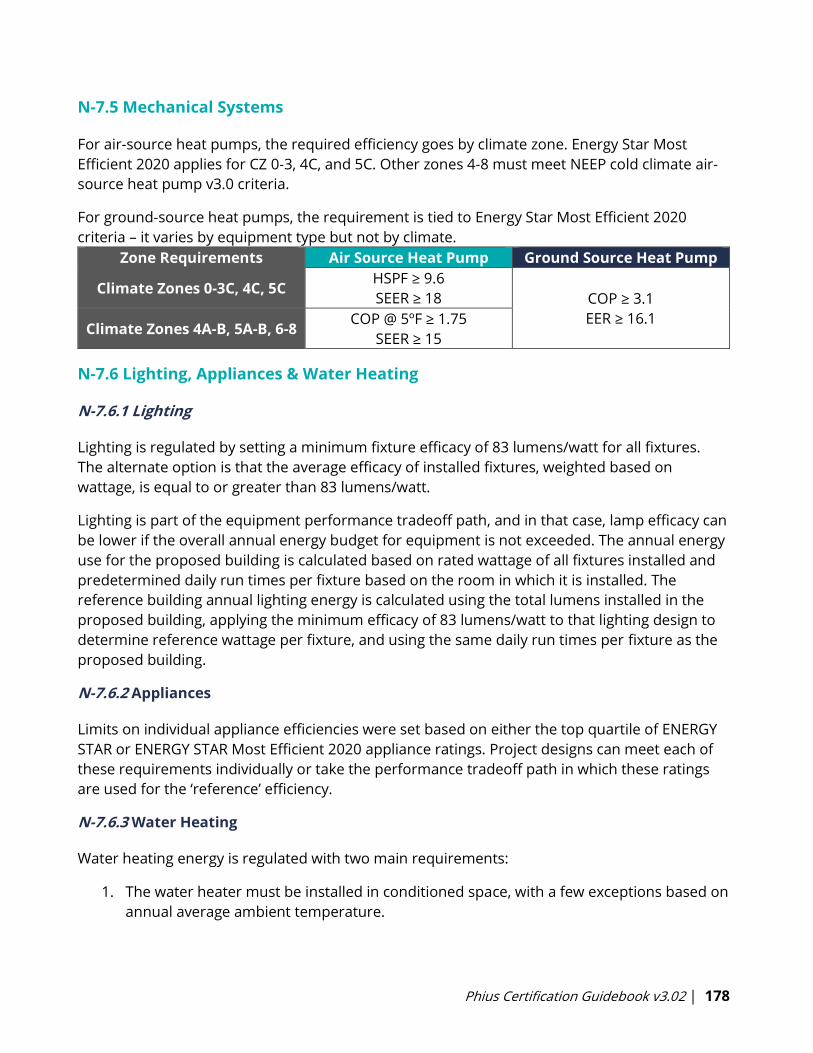
Phius Certification Guidebook v3.02 | 178
N-7.5 Mechanical Systems
For air-source heat pumps, the required efficiency goes by climate zone. Energy Star Most
Efficient 2020 applies for CZ 0-3, 4C, and 5C. Other zones 4-8 must meet NEEP cold climate air-
source heat pump v3.0 criteria.
For ground-source heat pumps, the requirement is tied to Energy Star Most Efficient 2020
criteria – it varies by equipment type but not by climate.
Zone Requirements Air Source Heat Pump Ground Source Heat Pump
Climate Zones 0-3C, 4C, 5C HSPF ≥ 9.6
SEER ≥ 18 COP ≥ 3.1
EER ≥ 16.1 Climate Zones 4A-B, 5A-B, 6-8
COP @ 5ºF ≥ 1.75
SEER ≥ 15
N-7.6 Lighting, Appliances & Water Heating
N-7.6.1 Lighting
Lighting is regulated by setting a minimum fixture efficacy of 83 lumens/watt for all fixtures.
The alternate option is that the average efficacy of installed fixtures, weighted based on
wattage, is equal to or greater than 83 lumens/watt.
Lighting is part of the equipment performance tradeoff path, and in that case, lamp efficacy can
be lower if the overall annual energy budget for equipment is not exceeded. The annual energy
use for the proposed building is calculated based on rated wattage of all fixtures installed and
predetermined daily run times per fixture based on the room in which it is installed. The
reference building annual lighting energy is calculated using the total lumens installed in the
proposed building, applying the minimum efficacy of 83 lumens/watt to that lighting design to
determine reference wattage per fixture, and using the same daily run times per fixture as the
proposed building.
N-7.6.2 Appliances
Limits on individual appliance efficiencies were set based on either the top quartile of ENERGY
STAR or ENERGY STAR Most Efficient 2020 appliance ratings. Project designs can meet each of
these requirements individually or take the performance tradeoff path in which these ratings
are used for the ‘reference’ efficiency.
N-7.6.3 Water Heating
Water heating energy is regulated with two main requirements:
1. The water heater must be installed in conditioned space, with a few exceptions based on
annual average ambient temperature.
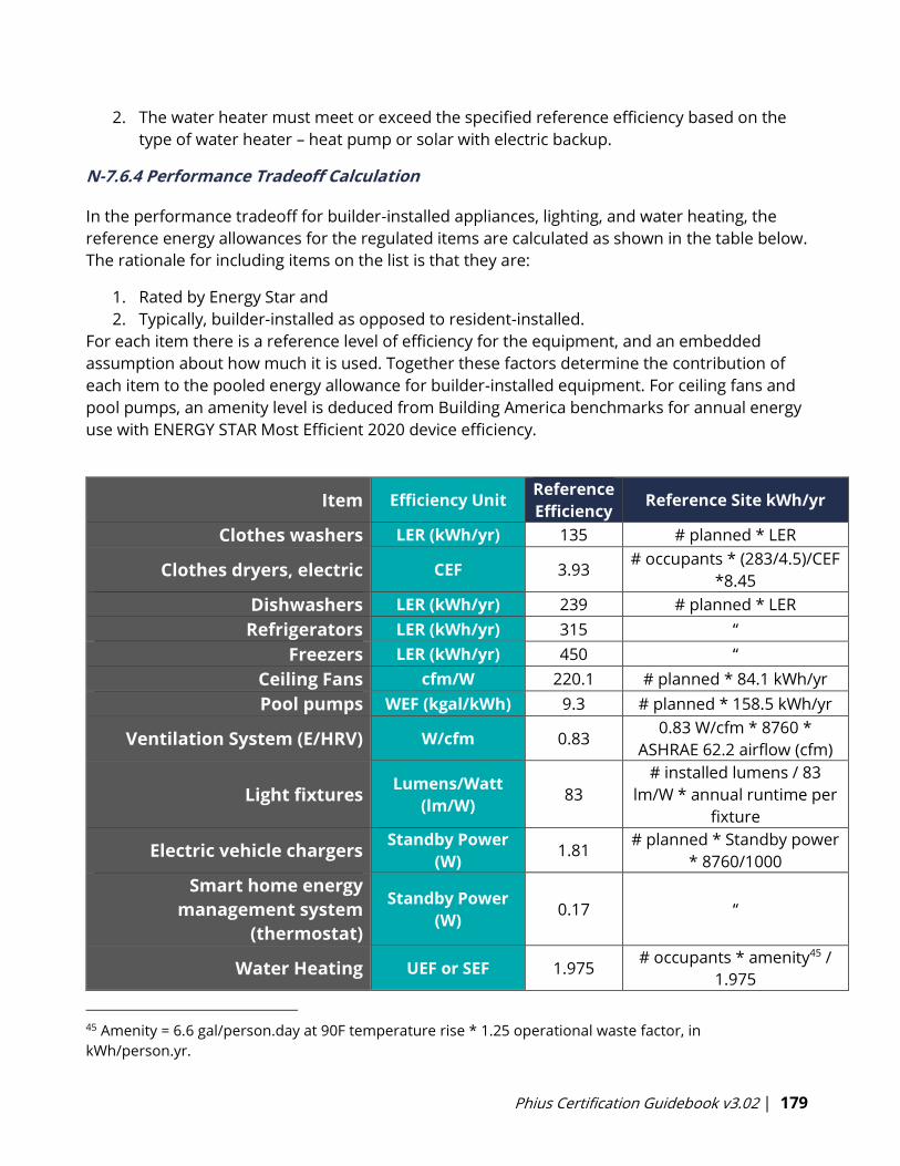
Phius Certification Guidebook v3.02 | 179
2. The water heater must meet or exceed the specified reference efficiency based on the
type of water heater – heat pump or solar with electric backup.
N-7.6.4 Performance Tradeoff Calculation
In the performance tradeoff for builder-installed appliances, lighting, and water heating, the
reference energy allowances for the regulated items are calculated as shown in the table below.
The rationale for including items on the list is that they are:
1. Rated by Energy Star and
2. Typically, builder-installed as opposed to resident-installed.
For each item there is a reference level of efficiency for the equipment, and an embedded
assumption about how much it is used. Together these factors determine the contribution of
each item to the pooled energy allowance for builder-installed equipment. For ceiling fans and
pool pumps, an amenity level is deduced from Building America benchmarks for annual energy
use with ENERGY STAR Most Efficient 2020 device efficiency.
Item Efficiency Unit Reference
Efficiency Reference Site kWh/yr
Clothes washers LER (kWh/yr) 135 # planned * LER
Clothes dryers, electric CEF 3.93 # occupants * (283/4.5)/CEF
*8.45
Dishwashers LER (kWh/yr) 239 # planned * LER
Refrigerators LER (kWh/yr) 315 “
Freezers LER (kWh/yr) 450 “
Ceiling Fans cfm/W 220.1 # planned * 84.1 kWh/yr
Pool pumps WEF (kgal/kWh) 9.3 # planned * 158.5 kWh/yr
Ventilation System (E/HRV) W/cfm 0.83 0.83 W/cfm * 8760 *
ASHRAE 62.2 airflow (cfm)
Light fixtures Lumens/Watt
(lm/W) 83
# installed lumens / 83
lm/W * annual runtime per
fixture
Electric vehicle chargers Standby Power
(W) 1.81
# planned * Standby power
* 8760/1000
Smart home energy
management system
(thermostat)
Standby Power
(W) 0.17 “
Water Heating UEF or SEF 1.975 # occupants * amenity45 /
1.975
45 Amenity = 6.6 gal/person.day at 90F temperature rise * 1.25 operational waste factor, in
kWh/person.yr.
Phius Certification Guidebook v3.02 | 180
LER = label energy rating
SEF = solar energy factor
UEF = uniform energy factor
WEF = weighted energy factor
N-8 Blinds
If the shading reduction factor for a blind in the closed position is “z”, and “Z effective” is in the
input in WUFI Passive then:
For exterior blinds use:
Z effective = 0.3 + 0.7 * z
Example: If blinds allow 46% solar access (solar transmittance, Ts) when closed,
use that for z, and z effective turns out to be 62%.
Z effective = 0.3 + (0.7*0.46) = 0.622
For interior blinds use:
Z effective = 1- (1-z) * (1-0.6)
Example: If blinds allow 46% solar access (solar transmittance, Ts) when closed,
use that for z, and z effective turns out to be 78%.
Z effective = 1 – (1-0.46) * (1-0.6) = 0.784
N-9 Multi-unit Lighting & MEL calculations
The basic protocol for lighting and miscellaneous electric loads is that they are calculated at
80% of RESNET (2013) levels for the “Rated Home”. [18] RESNET’s formulas are intended to
apply to living/dwelling units, whether detached or attached, and strictly speaking to buildings
of three stories or less. RESNET does not yet have protocol for multifamily common spaces. For
Phius certification, the scope of the RESNET formulas is expanded to include multifamily
buildings four stories or more in height but applies only to the dwelling units. Supplemental
protocol for multifamily common spaces and certain outdoor loads follows Building America
House Simulation Protocols (2014). [19] In the formulas, iCFA is used in place of RESNET’s CFA
and Building America’s FFA. The RESNET lighting formulas have been expressed more
compactly here but are algebraically equivalent to the published versions. There are additional
options for calculating the energy use of pools and elevators.
Miscellaneous Electric Loads (MELs)
For whole-building certification:
MEL = MELDWELL + MELCOMM + MELYARD (kWh/yr)
MELDWELL accounts for the living units.
MELCOMM accounts for the common spaces (if the design includes any).
MELYARD accounts for Large / Uncommon Electric and Gas loads (if the design includes any).
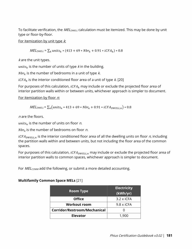
Phius Certification Guidebook v3.02 | 181
To facilitate verification, the MELDWELL calculation must be itemized. This may be done by unit
type or floor-by-floor.
For itemization by unit type k:
MELDWELL = ∑ 𝑢𝑛𝑖𝑡𝑠𝑘𝑘 ∗ (413 + 69 ∗ 𝑁𝑏𝑟𝑘 + 0.91 ∗ 𝑖𝐶𝐹𝐴𝑘) ∗ 0.8
k are the unit types.
𝑢𝑛𝑖𝑡𝑠𝑘 is the number of units of type k in the building.
𝑁𝑏𝑟𝑘 is the number of bedrooms in a unit of type k.
𝑖𝐶𝐹𝐴𝑘 is the interior conditioned floor area of a unit of type k. [20]
For purposes of this calculation, 𝑖𝐶𝐹𝐴𝑘 may include or exclude the projected floor area of
interior partition walls within or between units, whichever approach is simpler to document.
For itemization by floor n:
MELDWELL = ∑ (𝑢𝑛𝑖𝑡𝑠𝑛 ∗ 413 + 69 ∗ 𝑁𝑏𝑟𝑛 + 0.91 ∗ 𝑖𝐶𝐹𝐴𝐷𝑊𝐸𝐿𝐿,𝑛) ∗ 0.8𝑛
n are the floors.
𝑢𝑛𝑖𝑡𝑠𝑛 is the number of units on floor n.
𝑁𝑏𝑟𝑛 is the number of bedrooms on floor n.
𝑖𝐶𝐹𝐴𝐷𝑊𝐸𝐿𝐿,𝑛 is the interior conditioned floor area of all the dwelling units on floor n, including
the partition walls within and between units, but not including the floor area of the common
spaces.
For purposes of this calculation, 𝑖𝐶𝐹𝐴𝐷𝑊𝐸𝐿𝐿,𝑛 may include or exclude the projected floor area of
interior partition walls to common spaces, whichever approach is simpler to document.
For MELCOMM add the following, or submit a more detailed accounting.
Multifamily Common Space MELs [21]
Room Type Electricity
(kWh/yr)
Office 3.2 x iCFA
Workout room 9.8 x iCFA
Corridor/Restroom/Mechanical 0
Elevator 1,900
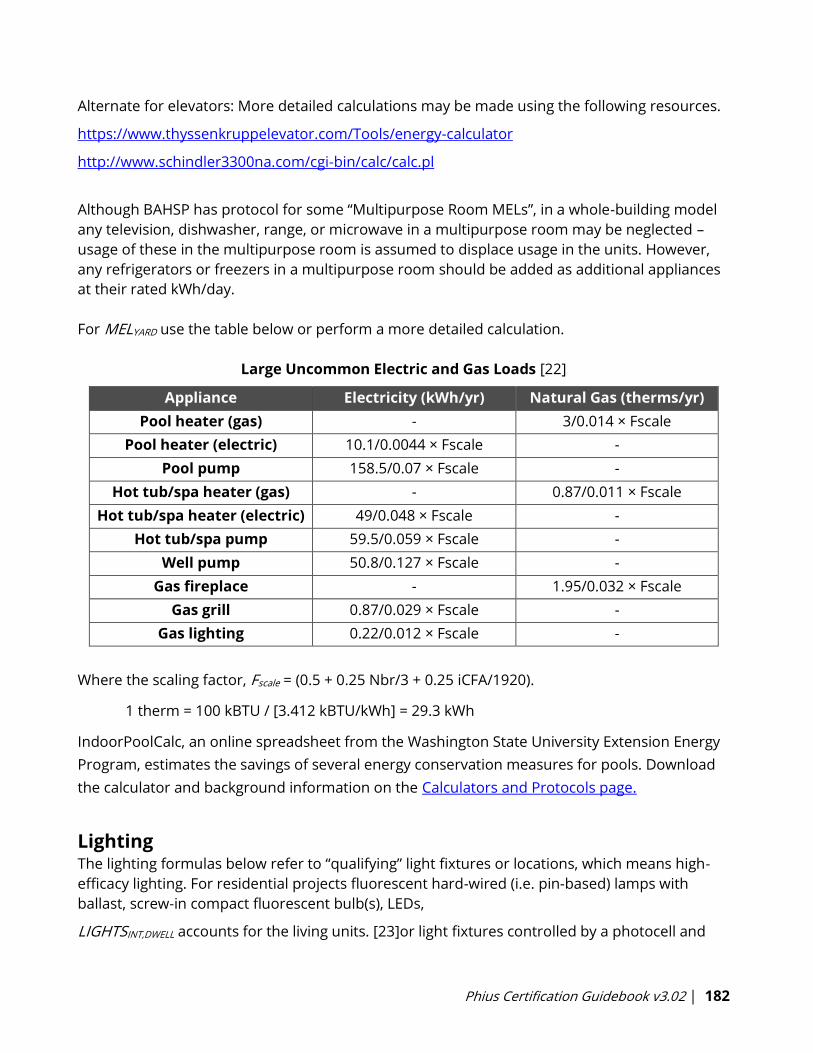
Phius Certification Guidebook v3.02 | 182
Alternate for elevators: More detailed calculations may be made using the following resources.
https://www.thyssenkruppelevator.com/Tools/energy-calculator
http://www.schindler3300na.com/cgi-bin/calc/calc.pl
Although BAHSP has protocol for some “Multipurpose Room MELs”, in a whole-building model
any television, dishwasher, range, or microwave in a multipurpose room may be neglected –
usage of these in the multipurpose room is assumed to displace usage in the units. However,
any refrigerators or freezers in a multipurpose room should be added as additional appliances
at their rated kWh/day.
For MELYARD use the table below or perform a more detailed calculation.
Large Uncommon Electric and Gas Loads [22]
Appliance Electricity (kWh/yr) Natural Gas (therms/yr)
Pool heater (gas) - 3/0.014 × Fscale
Pool heater (electric) 10.1/0.0044 × Fscale -
Pool pump 158.5/0.07 × Fscale -
Hot tub/spa heater (gas) - 0.87/0.011 × Fscale
Hot tub/spa heater (electric) 49/0.048 × Fscale -
Hot tub/spa pump 59.5/0.059 × Fscale -
Well pump 50.8/0.127 × Fscale -
Gas fireplace - 1.95/0.032 × Fscale
Gas grill 0.87/0.029 × Fscale -
Gas lighting 0.22/0.012 × Fscale -
Where the scaling factor, Fscale = (0.5 + 0.25 Nbr/3 + 0.25 iCFA/1920).
1 therm = 100 kBTU / [3.412 kBTU/kWh] = 29.3 kWh
IndoorPoolCalc, an online spreadsheet from the Washington State University Extension Energy
Program, estimates the savings of several energy conservation measures for pools. Download
the calculator and background information on the Calculators and Protocols page.
Lighting The lighting formulas below refer to “qualifying” light fixtures or locations, which means high-
efficacy lighting. For residential projects fluorescent hard-wired (i.e. pin-based) lamps with
ballast, screw-in compact fluorescent bulb(s), LEDs,
LIGHTSINT,DWELL accounts for the living units. [23]or light fixtures controlled by a photocell and
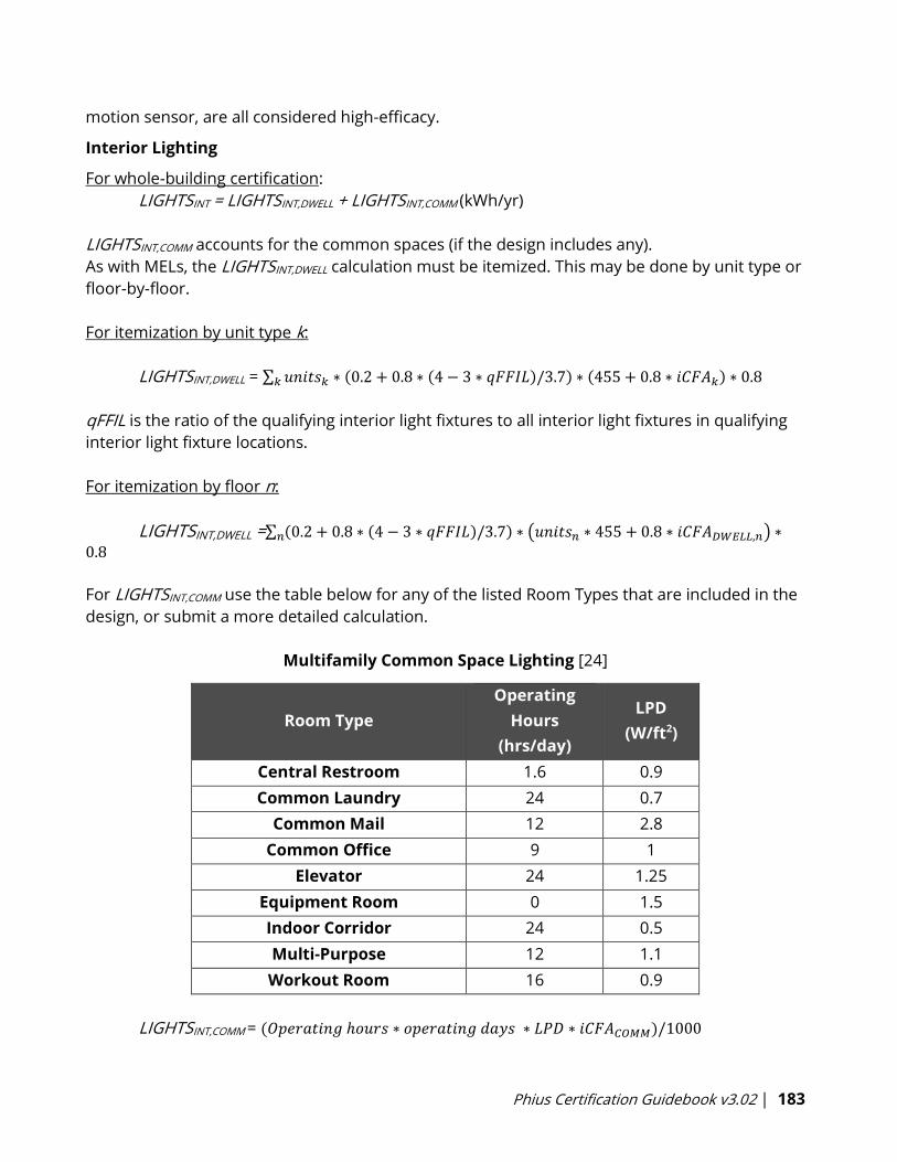
Phius Certification Guidebook v3.02 | 183
motion sensor, are all considered high-efficacy.
Interior Lighting
For whole-building certification:
LIGHTSINT = LIGHTSINT,DWELL + LIGHTSINT,COMM (kWh/yr)
LIGHTSINT,COMM accounts for the common spaces (if the design includes any).
As with MELs, the LIGHTSINT,DWELL calculation must be itemized. This may be done by unit type or
floor-by-floor.
For itemization by unit type k:
LIGHTSINT,DWELL = ∑ 𝑢𝑛𝑖𝑡𝑠𝑘𝑘 ∗ (0.2 + 0.8 ∗ (4 − 3 ∗ 𝑞𝐹𝐹𝐼𝐿)/3.7) ∗ (455 + 0.8 ∗ 𝑖𝐶𝐹𝐴𝑘) ∗ 0.8
qFFIL is the ratio of the qualifying interior light fixtures to all interior light fixtures in qualifying
interior light fixture locations.
For itemization by floor n:
LIGHTSINT,DWELL =∑ (0.2 + 0.8 ∗ (4 − 3 ∗ 𝑞𝐹𝐹𝐼𝐿)/3.7) ∗ (𝑢𝑛𝑖𝑡𝑠𝑛 ∗ 455 + 0.8 ∗ 𝑖𝐶𝐹𝐴𝐷𝑊𝐸𝐿𝐿,𝑛) ∗𝑛
0.8
For LIGHTSINT,COMM use the table below for any of the listed Room Types that are included in the
design, or submit a more detailed calculation.
Multifamily Common Space Lighting [24]
Room Type
Operating
Hours
(hrs/day)
LPD
(W/ft2)
Central Restroom 1.6 0.9
Common Laundry 24 0.7
Common Mail 12 2.8
Common Office 9 1
Elevator 24 1.25
Equipment Room 0 1.5
Indoor Corridor 24 0.5
Multi-Purpose 12 1.1
Workout Room 16 0.9
LIGHTSINT,COMM = (𝑂𝑝𝑒𝑟𝑎𝑡𝑖𝑛𝑔 ℎ𝑜𝑢𝑟𝑠 ∗ 𝑜𝑝𝑒𝑟𝑎𝑡𝑖𝑛𝑔 𝑑𝑎𝑦𝑠 ∗ 𝐿𝑃𝐷 ∗ 𝑖𝐶𝐹𝐴𝐶𝑂𝑀𝑀)/1000
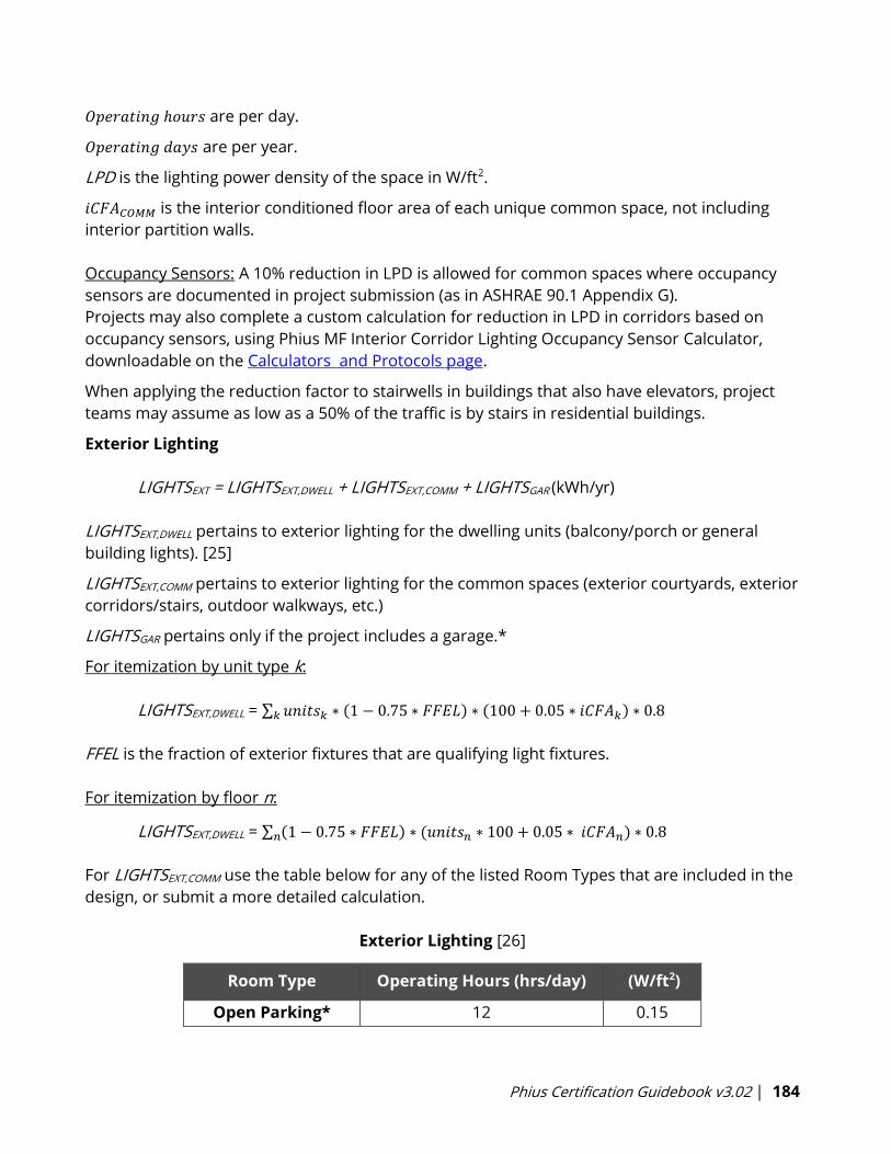
Phius Certification Guidebook v3.02 | 184
𝑂𝑝𝑒𝑟𝑎𝑡𝑖𝑛𝑔 ℎ𝑜𝑢𝑟𝑠 are per day.
𝑂𝑝𝑒𝑟𝑎𝑡𝑖𝑛𝑔 𝑑𝑎𝑦𝑠 are per year.
LPD is the lighting power density of the space in W/ft2.
𝑖𝐶𝐹𝐴𝐶𝑂𝑀𝑀 is the interior conditioned floor area of each unique common space, not including
interior partition walls.
Occupancy Sensors: A 10% reduction in LPD is allowed for common spaces where occupancy
sensors are documented in project submission (as in ASHRAE 90.1 Appendix G).
Projects may also complete a custom calculation for reduction in LPD in corridors based on
occupancy sensors, using Phius MF Interior Corridor Lighting Occupancy Sensor Calculator,
downloadable on the Calculators and Protocols page.
When applying the reduction factor to stairwells in buildings that also have elevators, project
teams may assume as low as a 50% of the traffic is by stairs in residential buildings.
Exterior Lighting
LIGHTSEXT = LIGHTSEXT,DWELL + LIGHTSEXT,COMM + LIGHTSGAR (kWh/yr)
LIGHTSEXT,DWELL pertains to exterior lighting for the dwelling units (balcony/porch or general
building lights). [25]
LIGHTSEXT,COMM pertains to exterior lighting for the common spaces (exterior courtyards, exterior
corridors/stairs, outdoor walkways, etc.)
LIGHTSGAR pertains only if the project includes a garage.*
For itemization by unit type k:
LIGHTSEXT,DWELL = ∑ 𝑢𝑛𝑖𝑡𝑠𝑘𝑘 ∗ (1 − 0.75 ∗ 𝐹𝐹𝐸𝐿) ∗ (100 + 0.05 ∗ 𝑖𝐶𝐹𝐴𝑘) ∗ 0.8
FFEL is the fraction of exterior fixtures that are qualifying light fixtures.
For itemization by floor n:
LIGHTSEXT,DWELL = ∑ (1 − 0.75 ∗ 𝐹𝐹𝐸𝐿) ∗ (𝑢𝑛𝑖𝑡𝑠𝑛𝑛 ∗ 100 + 0.05 ∗ 𝑖𝐶𝐹𝐴𝑛) ∗ 0.8
For LIGHTSEXT,COMM use the table below for any of the listed Room Types that are included in the
design, or submit a more detailed calculation.
Exterior Lighting [26]
Room Type Operating Hours (hrs/day) (W/ft2)
Open Parking* 12 0.15
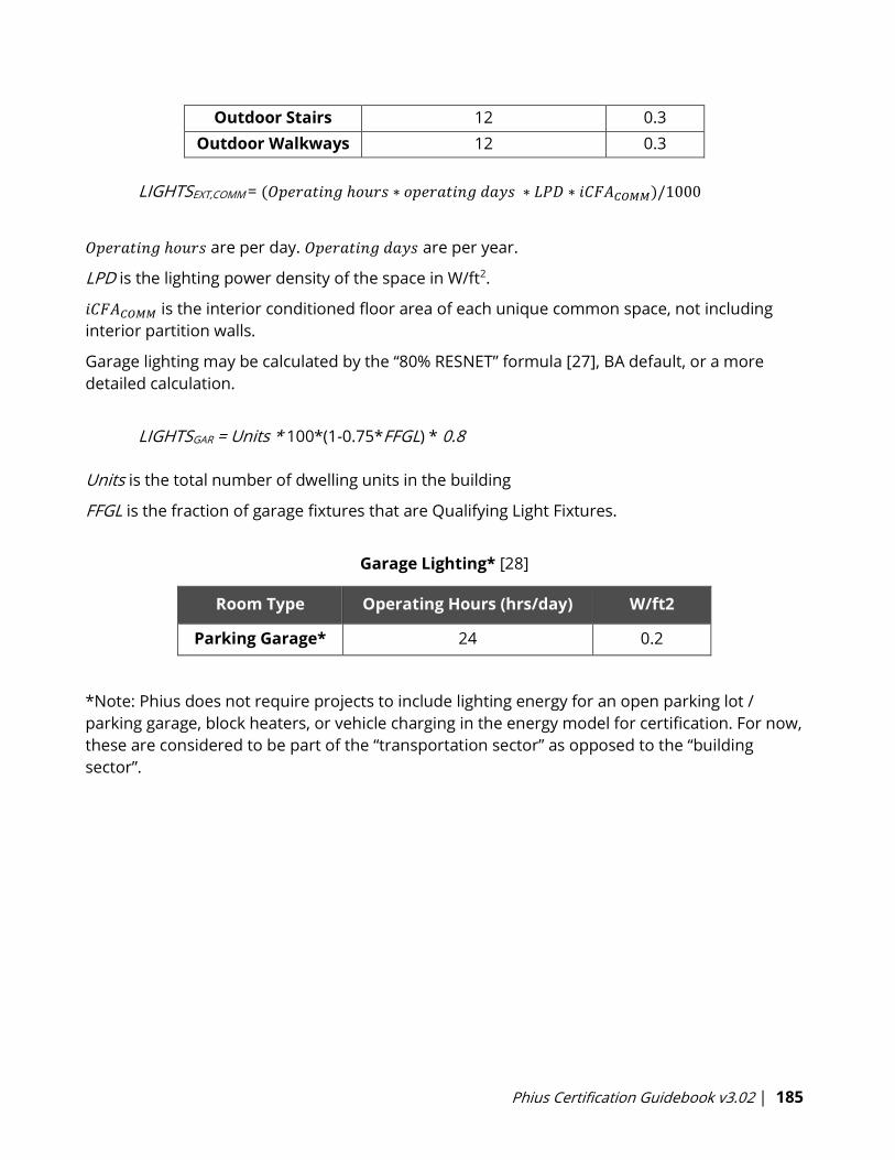
Phius Certification Guidebook v3.02 | 185
Outdoor Stairs 12 0.3
Outdoor Walkways 12 0.3
LIGHTSEXT,COMM = (𝑂𝑝𝑒𝑟𝑎𝑡𝑖𝑛𝑔 ℎ𝑜𝑢𝑟𝑠 ∗ 𝑜𝑝𝑒𝑟𝑎𝑡𝑖𝑛𝑔 𝑑𝑎𝑦𝑠 ∗ 𝐿𝑃𝐷 ∗ 𝑖𝐶𝐹𝐴𝐶𝑂𝑀𝑀)/1000
𝑂𝑝𝑒𝑟𝑎𝑡𝑖𝑛𝑔 ℎ𝑜𝑢𝑟𝑠 are per day. 𝑂𝑝𝑒𝑟𝑎𝑡𝑖𝑛𝑔 𝑑𝑎𝑦𝑠 are per year.
LPD is the lighting power density of the space in W/ft2.
𝑖𝐶𝐹𝐴𝐶𝑂𝑀𝑀 is the interior conditioned floor area of each unique common space, not including
interior partition walls.
Garage lighting may be calculated by the “80% RESNET” formula [27], BA default, or a more
detailed calculation.
LIGHTSGAR = Units * 100*(1-0.75*FFGL) * 0.8
Units is the total number of dwelling units in the building
FFGL is the fraction of garage fixtures that are Qualifying Light Fixtures.
Garage Lighting* [28]
Room Type Operating Hours (hrs/day) W/ft2
Parking Garage* 24 0.2
*Note: Phius does not require projects to include lighting energy for an open parking lot /
parking garage, block heaters, or vehicle charging in the energy model for certification. For now,
these are considered to be part of the “transportation sector” as opposed to the “building
sector”.

Phius Certification Guidebook v3.02 | 186
N-10 Non-Residential Utilization Patterns
Standard Default Patterns (per DIN V 18599-10:2007-02, Table 4) for Internal Loads and
Occupancy Calculations for Non-Residential Buildings
Garage buildings (for offices and private
use)7:00 18:00 250 75 0 0.95 1
Garage buildings (public use) 9:00 0:00 365 75 0 0.8 1
Traffic /circulation areas 7:00 18:00 250 100 0 0.8 1
Auxiliary spaces ( without habitable
rooms)7:00 18:00 250 100 2.6 0.9 1
Storeroom, technical equipment
room,archive7:00 18:00 250 100 2.6 0.98 1
Library - magazine and stores 8:00 20:00 300 100 2.6 0.9 1
Booking hall 7:00 18:00 250 200 2.6 0 1
Hotel bedroom 21:00 8:00 365 200 2.6 0.25 0.3
Canteen 8:00 15:00 250 200 2.6 0 1
Restaurant 10:00 0:00 300 200 2.6 0 1
Toilets and sanitary facilities in non
residential buildings7:00 18:00 250 200 2.6 0.9 1
Spectators and audience area (theaters
and event locations)19:00 23:00 250 200 2.6 0 1
Exhibition rooms and museums with
conservation requirements10:00 18:00 250 200 2.6 0 1
Library-open stacks areas 8:00 20:00 300 200 2.6 0 1
Retail shop/Department store 8:00 20:00 300 300 2.6 0 1
Retail shop/department store (food
department with refrigerated products)8:00 20:00 300 300 2.6 0 1
Classroom (school and nursery school) 8:00 15:00 200 300 2.6 0.25 0.9
Hospital ward or dormitory 0:00 24:00 365 300 2.6 0 0.5
Kitchen - preparation room or storeroom 7:00 23:00 300 300 2.6 0.5 1
Other Habitable Room 7:00 18:00 250 300 2.6 0.5 1
Foyer (theaters and event locations) 19:00 23:00 250 300 2.6 0.5 1
Fair/Congress building 13:00 18:00 150 300 2.6 0.5 1
Sports hall (without public viewing area) 8:00 23:00 300 300 2.6 0.3 1
Personal office (single occupant) 7:00 18:00 250 500 2.6 0.3 0.7
Workgroup office (two to six workplaces) 7:00 18:00 250 500 2.6 0.3 0.7
Landscaped office (seven or more
workplaces)7:00 18:00 250 500 2.6 0 1
Meeting, conference and seminar room 7:00 18:00 250 500 2.6 0.5 1
Lecture room, auditorium 8:00 18:00 150 500 2.6 0.25 0.7
Kitchens in non-residential buildings 10:00 23:00 300 500 2.6 0 1
Server room, computer center 0:00 24:00 365 500 2.6 0.5 0.5
Workshop, assembly,manufacturing 7:00 16:00 250 500 2.6 0 1
Library - reading rooms 8:00 20:00 300 500 2.6 0 1
Stage (theaters and event locations) 13:00 23:00 250 1000 2.6 0 0.6
RELATIVE
ABSENTEEISM
FACTOR FOR LIGHTING
RELATIVE TO BUILDING
OPERATION TIMESPACE TYPE
BEGINNING
OF USAGE
(TIME)
END OF
USAGE
(TIME)
ANNUAL
UTILIZATION
DAYS (d/a)
MAINTAINED
ILLUMINANACE
(lux)
HEIGHT OF THE
WORK PLANE
(ft)
Phius Certification Guidebook v3.02 | 187
References
i Wright, Graham S., and Katrin Klingenberg. Climate-Specific Passive Building Standards. Golden,
CO: National Renewable Energy Laboratory, 2015. Web. 13 May 2016.
http://www1.eere.energy.gov/library/asset_handler.aspx?src=http://apps1.eere.energy.gov/build
ings/publications/pdfs/building_america/climate-specific-passive-building.pdf&id=7134
2 -
2009. Web. 13 May 2016.
http://buildingscience.com/documents/insights/bsi-028-energy-flow-across-enclosures
3 Cummings, James. “Sensible and Latent Cooling Load Control Using Centrally‐Ducted,
Variable‐Capacity Space Conditioning Systems in Low Sensible Load Environments.” Office of
Energy Efficiency and Renewable Energy. energy.gov, 26 July 2012. Web. 16 May 2016.
http://energy.gov/eere/buildings/downloads/sensible-and-latent-cooling-load-control-using-
centrally-ducted-variable
4 -
May 2016.
http://buildingscience.com/documents/information-sheets/information-sheet-supplemental-
humidity-control
5 WaterSense® New Home Specification Guide for Efficient Hot Water Delivery Systems, Version
1.2. U.S. Environmental Protection Agency (EPA), 2014. Web. 10 May 2016.
https://basc.pnnl.gov/resources/watersense-new-home-specification-guide-hot-water-
delivery-systems
6 RESNET, op. cit., Appendix B
7 -10:2007- Energy Efficiency of Buildings Calculation of the Energy Needs,
Delivered Energy and Primary Energy for Heating, Cooling, Ventilation, Domestic Hot Water and
Lighting Part 10: Boundary Conditions of Use, Climatic Data. Deutsches Institut für Normung (DIN),
2007. Table 4. Print.
8 Henderson, Hugh, Yu Joe Huang, and Danny Parker. RESIDENTIAL EQUIPMENT PART LOAD
CURVES FOR USE IN DOE-2. Berkeley CA: Lawrence Berkeley National Laboratory, 1999. Web. 31
May 2016.
https://publications.lbl.gov/islandora/object/ir%3A112919
9 - Doubl
May 2016.
http://buildingscience.com/documents/enclosures-that-work/high-r-value-wall-
assemblies/high-r-value-double-stud-wall-construction?topic=doctypes/enclosures-that-
work/etw-high-r-value-enclosure-assemblie
Phius Certification Guidebook v3.02 | 188
10 -
Taunton Press, 29 Apr. 2015. Web. 16 May 2016.
http://www.greenbuildingadvisor.com/articles/dept/building-science/lstiburek-s-ideal-double-
stud-wall-design
11 -Bearing Masonry
Journal of Green Building 2.2 (2007): 42 50. Web. 31 May 2016.
https://www.researchgate.net/publication/269493678_Interior_Insulation_Retrofits_of_Load-
Bearing_Masonry_Walls_in_Cold_Climates
12 -011: Capillarity
2014. Web. 31 May 2016.
http://buildingscience.com/documents/insights/bsi-011-capillarity-small-sacrifices
13 -
http://buildingscience.com/documents/building-science-insights/bsi-095-how-buildings-age
14 -
May 2016.
http://buildingscience.com/documents/insights/bsi-001-the-perfect-wall
15 -091: Flow-
http://buildingscience.com/documents/building-science-insights/bsi-091-flow-through-
assemblies
16 » Green Basics: Encyclopedia » Envelope and Structure » Insulation Choices » Rigid Foam
http://www.greenbuildingadvisor.com/green-basics/rigid-foam-insulation
17 Selecting Ventilation Air Filters to Reduce PM2.5 Of Outdoor Origin. ASHRAE Journal. September
2016.
http://www.conforlab.com.br/wp-content/uploads/2016/10/2016Sep_012-
021_HarrimanFiltersToReducePM2.5.pdf
18 RESNET, op.cit., Section 303.4.
19 Wilson, E. et al. 2014 Building America House Simulation Protocols (BAHSP). Golden, CO: National
Renewable Energy Laboratory, 2014. Print..
http://energy.gov/eere/buildings/house-simulation-protocols-report
20
21
ce of New Hampshire, 2013, and assumes 1h/wk usage.
22 BAHSP, op. cit., Table 26.
23 RESNET, op. cit., clause 303.4.1.7.2.2 Interior Lighting, and equation 5.

Phius Certification Guidebook v3.02 | 189
24 New Construction 2011-01-
C89:D101 and C120:L132
http://energy.gov/eere/buildings/building-america-analysis-spreadsheets
25 RESNET, op. cit., clause 303.4.1.7.2.3 Exterior Lighting, and equation 6.
26 B10 Analysis workbook, op. cit.
27 RESNET, op. cit., clause 303.4.1.7.2.4 Garage lighting, and equation 7.
28 B10 Analysis workbook, op. cit.