permanent magnet diploes and quadrupoles for ffags
TRANSCRIPT
9/19/2005 1
Permanent Magnet Diploes and Quadrupolesfor FFAGs
Jinfang Liu and Peter Dent
Electron Energy Corporation
924 Links Ave, Landisville PA 17538
Phone: 717-898-2294 Fax: 717-898-0660
9/19/2005 2
(1) Permanent Magnet Overview
(2) Some Design Considerations
(3) Radiation Effect
(4) Permanent Magnet Dipoles
(5) Permanent Magnet Mangles
(6) Permanent Magnet Quadrupoles
(7) Summary
Outline
9/19/2005 3
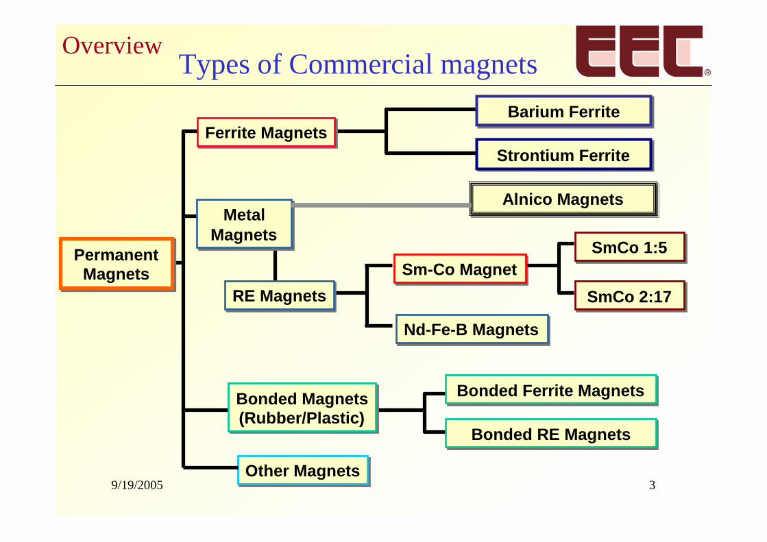
Types of Commercial magnets
Nd-Fe-B MagnetsNd-Fe-B Magnets
Sm-Co MagnetSm-Co Magnet
Strontium FerriteStrontium Ferrite
Barium FerriteBarium Ferrite
PermanentMagnets
PermanentMagnets
Bonded Magnets(Rubber/Plastic)Bonded Magnets(Rubber/Plastic)
MetalMagnets
MetalMagnets
Ferrite MagnetsFerrite Magnets
RE MagnetsRE Magnets
Alnico MagnetsAlnico Magnets
Bonded Ferrite MagnetsBonded Ferrite Magnets
Bonded RE MagnetsBonded RE Magnets
SmCo 1:5SmCo 1:5
SmCo 2:17SmCo 2:17
Other MagnetsOther Magnets
Overview
9/19/2005 4
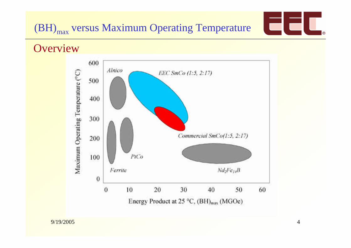
(BH)max versus Maximum Operating Temperature
Overview
9/19/2005 5
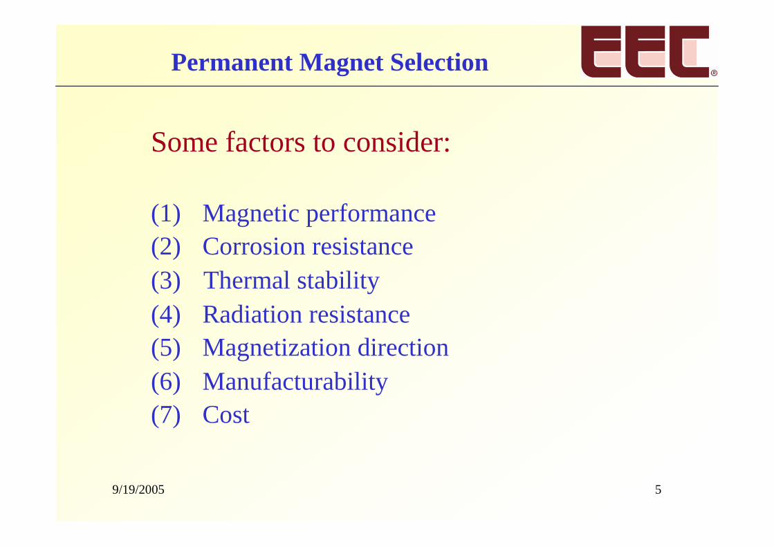
Some factors to consider:
(1) Magnetic performance(2) Corrosion resistance(3) Thermal stability(4) Radiation resistance(5) Magnetization direction(6) Manufacturability(7) Cost
Permanent Magnet Selection
9/19/2005 6
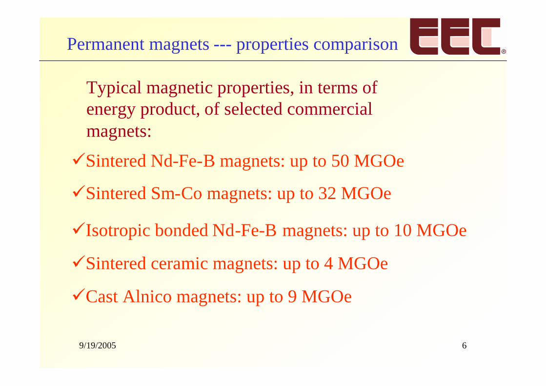
Typical magnetic properties, in terms ofenergy product, of selected commercialmagnets:
Sintered Nd-Fe-B magnets: up to 50 MGOe
Sintered Sm-Co magnets: up to 32 MGOe
Isotropic bonded Nd-Fe-B magnets: up to 10 MGOe
Sintered ceramic magnets: up to 4 MGOe
Cast Alnico magnets: up to 9 MGOe
Permanent magnets --- properties comparison
9/19/2005 7
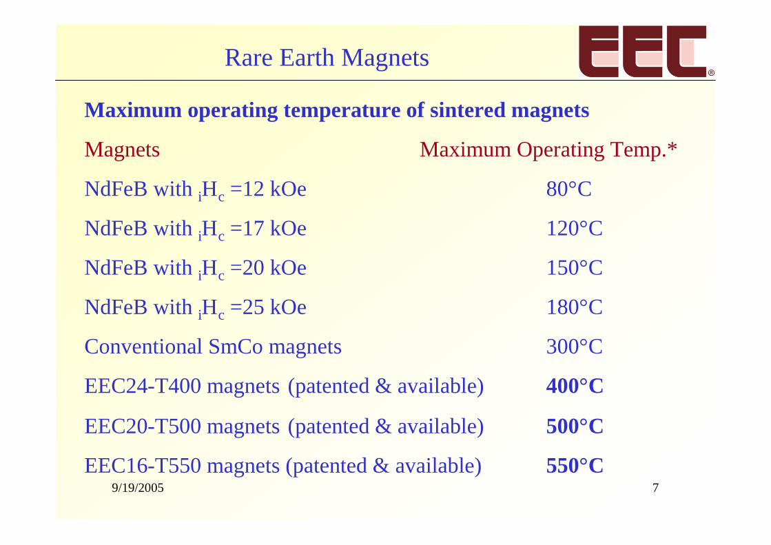
Maximum operating temperature of sintered magnets
Magnets Maximum Operating Temp.*
NdFeB with iHc =12 kOe 80°C
NdFeB with iHc =17 kOe 120°C
NdFeB with iHc =20 kOe 150°C
NdFeB with iHc =25 kOe 180°C
Conventional SmCo magnets 300°C
EEC24-T400 magnets (patented & available) 400°C
EEC20-T500 magnets (patented & available) 500°C
EEC16-T550 magnets (patented & available) 550°C
Rare Earth Magnets
9/19/2005 8
15
20
25
30
35
40
45
50
100 200 300 400 500 600
Maximum Operating Temp. (oC)
(BH
) max
(MG
Oe)
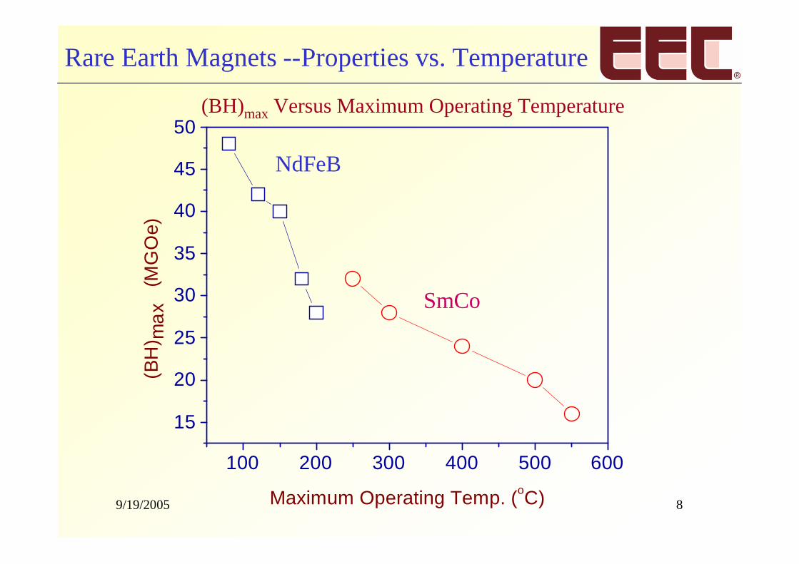
NdFeB
SmCo
(BH)max Versus Maximum Operating Temperature
Rare Earth Magnets --Properties vs. Temperature
9/19/2005 9
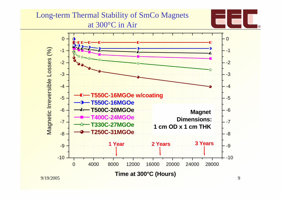
Long-term Thermal Stability of SmCo Magnetsat 300°C in Air
0 4000 8000 12000 16000 20000 24000 28000-10
-9
-8
-7
-6
-5
-4
-3
-2
-1
0
1 Year
MagnetDimensions:
1 cm OD x 1 cm THK
2 Years 3 Years
T550C-16MGOe w/coatingT550C-16MGOeT500C-20MGOeT400C-24MGOeT330C-27MGOeT250C-31MGOe
Time at 300°C (Hours)
Mag
netic
Irre
vers
ible
Loss
es(%
)
-10
-9
-8
-7
-6
-5
-4
-3
-2
-1
0
9/19/2005 10
High temperature magnets
DoD initiated the More Electric Aircraft program,which requires magnets with maximum operatingtemperature more than 400°C
Funded by the Department of Defense, a series ofsintered SmCo 2:17 magnets were developed at EECwith maximum operating temperature as high as 550°C
These patented SmCo UHT magnets were introducedto the industry in 1999.
Rare Earth Magnets --- Materials Selection
9/19/2005 11
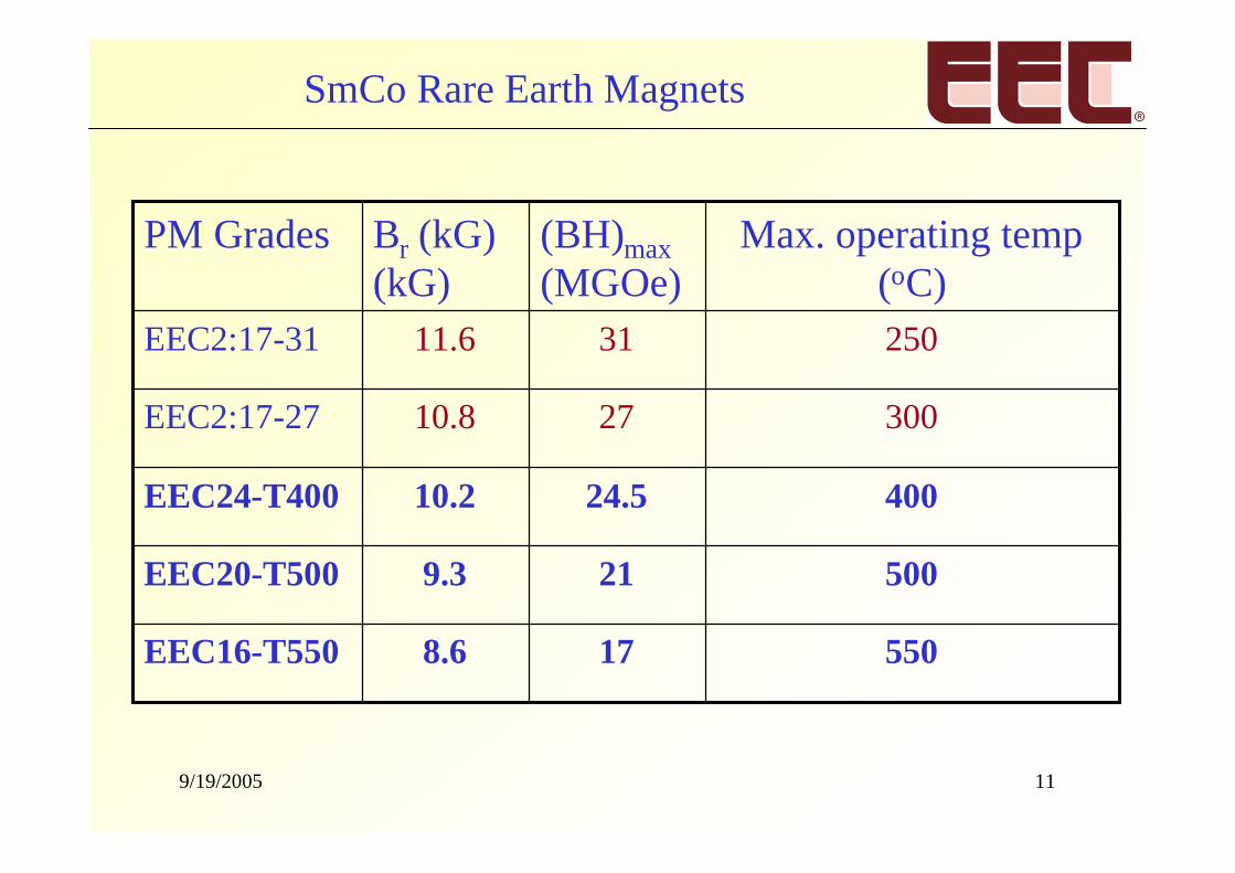
SmCo Rare Earth Magnets
550178.6EEC16-T550
500219.3EEC20-T500
40024.510.2EEC24-T400
3002710.8EEC2:17-27
2503111.6EEC2:17-31
Max. operating temp(oC)
(BH)max(MGOe)
Br (kG)(kG)
PM Grades
9/19/2005 12
Nd-Fe-B sintered magnets
Key features:
Highest (BH)max available (up to 50 MGOe)
Less expensive than Sm-Co magnets
Corrosion resistance is not good
Special coating is required
Maximum operating temperature is very low compared toSmCo magnets
Rare Earth Magnets --- Materials Selection
9/19/2005 13
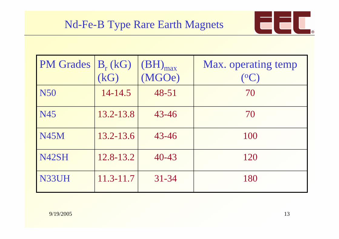
Nd-Fe-B Type Rare Earth Magnets
18031-3411.3-11.7N33UH
12040-4312.8-13.2N42SH
10043-4613.2-13.6N45M
7043-4613.2-13.8N45
7048-5114-14.5N50
Max. operating temp(oC)
(BH)max(MGOe)
Br (kG)(kG)
PM Grades
9/19/2005 14
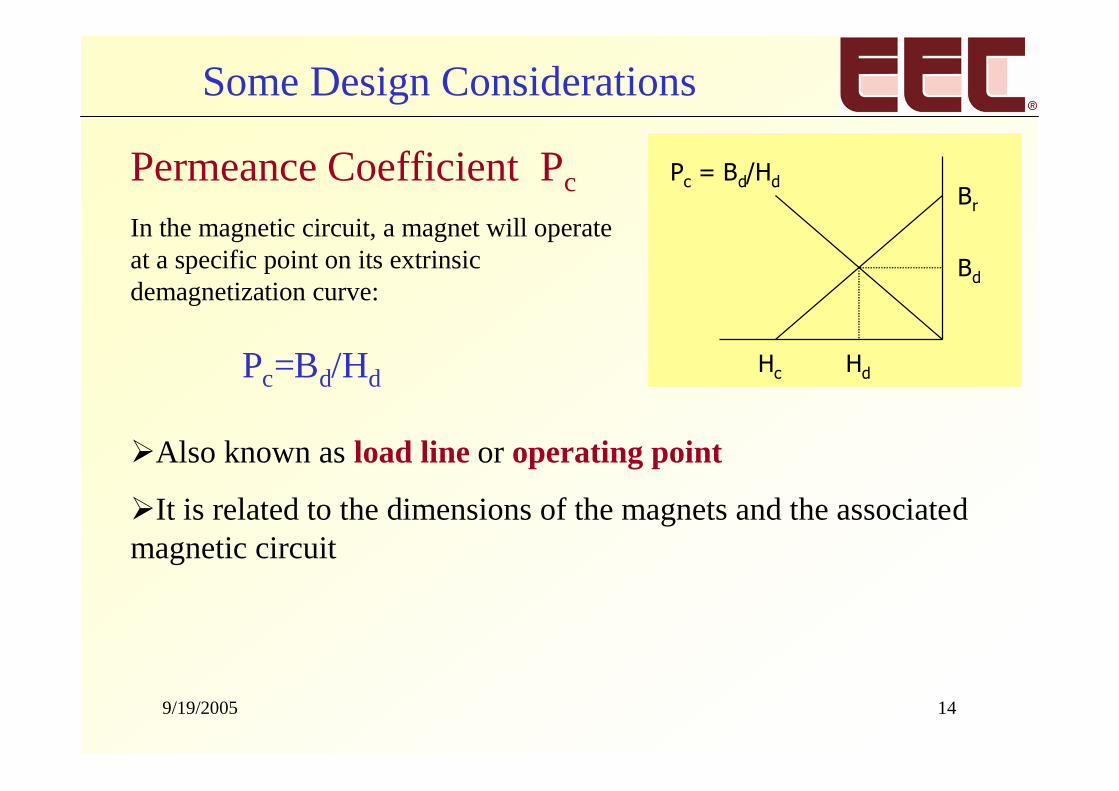
Permeance Coefficient Pc
Also known as load line or operating point
It is related to the dimensions of the magnets and the associatedmagnetic circuit
In the magnetic circuit, a magnet will operateat a specific point on its extrinsicdemagnetization curve:
Pc = Bd/HdBr
Bd
HdHcPc=Bd/Hd
Some Design Considerations
9/19/2005 15
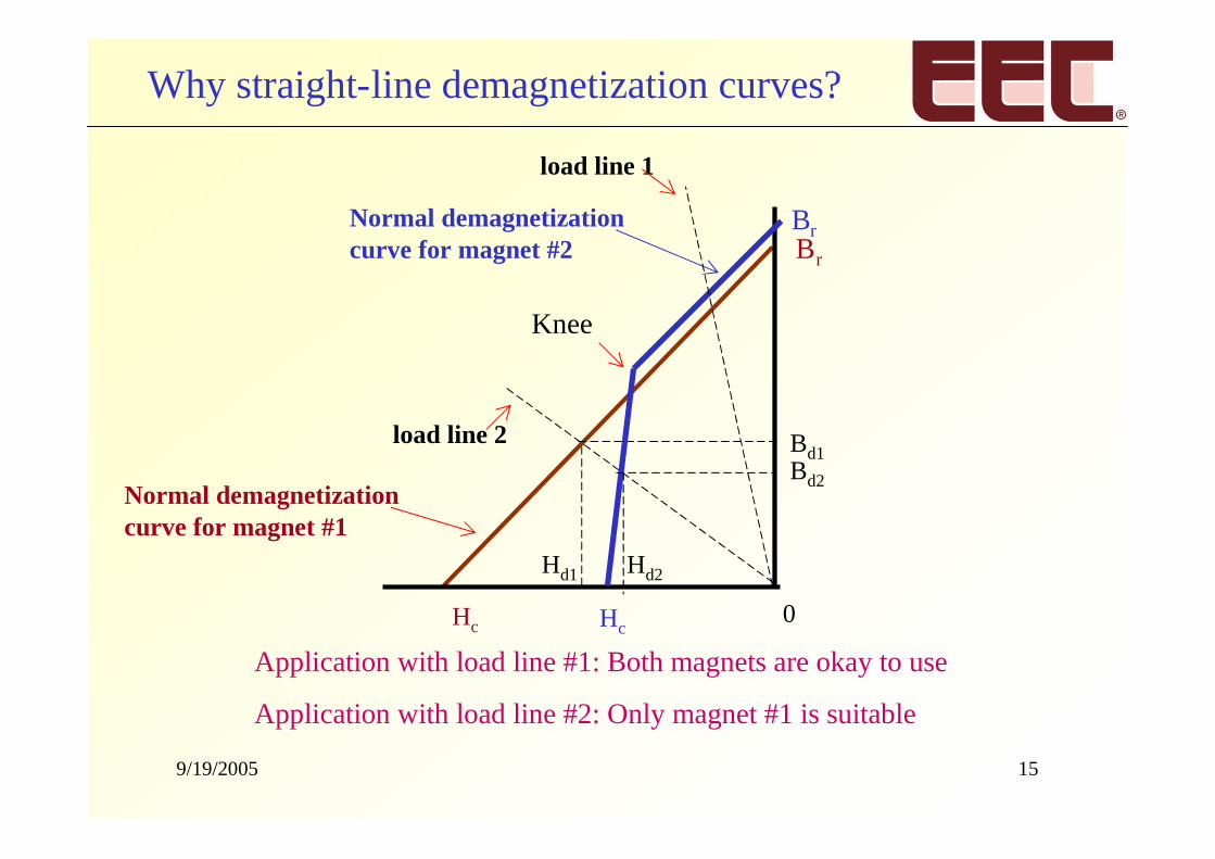
Why straight-line demagnetization curves?
Application with load line #1: Both magnets are okay to use
Application with load line #2: Only magnet #1 is suitable
Bd1
Normal demagnetizationcurve for magnet #1
load line 2
Br
Hc 0
Knee
load line 1
Bd2
Hd1 Hd2
Br
Hc
Normal demagnetizationcurve for magnet #2
9/19/2005 16
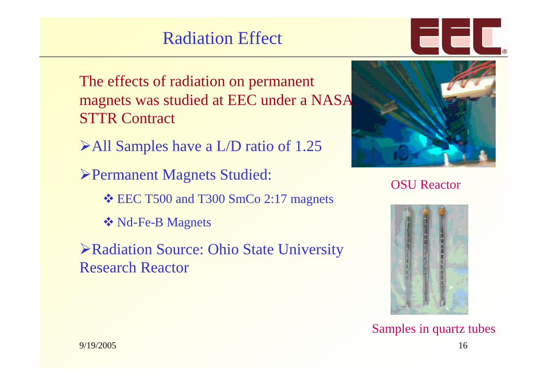
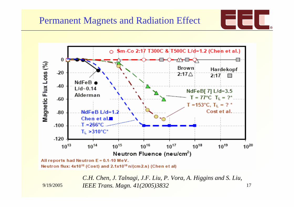
The effects of radiation on permanentmagnets was studied at EEC under a NASASTTR Contract
All Samples have a L/D ratio of 1.25
Permanent Magnets Studied:EEC T500 and T300 SmCo 2:17 magnets
Nd-Fe-B Magnets
Radiation Source: Ohio State UniversityResearch Reactor
Radiation Effect
OSU Reactor
Samples in quartz tubes
9/19/2005 17
Permanent Magnets and Radiation Effect
C.H. Chen, J. Talnagi, J.F. Liu, P. Vora, A. Higgins and S. Liu,IEEE Trans. Magn. 41(2005)3832
9/19/2005 18
-100
-80
-60
-40
-20
0
20
1.E+13 1.E+14 1.E+15 1.E+16 1.E+17 1.E+18 1.E+19 1.E+20
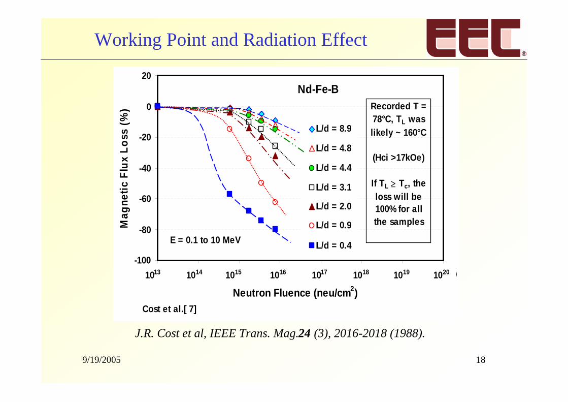
Neutron Fluence (neu/cm2)
Mag
neti
cF
lux
Lo
ss(%
)L/d = 8.9
L/d = 4.8
L/d = 4.4
L/d = 3.1
L/d = 2.0
L/d = 0.9
L/d = 0.4
1013 1014 1015 1016 1017 1018 1019 1020
Cost et al.[ 7]
Recorded T =78°C, TL waslikely ~ 160°C
(Hci >17kOe)
If TL Tc, theloss will be100% for allthe samples
E = 0.1 to 10 MeV
Nd-Fe-B
J.R. Cost et al, IEEE Trans. Mag.24 (3), 2016-2018 (1988).
Working Point and Radiation Effect
9/19/2005 19
Radiation Effect
The major radiation damage is caused by radiation-induced thermal spikes
The dominant factor for radiation tolerance is thermalstability, which is related to the following factors:
(1) Curie temperature of permanent magnets
(2) Working point of permanent magnet in the system
(3) Intrinsic coercivity
9/19/2005 20
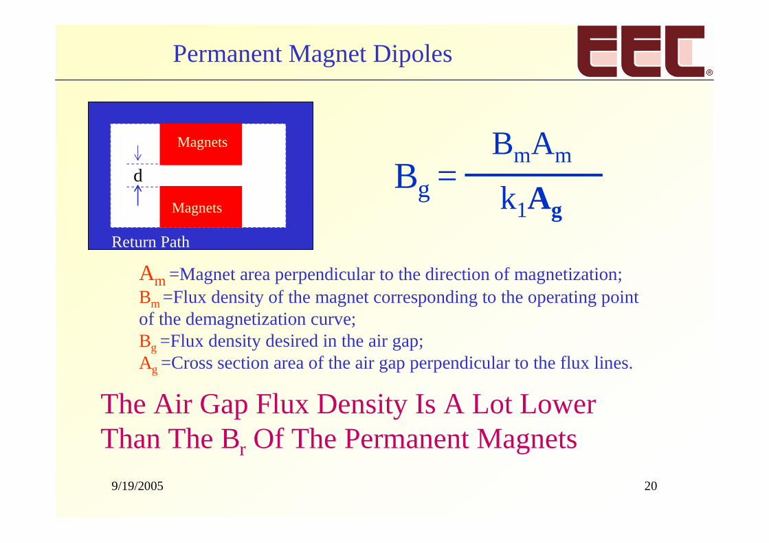
Permanent Magnet Dipoles
Magnets
Magnets
Return Path
d Bg = –––––BmAm
k1Ag
Am =Magnet area perpendicular to the direction of magnetization;Bm =Flux density of the magnet corresponding to the operating pointof the demagnetization curve;Bg =Flux density desired in the air gap;Ag =Cross section area of the air gap perpendicular to the flux lines.
The Air Gap Flux Density Is A Lot LowerThan The Br Of The Permanent Magnets
9/19/2005 21
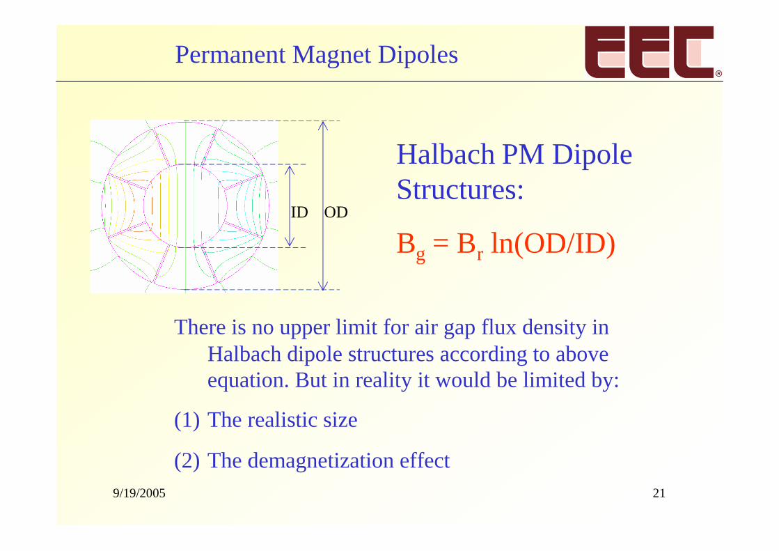
Permanent Magnet Dipoles
Halbach PM DipoleStructures:
Bg = Br ln(OD/ID)ODID
There is no upper limit for air gap flux density inHalbach dipole structures according to aboveequation. But in reality it would be limited by:
(1) The realistic size
(2) The demagnetization effect
9/19/2005 22
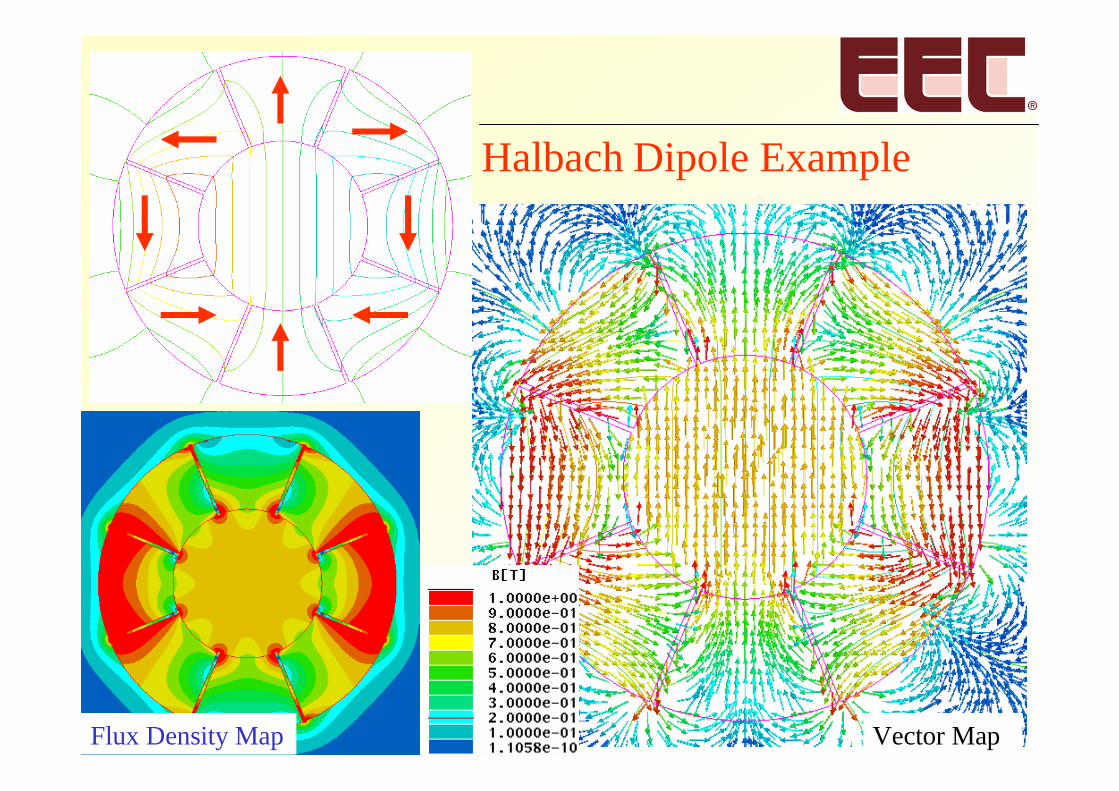
Flux Density Map Vector Map
Halbach Dipole Example
9/19/2005 23
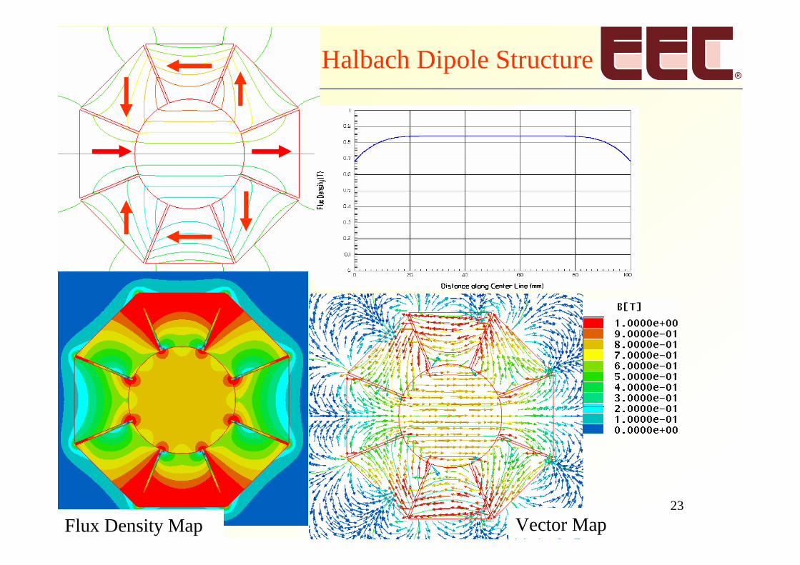
Vector MapFlux Density Map
Halbach Dipole Structure
9/19/2005 24
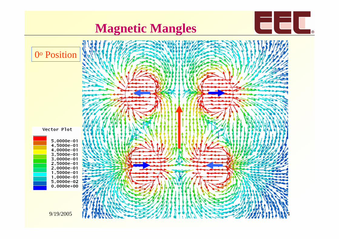
0o Position
Magnetic Mangles
9/19/2005 25
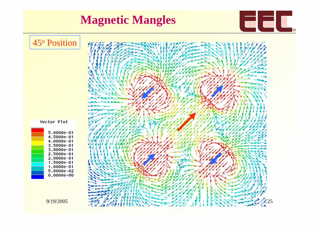
45o Position
Magnetic Mangles
9/19/2005 26
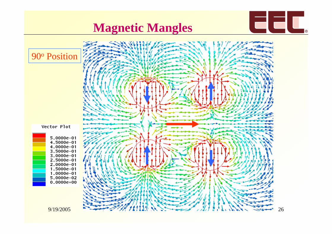
90o Position
Magnetic Mangles
9/19/2005 27
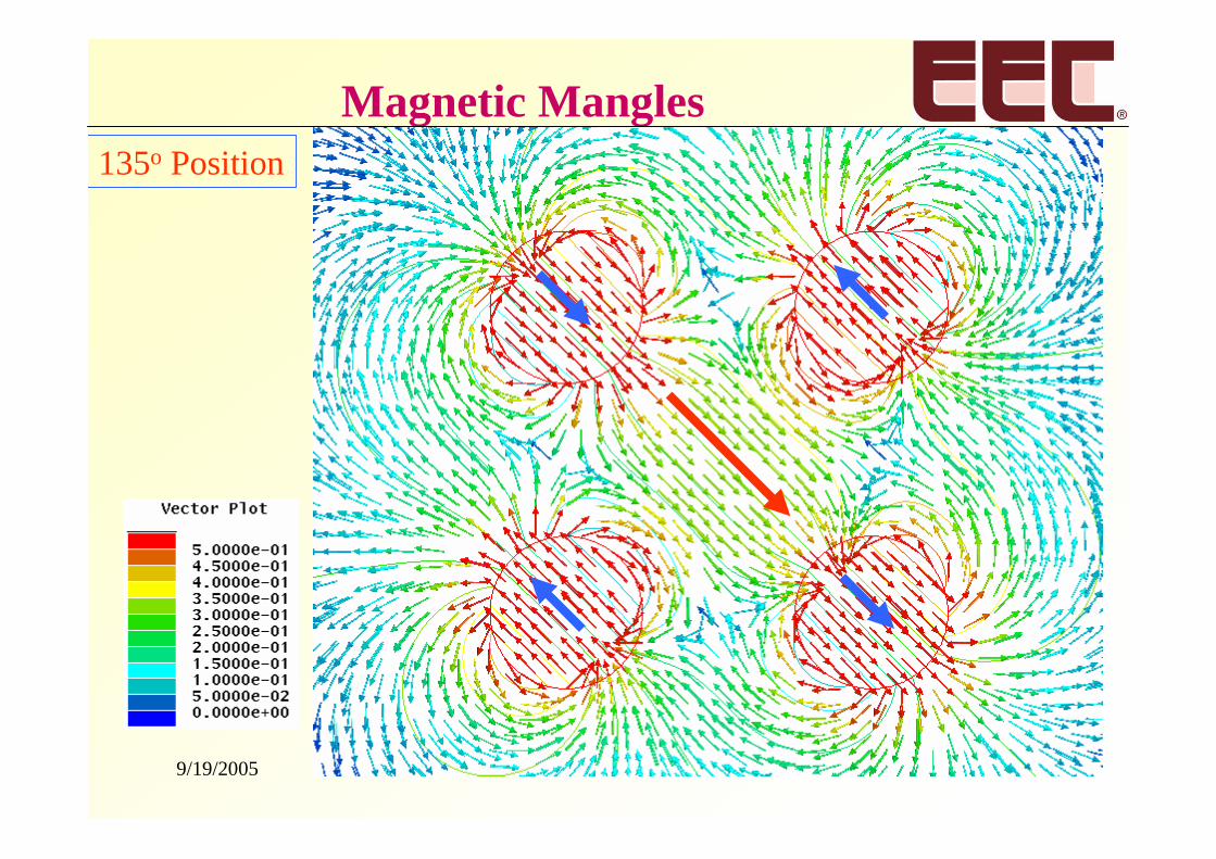
135o Position
Magnetic Mangles
9/19/2005 28
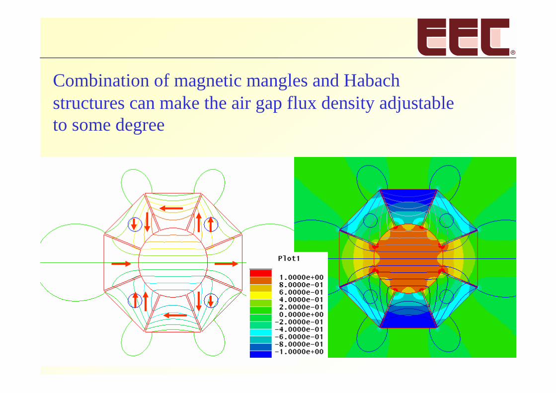
Combination of magnetic mangles and Habachstructures can make the air gap flux density adjustableto some degree
9/19/2005 29
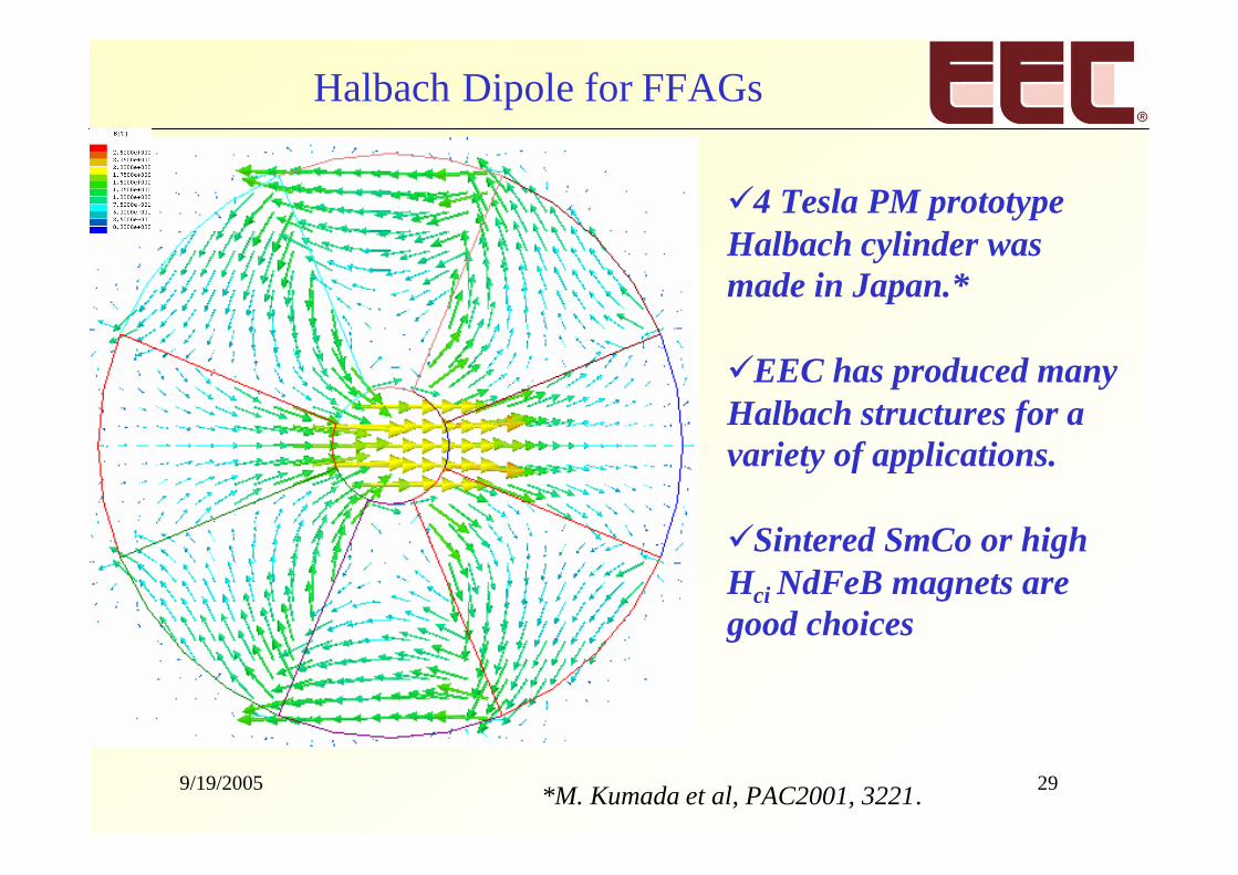
4 Tesla PM prototypeHalbach cylinder wasmade in Japan.*
EEC has produced manyHalbach structures for avariety of applications.
Sintered SmCo or highHci NdFeB magnets aregood choices
Halbach Dipole for FFAGs
*M. Kumada et al, PAC2001, 3221.
9/19/2005 30
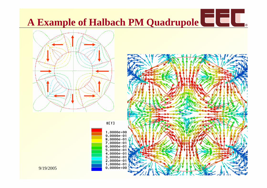
A Example of Halbach PM Quadrupole
9/19/2005 31
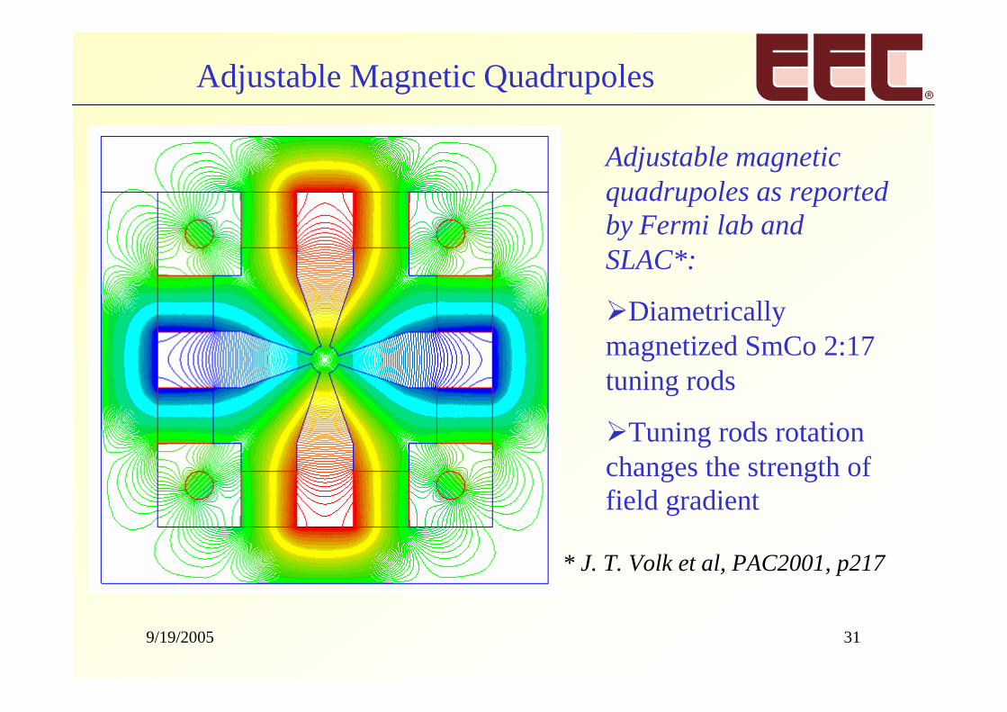
Adjustable magneticquadrupoles as reportedby Fermi lab andSLAC*:
Diametricallymagnetized SmCo 2:17tuning rods
Tuning rods rotationchanges the strength offield gradient
* J. T. Volk et al, PAC2001, p217
Adjustable Magnetic Quadrupoles
9/19/2005 32
Summary
Permanent magnet dipoles and quadrupoles canhave high air gap flux density if designed withHalbach principles.
Innovative designs can make the air gap fluxdensity adjustable.
Permanent magnet selection might include trade-offs between cost and performance.
SmCo magnets are far superior to NdFeB magnetswith respect to radiation resistance.

9/19/2005 33
Contact Information
Jinfang Liu, Director of TechnologyPeter Dent, Director of Sales and MarketingMichael Walmer, President
Electron Energy Corporation924 Links Ave.Landisville, PA 17538(717) 898-2294 Phone(717) 898-0660 [email protected]