performance investigation of a permanent magnet generator
TRANSCRIPT
Abstract--The rotor position is necessary to achieve the vector control drive system of Permanent Magnet Synchronous Motor (PMSM). In this thesis, the resolver sensor detecting the rotor position of PMSM is focused. PMSM has been widely used in high performance drive applications for its advantages such as compactness, high efficiency, reliability, and suitability to environment. Due to its high power density and smaller size, PMSM has evolved as the preferred solution for speed and position control drives on machine tools and robots. A PMSM is a motor that uses permanent magnets to produce the air gap magnetic field rather than using electromagnets. These motors have significant advantages, attracting the interest of researchers and industry for use in many applications. PMSMs are widely used in low and mid power applications such as computer peripheral equipments, robotics, adjustable speed drives and electric vehicles.
In order to overcome the inherent coupling effect and the sluggish response of scalar control the vector control is employed. By using the vector control, the performance of the AC machine can be made similar to that of a DC machine. In this thesis to achieve high performance the vector control of the Permanent magnet synchronous motors drive are used for different reference constant speed and mechanical load torque is employed. The simulation of PMSM drives with vector control technique is developed using environment. The effectiveness of the proposed control method is verified by simulation based on MATLAB/SIMULINK environment.
Jaswant Singh and Sulabh Sachan is M. Tech student in Department of Electrical Engineering, Kamla Nehru Institute of Technology, Sultanpur-228 118, India. and IIT Roorkee respectively. (e-mail:[email protected]).
Bindeshwar Singh and S.P. Singh is Assistant Professor in Department of Electrical Engineering, Kamla Nehru Institute of Technology, Sultanpur-228 118, India. (e-mail:[email protected], [email protected]). Ravi Chaurasia is Assistant Professor at NIT Meerut (U.P.) (e-mail: [email protected])
Index Terms--vector controlled technique (VECT), permanent magnet synchronous motor (PMSM), sine pulse with modulation (SPWM), modeling equations, current estimation, speed estimation.
NOMENCLATURE
eT Torque
dL d-axis inductances
qL q-axis inductances
sψ Stator flux
fψ Permanent magnet flux p Number of pole pairs
δ Torque angle (the angle between sδ and fδ )
sδΔ The change in torque angle due to move of sδ
fδΔ The change in torque angle due to move of fδ,d q Rotor direct and quadrature axis indexes
fψ Rotor flux (PM).
,d qL L d-axis and q-axes synchronous inductances.
,d qi i d-axis and q-axes currents.
,d qV V d-axis and q-axis voltages.
,q dψ ψ d and q-axes flux linkages.
J Moment of inertia.
JT Moment torque.
B Friction coefficient.
BT Friction torque.
I. INTRODUCTION
ERMANENT magnet synchronous motors (PMSM) are
PERFORMANCE INVESTIGATION OF PERMANENT MAGNET SYNCHRONOUS
MOTOR DRIVE USING VECTOR CONTROLLED TECHNIQUE
Jaswant Singh, Bindeshwar Singh, S. P. Singh, Ravi Chaurasia, and Sulabh Sachan
P
2012 2nd International Conference on Power, Control and Embedded Systems
978-1-4673-1049-9/12/$31.00 ©2012 IEEE
widely used in high-performance drives such as industrial robots and machine tools for their advantages high power density, high-torque, and free maintenance and so on. In recent years, the magnetic and thermal capabilities of the PM have been considerably increased by employing the high-coercive PM materials [1]. In last few years permanent magnet synchronous motor (PMSM), consequently is acquired in more and more far-ranging application, because of its properties such as small volume, light weight, high efficiency, small inertia, rotor without heat problem, etc. [2]. Sine pulse width modulation vector control is a technique to reduce the ripples of the electromagnetic torque, speed and current estimation. Space vector modulation techniques have several advantages that are offering better DC bus utilization, lower torque ripples, lower total harmonic distortion in the AC motor current, lower switching loss, and easier to implement in the digital systems. Vector controlled technique (VECT) is a new control method after vector control. It abandons decoupling thought of vector control, and uses the stator flux linkage directly to control the speed and the torque of motor. Thus the dynamic response of the system is very fast [3]. The VECT control strategy is applied for PMSM in order to improve the torque characteristics of the motor, which currently has caused the extensive attention of people. The traditional VECT usually adopts bang-bang control strategy to implement. But this control strategy can't meet the system requirements both of speed and torque at the same time, which leads to large fluctuations of speed and torque generated by system and leads to the problem of pulse current and switching noise caused by higher switching frequency changes. Sine Pulse Width Modulation (SPWM) control strategy has been widely used in the field of motor speed control, due to its potential advantages, such as small current waveform distortion, high utilization of DC voltage, easy-to-digital implementation, constant switching frequency of inverter, effectively to reduce pulsation of the motor torque and flux linkage, etc. The object studied in this paper is the permanent magnet synchronous. In application, the VECT strategy, which based on the SPWM, is adopted to simulate. The result shows that the system has the advantage of fast response, good dynamic performance and so on [4] [5]. The simulation results shows the proposed vector controlled technique with PMSM drive system having less flux linkage and torque ripples while it maintains as good torque response as the VECT. At the same time the complexity of the power circuit does not increase.
II. MATHEMATICAL MODELING OF PMSM
PMSM is an important category of the electric machines, in which the rotor magnetization is created by permanent magnets attached to the rotor. Many mathematical models
have been proposed for different applications, such as the abc-model and the two axis d-q-model. Due to the simplicity of the two axis d-q-model, it becomes the most widely used model in PMSM engineering controller design. The d-q-model offers significant convenience for control system design by transforming stationary symmetrical AC variables to DC ones in a rotating reference frame. Based on the d-q reference frame theory, the mathematical model of the PMSM can be expressed as the following equations: The two axes PMSM stator windings can be considered to have equal turn per phase. The rotor flux can be assumed to be concentrated along the d-axis while there is zero flux along the q axis, an assumption similarly made in the derivation of indirect vector controlled induction motor drives. Also, rotor flux is assumed to be constant at a given operating point. There is no need to include the rotor voltage equation as in the induction motor since there is no external source connected to the rotor magnet and variation in the rotor flux with respect to time is negligible. The stator equations of the induction machine in the rotor reference frames using flux linkages are taken to derive the model of the PMSM. The rotor reference frame is chosen because the position of the rotor magnets determine independently of the stator voltages and currents, the instantaneous induced emfs and subsequently the stator currents and torque of the machine. In Induction motor, the rotor fluxes are not independent variables, they are influenced by the stator voltage and currents and that is why any frame of reference is suitable for the dynamic modeling of the induction machine.
A. PMSM equations and its motion model
The stator flux linkage vector ψs and rotor flux linkage ψ
f of
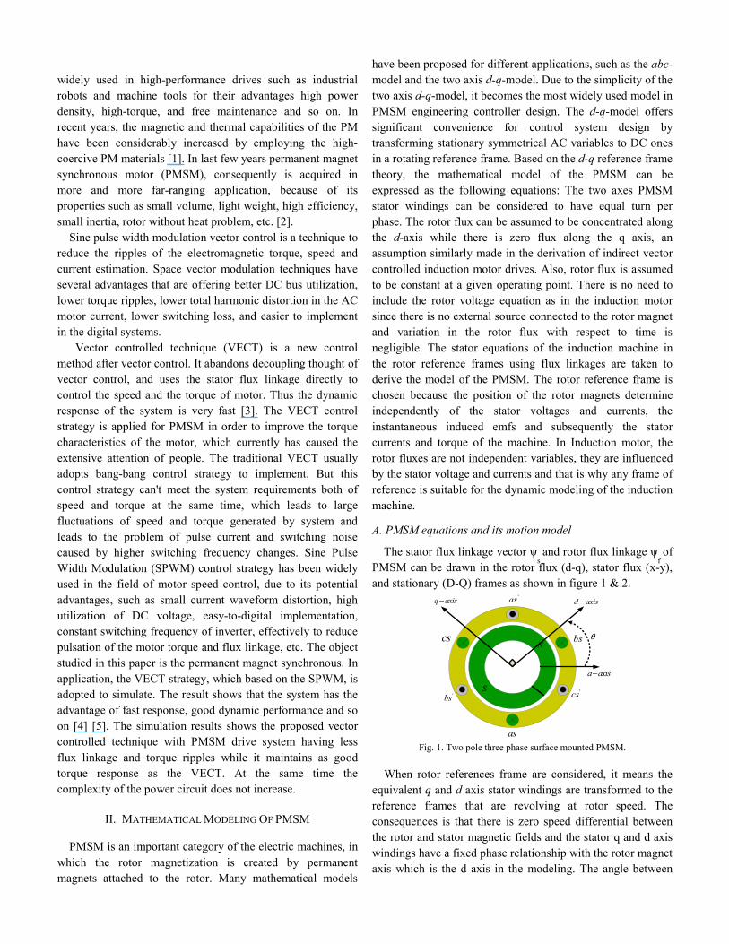
PMSM can be drawn in the rotor flux (d-q), stator flux (x-y), and stationary (D-Q) frames as shown in figure 1 & 2.
N
S
q axis− d axis−
a axis−
'cs
as
cs bs
'bs
'as
θ
Fig. 1. Two pole three phase surface mounted PMSM.
When rotor references frame are considered, it means the equivalent q and d axis stator windings are transformed to the reference frames that are revolving at rotor speed. The consequences is that there is zero speed differential between the rotor and stator magnetic fields and the stator q and d axis windings have a fixed phase relationship with the rotor magnet axis which is the d axis in the modeling. The angle between

the stator and rotor flux linkage δ is the load angle when the stator resistance is neglected. In the steady state, δ is constant corresponding to a load torque and both stator and rotor flux rotate at synchronous speed.
D
Q
d
qqi
di
sV
y
x
xi δsψ
fψ
rθ
Fig. 2. The stator and rotor flux linkages in different frames.
In transient operation δ varies and the stator and rotor flux rotate at different speeds. Since the electrical time constant is normally much smaller than the mechanical time constant, the rotating speed of the stator flux with respect to the rotor flux can be easily changed. It will be shown in this chapter that the increase of torque can be controlled by controlling the change of δ or the rotating speed of the stator flux. The well-known voltage equations in the rotor reference frame are as follows:
d
d d d r qdv R i
d tψ ω ψ= + − (1)
q
q q q r d
dv R i
d tψ
ω ψ= + + (2)
where Rd and Rq are the Quadrature and direct-axis winding resistances which are equal and be referred to as Rs is the stator resistance. To compute the stator flux linkage in the q and d axes, the current in the stator and rotor are required. The permanent magnet excitation can be modeled as a constant current source, fi
the rotor flux along d axis, so the d
axis rotor current is fi. The q axis current in the rotor is zero,
because there is no flux along this axis in the rotor, by assumption. Then the flux linkages are written as in equation (3).
d d d m fL i L iψ = + (3)
q q qL iψ = (4)
where Lm is the mutual inductance between the stator
winding and rotor magnets. Substituting these flux linkages into the stator voltage equations gives the stator equations (5): [6] [7].
( )q s q r d d f q qv R i L i L iω ψ ρ= + + + (5)
( )d s d r q q d d f d d dv R i L i L i R L iω ρ ψ= + + + + (6)
Arranging the above equations in matrix form: q q r d r m fq q
r q d d fd d
R L L L iv iL R Lv i
ρ ω ωω ρ ρ ψ
+⎡ ⎤ ⎡ ⎤⎡ ⎤ ⎡ ⎤= +⎢ ⎥ ⎢ ⎥⎢ ⎥ ⎢ ⎥− +⎢ ⎥ ⎢ ⎥⎣ ⎦ ⎣ ⎦⎣ ⎦ ⎣ ⎦
(7)
The developed torque motor is being given by (8)
3 ( )2e d d q dT P i iψ ψ= − (8)
which upon substitution of the flux linkages in terms of the inductances and current yields;
3 ( ( ) )2e d d d q q dT P i L L i iψ= + − (9)
fψ is the flux through the stator windings due to the
permanent magnet.
f m fL iψ = (10)
The mechanical Torque equation is (11)
m
e L mdT T B J
d tωω= + + (11)
Solving for the rotor mechanical speed from the above equation (12).
( )e L
mT T B dt
Jωω + += ∫ (12)
And
2
m r Pω ω= (13)
In the above equation ωr is the rotor electrical speed where as
mω is the rotor mechanical speed.
B. Parks Transformation
The dynamic d-q modeling is used for the study of motor during transient and steady state. It is done by converting the three phase voltages and currents to dqo variables by using Parks transformation. Converting the phase voltages variables
abcV to qdoV variables in rotor reference frame the following
equations (14) & (15) are obtained [8]:
0
cos cos( 120) cos( 120)2 sin sin( 120) sin( 120)3
1 1 12 2 2
q ar r r
d r r r b
c
V VV VV V
θ θ θθ θ θ
⎡ ⎤⎢ ⎥⎡ ⎤ − + ⎡ ⎤⎢ ⎥⎢ ⎥ ⎢ ⎥= − +⎢ ⎥⎢ ⎥ ⎢ ⎥⎢ ⎥⎢ ⎥ ⎢ ⎥⎣ ⎦⎣ ⎦ ⎢ ⎥⎣ ⎦
(14)
0
cos sin2 cos( 120) sin( 120)3
cos( 120) sin( 120)
qa r r
b r r d
r rc
VVV VV V
θ θθ θθ θ
⎡ ⎤⎡ ⎤ ⎡ ⎤⎢ ⎥⎢ ⎥ ⎢ ⎥= − − ⎢ ⎥⎢ ⎥ ⎢ ⎥⎢ ⎥⎢ ⎥ ⎢ ⎥+ +⎣ ⎦⎣ ⎦ ⎣ ⎦
(15)
C. Equivalent Circuit of PMSM
From the d-q modeling of the motor using the stator voltage equations the equivalent circuit of the motor can be derived as shown in Fig. 3. Assuming rotor d axis flux from the permanent magnet is represented by a constant current
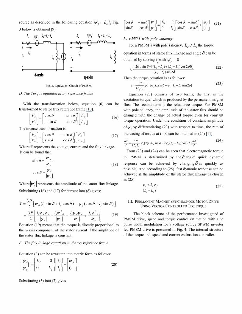
source as described in the following equation f m fL iψ = Fig.
3 below is obtained [9].
Fig. 3. Equivalent Circuit of PMSM.
D. The Torque equation in x-y reference frame With the transformation below, equation (6) can be transformed to stator flux reference frame [10].
cos sinsin cos
x d
y q
F FF F
δ δδ δ
⎡ ⎤ ⎡ ⎤⎡ ⎤=⎢ ⎥ ⎢ ⎥⎢ ⎥−⎣ ⎦⎣ ⎦ ⎣ ⎦
(16)
The inverse transformation is
co s s ins in co s
d x
q y
F FF F
δ δδ δ
⎡ ⎤ ⎡ ⎤−⎡ ⎤=⎢ ⎥ ⎢ ⎥⎢ ⎥⎣ ⎦⎣ ⎦ ⎣ ⎦
(17)
Where F represents the voltage, current and the flux linkage. It can be found that
sin
cos
q
s
d
s
ψδ
ψψδψ
=
=
(18)
Where sψ represents the amplitude of the stator flux linkage.
Substituting (16) and (17) for current into (8) gives:
3 ( sin cos ) (cos sin )2 d x y q yPT i i iψ δ δ ψ δ δ⎡ ⎤= + − +⎣ ⎦
2 23
2x d q y d x d q y d
s s s s
i i i iP ψ ψ ψ ψ ψ ψψ ψ ψ ψ
⎡ ⎤= + − +⎢ ⎥
⎢ ⎥⎣ ⎦ (19)
Equation (19) means that the torque is directly proportional to the y-axis component of the stator current if the amplitude of the stator flux linkage is constant.
E. The flux linkage equations in the x-y reference frame Equation (3) can be rewritten into matrix form as follows:
0
0 0d d d f
q q q
L iL i
ψ ψψ⎡ ⎤ ⎡ ⎤ ⎡ ⎤ ⎡ ⎤
= +⎢ ⎥ ⎢ ⎥ ⎢ ⎥ ⎢ ⎥⎣ ⎦⎣ ⎦ ⎣ ⎦ ⎣ ⎦
(20)
Substituting (3) into (7) gives
0cos sin cos sin0sin cos sin cos 0
x d f
y q
LL
ψ ψδ δ δ δψδ δ δ δ⎡ ⎤ ⎡ ⎤− − ⎡ ⎤⎡ ⎤ ⎡ ⎤
= +⎢ ⎥ ⎢ ⎥ ⎢ ⎥⎢ ⎥ ⎢ ⎥⎣ ⎦ ⎣ ⎦ ⎣ ⎦⎣ ⎦ ⎣ ⎦
(21)
F. PMSM with pole saliency
For a PMSM’s with pole saliency, d qL L≠ the torque
equation in terms of stator flux linkage and angleδ can be obtained by solving i
x with 0yψ =
2 sin [( ) ( ) cos 2 ]
( ) sin 2f d q d q y
xd q
L L L L ii
L Lψ δ δ
δ− + + −
=+
(22)
Then the torque equation is as follows: 3 [2 sin ( )sin2 ]
4 s f q s q dq d
PT L L LL L
ψ ψ δ ψ δ= − − (23)
Equation (23) consists of two terms; the first is the excitation torque, which is produced by the permanent magnet flux. The second term is the reluctance torque. For PMSM with pole saliency, the amplitude of the stator flux should be changed with the change of actual torque even for constant torque operation. Under the condition of constant amplitude of sψ by differentiating (23) with respect to time, the rate of
increasing of torque at t = 0 can be obtained in (24) [11].
3 [2 sin 2 ( ) cos 2 ]4 s f q s q d
q d
dT P dL L Ldt L L dt
δψ ψ δ ψ δ= − − (24)
From (23) and (24) can be seen that electromagnetic torque in PMSM is determined by theδ angle; quick dynamic response can be achieved by changingδ as quickly as possible. And according to (25), fast dynamic response can be achieved if the amplitude of the stator flux linkage is chosen as (25).
( )
s q f
q d
L
L L
ψ ψ<
− (25)
III. PERMANENT MAGNET SYNCHRONOUS MOTOR DRIVE USING VECTOR CONTROLLED TECHNIQUE
The block scheme of the performance investigated of PMSM drive, speed and torque control estimation with sine pulse width modulation for a voltage source SPWM inverter fed PMSM drive is presented in Fig. 4. The internal structure of the torque and, speed and current estimation controller.
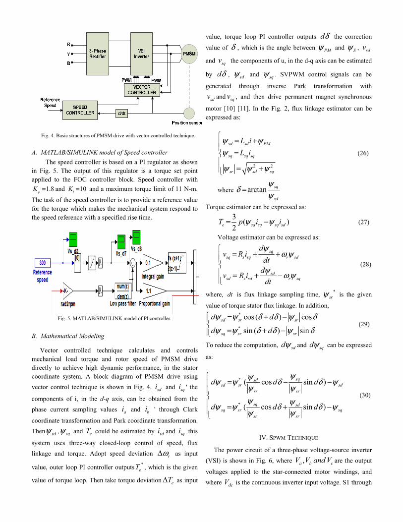
Fig. 4. Basic structures of PMSM drive with vector controlled technique.
A. MATLAB/SIMULINK model of Speed controller The speed controller is based on a PI regulator as shown in Fig. 5. The output of this regulator is a torque set point applied to the FOC controller block. Speed controller with
1.8pK = and 10iK = and a maximum torque limit of 11 N-m.
The task of the speed controller is to provide a reference value for the torque which makes the mechanical system respond to the speed reference with a specified rise time.
Fig. 5. MATLAB/SIMULINK model of PI controller.
B. Mathematical Modeling
Vector controlled technique calculates and controls mechanical load torque and rotor speed of PMSM drive directly to achieve high dynamic performance, in the stator coordinate system. A block diagram of PMSM drive using vector control technique is shown in Fig. 4. sdi and sqi ' the
components of i, in the d-q axis, can be obtained from the phase current sampling values ai and bi ' through Clark
coordinate transformation and Park coordinate transformation. Then sdψ , sqψ and eT could be estimated by sdi and sqi this
system uses three-way closed-loop control of speed, flux linkage and torque. Adopt speed deviation rωΔ as input
value, outer loop PI controller outputs *eT , which is the given
value of torque loop. Then take torque deviation eTΔ as input
value, torque loop PI controller outputs dδ the correction
value of δ , which is the angle between PMψ and Sψ , sdv
and sqv the components of u, in the d-q axis can be estimated
by dδ , sdψ and sqψ . SVPWM control signals can be
generated through inverse Park transformation with
sdv and sqv , and then drive permanent magnet synchronous
motor [10] [11]. In the Fig. 2, flux linkage estimator can be expressed as:
2 2
sd sd PM
sq sq sq
sr sd sq
L iL i
ψ ψψ
ψ ψ ψ
⎧ = +⎪⎪ =⎨⎪
= +⎪⎩
(26)
where arctan sq
sd
ψδ
ψ=
Torque estimator can be expressed as: 3 ( )2e sd sq sq sdT p i iψ ψ= − (27)
Voltage estimator can be expressed as:
sqsq s sq r sd
sdsd s sd r sq
dv R i
dtdv R i
dt
ψω ψ
ψ ω ψ
⎧= + +⎪⎪
⎨⎪ = + −⎪⎩
(28)
where, dt is flux linkage sampling time, *srψ is the given
value of torque stator flux linkage. In addition, *
*
cos ( ) cos
sin ( ) sinsd sr sr
sq sr sr
d d
d d
ψ ψ δ δ ψ δψ ψ δ δ ψ δ
⎧ = + −⎪⎨
= + −⎪⎩ (29)
To reduce the computation, sddψ and sqdψ can be expressed
as:
*
*
( cos sin )
( cos sin )
sqsdsd sr sd
sr sr
sq sdsq sr sq
sr sr
d d d
d d d
ψψψ ψ δ δ ψψ ψψ ψψ ψ δ δ ψψ ψ
⎧= − −⎪
⎪⎨⎪ = + −⎪⎩
(30)
IV. SPWM TECHNIQUE
The power circuit of a three-phase voltage-source inverter (VSI) is shown in Fig. 6, where ,a b cV V and V are the output
voltages applied to the star-connected motor windings, and where dcV is the continuous inverter input voltage. S1 through

S6 are the six power transistors those shape the output, which are controlled by switching signals. When an upper transistor is switched on, the corresponding lower transistor is switched off. There are eight different combinations of switching states as follows: (000), (100), (110), (010), (011), (001), (101), and (111). The first and last states do not cause a current to flow to the motor, and hence, the line-to-line voltages are zero. The other six states can produce voltages to be applied to the motor terminals.
Fig. 6. Three-phase VSI bridge circuit.
If the inverter operation starts by state (100) to be state 1, it is possible to compute the voltage space vectors for all inverter states which are shown in the complex space vector plane in Fig. 6 [13]. The six active voltage space vectors are of equal magnitude (2/3) dcV and mutually phase displaced by
600, as shown in Fig. 7. The peak fundamental phase voltage that may be produced by the inverter for a given dc link voltage occurs under six-step operation, and is given by:
1,2
six stepVdcVπ− = (31)
On the other hand, the maximum achievable peak fundamental phase voltage for conventional sinusoidal modulation as shown in Fig. 3 is:
1,sin 2pwmVdcV − = (32)
From equations (31) and (32), only 78.5% of the inverter capacity is used
Fig. 7. Voltage space vectors for a three-phase VSI
The modulation index M of the reference voltage space
vector *sV is defined as the ratio of the desired peak
fundamental phase voltage to half the dc link voltage (maximum achievable peak fundamental phase voltage for conventional sinusoidal PWM) are as the following:
Fig. 8. Locus comparison of maximum peak voltage
in sinusoidal PWM and SVPWM
1
( / 2)V
MVdc
= (33)
The largest possible peak phase voltage that may be achieved using the space vector modulation strategy corresponds to the radius of the largest circle that can be inscribed within the hexagon of Fig. 8. Thus, the peak fundamental phase voltage that may be achieved is:
1. 3svpwmVdcV = (34)
This corresponds to a maximum modulation index 1.15 max M ≈. From equations (31) and (34), about 90.6% of the inverter capacity is used. This represents 15% increase in maximum voltage compared with the conventional sinusoidal modulation. Consider the example depicted in Fig. 9, in which the desired voltage is found to lie in Sector 1. Although, the inverter cannot produce the desired voltage directly. It is possible to decompose it into two vectors, x V and y V , that lie on the two active inverter vectors on either side of the reference vector [12], [13], [14]. Therefore, in space vector notation: *
s x yV V V= + (35)
Fig. 9. Synthesis of desired space- vector voltage using realizable voltage vectors
Where the vectors, xV and yV , are obtained by operating
at the relevant inverter states, 1sV and 2sV , for suitable
portions of the switching period, sT . In general, when
operating in sector m, the reference vector may be decomposed according to:
* 1, , 1
m ms s m s m
s s
T TV V V
T T+
+= + (36)
Where mT and 1mT + are the times spent at adjacent active
Inverter states ,s mV and , 1s mV + . The remainder of the
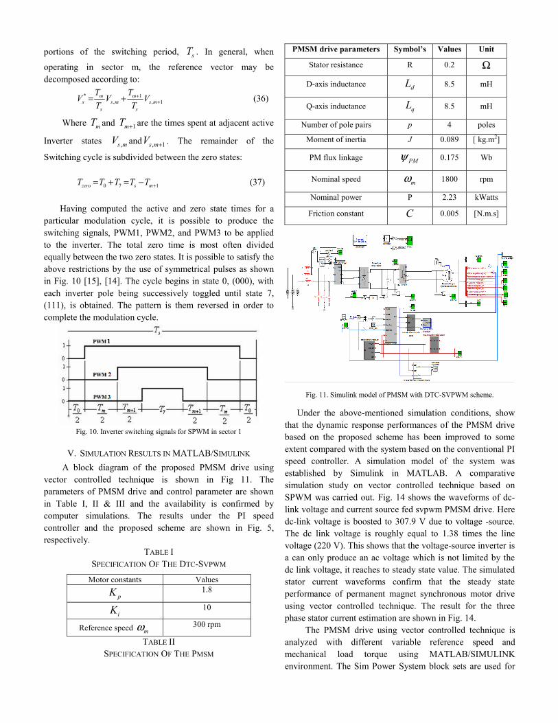
Switching cycle is subdivided between the zero states: 0 7 1zero s mT T T T T += + = − (37) Having computed the active and zero state times for a particular modulation cycle, it is possible to produce the switching signals, PWM1, PWM2, and PWM3 to be applied to the inverter. The total zero time is most often divided equally between the two zero states. It is possible to satisfy the above restrictions by the use of symmetrical pulses as shown in Fig. 10 [15], [14]. The cycle begins in state 0, (000), with each inverter pole being successively toggled until state 7, (111), is obtained. The pattern is them reversed in order to complete the modulation cycle.
Fig. 10. Inverter switching signals for SPWM in sector 1
V. SIMULATION RESULTS IN MATLAB/SIMULINK A block diagram of the proposed PMSM drive using vector controlled technique is shown in Fig 11. The parameters of PMSM drive and control parameter are shown in Table I, II & III and the availability is confirmed by computer simulations. The results under the PI speed controller and the proposed scheme are shown in Fig. 5, respectively.
TABLE I SPECIFICATION OF THE DTC-SVPWM
Motor constants Values
pK 1.8
iK 10
Reference speed mω 300 rpm
TABLE II SPECIFICATION OF THE PMSM
PMSM drive parameters Symbol’s Values Unit
Stator resistance R 0.2 Ω
D-axis inductance dL 8.5 mH
Q-axis inductance qL 8.5 mH
Number of pole pairs p 4 poles
Moment of inertia J 0.089 [ kg.m2]
PM flux linkage PMψ 0.175 Wb
Nominal speed mω 1800 rpm
Nominal power P 2.23 kWatts
Friction constant C 0.005 [N.m.s]
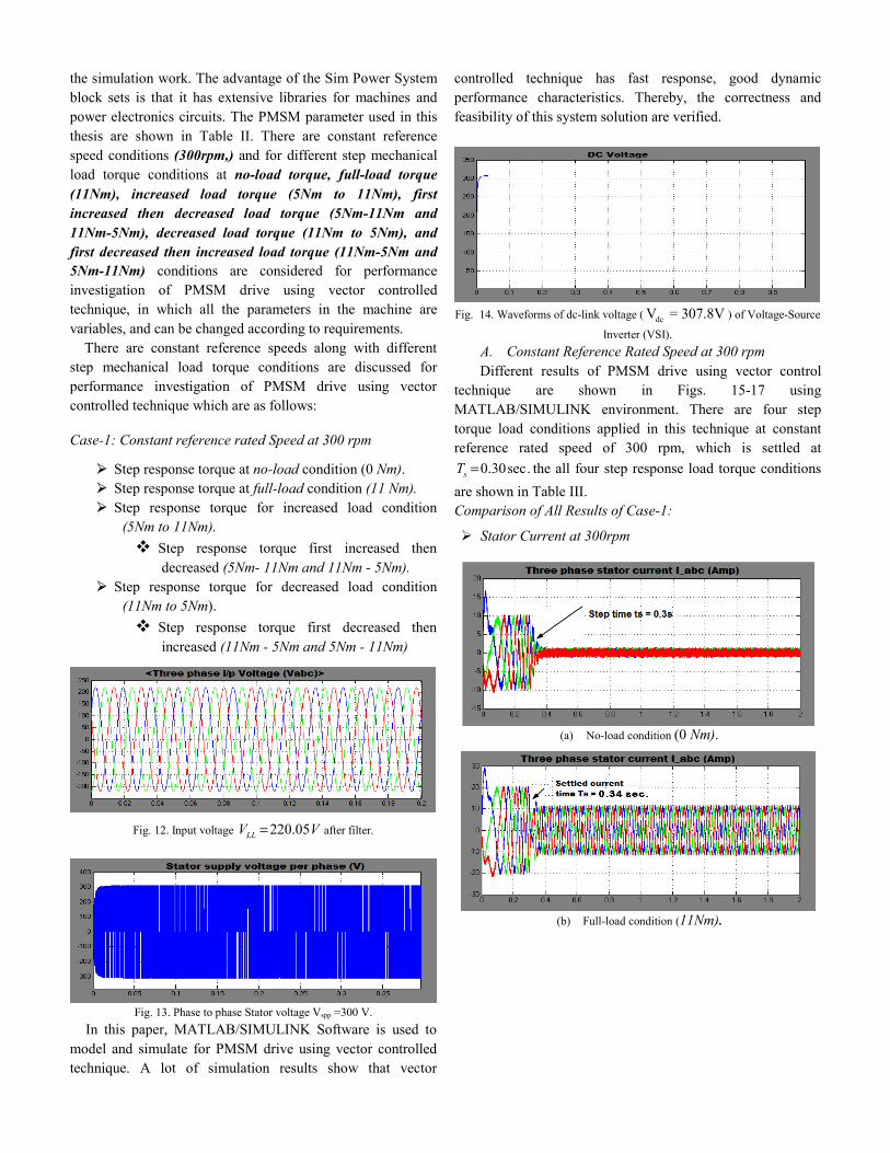
Fig. 11. Simulink model of PMSM with DTC-SVPWM scheme.
Under the above-mentioned simulation conditions, show that the dynamic response performances of the PMSM drive based on the proposed scheme has been improved to some extent compared with the system based on the conventional PI speed controller. A simulation model of the system was established by Simulink in MATLAB. A comparative simulation study on vector controlled technique based on SPWM was carried out. Fig. 14 shows the waveforms of dc-link voltage and current source fed svpwm PMSM drive. Here dc-link voltage is boosted to 307.9 V due to voltage -source. The dc link voltage is roughly equal to 1.38 times the line voltage (220 V). This shows that the voltage-source inverter is a can only produce an ac voltage which is not limited by the dc link voltage, it reaches to steady state value. The simulated stator current waveforms confirm that the steady state performance of permanent magnet synchronous motor drive using vector controlled technique. The result for the three phase stator current estimation are shown in Fig. 14. The PMSM drive using vector controlled technique is analyzed with different variable reference speed and mechanical load torque using MATLAB/SIMULINK environment. The Sim Power System block sets are used for
the simulation work. The advantage of the Sim Power System block sets is that it has extensive libraries for machines and power electronics circuits. The PMSM parameter used in this thesis are shown in Table II. There are constant reference speed conditions (300rpm,) and for different step mechanical load torque conditions at no-load torque, full-load torque (11Nm), increased load torque (5Nm to 11Nm), first increased then decreased load torque (5Nm-11Nm and 11Nm-5Nm), decreased load torque (11Nm to 5Nm), and first decreased then increased load torque (11Nm-5Nm and 5Nm-11Nm) conditions are considered for performance investigation of PMSM drive using vector controlled technique, in which all the parameters in the machine are variables, and can be changed according to requirements.
There are constant reference speeds along with different step mechanical load torque conditions are discussed for performance investigation of PMSM drive using vector controlled technique which are as follows:
Case-1: Constant reference rated Speed at 300 rpm
Step response torque at no-load condition (0 Nm). Step response torque at full-load condition (11 Nm). Step response torque for increased load condition
(5Nm to 11Nm). Step response torque first increased then
decreased (5Nm- 11Nm and 11Nm - 5Nm). Step response torque for decreased load condition
(11Nm to 5Nm). Step response torque first decreased then
increased (11Nm - 5Nm and 5Nm - 11Nm)
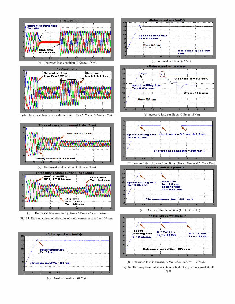
Fig. 12. Input voltage 220.05LLV V= after filter.
Fig. 13. Phase to phase Stator voltage Vspp =300 V.
In this paper, MATLAB/SIMULINK Software is used to model and simulate for PMSM drive using vector controlled technique. A lot of simulation results show that vector
controlled technique has fast response, good dynamic performance characteristics. Thereby, the correctness and feasibility of this system solution are verified.
Fig. 14. Waveforms of dc-link voltage ( dcV = 307.8V ) of Voltage-Source
Inverter (VSI). A. Constant Reference Rated Speed at 300 rpm
Different results of PMSM drive using vector control technique are shown in Figs. 15-17 using MATLAB/SIMULINK environment. There are four step torque load conditions applied in this technique at constant reference rated speed of 300 rpm, which is settled at
0.30sec.sT = the all four step response load torque conditions are shown in Table III. Comparison of All Results of Case-1:
Stator Current at 300rpm
(a) No-load condition (0 Nm).
(b) Full-load condition (11Nm).
(c) Increased load condition (0 Nm to 11Nm).
(d) Increased then decreased condition (5Nm- 11Nm and 11Nm - 5Nm).
.
(e) Decreased load condition (11Nm to 5Nm).
(f) Decreased then increased (11Nm - 5Nm and 5Nm - 11Nm).
Fig. 15. The comparison of all results of stator current in case-1 at 300 rpm.
(a) No-load condition (0 Nm).
(b) Full-load condition (11 Nm).
(c) Increased load condition (0 Nm to 11Nm)
(d) Increased then decreased condition (5Nm- 11Nm and 11Nm - 5Nm).
(e) Decreased load condition (11 Nm to 5 Nm)
(f) Decreased then increased (11Nm - 5Nm and 5Nm - 11Nm).
Fig. 16. The comparison of all results of actual rotor speed in case-1 at 300 rpm

(a) No-load condition (0 Nm).
(b) Full-load condition (11Nm)
(c) Increased load condition (0 Nm to 11Nm)
(d) Increased then decreased condition (5Nm- 11Nm and 11Nm - 5Nm)
(e) Decreased load condition (11Nm to 5Nm)
(f) Decreased then increased (11Nm - 5Nm and 5Nm - 11Nm).
Fig. 17. The comparison of all results of actual electromagnetic load torque in
case-1 at 300 rpm.
VI. CONCLUSIONS In this paper, direct torque control with Permanent magnet synchronous motor (PMSM) are proposed and simulated in SIMULINK/MATLAB. This paper presents a vector controlled technique adjustable speed and torque control system based on the V-source inverter topology has been presented. The performance investigation of three phase Permanent magnet synchronous motor (PMSM) drive is analyzed by using this technique; Simulation results are analyzed by the output waveforms in term of Permanent magnet synchronous motor (PMSM) drive outputs (performance parameters). A simulation model of the system was established by MATLAB/SIMULINK. A comparative simulation study on VECT was carried out. A vector controlled with sine pulse width modulation technique is used for generating a desired value of pulses by using an appropriate value of switching frequencies. Performance of 3-phase PMSM drive is investigated for the different load conditions and their comparison is also presented in this paper. The results of simulation have shown that the PMSM drive with the proposed control scheme has the merits of simple structure, robustness, quick tracking performance. SPWM allows the operation of inverter in over modulation region. This proposed strategy considers the inverter as a single unit and greatly reduces the complexity and cost when compared with traditional systems. It has reduced harmonics, low switching stress power and low common mode noise the results are show that to verify these new features. A lot of simulation results show that vector controlled technique has fast response, good dynamic performance characteristics. Thereby, the correctness and feasibility of this system solution are verified.
TABLE III
PERFORMANCE COMPARISON OF PMSM DRIVE USING VECTOR CONTROL AT CONSTANT RREFERNCE RATED SPEED 300 rpm
S. Step Performance Parameters PI Parameters
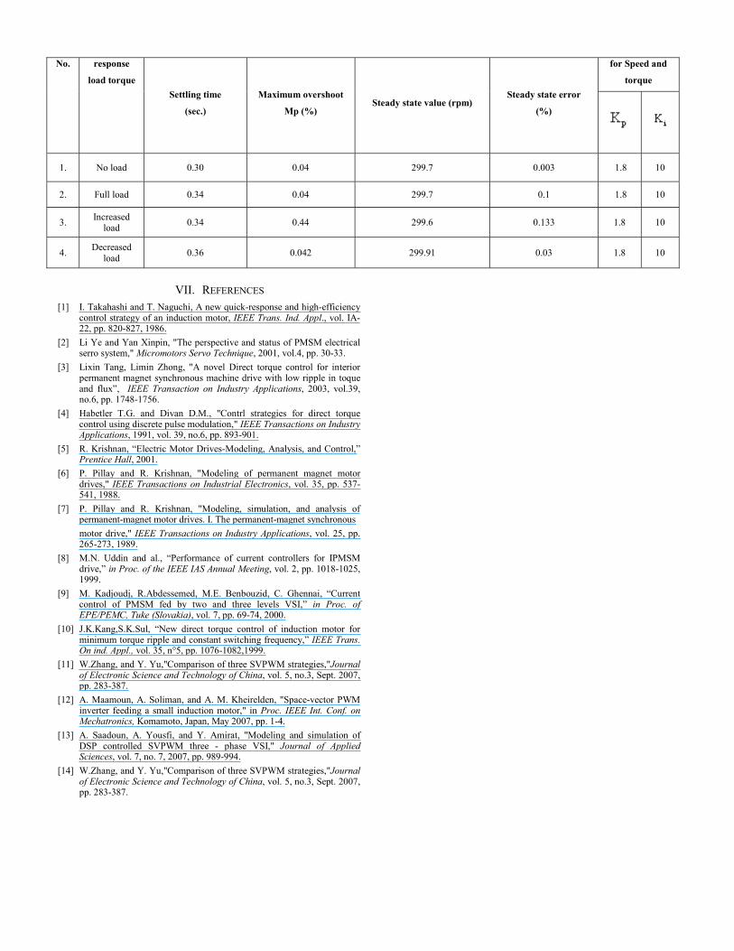
No. response
load torque Settling time
(sec.)
Maximum overshoot
Mp (%) Steady state value (rpm)
Steady state error
(%)
for Speed and
torque
1. No load 0.30 0.04 299.7 0.003 1.8 10
2. Full load 0.34 0.04 299.7 0.1 1.8 10
3. Increased load 0.34 0.44 299.6 0.133 1.8 10
4. Decreased load 0.36 0.042 299.91 0.03 1.8 10
VII. REFERENCES [1] I. Takahashi and T. Naguchi, A new quick-response and high-efficiency
control strategy of an induction motor, IEEE Trans. Ind. Appl., vol. IA-22, pp. 820-827, 1986.
[2] Li Ye and Yan Xinpin, "The perspective and status of PMSM electrical serro system," Micromotors Servo Technique, 2001, vol.4, pp. 30-33.
[3] Lixin Tang, Limin Zhong, "A novel Direct torque control for interior permanent magnet synchronous machine drive with low ripple in toque and flux”, IEEE Transaction on Industry Applications, 2003, vol.39, no.6, pp. 1748-1756.
[4] Habetler T.G. and Divan D.M., "Contrl strategies for direct torque control using discrete pulse modulation," IEEE Transactions on Industry Applications, 1991, vol. 39, no.6, pp. 893-901.
[5] R. Krishnan, “Electric Motor Drives-Modeling, Analysis, and Control,” Prentice Hall, 2001.
[6] P. Pillay and R. Krishnan, "Modeling of permanent magnet motor drives," IEEE Transactions on Industrial Electronics, vol. 35, pp. 537-541, 1988.
[7] P. Pillay and R. Krishnan, "Modeling, simulation, and analysis of permanent-magnet motor drives. I. The permanent-magnet synchronous motor drive," IEEE Transactions on Industry Applications, vol. 25, pp. 265-273, 1989.
[8] M.N. Uddin and al., “Performance of current controllers for IPMSM drive,” in Proc. of the IEEE IAS Annual Meeting, vol. 2, pp. 1018-1025, 1999.
[9] M. Kadjoudj, R.Abdessemed, M.E. Benbouzid, C. Ghennai, “Current control of PMSM fed by two and three levels VSI,” in Proc. of EPE/PEMC, Tuke (Slovakia), vol. 7, pp. 69-74, 2000.
[10] J.K.Kang,S.K.Sul, “New direct torque control of induction motor for minimum torque ripple and constant switching frequency,” IEEE Trans. On ind. Appl., vol. 35, n°5, pp. 1076-1082,1999.
[11] W.Zhang, and Y. Yu,"Comparison of three SVPWM strategies,"Journal of Electronic Science and Technology of China, vol. 5, no.3, Sept. 2007, pp. 283-387.
[12] A. Maamoun, A. Soliman, and A. M. Kheirelden, "Space-vector PWM inverter feeding a small induction motor," in Proc. IEEE Int. Conf. on Mechatronics, Komamoto, Japan, May 2007, pp. 1-4.
[13] A. Saadoun, A. Yousfi, and Y. Amirat, "Modeling and simulation of DSP controlled SVPWM three - phase VSI," Journal of Applied Sciences, vol. 7, no. 7, 2007, pp. 989-994.
[14] W.Zhang, and Y. Yu,"Comparison of three SVPWM strategies,"Journal of Electronic Science and Technology of China, vol. 5, no.3, Sept. 2007, pp. 283-387.