performance of drifreez driers in a freon-12 refrigerating system
TRANSCRIPT
NATIONAL BUREAU OF STANDARDS REPORT
3057
Performance of Drr’freez Driers in a Freon-12Refrigerating System
bv•/
Minoru FujiiAlbert W. DiniakErnest E. HughesC. W. Phii.lipsP. R. Achenbach
Report to
The Office of The Quartermaster GeneralDepartment of the Army
U. S. DEPARTMENT OF COMMERCE
NATIONAL BUREAU OF STANDARDS
U. S. DEPARTMENT OF COMMERCESinclair Weeks, Secretary
NATIONAL BUREAU OF STANDARDSA. V. Astin, Director
THE NATIONAL BUREAU OF STANDARDSThe scope of activities of the National Bureau of Standards is suggested in the following listing of
the divisions and sections engaged in technical work. In general, each section is engaged in special*
ized research, development, and engineering in the field indicated by its title. A brief description
of the activities, and of the resultant reports and publications, appears on the inside of the backcover of this report.
Electricity. Resistance Measurements. Inductance and Capacitance. Electrical Instruments.
Magnetic Measurements. Applied Electricity. Electrochemistry.
Optics and Metrology. Photometry and Colorimetry. Optical Instruments. PhotographicTechnology. Length. Gage.
Heat and Power. Temperature Measurements. Thermodynamics. Cryogenics. Engines andLubrication. Engine Fuels. Cryogenic Engineering.
Atomic and Radiation Physics. Spectroscopy. Radiometry. Mass Spectrometry. Solid State
Physics. Electron Physics. Atomic Physics. Neutron Measurements. Infrared Spectroscopy.Nuclear Physics. Radioactivity. X-Rays. Betatron. Nucleonic Instrumentation. Radio-logical Equipment. Atomic Energy Commission Instruments Branch.
Chemistry. Organic Coatings. Surface Chemistry. Organic Chemistry. Analytical Chemistry.Inorganic Chemistry. Electrodeposition. Gas Chemistry. Physic^ Chemistry. Thermo-chemistry. Spectrochemistry. Pure Substances.
Mechanics. Sound. Mechanical Instruments. Aerodynamics. Engineering Mechanics. Hy-draulics. Mass. Capacity, Density, and Fluid Meters.
Organic and Fibrous Materials. Rubber. Textiles. Paper. Leather. Testing and Specifi-
cations. Polymer Structure. Organic Plastics. Dental Research.
MetaUurgy. Thermal Metallurgy. Chemical Metallurgy. Mechanical Metallurgy. Corrosion.
Mineral Products. Porcelain and Pottery. Glass. Refractories. Enameled Metals. Con-creting Materials. Constitution and Microstructure. Chemistry of Mineral Products.
Building Technology. Structural Engineering. Fire Protection. Heating and Air Condition-ing. Floor, Roof, and WaU Coverings. Codes and Specifications.
Applied Mathematics. Numerical Analysis. Computation. Statistical Engineering. MachineDevelopment.
Electronics. Engineering Electronics. Electron Tubes. Electronic Computers. ElectronicInstrumentation.
Radio Propagation. Upper Atmosphere Research. Ionospheric Research. Regular Propaga-tion Services. Frequency Utilization Research. Tropospheric Propagation Research. HighFrequency Standards. Microwave Standards.
Ordnance Development. These three divisions are engaged in a broad program of researchElectromechanical Ordnance, and development in advanced ordnance. Activities includeOrdnance Electronics. basic and applied research, engineering, pilot production, field
testing, and evaluation of a wide variety of ordnance materiel. Special sk^s and facilities of otherNBS divisions also contribute to this program. The activity is sponsored by the Department ofDefense.
Missile Development. Missile research and development: engineering, dynamics, intelligence,
instrumentation, evaluation. Combustion in jet engines. These activities are sponsored by theDepartment of Defense.
• Office of Basic Instrumentation • Office of Weights and Measures.
NATIONAL BUREAU OF STANDARDS REPORTNBS PROJECT NBS REPORT
IOO3 -2O-4 S32 January 15, 1954 3057
Performance of Drifreez Driers in a Freon-12Refrip;erating System
by
Rinoru FujiiAlbert W, DiniakErnest E. HughesC. W. PhillipsP. R. Achenbach
Heating and Air Conditioning SectionGas Chemistry Section
to
The Office of The Q'u^rtermaster GeneralDepartment of the Army
<NB^U. S. DEPARTMENT OF COMMERCE
NATIONAL BUREAU OF STANDARDS
The publication, repr
unless permission iso
25.D,C, Such perm
cally prepared If tha
. 1 r- 11- 1 1 I pert, Is prohibited
Approved for public release by the. idards, Washington
Director of the National Institute of>rt has been speclfi-
Standards and Technology (NIST) for it. own use,
on October 9, 201 5.


PERFCRKANCE OF DRIFREEZ DRIERS IN A FREON-12
REFRIGERATING SYS TEN
by
Minoru Fujii, Albert W. Diniak, Ernest E. Huc^hes,C. W. Pbillips, and P. R. Achenbach
ABSTRACT
An :i nvestif^ation of the performance of Drifreezdriers for removiny moisture from a Freon-12 re-frimeratinp; system and the possible attendanthazards from, pulverization of the calcium carbidedesiccant and the circulation of acetylene in the’^efrimerant circuit was m.ade for thf^ Office ofThe Quartermaster General. The dr''ing charac-teristics of the Drifreez drier v/ere comparedwith those of a silica gel drier intended for thesame purpose and for systems of similar size.The teat results showed that the Drifreez drierxvas superior to the silica gel drier in theamount of x^rater that could be removed with equalvalues of end dryness up to 40 ppm or converselythe Drifreez drier x^jas superior in that it couldprodxice a loxfer end dr 3mess than a silica geldrier for equal xvater remioval in the range from5 to 20 grams of water. The Drifreez drier wasshoxAm to have a lov/er drx'-ing rate than the silicagel drier. The hazard tests shov/ed that thehighly-explosive miaterial, copper acetylide, x^ras
formed in the refrigerating system hj the reactionof acetylene v/ith the cooper tubing and that amild explosion coxxld be initiated b^r cutting thetubing with a hacksaw after removing the refrig-erant. Another hazard was shovm to be possibleif a Drifreez drier or anxr other drier usingcalcium carbide as the desiccant was emploxxed toremove moisture from a closed s^'^stcm in which airalone xvas being circulated. Vibration testsshowed that the calcium carbide in the Drifreezdrier pulverized to some extent but the particlesleaving the drier were too small to clog strainersand xTOuld probably not score compressor cxz-linderwalls
.
I
I. INTRODUCTION
In response to a request from the Office of TheCjuartermaster General, dated May 27, 1952, an investi-sration of the performiance of certain Drifreez driersmanufactured by Berna Corporation, Richmond Hill, N.Y.
,
was undertaken as a basis for determ^ining the desira-bility of using these or other driers employing cal-cium. carbide as the desiccant in Quartermaster re-frigeration units. The investigation was divided intothree main Darts, as follows: (A) Tests to determinethe effectiveness of the Drifreez driers in removingwater in a Freon-12 refrigerating system^ with respectto speed of drying, total capacity for water absorption,and end dryness of the system, (B*) tests to determinewhether or not any hazards would result from thepresence of acetylene gas in the S 3rstem, produced fromthe reaction of calcium carbide and water, and (C)tests to determiine whether the calcium carbide granuleswould pulverize under vibration and contribute foreignmatter in a solid state to the remainder of the refrig-erant system. The description of the apparatus, testprocedure, and results for the three parts of the in-vestigation are presented separately under the followingheadings
:
Part A Drying Tests
Part B Hazard Tests
Part C Vibration Tests
An overall evaluation of the Drifreez drier is m.adeat the end of the report.
II

PART A, DRYING TR3TS
I
,
introduction
The effectiveness of the Drifreez drier containingcalcium carbide for removing moisture from circulationin a refrigerating system using dichlorodifluoromethane(Freon-12) was studied on request of The Office of theOuartermaster General, The performance of the specimendriers was studied with respect to end dryness, speedof drying, and total moisture removing capacity withsome consideration being given to size, weight, and costin comparison with other driers now being used. Testsof a silica gel drier were also made for comparison.
Some of the more desirable properties of arefrigerant drier are as follows:
1. Ability to produce a low final moisture content.
2. Non-deliquescent
,
3. Non-frangible.
4. No corrosive or erosive end products.
5. Chemicall}’’ inert with respect to refrigerantand oil.
6. The rate of moisture rem*oval may be of importancefor some applications.
Hitherto moisture determinations in refrigeratingunits depended on sampling a large quantity of refrigerantfrom the system and measuring the average moisture contentof the entire sample. The inherent disadvantages of suchmethods can be eliminated by the application of anelectrolytic method developed by E. R. Weaver at theNational Bureau of Standards. This method of moisturemeasurement em.ploying an electrolytic film permittedmaking observations in rapid succession at the inletand outlet of the drier so that the drying process couldbe followed as it progressed.
I
- 2 -
II, Description of Specimens
Development of the Drifreez driers by the manufacturerwas in progress during the course of the tests. Fivedifferent models were submitted at different times by themanufacturer. The several models differed prim.arily inthe method of embedding the calcium carbide granules andin the number and kind of filter pads and screens usedat the txvo ends of the drier. The vibration tests weremade on the first model and drying tests were made withspecimens of the second, third and fourth models.
The specimens were identified as folloxvs:
DRIFREEZ CARTRIDGE
Berna CorporationRichmond Hill Ig, K. Y.
1/3 to 1 horsepowerThe nameplate carried the following information:"This cartridge removes all m.oisture occurringin refrigeration units using Methyl Chlorideor Freon under all normal operating condi-tions, Do not install on Sulfur Dioxide orAmmonia S3rstems, Installation is directlyinto the liquid line before the expansionvalve.
"
The dimensions of the cartridges were as follows:
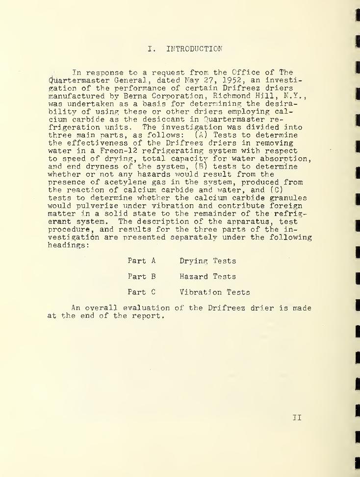
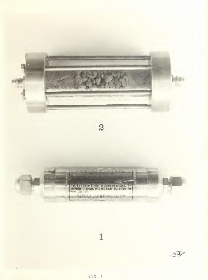
The desiccant was described by the manufacturer ashard crystalline acetylenogens containing trace elements.This can be more simply described as impure calciumcarbide. It was granular in form ranging from 0,4 In. to omesh, approximately. About 43 grams of desiccant wereused in each cartridge. Item l^Fig, 1
,is an exterior
view of one of the Drifreez driers.
Length from flare to flareDiameter, outsideWeight, approximately3 /^' in. flare connections6 cu. in, capacity
6-3/4 in.1-5/16 in.232 grams
1
Fig. 1

“ 3 -
^
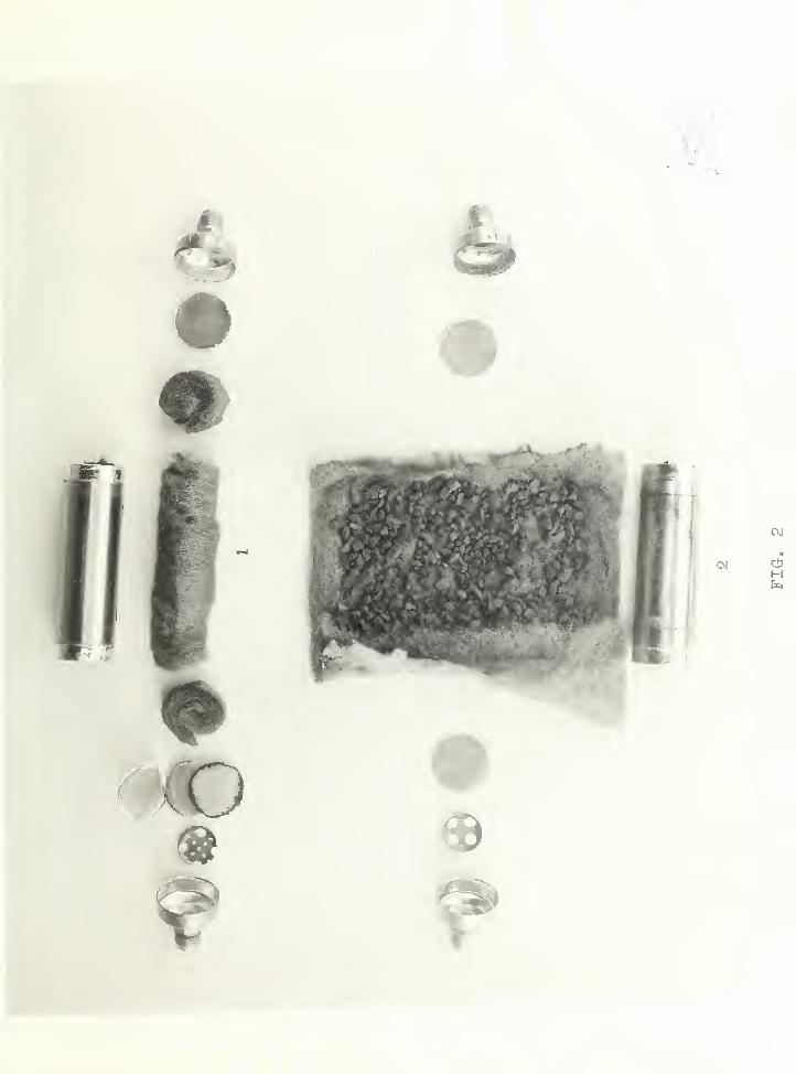
The second model submitted is shoivn disassembledas -^-tem 1 in Fig. 2. Calcium carbide granules, weighingapproximately 43 grams but with slight variation inamount among several cartridges, \uere spread on a finesteel wool pad. This pad was rolled up for insertioninto the cartridge as shoT-vn in Fig. 2. A steel woolpad was used at each end of the steel v7ool roll. Onthe outlet end of the drier tvio fine wire screenswith a thin wool filter sandwiched betxveen were usedwhereas a single fine wire screen was used on theinlet end. The screens v/ere approximately 65 x meshand appeared to be made of bronze xvire. The brass end-soft-soldered to the cylinder. A perforatedbaffle was placed between the wire screen and the brassend-piece on the outlet end.
The third ^model submitted is shoxvn disassembledas Item 2 in Fig. 2. In this model the calcium carbidegranules were rolled up in a steel wool pad backed up
outlet edges of these padswere folded oyer the calcium carbide as shown in Fig.2 before rolling them up. A single layer of screen wasused at each end of the roll and there were no wool
either end. The end-pieceand baffle features v;ere identical to those on the firstmodel tested.
The fourth model submitted had a cylindrical body ofglass for observation purposes and xvas considered to bea demonstration unit. It is shown as item 2 in Fig. 1 .The dimensions of ^ this cartridge were about the same asthose of the previous models except that the brassdiameter and 3/4 in thick.The glass cylinder xitted against shoulders machinedin tne ilanges^and v/as sealed with a rubber gasket ateither end. Six studs were used to draw the flanges
the gaskets and the cylinder. The centerportion of the cylinder was filled with granulatedcalcium carbide, and fine steel x^ool pads filled theremaining space at either end. A fine mesh screen x^^asplaced dov/nstreara of the steel wool pad xvithin thecartpdge on the outlet end. The entire specimenweighed n34 grams at the end of the test. The originalweight of the calcium carbide was reported by the manu-lacturer to be 43 grams whereas the weight of themixture of calcium carbide and calcium hydroxide was58 grams at the end of the test. The original weightof the calcium carbide could not readily be computed
- 4 -
from the final weir;ht of the raixture because of theimpurities present.
The silica gel drier used for the test was identi-fied as follov.-s:
Fueller Brass CompanyMaximum horsepox»7er - 1
The dimensions of the cartridge were as follows:
Length from flare to flareDiaraeter, outsideWeight3/c in. flare connections
cu, in. capacity
o j.n.
1-15,'^16 in.572 grams
o
The desiccant was granular silica gel areighing liegrams. The desiccant filled the entire c^^linder exceptfor a flat screen at the inlet end and a cone-shapedscreen at the outlet end. The brass end-pieces werescrewed to the crlinder and soft-soldered.
III. Description of Apparatus
1. Refrigeration Unit - (See Figs. 3 and 4)
the system was charged \i:
beginnins” of the test.
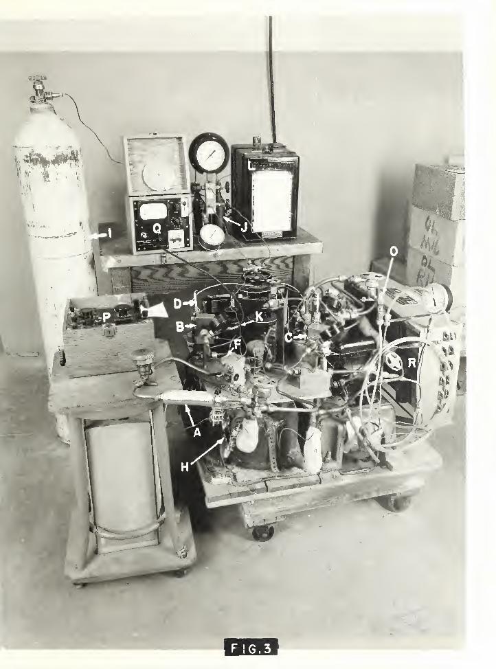
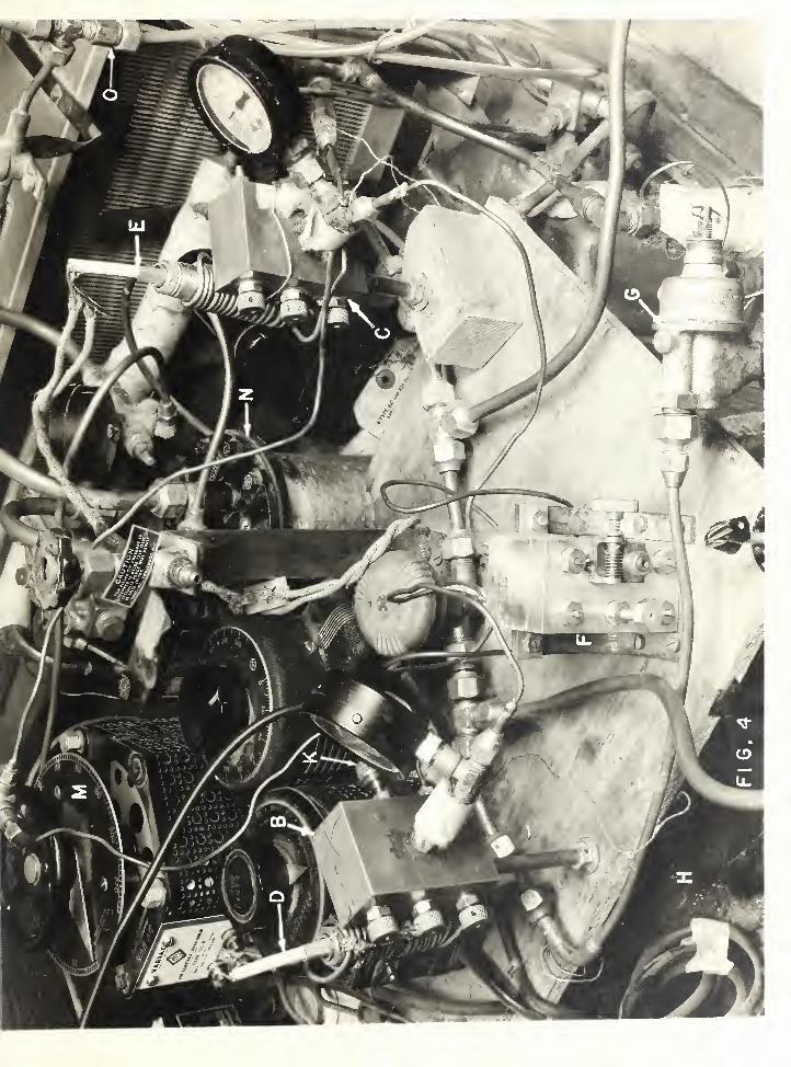
' l/3-horsenower air-cooled condensing unit (R) withan evaporator (K) wade of 3/^" copper tubing was enplo 3'’ed,
„th 4.5 pounds of Freon-12 at theA beat load was imposed on the
evaporator by passing electric current through nichromewire wound around the evaporator coil vjhich was insulated
.
electrically from the heating element v/ith asbestos.Current flow was adjusted by means of rheostat (M) tocontrol the load. The thermostatic expansion valve wasexchanged to an automatic expansion valve (G) during thecourse; of testing to provide steadier operating temper-atures and to avoid freeze-up at the valve due tohunting. An oil separator (N) was used to minimizethe f ] o’V of oil through the evaporator portion of thes 3^stem. A by-pass arrangement (C) was installed be-tween the discharge drier dovmstream of the oilseparator and the suction line for the purpose ofintroducing' water into the s^rstem. The specimen drier( --) was installed in the liouid line in accordance v^rith
FIG

G.3


the manufacturer's instructions. The overall vievj ofthe refrigeration unit and moisture measureinent appara-tus is sho’en in Fig. 3.
2 , Moisture Measurement
Tlie measurement of moistiire in the refrigerant wasmade using a method developed by E. R. Weaver of theI’'ational Bureau of otandards in which a h3rgroscopicfilm of sulphuric-phosphoric acid mixture was appliedto the surface of a detector exposed to tbs refrigerantgas and water vapor mixture in the refrigerating S3r3tem,The film reached equilibrium with the water vapor in therefrigerant gas rapidly forming a solution, tli' electro c-cal conductivity" of vrhich was a measure of the wat-rcontent of the refrigerant vapor. Gompres.sed air ofhnown moisture content T-as used as a comparison gas tocalibrate the film after each reading. By'- adjusting thepi’essure of ':.he compressed air until the same conductivitwas obtained, the two gases were made to have the sameconcentration of 'firater. The unknoi'n water content wasthen calculated from the tro pressures and the hnowncontent of the compressed air from the following formula:
Wx =
^/Vhere ’fx”
¥c
Fx =
Pc =
¥c PcPx
unknoi-m water content in refrigerantat zero gage preSvSure.Irnov/n water content of comparison airat zero gage pressure.absolute pressure at v;hich a conductivityreading v/as obtained on the unkno-'m re-frigerant gas.absolute pressi'.re of the comparison airat which the same conduct j.vity/ readingwas obtained as for the refrigerant gas.
Goricections were made for the deviation in behaviorof all the gases involved, including water vapor, fromthe ideal pas laws. The comprevssed air used for com-parison was saturated at between 1000 and 2000 poundsper square inch gage pressure and Vv’as permitted toexpand to get a comparison reading. For very dryconditions in a refrigerating sy'"stem, hovi-ever, asecondaryr comparison air v/as sometimes used. Thissecondary," supplyy of air is a ey/li^cder of fairly?- dryj-
air whose moisture content had been previously deter-mined byj comparison with the saturated air. For thesetests the compressed air required '^or making all moisture

- 6 -
determinations was obtained from a sinp;le cylinder bymeans of a parallel circuit with a saturator in onebranch. Because of the pressure relationships involved,the electrical method could be used to make moisturemeasurements in refrigerant in the gaseous state only.
The sampling 33^3 tern is shovrn diagramrnatically inBig, 5 and certain com.ponents are identified by letterin Figs, 3, 4 and 6 also. Two sampling points, one oneach side of the drier (A), were established on theliquid line. Two small bore tubes, each dipping intothe main stream of liquid refrigerant at the samplingpoints, carried a portion of the liquid refrigerant toheaters (D, E) v/here it was completely vaporized. Theheaters (D, E) consisted of the electric heating elementsregulated by rheostats to supply the required amount ofheat for complete vaporization of the liquid refrigerant.To attain an efficient vaporizing process, the refriger-ant tubing was wrapped around the heaters in a spiraland was thermally insulated from the surrounding air.The vaporized refrigerant then flowed to specially-built,pressure-tight detector blocks (B, C) containing thedetectors (K), (See Fig, 6) where the moisture determina-tions were made. By manipulating these control valvesin the detector block, either refrigerant vapor or thecompressed air used for comparison could be caused toflow past the h3rgroscopic film on the detector (K).After passing through the detector blocks (B, C) therefrigerant was returned to the suction line for re-circulation, The flow through the sampling circuit wascontrolled by valves (F) so that very little refrigerantwas permitted to bypass the evaporator (H), Compressedair used for comparison v;as exhausted to atmosphere.The piping circuits used for connecting the compressedair supply to the detector blocks are shown diagrammati-cally in Fig, 6, The gas connections were so arrangedthat the same cylinder of compressed air (I) suppliedthe ^Mry” comparison air directly and the 'Vet” com-parison gas through saturator (Jj, As shown in Fig, 6,either of the two comparison gases could be directedto the two detector blocks (B, C).
The detectors (K) were connected to a Weston galva-nometer (Q) (See Fig, 3) which served as a null pointindicator. An Esterline-Angus time recorder (L) wasused to record the net operating time of the refrigerationunit, A potentiometer (P) was used to measure the temper-atures of detector blocks (B, C) and of the gas samples.

SAMPLING
SYSTEM
O


GAS
CONNECTIONS

- 7 -
IV. Test Procedure
A total of seven series of tests were made todetermine drying performance of three models of the Dri-freez drier and one model of a silica gel drier, Afifth model of the Drifreez drier v/as not tested becausethe investigation was terminated.
Each drying test was begun with a nev; drier in awell-dried s 3?’stem, Wlien initial wetness of the systemwas high, other spare driers were used to reduce themoisture content in the system. Knom quantities ofwater were added in the suction line b]^ means of thebypass between the discharge line and the suction line,utilizing the pressure difference across the compressorto inject the water. The quantity of water added atone time varied from 0.1 gram to 20 grams. With a re-frigerant charge of 4.5 lb of Freon 12, 0.1 gram ofwater uniformly mixed in the system would produce aconcentration of about 50 ppm by weight if the effectof the oil in the system is neglected. At first,smaller amounts of water were added and larger amountswere added later. The moisture content at the inletand at the outlet of the specimen dryer was measuredalternately as fast as the apparatus permitted.
The compressor served as a good means of mixingwater in the refrigerant. Care was taken not to damageit by adding water too rapidly. The s 3/stem was operatedwith an evaporator temperature above 32 °F during mostof the investigation to prevent freezing of water inthe evaporator and at the expansion valve orifice.
V, Test Results
1. Drying Tests
Preliminary tests were made of two specimens of thesecond model of Drifreez cartridge. The results of thesetests were not suitable for plotting in graphical formbecause of difficulties v/ith the moisture measuringapparatus and freezing of the v;ater at the expansionvalve. These preliminary tests did indicate that a lowend dr3mess could be obtained with the Drifreez driers.
Fig. giving results of a different specimen ofDrifreez drier also indicates that low end dryness wasattained.
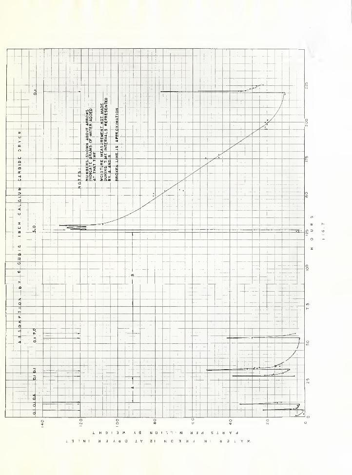
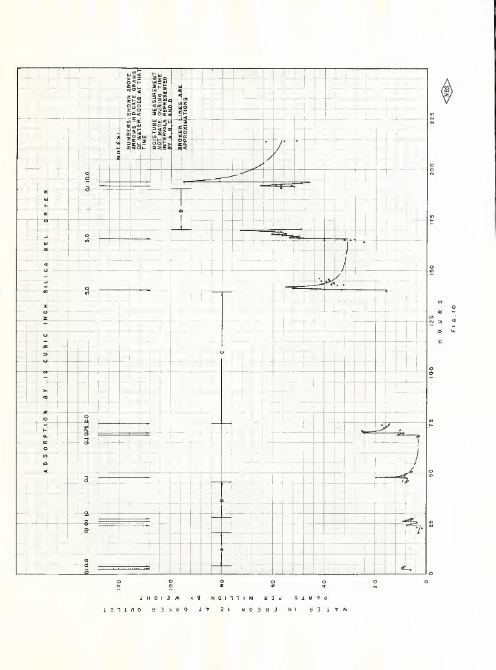
Tests v/ere made of three specimens of the third modelof the Drifreez driers submitted by the m.anufacturer . Inthis model the calcium carbide granules were rolled upin overlaid pads of steel wool and wool felt as shown initem 2 of Fig. 2, A total of o*2 grams of water was in-troduced into the system during tests of the firstspecimen in 9 injections ranging in magnitude from 0,1gram to 5 grams. The moisture content in parts permillion at the inlet to the drier is plotted in Fig, 7whereas that at the drier outlet is plotted in Fig, ^for the 225 hours of the test. Moisture contents wereobserved just before and for several hours after 7 ofthe 9 injections. When a small amount of water (0.1gram) was added, the system was dried to approximatelythe initial condition in 3 to 4 hours.
When 5.0 grams of v\rater were added at one time over90 hours v/ere required to lower the moisture content ofthe system from the maximum value of 131 ppm to 10 ppmby weight. The moisture content remained reasonablysteady at a value near 125 ppm for about 3.5 hoursafter injecting the 5 grams of water. This suggeststhat the amount of water added was more than could bedissolved in the entire refrigerant charge so there wasprobably free water floating on the liquid refrigerantin the receiver. The moisture content at the drieroutlet was almost as high as at the drier inlet duringthis 90 hour period indicating that the moisture wasabsorbed very slowl^^ by the drier. The close agreementin moisture content between the drier outlet and drierinlet V7as undoubtedly caused in part the bypassingof moisture around the calcium carbide granules. Becausea relatively small amount of calcium carbide was rolledup in steel wool and felt in the Drifreez cartridge,there would be many paths through the drier for x^rhich
the moisture-laden refrigerant xTOuld not come in contactwith the calcium carbide. Since the solubility of waterin Freon-12 at 32 °F is of the order of 25 ppm by weight,(A.S.R.E. Data Book, 7th Edition), free water was probablyreleased in the evaporator of the refrigerating systemfor 50 or more hours after the injection of the 5 gramsof water because the moisture content at the outlet ofthe drier exceeded this value. The moisture released inthe evaporator v/ould gradually be returned to the com-pressor by the refrigerant vapor as the system becamedr^’-er
,
1H9I3M A9 NOinniW d3d SidVdi31Nt d3AdQ iV 2t N03bd Nl d3iV/V\
100
125
150
175
200
225

1H9I3M A9 NOinniW b3d SlbWd131100 d3Aaa IV 91 N03d3 Nl d31VM
100
125
150
175
200
225

m
c
,v:
I
I
’7
X •'"in
^

During the tests of the second specimen of the thirdmodel of the Drifreez drier 20 grams of ivater were addedto the system at one time to determine the capacity ofthe drier for absorbing water. With an initial moisturecontent of 16 ppm before injection of the v/ater, themoisture content was reduced back down to 40 ppm after7 days operation. An additional two days of operationdid not reduce the moisture content below 40 ppm whichis not dry enough to prevent freezing-out of free waterat the expansion valve for suction pressures Delowfreezing.
Calcium carbide reacts with water to form calciumhydroxide and acetylene in accordance with the follox'^ing
equatioh
:
From the atomic weights of the several elements it canbe shown that 43 grams of calcium carbide would reactwith about 24 grams of water to produce about 50 gramsof calcium hydroxide and 17 grams of acetylene. Thetest of this second specimen indicated that 20 gramsof water was somev/hat in excess of the capacity of thisdrier when applied to a system operating at evaporatortemperatures below 32 ®F, whereas the theoretical equationindicated a capacity of about 24 grams of water. Thedifference may be due to impurities in the calcium car-bide.
A similar test v/as made of a third specimen of thethird model of the Drifreez drier with 5 grams of waterbeing added at three different times. The moisturecontent of the system was reduced to a loxv value witha spare drier before adding the first increment of 5grams. Four days later the moisture content w^as IS ppmat which time the second increment was added. In anotherfour days of continuous operation the drier had reducedthe moisture content to 22 ppm whereupon the third 5
gram, injection was made. After the third injection of5 grams 11 days were required to reduce the moisturecontent to 17 ppm.
The results obtained with the latter two specimensindicated that the third model Drifreez cartridges hada useful moisture absorbing capacity between 15 and 20grams of water when used in a Freon-12 system that isto be operated at evaporator temperatures a little be-low freezing.
10
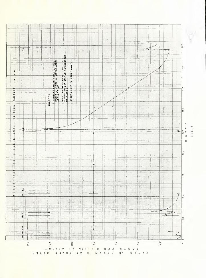
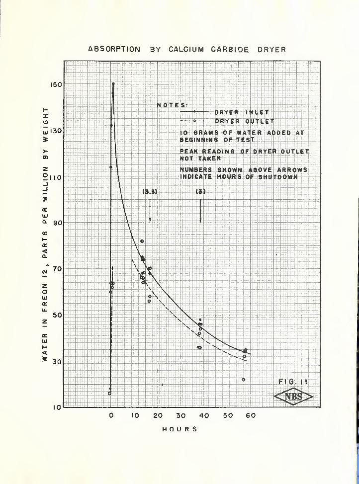
One test was made with the foiirth model of Drifreezdrier - the demonstration model shown as item 2 of Fig. 1with a cylindrical glass body. The test was started v/ith
an initial moisture content of 17 ppm and 10 grams ofwater were injected at one time. The drying curve isshown in Fig, 11 for the ensuing 60 hours during whichthe moisture content was reduced from a peak value of150 ppm to a final value of about 30 ppm. There is alikelihood that the moisture content at the drier inletremained near 150 ppm for three hours or more until allof the excess water in the receiver or in the compressorcould be dissolved by the refrigerant passing throughthe system. Observations were taken for only about onehour immediately after injection of the water. Fig. 11indicates that the moisture content varied somewhat forrepetitive readings at close time intervals. This couldbe caused by random variations in the moisture contentat the receiver outlet since the liquid refrigerant andwater in the receiver would not necessarily remain well-mixed, The moisture content at the drier outlet averagedabout 5 ppm lower than that at the drier inlet, A com-parison of Fig, 11 with Fig, 7 and ^ shov;s that thefourth model Drifreez cartridge reduced the moisturecontent more rapidly than the third model even thoughmore water was injected at one time in the fourth model.This difference is probably accounted for by the bettercontact between the desiccant and the moisture-ladenrefrigerant in the fourth model in which the calciumcarbide granules filled the entire cross section of thecartridge in the center portion.
After the 60 hours operation illustrated in Fig, 11an additional 5 grams of water were injected into thesystem. After about 5 days operation a pressure dropof 110 psig developed between the drier inlet and outletindicating a stoppage. Inspection revealed that thestoppage was caused by the calcium hydroxide depositedin a pasty mass on the downstream side of the calciumcarbide granules.
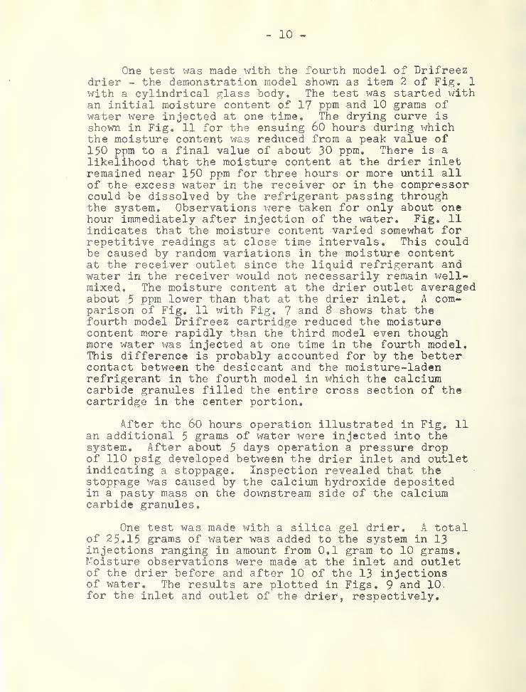
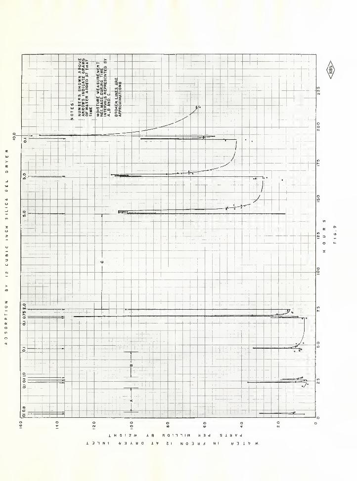
One test was made with a silica gel drier, A totalof 25.15 grams of water was added to the system in 13injections ranging in amount from 0,1 gram to 10 grams.Moisture observations were made at the inlet and outletof the drier before and after 10 of the 13 injectionsof water. The results are plotted in Figs. 9 and 10.for the inlet and outlet of the drier, respectively.
001
i H 9 1 3 M N 0 I n 1 I W
Z 1
d3d S I a V d
N Ii 3 “I N 1 d 3 A » Q 1 V N 0 3 d 3 d 3 i V M
25
50
75
100
125
150
175
200
225

1
'4
100
125
150
175
200
TT»p w ’ w
t*
s
ABSORPTION BY CALCIUM CARBIDE DRYER
150
oQj 130
90
HOURS
f
I"
w-
4
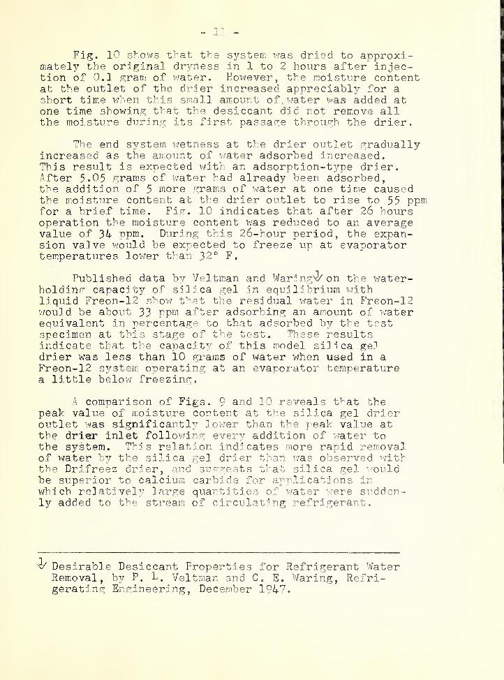
Fig, 10 shows that the system was dried to approxi-mately the original dryness in 1 to 2 hours after injec-tion of 0.1 gram of v/ater. Hov/ever, the moisture contentat the outlet of the drier increased appreciably for ashort time when this small amount of. water was added atone time showing that the desiccant did not remove allthe moisture during its first passage through the drier.
The end system wetness at the drier outlet graduallyincreased as the amount of water adsorbed increased.This result is expected with an adsorption-type drier.After 5.05 gram.s of water had already been adsorbed,the addition of 5 more grams of water at one time causedthe moisture content at the drier outlet to rise to 55 ppmfor a brief tirfie. Fir. 10 indicates that after 26 hoursoperation the moisture content was reduced to an averagevalue of 34 Ppm. During this 26-hour period, the expan-sion valve x\^ould be expected to freeze up at evaporatortemperatures lower than 32 ° F.
Pxablished data by Veltman and Waring4^ on the iwater-holding capacity of silica gel in equilibrium withliquid Freon-12 show that the residual v/ater in Freon-12v/ould be about 33 Ppm after adsorbing an amount of waterequivalent in percentage to that adsorbed by the testspecimen at this stage of the test. These resultsindicate that the capacit^-^ of this model silica geldrier was less than 10 grams of water v/hen used in aFreon-12 system, operating at an evaporator temperaturea little belov/ freezing.
A comparison of Figs. 9 and 10 reveals that thepeak value of moisture content at the silica gel drieroutlet was significantly lower than the peak value atthe drier inlet following every addition of water tothe system. This relation indicates more rapid removalof water by the silica gel drier than v/a
;
observed withthe Drifreez drier, and sug-^'ests that silica gel i/on.ld
be superior to calcium carbide for applications inX'/hicb relatnvel;'" large quantities of v.?ater were sxidden-ly added to the stream of circulating refrigerant.
^ Desirable Desiccant Properties for Refrigerant WaterRemoval, by P. 4. Veltman and C, E, Waring, Refri-gerating Engineering, December 1947.

o Kiscellaneous Observations
In addition to the moisture absorption character-istics of the Drifreez driers certain other featureswere observed.
A Drifreez cartridge was completely filled vjith
granular calcium carbide without steel wool filters orpads included and water wras passed through the cartridgeso that it could react with the calcium carbide. Thecalcium hydroxide resulting from the reaction became sodensely compacted in the cartridge that the water flowthrough the cartridge could not be maintained. When thecartridge was cut open it was found that the carbide hadnot been completely consumed and the calcium hydroxidehad to be removed with a hammer and chisel. This resultindicates that the products from the reaction of calciumcarbide and water occupy more space than the originalcarbide granules and reveals the importance of providingsome room for expansion in the drier cartridges as theyare manufactured.
A Drifreez cartridge was subjected to an internalhydrostatic pressure of 1700 psig for one hour withoutrupturing the cartridge.
The effect of temperature on the capacity of theDrifreez driers was not investigated because thedesiccant was of the chemical absorption type and,therefore, not likely to be significantly affected bythe usual range of refrigerant liquid line temperature.
The calcium hydroxide formed by the reaction ofcalcium carbide v/ith water has a secondary dehydratingeffect, but this effect is not likely to be of importantmagnitude in the presence of calcium carbide that hasnot reacted with water.
The filtering ability of the several Drifreez drierstested v/as examined hy inspection of the expansion valvestrainer and the system receiver at the conclusion oftesting. The strainer at the inlet of the expansionvalve contained very little foreign material resemblingCa(0K)2. The receiver was cut in tv7o and the interiorinspected. There was no dirt nor deliquescent materialfound in the receiver. The liquid refrigerant in thereceiver contained very little impurity.
- 13
Fo tests were made of the Drifreez drier vrith refrigerants other than Freon-12.
3 . Comparison of Electrolytic and GravimetricMethods of Moisture Determination
Comparison was made of the electrolytic method ofmoisture measurement with the phosphoric pentoxide(P2O 5 ) gravimetric method. The electrolytic method,developed by Mr, E, R, Weaver of the National Bureauof Standards, was used for the Drifreez tests becauseit permitted rapid readings of more than one pointor continuous readings of one point whereas the P20
^gravimetric method required comparatively largesamples for batch observation and provided an a^'^’erage
indication of the moisture content of the gas extractedfrom the system over an extended period.
Several m.ethods of comparing the two t 3rpes ofmeasurement were tried.
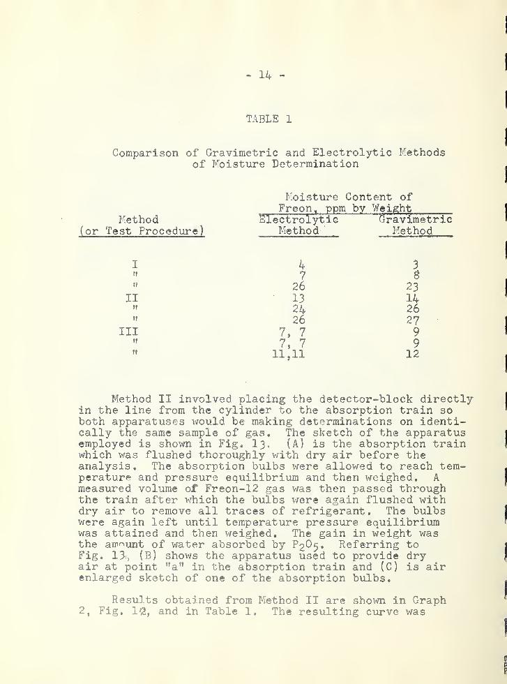
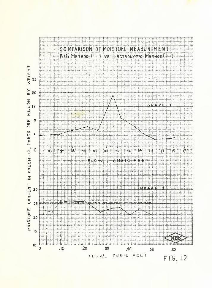
Method I involved a simultaneous removal of twoseparate vapor samples from a cylinder containingcommercial liquid dichlorodifluoromethaae (Freon-12).One sample was passed through a phosphorus pentoxideabsorption train (P2O 5 method) whereas the other samplewas passed through a detector block (electrolytic method)by means of which electrical determinations were madeat frequent intervals during the run. (The phosphorouspentoxide absorption train is explained later,) Thevalves obtained were plotted against the volume ofvapor that had passed through the absorption train, Atypical result is shovm in Graph 1, Fig. 12
,and in
Table 1. The area under the curve obtained is pro-portional to the weight of water in the entire sampleof refrigerant. The variation in moisture content re-vealed by the electrolytic measurement was believed tobe caused by the evaporation of liquid refrigerant inthe supply cylinder necessary to replace the vapordrawn as a sample. The evaporation of liquid refriger-ant both chills the liquid at the surface and changesthe moisture content of the vapor in contact with theliquid. Table 1 shovtjs good agreement between theaverage moisture content valves observed by the twomeasuring methods.
- 14 -
TABLE 1
Comparison of Gravimetric and Electrolyt^ic Methodsof Moisture Determination
Moisture Content ofFreon, ppm by Weight
Method Electrolylsic Gravimetric(or Test Procedure) Method- Method
I 4 3ft 7n 26 23
II 13 14ff 24 26ff 26 27
III 7, 7 9tf
7, 7 9ff 11,11 12
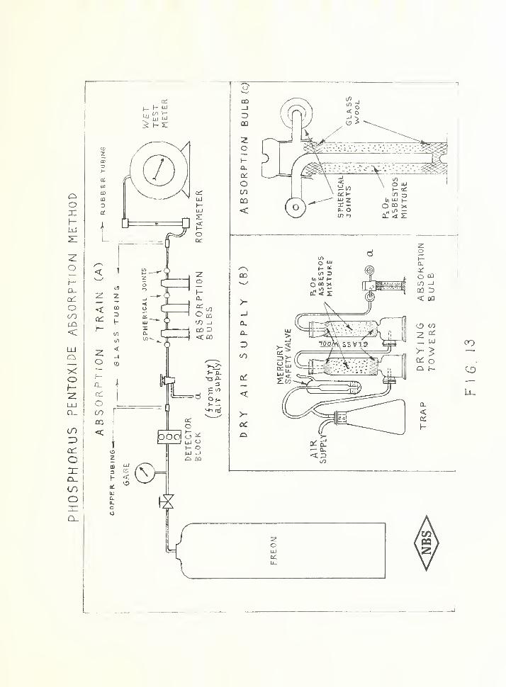
Method II involved placing the detector-block directlyin the line from the cylinder to the absorption train soboth apparatuses would be making determinations on identi-cally the same sample of gas. The sketch of the apparatusemployed is shown in Fig, I 3 . (A) is the absorption trainwhich was flushed thoroughly with dry air before theanalysis. The absorption bulbs were allowed to reach tem-perature and pressure equilibrium and then weighed, Ameasured volume of Freon-12 gas was then passed throughthe train after which the bulbs were again flushed withdry air to remove all traces of refrigerant. The bulbswere again left until temperature pressure equilibriumwas attained and then weighed. The gain in weight wasthe amount of water absorbed by ^2^ 5 * Referring toFig. 13i, (B) shows the apparatus used to provide dryair at point "a” in the absorption train and (C) is airenlarged sketch of one of the absorption bulbs.
Resu] ts obtained from Method II are shown in Graph2, Fig, li2 ,
and in Table 1. The resulting curve was
MOISTURE
content
in
FF^EON-IZ,
PARTS
PER
MILLJON
BY
WEIGHT
25
20
15
10
5
0
30
25
20
15
10
FLOW, CUBIC FEETFIG. 12
r
PHOSPHORUS
PENTOKIDE
ABSORPTION
METHOD

15
not as regular as uras expected and the slow flow of Freongas past the detector prevented taking rapid and numerouselectrical determinations. Method II still involved thedisadvantage of evaporating liquid refrigerant in thesupply tank.
Method III made use of a 1-1/2 cubic foot commercialrefrigerant cylinder which was charged with moist Freon-12 vapor to a pressure just below the saturation pressureof Freon-12 at room temperature (70 psig). With thissource of moist'’’ro-laden gas and the same apparatus asshown in Fig. 13 ,
moisture determinations were madeelectrically beiore and after each gravimetric deter-mination, and the results were compared. The size ofthe cylinder made it possible to run duplicate andtriplicate analyses before having to recharge thecylinder. Results are shovm in Table 1,
Tests were not made for all the ranges of moisturelevel. However, the results of these comparison testsindicate that the agreement between the two methods isclose enough to validate the conclusions reached inthe tests of the Drifreez drier.
VI. Discussion
The test results showed that the Drifreez drierremoved moisture from liquid Freon-12 in the testsystem to an end drimess of less than 5 ppm. Thispermits operation of a Freon-12 refrigerating sT^stemv/ithout release of free v;ater at the expansion valvefor refrigerant temperatures dov/n to approximately minus15°F, as indicated by the saturation curve for Freon-12 in the A.3.R.E. Data Book, 7th Edition, page 329.
To compare the Drifreez drier with another drier,a silica gel. drier of knovm trade acceptance was selectedTest results showed that this drier, when first installeddried the test S3"stGm to below 5 ppm. The selection ofsize of the silica gel drier for comoarison was basedon the respective manufacturers^ rated maximum horse-power capacity and on the size of flare connection. Thelength of the silica gel drier was about 1-1/4'* longerand the diameter was 5/^'** larger than that of the Dri-freez drier. Those differences made the total internalvolume of the silica gel drier approximately twice thatof the Drifreez drier. The Drifreez drier used a steelwool cushion for the desiccant and a filter whichoccupied a relativel 3r large space in the cylinder of
- 16 -
the drier whereas the entire space in the cylinder wasoccupied by drying agent in the silica gel drier. Thus,the drying ability of approximately 43 grams of calciumcarbide, which removes water chemically, was comparedwith approximately 12 cu. in. or ll6 grams of silicagel which removes water by adsorption. Based on pricequotations obtained December IS, 1953 from an estab-lished refrigeration -wholesaler in Washington, D. C.,normally stocking the two driers involved in thesetests, in lots of 25 or more, the wholesale price ofthe Drifreez drier was |3.5^ each, whereas that of thesilica gel drier was |3*60 each.
Except for the drying rates observed at conditionsof peak wetness, the instantaneous drying rate of bothdriers was small enough that the relative drying ratescould best be compared by observing the number of hoursrequired for each drier to reduce the system wetnessafter comparable amounts of moisfure have been removedby each drier.
Beginning with a residual moisture content of3 ppm after absorbing 3.1 grams of water during thefirst 127 hours of the test, the first specimen of thethird model Drifreez drier reduced the system drynessto about 74 ppm in approximately 26 hours afteranother 5 grams of water were added as shown in Fig, S.In the same length of time, the silica gel drier re-duced the system moisture content to about 34 ppm after5 grams of water v;ere added when it had already adsorbed5,05 grams of water during the first 141 hours of thetest and the residual moisture content was l6 ppm after -
that time as shown in Fig, 10. This comparison in-dicates more rapid moisture removal by the silica geldrier during the period cited. However,, the Drifreezdrier continued to absorb moisture and, in 96 hoursafter adding the 5 grams of water, had reduced themoisture content of the system to approximately 13 ppmat the drier outlet. The relatively rapid drying ofthe silica gel dryer is further shown in Fig, 10 bythe drop in system wetness to about 37 ppni in 2-1/2to 3 hours after the 5.0 grams were added at 141hours.
Fi,2;. 10 shows that after the test had been in progress for 74 hours, but prior to adding 2,0 grams to thesystem with the silica gel drier, the syst-em wetnesswas approximately 16 ppm, and 6? hours after adding the2.0 grams, making a total of 5.05 grams, the systemwetness vras again l6 ppm as indicated at an elapsedtim.e of 141 hours in both Figs. 9 and 10. Data by Veitman and Waring ^ show that l6 ppm was an equilibriumvalue of water in liquid Freon-12 for the percentageof water adsorbed by the silica gel at this stage ofthe test. By comparison, the Drifreez drier vras ableto reduce the system wetness to an average of 13 ppmafter absorbing ^.1 gramas of water as shovm on Fig. S.
The test results showed that the third specimenof the third model Drifreez drier, after absorbing15 grams v.’-as able to reduce the system wetness to17 ppm whereas tests of the second specimen of thethird model Drifreez drier showed that when about20 grams of water was absorbed b^^ the drier the sys-tem wetness was reduced to apnroximately 40 ppm.Veltman and Waring ^ show that the silica gel driercould be expected to adsorb only 5 grams of waterwithout exceeding an end dryness of 17 ppmx, andabout 12 gramis of water without exceeding an enddryness of 40 ppm.
The silica gel drier was able to reduce thesystem wetness to approxim.ately 60 ppm after ad-sorbing 25.15 grams compared to 40 ppm for a Drifreezedrier after absorbing 20 grams. Since freezing prob-lems occur at or below 20 to 30 ppm in Freon-12, theability of the driers to reduce system wetness belowthese levels was of primar^r interest in this inves-tigation. However, the abilit^^ to dry to a s^’^stem
wetness in the range above 20 to 30 ppni might beuseful in service or maintenance work as an initialstep in drying a very wet system. It XTOuld be expectedthat the Drifreez drier would lose its ability to re-move water from the refrigerant when all of the calciumcarbide had been consum.ed whereas the silica gel couldcontinue to adsorb some water but with an ever-increas-ing end wetness of the system.
VII. Conclusion
The dr^^'in^ tests of’ various r.odeIs of the testspecimen Drifreez (calcium carbide) drier, compared witha 12 cu in. silica s;el drier, lead to the followingconclusions:
1. For a given end dr^mess belovj 30 ppm, theDrifreez drier removed and held more water than thesilica gel drier. Moisture levels belov; 30 ppm are ofparticular interest in Freon->12 s^/stems operating at32° F or lower because freezing at the expansion valveis probable at higher moisture levels.
2. The instantaneous drying rate of the silica geldrier was higher than that of the Drifreez drier.
3. For equal m.oisture removal betx^een 5 grams and20 grams in each of the tv70 types of driers, the Drifreezdrier reduced the system wetness to a lox-^rer end pointthan the silica gel drier.
4. The canacit^^ of the third model Drifreez drier,containing 43 grams of commercial grade calcium carbide,for absorbing X''rater was between 15 and 20 grams of waterwhen used in Freon-12 systems operating at evaporatortemperatxrres no lower than 20° F.
19
PART B. HAZARD TESTS
I. Introduction
As requested bv the Office of The 'QuartermasterGeneral, tests were made to determdne whether or nothazard resulted from the use of Drifreez driers (withcalcium carbide as the desiccant) in a refrigeratingsystem employing dichlorodifluoromethane (Freon-12)as the refrigerant.
Moisture removal by calcium carbide driers isachieved b 3
r chemical reaction (absorption) which re-sults in the formation of acet^dene and calcium hydrox-ide. The main objective of this investigation was toevaluate the degree of hazard due to the presence ofacet^rlene in the refrigerating system and to determinewhether or not a secondary product, copper acet 3’’lide,
was form.ed in the S 3^stera from, the reaction of theacetylene with the copper in the piping circuit.
First, the products form.ed bv chemiical reactionas a result of using Drifreez driers for the removalof m.oisture in Freon-12 refrigerat ion unit were de-termined. The prim.ar 3
’’ products of the reaction ofcalcium carbide and water were found to be acet 3/'leneand calcium hn^-droxide. As will be shoiAm later, therewas strong evidence that the acet 3
^1 ene reacted wi.ththe copper in the S 3''stem to produce copper acet 3'-lide.
It was assumed for tr.e purpose of this investi-gation that acetylene had no effect on lubricatingoil, refri.gerant
,motor windings, or internal parts
of the systeiT. other than the copper tubing. The nextstep was to stud3
;- possible hazards that might arisefrom these products and the degree of danger undercertain conditions.
II. Study o f the Products of Reaction
1 . Acetylene
Acetylene formed hy the reaction of calcium car-bide and water, circulated in the system, xvith theFreon-12. Any excess of acet 3'lene over that v/hichcould be dissolved in Freon-12 would be expected to be
tra^-ned ir the recf^iiyar and condenser. ^ one-third-tonair-cooled condensing- unit X'/ith a specially built evapo-rater was used for the tests. Gas samrles x-zere extractedfor analysis and the acet^rlene content in the Freon-12 wasdetermined by the mass spectrometer from^ time to tim^e bothdur-inm the drying tests and durinm other special testsm.ade for the purpose of evaluating acet^'-lene productionxn the refrigerating system.
One gas sample xvas drax^m from the vapor space in thetop of the receiver after about ^9 grams of water hadbeen injected into the system.. At this time a total ofseven Drifreez driers had been used in the system..
( 35.15 gram.s of xvater adsorbed by three silica gel drierswere not included in the F9 grams mentioned above.) Theanalysis of the gas showed the acetylene content in thesample to be 12.95 percent hy volume.
Three yas samiples were drax^m from the discharge linebetx/\reen the oil separator and the condenser when therefrigeration unit x^^as in operation. After about 26grams of xvater had been absorbed by five Drifreez driers,the acetylene content of the gas xvas 0.^2 percent, byvolume. The second gas sample indicated 2.04 percentacetylene, by volume, after ^-9 grams of xvater had beenabsorbed by seven Drifreez driers. The third sample -in-
dicated 7.6 percent acetylene, by volume, after 121grams of xvater had been absorbed bx^ nine Drifreez driers.
Table 2 shoxvs, in chronological order, the amountof water added, txrpe and purpose of driers used, leak-ages in the system., and acetylene content. The tablexvas prepared from the drying test data. It can be seenthat silica gel driers and Drifreez driers were usednot only for observations on the drier performance,but also for dri^-ing out the system either after a testspecimien had ceased to dehydrate the system, or pre-liminary to beginning a new test. At the beginning ofthe test, 4.5 pounds of Freon-12 were charged into thesystem. Additional refrigerant had to be added to thesystem later because of leaks xvhich developed duringthe test, and the amount added xvas not measured. Otherniechanical difficulties interrupted the tests and madext necessary to replace the specimen driers twice dur-ing the course of the tests. Because several of thetests xvere not made to determine the total absorbingcapacity of the driers, precise relationships betweentv
e
acetylene content, amount of water injected, andamoxxnt of desiccant consumed xvere not established.
No literature was found on solubiliti^ of acetylenein Freon-12 and no tests were made to determine it.
Table 2 shows that 52 grams of water were added tothe system after the last leak occurred in the system onNovember 7 necessitating the addition of some Freon. Theeauation for the reaction of calcium carbide and waterohows that the absorptir^n of 36 grams of water producesaroroxiraately 26 grams of acet 3?"lene. Thus, the absorp-tion of 52 grams of water after Novem.ber 7 would producearnroximately 37.6 grams of acetylene or O.OS3 lb. Ifthe system were completel 3
?' empty on November 7 when theleak was discovered and a full charge of lb ofFreon-12 were added at that time, the system would con-tain a little over l.F percent, by weight, of acetyleneon February 3 after 52 grams of water had been absorbed.A concentration of l.i7 uercent, by weight, of acet^/lenein Freon-12 would correspond to a concentration of about6.5 nercent acet^rlene by volume at atmospheric pressurewith both materials in gaseous state.
The measured concentrat' on of acet^^lene b^r volum.ein the discharge line was 7.6 percent on February/ 3after 52 grams of xvater had been absorbed subseauent tothe last addition of Freon-12 to the sA'-stem. The compo-sition of the m;ixture of Freon-12 and acetArlene vaporsin the discharge line should be about the same as thatof the liquid in the receiver v/hen the refrigeratingunit is in steady operation. The difference between theobserved volum.etric concentration of 7.6 percent acetA'’-
lene in the discharge line on FebruarAr 3 and the valueof 6.5 percent computed fromi the anticipated am.ount ofacetylene formed in the system is not considered sig-nificant, but may indicate that the systemi v/as not com.-
pletely empty on November 7 A-rhen the last leak occurred.The samples of the Freon-12-acet3rlene mixture analA''zedon November 14 and 17 shoA-^jed a concentration of 2.04 per-cent acetA'-lene in the discharge line and 12.95 percentin the vapor space in the receiver. This comparisonsuggests that all 0/ the acetA’’lene produced was notreadil^r absorbed in the liquid Freon-12 in the receiver.As mentioned previously/- in this report, no measurementof the solubilit^" of acetylene in liquid Freon-12 wasmade
.
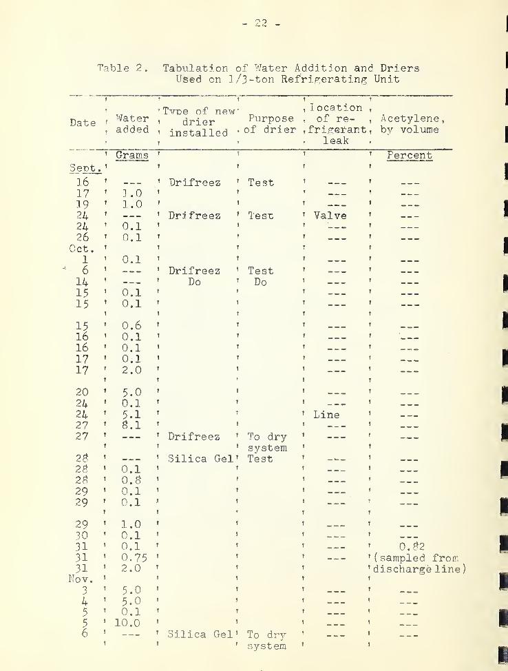
Table 2. Tabulation of Water Addition and DriersUsed on 1 /3-ton Refric:erating Unit
t ^ T ? ?
' ,, ^Tvoe of new' _’ location
,
Date 'Water
, drier Purpose , of re- tAcetylene,
, added, installed * drier ,frigef-antT by volume
, r » T leak r
r Gram.s t 1 T PercentSept T
•T f t t
16 t — t DriDreez t Test T — T —
17 1 .0 t t T — f —19 t 1.0 f f f — t —24 T — T Dri freez ? Test t Valve t —24 T 0.1 t f T '—
.
T —26 T 0.1 f t T — y —
Oct
.
t T r» T
1 t 0.1 T t t — y
6 f — t Drifreez f Test T — y —14 T — t Do T Do t — y —15 t 0.1 T r t — y —15 T 0.1 T f T — y —
T t t 1 y
15 t 0.6 t t t y
16 f 0.1 f r t — y ...16 t 0.1 f ! f — y —
17 t 0.1 f f f t —17 T 2.0 t t T — y —
f ! r T y
20 t 5.0 t f t — y
24 t 0.1 f t t — - y —24 T 5.1 f T t Line y . — .
27 t ^.1 t T T — y —27 f — f Drifreez ! To dry f — _ y —2^
! t T system t r
t — r Silica Gel T Test f — y —2g T 0.1 T T 1 ^ y ^ _
2S f o.s t ! f — y
29 f 0.1 T t t — y —
29 T 0.1 t t t — T —f T t f y
29 t 1.0 t y t — y
30 T 0.1 t t f — y
31 f 0.1 f t t — _ y 0.^^2
31 T 0.75 T ! T — y( sampled from
31 f 2.0 f r t ’ discharge line
)
yNov. T T t t
3t 5.0 t r T — — — f
4 f 5.0 t f t — y ^ _
5T 0.1 f t T y — . —
5T 10.0 f t f — — y
6 '’ Silica Gel’ To dr3
'‘ ’
’ '' system '
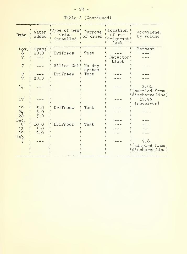
Table 2 (Continued)
r t
^ I Water
Iadded
f
’T^'-'pe of new^' drier ’
' 'aistalled ’
Purposeof drier
f f
’ Location ’
’ of re- ’
^ fri^erant '
' leak ’
Acetylene
,
by volume
Lov. ^ Grams ’
6 ’ 20.0 t Drifreez ’ Test7 t t 7
! t 7
7 T T Silica Gel’ To dryf 7 7 system
7 T T Drifreez ’ Test7 ’ 20.0 ’ '
f T T
T
T
t
?
t
T
t
T
t
t
f
Detector '
block ’
_ _ — ’
T
T
t
?
Percent
14 7
7
7
7
7
7
17 7
7
7
7
19 ’ 5.0 ’ Drifreez24 ’ 5.0 7
2^ ’ 5.0 7
Dec
.
r 7
9 ’ 10.
U
’ Drifreez12 ’ 5.0 7
19 ’ 2.0 7
Feb. 7 7
3 7 7
t T
t t
f t
t t
T ?
f t
t t
? T
' Test ’
T T
T ?
t t
’ Test ’
f f
T t
t t
T T
t f
t T
f t
’ 2.04’ ( sampled from* discharge line
)
’ 12.95’ (receiver)t
t
T
’ 7.6’ ( sampled from’ discharge line
)
» 2 /, -
2 , Calcium H^^droxide
Since the products formed hy the reaction of cal-cium carbide and water are knov/n to be calcium hydrox-ide and acet^rlene, no analyses were made to identifycalcium hydroxide as one of these products.
Calcium hydroxide formed by the reaction of cal-cium carbide and water should be retained in the drierto avoid clog^^ins: of the system or damage to the com.-
pressor
.
Observation made on the glass cylinder Drifreezdrier (the demonstration model) indicated that the steelwool filter in the drier had retained large am.ounts ofthe calcium h^rdroxide in a pasty form. When the ther-mostatic expansion valve was replaced by an automaticexpansion valve after eight Drifreez driers were used,the strainer at the inlet of the former was inspected.A very small amount of the paste-like substance whichappeared to be calcium hydroxide was found. The amountwas considered to be negligible.
The receiver was cut in half at the conclusion ofthe tests and its interior was inspected. Calcium hy-droxide was not found.
3 . Copper Acetylide
The tubing used in most Freon refrigeration sys-tems is made of copper. It was not known whether ornot the acetylene produced by a Drifreez drier wouldreact with copper to form copper acetylide in thepresence of Freon-12 in a refrigeration system.
The copper tubes used in the refrigeration unitemployed for the drying tests were cut open at the endof the drying tests. The inside surface of the tubingthroughout the system was found to be coated with ablack material. This coating was thicker and darkerin color im.mediately downstream from the drier.
The black material was identified by means of thefollowing analyses:
(a) When pieces of tubing with the black coatingwere heated over a bunsen burner, small puffs of smoke
were emitted from the open ends. Upon close investiga-tion, after the tubinv had been permitted to cool, itwas found that the black coating had disapneared. Sub-sequent reheating of the same tubin'^ did not cause anyfurther puffing.
(b) i/ifhile one of the pieces of tubing taken fromthe refrigeration system was being cut v/ith a hacksaxv,a mild explosion occurred which produced a dull yellowflash and some greyish-black fumes. A sm^all spot ofsoot remiained on the sav/blade. It is unlikely thatacetylene gas caused the explosion because the massspectrometer analysis of the '^ases liberated upon heat-ing the coated copper tubing showed only minute quanti-ties of acetylene.
It has been established'^^ that dry cuprous acety-lide is exceedingly explosive and is sensitive to shock,friction, and heat.
(c) Mien pieces of the copper tubing v/ere heated invacua, much carbon dioxide, some carbon monoxide, andhvdrogen were evolved as determined b^r a miass spectrometer.This indicated tl at the black material was probably anorganic substance. A minute amou.nt of acetvlene was alsoindicated, but this may have been desorbed from the sur-face .
(d) Pieces of the coated copper tubing were treatedwith dilute hydrochloric acid in vacua and the gaseousproduct was examined in a mass spectrometer. The recordfrom the analysis showed large ion currents at masses24, 25
,and 26 in the correct abundance ratio for
acetylene. The ion current at mass 26 was 2200 divisionsor over two-thirds full scale and acetiO. ene was by farthe most abundant component observed. In contrast, onlya sm.all amount of acetylene was found when the coatedcopper tubing was heated without the acid treatment .
It is well knowR'^ that the addition of dilute acidsto copper acetylide releases acetylene according to theequation
'^Handbook of Dangerous Materials by N. Irving Sax.
The Chemistri^ of Organic Compounds by James B. Conant
(e) Some of the strips of the coated copper tubine!:
were treated with dilute hydrochloric acid and the gasevolved was bubbled through an amrnoniacal solution ofcuprous chloride v/hich was kept in a reduced state by hy-droxyl amine hydrochloride. A red precipitate was ob-served.
It is knovm ~ that v^hen acet 3?’lene is shaken withamrnoniacal cuprous or silver solutions, precipitates ofm.etallic acetylide are found as indicated by the fol-lowing equation:
C2H2 + Chi2Cl2 + 2NH^0H -> CU2C2 + 2NH4CI + 2H2O
Thus, the gas liberated upon treatment of the coatedConner tubing v/ith dilute h^/drochloric acid was confirmedby an independent chemicaj method as being acetylene.
The conclusion dravm from the above observations andexperiments ivas that the black material covering the in-ner surface of the copper tubing contained copper acety-lide which was formed by reaction of the copper withacetylene liberated by the several Drifreez dehydrators.
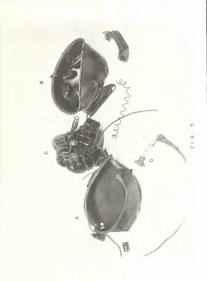
Referring to Fim. 1, both tubes numbered "I"’ weretaken from the liquid line upstream of the drier andthose numbered ”2” were taken from the liquid line down-stream of the drier and were cut longitudinally. Apiece of new unused copper tube is numbered ”3" and isshovm for comparison purpose. The hacksaw blade usedto cut the tubes is numbered "4”. The arrow pointingat the black soot on the hacksaw indicates the locationat which explosion occurred v^hile cuttino; one of thetubes numbered ”1", The arrow pointing at the lowerpicture of tube numbered ”1” indicates the part of tubethat was being cut when the explosion occurred.
III. Results of Hazard Tests
Among the three products (calcium h 3rdroxide,acetylene, and copper acet 3;’lide) formed b37- chemicalreaction of calcium carbide, water, and copper in a re-frigeration svstem, calcium hydroxide was not found tohave escaped from the Drifreez drier in sufficientquantity to cause clogging of the lines or dam.age tothe compressor, nor was it considered to be hazardouschemically in the refrigeration S 3^stera. However, fur-ther investigations were made to determine the


conditions that mifrht be hazardous and to stud 3r the
possible extent of damage by acetylene and copper acet^^-lide. Possible hazards could be explosion of copperacetylide, dissociation of acetylene, and explosion ofair-acetylene mixtures.
1 . Dissociation of Acet-^^lene in Presence of Freon-1 2
Tests were made to find the amount of Freon--12necessar3^ to prevent dissociation of acet 3’’lene under 300pounds per square inch gaye pressure. According to t-'^e
past experience of the acet^flene manufacturing^ industr^^,the causes and conditions for the spontaneous dissocia-tion of aceti'-lene were not precisel^^ knovm. A comprehen-sive studv of the conditions of heat pressure, friction,or impact that would initiate dissociation of acet^'^lenewould be hazardous so it was decided to detonate a samplewith a spark plug, if possible. Although it happens in-frequently, a spark ma^T- be produced in the refrigerantvapor in a hermetically-sealed motor-compressor unit byfailure of the windings of the motor.
The apparatus emploT/ed is shox\m in Fiy. 2. All ofthe tubes of the system shown in the figure were filledwith water b^,'- means of vacuum pump C. Acet^’-lene wasproduced in the generator A by dropping water from fun-nel B. The acetylene gas thus produced and Freon-12from tank J were charged into the 100 ml burette F toobtain the desired miixture. B 3
/ manipulation of valves,the acetyl ene-Freon mixture was charged into bomb H.This xvas accomplished b3
^ means of vacuum created in theS 3^stem b3
'- the vacuum pump C. The gas mixture was com-pressed usini3- air from tank 1 through reservoir E tobomb H by manipulatinp; suitable valves. The mixture inbomb H was ignited b3
'' a m.arine spark plug K installedon top of the bomb C. The spark plug was fastened bya ball sleeve fitting so that if an explosion toolc placethe spark plug would serve as a safet 37
" valve.
Under 300 pounds per square inch gage pressure, thegas m.ixture did not explode when its composition was Cpercent Freon-12 and 92 percent acet’-’lene (by volume)measured at atmospheric pressure. Under the same pres-sure, it exploded most of the time when the compositionwas 7 percent Freon-12 and 93 percent acet 3’'lene (’03?-
volume) measured at atmospheric pressu.re. Inconsistenc 3'-
in explosiveness at the latter concentration was be-lieved to be due to differences in the time lag between
charging the gases and igniting the mixture under pressureduring the several tests. Appreciable change in composi-tion of the mxixture v/as expected after the pressure wasapplied because of the difference in solubilities ofacetylene and Freon-12 in v/ater and the change in the rel-ative partial pressures. In order to find the true compo-sition under pressure, a gas mixture ox f percent Freon-12and 92 percent acetylene (b^^ volume) was charged in thebomb and pressure was applied by exactly the same pro-ceedure. At the time when it v/ould normally be ignited,the mixture was extracted from the bomb into a glasstube sampler for analysis. The mass spectrometer showedthat the real composition under pressure v^/as 9.2 percentFreon-12 and 90.^ percent acetylene (by volum.e) .
2 . Explosiveness of Ideal Fixture of Acetyleneand Air in Presence of Freon-12
The amount of Freon-12 necessary to prevent explosionof ideal mixtures of acet3xlene and air under one and twoatmospheres of pressure was determined.
The apparatus emplo^/ed was simxpler than the one usedfor dissociation of acetylene under pressure. The de-sired composition of a mdxture of Freon-12, air, andacet^rlene was obtained in a 100 ml burette. It was thentransferred to a spherical explosion pipette b^?- means ofa levelling bottle. One or two atmospheres of pressurewas applied to the gas mixture bv the levelling bottleand it was ignited by a spark produced between electrodesin the pipette. A rubber cap placed on the charginginlet of the pipette served as a safet}/- valve whenexplosion occurred. Mercury instead of water was usedin the pnpette levelling bottle and the lines.
It was found that under one atmosphere pressure, aconcentration above 12 percent Freon-12 (by volume)prevented explosion of ideal mixtures of air and acety-lene (7 to 13 percent acet^dene by volume). Ideal mix-tures of air and acet^dene exploded in mixture with 12percent Freon-12 (b]/- volume).
Under two atmospheres of pressure, mixtures con-taining more than I6 percent Freon-12, b^x volume, did notexplode with ideal mixtures of air and acet^/'lene.
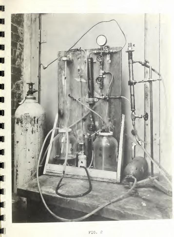
FIG. 2


3 • Explosion of Copper Acet'^^lide
Attempts v/ere made to explode the deposit found onthe inside surface of the copper tubin,p taken from the rfrigeration system. Heating, scratching, and tapping dinot cause it to explode.
Hox'/ever, a mild localized explosion v/as observedwhile sawing one of the pieces as described earlier inthis report.
Copper acetylide oxidizes rather rapidly when exposto the a-’r which may accomit for the inabilit 3
'- to delib-erately produce an explosion by heating, tapping, orscratching the deposit.
4 . Explosion of Compressor and Copper Tubin?^
A hermet icall^T- sealed l/5-horsepox^rer compressor wassubjected to an explosion of an ideal mixture of air andacet\''lene to determine its ability’’ to X'/ithstand such anexplosion or to examine the extent of its damage.
Fig. 3 shows the anparatus eniploved. Acetylene was'generated in the cartridge C, filled with calcium carbidbxr feeding water from cx/linder E. A separator D was useto separate water and calcium hxrdroxide from acetylene.After acetylene was charged into the compressor in theexplosion test chamber A, air was charged from compressed-air tank, F, which can be seen behind the gage board G.The initial pressure to which the corapressor was chargedwith acetxrlene and the final pressure to which it wascharged b].'' adding air were selected so that the mixturewould fall in the ideal mixture range (from 7 to 13percent acetxxlene, by volume). No Freon-12 icas presentin the compressor during these tests. The compressor,charged with the mixture, "'’as heated b3
* heat lamps to atem.perature higher than the ambient temperature, •-/hich
xvas about 40'’ F. The mixture v/as igr.ited by an ordinaryautomobile spark plug.
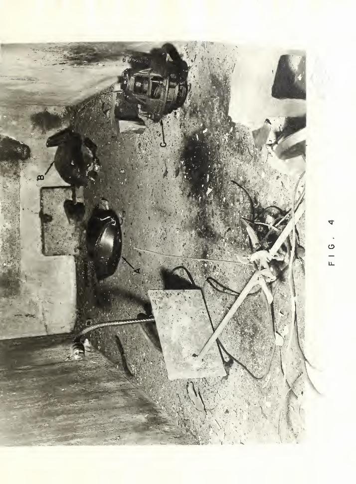
Under l60 pounds per square inch gage pressure, themixture of air and acetxrlene (7.2 percent by volume)exploded on ignition. The explosion caused the compres-sor to fail at the welded joint of the steel housing.Fio-. 4 shoxfs the interior of the test chamber after theexplosion. Fig. 5 shows the close-up of the damagedcorapressor. A and B are the upper and lower half of the
O.
CD
(DO.
CD
- 30 -
housin.e^, respectively. C is the motor and compressor.D is the spark plug, shovm in Fig. S only.
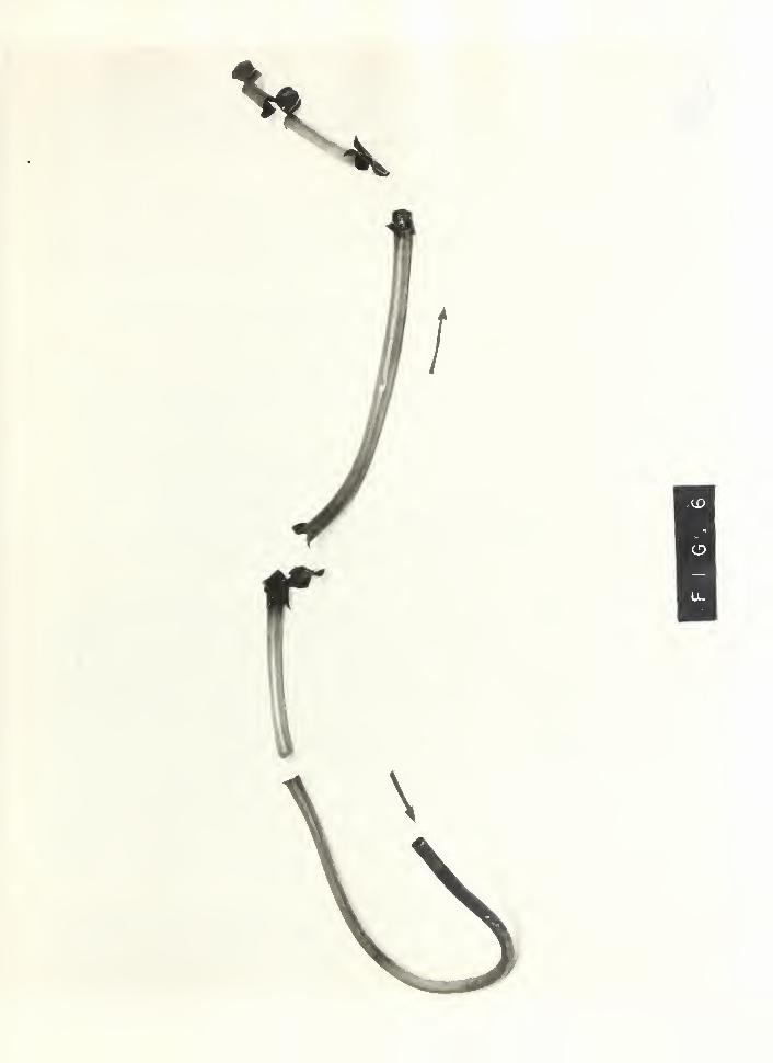
Prior to the ahoYe test during v;hich explosion ofthe compressor took place, explosion or rupture of l/4-in.copper tubing occurred while acetylene was being generatedThe line immediatel3r after the generator was clogged upby calcium hydroxide which was pushed into the line byrapid generation of acetylene. This created high pres-,sure in the line and probably/' caused the explosion.Pieces of copper tubing which failed are shoivn in Fig. 6.The arrows indicate the direction of gas flow. It x^as
not kno’m x^hether the explosion x^^as caused by dissocia-tion of acetylene or bx^ detonation of copper acetylide.The localized areas of rupture indicate ver^'- sudden risesin pressure because the tube X'/as not noticeably stretchedeven a short distance from the ruptured areas.
IV. Discus s ion and Conclusions
The hazard tests developed the following informationregarding the effects of using Drifreez driers (calciuimcarbide) to absorb water in a Freon-12 refrigeratingsystem:
(1) The normal products of the reaction of calciumcarbide and x^ater; namelA^, acetylene and calcium hydrox-ide, were produced in the sx'-stem.
(2) Nearl^^ all of the calcium h^^droxide ims retainedin the drier cartridge. That which escaped from thedrier did not present an 3^ problem of clogging in thestrainers or refrigerant lines.
(3) As much as 13 percent, bx^ volume, of acetylenexvas found in the vapor space of the receiver after 09grams of water had been absorbed in seven Drifreez driers.
(4) At 300 psig pressure, 9 percent or more ofFreon-12, b^'' volxime, prevented the ignition of acet^/'lenegas by means of an electrical spark.
( 5 ) At atmospheric pressure concentrations ofFreon-12 above 12 percent, b^r x^^olume, prevented explo-sions of ideal mixtures of air and acetylene when aspark discharge was used for ignition. At tx-tro atmospherespressure, concentrations of Freon-12 above I6 percentMere required to prevent similar explosions.

Ik
Uit
- 31
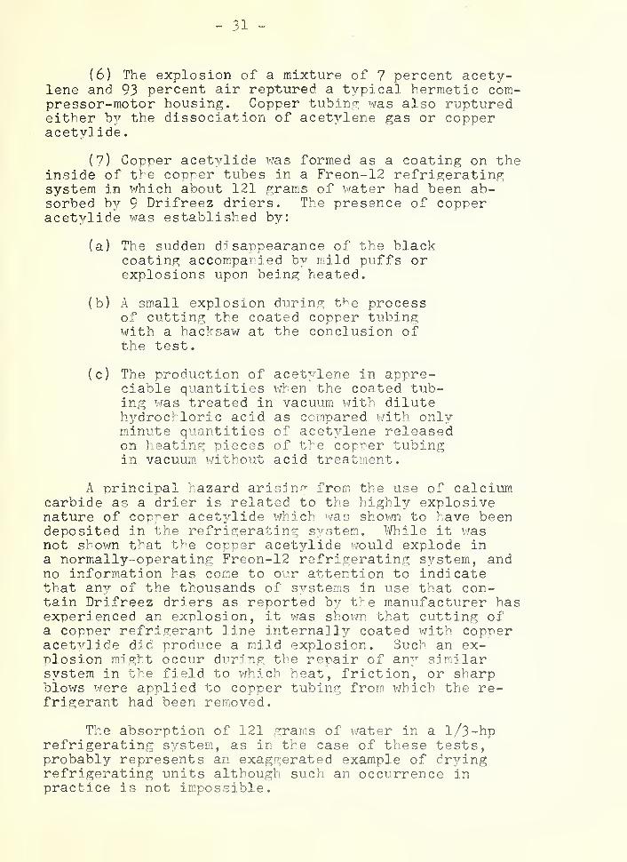
(6) The explosion of a mixture of 7 percent acety-lene and 93 percent air reptured a typical hermetic com-pressor-motor housing. Copper tubing was also rupturedeither by the dissociation of acetylene gas or copperacet3rlide.
(7) Copner acetvlide vra.s formed as a coating on theinside of the copper tubes in a Freon-12 refrigeratingsystem in which about 121 grams of water had been ab-sorbed by 9 Drifreez driers. The presence of copperacet^^lide was established by:
(a) The sudden disappearance of the blackcoating accompanied b^^ mild puffs orexplosions upon being heated.
(b) A small explosion during the processof cutting the coated copper tubingwith a hacksaw at the conclusion ofthe test.
(c) The production of acet^^-lene in appre-ciable quantities when the coated tub-ing was treated in vacuum with diluteh 3’’drochloric acid as compared with onlymiinute quantities of aceti^lene releasedon heating pieces of the copper tubingin vacuum without acid treatment.
A principal hazard arisinf;" from the use of calciumcarbide as a drier is related to the highly explosivenature of copper acet^^lide who’ ch was shovm to have beendeposited in the refrigerating s^^stem. 1/ifhile it wasnot shown that the copper acetylide would explode ina normally-operating Freon-12 refrigerating system, andno information has come to our attention to indicatethat an^?- of the thousands of s^^stems in use that con-tain Drifreez driers as reported b^,^ the m.anufacturer hasexperienced an explosion, it was shoim that cutting ofa copper refrigerant line internally coated v/ith copperacetvlide did produce a mild explosion. Such an ex-plosion might occur during the repair of an^’- simdlarsystem in the field to which heat, friction, or sharpblows were applied to copper tubing from which the re-frigerant had been remioved.
The absorption of 121 grams of water in a l/3-hprefrigerating system, as in the case of these tests,probably represents an exaggerated example of dryingrefrigerating units although such an occurrence inpractice is not impossible.
> •-
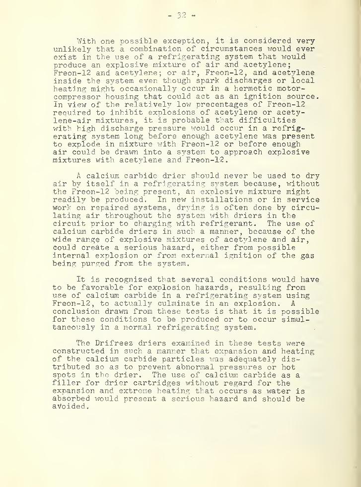
With one possible exception, it is considered veryunlikely that a combination of circumstances would everexist in the use of a refrigerating system that wouldproduce an explosive mixture of air and acetylene;Freon-12 and acetylene; or air, Freon-12, and acet3rleneinside the system even though spark discharges or localheating might occasionally occur in a hermetic motor-compressor housing that could act as an ignition source.In view of the relativel 3
’’ low precentages of Freon-12required to inhibit explosions of acetylene or acety-lene-air mixtures, it is probable that difficultieswith high discharge pressure would occur in a refrig-erating system long before enough acet 3'-lene was presentto explode in mixture with Freon-12 or before enoughair could be drawn into a system to approach explosivemixtures with acet 3’'lene and Freon-12.
A calcium carbide drier should never be used to dryair b3
'- itself in a refrigerating S 3rstem because, withoutthe Freon-12 being present, an explosive mixture mightreadil 3r be produced. In new installations or in servicework on repaired systems, dr3^ing is often done by circu-lating air throughout the S3’"stem with driers in thecircuit prior to charging with refrigerant. The use ofcalcium carbide driers in such a manner, because of thewide range of explosive mixtures of acet 3/lene and air,could create a serious hazard, either from possibleinternal explosion or from external ignition of the gasbeing purged from the S3'-stem.
It is recognized that several conditions would haveto be favorable for explosion hazards, resulting fromuse of calcium carbide in a refrigerating S 3/stem usingFreon-12, to actuall37- culminate in an explosion. Aconclusion drawn from these tests is that it is possiblefor these conditions to be produced or to occur simul-taneously in a normal refrigerating system.
The Drifreez driers examined in these tests wereconstructed in such a manner that expansion and heatingof the calcium carbide particles was adequately dis-tributed so as to prevent abnormal pressures or hotspots in the drier. The use of calcium carbide as afiller for drier cartridges without regard for theexpansion and extreme heating that occurs as water isabsorbed would present a serious hazard and should beavoided
.
33 ~
PART C, VIBRATION TEST
I . .introduction
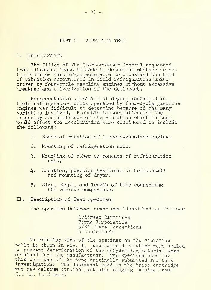
The Office of The Quartermaster General requestedthat vibration tests be made to determine v/hether or notthe Drifreez cartridges were able to withstand the kindof vibration encoir.ntered in field refrigeration unitsdriven by four-cycle gasoline engines without excessivebreakage and pulverization of the desiccant.
Representative vibration of dryers installed infield refrigeration units operated by four“C 3rcle gasolineengines was difficult to determine because of the manyvariables involved. Probable factors affecting the-frequency and amplitude of the vibration which in turnwould affect the acceleration x^ere considered to includethe follox'j'ing:
1. Speed of rotation of 4 cycle-gasoline engine.
2. Mounting of refrigeration unit.
3. Mounting of other components of refrigerationunit
.
4. Location, position (vertical or horizontal)and mounting of dryer.
5. Size, shape, and length of tube connectingthe various components,
II . Description of Test Specimen
The specimen Drifreez dryer xvas- identified as follows:
Drifreez CartridgeBerna Corporation3/gtf flare connections
6 cubic inch
An exterior viex'/ of the specimen on the vibrationtable is sho'wn in Fig. 1, New cartridges X'/hich were sealedto prevent deterioration of the dehydrating material xvereobtained from the manufacturer. The specimen used forthis test was of the txrpe originally submitted for thisinvestigation. The desiccant used in the brass cartridgewas rav calcium carbide particles ranging in size from0,4 in, to f mesho
- 34 -
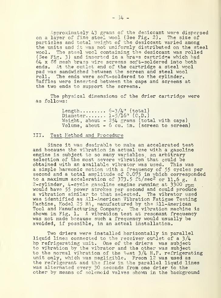
Approximately 43 grams of the desiccant were dispersedon a layer of fine steel wool (See Fig. 2). The size ofparticles and total weight of the desiccant varied amongthe units and it was not uniformly distributed on the steelwool. The steel wool containing the desiccant was rolled(See Fig. 3) and inserted in a bra'=s cartridge which had64 X mesh brass wire screens soft-soldered into bothends. At the outlet end of the cartridge a steel woolpad vras sandwiched between the screen and steel woolroll. The ends were soft-soldered to the cylinder.Baffles were inserted between the caps and screens atthe two ends to support the screens.
The physical dimensions of the drier cartridge wereas follows:
Length 6-3/4’'^ (total)Diameter....... 1-5/16” (O.D.)Weight, about -254 grams (total with caps)Volume, about - 6 cu. in. (screen to screen)
III. Test Method and Procedure
Since it was desirable to make an accelerated testand because the vibration in actual use with a gasolineengine is subject to so many variables^ an arbitraryselection of the most severe vibration that could beobtained with an available vibrator was used. This wasa simple harmonic motion with a frequency of 55 cycles persecond and a total amplitude of 0.075 in which correspondedto a maximum acceleration of 373.5 ft/sec2 or 11.6 g. A
2-cylinder, 4-C 3?-cle gasoline engine running at 3300 rpmwould have 55 power strokes per second and could producea vibration similar to that selected. The vibrator usedwas identified as All-American Vibration Fatigue TestingMachine, Model 25 HA, manufactured by the All-AmericanTool and Manufacturing Company, The vibration machine isshoivn in Fig. 1. A vibration test at resonant frequencywas not made because such a frequency would usually beavoided, if possible, in an actual installation.
Two driers were installed horizontally in parallelliquid lines connected to the receiver outlet of a 3/4hp refrigerating unit. One of the driers v/as subjectto vibration by the vibrator and the other V7as subjectto the normal vibration of the test 3/4 H.P. refrigeratingunit only, which was negligible. Freon 12 was used asthe refrigerant and the flow in the parallel liquid lineswas alternated ever3
r 30 seconds from one drier to theother by means of solenoid valves shoivn in the background

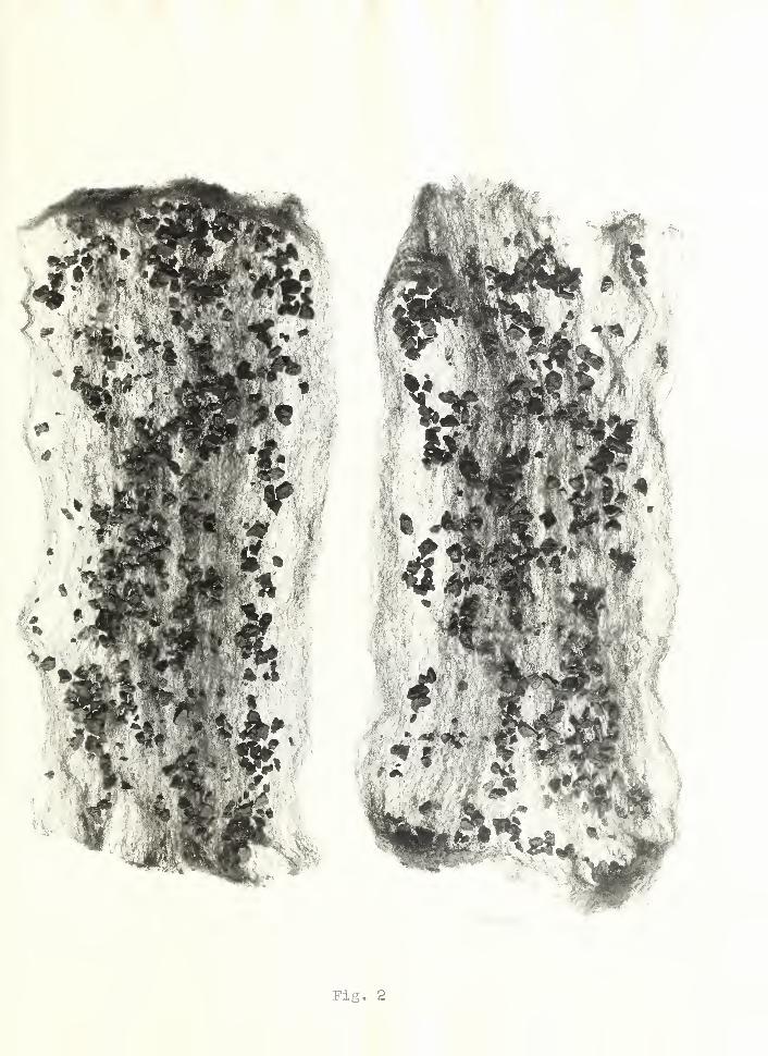
Fig. 2
s^

CT)
tiHP-4
VIBRATION

- 35 “
of Fig. 4 and a timing switch not shovm. Alternating theliquid flow between driers caused a sudden application ofthe liquid pressure to the interior of the driers orpulsing action similar to that occurring in a refriger-ating unit when it operated intermittently. Therefrigerating unit was operated continuously v/ith asuction pressure of about 40 psig during the vibrationtests.
In order to detect and compare the pulverization ofdesiccant resulting froi]i vibration, a filter containingtwo layers of fine n^j-lon cloth was placed downstream ofeach drier. These filters were made from the same pieceof nylon cloth. The filters are shown in the foregroundof Fig, 4. The nylon cloth, cut open, is shovm in Fig. 5.
After assembling the refrigerating unit, the systemwas thoroughly dried out using a vacuum pump. Althoughseveral breaks in tube connections occurred during thetest as a result of the vibration, the system probablyremained fairly dry because it was operated at a positivepressure throughout the refrigerant circuit.
The drier to be vibrated was securely fastened atthe middle of the cartridge to the table of the vibrator.{See Fig. 1). The simple harmonic motion was horizontaland the center line of the drier was perpendicular tothe table movement.
The total amplitude was set at 0,075” at the startof the test and there v/as no need of further adjustment.A General Radio Strobotac was used to set the frequencyat 55 cycles per second by illuminating the shaft of thevibrating mechanism under the table. The specimen drierwas subjected to vibration for a total of 100 hours.
IV. Test Results
Fig. 2 shows the desiccant on the steel wool as itappeared at the conclusion of the test. The specimenon the left was not subject to vibration and the one onthe right was subject to vibration for 100 hours. Nodifference was observed between the portions of desiccantin the two specimen driers.
Fig. 5 shows the two nylon cloth filters cut open;the one on the right was used on the liquid line down-stream of the drier attached to the vibrator table,
and the one on the left was installed on the other leg ofthe parallel circuit doiAmstream of the drier not subjectto vibration. Following the test the nylon filter in-stalled after the vibrated drier was found to have beendiscolored slightly more than the other. Microscopicexamination showed that the discoloration wascaused primarily by oil and fine parti^cles of thedesiccant. The powdered desiccant was so fine and insuch small quantity, it was impossible to identify thepowder by naked eye. Also it v/as impractical to separatethe particles from the nylon cloth for any quantitativeor qualitative analysis because of the glutenous effectof the oil deposit on the nylon.
Under microscopic observation, the size of holesin the nylon cloth of the filters was measured to beabout 3.3 microns (0.00012 in.) in length and 1.7microns (0.00007 in.) in width. The size of theparticles found on the filter downstream from thevibrated drier ranged from B to 32 microns ( 0.00032 to0.00125 in.) in diameter. On the other filter, size ofthe particles xvas about 2 microns (0.0000^ in.) indiameter.
Fig, 3 shows the two steel wool filters in which thecalcium carbide was wrapped as they appeared at the endof the test. No difference between the two was observed.
No change in pressure drop across either drierdeveloped during the 100-hr vibration test. This indi-cates that any particles larger than 32 microns thatmight have been separated from the original calciumcarbide granules and retained within the Drifreez cart-ridge had no measurable effect on its overall pressuredrop,
V. Discussion and Conclusion
The severity of the vibration vi^ith an accelerationof 11,6 g, can be gauged to some extent by the 16 failuresof the system during the 100-hour test that were attri-butable to vibration. The failures could be summarizedas follows; one broken thermocouple, one loosened Allenscrew on hub of vibration shaft, two worn out V-beltsbetween electric motor and adjustable-speed couplings,12 refrigerant leaks at flare joints and soldered joints.

FIG. 4-

FIG
I
The usual tubing loops used for absorbing vibration in arefrigeration-unit failed to prevent breakages during thtest. Plastic tubing was finally substituted for coppertubing to connect the dryer on the vibrator table intothe refrigerant circuit. The plastic tubing was successful in preventing joint failures.
The test results showed that the pulverization ofthe desiccant was increased by the severe vibration ofthe vibrating table as compared to that observed forthe normal vibration of the small refrigerating unitused for the test,. However, the particles of materialcollected dox-mstream from the driers ranged in diameterfrom 0.0000^ in. to 0,00125 in, and would probably passthrough any screen or strainer likel3r to be used in therefrigerating circuit. It is also probable that parti-cles in this size range would pass between the pistonsand cxT-linder walls of a compressor without significantcutting action. If the vibration caused particleslarger than 0,00125 in. to be dislodged from thecalcium carbide granules they were retained by thefilter in the outlet of the driers. The pulverizationof the calcium carbide was undoubtedly decreased bythe fact that the pieces xfere distributed rathersparsely on a steel x-^rool pad which acted as a cushion.
It was not possible from the data taken to expressthe effect of the 100-hour accelerated vibration testin terms of equivalent days, months, or years of normalvibration in a refrigerating system with respect to thepulverization of the desiccant.
Vibration tests of the drier in a wet refrigeratingsystem Mere not made. When the desiccant, calcium car-bide, reacts with ’water, it forms calcium hydroxide andacetylene. No tests were made to determine the abilityof the filter in the drier to retain the fine poxfder ofcalcium h3/droxide under vibration. However, in mixturewith liquid Freon the fine powder of calcium hydroxidewas observed to become very past3/ and thus not likelyto flow through the filters. The evidence that calciumhydroxide in liquid Freon became pasty and was notlikely to flox"7 through the filters was obtained b3^ ob-servation of the glass C3^1inder drier used during thedrying tests described in Part A, The glass cylinderwas partially filled with calcium carbide wathout awrapping of steel wool, and a steel wool pad was
”5 0 _- J o ~
inserted at either end of the glass cylinder. As thedesiccant reacted with moisture in the system, calciumhydroxide accumulated upstream of the filter pad at theoutlet of the container. A distinct boundary betweenthe steel wool and calcium hydroxide was observed andthe pressure drop across the drier increased to 110pounds per square inch gage indicating that the drierwas clogged up.
It was concluded from these tests that granularcalcium carbide, embedded in steel wool, would pulver-ize to some extent during normal operation in a dryrefrigerating system because of vibration, but theparticles that left the drier would be too small toclog strainers and would probably not score compressorcylinder walls.
- 39
VT. Evaluation of the Drifreez Drier
The investigation of the Drifreez drier indicatedthe follov/ing conclusions with respect to its dr3'-ing
characteristics, the hazards associated with its use,and its pulverization characteristics.
1.
For values of end dr^mess in the important rangebelow 30 ppm, the model of the Drifreez drier used forthe investigation removed and held more water than asilica gel drier of about twice the internal volume andselling currently for equal price. On the other hand,the instantaneous drA'-ing rate of the silica gel drierwas hieher than that of the Drifreez drier. Afterhaving removed equal amounts of moisture in the rangebetween 5 and 20 grams, the Drifreez drier produced alower end dr^/Tiess than the silica gel drier of equalcost
.
2.
Tv;o sources of hazard were revealed from theintroduction of acetylene gas into a refrigeratingsystem as a result of the reaction between calciumcarbide and water. These hazards are (a) the produc-tion of copper acetylide, b^?- reaction with coppertubing, which is sensitive to explosion b^T- heat,friction, or impact, and (b) the production of anexplosive mixture of air and aceti^'lene if a calciumcarbide drier were used to dry a s^/stem while aironly was being circulated in the s^’-stera. Althoughit is believed that the simultaneous development ofall the circumstances necessar3
'' for an explosionwould not occur very often, either hazard is possiblein normal operation or servicing of a refrigeratingsystem.
3
.
Vibration pulverized the granular calciumcarbide to some extent even v/hen embedded in steelwool as it was in the Drifreez drier, but the particlesthat left the drier were too small to clog strainersnormally/ used for liquid refrigerant and would probab-ly not score compressor cylinder walls.
V

THE NATIONAL BUREAU OF STANDARDS
Functions and Activities
The functions of the National Bureau of Standards are set forth in the Act of Congress, March
3, 1901, as amended hy Congress in Public Law 619, 1950. These include the development and
maintenance of the national standards of measurement and the provision of means and methods
for making measurements consistent with these standards; the determination of physical constants
and properties of materials; the development of methods and instruments for testing materials,
devices, and structures; advisory services to Government Agencies on scientific and technical
problems; invention and development of devices to serve special needs of the Government; and the
development of standard practices, codes, and specifications. The work includes basic and apphed
research, development, engineering, instrumentation, testing, evaluation, calibration services, and
various consultation and information services. A major portion of the Bureau’s work is performed
for other Government Agencies, particularly the Department of Defense and the Atomic Energy
Commission. The scope of activities is suggested by the listing of divisions and sections on the
inside of the front cover.
Reports and Publications
The results of the Bureau’s work take the form of either actual equipment and devices or
published papers and reports. Reports are issued to the sponsoring agency of a particular project
or program. Published papers appear either in the Bureau’s own series of publications or in the
journals of professional and scientific societies. The Bureau itself publishes three monthly peri-
odicals, available from the Government Printing Office: The Journal of Research, which presents
complete papers reporting technical investigations; the Technical News Bulletin, which presents
summary and preliminary reports on work in progress; and Basic Radio Propagation Predictions,
which provides data for determining the best frequencies to use for radio communications throughout
the world. There are also five series of nonperiodical publications: The Applied Mathematics
Series, Circulars, Handbooks, Building Materials and Structures Reports, and Miscellaneous
Publications.
Information on the Bureau’s publications can be found in NBS Circular 460, Publications of
the National Bureau of Standards ($1.00). Information on calibration services and fees can be
found in NBS Circular 483, Testing by the National Bureau of Standards (25 cents). Both are
available from the Government Printing Office. Inquiries regarding the Bureau’s reports and
publications should be addressed to the Office of Scientific Publications, National Bureau of Stand-
ards, Washington 25, D. C.