path optimization in stream-based overlay networks
TRANSCRIPT

����������� ������������������������� ������� �"!#�%$&��'�)(*���,+���-/.0���213�4��56$
798;:<8;=>7@?A8B:<C&D%E2FGH8BIJ=K8BL0MNF%OP8&?AQ%RTSHOU0SV:K:XWY8[Z]\KFU0S^=K_�`Ma8&Zb:<C[8;=
SHO%QUc8[RTS#d>`HD%\<\K`He�`fD%Z]`H\
g dihkj^l�hnm^o
p `fRe�D�:<8;=>MNE;?A8[O%E;8rqs=<`fDPetsSV=Ku^SV="Qcv�O%?bu�8[=<\K?w:nL
p SHRyx%="?AQP_f8Hz%U0SH\K\"S^E{FND%\|8B:K:2\

Path Optimization in Stream-Based Overlay Networks
Peter Pietzuch, Jeffrey Shneidman, Matt Welsh, Margo Seltzer, Mema RoussopoulosNOTE: Related Work under Blind Submission! Do NOT Distribute!
Harvard University Tech Report: TR26-04
AbstractThe emergence of sensor networks and distributed applications that gen-erate data streams has created a need for Internet overlays designed forstreaming data. Such stream-based overlay network (SBONs) consistof a set of Internet hosts that collect, process, and deliver stream-baseddata to multiple applications. A key challenge in the design and im-plementation of SBONs is efficient path optimization when mappinglogical query streams to physical network hosts and paths. Suboptimalplacements can induce poor utilization of network resources, leadingto severe performance penalties, link saturation, and network hotspots.Our goal is to realize efficient stream placement that takes the physi-cal topology of the Internet into account, thereby minimizing overallnetwork utilization.
In this paper, we describe a novel, network-aware path optimizationalgorithm for stream-based overlay networks. Our approach is based ona spring relaxation model that operates in a metric space defined by thepairwise node latency within the SBON. This relaxation placement al-gorithm utilizes the underlying network resources efficiently, is capableof performing inter-stream optimization, and can be implemented in ascalable and decentralized way.
To evaluate its performance, we define a set of evaluation metricsfor path optimization in terms of network utilization, application de-lay, and resource contention. Our simulation experiments with a real-istic network topology show that relaxation placement approaches op-timal network utilization without introducing an undue delay penaltyor resource contention. Compared to an optimal placement strategy,relaxation placement causes only15% more network traffic on aver-age, while adding a24% delay penalty for the application. We validateour simulation results with actual measurements involving70 PlanetLabnodes.
1 IntroductionRecently, there has been much interest generated in buildingdatastreaming applicationson the Internet. These applications typi-cally involve querying, processing, and delivering real-time datafrom multiple distributed data sources, such as sensor networks,and making use of shared resources in the Internet to aggregate,filter, or multicast this data. Commonly-cited target applicationsinclude real-time processing of financial data streams [1, 2], con-tinuous monitoring of Internet paths and system loads [15], andquerying geographically diverse sensor networks [14, 18].
In thesedata streaming applications, queries tend to be sim-ple but frequent, and data almost always needs to be transmittedto a location remote from the source. While any single stream-ing application might not stress the network infrastructure, un-less each application deploys its own network, the aggregate loadimposed by the myriad applications under consideration is likelyto overwhelm any existing infrastructure. Therefore, we neednew network infrastructure that is capable of efficiently support-ing this class of applications. We call this network infrastructureastream-based overlay network(SBON).
An SBON consists of some number of participants, possiblyin different administrative domains, each of whom is willing andable to transmit data and implement a variety of stream operators(e.g., merging two streams, duplicating a single stream to fa-cilitate transmission to multiple destinations, selecting elementsfrom the stream that meet some criteria). In addition, some par-ticipants may implement application-specific operators.
Stream-based overlay networks introduce two fundamentaltechnical challenges: First the SBON must perform apath place-ment decision, creating a mapping of a particular data stream andits operators onto a particular collection of participants. Second,the SBON must make this decision in a manner that makes ef-ficient use of the underlying network. There is an inherent ten-sion in this second challenge in that a placement that optimizesfor the global network good may harm the performance (delayor response time) for a particular application. Thus, we mustoptimize network utilization within the constraints of tolerableapplication latency.
A number of distributed stream processing systems incorpo-rate the notion of an SBON either explicitly or implicitly in theirdesigns [10, 14, 15, 27]. These systems differ with respect totheir scalability, fault tolerance, and query models. To date, how-ever, few of these systems have attempted to address the pathplacement decision in a manner that takes the physical topol-ogy of the Internet into account. To the best of our knowledge,none of these systems have considered the placement decision asa whole, and instead focus on the placement or optimization ofindividual streams.
The contributions of this paper are as follows. First, we for-malize the notion of astream-based overlay networkand the fun-damental path placement decision that must be resolved in sucha network. Second, we present a novel network-aware place-ment algorithm based on a spring relaxation model that operatesin a metric space defined by the pairwise node latency withinthe SBON. The spring relaxation-based algorithm we proposehas several attractive properties: it is fully decentralized, has lowcommunication overhead, and it facilitates optimization acrossmultiple data streams. We define a set of metrics that capturedifferent aspects of network efficiency including network uti-lization, infrastructure utilization (i.e., routers), and end-to-endlatency. Finally, we present extensive simulation results thatuse these metrics to compare our algorithm to several others in-cluding IP multicast, random placement, and source/destinationplacement as well as an optimal placement. We also validatethese simulation results with PlanetLab measurements.
We find that our spring-relaxation based algorithm achieveswithin 15 % of the optimal bandwidth-latency product (a met-ric that captures the amount of data in transit in the network)
1

NOTE! Related Work under blind submission: Do not distribute to anyone else!
0
20
40
60
80
100
10 100 1000 10000
Pe
rce
nta
ge
of
me
ssa
ge
s
Latency (in ms)
Number of producers1 producer
3 producers5 producers7 producers9 producers
11 producers13 producers
1,3,5, 7 producers
9,11 producers
13 producers
Figure 1: Resource contention with centralized stream-processing on Planetlab.Each producer is sending32 KB mes-sages over a TCP connection at a rate of20 KB/s.
while imposing only a24 % delay penalty. As a point of compar-ison, while IP Multicast achieves better latency results, it is onlywithin 27 % of the optimal in terms of the bandwidth-latencyproduct.
The rest of this paper is organized as follows. In Section 2,we motivate why SBONs are a necessary alternative to a tradi-tional centralized data warehouse approach and specify the re-quirements for performing path placement in SBONs. In Sec-tion 3, we introduce our SBON system model, formalize theplacement problem, and introduce our evaluation metrics. InSection 4, we present the Relaxation placement algorithm. InSection 5, we discuss both our simulation and deployment re-sults. In Section 6, we place our work in the context of otherrelated work and in Section 7, we discuss future work that isbeyond the scope of this paper. We conclude in Section 8.
2 MotivationThe traditional approach to stream-based processing involves acentralized data warehouse that collects and processes real-timedata [8]. While such an approach permits the use of extensiveresource provisioning and replication to manage server load, itdoes not lead to an efficient use of resources because streamsmust be routed to the central warehouse for processing.
We illustrate the problems inherent to centralized stream-based processing with the Planetlab experiment in Figure 1,which shows the latency distribution of messages in a streamsent by several producers to a single consumer node. As can beseen from the graph, when more than five producers are simul-taneously sending data directly to the consumer, contention inthe system causes the observed application latency to increase.The contention worsens as more producers are added, increasinglatency drastically.
Stream-based overlay networks (SBONs) offer a better ap-proach by leveraging resources in the Internet to process anddeliver stream data. Rather than sending data to a centralizedstore for processing, we believe that SBONs of the future couldbe used to run query operators on behalf of multiple concurrentqueries, perhaps allowing the results of a particular computationto be shared across multiple users. In such a shared scenario,interesting path optimization problems arise. The essential taskfacing an SBON ispath placement, whereby logical streams are
ProducerServices
CircuitLink
Circuit 1 Circuit 2
OperatorServices
ConsumerServices
P
C
S
S
S
C
P P P
Figure 2:Example of an SBON with two circuits that share aproducer and operator service.
mapped to physical resources (hosts and network links). Given alogical data stream consisting of zero or more data sources, oneor more processing operators, and one or more destinations, thegoal is to instantiate operators on nodes in the SBON to makebest use of the physical network resources and maintain goodperformance.
Specifically, a good placement algorithm must satisfy threebasic requirements. First, it must bescalablein that it can sup-port a large number of concurrent streams, as well as a largenumber of network hosts acting as data producers, consumers,or intermediate nodes that execute query operators. This impliesthat the algorithm must be decentralized, not depend on globalknowledge of network conditions and have low communicationoverhead. Second, path optimization should beadaptivewith re-spect to changing network conditions such as load, latency, andlink utilization, as well as changing stream characteristics and re-quirements. Third, the placement algorithm should yield“good”placement, where good is defined either in terms of global orapplication-specific metrics. For instance, it could minimizeoverall network utilization or load, or give placement priorityto certain classes of streams. Similarly, the algorithm could in-corporate end-application performance goals, such as maximumlatency or jitter of streams. Regardless of the design goal, thereshould be clear criteria with which to evaluate competing algo-rithms.
3 Stream-based Overlay NetworksIn this section, we introduce our model of astream-based over-lay network(SBON). A wide range of existing stream processingsystems are examples of SBONs and are expressible within thismodel. We are creating this model because these systems sharesimilar problems and can benefit from common problem-solvingmethodologies and analysis.
An SBON is an overlay network that streams data from one ormore producers to one or more consumers, possibly via one ormore operators that perform in-network processing. The basicmodel of an SBON is one of multiplecircuits interconnectingmultiple services, as shown in Figure 2. A circuit is a tree thatspecifies the relationship and identity of services in a data streamand corresponds to a query. Services that are part of a circuit areconnected withcircuit links. Note that a service identity maynot initially specify a physical node for hosting that service; thisunplacedservice scenario is described shortly, but highlights theidea that a circuit can be alogical statement, before it becomesfully realizedthrough placement decisions, tying it to physical
2

NOTE! Related Work under blind submission: Do not distribute to anyone else!
network locations.Services are categorized into three classes: A (1)producer
servicestrictly acts as a data producer for the SBON. A (2)con-sumer servicemay only receive data from the SBON. An (3)op-erator serviceprocesses data, both consuming and producingdata streams. If a service is permanently associated with a physi-cal network location, it is called apinned service. Typical pinnedservices may include producer and consumer services; the net-work addresses for these services may be explicitly specified bythe creator of a circuit. In contrast, anunpinned service, such asa relational join operator, can be instantiated at an arbitrary lo-cation in the SBON. Unpinned services can further be describedasplacedor unplacedbased on whether they are currently asso-ciated with a physical network location. Unpinned services areplaced by aplacement algorithm. An unpinned, placed servicecan be re-placed by a later iteration of the algorithm if the net-work or stream characteristics change.
Our model of an SBON makes few assumptions about ser-vices in order to capture a wide range of existing stream-processing systems. In particular, no single query language ordata model has been assumed. Instead we assume that informa-tion about circuits used in placement decisions can be accessedby the system. For example, this involves knowledge of networkcharacteristics of the circuit links connected to services, such asbandwidth usage. These characteristics are either known stati-cally or determined through run-time measurements.
3.1 Placement ProblemIn this section, we formalize the placement problem for unpinnedservices that underlies data path optimization in an SBON. Theplacement optimization is motivated by four observations, whichwe will formalize in the following sections.
1. Unpinned, unplaced services must be placed on physicalnodes; in other words, logical circuits must be realized.
2. Some placements are better than others. There is some costfunction that reveals the “quality” of a placement decision.
3. The goal of the placement problem is an optimal node as-signment for all unpinned services with respect to the costfunction.
4. Optimal placement requires global knowledge and isNP-hard, so we seek an approximation algorithm that is scal-able, adaptive, and yields “good” placement decisions, thecriteria mentioned above.
Placement Requirement. We seek a placementΠ that spec-ifies where each of them unpinned services(s1 . . . sm) in theSBON are located from thel possible physical nodes(n1 . . . nl).As a pedagogical device, one can think ofΠ as a matrix, wherea 1 in a service’s row entry indicates placement on the physi-cal node corresponding to the column entry. In the absence ofoutside constraints, a physical node can support multiple placedservices, as in this placement of three services onto two nodes:
Π =
n1 n2 n3
s1 1 0 0s2 1 0 0s3 0 0 1
(1)
We require that every service be placed exactly once; rows ofΠ must sum to 1.
Figure 3: Example of an inefficient circuit placement. Thethickness of a link is proportional to the used bandwidth.
Placement Quality. There are many possible placementsΠ.To evaluate a placement or to guide an optimization function tofind the best placementΠ, we must state a cost function of thefollowing form: Given the set of circuitsC, which includes therelationship and identity of all pinned and unpinned services, thetopologyT , which includes the network characteristics, and aspecific placementΠ, fcost evaluates to some scalar valuek.
fcost(C, T,Π) = k (2)
Intuitively, k is the quality of the placement decisionΠ ascalculated by this cost metric. Sample cost metrics are given inSection 3.2.
Ideal Goal: Optimal Placement. Ideally, we seek an opti-mization algorithm that calculates the best possible placementΠ. This can be expressed as an argument minimization function,
Placeopt = arg minΠ
[fcost(C, T,Π)] , (3)
subject to placing all services exactly once, and perhaps othercontraints that specify the set of candidate nodes allowed forplacement.
Realistic Goal: Approximation. Placeopt finds the optimalplacement for unpinned services for every circuit in the system.However, the assumption of global knowledge about all possibleplacements in the SBON is not realistic for a large-scale dis-tributed system. In addition, iffcost is non-trivial, thenPlaceopt
is NP-hard [19]. These two concerns makes the implementationof Placeopt infeasible.
Therefore, the rest of this paper focuses onPlacerelax, whichis an approximation algorithm based on spring relaxation thatuses two phases to approximate the optimal solution. In the nextsection, we consider interesting choices offcost, and then moti-vate our selection when describing the Relaxation algorithm inSection 4.
3.2 Cost MetricsCost metrics can be used both as part of an optimization functionand to evaluate a placement. Our strategy in this paper is to useseveral metrics, which we describe below, to drive our evalua-tion.
Short of economic utility statements, it is unlikely that all ofthe participants in a network can reach agreement on the “right”optimization metric. Much existing work in operator placement
3

NOTE! Related Work under blind submission: Do not distribute to anyone else!
has focused on allowing individual circuit owners to drive theoptimization in their favor. In contrast, this paper places the op-timization function in the hands of the network administrator,who may be better equipped to optimize for the “network good.”The placement in Figure 3 gives an intuition for what would bean inefficient placement. The placement of serviceS on physi-cal noden1 causes linkp to carry twice as much traffic, whereasnoden2 would not cause the same problem because of the di-rect links to the producer nodes. The metrics described in thissection capture this type of global network efficiency, but alsoincorporate application delay penalty and resource contention.
3.2.1 Network UtilizationBandwidth-Latency (BW-Lat) Product is the product of thebandwidth (in KB/s) used in a realized circuit linke times thelatency (in ms) of that link, calculated over all realized circuitlinks E (computed fromC, T , andΠ) in the SBON:∑
e∈E
BW(e) Lat(e) (4)
The BW-Lat metric captures network utilization by comput-ing the amount of data that is in transit in the network at anypoint in time. The rationale is that the less data is put into thenetwork by circuits in the SBON, the more network capacity isavailable to other circuits and applications. As a result, the BW-Lat metric makes an assumption that high latency network linksare more costly to use than low latency ones [33]. Often highlatency over a network link indicates network congestion causedby popularity or long geographical distance that translates intohigher operating cost. In both cases, reducing the utilization ofsuch a costly network link is beneficial.
Bandwidth-Hop Count (BW-HC) Product is the product ofthe bandwidth (in KB/s) used in a realized circuit linke times thenumber of physical routing hops for that link, calculated over allcircuit linksE in the SBON:∑
e∈E
BW(e) HC(e) (5)
The BW-HC metric emphasizes the utilization of Internetrouters and physical links by including the number of physicalrouting hops into the cost of streaming data through the circuit.This evaluation metric favors circuits that involve a small num-ber of physical links, thus using a smaller fraction of the totalbandwidth available in the network. Often the number of physi-cal routing hops correlates with geographic distance. This metricassumes that routing information about the physical topology isavailable to get an accurate measure of hop count.
3.2.2 Delay PenaltyDelay Stretch is defined as the sum of the longest path delayunder placementΠ for a circuitC divided by the shortest pathdelay. The shortest path delay is the circuit realized by placingall services at the consumer node (Πcons). Thus, using the func-tion Delay to denote the longest path delay of circuit under aparticular placement, we have:
∑C
Delay(C, T,Π)Delay(C, T,Πcons)
(6)
For simplicity, we are ignoring the processing delay intro-duced by services. Delay stretch is a common metric for mea-suring the delay penalty that applications have to pay when usingan application-level multicast network compared to an IP-levelmulticast implementation [6].
3.2.3 Resource Contention
Node Stress addresses resource contention in the SBON.Node stress is defined as the number of services hosted at a givennode. Usually, each node has a maximum node stress that it cansupport.
Link Stress is defined as the total bandwidth sent through aphysical link. When placing services in the SBON, a circuit linkcannot be placed if the placement causes a physical link alongthe path to exceed its maximum capacity.
4 Relaxation PlacementIn this section, we describe Relaxation placement, our network-aware path optimization algorithm. The main idea behind Relax-ation placement is to partition placement into two phases. First,an unpinned service in a circuit is placed using a spring relax-ation technique in a virtuallatency spaceand then the solutionis mapped back to the physicalnetwork space. Performing datapath optimization in latency space has the advantage of naturallycapturing global knowledge about latency in the network topol-ogy, without imposing a large overhead due to network probing.The choice of latency as the principal metric acknowledges thatmost of the placement cost functions described in Section 3.2depend on latency.
Next, we explain the characteristics of latency space beforepresenting the spring relaxation model used for service place-ment within that space in Section 4.2. A description of the com-plete Relaxation placement algorithm is given in Section 4.3. InSection 4.4, we explain how Relaxation placement can performcross-circuit optimization, adopting a global view of the opti-mization problem.
4.1 Latency SpaceRecently, several proposals have been made for the computa-tion of synthetic,n-dimensionalnetwork coordinates[20, 21]for physical nodes in the Internet. Network coordinates havethe property that the Euclidean distance between two coordi-nates is a reasonable prediction for the communication latencybetween the corresponding network nodes. This enables large-scale distributed applications to make latency-conscious deci-sions without the overhead of probing the network directly withall-pairs ping measurements. Network coordinates can usuallybe calculated after probing the latency to only a small subset ofnodes. That subset either consists of a set of well-known land-mark nodes [21] or is randomly selected [11]. Since communi-cation latency on the Internet violates the triangle inequality andchanges dynamically over time, network coordinates can onlyprovide an estimate of the true latency value. However, simula-tion results [12] suggest that network coordinates, even with lowdimensionality, have a small predication error.
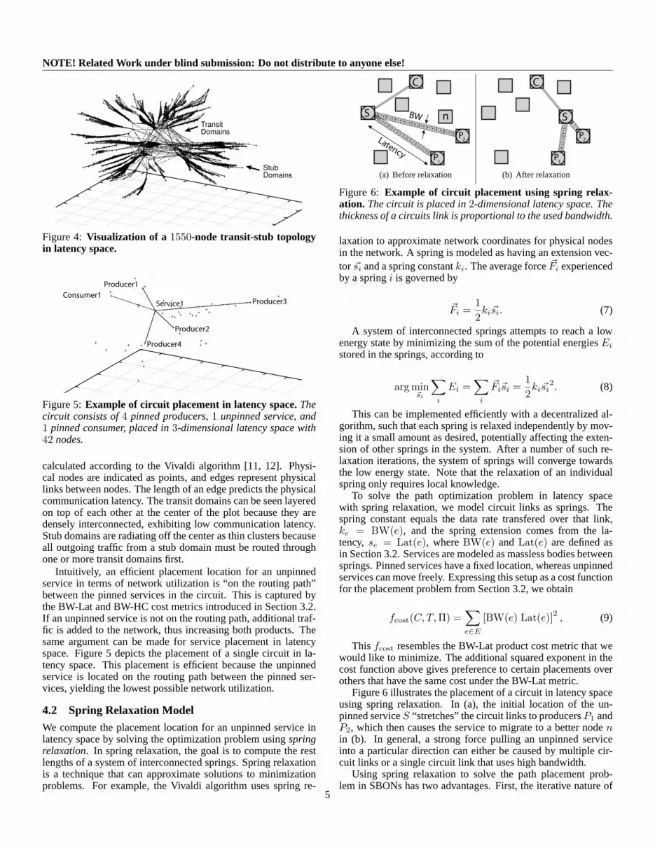
The plot in Figure 4 shows a3-dimensional latency space fora 1550-node transit-stub topology with10 transit domains and150 stub domains. The topology was created with the GeorgiaTech topology generator [34] and the network coordinates were
4
NOTE! Related Work under blind submission: Do not distribute to anyone else!
Transit
Domains
Stub
Domains
Figure 4: Visualization of a 1550-node transit-stub topologyin latency space.
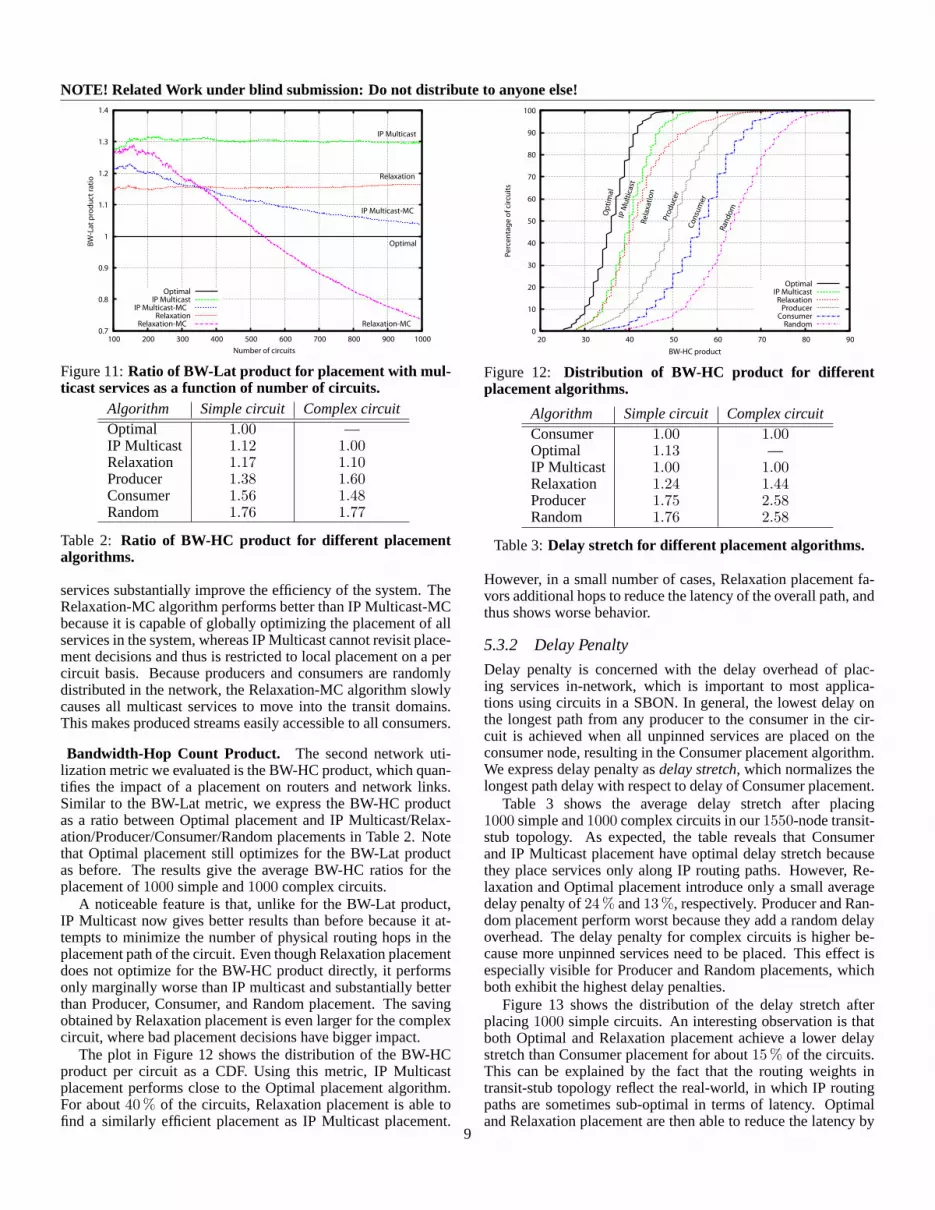
Consumer1
Service1 Producer3
Producer2
Producer1
Producer4
Figure 5:Example of circuit placement in latency space.Thecircuit consists of4 pinned producers,1 unpinned service, and1 pinned consumer, placed in3-dimensional latency space with42 nodes.
calculated according to the Vivaldi algorithm [11, 12]. Physi-cal nodes are indicated as points, and edges represent physicallinks between nodes. The length of an edge predicts the physicalcommunication latency. The transit domains can be seen layeredon top of each other at the center of the plot because they aredensely interconnected, exhibiting low communication latency.Stub domains are radiating off the center as thin clusters becauseall outgoing traffic from a stub domain must be routed throughone or more transit domains first.
Intuitively, an efficient placement location for an unpinnedservice in terms of network utilization is “on the routing path”between the pinned services in the circuit. This is captured bythe BW-Lat and BW-HC cost metrics introduced in Section 3.2.If an unpinned service is not on the routing path, additional traf-fic is added to the network, thus increasing both products. Thesame argument can be made for service placement in latencyspace. Figure 5 depicts the placement of a single circuit in la-tency space. This placement is efficient because the unpinnedservice is located on the routing path between the pinned ser-vices, yielding the lowest possible network utilization.
4.2 Spring Relaxation Model
We compute the placement location for an unpinned service inlatency space by solving the optimization problem usingspringrelaxation. In spring relaxation, the goal is to compute the restlengths of a system of interconnected springs. Spring relaxationis a technique that can approximate solutions to minimizationproblems. For example, the Vivaldi algorithm uses spring re-
n
Latency
BW
P1
C
S
P2
(a) Before relaxation
P1
C
S
P2
(b) After relaxation
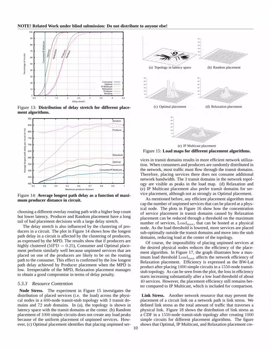
Figure 6: Example of circuit placement using spring relax-ation. The circuit is placed in2-dimensional latency space. Thethickness of a circuits link is proportional to the used bandwidth.
laxation to approximate network coordinates for physical nodesin the network. A spring is modeled as having an extension vec-tor ~si and a spring constantki. The average force~Fi experiencedby a springi is governed by
~Fi =12ki~si. (7)
A system of interconnected springs attempts to reach a lowenergy state by minimizing the sum of the potential energiesEi
stored in the springs, according to
arg min~si
∑i
Ei =∑
i
~Fi~si =12ki~si
2. (8)
This can be implemented efficiently with a decentralized al-gorithm, such that each spring is relaxed independently by mov-ing it a small amount as desired, potentially affecting the exten-sion of other springs in the system. After a number of such re-laxation iterations, the system of springs will converge towardsthe low energy state. Note that the relaxation of an individualspring only requires local knowledge.
To solve the path optimization problem in latency spacewith spring relaxation, we model circuit links as springs. Thespring constant equals the data rate transfered over that link,ke = BW(e), and the spring extension comes from the la-tency, se = Lat(e), whereBW(e) andLat(e) are defined asin Section 3.2. Services are modeled as massless bodies betweensprings. Pinned services have a fixed location, whereas unpinnedservices can move freely. Expressing this setup as a cost functionfor the placement problem from Section 3.2, we obtain
fcost(C, T,Π) =∑e∈E
[BW(e) Lat(e)]2 , (9)
This fcost resembles the BW-Lat product cost metric that wewould like to minimize. The additional squared exponent in thecost function above gives preference to certain placements overothers that have the same cost under the BW-Lat metric.
Figure 6 illustrates the placement of a circuit in latency spaceusing spring relaxation. In (a), the initial location of the un-pinned serviceS “stretches” the circuit links to producersP1 andP2, which then causes the service to migrate to a better nodenin (b). In general, a strong force pulling an unpinned serviceinto a particular direction can either be caused by multiple cir-cuit links or a single circuit link that uses high bandwidth.
Using spring relaxation to solve the path placement prob-lem in SBONs has two advantages. First, the iterative nature of
5

NOTE! Related Work under blind submission: Do not distribute to anyone else!1 updatePlacement(S):2 ~F ← ~03 ∀Sparent ∈ Parents( S)
4 ~F ← ~F + (~S − ~Sparent) ∗ BW(S, Sparent)5 ∀Schild ∈ Children( S)
6 ~F ← ~F + (~S − ~Schild) ∗ BW(Schild, S)
7 IF ( |~F | > Fthresh) THEN
8 ~S ← ~S + ~F ∗ δ
Figure 7:Pseudo code for the decentralized relaxation place-ment algorithm
spring relaxation allows placement decisions to adapt to changednetwork and circuit conditions. Second, the decentralized im-plementation of spring relaxation does not require coordinationbetween services. This keeps the communication overhead lowand opens up the possibility of cross-circuit optimization that hasglobal impact in the SBON, as will be described in Section 4.4.
4.3 AlgorithmIn this section, we explain how the Relaxation placement algo-rithm is used by an SBON and outline a decentralized imple-mentation. Consider an SBON with its circuits. Each unpinnedservice executes the following two steps continuously. (1) Theserviceplacesitself using spring relaxation in latency space withrespect to the location of its neighbors in the circuit. After that,(2) it mapsthe computed location from latency space to a nodein the physical network. If the new physical location differs fromits current location, the service may migrate to the new node.
To make the placement decision adaptable, the placement andmapping steps are repeated continuously by all unpinned ser-vices in the SBON. This does not cause a large communicationoverhead because each service can perform its placement deci-sion with local knowledge only after learning the network coor-dinates of its direct circuit neighbors. When the cost of migra-tion from one node to another is less than the improvement in thecost metric, the service moves to the new node. This optimizesthe data paths created in the SBON and adjusts them to changesin network and application conditions. Next, we describe the twosteps in more detail.
Relaxation Placement. We show the pseudo code for the dis-tributed Relaxation placement algorithm for circuits in Figure 7.TheupdatePlacement function is executed periodically byevery unpinned service in the SBON. The current network co-ordinate of the service is~S. A new unpinned service that hasbeen added to the SBON is assigned a provisional location in la-tency space, such as the node hosting the consumer service forthe new circuit. The total force~F is calculated by iterating overall parent and child services connected through input and outputcircuit links to serviceS and obtaining their current network co-ordinates. The force~F is updated with the distance in latencyspace between the current coordinate~S and the remote coordi-nates scaled by the bandwidth used by the circuit link (lines 3–6).The movement of the service through latency space is dampenedby a factorδ. If the magnitude of the force vector~F is largerthan a force thresholdFthresh, theupdatePlacement func-tion updates the current network coordinate~S (lines 7–8). Thechoice of the force threshold depends on the cost of service mi-gration. After the service coordinate has been updated, the ser-vice is mapped to a physical node in the SBON.
Service Mapping. To place a service in the SBON, it is neces-sary to map the network coordinate of the computed placementlocation in latency space to a suitable physical node. Two con-siderations are important here. First, the mapping should choosea physical node with a network coordinate as close as possibleto the placement coordinate. Second, the selected node and net-work path must have sufficient resources to support the new ser-vice and circuit links. Resources include node resources, suchas the load in terms of CPU utilization (node stress) or mem-ory consumption, and network resources, such as the availablenetwork capacity on the path of the circuit links (link stress).
We propose a simple scheme, in which we consider thek-closest physical nodes in latency space to the placement coordi-nate in order of proximity and select the first node for placementthat has sufficient resources. This relies on a scalable directorymechanism for looking up network coordinates of existing nodesand identifying the closest one. A possible solution is to relyon the routing properties of a DHT, such as Pastry [24], whichroutes a message with a destination key to the node with the clos-est existing key in the system. Each physical node in the SBONstores its network coordinate in the DHT. Ann-dimensional net-work coordinate can be mapped to a1-dimensional DHT keywith the help of a space-filling Hilbert function [25]. To find theclosest existing network coordinate, a message is routed via theDHT with the placement coordinate as a key. The DHT then en-sures that the message arrives at the closest existing node in thecoordinate space.
The mapping of a placement location in latency space to aphysical node will introduce amapping errorthat depends onthe distribution of nodes in latency space. In Section 5.5, weshow that the mapping error stays within a small fraction of thenetwork diameter for realistic network topologies.
4.4 Cross-circuit OptimizationAn advantage of the Relaxation placement algorithm is that itnaturally supports cross-circuit optimization decisions when cir-cuits are interconnected with shared services. For this, the entirecircuit graph can be viewed as a network of springs. The place-ment of an unpinned service in the SBON can then potentiallyaffect the placement of any other service with transitively sharedcircuit links. In practice, placement effects will be more local-ized because the cost of service migration ensures that placementdecisions do not create a domino effect in the system. Incorpo-rating the required bandwidth of a circuit link in the cost functionhas the desired result that placement decisions for services withhigh data rates have a stronger global impact in the SBON.
To enable the sharing of services and links among circuits,a circuit analyzermust determine whether a new circuit over-laps with any circuits already existing in the SBON. If this isthe case, stream processing and communication efforts can bereused, thus reducing resource usage in the SBON. A wide va-riety of techniques found in distributed query optimization [17]can be adopted to identify coverage among circuits.
To evaluate the potential of cross-circuit optimization withRelaxation placement, we implemented a simple circuit analyzerthat determines whether producers are shared among circuits inthe SBON. For each newly added circuit, the circuit analyzerchecks whether any of the producers are already part of othercircuits. When such a producer is identified, the structure ofthe involved circuits is altered by inserting amulticast service.A multicast service has a single input link from the producer
6

NOTE! Related Work under blind submission: Do not distribute to anyone else!
and multiple outputs links connected to the services that sharethis producer. It can then be placed at a location closer to theconsumers using the regular Relaxation placement algorithm de-scribed above in order to reduce the amount of network trafficgenerated. We evaluate the effect of multicast services on Relax-ation placement in Section 5.3.1.
5 EvaluationIn this section, we present the evaluation of the Relaxation place-ment algorithm for solving the path optimization problem in anSBON. Our goal is to compare Relaxation placement to fiveother relevant placement algorithms using the metrics defined inSection 3.2. The results are obtained from both simulation andPlanetLab deployment.
In simulation, we are able to perform the full evaluation andcompare each algorithm in terms of network utilization (BW-Latand BW-HC metrics), application delay penalty (delay stretch),and resource contention (node and link stress). In addition, weexamine cross-circuit optimization in terms of the BW-Lat met-ric usingmulticast services, as described in Section 4.4.
On PlanetLab, we compare Relaxation placement to fourother algorithms because the fifth, IP Multicast placement, as-sumes complete knowledge of the physical topology. We explorethe BW-Lat metric and an approximation to the BW-HC metricsince the exact physical topology is unknown. We also exam-ine application delay stretch. These experiments were performedby entering the full set of Planetlab ping times into our off-linesimulator, which then output an experiment file with placementdecisions. This file was used to deploy a real stream-processingsystem on Planetlab. We did not run resource contention exper-iments on Planetlab because of the side-effects this would haveon other experiments running in this shared environment.
The remainder of this section is structured as follows: first, wedescribe the alternate placement algorithms; we then present oursimulator setup in Section 5.2 and the simulation results in Sec-tion 5.3; this is followed by our PlanetLab setup in Section 5.4and the corresponding results in Section 5.5.
5.1 Other Placement AlgorithmsIn order to provide a comparative evaluation of the Relaxationalgorithm described in Section 4, we implemented five additionalplacement approaches.
Optimal Placement chooses the best possible placement withrespect to the BW-Lat cost metric after performing an exhaustivesearch over all possible placements, having global knowledge ofall placement locations. The complexity of this algorithm is ex-ponential in the number of unpinned services in the circuits. Thismeans that results for Optimal placement can only be calculatedfor simple circuits.
IP Multicast Placement puts unpinned services at physicalnodes that would be routers hosting branches of an IP multicasttree. In simulation, we calculate the IP multicast tree by takingthe union of all the IP unicast routes from the producers to theconsumers.
Producer Placement randomly picks one of the physicalnodes hosting producer services for the circuit and places all un-pinned services at this node. Such a placement algorithm of-ten utilizes the network less than Consumer placement becauseit can better leverage any selectivity of operator services. Less
C
S
1KB/s
P1 P2 P3
2KB/s
P4
(a) Simple circuit
C
S1
1KB/s
S2
2KB/s
S3
2KB/s
S4
2KB/s
P1 P2 P3
4KB/s
P4 P5
4KB/s
P6 P7
4KB/s
P8 P9
(b) Complex circuit
Figure 8:The two circuits used in experiments.
data is sent through the circuit if it is processed and potentiallydiscarded at a location close to the data producers.
Consumer Placement places all unpinned services at thephysical node hosting the pinned consumer service. This place-ment algorithm corresponds to a centralized, data-warehouse ap-proach to stream-processing, which is often used for current de-ployments of SBONs.
Random Placement picks a physical node for each unpinnedservice in the circuit at random. This placement algorithm isalso equivalent to a placement strategy in which a DHT is usedto hash an operator to a physical node in the network.
5.2 Simulation Setup
Since some of our evaluation metrics require the knowledge ofthe physical network topology, we decided to use a simulatorto evaluate the performance of our path optimization algorithm.Following previous work on the evaluation of large-scale peer-to-peer systems [24], we built a discrete-event simulator to avoidthe scalability issues of standard network simulators. Our simu-lator can place a large number of circuits on a physical networktopology according to one of several placement algorithms andthen compute a set of evaluation metrics.
Most of our experiments were carried out with a1550-nodetransit-stub topology, which was generated by the Georgia Techtopology generator [34]. The topology has10 transit domainswith 5 nodes, each connected to150 stub domains with10 nodeson average. Routing tables for the topology were calculated withthe help of the routing policy weights assigned to physical linksby the topology generator. These weights are intended to reflectInternet routing policy. The network diameter of the transit-stubtopology was878 ms.
The majority of experiments evaluated placing1000 circuitsin the SBON. Pinned services were randomly distributed acrossthe network. Only a single producer service was hosted at anyphysical node, with producers being shared among circuits. Eachcircuit had its own consumer service. The experiments consid-ered the two types of circuits shown in Figure 8. Both circuitsaggregate data from more than two producers, which we believeis realistic for many applications. Thesimple circuitconsists of4 producers sending messages at a rate of2 KB/s with 1 un-pinned serviceS aggregating the incoming data and outputting1 KB/s. Thecomplex circuitinvolves9 producers and requiresthe placement of4 unpinned services.
5.3 Simulation Results
Our experiments investigated the network utilization, delaypenalty, and resource contention of the six placement algorithms.Next, we present and discuss the results for each of these in termsof our evaluation metrics from Section 3.2.
7

NOTE! Related Work under blind submission: Do not distribute to anyone else!
Algorithm Simple circuit Complex circuitOptimal 1.00 —IP Multicast 1.27 1.00Relaxation 1.15 0.90Producer 1.43 1.43Consumer 1.60 1.32Random 1.81 1.58
Table 1: Ratio of BW-Lat product for different placementalgorithms.
0
10
20
30
40
50
60
70
80
90
100
1000 1500 2000 2500 3000 3500 4000 4500 5000 5500
Pe
rce
nta
ge
of
circ
uit
s
BW-Lat product (in KB)
Optimal
Op
tim
al
IP Multicast
IP M
ult
icas
t
Relaxation
Re
laxa
tio
n
Producer
Pro
du
cer
Consumer
Co
nsu
mer
Random
Ran
do
m
Figure 9:Distribution of BW-Lat product for different place-ment algorithms.
5.3.1 Network Utilization
Bandwidth-Latency Product. Our first evaluation metric isthe BW-Lat cost that captures network utilization as the amountof data in transit. Table 1 shows the BW-Lat product asa ratio between Optimal placement and IP Multicast/Relax-ation/Producer/Consumer/Random placements. The results givethe average BW-Lat ratios of two separate experiments, placing1000 simple and complex circuits in the1550-node topology.
For the simple circuit case, Relaxation placement performswell, which is expected because BW-Lat is the cost function usedby this placement algorithm in latency space. Relaxation place-ment is more efficient than IP Multicast placement because IPMulticast attempts to minimize routing hops and not necessar-ily routing latency. Therefore, Relaxation placement manages tofind better placement nodes that are not on the IP routing pathfrom the producer to consumer. The Producer placement algo-rithm does better than Consumer placement because, by placingthe selective operator service on one of the producers, data fromonly 3 producers needs to be sent through the network to the op-erator service. Random placement exhibits the highest BW-Latcost and Consumer placement is only marginally better.
With complex circuits, the Optimal placement algorithm isnot feasible any more because of the complexity of the exhaus-tive search through all placement possibilities. Instead, we nor-malize the BW-Lat ratio against IP Multicast placement. Relax-ation placement has the lowest BW-Lat cost. Producer place-ment does worse now than Consumer placement because thereduction of traffic by one producer is out-weighed by the badplacement decision of picking that producer for the placement ofall services in the circuit.
The distribution of the BW-Lat product per circuit as a CDFis plotted in Figure 9. It illustrates the clear division between
500000
1e+06
1.5e+06
2e+06
2.5e+06
3e+06
3.5e+06
0.2 0.3 0.4 0.5 0.6 0.7 0.8 0.9 1
BW
-La
t p
rod
uct
(in
KB
)
Maximum Producer Distance
Optimal
Optimal
IP Multicast
IP Multicast
Relaxation
Relaxation
Producer
Producer
Consumer
Consumer
Random
Random
Figure 10:BW-Lat product as a function of maximum pro-ducer distance (MPD) in circuit.
the evaluated placement algorithms. Even for the small fractionof badly placed circuits, Relaxation placement manages to causeonly 33 % more network traffic compared to Optimal placement.In the worst case, Producer placement results in55 % more data.
In the previous experiment, the producers in the SBON wererandomly assigned to physical nodes in the network. However,for some applications it is more likely that producers in a circuitare heavily clustered because, for example, they represent sensornetworks that are in physical proximity to each other. To addressthis, the graph in Figure 10 investigates how the sum of the BW-Lat product is influenced by the clustering of producers in thecircuit.1 The maximum producer distance (MPD) is defined asthe fraction of the network diameter that limits the maximumdistance between any two producers in a circuit.
As can be seen from the plot, an efficient placement strategycan result in a lower BW-Lat product when the producers arehighly clustered in the circuits. In that case, Producer placementis also a viable placement strategy because it places unpinnedservices within that cluster. As the MPD increases, Relaxationand IP Multicast placement give better performance.
Bandwidth-Latency Product with Multicast Services. Asexplained in Section 4.4,multicast servicescan improve thenetwork utilization when producers are shared among circuits.We examined an extension to Relaxation placement, calledRelaxation-MC, which has a circuit analyzer for adding multi-cast services on demand. For comparison, we also consideredan extension of IP Multicast placement, called IP Multicast-MC,in which multicast services are also added to shared producers.Unlike Relaxation-MC, IP Multicast-MC does not optimize ser-vices globally. This means that the location of placed services isnever reconsidered, unless they are added to a new circuit.
The plot in Figure 11 shows how the BW-Lat product is af-fected by multicast services when more circuits are added tothe SBON. It compares the two versions of Relaxation and IPMulticast placement with and without multicast services againstthe baseline of Optimal placement (without multicast services).Initially, as few producers are shared, multicast services add anoverhead. However, after about250 circuits are added, multicast
1Note that the y-axis of this plot (and others) is not zero-based. This is to em-phasize the differences between the placement algorithms, acknowledging thatno algorithm can perform better than Optimal placement.
8
NOTE! Related Work under blind submission: Do not distribute to anyone else!
0.7
0.8
0.9
1
1.1
1.2
1.3
1.4
100 200 300 400 500 600 700 800 900 1000
Optimal
Optimal
IP Multicast
IP Multicast
IP Multicast-MC
IP Multicast-MC
Relaxation
Relaxation
Relaxation-MC Relaxation-MC
Number of circuits
BW
-La
t p
rod
uc
t ra
tio
Figure 11:Ratio of BW-Lat product for placement with mul-ticast services as a function of number of circuits.
Algorithm Simple circuit Complex circuitOptimal 1.00 —IP Multicast 1.12 1.00Relaxation 1.17 1.10Producer 1.38 1.60Consumer 1.56 1.48Random 1.76 1.77
Table 2: Ratio of BW-HC product for different placementalgorithms.
services substantially improve the efficiency of the system. TheRelaxation-MC algorithm performs better than IP Multicast-MCbecause it is capable of globally optimizing the placement of allservices in the system, whereas IP Multicast cannot revisit place-ment decisions and thus is restricted to local placement on a percircuit basis. Because producers and consumers are randomlydistributed in the network, the Relaxation-MC algorithm slowlycauses all multicast services to move into the transit domains.This makes produced streams easily accessible to all consumers.
Bandwidth-Hop Count Product. The second network uti-lization metric we evaluated is the BW-HC product, which quan-tifies the impact of a placement on routers and network links.Similar to the BW-Lat metric, we express the BW-HC productas a ratio between Optimal placement and IP Multicast/Relax-ation/Producer/Consumer/Random placements in Table 2. Notethat Optimal placement still optimizes for the BW-Lat productas before. The results give the average BW-HC ratios for theplacement of1000 simple and1000 complex circuits.
A noticeable feature is that, unlike for the BW-Lat product,IP Multicast now gives better results than before because it at-tempts to minimize the number of physical routing hops in theplacement path of the circuit. Even though Relaxation placementdoes not optimize for the BW-HC product directly, it performsonly marginally worse than IP multicast and substantially betterthan Producer, Consumer, and Random placement. The savingobtained by Relaxation placement is even larger for the complexcircuit, where bad placement decisions have bigger impact.
The plot in Figure 12 shows the distribution of the BW-HCproduct per circuit as a CDF. Using this metric, IP Multicastplacement performs close to the Optimal placement algorithm.For about40 % of the circuits, Relaxation placement is able tofind a similarly efficient placement as IP Multicast placement.
0
10
20
30
40
50
60
70
80
90
100
20 30 40 50 60 70 80 90
Pe
rce
nta
ge
of
circ
uit
s
BW-HC product
OptimalIP Multicast
RelaxationProducer
ConsumerRandom
Op
tim
al
IP M
ult
icas
t
Re
laxa
tio
n
Pro
du
cer
Co
nsu
mer
Ran
do
m
Figure 12: Distribution of BW-HC product for differentplacement algorithms.
Algorithm Simple circuit Complex circuitConsumer 1.00 1.00Optimal 1.13 —IP Multicast 1.00 1.00Relaxation 1.24 1.44Producer 1.75 2.58Random 1.76 2.58
Table 3:Delay stretch for different placement algorithms.
However, in a small number of cases, Relaxation placement fa-vors additional hops to reduce the latency of the overall path, andthus shows worse behavior.
5.3.2 Delay Penalty
Delay penalty is concerned with the delay overhead of plac-ing services in-network, which is important to most applica-tions using circuits in a SBON. In general, the lowest delay onthe longest path from any producer to the consumer in the cir-cuit is achieved when all unpinned services are placed on theconsumer node, resulting in the Consumer placement algorithm.We express delay penalty asdelay stretch, which normalizes thelongest path delay with respect to delay of Consumer placement.
Table 3 shows the average delay stretch after placing1000 simple and1000 complex circuits in our1550-node transit-stub topology. As expected, the table reveals that Consumerand IP Multicast placement have optimal delay stretch becausethey place services only along IP routing paths. However, Re-laxation and Optimal placement introduce only a small averagedelay penalty of24 % and13 %, respectively. Producer and Ran-dom placement perform worst because they add a random delayoverhead. The delay penalty for complex circuits is higher be-cause more unpinned services need to be placed. This effect isespecially visible for Producer and Random placements, whichboth exhibit the highest delay penalties.
Figure 13 shows the distribution of the delay stretch afterplacing1000 simple circuits. An interesting observation is thatboth Optimal and Relaxation placement achieve a lower delaystretch than Consumer placement for about15 % of the circuits.This can be explained by the fact that the routing weights intransit-stub topology reflect the real-world, in which IP routingpaths are sometimes sub-optimal in terms of latency. Optimaland Relaxation placement are then able to reduce the latency by
9
NOTE! Related Work under blind submission: Do not distribute to anyone else!
0
10
20
30
40
50
60
70
80
90
100
0.5 1 1.5 2 2.5 3 3.5 4 4.5
Pe
rce
nta
ge
of
circ
uit
s
Delay stretch
ConsumerOptimal
IP MulticastRelaxation
ProducerRandom
Op
tim
al
Re
laxa
tio
n
Pro
du
cer
Co
nsu
me
r/IP
Mu
ltic
ast
Ran
do
m
Figure 13: Distribution of delay stretch for different place-ment algorithms.
400
450
500
550
600
650
700
750
800
850
900
0.2 0.3 0.4 0.5 0.6 0.7 0.8 0.9 1
Optimal
Relaxation
Consumer/IP Multicast
Producer
Random
Maximum producer distance
Av
era
ge
lon
ge
st p
ath
de
lay
pe
r ci
rcu
it (
in m
s)
Figure 14:Average longest path delay as a function of maxi-mum producer distance in circuit.
choosing a different overlay routing path with a higher hop countbut lower latency. Producer and Random placement have a longtail of bad placement decisions with a large delay stretch.
The delay stretch is also influenced by the clustering of pro-ducers in a circuit. The plot in Figure 14 shows how the longestpath delay in a circuit is affected by the clustering of producers,as expressed by the MPD. The results show that if producers arehighly clustered (MPD = 0.25), Consumer and Optimal place-ment perform similarly well because unpinned services that areplaced on one of the producers are likely to be on the routingpath to the consumer. This effect is confirmed by the low longestpath delay achieved by Producer placement when the MPD islow. Irrespectable of the MPD, Relaxation placement managesto obtain a good compromise in terms of delay penalty.
5.3.3 Resource Contention
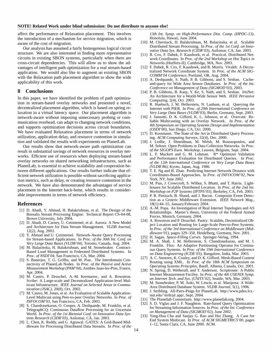
Node Stress. The experiment in Figure 15 investigates thedistribution of placed services (i.e. the load) across the physi-cal nodes in a600-node transit-stub topology with3 transit do-mains and72 stub domains. In (a), the topology is shown inlatency space with the transit domains at the center. (b) Randomplacement of1000 simple circuits does not create any load peaksbecause of the uniform placement of unpinned services. How-ever, (c) Optimal placement identifies that placing unpinned ser-
(a) Topology in latency space
0
50
100
150
200
250
300
(b) Random placement
0
50
100
150
200
250
300
(c) Optimal placement
0
50
100
150
200
250
300
(d) Relaxation placement
0
50
100
150
200
250
300
(e) IP Multicast placement
Figure 15:Load maps for different placement algorithms.
vices in transit domains results in more efficient network utiliza-tion. When consumers and producers are randomly distributed inthe network, most traffic must flow through the transit domains.Therefore, placing services there does not consume additionalnetwork bandwidth. The3 transit domains in the network topol-ogy are visible as peaks in the load map. (d) Relaxation and(e) IP Multicast placement also prefer transit domains for ser-vice placement, although not as strongly as Optimal placement.
As mentioned before, any efficient placement algorithm mustcap the number of unpinned services that can be placed at a phys-ical node. The plots in Figure 16 show how the concentrationof service placement in transit domains caused by Relaxationplacement can be reduced through a threshold on the maximumnumber of services,Loadmax, that can be hosted at a physicalnode. As the load threshold is lowered, more services are placedsub-optimally outside the transit domains and move into the stubdomains, reducing load at the center of the topology.
Of course, the impossibility of placing unpinned services atthe desired physical nodes reduces the efficiency of the place-ment algorithm. In Figure 17, the graph illustrates how a max-imum load thresholdLoadmax affects the network efficiency ofRelaxation placement. Efficiency is expressed as the BW-Latproduct after placing1000 simple circuits in a1550-node transit-stub topology. As can be seen from the plot, the loss in efficiencystarts increasing substantially after a low load threshold of about40 services. However, the placement efficiency still remains bet-ter compared to IP Multicast, which is included for comparison.
Link Stress. Another network resource that may prevent theplacement of a circuit link on a network path is link stress. Wedefined link stress as the total amount of traffic that traverses aphysical link. Figure 18 shows the distribution of link stress asa CDF in a1550-node transit-stub topology after creating1000simple circuits for different placement algorithms. The figureshows that Optimal, IP Multicast, and Relaxation placement cre-
10

NOTE! Related Work under blind submission: Do not distribute to anyone else!
0
50
100
150
200
250
300
(a) Loadmax = 100
0
50
100
150
200
250
300
(b) Loadmax = 66
0
50
100
150
200
250
300
(c) Loadmax = 33
0
50
100
150
200
250
300
(d) Loadmax = 10
Figure 16:Load maps for relaxation placement with differentload thresholdsLoadmax.
1.8e+06
1.9e+06
2e+06
2.1e+06
2.2e+06
2.3e+06
2.4e+06
0 50 100 150 200
Relaxation Placement
Optimal Placement
IP Multicast Placement
Maximum load threshold
BW
-La
t p
rod
uc
t (i
n K
B)
Figure 17: BW-Lat product for Relaxation placement as afunction of load threshold Loadmax.
ate overall less link stress through better utilization of the under-lying network. For Relaxation placement,80 % of all physicallinks use less than30 KB/s, compared to46 KB/s with Con-sumer placement.
A lower maximum link stress with a particular placement al-gorithm directly translates into a larger number of circuits thatcan be handled by the SBON. To illustrate this point, Table 4shows the maximum number of circuits that can be added toan SBON under a particular placement algorithm when there isa cap on the bandwidth usage of all physical links in the net-work. If all physical links in the network topology are restrictedto Linkmax = 400 KB/s, Random placement is able to placeonly 69 % of the circuits placed by Optimal placement. Relax-
Algorithm Num. of circuitsOptimal 844IP Multicast 717Relaxation 799Producer 675Consumer 680Random 585
Table 4:Number of placed circuits with maximum link stressthreshold, Linkmax = 400KB/s.
0
10
20
30
40
50
60
70
80
90
100
1 10 100 1000
Optimal
Optimal
IP Multicast
IP Multicast
Relaxation
Relaxation
Producer
Producer
Consumer
Consumer
Random
Random
Link stress (in KB/s)
Pe
rce
nta
ge
of
ph
ysic
al l
inks
Figure 18:Distribution of link stress for different placementalgorithms. Note that the x-axis uses a log scale.
Europe
US East
US West
Asia
Figure 19: Visualization of latency space for PlanetLabnodes.
ation placement achieves a much higher rate of95 %.
5.4 PlanetLab SetupTo validate the results obtained from our simulator on a transit-stub topology, we evaluated the different placement algorithmswith an SBON deployed onPlanetLab [31]. PlanetLab is aglobal, distributed test-bed that currently encompasses434 ma-chines located on5 continents. To give an idea for the PlanetLabtopology, the plot in Figure 19 depicts147 PlanetLab nodes inlatency space created from all-pairs ping measurements betweennodes [30]. As shown by the annotations, four clusters of nodescan be identified that correspond to nodes located on the US Eastcoast, the US West coast, in Europe, and in Asia. The networkdiameter for the PlanetLab topology is2074 ms.
As a recent survey has shown [5], the PlanetLab topology isnot an unbiased cross-section of the Internet but rather has anemphasis on well-provisioned, educational networks. Neverthe-less, its wide-area topology allows a qualitative verification ofour simulator results. In general, efficient network utilizationis important on PlanetLab because it is heavily shared amongmany parties so that efficient path optimization of an SBON de-ployed on PlanetLab directly benefits other applications. Oneof the challenges of PlanetLab experiments to evaluate path op-timization is that the physical network topology is not known.Although preliminary work to map the PlanetLab exists [23], weneeded to perform our own real-time measurements that inferedaspects of the PlanetLab topology. Circuits on PlanetLab were
11

NOTE! Related Work under blind submission: Do not distribute to anyone else!
0
10
20
30
40
50
60
70
80
90
100
0 0.05 0.1 0.15 0.2 0.25
PlanetlabTransit-Stub ts-1550
Placement error as ratio of network diameter
Pe
rce
nta
ge
of
circ
uit
s
Figure 20: Distribution of placement error when mappingfrom latency space to physical space.
created with a distributed stream-processing infrastructure.2
The setup for our PlanetLab experiments was as follows. Weused our simulator to build the Vivaldi latency space using all-pairs ping measurements. We then placed1000 simple circuitsoff-line according to different placement strategies, with pinnedservices randomly distributed across the network. The simulatoroutput an XML file, which then controlled the deployment of thestream-processing system on PlanetLab and set up circuits ac-cording to the calculated placement. Only one circuit was activein the system at a time. The quality of the placement was eval-uated through measurements on Planetlab usingScriptroute[28](for network utilization) and the stream-processing applicationitself (for delay penalty). We had no restriction on the number ofservices running on a node, but limited the candidate set of phys-ical nodes to those running ScriptRoute and for which all-pairsping data was available.
5.5 Planetlab ResultsBefore comparing Relaxation placement to other placement al-gorithms on Planetlab, we realized that its performance dependson the error introduced when mapping a placement from latencyspace to nodes in physical space, as explained in Section 4.3. Tocompare the suitability of Relaxation placement for the transit-stub and Planetlab topologies, Figure 20 plots the distribution ofthemapping error. The mapping error is defined as the fractionof the network diameter by which a physical node’s network co-ordinate used for placement differs from the desired coordinate.
The plot shows that the mapping error for the Planetlab topol-ogy is smaller than for the transit-stub topology. This is un-derstandable because the transit-stub topology in latency spacehas large volumes between stub domains that do not containany nodes. However, even the worst case mapping error for thetransit-stub topology is below13 %. The Planetlab topology ismore applicable to Relaxation placement as nodes are more uni-formly distributed.
5.5.1 Network UtilizationBandwidth-Latency Product. The first PlanetLab experi-
ment verifies the simulation results about network utilization interms of the BW-Lat product. For this, we measured the latencyof circuit links between PlanetLab nodes using Scriptroute. The
2Details omitted to preserve anonymity.
10
20
30
40
50
60
70
80
90
100
0 500 1000 1500 2000 2500 3000
OptimalRelaxtionProducer
ConsumerRandom
BW-Lat product (in KB)
Pe
rce
nta
ge
of
circ
uit
s
Figure 21: Distribution of BW-Lat product as measured onPlanetLab.
0
10
20
30
40
50
60
70
80
90
100
50 100 150 200 250 300 350 400 450 500
OptimalRelaxation
ProducerConsumer
Random
Pe
rce
nta
ge
of
circ
uit
s
BW-HC product
Figure 22: Distribution of BW-HC product as measured onPlanetLab.
CDF of the measurements is shown in Figure 21. The results re-flect our simulated predictions in Figure 9. Relaxation placementachieves a reduction of19 % in the amount of network traffic for90 % of the circuits when compared to Producer placement.
Bandwidth-Hop Count Product. We also considered the ef-fect of our placement algorithms on the BW-HC product onPlanetLab. To approximate the true physical hop count betweentwo nodes on PlanetLab, we used Scriptroute to collect 16,000traceroutes between118 PlanetLab nodes over several days. Al-though this is an approximation of physical hop count since notall routers are visible at the IP-level and routing paths change,we believe that is a reasonable indicator of true hop count.
The CDF plots for circuits with6 producers in Figure 22 showthat Relaxation placement performs better than Consumer place-ment. It is interesting to see that Producer placement achievesa lower BW-HC product than simulation. A possible explana-tion for this is that, since most institutions only host2 Planet-Lab nodes, placing a service on a remote node almost alwayscauses the path to leave the currentautonomous system(AS).However, routing to another autonomous system incurs a muchhigher overhead in terms of hop count when compared to intra-AS routing. To verify this, we ran this experiment with6 insteadof 4 producers per circuit, which reduces the efficiency of Pro-ducer placement.
12

NOTE! Related Work under blind submission: Do not distribute to anyone else!
0
10
20
30
40
50
60
70
80
90
100
0 200 400 600 800 1000 1200 1400
Pe
rce
nta
ge
of
circ
uit
s
Latency (in ms)
Optimal Relaxation
Producer Consumer
Random
Figure 23: Distribution of delay stretch as measured onPlanetLab.
5.5.2 Delay PenaltyThe final PlanetLab experiment explores the application-observed delay penalty of Relaxation placement. In this exper-iment, we determine the longest path latency from a consumerservice to any of the producers in a circuit. The longest path de-lay is obtained by a simple stream-processing application, whichmeasures the round-trip time of time-stamped messages througha circuit. The CDF of the average longest path delay can be seenin Figure 23. As expected, Consumer placement results in cir-cuits with lowest average latency. The plot has a very heavy tail;the longest delay, equal to the network delay plus applicationprocessing time, is around 6 seconds for Random placement.We also observe that for most circuits, the cost of Relaxationplacement, in terms of delay penalty, is not high. In fact, Relax-ation placement performs comparably to Consumer placement,and out-performs Random and Producer placements.
5.5.3 SummaryEven though the physical topology of PlanetLab is not avail-able, we believe that the results from our PlanetLab measure-ments confirm the performance evaluation in the simulator witha transit-stub topology. For three cost metrics (BW-Lat, BW-HC,and delay stretch), the evaluated placement algorithms performas expected. This means that an SBON deployed on PlanetLabthat uses Relaxation placement can achieve substantial savings interms of network utilization, while keeping the application delaypenalty low.
6 Related WorkIn this section, we give an overview of work related to path opti-mization in stream-based overlay networks.
Distributed stream processing systems, such asMedusa [10] and Borealis [1], are faced with the path op-timization problem when placing stream operators. Data pathsin Medusa are controlled by contracts for load management [4]that take node properties into account but are not network-aware.The work onnetwork-aware query processing[3] for Borealis isclosest to ours. Here, operators are either placed at the consumerside, at the producer side, or in-network on the DHT routingpath, depending on the network bandwidth usage for a query.Applications can also specify delay constraints on the placementpath in the DHT. By performing in-network placement in
latency space, our approach has more freedom in choosing agood placement node without having the restriction of followingDHT routing paths. In addition, Relaxation placement supportsdynamic, global path optimization across circuits and considersnode and link stress. Other stream processing systems, suchasGATES[9], avoid the problem of data path optimization bysupporting only pre-defined locations with pinned services inthe SBON. This leaves the burden of efficient data path selectionwith the system administrator. The work onmesh-based XMLrouting [27] uses an SBON for content-based routing of XMLdocuments. XML routers create an overlay mesh for streamingdata to clients. However, the topology of the mesh does notreflect the structure of individual queries in order to use theunderlying network resources efficiently.DistCED [22] is adistributed system for pattern detection in message streams.Pattern detectors in the overlay network are placed at distributednodes according to placement heuristics called distributionpolicies, minimizing different performance metrics. However,no evaluation of the system is provided.
Distributed databasespartition data across multiple nodes.The placement of query operators is then often driven by the lo-cation of the data [17]. InIrisNet [14], semi-structured data frommultiple sensor networks is partitioned hierarchically amongnodes. Stream queries contact all nodes that are relevant tothe query [13]. Our approach is complementary by installingqueries at suitable locations and streaming data to operators.The location of operators (and corresponding relational tables)in PIER [15], a distributed database built on top of a DHT, isdetermined through hashing. Such a random distribution hasgood load-balancing properties but uses the underlying networkresources inefficiently.Mariposa [29] is a distributed databasesystem that follows a market-based approach with economictechniques for a decentralized implementation of the query op-timization problem. However, global network costs, such asnetwork utilization, are not addressed. More recent efforts onrate-based query optimization[32] and intelligentpartitioningof streams[26] are directly applicable to our work when makinglocal placement decisions for services.
Content distribution networks build an overlay network forefficiently disseminating data to many parties, which requiresa network-aware selection for the location of multicast nodes.Narada [33] is an application-level multicast (ALM) system,which builds a multicast tree out of an overlay mesh. The authorsintroduced the issue of network efficiency and defined metrics toquantify resource usage, which are similar to ours. The over-lay mesh is optimized dynamically but cannot be optimized atthe granularity of a single circuit as in our approach because themesh is shared among applications.Overcast[16] is an ALMscheme, which maximizes total bandwidth for content distri-bution but does not deal with global network utilization. Pub-lish/subscribe systems, such asScribe[6, 7], are built on top ofa DHT and rely on hashing for routing path selection.
7 Future WorkThis paper has introduced a novel path placement scheme that isable to optimize an SBON with cross-circuit dependencies. Weare currently working on a fully decentralized implementation ofRelaxation placement that is deployable on PlanetLab. With this,we will explore cross-circuit optimization, which is supported byour current algorithm, on a global scale. In addition, we plan toinvestigate how physical network and logical circuit dynamics
13
NOTE! Related Work under blind submission: Do not distribute to anyone else!
affect the performance of Relaxation placement. This involvesthe introduction of a mechanism for service migration, which isaware of the cost of migration.
Our analysis has assumed a fairly homogenous logical circuitstructure. We are also interested in finding more representativecircuits in existing SBON systems, particularly when there arecross-circuit dependencies. This will allow us to show the ad-vantages of intelligent path optimization for a real stream-basedapplication. We would also like to augment an existing SBONwith the Relaxation path placement algorithm to show the wideapplicability of this work.
8 ConclusionsIn this paper, we have identified the problem of path optimiza-tion in stream-based overlay networks and presented a novel,decentralized placement algorithm, which is based on spring re-laxation in a virtual latency space. Our placement algorithm isnetwork-aware without imposing unnecessary probing or com-munication overhead, can adapt to changing network conditions,and supports optimization decisions across circuit boundaries.We have evaluated Relaxation placement in terms of networkutilization, application delay, and resource contention in simula-tion and validated the results with experiments on PlanetLab.
Our results show that network-aware path optimization canresult in substantial savings of network resources in overlay net-works. Efficient use of resources when deploying stream-basedoverlay networks on shared networking infrastructures, such asPlanetLab, is essential to achieve scalability and cooperation be-tween different applications. Our results further indicate that ef-ficient network utilization is possible without sacrificing applica-tion metrics, such as delay, or creating resource contention in thenetwork. We have also demonstrated the advantages of serviceplacement in the Internet back-bone, which results in consider-able improvements in terms of network efficiency.
References[1] D. Abadi, Y. Ahmad, H. Balakrishnan, et al. The Design of the
Borealis Stream Processing Engine. Technical Report CS-04-08,Brown University, July 2004.
[2] D. Abadi, D. Carney, U. Cetintemel, et al. Aurora: A New Modeland Architecture for Data Stream Management.VLDB Journal,12(2), Aug. 2003.
[3] Y. Ahmad and U. Cetintemel. Network-Aware Query Processingfor Stream-based Applications. InProc. of the 30th Int. Conf. onVery Large Data Bases (VLDB’04), Toronto, Canada, Aug. 2004.
[4] M. Balazinska, H. Balakrishnan, and M. Stonebraker. Contract-Based Load Management in Federated Distributed Systems. InProc. of NSDI’04, San Francisco, CA, Mar. 2004.
[5] S. Banerjee, T. G. Griffin, and M. Pias. The Interdomain Con-nectivity of PlanetLab Nodes. InProc. of the Passive and ActiveMeasurement Workshop (PAM’04), Antibes Juan-les-Pins, France,Apr. 2004.
[6] M. Castro, P. Druschel, A.-M. Kermarrec, and A. Rowstron.Scribe: A Large-scale and Decentralized Application-level Mul-ticast Infrastructure.IEEE Journal on Selected Areas in Commu-nication (JSAC), 20(8), Oct. 2002.
[7] M. Castro, M. Jones, et al. An Evaluation of Scalable Application-Level Multicast using Peer-to-peer Overlay Networks. InProc. ofINFOCOM’03, San Francisco, CA, Feb. 2003.
[8] S. Chandrasekaran, O. Cooper, A. Deshpande, M. Franklin, et al.TelegraphCQ: Continuous Dataflow Processing for an UncertainWorld. In Proc. of the 1st Biennial Conf. on Innovative Data Sys-tems Research (CIDR’03), Asilomar, CA, Jan. 2003.
[9] L. Chen, K. Reddy, and G. Agrawal. GATES: A Grid-Based Mid-dleware for Processing Distributed Data Streams. InProc. of the
13th Int. Symp. on High-Performance Dist. Comp. (HPDC-13),Honolulu, Hawaii, June 2004.
[10] M. Cherniack, H. Balakrishnan, M. Balazinska, et al. ScalableDistributed Stream Processing. InProc. of the 1st Conf. on Inno-vative Data Sys. Research (CIDR’03), Asilomar, CA, Jan. 2003.
[11] R. Cox, F. Dabek, F. Kaashoek, et al. Practical, Distributed Net-work Coordinates. InProc. of the 2nd Workshop on Hot Topics inNetworks (HotNets-II), Cambridge, MA, Nov. 2003.
[12] F. Dabek, R. Cox, F. Kaashoek, and R. Morris. Vivaldi: A Decen-tralized Network Coordinate System. InProc. of the ACM SIG-COMM’04 Conference, Portland, OR, Aug. 2004.
[13] A. Deshpande, S. Nath, P. B. Gibbons, and S. Seshan. Cache-and-query for Wide Area Sensor Databases. InProc. of the Int.Conference on Management of Data (SIGMOD’03), 2003.
[14] P. B. Gibbons, B. Karp, Y. Ke, S. Nath, and S. Seshan. IrisNet:An Architecture for a World-Wide Sensor Web.IEEE PervasiveComputing, 2(4), Oct. 2003.
[15] R. Huebsch, J. M. Hellerstein, N. Lanham, et al. Querying theInternet with PIER. InProc. of 29th International Conference onVery Large Data Bases (VLDB’03), Berlin, Germany, Sept. 2003.
[16] J. Jannotti, D. K. Gifford, K. L. Johnson, et al. Overcast: Re-liable Multicasting with an Overlay Network. InProc. of the4th Symposium on Operating Systems Design and Implementation(OSDI’00), San Diego, CA, Oct. 2000.
[17] D. Kossmann. The State of the Art in Distributed Query Process-ing. ACM Computing Surveys, 32(4), Dec. 2000.
[18] J. Ledlie, J. Shneidman, M. Welsh, M. Roussopoulos, andM. Seltzer. Open Problems in Data Collection Networks. InProc.of the SIGOPS Euro. Workshop, Leuven, Belgium, Sept. 2004.
[19] L. F. Mackert and G. M. Lohman. R* Optimizer Validationand Performance Evaluation for Distributed Queries. InProc.of the 12th International Conference on Very Large Data Bases(VLDB’86), Kyoto, Japan, Aug. 1986.
[20] T. E. Ng and H. Zhan. Predicting Internet Network Distance withCoordinates-Based Approaches. InProc. of INFOCOM’02, NewYork, NY, June 2002.
[21] M. Pias, J. Crowcroft, S. Wilbur, S. Bhatti, and T. Harris. Light-houses for Scalable Distributed Location. InProc. of the 2nd Int.Workshop on P2P Systems (IPTPS’03), Berkeley, CA, Feb. 2003.
[22] P. R. Pietzuch, B. Shand, and J. Bacon. Composite Event Detec-tion as a Generic Middleware Extension.IEEE Network Mag.,18(1):44–55, January/February 2004.
[23] A.-M. Popa. An Investigation of Real Internet Topologies and ASRelationships. Master’s thesis, University of the Federal ArmedForces, Munich, Germany, 2004.
[24] A. Rowstron and P. Druschel. Pastry: Scalable, Decentralized Ob-ject Location and Routing for Large-Scale Peer-to-Peer Systems.In Proc. of the 3rd International Conference on Middleware (Mid-dleware’01), pages 329–350, Heidelberg, Germany, Nov. 2001.
[25] H. Sagan.Space-Filling Curves. Springer-Verlag, 1994.[26] M. A. Shah, J. M. Hellerstein, S. Chandrasekaran, and M. J.
Franklin. Flux: An Adaptive Partitioning Operator for Continu-ous Query Systems. InProc. of the 19th International Conferenceon Data Engineering (ICDE’03), Bangalore, India, Mar. 2003.
[27] A. C. Snoeren, K. Conley, and D. K. Gifford. Mesh-Based ContentRouting using XML. InProc. of the 18th ACM Symposium onOperating Systems Principles, Banff, Alberta, Canada, Oct. 2001.
[28] N. Spring, D. Wetherall, and T. Anderson. Scriptroute: A PublicInternet Measurement Facility. InProc. of the 4th USENIX Symp.on Internet Tech. and Sys. (USITS’02), Seattle, WA, Mar. 2003.
[29] M. Stonebraker, P. M. Aoki, W. Litwin, et al. Mariposa: A Wide-Area Distributed Database System.VLDB Journal, 5(1), 1996.
[30] J. Stribling. All-Pairs-Pings for PlanetLab. http://www.pdos.lcs.-mit.edu/˜strib/plapp/, Sept. 2004.
[31] The Planetlab Consortium. http://www.planetlab.org, 2004.[32] S. D. Viglas and J. F. Naughton. Rate-based Query Optimization
for Streaming Information Sources. InProc. of the Int. Conferenceon Management of Data (SIGMOD’02), June 2002.
[33] Yang-Hua Chu and Sanjay G. Rao and Hui Zhang. A Case forEnd System Multicast. InProc. of ACM SIGMETRICS’00, pages1–12, Santa Clara, CA, June 2000. ACM.
14

NOTE! Related Work under blind submission: Do not distribute to anyone else!
[34] E. W. Zegura, K. L. Calvert, and S. Bhattacharjee. How to Modelan Internetwork. InProc of IEEE Infocom’96, volume 2, pages594–602, San Francisco, CA, Mar. 1996.
15