past, present and future of aerial robotic manipulators - hal
TRANSCRIPT
HAL Id: hal-03255846https://hal.laas.fr/hal-03255846
Submitted on 9 Jun 2021
HAL is a multi-disciplinary open accessarchive for the deposit and dissemination of sci-entific research documents, whether they are pub-lished or not. The documents may come fromteaching and research institutions in France orabroad, or from public or private research centers.
L’archive ouverte pluridisciplinaire HAL, estdestinée au dépôt et à la diffusion de documentsscientifiques de niveau recherche, publiés ou non,émanant des établissements d’enseignement et derecherche français ou étrangers, des laboratoirespublics ou privés.
Past, Present and Future of Aerial Robotic ManipulatorsAnibal Ollero, Marco Tognon, Alejandro Suarez, Dongjun Lee, Antonio
Franchi
To cite this version:Anibal Ollero, Marco Tognon, Alejandro Suarez, Dongjun Lee, Antonio Franchi. Past, Presentand Future of Aerial Robotic Manipulators. IEEE Transactions on Robotics, IEEE, 2021,�10.1109/TRO.2021.3084395�. �hal-03255846�
Preprint version final version at http://ieeexplore.ieee.org/ Accepted for IEEE Transaction on Robotics 2021
Past, Present and Future of Aerial RoboticManipulators
Anibal Ollero, Fellow, IEEE, Marco Tognon, Member, IEEE, Alejandro Suarez, Member, IEEE,Dongjun Lee, Member, IEEE, and Antonio Franchi, Senior member, IEEE
Abstract—This paper analyzes the evolution and current trendsin aerial robotic manipulation, comprising helicopters, conven-tional under-actuated multi-rotors and multi-directional thrustplatforms equipped with a wide variety of robotic manipula-tors capable of physically interacting with the environment. Italso covers cooperative aerial manipulation and interconnectedactuated multi-body designs. The review is completed withdevelopments in teleoperation, perception and planning. Finally,a new generation of aerial robotic manipulators is presented withour vision of the future.
Index Terms—Aerial Manipulation, Aerial Robots PhysicallyInteracting with the Environment, Unmanned Aerial Vehicles
I. INTRODUCTION
THE field of aerial robots physically interacting with theenvironment, and particularly AErial RObotic Manip-
ulators (AEROMs), has experienced ten years of sustainedgrowth. Diverse prototypes, functionalities and capabilitieshave been developed and evaluated in representative indoorand outdoor scenarios, demonstrating the possibility to suc-cessfully perform manipulation tasks while flying. The abilityof aerial manipulators to quickly reach and operate in highaltitude workspaces, along with the level of maturity reachedin recent years, led to the application of this technology inareas like inspection and maintenance, reducing time, cost andrisk for the human workers. In this sense, this paper aims atproviding a broad perspective and analysis of the work donein aerial manipulation, possibly helping engineers interestedin designing an aerial manipulation robot for a specific task.
Reviewing the main achievements in this field, it is possibleto identify common features that allow defining the classifica-tion proposed in Table I. Figure 1 shows the evolution of aerialmanipulator designs in the last decade, although early achieve-ments can be also found in the 90s with the disc lifting missionat the International Aerial Robotics Competition.1 The firstgeneration of aerial manipulators consisted of conventionalquadrotors capable of applying forces to a wall while keepingflight stability [1], grasping objects [2] and constructing cubicstructures [3] with an embedded arm with few Degrees of
A. Ollero and A. Suarez are with the GRVC Robotics Lab, Universidad deSevilla, 41012 Sevilla,Spain. E-mail: [email protected] (see https://grvc.us.es)
M. Tognon is with the Autonomous Systems Lab, ETH Zurich, 8092 Zurich,Switzerland. E-mail: [email protected]
D. Lee is with the Department of Mechanical Engineering, IAMD and IER,Seoul National University, Republic of Korea. e-mail [email protected]
A. Franchi is with the Robotics and Mechatronics lab, EEMCS Faculty, Uni-versity of Twente, Enschede, The Netherlands and with LAAS-CNRS, Uni-versite de Toulouse, CNRS, Toulouse, France. e-mail: [email protected]
1http://www.aerialroboticscompetition.org/mission1.php
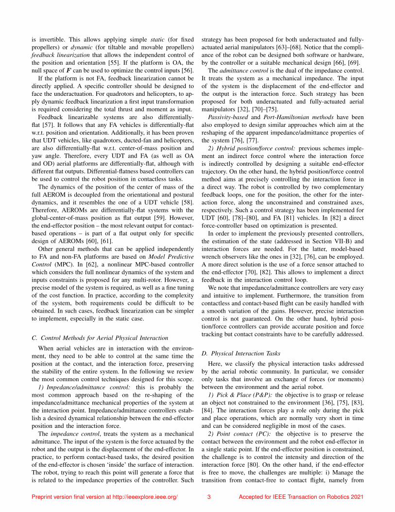
TABLE I: Generations of aerial robotic manipulators.
1st Gen. 2nd Gen. 3rd Gen.
Platforms HelicoptersQuadrotors
HelicoptersMulti-rotors
Multi-rotors:fully actuated,multibody
Arms Few DoFs 6/7 DoFsCompliance
Dual armsHyper-redundant
Navigation Motion trackingsystem
Indoor beaconsGPS SLAM
Perception No onboard mo-tion tracking
Onboard withmarkers
Onboard withoutmarkers
Planning No planning Ground stationBasic reaction
On-boardReactivity
Freedom (DoFs). Less conventional designs started to appear:[4] presents the modeling and control of a ducted-fan miniatureUAV interacting with the environment; a 6 DoFs gantry craneequipped with two 4 DoFs manipulators was also proposedin [5]; and a three-active-DoFs delta-like manipulator with athree-passive-DoFs end-effector installed on a quadrotor wasdeveloped in [6]. These prototypes employed motion trackingsystems for positioning in indoors [7]–[10], without relevantperception and planning.
Helicopters played an important role in the development ofthe aerial manipulation with early works in outdoors appliedto load transportation [11]–[13], interaction with the environ-ment [14], [15], and manipulation [16]–[18], showing betterperformance than multi-rotors in terms of payload capacityand operation time. However, the use of multi-rotors spread infollowing years because the control, mechanical constructionand handling of these platforms are significantly simpler, andallow to mitigate safety problems associated to the blades ofthe helicopters main rotor.
The second generation includes adapted aerial platforms forboth indoor and outdoor operations, equipped with rigid andcompliant arms (up to 6/7 DoFs) for precise end-effector posi-tioning and compensation of perturbations. They also integrateoutdoor navigation sensors based on GNSS (Global NavigationSatellite System), indoor navigation features based on beacons,on-board perception with markers, and off-board planningfeatures. Outdoor experiments involving grasping with 7 DoFsarms with both helicopters [19] and multi-rotors [20] werepresented. Different arm designs have been introduced as well,including parallel manipulators with a large singularity-freeworkspace [21] for precise end-effector positioning relativeto a target [22], or a hyper-redundant manipulator for mobilemanipulating UAVs [23]. Attention was also paid to controltechniques validated in simulation [24]. In [25] a frameworkfor outdoor aerial manipulation is presented. Regarding vision-
1
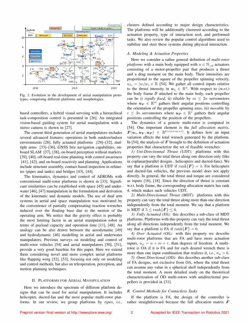
Fig. 1: Evolution in the development of aerial manipulation proto-types, comprising different platforms and morphologies.
based controllers, a hybrid visual servoing with a hierarchicaltask-composition control is presented in [26]. An integratedvision-based guiding system for aerial manipulation with astereo camera is shown in [27].
The current third generation of aerial manipulators includesseveral advanced features: operations in both outdoor/indoorenvironments [28], fully actuated platforms [29]–[32], mul-tiple arms [33]–[36], GNSS free navigation capabilities, on-board SLAM [37], [38], on-board perception without markers[39], [40], off-board real-time planning with control awareness[41], [42], and on-board reactivity and planning. Applications
include structure assembly, contact-based inspection in refiner-ies (pipes and tanks) and bridges [43], [44].
The kinematics, dynamics and control of AEROMs withconventional multi-rotor platforms is shown in [33]. Signifi-cant similarities can be established with space [45] and under-water [46], [47] manipulation in the formulation and derivationof the kinematic and dynamic models. The use of dual armsystems in aerial and space manipulation was motivated bythe convenience of partially compensating reaction wrenchesinduced over the floating base due to the motion of theoperating arm. We notice that the gravity effect is probablythe most limiting factor in an aerial manipulation robot interms of payload capacity and operation time [11], [48]. Ananalogy can be also drawn between the aerodynamic [49]and hydrodynamic [46] modelling in aerial and underwatermanipulators. Previous surveys on modeling and control ofmulti-rotor vehicles [54] and aerial manipulators [50], [51],provide a very good baseline for this paper. Here we extendthem considering novel and more complex aerial platformslike flapping wing [52], [53], focusing not only on modelingand control methods, but also on teleoperation, perception, andmotion planning techniques.
II. PLATFORMS FOR AERIAL MANIPULATION
Here we introduce the spectrum of different platform de-signs that can be used for aerial manipulation. It includeshelicopter, ducted-fan and the most popular multi-rotor plat-forms. In our review, we group platforms by types, i.e.,
clusters defined according to major design characteristics.The platforms will be additionally clustered according to theactuation property, type of interaction tool, and performedtasks. We also review the popular control algorithms used tostabilize and steer these systems during physical interaction.
A. Modeling & Actuation PropertiesHere we consider a rather general definition of multi-rotor
platforms with a main body equipped with n ∈ N>0 actuatorsconsisting of a motor-propeller pair that produces a thrustand a drag moment on the main body. Their intensities areproportional to the square of the propeller spinning velocity,uλi
= |wi|wi ∈ R [54]. We gather all control inputs relativeto the thrust intensity in uλ ∈ Rn. With respect to (w.r.t.)the body frame B attached to the main body, each propellercan be i) rigidly fixed, ii) tiltable by m ≤ 2n servomotorswhere uV ∈ Rm gathers their angular positions controllingthe orientation of the propeller spinning axes, iii) movable byr ≤ 3n servomotors where uP ∈ Rr gathers their angularpositions controlling the position of the propellers.
The dynamics of a generic multi-rotor is computed in[54]. One important element is the full allocation matrix,F (uλ,uV ,uP ) ∈ R6×(n+m+r). It defines how an inputvariation affects the total wrench generated by the platform.In [54], the analysis of F brought to the definition of actuationproperties that characterize the set of feasible wrenches:
1) Uni-Directionnal Thrust (UDT): platforms with thisproperty can vary the total thrust along one direction only (likein coplanar/parallel designs , helicopters and ducted-fans). Wesay that a platform is UDT if rank{F } = 4. For helicoptersand ducted-fan vehicles, the previous model does not applydirectly. In general, the total thrust and torque are consideredas inputs [16], [18]. Since the direction of thrust is constantw.r.t. body frame, the corresponding allocation matrix has rank4, which makes such vehicles UDT.
2) Multi-Directionnal Thrust (MDT): platforms with thisproperty can vary the total thrust along more than one directionindependently from the total moment. We say that a platformis MDT if 5 ≤ rank{F } ≤ 6.
3) Fully Actuated (FA): this describes a sub-class of MDTplatforms. Platforms with this property can vary the total thrustalong all directions independently from the total moment. Wesay that a platform is FA if rank{F } = 6.
4) Over Actuated (OA): with this property we describemulti-rotor platforms that are FA and have more actuationinputs, nu = n +m + r, than degrees of freedom. A multi-rotor is OA if it is FA and for each desired wrench there ismore than one input combination that realizes it, i.e., nu > 6.
5) Omni Directional (OD): this describes another sub-classof FA designs, not exclusive from OA, where the total thrustcan assume any value in a spherical shell independently fromthe total moment. A more detailed study on the theoreticalcharacterization of OD multi-rotors with unidirectional pro-pellers is provided in [31].
B. Control Methods for Contactless TasksIf the platform is FA, the design of the controller is
rather straightforward because the full allocation matrix F
Preprint version final version at http://ieeexplore.ieee.org/ 2 Accepted for IEEE Transaction on Robotics 2021
is invertible. This allows applying simple static (for fixedpropellers) or dynamic (for tiltable and movable propellers)feedback linearization that allows the independent control ofthe position and orientation [55]. If the platform is OA, thenull space of F can be used to optimize the control inputs [56].
If the platform is not FA, feedback linearization cannot bedirectly applied. A specific controller should be designed toface the underactuation. For quadrotors and helicopters, to ap-ply dynamic feedback linearization a first input transformationis required considering the total thrust and moment as input.
Feedback linearizable systems are also differentially-flat [57]. It follows that any FA vehicles is differentially-flatw.r.t. position and orientation. Additionally, it has been proventhat UDT vehicles, like quadrotors, ducted-fan and helicopters,are also differentially-flat w.r.t. center-of-mass position andyaw angle. Therefore, every UDT and FA (as well as OAand OD) aerial platforms are differentially-flat, although withdifferent flat outputs. Differential-flatness based controllers canbe used to control the robot position in contactless tasks.
The dynamics of the position of the center of mass of thefull AEROM is decoupled from the orientational and posturaldynamics, and it resembles the one of a UDT vehicle [58].Therefore, AEROMs are differentially-flat systems with theglobal-center-of-mass position as flat output [59]. However,the end-effector position – the most relevant output for contact-based operations – is part of a flat output only for specificdesign of AEROMs [60], [61].
Other general methods that can be applied independentlyto FA and non-FA platforms are based on Model PredictiveControl (MPC). In [62], a nonlinear MPC-based controllerwhich considers the full nonlinear dynamics of the system andinputs constraints is proposed for any multi-rotor. However, aprecise model of the system is required, as well as a fine tuningof the cost function. In practice, according to the complexityof the system, both requirements could be difficult to beobtained. In such cases, feedback linearization can be simplerto implement, especially in the static case.
C. Control Methods for Aerial Physical Interaction
When aerial vehicles are in interaction with the environ-ment, they need to be able to control at the same time theposition at the contact, and the interaction force, preservingthe stability of the entire system. In the following we reviewthe most common control techniques designed for this scope.
1) Impedance/admittance control: this is probably themost common approach based on the re-shaping of theimpedance/admittance mechanical properties of the system atthe interaction point. Impedance/admittance controllers estab-lish a desired dynamical relationship between the end-effectorposition and the interaction force.
The impedance control, treats the system as a mechanicaladmittance. The input of the system is the force actuated by therobot and the output is the displacement of the end-effector. Inpractice, to perform contact-based tasks, the desired positionof the end-effector is chosen ‘inside’ the surface of interaction.The robot, trying to reach this point will generate a force thatis related to the impedance properties of the controller. Such
strategy has been proposed for both underactuated and fully-actuated aerial manipulators [63]–[68]. Notice that the compli-ance of the robot can be designed both software or hardware,by the controller or a suitable mechanical design [66], [69].
The admittance control is the dual of the impedance control.It treats the system as a mechanical impedance. The inputof the system is the displacement of the end-effector andthe output is the interaction force. Such strategy has beenproposed for both underactuated and fully-actuated aerialmanipulators [32], [70]–[75].
Passivity-based and Port-Hamiltonian methods have beenalso employed to design similar approaches which aim at thereshaping of the apparent impedance/admittance properties ofthe system [76], [77].
2) Hybrid position/force control: previous schemes imple-ment an indirect force control where the interaction forceis indirectly controlled by designing a suitable end-effectortrajectory. On the other hand, the hybrid position/force controlmethod aims at precisely controlling the interaction force ina direct way. The robot is controlled by two complementaryfeedback loops, one for the position, the other for the inter-action force, along the unconstrained and constrained axes,respectively. Such a control strategy has been implemented forUDT [60], [78]–[80], and FA [81] vehicles. In [82] a directforce-controller based on optimization is presented.
In order to implement the previously presented controllers,the estimation of the state (addressed in Section VII-B) andinteraction forces are needed. For the latter, model-basedwrench observers like the ones in [32], [76], can be employed.A more direct solution is the use of a force sensor attached tothe end-effector [70], [82]. This allows to implement a directfeedback in the interaction control loop.
We note that impedance/admittance controllers are very easyand intuitive to implement. Furthermore, the transition fromcontactless and contact-based flight can be easily handled witha smooth variation of the gains. However, precise interactioncontrol is not guaranteed. On the other hand, hybrid posi-tion/force controllers can provide accurate position and forcetracking but contact constraints have to be carefully addressed.
D. Physical Interaction Tasks
Here, we classify the physical interaction tasks addressedby the aerial robotic community. In particular, we consideronly tasks that involve an exchange of forces (or moments)between the environment and the aerial robot.
1) Pick & Place (P&P): the objective is to grasp or releasean object not constrained to the environment [36], [75], [83],[84]. The interaction forces play a role only during the pickand place operations, which are normally very short in timeand can be considered negligible in most of the cases.
2) Point contact (PC): the objective is to preserve thecontact between the environment and the robot end-effector ina single static point. If the end-effector position is constrained,the challenge is to control the intensity and direction of theinteraction force [80]. On the other hand, if the end-effectoris free to move, the challenges are multiple: i) Manage thetransition from contact-free to contact flight, namely from
Preprint version final version at http://ieeexplore.ieee.org/ 3 Accepted for IEEE Transaction on Robotics 2021
zero to non-zero interaction forces. Bouncing effects or strongimpacts could destabilize or damage the robot; ii) Ensure asufficient force normal to the interacting surface to guaranteethe contact; iii) Keep the interaction force in the friction cone.If this is not ensured, the end-effector might slip causingthe crash of the robot. Applications falling into this categoryare the installation of sensor devices [85], the inspection bycontact of tanks [44], pipes [66] and other surfaces [6], [86].
3) Pulling/pushing (PP): this task is similar to the contactpoint, but the point of interaction is non static. The interactingsurface is not fully constrained and can move in the spacealong certain directions. When the robot is asked to pull anobject, the end-effector position (and perhaps orientation) isin general constrained to the point of interaction. On theother hand, when the robot is asked to push an object, themechanical constraint between the end-effector and the objectis not required as long as the interaction force lays in thefriction cone. For pulling/pushing tasks, the extra challengew.r.t. point contact is the dynamics of the object that nowneeds to be considered, together with its kinematic constraints.Classical benchmarks consist of opening/closing a drawer ora door and pulling/pushing a cart.
4) Sliding (S): the objective is to keep the contact betweenthe end-effector and a static surface, while the end-effectormoves on it. The static and dynamic frictions must be con-sidered in the control problem to avoid slippage, ensure thecontact, and move the end-effector along the desired trajectory.The most popular application is the continuous contact-basedinspection of tanks [44], pipes [66] and other surfaces [87].
5) Peg-in-hole (PH): the objective is to insert an object(attached to the end-effector) in a hole. If the difference insize between the object and the hole is small, this operationcan become very difficult. During the insertion, many ofthe DoF of the end-effector are constrained. This requiresboth a precise knowledge of the environment and a suitableimpedance shaping to cope with errors and uncertainties thatare present in real applications. If impedance shaping is notcarefully addressed, high-frequency vibration and resonanteffects could lead to instability or damages of the robot.
6) Manipulation (M): under this last category, we gather allsuch operations that require the application of specific forcesand torques. Examples are the bending of a pipe or a bar, theopening/closing of a valve [88], assembly of structures [89],tree cavity inspection [90], or corrosion repair [91].
According to the specific physical interaction task, aerialplatforms are equipped with different tools. The most commonare: rigid link (RL), a link rigidly attached to the robot; gripper(GR); passive links (PL), similar to rigid links, but attached tothe vehicle by a passive joint (e.g., cables); Articulated arm(AA) (see Section III). Some times, the end-effector is madeof a soft material, or includes a spring mechanism [6], [44],[66]. This makes the end-effector naturally compliant with theenvironment from a mechanical point of view.
E. Types of Multi-rotor Platforms
We finally review all the multi-rotor platforms that havebeen employed for physical interaction. We gathered them
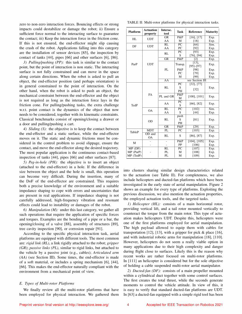
TABLE II: Multi-rotor platforms for physical interaction tasks.
Platform Actuationproperty
Interac.tool Task Reference Maturity
HL UDT GR P&P [16], [17] Exp.AA M [18] Exp.
DF UDT RL PC [64] Sim.AA PC [92] Exp.
ParP UDT
RL PC [93] Exp.S [76], [94] Exp.
GR P&P [2] Exp.
PL
Transp. [13],[95]–[97] Exp.
P&P [98] Exp.PC [79] Exp.M [99] Exp.
AA see Section III
TedP
FA
RLPC [32], [77]
Exp.S [32]PH
PL and GR P&P [100], [101] Exp.M
AA PC [66], [82] Exp.S
OA RL PC [102] Sim.AA S [44] Exp.
OD RLpush
[81] Exp.SPH
GR P&P [29] Exp.
TableP MDT PL PC [103] Exp.OD and
OA RL S [86], [87] Exp.
M - - P&P [104], [105] Exp.- - PP [106] Exp.
MP (DF)-
RL PC [107] Exp.MP (ParP) PL M [108] Exp.MP (TedP) PL M [109] Exp.
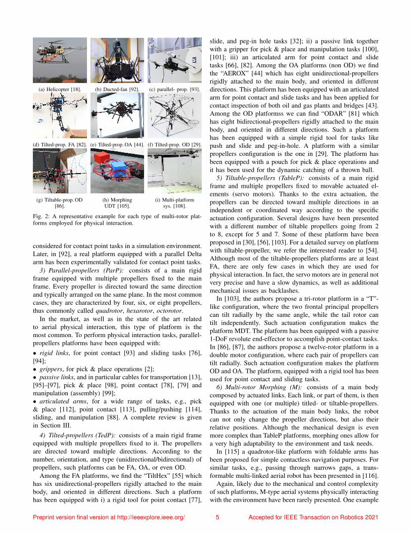
into clusters sharing similar design characteristics relatedto the actuation (see Table II). For completeness, we alsoinclude helicopters and ducted-fan platforms which have beeninvestigated in the early state of aerial manipulation. Figure 2shows an example for every type of platforms. Exploiting theprevious discussion, we also mention the actuation properties,the employed actuation tools, and the targeted tasks.
1) Helicopter (HL): consists of a main horizontal rotor,providing vertical lift, and a tail rotor mounted vertically tocounteract the torque from the main rotor. This type of actu-ation makes helicopters UDT. Despite this, helicopters wereone of the first platforms employed for aerial manipulation.The high payload allowed to equip them with cables fortransportation [12], [13], with a gripper for pick & place [16],and with industrial robotic arms for manipulation [18], [110].However, helicopters do not seem a really viable option inmany applications due to their high complexity and dangerduring flight close to surfaces. Likely this is the reason whyrecent works are rather focused on multi-rotor platforms.In [111] an helicopter is considered but for the sole objectiveof holding a cable suspended multi-rotor aerial manipulator.
2) Ducted-fan (DF): consists of a main propeller mountedwithin a cylindrical duct together with some control surfaces.The first creates the total thrust, while the seconds generatemoments to control the vehicle attitude. In view of this, itis easy to verify that standard ducted-fan platforms are UDT.In [63] a ducted-fan equipped with a simple rigid tool has been
Preprint version final version at http://ieeexplore.ieee.org/ 4 Accepted for IEEE Transaction on Robotics 2021
(a) Helicopter [18]. (b) Ducted-fan [92]. (c) parallel- prop. [93].
(d) Tilted-prop. FA [82]. (e) Tilted-prop. OA [44]. (f) Tilted-prop. OD [29].
(g) Tiltable-prop. OD[86].
(h) MorphingUDT [105].
(i) Multi-platformsys. [108].
Fig. 2: A representative example for each type of multi-rotor plat-forms employed for physical interaction.
considered for contact point tasks in a simulation environment.Later, in [92], a real platform equipped with a parallel Deltaarm has been experimentally validated for contact point tasks.
3) Parallel-propellers (ParP): consists of a main rigidframe equipped with multiple propellers fixed to the mainframe. Every propeller is directed toward the same directionand typically arranged on the same plane. In the most commoncases, they are characterized by four, six, or eight propellers,thus commonly called quadrotor, hexarotor, octorotor.
In the market, as well as in the state of the art relatedto aerial physical interaction, this type of platform is themost common. To perform physical interaction tasks, parallel-propellers platforms have been equipped with:• rigid links, for point contact [93] and sliding tasks [76],[94];• grippers, for pick & place operations [2];• passive links, and in particular cables for transportation [13],[95]–[97], pick & place [98], point contact [78], [79] andmanipulation (assembly) [99];• articulated arms, for a wide range of tasks, e.g., pick& place [112], point contact [113], pulling/pushing [114],sliding, and manipulation [88]. A complete review is givenin Section III.
4) Tilted-propellers (TedP): consists of a main rigid frameequipped with multiple propellers fixed to it. The propellersare directed toward multiple directions. According to thenumber, orientation, and type (unidirectional/bidirectional) ofpropellers, such platforms can be FA, OA, or even OD.
Among the FA platforms, we find the “TiltHex” [55] whichhas six unidirectional-propellers rigidly attached to the mainbody, and oriented in different directions. Such a platformhas been equipped with i) a rigid tool for point contact [77],
slide, and peg-in hole tasks [32]; ii) a passive link togetherwith a gripper for pick & place and manipulation tasks [100],[101]; iii) an articulated arm for point contact and slidetasks [66], [82]. Among the OA platforms (non OD) we findthe “AEROX” [44] which has eight unidirectional-propellersrigidly attached to the main body, and oriented in differentdirections. This platform has been equipped with an articulatedarm for point contact and slide tasks and has been applied forcontact inspection of both oil and gas plants and bridges [43].Among the OD platformss we can find “ODAR” [81] whichhas eight bidirectional-propellers rigidly attached to the mainbody, and oriented in different directions. Such a platformhas been equipped with a simple rigid tool for tasks likepush and slide and peg-in-hole. A platform with a similarpropellers configuration is the one in [29]. The platform hasbeen equipped with a pouch for pick & place operations andit has been used for the dynamic catching of a thrown ball.
5) Tiltable-propellers (TableP): consists of a main rigidframe and multiple propellers fixed to movable actuated el-ements (servo motors). Thanks to the extra actuation, thepropellers can be directed toward multiple directions in anindependent or coordinated way according to the specificactuation configuration. Several designs have been presentedwith a different number of tiltable propellers going from 2to 8, except for 5 and 7. Some of these platform have beenproposed in [30], [56], [103]. For a detailed survey on platformwith tiltable-propeller, we refer the interested reader to [54].Although most of the tiltable-propellers platforms are at leastFA, there are only few cases in which they are used forphysical interaction. In fact, the servo motors are in general notvery precise and have a slow dynamics, as well as additionalmechanical issues as backlashes.
In [103], the authors propose a tri-rotor platform in a “T”-like configuration, where the two frontal principal propellerscan tilt radially by the same angle, while the tail rotor cantilt independently. Such actuation configuration makes theplatform MDT. The platform has been equipped with a passive1-DoF revolute end-effector to accomplish point-contact tasks.In [86], [87], the authors propose a twelve-rotor platform in adouble motor configuration, where each pair of propellers cantilt radially. Such actuation configuration makes the platformOD and OA. The platform, equipped with a rigid tool has beenused for point contact and sliding tasks.
6) Multi-rotor Morphing (M): consists of a main bodycomposed by actuated links. Each link, or part of them, is thenequipped with one (or multiple) titled- or tiltable-propellers.Thanks to the actuation of the main body links, the robotcan not only change the propeller directions, but also theirrelative positions. Although the mechanical design is evenmore complex than TableP platforms, morphing ones allow fora very high adaptability to the environment and task needs.
In [115] a quadrotor-like platform with foldable arms hasbeen proposed for simple contactless navigation purposes. Forsimilar tasks, e.g., passing through narrows gaps, a trans-formable multi-linked aerial robot has been presented in [116].
Again, likely due to the mechanical and control complexityof such platforms, M-type aerial systems physically interactingwith the environment have been rarely presented. One example
Preprint version final version at http://ieeexplore.ieee.org/ 5 Accepted for IEEE Transaction on Robotics 2021
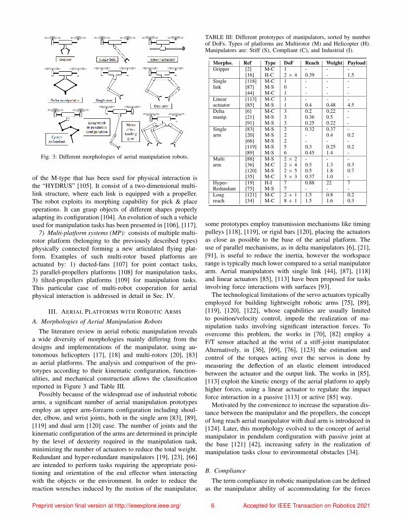
Fig. 3: Different morphologies of aerial manipulation robots.
of the M-type that has been used for physical interaction isthe “HYDRUS” [105]. It consist of a two-dimensional multi-link structure, where each link is equipped with a propeller.The robot exploits its morphing capability for pick & placeoperations. It can grasp objects of different shapes properlyadapting its configuration [104]. An evolution of such a vehicleused for manipulation tasks has been presented in [106], [117].
7) Multi-platform systems (MP): consists of multiple multi-rotor platform (belonging to the previously described types)physically connected forming a new articulated flying plat-form. Examples of such multi-rotor based platforms areactuated by: 1) ducted-fans [107] for point contact tasks,2) parallel-propellers platforms [108] for manipulation tasks,3) tilted-propellers platforms [109] for manipulation tasks.This particular case of multi-robot cooperation for aerialphysical interaction is addressed in detail in Sec. IV.
III. AERIAL PLATFORMS WITH ROBOTIC ARMS
A. Morphologies of Aerial Manipulation Robots
The literature review in aerial robotic manipulation revealsa wide diversity of morphologies mainly differing from thedesigns and implementations of the manipulator, using au-tonomous helicopters [17], [18] and multi-rotors [20], [83]as aerial platforms. The analysis and comparison of the pro-totypes according to their kinematic configuration, function-alities, and mechanical construction allows the classificationreported in Figure 3 and Table III.
Possibly because of the widespread use of industrial roboticarms, a significant number of aerial manipulation prototypesemploy an upper arm-forearm configuration including shoul-der, elbow, and wrist joints, both in the single arm [83], [89],[119] and dual arm [120] case. The number of joints and thekinematic configuration of the arms are determined in principleby the level of dexterity required in the manipulation task,minimizing the number of actuators to reduce the total weight.Redundant and hyper-redundant manipulators [19], [23], [66]are intended to perform tasks requiring the appropriate posi-tioning and orientation of the end effector when interactingwith the objects or the environment. In order to reduce thereaction wrenches induced by the motion of the manipulator,
TABLE III: Different prototypes of manipulators, sorted by numberof DoFs. Types of platforms are Multirotor (M) and Helicopter (H).Manipulators are: Stiff (S), Compliant (C), and Industrial (I).
Morpho. Ref Type DoF Reach Weight PayloadGripper [2] M-C 1 - - -
[16] H-C 2 × 4 0.39 - 1.5Single [118] M-C 1 - - -link [87] M-S 0 - - -
[44] M-C 1 - - -Linear [113] M-C 1 - - -actuator [85] M-S 1 0.4 0.48 4.5Delta [6] M-C 3 0.2 0.22 -manip. [21] M-S 3 0.36 0.5 -
[91] M-S 3 0.25 0.22 -Single [83] M-S 2 0.32 0.37 -arm [20] M-S 2 - 0.4 0.2
[66] M-S 2 - - -[119] M-S 5 0.3 0.25 0.2[89] M-S 6 0.45 1.4 -
Multi [88] M-S 2 × 2 - - -arm [36] M-C 2 × 4 0.5 1.3 0.3
[120] M-S 2 × 5 0.5 1.8 0.7[35] M-C 3 × 3 0.37 1.0 -
Hyper- [19] H-I 7 0.88 22 7Redundant [75] M-S 7 - - -Long [121] M-C 2 + 1 1.5 0.8 0.2reach [34] M-C 8 + 1 1.5 1.6 0.3
some prototypes employ transmission mechanisms like timingpulleys [118], [119], or rigid bars [120], placing the actuatorsas close as possible to the base of the aerial platform. Theuse of parallel mechanisms, as in delta manipulators [6], [21],[91], is useful to reduce the inertia, however the workspacerange is typically much lower compared to a serial manipulatorarm. Aerial manipulators with single link [44], [87], [118]and linear actuators [85], [113] have been proposed for tasksinvolving force interactions with surfaces [93].
The technological limitations of the servo actuators typicallyemployed for building lightweight robotic arms [75], [89],[119], [120], [122], whose capabilities are usually limitedto position/velocity control, impede the realization of ma-nipulation tasks involving significant interaction forces. Toovercome this problem, the works in [70], [82] employ aF/T sensor attached at the wrist of a stiff-joint manipulator.Alternatively, in [36], [69], [76], [123] the estimation andcontrol of the torques acting over the servos is done bymeasuring the deflection of an elastic element introducedbetween the actuator and the output link. The works in [85],[113] exploit the kinetic energy of the aerial platform to applyhigher forces, using a linear actuator to regulate the impactforce interaction in a passive [113] or active [85] way.
Motivated by the convenience to increase the separation dis-tance between the manipulator and the propellers, the conceptof long reach aerial manipulator with dual arm is introduced in[124]. Later, this morphology evolved to the concept of aerialmanipulator in pendulum configuration with passive joint atthe base [121] [42], increasing safety in the realization ofmanipulation tasks close to environmental obstacles [34].
B. Compliance
The term compliance in robotic manipulation can be definedas the manipulator ability of accommodating for the forces
Preprint version final version at http://ieeexplore.ieee.org/ 6 Accepted for IEEE Transaction on Robotics 2021
generated during the physical interactions with the environ-ment or with an agent (human or robot). Intuitively, thisconcept is associated to an elastic behavior in the joints orlinks. More formally, the compliance can be formulated asthe mechanical impedance (or, analogously, the admittance)that relates the position deviation of the manipulator withthe external force, characterized by the inertia, damping, andstiffness. Two forms of compliance can be identified dependingon its physical realizations: mechanical [15], [113], [118],[123], [125], or at control/software level [69], [70], [85]. Inthe first case, an elastic element is introduced in the joints orlinks of the manipulator, such that a significant deformationis produced when a force within the nominal range of theactuators is exerted. On the other hand, most industrial roboticarms like KUKA, Universal Robots or ABB, integrate accurateforce/torque sensors to control the apparent impedance.
The compliance is a highly desirable feature for an AEROMphysically interacting with the environment since the stabilityof the floating base may be compromised by the forces causedby the dynamic coupling with the manipulator. The ability ofaccommodating for the motion of the aerial platform [64],[71], [77] and/or the manipulator [69], [76], [113] results veryconvenient when considering the uncertainties associated tothe in-flight operations, especially in outdoor scenarios.
The first works that introduced compliance in aerial ma-nipulation [16], [113], [118], [123], [125] proposed differentcompliant mechanisms designed for their integration in heli-copters and multi-rotors, like grippers [16], lightweight roboticarms [36], [123], linear actuators [113], or flexible joints[118]. Several functionalities were demonstrated, includingcollision detection and reaction with active-passive compliance[123], [125], generation of high impact forces [113], deflectionbased torque/force control [69], and safe interaction in contactwith the environment [76]. The anthropomorphic, compliantand lightweight dual arm presented in [36] combines themechanical compliance with servo protection to improve therobustness, preventing that the actuators are damaged due toimpacts or overloads. The modeling and control of compliantjoint/arms was extended in [69], proposing a force controllerbased on Cartesian deflection. The passive joint in the long-reach (pendulum) configurations [34], [42], [121] provides anenhanced capability of accommodation thanks to the fact thatno torque is transmitted to the aerial platform about the jointaxis, while the force is still exerted along the link direction.In case of impact, the energy absorbed is stored as potentialenergy in the pendulum, and released later as kinetic energy.
C. Design and Mechatronic Aspects
Although the manipulator should provide a sufficient levelof dexterity to accomplish the task, increasing the numberof joints of the manipulator introduces some problems. Themost evident is the reduction in the payload capacity andflight time of the aerial platform. This can be clearly iden-tified expressing the mass distribution of the AEROM asmAP + mM + PLM <= ηMTOW , where mAP is theweight of the aerial platform (including all its componentsexcept the manipulator), mM and PLM are the weight and
payload capacity of the manipulator, MTOW is the maximumtake-off weight, and η is the load index of the platform.Different approaches can be adopted in the design of the robotdepending on how this equation is interpreted:
• Design determined by the weight of the payload (PLM ):some works propose the use of aerial robots in tasks involvingthe grasping [36], [83], [84], installation [85] or interaction[44], [66] with devices whose weight is predefined.• Design determined by the level of dexterity (mM ): the num-ber of joints is designed to obtain the manipulation dexterityrequired to accomplish the task. It is possible to distinguishbetween manipulators that use the joints for end-effectorpositioning [20], [35], [66], [83] or orientation [19], [119].Insertion [110] and assembly operations [89] are exampleswhere joints for orienting the wrist are required.• Design determined by the available payload (MTOW ):if the user or application demand the use of a particularaerial platform, then the weight of the onboard systems (mAP
and mM ) and the payload capacity (PLM ) are constrainedby ηMTOW . For example, safety reasons may impose amaximum total weight or maximum size of the AEROM.
Metrics like the lift load capacity or the payload-to-weightratio are useful for evaluation and comparison purposes [48].The so called smart servos like Dynamixel [35], [83], [88],[89], [91] or Herkulex [36], [120] are currently the best optionfor building lightweight robotic arms for aerial manipulation.These devices integrate the motor, gearbox, electronics andcommunications in a compact device with a relatively hightorque-to-weight ratio. These features significantly simplifythe design and development tasks, although their performanceis limited to position control at low update rates, usually below100 [Hz]. Some models allow the open-loop torque control,acting directly over the current signal. However, the friction ofthe gearbox makes impossible to estimate or control accuratelythe torque at the output link.
D. Single Arm vs Dual Arm
Most of the aerial manipulation prototypes developed in thelast decade consider a single manipulator attached to the aerialplatform, and only a few of them explore the use of two [36],[68], [88], [120] or three [35] arms. By using identical arms,the integration on the platform is simplified and shoulder-likemechanical interfaces can be used to interconnect the armswith the platform, as in [36], [120].
The dexterity and manipulation capabilities of a dual armsystem allow the realization of tasks that cannot be accom-plished with a single manipulator. The grasping and manipu-lation of long objects like bars or tubes [42] is a clear examplewhere a dual arm manipulator results more convenient than asingle arm. Other examples are: valve turning [88], cooperativebimanual grasping, and some assembly operations [89]. Amulti-arm system increases the payload capacity, extends theeffective workspace of the aerial manipulator [120], [121],and allows the partial cancellation of the reaction wrenchesinduced by one arm over the aerial platform using the otherarm as reaction [120]. The development of human-size [120]
Preprint version final version at http://ieeexplore.ieee.org/ 7 Accepted for IEEE Transaction on Robotics 2021
and human-like [36] dual arms is also motivated by theconvenience to replicate the abilities of human operators.
One capability of a dual arm aerial manipulator that resultsespecially interesting is the use of one arm as position sensorrelative to a grabbing point while the other arm conductsthe manipulation task. The idea is to estimate the positionof the aerial platform relative to the grabbing point from theinformation provided by the joint servos. It is necessary toremark that the positioning accuracy of the aerial platformshould be below the 10% of the reach of the manipulator toensure that the aerial manipulation task can be accomplished ina reliable way [48]. This problem is very relevant in outdoorsapplications, as the accuracy of position estimation systemslike RTK-GPS may not be good enough.
E. Control
The functionalities and potential applications of an AEROMare determined by the control capabilities of the aerial platformand the manipulator, considered as a whole. In the followingwe revise specific motion controllers for aerial manipulatorsbased on the dynamic model [43]:• Decoupled. These methods consider the aerial vehicle andthe robotic arm as two sub-systems that are controlled in-dependently [65], [70], [122]. The decoupled approach relieson the assumption that the influence of the manipulator overthe attitude and position dynamics of the aerial platform isrelatively small. The dynamic coupling is neglected or at besttreated as a disturbance to compensate [19]. This motivatesthe design of low weight and low inertia manipulators [119],[120]. Decoupled control methods best perform only in quasi-static motions. As soon as the motion is more demanding interms of accelerations, these methods fail, or in the best caseshow large tracking errors.• Coupled. These methods consider the system as a uniqueentity. The design of a coupled control scheme relies on thefull dynamic model, which explicitly takes into account thedynamic coupling through the inertia matrix [120]. Therefore,this approach is more suited for dynamic cases and allowbetter performance in terms of position accuracy and stability.Coupled controllers proposed in the state of the art arestrongly model-based and consider the full dynamics of thesystem [58], [61], [126]. A complete overview of such controlmethods is available in [51]. Furthermore, it requires the real-time computation of the dynamic model of a system with6 + NM degrees of freedom, being N the number of armsand M the number of joints per arm. They often requiretorque controlled motors that are in general unfeasible foraerial manipulators built with conventional servo actuators.• Partially coupled. The control of the aerial platform andthe manipulator are independent, but the controllers exploitthe information provided by each of the systems to estimatethe interaction wrenches and improve the performance of thecompound, typically in terms of positioning accuracy [75],[83]. To this category belongs the multi-layer architecturepresented in [122], where a momentum-based observer [71]is employed to compensate the dynamic couplings, and thevariable parameter integral backstepping controller in [20].
• Decoupled flatness-based. This approach is in betweendecoupled and coupled approaches. Each degree of freedom iscontrolled independently, as in a decoupled controller, but thefull system dynamics is considered via a feed-forward termcomputed thanks to the differential flatness property of someaerial manipulators [127].
F. Design and Application Guidelines
Given the wide variety of prototypes that can be found inthe literature, it is convenient to formulate a design method-ology to facilitate the development of specific solutions toparticular applications. Autonomous helicopters are in generalmore suited for the manipulation of heavy loads and highoperation times. Fully actuated multi-rotors equipped with fewDOF’s manipulators are suitable for exerting contact forces onsurfaces like walls or tanks, whereas dexterous robotic armsare more appropriate when the application requires the ade-quate full-pose control of the end-effector. Delta manipulatorshave been employed due to their compact design and lowinertia, that favors the accurate position control. Dual arm andthree-arm systems have been proposed to conduct bi-manualmanipulation tasks where a single arm may not be appropriate,introducing the long reach configuration to improve safety byreducing the probability of collision.
The design and development of an aerial manipulation robotrequires the choice of the specific components or modulesrequired to accomplish the task in the most effective andreliable way, rather than developing a general purpose aerialrobot. Some features like accurate position estimation andcontrol or compliant interaction control are usual requirementsin a wide variety of applications. The positioning accuracy isprobably one of the most challenging requirements in outdoorscenarios. Nevertheless, the operation time and payload ca-pacity of the aerial platform, which are directly related to itssize and weight, are currently the two main limiting factors inpractice. The use of big platforms (> 25 [kg] weight) should beavoided due to the inconveniences associated to its deploymentand operation, safety, regulation, maintenance and repair.
IV. COOPERATIVE AERIAL MANIPULATION
To handle an object too heavy or too large for a singleaerial robot, the concept of cooperative manipulation has beeninvestigated. A team of multiple aerial robots is deployed totransport and manipulate a common object while increasingthe total payload or the moment arm length via their cooper-ation. In this section, we survey some representative works inthe area of cooperative aerial manipulation.
One of the earliest successful demonstrations for this aerialcooperative manipulation is the cable-suspended transportationand manipulation by multiple quadrotors or helicopters (e.g.,[7]–[10], [12], [13], [108]). The works of [7]–[9] consideredthe problem of cooperative transportation of a triangular plate-like payload by three quadrotors with a cable connectedbetween each of their center-of-mass and a point on thepayload (see Figure 4). The key idea of [7], [8] was toconvert the problem as a quasi-static motion planning problem,that is, given each waypoint of the desired payload pose
Preprint version final version at http://ieeexplore.ieee.org/ 8 Accepted for IEEE Transaction on Robotics 2021
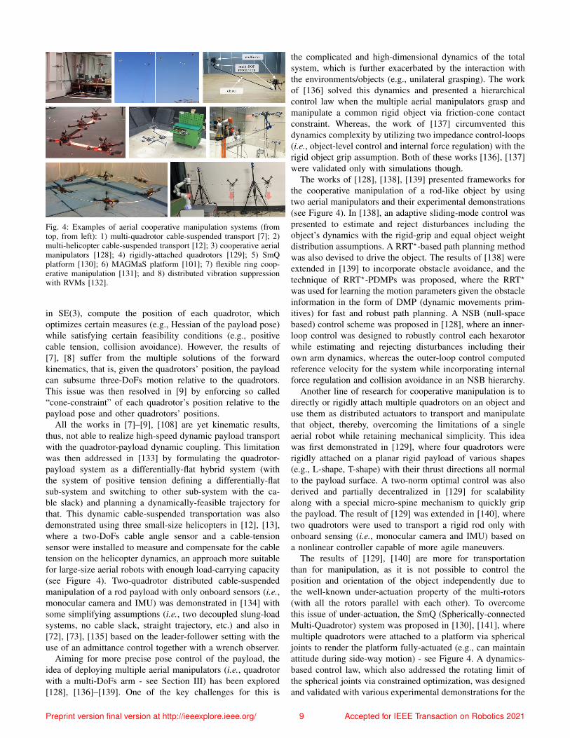
Fig. 4: Examples of aerial cooperative manipulation systems (fromtop, from left): 1) multi-quadrotor cable-suspended transport [7]; 2)multi-helicopter cable-suspended transport [12]; 3) cooperative aerialmanipulators [128]; 4) rigidly-attached quadrotors [129]; 5) SmQplatform [130]; 6) MAGMaS platform [101]; 7) flexible ring coop-erative manipulation [131]; and 8) distributed vibration suppressionwith RVMs [132].
in SE(3), compute the position of each quadrotor, whichoptimizes certain measures (e.g., Hessian of the payload pose)while satisfying certain feasibility conditions (e.g., positivecable tension, collision avoidance). However, the results of[7], [8] suffer from the multiple solutions of the forwardkinematics, that is, given the quadrotors’ position, the payloadcan subsume three-DoFs motion relative to the quadrotors.This issue was then resolved in [9] by enforcing so called“cone-constraint” of each quadrotor’s position relative to thepayload pose and other quadrotors’ positions.
All the works in [7]–[9], [108] are yet kinematic results,thus, not able to realize high-speed dynamic payload transportwith the quadrotor-payload dynamic coupling. This limitationwas then addressed in [133] by formulating the quadrotor-payload system as a differentially-flat hybrid system (withthe system of positive tension defining a differentially-flatsub-system and switching to other sub-system with the ca-ble slack) and planning a dynamically-feasible trajectory forthat. This dynamic cable-suspended transportation was alsodemonstrated using three small-size helicopters in [12], [13],where a two-DoFs cable angle sensor and a cable-tensionsensor were installed to measure and compensate for the cabletension on the helicopter dynamics, an approach more suitablefor large-size aerial robots with enough load-carrying capacity(see Figure 4). Two-quadrotor distributed cable-suspendedmanipulation of a rod payload with only onboard sensors (i.e.,monocular camera and IMU) was demonstrated in [134] withsome simplifying assumptions (i.e., two decoupled slung-loadsystems, no cable slack, straight trajectory, etc.) and also in[72], [73], [135] based on the leader-follower setting with theuse of an admittance control together with a wrench observer.
Aiming for more precise pose control of the payload, theidea of deploying multiple aerial manipulators (i.e., quadrotorwith a multi-DoFs arm - see Section III) has been explored[128], [136]–[139]. One of the key challenges for this is
the complicated and high-dimensional dynamics of the totalsystem, which is further exacerbated by the interaction withthe environments/objects (e.g., unilateral grasping). The workof [136] solved this dynamics and presented a hierarchicalcontrol law when the multiple aerial manipulators grasp andmanipulate a common rigid object via friction-cone contactconstraint. Whereas, the work of [137] circumvented thisdynamics complexity by utilizing two impedance control-loops(i.e., object-level control and internal force regulation) with therigid object grip assumption. Both of these works [136], [137]were validated only with simulations though.
The works of [128], [138], [139] presented frameworks forthe cooperative manipulation of a rod-like object by usingtwo aerial manipulators and their experimental demonstrations(see Figure 4). In [138], an adaptive sliding-mode control waspresented to estimate and reject disturbances including theobject’s dynamics with the rigid-grip and equal object weightdistribution assumptions. A RRT?-based path planning methodwas also devised to drive the object. The results of [138] wereextended in [139] to incorporate obstacle avoidance, and thetechnique of RRT?-PDMPs was proposed, where the RRT?
was used for learning the motion parameters given the obstacleinformation in the form of DMP (dynamic movements prim-itives) for fast and robust path planning. A NSB (null-spacebased) control scheme was proposed in [128], where an inner-loop control was designed to robustly control each hexarotorwhile estimating and rejecting disturbances including theirown arm dynamics, whereas the outer-loop control computedreference velocity for the system while incorporating internalforce regulation and collision avoidance in an NSB hierarchy.
Another line of research for cooperative manipulation is todirectly or rigidly attach multiple quadrotors on an object anduse them as distributed actuators to transport and manipulatethat object, thereby, overcoming the limitations of a singleaerial robot while retaining mechanical simplicity. This ideawas first demonstrated in [129], where four quadrotors wererigidly attached on a planar rigid payload of various shapes(e.g., L-shape, T-shape) with their thrust directions all normalto the payload surface. A two-norm optimal control was alsoderived and partially decentralized in [129] for scalabilityalong with a special micro-spine mechanism to quickly gripthe payload. The result of [129] was extended in [140], wheretwo quadrotors were used to transport a rigid rod only withonboard sensing (i.e., monocular camera and IMU) based ona nonlinear controller capable of more agile maneuvers.
The results of [129], [140] are more for transportationthan for manipulation, as it is not possible to control theposition and orientation of the object independently due tothe well-known under-actuation property of the multi-rotors(with all the rotors parallel with each other). To overcomethis issue of under-actuation, the SmQ (Spherically-connectedMulti-Quadrotor) system was proposed in [130], [141], wheremultiple quadrotors were attached to a platform via sphericaljoints to render the platform fully-actuated (e.g., can maintainattitude during side-way motion) - see Figure 4. A dynamics-based control law, which also addressed the rotating limit ofthe spherical joints via constrained optimization, was designedand validated with various experimental demonstrations for the
Preprint version final version at http://ieeexplore.ieee.org/ 9 Accepted for IEEE Transaction on Robotics 2021
SmQ platform in [130]. This spherical joint connection, whichallows for omni-direciontal thrust generation, was adopted in[135] as well. Similarly in [142] (see Section VI).
In addition to purely aerial cooperative manipulation sys-tems as discussed so far, there are recently emerging resultson the mixed deployment of aerial and ground robots toexploit their complementary capabilities, that are: the groundrobots often possess high load carrying ability, yet, withlimited workspace, wheres the aerial robots possess unlimitedworkspace (and ability to easily increase moment-arm length),yet, with limited payload. The work of [143] presented a co-operative manipulation system consisting of a ground mobilerobot and a quadrotor, where the position of a rigid objectwas controlled by the mobile robot while its tilting angle bythe (spherically connected) quadrotor. However, the result of[143] is limited only for the sagittal plane similar to the caseof a 2-DoFs pendulum-cart system. On the other hand, theMAGMaS (multiple aerial ground manipulator system) wasproposed in [144], where a 7-DoFs KUKA LBR iiwa industrialmanipulator and a (spherically connected) quadrotor werecontrolled to cooperatively manipulate a long rigid object,which was too heavy and too long to be individually handledby either robots (see Figure 4). This MAGMaS system wasthen extended in [101] with the spherical joint replaced bythe OTHEX system [100] for higher and wider-angle thrustcapacity with the bilateral teleoperation ability also added;and further expanded in [145], where the flexibility of theobject, likely arising for long-slender or large-size/thin objects,was incorporated. The authors designed a control law forthe cooperative manipulation of the flexible object whilesuppressing its vibration, proving its controllability as well.
The area of aerial cooperative manipulation of flexible orsoft objects has not been investigated much so far. The workof [131] considered the problem of cooperative handling aflexible ring by six quadrotors, each rigidly attached to the ringwith some tilted angle to directly provide horizontal-directioncontrol force (see Figure 4). The dynamics model of the ringwith each quadrotor as wrench generator was linearized aboutthe hovering configuration and Kalman estimation and LQR(linear quadratic regulator) were applied to regulate the ringpose while suppressing its vibration modes. Vibration controlof a long flexible beam of skewed rectangular cross-sectionwith distributed rotor-based vibration suppression modules(RVMs) was investigated recently in [132], where the two-rotor modules, whose design was optimized to maximizethrust force generation in the longitudinal-vertical plane withminimal torsional torque, were distributed along the beam.Further, optimal placement problem was solved by maximizingcontrollability Gramian and the vibration suppression wasexperimentally demonstrated (see Figure 4).
V. INTERCONNECTED ACTUATED MULTI-BODY DESIGNS
This section surveys a recently emerging class of aerialrobotic platforms, which consist of multiple articulated linksor bodies, that are mechanically connected with each other viapassive or actuated joints and fly with tilted or tilting rotorsdistributed over them. This kind of platforms can fly while
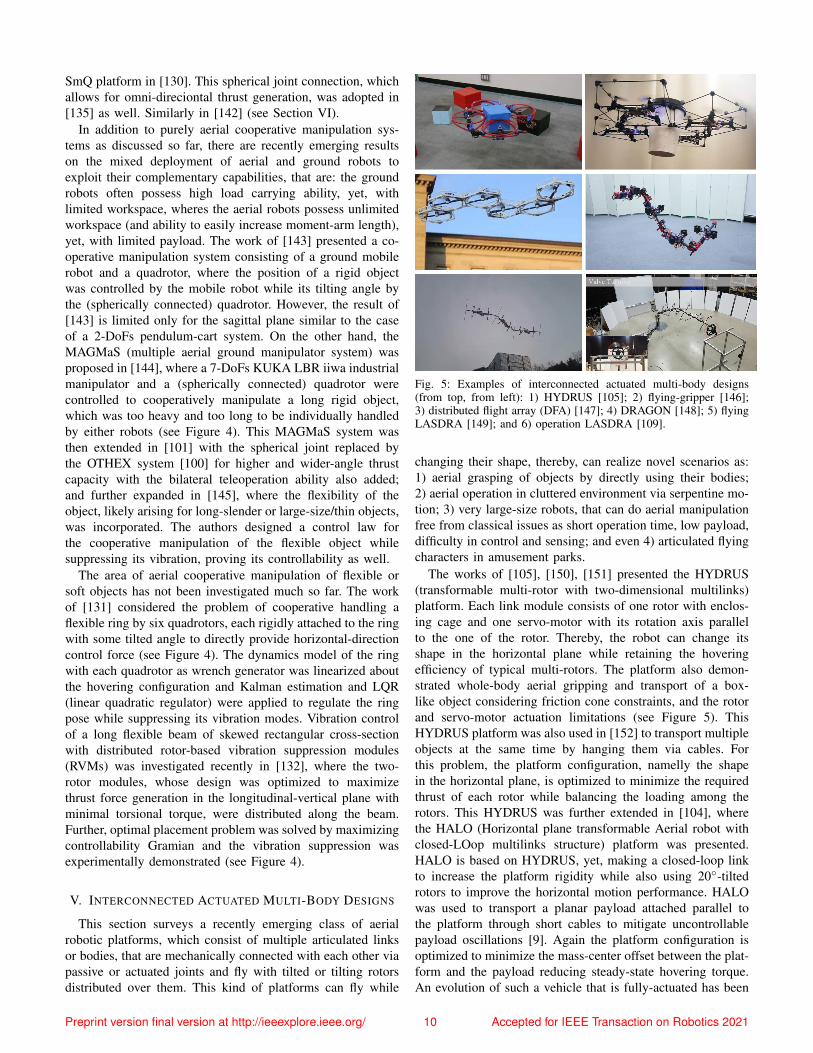
Fig. 5: Examples of interconnected actuated multi-body designs(from top, from left): 1) HYDRUS [105]; 2) flying-gripper [146];3) distributed flight array (DFA) [147]; 4) DRAGON [148]; 5) flyingLASDRA [149]; and 6) operation LASDRA [109].
changing their shape, thereby, can realize novel scenarios as:1) aerial grasping of objects by directly using their bodies;2) aerial operation in cluttered environment via serpentine mo-tion; 3) very large-size robots, that can do aerial manipulationfree from classical issues as short operation time, low payload,difficulty in control and sensing; and even 4) articulated flyingcharacters in amusement parks.
The works of [105], [150], [151] presented the HYDRUS(transformable multi-rotor with two-dimensional multilinks)platform. Each link module consists of one rotor with enclos-ing cage and one servo-motor with its rotation axis parallelto the one of the rotor. Thereby, the robot can change itsshape in the horizontal plane while retaining the hoveringefficiency of typical multi-rotors. The platform also demon-strated whole-body aerial gripping and transport of a box-like object considering friction cone constraints, and the rotorand servo-motor actuation limitations (see Figure 5). ThisHYDRUS platform was also used in [152] to transport multipleobjects at the same time by hanging them via cables. Forthis problem, the platform configuration, namelly the shapein the horizontal plane, is optimized to minimize the requiredthrust of each rotor while balancing the loading among therotors. This HYDRUS was further extended in [104], wherethe HALO (Horizontal plane transformable Aerial robot withclosed-LOop multilinks structure) platform was presented.HALO is based on HYDRUS, yet, making a closed-loop linkto increase the platform rigidity while also using 20◦-tiltedrotors to improve the horizontal motion performance. HALOwas used to transport a planar payload attached parallel tothe platform through short cables to mitigate uncontrollablepayload oscillations [9]. Again the platform configuration isoptimized to minimize the mass-center offset between the plat-form and the payload reducing steady-state hovering torque.An evolution of such a vehicle that is fully-actuated has been
Preprint version final version at http://ieeexplore.ieee.org/ 10 Accepted for IEEE Transaction on Robotics 2021
presented in [117].Similar to HYDRUS and HALO platforms, one can find
the flying gripper system proposed in [146]. It is designedas a modular closed-chain system, each module consistingof an off-the-shelf Crazyflie 2.0 quadrotor with a carbonfiber cuboid cage around it. An axially magnetized cylindricalNeodymium Iron Boron (NdFeB) magnet was attached on thevertical hinge of each cuboid to allow them to rotate aboutthe thrust direction of the quadrotors. A four-cuboid flyinggripper system was then constructed and experimented to graspa paper cup by squeezing the aperture angle of the four-barlinkage closed-chain among the four cuboids (see Figure 5).Related to the previous platforms there is also the distributedflight array (DFA) of [147] (see Figure 5). It is also constructedas a modular system, each module consisting of a rotor anddriving wheels, so that, only when they form an array (usingthe wheels), they can fly together. However, in this case thearray structure is fixed and not actuated.
On the other hand, [148] proposes the DRAGON (Dual-rotor embedded multilink Robot with the Ability of multi-degree-of-freedom aerial transformatiON) platform, consistingof multiple carbon fiber pipe modules, on each of which twoparallel rotors were attached via a two-DoFs thrust vectoringmechanism (i.e., dual-rotor gimbal module). The pipe moduleitself was then connected with other modules via a two-DoFs orthogonal-axes joint with a pulley transmission withhigh reduction ratio. This reduces the back-drivability ofthe joint, thereby, mitigating possible vibration propagationthrough these joints. In contrast to the HYDRUS and HALOplatforms, the DRAGON platform is fully-actuated, capableof assuming any pose and shape in SE(3) (up to the jointand rotor limits). Flying with fixed and changing shapes wasexperimentally demonstrated in [148] (see Figure 5), alsoperforming pulling/pushing operations [106].
Another research along the same line is based on theLASDRA (Large-size Aerial Skeleton with Distributed RotorActuation) platform [109], [149]. Each link is based on theODAR robot [81] and connected via string to maximizethe dexterity of the motion. The LASDRA system aims atovercoming the well-known challenges in aerial manipulation(e.g., limited battery and payload, difficulty of onboard sensingand control, etc.) by making the robot large enough so thatit can perform aerial manipulation tasks while tethered to theground (or other vehicles). The “base” could provide abundantpower and, consequently, the possibility of using powerfulrotors. The mechanical structure of the LASDRA platform alsoprovides the inherent stabilizing inertial/dissipative effects,while making the state estimation problem easier by enforcingthe kinematic relations (measurable by, e.g., IMUs) from the(known) base to the end-effector.
Outdoor autonomous flights of a 3m-long 3-link 15-DoFsuntethered LASDRA system was demonstrated in [149], wherethe estimation accuracy was substantially improved (i.e., inter-link position RMSE less than 5cm) by fusing the kinematicconstraints and the distributed IMU and GNSS sensors inthe form of semi-distributed EKF (extended Kalman filtering).The method provides stable autonomous flight while avoidingexcessive internal forces within the system (see Figure 5).
TABLE IV: Teleoperation features for aerial physical interaction.
Aerial platform Reference Humaninterface Task Level of
maturity
Single
UDT [154] hapticpointcontactand push
simulation
MDT [155]hapticand3D view
pick &place experiment
Multiple UDT [142], [156] haptic manip. simulationMDT [101] haptic manip. experiment
Various manipulation tasks with a 3m-long 2-link 6-DoFsoperational LASDRA system were also demonstrated in [109],where compliant turning of an industrial valve was achievedbased on the back-drivability of the BLDC rotors (see Fig-ure 5). This LASDRA system is scalable, that is, with eachlink addressing its own weight, arbitrary number of links canbe added indefinitely. To support this scalability, a distributedimpedance control law was designed and applied to eachindividual link of the LASDRA systems [109], [149].
VI. TELEOPERATION
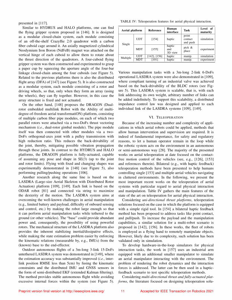
Because of the increasing number and complexity of appli-cations in which aerial robots could be applied, methods thatallow human intervention and supervision are required. It isindeed of fundamental importance, for safety and regulatoryreasons, to let a human operator remain in the loop whilethe robotic system acts on the environment in an autonomousor semi-autonomous way [28]. The majority of the presentedworks on aerial teleoperation at date focused on the contact-free motion control of the vehicles (see, e.g., [126], [153]and references therein). Bilateral (e.g., with haptic feedback)teleoperation methods have been presented to help humanscontrolling single [153] and multiple aerial vehicles navigatingin cluttered environments. In the following, we present themost important recent works on the teleoperation of aerialsystems with particular regard to aerial physical interactionand manipulation. Table IV gathers the main features of thestate of the art on teleoperation for aerial physical interaction.
Considering uni-directional thrust platforms, teleoperationsolutions focused on the case in which the platform is equippedwith a simple rigid tool. In [154] a bilateral haptic feedbackmethod has been proposed to address tasks like point contact,and pull/push. To increase the payload and the manipulationcapabilities, a similar solution for a multi-robot scenario isproposed in [142], [156]. In these works, the fleet of robotsis employed as a flying hand to remotely manipulate objects.However, likely due to its complexity, such solution has beenvalidated only in simulation.
To develop hardware-in-the-loop simulators for physicalinteraction tasks, the work in [157] uses an industrial armequipped with an additional smaller manipulator to simulatean aerial manipulator interacting with the environment. Theproblem of rendering the robot dynamics and the interactionforces is addressed. The latter can be then used in a haptic-feedback scenario to test specific teleoperation methods.
Considering multi-directional thrust and fully-actuated plat-forms, the literature focused on designing teleoperation solu-
Preprint version final version at http://ieeexplore.ieee.org/ 11 Accepted for IEEE Transaction on Robotics 2021
tions for pick & place tasks. The teleoperation of the cable-suspended aerial manipulator SAM equipped with an articu-lated arm is shown in [155]. The authors proposed the use ofa 3D visual plus haptic feedback helping the user to drive theend-effector toward the grasp of a object. In [101], the authorsaddressed the teleoperation problem of a heterogeneous multi-robot system composed of aerial and ground manipulators thatcooperatively manipulate long objects.
From the human point of view, the common feedback usedto help the telemanipulation are:
• Visual: from robot to human, cameras mounted on the aerialplatform or on the end-effector are employed to provide 2D oreven 3D images [155] to the operator. These information canalso be integrated with head mounted displays in a VirtualReality (VR) framework [158], [159] helping the operatorperforming the task. On the other hand, in [156] a RGBDcamera is used to extract human commands from the motionof his/her hand, which are then translated into robotic actions.• Haptic: haptic devices provides a sense of touch to thehuman. Using delta type haptic devices, one can apply 3Dforces to the human to augment his/her situation awareness.In [101], the haptic device is used to send the desired pose ofthe manipulated object from the human to the robotic system.In the other sense, it is used to apply on the human handforces that are related to the inertia of the system and thepresence of obstacles. In [154], the delta device is used tocontrol the interaction forces of a quadrotor platform equippedwith a rigid tool. The operator, moving the end-effector of thedevice, sends desired forces at the end-effector of the robot.On the other hand, the haptic device is used to apply to theuser forces that give the perception of the contact force appliedby the robot to the environment. These forces are also used togive the feeling of the distance from zero-commanded force.
VII. PERCEPTION AND PLANNING
A. Motivation and Requirements
Three phases can be distinguished in aerial manipulationoperations: 1) navigation from the take-off position to theproximity of the workspace ensuring collision avoidance andreactivity in case of unexpected obstacles; 2) approachingto the desired operation position with higher accuracy; 3)manipulation with accurate position and interaction control.
Phases 1) and 2) should consider perception to avoid col-lisions of a load being transported, also involving perception-based localization and accurate SLAM in GNSS denied en-vironments. Object detection, tracking and localization arerequired for grasping and manipulation in phase 3), beingdistinctive of aerial manipulators when compared to otheraerial robots. Motion planning also requires particular carein aerial manipulation. The dynamic coupling between themanipulator and the aerial platform should be consideredat the motion planning level to prevent undesired positiondeviations that may result in collisions with the environment.Therefore, the planner should consider the full body dynamicsand compute an optimal trajectory for every DoF.
B. Perception
Perception functionalities are needed for localization andmapping as well as for object detection and manipulation.
1) Localization and mapping: UAV navigation is usuallybased on GNSS. The position provided by GNSS is usedto close position control loops and to track desired trajec-tories. However, in many cases, the relative low frequencyand the accuracy degradation due to the satellite visibilityand communication problems, precludes its fully autonomousapplication. There are also many AEROM’s applications inGNSS denied environments that require alternative approachesbased on environment perception. In the following, we reviewlocalization methods and technologies for contact-free andmanipulation operations, e.g., while transporting a load withthe arms, or while performing contact-based inspection.
Odometry based on the combination of IMU and vision,with no absolute localization [160], is a well known approachthat has been applied in aerial manipulation. In [39] visual-inertial fusion with event cameras is presented. The use ofevent cameras offers significant advantages over standardcameras providing a very high dynamic range, very smalllatency, and no motion blur which are relevant characteristicsfor AEROMs in non-controlled outdoor environments.
Visual localization and SLAM methods were also applied.Absolute 3D localization in the world frameW (see Figure 6)and mapping can be performed from measurements obtainedby multi-modal sensorial approaches using 3D LIDAR, stereocameras and radio range measurements w.r.t. beacons (seeChapter IV.2 of [43]). Ultra Wide Band (UWB) time-of-flightsensors are applied to compute the position of a receiveron-board the aerial robot, by means of triangulation andRange Only estimation, based on a decentralized ExtendedInformation filter combined with a Particle Filter for ini-tialization. This can be applied at relatively long distancesbut the emitters should be well distributed; the method isaffected by reflections, and the orientation cannot be obtained.Moreover, they provide position estimation with only about0.5m accuracy. When the robot is tens of meters from objects,a 3D LIDAR provides a better accuracy and reliability. Finally,at small distances, stereo cameras can be applied and fuse thepoint clouds resulting from the camera with those provided bythe 3D LIDAR. In [38] a Multi-Sensor 6-DoFs Localizationmethod is applied. An Iterative Closest Point (ICP) algorithmextended to consider 3D-3D matchings between LIDAR (3Ddistances) or cameras (distances in the SURF space) is usedin the prediction stage. Also, the ICP can be easily combinedwith the IMU, optimizing the joint (laser and camera) error.The method can be implemented in real time with moderatecomputational cost on-board the robot. These methods havebeen implemented without any marker and by using measure-ments obtained at tens of meters with RMS errors between0.11m and 0.21m. Greater accuracy in relative localizationcan be obtained by means of markers. In particular, with visualmarkers it is possible to obtain the position with an accuracybetter than 5mm at a distance of 0.7m by means of imageprocessing. The method, presented in Chapter IV.4 of [43],is based on optimizing the alignment of deformable contours
Preprint version final version at http://ieeexplore.ieee.org/ 12 Accepted for IEEE Transaction on Robotics 2021
from textureless images.2) Object detection: Object detection is strongly dependent
on the used sensors. The payload of the aerial robot is a veryimportant constraint. Then, visual cameras with light opticsare the most used sensors. In aerial manipulation two differentproblems exist: the detection of objects to be manipulated ata certain distance (usually meters) in order to perform theapproach, and the detection for grasping and manipulation.The first is a rough detection based on: 1) features, related forexample to shape and color; 2) templates of the target object,which could be fixed or deformable to adapt to changes ofthe viewing angle due to the motion of the aerial robot; and3) classifiers, which could be also based on particular features.Moreover, there are methods based on motion analysis thatalso use features or templates. The deep learning classifiersextracting image features are being applied more and more.
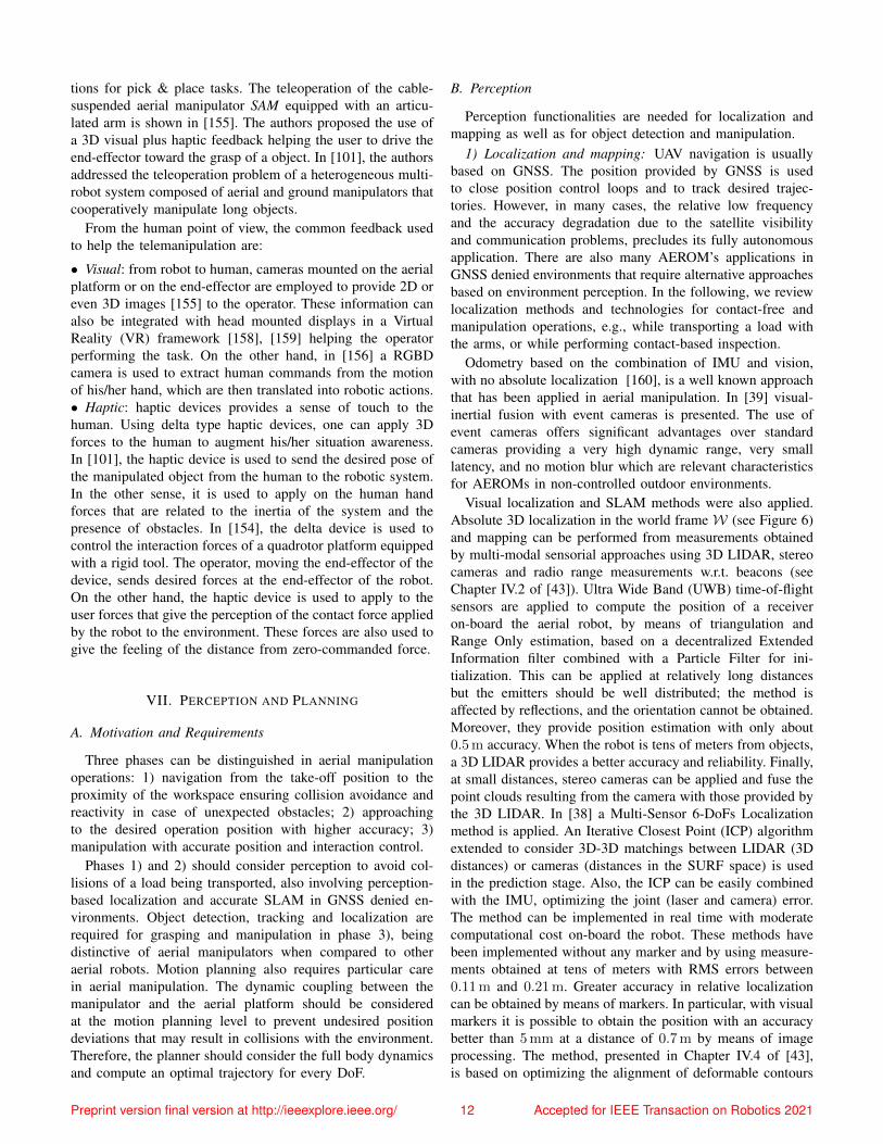
On the other hand, the detectors for grasping and ma-nipulation should provide high accuracy. Methods based onmarkers, i.e., fiducial markers, have been proposed. In ChapterIV.6 of [43] markers detection libraries and deep learning areapplied. It is also possible to avoid the use of markers andapply modeling techniques of the objects to be manipulated.Particularly, Gaussian Process Implicit Surfaces (GPIS) [161]takes into account the environment uncertainties involvedin computer vision. This probabilistic information has beenused in the H2020 AEROARMS project to generate graspconfigurations. Moreover, the model is used to compute therelative 3D pose. Figure 6 shows an outdoor crawler detec-tion and grasping with a dual arm. The GPIS models thecrawler surface computing a covariance term for each point ofthe approximated surface. Alternatively, RGB-D cameras andConvolutional Neural Networks (CNN) can be used to obtainin real-time a suitable model for grasping. The state variablesin the estimation of points of the object in the camera referenceframe of Figure 6 is given by [Cp[t],
Cη[t],C p[t],
Cω[t]]>,
where Cp[t], Cη[t], C p[t] and Cω[t] are respectively the po-sition, orientation, linear velocity and angular velocity in thecamera frame C shown in Figure 6 at the time instant t. Thesevariables can be estimated by means of an Extended KalmanFilter. The resulting estimations of the centroid of the object tobe grasped Cp, Cη are used to compute the grasping points ofthe bar handle by means of the model of the object. Then, thereferences for the grasping point of each arm can be obtainedas [Epi,Eηi]> = ET iC [
Cp[t],Cη[t]]
>, where Epi and Eηi fori = 1, 2 are the position and orientation of the grasping pointsfor the arms in the End-Effector frame, E , and ET iC is thetransformation from C to E for the arm i. These references canbe passed to control methods described in Section III. Positionbased [27], [162] or image-based visual servoing [40], [163]can be used, expressing the error and control inputs directlyin the image space, minimizing the error w.r.t. desired imagefeature coordinates.
C. Planning
1) Planning levels: The higher level in planning of aerialmanipulators is mission planning, e.g., the plan to assemblea structure from separate parts by taking into account the
Fig. 6: Aerial manipulator grasping a crawler.
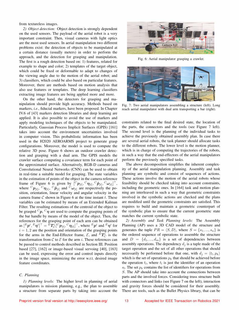
Fig. 7: Two aerial manipulators assembling a structure (left). Longreach aerial manipulator with dual arm transporting a bar (right).
constraints related to the final desired state, the location ofthe parts, the connectors and the tools (see Figure 7 left).The second level is the planning of the individual tasks toachieve the previously obtained assembly plan. In case thereare several aerial robots, the task planner should allocate tasksto the different robots. The lower level is the motion planner,which is in charge of computing the trajectories of the robots,in such a way that the end-effectors of the aerial manipulatorsperform the previously specified tasks.
The above decomposition simplifies the inherent complex-ity of the aerial manipulation planning. Assembly and taskplanning are symbolic and consist of sequences of actions.These actions involve the motion of the aerial robots whosefeasibility should be checked taking into account constraints,including the geometric ones. In [164] task and motion plan-ning are interleaved in such a way that geometric constraintsinvolved in the symbolic actions are checked and the plansare modified until the geometric constraints are satisfied. Thisrequires to build and maintain a geometric counterpart ofthe symbolic plan to ensure that the current geometric statematches the current symbolic state.
2) Assembly and Task Planning levels: The AssemblyPlanning (AP) uses a 3D CAD model of the structure andgenerates the tuple PR = 〈S,D〉, where S = {s1, ..., sn} isthe ordered sequence of operations to assemble the structureand D = {d1, ..., dm} is a set of dependencies betweenassembly operations. The dependency dj is a tuple made of thetarget operation and the set of all other operations that shouldnecessarily be performed before that one, with dj = 〈tl, pk〉which is the set of operations pk that should be achieved beforethe operation tl, where tl is just the identifier of an operationsl. The set pk contains the list of identifiers for operations fromS. The AP should take into account the connections betweenparts and the involved forces. Considering truss structure builtwith connectors and links (see Figure 7 on the left), interactionand gravity forces should be considered for their assembly.There are tools, such as the Bullet Physics library, that can be
Preprint version final version at http://ieeexplore.ieee.org/ 13 Accepted for IEEE Transaction on Robotics 2021
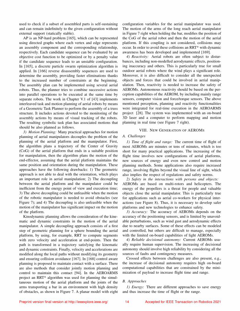
used to check if a subset of assembled parts is self-sustainingand can remain indefinitely to the given configuration withoutexternal support (statically stable).
AP is an NP-hard problem [165], which can be representedusing directed graphs where each vertex and edge representsan assembly component and the corresponding relationship,respectively. Each candidate sequence can be evaluated by anobjective cost function to be optimized or by a penalty valueif the candidate sequence leads to an unstable configuration.In [165], a discrete particle swarm optimization algorithm isapplied. In [166] reverse disassembly sequences are used todetermine the assembly, providing faster eliminations thanksto the increased number of constraints at the beginning.The assembly plan can be implemented using several aerialrobots. Thus, the planner tries to combine successive actionsinto parallel operations to be executed at the same time byseparate robots. The work in Chapter V.1 of [43] implementsinterleaved task and motion planning of aerial robots by meansof a Geometric Task Planner to perform the assembly of a trussstructure. It includes actions devoted to the monitoring of theassembly actions by means of visual tracking of the robots.The resulting symbolic task plan has associated motions thatshould be also planned as follows.
3) Motion Planning: Many practical approaches for motionplanning of aerial manipulators decouples the problem of theplanning of the aerial platform and the manipulator. First,the algorithm plans a trajectory of the Center of Gravity(CoG) of the aerial platform that ends in a suitable positionfor manipulation, then the algorithm plans the motion of theend-effector, assuming that the aerial platform maintains thesame position and orientation during the manipulation. Theseapproaches have the following drawbacks: 1) The geometricapproach is not able to deal with the orientation, which playsan important role in aerial manipulation; 2) The decouplingbetween the aerial platform and the manipulator could beinefficient from the energy point of view and execution time;3) The above decoupling could be unfeasible when the motionof the robotic manipulator is needed to avoid obstacles (seeFigure 7); and 4) The decoupling is also unfeasible when themotion of the manipulator has significant impact on the motionof the platform.
Kinodynamic planning allows the consideration of the kine-matic and dynamic constraints in the motion of the aerialmanipulator. A simple decoupling approach consists of a firststep of geometric planning for a sphere bounding the aerialplatform, by using, for example, RRT to compute segmentswith zero velocity and acceleration at end-points. Then thepath is transformed in a trajectory satisfying the kinematicand dynamic constraints. Finally, velocity and accelerations aremodified along the local paths without modifying its geometryand ensuring collision avoidance [167]. In [168] control awareplanning is proposed to maintain contact with a surface. Thereare also methods that consider jointly motion planning andcontrol to maintain this contact [94]. In the AEROARMSproject an RRT* algorithm was used for planning the simul-taneous motion of the aerial platform and the joints of thearms transporting a bar in an environment with high densityof obstacles, as shown in Figure 7. A planar model with eight
configuration variables for the aerial manipulator was used.The motion of the arms of the long reach aerial manipulatorin Figure 7 right when holding the bar, modifies the position ofthe CoG of the aerial robot and then the motion of the aerialplatform. If this coupling is not considered, collisions mayoccur. In order to avoid these collisions an RRT* with dynamicawareness has been developed and implemented [169].
4) Reactivity: Aerial robots are often subject to distur-bances, including non-modelled aerodynamic effects, position-ing inaccuracy and others. This is particularly true for smalloutdoor aerial robots where the wind plays a significant role.Moreover, it is also difficult to consider all the unexpectedobjects and forces that could be involved in aerial manip-ulation. Then, reactivity is needed to increase the safety ofAEROMs. Autonomous reactivity should be based on the per-ception capabilities of the AEROM, by including mainly rangesensors, computer vision and force/torque sensors. The abovementioned perception, planning and reactivity functionalitieswere integrated for real-time execution in the AEROARMSproject [28]. The system was implemented with an on-board3D laser and a computer to perform mapping and motionplanning in real time (see Figure 7 right).
VIII. NEW GENERATION OF AEROMS
A. Challenges1) Time of flight and range: The current time of flight of
most AEROMs are minutes or tens of minutes, which is tooshort for many practical applications. The increasing of theflight time involves new configurations of aerial platforms,new sources of energy and even new control and motionplanning methods. Some applications also require increasedrange, involving flights beyond the visual line of sight, whichalso implies the respect of regulations and safety norms.
2) Safety in the interactions with persons and objects:AEROMs are based on multi-rotors and helicopters. Theenergy of the propellers is a threat for people and valuableobjects close the aerial manipulator. This is particularly truefor applications such as aerial co-workers for physical inter-actions (see Figure 8). Thus, it is necessary to develop saferplatforms and new technologies to enhance safety.
3) Accuracy: The accuracy of AEROMs depends on theaccuracy of the positioning sensors, and is limited by unavoid-able perturbations, such as wind gust and aerodynamic effectsdue to nearby surfaces. Some of these effects can be modeledand controlled, but others are difficult to manage, especiallywith the limited on-board capabilities of light AEROMs.
4) Reliable decisional autonomy: Current AEROMs usu-ally require human supervision. The increasing of decisionalautonomy should involve high reliability by considering all thesources of faults and contingency measures.
Crossed effects between challenges are also present, e.g.,the increase of decisional autonomy requires high on-boardcomputational capabilities that are constrained by the mini-mization of payload to increase flight time and range.
B. Approaches1) Energy: There are different approaches to save energy
and thus increase the time of flight or the range.
Preprint version final version at http://ieeexplore.ieee.org/ 14 Accepted for IEEE Transaction on Robotics 2021
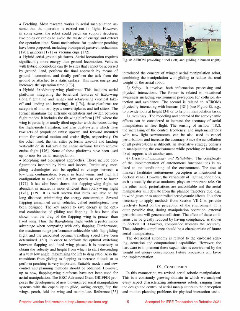
• Perching. Most research works in aerial manipulation as-sume that the operation is carried out in flight. However,in some cases, the robot could perch on support structureslike poles or cables to avoid the waste of energy and extendthe operation time. Some mechanisms for quadrotor perchinghave been proposed, including bioinspired passive mechanisms[170], grippers [171] or vacuum cups [172].• Hybrid aerial-ground platforms. Aerial locomotion requiressignificantly more energy than ground locomotion. Vehicleswith hybrid locomotion can fly to sites that cannot be accessedby ground, land, perform the final approach by means ofground locomotion, and finally perform the task from theground or attached to a static surface. This saves energy andincreases the operation time [173].• Hybrid fixed/rotary-wing platforms. This includes aerialplatforms integrating the beneficial features of fixed-wing(long flight time and range) and rotary-wing (vertical take-off and landing and hovering). In [174], these platforms arecategorized into two types: convertiplanes and tail sitters. Theformer maintains the airframe orientation and switch betweenflight modes. It includes the tilt-wing platform [175] where thewing is partially or totally tilted together with the rotors duringthe flight-mode transition, and also dual-systems which havetwo sets of propulsion units: upward and forward mountedrotors for vertical motion and cruise flight, respectively. Onthe other hand, the tail sitter performs take-off and landingvertically on its tail while the entire airframe tilts to achievecruise flight [176]. None of these platforms have been usedup to now for aerial manipulation.• Morphing and bioinspired approaches. These include con-figurations inspired by birds and insects. Particularly, mor-phing technologies can be applied to change between alow drag configuration, typical in fixed wings, and high liftconfiguration to avoid stall at low speeds or even to hover[177]. It has also been shown that flapping-wing flight, soabundant in nature, is more efficient than rotary-wing flight[178], [179]. It is well known that birds are able to flylong distances minimizing the energy consumption. Severalflapping unmanned aerial vehicles, called ornithopters, havebeen designed. The key aspect to save energy is the opti-mal combination of gliding and flapping. It has been alsoshown that the drag of the flapping wing is greater thanfixed wing. Thus, the flap-gliding flight yields a performanceadvantage when comparing with only flapping. Furthermore,the maximum range performance achievable with flap-glidingflight and the associated optimal travelling speed have beendetermined [180]. In order to perform the optimal switchingbetween flapping and fixed wing phases, it is necessary toobtain the velocity and height from which to start descendingat a very low angle, maximizing the lift to drag ratio. Also thetransitions from gliding to flapping to increase altitude or toperform perching is very important. Suitable models and newcontrol and planning methods should be obtained. However,up to now, flapping-wing platforms have not been used foraerial manipulation. The ERC Advanced Grant GRIFFIN pro-poses the development of new bio-inspired aerial manipulationsystems with the capability to glide, saving energy, flap thewings, perch, fold the wing and manipulate. Reference [53]
Fig. 8: AEROM providing a tool (left) and guiding a human (right).
introduced the concept of winged aerial manipulation robot,combining the manipulation with gliding to reduce the totalweight of the aerial robot.
2) Safety: It involves both information processing andphysical interactions. The former is related to situationalawareness including environment perception for collision de-tection and avoidance. The second is related to AEROMsphysically interacting with humans [181] (see Figure 8), e.g.,to provide tools at height [34] or to help in manipulation tasks.
3) Accuracy: The modeling and control of the aerodynamiceffects can be considered to increase the accuracy of aerialmanipulators in free flight. The sensing of airflow [182],the increasing of the control frequency, and implementationswith new light servomotors, can be also used to cancelperturbations and increase the accuracy. Since the cancellationof all perturbations is difficult, an alternative strategy consistsin manipulating the environment while perching or holding afixed support with another arm.
4) Decisional autonomy and Reliability: The complexityof the implementation of autonomous functionalities is re-lated to the conditioning of the environment. The use ofmarkers facilitates autonomous perception as mentioned inSection VII-B. However, the variability of lighting conditions,as it is usually the case outdoors, plays an important role. Onthe other hand, perturbations are unavoidable and the aerialmanipulator will deviate from the planned trajectory due, e.g.,to wind gusts or to uncontrolled aerodynamic effects. It is thennecessary to apply methods from Section VII-C to providereactivity based on the perception of the environment. It isquite possible that, during manipulation operation, externalperturbations will generate collisions. The effect of these colli-sions can be greatly reduced by having compliance, as shownin Section III. However, compliance worsens the accuracy.Thus, adaptive compliance should be a characteristic of futureaerial manipulators.
The decisional autonomy is related to the on-board sens-ing, actuation and computational capabilities. However, thehardware to implement these capabilities is constrained by theweight and energy consumption. Future processors will favorthe implementation.
IX. CONCLUSION
In this manuscript, we revised aerial robotic manipulation.This is a constantly growing domain in which we analyzedevery aspect characterizing autonomous robots, ranging fromthe design and control of aerial manipulators to the perceptionand motion planning problems for physical interaction tasks.
Preprint version final version at http://ieeexplore.ieee.org/ 15 Accepted for IEEE Transaction on Robotics 2021
Our analysis evinces that the research on aerial manipulationalready provided aerial robots with great physical interactioncapabilities. However, most of the experimental works done sofar have been conducted in structured indoor environments.Nevertheless, with the aim of increasing the precision androbustness of aerial manipulators for their application in realenvironments, the number of outdoor experimental investiga-tions is increasing. These studies address all the challengesrelated to disturbances and uncertainty in outdoor conditions(e.g., wind gust, illumination, etc.) that dramatically impactrobot performance.
Still, the great potential impact of aerial manipulation al-ready pushed its use for industrial applications. Contact-basedinspection is one of the first applications addressed but otherswill follow in domains like construction and maintenance. Thechallenges for the future and new approaches are related to theenergy, safety, accuracy and reliable decisional autonomy.
ACKNOWLEDGMENTS
This work has been funded by the European Commis-sion projects H2020 AERIAL-CORE (EC 871479) and ERCAdvanced Grant 788247-GRIFFIN; and the Basic ScienceResearch Program (2020R1A2C3010039) of the National Re-search Foundation of Korea.
REFERENCES
[1] A. Albers, S. Trautmann, T. Howard, Trong Anh Nguyen, M. Frietsch,and C. Sauter. Semi-autonomous flying robot for physical interactionwith environment. In 2010 IEEE Conference on Robotics, Automationand Mechatronics, pages 441–446, June 2010.
[2] D. Mellinger, Q. Lindsey, M. Shomin, and V. Kumar. Design, modeling,estimation and control for aerial grasping and manipulation. In 2011Proc. of the IEEE/RSJ Int. Conf. on Intelligent Robots and Systems(IROS), pages 2668–2673, San Francisco, CA, Sep. 2011.
[3] Q. Lindsey, D. Mellinger, and V. Kumar. Construction with quadrotorteams. Autonomous Robots, 33, 10 2012.
[4] L. Marconi, R. Naldi, and L. Gentili. Modelling and control of a flyingrobot interacting with the environment. Automatica, 47(12):2571 –2583, 2011.
[5] T. Danko C. Korpela and P. Oh. Mm-uav: Mobile manipulatingunmanned aerial vehicle. Journal of Intelligent & Robotic Systems,65(1-4):93–101, 2012.
[6] M. Fumagalli, R. Naldi, A. Macchelli, F. Forte, Arvid Keemink,S. Stramigioli, R. Carloni, and L. Marconi. Developing an aerialmanipulator prototype: Physical interaction with the environment.Robotics I& Automation Magazine, IEEE, 21:41–50, 9 2014.
[7] N. Michael, J. Fink, and V. Kumar. Cooperative manipulation andtransportation with aerial robots. In Robotics: Science and Systems,2009.
[8] N. Michael, J. Fink, and V. Kumar. Cooperative manipulation andtransportation with aerial robots. Autonomous Robots, 30(1):73–86,2011.
[9] J. Fink, N. Michael, S. Kim, and V. Kumar. Planning and controlfor cooperative manipulation and transportation with aerial robots.International Journal of Robotics Research, 30(3):324–334, 2011.
[10] Q. Jiang and V. Kumar. The inverse kinematics of cooperative transportwith multiple aerial robots. IEEE Transactions on Robotics, 29(1):136–145, 2013.
[11] P. E. I. Pounds, D. R. Bersak, and A. M. Dollar. Stability of small-scale uav helicopters and quadrotors with added payload mass underpid control. Autonomous Robots, 33(1-2):129–142, 2012.
[12] M. Bernard, K. Kondak, and G. Hommel. Load transportation systembased on autonomous small size helicopters. The Aeronautical Journal,114(1153):191–198, 2010.
[13] M. Bernard, K. Kondak, I. Maza, and A. Ollero. Autonomoustransportation and deployment with aerial robots for search and rescuemissions. Journal of Field Robotics, 28(6):914–931, 2011.
[14] P. E. Pounds and Aaron Dollar. Hovering stability of helicopterswith elastic constraints. In Dynamic Systems and Control Conference,volume 44182, pages 781–788, 2010.
[15] P. E. I. Pounds and A. M. Dollar. Stability of helicopters in com-pliant contact under pd-pid control. IEEE Transactions on Robotics,30(6):1472–1486, 2014.
[16] P. Pounds, D. Bersak, and A. Dollar. Grasping from the air: Hoveringcapture and load stability. In 2011 IEEE International Conference onRobotics and Automation, pages 2491 – 2498, 06 2011.
[17] P. E. Pounds and Aaron M Dollar. Aerial grasping from a helicopter uavplatform. In Experimental Robotics, pages 269–283. Springer, 2014.
[18] K. Kondak, F. Huber, M. Schwarzbach, M. Laiacker, D. Sommer,M. Bejar, and A. Ollero. Aerial manipulation robot composed ofan autonomous helicopter and a 7 degrees of freedom industrialmanipulator. In 2014 IEEE international conference on robotics andautomation (ICRA), pages 2107–2112. IEEE, 2014.
[19] F. Huber, Konstantin K., K. Krieger, D. Sommer, M. Schwarzbach,M. Laiacker, I. Kossyk, S. Parusel, S. Haddadin, and A. Albu-Schaeffer.First analysis and experiments in aerial manipulation using fullyactuated redundant robot arm. IEEE/RSJ International Conference onIntelligent Robots and Systems, 11 2013.
[20] A. E. Jimenez-Cano, J. Martin, G. Heredia, A. Ollero, and R. Cano.Control of an aerial robot with multi-link arm for assembly tasks.In 2013 IEEE International Conference on Robotics and Automation,pages 4916–4921, May 2013.
[21] M. Kamel, K. Alexis, and R. Siegwart. Design and modeling of dex-terous aerial manipulator. In 2016 IEEE/RSJ International Conferenceon Intelligent Robots and Systems (IROS), pages 4870–4876, Oct 2016.
[22] T. W. Danko, K. P. Chaney, and P. Y. Oh. A parallel manipulator formobile manipulating uavs. In IEEE Intl. Conference on Technologiesfor Practical Robot Applications, pages 1–6, 2015.
[23] T. W. Danko and P. Y. Oh. A hyper-redundant manipulator for mobilemanipulating unmanned aerial vehicles. In International Conferenceon Unmanned Aircraft Systems (ICUAS), pages 974–981, 2013.
[24] M. Kobilarov. Nonlinear trajectory control of multi-body aerialmanipulators. Journal of Intelligent I& Robotic Systems, 73(1):679–692, 1 2014.
[25] K. Morton and L. F. G. Toro. Development of a robust frameworkfor an outdoor mobile manipulation uav. In 2016 IEEE AerospaceConference, pages 1–8, March 2016.
[26] V. Lippiello, J. Cacace, A. Santamaria-Navarro, J. Andrade-Cetto,M. A. Trujillo, Y. R. Rodrıguez Esteves, and A. Viguria. Hybrid visualservoing with hierarchical task composition for aerial manipulation.IEEE Robotics and Automation Letters, 1(1):259–266, Jan 2016.
[27] C. Kanellakis, M. Terreran, D. Kominiak, and G. Nikolakopoulos.On vision enabled aerial manipulation for multirotors. In 2017 22ndIEEE International Conference on Emerging Technologies and FactoryAutomation (ETFA), pages 1–7, Sep. 2017.
[28] A. Ollero, G. Heredia, A. Franchi, G. Antonelli, K. Kondak, A. San-feliu, A. Viguria, J. R. Martinez-de Dios, F. Pierri, J. Cortes,A. Santamaria-Navarro, M. A. Trujillo Soto, R. Balachandran,J. Andrade-Cetto, and A. Rodriguez. The aeroarms project: Aerialrobots with advanced manipulation capabilities for inspection andmaintenance. IEEE Robotics Automation Magazine, 25(4):12–23, 2018.
[29] D. Brescianini and R. D’Andrea. Computationally efficient trajectorygeneration for fully actuated multirotor vehicles. IEEE Transactionson Robotics, 34(3):555–571, 2018.
[30] M. Kamel, S. Verling, O. Elkhatib, C. Sprecher, P. Wulkop, Z. Taylor,R. Siegwart, and I. Gilitschenski. The voliro omniorientational hexa-copter: An agile and maneuverable tiltable-rotor aerial vehicle. IEEERobotics & Automation Magazine, 25(4):34–44, 2018.
[31] M. Tognon and A. Franchi. Omnidirectional aerial vehicles withunidirectional thrusters: Theory, optimal design, and control. IEEERobotics and Automation Letters, 3(3):2277–2282, 2018.
[32] M. Ryll, . Muscio, F. Pierri, E. Cataldi, G.Antonelli, F. Caccavale,D. Bicego, and A. Franchi. 6d interaction control with aerial robots:The flying end-effector paradigm. The International Journal ofRobotics Research, 38(9):1045–1062, 2019.
[33] M. Orsag, C. Korpela, P. Oh, and S. Bogdan. Aerial manipulation.Springer Verlag, 2018.
[34] A. Suarez, F. Real, V. M. Vega, G. Heredia, A. Rodriguez-Castano,and A. Ollero. Compliant bimanual aerial manipulation: Standard andlong reach configurations. IEEE Access, 8:88844–88865, 2020.
[35] H. Paul, R. Miyazaki, R. Ladig, and K. Shimonomura. Landing ofa multirotor aerial vehicle on an uneven surface using multiple on-board manipulators. In 2019 IEEE/RSJ International Conference onIntelligent Robots and Systems (IROS), pages 1926–1933, 2019.
Preprint version final version at http://ieeexplore.ieee.org/ 16 Accepted for IEEE Transaction on Robotics 2021
[36] A. Suarez, G. Heredia, and A. Ollero. Design of an anthropomorphic,compliant, and lightweight dual arm for aerial manipulation. IEEEAccess, 6:29173–29189, 2018.
[37] A. Pumarola , A. Vakhitov, A. Agudo, F. Moreno-Noguer, and A. San-feliu. Relative localization for aerial manipulation with pl-slam.In Aerial Robotic Manipulation, pages 239–248. Springer Tracts inAdvanced Robotics, 2019.
[38] J. Paneque, J. R. Martinez-de Dios, and A. Ollero. Multi-sensor 6-doflocalization for aerial robots in complex gnss-denied environments. In2020 IEEE/RSJ International Conference on Intelligent Robots andSystems, pages 1978–1984, 11 2019.
[39] E. Mueggler, G. Gallego, H. Rebecq, and D. Scaramuzza. Continuous-time visual-inertial odometry for event cameras. IEEE Transactions onRobotics, 34(6):1425–1440, Dec 2018.
[40] A. Santamaria-Navarro, P. Grosch, V. Lippiello, J. Sola, and J. Andrade-Cetto. Uncalibrated visual servo for unmanned aerial manipulation.IEEE/ASME Transactions on Mechatronics, 22(4):1610–1621, 2017.
[41] A. Caballero, M. Bejar, and A. Ollero. On the use of velocityadaptation to outperform the motion planning with dynamics awarenessin aerial long-reach manipulators with two arms. In 2018 InternationalConference on Unmanned Aircraft Systems (ICUAS), pages 1125–1133,June 2018.
[42] A. Caballero, A. Suarez, F. Real, V. M. Vega, M. Bejar, A. Rodriguez-Castano, and A. Ollero. First experimental results on motion planningfor transportation in aerial long-reach manipulators with two arms. In2018 IEEE/RSJ International Conference on Intelligent Robots andSystems (IROS), pages 8471–8477, 2018.
[43] A. Ollero and B. Siciliano, editors. Aerial robotic manipulation. STARSpringer tracts in advanced robotics, July 2019.
[44] M. A. Trujillo, J. R. Martinez-de Dios, C. Martin, A. Viguria, andA. Ollero. Novel aerial manipulator for accurate and robust industrialndt contact inspection: a new tool for the oil and gas inspectionindustry. Sensors, 19:1305, 2019.
[45] Angel Flores-Abad, Ou Ma, Khanh Pham, and Steve Ulrich. A reviewof space robotics technologies for on-orbit servicing. Progress inAerospace Sciences, 68:1–26, 2014.
[46] Ingrid Schjølberg and Thor I Fossen. Modelling and control ofunderwater vehicle-manipulator systems. In in Proc. rd Conf. onMarine Craft maneuvering and control. Citeseer, 1994.
[47] Junku Yuh. Design and control of autonomous underwater robots: Asurvey. Autonomous Robots, 8(1):7–24, 2000.
[48] A. Suarez, V. M. Vega, M. Fernandez, G. Heredia, and A. Ollero.Benchmarks for aerial manipulation. IEEE Robotics and AutomationLetters, 5(2):2650–2657, 2020.
[49] A. E. Jimenez-Cano, P. J. Sanchez-Cuevas, P. Grau, A. Ollero, andG. Heredia. Contact-based bridge inspection multirotors: Design,modeling, and control considering the ceiling effect. IEEE Roboticsand Automation Letters, 4(4):3561–3568, Oct 2019.
[50] Xiangdong Meng, Yuqing He, and Jianda Han. Survey on aerial ma-nipulator: System, modeling, and control. Robotica, 38(7):1288–1317,2020.
[51] F. Ruggiero, V. Lippiello, and A. Ollero. Aerial manipulation: Aliterature review. IEEE Robotics and Automation Letters, 3(3):1957–1964, July 2018.
[52] A. Martın-Alcantara, P. Grau, R. Fernandez-Feria, and A. Ollero. Asimple model for gliding and low-amplitude flapping flight of a bio-inspired uav. In 2019 International Conference on Unmanned AircraftSystems (ICUAS), pages 729–737, June 2019.
[53] A. Suarez , P. Grau, G. Heredia, and A. Ollero. Winged aerial manip-ulation robot with dual arm and tail. Applied Sciences, 10(14):4783,2020.
[54] M. Hamandi, F. Usai, Q. Sable, N. Staub, M. Tognon, and A. Franchi.Survey on Aerial Multirotor Design: a Taxonomy Based on InputAllocation. Int. Journal of Robotics Research, 2021.
[55] A. Franchi, R. Carli, D. Bicego, and M. Ryll. Full-pose tracking controlfor aerial robotic systems with laterally-bounded input force. IEEETransactions on Robotics, 34(2):534–541, 2018.
[56] M. Ryll, H. H. Bulthoff, and P. Robuffo Giordano. A novel over-actuated quadrotor unmanned aerial vehicle: modeling, control, andexperimental validation. IEEE Trans. on Control Systems Technology,23(2):540–556, 2015.
[57] A. De Luca and G. Oriolo. Trajectory planning and control for planarrobots with passive last joint. Int. Journal of Robotics Research, 21(5-6):575–590, 2002.
[58] H. Yang and D. J. Lee. Dynamics and control of quadrotor with roboticmanipulator. In 2014 Proc. of the IEEE Int. Conf. on Robotics &Automation (ICRA), pages 5544–5549, Hong Kong, China, May. 2014.
[59] J. Welde, J. Paulos, and V. Kumar. Dynamically feasible task spaceplanning for underactuated aerial manipulators. IEEE Robotics andAutomation Letters, 6(2):3232–3239, 2021.
[60] H. Nguyen and D. Lee. Hybrid force/motion control and internaldynamics of quadrotors for tool operation. In 2013 Proc. of theIEEE/RSJ Int. Conf. on Intelligent Robots and Systems (IROS), pages3458–3464, Tokyo, Japan, Nov. 2013.
[61] B. Yuksel, G. Buondonno, and A. Franchi. Differential flatnessand control of protocentric aerial manipulators with any number ofarms and mixed rigid-/elastic-joints. In 2016 Proc. of the IEEE/RSJInt. Conf. on Intelligent Robots and Systems (IROS), pages 561–566,Daejeon, South Korea, Oct. 2016.
[62] D. Bicego, J. Mazzetto, M. Farina, R. Carli, and A. Franchi. Nonlinearmodel predictive control with actuator constraints for multi-rotor aerialvehicles. Journal of Intelligent & Robotics Systems, 3(100):1213–1247,2020.
[63] M. Fumagalli, R. Naldi, A. Macchelli, R. Carloni, S. Stramigioli,and L. Marconi. Modeling and control of a flying robot for contactinspection. In 2012 IEEE/RSJ International Conference on IntelligentRobots and Systems, pages 3532–3537, 2012.
[64] F. Forte, R. Naldi, A. Macchelli, and L. Marconi. Impedance controlof an aerial manipulator. In 2012 American Control Conference (ACC),pages 3839–3844. IEEE, 2012.
[65] V. Lippiello and F. Ruggiero. Exploiting redundancy in cartesianimpedance control of UAVs equipped with a robotic arm. In 2012Proc. of the IEEE/RSJ Int. Conf. on Intelligent Robots and Systems(IROS), pages 3768–3773, Vilamoura, Portugal, Oct. 2012.
[66] M. Tognon, H. A. Tello Chavez, E. Gasparin, Q. Sable, D. Bicego,A. Mallet, M. Lany, G. Santi, B. Revaz, J. Cortes, and A. Franchi.A truly redundant aerial manipulator system with application to push-and-slide inspection in industrial plants. IEEE Robotics and AutomationLetters, 4(2):1846–1851, 2019.
[67] J. L. J. Scholten, M. Fumagalli, S. Stramigioli, and R. Carloni.Interaction control of an uav endowed with a manipulator. In 2013IEEE International Conference on Robotics and Automation, pages4910–4915, 2013.
[68] V. Lippiello, G. A. Fontanelli, and F. Ruggiero. Image-based visual-impedance control of a dual-arm aerial manipulator. IEEE Roboticsand Automation Letters, 3(3):1856–1863, 2018.
[69] A. Suarez, G. Heredia, and A. Ollero. Physical-virtual impedancecontrol in ultralightweight and compliant dual-arm aerial manipulators.IEEE Robotics and Automation Letters, 3(3):2553–2560, July 2018.
[70] G. Antonelli, E. Cataldi, G. Muscio, M. Trujillo, Y. Rodriguez, F. Pierri,F. Caccavale, A. Viguria, S. Chiaverini, and A. Ollero. Impedancecontrol of an aerial-manipulator: Preliminary results. In 2016 Proc. ofthe IEEE/RSJ Int. Conf. on Intelligent Robots and Systems (IROS),pages 3848–3853, Daejeon, South Korea, 2016.
[71] F. Ruggiero, J. Cacace, H. Sadeghian, and V. Lippiello. Impedancecontrol of VToL UAVs with a momentum-based external generalizedforces estimator. In 2014 Proc. of the IEEE Int. Conf. on Robotics &Automation (ICRA), pages 2093–2099, Hong Kong, China, Apr. 2014.
[72] M. Tognon, C. Gabellieri, L. Pallottino, and A. Franchi. Aerial co-manipulation with cables: The role of internal force for equilibria,stability, and passivity. IEEE Robotics and Automation Letters, SpecialIssue on Aerial Manipulation, 3(3):2577 – 2583, 2018.
[73] C. Gabellieri, M. Tognon, D. Sanalitro, L. Palottino, and A. Franchi.A study on force-based collaboration in swarms. Swarm Intelligence,14:57–82, 2020.
[74] F. Augugliaro and R. D’Andrea. Admittance control for physicalhuman-quadrocopter interaction. In 12th European Control Conference,pages 1805–1810, Zurich, Switzerland, Jul. 2013.
[75] G. Heredia, A. E. Jimenez-Cano, I. Sanchez, D. Llorente, V. Vega,J. Braga, J. A. Acosta, and A. Ollero. Control of a multirotor outdooraerial manipulator. In 2014 IEEE/RSJ International Conference onIntelligent Robots and Systems, pages 3417–3422, 2014.
[76] B. Yuksel, C. Secchi, H. H. Bulthoff, and A. Franchi. Aerialphysical interaction via IDA-PBC. Int. Journal of Robotics Research,38(4):403421, 2019.
[77] R. Rashad, J. B. C. Engelen, and S. Stramigioli. Energy tank-basedwrench/impedance control of a fully-actuated hexarotor: A geometricport-hamiltonian approach. In 2019 International Conference onRobotics and Automation (ICRA), pages 6418–6424, 2019.
[78] M. Tognon, S. S. Dash, and A. Franchi. Observer-based control ofposition and tension for an aerial robot tethered to a moving platform.IEEE Robotics and Automation Letters, 1(2):732–737, 2016.
Preprint version final version at http://ieeexplore.ieee.org/ 17 Accepted for IEEE Transaction on Robotics 2021
[79] M. Tognon and A. Franchi. Dynamics, control, and estimation foraerial robots tethered by cables or bars. IEEE Transactions on Robotics,33(4):834–845, 2017.
[80] M. Tognon and A. Franchi. Theory and Applications for Control ofAerial Robots in Physical Interaction Through Tethers, volume 140.Springer Tracts in Advanced Robotics, 2020.
[81] S. Park, J. Lee, J. Ahn, M. Kim, J. Her, G. Yang, and D. Lee.Odar: Aerial manipulation platform enabling omnidirectional wrenchgeneration. IEEE/ASME Transactions on Mechatronics, 23(4):1907–1918, Aug 2018.
[82] G. Nava, Q. Sable, M. Tognon, D. Pucci, and A. Franchi. Directforce feedback control and online multi-task optimization for aerialmanipulators. IEEE Robotics and Automation Letters, 5(2):331–338,2020.
[83] S. Kim, S. Choi, and H. J. Kim. Aerial manipulation using a quadrotorwith a two dof robotic arm. In 2013 IEEE/RSJ International Conferenceon Intelligent Robots and Systems, pages 4990–4995, 2013.
[84] Hoseong Seo, Suseong Kim, and H Jin Kim. Aerial grasping ofcylindrical object using visual servoing based on stochastic modelpredictive control. In 2017 IEEE international conference on roboticsand automation (ICRA), pages 6362–6368. IEEE, 2017.
[85] S. Hamaza, I. Georgilas, M. Fernandez, P. Sanchez, T. Richardson,G. Heredia, and A. Ollero. Sensor installation and retrieval operationsusing an unmanned aerial manipulator. IEEE Robotics and AutomationLetters, 4(3):2793–2800, 2019.
[86] K. Bodie, M. Brunner, M. Pantic, S. Walser, P. Pfandler, U. Angst,R. Siegwart, and J. Nieto. Active interaction force control for contact-based inspection with a fully actuated aerial vehicle. IEEE Transactionson Robotics, pages 1–14, 2020.
[87] Karen Bodie, Maximilian Brunner, Michael Pantic, Stefan Walser,Patrick Pfandler, Ueli M Angst, Roland Siegwart, and Juan I. Nieto.An omnidirectional aerial manipulation platform for contact-basedinspection. In Proc. of Robotics: Science and Systems (RSS), pages1–9, 2019.
[88] M. Orsag, C. Korpela, S. Bogdan, and P. Oh. Valve turning usinga dual-arm aerial manipulator. In 2014 International Conference onUnmanned Aircraft Systems (ICUAS), pages 836–841, 2014.
[89] R. Cano, C. Perez, F. Oliveros Pruano, A. Ollero, and G. Heredia.Mechanical design of a 6-dof aerial manipulator for assembling barstructures using uavs. In 2nd RED-UAS, 2014.
[90] K. Steich, M. Kamel, P. Beardsley, M. K. Obrist, R. Siegwart, andT. Lachat. Tree cavity inspection using aerial robots. In 2016 IEEE/RSJInternational Conference on Intelligent Robots and Systems (IROS),pages 4856–4862. IEEE, 2016.
[91] P. Chermprayong, K. Zhang, F. Xiao, and M. Kovac. An integrateddelta manipulator for aerial repair: A new aerial robotic system. IEEERobotics Automation Magazine, 26(1):54–66, 2019.
[92] R. Naldi, A. Macchelli, N. Mimmo, and L. Marconi. Robust controlof an aerial manipulator interacting with the environment. IFAC-PapersOnLine, 51(13):537–542, 2018.
[93] H. W. Wopereis, J.J. Hoekstra, T.H. Post, G. A Folkertsma, StefanoStramigioli, and Matteo Fumagalli. Application of substantial andsustained force to vertical surfaces using a quadrotor. In 2017 IEEEinternational conference on robotics and automation (ICRA), pages2704–2709. IEEE, 2017.
[94] K. Alexis, G. Darivianakis, M. Burri, and R. Siegwart. Aerial roboticcontact-based inspection: planning and control. Autonomous Robots,40(4):631–655, 2016.
[95] I. Palunko, P. Cruz, and R. Fierro. Agile load transportation: Safeand efficient load manipulation with aerial robots. IEEE robotics &automation magazine, 19(3):69–79, 2012.
[96] I. Palunko, A. Faust, P. Cruz, L. Tapia, and R. Fierro. A reinforcementlearning approach towards autonomous suspended load manipulationusing aerial robots. In Robotics and Automation (ICRA), 2013 IEEEInternational Conference on, pages 4896–4901. IEEE, 2013.
[97] K. Sreenath, N. Michael, and V. Kumar. Trajectory generation andcontrol of a quadrotor with a cable-suspended load-a differentially-flat hybrid system. In Robotics and Automation (ICRA), 2013 IEEEInternational Conference on, pages 4888–4895. IEEE, 2013.
[98] P. Foehn, D. Falanga, N. Kuppuswamy, R. Tedrake, and D. Scaramuzza.Fast trajectory optimization for agile quadrotor maneuvers with a cable-suspended payload. In Robotics: Science and Systems, pages 1–10,2017.
[99] F. Augugliaro, A. Mirjan, F. Gramazio, M. Kohler, and R. D’Andrea.Building tensile structures with flying machines. In 2013 IEEE/RSJInternational Conference on Intelligent Robots and Systems, pages3487–3492, 2013.
[100] N. Staub, D. Bicego, Q. Sable, V. Arellano-Quintana, S. Mishra, andA. Franchi. Towards a flying assistant paradigm: the OTHex. In 2018Proc. of the IEEE Int. Conf. on Robotics & Automation (ICRA), pages6997–7002, Brisbane, Australia, May 2018.
[101] N. Staub, M. Mohammadi, D. Bicego, Q. Delamare, H. Yang, D. Prat-tichizzo, P. Robuffo Giordano, D. Lee, and A. Franchi. The tele-magmas: An aerial-ground comanipulator system. IEEE RoboticsAutomation Magazine, 25(4):66–75, Dec 2018.
[102] A. Nikou, G. C. Gavridis, and K. J. Kyriakopoulos. Mechanical design,modelling and control of a novel aerial manipulator. In 2015 Proc. ofthe IEEE Int. Conf. on Robotics & Automation (ICRA), pages 4698–4703, Seattle, WA, USA, may 2015.
[103] C. Papachristos, K. Alexis, and A. Tzes. Dual-authority thrust-vectoring of a tri-tiltrotor employing model predictive control. Journalof Intelligent & Robotic Systems, 81(3-4):471, 2016.
[104] T. Anzai, M. Zhao, S. Nozawa, F. Shi, K. Okada, and M. Inaba. Aerialgrasping based on shape adaptive transformation by halo: horizontalplane transformable aerial robot with closed-loop multilinks structure.In IEEE International Conference on Robotics and Automation, 2018.
[105] M. Zhao, K. Kawasaki, X. Chen, S. Noda, K. Okada, and M. Inaba.Whole-body aerial manipulation by transformable multirotor with two-dimensional multilinks. In 2017 IEEE International Conference onRobotics and Automation (ICRA), pages 5175–5182, 2017.
[106] M. Zhao, F. Shi, T. Anzai, K. Okada, and M. Inaba. Online motionplanning for deforming maneuvering and manipulation by multilinkedaerial robot based on differential kinematics. IEEE Robotics andAutomation Letters, 5(2):1602–1609, 2020.
[107] R. Naldi, A. Ricco, A. Serrani, and L. Marconi. A modular aerialvehicle with redundant actuation. In International Conference onIntelligent Robots and Systems, pages 1393–1398, 2013.
[108] D. Sanalitro, H. J. Savino, M. Tognon, J. Cortes, and A. Franchi. Full-pose manipulation control of a cable-suspended load with multipleUAVs under uncertainties. IEEE Robotics and Automation Letters,5(2):2185–2191, 2020.
[109] H. Yang, S. Park, J. Lee, J. Ahn, D. Son, and D. Lee. Lasdra: Large-size aerial skeleton system with distributed rotor actuation. In 2018IEEE International Conference on Robotics and Automation (ICRA),pages 7017–7023, May 2018.
[110] C. Korpela, P. Brahmbhatt, M. Orsag, and P. Oh. Towards therealization of mobile manipulating unmanned aerial vehicles (mm-uav):Peg-in-hole insertion tasks. In 2013 IEEE Conference on Technologiesfor Practical Robot Applications (TePRA), pages 1–6, April 2013.
[111] Y. Sarkisov, M. J. Kim, D. Bicego, D. Tsetserukou, C. Ott, A. Franchi,and K. Kondak. Development of SAM: cable-suspended aerial manip-ulator. In 2019 Proc. of the IEEE Int. Conf. on Robotics & Automation(ICRA), Montreal, Canada, May 2019.
[112] G. Garimella and M. Kobilarov. Towards model-predictive controlfor aerial pick-and-place. In 2015 IEEE International Conference onRobotics and Automation (ICRA), pages 4692–4697, 2015.
[113] T. Bartelds, A. Capra, S. Hamaza, S. Stramigioli, and M. Fumagalli.Compliant aerial manipulators: Toward a new generation of aerialrobotic workers. IEEE Robotics and Automation Letters, 1(1):477–483, 2016.
[114] S. Kim, H. Seo, and H. J. Kim. Operating an unknown drawer using anaerial manipulator. In 2015 IEEE International Conference on Roboticsand Automation (ICRA), pages 5503–5508, 2015.
[115] D. Falanga, K. Kleber, S. Mintchev, D. Floreano, and D. Scaramuzza.The foldable drone: A morphing quadrotor that can squeeze and fly.IEEE Robotics and Automation Letters, 4(2):209–216, 2019.
[116] M. Zhao, F. Shi, T. Anzai, K. Chaudhary, X. Chen, K. Okada,and M. Inaba. Flight motion of passing through small opening bydragon: Transformable multilinked aerial robot. In Int. Conference onIntelligent Robots and Systems (IROS), pages 4735–4742, 2018.
[117] T. Anzai, M. Zhao, M. Murooka, F. Shi, K. Okada, and M. Inaba.Design, modeling and control of fully actuated 2d transformable aerialrobot with 1 dof thrust vectorable link module. In 2019 IEEE/RSJInternational Conference on Intelligent Robots and Systems (IROS),pages 2820–2826, 2019.
[118] B. Yuksel, S. Mahboubi, C. Secchi, H. H. Bulthoff, and A. Franchi. De-sign, identification and experimental testing of a light-weight flexible-joint arm for aerial physical interaction. In 2015 IEEE InternationalConference on Robotics and Automation (ICRA), pages 870–876, 2015.
[119] C. D. Bellicoso, L. R. Buonocore, V. Lippiello, and B. Siciliano.Design, modeling and control of a 5-dof light-weight robot arm foraerial manipulation. In 2015 23rd Mediterranean Conference onControl and Automation (MED), pages 853–858, 2015.
Preprint version final version at http://ieeexplore.ieee.org/ 18 Accepted for IEEE Transaction on Robotics 2021
[120] A. Suarez, A. E. Jimenez-Cano, V. Manuel Vega, G. Heredia,A. Rodriguez-Castano, and A. Ollero. Design of a lightweight dualarm system for aerial manipulation. Mechatronics, 50:30 – 44, 2018.
[121] A. Suarez, P. Sanchez-Cuevas, M. Fernandez, M. Perez, G. Heredia,and A. Ollero. Lightweight and compliant long reach aerial manipulatorfor inspection operations. In 2018 IEEE/RSJ International Conferenceon Intelligent Robots and Systems (IROS), pages 6746–6752, 2018.
[122] F. Ruggiero, M. A. Trujillo, R. Cano, H. Ascorbe, A. Viguria, C. Perez,V. Lippiello, A. Ollero, and B. Siciliano. A multilayer control formultirotor UAVs equipped with a servo robot arm. In 2015 Proc. ofthe IEEE Int. Conf. on Robotics & Automation (ICRA), pages 4014–4020, Seattle, WA, May 2015.
[123] A. Suarez, G. Heredia, and A. Ollero. Lightweight compliant armwith compliant finger for aerial manipulation and inspection. In 2016IEEE/RSJ International Conference on Intelligent Robots and Systems(IROS), pages 4449–4454. IEEE, 2016.
[124] A Suarez, AM Giordano, K. Kondak, G. Heredia, and A. Ollero.Flexible link long reach manipulator with lightweight dual arm: Soft-collision detection, reaction, and obstacle localization. In Int. Confer-ence on Soft Robotics (RoboSoft), pages 406–411, 2018.
[125] A. Suarez, G. Heredia, and A. Ollero. Lightweight compliant arm foraerial manipulation. In 2015 IEEE/RSJ International Conference onIntelligent Robots and Systems (IROS), pages 1627–1632. IEEE, 2015.
[126] A. Y. Mersha, S. Stramigioli, and R. Carloni. On bilateral teleoperationof aerial robots. IEEE Transactions on Robotics, 30(1):258–274, 2014.
[127] M. Tognon, B. Yuksel, G. Buondonno, and A. Franchi. Dynamicdecentralized control for protocentric aerial manipulators. In 2017Proc. of the IEEE Int. Conf. on Robotics & Automation (ICRA), pages6375–6380, Singapore, May 2017.
[128] S. Kim, H. Seo, and J. Shin H. J. Kim. Cooperative aerial manip-ulation using multirotors with multi-dof robotic arms. IEEE/ASMETransactions on Mechatronics, 23(2):702–713, 2018.
[129] D. Melinger, M. Shomin, and V. Kumar. Cooperative grasping andtransport using multiple quadrotors. In International Symposium onDistributed Autonomous Robots, 2010.
[130] H. Nguyen, S. Park, J. Park, and D. Lee. A novel robotic platformfor aerial manipulation using quadrotors as rotating thrust generators.IEEE Transactions on Robotics, 34(2):353–369, April 2018.
[131] R. Ritz and R. D’Andrea. Carrying a flexible payload with multipleflying vehicles. In IEEE/RSJ International Conference on IntelligentRobots and Systems, pages 3465–3471, 2013.
[132] H. Yang, M. S. Kim, and D. J. Lee. Distributed rotor-based vibrationsuppression for flexible object transport and manipulation. In IEEEInternational Conference on Robotics and Automation, 2020.
[133] Koushil Sreenath and Vijay Kumar. Dynamics, control and planningfor cooperative manipulation of payloads suspended by cables frommultiple quadrotor robots. In Robotics: Science and Systems, 2013.
[134] M. Gassner, T. Cieslewski, and D. Scaramuzza. Dynamic collaborationwithout communication: Vision-based cable-suspended load transportwith two quadrotors. In IEEE International Conference on Roboticsand Automation, pages 5196–5202, 2017.
[135] A. Tagliabue, M. Kamel, R. Siegwart, and J. Nieto. Robust collabora-tive object transportation using multiple mavs. International Journalof Robotics Research, 38(9):1020–1044, 2019.
[136] H. Yang and D. J. Lee. Hierarchical cooperative control frameworkof multiple quadrotor-manipulator systems. In IEEE InternationalConference on Robotics and Automation, pages 4656–4662, 2015.
[137] F. Caccavale, G. Giglio, G. Muscio, and F. Pierri. Cooperativeimpedance control for multiple uavs with a robotic arm. In IEEE/RSJInternational Conference on Intelligent Robots and Systems, pages2366–2371, 2015.
[138] H. Lee, H. Kim, and H. J. Kim. Path planning and control of multipleaerial manipulators for a cooperative transportation. In IEEE/RSJInternational Conference on Intelligent Robots and Systems, 2015.
[139] S. Kim, H. Seo, and J. Shin H. J. Kim. Cooperative in the air: alearning-based approach for the efficient motion planning of aerialmanipulators. IEEE Robotics and Automation Magazine, 25(4):76–85,2018.
[140] G. Loianno and V. Kumar. Cooperative transportation using smallquadrotors using monocular vision and inertial sensing. IEEE Roboticsand Automation Letters, 3(2):680–687, 2018.
[141] H-N. Nguyen, S. Park, and D. J. Lee. Aerial tool operation system usingquadrotors as rotating thrust generators. In IEEE/RSJ InternationalConference on Intelligent Robots and Systems, 2015.
[142] M. Mohammadi, A. Franchi, D. Barcelli, and D. Prattichizzo. Cooper-ative aerial tele-manipulation with haptic feedback. In 2016 IEEE/RSJ
International Conference on Intelligent Robots and Systems (IROS),pages 5092–5098, Oct 2016.
[143] T. W. Nguyen, L. Catoire, and E. Garone. Control of a quadrotor and agroud vehicle manipulating an object. Automatica, 105:384–390, 2019.
[144] N. Staub, M. Mohammadi, D. Bicego, D. Prattichizzo, and A. Franchi.Towards robotic MAGMaS: Multiple aerial-ground manipulator sys-tems. In 2017 Proc. of the IEEE Int. Conf. on Robotics & Automation(ICRA), Singapore, May 2017.
[145] H. Yang, N. Staub, A. Franchi, and D. J. Lee. Modeling and controlof multiple aerial-ground manipulator system (magmas) with loadflexibility. In IEEE/RSJ International Conference on Intelligent Robotsand Systems, 2018.
[146] B. Gabrich, D. Saldana, V. Kumar, and M. Yim. A flying gripperbased on cuboid modular robots. In IEEE International Conference onRobotics and Automation, 2018.
[147] R. Oung, F. Bourgault, M. Donovan, and R. D’Andrea. The distributedflight array. In IEEE International Conference on Robotics andAutomation, pages 601–607, 2010.
[148] M. Zhao, T. Anzai, F. Shi, X. Chen, K. Okada, and M. Inaba.Design, modeling, and control of an aerial robot dragon: a dual-rotor-embedded multilink robot with the ability of multi-degree-of-freedom aerial transformation. IEEE Robotics and Automation Letters,3(2):1176–1183, 2018.
[149] S. Park, Y. Lee, J. Heo, and D. Lee. Pose and posture estimation ofaerial skeleton systems for outdoor flying. In International Conferenceon Robotics and Automation (ICRA), pages 704–710, 2019.
[150] F. Shi, M. Zhao, M. Murooka, K. Okada, and M. Inaba. Aerialregrasping: Pivoting with transformable multilink aerial robot. In 2020IEEE International Conference on Robotics and Automation (ICRA),pages 200–207, 2020.
[151] M. Zhao, K. Kawasaki, T. Anzai, X. Chen, S. Noda, F. Shi, K. Okada,and M. Inaba. Transformable multirotor with two-dimensional multi-links: modeling, control, and whole-body aerial manipulation. Inter-national Journal of Robotics Research, 37(9):1085–1112, 2018.
[152] T. Anzai, M. Zhao, X. Chen, F. Shi, K. Kawasaki, K. Okada, andM. Inaba. Multilinked multirotor with internal communication systemfor multiple objects transportation based on form optimization method.In IEEE/RSJ International Conference on Intelligent Robots and Sys-tems, pages 5977–5984, 2017.
[153] C. Masone, M. Mohammadi, P. Robuffo Giordano, and A. Franchi.Shared planning and control for mobile robots with integral haptic feed-back. The International Journal of Robotics Research, 37(11):1395–1420, 2018.
[154] G. Gioioso, M. Mohammadi, A. Franchi, and D. Prattichizzo. A force-based bilateral teleoperation framework for aerial robots in contact withthe environment. In 2015 Proc. of the IEEE Int. Conf. on Robotics &Automation (ICRA), pages 318–324, Seattle, WA, May 2015.
[155] J. Lee, R. Balachandran, Y. S. Sarkisov, M. De Stefano, A. Coelho,K. Shinde, M. J. Kim, R. Triebel, and K. Kondak. Visual-inertialtelepresence for aerial manipulation. arXiv preprint arXiv:2003.11509,2020.
[156] G. Gioioso, A. Franchi, G. Salvietti, S. Scheggi, and D. Prattichizzo.The Flying Hand: a formation of UAVs for cooperative aerial tele-manipulation. In 2014 Proc. of the IEEE Int. Conf. on Robotics &Automation (ICRA), pages 4335–4341, Hong Kong, China, May. 2014.
[157] M. De Stefano, R. Balachandran, J. Artigas, and C. Secchi. Reproduc-ing physical dynamics with hardware-in-the-loop simulators: A passiveand explicit discrete integrator. In 2017 IEEE International Conferenceon Robotics and Automation (ICRA), pages 5899–5906, 2017.
[158] G. A. Yashin, D. Trinitatova, R. T. Agishev, R. Ibrahimov, andD. Tsetserukou. Aerovr: Virtual reality-based teleoperation withtactile feedback for aerial manipulation. In 2019 19th InternationalConference on Advanced Robotics (ICAR), pages 767–772. IEEE, 2019.
[159] Y. Wu, J. Song, J. Sun, F. Zhu, and H. Chen. Aerial grasping basedon vr perception and haptic control. In 2018 IEEE InternationalConference on Real-time Computing and Robotics (RCAR), pages 556–562. IEEE, 2018.
[160] A. Santamaria-Navarro, G. Loianno, J. Sola, V. Kumar, and J. AndradeCetto. Autonomous navigation of micro aerial vehicles using high-rateand low-cost sensors. Autonomous Robots, 42, 12 2017.
[161] W. Martens, Y. Poffet, P. R. Soria, R. Fitch, and S. Sukkarieh.Geometric priors for gaussian process implicit surfaces. IEEE Roboticsand Automation Letters, 2(2):373–380, April 2017.
[162] C. Kanellakis and G. Nikolakopoulos. Guidance for autonomous aerialmanipulator using stereo vision. Journal of Intelligent & RoboticSystems, 08 2019.
Preprint version final version at http://ieeexplore.ieee.org/ 19 Accepted for IEEE Transaction on Robotics 2021
[163] S. Kim, H. Seo, S. Choi, and H. J. Kim. Vision-guided aerialmanipulation using a multirotor with a robotic arm. IEEE/ASMETransactions on Mechatronics, 21(4):1912–1923, 2016.
[164] L. De Silva, M. Gharbi, A. K. Pandey, and R. Alami. A new approach tocombined symbolic-geometric backtracking in the context of human–robot interaction. In IEEE international conference on robotics andautomation (ICRA), 2014.
[165] H. Lv and C. Lu. An assembly sequence planning approach with adiscrete particle swarm optimization algorithm. International Journalof Advanced Manufacturing Technology, 50(5):761–770, Sept 2010.
[166] G. Tian, M. Zhou, and J. Chu. A chance constrained programmingapproach to determine the optimal disassembly sequence. IEEETransactions on Automation Science and Engineering, 10(4):1004–1013, Oct 2013.
[167] A. Boeuf, J. Cortes, R. Alami, and T. Simeon. Enhancing sampling-based kinodynamic motion planning for quadrotors. 2015 IEEE/RSJInternational Conference on Intelligent Robots and Systems (IROS),pages 2447–2452, 2015.
[168] M. Tognon, E. Cataldi, H. A. T. Chavez, G. Antonelli, J. Cortes, andA. Franchi. Control-aware motion planning for task-constrained aerialmanipulation. IEEE Robotics and Automation Letters, 3(3):2478–2484,2018.
[169] A. Caballero, M.l Bejar, A. Rodriguez-Castano, and A. Ollero. Motionplanning with dynamics awareness for long reach manipulation in aerialrobotic systems with two arms. International Journal of AdvancedRobotic Systems, 15(3):1729881418770525, 2018.
[170] J. Thomas, J. Polin, K. Sreenath, and V. Kumar. Avian-inspiredgrasping for quadrotor micro uavs. In ASME 2013 international designengineering technical conferences and computers and information inengineering conference. American Society of Mechanical EngineersDigital Collection, 2013.
[171] P. Hannibal, O. Koji, L. Robert, and S. Kazuhiro. A multirotor platformemploying a three-axis vertical articulated robotic arm for aerialmanipulation tasks. In 2018 IEEE/ASME International Conference onAdvanced Intelligent Mechatronics (AIM), pages 478–485. IEEE, 2018.
[172] H. W. Wopereis, T. D. van der Molen, T. H. Post, S. Stramigioli, andM. Fumagalli. Mechanism for perching on smooth surfaces using aerialimpacts. In 2016 IEEE International Symposium on Safety, Security,and Rescue Robotics (SSRR), pages 154–159, 2016.
[173] A. Lopez-Lora, P. J. Sanchez-Cuevas, A. Garofano, A. Suarez,A. Ollero, and G. Heredia. Mhyro: Modular hybrid robot for contactinspection and maintenance in oil and gas plants. In 2020 Proc. of theIEEE/RSJ Int. Conf. on Intelligent Robots and Systems (IROS). IEEE,2020.
[174] Adnan S. Saeed, Ahmad Bani Younes, Chenxiao Cai, and Guowei Cai.A survey of hybrid unmanned aerial vehicles. Progress in AerospaceSciences, 98:91 – 105, 2018.
[175] C. Papachristos, K. Alexis, and A. Tzes. Design and experimentalattitude control of an unmanned tilt-rotor aerial vehicle. In Intl. Conf.on Advanced Robotics, pages 465–470, 2011.
[176] S. Verling, T. Stastny, G. Battig, K. Alexis, and R. Siegwart. Model-based transition optimization for a vtol tailsitter. In 2017 IEEEInternational Conference on Robotics and Automation (ICRA), pages3939–3944, May 2017.
[177] S. Mintchev and D. Floreano. Adaptive morphology: A design principlefor multimodal and multifunctional robots. IEEE Robotics AutomationMagazine, 23(3):42–54, Sep. 2016.
[178] S.A. Ansari, R. Zbikowski, and K. Knowles. Aerodynamic modellingof insect-like flapping flight for micro air vehicles. Progress inAerospace Sciences, 42(2):129 – 172, 2006.
[179] M. I. Woods, J. F. Henderson, and G. D. Lock. Energy requirements forthe flight of micro air vehicles. Aeronautical Journal, 105(1045):135–149, 2001. ID number: ISI:000167498300004.
[180] G. Sachs. New model of flap-gliding flight. Journal of TheoreticalBiology, 377:110 – 116, 2015.
[181] M. Tognon, R. Alami, and B. Siciliano. Physical human-robot interac-tion with a tethered aerial vehicle: Application to a force-based humanguiding problem. IEEE Transactions on Robotics, pages 1–12, 2021.
[182] A. Tagliabue, A. Paris, S. Kim, R. Kubicek, S. Bergbreiter, and J. P.How. Touch the wind: Simultaneous airflow, drag and interactionsensing on a multirotor. In 2020 IEEE/RSJ International Conferenceon Intelligent Robots and Systems (IROS), pages 1645–1652, 2020.
Dr. Anibal Ollero is a Professor and Head of theGRVC Robotics Laboratory at the ETSI Universityof Seville, Spain. He received Industrial Engineer-ing and PhD Degree from University of Seville,respectively in 1977 and 1980. His main researchinterest is in aerial robotics. He is the author ofmore than 750 papers including about 200 papersin peer-reviewed journals, is the recipient of 25research awards, and is the Co-chair of the IEEERAS Technical Committee on Aerial Robotics andUnmanned Aerial Vehicles.
Dr. Marco Tognon (S’15-M’18) is a postdoctoralresearcher at ETH Zurich, Switzerland, in the ASLgroup. He received the Ph.D. degree in Robotics in2018, from INSA Toulouse, France, developing histhesis at LAAS-CNRS. His thesis has been awardedwith three prizes. He received the M.Sc. degree inautomation engineering in 2014, from the Universityof Padua, Italy. His current research interests includerobotics, aerial physical interaction, multi-robot sys-tems, and human-robot physical interaction.
Dr. Alejandro Suarez is a postdoctoral researcher atUniversity of Seville, Spain, in the GRVC RoboticsLabs. He received the B.S. in telecommunications in2012, the M.Sc. degree in automation engineering in2013, and the Ph.D. degree in Robotics in 2019 fromthe University of Seville, developing his researchwork in the same group since 2012. His thesis hasbeen awarded with two prizes. His current researchinterests include robotics, aerial robotic manipula-tion, robotic arm design, and compliance.
Dr. Dongjnu Lee is a Professor with the Depart-ment of Mechanical Engineering at Seoul NationalUniversity (SNU), Korea. He received the B.S. andM.S. degrees from KAIST, Korea, and the Ph.D.degree in mechanical engineering from University ofMinnesota, respectively in 1995, 1997 and 2004. Hismain research interests are the dynamics and controlof robotic and mechatronic systems with emphasison aerial/mobile robots, teleoperation/haptics, mul-tirobot systems, and industrial control applications.
Dr. Antonio Franchi (S’07-M’11-SM’16) is a Pro-fessor of Robotics in the Faculty of Electrical En-gineering, Mathematics & Computer Science, at theUniversity of Twente, The Netherlands. His interestsare the design and control for robotic systems withapplications to multi-robot systems and aerial robots.He co-authored about 140 papers/chapters in peer-reviewed international journals, conferences, books.He is the co-founder and co-chair of the IEEE RASTechnical Committee on Multiple Robot Systems.
Preprint version final version at http://ieeexplore.ieee.org/ 20 Accepted for IEEE Transaction on Robotics 2021