partial connector colouring
TRANSCRIPT

Partial Connector Colouring⋆
Dave Clarke and Jose Proenca
IBBT-DistriNet, Department of Computer Science,K.U.Leuven, Belgium
{firstname.lastname}@cs.kuleuven.be
Abstract. Connector colouring provided an intuitive semantics of Reoconnectors which lead to effective implementation techniques, first basedon computing colouring tables directly, and later on encodings of colour-ing into constraints. One weakness of the framework is that it operatesglobally, giving a colouring to all primitives of the connector in lock-step,including those not involved in the interaction. This global approach lim-its both scalability and the available concurrency. This paper addressesthese problems by introducing partiality into the connector colouringmodel. Partial colourings allow parts of a connector to operate indepen-dently and in isolation, increasing scalability and concurrency.
1 Introduction
Reo [1] is a visual language for coordinating components and web services usingconnectors composed from a small, but open, collection of primitives. A lot ofresearch has gone into semantic models for Reo, with the following (incomplete)goals: to facilitate reasoning about Reo connectors; to provide context-dependentbehaviour; and to enable efficient implementations. Connector colouring [8] pro-vided a great leap forward on these three fronts. Firstly, it is an intensionalsemantic model that also gives a visual representation of what’s going on in-side a connector. Secondly, connector colouring offered the first context depen-dent semantics for Reo. Thirdly, the semantics were simple enough to enable anstraightforward implementation of Reo [2]. Further improvements in implemen-tation efficiency were obtained by encoding connector colouring as constraintsand using SAT and constraint satisfaction techniques [9].
The problem with the resulting implementation approach, and indeed withconnector colouring as a semantic model, is that it gives only a global descrip-tion of the behaviour of a connector, with all primitives participating lock-stepto determine what to do next. In the constraints encoding, the constraints ofall primitives are conjoined together to compute the next step. This has threenegative consequences: the amount of available concurrency is reduced; imple-mentations are inherently unscalable; and the behavioural possibilities offered byconnectors are actually reduced—some desirable behaviour becomes impossible.
⋆ This research is partly funded by the EU project FP7-231620 HATS: Highly Adapt-able and Trustworthy Software using Formal Models (http://www.hats-project.eu)and KULeuven BOF Project STRT1/09/031: DesignerTypeLab.

This paper proposes a solution to this problem which overcomes these nega-tive consequences, simply by considering certain partial connector colourings asvalid. Rather than giving behaviour to the entire connector, a partial colouringcan give behaviour to a part of a connector in a coherent fashion. This enablesthe local colouring of multiple parts of a connector concurrently and indepen-dently. The details of partial connector colouring are worked out for existingcolouring schemes and new encodings as constraints are presented. We describehow existing constraint satisfaction engines can be used to implement partialcolouring, and provide some benchmarks.
The paper is organised as follows. Section 2 gives a review of Reo and the con-nector colouring model. Section 3 details the problem being addressed. Section 4describes one solution, namely, partial connector colouring. Section 5 reviewsand adapts the constraint-based encoding of connector colouring. Section 6 dis-cusses the implementation of our approach and gives some benchmarks. Section 7discusses related work and Section 8 concludes.
2 Background: Reo and Connector Colouring
2.1 Reo Coordination Model
Reo [1] is a coordination model, wherein coordinating connectors are constructedby composing more primitive connectors. Reo’s primitives, such as channels,offer a variety of behavioural policies regarding synchronisation, buffering, andlossiness. Being able to compose connectors out of smaller primitives is oneof the strengths of Reo. It allows, for example, multi-party synchronisation tobe expressed simply by plugging simple channels together. In addition, Reo’sgraphical notation helps bring intuition about the behaviour of a connector.
Communication with a primitive occurs through its ports, called ends: prim-itives consume data through their source ends, and produce data through theirsink ends. (Source and sink ends correspond to the notions of source and sinkin directed graphs.) Connectors are formed by plugging the ends of primitivestogether, without loss of generality, in a 1:1 fashion, connecting a sink end toa source end, to form nodes. Data flows through a connector from primitiveto primitive through nodes, subject to the constraint that nodes cannot bufferdata—the two ends in a node are synchronised. The behaviour of each primitivedepends upon its current state and the semantics of a connector can be describedper-state in a series of rounds. Data flow on a primitive’s end occurs when a sin-gle datum is passed through that end. Within any round data flow may occur onsome number of ends. This is equated with the notion of synchrony. Componentsattach to the boundary of a connector.
Some Reo primitives are:
Replicator
(a
b
c
)replicates data synchronously from a to b and c.

Merger
(c
a
b
)copies data synchronously either from a to c or b to
c, but not from both.
Priority merger
(c
a
b
!)
behaves like a merger, but prefers to select
data from a over b, if both alternatives are possible. The ! marks the higherpriority input.
LossySync(a b
)has two possible behaviours. Data can either flow
synchronously from a to b, when possible, or can flow on a but not on b. TheLossySync is context-dependent, in that it prefers to allow data to flow froma to b rather than lose it.
Sync(a b
)passes data synchronously from a to b
SyncDrain(a b
)synchronises ends a and b, consuming the data.
AsyncDrain(a b
)consumes data either from a or from b, but not
from both.FIFO1
(a b
)is a stateful channel representing a buffer of size 1.
When the buffer is empty it can receive data on a, but not output data onb. It then changes state and becomes full. A full FIFO1 with data d, denoted(a bd
), can output d through b, but cannot receive data on a. It
then changes state and becomes empty again.Exclusive Router ( ) denotes an exclusive router, which has one input and
multiple outputs. The input data is synchronously sent to exactly one output.
Doing nothing—no data flow—is always one of the behavioural possibilities.In diagrams of connectors, nodes will be denoted ( ). In general, these can
also have multiple source and sink ends, to denote generalised mergers and repli-cators, but these can be encoded in terms of binary mergers and replicators.
Example 1. The synchronous merge connector, presented in Fig. 1, is a commonworkflow pattern [18]. The connector controls the execution of two components Aand B such that either A executes, or B executes, or both execute. The connectorthen synchronises on the completion of whichever of A and/or B ran.
2.2 Connector colouring: an overview
The connector colouring (CC) semantics for Reo [8] is based on colouring theends of a connector using 2 colours to represent the presence or absence of dataflow. A more refined version using 3 colours enabled context-dependent seman-tics. In each state, each primitive has a set of possible colourings that determineits synchronisation constraints. Each colouring is a mapping from the ends ofa primitive to a colour, and the set of the colourings of a connector is calledits colouring table. These tables are composed by considering each entry in onetable with every entry in the other and joining compatible ones. Compatibility

i o
A
B
Fig. 1. Synchronous merge connector.
a b b c a b c
Primitives and their colouring tables Connector and its colouring table
Fig. 2. Connector colouring. The dotted lines indicates compatible colourings.
between colourings is determined by ensuring that they match where two endsare joined to form a node. Fig. 2 illustrates the idea.
2-Colouring The 2-colouring scheme consists of colours , which denotesthe presence of data flow, and , which denotes its absence. For orientation,the indicates the end. When plugging together colouring tables to computethe behaviour of connectors, both colours match only with themselves. That is,
and are the only valid combinations.
3-Colouring The 3-colouring scheme is used to express context-dependentbehaviour. A primitive depends on its context if its behaviour changes non-monotonically with increases in possibilities of data flowing on its ends [8, 6].That is, by adding more possibilities of data flow, the primitive actually rulesout already valid behaviour possibilities. One colour ( ) marks ends in theconnector where data flows, and two colours mark the absence of data flow (and ). The arrow indicates the reason for no flow, which can be either be-cause no data is being written or because connector or component is not readyto receive the data. The arrow flows from the cause. denotes that the reasonfor no-flow originates from the context, and we say that the end requires a rea-son for no flow. Dually, indicates that the reason for no-flow originates fromthe primitive and we say that the end gives a reason for no-flow. Two 3-colours

Channel Representation Colouring table
LossySync a ba ba ba b
Priority Merger ca
b
!c
a
bc
a
b
ca
bc
a
b
FIFOEmpty1a b
a ba b
Table 1. Colouring tables for some primitives.
match if both represent flow, or if the reason for no-flow comes from at leastone of the ends. That is, the valid combinations are: , ,and , but not . Table 1 presents the colouring tables for someprimitives. Fig. 2 gives a small example illustrating how 3-colouring works.
2.3 Notation
Let X be the global set of node names. Let X l ={x↓ | x ∈ X
}∪{x↑ | x ∈ X
}.
Here x↓ denotes that x is a source end, and x↑ denotes that x is a sink end.Let ‘◦’ range over the set {↑, ↓}; define ◦ as ↑ = ↓ and ↓ = ↑. Let P be theset of primitives in a connector. Let P range over subsets of P. Function ends :P → P(X l) gives the ends of a primitive. nodes : P → P(X ) gives the setof nodes (which is the set of ends with the direction marking removed). Thesefunctions can be lifted to operate on P(P) in the obvious way. Function internal :P(P) → P(X ) gives all the internal nodes and boundary : P(P) → P(X l) givesall the boundary ends for connector with primitives P . These are constrained byinternal(P )∩ boundary(P )‡ = ∅, where (−)‡ removes the ↑ or ↓. A collection ofprimitives P is a well-formed connector whenever ∀p, p′ ∈ P·ends(p)∩ends(p′) =∅. That is each node in P appears at most once as a sink and once as a source.
2.4 Formalism
Connector colouring is formalised as follows, adapting the original description [8].The basis of connector colouring is a colouring scheme, a tuple (Colour,⌢),consisting of a set of colours and a symmetric match relation ⌢ ⊆ Colour ×Colour that determines when two colours may be plugged together.
Definition 1 (Connector Colouring). Given colouring scheme (Colour,⌢).A colouring for connector P is a function c : X → Colour, where X = ends(P ) ⊆X l, that maps each end to a colour such that for all x ∈ internal(P ), c(x↑)⌢c(x↓).A colouring table over ends X ⊆ X l is a set of colourings with domain X. Two

colouring tables over disjoint sets of ends are compatible, denoted c1⌢c2, when-ever ∀x ∈ X · x◦ ∈ dom(c1) ∧ x
◦ ∈ dom(c2) ⇒ c1(x◦)⌢c2(x
◦). The productof two colouring tables T1 and T2 with disjoint domains, denoted T1 ⊙ T2, is thefollowing colouring table, whose domain is the union of the domains of T1 andT2, T1 ⊙ T2 = {c1 ∪ c2 | c1 ∈ T1, c2 ∈ T2, c1⌢c2}.
2-colouring is given by colouring scheme where Colour = { , }, wherebinary relation ⌢ is ’=’. 3-colouring is given by Colour = { , , } and⌢ = {〈 , 〉, 〈 , 〉, 〈 , 〉, 〈 , 〉} .
The second colouring from Fig. 2, namely a b, is formalised as
colouring{a↓ 7→ , b↑ 7→
}. It models the scenario where end a has data
flow and end b has no data flow but requires a reason for its absence.A stateful connector with ends X and states Q can be modelled using au-
tomata with transition structure ∆ ⊆ Q × (X → Colour) × Q, such that statechanges occur only when flow occurs at some end.
3 Problem Statement
The problem with connector colouring semantics (and the encoding into con-straints based on them) is that it takes a global view of the connector, thatis, all primitives of the connector are considered at every round. This has twonegative consequences. Firstly, it eliminates the opportunity to exploit the con-current, potentially asynchronous, evolution of distinct parts of a connector.Secondly, it means that implementations based on connector colouring will notbe scalable.
Consider the connector in the top left-hand corner of Fig. 3. This consists ofa FIFO1 connected to priority merger. On the boundary are three components:Both A and B are attempting to write a single message, while C is able to acceptas many messages as possible. The different boxes in the figure correspond to dif-ferent states of this connector. The transitions between these states are labelledwith a 3-colouring if one exists, and a 2-colouring if not. (Valid 3-colourings canbe converted to valid 2-colourings by forgetting the direction-of-reason arrows.)
Ideally, all transitions except the dotted one should be permitted—the dottedtransition violates the preference of the priority merger. However, 2-colouringallows all transitions, which is too lax. On the other end of the spectrum, theonly reachable transitions permitted by 3-colouring are those indicated with athick line. 3-colouring rules out the dotted transition, but it also rules out otherpossibilities. Consider, for example, the transitions from the start state. Thesecorrespond to allowing writers A and B to succeed independently or together.But 3-colouring allows only both succeeding together. The other two behavioursare reasonable, as there is no channel synchronising actions A and B.
4 Partial Connector Colouring
The problems described in the previous section are solved by partial connectorcolouring. The idea is simple: only part of the connector is coloured to determine

1A
a
c
1 B
b!
∞C
d
1
a
c
0
b!
∞
d
0
a
c
1
b
•
!
∞
d
0
a
c
0
b
•
!
∞
d
0
a
c
1
b!
∞
d
0
a
c
0
b!
∞
d
Fig. 3. Evolution of example connector.
the behaviour. The part that is not coloured plays no role in the computation.The challenge is determining which partial colourings are sensible; this comesdown determining where the boundary of the coloured part can be draw andwhat that boundary may look like.
Partial connector colouring is based on partial colouring schemes, which aretriples (Colour,⌢, valid), where Colour is a set of colours, ⌢ ⊆ (Colour + 1)×(Colour + 1) is a symmetric matching relation such that ⊥⌢⊥, and valid :Colour → 2 is a predicate that states which colours can appear on the boundaryof the coloured part, defined as valid(x) if and only if x ⌢ ⊥.
Definition 2 (Partial Connector Colouring). Given a partial colouringscheme (Colour,⌢, valid). A partial colouring c : X ⇀ Colour for X ⊆ X l isa partial function from ends to colours. The remainder of the definition (partialcolouring tables and table composition) follows Definition 1, with partial colour-ings instead of total colourings.
A light gray colour will be used to denotes places where no colouring is computed—that is where the colouring table is undefined. Valid partial colourings satisfytwo well-formedness conditions on the internal ends and boundary ends.

Definition 3 (Valid Partial Colouring). A partial colouring c : X ⇀ Colourfor connector P , where X = ends(P ), is valid iff for all x ∈ internal(P ),c(x↑)⌢c(x↓) and valid(x◦) holds for all x◦ ∈ boundary(P ).
Partial 2-colouring is defined as Colour = { , } and⌢ = {〈 , 〉,〈 , 〉, 〈 ,⊥〉, 〈⊥, 〉, 〈⊥,⊥〉}. Only valid( ) holds. A valid partial2-colouring is one where no data flows at the boundaries.
Partial 3-colouring as Colour = { , , } and ⌢ = {〈 , 〉,〈 , 〉, 〈 , 〉, 〈 , 〉〈 ,⊥〉, 〈⊥, 〉, 〈⊥,⊥〉}Only valid( )holds. A valid partial 3-colouring is one where all boundary ends give a reasonfor no flow.
Both partial 2- and 3-colouring schemes are well-behaved with respect tocomposition; the composition of two valid colourings produces a valid colouring.
The level of granularity expressed thus far is that of whole primitives, but wecan go finer. For some primitives, the behaviour of some ends is independent ofits other ends. This means that different parts of the primitive can be coloured(or not coloured) independently. This kind of behaviour is called split colouring.
We illustrate split colourings using the FIFO1 buffer. Consider the partialcolouring of the FIFO1 buffer is it its empty state in Fig. 4(a). It is the case thatboth ends of this primitive are independent (in the empty state), so the colourtables could be presented as in Fig. 4(b), where the FIFO1 is actually treatedas two separate primitives. Based on this, the effective colouring table for theFIFO1 buffer is the one in Fig. 4(c).
The remainder of the figure revisits our example connector. Fig. 4(d) showsan attempt to find a colouring without split colourings for one of the transitionsleaving the initial state, but this colouring is not valid due to the node markedx. This corresponds to a writer blocking for no reason. With split colourings, thecolouring in Fig. 4(e) can instead be used. This colouring does not even look atthe writer; it is not blocked, just not involved in the computation.
Two conditions govern the validity of a split colouring. The first is that whenwe split the colouring table for the connector and then rejoin it, as in Fig. 4(a–c), no additional data flow behaviour is introduced. The second condition dealswith stateful primitives. As each split colouring is derived from some partial
b c b c b cx
(a) (b) (c) (d) (e)
Fig. 4. Splitting the colouring table of an empty FIFO1 buffer (a–c). Candidate con-nector without split colourings (d) and with them (e)

e f
(a)
e f
synchronise
e f
synchronise
(b) (c)
Fig. 5. Splitting the automaton of a FIFO1. The automata for the parts of the splitFIFO1 have an out-of-phase synchronisation step to keep the same view on the state.
colouring, which itself may cause a change in the state, consistency demandsthat no no-flow colouring can result in a state change and that any combinationof split colourings do not result in different state changes—there is at most onestate change among the split colourings.
When only one part causes a change of state, the two parts need to syn-chronise to ensure that both have the same view on the state. We illustratewith an example. Fig. 5(a) gives an automaton for a FIFO1, where transitionsare labelled with the split colourings that cause the respective transitions—eachtransition has multiple colourings. When the primitive is split it results in thetwo automata shown in Fig. 5(b–c), one for each end of the FIFO1. Now, if a dataflow transition is taken in the first automaton in state e, the second automatonis not aware of the state change, as it has no behaviour to change the state. Inorder for them to get into the same state, an out-of-phase synchronisation stepis made between the two ends of the split primitive. Formal conditions capturingthe correctness criteria have been explored in Proenca’s thesis [16].
Fig. 6 presents what partial 3-colouring will allow. Split colouring of theFIFO1 primitive is required for the transitions marked 1 and 2. Not only doespartial 3-colouring with split colouring allows all desirable behaviours, but it alsoreduces the computation required to achieve these, thereby increasing scalability.It allows mosaic evolution, whereby different parts of the connector can evolveat different rates, increasing concurrency. Partial and split colourings thus offermore potential concurrency, as the ends can be computed independently, betterscalability, as the size of the connector being considered can be smaller, andmore behavioural possibilities.
5 Constraint-based Encoding
In previous work we showed how to encode connector colouring as constraints [9].The constraints encode three aspects of behaviour: synchronisation constraints

1
a
c
1
b!
∞
d
1
a
c
0
b!
∞
d
0
a
c
1
b
•
!
∞
d
0
a
c
0
b
•
!
∞
d
0
a
c
1
b!
∞
d
0
a
c
0
b!
∞
d
1 2
Fig. 6. Evolution of example connector with partial colouring.
(SC) describe the presence or absence of data flow at each end—that is, whetheror not those ends synchronise; data flow constraints (DFC) describe the dataflow at the ends that synchronise (which connector colouring does not capture);and context constraints (CC) describe the direction of the reasons for no-flow.For encoding 2-colouring, context constraints can be dropped. State and statetransitions can also be encoded, but we omit them here for brevity.
Constraints are defined over (1) propositional synchronisation variables X ,
(2) data flow variables X = {x | x ∈ X} ranging over Data⊥ =Data∪{NO-FLOW},where Data be the domain of data and where NO-FLOW /∈ Data represents ‘no dataflow’, and (3) propositional context variables X l. The encoding of colourings intoconstraints is given in the following table:
Colouring Constraint Colouring Constraint
x↓ 7→ x x↑ 7→ xx↓ 7→ ¬x ∧ x↓ x↑ 7→ ¬x ∧ x↑
x↓ 7→ ¬x ∧ ¬x↓ x↑ 7→ ¬x ∧ ¬x↑

Constraints are expressed as quantifier-free, first-order logical formulas. Ta-ble 2 presents the semantics of some commonly used primitives. A solution to aformula ψ is an assignment of variables, defined in the usual manner [9].
Channel Representation SC DFC CC
Sync a b a ↔ b a = b a ∨ ¬a↓ ∨ ¬b↑
LossySync a b b → a b → (a = b)¬a → (¬b ∧ ¬a↓ ∧ b↑) ∧
¬b → ((a ∧ ¬b↑) ∨ ¬a)
PriorityMerger
ca
b
! (c ↔ (a ∨ b))∧ ¬(a ∧ b)
a → (c = a) ∧
b → (c = b)
(c ∧ ¬a) → ¬a↓ ∧
(c ∧ ¬b) → b↓ ∧
¬c → ((¬a↓ ∧ ¬b↓) ∨ ¬c↑)
Replicator ab
c
(a ↔ b) ∧(a ↔ c)
b = a ∧ c = a a ∨ ¬a↓ ∨ ¬b↑ ∨ ¬c↑
FIFO1
(empty)a b ¬b ⊤ (¬a → ¬a↓) ∧ b↑
FIFO1
(full)a bd ¬a b → (b = d) a↓ ∧ (¬b → ¬b↑)
Table 2. Channel Encodings. SC=synchronisation constraints. DC=data flow con-straints. CC=context constraints.
The following axiom captures the relationship between the different kinds ofvariables, and it is applicable to all ends in a connector:
(¬x↔ x = NO-FLOW) ∧ (¬x→ x↑ ∨ x↓) (flow axiom)
The first clause captures that NO-FLOW is used as the value of a data flow variablewhen no flow occurs, which is the same as when the corresponding synchronisa-tion variable is ⊥. The constraint x↑∨x↓ is interpreted as saying that the reasonfor no data flow either comes from the sink end, from the source end, or fromboth ends. The second clause is dropped when using 2-colouring. Let Flow(X)denote the conjunction
∧x∈X(¬x↔ x = NO-FLOW) ∧ (¬x→ x↑ ∨ x↓).
The constraints for an entire connector are obtained by taking the conjunc-tion of the constraints of the primitives making up the connector and addingin the flow axiom for the ends present. For example, the connector in Fig. 2 isencoded in constraints as follows:
ΨSC = b→ a ∧ ¬c ΨDFC = b→ (a = b) ∧ ⊤ΨCC = ¬a→ (¬b ∧ ¬a↓ ∧ b↑) ∧ ¬b→ ((a ∧ ¬b↑) ∨ ¬a) ∧ (¬b→ ¬b↓) ∧ c↑
Ψ = ΨSC ∧ ΨDFC ∧ ΨCC ∧ Flow({a, b, c}).
5.1 Partial 2- and 3-Constraints
Now we can modify the constraints generated to handle partial colouring. Thefirst difference is that the constraints will be applied not to all primitives,
but to a subset of the primitives—split primitives treated as separate primi-tives. First, let constraintsp denote the constraints for connector p, and defineconstraintsP =
∧p∈P constraintsp. Two kinds of additional are constraints gen-
erated. The first ensures that the solution to the constraints corresponds to avalid partial colouring by constraining the boundary:
∧
x◦∈boundary(P )
¬x ∧ x◦ (boundary)
The 2-colouring variant is obtained by dropping the ‘∧x◦’ part. It is straight-forward to show that the collection of constraints faithfully encodes partial 2/3-colouring. An additional kind of constraint is added to check whether there is anyflow within a connector, as ultimately we are only interested in partial colouringswhere something happens: ∨
x∈internal(P )
x (internal-flow)
6 Implementation and Benchmarks
Partial connector colouring is implemented using constraint satisfaction in afashion similar to our constraint-based implementation of Reo [9]. The previousimplementation collected all the constraints for a connector and solved them.The resulting solution described the behaviour in the connector.
To exploit partiality, a different approach is required. This involves trying tosolve the constraints for a part of the total connector; if no solution is found,a larger part is tried. More specifically, each thread operating on a connectorperforms the following steps. The thread is initially given a number of primitives,which it is said to own. It collects the constraints for those primitives, includingthe boundary and internal flow constraints, and solves the resulting constraintsatisfaction problem. A solution corresponds to flow within that part of theconnector, so the thread ensures that the corresponding data is moved to whereit belongs and the states of stateful primitives change. If, however, there is nosolution, then the part of the connector the thread is operating on is expandedand the algorithm repeats. When two threads attempt to own the same part ofthe connector, one claims both parts of the connector and the other thread isreturned to the thread pool to be reassigned work.
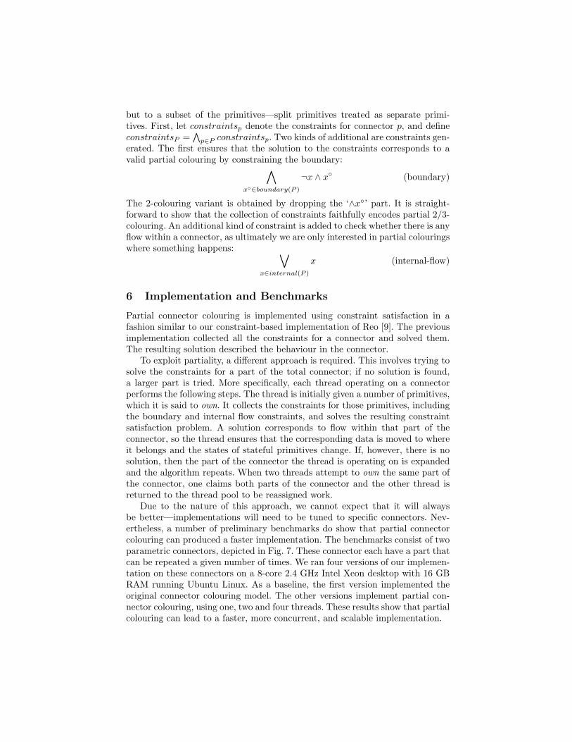
Due to the nature of this approach, we cannot expect that it will alwaysbe better—implementations will need to be tuned to specific connectors. Nev-ertheless, a number of preliminary benchmarks do show that partial connectorcolouring can produced a faster implementation. The benchmarks consist of twoparametric connectors, depicted in Fig. 7. These connector each have a part thatcan be repeated a given number of times. We ran four versions of our implemen-tation on these connectors on a 8-core 2.4 GHz Intel Xeon desktop with 16 GBRAM running Ubuntu Linux. As a baseline, the first version implemented theoriginal connector colouring model. The other versions implement partial con-nector colouring, using one, two and four threads. These results show that partialcolouring can lead to a faster, more concurrent, and scalable implementation.

1A
1B
1C
1D∞ Z
h
1W1
1R1
1W2
1R2
1Wn
1Rn
· · ·
· · ·
· · ·
n
0 1 2 3 4 5 6 7
110
100
1000
0
Height (h)
Tim
e (m
illis
econ
ds)
Partial CC: 1 ThreadPartial CC: 2 ThreadsPartial CC: 4 ThreadsConnector Colouring
0 50 100 150 200
050
100
150
200
Size (n)T
ime
(mill
isec
onds
)
Partial CC: 1 ThreadPartial CC: 2 ThreadsPartial CC: 4 ThreadsConnector Colouring
(a) (b)
Fig. 7. Benchmarks: Multiple Merger (a) demonstrates that partial connector colour-ing offers an order of magnitude improvement for one thread, though multiple threadscreate too much contention. Pairwise Asynchronous (b) demonstrates significant ad-vantages of partial colouring, which scales well as more threads (cores) are added.
There are however a number of dimensions where heuristics can be appliedto improve the performance of the implementation, such as choosing the numberof threads, choosing where they start computing, and choosing how the set ofprimitives considered grows. These will be investigated in future work.
7 Related work
Many semantic models exist for Reo. Clarke et al. [6] outline the differencebetween various models. Only connector colouring [8], Reo automata [6], inten-tional automata [10], and the tile model [4] capture context dependent behaviour.Connector colouring was the first to do so, and the others refine it in one wayor another. The models are all distinct—and the relationship between them hasnot been investigated—but for our purposes, we do not consider automata-basedmodels as these do not lead to scalable implementations. The constraint-basedencoding of Reo [9] offers orders of magnitude improvement in performance andscalability of Reo implementations.
Wegner describes coordination as constrained interaction [19] and Monta-nari and Rossi express coordination as a constraint satisfaction problem [15].

They describe how to solve synchronisation problems using constraint solvingtechniques, but they do not encode context dependency or identify the benefitsof partiality. Lazovik et al. [13] utilise constraints to provide a choreographyframework for web services. The choreography, the business processes, and therequests are modelled as a set of constraints. Their setting, however, cannot ex-press the same kinds of coordination patterns as Reo. The analogy between Reoand constraint satisfaction has already been made [3], and indeed Kluppelholzand Baier encode the constraint automata model for Reo in terms of binary deci-sion diagrams in order to model check Reo connectors [12]. Constraint automataare represented by binary decision diagrams, encoded as propositional formulæ.Their encoding is similar to ours, though they use exclusively boolean variables,whilst our constraint encoding is phrased in terms of a richer data domain.
Minsky and Ungureanu introduce the Law-Governed Interaction (LGI) mech-anism [14], implemented by the Moses toolkit, where in laws are constraints spec-ified in a Prolog-like language, enforced on regulated events of the agents, such assending or receiving messages. This mechanism targets distributed coordinationof heterogenous agents using a policy that enforces extensible laws. However,laws are local, in the sense that can only refer to the agent being regulated.While this allows LGI to achieve good performance, it limits expressiveness.
Bruni et al.’s stateless algebra of connectors [7] and Sobocinski’s [17] state-ful extension resemble the core of Reo, though they lack context dependencyand data. The semantics is similar to 2-colouring in this limited setting. Bliduzeand Sifakis [5] present a semantics for their BIP coordination model in terms ofboolean propositions. Although similar, BIP is not as expressive as Reo. Jong-mans et al. [11] present an encoding of 3-colouring in terms of 2-colouring thatresembles our encoding into propositional constraints. Their approach adds fic-titious nodes into the Reo level, whereas ours is completely under the surface.
8 Conclusion
This paper presented partial connector colouring which improves on the ex-isting connector colouring semantics for Reo and their subsequent encoding asconstraints in three respects. Firstly, the semantics enable a more scalable imple-mentation by avoiding the lock-step evaluation of an entire connector. Secondly,the amount of concurrency is increased by enabling different parts of a connectorto evolve independently at different rates. Finally, partial 3-colouring retains thecontext dependent behaviour of 3-colouring but regains some of the behaviouralpossibilities lost due to the lock-step computation. Benchmarks have also beenpresented to confirm the possible performance improvements.
An interesting direction for future work is a more in depth empirical explo-ration of the heuristics alluded to in Section 6.
References
1. F. Arbab. Reo: a channel-based coordination model for component composition.Mathematical Structures in Computer Science, 14(3):329–366, 2004.
2. F. Arbab, C. Koehler, Z. Maraikar, Y. Moon, and J. Proenca. Modeling, testingand executing Reo connectors with the Eclipse Coordination Tools. In Interna-tional Workshop on Formal Aspects of Component Software (FACS), Malaga, 2008.Electronic Notes in Theoretical Computer Science (ENTCS).
3. Farhad Arbab. Composition of interacting computations. In D. Goldin, S. Smolka,and P. Wegner, editors, Interactive Computation: The New Paradigm, pages 277–321, Secaucus, NJ, USA, 2006. Springer-Verlag New York, Inc.
4. Farhad Arbab, Roberto Bruni, Dave Clarke, Ivan Lanese, and Ugo Montanari. Tilesfor Reo. In Proceedings of Recent Trends in Algebraic Development Techniques(WADT), volume 5486 of LNCS, pages 37–55, Berlin, Heidelberg, 2008. Springer.
5. Simon Bliudze and Joseph Sifakis. Synthesizing glue operators from glue con-straints for the construction of component-based systems. In Software Composi-tion, volume 6708 of Lecture Notes in Computer Science, pages 51–67, 2011.
6. Marcello M. Bonsangue, Dave Clarke, and Alexandra Silva. Automata for context-dependent connectors. volume 5521 of LNCS, pages 184–203, 2009.
7. Roberto Bruni, Ivan Lanese, and Ugo Montanari. A basic algebra of statelessconnectors. Theor. Comput. Sci., 366(1-2):98–120, 2006.
8. D. Clarke, D. Costa, and F. Arbab. Connector colouring I: Synchronisation andcontext dependency. Science of Computer Programming, 66(3):205–225, May 2007.
9. D. Clarke, J. Proenca, A. Lazovik, and F. Arbab. Channel-based coordination viaconstraint satisfaction. Sci. Comput. Program., 76(8):681–710, 2011.
10. David Costa. Formal Models for Component Connectors. PhD thesis, Vrij Univer-siteit Amsterdam, 2010.
11. Sung-Shik T. Q. Jongmans, Christian Krause, and Farhad Arbab. Encodingcontext-sensitivity in reo into non-context-sensitive semantic models. In Coor-dination Models and Languages, volume 6721 of LNCS, pages 31–48, 2011.
12. Sascha Kluppelholz and Christel Baier. Symbolic model checking for channel-basedcomponent connectors. ENTCS, 175(2):19–37, 2007.
13. A. Lazovik, M. Aiello, and R. Gennari. Choreographies: Using constraints to satisfyservice requests. In Proc. of the Advanced International Conference on Telecom-munications and International Conference on Internet and Web Applications andServices, page 150, Washington, DC, USA, 2006. IEEE Computer Society.
14. Naftaly H. Minsky and Victoria Ungureanu. Law-governed interaction: a coordi-nation and control mechanism for heterogeneous distributed systems. ACM Trans-actions on Software Engineering and Methodology, 9(3):273–305, 2000.
15. Ugo Montanari and Francesca Rossi. Modeling process coordination via tiles,graphs, and constraints. In 3rd Biennial World Conference on Integrated Designand Process Technology, volume 4, pages 1–8, 1998.
16. Jose Proenca. Synchronous coordination of distributed components. PhD thesis,LIACS, Leiden University, May 2011.
17. P. Sobocinski. Representations of Petri net interactions. In Concurrency Theory(CONCUR ‘10), number 6269 in LNCS, pages 554–568. Springer, 2010.
18. W. M. P. van der Aalst, A. H. M. ter Hofstede, B. Kiepuszewski, and A. P. Barros.Workflow patterns. Distributed and Parallel Databases, 14(1):5–51, 2003.
19. P. Wegner. Coordination as constrained interaction (extended abstract). In Coor-dination Languages and Models, volume 1061 of LNCS, pages 28–33, 1996.