owner's manual - sega retro
TRANSCRIPT
OWNER'S MANUAL
IMPORTANT• � Before using this product, read this manual carefully to understand the
contents herein stated.• � After reading this manual, be sure to keep it near the product or in a
convenient place for easy reference when necessary.
OW
NER
'S MAN
UAL
2SPICY
420-7031-01
Nissay Aroma Building, 5-37-1, Kamata, Ohta-ku, Tokyo 144-8721, JapanPhone: +81-3-5480-6582 Facsimile: +81-3-5480-6584
© SEGA
420-7031-011ST PRINTING
TAB
LE OF C
ON
TENTS
�
TABLE OF CONTENTS
E0-0703 420-7031-01
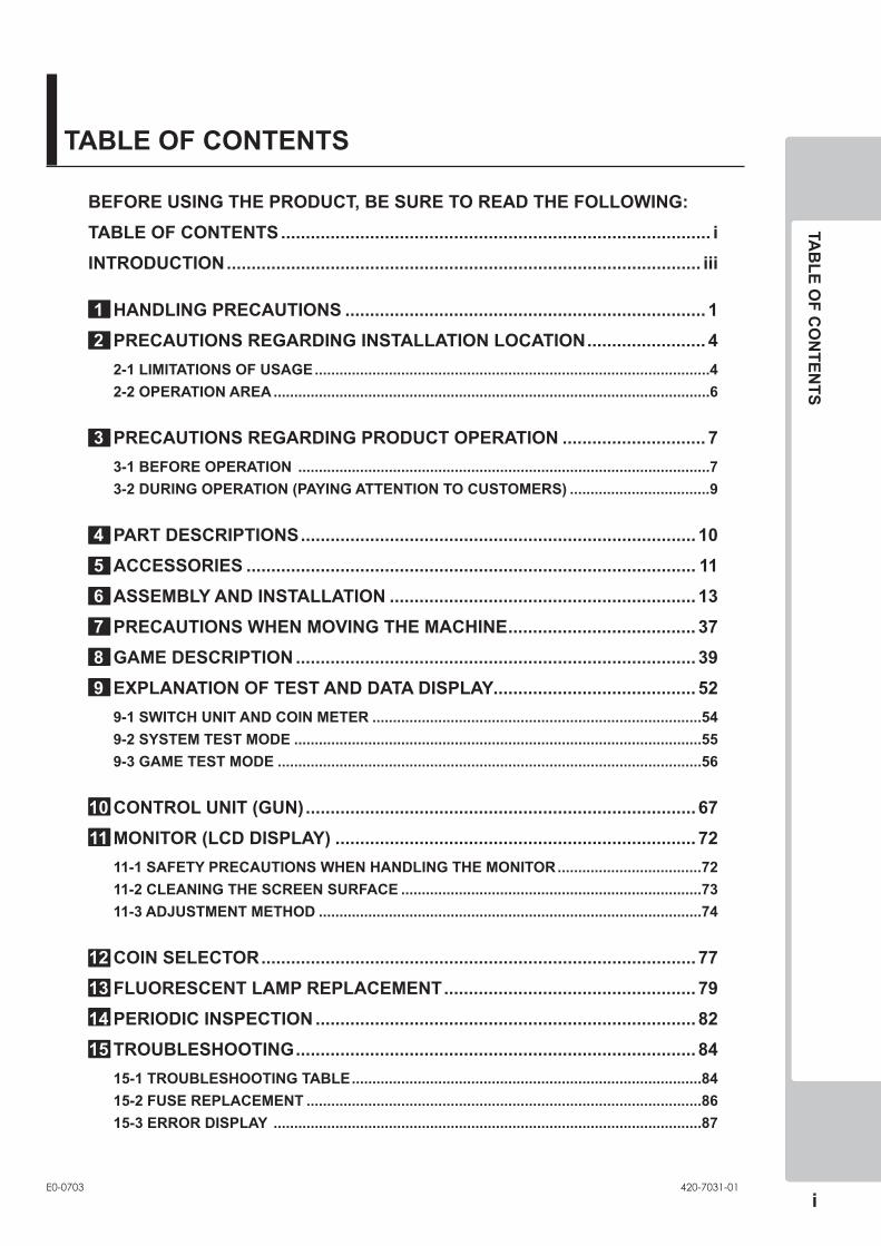
BEFORE USING THE PRODUCT, BE SURE TO READ THE FOLLOWING:TABLE OF CONTENTS ....................................................................................... �INTRODUCTION ................................................................................................ ���
1 HANDLING PRECAUTIONS ......................................................................... 1 2 PRECAUTIONS REGARDING INSTALLATION LOCATION ........................ 4 2-1 LIMITATIONS OF USAGE ................................................................................................4 2-2 OPERATION AREA ..........................................................................................................6
3 PRECAUTIONS REGARDING PRODUCT OPERATION ............................. 7 3-1 BEFORE OPERATION ....................................................................................................7 3-2 DURING OPERATION (PAYING ATTENTION TO CUSTOMERS) ..................................9
4 PART DESCRIPTIONS ................................................................................ 10 5 ACCESSORIES ........................................................................................... 11 6 ASSEMBLY AND INSTALLATION .............................................................. 13 7 PRECAUTIONS WHEN MOVING THE MACHINE ...................................... 37 8 GAME DESCRIPTION ................................................................................. 39 9 EXPLANATION OF TEST AND DATA DISPLAY......................................... 52 9-1 SWITCH UNIT AND COIN METER ................................................................................54 9-2 SYSTEM TEST MODE ...................................................................................................55 9-3 GAME TEST MODE .......................................................................................................56
10 CONTROL UNIT (GUN) ............................................................................... 67 11 MONITOR (LCD DISPLAY) ......................................................................... 72 11-1 SAFETY PRECAUTIONS WHEN HANDLING THE MONITOR ...................................72 11-2 CLEANING THE SCREEN SURFACE .........................................................................73 11-3 ADJUSTMENT METHOD .............................................................................................74
12 COIN SELECTOR ........................................................................................ 77 13 FLUORESCENT LAMP REPLACEMENT ................................................... 79 14 PERIODIC INSPECTION ............................................................................. 82 15 TROUBLESHOOTING ................................................................................. 84 15-1 TROUBLESHOOTING TABLE .....................................................................................84 15-2 FUSE REPLACEMENT ................................................................................................86 15-3 ERROR DISPLAY ........................................................................................................87
ii
TAB
LE OF C
ON
TENTS
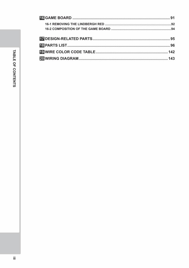
16 GAME BOARD ............................................................................................ 91 16-1 REMOVING THE LINDBERGH RED ...........................................................................92 16-2 COMPOSITION OF THE GAME BOARD ....................................................................94
17 DESIGN-RELATED PARTS ......................................................................... 95 18 PARTS LIST ................................................................................................. 9619 WIRE COLOR CODE TABLE .................................................................... 142 20 WIRING DIAGRAM .................................................................................... 143
TAB
LE OF C
ON
TENTS
���
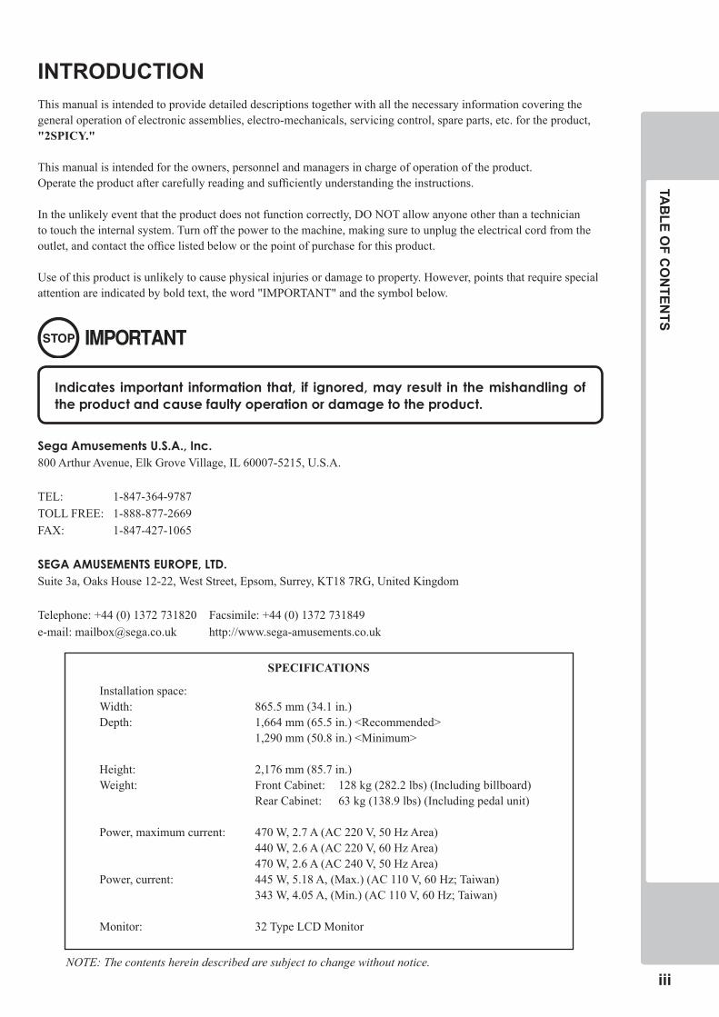
INTRODUCTIONThis manual is intended to provide detailed descriptions together with all the necessary information covering the general operation of electronic assemblies, electro-mechanicals, servicing control, spare parts, etc. for the product, "2SPICY."
This manual is intended for the owners, personnel and managers in charge of operation of the product. Operate the product after carefully reading and sufficiently understanding the instructions.
In the unlikely event that the product does not function correctly, DO NOT allow anyone other than a technician to touch the internal system. Turn off the power to the machine, making sure to unplug the electrical cord from the outlet, and contact the office listed below or the point of purchase for this product.
Use of this product is unlikely to cause physical injuries or damage to property. However, points that require special attention are indicated by bold text, the word "IMPORTANT" and the symbol below.
Indicates important information that, if ignored, may result in the mishandling of the product and cause faulty operation or damage to the product.
Sega Amusements U.S.A., Inc.800 Arthur Avenue, Elk Grove Village, IL 60007-5215, U.S.A.
TEL: 1-847-364-9787TOLL FREE: 1-888-877-2669FAX: 1-847-427-1065
SEGA AMUSEMENTS EUROPE, LTD.Suite 3a, Oaks House 12-22, West Street, Epsom, Surrey, KT18 7RG, United Kingdom
Telephone: +44 (0) 1372 731820 Facsimile: +44 (0) 1372 731849e-mail: [email protected] http://www.sega-amusements.co.uk
SPECIFICATIONS
Installation space:Width: 865.5 mm (34.1 in.)Depth: 1,664 mm (65.5 in.) <Recommended> 1,290 mm (50.8 in.) <Minimum>
Height: 2,176 mm (85.7 in.)Weight: Front Cabinet: 128 kg (282.2 lbs) (Including billboard) Rear Cabinet: 63 kg (138.9 lbs) (Including pedal unit)
Power, maximum current: 470 W, 2.7 A (AC 220 V, 50 Hz Area) 440 W, 2.6 A (AC 220 V, 60 Hz Area) 470 W, 2.6 A (AC 240 V, 50 Hz Area)Power, current: 445 W, 5.18 A, (Max.) (AC 110 V, 60 Hz; Taiwan) 343 W, 4.05 A, (Min.) (AC 110 V, 60 Hz; Taiwan)
Monitor: 32 Type LCD Monitor
NOTE: The contents herein described are subject to change without notice.
�v
INTR
OD
UC
TION
Definition of ‘Site Maintenance Personnel or Other Qualified Individuals’
Parts replacement, maintenance inspections and troubleshooting should be carried out by site maintenance personnel or other qualified professionals. This manual includes directions for potentially dangerous procedures which should only be carried out by professionals with the appropriate specialized knowledge.
The site maintenance personnel or other qualified professionals mentioned in this manual are defined as follows:
Site maintenance personnel:Individuals with experience in maintaining amusement equipment, vending machines, etc., working under the supervision of the owner/operator of this product to maintain machines within amusement facilities or similar premises by carrying out everyday procedures such as assembly, maintenance inspections, and replacement of units/expendable parts.
Activities to be carried out by site maintenance personnel:Amusement equipment/vending machine assembly, maintenance inspection and replacement of units/expendable parts.
Other qualified professionals:Persons employed by amusement equipment manufacturers, or involved in design, production, testing or maintenance of amusement equipment. The individual should have either graduated from technical school or hold similar qualifications in electrical/electronics/mechanical engineering.
Activities to be carried out by other qualified professionals:Amusement equipment/vending machine assembly, repair/adjustment of electrical/electronic/mechanical parts.
Procedures not described in this manual or marked as 'to be carried out by site maintenance personnel or other qualified professionals' should not be carried out by personnel without the necessary skill or technology. Work carried out by unqualified persons may cause serious accidents, including electrocution.
HA
ND
LING
PREC
AU
TION
S
�
�
HANDLING PRECAUTIONS
When installing or inspecting the machine, be very careful of the following points and pay attention to ensure that the player can enjoy the game safely.Non-compliance with the following points or inappropriate handling running counter to the cautionary matters herein stated can cause personal injury or damage to the machine.
• Beforeperformingwork,besuretoturnthepoweroff.Performingtheworkwithoutturningthepoweroffcancauseanelectricshockorshortcircuit.Inthecaseworkshouldbeperformedinthestatusofpoweron,thismanualalwaysstatestothateffect.
• Toavoidanelectricshockorshortcircuit,donotpluginorunplugquickly.
• Toavoidanelectricshock,donotpluginorunplugwithawethand.
• Donotexposepowercordsorearthwiresonthesurface,(floor,passage,etc.).Ifexposed,thepowercordsandearthwiresaresusceptibletodamage.Damagedcordsandwirescancauseanelectricshockorshortcircuit.
• Toavoidcausingafireoranelectricshock,donotputthingsonordamagethepowercords.
• Whenorafterinstallingtheproduct,donotunnecessarilypullthepowercord.Ifdamaged,thepowercordcancauseafireoranelectricshock.
• Incasethepowercordisdamaged,askforareplacementthroughwheretheproductwaspurchasedfromortheofficehereinstated.Usingthecordasisdamagedcancausefire,anelectricshockorleakage.
• Besuretoperformgroundingappropriately.Inappropriategroundingcancauseanelectricshock.
• Besuretousefusesmeetingthespecifiedrating.Usingfusesexceedingthespecifiedratingcancauseafireoranelectricshock.
• BesurethatconnectionssuchasICBDaremadeproperly.Insufficientinsertioncancauseanelectricshock.
• Specificationchanges,removalofequipment,conversionand/oraddition,notdesignatedbySEGAarenotpermitted.
-Failuretoobservethismaycauseafireoranelectricshock.Non-compliancewiththisinstructioncanhaveabadinfluenceuponphysicalconditionsoftheplayersortheonlookers,orresultininjuryduringplay.
-SEGAshallnotbeheldresponsiblefordamage,compensationfordamagetoathirdparty,causedbyspecificationchangesnotdesignatedbySEGA.
• Ifworkorpartsreplacementnotindicatedinthismanualiscarriedout,anaccidentmayoccur.Ifitisnecessarytocarryoutworknotindicatedinthismanual,besuretohaveitdonebytheofficeindicatedinthismanualorbythepointofpurchase.Also,pleaseinquireregardingdetailsoftheworkinvolved.
• Besuretoperformperiodicmaintenanceinspectionshereinstated.
�
�
HA
ND
LING
PREC
AU
TION
S
�
• FortheICboardcircuitinspections,onlythelogictesterisallowed.Theuseofamultiple-purposetesterisnotpermitted,sobecarefulinthisregard.
• StaticelectricityfromyourbodymaydamagesomeelectronicsdevicesontheICboard.BeforehandlingtheICboard,touchagroundedmetallicsurfacesothatthestaticelectricitycanbedischarged.
• Donotturnthepoweronandoffcontinuously.Repeatedlyturningthepoweronandoffmaycauseproductmalfunctionorpartsdamage.
• Somepartsarenotdesignedandmanufacturedspecificallyforthisgamemachine.Themanufacturersmaydiscontinue,orchangethespecificationsofsuchgeneral-purposeparts.Ifthisisthecase,SEGAcannotrepairorreplaceafailedgamemachinewhetherornotawarrantyperiodhasexpired.
HA
ND
LING
PREC
AU
TION
S
�
�
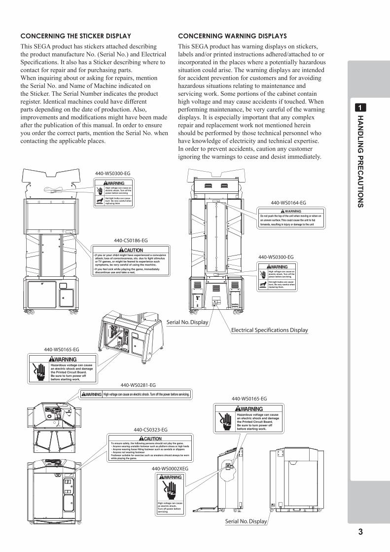
CONCERNINGTHESTICKERDISPLAY
This SEGA product has stickers attached describing the product manufacture No. (Serial No.) and Electrical Specifications. It also has a Sticker describing where to contact for repair and for purchasing parts.When inquiring about or asking for repairs, mention the Serial No. and Name of Machine indicated on the Sticker. The Serial Number indicates the product register. Identical machines could have different parts depending on the date of production. Also, improvements and modifications might have been made after the publication of this manual. In order to ensure you order the correct parts, mention the Serial No. when contacting the applicable places.
CONCERNINGWARNINGDISPLAYS
This SEGA product has warning displays on stickers, labels and/or printed instructions adhered/attached to or incorporated in the places where a potentially hazardous situation could arise. The warning displays are intended for accident prevention for customers and for avoiding hazardous situations relating to maintenance and servicing work. Some portions of the cabinet contain high voltage and may cause accidents if touched. When performing maintenance, be very careful of the warning displays. It is especially important that any complex repair and replacement work not mentioned herein should be performed by those technical personnel who have knowledge of electricity and technical expertise.In order to prevent accidents, caution any customer ignoring the warnings to cease and desist immediately.
440-CS0323-EG
440-WS0164-EG
Serial No. DisplayElectrical Specifications Display
Serial No. Display
440-WS0300-EG
440-WS0300-EG
440-CS0186-EG
440-WS0165-EG
440-WS0165-EG
440-WS0002XEG
440-WS0281-EG
�
PREC
AU
TION
S REG
AR
DIN
G IN
STALLATIO
N LO
CATIO
N
�
PRECAUTIONS REGARDING INSTALLATION LOCATION
Thisproductisanindoorgamemachine.Donotinstallitoutside.Evenindoors,avoidinstallinginplacesmentionedbelowsoasnottocauseafire,electricshock,injuryand/ormalfunction.
-Placessubjecttorainorwaterleakage,orplacessubjecttohighhumidityintheproximityofanindoorswimmingpooland/orshower,etc.
-Placessubjecttodirectsunlight,orplacessubjecttohightemperaturesintheproximityofheatingunits,etc.
-Placesfilledwithinflammablegasorvicinityofhighlyinflammable/volatilechemicalsorhazardousmatter.
-Dustyplaces.
-Slopedsurfaces.
-Placessubjecttoanytypeofviolentimpact.
-Vicinityofanti-disasterfacilitiessuchasfireexitsandfireextinguishers.
-Areaswherethetemperatureexceedstheapplicabletemperature(ambienttemperature)rangeof5to30degreescentigrade.
• BesuretochecktheElectricalSpecifications.Ensurethatthisproductiscompatiblewiththelocation'spowersupply,voltage,andfrequencyrequirements.AplatedescribingElectricalSpecificationsisattachedtotheproduct.Non-compliancewiththeElectricalSpecificationscancauseafireandelectricshock.
• Thisproductrequiresabreakerandearthmechanismaspartofthelocationfacilities.Usingtheproductwithoutthesecancauseafireandelectricshock.
• Ensurethattheindoorwiringforthepowersupplyisratedat15Aorhigher(ACsinglephase100V~120Varea),and7Aorhigher(AC220V~240Varea).Non-compliancewiththeElectricalSpecificationscancauseafireandelectricshock.
• Besuretouseanindependentpowersupplyequippedwithanearthleakagebreaker.Usingapowersupplywithoutanearthleakagebreakercancauseanoutbreakoffireifapowersurgeoccurs.
• Puttingmanyloadsononeelectricaloutletcancausegenerationofheatandafireresultingfromoverload.
• Whenusinganextensioncord,ensurethatthecordisratedat15Aorhigher(AC100V~120Varea)and7Aorhigher(AC220V~240Varea).Usingacordratedlowerthanthespecifiedratingcancauseafireandelectricshock.
�
�-� LIMITATIONS OF USAGE
PREC
AU
TION
S REG
AR
DIN
G IN
STALLATIO
N LO
CATIO
N
�
�
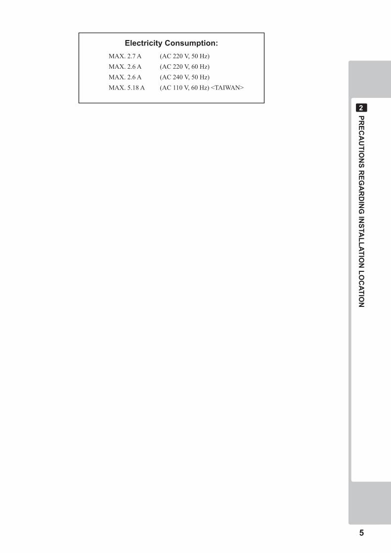
PRECAUTIONS REGARDING INSTALLATION LOCATION Electricity Consumption: MAX. 2.7 A (AC 220 V, 50 Hz)MAX. 2.6 A (AC 220 V, 60 Hz)MAX. 2.6 A (AC 240 V, 50 Hz)MAX. 5.18 A (AC 110 V, 60 Hz) <TAIWAN>
�
PREC
AU
TION
S REG
AR
DIN
G IN
STALLATIO
N LO
CATIO
N
�
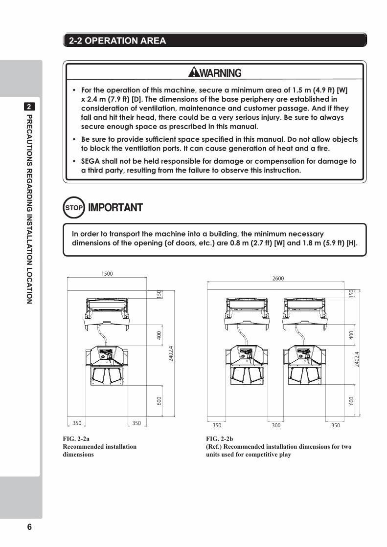
• Fortheoperationofthismachine,secureaminimumareaof1.5m(4.9ft)[W]x2.4m(7.9ft)[D].Thedimensionsofthebaseperipheryareestablishedinconsiderationofventilation,maintenanceandcustomerpassage.Andiftheyfallandhittheirhead,therecouldbeaveryseriousinjury.Besuretoalwayssecureenoughspaceasprescribedinthismanual.
• Besuretoprovidesufficientspacespecifiedinthismanual.Donotallowobjectstoblocktheventilationports.Itcancausegenerationofheatandafire.
• SEGAshallnotbeheldresponsiblefordamageorcompensationfordamagetoathirdparty,resultingfromthefailuretoobservethisinstruction.
�-� OPERATION AREA
Inordertotransportthemachineintoabuilding,theminimumnecessarydimensionsoftheopening(ofdoors,etc.)are0.8m(2.7ft)[W]and1.8m(5.9ft)[H].
350 350 350 300 350
15002600
600
2402.4
2402.4
600
400
150
400
150
FIG. 2-2b (Ref.) Recommended installation dimensions for two units used for competitive play
FIG. 2-2aRecommended installationdimensions
PREC
AU
TION
S REG
AR
DIN
G PR
OD
UC
T OPER
ATION
�
�
Inordertoavoidaccidents,checkthefollowingbeforestartingtheoperation:
• Toensuremaximumsafetyfortheplayersandthecustomers,ensurethatwheretheproductisoperatedhassufficientlightingtoallowanywarningstoberead.Operationunderinsufficientlightingcancausebodilycontactwitheachother,hittingaccident,and/ortroublebetweencustomers.
• Besuretoperformappropriateadjustmentofthemonitor(projector).Foroperationofthismachine,donotleavemonitor'sflickeringordeviationasis.Failuretoobservethiscanhaveabadinfluenceupontheplayers'orthecustomers'physicalconditions.
• Itissuggestedtoensureaspaceallowingtheplayerswhofeelsickwhileplayingthegametotakearest.
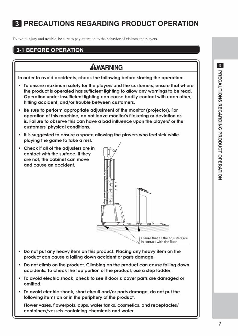
• Checkifalloftheadjustersareincontactwiththesurface.Iftheyarenot,thecabinetcanmoveandcauseanaccident.
• Donotputanyheavyitemonthisproduct.Placinganyheavyitemontheproductcancauseafallingdownaccidentorpartsdamage.
• Donotclimbontheproduct.Climbingontheproductcancausefallingdownaccidents.Tocheckthetopportionoftheproduct,useastepladder.
• Toavoidelectricshock,checktoseeifdoor&coverpartsaredamagedoromitted.
• Toavoidelectricshock,shortcircuitand/orpartsdamage,donotputthefollowingitemsonorintheperipheryoftheproduct.
Flowervases,flowerpots,cups,watertanks,cosmetics,andreceptacles/containers/vesselscontainingchemicalsandwater.
�-� BEFORE OPERATION
Ensure that all the adjusters arein contact with the floor.
PRECAUTIONS REGARDING PRODUCT OPERATION�
To avoid injury and trouble, be sure to pay attention to the behavior of visitors and players.
�
PREC
AU
TION
S REG
AR
DIN
G PR
OD
UC
T OPER
ATION
�
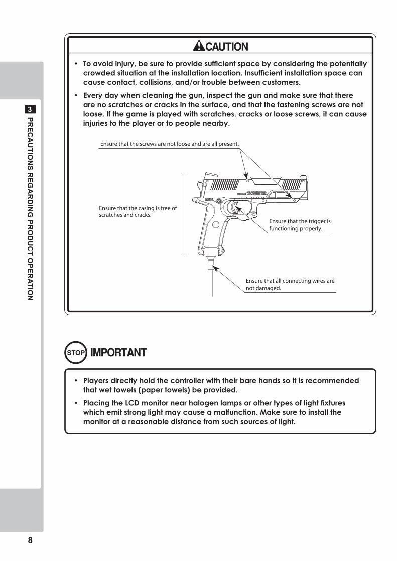
• Toavoidinjury,besuretoprovidesufficientspacebyconsideringthepotentiallycrowdedsituationattheinstallationlocation.Insufficientinstallationspacecancausecontact,collisions,and/ortroublebetweencustomers.
• Everydaywhencleaningthegun,inspectthegunandmakesurethattherearenoscratchesorcracksinthesurface,andthatthefasteningscrewsarenotloose.Ifthegameisplayedwithscratches,cracksorloosescrews,itcancauseinjuriestotheplayerortopeoplenearby.
Ensure that all connecting wires arenot damaged.
Ensure that the screws are not loose and are all present.
Ensure that the casing is free ofscratches and cracks.
Ensure that the trigger isfunctioning properly.
• Playersdirectlyholdthecontrollerwiththeirbarehandssoitisrecommendedthatwettowels(papertowels)beprovided.
• PlacingtheLCDmonitornearhalogenlampsorothertypesoflightfixtureswhichemitstronglightmaycauseamalfunction.Makesuretoinstallthemonitoratareasonabledistancefromsuchsourcesoflight.
PREC
AU
TION
S REG
AR
DIN
G PR
OD
UC
T OPER
ATION
�
�
To avoid injury and trouble, be sure to pay attention to the behavior of visitors and players.
• Forsafetyreasons,donotallowanyofthefollowingpeopletoplaythegame.-Thosewhoneedassistancesuchastheuseofapparatuswhenwalking.-Thosewhohavehighbloodpressureoraheartproblem.-Thosewhohaveexperiencedmuscleconvulsionorlossofconsciousness
whenplayingvideogames,etc.-Thosewhohaveneckorspinalcordproblems.-Thosewhoareintoxicatedorundertheinfluenceofdrugs.-Pregnantwomen.-Thosewhoarenotingoodhealth.-Thosewhodonotfollowtheattendant’sinstructions.-ThosewhocannotgrasptheControlUnitsecurelybecauseofimmobilityinfingers,handsorarms.
-Personswhodisregardtheproduct'swarningdisplays.• Evenplayerswhohaveneverbeenadverselyaffectedbylightstimulusmight
experiencedizzinessorheadachedependingontheirphysicalconditionwhenplayingthegame.Smallchildrenareespeciallylikelytoexperiencethesesymptoms.Cautionguardiansofsmallchildrentokeepwatchontheirchildrenduringplay.
• Instructthosewhofeelsickduringplaytohaveamedicalexamination.• Toavoidinjuryfromfallsandelectricshocksduetospilleddrinks,instructthe
playernottoplaceheavyitemsordrinksontheproduct.• Toavoidelectricshocksandshortcircuits,donotallowcustomerstoput
handsandfingersorextraneousmatterintheopeningsoftheproductorsmallopeningsinoraroundthedoors.
• Toavoidfallsandresultinginjury,immediatelystopthecustomerfromleaningagainstorclimbingontheproduct,etc.
• Toavoidelectricshockandshortcircuit,donotallowcustomerstounplugthepowerplugwithoutajustifiablereason.
• Immediatelystopsuchviolentactsashittingandkickingtheproduct.Suchviolentactscancausepartsdamageorcausethecabinettofallover,resultingininjury.
• Instructplayerstoholdthegunsecurelywhileplaying.Ifthegunisdropped,itcouldcauseinjurytotheplayer.
• Itemssuchaslargefingerringscancauseinjurytothefingerswhileplaying.Instructplayerstoremoveallaccessoriesthatcouldcauseanaccidentbeforeplaying.
• Instructplayersthatasinglegunisnevertobeheldbytwoormorepeopleduringplay.Otherwisetherecouldbedangerouscontactoracollision.
�-� DURING OPERATION (PAYING ATTENTION TO CUSTOMERS)
�0
PAR
T DESC
RIPTIO
NS
�
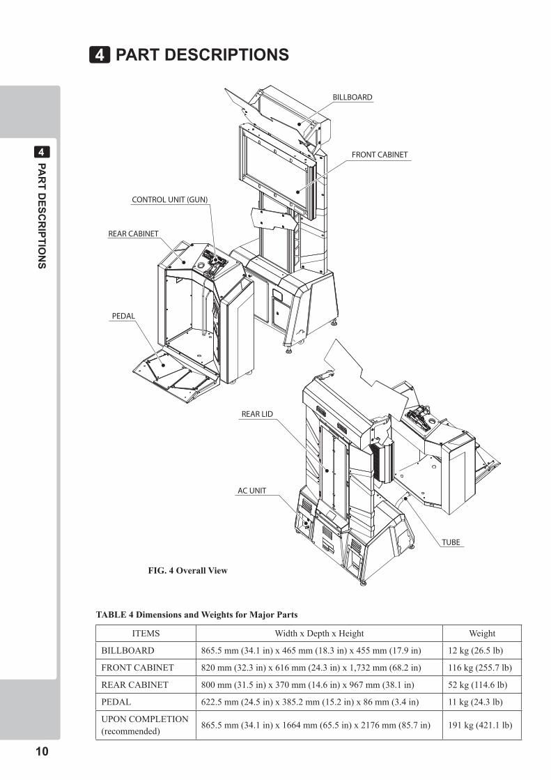
PART DESCRIPTIONS
TUBE
REAR LID
AC UNIT
PEDAL
REAR CABINET
FRONT CABINET
BILLBOARD
CONTROL UNIT (GUN)
�
FIG. 4 Overall View
TABLE 4 Dimensions and Weights for Major Parts
ITEMS Width x Depth x Height Weight
BILLBOARD 865.5 mm (34.1 in) x 465 mm (18.3 in) x 455 mm (17.9 in) 12 kg (26.5 lb)
FRONT CABINET 820 mm (32.3 in) x 616 mm (24.3 in) x 1,732 mm (68.2 in) 116 kg (255.7 lb)
REAR CABINET 800 mm (31.5 in) x 370 mm (14.6 in) x 967 mm (38.1 in) 52 kg (114.6 lb)
PEDAL 622.5 mm (24.5 in) x 385.2 mm (15.2 in) x 86 mm (3.4 in) 11 kg (24.3 lb)
UPON COMPLETION (recommended) 865.5 mm (34.1 in) x 1664 mm (65.5 in) x 2176 mm (85.7 in) 191 kg (421.1 lb)
AC
CESSO
RIES
��
�
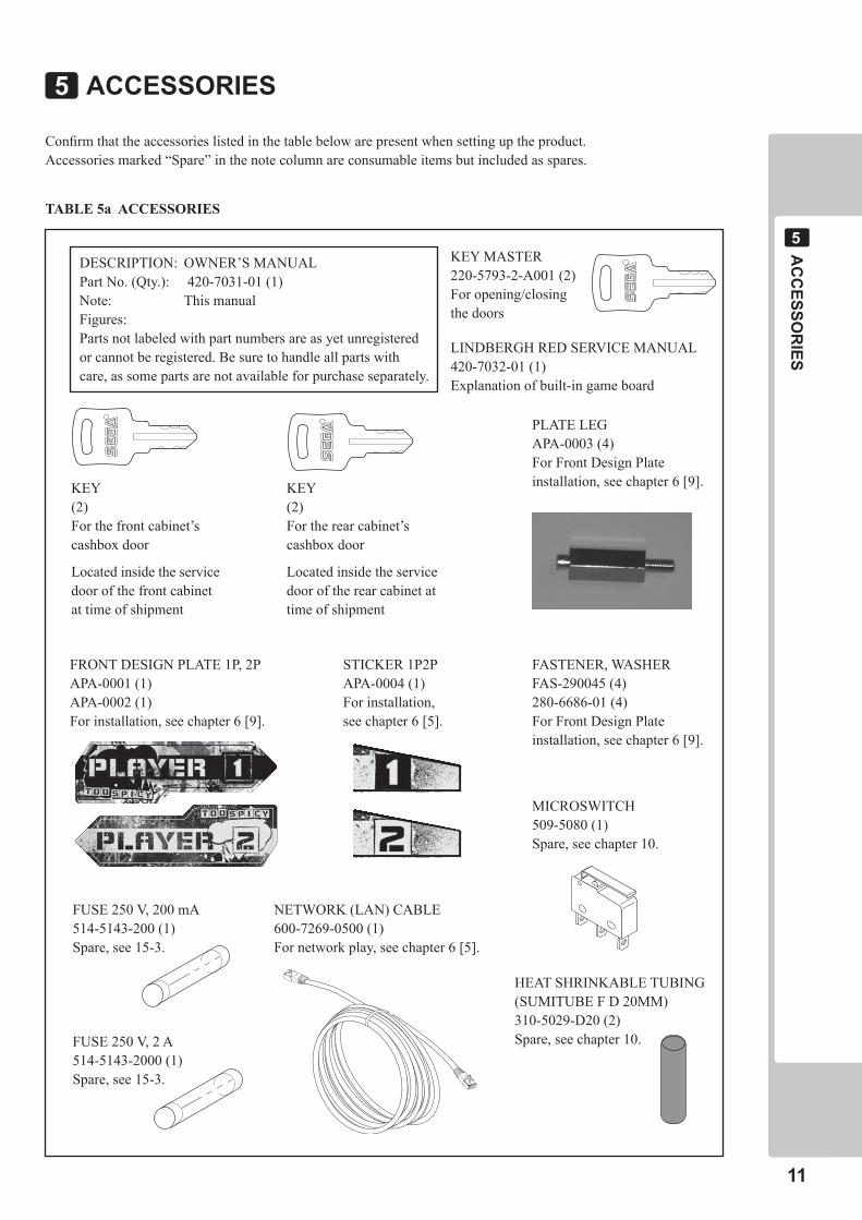
ACCESSORIES
Confirm that the accessories listed in the table below are present when setting up the product.Accessories marked “Spare” in the note column are consumable items but included as spares.
KEY MASTER220-5793-2-A001 (2)For opening/closing the doors
LINDBERGH RED SERVICE MANUAL420-7032-01 (1)Explanation of built-in game board
DESCRIPTION: OWNER’S MANUALPart No. (Qty.): 420-7031-01 (1)Note: This manualFigures: Parts not labeled with part numbers are as yet unregistered or cannot be registered. Be sure to handle all parts with care, as some parts are not available for purchase separately.
PLATE LEGAPA-0003 (4)For Front Design Plateinstallation, see chapter 6 [9].
STICKER 1P2PAPA-0004 (1)For installation,see chapter 6 [5].
NETWORK (LAN) CABLE 600-7269-0500 (1)For network play, see chapter 6 [5].
MICROSWITCH 509-5080 (1)Spare, see chapter 10.
FRONT DESIGN PLATE 1P, 2PAPA-0001 (1) APA-0002 (1)For installation, see chapter 6 [9].
KEY(2)For the rear cabinet’s cashbox door
Located inside the service door of the rear cabinet at time of shipment
KEY(2)For the front cabinet’s cashbox door
Located inside the service door of the front cabinet at time of shipment
FASTENER, WASHERFAS-290045 (4)280-6686-01 (4)For Front Design Plateinstallation, see chapter 6 [9].
�
TABLE 5a ACCESSORIES
FUSE 250 V, 200 mA514-5143-200 (1)Spare, see 15-3.
FUSE 250 V, 2 A514-5143-2000 (1)Spare, see 15-3.
HEAT SHRINKABLE TUBING(SUMITUBE F D 20MM) 310-5029-D20 (2)Spare, see chapter 10.
��
AC
CESSO
RIES
�
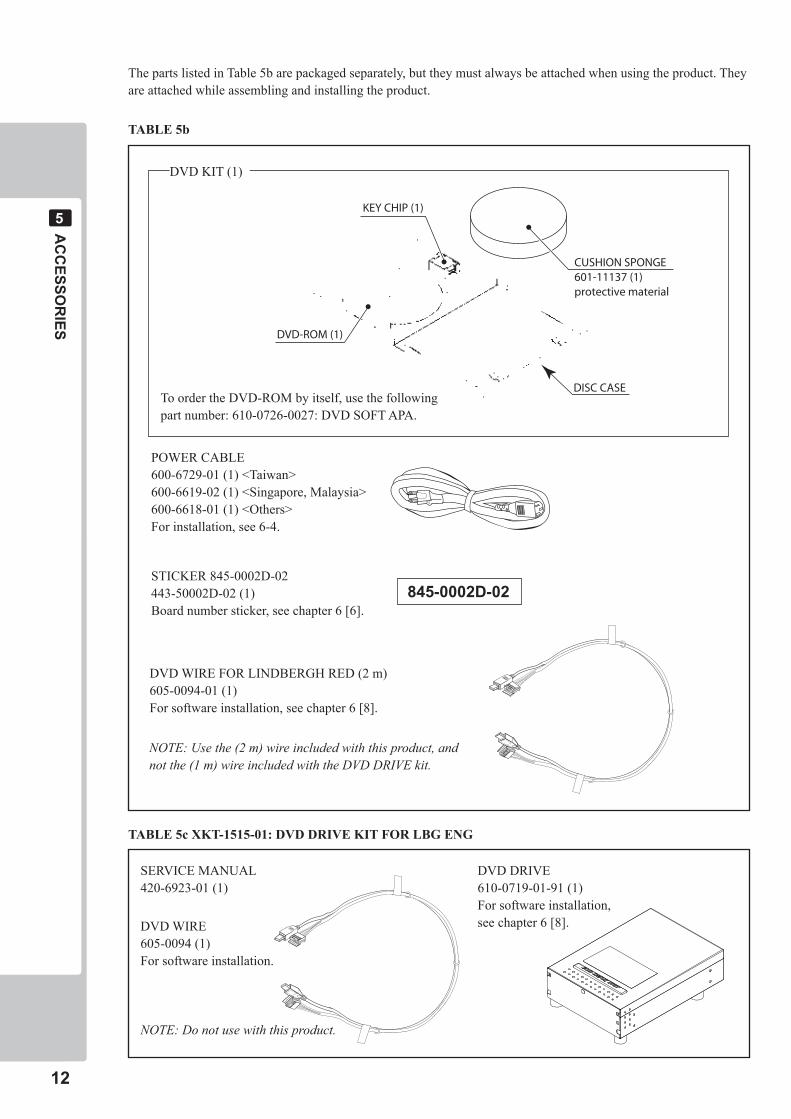
The parts listed in Table 5b are packaged separately, but they must always be attached when using the product. They are attached while assembling and installing the product.
DVD WIRE FOR LINDBERGH RED (2 m)605-0094-01 (1)For software installation, see chapter 6 [8].
POWER CABLE600-6729-01 (1) <Taiwan>600-6619-02 (1) <Singapore, Malaysia>600-6618-01 (1) <Others>For installation, see 6-4.
DVD KIT (1)
To order the DVD-ROM by itself, use the following part number: 610-0726-0027: DVD SOFT APA.
STICKER 845-0002D-02443-50002D-02 (1)Board number sticker, see chapter 6 [6].
DVD-ROM (1)
CUSHION SPONGE601-11137 (1)protective material
DISC CASE
KEY CHIP (1)
NOTE: Use the (2 m) wire included with this product, and not the (1 m) wire included with the DVD DRIVE kit.
TABLE 5b
TABLE 5c XKT-1515-01: DVD DRIVE KIT FOR LBG ENG
DVD WIRE605-0094 (1)For software installation.
NOTE: Do not use with this product.
SERVICE MANUAL420-6923-01 (1)
DVD DRIVE610-0719-01-91 (1)For software installation,see chapter 6 [8].
���-000�D-0�
ASSEM
BLY A
ND
INSTA
LLATION
��
�
• Thisworkshouldbecarriedoutbysitemaintenancepersonnelorotherqualifiedprofessionals.Workperformedbynon-technicalpersonnelcancauseasevereaccidentsuchaselectricshock.Failingtocomplywiththisinstructioncancauseasevereaccidentsuchaselectricshocktotheplayerduringoperation.
• Performassemblyworkbyfollowingtheprocedurehereinstated.Failuretocomplywiththeinstructionscancauseelectricshock.
• Performassemblingasperthismanual.Sincethisisacomplexmachine,incorrectassemblingcancauseanelectricshock,machinedamageand/orimproperfunctioningasperspecifiedperformance.
• Whenassembling,morethanonepersonisrequired.Dependingontheassemblywork,therearesomecasesinwhichworkingbyonepersonalonecancausepersonalinjuryorpartsdamage.
• Ensurethatconnectorsareproperlyconnected.Improperconnectionscancauseelectricshock.
• Becarefulnottodamagethewires.Damagedwiresmaycauseelectricshockorshortcircuitorpresentariskoffire.
• Donotcarelesslypushonthemonitor.Thiscouldcauseittofallover.
• Providesufficientspacesothatassemblingcanbeperformed.Performingworkinplaceswithnarrowspaceorlowceilingmaycauseanaccidentandassemblyworktobedifficult.
• Toperformworksafelyandavoidseriousaccidentsuchasthecabinetfallingdown,donotperformworkinplaceswherestep-likegradedifferences,aditch,orslopeexist.
• Donotuseconnectorsotherthanthoseconnectedtoandusedbythegameboardatthetimeofshipment.Donotconnectwirestounusedconnectors.Thiscouldcausethegenerationofheatorsmoke,oraburnout.
ASSEMBLY AND INSTALLATION�
• Wearappropriateworkclothingsothatworkcanbeperformedsafely.Useglovesandsafetyshoestopreventaccidentsorinjuries.
• Wheninstallingawireprotectioncoveroverafloor,useamaterialshapedsothatnoonepassingbywillstumbleoverit.Usingamaterialthatcouldbestumbledovermightleadtoanaccidentalfall.
• Becarefulinhandlingplasticparts.Besurenottotightenscrewsornutstootightly.Ifsuchpartsareexposedtoexcessiveloadsorimpact,theymightbecomedamaged,resultinginfragmentsorcracksthatcouldcauseaccidentalinjury.
��
ASSEM
BLY A
ND
INSTA
LLATION
�
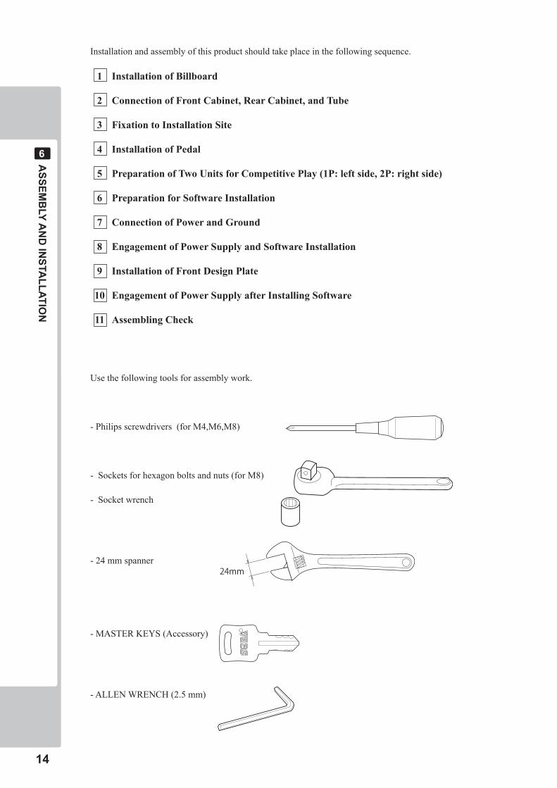
Use the following tools for assembly work.
- Philips screwdrivers (for M4,M6,M8)
- Sockets for hexagon bolts and nuts (for M8)
- Socket wrench
- 24 mm spanner
- MASTER KEYS (Accessory)
- ALLEN WRENCH (2.5 mm)
24mm
Installation and assembly of this product should take place in the following sequence.
1 Installation of Billboard
2 Connection of Front Cabinet, Rear Cabinet, and Tube
3 Fixation to Installation Site
4 Installation of Pedal
5 Preparation of Two Units for Competitive Play (1P: left side, 2P: right side)
6 Preparation for Software Installation
7 Connection of Power and Ground
8 Engagement of Power Supply and Software Installation
9 Installation of Front Design Plate
10 Engagement of Power Supply after Installing Software
11 Assembling Check
ASSEM
BLY A
ND
INSTA
LLATION
15
6
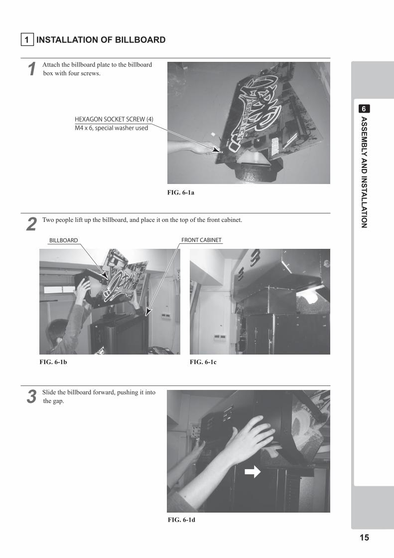
1 Attach the billboard plate to the billboard box with four screws.
2 Two people lift up the billboard, and place it on the top of the front cabinet.
3 Slide the billboard forward, pushing it into the gap.
FIG. 6-1b
FRONT CABINETBILLBOARD
FIG. 6-1c
➡
FIG. 6-1d
HEXAGON SOCKET SCREW (4) M4 x 6, special washer used
FIG. 6-1a
1 INSTALLATION OF BILLBOARD
��
ASSEM
BLY A
ND
INSTA
LLATION
�
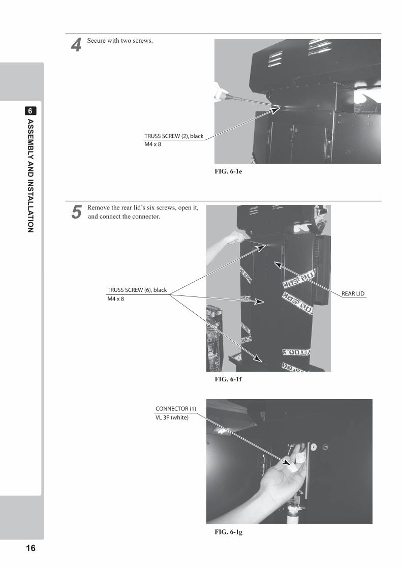
� Secure with two screws.
� Remove the rear lid’s six screws, open it, and connect the connector.
REAR LID
CONNECTOR (1)
VL 3P (white)
TRUSS SCREW (6), black
M4 x 8
FIG. 6-1g
TRUSS SCREW (2), blackM4 x 8
FIG. 6-1e
FIG. 6-1f
ASSEM
BLY A
ND
INSTA
LLATION
��
�
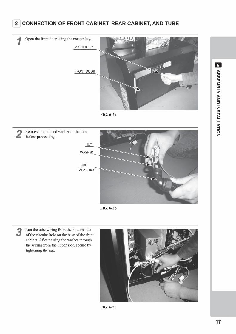
� Open the front door using the master key.
� Remove the nut and washer of the tube before proceeding.
� Run the tube wiring from the bottom side of the circular hole on the base of the front cabinet. After passing the washer through the wiring from the upper side, secure by tightening the nut.
MASTER KEY
FRONT DOOR
WASHER
TUBEAPA-0100
NUT
FIG. 6-2a
FIG. 6-2b
FIG. 6-2c
� CONNECTION OF FRONT CABINET, REAR CABINET, AND TUBE
��
ASSEM
BLY A
ND
INSTA
LLATION
�
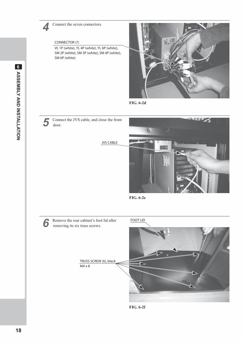
� Connect the seven connectors.
� Connect the JVS cable, and close the front door.
� Remove the rear cabinet’s foot lid after removing its six truss screws.
CONNECTOR (7)
VL 1P (white), YL 4P (white), YL 6P (white),SM 2P (white), SM 3P (white), SM 4P (white),SM 6P (white)
JVS CABLE
TRUSS SCREW (6), blackM4 x 8
FOOT LID
FIG. 6-2d
FIG. 6-2e
FIG. 6-2f
ASSEM
BLY A
ND
INSTA
LLATION
��
�
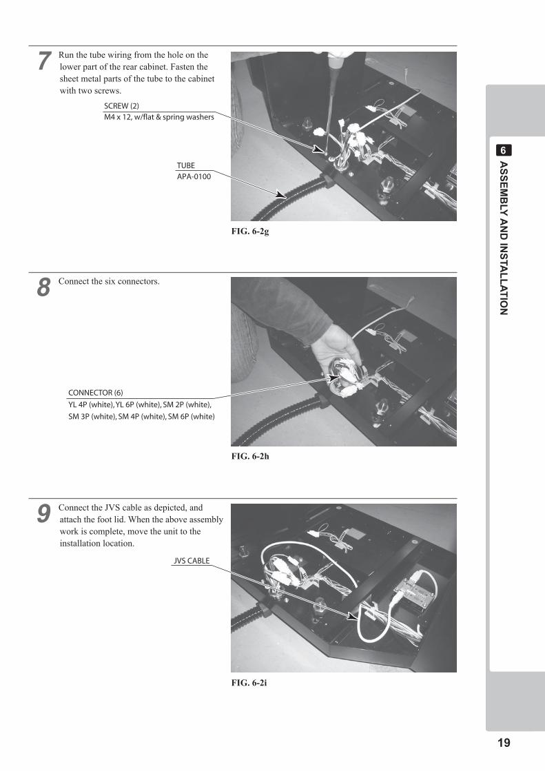
� Run the tube wiring from the hole on the lower part of the rear cabinet. Fasten the sheet metal parts of the tube to the cabinet with two screws.
� Connect the six connectors.
� Connect the JVS cable as depicted, and attach the foot lid. When the above assembly work is complete, move the unit to the installation location.
TUBEAPA-0100
SCREW (2)M4 x 12, w/flat & spring washers
CONNECTOR (6)
YL 4P (white), YL 6P (white), SM 2P (white),
SM 3P (white), SM 4P (white), SM 6P (white)
JVS CABLE
FIG. 6-2g
FIG. 6-2h
FIG. 6-2i
�0
ASSEM
BLY A
ND
INSTA
LLATION
�
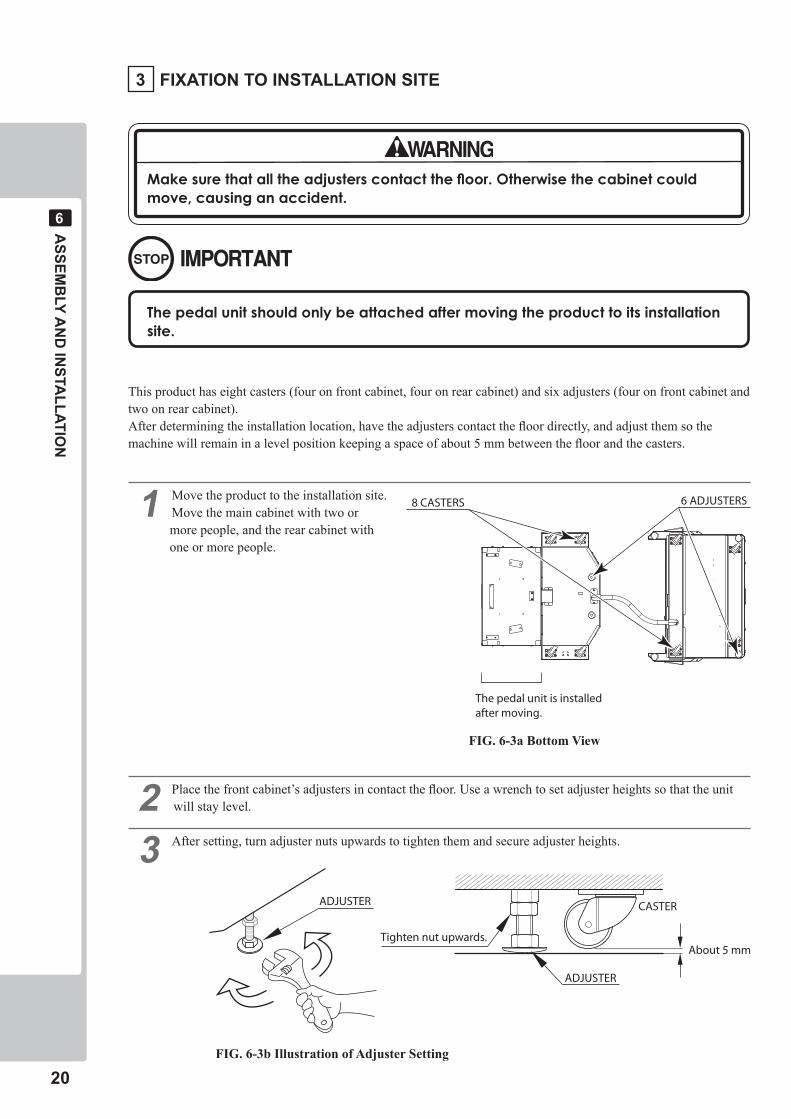
This product has eight casters (four on front cabinet, four on rear cabinet) and six adjusters (four on front cabinet and two on rear cabinet).After determining the installation location, have the adjusters contact the floor directly, and adjust them so the machine will remain in a level position keeping a space of about 5 mm between the floor and the casters.
� Move the product to the installation site.Move the main cabinet with two or more people, and the rear cabinet with one or more people.
� Place the front cabinet’s adjusters in contact the floor. Use a wrench to set adjuster heights so that the unit will stay level.
� After setting, turn adjuster nuts upwards to tighten them and secure adjuster heights.
The pedal unit is installedafter moving.
8 CASTERS 6 ADJUSTERS
About 5 mm
ADJUSTER
Tighten nut upwards.
ADJUSTER
CASTER
FIG. 6-3a Bottom View
� FIXATION TO INSTALLATION SITE
Makesurethatalltheadjusterscontactthefloor.Otherwisethecabinetcouldmove,causinganaccident.
Thepedalunitshouldonlybeattachedaftermovingtheproducttoitsinstallationsite.
FIG. 6-3b Illustration of Adjuster Setting
ASSEM
BLY A
ND
INSTA
LLATION
��
�
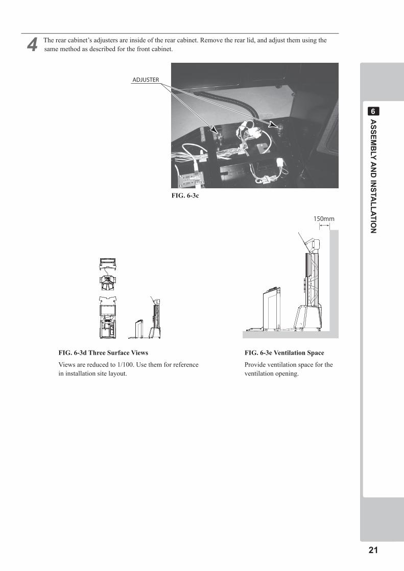
ADJUSTER
150mm
FIG. 6-3c
FIG. 6-3d Three Surface Views
Views are reduced to 1/100. Use them for reference in installation site layout.
� The rear cabinet’s adjusters are inside of the rear cabinet. Remove the rear lid, and adjust them using the same method as described for the front cabinet.
FIG. 6-3e Ventilation Space
Provide ventilation space for the ventilation opening.
��
ASSEM
BLY A
ND
INSTA
LLATION
�
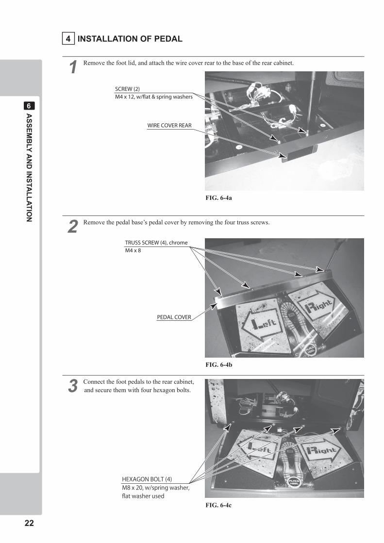
� Remove the foot lid, and attach the wire cover rear to the base of the rear cabinet.
� Remove the pedal base’s pedal cover by removing the four truss screws.
� Connect the foot pedals to the rear cabinet, and secure them with four hexagon bolts.
SCREW (2)M4 x 12, w/flat & spring washers
WIRE COVER REAR
TRUSS SCREW (4), chromeM4 x 8
PEDAL COVER
HEXAGON BOLT (4)M8 x 20, w/spring washer,flat washer used
FIG. 6-4a
� INSTALLATION OF PEDAL
FIG. 6-4b
FIG. 6-4c
ASSEM
BLY A
ND
INSTA
LLATION
��
�
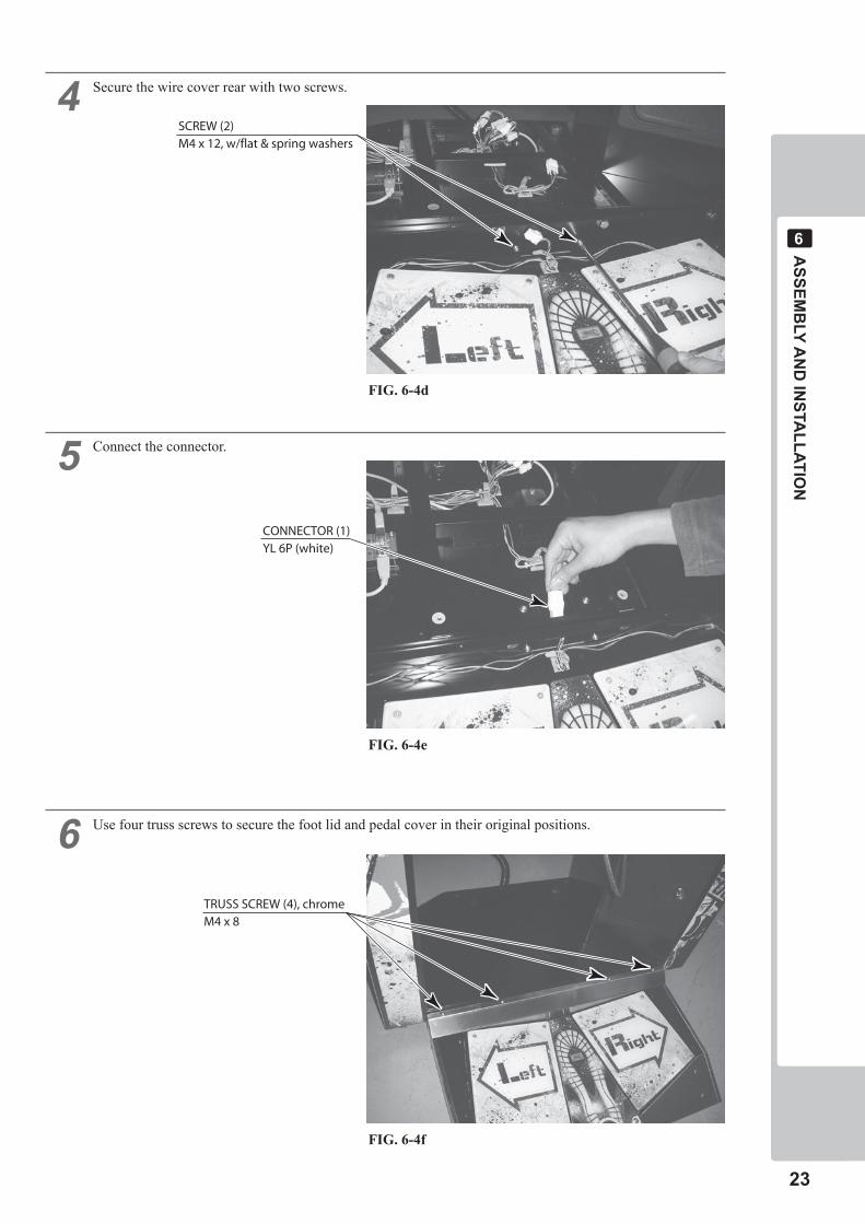
� Secure the wire cover rear with two screws.
� Connect the connector.
� Use four truss screws to secure the foot lid and pedal cover in their original positions.
SCREW (2)M4 x 12, w/flat & spring washers
CONNECTOR (1)YL 6P (white)
TRUSS SCREW (4), chromeM4 x 8
FIG. 6-4d
FIG. 6-4e
FIG. 6-4f
��
ASSEM
BLY A
ND
INSTA
LLATION
�
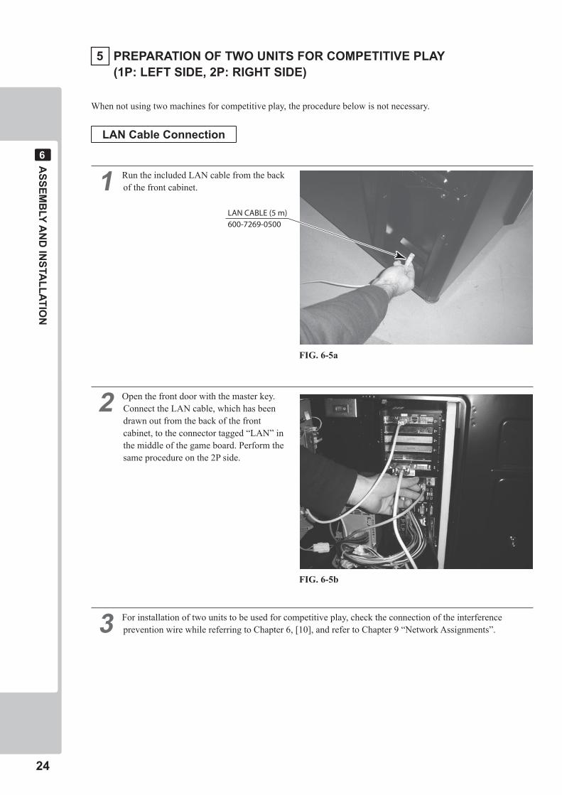
When not using two machines for competitive play, the procedure below is not necessary.
LAN Cable Connection
� Run the included LAN cable from the back of the front cabinet.
� Open the front door with the master key. Connect the LAN cable, which has been drawn out from the back of the front cabinet, to the connector tagged “LAN” in the middle of the game board. Perform the same procedure on the 2P side.
� For installation of two units to be used for competitive play, check the connection of the interference prevention wire while referring to Chapter 6, [10], and refer to Chapter 9 “Network Assignments”.
LAN CABLE (5 m)600-7269-0500
� PREPARATION OF TWO UNITS FOR COMPETITIVE PLAY (�P: LEFT SIDE, �P: RIGHT SIDE)
FIG. 6-5a
FIG. 6-5b
ASSEM
BLY A
ND
INSTA
LLATION
��
�
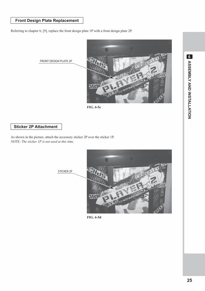
Front Design Plate Replacement
Referring to chapter 6, [9], replace the front design plate 1P with a front design plate 2P.
Sticker �P Attachment
As shown in the picture, attach the accessory sticker 2P over the sticker 1P.NOTE: The sticker 1P is not used at this time.
FRONT DESIGN PLATE 2P
FIG. 6-5c
FIG. 6-5d
STICKER 2P
��
ASSEM
BLY A
ND
INSTA
LLATION
�
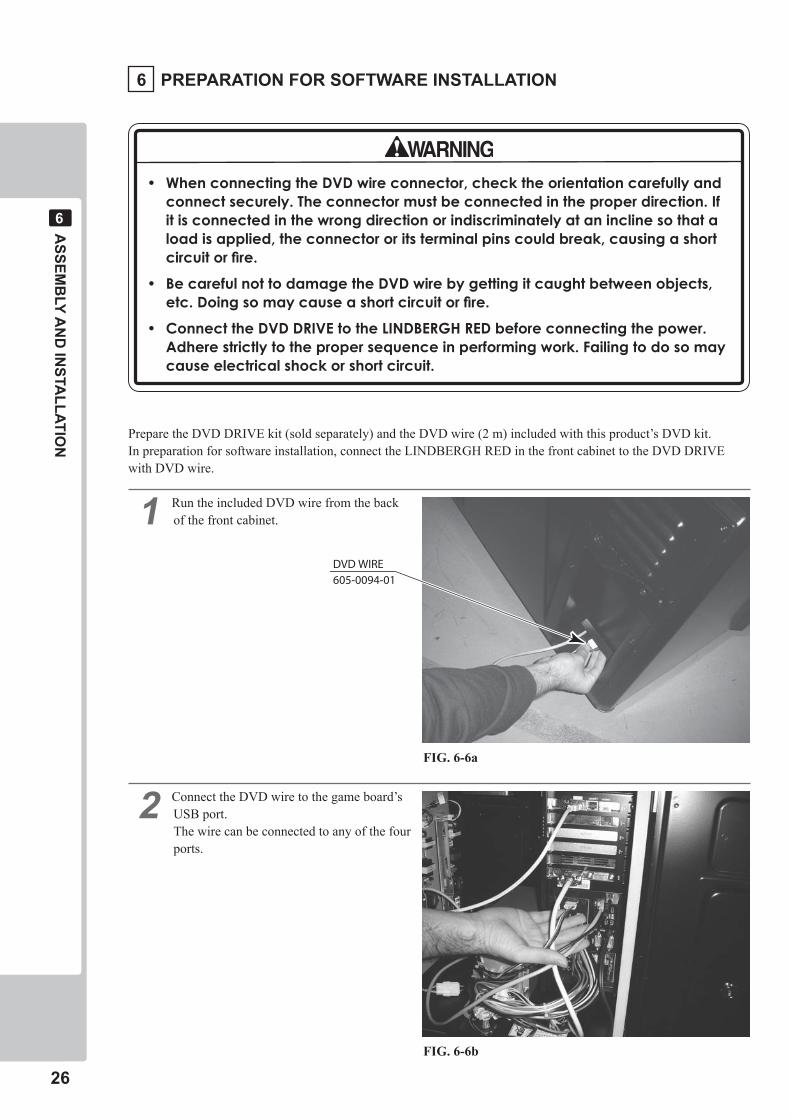
Prepare the DVD DRIVE kit (sold separately) and the DVD wire (2 m) included with this product’s DVD kit.In preparation for software installation, connect the LINDBERGH RED in the front cabinet to the DVD DRIVE with DVD wire.
� Run the included DVD wire from the back of the front cabinet.
� Connect the DVD wire to the game board’s USB port.The wire can be connected to any of the four ports.
• WhenconnectingtheDVDwireconnector,checktheorientationcarefullyandconnectsecurely.Theconnectormustbeconnectedintheproperdirection.Ifitisconnectedinthewrongdirectionorindiscriminatelyataninclinesothataloadisapplied,theconnectororitsterminalpinscouldbreak,causingashortcircuitorfire.
• BecarefulnottodamagetheDVDwirebygettingitcaughtbetweenobjects,etc.Doingsomaycauseashortcircuitorfire.
• ConnecttheDVDDRIVEtotheLINDBERGHREDbeforeconnectingthepower.Adherestrictlytothepropersequenceinperformingwork.Failingtodosomaycauseelectricalshockorshortcircuit.
� PREPARATION FOR SOFTWARE INSTALLATION
FIG. 6-6a
FIG. 6-6b
DVD WIRE605-0094-01
ASSEM
BLY A
ND
INSTA
LLATION
��
�
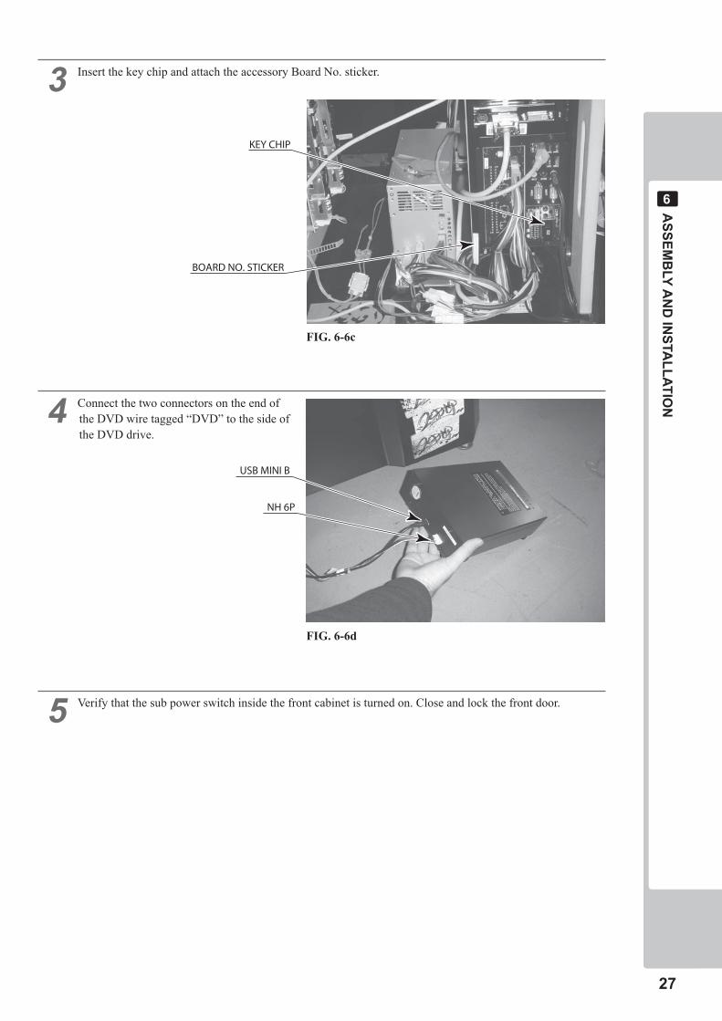
� Insert the key chip and attach the accessory Board No. sticker.
� Connect the two connectors on the end of the DVD wire tagged “DVD” to the side of the DVD drive.
� Verify that the sub power switch inside the front cabinet is turned on. Close and lock the front door.
USB MINI B
NH 6P
BOARD NO. STICKER
KEY CHIP
FIG. 6-6c
FIG. 6-6d
��
ASSEM
BLY A
ND
INSTA
LLATION
�
POWER PLUG
Always connect the ground wire.
GROUND WIRE
CONVERSION ADAPTER
FIG. 6-7a
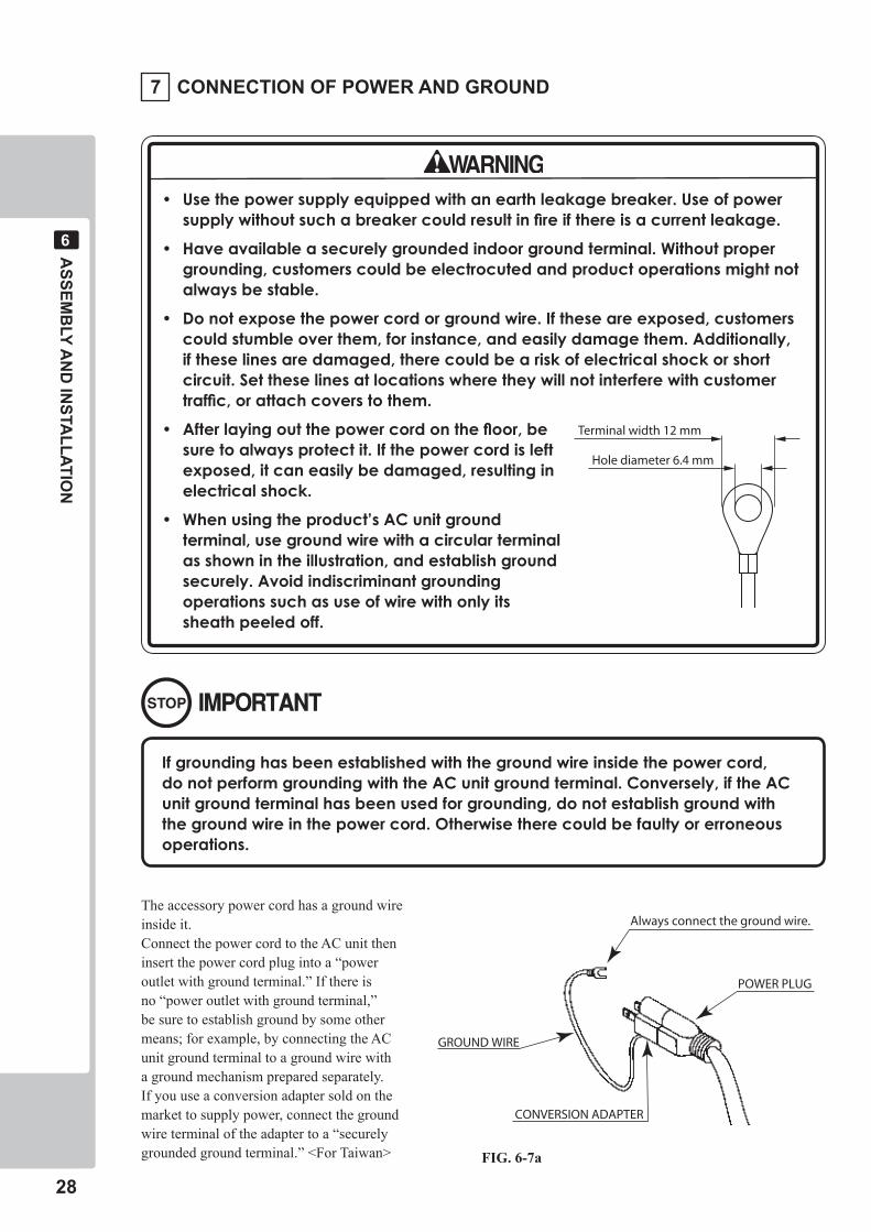
� CONNECTION OF POWER AND GROUND
• Usethepowersupplyequippedwithanearthleakagebreaker.Useofpowersupplywithoutsuchabreakercouldresultinfireifthereisacurrentleakage.
• Haveavailableasecurelygroundedindoorgroundterminal.Withoutpropergrounding,customerscouldbeelectrocutedandproductoperationsmightnotalwaysbestable.
• Donotexposethepowercordorgroundwire.Iftheseareexposed,customerscouldstumbleoverthem,forinstance,andeasilydamagethem.Additionally,iftheselinesaredamaged,therecouldbeariskofelectricalshockorshortcircuit.Settheselinesatlocationswheretheywillnotinterferewithcustomertraffic,orattachcoverstothem.
• Afterlayingoutthepowercordonthefloor,besuretoalwaysprotectit.Ifthepowercordisleftexposed,itcaneasilybedamaged,resultinginelectricalshock.
• Whenusingtheproduct’sACunitgroundterminal,usegroundwirewithacircularterminalasshownintheillustration,andestablishgroundsecurely.Avoidindiscriminantgroundingoperationssuchasuseofwirewithonlyitssheathpeeledoff.
Hole diameter 6.4 mm
Terminal width 12 mm
Ifgroundinghasbeenestablishedwiththegroundwireinsidethepowercord,donotperformgroundingwiththeACunitgroundterminal.Conversely,iftheACunitgroundterminalhasbeenusedforgrounding,donotestablishgroundwiththegroundwireinthepowercord.Otherwisetherecouldbefaultyorerroneousoperations.
The accessory power cord has a ground wire inside it.Connect the power cord to the AC unit then insert the power cord plug into a “power outlet with ground terminal.” If there is no “power outlet with ground terminal,” be sure to establish ground by some other means; for example, by connecting the AC unit ground terminal to a ground wire with a ground mechanism prepared separately. If you use a conversion adapter sold on the market to supply power, connect the ground wire terminal of the adapter to a “securely grounded ground terminal.” <For Taiwan>
ASSEM
BLY A
ND
INSTA
LLATION
��
�
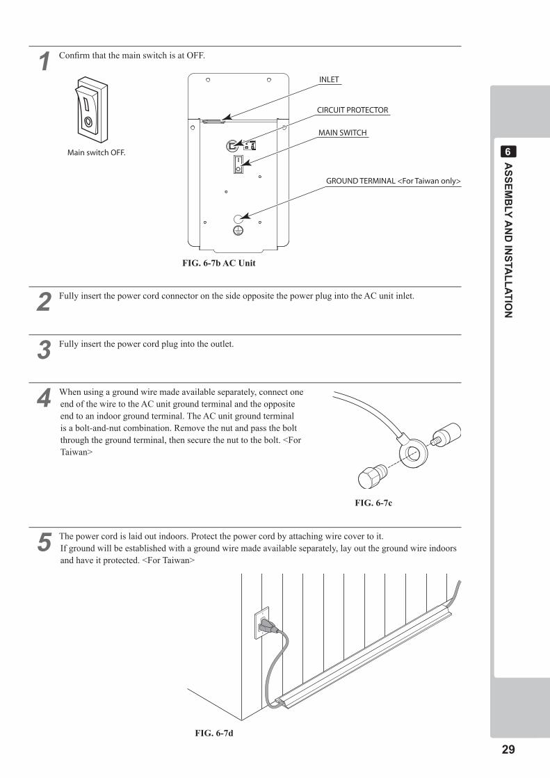
� Confirm that the main switch is at OFF.
� Fully insert the power cord connector on the side opposite the power plug into the AC unit inlet.
� Fully insert the power cord plug into the outlet.
� When using a ground wire made available separately, connect one end of the wire to the AC unit ground terminal and the opposite end to an indoor ground terminal. The AC unit ground terminal is a bolt-and-nut combination. Remove the nut and pass the bolt through the ground terminal, then secure the nut to the bolt. <For Taiwan>
� The power cord is laid out indoors. Protect the power cord by attaching wire cover to it.If ground will be established with a ground wire made available separately, lay out the ground wire indoors and have it protected. <For Taiwan>
GROUND TERMINAL <For Taiwan only>
Main switch OFF.
INLET
CIRCUIT PROTECTOR
MAIN SWITCH
FIG. 6-7b AC Unit
FIG. 6-7c
FIG. 6-7d
�0
ASSEM
BLY A
ND
INSTA
LLATION
�
� ENGAGEMENT OF POWER SUPPLY AND SOFTWARE INSTALLATION
• BecarefulnottodamagetheDVDwirebygettingitcaughtbetweenobjects,etc.Doingsomaycauseashortcircuitorfire.
• Thefollowingexplanationassumesthattheproducthasbeenassembledproperlyasexplainedabove.Ifthereisanerrororiftheproductoperatesinamannerotherthanasindicatedbelow,cutoffthepowersupplyimmediately.Failuretodosomayresultinafireorelectricalshock.
• IfyoulookdirectlyatthelaserbeamintheDVDDRIVE,youcouldsuffervisionimpairment.DonotlookinsidetheDVDDRIVE.
• Thesoftwareisnotinstalledonthegameboard(LINDBERGHRED)whenthepowersupplyisengaged,sothe“Error22”messageisnotamalfunction.
However,ifthereisanothererrordisplay,orifthereisnovideooutputatall,theremighthavebeenanerrorinproductassembly,wiringconnectionsmightbefaulty,ortheLINDBERGHREDmightnotbefunctioningproperly.
• Afterthepowersupplyisengaged,waitfor“Error22”messagetobedisplayed.Iftheproductisindiscriminatelyoperatedinanywaybeforehand,therecouldbeunexpectedproblemsormalfunctions,aswellasdamagetoparts.
• Once“Error22”isdisplayed,settheDVD-ROMintheDVDDRIVEandre-engagethepowersupply.Installationtakesplace.
• Afterthepowersupplyisengaged,theDVDDRIVEtraywillnotcomeoutforabout30secondsevenifyoupresstheswitch.ThisisduetoDVDDRIVEinitialization.
• TheDVDDRIVEtraycancomeoutorreturnonlywhilethepowersupplyisengaged.Thetraycannotbeopenedorclosedwhilethepowerisoff.
• Evenafterthesoftwarehasbeeninstalled,storetheDVDsoftwarekit,DVDDRIVEandDVDwireinasecurelocation.
• Ifforanyreasoninstallationcannotbecompleted,anerrorisdisplayed.Refertotheservicemanualandtakecorrectiveaction.
Prepare the DVD DRIVE kit (sold separately). (See Table 5c.)Use the DVD wire (2 m) included with this product, and not the wire included with the DVD DRIVE kit.
� Turn the main switch of the AC unit to ON and engage the power supply.
� The LINDBERGH RED Startup Screen appears. Wait for at least one minute. The error state is established. Check to be sure it is “Error 22.” If it is “Error 22,” proceed to the next operation. If it is not “Error 22,” refer to the LINDBERGH RED Service Manual and take corrective action.
ASSEM
BLY A
ND
INSTA
LLATION
��
�
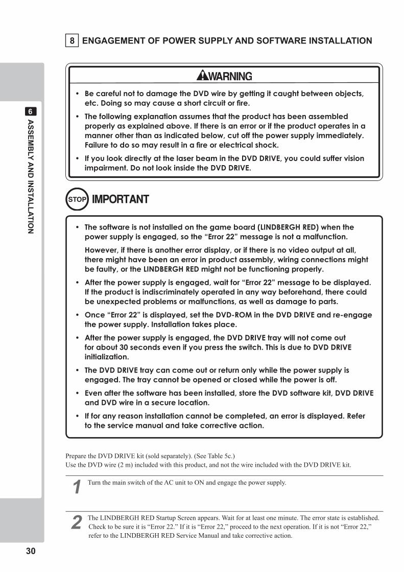
� Take out 1 urea (resin-head) screw and remove the DVD DRIVE case lid.
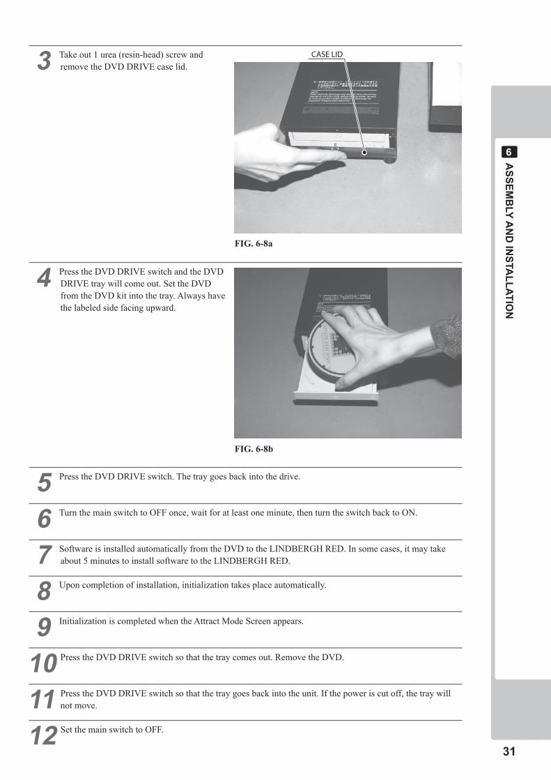
� Press the DVD DRIVE switch and the DVD DRIVE tray will come out. Set the DVD from the DVD kit into the tray. Always have the labeled side facing upward.
� Press the DVD DRIVE switch. The tray goes back into the drive.
� Turn the main switch to OFF once, wait for at least one minute, then turn the switch back to ON.
� Software is installed automatically from the DVD to the LINDBERGH RED. In some cases, it may take about 5 minutes to install software to the LINDBERGH RED.
� Upon completion of installation, initialization takes place automatically.
� Initialization is completed when the Attract Mode Screen appears.
�0 Press the DVD DRIVE switch so that the tray comes out. Remove the DVD.
�� Press the DVD DRIVE switch so that the tray goes back into the unit. If the power is cut off, the tray will not move.
�� Set the main switch to OFF.
CASE LID
FIG. 6-8a
FIG. 6-8b
��
ASSEM
BLY A
ND
INSTA
LLATION
�
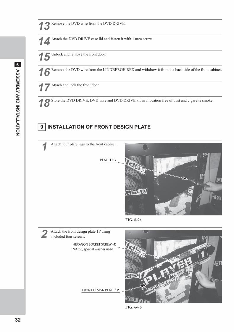
� Attach four plate legs to the front cabinet.
� Attach the front design plate 1P using included four screws.
PLATE LEG
HEXAGON SOCKET SCREW (4)M4 x 6, special washer used
FRONT DESIGN PLATE 1P
�� Remove the DVD wire from the DVD DRIVE.
�� Attach the DVD DRIVE case lid and fasten it with 1 urea screw.
�� Unlock and remove the front door.
�� Remove the DVD wire from the LINDBERGH RED and withdraw it from the back side of the front cabinet.
�� Attach and lock the front door.
�� Store the DVD DRIVE, DVD wire and DVD DRIVE kit in a location free of dust and cigarette smoke.
� INSTALLATION OF FRONT DESIGN PLATE
FIG. 6-9a
FIG. 6-9b
ASSEM
BLY A
ND
INSTA
LLATION
��
�
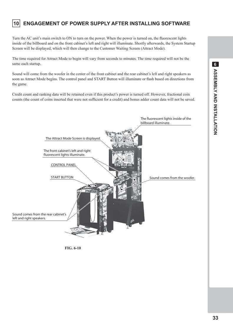
Sound comes from the woofer.
The fluorescent lights inside of thebillboard illuminate.
The Attract Mode Screen is displayed.
The front cabinet’s left and rightfluorescent lights illuminate.
CONTROL PANEL
START BUTTON
Sound comes from the rear cabinet’sleft and right speakers.
�0 ENGAGEMENT OF POWER SUPPLY AFTER INSTALLING SOFTWARE
Turn the AC unit’s main switch to ON to turn on the power. When the power is turned on, the fluorescent lights inside of the billboard and on the front cabinet’s left and right will illuminate. Shortly afterwards, the System Startup Screen will be displayed, which will then change to the Customer Waiting Screen (Attract Mode).
The time required for Attract Mode to begin will vary from seconds to minutes. The time required will not be the same each startup.
Sound will come from the woofer in the center of the front cabinet and the rear cabinet’s left and right speakers as soon as Attract Mode begins. The control panel and START Button will illuminate or flash based on directions from the game.
Credit count and ranking data will be retained even if this product’s power is turned off. However, fractional coin counts (the count of coins inserted that were not sufficient for a credit) and bonus adder count data will not be saved.
FIG. 6-10
��
ASSEM
BLY A
ND
INSTA
LLATION
�
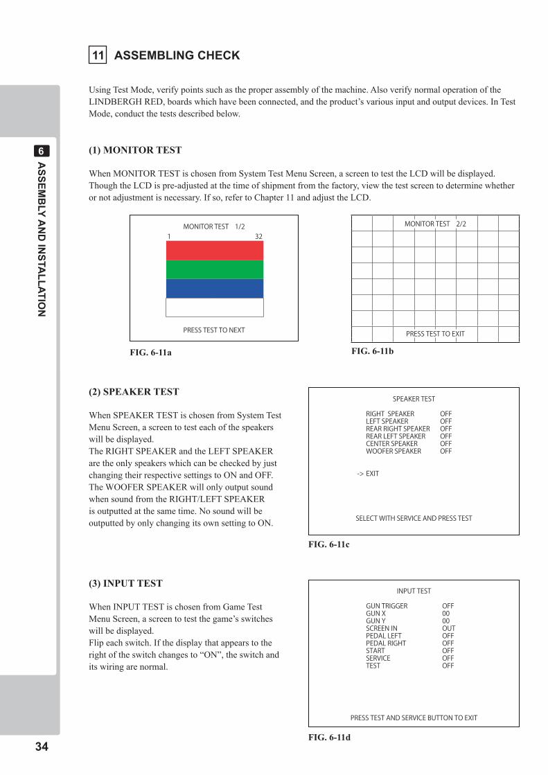
(2) SPEAKER TEST
When SPEAKER TEST is chosen from System Test Menu Screen, a screen to test each of the speakers will be displayed.The RIGHT SPEAKER and the LEFT SPEAKER are the only speakers which can be checked by just changing their respective settings to ON and OFF.The WOOFER SPEAKER will only output sound when sound from the RIGHT/LEFT SPEAKER is outputted at the same time. No sound will be outputted by only changing its own setting to ON.
(3) INPUT TEST
When INPUT TEST is chosen from Game Test Menu Screen, a screen to test the game’s switches will be displayed.Flip each switch. If the display that appears to the right of the switch changes to “ON”, the switch and its wiring are normal.
FIG. 6-11a
�� ASSEMBLING CHECK
Using Test Mode, verify points such as the proper assembly of the machine. Also verify normal operation of the LINDBERGH RED, boards which have been connected, and the product’s various input and output devices. In Test Mode, conduct the tests described below.
(1) MONITOR TEST
When MONITOR TEST is chosen from System Test Menu Screen, a screen to test the LCD will be displayed.Though the LCD is pre-adjusted at the time of shipment from the factory, view the test screen to determine whether or not adjustment is necessary. If so, refer to Chapter 11 and adjust the LCD.
FIG. 6-11b
FIG. 6-11c
FIG. 6-11d
MONITOR TEST 2/2
PRESS TEST TO EXIT
MONITOR TEST 1/21 32
PRESS TEST TO NEXT
SPEAKER TEST
RIGHT SPEAKER OFFLEFT SPEAKER OFFREAR RIGHT SPEAKER OFFREAR LEFT SPEAKER OFFCENTER SPEAKER OFFWOOFER SPEAKER OFF
-> EXIT
SELECT WITH SERVICE AND PRESS TEST
INPUT TEST
GUN TRIGGER OFFGUN X 00GUN Y 00SCREEN IN OUTPEDAL LEFT OFFPEDAL RIGHT OFFSTART OFFSERVICE OFFTEST OFF
PRESS TEST AND SERVICE BUTTON TO EXIT
ASSEM
BLY A
ND
INSTA
LLATION
��
�
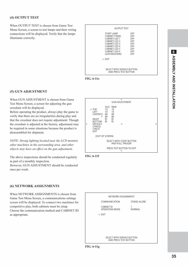
(4) OUTPUT TEST
When OUTPUT TEST is chosen from Game Test Menu Screen, a screen to test lamps and their wiring connections will be displayed. Verify that the lamps illuminate correctly.
(5) GUN ADJUSTMENT
When GUN ADJUSTMENT is chosen from Game Test Menu Screen, a screen for adjusting the gun crosshair will be displayed.Before operating the product, always play the game to verify that there are no irregularities during play and that the crosshair does not require adjustment. Though the crosshair is adjusted at the factory, adjustment may be required in some situations because the product is disassembled for shipment.
NOTE: Strong lighting located near the LCD monitor, other machines in the surrounding area, and other objects may have an effect on the gun adjustment.
The above inspections should be conducted regularly as part of a monthly inspection.However, GUN ADJUSTMENT should be conducted once per week.
(6) NETWORK ASSIGNMENTS
When NETWORK ASSIGNMENTS is chosen from Game Test Menu Screen, a communications settings screen will be displayed. To connect two machines for competitive play, both cabinets must be setup.Choose the communication method and CABINET ID as appropriate.
FIG. 6-11e
FIG. 6-11f
FIG. 6-11g
OUTPUT TEST
START LAMP OFFCABINET PANEL OFFCABINET LED 1 OFFCABINET LED 2 OFFCABINET LED 3 OFFCABINET LED 4 OFFCABINET LED 5 OFFCABINET LED 6 OFFGUN KNOCKING OFF
-> EXIT
SELECT WITH SERVICE BUTTONAND PRESS TEST BUTTON
+GUN ADJUSTMENT
OLD NEW-> TOP 10 10LEFT 10 10CENTER X 80 80 Y 80 80RIGHT f0 f0BOTTOM f0 f0
+ DEFAULT + +CANCELCHECKEXIT
[OUT OF SCREEN]
SELECT WITH START BUTTONAND PULL TRIGGER
PRESS TEST BUTTON TO EXIT+
NETWORK ASSIGNMENTS
COMMUNICATION STAND-ALONE
CABINET ID 1OPERATION MODE NORMAL
-> EXIT
SELECT WITH SERVICE BUTTONAND PRESS TEST BUTTON
��
ASSEM
BLY A
ND
INSTA
LLATION
�
The Interference Prevention Wiring
• Thisworkshouldbeperformedbythesitemaintenanceindividualorotherskilledprofessional.Workperformedbynon-technicalpersonnelcancausemalfunctioning.
• Inordertopreventelectricshockandshortcircuithazards,besuretoturnpoweroffbeforeperformingwork.
• Becarefulnottodamagethewires.Damagedwiresmaycauseelectricshockorshortcircuitorpresentafirerisk.
When the game machines of a same or similar type are installed side by side, their sensors may interfere with each other. To reject the interference, follow the procedure below.
The following game machines employ a same or similar type of sensor. If interference happens to the sensors, operation of the games may be mutually disturbed.
- THE HOUSE OF THE DEAD 2, U/R type, DX type and Super DX type- DEATH CRIMSON, U/R type and DX type- THE LOST WORLD, U/R type, DX type and Super DX type- BRAVE FIRE FIGHTERS- SAMBA DE AMIGO- CONFIDENTIAL MISSION, U/R type and DX type- SHAKATTO TAMBOURINE- LUPIN THE 3RD THE SHOOTING, U/R type and DX type- THE MAZE OF THE KINGS, U/R type and DX type- THE HOUSE OF THE DEAD 3, U/R type and DX type- VIRTUA COP 3, U/R type and DX type- GHOST SQUAD, U/R type and DX type- THE HOUSE OF THE DEAD 4 DX type and SPECIAL type- 2SPICY
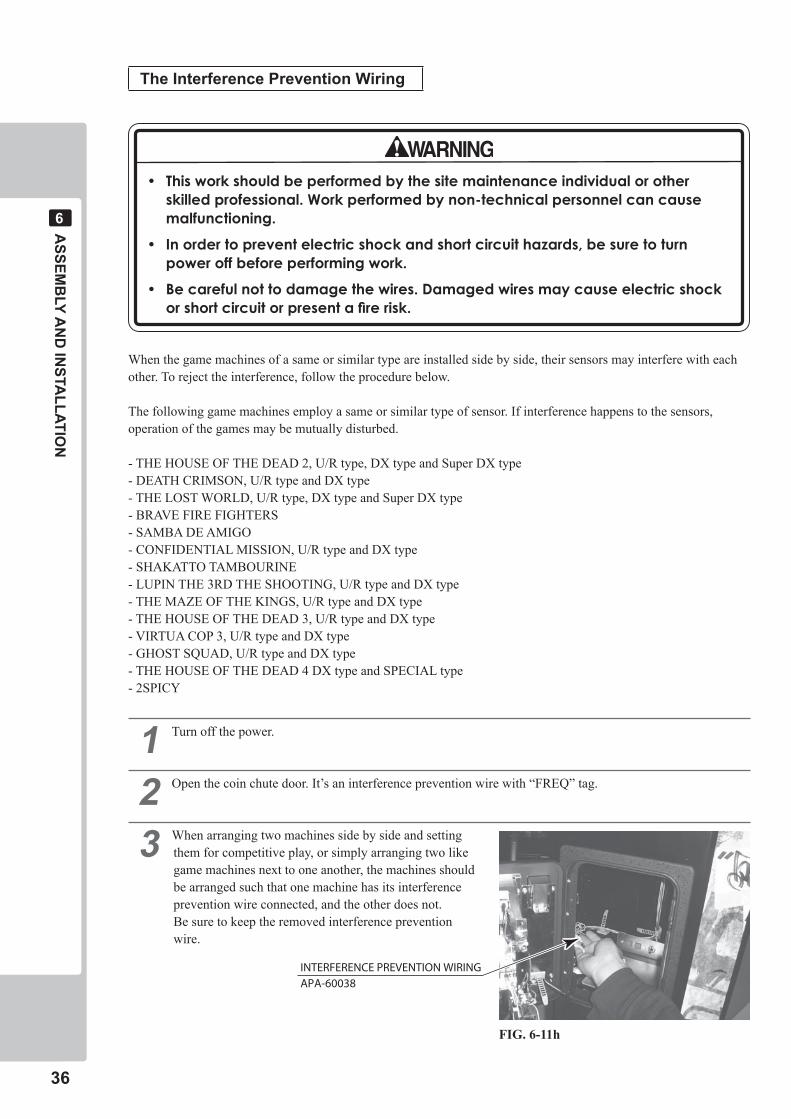
� Turn off the power.
� Open the coin chute door. It’s an interference prevention wire with “FREQ” tag.
� When arranging two machines side by side and setting them for competitive play, or simply arranging two like game machines next to one another, the machines should be arranged such that one machine has its interference prevention wire connected, and the other does not. Be sure to keep the removed interference prevention wire.
FIG. 6-11h
INTERFERENCE PREVENTION WIRINGAPA-60038
PREC
AU
TION
S WH
EN M
OVIN
G TH
E MA
CH
INE
��
�
Ground the casters and move the product.
Always remove the pedal unit.
PRECAUTIONS WHEN MOVING THE MACHINE�
• Alwaysdisconnectthepowercablebeforemovingtheproduct.Ifitismovedwiththepowercableconnected,thecablecouldbedamaged,causingfireorelectricshock.
• Tomovetheunitoverthefloor,pullintheadjustorsandhavethecasterscontactthefloor.Whilemovingtheunit,becarefulthatthecastersdonotrolloverthepowercordorthegroundwire.Ifcordorwireisdamaged,therecouldbeelectricalshocksand/orshortcircuits.
• Toliftupthecabinet,holditatthebottom.Ifyouholditanywhereelse,theweightofthecabinetcouldcausedamagetopartsorattachments,resultingininjury.
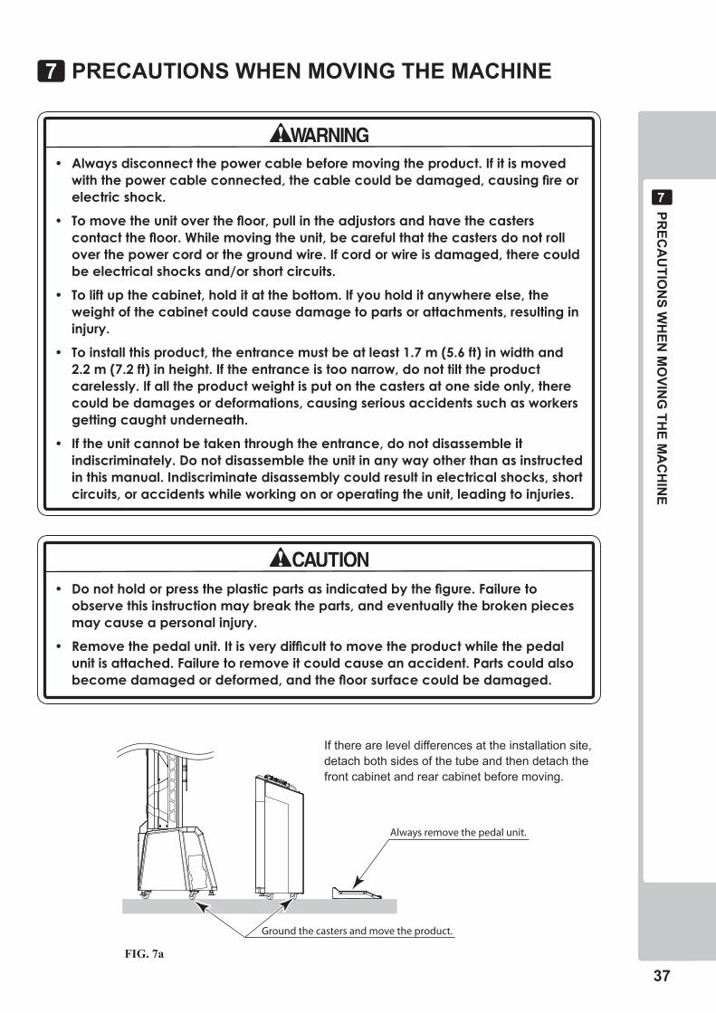
• Toinstallthisproduct,theentrancemustbeatleast1.7m(5.6ft)inwidthand2.2m(7.2ft)inheight.Iftheentranceistoonarrow,donottilttheproductcarelessly.Ifalltheproductweightisputonthecastersatonesideonly,therecouldbedamagesordeformations,causingseriousaccidentssuchasworkersgettingcaughtunderneath.
• Iftheunitcannotbetakenthroughtheentrance,donotdisassembleitindiscriminately.Donotdisassembletheunitinanywayotherthanasinstructedinthismanual.Indiscriminatedisassemblycouldresultinelectricalshocks,shortcircuits,oraccidentswhileworkingonoroperatingtheunit,leadingtoinjuries.
• Donotholdorpresstheplasticpartsasindicatedbythefigure.Failuretoobservethisinstructionmaybreaktheparts,andeventuallythebrokenpiecesmaycauseapersonalinjury.
• Removethepedalunit.Itisverydifficulttomovetheproductwhilethepedalunitisattached.Failuretoremoveitcouldcauseanaccident.Partscouldalsobecomedamagedordeformed,andthefloorsurfacecouldbedamaged.
FIG. 7a
If there are level differences at the installation site, detach both sides of the tube and then detach the front cabinet and rear cabinet before moving.

��
PREC
AU
TION
S WH
EN M
OVIN
G TH
E MA
CH
INE
�
Do not move or push the product holding the shaded areas.
FIG. 7b
GA
ME D
ESCR
IPTION
��
�
SPEAKER
BILLBOARD
LCD MONITOR
TOWER (L & R)START BUTTON
GAME DESCRIPTION�
The following explanations apply when the product is functioning satisfactorily. Should there be any operations different from the following contents, some sort of abnormality may have occurred. Immediately look into the cause of the fault and eliminate the cause thereof to ensure satisfactory operation.
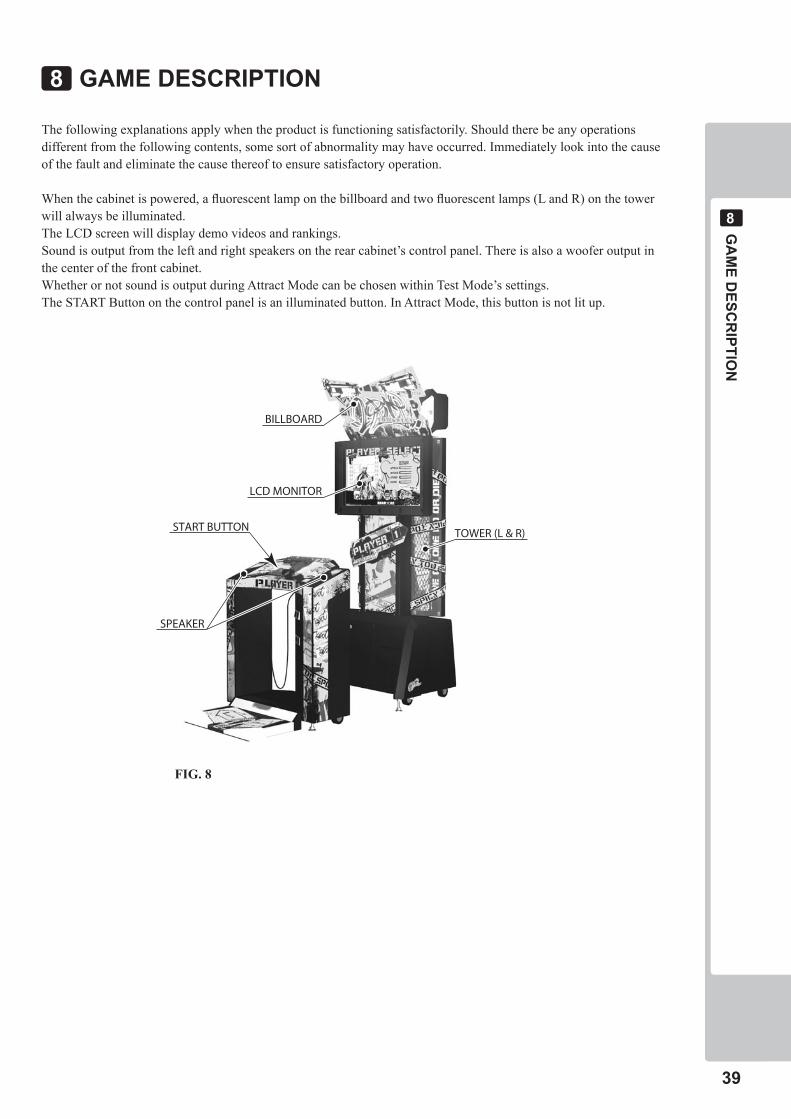
When the cabinet is powered, a fluorescent lamp on the billboard and two fluorescent lamps (L and R) on the tower will always be illuminated.The LCD screen will display demo videos and rankings.Sound is output from the left and right speakers on the rear cabinet’s control panel. There is also a woofer output in the center of the front cabinet.Whether or not sound is output during Attract Mode can be chosen within Test Mode’s settings.The START Button on the control panel is an illuminated button. In Attract Mode, this button is not lit up.
FIG. 8
�0
GA
ME D
ESCR
IPTION
�
(�) HOW TO PLAY
� When a coin is inserted, the credit display on the bottom of the screen will increase in number.When a sufficient number of coins to play either of the game’s modes is inserted, the “INSERT COIN(S)” message on the bottom of the screen will disappear, and the display of the playable game mode will change to “XX Mode: PRESS START BUTTON”. The START Button will then begin to blink.
Up to twenty four credits can be counted. If coins are inserted after twenty four credits have been counted, they will not be counted towards credits, and they will not be returned. However, they will be counted as inserted coins for the coin meter and for Test Mode data.
� When the START Button is pressed, the tutorial will begin.Follow the instructions that display on the screen to practice using the controls.The tutorial can be skipped by pressing the START Button once again.
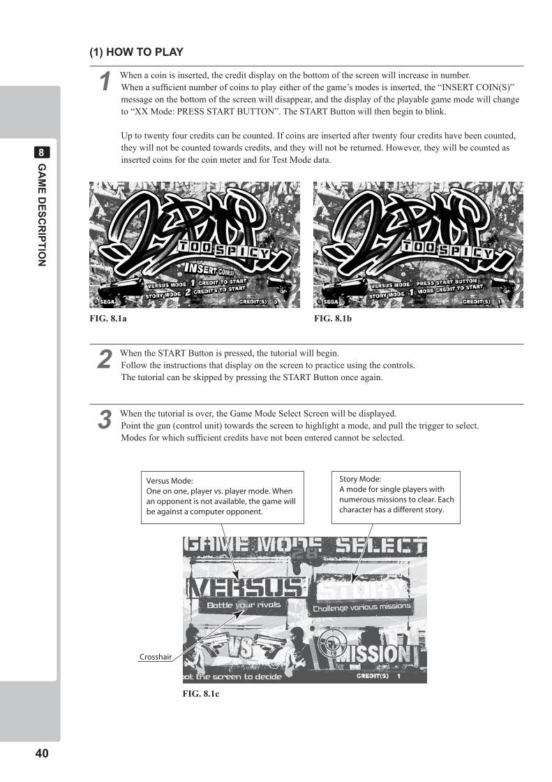
� When the tutorial is over, the Game Mode Select Screen will be displayed.Point the gun (control unit) towards the screen to highlight a mode, and pull the trigger to select.Modes for which sufficient credits have not been entered cannot be selected.
Crosshair
Versus Mode:One on one, player vs. player mode. When an opponent is not available, the game will be against a computer opponent.
Story Mode:A mode for single players with numerous missions to clear. Each character has a different story.
FIG. 8.1a FIG. 8.1b
FIG. 8.1c
GA
ME D
ESCR
IPTION
��
�
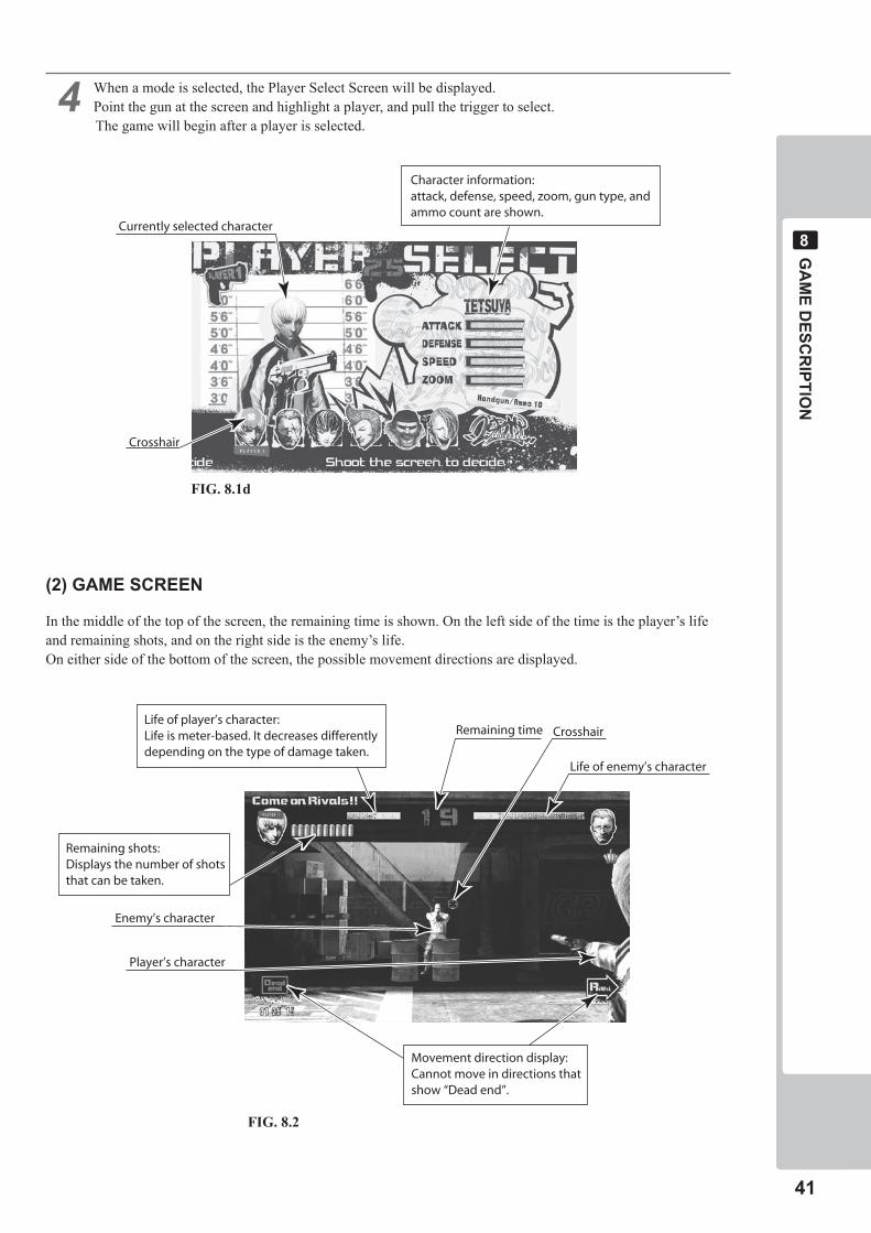
� When a mode is selected, the Player Select Screen will be displayed.Point the gun at the screen and highlight a player, and pull the trigger to select.The game will begin after a player is selected.
(�) GAME SCREEN
In the middle of the top of the screen, the remaining time is shown. On the left side of the time is the player’s life and remaining shots, and on the right side is the enemy’s life.On either side of the bottom of the screen, the possible movement directions are displayed.
Movement direction display:Cannot move in directions thatshow “Dead end”.
Life of player’s character:Life is meter-based. It decreases differentlydepending on the type of damage taken.
Remaining time Crosshair
Life of enemy’s character
Remaining shots:Displays the number of shotsthat can be taken.
Enemy’s character
Player’s character
Character information:attack, defense, speed, zoom, gun type, andammo count are shown.
Currently selected character
Crosshair
FIG. 8.1d
FIG. 8.2
��
GA
ME D
ESCR
IPTION
�
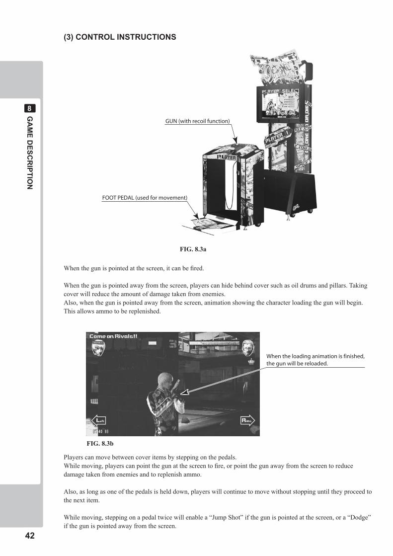
(�) CONTROL INSTRUCTIONS
When the gun is pointed at the screen, it can be fired.
When the gun is pointed away from the screen, players can hide behind cover such as oil drums and pillars. Taking cover will reduce the amount of damage taken from enemies.Also, when the gun is pointed away from the screen, animation showing the character loading the gun will begin. This allows ammo to be replenished.
Players can move between cover items by stepping on the pedals.While moving, players can point the gun at the screen to fire, or point the gun away from the screen to reduce damage taken from enemies and to replenish ammo.
Also, as long as one of the pedals is held down, players will continue to move without stopping until they proceed to the next item.
While moving, stepping on a pedal twice will enable a “Jump Shot” if the gun is pointed at the screen, or a “Dodge” if the gun is pointed away from the screen.
FOOT PEDAL (used for movement)
GUN (with recoil function)
When the loading animation is finished,the gun will be reloaded.
FIG. 8.3a
FIG. 8.3b
GA
ME D
ESCR
IPTION
��
�
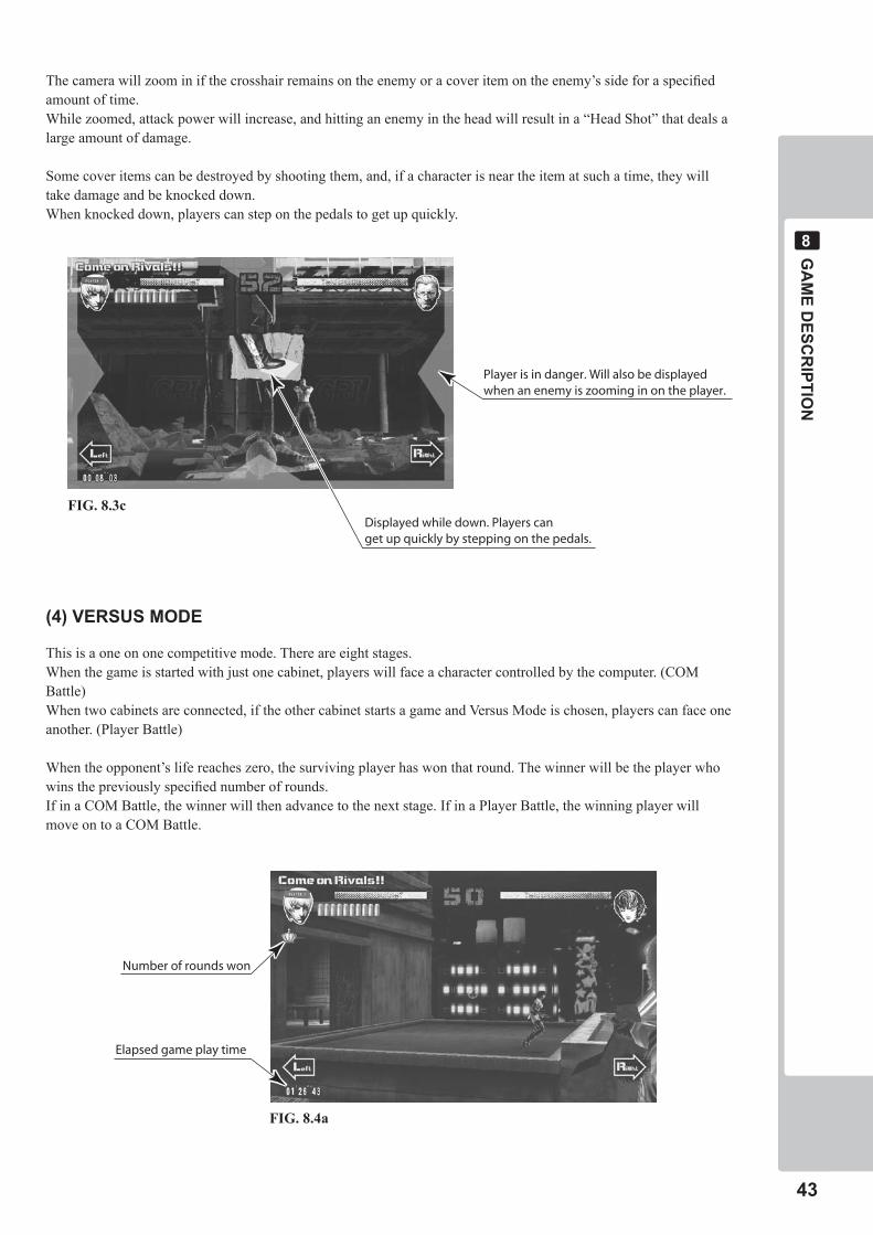
The camera will zoom in if the crosshair remains on the enemy or a cover item on the enemy’s side for a specified amount of time.While zoomed, attack power will increase, and hitting an enemy in the head will result in a “Head Shot” that deals a large amount of damage.
Some cover items can be destroyed by shooting them, and, if a character is near the item at such a time, they will take damage and be knocked down.When knocked down, players can step on the pedals to get up quickly.
(�) VERSUS MODE
This is a one on one competitive mode. There are eight stages.When the game is started with just one cabinet, players will face a character controlled by the computer. (COM Battle)When two cabinets are connected, if the other cabinet starts a game and Versus Mode is chosen, players can face one another. (Player Battle)
When the opponent’s life reaches zero, the surviving player has won that round. The winner will be the player who wins the previously specified number of rounds. If in a COM Battle, the winner will then advance to the next stage. If in a Player Battle, the winning player will move on to a COM Battle.
Player is in danger. Will also be displayedwhen an enemy is zooming in on the player.
Displayed while down. Players canget up quickly by stepping on the pedals.
Elapsed game play time
Number of rounds won
FIG. 8.3c
FIG. 8.4a
��
GA
ME D
ESCR
IPTION
�
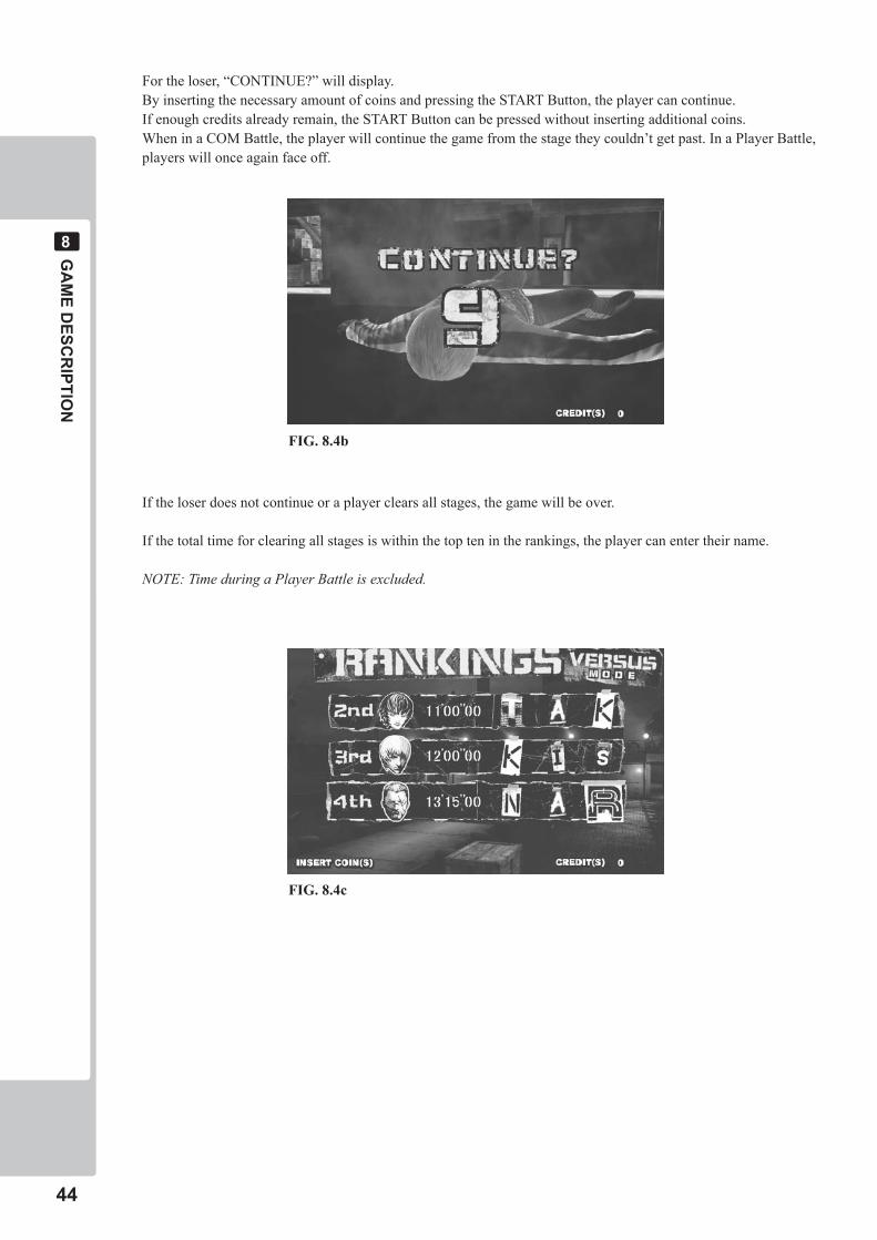
For the loser, “CONTINUE?” will display.By inserting the necessary amount of coins and pressing the START Button, the player can continue.If enough credits already remain, the START Button can be pressed without inserting additional coins.When in a COM Battle, the player will continue the game from the stage they couldn’t get past. In a Player Battle, players will once again face off.
If the loser does not continue or a player clears all stages, the game will be over.
If the total time for clearing all stages is within the top ten in the rankings, the player can enter their name.
NOTE: Time during a Player Battle is excluded.
FIG. 8.4b
FIG. 8.4c
GA
ME D
ESCR
IPTION
��
�
(�) STORY MODE
This mode allows players to enjoy a storyline while clearing a large number of missions.The story of each character is different.
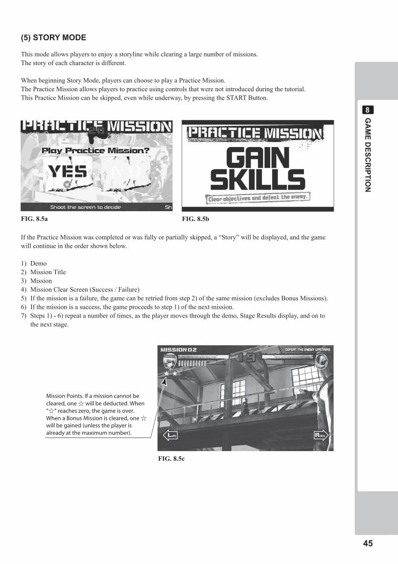
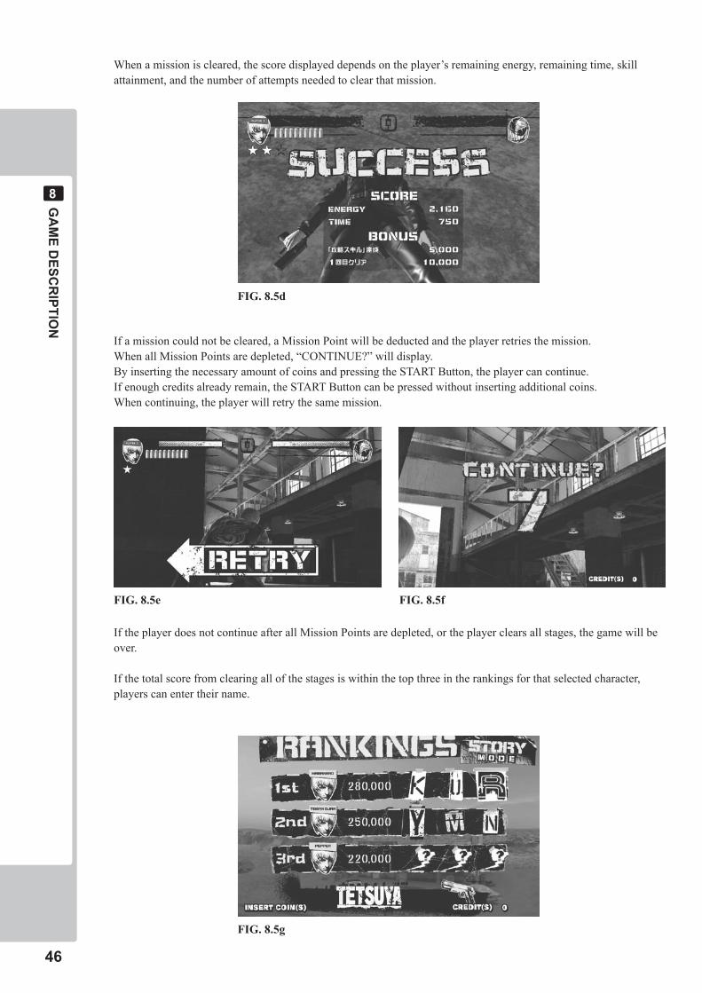
When beginning Story Mode, players can choose to play a Practice Mission.The Practice Mission allows players to practice using controls that were not introduced during the tutorial.This Practice Mission can be skipped, even while underway, by pressing the START Button.
If the Practice Mission was completed or was fully or partially skipped, a “Story” will be displayed, and the game will continue in the order shown below.
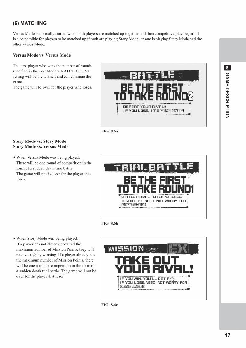
1) Demo2) Mission Title3) Mission4) Mission Clear Screen (Success / Failure)5) If the mission is a failure, the game can be retried from step 2) of the same mission (excludes Bonus Missions).6) If the mission is a success, the game proceeds to step 1) of the next mission.7) Steps 1) - 6) repeat a number of times, as the player moves through the demo, Stage Results display, and on to
the next stage.
Mission Points. If a mission cannot be cleared, one ☆ will be deducted. When “☆” reaches zero, the game is over.When a Bonus Mission is cleared, one ☆will be gained (unless the player is already at the maximum number).
FIG. 8.5a FIG. 8.5b
FIG. 8.5c
��
GA
ME D
ESCR
IPTION
�
When a mission is cleared, the score displayed depends on the player’s remaining energy, remaining time, skill attainment, and the number of attempts needed to clear that mission.
If a mission could not be cleared, a Mission Point will be deducted and the player retries the mission.When all Mission Points are depleted, “CONTINUE?” will display.By inserting the necessary amount of coins and pressing the START Button, the player can continue.If enough credits already remain, the START Button can be pressed without inserting additional coins.When continuing, the player will retry the same mission.
If the player does not continue after all Mission Points are depleted, or the player clears all stages, the game will be over.
If the total score from clearing all of the stages is within the top three in the rankings for that selected character, players can enter their name.
FIG. 8.5d
FIG. 8.5e FIG. 8.5f
FIG. 8.5g
GA
ME D
ESCR
IPTION
��
�
(�) MATCHING
Versus Mode is normally started when both players are matched up together and then competitive play begins. It is also possible for players to be matched up if both are playing Story Mode, or one is playing Story Mode and the other Versus Mode.
Versus Mode vs. Versus Mode
The first player who wins the number of rounds specified in the Test Mode’s MATCH COUNT setting will be the winner, and can continue the game.The game will be over for the player who loses.
Story Mode vs. Story ModeStory Mode vs. Versus Mode
•When Versus Mode was being played: There will be one round of competition in the
form of a sudden death trial battle. The game will not be over for the player that
loses.
•When Story Mode was being played: If a player has not already acquired the
maximum number of Mission Points, they will receive a ☆ by winning. If a player already has the maximum number of Mission Points, there will be one round of competition in the form of a sudden death trial battle. The game will not be over for the player that loses.
FIG. 8.6a
FIG. 8.6b
FIG. 8.6c
��
GA
ME D
ESCR
IPTION
�
(�) CHARACTER LIST
All characters are androids created by a company called GRI. To obtain information regarding an inheritance left behind by the “Boss”, they pursue the “Man in Black” a.k.a. “Shadow”.
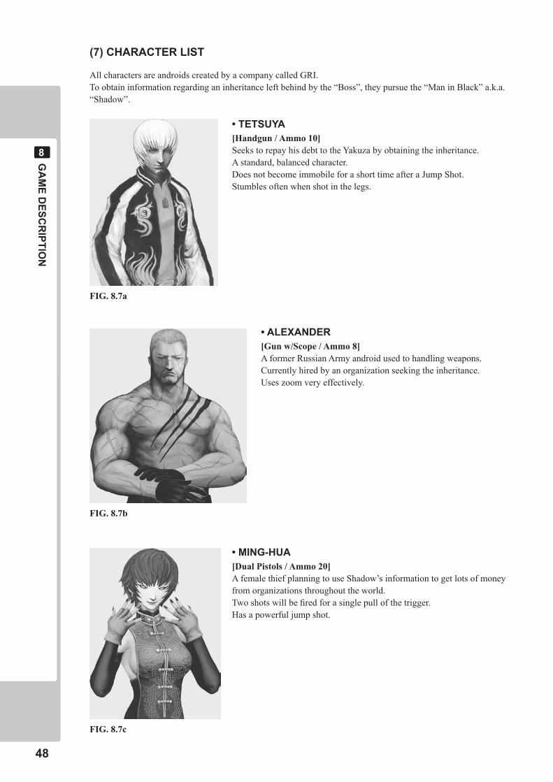
• TETSUYA[Handgun / Ammo 10]Seeks to repay his debt to the Yakuza by obtaining the inheritance.A standard, balanced character.Does not become immobile for a short time after a Jump Shot.Stumbles often when shot in the legs.
• ALEXANDER[Gun w/Scope / Ammo 8]A former Russian Army android used to handling weapons.Currently hired by an organization seeking the inheritance.Uses zoom very effectively.
• MING-HUA[Dual Pistols / Ammo 20]A female thief planning to use Shadow’s information to get lots of money from organizations throughout the world.Two shots will be fired for a single pull of the trigger.Has a powerful jump shot.
FIG. 8.7a
FIG. 8.7b
FIG. 8.7c
GA
ME D
ESCR
IPTION
��
�
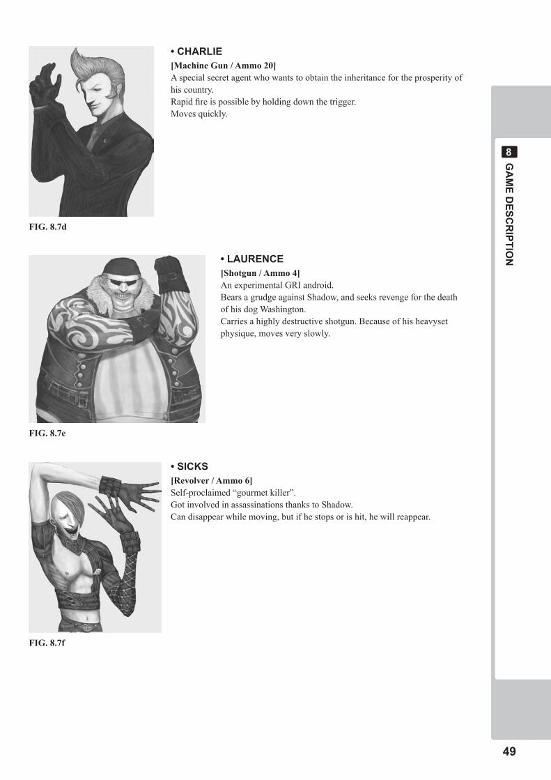
• CHARLIE[Machine Gun / Ammo 20]A special secret agent who wants to obtain the inheritance for the prosperity of his country.Rapid fire is possible by holding down the trigger.Moves quickly.
• LAURENCE[Shotgun / Ammo 4]An experimental GRI android.Bears a grudge against Shadow, and seeks revenge for the death of his dog Washington.Carries a highly destructive shotgun. Because of his heavyset physique, moves very slowly.
• SICKS[Revolver / Ammo 6]Self-proclaimed “gourmet killer”.Got involved in assassinations thanks to Shadow.Can disappear while moving, but if he stops or is hit, he will reappear.
FIG. 8.7d
FIG. 8.7e
FIG. 8.7f
�0
GA
ME D
ESCR
IPTION
�
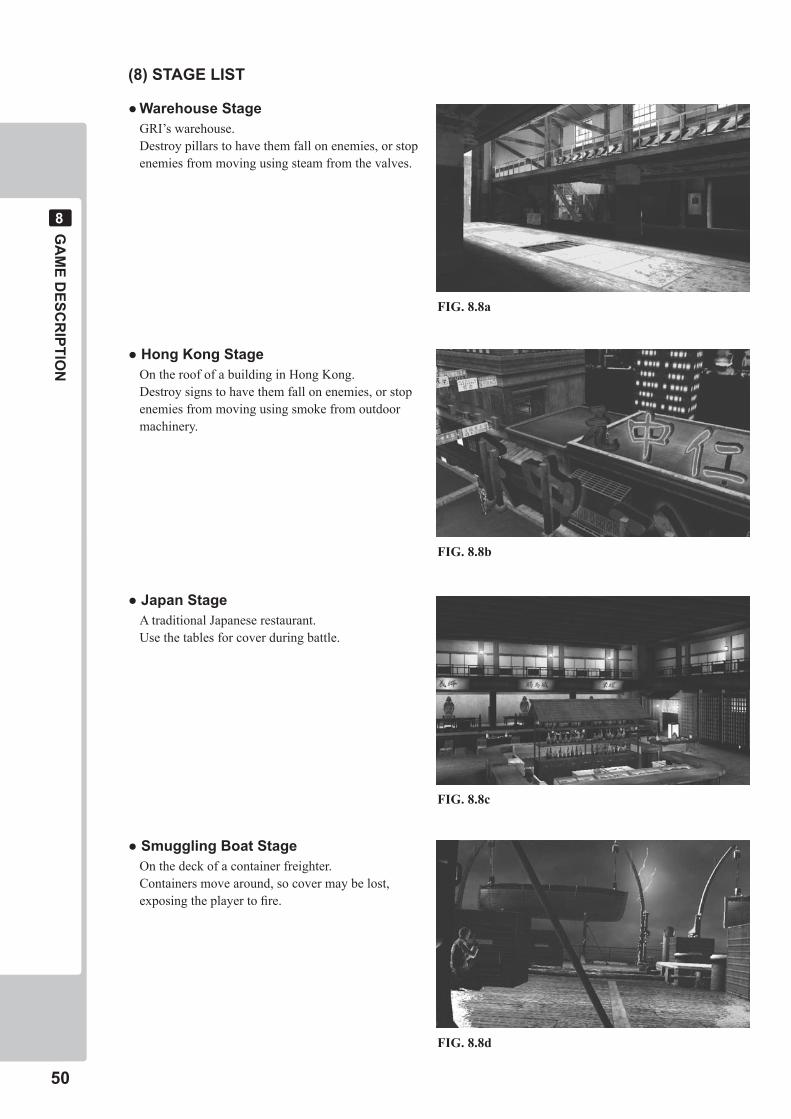
(�) STAGE LIST
●WarehouseStage GRI’s warehouse. Destroy pillars to have them fall on enemies, or stop
enemies from moving using steam from the valves.
●HongKongStage On the roof of a building in Hong Kong. Destroy signs to have them fall on enemies, or stop
enemies from moving using smoke from outdoor machinery.
●JapanStage A traditional Japanese restaurant. Use the tables for cover during battle.
●SmugglingBoatStage On the deck of a container freighter. Containers move around, so cover may be lost,
exposing the player to fire.
FIG. 8.8a
FIG. 8.8b
FIG. 8.8c
FIG. 8.8d
GA
ME D
ESCR
IPTION
��
�
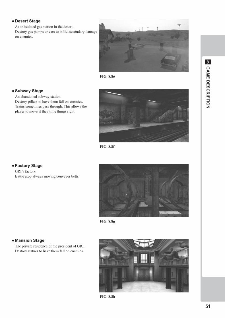
●DesertStage At an isolated gas station in the desert. Destroy gas pumps or cars to inflict secondary damage
on enemies.
●SubwayStage An abandoned subway station. Destroy pillars to have them fall on enemies. Trains sometimes pass through. This allows the
player to move if they time things right.
●FactoryStage GRI’s factory. Battle atop always moving conveyer belts.
●MansionStage The private residence of the president of GRI. Destroy statues to have them fall on enemies.
FIG. 8.8e
FIG. 8.8f
FIG. 8.8g
FIG. 8.8h
��
EXPLAN
ATION
OF TEST A
ND
DATA D
ISPLAY
�
EXPLANATION OF TEST AND DATA DISPLAY�
Donottouchanypartsthatarenotspecifiedinthesedirections.Touchingunspecifiedlocationsmayleadtoelectricshockorcauseshortcircuits.
Becarefulthatafingerorhanddoesnotgetcaughtwhenopening/closingthecoinchutedoor.
• WhenyouentertheTestMode,fractionalcoinandbonusadderdataiserased.
• Adjustthesoundtotheoptimumvolume,takingintoconsiderationtheenvironmentalrequirementsoftheinstallationlocation.
• Removingthecoinmetercircuitryrendersthegameinoperable.
EXPLAN
ATION
OF TEST A
ND
DATA D
ISPLAY
��
�
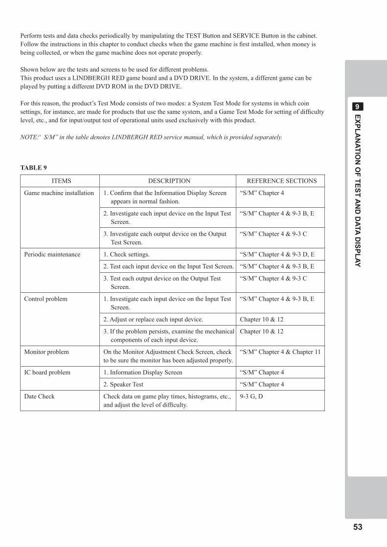
Perform tests and data checks periodically by manipulating the TEST Button and SERVICE Button in the cabinet. Follow the instructions in this chapter to conduct checks when the game machine is first installed, when money is being collected, or when the game machine does not operate properly.
Shown below are the tests and screens to be used for different problems. This product uses a LINDBERGH RED game board and a DVD DRIVE. In the system, a different game can be played by putting a different DVD ROM in the DVD DRIVE.
For this reason, the product’s Test Mode consists of two modes: a System Test Mode for systems in which coin settings, for instance, are made for products that use the same system, and a Game Test Mode for setting of difficulty level, etc., and for input/output test of operational units used exclusively with this product.
NOTE: “ S/M” in the table denotes LINDBERGH RED service manual, which is provided separately.
ITEMS DESCRIPTION REFERENCE SECTIONS
Game machine installation 1. Confirm that the Information Display Screen appears in normal fashion.
“S/M” Chapter 4
2. Investigate each input device on the Input Test Screen.
“S/M” Chapter 4 & 9-3 B, E
3. Investigate each output device on the Output Test Screen.
“S/M” Chapter 4 & 9-3 C
Periodic maintenance 1. Check settings. “S/M” Chapter 4 & 9-3 D, E
2. Test each input device on the Input Test Screen. “S/M” Chapter 4 & 9-3 B, E
3. Test each output device on the Output Test Screen.
“S/M” Chapter 4 & 9-3 C
Control problem 1. Investigate each input device on the Input Test Screen.
“S/M” Chapter 4 & 9-3 B, E
2. Adjust or replace each input device. Chapter 10 & 12
3. If the problem persists, examine the mechanical components of each input device.
Chapter 10 & 12
Monitor problem On the Monitor Adjustment Check Screen, check to be sure the monitor has been adjusted properly.
“S/M” Chapter 4 & Chapter 11
IC board problem 1. Information Display Screen “S/M” Chapter 4
2. Speaker Test “S/M” Chapter 4
Date Check Check data on game play times, histograms, etc., and adjust the level of difficulty.
9-3 G, D
TABLE 9
��
EXPLAN
ATION
OF TEST A
ND
DATA D
ISPLAY
�
FIG. 9-1a Switch Unit
TEST SERVICESOUNDVOLUME
SOUND VOLUME SWITCH(SOUND VOLUME)
TEST BUTTON(TEST)
SERVICE BUTTON(SERVICE)
FIG. 9-1b Coin Meter
COIN METER
�-� SWITCH UNIT AND COIN METER
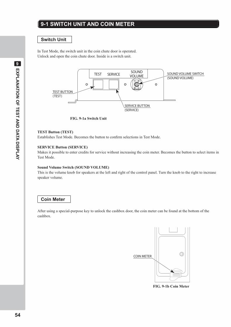
SwitchUnit
In Test Mode, the switch unit in the coin chute door is operated. Unlock and open the coin chute door. Inside is a switch unit.
TEST Button (TEST)Establishes Test Mode. Becomes the button to confirm selections in Test Mode.
SERVICE Button (SERVICE)Makes it possible to enter credits for service without increasing the coin meter. Becomes the button to select items in Test Mode.
Sound Volume Switch (SOUND VOLUME)This is the volume knob for speakers at the left and right of the control panel. Turn the knob to the right to increase speaker volume.
Coin Meter
After using a special-purpose key to unlock the cashbox door, the coin meter can be found at the bottom of the cashbox.
EXPLAN
ATION
OF TEST A
ND
DATA D
ISPLAY
��
�
�-� SYSTEM TEST MODE
SYSTEM TEST MENU
SYSTEM INFORMATION STORAGE INFORMATION JVS TEST MONITOR TEST SPEAKER TEST COIN ASSIGNMENTS CLOCK SETTING NETWORK SETTING GAME TEST MODE -> EXIT
SELECT WITH SERVICE AND PRESS TEST
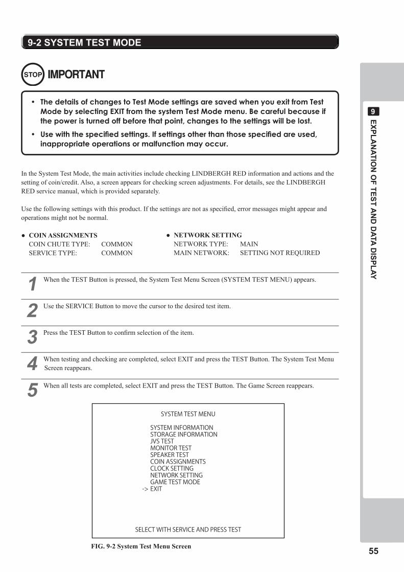
• ThedetailsofchangestoTestModesettingsaresavedwhenyouexitfromTestModebyselectingEXITfromthesystemTestModemenu.Becarefulbecauseifthepoweristurnedoffbeforethatpoint,changestothesettingswillbelost.
• Usewiththespecifiedsettings.Ifsettingsotherthanthosespecifiedareused,inappropriateoperationsormalfunctionmayoccur.
In the System Test Mode, the main activities include checking LINDBERGH RED information and actions and the setting of coin/credit. Also, a screen appears for checking screen adjustments. For details, see the LINDBERGH RED service manual, which is provided separately.
Use the following settings with this product. If the settings are not as specified, error messages might appear and operations might not be normal.
● COINASSIGNMENTS COIN CHUTE TYPE: COMMON SERVICE TYPE: COMMON
� When the TEST Button is pressed, the System Test Menu Screen (SYSTEM TEST MENU) appears.
� Use the SERVICE Button to move the cursor to the desired test item.
� Press the TEST Button to confirm selection of the item.
� When testing and checking are completed, select EXIT and press the TEST Button. The System Test Menu Screen reappears.
� When all tests are completed, select EXIT and press the TEST Button. The Game Screen reappears.
FIG. 9-2 System Test Menu Screen
● NETWORKSETTING NETWORK TYPE: MAIN MAIN NETWORK: SETTING NOT REQUIRED
��
EXPLAN
ATION
OF TEST A
ND
DATA D
ISPLAY
�
�-� GAME TEST MODE
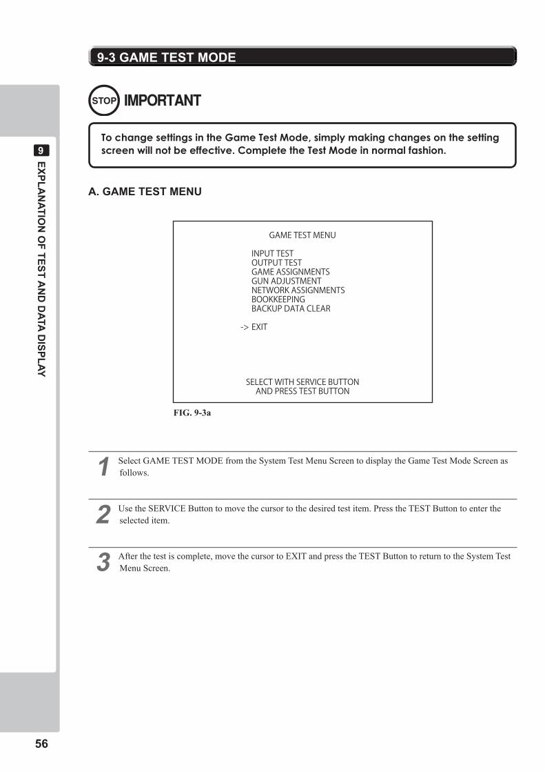
TochangesettingsintheGameTestMode,simplymakingchangesonthesettingscreenwillnotbeeffective.CompletetheTestModeinnormalfashion.
� Select GAME TEST MODE from the System Test Menu Screen to display the Game Test Mode Screen as follows.
� Use the SERVICE Button to move the cursor to the desired test item. Press the TEST Button to enter the selected item.
� After the test is complete, move the cursor to EXIT and press the TEST Button to return to the System Test Menu Screen.
FIG. 9-3a
A. GAME TEST MENU
GAME TEST MENU
INPUT TESTOUTPUT TESTGAME ASSIGNMENTSGUN ADJUSTMENTNETWORK ASSIGNMENTSBOOKKEEPINGBACKUP DATA CLEAR
-> EXIT
SELECT WITH SERVICE BUTTONAND PRESS TEST BUTTON
EXPLAN
ATION
OF TEST A
ND
DATA D
ISPLAY
��
�
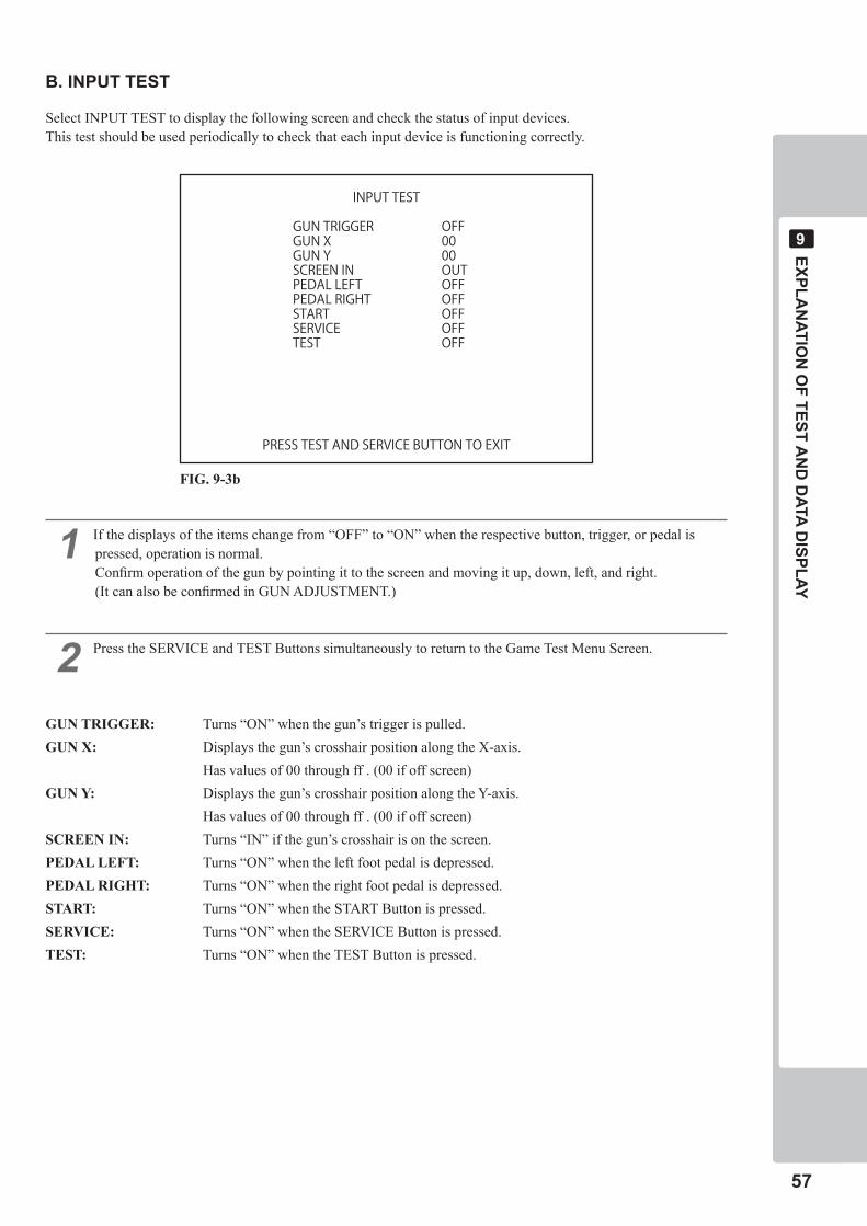
B. INPUT TEST
Select INPUT TEST to display the following screen and check the status of input devices.This test should be used periodically to check that each input device is functioning correctly.
� If the displays of the items change from “OFF” to “ON” when the respective button, trigger, or pedal is pressed, operation is normal.Confirm operation of the gun by pointing it to the screen and moving it up, down, left, and right.(It can also be confirmed in GUN ADJUSTMENT.)
� Press the SERVICE and TEST Buttons simultaneously to return to the Game Test Menu Screen.
GUN TRIGGER: Turns “ON” when the gun’s trigger is pulled.GUN X: Displays the gun’s crosshair position along the X-axis. Has values of 00 through ff . (00 if off screen)GUN Y: Displays the gun’s crosshair position along the Y-axis. Has values of 00 through ff . (00 if off screen)SCREEN IN: Turns “IN” if the gun’s crosshair is on the screen.PEDAL LEFT: Turns “ON” when the left foot pedal is depressed.PEDAL RIGHT: Turns “ON” when the right foot pedal is depressed.START: Turns “ON” when the START Button is pressed.SERVICE: Turns “ON” when the SERVICE Button is pressed.TEST: Turns “ON” when the TEST Button is pressed.
INPUT TEST
GUN TRIGGER OFFGUN X 00GUN Y 00SCREEN IN OUTPEDAL LEFT OFFPEDAL RIGHT OFFSTART OFFSERVICE OFFTEST OFF
PRESS TEST AND SERVICE BUTTON TO EXIT
FIG. 9-3b
��
EXPLAN
ATION
OF TEST A
ND
DATA D
ISPLAY
�
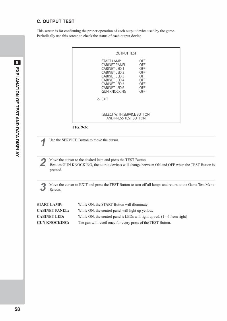
C. OUTPUT TEST
This screen is for confirming the proper operation of each output device used by the game.Periodically use this screen to check the status of each output device.
� Use the SERVICE Button to move the cursor.
� Move the cursor to the desired item and press the TEST Button.Besides GUN KNOCKING, the output devices will change between ON and OFF when the TEST Button is pressed.
� Move the cursor to EXIT and press the TEST Button to turn off all lamps and return to the Game Test Menu Screen.
START LAMP: While ON, the START Button will illuminate.CABINET PANEL: While ON, the control panel will light up yellow.CABINET LED: While ON, the control panel’s LEDs will light up red. (1 - 6 from right)GUN KNOCKING: The gun will recoil once for every press of the TEST Button.
OUTPUT TEST
START LAMP OFFCABINET PANEL OFFCABINET LED 1 OFFCABINET LED 2 OFFCABINET LED 3 OFFCABINET LED 4 OFFCABINET LED 5 OFFCABINET LED 6 OFFGUN KNOCKING OFF
-> EXIT
SELECT WITH SERVICE BUTTONAND PRESS TEST BUTTON
FIG. 9-3c
EXPLAN
ATION
OF TEST A
ND
DATA D
ISPLAY
��
�
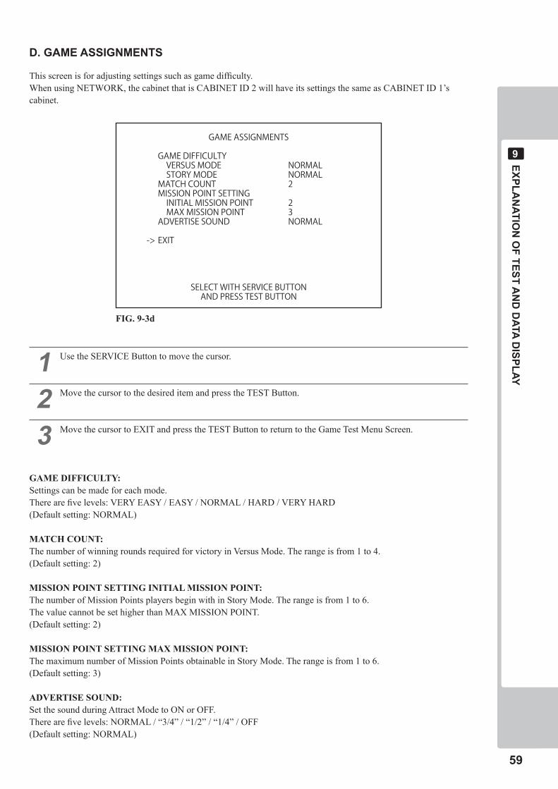
D. GAME ASSIGNMENTS
This screen is for adjusting settings such as game difficulty.When using NETWORK, the cabinet that is CABINET ID 2 will have its settings the same as CABINET ID 1’s cabinet.
� Use the SERVICE Button to move the cursor.
� Move the cursor to the desired item and press the TEST Button.
� Move the cursor to EXIT and press the TEST Button to return to the Game Test Menu Screen.
GAME DIFFICULTY:Settings can be made for each mode.There are five levels: VERY EASY / EASY / NORMAL / HARD / VERY HARD(Default setting: NORMAL)
MATCH COUNT:The number of winning rounds required for victory in Versus Mode. The range is from 1 to 4.(Default setting: 2)
MISSION POINT SETTING INITIAL MISSION POINT:The number of Mission Points players begin with in Story Mode. The range is from 1 to 6.The value cannot be set higher than MAX MISSION POINT.(Default setting: 2)
MISSION POINT SETTING MAX MISSION POINT:The maximum number of Mission Points obtainable in Story Mode. The range is from 1 to 6.(Default setting: 3)
ADVERTISE SOUND:Set the sound during Attract Mode to ON or OFF.There are five levels: NORMAL / “3/4” / “1/2” / “1/4” / OFF(Default setting: NORMAL)
GAME ASSIGNMENTS
GAME DIFFICULTY VERSUS MODE NORMAL STORY MODE NORMALMATCH COUNT 2MISSION POINT SETTING INITIAL MISSION POINT 2 MAX MISSION POINT 3ADVERTISE SOUND NORMAL
-> EXIT
SELECT WITH SERVICE BUTTONAND PRESS TEST BUTTON
FIG. 9-3d
�0
EXPLAN
ATION
OF TEST A
ND
DATA D
ISPLAY
�
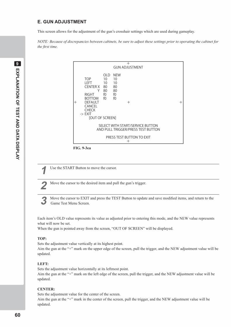
E.GUNADJUSTMENT
This screen allows for the adjustment of the gun’s crosshair settings which are used during gameplay.
NOTE: Because of discrepancies between cabinets, be sure to adjust these settings prior to operating the cabinet for the first time.
� Use the START Button to move the cursor.
� Move the cursor to the desired item and pull the gun’s trigger.
� Move the cursor to EXIT and press the TEST Button to update and save modified items, and return to the Game Test Menu Screen.
Each item’s OLD value represents its value as adjusted prior to entering this mode, and the NEW value represents what will now be set.When the gun is pointed away from the screen, “OUT OF SCREEN” will be displayed.
TOP:Sets the adjustment value vertically at its highest point.Aim the gun at the “+” mark on the upper edge of the screen, pull the trigger, and the NEW adjustment value will be updated.
LEFT:Sets the adjustment value horizontally at its leftmost point.Aim the gun at the “+” mark on the left edge of the screen, pull the trigger, and the NEW adjustment value will be updated.
CENTER:Sets the adjustment value for the center of the screen.Aim the gun at the “+” mark in the center of the screen, pull the trigger, and the NEW adjustment value will be updated.
+GUN ADJUSTMENT
OLD NEWTOP 10 10LEFT 10 10CENTER X 80 80 Y 80 80RIGHT f0 f0BOTTOM f0 f0
+ DEFAULT + +CANCELCHECK
-> EXIT [OUT OF SCREEN]
SELECT WITH START/SERVICE BUTTONAND PULL TRIGGER/PRESS TEST BUTTON
PRESS TEST BUTTON TO EXIT+
FIG. 9-3ea
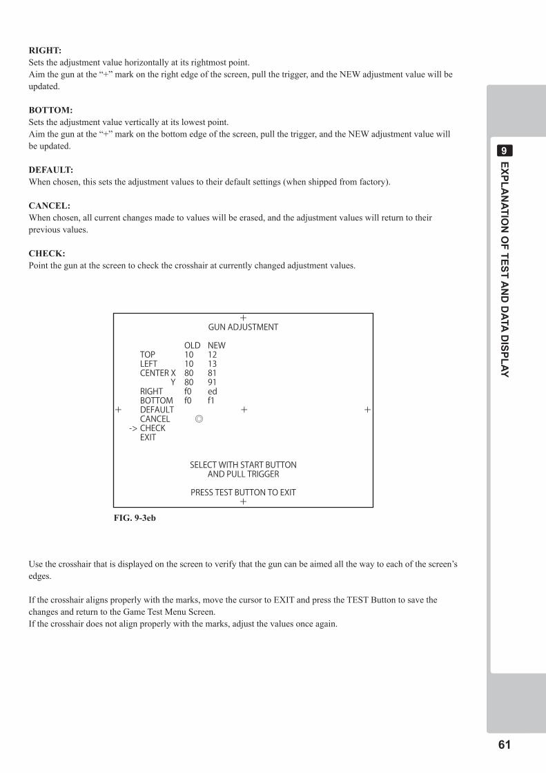
EXPLAN
ATION
OF TEST A
ND
DATA D
ISPLAY
��
�
RIGHT:Sets the adjustment value horizontally at its rightmost point.Aim the gun at the “+” mark on the right edge of the screen, pull the trigger, and the NEW adjustment value will be updated.
BOTTOM:Sets the adjustment value vertically at its lowest point.Aim the gun at the “+” mark on the bottom edge of the screen, pull the trigger, and the NEW adjustment value will be updated.
DEFAULT:When chosen, this sets the adjustment values to their default settings (when shipped from factory).
CANCEL:When chosen, all current changes made to values will be erased, and the adjustment values will return to their previous values.
CHECK:Point the gun at the screen to check the crosshair at currently changed adjustment values.
Use the crosshair that is displayed on the screen to verify that the gun can be aimed all the way to each of the screen’s edges.
If the crosshair aligns properly with the marks, move the cursor to EXIT and press the TEST Button to save the changes and return to the Game Test Menu Screen.If the crosshair does not align properly with the marks, adjust the values once again.
+GUN ADJUSTMENT
OLD NEWTOP 10 12LEFT 10 13CENTER X 80 81 Y 80 91RIGHT f0 edBOTTOM f0 f1
+ DEFAULT + +CANCEL ◎
-> CHECKEXIT
SELECT WITH START BUTTONAND PULL TRIGGER
PRESS TEST BUTTON TO EXIT+
FIG. 9-3eb
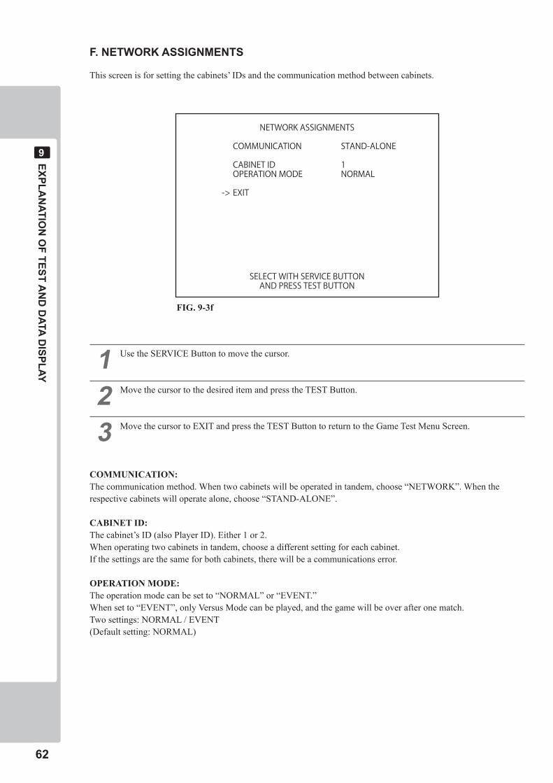
��
EXPLAN
ATION
OF TEST A
ND
DATA D
ISPLAY
�
F. NETWORK ASSIGNMENTS
This screen is for setting the cabinets’ IDs and the communication method between cabinets.
� Use the SERVICE Button to move the cursor.
� Move the cursor to the desired item and press the TEST Button.
� Move the cursor to EXIT and press the TEST Button to return to the Game Test Menu Screen.
COMMUNICATION:The communication method. When two cabinets will be operated in tandem, choose “NETWORK”. When the respective cabinets will operate alone, choose “STAND-ALONE”.
CABINET ID:The cabinet’s ID (also Player ID). Either 1 or 2.When operating two cabinets in tandem, choose a different setting for each cabinet.If the settings are the same for both cabinets, there will be a communications error.
OPERATION MODE:The operation mode can be set to “NORMAL” or “EVENT.” When set to “EVENT”, only Versus Mode can be played, and the game will be over after one match.Two settings: NORMAL / EVENT(Default setting: NORMAL)
NETWORK ASSIGNMENTS
COMMUNICATION STAND-ALONE
CABINET ID 1OPERATION MODE NORMAL
-> EXIT
SELECT WITH SERVICE BUTTONAND PRESS TEST BUTTON
FIG. 9-3f
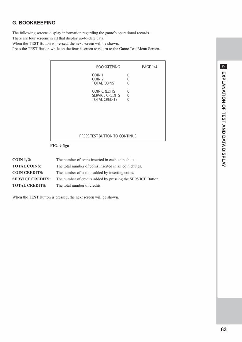
EXPLAN
ATION
OF TEST A
ND
DATA D
ISPLAY
��
�
G. BOOKKEEPING
The following screens display information regarding the game’s operational records.There are four screens in all that display up-to-date data.When the TEST Button is pressed, the next screen will be shown.Press the TEST Button while on the fourth screen to return to the Game Test Menu Screen.
COIN 1, 2: The number of coins inserted in each coin chute.TOTAL COINS: The total number of coins inserted in all coin chutes.COIN CREDITS: The number of credits added by inserting coins.SERVICE CREDITS: The number of credits added by pressing the SERVICE Button.TOTAL CREDITS: The total number of credits.
When the TEST Button is pressed, the next screen will be shown.
BOOKKEEPING PAGE 1/4
COIN 1 0COIN 2 0TOTAL COINS 0
COIN CREDITS 0SERVICE CREDITS 0TOTAL CREDITS 0
PRESS TEST BUTTON TO CONTINUE
FIG. 9-3ga
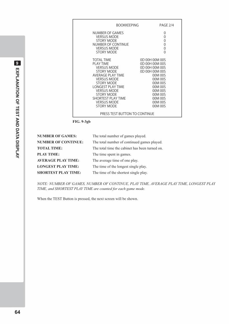
��
EXPLAN
ATION
OF TEST A
ND
DATA D
ISPLAY
�
NUMBER OF GAMES: The total number of games played.NUMBER OF CONTINUE: The total number of continued games played.TOTAL TIME: The total time the cabinet has been turned on.PLAY TIME: The time spent in games.AVERAGE PLAY TIME: The average time of one play.LONGEST PLAY TIME: The time of the longest single play.SHORTEST PLAY TIME: The time of the shortest single play.
NOTE: NUMBER OF GAMES, NUMBER OF CONTINUE, PLAY TIME, AVERAGE PLAY TIME, LONGEST PLAY TIME, and SHORTEST PLAY TIME are counted for each game mode.
When the TEST Button is pressed, the next screen will be shown.
BOOKKEEPING PAGE 2/4
NUMBER OF GAMES 0 VERSUS MODE 0 STORY MODE 0NUMBER OF CONTINUE 0 VERSUS MODE 0 STORY MODE 0
TOTAL TIME 0D 00H 00M 00SPLAY TIME 0D 00H 00M 00S VERSUS MODE 0D 00H 00M 00S STORY MODE 0D 00H 00M 00SAVERAGE PLAY TIME 00M 00S VERSUS MODE 00M 00S STORY MODE 00M 00SLONGEST PLAY TIME 00M 00S VERSUS MODE 00M 00S STORY MODE 00M 00SSHORTEST PLAY TIME 00M 00S VERSUS MODE 00M 00S STORY MODE 00M 00S
PRESS TEST BUTTON TO CONTINUE
FIG. 9-3gb
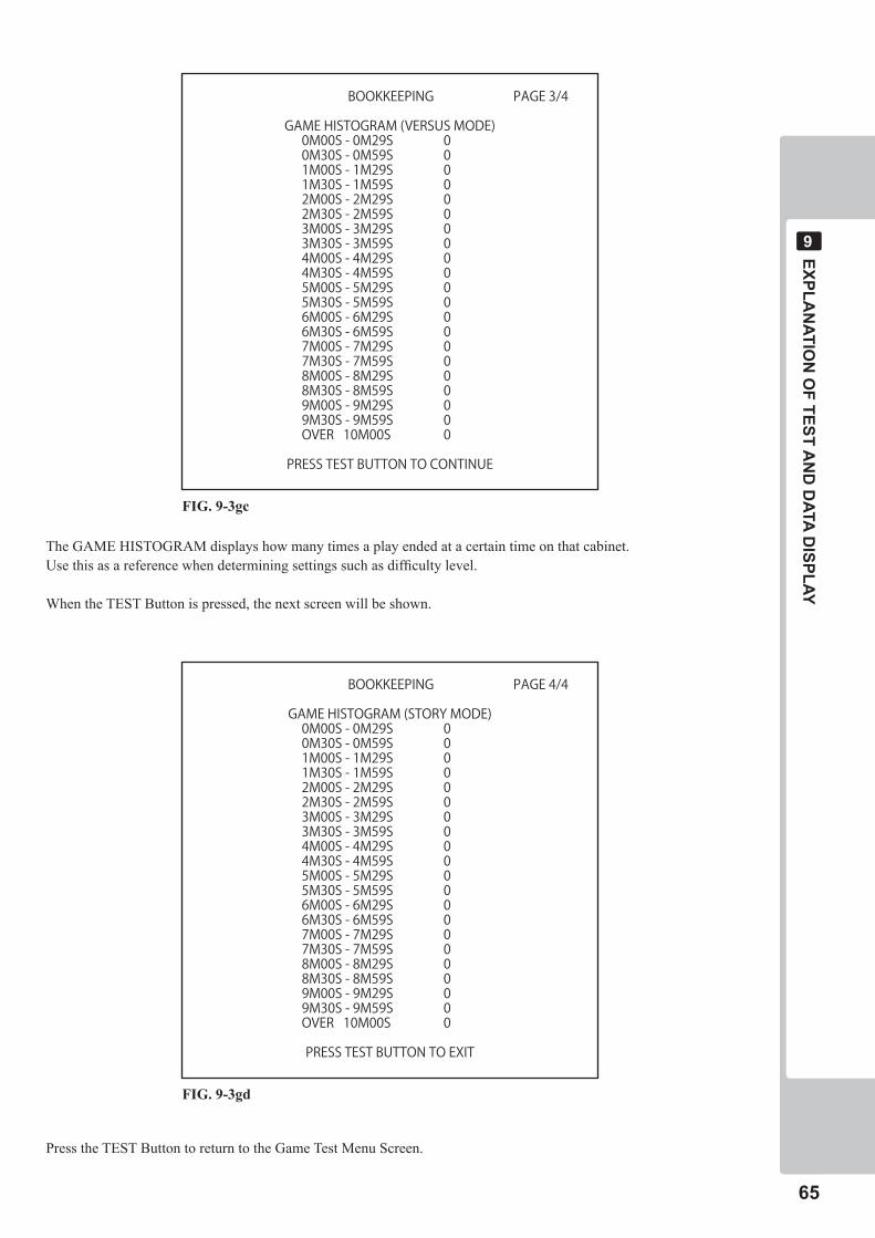
EXPLAN
ATION
OF TEST A
ND
DATA D
ISPLAY
��
�
The GAME HISTOGRAM displays how many times a play ended at a certain time on that cabinet.Use this as a reference when determining settings such as difficulty level.
When the TEST Button is pressed, the next screen will be shown.
Press the TEST Button to return to the Game Test Menu Screen.
BOOKKEEPING PAGE 3/4
GAME HISTOGRAM (VERSUS MODE)0M00S - 0M29S 00M30S - 0M59S 01M00S - 1M29S 01M30S - 1M59S 02M00S - 2M29S 02M30S - 2M59S 03M00S - 3M29S 03M30S - 3M59S 04M00S - 4M29S 04M30S - 4M59S 05M00S - 5M29S 05M30S - 5M59S 06M00S - 6M29S 06M30S - 6M59S 07M00S - 7M29S 07M30S - 7M59S 08M00S - 8M29S 08M30S - 8M59S 09M00S - 9M29S 09M30S - 9M59S 0OVER 10M00S 0
PRESS TEST BUTTON TO CONTINUE
FIG. 9-3gc
BOOKKEEPING PAGE 4/4
GAME HISTOGRAM (STORY MODE)0M00S - 0M29S 00M30S - 0M59S 01M00S - 1M29S 01M30S - 1M59S 02M00S - 2M29S 02M30S - 2M59S 03M00S - 3M29S 03M30S - 3M59S 04M00S - 4M29S 04M30S - 4M59S 05M00S - 5M29S 05M30S - 5M59S 06M00S - 6M29S 06M30S - 6M59S 07M00S - 7M29S 07M30S - 7M59S 08M00S - 8M29S 08M30S - 8M59S 09M00S - 9M29S 09M30S - 9M59S 0OVER 10M00S 0
PRESS TEST BUTTON TO EXIT
FIG. 9-3gd
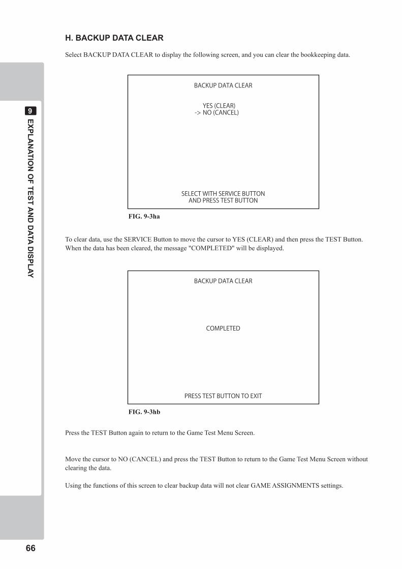
��
EXPLAN
ATION
OF TEST A
ND
DATA D
ISPLAY
�
H. BACKUP DATA CLEAR
Select BACKUP DATA CLEAR to display the following screen, and you can clear the bookkeeping data.
To clear data, use the SERVICE Button to move the cursor to YES (CLEAR) and then press the TEST Button. When the data has been cleared, the message "COMPLETED" will be displayed.
Press the TEST Button again to return to the Game Test Menu Screen.
Move the cursor to NO (CANCEL) and press the TEST Button to return to the Game Test Menu Screen without clearing the data.
Using the functions of this screen to clear backup data will not clear GAME ASSIGNMENTS settings.
BACKUP DATA CLEAR
YES (CLEAR)-> NO (CANCEL)
SELECT WITH SERVICE BUTTONAND PRESS TEST BUTTON
FIG. 9-3ha
BACKUP DATA CLEAR
COMPLETED
PRESS TEST BUTTON TO EXIT
FIG. 9-3hb
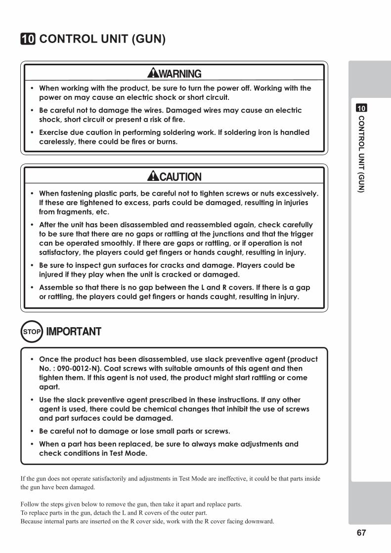
CO
NTR
OL U
NIT (G
UN
)
��
�0
CONTROL UNIT (GUN)�0
• Whenworkingwiththeproduct,besuretoturnthepoweroff.Workingwiththepoweronmaycauseanelectricshockorshortcircuit.
• Becarefulnottodamagethewires.Damagedwiresmaycauseanelectricshock,shortcircuitorpresentariskoffire.
• Exerciseduecautioninperformingsolderingwork.Ifsolderingironishandledcarelessly,therecouldbefiresorburns.
• Whenfasteningplasticparts,becarefulnottotightenscrewsornutsexcessively.Ifthesearetightenedtoexcess,partscouldbedamaged,resultingininjuriesfromfragments,etc.
• Aftertheunithasbeendisassembledandreassembledagain,checkcarefullytobesurethattherearenogapsorrattlingatthejunctionsandthatthetriggercanbeoperatedsmoothly.Iftherearegapsorrattling,orifoperationisnotsatisfactory,theplayerscouldgetfingersorhandscaught,resultingininjury.
• Besuretoinspectgunsurfacesforcracksanddamage.Playerscouldbeinjurediftheyplaywhentheunitiscrackedordamaged.
• AssemblesothatthereisnogapbetweentheLandRcovers.Ifthereisagaporrattling,theplayerscouldgetfingersorhandscaught,resultingininjury.
• Oncetheproducthasbeendisassembled,useslackpreventiveagent(productNo.:090-0012-N).Coatscrewswithsuitableamountsofthisagentandthentightenthem.Ifthisagentisnotused,theproductmightstartrattlingorcomeapart.
• Usetheslackpreventiveagentprescribedintheseinstructions.Ifanyotheragentisused,therecouldbechemicalchangesthatinhibittheuseofscrewsandpartsurfacescouldbedamaged.
• Becarefulnottodamageorlosesmallpartsorscrews.
• Whenaparthasbeenreplaced,besuretoalwaysmakeadjustmentsandcheckconditionsinTestMode.
If the gun does not operate satisfactorily and adjustments in Test Mode are ineffective, it could be that parts inside the gun have been damaged.
Follow the steps given below to remove the gun, then take it apart and replace parts. To replace parts in the gun, detach the L and R covers of the outer part. Because internal parts are inserted on the R cover side, work with the R cover facing downward.
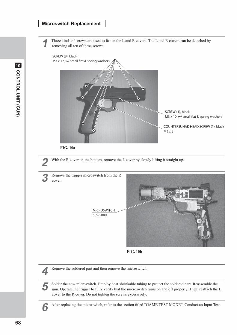
��
CO
NTR
OL U
NIT (G
UN
)
�0
MicroswitchReplacement
� Three kinds of screws are used to fasten the L and R covers. The L and R covers can be detached by removing all ten of these screws.
� With the R cover on the bottom, remove the L cover by slowly lifting it straight up.
� Remove the trigger microswitch from the R cover.
� Remove the soldered part and then remove the microswitch.
� Solder the new microswitch. Employ heat shrinkable tubing to protect the soldered part. Reassemble the gun. Operate the trigger to fully verify that the microswitch turns on and off properly. Then, reattach the L cover to the R cover. Do not tighten the screws excessively.
� After replacing the microswitch, refer to the section titled “GAME TEST MODE”. Conduct an Input Test.
COUNTERSUNAK-HEAD SCREW (1), blackM3 x 8
SCREW (8), blackM3 x 12, w/ small flat & spring washers
SCREW (1), blackM3 x 10, w/ small flat & spring washers
MICROSWITCH509-5080
FIG. 10a
FIG. 10b
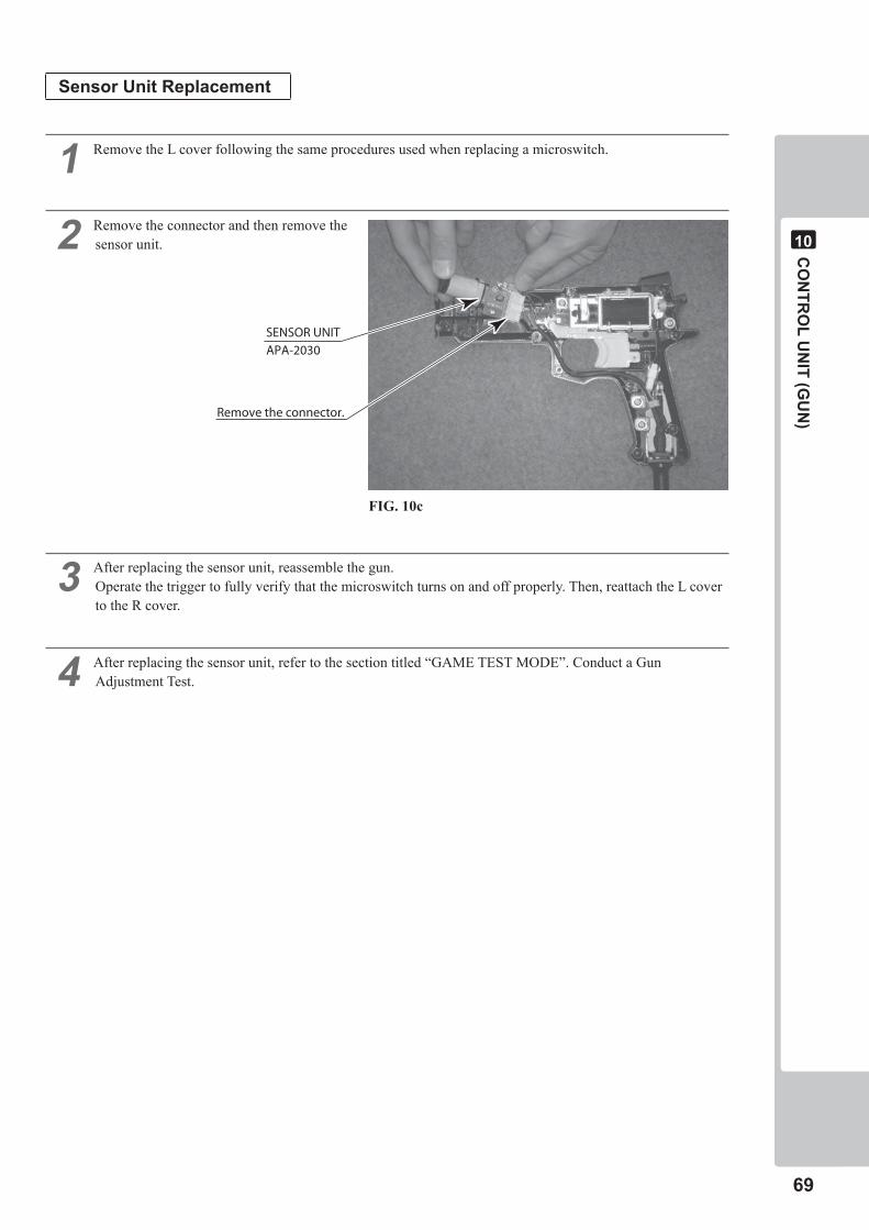
CO
NTR
OL U
NIT (G
UN
)
��
�0
Sensor Unit Replacement
� Remove the L cover following the same procedures used when replacing a microswitch.
� Remove the connector and then remove the sensor unit.
� After replacing the sensor unit, reassemble the gun. Operate the trigger to fully verify that the microswitch turns on and off properly. Then, reattach the L cover to the R cover.
� After replacing the sensor unit, refer to the section titled “GAME TEST MODE”. Conduct a Gun Adjustment Test.
SENSOR UNIT
APA-2030
Remove the connector.
FIG. 10c
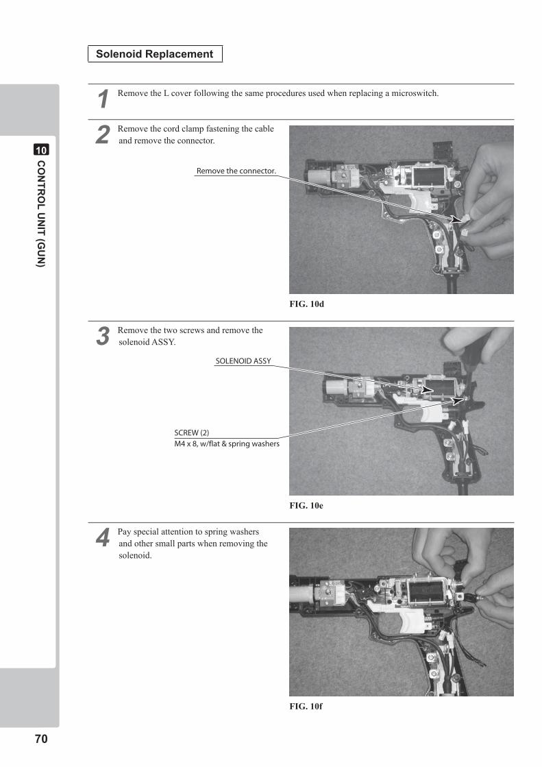
�0
CO
NTR
OL U
NIT (G
UN
)
�0
Solenoid Replacement
� Remove the L cover following the same procedures used when replacing a microswitch.
� Remove the cord clamp fastening the cable and remove the connector.
� Remove the two screws and remove the solenoid ASSY.
� Pay special attention to spring washers and other small parts when removing the solenoid.
Remove the connector.
SOLENOID ASSY
SCREW (2)M4 x 8, w/flat & spring washers
FIG. 10d
FIG. 10e
FIG. 10f
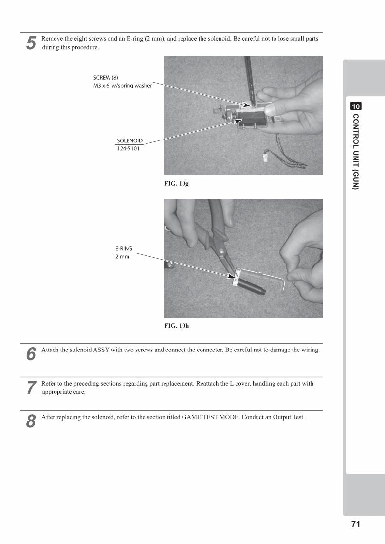
CO
NTR
OL U
NIT (G
UN
)
��
�0
� Remove the eight screws and an E-ring (2 mm), and replace the solenoid. Be careful not to lose small parts during this procedure.
� Attach the solenoid ASSY with two screws and connect the connector. Be careful not to damage the wiring.
� Refer to the preceding sections regarding part replacement. Reattach the L cover, handling each part with appropriate care.
� After replacing the solenoid, refer to the section titled GAME TEST MODE. Conduct an Output Test.
E-RING2 mm
SCREW (8)M3 x 6, w/spring washer
SOLENOID124-5101
FIG. 10g
FIG. 10h
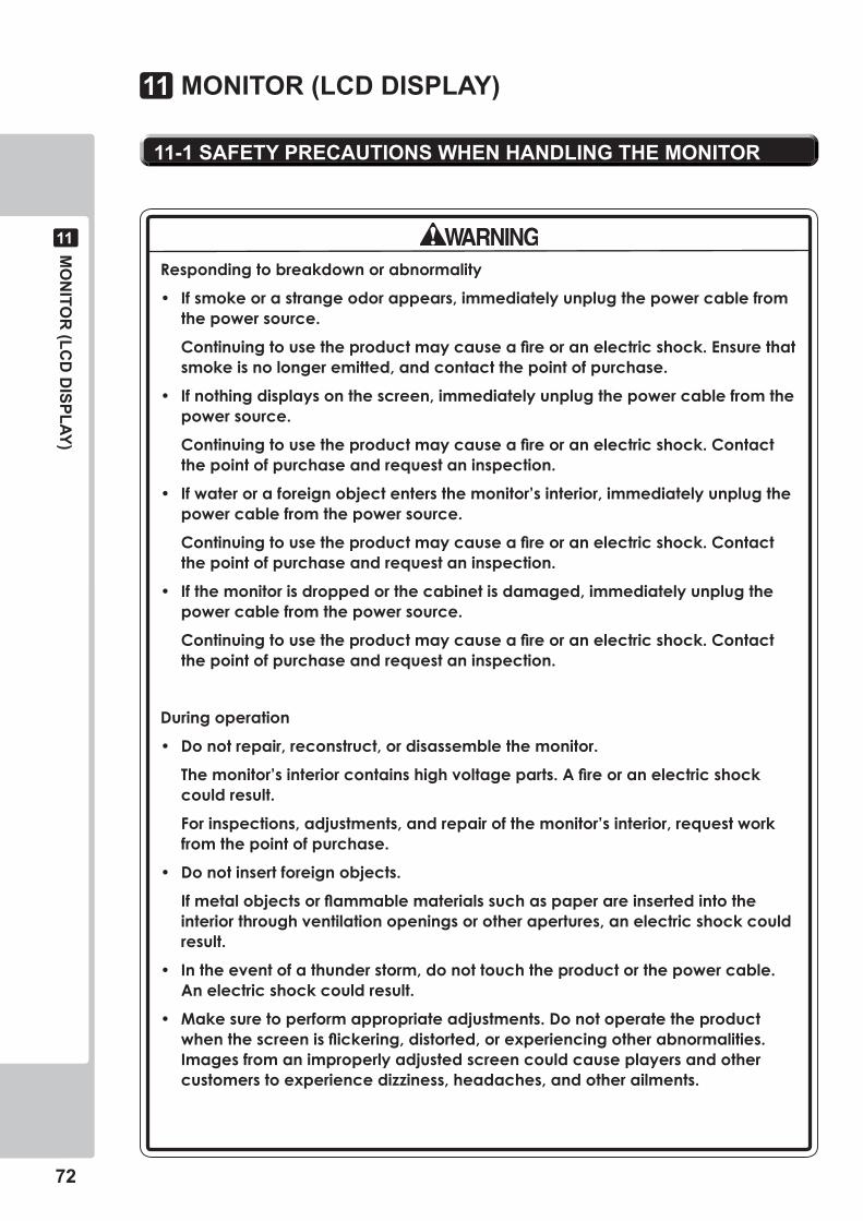
��
MO
NITO
R (LC
D D
ISPLAY)
��
��-� SAFETY PRECAUTIONS WHEN HANDLING THE MONITOR
MONITOR (LCD DISPLAY)��
Respondingtobreakdownorabnormality
• Ifsmokeorastrangeodorappears,immediatelyunplugthepowercablefromthepowersource.
Continuingtousetheproductmaycauseafireoranelectricshock.Ensurethatsmokeisnolongeremitted,andcontactthepointofpurchase.
• Ifnothingdisplaysonthescreen,immediatelyunplugthepowercablefromthepowersource.
Continuingtousetheproductmaycauseafireoranelectricshock.Contactthepointofpurchaseandrequestaninspection.
• Ifwateroraforeignobjectentersthemonitor’sinterior,immediatelyunplugthepowercablefromthepowersource.
Continuingtousetheproductmaycauseafireoranelectricshock.Contactthepointofpurchaseandrequestaninspection.
• Ifthemonitorisdroppedorthecabinetisdamaged,immediatelyunplugthepowercablefromthepowersource.
Continuingtousetheproductmaycauseafireoranelectricshock.Contactthepointofpurchaseandrequestaninspection.
Duringoperation
• Donotrepair,reconstruct,ordisassemblethemonitor.
Themonitor’sinteriorcontainshighvoltageparts.Afireoranelectricshockcouldresult.
Forinspections,adjustments,andrepairofthemonitor’sinterior,requestworkfromthepointofpurchase.
• Donotinsertforeignobjects.
Ifmetalobjectsorflammablematerialssuchaspaperareinsertedintotheinteriorthroughventilationopeningsorotherapertures,anelectricshockcouldresult.
• Intheeventofathunderstorm,donottouchtheproductorthepowercable.Anelectricshockcouldresult.
• Makesuretoperformappropriateadjustments.Donotoperatetheproductwhenthescreenisflickering,distorted,orexperiencingotherabnormalities.Imagesfromanimproperlyadjustedscreencouldcauseplayersandothercustomerstoexperiencedizziness,headaches,andotherailments.
MO
NITO
R (LC
D D
ISPLAY)
��
��
��-� CLEANING THE SCREEN SURFACE
• Useasoft,drycloth(flannel-type)towipeawaydirt.Donotusematerialssuchascoarsemeshgauze.
• Alcohol(ethanol)istherecommendedsolventforremovingdirt.Whenusingacleaningagent,followtheprecautionsbelow.
-Diluteneutralcleaningagentsforhomeusewithwater.Soakasoftclothinthesolution,andwringitthoroughlybeforewipingthescreen.
-Donotuseabrasivecleaningagentsorpowders,orcleaningagentscontainingbleach.
-Donotusealkalinecleaningagentssuchasglasscleaners,orsolventssuchasthinners.
• Donotscruborscratchthescreensurfacewithabrasivematerialssuchasbrushesorscrubbrushes.
Clean the screen surface once a week.
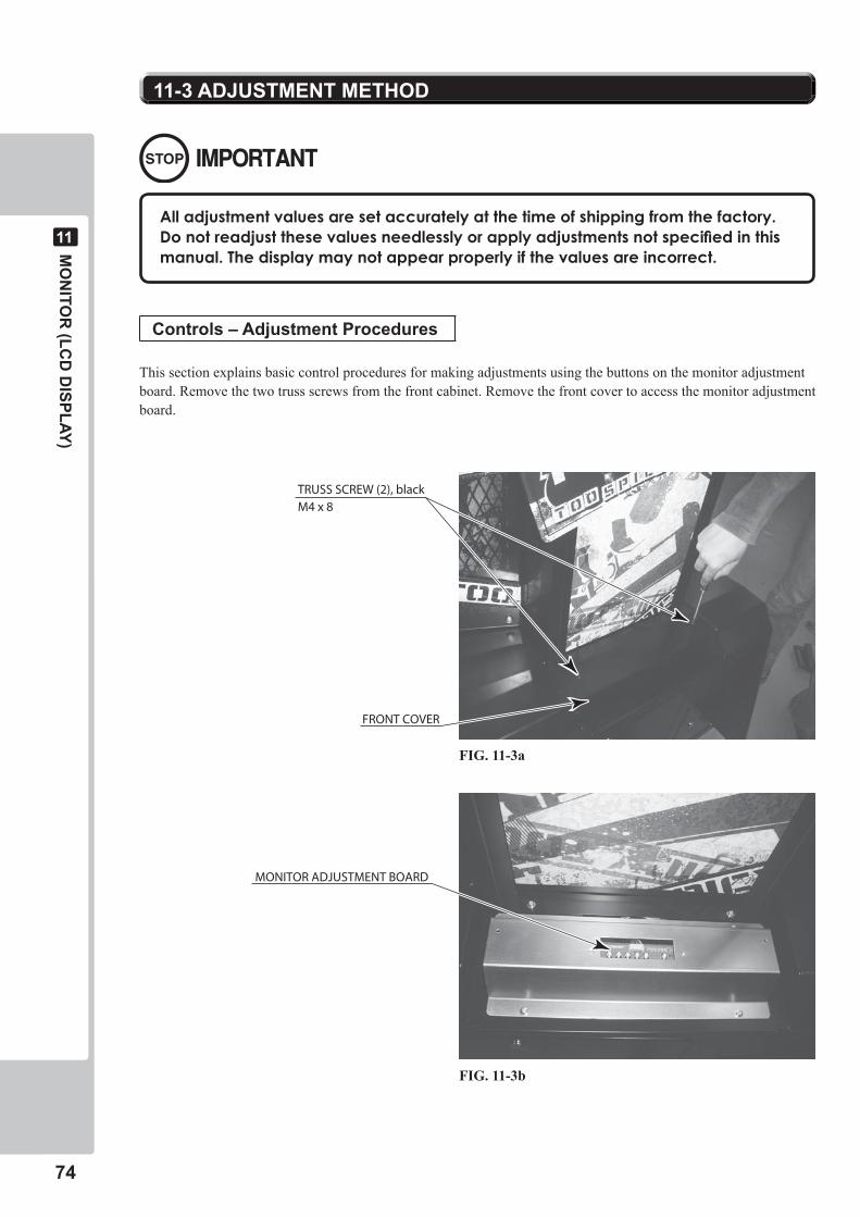
��
MO
NITO
R (LC
D D
ISPLAY)
��
11-3ADJUSTMENTMETHOD
FRONT COVER
TRUSS SCREW (2), blackM4 x 8
MONITOR ADJUSTMENT BOARD
Alladjustmentvaluesaresetaccuratelyatthetimeofshippingfromthefactory.Donotreadjustthesevaluesneedlesslyorapplyadjustmentsnotspecifiedinthismanual.Thedisplaymaynotappearproperlyifthevaluesareincorrect.
Controls – Adjustment Procedures
This section explains basic control procedures for making adjustments using the buttons on the monitor adjustment board. Remove the two truss screws from the front cabinet. Remove the front cover to access the monitor adjustment board.
FIG. 11-3a
FIG. 11-3b
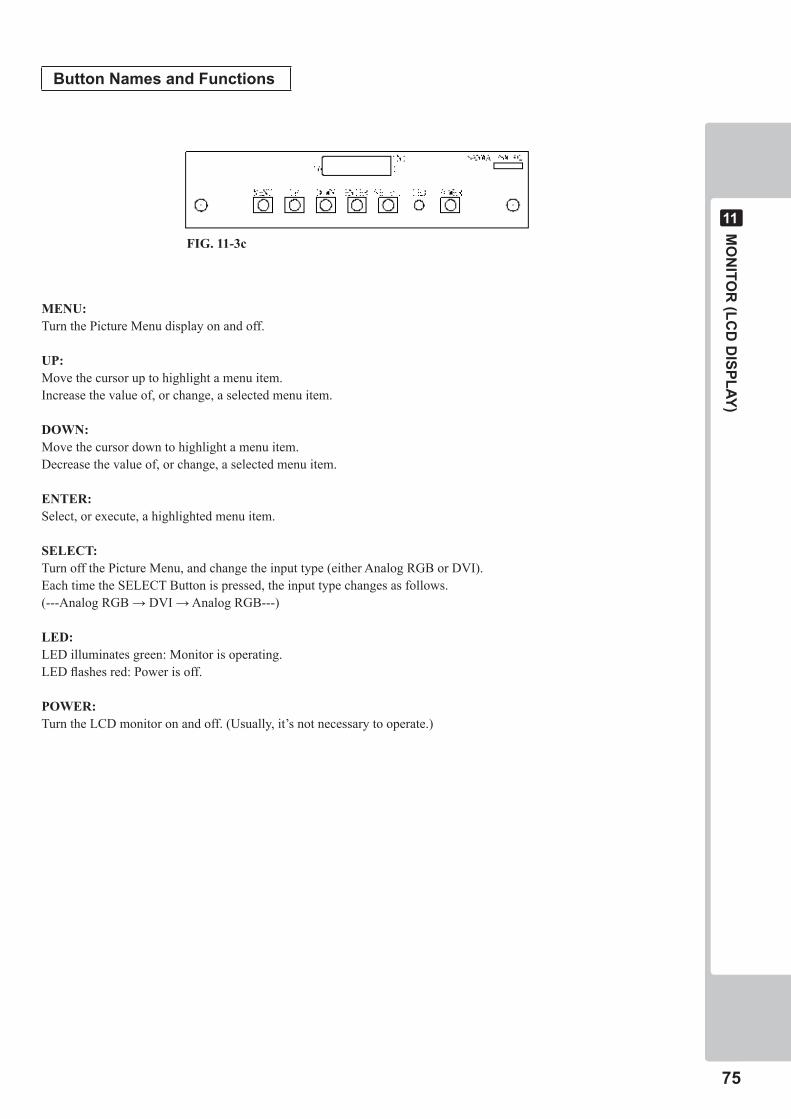
MO
NITO
R (LC
D D
ISPLAY)
��
��
Button Names and Functions
MENU: Turn the Picture Menu display on and off.
UP: Move the cursor up to highlight a menu item.Increase the value of, or change, a selected menu item.
DOWN: Move the cursor down to highlight a menu item.Decrease the value of, or change, a selected menu item.
ENTER: Select, or execute, a highlighted menu item.
SELECT: Turn off the Picture Menu, and change the input type (either Analog RGB or DVI).Each time the SELECT Button is pressed, the input type changes as follows.(---Analog RGB → DVI → Analog RGB---)
LED:LED illuminates green: Monitor is operating.LED flashes red: Power is off.
POWER: Turn the LCD monitor on and off. (Usually, it’s not necessary to operate.)
FIG. 11-3c
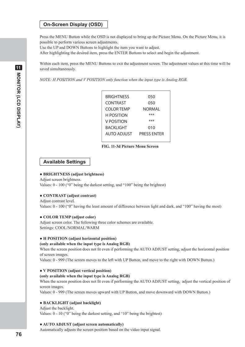
��
MO
NITO
R (LC
D D
ISPLAY)
��
On-Screen Display (OSD)
Press the MENU Button while the OSD is not displayed to bring up the Picture Menu. On the Picture Menu, it is possible to perform various screen adjustments.Use the UP and DOWN Buttons to highlight the item you want to adjust.After highlighting the desired item, press the ENTER Buttons to select and begin the adjustment.
Within each item, press the MENU Buttons to exit the adjustment screen. The adjustment values at this time will be saved simultaneously.
NOTE: H POSITION and V POSITION only function when the input type is Analog RGB.
Available Settings
●BRIGHTNESS(adjustbrightness)Adjust screen brightness.Values: 0 - 100 (“0” being the darkest setting, and “100” being the brightest)
●CONTRAST(adjustcontrast)Adjust contrast level.Values: 0 - 100 (“0” having the least amount of difference between light and dark, and “100” having the most)
●COLORTEMP(adjustcolor)Adjust screen color. The following three color schemes are available.Settings: COOL/NORMAL/WARM
●HPOSITION(adjusthorizontalposition)(only available when the input type is Analog RGB)When the screen position does not fit even if performing the AUTO ADJUST setting, adjust the horizontal position of screen images.Values: 0 - 999 (The screen moves to the left with UP Button, and move to the right with DOWN Button.)
●VPOSITION(adjustverticalposition)(only available when the input type is Analog RGB)When the screen position does not fit even if performing the AUTO ADJUST setting, adjust the vertical position of screen images. Values: 0 - 999 (The screen moves upward with UP Button, and move downward with DOWN Button.)
●BACKLIGHT(adjustbacklight)Adjust the backlight.Values: 0 - 10 (“0” being the darkest setting, and “10” being the brightest)
●AUTOADJUST(adjustscreenautomatically)Automatically adjusts the screen position based on the video input signal.
FIG. 11-3d Picture Menu Screen
BRIGHTNESS 050
CONTRAST 050
COLORTEMP NORMAL
HPOSITION ***
VPOSITION ***
BACKLIGHT 010
AUTOADJUST PRESSENTER
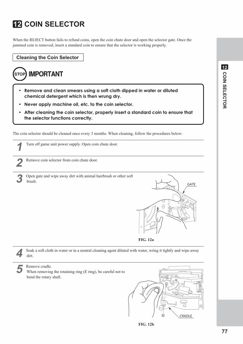
CO
IN SELEC
TOR
��
��
When the REJECT button fails to refund coins, open the coin chute door and open the selector gate. Once the jammed coin is removed, insert a standard coin to ensure that the selector is working properly.
Cleaning the Coin Selector
The coin selector should be cleaned once every 3 months. When cleaning, follow the procedures below:
� Turn off game unit power supply. Open coin chute door.
� Remove coin selector from coin chute door.
� Open gate and wipe away dirt with animal hairbrush or other soft brush.
� Soak a soft cloth in water or in a neutral cleaning agent diluted with water, wring it tightly and wipe away dirt.
� Remove cradle. When removing the retaining ring (E ring), be careful not to bend the rotary shaft.
GATE
CRADLE
COIN SELECTOR��
• Removeandcleansmearsusingasoftclothdippedinwaterordilutedchemicaldetergentwhichisthenwrungdry.
• Neverapplymachineoil,etc.tothecoinselector.
• Aftercleaningthecoinselector,properlyinsertastandardcointoensurethattheselectorfunctionscorrectly.
FIG. 12a
FIG. 12b
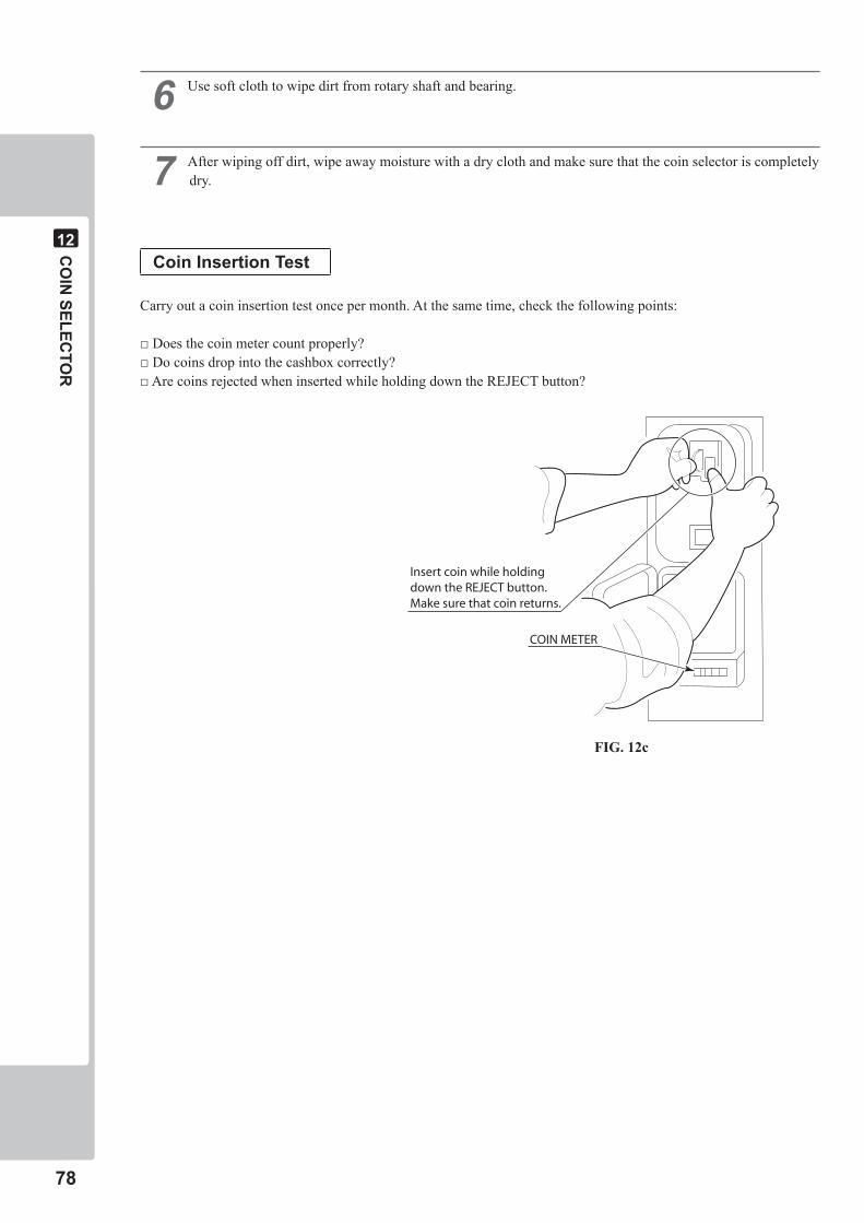
��
CO
IN SELEC
TOR
��
COIN METER
Insert coin while holding down the REJECT button. Make sure that coin returns.
� Use soft cloth to wipe dirt from rotary shaft and bearing.
� After wiping off dirt, wipe away moisture with a dry cloth and make sure that the coin selector is completely dry.
Coin Insertion Test
Carry out a coin insertion test once per month. At the same time, check the following points:
□ Does the coin meter count properly?□ Do coins drop into the cashbox correctly?□ Are coins rejected when inserted while holding down the REJECT button?
FIG. 12c
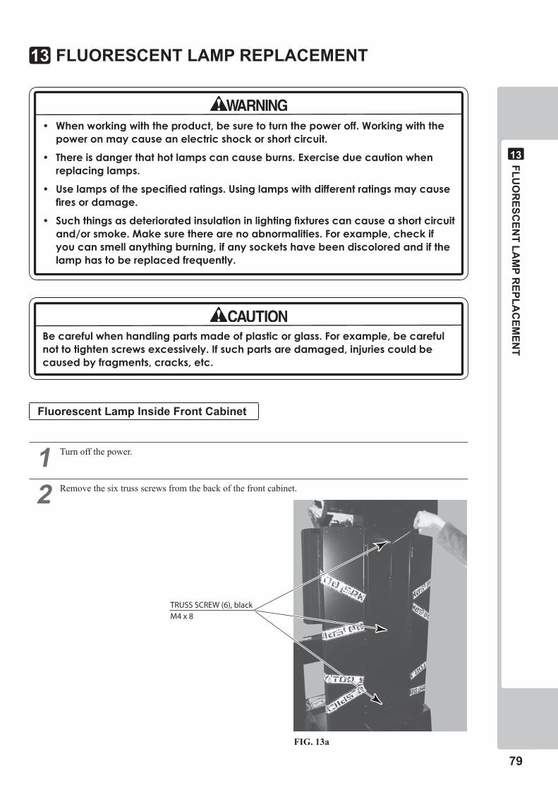
FLUO
RESC
ENT LA
MP R
EPLAC
EMEN
T
��
��
TRUSS SCREW (6), blackM4 x 8
FLUORESCENT LAMP REPLACEMENT��
• Whenworkingwiththeproduct,besuretoturnthepoweroff.Workingwiththepoweronmaycauseanelectricshockorshortcircuit.
• Thereisdangerthathotlampscancauseburns.Exerciseduecautionwhenreplacinglamps.
• Uselampsofthespecifiedratings.Usinglampswithdifferentratingsmaycausefiresordamage.
• Suchthingsasdeterioratedinsulationinlightingfixturescancauseashortcircuitand/orsmoke.Makesuretherearenoabnormalities.Forexample,checkifyoucansmellanythingburning,ifanysocketshavebeendiscoloredandifthelamphastobereplacedfrequently.
Becarefulwhenhandlingpartsmadeofplasticorglass.Forexample,becarefulnottotightenscrewsexcessively.Ifsuchpartsaredamaged,injuriescouldbecausedbyfragments,cracks,etc.
Fluorescent Lamp Inside Front Cabinet
� Turn off the power.
� Remove the six truss screws from the back of the front cabinet.
FIG. 13a
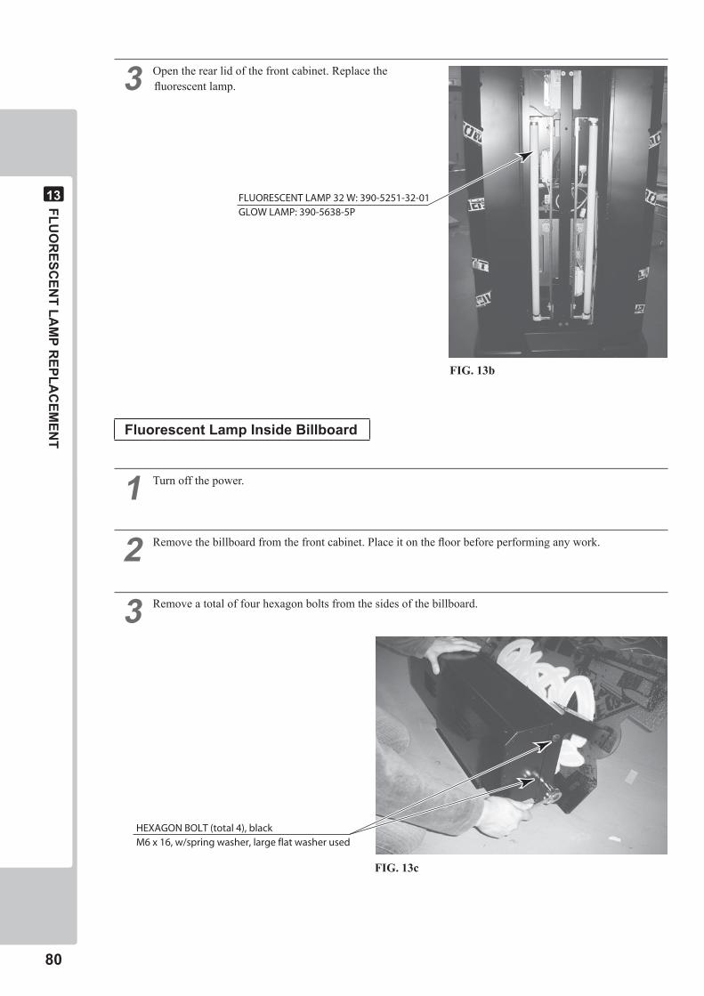
�0
FLUO
RESC
ENT LA
MP R
EPLAC
EMEN
T
��
� Open the rear lid of the front cabinet. Replace the fluorescent lamp.
Fluorescent Lamp Inside Billboard
� Turn off the power.
� Remove the billboard from the front cabinet. Place it on the floor before performing any work.
� Remove a total of four hexagon bolts from the sides of the billboard.
FLUORESCENT LAMP 32 W: 390-5251-32-01GLOW LAMP: 390-5638-5P
HEXAGON BOLT (total 4), blackM6 x 16, w/spring washer, large flat washer used
FIG. 13b
FIG. 13c
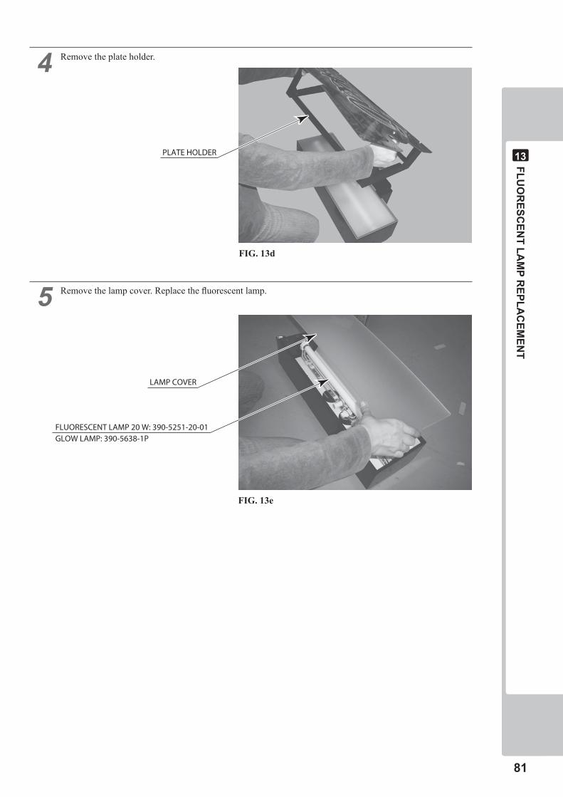
FLUO
RESC
ENT LA
MP R
EPLAC
EMEN
T
��
��
� Remove the plate holder.
� Remove the lamp cover. Replace the fluorescent lamp.
PLATE HOLDER
FLUORESCENT LAMP 20 W: 390-5251-20-01 GLOW LAMP: 390-5638-1P
LAMP COVER
FIG. 13d
FIG. 13e
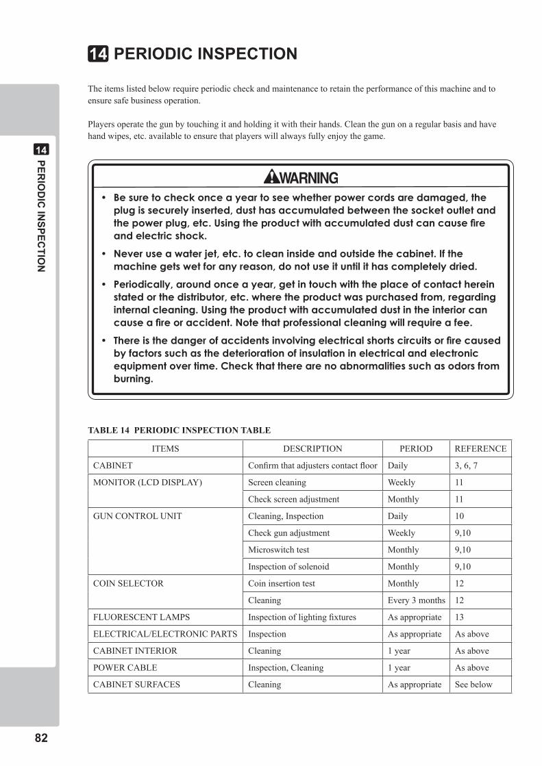
��
PERIO
DIC
INSPEC
TION
��
PERIODIC INSPECTION��
The items listed below require periodic check and maintenance to retain the performance of this machine and to ensure safe business operation.
Players operate the gun by touching it and holding it with their hands. Clean the gun on a regular basis and have hand wipes, etc. available to ensure that players will always fully enjoy the game.
• Besuretocheckonceayeartoseewhetherpowercordsaredamaged,theplugissecurelyinserted,dusthasaccumulatedbetweenthesocketoutletandthepowerplug,etc.Usingtheproductwithaccumulateddustcancausefireandelectricshock.
• Neveruseawaterjet,etc.tocleaninsideandoutsidethecabinet.Ifthemachinegetswetforanyreason,donotuseituntilithascompletelydried.
• Periodically,aroundonceayear,getintouchwiththeplaceofcontacthereinstatedorthedistributor,etc.wheretheproductwaspurchasedfrom,regardinginternalcleaning.Usingtheproductwithaccumulateddustintheinteriorcancauseafireoraccident.Notethatprofessionalcleaningwillrequireafee.
• Thereisthedangerofaccidentsinvolvingelectricalshortscircuitsorfirecausedbyfactorssuchasthedeteriorationofinsulationinelectricalandelectronicequipmentovertime.Checkthattherearenoabnormalitiessuchasodorsfromburning.
ITEMS DESCRIPTION PERIOD REFERENCE
CABINET Confirm that adjusters contact floor Daily 3, 6, 7
MONITOR (LCD DISPLAY) Screen cleaning Weekly 11
Check screen adjustment Monthly 11
GUN CONTROL UNIT Cleaning, Inspection Daily 10
Check gun adjustment Weekly 9,10
Microswitch test Monthly 9,10
Inspection of solenoid Monthly 9,10
COIN SELECTOR Coin insertion test Monthly 12
Cleaning Every 3 months 12
FLUORESCENT LAMPS Inspection of lighting fixtures As appropriate 13
ELECTRICAL/ELECTRONIC PARTS Inspection As appropriate As above
CABINET INTERIOR Cleaning 1 year As above
POWER CABLE Inspection, Cleaning 1 year As above
CABINET SURFACES Cleaning As appropriate See below
TABLE 14 PERIODIC INSPECTION TABLE
PERIO
DIC
INSPEC
TION
��
��
Cleaning the Cabinet Surfaces
When the cabinet surfaces become dirty, remove stains with a soft cloth soaked in water or diluted (with water) chemical detergent and then wrung dry. To avoid damaging the finish, do not use such solvents as thinner, benzene, etc. (other than ethyl alcohol) or abrasives (bleaching agent and chemical dust-cloth).
Some general-purpose household, kitchen, and furniture cleaning products may contain strong solvents that degrade plastic parts, coatings, and print. Before using any cleaning product, read the product's cautionary notes carefully and test the product first on a small area that is not highly visible.
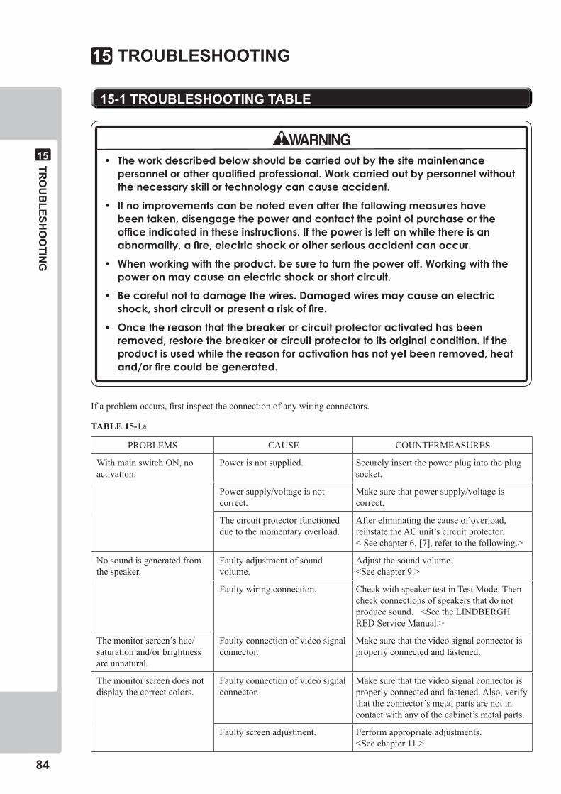
��
TRO
UB
LESHO
OTIN
G
��
��-� TROUBLESHOOTING TABLE
TROUBLESHOOTING��
• Theworkdescribedbelowshouldbecarriedoutbythesitemaintenancepersonnelorotherqualifiedprofessional.Workcarriedoutbypersonnelwithoutthenecessaryskillortechnologycancauseaccident.
• Ifnoimprovementscanbenotedevenafterthefollowingmeasureshavebeentaken,disengagethepowerandcontactthepointofpurchaseortheofficeindicatedintheseinstructions.Ifthepowerisleftonwhilethereisanabnormality,afire,electricshockorotherseriousaccidentcanoccur.
• Whenworkingwiththeproduct,besuretoturnthepoweroff.Workingwiththepoweronmaycauseanelectricshockorshortcircuit.
• Becarefulnottodamagethewires.Damagedwiresmaycauseanelectricshock,shortcircuitorpresentariskoffire.
• Oncethereasonthatthebreakerorcircuitprotectoractivatedhasbeenremoved,restorethebreakerorcircuitprotectortoitsoriginalcondition.Iftheproductisusedwhilethereasonforactivationhasnotyetbeenremoved,heatand/orfirecouldbegenerated.
If a problem occurs, first inspect the connection of any wiring connectors.
PROBLEMS CAUSE COUNTERMEASURES
With main switch ON, no activation.
Power is not supplied. Securely insert the power plug into the plug socket.
Power supply/voltage is not correct.
Make sure that power supply/voltage is correct.
The circuit protector functioned due to the momentary overload.
After eliminating the cause of overload, reinstate the AC unit’s circuit protector. < See chapter 6, [7], refer to the following.>
No sound is generated from the speaker.
Faulty adjustment of sound volume.
Adjust the sound volume. <See chapter 9.>
Faulty wiring connection. Check with speaker test in Test Mode. Then check connections of speakers that do not produce sound. <See the LINDBERGH RED Service Manual.>
The monitor screen’s hue/saturation and/or brightness are unnatural.
Faulty connection of video signal connector.
Make sure that the video signal connector is properly connected and fastened.
The monitor screen does not display the correct colors.
Faulty connection of video signal connector.
Make sure that the video signal connector is properly connected and fastened. Also, verify that the connector’s metal parts are not in contact with any of the cabinet’s metal parts.
Faulty screen adjustment. Perform appropriate adjustments. <See chapter 11.>
TABLE 15-1a
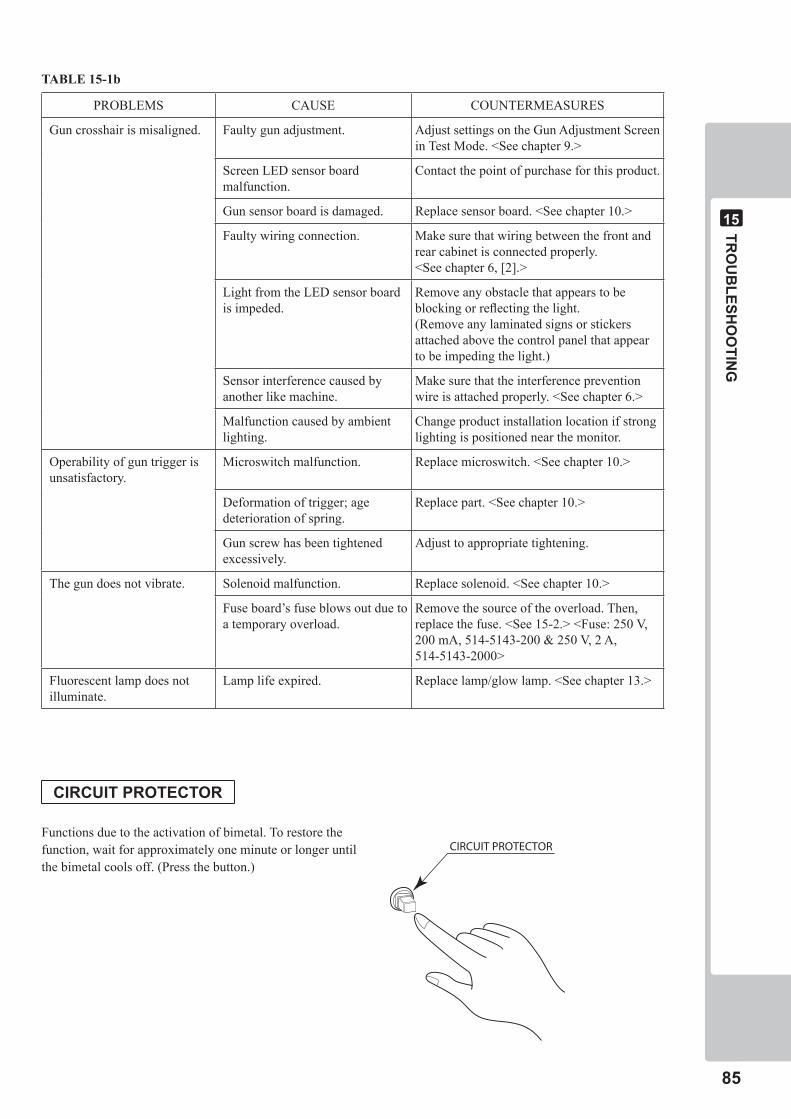
TRO
UB
LESHO
OTIN
G
��
��
CIRCUIT PROTECTOR
PROBLEMS CAUSE COUNTERMEASURES
Gun crosshair is misaligned. Faulty gun adjustment. Adjust settings on the Gun Adjustment Screen in Test Mode. <See chapter 9.>
Screen LED sensor board malfunction.
Contact the point of purchase for this product.
Gun sensor board is damaged. Replace sensor board. <See chapter 10.>
Faulty wiring connection. Make sure that wiring between the front and rear cabinet is connected properly. <See chapter 6, [2].>
Light from the LED sensor board is impeded.
Remove any obstacle that appears to be blocking or reflecting the light.(Remove any laminated signs or stickers attached above the control panel that appear to be impeding the light.)
Sensor interference caused by another like machine.
Make sure that the interference prevention wire is attached properly. <See chapter 6.>
Malfunction caused by ambient lighting.
Change product installation location if strong lighting is positioned near the monitor.
Operability of gun trigger is unsatisfactory.
Microswitch malfunction. Replace microswitch. <See chapter 10.>
Deformation of trigger; age deterioration of spring.
Replace part. <See chapter 10.>
Gun screw has been tightened excessively.
Adjust to appropriate tightening.
The gun does not vibrate. Solenoid malfunction. Replace solenoid. <See chapter 10.>
Fuse board’s fuse blows out due to a temporary overload.
Remove the source of the overload. Then, replace the fuse. <See 15-2.> <Fuse: 250 V, 200 mA, 514-5143-200 & 250 V, 2 A, 514-5143-2000>
Fluorescent lamp does not illuminate.
Lamp life expired. Replace lamp/glow lamp. <See chapter 13.>
TABLE 15-1b
CIRCUIT PROTECTOR
Functions due to the activation of bimetal. To restore the function, wait for approximately one minute or longer until the bimetal cools off. (Press the button.)
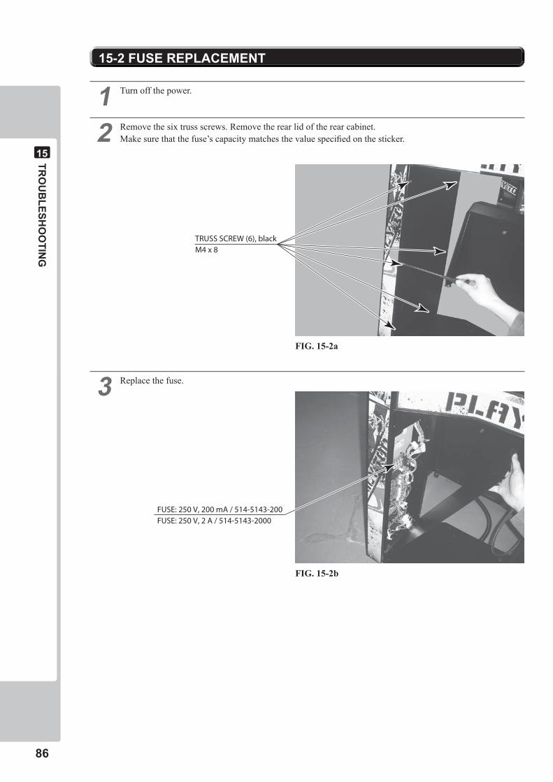
��
TRO
UB
LESHO
OTIN
G
��
� Turn off the power.
� Remove the six truss screws. Remove the rear lid of the rear cabinet.Make sure that the fuse’s capacity matches the value specified on the sticker.
� Replace the fuse.
��-� FUSE REPLACEMENT
TRUSS SCREW (6), blackM4 x 8
FUSE: 250 V, 200 mA / 514-5143-200FUSE: 250 V, 2 A / 514-5143-2000
FIG. 15-2a
FIG. 15-2b
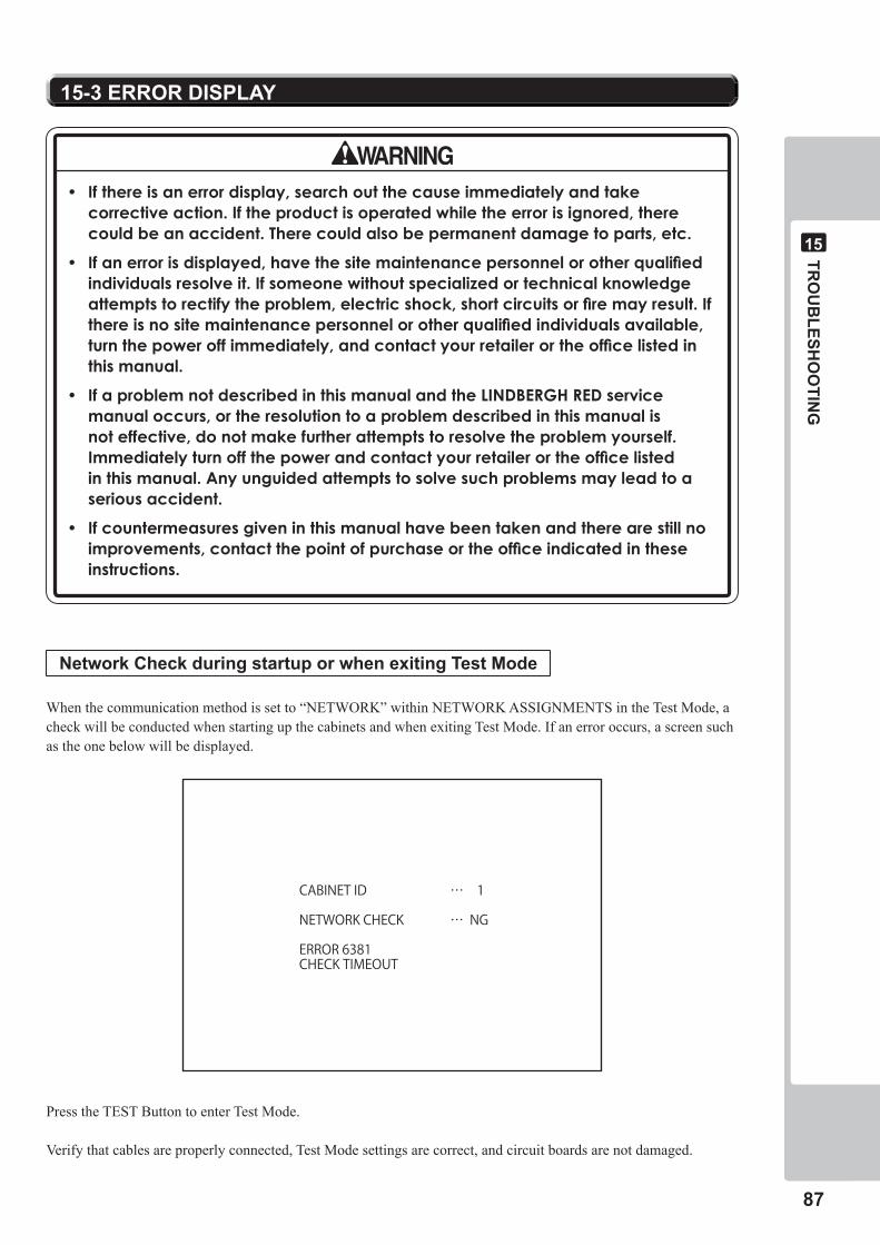
TRO
UB
LESHO
OTIN
G
��
��
��-� ERROR DISPLAY
• Ifthereisanerrordisplay,searchoutthecauseimmediatelyandtakecorrectiveaction.Iftheproductisoperatedwhiletheerrorisignored,therecouldbeanaccident.Therecouldalsobepermanentdamagetoparts,etc.
• Ifanerrorisdisplayed,havethesitemaintenancepersonnelorotherqualifiedindividualsresolveit.Ifsomeonewithoutspecializedortechnicalknowledgeattemptstorectifytheproblem,electricshock,shortcircuitsorfiremayresult.Ifthereisnositemaintenancepersonnelorotherqualifiedindividualsavailable,turnthepoweroffimmediately,andcontactyourretailerortheofficelistedinthismanual.
• IfaproblemnotdescribedinthismanualandtheLINDBERGHREDservicemanualoccurs,ortheresolutiontoaproblemdescribedinthismanualisnoteffective,donotmakefurtherattemptstoresolvetheproblemyourself.Immediatelyturnoffthepowerandcontactyourretailerortheofficelistedinthismanual.Anyunguidedattemptstosolvesuchproblemsmayleadtoaseriousaccident.
• Ifcountermeasuresgiveninthismanualhavebeentakenandtherearestillnoimprovements,contactthepointofpurchaseortheofficeindicatedintheseinstructions.
NetworkCheckduringstartuporwhenexitingTestMode
When the communication method is set to “NETWORK” within NETWORK ASSIGNMENTS in the Test Mode, a check will be conducted when starting up the cabinets and when exiting Test Mode. If an error occurs, a screen such as the one below will be displayed.
Press the TEST Button to enter Test Mode.
Verify that cables are properly connected, Test Mode settings are correct, and circuit boards are not damaged.
CABINET ID … 1
NETWORK CHECK … NG
ERROR 6381CHECK TIMEOUT
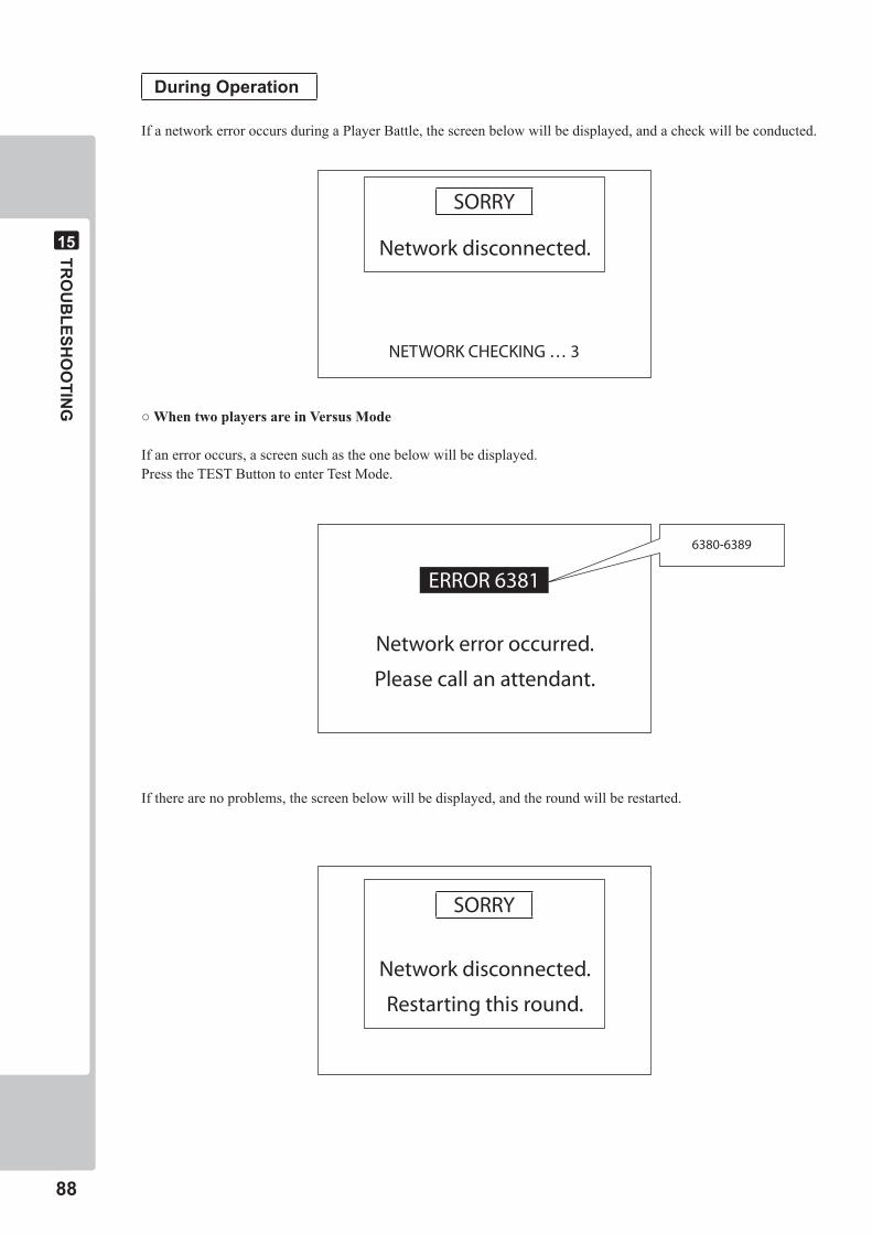
��
TRO
UB
LESHO
OTIN
G
��
During Operation
If a network error occurs during a Player Battle, the screen below will be displayed, and a check will be conducted.
○WhentwoplayersareinVersusMode
If an error occurs, a screen such as the one below will be displayed.Press the TEST Button to enter Test Mode.
If there are no problems, the screen below will be displayed, and the round will be restarted.
SORRY
Networkdisconnected.
NETWORKCHECKING…3
ERROR6381
Networkerroroccurred.
Pleasecallanattendant.
SORRY
Networkdisconnected.
Restartingthisround.
6380-6389
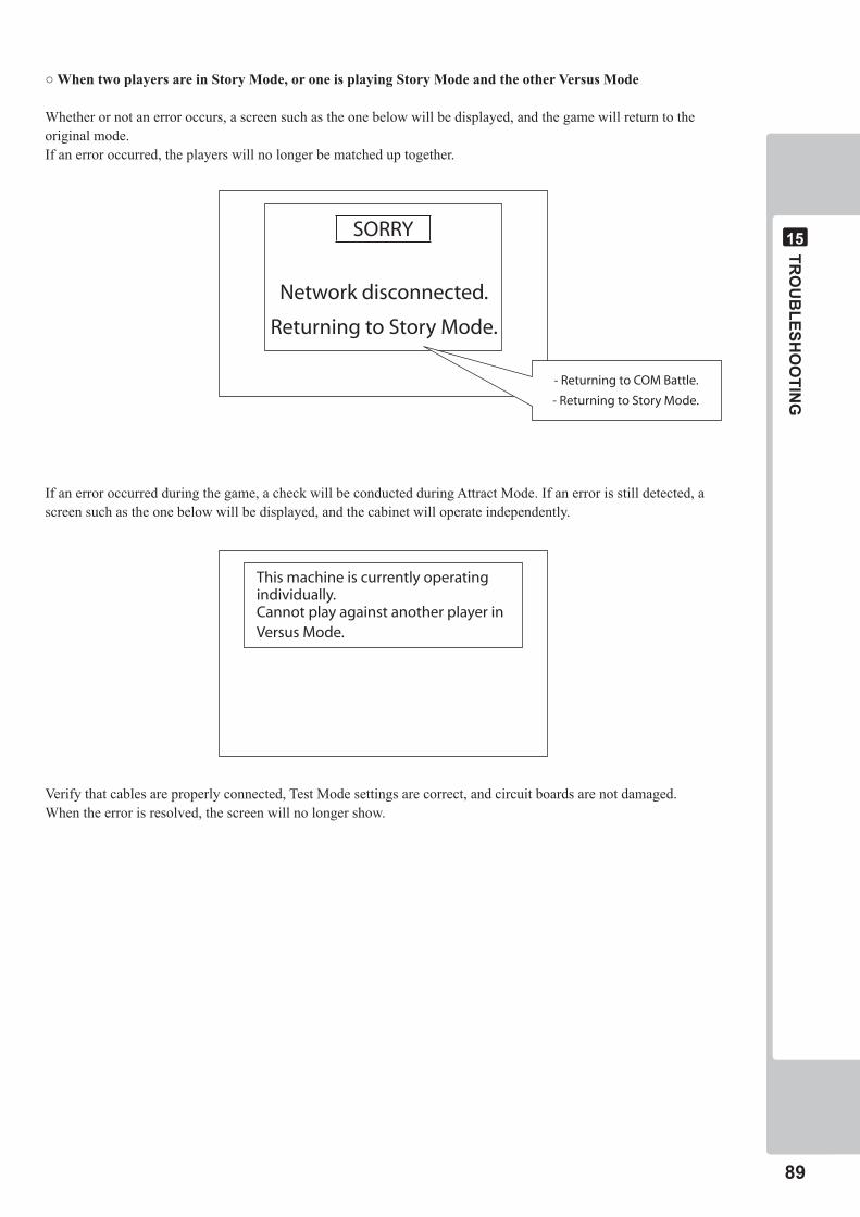
TRO
UB
LESHO
OTIN
G
��
��
○WhentwoplayersareinStoryMode,oroneisplayingStoryModeandtheotherVersusMode
Whether or not an error occurs, a screen such as the one below will be displayed, and the game will return to the original mode.If an error occurred, the players will no longer be matched up together.
If an error occurred during the game, a check will be conducted during Attract Mode. If an error is still detected, a screen such as the one below will be displayed, and the cabinet will operate independently.
Verify that cables are properly connected, Test Mode settings are correct, and circuit boards are not damaged.When the error is resolved, the screen will no longer show.
SORRY
Networkdisconnected.
ReturningtoStoryMode.
-ReturningtoCOMBattle.
-ReturningtoStoryMode.
Thismachineiscurrentlyoperatingindividually.CannotplayagainstanotherplayerinVersusMode.
�0
TRO
UB
LESHO
OTIN
G
��
Error Codes
ERROR 6380: UNKNOWN ERROR(Cause of error is not determined.)
Confirm points such as:- Are the cables properly connected?- Are Test Mode’s settings correct?- Are the circuit boards in good condition?
ERROR 6381: CHECK TIMEOUT(Network Check ran out of time.)
Confirm points such as:- Are the cables properly connected?- Is the other cabinet’s power on?- Is the other cabinet’s communication setting set for “NETWORK”?- Do both cabinets have different CABINET IDs?
ERROR 6383: DIFFERENT RESOLUTION(Network composed of cabinets with varying resolutions.)
- Communication cannot be established between a cabinet set at 640x480 (VGA) and another cabinet set at 1280x768 (WXGA).
- Operate using cabinets set with the same resolution.
ERROR 6389: PACKET LOST(Connection lost.)
Confirm points such as:- Are the cables all making proper contact?- Are hubs, etc. connected to the LAN?- Are there devices that produce noise, such as strong magnetic charges, near the cabinet which may cause
interference?
GA
ME B
OA
RD
��
��
GAME BOARD��
• Whenexchangingthegameboard,placeandpostthedamagedboardinthenewboard’sspecialpackaging.Ifyoudonothavethepackagingoritisdamagedorderoneusingthefollowingproductnumber/name<601-11691:CARTONBOXLBG>.
• Whensendingaboardforrepairs,donotdismantletheboardinanywaypriortosendingitaway.Itmaynotbepossibletomeetyourrequestifanypartsaremissing.
• Sendagameboardinforrepairwiththekeychipstillinserted.
• Whenworkingwiththeproduct,besuretoturnthepoweroff.Workingwiththepoweronmaycauseanelectricshockorshortcircuit.
• Becarefulnottodamagethewires.Damagedwiresmaycauseanelectricshock,shortcircuitorpresentariskoffire.
• Donotexposethegameboard,etc.foranyreason.Doingsomaycauseelectricshockormalfunctioning.
• Noconnectorsotherthanthoseconnectedonthegameboardwhenfirstdeliveredcanbeusedbythisproduct.Donotconnectanyotherwirestoanyoftheunusedconnectors.Thismayleadtothegenerationofheat,smokeorburnouts.
• Whenreplacingorrepairingthegameboardandthenreturningittothecabinet,besuretoreconnectalltheconnectorscorrectly.Improperconnectionmaycauseelectricshock,shortcircuitorfire.
• Whenconnectingtheconnectors,besuretoattachthemcorrectly.Thereisonlyonecorrectwayinwhichtheymustbeconnected.Attemptingtoconnectthemincorrectlymaycausedamagetothepinsontheconnectors,andcauseelectricshock,shortcircuitorfire.
• Inthisproduct,settingchangesaremadeusingtheTestMode.Thegameboardneednotbeoperated.Usethegameboard,etc.asiswiththesamesettingmadeatthetimeofshipmentsoasnottocauseelectricshockandmalfunctioning.
• ThechippartsonICboardscanbedamagedbyelectrostaticdischargefromthehumanbody.BeforehandlinganICboard,alwaysneutralizeanystaticchargeinthebodybytouchingagroundedmetalsurface.
• Becarefulnottogetfingerscaughtwhenremovingdoorsorotherparts.
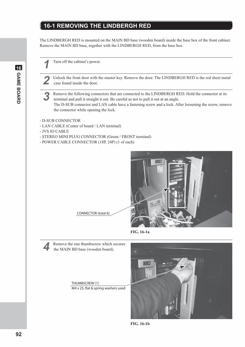
��
GA
ME B
OA
RD
��
The LINDBERGH RED is mounted on the MAIN BD base (wooden board) inside the base box of the front cabinet. Remove the MAIN BD base, together with the LINDBERGH RED, from the base box.
� Turn off the cabinet’s power.
� Unlock the front door with the master key. Remove the door. The LINDBERGH RED is the red sheet metal case found inside the door.
� Remove the following connectors that are connected to the LINDBERGH RED. Hold the connector at its terminal and pull it straight it out. Be careful as not to pull it out at an angle.The D-SUB connector and LAN cable have a fastening screw and a lock. After loosening the screw, remove the connector while opening the lock.
- D-SUB CONNECTOR- LAN CABLE (Center of board / LAN terminal)- JVS IO CABLE- STEREO MINI PLUG CONNECTOR (Green / FRONT terminal)- POWER CABLE CONNECTOR (18P, 24P) (1 of each)
� Remove the one thumbscrew which secures the MAIN BD base (wooden board).
��-� REMOVING THE LINDBERGH RED
CONNECTOR (total 6)
THUMBSCREW (1)M4 x 25, flat & spring washers used
FIG. 16-1a
FIG. 16-1b
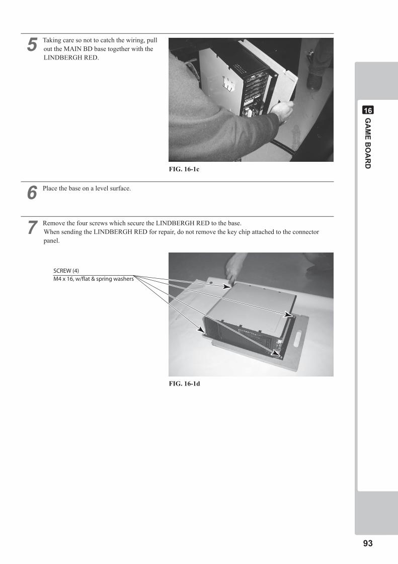
GA
ME B
OA
RD
��
��
� Taking care so not to catch the wiring, pull out the MAIN BD base together with the LINDBERGH RED.
� Place the base on a level surface.
� Remove the four screws which secure the LINDBERGH RED to the base.When sending the LINDBERGH RED for repair, do not remove the key chip attached to the connector panel.
SCREW (4)M4 x 16, w/flat & spring washers
FIG. 16-1c
FIG. 16-1d
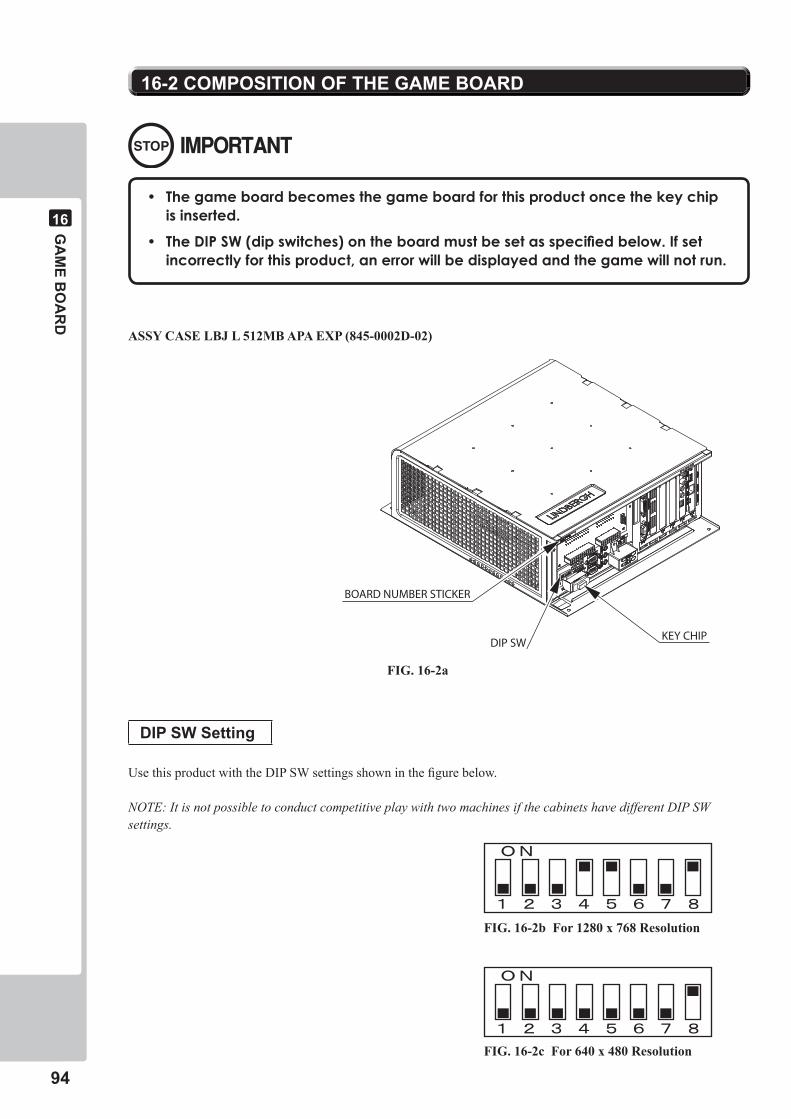
��
GA
ME B
OA
RD
��
DIP SW Setting
Use this product with the DIP SW settings shown in the figure below.
NOTE: It is not possible to conduct competitive play with two machines if the cabinets have different DIP SW settings.
��-� COMPOSITION OF THE GAME BOARD
BOARD NUMBER STICKER
KEY CHIPDIP SW
• Thegameboardbecomesthegameboardforthisproductoncethekeychipisinserted.
• TheDIPSW(dipswitches)ontheboardmustbesetasspecifiedbelow.Ifsetincorrectlyforthisproduct,anerrorwillbedisplayedandthegamewillnotrun.
ASSY CASE LBJ L 512MB APA EXP (845-0002D-02)
FIG. 16-2a
FIG. 16-2b For 1280 x 768 Resolution
FIG. 16-2c For 640 x 480 Resolution
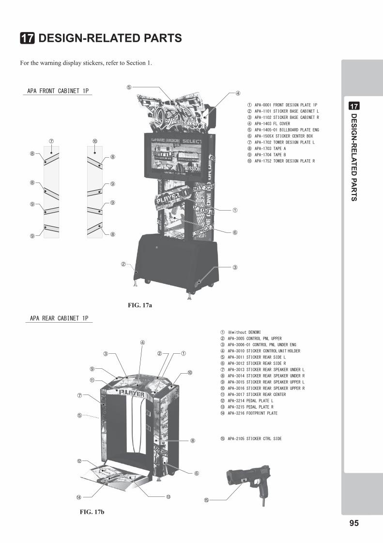
DESIG
N-R
ELATED PA
RTS
��
��
DESIGN-RELATED PARTS��
For the warning display stickers, refer to Section 1.
FIG. 17a
FIG. 17b
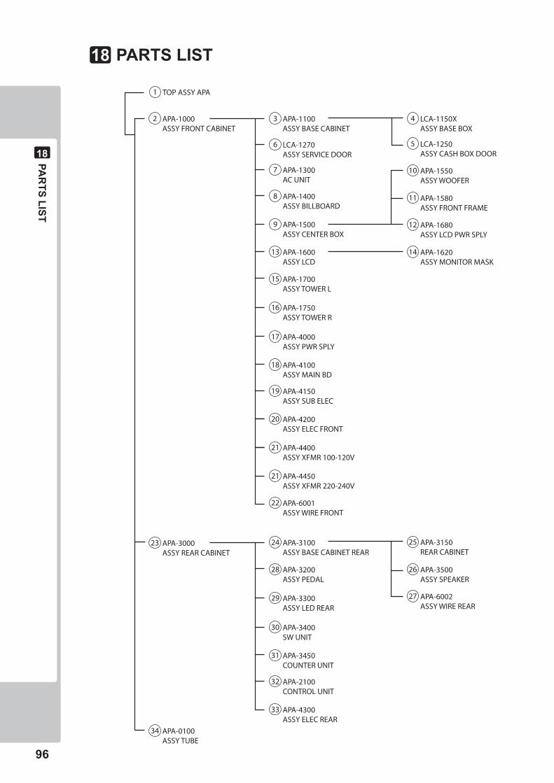
��
PAR
TS LIST
��
3 APA-1100ASSY BASE CABINET
16 APA-1750ASSY TOWER R
6 LCA-1270ASSY SERVICE DOOR
7 APA-1300AC UNIT
15 APA-1700ASSY TOWER L
17 APA-4000ASSY PWR SPLY
18 APA-4100ASSY MAIN BD
19 APA-4150ASSY SUB ELEC
20 APA-4200ASSY ELEC FRONT
21 APA-4400ASSY XFMR 100-120V
21 APA-4450ASSY XFMR 220-240V
22 APA-6001ASSY WIRE FRONT
2 APA-1000ASSY FRONT CABINET
23 APA-3000ASSY REAR CABINET
34 APA-0100ASSY TUBE
1 TOP ASSY APA
8 APA-1400ASSY BILLBOARD
9 APA-1500ASSY CENTER BOX
13 APA-1600ASSY LCD
5 LCA-1250ASSY CASH BOX DOOR
4 LCA-1150XASSY BASE BOX
14 APA-1620ASSY MONITOR MASK
12 APA-1680ASSY LCD PWR SPLY
11 APA-1580ASSY FRONT FRAME
10 APA-1550ASSY WOOFER
29 APA-3300ASSY LED REAR
28 APA-3200ASSY PEDAL
30 APA-3400SW UNIT
31 APA-3450COUNTER UNIT
32 APA-2100CONTROL UNIT
33 APA-4300ASSY ELEC REAR
24 APA-3100ASSY BASE CABINET REAR
27 APA-6002ASSY WIRE REAR
26 APA-3500ASSY SPEAKER
25 APA-3150REAR CABINET
PARTS LIST��
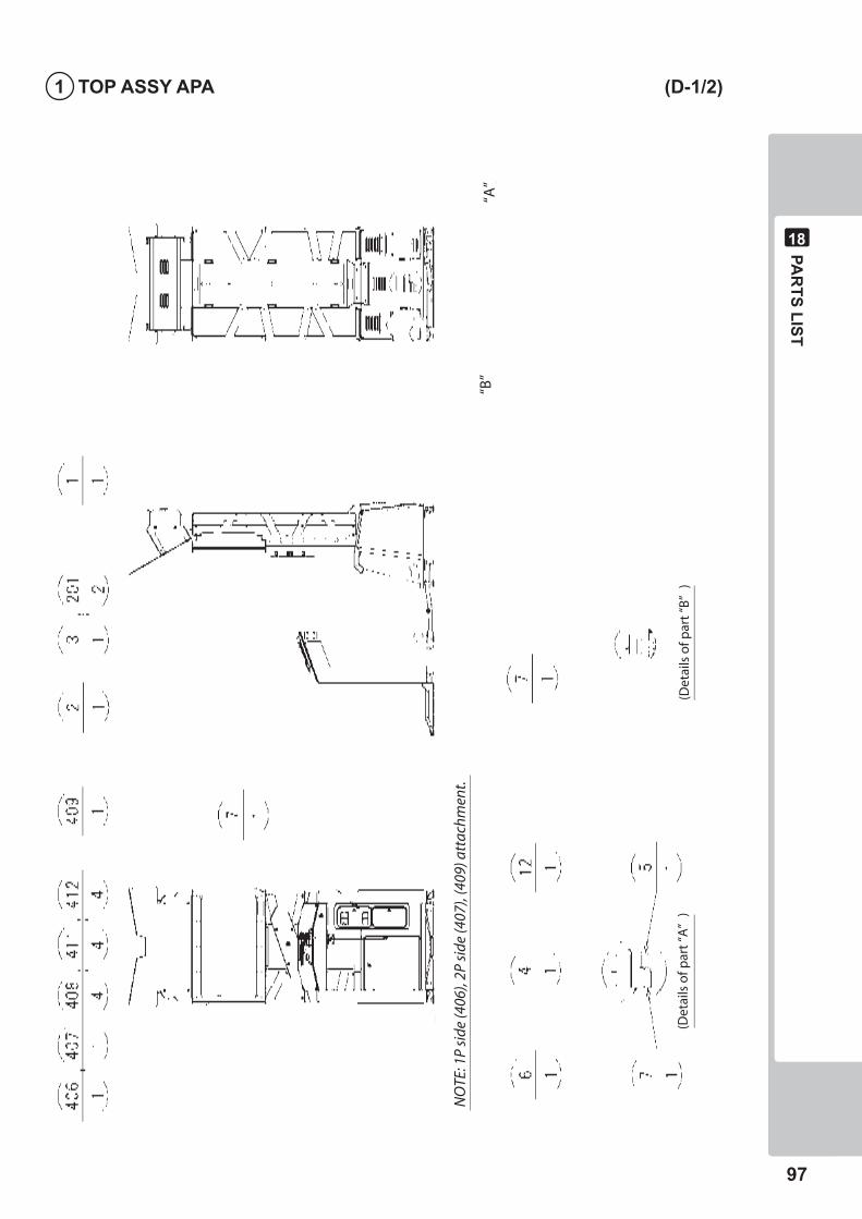
PAR
TS LIST
��
��
� TOP ASSY APA (D-�/�)
“A”
“B”
(Det
ails
of p
art
“B”
)(D
etai
ls o
f par
t “A
”)
NO
TE: 1
P si
de (4
06),
2P s
ide
(407
), (4
09) a
ttac
hmen
t.
��
PAR
TS LIST
��
� TOP ASSY APA (D-�/�)
ITEMNO. PARTNO. DESCRIPTION NOTE
1 APA-1000 ASSYFRONTCABINET 2 APA-3000 ASSYREARCABINET 3 APA-0100 ASSYTUBE 8 421-8479-01 STICKERINSTRSUNLIGHTENG 9 SGM-3811 POLTHNCOV850×900×1700 10 SGM-1798 POLYCOVER760×380×1000
201 000-P00412-W MSCRPHW/FSM4×12 202 000-T00430-0B MSCRTHBLKM4×30
401 220-5793-2-A001 KEYMASTERA001 402 SGM-4111Y KEYBAG 403 420-7031-01 OWNERSMANUALAPAENG 404 420-7032-01 SERVICEMANUALLBJENG 406 APA-0001 FRONTDESIGNPLATE1P 407 APA-0002 FRONTDESIGNPLATE2P 408 APA-0003 PLATELEG 409 APA-0004 STICKER1P2P 411 FAS-290045 HEXSKTLHCAPSCRSTNM4×6 412 280-6686-01 SPWSHR4.5×16×4 413 600-7269-0500 ASSYLANCABLE0500CM 414 600-6729-01 ACCABLECONNECTTYPE15AW/E <Taiwan> 600-6619-02 ACCABLECONNECTTYPEFORUK <Singapore,Malaysia> 600-6619-01 ACCABLECONNECTTYPEFOREXP <Philippines,Korea,Indonesia, HongKong,Australia> 415 443-50002D-02 STICKER845-0002D-02 416 509-5080 SWMICROTYPE 417 310-5029-D20 SUMITUBEFD20MM 418 514-5143-200 FUSES.B200MA250VHBCCEROHS 419 514-5143-2000 FUSES.B2000MA250VHBCCEROHS 420 605-0094-01 ASSYWIREDVDFORLINDBERGHL
/ 421-6690-06 STICKER110V <Taiwan> / 421-6690-04 STICKER230V <Singapore> / 421-6690-03 STICKER220V(80556) <Philippines,Korea,Indonesia, HongKong> / 421-6690-05 STICKER240V <Malaysia,Australia>
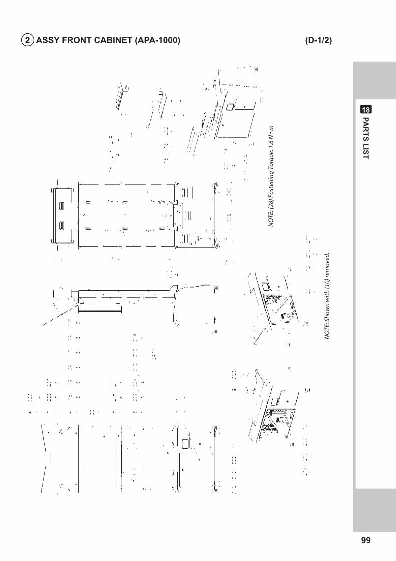
PAR
TS LIST
��
��
� ASSY FRONT CABINET (APA-�000) (D-�/�)
NO
TE: (
28) F
aste
ning
Tor
que:
1.8
N •
m
NO
TE: S
how
n w
ith
(10)
rem
oved
.
�00
PAR
TS LIST
��
� ASSY FRONT CABINET (APA-�000) (D-�/�)
ITEMNO. PARTNO. DESCRIPTION NOTE
1 APA-1100 ASSYBASECABINET 2 LCA-1270 ASSYSERVICEDOOR 3 APA-1300 ACUNIT 4 APA-1400 ASSYBILLBOARD 5 APA-1500 ASSYCENTERBOX 6 APA-1600 ASSYLCD 7 APA-1700 ASSYTOWERL 8 APA-1750 ASSYTOWERR 9 APA-4000 ASSYPWRSPLY 10 APA-4100 ASSYMAINBD 11 APA-4150 ASSYSUBELEC 12 APA-4200 ASSYELECFRONT 13 VTF-1006 FRONTCOVERSPONGE 14 APA-1001 FRONTCOVERBRKT 15 APA-1002 FRONTCOVER 16 APA-1003 TOWERHOLDERREAR 17 APA-1004 CUSHIONCENTER 18 421-11416 STICKERCAUTIONFORK 20 440-WS0165-EG STICKERWBDPOWEROFFSENG 21 440-WS0164-EG STICKERWFALLENG 22 440-CS0186-EG STICKERCEPILEPSY40ENG 23 440-WS0300-EG STICKERWPOWEROFF&HITEMPENG 24 123-5123-91 STUDBOLTM6FORLCD 25 280-5113 COLLARFORTV 26 280-5114 SPACER6.4-25×2 27 253-5569 BUSHFORLCD 28 253-5570 CAPFORLCD
101 280-5277 CORDCLAMP18 102 280-5275-SR10 CORDCLAMPSR10 103 280-6676 CORDCLAMPTL-25ATKK
201 000-T00430-0B MSCRTHBLKM4×30 202 000-T00408-0B MSCRTHBLKM4×8 203 030-000820-SB HEXBLTW/SBLKM8×20 204 068-852216-0B FLTWSHRBLK8.5-22×1.6 205 050-F00600 FLGNUTM6 206 030-000616-S HEXBLTW/SM6×16 207 068-652016 FLTWSHR6.5-20×1.6 208 000-P00412-W MSCRPHW/FSM4×12 209 032-000425 WINGBLTM4×25 210 068-441616 FLTWSHR4.4-16×1.6 211 000-P00425-S MSCRPHW/SM4×25 213 060-S00400 SPRWSHRM4 215 FAS-000006 MSCRPHPORICURVOM3×10 216 068-330808-PN FLTWSHRPLASTIC3.3-8×0.8
301 APA-6001-01 ASSYWIREFRONTEXP 302 APA-60005 WHDC24VFORLCD 303 600-7360-0400 WHLBGPWR24PPTOP0400MM 304 600-7361-0400 WHLBGPWR18PPTOP0400MM 306 APA-60008 WHDC5VFRONTCABINET
/ APA-4400 ASSYXFMR100V-120V <Taiwan> / APA-4450 ASSYXFMR220V-240V <Singapore,Philippines, Malaysia,Korea,Indonesia, HongKong,Australia>
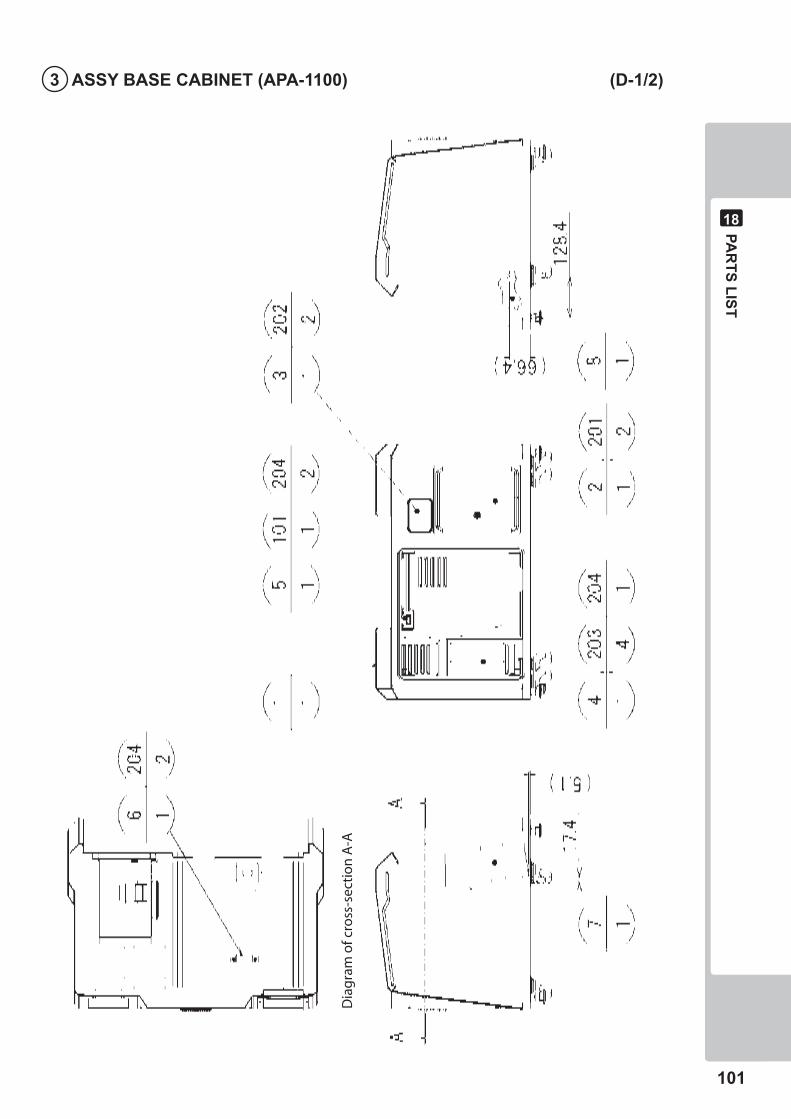
PAR
TS LIST
�0�
��
� ASSY BASE CABINET (APA-��00) (D-�/�)
Dia
gra
m o
f cro
ss-s
ecti
on
A-A
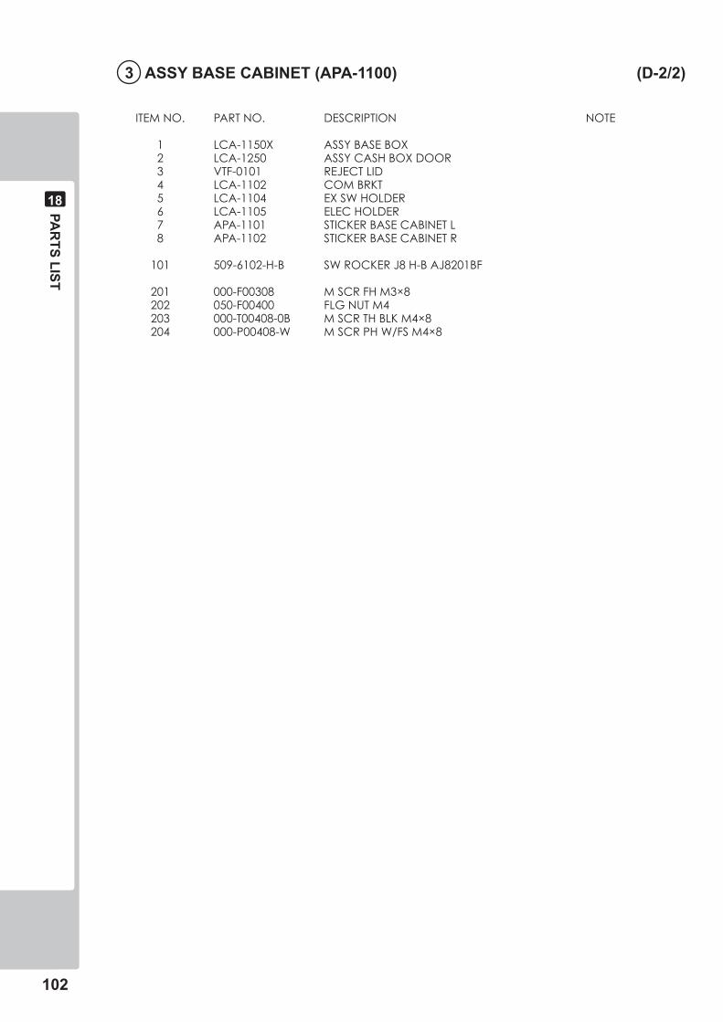
�0�
PAR
TS LIST
��
� ASSY BASE CABINET (APA-��00) (D-�/�)
ITEMNO. PARTNO. DESCRIPTION NOTE
1 LCA-1150X ASSYBASEBOX 2 LCA-1250 ASSYCASHBOXDOOR 3 VTF-0101 REJECTLID 4 LCA-1102 COMBRKT 5 LCA-1104 EXSWHOLDER 6 LCA-1105 ELECHOLDER 7 APA-1101 STICKERBASECABINETL 8 APA-1102 STICKERBASECABINETR
101 509-6102-H-B SWROCKERJ8H-BAJ8201BF
201 000-F00308 MSCRFHM3×8 202 050-F00400 FLGNUTM4 203 000-T00408-0B MSCRTHBLKM4×8 204 000-P00408-W MSCRPHW/FSM4×8
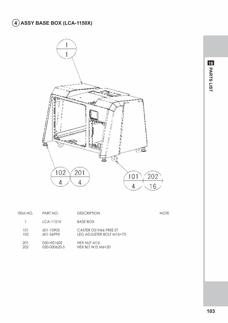
PAR
TS LIST
�0�
��
� ASSY BASE BOX (LCA-���0X)
ITEMNO. PARTNO. DESCRIPTION NOTE
1 LCA-1151X BASEBOX
101 601-10905 CASTERD51H66FREEST 102 601-5699X LEGADJUSTERBOLTM16×75
201 050-H01600 HEXNUTM16 202 030-000620-S HEXBLTW/SM6×20
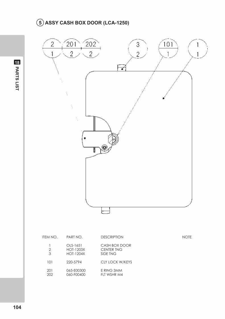
�0�
PAR
TS LIST
��
� ASSY CASH BOX DOOR (LCA-���0)
ITEMNO. PARTNO. DESCRIPTION NOTE
1 OLS-1651 CASHBOXDOOR 2 HOT-1203X CENTERTNG 3 HOT-1204X SIDETNG
101 220-5794 CLYLOCKW/KEYS
201 065-E00300 ERING3MM 202 060-F00400 FLTWSHRM4
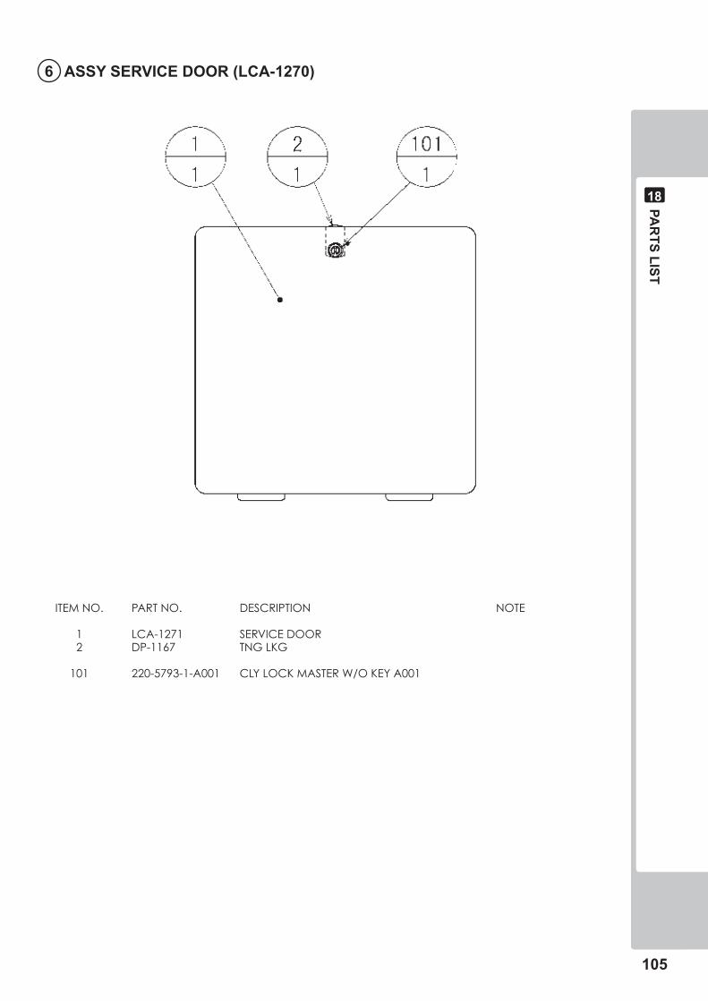
PAR
TS LIST
�0�
��
� ASSY SERVICE DOOR (LCA-���0)
ITEMNO. PARTNO. DESCRIPTION NOTE
1 LCA-1271 SERVICEDOOR 2 DP-1167 TNGLKG
101 220-5793-1-A001 CLYLOCKMASTERW/OKEYA001
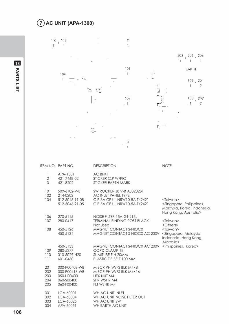
�0�
PAR
TS LIST
��
� AC UNIT (APA-��00)
ITEMNO. PARTNO. DESCRIPTION NOTE
1 APA-1301 ACBRKT 2 421-7468-02 STICKERC.PW/PIC 3 421-8202 STICKEREARTHMARK
101 509-6102-V-B SWROCKERJ8V-BAJ8202BF 102 214-0202 ACINLETPANELTYPE 104 512-5046-91-08 C.P8ACEULNRW10-8A-TK2421 <Taiwan> 512-5046-91-05 C.P5ACEULNRW10-5A-TK2421 <Singapore,Philippines, Malaysia,Korea,Indonesia, HongKong,Australia> 106 270-5115 NOISEFILTER15AGT-215J 107 280-0417 TERMINALBINDINGPOSTBLACK <Taiwan> NotUsed <Others> 108 450-5126 MAGNETCONTACTS-NIOCX <Taiwan> 450-5134 MAGNETCONTACTS-NIOCXAC230V <Singapore,Malaysia, Indonesia,HongKong, Australia> 450-5133 MAGNETCONTACTS-NIOCXAC200V <Philippines,Korea> 109 280-5277 CORDCLAMP18 110 310-5029-H20 SUMITUBEFH20MM 111 601-0460 PLASTICTIEBELT100MM
201 000-P00408-WB MSCRPHW/FSBLKM4×8 202 000-P00416-WB MSCRPHW/FSBLKM4×16 203 050-H00400 HEXNUTM4 204 060-S00400 SPRWSHRM4 205 060-F00400 FLTWSHRM4
301 LCA-60001 WHACUNITINLET 302 LCA-60004 WHACUNITNOISEFILTEROUT 303 LCA-60025 WHACUNITSW 304 APA-60051 WHEARTHACUNIT
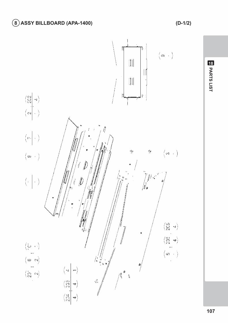
PAR
TS LIST
�0�
��
� ASSY BILLBOARD (APA-��00) (D-�/�)
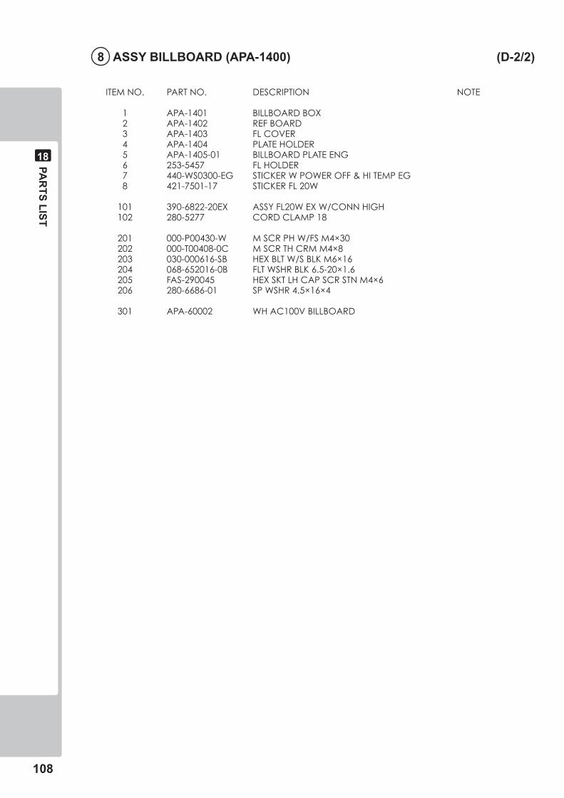
�0�
PAR
TS LIST
��
� ASSY BILLBOARD (APA-��00) (D-�/�)
ITEMNO. PARTNO. DESCRIPTION NOTE
1 APA-1401 BILLBOARDBOX 2 APA-1402 REFBOARD 3 APA-1403 FLCOVER 4 APA-1404 PLATEHOLDER 5 APA-1405-01 BILLBOARDPLATEENG 6 253-5457 FLHOLDER 7 440-WS0300-EG STICKERWPOWEROFF&HITEMPEG 8 421-7501-17 STICKERFL20W
101 390-6822-20EX ASSYFL20WEXW/CONNHIGH 102 280-5277 CORDCLAMP18
201 000-P00430-W MSCRPHW/FSM4×30 202 000-T00408-0C MSCRTHCRMM4×8 203 030-000616-SB HEXBLTW/SBLKM6×16 204 068-652016-0B FLTWSHRBLK6.5-20×1.6 205 FAS-290045 HEXSKTLHCAPSCRSTNM4×6 206 280-6686-01 SPWSHR4.5×16×4
301 APA-60002 WHAC100VBILLBOARD
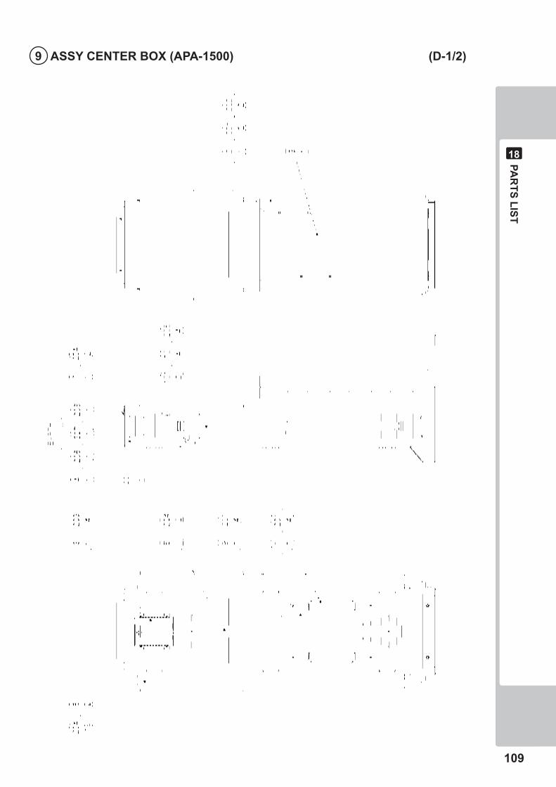
PAR
TS LIST
�0�
��
� ASSY CENTER BOX (APA-��00) (D-�/�)
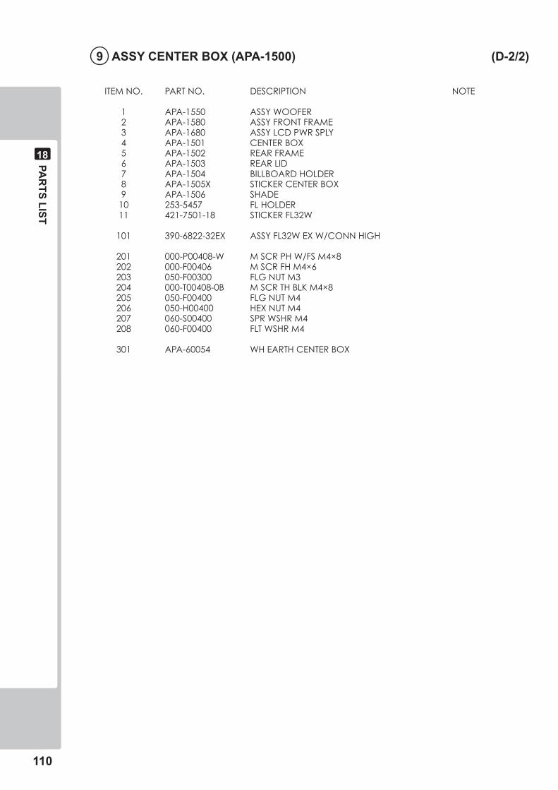
��0
PAR
TS LIST
��
� ASSY CENTER BOX (APA-��00) (D-�/�)
ITEMNO. PARTNO. DESCRIPTION NOTE
1 APA-1550 ASSYWOOFER 2 APA-1580 ASSYFRONTFRAME 3 APA-1680 ASSYLCDPWRSPLY 4 APA-1501 CENTERBOX 5 APA-1502 REARFRAME 6 APA-1503 REARLID 7 APA-1504 BILLBOARDHOLDER 8 APA-1505X STICKERCENTERBOX 9 APA-1506 SHADE 10 253-5457 FLHOLDER 11 421-7501-18 STICKERFL32W
101 390-6822-32EX ASSYFL32WEXW/CONNHIGH
201 000-P00408-W MSCRPHW/FSM4×8 202 000-F00406 MSCRFHM4×6 203 050-F00300 FLGNUTM3 204 000-T00408-0B MSCRTHBLKM4×8 205 050-F00400 FLGNUTM4 206 050-H00400 HEXNUTM4 207 060-S00400 SPRWSHRM4 208 060-F00400 FLTWSHRM4
301 APA-60054 WHEARTHCENTERBOX
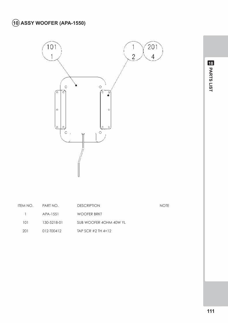
PAR
TS LIST
���
��
�0 ASSY WOOFER (APA-���0)
ITEMNO. PARTNO. DESCRIPTION NOTE
1 APA-1551 WOOFERBRKT
101 130-5218-01 SUBWOOFER4OHM40WYL
201 012-T00412 TAPSCR#2TH4×12
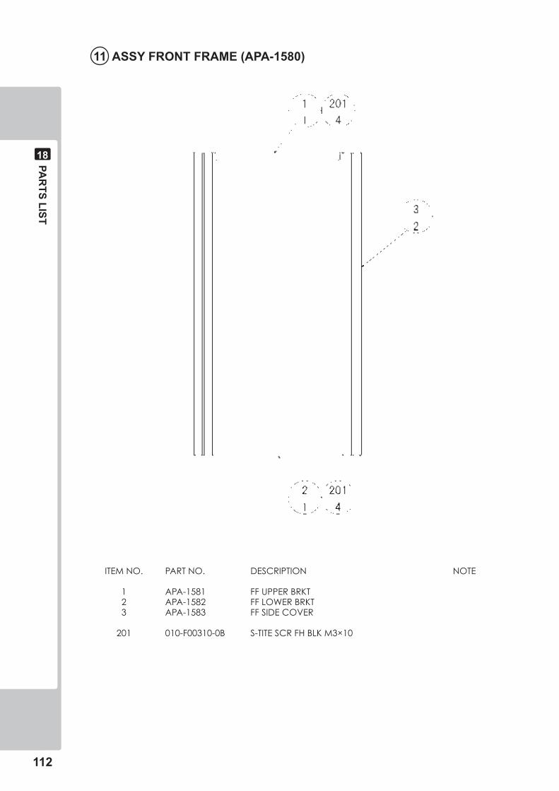
���
PAR
TS LIST
��
�� ASSY FRONT FRAME (APA-���0)
ITEMNO. PARTNO. DESCRIPTION NOTE
1 APA-1581 FFUPPERBRKT 2 APA-1582 FFLOWERBRKT 3 APA-1583 FFSIDECOVER
201 010-F00310-0B S-TITESCRFHBLKM3×10
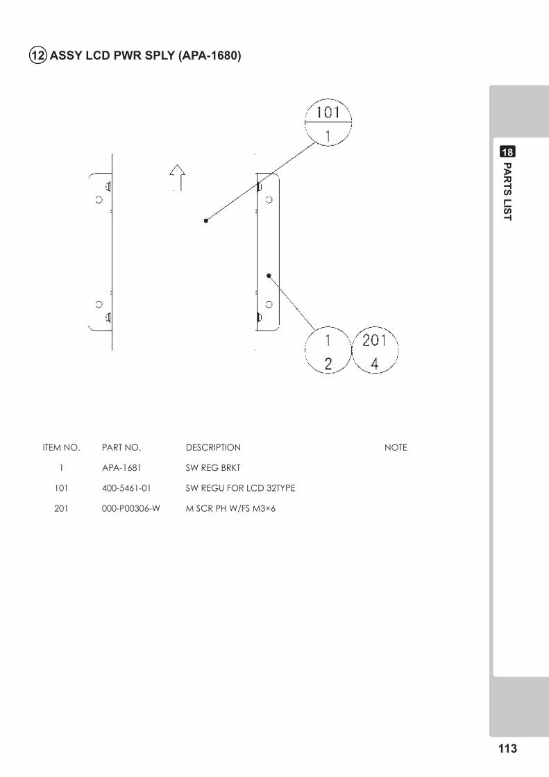
PAR
TS LIST
���
��
�� ASSY LCD PWR SPLY (APA-���0)
ITEMNO. PARTNO. DESCRIPTION NOTE
1 APA-1681 SWREGBRKT
101 400-5461-01 SWREGUFORLCD32TYPE
201 000-P00306-W MSCRPHW/FSM3×6
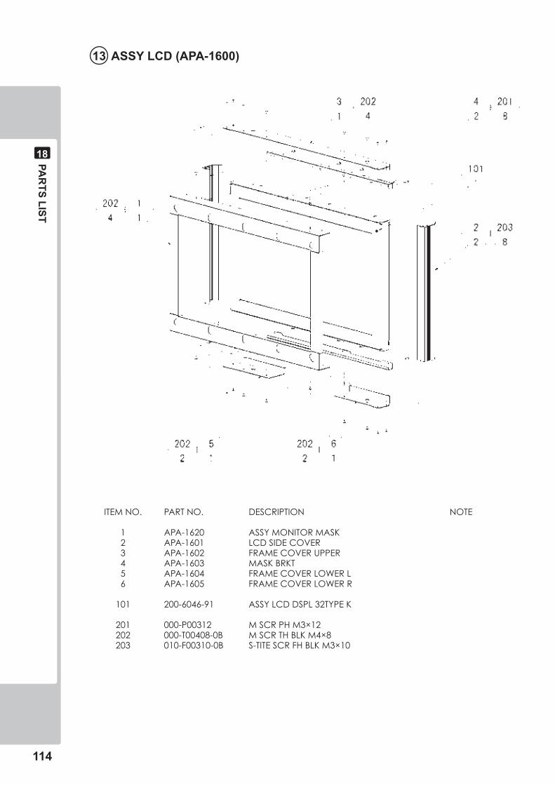
���
PAR
TS LIST
��
�� ASSY LCD (APA-��00)
ITEMNO. PARTNO. DESCRIPTION NOTE
1 APA-1620 ASSYMONITORMASK 2 APA-1601 LCDSIDECOVER 3 APA-1602 FRAMECOVERUPPER 4 APA-1603 MASKBRKT 5 APA-1604 FRAMECOVERLOWERL 6 APA-1605 FRAMECOVERLOWERR
101 200-6046-91 ASSYLCDDSPL32TYPEK
201 000-P00312 MSCRPHM3×12 202 000-T00408-0B MSCRTHBLKM4×8 203 010-F00310-0B S-TITESCRFHBLKM3×10
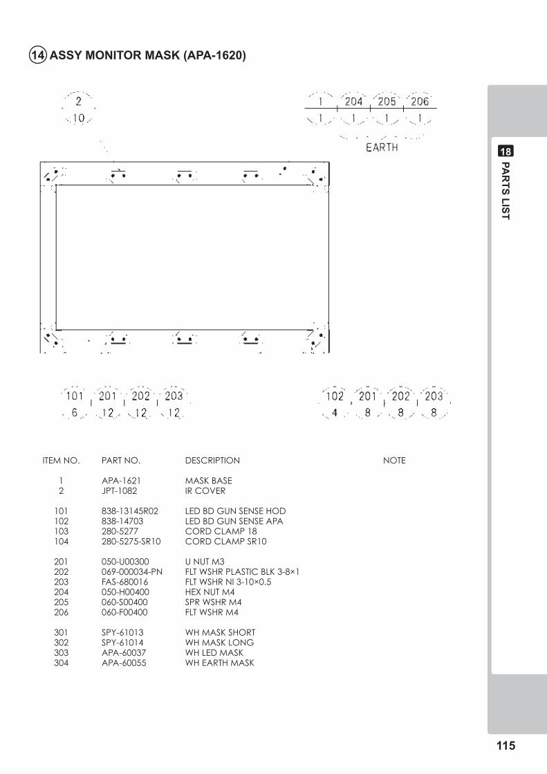
PAR
TS LIST
���
��
�� ASSY MONITOR MASK (APA-���0)
ITEMNO. PARTNO. DESCRIPTION NOTE
1 APA-1621 MASKBASE 2 JPT-1082 IRCOVER
101 838-13145R02 LEDBDGUNSENSEHOD 102 838-14703 LEDBDGUNSENSEAPA 103 280-5277 CORDCLAMP18 104 280-5275-SR10 CORDCLAMPSR10
201 050-U00300 UNUTM3 202 069-000034-PN FLTWSHRPLASTICBLK3-8×1 203 FAS-680016 FLTWSHRNI3-10×0.5 204 050-H00400 HEXNUTM4 205 060-S00400 SPRWSHRM4 206 060-F00400 FLTWSHRM4
301 SPY-61013 WHMASKSHORT 302 SPY-61014 WHMASKLONG 303 APA-60037 WHLEDMASK 304 APA-60055 WHEARTHMASK
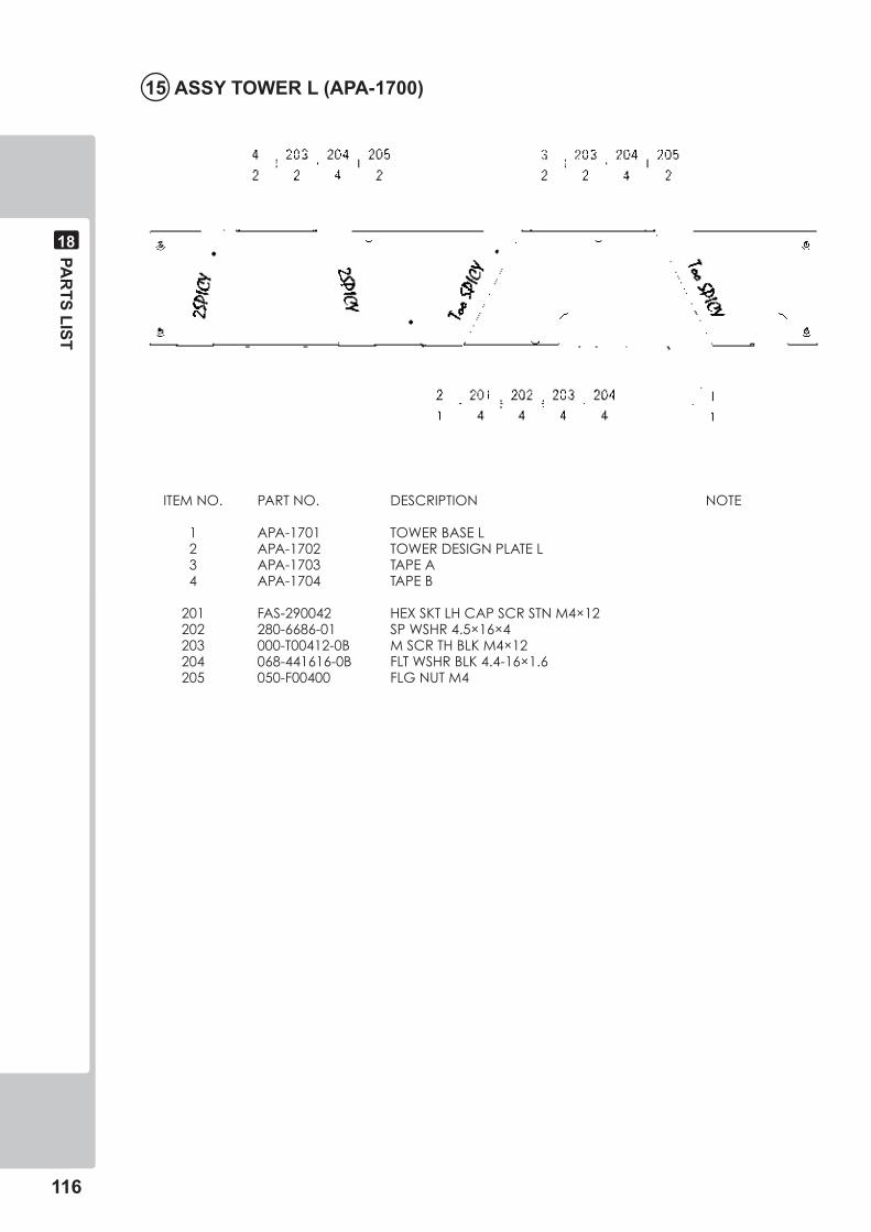
���
PAR
TS LIST
��
ITEMNO. PARTNO. DESCRIPTION NOTE
1 APA-1701 TOWERBASEL 2 APA-1702 TOWERDESIGNPLATEL 3 APA-1703 TAPEA 4 APA-1704 TAPEB
201 FAS-290042 HEXSKTLHCAPSCRSTNM4×12 202 280-6686-01 SPWSHR4.5×16×4 203 000-T00412-0B MSCRTHBLKM4×12 204 068-441616-0B FLTWSHRBLK4.4-16×1.6 205 050-F00400 FLGNUTM4
�� ASSY TOWER L (APA-��00)
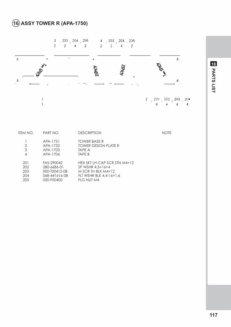
PAR
TS LIST
���
��
�� ASSY TOWER R (APA-���0)
ITEMNO. PARTNO. DESCRIPTION NOTE
1 APA-1751 TOWERBASER 2 APA-1752 TOWERDESIGNPLATER 3 APA-1703 TAPEA 4 APA-1704 TAPEB
201 FAS-290042 HEXSKTLHCAPSCRSTNM4×12 202 280-6686-01 SPWSHR4.5×16×4 203 000-T00412-0B MSCRTHBLKM4×12 204 068-441616-0B FLTWSHRBLK4.4-16×1.6 205 050-F00400 FLGNUTM4
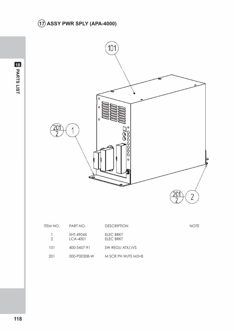
���
PAR
TS LIST
��
�� ASSY PWR SPLY (APA-�000)
ITEMNO. PARTNO. DESCRIPTION NOTE
1 SHT-4904X ELECBRKT 2 LCA-4001 ELECBRKT
101 400-5457-91 SWREGUATX/JVS
201 000-P00308-W MSCRPHW/FSM3×8
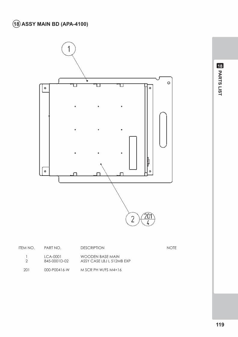
PAR
TS LIST
���
��
�� ASSY MAIN BD (APA-��00)
ITEMNO. PARTNO. DESCRIPTION NOTE
1 LCA-0001 WOODENBASEMAIN 2 845-0001D-02 ASSYCASELBJL512MBEXP
201 000-P00416-W MSCRPHW/FSM4×16
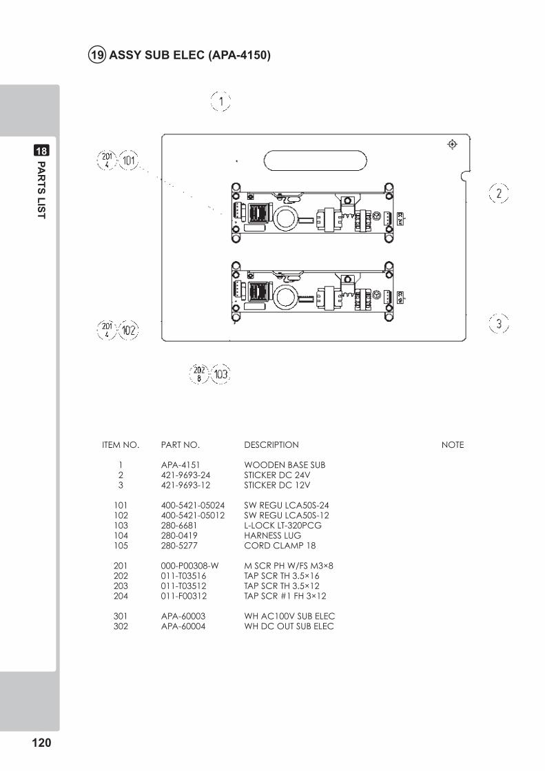
��0
PAR
TS LIST
��
�� ASSY SUB ELEC (APA-���0)
ITEMNO. PARTNO. DESCRIPTION NOTE
1 APA-4151 WOODENBASESUB 2 421-9693-24 STICKERDC24V 3 421-9693-12 STICKERDC12V
101 400-5421-05024 SWREGULCA50S-24 102 400-5421-05012 SWREGULCA50S-12 103 280-6681 L-LOCKLT-320PCG 104 280-0419 HARNESSLUG 105 280-5277 CORDCLAMP18
201 000-P00308-W MSCRPHW/FSM3×8 202 011-T03516 TAPSCRTH3.5×16 203 011-T03512 TAPSCRTH3.5×12 204 011-F00312 TAPSCR#1FH3×12
301 APA-60003 WHAC100VSUBELEC 302 APA-60004 WHDCOUTSUBELEC
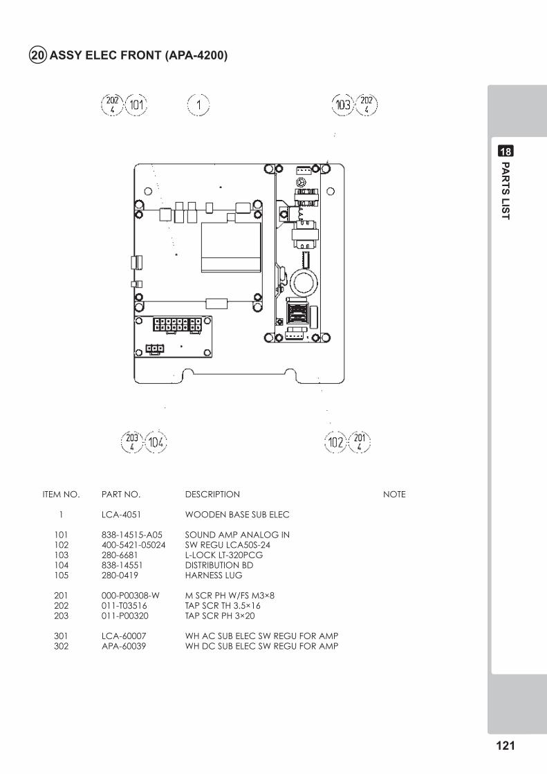
PAR
TS LIST
���
��
�0 ASSY ELEC FRONT (APA-��00)
ITEMNO. PARTNO. DESCRIPTION NOTE
1 LCA-4051 WOODENBASESUBELEC
101 838-14515-A05 SOUNDAMPANALOGIN 102 400-5421-05024 SWREGULCA50S-24 103 280-6681 L-LOCKLT-320PCG 104 838-14551 DISTRIBUTIONBD 105 280-0419 HARNESSLUG
201 000-P00308-W MSCRPHW/FSM3×8 202 011-T03516 TAPSCRTH3.5×16 203 011-P00320 TAPSCRPH3×20
301 LCA-60007 WHACSUBELECSWREGUFORAMP 302 APA-60039 WHDCSUBELECSWREGUFORAMP
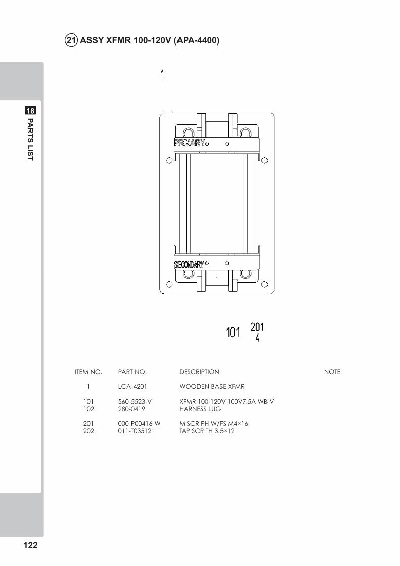
���
PAR
TS LIST
��
ITEMNO. PARTNO. DESCRIPTION NOTE
1 LCA-4201 WOODENBASEXFMR
101 560-5523-V XFMR100-120V100V7.5AWBV 102 280-0419 HARNESSLUG
201 000-P00416-W MSCRPHW/FSM4×16 202 011-T03512 TAPSCRTH3.5×12
�� ASSY XFMR �00-��0V (APA-��00)
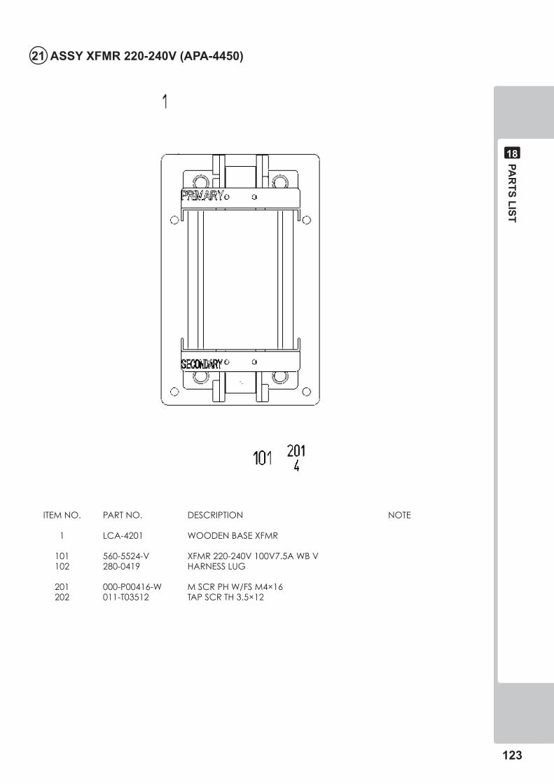
PAR
TS LIST
���
��
�� ASSY XFMR ��0-��0V (APA-���0)
ITEMNO. PARTNO. DESCRIPTION NOTE
1 LCA-4201 WOODENBASEXFMR
101 560-5524-V XFMR220-240V100V7.5AWBV 102 280-0419 HARNESSLUG
201 000-P00416-W MSCRPHW/FSM4×16 202 011-T03512 TAPSCRTH3.5×12
���
PAR
TS LIST
��
�� ASSY WIRE FRONT (APA-�00�-0�)
This is comprised of the following wire harnesses. ASSY drawing is not available.
ITEMNO. PARTNO. DESCRIPTION NOTE
101 601-0460 PLASTICTIEBELT100MM
301 600-7009-2500 ASSYRGBCAD-SUB15P2500MM 302 600-7919-150 CBLAUDRCATOMINIPLUG150CM 303 APA-60041 WHACBASESERVICEMANSW 304 APA-60001 WHAC100VFRONTCABINET 305 APA-60006 WHDC24VFRONTCABINET 306 APA-60007 WHDC12VFRONTCABINET 308 APA-60009 WHWOOFERFRONTCABINET 309 APA-60010 WHSPEAKERFRONTCABINET 310 APA-60011 WHVOLUMEFRONTCABINET 311 APA-60036 WHLEDFRONTCABINET 312 APA-60052 WHEARTHBASECABINET 313 APA-60042 WHACBASEXFMROUT
PAR
TS LIST
125
18
23 ASSY REAR CABINET (APA-3000) (D-1/2)
NO
TE: “
*” s
ign
show
s th
e ac
tual
dim
ensi
ons
alon
g th
e si
de.
“*”
(Op
po
site
sid
e
)
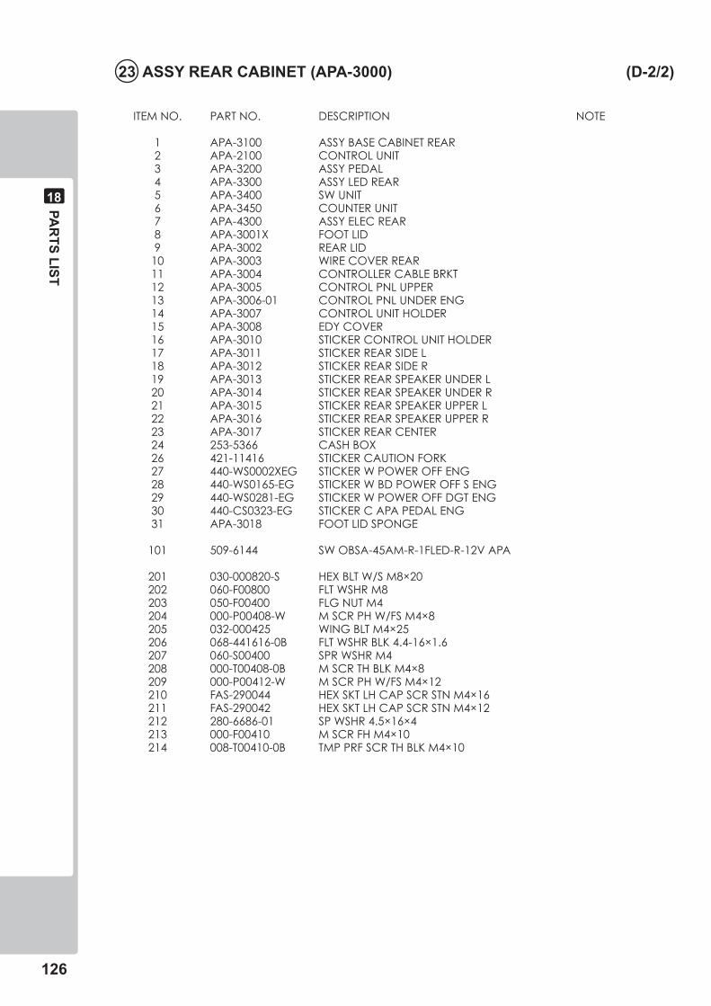
���
PAR
TS LIST
��
�� ASSY REAR CABINET (APA-�000) (D-�/�)
ITEMNO. PARTNO. DESCRIPTION NOTE
1 APA-3100 ASSYBASECABINETREAR 2 APA-2100 CONTROLUNIT 3 APA-3200 ASSYPEDAL 4 APA-3300 ASSYLEDREAR 5 APA-3400 SWUNIT 6 APA-3450 COUNTERUNIT 7 APA-4300 ASSYELECREAR 8 APA-3001X FOOTLID 9 APA-3002 REARLID 10 APA-3003 WIRECOVERREAR 11 APA-3004 CONTROLLERCABLEBRKT 12 APA-3005 CONTROLPNLUPPER 13 APA-3006-01 CONTROLPNLUNDERENG 14 APA-3007 CONTROLUNITHOLDER 15 APA-3008 EDYCOVER 16 APA-3010 STICKERCONTROLUNITHOLDER 17 APA-3011 STICKERREARSIDEL 18 APA-3012 STICKERREARSIDER 19 APA-3013 STICKERREARSPEAKERUNDERL 20 APA-3014 STICKERREARSPEAKERUNDERR 21 APA-3015 STICKERREARSPEAKERUPPERL 22 APA-3016 STICKERREARSPEAKERUPPERR 23 APA-3017 STICKERREARCENTER 24 253-5366 CASHBOX 26 421-11416 STICKERCAUTIONFORK 27 440-WS0002XEG STICKERWPOWEROFFENG 28 440-WS0165-EG STICKERWBDPOWEROFFSENG 29 440-WS0281-EG STICKERWPOWEROFFDGTENG 30 440-CS0323-EG STICKERCAPAPEDALENG 31 APA-3018 FOOTLIDSPONGE
101 509-6144 SWOBSA-45AM-R-1FLED-R-12VAPA
201 030-000820-S HEXBLTW/SM8×20 202 060-F00800 FLTWSHRM8 203 050-F00400 FLGNUTM4 204 000-P00408-W MSCRPHW/FSM4×8 205 032-000425 WINGBLTM4×25 206 068-441616-0B FLTWSHRBLK4.4-16×1.6 207 060-S00400 SPRWSHRM4 208 000-T00408-0B MSCRTHBLKM4×8 209 000-P00412-W MSCRPHW/FSM4×12 210 FAS-290044 HEXSKTLHCAPSCRSTNM4×16 211 FAS-290042 HEXSKTLHCAPSCRSTNM4×12 212 280-6686-01 SPWSHR4.5×16×4 213 000-F00410 MSCRFHM4×10 214 008-T00410-0B TMPPRFSCRTHBLKM4×10
PAR
TS LIST
���
��
�� ASSY BASE CABINET REAR (APA-��00) (D-�/�)
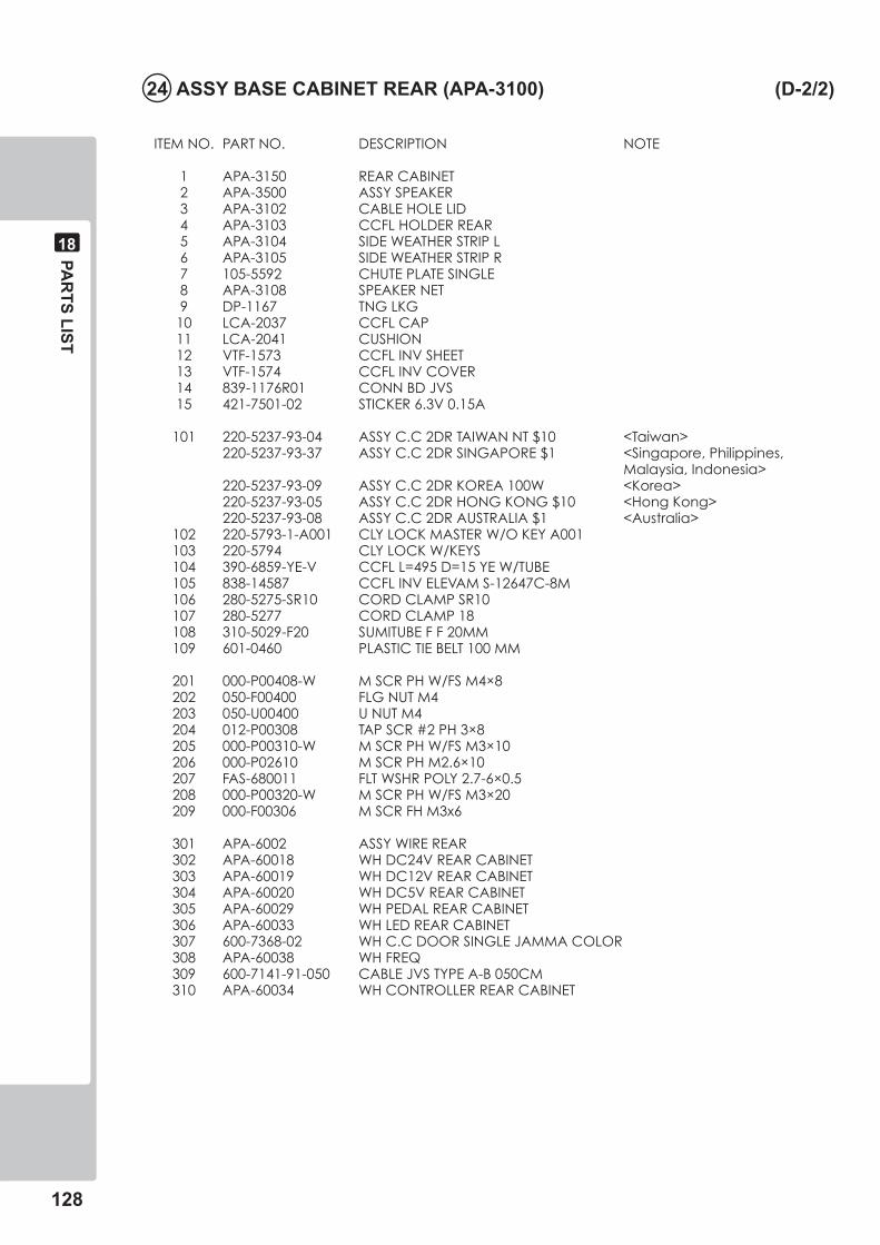
���
PAR
TS LIST
��
�� ASSY BASE CABINET REAR (APA-��00) (D-�/�)
ITEMNO. PARTNO. DESCRIPTION NOTE
1 APA-3150 REARCABINET 2 APA-3500 ASSYSPEAKER 3 APA-3102 CABLEHOLELID 4 APA-3103 CCFLHOLDERREAR 5 APA-3104 SIDEWEATHERSTRIPL 6 APA-3105 SIDEWEATHERSTRIPR 7 105-5592 CHUTEPLATESINGLE 8 APA-3108 SPEAKERNET 9 DP-1167 TNGLKG 10 LCA-2037 CCFLCAP 11 LCA-2041 CUSHION 12 VTF-1573 CCFLINVSHEET 13 VTF-1574 CCFLINVCOVER 14 839-1176R01 CONNBDJVS 15 421-7501-02 STICKER6.3V0.15A
101 220-5237-93-04 ASSYC.C2DRTAIWANNT$10 <Taiwan> 220-5237-93-37 ASSYC.C2DRSINGAPORE$1 <Singapore,Philippines, Malaysia,Indonesia> 220-5237-93-09 ASSYC.C2DRKOREA100W <Korea> 220-5237-93-05 ASSYC.C2DRHONGKONG$10 <HongKong> 220-5237-93-08 ASSYC.C2DRAUSTRALIA$1 <Australia> 102 220-5793-1-A001 CLYLOCKMASTERW/OKEYA001 103 220-5794 CLYLOCKW/KEYS 104 390-6859-YE-V CCFLL=495D=15YEW/TUBE 105 838-14587 CCFLINVELEVAMS-12647C-8M 106 280-5275-SR10 CORDCLAMPSR10 107 280-5277 CORDCLAMP18 108 310-5029-F20 SUMITUBEFF20MM 109 601-0460 PLASTICTIEBELT100MM
201 000-P00408-W MSCRPHW/FSM4×8 202 050-F00400 FLGNUTM4 203 050-U00400 UNUTM4 204 012-P00308 TAPSCR#2PH3×8 205 000-P00310-W MSCRPHW/FSM3×10 206 000-P02610 MSCRPHM2.6×10 207 FAS-680011 FLTWSHRPOLY2.7-6×0.5 208 000-P00320-W MSCRPHW/FSM3×20 209 000-F00306 MSCRFHM3x6
301 APA-6002 ASSYWIREREAR 302 APA-60018 WHDC24VREARCABINET 303 APA-60019 WHDC12VREARCABINET 304 APA-60020 WHDC5VREARCABINET 305 APA-60029 WHPEDALREARCABINET 306 APA-60033 WHLEDREARCABINET 307 600-7368-02 WHC.CDOORSINGLEJAMMACOLOR 308 APA-60038 WHFREQ 309 600-7141-91-050 CABLEJVSTYPEA-B050CM 310 APA-60034 WHCONTROLLERREARCABINET
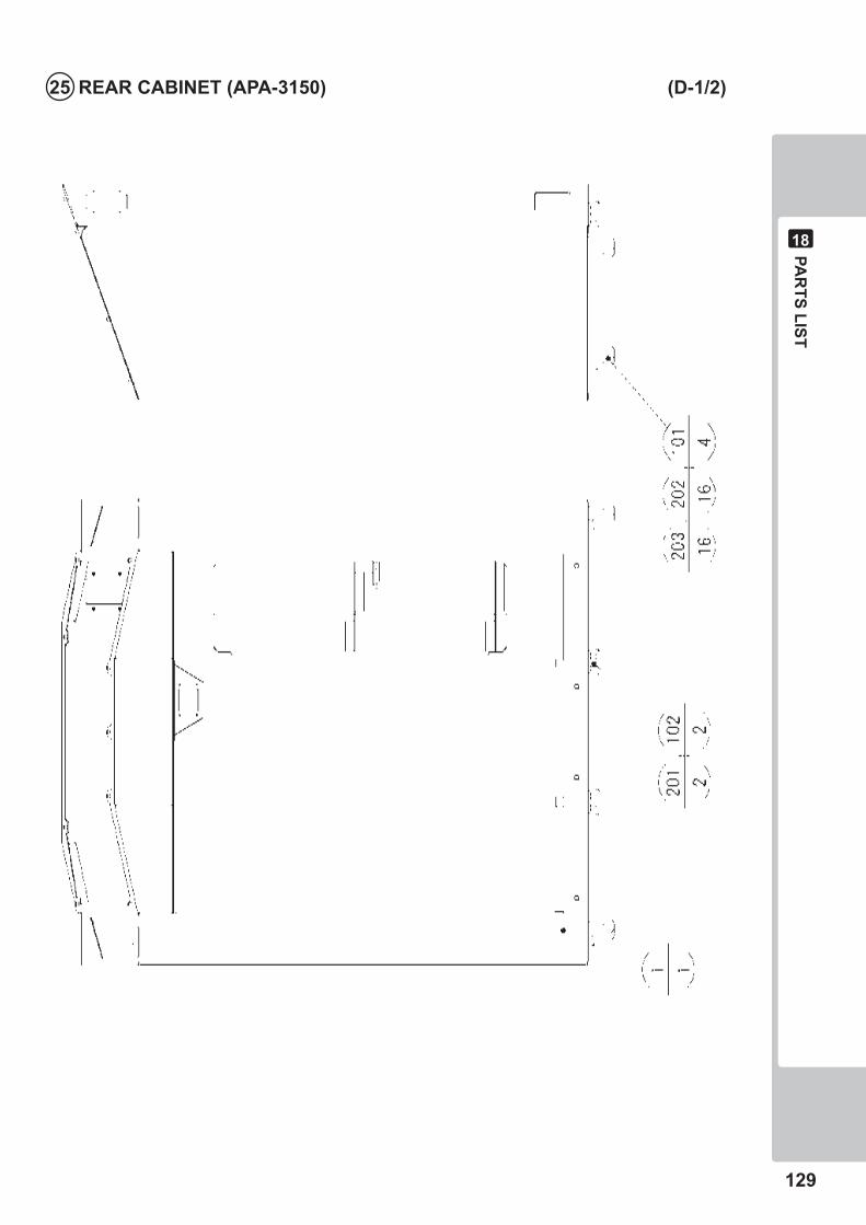
PAR
TS LIST
���
��
�� REAR CABINET (APA-���0) (D-�/�)
��0
PAR
TS LIST
��
�� REAR CABINET (APA-���0) (D-�/�)
ITEMNO. PARTNO. DESCRIPTION NOTE
1 APA-3151 REARCABINETBLANK
101 601-10905 CASTERD51H66FREEST 102 601-11546 LEGADJUSTERBOLTM16×60DISGO
201 050-H01600 HEXNUTM16 202 030-000616-S HEXBLTW/SM6×16 203 060-F00600 FLTWSHRM6
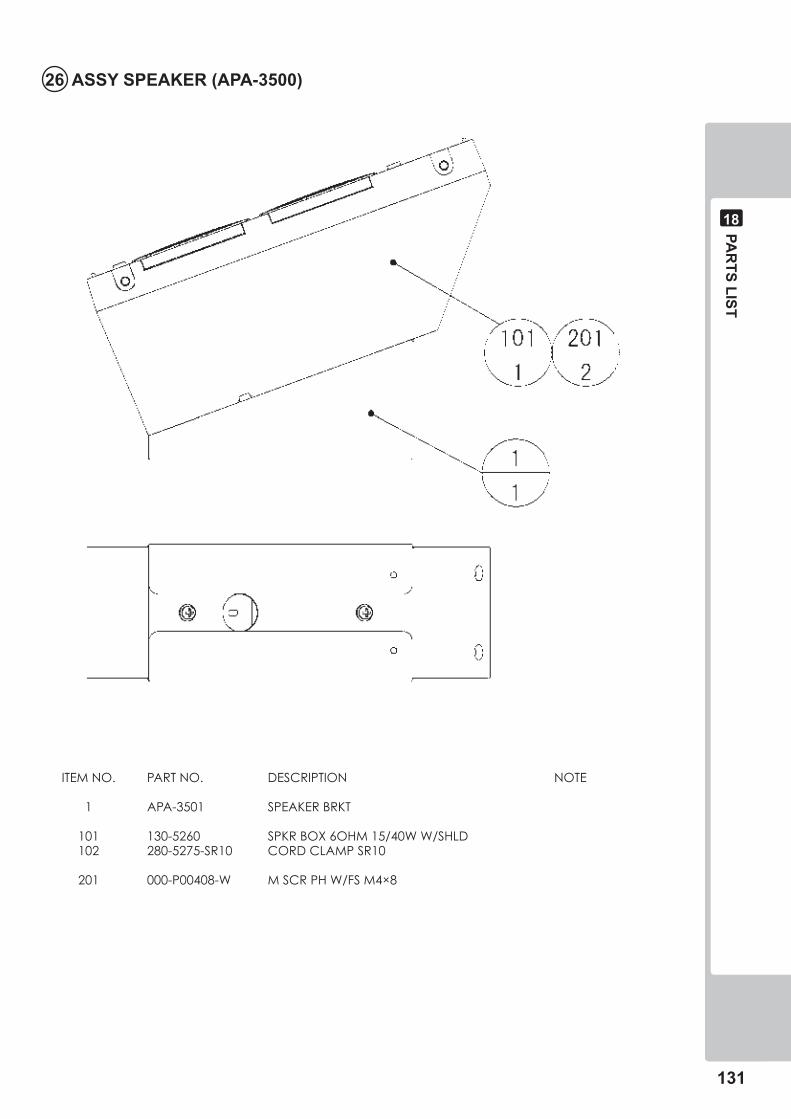
PAR
TS LIST
���
��
�� ASSY SPEAKER (APA-��00)
ITEMNO. PARTNO. DESCRIPTION NOTE
1 APA-3501 SPEAKERBRKT
101 130-5260 SPKRBOX6OHM15/40WW/SHLD 102 280-5275-SR10 CORDCLAMPSR10
201 000-P00408-W MSCRPHW/FSM4×8
���
PAR
TS LIST
��
�� ASSY WIRE REAR (APA-�00�)
This is comprised of the following wire harnesses. ASSY drawing is not available.
ITEMNO. PARTNO. DESCRIPTION NOTE
101 601-0460 PLASTICTIEBELT100MM
301 APA-60021 WHSPEAKERREARCABINET 302 APA-60022 WHSTART&SWUNITREARCABINET 303 APA-60030 WHLAMPREARCABINET 304 APA-60032 WHCOIN&METERREARCABINET
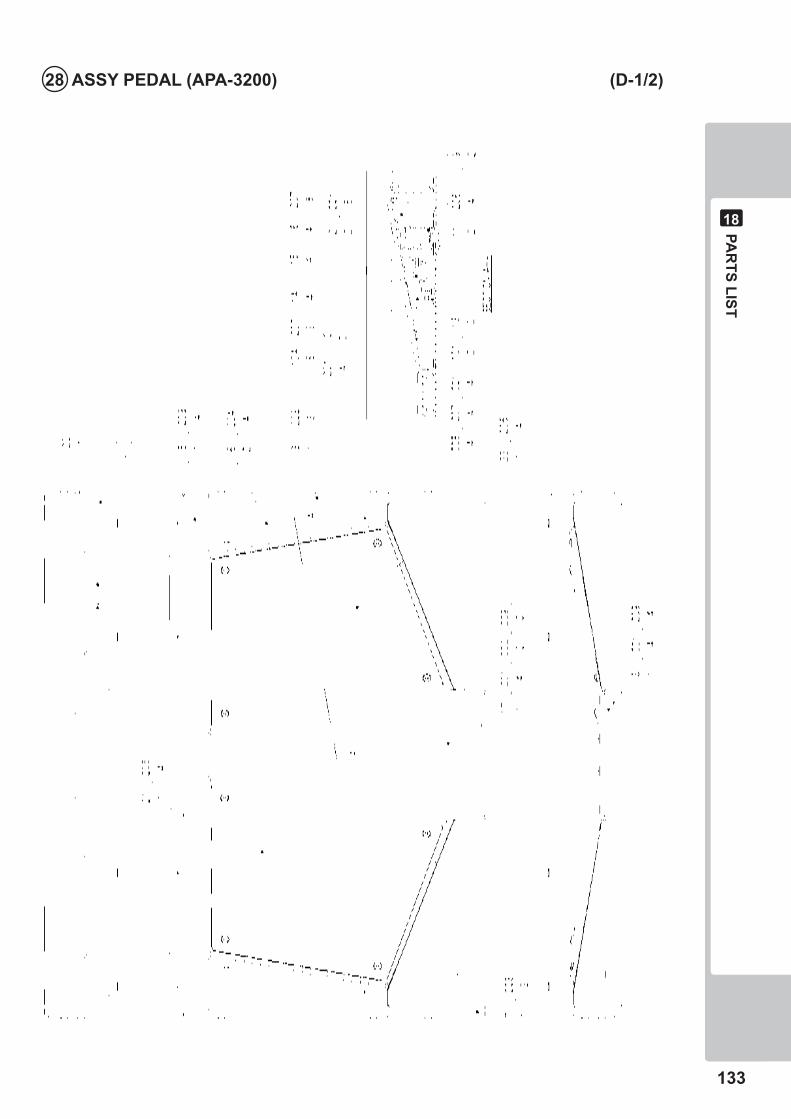
PAR
TS LIST
���
��
�� ASSY PEDAL (APA-��00) (D-�/�)
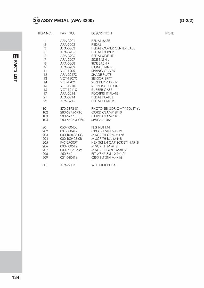
���
PAR
TS LIST
��
�� ASSY PEDAL (APA-��00) (D-�/�)
ITEMNO. PARTNO. DESCRIPTION NOTE
1 APA-3201 PEDALBASE 2 APA-3202 PEDAL 3 APA-3203 PEDALCOVERCENTERBASE 5 APA-3205 PEDALCOVER 6 APA-3206 PEDALSIDELID 7 APA-3207 SIDESASHL 8 APA-3208 SIDESASHR 9 APA-3209 COMSPRING 11 VCT-1205 SPRINGCOVER 12 APA-3217X SHADEPLATE 13 VCT-1207X SENSORBRKT 14 VCT-1209 STOPPERRUBBER 15 VCT-1210 RUBBERCUSHION 16 VCT-1211X RUBBERCASE 17 APA-3216 FOOTPRINTPLATE 21 APA-3214 PEDALPLATEL 22 APA-3215 PEDALPLATER
101 370-5173-01 PHOTOSENSOROMT-15DJST-YL 102 280-5275-SR10 CORDCLAMPSR10 103 280-5277 CORDCLAMP18 104 280-6622-30030 SPACERTUBE
201 050-F00400 FLGNUTM4 202 031-0S0412 CRGBLTSTNM4×12 203 000-T00408-0C MSCRTHCRMM4×8 204 000-T00408-0B MSCRTHBLKM4×8 205 FAS-290057 HEXSKTLHCAPSCRSTNM5×8 206 000-F00512 MSCRFHM5×12 207 000-P00312-W MSCRPHW/FSM3×12 208 250-5421 FLTWSHR3.5-12T=1.0 209 031-0S0416 CRGBLTSTNM4×16
301 APA-60031 WHFOOTPEDAL
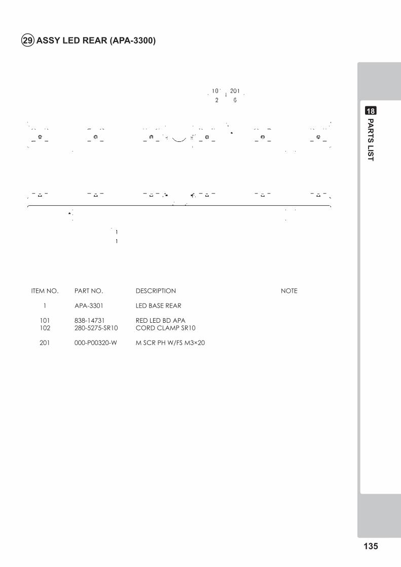
PAR
TS LIST
���
��
�� ASSY LED REAR (APA-��00)
ITEMNO. PARTNO. DESCRIPTION NOTE
1 APA-3301 LEDBASEREAR
101 838-14731 REDLEDBDAPA 102 280-5275-SR10 CORDCLAMPSR10
201 000-P00320-W MSCRPHW/FSM3×20
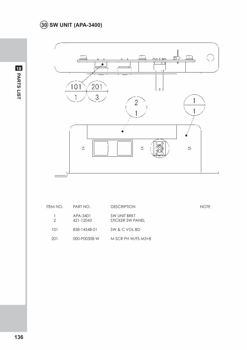
���
PAR
TS LIST
��
�0 SW UNIT (APA-��00)
ITEMNO. PARTNO. DESCRIPTION NOTE
1 APA-3401 SWUNITBRKT 2 421-12043 STICKERSWPANEL
101 838-14548-01 SW&CVOLBD
201 000-P00308-W MSCRPHW/FSM3×8
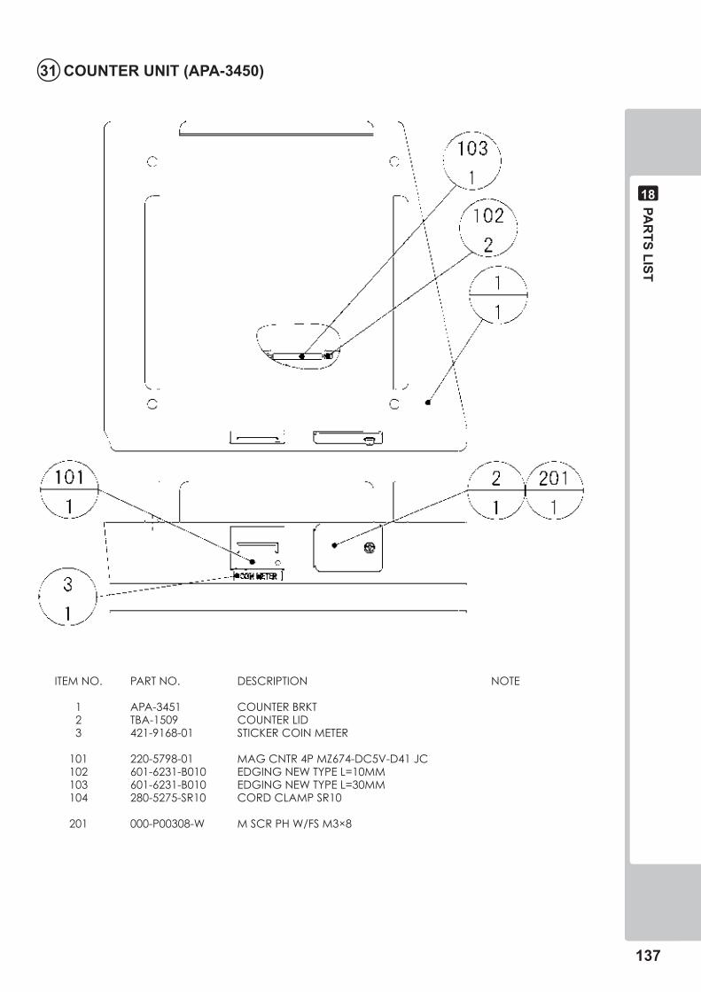
PAR
TS LIST
���
��
�� COUNTER UNIT (APA-���0)
ITEMNO. PARTNO. DESCRIPTION NOTE
1 APA-3451 COUNTERBRKT 2 TBA-1509 COUNTERLID 3 421-9168-01 STICKERCOINMETER
101 220-5798-01 MAGCNTR4PMZ674-DC5V-D41JC 102 601-6231-B010 EDGINGNEWTYPEL=10MM 103 601-6231-B010 EDGINGNEWTYPEL=30MM 104 280-5275-SR10 CORDCLAMPSR10
201 000-P00308-W MSCRPHW/FSM3×8
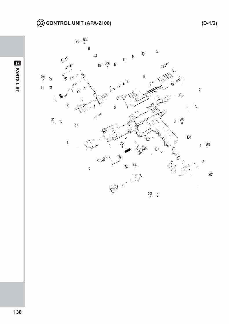
���
PAR
TS LIST
��
�� CONTROL UNIT (APA-��00) (D-�/�)
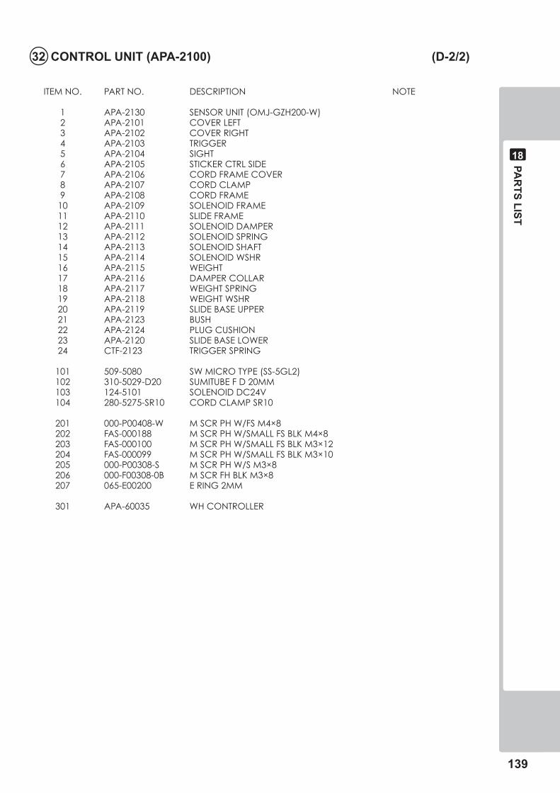
PAR
TS LIST
���
��
ITEMNO. PARTNO. DESCRIPTION NOTE
1 APA-2130 SENSORUNIT(OMJ-GZH200-W) 2 APA-2101 COVERLEFT 3 APA-2102 COVERRIGHT 4 APA-2103 TRIGGER 5 APA-2104 SIGHT 6 APA-2105 STICKERCTRLSIDE 7 APA-2106 CORDFRAMECOVER 8 APA-2107 CORDCLAMP 9 APA-2108 CORDFRAME 10 APA-2109 SOLENOIDFRAME 11 APA-2110 SLIDEFRAME 12 APA-2111 SOLENOIDDAMPER 13 APA-2112 SOLENOIDSPRING 14 APA-2113 SOLENOIDSHAFT 15 APA-2114 SOLENOIDWSHR 16 APA-2115 WEIGHT 17 APA-2116 DAMPERCOLLAR 18 APA-2117 WEIGHTSPRING 19 APA-2118 WEIGHTWSHR 20 APA-2119 SLIDEBASEUPPER 21 APA-2123 BUSH 22 APA-2124 PLUGCUSHION 23 APA-2120 SLIDEBASELOWER 24 CTF-2123 TRIGGERSPRING
101 509-5080 SWMICROTYPE(SS-5GL2) 102 310-5029-D20 SUMITUBEFD20MM 103 124-5101 SOLENOIDDC24V 104 280-5275-SR10 CORDCLAMPSR10
201 000-P00408-W MSCRPHW/FSM4×8 202 FAS-000188 MSCRPHW/SMALLFSBLKM4×8 203 FAS-000100 MSCRPHW/SMALLFSBLKM3×12 204 FAS-000099 MSCRPHW/SMALLFSBLKM3×10 205 000-P00308-S MSCRPHW/SM3×8 206 000-F00308-0B MSCRFHBLKM3×8 207 065-E00200 ERING2MM
301 APA-60035 WHCONTROLLER
�� CONTROL UNIT (APA-��00) (D-�/�)
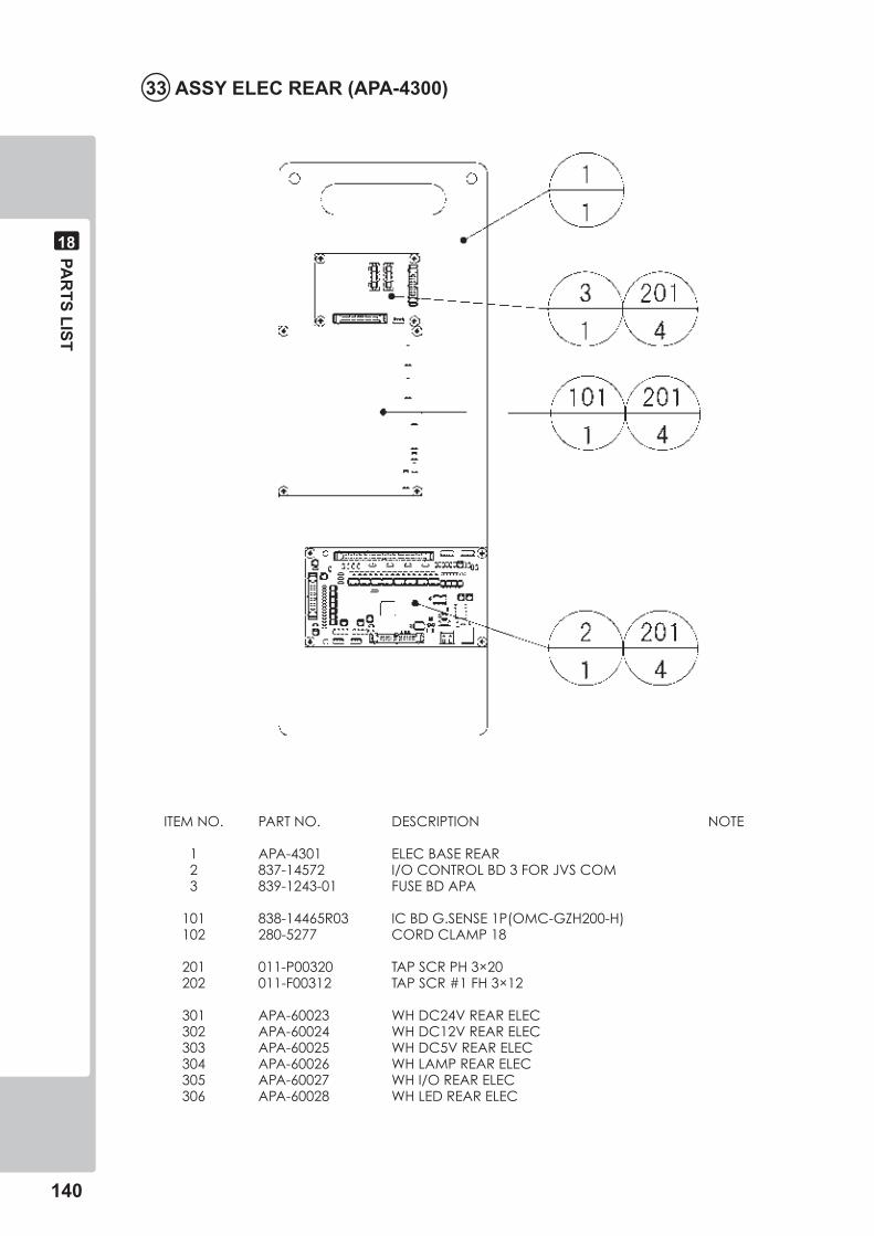
��0
PAR
TS LIST
��
�� ASSY ELEC REAR (APA-��00)
ITEMNO. PARTNO. DESCRIPTION NOTE
1 APA-4301 ELECBASEREAR 2 837-14572 I/OCONTROLBD3FORJVSCOM 3 839-1243-01 FUSEBDAPA
101 838-14465R03 ICBDG.SENSE1P(OMC-GZH200-H) 102 280-5277 CORDCLAMP18
201 011-P00320 TAPSCRPH3×20 202 011-F00312 TAPSCR#1FH3×12
301 APA-60023 WHDC24VREARELEC 302 APA-60024 WHDC12VREARELEC 303 APA-60025 WHDC5VREARELEC 304 APA-60026 WHLAMPREARELEC 305 APA-60027 WHI/OREARELEC 306 APA-60028 WHLEDREARELEC
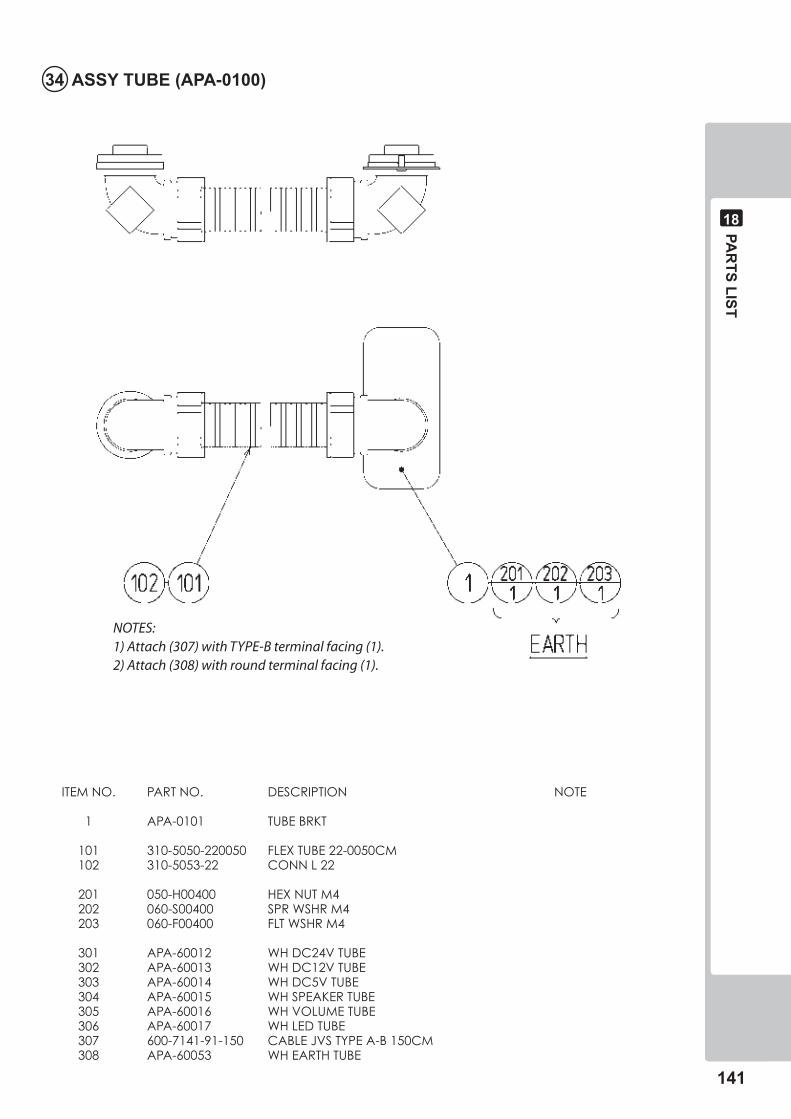
PAR
TS LIST
���
��
�� ASSY TUBE (APA-0�00)
NOTES:1) Attach (307) with TYPE-B terminal facing (1).2) Attach (308) with round terminal facing (1).
ITEMNO. PARTNO. DESCRIPTION NOTE
1 APA-0101 TUBEBRKT
101 310-5050-220050 FLEXTUBE22-0050CM 102 310-5053-22 CONNL22
201 050-H00400 HEXNUTM4 202 060-S00400 SPRWSHRM4 203 060-F00400 FLTWSHRM4
301 APA-60012 WHDC24VTUBE 302 APA-60013 WHDC12VTUBE 303 APA-60014 WHDC5VTUBE 304 APA-60015 WHSPEAKERTUBE 305 APA-60016 WHVOLUMETUBE 306 APA-60017 WHLEDTUBE 307 600-7141-91-150 CABLEJVSTYPEA-B150CM 308 APA-60053 WHEARTHTUBE
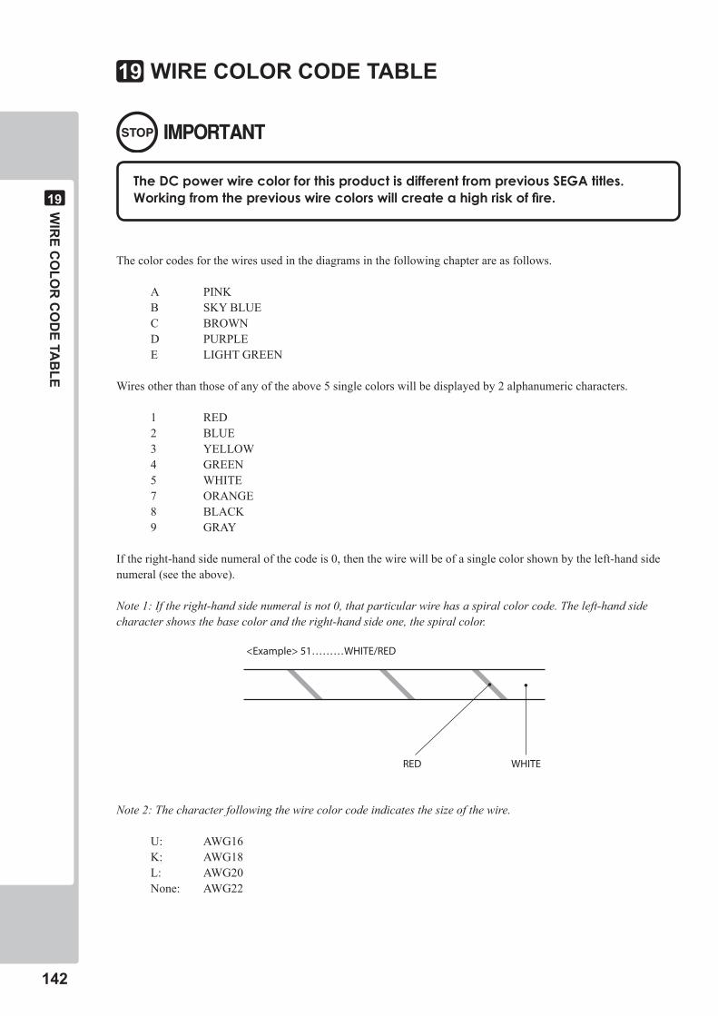
���
WIR
E CO
LOR
CO
DE TA
BLE
��
WIRE COLOR CODE TABLE��
TheDCpowerwirecolorforthisproductisdifferentfrompreviousSEGAtitles.Workingfromthepreviouswirecolorswillcreateahighriskoffire.
The color codes for the wires used in the diagrams in the following chapter are as follows.
A PINKB SKY BLUEC BROWND PURPLEE LIGHT GREEN
Wires other than those of any of the above 5 single colors will be displayed by 2 alphanumeric characters.
1 RED2 BLUE3 YELLOW4 GREEN5 WHITE7 ORANGE8 BLACK9 GRAY
If the right-hand side numeral of the code is 0, then the wire will be of a single color shown by the left-hand side numeral (see the above).
Note 1: If the right-hand side numeral is not 0, that particular wire has a spiral color code. The left-hand side character shows the base color and the right-hand side one, the spiral color.
Note 2: The character following the wire color code indicates the size of the wire.
U: AWG16K: AWG18L: AWG20None: AWG22
RED WHITE
<Example> 51………WHITE/RED
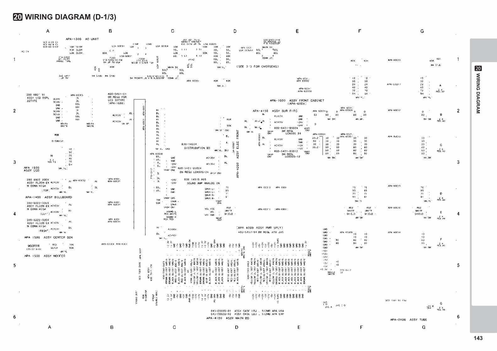
143
WIR
ING
DIA
GR
AM
20
WIRING DIAGRAM (D-1/3)20
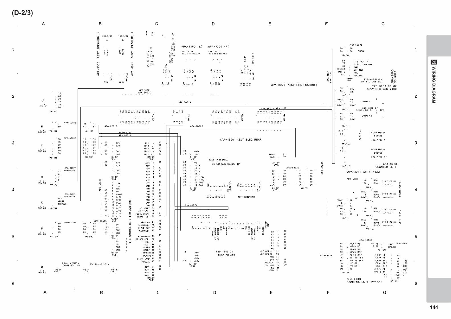
144
WIR
ING
DIA
GR
AM
20
(D-2/3)
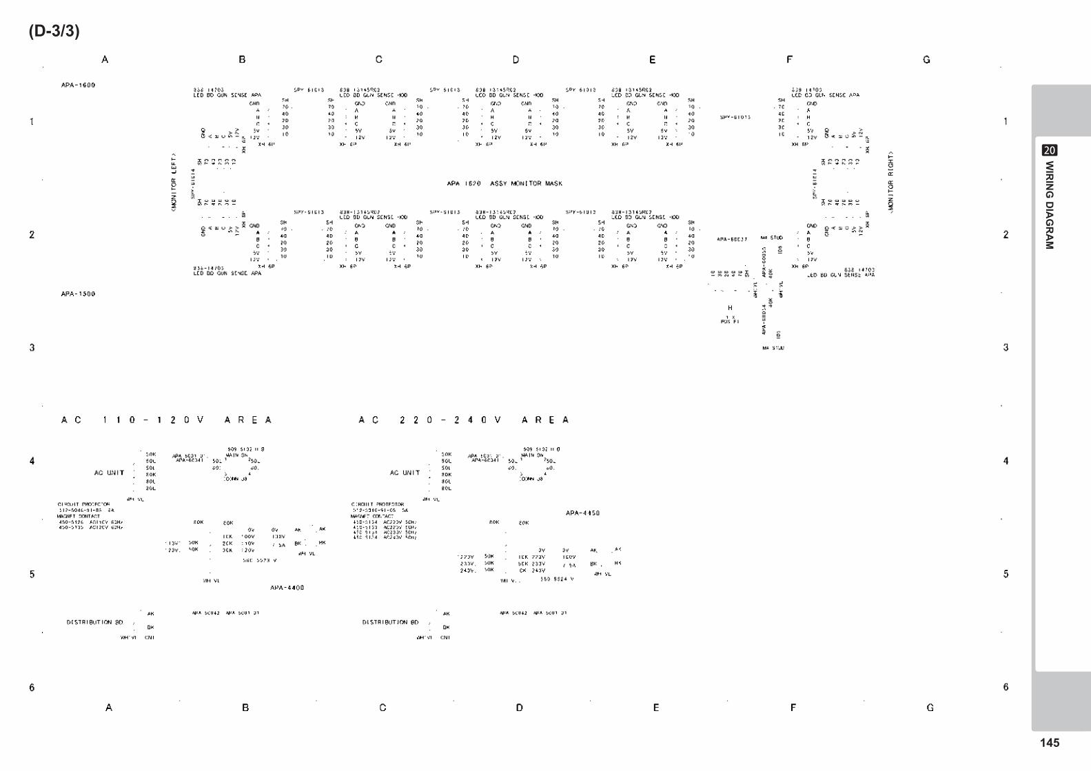
145
WIR
ING
DIA
GR
AM
20
(D-3/3)