overview of our product range - kuvag
TRANSCRIPT
POWER ENGINEERINGHIGH VOLTAGE
TRAFFIC ENGINEERING
POWER ENGINEERINGMEDIUM VOLTAGE
INDUSTRIAL SOLUTIONS
www.kuvag.com www.kuvag.com
POWER ENGINEERINGHIGH VOLTAGE
TRAFFIC ENGINEERING
POWER ENGINEERINGMEDIUM VOLTAGE
INDUSTRIAL SOLUTIONS
www.kuvag.com www.kuvag.com
POWER ENGINEERINGHIGH VOLTAGE
TRAFFIC ENGINEERING
POWER ENGINEERINGMEDIUM VOLTAGE
INDUSTRIAL SOLUTIONS
www.kuvag.com www.kuvag.com
POWER ENGINEERINGHIGH VOLTAGE
TRAFFIC ENGINEERING
POWER ENGINEERINGMEDIUM VOLTAGE
INDUSTRIAL SOLUTIONS
www.kuvag.com www.kuvag.com
www.kuvag.com
CATALOGUE 19•20
LEADING ININSULATION TECHNOLOGY
Overview on our product offering
Products for indoor use Page
Post insulators up to 4 kV 4
Post insulators up to 7,2 kV 5
Post insulators up to 12 kV 6
Post insulators 17,5 – 38,5 kV 7
Capacitive post insulators 12 – 38,5 kV 8
Bushings – 12 kV 9-10
Spouts 11-13
Low voltage insulators 1 – 3,6 kV 14
Screwable Bushings – up to 36 kV 15
Bushings DGFI type – up to 36 kV 16
Products for outdoor use
Outdoor pin insulator (PI/LPI) – up to 36 kV 17
Outdoor post insulator (FS types) – from 6 to 36 kV 18
Outdoor bushings – up to 45 kV 19
Accessories & equipment 20
Capacitive Voltage detection system 21-24
Page
Indoor post insulators up to 4 kV 5
Indoor post insulators up to 7,2 kV 6
Indoor post insulators up to 12 kV 7
Indoor post insulators 17,5 kV – 38,5 kV 8
Capacitive post insulators 12 kV – 38,5 kV 9
Bushings – 12 kV 10-11
Spouts 11-14
Low voltage insulators up to 3,6 kV 15
Screwable bushings type GD up to 36 kV 16
Indoor bushings type DGFI 12 kV 17
Monoblocks up to 3150 A 18
Bushing plugs up to 52 kV 19
Transformer bushings up to 36 kV 20
Busbar holders 21
Capacitive voltage detection systems 22-23
Pole unit EPU - 12 kV / 1250 A - 31,5 kA 24
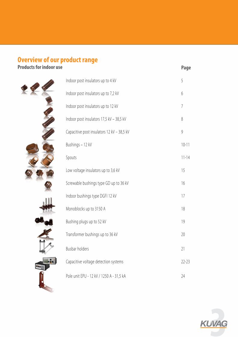
Overview of our product rangeProducts for indoor use
3
Page
Outdoor post insulators type PI/LPI - up to 36 kV 25
Outdoor post insulators type FS - up to 36 kV 26
Outdoor / indoor bushings - up to 45 kV 27
Composite insulators 28
Long rod insulators 3,6 kV - 36 kV 30
Long rod insulators CI - LRZ 3,6 kV - 52 kV 31
Post insulators 3,6 - 52 kV 32
Post insulators CI 3,6 kV - 36 kV 33
Post insulators 3,6 kV - 36 kV 34
Available fitting types 35
Technical specifications 36
Relevant standards - overview 37
Product lines and applications of KUVAG products 38
Composite Insulators
Overview on our product range
1
Long-rod medium voltage 3,6 – 36 kV
Post insulators 3,6 – 36 kV (Overhead line, rail)
Apparatus post insulators 3,6 – 36 kV
Long-rod high voltage – up to 36 kV
Line post insulators 3,6 – 36 kV
CI-LRF
CI-LRZ
CI-P
CI-PI
CI-AP
The CI-LRF is a tension / suspension insulator with alternating sheds for use in overhead lines. The rated system voltage for application of this insulator is from 3,6 – 36,0 kV. All standard ICE and ANSI fittings as well as custom-made fittings are available upon request.
The CI-LRZ is a tension / suspension insulator for use in overhead lines up to 36 kV. All standard ICE and ANSI fittings as well as custom-made fittings are available upon request.
The CI-LRZ is a tension / suspension insulator with alternating sheds for use in overhead lines up to 36 kV. All standard ICE and ANSI fittings as well as custom-made fittings are available upon request.
The post insulators CI-AP is designed for use in apparatus and equipment such as switchgears. Beside a broad range of standard fittings, the use of custom-made fittings is easily possible.
Our CI-PI family is designed for use in distribution overhead lines and rail applications. The insulator has alternating sheds, beside ICE and ANSI fittings, we also offer custom-made fitting designs for this insulator.
Overview on our product offering
Products for indoor use Page
Post insulators up to 4 kV 4
Post insulators up to 7,2 kV 5
Post insulators up to 12 kV 6
Post insulators 17,5 – 38,5 kV 7
Capacitive post insulators 12 – 38,5 kV 8
Bushings – 12 kV 9-10
Spouts 11-13
Low voltage insulators 1 – 3,6 kV 14
Screwable Bushings – up to 36 kV 15
Bushings DGFI type – up to 36 kV 16
Products for outdoor use
Outdoor pin insulator (PI/LPI) – up to 36 kV 17
Outdoor post insulator (FS types) – from 6 to 36 kV 18
Outdoor bushings – up to 45 kV 19
Accessories & equipment 20
Capacitive Voltage detection system 21-24
POWER ENGINEERINGHIGH VOLTAGE
TRAFFIC ENGINEERING
POWER ENGINEERINGMEDIUM VOLTAGE
INDUSTRIAL SOLUTIONS
www.kuvag.com www.kuvag.com
POWER ENGINEERINGHIGH VOLTAGE
TRAFFIC ENGINEERING
POWER ENGINEERINGMEDIUM VOLTAGE
INDUSTRIAL SOLUTIONS
www.kuvag.com www.kuvag.com
POWER ENGINEERINGHIGH VOLTAGE
TRAFFIC ENGINEERING
POWER ENGINEERINGMEDIUM VOLTAGE
INDUSTRIAL SOLUTIONS
www.kuvag.com www.kuvag.com
POWER ENGINEERINGHIGH VOLTAGE
TRAFFIC ENGINEERING
POWER ENGINEERINGMEDIUM VOLTAGE
INDUSTRIAL SOLUTIONS
www.kuvag.com www.kuvag.com
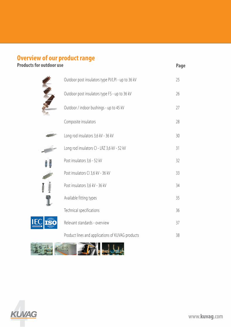
Overview of our product rangeProducts for outdoor use
4 www.kuvag.com
4
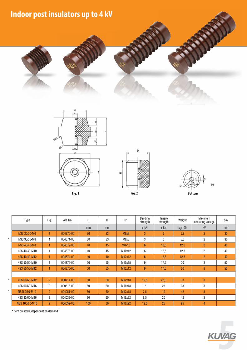
Indoor insulators are manufactured for voltage levels from 0.4 to 38.5 kV. There is high product variability thanks to various mounting bushes. Another relevant parameter is insulator bending strength – the standard design is from 5 to 25 kN. If none of the standard catalogue designs suit you, we will adapt the design to your requirements.
Indoor post insulator up to 4 kV
Post insulators up to 4 kV
Type Fig. Art. No. H D D1Bending strength
Tensile strength
WeightMaximum
operating voltageSW
mm mm > kN > kN kg/100 kV mm
NSS 30/30-M6 1 004870-00 30 33 M6x8 3 6 5,8 2 30
NSS 30/30-M8 1 004871-00 30 33 M8x8 3 6 5,8 2 30
NSS 40/40-M8 1 004872-00 40 45 M8x10 6 12,5 12,3 2 40
NSS 40/40-M10 1 004873-00 40 45 M10x12 6 12,5 12,3 2 40
NSS 40/40-M12 1 004874-00 40 40 M12x12 6 12,5 12,3 2 40
NSS 50/50-M10 1 004875-00 50 55 M10x15 9 17,5 20 3 50
NSS 50/50-M12 1 004876-00 50 55 M12x12 9 17,5 20 3 50
NSS 60/60-M12 2 000714-00 60 60 M12x18 12,5 22,5 33 3
NSS 60/60-M16 2 000516-00 60 60 M16x18 15 25 33 3
NSS80/60-M12 2 004051-00 80 60 M12x18 7,5 19 42 3
NSS 80/60-M16 2 004039-00 80 60 M16x22 9,5 20 42 3
NSS 100/80-M16 2 004052-00 100 80 M16x22 12,5 25 95 4
4
Indoor insulators are manufactured for voltage levels from 0.4 to 38.5 kV. There is high product variability thanks to various mounting bushes. Another relevant parameter is insulator bending strength – the standard design is from 5 to 25 kN. If none of the standard catalogue designs suit you, we will adapt the design to your requirements.
Indoor post insulator up to 4 kV
Post insulators up to 4 kV
Type Fig. Art. No. H D D1Bending strength
Tensile strength
WeightMaximum
operating voltageSW
mm mm > kN > kN kg/100 kV mm
NSS 30/30-M6 1 004870-00 30 33 M6x8 3 6 5,8 2 30
NSS 30/30-M8 1 004871-00 30 33 M8x8 3 6 5,8 2 30
NSS 40/40-M8 1 004872-00 40 45 M8x10 6 12,5 12,3 2 40
NSS 40/40-M10 1 004873-00 40 45 M10x12 6 12,5 12,3 2 40
NSS 40/40-M12 1 004874-00 40 40 M12x12 6 12,5 12,3 2 40
NSS 50/50-M10 1 004875-00 50 55 M10x15 9 17,5 20 3 50
NSS 50/50-M12 1 004876-00 50 55 M12x12 9 17,5 20 3 50
NSS 60/60-M12 2 000714-00 60 60 M12x18 12,5 22,5 33 3
NSS 60/60-M16 2 000516-00 60 60 M16x18 15 25 33 3
NSS80/60-M12 2 004051-00 80 60 M12x18 7,5 19 42 3
NSS 80/60-M16 2 004039-00 80 60 M16x22 9,5 20 42 3
NSS 100/80-M16 2 004052-00 100 80 M16x22 12,5 25 95 4
Fig. 1 Fig. 2 Bottom
* Item on stock, dependent on demand
*
*
*
Indoor post insulators up to 4 kV
5
www.kuvag.com
5Vnitřní izolátory do 7,2 kVIndoor insulators up to 7,2 kV
¬ÌÛÚÂÌÌË ËÁÓΡÚÓ˚ ‰Ó 7,2ͬepoxy resin indoor - post insulators up to 7,2kV
ŒÔÓÌ˚ ËÁÓΡÚÓ˚ ‰Ó 7,2ͬ / post insulators up to 7,2kV
D
–ËÒ. 1 / Fig. 1
H
D1
ÌËÊÌ Á‡ÍÂÔÎÂÌË / bottom fitting
10
20
Ø D
H ±
0,5
D4D3
D2
–ËÒ. 2 / Fig. 2 –ËÒ. 3 / Fig. 3 –ËÒ. 4 / Fig. 4
D3D4
D2D2
“ËÔ –ËÒÛÌÓÍÕÓÏ ËÒÔÓÎ-ÌÂÌˡ
¬˚ÒÓÚ‡ ƒÎË̇ –ÂÁ¸·‡ œÓ˜ÌÓÒÚ¸ ̇
ËÁ„Ë· œÓ˜ÌÓÒÚ¸
‡ÒÚˇÊÂÌˡ
ÇÍÒ. Á‡ÚˇÊÌÓÈ ÏÓÏÂÌÚ
ÇÍÒ. ‡·Ó˜ÂÂ Ì‡ÔˇÊÂÌËÂ
type fig. art.no. h d thread bending strength
tensile strength weight max. initial
tensionmax. operating
voltage
mm mm >kN >kN kg / 100 Nm kV
NSS 30/30-M6 1 K454 30 30 M6x8 3 6 7 20 2
NSS 30/30-M8 1 K349 30 30 M8x8 3,5 7 7 20 2
NSS 40/40-M8 1 K351 40 40 M8x10 5,5 14 12 60 2
NSS 40/40-M10 1 K216 40 40 M10x12 5,5 14 12 60 2
NSS 40/40-M12 1 K370 40 40 M12x12 5,5 14 12 60 2
NSS 60/60-M12 1 K714 60 60 M12x18 12,5 22,5 33 100 3
NSS 60/60-M16 1 K516 60 60 M16x18 15 25 33 100 3
NSS 80/60-M12 1 K4051 80 60 M12x18 7,5 19 42 100 3
NSS 80/60-M16 1 K4039 80 60 M16x22 9,5 20 42 100 3
NSS 100/80-M16 1 K4052 100 80 M16x22 12,5 25 95 120 4
“ËÔ–ËÒÛ-ÌÓÍ
ÕÓÏ ËÒÔÓÎ-ÌÂÌˡ
◊ÂÚÂÊœÛÚ¸
Ûژ͘ӘÌÓÒÚ¸ ̇ ËÁ„Ë·
ÇÒÒ‡ h d d1 d2 d3 d4 ÇÍÒ. ‡·Ó˜ÂÂ Ì‡ÔˇÊÂÌËÂ
type fig. art.no. drawing creepage distance
bending strength weight h d d1 d2 d3 d4 max. operating
voltage
mm >kN kg mm mm mm mm mm mm kV
SGA 1/40 2 K491 M0130 67 5 0,18 40 60 M10x12 M10x12 M6x5 36 1
SGA 1/40 3 K109 M0130 67 5 0,18 40 60 M10x12 M10x12 1
SGA 1/45 4 K113 M0130 72 5 0,22 45 60 M10x16 M10x16 M6x8 36 1
SGA 1/50 3 K464 M0130 77 5 0,26 50 60 M12x18 M10x16 1
SGA 3/60 2 K314 M0130 87 5 0,31 60 60 M12x18 M12x18 M6x12 36 3
SGA 3/60 3 K311 M0130 87 5 0,31 60 60 M12x18 M12x18 3
SGB 1R 4 K114 M0131 60 7,5 0,34 45 66 M16x15 M16x15 M10x16 46 1
SGC 1R 4 K115 M0132 59 12,5 0,54 45 86 M16x15 M16x15 M10x16 66 1
SGB 3/65 3 K312 M0134 85 7,5 0,46 65 66 M16x20 M16x20 3
SGB 3/70 2 K117 M0134 90 7,5 0,49 70 66 M16x20 M16x20 M10x16 46 3
SGB 3/70 3 K653 M0134 90 7,5 0,49 70 66 M16x20 M16x20 3
SGB 3/87 2 K333 M0134 107 7,5 0,57 87 66 M16x20 M16x20 M10x16 46 7,2
SGB 3/87 3 K313 M0134 107 7,5 0,57 87 66 M16x20 M16x20 7,2
SGD 7,2N 3 K321 M0136 115 20 1,22 80 88 M16x20 M16x20 7,2
KUVAG CR spol. s r.o, Nádražní 489, 335 01 Nepomuk / Czech RepublicTel.: +420 371 512 200, Fax: +420 371 591 596, E-Mail: [email protected], www.kuvag.cz
08_indor-7kv.indd 1 13.11.2007 10:56:45
NSS 50/50-M12 1 K369 50 50 M12x12 9 17 19 80 3
NSS 50/50-M10 1 K743 50 50 M10x15 6,5 17 19 80 3
Podpěrné izolátory do 7,2 kV / post insulators up to 7,2 kVTyp Obr. Obj. č. Výkres č. Povrchová
dráhaPevnost v
ohybu H D d1 d2 d3 d4 Váha Maximální pracovní napětí
Type Fig. Art. No. Drawing No. Creepage distance
Bending strength H D d1 d2 d3 d4 Weight Maximum
operating voltage
mm > kN mm mm mm kg kV
SGA 1/40 1 000491-00 M0130 67 5 40 60 M10x12 M10x12 M6x5 3 36 0,18 1
SGA 1/40 2 000109-00 M0130 67 5 40 60 M10x12 M10x12 0,18 1
SGA 1/45 3 000113-00 M0130 72 5 45 60 M10x12 M10x12 M6x8 3 36 0,22 1
SGA 1/50 2 000464-00 M0130 77 5 50 60 M12x18 M12x18 0,26 1
SGA 3/60 1 000314-00 M0130 87 5 60 60 M12x18 M12x18 M6x12 36 0,31 3
SGA 3/60 2 000311-00 M0130 87 5 60 60 M12x18 M12x18 0,31 3
SGB 1R 3 000114-00 M0131 60 7,5 45 66 M16x15 M16x15 M10x16 46 0,34 1
SGC 1R 3 000115-00 M0132 59 12,5 45 86 M16x15 M16x15 M10x16 66 0,54 1
SGB 3/65 2 000312-00 M0134 85 7,5 65 66 M16x20 M16x20 0,46 3
SGB 3/70 1 000117-00 M0134 90 7,5 70 66 M16x20 M16x20 M10x16 46 0,49 3
SGB 3/70 2 000653-00 M0134 90 7,5 70 66 M16x20 M16x20 0,49 3
SGB 3/87 1 000333-00 M1169 107 7,5 87 75 M16x20 M16x20 M10x16 46 0,57 7,2
SGB 3/87 2 000313-00 M0134 107 7,5 87 66 M16x20 M16x20 0,57 7,2
SGD 7,2N 2 000321-00 M0136 115 20 80 88 M16x20 M16x20 1,22 7,2
JO6-60 So H65 5 1423 NP_111_2498_1 105 8,2 65 55 M12x18 M12x18 0,23 3
JO6-60 So H95 6 1424 NP_111_2497_1 135 5,3 95 55 M12x18 M12x18 0,33 3
Obr. 1 / Fig. 1 Obr. 2 / Fig. 2 Obr. 3 / Fig. 3 Obr. 4 / Fig. 4
Obr. 5 / Fig. 5 Obr. 6 / Fig. 6
spodní uchycení/bottom fittings
Indoor post insulators up to 7,2 kV
www.kuvag.com
Indoor insulators up to 7,2 kV
epoxy resin indoor - post insulators up to 7,2kV
–ËÒ. 1 / Fig. 1 ÌËÊÌ Á‡ÍÂÔÎÂÌË / bottom fitting –ËÒ. 2 / Fig. 2 –ËÒ. 3 / Fig. 3 –ËÒ. 4 / Fig. 4
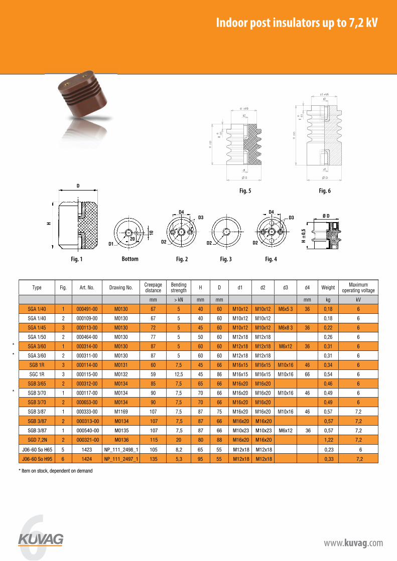
Post insulators up to 7,2 kV
Type Fig. Art. No. Drawing No.Creepage distance
Bending strength
H D d1 d2 d3 d4 WeightMaximum
operating voltage
mm > kN mm mm mm kg kV
SGA 1/40 1 000491-00 M0130 67 5 40 60 M10x12 M10x12 M6x5 3 36 0,18 1
SGA 1/40 2 000109-00 M0130 67 5 40 60 M10x12 M10x12 0,18 1
SGA 1/45 3 000113-00 M0130 72 5 45 60 M10x12 M10x12 M6x8 3 36 0,22 1
SGA 1/50 2 000464-00 M0130 77 5 50 60 M12x18 M12x18 0,26 1
SGA 3/60 1 000314-00 M0130 87 5 60 60 M12x18 M12x18 M6x12 36 0,31 3
SGA 3/60 2 000311-00 M0130 87 5 60 60 M12x18 M12x18 0,31 3
SGB 1R 3 000114-00 M0131 60 7,5 45 66 M16x15 M16x15 M10x16 46 0,34 1
SGC 1R 3 000115-00 M0132 59 12,5 45 86 M16x15 M16x15 M10x16 66 0,54 1
SGB 3/65 2 000312-00 M0134 85 7,5 65 66 M16x20 M16x20 0,46 3
SGB 3/70 1 000117-00 M0134 90 7,5 70 66 M16x20 M16x20 M10x16 46 0,49 3
SGB 3/70 2 000653-00 M0134 90 7,5 70 66 M16x20 M16x20 0,49 3
SGB 3/87 1 000333-00 M1169 107 7,5 87 75 M16x20 M16x20 M10x16 46 0,57 7,2
SGB 3/87 2 000313-00 M0134 107 7,5 87 66 M16x20 M16x20 0,57 7,2
SGD 7,2N 2 000321-00 M0136 115 20 80 88 M16x20 M16x20 1,22 7,2
JO6-60 So H65 1423 NP_111_2498_1 105 8,2 65 55 M12x18 M12x18 0,23 3
JO6-60 So H95 1424 NP_111_2497_1 135 5,3 95 55 M12x18 M12x18 0,33 3
Fig. 1 Fig. 2 Fig. 3 Fig. 4Bottom fittings
6
6
6
6
6
6
6
6
6
6
6
* Item on stock, dependent on demand
*
*
*
www.kuvag.com
Indoor insulators up to 7,2 kV
epoxy resin indoor - post insulators up to 7,2kV
–ËÒ. 1 / Fig. 1 ÌËÊÌ Á‡ÍÂÔÎÂÌË / bottom fitting –ËÒ. 2 / Fig. 2 –ËÒ. 3 / Fig. 3 –ËÒ. 4 / Fig. 4
Post insulators up to 7,2 kV
Type Fig. Art. No. Drawing No.Creepage distance
Bending strength
H D d1 d2 d3 d4 WeightMaximum
operating voltage
mm > kN mm mm mm kg kV
SGA 1/40 1 000491-00 M0130 67 5 40 60 M10x12 M10x12 M6x5 3 36 0,18 1
SGA 1/40 2 000109-00 M0130 67 5 40 60 M10x12 M10x12 0,18 1
SGA 1/45 3 000113-00 M0130 72 5 45 60 M10x12 M10x12 M6x8 3 36 0,22 1
SGA 1/50 2 000464-00 M0130 77 5 50 60 M12x18 M12x18 0,26 1
SGA 3/60 1 000314-00 M0130 87 5 60 60 M12x18 M12x18 M6x12 36 0,31 3
SGA 3/60 2 000311-00 M0130 87 5 60 60 M12x18 M12x18 0,31 3
SGB 1R 3 000114-00 M0131 60 7,5 45 66 M16x15 M16x15 M10x16 46 0,34 1
SGC 1R 3 000115-00 M0132 59 12,5 45 86 M16x15 M16x15 M10x16 66 0,54 1
SGB 3/65 2 000312-00 M0134 85 7,5 65 66 M16x20 M16x20 0,46 3
SGB 3/70 1 000117-00 M0134 90 7,5 70 66 M16x20 M16x20 M10x16 46 0,49 3
SGB 3/70 2 000653-00 M0134 90 7,5 70 66 M16x20 M16x20 0,49 3
SGB 3/87 1 000333-00 M1169 107 7,5 87 75 M16x20 M16x20 M10x16 46 0,57 7,2
SGB 3/87 2 000313-00 M0134 107 7,5 87 66 M16x20 M16x20 0,57 7,2
SGD 7,2N 2 000321-00 M0136 115 20 80 88 M16x20 M16x20 1,22 7,2
JO6-60 So H65 1423 NP_111_2498_1 105 8,2 65 55 M12x18 M12x18 0,23 3
JO6-60 So H95 1424 NP_111_2497_1 135 5,3 95 55 M12x18 M12x18 0,33 3
Fig. 1 Fig. 2 Fig. 3 Fig. 4Bottom fittings
SGB 3/87 2 000313-00 M0134 107 7,5 87 66 M16x20 M16x20 0,57 7,2
SGB 3/87 1 000540-00 M0135 107 7,5 87 66 M10x23 M10x23 M6x12 36 0,57 7,2
SGD 7,2N 2 000321-00 M0136 115 20 80 88 M16x20 M16x20 1,22 7,2
J06-60 So H65 5 1423 NP_111_2498_1 105 8,2 65 55 M12x18 M12x18 0,23 6
J06-60 So H95 6 1424 NP_111_2497_1 135 5,3 95 55 M12x18 M12x18 0,33 7,2
www.kuvag.com
Indoor insulators up to 7,2 kV
epoxy resin indoor - post insulators up to 7,2kV
–ËÒ. 1 / Fig. 1 ÌËÊÌ Á‡ÍÂÔÎÂÌË / bottom fitting –ËÒ. 2 / Fig. 2 –ËÒ. 3 / Fig. 3 –ËÒ. 4 / Fig. 4
Post insulators up to 7,2 kV
Type Fig. Art. No. Drawing No.Creepage distance
Bending strength
H D d1 d2 d3 d4 WeightMaximum
operating voltage
mm > kN mm mm mm kg kV
SGA 1/40 1 000491-00 M0130 67 5 40 60 M10x12 M10x12 M6x5 3 36 0,18 1
SGA 1/40 2 000109-00 M0130 67 5 40 60 M10x12 M10x12 0,18 1
SGA 1/45 3 000113-00 M0130 72 5 45 60 M10x12 M10x12 M6x8 3 36 0,22 1
SGA 1/50 2 000464-00 M0130 77 5 50 60 M12x18 M12x18 0,26 1
SGA 3/60 1 000314-00 M0130 87 5 60 60 M12x18 M12x18 M6x12 36 0,31 3
SGA 3/60 2 000311-00 M0130 87 5 60 60 M12x18 M12x18 0,31 3
SGB 1R 3 000114-00 M0131 60 7,5 45 66 M16x15 M16x15 M10x16 46 0,34 1
SGC 1R 3 000115-00 M0132 59 12,5 45 86 M16x15 M16x15 M10x16 66 0,54 1
SGB 3/65 2 000312-00 M0134 85 7,5 65 66 M16x20 M16x20 0,46 3
SGB 3/70 1 000117-00 M0134 90 7,5 70 66 M16x20 M16x20 M10x16 46 0,49 3
SGB 3/70 2 000653-00 M0134 90 7,5 70 66 M16x20 M16x20 0,49 3
SGB 3/87 1 000333-00 M1169 107 7,5 87 75 M16x20 M16x20 M10x16 46 0,57 7,2
SGB 3/87 2 000313-00 M0134 107 7,5 87 66 M16x20 M16x20 0,57 7,2
SGD 7,2N 2 000321-00 M0136 115 20 80 88 M16x20 M16x20 1,22 7,2
JO6-60 So H65 1423 NP_111_2498_1 105 8,2 65 55 M12x18 M12x18 0,23 3
JO6-60 So H95 1424 NP_111_2497_1 135 5,3 95 55 M12x18 M12x18 0,33 3
Fig. 1 Fig. 2 Fig. 3 Fig. 4Bottom fittings
6 www.kuvag.com
Post insulators up 12kV
–ËÒ. 1 / Fig. 1
ÌËÊÌ Á‡ÍÂÔÎÂÌË / bottom fitting
–ËÒ. 2 / Fig. 2 –ËÒ. 3 / Fig. 3
¬ÂıÌ „ÌÂÁ‰Ó ÔÓÚÂ̈ˇθÌÓ ‚Á‡ËÏÓÒ‚ˇÁ‡ÌÓ
Fig. 1 Fig. 2 Fig. 3
Bottom fittings
Top inserts electrical conductively connected
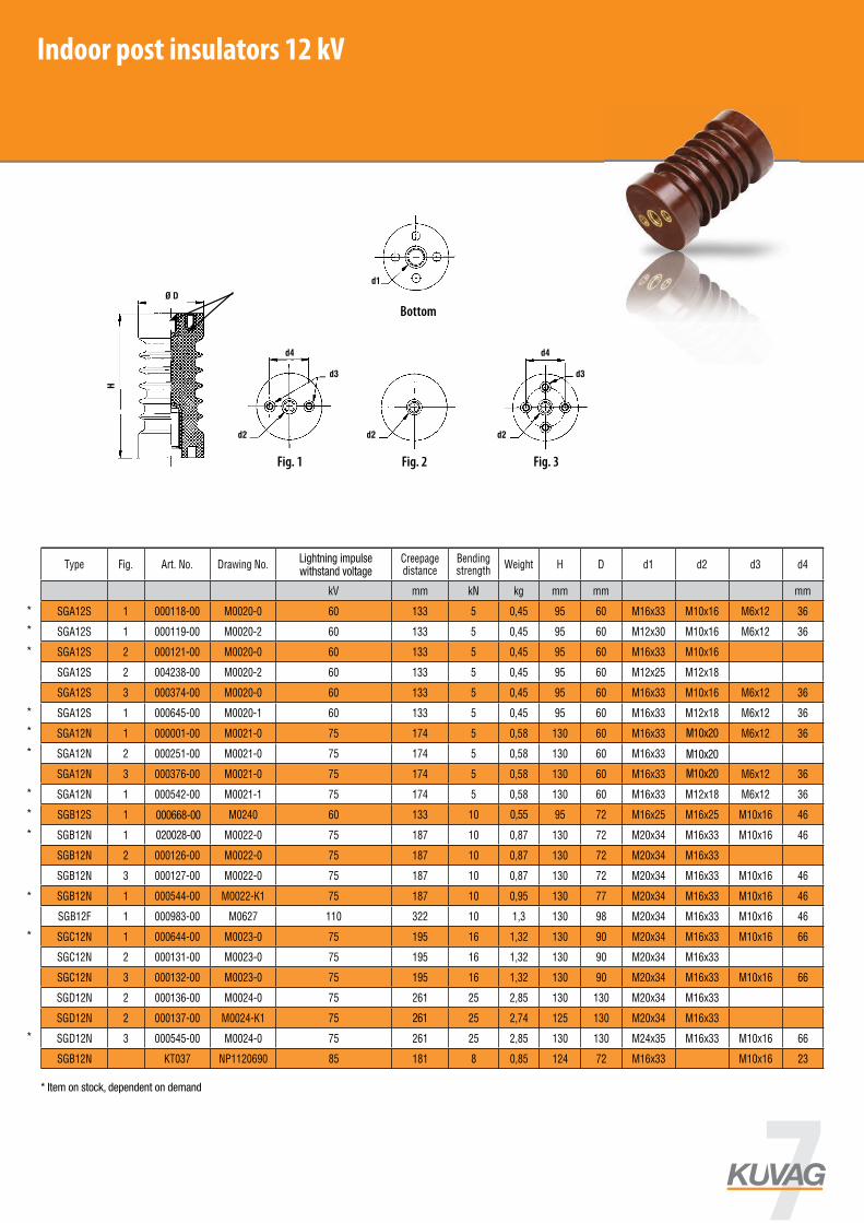
Post insulators up to 12 kV
Type Fig. Art. No. Drawing No.Lighting impulse withstand voltage
Creepage distance
Bending strength
Weight H D d1 d2 d3 d4
kV mm kN kg mm mm mm
SGA12S 1 000118-00 M0020-0 60 133 5 0,45 95 60 M16x33 M10x16 M6x12 36
SGA12S 1 000119-00 M0020-2 60 133 5 0,45 95 60 M12x30 M10x16 M6x12 36
SGA12S 2 000121-00 M0020-0 60 133 5 0,45 95 60 M16x33 M10x16
SGA12S 2 004238-00 M0020-2 60 133 5 0,45 95 60 M12x25 M12x18
SGA12S 3 000374-00 M0020-0 60 133 5 0,45 95 60 M16x33 M10x16 M6x12 36
SGA12S 1 000645-00 M0020-1 60 133 5 0,45 95 60 M16x33 M12x18 M6x12 36
SGA12N 1 000001-00 M0021-0 75 174 5 0,58 130 60 M16x33 M10x16 M6x12 36
SGA12N 2 000251-00 M0021-0 75 174 5 0,58 130 60 M16x33 M10x16
SGA12N 3 000376-00 M0021-0 75 174 5 0,58 130 60 M16x33 M10x16 M6x12 36
SGA12N 1 000542-00 M0021-1 75 174 5 0,58 130 60 M16x33 M12x18 M6x12 36
SGB12S 1 000688-00 M0240 60 133 10 0,58 95 72 M16x25 M16x25 M10x16 46
SGB12N 1 000125-00 M0022-0 75 187 10 0,87 130 72 M20x34 M16x33 M10x16 46
SGB12N 2 000126-00 M0022-0 75 187 10 0,87 130 72 M20x34 M16x33
SGB12N 3 000127-00 M0022-0 75 187 10 0,87 130 72 M20x34 M16x33 M10x16 46
SGB12N 1 000544-00 M0022-K1 75 187 10 0,95 130 77 M20x34 M16x33 M10x16 46
SGB12F 1 000983-00 M0627 110 322 10 1,3 130 98 M20x34 M16x33 M10x16 46
SGC12N 1 000644-00 M0023-0 75 195 16 1,32 130 90 M20x34 M16x33 M10x16 66
SGC12N 2 000131-00 M0023-0 75 195 16 1,32 130 90 M20x34 M16x33
SGC12N 3 000132-00 M0023-0 75 195 16 1,32 130 90 M20x34 M16x33 M10x16 66
SGD12N 2 000136-00 M0024-0 75 261 25 2,85 130 130 M20x34 M16x33
SGD12N 2 000137-00 M0024-K1 75 256 25 2,74 125 130 M20x34 M16x33
SGD12N 3 000545-00 M0024-0 75 261 25 2,85 130 130 M24x35 M16x33 M10x16 66
SGB12N KT037 NP1120690 85 181 8 0,85 124 72 M16x33 M10x16 23
Indoor post insulators 12 kV
* Item on stock, dependent on demand
*
*
*
*
*
*
*
*
*
*
*
*
000668-00
261
0,55
M10x20
M10x20
M10x20
020028-00
www.kuvag.com
Indoor insulators up to 7,2 kV
epoxy resin indoor - post insulators up to 7,2kV
–ËÒ. 1 / Fig. 1 ÌËÊÌ Á‡ÍÂÔÎÂÌË / bottom fitting –ËÒ. 2 / Fig. 2 –ËÒ. 3 / Fig. 3 –ËÒ. 4 / Fig. 4
Post insulators up to 7,2 kV
Type Fig. Art. No. Drawing No.Creepage distance
Bending strength
H D d1 d2 d3 d4 WeightMaximum
operating voltage
mm > kN mm mm mm kg kV
SGA 1/40 1 000491-00 M0130 67 5 40 60 M10x12 M10x12 M6x5 3 36 0,18 1
SGA 1/40 2 000109-00 M0130 67 5 40 60 M10x12 M10x12 0,18 1
SGA 1/45 3 000113-00 M0130 72 5 45 60 M10x12 M10x12 M6x8 3 36 0,22 1
SGA 1/50 2 000464-00 M0130 77 5 50 60 M12x18 M12x18 0,26 1
SGA 3/60 1 000314-00 M0130 87 5 60 60 M12x18 M12x18 M6x12 36 0,31 3
SGA 3/60 2 000311-00 M0130 87 5 60 60 M12x18 M12x18 0,31 3
SGB 1R 3 000114-00 M0131 60 7,5 45 66 M16x15 M16x15 M10x16 46 0,34 1
SGC 1R 3 000115-00 M0132 59 12,5 45 86 M16x15 M16x15 M10x16 66 0,54 1
SGB 3/65 2 000312-00 M0134 85 7,5 65 66 M16x20 M16x20 0,46 3
SGB 3/70 1 000117-00 M0134 90 7,5 70 66 M16x20 M16x20 M10x16 46 0,49 3
SGB 3/70 2 000653-00 M0134 90 7,5 70 66 M16x20 M16x20 0,49 3
SGB 3/87 1 000333-00 M1169 107 7,5 87 75 M16x20 M16x20 M10x16 46 0,57 7,2
SGB 3/87 2 000313-00 M0134 107 7,5 87 66 M16x20 M16x20 0,57 7,2
SGD 7,2N 2 000321-00 M0136 115 20 80 88 M16x20 M16x20 1,22 7,2
JO6-60 So H65 1423 NP_111_2498_1 105 8,2 65 55 M12x18 M12x18 0,23 3
JO6-60 So H95 1424 NP_111_2497_1 135 5,3 95 55 M12x18 M12x18 0,33 3
Fig. 1 Fig. 2 Fig. 3 Fig. 4Bottom fittings
Lightning impulsewithstand voltage
7
–ËÒ. 1 / Fig. 1
ÌËÊÌ Á‡ÍÂÔÎÂÌË / bottom fitting
–ËÒ. 2 / Fig. 2 –ËÒ. 3 / Fig. 3
¬ÂıÌ „ÌÂÁ‰Ó ÔÓÚÂ̈ˇθÌÓ ‚Á‡ËÏÓÒ‚ˇÁ‡ÌÓ
Indoor insulators from 17,5 kV up to 38,5 kV
Fig. 1 Fig. 2 Fig. 3
Bottom fittings
Top inserts electrical conductively connected
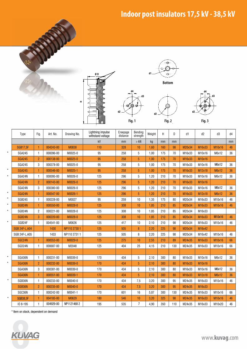
Post insulators from 17,5 kV up to 38,5 kV
Type Fig. Art. No. Drawing No.Lighting impulse withstand voltage
Creepage distance
Bending strength
Weight H D d1 d2 d3 d4
kV mm > kN kg mm mm mm
SGB17,5F 1 004243-00 M0838 110 328 10 1,60 160 98 M20x34 M16x33 M10x16 46
SGA24S 1 000096-00 M0025-0 95 258 5 1,00 175 70 M16x33 M10x16 M6x12 36
SGA24S 2 000138-00 M0025-0 95 258 5 1,00 175 70 M16x33 M10x16
SGA24S 3 000378-00 M0025-0 95 258 5 1,00 175 70 M16x33 M10x16 4xM6x12 36
SGA24S 1 000546-00 M0025-1 95 258 5 1,00 175 70 M16x33 M12x18 M6x12 36
SGA24N 1 000095-00 M0026-0 125 296 5 1,20 210 70 M16x33 M10x16 M6x12 36
SGA24N 2 000143-00 M0026-0 125 296 5 1,20 210 70 M16x33 M10x16
SGA24N 3 000380-00 M0026-0 125 296 5 1,20 210 70 M16x33 M10x16 4xM6x12 36
SGA24N 1 000547-00 M0026-1 125 296 5 1,20 210 70 M16x33 M12x18 M6x12 36
SGB24S 1 000228-00 M0027 95 259 10 1,35 175 80 M20x34 M16x33 M10x16 46
SGB24N 1 000550-00 M0028-0 125 308 10 1,85 210 85 M20x34 M16x33 M10x16 46
SGB24N 2 000221-00 M0028-0 125 308 10 1,85 210 85 M20x34 M16x33
SGB24N 3 000220-00 M0028-0 125 308 10 1,85 210 85 M20x34 M16x33 4xM10x16 46
SGB24F 1 004541-00 M0626 125 417 10 2,10 210 98 M20x34 M16x33 M10x16 46
SGB 24F-L,A04 1430 NP110 2730 1 125 505 8 2,20 225 98 M20x34 M16x42
SGB 24F-L,A05 1433 NP110 2731 1 125 505 8 2,20 225 98 M20x34 M16x42 M10x16 46
SGC24N 1 000553-00 M0029-0 125 275 10 2,55 210 89 M24x35 M16x33 M10x16 66
SGD24N 1 000687-00 M2048 125 404 25 4,15 210 130 M24x35 M16x33 M10x16 66
SGA36N 1 000231-00 M0039-0 170 434 5 2,10 300 80 M16x33 M10x16 M6x12 36
SGA36N 2 000232-00 M0039-0 170 434 5 2,10 300 80 M16x33 M10x16
SGA36N 3 000381-00 M0039-0 170 434 5 2,10 300 80 M16x33 M10x16 4xM6x12 36
SGA36N 1 000551-00 M0039-1 170 434 5 2,10 300 80 M16x33 M12x18 M6x12 36
SGB36N 1 000233-00 M0040-0 170 434 7,5 3,20 300 95 M24x35 M16x33 M10x16 46
SGB36N 2 000235-00 M0040-0 170 434 7,5 3,20 300 95 M24x35 M16x33
SGC36N 1 000242-00 M0041-1 170 601 16 5,87 300 130 M24x35 M16x33 M10x16 66
SGB36F 1 004185-00 M0629 180 546 10 3,20 325 98 M24x35 M16x33 M10x16 46
IO 8-195 1 1275 NP1120687 195 535 8 4,90 350 110 M24x35 M16x33 M10x20 46
–ËÒ. 1 / Fig. 1
ÌËÊÌ Á‡ÍÂÔÎÂÌË / bottom fitting
–ËÒ. 2 / Fig. 2 –ËÒ. 3 / Fig. 3
¬ÂıÌ „ÌÂÁ‰Ó ÔÓÚÂ̈ˇθÌÓ ‚Á‡ËÏÓÒ‚ˇÁ‡ÌÓ
Indoor insulators from 17,5 kV up to 38,5 kV
Fig. 1 Fig. 2 Fig. 3
Bottom fittings
Top inserts electrical conductively connected
Post insulators from 17,5 kV up to 38,5 kV
Type Fig. Art. No. Drawing No.Lighting impulse withstand voltage
Creepage distance
Bending strength
Weight H D d1 d2 d3 d4
kV mm > kN kg mm mm mm
SGB17,5F 1 004243-00 M0838 110 328 10 1,60 160 98 M20x34 M16x33 M10x16 46
SGA24S 1 000096-00 M0025-0 95 258 5 1,00 175 70 M16x33 M10x16 M6x12 36
SGA24S 2 000138-00 M0025-0 95 258 5 1,00 175 70 M16x33 M10x16
SGA24S 3 000378-00 M0025-0 95 258 5 1,00 175 70 M16x33 M10x16 4xM6x12 36
SGA24S 1 000546-00 M0025-1 95 258 5 1,00 175 70 M16x33 M12x18 M6x12 36
SGA24N 1 000095-00 M0026-0 125 296 5 1,20 210 70 M16x33 M10x16 M6x12 36
SGA24N 2 000143-00 M0026-0 125 296 5 1,20 210 70 M16x33 M10x16
SGA24N 3 000380-00 M0026-0 125 296 5 1,20 210 70 M16x33 M10x16 4xM6x12 36
SGA24N 1 000547-00 M0026-1 125 296 5 1,20 210 70 M16x33 M12x18 M6x12 36
SGB24S 1 000228-00 M0027 95 259 10 1,35 175 80 M20x34 M16x33 M10x16 46
SGB24N 1 000550-00 M0028-0 125 308 10 1,85 210 85 M20x34 M16x33 M10x16 46
SGB24N 2 000221-00 M0028-0 125 308 10 1,85 210 85 M20x34 M16x33
SGB24N 3 000220-00 M0028-0 125 308 10 1,85 210 85 M20x34 M16x33 4xM10x16 46
SGB24F 1 004541-00 M0626 125 417 10 2,10 210 98 M20x34 M16x33 M10x16 46
SGB 24F-L,A04 1430 NP110 2730 1 125 505 8 2,20 225 98 M20x34 M16x42
SGB 24F-L,A05 1433 NP110 2731 1 125 505 8 2,20 225 98 M20x34 M16x42 M10x16 46
SGC24N 1 000553-00 M0029-0 125 275 10 2,55 210 89 M24x35 M16x33 M10x16 66
SGD24N 1 000687-00 M2048 125 404 25 4,15 210 130 M24x35 M16x33 M10x16 66
SGA36N 1 000231-00 M0039-0 170 434 5 2,10 300 80 M16x33 M10x16 M6x12 36
SGA36N 2 000232-00 M0039-0 170 434 5 2,10 300 80 M16x33 M10x16
SGA36N 3 000381-00 M0039-0 170 434 5 2,10 300 80 M16x33 M10x16 4xM6x12 36
SGA36N 1 000551-00 M0039-1 170 434 5 2,10 300 80 M16x33 M12x18 M6x12 36
SGB36N 1 000233-00 M0040-0 170 434 7,5 3,20 300 95 M24x35 M16x33 M10x16 46
SGB36N 2 000235-00 M0040-0 170 434 7,5 3,20 300 95 M24x35 M16x33
SGC36N 1 000242-00 M0041-1 170 601 16 5,87 300 130 M24x35 M16x33 M10x16 66
SGB36F 1 004185-00 M0629 180 546 10 3,20 325 98 M24x35 M16x33 M10x16 46
IO 8-195 1 1275 NP1120687 195 535 8 4,90 350 110 M24x35 M16x33 M10x20 46
Indoor post insulators 17,5 kV - 38,5 kV
* Item on stock, dependent on demand
M10x16
004929-00 7NP1121468 2
M6x12
M6x12
M6x12
SGB38,5F*
*
*
*
*
*
*
*
*
*
*
*
www.kuvag.com
Indoor insulators up to 7,2 kV
epoxy resin indoor - post insulators up to 7,2kV
–ËÒ. 1 / Fig. 1 ÌËÊÌ Á‡ÍÂÔÎÂÌË / bottom fitting –ËÒ. 2 / Fig. 2 –ËÒ. 3 / Fig. 3 –ËÒ. 4 / Fig. 4
Post insulators up to 7,2 kV
Type Fig. Art. No. Drawing No.Creepage distance
Bending strength
H D d1 d2 d3 d4 WeightMaximum
operating voltage
mm > kN mm mm mm kg kV
SGA 1/40 1 000491-00 M0130 67 5 40 60 M10x12 M10x12 M6x5 3 36 0,18 1
SGA 1/40 2 000109-00 M0130 67 5 40 60 M10x12 M10x12 0,18 1
SGA 1/45 3 000113-00 M0130 72 5 45 60 M10x12 M10x12 M6x8 3 36 0,22 1
SGA 1/50 2 000464-00 M0130 77 5 50 60 M12x18 M12x18 0,26 1
SGA 3/60 1 000314-00 M0130 87 5 60 60 M12x18 M12x18 M6x12 36 0,31 3
SGA 3/60 2 000311-00 M0130 87 5 60 60 M12x18 M12x18 0,31 3
SGB 1R 3 000114-00 M0131 60 7,5 45 66 M16x15 M16x15 M10x16 46 0,34 1
SGC 1R 3 000115-00 M0132 59 12,5 45 86 M16x15 M16x15 M10x16 66 0,54 1
SGB 3/65 2 000312-00 M0134 85 7,5 65 66 M16x20 M16x20 0,46 3
SGB 3/70 1 000117-00 M0134 90 7,5 70 66 M16x20 M16x20 M10x16 46 0,49 3
SGB 3/70 2 000653-00 M0134 90 7,5 70 66 M16x20 M16x20 0,49 3
SGB 3/87 1 000333-00 M1169 107 7,5 87 75 M16x20 M16x20 M10x16 46 0,57 7,2
SGB 3/87 2 000313-00 M0134 107 7,5 87 66 M16x20 M16x20 0,57 7,2
SGD 7,2N 2 000321-00 M0136 115 20 80 88 M16x20 M16x20 1,22 7,2
JO6-60 So H65 1423 NP_111_2498_1 105 8,2 65 55 M12x18 M12x18 0,23 3
JO6-60 So H95 1424 NP_111_2497_1 135 5,3 95 55 M12x18 M12x18 0,33 3
Fig. 1 Fig. 2 Fig. 3 Fig. 4Bottom fittings
Lightning impulsewithstand voltage
8 www.kuvag.com
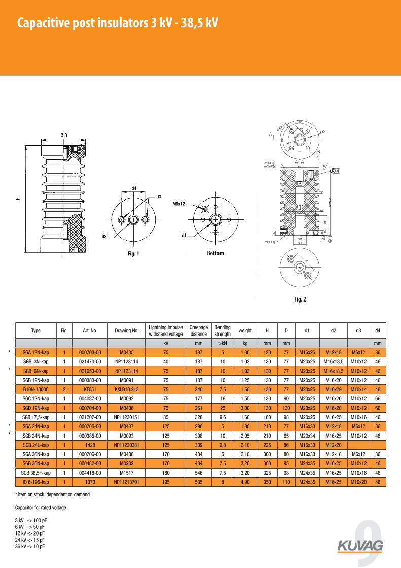
Capacitive post insulators 3 kV - 38,5 kV
Capacitive post insulators from 12 up to 38,5kV
Capacitive insulatorsThe design of these insulators follows from the standard indoor ones. The insulator has a capacitor cast in and its bottom terminal is used for connection to a voltage indicator.
Fig. 1 Fig. 2Bottom fittings
Top inserts electrical conductively connected
Capacitive insulators
Type Fig. Art. No. Drawing No.Lighting impulse withstand voltage
Creepage distance
Bending strength
Weight H D d1 d2 d3 d4
kV mm > kN kg mm mm mm
SGA12N-kap 1 000703-00 M0435 75 187 5 1,30 130 77 M16x25 M12x18 M6x12 36
SGB12N-kap 1 000383-00 M0091 75 187 10 1,25 130 77 M20x25 M16x20 M10x12 46
B10N-1000C 2 KT051 KXI.B10.213 75 240 7,5 1,50 130 77 M20x25 M16x29 M10x14 46
SGC12N-kap 1 004087-00 M0092 75 177 16 1,55 130 90 M20x25 M16x20 M10x12 66
SGD12N-kap 1 000704-00 M0436 75 261 25 3,00 130 13 M20x25 M16x20 M10x1 66
SGA24N-kap 1 000705-00 M0437 125 296 5 1,80 210 77 M16x33 M12x18 M6x12 36
SGB24N-kap 1 000385-00 M0093 125 308 10 2,05 210 85 M20x34 M16x25 M10x12 46
SGB 24L-kap 1 1428 NP112 2038 1 125 339 6,8 2,10 225 86 M16x33 M12x20
SGA36N-kap 1 000706-00 M0438 170 434 5 2,10 300 80 M16x33 M12x18 M6x12 36
SGB36N-kap 1 000482-00 M0202 170 434 7,5 3,20 300 95 M24x35 M16x25 M10x12 46
SGB38,5F-kap 1 004418-00 M1517 180 546 7,5 3,56 325 98 M24x35 M16x25 M10x16 46
IO 8-195 kap 1 1370 NP11213701 195 535 8 4,90 350 110 M24x35 M16x25 M10x20 46
* Item on stock, dependent on demand
Capacitor for rated voltage
3 kV -> 100 pF6 kV -> 50 pF 12 kV -> 20 pF24 kV -> 15 pF36 kV -> 10 pF
*
*
*
*
Type Fig. Art. No. Drawing No.Lightning impulse withstand voltage
Creepage distance
Bending strength
weight H D d1 d2 d3 d4
kV mm >kN kg mm mm mm
SGA 12N-kap 1 000703-00 M0435 75 187 5 1,30 130 77 M16x25 M12x18 M6x12 36
SGB 3N-kap 1 021470-00 NP1123114 40 187 10 1,03 130 77 M20x25 M16x18,5 M10x12 46
SGB 6N-kap 1 021053-00 NP1123114 75 187 10 1,03 130 77 M20x25 M16x18,5 M10x12 46
SGB 12N-kap 1 000383-00 M0091 75 187 10 1,25 130 77 M20x25 M16x20 M10x12 46
B10N-1000C 2 KT051 KXI.B10.213 75 240 7,5 1,50 130 77 M20x25 M16x29 M10x14 46
SGC 12N-kap 1 004087-00 M0092 75 177 16 1,55 130 90 M20x25 M16x20 M10x12 66
SGD 12N-kap 1 000704-00 M0436 75 261 25 3,00 130 130 M20x25 M16x20 M10x12 66
SGB 17,5-kap 1 021207-00 NP11230151 85 328 9,6 1,60 160 98 M20x25 M16x25 M10x16 46
SGA 24N-kap 1 000705-00 M0437 125 296 5 1,80 210 77 M16x33 M12x18 M6x12 36
SGB 24N-kap 1 000385-00 M0093 125 308 10 2,05 210 85 M20x34 M16x25 M10x12 46
SGB 24L-kap 1 1428 NP11220381 125 339 6,8 2,10 225 86 M16x33 M12x20
SGA 36N-kap 1 000706-00 M0438 170 434 5 2,10 300 80 M16x33 M12x18 M6x12 36
SGB 36N-kap 1 000482-00 M0202 170 434 7,5 3,20 300 95 M24x35 M16x25 M10x12 46
SGB 38,5F-kap 1 004418-00 M1517 180 546 7,5 3,20 325 98 M24x35 M16x25 M10x16 46
IO 8-195-kap 1 1370 NP11213701 195 535 8 4,90 350 110 M24x35 M16x25 M10x20 46
www.kuvag.com
Indoor insulators up to 7,2 kV
epoxy resin indoor - post insulators up to 7,2kV
–ËÒ. 1 / Fig. 1 ÌËÊÌ Á‡ÍÂÔÎÂÌË / bottom fitting –ËÒ. 2 / Fig. 2 –ËÒ. 3 / Fig. 3 –ËÒ. 4 / Fig. 4
Post insulators up to 7,2 kV
Type Fig. Art. No. Drawing No.Creepage distance
Bending strength
H D d1 d2 d3 d4 WeightMaximum
operating voltage
mm > kN mm mm mm kg kV
SGA 1/40 1 000491-00 M0130 67 5 40 60 M10x12 M10x12 M6x5 3 36 0,18 1
SGA 1/40 2 000109-00 M0130 67 5 40 60 M10x12 M10x12 0,18 1
SGA 1/45 3 000113-00 M0130 72 5 45 60 M10x12 M10x12 M6x8 3 36 0,22 1
SGA 1/50 2 000464-00 M0130 77 5 50 60 M12x18 M12x18 0,26 1
SGA 3/60 1 000314-00 M0130 87 5 60 60 M12x18 M12x18 M6x12 36 0,31 3
SGA 3/60 2 000311-00 M0130 87 5 60 60 M12x18 M12x18 0,31 3
SGB 1R 3 000114-00 M0131 60 7,5 45 66 M16x15 M16x15 M10x16 46 0,34 1
SGC 1R 3 000115-00 M0132 59 12,5 45 86 M16x15 M16x15 M10x16 66 0,54 1
SGB 3/65 2 000312-00 M0134 85 7,5 65 66 M16x20 M16x20 0,46 3
SGB 3/70 1 000117-00 M0134 90 7,5 70 66 M16x20 M16x20 M10x16 46 0,49 3
SGB 3/70 2 000653-00 M0134 90 7,5 70 66 M16x20 M16x20 0,49 3
SGB 3/87 1 000333-00 M1169 107 7,5 87 75 M16x20 M16x20 M10x16 46 0,57 7,2
SGB 3/87 2 000313-00 M0134 107 7,5 87 66 M16x20 M16x20 0,57 7,2
SGD 7,2N 2 000321-00 M0136 115 20 80 88 M16x20 M16x20 1,22 7,2
JO6-60 So H65 1423 NP_111_2498_1 105 8,2 65 55 M12x18 M12x18 0,23 3
JO6-60 So H95 1424 NP_111_2497_1 135 5,3 95 55 M12x18 M12x18 0,33 3
Fig. 1 Fig. 2 Fig. 3 Fig. 4Bottom fittingsFig. 1
9

99Bushing type BWS 12 kV
des. 1
des. 2
des. 3
des. 4
dedes.s. 1 1
Bushing type BWSType Fig. Art. No. Rated voltage Test voltage Weight
kV kV kg
BWS 10-42 des. 1 1 KT047 12 42 3,37
BWS 10-42 des. 2 2 KT046 12 42 3,36
BWS 10-42 des. 3 3 KT048 12 42 3,35
BWS 10-42 des. 4 4 KT073 12 42 3,38
Indoor bushings type BWS 12 kV
Fig. 1 Fig. 3
Fig. 2 Fig. 4
10 www.kuvag.com

Bushing type BWR 12 kV
BWR 10-42
Komora typ B12Spout type B12
Bushing type BWRType Fig. Art. No. Rated voltage Test voltage Weight
kV kV kg
BWR 10 - 42 1 KT049 12 42 2,70
Spout B12Type Fig. Art. No. Rated voltage Test voltage Weight
kV kV kg
Spout B12-2 2 CZ7225 12 42 3,20
Fig. 1
Fig. 2
Indoor bushings type BWR 12 kV
Spout type B12
11
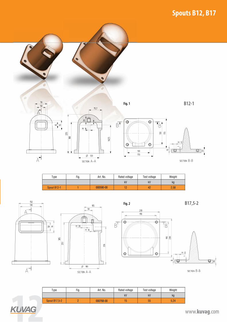
Spout B12, B17
B12-1
B17,5-2
Spout B12Type Fig. Art. No. Rated voltage Test voltage Weight
kV kV kg
Spout B12-1 1 K590 12 42 2,58
Spout B17Type Fig. Art. No. Rated voltage Test voltage Weight
kV kV kg
Spout B17,5-2 2 K768 15 55 5,24
Fig. 1
Fig. 2
000590-00
000768-00
Spouts B12, B17
12 www.kuvag.com
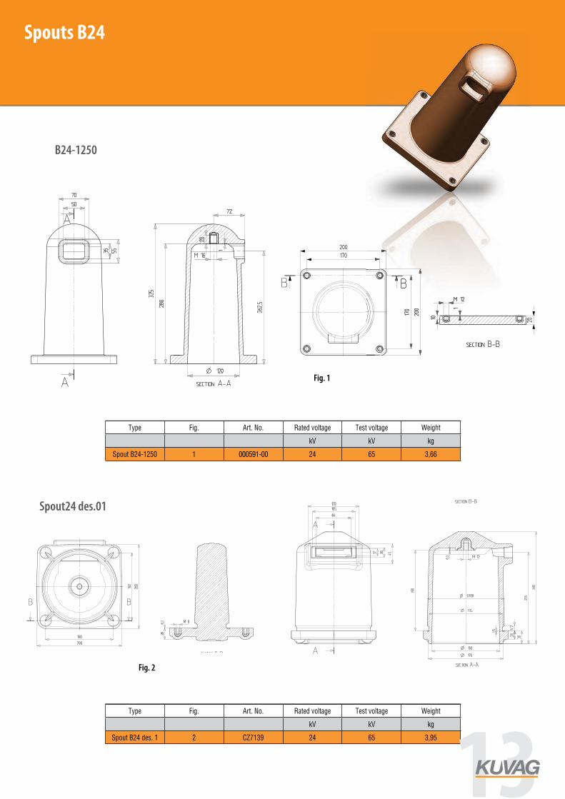
Spout B24
B24-1250
Spout24 des.01
Spout B24Type Fig. Art. No. Rated voltage Test voltage Weight
kV kV kg
Spout B24-1250 1 K591 24 65 3,66
Spout B24Type Fig. Art. No. Rated voltage Test voltage Weight
kV kV kg
Spout B24 des. 1 2 CZ7139 24 65 3,95
Fig. 1
Fig. 2
000591-00
Spouts B24
13

www.kuvag.com
Spout B24, B36
Spout B24-2Type Fig. Art. No. Rated voltage Test voltage Weight
kV kV kg
Spout B24-2 1 K4053 24 65 5,89
Spout B36Type Fig. Art. No. Rated voltage Test voltage Weight
kV kV kg
Spout B36 2 K592 36 85 9,22
Fig. 1
Fig. 2
004053-00
000592-00
Spouts B24, B36
14 www.kuvag.com
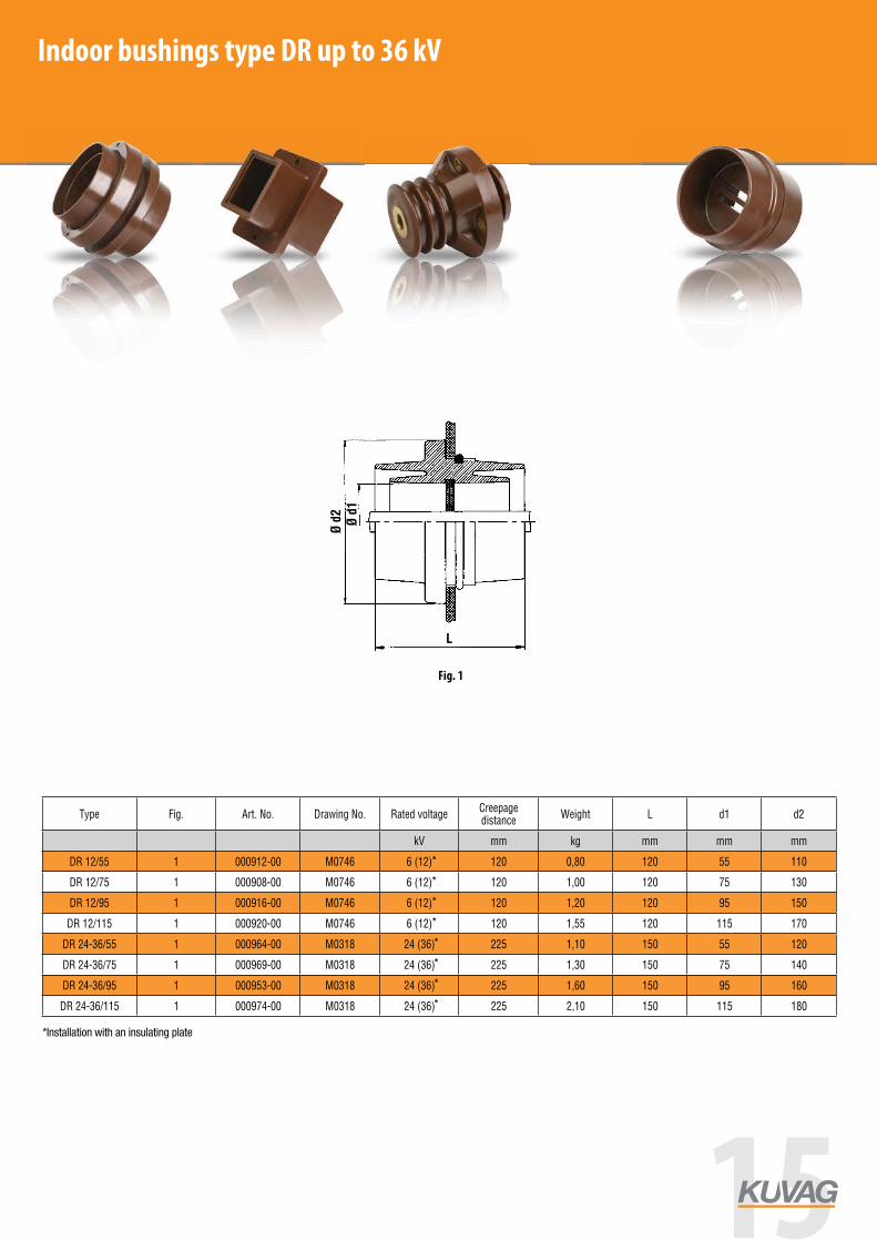
Bushings for indoor applicationsWall bushings are used in many applications for MV switchgears to pass conductors between the individual switchgear sections. Kuvag offers here a rich variety of bushings for different conductor sizes and voltage levels up to 36 kV.
GD and DR bushing types may be supplied upon request with an EPDM insert installed in the bushing centre. Depending on the conductor (busbar) type in use, EPDM inserts already come with the appropriate holes for conductors.
Bushings type DR up to 36 kV
–ËÒ. 1 / Fig. 1 Fig. 1
Bushing up to 36 kV
Type Fig. Art. No. Drawing No. Rated voltageCreepage distance
Weight L d1 d2
kV mm kg mm mm mm
DR 12/55 1 000912-00 M0746 6 (12) 120 0,80 120 55 110
DR 12/75 1 000908-00 M0746 6 (12) 120 1,00 120 75 130
DR 12/95 1 000916-00 M0746 6 (12) 120 1,20 120 95 150
DR 12/115 1 000920-00 M0746 6 (12) 120 1,55 120 115 170
DR 24-36/55 1 000964-00 M0318 24 (36) 225 1,10 150 55 120
DR 24-36/75 1 000969-00 M0318 24 (36) 225 1,30 150 75 140
DR 24-36/95 1 000953-00 M0318 24 (36) 225 1,60 150 95 160
DR 24-36/115 1 000974-00 M0318 24 (36) 225 2,10 150 115 180
*
*
*
*
*
*
*
*
*Installation with an insulating plate
Indoor bushings type DR up to 36 kV
Fig. 1
15
www.kuvag.com
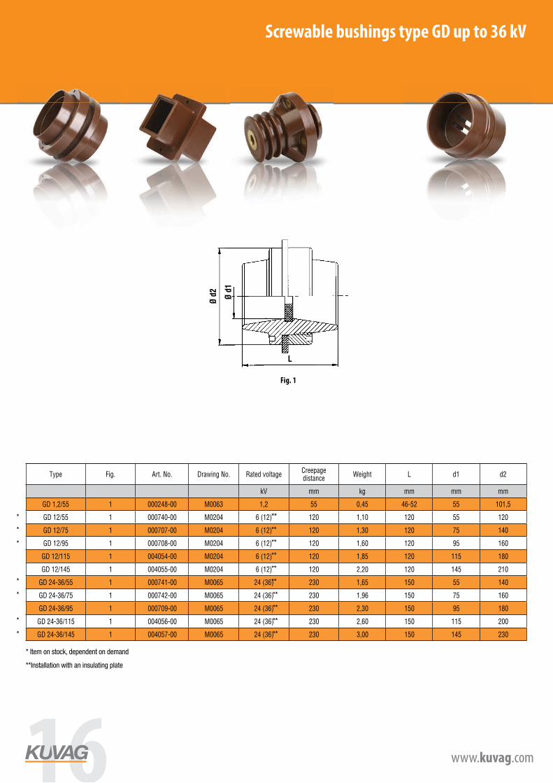
Srewable bushings type GD up to 36 kV
Fig. 1
Bushing up to 36 kV
Type Fig. Art. No. Drawing No. Rated voltageCreepage distance
Weight L d1 d2
kV mm kg mm mm mm
GD 1,2/55 1 000248-00 M0063 1,2 55 0,45 46-52 55 101,5
GD 12/55 1 000740-00 M0204 6 (12) 120 1,10 120 55 120
GD 12/75 1 000707-00 M0204 6 (12) 120 1,30 120 75 140
GD 12/95 1 000708-00 M0204 6 (12) 120 1,60 120 95 160
GD 12/115 1 004054-00 M0204 6 (12) 120 1,85 120 115 180
GD 12/145 1 004055-00 M0204 6 (12) 120 2,20 120 145 210
GD 24-36/55 1 000741-00 M0065 24 (36) 230 1,65 150 55 140
GD 24-36/75 1 000742-00 M0065 24 (36) 230 1,96 150 75 160
GD 24-36/95 1 000709-00 M0065 24 (36) 230 2,30 150 95 180
GD 24-36/115 1 004056-00 M0065 24 (36) 230 2,60 150 115 200
GD 24-36/145 1 004057-00 M0065 24 (36) 230 3,00 150 145 230
Bushings for indoor applicationsWall bushings are used in many applications for MV switchgears to pass conductors between the individual switchgear sections. Kuvag offers here a rich variety of bushings for different conductor sizes and voltage levels up to 36 kV.
GD and DR bushing types may be supplied upon request with an EPDM insert installed in the bushing centre. Depending on the conductor (busbar) type in use, EPDM inserts already come with the appropriate holes for conductors.
Bushings type DR up to 36 kV
–ËÒ. 1 / Fig. 1 Fig. 1
Bushing up to 36 kV
Type Fig. Art. No. Drawing No. Rated voltageCreepage distance
Weight L d1 d2
kV mm kg mm mm mm
DR 12/55 1 000912-00 M0746 6 (12) 120 0,80 120 55 110
DR 12/75 1 000908-00 M0746 6 (12) 120 1,00 120 75 130
DR 12/95 1 000916-00 M0746 6 (12) 120 1,20 120 95 150
DR 12/115 1 000920-00 M0746 6 (12) 120 1,55 120 115 170
DR 24-36/55 1 000964-00 M0318 24 (36) 225 1,10 150 55 120
DR 24-36/75 1 000969-00 M0318 24 (36) 225 1,30 150 75 140
DR 24-36/95 1 000953-00 M0318 24 (36) 225 1,60 150 95 160
DR 24-36/115 1 000974-00 M0318 24 (36) 225 2,10 150 115 180
www.kuvag.com
Srewable bushings type GD up to 36 kV
Fig. 1
Bushing up to 36 kV
Type Fig. Art. No. Drawing No. Rated voltageCreepage distance
Weight L d1 d2
kV mm kg mm mm mm
GD 1,2/55 1 000248-00 M0063 1,2 55 0,45 46-52 55 101,5
GD 12/55 1 000740-00 M0204 6 (12) 120 1,10 120 55 120
GD 12/75 1 000707-00 M0204 6 (12) 120 1,30 120 75 140
GD 12/95 1 000708-00 M0204 6 (12) 120 1,60 120 95 160
GD 12/115 1 004054-00 M0204 6 (12) 120 1,85 120 115 180
GD 12/145 1 004055-00 M0204 6 (12) 120 2,20 120 145 210
GD 24-36/55 1 000741-00 M0065 24 (36) 230 1,65 150 55 140
GD 24-36/75 1 000742-00 M0065 24 (36) 230 1,96 150 75 160
GD 24-36/95 1 000709-00 M0065 24 (36) 230 2,30 150 95 180
GD 24-36/115 1 004056-00 M0065 24 (36) 230 2,60 150 115 200
GD 24-36/145 1 004057-00 M0065 24 (36) 230 3,00 150 145 230
**
**
**
**
**
**
**
**
**
**
* Item on stock, dependent on demand
**Installation with an insulating plate
*
*
*
*
*
*
*
Screwable bushings type GD up to 36 kV
Fig. 1
16 www.kuvag.com

Bushings type DGFI up to 36 kV
Fig. 1
Bushing up to 36 kV
Type Fig. Art. No. Drawing No. Rated voltageCreepage distance
Weight L d1 d2
kV mm kg mm mm mm
DGFI 12/55 1 000323-00 M0066 12 140 3,00 285 55 100
DGFI 12/75 1 000324-00 M0066 12 140 3,30 285 75 120
DGFI 12/95 1 000325-00 M0066 12 140 3,60 285 95 140
DGFI 12/145 1 000326-00 M0066 12 140 4,20 285 145 190
DGFI 24/55 1 000327-00 M0067 24 250 6,50 440 55 120
DGFI 24/75 1 000328-00 M0067 24 250 7,20 440 75 140
DGFI 24/95 1 000329-00 M0067 24 250 7,80 440 95 160
GDFI 36/55 1 000330-00 M0068 36 350 9,40 570 55 134
DGFI 36/75 1 000331-00 M0068 36 350 10,20 570 75 154
DGFI 36/115 1 000720-00 M0068 36 350 15,30 570 115 194
Bushings for indoor applicationsWall bushings are used in many applications for MV switchgears to pass conductors between the individual switchgear sections. Kuvag offers here a rich variety of bushings for different conductor sizes and voltage levels up to 36 kV.
GD and DR bushing types may be supplied upon request with an EPDM insert installed in the bushing centre. Depending on the conductor (busbar) type in use, EPDM inserts already come with the appropriate holes for conductors.
Bushings type DR up to 36 kV
–ËÒ. 1 / Fig. 1 Fig. 1
Bushing up to 36 kV
Type Fig. Art. No. Drawing No. Rated voltageCreepage distance
Weight L d1 d2
kV mm kg mm mm mm
DR 12/55 1 000912-00 M0746 6 (12) 120 0,80 120 55 110
DR 12/75 1 000908-00 M0746 6 (12) 120 1,00 120 75 130
DR 12/95 1 000916-00 M0746 6 (12) 120 1,20 120 95 150
DR 12/115 1 000920-00 M0746 6 (12) 120 1,55 120 115 170
DR 24-36/55 1 000964-00 M0318 24 (36) 225 1,10 150 55 120
DR 24-36/75 1 000969-00 M0318 24 (36) 225 1,30 150 75 140
DR 24-36/95 1 000953-00 M0318 24 (36) 225 1,60 150 95 160
DR 24-36/115 1 000974-00 M0318 24 (36) 225 2,10 150 115 180
Indoor bushings type DGFI 12 kV - 36 kV
Fig. 1
Bushings type DGFI up to 36 kV
Fig. 1
Bushing up to 36 kV
Type Fig. Art. No. Drawing No. Rated voltageCreepage distance
Weight L d1 d2
kV mm kg mm mm mm
DGFI 12/55 1 000323-00 M0066 12 140 3,00 285 55 100
DGFI 12/75 1 000324-00 M0066 12 140 3,30 285 75 120
DGFI 12/95 1 000325-00 M0066 12 140 3,60 285 95 140
DGFI 12/145 1 000326-00 M0066 12 140 4,20 285 145 190
DGFI 24/55 1 000327-00 M0067 24 250 6,50 440 55 120
DGFI 24/75 1 000328-00 M0067 24 250 7,20 440 75 140
DGFI 24/95 1 000329-00 M0067 24 250 7,80 440 95 160
GDFI 36/55 1 000330-00 M0068 36 350 9,40 570 55 134
DGFI 36/75 1 000331-00 M0068 36 350 10,20 570 75 154
DGFI 36/115 1 000720-00 M0068 36 350 15,30 570 115 194
17
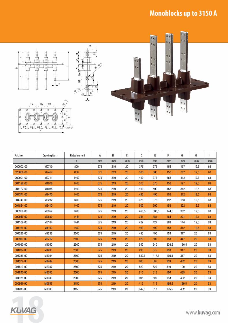
Monoblocks up to 3150 A
Art. No. Drawing No. Rated current A B C D E F G H I
A mm mm mm mm mm mm mm mm mm
000902-00 M0710 800 575 219 20 375 375 158 197 12,5 63
020088-00 M2467 800 575 219 20 380 380 158 202 12,5 63
000901-00 M0711 1400 575 219 20 490 375 158 312 12,5 63
004126-00 M1078 1400 575 219 20 375 375 158 197 12,5 63
004127-00 M1085 1400 575 219 20 490 490 158 312 12,5 63
004371-00 M1470 1400 575 219 20 490 490 158 312 12,5 63
004743-00 M2232 1400 575 219 20 375 375 197 158 12,5 63
004824-00 M2410 1400 575 219 20 500 500 158 322 12,5 63
000950-00 M0857 1400 575 219 20 466,5 383,5 144,5 302 12,5 63
000949-00 M0859 1444 575 219 20 385 385 164 201 12,5 63
004109-00 M0164 1444 575 219 20 427 427 263 144 12,5 63
004161-00 M1160 1450 575 219 20 490 490 158 312 12,5 63
004282-00 M1236 2500 575 219 20 490 490 153 317 20 63
000903-00 M0712 2100 575 219 20 620 505 153 447 20 63
004090-00 M1050 2500 575 219 20 540 540 339,5 180,5 20 63
004207-00 M1205 2500 575 219 20 490 375 153 317 20 63
004281-00 M1304 2500 575 219 20 532,5 417,5 195,5 317 20 63
004372-00 M1469 2500 575 219 20 605 605 153 432 20 63
004819-00 M2387 2500 575 219 20 529 529 319 190 20 63
004820-00 M2385 2500 575 219 20 615 615 160 435 20 63
004125-00 M1083 2600 575 219 20 605 605 153 432 20 63
000951-00 M0858 3150 575 219 20 415 415 195,5 199,5 20 63
004280-00 M1303 3150 575 219 20 647,5 317 195,5 452 20 63
18 www.kuvag.com
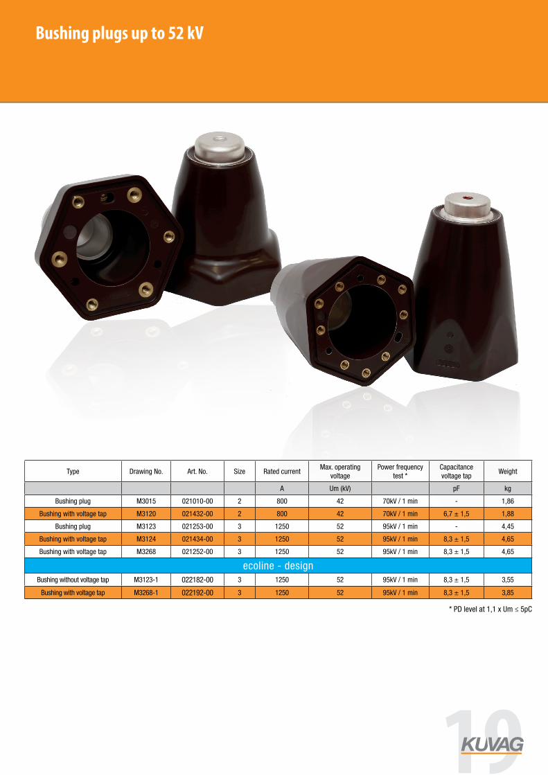
Bushing plugs up to 52 kV
* PD level at 1,1 x Um ≤ 5pC
Type Drawing No. Art. No. Size Rated currentMax. operating
voltagePower frequency
test *Capacitance voltage tap
Weight
A Um (kV) pF kg
Bushing plug M3015 021010-00 2 800 42 70kV / 1 min - 1,86
Bushing with voltage tap M3120 021432-00 2 800 42 70kV / 1 min 6,7 ± 1,5 1,88
Bushing plug M3123 021253-00 3 1250 52 95kV / 1 min - 4,45
Bushing with voltage tap M3124 021434-00 3 1250 52 95kV / 1 min 8,3 ± 1,5 4,65
Bushing with voltage tap M3268 021252-00 3 1250 52 95kV / 1 min 8,3 ± 1,5 4,65
ecoline - designBushing without voltage tap M3123-1 022182-00 3 1250 52 95kV / 1 min 8,3 ± 1,5 3,55
Bushing with voltage tap M3268-1 022192-00 3 1250 52 95kV / 1 min 8,3 ± 1,5 3,85
19

Transformer bushings up to 36 kV
Type Drawing No. Art. No. Interface Rated voltage Rated current Thread A B Weight
kV A mm mm kg
TB 24-250-R M3188 021353-00 A 24 250 M10 189,5 73 1,06
TB 24-250-N M3187 021352-00 A 24 250 M10 224,5 108 1,20
TB 24-250-L M3186 021351-00 A 24 250 M10 284,5 168 1,43
TB 36-630 M3185 021350-00 C 36 630 M16 330 150 2,50
20 www.kuvag.com
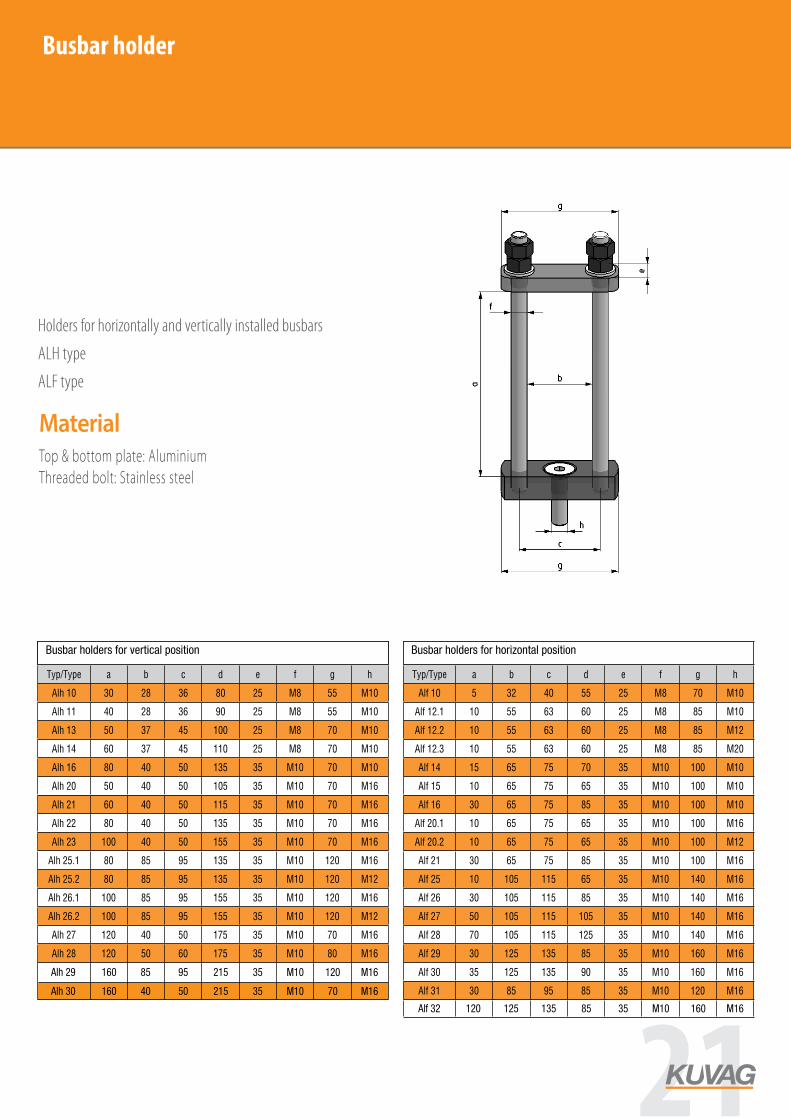
Busbar holder
AccessoriesHolders for horizontally and vertically installed busbars
ALH type
ALF type
Accessories
Busbar holders for vertical positionTyp/Type a b c d e f g h
Alh 10 30 28 36 80 25 M8 55 M10
Alh 11 40 28 36 90 25 M8 55 M10
Alh 13 50 37 45 100 25 M8 70 M10
Alh 14 60 37 45 110 25 M8 70 M10
Alh 16 80 40 50 135 35 M10 70 M10
Alh 20 50 40 50 105 35 M10 70 M16
Alh 21 60 40 50 115 35 M10 70 M16
Alh 22 80 40 50 135 35 M10 70 M16
Alh 23 100 40 50 155 35 M10 70 M16
Alh 25.1 80 85 95 135 35 M10 120 M16
Alh 25.2 80 85 95 135 35 M10 120 M12
Alh 26.1 100 85 95 155 35 M10 120 M16
Alh 26.2 100 85 95 155 35 M10 120 M12
Alh 27 120 40 50 175 35 M10 70 M16
Alh 28 120 50 60 175 35 M10 80 M16
Busbar holders for horiznotal positionTyp/Type a b c d e f g h
Alf 10 5 32 40 55 25 M8 70 M10
Alf 12.1 10 55 63 60 25 M8 85 M10
Alf 12.2 10 55 63 60 25 M8 85 M12
Alf 12.3 10 55 63 60 25 M8 85 M20
Alf 14 15 65 75 70 35 M10 100 M10
Alf 15 10 65 75 65 35 M10 100 M10
Alf 16 30 65 75 85 35 M10 100 M10
Alf 20.1 10 65 75 65 35 M10 100 M16
Alf 20.2 10 65 75 65 35 M10 100 M12
Alf 21 30 65 75 85 35 M10 100 M16
Alf 25 10 105 115 65 35 M10 140 M16
Alf 26 30 105 115 85 35 M10 140 M16
Alf 27 50 105 115 105 35 M10 140 M16
Alf 28 70 105 115 125 35 M10 140 M16
Alf 29 30 125 135 85 35 M10 160 M16
Alf 30 35 125 135 90 35 M10 160 M16
Alf 31 30 85 95 85 35 M10 120 M16
MaterialTop & bottom plate: AluminiumThreaded bolt: Stainless steel
Alh 29
Alf 32
Alh 30
160
120
160
85
125
40
95
135
50
215
85
215
35
35
35
M10
M10
M10
120
160
70
M16
M16
M16
Busbar holders for vertical position Busbar holders for horizontal position
21
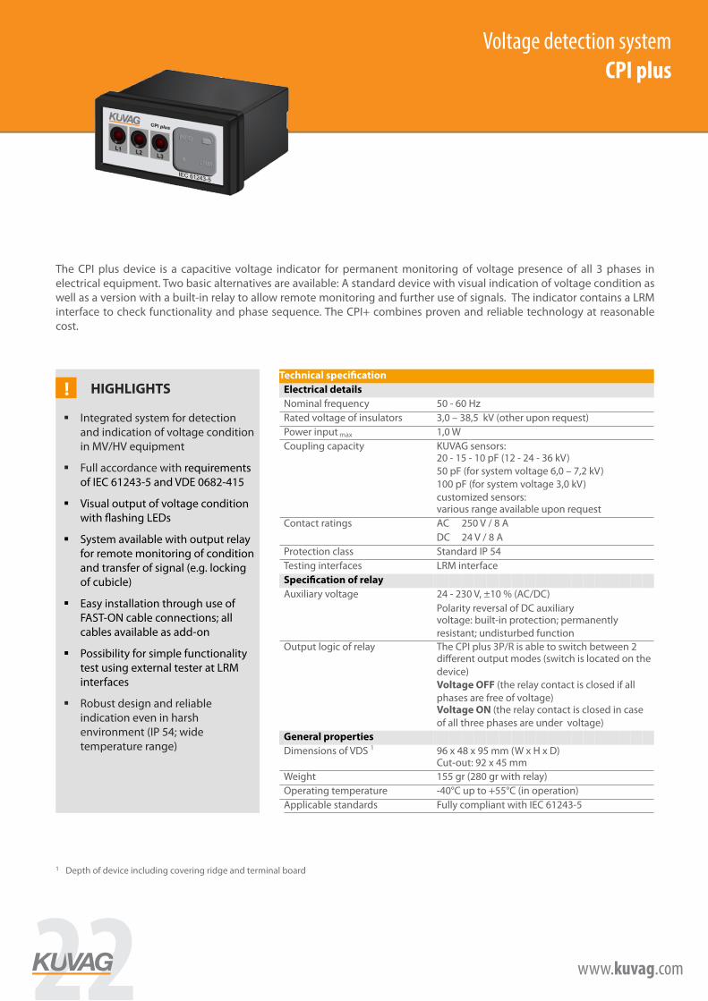
Voltage detection system CPI plus (w/o relay)
! HIGHLIGHTS
§ Integrated system for detection and indication of voltage condition in MV/HV equipment
§ Full accordance with requirements of IEC 61243-5 and VDE 0682-415
§ Visual output of voltage condition with flashing LEDs
§ System available with output relay for remote monitoring of condition and transfer of signal (e.g. locking of cubicle)
§ Easy installation through use of FAST-ON cable connections; all cables available as add-on
§ Possibility for simple functionality test using external tester at LRM interfaces
§ Robust design and reliable indication even in harsh environment (IP 54; wide temperature range)
Technical specification Electrical details Nominal frequency 50 - 60 Hz Rated voltage of insulators 3,0 – 38,5 kV (other upon request) Power input max 1,0 W Coupling capacity KUVAG sensors:
20 - 15 - 10 pF (12 - 24 - 36 kV) 50 pF (for system voltage 6,0 – 7,2 kV) 100 pF (for system voltage 3,0 kV) customized sensors: various range available upon request
Contact ratings AC 250 V / 8 A DC 24 V / 8 A Protection class Standard IP 54 Testing interfaces LRM interface
Specification of relay Auxiliary voltage 24 - 230 V, ±10 % (AC/DC)
Polarity reversal of DC auxiliary voltage: built-in protection; permanently resistant; undisturbed function
Output logic of relay
The CPI plus 3P/R is able to switch between 2 different output modes (switch is located on the device) Voltage OFF (the relay contact is closed if all phases are free of voltage) Voltage ON (the relay contact is closed in case of all three phases are under voltage)
General properties Dimensions of VDS 1 96 x 48 x 95 mm (W x H x D)
Cut-out: 92 x 45 mm Weight 155 gr (280 gr with relay) Operating temperature -40°C up to +55°C (in operation) Applicable standards Fully compliant with IEC 61243-5
The CPI plus device is a capacitive voltage indicator for permanent monitoring of voltage presence of all 3 phases in electrical equipment. Two basic alternatives are available: A standard device with visual indication of voltage condition as well as a version with a built-in relay to allow remote monitoring and further use of signals. The indicator contains a LRM interface to check functionality and phase sequence. The CPI+ combines proven and reliable technology at reasonable cost.
1 Depth of device including covering ridge and terminal board
Voltage detection systemCPI plus
22 www.kuvag.com

Voltage detection system KUVIN (w/o relay)
! HIGHLIGHTS
§ New voltage detection system with LCD display and integrated LRM interface
§ Full accordance with all requirements of IEC 61243-5 and VDE 0682-415
§ Completely free of maintenance, operating test integrated into device (no external testing device needed)
§ Additional visual output in case of failure mode in switchgear with LEDs
§ Integrated relay for remote monitoring of condition and transfer of signal
§ Coupling capacity can be configured through built-in switching module (10 pre-defined ranges)
§ Easy installation through use of FAST-ON cable connections; all cables available as add-on.
Technical specification Electrical details
Nominal frequency 50 - 60 Hz Rated voltage of insulators 6,0 - 72,0 kV Power input max 1,0 W System rated voltage 1 6,0 kV to 72,0 kV Coupling capacity Capacity configured directly at device
standard range from 200 kVpF – 4.000 kVpF Other capacities available upon request
Contact ratings AC 250 V / 8 A DC 24 V / 8 A Protection class IP 54 Testing interfaces LRM interface
Specification of relay Auxiliary voltage 24 - 230 V, ±10 %
Polarity reversal of DC auxiliary voltage: built-in protection; permanently resistant; undisturbed function
Output logic Available options for output: § Fixed output logic (HV-on or HV-off) § 2 interchangeable operating modes (HV-on and HV-off; not simultaneously) § 2 operating modes in one device (with 2 integrated output relays)
General properties Dimensions of VDS 2 96 x 48 x 30 mm (W x H x D) Cut-out: 92 x 45 mm Weight app. 220 g Operating temperature -30°C to +60°C (in operation)
-40°C to +70°C (for storage) Applicable norms Fully compliant with IEC 61243-5
1 If suitable coupling electrodes are available, range of rated voltage can be extended 2 Depth of device including covering ridge and terminal board
The KUVIN device is a capacitive voltage indicator with an integrated LCD display and LRM interface for permanent monitoring of voltage presence of all 3 phases in electrical equipment. Two basic alternatives are available: A standard device with visual indication of voltage condition as well as a version with a built-in relay to allow remote monitoring and further use of signals. The indicator is free of maintenance and combines proven and reliable technology at reasonable cost.
Voltage detection systemKUVIN
23
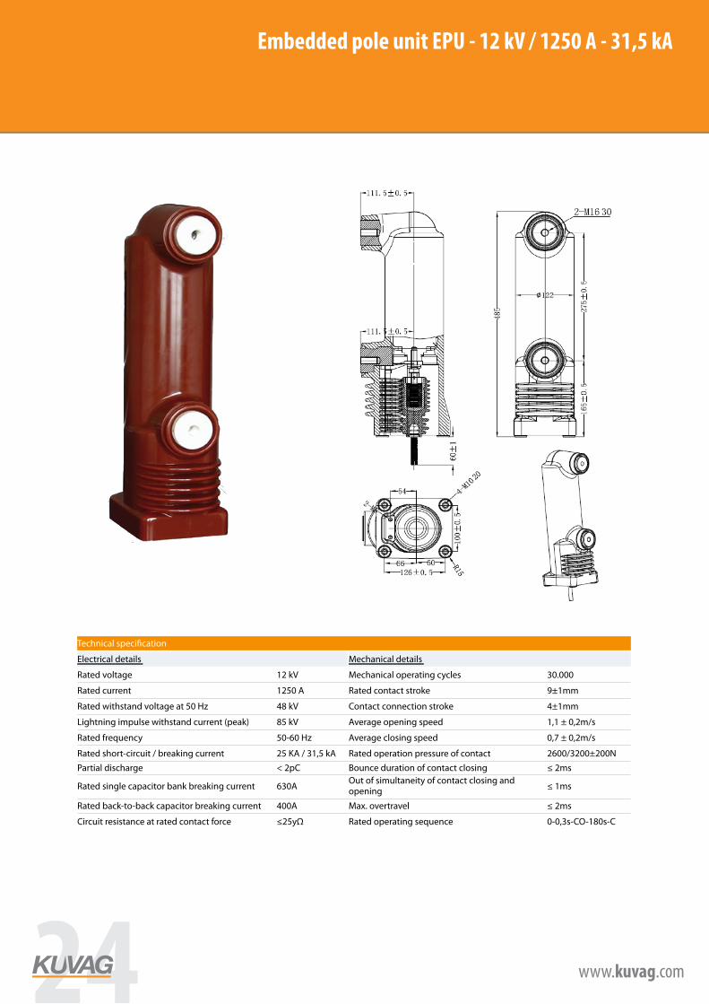
Embedded pole unit EPU - 12 kV / 1250 A - 31,5 kAEmbedded pole unit EPU - 12kV/1250A-31,5kA
Technical specification
Electrical details Mechanical details
Rated voltage 12 kV Mechanical operating cycles 30.000
Rated current 1250 A Rated contact stroke 9±1mm
Rated withstand voltage at 50 Hz 48 kV Contact connection stroke 4±1mm
Lightning impulse withstand current (peak) 85 kV Average opening speed 1,1 ± 0,2m/s
Rated frequency 50-60 Hz Average closing speed 0,7 ± 0,2m/s
Rated short-circuit / breaking current 25 KA / 31,5 kA Rated operation pressure of contact 2600/3200±200N
Partial discharge < 2pC Bounce duration of contact closing ≤ 2ms
Rated single capacitor bank breaking current 630A Out of simultaneity of contact closing and opening ≤ 1ms
Rated back-to-back capacitor breaking current 400A Max. overtravel ≤ 2ms
Circuit resistance at rated contact force ≤25yΩ Rated operating sequence 0-0,3s-CO-180s-C
24 www.kuvag.com
www.kuvag.com
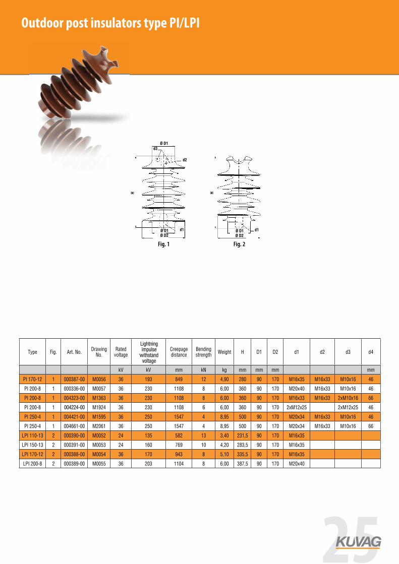
Outdoor insulators and bushings Outdoor insulators are manufactured of special hydrophobic resins to provide for the minimum absorption capacity of such insulators. Another relevant aspect is the high resistance to UV radiation and heat stability. This is why such insulators are widely used in outdoor isolators, lines and transport applications, for instance.
Fig. 1 Fig. 2
Outdoor post insulators
Type Fig. Art. No.Drawing
No.Rated
voltage
Lighting impulse
withstand voltage
Creepage distance
Bending strength
Weight H D1 D2 d1 d2 d3 d4
kV kV mm kN kg mm mm mm mm
PI 170-12 1 000387-00 M0056 36 193 849 12 4,90 280 90 170 M16x35 M16x33 M10x16 46
PI 200-8 1 000336-00 M0057 36 230 1108 8 6,00 360 90 170 M20x40 M16x33 M10x16 46
PI 200-8 1 004323-00 M1363 36 230 1108 8 6,00 360 90 170 M16x33 M16x33 2xM10x16 66
PI 200-8 1 004424-00 M1924 36 230 1108 8 6,00 360 90 170 2xM12x25 2xM12x25 46
PI 250-4 1 004421-00 M1595 36 250 1547 4 8,95 500 90 170 M20x34 M16x33 M10x16 46
PI 250-4 1 004661-00 M2061 36 250 1547 4 8,95 500 90 170 M20x34 M16x33 M10x16 66
LPI 110-13 2 000390-00 M0052 24 135 582 13 3,40 231,5 90 170 M16x35
LPI 150-13 2 000391-00 M0053 24 160 769 10 4,20 283,5 90 170 M16x35
LPI 170-12 2 000388-00 M0054 36 170 943 8 5,10 335,5 90 170 M16x35
LPI 200-8 2 000389-00 M0055 36 203 1104 8 6,00 387,5 90 170 M20x40
Outdoor post insulators type PI/LPI
www.kuvag.com
Outdoor insulators and bushings Outdoor insulators are manufactured of special hydrophobic resins to provide for the minimum absorption capacity of such insulators. Another relevant aspect is the high resistance to UV radiation and heat stability. This is why such insulators are widely used in outdoor isolators, lines and transport applications, for instance.
Fig. 1 Fig. 2
Outdoor post insulators
Type Fig. Art. No.Drawing
No.Rated
voltage
Lighting impulse
withstand voltage
Creepage distance
Bending strength
Weight H D1 D2 d1 d2 d3 d4
kV kV mm kN kg mm mm mm mm
PI 170-12 1 000387-00 M0056 36 193 849 12 4,90 280 90 170 M16x35 M16x33 M10x16 46
PI 200-8 1 000336-00 M0057 36 230 1108 8 6,00 360 90 170 M20x40 M16x33 M10x16 46
PI 200-8 1 004323-00 M1363 36 230 1108 8 6,00 360 90 170 M16x33 M16x33 2xM10x16 66
PI 200-8 1 004424-00 M1924 36 230 1108 8 6,00 360 90 170 2xM12x25 2xM12x25 46
PI 250-4 1 004421-00 M1595 36 250 1547 4 8,95 500 90 170 M20x34 M16x33 M10x16 46
PI 250-4 1 004661-00 M2061 36 250 1547 4 8,95 500 90 170 M20x34 M16x33 M10x16 66
LPI 110-13 2 000390-00 M0052 24 135 582 13 3,40 231,5 90 170 M16x35
LPI 150-13 2 000391-00 M0053 24 160 769 10 4,20 283,5 90 170 M16x35
LPI 170-12 2 000388-00 M0054 36 170 943 8 5,10 335,5 90 170 M16x35
LPI 200-8 2 000389-00 M0055 36 203 1104 8 6,00 387,5 90 170 M20x40
6004224-00
Lightning impulse
withstand voltage
25
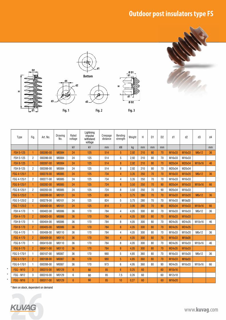
Outdoor post insulators type FSOutdoor insulators type FS
–ËÒ. 1 / Fig. 1 –ËÒ. 2 / Fig. 2 –ËÒ. 3 / Fig. 3
3
/ bottom fitting
Fig. 1 Fig. 2 Fig. 3
Bottom fittings
Outdoor post insulators
Type Fig. Art. No.Drawing
No.Rated
voltage
Lighting impulse
withstand voltage
Creepage distance
Bending strength
Weight H D1 D2 d1 d2 d3 d4
kV kV mm kN kg mm mm mm mm
FSH 5-125 1 000395-00 M0084 24 125 514 5 2,92 210 80 70 M16x33 M16x33 M6x12 36
FSH 5-125 2 000396-00 M0084 24 125 514 5 2,92 210 80 70 M16x33 M16x33
FSH 8-125 1 000397-00 M0084 24 125 514 8 2,92 210 80 70 M20x34 M20x34 M10x16 46
FSH 8-125 2 000398-00 M0084 24 125 514 8 2,92 210 80 70 M20x34 M20x34
FSG 4-125/1 1 000276-00 M0085 24 125 734 4 3,35 250 70 70 M16x33 M10x20 M6x12 36
FSG 4-125/1 2 000277-00 M0085 24 125 734 4 3,35 250 70 70 M16x33 M16x33
FSG 8-125/1 1 000282-00 M0085 24 125 724 8 3,50 250 70 90 M20x34 M16x33 M10x16 66
FSG 8-125/1 2 000283-00 M0085 24 125 724 8 3,50 250 70 90 M20x34 M16x33
FSG 5-125/2 1 000399-00 M0101 24 125 824 5 3,75 280 70 70 M16x33 M10x20 M6x12 36
FSG 5-125/2 2 000278-00 M0101 24 125 824 5 3,75 280 70 70 M16x33
FSG 7-125/2 1 000400-00 M0101 24 125 814 7 3,90 280 70 90 M20x34 M16x33 M10x16 66
FSH 4-170 1 000402-00 M0086 36 170 784 4 4,05 300 80 70 M16x33 M16x33 M6x12 36
FSH 4-170 2 000403-00 M0086 36 170 784 4 4,05 300 80 70 M16x33 M16x33
FSH 8-170 1 000404-00 M0086 36 170 784 8 4,05 300 80 70 M24x35 M24x35 M10x16 46
FSH 8-170 2 000405-00 M0086 36 170 784 8 4,05 300 80 70 M24x35 M24x35
FSG 4-170 1 000408-00 M0110 36 170 784 4 4,05 300 80 70 M16x33 M10x20 M6x12 36
FSG 4-170 2 000409-00 M0110 36 170 784 4 4,05 300 80 70 M16x33 M16x33
FSG 8-170 1 000410-00 M0110 36 170 784 8 4,05 300 80 70 M24x35 M16x33 M10x16 46
FSG 8-170 2 000411-00 M0110 36 170 784 8 4,05 300 80 70 M24x35 M16x33
FSG 5-170/1 1 000107-00 M0087 36 170 980 5 4,85 360 80 70 M16x33 M10x20 M6x12 36
FSG 5-170/1 2 000108-00 M0087 36 170 980 5 4,85 360 80 70 M16x33 M16x33
FSG 6-170/1 1 000288-00 M0087 36 170 973 6 4,95 360 80 90 M24x35 M16x33 M10x16 66
FSG - M10 3 000315-00 M0129 6 85 6 0,25 60 34 60 M10x16
FSG - M12 3 000316-00 M0129 6 85 7,5 0,26 60 34 60 M12x18
FSG - M16 3 000317-00 M0129 6 85 10 0,27 60 34 60 M16x20
60
60
60
M10x20
M16x33
M10x20
* Item on stock, dependent on demand
*
*
*
www.kuvag.com
Indoor insulators up to 7,2 kV
epoxy resin indoor - post insulators up to 7,2kV
–ËÒ. 1 / Fig. 1 ÌËÊÌ Á‡ÍÂÔÎÂÌË / bottom fitting –ËÒ. 2 / Fig. 2 –ËÒ. 3 / Fig. 3 –ËÒ. 4 / Fig. 4
Post insulators up to 7,2 kV
Type Fig. Art. No. Drawing No.Creepage distance
Bending strength
H D d1 d2 d3 d4 WeightMaximum
operating voltage
mm > kN mm mm mm kg kV
SGA 1/40 1 000491-00 M0130 67 5 40 60 M10x12 M10x12 M6x5 3 36 0,18 1
SGA 1/40 2 000109-00 M0130 67 5 40 60 M10x12 M10x12 0,18 1
SGA 1/45 3 000113-00 M0130 72 5 45 60 M10x12 M10x12 M6x8 3 36 0,22 1
SGA 1/50 2 000464-00 M0130 77 5 50 60 M12x18 M12x18 0,26 1
SGA 3/60 1 000314-00 M0130 87 5 60 60 M12x18 M12x18 M6x12 36 0,31 3
SGA 3/60 2 000311-00 M0130 87 5 60 60 M12x18 M12x18 0,31 3
SGB 1R 3 000114-00 M0131 60 7,5 45 66 M16x15 M16x15 M10x16 46 0,34 1
SGC 1R 3 000115-00 M0132 59 12,5 45 86 M16x15 M16x15 M10x16 66 0,54 1
SGB 3/65 2 000312-00 M0134 85 7,5 65 66 M16x20 M16x20 0,46 3
SGB 3/70 1 000117-00 M0134 90 7,5 70 66 M16x20 M16x20 M10x16 46 0,49 3
SGB 3/70 2 000653-00 M0134 90 7,5 70 66 M16x20 M16x20 0,49 3
SGB 3/87 1 000333-00 M1169 107 7,5 87 75 M16x20 M16x20 M10x16 46 0,57 7,2
SGB 3/87 2 000313-00 M0134 107 7,5 87 66 M16x20 M16x20 0,57 7,2
SGD 7,2N 2 000321-00 M0136 115 20 80 88 M16x20 M16x20 1,22 7,2
JO6-60 So H65 1423 NP_111_2498_1 105 8,2 65 55 M12x18 M12x18 0,23 3
JO6-60 So H95 1424 NP_111_2497_1 135 5,3 95 55 M12x18 M12x18 0,33 3
Fig. 1 Fig. 2 Fig. 3 Fig. 4Bottom fittings
Lightning impulse
withstand voltage
Outdoor insulators type FS
–ËÒ. 1 / Fig. 1 –ËÒ. 2 / Fig. 2 –ËÒ. 3 / Fig. 3
3
/ bottom fitting
Fig. 1 Fig. 2 Fig. 3
Bottom fittings
Outdoor post insulators
Type Fig. Art. No.Drawing
No.Rated
voltage
Lighting impulse
withstand voltage
Creepage distance
Bending strength
Weight H D1 D2 d1 d2 d3 d4
kV kV mm kN kg mm mm mm mm
FSH 5-125 1 000395-00 M0084 24 125 514 5 2,92 210 80 70 M16x33 M16x33 M6x12 36
FSH 5-125 2 000396-00 M0084 24 125 514 5 2,92 210 80 70 M16x33 M16x33
FSH 8-125 1 000397-00 M0084 24 125 514 8 2,92 210 80 70 M20x34 M20x34 M10x16 46
FSH 8-125 2 000398-00 M0084 24 125 514 8 2,92 210 80 70 M20x34 M20x34
FSG 4-125/1 1 000276-00 M0085 24 125 734 4 3,35 250 70 70 M16x33 M10x20 M6x12 36
FSG 4-125/1 2 000277-00 M0085 24 125 734 4 3,35 250 70 70 M16x33 M16x33
FSG 8-125/1 1 000282-00 M0085 24 125 724 8 3,50 250 70 90 M20x34 M16x33 M10x16 66
FSG 8-125/1 2 000283-00 M0085 24 125 724 8 3,50 250 70 90 M20x34 M16x33
FSG 5-125/2 1 000399-00 M0101 24 125 824 5 3,75 280 70 70 M16x33 M10x20 M6x12 36
FSG 5-125/2 2 000278-00 M0101 24 125 824 5 3,75 280 70 70 M16x33
FSG 7-125/2 1 000400-00 M0101 24 125 814 7 3,90 280 70 90 M20x34 M16x33 M10x16 66
FSH 4-170 1 000402-00 M0086 36 170 784 4 4,05 300 80 70 M16x33 M16x33 M6x12 36
FSH 4-170 2 000403-00 M0086 36 170 784 4 4,05 300 80 70 M16x33 M16x33
FSH 8-170 1 000404-00 M0086 36 170 784 8 4,05 300 80 70 M24x35 M24x35 M10x16 46
FSH 8-170 2 000405-00 M0086 36 170 784 8 4,05 300 80 70 M24x35 M24x35
FSG 4-170 1 000408-00 M0110 36 170 784 4 4,05 300 80 70 M16x33 M10x20 M6x12 36
FSG 4-170 2 000409-00 M0110 36 170 784 4 4,05 300 80 70 M16x33 M16x33
FSG 8-170 1 000410-00 M0110 36 170 784 8 4,05 300 80 70 M24x35 M16x33 M10x16 46
FSG 8-170 2 000411-00 M0110 36 170 784 8 4,05 300 80 70 M24x35 M16x33
FSG 5-170/1 1 000107-00 M0087 36 170 980 5 4,85 360 80 70 M16x33 M10x20 M6x12 36
FSG 5-170/1 2 000108-00 M0087 36 170 980 5 4,85 360 80 70 M16x33 M16x33
FSG 6-170/1 1 000288-00 M0087 36 170 973 6 4,95 360 80 90 M24x35 M16x33 M10x16 66
FSG - M10 3 000315-00 M0129 6 85 6 0,25 60 34 60 M10x16
FSG - M12 3 000316-00 M0129 6 85 7,5 0,26 60 34 60 M12x18
FSG - M16 3 000317-00 M0129 6 85 10 0,27 60 34 60 M16x20
26 www.kuvag.com
www.kuvag.com
Fig. 1 Fig. 2
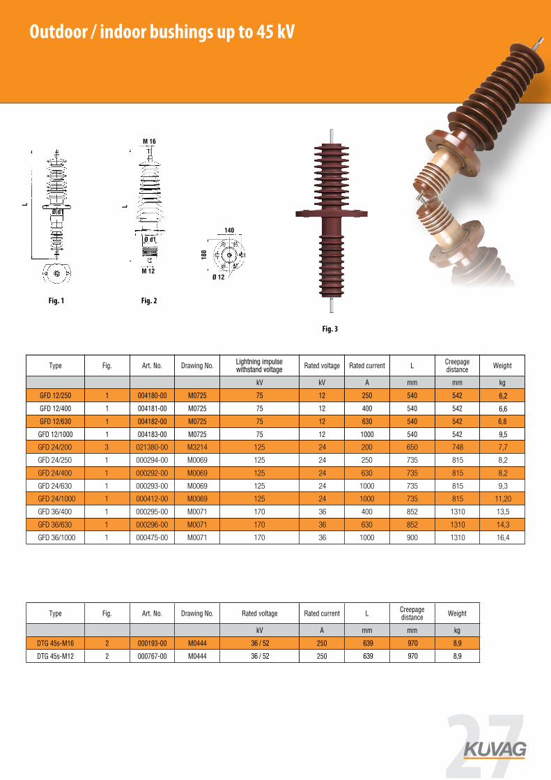
Outdoor / indoor bushings with bolt
Type Fig. Art. No. Drawing No.Lighting impulse withstand
voltageRated voltage Rated current L
Creepage distance
Weight
kV kV A mm mm kg
GFD 12/250 1 004180-00 M0725 75 12 250 540 542 6
GFD 12/400 1 004181-00 M0725 75 12 400 540 542 6,4
GFD 12/630 1 004182-00 M0725 75 12 630 540 542 6,8
GFD 12/1000 1 004183-00 M0725 75 12 1000 540 542 9,1
GFD 24/250 1 000294-00 M0069 125 24 250 740 815 8,2
GFD 24/400 1 000292-00 M0069 125 24 400 740 815 8,8
GFD 24/630 1 000293-00 M0069 125 24 630 740 815 9,3
GFD 24/1000 1 000412-00 M0069 125 24 1000 740 815 10,5
GFD 36/400 1 000295-00 M0071 170 36 400 852 1310 13,5
GFD 36/630 1 000296-00 M0071 170 36 630 852 1310 14,3
GFD 36/1000 1 000475-00 M0071 170 36 1000 900 1310 16,4
Transformer bushings
Type Fig. Art. No. Drawing No. Rated voltageCreepage distance
Rated current LCreepage distance
Weight
kV kV A mm mm kg
DTG 45s-M16 2 000193-00 M0444 45 970 250 8,9 639 86
DTG 45s-M12 2 000767-00 M0444 45 970 250 8,9 639 86
Outdoor / indoor bushings up to 45 kV
www.kuvag.com
Fig. 1 Fig. 2
Outdoor / indoor bushings with bolt
Type Fig. Art. No. Drawing No.Lighting impulse withstand
voltageRated voltage Rated current L
Creepage distance
Weight
kV kV A mm mm kg
GFD 12/250 1 004180-00 M0725 75 12 250 540 542 6
GFD 12/400 1 004181-00 M0725 75 12 400 540 542 6,4
GFD 12/630 1 004182-00 M0725 75 12 630 540 542 6,8
GFD 12/1000 1 004183-00 M0725 75 12 1000 540 542 9,1
GFD 24/250 1 000294-00 M0069 125 24 250 740 815 8,2
GFD 24/400 1 000292-00 M0069 125 24 400 740 815 8,8
GFD 24/630 1 000293-00 M0069 125 24 630 740 815 9,3
GFD 24/1000 1 000412-00 M0069 125 24 1000 740 815 10,5
GFD 36/400 1 000295-00 M0071 170 36 400 852 1310 13,5
GFD 36/630 1 000296-00 M0071 170 36 630 852 1310 14,3
GFD 36/1000 1 000475-00 M0071 170 36 1000 900 1310 16,4
Transformer bushings
Type Fig. Art. No. Drawing No. Rated voltageCreepage distance
Rated current LCreepage distance
Weight
kV kV A mm mm kg
DTG 45s-M16 2 000193-00 M0444 45 970 250 8,9 639 86
DTG 45s-M12 2 000767-00 M0444 45 970 250 8,9 639 86
GFD 24/200 3 021380-00 M3214 125 24 200 650 748 7,7
GFD 24/1000 1 000412-00 M0069 125 24 1000 735 815 11,20
GFD 24/400 1 000292-00 M0069 125 24 630 735 815 8,2
GFD 36/630 1 000296-00 M0071 170 36 630 852 1310 14,3
GFD 24/250 1 000294-00 M0069 125 24 250 735 815 8,2
GFD 36/400 1 000295-00 M0071 170 36 400 852 1310 13,5
GFD 24/630 1 000293-00 M0069 125 24 1000 735 815 9,3
GFD 36/1000 1 000475-00 M0071 170 36 1000 900 1310 16,4
Fig. 3
www.kuvag.com
Fig. 1 Fig. 2
Outdoor / indoor bushings with bolt
Type Fig. Art. No. Drawing No.Lighting impulse withstand
voltageRated voltage Rated current L
Creepage distance
Weight
kV kV A mm mm kg
GFD 12/250 1 004180-00 M0725 75 12 250 540 542 6
GFD 12/400 1 004181-00 M0725 75 12 400 540 542 6,4
GFD 12/630 1 004182-00 M0725 75 12 630 540 542 6,8
GFD 12/1000 1 004183-00 M0725 75 12 1000 540 542 9,1
GFD 24/250 1 000294-00 M0069 125 24 250 740 815 8,2
GFD 24/400 1 000292-00 M0069 125 24 400 740 815 8,8
GFD 24/630 1 000293-00 M0069 125 24 630 740 815 9,3
GFD 24/1000 1 000412-00 M0069 125 24 1000 740 815 10,5
GFD 36/400 1 000295-00 M0071 170 36 400 852 1310 13,5
GFD 36/630 1 000296-00 M0071 170 36 630 852 1310 14,3
GFD 36/1000 1 000475-00 M0071 170 36 1000 900 1310 16,4
Transformer bushings
Type Fig. Art. No. Drawing No. Rated voltageCreepage distance
Rated current LCreepage distance
Weight
kV kV A mm mm kg
DTG 45s-M16 2 000193-00 M0444 45 970 250 8,9 639 86
DTG 45s-M12 2 000767-00 M0444 45 970 250 8,9 639 86
Fig. 2Fig. 1
6,6
9,5
6,2
Lightning impulsewithstand voltage
36 / 52
36 / 52
www.kuvag.com
Fig. 1 Fig. 2
Outdoor / indoor bushings with bolt
Type Fig. Art. No. Drawing No.Lighting impulse withstand
voltageRated voltage Rated current L
Creepage distance
Weight
kV kV A mm mm kg
GFD 12/250 1 004180-00 M0725 75 12 250 540 542 6
GFD 12/400 1 004181-00 M0725 75 12 400 540 542 6,4
GFD 12/630 1 004182-00 M0725 75 12 630 540 542 6,8
GFD 12/1000 1 004183-00 M0725 75 12 1000 540 542 9,1
GFD 24/250 1 000294-00 M0069 125 24 250 740 815 8,2
GFD 24/400 1 000292-00 M0069 125 24 400 740 815 8,8
GFD 24/630 1 000293-00 M0069 125 24 630 740 815 9,3
GFD 24/1000 1 000412-00 M0069 125 24 1000 740 815 10,5
GFD 36/400 1 000295-00 M0071 170 36 400 852 1310 13,5
GFD 36/630 1 000296-00 M0071 170 36 630 852 1310 14,3
GFD 36/1000 1 000475-00 M0071 170 36 1000 900 1310 16,4
Transformer bushings
Type Fig. Art. No. Drawing No. Rated voltageCreepage distance
Rated current LCreepage distance
Weight
kV kV A mm mm kg
DTG 45s-M16 2 000193-00 M0444 45 970 250 8,9 639 86
DTG 45s-M12 2 000767-00 M0444 45 970 250 8,9 639 86
639 970 8,9
639 970 8,9
27
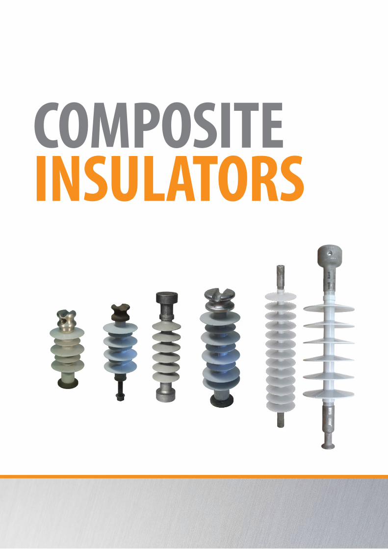
Composite Insulators
© KUVAG GmbH & Co KG,
COMPOSITEINSULATORS
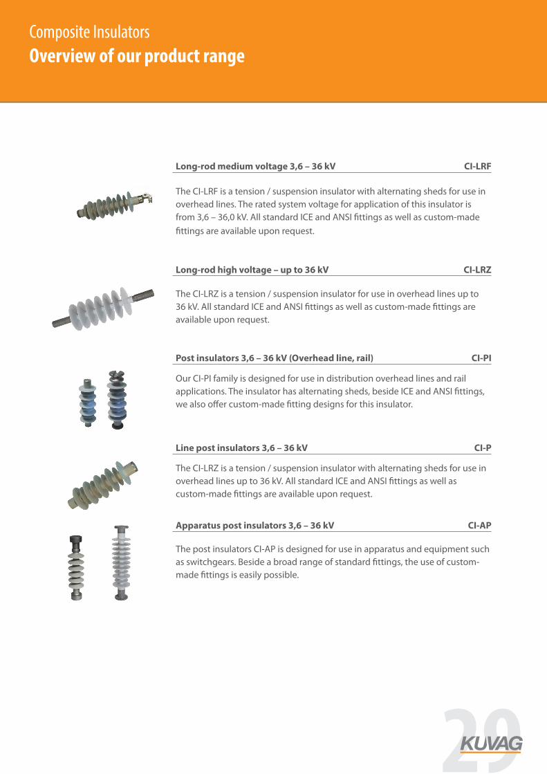
Composite Insulators
Overview on our product range
1
Long-rod medium voltage 3,6 – 36 kV
Post insulators 3,6 – 36 kV (Overhead line, rail)
Apparatus post insulators 3,6 – 36 kV
Long-rod high voltage – up to 36 kV
Line post insulators 3,6 – 36 kV
CI-LRF
CI-LRZ
CI-P
CI-PI
CI-AP
The CI-LRF is a tension / suspension insulator with alternating sheds for use in overhead lines. The rated system voltage for application of this insulator is from 3,6 – 36,0 kV. All standard ICE and ANSI fittings as well as custom-made fittings are available upon request.
The CI-LRZ is a tension / suspension insulator for use in overhead lines up to 36 kV. All standard ICE and ANSI fittings as well as custom-made fittings are available upon request.
The CI-LRZ is a tension / suspension insulator with alternating sheds for use in overhead lines up to 36 kV. All standard ICE and ANSI fittings as well as custom-made fittings are available upon request.
The post insulators CI-AP is designed for use in apparatus and equipment such as switchgears. Beside a broad range of standard fittings, the use of custom-made fittings is easily possible.
Our CI-PI family is designed for use in distribution overhead lines and rail applications. The insulator has alternating sheds, beside ICE and ANSI fittings, we also offer custom-made fitting designs for this insulator.
Composite InsulatorsOverview of our product range
29

Composite Insulators
Long rod insulator 3,6 - 36,0 kV
Long-rod insulator CI - LRF
2
Fittings § Socket (type S) & ball (type B) acc. to IEC 60120 § Clevis (type C) and tongue (type T) acc. to IEC 60471 / IEC 61466-1 § Y-clevis (type Y) and eye (type E) acc. to IEC 61466-1 § Fittings acc. to ANSI C29.9, ANSI C29.12 and custom made fittings are
available for all standard insulators
General § Tension / suspension composite insulator § Rod Ø = 13 mm; sheds 106/76 mm (alternating sheds) § Largest shed diameter available = 106 mm § Design of insulator acc. to IEC 61109 (specification in line with
ANSI C29.11 and ANSI C29.12 is available upon request)
Type number of sheds
creepage distance STL connecting
length lightning impulse withstand voltage
power frequency withstand voltage
suggested voltage level
[ ] [mm] [kN] [mm] [kV] [kV] [kV]
CI - LRF - 3,6 - 193 1 135 70 193 3,6
CI - LRF - 7,2 - 221 2 245 70 221 7,2
CI - LRF – 12 - 249 3 355 70 249 >75 >28 12
CI - LRF – 12 - 277 4 435 70 277 12
CI - LRF – 24 - 305 5 515 70 305 >125 >50 24
CI - LRF – 24 - 333 6 595 70 333 24
CI - LRF - 24 - 361 7 675 70 361 24
CI - LRF - 36 - 389 8 755 70 389 >170 >70 36
CI - LRF - 36 - 417 9 835 70 417 36
CI - LRF - 36 - 475 10 945 70 475 36
Composite InsulatorsLong rod insulators 3,6 kV - 36 kV
TypeNumber of
shedsCreepage distance
STLConnecting
lengthLightning impulse withstand voltage
Power frequency withstand voltage
Suggested voltage level
[mm] [kN] [mm] [kV] [kV] [kV]
CI - LRF - 3,6 - 193 1 135 70 193 3,6
CI - LRF - 7,2 - 221 2 245 70 221 7,2
CI - LRF - 12 - 249 3 355 70 249 >75 >28 12
CI - LRF - 12 - 277 4 435 70 277 12
CI - LRF - 24 - 305 5 515 70 305 >125 >50 24
CI - LRF - 24 - 333 6 595 70 333 24
CI - LRF - 24 - 361 7 675 70 361 24
CI - LRF - 36 - 389 8 755 70 389 >170 >70 36
CI - LRF - 36 - 417 9 835 70 417 36
CI - LRF - 36 - 475 10 945 70 475 36
30 www.kuvag.com

Composite Insulators
Long rod insulator 3,6 - 420,0 kV
Long-rod insulator CI - LRZ
Fittings § Socket (type S) & ball (type B) acc. to IEC 60120 § Clevis (type C) and tongue (type T) acc. to IEC 60471 / IEC 61466-1 § Y-clevis (type Y) and eye (type E) acc. to IEC 61466-1 § Fittings acc. to ANSI C29.9, ANSI C29.12 and custom made fittings are
available for all standard insulators
General § Tension / suspension composite insulator § Rod Ø = 20 mm; all sheds same diameter § Largest shed diameter available = 106 mm § Design of insulator acc. to IEC 61109 (specification in line with
ANSI C29.11 and ANSI C29.12 is available upon request)
Type number of sheds
creepage distance STL connecting
length lightning impulse withstand voltage
power frequency withstand voltage
suggested voltage level
[ ] [mm] [kN] [mm] [kV] [kV] [kV]
CI - LRZ - 3,6 - 260 1 140 80 260 3,6
CI - LRZ - 7,2 - 300 2 270 80 300 7,2
CI - LRZ - 12 - 340 3 410 80 340 >75 >28 12
CI - LRZ - 24 - 380 4 540 80 380 160 65 24
CI - LRZ - 24 - 420 5 680 80 420 185 80 24
CI - LRZ - 36 - 460 6 810 80 460 200 92 36
CI - LRZ - 36 - 500 7 950 80 500 230 115 36
CI - LRZ - 52 - 540 8 1.080 80 540 52
CI - LRZ - 52 - 580 9 1.220 80 580 52
CI - LRZ - 72,5 - 620 10 1.350 80 620 300 150 72,5
CI - LRZ - 123 - 1050 20 2.660 120 1.050 550 260 123,0
CI - LRZ - 145 - 1280 26 3.490 120 1.280 145,0
CI - LRZ - 245 - 1860 40 5.300 120 1.860 1.100 520 245,0
CI - LRZ - 420 - 3500 80 10.660 160 3.500 420,0
3
Composite InsulatorsLong rod insulators CI - LRZ 3,6 kV - 52 kV
TypeNumber of
shedsCreepage distance
STLConnecting
lengthLightning impulse withstand voltage
Power frequency withstand voltage
Suggested voltage level
[mm] [kN] [mm] [kV] [kV] [kV]
CI - LRZ - 3,6 - 260 1 140 80 260 3,6
CI - LRZ - 7,2 - 300 2 270 80 300 7,2
CI - LRZ - 12 - 340 3 410 80 340 >75 >28 12
CI - LRZ - 24 - 380 4 540 80 380 160 65 24
CI - LRZ - 24 - 420 5 680 80 420 185 80 24
CI - LRZ - 36 - 460 6 810 80 460 200 92 36
CI - LRZ - 36 - 500 7 950 80 500 230 115 36
CI - LRZ - 52 - 540 8 1.080 80 540 52
CI - LRZ - 52 - 580 9 1.220 80 580 52
31

Composite Insulators
Post insulator 3,6 - 52 kV
Post insulator CI - PI
Fittings § Fittings acc. to IEC 60273 § Pin fittings of various types § Cap fittings § Railway fittings § Custom-made fittings available for all standard insulators
General § Post composite insulators for overhead lines and apparatus § Rod Ø = 30 mm; sheds 130/90 (alternating sheds) § Largest shed diameter available = 130 mm § Design of insulator acc. to IEC 61109 (specification in line with
ANSI C29.11 and ANSI C29.12 is available upon request)
Type number of sheds
creepage distance SCL [kN] connecting
length lightning impulse
withstand power frequency
withstand suggested
voltage level
[ ] [mm] [kN] [mm] [kV] [kV] [kV]
CI - PI - 3,6 - 124 1 160 15 124 3,6
CI - PI - 7,2 - 148 2 240 13 148 7,2
CI - PI - 12 - 172 3 355 13 172 >75 >28 12
CI - PI - 12 - 196 4 435 10 196 12
CI - PI - 24 - 220 5 550 10 220 >125 >50 24
CI - PI - 24 - 244 6 630 8 244 24
CI - PI - 24 - 268 7 745 8 268 24
CI - PI - 36 - 292 8 825 6 292 >170 >70 36
CI - PI - 36 - 316 9 940 6 316 36
CI - PI - 36 - 340 10 1.020 6 340 36
CI - PI - 36 - 368 11 1.135 4 368 230 108 52
4
Composite InsulatorsPost insulators CI -PI 3,6 kV - 52 kV
TypeNumber of
shedsCreepage distance
STLConnecting
lengthLightning impulse
withstandPower frequency
withstandSuggested
voltage level
[mm] [kN] [mm] [kV] [kV] [kV]
CI - PI - 3,6 - 124 1 160 15 124 3,6
CI - PI - 7,2 - 148 2 240 13 148 7,2
CI - PI - 12 - 172 3 355 13 172 >75 >28 12
CI - PI - 12 - 196 4 435 10 196 12
CI - PI - 24 - 220 5 550 10 220 >125 >50 24
CI - PI - 24 - 244 6 630 8 244 24
CI - PI - 24 - 268 7 745 8 268 24
CI - PI - 36 - 292 8 825 6 292 >170 >70 36
CI - PI - 36 - 316 9 940 6 316 36
CI - PI - 36 - 340 10 1.020 6 340 36
CI - PI - 36 - 368 11 1.135 4 368 230 108 52
32 www.kuvag.com
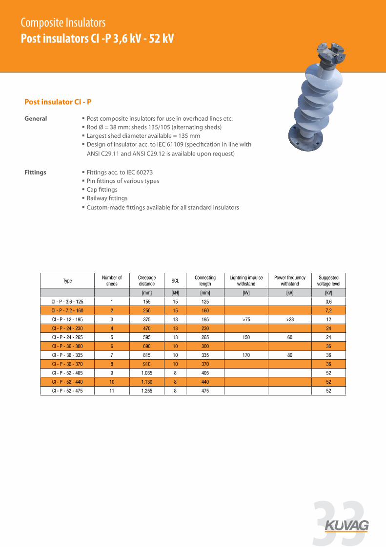
Composite Insulators
Post insulator 3,6 - 52 kV
Type number of sheds
creepage distance SCL connecting
length lightning impulse
withstand power frequency
withstand suggested
voltage level
[ ] [mm] [kN] [mm] [kV] [kV] [kV]
CI - P - 3,6 - 125 1 155 15 125 3,6
CI - P - 7,2 - 160 2 250 15 160 7,2
CI - P - 12 - 195 3 375 13 195 >75 >28 12
CI - P - 24 - 230 4 470 13 230 24
CI - P - 24 - 265 5 595 13 265 150 60 24
CI - P - 36 - 300 6 690 10 300 36
CI - P - 36 - 335 7 815 10 335 170 80 36
CI - P - 36 - 370 8 910 10 370 36
CI - P - 52 - 405 9 1.035 8 405 52
CI - P - 52 - 440 10 1.130 8 440 52
CI - P - 52 - 475 11 1.255 8 475 52
Post insulator CI - P
Fittings § Fittings acc. to IEC 60273 § Pin fittings of various types § Cap fittings § Railway fittings § Custom-made fittings available for all standard insulators
General § Post composite insulators for use in overhead lines etc. § Rod Ø = 38 mm; sheds 135/105 (alternating sheds) § Largest shed diameter available = 135 mm § Design of insulator acc. to IEC 61109 (specification in line with
ANSI C29.11 and ANSI C29.12 is available upon request)
5
Composite InsulatorsPost insulators CI -P 3,6 kV - 52 kV
TypeNumber of
shedsCreepage distance
SCLConnecting
lengthLightning impulse
withstandPower frequency
withstandSuggested
voltage level
[mm] [kN] [mm] [kV] [kV] [kV]
CI - P - 3,6 - 125 1 155 15 125 3,6
CI - P - 7,2 - 160 2 250 15 160 7,2
CI - P - 12 - 195 3 375 13 195 >75 >28 12
CI - P - 24 - 230 4 470 13 230 24
CI - P - 24 - 265 5 595 13 265 150 60 24
CI - P - 36 - 300 6 690 10 300 36
CI - P - 36 - 335 7 815 10 335 170 80 36
CI - P - 36 - 370 8 910 10 370 36
CI - P - 52 - 405 9 1.035 8 405 52
CI - P - 52 - 440 10 1.130 8 440 52
CI - P - 52 - 475 11 1.255 8 475 52
33
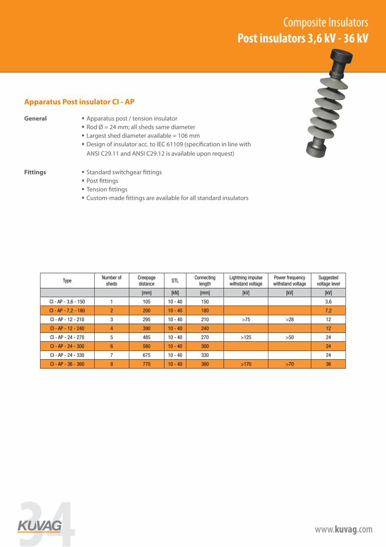
Composite Insulators
Post insulator 3,6 - 36 kV
Type number of sheds
creepage distance STL connecting
length lightning impulse withstand voltage
power frequency withstand voltage
suggested voltage level
[ ] [mm] [kN] [mm] [kV] [kV] [kV]
CI - AP - 3,6 - 150 1 105 10 - 40 150 3,6
CI - AP - 7,2 - 180 2 200 10 - 40 180 7,2
CI - AP - 12 - 210 3 295 10 - 40 210 >75 >28 12
CI - AP - 12 - 240 4 390 10 - 40 240 12
CI - AP - 24 - 270 5 485 10 - 40 270 >125 >50 24
CI - AP - 24 - 300 6 580 10 - 40 300 24
CI - AP - 24 - 330 7 675 10 - 40 330 24
CI - AP - 36 - 360 8 770 10 - 40 360 >170 >70 36
Apparatus Post insulator CI - AP
Fittings § Standard switchgear fittings § Post fittings § Tension fittings § Custom-made fittings are available for all standard insulators
General § Apparatus post / tension insulator § Rod Ø = 24 mm; all sheds same diameter § Largest shed diameter available = 106 mm § Design of insulator acc. to IEC 61109 (specification in line with
ANSI C29.11 and ANSI C29.12 is available upon request)
6
Composite InsulatorsPost insulators 3,6 kV - 36 kV
TypeNumber of
shedsCreepage distance
STLConnecting
lengthLightning impulse withstand voltage
Power frequency withstand voltage
Suggested voltage level
[mm] [kN] [mm] [kV] [kV] [kV]
CI - AP - 3,6 - 150 1 105 10 - 40 150 3,6
CI - AP - 7,2 - 180 2 200 10 - 40 180 7,2
CI - AP - 12 - 210 3 295 10 - 40 210 >75 >28 12
CI - AP - 12 - 240 4 390 10 - 40 240 12
CI - AP - 24 - 270 5 485 10 - 40 270 >125 >50 24
CI - AP - 24 - 300 6 580 10 - 40 300 24
CI - AP - 24 - 330 7 675 10 - 40 330 24
CI - AP - 36 - 360 8 770 10 - 40 360 >170 >70 36
34 www.kuvag.com
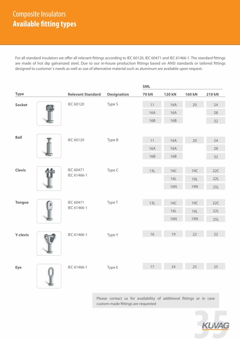
Composite Insulators
Available fitting types
Type Relevant Standard Designation 70 kN 120 kN 160 kN 210 kN
SML
Socket
16A
Ball
Clevis
Tongue
Y-clevis
Eye
IEC 60120 Type S
For all standard insulators we offer all relevant fittings according to IEC 60120, IEC 60471 and IEC 61466-1. The standard fittings are made of hot dip galvanized steel. Due to our in-house production fittings based on ANSI standards or tailored fittings designed to customer`s needs as well as use of alternative material such as aluminum are available upon request.
16B
16A
16B
20 24
28
32
IEC 60120 Type B 11 16A
16A
16B
16A
16B
20 24
28
32
11 16A
IEC 60471 IEC 61466-1
Type C
16L
16N
19C 22C
22L
25L
13L 16C
IEC 60471 IEC 61466-1
19L
19N
Type T
16L
16N
19C 22C
22L
25L
13L 16C
19L
19N
IEC 61466-1 Type Y 22 22 16 19
IEC 61466-1 Type E 25 25 17 24
i Please contact us for availability of additional fittings or in case custom-made fittings are requested
7
Composite InsulatorsAvailable fitting types
35

Composite Insulators
Technical specification
Rod § ECR-Glass (boron free, brittle fracture-resistant) § Standard Ø of rods are 13, 20, 24, 30 and 38 mm; Alternative Ø for
ECR-rod is possible in custom-made insulators § SML of insulators ranging from 70 to 210 kN
Housing & weather sheds
§ Hydrophobic LSR silicone (standard) § Use of HTV silicone for insulator is possible as an option § Weather sheds are molded as part of the cover; sealing is done by
overmoulding of fitting and rod during casting
Fittings § Fitting design and dimensions in accordance with ICE or ANSI standards (ANSI C29.9, ANSI C29.12)
§ Hot-dip galvanized forged steel; Specification and average coating thickness > 85 µm in line with IEC 60383
§ Equipment such as nuts and bolts made of galvanized steel (8.8); Higher strength categories are available as option
§ Custom-made options for fittings (material, dimensions, coating, etc.) are available and can be assembled on standard insulators
Our insulators are designed according to the specifications outlined in IEC 61109, IEC 62217, IEC 60815 and IEC 61466-2. Insulators which comply with the relevant ANSI standards are available upon request. In addition to our standard product program, we offer tailor-made solutions. Each insulator leaving our factory is checked visually as well as mechanically (testing of tensile properties). Checks and tests according to customer needs and in eddition to our standard inspection procedure.
8
Composite InsulatorsTechnical specification
36 www.kuvag.com
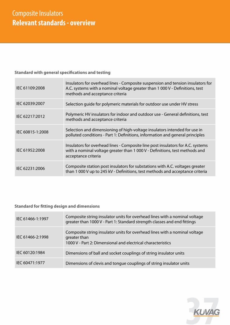
Composite Insulators
Relevant standards - overview
Standard with general specifications and testing
Standard for fitting design and dimensions
9
IEC 61109:2008 Insulators for overhead lines - Composite suspension and tension insulators for A.C. systems with a nominal voltage greater than 1 000 V - Definitions, test methods and acceptance criteria
IEC 62039:2007 Selection guide for polymeric materials for outdoor use under HV stress
IEC 62217:2012 Polymeric HV insulators for indoor and outdoor use - General definitions, test methods and acceptance criteria
IEC 60815-1:2008 Selection and dimensioning of high-voltage insulators intended for use in polluted conditions - Part 1: Definitions, information and general principles
IEC 61952:2008 Insulators for overhead lines - Composite line post insulators for A.C. systems with a nominal voltage greater than 1 000 V - Definitions, test methods and acceptance criteria
IEC 62231:2006 Composite station post insulators for substations with A.C. voltages greater than 1 000 V up to 245 kV - Definitions, test methods and acceptance criteria
IEC 61466-1:1997 Composite string insulator units for overhead lines with a nominal voltage greater than 1000 V - Part 1: Standard strength classes and end fittings
IEC 61466-2:1998 Composite string insulator units for overhead lines with a nominal voltage greater than 1000 V - Part 2: Dimensional and electrical characteristics
IEC 60120:1984 Dimensions of ball and socket couplings of string insulator units
IEC 60471:1977 Dimensions of clevis and tongue couplings of string insulator units
Composite InsulatorsRelevant standards - overview
37
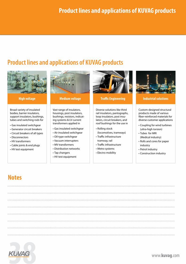
www.kuvag.com
Product lines and applications of KUVAG products
Your Notes.................................................................................................................................................................................................................................
.................................................................................................................................................................................................................................
.................................................................................................................................................................................................................................
.................................................................................................................................................................................................................................
.................................................................................................................................................................................................................................
.................................................................................................................................................................................................................................
.................................................................................................................................................................................................................................
.................................................................................................................................................................................................................................
.................................................................................................................................................................................................................................
Product lines and applications of KUVAG products
Broad variety of insulated bodies, barrier insulators, support insulators, bushings, tubes and switching rods for
Gas insulated switchgear
Generator circuit breaker
Circuit breakers of all types
Disconnectors
HV transformers
Cable joints & end plugs
Vast range of insulators, housings, post insulators, bushings, resistors, indica-ting systems & LV current transformers applied in
Gas insulated switchgear
Air insulated switchgear
MV circuit breakers of all types
Recloser
MV transformer products
Outdoor applications
Leading solutions for pantographs, loop insulators, post insulators and roof bushings for
Rolling stock
Traffic Infrastructure
Broad knowledge and experience in hydrophobic material solutions for outdoor applications
Inner tubes for MRI (up to Ø 800 mm and length of 1.500 mm)
Outer tubes for MRI (up to Ø 850 and length of 1.500 mm)
Insulating loops
Broad variety of insulated bodies, barrier insulators, support insulators, bushings, tubes and switching rods for
• Gas insulated switchgear• Generator circuit breakers• Circuit breakers of all types• Disconnectors• HV transformers• Cable joints & end plugs• HV test equipment
Vast range of insulators, housings, post insulators, bushings, resistors, indicat-ing systems & LV current transformers applied in
• Gas insulated switchgear• Air insulated switchgear• Oil-type switchgear• Vacuum interrupters• MV transformers• Distribution networks• Tap changers• HV test equipment
Diverse solutions like third rail insulators, pantographs, loop insulators, post insu-lators, circuit breakers, and roof bushings for the use in
• Rolling stock (locomotives, tramways)• Traffic infrastructure tramway, rail• Traffic infrastructure• Metro systems• Electro mobility
Custom-designed structural products made of various fiber-reinforced materials for diverse customer applications
• Coupling for wind turbines (ultra-high torsion)• Tubes for MRI (Medical industry)• Rolls and cores for paper industry• Petrol industry• Construction industry
High voltage Medium voltage Traffic Engineering Industrial solutions
POWER ENGINEERINGHIGH VOLTAGE
TRAFFIC ENGINEERING
POWER ENGINEERINGMEDIUM VOLTAGE
INDUSTRIAL SOLUTIONS
www.kuvag.com www.kuvag.com
POWER ENGINEERINGHIGH VOLTAGE
TRAFFIC ENGINEERING
POWER ENGINEERINGMEDIUM VOLTAGE
INDUSTRIAL SOLUTIONS
www.kuvag.com www.kuvag.com
POWER ENGINEERINGHIGH VOLTAGE
TRAFFIC ENGINEERING
POWER ENGINEERINGMEDIUM VOLTAGE
INDUSTRIAL SOLUTIONS
www.kuvag.com www.kuvag.com
POWER ENGINEERINGHIGH VOLTAGE
TRAFFIC ENGINEERING
POWER ENGINEERINGMEDIUM VOLTAGE
INDUSTRIAL SOLUTIONS
www.kuvag.com www.kuvag.com
Notes
38 www.kuvag.com
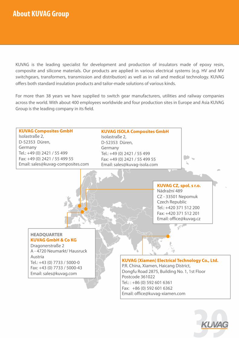
About KUVAG Group
KUVAG is the leading specialist for development and production of insulators made of epoxy resin, composite and silicone materials. Our products are applied in various electrical systems (e.g. HV and MV switchgears, transformers, transmission and distribution) as well as in rail and medical technology. KUVAG o ers both standard insulation products and tailor-made solutions of various kinds. For more than 38 years we have supplied to switch gear manufacturers, utilities and railway companies across the world. With about 400 employees worldwide and four production sites in Europe and Asia KUVAG Group is the leading company in its eld.
KUVAG CZ, spol. s r.o. Nádražní 489 CZ - 33501 Nepomuk Czech Republic Tel.: +420 371 512 200 Fax: +420 371 512 201 Email: [email protected]
KUVAG (Xiamen) Electrical Technology Co., Ltd. P.R. China, Xiamen, Haicang District, Dongfu Road 2875, Building No. 1, 1st Floor Postcode 361022 Tel.: : +86 (0) 592 601 6361Fax: +86 (0) 592 601 6362 Email: [email protected]
HEADQUARTER KUVAG GmbH & Co KG Dragonerstraße 2 A - 4720 Neumarkt/ Hausruck Austria Tel.: +43 (0) 7733 / 5000-0 Fax: +43 (0) 7733 / 5000-43 Email: [email protected]
KUVAG Composites GmbH Isolastraße 2, D-52353 Düren, Germany Tel.: +49 (0) 2421 / 55 499 Fax: +49 (0) 2421 / 55 499 55 Email: [email protected]
KUVAG ISOLA Composites GmbH Isolastraße 2, D-52353 Düren, Germany Tel.: +49 (0) 2421 / 55 499 Fax: +49 (0) 2421 / 55 499 55 Email: [email protected]
offi
About KUVAG Group
39
KUVAG Group
KUVAG GmbH & Co KGDragonerstraße 2
A - 4720 NeumarktAustria
Tel: +43 (0) 7733 5000 - 0Fax: +43 (0) 7733 5000 - 43