oversoc: a framework for the exploration of rtos for rsoc platforms
TRANSCRIPT

Hindawi Publishing CorporationInternational Journal of Reconfigurable ComputingVolume 2009, Article ID 450607, 22 pagesdoi:10.1155/2009/450607
Research Article
OveRSoC: A Framework for the Exploration ofRTOS for RSoC Platforms
Benoıt Miramond,1 Emmanuel Huck,1 Francois Verdier,1 Amine Benkhelifa,1
Bertrand Granado,1 Thomas Lefebvre,1 Mehdi Aıchouch,1 Jean Christophe Prevotet,2
Yaset Oliva,2 Daniel Chillet,3 and Sebastien Pillement3
1 ETIS, CNRS-UMR8051, ENSEA, Universite de Cergy-Pontoise, 6 avenue du Ponceau, 95000 Cergy-Pontoise, France2 IETR INSA—UMR 6164 CNRS, CS 14315, 35043 Rennes, France3 CAIRN—IRISA/ENSSAT, 6 rue de kerampont, 22300 Lannion, France
Correspondence should be addressed to Emmanuel Huck, [email protected]
Received 15 March 2009; Revised 19 October 2009; Accepted 20 December 2009
Recommended by Lionel Torres
This paper presents the OveRSoC project. The objective is to develop an exploration and validation methodology of embedded RealTime Operating Systems (RTOSs) for Reconfigurable System-on-Chip-based platforms. Here, we describe the overall methodologyand the corresponding design environment. The method is based on abstract and modular SystemC models that allow to explore,simulate, and validate the distribution of OS services on this kind of platform. The experimental results show that our componentsaccurately model the dynamic and deterministic behavior of both application and RTOS.
Copyright © 2009 Benoıt Miramond et al. This is an open access article distributed under the Creative Commons AttributionLicense, which permits unrestricted use, distribution, and reproduction in any medium, provided the original work is properlycited.
1. Introduction
Nowadays, algorithmic complexity tends to increase in manydomains such as signal, image processing or control. Inparallel, embedded applications require a significant powerof calculation in order to satisfy real-time constraints. Thisleads to the design of hardware architectures composed ofheterogeneous and optimized computation units operatingin parallel. Hardware components in SoC (System on Chip)may exhibit programmable computation units, reconfig-urable units, or even dedicated data-paths. In particular,reconfigurable units, denoted here as Dynamically Reconfig-urable Accelerators (DRA), allow an architecture to adapt tovarious incoming tasks at runtime.
Due to their intrinsic complexities, such heterogeneousarchitectures need even more complex management andcontrol. In this context, the utilization of an RTOS (RealTime Operating System) is more and more required tosupport services such as communications, memory manage-ment, task scheduling, task placement, and so forth. Theseservices have to be fulfilled in real-time according to theapplication constraints. Moreover, such an operating system
must provide a complete design framework independent ofthe technology and of the hardware architecture. As for stan-dard computers, the RTOS must also provide an abstractionand a unified programming model of the heterogeneousplatforms. This abstraction permits to drastically reduce thetime to market by encouraging re-usability.
Embedded RTOS for SoCs are of great interest andare subject of several significant studies. In the context ofreconfigurable architectures, a study in [1] has determinedand classified the different services that operating systemsshould provide to handle reconfigurability. Today, twodifferent approaches have emerged for the development andthe integration of these dedicated services. The first consistsin utilizing an existing standard RTOS (RTAI, RTLinux,VxWorks, etc.) and in adding functionalities dedicated to themanagement of the reconfigurable resources [2]. The secondis to develop a specific RTOS from scratch by implementingthe necessary functionalities devoted to the management ofthe reconfigurable resources [3, 4].
The design process of such complex and heterogeneousreconfigurable systems requires method, rigor and tools.The OveRSoC framework is developed to take into account

2 International Journal of Reconfigurable Computing
both the RTOS, and the platform to propose an efficientexploration of the design space. The OverSoC methodologyis based on 4 important design concepts: exploration,separation of concerns, incremental refinement and re-usability.
Firstly, a number of design choices have to be doneprior any implementation, especially when the platformitself is designed and tailored for a specific application. Weadvocate the use of a high level model of ReconfigurableSoCs (RSoC) in order to explore different critical designchoices. Among these important choices we distinguish twoexploration issues:
(i) the exploration of the application partitioning ontothe processing resources (topic already addressed inthe literature [5, 6]),
(ii) the exploration of the RTOS services distribution andtheir algorithms.
Each design strategy belonging to these exploration levelsis manually made by the designer. But the proposed methodhelps the designer to easily and quickly build the executablespecification of the corresponding systems. The underly-ing tools then bring performance evaluations in order toanalyze and compare design strategies. The design choicescorresponding to the second exploration issue (RTOS) arethe architecture of the embedded RTOS (centralized ordistributed, OS services organization, software, or hardwareimplementation, etc.), the services algorithms (schedulingpolicies, etc.), the interactions between OS service functionsand underlying resources (reconfigurable, memories, inter-connects) and the software programming model.
Secondly, once validated the candidate design solutionsare incrementally refined toward lower levels of abstrac-tion down to the final implementation. The OveRSoCmethodology permits the separation of concerns during themodeling and refinement process. It also defines modelingrules that facilitate independence and re-usability betweencomponents. For each design concern specific and relatedrefinement steps are proposed. The resulting methodologyserves as a design map for the designer of RSoC platforms.
Finally, the method imposes a functional approachat each level of abstraction which allows the validationof the application functionality besides the performanceevaluation.
As a consequence, in the rest of the paper the problem ofOS design is presented as a platform management problem.This paper presents the OveRSoC methodology and therelated framework that consists of a set of SystemC models.The associated graphical exploration environment is alsopresented.
The remainder of the paper is as follows. Related workis described in Section 2. Section 3 presents the OveRSoCmethodology and the corresponding tool for RTOS design.The flexible SystemC abstract RTOS model which allowsRTOS service distribution and customization is presentedin Section 4. Section 5 describes the RSoC architecturemodeling step. Section 6 provides experimental results whileSection 7 brings out our conclusions and presents theperspectives of this work.
2. Related Work
One of the main issues in reconfigurable platforms consistsin determining efficient control mechanisms that may havedynamical properties in the sense that they must take on-linedecisions from unpredictable system properties [7]. Severalstudies such as [3, 8] aimed at identifying the propertiesof the RTOS that can take dynamic reconfiguration intoaccount. Specific properties such as application partitioningand tasks placement are described and placed in the contextof reconfigurable computing which is often based on a farmof reconfigurable circuits. In [8], authors present one of thefirst attempts to develop an OS dedicated to the managementof reconfigurable resources.
For the particular SoC domain, the authors in [9] listimportant properties to stress the usefulness of an OS tomanage heterogeneous and static resources.
Adding reconfigurable units in a chip brings up manyother issues from a design point of view. Introducing an OSfor the management of an RSoC is of high interest in theresearch community [10]. Indeed, the partial reconfigurationabilities of current architectures need to be fully exploitedin order to improve performance, cost, power-efficiency andtime-to-market. Even if classical software approaches canbe used, the OS then needs to be adapted to this newcomputation paradigm. More precisely, specific services arerequested to manage the specific properties and resources ofthe dynamically reconfigurable units.
Designing a complete RSoC including an RTOS is a verycomplex task and requires appropriate methodologies. Inthis section we firstly introduce constraints on a dedicatedRTOS for RSoC, we then discuss a proposal of methodologiesin order to design these circuits efficiently.
2.1. Dedicated OS Services. The required specific services forRSoC can be roughly decomposed in four categories:
2.1.1. Spatiotemporal Scheduling. The task scheduling serviceis obviously one of the most important features of a multi-tasking OS. Scheduling of hardware tasks on reconfigurableareas adds a spatial dimension to the classical temporalproblem [11]. This is defined as the spatiotemporal schedul-ing problem. The mapping of hardware tasks onto thereconfigurable unit can follow two spatial schemes accordingto the technology [3]: 1D or 2D schemes. While the 1Dtechnique is simple to support, its performance in termsof computation density is low. On the other side, the 2Dplacement technique ensures a more efficient utilization ofthe reconfigurable area, but the associated algorithms aremore complex.
2.1.2. Reconfiguration and Resource Usage Management. Theresource management is very close to the placement servicewhich needs to know the global state of the system. Theresource table needs to be extended to store specific infor-mation necessary to manage the reconfiguration [2]. We cancite for example the area information for each reconfigurabletask, the task communication needs which must be ensured

International Journal of Reconfigurable Computing 3
when the task is placed on the reconfigurable resource, theform factor, and so forth. The area fragmentation problemalso appears when managing reconfigurable resources [12,13]. This problem can prevent the placement of tasks whilethere is enough area within the reconfigurable resource. Inthis case, the designer can decide to implement a defrag-mentation service into the OS to limit the task placementrejection.
The reconfiguration latency of DRA represents a majorproblem that must be taken into account. Several works canbe found addressing temporal partitioning for reconfigu-ration latency minimization [14]. Moreover, configurationprefetching techniques are used to minimize the reconfigura-tion overhead [15]. A prefetch and replacement unit modifiesthe schedule and significantly reduces the latency even forhighly dynamic tasks.
2.1.3. Task Preemption and Migration. hardware task migra-tion is an interesting property that requires the imple-mentation of the hardware task preemption service [16].Efficient implementation of preemption and migrationrequires several additional OS services, such as onlinecommunications routing and spatial placement. To limitthe scheduling overhead and the number of configurationphases, which can be very time consuming, some OS preventthe preemption of hardware tasks. Non preemptive operatingsystems are known to be more deterministic, but do nottake full advantage of platform flexibility. The conditionsallowing more complex hardware task preemptions aredefined in [17]. In this article, the authors describe threetypes of requirements allowing to perform multitaskingon FPGA. First, save and restore mechanisms of currentstate of all registers and internal memories are required.Second, the configuration manager must obviously supportfast configuration and readback of the FPGA. It must alsohave complete control over all the clock signals in order tofreeze execution during context switching. Finally, it requiresan open bitstream format in order to readback the statusinformation bits.
As an example, preemption of hardware tasks have beenstudied in [18]. The authors present prospective architecturalextensions of SRAM-based FPGA devices allowing a veryfast and efficient context save and restoration. The proposedarchitecture supports the hardware defragmentation.
2.1.4. Flexible Communications. This property deals with theinter-task communication property of an OS and impacts therouting service [19]. The communication functionality is animportant part of the system to ensure the data exchangesbetween all tasks, whatever their type or localization. Con-sidering the localization of the tasks, communications areclassically divided into two different types:
(i) the global communications: this communicationlevel enables data exchanges between the differentavailable resources (e.g., DSP, processors, reconfig-urable units, etc.).
(ii) the local communications: this level ensures the datarouting between different tasks placed simultane-ously into the same reconfigurable area.
The global communication structures have to supportflexible throughput and guaranteed bandwidth. In this case,OS services must provide the capacities to manage thesestructures. The requirements of the local communicationswithin the reconfigurable area are quite different. Tasksimplemented within this area are dedicated to intensivecomputation and are generally constrained by real timeexecution. In this case, communications do not support anydelay nor excessive latency.
2.2. RSoC Dedicated Methodologies. Several studies tend toabstract the reconfiguration management by working at asystem-level model. This level enables the exploration ofsystems while software, hardware or reconfigurable partsare not completely defined. It also enables the validation ofvarious configurations to find the most efficient solution.
In order to introduce the reconfiguration in Symbad[20] which is a system-level codesign platform for SoC, therefinement phase has been modified to handle static andreconfigurable modules [21]. Specific simulation parame-ters, such as the reconfiguration time, are taken into account.Associated tools enable the evaluation of the reconfigurablecontribution to the system performances. In [22], theauthors propose a methodology in order to implement anapplication in an RSoC. This methodology is based on aUML descriptive model of the software parts and on aSystemC description of the architecture. Currently, theseworks do not take the dynamicity of the reconfiguration intoaccount.
The collaborators of the Adriatic project propose anoriginal methodology that handles dynamic reconfiguration[23]. The reconfigurable block is composed of a controllerthat launches or stops reconfigurable tasks, and features aninput router that dispatches data among active blocks. Adri-atic then proposes high level estimation of performances.Different strategies and approaches of estimation, simulationand partitioning are implemented in the Perfecto [24] andReChannel [25] frameworks. Unfortunately, none of theseworks considers the development of an OS in order todynamically manage the RSoC.
New approaches tend to provide a high-level hardwaredesign model while managing the hardware implementa-tion efficiently. This goal is achieved by a multi-languagesapproach.
In [26], the authors develop a framework based onthe RTL language HIDE for implementation purpose, andon Handel-C to describe hardware at a higher level ofabstraction. At present, the proposed framework does nothandle dynamically reconfigurable architectures.
The multi-languages strategy is also used in the EuropeanProject Andres [27] which addresses heterogeneous systems.It is built around the HetSC methodology for the specifica-tion of the software part and the OSSS+R SystemC library forthe reconfigurable part. Andres also includes a part of analogmixed design by supporting the SystemC AMS.

4 International Journal of Reconfigurable Computing
A special case of RTOS generation is the definitionof dedicated OS services for DRA. The work presentedin [28] addresses this problem by proposing a RTOS/SoCcodesign framework. The customized RTOS is automaticallygenerated from existing OS basic blocks which are availablein software and/or in hardware. The 4S project [29] providesa design flow to develop RSoC platforms including anOS. In this project, algorithms are implemented into taskswhich are mapped onto reconfigurable or non reconfigurablemodules. The proposed tool provides information aboutthe performances of each task for a given mapping. Inan exploration step, the OS manages the implementationof tasks within reconfigurable units and generates flexiblecommunication mechanisms. At present, these projects donot include the OS definition as part of the design process.
As a conclusion, adding reconfigurability in a platformimposes the management of hardware tasks at run-time.These tasks have to be placed into a reconfigurable unit ina dynamic and flexible manner. To ensure this management,some OS services need to be adapted (synchronization,migration, etc.), but some other services are completelynew and need to be developed from scratch (spatiotemporalscheduling, fragmentation management, etc.). In the litera-ture, to the best of our knowledge, no work proposes a com-plete solution, neither on real platforms nor in simulation,for the DRA management. The main contribution of thispaper is to propose a unified modeling environment whereall the needed services can be specified, tested and validatedwhen distributed onto an heterogeneous multiprocessorplatform. In this paper we do not provide and describe newspatiotemporal algorithms nor defragmentation methodsbut an open platform for the exploration of these complexalgorithms where existing and upcoming methods for DRAmanagement may be evaluated and compared. The servicesand the underlying platform are part of the explorationprocess. This objective has been reached thanks to thefollowing contributions:
(i) a design methodology adapted to the exploration ofthe RSoC specific services,
(ii) a tool implementing this methodology,
(iii) a set of generic simulation models of MPSoC (MultiProcessors System-on-Chip) components,
(iv) a high-level model of a DRA,
(v) a top-down refinement process.
3. The OveRSoC Methodology
In this section, we describe the methodology which is devel-oped in the OveRSoC project and the tool that implementsit. Our main goal is to provide a simulation framework forhardware/software design exploration of an RSoC includinga dedicated RTOS. The framework is based on four mainconcepts: a methodology based on several design and analysissteps, the automation of simulation code generation froma library of basic blocks, the separation of concerns andthe capability to simulate heterogeneous abstraction levelsduring the modeling process.
3.1. Platform Exploration Flow. The global methodologyfocuses on the original concepts addressed by OveRSoC,that is, the exploration of a distributed control of dynamicreconfiguration. In this way the methodology aims to explorethe appropriate OS services that will be necessary to managethe RSoC platform. It relies on an iterative approach basedon the refinement concepts as depicted in Figure 1.
The input of the exploration flow consists in specifyingboth the application and the system constraints. The RSoCplatform model requires parametrization. The application isdescribed as a set of tasks implemented whether in hardwareor software. Their communications and synchronizations arealso described as a graph of connections and dependencies.These dependencies can represent either pure data streamsor synchronization mechanisms. Since version 2.0, SystemCsupports a very powerful generic model of computation [30]but at the present time we only consider CommunicatingSequential Process, Data-flow, and Kahn Process Networks[31]. These models satisfy the set of properties of the digitaland signal processing domains that we address in this work.As imposed by the methodology, the functional behavior ofeach task must be defined as a pure C specification whetherthe tasks are executed in software or in hardware. During theearly modeling steps, we use a common specification for thesoftware or hardware implementation of a task. But for allthe tasks, information about the execution time, periodicity,deadline are taken into account and considered as imple-mentation specific attributes. This type of information maybe either first estimated and refined afterwards or directlyobtained by other tools that are capable of delivering accuratetiming in the case of reused software or hardware IPs.
The basic RSoC platform considered is composed bythree main types of components: the OS that managesthe entire structure, the Processing Elements (PEs): theprocessors and the DRA, and the Communication Elements(CEs) composed of a communication media and a memoryhierarchy. The OS may be distributed on the PEs of theRSoC platform (at least one processor and one DRA). Theframework provides a set of models stored into the systemlibrary for each type of component. The library can beextended by adding new models to take into account newarchitectures. All the components feature their own list ofdesign attributes. These attributes are used to customizeeach block within the RSoC platform. For example, thescheduler algorithm of a specific instance constitutes anattribute for an operating system, the latency of a specific taskcorresponds to an attribute for the application, the numbersand types of available resources within the reconfigurablearea constitute one of the attributes that describe theDRA.
Once the platform architecture is defined and cus-tomized, the central work for the designer is to specify thedifferent services that are required by the operating systemin order to manage the global platform. Some services areavailable in a service library, but it is also possible to createnew ones by specifying their behavior.
The validation of the design is based on the notion ofmetrics. Metrics are component specific measurements thatcan be reported to the designer during the simulation. They

International Journal of Reconfigurable Computing 5
Distributed RTOS
DOGME tool
ApplicationSystem
constraintsOveRSoc
methodology
RsoC & RTOSmodeling
uP
IO DRA
Interconnect
Simulation
Validation
Library
Services
PE
CE
Do not fit constraints
Exploration
Design steps& refinement
Step 1
Step 2
Step 3
Step 4
Application
+ architecture
+ RTOS
+ refinement
Virtual nodesAnnotated nodes
CA nodesRTL nodes
Finalapplicationdescription
Finalarchitecturedescription
FinalRTOS
description
Mappingrules
Performancereport
Memoryhierarchy
Figure 1: The OveRSoC exploration and refinement flow. Exploration is defined as an iterative process: modeling, simulation/validationand exploration. The inputs of the method are the specification of the application as a pure functional C code, and the system constraints.Once the system validated, the design process starts again at a lower level of abstraction until the final system description. At each level ofabstraction, the goal of the exploration depends on the separation of concerns paradigm (Section 3.2). This paradigm is defined as a 4 stepsprocess where the following concerns are successively addressed: application specification, architecture description, RTOS definition andplatform refinement.
help the designer to verify the system constraints such as thePE workload, the communication congestion and so forth.
Examples of metrics that are already provided by thelibrary components concern the tasks sequencing, the num-ber of preemptions, the usage of resources and all events thatmay occur during the execution (semaphore’s pend and post,etc.).
In particular, these metrics help to check the respect ofthe timing constraints. Obviously, the functional behavior ofthe application can still be validated by the designer. Oncethe attributes are completely defined, the whole platform issimulated in SystemC and metrics are evaluated. The analysisstep is then manually performed by the designer in orderto analyse the results of the simulation and to estimate theimpact of specific attributes on the overall performances. The
designer may then modify the value of some attributes anditerate the global simulation of the platform to explore thedesign space.
For the validation of the design choices, both the appli-cation (functionality) and the underlying RSoC platform(concurrency and timing) are simulated at high level in orderto substantially decrease the simulation time of the wholeplatform. The exploration flow is conceived in a hierarchicalway, according to the refinement concepts, and allowsthe designer to refine progressively his description of theplatform to get more and more detailed results. We identified4 refinement levels described in Section 3.3. At the highestlevel, we only consider the duration of tasks and RTOS calls,but not the memory nor the communication time. Thennew attributes and metrics may appear as the description
6 International Journal of Reconfigurable Computing
Modeling layer Concern
Application
F1F2
F3F4
ConcurrencyAPI
Architecture
Proc ProcDRA
accelerator
Communication media
Memory hierarchy I/Os
Applicationfunctionality
Concurrencymanagement
RTOS architecture
Platform architecture
Performance evaluation
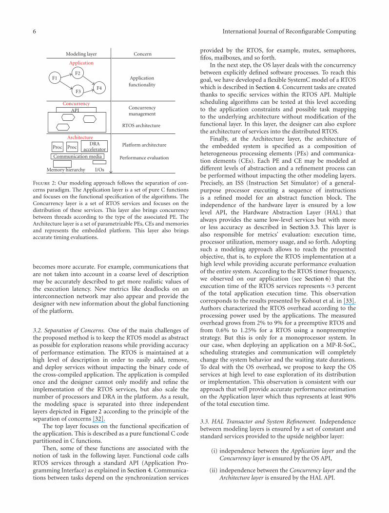
Figure 2: Our modeling approach follows the separation of con-cerns paradigm. The Application layer is a set of pure C functionsand focuses on the functional specification of the algorithms. TheConcurrency layer is a set of RTOS services and focuses on thedistribution of these services. This layer also brings concurrencybetween threads according to the type of the associated PE. TheArchitecture layer is a set of parametrizable PEs, CEs and memoriesand represents the embedded platform. This layer also bringsaccurate timing evaluations.
becomes more accurate. For example, communications thatare not taken into account in a coarse level of descriptionmay be accurately described to get more realistic values ofthe execution latency. New metrics like deadlocks on aninterconnection network may also appear and provide thedesigner with new information about the global functioningof the platform.
3.2. Separation of Concerns. One of the main challenges ofthe proposed method is to keep the RTOS model as abstractas possible for exploration reasons while providing accuracyof performance estimation. The RTOS is maintained at ahigh level of description in order to easily add, remove,and deploy services without impacting the binary code ofthe cross-compiled application. The application is compiledonce and the designer cannot only modify and refine theimplementation of the RTOS services, but also scale thenumber of processors and DRA in the platform. As a result,the modeling space is separated into three independentlayers depicted in Figure 2 according to the principle of theseparation of concerns [32].
The top layer focuses on the functional specification ofthe application. This is described as a pure functional C codepartitioned in C functions.
Then, some of these functions are associated with thenotion of task in the following layer. Functional code callsRTOS services through a standard API (Application Pro-gramming Interface) as explained in Section 4. Communica-tions between tasks depend on the synchronization services
provided by the RTOS, for example, mutex, semaphores,fifos, mailboxes, and so forth.
In the next step, the OS layer deals with the concurrencybetween explicitly defined software processes. To reach thisgoal, we have developed a flexible SystemC model of a RTOSwhich is described in Section 4. Concurrent tasks are createdthanks to specific services within the RTOS API. Multiplescheduling algorithms can be tested at this level accordingto the application constraints and possible task mappingto the underlying architecture without modification of thefunctional layer. In this layer, the designer can also explorethe architecture of services into the distributed RTOS.
Finally, at the Architecture layer, the architecture ofthe embedded system is specified as a composition ofheterogeneous processing elements (PEs) and communica-tion elements (CEs). Each PE and CE may be modeled atdifferent levels of abstraction and a refinement process canbe performed without impacting the other modeling layers.Precisely, an ISS (Instruction Set Simulator) of a general-purpose processor executing a sequence of instructionsis a refined model for an abstract function block. Theindependence of the hardware layer is ensured by a lowlevel API, the Hardware Abstraction Layer (HAL) thatalways provides the same low-level services but with moreor less accuracy as described in Section 3.3. This layer isalso responsible for metrics’ evaluation: execution time,processor utilization, memory usage, and so forth. Adoptingsuch a modeling approach allows to reach the presentedobjective, that is, to explore the RTOS implementation at ahigh level while providing accurate performance evaluationof the entire system. According to the RTOS timer frequency,we observed on our application (see Section 6) that theexecution time of the RTOS services represents ≈3 percentof the total application execution time. This observationcorresponds to the results presented by Kohout et al. in [33].Authors characterized the RTOS overhead according to theprocessing power used by the applications. The measuredoverhead grows from 2% to 9% for a preemptive RTOS andfrom 0.6% to 1.25% for a RTOS using a nonpreemptivestrategy. But this is only for a monoprocessor system. Inour case, when deploying an application on a MP-R-SoC,scheduling strategies and communication will completelychange the system behavior and the waiting state durations.To deal with the OS overhead, we propose to keep the OSservices at high level to ease exploration of its distributionor implementation. This observation is consistent with ourapproach that will provide accurate performance estimationon the Application layer which thus represents at least 90%of the total execution time.
3.3. HAL Transactor and System Refinement. Independencebetween modeling layers is ensured by a set of constant andstandard services provided to the upside neighbor layer:
(i) independence between the Application layer and theConcurrency layer is ensured by the OS API,
(ii) independence between the Concurrency layer and theArchitecture layer is ensured by the HAL API.
International Journal of Reconfigurable Computing 7
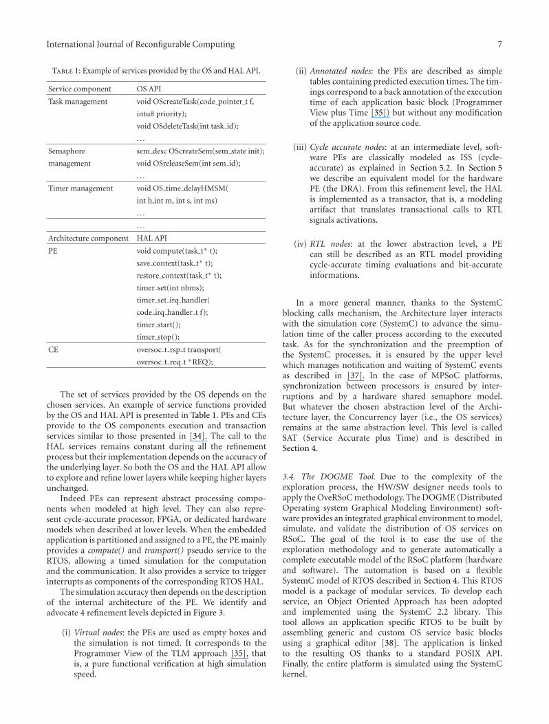
Table 1: Example of services provided by the OS and HAL API.
Service component OS API
Task management void OScreateTask(code pointer t f,
intu8 priority);
void OSdeleteTask(int task id);
. . .
Semaphore sem desc OScreateSem(sem state init);
management void OSreleaseSem(int sem id);
. . .
Timer management void OS time delayHMSM(
int h,int m, int s, int ms)
. . .
. . .
Architecture component HAL API
PE void compute(task t∗ t);
save context(task t∗ t);
restore context(task t∗ t);
timer set(int nbms);
timer set irq handler(
code irq handler t f);
timer start();
timer stop();
CE oversoc t rsp t transport(
oversoc t req t ∗REQ);
The set of services provided by the OS depends on thechosen services. An example of service functions providedby the OS and HAL API is presented in Table 1. PEs and CEsprovide to the OS components execution and transactionservices similar to those presented in [34]. The call to theHAL services remains constant during all the refinementprocess but their implementation depends on the accuracy ofthe underlying layer. So both the OS and the HAL API allowto explore and refine lower layers while keeping higher layersunchanged.
Indeed PEs can represent abstract processing compo-nents when modeled at high level. They can also repre-sent cycle-accurate processor, FPGA, or dedicated hardwaremodels when described at lower levels. When the embeddedapplication is partitioned and assigned to a PE, the PE mainlyprovides a compute() and transport() pseudo service to theRTOS, allowing a timed simulation for the computationand the communication. It also provides a service to triggerinterrupts as components of the corresponding RTOS HAL.
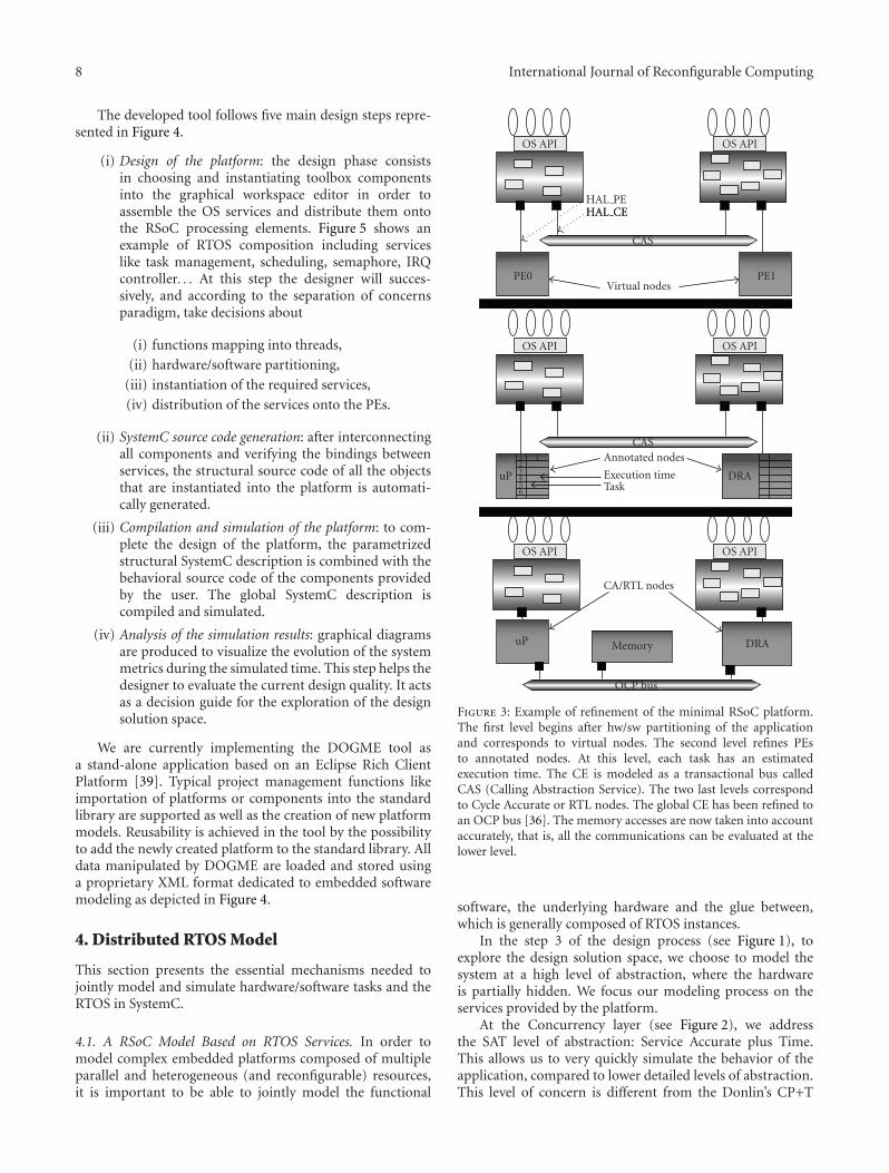
The simulation accuracy then depends on the descriptionof the internal architecture of the PE. We identify andadvocate 4 refinement levels depicted in Figure 3.
(i) Virtual nodes: the PEs are used as empty boxes andthe simulation is not timed. It corresponds to theProgrammer View of the TLM approach [35], thatis, a pure functional verification at high simulationspeed.
(ii) Annotated nodes: the PEs are described as simpletables containing predicted execution times. The tim-ings correspond to a back annotation of the executiontime of each application basic block (ProgrammerView plus Time [35]) but without any modificationof the application source code.
(iii) Cycle accurate nodes: at an intermediate level, soft-ware PEs are classically modeled as ISS (cycle-accurate) as explained in Section 5.2. In Section 5we describe an equivalent model for the hardwarePE (the DRA). From this refinement level, the HALis implemented as a transactor, that is, a modelingartifact that translates transactional calls to RTLsignals activations.
(iv) RTL nodes: at the lower abstraction level, a PEcan still be described as an RTL model providingcycle-accurate timing evaluations and bit-accurateinformations.
In a more general manner, thanks to the SystemCblocking calls mechanism, the Architecture layer interactswith the simulation core (SystemC) to advance the simu-lation time of the caller process according to the executedtask. As for the synchronization and the preemption ofthe SystemC processes, it is ensured by the upper levelwhich manages notification and waiting of SystemC eventsas described in [37]. In the case of MPSoC platforms,synchronization between processors is ensured by inter-ruptions and by a hardware shared semaphore model.But whatever the chosen abstraction level of the Archi-tecture layer, the Concurrency layer (i.e., the OS services)remains at the same abstraction level. This level is calledSAT (Service Accurate plus Time) and is described inSection 4.
3.4. The DOGME Tool. Due to the complexity of theexploration process, the HW/SW designer needs tools toapply the OveRSoC methodology. The DOGME (DistributedOperating system Graphical Modeling Environment) soft-ware provides an integrated graphical environment to model,simulate, and validate the distribution of OS services onRSoC. The goal of the tool is to ease the use of theexploration methodology and to generate automatically acomplete executable model of the RSoC platform (hardwareand software). The automation is based on a flexibleSystemC model of RTOS described in Section 4. This RTOSmodel is a package of modular services. To develop eachservice, an Object Oriented Approach has been adoptedand implemented using the SystemC 2.2 library. Thistool allows an application specific RTOS to be built byassembling generic and custom OS service basic blocksusing a graphical editor [38]. The application is linkedto the resulting OS thanks to a standard POSIX API.Finally, the entire platform is simulated using the SystemCkernel.
8 International Journal of Reconfigurable Computing
The developed tool follows five main design steps repre-sented in Figure 4.
(i) Design of the platform: the design phase consistsin choosing and instantiating toolbox componentsinto the graphical workspace editor in order toassemble the OS services and distribute them ontothe RSoC processing elements. Figure 5 shows anexample of RTOS composition including serviceslike task management, scheduling, semaphore, IRQcontroller. . . At this step the designer will succes-sively, and according to the separation of concernsparadigm, take decisions about
(i) functions mapping into threads,
(ii) hardware/software partitioning,
(iii) instantiation of the required services,
(iv) distribution of the services onto the PEs.
(ii) SystemC source code generation: after interconnectingall components and verifying the bindings betweenservices, the structural source code of all the objectsthat are instantiated into the platform is automati-cally generated.
(iii) Compilation and simulation of the platform: to com-plete the design of the platform, the parametrizedstructural SystemC description is combined with thebehavioral source code of the components providedby the user. The global SystemC description iscompiled and simulated.
(iv) Analysis of the simulation results: graphical diagramsare produced to visualize the evolution of the systemmetrics during the simulated time. This step helps thedesigner to evaluate the current design quality. It actsas a decision guide for the exploration of the designsolution space.
We are currently implementing the DOGME tool asa stand-alone application based on an Eclipse Rich ClientPlatform [39]. Typical project management functions likeimportation of platforms or components into the standardlibrary are supported as well as the creation of new platformmodels. Reusability is achieved in the tool by the possibilityto add the newly created platform to the standard library. Alldata manipulated by DOGME are loaded and stored usinga proprietary XML format dedicated to embedded softwaremodeling as depicted in Figure 4.
4. Distributed RTOS Model
This section presents the essential mechanisms needed tojointly model and simulate hardware/software tasks and theRTOS in SystemC.
4.1. A RSoC Model Based on RTOS Services. In order tomodel complex embedded platforms composed of multipleparallel and heterogeneous (and reconfigurable) resources,it is important to be able to jointly model the functional
OS API OS API
HAL PEHAL CE
CAS
Virtual nodesPE0 PE1
OS API OS API
uP
1 123456
DRA
HAL CE
CASAnnotated nodes
Execution timeTask
OS API OS API
uP Memory DRA
CA/RTL nodes
OCP bus
Figure 3: Example of refinement of the minimal RSoC platform.The first level begins after hw/sw partitioning of the applicationand corresponds to virtual nodes. The second level refines PEsto annotated nodes. At this level, each task has an estimatedexecution time. The CE is modeled as a transactional bus calledCAS (Calling Abstraction Service). The two last levels correspondto Cycle Accurate or RTL nodes. The global CE has been refined toan OCP bus [36]. The memory accesses are now taken into accountaccurately, that is, all the communications can be evaluated at thelower level.
software, the underlying hardware and the glue between,which is generally composed of RTOS instances.
In the step 3 of the design process (see Figure 1), toexplore the design solution space, we choose to model thesystem at a high level of abstraction, where the hardwareis partially hidden. We focus our modeling process on theservices provided by the platform.
At the Concurrency layer (see Figure 2), we addressthe SAT level of abstraction: Service Accurate plus Time.This allows us to very quickly simulate the behavior of theapplication, compared to lower detailed levels of abstraction.This level of concern is different from the Donlin’s CP+T

International Journal of Reconfigurable Computing 9
T1 T2 T3
API API
Taskmanager Scheduler
Mutex Core OS
XMLlibrary
Iterate overthe design flow
If the resultsquality is low
Highqualityresults
Refi
nem
ent
Application
Syst
emC
SystemC/TLMlibrary
Metrics analysis
Figure 4: The DOGME tool brings facilities to manipulate thecomponents of the library. These components model RTOS servicesfor the control of an RSoC platform. In the library the servicesare described both by a SystemC generic source code and an XMLexchange file. The designer graphically instantiates the components,then the tool automatically adds debug components for metricevaluation into the specification and generates the code of thecorresponding platform. The platform is compiled and linked withthe SystemC libraries and simulated thanks to graphical interfaces.The designer can finally evaluate the metrics of his platform and cantake decisions about exploration or refinement.
(Communicating Processes with Time) level [35] whichmainly focuses on hardware modeling but which does notinclude the RTOS services. This level of modeling impliesthat the architecture is not modeled explicitly, all the appli-cation tasks are functional, annotated with approximated ormeasured execution timing, and all the RTOS services areexplicit and timed.
The core element of our distributed architecture modelis a high-level functional model of a RTOS written inSystemC. Since SystemC does not support OS modelingfacilities in its actual version, a first step was then to extendSystemC with embedded software modeling features [37].The works presented in [40–43] are examples of simulationenvironments dealing with this challenge.
The proposed RTOS model [37] acts as a Service Accurate+ Time model of a virtual PE (processor or DRA) in thesense that all the necessary services of an embedded RTOS aremodeled as independent modules with their own behaviorand timing. The RTOS model is built as a collection ofservice modules implemented in the form of a hierarchical
sc modules to foster high level exploration of customarchitectures. The main RTOS model instantiates all itsmodules and uses sc export to provide a global API tothe application code as illustrated in Figure 6. Each servicemodule has its own interface that furnishes the correspondingservices’ functions to the embedded application. This modelincludes mechanisms for modeling dynamic creation oftasks, task preemption and interrupt handling as describedin [37]. Figure 6 illustrates the hierarchical structure of theSystemC RTOS model composed of the following servicemodules:
(i) a task manager that keeps the information andproperties of each task according to its implementa-tion (software or hardware): state, context, priority,timings, area, used software or hardware resources . . .
(ii) a scheduler that implements a specific algorithm:EDF [7], HPF [7], horizon [44], . . .
(iii) a synchronization service using semaphores.
(iv) a time management service that keeps track of time,timeouts, periods, deadlines . . .
(v) an interrupt manager that makes the system reactiveto external or internal events.
(vi) a specific simulation service (advance time).
Each service module is modeled as a SystemC hierarchi-cal sc channel and is symbolized in the figure using theSystemC representation [30]. A service module thus providesseveral service functions through its interface.
For example, the task manager provides the followingfunctions: create (dynamically) a task, delete a task, getthe state of a task, change the state of a task. . . The taskcreation function associates a simulation process (and thusconcurrency) to one of the pure C function present at theApplication layer.
Some service functions are accessible from the Appli-cation layer through the OS API. Those are called externalservice functions. Others are only accessible from the otherservice modules through a SystemC port to establish inter-module communications and are called internal servicefunctions.
At this layer, timed simulations of the application usea specific simulation call (called OS WAIT()), associatedto each bloc of task code between two system-calls andredirected through the Concurrency layer toward the Archi-tecture layer. This service, represented in Figure 6, allowseach function to progress in time. In addition, each OSservice function within the OS itself may also be annotatedwith timing information (depending on the processor)allowing a timed simulation of a realistic system.
Actually the system library provides a set of basic genericservices: interrupt management, timer management, inter-tasks synchronization, and memory management. It alsoprovides hardware and software specific services such as thetask management of software or hardware tasks, softwarescheduling policies and hardware placement algorithms.

10 International Journal of Reconfigurable Computing
Figure 5: The DOGME tool represents a distributed RTOS through hierarchical views: the Component Graphical Editor, where the servicesare organized inside each PE, and the Platform Graphical Editor, where the groups of services are composed according to the number andtype of PEs into the RSoC platform. Here the Component Graphical Editor is shown. It uses toolbox components to specify and customize theservices of a dedicated group. Each service is modeled as a software (C++) component having ports and interfaces. Each service componentprovides several service functions.
T1 T2 Tn ITn
API Synchro Timer Task IRQ Simu
Semaphore
Timer
Taskmanager IRQ
manager
SchedulerOther
os wait
SystemC terminology
Port
Interface
sc module
sc channel
sc export (of interface)
Primitive canal/connection
ITnInterrupt
TnTask
Figure 6: The modular RTOS model and its composed API. EachOS service exports its own interface to the application. Services areconnected together to ensure the global OS coherency and behavior.
4.2. Distant Communications and Services Requests. Weextend the model for distributed multiprocessor architec-tures exploration with the following features: the wholeapplication is decomposed into multiple threads sharing
the same addressable memory, the application is staticallypartitioned onto multiple processing nodes, each processorhas its own scheduling strategy (policy, priorities, etc). Allinter-processor communications are modeled using trans-actions with respect to TLM 1.0 methodology. A uniquetransport method is used for both requests and replies. Allcommunications are currently performed instantaneouslybut this allows a communication refinement process andthus a time accurate simulation by introducing bus-relatedor network-related timings into transactional ports.
Our approach for modeling distributed OS services isinspired from the middleware philosophy which consists inusing proxies and skeletons services. A proxy service providesa local entry point to a distant service accessible throughan interconnection infrastructure. This adds dedicated portsand interfaces to the RTOS (and also on services modulesneeding to communicate).
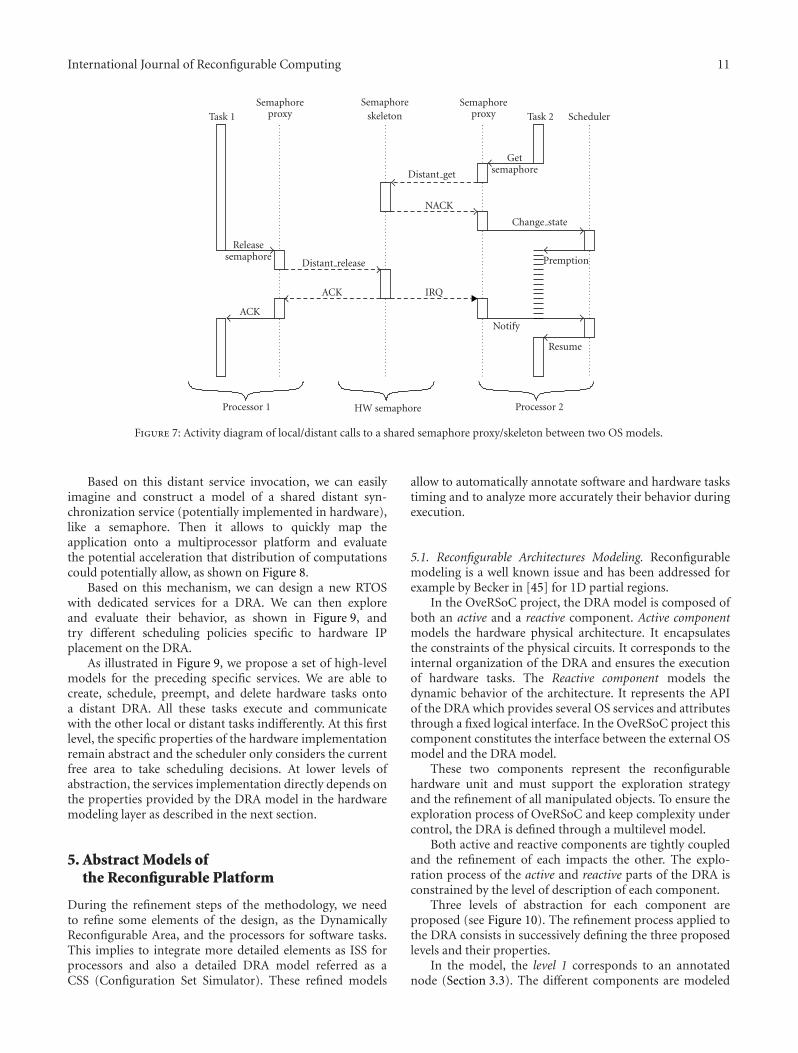
Figure 7 illustrates transactions between two localsemaphore services (proxies) and a shared distant semaphoreimplementation (skeleton). Get and release semaphoreinvocations are performed locally to the proxy which for-wards transactions to the distant service. By using a simpletransport method, all distant calls put the caller tasks intoan active waiting state. In case of access conflicts, the sharedservice has its own arbitration policy. Then, replies are sentback to the caller at the end of the service execution.
Communication from a distant service to local proxiesare performed by using signals which are similar to interruptrequests that are managed by local proxies. Suspended tasksmay then be resumed by their own schedulers depending onlocal policies.
International Journal of Reconfigurable Computing 11
Task 1
Semaphoreproxy
Semaphoreskeleton
Semaphoreproxy Task 2 Scheduler
Releasesemaphore
Distant release
ACK
ACK
IRQ
NACK
Distant get
Getsemaphore
Change state
Premption
Resume
Notify
Processor 1 HW semaphore Processor 2
Figure 7: Activity diagram of local/distant calls to a shared semaphore proxy/skeleton between two OS models.
Based on this distant service invocation, we can easilyimagine and construct a model of a shared distant syn-chronization service (potentially implemented in hardware),like a semaphore. Then it allows to quickly map theapplication onto a multiprocessor platform and evaluatethe potential acceleration that distribution of computationscould potentially allow, as shown on Figure 8.
Based on this mechanism, we can design a new RTOSwith dedicated services for a DRA. We can then exploreand evaluate their behavior, as shown in Figure 9, andtry different scheduling policies specific to hardware IPplacement on the DRA.
As illustrated in Figure 9, we propose a set of high-levelmodels for the preceding specific services. We are able tocreate, schedule, preempt, and delete hardware tasks ontoa distant DRA. All these tasks execute and communicatewith the other local or distant tasks indifferently. At this firstlevel, the specific properties of the hardware implementationremain abstract and the scheduler only considers the currentfree area to take scheduling decisions. At lower levels ofabstraction, the services implementation directly depends onthe properties provided by the DRA model in the hardwaremodeling layer as described in the next section.
5. Abstract Models ofthe Reconfigurable Platform
During the refinement steps of the methodology, we needto refine some elements of the design, as the DynamicallyReconfigurable Area, and the processors for software tasks.This implies to integrate more detailed elements as ISS forprocessors and also a detailed DRA model referred as aCSS (Configuration Set Simulator). These refined models
allow to automatically annotate software and hardware taskstiming and to analyze more accurately their behavior duringexecution.
5.1. Reconfigurable Architectures Modeling. Reconfigurablemodeling is a well known issue and has been addressed forexample by Becker in [45] for 1D partial regions.
In the OveRSoC project, the DRA model is composed ofboth an active and a reactive component. Active componentmodels the hardware physical architecture. It encapsulatesthe constraints of the physical circuits. It corresponds to theinternal organization of the DRA and ensures the executionof hardware tasks. The Reactive component models thedynamic behavior of the architecture. It represents the APIof the DRA which provides several OS services and attributesthrough a fixed logical interface. In the OveRSoC project thiscomponent constitutes the interface between the external OSmodel and the DRA model.
These two components represent the reconfigurablehardware unit and must support the exploration strategyand the refinement of all manipulated objects. To ensure theexploration process of OveRSoC and keep complexity undercontrol, the DRA is defined through a multilevel model.
Both active and reactive components are tightly coupledand the refinement of each impacts the other. The explo-ration process of the active and reactive parts of the DRA isconstrained by the level of description of each component.
Three levels of abstraction for each component areproposed (see Figure 10). The refinement process applied tothe DRA consists in successively defining the three proposedlevels and their properties.
In the model, the level 1 corresponds to an annotatednode (Section 3.3). The different components are modeled

12 International Journal of Reconfigurable Computing
TimerTask
manager
IRQmanager
Scheduler
Proxy BasicOS
TimerTask
manager
IRQmanager
Scheduler
Proxy BasicOS
TimerTask
manager
IRQmanager
Scheduler
Skeleton
TLM bus
Proxy BasicOS
TimerTask
manager
IRQmanager
Scheduler
Proxy BasicOS
T1 T2 TnITn T1 T2 Tn
ITn T1 T2 Tn ITn T1 T2 Tn ITn
1 · · ·n
Figure 8: Model of MPSoC RTOSes with a hardware shared semaphore service. Each RTOS has a local Proxy service which forwards a(semaphore) request to an external device (the skeleton) that processes the real service, as a RPC (Remote Procedure Call), except the skeletonservices could be refined in hardware.
OS and tasks on a processor
T1 T2 Tn ITn
Timer
Taskmanager IRQ
manager
Scheduler
Sem. proxyOS
Reconf. zonemanager
OS and IPs on a DRA(dynamicaly reconfiguranle area)
DRA OS
IPn IPn IPn
Timer
Sem. proxyLoader placer
1 · · ·n
Sem. skeleton
Service to explore
Shared semaphore(external, hardware)
Figure 9: Model of RSoC specific OS: one standard customized with a DRA manager, one specific into the DRA, and another one specificfor a refined shared semaphore service alone as an external device.
through a small number of parameters and permit a fast andcoarse evaluation of methods and performances. The activecomponent is considered as an homogeneous unconstrainedrectangular area with a reconfiguration memory. The onlyparameter which is required to execute the tasks in theDRA is the task’s area. At this level, the resources of theDRA are considered as unconstrained, that is, no bandwidthlimitation, no latency, no area constraints, and so forth.In terms of performance, the designer evaluates the globalarea required in the active components, as well as thereconfiguration overhead introduced by its task managementservices.
The second level refines the active components defined asa rectangle which contains a set of heterogeneous resources
such as memory, abstract running blocks and interconnectresources with limited bandwidth. The task heterogeneityis present at this level and a minimal placement serviceis required. At this level, the reactive component uses thestructural information of the active component to verify theconstraints of tasks. The corresponding definition of tasksmust be completed by parameters, such as the rectangularsize, the form factor of the area and so forth.
The level 3 is the most accurate level of description and allthe elementary blocks of the active components are described.They are defined as an array of LUT (Look Up Table) withglue logic for arithmetic computation and the correspondingsequential elements, a set of memory allocated throughoutthe array, columns of hardwired blocks and eventually

International Journal of Reconfigurable Computing 13
Level 1
Level 2
Level 3
Re-active components Active components
Task 1-Nb CLB-Nb LUT-Mem size-· · ·
T1.width ≤ Rbi.width&&T1.height ≤ Rbi.height
T1.nb Clb ≤ Rbi.Clb&&T1.nb Lut ≤ Rbi.nb Lut
CLB1CLB2 RB2
RB1
Task 1-width-height
Task 1-x au
semGive()
Creat task (Ti)T1.x ≤ DRA.x
Delete task (Ti)
semGive()
Creat task (Ti)
Delete task (Ti)
semGive()
Creat task (Ti)
Delete task (Ti)
DRA
Tj RB2
RB1 Tk
Figure 10: Hierarchical model of the active and reactive compo-nents of the DRA. The different levels permit to represents the DRAwith more or less details. Refinement process leads to the completedefinition of the internal architecture of the DRA. Belongingto the refinement of architectural aspects (active component),the supported services can be developed and evaluated (reactivecomponent).
hardware core processors like PowerPCs in last Xilinx’stechnology. The corresponding reactive component mustimplement all the services described in Section 2. Theseservices take both the application constraints and the precisecircuit organization into account.
From this model, the DRA management can be exploredthrough the implementation of distributed OS services.
For example, we present a particular implementation ofthe createTask OS service in Figure 11. In this example, aplacer and a loader service are also implemented in the DRA.The first sequence of Figure 11 shows the hardware taskcreation call, createTask(T3h). This OS call is performedby the software task T1 and is handled by a processorOS service. Since the task to create must be executedonto the DRA, the OS service call is passed to the DRAthrough the interface, createHWTask(T3h). This interface,implemented by the reactive component, calls the DRA OSservice of task creation. Before loading the task, the DRAmust verify if this new task can be loaded and placed inthe reconfigurable area. To do that, the hardware OS callsthe placer service, isLoadable(T3h). At this step, theverification depends on the level of DRA description. Forexample, at level one, the placer checks if the available area
is sufficient for this new task. In this case, we can model thisverification as
Nt∑
i=1
Ai + Anewtask ≤ totalArea, (1)
whereAi is the necessary area for the task i,Anewtask is the areaof the new task to instantiate onto the DRA, Nt representsthe number of tasks already instantiated within the DRA, andtotalArea the total DRA area.
In the first part of this diagram, we illustratedthe case where the placement of a new task is pos-sible. In this case, the placer calls the loader service,loadTask(T3h). The loader ensures the loading of thetask bitstream, loadBistream(T3h), and finally starts thetask, start(T3h). This sequence can be modified in orderto evaluate potential overhead of different implementationsolutions.
In the second part of this sequence the CreateTask OS callis performed by the software task T2, createTask(T4h).The beginning of the sequence is the same as the firstsequence presented above, but in this case, we consider thatthe placement of the new task into the DRA is not possible,ie. the return value for the isLoadable(T4h) function is NoOK due to unavailable area. In this case, the task executionis refused by the DRA, and an error signal is returned. Tofinish this example, we suppose that a software version of taskT4h exists and the system decides to switch to the softwareversion, create(T4s), and to schedule it immediately.
5.2. Processor Modeling. In this work, we use ISS for soft-ware simulation. As a proof of concept of our embeddedsoftware modeling approach, we developed a SystemC ISScorresponding to the ATMEL AVR Instruction Set Archi-tecture. Targeting either hardcore processors or ISS followsthe same compilation flow. We can thus reuse standardcompilation tools. The binary code must then be loaded intoSystemC memory models by external modules (bootstrap).The ISS communicates with memory through standardhierarchical channels. At this level of the model framework,communications can be refined towards Register TransferLevel. The ISS fetches instructions and simulates opcodeexecution. We implemented two modes of operation for theISS: accurate and fast mode. When functioning in its main(accurate) mode the ISS classically extracts, executes 16-bits opcodes and increments the program counter. Once abasic block, has been executed, the ISS keeps track of thesimulated execution time into specific tables to minimize thesimulation overhead. Each basic block is thus associated witha block ID which corresponds either to an entire softwaretask code or to instruction blocks within the task code.The ISS can also be interrupted and can thus model taskpreemption at a very fine level. In fast mode, preemptionis also possible but at a coarser level since simulated timeadvances with a basic block precision. Interrupts can notoccur before the end of the single SystemC wait timeparameter. Once interrupted, the remaining time is saved intables and reused when the basic block is started again.

14 International Journal of Reconfigurable Computing
TaskT1
TaskT2
Applicationsoftware tasks
Applicationhardware tasks
OS serviceson processor
DRAinterface
OS serviceson DRA
TaskT4s
CreateTask
Start(T1)
Start(T3h)
Start(T2)
Start(T4s)
Restart(T2)
CreateTask(T3h)
CreateTask(T3h)
CreateTask(T4h)
Create(T4s)
Stop(T2)
Schedule
Reschedule
Reschedule
Reschedule
Error
CreateHWTask(T3h)
CreateHWTask(T4h)CreateTask(T4h)
isLoadable(T4h)
isLoadable(T3h)
LoadTask(T3h)LoadingBitstream(T3h)
HWTaskFinishedTaskFinished
No OKNo OK
OK
Reactive componentsCreateTask
Active componentsTaskT3h
TaskT4h
Placer Loader
Area or form or · · ·verification
Area or form or · · ·verification
Figure 11: Sequence diagram of the CreateTask service implementation. After a Create task system call a sequence of system call depends onthe services implemented on the DRA. Here we can evaluate and develop the loader and the placer services of the DRA dedicated RTOS.
Since components within each layer can be describedat different levels of abstraction, the challenge is thereforeto synchronize the functional and timed simulation acrossthe layers. This is particularly difficult for the softwaremodels that exist at three different layers simultaneously:the draft application specification is modeled as C func-tions in the Application layer, RTOS services as SystemCtransactions in the Concurrency layer, and advanced versionsoftware as instruction-accurate (compiled) descriptions inthe Architecture layer. Thanks to the adopted separation ofconcerns approach, functional (Application layer) and timed(Architecture layer) aspects can be separated. Functional andtimed aspects are thus limited to the corresponding layers.Consequently, a cycle-accurate software description has itshigh-level functional equivalent inside the top layer. Here,the duplication of the application description follows andreinforces the separation of concerns. It eases embeddedsoftware design by allowing software IP reuse, simulationof code portions with heterogeneous development levels,and RTOS services exploration. Furthermore, the methodcan be equally applied to hardware implementation ofthe application tasks since the Application layer makes no
assumption about the hardware/software partitioning. Thisco-existence of the task description and its implementationversion is referred as a Simulation Couple (SC) in ourframework. Thus coherent execution of the SC only dependson a common definition of synchronization points. Thosecorrespond to the RTOS system calls present both in thehigh-level code and in the binary code. So the granularityof the Basic Blocks (BB) for the ISS is defined as thesequences of instructions between two system calls. Each taskis associated a SystemC process and a synchronization eventmanaged by the RTOS model and shared by all the BB of thetask.
As depicted in Figure 12 the scheduler launches thehighest priority ready task by notifying its synchronizationevent. The corresponding process is activated and its func-tional code executes in the top layer in zero simulationtime till encountering a call to the RTOS API. The RTOSservice first uses the HAL API and delegates the executiontime evaluation of this BB to the PE. Without interrupt,the PE estimates the duration of the BB and advances thesimulation time. If an interrupt occurs in the middle of aBB, the ISS stops at the corresponding date and saves task

International Journal of Reconfigurable Computing 15
Functionalresults
void task code(){int n = OS fifo pend();int BB = fib(n) + fib(n− 1)OS mutex pend(shared var mutex);shared var = BB;
OS mutex post(shared var mutex);
}
void OS mutex pend(OS EVENT mutex){HAL.compute(current Task);wait for mutex(mutex);reschedule();}
PE
Time
· · ·00000066 fib:66: 0f 93 push r1668: 1f 93 push r176a: cf 93 push r286c: df 93 push r296e: d9 2f mov r29, r2570: c8 2f mov r28, r24· · ·90: 02 c0 rjmp .+4 ; 0x9692: 81 e0 ldi r24, 0x01 ; 194: 90 e0 ldi r25, 0x00 ; 0· · ·
Figure 12: Example of a Simulation Couple. The software part ofthe application has two representations: a functionnal one used inhigh level abstraction layer and a timed one based on the use of anISS.
context. The interrupt is then processed and the relatedroutine is executed in the Concurrency layer. When thescheduler is reactivated, it can decide (according to thechosen scheduling policy) to resume the task or to elect a newone. The same scenario is repeated again until the end of thesimulation.
6. Experiments
We applied our framework to a realistic application in thefield of image processing for robotic vision. The application(see Figure 13) is used to learn object views or landscapesand extracts local visual features from the neighborhood ofimage’s keypoints.
We specified at the Application layer the applicationas a set of 30 different communicating tasks and someof them could be run 400 times dynamically in paralleldepending on the entry data as depicted in Figure 14. The fulldescription of our application is out of the scope of this paper[46]. However, following a biologically inspired approach,this vision architecture belongs to a larger sensorimotorloop that brings interesting dynamical properties: the degreeof parallelism and the execution time varies according to
input data, namely the number of interest points, andthe robot speed mode (high, intermediate, and low detailmode).
6.1. Software Exploration. In this context, we performedthe profiling of the entire application on a hardware SoCplatform. We also built the profile of the μC/OS-II [47]services (deterministic). For the purpose of the explorationwe have targeted a Nios-II [48] based multiprocessorarchitecture (MPSoC) prototyped onto an Altera Cyclone-II FPGA circuit. The profiling of embedded software is along and rigorous work which needs a non-preemptive andnon-intrusive measurement technique. For this purpose, wemodified the source code of the RTOS in order to providesuch a measure technique both for the application basicblocks and for the OS services. After several executionsonto a set of representative images, we built a timingdata base for this application. For a simulation purpose,assigning a unique and representative execution time to theapplication tasks is a complex problem when the varianceof the measured values is important. According to therefinement layers presented in Section 3.2, we currentlyrecommend the use of an average value as a first approx-imation of the execution time and a stochastic draw intothe timing data-base as a better estimation. Then, thesetiming data must be back-annotated into the high-levelmodel in order to explore and evaluate the architecturedimensioning and the implementation strategies: tasks dis-tribution, services distribution, scheduling algorithms, andso forth.
At this step, the application and the soft RTOS serviceswere fully annotated into the Architecture layer. Followingthe design flow presented in Figure 1, we then performed afirst set of simulations in order to evaluate the critical partsof the application when partitioned onto several processors.During these simulations the SystemC models related tothe Architecture layer estimate the global system executiontimes. Figure 15(a) summarizes this information. Each plotrepresents an average value of the system performance fordifferent images (number of keypoints). We can see thata pure software application could not be more acceleratedusing more than three processors (only a small gain betweentwo and three). This MPSoC implementation reaches aglobal execution time of ≈27000 ms. Moreover we identifiedthat the gaussian pyramid [46] represents the critical partof the application. So, we then explored the implementationof the related tasks into hardware in a reconfigurabledevice.
6.2. Heterogeneous Exploration Based on System Metrics. Wedeployed our application using a static partitioning betweensoftware and hardware tasks (more details can be foundin [46]). The result of the partitioning is a set of 12software tasks and a set of 18 hardware regular treatments.We realized the design of the hardware blocks in VHDLand back annotated the synthesis results (number of slices,execution times, communication latencies and configurationtimes) into the functional DRA model. The acceleration of

16 International Journal of Reconfigurable Computing
Figure 13: Graphical results of the SystemC functional model simulation of the robotic vision application.
a hardware implementation for the critical software tasks isvery important: their total execution time is divided by afactor 4000. A second iteration of simulations (upper loop ofFigure 1) was processed in order to define the new adequatearchitecture.
To figure out the right number of processors, weperformed a new set of experimentations, as shown onFigure 15(b). The result of the second exploration is anarchitecture composed of 3 processors and a DRA witha yet undefined size. Indeed, the gain obtained by thehardware implementation of the gaussian pyramid permitsto parallelize the 12 remaining software tasks to have asignificant gain.
During this exploration/refinement process, the designercan use the system metrics presented in Section 3.1 andautomatically extracted by the tool. Some examples ofmetrics used for the system dimensioning are the Ganttchart, the DRA chart (Figure 16) and the Communicationchart depicted in Figure 17. The Gantt diagram representsthe state of each task (software or hardware) along time:ready, running, waiting states and a configuring state for
hardware tasks only. The Gantt charts of Figure 16(a) depictthe new configuration of the system architecture. The 12upper lines represent the ordering of the software tasksonto the 3 processors and the remaining lines represent the18 hardware tasks running in parallel in the DRA. Thisarchitecture corresponds to the best achievable performancessince the size of the DRA has been computed as the sum ofthe hardware tasks occupation. More precisely, the hardwarepartition uses near to 1200 slices (In the Virtex-5 FPGAslices are organized differently from previous generations.Each Virtex-5 FPGA slice contains four LUTs and fourflip-flops -previously it was two LUTs and two flip-flops-),14 BRAM and 12 DSP48 blocks. Hence, the estimatedresource utilization for the global architecture (DRA + threeprocessors) is about 4375 slices, 21 BRAM and 16 DSP48blocks. This estimation would correspond for example tothe size of a LX30T Virtex 5 circuit [49]. The globalsystem latency ranging from 950 ms (Gantt of Figure 16)to about 60 ms depending of the application mode. Weobtain about x28 acceleration compared to the pure softwareimplementation.

International Journal of Reconfigurable Computing 17N
um
ber
ofpr
oces
ses
0
50
100
150
200
250
300
350
400
450
Video frame
0 1000 2000 3000 4000 5000
High detail modeIntermediate modeLow detail mode
Figure 14: Number of processes created and managed by the OSmodel during the application simulation on a set of 6000 images foreach modes.
6.3. Reconfiguration Management. In order to reduce the sizeof the hardware partition we vary the number of slices ofthe DRA and evaluated the capability of the system to adaptthe hardware scheduling to a restricted area. In Figure 16,we present the results for one of the explored restrictedarchitecture. We observe on the Gantt chart a differentschedule of the hardware IP depending on the occupationrate of the DRA. The comparison between DRA charts ofFigures 16(c) and 16(d) shows a clear difference in theutilization of the DRA over the time.
In the first case (Figures 16(a) and 16(c)), the DRAis never full and the tasks are configured as soon as theRTOS puts them in the Ready State. Here, the configurationonly depends on the data dependencies in the applicationgraph.
In the second case (Figures 16(b) and 16(d)) we considera smaller DRA composed of 3000 slices. The DRA can notconfigure all the tasks at the same time. Here configurationdepends both on the data dependencies and on the availableresources. At level 1 of the DRA model, the hardwarescheduler only manages available resources. It searches forsleeping tasks within the DRA to be replaced by a newtask asking for resources. Besides, once a hardware taskfinishes its execution, it is removed (its resources are freed),enabling another task to be implemented. For the estimationof the configuration time we used a metric which dependson the size of the partial bitstream for the targeted DRAtechnology (about 50 μs per block of 16 CLBs on a Virtex5).
As a first conclusion the exploration of the architecturefor the robotic vision application leads us to model acomplete RSoC platform at a high-level of abstraction. Thishigh-level model focuses on the definition of the RTOSservices needed by the identified architectures. For the
systems presented in this section, we used as many OS asprocessors. All these components (Figure 9) are composed ofthe following services:
(i) a task management service to dynamically createkeypoints extraction tasks,
(ii) several shared semaphores and mutex to synchronizethe application and to protect image data into theshared memories,
(iii) a priority based scheduler on each processor,
(iv) a time management service for timeouts,
(v) an interrupt manager for the management of themultiprocessor architecture.
Also, another RTOS model is dedicated to the manage-ment of hardware tasks. This RTOS model provides severaladditional services:
(i) at level 1 of the DRA, a specific scheduling serviceusing only the available resources,
(ii) at level 2 of the DRA, a refined scheduling serviceusing also the localization and the shape of the tasks,
(iii) a placement service related to the level of the DRAmodel,
(iv) a communication service using hardware FIFO(results are presented on Figure 17),
(v) several mutex and semaphore proxies for the syn-chronization with software tasks.
The refinement of the DRA to level 3 allows to test low-level hardware scheduling and placement strategies. We haveimplemented two simple placement algorithms to managethe DRA resources at a finer grain.
6.4. Accuracy and Simulation Overhead of the Model. Toevaluate the efficiency of our modeling approach, we per-formed two sets of experiments. First, we evaluated themodel accuracy and compared the simulated executiontime relative to actual board measurements for multipleimplementations. The average application times measuredon board is 2926 ms and the simulated time gives 2836 ms.Those results validate our high level model considering thesimulation’s accuracy is within 3-4% of board measure-ments.
Then we evaluated the simulation time of the applicationon top of our RTOS model in comparison with a purelyfunctional description. The deployment of the applicationtasks was explored and simulated using the Application andConcurrency layers of Figure 2. We vary the number ofPEs within the architecture from 1 to 6 OS (Processors orDRA). Tasks execute and communicate in the same way onboard and in simulation trough a single shared memoryspace protected with shared semaphores. Table 2 shows thescalability of our model. It indicates the simulation time tn

18 International Journal of Reconfigurable ComputingE
xecu
tion
tim
e(s
econ
ds)
(mea
sure
don
asa
mpl
eof
20re
pres
enta
tive
imag
es)
24.5
25
25.5
26
26.5
27
27.5
28
28.5
29
Number of processors, mode: high detail
1 2 3 4 5
Full SW (max)Full SW (avg)Full SW (min)
(a) Pure software tasks implementation of the application
Exe
cuti
onti
me
(sec
onds
)(m
easu
red
ona
sam
ple
of20
repr
esen
tati
veim
ages
)
0
0.25
0.5
0.75
1
1.25
1.5
1.75
2
2.25
Number of processors, mode: high detail
1 2 3 4 5
SW + HW (max)SW + HW (avg)SW + HW (min)
(b) Mixed hardware and software tasks implementation
Figure 15: Performance gain exploration for several sizes of MPRSOC architectures for case (a) all tasks in software; case (b) partitioned inhardware (on a DRA) and software on multiple processors.
Table 2: Simulation overhead versus number of OS.
n 0 1 2 3 4 5 6
simulation
time tn 5.5 6 7.4 8.6 9.8 11.1 12.8
(second)
overhead −8.9 0 23.3 43.3 63.3 85 113.3
sn (%)
of a platform modeled at the Concurrency layer composedof n RTOS and the average simulation overhead sn = (tn −t1)/t1 for different platform sizes. t0 represents the executiontime of the pure functional application specification (at theApplication layer). Simulations were realized on an IntelDualCore workstation running at 1.66 GHz with 2 GB ofRAM.
For monoprocessor platforms, the RTOS model does notimpact the simulation time since the overhead is only 8.9%more than the purely functional application description.Results indicate that the simulation time overhead is around23% more per simulated RTOS. This overhead is due to theSystemC simulation kernel that works for the whole list ofSystemC sc thread of the system, which increases with thenumber of RTOS.
Finally, the framework allows to simulate an applicationin a functional and non-intrusive debug mode as illustratedin Figure 13.
6.5. Perspectives. We are now working on the integrationof all the components into a basic and scalable targetarchitecture which is composed of one ISS, a DRA model, ashared bus, a global memory and a distributed OS. The finalplatform model uses the three layers presented in Figure 2
(Application, Concurrency and Architecture layers) in orderto provide a good tradeoff between performance accuracyand simulation overhead. The first experiments show thatgoing down till the cycle-accurate level of the Architecturelayer (ISS and CSS models) brings a simulation overhead500 times longer compared to a timed simulation at theConcurrency layer.
7. Conclusion and Perspectives
In this paper, we have presented a modeling frameworkfor the design of a complete RSoC platform includingprocessor(s), Dynamically Reconfigurable Architecture andOS services. The proposed design flow is based on a systemlevel modeling approach which eases the exploration of theRTOS services distribution both onto processors and directlyinside a reconfigurable region of the considered hardwareunit. The main contribution of this work consists inproposing a unified modeling and refinement methodologyfor the software and the hardware parts of a dynamicallyreconfigurable system.
We have also listed the specific services that are neededin the literature for the management of the reconfigurableresources of the architecture. Thanks to a modular andflexible modeling approach we developed a library of genericcomponents for the description of RSoC platforms. Amongthem, we developed basic hardware services such as hardwaretask management, hardware/software synchronization andbitstream management at high level of abstraction. Theglobal method and the SystemC models were validated onan image processing application.
Today, the presented results show that the frameworkallows to define, simulate, and explore the specific servicesof RTOS for RSoC platforms very early in the design flow.

International Journal of Reconfigurable Computing 19
(a) Gantt Chart for large DRA (b) Gantt Chart for smaller DRA
(c) Occupation rate of large DRA (d) Occupation rate of smaller DRA
Figure 16: (a) and (b) represent the Gantt diagram for all the application tasks in both software on 3 processors and in hardware on a DRAof 4500 slices on the left and 3000 on the right. (c) and (d) represent the evolution of the DRA occupation over the time.

20 International Journal of Reconfigurable Computing
Figure 17: The DOGME tool provides several metrics helping the designer to evaluate the simulated design solutions. The window showscommunications between tasks over time. It also computes the filling ratio for FIFO based communications.
Now, we have to refine some existing services such as thehardware scheduler at lower levels of abstraction in order tomanage and estimate more accurately the resources used byan application on a real FPGA. We also have to extend thelibrary of models: processing units, refined communicationmedia and services such as placement algorithms from theliterature. The OveRSoc framework could then be used asa comparison environment for upcoming methods in thecontext of DRA management.
Acknowledgments
We would like to thank Sylvain Viateur for his help on theISS SystemC model. The work presented in this paper wasperformed in the OveRSoC project which is supported by thefrench ANR funding.
References
[1] O. Diessel and G. Wigley, “Opportunities for operatingsystems research in reconfigurable computing,” Technical
Report ACRC-99-018, Advanced Computing Research Centre,School of Computer and Information Science, University ofSouth Australia, Mawson Lakes, South Australia, 1999.
[2] V. Nollet, P. Coene, D. Verkest, S. Vernalde, and R. Lauw-ereins, “Designing an operating system for a heterogeneousreconfigurable SoC,” in Proceedings of International Paralleland Distributed Processing Symposium (IPDPS ’03), p. 7, April2003.
[3] C. Steiger, H. Walder, and M. Platzner, “Operating systems forreconfigurable embedded platforms: online scheduling of real-time tasks,” IEEE Transactions on Computers, vol. 53, no. 11,pp. 1393–1407, 2004.
[4] J. Becker, M. Hubner, G. Hettich, R. Constapel, J. Eisenmann,and J. Luka, “Dynamic and partial FPGA exploitation,”Proceedings of the IEEE, vol. 95, no. 2, pp. 438–452, 2007.
[5] B. Miramond and J.-M. Delosme, “Design space explorationfor dynamically reconflgurable architectures,” in Proceedingsof Design, Automation and Test in Europe (DATE ’05), pp. 366–371, Munich, Germany, March 2005.
[6] M. Yuan, X. He, and Z. Gu, “Hardware/software partition-ing and static task scheduling on runtime reconfigurableFPGAs using a SMT solver,” in Proceedings of the 14th IEEE

International Journal of Reconfigurable Computing 21
Real-Time and Embedded Technology and Applications Sympo-sium (RTAS ’08), pp. 295–304, St. Louis, Mo, USA, April 2008.
[7] K. Ramamritham and J. A. Stankovic, “Scheduling algorithmsand operating systems support for real-time systems,” Proceed-ings of the IEEE, vol. 82, no. 1, pp. 55–67, 1994.
[8] G. Wigley and D. Kearney, “The first real operating systemfor reconfigurable computers,” in Proceedings of AustralasianConference on Computer Systems Architecture (ACSAC ’01), pp.130–137, IEEE Computer Society, 2001.
[9] F. Engel, I. Kuz, S. Petters, and S. Ruocco, “Operating systemson SoCs: a good idea?” in Proceedings of IEEE EmbeddedReal-Time Systems Implementation Workshop (ERTSI ’04),December 2004.
[10] I. Benkhermi, M. E. A. Benkhelifa, D. Chillet, S. Pillement,J.-C. Prevotet, and F. Verdier, “System-level modelling forreconfigurable SoCs,” in Proceedings of the 20th Conference onDesign of Circuits and Integrated Systems (DCIS ’05), Lisboa,Portugal, November 2005.
[11] K. Bazargan, R. Kastner, and M. Sarrafzadeh, “Fast tem-plate placement for reconfigurable computing systems,” IEEEDesign and Test of Computers, vol. 17, no. 1, pp. 68–83, 2000.
[12] A. Kuhn, F. Madlener, and S. Huss, “Resource management fordynamic reconfigurable hardware structures,” in Proceedingsof Reconfigurable Communication Centric System-on-Chips(ReCoSoC ’06), 2006.
[13] J. C. Van Der Veen, S. P. Fekete, M. Majer, et al., “Defragment-ing the module layout of a partially reconfigurable device,” inProceedings of the 5th International Conference on Engineeringof Reconfigurable Systems and Algorithms (ERSA ’05), pp. 92–101, Las Vegas, Nev, USA, June 2005.
[14] K. Puma and D. Bhatia, “Temporal partitioning and schedul-ing data flow graphs for re-configurable computers,” IEEETransactions on Computers, vol. 48, no. 6, pp. 579–590, 1999.
[15] J. Resano, D. Mozos, D. Verkest, F. Catthoor, and S. Vernalde,“Specific scheduling support to minimize the reconfigura-tion overhead of dynamically reconfigurable hardware,” inProceedings of the 41st Annual Design Automation Conference(DAC ’04), pp. 119–124, San Diego, Calif, USA, 2004.
[16] L. Levinson, R. Manner, M. Sessler, and H. Simmler, “Pre-emptive multitasking on FPGAs,” in Proceedings of the 8thIEEE Symposium on Field-Programmable Custom ComputingMachines (FCCM ’00), pp. 301–302, 2000.
[17] H. Simmler, L. Levinson, and R. Manner, “Multitaskingon FPGA coprocessors,” in Field-Programmable Logic andApplications: The Roadmap to Reconfigurable Computing, vol.1896 of Lecture Notes in Computer Science, pp. 121–130,Springer, Berlin, Germany, 2000.
[18] D. Koch, A. Ahmadinia, C. Bobda, and H. Kalte, “FPGAarchitecture extensions for preemptive multitasking and hard-ware defragmentation,” in Proceedings of IEEE InternationalConference on Field-Programmable Technology (FPT ’04), vol.3203 of Lecture Notes in Computer Science, pp. 433–436,Brisbane, Australia, December 2004.
[19] T. Marescox, A. Bartic, B. Verkest, S. Vernalde, and R. Lauw-ereins, “Interconnection networks enable fine-grain dynamicmultitasking on FPGAs,” in Proceedings of the 12th FieldProgrammable Logic and Applications Conference, vol. 2438, pp.795–804, September 2002.
[20] Symbad, “SYMBAD—Formal Verification in SYsteM LevelBased Design,” 2002, http://www.setnet.org/Research/SYM-BAD.htm.
[21] M. Borgatti, A. Capello, U. Rossi, et al., “An integrated designand verification methodology for reconfigurable multimediasystems,” in Proceedings of Design, Automation and Test inEurope (DATE ’05), pp. 266–271, Munich, Germany, March2005.
[22] P. Hsiung, C. Liao, C. Tseng, S. Lin, Y. Chen, and K. Chiu,“Hardware-software codesign and coverification method-ology for dynamically reconfigurable system-on-chips,” inProceedings of Workshop on Object-Oriented Technology andApplications (OOTA ’04), 2004.
[23] Y. Qu, K. Tiensyrja, and K. Masselos, “System-level modelingof dynamically reconfigurable co-processors,” in Field Pro-grammable Logic and Application, vol. 3203 of Lecture Notesin Computer Science, pp. 881–885, Springer, Berlin, Germany,2004.
[24] P.-A. Hsiung, C.-H. Huang, and C.-F. Liao, “Perfecto: asystemc-based performance evaluation framework for dynam-ically partially reconfigurable systems,” in Proceedings ofInternational Conference on Field Programmable Logic andApplications (FPL ’06), Lecture Notes in Computer Science,pp. 190–195, Madrid, Spain, August 2006.
[25] A. Raabe, P. A. Hartmann, and J. K. Anlauf, “ReChannel:describing and simulating reconfigurable hardware in sys-temC,” ACM Transactions on Design Automation of ElectronicSystems, vol. 13, no. 1, pp. 112–120, 2008.
[26] K. Benkrid, A. Benkrid, and S. Belkacemi, “Efficient FPGAhardware development: a multi-language approach,” Journalof Systems Architecture, vol. 53, no. 4, pp. 184–209, 2007.
[27] A. Herrholz, F. Oppenheimer, P. A. Hartmann, et al., “TheANDRES project: analysis and design of run-time reconfig-urable, heterogeneous systems,” in Proceedings of InternationalConference on Field Programmable Logic and Applications(FPL ’07), pp. 396–401, August 2007.
[28] J. J. Lee and V. J. Mooney III, “Hardware/software partitioningof operating systems: focus on deadlock detection and avoid-ance,” IEE Proceedings: Computers and Digital Techniques, vol.152, no. 2, pp. 167–182, 2005.
[29] G. Smit, E. Schuler, J. Becker, J. Quevremont, and W. Brugger,“Overview of the 4S project,” in Proceedings of InternationalSymposium on System-on-Chip, pp. 70–73, Tampere, Finland,November 2005.
[30] OSCI, “IEEE 1666TM Standard SystemC Language,” http://www.systemc.org/.
[31] E. A. Lee and S. Neuendorffer, “Concurrent models of com-putation for embedded software,” IEE Proceedings: Computersand Digital Techniques, vol. 152, no. 2, pp. 239–250, 2005.
[32] K. Keutzer, “System-level design: orthogonalization of con-cerns and platform-based design,” IEEE Transactions onComputer-Aided Design of Integrated Circuits and Systems, vol.19, no. 12, pp. 1523–1543, 2000.
[33] P. Kohout, B. Ganesh, and B. Jacob, “Hardware supportfor real-time operating systems,” in Proceedings ofthe 1st IEEE/ACM/IFIP International Conference onHardware/Software Codesign and System Synthesis(CODES+ISSS ’03), pp. 45–51, Newport Beach, Calif,USA, October 2003.
[34] P. Gerin, H. Shen, A. Chureau, A. Bouchhima, and A. A.Jerraya, “Flexible and executable hardware/software interfacemodeling for multiprocessor SoC design using systemC,” inProceedings of the Asia and South Pacific Design AutomationConference (ASP-DAC ’07), pp. 390–395, IEEE ComputerSociety, Washington, DC, USA, 2007.

22 International Journal of Reconfigurable Computing
[35] A. Donlin, “Transaction level modeling: flows and use mod-els,” in Proceedings of the 2nd IEEE/ACM/IFIP InternationalConference on Hardware/Software Codesign and Systems Syn-thesis (CODES+ISSS ’04), pp. 75–80, Stockholm, sweden,2004.
[36] OCP-IP, “Open core protocol international partnership,”http://www.ocpip.org/.
[37] E. Huck, B. Miramond, and F. Verdier, “A modular systemCRTOS model for embedded services explorations,” in Proceed-ings of Conference on Design and Architectures for Signal andImage Processing (DASIP ’07), Grenoble, France, 2007.
[38] B. Miramond, F. Verdier, and M. Aichouch, “DOGMEdistributed operating system graphical modeling environ-ment,” http://oversoc.ensea.fr/ oversoc-graphical-modeling-environment-1.
[39] “Eclipse rich client platform,” http://eclipsercp.org/.[40] D. Desmet, D. Verkest, and H. De Man, “Operating system
based software generation for systems-on-chip,” in Proceedingsof Design Automation Conference, pp. 396–401, 2000.
[41] P. Hastono, S. Klaus, and S. A. Huss, “Real-time operatingsystem services for realistic systemc simulation models ofembedded systems,” in Proceedings of Forum on Specificationand Design Languages (FDL ’04), pp. 380–392, Lille, France,September 2004.
[42] H. Posadas, J. A. Adamez, E. Villar, F. Blasco, and F. Escuder,“RTOS modeling in SystemC for real-time embedded SWsimulation: a POSIX model,” Design Automation for EmbeddedSystems, vol. 10, no. 4, pp. 209–227, 2005.
[43] Z. He, A. Mok, and C. Peng, “Timed RTOS modeling forembedded system design,” in Proceedings of the 11th IEEE Real-Time and Embedded Technology and Applications Symposium(RTAS ’05), pp. 448–457, San Francisco, Calif, USA, March2005.
[44] P.-A. Hsiung, C.-H. Huang, and Y.-H. Chen, “Hardware taskscheduling and placement in operating systems for dynam-ically reconfigurable SoC,” Journal of Embedded Computing,vol. 3, no. 1, pp. 53–62, 2009.
[45] M. Ullmann, M. Hubner, and J. Becker, “On-demand FPGArun-time system for flexible and dynamical reconfiguration,”International Journal of Engineering Simulation, vol. 1, no. 3-4,pp. 193–204, 2005.
[46] F. Verdier, B. Miramond, M. Maillard, E. Huck, and T. Lefeb-vre, “Using high-level RTOS models for HW/SW embeddedarchitecture exploration: case study on mobile robotic vision,”EURASIP Journal on Embedded Systems, vol. 2008, no. 1,Article ID 349465, 17 pages, 2008.
[47] J. Labrosse, “MicroC/OS-II: the real-time kernel,” CMPMedia, 2002, http://www.micrium.com/page/support/book-store.
[48] “Altera,” http://www.altera.com/.[49] Xilinx, “Virtex 5 familly overview,” http://www.xilinx.com/.