oriented sulphides induced by electric current in medium carbon steel
TRANSCRIPT

Full Terms & Conditions of access and use can be found athttp://www.tandfonline.com/action/journalInformation?journalCode=tphl20
Download by: [MPI Max-Planck-Institute Eisenforschung] Date: 13 October 2016, At: 02:58
Philosophical Magazine Letters
ISSN: 0950-0839 (Print) 1362-3036 (Online) Journal homepage: http://www.tandfonline.com/loi/tphl20
Oriented sulphides induced by electric current inmedium carbon steel
X.F. Zhang, W.J. Lu & R.S. Qin
To cite this article: X.F. Zhang, W.J. Lu & R.S. Qin (2015) Oriented sulphides induced byelectric current in medium carbon steel, Philosophical Magazine Letters, 95:2, 101-109, DOI:10.1080/09500839.2015.1013516
To link to this article: http://dx.doi.org/10.1080/09500839.2015.1013516
Published online: 16 Mar 2015.
Submit your article to this journal
Article views: 45
View related articles
View Crossmark data
Citing articles: 3 View citing articles
Oriented sulphides induced by electric current in medium carbonsteel
X.F. Zhang*, W.J. Lu and R.S. Qin*
Department of Materials, Imperial College London, Exhibition Road, London SW7 2AZ, UK
(Received 30 October 2014; accepted 27 January 2015)
Oriented sulphides parallel to the electric current direction have been experi-mentally observed when a pulsed electric current is passed through mediumcarbon steels with MnS inclusions. Two different configurations of sulphidesoccur after the application of the electric current: namely, oriented elongatedellipsoidal particles and oriented chain-like particles composed of two or threesmall spherical sulphides. Theoretical analysis indicates that this phenomenonis associated with minimization of the electrical resistance of the material.
Keywords: pulsed electric current; inclusions; electrical conductivity; steel
1. Introduction
Impurities – such as inclusions, precipitates and second phases – can be present in met-als and alloys and influence the mechanical properties at high and/or low service tem-peratures [1,2]. These particles also affect the electrical properties of metals and alloys,e.g. by reducing the electrical conductivity. Applying an external field, which can bethermal, electric or magnetic, might affect the configurations of these impurities. Thesechanges in configurations might induce improvement or deterioration of the mechanicaland electrical properties. Of these fields, electric fields are especially convenient forpractical purposes since their magnitudes, phases and frequencies can easily be adjusted.When an electric current passes through a conductor, the system free energy containsan additional term Ge in comparison with the system without electric current but in thesame state (temperature, pressure, constituents, etc.). The term Ge has the followingform [3,4]:
Ge ¼ � l8p
Z ZV
j~ðrÞ � j~ðr0Þjr � r0j drdr0 (1)
where μ is the magnetic permeability, V is the volume of the material, and r and r′ are twodifferent positions in space. j~ðrÞ is the current density at position r. The distribution ofelectric current density is affected by the spatial configuration of electrical conductivity. Ifthe configuration of impurities in a metal can be changed by an electric current, the electri-cal conductivity of part or of the whole sample changes. This causes an alternation of
*Corresponding authors. Email: [email protected] (X.F. Zhang); [email protected](R.S. Qin)
© 2015 Taylor & Francis
Philosophical Magazine Letters, 2015Vol. 95, No. 2, 101–109, http://dx.doi.org/10.1080/09500839.2015.1013516
current distribution from j1!
to j2!, and hence a change of electric-current-associated free
energy ΔGe. ΔGe can be expressed as [4,5]:
DGe ¼ � l8p
Z ZV
j1!ðrÞ j1!ðr0Þ � j2
!ðrÞ j2!ðr0Þjr � r0j d3rd3r0 (2)
where the sub-indices 1 and 2 represent the states before and after microstructural evo-lution. Normally, numerical calculation can be performed to give the quantitative valueof ΔGe [3], but the calculation is a complex process. In essence, ΔGe is proportional to
a geometric factor k, to the square of the current density j2 and tor1 � r22r1 þ r2
. Thus, the
general expression of ΔGe can be expressed as follows [6]:
DGe1 r1 � r22r1 þ r2
kj2 (3)
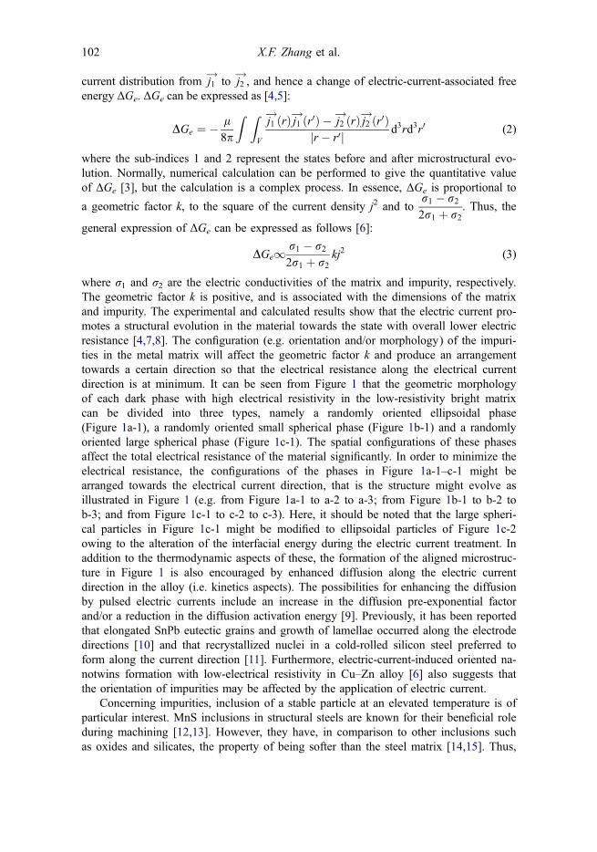
where σ1 and σ2 are the electric conductivities of the matrix and impurity, respectively.The geometric factor k is positive, and is associated with the dimensions of the matrixand impurity. The experimental and calculated results show that the electric current pro-motes a structural evolution in the material towards the state with overall lower electricresistance [4,7,8]. The configuration (e.g. orientation and/or morphology) of the impuri-ties in the metal matrix will affect the geometric factor k and produce an arrangementtowards a certain direction so that the electrical resistance along the electrical currentdirection is at minimum. It can be seen from Figure 1 that the geometric morphologyof each dark phase with high electrical resistivity in the low-resistivity bright matrixcan be divided into three types, namely a randomly oriented ellipsoidal phase(Figure 1a-1), a randomly oriented small spherical phase (Figure 1b-1) and a randomlyoriented large spherical phase (Figure 1c-1). The spatial configurations of these phasesaffect the total electrical resistance of the material significantly. In order to minimize theelectrical resistance, the configurations of the phases in Figure 1a-1–c-1 might bearranged towards the electrical current direction, that is the structure might evolve asillustrated in Figure 1 (e.g. from Figure 1a-1 to a-2 to a-3; from Figure 1b-1 to b-2 tob-3; and from Figure 1c-1 to c-2 to c-3). Here, it should be noted that the large spheri-cal particles in Figure 1c-1 might be modified to ellipsoidal particles of Figure 1c-2owing to the alteration of the interfacial energy during the electric current treatment. Inaddition to the thermodynamic aspects of these, the formation of the aligned microstruc-ture in Figure 1 is also encouraged by enhanced diffusion along the electric currentdirection in the alloy (i.e. kinetics aspects). The possibilities for enhancing the diffusionby pulsed electric currents include an increase in the diffusion pre-exponential factorand/or a reduction in the diffusion activation energy [9]. Previously, it has been reportedthat elongated SnPb eutectic grains and growth of lamellae occurred along the electrodedirections [10] and that recrystallized nuclei in a cold-rolled silicon steel preferred toform along the current direction [11]. Furthermore, electric-current-induced oriented na-notwins formation with low-electrical resistivity in Cu–Zn alloy [6] also suggests thatthe orientation of impurities may be affected by the application of electric current.
Concerning impurities, inclusion of a stable particle at an elevated temperature is ofparticular interest. MnS inclusions in structural steels are known for their beneficial roleduring machining [12,13]. However, they have, in comparison to other inclusions suchas oxides and silicates, the property of being softer than the steel matrix [14,15]. Thus,
102 X.F. Zhang et al.
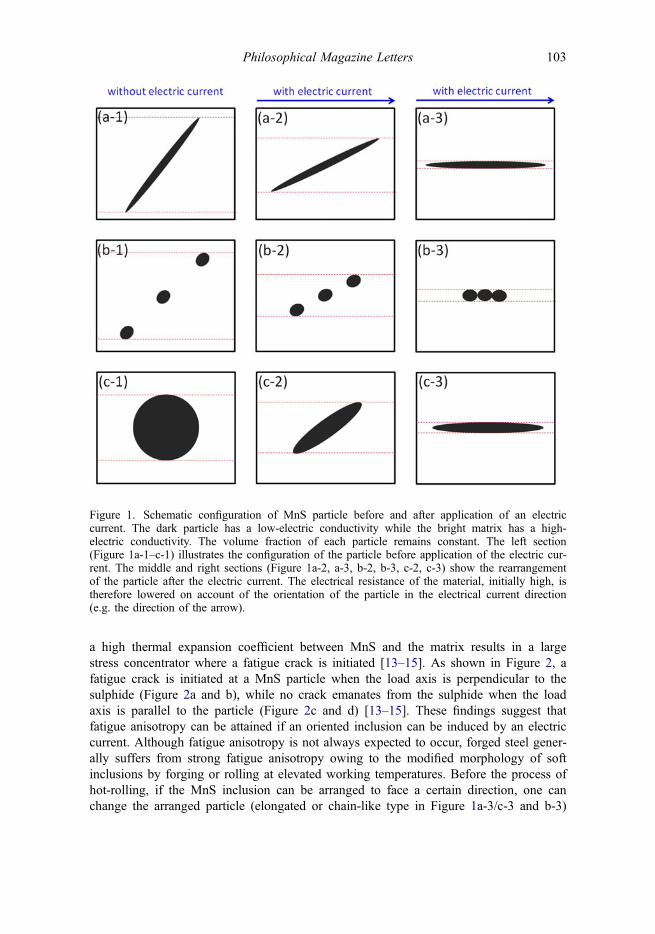
a high thermal expansion coefficient between MnS and the matrix results in a largestress concentrator where a fatigue crack is initiated [13–15]. As shown in Figure 2, afatigue crack is initiated at a MnS particle when the load axis is perpendicular to thesulphide (Figure 2a and b), while no crack emanates from the sulphide when the loadaxis is parallel to the particle (Figure 2c and d) [13–15]. These findings suggest thatfatigue anisotropy can be attained if an oriented inclusion can be induced by an electriccurrent. Although fatigue anisotropy is not always expected to occur, forged steel gener-ally suffers from strong fatigue anisotropy owing to the modified morphology of softinclusions by forging or rolling at elevated working temperatures. Before the process ofhot-rolling, if the MnS inclusion can be arranged to face a certain direction, one canchange the arranged particle (elongated or chain-like type in Figure 1a-3/c-3 and b-3)
Figure 1. Schematic configuration of MnS particle before and after application of an electriccurrent. The dark particle has a low-electric conductivity while the bright matrix has a high-electric conductivity. The volume fraction of each particle remains constant. The left section(Figure 1a-1–c-1) illustrates the configuration of the particle before application of the electric cur-rent. The middle and right sections (Figure 1a-2, a-3, b-2, b-3, c-2, c-3) show the rearrangementof the particle after the electric current. The electrical resistance of the material, initially high, istherefore lowered on account of the orientation of the particle in the electrical current direction(e.g. the direction of the arrow).
Philosophical Magazine Letters 103
into a globular-type sulphide when the rolling direction is perpendicular to the orientedinclusion. By keeping MnS globular, fatigue isotropy can be markedly improved. Here,MnS is only an example, and in general other particles whose configurations are influ-enced by electric fields can be used to fabricate and design novel microstructures. Inthis letter, a possible configuration of oriented MnS particles in medium carbon steelwill be described, providing insight into the effect of electric currents on orientation ofinclusions.
2. Experimental details
The sample used was medium carbon steel containing MnS inclusions. The steel wasplaced in a graphite crucible and heated to a molten state at approximately 1520 °C.The MnS inclusions with melting point of 1610 °C remain solid in the molten steel. Inorder to apply the electric pulse, a pair of steel bars was submerged into the liquid steelto act as electrodes. To determine the effect of the electric current, two sets of experi-ments were carried out, with and without the current. The experimental procedures wereotherwise identical. The frequency of the applied pulses was 1 Hz and the duration ofeach pulse was 60 μs. The density of the pulsed electric current was 1.8 × 10⁶ A/m2
and the total treatment time was 6 min. A longitudinal section was observed to detect
Figure 2. Fatigue crack initiation from different configurations of the MnS particles. (a) Cracksare along single ellipsoidal MnS inclusion when the load axis is perpendicular to the sulphide;(b) Cracks emanates from the chain-like type MnS inclusions when the load axis is perpendicularto the sulphides; (c) and (d) no crack emanates from the sulphide when the load axis is parallelto the particles.
104 X.F. Zhang et al.
the configuration of the inclusions. The furnace-cooled samples were longitudinally sec-tioned and polished for metallographic examination. The configuration of the inclusionswas initially examined by optical microscopy to confirm the overall distribution of theparticles. The configuration of the inclusions before and after the electric current wasexamined by transmission electron microscopy (TEM). For these observations, the spec-imens were mechanically polished to a thickness of 30 μm and punched to discs 3 mmin diameter by a brass cutter. The thin-film specimens were electrically polished using asolution (30 ml perchloric acid and 270 ml acetic acid) at 15 °C and observed by aTEM operated at an acceleration voltage of 200 kV.
3. Results and discussion
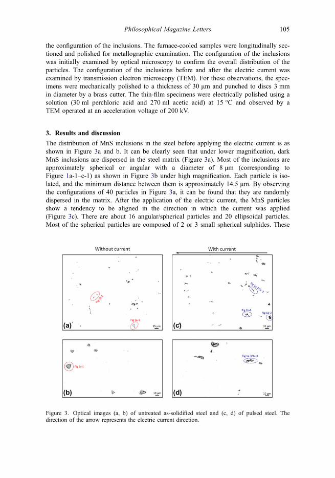
The distribution of MnS inclusions in the steel before applying the electric current is asshown in Figure 3a and b. It can be clearly seen that under lower magnification, darkMnS inclusions are dispersed in the steel matrix (Figure 3a). Most of the inclusions areapproximately spherical or angular with a diameter of 8 μm (corresponding toFigure 1a-1–c-1) as shown in Figure 3b under high magnification. Each particle is iso-lated, and the minimum distance between them is approximately 14.5 μm. By observingthe configurations of 40 particles in Figure 3a, it can be found that they are randomlydispersed in the matrix. After the application of the electric current, the MnS particlesshow a tendency to be aligned in the direction in which the current was applied(Figure 3c). There are about 16 angular/spherical particles and 20 ellipsoidal particles.Most of the spherical particles are composed of 2 or 3 small spherical sulphides. These
Figure 3. Optical images (a, b) of untreated as-solidified steel and (c, d) of pulsed steel. Thedirection of the arrow represents the electric current direction.
Philosophical Magazine Letters 105
small sulphides are connected to each other, forming a chain-like large particles asshown in Figure 1b-3. In case of the ellipsoidal particles, the direction of their long axisis parallel to the electric current direction as indicated in Figure 1a-3 or c-3. The config-urations of Figure 1a-2/c-2 and b-2 can also be found in small number in the pulsedsteel in Figure 3c. It can be clearly seen from Figure 3d with high magnification thatthe length of the major axis ranges from 8 to 22.4 μm. It seems that some large spheri-cal particles are modified to ellipsoidal particles on account of a modified interfacialenergy (e.g. see evolution from Figure 1c-1 to c-2). The different interfacial energybetween spherical and ellipsoidal particles will contribute to their morphologicalchange. As indicated in Equations (2) and (3), the higher ΔGe in the pulsed steel mightresult in a decrease in interfacial energy to minimize the system free energy.
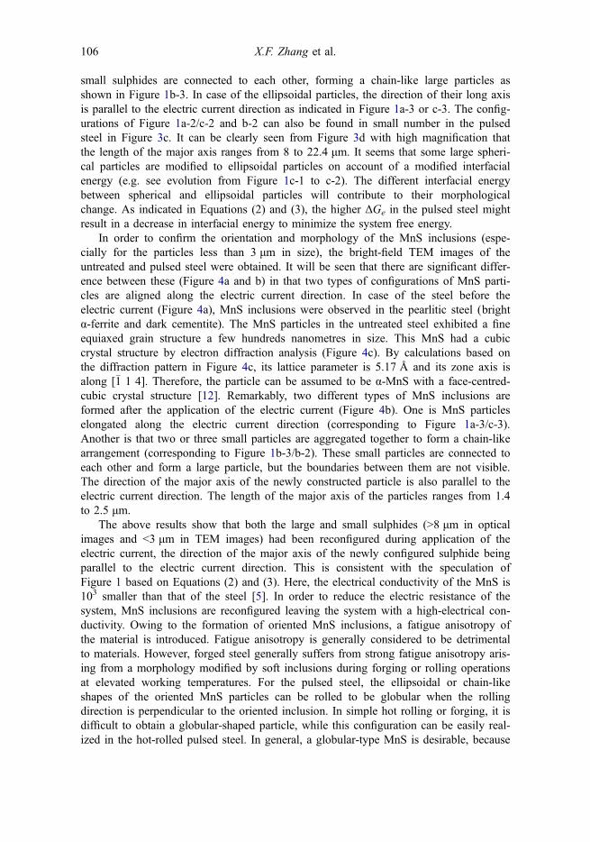
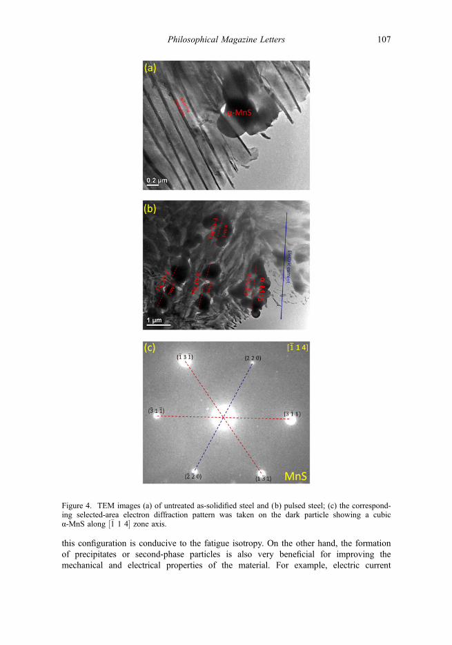
In order to confirm the orientation and morphology of the MnS inclusions (espe-cially for the particles less than 3 μm in size), the bright-field TEM images of theuntreated and pulsed steel were obtained. It will be seen that there are significant differ-ence between these (Figure 4a and b) in that two types of configurations of MnS parti-cles are aligned along the electric current direction. In case of the steel before theelectric current (Figure 4a), MnS inclusions were observed in the pearlitic steel (brightα-ferrite and dark cementite). The MnS particles in the untreated steel exhibited a fineequiaxed grain structure a few hundreds nanometres in size. This MnS had a cubiccrystal structure by electron diffraction analysis (Figure 4c). By calculations based onthe diffraction pattern in Figure 4c, its lattice parameter is 5.17 Å and its zone axis isalong [�1 1 4]. Therefore, the particle can be assumed to be α-MnS with a face-centred-cubic crystal structure [12]. Remarkably, two different types of MnS inclusions areformed after the application of the electric current (Figure 4b). One is MnS particleselongated along the electric current direction (corresponding to Figure 1a-3/c-3).Another is that two or three small particles are aggregated together to form a chain-likearrangement (corresponding to Figure 1b-3/b-2). These small particles are connected toeach other and form a large particle, but the boundaries between them are not visible.The direction of the major axis of the newly constructed particle is also parallel to theelectric current direction. The length of the major axis of the particles ranges from 1.4to 2.5 μm.
The above results show that both the large and small sulphides (>8 μm in opticalimages and <3 μm in TEM images) had been reconfigured during application of theelectric current, the direction of the major axis of the newly configured sulphide beingparallel to the electric current direction. This is consistent with the speculation ofFigure 1 based on Equations (2) and (3). Here, the electrical conductivity of the MnS is103 smaller than that of the steel [5]. In order to reduce the electric resistance of thesystem, MnS inclusions are reconfigured leaving the system with a high-electrical con-ductivity. Owing to the formation of oriented MnS inclusions, a fatigue anisotropy ofthe material is introduced. Fatigue anisotropy is generally considered to be detrimentalto materials. However, forged steel generally suffers from strong fatigue anisotropy aris-ing from a morphology modified by soft inclusions during forging or rolling operationsat elevated working temperatures. For the pulsed steel, the ellipsoidal or chain-likeshapes of the oriented MnS particles can be rolled to be globular when the rollingdirection is perpendicular to the oriented inclusion. In simple hot rolling or forging, it isdifficult to obtain a globular-shaped particle, while this configuration can be easily real-ized in the hot-rolled pulsed steel. In general, a globular-type MnS is desirable, because
106 X.F. Zhang et al.
this configuration is conducive to the fatigue isotropy. On the other hand, the formationof precipitates or second-phase particles is also very beneficial for improving themechanical and electrical properties of the material. For example, electric current
Figure 4. TEM images (a) of untreated as-solidified steel and (b) pulsed steel; (c) the correspond-ing selected-area electron diffraction pattern was taken on the dark particle showing a cubicα-MnS along ½�1 1 4� zone axis.
Philosophical Magazine Letters 107
pulsing induced the formation of oriented nanotwins with a high-electrical conductivityand greatly enhanced the mechanical and electrical properties of a Cu–Zn alloy [6].Furthermore, electric current pulsing may also lead to a corresponding change in thetexture of materials [16–18]. This has great significance for the applications of Mgalloys, Al alloys and electrical silicon steel. In general, a fundamental understanding ofparticle configurations modified by electric currents can help in the fabrication anddesign of novel microstructures.
4. Conclusions
The effect of pulsed electric currents can minimize the electrical resistance of a mate-rial. In particular, in this work-oriented sulphides parallel to the electric current directionhave been configured in medium carbon steel. Optical and TEM observations confirmthat such configurations can be produced in both large sulphides (>8 μm in opticalimages) and small sulphides (<3 μm in TEM images). Such a phenomenon provides aspecial and effective approach to fabricating and designing novel microstructures.
AcknowledgementsThe authors are grateful to Professor Kenneth C. Mills at Imperial College London and MrAndrew Smith and Mr Michael McDonald at TATA Steel Teesside Technology Centre for fruitfuldiscussions. We are grateful to TATA Steel Europe for the provision of steel samples used in theexperiments.
Funding
The work was financially supported by EPSRC [grant number EP/J011460/1].
References
[1] C. Punckt, M. Bölscher, H.H. Rotermund, A.S. Mikhailov, L. Organ, N. Budiansky, J.R. Scullyand J.L. Hudson, Science 305 (2004) p.1133.
[2] M.P. Ryan, D.E. Williams, R.J. Chater, B.M. Hutton and D.S. McPhail, Nature 415 (2002)p.770.
[3] X.F. Zhang and R.S. Qin, Appl. Phys. Lett. 104 (2014) p.114106.[4] R.S. Qin, E.I. Samuel and A. Bhowmik, J. Mater. Sci. 46 (2011) p.2838.[5] X.F. Zhang, W.J. Lu and R.S. Qin, Scr. Mater. 69 (2013) p.453.[6] X.L. Wang, Y.B. Wang, Y.M. Wang, B.Q. Wang and J.D. Guo, Appl. Phys. Lett. 91 (2007)
p.163112.[7] Y. Dolinsky and T. Elperin, Phys. Rev. B 50 (1994) p.52.[8] R.S. Qin, A. Rahnama, W.J. Lu, X.F. Zhang and B. Elliott-Bowman, Mater. Sci. Technol. 30
(2014) p.1040.[9] Y.Z. Zhou, W. Zhang, J.D. Guo and G.H. He, Philos. Mag. Lett. 84 (2004) p.341.[10] J.M. Li, S.L. Li, J. Li and H.T. Lin, Scr. Metal. Mater. 31 (1994) p.1691.[11] W.B. Dai, X.L. Wang, H.M. Zhao and X. Zhao, Mater. Trans. 53 (2012) p.229.[12] N. Matsui and K. Watari, ISIJ Int. 46 (2006) p.1720.[13] C. Temmel, B. Karlsson and N.G. Ingesten, Fatigue Fract. Eng. Mater. Struct. 31 (2008)
p.466.
108 X.F. Zhang et al.

[14] A. Melander, Int. J. Fatigue 19 (1997) p.13.[15] T.J. Baker, K.B. Gave and J.A. Charles, Met. Technol. 3 (1976) p.183.[16] L. Guan, G.Y. Tang, P.K. Chu and Y.B. Jiang, J. Mater. Res. 24 (2009) p.3674.[17] C.Y. Liu, Y.J. Hu, Y.S. Liu, H.W. Tseng, T.S. Huang, C.T. Lu, Y.C. Chuang and S.L. Cheng,
Acta Mater. 61 (2013) p.5713.[18] G.L. Hu, Y.H. Zhu, C.H. Shek and G.Y. Tang, J. Mater. Res. 26 (2011) p.917.
Philosophical Magazine Letters 109