orbital dynamics of a simple solar photon thruster
TRANSCRIPT
Hindawi Publishing CorporationMathematical Problems in EngineeringVolume 2009, Article ID 537256, 11 pagesdoi:10.1155/2009/537256
Research ArticleOrbital Dynamics of a Simple SolarPhoton Thruster
Anna D. Guerman,1 Georgi V. Smirnov,2and Maria Cecilia Pereira3
1 University of Beira Interior, 6201-001 Covilha, Portugal2 University of Porto, 4169-007 Porto, Portugal3 Aeronautical Institute of Technology, 12.228-900 Sao Jose dos Campos, Brazil
Correspondence should be addressed to Anna D. Guerman, [email protected]
Received 29 July 2009; Accepted 13 November 2009
Recommended by Maria Zanardi
We study orbital dynamics of a compound solar sail, namely, a Simple Solar Photon Thrusterand compare its behavior to that of a common version of sailcraft. To perform this analysis,development of a mathematical model for force created by light reflection on all sailcraft elementsis essential. We deduce the equations of sailcraft’s motion and compare performance of twoschemes of solar propulsion for two test time-optimal control problems of trajectory transfer.
Copyright q 2009 Anna D. Guerman et al. This is an open access article distributed under theCreative Commons Attribution License, which permits unrestricted use, distribution, andreproduction in any medium, provided the original work is properly cited.
1. Introduction
The use of solar pressure to create propulsion can minimize spacecraft on-board energyconsumption during a mission [1, 2]. Modern materials and technologies made thispropulsion scheme feasible, and many projects of solar sails are now under development,making solar sail dynamics the subject of numerous studies.
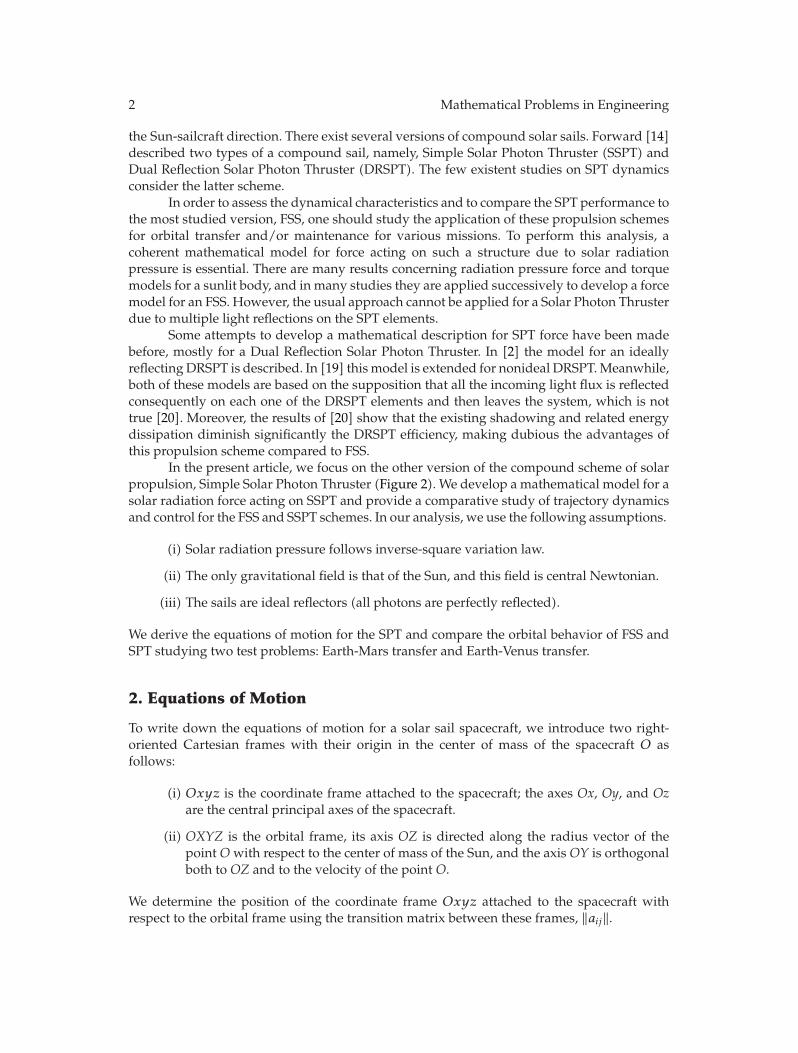
So far, the most extensively studied problem is the orbital maneuver of a Flat Solar Sail(FSS, Figure 1). In this case, the control is performed by turning the entire sail surface withrespect to the Sun direction. This changes the radiation pressure and results in evolution ofthe vehicle trajectory. Some of the many missions studied are described in [3–13].
The use of a compound solar sail, or Solar Photon Thruster (SPT), was proposed byTsander long ago [1, 2], but the study of this spacecraft began quite recently [14–18]. The SPTconsists of a parabolic surface which concentrates the solar radiation pressure on a systemof smaller mirrors. The control effort in such system is produced by displacement of a smallmirror with respect to the parabolic surface. The sail axis is supposed to be oriented along
2 Mathematical Problems in Engineering
the Sun-sailcraft direction. There exist several versions of compound solar sails. Forward [14]described two types of a compound sail, namely, Simple Solar Photon Thruster (SSPT) andDual Reflection Solar Photon Thruster (DRSPT). The few existent studies on SPT dynamicsconsider the latter scheme.
In order to assess the dynamical characteristics and to compare the SPT performance tothe most studied version, FSS, one should study the application of these propulsion schemesfor orbital transfer and/or maintenance for various missions. To perform this analysis, acoherent mathematical model for force acting on such a structure due to solar radiationpressure is essential. There are many results concerning radiation pressure force and torquemodels for a sunlit body, and in many studies they are applied successively to develop a forcemodel for an FSS. However, the usual approach cannot be applied for a Solar Photon Thrusterdue to multiple light reflections on the SPT elements.
Some attempts to develop a mathematical description for SPT force have been madebefore, mostly for a Dual Reflection Solar Photon Thruster. In [2] the model for an ideallyreflecting DRSPT is described. In [19] this model is extended for nonideal DRSPT. Meanwhile,both of these models are based on the supposition that all the incoming light flux is reflectedconsequently on each one of the DRSPT elements and then leaves the system, which is nottrue [20]. Moreover, the results of [20] show that the existing shadowing and related energydissipation diminish significantly the DRSPT efficiency, making dubious the advantages ofthis propulsion scheme compared to FSS.
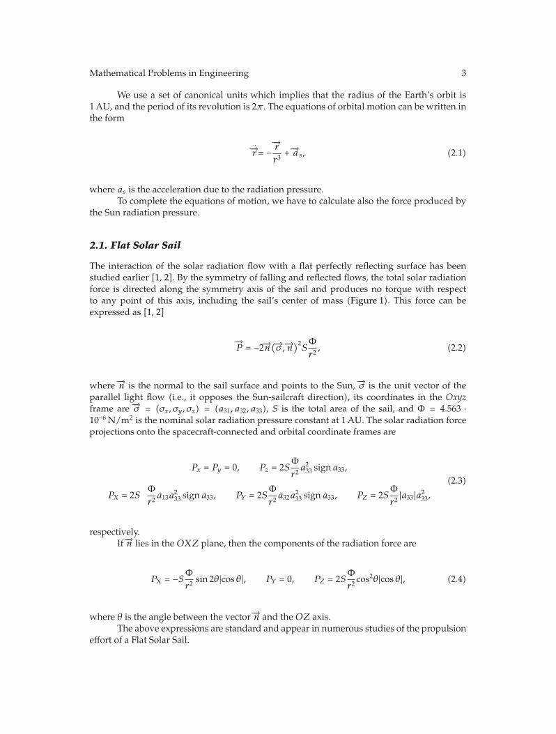
In the present article, we focus on the other version of the compound scheme of solarpropulsion, Simple Solar Photon Thruster (Figure 2). We develop a mathematical model for asolar radiation force acting on SSPT and provide a comparative study of trajectory dynamicsand control for the FSS and SSPT schemes. In our analysis, we use the following assumptions.
(i) Solar radiation pressure follows inverse-square variation law.
(ii) The only gravitational field is that of the Sun, and this field is central Newtonian.
(iii) The sails are ideal reflectors (all photons are perfectly reflected).
We derive the equations of motion for the SPT and compare the orbital behavior of FSS andSPT studying two test problems: Earth-Mars transfer and Earth-Venus transfer.
2. Equations of Motion
To write down the equations of motion for a solar sail spacecraft, we introduce two right-oriented Cartesian frames with their origin in the center of mass of the spacecraft O asfollows:
(i) Oxyz is the coordinate frame attached to the spacecraft; the axes Ox, Oy, and Ozare the central principal axes of the spacecraft.
(ii) OXYZ is the orbital frame, its axis OZ is directed along the radius vector of thepoint O with respect to the center of mass of the Sun, and the axis OY is orthogonalboth to OZ and to the velocity of the point O.
We determine the position of the coordinate frame Oxyz attached to the spacecraft withrespect to the orbital frame using the transition matrix between these frames, ‖aij‖.
Mathematical Problems in Engineering 3
We use a set of canonical units which implies that the radius of the Earth’s orbit is1 AU, and the period of its revolution is 2π . The equations of orbital motion can be written inthe form
..−→r = −−→rr3
+ −→as, (2.1)
where as is the acceleration due to the radiation pressure.To complete the equations of motion, we have to calculate also the force produced by
the Sun radiation pressure.
2.1. Flat Solar Sail
The interaction of the solar radiation flow with a flat perfectly reflecting surface has beenstudied earlier [1, 2]. By the symmetry of falling and reflected flows, the total solar radiationforce is directed along the symmetry axis of the sail and produces no torque with respectto any point of this axis, including the sail’s center of mass (Figure 1). This force can beexpressed as [1, 2]
−→P = −2−→n
(−→σ ,−→n)2SΦr2, (2.2)
where −→n is the normal to the sail surface and points to the Sun, −→σ is the unit vector of theparallel light flow (i.e., it opposes the Sun-sailcraft direction), its coordinates in the Oxyzframe are −→σ = (σx, σy, σz) = (a31, a32, a33), S is the total area of the sail, and Φ = 4.563 ·10−6 N/m2 is the nominal solar radiation pressure constant at 1 AU. The solar radiation forceprojections onto the spacecraft-connected and orbital coordinate frames are
Px = Py = 0, Pz = 2SΦr2a2
33 signa33,
PX = 2SΦr2a13a
233 signa33, PY = 2S
Φr2a32a
233 signa33, PZ = 2S
Φr2 |a33|a2
33,
(2.3)
respectively.If −→n lies in the OXZ plane, then the components of the radiation force are
PX = −SΦr2
sin 2θ|cos θ|, PY = 0, PZ = 2SΦr2
cos2θ|cos θ|, (2.4)
where θ is the angle between the vector −→n and the OZ axis.The above expressions are standard and appear in numerous studies of the propulsion
effort of a Flat Solar Sail.
4 Mathematical Problems in Engineering
xY
dS
σ
σ1z
X
y
Z
Figure 1: Flat Solar Sail (FSS).
ξ
v
σ1
σ
σ2
x
f = a/2
z
y
θ
ξdF = 0
Figure 2: Solar Photon Thruster (SPT).
2.2. Solar Photon Thruster
We consider here another system that is shown in Figure 2. It consists of a parabolic collectorand a control mirror (director). When reflection is ideal and the collector axis is exactlyaligned with the Sun-sailcraft direction, the collector concentrates the sunlight in the centerof the director. In order to minimize the solar radiation torque that causes perturbations ofthe sailcraft orientation, the director should be located at the sailcraft’s center of mass. Thisscheme of solar propulsion seems to be more reliable with respect to small misalignments ofthe sail axis than the DRSPT scheme studied in [15–17] which uses a collimator.
In the analysis, we assume the control mirror small enough to disregard the influenceof its shadow. We also suppose that the SPT axis is aligned exactly along the Sun direction.
We consider the parabolic surface described in the reference frame Oxyz by theequation
x2 + y2 + 2a(z − f
)= 0,
(x2 + y2 ≤ R2
), (2.5)
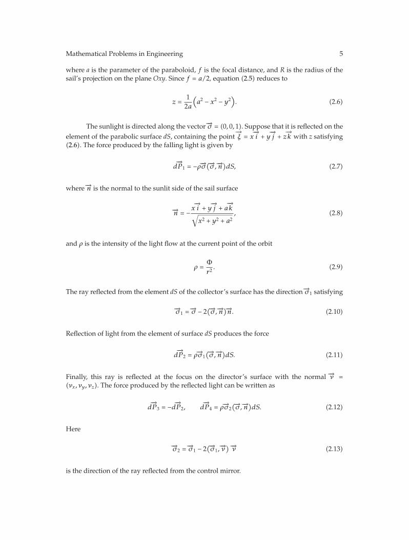
Mathematical Problems in Engineering 5
where a is the parameter of the paraboloid, f is the focal distance, and R is the radius of thesail’s projection on the plane Oxy. Since f = a/2, equation (2.5) reduces to
z =1
2a
(a2 − x2 − y2
). (2.6)
The sunlight is directed along the vector −→σ = (0, 0, 1). Suppose that it is reflected on theelement of the parabolic surface dS, containing the point
−→ξ = x
−→i + y
−→j + z
−→k with z satisfying
(2.6). The force produced by the falling light is given by
d−→P 1 = −ρ−→σ
(−→σ ,−→n)dS, (2.7)
where −→n is the normal to the sunlit side of the sail surface
−→n = −x−→i + y
−→j + a
−→k
√x2 + y2 + a2
, (2.8)
and ρ is the intensity of the light flow at the current point of the orbit
ρ =Φr2. (2.9)
The ray reflected from the element dS of the collector’s surface has the direction −→σ 1 satisfying
−→σ 1 = −→σ − 2(−→σ ,−→n
)−→n. (2.10)
Reflection of light from the element of surface dS produces the force
d−→P 2 = ρ−→σ 1
(−→σ ,−→n)dS. (2.11)
Finally, this ray is reflected at the focus on the director’s surface with the normal −→ν =(νx, νy, νz). The force produced by the reflected light can be written as
d−→P 3 = −d−→P 2, d
−→P 4 = ρ−→σ 2
(−→σ ,−→n)dS. (2.12)
Here
−→σ 2 = −→σ 1 − 2(−→σ 1,
−→ν) −→ν (2.13)
is the direction of the ray reflected from the control mirror.
6 Mathematical Problems in Engineering
The reflection of the light on the parabolic surface is unique if the normal to the directordoes not cross this surface, so the control angle must be greater than half the angular aperture,that is,
θ ≥ tan−1(R
zR
). (2.14)
Here θ is the angle between vector −→ν and the sail axis (cos θ = νz), and zR = (1/2a)(a2 − R2)is the z-coordinate of the collector’s border. Finally we arrive at the restriction
|tan θ| ≥ 2aRa2 − R2
. (2.15)
Multiple reflections on the collector destroy the collector’s film and produce a considerabledisturbing torque, and so have to be avoided. Therefore condition (2.15) has to be satisfiedduring the orbital maneuver.
The elementary force created by interaction of light with parabolic surface and mirroris
d−→P = d
−→P 1 + d
−→P 2 + d
−→P 3 + d
−→P 4 = d
−→P 1 + d
−→P 4
= −ρ−→σ(−→σ ,−→n
)dS + ρ−→σ 2
(−→σ ,−→n)d = ρ
(−→σ 2 − −→σ)(−→σ ,−→n
)dS.
(2.16)
After integration, we obtain
Px = 2Φr2πR2νxνz
[
1 − 2a2
R2ln
(
1 +R2
a2
)]
,
Py = 2Φr2πR2νyνz
[
1 − 2a2
R2ln
(
1 +R2
a2
)]
,
Pz = 2Φr2πR2
[
ν2z +
(1 − 2ν2
z
) a2
R2ln
(
1 +R2
a2
)]
.
(2.17)
If the control mirror moves in the OXZ plane (νx = sin θ, νy = 0, νz = cos θ), then thecomponents of the light pressure force in the orbital coordinate frame are
PX =Φr2πR2
[
1 − 2a2
R2ln
(
1 +R2
a2
)]
sin 2θ, PY = 0,
PZ = 2Φr2πR2
[
cos2θ − a2
R2ln
(
1 +R2
a2
)
cos 2θ
]
.
(2.18)
Mathematical Problems in Engineering 7
If χ = R/a � 1, then it is possible to simplify (2.18). One can use Taylor’s formula to obtainthe expressions
PX = −Φr2πR2
[
1 − R2
a2+ o
(R3
a3
)]
sin 2θ, PY = 0,
PZ = 2Φr2πR2
[
sin2θ +R2
2a2cos 2θ + o
(R3
a3
)]
.
(2.19)
If χ2 = R2/a2 is negligible (i.e., the sail is almost plane), we get
PX = −Φr2S sin 2θ, PY = 0, PZ = 2
Φr2S sin2θ, (2.20)
where S = πR2 is the effective sail area, that is, the area of the sail projection on the plane Oxy.Formulas (2.20) are similar to those used in [11–13] for a different scheme of SPT, so one canexpect qualitative similarity of the results for small χ, at least for the maneuvers that requirecontrol angles within limits (2.15).
3. In-Plane Orbital Motion
To compare the principal characteristics of SPT and FSS we studied two test time-optimalcontrol problems of solar sail dynamics, namely, the time-optimal Earth-Mars and Earth-Venus transfers [3, 21] for both systems. Since our goal is to compare qualitative behaviorof the above systems, we choose the simplest formulation for orbital transfer problem. Inboth cases, we assume that the planet orbits are circular and coplanar and that the spacecraftmoves in the ecliptic plane, starting from the Earth-orbit at 1 AU with Earth-orbital velocity.We find the control law that guarantees the fastest transfer to the planet’s orbit.
This model of orbital dynamics results in the following equations of motion in the orbitplane [3]:
r = u, ϕ =w
r, u =
w2
r− 1r2
+ asZ, w = −uwr
+ asX. (3.1)
Here ϕ is the polar angle, and u and w are the radial and transversal components of sailvelocity, respectively.
For the FSS, the components of the light pressure acceleration onto the axis of orbitalcoordinate frame OXYZ are
asX =Φmr2
S|cos θ| sin 2θ, asZ = 2Φmr2
S∣∣∣cos3θ
∣∣∣. (3.2)
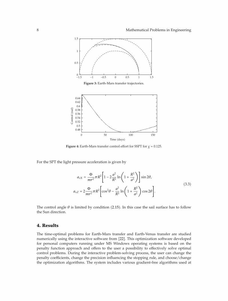
8 Mathematical Problems in Engineering
0
1
0.5
1.5
−1.5 −1 −0.5 0 0.5 1 1.5
Figure 3: Earth-Mars transfer trajectories.
0.58
0.480.5
0.520.540.56
0.60.620.64
0
Con
trol
(rad
)
50 100 150
Time (days)
Figure 4: Earth-Mars transfer control effort for SSPT for χ = 0.125.
For the SPT the light pressure acceleration is given by
asX =Φmr2
πR2
[
1 − 2a2
R2ln
(
1 +R2
a2
)]
sin 2θ,
asZ = 2Φmr2
πR2
[
cos2θ − a2
R2ln
(
1 +R2
a2
)
cos 2θ
]
.
(3.3)
The control angle θ is limited by condition (2.15). In this case the sail surface has to followthe Sun direction.
4. Results
The time-optimal problems for Earth-Mars transfer and Earth-Venus transfer are studiednumerically using the interactive software from [22]. This optimization software developedfor personal computers running under MS Windows operating systems is based on thepenalty function approach and offers to the user a possibility to effectively solve optimalcontrol problems. During the interactive problem-solving process, the user can change thepenalty coefficients, change the precision influencing the stopping rule, and choose/changethe optimization algorithms. The system includes various gradient-free algorithms used at
Mathematical Problems in Engineering 9
0.5
00.10.20.30.4
0.60.70.80.9
1
−1 −0.8 −0.6 −0.4 −0.2 0 0.2 0.4 0.6 0.8 1
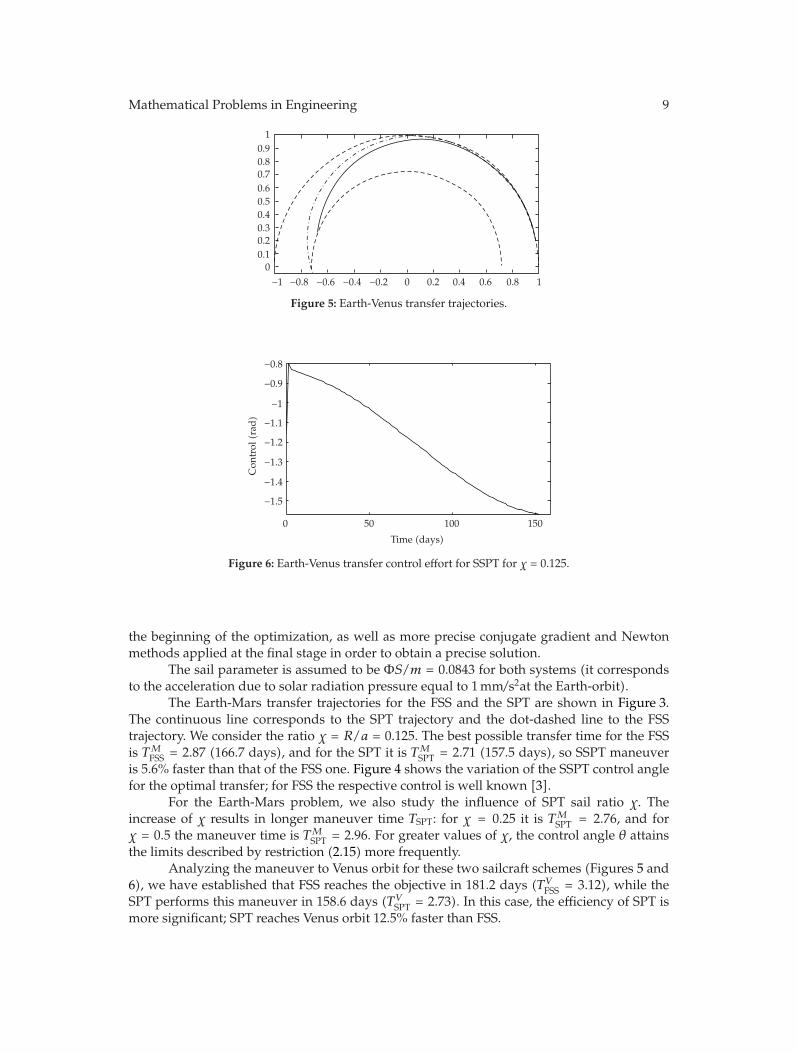
Figure 5: Earth-Venus transfer trajectories.
−1.1
−1.5
−1.4
−1.3
−1.2
−1
−0.9
−0.8
0
Con
trol
(rad
)
50 100 150
Time (days)
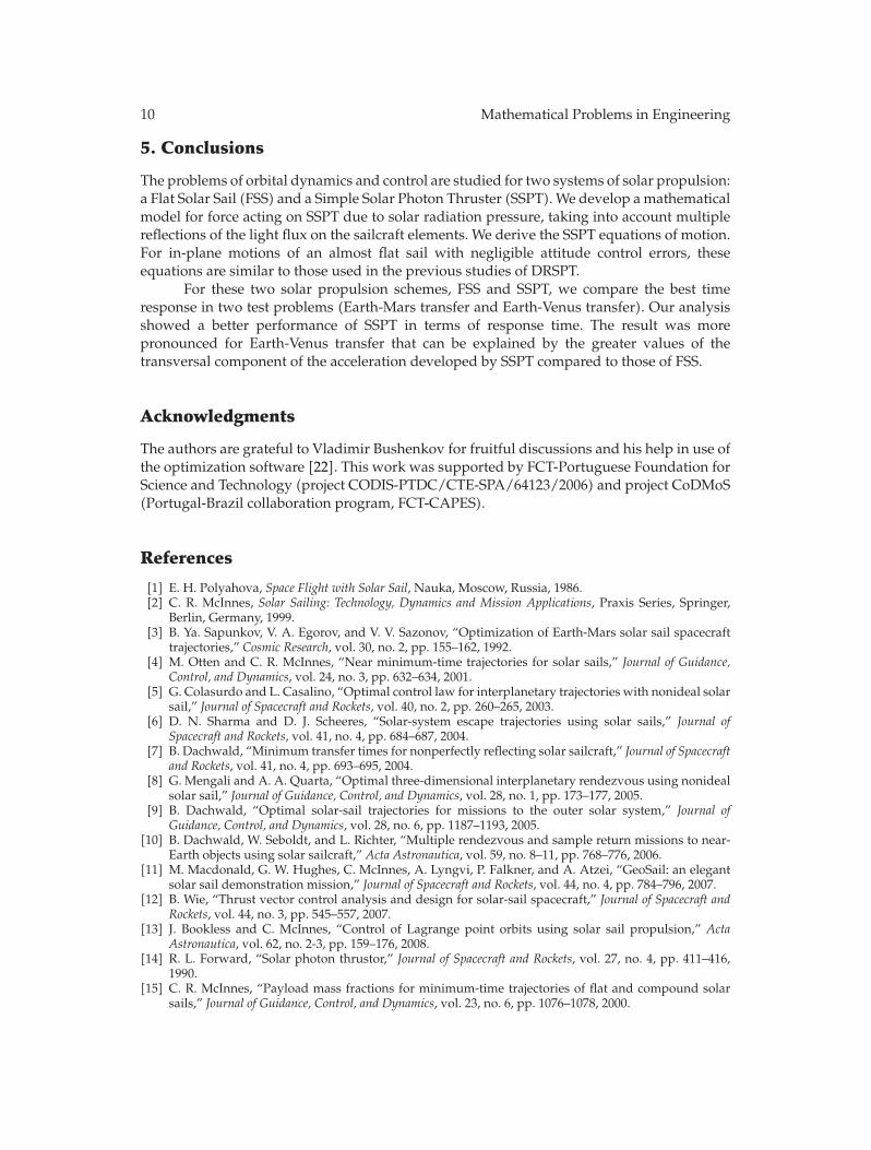
Figure 6: Earth-Venus transfer control effort for SSPT for χ = 0.125.
the beginning of the optimization, as well as more precise conjugate gradient and Newtonmethods applied at the final stage in order to obtain a precise solution.
The sail parameter is assumed to be ΦS/m = 0.0843 for both systems (it correspondsto the acceleration due to solar radiation pressure equal to 1 mm/s2at the Earth-orbit).
The Earth-Mars transfer trajectories for the FSS and the SPT are shown in Figure 3.The continuous line corresponds to the SPT trajectory and the dot-dashed line to the FSStrajectory. We consider the ratio χ = R/a = 0.125. The best possible transfer time for the FSSis TMFSS = 2.87 (166.7 days), and for the SPT it is TMSPT = 2.71 (157.5 days), so SSPT maneuveris 5.6% faster than that of the FSS one. Figure 4 shows the variation of the SSPT control anglefor the optimal transfer; for FSS the respective control is well known [3].
For the Earth-Mars problem, we also study the influence of SPT sail ratio χ. Theincrease of χ results in longer maneuver time TSPT: for χ = 0.25 it is TMSPT = 2.76, and forχ = 0.5 the maneuver time is TMSPT = 2.96. For greater values of χ, the control angle θ attainsthe limits described by restriction (2.15) more frequently.
Analyzing the maneuver to Venus orbit for these two sailcraft schemes (Figures 5 and6), we have established that FSS reaches the objective in 181.2 days (TVFSS = 3.12), while theSPT performs this maneuver in 158.6 days (TVSPT = 2.73). In this case, the efficiency of SPT ismore significant; SPT reaches Venus orbit 12.5% faster than FSS.
10 Mathematical Problems in Engineering
5. Conclusions
The problems of orbital dynamics and control are studied for two systems of solar propulsion:a Flat Solar Sail (FSS) and a Simple Solar Photon Thruster (SSPT). We develop a mathematicalmodel for force acting on SSPT due to solar radiation pressure, taking into account multiplereflections of the light flux on the sailcraft elements. We derive the SSPT equations of motion.For in-plane motions of an almost flat sail with negligible attitude control errors, theseequations are similar to those used in the previous studies of DRSPT.
For these two solar propulsion schemes, FSS and SSPT, we compare the best timeresponse in two test problems (Earth-Mars transfer and Earth-Venus transfer). Our analysisshowed a better performance of SSPT in terms of response time. The result was morepronounced for Earth-Venus transfer that can be explained by the greater values of thetransversal component of the acceleration developed by SSPT compared to those of FSS.
Acknowledgments
The authors are grateful to Vladimir Bushenkov for fruitful discussions and his help in use ofthe optimization software [22]. This work was supported by FCT-Portuguese Foundation forScience and Technology (project CODIS-PTDC/CTE-SPA/64123/2006) and project CoDMoS(Portugal-Brazil collaboration program, FCT-CAPES).
References
[1] E. H. Polyahova, Space Flight with Solar Sail, Nauka, Moscow, Russia, 1986.[2] C. R. McInnes, Solar Sailing: Technology, Dynamics and Mission Applications, Praxis Series, Springer,
Berlin, Germany, 1999.[3] B. Ya. Sapunkov, V. A. Egorov, and V. V. Sazonov, “Optimization of Earth-Mars solar sail spacecraft
trajectories,” Cosmic Research, vol. 30, no. 2, pp. 155–162, 1992.[4] M. Otten and C. R. McInnes, “Near minimum-time trajectories for solar sails,” Journal of Guidance,
Control, and Dynamics, vol. 24, no. 3, pp. 632–634, 2001.[5] G. Colasurdo and L. Casalino, “Optimal control law for interplanetary trajectories with nonideal solar
sail,” Journal of Spacecraft and Rockets, vol. 40, no. 2, pp. 260–265, 2003.[6] D. N. Sharma and D. J. Scheeres, “Solar-system escape trajectories using solar sails,” Journal of
Spacecraft and Rockets, vol. 41, no. 4, pp. 684–687, 2004.[7] B. Dachwald, “Minimum transfer times for nonperfectly reflecting solar sailcraft,” Journal of Spacecraft
and Rockets, vol. 41, no. 4, pp. 693–695, 2004.[8] G. Mengali and A. A. Quarta, “Optimal three-dimensional interplanetary rendezvous using nonideal
solar sail,” Journal of Guidance, Control, and Dynamics, vol. 28, no. 1, pp. 173–177, 2005.[9] B. Dachwald, “Optimal solar-sail trajectories for missions to the outer solar system,” Journal of
Guidance, Control, and Dynamics, vol. 28, no. 6, pp. 1187–1193, 2005.[10] B. Dachwald, W. Seboldt, and L. Richter, “Multiple rendezvous and sample return missions to near-
Earth objects using solar sailcraft,” Acta Astronautica, vol. 59, no. 8–11, pp. 768–776, 2006.[11] M. Macdonald, G. W. Hughes, C. McInnes, A. Lyngvi, P. Falkner, and A. Atzei, “GeoSail: an elegant
solar sail demonstration mission,” Journal of Spacecraft and Rockets, vol. 44, no. 4, pp. 784–796, 2007.[12] B. Wie, “Thrust vector control analysis and design for solar-sail spacecraft,” Journal of Spacecraft and
Rockets, vol. 44, no. 3, pp. 545–557, 2007.[13] J. Bookless and C. McInnes, “Control of Lagrange point orbits using solar sail propulsion,” Acta
Astronautica, vol. 62, no. 2-3, pp. 159–176, 2008.[14] R. L. Forward, “Solar photon thrustor,” Journal of Spacecraft and Rockets, vol. 27, no. 4, pp. 411–416,
1990.[15] C. R. McInnes, “Payload mass fractions for minimum-time trajectories of flat and compound solar
sails,” Journal of Guidance, Control, and Dynamics, vol. 23, no. 6, pp. 1076–1078, 2000.
Mathematical Problems in Engineering 11
[16] G. Mengali and A. A. Quarta, “Earth escape by ideal sail and solar-photon thrustor spacecraft,”Journal of Guidance, Control, and Dynamics, vol. 27, no. 6, pp. 1105–1108, 2004.
[17] G. Mengali and A. A. Quarta, “Time-optimal three-dimensional trajectories for solar photon thrusterspacecraft,” Journal of Spacecraft and Rockets, vol. 42, no. 2, pp. 379–381, 2005.
[18] B. Dachwald and P. Wurm, “Design concept and modeling of an advanced solar photon thruster,” inProceedings of the 19th AAS/AIAA Space Flight Mechanics Meeting, Savannah, Ga, USA, February 2009,paper no. AAS 09-147.
[19] G. Mengali and A. A. Quarta, “Compound solar sail with optical properties: models andperformance,” Journal of Spacecraft and Rockets, vol. 43, no. 1, pp. 239–245, 2006.
[20] A. D. Guerman and G. Smirnov, “Comment on “compound solar sail with optical properties: modelsand performance”,” Journal of Spacecraft and Rockets, vol. 44, no. 3, pp. 732–734, 2007.
[21] P. A. Tychina, V. A. Egorov, and V. V. Sazonov, “Optimization of the flight of a spacecraft with a solarsail from Earth to Mars with a perturbation maneuver near Venus,” Cosmic Research, vol. 40, no. 3, pp.255–263, 2002.
[22] G. Smirnov and V. Bushenkov, Curso de Optimizacao: Programacao Matematica, Calculo de Variacoes,Controlo Optimo, Escolar Editora, Lisbon, Portugal, 2005.